10538313 AC 0370
User Manual: AC-0370
Open the PDF directly: View PDF ![]() .
.
Page Count: 136 [warning: Documents this large are best viewed by clicking the View PDF Link!]
- 1 System Description
- 2 Technical Data and Dimensions
- 2.1 CE-marking, UL approval and unit designation
- 2.2 General technical data
- 2.3 MOVIDRIVE® compact MC_4_A...-5_3 (400/500 V units)
- 2.4 MOVIDRIVE® compact MC_4_A...-2_3 (230 V units)
- 2.5 Additional functions in the application type
- 2.6 MOVIDRIVE® compact MCF/MCV/MCS electronics data
- 2.7 MOVIDRIVE® compact MCH electronics data
- 2.8 MOVIDRIVE® compact dimensions
- 2.9 IPOSplus®
- 2.10 DBG11B keypad option
- 2.11 Serial interface option type USS21A (RS-232 and RS-485)
- 2.12 5 V encoder power supply option type DWI11A
- 2.13 MOVITOOLS software
- 2.14 Application modules for MOVIDRIVE® compact
- 2.15 Braking resistor option type BW...
- 2.16 Line chokes option type ND...
- 2.17 NF...-... line filter option
- 2.18 Output choke option type HD...
- 2.19 Output filter option type HF...
- 2.20 Pre-fabricated cables
- 3 Project Planning
MOVIDRIVE®
compact
Edition
08/2002
Catalog
1053 8313 / EN
SEW-EURODRIVE
MOVIDRIVE® compact
Catalog 3
1 System Description................................................................................................ 4
1.1 Overview of the system.................................................................................. 4
1.2 Functions / features ..................................................................................... 10
1.3 Additional functions of the application version ............................................. 12
1.4 Application modules..................................................................................... 14
2 Technical Data and Dimensions ......................................................................... 16
2.1 CE-marking, UL approval and unit designation............................................ 16
2.2 General technical data ................................................................................. 17
2.3 MOVIDRIVE®
compact
MC_4_A...-5_3 (400/500 V units)........................... 18
2.4 MOVIDRIVE®
compact
MC_4_A...-2_3 (230 V units).................................. 28
2.5 Additional functions in the application type .................................................. 36
2.6 MOVIDRIVE®
compact
MCF/MCV/MCS electronics data ........................... 38
2.7 MOVIDRIVE®
compact
MCH electronics data............................................. 42
2.8 MOVIDRIVE®
compact
dimensions............................................................. 45
2.9 IPOSplus® ..................................................................................................... 50
2.10 DBG11B keypad option ............................................................................... 51
2.11 Serial interface option type USS21A (RS-232 and RS-485)........................ 52
2.12 5 V encoder power supply option type DWI11A........................................... 53
2.13 MOVITOOLS software ................................................................................. 54
2.14 Application modules for MOVIDRIVE®
compact
.......................................... 55
2.15 Braking resistor option type BW................................................................... 59
2.16 Line chokes option type ND... ...................................................................... 65
2.17 NF...-... line filter option................................................................................ 66
2.18 Output choke option type HD....................................................................... 68
2.19 Output filter option type HF... ....................................................................... 69
2.20 Pre-fabricated cables ................................................................................... 72
3 Project Planning................................................................................................... 82
3.1 Motor selection for asynchronous AC motors (VFC).................................... 82
3.2 Motor selection for asynchronous servomotors (CFC)................................. 89
3.3 Motor selection for synchronous servomotors (SERVO) ........................... 110
Address List............................................................................................................. 118
P
i
f
kVA
Hz
n
1
4
MOVIDRIVE® compact Catalog
Overview of the system
1 System Description
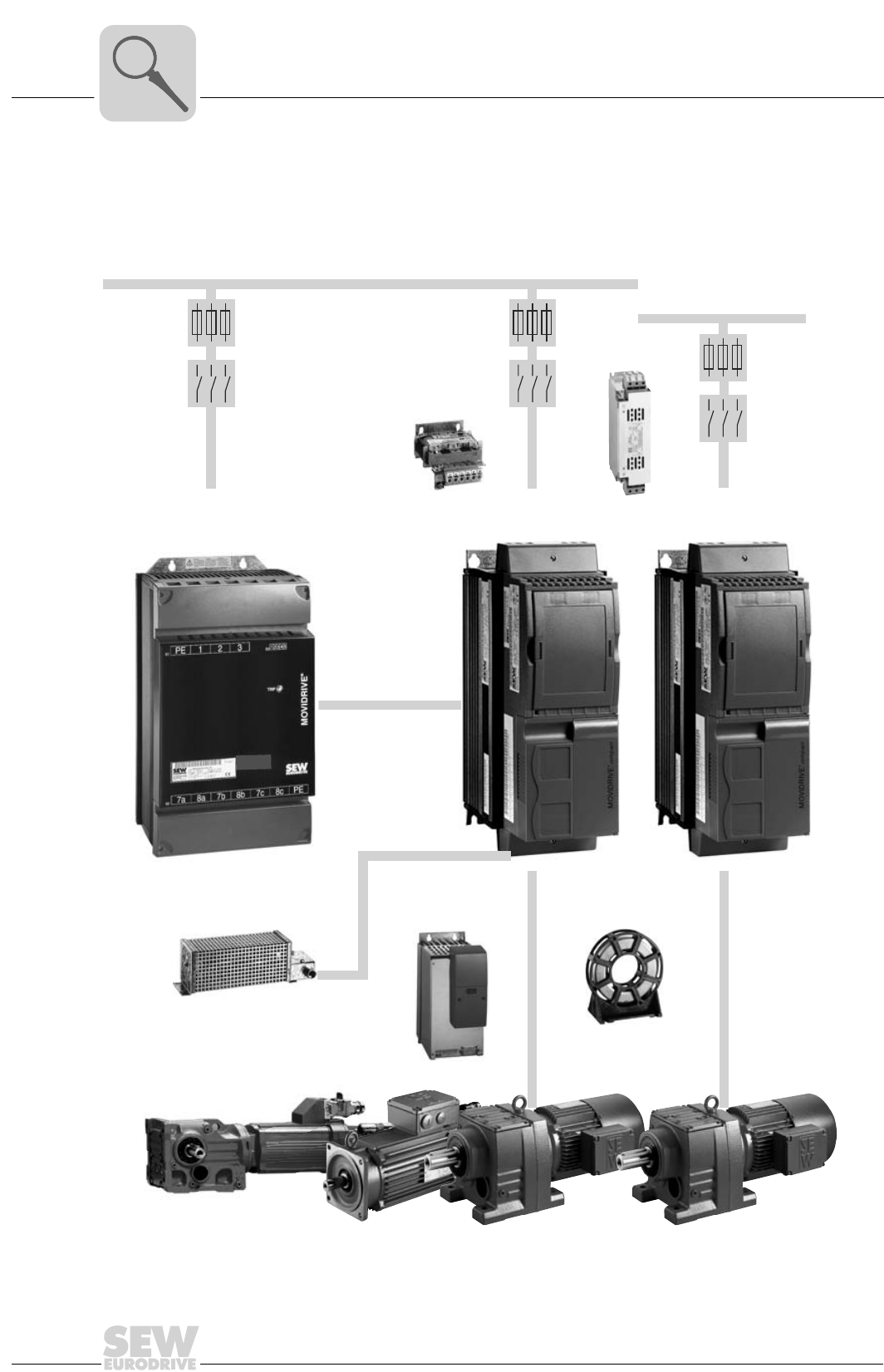
1.1 Overview of the system
Power components
02603BEN
Figure 1: Overview of the system, MOVIDRIVE® compact MC_4_A power components
3 x 380...500 V
AC
3 x 200...240 V
AC
MOVIDRIVE
MC_40/41/42A...-5_3
®
compact
MOVIDRIVE
MC_40/41/42A...-2_3
®
compact
Output filter
option Output choke
option
Braking resistor
option
Input filter
option
Line choke
option
DC link
MOVIDRIVE MDR60A
Regen. power supply unit option
®
MOVIDRIVE® compact Catalog
5
1
Overview of the system
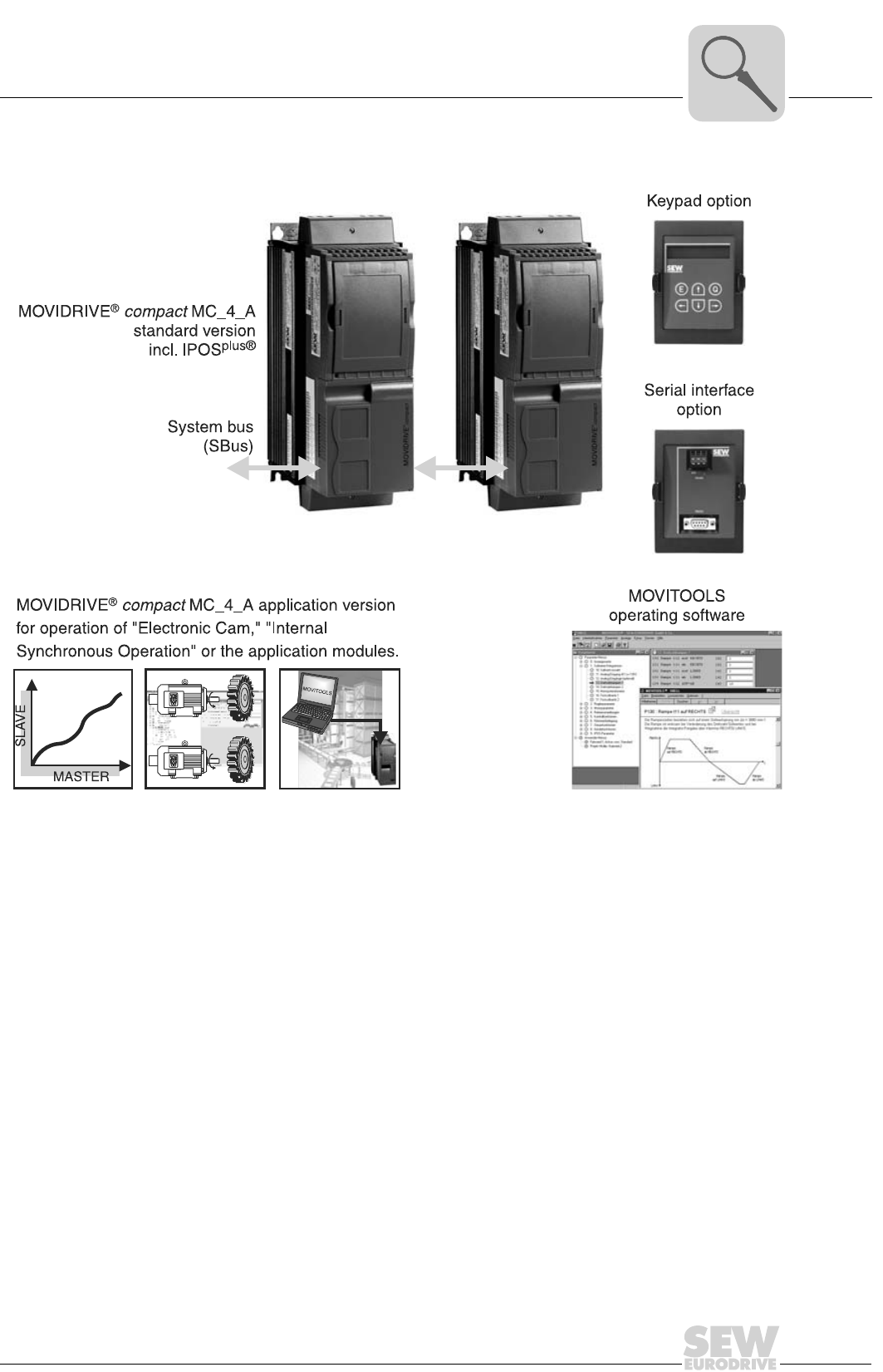
Communications components
02604AEN
Figure 2: Overview of the system, MOVIDRIVE® compact MC_4_A communications components

1
6
MOVIDRIVE® compact Catalog
Overview of the system
General descrip-
tion
MOVIDRIVE® compact is the term for compact and high-performance drive inverters
from SEW. MOVIDRIVE® compact units are precisely tailored to your requirements. You
can use them for AC drives in the power range from 1.5 to 90 kW (2.0 to 120 HP). They
satisfy the most exacting requirements for dynamic properties and control quality thanks
to the most modern inverter technology combined with tried-and-tested SEW control
processes.
Range of units The MOVIDRIVE® compact range of units includes four series:
Unit variants The MCF, MCV and MCS series are available in two variants:
•MCF/MCV/MCS40A: Control via binary inputs and setpoint selection via analog set-
point input.
•MCF/MCV/MCS41A: Control either via PROFIBUS interface or binary inputs. Set-
point selection via PROFIBUS-DP interface.
The MCH series is available in three variants:
•MCH40A: Control via binary inputs and setpoint selection via analog setpoint input.
•MCH41A: Control either via PROFIBUS interface or binary inputs. Setpoint selection
via PROFIBUS-DP interface.
•MCH42A: Control either via INTERBUS FO interface or binary inputs. Setpoint se-
lection via INTERBUS FO interface.
Unit versions MOVIDRIVE® compact drive inverters are each available in two versions, namely the
standard version and the technology version.
Standard version As standard, the units are equipped with the IPOSplus® integrated positioning and se-
quence control system. They can also be expanded with the available options.
The standard version is indicated by the '00' digits at the end of the unit designation.
Technology
version
In addition to the features of the standard version, these units include the technology
functions of 'electronic cam' and 'internal synchronous operation'. Furthermore, you can
use all the application modules available in the MOVITOOLS software package with the
units in technology version.
The technology version is indicated by the '0T' characters at the end of the unit desig-
nation.
• MOVIDRIVE® compact MCF: Drive inverter for asynchronous AC motors without
encoder feedback, VFC control mode
• MOVIDRIVE® compact MCV: Drive inverter for asynchronous AC motors with encoder
feedback, either VFC or CFC control mode.
• MOVIDRIVE® compact MCS: Drive inverter for synchronous servo motors with resolver,
CFC control mode.
• MOVIDRIVE® compact MCH: Drive inverter for asynchronous AC motors, asynchronous
servo motors or synchronous servo motors. Encoder feed-
back with Hiperface encoder, sin/cos encoder or TTL sen-
sor.

MOVIDRIVE® compact Catalog
7
1
Overview of the system
Overview of the
series and ver-
sions
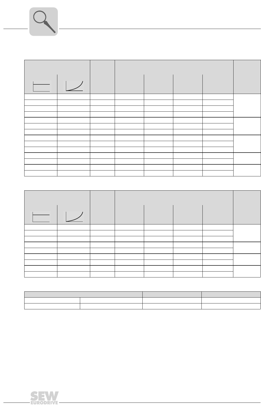
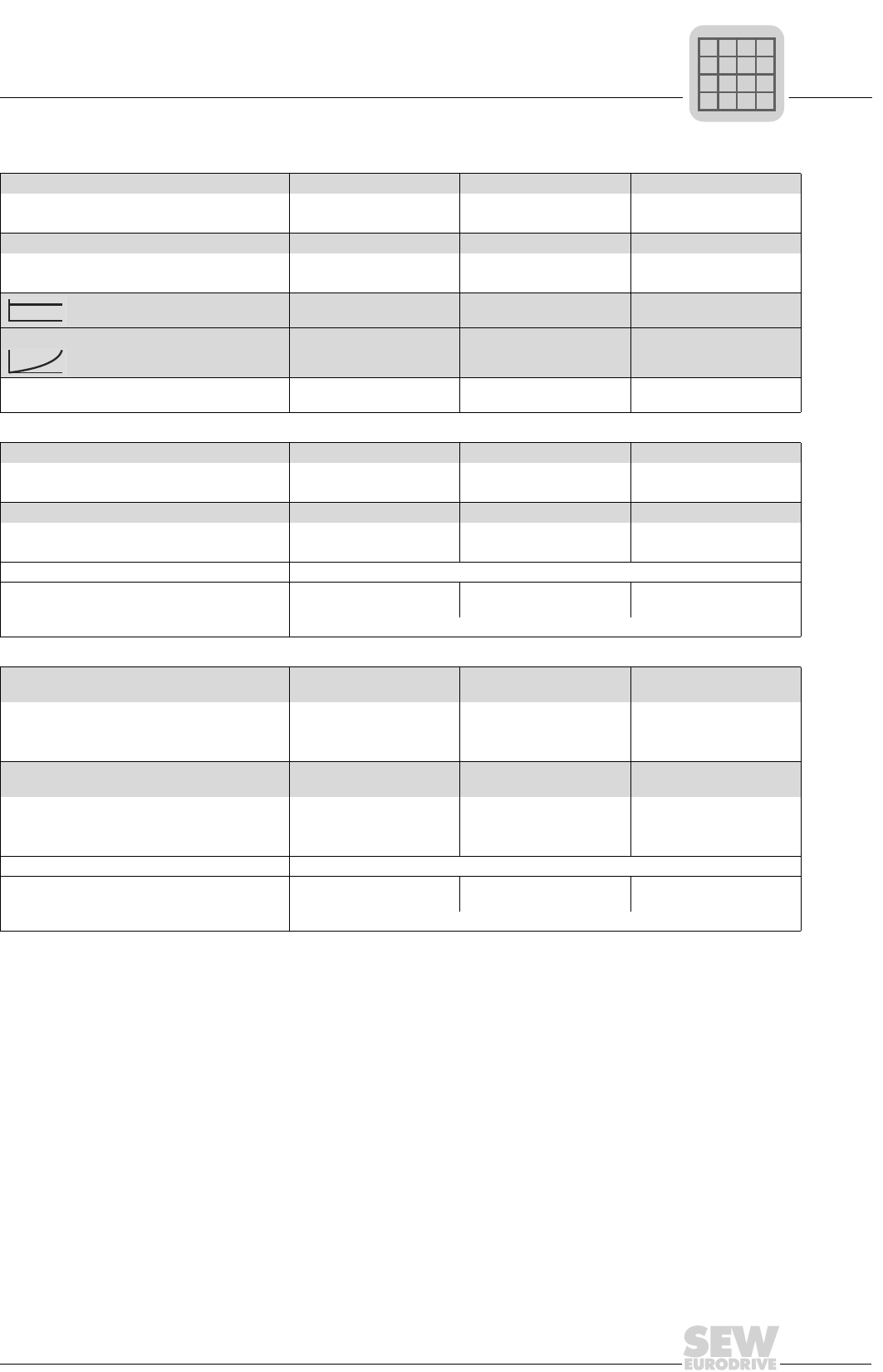
The following table presents an overview of the series and versions:
Control mode VFC (Voltage Flux Control) and CFC (Current Flux Control) control modes are features
of MOVIDRIVE® compact drive inverters. Continuous calculation of the complete motor
model forms the basis for both control modes.
System bus
(SBus)
The system bus (SBus) is available as standard. It permits several MOVIDRIVE® drive
inverters to be networked together. As a result, data can be exchanged rapidly between
the units. MOVILINK® is the uniform SEW unit profile used for communication via the
SBus.
MOVILINK®MOVILINK® means the same message structure is always used, regardless of the in-
terface selected (SBus, RS-232, RS-485, fieldbus interfaces). As a result, the control
software is independent of the selected interface.
IPOSplus® A significant feature of MOVIDRIVE® drive inverters is that the IPOSplus® positioning
and sequence control system is integrated as standard. IPOSplus® enables you to con-
trol sequences of motion directly in the inverter, right on the plant floor. This concept
takes the load off the master controller and allows modular concepts to be implemented
more easily.
Without
encoder input
With encoder input
for sin/cos and incre-
mental encoders
With resolver
input
With encoder input for
Hiperface, sin/cos and
incremental encoders
Without field-
bus MCF40A MCV40A MCS40A MCH40A
With PROFI-
BUS-DP MCF41A MCV41A MCS41A MCH41A
With INTER-
BUS FO ---MCH42A
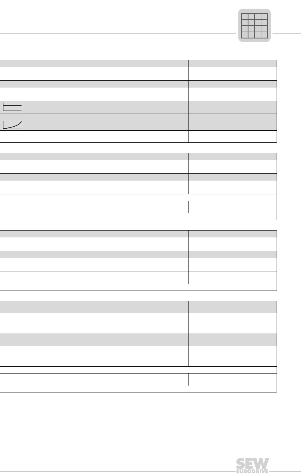
VFC (Voltage Flux Control) control mode CFC (Current Flux Control) control mode
Voltage-controlled control mode for AC asynchro-
nous motors with and without encoder feedback.
• With encoder feedback
– At least 150% torque, even with the motor
stopped
– Servo-like characteristics
• Without encoder feedback
– At least 150 % torque up to 0.5 Hz
Current-controlled control mode for AC asynchro-
nous motors and permanent-field AC servomotors.
Encoder feedback is always required.
• At least 160 % torque, even with the motor
stopped
• Maximum precision and concentric running
characteristics right down to standstill
• Servo characteristics and torque control even
for asynchronous AC motors
• Reacts to load changes within a few millisec-
onds
1
8
MOVIDRIVE® compact Catalog
Overview of the system
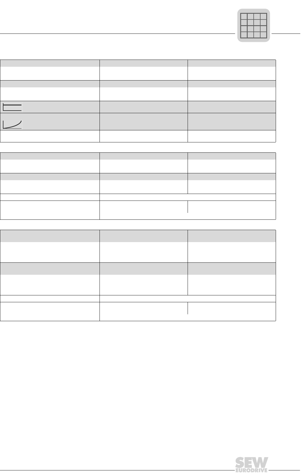
The units at a glance
MOVIDRIVE® compact for 3 × 380 500 VAC supply voltage (400/500 V units):
MOVIDRIVE® compact for 3 × 200 240 VAC supply voltage (230 V units):
MOVIDRIVE® MDR60A regenerative power supply units for 400/500 V units:
Recommended motor power (VFC)
(at Vin = 3 × 400 VAC)
Continuous
output cur-
rent
MOVIDRIVE® compact type Size
(CFC)
MCF4_A
Asynchronous
without
encoder
MCV4_A
Asynchronous
with encoder
MCS4_A
Synchronous
with resolver
MCH42A
Asynchronous/
synchronous
with encoder
(Techn.
data)
1.5 kW (2.0 HP) 2.2 kW (3.0 HP) 4.0 AAC 0015-5A3-4-.. 0015-5A3-4-.. 0015-5A3-4-.. 0015-5A3-4-..
1
(→ page 22)
2.2 kW (3.0 HP) 3.0 kW (4.0 HP) 5.5 AAC 0022-5A3-4-.. 0022-5A3-4-.. 0022-5A3-4-.. 0022-5A3-4-..
3.0 kW (4.0 HP) 4.0 kW (5.0 HP) 7.0 AAC 0030-5A3-4-.. 0030-5A3-4-.. 0030-5A3-4-.. 0030-5A3-4-..
4.0 kW (5.0 HP) 5.5 kW (7.5 HP) 9.5 AAC 0040-5A3-4-.. 0040-5A3-4-.. 0040-5A3-4-.. 0040-5A3-4-..
5.5 kW (7.5 HP) 7.5 kW (10 HP) 12.5 AAC 0055-5A3-4-.. 0055-5A3-4-.. 0055-5A3-4-.. 0055-5A3-4-.. 2
(→ page 24)
7.5 kW (10 HP) 11 kW (15 HP) 16 AAC 0075-5A3-4-.. 0075-5A3-4-.. 0075-5A3-4-.. 0075-5A3-4-..
11 kW (15 HP) 15 kW (20 HP) 24 AAC 0110-5A3-4-.. 0110-5A3-4-.. 0110-5A3-4-.. 0110-5A3-4-..
15 kW (20 HP) 22 kW (30 HP) 32 AAC 0150-503-4-.. 0150-503-4-.. 0150-503-4-.. 0150-503-4-.. 3
(→ page 26)
22 kW (30 HP) 30 kW (40 HP) 46 AAC 0220-503-4-.. 0220-503-4-.. 0220-503-4-.. 0220-503-4-..
30 kW (40 HP) 37 kW (50 HP) 60 AAC 0300-503-4-.. 0300-503-4-.. 0300-503-4-.. 0300-503-4-..
37 kW (50 HP) 45 kW (60 HP) 73 AAC 0370-503-4-.. 0370-503-4-.. 0370-503-4-.. 0370-503-4-.. 4
(→ page 28)
45 kW (60 HP) 55 kW (75 HP) 89 AAC 0450-503-4-.. 0450-503-4-.. 0450-503-4-.. 0450-503-4-..
55 kW (75 HP) 75 kW (100 HP) 105 AAC 0550-503-4-.. 0550-503-4-.. 0550-503-4-.. 0550-503-4-.. 5
(→ page 30)
75 kW (100 HP) 90 kW (120 HP) 130 AAC 0750-503-4-.. 0750-503-4-.. 0750-503-4-.. 0750-503-4-..
Recommended motor power (VFC)
(at Vin = 3 × 230 VAC)
Continuous
output cur-
rent
MOVIDRIVE® compact type Size
(CFC)
MCF4_A
Asynchronous
without
encoder
MCV4_A
Asynchronous
with encoder
MCS4_A
Synchronous
with resolver
MCH42A
Asynchronous/
synchronous
with encoder
(Technical
data)
1.5 kW (2.0 HP) 2.2 kW (3.0 HP) 7.3 AAC 0015-2A3-4-.. 0015-2A3-4-.. 0015-2A3-4-.. 0015-2A3-4-.. 1
(→ page 32)
2.2 kW (3.0 HP) 3.7 kW (5.0 HP) 8.6 AAC 0022-2A3-4-.. 0022-2A3-4-.. 0022-2A3-4-.. 0022-2A3-4-..
3.7 kW (5.0 HP) 5.0 kW (6.8 HP) 14.5 AAC 0037-2A3-4-.. 0037-2A3-4-.. 0037-2A3-4-.. 0037-2A3-4-..
5.5 kW (7.5 HP) 7.5 kW (10 HP) 22 AAC 0055-2A3-4-.. 0055-2A3-4-.. 0055-2A3-4-.. 0055-2A3-4-.. 2
(→ page 34)
7.5 kW (10 HP) 11 kW (15 HP) 29 AAC 0075-2A3-4-.. 0075-2A3-4-.. 0075-2A3-4-.. 0075-2A3-4-..
11 kW (15 HP) 15 kW (20 HP) 42 AAC 0110-203-4-.. 0110-203-4-.. 0110-203-4-.. 0110-203-4-.. 3
(→ page 36)
15 kW (20 HP) 22 kW (30 HP) 54 AAC 0150-203-4-.. 0150-203-4-.. 0150-203-4-.. 0150-203-4-..
22 kW (30 HP) 30 kW (40 HP) 80 AAC 0220-203-4-.. 0220-203-4-.. 0220-203-4-.. 0220-203-4-.. 4
(→ page 38)
30 kW (40 HP) 37 kW (50 HP) 95 AAC 0300-203-4-.. 0300-203-4-.. 0300-203-4-.. 0300-203-4-..
Regenerative power supply units1)
1) Technical data → 'MDR60A Regenerative Power Supply Unit' manual
MOVIDRIVE® MDR60A Size
1.5 ... 37 kW (20 ... 50 HP) Iin = 66 AAC, IDCL = 70 ADC 0370-503-00 3
15 ... 75 kW (20 ... 100 HP) Iin = 117 AAC, IDCL = 141 ADC 0750-503-00 4
MOVIDRIVE® compact Catalog
9
1
Overview of the system
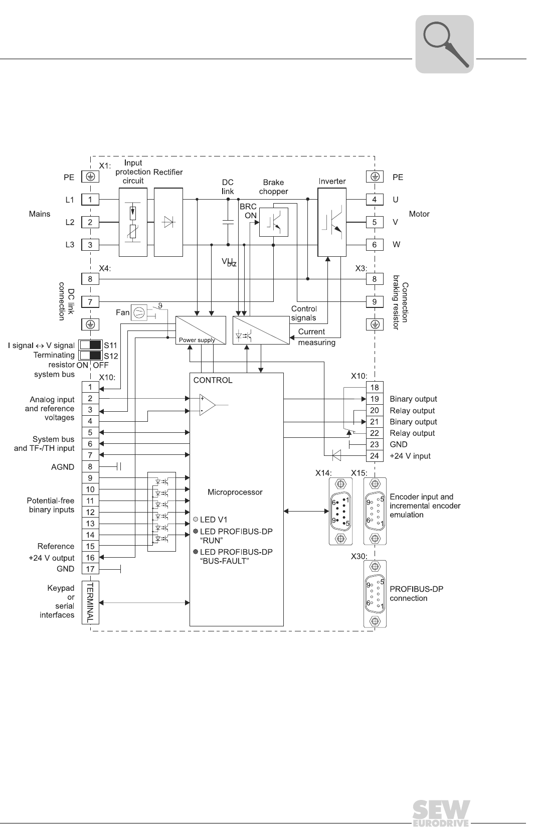
Block wiring dia-
gram
The following block wiring diagram shows the configuration principles and theory of
operation of MOVIDRIVE® compact drive inverters taking the example of the MOVI-
DRIVE® compact MCV41A.
05291AEN
Figure 3: MOVIDRIVE® compact MCV41A block circuit diagram

1
10
MOVIDRIVE® compact Catalog
Functions / features
1.2 Functions / features
Unit properties • Wide voltage range
– 400/500 V units for the voltage range 3 × 380 ... 500 VAC
– 230 V units for the voltage range 3 × 200 ... 240 VAC
• High overload capacity
– 150 % IN short-term operation
– 125 % IN sustained for operation without overload (pumps, fans)
• In VFC mode and at IN = 100 % permitted ambient temperature up to ϑ = 50° C
• 4Q capability thanks to integrated brake chopper fitted as standard
• Compact unit mounting position for minimum switch cabinet space requirement and
optimum utilization of switch cabinet volume
• Integrated input filter fitted as standard in sizes 1 and 2, adherence to class A limit
on the input side without any additional measures
• Six isolated binary inputs and three binary outputs, one of which is a relay output,
programmable inputs/outputs
• One TF/TH input for the motor protection involving a PTC thermistor or thermocon-
tact
• 3-color LED to display operating and fault states.
• Separate 24 VDC voltage input for powering the inverter electronics (parameter set-
ting, diagnostics and data storage even with the supply system switched off)
• Removable connection unit and, in addition with MOVIDRIVE® compact MCH4_A,
separable electronics terminals
• Power terminals of size 1 units can be disconnected
Control functions • VFC or CFC control processes for field-oriented operation (asynchronous servo)
• With MCH4_A: Either asynchronous or synchronous AC motors can be operated.
•IPOS
plus® positioning and sequence control system integrated as standard
• Two complete parameter sets
• Automatic motor calibration
• Automatic brake control by the inverter
• DC braking to decelerate the motor even in 1Q mode
• Slip compensation for high static accuracy of speed, even without encoder feedback
• Flying restart circuit for flying restart of the inverter
• Hoist capability with all motor systems which can be connected
• Motor pull-out protection by sliding current limitation in the field weakening range
• Speed window masking to avoid mechanical resonance ranges
• Heating current to prevent condensation forming in the motor
• Factory settings can be reactivated
• Parameter lock to protect against parameter changes
• Speed controller and encoder input in types MCV (optionally sin/cos encoder, TTL
sensor or HTL sensor), MCS (resolver) and MCH (optionally Hiperface encoder, sin/
cos encoder or TTL sensor), user-friendly controller setting tool in the user interface

MOVIDRIVE® compact Catalog
11
1
Functions / features
• Protective feature for complete protection of the inverter and motor (short-circuit,
overload, overvoltage/undervoltage, ground fault, excess temperature in the inverter,
motor pull-out protection, excess temperature in the motor)
• Temperature-controlled power unit fan, i.e. no disruptive fan noise in most cases.
• Speed monitoring and monitoring of the motor and regenerative limit power
• Programmable signal range monitoring (speed, current, maximum current)
• Memory for storing x/t diagrams which can be displayed using the SCOPE process
data visualization software (four channels, real-time capable)
• Fault memory (five memory locations) with all relevant operating data at the moment
of the fault
• Elapsed-hour counter for ON-hours (unit connected to supply system or 24 VDC) and
enable hours (output stage energized)
• Uniform operation, identical parameter setting and the same unit connection technol-
ogy for the entire MOVIDRIVE® unit series
Setpoint technol-
ogy
• Ramp switch mode (total of four ramps)
• Motor potentiometer, can be combined with analog setpoint and internal fixed set-
points
• External setpoint selections: 0 ... +10 V, ±10 V, 0 ... 20 mA, 4 ... 20 mA or fieldbus
• S-pattern for jerk-free speed changes
• Programmable input characteristics for flexible setpoint processing
• Six bipolar fixed setpoints which can be mixed with external setpoints and motor po-
tentiometer function
Communication /
operation
• System bus for networking up to 64 MOVIDRIVE® units to one another
• PROFIBUS-DP interface (max. 12 Mbaud) in MC_41A and INTERBUS FO interface
in MCH42A
• Straightforward startup and parameter setting using keypad or PC
System expan-
sion
• Extensive range of expansion options, for example:
– Removable plain text keypad with parameter memory
– RS-232 and RS-485 serial interfaces
– Braking resistors, input filters, line chokes, output chokes, output filters
• MOVITOOLS software package with SCOPE process data visualization
• Technology version with access to technology functions and application modules for
user-friendly application solutions
• MOVIDRIVE® MDR60A regenerative power supply unit
– Regenerative energy is fed back into the supply system
– This reduces the thermal load in the switch cabinet and helps to cut costs
Standards / certif-
icates
• UL, cUL and C-Tick approved
• Safe separation of power and electronic connections according to EN 50178
• Compliance with all the requirements for CE certification of machines and plant
equipped with MOVIDRIVE® on the basis of the EC Low-voltage Directive 73/23/
EEC and the EMC Directive 89/336/EEC. Compliance with EMC product standard
EN 61800-3
1
12
MOVIDRIVE® compact Catalog
Additional functions of the application version
1.3 Additional functions of the application version
SEW offers additional functions for special applications. You can use these additional
functions with MOVIDRIVE® units in technology version (...-0T).
The following additional functions are available:
• Electronic cam
• Internal synchronous operation
Please refer to the 'Electronic Cam' and 'Internal Synchronous Operation' manuals for
detailed information about the additional functions. These manuals form part of the
'Technology Version' documentation package available from SEW.
Electronic cam You can use the MOVIDRIVE® range of units with the 'electronic cam' whenever you
need to harmonize complex sequences of motion in cyclical machines. This solution
gives you much greater flexibility in comparison to the mechanical cam. As a result, it
meets the needs of modern production and processing lines.
A user-friendly cam editor helps you during startup. You can also import existing cam
data. You can also set application-specific parameters for the engagement and disen-
gagement phases using the cam editor.
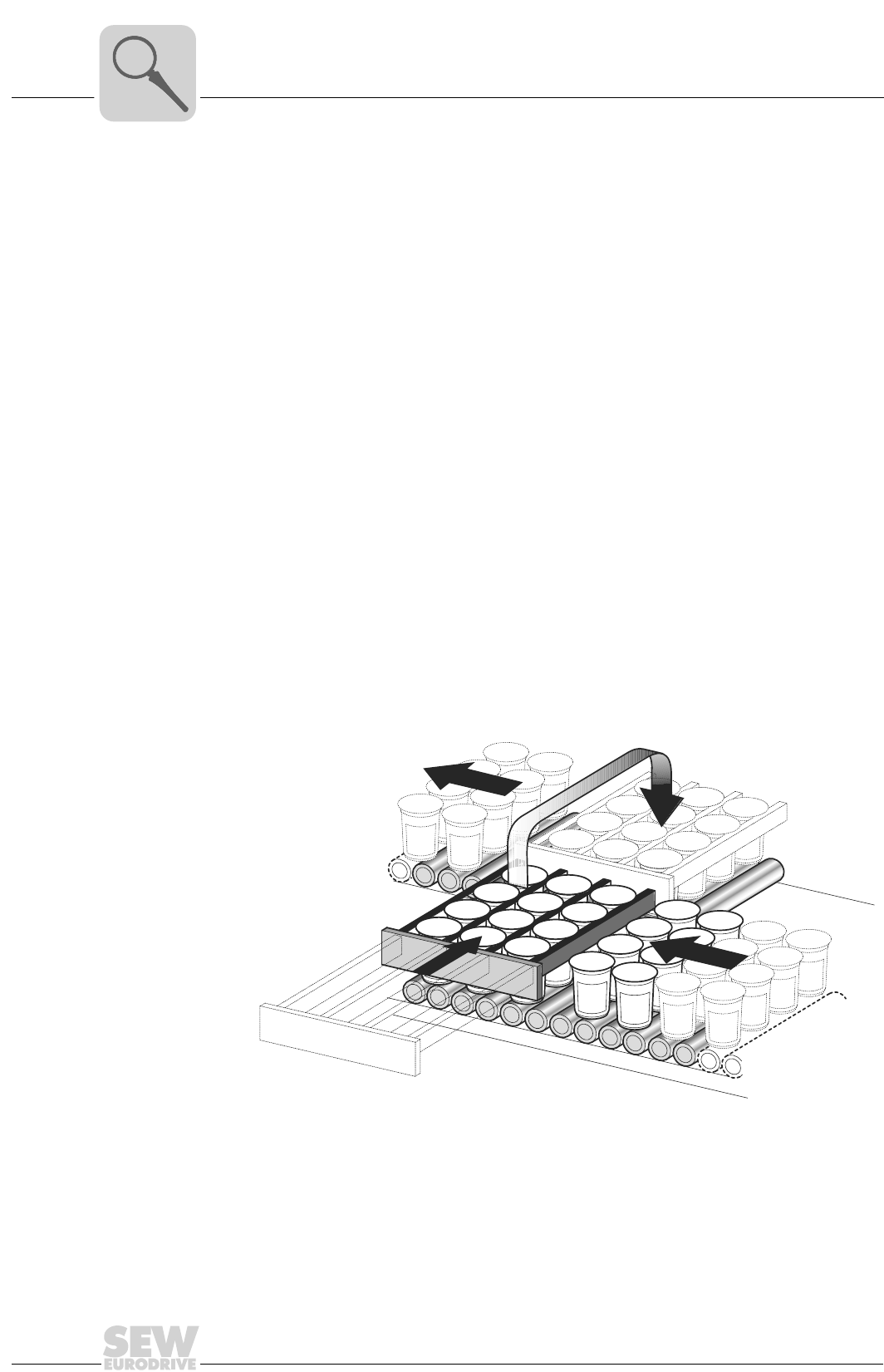
Example The figure below displays a typical application for the 'electronic cam'. Freshly filled yo-
gurt jars are transported for further processing. The 'electronic cam' makes it possible
for movement to take place smoothly, which is an important requirement for this appli-
cation.
03672AXX
Figure 4: Typical application for the 'electronic cam'
MOVIDRIVE® compact Catalog
13
1
Additional functions of the application version
Internal synchro-
nous operation
You can always use the MOVIDRIVE® range of units with 'internal synchronous opera-
tion' whenever a group of motors have to be operated at a synchronous angle in relation
to one another or with an adjustable proportional ratio (electronic gear). A user-friendly
monitor helps you during startup.
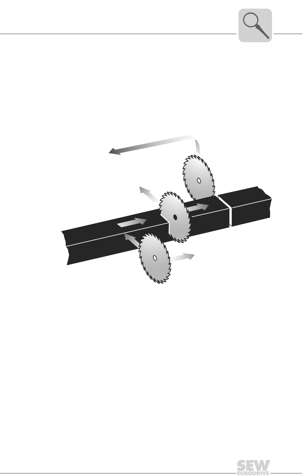
Example The figure below displays a typical application for the 'internal synchronous operation'.
Extruded material has to be cut to length. The saw receives a start signal and synchro-
nizes itself with the extruded material. The saw moves synchronously to the extruded
material as it cuts. The saw returns to its starting position at the end of the sawing oper-
ation.
03866AXX
Figure 5: Typical application for the 'internal synchronous operation'

1
14
MOVIDRIVE® compact Catalog
Application modules
1.4 Application modules
The application Usually, the application involves more than adjusting the speed of a motor. Often, the
inverter is also required to control sequences of motion and undertake typical PLC tasks.
More and more complex drive applications have to be carried out without this resulting
in lengthy project planning and startup routines.
The solution with
MOVIDRIVE®
SEW offers various standardized control programs specifically for 'positioning', 'winding'
and 'controlling' applications. These programs are called application modules. The ap-
plication modules form part of the MOVITOOLS software package and can be used with
units in technology version.
A user-friendly user interface leads you through the process of setting the parameters.
All you have to do is enter the parameters you need for your application. The application
modules turns this information into the control program and loads it into the inverter.
MOVIDRIVE® then undertakes all the movement control functions. This takes the load
off the master controller and allows decentralized concepts to be implemented more
easily.
The benefits at a
glance
• Wide range of functions
• User-friendly user interface
• You only have to enter the parameters needed for the application
• User-friendly application programs guide you through the process of setting param-
eters, so there is no need for complicated programming
• No programming experience necessary
• No lengthy learning curve, therefore quick project planning and startup
• Control of all movement functions is performed directly in MOVIDRIVE®
• Decentralized concepts can be implemented more easily
Available applica-
tion modules
The application modules currently available for MOVIDRIVE® compact are listed below.
These application modules are explained in the 'Technical Data and Dimensions' chap-
ter.
Positioning Linear movement, the movement records are administered in the inverter:
• Table positioning with bus control
Linear movement, the movement records are administered in the PLC:
• Positioning via bus
• Extended positioning via bus
Rotational movement:
• Rotary axis
Winding • Constant tension center winder
• Winder with jockey roll control
Controlling • Flying saw
MOVIDRIVE® compact Catalog
15
1
Application modules
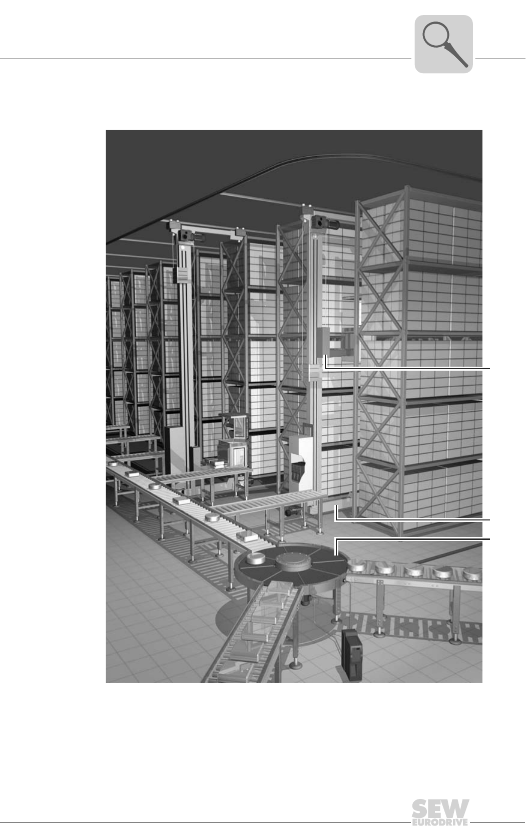
Application The following figure shows an example for how the various SEW applications modules
are used in a block warehouse.
1. Hoist: Table positioning
2. Travel axis: Absolute value or bus positioning
3. Rotary distributor: Rotary axis
04008AXX
Figure 6: Application in a block warehouse
1.
2.
3.
2
16
MOVIDRIVE® compact Catalog
CE-marking, UL approval and unit designation
2 Technical Data and Dimensions
2.1 CE-marking, UL approval and unit designation
CE-marking • Low Voltage Directive
MOVIDRIVE® compact drive inverters comply with the regulations of the Low Volt-
age Directive 73/23/EEC.
• Electromagnetic compatibility (EMC)
MOVIDRIVE® compact drive inverters are designed as components for installation
in machinery and plant. They comply with the EMC product standard EN 61800-3
'Variable-speed electrical drives'. Provided the installation instructions are complied
with, they satisfy the appropriate requirements for CE-marking of the entire machine/
system in which they are fitted, on the basis of the EMC Directive 89/336/EEC.
MOVIDRIVE® compact drive inverters of size 1 and 2 are fitted with an input filter as
standard. These units comply with limit value class A to EN 55011 and EN 55014 on
the line side without further measures.
The CE-mark on the nameplate indicates conformity with the Low-voltage Directive 73/
23/EEC and the EMC Directive 89/336/EEC. We can issue a declaration of conformity
to this effect on request.
UL approval UL and cUL approval has been granted for the entire MOVIDRIVE® range of units. cUL
is equivalent to CSA approval.
C-Tick C-Tick approval has been granted for the entire MOVIDRIVE® compact range of units.
C-Tick certifies conformity with the requirements of the ACA (Australian Communica-
tions Authority).
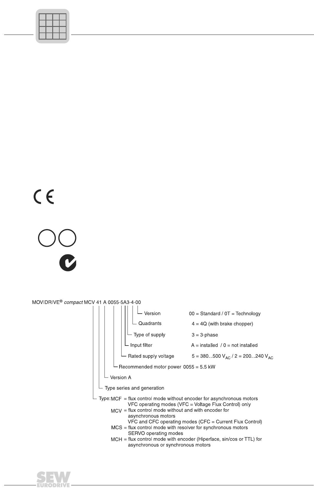
Unit designation The following example illustrates the unit designation of MOVIDRIVE® compact:
UL
®
C
UL
®
05292AEN
P
if
kVA
Hz
n
MOVIDRIVE® compact Catalog
17
2
General technical data
2.2 General technical data
The following table lists the technical data applicable to all MOVIDRIVE® compact drive
inverters, irrespective of their type, version, size and performance.
MOVIDRIVE®
compact unit
series
MOVIDRIVE® compact All sizes
Interference immunity To EN 61800-3
Interference emission with EMC-com-
pliant installation
According to class B limit to EN 55011 and EN 55014
To EN 61800-3
Sizes 1 and 2 on line side according to class A limit to EN
55011 and EN 55014 without further measures
Ambient temperature ϑamb
Derating ambient temperature
Climate class
0 °C...+50 °C at ID = 100 % IN and fPWM = 4 kHz
0 °C...+40 °C at ID = 125 % IN and fPWM = 4 kHz
0 °C...+40 °C at ID = 100 % IN and fPWM = 8 kHz
PN reduction: 3.0 % IN per K to max. 60 °C
EN 60721-3-3, class 3K3
Storage temperature1) ϑL
1) Connect to supply voltage for min. 5 minutes every 2 years if stored for long periods, otherwise the unit
service life may be reduced.
-25 °C...+70 °C (EN 60721-3-3, class 3K3)
DBG keypad: -20 °C...+60 °C
Type of cooling (DIN 51751) Forced cooling
Temperature-controlled fan, response threshold at ϑ = 45 °C
Enclosure Sizes 1 to 3
EN 60529 Size 4 and 5
(NEMA1)
IP20
IP00 (power connections); IP10 with Plexiglas cover mounted
(supplied as standard)
Operating mode DB (EN 60149-1-1 and 1-3)
Installation altitude h ≤ 1000 m (3300 ft)
IN reduction: 1 % per 100 m (330 ft)
from 1000 m (3300 ft) to max. 2000 m (6600 ft)
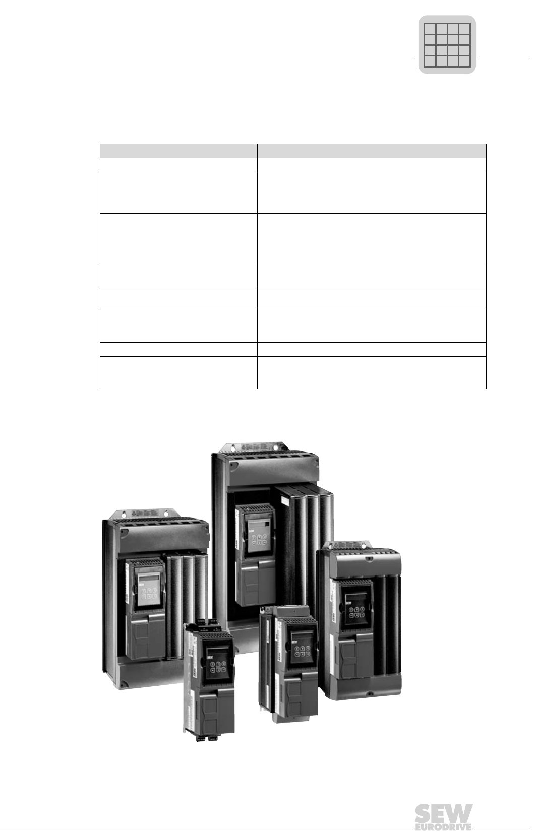
02531AXX
Figure 7: MOVIDRIVE® compact unit series
P
if
kVA
Hz
n
2
18
MOVIDRIVE® compact Catalog
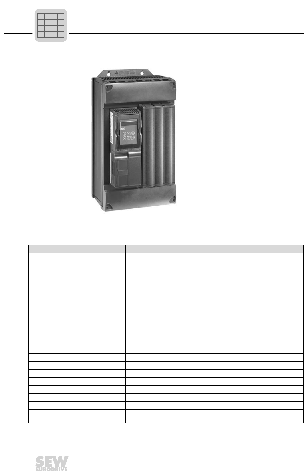
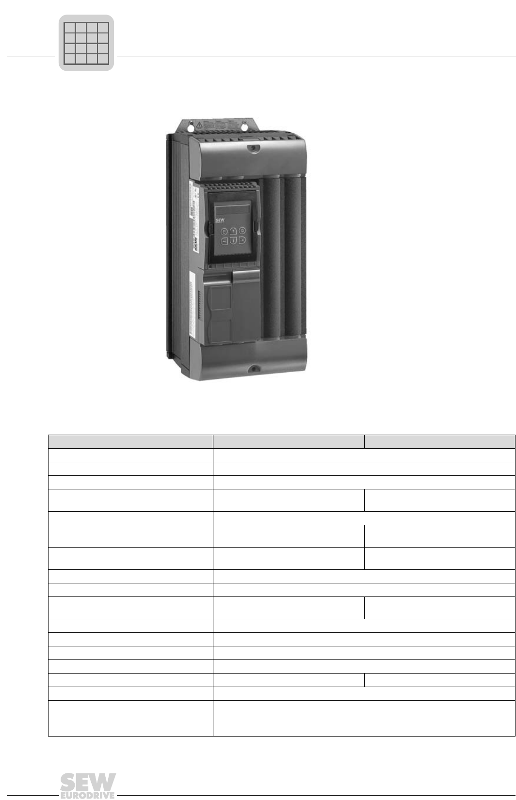
MOVIDRIVE® compact MC_4_A...-5_3 (400/500 V units)
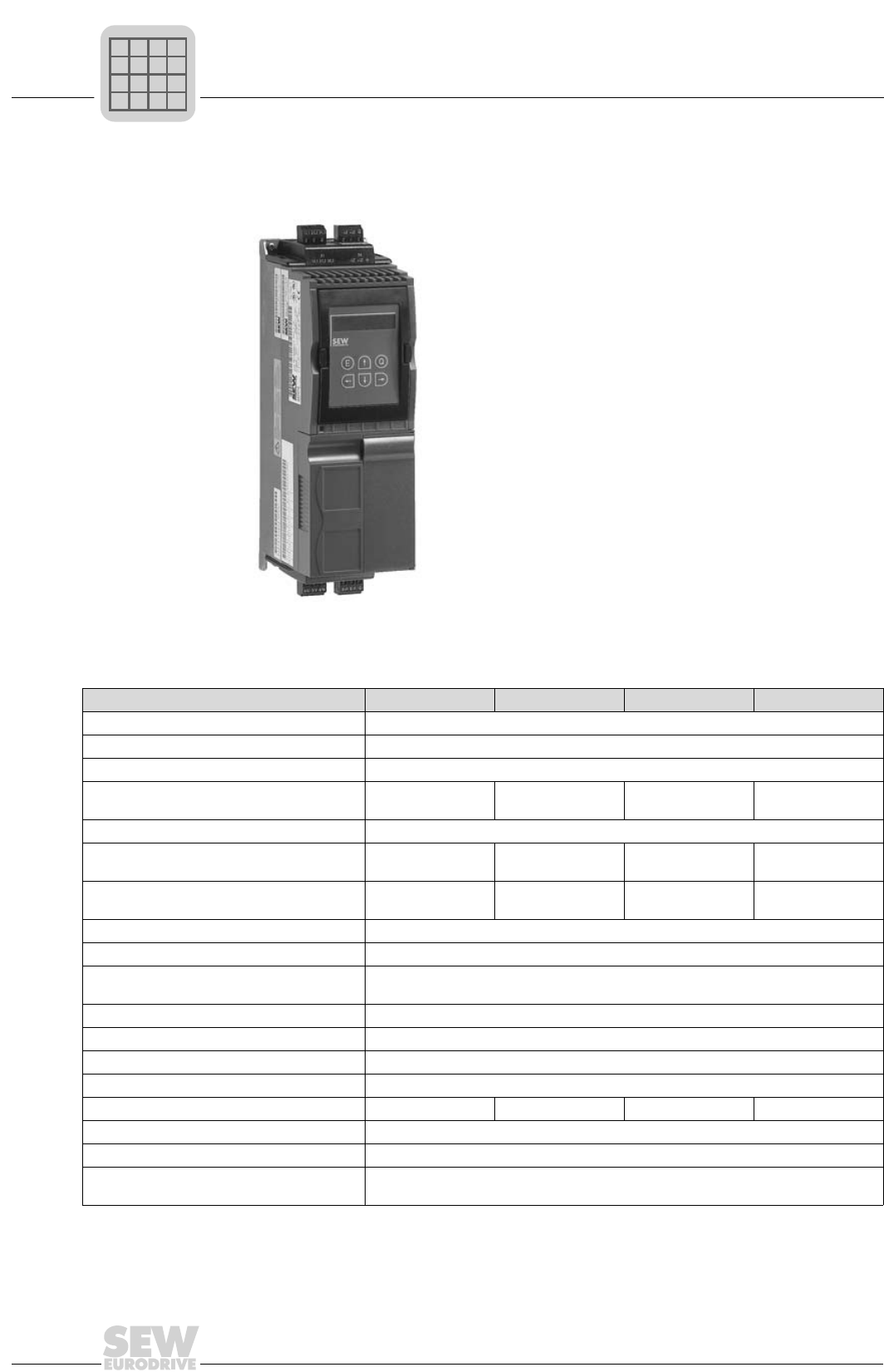
2.3 MOVIDRIVE® compact MC_4_A...-5_3 (400/500 V units)
Size 1
02570AXX
Figure 8: Size 1
MOVIDRIVE® compact 0015-5A3-4-0_ 0022-5A3-4-0_ 0030-5A3-4-0_ 0040-5A3-4-0_
INPUT
Supply voltage Vmains 3 × 380 VAC -10 %...3 × 500 VAC +10 %
Supply frequency fmains 50 Hz...60 Hz ±5 %
Rated system current1)Imains 100 %
(at Vmains = 3 × 400 VAC) 125 %
3.6 AAC
4.5 AAC
5.0 AAC
6.2 AAC
6.3 AAC
7.9 AAC
8.6 AAC
10.7 AAC
OUTPUT
Rated output power2) PN
(at Vmains = 3 × 400...500 VAC)
2.8 kVA 3.8 kVA 4.9 kVA 6.6 kVA
Rated output current1) IN
(at Vmains = 3 × 400 VAC)
4.0 AAC 5.5 AAC 7.0 AAC 9.5 AAC
Current limitation Imax Motor and regenerative 150 % IN, duration depending on the capacity utilization
Internal current limitation Imax = 0...150 % can be set in menu (P303 / P313)
Minimum permitted brake RBWmin
resistance value (4Q operation)
68 Ω
Output voltage Vout max. Vin
PWM frequency fPWM Adjustable: 4/8/16 kHz (P860 / P861)
Speed range / resolution nA / ∆nA-5000...0...+5000 rpm / 0.2 rpm across the entire range
GENERAL
Power loss at PNPVmax 85 W 105 W 130 W 180 W
Cooling air consumption 40 m3/h (24 ft3/min)
Weight 2.8 kg (6.16 lb)
Dimensions W × H × D MCF/MCV/MCS: 105 × 315 × 155 mm (4.13 × 12.40 × 6.10 in)
MCH: 105 × 315 × 161 mm (4.13 × 12.40 × 6.34 in)
1) The system and output currents must be reduced by 20 % from the nominal values for Vmains = 3 × 500 VAC.
2) The performance data apply to fPWM = 4 kHz (factory setting in VFC operating modes).
P
if
kVA
Hz
n
MOVIDRIVE® compact Catalog
19
2
MOVIDRIVE® compact MC_4_A...-5_3 (400/500 V units)
MCF4_A standard type (VFC) 0015-5A3-4-00 0022-5A3-4-00 0030-5A3-4-00 0040-5A3-4-00
MCF40A part numbers (without fieldbus) 826 738 3 826 739 1 826 740 5 826 741 3
MCF41A part numbers (with PROFIBUS-DP) 826 835 5 826 836 3 826 837 1 826 838 X
MCF4_A application type (VFC) 0015-5A3-4-0T 0022-5A3-4-0T 0030-5A3-4-0T 0040-5A3-4-0T
MCF40A part numbers (without fieldbus) 827 426 6 827 427 4 827 428 2 827 429 0
MCF41A part numbers (with PROFIBUS-DP) 827 449 5 827 450 9 827 451 7 827 452 5
Constant load
Recommended motor power Pmot 1.5 kW (2.0 HP) 2.2 kW (3.0 HP) 3.0 kW (4.0 HP) 4.0 kW (5.0 HP)
Variable torque load or constant
load without overload
Recommended motor power Pmot 2.2 kW (3.0 HP) 3.0 kW (4.0 HP) 4.0 kW (5.0 HP) 5.5 kW (7.5 HP)
Continuous output current = 125 % INID
(at Vmains = 3 × 400 VAC and fPWM = 4 kHz)
5.0 AAC 6.9 AAC 8.8 AAC 11.9 AAC
MCV4_A standard type (VFC/CFC) 0015-5A3-4-00 0022-5A3-4-00 0030-5A3-4-00 0040-5A3-4-00
MCV40A part numbers (without fieldbus) 826 908 4 826 909 2 826 910 6 826 911 4
MCV41A part numbers (with PROFIBUS-DP) 826 928 9 826 929 7 826 930 0 826 931 9
MCV4_A application type (VFC/CFC) 0015-5A3-4-0T 0022-5A3-4-0T 0030-5A3-4-0T 0040-5A3-4-0T
MCV40A part numbers (without fieldbus) 827 472 X 827 473 8 827 474 6 827 475 4
MCV41A part numbers (with PROFIBUS-DP) 827 495 9 827 496 7 827 497 5 827 498 3
VFC operating mode Recommended motor power → MCF4_A
CFC operating mode (fPWM = 8 kHz)
Continuous output current = 100 % INID4.0 AAC 5.5 AAC 7.0 AAC 9.5 AAC
Recommended motor power → Sec. Project Planning, CFC motor selection
MCS4_A standard type (SERVO) 0015-5A3-4-00 0022-5A3-4-00 0030-5A3-4-00 0040-5A3-4-00
MCS40A part numbers (without fieldbus) 827 060 0 827 061 9 827 062 7 827 063 5
MCS41A part numbers (with PROFIBUS-DP) 827 077 5 827 078 3 827 079 1 827 080 5
MCS4_A application type (SERVO) 0015-5A3-4-0T 0022-5A3-4-0T 0030-5A3-4-0T 0040-5A3-4-0T
MCS40A part numbers (without fieldbus) 827 518 1 827 519 X 827 520 3 827 521 1
MCS41A part numbers (with PROFIBUS-DP) 827 541 6 827 542 4 827 543 2 827 544 0
SERVO operating mode (fPWM = 8 kHz)
Continuous output current = 100 % INID4.0 AAC 5.5 AAC 7.0 AAC 9.5 AAC
Recommended motor power → Sec. Project Planning, SERVO motor selection
MCH4_A standard type
(VFC/CFC/SERVO) 0015-5A3-4-00 0022-5A3-4-00 0030-5A3-4-00 0040-5A3-4-00
MCH40A part numbers (without fieldbus) 827 603 X 827 604 8 827 605 6 827 606 4
MCH41A part numbers (with PROFIBUS-DP) 827 649 8 827 650 1 827 651 X 827 652 8
MCH42A part numbers (with INTERBUS FO) 827 565 3 827 566 1 827 567 X 827 568 8
MCH4_A application type
(VFC/CFC/SERVO) 0015-5A3-4-0T 0022-5A3-4-0T 0030-5A3-4-0T 0040-5A3-4-0T
MCH40A part numbers (without fieldbus) 827 626 9 827 627 7 827 628 5 827 629 3
MCH41A part numbers (with PROFIBUS-DP) 827 672 2 827 673 0 827 674 9 827 675 7
MCH42A part numbers (with INTERBUS FO) 827 158 5 827 159 3 827 160 7 827 161 5
VFC operating mode Recommended motor power → MCF4_A
CFC/SERVO operating mode (fPWM = 8 kHz)
Continuous output current = 100 % INID4.0 AAC 5.5 AAC 7.0 AAC 9.5 AAC
Recommended motor power → Sec. Project Planning, CFC/SERVO motor selection
P
if
kVA
Hz
n
2
20
MOVIDRIVE® compact Catalog
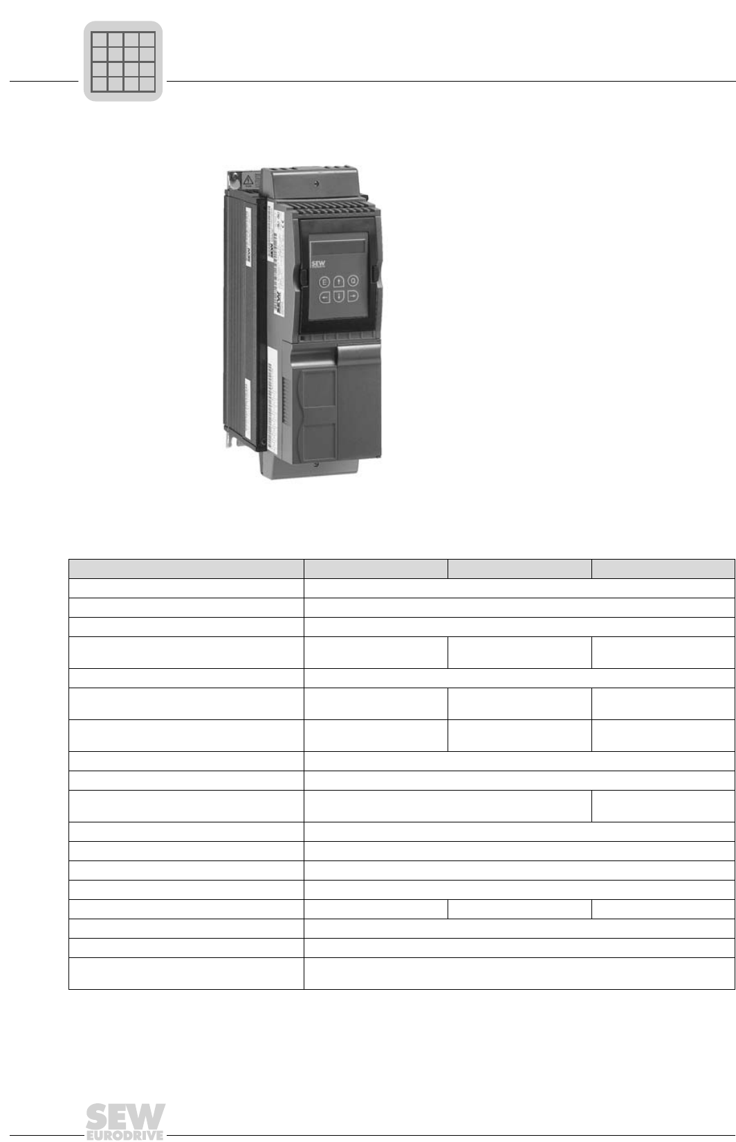
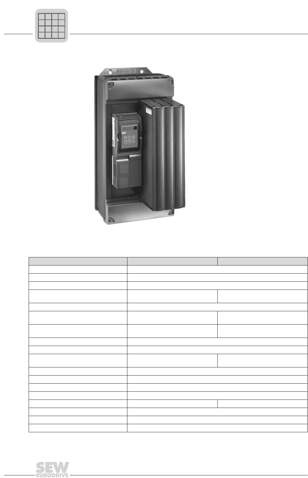
MOVIDRIVE® compact MC_4_A...-5_3 (400/500 V units)
Size 2
02571AXX
Figure 9: Size 2
MOVIDRIVE® compact 0055-5A3-4-0_ 0075-5A3-4-0_ 0110-5A3-4-0_
INPUT
Supply voltage Vmains 3 × 380 VAC -10 %...3 × 500 VAC +10 %
Supply frequency fmains 50 Hz...60 Hz ±5 %
Rated system current1)Imains 100 %
(at Vmains = 3 × 400 VAC) 125 %
11.3 AAC
14.1 AAC
14.4 AAC
18.0 AAC
21.6 AAC
27.0 AAC
OUTPUT
Rated output power2) PN
(at Vmains = 3 × 400...500 VAC)
8.7 kVA 11.2 kVA 16.8 kVA
Rated output current1) IN
(at Vmains = 3 × 400 VAC)
12.5 AAC 16 AAC 24 AAC
Current limitation Imax Motor and regenerative 150 % IN, duration depending on the capacity utilization
Internal current limitation Imax = 0...150 % can be set in menu (P303 / P313)
Minimum permitted brake RBWmin
resistance value (4Q operation)
47 Ω22 Ω
Output voltage Vout max. Vin
PWM frequency fPWM Adjustable: 4/8/16 kHz (P860 / P861)
Speed range / resolution nA / ∆nA-5000...0...+5000 rpm / 0.2 rpm across the entire range
GENERAL
Power loss at PNPVmax 220 W 290 W 400 W
Cooling air consumption 80 m3/h (48 ft3/min)
Weight 5.9 kg (12.98 lb)
Dimensions W × H × D MCF/MCV/MCS: 130 × 335 × 207 mm (5.12 × 13.19 × 8.15 in)
MCH: 130 × 335 × 213 mm (5.12 × 13.19 × 8.39 in)
1) The system and output currents must be reduced by 20 % from the nominal values for Vin = 3 × 500 VAC.
2) The performance data apply to fPWM = 4 kHz (factory setting in VFC operating modes).
P
if
kVA
Hz
n

MOVIDRIVE® compact Catalog
21
2
MOVIDRIVE® compact MC_4_A...-5_3 (400/500 V units)
MCF4_A standard type (VFC) 0055-5A3-4-00 0075-5A3-4-00 0110-5A3-4-00
MCF40A part numbers (without fieldbus) 826 742 1 826 743 X 826 744 8
MCF41A part numbers (with PROFIBUS-DP) 826 839 8 826 840 1 826 841 X
MCF4_A application type (VFC) 0055-5A3-4-0T 0075-5A3-4-0T 0110-5A3-4-0T
MCF40A part numbers (without fieldbus) 827 430 4 827 431 2 827 432 0
MCF41A part numbers (with PROFIBUS-DP) 827 453 3 827 454 1 827 455 X
Constant load
Recommended motor power Pmot 5.5 kW (7.5 HP) 7.5 kW (10 HP) 11 kW (15 HP)
Variable torque load or constant
load without overload
Recommended motor power Pmot 7.5 kW (10 HP) 11 kW (15 HP) 15 kW (20 HP)
Continuous output current = 125 % INID
(at Vmains = 3 × 400 VAC and fPWM = 4 kHz)
15.6 AAC 20.0 AAC 30.0 AAC
MCV4_A standard type (VFC/CFC) 0055-5A3-4-00 0075-5A3-4-00 0110-5A3-4-00
MCV40A part numbers (without fieldbus) 826 912 2 826 913 0 826 914 9
MCV41A part numbers (with PROFIBUS-DP) 826 932 7 826 933 5 826 934 3
MCV4_A application type (VFC/CFC) 0055-5A3-4-0T 0075-5A3-4-0T 0110-5A3-4-0T
MCV40A part numbers (without fieldbus) 827 476 2 827 477 0 827 478 9
MCV41A part numbers (with PROFIBUS-DP) 827 499 1 827 500 9 827 501 7
VFC operating mode Recommended motor power → MCF4_A
CFC operating mode (fPWM = 8 kHz)
Continuous output current = 100 % INID12.5 AAC 16 AAC 24 AAC
Recommended motor power → Sec. Project Planning, CFC motor selection
MCS4_A standard type (SERVO) 0055-5A3-4-00 0075-5A3-4-00 0110-5A3-4-00
MCS40A part numbers (without fieldbus) 827 064 3 827 065 1 827 066 X
MCS41A part numbers (with PROFIBUS-DP) 827 081 3 827 082 1 827 083 X
MCS4_A application type (SERVO) 0055-5A3-4-0T 0075-5A3-4-0T 0110-5A3-4-0T
MCS40A part numbers (without fieldbus) 827 522 X 827 523 8 827 524 6
MCS41A part numbers (with PROFIBUS-DP) 827 545 9 827 546 7 827 547 5
SERVO operating mode (fPWM = 8 kHz)
Continuous output current = 100 % INID12.5 AAC 16 AAC 24 AAC
Recommended motor power → Sec. Project Planning, SERVO motor selection
MCH4_A standard type
(VFC/CFC/SERVO) 0055-5A3-4-00 0075-5A3-4-00 0110-5A3-4-00
MCH40A part numbers (without fieldbus) 827 607 2 827 608 0 827 609 9
MCH41A part numbers (with PROFIBUS-DP) 827 653 6 827 654 4 827 655 2
MCH42A part numbers (with INTERBUS FO) 827 569 6 827 570 X 827 571 8
MCH4_A application type
(VFC/CFC/SERVO) 0055-5A3-4-0T 0075-5A3-4-0T 0110-5A3-4-0T
Part numbers (without fieldbus) 827 630 7 827 631 5 827 632 3
Part numbers (with PROFIBUS-DP) 827 676 5 827 677 3 827 678 1
Part numbers (with INTERBUS FO) 827 162 3 827 163 1 827 164 X
VFC operating mode Recommended motor power → MCF4_A
CFC/SERVO operating mode (fPWM = 8 kHz)
Continuous output current = 100 % INID12.5 AAC 16 AAC 24 AAC
Recommended motor power → Sec. Project Planning, CFC/SERVO motor selection
P
if
kVA
Hz
n
2
22
MOVIDRIVE® compact Catalog
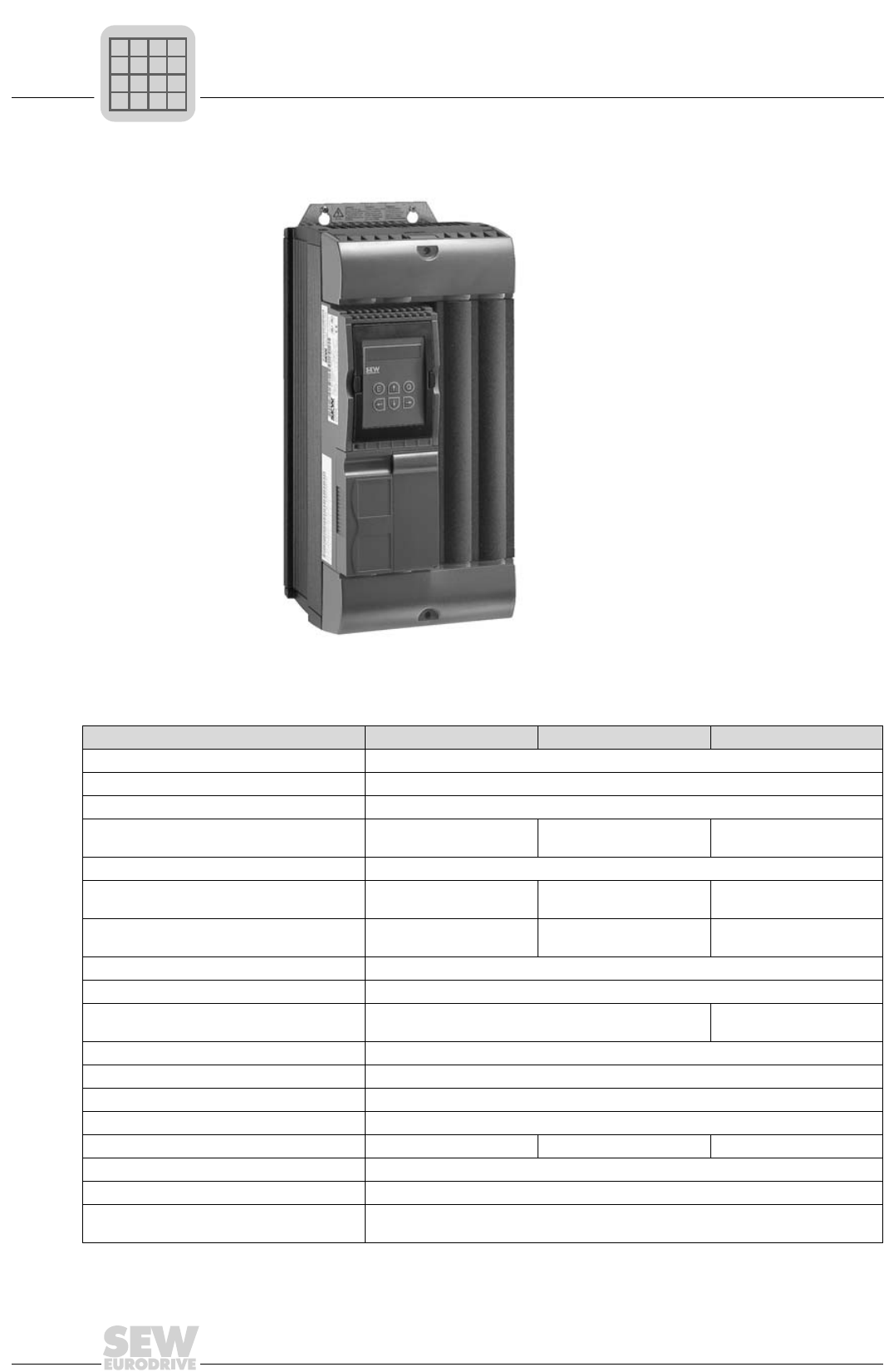
MOVIDRIVE® compact MC_4_A...-5_3 (400/500 V units)
Size 3
02572AXX
Figure 10: Size 3
MOVIDRIVE® compact 0150-503-4-0_ 0220-503-4-0_ 0300-503-4-0_
INPUT
Supply voltage Vmains 3 × 380 VAC -10 %...3 × 500 VAC +10 %
Supply frequency fmains 50 Hz...60 Hz ±5 %
Rated system current1)Imains 100 %
(at Vmains = 3 × 400 VAC) 125 %
28.8 AAC
36.0 AAC
41.4 AAC
51.7 AAC
54.0 AAC
67.5 AAC
OUTPUT
Rated output power2) PN
(at Vmains = 3 × 400...500 VAC)
22.2 kVA 31.9 kVA 41.6 kVA
Rated output current1) IN
(at Vmains = 3 × 400 VAC)
32 AAC 46 AAC 60 AAC
Current limitation Imax Motor and regenerative 150 % IN, duration depending on the capacity utilization
Internal current limitation Imax = 0...150 % can be set in menu (P303 / P313)
Minimum permitted brake RBWmin
resistance value (4Q operation)
15 Ω12 Ω
Output voltage Vout max. Vin
PWM frequency fPWM Adjustable: 4/8/16 kHz (P860 / P861)
Speed range / resolution nA / ∆nA-5000...0...+5000 rpm / 0.2 rpm across the entire range
GENERAL
Power loss at PNPVmax 550 W 750 W 950 W
Cooling air consumption 180 m3/h (108 ft3/min)
Weight 14.3 kg (31.46 lb)
Dimensions W × H × D MCF/MCV/MCS: 200 × 465 × 227 mm (7.87 × 18.31 × 8.94 in)
MCH: 200 × 465 × 233 mm (7.87 × 18.31 × 9.17 in)
1) The system and output currents must be reduced by 20 % from the nominal values for Vin = 3 × 500 VAC.
2) The performance data apply to fPWM = 4 kHz (factory setting in VFC operating modes).
P
if
kVA
Hz
n

MOVIDRIVE® compact Catalog
23
2
MOVIDRIVE® compact MC_4_A...-5_3 (400/500 V units)
MCF4_A standard type (VFC) 0150-503-4-00 0220-503-4-00 0300-503-4-00
MCF40A part numbers (without fieldbus) 826 745 6 826 746 4 826 747 2
MCF41A part numbers (with PROFIBUS-DP) 826 842 8 826 843 6 826 844 4
MCF4_A application type (VFC) 0150-503-4-0T 0220-503-4-0T 0300-503-4-0T
MCF40A part numbers (without fieldbus) 827 433 9 827 434 7 827 435 5
MCF41A part numbers (with PROFIBUS-DP) 827 456 8 827 457 6 827 458 4
Constant load
Recommended motor power Pmot 15 kW (20 HP) 22 kW (30 HP) 30 kW (40 HP)
Variable torque load or constant
load without overload
Recommended motor power Pmot 22 kW (30 HP) 30 kW (40 HP) 37 kW (50 HP)
Continuous output current = 125 % INID
(at Vmains = 3 × 400 VAC and fPWM = 4 kHz)
40.0 AAC 57.5 AAC 75.0 AAC
MCV4_A standard type (VFC/CFC) 0150-503-4-00 0220-503-4-00 0300-503-4-00
MCV40A part numbers (without fieldbus) 826 915 7 826 916 5 826 917 3
MCV41A part numbers (with PROFIBUS-DP) 826 935 1 826 936 X 826 937 8
MCV4_A application type (VFC/CFC) 0150-503-4-0T 0220-503-4-0T 0300-503-4-0T
MCV40A part numbers (without fieldbus) 827 479 7 827 480 0 827 481 9
MCV41A part numbers (with PROFIBUS-DP) 827 502 5 827 503 3 827 504 1
VFC operating mode Recommended motor power → MCF4_A
CFC operating mode (fPWM = 8 kHz)
Continuous output current = 100 % INID32 AAC 46 AAC 60 AAC
Recommended motor power → Sec. Project Planning, CFC motor selection
MCS4_A standard type (SERVO) 0150-503-4-00 0220-503-4-00 0300-503-4-00
MCS40A part numbers (without fieldbus) 827 067 8 827 068 6 827 069 4
MCS41A part numbers (with PROFIBUS-DP) 827 084 8 827 085 6 827 086 4
MCS4_A application type (SERVO) 0150-503-4-0T 0220-503-4-0T 0300-503-4-0T
MCS40A part numbers (without fieldbus) 827 525 4 827 526 2 827 527 0
MCS41A part numbers (with PROFIBUS-DP) 827 548 3 827 549 1 827 550 5
SERVO operating mode (fPWM = 8 kHz)
Continuous output current = 100 % INID32 AAC 46 AAC 60 AAC
Recommended motor power → Sec. Project Planning, SERVO motor selection
MCH4_A standard type
(VFC/CFC/SERVO) 0150-503-4-00 0220-503-4-00 0300-503-4-00
MCH40A part numbers (without fieldbus) 827 610 2 827 611 0 827 612 9
MCH41A part numbers (with PROFIBUS-DP) 827 656 0 827 657 9 827 658 7
MCH42A part numbers (with INTERBUS FO) 827 572 6 827 573 4 827 574 2
MCH4_A application type
(VFC/CFC/SERVO) 0150-503-4-0T 0220-503-4-0T 0300-503-4-0T
MCH40A part numbers (without fieldbus) 827 633 1 827 634 X 827 635 8
MCH41A part numbers (with PROFIBUS-DP) 827 679 X 827 680 3 827 681 1
MCH42A part numbers (with INTERBUS FO) 827 165 8 827 166 6 827 167 4
VFC operating mode Recommended motor power → MCF4_A
CFC/SERVO operating mode (fPWM = 8 kHz)
Continuous output current = 100 % INID32 AAC 46 AAC 60 AAC
Recommended motor power → Sec. Project Planning, CFC/SERVO motor selection
P
if
kVA
Hz
n
2
24
MOVIDRIVE® compact Catalog
MOVIDRIVE® compact MC_4_A...-5_3 (400/500 V units)
Size 4
02573AXX
Figure 11: Size 4
MOVIDRIVE® compact 0370-503-4-0_ 0450-503-4-0_
INPUT
Supply voltage Vmains 3 × 380 VAC -10 %...3 × 500 VAC +10 %
Supply frequency fmains 50 Hz...60 Hz ±5 %
Rated system current1)Imains 100 %
(at Vmains = 3 × 400 VAC) 125 %
65.7 AAC
81.9 AAC
80.1 AAC
100.1 AAC
OUTPUT
Rated output power2) PN
(at Vmains = 3 × 400...500 VAC)
51.1 kVA 62.3 kVA
Rated output current1) IN
(at Vmains = 3 × 400 VAC)
73 AAC 89 AAC
Current limitation Imax Motor and regenerative 150 % IN, duration depending on the capacity utilization
Internal current limitation Imax = 0...150 % can be set in menu (P303 / P313)
Minimum permitted brake RBWmin
resistance value (4Q operation)
6 Ω
Output voltage Vout max. Vin
PWM frequency fPWM Adjustable: 4/8/16 kHz (P860 / P861)
Speed range / resolution nA / ∆nA-5000...0...+5000 rpm / 0.2 rpm across the entire range
GENERAL
Power loss at PNPVmax 1200 W 1450 W
Cooling air consumption 180 m3/h (108 ft3/min)
Weight 26.3 kg (57.86 lb)
Dimensions W × H × D MCF/MCV/MCS: 280 × 522 × 227 mm (11.02 × 20.55 × 8.94 in)
MCH: 280 × 522 × 233 mm (11.02 × 20.55 × 9.17 in)
1) The system and output currents must be reduced by 20 % from the nominal values for Vin = 3 × 500 VAC.
2) The performance data apply to fPWM = 4 kHz (factory setting in VFC operating modes).
P
if
kVA
Hz
n

MOVIDRIVE® compact Catalog
25
2
MOVIDRIVE® compact MC_4_A...-5_3 (400/500 V units)
MCF4_A standard type (VFC) 0370-503-4-00 0450-503-4-00
MCF40A part numbers (without fieldbus) 826 748 0 826 749 9
MCF41A part numbers (with PROFIBUS-DP) 826 845 2 826 846 0
MCF4_A application type (VFC) 0370-503-4-0T 0450-503-4-0T
MCF40A part numbers (without fieldbus) 827 436 3 827 437 1
MCF41A part numbers (with PROFIBUS-DP) 827 459 2 827 460 6
Constant load
Recommended motor power Pmot 37 kW (50 HP) 45 kW (60 HP)
Variable torque load or constant
load without overload
Recommended motor power Pmot 45 kW (60 HP) 55 kW (75 HP)
Continuous output current = 125 % INID
(at Vmains = 3 × 400 VAC and fPWM = 4 kHz)
91 AAC 111 AAC
MCV4_A standard type (VFC/CFC) 0370-503-4-00 0450-503-4-00
MCV40A part numbers (without fieldbus) 826 918 1 826 919 X
MCV41A part numbers (with PROFIBUS-DP) 826 938 6 826 939 4
MCV4_A application type (VFC/CFC) 0370-503-4-0T 0450-503-4-0T
MCV40A part numbers (without fieldbus) 827 482 7 827 483 5
MCV41A part numbers (with PROFIBUS-DP) 827 505 X 827 506 8
VFC operating mode Recommended motor power → MCF4_A
CFC operating mode (fPWM = 8 kHz)
Continuous output current = 100 % INID73 AAC 89 AAC
Recommended motor power → Sec. Project Planning, CFC motor selection
MCS4_A standard type (SERVO) 0370-503-4-00 0450-503-4-00
MCS40A part numbers (without fieldbus) 827 070 8
MCS41A part numbers (with PROFIBUS-DP) 827 087 2
MCS4_A application type (SERVO) 0370-503-4-0T 0450-503-4-0T
MCS40A part numbers (without fieldbus) 827 528 9 827 529 7
MCS41A part numbers (with PROFIBUS-DP) 827 551 3 827 552 1
SERVO operating mode (fPWM = 8 kHz)
Continuous output current = 100 % INID73 AAC 89 AAC
Recommended motor power → Sec. Project Planning, SERVO motor selection
MCH4_A standard type
(VFC/CFC/SERVO) 0370-503-4-00 0450-503-4-00
MCH40A part numbers (without fieldbus) 827 613 7 827 614 5
MCH41A part numbers (with PROFIBUS-DP) 827 659 5 827 660 9
MCH42A part numbers (with INTERBUS FO) 827 575 0 827 576 9
MCH4_A application type
(VFC/CFC/SERVO) 0370-503-4-0T 0450-503-4-0T
MCH40A part numbers (without fieldbus) 827 636 6 827 637 4
MCH41A part numbers (with PROFIBUS-DP) 827 682 X 827 683 8
MCH42A part numbers (with INTERBUS FO) 827 168 2 827 169 0
VFC operating mode Recommended motor power → MCF4_A
CFC/SERVO operating mode (fPWM = 8 kHz)
Continuous output current = 100 % INID73 AAC 89 AAC
Recommended motor power → Sec. Project Planning, CFC/SERVO motor selection
P
if
kVA
Hz
n
2
26
MOVIDRIVE® compact Catalog
MOVIDRIVE® compact MC_4_A...-5_3 (400/500 V units)
Size 5
02574AXX
Figure 12: Size 5
MOVIDRIVE® compact 0550-503-4-0_ 0750-503-4-0_
INPUT
Supply voltage Vmains 3 × 380 VAC -10 %...3 × 500 VAC +10 %
Supply frequency fmains 50 Hz...60 Hz ±5 %
Rated system current1)Imains 100 %
(at Vmains = 3 × 400 VAC) 125 %
94.5 AAC
118.1 AAC
117.0 AAC
146.3 AAC
OUTPUT
Rated output power2) PN
(at Vmains = 3 × 400...500 VAC)
73.5 kVA 91.0 kVA
Rated output current1) IN
(at Vmains = 3 × 400 VAC)
105 AAC 130 AAC
Current limitation Imax Motor and regenerative 150 % IN, duration depending on the capacity utilization
Internal current limitation Imax = 0...150 % can be set in menu (P303 / P313)
Minimum permitted brake RBWmin
resistance value (4Q operation)
6 Ω4 Ω
Output voltage Vout max. Vin
PWM frequency fPWM Adjustable: 4/8/16 kHz (P860 / P861)
Speed range / resolution nA / ∆nA-5000...0...+5000 rpm / 0.2 rpm across the entire range
GENERAL
Power loss at PNPVmax 1700 W 2000 W
Cooling air consumption 360 m3/h (216 ft3/min)
Weight 34.3 kg (75.46 lb)
Dimensions W × H × D 280 × 610 × 330 mm (11.02 × 24.02 × 12.99 in)
1) The system and output currents must be reduced by 20 % from the nominal values for Vin = 3 × 500 VAC.
2) The performance data apply to fPWM = 4 kHz (factory setting in VFC operating modes).
P
if
kVA
Hz
n
MOVIDRIVE® compact Catalog
27
2
MOVIDRIVE® compact MC_4_A...-5_3 (400/500 V units)
MCF4_A standard type (VFC) 0550-503-4-00 0750-503-4-00
MCF40A part numbers (without fieldbus) 826 750 2 826 751 0
MCF41A part numbers (with PROFIBUS-DP) 826 847 9 826 848 7
MCF4_A application type (VFC) 0550-503-4-0T 0750-503-4-0T
MCF40A part numbers (without fieldbus) 827 438 X 827 439 8
MCF41A part numbers (with PROFIBUS-DP) 827 461 4 827 462 2
Constant load
Recommended motor power Pmot 55 kW (75 HP) 75 kW (100 HP)
Variable torque load or constant
load without overload
Recommended motor power Pmot 75 kW (100 HP) 90 kW (120 HP)
Continuous output current = 125 % INID
(at Vmains = 3 × 400 VAC and fPWM = 4 kHz)
131 AAC 162 AAC
MCV4_A standard type (VFC/CFC) 0550-503-4-00 0750-503-4-00
MCV40A part numbers (without fieldbus) 826 920 3 826 921 1
MCV41A part numbers (with PROFIBUS-DP) 826 940 8 826 941 6
MCV4_A application type (VFC/CFC) 0550-503-4-0T 0750-503-4-0T
MCV40A part numbers (without fieldbus) 827 484 3 827 485 1
MCV41A part numbers (with PROFIBUS-DP) 827 507 6 827 508 4
VFC operating mode Recommended motor power → MCF4_A
CFC operating mode (fPWM = 8 kHz)
Continuous output current = 100 % INID105 AAC 130 AAC
Recommended motor power → Sec. Project Planning, CFC motor selection
MCS4_A standard type (SERVO) 0550-503-4-00 0750-503-4-00
MCS40A part numbers (without fieldbus)
MCS41A part numbers (with PROFIBUS-DP)
MCS4_A application type (SERVO) 0550-503-4-0T 0750-503-4-0T
MCS40A part numbers (without fieldbus) 827 530 0 827 531 9
MCS41A part numbers (with PROFIBUS-DP) 827 553 X 827 554 8
SERVO operating mode (fPWM = 8 kHz)
Continuous output current = 100 % INID105 AAC 130 AAC
Recommended motor power → Sec. Project Planning, SERVO motor selection
MCH4_A standard type
(VFC/CFC/SERVO) 0550-503-4-00 0750-503-4-00
MCH40A part numbers (without fieldbus) 827 615 3 827 616 1
MCH41A part numbers (with PROFIBUS-DP) 827 661 7 827 662 5
MCH42A part numbers (with INTERBUS FO) 827 577 7 827 578 5
MCH4_A application type
(VFC/CFC/SERVO) 0550-503-4-0T 0750-503-4-0T
MCH40A part numbers (without fieldbus) 827 638 2 827 639 0
MCH41A part numbers (with PROFIBUS-DP) 827 684 6 827 685 4
MCH42A part numbers (with INTERBUS FO) 827 170 4 827 171 2
VFC operating mode Recommended motor power → MCF4_A
CFC/SERVO operating mode (fPWM = 8 kHz)
Continuous output current = 100 % INID105 AAC 130 AAC
Recommended motor power → Sec. Project Planning, CFC/SERVO motor selection
P
if
kVA
Hz
n
2
28
MOVIDRIVE® compact Catalog
MOVIDRIVE® compact MC_4_A...-2_3 (230 V units)
2.4 MOVIDRIVE® compact MC_4_A...-2_3 (230 V units)
Size 1
02570AXX
Figure 13: Size 1
MOVIDRIVE® compact 0015-2A3-4-0_ 0022-2A3-4-0_ 0037-2A3-4-0_
INPUT
Supply voltage Vmains 3 × 200 VAC -10 %...3 × 240 VAC +10 %
Supply frequency fmains 50 Hz...60 Hz ±5 %
Rated system current Imains 100 %
(at Vmains = 3 × 230 VAC) 125 %
6.7 AAC
8.4 AAC
7.8 AAC
9.8 AAC
12.9 AAC
16.1 AAC
OUTPUT
Rated output power1) PN
(at Vmains = 3 × 230...240 VAC)
2.7 kVA 3.4 kVA 5.8 kVA
Rated output current IN
(at Vmains = 3 × 230 VAC)
7.3 AAC 8.6 AAC 14.5 AAC
Current limitation Imax Motor and regenerative 150 % IN, duration depending on the capacity utilization
Internal current limitation Imax = 0...150 % can be set in menu (P303 / P313)
Minimum permitted brake RBWmin
resistance value (4Q operation)
27 Ω
Output voltage Vout max. Vin
PWM frequency fPWM Adjustable: 4/8/16 kHz (P860 / P861)
Speed range / resolution nA / ∆nA-5000...0...+5000 rpm / 0.2 rpm across the entire range
GENERAL
Power loss at PNPVmax 110 W 126 W 210 W
Cooling air consumption 40 m3/h (24 ft3/min)
Weight 2.8 kg (6.16 lb)
Dimensions W × H × D MCF/MCV: 105 × 315 × 155 mm (4.13 × 12.40 × 6.10 in)
MCH: 105 × 315 × 161 mm (4.13 × 12.40 × 6.34 in)
1) The performance data apply to fPWM = 4 kHz (factory setting in VFC operating modes).
P
if
kVA
Hz
n
MOVIDRIVE® compact Catalog
29
2
MOVIDRIVE® compact MC_4_A...-2_3 (230 V units)
MCF4_A standard type (VFC) 0015-2A3-4-00 0022-2A3-4-00 0037-2A3-4-00
MCF40A part numbers (without fieldbus) 826 752 9 826 753 7 826 754 5
MCF41A part numbers (with PROFIBUS-DP) 826 853 3 826 854 1 826 855 X
MCF4_A application type (VFC) 0015-2A3-4-0T 0022-2A3-4-0T 0037-2A3-4-0T
MCF40A part numbers (without fieldbus) 827 440 1 827 441 X 827 442 8
MCF41A part numbers (with PROFIBUS-DP) 827 463 0 827 464 9 827 465 7
Constant load
Recommended motor power Pmot 1.5 kW (2.0 HP) 2.2 kW (3.0 HP) 3.7 kW (5.0 HP)
Variable torque load or constant
load without overload
Recommended motor power Pmot 2.2 kW (3.0 HP) 3.7 kW (5.0 HP) 5.0 kW (6.8 HP)
Continuous output current = 125 % INID
(at Vmains = 3 × 230 VAC and fPWM = 4 kHz)
9.1 AAC 10.8 AAC 18.1 AAC
MCV4_A standard type (VFC/CFC) 0015-2A3-4-00 0022-2A3-4-00 0037-2A3-4-00
MCV40A part numbers (without fieldbus) 826 922 X 826 923 8 826 924 6
MCV41A part numbers (with PROFIBUS-DP) 826 942 4 826 943 2 826 944 0
MCV4_A application type (VFC/CFC) 0015-2A3-4-0T 0022-2A3-4-0T 0037-2A3-4-0T
MCV40A part numbers (without fieldbus) 827 486 X 827 487 8 827 488 6
MCV41A part numbers (with PROFIBUS-DP) 827 509 2 827 510 6 827 511 4
VFC operating mode Recommended motor power → MDF60A
CFC operating mode (fPWM = 8 kHz)
Continuous output current = 100 % INID7.3 AAC 8.6 AAC 14.5 AAC
Recommended motor power → Sec. Project Planning, CFC motor selection
MCH4_A standard type
(VFC/CFC) 0015-2A3-4-00 0022-2A3-4-00 0037-2A3-4-00
MCH40A part numbers (without fieldbus) 827 617 X 827 618 8 827 619 6
MCH41A part numbers (with PROFIBUS-DP) 827 663 3 827 664 1 827 665 X
MCH42A part numbers (with INTERBUS FO) 827 588 2 827 589 0 827 590 4
MCH4_A application type
(VFC/CFC) 0015-2A3-4-0T 0022-2A3-4-0T 0037-2A3-4-0T
MCH40A part numbers (without fieldbus) 827 640 4 827 641 2 827 642 0
MCH41A part numbers (with PROFIBUS-DP) 827 686 2 827 687 0 827 688 9
MCH42A part numbers (with INTERBUS FO) 827 579 3 827 580 7 827 581 5
VFC operating mode Recommended motor power → MCF4_A
CFC/SERVO operating mode (fPWM = 8 kHz)
Continuous output current = 100 % INID7.3 AAC 8.6 AAC 14.5 AAC
Recommended motor power → Sec. Project Planning, CFC/SERVO motor selection
P
if
kVA
Hz
n

2
30
MOVIDRIVE® compact Catalog
MOVIDRIVE® compact MC_4_A...-2_3 (230 V units)
Size 2
02571AXX
Figure 14: Size 2
MOVIDRIVE® compact 0055-2A3-4-0_ 0075-2A3-4-0_
INPUT
Supply voltage Vmains 3 × 200 VAC -10 %...3 × 240 VAC +10 %
Supply frequency fmains 50 Hz...60 Hz ±5 %
Rated system current Imains 100 %
(at Vmains = 3 × 230 VAC) 125 %
19.5 AAC
24.4 AAC
27.4 AAC
34.3 AAC
OUTPUT
Output rated power1) PN
(at Vmains = 3 × 230...240 VAC)
8.8 kVA 11.6 kVA
Output rated current IN
(at Vmains = 3 × 230 VAC)
22 AAC 29 AAC
Current limitation Imax Motor and regenerative 150 % IN, duration depending on the capacity utilization
Internal current limitation Imax = 0...150 % can be set in menu (P303 / P313)
Minimum permitted brake RBWmin
resistance value (4Q operation)
12 Ω
Output voltage Vout max. Vin
PWM frequency fPWM Adjustable: 4/8/16 kHz (P860 / P861)
Speed range / resolution nA / ∆nA-5000...0...+5000 rpm / 0.2 rpm across the entire range
GENERAL
Power loss at PNPVmax 300 W 380 W
Cooling air consumption 80 m3/h (48 ft3/min)
Weight 5.9 kg (12.98 lb)
Dimensions W × H × D MCF/MCV: 130 × 335 × 207 mm (5.12 × 13.19 × 8.15 in)
MCH: 130 × 335 × 213 mm (5.12 × 13.19 × 8.39 in)
1) The performance data apply to fPWM = 4 kHz (factory setting in VFC operating modes).
P
if
kVA
Hz
n
MOVIDRIVE® compact Catalog
31
2
MOVIDRIVE® compact MC_4_A...-2_3 (230 V units)
MCF4_A standard type (VFC) 0055-2A3-4-00 0075-2A3-4-00
MCF40A part numbers (without fieldbus) 826 755 3 826 756 1
MCF41A part numbers (with PROFIBUS-DP) 826 856 8 826 857 6
MCF4_A application type (VFC) 0055-2A3-4-0T 0075-2A3-4-0T
MCF40A part numbers (without fieldbus) 827 443 6 827 444 4
MCF41A part numbers (with PROFIBUS-DP) 827 466 5 827 467 3
Constant load
Recommended motor power Pmot 5.5 kW (7.5 HP) 7.5 kW (10 HP)
Variable torque load or constant
load without overload
Recommended motor power Pmot 7.5 kW (10 HP) 11 kW (15 HP)
Continuous output current = 125 % INID
(at Vmains = 3 × 230 VAC and fPWM = 4 kHz)
27.5 AAC 36.3 AAC
MCV4_A standard type (VFC/CFC) 0055-2A3-4-00 0075-2A3-4-00
MCV40A part numbers (without fieldbus) 826 925 4 826 926 2
MCV41A part numbers (with PROFIBUS-DP) 826 945 9 826 946 7
MCV4_A application type (VFC/CFC) 0055-2A3-4-0T 0075-2A3-4-0T
MCV40A part numbers (without fieldbus) 827 489 4 827 490 8
MCV41A part numbers (with PROFIBUS-DP) 827 512 2 827 513 0
VFC operating mode Recommended motor power → MCF4_A
CFC operating mode (fPWM = 8 kHz)
Continuous output current = 100 % INID22 AAC 29 AAC
Recommended motor power → Sec. Project Planning, CFC motor selection
MCH4_A standard type
(VFC/CFC) 0055-2A3-4-00 0075-2A3-4-00
MCH40A part numbers (without fieldbus) 827 620 X 827 621 8
MCH41A part numbers (with PROFIBUS-DP) 827 666 8 827 667 6
MCH42A part numbers (with INTERBUS FO) 827 591 2 827 592 0
MCH4_A application type
(VFC/CFC) 0055-2A3-4-0T 0075-2A3-4-0T
MCH40A part numbers (without fieldbus) 827 643 9 827 644 7
MCH41A part numbers (with PROFIBUS-DP) 827 689 7 827 690 0
MCH42A part numbers (with INTERBUS FO) 827 582 3 827 583 1
VFC operating mode Recommended motor power → MCF4_A
CFC/SERVO operating mode (fPWM = 8 kHz)
Continuous output current = 100 % INID22 AAC 29 AAC
Recommended motor power → Sec. Project Planning, CFC/SERVO motor selection
P
if
kVA
Hz
n
2
32
MOVIDRIVE® compact Catalog
MOVIDRIVE® compact MC_4_A...-2_3 (230 V units)
Size 3
02572AXX
Figure 15: Size 3
MOVIDRIVE® compact 0110-203-4-0_ 0150-203-4-0_
INPUT
Supply voltage Vmains 3 × 200 VAC -10 %...3 × 240 VAC +10 %
Supply frequency fmains 50 Hz...60 Hz ±5 %
Rated system current Imains 100 %
(at Vmains = 3 × 230 VAC) 125 %
40.0 AAC
50.0 AAC
49.0 AAC
61.0 AAC
OUTPUT
Output rated power1) PN
(at Vmains = 3 × 230...240 VAC)
17.1 kVA 21.5 kVA
Output rated current IN
(at Vmains = 3 × 230 VAC)
42 AAC 54 AAC
Current limitation Imax Motor and regenerative 150 % IN, duration depending on the capacity utilization
Internal current limitation Imax = 0...150 % can be set in menu (P303 / P313)
Minimum permitted brake RBWmin
resistance value (4Q operation)
7.5 Ω5.6 Ω
Output voltage Vout max. Vin
PWM frequency fPWM Adjustable: 4/8/16 kHz (P860 / P861)
Speed range / resolution nA / ∆nA-5000...0...+5000 rpm / 0.2 rpm across the entire range
GENERAL
Power loss at PNPVmax 580 W 720 W
Cooling air consumption 180 m3/h (108 ft3/min)
Weight 14.3 kg (31.46 lb)
Dimensions W × H × D MCF/MCV/MCS: 200 × 465 × 227 mm (7.87 × 18.31 × 8.94 in)
MCH: 200 × 465 × 233 mm (7.87 × 18.31 × 9.17 in)
1) The performance data apply to fPWM = 4 kHz (factory setting in VFC operating modes).
P
if
kVA
Hz
n

MOVIDRIVE® compact Catalog
33
2
MOVIDRIVE® compact MC_4_A...-2_3 (230 V units)
MCF4_A standard type (VFC) 0110-203-4-00 0150-203-4-00
MCF40A part numbers (without fieldbus) 826 757 X 827 263 8
MCF41A part numbers (with PROFIBUS-DP) 826 858 4 827 266 2
MCF4_A application type (VFC) 0110-203-4-0T 0150-203-4-0T
MCF40A part numbers (without fieldbus) 827 445 2 827 446 0
MCF41A part numbers (with PROFIBUS-DP) 827 468 1 827 469 X
Constant load
Recommended motor power Pmot 11 kW (15 HP) 15 kW (20 HP)
Variable torque load or constant
load without overload
Recommended motor power Pmot 15 kW (20 HP) 22 kW (30 HP)
Continuous output current = 125 % INID
(at Vmains = 3 × 230 VAC and fPWM = 4 kHz)
52.5 AAC 67.5 AAC
MCV4_A standard type (VFC/CFC) 0110-203-4-00 0150-203-4-00
MCV40A part numbers (without fieldbus) 826 927 0 827 269 7
MCV41A part numbers (with PROFIBUS-DP) 826 947 5 827 272 7
MCV4_A application type (VFC/CFC) 0110-203-4-0T 0150-203-4-0T
MCV40A part numbers (without fieldbus) 827 491 6 827 492 4
MCV41A part numbers (with PROFIBUS-DP) 827 514 9 827 515 7
VFC operating mode Recommended motor power → MCF4_A
CFC operating mode (fPWM = 8 kHz)
Continuous output current = 100 % INID42 AAC 54 AAC
Recommended motor power → Sec. Project Planning, CFC motor selection
MCH4_A standard type
(VFC/CFC)
0110-203-4-00 0150-203-4-00
MCH40A part numbers (without fieldbus) 827 622 6 827 623 4
MCH41A part numbers (with PROFIBUS-DP) 827 668 4 827 669 2
MCH42A part numbers (with INTERBUS FO) 827 593 9 827 594 7
MCH4_A application type
(VFC/CFC)
0110-203-4-0T 0150-203-4-0T
MCH40A part numbers (without fieldbus) 827 645 5 827 646 3
MCH41A part numbers (with PROFIBUS-DP) 827 691 9 827 692 7
MCH42A part numbers (with INTERBUS FO) 827 584 X 827 585 8
VFC operating mode Recommended motor power → MCF4_A
CFC/SERVO operating mode (fPWM = 8 kHz)
Continuous output current = 100 % INID42 AAC 54 AAC
Recommended motor power → Sec. Project Planning, CFC/SERVO motor selection
P
if
kVA
Hz
n

2
34
MOVIDRIVE® compact Catalog
MOVIDRIVE® compact MC_4_A...-2_3 (230 V units)
Size 4
02573AXX
Figure 16: Size 4
MOVIDRIVE® compact 0220-203-4-0_ 0300-203-4-0_
INPUT
Supply voltage Vmains 3 × 200 VAC -10 %...3 × 240 VAC +10 %
Supply frequency fmains 50 Hz...60 Hz ±5 %
Rated system current Imains 100 %
(at Vmains = 3 × 230 VAC) 125 %
72 AAC
90 AAC
86 AAC
107 AAC
OUTPUT
Output rated power1) PN
(at Vmains = 3 × 230...240 VAC)
31.8 kVA 37.8 kVA
Output rated current IN
(at Vmains = 3 × 230 VAC)
80 AAC 95 AAC
Current limitation Imax Motor and regenerative 150 % IN, duration depending on the capacity utilization
Internal current limitation Imax = 0...150 % can be set in menu (P303 / P313)
Minimum permitted brake RBWmin
resistance value (4Q operation)
3.0 Ω
Output voltage Vout max. Vin
PWM frequency fPWM Adjustable: 4/8/16 kHz (P860 / P861)
Speed range / resolution nA / ∆nA-5000...0...+5000 rpm / 0.2 rpm across the entire range
GENERAL
Power loss at PNPVmax 1100 W 1300 W
Cooling air consumption 180 m3/h (108 ft3/min)
Weight 26.3 kg (57.86 lb)
Dimensions W × H × D MCF/MCV/MCS: 280 × 522 × 227 mm (11.02 × 20.55 × 8.94 in)
MCH: 280 × 522 × 233 mm (11.02 × 20.55 × 9.17 in)
1) The performance data apply to fPWM = 4 kHz (factory setting in VFC operating modes).
P
if
kVA
Hz
n

MOVIDRIVE® compact Catalog
35
2
MOVIDRIVE® compact MC_4_A...-2_3 (230 V units)
MCF4_A standard type (VFC) 0220-203-4-00 0300-203-4-00
MCF40A part numbers (without fieldbus) 827 264 6 827 265 4
MCF41A part numbers (with PROFIBUS-DP) 827 267 0 827 268 9
MCF4_A application type (VFC) 0220-203-4-0T 0300-203-4-0T
MCF40A part numbers (without fieldbus) 827 447 9 827 448 7
MCF41A part numbers (with PROFIBUS-DP) 827 470 3 827 471 1
Constant load
Recommended motor power Pmot 22 kW (30 HP) 30 kW (40 HP)
Variable torque load or constant
load without overload
Recommended motor power Pmot 30 kW (40 HP) 37 kW (50 HP)
Continuous output current = 125 % INID
(at Vmains = 3 × 230 VAC and fPWM = 4 kHz)
100 AAC 118 AAC
MCV4_A standard type (VFC/CFC) 0220-203-4-00 0300-203-4-00
MCV40A part numbers (without fieldbus) 827 270 0 827 271 9
MCV41A part numbers (with PROFIBUS-DP) 827 273 5 827 274 3
MCV4_A application type (VFC/CFC) 0220-203-4-0T 0300-203-4-0T
MCV40A part numbers (without fieldbus) 827 493 2 827 494 0
MCV41A part numbers (with PROFIBUS-DP) 827 516 5 827 517 3
VFC operating mode Recommended motor power → MCF4_A
CFC operating mode (fPWM = 8 kHz)
Continuous output current = 100 % INID80 AAC 95 AAC
Recommended motor power → Sec. Project Planning, CFC motor selection
MCH4_A standard type
(VFC/CFC) 0220-203-4-00 0300-203-4-00
MCH40A part numbers (without fieldbus) 827 624 2 827 625 0
MCH41A part numbers (with PROFIBUS-DP) 827 670 6 827 671 4
MCH42A part numbers (with INTERBUS FO) 827 595 5 827 596 3
MCH4_A application type
(VFC/CFC) 0220-203-4-0T 0300-203-4-0T
MCH40A part numbers (without fieldbus) 827 647 1 827 648 X
MCH41A part numbers (with PROFIBUS-DP) 827 693 5 827 694 3
MCH42A part numbers (with INTERBUS FO) 827 586 6 827 587 4
VFC operating mode Recommended motor power → MCF4_A
CFC/SERVO operating mode (fPWM = 8 kHz)
Continuous output current = 100 % INID80 AAC 95 AAC
Recommended motor power → Sec. Project Planning, CFC/SERVO motor selection
P
if
kVA
Hz
n

2
36
MOVIDRIVE® compact Catalog
Additional functions in the application type
2.5 Additional functions in the application type
Electronic cam Refer to the 'Electronic cam' manual for detailed information. This manual forms part of
the 'application version' documentation package which you can order from SEW.
Please note the following points:
• The 'electronic cam' can only be implemented on MOVIDRIVE® units in application
version (...-0T).
• It is essential for the 'electronic cam' to have the current-controlled control mode and,
therefore, encoder feedback. As a result, the 'electronic cam' can only be implement-
ed with type MCV in CFC operating modes, with type MCS in SERVO operating
modes and with type MCH in CFC or SERVO operating modes. The 'electronic cam'
cannot be implemented with type MCV/MCH in VFC and VFC-n-CONTROL operat-
ing modes or with type MCF.
• The 'electronic cam' is available in parameter set 1 only.
Motor and encoder Use the following motor types:
• For operation with MOVIDRIVE® compact MCV4_A...-5_3-4-0T:
– Asynchronous servomotor CT/CV with high-resolution sin/cos encoder.
– AC motor DT/DV/D with incremental encoder option, preferably high-resolution
sin/cos encoder.
• For operation with MOVIDRIVE® compact MCS4_A...-5_3-4-0T:
– Synchronous servomotor CM with AS1H (Hiperface encoder).
– Synchronous servomotor DS/DY with resolver.
• For operation with MOVIDRIVE® compact MCH4_A...-5_3-4-0T:
– Asynchronous servomotor CT/CV with AV1H option (Hiperface encoder).
– AC motor DT/DV/D with AV1H option (Hiperface encoder).
– Synchronous servomotor CM with AS1H/ES1H (Hiperface encoder).
High-resolution speed detection is required for optimum operation of the cam disk. The
encoders installed as standard on CT/CV, CM and DS/DY motors fulfill these require-
ments. SEW recommends using high-resolution sin/cos encoders ES1S, ES2S or EV1S
as incremental encoders if DT/DV/D motors are used.
MASTER
SLAVE
P
if
kVA
Hz
n

MOVIDRIVE® compact Catalog
37
2
Additional functions in the application type
Internal synchro-
nous operation
Refer to the 'Internal Synchronous Operation' manual for detailed information. This man-
ual forms part of the 'Additional Functions and Application Modules' documentation
package which you can order from SEW.
Please note the following points:
• 'Internal synchronous operation' can only be implemented on MOVIDRIVE® units in
application version (...-0T).
• It is essential for 'internal synchronous operation' to have the current-controlled con-
trol mode and, therefore, encoder feedback. As a result, 'internal synchronous oper-
ation' can only be implemented with type MCV in CFC operating modes, with type
MCS in SERVO operating modes and with type MCH in CFC or SERVO operating
modes. 'Internal synchronous operation' cannot be implemented with type MCV/
MCH in VFC and VFC-n-CONTROL operating modes or with type MCF.
• 'Internal synchronous operation' is available in parameter set 1 only.
Motor and encoder Use the following motor types:
• For operation with MOVIDRIVE® compact MCV4_A...-5_3-4-0T:
– Asynchronous servomotor CT/CV with high-resolution sin/cos encoder.
– AC motor DT/DV/D with incremental encoder option, preferably high-resolution
sin/cos encoder.
• For operation with MOVIDRIVE® compact MCS4_A...-5_3-4-0T:
– Synchronous servomotor CM with AS1H (Hiperface encoder).
– Synchronous servomotor DS/DY with resolver.
• For operation with MOVIDRIVE® compact MCH4_A...-5_3-4-0T:
– Asynchronous servomotor CT/CV with AV1H option (Hiperface encoder).
– AC motor DT/DV/D with AV1H option (Hiperface encoder).
– Synchronous servomotor CM with AS1H/ES1H (Hiperface encoder).
High-resolution speed detection is required for optimum operation of internal synchro-
nous operation. The encoders installed as standard on CT/CV, CM and DS/DY motors
fulfill these requirements. SEW recommends using high-resolution sin/cos encoders
ES1S, ES2S or EV1S as incremental encoders if DT/DV/D motors are used.
P
if
kVA
Hz
n
2
38
MOVIDRIVE® compact Catalog
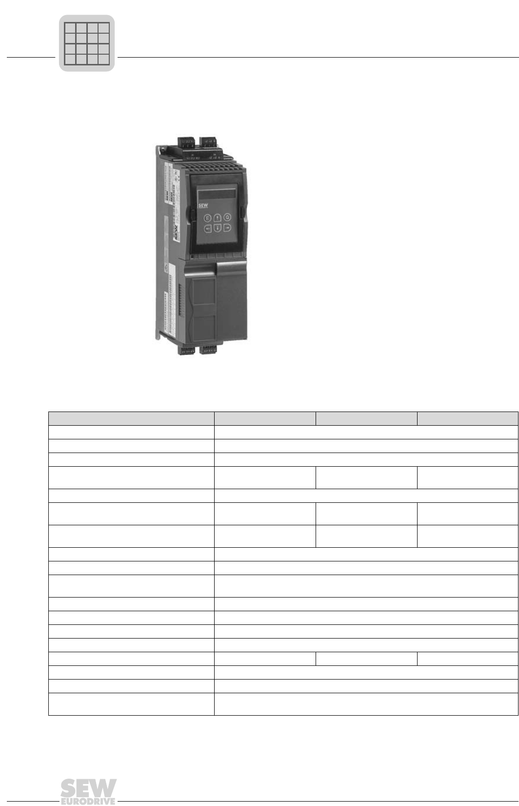
MOVIDRIVE® compact MCF/MCV/MCS electronics data
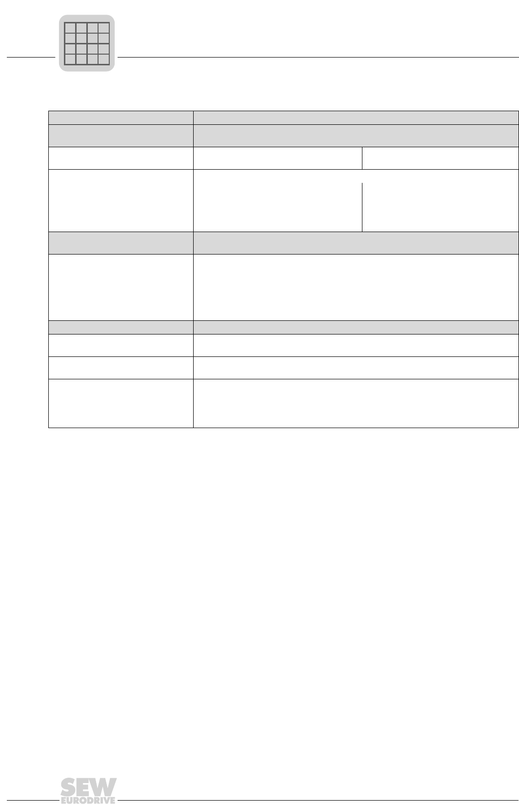
2.6 MOVIDRIVE® compact MCF/MCV/MCS electronics data
MOVIDRIVE® compact Setpoint processing and speed ramps
MCF/MCV/MCS40A
and MCV/MCS41A Version with analog setpoint input
Voltage supply X10:1
for setpoint input X10:3
REF1: +10 VDC +5 % / -0 %, Imax = 3 mA
REF2: -10 VDC +0 % / -5 %, Imax = 3 mA
Reference voltages for setpoint potentiom-
eter
Setpoint input n1 X10:2/X10:4 AI11/AI12: Voltage or current input, can be set with S11 and P11_, sampling interval 1 ms
(Differential input)
Operating mode AI11/AI12
Resolution
Internal resistance
Voltage input:
n1 = 0...+10 V or -10 V...0...+10 V
12 bits
Ri = 40 kΩ (external voltage supply)
Ri = 20 kΩ (supply from REF1/REF2)
Current input:
n1 = 0...20 mA or 4...20 mA
11 bits
Ri = 250 Ω
MCF/MCV/MCS41A (X10:2 and X10:4
ineffective with MCF41A)
Version with PROFIBUS-DP interface. There is no analog setpoint input n1 (AI11/AI12)
in MCF41A, setpoint specification only via PROFIBUS-DP interface.
Protocol option
Baud rate
Connection system
Bus termination
Station address
Name of the GSD file
DP identity number
PROFIBUS-DP acc. to IEC 61158
Automatic detection of baud rate from 9.6 kbaud to 12 Mbaud
9-pin sub D connector, pin assignment to IEC 61158
Can be activated for cable type A to IEC 61158
0...125, can be set using DIP switch
SEW_6002.GSD
6002hex (24578dec)
Applies to all versions
Setpoint input n2 X10:6
TF/TH input
Analog input 0...10 V or optionally (→ P120) TF/TH input
with response threshold at RTF ≥ 2.9 kΩ ±10 %
Internal setpoints Parameter set 1: n11/n12/n13 = -5000...0...+5000 rpm
Parameter set 2: n21/n22/n23 = -5000...0...+5000 rpm
Time ranges of speed ramps
at ∆n = 3000 rpm
1st ramp t11/t21 Up: 0.0...2000 s Down: 0.0...2000 s
2nd ramp t12/t22 Up = down: 0.0...2000 s
Stop ramp t13/t23 Down: 0...20 s
Emergency ramp t14/t24 Down: 0...20 s
Motorized potentiometert3 Up: 0.2...50 s Down: 0.2...50 s
P
if
kVA
Hz
n

MOVIDRIVE® compact Catalog
39
2
MOVIDRIVE® compact MCF/MCV/MCS electronics data
MOVIDRIVE® compact Other electronics data
Auxiliary voltage output1) X10:16 VO24: VOUT = 24 VDC, maximum current carrying capacity Imax = 200 mA
Ext. voltage supply1) X10:24 VI24: VIN = 24 VDC -15 % / +20 % (range: 19.2...30 VDC) to EN 61131-2
Binary inputs X10:9...X10:14
Internal resistance
DIØØ...DIØ5: Isolated (optocoupler), PLC-compatible (EN 61131), sampling interval 5 ms
Ri ≈ 3.0 kΩ, IE ≈ 10 mA
Signal level +13 V...+30 V = '1' = Contact closed
-3 V...+5 V = '0' = Contact open To EN 61131
Function X10:9
X10:10...X10:14
DIØØ: With fixed assignment '/Controller inhibit'
DIØ1...DIØ5: Selection option → Parameter menu P60_
Binary outputs1) X10:21/X10:19 DBØØ/DOØ2: PLC compatible (EN 61131-2), response time 5 ms
Signal level '0' = 0 V '1' = +24 V Important: Do not apply external voltage!
Function X10:21
X10:19
DBØØ: With fixed assignment '/Brake', Imax = 150 mA, short-circuit proof
DOØ2: Selection option → Parameter menu P62_, Imax = 50 mA, short-circuit proof
Only in MCF/MCV/MCS40AX10:19
Analog output AOØ1: → Menu P64_, resolution 8-bit, Imax = 20 mA (short-circuit proof)
Relay output X10:18/20/22 DOØ1: Load capacity of the relay contacts Vmax = 30 VDC, Imax = 800 mA
Function X10:18
X10:20
X10:22
DOØ1-C: Shared relay contact
DOØ2-NO: NO contact
DOØ2-NC: NC contact
Selection option → Parameter menu P62_
System bus (SBus) X10:5
X10:7
SC11: SBus high
SC12: SBus low
CAN bus to CAN specification 2.0, parts A and B, transmission
technology to ISO 11898, max. 64 stations, terminating resistor
(120 Ω) can be activated using DIP switches
Motor encoder input1) X15:
not with type MCF4_A
Encoder with type MCV4_A
Permitted encoder types:
• sin/cos encoder 1 VSS
• 5 V TTL sensors
• 24 V HTL sensors
Encoder power supply: +24 V, Imax = 180 mA
Resolver with type MCS4_A
2-pole, 7 VAC_r.m.s., 7 kHz
Output encoder X14:
simulation or
input external encoder1)
not with type MCF4_A
Output encoder simulation:
Signal level to RS-422 (5 V TTL)
Number of pulses as on X15: (MCV4_A) or
fixed 1024 pulses/revolution (MCS4_A)
Input external encoder (max. 200 kHz):
Only encoder with signal level to RS-422
(5 V TTL) should be connected!
Encoder power supply: +24 V, Imax = 180
mA
Reference terminals X10:8
X10:17/X10:23
X10:15
AGND: Reference potential for analog signals n1 and n2 and terminals X10:1 and X10:3
DGND: Reference potential for binary signals, system bus (SBus), encoder and resolver.
DCOM: Reference potential for binary inputs X10:9...X10:14 (DIØØ...DIØ5).
Permitted line cross section one core per terminal: 0.20...2.5 mm2 (AWG 24...12)
two cores per terminal: 0.20...1 mm2 (AWG 24...17)
1) MCF/MCV/MCS40A (without fieldbus): The unit provides a current of Imax = 400 mA for the +24 V outputs (VO24, DBØØ,
DBØ2, encoder supply). If this value is insufficient, a 24 VDC power supply unit must be connected to X10:24 (VI24). This exter-
nal 24 VDC power supply must be capable of supplying a continuous power of 50 W and a peak power (1 s) of 100 W.
MCF/MCV/MCS41A (with PROFIBUS-DP): SEW recommends always supplying these units with 24 VDC at terminal X10:24
(VI24). This external 24 VDC power supply must be capable of supplying a continuous power of 50 W and a peak power (1 s) of
100 W.
The maximum total current which may be applied to the 24 VDC outputs X10:16 (VO24), X10:21 (DBØØ) and X10:19 (DOØ2)
is Imax = 400 mA.
P
if
kVA
Hz
n
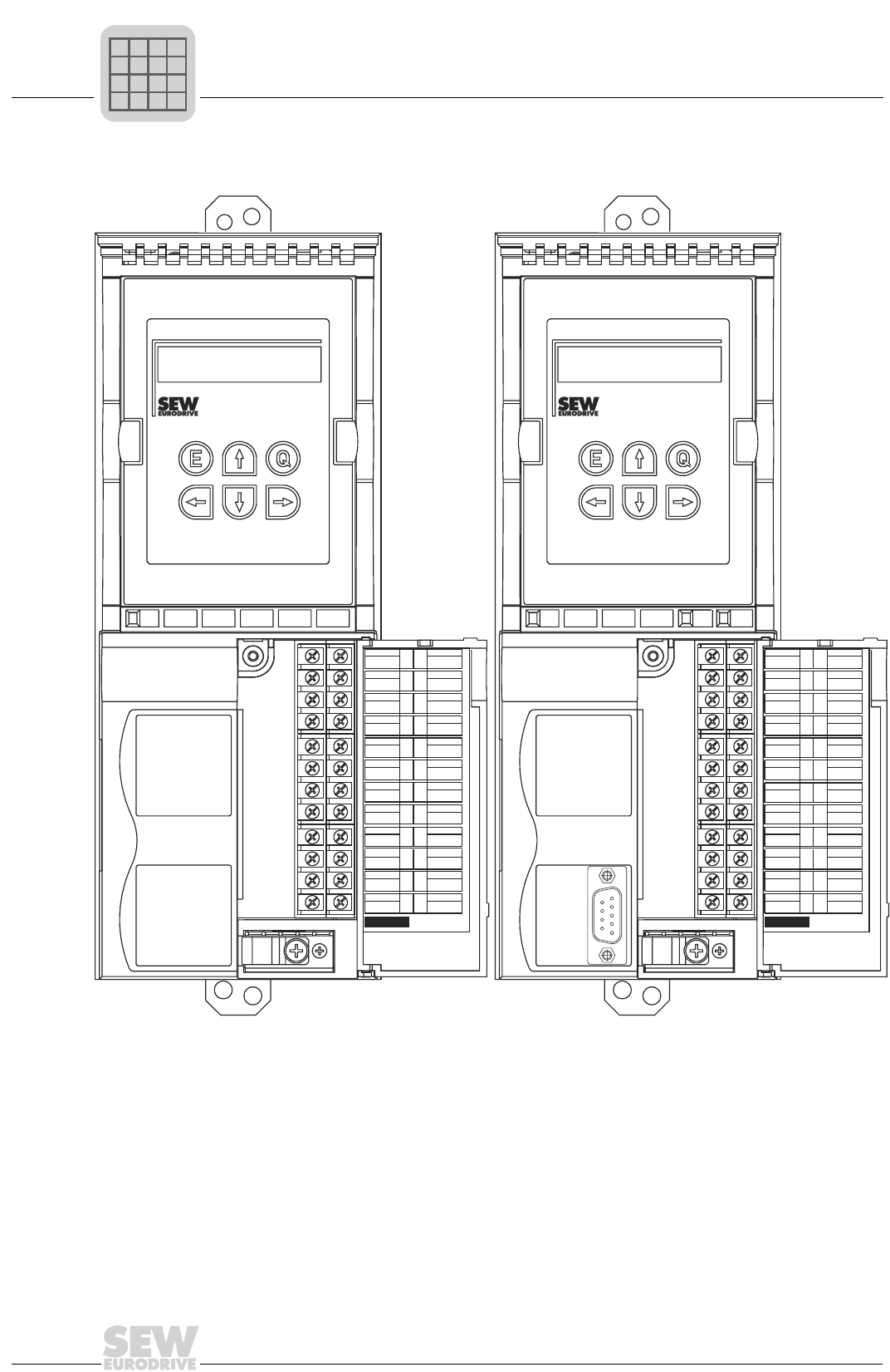
2
40
MOVIDRIVE® compact Catalog
MOVIDRIVE® compact MCF/MCV/MCS electronics data
Front view of MCF40A, MCF41A control unit
03381AXX
Figure 17: Front view of MCF40A, MCF41A control unit
X10 X10MCF40A MCF41A
REF1
REF2
SC11
SC12
DIØØ
DIØ2
DIØ4
DCOM
DGND
DOØ2
DBØØ
DGND
REF1
SC11
SC12
DIØØ
DIØ2
DIØ4
DCOM
DGND
DOØ2
DBØØ
DGND
AI11
AI12
AI21
AGND
DIØ1
DIØ3
DIØ5
VO24
DOØ1-C
DOØ1-NO
DOØ1-NC
VI24
AI21
AGND
DIØ1
DIØ3
DIØ5
VO24
DOØ1-C
DOØ1-NO
DOØ1-NC
VI24
1
3
5
7
9
11
13
15
17
19
21
23
1
3
5
7
9
11
13
15
17
19
21
23
2
4
6
8
10
12
14
16
18
20
22
24
2
4
6
8
10
12
14
16
18
20
22
24
1
5
6
9
PROFIBUS DP
X30
RUN BUS
FAULT
P
if
kVA
Hz
n
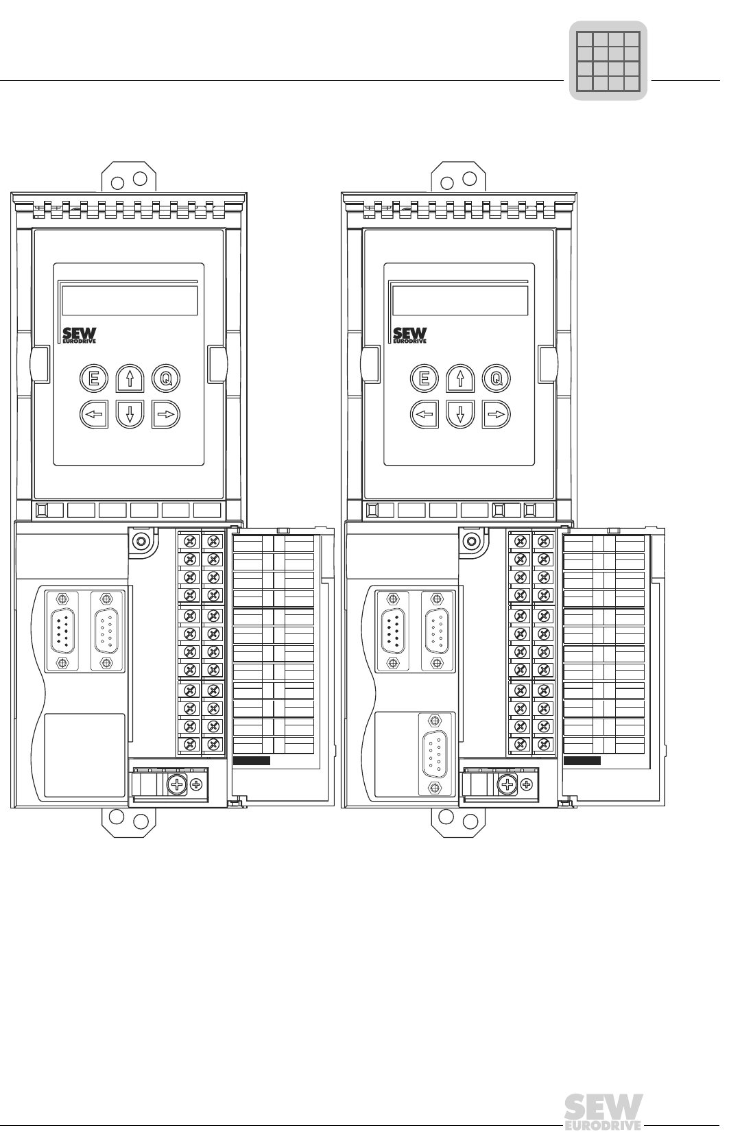
MOVIDRIVE® compact Catalog
41
2
MOVIDRIVE® compact MCF/MCV/MCS electronics data
Front view of MCV/MCS40A, MCV/MCS41A control unit
03383AXX
Figure 18: Front view of MCV/MCS40A, MCV/MCS41A control unit
X10 X10MCV40A MCV41A
REF1
REF2
SC11
SC12
DIØØ
DIØ2
DIØ4
DCOM
DGND
DOØ2
DBØØ
DGND
REF1
REF2
SC11
SC12
DIØØ
DIØ2
DIØ4
DCOM
DGND
DOØ2
DBØØ
DGND
AI11
AI12
AI21
AGND
DIØ1
DIØ3
DIØ5
VO24
DOØ1-C
DOØ1-NO
DOØ1-NC
VI24
AI11
AI12
AI21
AGND
DIØ1
DIØ3
DIØ5
VO24
DOØ1-C
DOØ1-NO
DOØ1-NC
VI24
1
3
5
7
9
11
13
15
17
19
21
23
1
3
5
7
9
11
13
15
17
19
21
23
2
4
6
8
10
12
14
16
18
20
22
24
2
4
6
8
10
12
14
16
18
20
22
24
1
5
6
9
PROFIBUS DP
X30
RUN BUS
FAULT
1
5
6
9
5
1
9
6
X15
ENCODER IN
X14
ENCODER I/O
1
5
6
9
5
1
9
6
X15
ENCODER IN
X15
ENCODER I/O
P
if
kVA
Hz
n
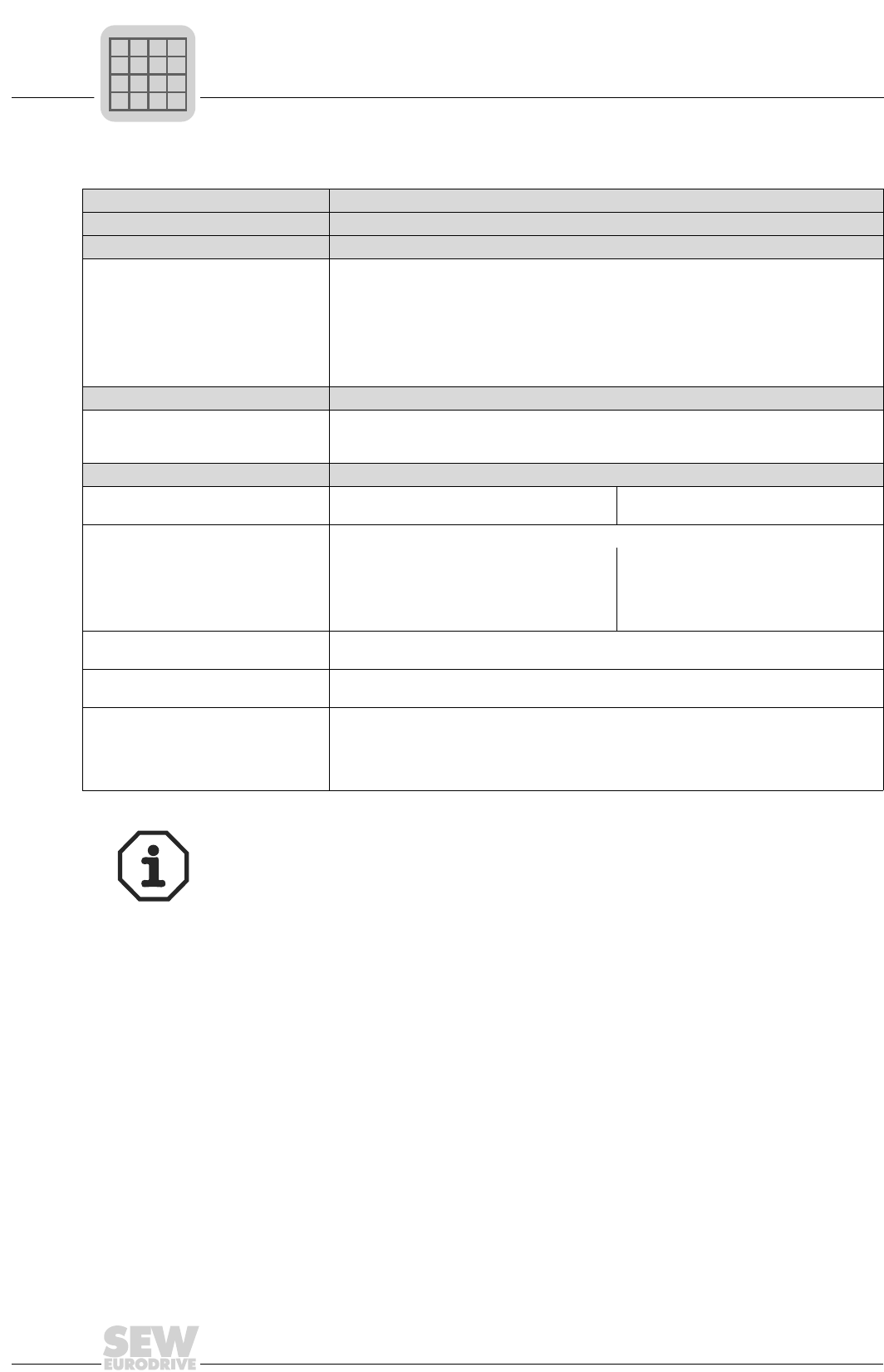
2
42
MOVIDRIVE® compact Catalog
MOVIDRIVE® compact MCH electronics data
2.7 MOVIDRIVE® compact MCH electronics data
MOVIDRIVE® compact Setpoint processing and speed ramps
MCH40A Version without fieldbus interface.
MCH41A Version with PROFIBUS-DP interface.
Protocol option
Baud rate
Connection system
Bus termination
Station address
Name of the GSD file
DP identity number
PROFIBUS-DP acc. to IEC 61158
Automatic detection of baud rate from 9.6 kbaud to 12 Mbaud
9-pin sub D connector, pin assignment to IEC 61158
not integrated, implement using suitable PROFIBUS plug with terminating resistors that can
be switched on
0...125, can be set using DIP switch
SEW_6003.GSD
6003hex (24579dec)
MCH42A Version with INTERBUS fiber optic (FO) interface.
Protocol option
Baud rate
Connection system
INTERBUS to prEN 50254 (DIN 19258) with optically controlled FO interface
500 kbaud and 2 Mbaud, changeover via DIP switch
4 F-SMA plugs (2 × remote bus input and 2 × remote bus output)
Applies to all versions
Voltage supply X10:1
for setpoint input X10:6
REF1: +10 VDC +5 % / -0 %, Imax = 3 mA
REF2: -10 VDC +0 % / -5 %, Imax = 3 mA
Reference voltages for setpoint potentiom-
eter
Setpoint input n1 X10:2/X10:3 AI11/AI12: Voltage or current input, can be set with S11 and P11_, sampling interval 1 ms
(Differential input)
Operating mode AI11/AI12
Resolution
Internal resistance
Voltage input:
n1 = 0...+10 V or -10 V...0...+10 V
12 bits
Ri = 40 kΩ (external voltage supply)
Ri = 20 kΩ (supply from REF1/REF2)
Current input:
n1 = 0...20 mA or 4...20 mA
11 bits
Ri = 250 Ω
Setpoint input n2 X10:4
TF/TH input
Analog input 0...10 V or optionally (→ P120) TF/TH input
with response threshold at RTF ≥ 2.9 kΩ ±10 %
Internal setpoints Parameter set 1: n11/n12/n13 = -5000...0...+5000 rpm
Parameter set 2: n21/n22/n23 = -5000...0...+5000 rpm
Time ranges of speed ramps
at ∆n = 3000 rpm
1st ramp t11/t21 Up: 0.0...2000 s Down: 0.0...2000 s
2nd ramp t12/t22 Up = down: 0.0...2000 s
Stop ramp t13/t23 Down: 0...20 s
Emergency ramp t14/t24 Down: 0...20 s
Motorized potentiometert3 Up: 0.2...50 s Down: 0.2...50 s
The PROFIBUS-DP interface of the MOVIDRIVE® MCH41A unit corresponds to the
state-of-the-art in PROFIBUS technology. The new, ground-breaking PROFIBUS-ASIC
technology has been used for these units.
The concept of the MCH41A PROFIBUS-DP interface is the same as the MOVIDRIVE®
MD_60A option 'PROFIBUS fieldbus interface type DFP21A'. As a result, both PROFI-
BUS interfaces can be used with the same PROFIBUS project planning.
P
if
kVA
Hz
n
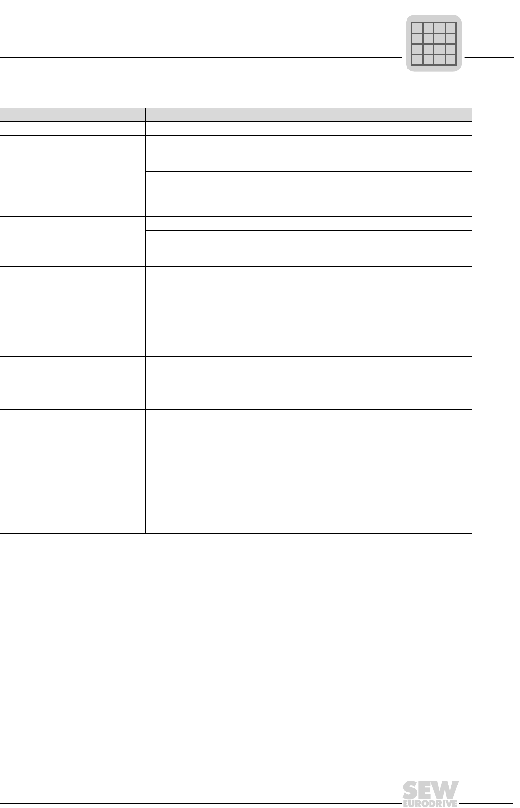
MOVIDRIVE® compact Catalog
43
2
MOVIDRIVE® compact MCH electronics data
MOVIDRIVE® compact Other electronics data
Auxiliary voltage output1) X11:8 VO24: VOUT = 24 VDC, maximum current carrying capacity Imax = 200 mA
Ext. voltage supply1) X12:6 VI24: VIN = 24 VDC -15 % / +20 % (range: 19.2...30 VDC) to EN 61131-2
Binary inputs X11:1...X11:6
Internal resistance
DIØØ...DIØ5: Isolated (optocoupler), PLC-compatible (EN 61131), sampling interval 5 ms
Ri ≈ 3.0 kΩ, IE ≈ 10 mA
Signal level +13 V...+30 V = '1' = Contact closed
-3 V...+5 V = '0' = Contact open To EN 61131
Function X11:1
X11:2...X11:6
DIØØ: With fixed assignment '/Controller inhibit'
DIØ1...DIØ5: Selection option → Parameter menu P60_
Binary outputs1) X12:1/X12:5 DBØØ/DOØ2: PLC compatible (EN 61131-2), response time 5 ms
Signal level '0' = 0 V '1' = +24 V Important: Do not apply external voltage!
Function X12:1
X12:5
DBØØ: With fixed assignment '/Brake', Imax = 150 mA, short-circuit proof
DOØ2: Selection option → Parameter menu P62_, Imax = 50 mA, short-circuit proof
Analog output X12:5 AOØ1: → Menu P64_, resolution 8-bit, Imax = 20 mA (short-circuit proof)
Relay output X12:2/3/4 DOØ1: Load capacity of the relay contacts Vmax = 30 VDC, Imax = 800 mA
Function X12:2
X12:3
X12:4
DOØ1-C: Shared relay contact
DOØ2-NO: NO contact
DOØ2-NC: NC contact
Selection option → Parameter menu P62_
System bus (SBus) X10:7/10
X10:8/11
SC11/21: SBus high
SC12/22: SBus low
CAN bus to CAN specification 2.0, parts A and B, transmission
technology to ISO 11898, max. 64 stations, terminating resistor
(120 Ω) can be activated using DIP switches
Motor encoder input1) X15: Permitted encoder types:
• Hiperface encoders
• sin/cos encoder 1 VSS
• TTL sensor
Encoder power supply: +12 V, Imax = 180 mA
Output encoder X14:
simulation or
input external encoder1)
Output encoder simulation:
Signal level to RS-422 (5 V TTL)
The number of pulses is as follows:
• 1024 pulses/revolution (Hiperface encoder
on X15)
• as on X15: Motor encoder input (sin/cos
encoder or TTL sensor on X15)
Input external encoder (max. 200 kHz):
Permitted encoder types:
• Hiperface encoders
• sin/cos encoder 1 VSS
• TTL sensor
Encoder power supply: +12 V, Imax = 180
mA
Reference terminals X10:5
X10:9/X11:9/X12:7
X11:7
AGND: Reference potential for analog signals n1 and n2 and terminals X10:1 and X10:6
DGND: Reference potential for binary signals, system bus (SBus), encoder and resolver.
DCOM: Reference potential for binary inputs X10:9...X10:14 (DIØØ...DIØ5).
Permitted line cross section only one core per terminal: 0.20...1.5 mm2 (AWG 24...16)
Use right-angled crimping pliers with 1.5 mm2 (AWG16)
1) MCH40A (without fieldbus): The unit provides a current of Imax = 400 mA for the +24 V outputs (VO24, DBØØ, DBØ2,
encoder supply). If this value is insufficient, a 24 VDC power supply unit must be connected to X10:24 (VI24). This external
24VDC power supply must be capable of supplying a continuous power of 50 W and a peak power (1 s) of 100 W.
MCH41A (with PROFIBUS-DP) or MCH42A (with INTERBUS FO): SEW recommends always supplying these units with
24VDC at terminal X10:24 (VI24). This external 24 VDC power supply must be capable of supplying a continuous power of 50 W
and a peak power (1 s) of 100 W.
The maximum total current which may be applied to the 24 VDC outputs X10:16 (VO24), X10:21 (DBØØ) and X10:19 (DOØ2)
is Imax = 400 mA.
P
if
kVA
Hz
n
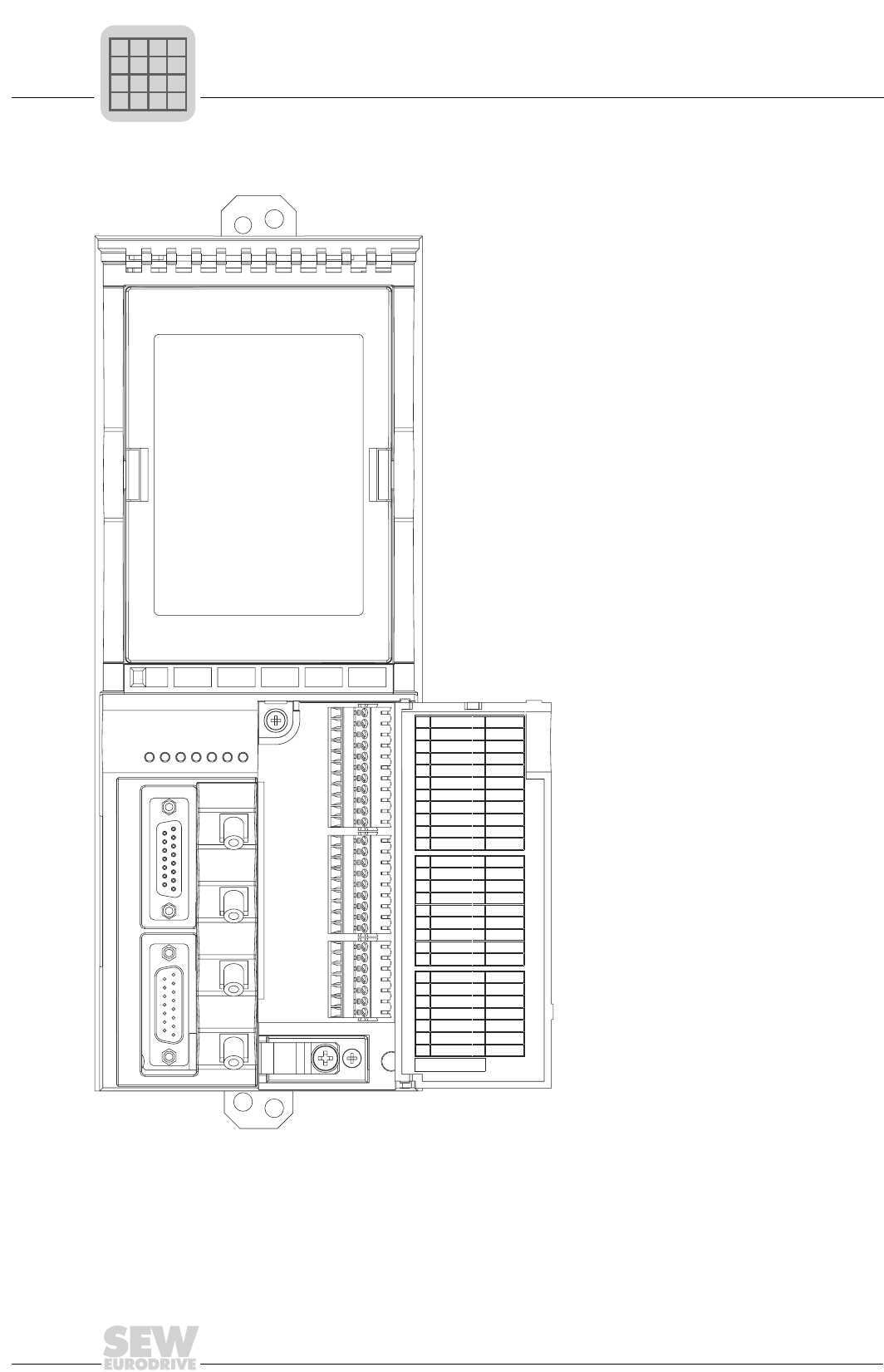
2
44
MOVIDRIVE® compact Catalog
MOVIDRIVE® compact MCH electronics data
Front view of MCH42A control unit
05294AXX
Figure 19: Front view of MCH42A control unit
V1
X14 Encoder I/O
X15 Encoder IN
X10
X11
X12
Remote IN
X30 IN
Remote IN
X31 OUT
Remote OUT
X32 IN
Remote OUT
X33 OUT
1
2
3
4
5
6
7
8
9
10
11
1
2
3
4
5
6
7
8
9
1
2
3
4
5
6
7
U
CC
BA
RD
TR
FO1
FO2
L
1
2
3
4
5
6
7
8
9
10
11
1
2
3
4
5
6
7
8
9
1
2
3
4
5
6
7
REF1
AI11
AI12
AI21
AGND
REF2
SC11
SC12
DGND
SC21
SC22
DIØØ
DIØ1
DIØ2
DIØ3
DIØ4
DIØ5
DCOM
VO24
DGND
DBØØ
DOØ1-C
DOØ1-NO
DOØ1-NC
DOØ2
VI24
DGND
X10
X11
X12
MCH 42A
P
if
kVA
Hz
n
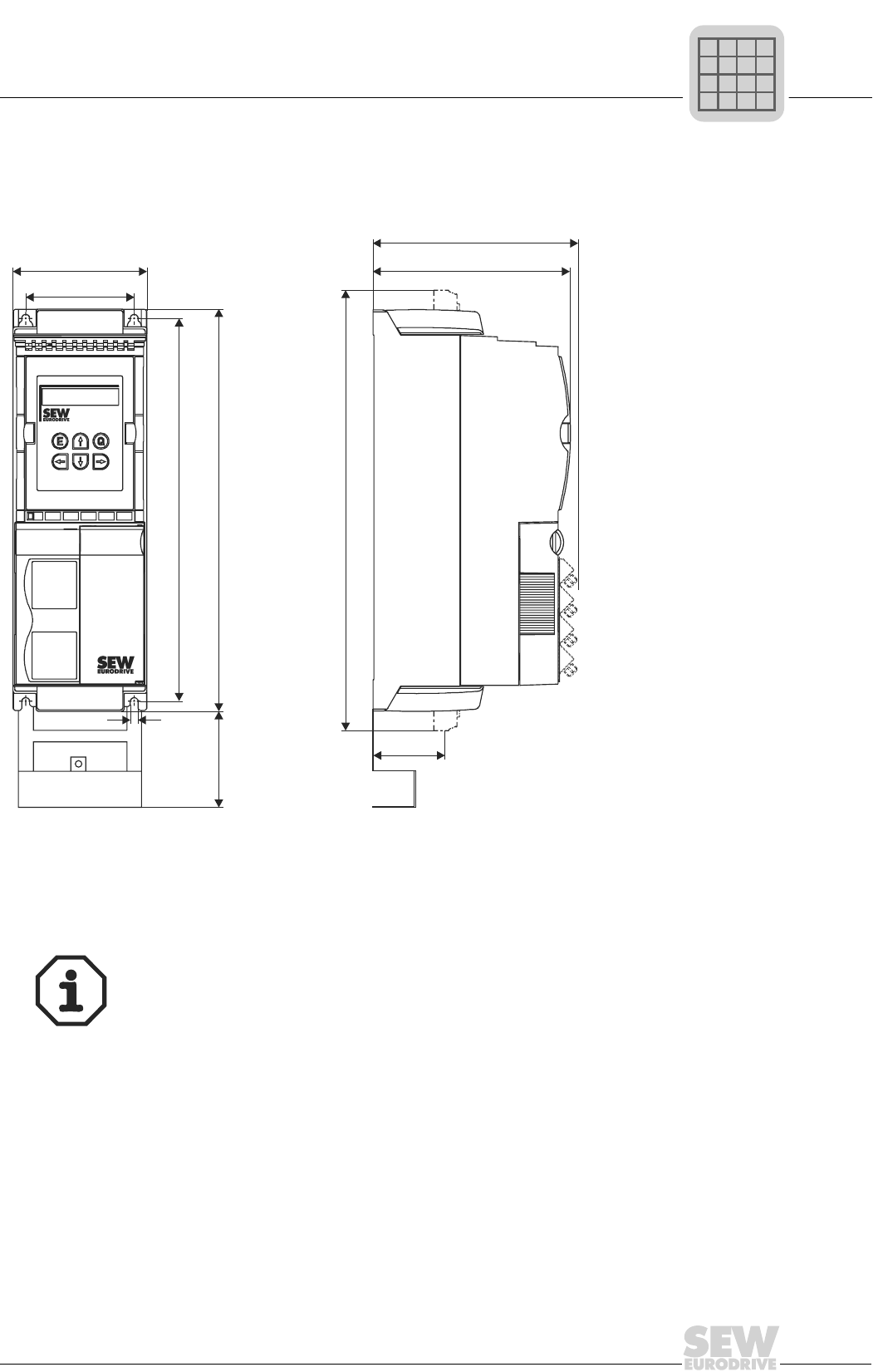
MOVIDRIVE® compact Catalog
45
2
MOVIDRIVE® compact dimensions
2.8 MOVIDRIVE® compact dimensions
Dimensions, size 1 (0015...0040-5A3 and 0015...0037-2A3)
02490AXX
Figure 20: Dimensions, size 1, in mm (in)
* Power shield clamp
** Unit dimension with power terminals attached
82 (3.23)
54 (2.13)
85 (3.35)
105 (4.13)
6
(0.24)
300 (11.81)
315 (12.40)
MCF/MCV/MCS: 155 (6.10)
MCH: 161 (6.34)
345** (13.58**)
*
Provide at least 100 mm (4 in) clearance above and below the unit to ensure adequate
cooling! No lateral clearance required; the units can be lined up side-by-side.
P
if
kVA
Hz
n
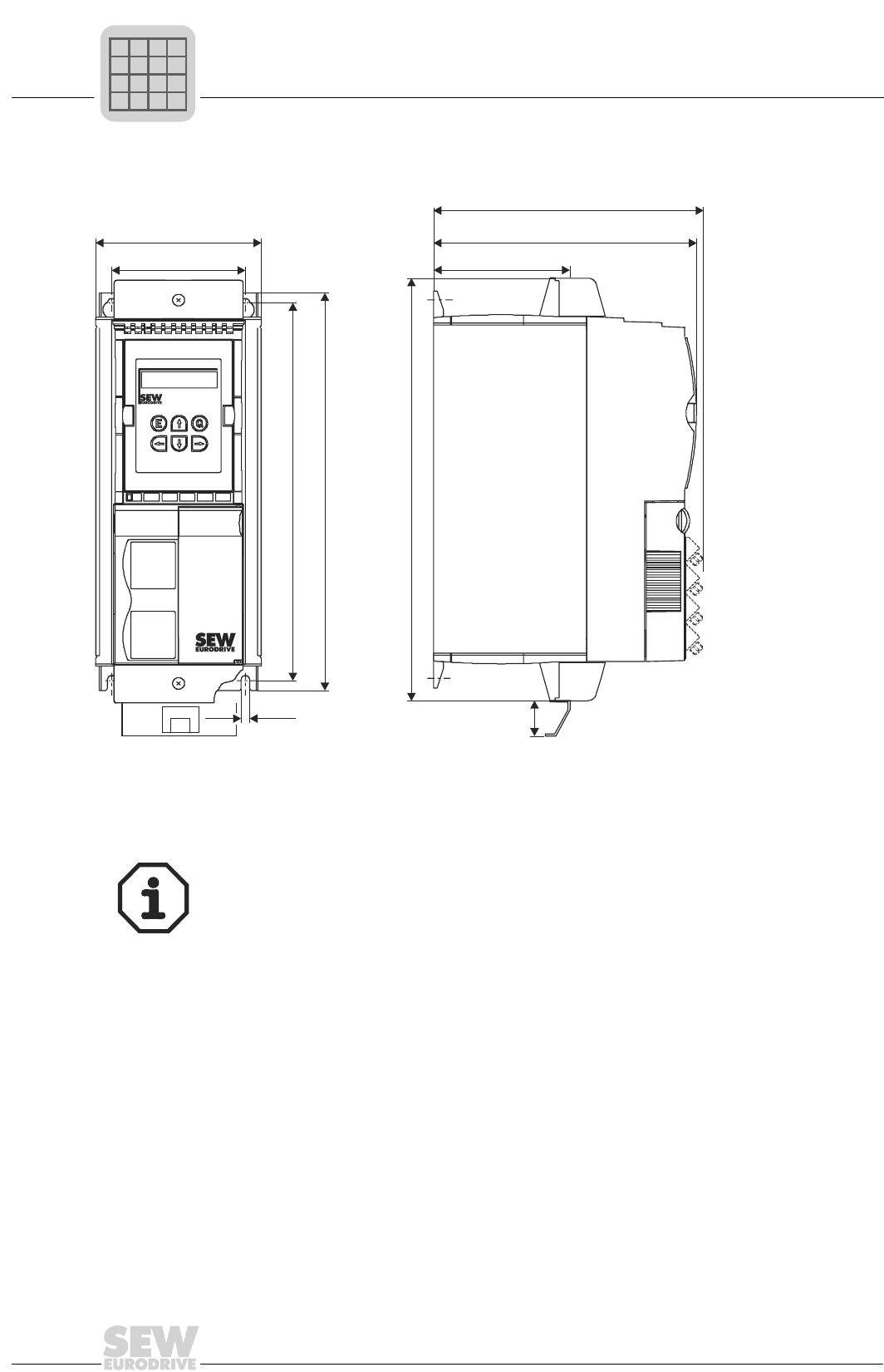
2
46
MOVIDRIVE® compact Catalog
MOVIDRIVE® compact dimensions
Dimensions, size 2 (0055...0110-5A3 and 0055 / 0075-2A3)
02578AXX
Figure 21: Dimensions, size 2, in mm (in)
* Power shield clamp
130 (5.12)
105 (4.13)
MCF/MCV/MCS: 207 (8.15)
300 (11.81)
315 (12.40)
335 (13.19)
6.5 (0.26)
32
(1.60)
120 (4.72)
*
MCH: 213 (8.39)
Provide at least 100 mm (4 in) clearance above and below the unit to ensure adequate
cooling! No lateral clearance required; the units can be lined up side-by-side.
P
if
kVA
Hz
n
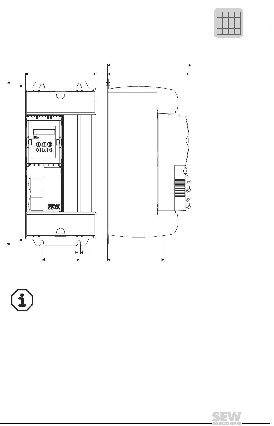
MOVIDRIVE® compact Catalog
47
2
MOVIDRIVE® compact dimensions
Dimensions, size 3 (0150...0300-503 and 0110 / 0150-203)
02579AXX
Figure 22: Dimensions, size 3, in mm (in)
465 (18.31)
445 (17.52)
7
(0.28)
105 (4.13)
200 (7.87)
173 (6.81)
MCF/MCV/MCS: 227 (8.94)
MCH: 233 (9.17)
Provide at least 100 mm (4 in) clearance above and below the unit to ensure adequate
cooling! No lateral clearance required; the units can be lined up side-by-side.
P
if
kVA
Hz
n
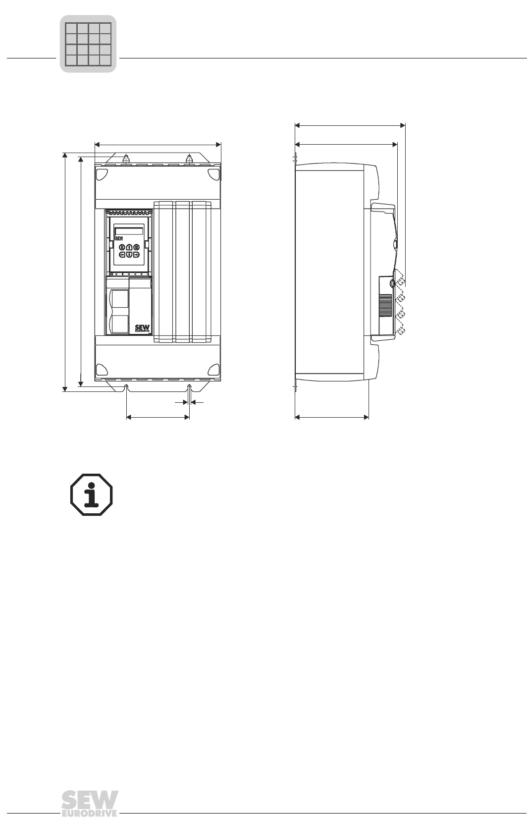
2
48
MOVIDRIVE® compact Catalog
MOVIDRIVE® compact dimensions
Dimensions, size 4 (0370 / 0450-503 and 0220 / 0300-203)
02593AXX
Figure 23: Dimensions, size 4, in mm (in)
522 (20.55)
502 (19.76)
140 (5.51)
7
(0.28)
280 (11.02)
160 (6.30)
MCF/MCV/MCS: 227 (8.94)
MCH: 233 (9.17)
Provide at least 100 mm (4 in) clearance above and below the unit. No clearance is re-
quired at the sides; the units can be lined up side-by-side.
Do not install any components which are sensitive to high temperatures within 300 mm
(11.81 in) of the top of the unit (e.g. contactors or fuses).
P
if
kVA
Hz
n
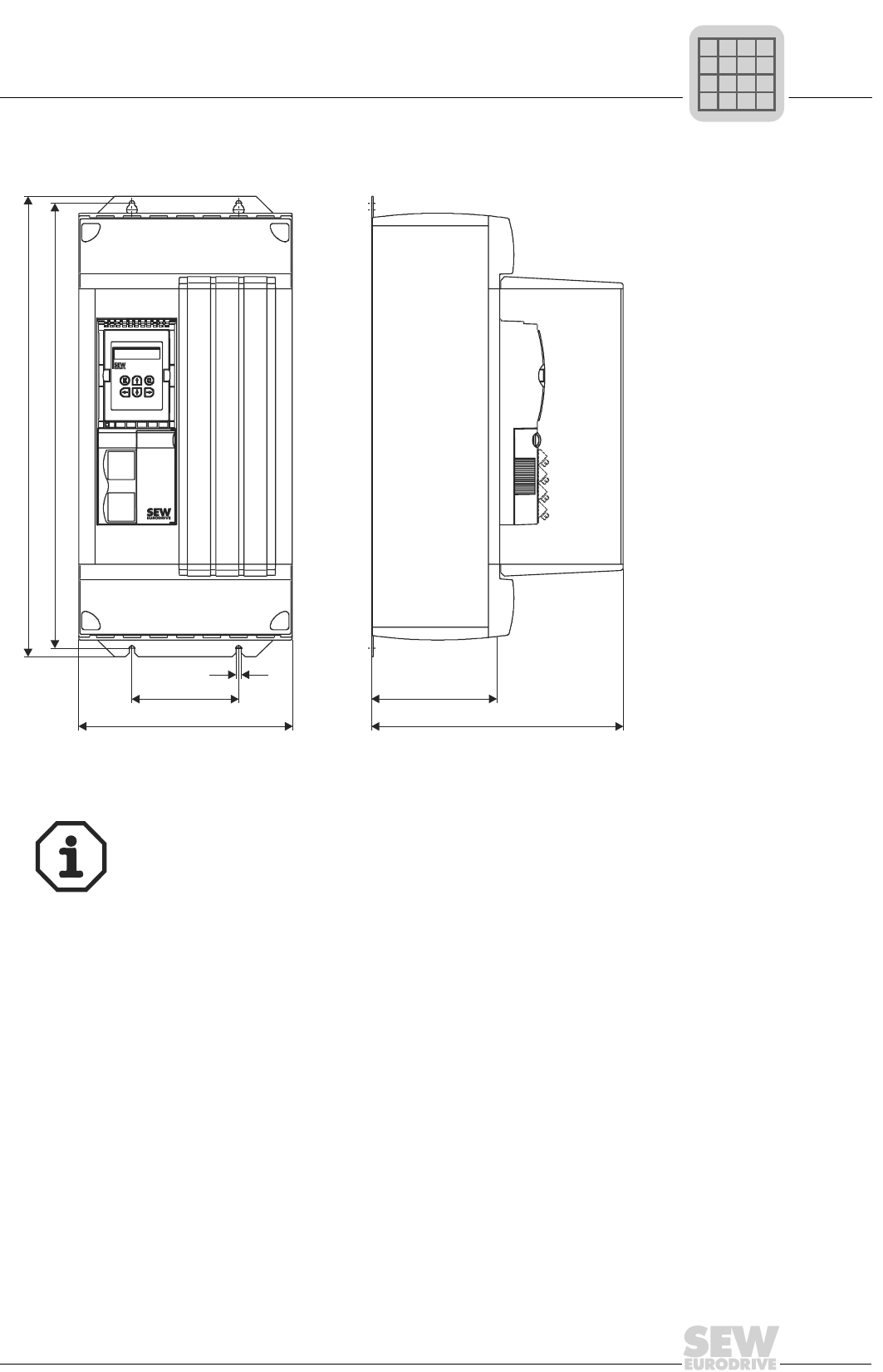
MOVIDRIVE® compact Catalog
49
2
MOVIDRIVE® compact dimensions
Dimensions, size 5 (0550 / 0750-503)
02594AXX
Figure 24: Dimensions, size 5, in mm (in)
610 (24.02)
590 (23.23)
140 (5.51)
7
(0.28)
280 (11.02)
160 (6.30)
330 (12.99)
Provide at least 100 mm (4 in) clearance above and below the unit. No clearance is re-
quired at the sides; the units can be lined up side-by-side.
Do not install any components which are sensitive to high temperatures within 300 mm
(11.81 in) of the top of the unit (e.g. contactors or fuses).
P
if
kVA
Hz
n
2
50
MOVIDRIVE® compact Catalog
IPOSplus®
2.9 IPOSplus®
Description The IPOSplus® positioning and sequence control system is integrated into every MOV-
IDRIVE® inverter as standard. With IPOSplus®, control functions and positioning tasks
can be performed either simultaneously or independently of one another.
The IPOSplus® sequence control system makes it possible to run a user program, re-
gardless of any encoder feedback or the selected control mode (VFC, CFC, SERVO).
In conjunction with encoder feedback (MCV, MCS, MCH), the IPOSplus® positioning
control provides a high-performance point-to-point positioning capability. The IPOSplus®
program is written using the MOVITOOLS software. Startup of the inverter, accessing
parameters and editing variables are possible either with the software or the DBG11B
keypad. (Note: The DBG11B can only be used for startup in VFC mode.)
Properties • Program execution independent of encoder feedback and operating mode.
• The user program is continued even if the unit develops a malfunction (troubleshoot-
ing is possible in the user program).
• Two user programs can be run in parallel and independently of one another (task 1,
interrupt-capable, and task 2).
• The user programs programmed in assembler can contain up to 800 program lines.
• User-friendly and comprehensive control options for the inverter.
• Extensive options for communication via system bus (SBus), RS-485, RS-232 and
fieldbus (direct communication with MOVIMOT® is possible).
• Processing of digital and analog input/output signals.
With MCV/MCS/
MCH only
• Positioning with selectable travel speed and positioning ramp.
• Feedforward for position, speed and torque control loops with minimized lag error.
• Two touch probe inputs.
• LINEAR, SINUSOIDAL and SQUARED ramp functions.
• Status and monitoring functions: Lag error monitoring, position signal, software and
hardware limit switches.
• Eight possible reference travel types.
• Possibility of changing the target position, travel speed, positioning ramp and torque
while movement is in progress.
• 'Endless positioning' is possible.
• Override function.
Technical data
Max. program length of task 1 and task 2 approx. 800 program lines in total (assembler programming)
Command processing time per program line Task 1: 1.0 ms; Task 2: 0.5 ms
Variables 512, of which 128 (0...127) can be stored to non-volatile memory; range of val-
ues: -231...+(231-1)
Touch probe inputs 2 inputs, processing time < 100 µs
Sampling interval of digital and analog inputs 1...5 ms
Digital inputs/outputs 6 inputs / 3 outputs
Analog inputs/outputs 1 input (0...10 V, ±10 V, 0...20 mA, 4...20 mA)
1 input (0...10 V)
1 output (0...20 mA, 4...20 mA)
P
if
kVA
Hz
n
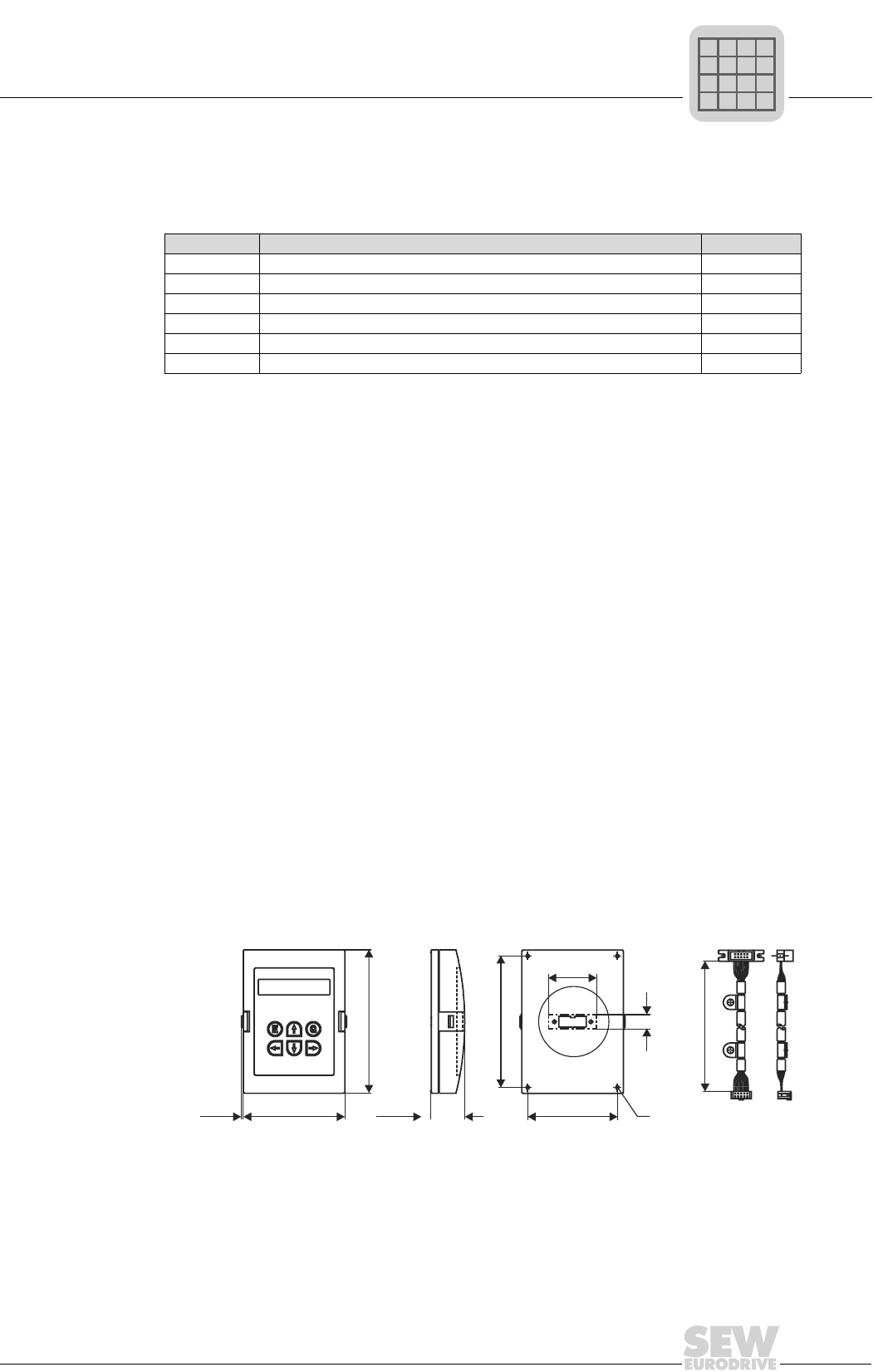
MOVIDRIVE® compact Catalog
51
2
DBG11B keypad option
2.10 DBG11B keypad option
Description The keypad is used for startup and for service. The basic version of MOVIDRIVE® does
not have a keypad but can be upgraded.
Equipment • Illuminated plain text display, five languages can be set.
• Membrane keypad with 6 keys.
• Selection between the quick menu, detailed parameter menu and startup menu in
VFC mode (CFC and SERVO startup is not possible with the DBG11B).
• Can be plugged onto the inverter (TERMINAL option slot).
• Connection possible via FKG11A extension cable (part number 822 101 4).
• Enclosure IP40 (EN 60529)
Note The DBG11B keypad option and the USS21A serial interface option are connected to
the same inverter slot (TERMINAL) and cannot therefore be used at the same time.
Functions • Displays of process values and status displays.
• Status displays of the binary inputs/outputs.
• Fault memory inquiry and fault reset.
• Displaying and setting the operating parameters and service parameters.
• Saving data and transferring parameter sets to other MOVIDRIVE® units.
• User-friendly startup menu for VFC mode.
• Storing a curve for the electronic cam.
Dimensions
1. Cut-out for the plug in the mounting plate
2. DBG11B-MOVIDRIVE® communications cable
3. Holes for tapping screws 3.5 × 9.5 mm (0.14 × 0.37 in)
Keypad Language Part number
DBG11B-08 DE/EN/FR/ES/PT (German/English/French/Spanish/Portuguese) 824 154 6
DBG11B-09 EN/IT/SV/DA/FI (English/Italian/Swedish/Danish/Finnish) 824 155 4
DBG11B-11 ES/DE/EN/FR/PT (Spanish/German/English/French/Portuguese) 824 156 2
DBG11B-12 SV/EN/IT/DA/FI (Swedish/English/Italian/Danish/Finnish) 824 157 0
DBG11B-13 EN/ES/DE/FR/PT (English/Spanish/German/French/Portuguese) 824 158 9
DBG11B-14 FR/IT/ES/PT/EN (French/Italian/Spanish/Portuguese/English) 824 248 8
04030AXX
Figure 25: Dimensions, DBG11B and FKG11A, in mm (in)
110 (4.33)
12 (0.47)
1.
75 (2.95)
40 (1.57)
1.
85 (3.35)
120 (4.72)
1800 (70.87)
822 101 4
28.5 (1.12)
1.5 (0.06)
FKG11A
2.
DBG11B
3.
P
if
kVA
Hz
n
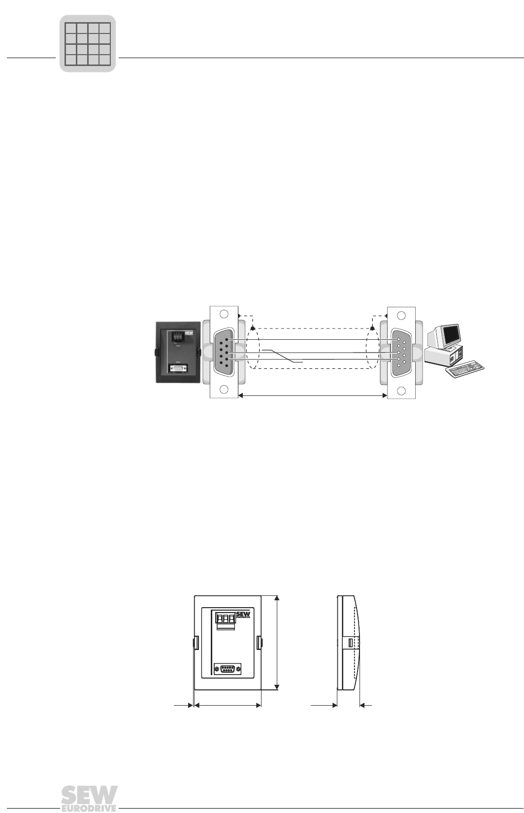
2
52
MOVIDRIVE® compact Catalog
Serial interface option type USS21A (RS-232 and RS-485)
2.11 Serial interface option type USS21A (RS-232 and RS-485)
Part number 822 914 7
Description MOVIDRIVE® can be equipped with isolated RS-232 and RS-485 interfaces. The RS-
232 interface is configured as a 9-pin sub D female connector (EIA standard) and the
RS-485 interface as a terminal connection. The interfaces are accommodated in a hous-
ing for plugging onto the inverter (TERMINAL option slot). The option can be plugged on
during operation. The transmission rate of both interfaces is 9600 baud.
Startup, operation and service are possible from the PC via the serial interface. The
SEW MOVITOOLS software is used for this. It is also possible to transfer parameter set-
tings to several MOVIDRIVE® drive inverters via PC.
Note DBG11B and USS21A are connected to the same inverter slot (TERMINAL) and cannot
be used at the same time.
RS-232 interface To connect a PC to the MOVIDRIVE® USS21A option, use a commercial shielded serial
interface cable with a 1:1 connection assignment.
RS-485 interface You can network up to 16 MOVIDRIVE® units for communications purposes (max. total
cable length 200 m (660 ft)) via the RS-485 interface of the USS21A. Dynamic terminat-
ing resistors are permanently installed, so do not connect any external terminating re-
sistors.
Unit addresses 0...99 are permitted with multipoint connections. In this case, the 'point
to point connection' must not be selected in MOVITOOLS. The communications address
in MOVITOOLS and the RS-485 address of the MOVIDRIVE® unit (P810) must be the
same.
Dimensions
02399AEN
Figure 26: USS21A-PC connection cable (1:1 connection assignment)
RxD
TxD 22
33
55
max. 5 m (16.5 ft)
USS21A PC COM 1-4
55
33
222
3
5
5
3
2
9-pin sub D connector (female)9-pin sub D connector (male)
GND (ground)
01003BXX
Figure 27: Dimensions, USS21A, in mm (in)
85 (3.35)
120 (4.72)
RS232
RS485
0V5 - +
28.5 (1.12)
1.5 (0.06)
P
if
kVA
Hz
n
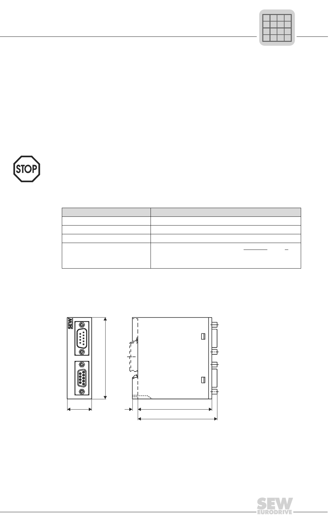
MOVIDRIVE® compact Catalog
53
2
5 V encoder power supply option type DWI11A
2.12 5 V encoder power supply option type DWI11A
Part number 822 759 4
Description If you are using an incremental encoder with a 5 VDC encoder power supply, install the
5 V encoder power supply option type DWI11A between the inverter and the incremental
encoder. This option provides a regulated 5 VDC power supply for the encoder. This in-
volves converting the 24 VDC power supply for the encoder inputs to 5 VDC by means of
a voltage controller. The supply voltage at the encoder is measured using a sensor line
and the voltage drop along the encoder cable is compensated.
Do not connect incremental encoders with 5 VDC encoder power supply directly to the
encoder inputs X14: and X15:. Such a connection would result in irreparable damage to
the encoders.
Technical data
Recommendation Use prefabricated cables from SEW for connection of the encoder.
Dimensions
The DWI11A option is mounted on a support rail (EN 50022-35 × 7.5) in the switch cab-
inet.
Note that in the event of a short circuit on the sensor line, the connected encoder may
be subjected to a voltage in excess of its permitted voltage.
Option 5 V encoder power supply type DWI11A
Part number 822 759 4
Voltage input +24 V to EN 61131-2, 18...30 VDC, Imax = 120 mA
Encoder power supply +5 V (up to Vmax ≈ +10 V), Imax = 300 mA
Max. line length which can be con-
nected
100 m (330 ft) total
Use a shielded twisted-pair cable (A and A, B and B, C and C) for
connecting the encoder to the DWI11A and the DWI11A to MOV-
IDRIVE®.
01315BXX
Figure 28: Dimensions, DWI11A, in mm (in)
68 (2.68)
73 (2.87)
5 (0.20)
22.5 (0.89)
75 (2.96)
X2: Encoder X1: MOVIDRIVE
DWI
P
if
kVA
Hz
n
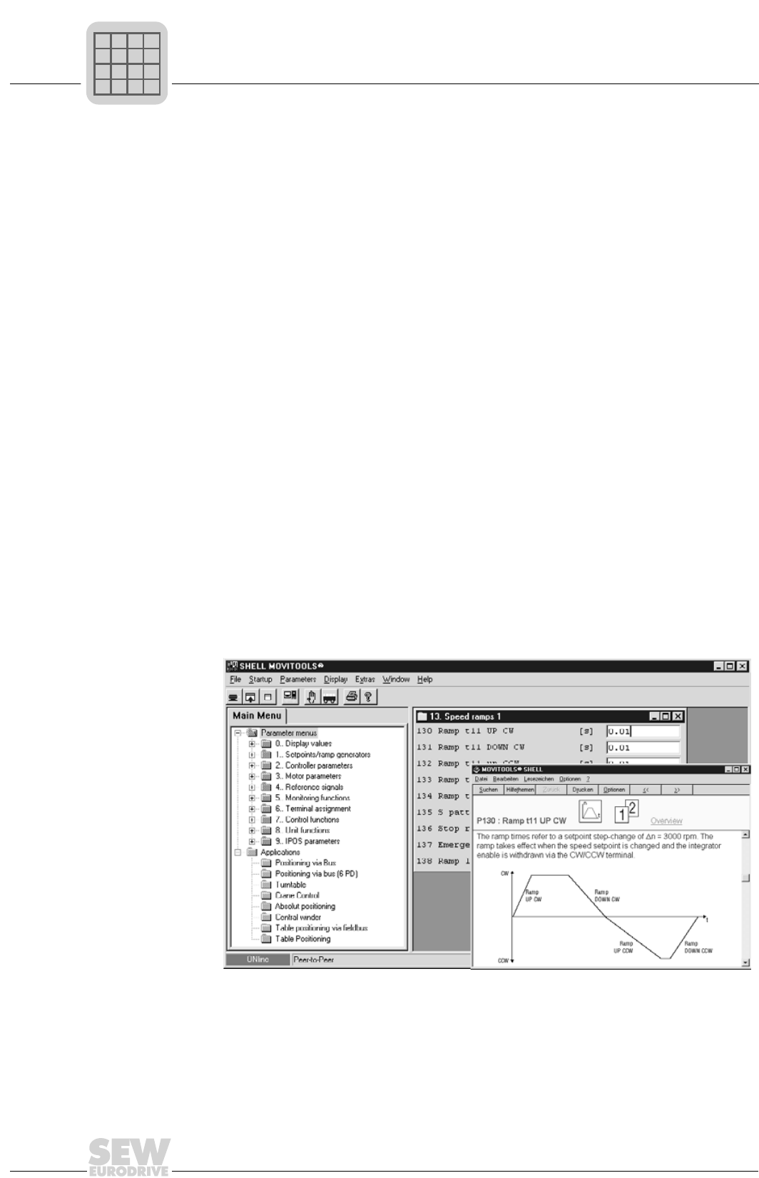
2
54
MOVIDRIVE® compact Catalog
MOVITOOLS software
2.13 MOVITOOLS software
Part number 0918 5054
Description MOVITOOLS is a program package comprising SHELL, SCOPE, IPOSplus® Compiler
and LOGODrive. You can use MOVITOOLS to address either of the three ranges of
units MOVIDRIVE® MD_60A, MOVIDRIVE® compact and MOVITRAC® 07.
• SHELL can be used for starting up the drive and setting its parameters in a conve-
nient fashion.
• SCOPE provides extensive oscilloscope functions for diagnostics of the drive.
•IPOS
plus® Compiler provides a convenient way of writing programs for applications
in a high-level language.
• The assembler enables you to write programs directly on the machine.
• LOGODrive allows you to write applications with graphics support.
• Device status displays the status of the connected unit.
Various application modules, e.g. table positioning, are stored in MOVITOOLS in ad-
vance as IPOSplus® programs and can be activated using units in application version.
MOVITOOLS is supplied on a CD-ROM and can also be downloaded from the SEW
homepage (http://www.sew-eurodrive.com). MOVITOOLS can be used with the follow-
ing operating systems:
• Windows® 95
• Windows® 98
• Windows NT® 4.0
• Windows® 2000 (from version 2.60)
• Windows® Me (from version 2.60)
02719AEN
Figure 29: MOVITOOLS window
P
if
kVA
Hz
n

MOVIDRIVE® compact Catalog
55
2
Application modules for MOVIDRIVE® compact
2.14 Application modules for MOVIDRIVE® compact
In the past, it was necessary to write complicated control programs for the machine con-
trol in order to implement applications such as bus positioning. All movements were con-
trolled by the machine control.
IPOSplus® SEW MOVIDRIVE® compact drive inverters with integrated IPOSplus® positioning and
sequence control systems are capable of controlling all movements themselves. The
control program runs in the inverter. The major advantages are:
• Decentralized concepts can be implemented more easily.
• Movements are controlled closer to the machine, i.e. response times are shorter.
• The machine control does not have to perform as many functions.
Users do not have to go to the trouble of writing the IPOSplus® control program them-
selves. SEW offers application modules for MOVIDRIVE® compact units in application
version. The application modules form part of the MOVITOOLS software package.
Advantages The application modules offer the following benefits:
• Wide range of functions
• User-friendly user interface
• You only have to enter the parameters needed for the application
• User-friendly application programs guide you through the process of setting param-
eters, i.e. there is no need for complicated programming
• No programming experience necessary
• Steep learning curve
Scope of supply
and documenta-
tion
The application modules form part of the MOVITOOLS software package and can be
used with units in application version (MOVIDRIVE® compact...-0T). All manuals relat-
ing to the application modules are contained in the 'Additional Functions and Application
Modules' documentation package. You can order this documentation package from
SEW.
The individual manuals (files in PDF format) can also be downloaded from the SEW
homepage (http://www.sew-eurodrive.com).
MOVITOOLS
P
if
kVA
Hz
n

2
56
MOVIDRIVE® compact Catalog
Application modules for MOVIDRIVE® compact
Positioning The application modules for the 'Positioning' application are suited to all applications
which involve target positions being specified and then movement taking place to those
positions. The sequence of motion can be linear or rotational.
These include trolleys, hoists, gantries, rotary tables, swiveling devices and storage and
retrieval units for high-bay warehouses.
Linear position-
ing
In the case of linear positioning application modules, SEW distinguishes between
whether the movement records are managed in the inverter or in the master PLC.
Movement records
in the inverter
•Table positioning with bus control
You can manage up to 32 movement records in the inverter with this application module.
A movement record is made up of the destination, speed and ramp. The destination to
which movement is to take place is selected using binary code, by means of virtual ter-
minals (fieldbus, system bus). The application module comes with the following range
of features:
• 32 table positions can be defined and selected.
• The travel speed can be selected as required for each positioning movement.
• The ramp can be set separately for each positioning movement.
• Software limit switches can be defined and evaluated.
• Menu system for startup and diagnostics
– Freely definable user travel units
– Calculation of position resolution during positioning via the motor encoder
– Graphical position display
This application module is suited to applications in which movement has to take place
to a limited number of different destinations only and that require the highest possible
degree of independence from the machine control.
There are four operating modes for controlling the machine:
• Jog mode: The machine can be moved manually.
• Reference travel: The machine zero is determined automatically with incremental po-
sition measurement.
• Teach-in: The stored position can be corrected without a programming unit.
• Automatic mode: Automatic sequence controlled by the master PLC.
Movement records
in the PLC
•Positioning via bus
•Extended positioning via bus
In these application modules, the movement records are managed in the PLC. The des-
tination and travel speed are specified via the fieldbus or system bus. The application
modules come with the following range of features:
• Any number of target positions can be defined and selected by means of a fieldbus/
system bus.
• The travel speed can be selected as required via the fieldbus/system bus for each
positioning movement.
• Software limit switches can be defined and evaluated.
• Straightforward connection to the machine control.
P
if
kVA
Hz
n

MOVIDRIVE® compact Catalog
57
2
Application modules for MOVIDRIVE® compact
• Menu system for startup and diagnostics
– Freely definable user travel units
– Calculation of position resolution during positioning via the motor encoder
– Jog mode with variable speed
– Fieldbus monitor
These application modules are suited for applications in which movement has to take
place to a large number of different target positions.
There are three operating modes for controlling the machine:
• Jog mode: The machine can be moved manually.
• Reference travel: The machine zero is determined automatically with incremental po-
sition measurement.
• Automatic mode: Automatic sequence controlled by the master PLC.
Rotational posi-
tioning
•Rotary axis
You can manage up to 16 movement records in the inverter with this application module.
A movement record is made up of the destination, speed and ramp. The destination to
which movement is to take place is selected using binary code, by means of the binary
inputs of the inverter or via virtual terminals (fieldbus, system bus). The position mea-
surement can only take place with incremental encoders. The application module comes
with the following range of features:
• 16 table positions can be defined and selected.
• The travel speed can be selected as required for each positioning movement.
• The ramp can be set separately for each positioning movement.
• Flying referencing when using a non-whole number ratio.
• Positioning with position optimization or positioning with a predefined direction of ro-
tation.
• Pulse mode with 16 step widths.
• External encoder for position detection possible.
• Menu system for startup and diagnostics
– Calculation of position resolution during positioning via the motor encoder
– Graphical position display
This application module is suited for applications in which rotational movements or sim-
ilar endless movements are required. These include rotary tables, circular indexing ta-
bles, swiveling devices or cyclic belts.
The following operating modes are available for controlling the machine:
• Jog mode: The machine can be moved manually.
• Reference travel: The machine zero is determined automatically.
• Teach-in: The stored position can be corrected without a programming unit.
• Positioning with position optimization
• Positioning with a fixed direction of rotation
• Cyclical operation
P
if
kVA
Hz
n

2
58
MOVIDRIVE® compact Catalog
Application modules for MOVIDRIVE® compact
Winding •Constant tension central winder (short: central winder)
In this application, the web tension is set for winding or unwinding using the setpoints,
the mechanical friction values, the winding diameter and the winding characteristics.
Control takes place either via the binary inputs of the inverter or the virtual terminals
(fieldbus, system bus). The application module comes with the following range of fea-
tures:
• Calculation of the reel diameter and the tensile force.
• Material tear monitoring.
• Material length counter.
• Straightforward connection to the machine control.
• Menu system for startup and diagnostics
– Adjustable winding curve
– Display of web speed and current diameter
This application module is suited for applications in which an endless material, e.g. pa-
per, film, foam, textiles or sheet metal is wound for further processing.
There are four operating modes for controlling the machine:
• Jog mode: The machine can be moved manually.
• Teach-in: The speed-dependent friction values are determined automatically.
• Automatic mode with constant torque.
• Automatic mode with constant web tension.
Controlling •Flying saw
In this application module, the sequence of motion is controlled according to specifica-
tions. The application module comes with the following range of features:
• Cut edge protection or singling using the 'Draw gap' function.
• Immediate cut function by manual interrupt.
• Material length counter.
• Straightforward connection to the machine control.
• Menu system for startup and diagnostics
– Display of the current cut length and the material speed
– Display of the saw drive speed
This application module is suited for applications in which endless material has to be cut,
sawn or pressed, e.g. diagonal saws or flying punches.
There are two operating modes for controlling the machine:
• Jog mode: The machine can be moved manually.
• Reference travel: The reference point of the machine is determined.
• Positioning mode
• Automatic mode
P
if
kVA
Hz
n
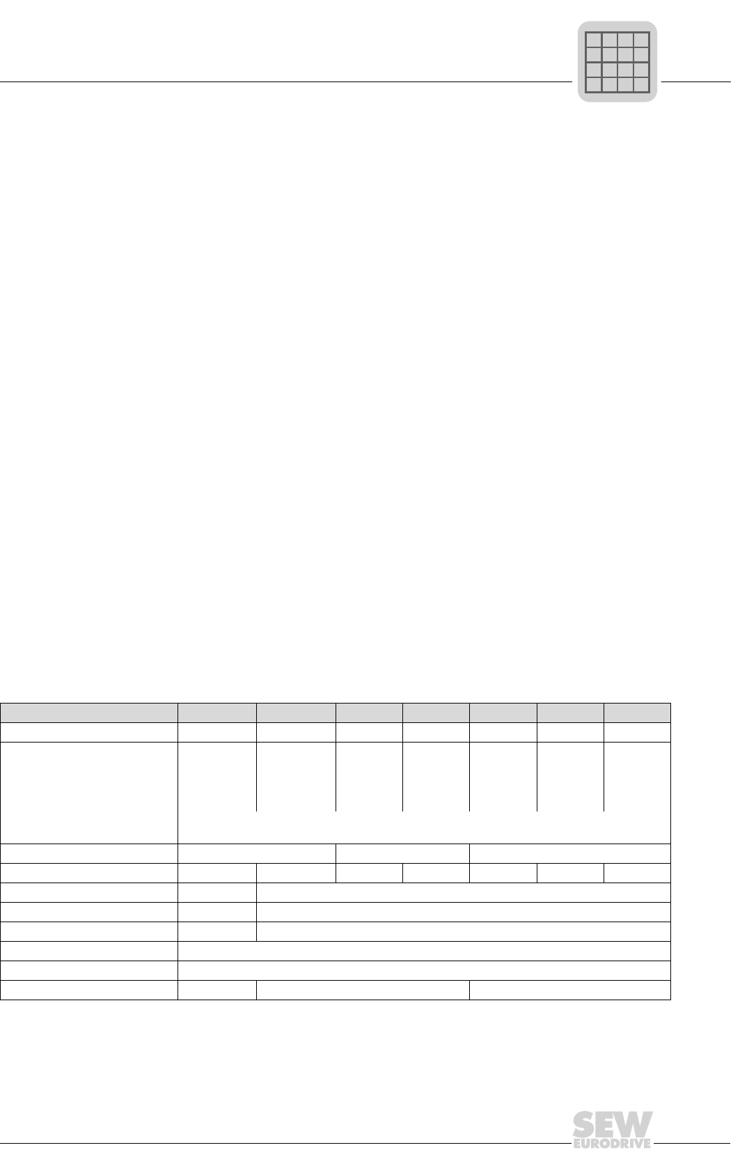
MOVIDRIVE® compact Catalog
59
2
Braking resistor option type BW...
2.15 Braking resistor option type BW...
General informa-
tion
The braking resistors in the BW... series are adapted to the technical characteristics of
MOVIDRIVE® drive inverters.
Flat-type braking
resistor
• Shockproof (IP54)
• Internal thermal overload protection (fuse which cannot be replaced)
• Touch guard and mounting rail mounting available from SEW as accessories.
Wire and grid
resistors
• Perforated sheet cover (IP20) open towards the mounting surface.
• The short-time load capacity of the wire and grid resistors is greater than in the flat-
type braking resistors (→ power diagrams).
SEW recommends protecting the wire and grid resistors against overload using a bime-
tallic relay. Set the trip current to the value IF in the table. Do not use any electronic or
electromagnetic fuses since even the brief excess currents which are still permitted may
cause them to trip.
The surfaces of the resistors get very hot if loaded with PN. Bear this aspect in mind
when selecting the installation location. As a rule, braking resistors are mounted on the
switch cabinet roof.
The performance data listed in the tables below show the load capacity of the braking
resistors according to their cyclic duration factor (cyclic duration factor = cdf of the brak-
ing resistor in % in relation to a cycle duration ≤ 120 s).
Parallel connec-
tion
Two braking resistors must be connected in parallel in the case of some inverter/resistor
combinations. In this case, the trip current must be set on the bimetallic relay to twice
the value of IF entered in the table.
Assignment to 400/500 V units (...-5_3)
Braking resistor type BW100-005 BW100-006 BW168 BW268 BW147 BW247 BW347
Part number 826 269 1 821 701 7 820 604 X 820 715 1 820 713 5 820 714 3 820 798 4
Load capacity 100 % cdf
at 50 % cdf1)
25 % cdf
12 % cdf
6 % cdf
1) cdf = Cyclic duration factor of the braking resistor in relation to a cycle duration TD ≤ 120 s.
0.45 kW
0.60 kW
0.83 kW
1.11 kW
2.00 kW
0.6 kW
1.1 kW
1.9 kW
3.5 kW
5.7 kW
0.8 kW
1.4 kW
2.6 kW
4.7 kW
7.6 kW
1.2 kW
2.2 kW
3.8 kW
6.7 kW
10 kW2)
2) Physical power limit due to the DC link voltage and the resistance value.
1.2 kW
2.2 kW
3.8 kW
7.2 kW
11 kW
2.0 kW
3.8 kW
6.4 kW
12 kW
14.4 kW2)
4.0 kW
7.6 kW
12.8 kW
14.4 kW2)
14.4 kW2)
Note the regenerative power limit of the inverter!
(= 150 % of the recommended motor power → Technical Data)
Resistance value RBW 100 Ω ±10 % 68 Ω ±10 % 47 Ω ±10 %
Trip current (of F16) IF0.8 ARMS 1.8 ARMS 2.5 ARMS 3.4 ARMS 3.5 ARMS 4.9 ARMS 7.8 ARMS
Type Flat type Wire resistor on ceramic core
Connections Cable Ceramic terminals 2.5 mm2 (AWG12)
Enclosure IP54 IP20 (when mounted)
Ambient temperature ϑamb -20...+45 °C
Type of cooling KS = Self-cooling
for MOVIDRIVE®0015/0022 0015...0040 0055/0075
P
if
kVA
Hz
n
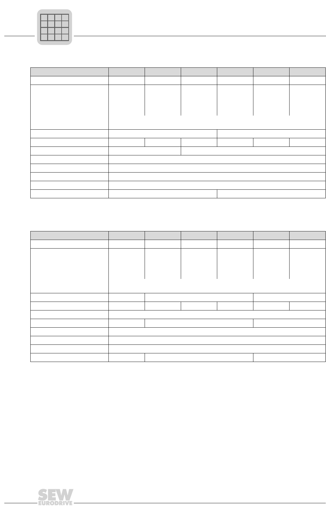
2
60
MOVIDRIVE® compact Catalog
Braking resistor option type BW...
Braking resistor type BW039-012 BW039-026 BW039-050 BW018-015 BW018-035 BW018-075
Part number 821 689 4 821 690 8 821 691 6 821 684 3 821 685 1 821 686 X
Load capacity 100 % cdf
at 50 % cdf1)
25 % cdf
12 % cdf
6 % cdf
1.2 kW
2.1 kW
3.8 kW
7.0 kW
11.4 kW
2.6 kW
4.6 kW
8.3 kW
15.3 kW
17.3 kW2)
5.0 kW
8.5 kW
15.0 kW
17.3 kW2)
17.3 kW2)
1.5 kW
2.5 kW
4.5 kW
6.7 kW
11.4 kW
3.5 kW
5.9 kW
10.5 kW
15.7 kW
26.6 kW
7.5 kW
12.7 kW
22.5 kW
33.7 kW
37.5 kW2)
Note the regenerative power limit of the inverter!
(= 150 % of the recommended motor power → Technical Data)
Resistance value RBW 39 Ω ±10 % 18 Ω ±10 %
Trip current (of F16) IF4.2 ARMS 7.8 ARMS 11 ARMS 4.0 ARMS 8.1 ARMS 14 ARMS
Type Wire resistor Grid resistor
Connections Ceramic terminals 2.5 mm2 (AWG12)
Enclosure IP20 (when mounted)
Ambient temperature ϑamb -20...+45 °C
Type of cooling KS = Self-cooling
for MOVIDRIVE®0110 0150/0220 and 2 × parallel with 0370/0450
1) cdf = Cyclic duration factor of the braking resistor in relation to a cycle duration TD ≤ 120 s.
2) Physical power limit due to the DC link voltage and the resistance value.
Braking resistor type BW915 BW012-025 BW012-050 BW012-100 BW106 BW206
Part number 821 260 0 821 680 0 821 681 9 821 682 7 821 050 0 821 051 9
Load capacity 100 % cdf
at 50 % cdf1)
25 % cdf
12 % cdf
6 % cdf
16 kW
27 kW
45 kW2)
45 kW2)
45 kW2)
2.5 kW
4.2 kW
7.5 kW
11.2 kW
19.0 kW
5.0 kW
8.5 kW
15.0 kW
22.5 kW
38.0 kW
10 kW
17 kW
30 kW
45 kW
56 kW2)
13 kW
24 kW
40 kW
66 kW
102 kW
18 kW
32 kW
54 kW
88 kW
112 kW2)
Note the regenerative power limit of the inverter!
(= 150 % of the recommended motor power → Technical Data)
Resistance value RBW 15 Ω ±10 % 12 Ω ±10 % 6 Ω ±10 %
Trip current (of F16) IF28 ARMS 6.1 ARMS 12 ARMS 22 ARMS 38 ARMS 42 ARMS
Type Grid resistor
Connections M8 stud Ceramic terminals 2.5 mm2 (AWG12) M8 stud
Enclosure IP20 (when mounted)
Ambient temperature ϑamb -20...+45 °C
Type of cooling KS = Self-cooling
for MOVIDRIVE®0220 0300 0370...0750
1) cdf = Cyclic duration factor of the braking resistor in relation to a cycle duration TD ≤ 120 s.
2) Physical power limit due to the DC link voltage and the resistance value.
P
if
kVA
Hz
n
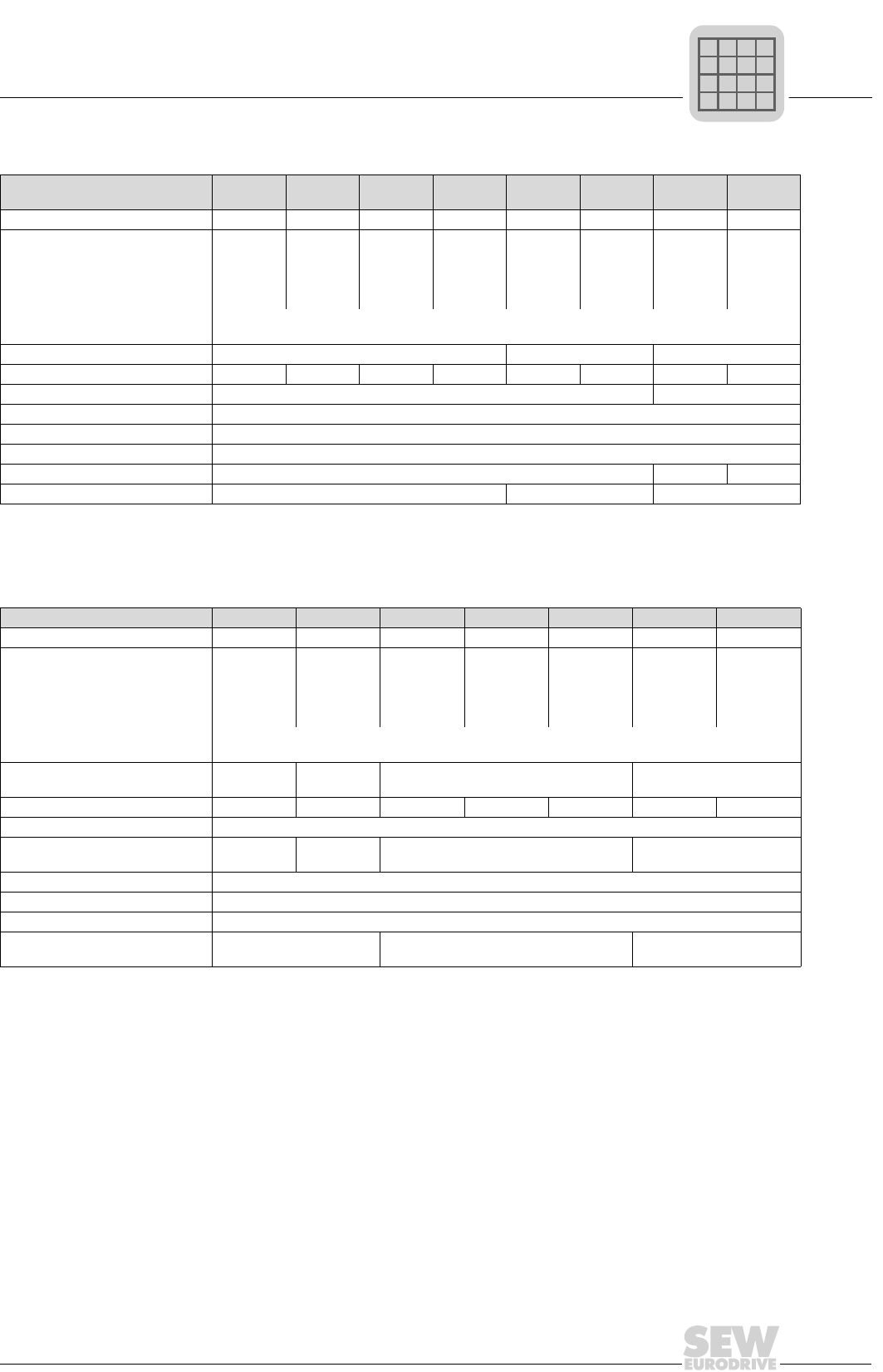
MOVIDRIVE® compact Catalog
61
2
Braking resistor option type BW...
Assignment to 230 V units (-2_3)
Braking resistor type BW039-
003
BW039-
006
BW039-
012
BW039-
026
BW027-
006
BW027-
012
BW018-
015
BW018-
035
Part number 821 687 8 821 688 6 821 689 4 821 690 8 822 422 6 822 423 4 821 684 3 821 685 1
Load capacity 100 % cdf
at 50 % cdf1)
25 % cdf
12 % cdf
6 % cdf
1) cdf = Cyclic duration factor of the braking resistor in relation to a cycle duration TD ≤ 120 s.
0.3 kW
0.5 kW
1.0 kW
1.7 kW
2.8 kW
0.6 kW
1.1 kW
1.9 kW
3.5 kW
5.7 kW
1.2 kW
2.1 kW
3.8 kW
5.9 kW2)
5.9 kW2)
2) Physical power limit due to the DC link voltage and the resistance value.
2.6 kW
4.6 kW
5.9 kW2)
5.9 kW2)
5.9 kW2)
0.6 kW
1.2 kW
2.0 kW
3.5 kW
6.0 kW
1.2 kW
2.3 kW
5.0 kW
7.5 kW
8.5 kW2)
1.5 kW
2.5 kW
4.5 kW
6.7 kW
11.4 kW
3.5 kW
5.9 kW
10.5 kW
15.7 kW
25.6 kW3)
3) Physical power limit due to the DC link voltage and the resistance value.
Note the regenerative power limit of the inverter!
(= 150 % of the recommended motor power → Technical Data)
Resistance value RBW 39 Ω ±10 % 27 Ω ±10 % 18 Ω ±10 %
Trip current (of F16) IF2.0 ARMS 3.2 ARMS 4.2 ARMS 7.8 ARMS 2.5 ARMS 4.4 ARMS 4.0 ARMS 8.1 ARMS
Type Wire resistor Grid resistor
Connections Ceramic terminals 2.5 mm2 (AWG12)
Enclosure IP20 (when mounted)
Ambient temperature ϑamb -20...+45 °C
Type of cooling KS = Self-cooling
for MOVIDRIVE®0015/0022 0015...0037 2 × parallel with 0110
Braking resistor type BW018-075 BW915 BW012-025 BW012-050 BW012-100 BW106 BW206
Part number 821 686 X 821 260 0 821 680 0 821 681 9 821 682 7 821 050 0 821 051 9
Load capacity 100 % cdf
at 50 % cdf1)
25 % cdf
12 % cdf
6 % cdf
7.5 kW
12.7 kW
22.5 kW
25.6 kW2)
25.6 kW2)
16.0 kW
27.0 kW
30.7 kW2)
30.7 kW2)
30.7 kW2)
2.5 kW
4.2 kW
7.5 kW
11.2 kW
19.0 kW
5.0 kW
8.5 kW
15.0 kW
19.2 kW2)
19.2 kW2)
10 kW
17 kW
19.2 kW2)
19.2 kW2)
19.2 kW2)
13 kW
24 kW
38.4 kW2)
38.4 kW2)
38.4 kW2)
18 kW
32 kW
38.4 kW2)
38.4 kW2)
38.4 kW2)
Note the regenerative power limit of the inverter!
(= 150 % of the recommended motor power → Technical Data)
Resistance value RBW 18 Ω ±10 % 15 Ω
±10 % 12 Ω ±10 % 6 Ω ±10 %
Trip current (of F16) IF14 ARMS 28 ARMS 10 ARMS 19 ARMS 27 ARMS 38 ARMS 42 ARMS
Type Grid resistor
Connections 2.5 mm2
(AWG12) M8 stud Ceramic terminals 2.5 mm2 (AWG12) M8 stud
Enclosure IP20 (when mounted)
Ambient temperature ϑamb -20...+45 °C
Type of cooling KS = Self-cooling
for MOVIDRIVE®2 × parallel with 0110 0055/0075 0150 and 2 × parallel with
0220/0300
1) cdf = Cyclic duration factor of the braking resistor in relation to a cycle duration TD ≤ 120 s.
P
if
kVA
Hz
n
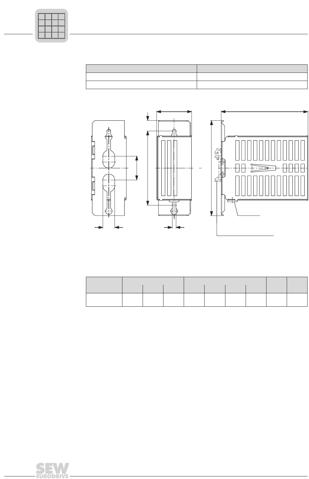
2
62
MOVIDRIVE® compact Catalog
Braking resistor option type BW...
Touch guard Touch guard is available for braking resistors in flat-pack design.
All dimensions in mm (in):
Mounting rail
installation
A mounting rail attachment is available from SEW as an accessory, part number 822
194 4, for mounting the touch guard on a mounting rail.
Touch guard BS005
Part number 813 152 X
For braking resistor BW100-005
00524BEN
Figure 30: Dimensions, touch guard
Touch guard Main dimensions Fixing dimensions Weight
W H D a a1 bb1 xkg (lb)
BS005 60
(2.36)
160
(6.30)
252
(9.92)
125
(4.92)
40
(1.57)
20
(0.79)
6
(0.24)
17.5
(0.69)
0.5
(1.1)
a
x
b1
b
a1
H
WD
Grommet
Mounting rail attachment
P
if
kVA
Hz
n
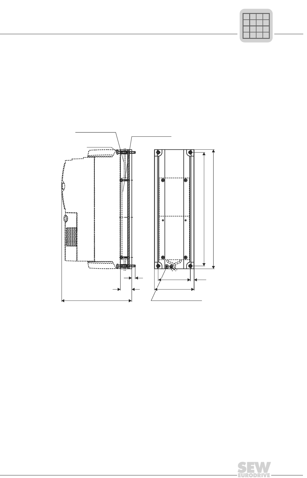
MOVIDRIVE® compact Catalog
63
2
Braking resistor option type BW...
DKB11A heat sink for brake resistors in flat-pack design
Part number 814 345 5
Description The DKB11A heat sink for brake resistors in flat-pack design provides a space-saving
means of mounting braking resistors in flatpack design (BW100-005) below MOVID-
RIVE® size 1 (400/500 V units: 0015...0040; 230 V units: 0015...0037). The resistor is
inserted into the heat sink and attached using the supplied screws (M4 × 20).
1) Mounting surface for the braking resistor
2) Retaining screws, not included in scope of delivery
03826AEN
Figure 31: Dimensions, DKB11A heat sink for brake resistors in flatpack design in mm (in)
814 345 5
BW...-005
BW...-003
300 (11.81)
315 (12.40)
85 (3.35)
105 (4.13)
10 (0.39)
185 (7.28)
30
(1.18)
9
(0.35)
M4 x 20
2)
1)
4 x M5 x 12
PE screw M5
4 x Spacer bolt 4 x Pan head screw
P
if
kVA
Hz
n
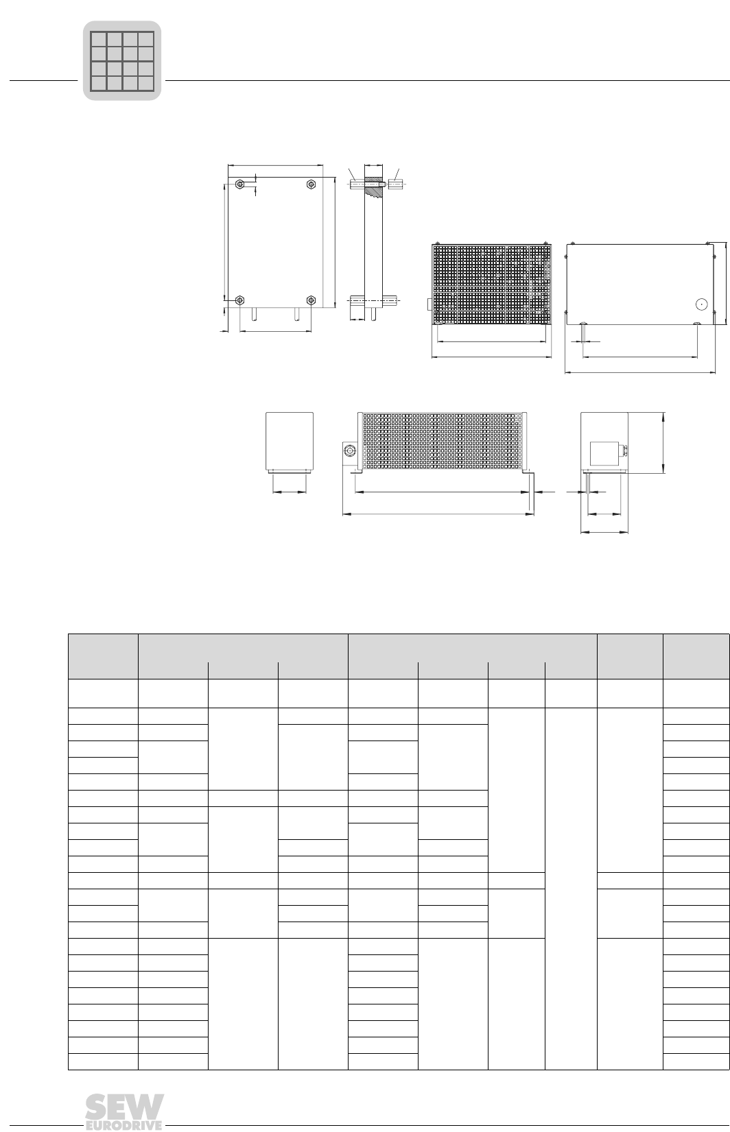
2
64
MOVIDRIVE® compact Catalog
Braking resistor option type BW...
Dimensions,
BW...
Mounting position as required
00523BEN
Figure 32: Dimensions, BW... braking resistors
bax1 c
b1
a
b
c
a
b
x1
x2 12
(0.47)
12
M4
Flat-pack design
Wire-wound resistor
Steel grid resistor
H
D
W
W
D
H
HD
W
Connecting cable, length 500 mm (19.69 in)
4 M4 threaded bushings,
types 1 and 2 are supplied
All dimensions in mm (in):
BW... Main dimensions Fixing dimensions Hole
dimension
Weight
Type W H D a b/b1 x1 x2 ckg (lb)
BW100-005 216 (8.50) 80 (3.15) 15 (0.59) 204 (8.03) 60 (2.36) 6 (0.24) 10 (0.39) 4 threaded
bushes 0.6 (1.3)
BW100-006 486 (19.13)
120 (4.72)
92 (3.62) 426 (16.77) 64 (2.52)
10 (0.39)
-
5.8 (0.23)
2.2 (4.9)
BW168 365 (14.37)
185 (7.28)
326 (12.83)
150 (5.91)
3.6 (8.0)
BW268 465 (18.31) 426 (16.77) 4.3 (9.5)
BW147 4.3 (9.5)
BW247 665 (26.18) 626 (24.65) 6.1 (13.5)
BW347 670 (26.38) 145 (5.71) 340 (13.39) 630 (24.80) 300 (11.81) 13.2 (29.1)
BW039-003 286 (11.26)
120 (4.72)
92 (3.62) 226 (8.90) 64 (2.52) 1.5 (3.3)
BW039-006 486 (19.13) 426 (16.77) 2.2 (4.9)
BW039-012 185 (7.28) 150 (5.91) 4.3 (9.5)
BW039-026 586 (23.07) 275 (10.83) 530 (20.87) 240 (9.45) 7.5 (16.6)
BW039-050 395 (15.55) 260 (10.24) 490 (19.29) 370 (14.57) 380 (14.96) - 10.5 (0.41) 12 (26.5)
BW027-006 486 (19.13) 120 (4.72)
92 (3.62) 426 (16.77) 64 (2.52)
10 (0.39) 5.8 (0.23)
2.2 (4.9)
BW027-012 185 (7.28) 150 (5.91) 4.3 (9.5)
BW018-015 600 (23.62) 92 (3.62) 540 (21.26) 64 (2.52) 4.0 (8.8)
BW018-035 295 (11.61)
260 (10.24) 490 (19.29)
270 (10.63)
380 (14.96) - 10.5 (0.41)
9.0 (19.8)
BW018-075 595 (23.43) 570 (22.44) 21 (46.3)
BW915 795 (31.30) 770 (30.31) 26 (57.3)
BW012-025 295 (11.61) 270 (10.63) 9.0 (19.8)
BW012-050 395 (15.55) 370 (14.57) 12 (26.5)
BW012-100 595 (23.43) 570 (22.44) 21 (46.3)
BW106 795 (31.30) 770 (30.31) 32 (70.5)
BW206 995 (39.17) 970 (38.18) 43 (94.8)
P
if
kVA
Hz
n
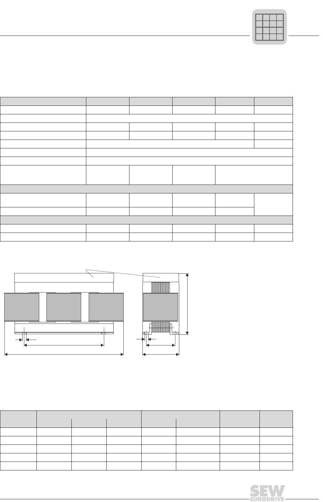
MOVIDRIVE® compact Catalog
65
2
Line chokes option type ND...
2.16 Line chokes option type ND...
• To increase the overvoltage protection
• To limit the charging current when several inverters are connected together in parallel on the input end with a shared
supply system contactor (rated current of line choke = total of inverter rated currents)
Line choke type ND020-013 ND045-013 ND085-013 ND1503 ND200-0033
Part number 826 012 5 826 013 3 826 014 1 825 548 2 826 579 8
Rated voltage VN3 × 380 VAC -10 %...3 × 500 VAC +10 %, 50/60 Hz
Rated current1) IN
1) If more than one MOVIDRIVE® is connected to a line choke, the total value of the rated currents of the connected units must not
exceed the rated current of the line choke!
20 AAC 45 AAC 85 AAC 150 AAC 200 AAC
Power loss at INPV10 W 15 W 25 W 65 W 100 W
Inductance LN0.1 mH 0.03 mH
Ambient temperature ϑamb -25...+45 °C
Enclosure IP 00 (EN 60529)
Connections
Modular terminal
blocks
4 mm2 (AWG 10)
Modular terminal
blocks
10 mm2 (AWG 8)
Modular terminal
blocks
35 mm2 (AWG 2)
M10 stud / PE: M8 stud
Assignment to 400/500 V units (...-5_3)
In rated operation (100 %) 0015...0075 0110...0220 0300...0450 and
MDR60A0370 0550/0750 MDR60A0750
With increased power (VFC, 125 %) 0015...0075 0110/0150 0220...0370 0450...0750
Assignment to 230 V units (...-2_3)
In rated operation (100 %) 0015...0055 0075/0110 0150/0220 0300 -
With increased power (VFC, 125 %) 0015...0037 0055/0075 0110/0150 0220/0300 -
00526BEN
Figure 33: Dimensions, ND... line chokes
Mounting position as required
H
a
c
b
c
D
W
Space for terminals (safe to touch)
All dimensions in mm (in):
Line choke
type
Main dimensions Fixing dimensions Hole dim. Weight
W H D a b c kg (lb)
ND020-013 85 (3.35) 60 (2.36) 120 (4.72) 50 (1.97) 31 (1.22) 5-10 (0.20-0.39) 0.5 (1.1)
ND045-013 125 (4.92) 95 (3.74) 170 (6.69) 84 (3.31) 55-75 (2.17-2.95) 6 (0.24) 2.5 (5.5)
ND085-013 185 (7.28) 115 (4.53) 235 (9.25) 136 (5.35) 56 (2.20) 7 (0.28) 8 (17.6)
ND1503 255 (10.04) 140 (5.51) 230 (9.06) 170 (6.69) 77 (3.03) 8 (0.31) 17 (37.5)
ND200-0033 250 (9.84) 160 (6.30) 230 (9.06) 180 (7.09) 98 (3.86) 8 (0.31) 15 (33.1)
P
if
kVA
Hz
n
2
66
MOVIDRIVE® compact Catalog
NF...-... line filter option
2.17 NF...-... line filter option
• To suppress interference emissions on the line side of inverters
Input filter type NF009-
503
NF014-
503
NF018-
503
NF035-
503
NF048-
503
NF063-
503
NF085-
503
NF115-
503
NF150-
503
Part number 827 412 6 827 116 X 827 413 4 827 128 3 827 117 8 827 414 2 827 415 0 827 416 9 827 417 7
Rated voltage VN3 × 380 VAC -10 %...3 × 500 VAC +10 %, 50/60 Hz
Rated current IN9 AAC 14 AAC 18 AAC 35 AAC 48 AAC 63 AAC 85 AAC 115 AAC 150 AAC
Power loss
at INPV6 W 9 W 12 W 15 W 22 W 30 W 35 W 60 W 90 W
Earth-leakage cur-
rent at VN
< 25 mA < 25 mA < 25 mA < 25 mA < 40 mA < 30 mA < 30 mA < 30 mA < 30 mA
Ambient
temperature
ϑamb
-25...+40 °C
Enclosure IP 20 (EN 60529)
Connections
L1-L3/L1’-L3’ 4 mm2 (AWG 10) 10 mm2 (AWG 8) 16 mm2
(AWG 6)
35 mm2
(AWG 2)
50 mm2
(AWG1/0)
95 mm2
(AWG4/0)
PE M5 stud M5 stud M6 stud M6 stud M8 stud M10 stud M10 stud
Assignment to 400/500 V units (...-5_3)
In rated operation
(100 %)
0015...
0040
0055/
0075 -0110/
0150 0220 0300 0370/
0450 0550 0750
With increased power
(VFC, 125 %)
0015...
0030
0040/
0055 0075 0110 0150 0220 0300/
0370 0450 0550/
0750
Assignment to 230 V units (...-2_3)
In rated operation
(100 %)
0015/
0022 0037 - 0055/
0075 0110 0150 0220 0300 -
With increased power
(VFC, 125 %) 0015 0022 0037 0055/
0075 -0110/
0150 -0220/
0300 -
The effectiveness of input filters is restricted in IT systems.
P
if
kVA
Hz
n
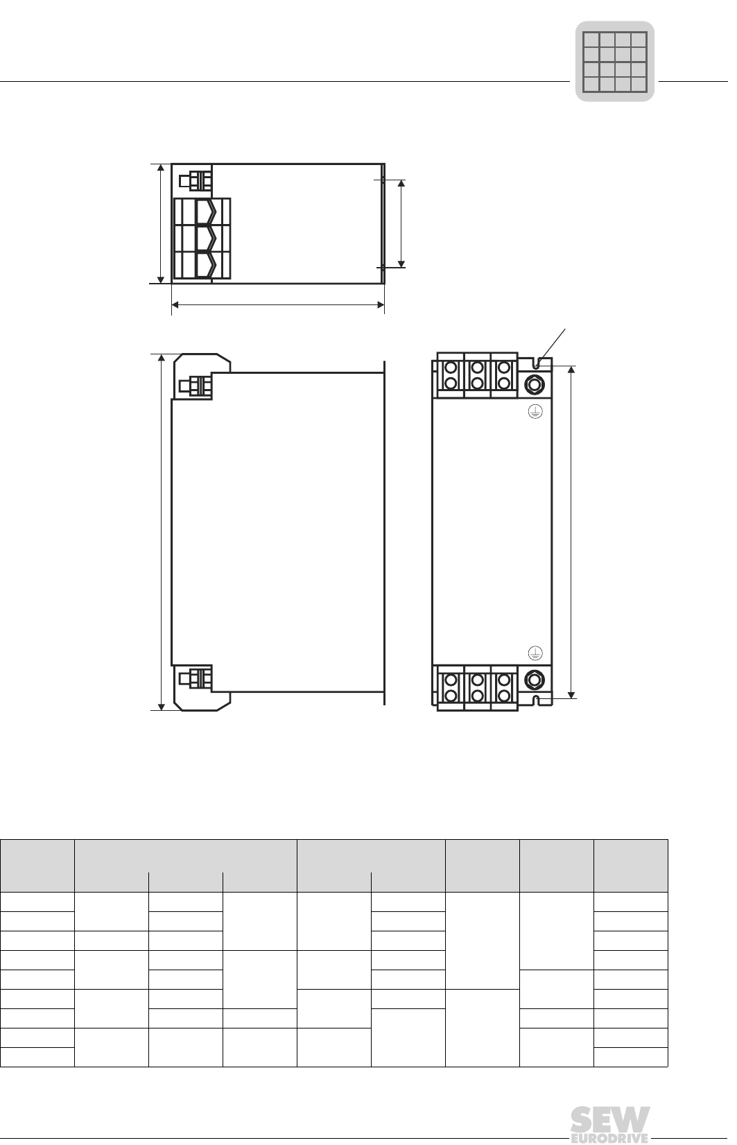
MOVIDRIVE® compact Catalog
67
2
NF...-... line filter option
Mounting position as required
05233AEN
Figure 34: Dimensions, NF input filters
a
H
b
c
LINE
L3 L2 L1
L3' L2' L1'
LOAD
D
W
All dimensions in mm (in):
Input filter
type
Main dimensions Fixing dimensions Hole
dimension PE connec-
tion
Weight
W H D a b c kg (lb)
NF009-503 55 (2.16) 195 (7.67)
80 (3.15) 20 (0.79)
180 (7.09)
5.5 (0.22) M5
0.8 (1.8)
NF014-503 225 (8.85) 210 (8.27) 0.9 (2.0)
NF018-503 50 (1.96) 255 (10.04) 240 (9.45) 1.1 (2.4)
NF035-503 60 (2.36) 275 (10.83)
100 (3.93) 30 (1.18) 255 (10.04) 1.7 (3.7)
NF048-503 315 (12.40) 295 (11.61) M6 2.1 (4.6)
NF063-503 90 (3.54) 260 (10.24) 60 (2.36) 235 (9.25)
6.5 (0.26)
2.4 (5.3)
NF085-503 320 (12.60) 140 (5.51)
255 (10.04)
M8 3.5 (7.7)
NF115-503 100 (3.93) 330 (13.00) 155 (6.10) 65 (2.56) M10 4.8 (10.6)
NF150-503 5.6 (12.3)
P
if
kVA
Hz
n
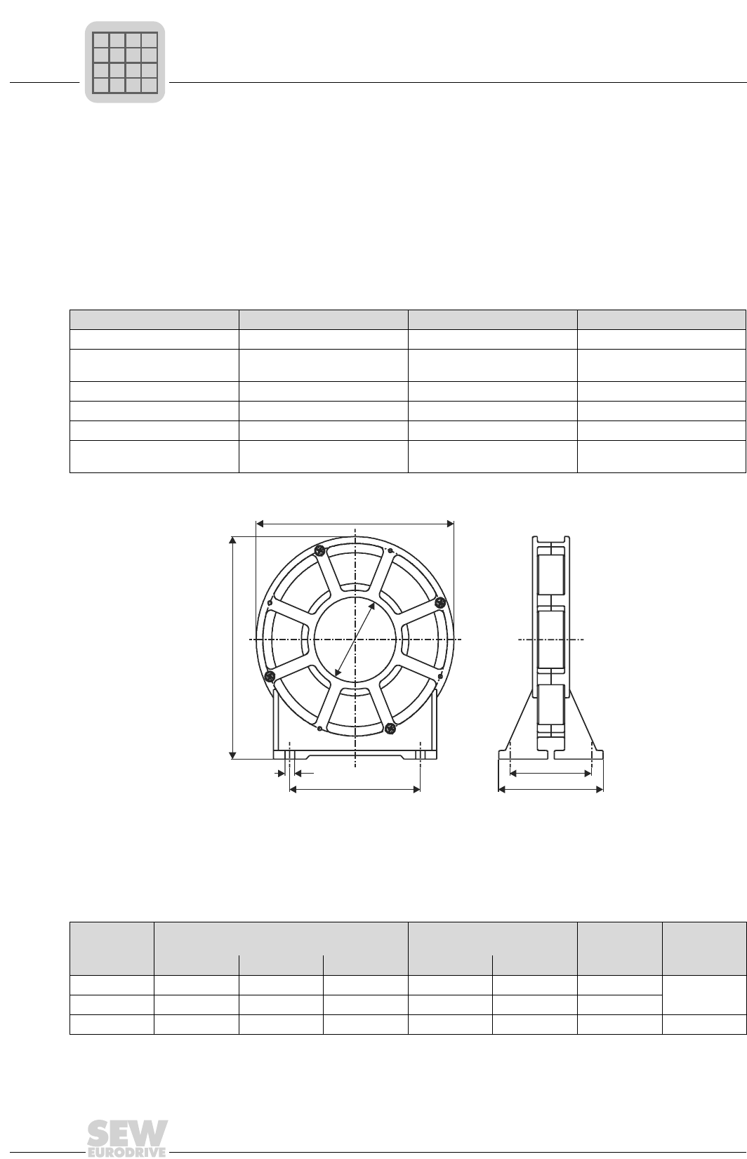
2
68
MOVIDRIVE® compact Catalog
Output choke option type HD...
2.18 Output choke option type HD...
Mounting position as required
• To suppress radiated interference from the unshielded motor cable. We recommend routing the motor cable through
the output choke with five loops. Less than five loops are possible if the cable has a large diameter. To make up for
this, two or three output chokes should be connected in series. Two output chokes should be connected in series if
there are four loops, and three output chokes in series if there are three loops.
Output chokes are allocated on the basis of the cable cross sections of the motor feeders. Consequently, there is no
separate allocation table for the 230 V units.
Output choke type HD001 HD002 HD003
Part number 813 325 5 813 557 6 813 558 4
Dimensions W × H × D 121 × 64 × 131 mm
(4.76 × 2.52 × 5.16 in)
66 × 49 × 73 mm
(2.60 × 1.93 × 2.87 in)
170 × 64 × 185 mm
(6.69 × 2.52 × 7.28 in)
Inside diameter d 50 mm (1.97 in) 23 mm (0.91 in) 88 mm (4.46 in)
Max. power loss PVmax 15 W8 W30 W
Weight 0.5 kg (1.1 lb) 0.2 kg (0.44 lb) 1.1 kg (2.42 lb)
For cable cross sections 1.5...16 mm2
(AWG 16...6) ≤ 1.5 mm2 (AWG 16) ≥ 16 mm2 (AWG 6)
00570CEN
Figure 35: Dimensions, HD... output chokes
d
ab
c
D
W
H
All dimensions in mm (in):
Output choke
type
Main dimensions Fixing dimensions Inside ∅Hole dimen-
sion
W H D a b d c
HD001 121 (4.76) 64 (2.52) 131 (5.16) 80 (3.15) 50 (1.97) 50 (1.97) 5.8 (0.23)
HD002 66 (2.60) 49 (1.93) 73 (2.87) 44 (1.73) 38 (1.50) 23 (0.91)
HD003 170 (6.69) 64 (2.52) 185 (7.28) 120 (4.72) 50 (1.97) 88 (3.46) 7.0 (0.28)
P
if
kVA
Hz
n
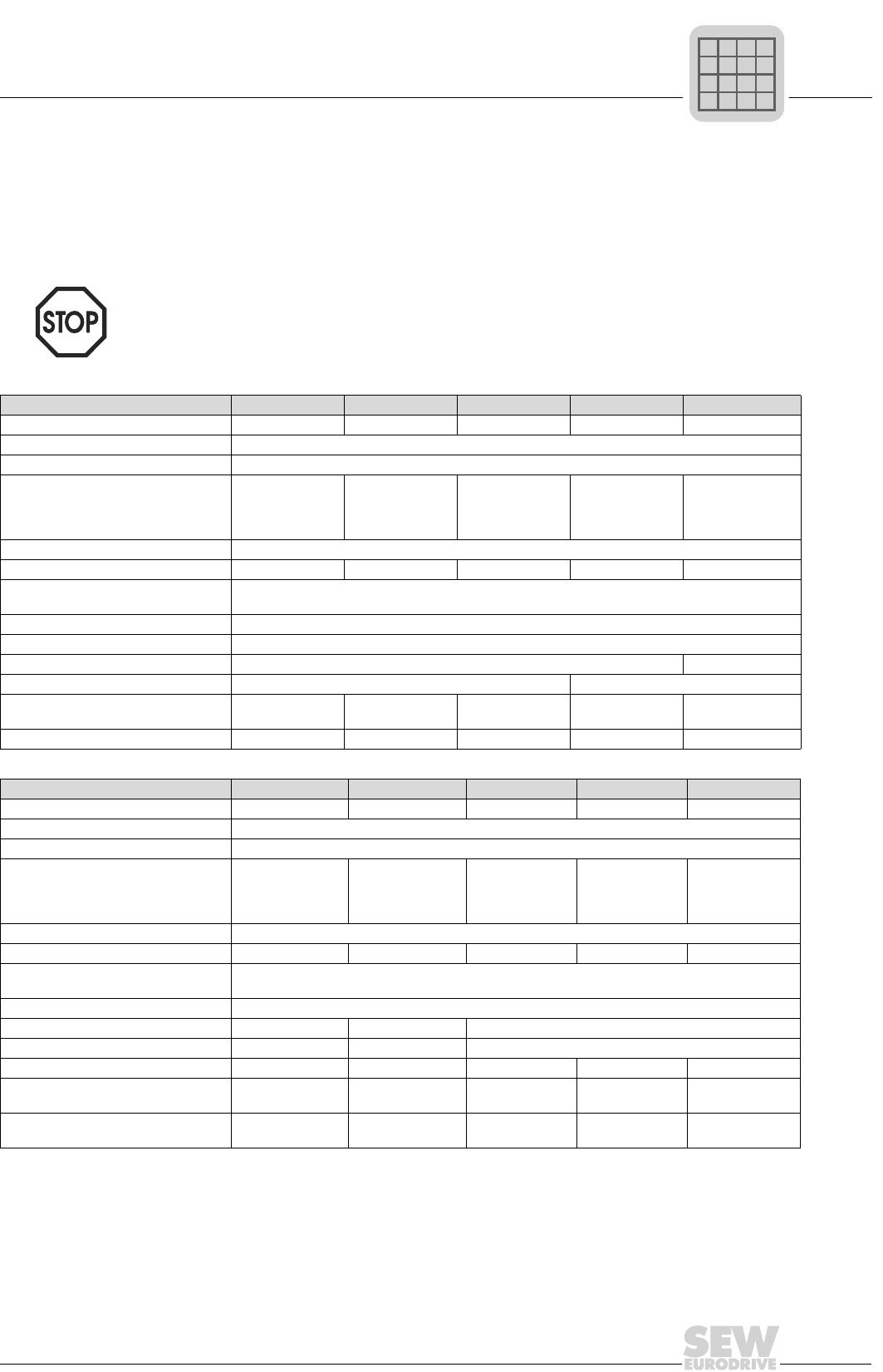
MOVIDRIVE® compact Catalog
69
2
Output filter option type HF...
2.19 Output filter option type HF...
Sine filter for smoothing the output voltage of inverters. They are used:
• In group drives (several motor feeders in parallel); the discharge currents in the motor cables are suppressed.
• To protect the motor winding insulation of non-SEW motors which are not suitable for use with PWM inverters and
could be damaged by voltage spikes in long motor feeders (> 100 m).
• Output filters are only allowed to be used with 400/500 V units type MCF, MCV and
MCH in VFC operating modes. Do not use with 230 V units, do not use with type MDV
in CFC operating modes, do not use with type MCH in CFC or SERVO operating
modes and do not use with type MDS.
• Output filters are not allowed to be used in hoists.
Output filter type HF015-503 HF022-503 HF030-503 HF040-503 HF055-503
Part number 826 030 3 826 031 1 826 032 X 826 311 6 826 312 4
Rated voltage VN3 × 380 VAC -10 %...3 × 500 VAC +10 %, 50/60 Hz1)
Voltage drop at IN∆V< 6.5 % (7.5 %) at 400 V / < 4 % (5 %) at 500 V and fAmax = 50 Hz (60 Hz)
Rated throughput current2)IN 400 V
(at Vmains = 3 × 400 VAC)
Rated throughput current2)IN 500 V
(at Vmains = 3 × 500 VAC)
4 AAC
3 AAC
6 AAC
5 AAC
8 AAC
6 AAC
10 AAC
8 AAC
12 AAC
10 AAC
Earth-leakage current at VN∆I0 mA
Power loss at INPV35 W 55 W 65 W 90 W 115 W
Emitted interference via unshielded
motor lead
According to class B limit to EN 55011 and EN 55014
Complies with EN 50081, parts 1 and 2
Ambient temperature ϑamb 0...+45 °C (reduction: 3.0 % IN per K to max. 60 °C)
Enclosure (EN 60529) IP 20
Connections M4 connection studs: 0.5...6 mm2 (AWG 20...10) 10 mm2 (AWG 8)
Weight 4.4 kg (9.68 lb) 10.8 kg (23.76 lb)
For MOVIDRIVE® MD_60A...-5_3
In rated operation (100 %) 0015 0022 0030 0040 0055
With increased power (125 %) - 0015 0022 0030 0040
Output filter type HF075-503 HF450-503 HF023-403 HF033-403 HF047-403
Part number 826 313 2 826 948 3 825 784 1 825 785 X 825 786 8
Rated voltage VN3 × 380 VAC -10 %...3 × 500 VAC +10 %, 50/60 Hz1)
Voltage drop at IN∆V< 6.5 % (7.5 %) at 400 V / < 4 % (5 %) at 500 V and fAmax = 50 Hz (60 Hz)
Rated throughput current2)IN 400 V
(at Vmains = 3 × 400 VAC)
Rated throughput current2)IN 500 V
(at Vmains = 3 × 500 VAC)
16 AAC
13 AAC
90 AAC
72 AAC
23 AAC
19 AAC
33 AAC
26 AAC
47 AAC
38 AAC
Earth-leakage current at VN∆I0 mA
Power loss at INPV135 W 400 W 90 W 120 W 200 W
Emitted interference via unshielded
motor lead
According to class B limit to EN 55011 and EN 55014
Complies with EN 50081, parts 1 and 2
Ambient temperature ϑamb 0...+45 °C (reduction: 3.0 % IN per K to max. 60 °C)
Enclosure (EN 60529) IP 20 IP 10 IP 20
Connections 10 mm2 (AWG 8) 35 mm2 (AWG 2) 25 mm2 (AWG 4)
Weight 10.8 kg (23.76 lb) 32 kg (70.58 lb) 15.9 kg (35.0 lb) 16.5 kg (36.3 lb) 23 kg (50.6 lb)
For MOVIDRIVE® MD_60A...-5_3
In rated operation (100 %) 0075
0370/0450/
05503)/07503) 0110 0150/03003) 0220
With increased power (125 %) 0055 0300/0370/0450/
0550/0750 0075 0110/02203) 0150
1) A reduction of 6 % IN per 10 Hz applies above fAN = 60 Hz for the rated throughput current IN.
2) Only applies to operation without UZ connection. For operation with UZ connection, observe the project planning instructions in the
MOVIDRIVE® compact System Manual, Sec. 'Project Planning/Connecting the optional power components'.
3) Connect two HF... output filters together in parallel for operation with these MOVIDRIVE® units.
P
if
kVA
Hz
n
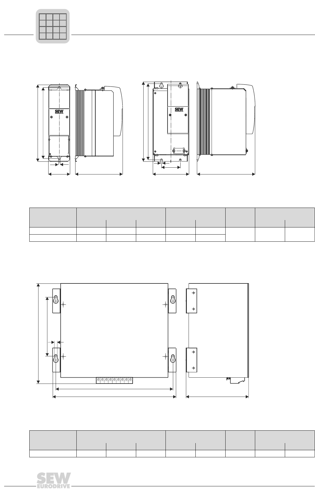
2
70
MOVIDRIVE® compact Catalog
Output filter option type HF...
Dimensions, output filter HF...-503, in mm (in)
HF015/022/030-503 HF040/055/075-503
00527BEN
Figure 36: Dimensions, output filter HF015...075-503
Only the mounting position shown in the dimensions diagram is permitted
Output filter type Main dimensions Fixing dimensions Hole dimen-
sion Ventilation clearance1)
1) No clearance is required at the sides; the units can be lined up side-by-side.
W H D a b c Top Bottom
HF015/022/030-503 80 (3.15) 286 (11.26) 176 (6.93) - 265 (10.43) 7 (0.28) 100 (3.94) 100 (3.94)
HF040/055/075-503 135 (5.31) 296 (11.65) 216 (8.50) 70 (2.76) 283 (11.14)
HF450-503
03388BEN
Figure 37: Dimensions, output filter HF450-503
Only the mounting position shown in the dimensions diagram is permitted
Output filter type Main dimensions Fixing dimensions Hole dimen-
sion Ventilation clearance
W H D a b c Top Bottom
HF450-503 465 (18.31) 385 (15.16) 240 (9.45) 436 (17.17) 220 (8.66) 8.5 (0.33) 100 (3.94) 100 (3.94)
b
b
ca
c
H
WD
DW
H
a
b
H
c
WD
P
if
kVA
Hz
n
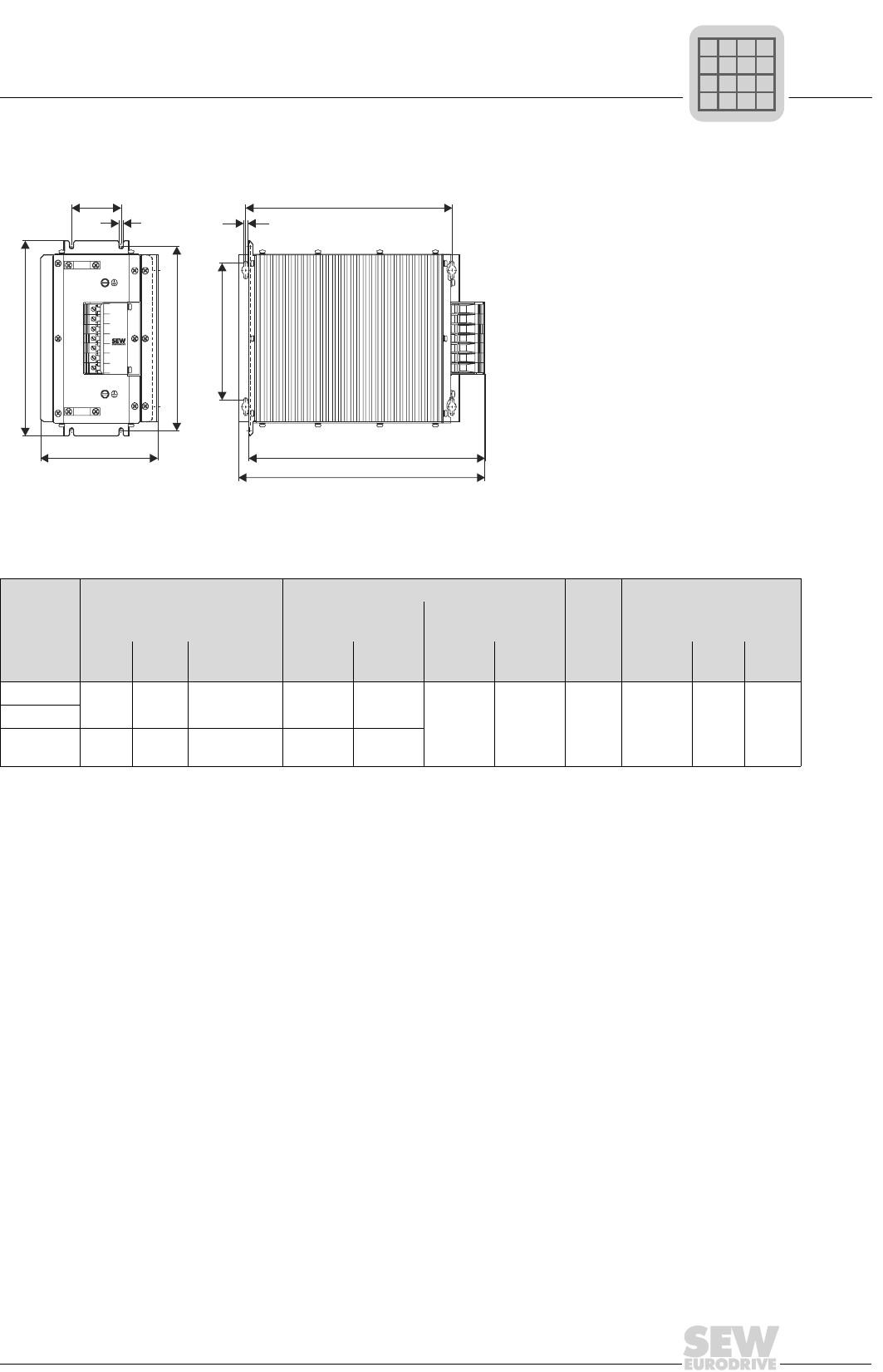
MOVIDRIVE® compact Catalog
71
2
Output filter option type HF...
Dimensions, output filter HF...-403, in mm (in)
00528BEN
Figure 38: Dimensions, output filter HF...-403
Type
Main dimensions
Fixing dimensions Hole
dimen
sion
Ventilation clearance
Standard installa-
tion
Crossways mount-
ing position
W H D/D1 a b a1 a2 cAt side Top Bot-
tom
HF023-403 145
(5.71)
284
(11.18)
365/390
(14.37/15.35)
268
(10.55)
60
(2.36) 210
(8.27)
334
(13.15)
6.5
(0.26)
30 each
(1.18 ea)
150
(5.91)
150
(5.91)
HF033-403
HF047-403 190
(7.48)
300
(11.82)
385/400
(15.16/15.57)
284
(11.18)
80
(3.15)
b
c
a
4
5
6
7
U
V
W
b1
a1
c
H
WD
D1
P
if
kVA
Hz
n
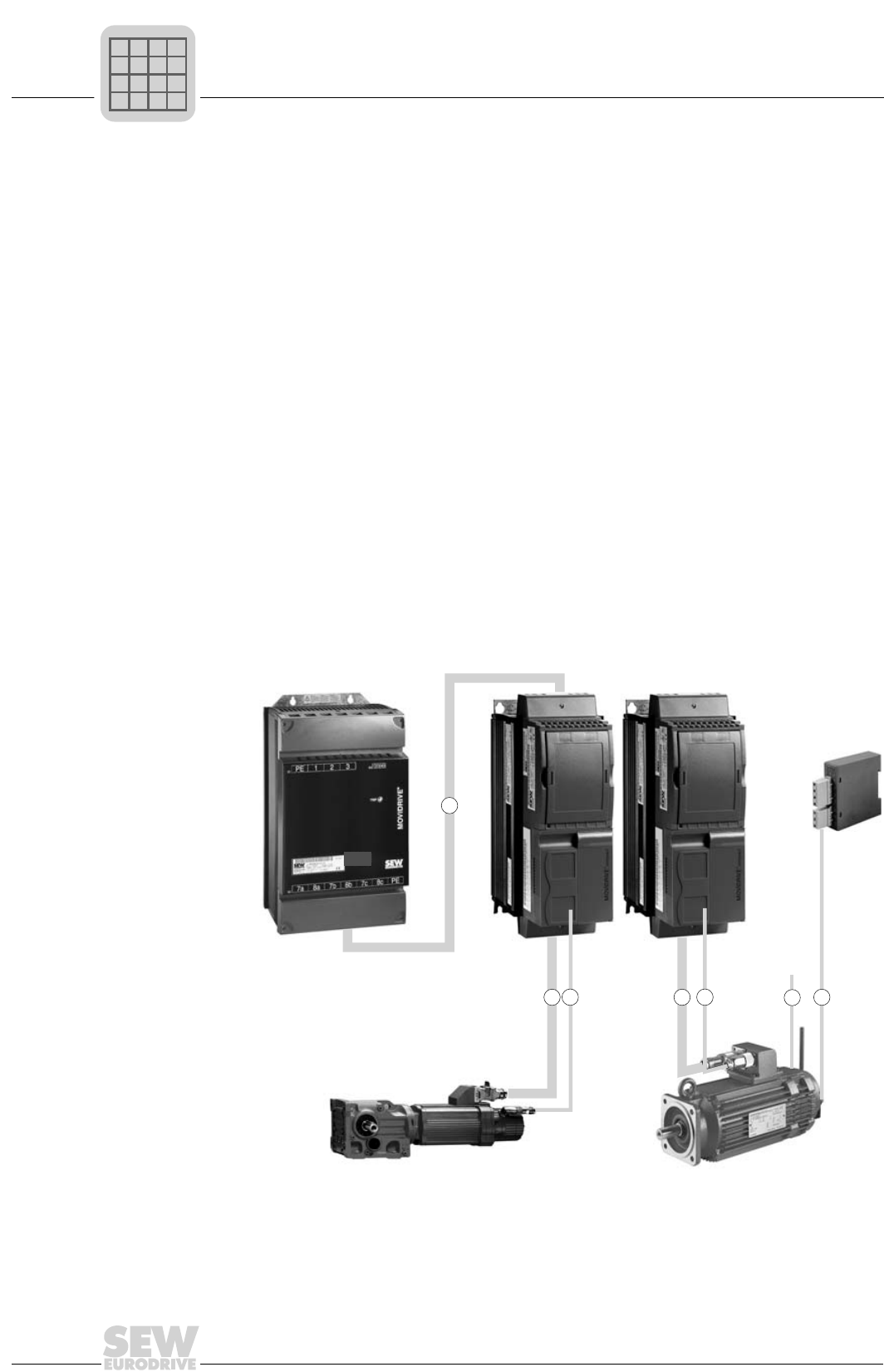
2
72
MOVIDRIVE® compact Catalog
Pre-fabricated cables
2.20 Pre-fabricated cables
Overview SEW offers cable sets and prefabricated cables for straightforward and error-free con-
nection of various system components to MOVIDRIVE®. Specifically, these are:
1. Cable sets for DC link connection MDR → MCF/MCV/MCS/MCH
2. Motor cables and extension cables for connecting CM motors to MCS and MCH
3. Motor cables for connecting DS/DY motors to MCS
4. Hiperface cables, resolver cables and extension cables (plug and terminal box ver-
sions) for CM/DS/DY motors
5. VR forced cooling fan cables and extension cables
6. Brake cables
7. Encoder cables for connecting the motor encoder to encoder input X15 of the MCV
basic unit or to 'X2: Encoder' of the 5 V encoder power supply type DWI11A
8. Encoder connection 'X1: MOVIDRIVE' of the DWI11A and X15 MCV basic unit
9. Encoder cables for connecting an external encoder or a control (encoder simulation
output) to X14 of the MCV/MCS basic unit
10.Encoder connection (MCV/MCS: master X14 → slave X14)
It is necessary to differentiate between whether the cables are intended for fixed routing
or for use in cat tracks. The cables are pre-fabricated in 1 m steps for the required length.
05297AEN
Figure 39: Cable sets for the MOVIDRIVE® compact system
MOVIDRIVE
MDR60A
®
1.
3.2. 4.4. 6.
5.
MOVIDRIVE
MCS4_A
MCH4_A
®
compact
MOVIDRIVE
MCS4_A
®
compact
BMK
brake rectifier
to the
switch cabinet
P
if
kVA
Hz
n
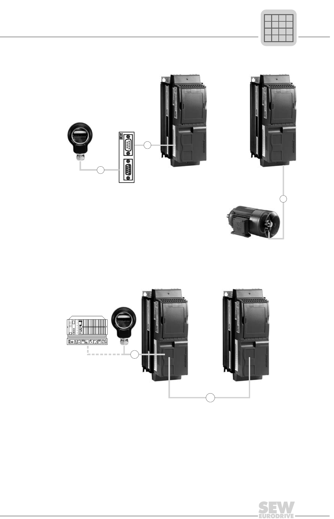
MOVIDRIVE® compact Catalog
73
2
Pre-fabricated cables
05298AXX
Figure 40: Motor encoder connection
05299AXX
Figure 41: Connection of external encoder and master/slave connection
X2: Encoder X1: MOVIDRIVE
DWI
7.
8.
7.
MOVIDRIVE
MCV4_A
®
compact
MOVIDRIVE
MCV4_A
®
compact
MOVIDRIVE
MCV4_A
MCS4_A
®
compact
MOVIDRIVE
MCV4_A
MCS4_A
®
compact
10.
X14: Master X14: Slave
9.
P
if
kVA
Hz
n
2
74
MOVIDRIVE® compact Catalog
Pre-fabricated cables
1. Cable sets for DC link connection MDR → MCF/MCV/MCS/MCH
Description SEW strongly recommends that the cable sets named below are used, because they
possess the relevant dielectric strength and are also color-coded. This is necessary be-
cause cross-polarity and ground faults could cause irreparable damage to the connect-
ed equipment.
The length of the cables restricts the DC link circuit connection to the permitted five
meters (16.4 ft), whilst they can also be cut to length by the customer for connecting sev-
eral units. The lugs for connecting to the regenerative power supply unit and an inverter
are supplied with the cable set. Use commercial lugs for connecting additional inverters.
The inverters must then be connected to the regenerative power supply unit in a star
configuration. Use a busbar subdistributor if the DC link terminals of the regenerative
power supply unit are not sufficient.
Type of routing Only fixed routing is possible.
2. Motor cables for connecting CM motors to MCS or MCH and extension cables
Motor cables The cables are equipped with a plug for the motor connection and conductor end
sleeves for the inverter connection.
Cable set type DCP12A DCP13A DCP15A
Part number 814 567 9 814 250 5 814 251 3
For connecting MOV-
IDRIVE® 0015...0110 0150...0300 0370...0750
Number of cores and line cross section Part number Type of routing For motor
4×1.5 mm2 (AWG 16) 199 179 5
Fixed routing
CM..SM51
4×1.5 mm2 (AWG 16) + 3×1.0 mm2 (AWG 17) 199 189 2 CM..BR SB51
4×2.5 mm2 (AWG 12) 199 181 7 CM..SM52
4×2.5 mm2 (AWG 12) + 3×1.0 mm2 (AWG 17) 199 191 4 CM..BR SB52
4×4 mm2 (AWG 10) 199 183 3 CM..SM54
4×4 mm2 (AWG 10) + 3×1.0 mm2 (AWG 17) 199 193 0 CM..BR SB54
4×6 mm2 (AWG 10) 199 185 X CM..SM56
4×6 mm2 (AWG 10) + 3×1.5 mm2 (AWG 16) 199 195 7 CM..BR SB56
4×10 mm2 (AWG 8) 199 187 6 CM..SM59
4×10 mm2 (AWG 8) + 3×1.5 mm2 (AWG 16) 199 197 3 CM..BR SB59
Number of cores and line cross section Part number Type of routing For motor
4×1.5 mm2 (AWG 16) 199 180 9
Cat track routing
CM..SM51
4×1.5 mm2 (AWG 16) + 3×1.0 mm2 (AWG 17) 199 190 6 CM..BR SB51
4×2.5 mm2 (AWG 12) 199 182 5 CM..SM52
4×2.5 mm2 (AWG 12) + 3×1.0 mm2 (AWG 17) 199 192 2 CM..BR SB52
4×4 mm2 (AWG 10) 199 184 1 CM..SM54
4×4 mm2 (AWG 10) + 3×1.0 mm2 (AWG 17) 199 194 9 CM..BR SB54
4×6 mm2 (AWG 10) 199 186 8 CM..SM56
4×6 mm2 (AWG 10) + 3×1.5 mm2 (AWG 16) 199 196 5 CM..BR SB56
4×10 mm2 (AWG 8) 199 188 4 CM..SM59
4×10 mm2 (AWG 8) + 3×1.5 mm2 (AWG 16) 199 198 1 CM..BR SB59
P
if
kVA
Hz
n
MOVIDRIVE® compact Catalog
75
2
Pre-fabricated cables
Extension cables The cables are equipped with a plug and coupling for extending the CM motor cable.
3. Motor cables for connecting DS/DY motors to MCS
Description The cables are equipped with a plug for the motor connection and conductor end
sleeves for the inverter connection.
Number of cores and line cross section Part number Type of routing For motor
4×1.5 mm2 (AWG 16) 199 549 9
Fixed routing
CM..SM51
4×1.5 mm2 (AWG 16) + 3×1.0 mm2 (AWG 17) 199 199 X CM..BR SB51
4×2.5 mm2 (AWG 12) 199 551 0 CM..SM52
4×2.5 mm2 (AWG 12) + 3×1.0 mm2 (AWG 17) 199 201 5 CM..BR SB52
4×4 mm2 (AWG 10) 199 553 7 CM..SM54
4×4 mm2 (AWG 10) + 3×1.0 mm2 (AWG 17) 199 203 1 CM..BR SB54
4×6 mm2 (AWG 10) 199 555 3 CM..SM56
4×6 mm2 (AWG 10) + 3×1.5 mm2 (AWG 16) 199 205 8 CM..BR SB56
4×10 mm2 (AWG 8) 199 557 X CM..SM59
4×10 mm2 (AWG 8) + 3×1.5 mm2 (AWG 16) 199 207 4 CM..BR SB59
Number of cores and line cross section Part number Type of routing For motor
4×1.5 mm2 (AWG 16) 199 550 2
Cat track routing
CM..SM51
4×1.5 mm2 (AWG 16) + 3×1.0 mm2 (AWG 17) 199 200 7 CM..BR SB51
4×2.5 mm2 (AWG 12) 199 552 9 CM..SM52
4×2.5 mm2 (AWG 12) + 3×1.0 mm2 (AWG 17) 199 202 3 CM..BR SB52
4×4 mm2 (AWG 10) 199 554 5 CM..SM54
4×4 mm2 (AWG 10) + 3×1.0 mm2 (AWG 17) 199 204 X CM..BR SB54
4×6 mm2 (AWG 10) 199 556 1 CM..SM56
4×6 mm2 (AWG 10) + 3×1.5 mm2 (AWG 16) 199 206 6 CM..BR SB56
4×10 mm2 (AWG 8) 199 558 8 CM..SM59
4×10 mm2 (AWG 8) + 3×1.5 mm2 (AWG 16) 199 208 2 CM..BR SB59
Number of cores and line cross section Part number Type of routing For motor
4×1.5 mm2 (AWG 16) 198 669 4
Fixed routing
DS56 / SM11
4×1.5 mm2 (AWG 16) + 2×0.75 mm2 (AWG 18) 198 670 8 DS56..B / SM11
4×1.5 mm2 (AWG 16) 198 683 X DY71 / SM21
4×2.5 mm2 (AWG 12) 198 684 8 DS71 / SM22
4×2.5 mm2 (AWG 12) 198 685 6 DY90/112 / SM32
4×4 mm2 (AWG 10) 198 686 4 DY90/112 / SM34
4×6 mm2 (AWG 10) 198 687 2 DY90/112 / SM36
4×6 mm2 (AWG 10) 198 688 0 DY112 / SM46
4×10 mm2 (AWG 8) 198 689 9 DY112 / SM41
P
if
kVA
Hz
n
2
76
MOVIDRIVE® compact Catalog
Pre-fabricated cables
4. Hiperface cables, resolver cables and extension cables
Hiperface cables for CM motors with plug connection:
Extension cables for Hiperface cables (CM motors with plug connection):
Number of cores and line cross section Part number Type of routing For motor
4×1.5 mm2 (AWG 16) 198 741 0
Cat track routing
DS56 / SM11
4×1.5 mm2 (AWG 16) + 2×0.75 mm2 (AWG 18) 198 742 9 DS56..B / SM11
4×1.5 mm2 (AWG 16) 198 734 8 DY71 / SM21
4×2.5 mm2 (AWG 12) 198 735 6 DS71 / SM22
4×2.5 mm2 (AWG 12) 198 736 4 DY90/112 / SM32
4×4 mm2 (AWG 10) 198 737 2 DY90/112 / SM34
4×6 mm2 (AWG 10) 198 738 0 DY90/112 / SM36
4×6 mm2 (AWG 10) 198 739 9 DY112 / SM46
4×10 mm2 (AWG 8) 198 740 2 DY112 / SM41
Part number 199 488 3 199 320 8
Routing Fixed routing Cat track routing
For Hiperface encoder AS1H/ES1H in
motor CM71...112
Line cross section 6 × 2 × 0.25 mm2 (AWG 23)
Conductor colors
cos+: Red (RD)
cos-: Blue (BU)
sin+: Yellow (YE)
sin-: Green (GN)
D+: Black (BK)
D-: Violet (VT)
TF/TH/KTY+: Brown (BN)
TF/TH/KTY-: White (WH)
GND: Grey/pink + pink (GY-PK + PK)
US: Red/blue + gray (RD-BU + GY)
Manufacturer and type Lapp, PVC/C/PP 303 028 1 Nexans, 493 290 70
Connection to encoder / motor
MOVIDRIVE® compact MCH4_A
With 12-pin round connector plug (Intercontec, type ASTA021NN00 10 000 5 000)
With 15-pin sub D plug
Part number 199 539 1 199 540 5
Routing Fixed routing Cat track routing
For Hiperface encoder AS1H/ES1H in
motor CM71...112
Line cross section 6 × 2 × 0.25 mm2 (AWG 23)
Conductor colors
cos+: Red (RD)
cos-: Blue (BU)
sin+: Yellow (YE)
sin-: Green (GN)
D+: Black (BK)
D-: Violet (VT)
TF/TH/KTY+: Brown (BN)
TF/TH/KTY-: White (WH)
GND: Grey/pink + pink (GY-PK + PK)
US: Red/blue + gray (RD-BU + GY)
Manufacturer and type Lapp, PVC/C/PP 303 028 1 Nexans, 493 290 70
Connection to encoder / motor
Hiperface cable
With 12-pin round connector plug (Intercontec, type ASTA021NN00 10 000 5 000)
With 12-pin round connector plug (Intercontec, type AKUA20)
P
if
kVA
Hz
n
MOVIDRIVE® compact Catalog
77
2
Pre-fabricated cables
Hiperface cables for CM motors with terminal box:
Resolver cables for DS56 and CM motors with plug connection:
Extension cables for resolver cables (DS56 and CM motors with plug connection):
Part number 199 591 X 199 592 8
Routing Fixed routing Cat track routing
For Hiperface encoder AS1H/ES1H in
motor CM71...112
Line cross section 6 × 2 × 0.25 mm2 (AWG 23)
Conductor colors
cos+: Red (RD)
cos-: Blue (BU)
sin+: Yellow (YE)
sin-: Green (GN)
D+: Black (BK)
D-: Violet (VT)
TF/TH/KTY+: Brown (BN)
TF/TH/KTY-: White (WH)
GND: Grey/pink + pink (GY-PK + PK)
US: Red/blue + gray (RD-BU + GY)
Manufacturer and type Lapp, PVC/C/PP 303 028 1 Nexans, 493 290 70
Connection to encoder / motor
MOVIDRIVE® compact MCH4_A
With conductor end sleeves
With 15-pin sub D plug
Part number 199 487 5 199 319 4
Routing Fixed routing Cat track routing
For RH1M resolver in motor DS56, CM71...112
Line cross section 5 × 2 × 0.25 mm2 (AWG 23)
Conductor colors
Ref.+: Pink (PK)
Ref.-: Gray (GY)
cos+: Red (RD)
cos-: Blue (BU)
sin+: Yellow (YE)
sin-: Green (GN)
TF/TH/KTY+: Brown + pink (BN + PK)
TF/TH/KTY-: White + black (WH + BK)
Manufacturer and type Lapp, PVC/C/PP Nexans
Connection to resolver/motor
MOVIDRIVE® compact MCS4_A
With 12-pin round connector plug (Intercontec, type ASTA021NN00 10 000 5 000)
With 9-pin sub D plug
Part number 199 542 1 199 541 3
Routing Fixed routing Cat track routing
For RH1M resolver in motor DS56, CM71...112
Line cross section 5 × 2 × 0.25 mm2 (AWG 23)
Conductor colors
Ref.+: Pink (PK)
Ref.-: Gray (GY)
cos+: Red (RD)
cos-: Blue (BU)
sin+: Yellow (YE)
sin-: Green (GN)
TF/TH/KTY+: Brown + pink (BN + PK)
TF/TH/KTY-: White + black (WH + BK)
Manufacturer and type Lapp, PVC/C/PP Nexans
Connection to resolver/motor
Resolver cables
With 12-pin round connector plug (Intercontec, type ASTA021NN00 10 000 5 000)
With 12-pin round connector plug (Intercontec, type AKUA20)
P
if
kVA
Hz
n
2
78
MOVIDRIVE® compact Catalog
Pre-fabricated cables
Resolver cables for DY71...112 motors with plug connection:
Resolver cables for DS56 and DY71...112 motors with terminal box:
5. VR forced cooling fan cables and extension cables
VR forced cooling fan cables:
Extension cables for VR forced cooling fan cables:
Part number 198 827 1 198 812 3
Routing Fixed routing Cat track routing
For RH1M resolver in motor DY71...112
Line cross section 4 × 2 × 0.25 mm2 (AWG 23)
Conductor colors
Ref.+: Pink (PK)
Ref.-: Gray (GY)
cos+: Red (RD)
cos-: Blue (BU)
sin+: Yellow (YE)
sin-: Green (GN)
TF/TH: Brown (BN)
TF/TH: White (WH)
Manufacturer and type Lapp, Unitronic Li2YCY (TP)
Helukabel, Paar-Tronic-CY
Lapp, Unitronic FD CP (TP)
Helukabel, Super-Paar-Tronic-C-PUR
Connection to resolver/motor
MOVIDRIVE® compact MCS4_A
With 12-pin round connector plug (Framatome Souriou, type GN-DMS2-12S)
With 9-pin sub D plug
Part number 199 589 8 199 590 1
Routing Fixed routing Cat track routing
For RH1M resolver in motor DS56, DY71...112
Line cross section 5 × 2 × 0.25 mm2 (AWG 23)
Conductor colors
Ref.+: Pink (PK)
Ref.-: Gray (GY)
cos+: Red (RD)
cos-: Blue (BU)
sin+: Yellow (YE)
sin-: Green (GN)
TF/TH/KTY+: Brown + pink (BN + PK)
TF/TH/KTY-: White + black (WH + BK)
Manufacturer and type Lapp, PVC/C/PP Nexans
Connection to resolver/motor
MOVIDRIVE® compact MCS4_A
With conductor end sleeves
With 9-pin sub D plug
Part number 199 559 6 199 560 X
Routing Fixed routing Cat track routing
Line cross section 3 × 1 mm2 (AWG 17)
Connection VR forced cooling fan
Switch cabinet
With plug STAK 200
With conductor end sleeves
Part number 199 561 8 199 562 6
Routing Fixed routing Cat track routing
Line cross section 3 × 1 mm2 (AWG 17)
Connection VR forced cooling fan
VR forced cooling fan
cables
With plug STAK 200
with plug connection
P
if
kVA
Hz
n
MOVIDRIVE® compact Catalog
79
2
Pre-fabricated cables
6. Brake cables
7. Motor encoder cables, connection to MCV4_A, X15
Cables for TTL sensors and sin/cos motor encoders (TTL sensors and sin/cos encoders)
Cables for HTL motor encoders (HTL encoders)
Part number 198 633 3 198 745 3
Routing Fixed routing Cat track routing
Line cross section 4 × 1.5 mm2 (AWG 16)
Connection to DY motor
Brake rectifier
With plug
With conductor end sleeves
Part number 198 829 8 198 828 X
Routing Fixed routing Cat track routing
For encoder ES1T, ES2T and EV1T via option DWI11A and cable 814 344 7
ES1S, ES2S, EV1S, ES1R, ES2R and EV1R directly to X15 (MCV)
Line cross section 4 × 2 × 0.25 mm2 (AWG 23) + 1 × 0.25 mm2 (AWG 23)
Conductor colors
A: Yellow (YE)
A: Green (GN)
B: Red (RD)
B: Blue (BU)
C: Pink (PK)
C: Gray (GY)
UB: White (WH)
⊥: Brown (BN)
Sensor line: Violet (VT)
Manufacturer and type Lapp, Unitronic Li2YCY (TP)
Helukabel, Paar-Tronic-CY
Lapp, Unitronic FD CP (TP)
Helukabel, Super-Paar-Tronic-C-PUR
Connection To encoder/motor
To MCV4_A, X15 or DWI11A
With conductor end sleeves
On ES1T, ES2T and EV1T, connect the violet conductor (VT) on the encoder to UB
On ES1S, ES2S, EV1S, ES1R, ES2R and EV1R,
cut off the violet conductor (VT) at the encoder end
With 9-pin sub D plug
Part number 198 932 4 198 931 6
Routing Fixed routing Cat track routing
For encoder ES1C, ES2C and EV1C
Line cross section 5 × 0.25 mm2 (AWG 23) + 1 × 0.25 mm2 (AWG 23)
Conductor colors
A: Yellow (YE)
B: Green (GN)
C: Gray (GY)
UB: White (WH)
⊥: Brown (BN)
Manufacturer and type Lapp, Unitronic LiYCY
Helukabel, Tronic-CY
Lapp, Unitronic FD CP
Helukabel, Super-Tronic-C-PURö
Connection To encoder/motor
To MCV4_A, X15
With conductor end sleeves
With 9-pin sub D plug
P
if
kVA
Hz
n
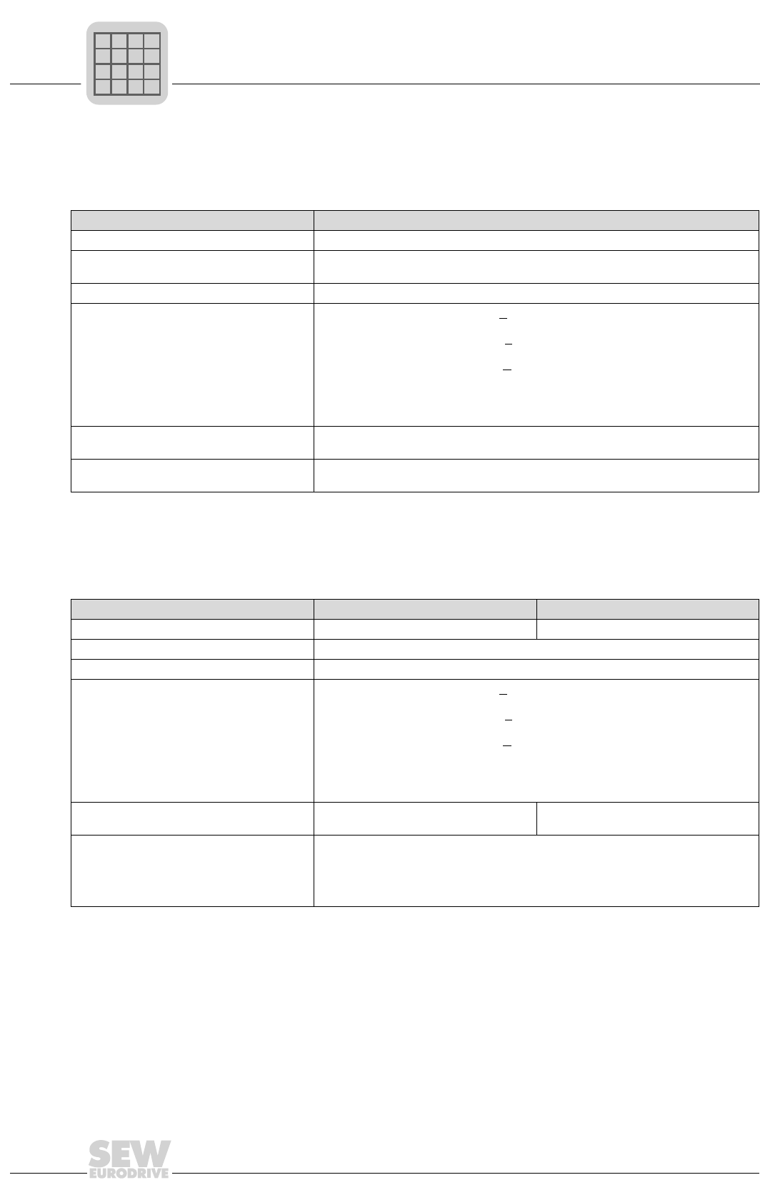
2
80
MOVIDRIVE® compact Catalog
Pre-fabricated cables
8. Encoder connection
9. Cable for external encoder (TTL encoder) or encoder simulation, connection on X14
This cable is intended for the following connections:
• MOVIDRIVE® compact MCV 'Encoder In' (X15) → 5 V encoder power supply option type DWI11A
Part number 814 344 7
Routing Fixed routing
For encoder with 5 V encoder power sup-
ply ES1T, ES2T and EV1T via option DWI11A
Line cross section 4 × 2 × 0.25 mm2 (AWG 23) + 1 × 0.25 mm2 (AWG 23)
Conductor colors
A: Yellow (YE)
A: Green (GN)
B: Red (RD)
B: Blue (BU)
C: Pink (PK)
C: Gray (GY)
UB: White (WH)
⊥: Brown (BN)
Sensor line: Violet (VT)
Manufacturer and type Lapp, Unitronic Li2YCY (TP)
Helukabel, Paar-Tronic-CY
Connection to To DWI11A
X15
With 9-pin sub D socket
With 9-pin sub D plug
This cable is provided for connecting an external encoder or evaluation of encoder simulation on MCV/MCS4_A.
Part number 815 354 X -
Routing Fixed routing -
For encoder ES1R, ES2R and EV1R or evaluation of encoder simulation
Line cross section 4 × 2 × 0.25 mm2 (AWG 23) + 1 × 0.25 mm2 (AWG 23)
Conductor colors
A: Yellow (YE)
A: Green (GN)
B: Red (RD)
B: Blue (BU)
C: Pink (PK)
C: Gray (GY)
UB: White (WH)
⊥: Brown (BN)
Switch mode: Violet (VT)
Manufacturer and type Lapp, Unitronic Li2YCY (TP)
Helukabel, Paar-Tronic-CY -
Connection To encoder/to the
Evaluation unit
To MCV/MCS4_A, X14
With conductor end sleeves
External encoder: cut off the violet conductor (VT) at the encoder end
Evaluation unit: jumper the violet conductor (VT) with the brown conductor (BN)
With 9-pin sub D socket
P
if
kVA
Hz
n

MOVIDRIVE® compact Catalog
81
2
Pre-fabricated cables
10. Encoder connection MCV/MCS4_A X14: Master → MCV/MCS4_A X14: Slave
This cable is provided for the master/slave connection of two MCV/MCS4_A units.
Part number 815 355 8
Routing Fixed routing
For master/slave connection X14: Master → X14: Slave
Line cross section 4 × 2 × 0.25 mm2 (AWG 23) + 1 × 0.25 mm2 (AWG 23)
Conductor colors
A: Yellow (YE)
A: Green (GN)
B: Red (RD)
B: Blue (BU)
C: Pink (PK)
C: Gray (GY)
UB: White (WH)
⊥: Brown (BN)
Sensor line: Violet (VT)
Manufacturer and type Lapp, Unitronic Li2YCY (TP)
Helukabel, Paar-Tronic-CY
Connection to X14: Master1)
X14: Slave1)
1) Important: Connect the socket marked 'Master' to X14: Master and the socket marked 'Slave' to X14: Slave!
With 9-pin sub D socket
With 9-pin sub D socket
P
if
kVA
Hz
n
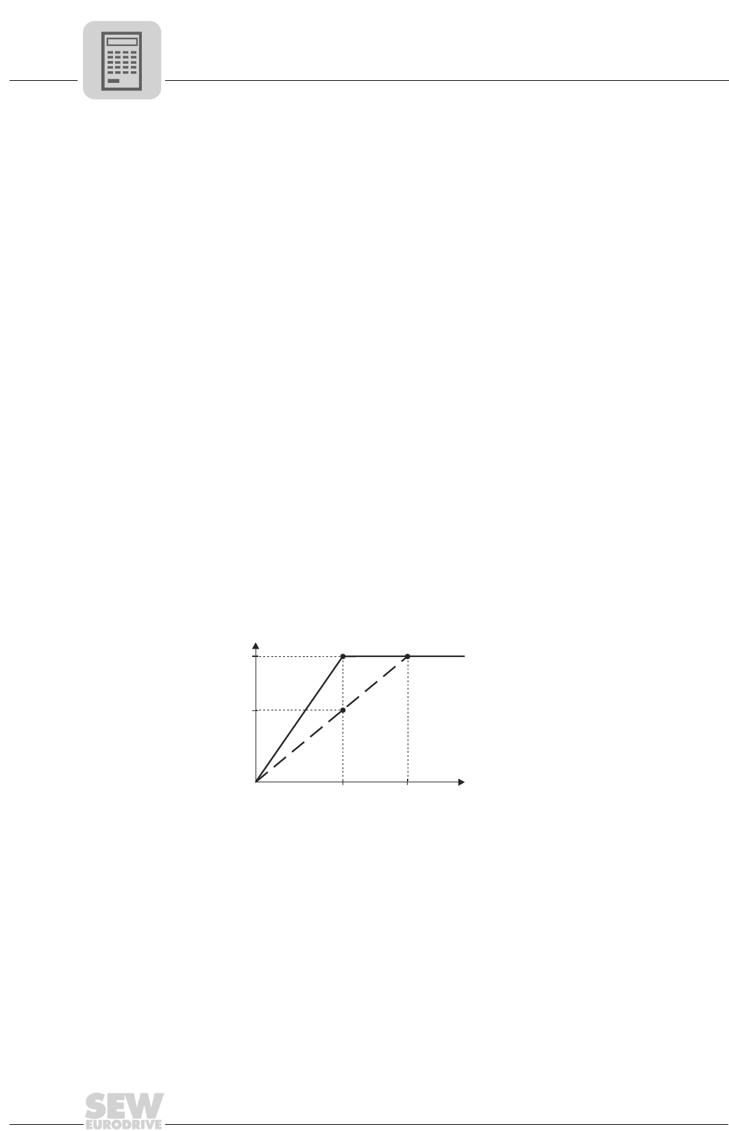
3
82
MOVIDRIVE® compact Catalog
Motor selection for asynchronous AC motors (VFC)
3 Project Planning
3.1 Motor selection for asynchronous AC motors (VFC)
Basic recommen-
dations
• Only use motors with a thermal classification of F at least.
• Use TF thermistor sensors or TH winding thermostats. TH should be preferred in the
case of multi-motor drives on one inverter. The series connection of TH contacts (NC
contacts) is not subject to any restriction if joint monitoring is provided.
• For multi-motor drives, we recommend that the motors should not differ from one an-
other by more than 3 type levels.
• 4-pole motors should be preferred. This particularly applies to geared motors which
are operated with a high oil filling level as a result of their vertical mounting position.
• Generally speaking, the motor can be operated at its listed power without forced
cooling if the operating conditions differ from S1-mode, e.g. positioning drive with
1:20 speed range in S3-mode.
• Avoid selecting a motor which is too large, especially in case of a delta connection.
Otherwise, the inverter may trigger a short circuit detection function due to the small
winding resistance of the motor (1/3 that of a star connection).
• A MOVIDRIVE® compact MCV4_A (with encoder connection) is required for speed
control. The motor must then be equipped with an incremental encoder, preferably
with 1024 increments/revolution.
Voltage/fre-
quency charac-
teristic
The asynchronous motor follows a load-dependent voltage/frequency characteristic in
VFC operating mode. It is possible to achieve full motor torque down to minimum speeds
because the motor model is continuously calculated. This characteristic curve is set by
entering the rated motor voltage and the rated frequency of the motor in the startup func-
tion. The setting determines the speed-dependent torque and power characteristics of
the asynchronous motor.
Sample asynchro-
nous motor 230/
400 V, 50 Hz
1 Star connection; 400 V, 50 Hz
2 Delta connection: 230 V, 50 Hz
3 Delta connection: 400 V, 87 Hz
The inverter output voltage VA is limited by the supply voltage which is connected. The
'nominal system voltage' input value in the startup function limits the effective value of
the maximum output voltage. This restriction is used whenever the connected motor has
a lower design voltage than the power supply of the inverter. The maximum permitted
motor voltage should be entered. Furthermore, make sure that the 'nominal system volt-
age' input value is less than or equal to the supply voltage of the inverter.
01650BEN
Figure 42: Voltage/frequency characteristics of the asynchronous motor
0
230
400
0f [Hz]
50 87
13
2
Voutp [V]
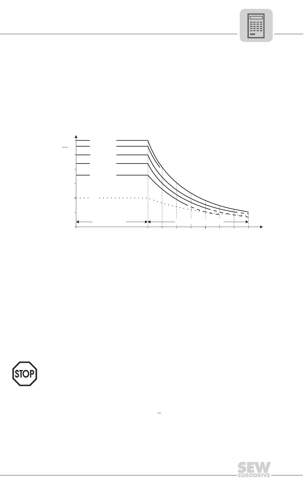
MOVIDRIVE® compact Catalog
83
3
Motor selection for asynchronous AC motors (VFC)
Speed/torque
characteristics
The field weakening range starts when the set maximum output voltage of the inverter
is reached. As the speed increases, the motor generates:
• constant torque with increasing power in the basic speed range,
• constant power with an inversely proportionate decrease in torque in the field weak-
ening range.
When determining the maximum speed in the field weakening range, note that the rated
torque MN (in relation to the rated speed, e.g. nN = 1500 rpm) falls in inverse proportion
and the breakdown torque MK is reduced in an inverse quadratic relationship. The MK/
MN ratio is a motor-specific parameter. The MOVIDRIVE® pull-out protection limits the
speed when the maximum possible torque is reached.
With geared motors, the maximum motor speed is dependent on the size and mounting
position of the gear unit. The speed should not exceed 3000 rpm due to the resulting
noise and oil churning losses.
Dynamic applica-
tions (Pinverter
greater than Pmo-
tor)
• The startup function sets the current limit of the inverter (P303/P313) to 150 % of the
rated motor current. The value of the current limit refers to the rated inverter current.
As a result, 150 % of the rated motor current is less than 150 % of the rated inverter
current (value of P303/P313). This parameter must be set to a higher value manually
for dynamic applications.
• The startup function sets the slip compensation parameter (P324/P334) to the nom-
inal slip of the motor. In the case of VFC-n-CONTROL, the internal slip limiting func-
tion allows the slip to reach max. 150 % of this setting. Consequently, the motor de-
velops at most 150 % of the nominal motor torque. The slip compensation parameter
(P324) must be increased accordingly for greater torques.
Combinations
with Pinverter
greater than 4 ×
Pmotor
The large difference between the rated inverter current and the rated motor current
means that these combinations cannot be started up without taking special measures:
• Project planning for connecting the motor in a delta connection. This means the mo-
tor current is increased by a factor √3 and the unfavorable ratio is reduced.
• The motor must be started up in VFC & GROUP operating mode if this measure does
not suffice. In this operating mode, the inverter operates without slip compensation
and simulates a constant-voltage constant-frequency system (system with a con-
stant U/f ratio).
01729BEN
Figure 43: Quadratically falling breakdown torque
0 1500 1800 2100 2400 2700 3000 3300 3600
0
M
N
M
M
N
M = 1.8 M
KN
M = 2.2 M
KN
M = 2.5 M
KN
M = 2.8 M
KN
M = 3.0 M
KN
0.5
1.0
1.5
2.0
2.5
3.0
Armature range Field weakening range
n / rpm
Set parameter P324 'Slip compensation' to max. 130 % of the nominal slip of the
motor for stable operation.
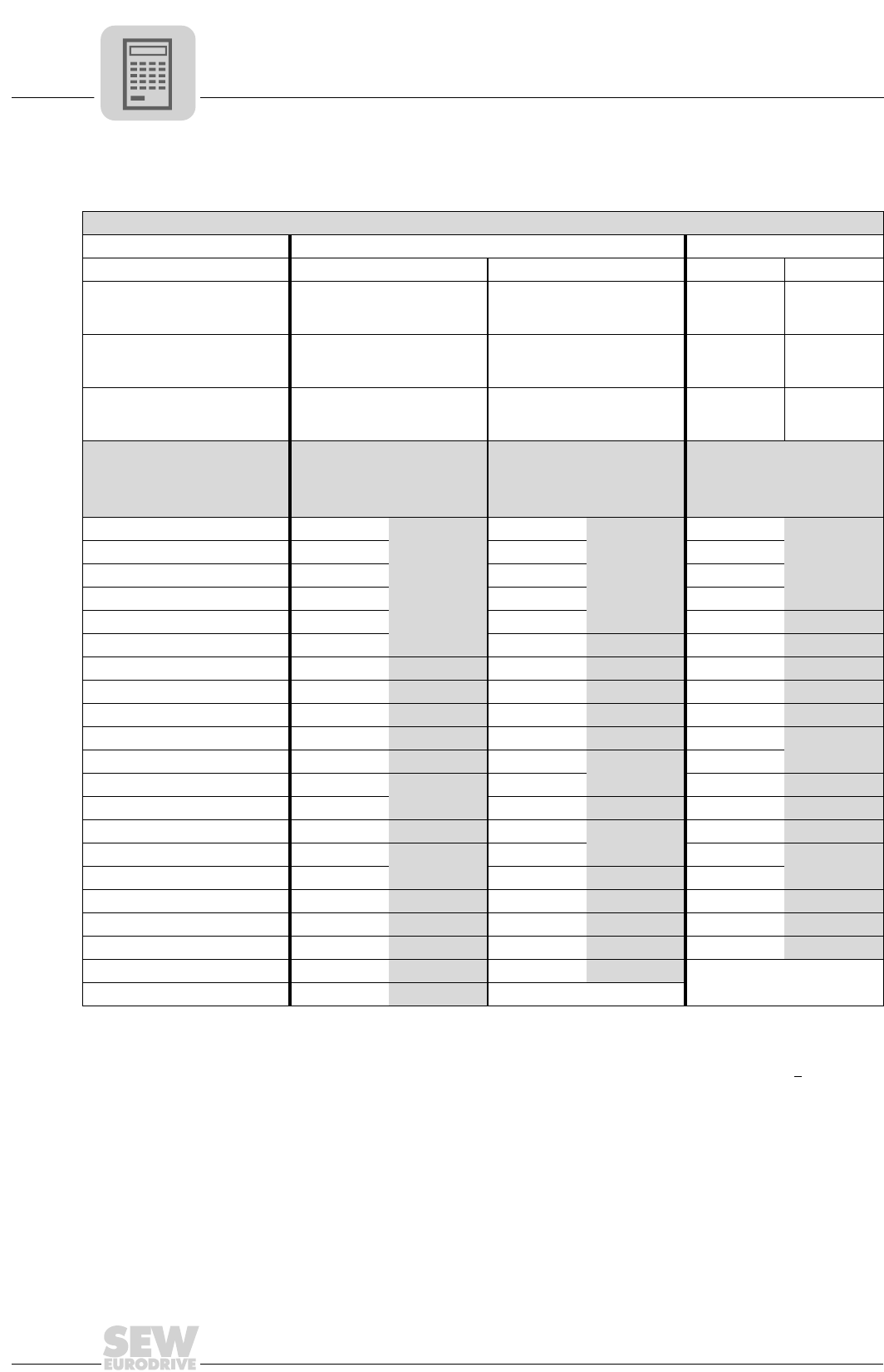
3
84
MOVIDRIVE® compact Catalog
Motor selection for asynchronous AC motors (VFC)
Motor selection in delta/star topology (230/400 VAC / 50 Hz)
Motors for 380 VAC / 60 Hz can also be allocated on the basis of this selection table.
Pmax [kW (HP)] for operation on MOVIDRIVE® compact MCF/MCV/MCH 4_A...-5_3 (400/500 V units)
Connection 댴 / 400 VAC1)
1) Also applies to motors with rated voltage 460 V or 500 V and to 400 V / 690 V motors with ∆ connection.
∆ / 230 VAC2)
2) Also applies to motors with rated voltage 266 V or 290 V.
Cooling Self-cooling Forced Self-cooling Forced
fmin...fmax [Hz]
10 - 50
6 - 60
5 - 70 / 5.5 - 80 ≤ 2.5 - 50 / ≤ 3 - 603)
3) The following applies to MCF, MCV and MCH without speed control: fmin = 0.5 Hz
9 - 87 ≤ 2.5 - 873)
nmin...nmax [rpm]
300 - 1500
180 - 1800
150 - 2100 / 165 - 2400 ≤ 75 - 1500 / ≤ 90 - 1800 270 - 2610 ≤ 75 - 2610
Setting range
1:5
1:10
1:15 ≥ 1:20 1:10 ≥ 1:20
Motor type Rated power Pn
[kW (HP)]
P = Preduced P = PnP = Pincreased4)
4) Pincreased means that the motor is operated at the power of the next larger motor (1 frame size), rather than with the √3-fold power.
[kW (HP)]
With MCF/
MCV/MCH5)
4_A...-5_3
5) The devices listed here permit intermittent loads of up to 1.5 times the nominal load in the specific application. With variable torque
load and constant load without overload, each inverter can also be operated with an increased continuous output power (→ Sec. Tech-
nical Data). The continuous output current of 125 % of the rated unit current is only available at fPWM = 4 kHz in the VFC operating
modes.
[kW (HP)]
With MCF/
MCV/MCH5)
4_A...-5_3
[kW (HP)]
With MCF/
MCV/MCH5)
4_A...-5_3
DT71D4 0.37 (0.5) 0.25 (0.33)
0015
0.37 (0.5)
0015
0.55 (0.75)
0015
DT80K4 0.55 (0.75) 0.37 (0.5) 0.55 (0.75) 0.75 (1.0)
DT80N4 0.75 (1.0) 0.55 (0.75) 0.75 (1.0) 1.1 (1.5)
DT90S4 1.1 (1.5) 0.75 (1.0) 1.1 (1.5) 1.5 (2.0)
DT90L4 1.5 (2.0) 1.1 (1.5) 1.5 (2.0) 2.2 (3.0) 0022
DV100M4 2.2 (3.0) 1.5 (2.0) 2.2 (3.0) 0022 3.0 (4.0) 0030
DV100L4 3.0 (4.0) 2.2 (3.0) 0022 3.0 (4.0) 0030 4.0 (5.4) 0040
DV112M4 4.0 (5.4) 3.0 (4.0) 0030 4.0 (5.4) 0040 5.5 (7.5) 0055
DV132S4 5.5 (7.5) 4.0 (5.4) 0040 5.5 (7.5) 0055 7.5 (10) 0075
DV132M4 7.5 (10) 5.5 (7.5) 0055 7.5 (10) 0075 9.2 (12.5) 0110
DV132ML4 9.2 (12.5) 7.5 (10) 0075 9.2 (12.5) 0110 11 (15)
DV160M4 11 (15) 9.2 (12.5) 0110 11 (15) 15 (20) 0150
DV160L4 15 (20) 11 (15) 15 (20) 0150 18.5 (25) 0220
DV180M4 18.5 (25) 15 (20) 0150 18.5 (25) 0220 22 (30) 0300
DV180L4 22 (30) 18.5 (25) 0220 22 (30) 30 (40) 0370
DV200L4 30 (40) 22 (30) 30 (40) 0300 37 (50)
DV225S4 37 (50) 30 (40) 0300 37 (50) 0370 45 (60) 0450
DV225M4 45 (60) 37 (50) 0370 45 (60) 0450 55 (75) 0550
DV250M4 55 (75) 45 (60) 0450 55 (75) 0550 75 (100) 0750
DV280S4 75 (100) 55 (75) 0550 75 (100) 0750 -
D280M4 90 (120) 75 (100) 0750 -

MOVIDRIVE® compact Catalog
85
3
Motor selection for asynchronous AC motors (VFC)
Examples for motor selection delta/star topology 230/400 V
Trolley
drive
Constant load with overload (acceleration) and low load when in motion:
•P
travel = 1.3 kW
•P
max = 13 kW
•n
min = 270 rpm, setting range 1:10
•n
max = 2610 rpm
In inverter mode with adapted power (P = Pn), the motor output can be 150 % of its listed
power during the acceleration phase. Consequently:
PMot = Pmax : 1.5 = 13 kW : 1.5 = 8.67 kW
A DV132M4 with delta connection (Pn = 9.2 kW) is selected.
The selection table (→ page 84) allocates a MOVIDRIVE® compact MCF60A0110 (P =
Pn).
Hoist
drive
High constant load with intermittent overload (acceleration):
•P
max = 26 kW
•P
sustained = 20 kW
• Speed range 1:15, low speed only for positioning
• Brake applied when stationary
• Load type S3 (40 % c.d.f.)
The inverter output can be 150 % of its rated current during acceleration. Consequently,
a MOVIDRIVE® compact MCF60A0220 is selected.
In view of the load type (S3, 40 % c.d.f.), the selection table allocates motor type
DV180L4 (Pn = 22 kW) in a star connection.
→ Sec. Project planning for hoists for more information.
Fan/
pump
Variable torque load with the following power values:
•P
max = 4.8 kW
•n
max = 1400 rpm, continuous duty with nmax
The motor can be operated at its listed power (P = Pn) even without forced cooling due
to the quadratically falling torque. This means the DV132S4 motor type with star con-
nection (Pn = 5.5 kW) is adequate.
The selection table allocates a MOVIDRIVE® compact MCF60A0055 (P = Pn). Howev-
er, the inverter can be operated with an increased output power because this case in-
volves a variable torque load without overload. Consequently, a MOVIDRIVE® compact
MCF60A0040 is sufficient.
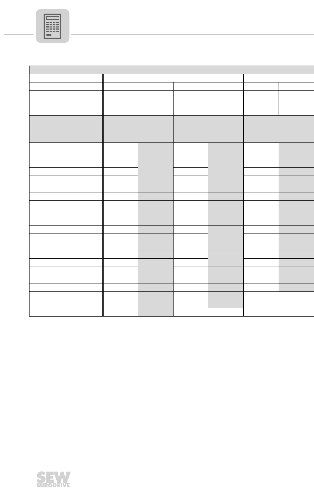
3
86
MOVIDRIVE® compact Catalog
Motor selection for asynchronous AC motors (VFC)
Motor selection in double-star/star topology (230/460 VAC / 60 Hz)
Pmax [kW (HP)] for operation on MOVIDRIVE® compact MCF/MCV/MCH 4_A...-5_3 (400/500 V units)
Connection 댴 / 460 VAC 댴댴 / 230 VAC
Cooling Self-cooling Self-cooling Forced Self-cooling Forced
fmin...fmax [Hz] 6 - 90 10 - 60 0 - 601)
1) The following applies to MCF, MCV and MCH without speed control: fmin = 0.5 Hz
10 - 120 0 - 1201)
nmin...nmax [rpm] 180 - 2700 200 - 1800 0 - 1800 200 - 3600 0 - 3600
Setting range 1:15 1:6 ≥ 1:15 1:12 ≥ 1:20
Motor type Rated power Pn
[kW (HP)]
P = Preduced P = PnP = Pincreased2)
2) Pincreased means that the motor is operated at the power of the next larger motor (1 frame size), rather than with the √3-fold power.
[kW (HP)]
With MCF/
MCV/MCH3)
4_A...-5_3
3) The devices listed here permit intermittent loads of up to 1.5 times the nominal load in the specific application. With variable torque
load and constant load without overload, each inverter can also be operated with an increased continuous output power (→ Sec. Tech-
nical Data). The continuous output current of 125 % of the rated unit current is only available at fPWM = 4 kHz in the VFC operating
modes.
[kW (HP)]
With MCF/
MCV/MCH3)
4_A...-5_3
[kW (HP)]
With MCF/
MCV/MCH3)
4_A...-5_3
DT71D4 0.37 (0.5) 0.25 (0.33)
0015
0.37 (0.5)
0015
0.75 (1.0)
0015DT80K4 0.55 (0.75) 0.37 (0.5) 0.55 (0.75) 1.1 (1.5)
DT80N4 0.75 (1.0) 0.55 (0.75) 0.75 (1.0) 1.5 (2.0)
DT90S4 1.1 (1.5) 0.75 (1.0) 1.1 (1.5) 2.2 (3.0) 0022
DT90L4 1.5 (2.0) 1.1 (1.5) 1.5 (2.0) 3.0 (4.0) 0030
DV100M4 2.2 (3.0) 1.5 (2.0) 2.2 (3.0) 0022 4.0 (5.4) 0040
DV100L4 3.7 (5.0) 2.2 (3.0) 0022 3.0 (4.0) 0030 5.5 (7.5) 0055
DV112M4 4.0 (5.4) 3.0 (4.0) 0030 4.0 (5.4) 0040 7.5 (10) 0075
DV132S4 5.5 (7.5) 4.0 (5.4) 0040 5.5 (7.5) 0055 9.2 (12.5) 0110
DV132M4 7.5 (10) 5.5 (7.5) 0055 7.5 (10) 0075 11 (15)
DV132ML4 9.2 (12.5) 7.5 (10) 0075 9.2 (12.5) 0110 15 (20) 0150
DV160M4 11 (15) 9.2 (12.5) 0110 11 (15) 18.5 (25) 0220
DV160L4 15 (20) 11 (15) 15 (20) 0150 22 (30)
DV180M4 18.5 (25) 15 (20) 0150 18.5 (25) 0220 30 (40) 0300
DV180L4 22 (30) 18.5 (25) 0220 22 (30) 37 (50) 0370
DV200L4 30 (40) 22 (30) 30 (40) 0300 45 (60) 0450
DV225S4 37 (50) 30 (40) 0300 37 (50) 0370 55 (75) 0550
DV225M4 45 (60) 37 (50) 0370 45 (60) 0450 75 (100) 0750
DV250M4 55 (75) 45 (60) 0450 55 (75) 0550
-DV280S4 75 (100) 55 (75) 0550 75 (100) 0750
D280M4 90 (120) 75 (100) 0750 -
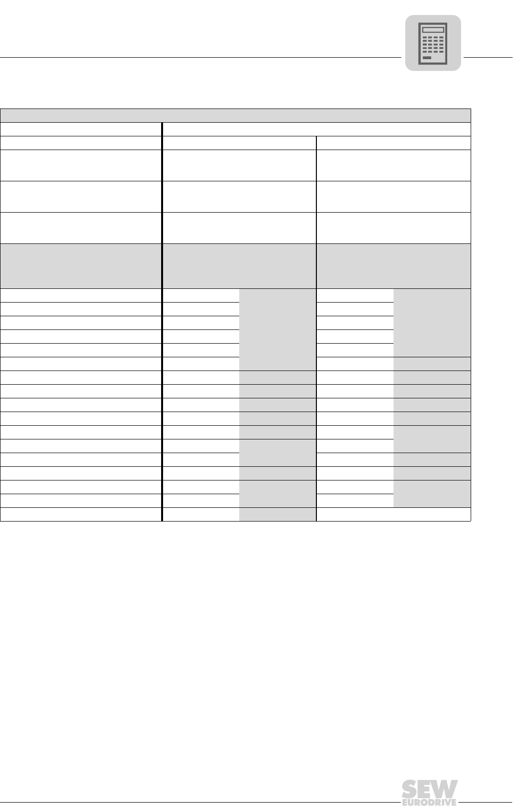
MOVIDRIVE® compact Catalog
87
3
Motor selection for asynchronous AC motors (VFC)
Motor selection with the delta topology (230 VAC / 50 Hz)
Pmax [kW (HP)] for operation on MOVIDRIVE® compact MCF/MCV/MCH 4_A...-2_3 (230 V units)
Connection ∆ / 230 VAC
Cooling Self-cooling Forced
fmin...fmax [Hz]
10 - 50
6 - 60
5 - 70 / 5.5 - 80 ≤ 2.5 - 50 / ≤ 3 - 601)
1) The following applies to MCF, MCV and MCH without speed control: fmin = 0.5 Hz
nmin...nmax [rpm]
300 - 1500
180 - 1800
150 - 2100 / 165 - 2400 ≤ 75 - 1500 / ≤ 90 - 1800
Setting range
1:5
1:10
1:15 ≥ 1:20
Motor type2)
2) In load type S3 (40 % c.d.f.), the motor must not be operated at its listed power (P = Pn) even without forced-cooling. Example: Pstat
= 2 kW, Pdyn = 2.5 kW → selected motor DV100M4 (Pn = 2.2 kW).
Rated power Pn
[kW (HP)]
P = Preduced P = Pn
[kW (HP)]
With MCF/
MCV/MCH3)
4_A...-2_3
3) The devices listed here permit intermittent loads of up to 1.5 times the nominal load in the specific application. With variable torque
load and constant load without overload, each inverter can also be operated with an increased continuous output power (→ Sec. Tech-
nical Data). The continuous output current of 125 % of the rated unit current is only available at fPWM = 4 kHz in the VFC operating
modes.
[kW (HP)]
With MCF/
MCV/MCH3)
4_A...-2_3
DT71D4 0.37 (0.5) 0.25 (0.33)
0015
0.37 (0.5)
0015
DT80K4 0.55 (0.75) 0.37 (0.5) 0.55 (0.75)
DT80N4 0.75 (1.0) 0.55 (0.75) 0.75 (1.0)
DT90S4 1.1 (1.5) 0.75 (1.0) 1.1 (1.5)
DT90L4 1.5 (2.0) 1.1 (1.5) 1.5 (2.0)
DV100M4 2.2 (3.0) 1.5 (2.0) 2.2 (3.0) 0022
DV100L4 3.0 (4.0) 2.2 (3.0) 0022 3.0 (4.0) 0030
DV112M4 4.0 (5.4) 3.0 (4.0) 0030 4.0 (5.4) 0040
DV132S4 5.5 (7.5) 4.0 (5.4) 0040 5.5 (7.5) 0055
DV132M4 7.5 (10) 5.5 (7.5) 0055 7.5 (10) 0075
DV132ML4 9.2 (12.5) 7.5 (10) 0075 9.2 (12.5) 0110
DV160M4 11 (15) 9.2 (12.5) 0110 11 (15)
DV160L4 15 (20) 11 (15) 15 (20) 0150
DV180M4 18.5 (25) 15 (20) 0150 18.5 (25) 0220
DV180L4 22 (30) 18.5 (25) 0220 22 (30) 0300
DV200L4 30 (40) 22 (30) 30 (40)
DV225S4 37 (50) 30 (40) 0300 -
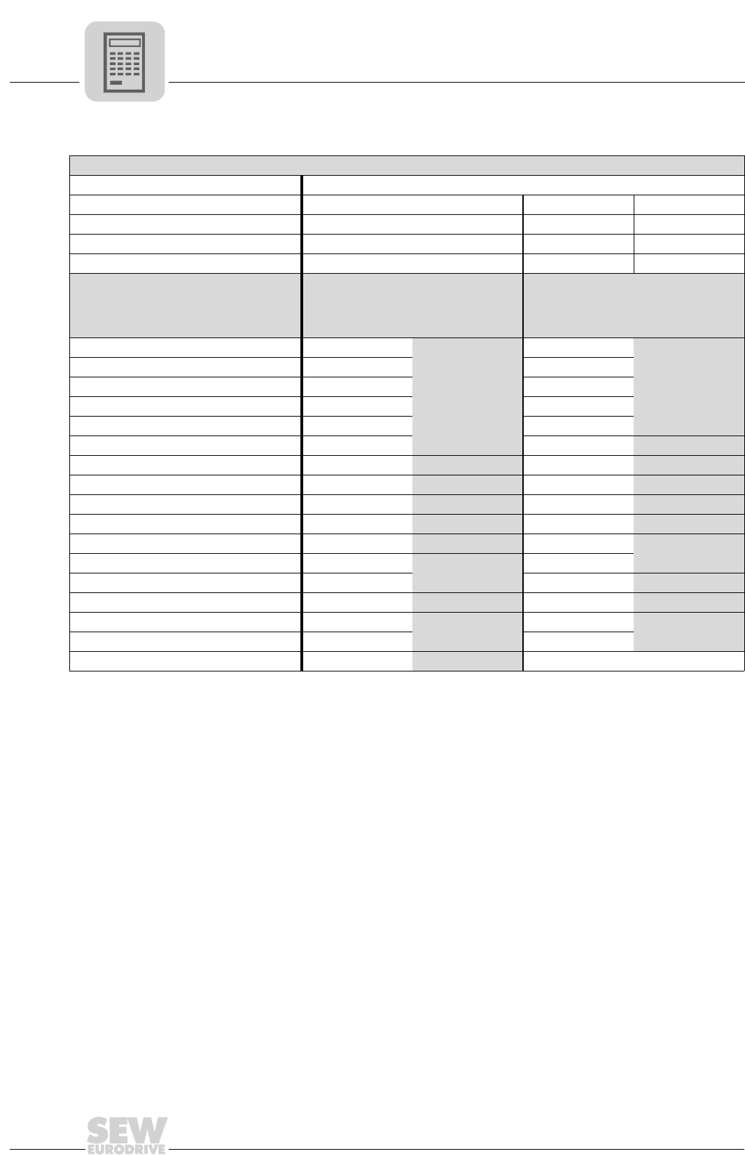
3
88
MOVIDRIVE® compact Catalog
Motor selection for asynchronous AC motors (VFC)
Motor selection with the double-star topology (230 VAC / 60 Hz)
Pmax [kW (HP)] for operation on MOVIDRIVE® compact MCF/MCV/MCH 4_A...-2_3 (230 V units)
Connection 댴댴 / 230 VAC
Cooling Self-cooling Self-cooling Forced
fmin...fmax [Hz] 6 - 90 10 - 60 0 - 601)
1) The following applies to MCF, MCV and MCH without speed control: fmin = 0.5 Hz
nmin...nmax [rpm] 180 - 2700 200 - 1800 0 - 1800
Setting range 1:15 1:6 ≥ 1:15
Motor type Rated power Pn
[kW (HP)]
P = Preduced P = Pn
[kW (HP)]
With MCF/
MCV/MCH2)
4_A...-2_3
2) The devices listed here permit intermittent loads of up to 1.5 times the nominal load in the specific application. With variable torque
load and constant load without overload, each inverter can also be operated with an increased continuous output power (→ Sec. Tech-
nical Data). The continuous output current of 125 % of the rated unit current is only available at fPWM = 4 kHz in the VFC operating
modes.
[kW (HP)]
With MCF/
MCV/MCH3)
4_A...-2_3
DT71D4 0.37 (0.5) 0.25 (0.33)
0015
0.37 (0.5)
0015
DT80K4 0.55 (0.75) 0.37 (0.5) 0.55 (0.75)
DT80N4 0.75 (1.0) 0.55 (0.75) 0.75 (1.0)
DT90S4 1.1 (1.5) 0.75 (1.0) 1.1 (1.5)
DT90L4 1.5 (2.0) 1.1 (1.5) 1.5 (2.0)
DV100M4 2.2 (3.0) 1.5 (2.0) 2.2 (3.0) 0022
DV100L4 3.7 (5.0) 2.2 (3.0) 0022 3.0 (4.0) 0030
DV112M4 4.0 (5.4) 3.0 (4.0) 0030 4.0 (5.4) 0040
DV132S4 5.5 (7.5) 4.0 (5.4) 0040 5.5 (7.5) 0055
DV132M4 7.5 (10) 5.5 (7.5) 0055 7.5 (10) 0075
DV132ML4 9.2 (12.5) 7.5 (10) 0075 9.2 (12.5) 0110
DV160M4 11 (15) 9.2 (12.5) 0110 11 (15)
DV160L4 15 (20) 11 (15) 15 (20) 0150
DV180M4 18.5 (25) 15 (20) 0150 18.5 (25) 0300
DV180L4 22 (30) 18.5 (25) 0220 22 (30) 0370
DV200L4 30 (40) 22 (30) 30 (40)
DV225S4 37 (50) 30 (40) 0300 -
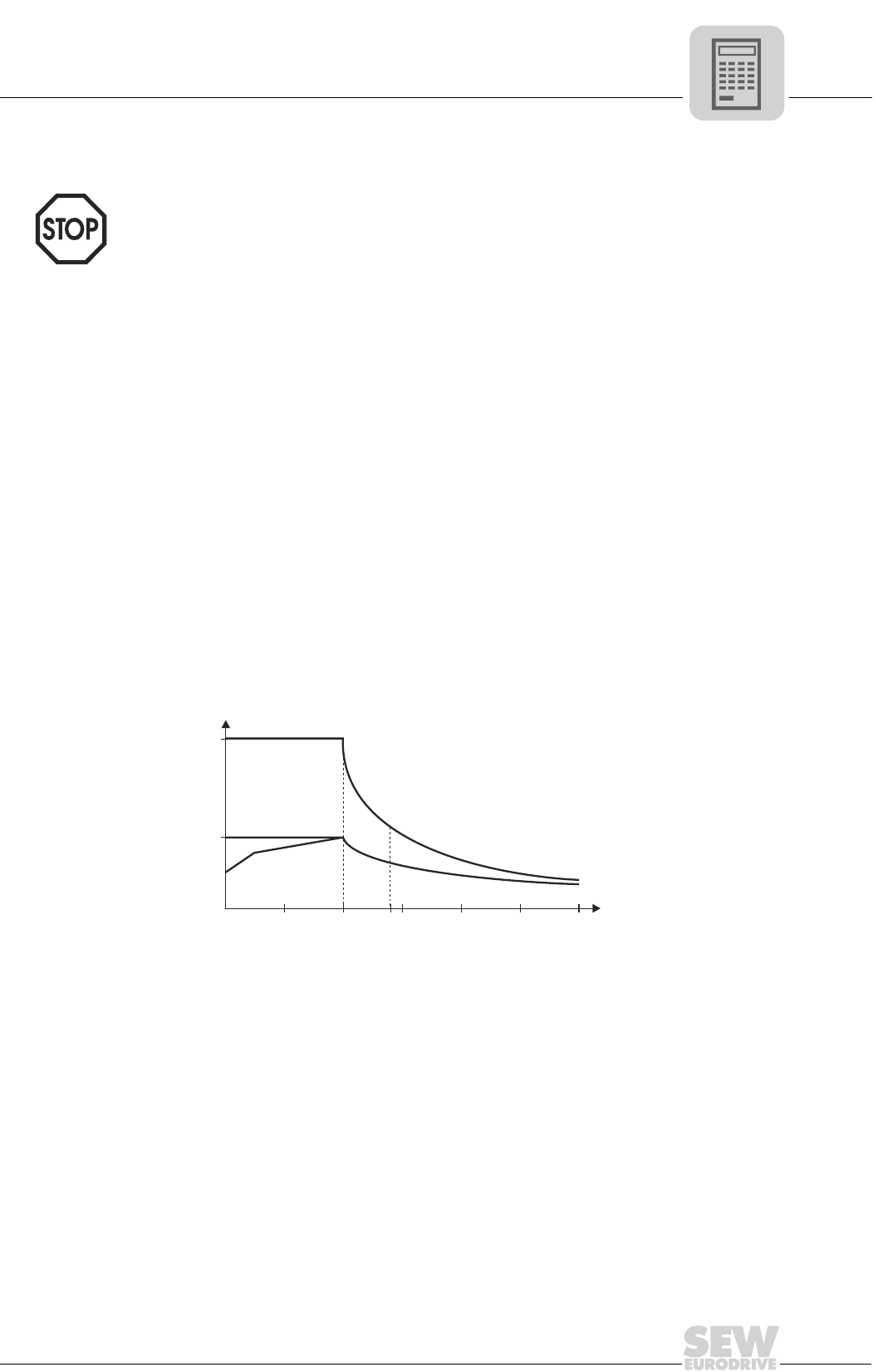
MOVIDRIVE® compact Catalog
89
3
Motor selection for asynchronous servomotors (CFC)
3.2 Motor selection for asynchronous servomotors (CFC)
Motor character-
istics
The drive in CFC operating modes is characterized by its ability to control torque directly
and rapidly. This means it achieves a high level of dynamic overload capacity (up to 3 ×
MN) and a very high speed and control range (up to 1:5000). Smooth running at speed
and positioning accuracy fulfill the exacting requirements of servo systems. This behav-
ior is achieved by the field-oriented control function. The current components for mag-
netization (Id) and torque generation (Iq) are controlled separately. A feature of the CFC
operating modes is that there must always be an encoder on the motor.
The inverter needs exact data about the connected motor in order to calculate the motor
model. These data are made available by the MOVITOOLS software with the startup
function. CFC operating modes are only possible with 4-pole SEW-motors (CT/CV or
DT/DV/D), not with the other SEW motors or non-SEW motors. The necessary motor
data for the CFC operating modes are stored in MOVIDRIVE® for the 4-pole SEW mo-
tors.
Typical speed-
torque characteris-
tic
MN is determined by the motor. Mmax and ntransition depend on the motor/inverter com-
bination. You can refer to the motor selection tables for CFC mode for the values of ntran-
sition, MN and Mmax.
The torque limit (M limit) is set automatically by the startup function of the MOVITOOLS
software package. Do not alter this automatically set value!
We recommend always using the latest version of MOVITOOLS (2.70 or later) for star-
tup. The latest MOVITOOLS version can be downloaded from our homepage
(www.sew-eurodrive.de).
01651BEN
Figure 44: Speed/torque characteristic curve in CFC operating mode
1 With integrated cooling
2 With forced cooling
3 Maximum torque
0
Mmax
0
2
1
3
n
M
n
base
Mrated
1.4 n×
base

3
90
MOVIDRIVE® compact Catalog
Motor selection for asynchronous servomotors (CFC)
Magnetization
current
Dynamic drives which are supposed to accelerate without a time lag are also energized
when at a standstill without load. This means the magnetization current Id is flowing. The
inverter must be able to supply this current constantly in applications in which the output
stage is permanently enabled, e.g. in CFC & M-CONTROL mode. In particular in the
case of large motors with a slip frequency ≤ 2 Hz, you must refer to the diagrams in Sec.
'Load capacity of the units at low output frequencies' to check whether the inverter can
supply the current. Also check whether the thermal characteristics of the motor are suit-
able for this mode of operation (forced cooling fan). Refer to the motor tables (CT/CV →
page 93, DT/DV/D → page 98) for the magnetization current Id.
Basic recommen-
dations
CFC operating modes are only possible with SEW-motors (CT/CV or DT/DV/D series),
not with non-SEW motors. The necessary motor data for the CFC operating modes are
stored in MOVIDRIVE® for the SEW motors.
Speed is the correcting variable in the CFC modes with speed control. Torque is the cor-
recting variable in the CFC modes with torque control (CFC & M-CONTROL).
CFC mode with
speed control
There is no reason to differentiate between quadratic, dynamic and static load types
when configuring a system for CFC mode. Project planning for an asynchronous motor
in CFC mode is undertaken in accordance with the following requirements:
1. Effective torque demand at the average speed of the application.
Mr.m.s. < Mn_mot
The point must lie below the characteristic curve for the continuous torque (Figure
44, curve 2). No forced cooling is required if this operating point lies below the char-
acteristic curve for forced cooling (Figure 44, curve 1).
2. Maximum torque required across the speed characteristic.
Mmax < Mdyn_mot
This operating point must lie below the characteristic curve for the maximum torque
of the motor-MOVIDRIVE® combination (Figure 44, curve 3).
3. Maximum speed
The maximum speed of the motor should not be configured higher than 1.4 times the
transition speed. The maximum torque available will then still be approx. 100 % of
the rated continuous torque of the motor; the input speed for the gear unit connected
to the motor output will still be less than 3000 rpm with delta connection.
nmax < 1.4 × ntransition < 3000 rpm
Motor cooling Self-cooling of asynchronous motors is based on the integrated fan, and consequently
depends on the speed. The integrated fan does not provide any cooling at low speeds
and when the motor is stopped. Forced cooling may be required in case of a high static
load or a high effective torque.

MOVIDRIVE® compact Catalog
91
3
Motor selection for asynchronous servomotors (CFC)
CFC mode with
torque control
(CFC & M-CON-
TROL)
This operating mode permits direct torque control of the asynchronous motor in the ba-
sic speed range (n ≤ ntransition). The setpoint sources of the speed controlled CFC mode
can also be used for torque control. All speed setpoint sources are interpreted as current
setpoint sources. The settings for evaluating the analog input (→ P11_, parameter de-
scription) also remain in effect. The fixed setpoints (P16_, P17_) can be entered either
in the unit [rpm] or [%IN_inverter] (→ MOVITOOLS).
The following relationship applies between the units:
3000 rpm = 150 % rated inverter current
The torque on the output shaft can then be calculated for the basic speed range (n ≤
ntransition) using the following formulae:
Specification of a setpoint for the motor torque in %In_inverter:
Specification of a setpoint for the motor torque in rpm:
In addition to the current Iq for creating the torque, the inverter also needs to supply the
magnetization current Id. The inverter output current Itot which actually flows can be cal-
culated using the following formulae:
Specification of a setpoint for the motor torque in %In_inverter:
Specification of a setpoint for the motor torque in rpm:
04972AEN
04973AEN
In_inverter = Rated output current of the inverter
kT= Torque constant = Mn / Iq_n
Mn and Iq_n are motor-specific parameters. Refer to the motor tables (DT/DV/D
→ page 98, CT/CV → page 93) for the values of the torque constants kT and the
motor-specific parameters Mn and Iq_n.
04974AEN
04975AEN
Iq_n = Nominal value for the current which generates the torque, according to the motor
table
Id_n = Nominal value for the magnetization current, according to the motor table
M k I Setpo
T n inverter
=× ×
_
int
Mk I Setpo
rpm
Tninverter
=×× ×15 3000
.int
_
I Setpo I I
tot n inverter d N
=× +int
__
di
22
I Setpo I rpm I
tot n inverter d N
=×××
F
H
GI
K
J+int . __
15 1
3000
2
2
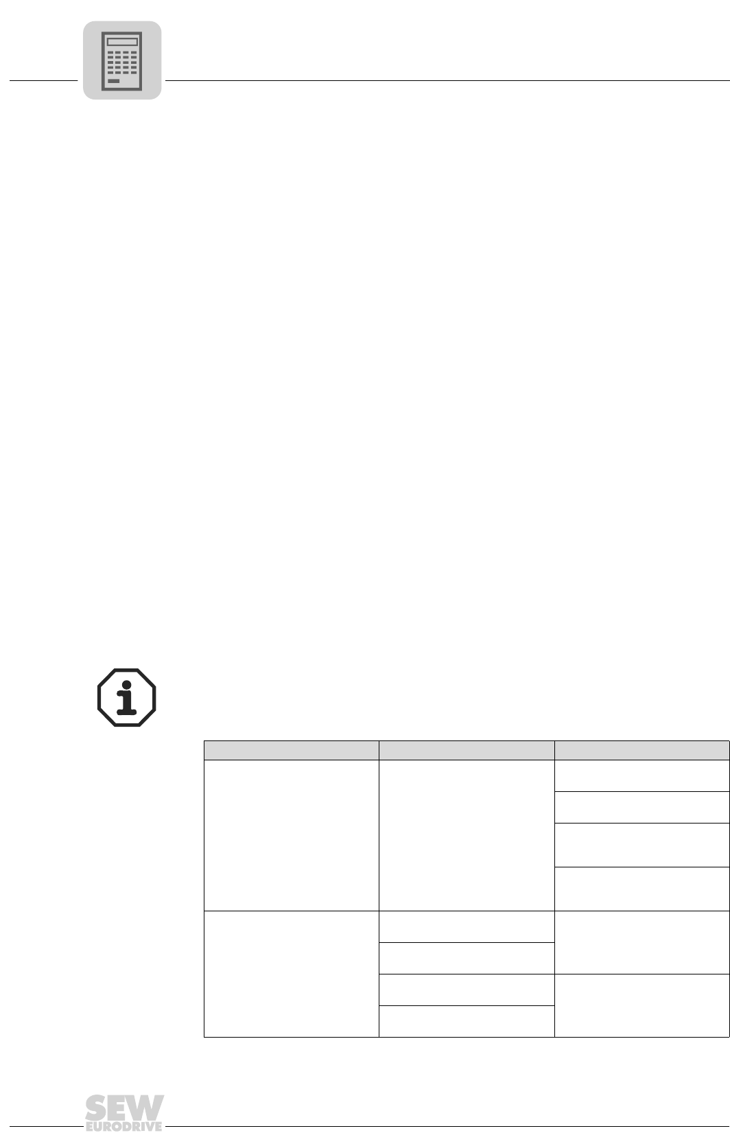
3
92
MOVIDRIVE® compact Catalog
Motor selection for asynchronous servomotors (CFC)
CT/CV asynchro-
nous servomo-
tors
SEW offers series CT/CV asynchronous servomotors especially for operation with
MOVIDRIVE® compact in the CFC operating modes. These motors have the following
characteristics:
High power yield The optimum winding of CT/CV motors permits a high power yield.
Organization into
speed categories
CT/CV motors are supplied in four speed categories. This ensures optimum utilization
of torque and speed.
With sin/cos
encoder as stan-
dard
As standard, CT/CV motors are equipped with a high-resolution sin/cos encoder (ES1S,
ES2S, EV1S).
As standard, with
TF or TH motor
protection
The winding temperature of the three motor phases is monitored using thermistor sen-
sors (TF). The thermistor sensor can be connected to the TF/TH input of MOVIDRIVE®
compact. Thermal monitoring is then undertaken by MOVIDRIVE® compact; no addi-
tional monitoring unit is required.
Bimetallic switches (TH) can also be used instead of thermistor sensors. The bimetallic
switches are also connected to the TF/TH input.
Thermal classifica-
tion F as standard
As standard, CT/CV motors are built using thermal classification F materials. The max-
imum permitted temperature rise is therefore 105 K.
Reinforced pinion
spigot
CT/CV motors can generate up to three times their rated motor torque during dynamic
operation. For this reason, these motors are fitted with reinforced pinion spigots for di-
rect mounting to gear units. These spigots enable these motors to transmit the high
torque levels reliably.
Either DT/DV/D motors or CT/CV motors can be used in CFC mode. SEW recommends
using CT/CV motors in order to achieve optimum benefit from the advantages of CFC
mode.
Advantage Disadvantage
CFC mode with DT/DV/D motor
Motor selection → page 101 Standard version of motor
Slower transition speed than the
CT/CV motor.
The power yield of the motor is
less than the rated motor power.
In terms of the power yield, the
mass inertia is greater than the
CT/CV motors.
In some inverter/motor combina-
tions, the maximum torque is lim-
ited by the mechanical strength.
CFC mode with CT/CV motor
Motor selection → page 94
Faster transition speed than DT/
DV/D motor. Not an IEC standard motor
Usually with a power yield one
level higher.
Lower mass inertia in relation to
the power yield. Higher current consumption due
to the higher power yield, there-
fore a larger inverter must be
assigned.
Motor is designed for dynamic
operation.
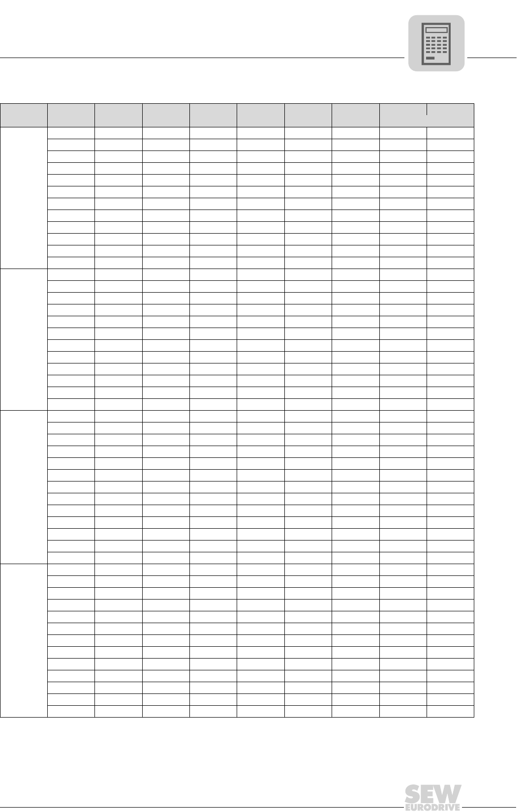
MOVIDRIVE® compact Catalog
93
3
Motor selection for asynchronous servomotors (CFC)
Motor table CT/CV
nNMotor MNINIq_n Id_n kTUNJmot JBmot
[rpm] [Nm] [A] [A] [A] [A] [V] [10-4 kgm2]
1200
CT80N4 5 2.0 1.52 1.30 2.50 350 8.7 9.6
CT90L4 10 3.5 2.95 1.89 2.86 345 34 39.5
CV100M4 15 4.7 4.13 2.25 3.19 345 53 59
CV100L4 26 8.9 8.30 3.21 2.92 310 65 71
CV132S4 37 11.1 9.99 4.83 3.33 340 146 158
CV132M4 50 15.5 14.2 6.18 3.23 340 280 324
CV132ML4 61 17.6 16.0 7.43 3.47 345 330 374
CV160M4 73 22.5 20.3 9.73 3.24 335 400 440
CV160L4 95 29 25.3 14.2 3.28 330 925 1030
CV180M4 110 34 27.7 19.7 3.24 330 1120 1226
CV180L4 125 35 28.4 20.5 3.57 345 1290 1396
CV200L4 200 58 52.9 23.7 3.45 330 2340 2475
1700
CT80N4 5 2.8 2.15 1.79 2.33 350 8.7 9.6
CT90L4 10 4.8 4.03 2.61 2.48 345 34 39.5
CV100M4 15 6.5 5.71 3.10 2.63 345 53 59
CV100L4 26 13.6 12.9 4.41 2.02 315 65 71
CV132S4 37 15.2 13.7 6.67 2.70 340 146 158
CV132M4 48 20.8 18.9 8.70 2.54 335 280 324
CV132ML4 58 24.4 21.7 11.2 2.67 320 330 374
CV160M4 71 29.8 26.6 13.4 2.67 340 400 440
CV160L4 89 37.5 32.0 19.5 2.78 330 925 1030
CV180M4 105 44.5 35.2 27.2 2.98 335 1120 1226
CV180L4 115 48.5 37.5 30.7 3.07 325 1290 1396
CV200L4 190 77 69.4 33.4 2.74 330 2340 2475
2100
CT71D4 2.5 2.0 1.60 1.20 1.56 340 4.6 5.5
CT80N4 5 3.5 2.67 2.26 1.87 340 8.7 9.6
CT90L4 10 6.1 5.14 3.29 1.95 335 34 39.5
CV100M4 15 8.1 7.09 3.91 2.12 335 53 59
CV100L4 25 14.8 13.7 5.56 1.82 305 65 71
CV132S4 37 19.2 17.3 8.41 2.14 335 146 158
CV132M4 48 26 23.7 10.7 2.03 335 280 324
CV132ML4 58 29 26.0 12.9 2.23 340 330 374
CV160M4 70 37 33.9 16.9 2.13 330 400 440
CV160L4 88 46 38.9 24.6 2.26 330 925 1030
CV180M4 100 53 40.5 34.2 2.47 330 1120 1226
CV180L4 115 56 43.4 35.4 2.65 345 1290 1396
CV200L4 175 88 77.8 41.2 2.25 325 2340 2475
3000
CT71D4 2.4 2.6 2.01 1.65 1.19 345 4.6 5.5
CT80N4 4.5 4.3 2.97 3.11 1.52 350 8.7 9.6
CT90L4 9.5 7.9 6.47 4.54 1.47 345 34 39.5
CV100M4 15 11.3 9.93 5.39 1.51 345 53 59
CV100L4 21 17.0 15.2 7.65 1.38 310 65 71
CV132S4 35 25.0 22.1 11.6 1.58 340 146 158
CV132M4 45 34 30.5 15.1 1.48 335 280 324
CV132ML4 52 38 32.7 19.3 1.59 320 330 374
CV160M4 64 47 40.8 23.3 1.57 345 400 440
CV160L4 85 62 51.9 33.9 1.64 335 925 1030
CV180M4 93 68 49.0 47.2 1.90 340 1120 1226
CV180L4 110 81 61.2 53.1 1.80 325 1290 1396
CV200L4 145 102 84.0 57.8 1.73 330 2340 2475
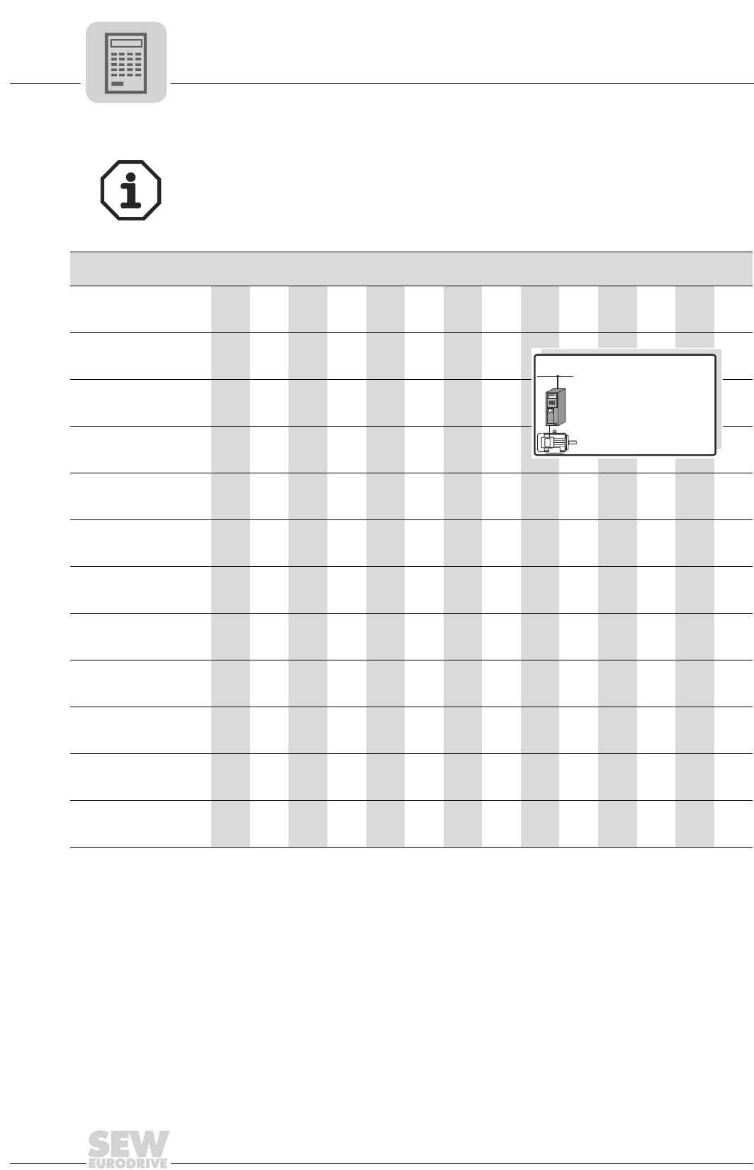
3
94
MOVIDRIVE® compact Catalog
Motor selection for asynchronous servomotors (CFC)
CT/CV motor selection
1. Rated speed nN = 1200 rpm:
CT/CV motors in the four speed categories are designed for operation with 400/500 V
units. Please contact SEW concerning operation with 230 V units.
Motor MOVIDRIVE® compact MCV/MCH4_A...-5_3 (400/500 V units) in CFC operating modes (P700)
0015 0022 0030 0040 0055 0075 0110 0150 0220 0300 0370 0450 0550 0750
CT80N4
Mmax[Nm]
([lb.in])
15.6
(138)
ntransition[rpm] 540
CT90L4
Mmax [Nm]
([lb.in])
18.2
(160)
25.7
(227)
30.5
(270)
ntransition[rpm] 928 781 685
CV100M4
Mmax [Nm]
([lb.in])
29.0
(256)
37.0
(327)
45.0
(398)
ntransition[rpm] 883 781 680
CV100L4
Mmax [Nm]
([lb.in])
32.6
(288)
45.3
(400)
60.0
(530)
75.0
(663)
ntransition[rpm] 1062 947 813 675
CV132S4
Mmax [Nm]
([lb.in])
64.0
(565)
84.0
(743)
110
(972)
ntransition[rpm] 992 915 1175
CV132M4
Mmax [Nm]
([lb.in])
82.0
(725)
125
(1105)
150
(1326)
ntransition[rpm] 1011 877 770
CV132ML4
Mmax [Nm]
([lb.in])
126
(1114)
169
(1495)
183
(1617)
ntransition[rpm] 922 819 725
CV160M4
Mmax [Nm]
([lb.in])
125
(1105)
169
(1495)
219
(1936)
ntransition[rpm] 986 909 840
CV160L4
Mmax [Nm]
([lb.in])
163
(1440)
240
(2121)
294
(2600)
ntransition[rpm] 1043 954 1240
CV180M4
Mmax [Nm]
([lb.in])
241
(2130)
320
(2828)
360
(3183)
ntransition[rpm] 1050 986 1005
CV180L4
Mmax [Nm]
([lb.in])
231
(2042)
308
(2723)
360
(3183)
ntransition[rpm] 1018 973 980
CV200L4
Mmax [Nm]
([lb.in])
326
(2882)
402
(3554)
494
(4367)
567
(5013)
ntransition[rpm] 1011 986 947 940
P700: CFC...
EQ
Q
3 400/500 V×AC
CT/CV: n = 1200 rpm
N
MCV/MCH4_A...-5_3
(400/500 V)
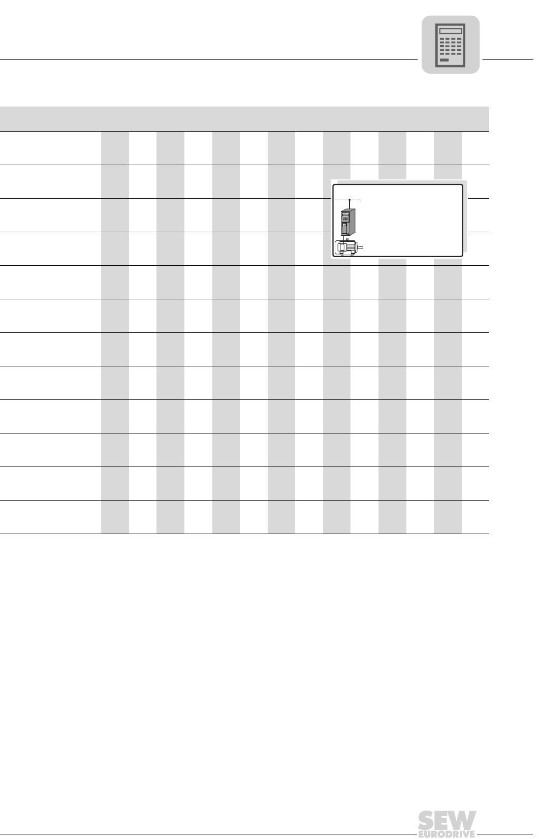
MOVIDRIVE® compact Catalog
95
3
Motor selection for asynchronous servomotors (CFC)
2. Rated speed nN = 1700 rpm:
Motor MOVIDRIVE® compact MCV/MCH4_A...-5_3 (400/500 V units) in CFC operating modes (P700)
0015 0022 0030 0040 0055 0075 0110 0150 0220 0300 0370 0450 0550 0750
CT80N4
Mmax [Nm]
([lb.in])
12.6
(111)
15.6
(138)
ntransition[rpm] 1150 980
CT90L4
Mmax [Nm]
([lb.in])
18.0
(159)
23.5
(208)
30.5
(270)
ntransition[rpm] 1400 1280 1150
CV100M4
Mmax [Nm]
([lb.in])
25.7
(227)
36.0
(318)
45.0
(398)
ntransition[rpm] 1402 1274 1150
CV100L4
Mmax [Nm]
([lb.in])
32.9
(290)
44.2
(390)
57.0
(504)
75.0
(663)
ntransition[rpm] 1510 1402 1274 1090
CV132S4
Mmax [Nm]
([lb.in])
59.0
(522)
91.0
(805)
110
(972)
ntransition[rpm] 1470 1330 1280
CV132M4
Mmax [Nm]
([lb.in])
89.0
(787)
121
(1070)
150
(1326)
ntransition[rpm] 1440 1330 1250
CV132ML4
Mmax [Nm]
([lb.in])
83.0
(734)
114
(1008)
166
(1468)
183
(1618)
ntransition[rpm] 1562 1485 1331 1325
CV160M4
Mmax [Nm]
([lb.in])
120
(1060)
176
(1555)
219
(1936)
ntransition[rpm] 1420 1310 1250
CV160L4
Mmax [Nm]
([lb.in])
170
(1503)
226
(2000)
277
(2450)
294
(2600)
ntransition[rpm] 1470 1400 1330 1380
CV180M4
Mmax [Nm]
([lb.in])
168
(1485)
226
(2000)
280
(2475)
345
(3050)
360
(3183)
ntransition[rpm] 1550 1510 1460 1400 1490
CV180L4
Mmax [Nm]
([lb.in])
217
(1918)
269
(2378)
332
(2935)
360
(3183)
ntransition[rpm] 1450 1420 1370 1420
CV200L4
Mmax [Nm]
([lb.in])
353
(3120)
420
(3713)
524
(4632)
ntransition[rpm] 1421 1395 1344
P700: CFC...
EQ
Q
3 400/500 V×AC
CT/CV: n = 1700 rpm
N
MCV/MCH4_A...-5_3
(400/500 V)
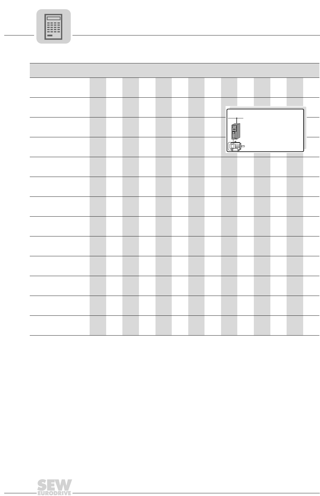
3
96
MOVIDRIVE® compact Catalog
Motor selection for asynchronous servomotors (CFC)
3. Rated speed nN = 2100 rpm:
Motor MOVIDRIVE® compact MCV/MCH4_A...-5_3 (400/500 V units) in CFC operating modes (P700)
0015 0022 0030 0040 0055 0075 0110 0150 0220 0300 0370 0450 0550 0750
CT71D4
Mmax [Nm]
([lb.in])
7.7
(68)
ntransition[rpm] 1280
CT80N4
Mmax [Nm]
([lb.in])
9.7
(86)
13.8
(122)
15.6
(138)
ntransition[rpm] 1754 1510 1400
CT90L4
Mmax [Nm]
([lb.in])
18.3
(162)
25.5
(225)
30.5
(270)
ntransition[rpm] 1843 1677 1625
CV100M4
Mmax [Nm]
([lb.in])
28.0
(248)
38.1
(337)
45.0
(398)
ntransition[rpm] 1760 1626 1550
CV100L4
Mmax [Nm]
([lb.in])
33.7
(298)
44.0
(390)
67.0
(592)
75.0
(663)
ntransition[rpm] 2003 1894 1645 1550
CV132S4
Mmax [Nm]
([lb.in])
72.0
(637)
97.0
(858)
110
(972)
ntransition[rpm] 1850 1722 1730
CV132M4
Mmax [Nm]
([lb.in])
95.0
(840)
138
(1220)
150
(1326)
ntransition[rpm] 1850 1670 1670
CV132ML4
Mmax [Nm]
([lb.in])
139
(1230)
183
(1618)
ntransition[rpm] 1715 1574
CV160M4
Mmax [Nm]
([lb.in])
138
(1220)
183
(1618)
219
(1936)
ntransition[rpm] 1792 1690 1625
CV160L4
Mmax [Nm]
([lb.in])
177
(1565)
218
(1927)
268
(2370)
294
(2600)
ntransition[rpm] 1882 1824 1740 1760
CV180M4
Mmax [Nm]
([lb.in])
218
(1927)
270
(2387)
322
(2847)
360
(3183)
ntransition[rpm] 1939 1894 1836 1930
CV180L4
Mmax [Nm]
([lb.in])
260
(2300)
310
(2740)
360
(3183)
ntransition[rpm] 1824 1786 1840
CV200L4
Mmax [Nm]
([lb.in])
329
(2910)
412
(3642)
ntransition[rpm] 1830 1792
P700: CFC...
EQ
Q
3 400/500 V×AC
CT/CV: n = 2100 rpm
N
MCV/MCH4_A...-5_3
(400/500 V)
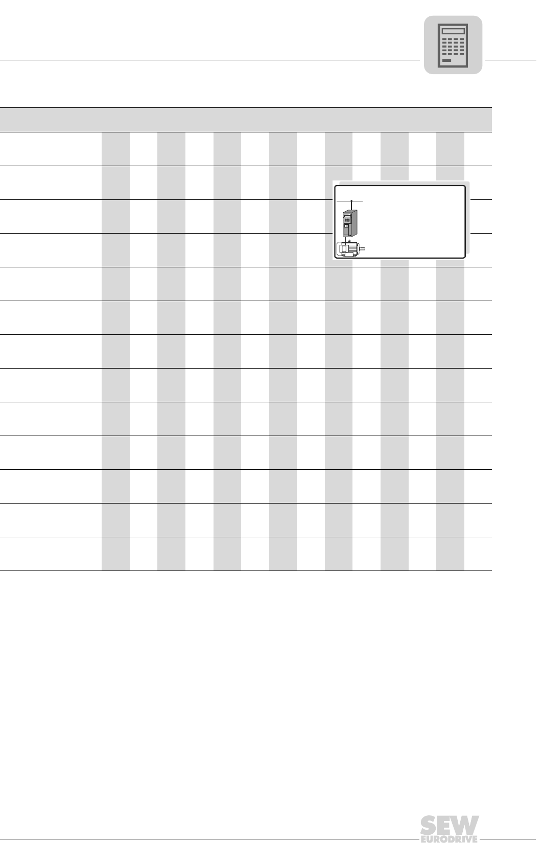
MOVIDRIVE® compact Catalog
97
3
Motor selection for asynchronous servomotors (CFC)
4. Rated speed nN = 3000 rpm:
Motor MOVIDRIVE® compact MCV/MCH4_A...-5_3 (400/500 V units) in CFC operating modes (P700)
0015 0022 0030 0040 0055 0075 0110 0150 0220 0300 0370 0450 0550 0750
CT71D4
Mmax [Nm]
([lb.in])
6.6
(58)
7.7
(68)
ntransition[rpm] 2280 2080
CT80N4
Mmax [Nm]
([lb.in])
9.7
(86)
12.7
(112)
15.5
(137)
ntransition[rpm] 2560 2350 2200
CT90L4
Mmax [Nm]
([lb.in])
12.7
(112)
18.0
(160)
24.0
(212)
30.5
(270)
ntransition[rpm] 2790 2650 2490 2360
CV100M4
Mmax [Nm]
([lb.in])
26.5
(235)
34.6
(305)
45.0
(398)
ntransition[rpm] 2620 2490 2425
CV100L4
Mmax [Nm]
([lb.in])
31.8
(281)
49.0
(433)
66.0
(583)
75.0
(663)
ntransition[rpm] 2800 2600 2380 2290
CV132S4
Mmax [Nm]
([lb.in])
51.0
(450)
69.0
(610)
101
(893)
110
(972)
ntransition[rpm] 2740 2650 2455 2580
CV132M4
Mmax [Nm]
([lb.in])
67.0
(592)
99.0
(875)
131
(1158)
150
(1326)
ntransition[rpm] 2750 2600 2450 2400
CV132ML4
Mmax [Nm]
([lb.in])
94.0
(830)
124
(1096)
152
(1343)
183
(1618)
ntransition[rpm] 2765 2656 2547 2400
CV160M4
Mmax [Nm]
([lb.in])
98.0
(866)
131
(1158)
161
(1423)
198
(1750)
219
(1936)
ntransition[rpm] 2630 2550 2470 2370 2380
CV160L4
Mmax [Nm]
([lb.in])
124
(1096)
155
(1370)
192
(1697)
228
(2015)
286
(2528)
ntransition[rpm] 2720 2680 2620 2545 2440
CV180M4
Mmax [Nm]
([lb.in])
150
(1326)
191
(1690)
228
(2015)
289
(2555)
ntransition[rpm] 2790 2745 2700 2635
CV180L4
Mmax [Nm]
([lb.in])
182
(1610)
220
(1945)
276
(2440)
ntransition[rpm] 2620 2580 2540
CV200L4
Mmax [Nm]
([lb.in])
293
(2590)
ntransition[rpm] 2573
P700: CFC...
EQ
Q
3 400/500 V×AC
CT/CV: n = 3000 rpm
N
MCV/MCH4_A...-5_3
(400/500 V)
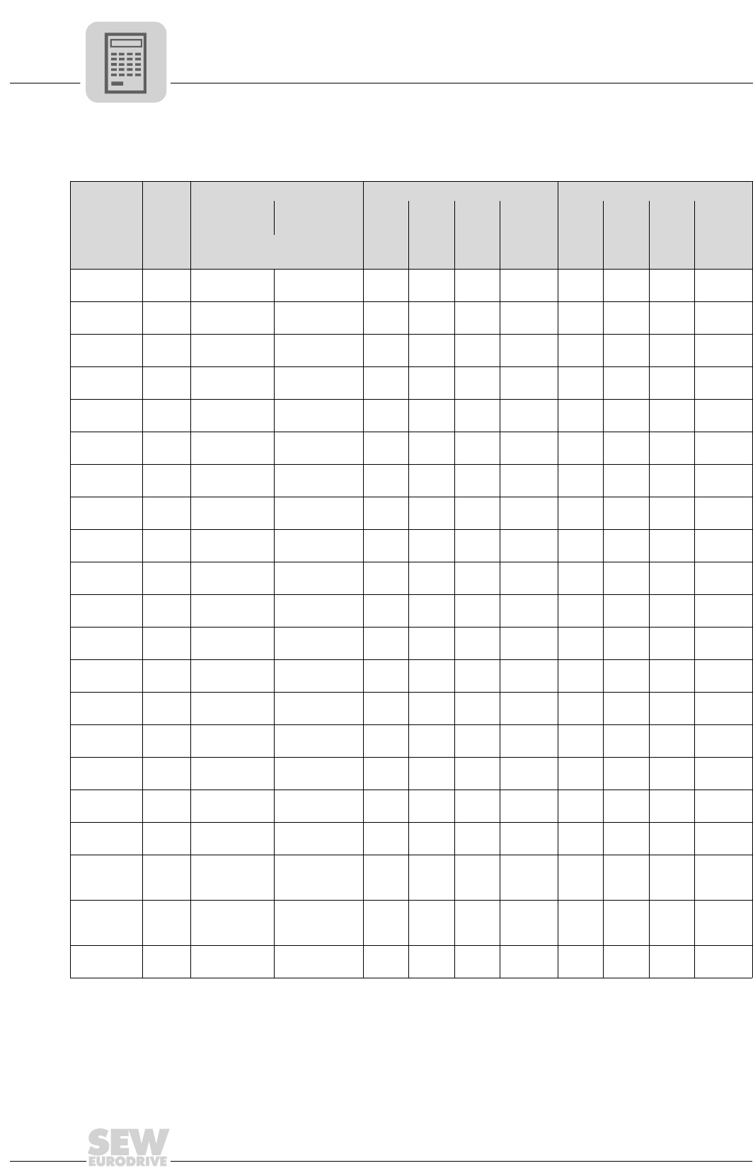
3
98
MOVIDRIVE® compact Catalog
Motor selection for asynchronous servomotors (CFC)
DT/DV/D motor tables
Characteristic values for delta/star 230/400 V / 50 Hz
Motor
MN
Mass moment of inertia JMStar 댴 (400 V) Delta ∆ (230 V)
Without
brake With brake InIq_n1)
1) Applies in the basic speed range up to ntransition.
Id_n1) kT1) InIq_n1) Id_n1) kT1)
[Nm
(lb.in)] [10-4 kgm2 (10-3 lb.ft2)] [A] [A] [A] [Nm/A] [A] [A] [A] [Nm/A]
DT71D4 2.6
(23) 4.6 (10.4) 5.5 (12.5) - - - - 2.15 1.82 1.14 1.43
DT80K4 3.9
(34) 6.6 (15.6) 7.5 (17.7) - - - - 3.03 2.53 1.67 1.54
DT80N4 5.2
(46) 8.7 (20.7) 9.6 (22.8) 2.15 1.72 1.29 3.02 3.72 2.99 2.21 1.74
DT90S4 7.5
(66) 25 (59.4) 31 (72.2) 2.80 2.39 1.46 3.13 4.85 4.17 2.48 1.80
DT90L4 10.2
(90) 34 (78.9) 40 (93.6) 3.7 3.18 1.89 3.21 6.41 5.51 3.28 1.85
DV100M4 15.0
(133) 42 (101) 48 (114) 4.95 4.37 2.32 3.43 8.57 7.57 4.02 1.98
DV100L4 20.5
(181) 53 (126) 59 (139) 6.7 5.89 3.19 3.48 11.6 10.2 5.52 2.01
DV112M4 26.9
(238) 98 (233) 110 (262) 8.7 7.85 3.75 3.43 15.2 13.6 6.79 1.98
DV132S4 36.7
(324) 146 (416) 158 (445) 11.4 10.3 4.89 3.56 19.8 17.9 8.46 2.05
DV132M4 50.1
(443) 280 (655) 330 (769) 15.5 14.2 6.21 3.53 27.0 24.6 11.1 2.04
DV132ML4 61.0
(539) 330 (769) 380 (887) 18.7 17.1 7.57 3.57 32.5 29.6 13.4 2.06
DV160M4 72.9
(644) 398 (945) 448 (1049) 22.5 20.3 9.70 3.59 39.0 35.1 17.0 2.08
DV160L4 98.1
(867) 925 (2197) 1060 (2449) 31.0 27.6 14.1 3.55 54.0 47.8 25.1 2.05
DV180M4 121
(1070) 1120 (2660) 1255/15202)
(2912/31642))
2) Double disk brake
38.5 33.1 19.7 3.66 67.0 57.3 34.7 2.11
DV180L4 143
(1264) 1290 (3064) 1425/15202)
(3316/35672))46.0 40.7 21.4 3.51 80.0 70.4 38.0 2.03
DV200L4 195
(1724) 2340 (5558) 2475/25702)
(5809/60612))57.0 51.8 23.8 3.76 99.0 89.8 41.7 2.17
DV225S4 240
(2122) 3010 (7149) 3145/32402)
(7400/76522))70.0 64.5 27.2 3.72 122 112 48.4 2.14
DV225M4 292
(2581) 3570 (8479) 3705/38002)
(8730/89822))86.0 77.6 37.1 3.76 149 134 65.2 2.18
DV250M4 356
(3147) 6300 (14950)
6600/67302)
(15550/
159082))
102 91.7 44.7 3.88 - - - -
DV280S4 483
(4270) 8925 (21180)
9225/93552)
(21737/
221122))
142 124 68.9 3.90 - - - -
D280M4 580
(5127)
14500
(34409) 3)
3) On request
155 147 49.2 3.95 - - - -
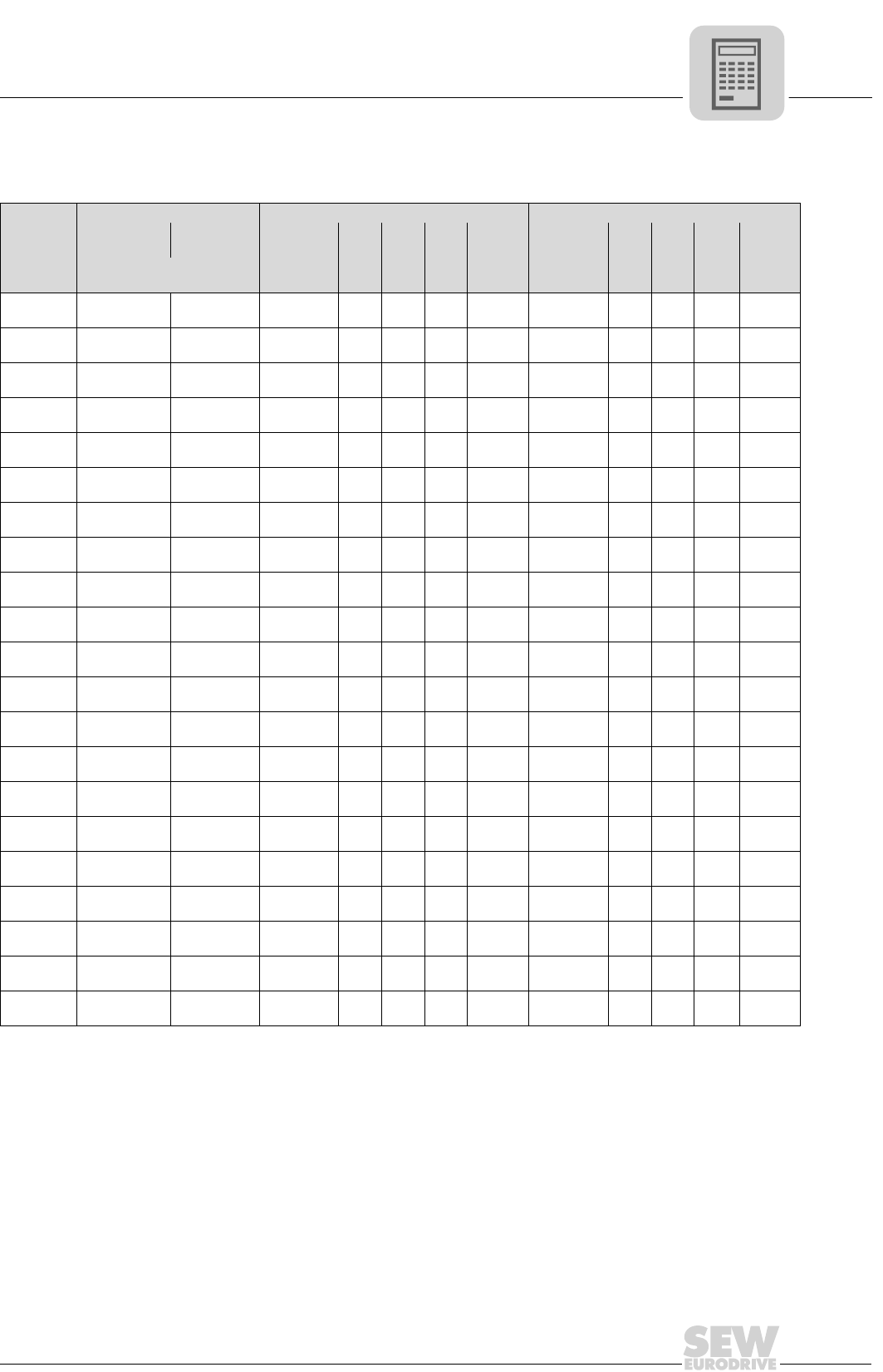
MOVIDRIVE® compact Catalog
99
3
Motor selection for asynchronous servomotors (CFC)
Characteristic values for double-star/star 230/460 V / 60 Hz
(according to MG1, NEMA design B up to DT80K4, NEMA design C up to DT80N4)
Motor
Mass moment of inertia JMStar 댴 (460 V) Double-star 댴댴 (230 V)
Without brake With brake MN at
1000 rpm InIq_n1)
1) Applies in the basic speed range up to ntransition.
Id_n1) kT1) MN at
2400 rpm InIq_n1) Id_n1) kT1)
[10-4 kgm2 (10-3 lb.ft2)] [Nm (lb.in)] [A] [A] [A] [Nm/A
(lb.in/A)] [Nm (lb.in)] [A] [A] [A] [Nm/A
(lb.in/A)]
DT71D4 4.6 (10.4) 5.5 (12.5) 2.60 (23.0) 1.15 0.95 0.65 2.74
(24.2) 2.60 (23.0) 2.30 1.90 1.30 1.37
(12.1)
DT80K4 6.6 (15.6) 7.5 (17.7) 3.90 (34.5) 1.67 1.35 0.98 2.89
(27.3) 3.90 (34.5) 3.34 2.70 1.96 1.44
(12.8)
DT80N4 8.7 (20.7) 9.6 (22.8) 5.20 (46.0) 2.11 1.72 1.22 3.03
(26.8) 5.20 (46.0) 4.21 3.44 2.44 1.51
(13.4)
DT90S4 25 (59.4) 31 (72.2) 7.50 (66.3) 2.94 2.33 1.80 3.21
(28.4) 7.50 (66.3) 5.89 4.66 3.60 1.61
(14.2)
DT90L4 34 (78.9) 40 (93.6) 10.2 (90.2) 3.57 3.06 1.84 3.35
(29.6) 10.2 (90.2) 7.13 6.11 3.68 1.67
(14.8)
DT100LS4 42 (101) 48 (114) 15.0 (133) 5.00 4.47 2.25 3.34
(29.5) 15.0 (133) 10.1 9.00 4.50 1.66
(14.7)
DT100L4 53 (126) 59 (139) 20.5 (181) 7.92 7.32 3.02 3.45
(30.5) 20.5 (181) 15.8 14.6 6.05 1.72
(15.2)
DV112M4 98 (233) 110 (262) 26.9 (238) 8.20 7.47 3.37 3.60
(31.8) 26.9 (238) 16.4 14.9 6.74 1.80
(15.9)
DV132S4 146 (416) 158 (445) 36.7 (324) 11.0 10.3 3.77 3.55
(31.4) 36.7 (324) 22.0 20.7 7.54 1.78
(15.7)
DV132M4 280 (655) 330 (769) 50.0 (442) 15.9 14.3 6.87 3.46
(30.5) 50.1 (443) 31.8 28.7 13.7 1.77
(15.3)
DV132ML4 330 (769) 380 (887) 61.0 (539) 18.6 16.9 7.69 3.61
(31.7) 61.0 (539) 37.2 33.9 15.4 1.80
(15.8)
DV160M4 398 (945) 448 (1049) 71.0 (628) 22.7 20.4 9.93 3.47
(30.7) 71.0 (628) 45.4 40.8 19.9 1.74
(15.4)
DV160L4 925 (2197) 1060 (2449) 96.0 (849) 30.7 27.4 13.7 3.51
(31.0) 96.0 (849) 61.3 54.8 27.5 1.75
(15.5)
DV180M4 1120 (2660) 1255/15202)
(2912/31642))
2) Double disk brake
120 (1060) 36.5 33.6 14.3 3.57
(31.6) 120 (1060) 72.9 67.1 28.6 1.79
(15.8)
DV180L4 1290 (3064) 1425/15202)
(3316/35672))130 (1150) 42.7 37.6 20.2 3.46
(30.6) 130 (1150) 85.4 75.1 40.5 1.73
(15.3)
DV200L4 2340 (5558) 2475/25702)
(5809/60612))190 (1680) 54.6 52.1 16.2 3.65
(32.3) 190 (1680) 109 104 32.5 1.82
(16.2)
DV225S4 3010 (7149) 3145/32402)
(7400/76522))235 (2078) 67.9 64.5 21.0 3.64
(32.3) 235 (2078) 136 129 42.0 1.83
(16.2)
DV225M4 3570 (8479) 3705/38002)
(8730/89822))280 (2475) 78.8 74.1 27.0 3.78
(33.5) 260 (2300) 148 138 54.0 1.89
(16.8)
D250M4 7300 (17323) 3)
3) On request
356 (3147) 102 95.6 36.4 3.73
(33.0) -----
D280S4 12000 (28476) 3) 483 (4270) 135 128 45.2 3.77
(33.3) -----
D280M4 14500 (34409) 3) 580 (5128) 162 153 51.7 3.79
(33.5) -----
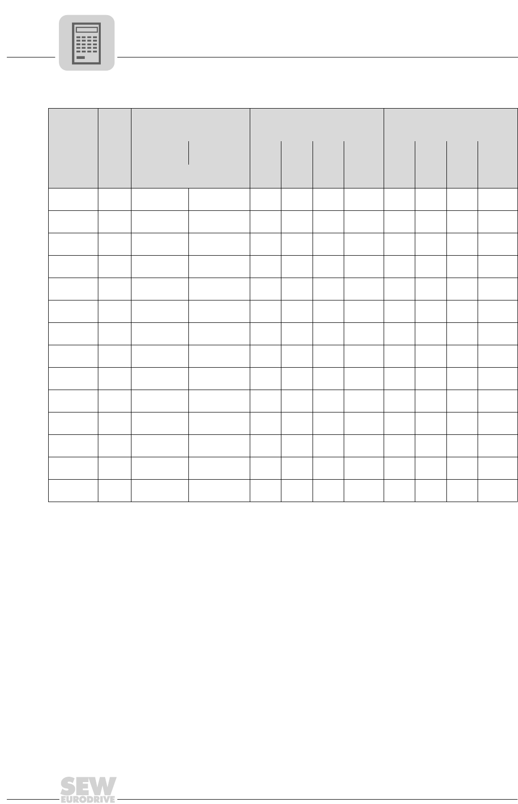
3
100
MOVIDRIVE® compact Catalog
Motor selection for asynchronous servomotors (CFC)
Characteristic values for JEC motors
Motor
MN
Mass moment of inertia JM
400 V / 60 Hz
440 V / 60 Hz
400 V / 50 Hz
200 V / 60 Hz
220 V / 60 Hz
200 V / 50 Hz
Without
brake With brake InIq_n1)
1) Applies in the basic speed range up to ntransition.
Id_n1) kT1) InIq_n1) Id_n1) kT1)
[Nm
(lb.in)] [10-4 kgm2 (10-3 lb.ft2)] [A] [A] [A] [Nm/A
(lb.in/A)] [A] [A] [A] [Nm/A
(lb.in/A)]
DT80K4 2.71
(24) 6.55 (15.5) 7.45 (17.7) 1.35
(댴)0.96 0.95 2.82
(24.9)
2.70
(댴댴)1.92 1.90 1.41
(12.5)
DT80N4 4.97
(44) 8.7 (20.6) 9.6 (22.8) 2.20
(댴)1.72 1.37 2.88
(25.5)
4.40
(댴댴)3.45 2.73 1.44
(12.7)
DT90L4 10.0
(88) 34 (80.7) 39.4 (93.5) 3.85
(댴)3.29 2.00 3.04
(26.9)
7.70
(댴댴)6.58 3.99 1.52
(13.4)
DV100M4 14.9
(131) 53 (126) 58.4 (139) 4.70
(댴)4.13 2.25 3.60
(31.8)
9.40
(댴댴)8.25 4.50 1.80
(15.9)
DV112M4 24.4
(215) 98 (233) 110.2 (262) 8.50
(댴)7.55 3.93 3.24
(28.6)
17.0
(댴댴)15.1 7.85 1.62
(14.3)
DV132S4 36.7
(324) 146 (346) 158.0 (375) 12.0
(∆)10.9 5.10 3.38
(29.9)
24.0
(∆∆)21.7 10.2 1.69
(14.9)
DV132M4 48.8
(431) 280 (664) 323.7 (768) 16.0
(∆)14.6 6.50 3.34
(29.5)
32.0
(∆∆)29.2 13.0 1.67
(14.8)
DV160M4 70.4
(622) 398 (944) 441.7 (1048) 23.0
(∆)20.6 10.3 3.42
(30.2)
46.0
(∆∆)41.2 20.5 1.71
(15.1)
DV160L4 96.6
(854) 925 (2195) 1031 (2447) 32.3
(∆)28.6 14.9 3.38
(29.9)
64.5
(∆∆)57.2 29.8 1.69
(14.9)
DV180M4 120
(1060) 1120 (2658) 1226/13322)
(2909/31602))
2) Double disk brake
40.5
(∆)34.8 20.7 3.46
(30.6)
81.0
(∆∆)69.6 41.4 1.73
(15.3)
DV180L4 140
(1237) 1290 (3060) 1396/15022)
(3313/35642))
47.8
(∆)42.0 22.7 3.34
(29.5)
95.5
(∆∆)84.1 45.3 1.67
(14.8)
DV200L4 194
(1714) 2340 (5553) 2446/25522)
(5804/60562))
60.0
(∆)54.5 24.9 3.56
(31.5)
120
(∆∆)109 49.9 1.78
(15.7)
DV225S4 234
(2068) 3010 (7143) 3116/32222)
(7394/76452))
72.0
(∆)66.0 28.7 3.54
(31.3)
144
(∆∆)132 57.3 1.77
(15.6)
DV225M4 284
(2510) 3570 (8472) 3676/37822)
(8723/89752))
88.5
(∆)79.5 38.9 3.58
(31.6)
177
(∆∆)159 77.9 1.79
(15.8)

MOVIDRIVE® compact Catalog
101
3
Motor selection for asynchronous servomotors (CFC)
DT/DV/D motor selection with the delta/star topology (230/400 VAC / 50 Hz)
1. Star connection 댴 400 V / 50 Hz or 400/690 V / 50 Hz motors in ∆ connection:
Motor MOVIDRIVE® compact MCV/MCH4_A...-5_3 (400/500 V units) in CFC operating modes (P700)
댴 400 V / 50 Hz 0015 0022 0030 0040 0055 0075 0110 0150 0220 0300 0370 0450 0550 0750
DT80N4
Mmax[Nm]
([lb.in])
9.3
(82)
ntransition [rpm] 908
DT90S4
Mmax [Nm]
([lb.in])
13.5
(120)
13.5
(120)
ntransition [rpm] 1011 1011
DT90L4
Mmax [Nm]
([lb.in])
18.2
(161)
18.3
(162)
18.3
(162)
ntransition [rpm] 928 1049 1056
DV100M4
Mmax [Nm]
([lb.in])
26.8
(236)
26.8
(236)
26.8
(236)
ntransition [rpm] 940 1043 1056
DV100L4
Mmax [Nm]
([lb.in])
36.8
(325)
36.8
(325)
36.8
(325)
ntransition [rpm] 889 1004 1011
DV112M4
Mmax [Nm]
([lb.in])
47.1
(416)
48.4
(427)
48.4
(427)
ntransition [rpm] 915 1030 1062
DV132S4
Mmax [Nm]
([lb.in])
64.4
(569)
66.1
(584)
66.1
(584)
ntransition [rpm] 992 1132 1196
DV132M4
Mmax [Nm]
([lb.in])
81.7
(722)
90.2
(797)
90.2
(797)
ntransition [rpm] 1011 1145 1152
DV132ML4
Mmax [Nm]
([lb.in])
110
(972)
110
(972)
ntransition [rpm] 1043 1132
DV160M4
Mmax [Nm]
([lb.in])
124
(1096)
131
(1157)
131
(1157)
ntransition [rpm] 986 1132 1196
DV160L4
Mmax [Nm]
([lb.in])
163
(1440)
177
(1565)
177
(1565)
ntransition [rpm] 1043 1248 1312
DV180M4
Mmax [Nm]
([lb.in])
217
(1917)
217
(1917)
217
(1917)
ntransition [rpm] 1164 1395 1465
DV180L4
Mmax [Nm]
([lb.in])
230
(2033)
258
(2280)
258
(2280)
258
(2280)
ntransition [rpm] 1017 1152 1299 1369
DV200L4
Mmax [Nm]
([lb.in])
325
(2873)
351
(3100)
351
(3100)
351
(3100)
ntransition [rpm] 1011 1126 1299 1420
DV225S4
Mmax [Nm]
([lb.in])
Please note: The maximum
torque Mmax is limited to 180 % of
the rated motor torque MN.
395
(3490)
433
(3826)
433
(3826)
433
(3826)
ntransition [rpm] 947 1030 1164 1312
DV225M4
Mmax [Nm]
([lb.in])
482
(4260)
526
(4648)
526
(4648)
ntransition [rpm] 1030 1100 1299
DV250M4
Mmax [Nm]
([lb.in])
587
(5188)
641
(5665)
ntransition [rpm] 1017 1133
DV280S4
Mmax [Nm]
([lb.in])
711
(6283)
ntransition [rpm] 1075
D280M4
Mmax [Nm]
([lb.in])
745
(6583)
ntransition [rpm] 1107
P700: CFC...
EQ
Q
3 400/500 V×AC
DT/DV/D: 400 V/50 Hz댴
MCV/MCH4_A...-5_3
(400/500 V)
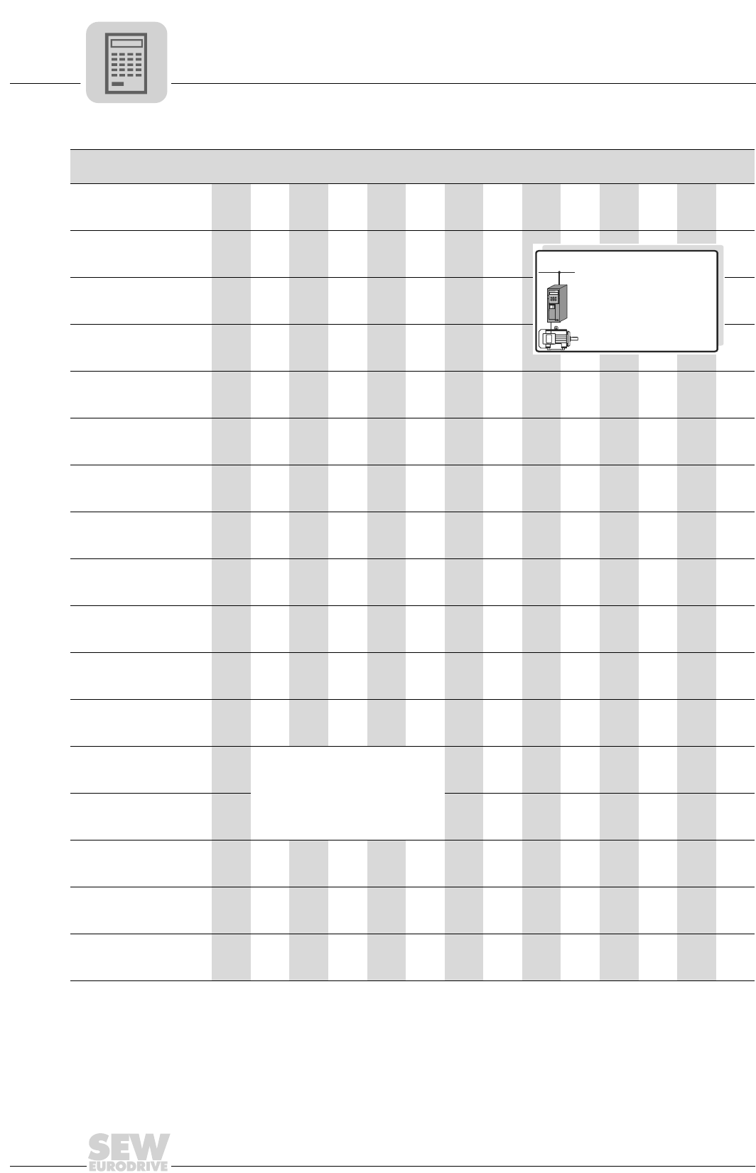
3
102
MOVIDRIVE® compact Catalog
Motor selection for asynchronous servomotors (CFC)
2. Delta connection ∆ 230 V / 50 Hz:
Motor MOVIDRIVE® compact MCV/MCH4_A...-5_3 (400/500 V units) in CFC operating modes (P700)
∆ 230 V / 50 Hz 0015 0022 0030 0040 0055 0075 0110 0150 0220 0300 0370 0450 0550 0750
DT71D4
Mmax [Nm]
([lb.in])
4.6
(40.5)
ntransition [rpm] 1958
DT80K4
Mmax [Nm]
([lb.in])
6.9
(61)
6.9
(61)
ntransition [rpm] 1849 1868
DT80N4
Mmax [Nm]
([lb.in])
9.3
(82)
9.3
(82)
9.3
(82)
ntransition [rpm] 1817 2054 2054
DT90S4
Mmax [Nm]
([lb.in])
13.5
(120)
13.5
(120)
13.5
(120)
ntransition [rpm] 1971 2246 2304
DT90L4
Mmax [Nm]
([lb.in])
18.3
(162)
18.3
(162)
18.3
(162)
ntransition [rpm] 1843 2240 2329
DV100M4
Mmax [Nm]
([lb.in])
26.8
(236)
26.8
(236)
26.8
(236)
ntransition [rpm] 1862 2214 2297
DV100L4
Mmax [Nm]
([lb.in])
36.8
(325)
36.8
(325)
36.8
(325)
ntransition [rpm] 1779 2080 2188
DV112M4
Mmax [Nm]
([lb.in])
45.5
(402)
48.4
(427)
48.4
(427)
ntransition [rpm] 1779 2163 2195
DV132S4
Mmax [Nm]
([lb.in])
66.1
(584)
66.1
(584)
66.1
(584)
ntransition [rpm] 1996 2374 2444
DV132M4
Mmax [Nm]
([lb.in])
90.2
(797)
90.2
(797)
ntransition [rpm] 1939 2310
DV132ML4
Mmax [Nm]
([lb.in])
110
(972)
110
(972)
ntransition [rpm] 2105 2246
DV160M4
Mmax [Nm]
([lb.in])
131
(1157)
131
(1157)
131
(1157)
ntransition [rpm] 1894 2246 2348
DV160L4
Mmax[Nm]
([lb.in])
Please note: The maximum
torque Mmax is limited to 180 % of
the rated motor torque MN.
177
(1565)
177
(1565)
177
(1565)
177
(2496)
ntransition [rpm] 1881 2208 2451 2496
DV180M4
Mmax [Nm]
([lb.in])
217
(1917)
217
(1917)
217
(1917)
217
(1917)
ntransition [rpm] 1952 2336 2611 2809
DV180L4
Mmax [Nm]
([lb.in])
258
(2280)
258
(2280)
258
(2280)
ntransition [rpm] 1836 2131 2457
DV200L4
Mmax [Nm]
([lb.in])
329
(2908)
351
(3100)
ntransition [rpm] 1830 2092
DV225S4
Mmax [Nm]
([lb.in])
405
(3580)
ntransition [rpm] 1708
P700: CFC...
EQ
Q
3 400/500 V×AC
DT/DV: 230 V/50 Hz∆
MCV/MCH4_A...-5_3
(400/500 V)
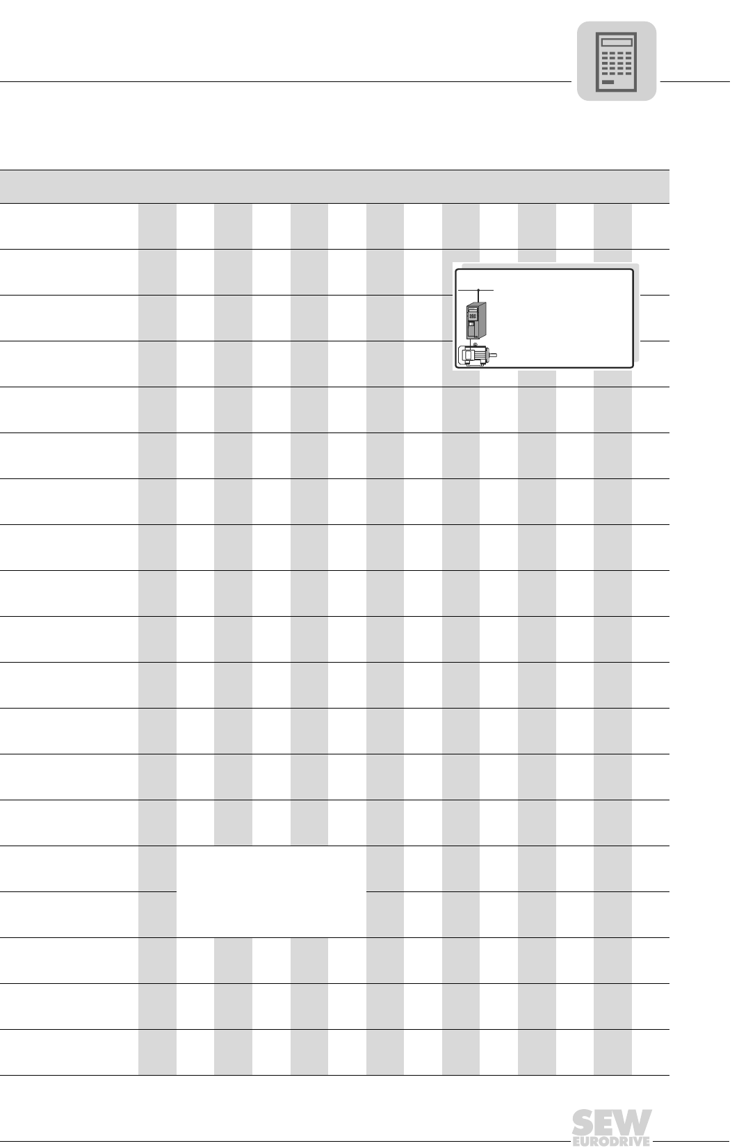
MOVIDRIVE® compact Catalog
103
3
Motor selection for asynchronous servomotors (CFC)
DT/DV/D motor selection with the double-star/star topology (230/460 VAC / 60 Hz)
1. Star connection 댴 460 V / 60 Hz:
Motor MOVIDRIVE® compact MCV/MCH4_A...-5_3 (400/500 V units) in CFC operating modes (P700)
댴 460 V / 60 Hz 0015 0022 0030 0040 0055 0075 0110 0150 0220 0300 0370 0450 0550 0750
DT80N4
Mmax [Nm]
([lb.in])
9.3
(82)
ntransition [rpm] 1145
DT90S4
Mmax [Nm]
([lb.in])
13.5
(120)
ntransition [rpm] 1312
DT90L4
Mmax [Nm]
([lb.in])
18.3
(162)
18.3
(162)
ntransition [rpm] 1152 1318
DT100LS4
Mmax [Nm]
([lb.in])
26.5
(234)
27.0
(238)
ntransition [rpm] 1100 1222
DT100L4
Mmax [Nm]
([lb.in])
28.2
(250)
36.8
(325)
36.8
(325)
ntransition [rpm] 1171 1075 1120
DV112M4
Mmax [Nm]
([lb.in])
35.8
(316)
48.4
(427)
48.4
(427)
ntransition [rpm] 1196 1139 1312
DV132S4
Mmax [Nm]
([lb.in])
48.7
(430)
65.1
(575)
66.1
(584)
ntransition [rpm] 1068 992 1100
DV132M4
Mmax [Nm]
([lb.in])
80.0
(705)
90.2
(797)
ntransition [rpm] 1088 1222
DV132ML4
Mmax [Nm]
([lb.in])
110
(972)
110
(972)
ntransition [rpm] 1196 1299
DV160M4
Mmax [Nm]
([lb.in])
120.3
(1062)
131
(1157)
131
(1157)
ntransition [rpm] 1132 1260 1318
DV160L4
Mmax [Nm]
([lb.in])
161
(1422)
177
(1565)
ntransition [rpm] 1158 1370
DV180M4
Mmax [Nm]
([lb.in])
164
(1448)
217
(1917)
217
(1917)
ntransition [rpm] 1140 1177 1350
DV180L4
Mmax [Nm]
([lb.in])
228
(2015)
258
(2280)
258
(2280)
ntransition [rpm] 1081 1196 1324
DV200L4
Mmax [Nm]
([lb.in])
323
(2845)
351
(3100)
351
(3100)
ntransition [rpm] 1024 1107 1248
DV225S4
Mmax[Nm]
([lb.in])
Please note: The maximum
torque Mmax is limited to 180 % of
the rated motor torque MN.
318
(2815)
391
(3456)
433
(3826)
433
(3826)
ntransition [rpm] 1100 1075 1145 1286
DV225M4
Mmax [Nm]
([lb.in])
401
(3542)
494
(4364)
526
(4648)
526
(4648)
ntransition [rpm] 1081 1056 1139 1324
D250M4
Mmax [Nm]
([lb.in])
570
(5040)
640
(5656)
ntransition [rpm] 1300 1395
D280S4
Mmax [Nm]
([lb.in])
717
(6335)
ntransition [rpm] 1345
D280M4
Mmax [Nm]
([lb.in])
712
(6290)
ntransition [rpm] 1337
P700: CFC...
EQ
Q
3 460 V×AC
DT/DV/D: 460 V/60 Hz댴
MCV/MCH4_A...-5_3
(400/500 V)
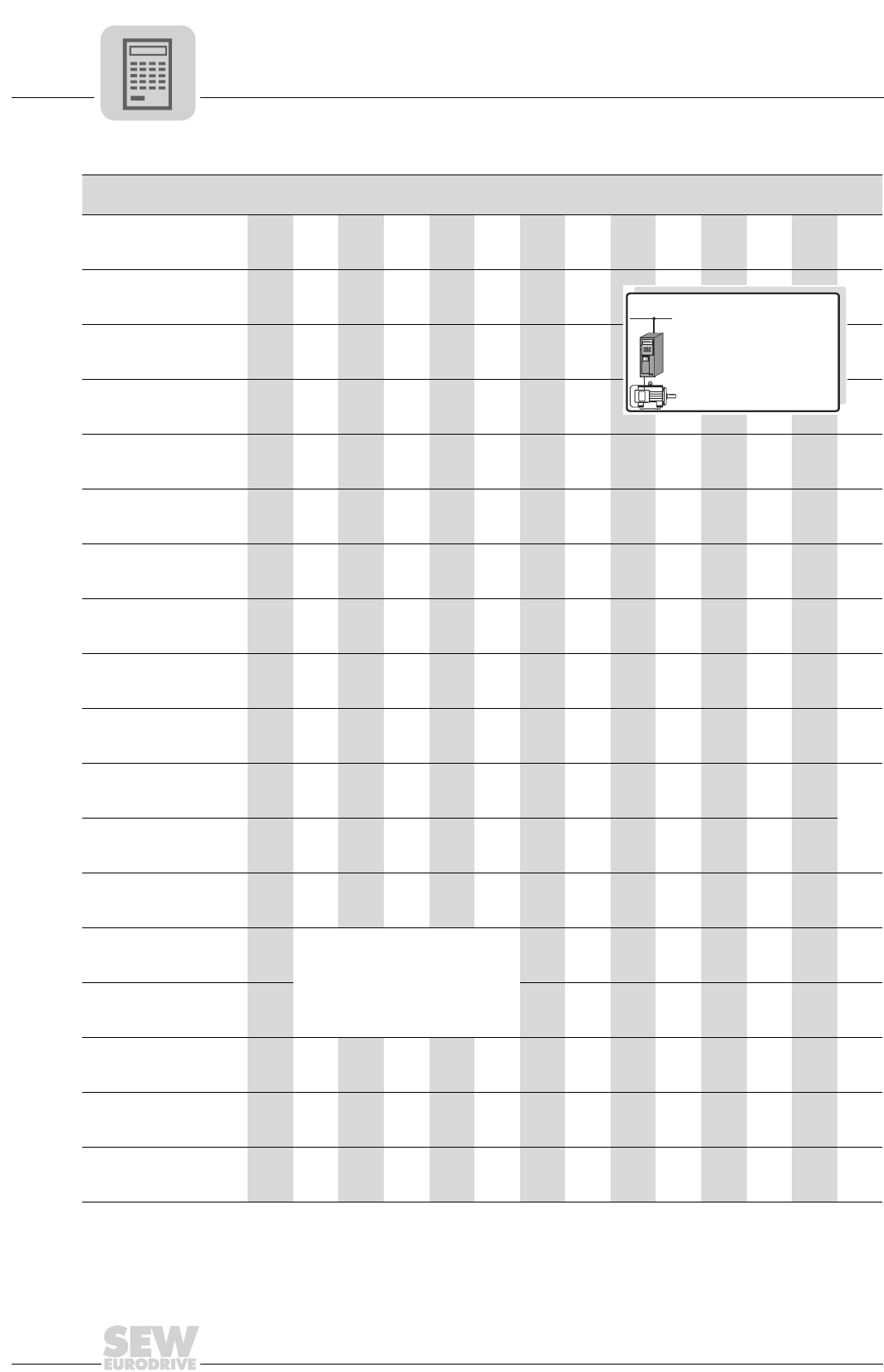
3
104
MOVIDRIVE® compact Catalog
Motor selection for asynchronous servomotors (CFC)
2. Double-star connection 댴댴 230 V / 60 Hz:
Motor MOVIDRIVE® compact MCV/MCH4_A...-5_3 (400/500 V units) in CFC operating modes (P700)
댴댴 230 V / 60 Hz 0015 0022 0030 0040 0055 0075 0110 0150 0220 0300 0370 0450 0550 0750
DT71D4
Mmax [Nm]
([lb.in])
4.6
(40.5)
ntransition [rpm] 2988
DT80K4
Mmax [Nm]
([lb.in])
7.0
(62)
7.0
(62)
ntransition [rpm] 2688 2822
DT80N4
Mmax [Nm]
([lb.in])
8.3
(73)
9.3
(82)
9.3
(82)
ntransition [rpm] 2585 2873 2969
DT90S4
Mmax [Nm]
([lb.in])
11.9
(105)
13.5
(120)
13.5
(120)
ntransition [rpm] 2636 2931 3462
DT90L4
Mmax [Nm]
([lb.in])
16.4
(145)
18.3
(162)
18.3
(162)
ntransition [rpm] 2604 3014 3353
DT100LS4
Mmax [Nm]
([lb.in])
22.5
(200)
27.0
(238)
27.0
(238)
ntransition [rpm] 2592 2732 3104
DT100L4
Mmax [Nm]
([lb.in])
32.5
(287)
36.8
(325)
ntransition [rpm] 2592 2912
DV112M4
Mmax [Nm]
([lb.in])
41.4
(365)
48.4
(427)
ntransition [rpm] 2534 2988
DV132S4
Mmax [Nm]
([lb.in])
62.4
(550)
66.1
(585)
ntransition [rpm] 2233 2572
DV132M4
Mmax [Nm]
([lb.in])
80.0
(705)
90.2
(797)
ntransition [rpm] 2348 2707
DV132ML4
Mmax [Nm]
([lb.in])
110
(972)
110
(972)
ntransition [rpm] 2566 2944
DV160M4
Mmax [Nm]
([lb.in])
115
(1015)
131
(1157)
131
(1157)
ntransition [rpm] 2451 2688 2963
DV160L4
Mmax [Nm]
([lb.in])
150
(1325)
177
(1565)
177
(1565)
ntransition [rpm] 2457 2512 2918
DV180M4
Mmax[Nm]
([lb.in])
Please note: The maximum
torque Mmax is limited to 180 % of
the rated motor torque MN.
189
(1670)
217
(1917)
217
(1917)
217
(1917)
ntransition [rpm] 2355 2457 2771 3040
DV180L4
Mmax [Nm]
([lb.in])
220
(1943)
258
(2280)
258
(2280)
ntransition [rpm] 2284 2291 2720
DV200L4
Mmax [Nm]
([lb.in])
281
(2482)
350
(3092)
ntransition [rpm] 2208 2163
DV225S4
Mmax [Nm]
([lb.in])
346
(3056)
ntransition [rpm] 2291
DV225M4
Mmax [Nm]
([lb.in])
354
(3127)
ntransition [rpm] 2278
P700: CFC...
EQ
Q
3 460 V×AC
DT/DV: 230 V/60 Hz댴댴
MCV/MCH4_A...-5_3
(400/500 V)

MOVIDRIVE® compact Catalog
105
3
Motor selection for asynchronous servomotors (CFC)
DT/DV/D motor selection with the double-star/star or double-delta/delta topology
(200/400 VAC / 50 Hz)
1. Star connection 댴 or delta connection ∆ 400 V / 50 Hz:
Motor MOVIDRIVE® compact MCV/MCH4_A...-5_3 (400/500 V units) in CFC operating modes (P700)
댴, ∆ 400 V / 50 Hz1)
1) The values also apply to 400 V / 60 Hz and 440 V / 60 Hz.
0015 0022 0030 0040 0055 0075 0110 0150 0220 0300 0370 0450 0550 0750
DT80K4
Mmax [Nm]
([lb.in])
6.9
(61)
ntransition [rpm] 748
DT80N4
Mmax [Nm]
([lb.in])
9.3
(82)
ntransition [rpm] 985
DT90L4
Mmax [Nm]
([lb.in])
17.2
(152)
18.3
(162)
18.3
(162)
ntransition [rpm] 1011 1120 1145
DV100M4
Mmax [Nm]
([lb.in])
26.8
(236)
26.8
(236)
26.8
(236)
ntransition [rpm] 940 1043 1056
DV112M4
Mmax [Nm]
([lb.in])
44.5
(393)
48.4
(427)
48.4
(427)
ntransition [rpm] 992 1088 1145
DV132S4
Mmax [Nm]
([lb.in])
61.0
(540)
66.1
(584)
66.1
(584)
ntransition [rpm] 1068 1177 1280
DV132M4
Mmax [Nm]
([lb.in])
77.3
(683)
90.2
(797)
90.2
(797)
ntransition [rpm] 1088 1210 1228
DV160M4
Mmax [Nm]
([lb.in])
118
(1042)
131
(1157)
131
(1157)
ntransition [rpm] 1056 1177 1273
DV160L4
Mmax [Nm]
([lb.in])
154
(1363)
177
(1565)
177
(1565)
ntransition [rpm] 1113 1292 1401
DV180M4
Mmax[Nm]
([lb.in])
Please note: The maximum
torque Mmax is limited to 180 % of
the rated motor torque MN.
217
(1917)
217
(1917)
217
(1917)
ntransition [rpm] 1177 1440 1561
DV180L4
Mmax [Nm]
([lb.in])
218
(1930)
258
(2280)
258
(2280)
258
(2280)
ntransition [rpm] 1088 1177 1344 1452
DV200L4
Mmax [Nm]
([lb.in])
308
(2730)
351
(3100)
351
(3100)
351
(3100)
ntransition [rpm] 1075 1139 1331 1472
DV225S4
Mmax [Nm]
([lb.in])
374
(3307)
433
(3826)
433
(3826)
433
(3826)
ntransition [rpm] 1004 1043 1190 1363
DV225M4
Mmax [Nm]
([lb.in])
456
(4037)
526
(4648)
526
(4648)
ntransition [rpm] 1094 1113 1324
P700: CFC...
EQ
Q
3 400 V×AC
DT/DV: , 420 V / 50 Hz댴∆
MCV/MCH4_A...-5_3
(400/500 V)
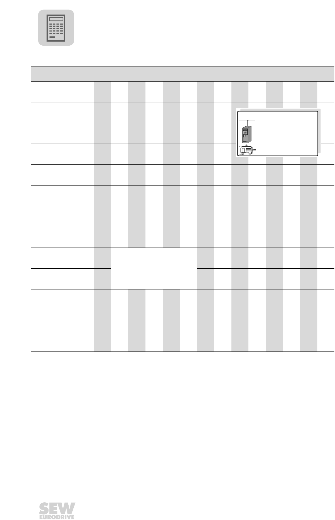
3
106
MOVIDRIVE® compact Catalog
Motor selection for asynchronous servomotors (CFC)
2. Double-star connection 댴댴 or double-delta ∆∆ 200 V / 50 Hz:
Motor MOVIDRIVE® compact MCV/MCH4_A...-5_3 (400/500 V units) in CFC operating modes (P700)
댴댴, ∆∆ 200 V / 50 Hz1)
1) The values also apply to 200 V / 60 Hz and 220 V / 60 Hz.
0015 0022 0030 0040 0055 0075 0110 0150 0220 0300 0370 0450 0550 0750
DT80K4
Mmax [Nm]
([lb.in])
6.9
(61)
6.9
(61)
ntransition [rpm] 2035 2112
DT80N4
Mmax [Nm]
([lb.in])
9.3
(82)
9.3
(82)
9.3
(82)
ntransition [rpm] 2483 2624 2624
DT90L4
Mmax [Nm]
([lb.in])
18.3
(162)
18.3
(162)
18.3
(162)
ntransition [rpm] 2521 2924 2963
DV100M4
Mmax [Nm]
([lb.in])
24.4
(215)
26.8
(236)
26.8
(236)
ntransition [rpm] 2124 2419 2732
DV112M4
Mmax [Nm]
([lb.in])
48.4
(427)
48.4
(427)
ntransition [rpm] 2457 2796
DV132S4
Mmax [Nm]
([lb.in])
58.3
(515)
66.1
(585)
66.1
(585)
ntransition [rpm] 2355 2656 3052
DV132M4
Mmax [Nm]
([lb.in])
77.3
(683)
90.2
(797)
90.2
(797)
ntransition [rpm] 2361 2688 2886
DV160M4
Mmax [Nm]
([lb.in])
112
(995)
131
(1157)
131
(1157)
131
(1157)
ntransition [rpm] 2265 2470 2784 2918
DV160L4
Mmax [Nm]
([lb.in])
Please note: The maximum
torque Mmax is limited to 180 % of
the rated motor torque MN.
177
(1565)
177
(1565)
177
(1565)
177
(1565)
ntransition [rpm] 2316 2726 2995 3084
DV180M4
Mmax [Nm]
([lb.in])
217
(1917)
217
(1917)
217
(1917)
ntransition [rpm] 2406 2803 3251
DV180L4
Mmax [Nm]
([lb.in])
252
(2233)
258
(2280)
ntransition [rpm] 2240 2662
DV200L4
Mmax [Nm]
([lb.in])
336
(2975)
ntransition [rpm] 2233
DV225S4
Mmax [Nm]
([lb.in])
330
(2917)
ntransition [rpm] 2112
P700: CFC...
EQ
Q
3 400 V×AC
DT/DV:
, 210 V / 50 Hz댴댴 ∆∆
MCV/MCH4_A...-5_3
(400/500 V)
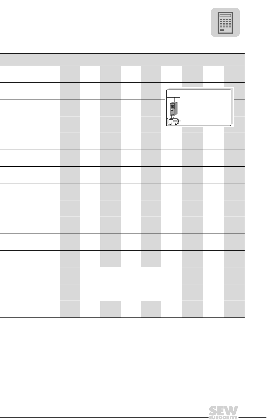
MOVIDRIVE® compact Catalog
107
3
Motor selection for asynchronous servomotors (CFC)
DT/DV motor selection with the delta connection type (230 VAC / 50 Hz)
Motor MOVIDRIVE® compact MCV/MCH4_A...-2_3 (230 V units) in CFC operating modes (P700)
∆ 230 V / 50 Hz 0015 0022 0037 0055 0075 0110 0150 0220 0300
DT80K4
Mmax [Nm]
([lb.in])
6.9
(61)
ntransition [rpm] 812
DT80N4
Mmax [Nm]
([lb.in])
9.3
(82)
ntransition [rpm] 908
DT90S4
Mmax [Nm]
([lb.in])
13.5
(120)
13.5
(120)
ntransition [rpm] 1011 1011
DT90L4
Mmax [Nm]
([lb.in])
18.3
(162)
18.3
(162)
18.3
(162)
ntransition [rpm] 953 1024 1056
DV100M4
Mmax [Nm]
([lb.in])
25.5
(225)
26.8
(236)
ntransition [rpm] 921 1056
DV100L4
Mmax [Nm]
([lb.in])
36.8
(325)
36.8
(325)
ntransition [rpm] 972 1011
DV112M4
Mmax [Nm]
([lb.in])
48.4
(427)
48.4
(427)
ntransition [rpm] 1036 1062
DV132S4
Mmax [Nm]
([lb.in])
65.3
(577)
66.1
(584)
66.1
(584)
ntransition [rpm] 992 1152 1196
DV132M4
Mmax [Nm]
([lb.in])
85.4
(755)
90.2
(797)
90.2
(797)
ntransition [rpm] 998 1152 1152
DV132ML4
Mmax [Nm]
([lb.in])
110
(972)
110
(972)
110
(972)
ntransition [rpm] 1050 1132 1132
DV160M4
Mmax [Nm]
([lb.in])
126
(1110)
131
(1157)
131
(1157)
ntransition [rpm] 980 1120 1196
DV160L4
Mmax [Nm]
([lb.in])
158
(1395)
177
(1565)
177
(1565)
ntransition [rpm] 1050 1248 1312
DV180M4
Mmax [Nm]
([lb.in])
Please note: The maximum torque
Mmax is limited to 180 % of the rated
motor torque MN.
217
(1917)
217
(1917)
ntransition [rpm] 1165 1325
DV180L4
Mmax [Nm]
([lb.in])
231
(2042)
258
(2280)
ntransition [rpm] 1017 1068
DV200L4
Mmax [Nm]
([lb.in])
295
(2605)
ntransition [rpm] 1025
P700: CFC...
EQ
Q
3 230 V×AC
DT/DV: 230 V/50 Hz∆
MCV/MCH4_A...-2_3
(230 V)
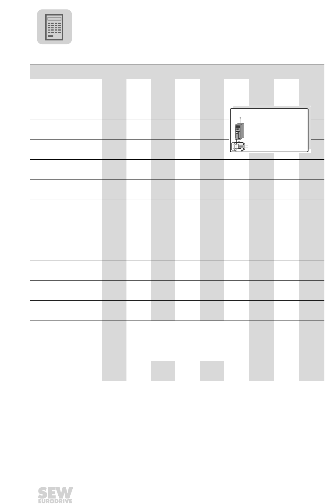
3
108
MOVIDRIVE® compact Catalog
Motor selection for asynchronous servomotors (CFC)
DT/DV motor selection with the double-star topology (230 VAC / 60 Hz)
Motor MOVIDRIVE® compact MCV/MCH4_A...-2_3 (230 V units) in CFC operating modes (P700)
댴댴 230 V / 60 Hz 0015 0022 0037 0055 0075 0110 0150 0220 0300
DT80K4
Mmax [Nm]
([lb.in])
7.0
(62)
ntransition [rpm] 1100
DT80N4
Mmax [Nm]
([lb.in])
9.3
(82)
ntransition [rpm] 1145
DT90S4
Mmax [Nm]
([lb.in])
13.5
(120)
13.5
(120)
ntransition [rpm] 1267 1337
DT90L4
Mmax [Nm]
([lb.in])
17.2
(152)
18.3
(162)
18.3
(162)
ntransition [rpm] 1145 1210 1325
DT100LS4
Mmax [Nm]
([lb.in])
20.1
(178)
27.0
(238)
ntransition [rpm] 1190 1228
DT100L4
Mmax [Nm]
([lb.in])
29.2
(258)
36.8
(325)
36.8
(325)
ntransition [rpm] 1158 1113 1120
DV112M4
Mmax [Nm]
([lb.in])
37.2
(328)
48.4
(427)
48.4
(427)
ntransition [rpm] 1190 1248 1337
DV132S4
Mmax [Nm]
([lb.in])
57.0
(504)
66.1
(585)
66.1
(585)
ntransition [rpm] 1030 1062 1120
DV132M4
Mmax [Nm]
([lb.in])
71.7
(633)
90.2
(797)
90.2
(797)
ntransition [rpm] 1113 1165 1222
DV132ML4
Mmax [Nm]
([lb.in])
109
(970)
110
(972)
ntransition [rpm] 1100 1260
DV160M4
Mmax [Nm]
([lb.in])
104
(920)
131
(1157)
131
(1157)
ntransition [rpm] 1165 1145 1318
DV160L4
Mmax [Nm]
([lb.in])
133
(1178)
177
(1565)
177
(1565)
ntransition [rpm] 1190 1267 1395
DV180M4
Mmax [Nm]
([lb.in])
Please note: The maximum torque
Mmax is limited to 180 % of the rated
motor torque MN.
208
(1840)
217
(1917)
ntransition [rpm] 1100 1203
DV180L4
Mmax [Nm]
([lb.in])
236
(2087)
ntransition [rpm] 1075
DV200L4
Mmax [Nm]
([lb.in])
210
(1860)
253
(2235)
ntransition [rpm] 1080 1062
P700: CFC...
EQ
Q
3 230 V×AC
DT/DV: 230 V/60 Hz댴댴
MCV/MCH4_A...-2_3
(230 V)
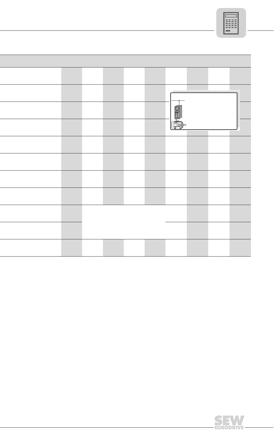
MOVIDRIVE® compact Catalog
109
3
Motor selection for asynchronous servomotors (CFC)
DT/DV motor selection with the double-star or double-delta topology (200 VAC / 50 Hz)
Motor MOVIDRIVE® compact MCV/MCH4_A...-2_3 (230 V units) in CFC operating modes (P700)
댴댴, ∆∆ 200 V / 50 Hz1)
1) The values also apply to 200 V / 60 Hz and 220 V / 60 Hz.
0015 0022 0037 0055 0075 0110 0150 0220 0300
DT80K4
Mmax [Nm]
([lb.in])
6.9
(61)
ntransition [rpm] 748
DT80N4
Mmax [Nm]
([lb.in])
9.3
(82)
ntransition [rpm] 985
DT90L4
Mmax [Nm]
([lb.in])
15.5
(137)
18.3
(162)
18.3
(162)
ntransition [rpm] 1049 998 1145
DV100M4
Mmax [Nm]
([lb.in])
26.8
(236)
26.8
(236)
ntransition [rpm] 1050 1056
DV112M4
Mmax [Nm]
([lb.in])
48.4
(427)
48.4
(427)
48.4
(427)
ntransition [rpm] 1017 1132 1145
DV132S4
Mmax [Nm]
([lb.in])
66.1
(585)
66.1
(585)
ntransition [rpm] 1107 1280
DV132M4
Mmax [Nm]
([lb.in])
90.2
(797)
90.2
(797)
90.2
(797)
ntransition [rpm] 1139 1228 1228
DV160M4
Mmax [Nm]
([lb.in])
131
(1157)
131
(1157)
ntransition [rpm] 1050 1273
DV160L4
Mmax [Nm]
([lb.in])
Please note: The maximum torque
Mmax is limited to 180 % of the rated
motor torque MN.
177
(1565)
177
(1565)
ntransition [rpm] 1177 1312
DV180M4
Mmax [Nm]
([lb.in])
195
(1723)
217
(1917)
ntransition [rpm] 1145 1216
DV180L4
Mmax [Nm]
([lb.in])
226
(2000)
ntransition [rpm] 1080
P700: CFC...
EQ
Q
3 200 V×AC
DT/DV:
, 210 V / 50 Hz댴댴 ∆∆
MCV/MCH4_A...-2_3
(230 V)
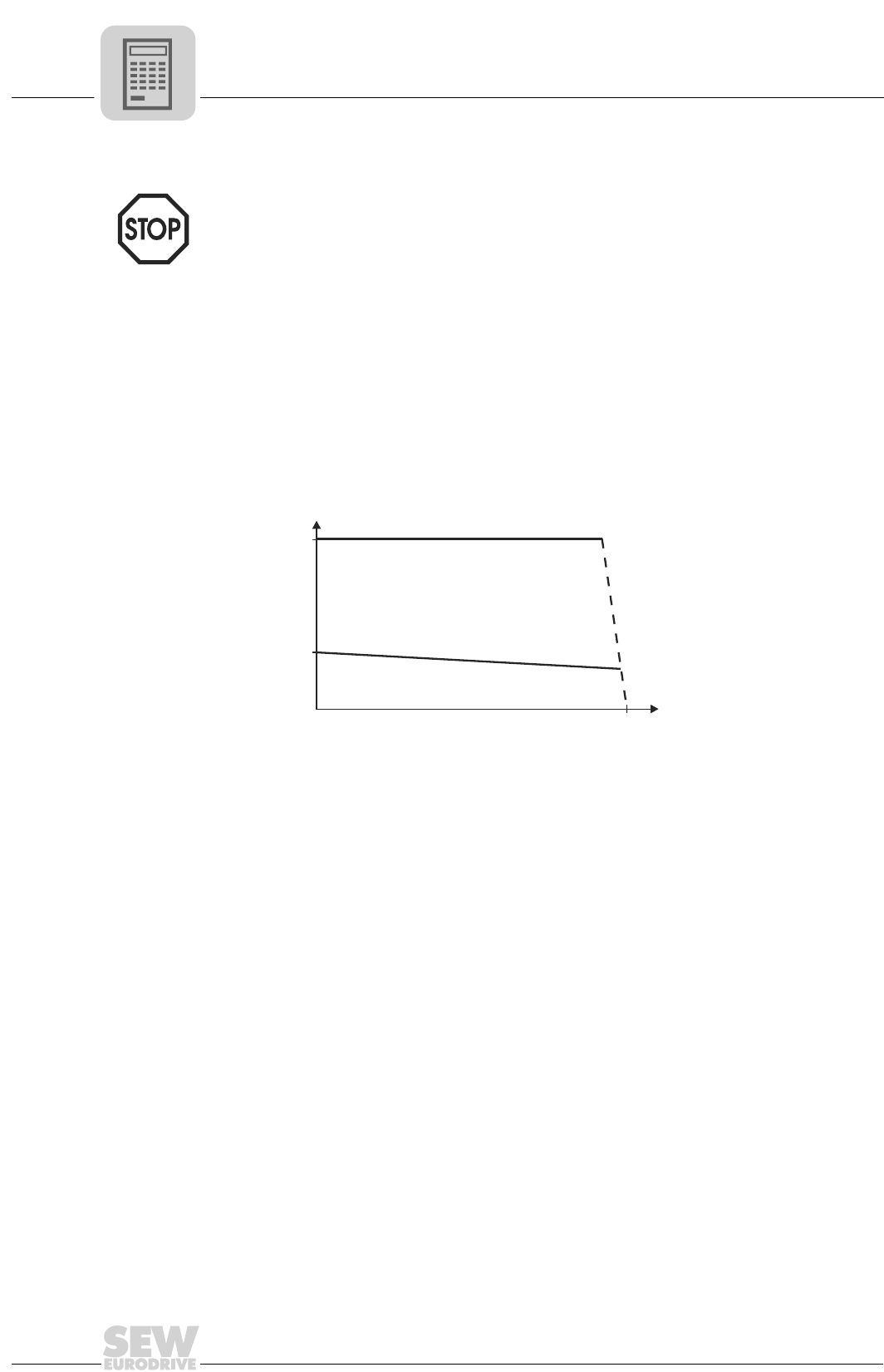
3
110
MOVIDRIVE® compact Catalog
Motor selection for synchronous servomotors (SERVO)
3.3 Motor selection for synchronous servomotors (SERVO)
Motor character-
istics
The requirements made of a servo drive include speed dynamics, stable speed and po-
sitioning accuracy. CM/DFS/DFY motors with MOVIDRIVE® meet these requirements.
Technically speaking, these are synchronous motors with permanent magnets on the
rotor and an integrated resolver. The required characteristics, namely a constant torque
over a wide speed range (up to 4500 rpm), a high speed and control range (up to 1:3000)
and a high overload capacity (3 × M0), are achieved using control by MOVIDRIVE®. The
servomotor has a lower mass moment of inertia than the asynchronous motor. This
means it is optimally suited to applications requiring dynamic speeds.
M0 is determined by the motor. Mmax is 3 × M0 of the motor. The attainable Mmax may
also be less, depending on the inverter.
Refer to the motor table (CM → page 112, DFS/DFY → page 115) for the values for M0.
Refer to the motor table (CM → page 113, DFS/DFY → page 116) for the values for M0.
The torque limit (M limit) is set automatically by the startup function of the MOVITOOLS
software package. Do not alter this automatically set value!
We recommend always using the latest version of MOVITOOLS (2.70 or later) for star-
tup. The latest MOVITOOLS version can be downloaded from our homepage
(www.sew-eurodrive.de).
01652CEN
Figure 45: Speed/torque characteristic curve of the DFY servomotor
1 Continuous torque
2 Maximum torque
0
Mmax
0
1
2
M0
M [lb.in]
n [rpm]
n
rated

MOVIDRIVE® compact Catalog
111
3
Motor selection for synchronous servomotors (SERVO)
Basic recommen-
dations
SERVO operating modes are only possible with SEW motors (CM/DFS/DFY), not with
non-SEW motors. The necessary motor data for the SERVO operating modes are
stored in MOVIDRIVE® for the SEW motors.
Speed is the correcting variable in the SERVO modes with speed control. Torque is the
correcting variable in the SERVO modes with torque control (SERVO & M-CONTROL).
SERVO mode with
speed control
There is no reason to differentiate between quadratic, dynamic and static load types
when configuring a system for SERVO mode. Project planning for a synchronous motor
is undertaken in accordance with the following requirements:
1. Effective torque demand at the average speed of the application.
Mr.m.s. < Mn_mot
The point must lie below the characteristic curve for the continuous torque (Figure
45, curve 1). The continuous torque of the DFY series can be increased by 60 % by
forced cooling if this operating point lies above the characteristic curve for self-cool-
ing.
2. Maximum torque required across the speed characteristic.
Mmax < Mdyn_mot
This operating point must lie below the characteristic curve for the maximum torque
of the motor-MOVIDRIVE® combination (Figure 45, curve 2).
3. Maximum speed
The maximum speed must not be configured higher than the rated speed of the mo-
tor. Planetary gear units should be used for speeds greater than 3000 rpm as a result
of the high input speed.
nmax ≤ nN
SERVO mode with
torque control
(SERVO & M-
CTRL.)
This operating mode allows the torque of the servomotor to be controlled directly. The
setpoint sources of the speed controlled SERVO mode can also be used for torque con-
trol. All speed setpoint sources are interpreted as current setpoint sources. The settings
for evaluating the analog input (→ P11_, parameter description) also remain in effect.
The fixed setpoints (P16_, P17_) can be entered either in the unit [rpm] or [%IN_inverter]
(→ MOVITOOLS).
The following relationship applies between the units:
3000 rpm = 150 % rated inverter current
You can calculate the torque at the output shaft of the servomotor using the following
formula:
04976AEN
M0Continuous static torque according to the motor table DFS/DFY (→ page 115)
I0Continuous static torque according to the motor table DFS/DFY (→ page 115)
MM
I
In
rpm
n inverter set
=× ××
0
0
150%
3000
_
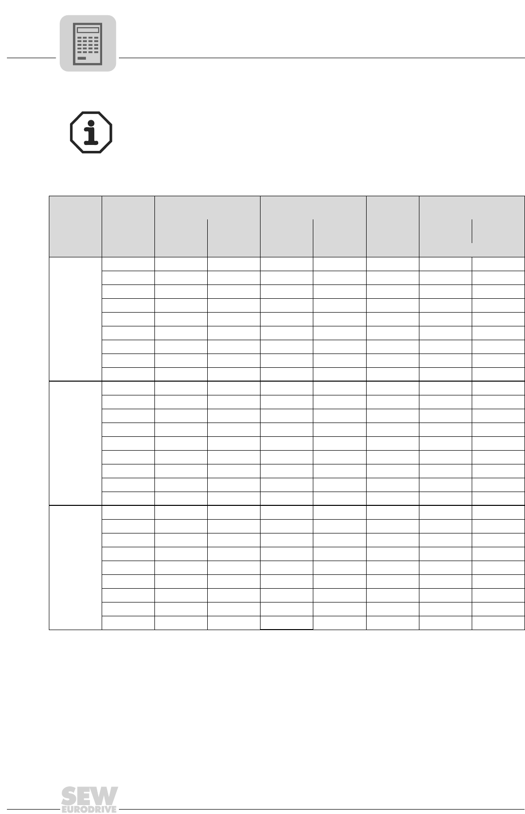
3
112
MOVIDRIVE® compact Catalog
Motor selection for synchronous servomotors (SERVO)
Motor table CM
Characteristic values at Vmax = 400 VAC
Additional project planning notes and information about the type CM synchronous ser-
vomotors can be found in the 'Geared Servo Motors' catalog. This can be ordered from
SEW.
nNMotor
Without forced cooling
fan
With forced cooling fan
VR Imax
Mass moment of inertia
JM
M0I0M0_VR I0_VR
Without
brake With brake
[rpm] [Nm (lb.in)] [A] [Nm (lb.in)] [A] [A] [10-4 kgm2 (10-3 lb.ft2)]
2000
CM71S 5.0 (44) 2.2 7.3 (64) 3.2 8.8 4.85 (11.4) 6.89 (16.2)
CM71M 6.5 (57) 2.9 9.4 (83) 4.2 11.6 6.27 (14.7) 8.31 (19.5)
CM71L 9.5 (84) 4.2 13.8 (122) 6.1 16.8 9.1 (21.4) 11.1 (26.1)
CM90S 11.0 (97) 4.9 16.0 (141) 7.1 20.0 14.3 (33.6) 19.8 (46.5)
CM90M 14.5 (128) 6.9 21.0 (185) 10.0 28.0 18.6 (43.7) 24.1 (56.7)
CM90L 21.0 (185) 9.9 30.5 (270) 14.4 40.0 27.1 (63.7) 32.6 (76.7)
CM112S 23.5 (207) 10.0 34.0 (300) 14.5 40.0 67.4 (159) 87.5 (206)
CM112M 31.0 (274) 13.5 45.0 (397) 19.6 54.0 87.4 (206) 108 (254)
CM112L 45.0 (397) 19.1 65.0 (574) 29.0 80.0 128 (301) 148 (348)
3000
CM71S 5.0 (44) 3.3 7.3 (64) 4.8 13.2 4.85 (11.4) 6.89 (16.2)
CM71M 6.5 (57) 4.3 9.4 (83) 6.2 17.2 6.27 (14.7) 8.31 (19.5)
CM71L 9.5 (84) 6.2 13.8 (122) 9.0 25.0 9.1 (21.4) 11.1 (26.1)
CM90S 11.0 (97) 7.3 16.0 (141) 10.6 30.0 14.3 (33.6) 19.8 (46.5)
CM90M 14.5 (128) 10.1 21.0 (185) 14.6 40.0 18.6 (43.7) 24.1 (56.7)
CM90L 21.0 (185) 14.4 30.5 (270) 21.0 58.0 27.1 (63.7) 32.6 (76.7)
CM112S 23.5 (207) 15.0 34.0 (300) 22.0 60.0 67.4 (159) 87.5 (206)
CM112M 31.0 (274) 20.5 45.0 (397) 30.0 82.0 87.4 (206) 108 (254)
CM112L 45.0 (397) 30.0 65.0 (574) 44.0 120 128 (301) 148 (348)
4500
CM71S 5.0 (44) 4.9 7.3 (64) 7.2 20.0 4.85 (11.4) 6.89 (16.2)
CM71M 6.5 (57) 6.6 9.4 (83) 9.6 27.0 6.27 (14.7) 8.31 (19.5)
CM71L 9.5 (84) 9.6 13.8 (122) 14.0 39.0 9.1 (21.4) 11.1 (26.1)
CM90S 11.0 (97) 11.1 16.0 (141) 16.2 45.0 14.3 (33.6) 19.8 (46.5)
CM90M 14.5 (128) 14.7 21.0 (185) 21.5 59.0 18.6 (43.7) 24.1 (56.7)
CM90L 21.0 (185) 21.6 30.5 (270) 31.5 86.0 27.1 (63.7) 32.6 (76.7)
CM112S 23.5 (207) 22.5 34.0 (300) 32.5 90.0 67.4 (159) 87.5 (206)
CM112M 31.0 (274) 30.0 45.0 (397) 44.0 120 87.4 (206) 108 (254)
CM112L 45.0 (397) 46.0 65.0 (574) 67.0 184 128 (301) 148 (348)
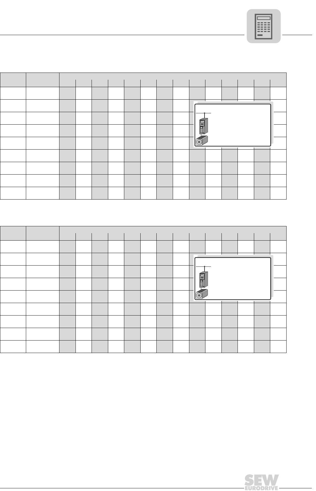
MOVIDRIVE® compact Catalog
113
3
Motor selection for synchronous servomotors (SERVO)
CM motor selection
1. Rated speed nN = 2000 rpm:
2. Rated speed nN = 3000 rpm:
Motor MOVIDRIVE® compact MCS/MCH4_A...-5_3 (400/500 V units) in SERVO operating modes (P700)
0015 0022 0030 0040 0055 0075 0110 0150 0220 0300 0370 0450 0550 0750
CM71S Mmax [Nm]
([lb.in])
13.0
(115)
16.0
(141)
16.5
(145)
CM71M Mmax [Nm]
([lb.in])
13.0
(115)
16.9
(149)
19.8
(175)
21.5
(190)
CM71L Mmax [Nm]
([lb.in])
18.5
(163)
22.8
(201)
28.5
(252)
31.4
(278)
CM90S Mmax [Nm]
([lb.in])
18.5
(163)
23.3
(206)
30.8
(272)
38.0
(336)
39.6
(350)
CM90M Mmax [Nm]
([lb.in])
22.5
(199)
30.5
(269)
39.2
(346)
47.9
(423)
52.2
(461)
CM90L Mmax [Nm]
([lb.in])
31.9
(282)
41.4
(366)
52.5
(464)
72.5
(640)
75.6
(668)
CM112S Mmax [Nm]
([lb.in])
35.3
(312)
45.8
(405)
57.3
(506)
77.6
(686)
81.1
(717)
CM112M Mmax [Nm]
([lb.in])
45.9
(405)
58.3
(515)
84.3
(745)
102.3
(904)
107.0
(945)
CM112L Mmax [Nm]
([lb.in])
87.4
(772)
112.8
(997)
150.4
(1329)
161.2
(1425)
P700: SERVO...
EQ
Q
3 400/500 V×AC
CM: n = 2000 rpm
N
MCS/MCH4_A...-5_3
(400/500 V)
Motor MOVIDRIVE® compact MCS/MCH4_A...-5_3 (400/500 V units) in SERVO operating modes (P700)
0015 0022 0030 0040 0055 0075 0110 0150 0220 0300 0370 0450 0550 0750
CM71S Mmax [Nm]
([lb.in])
9.0
(80)
11.9
(105)
14.3
(126)
16.5
(145)
16.5
(145)
CM71M Mmax [Nm]
([lb.in])
12.2
(107)
14.8
(130)
18.9
(167)
21.5
(190)
21.5
(190)
CM71L Mmax [Nm]
([lb.in])
15.8
(140)
20.6
(182)
26.1
(230)
30.5
(270)
31.4
(278)
CM90S Mmax [Nm]
([lb.in])
21.2
(187)
27.0
(238)
33.6
(297)
39.6
(350)
CM90M Mmax [Nm]
([lb.in])
27.4
(242)
34.4
(304)
48.1
(425)
52.2
(461)
CM90L Mmax [Nm]
([lb.in])
36.5
(322)
53.1
(469)
67.6
(597)
75.0
(663)
CM112S Mmax [Nm]
([lb.in])
39.0
(344)
56.6
(500)
71.7
(633)
80.6
(712)
CM112M Mmax [Nm]
([lb.in])
55.8
(493)
72.9
(644)
98.0
(866)
106.3
(940)
CM112L Mmax [Nm]
([lb.in])
77.6
(686)
109.0
(963)
137.2
(1213)
157.5
(1392)
162.6
(1437)
P700: SERVO...
EQ
Q
3 400/500 V×AC
CM: n = 3000 rpm
N
MCS/MCH4_A...-5_3
(400/500 V)
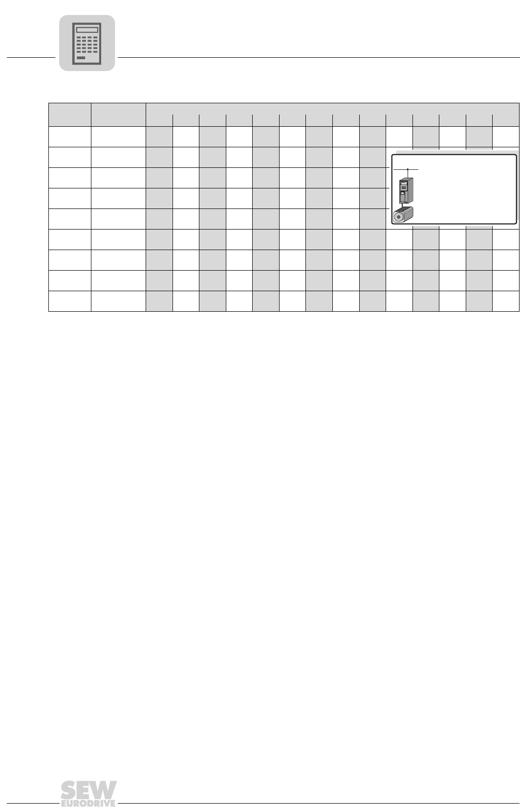
3
114
MOVIDRIVE® compact Catalog
Motor selection for synchronous servomotors (SERVO)
3. Rated speed nN = 4500 rpm:
Motor MOVIDRIVE® compact MCS/MCH4_A...-5_3 (400/500 V units) in SERVO operating modes (P700)
0015 0022 0030 0040 0055 0075 0110 0150 0220 0300 0370 0450 0550 0750
CM71S Mmax [Nm]
([lb.in])
8.0
(70)
10.0
(88)
13.0
(115)
15.7
(138)
16.5
(145)
CM71M Mmax [Nm]
([lb.in])
9.9
(87)
13.3
(117)
16.7
(147)
19.8
(175)
21.5
(190)
CM71L Mmax [Nm]
([lb.in])
18.1
(160)
22.1
(195)
29.8
(263)
31.4
(277)
CM90S Mmax [Nm]
([lb.in])
18.4
(162)
23.1
(204)
33.6
(297)
39.6
(350)
39.6
(350)
CM90M Mmax [Nm]
([lb.in])
24.1
(213)
34.9
(308)
45.2
(400)
52.2
(461)
CM90L Mmax [Nm]
([lb.in])
36.5
(322)
47.9
(423)
65.5
(580)
75.6
(668)
75.6
(668)
CM112S Mmax [Nm]
([lb.in])
39.2
(346)
51.2
(452)
70.0
(618)
81.1
(716)
81.1
(716)
CM112M Mmax [Nm]
([lb.in])
52.7
(465)
73.5
(650)
90.5
(800)
104.2
(921)
107.0
(945)
CM112L Mmax [Nm]
([lb.in])
73.8
(652)
94.0
(830)
112.8
(997)
133.0
(1175)
150.4
(1330)
162.2
(1434)
P700: SERVO...
EQ
Q
3 400/500 V×AC
CM: n = 4500 rpm
N
MCS/MCH4_A...-5_3
(400/500 V)
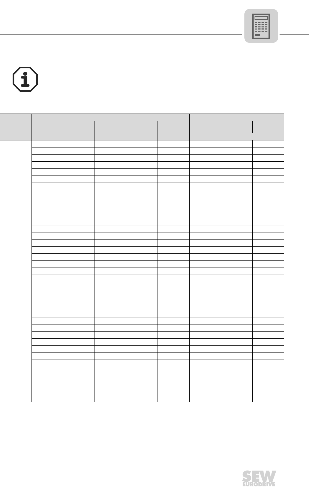
MOVIDRIVE® compact Catalog
115
3
Motor selection for synchronous servomotors (SERVO)
Motor table DFS/DFY
Characteristic values at Vmax = 400 VAC
Additional project planning notes and information about the type DFS/DFY synchronous
servomotors can be found in the 'Geared Servo Motors' catalog. This document can be
ordered from SEW.
nNMotor
Without forced cooling fan With forced cooling fan VY
Imax
Mass moment of inertia JM
M0I0M0_VY I0_VY
Without
brake With brake
[rpm] [Nm (lb.in)] [A] [Nm (lb.in)] [A] [A] [10-4 kgm2 (10-3 lb.ft2)]
2000
DFY71S 2.5 (22) 1.25 4.0 (35) 2.0 3.75 3.42 (8.12) 5.46 (13.0)
DFY71M 3.7 (33) 1.8 5.9 (52) 2.9 5.4 4.85 (11.5) 6.89 (16.3)
DFY71ML 5.0 (44) 2.5 8.0 (71) 4.0 7.5 6.27 (14.9) 8.31 (19.7)
DFY71L 7.5 (66) 3.7 12 (106) 5.9 11.1 9.1 (21.6) 11.1 (26.3)
DFY90S 9.0 (80) 4.0 14.4 (127) 6.4 12 14.3 (34.0) 19.8 (47.0)
DFY90M 12 (106) 5.3 19.2 (170) 8.5 15.9 18.6 (44.1) 24.1 (57.2)
DFY90L 18 (159) 8.0 28.9 (255) 12.9 24 27.1 (64.3) 32.6 (77.4)
DFY112S 12 (106) 5.5 19.2 (170) 8.8 16.5 47.2 (112) 67.4 (160)
DFY112M 17.5 (155) 8.0 28 (248) 12.8 24 67.4 (160) 87.5 (208)
DFY112ML 24 (212) 11 38.5 (340) 17.6 33 87.4 (207) 108 (256)
DFY112L 35 (309) 16 56 (495) 25.5 48 128 (304) 148 (351)
3000
DFS56M 1.0 (8.8) 1.55 - - 4.65 0.47 (1.12) 0.85 (2.02)
DFS56L 2.0 (18) 2.22 - - 6.66 0.82 (1.95) 1.2 (2.85)
DFY71S 2.5 (22) 1.85 4.0 (35) 3.0 5.55 3.42 (8.12) 5.46 (13.0)
DFY71M 3.7 (33) 2.7 5.9 (52) 4.3 8.1 4.85 (11.5) 6.89 (16.3)
DFY71ML 5.0 (44) 3.8 8.0 (71) 6.1 11.4 6.27 (14.9) 8.31 (19.7)
DFY71L 7.5 (66) 5.5 12 (106) 8.8 16.5 9.1 (21.6) 11.1 (26.3)
DFY90S 9.0 (80) 5.9 14.4 (127) 9.4 17.7 14.3 (34.0) 19.8 (47.0)
DFY90M 12 (106) 7.9 19.2 (170) 12.6 23.7 18.6 (44.1) 24.1 (57.2)
DFY90L 18 (159) 12 29 (256) 19.7 36 27.1 (64.3) 32.6 (77.4)
DFY112S 12 (106) 8.0 19.2 (170) 12.8 24 47.2 (112) 67.4 (160)
DFY112M 17.5 (155) 12 28 (248) 19.2 36 67.4 (160) 87.5 (208)
DFY112ML 24 (212) 16.5 38.5 (340) 26.5 49.5 87.4 (207) 108 (256)
DFY112L 35 (309) 24 56 (495) 38 72 128 (304) 148 (351)
4500
DFS56M 1.0 (8.8) 1.55 - - 4.65 0.47 (1.12) 0.85 (2.02)
DFS56L 2.0 (18) 2.22 - - 6.66 0.82 (1.95) 1.2 (2.85)
DFY71S 2.5 (22) 2.8 4.0 (35) 4.5 8.4 3.42 (8.12) 5.46 (13.0)
DFY71M 3.7 (33) 4.1 5.9 (52) 6.6 12.3 4.85 (11.5) 6.89 (16.3)
DFY71ML 5.0 (44) 5.8 8.0 (71) 9.3 17.4 6.27 (14.9) 8.31 (19.7)
DFY71L 7.5 (66) 8.2 12 (106) 13.1 24.6 9.1 (21.6) 11.1 (26.3)
DFY90S 9.0 (80) 9.0 14.4 (127) 14.4 27 14.3 (34.0) 19.8 (47.0)
DFY90M 12 (106) 11.6 19.2 (170) 18.6 34.8 18.6 (44.1) 24.1 (57.2)
DFY90L 18 (159) 18 29 (256) 29 54 27.1 (64.3) 32.6 (77.4)
DFY112S 12 (106) 11.7 19.2 (170) 18.7 35.1 47.2 (112) 67.4 (160)
DFY112M 17.5 (155) 18 28 (248) 28.8 54 67.4 (160) 87.5 (208)
DFY112ML 24 (212) 24.5 38.5 (340) 39.2 73.5 87.4 (207) 108 (256)
DFY112L 35 (309) 36.5 56 (495) 58.4 109 128 (304) 148 (351)
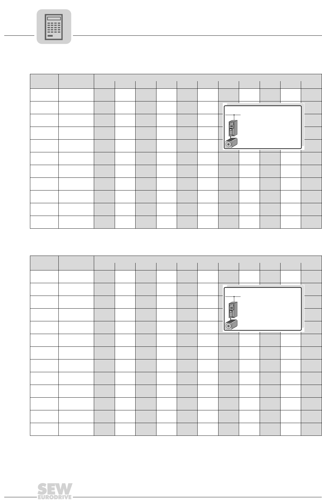
3
116
MOVIDRIVE® compact Catalog
Motor selection for synchronous servomotors (SERVO)
DFS/DFY motor selection
1. Rated speed nN = 2000 rpm:
2. Rated speed nN = 3000 rpm:
Motor MOVIDRIVE® compact MCS/MCH4_A...-5_3 (400/500 V units) in SERVO operating modes (P700)
0015 0022 0030 0040 0055 0075 0110 0150 0220 0300 0370
DFY71S Mmax [Nm]
([lb.in])
7.5
(66.3)
DFY71M Mmax [Nm]
([lb.in])
11.1
(98.1)
DFY71ML Mmax [Nm]
([lb.in])
12.0
(106)
15.0
(133)
DFY71L Mmax [Nm]
([lb.in])
12.2
(108)
16.7
(148)
21.3
(188)
22.5
(199)
DFY90S Mmax [Nm]
([lb.in])
13.5
(119)
18.6
(164)
23.6
(209)
27.0
(238)
DFY90M Mmax [Nm]
([lb.in])
18.7
(165)
23.7
(210)
32.2
(285)
36.0
(318)
DFY90L Mmax [Nm]
([lb.in])
32.1
(284)
42.2
(373)
54.0
(477)
DFY112S Mmax [Nm]
([lb.in])
18.0
(159)
22.9
(202)
31.1
(275)
36.0
(318)
DFY112M Mmax [Nm]
([lb.in])
31.2
(276)
41.0
(362)
52.5
(464)
DFY112ML Mmax [Nm]
([lb.in])
40.9
(362)
52.3
(462)
72.0
(636)
DFY112L Mmax [Nm]
([lb.in])
52.5
(464)
78.8
(697)
105
(928)
P700: SERVO...
EQ
Q
3 400/500 V×AC
DFY: n = 2000 rpm
N
MCS/MCH4_A...-5_3
(400/500 V)
Motor MOVIDRIVE® compact MCS/MCH4_A...-5_3 (400/500 V units) in SERVO operating modes (P700)
0015 0022 0030 0040 0055 0075 0110 0150 0220 0300 0370
DFS56M Mmax [Nm]
([lb.in])
3.0
(26.5)
DFS56L Mmax [Nm]
([lb.in])
5.0
(44.2)
6.0
(53.2)
DFY71S Mmax [Nm]
([lb.in])
7.5
(66.4)
DFY71M Mmax [Nm]
([lb.in])
8.2
(72.7)
11.1
(97.9)
DFY71ML Mmax [Nm]
([lb.in])
7.9
(69.8)
10.9
(96.0)
13.8
(122)
15.0
(133)
DFY71L Mmax [Nm]
([lb.in])
11.2
(99.4)
14.3
(127)
19.4
(172)
22.5
(199)
DFY90S Mmax [Nm]
([lb.in])
16.0
(142)
21.7
(192)
27.0
(238)
DFY90M Mmax [Nm]
([lb.in])
21.6
(191)
28.5
(252)
36.0
(318)
DFY90L Mmax [Nm]
([lb.in])
28.1
(249)
36.0
(318)
54.0
(477)
DFY112S Mmax [Nm]
([lb.in])
21.4
(189)
28.1
(249)
36.0
(318)
DFY112M Mmax [Nm]
([lb.in])
27.3
(242)
35.0
(309)
52.5
(464)
DFY112ML Mmax [Nm]
([lb.in])
52.4
(463)
69.8
(617)
72.3
(639)
DFY112L Mmax [Nm]
([lb.in])
52.4
(463)
70.0
(619)
100
(890)
105
(928)
P700: SERVO...
EQ
Q
3 400/500 V×AC
DFS/DFY: n = 3000 rpm
N
MCS/MCH4_A...-5_3
(400/500 V)
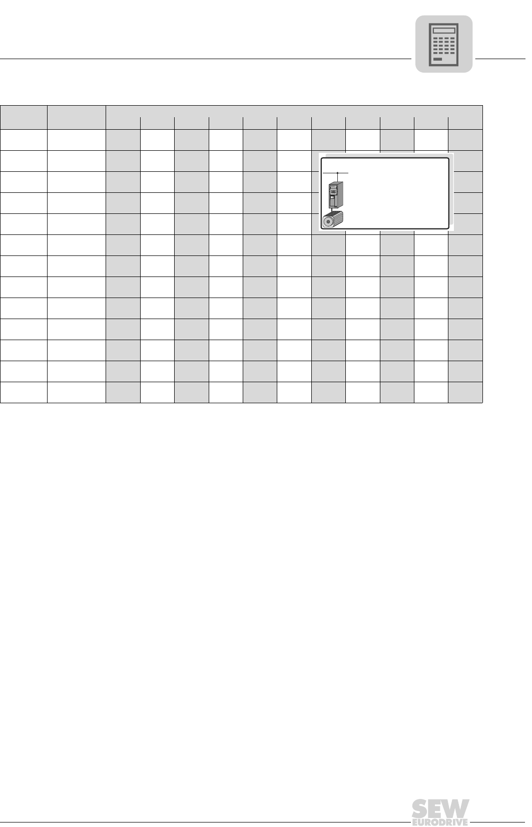
MOVIDRIVE® compact Catalog
117
3
Motor selection for synchronous servomotors (SERVO)
3. Rated speed nN = 4500 rpm:
Motor MOVIDRIVE® compact MCS/MCH4_A...-5_3 (400/500 V units) in SERVO operating modes (P700)
0015 0022 0030 0040 0055 0075 0110 0150 0220 0300 0370
DFS56M Mmax [Nm]
([lb.in])
3.0
(26.5)
DFS56L Mmax [Nm]
([lb.in])
5.0
(44.2)
6.0
(53.2)
DFY71S Mmax [Nm]
([lb.in])
5.4
(47.4)
7.4
(65.1)
7.5
(66.3)
DFY71M Mmax [Nm]
([lb.in])
7.4
(65.8)
9.5
(83.8)
11.1
(97.8)
DFY71ML Mmax [Nm]
([lb.in])
9.1
(80.0)
12.3
(109)
15.0
(132)
DFY71L Mmax [Nm]
([lb.in])
13.0
(115)
17.1
(152)
22.0
(194)
22.5
(199)
DFY90S Mmax [Nm]
([lb.in])
14.3
(126)
18.8
(166)
24.0
(212)
27.0
(238)
DFY90M Mmax [Nm]
([lb.in])
19.4
(171)
24.8
(219)
36.0
(318)
DFY90L Mmax [Nm]
([lb.in])
36.0
(318)
48.0
(424)
53.8
(576)
DFY112S Mmax [Nm]
([lb.in])
19.2
(170)
24.6
(218)
36.0
(318)
DFY112M Mmax [Nm]
([lb.in])
35.0
(309)
46.7
(413)
52.3
(463)
DFY112ML Mmax [Nm]
([lb.in])
47.0
(416)
67.6
(598)
71.7
(634)
DFY112L Mmax [Nm]
([lb.in])
66.2
(585)
86.3
(763)
105
(928)
P700: SERVO...
EQ
Q
3 400/500 V×AC
DFS/DFY: n = 4500 rpm
N
MCS/MCH4_A...-5_3
(400/500 V)

118
08/2002
Address List
Address List
Germany
Headquarters
Production
Sales
Service
Bruchsal SEW-EURODRIVE GmbH & Co
Ernst-Blickle-Straße 42
D-76646 Bruchsal
P.O. Box
Postfach 3023 · D-76642 Bruchsal
Tel. +49 (0) 72 51 / 75-0
Fax +49 (0) 72 51 / 75-19 70
http://www.sew-eurodrive.de
sew@sew-eurodrive.de
Service Electronics:
Tel. +49 (0) 1 71 / 7210791
Service Gear Units and Motors:
Tel. +49 (0) 1 72 / 7 60 13 77
Production Graben SEW-EURODRIVE GmbH & Co
Ernst-Blickle-Straße 1
D-76676 Graben-Neudorf
P.O. Box
Postfach 1220 · D-76671 Graben-Neudorf
Tel. +49 (0) 72 51 / 75-0
Fax +49 (0) 72 51 / 75-29 70
Telex 7 822 276
Assembly
Service
Garbsen
(near Hannover)
SEW-EURODRIVE GmbH & Co
Alte Ricklinger Straße 40-42
D-30823 Garbsen
P.O. Box
Postfach 110453 · D-30804 Garbsen
Tel. +49 (0) 51 37 / 87 98-30
Fax +49 (0) 51 37 / 87 98-55
scm-garbsen@sew-eurodrive.de
Kirchheim
(near München)
SEW-EURODRIVE GmbH & Co
Domagkstraße 5
D-85551 Kirchheim
Tel. +49 (0) 89 / 90 95 52-10
Fax +49 (0) 89 / 90 95 52-50
scm-kirchheim@sew-eurodrive.de
Langenfeld
(near Düsseldorf)
SEW-EURODRIVE GmbH & Co
Siemensstraße 1
D-40764 Langenfeld
Tel. +49 (0) 21 73 / 85 07-30
Fax +49 (0) 21 73 / 85 07-55
scm-langenfeld@sew-eurodrive.de
Meerane
(near Zwickau)
SEW-EURODRIVE GmbH & Co
Dänkritzer Weg 1
D-08393 Meerane
Tel. +49 (0) 37 64 / 76 06-0
Fax +49 (0) 37 64 / 76 06-30
scm-meerane@sew-eurodrive.de
Technical Offices Augsburg SEW-EURODRIVE GmbH & Co
Max-von-Laue-Str. 9
D-86156 Augsburg
Tel. +49 (0) 8 21 / 2 27 79-10
Fax +49 (0) 8 21 / 2 27 79-50
tb-augsburg@sew-eurodrive.de
Berlin SEW-EURODRIVE GmbH & Co
Lilienthalstraße 3a
D-15732 Waltersdorf
Tel. +49 (0) 3 37 62 / 22 66 30
Fax +49 (0) 3 37 62 / 22 66 36
tb-berlin@sew-eurodrive.de
Bodensee SEW-EURODRIVE GmbH & Co
Burgbergring 91
D-88662 Überlingen
Tel. +49 (0) 75 51 / 92 26-30
Fax +49 (0) 75 51 / 92 26-56
tb-bodensee@sew-eurodrive.de
Bremen SEW-EURODRIVE GmbH & Co
Kohlhökerstr.48
D-28203 Bremen
Tel. +49 (0) 4 21 / 3 39 18-0
Fax +49 (0) 4 21 / 3 39 18-22
tb-bremen@sew-eurodrive.de
Dortmund SEW-EURODRIVE GmbH & Co
Chemnitzer Straße 130
D-44139 Dortmund
Tel. +49 (0) 2 31 / 91 20 50-10
Fax +49 (0) 2 31 / 91 20 50-20
tb-dortmund@sew-eurodrive.de
Dresden SEW-EURODRIVE GmbH & Co
Hauptstraße 32
D-01445 Radebeul
Tel. +49 (0) 3 51 / 2 63 38-0
Fax +49 (0) 3 51 / 2 63 38-38
tb-dresden@sew-eurodrive.de
Erfurt SEW-EURODRIVE GmbH & Co
Blumenstraße 70
D-99092 Erfurt
Tel. +49 (0) 3 61 / 2 17 09-70
Fax +49 (0) 3 61 / 2 17 09-79
tb-erfurt@sew-eurodrive.de
Güstrow SEW-EURODRIVE GmbH & Co
Thünenweg 19
D-18273 Güstrow
P.O. Box
Postfach 1216 · D-18262 Güstrow
Tel. +49 (0) 38 43 / 85 57 80
Fax +49 (0) 38 43 / 85 57 88
tb-guestrow@sew-eurodrive.de
Hamburg SEW-EURODRIVE GmbH & Co
Wohldorfer Straße 5
D-22081 Hamburg
P.O. Box
Postfach 7610 07 · D-22060 Hamburg
Tel. +49 (0) 40 / 29 81 09-60
Fax +49 (0) 40 / 29 81 09-70
tb-hamburg@sew-eurodrive.de
Hannover/Garb-
sen
SEW-EURODRIVE GmbH & Co
Alte Ricklinger Str.40-42
D-30823 Garbsen
P.O. Box
Postfach 1104 53 · D-30804 Garbsen
Tel. +49 (0) 51 37 / 87 98-10
Fax +49 (0) 51 37 / 87 98-50
tb-hannover@sew-eurodrive.de

08/2002
119
Address List
Heilbronn SEW-EURODRIVE GmbH & Co
Zeppelinstraße 7
D-74357 Bönnigheim
P.O. Box
Postfach 68 · D-74355 Bönnigheim
Tel. +49 (0) 71 43 / 87 38-0
Fax +49 (0) 71 43 / 87 38-25
tb-heilbronn@sew-eurodrive.de
Herford SEW-EURODRIVE GmbH & Co
Radewiger Straße 21
D-32052 Herford
P.O. Box
Postfach 4108 · D-32025 Herford
Tel. +49 (0) 52 21 / 91 41-0
Fax +49 (0) 52 21 / 91 41-20
tb-herford@sew-eurodrive.de
Karlsruhe SEW-EURODRIVE GmbH & Co
Ettlinger Weg 2
D-76467 Bietigheim
P.O. Box
Postfach 43 · D-76463 Bietigheim
Tel. +49 (0) 72 45 / 91 90-10
Fax +49 (0) 72 45 / 91 90-20
tb-karlsruhe@sew-eurodrive.de
Kassel SEW-EURODRIVE GmbH & Co
Waldauer Weg 80
D-34253 Lohfelden
Tel. +49 (0) 5 61 / 9 51 44-80
Fax +49 (0) 5 61 / 9 51 44-90
tb-kassel@sew-eurodrive.de
Koblenz SEW-EURODRIVE GmbH & Co
Bahnstraße 17a
D-56743 Mendig
Tel. +49 (0) 26 52 / 97 13-30
Fax +49 (0) 26 52 / 97 13-40
tb-koblenz@sew-eurodrive.de
Lahr SEW-EURODRIVE GmbH & Co
Europastraße 3
D-77933 Lahr / Schwarzwald
Tel. +49 (0) 78 21 / 9 09 99-60
Fax +49 (0) 78 21 / 9 09 99-79
tb-lahr@sew-eurodrive.de
Langenfeld SEW-EURODRIVE GmbH & Co
Siemensstraße 1
D-40764 Langenfeld
Tel. +49 (0) 21 73 / 85 07-10
Fax +49 (0) 21 73 / 85 07-50
tb-langenfeld@sew-eurodrive.de
Magdeburg SEW-EURODRIVE GmbH & Co
Burgstraße 7
D-39326 Wolmirstedt
Tel. +49 (0) 3 92 01 / 70 04-1
Fax +49 (0) 3 92 01 / 70 04-9
tb-magdeburg@sew-eurodrive.de
Mannheim SEW-EURODRIVE GmbH & Co
Radeberger Straße 2
D-68309 Mannheim
Tel. +49 (0) 6 21 / 7 16 83-10
Fax +49 (0) 6 21 / 7 16 83-22
tb-mannheim@sew-eurodrive.de
München SEW-EURODRlVE GmbH & Co
Domagkstraße 5
D-85551 Kirchheim
Tel. +49 (0) 89 / 90 95 51-10
Fax +49 (0) 89 / 90 95 51-50
tb-muenchen@sew-eurodrive.de
Münster SEW-EURODRIVE GmbH & Co
Von-Vincke-Straße 14
D-48143 Münster
Tel. +49 (0) 2 51 / 4 14 75-11
Fax +49 (0) 2 51 / 4 14 75-50
tb-muenster@sew-eurodrive.de
Nürnberg SEW-EURODRIVE GmbH & Co
An der Radrunde 168
D-90455 Nürnberg
Tel. +49 (0) 9 11 / 98 88 45-0
Fax +49 (0) 9 11 / 98 88 46-0
tb-nuernberg@sew-eurodrive.de
Regensburg SEW-EURODRIVE GmbH & Co
Im Gewerbepark A15
D-93059 Regensburg
Tel. +49 (0) 9 41 / 4 66 68 68
Fax +49 (0) 9 41 / 4 66 68 66
tb-regensburg@sew-eurodrive.de
Rhein-Main SEW-EURODRIVE GmbH & Co
Niederstedter Weg 5
D-61348 Bad Homburg
Tel. +49 (0) 61 72 / 96 17-0
Fax +49 (0) 61 72 / 96 17-50
tb-rheinmain@sew-eurodrive.de
Stuttgart SEW-EURODRIVE GmbH & Co
Friedrich-List-Straße 46
D-70771 Leinfelden-Echterdingen
Tel. +49 (0) 7 11 / 1 60 72-0
Fax +49 (0) 7 11 / 1 60 72 72
tb-stuttgart@sew-eurodrive.de
Ulm SEW-EURODRIVE GmbH & Co
Hauffstraße 21
D-89160 Dornstadt
Tel. +49 (0) 73 48 / 98 85-0
Fax +49 (0) 73 48 / 98 85-90
tb-ulm@sew-eurodrive.de
Würzburg SEW-EURODRIVE GmbH & Co
Werner-von-Siemens-Straße 55a
D-97076 Würzburg-Lengfeld
Tel. +49 (0) 9 31 / 2 78 86-60
Fax +49 (0) 9 31 / 2 78 86-66
tb-wuerzburg@sew-eurodrive.de
Zwickau /
Meerane
SEW-EURODRIVE GmbH & Co
Dänkritzer Weg1
D-08393 Meerane
Tel. +49 (0) 37 64 / 76 06-0
Fax +49 (0) 37 64 / 76 06-20
tb-zwickau@sew-eurodrive.de
Germany

120
08/2002
Address List
France
Production
Sales
Service
Haguenau SEW-USOCOME
48-54, route de Soufflenheim
B. P. 185
F-67506 Haguenau Cedex
Tel. +33 (0) 3 88 73 67 00
Fax +33 (0) 3 88 73 66 00
http://www.usocome.com
sew@usocome.com
Assembly
Sales
Service
Bordeaux SEW-USOCOME
Parc d’activités de Magellan
62, avenue de Magellan - B. P. 182
F-33607 Pessac Cedex
Tel. +33 (0) 5 57 26 39 00
Fax +33 (0) 5 57 26 39 09
Lyon SEW-USOCOME
Parc d’Affaires Roosevelt
Rue Jacques Tati
F-69120 Vaulx en Velin
Tel. +33 (0) 4 72 15 37 00
Fax + 33 (0) 4 72 15 37 15
Paris SEW-USOCOME
Zone industrielle
2, rue Denis Papin
F-77390 Verneuil I’Etang
Tel. +33 (0) 1 64 42 40 80
Fax +33 (0) 1 64 42 40 88
Technical Offices Alsace Franche-
Comté
SEW-USOCOME
51, rue de Mulhouse
F-68210 Balschwiller
Tel. +33 (0) 3 89 25 91 01
Fax +33 (0) 3 89 25 91 21
Alsace Nord SEW-USOCOME
32, rue Jeanne d’Arc
F-67250 Surbourg
Tel. +33 (0) 3 88 54 74 44
Fax +33 (0) 3 88 80 47 62
Aquitaine SEW-USOCOME
Parc d‘activités de Magellan
62, avenue de Magellan
B.P.182
F-33607 Pessac Cedex
Tel. +33 (0) 5 57 26 39 00
Fax +33 (0) 5 57 26 39 09
Ardennes
Lorraine
SEW-USOCOME
7, rue de Prény
F-54000 Nancy
Tel. +33 (0) 3 83 96 28 04
Fax +33 (0) 3 83 96 28 07
Bourgogne SEW-USOCOME
10, rue de la Poste
F-71350 St. Loup de la Salle
Tel. +33 (0) 3 85 49 92 18
Fax +33 (0) 3 85 49 92 19
Bretagne Ouest SEW-USOCOME
4, rue des Châtaigniers
F-44830 Brains
Tel. +33 (0) 2 51 70 54 04
Fax +33 (0) 2 51 70 54 05
Centre Pays de
Loire
SEW-USOCOME
9, rue des Erables
F-37540 Saint Cyr sur Loire
Tel. +33 (0) 2 47 41 33 23
Fax +33 (0) 2 47 41 34 03
Centre
Auvergne
SEW-USOCOME
17, boulevard de la liberté
F-63200 Riom
Tel. +33 (0) 4 73 64 85 60
Fax +33 (0) 4 73 64 85 61
Champagne SEW-USOCOME
139, rue Thiers
F-10120 Saint André les Vergers
Tel. +33 (0) 3 25 79 63 24
Fax +33 (0) 3 25 79 63 25
Lyon Nord-Est SEW-USOCOME
Parc d’Affaires Roosevelt
Rue Jacques Tati
F-69120 Vaulx en Velin
Tel. +33 (0) 4 72 15 37 03
Fax +33 (0) 4 72 15 37 15
Lyon Ouest SEW-USOCOME
Parc d’Affaires Roosevelt
Rue Jacques Tati
F-69120 Vaulx en Velin
Tel. +33 (0) 4 72 15 37 04
Fax +33 (0) 4 72 15 37 15
Lyon Sud-Est SEW-USOCOME
4, Montée du Pavé
F-26750 Génissieux
Tel. +33 (0) 4 75 05 65 95
Fax +33 (0) 4 75 05 65 96
Nord SEW-USOCOME
348, rue du Calvaire
F-59213 Bermerain Cidex 102
Tel. +33 (0) 3 27 27 07 88
Fax +33 (0) 3 27 27 24 41
Normandie SEW-USOCOME
Les Courtillages Hameau de Coupigny
F-14370 Airan
Tel. +33 (0) 2 31 78 99 70
Fax +33 (0) 2 31 78 99 72
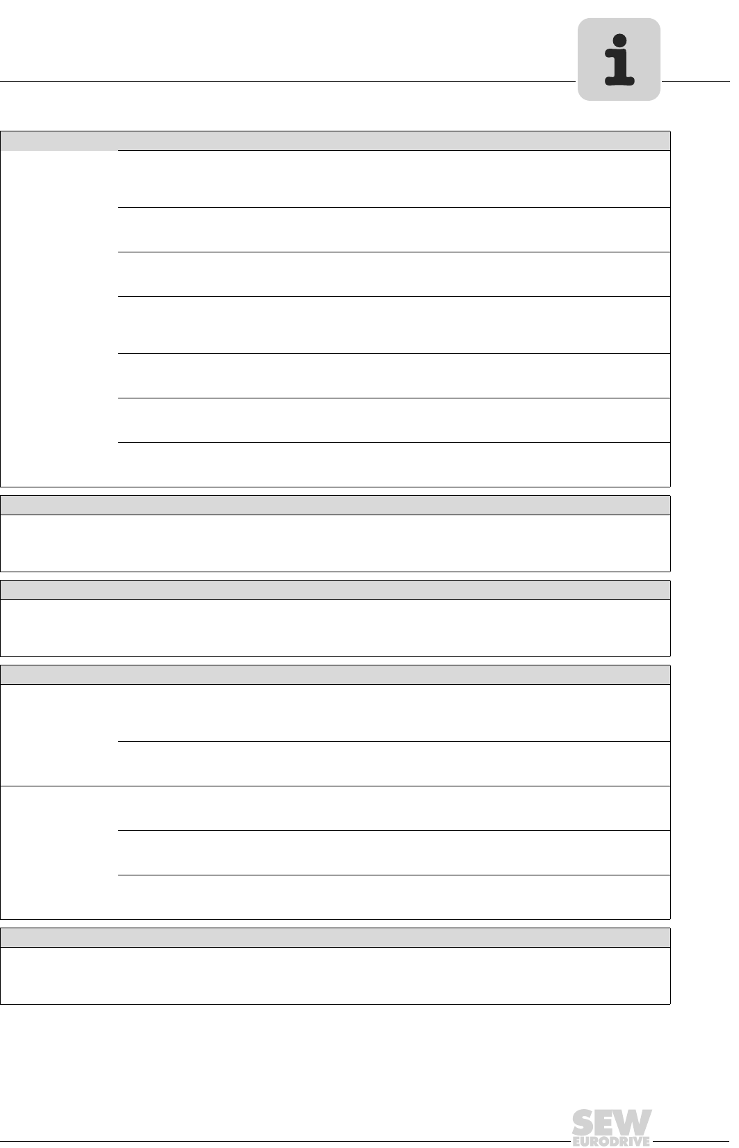
08/2002
121
Address List
Paris Est SEW-USOCOME
Résidence Le Bois de Grâce
2, allée des Souches Vertes
F-77420 Champs sur Marne
Tel. +33 (0) 1 64 68 40 50
Fax +33 (0)1 64 68 45 00
Paris Ouest SEW-USOCOME
1, rue Matisse
F-78960 Voisins le Bretonneux
Tel. +33 (0) 1 30 64 46 33
Fax +33 (0) 1 30 57 54 86
Paris Picardie SEW-USOCOME
25 bis, rue Kléber
F-92300 Levallois Perret
Tel. +33 (0) 1 41 05 92 74
Fax +33 (0) 1 41 05 92 75
Paris Sud SEW-USOCOME
6. chemin des Bergers
Lieu-dit Marchais
F-91410 Roinville sous Dourdan
Tel. +33 (0) 1 60 81 10 56
Fax +33 (0) 1 60 81 10 57
Provence SEW-USOCOME
Chemin Les Grands Vallons
F-13100 St Marc Jaumegarde
Tel. +33 (0) 4 42 24 90 05
Fax +33 (0) 4 42 24 90 13
Pyrénées SEW-USOCOME
271, Lieu-dit Ninaut
F-31190 Caujac
Tel. +33 (0) 5 61 08 15 85
Fax +33 (0) 5 61 08 16 44
Sud-Atlantique SEW-USOCOME
12, rue des Pinsons
F-44120 Vertou
Tel. +33 (0) 2 40 80 32 23
Fax +33 (0) 2 40 80 32 13
Algeria
Technical Office Alger Réducom
16, rue des Frères Zaghnoun
Bellevue El-Harrach
16200 Alger
Tel. +213 (0) 2 82 22 84
Fax +213 (0) 2 82 22 84
Argentina
Assembly
Sales
Service
Buenos Aires SEW EURODRIVE ARGENTINA S.A.
Centro Industrial Garin, Lote 35
Ruta Panamericana Km 37,5
1619 Garin
Tel. +54 (0) 33 27 45 72 84
Fax +54 (0) 33 27 45 72 21
sewar@sew-eurodrive.com.ar
Australia
Assembly
Sales
Service
Melbourne SEW-EURODRIVE PTY. LTD.
27 Beverage Drive
Tullamarine, Victoria 3043
Tel. +61 (0) 3 99 33 10 00
Fax +61 (0) 3 99 33 10 03
http://www.sew-eurodrive.com.au
enquires@sew-eurodrive.com.au
Sydney SEW-EURODRIVE PTY. LTD.
9, Sleigh Place, Wetherill Park
New South Wales, 2164
Tel. +61 (0) 2 97 25 99 00
Fax +61 (0) 2 97 25 99 05
enquires@sew-eurodirve.com.au
Technical Offices Adelaide SEW-EURODRIVE PTY. LTD.
Unit 1/601 Anzac Highway
Glenelg, S.A. 5045
Tel. +61 (0) 8 82 94 82 77
Fax +61 (0) 8 82 94 28 93
enquires@sew-eurodrive.com.au
Perth SEW-EURODRIVE PTY. LTD.
105 Robinson Avenue
Belmont, W.A. 6104
Tel. +61 (0) 8 94 78 26 88
Fax +61 (0) 8 92 77 75 72
enquires@sew-eurodrive.com.au
Brisbane SEW-EURODRIVE PTY.LTD.
1 /34 Collinsvale St
Rocklea, Queensland, 4106
Tel. +61 (0) 7 32 72 79 00
Fax +61 (0) 7 32 72 79 01
enquires@sew-eurodrive.com.au
Austria
Assembly
Sales
Service
Wien SEW-EURODRIVE Ges.m.b.H.
Richard-Strauss-Strasse 24
A-1230 Wien
Tel. +43 (0) 16 17 55 00-0
Fax +43 (0) 16 17 55 00-30
http://sew-eurodrive.at
sew@sew-eurodrive.at
France
122
08/2002
Address List
Technical Offices Linz SEW-EURODRIVE Ges.m.b.H.
Reuchlinstr. 6/3
A-4020 Linz
Tel. +43 (0) 7 32 65 51 09-0
Fax +43 (0) 7 32 65 51 09-20
sew@linz.sew-eurodrive.at
Graz SEW-EURODRIVE Ges.m.b.H.
Grabenstraße 231
A-8045 Graz
Tel. +43 (0) 316 68 57 56-0
Fax +43 (0) 316 68 57 55
sew@graz.sew-eurodrive.at
Bangladesh
Dhaka Triangle Trade International
Bldg-5, Road-2, Sec-3,
Uttara Model Town
Dhaka-1230 Bangladesh
Tel. +880 (0) 28 91 22 46
Fax +880 (0) 28 91 33 44
Belgium
Assembly
Sales
Service
Brüssel CARON-VECTOR S.A.
Avenue Eiffel 5
B-1300 Wavre
Tel. +32 (0) 10 23 13 11
Fax +32 (0) 10 2313 36
http://www.caron-vector.be
info@caron-vector.be
Technical Office Vlaanderen CARON-VECTOR S.A.
Industrieweg 112-114
B-9032 Gent (Wondelgem)
Tel. +32 (0) 92 27 34 52
Fax +32 (0) 92 27 41 55
Bolivia
La Paz GRUPO LARCOS LTDA.
Av. Jose Carrasco Not. 1398
Entre Hugo Estrada Y Av. Busch
La Paz
Tel. +591 (0) 2 34 06 14
Fax +591 (0) 2 35 79 17
Brazil
Production
Sales
Service
Sao Paulo SEW-EURODRIVE Brasil Ltda.
Avenida Amâncio Gaiolli, 50
Caixa Postal: 201-07111-970
Guarulhos - Cep.: 07251-250
Tel. +55 (0) 11 64 89 90 00
Fax +55 (0) 11 64 89 90 09
http://www.sew.com.br
filial.sp@sew.com.br
Additional addresses for service in Brazil provided on request!
Bulgaria
Sales Sofia BEVER-DRIVE GMBH
Bogdanovetz Str.1
BG-1606 Sofia
Tel. +359 (0) 9 29 53 25 65
Fax +359 (0) 9 29 54 93 45
bever@mbox.infotel.bg
Cameroon
Technical Office Douala Electro-Services
Rue Drouot Akwa
B.P. 2024
Douala
Tel. +237 (0) 43 22 99
Fax +237 (0) 42 77 03
Canada
Assembly
Sales
Service
Toronto SEW-EURODRIVE CO. OF CANADA LTD.
210 Walker Drive
Bramalea, Ontario L6T3W1
Tel. +1 (0) 905 7 91-15 53
Fax +1 (0) 905 7 91-29 99
http://www.sew-eurodrive.ca
l.reynolds@sew-eurodrive.ca
Vancouver SEW-EURODRIVE CO. OF CANADA LTD.
7188 Honeyman Street
Delta. B.C. V4G 1 E2
Tel. +1 (0) 604 9 46-55 35
Fax +1 (0) 604 946-2513
b.wake@sew-eurodrive.ca
Montreal SEW-EURODRIVE CO. OF CANADA LTD.
2555 Rue Leger Street
LaSalle, Quebec H8N 2V9
Tel. +1 (0) 514 3 67-11 24
Fax +1 (0) 514 3 67-36 77
a.peluso@sew-eurodrive.ca
Additional addresses for service in Canada provided on request!
Austria

08/2002
123
Address List
Chile
Assembly
Sales
Service
Santiago de
Chile
SEW-EURODRIVE CHILE LTDA.
Las Encinas 1295
Parque Industrial Valle Grande
LAMPA
RCH-Santiago de Chile
P.O. Box
Casilla 23 Correro Quilicura - Santiago - Chile
Tel. +56 (0) 26 23 82 03 + 6 23 81 63
Fax +56 (0) 26 23 81 79
sewsales@entelchile.net
China
Production
Assembly
Sales
Service
Tianjin SEW-EURODRIVE (Tianjin) Co., Ltd.
No. 46, 7th Avenue, TEDA
Tianjin 300457
Tel. +86 (0) 22 25 32 26 12
Fax +86 (0) 22 25 32 26 11
http://www.sew.com.cn
Technical Offices Beijing SEW-EURODRIVE (Tianjin) Co., LTD
Room 1205/1206,
Golden Corner Building, No. 129
Xuanwumen
Xidajie, Xicheng District
Beijing 100031
Tel. +86 (0) 10 66 41 20 26
Fax +86 (0) 10 66 41 10 17
beijing@sew.com.cn
Chengdu SEW-Eurodrive (Tianjin) Co. Ltd.
Room 715, Sichuan International Building
No. 206, Shun Cheng Avenue
Chengdu 610015
Tel. +86 (0) 2 86 52 15 60
Fax +86 (0) 2 85 52 15 63
chengdu@sew.com.cn
Fuzhou SEW-Eurodrive (Tianjin) Co. Ltd.
Unit D, 15/F, Oriental Hotel Fujian
Fuzhou 350001
Tel. +86 (0) 59 17 50 75 96
Fax +86 (0) 59 17 50 72 85
fuzhou@sew.com.cn
Guangzhou SEW-EURODRIVE Pte.Ltd.
Rm 1702, No. 138, Tiyudong Road
Guangzhou, Guangdong, 510620
Tel. +86 (0) 20 38 78 00 12
Fax +86 (0) 20 38 78 00 13
guangzhou@sew.com.cn
Jinan SEW-Eurodrive (Tianjin) Co.Ltd.
Room 2008-2009, Liang You Fu Lin Hotel
No. 5, Luo Yuan Avenue
Jinan 250063
Tel. +86 (0) 53 16 41 26 22
Fax +86 (0) 53 16 41 24 30
jinan@sew.com.cn
Kunming SEW-EURODRIVE (Tianjin) Co., Ltd
Room 1401 Dong Yuan Business Building No.
464
Tuodong Road, Kunming
Yunnan Province 650011
Tel. +86 (0) 87 13 11 36 77
Fax +86 (0) 87 13 15 44 54
kunming@sew.com.cn
Nanjing SEW-Eurodrive (Tianjing) Co.Ltd.
Room 710, Jianda Plaza
No. 223, North Zhongshan Road
Nanjing 210009
Tel. +86 (0) 2 53 34 67 68
Fax +86 (0) 2 53 34 68 71
nanjing@sew.com.cn
Shanghai SEW-EURODRIVE (TIANJIN) CO., Ltd
16/F, E Block, Jinxuan Building
No. 238 South Dandong Road
Xuhui District
Shanghai 200030
Tel. +86 (0) 21 64 69 35 34
Fax +86 (0) 21 64 69 55 32
shanghai@sew.com.cn
Shenyang SEW-EURODRIVE (Tianjin) Co., Ltd
Shenyang OfficeRoom 0605 Koh Brother Build-
ing
No. 21 Beijing Street
Shenhe District Shenyang City, 110013
Tel. +86 (0) 24 22 52 15 96
Fax +86 (0) 24 22 52 15 79
shenyang@sew.com.cn
Wuhan SEW-Eurodrive (Tianjin) Co.Ltd.
Room 911, Tai He Plaza
Wusheng Road
Wuhan 430033
Tel. +86 (0) 27 85 71 22 93
Fax +86 (0) 27 85 71 22 82
wuhan@sew.com.cn
Xian SEW-EURODRIVE (TIANJIN) CO., Ltd
Rm 611, Fan Mei Building
No. 1 Nan Guan Main Street
Xian 710068, Shanxi Province
Tel. +86 (0) 2 97 81 13 27
Fax +86 (0) 2 97 81 13 27
xian@sew.com.cn
Colombia
Assembly
Sales
Service
Bogotá SEW-EURODRIVE COLOMBIA LTDA.
Calle 22 No. 132-60
Bodega 6, Manzana B
Santafé de Bogotá
Tel. +57 (0) 5715 47 50 50
Fax +57 (0) 5715 47 50 44
sewcol@andinet.com

124
08/2002
Address List
Croatia
Sales
Service
Zagreb KOMPEKS d. o. o.
PIT Erdödy 4 II
HR 10 000 Zagreb
Tel. +385 (0) 14 61 31 58
Fax +385 (0) 14 61 31 58
kompeks@net.hr
Czech Republic
Sales Praha SEW-EURODRIVE CZ S.R.O.
Business Centrum Praha
Luná 591
CZ-16000 Praha 6 - Vokovice
Tel. +420 (0) 2 20 12 12 34 +
220121236
Fax +420 (0) 2 20 12 12 37
http://www.sew-eurodrive.cz
sew@sew-eurodrive.cz
Technical Offices Brno SEW-EURODRIVE CZ S.R.O.
Zvonarka 16
CZ-61700 Brno
Tel. +420 (0) 5 43 25 61 51 + 5
43 25 61 63
Fax +420 (0) 5 43 25 68 45
Hradec Kralove SEW-EURODRIVE CZ S.R.O.
Technicka Kancelar - vychodni Cechy
Smermova
CZ-53374 Horni Jeleni
Tel. +420 (0) 6 02 41 03 88
Fax +420 (0) 4 56 89 36 34
Denmark
Assembly
Sales
Service
Kopenhagen SEW-EURODRIVEA/S
Geminivej 28-30, P.O. Box 100
DK-2670 Greve
Tel. +45 (0) 43 95 8500
Fax +45 (0) 43 95 8509
http://www.sew-eurodrive.dk
sew@sew-eurodrive.dk
Technical Offices Aarhus SEW-EURODRIVEA/S
Birkenhaven 45
DK-8520 Lystrup
Tel. +45 (0) 86 22 8344
Fax +45 (0) 86 22 8490
Helsingør SEW-EURODRIVEA/S
Rømøvej 2
DK-3140 Ålsgårde
Tel. +45 (0) 49 75 5700
Fax +45 (0) 49 75 5800
Odense SEW-EURODRIVEA/S
Lindelyvei 29, Nr. Søby
DK-5792 Arslev
Tel. +45 (0) 65 90 2070
Fax +45 (0) 65 90 2309
Egypt
Cairo Copam Egypt
for Engineering & Agencies
33 EI Hegaz ST, Heliopolis, Cairo
Tel. +20 (0) 22 56 62 99 + 22 41 06 39
Fax +20 (0) 22 59 47 57 + 22 40 47 87
copam@datum.com.eg
Estonia
Sales Tallin ALAS-KUUL AS
Paldiski mnt.125
EE 0006 Tallin
Tel. +372 (0) 6 59 32 30
Fax +372 (0) 6 59 32 31
Finland
Assembly
Sales
Service
Lahti SEW-EURODRIVE OY
Vesimäentie 4
FIN-15860 Hollola 2
Tel. +358 (0) 3 589 300
Fax +358 (0) 3 780 6211
http://www.sew-eurodrive.fi
sew@sew-eurodrive.fi
Technical Offices Helsinki SEW-EURODRIVE OY
Luutnantinaukio 5C LT2
FIN-00410 Helsinki
Tel. +358 (0) 3 589 300
Fax + 358 (0) 9 566 6311
Vaasa SEW-EURODRIVE OY
Kauppapuistikko 15 A
FIN-65100 Vaasa
Tel. +358 (0) 3 589 300
Fax +358 (0) 6 312 7470
Gabon
Technical Office Libreville Electro-Services
B.P. 1889
Libreville
Tel. +241 (0) 73 40 11
Fax +241 (0) 73 40 12
08/2002
125
Address List
Great Britain
Assembly
Sales
Service
Normanton SEW-EURODRIVE Ltd.
Beckbridge Industrial Estate
P.O. Box No.1
GB-Normanton, West- Yorkshire WF6 1QR
Tel. +44 (0) 19 24 89 38 55
Fax +44 (0) 19 24 89 37 02
http://www.sew-eurodrive.co.uk
info@sew-eurodrive.co.uk
Technical Offices London SEW-EURODRIVE Ltd.
764 Finchely Road, Temple Fortune
GB-London N.W.11 7TH
Tel. +44 (0) 20 84 58 89 49
Fax +44 (0) 20 84 58 74 17
Midlands SEW-EURODRIVE Ltd.
5 Sugar Brook court,
Aston Road,
Bromsgrove, Worcs
B60 3EX
Tel. +44 (0) 15 27 87 73 19
Fax +44 (0) 15 27 57 52 45
Scotland SEW-EURODRIVE Ltd.
Scottish Office
No 37 Enterprise House
Springkerse Business Park
GB-Stirling FK7 7UF Scotland
Tel. +44 (0) 17 86 47 87 30
Fax +44 (0) 17 86 45 02 23
Greece
Sales
Service
Athen Christ. Boznos & Son S.A.
12, Mavromichali Street
P.O. Box 80136, GR-18545 Piraeus
Tel. +30 (0) 1 04 22 51 34
Fax +30 (0) 1 04 22 51 59
http://www.boznos.gr
Boznos@otenet.gr
Technical Office Thessaloniki Christ. Boznos & Son S.A.
Maiandrou 15
562 24 Evosmos, Thessaloniki
Tel. +30 (0) 3 10 70 54 00
Fax +30 (0) 3 10 70 55 15
Hong Kong
Assembly
Sales
Service
Hong Kong SEW-EURODRIVE LTD.
Unit No. 801-806, 8th Floor
Hong Leong Industrial Complex
No. 4, Wang Kwong Road
Kowloon, Hong Kong
Tel. +852 (0) 2-7 96 04 77 + 79 60 46 54
Fax +852 (0) 2-7 95-91 29
sew@sewhk.com
Hungary
Sales
Service
Budapest SEW-EURODRIVE Kft.
H-1037 Budapest
Kunigunda u. 18
Tel. +36 (0) 1 437 06 58
Fax +36 (0) 1 437 06 50
sew-eurodrive.voros@matarnet.hu
Iceland
Hafnarfirdi VARMAVERK ehf
Dalshrauni 5
IS - 220 Hafnarfirdi
Tel. +354 (0) 5 65 17 50
Fax +354 (0) 5 65 19 51
varmaverk@varmaverk.is
India
Assembly
Sales
Service
Baroda SEW-EURODRIVE India Pvt. Ltd.
Plot No. 4, Gidc
Por Ramangamdi · Baroda - 391 243
Gujarat
Tel. +91 (0) 265-83 10 86
Fax +91 (0) 265-83 10 87
sew.baroda@gecsl.com
Technical Offices Calcutta SEW EURODRIVE INDIA PVT. LTD.
Juthika Apartment, Flat No. B1
11/1, Sunny Park
Calcutta - 700 019
Tel. +91 (0) 33-4 85 39 18
Fax +91 (0) 33-4 85 38 26
sewcal@cal.vsnl.net.in
Chennai SEW-EURODRIVE India Private Limited
2nd Floor, Hariram Building
Chennai - 600 006, Tamil Nadu
Tel. +91 (0) 44-8 21 44 71
Fax +91 (0) 44-8 21 44 73
New Delhi SEW-EURODRIVE India Private Limited
303 Kirti Deep,
2-Nangal Raya Business Centre
New Delhi 110 046
Tel. +91 (0) 11-5 61 15 66
Fax +91 (0) 11-5 51 34 94
Pune SEW-EURODRIVE India Private Limited
206, Metro House 7
Mangaldas Road
Pune 411001, Maharashtra
Tel. +91 (0) 20 60 10 54
Fax +91 (0) 20 63 13 65
sewpun@pn2.vsnl.net.in

126
08/2002
Address List
Indonesia
Technical Office Jakarta SEW-EURODRIVE Pte Ltd.
Jakarta Liaison Office,
Menara Graha Kencana
Jl. Perjuangan No. 88, LT 3 B, Kebun Jeruk,
Jakarta 11530
Tel. +62 (0) 21 535-90 66/7
Fax +62 (0) 21 536-36 86
Ireland
Sales
Service
Dublin Alperton Engineering Ltd.
48 Moyle Road
Dublin Industrial Estate
Glasnevin, Dublin 11
Tel. +353 (0) 18 30 62 77
Fax +353 (0) 18 30 64 58
Israel
Tel-Aviv Liraz Handasa Ltd.
Ahofer Str 34B / 228
58858 Holon
Tel. +972 (0) 3-5 59 95 11
Fax +972 (0) 3-5 59 95 12
lirazhandasa@barak-online.net
Italy
Assembly
Sales
Service
Milano SEW-EURODRIVE di R. Blickle & Co.s.a.s.
Via Bernini,14
I-20020 Solaro (Milano)
Tel. +39 (0) 2 96 98 01
Fax +39 (0) 2 96 79 97 81
sewit@sew-eurodrive.it
Technical Offices Bologna SEW-EURODRIVE di R. Blickle & Co.s.a.s.
Via Emilia,172
I-40064 Ozzano dell’Emilia (Bo)
Tel. +39 (0) 51 79 66 60
Fax +39 (0) 51 79 65 95
Caserta SEW-EURODRIVE di R. Blickle & Co.s.a.s.
Viale Carlo III-Parco Matilde A
I-81020 S. Nicola la Strada (Caserta)
Tel. +39 (0) 8 23 45 06 11
Fax +39 (0) 8 23 42 14 14
Firenze RIMA
Via Einstein, 14
I-50013 Campi Bisenzio (Firenze)
Tel. +39 (0) 5 58 98 58 21 /-22
Fax +39 (0) 5 58 98 58 30
Roma Elettromec
Via Castel Rosso, 10
I-00144 Roma
Tel. +39 (0) 65 92 45 30
Fax +39 (0) 65 92 45 30
Torino SEW-EURODRIVE di R. Blickle & Co.s.a.s.
Corso G. Ferraris,146
I-10129 Torino
Tel. +39 (0) 1 13 18 66 06
Fax +39 (0) 1 13 19 0115
Verona SEW-EURODRIVE di R. Blickle & Co.s.a.s.
Via P. Sgulmero, 27/A
I-37132 Verona
Tel. +39 (0) 45 97 77 22
Fax +39 (0) 45 97 60 79
Ivory Coast
Technical Office Abidjan SICA
Ste industrielle et commerciale pour l’Afrique
165, Bld de Marseille
B.P. 2323, Abidjan 08
Tel. +225 (0) 25 79 44
Fax +225 (0) 25 84 36
Japan
Assembly
Sales
Service
Toyoda-cho SEW-EURODRIVE JAPAN CO., LTD
250-1, Shimoman-no,
Toyoda-cho, Iwata gun
Shizuoka prefecture, 438-0818
Tel. +81 (0) 53 83 7 3811-13
Fax +81 (0) 53 83 7 3814
sewjapan@lilac.ocn.ne.jp
Technical Offices Fukuoka SEW-EURODRIVE JAPAN CO., LTD.
C-go, 5th-floor, Yakuin-Hiruzu-Bldg.
1-5-11, Yakuin, Chuo-ku
Fukuoka, 810-0022
Tel. +81 (0) 92 713 69 55
Fax +81 (0) 92 713 68 60
sewkyushu@jasmine.ocn.ne.jp
Osaka SEW-EURODRIVE JAPAN CO., LTD.
B-Space EIRAI Bldg., 3rd Floor
1-6-9 Kyoumachibori,
Nishi-ku, Osaka, 550-0003
Tel. +81 (0) 6 64 44-83 30
Fax +81 (0) 6 64 44-83 38
sewosaka@crocus.ocn.ne.jp
Tokyo SEW-EURODRIVE JAPAN CO., LTD.
Izumi-Bldg. 5 F
3-2-15 Misaki-cho Chiyoda-ku, Tokyo
101-0061
Tel. +81 (0) 3 32 39-04 69
Fax +81 (0) 3 32 39-09 43
sewtokyo@basil.ocn.ne.jp
08/2002
127
Address List
Korea
Assembly
Sales
Service
Ansan-City SEW-EURODRIVE KOREA CO., LTD.
B 601-4, Banweol Industrial Estate
Unit 1048-4, Shingil-Dong
Ansan 425-120
Tel. +82 (0) 3 14 92-80 51
Fax +82 (0) 3 14 92-80 56
master@sew-korea.co.kr
Technical Offices Busan SEW-EURODRIVE KOREA Co., Ltd.
No. 407, Samjoo officetel.
116-7, Kamjun-2-dong, Sasang-ku
Busan 617-724
Tel. +82 (0) 5 13 13 48 04
Fax +82 (0) 5 13 13 48 05
sewpu2@channeli.net
Daegu SEW-EURODRIVE KOREA Co., Ltd.
No.1108 Sungan officete
l 87-36, Duryu 2-dong, Dalseo-ku
Daegu 704-712
Tel. +82 (0) 5 36 50-7111
Fax +82 (0) 5 36 50-7112
sewdaegu@netsgo.com
DaeJeon SEW-Eurodrive KOREA Co., Ltd.
No. 2017, Hongin offictel
536-9, Bongmyung-dong, Yusung-ku
Daejeon 305-710
Tel. +82 (0) 4 28 28-64 61
Fax +82 (0) 4 28 28-64 63
sewdaejeon@netsgo.com
Kwangju SEW-EURODRIVE KOREA Co., Ltd.
4fl., Shinhyun B/D
96-16 Unam-dong, Buk-ku
Kwangju 500-170
Tel. +82 (0) 62 511-9172
Fax +82 (0) 62 511-9174
sewkwangju@netsgo.com
Seoul SEW-EURODRIVE KOREA Co., Ltd.
No.1104 Sunkyung officetel
106-4 Kuro 6-dong, Kuro-ku
Seoul 152-056
Tel. +82 (0) 28 62-80 51
Fax +82 (0) 28 62-81 99
sewseoul@netsgo.com
Lebanon
Technical Office Beirut Gabriel Acar & Fils sarl
B. P. 80484
Bourj Hammoud, Beirut
Tel. +961 (0) 1 49 47 86
+961 (0) 1 49 82 72
+961 (0) 3 27 45 39
Fax +961 (0) 1 49 49 71
gacar@beirut.com
Luxembourg
Assembly
Sales
Service
Brüssel CARON-VECTOR S.A.
Avenue Eiffel 5
B-1300 Wavre
Tel. +352 (0) 10 23 13 11
Fax +352 (0) 10 2313 36
http://www.caron-vector.be
info@caron-vector.be
Macedonia
Sales Skopje SGS-Skopje / Macedonia
"Teodosij Sinactaski” 66
91000 Skopje / Macedonia
Tel. +389 (0) 9 91 38 43 90
Fax +389 (0) 9 91 38 43 90
sgs@mol.com.mk
Malaysia
Assembly
Sales
Service
Johore SEW-EURODRIVE SDN BHD
No. 95, Jalan Seroja 39, Taman Johor Jaya
81000 Johor Bahru, Johor
West Malaysia
Tel. +60 (0) 73 54 57 07 + 73 54 94 09
Fax +60 (0) 73 5414 04
kchtan@pd.jaring.my
Technical Offices Kota Kinabalu SEW-EURODRIVE Sdn Bhd
(Kota Kinabalu Branch)
Lot No. 2,1st Floor, Inanam Baru
Phase III, Miles 5.1 /2, Jalan Tuaran, Inanam
89350 Kota Kinabalu
Sabah, Malaysia
Tel. +60 (0) 88-42 47 92
Fax +60 (0) 88-42 48 07
Kuala Lumpur SEW-EURODRIVE Sdn. Bhd.
No. 2, Jalan Anggerik Mokara 31/46
Kota Kemuning Seksyen 31
40460 Shah Alam
Selangor Darul Ehsan
Tel. +60 (0) 35 22 96 33
Fax +60 (0) 35 22 96 22
sewpjy@po.jaring.my
Penang SEW-EURODRIVE Sdn. Bhd.
No. 38, Jalan Bawal
Kimsar Garden
13700 Prai, Penang
Tel. +60 (0) 43 99 93 49 + 43 99 98 35
Fax +60 (0) 43 99 93 48
seweurodrive@po.jaring.my

128
08/2002
Address List
Mexico
Tultitlan SEW-EURODRIVE, Sales and Distribution,
S.A.de C.V.
Boulevard Tultitlan Oriente #2 "G"
Colonia Ex-Rancho de Santiaguito
Tultitlan, Estado de Mexico, Mexico 54900
Tel. +52 (0) 55 58 88 29 76
Fax +52 (0) 55 58 88 29 77
scmexico@seweurodrive.com.mx
Morocco
Technical Office Casablanca S. R. M.
Société de Réalisations Mécaniques
5, rue Emir Abdelkader
05 Casablanca
Tel. +212 (0) 2 61 86 69 + 61 86 70 +
61 86 71
Fax +212 (0) 2 62 15 88
srm@marocnet.net.ma
Netherlands
Assembly
Sales
Service
Rotterdam VECTOR Aandrijftechniek B.V.
Industrieweg 175
NL-3044 AS Rotterdam
Postbus 10085
NL-3004 AB Rotterdam
Tel. +31 (0) 10 44 63 700
Fax +31 (0) 10 41 55 552
http://www.vector-aandrijftechniek.nl
info@vector.nu
New Zealand
Assembly
Sales
Service
Auckland SEW-EURODRIVE NEW ZEALAND LTD.
P.O. Box 58-428
82 Greenmount drive
East Tamaki Auckland
Tel. +64 (0) 9-2 74 56 27
Fax +64 (0) 9-2 74 01 65
sales@sew-eurodrive.co.nz
Christchurch SEW-EURODRIVE NEW ZEALAND LTD.
10 Settlers Crescent, Ferrymead
Christchurch
Tel. +64 (0) 3-3 84 62 51
Fax +64 (0) 3-3 85 64 55
sales@sew-eurodrive.co.nz
Technical Office Palmerston
North
SEW-EURODRIVE NEW ZEALAND LTD.
C/-Grant Shearman, RD 5, Aronui Road
Palmerston North
Tel. +64 (0) 6-3 55 21 65
Fax +64 (0) 6-3 55 23 16
sales@sew-eurodrive.co.nz
Norway
Assembly
Sales
Service
Moss SEW-EURODRIVE A/S
Solgaard skog 71
N-1599 Moss
Tel. +47 (0) 69 2410 20
Fax +47 (0) 69 2410 40
sew@sew-eurodrive.no
Pakistan
Technical Office Karachi SEW-EURODRIVE Pte. Ltd.
Karachi Liaison Office A/3,1 st Floor,
Central Commercial Area
Sultan Ahmed Shah Road
Block7/8, K.C.H.S. Union Ltd., Karachi
Tel. +92 (0) 92-21-43 93 69
Fax +92 (0) 92-21-43 73 65
Paraguay
Asunción EQUIS S. R. L.
Avda. Madame Lynchy y Sucre
Asunción
Tel. +595 (0) 21 67 21 48
Fax +595 (0) 21 67 21 50
Peru
Assembly
Sales
Service
Lima SEW DEL PERU MOTORES REDUCTORES
S.A.C.
Los Calderos # 120-124
Urbanizacion Industrial Vulcano, ATE, Lima
Tel. +51 (0) 511 349-52 80
Fax +51 (0) 511 349-30 02
sewperu@terra.com.pe
Philippines
Technical Office Manila SEW-EURODRIVE Pte Ltd
Manila Liaison Office
Suite 110, Ground Floor
Comfoods Building
Senator Gil Puyat Avenue
1200 Makati City
Tel. +63 (0) 2-8 94 27 52 54
Fax +63 (0) 2-8 94 27 44
sewmla@i-next.net

08/2002
129
Address List
Poland
Sales Lodz SEW-EURODRIVE Polska Sp.z.o.o.
ul. Techniczna 3/5
PL-92-519 Lodz
Tel. +48 (0) 4 26 77 10 90
Fax +48 (0) 4 26 77 10 99
http://www.sew-eurodrive.pl
sew@sew-eurodrive.pl
Technical Office Katowice SEW-EURODRIVE Polska Sp.z.o.o.
ul. Nad Jeziorem 87
PL-43-100 Tychy
Tel. +48 (0) 3 22 17 50 26 +
322175027
Fax +48 (0) 3 22 27 79 10 + 3 22 17 74
68 + 3 22 17 50 26 + 3 22 17 50 27
Bydgoszcz SEW-EURODRIVE Polska Sp.z.o.o.
ul. Fordonska 246
PL-85-959 Bydgoszcz
Tel. +48 (0) 5 23 60 65 90
Fax +48 (0) 5 23 60 65 91
Szczecinek SEW-EURODRIVE Polska Sp.z.o.o.
ul. Mickiewicza 2 pok. 36
PL-78-400 Szczecinek
Tel. +48 (0) 9 43 72 88 20
Fax +48 (0) 5 23 72 88 21
Portugal
Assembly
Sales
Service
Coimbra SEW-EURODRIVE, LDA.
Apartado 15
P-3050-901 Mealhada
Tel. +351 (0) 2 31 20 96 70
Fax +351 (0) 2 31 20 36 85
http://www.sew-eurodrive.pt
infosew@sew-eurodrive.pt
Technical Offices Lisboa Tertir
Edificio Lisboa
Gabinete 119
P-2615 Alverca do Ribatejo
Tel. +351 (0) 2 19 58 01 98
Fax +351 (0) 2 19 58 02 45
esc.lisboa@sew-eurodrive.pt
Porto AV. D. AFONSO HENRIQUES, 1196-9°
Sala 909 - Edificio Acia
P- 4450 Matosinhos
Tel. +351 (0) 2 29 35 03 83
Fax +351 (0) 2 29 35 03 84
MobilTel. +351 (0) 9 33 2 55 91 10
esc.porto@sew-eurodrive.pt
Romania
Sales
Service
Bucuresti Sialco Trading SRL
str. Madrid nr.4
71222 Bucuresti
Tel. +40 (0) 2 12 30 13 28
Fax +40 (0) 2 12 30 71 70
sialco@sialco.ro
Russia
Sales St. Petersburg ZAO SEW-EURODRIVE
P.O. Box 263
RUS-195220 St. Petersburg
Tel. +7 (0) 812 5 35 71 42 +
8125350430
Fax +7 (0) 812 5 35 22 87
sew@sew-eurodrive.ru
Technical Office Moskau ZAO SEW-EURODRIVE
RUS-113813 Moskau
Tel. +7 (0) 9 52 38 76 11
Fax +7 (0) 9 52 38 04 22
Senegal
Technical Office Dakar SENEMECA
Mécanique Générale
Km 8, Route de Rufisque
B.P. 3251, Dakar
Tel. +221 (0) 849 47 70
Fax +221 (0) 849 47 71
senemeca@sentoo.sn
Singapore
Assembly
Sales
Service
SEW-EURODRIVE PTE. LTD.
No 9, Tuas Drive 2
Jurong Industrial Estate
Singapore 638644
Tel. +65 (0) 68 62 17 01 ... 17 05
Fax +65 (0) 68 61 28 27
Telex 38 659
sales@sew-eurodrive.com.sg
Slovenia
Sales
Service
Celje Pakman - Pogonska Tehnika d.o.o.
UI. XIV. divizije 14
SLO – 3000 Celje
Tel. +386 (0) 3 490 83 20
Fax +386 (0) 3 490 83 21
pakman@siol.net

130
08/2002
Address List
South Africa
Assembly
Sales
Service
Johannesburg SEW-EURODRIVE (PROPRIETARY) LIMITED
Eurodrive House
Cnr. Adcock Ingram and Aerodrome Roads
Aeroton Ext. 2
Johannesburg 2013
P.O.Box 90004
Bertsham 2013
Tel. + 27 (0) 11 248 70 00
Fax +27 (0) 11 494 23 11
ljansen@sew.co.za
Capetown SEW-EURODRIVE (PROPRIETARY) LIMITED
Rainbow Park
Cnr. Racecourse & Omuramba Road
Montague Gardens
Cape Town
P.O.Box 36556
Chempet 7442
Cape Town
Tel. +27 (0) 21 552 98 20
Fax +27 (0) 21 552 98 30
Telex 576 062
dswanepoel@sew.co.za
Durban SEW-EURODRIVE (PROPRIETARY) LIMITED
2 Monaceo Place
Pinetown
Durban
P.O. Box 10433, Ashwood 3605
Tel. +27 (0) 31 700 34 51
Fax +27 (0) 31 700 38 47
dtait@sew.co.za
Technical Offices Nelspruit SEW-EURODRIVE (PTY) LTD.
7 Christie Crescent
Vintonia
P.O.Box 1942
Nelspruit 1200
Tel. +27 (0) 13 752 80 07
Fax +27 (0) 13 752 80 08
robermeyer@sew.co.za
Port Elizabeth SEW-EURODRIVE PTY LTD.
5 b Linsay Road
Neave Township
6000 Port Elizabeth
Tel. +27 (0) 41 453 03 03
Fax +27 (0) 41 453 03 05
dswanepoel@sew.co.za
Richards Bay SEW-EURODRIVE PTY LTD.
25 Eagle Industrial Park Alton
Richards Bay
P.O. Box 458
Richards Bay 3900
Tel. +27 (0) 35 797 38 05
Fax +27 (0) 35 797 38 19
dtait@sew.co.za
Spain
Assembly
Sales
Service
Bilbao SEW-EURODRIVE ESPAÑA, S.L.
Parque Tecnológico, Edificio, 302
E-48170 Zamudio (Vizcaya)
Tel. +34 (0) 9 44 31 84 70
Fax +34 (0) 9 44 31 84 71
sew.spain@sew-eurodrive.es
Technical Offices Barcelona Delegación Barcelona
Avenida Francesc Maciá 40-44 Oficina 3.1
E-08206 Sabadell (Barcelona)
Tel. +34 (0) 9 37 16 22 00
Fax +34 (0) 9 37 23 30 07
Lugo Delegación Noroeste
Apartado, 1003
E-27080 Lugo
Tel. +34 (0) 6 39 40 33 48
Fax +34 (0) 9 82 20 29 34
Madrid Delegación Madrid
Gran Via. 48-2° A-D
E-28220 Majadahonda (Madrid)
Tel. +34 (0) 9 16 34 22 50
Fax +34 (0) 9 16 34 08 99
Sri Lanka
Colombo 4 SM International (Pte) Ltd
254, Galle Raod
Colombo 4, Sri Lanka
Tel. +94 (0) 941-59 79 49
Fax +94 (0) 941-58 29 81
Sweden
Assembly
Sales
Service
Jönköping SEW-EURODRIVE AB
Gnejsvägen 6-8
S-55303 Jönköping
Box 3100 S-55003 Jönköping
Tel. +46 (0) 36 34 42 00
Fax +46 (0) 36 34 42 80
http://www.sew-eurodrive.se
info@sew-eurodrive.se

08/2002
131
Address List
Technical Offices Göteborg SEW-EURODRIVE AB
Gustaf Werners gata 8
S-42131 Västra Frölunda
Tel. +46 (0) 3 17 09 68 80
Fax +46 (0) 3 17 09 68 93
Malmö SEW-EURODRIVE AB
Borrgatan 5
S-21124 Malmö
Tel. +46 (0) 4 06 80 64 80
Fax +46 (0) 4 06 80 64 93
Stockholm SEW-EURODRIVE AB
Björkholmsvägen 10
S-14125 Huddinge
Tel. +46 (0) 84 49 86 80
Fax +46 (0) 84 49 86 93
Skellefteå SEW-EURODRIVE AB
Trädgårdsgatan 8
S-93131 Skellefteå
Tel. +46 (0) 9 10 71 53 80
Fax +46 (0) 9 10 71 53 93
Switzerland
Assembly
Sales
Service
Basel Alfred lmhof A.G.
Jurastrasse 10
CH-4142 Münchenstein bei Basel
Tel. +41 (0) 6 14 17 17 17
Fax +41 (0) 6 14 17 17 00
http://www.imhof-sew.ch
info@imhof-sew.ch
Technical Offices Suisse romande André Gerber
Es Perreyres
1436 Chamblon
Tel. +41 (0) 2 44 45 38 50
Fax +41 (0) 2 44 45 48 87
Bern Rudolf Bühler
Allerheiligenstraße 97d
2540 Grenchen
Tel. +41 (0) 3 26 52 23 39
Fax +41 (0) 3 26 52 23 31
Luzern Beat Lütolf
Baumacher 11
6244 Nebikon
Tel. +41 (0) 6 27 56 47 80
Fax +41 (0) 6 27 56 47 86
Zürich René Rothenbühler
Nörgelbach 7
8493 Saland
Tel. +41 (0) 5 23 86 31 50
Fax +41 (0) 5 23 86 3213
Taiwan (R.O.C.)
Nan Tou Ting Shou Trading Co., Ltd.
No. 55 Kung Yeh N. Road
Industrial District
Nan Tou 540
Tel. +886 (0) 49-255-353
Fax +886 (0) 49-257-878
Taipei Ting Shou Trading Co., Ltd.
6F-3, No. 267, Sec. 2
Tung Hwa South Road, Taipei
Tel. +886 (0) 27 38 35 35
Fax +886 (0) 27 36 82 68
Telex 27 245
nestnet@ms6.hinet.net
Thailand
Assembly
Sales
Service
Chon Buri SEW-EURODRIVE (Thailand) Ltd.
Bangpakong Industrial Park 2
700/456, Moo.7, Tambol Donhuaroh
Muang District
Chon Buri 20000
Tel. +66 (0) 38 21 40 22
Fax +66 (0) 38 21 45 31
sewthailand@sew-eurodrive.co.th
Technical Offices Bangkok SEW-EURODRIVE PTE LTD
Bangkok Liaison Office
TPS Building, Room No. 5/4
1023, Phattanakarn Road
Klongtan, Phrakanong, Bangkok,10110
Tel. +66 (0) 2717 81 51
Fax +66 (0) 2717 81 52
sewthailand@sew-eurodrive.co.th
Hadyai SEW-EURODRIVE (Thailand) Ltd.
Hadyai Country Home Condominium
59/101 Soi.17/1
Rachas-Utid Road.
Hadyai, Songkhla 90110
Tel. +66 (0) 74-35 94 41
Fax +66 (0) 74-35 94 42
sewhdy@ksc.th.com
Khonkaen SEW-EURODRIVE (Thailand) Ltd.
4th Floor, Kaow-U-HA MOTOR Bldg,
359/2, Mitraphab Road.
Muang District
Khonkaen 40000
Tel. +66 (0) 43-22 57 45
Fax +66 (0) 43-32 48 71
sewkk@cscoms.com
Lampang SEW-EURODRIVE (Thailand) Ltd.
264 Chatchai Road, sub-tuy,
Muang, Lampang 52100
Tel. +66 (0) 54-31 02 41
Fax +66 (0) 54-31 02 42
sewthailand@sew-eurodrive.co.th
Sweden

132
08/2002
Address List
Tunisia
Technical Office Tunis T. M.S. Technic Marketing Service
7, rue Ibn EI Heithem
Z.I. SMMT
2014 Mégrine Erriadh
Tel. +216 (0) 1 43 40 64 + 1 43 20 29
Fax +216 (0) 1 43 29 76
Turkey
Assembly
Sales
Service
Istanbul SEW-EURODRIVE
Hareket Sistemleri Sirketi
Bagdat Cad. Koruma Cikmazi No. 3
TR-81540 Maltepe ISTANBUL
Tel. +90 (0) 216 4 41 91 63 + 216 4 41
91 64 + 216 3 83 80 14
Fax +90 (0) 216 3 05 58 67
seweurodrive@superonline.com.tr
Technical Offices Ankara SEW-EURODRIVE
Hareket Sistemleri Sirketi
Ehlibeyt Mah. Ceyhun Atif Kansu Cad. 12. Sok.
Tepe Apt. No. 7/12
TR-06520 Balgat-Ankara
Tel. +90 (0) 312 286 80 14
Fax +90 (0) 312 286 80 15
Izmir SEW-EURODRIVE
Hareket Sistemleri Ticaret Ltd. Sirketi
1203/11 Sok. No. 4/613
Hasan Atli Is Merkezi
TR-35110 Yenisehir-Izmir
Tel. +90 (0) 232 4 69 62 64
Fax +90 (0) 232 4 33 61 05
Uruguay
Montevideo SEW-EURODRIVE S. A. Sucursal Uruguay
German Barbato 1526
CP 11200 Montevideo
Tel. +598 (0) 2 9018 189
Fax +598 (0) 2 9018 188
sewuy@sew-eurodrive.com.uy
USA
Production
Assembly
Sales
Service
Greenville SEW-EURODRIVE INC.
1295 Old Spartanburg Highway
P.O. Box 518
Lyman, S.C. 29365
Tel. +1 (0) 864 4 39 75 37
Fax Sales +1 (0) 864 439-78 30
Fax Manuf. +1 (0) 864 4 39-99 48
Fax Ass. +1 (0) 864 4 39-05 66
Telex 805 550
http://www.seweurodrive.com
cslyman@seweurodrive.com
Assembly
Sales
Service
San Francisco SEW-EURODRIVE INC.
30599 San Antonio St.
Hayward, California 94544-7101
Tel. +1 (0) 510 4 87-35 60
Fax +1 (0) 510 4 87-63 81
cshayward@seweurodrive.com
Philadelphia/PA SEW-EURODRIVE INC.
Pureland Ind. Complex
200 High Hill Road, P.O. Box 481
Bridgeport, New Jersey 08014
Tel. +1 (0) 856 4 67-22 77
Fax +1 (0) 856 8 45-31 79
csbridgeport@seweurodrive.com
Dayton SEW-EURODRIVE INC.
2001 West Main Street
Troy, Ohio 45373
Tel. +1 (0) 9 37 3 35-00 36
Fax +1 (0) 9 37 4 40-37 99
cstroy@seweurodrive.com
Dallas SEW-EURODRIVE INC.
3950 Platinum Way
Dallas, Texas 75237
Tel. +1 (0) 214 3 30-48 24
Fax +1 (0) 214 3 30-47 24
csdallas@seweurodrive.com
Additional addresses for service in the USA provided on request!
Venezuela
Assembly
Sales
Service
Valencia SEW-EURODRIVE Venezuela S.A.
Av. Norte Sur No. 3, Galpon 84-319
Zona Industrial Municipal Norte
Valencia, Estado Carabobo
Tel. +58 (0) 241 8 32 98 04
Fax +58 (0) 241 8 38 62 75
sewventas@cantv.net
sewfinanzas@cantv.net

133

134

135

SEW-EURODRIVE GmbH & Co · P.O. Box 3023 · D-76642 Bruchsal/Germany · Phone +49-7251-75-0
Fax +49-7251-75-1970 · http://www.sew-eurodrive.com · sew@sew-eurodrive.com
