1104Dm ESM, Engine Specification Manual, Mechanical, ERM 1104D_Mech%20tier3 1104D Mech%20tier3
User Manual: 1104D_Mech%20tier3
Open the PDF directly: View PDF ![]() .
.
Page Count: 276 [warning: Documents this large are best viewed by clicking the View PDF Link!]
- Retour index souffleuses industrielles, semi-industrielles et motorisées
- 1 General information
- Introduction 1
- How to use the manual 2
- Creating an engine specification 3
- 2 The engine range
- Maximum intermittent ratings 5
- 3 Engine specification
- 4 Options
- Mechanical options
- Introduction 27
- Naturally aspirated - non-balanced 28
- Naturally aspirated - balanced 28
- Turbocharged - non-balanced 29
- Turbocharged - balanced 29
- Turbocharged, air to air charge cooled - non-balanced 30
- Turbocharged, air to air charge cooled - balanced 30
- ECM
- Adaptor plate
- Flywheel housings
- Non-stressed cylinder block 33
- Stressed cylinder block 33
- Flywheel housing design 34
- C0001 - Cast iron SAE 3, 156,4 mm (6.16 in) deep 34
- C0002 - Cast iron SAE 3, 135,0 mm (5.32 in) deep 35
- C0006 - Adaptor plate for combine harvesters 35
- C0010 - Cast iron SAE 3, 135,0 mm (5.32 in) deep, LHS starter 36
- C0021 - Cast iron SAE 2, 156,4 mm (6.16 in) deep, LHS or RHS starter 36
- C0022 - Cast iron SAE 3, 156,4 mm (6.16 in) deep, RHS starter 37
- C0026 - Cast iron SAE 3, 84,0 mm (3.31 in) deep, LHS starter 37
- C0027 - Cast iron SAE 3, 135,0 mm (5.32 in) deep, RHS starter, with adaptor to
- convert from SAE 3 to SAE 4 38
- C0030 - Cast iron SAE 3, 84,0 mm (3.31 in) deep, RHS starter 39
- C0031 - Cast iron SAE 3, 84,0 mm (3.31 in) deep, RHS starter 39
- C0033 - Cast iron SAE 3, 81,0 mm (3.18 in) deep, LHS starter 40
- C0036 - Cast iron SAE 3, 135,0 mm (5.32 in) deep, RHS starter 40
- C0037 - Cast iron SAE 3, 156,4 mm (6.16 in) deep, RHS starter 41
- Flywheels
- Non-stressed cylinder block 42
- Stressed cylinder block 43
- D0000 - Crankshaft palm 43
- D0003 - For Centaflex couplings 44
- D0004 - For SAE, Borg and Beck, twin disc 44
- D0005 - As D0004 but with pilot bearing housing 45
- D0006 - For 12/13 in American Borg and Beck clutches 45
- D0008 - For Clark 18000 torque converters (non stressed) 46
- D0014 - For Borg Warner torque converters (non stressed) 46
- D0014 - For Borg Warner torque converters (stressed) 47
- D0022 - Non stressed flywheel "for 10 SAE light" 47
- D0030 - For Allison AT545 transmissions 48
- D0044 - For SAE transmissions 48
- D0045 - For Spicer transmissions 49
- D0046 - For hydrostatic transmission 49
- D0048 - For wet backend, 122 tooth starter ring 50
- D0052 - For ZF auto transmissions 50
- D0053 - For various transmissions 51
- D0055 - For customer transmission 51
- D0056 - For customer transmission 52
- D0061 - For customer transmission 52
- D0062 - For customer transmission 53
- D0063 - For customer transmission 53
- D0064 - For customer transmission 54
- D0065 - For customer transmission 54
- D0066 - For customer transmission 55
- D0067 - For customer transmission 55
- D0068 - For customer transmission 56
- D0069 - For customer transmission 56
- D0070 - For ZF115 transmission 57
- D0092 - For ZFWG9 transmission 57
- Starter motors
- Fan drives
- Fan drive standard vee 61
- Fan drive multi vee 62
- F0011 to F0013 and F0021 to F0025 62
- F0031 to F0035 and F0041 to F0042 63
- F0061 to F0064 - Fan pulley 63
- F0501 - Fan drive housing for standard pulley 64
- F0501 - Fan drive housing for multi vee pulley 64
- F0502 - Fan drive housing 65
- F0503 - Fan drive housing 65
- F0504 - Fan drive housing 66
- F4422/F4441/F4442 - Fan centre 285 mm 66
- F4451/F4452/F4461/F4462 67
- Lubricating oil sumps and dipsticks
- Non-stressed cylinder block sumps 68
- Stressed cylinder block sumps 68
- Dipsticks 68
- Oil capacities and gradability 69
- Gradient of operation and oil capacities 69
- G0100/G0101/G0104 - Steel, flat bottom sump 69
- G0203 - Steel, flat bottom sump 70
- G0301/G0303 - Cast iron, flat bottom sump 70
- G0401 - Aluminium, front well sump 71
- G0600 - Aluminium, shallow rear well sump 71
- G0600/G0601/G0603/G0604 - Aluminium, shallow rear well sump 72
- G1001 - Aluminium, deep well sump 72
- G2000 - Cast iron, deep flat bottom sump 73
- G2001/G2003 - Cast iron, deep flat bottom sump 73
- G2004 - Cast iron, deep flat bottom sump 74
- G2101 - Cast iron, shallow tunnel sump 74
- Lubricating oil filler and breather
- Top cover, breathers and lubricating oil fillers 75
- Breather branding 75
- Breather system options 75
- Timing case lubricating oil fillers 76
- H0200 - Open breather short hose H1200 - Open breather long hose 76
- H0300 - Mechanical, filtered open breather 77
- H**00 - Top cover, no filler 77
- H**10 - Top cover, filler middle 78
- H**20 - Top cover, filler rear 78
- HD001 - Timing case filler, LHS mid position 79
- HD004 - Timing case filler, on LHS lower position 79
- HD005 - Timing case filler, on LHS upper position 80
- HD006 - Timing case filler, LHS mid position for customer supplied filler 80
- HD007 - Remote timing case filler 81
- HD011 - Remote timing case filler adaptor, LHS mid position 81
- Lubricating oil filters and coolers
- Spin on oil filters 82
- Lubricating oil filter branding 82
- Oil cooler 83
- J0011/J0051 - Vertically down, LHS 83
- J0021/J0061 - Horizontal filter, LHS 84
- J0030 - Vertically down filter head, RHS no filter (customer supply), without oil cooler 84
- J0031/J0071 - Vertically down filter head, RHS 85
- J0050 - Vertically down filter head, LHS no filter (customer supply), with oil cooler 85
- J0060 - Horizontal filter, LHS, no filter (customer supply) with oil cooler 86
- J0130 - Adaptor for remote oil filter (customer supply) with oil cooler 86
- Crankshaft pulleys
- Fan drive standard vee 87
- Fan drive multi vee 87
- K0000 - Crankshaft stub seal, for no crankshaft pulley fitted 88
- K0001 - Cast iron, single groove, 200 mm diameter 12,7 mm belt 88
- K0004 - Cast iron, twin groove, 200 mm diameter 12,7 mm belt 89
- K0006 - Cast iron, twin groove, 170 mm diameter 12,7 mm belt 89
- K0007 - Cast iron, single groove, 170 mm diameter 12,7 mm belt 90
- K0010/K0020 - Primary drive, steel, 150 mm - 200 mm diameter 90
- K0010/K0020 - Primary drive, steel, 150 mm - 200 mm diameter 91
- Coolant pump and outlet connection
- L0052 - Coolant pump with horizontal coolant outlet connection, with
- thermostat assembly 92
- L0053 - Coolant pump with horizontal coolant outlet connection RHS, with
- thermostat assembly 93
- L0056 - Coolant pump with vertical coolant outlet connection in centre, with
- thermostat assembly 93
- L0052 to L0056 - Coolant pump 94
- Fans and extensions
- Alternators
- Belt driven auxiliaries
- Timing case and gear driven auxiliaries
- Q1000 - Timing case LHS PTO, no auxiliaries fitted 105
- Q1001 - Exhauster 105
- Q1005, Q1035 and Q2035 - Hydraulic pump drive adaptor, 2 bolt fixing, SAE flange,
- 13 tooth spline, LHS 106
- Q1009 - Hydraulic pump drive adaptor, 4 bolt fixing, LHS PTO 106
- Q1015, Q1036 and Q2036 - Hydraulic pump drive adaptor, 2 bolt fixing, SAE flange,
- 11 tooth spline, LHS 107
- Q1016, Q1037 and Q2037 - Hydraulic pump drive adaptor, 2 bolt fixing, SAE flange,
- 9 tooth spline, LHS 107
- Q1020 - Z drive adaptor with SAE B flange for customer fit compressor or auxiliaries 108
- Q1023 - Compressor 225 cc with SAE flange, head unloader 108
- Q1024 - Compressor 225 cc with DIN flange, head unloader 109
- Q1025 - Z drive adaptor and compressor, 225 cc with DIN flange, line unload 109
- Q1026 - Z drive adaptor and compressor, 225 cc with SAE flange, line unload 110
- Q1038 - Adaptor and extension for SAE B drive 110
- Q1100 - Timing case with no PTO capability 111
- Q2030 - Timing case, twin PTO 111
- Q3000/Q3030 - Timing case, single RHS PTO, no auxiliaries fitted 112
- Q4042 - Heavy duty to suit compressor 630 cc, SAE flange, head unload 112
- Q4055 - Heavy duty to suit SAE B drive flange, 13 tooth spline, no auxiliaries 113
- Q4059 - Heavy duty to suit SAE B drive flange, 15 tooth spline, no auxiliaries 113
- Balancer
- Manifolds, elbows and air filters for turbocharged engines
- Exhaust hardware 116
- S0100 - Side mounted turbo, RHS, exhaust forward, no exhaust elbow,
- cross over pipe to rear, end 116
- S0101 - Side mounted turbo, RHS, exhaust forward, no exhaust elbow,
- cross over pipe to rear, top 117
- S0110 - Side mounted turbo, RHS, exhaust elbow forward up,
- cross over pipe to rear, end 117
- S0111 - Side mounted turbo, RHS, exhaust elbow forward up,
- cross over pipe to rear, top 118
- S0114 - Side mounted turbo, RHS, exhaust elbow forward up,
- cross over pipe to rear, top with air filter 118
- S0120 - Side mounted turbo, RHS, exhaust elbow forward down,
- cross over pipe to rear, end 119
- S0121 - Side mounted turbo, RHS, exhaust elbow forward down,
- cross over pipe to rear, top 119
- S0150 - Side mounted turbo, RHS, exhaust rearward, no exhaust elbow,
- cross over pipe to rear, end 120
- S0151 - Side mounted turbo, RHS, exhaust rearward, no exhaust elbow,
- cross over pipe to rear, top 120
- S0251 - Top mounted turbo, exhaust outlet rearward, no exhaust elbow,
- cross over pipe to rear, top 121
- S1101 - Side mounted turbo, RHS, exhaust forward, no exhaust elbow,
- compressor outlet up, for air to air cooling 121
- S1111 - Side mounted turbo, RHS, exhaust elbow forward up,
- compressor outlet up, for air to air cooling 122
- S1112 - Side mounted turbo, RHS, exhaust elbow forward up,
- compressor outlet down, for air to air cooling 122
- S1114 - Side mounted turbo, RHS, exhaust elbow forward up,
- compressor outlet down, for air to air cooling, with air filter 123
- S1121 - Side mounted turbo, RHS, exhaust elbow forward down,
- compressor outlet up, for air to air cooling 123
- S1151 - Side mounted turbo, RHS, exhaust rearward, no exhaust elbow,
- compressor outlet up, air to air cooling 124
- S1152 - Side mounted turbo, RHS, exhaust rearward, no exhaust elbow,
- compressor outlet down, for air to air cooling 124
- S1181 - Side mounted turbo, RHS, exhaust elbow rearward up,
- compressor outlet up, for air to air cooling 125
- S1182 - Side mounted turbo, RHS, exhaust elbow rearward up,
- compressor outlet down, for air to air cooling 125
- Intake manifold, intake connections
- Exhaust outlet and elbow
- Fuel filters secondary
- Cold start aids
- Lifting eyes
- Paint
- Mechanical options
- 5 Accessories
- Introduction 141
- Resistors and regulators
- Fuel systems
- Engine mounting brackets
- ZC002 - Front pedestal mounting brackets, LHS and RHS 145
- ZC003 - Rear brackets, LHS and RHS 146
- ZC012 - Front mounting studs only 146
- ZC016 - Front mounting brackets, LHS and RHS (with flywheel housing plugs) 147
- ZC018 - Front pedestal brackets, LHS and RHS 147
- ZC019 - Front mounting brackets, LHS and RHS (for high peak loads, 10g) 148
- Heater/starter switch
- Sump drain
- Lubricating oil switches and valves
- ZJ003 - Lubricating oil pressure switch fitted in oil filter head - Deutsch connector 151
- ZJ005 - Lubricating oil sampling valve, fitted in lubricating oil filter head 152
- ZJ006 - Lubricating oil pressure switch fitted in cylinder block - Deutsch connector 152
- ZJ008 - Lubricating oil sampling valve fitted in pressure rail 153
- Coolant temperature sender and gauge
- Radiator
- ZM000 - Not required 155
- ZM101 - Radiator supplied loose 155
- ZM102 - Radiator fitted, without fan guards 155
- ZM103 - Radiator fitted, with fan guards 155
- ZM122 - Radiator with intercooler fitted, with fan guards 155
- ZM124 - Radiator with intercooler fitted, with fan guards 155
- ZM130 - Radiator with intercooler fitted, with fan guards, to suit twin PTO 155
- Engine wiring harnesses
- Fuel filter-primary
- Labels
- ZY003 - Emissions, label LHS block, front low and Perkins decal 158
- ZY004 - Emissions, label LHS block, rear low and Perkins decal 158
- ZY005 - Emissions, label RHS block, front low and Perkins decal 158
- ZY014 - Emissions, label LHS block, rear low 158
- ZY023 - Emissions, label LHS block, front low and Perkins decal with
- additional emissions label supplied loose 158
- ZY024 - Emissions, label LHS block, rear low and Perkins decal with
- additional emissions label supplied loose 158
- Cab heater connections
- 6 Technical data
- Introduction 163
- Basic technical data
- Power curves
- 1104D-44 - T2968, (non-balanced) 167
- 1104D-44 - T2969, (balanced) 169
- 1104D-44T - T2970, (non-balanced) 171
- 1104D-44T - T2971, (balanced) 173
- 1104D-44TA - T2972, (balanced) 175
- 1104D-44T - T2978, (non-balanced) 177
- 1104D-44T - T2979, (balanced) 179
- 1104D-44TA - T3055, (balanced) 181
- 1104D-44TA - T3056, (non-balanced) 183
- 1104D-44TA - T3058, (non-balanced) 185
- 1104D-44TA - T3059, (balanced) 187
- 1104D-44T - T3060, (non-balanced) 189
- 1104D-44T - T3061, (balanced) 191
- 1104D-44T - T3066, (non-balanced) 193
- 1104D-44T - T3067, (balanced) 195
- 1104D-44T - T3360, (non-balanced) 197
- 1104D-44TA - T3496, (balanced) 199
- 1104D-44TA - T3499, (balanced) 201
- 1104D-44TA - T3500, (balanced) 203
- Cylinder block views non-stressed block
- Cylinder block views stressed block
- Cold start system
- Cooling system
- Heat Balance
- 1104D-44 Curve number T2968 (non-balanced) 214
- 1104D-44 Curve number T2969 (balanced) 214
- 1104D-44T Curve number T2970 (non-balanced) 214
- 1104D-44T Curve number T2971 (balanced) 214
- 1104D-44TA Curve number T2972 (balanced) 215
- 1104D-44T Curve number T2978 (non-balanced) 215
- 1104D-44T Curve number T2979 (balanced) 215
- 1104D-44TA Curve number T3055 (balanced) 215
- 1104D-44TA Curve number T3056 (non-balanced) 216
- 1104D-44TA Curve number T3058 (non-balanced) 216
- 1104D-44TA Curve number T3059 (balanced) 216
- 1104D-44T Curve number T3060 (non-balanced) 216
- 1104D-44T Curve number T3061 (balanced) 217
- 1104D-44T Curve number T3066 (non-balanced) 217
- 1104D-44T Curve number T3067 (balanced) 217
- 1104D-44T Curve number T3360 (non-balanced) 217
- 1104D-44T Curve number T3361 (balanced) 218
- 1104D-44TA Curve number T3496 (non-balanced) 218
- 1104D-44TA Curve number T3499 (non-balanced) 218
- 1104D-44TA Curve number T3500 (non-balanced) 218
- Exhaust system
- 1104D-44 Curve number T2968 (non-balanced) 219
- 1104D-44 Curve number T2969 (balanced) 219
- 1104D-44T Curve number T2970 (non-balanced) 219
- 1104D-44T Curve number T2971 (balanced) 219
- 1104D-44TA Curve number T2972 (balanced) 220
- 1104D-44T Curve number T2978 (non-balanced) 220
- 1104D-44T Curve number T2979 (balanced) 220
- 1104D-44TA Curve number T3055 (balanced) 220
- 1104D-44TA Curve number T3056 (non-balanced) 221
- 1104D-44TA Curve number T3058 (non-balanced) 221
- 1104D-44TA Curve number T3059 (balanced) 221
- 1104D-44T Curve number T3060 (non-balanced) 221
- 1104D-44T Curve number T3061 (balanced) 222
- 1104D-44T Curve number T3066 (non-balanced) 222
- 1104D-44T Curve number T3067 (balanced) 222
- 1104D-44T Curve number T3360 (non-balanced) 222
- 1104D-44TA Curve number T3496 (non-balanced) 223
- 1104D-44TA Curve number T3499 (non-balanced) 223
- 1104D-44TA Curve number T3500 (non-balanced) 223
- Induction system
- Air flow data tables
- 1104D-44 Curve number T2968 (non-balanced) 225
- 1104D-44 Curve number T2969 (balanced) 225
- 1104D-44T Curve number T2970 (non-balanced) 225
- 1104D-44T Curve number T2971 (balanced) 225
- 1104D-44TA Curve number T2972 (balanced) 226
- 1104D-44T Curve number T2978 (non-balanced) 226
- 1104D-44T Curve number T2979 (balanced) 226
- 1104D-44TA Curve number T3055 (balanced) 226
- 1104D-44TA Curve number T3056 (non-balanced) 227
- 1104D-44TA Curve number T3058 (non-balanced) 227
- 1104D-44TA Curve number T3059 (balanced) 227
- 1104D-44T Curve number T3060 (non-balanced) 227
- 1104D-44T Curve number T3061 (balanced) 228
- 1104D-44T Curve number T3066 (non-balanced) 228
- 1104D-44T Curve number T3067 (balanced) 228
- 1104D-44T Curve number T3360 (non-balanced) 228
- 1104D-44T Curve number T3361 (balanced) 229
- 1104D-44T Curve number T3496 (non-balanced) 229
- 1104D-44T Curve number T3499 (non-balanced) 229
- Fuel Specifications
- Fuel specific gravity 230
- Fuel tank location 230
- Low pressure fuel system - fuel tank positions - ‘T’ into fuel return pipe (V1001) 231
- Low pressure fuel system - fuel tank in lowest position - ‘T’ into
- fuel return pipe (V3201) 231
- Low pressure fuel system - fuel tank in highest position ‘T’ into
- fuel return pipe `(V3201) 232
- Low pressure fuel system - fuel tank in lowest position atmospheric
- fuel return line (V2201) 232
- Low pressure fuel system - fuel tank in highest position atmospheric
- fuel return line (V2201) 233
- S8001 - Altitude and temperature 234
- S8002 - Humidity 235
- Lubrication system
- Electrical circuit diagram
- Engine mountings
- Power take-off
- Centre of gravity
- Ratings
- Low speed torque 245
- Transient smoke 245
- Allowances for engine driven auxiliary equipment 245
- De-rating 245
- Inlet air temperature 245
- Altitude 245
- Humidity 246
- Temperature 246
- Exhauster, curve 5608 247
- Compressor single cylinder 225cc - free air delivery 248
- Compressor single cylinder 225cc - delivered air temperature 249
- Compressor single cylinder 225cc - power consumption 250
- Compressor single cylinder 225cc - air charging time to pressurise a 50 litre receiver 251
- Fan performance curve 2184/C - options M2203 to M2206 252
- Fan performance curve 5441 - options M3313 to M3316 253
- Fan performance curve 5442 - options M3323 to M3326 254
- Fan performance curve 5443 - options M3415 to M3416 255
- Fan performance curve 9500 - option M4326 256
- Fan performance curve 9501 - option M2323 to M2326 257
- Important notes
- General information
- The engine range
- Engine specification
- Options
- Mechanical options
- Introduction
- Naturally aspirated - non-balanced
- Naturally aspirated - balanced
- Turbocharged - non-balanced
- Turbocharged - balanced
- Turbocharged, air to air charge cooled - non-balanced
- Turbocharged, air to air charge cooled - balanced
- ECM
- Adaptor plate
- Flywheel housings
- Non-stressed cylinder block
- Stressed cylinder block
- Flywheel housing design
- C0001 - Cast iron SAE 3, 156,4 mm (6.16 in) deep
- C0002 - Cast iron SAE 3, 135,0 mm (5.32 in) deep
- C0006 - Adaptor plate for combine harvesters
- C0010 - Cast iron SAE 3, 135,0 mm (5.32 in) deep, LHS starter
- C0021 - Cast iron SAE 2, 156,4 mm (6.16 in) deep, LHS or RHS starter
- C0022 - Cast iron SAE 3, 156,4 mm (6.16 in) deep, RHS starter
- C0026 - Cast iron SAE 3, 84,0 mm (3.31 in) deep, LHS starter
- C0027 - Cast iron SAE 3, 135,0 mm (5.32 in) deep, RHS starter, with adaptor to convert from SAE 3 to SAE 4
- C0030 - Cast iron SAE 3, 84,0 mm (3.31 in) deep, RHS starter
- C0031 - Cast iron SAE 3, 84,0 mm (3.31 in) deep, RHS starter
- C0033 - Cast iron SAE 3, 81,0 mm (3.18 in) deep, LHS starter
- C0036 - Cast iron SAE 3, 135,0 mm (5.32 in) deep, RHS starter
- C0037 - Cast iron SAE 3, 156,4 mm (6.16 in) deep, RHS starter
- Flywheels
- Non-stressed cylinder block
- Stressed cylinder block
- D0000 - Crankshaft palm
- D0003 - For Centaflex couplings
- D0004 - For SAE, Borg and Beck, twin disc
- D0005 - As D0004 but with pilot bearing housing
- D0006 - For 12/13 in American Borg and Beck clutches
- D0008 - For Clark 18000 torque converters (non stressed)
- D0014 - For Borg Warner torque converters (non stressed)
- D0014 - For Borg Warner torque converters (stressed)
- D0022 - Non stressed flywheel "for 10 SAE light"
- D0030 - For Allison AT545 transmissions
- D0044 - For SAE transmissions
- D0045 - For Spicer transmissions
- D0046 - For hydrostatic transmission
- D0048 - For wet backend, 122 tooth starter ring
- D0052 - For ZF auto transmissions
- D0053 - For various transmissions
- D0055 - For customer transmission
- D0056 - For customer transmission
- D0061 - For customer transmission
- D0062 - For customer transmission
- D0063 - For customer transmission
- D0064 - For customer transmission
- D0065 - For customer transmission
- D0066 - For customer transmission
- D0067 - For customer transmission
- D0068 - For customer transmission
- D0069 - For customer transmission
- D0070 - For ZF115 transmission
- D0092 - For ZFWG9 transmission
- Starter motors
- Fan drives
- Fan drive standard vee
- Fan drive multi vee
- F0011 to F0013 and F0021 to F0025
- F0031 to F0035 and F0041 to F0042
- F0061 to F0064 - Fan pulley
- F0501 - Fan drive housing for standard pulley
- F0501 - Fan drive housing for multi vee pulley
- F0502 - Fan drive housing
- F0503 - Fan drive housing
- F0504 - Fan drive housing
- F4422/F4441/F4442 - Fan centre 285 mm
- F4451/F4452/F4461/F4462
- Lubricating oil sumps and dipsticks
- Non-stressed cylinder block sumps
- Stressed cylinder block sumps
- Dipsticks
- Oil capacities and gradability
- Gradient of operation and oil capacities
- G0100/G0101/G0104 - Steel, flat bottom sump
- G0203 - Steel, flat bottom sump
- G0301/G0303 - Cast iron, flat bottom sump
- G0401 - Aluminium, front well sump
- G0600 - Aluminium, shallow rear well sump
- G0600/G0601/G0603/G0604 - Aluminium, shallow rear well sump
- G1001 - Aluminium, deep well sump
- G2000 - Cast iron, deep flat bottom sump
- G2001/G2003 - Cast iron, deep flat bottom sump
- G2004 - Cast iron, deep flat bottom sump
- G2101 - Cast iron, shallow tunnel sump
- Lubricating oil filler and breather
- Top cover, breathers and lubricating oil fillers
- Breather branding
- Breather system options
- Timing case lubricating oil fillers
- H0200 - Open breather short hose H1200 - Open breather long hose
- H0300 - Mechanical, filtered open breather
- H**00 - Top cover, no filler
- H**10 - Top cover, filler middle
- H**20 - Top cover, filler rear
- HD001 - Timing case filler, LHS mid position
- HD004 - Timing case filler, on LHS lower position
- HD005 - Timing case filler, on LHS upper position
- HD006 - Timing case filler, LHS mid position for customer supplied filler
- HD007 - Remote timing case filler
- HD011 - Remote timing case filler adaptor, LHS mid position
- Lubricating oil filters and coolers
- Spin on oil filters
- Lubricating oil filter branding
- Oil cooler
- J0011/J0051 - Vertically down, LHS
- J0021/J0061 - Horizontal filter, LHS
- J0030 - Vertically down filter head, RHS no filter (customer supply), without oil cooler
- J0031/J0071 - Vertically down filter head, RHS
- J0050 - Vertically down filter head, LHS no filter (customer supply), with oil cooler
- J0060 - Horizontal filter, LHS, no filter (customer supply) with oil cooler
- J0130 - Adaptor for remote oil filter (customer supply) with oil cooler
- Crankshaft pulleys
- Fan drive standard vee
- Fan drive multi vee
- K0000 - Crankshaft stub seal, for no crankshaft pulley fitted
- K0001 - Cast iron, single groove, 200 mm diameter 12,7 mm belt
- K0004 - Cast iron, twin groove, 200 mm diameter 12,7 mm belt
- K0006 - Cast iron, twin groove, 170 mm diameter 12,7 mm belt
- K0007 - Cast iron, single groove, 170 mm diameter 12,7 mm belt
- K0010/K0020 - Primary drive, steel, 150 mm - 200 mm diameter
- K0010/K0020 - Primary drive, steel, 150 mm - 200 mm diameter
- Coolant pump and outlet connection
- L0052 - Coolant pump with horizontal coolant outlet connection, with thermostat assembly
- L0053 - Coolant pump with horizontal coolant outlet connection RHS, with thermostat assembly
- L0056 - Coolant pump with vertical coolant outlet connection in centre, with thermostat assembly
- L0052 to L0056 - Coolant pump
- Fans and extensions
- Alternators
- Belt driven auxiliaries
- Timing case and gear driven auxiliaries
- Q1000 - Timing case LHS PTO, no auxiliaries fitted
- Q1001 - Exhauster
- Q1005, Q1035 and Q2035 - Hydraulic pump drive adaptor, 2 bolt fixing, SAE flange, 13 tooth spline, LHS
- Q1009 - Hydraulic pump drive adaptor, 4 bolt fixing, LHS PTO
- Q1015, Q1036 and Q2036 - Hydraulic pump drive adaptor, 2 bolt fixing, SAE flange, 11 tooth spline, LHS
- Q1016, Q1037 and Q2037 - Hydraulic pump drive adaptor, 2 bolt fixing, SAE flange, 9 tooth spline, LHS
- Q1020 - Z drive adaptor with SAE B flange for customer fit compressor or auxiliaries
- Q1023 - Compressor 225 cc with SAE flange, head unloader
- Q1024 - Compressor 225 cc with DIN flange, head unloader
- Q1025 - Z drive adaptor and compressor, 225 cc with DIN flange, line unload
- Q1026 - Z drive adaptor and compressor, 225 cc with SAE flange, line unload
- Q1038 - Adaptor and extension for SAE B drive
- Q1100 - Timing case with no PTO capability
- Q2030 - Timing case, twin PTO
- Q3000/Q3030 - Timing case, single RHS PTO, no auxiliaries fitted
- Q4042 - Heavy duty to suit compressor 630 cc, SAE flange, head unload
- Q4055 - Heavy duty to suit SAE B drive flange, 13 tooth spline, no auxiliaries
- Q4059 - Heavy duty to suit SAE B drive flange, 15 tooth spline, no auxiliaries
- Balancer
- Manifolds, elbows and air filters for turbocharged engines
- Exhaust hardware
- S0100 - Side mounted turbo, RHS, exhaust forward, no exhaust elbow, cross over pipe to rear, end
- S0101 - Side mounted turbo, RHS, exhaust forward, no exhaust elbow, cross over pipe to rear, top
- S0110 - Side mounted turbo, RHS, exhaust elbow forward up, cross over pipe to rear, end
- S0111 - Side mounted turbo, RHS, exhaust elbow forward up, cross over pipe to rear, top
- S0114 - Side mounted turbo, RHS, exhaust elbow forward up, cross over pipe to rear, top with air filter
- S0120 - Side mounted turbo, RHS, exhaust elbow forward down, cross over pipe to rear, end
- S0121 - Side mounted turbo, RHS, exhaust elbow forward down, cross over pipe to rear, top
- S0150 - Side mounted turbo, RHS, exhaust rearward, no exhaust elbow, cross over pipe to rear, end
- S0151 - Side mounted turbo, RHS, exhaust rearward, no exhaust elbow, cross over pipe to rear, top
- S0251 - Top mounted turbo, exhaust outlet rearward, no exhaust elbow, cross over pipe to rear, top
- S1101 - Side mounted turbo, RHS, exhaust forward, no exhaust elbow, compressor outlet up, for air to air cooling
- S1111 - Side mounted turbo, RHS, exhaust elbow forward up, compressor outlet up, for air to air cooling
- S1112 - Side mounted turbo, RHS, exhaust elbow forward up, compressor outlet down, for air to air cooling
- S1114 - Side mounted turbo, RHS, exhaust elbow forward up, compressor outlet down, for air to air cooling, with air filter
- S1121 - Side mounted turbo, RHS, exhaust elbow forward down, compressor outlet up, for air to air cooling
- S1151 - Side mounted turbo, RHS, exhaust rearward, no exhaust elbow, compressor outlet up, air to air cooling
- S1152 - Side mounted turbo, RHS, exhaust rearward, no exhaust elbow, compressor outlet down, for air to air cooling
- S1181 - Side mounted turbo, RHS, exhaust elbow rearward up, compressor outlet up, for air to air cooling
- S1182 - Side mounted turbo, RHS, exhaust elbow rearward up, compressor outlet down, for air to air cooling
- Intake manifold, intake connections
- Exhaust outlet and elbow
- Fuel filters secondary
- Cold start aids
- Lifting eyes
- Paint
- Mechanical options
- Accessories
- Introduction
- Resistors and regulators
- Fuel systems
- Engine mounting brackets
- ZC002 - Front pedestal mounting brackets, LHS and RHS
- ZC003 - Rear brackets, LHS and RHS
- ZC012 - Front mounting studs only
- ZC016 - Front mounting brackets, LHS and RHS (with flywheel housing plugs)
- ZC018 - Front pedestal brackets, LHS and RHS
- ZC019 - Front mounting brackets, LHS and RHS (for high peak loads, 10g)
- Heater/starter switch
- Sump drain
- Lubricating oil switches and valves
- ZJ003 - Lubricating oil pressure switch fitted in oil filter head - Deutsch connector
- ZJ005 - Lubricating oil sampling valve, fitted in lubricating oil filter head
- ZJ006 - Lubricating oil pressure switch fitted in cylinder block - Deutsch connector
- ZJ008 - Lubricating oil sampling valve fitted in pressure rail
- Coolant temperature sender and gauge
- Radiator
- ZM000 - Not required
- ZM101 - Radiator supplied loose
- ZM102 - Radiator fitted, without fan guards
- ZM103 - Radiator fitted, with fan guards
- ZM122 - Radiator with intercooler fitted, with fan guards
- ZM124 - Radiator with intercooler fitted, with fan guards
- ZM130 - Radiator with intercooler fitted, with fan guards, to suit twin PTO
- Engine wiring harnesses
- Fuel filter-primary
- Labels
- ZY003 - Emissions, label LHS block, front low and Perkins decal
- ZY004 - Emissions, label LHS block, rear low and Perkins decal
- ZY005 - Emissions, label RHS block, front low and Perkins decal
- ZY014 - Emissions, label LHS block, rear low
- ZY023 - Emissions, label LHS block, front low and Perkins decal with additional emissions label supplied loose
- ZY024 - Emissions, label LHS block, rear low and Perkins decal with additional emissions label supplied loose
- Cab heater connections
- Technical data
- Introduction
- Basic technical data
- Power curves
- 1104D-44 - T2968, (non-balanced)
- 1104D-44 - T2969, (balanced)
- 1104D-44T - T2970, (non-balanced)
- 1104D-44T - T2971, (balanced)
- 1104D-44TA - T2972, (balanced)
- 1104D-44T - T2978, (non-balanced)
- 1104D-44T - T2979, (balanced)
- 1104D-44TA - T3055, (balanced)
- 1104D-44TA - T3056, (non-balanced)
- 1104D-44TA - T3058, (non-balanced)
- 1104D-44TA - T3059, (balanced)
- 1104D-44T - T3060, (non-balanced)
- 1104D-44T - T3061, (balanced)
- 1104D-44T - T3066, (non-balanced)
- 1104D-44T - T3067, (balanced)
- 1104D-44T - T3360, (non-balanced)
- 1104D-44TA - T3496, (balanced)
- 1104D-44TA - T3499, (balanced)
- 1104D-44TA - T3500, (balanced)
- Cylinder block views non-stressed block
- Cylinder block views stressed block
- Cold start system
- Cooling system
- Heat Balance
- 1104D-44 Curve number T2968 (non-balanced)
- 1104D-44 Curve number T2969 (balanced)
- 1104D-44T Curve number T2970 (non-balanced)
- 1104D-44T Curve number T2971 (balanced)
- 1104D-44TA Curve number T2972 (balanced)
- 1104D-44T Curve number T2978 (non-balanced)
- 1104D-44T Curve number T2979 (balanced)
- 1104D-44TA Curve number T3055 (balanced)
- 1104D-44TA Curve number T3056 (non-balanced)
- 1104D-44TA Curve number T3058 (non-balanced)
- 1104D-44TA Curve number T3059 (balanced)
- 1104D-44T Curve number T3060 (non-balanced)
- 1104D-44T Curve number T3061 (balanced)
- 1104D-44T Curve number T3066 (non-balanced)
- 1104D-44T Curve number T3067 (balanced)
- 1104D-44T Curve number T3360 (non-balanced)
- 1104D-44T Curve number T3361 (balanced)
- 1104D-44TA Curve number T3496 (non-balanced)
- 1104D-44TA Curve number T3499 (non-balanced)
- 1104D-44TA Curve number T3500 (non-balanced)
- Exhaust system
- 1104D-44 Curve number T2968 (non-balanced)
- 1104D-44 Curve number T2969 (balanced)
- 1104D-44T Curve number T2970 (non-balanced)
- 1104D-44T Curve number T2971 (balanced)
- 1104D-44TA Curve number T2972 (balanced)
- 1104D-44T Curve number T2978 (non-balanced)
- 1104D-44T Curve number T2979 (balanced)
- 1104D-44TA Curve number T3055 (balanced)
- 1104D-44TA Curve number T3056 (non-balanced)
- 1104D-44TA Curve number T3058 (non-balanced)
- 1104D-44TA Curve number T3059 (balanced)
- 1104D-44T Curve number T3060 (non-balanced)
- 1104D-44T Curve number T3061 (balanced)
- 1104D-44T Curve number T3066 (non-balanced)
- 1104D-44T Curve number T3067 (balanced)
- 1104D-44T Curve number T3360 (non-balanced)
- 1104D-44TA Curve number T3496 (non-balanced)
- 1104D-44TA Curve number T3499 (non-balanced)
- 1104D-44TA Curve number T3500 (non-balanced)
- Induction system
- Air flow data tables
- 1104D-44 Curve number T2968 (non-balanced)
- 1104D-44 Curve number T2969 (balanced)
- 1104D-44T Curve number T2970 (non-balanced)
- 1104D-44T Curve number T2971 (balanced)
- 1104D-44TA Curve number T2972 (balanced)
- 1104D-44T Curve number T2978 (non-balanced)
- 1104D-44T Curve number T2979 (balanced)
- 1104D-44TA Curve number T3055 (balanced)
- 1104D-44TA Curve number T3056 (non-balanced)
- 1104D-44TA Curve number T3058 (non-balanced)
- 1104D-44TA Curve number T3059 (balanced)
- 1104D-44T Curve number T3060 (non-balanced)
- 1104D-44T Curve number T3061 (balanced)
- 1104D-44T Curve number T3066 (non-balanced)
- 1104D-44T Curve number T3067 (balanced)
- 1104D-44T Curve number T3360 (non-balanced)
- 1104D-44T Curve number T3361 (balanced)
- 1104D-44T Curve number T3496 (non-balanced)
- 1104D-44T Curve number T3499 (non-balanced)
- Fuel Specifications
- Fuel specific gravity
- Fuel tank location
- Low pressure fuel system - fuel tank positions - ‘T’ into fuel return pipe (V1001)
- Low pressure fuel system - fuel tank in lowest position - ‘T’ into fuel return pipe (V3201)
- Low pressure fuel system - fuel tank in highest position ‘T’ into fuel return pipe `(V3201)
- Low pressure fuel system - fuel tank in lowest position atmospheric fuel return line (V2201)
- Low pressure fuel system - fuel tank in highest position atmospheric fuel return line (V2201)
- S8001 - Altitude and temperature
- S8002 - Humidity
- Lubrication system
- Electrical circuit diagram
- Engine mountings
- Power take-off
- Centre of gravity
- Ratings
- Low speed torque
- Transient smoke
- Allowances for engine driven auxiliary equipment
- De-rating
- Inlet air temperature
- Altitude
- Humidity
- Temperature
- Exhauster, curve 5608
- Compressor single cylinder 225cc - free air delivery
- Compressor single cylinder 225cc - delivered air temperature
- Compressor single cylinder 225cc - power consumption
- Compressor single cylinder 225cc - air charging time to pressurise a 50 litre receiver
- Fan performance curve 2184/C - options M2203 to M2206
- Fan performance curve 5441 - options M3313 to M3316
- Fan performance curve 5442 - options M3323 to M3326
- Fan performance curve 5443 - options M3415 to M3416
- Fan performance curve 9500 - option M4326
- Fan performance curve 9501 - option M2323 to M2326
- Important notes

i
Perkins 1100D Series
Models NK, NL and NM
Engine Specification Manual
Mechanical FIE only
1104D-44 Four cylinder diesel engines for
1104D-44T agricultural, industrial, construction
1104D-44TA and material handling applications
Developed to meet EEC off-road mobile machinery Stage IIIA and EPA off-road Tier 3 legislation
TPD1599 Issue 6
Perkins Confidential:YELLOW
1100 Series, 1104D, Mechanical FIE
Engine Specification Manual, TPD1599 Issue 6, January 2009
Publication TPD1599 Issue 6.
© Proprietary information of Perkins Engines Company Limited, all rights reserved.
The information is correct at the time of print.
Published in January 2009 by Marketing Support Services.

ii
Chapters
1 General information
2 The engine range
3 Engine specification
4 Options
5 Accessories
6 Technical data
The following pages contain a detailed table of contents

Engine Specification Manual, TPD1599 Issue 6, January 2009 iii
Contents
1 General information
Introduction ... ... ... ... ... ... ... ... ... ... ... ... ... ... ... ... ... ... ... ... ... ... ... ... ... ... ... ... ... .. 1
Mechanical FIE... ... ... ... ... ... ... ... ... ... ... ... ... ... ... ... ... ... ... ... ... ... ... ... ... ... ... ... .. 1
How to use the manual .. ... ... ... ... ... ... ... ... ... ... ... ... ... ... ... ... ... ... ... ... ... ... ... ... .. 2
Creating an engine specification ... ... ... ... ... ... ... ... ... ... ... ... ... ... ... ... ... ... ... ... ... .. 3
Abbreviations and codes
Abbreviations.. ... ... ... ... ... ... ... ... ... ... ... ... ... ... ... ... ... ... ... ... ... ... ... ... ... ... ... ... .. 4
Drawing standards . ... ... ... ... ... ... ... ... ... ... ... ... ... ... ... ... ... ... ... ... ... ... ... ... ... ... .. 4
2 The engine range
Maximum intermittent ratings ... ... ... ... ... ... ... ... ... ... ... ... ... ... ... ... ... ... ... ... ... ... .. 5
3 Engine specification
Sub application codes
Agricultural ... ... ... ... ... ... ... ... ... ... ... ... ... ... ... ... ... ... ... ... ... ... ... ... ... ... ... ... ... .. 8
Construction ... ... ... ... ... ... ... ... ... ... ... ... ... ... ... ... ... ... ... ... ... ... ... ... ... ... ... ... ... .. 8
Industrial ... ... ... ... ... ... ... ... ... ... ... ... ... ... ... ... ... ... ... ... ... ... ... ... ... ... ... ... ... ... .. 8
Material handling ... ... ... ... ... ... ... ... ... ... ... ... ... ... ... ... ... ... ... ... ... ... ... ... ... ... ... .. 8
Option selection procedure
Option and accessory selection . ... ... ... ... ... ... ... ... ... ... ... ... ... ... ... ... ... ... ... ... ... 10
Main options ... ... ... ... ... ... ... ... ... ... ... ... ... ... ... ... ... ... ... ... ... ... ... ... ... ... ... ... ... 10
Accessory options .. ... ... ... ... ... ... ... ... ... ... ... ... ... ... ... ... ... ... ... ... ... ... ... ... ... ... 10
Machine load factor ... ... ... ... ... ... ... ... ... ... ... ... ... ... ... ... ... ... ... ... ... ... ... ... ... ... 10
Option selection template
Option selection template form... ... ... ... ... ... ... ... ... ... ... ... ... ... ... ... ... ... ... ... ... ... 11

iv Engine Specification Manual, TPD1599 Issue 6, January 2009
1100 Series, 1104D, Mechanical FIE
General arrangement drawings
Naturally aspirated
1104D-44 - Left view... ... ... ... ... ... ... ... ... ... ... ... ... ... ... ... ... ... ... ... ... ... ... ... ... ... 12
1104D-44 - Front view ... ... ... ... ... ... ... ... ... ... ... ... ... ... ... ... ... ... ... ... ... ... ... ... ... 13
1104D-44 - Right view ... ... ... ... ... ... ... ... ... ... ... ... ... ... ... ... ... ... ... ... ... ... ... ... ... 14
1104D-44 - Rear view . ... ... ... ... ... ... ... ... ... ... ... ... ... ... ... ... ... ... ... ... ... ... ... ... ... 15
1104D-44 - Plan view.. ... ... ... ... ... ... ... ... ... ... ... ... ... ... ... ... ... ... ... ... ... ... ... ... ... 16
Top mounted turbocharger engines
1104D-44T - Left view. ... ... ... ... ... ... ... ... ... ... ... ... ... ... ... ... ... ... ... ... ... ... ... ... ... 17
1104D-44T - Front view .. ... ... ... ... ... ... ... ... ... ... ... ... ... ... ... ... ... ... ... ... ... ... ... ... 18
1104D-44T - Right view .. ... ... ... ... ... ... ... ... ... ... ... ... ... ... ... ... ... ... ... ... ... ... ... ... 19
1104D-44T - Rear view... ... ... ... ... ... ... ... ... ... ... ... ... ... ... ... ... ... ... ... ... ... ... ... ... 20
1104D-44T - Plan view ... ... ... ... ... ... ... ... ... ... ... ... ... ... ... ... ... ... ... ... ... ... ... ... ... 21
Side mounted turbocharger engines
1104D-44TA - Left view .. ... ... ... ... ... ... ... ... ... ... ... ... ... ... ... ... ... ... ... ... ... ... ... ... 22
1104D-44TA - Front view ... ... ... ... ... ... ... ... ... ... ... ... ... ... ... ... ... ... ... ... ... ... ... ... 23
1104D-44TA - Right view ... ... ... ... ... ... ... ... ... ... ... ... ... ... ... ... ... ... ... ... ... ... ... ... 24
1104D-44TA - Rear view ... ... ... ... ... ... ... ... ... ... ... ... ... ... ... ... ... ... ... ... ... ... ... ... 25
1104D-44TA - Plan view . ... ... ... ... ... ... ... ... ... ... ... ... ... ... ... ... ... ... ... ... ... ... ... ... 26
4 Options
Mechanical options
Introduction . ... ... ... ... ... ... ... ... ... ... ... ... ... ... ... ... ... ... ... ... ... ... ... ... ... ... ... ... ... 27
Naturally aspirated - non-balanced . ... ... ... ... ... ... ... ... ... ... ... ... ... ... ... ... ... ... ... ... 28
Naturally aspirated - balanced ... ... ... ... ... ... ... ... ... ... ... ... ... ... ... ... ... ... ... ... ... ... 28
Turbocharged - non-balanced. ... ... ... ... ... ... ... ... ... ... ... ... ... ... ... ... ... ... ... ... ... ... 29
Turbocharged - balanced ... ... ... ... ... ... ... ... ... ... ... ... ... ... ... ... ... ... ... ... ... ... ... ... 29
Turbocharged, air to air charge cooled - non-balanced .. ... ... ... ... ... ... ... ... ... ... ... ... 30
Turbocharged, air to air charge cooled - balanced . ... ... ... ... ... ... ... ... ... ... ... ... ... ... 30
ECM
AM000 - Not required.. ... ... ... ... ... ... ... ... ... ... ... ... ... ... ... ... ... ... ... ... ... ... ... ... ... 31
Adaptor plate
B0000 - Not required... ... ... ... ... ... ... ... ... ... ... ... ... ... ... ... ... ... ... ... ... ... ... ... ... ... 32

Engine Specification Manual, TPD1599 Issue 6, January 2009 v
1100 Series, 1104D, Mechanical FIE
Flywheel housings
Non-stressed cylinder block ... ... ... ... ... ... ... ... ... ... ... ... ... ... ... ... ... ... ... ... ... ... ... 33
Stressed cylinder block .. ... ... ... ... ... ... ... ... ... ... ... ... ... ... ... ... ... ... ... ... ... ... ... ... 33
Flywheel housing design ... ... ... ... ... ... ... ... ... ... ... ... ... ... ... ... ... ... ... ... ... ... ... ... 34
C0001 - Cast iron SAE 3, 156,4 mm (6.16 in) deep... ... ... ... ... ... ... ... ... ... ... ... ... ... 34
C0002 - Cast iron SAE 3, 135,0 mm (5.32 in) deep... ... ... ... ... ... ... ... ... ... ... ... ... ... 35
C0006 - Adaptor plate for combine harvesters... ... ... ... ... ... ... ... ... ... ... ... ... ... ... ... 35
C0010 - Cast iron SAE 3, 135,0 mm (5.32 in) deep, LHS starter... ... ... ... ... ... ... ... ... 36
C0021 - Cast iron SAE 2, 156,4 mm (6.16 in) deep, LHS or RHS starter.. ... ... ... ... ... 36
C0022 - Cast iron SAE 3, 156,4 mm (6.16 in) deep, RHS starter .. ... ... ... ... ... ... ... ... 37
C0026 - Cast iron SAE 3, 84,0 mm (3.31 in) deep, LHS starter. ... ... ... ... ... ... ... ... ... 37
C0027 - Cast iron SAE 3, 135,0 mm (5.32 in) deep, RHS starter, with adaptor to
convert from SAE 3 to SAE 4 . ... ... ... ... ... ... ... ... ... ... ... ... ... ... ... ... ... ... ... ... ... ... 38
C0030 - Cast iron SAE 3, 84,0 mm (3.31 in) deep, RHS starter ... ... ... ... ... ... ... ... ... 39
C0031 - Cast iron SAE 3, 84,0 mm (3.31 in) deep, RHS starter ... ... ... ... ... ... ... ... ... 39
C0033 - Cast iron SAE 3, 81,0 mm (3.18 in) deep, LHS starter. ... ... ... ... ... ... ... ... ... 40
C0036 - Cast iron SAE 3, 135,0 mm (5.32 in) deep, RHS starter .. ... ... ... ... ... ... ... ... 40
C0037 - Cast iron SAE 3, 156,4 mm (6.16 in) deep, RHS starter .. ... ... ... ... ... ... ... ... 41
Flywheels
Non-stressed cylinder block ... ... ... ... ... ... ... ... ... ... ... ... ... ... ... ... ... ... ... ... ... ... ... 42
Stressed cylinder block .. ... ... ... ... ... ... ... ... ... ... ... ... ... ... ... ... ... ... ... ... ... ... ... ... 43
D0000 - Crankshaft palm ... ... ... ... ... ... ... ... ... ... ... ... ... ... ... ... ... ... ... ... ... ... ... ... 43
D0003 - For Centaflex couplings ... ... ... ... ... ... ... ... ... ... ... ... ... ... ... ... ... ... ... ... ... 44
D0004 - For SAE, Borg and Beck, twin disc... ... ... ... ... ... ... ... ... ... ... ... ... ... ... ... ... 44
D0005 - As D0004 but with pilot bearing housing .. ... ... ... ... ... ... ... ... ... ... ... ... ... ... 45
D0006 - For 12/13 in American Borg and Beck clutches ... ... ... ... ... ... ... ... ... ... ... ... 45
D0008 - For Clark 18000 torque converters (non stressed)... ... ... ... ... ... ... ... ... ... ... 46
D0014 - For Borg Warner torque converters (non stressed).. ... ... ... ... ... ... ... ... ... ... 46
D0014 - For Borg Warner torque converters (stressed). ... ... ... ... ... ... ... ... ... ... ... ... 47
D0022 - Non stressed flywheel "for 10 SAE light".. ... ... ... ... ... ... ... ... ... ... ... ... ... ... 47
D0030 - For Allison AT545 transmissions .. ... ... ... ... ... ... ... ... ... ... ... ... ... ... ... ... ... 48
D0044 - For SAE transmissions . ... ... ... ... ... ... ... ... ... ... ... ... ... ... ... ... ... ... ... ... ... 48
D0045 - For Spicer transmissions .. ... ... ... ... ... ... ... ... ... ... ... ... ... ... ... ... ... ... ... ... 49
D0046 - For hydrostatic transmission ... ... ... ... ... ... ... ... ... ... ... ... ... ... ... ... ... ... ... 49
D0048 - For wet backend, 122 tooth starter ring ... ... ... ... ... ... ... ... ... ... ... ... ... ... ... 50
D0052 - For ZF auto transmissions ... ... ... ... ... ... ... ... ... ... ... ... ... ... ... ... ... ... ... ... 50
D0053 - For various transmissions ... ... ... ... ... ... ... ... ... ... ... ... ... ... ... ... ... ... ... ... 51
D0055 - For customer transmission .. ... ... ... ... ... ... ... ... ... ... ... ... ... ... ... ... ... ... ... 51
D0056 - For customer transmission .. ... ... ... ... ... ... ... ... ... ... ... ... ... ... ... ... ... ... ... 52
D0061 - For customer transmission .. ... ... ... ... ... ... ... ... ... ... ... ... ... ... ... ... ... ... ... 52
D0062 - For customer transmission .. ... ... ... ... ... ... ... ... ... ... ... ... ... ... ... ... ... ... ... 53
D0063 - For customer transmission .. ... ... ... ... ... ... ... ... ... ... ... ... ... ... ... ... ... ... ... 53
D0064 - For customer transmission ... ... ... ... ... ... ... ... ... ... ... ... ... ... ... ... ... ... ... ... 54
D0065 - For customer transmission .. ... ... ... ... ... ... ... ... ... ... ... ... ... ... ... ... ... ... ... 54
D0066 - For customer transmission ... ... ... ... ... ... ... ... ... ... ... ... ... ... ... ... ... ... ... ... 55
D0067 - For customer transmission .. ... ... ... ... ... ... ... ... ... ... ... ... ... ... ... ... ... ... ... 55
D0068 - For customer transmission .. ... ... ... ... ... ... ... ... ... ... ... ... ... ... ... ... ... ... ... 56
D0069 - For customer transmission ... ... ... ... ... ... ... ... ... ... ... ... ... ... ... ... ... ... ... ... 56
D0070 - For ZF115 transmission ... ... ... ... ... ... ... ... ... ... ... ... ... ... ... ... ... ... ... ... ... 57
D0092 - For ZFWG9 transmission ... ... ... ... ... ... ... ... ... ... ... ... ... ... ... ... ... ... ... ... 57

vi Engine Specification Manual, TPD1599 Issue 6, January 2009
1100 Series, 1104D, Mechanical FIE
Starter motors
Starter motor branding ... ... ... ... ... ... ... ... ... ... ... ... ... ... ... ... ... ... ... ... ... ... ... ... ... 58
E0191 - 12V 5 kW RHS suitable for dry back end only (for SAE 3 housing) . ... ... ... ... 58
E0201 - 24V 4,5 kW RHS .. ... ... ... ... ... ... ... ... ... ... ... ... ... ... ... ... ... ... ... ... ... ... ... 59
E0301 - 12V 3,2 kW LHS, suitable for dry back end only ... ... ... ... ... ... ... ... ... ... ... ... 59
E0311 - 12V 3,2 kW RHS, suitable for dry back end only .. ... ... ... ... ... ... ... ... ... ... ... 60
Fan drives
Fan drive standard vee ... ... ... ... ... ... ... ... ... ... ... ... ... ... ... ... ... ... ... ... ... ... ... ... ... 61
Fan drive multi vee.. ... ... ... ... ... ... ... ... ... ... ... ... ... ... ... ... ... ... ... ... ... ... ... ... ... ... 62
F0011 to F0013 and F0021 to F0025 . ... ... ... ... ... ... ... ... ... ... ... ... ... ... ... ... ... ... ... 62
F0031 to F0035 and F0041 to F0042 . ... ... ... ... ... ... ... ... ... ... ... ... ... ... ... ... ... ... ... 63
F0061 to F0064 - Fan pulley... ... ... ... ... ... ... ... ... ... ... ... ... ... ... ... ... ... ... ... ... ... ... 63
F0501 - Fan drive housing for standard pulley ... ... ... ... ... ... ... ... ... ... ... ... ... ... ... ... 64
F0501 - Fan drive housing for multi vee pulley ... ... ... ... ... ... ... ... ... ... ... ... ... ... ... ... 64
F0502 - Fan drive housing .. ... ... ... ... ... ... ... ... ... ... ... ... ... ... ... ... ... ... ... ... ... ... ... 65
F0503 - Fan drive housing .. ... ... ... ... ... ... ... ... ... ... ... ... ... ... ... ... ... ... ... ... ... ... ... 65
F0504 - Fan drive housing .. ... ... ... ... ... ... ... ... ... ... ... ... ... ... ... ... ... ... ... ... ... ... ... 66
F4422/F4441/F4442 - Fan centre 285 mm . ... ... ... ... ... ... ... ... ... ... ... ... ... ... ... ... ... 66
F4451/F4452/F4461/F4462 ... ... ... ... ... ... ... ... ... ... ... ... ... ... ... ... ... ... ... ... ... ... ... 67
Lubricating oil sumps and dipsticks
Non-stressed cylinder block sumps ... ... ... ... ... ... ... ... ... ... ... ... ... ... ... ... ... ... ... ... 68
Stressed cylinder block sumps ... ... ... ... ... ... ... ... ... ... ... ... ... ... ... ... ... ... ... ... ... ... 68
Dipsticks.. ... ... ... ... ... ... ... ... ... ... ... ... ... ... ... ... ... ... ... ... ... ... ... ... ... ... ... ... ... ... 68
Oil capacities and gradability .. ... ... ... ... ... ... ... ... ... ... ... ... ... ... ... ... ... ... ... ... ... ... 69
Gradient of operation and oil capacities.. ... ... ... ... ... ... ... ... ... ... ... ... ... ... ... ... ... ... 69
G0100/G0101/G0104 - Steel, flat bottom sump.. ... ... ... ... ... ... ... ... ... ... ... ... ... ... ... 69
G0203 - Steel, flat bottom sump . ... ... ... ... ... ... ... ... ... ... ... ... ... ... ... ... ... ... ... ... ... 70
G0301/G0303 - Cast iron, flat bottom sump ... ... ... ... ... ... ... ... ... ... ... ... ... ... ... ... ... 70
G0401 - Aluminium, front well sump ... ... ... ... ... ... ... ... ... ... ... ... ... ... ... ... ... ... ... ... 71
G0600 - Aluminium, shallow rear well sump... ... ... ... ... ... ... ... ... ... ... ... ... ... ... ... ... 71
G0600/G0601/G0603/G0604 - Aluminium, shallow rear well sump ... ... ... ... ... ... ... ... 72
G1001 - Aluminium, deep well sump .. ... ... ... ... ... ... ... ... ... ... ... ... ... ... ... ... ... ... ... 72
G2000 - Cast iron, deep flat bottom sump .. ... ... ... ... ... ... ... ... ... ... ... ... ... ... ... ... ... 73
G2001/G2003 - Cast iron, deep flat bottom sump .. ... ... ... ... ... ... ... ... ... ... ... ... ... ... 73
G2004 - Cast iron, deep flat bottom sump .. ... ... ... ... ... ... ... ... ... ... ... ... ... ... ... ... ... 74
G2101 - Cast iron, shallow tunnel sump . ... ... ... ... ... ... ... ... ... ... ... ... ... ... ... ... ... ... 74

Engine Specification Manual, TPD1599 Issue 6, January 2009 vii
1100 Series, 1104D, Mechanical FIE
Lubricating oil filler and breather
Top cover, breathers and lubricating oil fillers ... ... ... ... ... ... ... ... ... ... ... ... ... ... ... ... 75
Breather branding... ... ... ... ... ... ... ... ... ... ... ... ... ... ... ... ... ... ... ... ... ... ... ... ... ... ... 75
Breather system options. ... ... ... ... ... ... ... ... ... ... ... ... ... ... ... ... ... ... ... ... ... ... ... ... 75
Timing case lubricating oil fillers. ... ... ... ... ... ... ... ... ... ... ... ... ... ... ... ... ... ... ... ... ... 76
H0200 - Open breather short hose H1200 - Open breather long hose .. ... ... ... ... ... ... 76
H0300 - Mechanical, filtered open breather ... ... ... ... ... ... ... ... ... ... ... ... ... ... ... ... ... 77
H**00 - Top cover, no filler . ... ... ... ... ... ... ... ... ... ... ... ... ... ... ... ... ... ... ... ... ... ... ... 77
H**10 - Top cover, filler middle... ... ... ... ... ... ... ... ... ... ... ... ... ... ... ... ... ... ... ... ... ... 78
H**20 - Top cover, filler rear... ... ... ... ... ... ... ... ... ... ... ... ... ... ... ... ... ... ... ... ... ... ... 78
HD001 - Timing case filler, LHS mid position. ... ... ... ... ... ... ... ... ... ... ... ... ... ... ... ... 79
HD004 - Timing case filler, on LHS lower position . ... ... ... ... ... ... ... ... ... ... ... ... ... ... 79
HD005 - Timing case filler, on LHS upper position ... ... ... ... ... ... ... ... ... ... ... ... ... ... 80
HD006 - Timing case filler, LHS mid position for customer supplied filler.. ... ... ... ... ... 80
HD007 - Remote timing case filler.. ... ... ... ... ... ... ... ... ... ... ... ... ... ... ... ... ... ... ... ... 81
HD011 - Remote timing case filler adaptor, LHS mid position ... ... ... ... ... ... ... ... ... ... 81
Lubricating oil filters and coolers
Spin on oil filters . ... ... ... ... ... ... ... ... ... ... ... ... ... ... ... ... ... ... ... ... ... ... ... ... ... ... ... 82
Lubricating oil filter branding .. ... ... ... ... ... ... ... ... ... ... ... ... ... ... ... ... ... ... ... ... ... ... 82
Oil cooler ... ... ... ... ... ... ... ... ... ... ... ... ... ... ... ... ... ... ... ... ... ... ... ... ... ... ... ... ... ... 83
J0011/J0051 - Vertically down, LHS .. ... ... ... ... ... ... ... ... ... ... ... ... ... ... ... ... ... ... ... 83
J0021/J0061 - Horizontal filter, LHS... ... ... ... ... ... ... ... ... ... ... ... ... ... ... ... ... ... ... ... 84
J0030 - Vertically down filter head, RHS no filter (customer supply), without oil cooler. 84
J0031/J0071 - Vertically down filter head, RHS . ... ... ... ... ... ... ... ... ... ... ... ... ... ... ... 85
J0050 - Vertically down filter head, LHS no filter (customer supply), with oil cooler .. ... 85
J0060 - Horizontal filter, LHS, no filter (customer supply) with oil cooler ... ... ... ... ... ... 86
J0130 - Adaptor for remote oil filter (customer supply) with oil cooler ... ... ... ... ... ... ... 86
Crankshaft pulleys
Fan drive standard vee... ... ... ... ... ... ... ... ... ... ... ... ... ... ... ... ... ... ... ... ... ... ... ... ... 87
Fan drive multi vee . ... ... ... ... ... ... ... ... ... ... ... ... ... ... ... ... ... ... ... ... ... ... ... ... ... ... 87
K0000 - Crankshaft stub seal, for no crankshaft pulley fitted . ... ... ... ... ... ... ... ... ... ... 88
K0001 - Cast iron, single groove, 200 mm diameter 12,7 mm belt ... ... ... ... ... ... ... ... 88
K0004 - Cast iron, twin groove, 200 mm diameter 12,7 mm belt ... ... ... ... ... ... ... ... ... 89
K0006 - Cast iron, twin groove, 170 mm diameter 12,7 mm belt ... ... ... ... ... ... ... ... ... 89
K0007 - Cast iron, single groove, 170 mm diameter 12,7 mm belt ... ... ... ... ... ... ... ... 90
K0010/K0020 - Primary drive, steel, 150 mm - 200 mm diameter . ... ... ... ... ... ... ... ... 90
K0010/K0020 - Primary drive, steel, 150 mm - 200 mm diameter . ... ... ... ... ... ... ... ... 91
Coolant pump and outlet connection
L0052 - Coolant pump with horizontal coolant outlet connection, with
thermostat assembly .. ... ... ... ... ... ... ... ... ... ... ... ... ... ... ... ... ... ... ... ... ... ... ... ... ... 92
L0053 - Coolant pump with horizontal coolant outlet connection RHS, with
thermostat assembly .. ... ... ... ... ... ... ... ... ... ... ... ... ... ... ... ... ... ... ... ... ... ... ... ... ... 93
L0056 - Coolant pump with vertical coolant outlet connection in centre, with
thermostat assembly .. ... ... ... ... ... ... ... ... ... ... ... ... ... ... ... ... ... ... ... ... ... ... ... ... ... 93
L0052 to L0056 - Coolant pump ... ... ... ... ... ... ... ... ... ... ... ... ... ... ... ... ... ... ... ... ... 94

viii Engine Specification Manual, TPD1599 Issue 6, January 2009
1100 Series, 1104D, Mechanical FIE
Fans and extensions
M0003/M0004/M0005/M0006 - Fan extension ... ... ... ... ... ... ... ... ... ... ... ... ... ... ... ... 96
M2203 to M2206 - Fan 6 blade pusher... ... ... ... ... ... ... ... ... ... ... ... ... ... ... ... ... ... ... 96
M2323 to M2326, M3323 to M3326 and M4326 - 10 blade (puller) ... ... ... ... ... ... ... ... 97
M3313 to M3316, 7 blade (puller) ... ... ... ... ... ... ... ... ... ... ... ... ... ... ... ... ... ... ... ... ... 97
M3415 and M3416 - Fan 7 blade (pusher) . ... ... ... ... ... ... ... ... ... ... ... ... ... ... ... ... ... 98
Alternators
Standard vee belt drive ... ... ... ... ... ... ... ... ... ... ... ... ... ... ... ... ... ... ... ... ... ... ... ... ... 99
Multi vee belt drive .. ... ... ... ... ... ... ... ... ... ... ... ... ... ... ... ... ... ... ... ... ... ... ... ... ... ... 99
Alternator branding . ... ... ... ... ... ... ... ... ... ... ... ... ... ... ... ... ... ... ... ... ... ... ... ... ... ... 99
N0050 - Automatic belt tensioner ... ... ... ... ... ... ... ... ... ... ... ... ... ... ... ... ... ... ... ... . 100
N0101/N0111/N0121 - Alternator 65A, 75A, 85A, 12v ... ... ... ... ... ... ... ... ... ... ... ... . 100
N0131/N0171/N0301/N0321 - Alternator, 100A, 120A, 12v and 55A, 75A 24v.. ... ... . 101
Multi Vee belt drive ... ... ... ... ... ... ... ... ... ... ... ... ... ... ... ... ... ... ... ... ... ... ... ... ... . 101
Belt driven auxiliaries
Standard vee belt drive ... ... ... ... ... ... ... ... ... ... ... ... ... ... ... ... ... ... ... ... ... ... ... ... . 102
P0001 - Auxiliary drive, single groove pulley, 200 mm diameter ... ... ... ... ... ... ... ... . 102
P0003 - Auxiliary drive, single groove pulley, 140 mm diameter ... ... ... ... ... ... ... ... . 103
Timing case and gear driven auxiliaries
Q1000 - Timing case LHS PTO, no auxiliaries fitted .. ... ... ... ... ... ... ... ... ... ... ... ... . 105
Q1001 - Exhauster.. ... ... ... ... ... ... ... ... ... ... ... ... ... ... ... ... ... ... ... ... ... ... ... ... ... . 105
Q1005, Q1035 and Q2035 - Hydraulic pump drive adaptor, 2 bolt fixing, SAE flange,
13 tooth spline, LHS ... ... ... ... ... ... ... ... ... ... ... ... ... ... ... ... ... ... ... ... ... ... ... ... ... . 106
Q1009 - Hydraulic pump drive adaptor, 4 bolt fixing, LHS PTO . ... ... ... ... ... ... ... ... . 106
Q1015, Q1036 and Q2036 - Hydraulic pump drive adaptor, 2 bolt fixing, SAE flange,
11 tooth spline, LHS ... ... ... ... ... ... ... ... ... ... ... ... ... ... ... ... ... ... ... ... ... ... ... ... ... . 107
Q1016, Q1037 and Q2037 - Hydraulic pump drive adaptor, 2 bolt fixing, SAE flange,
9 tooth spline, LHS.. ... ... ... ... ... ... ... ... ... ... ... ... ... ... ... ... ... ... ... ... ... ... ... ... ... . 107
Q1020 - Z drive adaptor with SAE B flange for customer fit compressor or auxiliaries 108
Q1023 - Compressor 225 cc with SAE flange, head unloader ... ... ... ... ... ... ... ... ... . 108
Q1024 - Compressor 225 cc with DIN flange, head unloader ... ... ... ... ... ... ... ... ... . 109
Q1025 - Z drive adaptor and compressor, 225 cc with DIN flange, line unload.. ... ... . 109
Q1026 - Z drive adaptor and compressor, 225 cc with SAE flange, line unload. ... ... . 110
Q1038 - Adaptor and extension for SAE B drive ... ... ... ... ... ... ... ... ... ... ... ... ... ... . 110
Q1100 - Timing case with no PTO capability . ... ... ... ... ... ... ... ... ... ... ... ... ... ... ... . 111
Q2030 - Timing case, twin PTO . ... ... ... ... ... ... ... ... ... ... ... ... ... ... ... ... ... ... ... ... . 111
Q3000/Q3030 - Timing case, single RHS PTO, no auxiliaries fitted .. ... ... ... ... ... ... . 112
Q4042 - Heavy duty to suit compressor 630 cc, SAE flange, head unload ... ... ... ... . 112
Q4055 - Heavy duty to suit SAE B drive flange, 13 tooth spline, no auxiliaries.. ... ... . 113
Q4059 - Heavy duty to suit SAE B drive flange, 15 tooth spline, no auxiliaries.. ... ... . 113
Balancer
R0000 - Balancer not required ... ... ... ... ... ... ... ... ... ... ... ... ... ... ... ... ... ... ... ... ... . 114
R0001 - Balancer fitted ... ... ... ... ... ... ... ... ... ... ... ... ... ... ... ... ... ... ... ... ... ... ... ... . 114

Engine Specification Manual, TPD1599 Issue 6, January 2009 ix
1100 Series, 1104D, Mechanical FIE
Manifolds, elbows and air filters for turbocharged engines
Exhaust hardware .. ... ... ... ... ... ... ... ... ... ... ... ... ... ... ... ... ... ... ... ... ... ... ... ... ... .. 116
S0100 - Side mounted turbo, RHS, exhaust forward, no exhaust elbow,
cross over pipe to rear, end ... ... ... ... ... ... ... ... ... ... ... ... ... ... ... ... ... ... ... ... ... ... .. 116
S0101 - Side mounted turbo, RHS, exhaust forward, no exhaust elbow,
cross over pipe to rear, top. ... ... ... ... ... ... ... ... ... ... ... ... ... ... ... ... ... ... ... ... ... ... .. 117
S0110 - Side mounted turbo, RHS, exhaust elbow forward up,
cross over pipe to rear, end ... ... ... ... ... ... ... ... ... ... ... ... ... ... ... ... ... ... ... ... ... ... .. 117
S0111 - Side mounted turbo, RHS, exhaust elbow forward up,
cross over pipe to rear, top. ... ... ... ... ... ... ... ... ... ... ... ... ... ... ... ... ... ... ... ... ... ... .. 118
S0114 - Side mounted turbo, RHS, exhaust elbow forward up,
cross over pipe to rear, top with air filter ... ... ... ... ... ... ... ... ... ... ... ... ... ... ... ... ... .. 118
S0120 - Side mounted turbo, RHS, exhaust elbow forward down,
cross over pipe to rear, end ... ... ... ... ... ... ... ... ... ... ... ... ... ... ... ... ... ... ... ... ... ... .. 119
S0121 - Side mounted turbo, RHS, exhaust elbow forward down,
cross over pipe to rear, top. ... ... ... ... ... ... ... ... ... ... ... ... ... ... ... ... ... ... ... ... ... ... .. 119
S0150 - Side mounted turbo, RHS, exhaust rearward, no exhaust elbow,
cross over pipe to rear, end ... ... ... ... ... ... ... ... ... ... ... ... ... ... ... ... ... ... ... ... ... ... .. 120
S0151 - Side mounted turbo, RHS, exhaust rearward, no exhaust elbow,
cross over pipe to rear, top. ... ... ... ... ... ... ... ... ... ... ... ... ... ... ... ... ... ... ... ... ... ... .. 120
S0251 - Top mounted turbo, exhaust outlet rearward, no exhaust elbow,
cross over pipe to rear, top. ... ... ... ... ... ... ... ... ... ... ... ... ... ... ... ... ... ... ... ... ... ... .. 121
S1101 - Side mounted turbo, RHS, exhaust forward, no exhaust elbow,
compressor outlet up, for air to air cooling . ... ... ... ... ... ... ... ... ... ... ... ... ... ... ... ... .. 121
S1111 - Side mounted turbo, RHS, exhaust elbow forward up,
compressor outlet up, for air to air cooling . ... ... ... ... ... ... ... ... ... ... ... ... ... ... ... ... .. 122
S1112 - Side mounted turbo, RHS, exhaust elbow forward up,
compressor outlet down, for air to air cooling. ... ... ... ... ... ... ... ... ... ... ... ... ... ... ... .. 122
S1114 - Side mounted turbo, RHS, exhaust elbow forward up,
compressor outlet down, for air to air cooling, with air filter ... ... ... ... ... ... ... ... ... ... .. 123
S1121 - Side mounted turbo, RHS, exhaust elbow forward down,
compressor outlet up, for air to air cooling . ... ... ... ... ... ... ... ... ... ... ... ... ... ... ... ... .. 123
S1151 - Side mounted turbo, RHS, exhaust rearward, no exhaust elbow,
compressor outlet up, air to air cooling .. ... ... ... ... ... ... ... ... ... ... ... ... ... ... ... ... ... .. 124
S1152 - Side mounted turbo, RHS, exhaust rearward, no exhaust elbow,
compressor outlet down, for air to air cooling. ... ... ... ... ... ... ... ... ... ... ... ... ... ... ... .. 124
S1181 - Side mounted turbo, RHS, exhaust elbow rearward up,
compressor outlet up, for air to air cooling . ... ... ... ... ... ... ... ... ... ... ... ... ... ... ... ... .. 125
S1182 - Side mounted turbo, RHS, exhaust elbow rearward up,
compressor outlet down, for air to air cooling. ... ... ... ... ... ... ... ... ... ... ... ... ... ... ... .. 125
Intake manifold, intake connections
T4010 - Rear, top, vertical up connection .. ... ... ... ... ... ... ... ... ... ... ... ... ... ... ... ... .. 128
T4050 - Rear, top, forward facing 90° connection.. ... ... ... ... ... ... ... ... ... ... ... ... ... .. 129
T4080 - Rear, top, side facing, LHS 90° connection .. ... ... ... ... ... ... ... ... ... ... ... ... .. 129
T6010 - Rear, horizontal straight connection . ... ... ... ... ... ... ... ... ... ... ... ... ... ... ... .. 130
T6070 - Rear with side facing, inward facing 90° connection. ... ... ... ... ... ... ... ... ... .. 130

xEngine Specification Manual, TPD1599 Issue 6, January 2009
1100 Series, 1104D, Mechanical FIE
Exhaust outlet and elbow
Exhaust hardware ... ... ... ... ... ... ... ... ... ... ... ... ... ... ... ... ... ... ... ... ... ... ... ... ... ... . 131
U0300 - Centre side ... ... ... ... ... ... ... ... ... ... ... ... ... ... ... ... ... ... ... ... ... ... ... ... ... . 131
U0301/U0303/U0304 - Centre side, with vertical elbow . ... ... ... ... ... ... ... ... ... ... ... . 132
U0400 - Centre down.. ... ... ... ... ... ... ... ... ... ... ... ... ... ... ... ... ... ... ... ... ... ... ... ... . 132
U0500 - Centre top . ... ... ... ... ... ... ... ... ... ... ... ... ... ... ... ... ... ... ... ... ... ... ... ... ... . 133
Fuel filters secondary
Spin on filter canister .. ... ... ... ... ... ... ... ... ... ... ... ... ... ... ... ... ... ... ... ... ... ... ... ... . 134
Replaceable filter elements. ... ... ... ... ... ... ... ... ... ... ... ... ... ... ... ... ... ... ... ... ... ... . 134
Fuel filter - secondary branding .. ... ... ... ... ... ... ... ... ... ... ... ... ... ... ... ... ... ... ... ... . 134
V1001 - Single, LHS, centre of cylinder head . ... ... ... ... ... ... ... ... ... ... ... ... ... ... ... . 135
V2201 - Single, LHS, centre of cylinder head . ... ... ... ... ... ... ... ... ... ... ... ... ... ... ... . 135
V3201 - Single LHS, off centre of cylinder head, FIP boost capsule fuel return to filter 136
Cold start aids
W0011 - Glow plugs, busbar with stud and nut . ... ... ... ... ... ... ... ... ... ... ... ... ... ... . 137
Lifting eyes
X0001 - Front LHS and rear RHS ... ... ... ... ... ... ... ... ... ... ... ... ... ... ... ... ... ... ... ... . 138
X0002 - Front RHS and rear LHS ... ... ... ... ... ... ... ... ... ... ... ... ... ... ... ... ... ... ... ... . 139
X0003 - Front RHS and rear LHS ... ... ... ... ... ... ... ... ... ... ... ... ... ... ... ... ... ... ... ... . 139
Paint
Y0000 - Lacquer . ... ... ... ... ... ... ... ... ... ... ... ... ... ... ... ... ... ... ... ... ... ... ... ... ... ... . 140
Y9008 - Croda protection ... ... ... ... ... ... ... ... ... ... ... ... ... ... ... ... ... ... ... ... ... ... ... . 140
Y9018 - Light grey... ... ... ... ... ... ... ... ... ... ... ... ... ... ... ... ... ... ... ... ... ... ... ... ... ... . 140
Y9034 - Blue with heavy preservative. ... ... ... ... ... ... ... ... ... ... ... ... ... ... ... ... ... ... . 140
Y9036 - Light grey primer, with light preservative... ... ... ... ... ... ... ... ... ... ... ... ... ... . 140
5 Accessories
Introduction ... ... ... ... ... ... ... ... ... ... ... ... ... ... ... ... ... ... ... ... ... ... ... ... ... ... ... ... . 141
Resistors and regulators
ZA014 - Voltage regulator front top, LHS ... ... ... ... ... ... ... ... ... ... ... ... ... ... ... ... ... . 142
ZA015 - Voltage regulator rear top, LHS ... ... ... ... ... ... ... ... ... ... ... ... ... ... ... ... ... . 143
ZA016 - Voltage regulator supplied loose... ... ... ... ... ... ... ... ... ... ... ... ... ... ... ... ... . 143
Fuel systems
ZA000 - Not required .. ... ... ... ... ... ... ... ... ... ... ... ... ... ... ... ... ... ... ... ... ... ... ... ... . 144
Engine mounting brackets
ZC002 - Front pedestal mounting brackets, LHS and RHS ... ... ... ... ... ... ... ... ... ... . 145
ZC003 - Rear brackets, LHS and RHS ... ... ... ... ... ... ... ... ... ... ... ... ... ... ... ... ... ... . 146
ZC012 - Front mounting studs only. ... ... ... ... ... ... ... ... ... ... ... ... ... ... ... ... ... ... ... . 146
ZC016 - Front mounting brackets, LHS and RHS (with flywheel housing plugs) ... ... . 147
ZC018 - Front pedestal brackets, LHS and RHS ... ... ... ... ... ... ... ... ... ... ... ... ... ... . 147
ZC019 - Front mounting brackets, LHS and RHS (for high peak loads, 10g). ... ... ... . 148
Heater/starter switch
ZE001 - Heater/starter switch and security lock, supplied loose ... ... ... ... ... ... ... ... . 149

Engine Specification Manual, TPD1599 Issue 6, January 2009 xi
1100 Series, 1104D, Mechanical FIE
Sump drain
ZG000 - Standard sump plug . ... ... ... ... ... ... ... ... ... ... ... ... ... ... ... ... ... ... ... ... ... .. 150
Lubricating oil switches and valves
ZJ003 - Lubricating oil pressure switch fitted in oil filter head - Deutsch connector... .. 151
ZJ005 - Lubricating oil sampling valve, fitted in lubricating oil filter head... ... ... ... ... .. 152
ZJ006 - Lubricating oil pressure switch fitted in cylinder block - Deutsch connector .. 152
ZJ008 - Lubricating oil sampling valve fitted in pressure rail.. ... ... ... ... ... ... ... ... ... .. 153
Coolant temperature sender and gauge
ZL000 - Not required .. ... ... ... ... ... ... ... ... ... ... ... ... ... ... ... ... ... ... ... ... ... ... ... ... .. 154
Radiator
ZM000 - Not required . ... ... ... ... ... ... ... ... ... ... ... ... ... ... ... ... ... ... ... ... ... ... ... ... .. 155
ZM101 - Radiator supplied loose ... ... ... ... ... ... ... ... ... ... ... ... ... ... ... ... ... ... ... ... .. 155
ZM102 - Radiator fitted, without fan guards ... ... ... ... ... ... ... ... ... ... ... ... ... ... ... ... .. 155
ZM103 - Radiator fitted, with fan guards ... ... ... ... ... ... ... ... ... ... ... ... ... ... ... ... ... .. 155
ZM122 - Radiator with intercooler fitted, with fan guards ... ... ... ... ... ... ... ... ... ... ... .. 155
ZM124 - Radiator with intercooler fitted, with fan guards ... ... ... ... ... ... ... ... ... ... ... .. 155
ZM130 - Radiator with intercooler fitted, with fan guards, to suit twin PTO ... ... ... ... .. 155
Engine wiring harnesses
ZN000 - Not required.. ... ... ... ... ... ... ... ... ... ... ... ... ... ... ... ... ... ... ... ... ... ... ... ... .. 156
Fuel filter-primary
Spin on filters.. ... ... ... ... ... ... ... ... ... ... ... ... ... ... ... ... ... ... ... ... ... ... ... ... ... ... ... .. 157
ZV011 - Single filter including water separator, supplied loose.. ... ... ... ... ... ... ... ... .. 157
Labels
ZY003 - Emissions, label LHS block, front low and Perkins decal . ... ... ... ... ... ... ... .. 158
ZY004 - Emissions, label LHS block, rear low and Perkins decal.. ... ... ... ... ... ... ... .. 158
ZY005 - Emissions, label RHS block, front low and Perkins decal ... ... ... ... ... ... ... .. 158
ZY014 - Emissions, label LHS block, rear low ... ... ... ... ... ... ... ... ... ... ... ... ... ... ... .. 158
ZY023 - Emissions, label LHS block, front low and Perkins decal with
additional emissions label supplied loose .. ... ... ... ... ... ... ... ... ... ... ... ... ... ... ... ... .. 158
ZY024 - Emissions, label LHS block, rear low and Perkins decal with
additional emissions label supplied loose .. ... ... ... ... ... ... ... ... ... ... ... ... ... ... ... ... .. 158
Cab heater connections
ZZ001 - Without connections, rear of cylinder head plugged with threaded insert ... .. 159
ZZ012 - Feed rear cylinder head, angled return to rear of the timing case ... ... ... ... .. 160
ZZ014 - Feed LHS cylinder head Q1025/Q1026 only ... ... ... ... ... ... ... ... ... ... ... ... .. 160
ZZ014 - Angled return to rear of the timing case for Q1025/Q1026 .. ... ... ... ... ... ... .. 161
6 Technical data
Introduction ... ... ... ... ... ... ... ... ... ... ... ... ... ... ... ... ... ... ... ... ... ... ... ... ... ... ... ... .. 163
Basic technical data
Engine type: 1104D-44... ... ... ... ... ... ... ... ... ... ... ... ... ... ... ... ... ... ... ... ... ... ... ... .. 164
Engine type: 1104D-44T ... ... ... ... ... ... ... ... ... ... ... ... ... ... ... ... ... ... ... ... ... ... ... .. 165
Engine type: 1104D-44TA .. ... ... ... ... ... ... ... ... ... ... ... ... ... ... ... ... ... ... ... ... ... ... .. 166

xii Engine Specification Manual, TPD1599 Issue 6, January 2009
1100 Series, 1104D, Mechanical FIE
Power curves
1104D-44 - T2968, (non-balanced) ... ... ... ... ... ... ... ... ... ... ... ... ... ... ... ... ... ... ... . 167
1104D-44 - T2969, (balanced) .. ... ... ... ... ... ... ... ... ... ... ... ... ... ... ... ... ... ... ... ... . 169
1104D-44T - T2970, (non-balanced) ... ... ... ... ... ... ... ... ... ... ... ... ... ... ... ... ... ... . 171
1104D-44T - T2971, (balanced) ... ... ... ... ... ... ... ... ... ... ... ... ... ... ... ... ... ... ... ... . 173
1104D-44TA - T2972, (balanced) . ... ... ... ... ... ... ... ... ... ... ... ... ... ... ... ... ... ... ... . 175
1104D-44T - T2978, (non-balanced) ... ... ... ... ... ... ... ... ... ... ... ... ... ... ... ... ... ... . 177
1104D-44T - T2979, (balanced) ... ... ... ... ... ... ... ... ... ... ... ... ... ... ... ... ... ... ... ... . 179
1104D-44TA - T3055, (balanced) . ... ... ... ... ... ... ... ... ... ... ... ... ... ... ... ... ... ... ... . 181
1104D-44TA - T3056, (non-balanced) .. ... ... ... ... ... ... ... ... ... ... ... ... ... ... ... ... ... . 183
1104D-44TA - T3058, (non-balanced) . ... ... ... ... ... ... ... ... ... ... ... ... ... ... ... ... ... . 185
1104D-44TA - T3059, (balanced) . ... ... ... ... ... ... ... ... ... ... ... ... ... ... ... ... ... ... ... . 187
1104D-44T - T3060, (non-balanced) ... ... ... ... ... ... ... ... ... ... ... ... ... ... ... ... ... ... . 189
1104D-44T - T3061, (balanced) ... ... ... ... ... ... ... ... ... ... ... ... ... ... ... ... ... ... ... ... . 191
1104D-44T - T3066, (non-balanced) ... ... ... ... ... ... ... ... ... ... ... ... ... ... ... ... ... ... . 193
1104D-44T - T3067, (balanced) ... ... ... ... ... ... ... ... ... ... ... ... ... ... ... ... ... ... ... ... . 195
1104D-44T - T3360, (non-balanced) ... ... ... ... ... ... ... ... ... ... ... ... ... ... ... ... ... ... . 197
1104D-44TA - T3496, (balanced) . ... ... ... ... ... ... ... ... ... ... ... ... ... ... ... ... ... ... ... . 199
1104D-44TA - T3499, (balanced) . ... ... ... ... ... ... ... ... ... ... ... ... ... ... ... ... ... ... ... . 201
1104D-44TA - T3500, (balanced) . ... ... ... ... ... ... ... ... ... ... ... ... ... ... ... ... ... ... ... . 203
Cylinder block views non-stressed block
Non stressed block and head - left hand side view. ... ... ... ... ... ... ... ... ... ... ... ... ... . 205
Non stressed block and head - front view... ... ... ... ... ... ... ... ... ... ... ... ... ... ... ... ... . 206
Non stressed block and head - right side view ... ... ... ... ... ... ... ... ... ... ... ... ... ... ... . 206
Non stressed block and head - rear side view ... ... ... ... ... ... ... ... ... ... ... ... ... ... ... . 207
Non stressed block and head - plan view ... ... ... ... ... ... ... ... ... ... ... ... ... ... ... ... ... . 207
Cylinder block views stressed block
Stressed block and head - left hand side view ... ... ... ... ... ... ... ... ... ... ... ... ... ... ... . 208
Stressed block and head - front view.. ... ... ... ... ... ... ... ... ... ... ... ... ... ... ... ... ... ... . 209
Stressed block and head - right side view .. ... ... ... ... ... ... ... ... ... ... ... ... ... ... ... ... . 209
Stressed block and head - rear side view ... ... ... ... ... ... ... ... ... ... ... ... ... ... ... ... ... . 210
Stressed block and head - plan view .. ... ... ... ... ... ... ... ... ... ... ... ... ... ... ... ... ... ... . 210
Cold start system
Equipment required for cold temperatures.. ... ... ... ... ... ... ... ... ... ... ... ... ... ... ... ... . 211
Cold start performance table .. ... ... ... ... ... ... ... ... ... ... ... ... ... ... ... ... ... ... ... ... ... . 211
Battery performance .. ... ... ... ... ... ... ... ... ... ... ... ... ... ... ... ... ... ... ... ... ... ... ... ... . 212
Battery to starter lead resistance ... ... ... ... ... ... ... ... ... ... ... ... ... ... ... ... ... ... ... ... . 212
Cooling system
Engine coolant capacities - typical values .. ... ... ... ... ... ... ... ... ... ... ... ... ... ... ... ... . 213
Radiators. ... ... ... ... ... ... ... ... ... ... ... ... ... ... ... ... ... ... ... ... ... ... ... ... ... ... ... ... ... . 213
Radiator coolant flow rates . ... ... ... ... ... ... ... ... ... ... ... ... ... ... ... ... ... ... ... ... ... ... . 213

Engine Specification Manual, TPD1599 Issue 6, January 2009 xiii
1100 Series, 1104D, Mechanical FIE
Heat Balance
1104D-44 Curve number T2968 (non-balanced) ... ... ... ... ... ... ... ... ... ... ... ... ... ... .. 214
1104D-44 Curve number T2969 (balanced)... ... ... ... ... ... ... ... ... ... ... ... ... ... ... ... .. 214
1104D-44T Curve number T2970 (non-balanced) . ... ... ... ... ... ... ... ... ... ... ... ... ... .. 214
1104D-44T Curve number T2971 (balanced) ... ... ... ... ... ... ... ... ... ... ... ... ... ... ... .. 214
1104D-44TA Curve number T2972 (balanced) . ... ... ... ... ... ... ... ... ... ... ... ... ... ... .. 215
1104D-44T Curve number T2978 (non-balanced) . ... ... ... ... ... ... ... ... ... ... ... ... ... .. 215
1104D-44T Curve number T2979 (balanced) ... ... ... ... ... ... ... ... ... ... ... ... ... ... ... .. 215
1104D-44TA Curve number T3055 (balanced) . ... ... ... ... ... ... ... ... ... ... ... ... ... ... .. 215
1104D-44TA Curve number T3056 (non-balanced)... ... ... ... ... ... ... ... ... ... ... ... ... .. 216
1104D-44TA Curve number T3058 (non-balanced) .. ... ... ... ... ... ... ... ... ... ... ... ... .. 216
1104D-44TA Curve number T3059 (balanced) .. ... ... ... ... ... ... ... ... ... ... ... ... ... ... .. 216
1104D-44T Curve number T3060 (non-balanced) . ... ... ... ... ... ... ... ... ... ... ... ... ... .. 216
1104D-44T Curve number T3061 (balanced) ... ... ... ... ... ... ... ... ... ... ... ... ... ... ... .. 217
1104D-44T Curve number T3066 (non-balanced) . ... ... ... ... ... ... ... ... ... ... ... ... ... .. 217
1104D-44T Curve number T3067 (balanced) ... ... ... ... ... ... ... ... ... ... ... ... ... ... ... .. 217
1104D-44T Curve number T3360 (non-balanced) . ... ... ... ... ... ... ... ... ... ... ... ... ... .. 217
1104D-44T Curve number T3361 (balanced) ... ... ... ... ... ... ... ... ... ... ... ... ... ... ... .. 218
1104D-44TA Curve number T3496 (non-balanced)... ... ... ... ... ... ... ... ... ... ... ... ... .. 218
1104D-44TA Curve number T3499 (non-balanced)... ... ... ... ... ... ... ... ... ... ... ... ... .. 218
1104D-44TA Curve number T3500 (non-balanced)... ... ... ... ... ... ... ... ... ... ... ... ... .. 218
Exhaust system
1104D-44 Curve number T2968 (non-balanced) ... ... ... ... ... ... ... ... ... ... ... ... ... ... .. 219
1104D-44 Curve number T2969 (balanced)... ... ... ... ... ... ... ... ... ... ... ... ... ... ... ... .. 219
1104D-44T Curve number T2970 (non-balanced) . ... ... ... ... ... ... ... ... ... ... ... ... ... .. 219
1104D-44T Curve number T2971 (balanced) ... ... ... ... ... ... ... ... ... ... ... ... ... ... ... .. 219
1104D-44TA Curve number T2972 (balanced) .. ... ... ... ... ... ... ... ... ... ... ... ... ... ... .. 220
1104D-44T Curve number T2978 (non-balanced) . ... ... ... ... ... ... ... ... ... ... ... ... ... .. 220
1104D-44T Curve number T2979 (balanced) ... ... ... ... ... ... ... ... ... ... ... ... ... ... ... .. 220
1104D-44TA Curve number T3055 (balanced) .. ... ... ... ... ... ... ... ... ... ... ... ... ... ... .. 220
1104D-44TA Curve number T3056 (non-balanced)... ... ... ... ... ... ... ... ... ... ... ... ... .. 221
1104D-44TA Curve number T3058 (non-balanced)... ... ... ... ... ... ... ... ... ... ... ... ... .. 221
1104D-44TA Curve number T3059 (balanced) .. ... ... ... ... ... ... ... ... ... ... ... ... ... ... .. 221
1104D-44T Curve number T3060 (non-balanced) . ... ... ... ... ... ... ... ... ... ... ... ... ... .. 221
1104D-44T Curve number T3061 (balanced) ... ... ... ... ... ... ... ... ... ... ... ... ... ... ... .. 222
1104D-44T Curve number T3066 (non-balanced) . ... ... ... ... ... ... ... ... ... ... ... ... ... .. 222
1104D-44T Curve number T3067 (balanced) ... ... ... ... ... ... ... ... ... ... ... ... ... ... ... .. 222
1104D-44T Curve number T3360 (non-balanced) . ... ... ... ... ... ... ... ... ... ... ... ... ... .. 222
1104D-44TA Curve number T3496 (non-balanced)... ... ... ... ... ... ... ... ... ... ... ... ... .. 223
1104D-44TA Curve number T3499 (non-balanced)... ... ... ... ... ... ... ... ... ... ... ... ... .. 223
1104D-44TA Curve number T3500 (non-balanced)... ... ... ... ... ... ... ... ... ... ... ... ... .. 223
Induction system
Air filters . ... ... ... ... ... ... ... ... ... ... ... ... ... ... ... ... ... ... ... ... ... ... ... ... ... ... ... ... ... .. 224
Inlet restriction ... ... ... ... ... ... ... ... ... ... ... ... ... ... ... ... ... ... ... ... ... ... ... ... ... ... ... .. 224
Restriction indicator ... ... ... ... ... ... ... ... ... ... ... ... ... ... ... ... ... ... ... ... ... ... ... ... ... .. 224

xiv Engine Specification Manual, TPD1599 Issue 6, January 2009
1100 Series, 1104D, Mechanical FIE
Air flow data tables
1104D-44 Curve number T2968 (non-balanced) ... ... ... ... ... ... ... ... ... ... ... ... ... ... . 225
1104D-44 Curve number T2969 (balanced) ... ... ... ... ... ... ... ... ... ... ... ... ... ... ... ... . 225
1104D-44T Curve number T2970 (non-balanced).. ... ... ... ... ... ... ... ... ... ... ... ... ... . 225
1104D-44T Curve number T2971 (balanced) . ... ... ... ... ... ... ... ... ... ... ... ... ... ... ... . 225
1104D-44TA Curve number T2972 (balanced)... ... ... ... ... ... ... ... ... ... ... ... ... ... ... . 226
1104D-44T Curve number T2978 (non-balanced).. ... ... ... ... ... ... ... ... ... ... ... ... ... . 226
1104D-44T Curve number T2979 (balanced) . ... ... ... ... ... ... ... ... ... ... ... ... ... ... ... . 226
1104D-44TA Curve number T3055 (balanced)... ... ... ... ... ... ... ... ... ... ... ... ... ... ... . 226
1104D-44TA Curve number T3056 (non-balanced) ... ... ... ... ... ... ... ... ... ... ... ... ... . 227
1104D-44TA Curve number T3058 (non-balanced) ... ... ... ... ... ... ... ... ... ... ... ... ... . 227
1104D-44TA Curve number T3059 (balanced)... ... ... ... ... ... ... ... ... ... ... ... ... ... ... . 227
1104D-44T Curve number T3060 (non-balanced).. ... ... ... ... ... ... ... ... ... ... ... ... ... . 227
1104D-44T Curve number T3061 (balanced) . ... ... ... ... ... ... ... ... ... ... ... ... ... ... ... . 228
1104D-44T Curve number T3066 (non-balanced).. ... ... ... ... ... ... ... ... ... ... ... ... ... . 228
1104D-44T Curve number T3067 (balanced) . ... ... ... ... ... ... ... ... ... ... ... ... ... ... ... . 228
1104D-44T Curve number T3360 (non-balanced).. ... ... ... ... ... ... ... ... ... ... ... ... ... . 228
1104D-44T Curve number T3361 (balanced) . ... ... ... ... ... ... ... ... ... ... ... ... ... ... ... . 229
1104D-44T Curve number T3496 (non-balanced).. ... ... ... ... ... ... ... ... ... ... ... ... ... . 229
1104D-44T Curve number T3499 (non-balanced).. ... ... ... ... ... ... ... ... ... ... ... ... ... . 229
Fuel Specifications
Fuel specific gravity ... ... ... ... ... ... ... ... ... ... ... ... ... ... ... ... ... ... ... ... ... ... ... ... ... . 230
Fuel tank location ... ... ... ... ... ... ... ... ... ... ... ... ... ... ... ... ... ... ... ... ... ... ... ... ... ... . 230
Low pressure fuel system - fuel tank positions - ‘T’ into fuel return pipe (V1001)... ... . 231
Low pressure fuel system - fuel tank in lowest position - ‘T’ into
fuel return pipe (V3201) .. ... ... ... ... ... ... ... ... ... ... ... ... ... ... ... ... ... ... ... ... ... ... ... . 231
Low pressure fuel system - fuel tank in highest position ‘T’ into
fuel return pipe `(V3201) ... ... ... ... ... ... ... ... ... ... ... ... ... ... ... ... ... ... ... ... ... ... ... . 232
Low pressure fuel system - fuel tank in lowest position atmospheric
fuel return line (V2201) .. ... ... ... ... ... ... ... ... ... ... ... ... ... ... ... ... ... ... ... ... ... ... ... . 232
Low pressure fuel system - fuel tank in highest position atmospheric
fuel return line (V2201) ... ... ... ... ... ... ... ... ... ... ... ... ... ... ... ... ... ... ... ... ... ... ... ... . 233
S8001 - Altitude and temperature .. ... ... ... ... ... ... ... ... ... ... ... ... ... ... ... ... ... ... ... . 234
S8002 - Humidity .. ... ... ... ... ... ... ... ... ... ... ... ... ... ... ... ... ... ... ... ... ... ... ... ... ... . 235
Lubrication system
Lubricating pressure instrumentation.. ... ... ... ... ... ... ... ... ... ... ... ... ... ... ... ... ... ... . 236
Installation angle and gradients of operation .. ... ... ... ... ... ... ... ... ... ... ... ... ... ... ... . 236
Lubricating oil specification . ... ... ... ... ... ... ... ... ... ... ... ... ... ... ... ... ... ... ... ... ... ... . 236
Lubricating oil pressure... ... ... ... ... ... ... ... ... ... ... ... ... ... ... ... ... ... ... ... ... ... ... ... . 236
Lubricating oil temperatures ... ... ... ... ... ... ... ... ... ... ... ... ... ... ... ... ... ... ... ... ... ... . 236
Recommended viscosity grades . ... ... ... ... ... ... ... ... ... ... ... ... ... ... ... ... ... ... ... ... . 236
Electrical circuit diagram
Starter motors . ... ... ... ... ... ... ... ... ... ... ... ... ... ... ... ... ... ... ... ... ... ... ... ... ... ... ... . 237
Alternators... ... ... ... ... ... ... ... ... ... ... ... ... ... ... ... ... ... ... ... ... ... ... ... ... ... ... ... ... . 237
Engine mountings
Standard methods... ... ... ... ... ... ... ... ... ... ... ... ... ... ... ... ... ... ... ... ... ... ... ... ... ... . 239
Flexible mountings .. ... ... ... ... ... ... ... ... ... ... ... ... ... ... ... ... ... ... ... ... ... ... ... ... ... . 239

Engine Specification Manual, TPD1599 Issue 6, January 2009 xv
1100 Series, 1104D, Mechanical FIE
Power take-off
Crankshaft PTO.. ... ... ... ... ... ... ... ... ... ... ... ... ... ... ... ... ... ... ... ... ... ... ... ... ... ... .. 240
Side mounted PTO position ... ... ... ... ... ... ... ... ... ... ... ... ... ... ... ... ... ... ... ... ... ... .. 241
Customer supplied pumps.. ... ... ... ... ... ... ... ... ... ... ... ... ... ... ... ... ... ... ... ... ... ... .. 243
Torsional vibration .. ... ... ... ... ... ... ... ... ... ... ... ... ... ... ... ... ... ... ... ... ... ... ... ... ... .. 243
Flywheel/cylinder block bending moments. ... ... ... ... ... ... ... ... ... ... ... ... ... ... ... ... .. 243
Centre of gravity
Naturally aspirated - non stressed block ... ... ... ... ... ... ... ... ... ... ... ... ... ... ... ... ... .. 244
Naturally aspirated - stressed block ... ... ... ... ... ... ... ... ... ... ... ... ... ... ... ... ... ... ... .. 244
Turbocharged and turbocharged aftercooled - non stressed block ... ... ... ... ... ... ... .. 244
Turbocharged and turbocharged aftercooled - stressed block... ... ... ... ... ... ... ... ... .. 244
Ratings
Low speed torque... ... ... ... ... ... ... ... ... ... ... ... ... ... ... ... ... ... ... ... ... ... ... ... ... ... .. 245
Transient smoke. ... ... ... ... ... ... ... ... ... ... ... ... ... ... ... ... ... ... ... ... ... ... ... ... ... ... .. 245
Allowances for engine driven auxiliary equipment . ... ... ... ... ... ... ... ... ... ... ... ... ... .. 245
De-rating. ... ... ... ... ... ... ... ... ... ... ... ... ... ... ... ... ... ... ... ... ... ... ... ... ... ... ... ... ... .. 245
Inlet air temperature ... ... ... ... ... ... ... ... ... ... ... ... ... ... ... ... ... ... ... ... ... ... ... ... ... .. 245
Altitude ... ... ... ... ... ... ... ... ... ... ... ... ... ... ... ... ... ... ... ... ... ... ... ... ... ... ... ... ... ... .. 245
Humidity . ... ... ... ... ... ... ... ... ... ... ... ... ... ... ... ... ... ... ... ... ... ... ... ... ... ... ... ... ... .. 246
Temperature... ... ... ... ... ... ... ... ... ... ... ... ... ... ... ... ... ... ... ... ... ... ... ... ... ... ... ... .. 246
Exhauster, curve 5608 .. ... ... ... ... ... ... ... ... ... ... ... ... ... ... ... ... ... ... ... ... ... ... ... .. 247
Compressor single cylinder 225cc - free air delivery.. ... ... ... ... ... ... ... ... ... ... ... ... .. 248
Compressor single cylinder 225cc - delivered air temperature .. ... ... ... ... ... ... ... ... .. 249
Compressor single cylinder 225cc - power consumption ... ... ... ... ... ... ... ... ... ... ... .. 250
Compressor single cylinder 225cc - air charging time to pressurise a 50 litre receiver 251
Fan performance curve 2184/C - options M2203 to M2206 .. ... ... ... ... ... ... ... ... ... .. 252
Fan performance curve 5441 - options M3313 to M3316 ... ... ... ... ... ... ... ... ... ... .. 253
Fan performance curve 5442 - options M3323 to M3326 ... ... ... ... ... ... ... ... ... ... .. 254
Fan performance curve 5443 - options M3415 to M3416 ... ... ... ... ... ... ... ... ... ... .. 255
Fan performance curve 9500 - option M4326 .. ... ... ... ... ... ... ... ... ... ... ... ... ... ... .. 256
Fan performance curve 9501 - option M2323 to M2326 .. ... ... ... ... ... ... ... ... ... ... .. 257
Important notes
Company liability ... ... ... ... ... ... ... ... ... ... ... ... ... ... ... ... ... ... ... ... ... ... ... ... ... ... .. 258
Installation .. ... ... ... ... ... ... ... ... ... ... ... ... ... ... ... ... ... ... ... ... ... ... ... ... ... ... ... ... .. 258
Legislation .. ... ... ... ... ... ... ... ... ... ... ... ... ... ... ... ... ... ... ... ... ... ... ... ... ... ... ... ... .. 258
Warranty. ... ... ... ... ... ... ... ... ... ... ... ... ... ... ... ... ... ... ... ... ... ... ... ... ... ... ... ... ... .. 258
California Proposition 65 ... ... ... ... ... ... ... ... ... ... ... ... ... ... ... ... ... ... ... ... ... ... ... .. 259


Engine Specification Manual, TPD1599 Issue 6, January 2009 1
1
1100 Series, 1104D, Mechanical FIE
General information 1
Introduction
Mechanical FIE
The 1100D Series range of four cylinder engines is developed to meet EPA Tier 3 and EEC Stage IIIA off
highway emissions legislation.
zEU Stage IIIA: 1104D-44, 1104D-44T and 1104D-44TA
zUS EPA Tier 3: 1104D-44T and 1104D-44TA
This Engine Specification Manual is a publication of ratings and options to enable sales and application
personnel to select and specify 1104D Series engines with Mechanical FIE for a wide variety of industrial,
construction, material handling and agricultural applications.
This is the only manual that should be used for specifying 1104D products with Mechanical FIE.
Included in the manual are:
zThe range of ratings
zInformation and drawings where available for the 1104D, 4 cylinder options
zIdentification of carry over options from the 1100C product range.
Technical information is provided for guidance only, to assist with option selection.
Additional information to support this manual can be found on the Perkins Product World intranet site
https://ediscovery.cat.com/cda/layout?m=18305&x=7 and will include regular updates on:
zLatest option and rating information
zOption and accessory availability timing
zGeneric engine builds.

2Engine Specification Manual, TPD1599 Issue 6, January 2009
1100 Series, 1104D, Mechanical FIE
How to use the manual
All the information needed to specify an engine for an application can be found in chapters 2 to 6. Use the
chapters as follows:
The manual is designed to be user friendly and includes compatibility information and symbols in the options
and accessories tables to assist the user to correctly specify an engine specification.
Chapter 2: The engine range
This chapter contains brief details of the power output of the 1104D Series engine (Mechanical FIE). Use the
data in this chapter to determine which of the engines is required for the application.
Chapter 3: Engine specification
This chapter contains information that will guide the user in the process of specifying options and accessories
necessary to complete a full engine specification. An option selection template can be found on page 10.
To identify the Customers’ particular application, a table listing sub-application codes and descriptions is
shown on page 8.
General arrangement drawings for different specifications will be included in this chapter.
Chapter 4: Options
This chapter shows the range of options for selection (refer to option availability timing, before making a
selection). Miniature drawings of the options are also shown where available.
Chapter 5: Accessories
This chapter shows the range of accessories for selection (refer to accessory availability timing, before making
a selection). Miniature drawings of the accessories are also shown where available.
To complete the specification of the engine, use the information shown in these chapters to select the options
and accessories required for the application. Only one option or accessory can be selected from each group.
Make a choice from each group even if it is “not required”.
Chapter 6: Technical data
This chapter contains preliminary technical information for the engines in the range and is intended to assist
the user of the manual to select options.

Engine Specification Manual, TPD1599 Issue 6, January 2009 3
1100 Series, 1104D, Mechanical FIE
Creating an engine specification
1 The SPES method
Project engine specifications should be completed using SPES (Sales Project Engine Specification). When
completing the SPES refer to the Sales Project Engine Specification Guide.
If it is established when specifying an engine that an option is required that is not listed in the Engine
Specification Manual, a request should be made to the 1104D product team using the NORF process complete
with business case.
A NORF request can be made using PF10006 which can be found on the intranet. The product team will
assess the viability of introducing this requested option. Until this option has been approved, NO commitment
should be made to the customer.
2 The Cameleon method
Project engine specifications selected from this manual can be created using the Perkins ‘Cameleon’
configurator. Specifications will be automatically checked for compatibility. Those which are confirmed as
acceptable will be issued with a unique engine list number.
Using the ‘Cameleon’ computer system, engine specifications can be ordered simply and quickly for rapid
response to customer demands.

4Engine Specification Manual, TPD1599 Issue 6, January 2009
1100 Series, 1104D, Mechanical FIE
Abbreviations and codes
Abbreviations
DC Design change
ECR Engineering Change Request
LHS Left hand side, when viewed from the flywheel end of the engine
NA Naturally aspirated
NORF New option request form (part of revised DC process)
PDL Perkins Data Link
PTO Power take off
RHS Right hand side, when viewed from the flywheel end of the engine
SAE Society of Automotive Engineers
SPES Sales Project Engine Specification
T Direct injection Turbocharged
TA Direct Injection Turbocharged Aftercooled
Drawing standards
ØDiameter
XX Rear face of cylinder block
X2X2 Rear face of cylinder block (engines with stressed cylinder block)
YY Crankshaft centre line (horizontal)
ZZ Crankshaft centre line (vertical)
Note: All dimensions are in mm unless otherwise stated.
First angle projection Third angle projection
Engine type codes
Mechanical FIE Engine type codes
1104D-44 NK
1104D-44T NL
1104D-44TA NM

Engine Specification Manual, TPD1599 Issue 6, January 2009 5
2
1100 Series, 1104D, Mechanical FIE
The engine range 2
The 1100D Series range of four cylinder engines is developed to meet EPA Tier 3 and EEC Stage IIIA off
highway emissions legislation. The Mechanical range specifically targets:
zEU Stage IIIA: 1104D-44, 1104D-44T and 1104D-44TA
zUS EPA Tier 3: 1104D-44T and 1104D-44TA
The engines have been developed to ISO TR 14396.
This Engine Specification Manual covers 4 cylinder 1104D-44 Mechanical FIE engines only.
The full range of engines include naturally aspirated, turbocharged, and air to air aftercooled 4 cylinder
variants.
The engines develop from 55,9 kW to 83,0 kW at speeds from 2200 to 2400 rev/min, and are suitable for most
agricultural, industrial, construction, material handling applications.
Maximum intermittent ratings
Engine type Maximum rating
kW at rev/min
1104D-44 55,9 @ 2200 rev/min
1104D-44T 74.5 @ 2200 rev/min
1104D-44TA 83,0 @ 2300 rev/min


Engine Specification Manual, TPD1599 Issue 6, January 2009 7
3
1100 Series, 1104D, Mechanical FIE
Engine specification 3
Mandatory specification requirements
zAll engines must be specified using option codes.
zA selection must be made for All options even if the option is ‘not required’.
zBefore selecting an option read carefully any notes relating to the option. These will indicate any restrictions
if this option is chosen.
zIf it is established when specifying an engine that an option is required that is not listed in this 1104D Series
Engine Manual, then a NORF (part of the revised ECR (Engineering Change Request) process) must be
raised, complete with justification to obtain approval.
zWhere the * symbol appears, this represents any series of characters. For example S2*** represents any
turbo option starting with S2.

8Engine Specification Manual, TPD1599 Issue 6, January 2009
1100 Series, 1104D, Mechanical FIE
Sub application codes
Agricultural
Construction
Industrial
Material handling
Application group/sub-application Code
Tractors wheeled AGR20
Tractors fast AGR21
Special harvesters AGR22
Combine harvesters AGR24
Lawn and garden AGR25
Sprayers AGR26
Agricultural - other AGR28
Wood chippers AGR39
Forestry harvesters AGR85
Application group/sub-application Code
Self propelled drills CON29
Excavators CON30
Backhoe loaders CON31
Wheeled shovel loaders CON32
Bulldozer CON33
Scrapers CON34
Graders CON35
Dumpers CON36
Trenchers CON37
Skid steer loaders CON38
Mini excavators CON41
Pavers CON51
Road rollers CON53
Construction - other CON69
Application group/sub-application Code
Industrial - other IND42
Snow blowers IND43
Snow groomers IND44
Compressors IND50
Petroleum industry IND59
Mining equipment IND61
Locomotive/rail traction IND75
Pump sets IND84
Sweepers IND87
Application group/sub-application Code
Aircraft baggage handlers MAT14
Telescopic handlers MAT40
Cranes MAT54
Access platforms MAT68
Forklift trucks MAT70
Rough terrain, forklift trucks MAT71
Towing tractors MAT72
Side loaders MAT73
Straddle carriers MAT76

Engine Specification Manual, TPD1599 Issue 6, January 2009 9
1100 Series, 1104D, Mechanical FIE
Option selection procedure
To assist with the process of selecting options and accessories, an option selection template is included, see
“Option selection template” on page 11.. Copy this form, then follow the sequence of the option groups to
prepare the engine specification. Once the specification has been drafted, it can be transferred to the engine
order form, which is available from Perkins.
To enable the specification to be processed, additional information is required relating to the application into
which the engine is to be installed.
Listed below are the additional questions which need to be completed to enable the specification to proceed.
Application form
Question Range Selection
(one per question)
1 Sub application code See page 8
2 Emission standard EPA Tier 3
EEC Stage IIIA
3 Voltage 12
24
4 Maximum altitude
Up to 600 metres
Up to 2250 metres
Up to 3000 metres
5 Maximum ambient temperature °C
6 Minimum start temperature °C
7 Expected oil change period Up to 500 hours
8 Average load factor See page 10
9 Average usage (per year) Hours
10 Expected engine life (years) Years
11 Special fuel requirements Diesel (1)
(1). Max. 20% bio fuel.
12 Front end drive - timing case
PTO
LHS Nm
PTO
RHS Nm
13 Front end inertia, including crankshaft pulley kg m²
14 Rear end inertia, including flywheel kg m²
15
16 PTO torque from crankshaft pulley Nm

10 Engine Specification Manual, TPD1599 Issue 6, January 2009
1100 Series, 1104D, Mechanical FIE
Option and accessory selection
Before selecting an option, read carefully any notes relating to the option as these will indicate any restrictions
if the option is chosen. A selection must be made for all options and accessories, even if the option is “not
required”.
Main options
A selection of one option code must be made from each of the option sections A through to Y. Put the correct
codes onto the order form in the following manner:
Accessory options
A selection of one option code must be made from each of the option sections ZA through to ZZ. Put the correct
codes onto the order form in the following manner:
Machine load factor
To enable the machine load factor to be calculated two methods are illustrated below to assist with the
calculation. The first, to establish load factor, is based on fuel usage. The second, to estimate load factor, is
based on operating conditions.
Method 1 - To establish machine load factor
zFuel used over a one hour period of normal operation - A litres
zFuel used over a one hour period at maximum rating - B litres
zTypical Machine Load Factor is:
%
If it is not possible to calculate the load factor by this method, an alternative approach is to use method 2.
Method 2 - To estimate machine load factor
For a machine working in normal operating conditions use the following example to estimate the load factor
based on estimated operating times.
Note: These times will vary depending on machine type.
zExample using four cylinder power curve TBA
zMaximum available cycle power at 2400 rev/min = 129,5 kW
zWorked example based on estimated operating times.
zEstimated machine load factor is:
%
If further assistance is required please contact Perkins Applications department.
Lubricating oil fillers and breather H 0 2 1 1
Lubricating oil filters and coolers J 0 1 4 1
Mountings Z C 0 0 1
Heater/starter switch Z E 0 0 2
Duration
%
Power
kW
Weighted
power
Maximum rated speed power 20 x 129,5 = 25,9
Maximum torque speed power 40 x 95,0 = 38,0
Idle speeds (high/low power) 40 x 0 = 0,0
100 63,9
ALitres⋅
BLitres⋅
----------------------- 100 C=×
63 9,
129 5,
---------------100 49=×

Engine Specification Manual, TPD1599 Issue 6, January 2009 11
1100 Series, 1104D, Mechanical FIE
Option selection template
Option selection template form
Option group Ref.
code Description
A Rating Option selection needed
AM ECM Option selection needed
Front end
F Fan drive Option selection needed
K Crank pulley Option selection needed
M Fan and extensions Option selection needed
N Alternator Option selection needed
NL Alternator branding Option selection needed
P Belt driven auxiliaries Option selection needed
QTiming case and gear driven
auxiliaries Option selection needed
Back end
B Adaptor plate Option selection needed
C Flywheel housing Option selection needed
D Flywheel and starter ring Option selection needed
E Starter motor Option selection needed
EL Starter motor branding Option selection needed
Aspiration
S Tubocharger, manifold Option selection needed
SD Turbocharger exhaust hardware Option selection needed
T Induction connections Option selection needed
U Exhaust manifolds Option selection needed
UD Exhaust hardware Option selection needed
Oil
G Lubricating oil sump Option selection needed
ZG Sump drain Option selection needed
H Lubricating oil fillers and breathers Option selection needed
HL Breather branding Option selection needed
HD Timing case oil fillers Option selection needed
J Lubricating oil filter and cooler Option selection needed
JD Lubricating oil filter branding Option selection needed
R Balancer Option selection needed
Fuel
V Fuel filter secondary Option selection needed
VD Fuel filter secondary branding Option selection needed
ZB Fuel systems Option selection needed
ZV Fuel filter primary Option selection needed
Coolant
LCoolant pump and thermostat
housing, outlet connection Option selection needed
ZM Radiator Option selection needed
ZZ Cab heater connections Option selection needed
Controls
W Cold start aid Option selection needed
ZE Heater switch Option selection needed
ZJ Lubricating oil pressure switch Option selection needed
ZL Coolant temperature gauge and
sender Option selection needed
ZN Engine wiring harness Option selection needed
Dress
X Lifting eyes Option selection needed
Y Paint Option selection needed
ZC Engine mountings Option selection needed
ZY Emissions labels Option selection needed

12 Engine Specification Manual, TPD1599 Issue 6, January 2009
1100 Series, 1104D, Mechanical FIE
General arrangement drawings
Naturally aspirated
1104D-44 - Left view
88,976,2
47,655,6
135
451
663,2
677,9
567,7
530,8
229,6
216,7
140,2
186,3
573
531,1
Ø 54
232,8
49,2 17,5
431,8
479,5
Ø 94,0
365,4
39,5
240,9
THERMOSTAT
Ø 51
Ø 40,9
X
YY
X
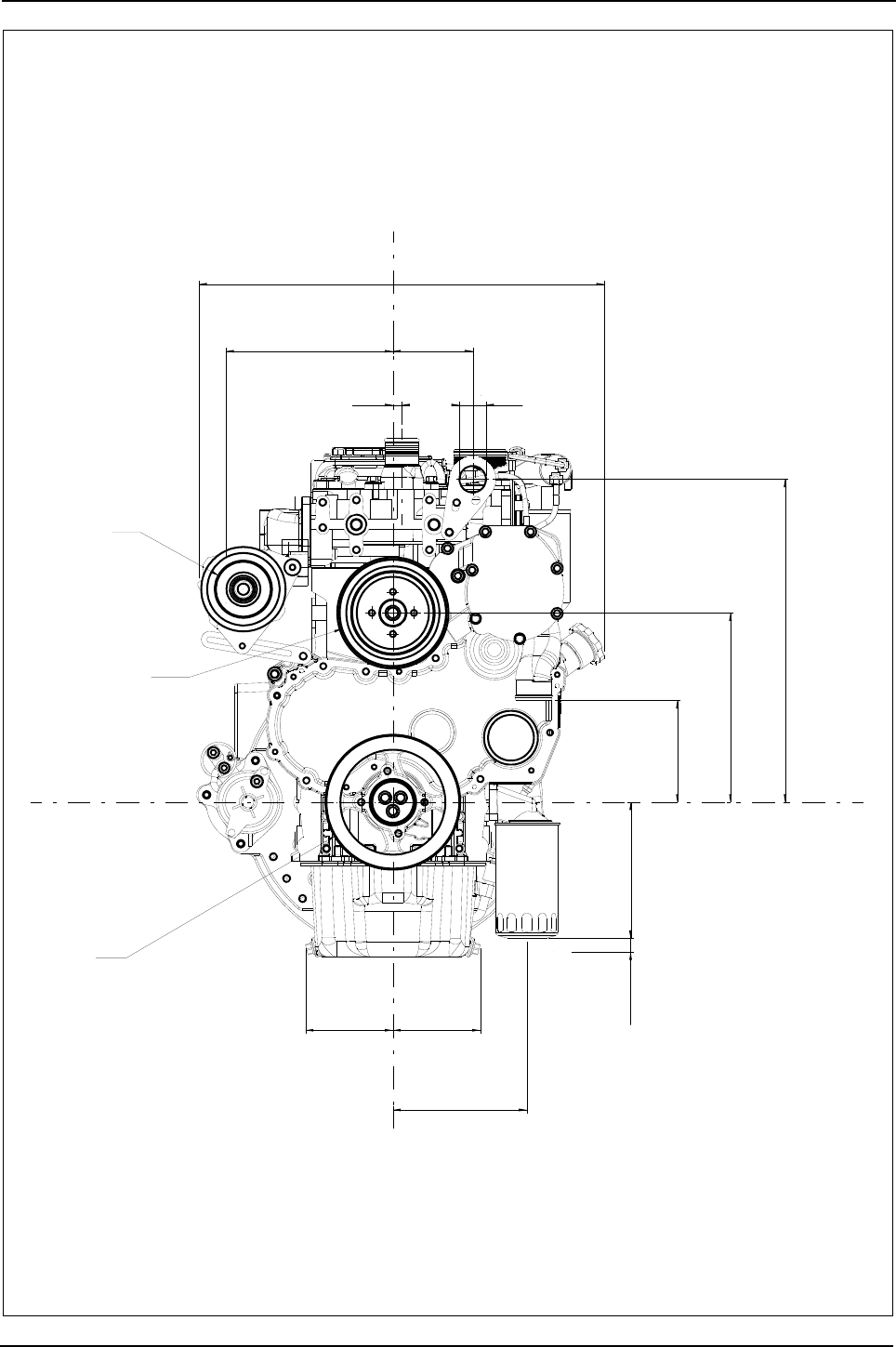
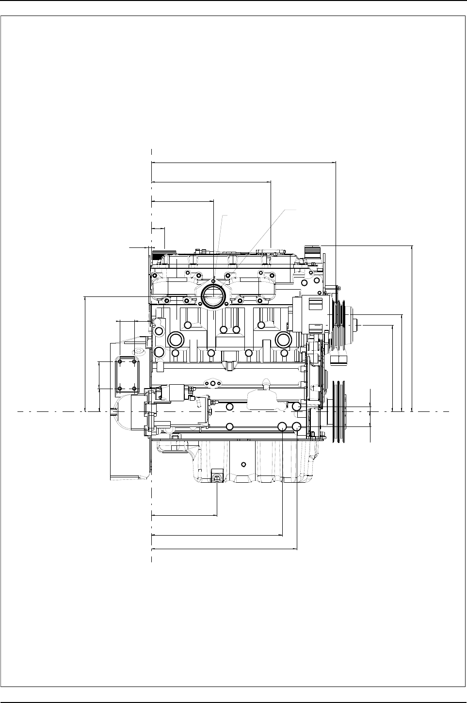
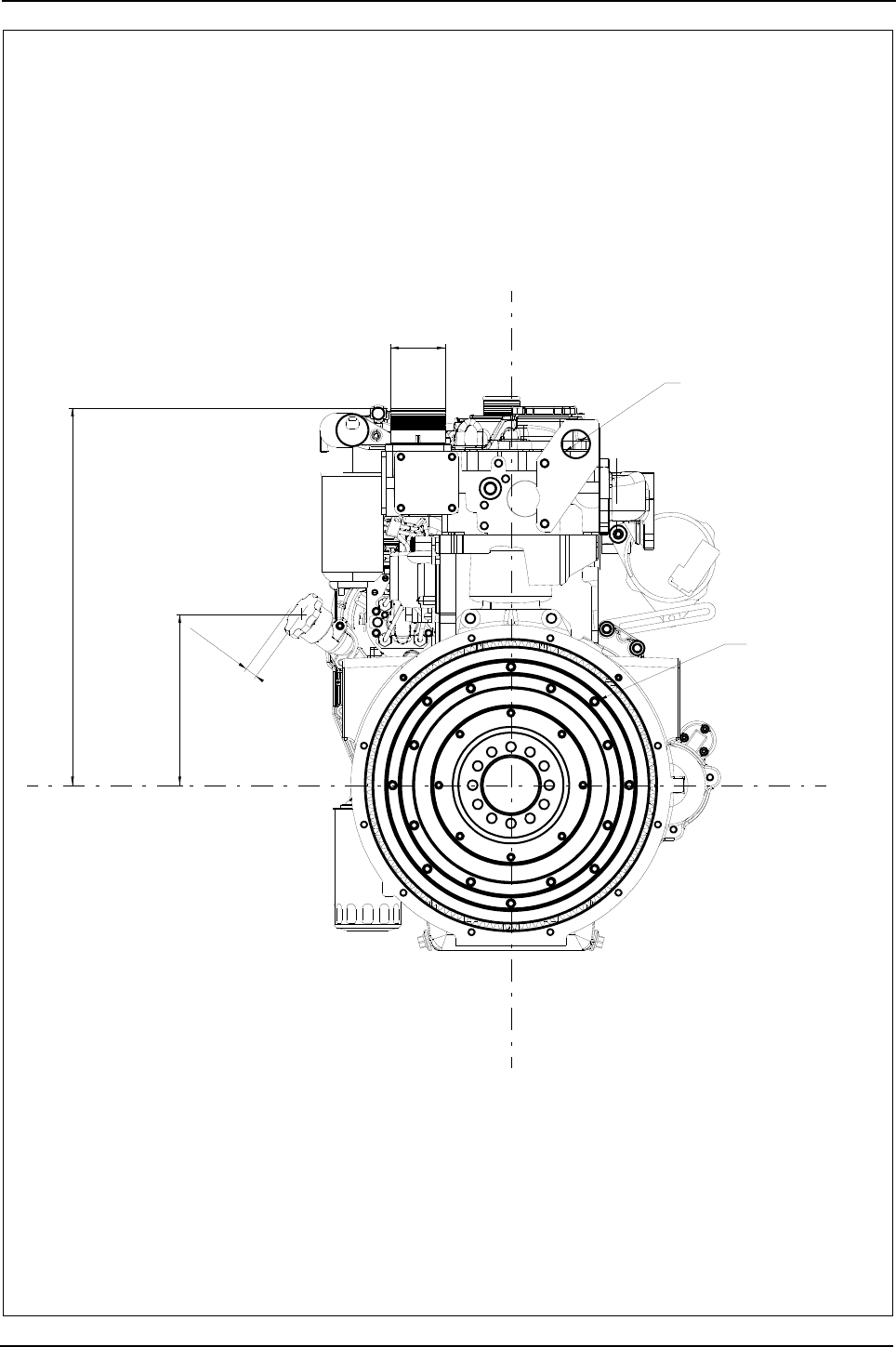
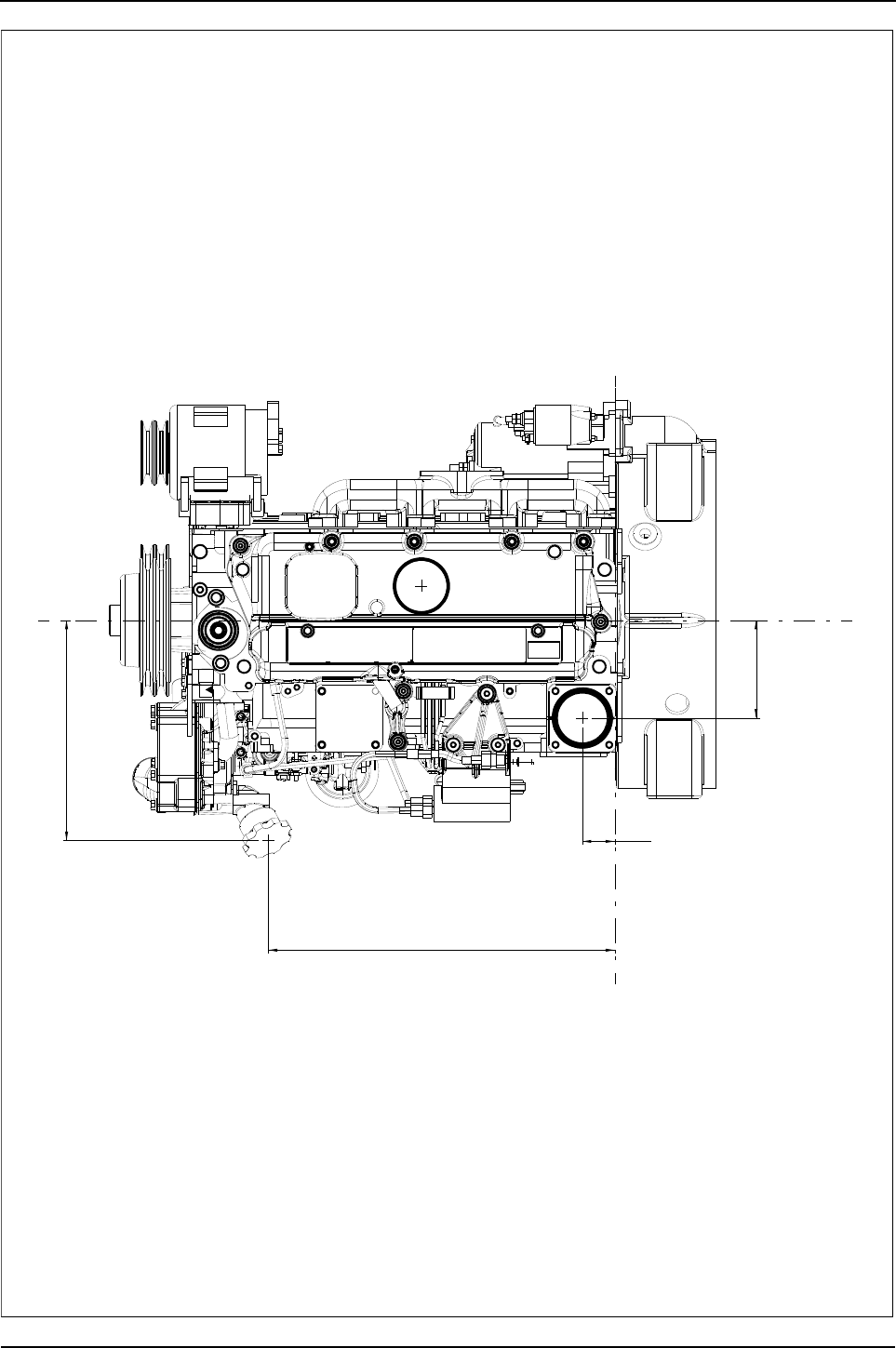
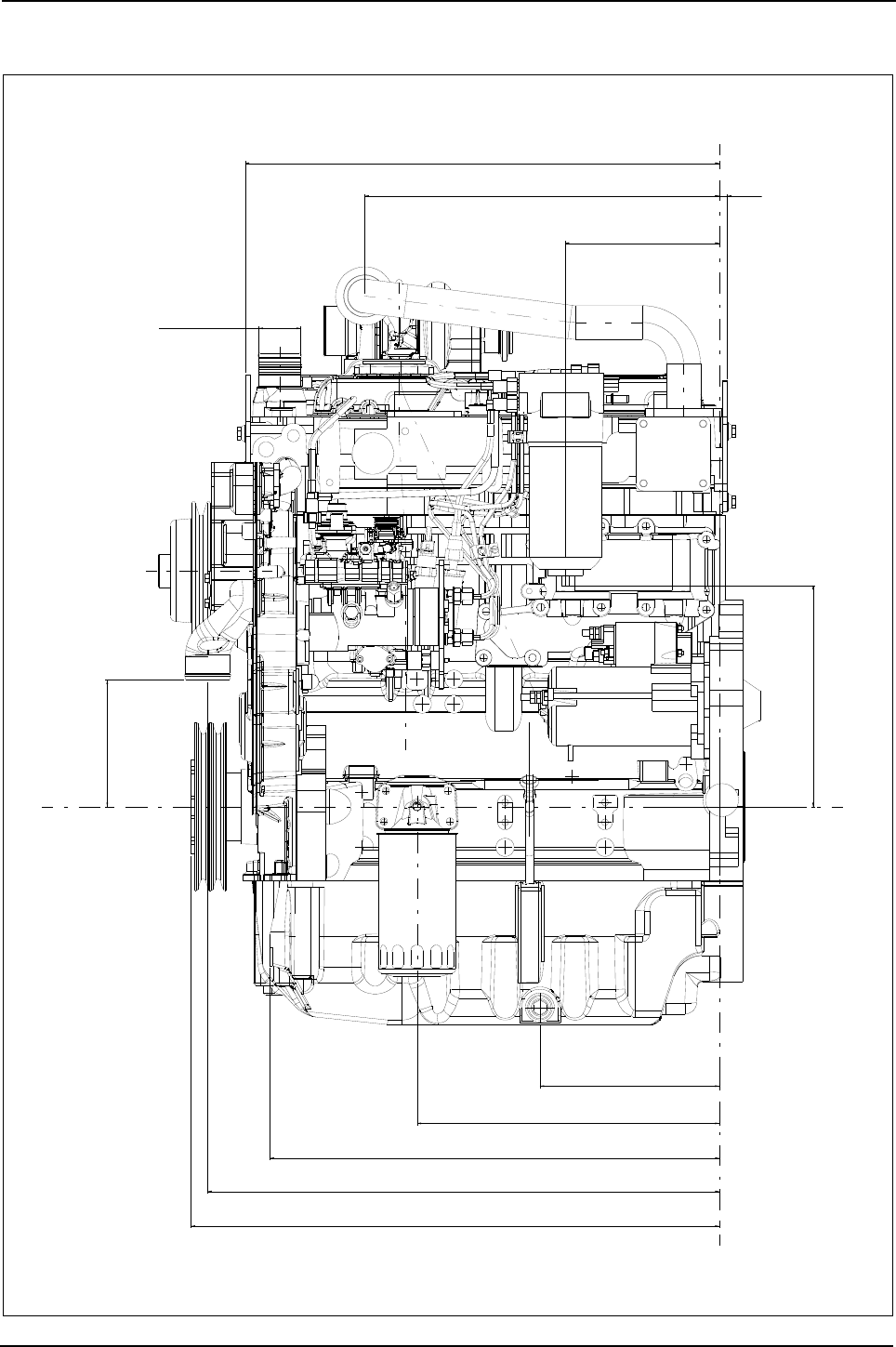
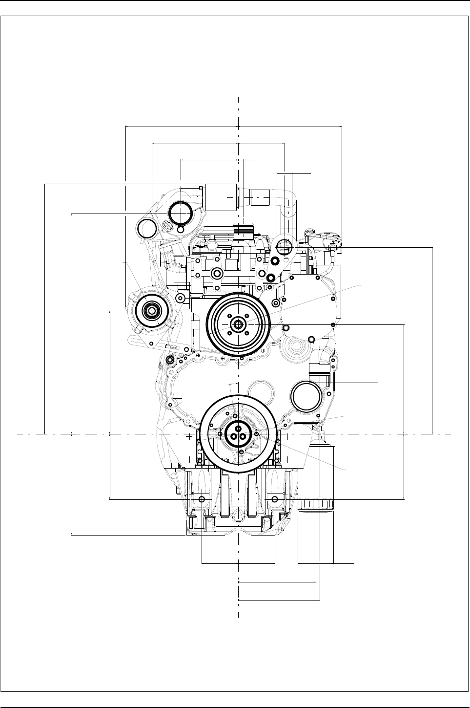
18 Engine Specification Manual, TPD1599 Issue 6, January 2009
1100 Series, 1104D, Mechanical FIE
1104D-44T - Front view
y
z
y
z
320,7
574,8
150,4
652
285
95,395,3
201,9
Ø 94
COOLANT
INLET
Ø 54
211,9
170,4
170,4
263,2
120,2
486,4
269,4
FAN PULLEY
Ø 160 EFFECTIVE
ALTERNATOR
PULLEY Ø 82,5
EFFECTIVE
CRANK PULLEY
Ø 200 EFFECTIVE
225,1
Ø 40
13,5
10°
294
Y
Y
Z
Z
4 HOLES
7/16 -20 UNF
ON 95.3 PCD
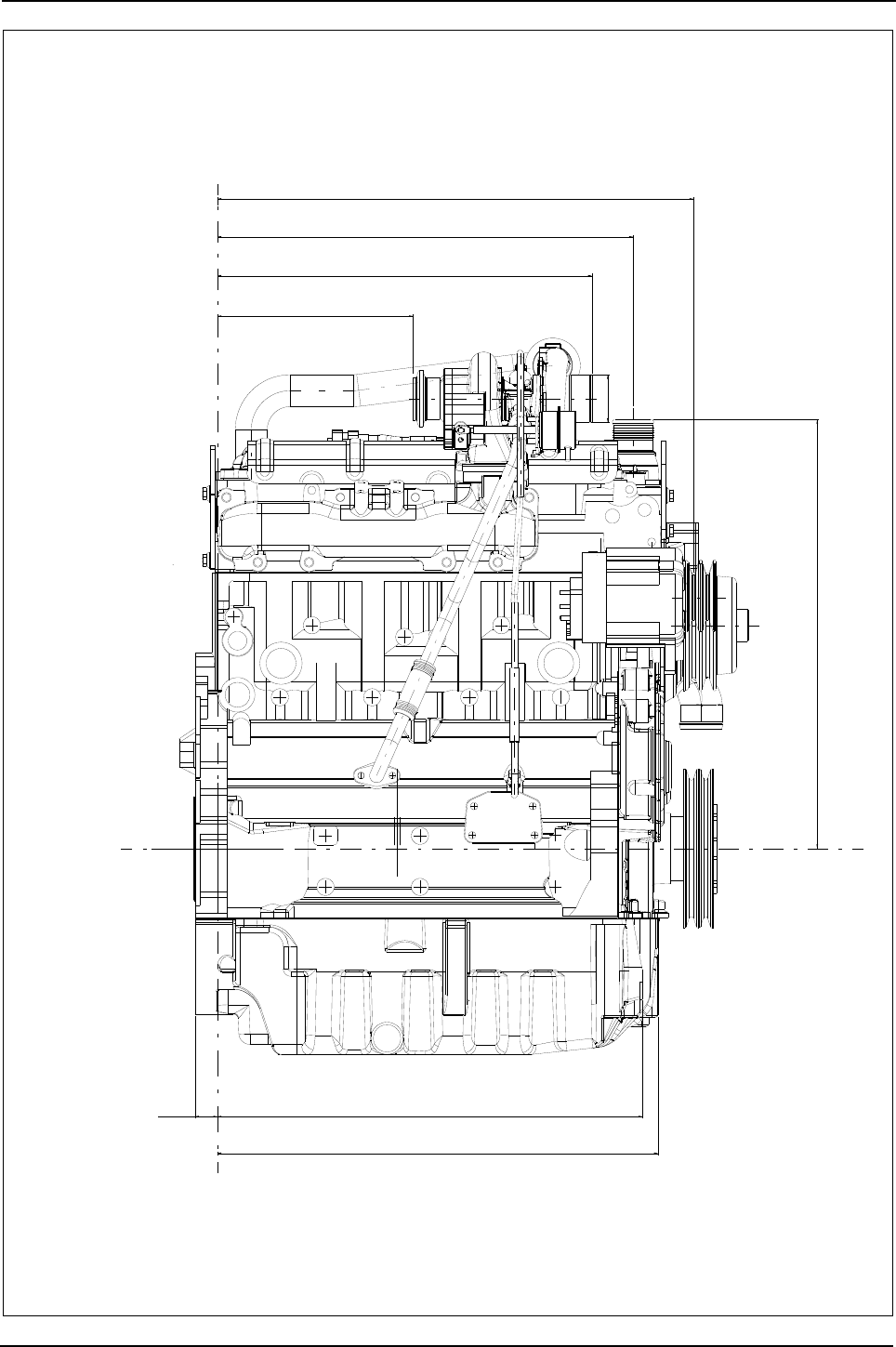
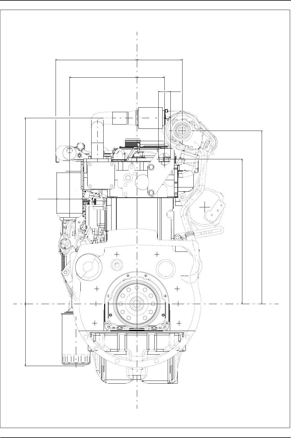
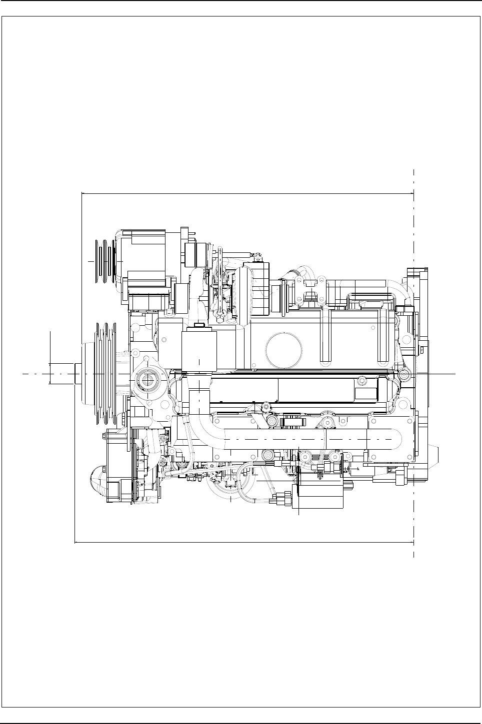
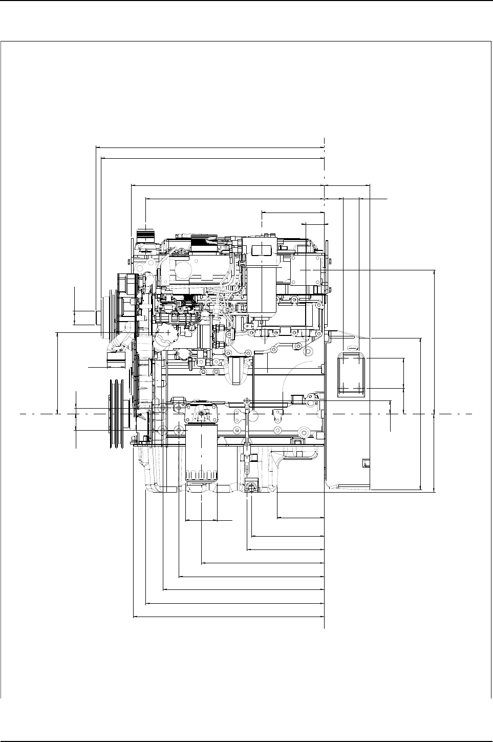
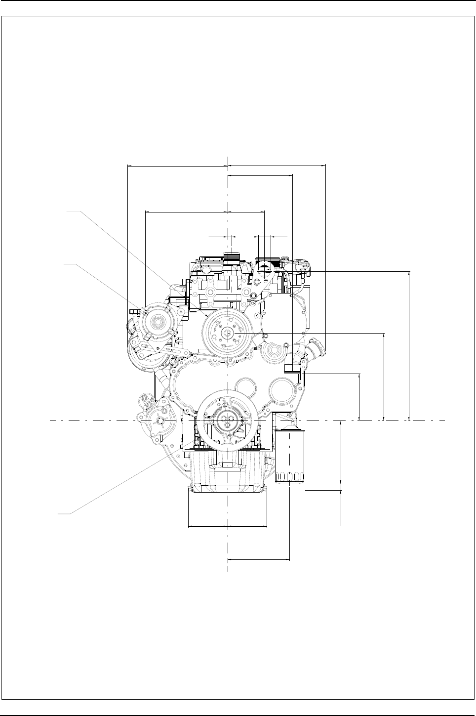
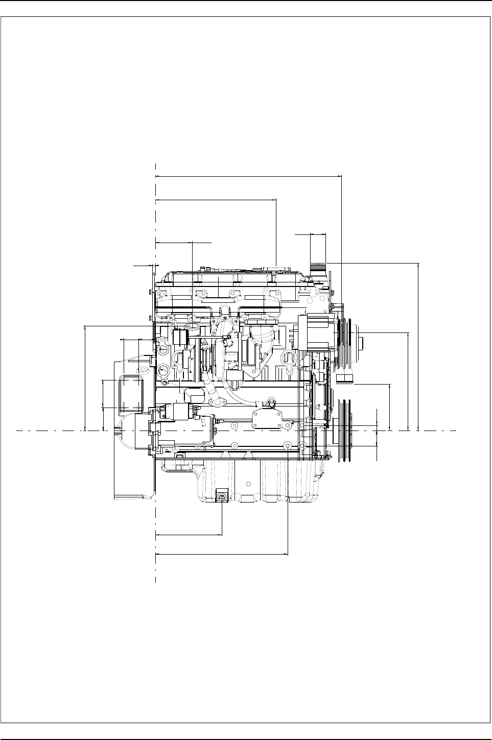
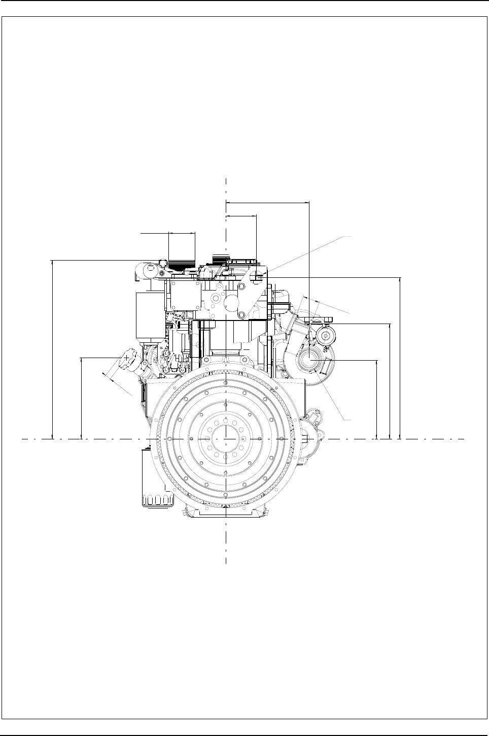
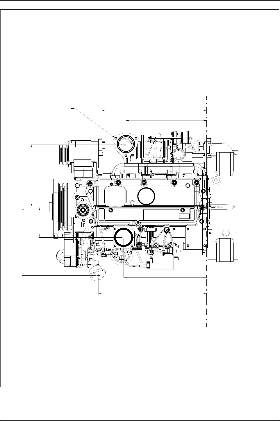

Engine Specification Manual, TPD1599 Issue 6, January 2009 27
4
1100 Series, 1104D, Mechanical FIE
Options 4
Mechanical options
Introduction
This chapter contains all information relating to the options for the 1104D Mechanical FIE engine range.
Before specifying an option read carefully any notes relating to the option as these will indicate any restrictions
if this option is chosen.
Any notes relating to option selection and compatibility are only correct at the date of publication. Be
aware that both product offerings and option compatibilities are subject to change or withdrawal at
any time.

28 Engine Specification Manual, TPD1599 Issue 6, January 2009
1100 Series, 1104D, Mechanical FIE
Maximum intermittent ratings
Naturally aspirated - non-balanced
Naturally aspirated - balanced
Notes:
zAll ratings are available for 12 and 24 volt systems (24 volt systems use a dropper resistor on the Fuel
injection shut off solenoid and the cold start advance
zAll standard mechanical ratings are available with low idles of either 800 or 1000 rev/min, offered in 50 rev/
min increments
zAll ratings to ISO 14396 gross
zFor power curves, see “Power curves” on page 167.
zInlet restriction 3.0 kPa, exhaust back pressure 10 kPa (both at rated speed)
zAll ratings approved to a maximum altitude of 600 metres
zThe 1104D-44 product WILL NOT be certified to EPA Tier 3 emissions legislation
zThe 1104D-44 WILL BE certified to EU Stage IIIA emissions legislation.
Engine type Max. rating kW (bhp)
@ rev/min (1)
1. Intermittent is defined as cyclic power and/or speed, with maximum power being utilised for no more than one
hour in any two hour period and the average load not exceeding the mechanical sign-off of the engine.
Torque Nm
@ rev/min Max. TBU % Power curve Option code
1104D-44 55.9 @ 2200 265 @ 1700 9.05 T2968 A0102
Engine type Max. rating kW (bhp)
@ rev/min (1)
1. Intermittent is defined as cyclic power and/or speed, with maximum power being utilised for no more than one
hour in any two hour period and the average load not exceeding the mechanical sign-off of the engine.
Torque Nm
@ rev/min Max. TBU % Power curve Option code
1104D-44 54.0 @ 2200 261 @ 1700 11.06 T2969 A0104

Engine Specification Manual, TPD1599 Issue 6, January 2009 29
1100 Series, 1104D, Mechanical FIE
Turbocharged - non-balanced
Turbocharged - balanced
Notes:
zAll ratings are available for 12 and 24 volt systems (24 volt systems use a dropper resistor on the Fuel
injection shut off solenoid and the cold start advance
zAll standard mechanical ratings are available with low idles of either 800 or 1000 rev/min, offered in 50 rev/
min increments
zAll ratings to ISO 14396 gross
zAll ratings to EPA Tier 3 and EU Stage IIIA certification
zFor power curves, see “Power curves” on page 167.
zInlet restriction 5 kPa, exhaust back pressure 15 kPa (both at rated speed)
zAll ratings approved to a maximum altitude of 3000 metres unless stated.
Engine type Max. rating kW (bhp)
@ rev/min (1)
1. Intermittent is defined as cyclic power and/or speed, with maximum power being utilised for no more than one
hour in any two hour period and the average load not exceeding the mechanical sign-off of the engine.
Torque Nm
@ rev/min Max. TBU % Power curve Option code
1104D-44T
57,5 @ 2200 309 @ 1400 24.10 T3060 A0202
57,5 @ 2300 309 @ 1400 29.29 T3060 A0216
57,5 @ 2400 309 @ 1400 34.93 T3060 A0201
62.5 @ 2400 354 @ 1400 42.17 T2970 A0203
62.5 @ 2200 354 @ 1400 30.15 T2970 A0204
62.5 @ 2300 354 @ 1400 36.68 T2970 A0218
66.0 @ 2200 370 @ 1400 28.92 T3360 A0214
66.0 @ 2300 370 @ 1400 35.53 T3360 A0215
70.0 @ 2200 392 @ 1400 29.37 T2978 A0205
70.0 @ 2300 392 @ 1400 35.17 T2978 A0220
74.5 @ 2200 392 @ 1400 21.36 T3066 A0223 (2)
74.5 @ 2300 392 @ 1400 26.86 T3066 A0222 (2)
2. Restricted to a maximum altitude of 2,250 m in heavy duty applications.
Engine type Max. rating kW (bhp)
@ rev/min (1)
1. Intermittent is defined as cyclic power and/or speed, with maximum power being utilised for no more than one
hour in any two hour period and the average load not exceeding the mechanical sign-off of the engine.
Torque Nm
@ rev/min Max. TBU % Power curve Option code
1104D-44T
55.5 @ 2200 307 @ 1400 27.39 T3061 A0207
55.5 @ 2300 307 @ 1400 32.90 T3061 A0217
55.5 @ 2400 307 @ 1400 38.91 T3061 A0206
60.5 @ 2400 352 @ 1400 46.06 T2971 A0208
60.5 @ 2300 352 @ 1400 40.24 T2971 A0219
60.5 @ 2200 352 @ 1400 33.84 T2971 A0209
72,0 @ 2300 390 @ 1400 29.57 T3067 A0224 (2)
2. Restricted to a maximum of 2,250 m in heavy duty applications.
72,5 @ 2200 390 @ 1400 23.81 T3067 A0225 (2)
68.0 @ 2200 390 @ 1400 32.20 T2979 A0210
68.0 @ 2300 390 @ 1400 38.30 T2979 A0221

30 Engine Specification Manual, TPD1599 Issue 6, January 2009
1100 Series, 1104D, Mechanical FIE
Turbocharged, air to air charge cooled - non-balanced
Turbocharged, air to air charge cooled - balanced
Notes:
zAll ratings are available for 12 and 24 volt systems (24 volt systems use a dropper resistor on the Fuel
injection shut off solenoid and the cold start advance
zAll standard mechanical ratings are available with low idles of either 800 or 1000 rev/min, offered in 50 rev/
min increments
zAll ratings to ISO 14396 gross
zAll ratings to EPA Tier 3 and EU Stage IIIA certification
zFor power curves, see “Power curves” on page 167.
zInlet restriction 5 kPa, exhaust back pressure 15 kPa (both at rated speed)
zAll ratings approved to an altitude of 3000 metres
zAn 87 kW (unbalanced) rating may be made available in 2008, subject to committed Customer interest.
Please contact NPI Product Marketing (Peterborough) for further details.
Engine type Max. rating kW (bhp)
@ rev/min (1)
1. Intermittent is defined as cyclic power and/or speed, with maximum power being utilised for no more than one
hour in any two hour period and the average load not exceeding the mechanical sign-off of the engine.
Torque Nm
@ rev/min Max. TBU % Power curve Option code
1104D-44TA
70.0 @ 2200 395 @ 1400 T3500 A0326
70.0 @ 2300 395 @ 1400 T3500 A0327
74.5 @ 2200 410 @ 1400 26.54 T3056 A0306
74.5 @ 2200 405 @ 1400 T3496 A0324
74.5 @ 2300 410 @ 1400 32.26 T3056 A0320
74.5 @ 2400 410 @ 1400 38.51 T3056 A0305
83.0 @ 2200 418 @ 1400 16.11 T3058 A0307
83.0 @ 2300 418 @ 1400 21.16 T3058 A0323
Engine type Max. rating kW (bhp)
@ rev/min (1)
1. Intermittent is defined as cyclic power and/or speed, with maximum power being utilised for no more than one
hour in any two hour period and the average load not exceeding the mechanical sign-off of the engine.
Torque Nm
@ rev/min Max. TBU % Power curve Option code
1104D-44TA
68.0 @ 2200 393 @ 1400 T3055 A0328
68.0 @ 2300 393 @ 1400 T3055 A0329
74.9 @ 2200 412 @ 1400 26.77 T2972 A0310
74.9 @ 2200 405 @ 1400 T3499 A0325
81.0 @ 2200 416 @ 1400 18.18 T3059 A0315
81.0 @ 2300 416 @ 1400 23.44 T3059 A0322


Engine Specification Manual, TPD1599 Issue 6, January 2009 33
1100 Series, 1104D, Mechanical FIE
Flywheel housings
Non-stressed cylinder block
Stressed cylinder block
Description Option
Not required, customer to supply housing with LHS starter (1)
1. Incompatible with D0008/D0014/D0048/D0055/D0056/D0062/D0066/D0067/D0068.
C0050
Not required, customer to supply housing with RHS starter C0051
Cast iron SAE 3, 156,4 mm (6.16 in) deep, RHS starter C0001
Cast iron SAE 3, 135,0 mm (5.32 in) deep, RHS starter C0002
Adaptor plate for combine harvesters, RHS starter C0006
Cast iron SAE 3, 135,0 mm (5.32 in) deep, LHS starter (2)
2. Incompatible with J0021/J0060/J0061 when E0301 is selected.
C0010
Cast iron SAE 2, 156,4 mm (6.16 in) deep, LHS or RHS starter (2) (3)
3. Available with RHS starter only E0311 and E0201 only.
C0021
Cast iron SAE 3, 156,4 mm (6.16 in) deep, RHS starter as C0001 less torque convertor access hole C0022
Cast iron SAE 3, 84,0 mm (3.31 in) deep, LHS starter (4) for use as a non sealed housing
4. Compatible with flywheel D0000/D0008/D0014/D0048, incompatible with Q**38 when starter motor selected.
C0026
Cast iron SAE 3, 135,0 mm (5.32 in) deep, RHS starter with adaptor to convert from SAE 3 to SAE 4 C0027
Cast iron SAE 3, 84,0 mm (3.31 in) deep, RHS starter C0030
Cast iron SAE 3, 84,0 mm (3.31 in) deep, RHS starter
as C0030 with different speed sensor tapping and different starter tappings C0031
Cast iron SAE 3, 81,0 mm (3.18 in) deep, LHS starter (2) for use as a non sealed housing C0033
Cast iron SAE 3, 135,0 mm (5.32 in) deep, RHS starter (5)
5. Incompatible with G03**.
C0036
Cast iron SAE 3, 156,4 mm (6.16 in) deep, RHS starter (5) C0037
Description Option
Not required, starter spigot on LHS in block (1)
1. Incompatible with S3171, ZY004/ZY014/ZY024 when LHS starter selected.
C1000

34 Engine Specification Manual, TPD1599 Issue 6, January 2009
1100 Series, 1104D, Mechanical FIE
Flywheel housing design
Note: If a bell housing or similar component is to fitted to a flywheel housing in this chapter, refer to the data
in the table below.
C0001 - Cast iron SAE 3, 156,4 mm (6.16 in) deep
SAE
number
‘A’ diameter mm (in) ‘B’ diameter
mm (in)
‘C’ diameter
mm (in)
Tapped holes
Nominal size Tolerance
-0.000 to Quantity Size mm
3 409,6 (16.125) +0,13 (+0.005) 450,9 (17.75) 428,6 (16.875) 12 10
2 447,7 (17.625) +0,13 (+0.005) 489,0 (19.25) 466,7 (18.375) 12 10
16 HOLE
SPACING
8 HOLE
SPACING
12 HOLE
SPACING
11.25
22.5 22.5
30
45
15 U1015
45°
238,1
starter motor mounting
218
238,1
128,6
ø38,1
- 2 places
228,5
136
160
180
82
115
145
114,3
41,3
156,4
55,647,6
76,288,9
11
62,5
62,5
,562
ø X 4,8 deep
98,48
98,43
ø88,95
88,90
11
11
6-M12 X 1,75
3-M10 X 1,5 X 20
3713M049 flywheel housing View on arrow A
X
Y
Z
Z
2-M10 X 1,5 X 20
drill pattern,
flange and spigot
to No.3 S.A.E
2-M16 X 1,5
1 each side
(plugged)
X
Y
4-M12 X 1,75
both sides
A

Engine Specification Manual, TPD1599 Issue 6, January 2009 35
1100 Series, 1104D, Mechanical FIE
C0002 - Cast iron SAE 3, 135,0 mm (5.32 in) deep
C0006 - Adaptor plate for combine harvesters
30°
135
55,647,6
76,288,9
136
160
180
82
115
145
117
125
238,1 238,1
starter motor mounting
218
233
ø38
11
11
11
62,5
62,5
62,5
ø X 5 DEEP
98,48
98,43
ø88,95
88,90
41
3713K027 flywheel housing
12-M10 X 1,5 X 20
drill pattern
flange pattern
to NO.3 S.A.E.
6-M12 X 1,75
Y
Z
Z
B
4-M12 X 1,75 X 24
both sides
X
X
Y
A
2-M10 X 1,5
1-M10 X 1,5 X 20
View on arrow A
1-M16 X 1,5
View on arrow B
154,5
210,9
50,8
50,8
149
205,3
56,4
154,5
212,7
74,7
159,8
212,7
62,9
62,9
8,8
8,8
ø88,95
88,90
ø X 5 DEEP
98,48
98,43
28,5
25
8,8
62,9
ø409,575
409,448
starter motor mounting
218
3714T052 ADAPTOR PLATE
A
Y
Z
Z
View on arrow A
11-ø11,2
2-M10 X 1,5 X 20
X
X
Y
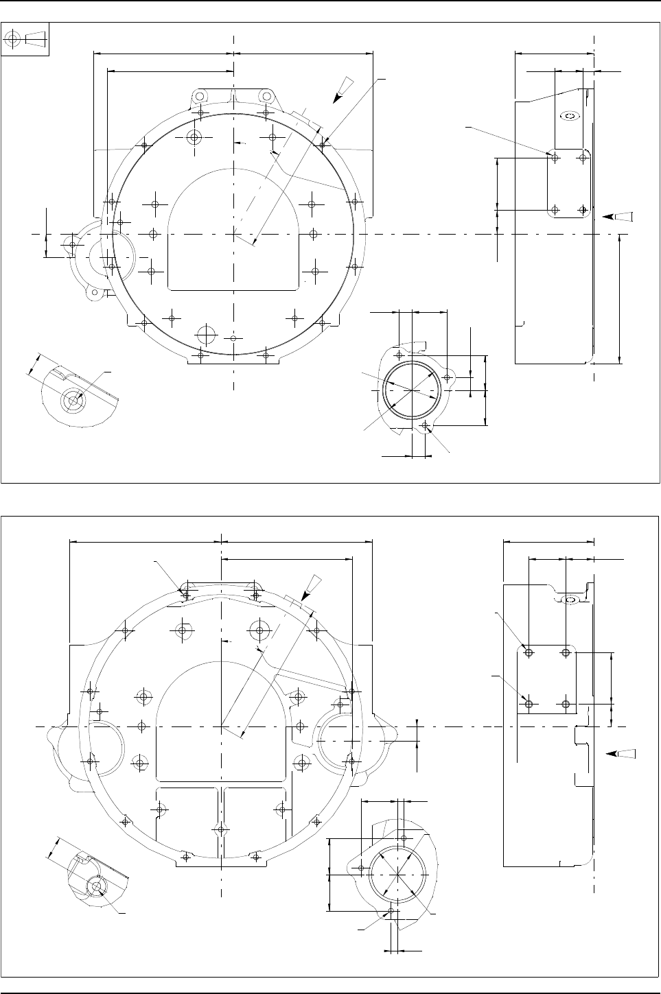
36 Engine Specification Manual, TPD1599 Issue 6, January 2009
1100 Series, 1104D, Mechanical FIE
C0010 - Cast iron SAE 3, 135,0 mm (5.32 in) deep, LHS starter
C0021 - Cast iron SAE 2, 156,4 mm (6.16 in) deep, LHS or RHS starter
30°
39,7
238,1 238,1
starter motor mounting
214,4
233
21,7
59,7
21,7
59,7
21,7 59,7
41,388,9
135
47,6
222,6
41
19,1
ø X 5 DEEP
98,48
98,43
ø88,95
88,90
3713K033 FLYWHEEL HOUSING
12-M10 X 1,5 X 20
drill pattern
FLANGE AND SPIGOT
TO NO.3 S.A.E.
Z
Z
Y
4-M12 X 1,75 X 24
BOTH SIDES
Y
X
X
A
View on arrow A
B
3-M10 X 1,5
VIEW ON ARROW B
M16 X 1,5
PLUGGED
30°
63,5
156,4
48,4
38,188,9
62,5
62,5
11
1162,5
ø88,95
88,90
ø X 5-deep
98,48
98,43
25,4
,4260260,4
41
252
,1
Starter motor pocket
226
Z
Y
Z
3713W016 flywheel housing
12-M10 X 1,5 X 20
drill pattern
flange and spigot
TO NO.2 S.A.E. B
2-M12 X 1,75
both sides
2-M12 X 1,75 X 24
both sides
X
Y
X
A
3-M10 X 1,5
View on arrow A
M16 X 1,5
plugged
View on arrow B
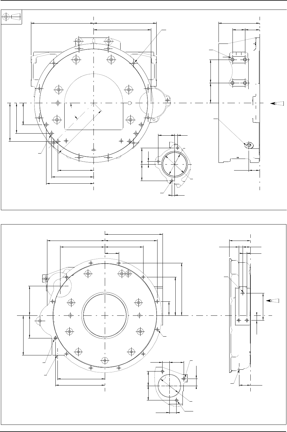
Engine Specification Manual, TPD1599 Issue 6, January 2009 37
1100 Series, 1104D, Mechanical FIE
C0022 - Cast iron SAE 3, 156,4 mm (6.16 in) deep, RHS starter
C0026 - Cast iron SAE 3, 84,0 mm (3.31 in) deep, LHS starter
136
160
180
82
115
145
238,1 238,1
starter motor mounting
218
45°
2-PLACES
228,5
62,5
62,5
62,5
11
11
11
ø
88,95
88,90
ø X 4,8 DEEP
98,48
98,43
55,647,6
156,4
76,288,9
41,3
3713M048 FLYWHEEL HOUSING
A
6-M12 X 1,75
12-M10 X 1,5 X 20
drill pattern
FLANGE AND SPIGOT
TO NO.3 S.A.E.
Y
Z
Z
4-M12 X 1,75
BOTH SIDES
2-M16 X 1,5
1 EACH SIDE
(PLUGGED)
X
Y
X
View on arrow A
3-M10 X 1,5 X 20
19,1
38,1
84,1
30,215,9
55,5
151,5
207
55,5
151,5
207
starter motor mounting
176,5
228,6
116,8
88,9
157,2
195
187,3
27,8 57,1
57,1
27,8
27,8
57,1
ø88,95
88,90
108
15,9
228,6
A_151
A_210
Flywheel housing
Z
Y
Z
A
11-3/8-24 UNF X 25,4
holes spaced as for 12
equi-spaced. flange and
spigot to suit No.3 S.A.E.
3/4-14 NPSI
(plugged)
3/8-24 UNF X 15,9
3-3/8-24 UNF X 19
both sides
1/2-14 NPSI
X
Y
X
View on arrow A
2-M10 X 1,5 X 20
M10 X 1,5

38 Engine Specification Manual, TPD1599 Issue 6, January 2009
1100 Series, 1104D, Mechanical FIE
C0027 - Cast iron SAE 3, 135,0 mm (5.32 in) deep, RHS starter, with adaptor to convert from SAE 3 to
SAE 4
238,1 238,1
starter motor mounting
218
136
160
180
82
115
145
117
125
ø38
154
55,6 47,6
11
11
62,5
62,5
62,5
11
ø88,95
88,90
ø X 5-deep
98,48
98,43
76,288,9
41
30°
3713K027 flywheel housing 3714M011 adaptor plate
12-M10 X 1,5 X 12,7
drill pattern
flange pattern
to No.4 S.A.E.
6-M12 X 1,75
Z
Y
Z
View on arrow B
B
4-M12 X 1,75 X 24
both sides
Y
X
X
A
View on arrow A
2-M10 X 1,5
1-M10 X 1,5 X 20
1-M16 X 1,5

Engine Specification Manual, TPD1599 Issue 6, January 2009 39
1100 Series, 1104D, Mechanical FIE
C0030 - Cast iron SAE 3, 84,0 mm (3.31 in) deep, RHS starter
C0031 - Cast iron SAE 3, 84,0 mm (3.31 in) deep, RHS starter
238,1 238,1
125 218
136
160
180
82
115
145
45°
228,5
76,288,9
14,347,6
84,1
41,3
63,5
63,5
63,5
ø
88,95
88,90
ø X 5-deep
98,48
98,43
117
ø 38,1
3713K065 flywheel housing
12-M10 X 1,5 X 20
drill pattern,
flange and spigot
to No.3 S.A.E.
6-M12 X 1,75
Z
Z
Y
M16 X 1,5
(plugged)
X
Y
X
4-M12 X 1,75
both sides
A
View on arrow A
3-M10 X 1,5 X 20
125
238,1 238,1
218
228,5
11
11
62,5
11
62,5
62,5
ø88,95
88,90
ø X 5 deep
98,48
98,43
45°
ø38,1
14,3 47,6
84,1
41,3
88,9
117
248
82
115
145
136
160
180
76,2
3713K066 flywheel housing
12-M10 X 1,5 X 20
drill pattern,
flange and spigot
to No.3 S.A.E.
6-M12 X 1,75
Z
Y
Z
Y
View on arrow A
3-M10 X 1,5 X 20
M20 X 1,5
(plugged)
4-M12 X 1,75
both sides
X
X

40 Engine Specification Manual, TPD1599 Issue 6, January 2009
1100 Series, 1104D, Mechanical FIE
C0033 - Cast iron SAE 3, 81,0 mm (3.18 in) deep, LHS starter
C0036 - Cast iron SAE 3, 135,0 mm (5.32 in) deep, RHS starter
235
207
55,5
151,5
55,5
151,5
207
214,7
38,1
62,6
10,8
62,6
62,6
10,8
10,8
ø88,95
88,90
15,9 50,8
69,163,5
235
Flywheel housing
11-3/8-16 UNC X 22 DEEP
holes spaced as for 12
equi-spaced
XZ
Z
Y
4-1/2-13 UNC X 22
both sides
Y
X
View on arrow A
A
150 85
40
80
55 60
135
,1563
,15
63,15
63
ø88,95
88,90
41
starter motor mounting
215,9
30°
233
232
6,61
6,61
6,61
both sides245
30
230
50
60
3713K114 flywheel housing
B
12-M10 X 1,5 X 20
drill pattern,
flange and spigot
to No.3 S.A.E
Z
Y
Z
c
A
4-M12 X 1,75 X24
both sides
X
X
Y
3-M10 X 1,5 X 20
View on arrow B
4-M12 X 1,75 X 24
View on arrow C
Z
Z
M22 X 1,5
(plugged)
View on arrow A
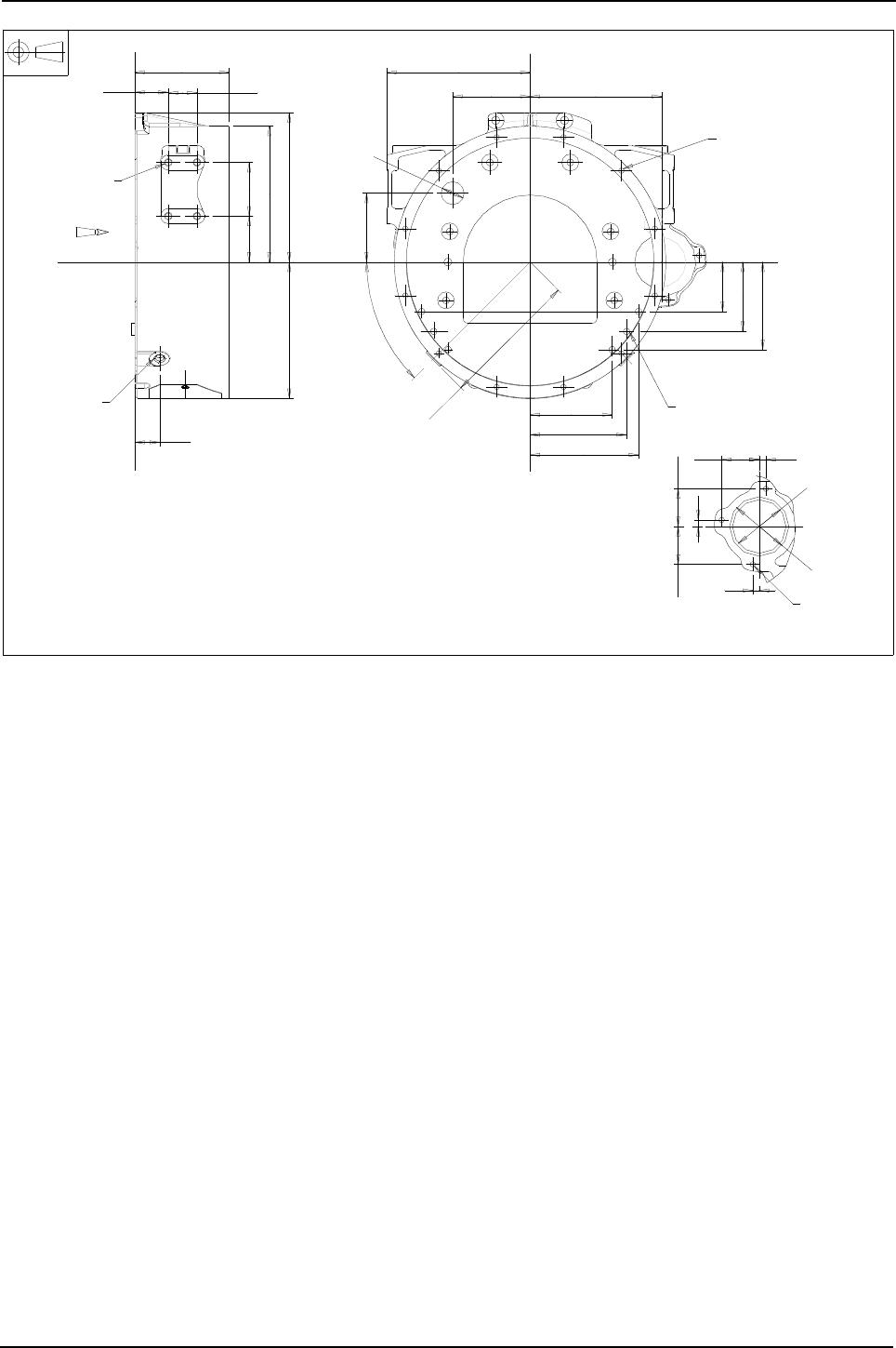
Engine Specification Manual, TPD1599 Issue 6, January 2009 41
1100 Series, 1104D, Mechanical FIE
C0037 - Cast iron SAE 3, 156,4 mm (6.16 in) deep, RHS starter
starter motor
218,1
228,5
both sides238
156,4
248226,4
55,6 47,6
225,5
76,2 88,9
41,3
11
11
62,5 62,5
11
82
115
145
180
160
136
114,3
128,6
ø 38,1
45°
62,5
ø88,95
88,90
ø98,48
98,43
3713M052 housing flywheel
12 - M10 x 1,5 x 20 equispaced
A
Y
Z
Z
6 - M12 x 1,75
2 - M16 x 1,5
Y
X
X
4 - M12 x 1,75
3 - M10 x 1,5
View on arrow A
drilled pattern flanged
and spigot PTO No. 3 S.A.E
x 20
(plugged)
both sides

42 Engine Specification Manual, TPD1599 Issue 6, January 2009
1100 Series, 1104D, Mechanical FIE
Flywheels
Non-stressed cylinder block
Notes:
zThe masses and inertias shown on the drawings are for the flywheel only. Take the mass and inertia of all
starter rings to be 1,82 kg (4 lb) and 0,073 kg m² (250 lb in²) respectively
zAll the flywheels listed above are fitted with 126 tooth starter ring, except where indicated.
Description Option
Not required D0000
For Centaflex couplings (1)
1. Incompatible with C0026.
D0003
For SAE, Borg and Beck, twin disc clutches without pilot bearing housing D0004
As D0004 but with pilot bearing housing D0005
For 12/13 in American Borg and Beck clutches D0006
For Clark 18000 torque converters D0008
For Borg Warner torque converters D0014
Non stressed flywheel "for 10 SAE light" D0022
For Allison AT545 transmission D0030
For SAE transmissions D0044
For Spicer transmissions D0045
For hydrostatic transmissions D0046
For wet backend, 122 tooth starter ring (2)
2. For use with flywheel housing C0026 only E0000/E0012/E0311 only, G10**/G06** only.
D0048
For ZF auto transmissions D0052
For various transmissions D0053
For customer transmissions D0061
For customer transmissions D0063
For customer transmissions D0064
For ZF115 transmissions D0070
For use with ZFWG9 transmissions D0092

Engine Specification Manual, TPD1599 Issue 6, January 2009 43
1100 Series, 1104D, Mechanical FIE
Stressed cylinder block
Notes:
zThe masses and inertias shown on the drawings are for the flywheel only. Take the mass and inertia of all
starter rings to be 1,82 kg (4 lb) and 0,073 kg m² (250 lb in²) respectively
zAll the flywheels listed above are fitted with 115 tooth starter ring, except where indicated.
D0000 - Crankshaft palm
Description Option
Not required D0000
For Borg Warner torque converters D0014
For customer transmissions D0055
For customer transmissions D0056
For customer transmissions D0062
For customer transmissions D0063
For customer transmissions D0065
For customer transmissions D0066
For customer transmissions D0067
For customer transmissions D0068
For customer transmissions D0069
Crankshaft to flywheel fixing
Crankshaft palm
Y
133,27
133,32
Ø
30°
10 Bolt fixing
X2X
22,2Ø
30°
30°
30°
30°
10 holes ½ - 20 UNF X 19 ON 107,95 P.C.Ø.
34,48
35,92
Y
55,6
1,02 Max
38,1Ø
76,2Ø
46,96
46,99
Ø
XX2
28,6
0,8 x 60°Incl
11,5 X 25,4 Ø
20,6
22,2
Z
Z
D0000

44 Engine Specification Manual, TPD1599 Issue 6, January 2009
1100 Series, 1104D, Mechanical FIE
D0003 - For Centaflex couplings
D0004 - For SAE, Borg and Beck, twin disc
Flywheel 31221323, starter ring 126 tooth 31162121, (assembly 41117313)
&&&&D0003
YY
X
Z
Z
Mass 31,98 kg
Inertia mk² 0,63 kg m²
GD2 2,52 kg m ²
54,3
63
81,6
32,8
15°
45°
15°
15°
X
Ø 260,4
Ø 336,6
Ø 387,4
Ø 50,8
a
a
a
a
a
a
6 - 'a' M16 x 2 x 32
on 165,1 P.C.D.
b
b
bb
b
b
6 - 'b' M12 x 1,75 x 2
equispaced on 165,1 P.C.D.
Ø136,04
136,00
A1060
203,2 P.C.DIA.
EQUISPACED ON
8-M8 X 1,25 X 14,3
333,38 P.C.DIA.
EQUISPACED ON
-24UNF X 25,4
8
3
8-
295,28 P.C.DIA.
EQUISPACED ON
-24UNF X 25,4
8
3
8-
219,037
219,139
79,356
79,413
X
X
Z
Z
Y
Y
2
kgm
4,56
2
GD
2
1,14 kgm
2
mkINERTIA
kg
MASS 48,0
120,2
102,7
70,9
54,2
117
80,4
67,7
32,8
164
225
Ø
390
352,425
352,552
314,325
314,401
276
Ø
Ø
Ø
Ø
Ø
Ø
Ø
Flywheel 3122E134, starter ring 126 tooth 31162121, (assembly 4111D128)

Engine Specification Manual, TPD1599 Issue 6, January 2009 45
1100 Series, 1104D, Mechanical FIE
D0005 - As D0004 but with pilot bearing housing
D0006 - For 12/13 in American Borg and Beck clutches
Flywheel 3122E134, with pilot housing 3743H011, starter ring 126 tooth 31162121, (assembly 4111D128)
Ø 276
Ø314,401
314,325
Ø352,552
352,425
Ø 390
Ø 225
Ø 164
Ø71,984
71,958
102,7
117
120,2
67,7
32,8
56,6
86,8
Y Y
Z
Z
X
70,9
80,4
X
54,2
Mass 49,7 kg
Inertia mk² 1,31 kg m²
GD² 5,25 kg m²
Ø219,139
219,037
8- 3
8-24UNF x 25,4
equispaced on
333,38 P.C.D.
8- 3
8-24UNF x 25,4
equispaced on
295,28 P.C.D.
8-M8 x 1,25 x 14,3
equispaced on
203,2 P.C.D.
YB&&D0005B
A
A
68,5
32,8
50,3
45,5
35,2
171,45
376,8
76,2
51,984
51,966
FLYWHEEL MASS = 29,33 kg
FLYWHEEL AND STARTER RING MASS = 27,52 kg
FLYWHEEL INERTIA mk2 = 0,56 kgm2
GD 2 = 2,24 kgm2
FLYWHEEL AND STARTER RING INERTIA mk² = 0,63 kgm²
GD² = 2,52 kgm²
31221591 FLYWHEEL 31162121 STARTER RING 41117203 FLYWHEEL ASSEMBLY
X
X
Y
SECTION A-A
Y
Z
Z
8- 8,5 X 28,6
3/8-24UNF X 23,8
9,56 X 5,6
358,78 PCD
8- 8,5 X 28,6
3/8-24UNF X23,8
9,56 X 5,6
342,90 PCD
12- 13,5
EQUISPACED

46 Engine Specification Manual, TPD1599 Issue 6, January 2009
1100 Series, 1104D, Mechanical FIE
D0008 - For Clark 18000 torque converters (non stressed)
D0014 - For Borg Warner torque converters (non stressed)
Ø384
Ø305
Ø
A1063
32,8
X
X
Y
Y
Z
Z
51,2
5
1
,
9
6
7
5
1
,
9
8
6
EQUI-SPACED ON A 342,9 P.C.D.
25,4 X 4,8Ø11 C/BORED Ø8-
68,7
2
kg m
1,71
2
GD
2
0,43 kg m
2
mkINERTIA
kg
MASS 19,88
Flywheel 3122A032, starter ring 126 tooth 31162121 (assembly 411D127)
Flywheel 3122A051, starter ring 126 tooth 31162121 (assembly 4111D078)
Y
X
X
Z
Z
Y
2
kg m 1,89
2
GD
2
kg m 0,47
2
mk Inertia
kgMass 23,2
19,063
19,088
Ø
70,3
32,8
68,80
69,06
62,6
54,2
384Ø
266,7Ø
303Ø
38Ø
A
319,09 P.C.Dia.
equispaced on
6-5/16 - 18 UNC X 19

Engine Specification Manual, TPD1599 Issue 6, January 2009 47
1100 Series, 1104D, Mechanical FIE
D0014 - For Borg Warner torque converters (stressed)
D0022 - Non stressed flywheel "for 10 SAE light"
D0014
Flywheel 3121H041, starter ring 115 tooth, 0410236 (assembly 4111D062) A1360
Ø19,088
Ø19,063
Z
Z
Mounting face for
starter motor
Y Y
Ø 266,7
Ø 38
X2
X2
6 - 5/16 - 18 UNC x 22
equi-spaced on 319.1 P.C.D.
34
Ø 303
Ø 352.4
35.4
27.6
19.6
32.8
21.2
14.8
Mass 22,6 kg
Inertia mk² 0,43kgm²
GD² 1,72 kgm²
Drawing not available at time of print

48 Engine Specification Manual, TPD1599 Issue 6, January 2009
1100 Series, 1104D, Mechanical FIE
D0030 - For Allison AT545 transmissions
D0044 - For SAE transmissions
Drawing not available at time of print
on 333,4 P.C.DIA.
-24UNF X 25,4 equispaced
8
3
8
3122E136 flywheel, 31162121 starter ring.
352,425
352,552
Ø
32,8
YY
Z
Z
X
X
79Ø
120,2
117
102,7
67,7
80,4
54,2
314Ø
390Ø
276Ø
225Ø
164Ø

Engine Specification Manual, TPD1599 Issue 6, January 2009 49
1100 Series, 1104D, Mechanical FIE
D0045 - For Spicer transmissions
D0046 - For hydrostatic transmission
kgMass 23,3
2
kg m 1,89
2
GD
2
kg m 0,47
2
mk Inertia
X
X
Z
Z
YY
3122A141 flywheel 31162121 Starter ring
360 P.C.DIA.
equispaced on
8-M8 X 1,25 X 16
61,8Ø
384Ø
266,7Ø
344Ø
69,49
71,19
32,8
64
55,6
Ø
Ø
Ø
Ø
Ø
Ø
A1069
295,28 P.C.DIA.
EQUISPACED ON
8-3/8-24UNF X 25
80
117,2
32,8
2
m
kg
3,84
2
GD
2
mkg0,96
2 mk
INERTIA
kg
MASS 42
89,2
81,2
67,2
54,2
165
225
314,325
314,401
390
316
Y
X
X
Z
Z
Y
Flywheel 31227135, starter ring 126 tooth 31162121, (assembly 41117321)
A&&&D0046
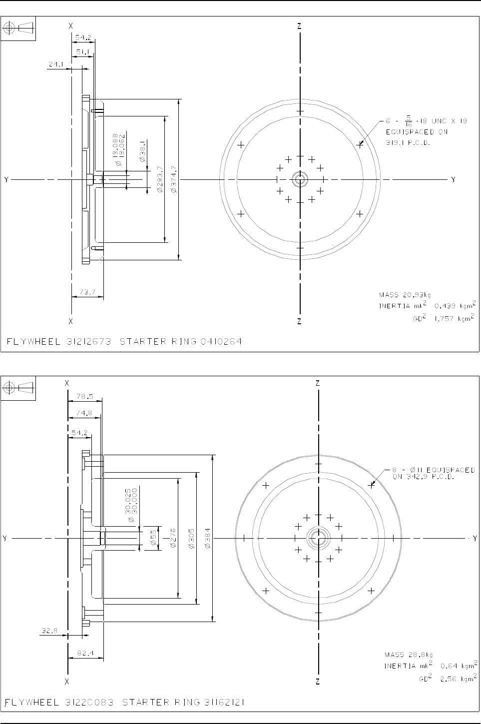
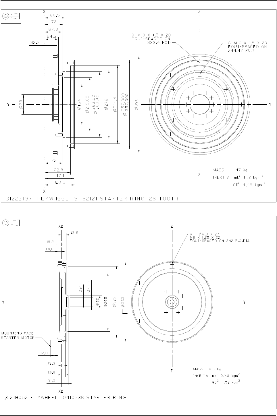
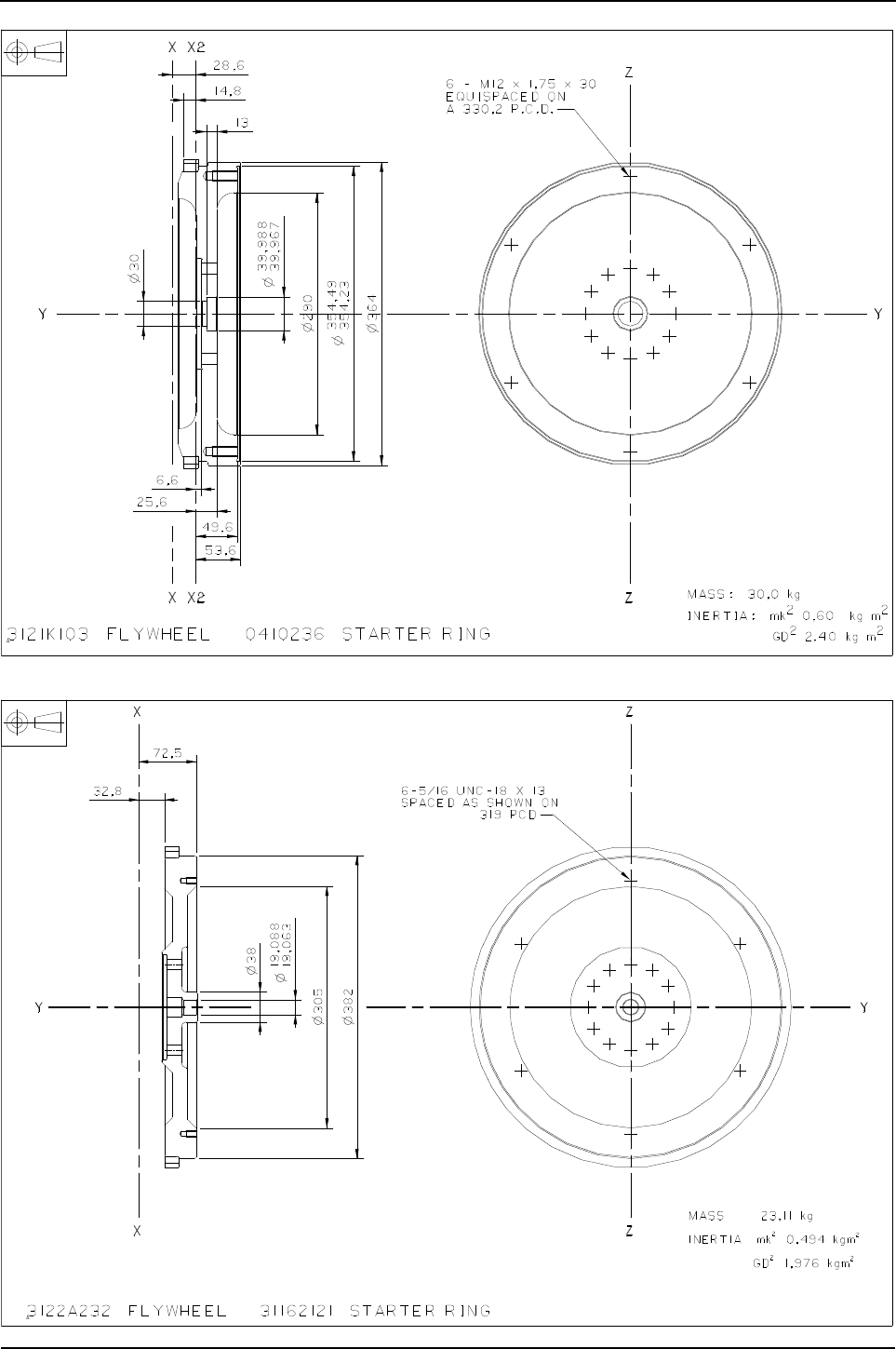
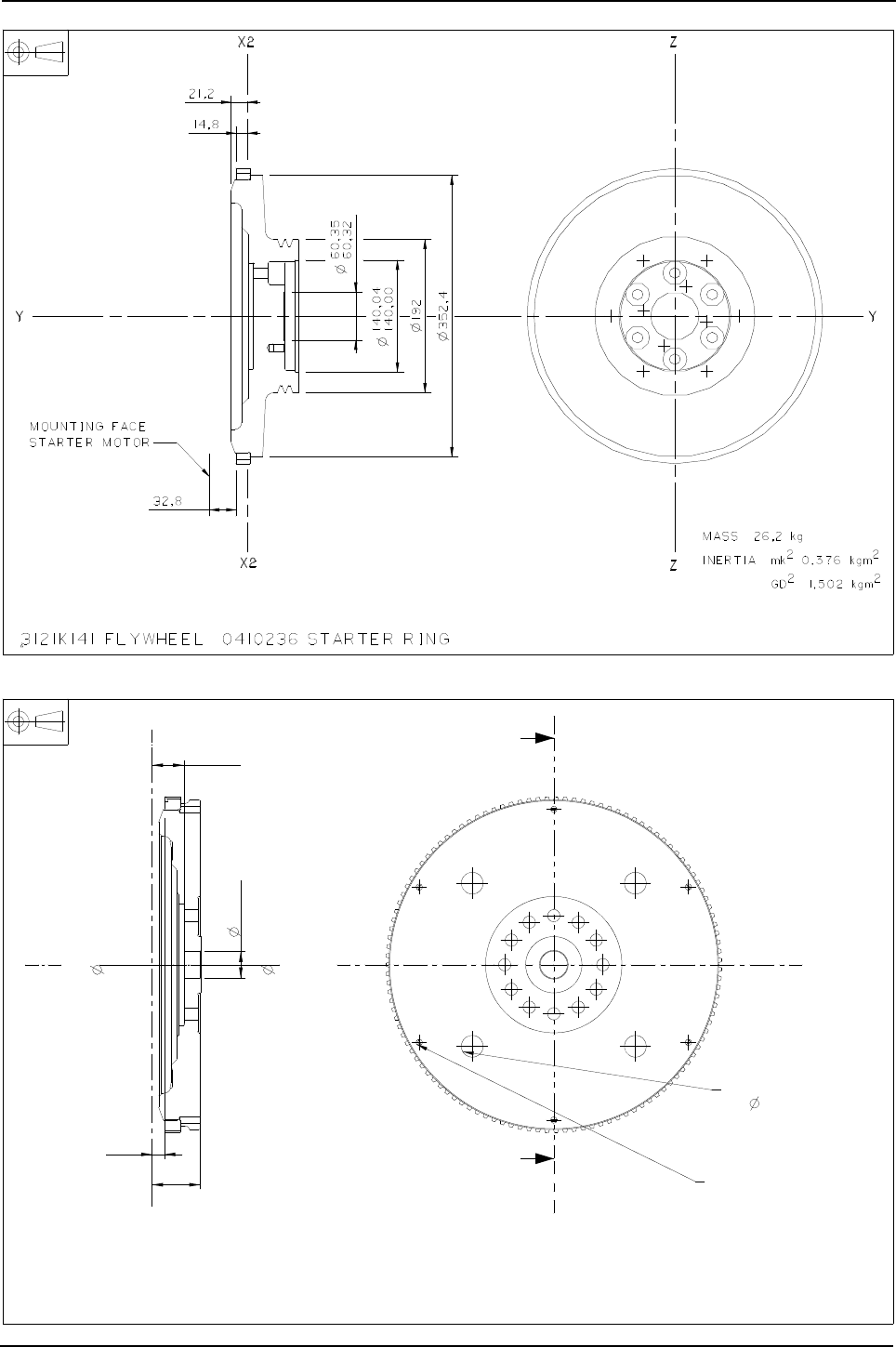
Engine Specification Manual, TPD1599 Issue 6, January 2009 53
1100 Series, 1104D, Mechanical FIE
D0062 - For customer transmission
D0063 - For customer transmission
Flywheel mass = 21,95 kg
Flywheel and stater ring mass = 23,66 kg
Flywheel inertia mk² = 0,40 kgm²
GD² = 1,62 kgm²
Flywheel and starter ring inertia mk² = 0,45 kgm²
GD² = 1,80 kgm²
A
A
35,2
52,9
30,036
30,034
0
0
13,7
3121H063 FLYWHEEL 0410236 STARTER RING 4111D277 FLYWHEEL ASSEMBLY
Z
Z
Y
6-M8 X 1,25 X 19
EQUISPACED ON 342 P.C.D.
C/BORE
4 - 24 X 12
EQUISPACED ON 254 PCD
SECTION A-A
X
X
Y
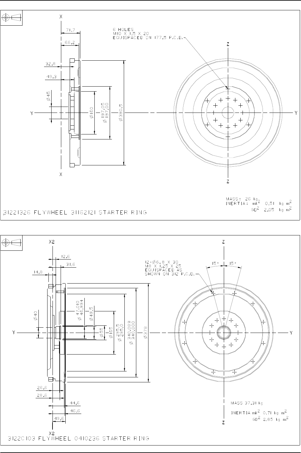
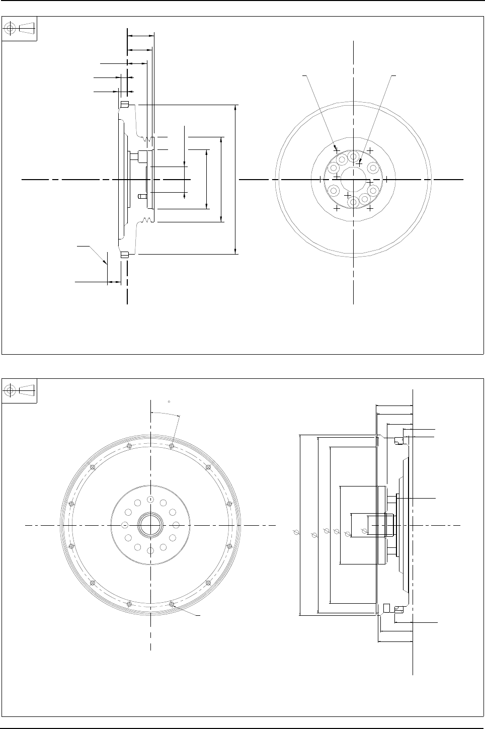
Engine Specification Manual, TPD1599 Issue 6, January 2009 55
1100 Series, 1104D, Mechanical FIE
D0066 - For customer transmission
D0067 - For customer transmission
46,6
58,8
63,8
4 - M10 x 1,0 x 15
6 - M10 x 1,5 x 15
starter motor
Mounting face
32,8
352,4Ø
21,2
14,8
140,00
140,04
Ø
60,32
60,35
Ø
200Ø
2
1,528 kgm
2
GD
2
0,382 kgm
2
Inertia mk
kgMass 26,8
X2
X2
YY
Z
Z
3121K133 flywheel 0410236 starter ring
15
78,2
75,2
9,2
68,5
73,2
54,2 20,7
38,2
35,2
381
370,2
370,0
330
165
49,5
40
FLYWHEEL MASS= 36.69 kg
FLYWHEEL AND STARTER RING MASS= 38.40 kg
FLYWHEEL INERTIA, mk² = 0.70 kgm²
FLYWHEEL INERTIA, GD² = 2.80 kgm²
FLYWHEEL AND STARTER RING INERTIA, mk² = 0.75 kgm²
FLYWHEEL AND STARTER RING INERTIA, GD² = 3.00 kgm²
12-M8 X 1.25 X 20
EQUISPACED ON 345 PCD
3122C161 FLYWHEEL 0410236 STARTER RING 115 TOOTH FLYWHEEL ASSEMBLY 4111D306
Z
Z
Y
X
X
Y

56 Engine Specification Manual, TPD1599 Issue 6, January 2009
1100 Series, 1104D, Mechanical FIE
D0068 - For customer transmission
D0069 - For customer transmission
R&&&D0068
3121E141 flywheel, 0410236 starter ring
14,8
motor
for starter
Mounting face
32,8
Z
34
19,6
Z
299Ø
YY
21,2
52,0
52,3
Ø
362Ø
65Ø
270,5Ø
X2
333,375 P.C.D.
equispaced on
1,824 GD²:
0,456mk² Inertia :
kgMass: 22,8
- 18 UNC X 22
16
5
4 -
X2
16,4
Drawing not available at time of print

Engine Specification Manual, TPD1599 Issue 6, January 2009 57
1100 Series, 1104D, Mechanical FIE
D0070 - For ZF115 transmission
D0092 - For ZFWG9 transmission
210Ø
65Ø
32,7
40,000
40,039
Ø
on 333,4 P.C.D.
11 equispacedØ- 4
72,9
386Ø
94,7
28,8
275Ø
3,24 kgm² GD²
0,81 kgm²Inertia mk²
kgMass 43,33
X
X
YY
Z
Z
86,4
3122A162 flywheel 31162121 starter ring
A
A
Ø55
Ø
30,025
30,000
73,3
78,3
Ø305
Ø 384
30°
2
5
Ø276
69,4
54,2
50,2
17,5
3122A251 flywheel 31162121 starter ring (assembly 4111D298)
X
X
Y
Section A-A
8 - M10 x 1,5 x 25
Y
Z
Z
equispaced on 350 P.C.D.
45°

58 Engine Specification Manual, TPD1599 Issue 6, January 2009
1100 Series, 1104D, Mechanical FIE
Starter motors
Starter motor branding
E0191 - 12V 5 kW RHS suitable for dry back end only (for SAE 3 housing)
Description Option
Not required E0000
12V 5 kW RHS suitable for dry back end only (for SAE 3 housing) (1)
1. Only compatible with non-stressed RHS flywheel housing options.
E0191
24V 4.5 kW RHS, suitable for dry back end only (1) E0201
12V 3.2 kW LHS, suitable for dry back end only (2) (3) (4) replacement for option code E0101
2. For use with flywheel housing C0010/C0033/C0021/C0026 only.
3. Incompatible with Q**38.
4. Incompatible with Q4042/Q4055/Q4059 when J0060/J0061 selected.
E0301
12V 3.2 kW RHS, suitable for dry back end only (1) replacement for option code E0111 E0311
Description Option
Not applicable (1)
1. Compatible with E0000 only.
EL000
Standard EL001
90°
35°
50°
25
55,5
262,3
169
184
202,2
253,8
247
ø22
ø52
154
69
ø99,8
22,9
124,275
98,557,3
NOM. RING
GEAR
CLEARANCE
3
29,5
97,4 56,4
60°
3-ø
ON 127 PCD
11
92,8
()
10°
2873K416 STARTER MOTOR
EARTH TERMINAL M10 x 1,5
PINION No. OF TEETH :- 11PD.P. :- 8PP.C.D. :- 34.93
BATTERY TERMINAL M10 x 1,5
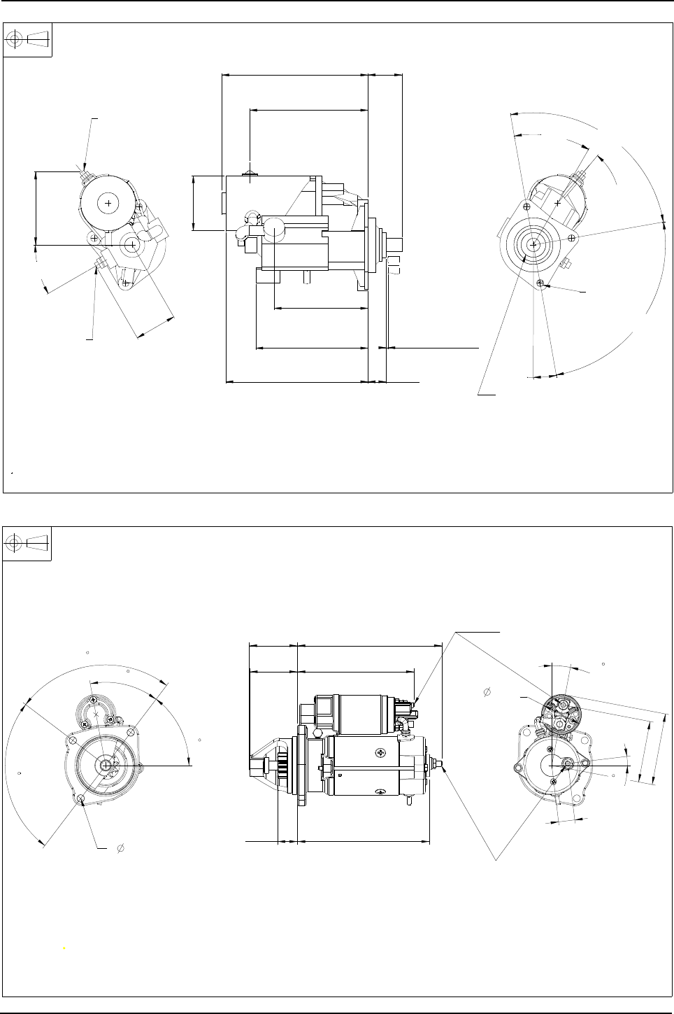
Engine Specification Manual, TPD1599 Issue 6, January 2009 59
1100 Series, 1104D, Mechanical FIE
E0201 - 24V 4,5 kW RHS
E0301 - 12V 3,2 kW LHS, suitable for dry back end only
Nom. ring gear
clearance
3
40° 90°
90°
10°
10°
55,5
233,2
239,8
194
184,2
30,5
28,5
Battery terminal
on opposite side
154
69
119,7
30°
ø90
2873K406 starter motor
Pinion
No. of teeth:- 10
D.P.:- 8/10
P.C.D.:- 31.75
3 holes ø11
on 127 PCD
Earth terminal
M8 x 1.25
Battery terminal
M10 x 1.5
2873K624 starter motor
PINION
No. OF TEETH 10
MODULE 3.175
PRESSURE ANGLE 20°
P.C.DIAMETER 31.75
61,5
90
90
52,8
10,8
48
73,2
74
30,7
179,1
222
203
6,9
25
94,5
110,3
M8 X 1,25
BATTERY TERMINAL
EARTH TERMINAL
M8 X 1,25
3- 11 ON
127 P.C.D.
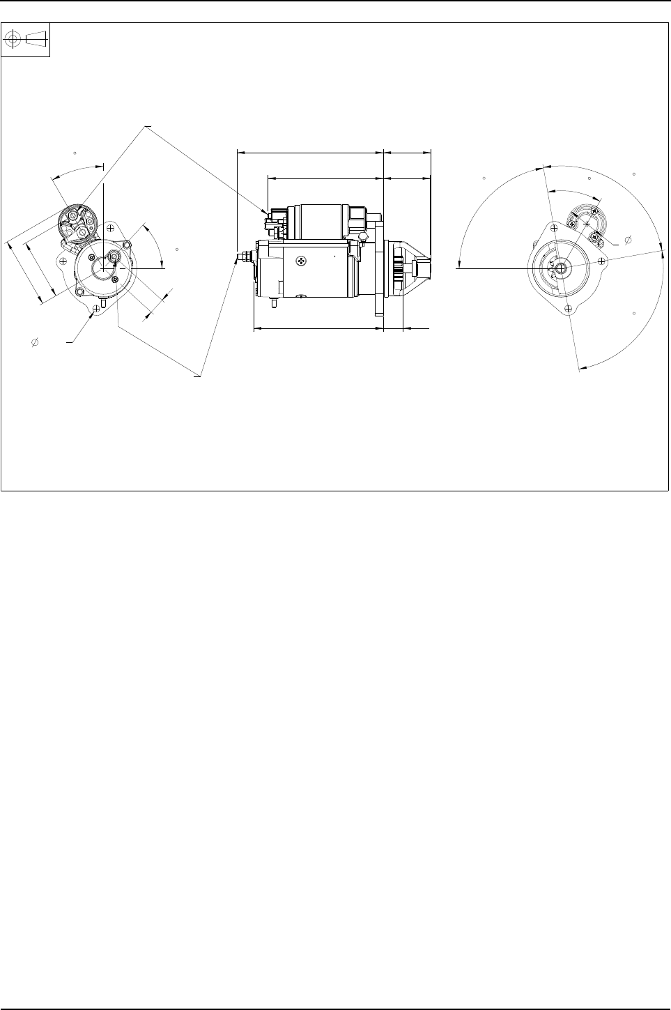
60 Engine Specification Manual, TPD1599 Issue 6, January 2009
1100 Series, 1104D, Mechanical FIE
E0311 - 12V 3,2 kW RHS, suitable for dry back end only
2873K621 starter motor
Pinion
No. of teeth 10
module 3.175
Pressure angle 20°
P.C.Diameter 31.75
30,7201,6
227 74
73,2179
80
40
90
90
25
94,5
61,5
47,6
30
110,3
EARTH TERMINAL
M8 x 1.25
BATTERY TERMINAL
M8 x 1.25
3- 11 ON
127 P.C.D.

Engine Specification Manual, TPD1599 Issue 6, January 2009 61
1100 Series, 1104D, Mechanical FIE
Fan drives
Fan drive standard vee
Note: All fan pulleys have twin grooves.
Caution: When engines are supplied with one fan belt the unused fan pulley must not be used to drive
auxiliary equipment.
Drive
ratio Description Option
n/a Fan drive not required only selectable with M0000/P0000/N0000 F0000
1 : 1
Fan centre 262 mm (10.31 in) pulley Dia. 200 mm (1)
1. Select crankshaft pulley K0001 or K0004.
F0011
Fan centre 285 mm (11.22 in) pulley Dia. 200 mm (1) F0012
Fan centre 356 mm (14.02 in) pulley Dia. 200 mm (1) F0013
1.25 : 1
Fan centre 262 mm (10.31 in) pulley Dia. 160 mm (1) (2)
2. Compatible with composite fans only.
F0021
Fan centre 285 mm (11.22 in) pulley Dia. 160 mm (1) (2) F0022
Fan centre 356 mm (14.02 in) pulley Dia. 160 mm (1) (2) F0023
Fan centre 440 mm (17.32 in) pulley Dia. 160 mm (1) (2) F0025
0.85 : 1
Fan centre 262 mm (10.31 in) pulley Dia. 200 mm (3)
3. Select crankshaft pulley K0006 or K0007.
F0031
Fan centre 285 mm (11.22 in) pulley Dia. 200 mm (3) F0032
Fan centre 356 mm (14.02 in) pulley Dia. 200 mm (3) F0033
Fan centre 440 mm (17.32 in) pulley Dia. 200 mm (3) F0035
1.06 : 1
Fan centre 262 mm (10.31 in) pulley Dia. 160 mm (3) F0041
Fan centre 285 mm (11.22 in) pulley Dia. 160 mm (3) F0042
Fan centre 356 mm (14.02 in) pulley Dia. 160 mm (3) F0043
1.43 :1
Fan centre 262 mm (10.31 in) pulley Dia. 140 mm (1) (2) F0061
Fan centre 285 mm (11.22 in) pulley Dia. 140 mm (1) (2) F0062
Fan centre 356 mm (14.02 in) pulley Dia. 140 mm (1) (2) F0063
Fan centre 395 mm (15.55 in) pulley Dia. 140 mm (1) (2) F0064
n/a
Fan centre 262 mm (10.31 in) no pulley or belts F0501
Fan centre 285 mm (11.22 in) no pulley or belts F0502
Fan centre 356 mm (14.02 in) no pulley or belts F0503
Fan centre 395 mm (15.55 in) no pulley or belts F0504
Fan centre 310 mm (12.20 in) (3) no pulley or belts F0507

62 Engine Specification Manual, TPD1599 Issue 6, January 2009
1100 Series, 1104D, Mechanical FIE
Fan drive multi vee
F0011 to F0013 and F0021 to F0025
Drive
ratio Description Option
n/a Fan drive not required only selectable with M0000/P0000/N0000 F0000
0.9 : 1 Fan centre 262 mm (10.31 in) pulley Dia. 167 mm (1)
1. Select 150 mm crankshaft pulley K0010/K0011.
F4421
Fan centre 285 mm (11.22 in) pulley Dia. 167 mm (2) F4422
1 : 1 Fan centre 262 mm (10.31 in) pulley Dia. 150 mm (2) F4461
Fan centre 285 mm (11.22 in) pulley Dia. 150 mm (2) F4462
1.2 : 1 Fan centre 262 mm (10.31 in) pulley Dia. 167 mm (2) F4441
Fan centre 285 mm (11.22 in) pulley Dia. 167 mm (2) F4442
1.33 : 1 Fan centre 262 mm (10.31 in) pulley Dia. 150 mm (2) (3)
2. Compatible with composite fans only.
F4451
Fan centre 285 mm (11.22 in) pulley Dia. 150 mm (2) (3) F4452
Fan centre 262 mm (10.31 in) (3) no pulley or belts
3. Incompatible with K0000, only selectable with M0000 and P0000.
F0501
n/a Fan centre 285 mm (11.22 in) (3) no pulley or belts F0502
Fan centre 310 mm (12.20 in) (3) no pulley or belts F0507
14,7
on a 63,5 P.C.Diameter
9 equispacedØ4 holes
4113K006
4113K007
4113K005
4113K005
4113K005
X2
X2
440
F0025
40,92
40,97
Ø
1,25:1
1,25:1
F0023
1,25:1
F0022
160Ø 200Ø
Fan drive assemblies; for part numbers refer to the table shown
fan extension dimensions
Refer to 'M' options for
4113K006
Fan height
608,255
18
specified
not be that
Housing shown may
Z
Z
YY X
X
28,6
3115C113
Twin
3115C111
Twin
1:1
RATIO
1,25:1
RATIO
4113K005
356
285
262
356
285
262
1:1
1:1
1,25:1
1:1
F0021
F0013
F0012
F0011
ratio
Pulley
code
Option
mm
height
Fan
AØeffective
Pulley
AØ
housing assy
Fan drive
12,7
36°
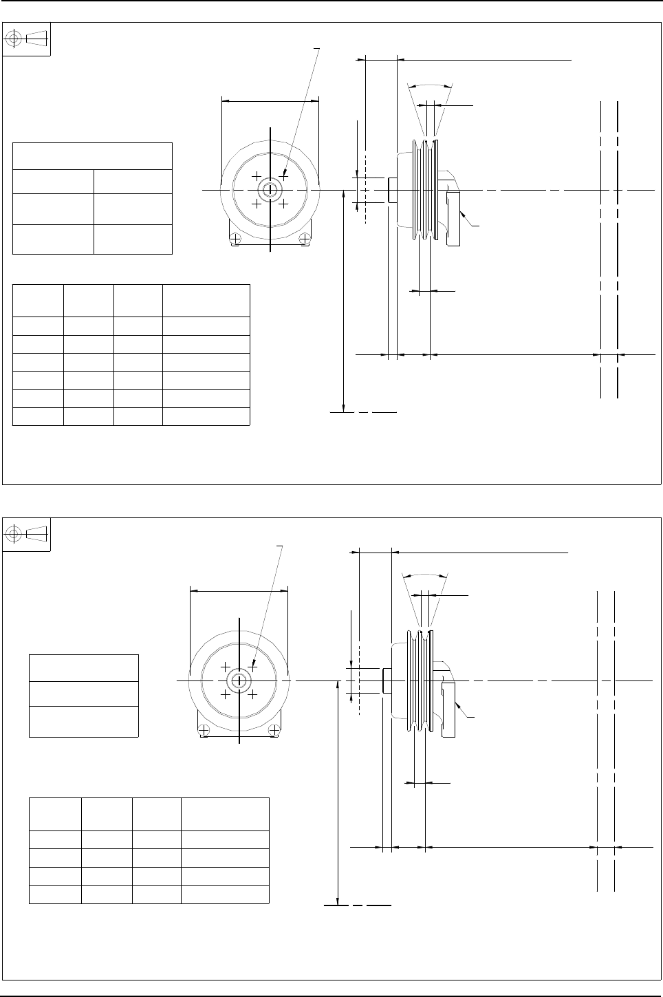
Engine Specification Manual, TPD1599 Issue 6, January 2009 63
1100 Series, 1104D, Mechanical FIE
F0031 to F0035 and F0041 to F0042
F0061 to F0064 - Fan pulley
4113K007
440
0,85:1
F0035
14,7
4113K005
4113K005
4113K005
4113K006
160Ø 200Ø
Fan drive assemblies ; for part numbers refer to table shown
40,92
40,97
Ø
Fan height
608,255
18
specified
not be that
Housing shown may
Z
Z
YY X2X
X2X
3115C113
Twin
3115C111
Twin
0,85:1
Ratio
1,06:1
Ratio
4113K005
285
262
356
285
262
0,85:1
0,85:1
1,06:1
1,06:1
0,85:1
F0042
F0041
F0033
F0032
F0031
fan extension dimensions
Refer to 'M' options for
ratio
Pulley
code
Option
mm
height
Fan
AØeffective
Pulley
28,6
AØ
housing assy
Fan drive
on a 63,5 P.C.Diameter
9 equispacedØ4 holes
12,7
36°
4113K005
262
1.43:1
F0061
fan extension dimensions
Refer to 'M' options for
14,7
4113K007
4113K006
X2
X2
395
140Ø
Fan drive assemblies; for part numbers refer to the table shown
40,92
40,97
Ø
fan height
608,255
18
specified
not be that
Housing shown may
Z
Z
YY X
X
28,6
3115C161
Twin
4113K005
356
285
1.43:1
1.43:1
1.43:1
F0064
F0063
F0062
ratio
Pulley
code
Option
mm
height
Fan
AØeffective
Pulley
AØ
housing assy
Fan drive
on a 63,5 P.C.Diameter
9 equispacedØ4 holes
12,7
36°
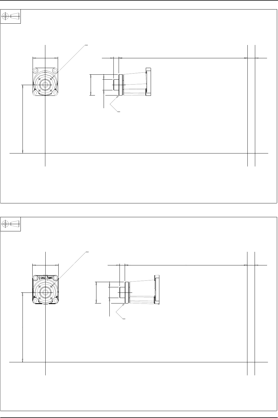
64 Engine Specification Manual, TPD1599 Issue 6, January 2009
1100 Series, 1104D, Mechanical FIE
F0501 - Fan drive housing for standard pulley
F0501 - Fan drive housing for multi vee pulley
fan height262
96 19,7
ø
40,96
40,91
ø80
657,9 28,6
ZXX2
4113K005-FAN DRIVE HOUSING ASSEMBLY-TO SUIT OPTIONS K0001/K0004/K0006/K0007
4-M8 x 1,25 equispaced on 63,5 P.C.D
1,5 x 45°
X
Y
X2
Z
Y
665,219,7
ø80
ø
40,96
40,91
97 28,6
FAN HEIGHT262
Z
4133K001-fan drive housing assembly-to suit options K0010/K0011/K0020/K0021
4-M 8 x 1,25 EQUISPACED ON 63,5 P.C.D
X
Y
Z
Y
1,5 45°
X2
XX2
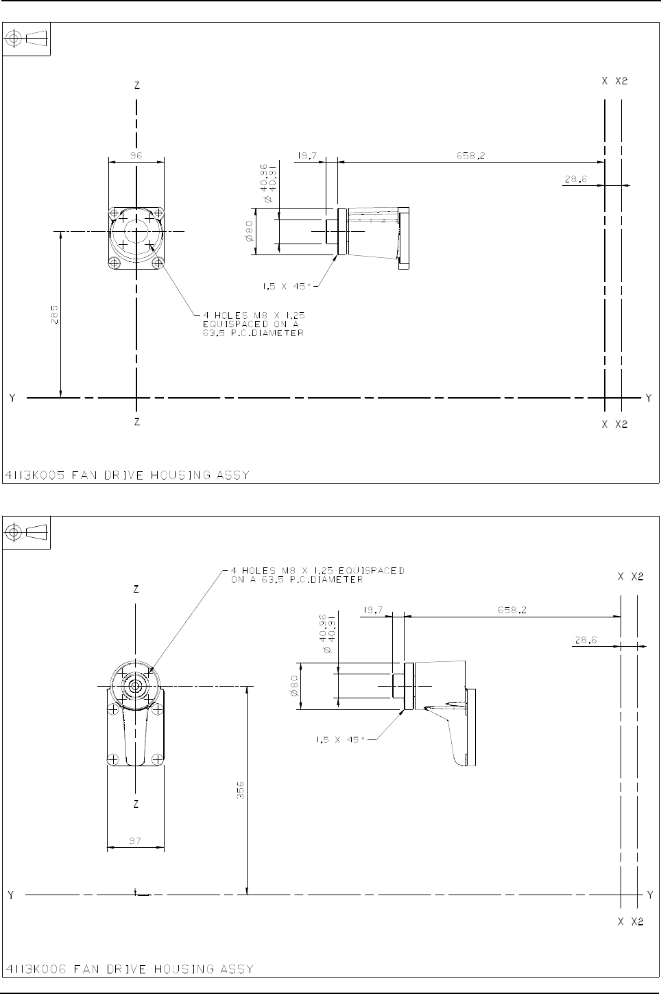

66 Engine Specification Manual, TPD1599 Issue 6, January 2009
1100 Series, 1104D, Mechanical FIE
F0504 - Fan drive housing
F4422/F4441/F4442 - Fan centre 285 mm
658,2
28,6
19,7
80Ø
395
40,91
40,96
Ø
Y
X2
X2
4113K007 fan drive housing assy
on a 63,5 P.C.Diameter
4 holes M 8 X 1,25 equispaced
Z
Z
Y
X
X
1,5 X 45°
3115Y011 pulley
Option Code Pulley Ratio Fan Height mm Fan Drive Housing Assy
F4422 0,9 : 1 285 4113K0011
Note: Option codes with fan heights over 310mm include idler pulley - see seperate drawing
601,2 to first groove68,5
Refer to 'm' options for
fan extension dimensions
fan height
Ø
40,96
40,91
15,2
Effective Ø 167
Housing shown may not be that specified
X
X
Y
Y
To suit 8 rib multi V drive belt
Z
Z
4 holes Ø 9 equispaced
on 63,5 P.C.Dia
F4441
1,2 : 1
262 4113K0011
F4443 285 4113K0011

Engine Specification Manual, TPD1599 Issue 6, January 2009 67
1100 Series, 1104D, Mechanical FIE
F4451/F4452/F4461/F4462
3115Y021 Pulley
A
601,2 to first groove
68,515,2
Refer to 'M'options for
fan extension dimensions
Effective Ø 150
Fan height
40,96
40,91
Housing shown may not
To suit 8 rib multi V drive belt
YY
X
X
4 holes Ø 9 equispaced
on 63,5 P.C.Dia
Z
Z
be that specified
Option Code Pulley Ratio Fan Height mm Fan Drive Housing Assy
F4451
0,33 : 1
262
4113K011
F4452 285
Note: Option codes with fan heights over 310 mm include idler pulley - see seperate drawing
F4461
1 : 1
262
4113K011
F4462 285

68 Engine Specification Manual, TPD1599 Issue 6, January 2009
1100 Series, 1104D, Mechanical FIE
Lubricating oil sumps and dipsticks
Non-stressed cylinder block sumps
Stressed cylinder block sumps
Dipsticks
Example: Steel, flat bottom sump with short dipstick LHS = G0101.
Description Option
Steel, flat bottom sump, LHS dipstick only (1) (2) (3) (4) (5)
1. Available with G***1.
2. Available with G***2.
3. Available with G***0.
4. Available with G***5.
5. Available with G**11.
G01**
Steel, flat bottom sump, RHS dipstick only (3) (6)
6. Available with G***3.
G02**
Cast iron, flat bottom sump (1) (4) (6) balancer R0001 can be selected G03**
Aluminium, front well sump (1) G04**
Aluminium, shallow rear well sump (1) (2) (3) (4) (5) (6) (7) (8) (9)
7. Available with G***4.
8. Available with G***9.
9. Available with G***7.
G06**
Aluminium, deep well sump (1) (4) G10**
Description Option
Cast iron, deep flat bottom sump (1) (2) (3) (4) balancer R0001 can be selected
1. Available with G***1.
2. Available with G***3.
3. Available with G***4.
4. Available with G***6.
G20**
Cast iron, shallow tunnel sump (1) (5) balancer R0001 must be selected
5. Available with balancer R0001 only
G21**
Description Option
No dipstick G**00
Dipstick short, LHS G**01
Dipstick long, LHS G**02
Dipstick short, RHS G**03
Dipstick medium, LHS G**04
Dipstick medium, LHS, rearward facing G**05
Dipstick special, RHS G**06
Dipstick medium, RHS G**07
Dipstick Long, forward facing, LHS G**08
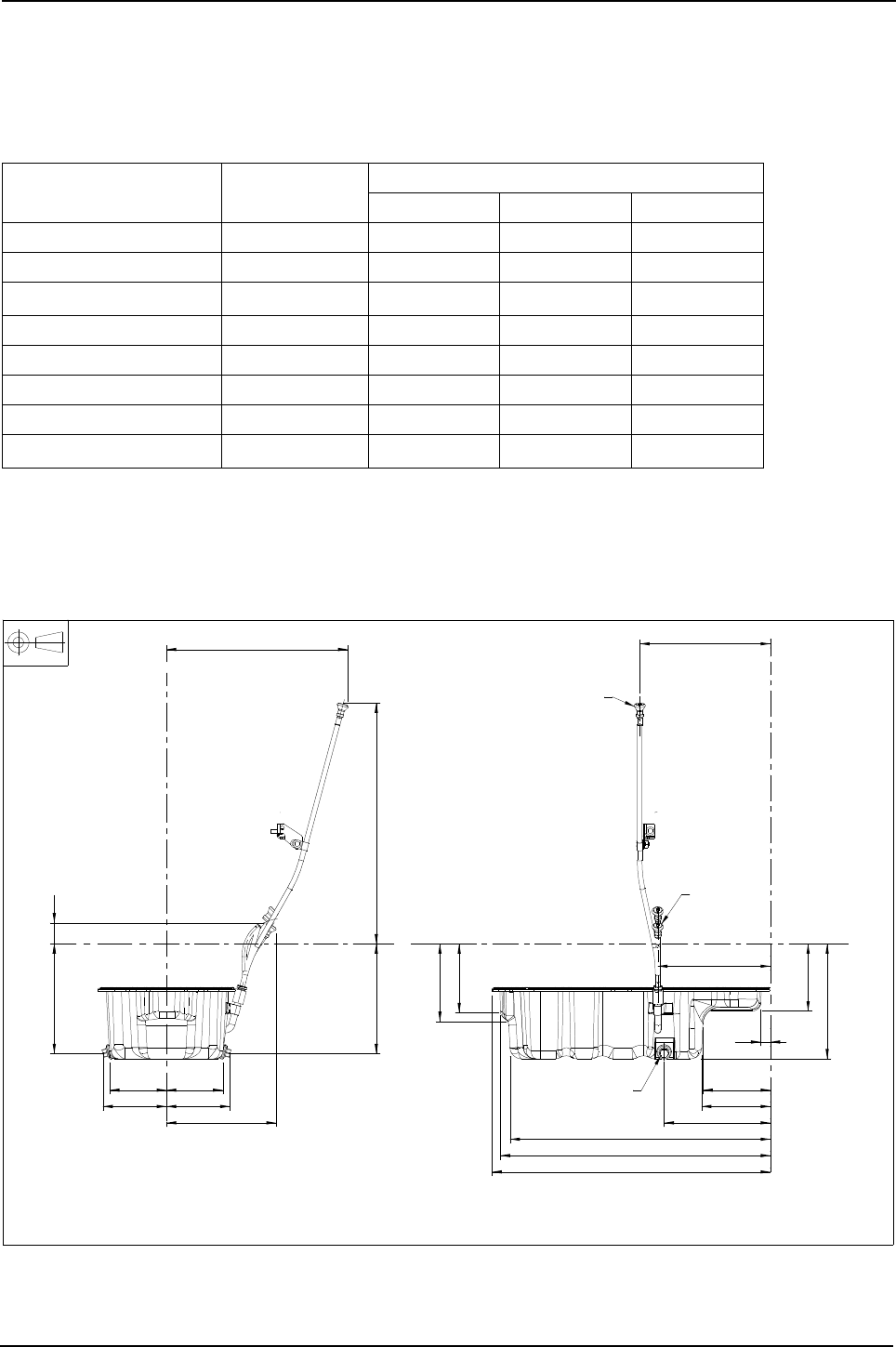
Engine Specification Manual, TPD1599 Issue 6, January 2009 69
1100 Series, 1104D, Mechanical FIE
Oil capacities and gradability
Gradient of operation and oil capacities
The table below shows the oil capacity of each sump and the angle at continuous operation permitted in all
directions. Gradient figures are measured from the horizontal position.
Note: Oil change period of low capacity sumps under review.
Note: For the total oil capacity of the engine, add 1,5 litres, (2.6 UK pints), 1.6 US quarts to the figures in the
above table.
G0100/G0101/G0104 - Steel, flat bottom sump
Option code Gradient w
limitation (1)
1. Based on minimum oil level.
Sump capacities Max/min
Litres UK pints US quarts
G010*/G020* 24° 6,9/5,6 12.1/9.9 7.3/5.9
G030* 30° 7,0/5,5 12.3/9.6 7.4/5.8
G030* (2)
2. When balancer fitted.
25° 6,4/4,1 11.3/7.2 6.7/4.3
G040* 30° 8,1/6,6 14.3/11.6 8.6/7.0
G060*/G080* 30° 8,0/6,4 14.1/11.3 8.4/6.7
G100* 25° 13.5/6.1 23.6/10.8 14.3/6.4
G200* 35° 9,4/7,6 16.5/13.3 9.9/8.0
G210* (2) 25° 7,0/5,9 12.3/10.4 7.4/6.2
230
234
137
BOTH SIDES217
141
136
568
530
550
160
20
116 115
224
129129
370
224
491
266
43
224
141
ZX
Y
G0101
16 A/F
Z
Y
X
G0102
ELEC. ONLY
3717Y061 SUMP 32186405 DRAIN PLUG
G0101 3577A125 DIPSTICK TUBE 3178C077 DIPSTICK
G0104 3577A155 DIPSTICK TUBE 3178C165 DIPSTICK
G0108 MECH 4125A073 DIPSTICK TUBE 3178C117 DIPSTICK
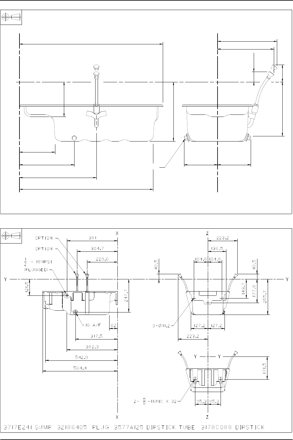
70 Engine Specification Manual, TPD1599 Issue 6, January 2009
1100 Series, 1104D, Mechanical FIE
G0203 - Steel, flat bottom sump
G0301/G0303 - Cast iron, flat bottom sump
3577A128 dipstick tube, 3178C088 dipstick, used with J0016 J0019.
68,18
235,54
222,80
40,76
3717Y062 sump, 3577A125 dipstick tube, 3178C077 dipstick, 32186405 drain plug.
214,7
234,8
137,4
16 across flats
131,8131,8
529,5
304,7
216,7
141,3
567,7
YY
Z
Z
X
X
R&&&G0010
R&&&G0003

Engine Specification Manual, TPD1599 Issue 6, January 2009 71
1100 Series, 1104D, Mechanical FIE
G0401 - Aluminium, front well sump
G0600 - Aluminium, shallow rear well sump
181,4
3717E124 sump 32186405 drain plug
3577A128 dipstick tube 3178C085 dipstick
336,6 2 places
59,8
16 across flats
314,7 2 PLACES
534,3
319
331,7
569,2
230,5
129,3
24,7
122,7122,7
Z
X
Z
YY
XA&&&G0002
R&&&G0060

72 Engine Specification Manual, TPD1599 Issue 6, January 2009
1100 Series, 1104D, Mechanical FIE
G0600/G0601/G0603/G0604 - Aluminium, shallow rear well sump
G1001 - Aluminium, deep well sump
Drain plug
126
Drain plug
126
223
319
41,4
223
41,4
230
77
162
223
240
both sides
111
282
20
563
Z
Y
Z
G0603 G0601
G0604
4145H131 sump 32186405 drain plug
G0601 3577A125 dipstick tube 3178C069 dipstick
G0603 3577A125 dipstick tube 3178C069 dipstick
G0604 3577A156 dipstick tube 3178C185 dipstick
X
16 A/F
X
Y
3717E225 sump 32186405 drain plug 3577A156 dipstick tube 3178C178 dipstick
1/2 - 14 BSP
288 319
83
X
X
102
Z
247
117 457
379
Y
Z
16 across flats
Y
312
110
229
M 16 X 1,5
332
R&&&0065
Subject to alteration on dipstick position
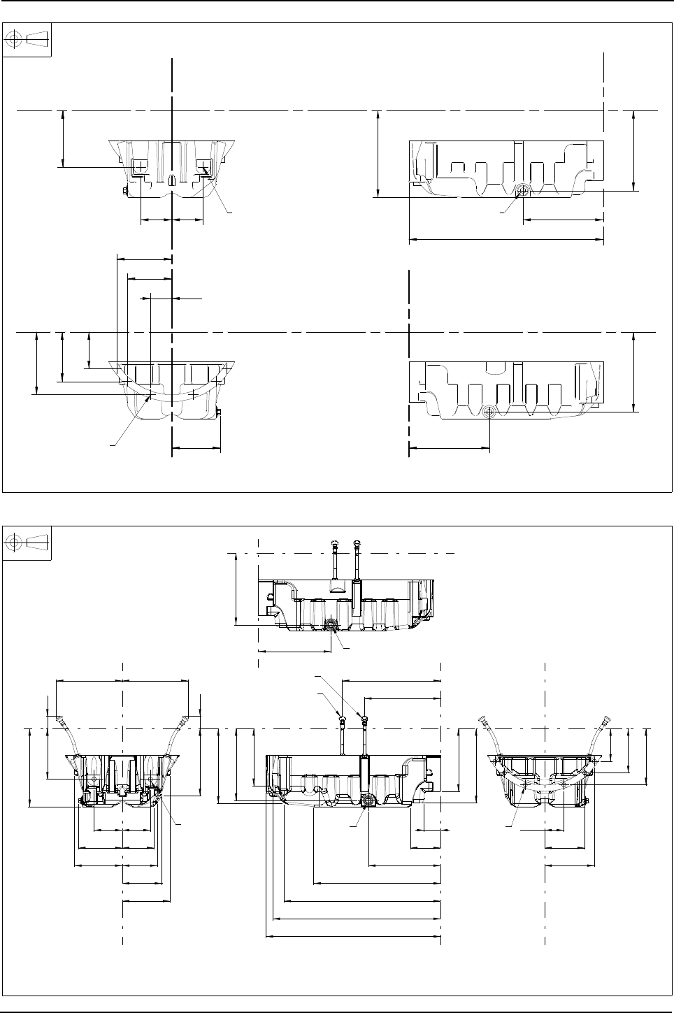
Engine Specification Manual, TPD1599 Issue 6, January 2009 73
1100 Series, 1104D, Mechanical FIE
G2000 - Cast iron, deep flat bottom sump
G2001/G2003 - Cast iron, deep flat bottom sump
16 A/F
243,7
245,395,395,3
264,3
171,5
593
X2
X2
13,5Ø6-
190,5
150
111,1
65,1
135,7
168,3
Z
X2
148,4
243,7
Y
X2
Y
245,3
Y
2-M16 x 2 x 32
Y
Z
3717E271 sump,3577A159 dipstick tube,3178C081 dipstick,32186405 drain plugs.
R&&&G0068
R&&&G0007
95,3 95,3
162
264
228
108
134
171
245
430
531
571.5
591
223 223
42
42
148,4
65,1
135,7
168,3
258
333
119
244
245
162
111,1
150
190,5
243,7
254
213
252
56
102
193
G2003
G2001
G2001 3717E272 sump
G2003 3717E271 sump 32186405 drain plug 3577A125 dipstick tube 3178C081 dipstick
Z
Y
Z
Y
2 - M16 X 2 X 32 16 A/F
X2
X2
Z
Z
6 - ø13.5
X2
X2
Y
Y
G2003 only

74 Engine Specification Manual, TPD1599 Issue 6, January 2009
1100 Series, 1104D, Mechanical FIE
G2004 - Cast iron, deep flat bottom sump
G2101 - Cast iron, shallow tunnel sump
R&&&G0055
19
222
X2
R191,3
21,4
YY
190,5
150
111,1
168,3
135,7
65,1
16 across FLATS
264,3
571,5
593
258,2
148,4
95,395,3
2-M16 X 2 X 32
243,7
Z
245,3
41,2
13,5Ø6-
171,4
36,2
2-places
2-places
Y
X2
Y
3717J191 sump 2431A016 drain plug 3178C088 dipstick 3577A125 dipstick tube
A&F&G0041

Engine Specification Manual, TPD1599 Issue 6, January 2009 75
1100 Series, 1104D, Mechanical FIE
Lubricating oil filler and breather
Top cover, breathers and lubricating oil fillers
Example: Open breather with rear top cover filler = H1220
Breather branding
Breather system options
Warning! EU and EPA legislation no longer allows direct piping of crankcase gases to the induction system.
Description Option
Closed breather (1) mandatory for all naturally aspirated engines
1. Not available for turbo and air to air charge cooled models.
H01**
Open breather, short hose H02**
Filtered open breather (2)
2. Incompatible with G0401/G2002, Q1023/Q1024/Q1025/Q1026/Q4042, .
H03**
Open breather, long hose (3)
3. Available as H1210 and H1220 only.
H12**
Top cover, no filler (4) must select block or timing case filler
4. Not available with HD000/Q4042.
H**00
Top cover, filler middle (5)
5. Not compatible with S0251/S1253.
H**10
Top cover, filler rear (5) H**20
Description Option
Not required (1)(2)
1. Compatible with H02**, H12** only.
2. Compatible with H03** only.
HL000
Standard (2) HL001
Engine type Legislation Standard option Optional
NA EU Closed (without canister) (H01**)
EPA Product not available
Turbo EU Open (H02**) Filtered open (H03**)
EPA Open (H02**) Filtered open (H03**)
Turbo / air charge
cooled
EU Open (H02**) Filtered open (H03**)
Open (H02**)
EPA Open (H02**) Filtered open (H03**)
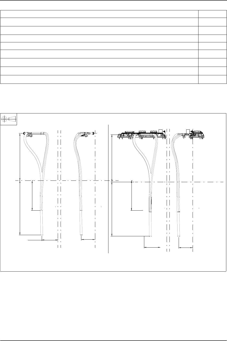
76 Engine Specification Manual, TPD1599 Issue 6, January 2009
1100 Series, 1104D, Mechanical FIE
Timing case lubricating oil fillers
H0200 - Open breather short hose H1200 - Open breather long hose
Description Option
Timing case filler, not required HD000
Timing case filler, LHS mid position (1)
1. Incompatible with Q1023/Q1024/Q1025/Q1026/Q4042.
HD001
Timing case filler, on LHS lower position (2)
2. For use with Q1100/Q3000/Q3030 only.
HD004
Timing case filler, on LHS upper position HD005
Timing case filler, LHS mid position for customer supplied filler HD006
Remote timing case filler LHS lower position (1) HD007
Remote timing case filler adaptor, LHS mid position (1) HD011
LHS mid-positionfiller (3)
3. For use with RHS PTO timing cases. Q3000/3030.
HD100
AAA BBB
500
option H02*0
316
500
173,5
145
option H12*0
574,8
option H02*0
316,3
168,4
option H12*0
574,5
148
H*2*0 mechanical to suit ZA014 only H*2** mechanical to suit ZA000/15/16
4134K022 breather pipe assy O/D 22
4133J011 breather pipe assy O/D 22 (ZA014 option only)
33872632 short hose 33872639 long hose
XX2 Z
Y
Y
XX2 Z
XX2 Z
XX2 Z
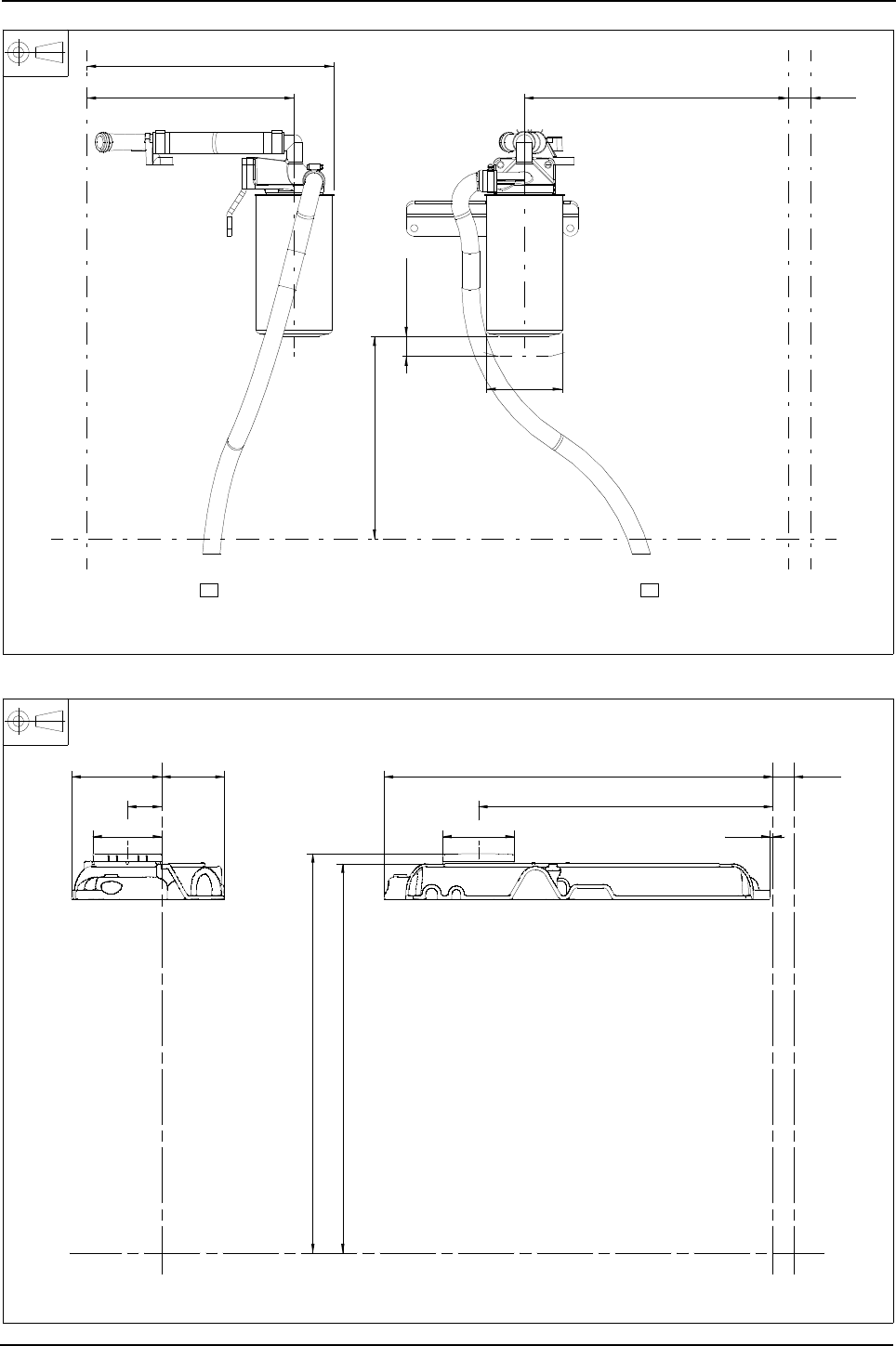
Engine Specification Manual, TPD1599 Issue 6, January 2009 77
1100 Series, 1104D, Mechanical FIE
H0300 - Mechanical, filtered open breather
H**00 - Top cover, no filler
255
removal
25
332,4
96
261,4
311,4
28,6
4134E071 filter head assembly 2654A104 filter 4133J011 breather transfer pipe
3653A042 bracket
X
X
Y
X2
X2
Z
Z
Y
Z
Z
Y Y
X
X
X2
X2
120,5 83,8
46
92,2
534,2
519,7
393,6
96,2 3,6
28,6
520,5
4142X291 Cyl. Head cover, 3788N003 Injector cover
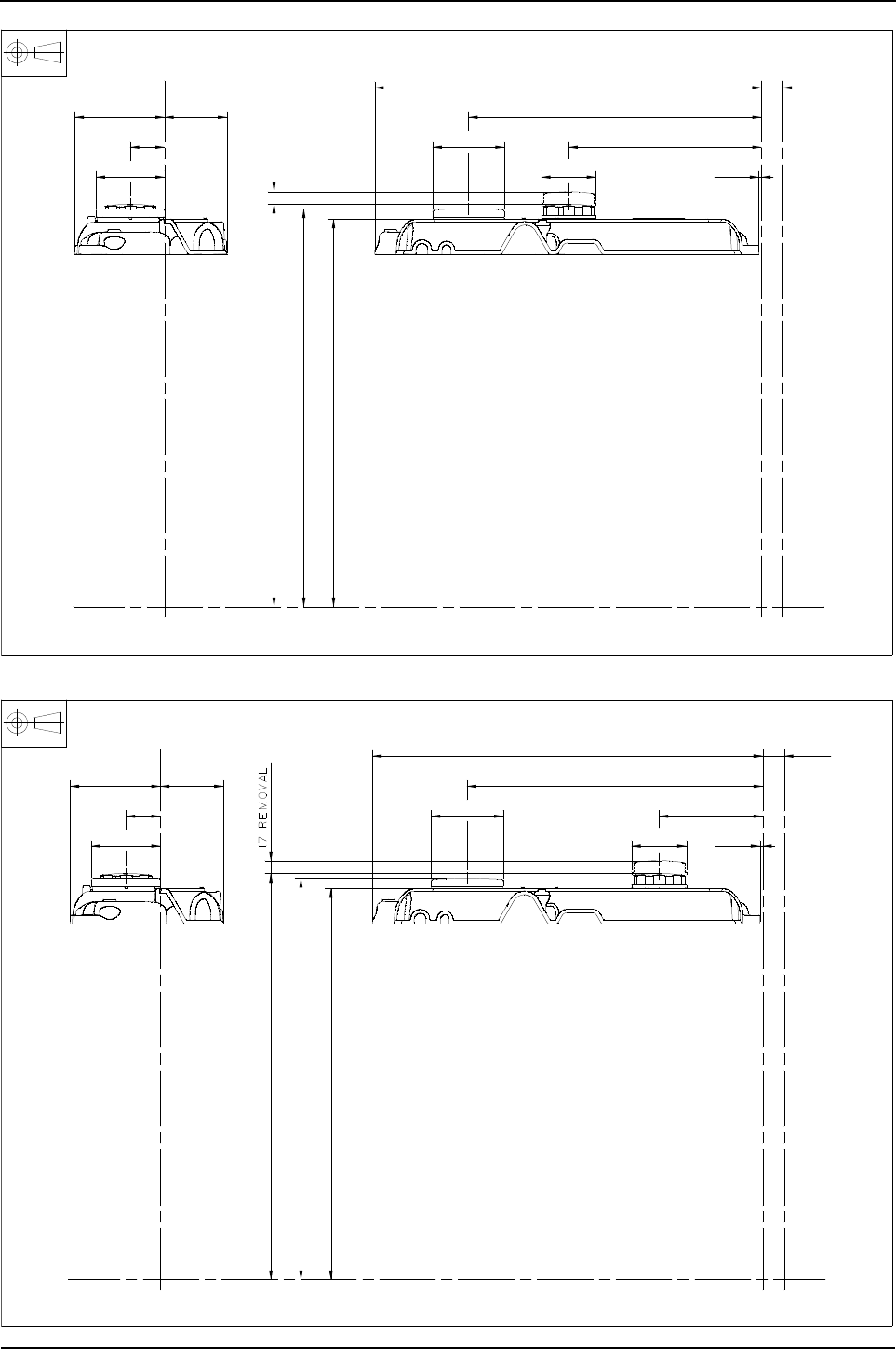
78 Engine Specification Manual, TPD1599 Issue 6, January 2009
1100 Series, 1104D, Mechanical FIE
H**10 - Top cover, filler middle
H**20 - Top cover, filler rear
Z
Z
Y Y
X
X
X2
X2
120,5 83,8
46
92,2
540,5
534,2
520,5
17 removal
519,7
393,6
96,2 259
Ø 73 3,6
28,6
4142X929 Cyl. Head cover, 3788N003 Injector cover, 4142X099 Filler cap
Z
Z
Y Y
X
X
X2
X2
120,5 83,8
46
92,2
540,5
534,2
520,5
519,7
393,6
96,2 138
Ø 73 3,6
28,6
4142X293 Cyl. Head cover, 3788N003 Injector cover, 4142X099 Filler cap

Engine Specification Manual, TPD1599 Issue 6, January 2009 79
1100 Series, 1104D, Mechanical FIE
HD001 - Timing case filler, LHS mid position
HD004 - Timing case filler, on LHS lower position
y
z
y
z
y
z
y
37°
318
295
464
433
241
270
ø69
28,6
4134C072 OIL FILLER ASSEMBLY
Z
Z
Y
Y
X
X
X2
X2
47°
26°
256
462
177
203
431
ø69
-REMOVAL
17
280
28,6
4134C073 OIL FILLER ASSEMBLY
Z
Z
Y
X
X
Y
X2
X2
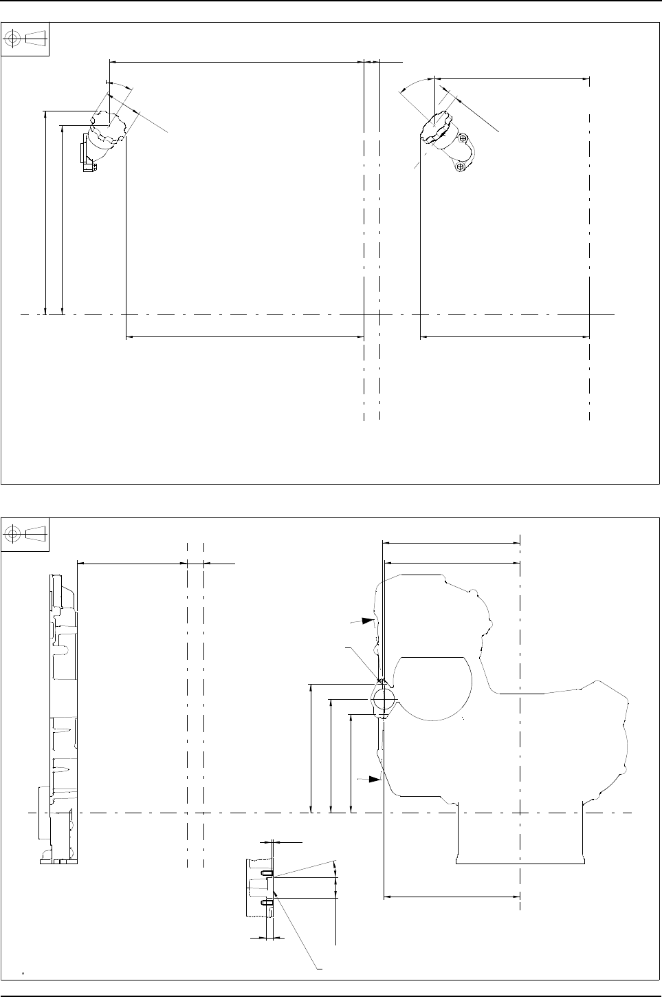
80 Engine Specification Manual, TPD1599 Issue 6, January 2009
1100 Series, 1104D, Mechanical FIE
HD005 - Timing case filler, on LHS upper position
HD006 - Timing case filler, LHS mid position for customer supplied filler
32°
46°
REMOVAL
17
282
464
308
ø69
433
344
371
28,6
4134C072 OIL FILLER ASSEMBLY
Z
X
XX2
X2
A
A
237,4
240,8
224,5
198,7
172,7
238,5
511,6 28,6
12
15°
4142X103 BLANKING PLATE.
Z
Z
Y
2 - M8 X 1,25 X 16
FOR CUSTOMER
SUPPLIED FILLER
X
X
X2
X2
Y
SECTION A-A
ø
SUPPLIED FITTED WITH BLANKING PLATE
3,0
2,6
36,062
36,000
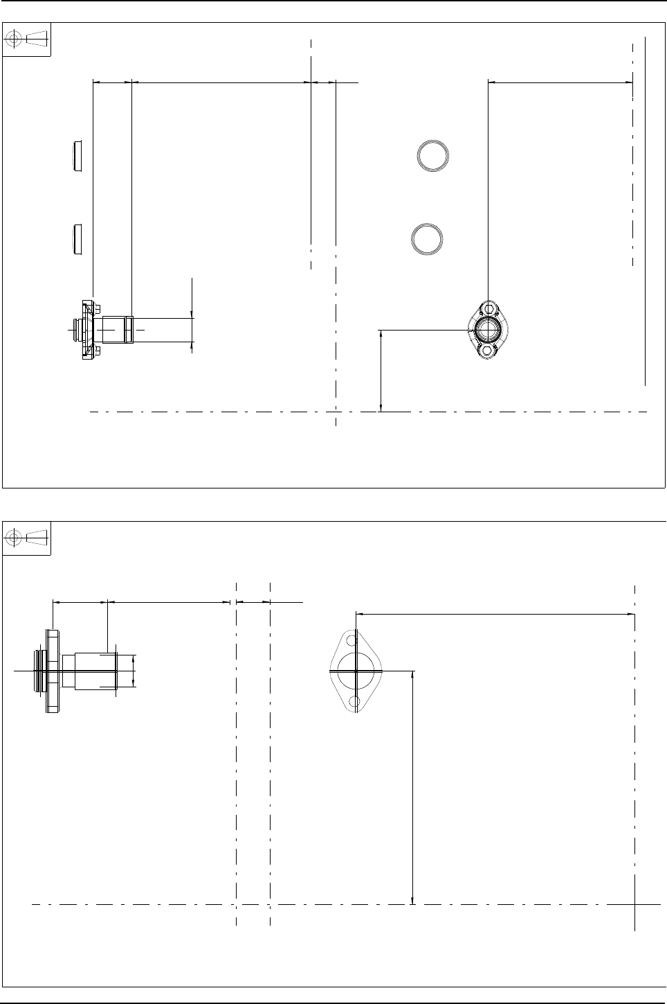
Engine Specification Manual, TPD1599 Issue 6, January 2009 81
1100 Series, 1104D, Mechanical FIE
HD007 - Remote timing case filler
HD011 - Remote timing case filler adaptor, LHS mid position
454,645 167,1
94,4
ø27
28,6
4134C075 OIL FILLER ASSEMBLY
Z
Y
X
X
X2
X2
x
y
zxy
z
x
y
zy
28,6
198,7
237,4
454,5
47
ø 27
4134C071 OIL FILLER ASSEMBLY
Z
Z
Y
X
X
Y
X2
X2

82 Engine Specification Manual, TPD1599 Issue 6, January 2009
1100 Series, 1104D, Mechanical FIE
Lubricating oil filters and coolers
Spin on oil filters
Lubricating oil filter branding
Description Option
Vertically down filter, LHS, without oil cooler (1) (2)
1. Naturally aspirated engines only.
2. Incompatible with balanced engines, if a balancer is specified a cooler must be selected.
J0011
Horizontal filter, LHS, without oil cooler (1) (2) (3) J0021
Vertically down filter head, RHS no filter (customer to supply), without oil cooler (1) (2) (4) (5) J0030
Vertically down filter, RHS without oil cooler (1) (2) (4) (5) J0031
Vertically down filter head, LHS no filter (customer to supply), with oil cooler J0050
Vertically down filter, LHS, with oil cooler J0051
Horizontal filter, LHS, no filter (customer to supply) with oil cooler (3)
3. Incompatible with Q1023/Q1024/Q1025/Q1026/Q1038/Q2038.
J0060
Horizontal filter, LHS, with oil cooler (3) J0061
Vertically down filter head, RHS no filter (customer to supply), with oil cooler (4) (5)
4. Oil filters fitted on the right hand side are not compatible when balancer selected.
5. Incompatible with G0203/G0303/G0603.
J0070
Vertically down filter head, RHS with oil cooler (4) (5) J0071
Adaptor for remote oil filter (customer to supply) with oil cooler (6)
6. Perkins Application and Engineering approval required prior to selection.
J0130
Description Option
Not applicable (1)
1. Compatible with J0030/J0050/J0070/J0130 only.
JD000
Standard JD001
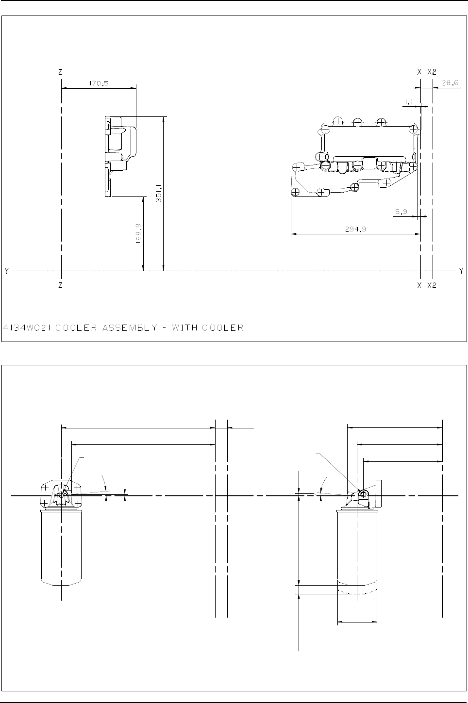

84 Engine Specification Manual, TPD1599 Issue 6, January 2009
1100 Series, 1104D, Mechanical FIE
J0021/J0061 - Horizontal filter, LHS
J0030 - Vertically down filter head, RHS no filter (customer supply), without oil cooler
28,6
210,5
0,6
5°
M12 X 1,5
switch tapping
Oil pressure
plugged
M10 X 1,0
REMOVAL20
94Ø
53,9
273,6
224,5
195,3
115,8
374,1
1
3773A081 adaptor 3773A071 head 2654407 filter
Z
X2
X
XX2 Z
Y
Y

Engine Specification Manual, TPD1599 Issue 6, January 2009 85
1100 Series, 1104D, Mechanical FIE
J0031/J0071 - Vertically down filter head, RHS
J0050 - Vertically down filter head, LHS no filter (customer supply), with oil cooler
389,4 224,9
186,9
5°
plugged
M10 X 1,0
38
5°
M12 X 1,5
switch tapping
Oil pressure
94Ø
35,5177,8 removal20
Z
X
X2
X
X2
Z
201,9365,4
28,6
3773A061 head 2654407 filter
YY
-16UNF X 15
4
3
341,4
224,9
5°
5°
M12 X 1,5
switch tapping
Oil pressure
plugged
M10 X 1,0
Z
X2
X
XX2 Z
28,6
201,9
0,6
75,5Ø
186,9
3,1
12
365,4
31,5
Y
Y
3773A061 head
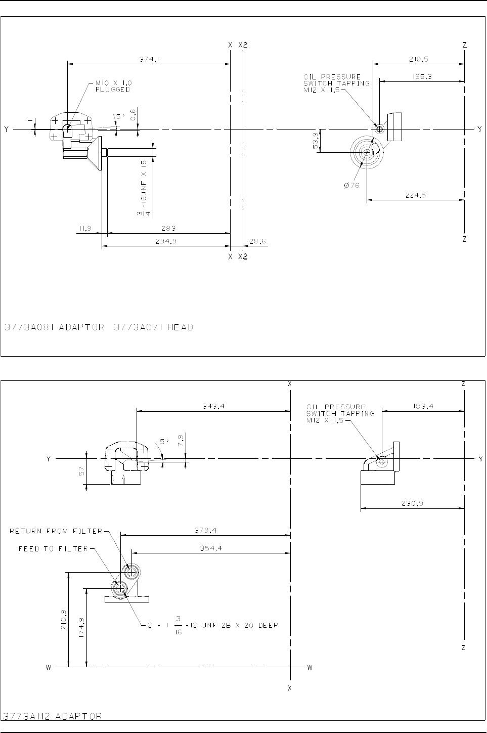

Engine Specification Manual, TPD1599 Issue 6, January 2009 87
1100 Series, 1104D, Mechanical FIE
Crankshaft pulleys
Fan drive standard vee
Example: Primary drive 150 mm, secondary single groove 200 mm = K0011
Fan drive multi vee
Example:
Note: See fan drive options for compatible crankshaft pulley options.
Description Option
Crankshaft stub seal, when no crankshaft pulley fitted (1)
1. Compatible with F0000/M0000/N0000/P0000 only.
K0000
Cast iron, single groove, 200 mm diameter 12,7 mm belt K0001
Cast iron, twin groove, 200 mm diameter 12,7 mm belt K0004
Cast iron, twin groove, 170 mm diameter 12,7 mm belt K0006
Cast iron, single groove, 170 mm diameter 12,7 mm belt K0007
Description Option
Crankshaft stub seal, when no crankshaft pulley fitted (1)
1. Compatible with F0000/M0000/N0000/P0000 only.
K000*
Primary drive, steel, 150 mm diameter K001*
Primary drive, steel, 200 mm diameter K002*
No secondary pulley required K***0
Secondary PTO, single groove, vee belt drive pulley 200 mm diameter K***1

88 Engine Specification Manual, TPD1599 Issue 6, January 2009
1100 Series, 1104D, Mechanical FIE
K0000 - Crankshaft stub seal, for no crankshaft pulley fitted
K0001 - Cast iron, single groove, 200 mm diameter 12,7 mm belt
Crankshaft seal stub
RG&&K0000
631,6
Ø 132
28,6
X2
X2
6-M12 X 1,75 equispaced on 110 P.C. Dia
Y
Y
Z
Z
X
X
ø203,2
36°
621,4
608,2
80°
28,6
12,7
ø - effective
200
X
X
Y
X2
X2
4- 7/16 - 20 UNF
spaced as shown
on 95,25 P.C.DIA
Z
Z
Y
Pulley - crankshaft

Engine Specification Manual, TPD1599 Issue 6, January 2009 89
1100 Series, 1104D, Mechanical FIE
K0004 - Cast iron, twin groove, 200 mm diameter 12,7 mm belt
K0006 - Cast iron, twin groove, 170 mm diameter 12,7 mm belt
36°
18
608,2
80°
Ø 203
640,9 28,6
12,700
effective
Ø 200,000
4 - 7/16 X 20 UNF spaced
as shown on 95,25 P.C.DIA.
Z
Z
Y
X
X
Y
X2
X2
Crankshaft pulley
Crankshaft pulley
36°
608,2
640,9
18
80°
Ø 173
28,6
effective
Ø 170
12,7
4 - M10 X 1,5 spaced as
shown on 95,25 P.C.DIA.
Z
Z
YY
X
X
X2
X2
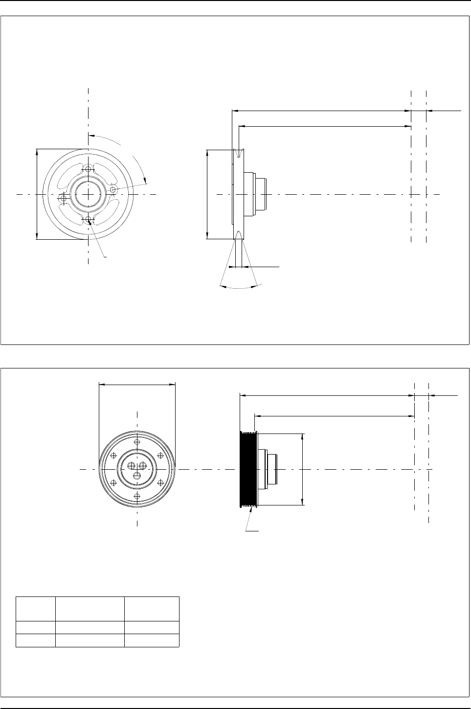
90 Engine Specification Manual, TPD1599 Issue 6, January 2009
1100 Series, 1104D, Mechanical FIE
K0007 - Cast iron, single groove, 170 mm diameter 12,7 mm belt
K0010/K0020 - Primary drive, steel, 150 mm - 200 mm diameter
Ø 173
80°
36°
621,4
608,2
28,6
effective
Ø 170
12,7
X
X
Y
X2
X2
4 - 7/16 - 20 UNF
spaced as shown
on 95,25 P.C.DIA
Z
Z
Y
Crankshaft pulley
ø 154,5
601,2 to first groove
EFF ø A
28,6631,6
Option
code
Pulley
part No.
Effective
Dia. A
K0010 3115X041 150
K0020 3115X031 200
3741A051 adaptor
Y
Z
Z
X
X
Y
To suit 8 rib
multi V drive belt
X2
X2

Engine Specification Manual, TPD1599 Issue 6, January 2009 91
1100 Series, 1104D, Mechanical FIE
K0010/K0020 - Primary drive, steel, 150 mm - 200 mm diameter
ø 154,5
601,2 to first groove
Eff ø A
28,6631,6
Option
code
Pulley
part No.
Effective
Dia. A
K0010 3115X041 150
K0020 3115X031 200
3741A051 adaptor
Y
Z
Z
X
X
Y
To suit 8 rib
multi V drive belt
X2
X2
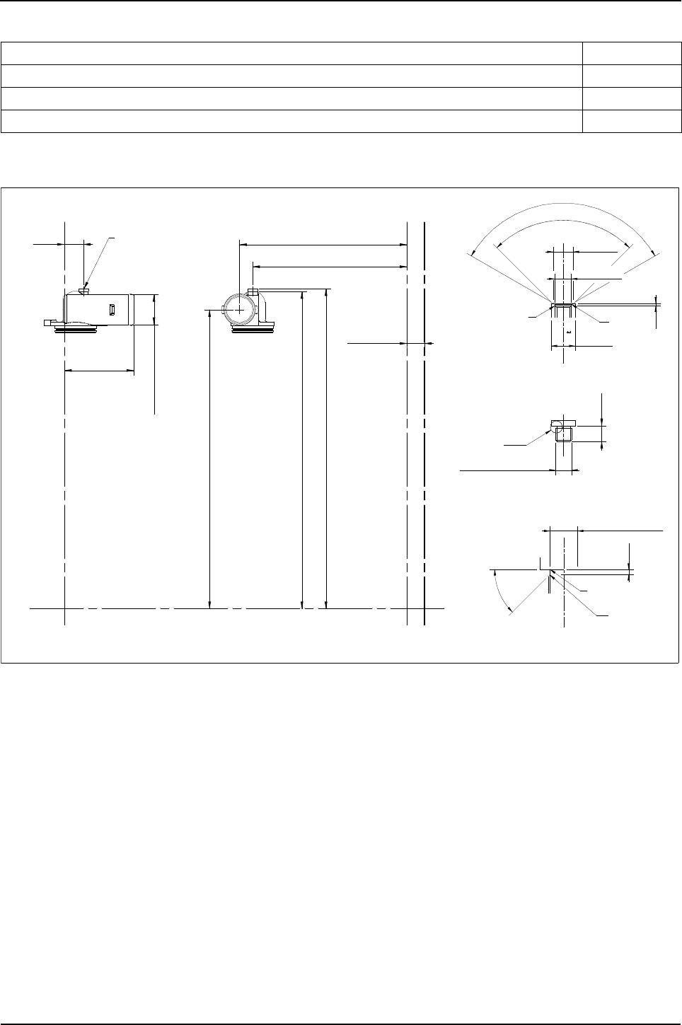
92 Engine Specification Manual, TPD1599 Issue 6, January 2009
1100 Series, 1104D, Mechanical FIE
Coolant pump and outlet connection
L0052 - Coolant pump with horizontal coolant outlet connection, with thermostat assembly
Description Option
Coolant pump with horizontal coolant outlet connection, LHS with thermostat assembly L0052
Coolant pump with horizontal coolant outlet connection, RHS with thermostat assembly L0053
Coolant pump with vertical coolant outlet connection with thermostat assembly (1)
1. Only option compatible with radiator options.
L0056
527,2
12,1
Enlarged view of 1/4-18 N.P.S.M boss
90°
R0,5 Max R1
Detail A
16,53Ø
2,1
20Ø
120°
13,62Ø
1/4-18 N.P.S.M
2,1
R0.5
R0.5
45°
11,355Ø
Detail A - enlarged
Enlarged view of 1/4-18 N.P.S.M boss
Incl.plug531,8
4133L508 water outlet connection
28,6
50,3Ø
525,8
498
plugged
1/4-18 N.P.S.M
31,2
YY
X
X
X2
X2
Z
Z
115,3
548,8

Engine Specification Manual, TPD1599 Issue 6, January 2009 93
1100 Series, 1104D, Mechanical FIE
L0053 - Coolant pump with horizontal coolant outlet connection RHS, with thermostat assembly
L0056 - Coolant pump with vertical coolant outlet connection in centre, with thermostat assembly
548,8
527,2
12,1
ENLARGED VIEW OF 1/4-18 N.P.S.M BOSS
90°
R0,5 MAX R1
DETAIL A
16,53Ø
2,1
20Ø
120°
13,62Ø
1/4-18 N.P.S.M
2,1
R0.5
R0.5
45°
11,355Ø
DETAIL A - ENLARGED
ENLARGED VIEW OF 1/4-18 N.P.S.M BOSS
4133L509 WATER OUTLET CONNECTION
50,3Ø
525,8
5,8
PLUGGED
1/4-18 N.P.S.M
106,7
28,6
INCL.PLUG531.8
498
Y Y
Z
Z
X2
X2
X
X
527,2
Y Y
X
X
X2
X2
Z
Z
28,6 18,5
50,3Ø
4133L507 WATER OUTLET CONNECTION
536,8
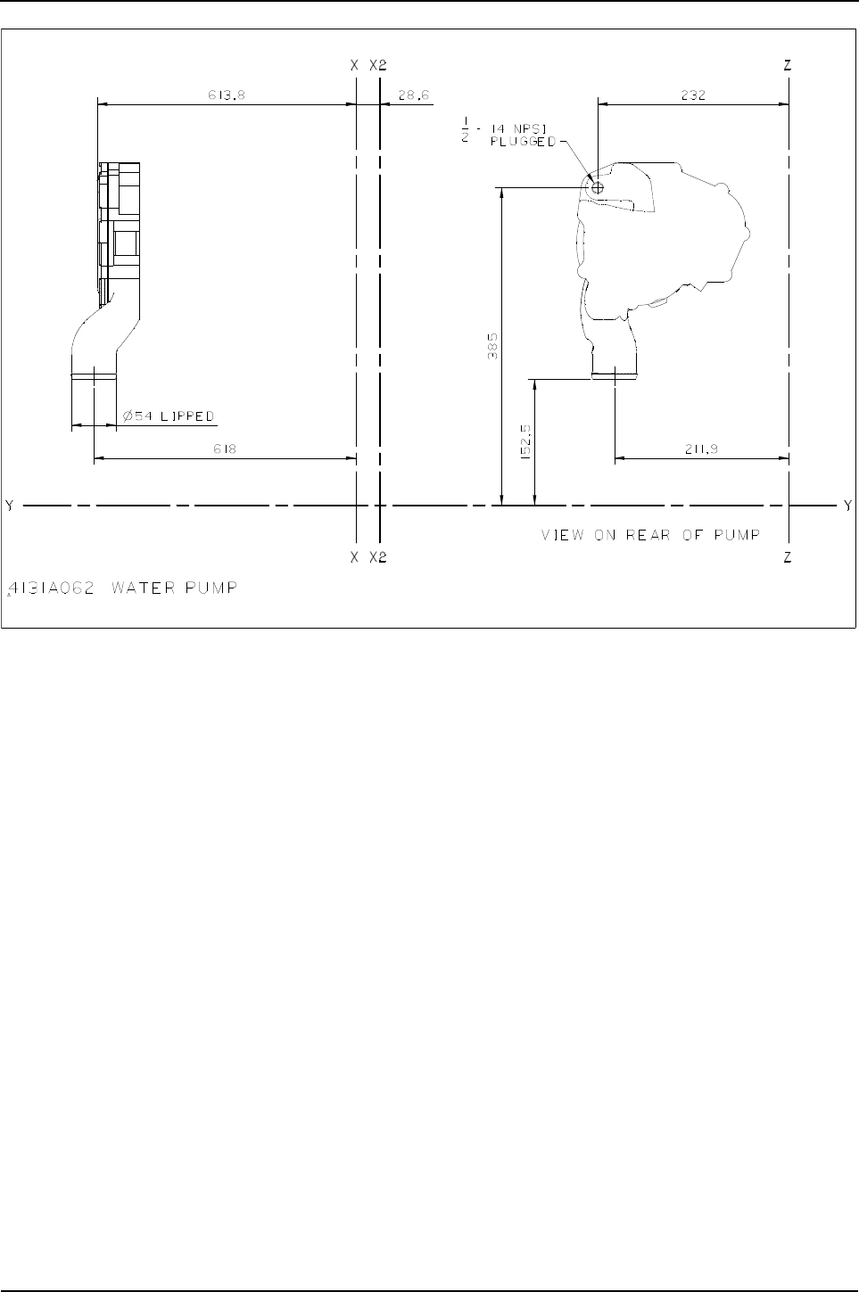

Engine Specification Manual, TPD1599 Issue 6, January 2009 95
1100 Series, 1104D, Mechanical FIE
Fans and extensions
Description Option
Fan and extension not required (1)
1. Customer supplied fan and extensions must be approved by Perkins Applications.
M0000
38 mm (1.5 in), fan extension (1) M0003
51 mm (2.0 in), fan extension (1) M0004
63 mm (2.5 in), fan extension (1) M0005
76 mm (3.0 in), fan extension (1) M0006
Fan and extension not required, fitted with transit hardware only M0090
457.2 mm (18 in) Pusher, 6 blade, with 38 mm (1.5 in), fan extension (2)
2. Metal fans.
These fans are limited to engines with rated speeds up to and including 2200 rev/min. When a balancer is selected
rated speeds can be increased to 2400 rev/min.
M2203
457.2 mm (18 in) Pusher, 6 blade, with 51 mm (2.0 in), fan extension (2) M2204
457.2 mm (18 in) Pusher, 6 blade, with 63 mm (2.5 in), fan extension (2) M2205
457.2 mm (18 in) Pusher, 6 blade, with 76 mm (3.0 in), fan extension (2) M2206
457.2 mm (18 in) Puller, 7 blade, with 63 mm (2.5 in), fan extension (3)
3. Composite fans.
M2315
457.2 mm (18 in) Puller, 10 blade, with 38 mm (1.5 in), fan extension (3) (4)
4. Not available with P0001/P0003.
M2323
457.2 mm (18 in) Puller, 10 blade, with 51 mm (2.0 in), fan extension (3) M2324
457.2 mm (18 in) Puller, 10 blade, with 63 mm (2.5 in), fan extension (3) M2325
457.2 mm (18 in) Puller, 10 blade, with 76 mm (3.0 in), fan extension (3) M2326
457.2 mm (18 in) Pusher, 7 blade, with 63 mm (2.5 in), fan extension (3) M2415
457.2 mm (18 in) Pusher, 7 blade, with 76 mm (3.0 in), fan extension (3) (4) M2416
508 mm (20 in) Puller, 7 blade, with 38 mm (1.5 in), fan extension (3) (4) M3313
508 mm (20 in) Puller, 7 blade, with 51 mm (2.0 in), fan extension (3) M3314
508 mm (20 in) Puller, 7 blade, with 63 mm (2.5 in), fan extension (3) M3315
508 mm (20 in) Puller, 7 blade, with 76 mm (3.0 in), fan extension (3) M3316
508 mm (20 in) Puller, 10 blade, with 38 mm (1.5 in), fan extension (3) (4) M3323
508 mm (20 in) Puller, 10 blade, with 51 mm (2.0 in), fan extension (3) M3324
508 mm (20 in) Puller, 10 blade, with 63 mm (2.5 in), fan extension (3) M3325
508 mm (20 in) Puller, 10 blade, with 76 mm (3.0 in), fan extension (3) M3326
508 mm (20 in) Pusher, 7 blade, with 63 mm (2.5 in), fan extension (3) (4) M3415
508 mm (20 in) Pusher, 7 blade, with 76 mm (3.0 in), fan extension (3) M3416
559 mm (22 in) Puller, 10 blade, with 76 mm (3.0 in), fan extension (3) M4326
559 mm (22 in) Pusher, 7 blade, with 63 mm (2.5 in), fan extension (3) (4) M4415

96 Engine Specification Manual, TPD1599 Issue 6, January 2009
1100 Series, 1104D, Mechanical FIE
M0003/M0004/M0005/M0006 - Fan extension
M2203 to M2206 - Fan 6 blade pusher
DIM.A
ø
40,970
40,919
5
X 45°
1,0
0,5
R MAX
0,4
Option code Part number Dimension A
M0003 3748W223 38,1
M0004 3748W232 50,8
M0005 63
M0006 3748W243 76
4 -holes ø9 equispaced
on 63,5 P.C.Dia.
3748W242
D
B
C
pusher)(
Reverse airflow
Fan mounting face
Leading edge
suit M8 fixings.
63,6/63,4 P.C.diameter, to
4 holes equispaced on a
A
Ø
diameter
fan spigot
40,97/40,92 X 5Ø
ZERO
38
25
12
3748W242
mm
Fan spacing
M***6
M***3
M***4
M***5
code
Option
3748W243 76
63
51
38
3748W232
3748W223
Dim D
Extension
number
Part
Material
39.5515,6Aluminium2485C822M2203-6 457,2
Code ADCBPart NO.
)pusher(Fan 6 blade-reverse airflow

Engine Specification Manual, TPD1599 Issue 6, January 2009 97
1100 Series, 1104D, Mechanical FIE
M2323 to M2326, M3323 to M3326 and M4326 - 10 blade (puller)
M3313 to M3316, 7 blade (puller)
A1113
D
C
B
24,9
SPIGOT DIAMETER
40,97/40,92 X 5Ø
FACE
FAN MOUNTING
SUIT M8 FIXINGS.
63,6/63,4 P.C.DIAMETER, TO
4 HOLES EQUISPACED ON A
A
Ø
L
E
A
D
I
N
G
E
D
G
E
)PULLER(
STANDARD AIRFLOW
Fan 10 blade-standard airflow (puller) Code Extension D Part No
Code A Part No. Material B C M***3 38 3748W223
M2323/6 457,0 2485C522 Plastic 27,94 25,1 M***4 51 3748W232
M3323/6 508,0 2485C518 Plastic 29,21 25,1 M***5 63 3748W242
M4326 559,0 2485C521 Plastic 30,48 25,1 M***6 76 3748W243
Note: Minimum of 25 mm clearance in front and behind of
dimensions B and C must be maintained.
A1114
24,4
SUIT M8 FIXINGS.
63,6/63,4 P.C.DIAMETER, TO
4 HOLES EQUISPACED ON A
A
Ø
D
B
C
)PULLER(
STANDARD AIRFLOW
DIAMETER
FAN SPIGOT
40,97/40,92 X 5Ø
FAN MOUNTING FACE
LEADING EDGE
Code Extension D Part No
M***3 38 3748W223
Fan 7 blade-standard airflow (puller) M***4 51 3748W232
Code A Part No. Material B C M***5 63 3748W242
M3313/6 508 2485C517 Plastic 24,4 24,9 M***6 76 3748W243
Note: Minimum of 25 mm clearance in front and behind of
dimensions B and C must be maintained.
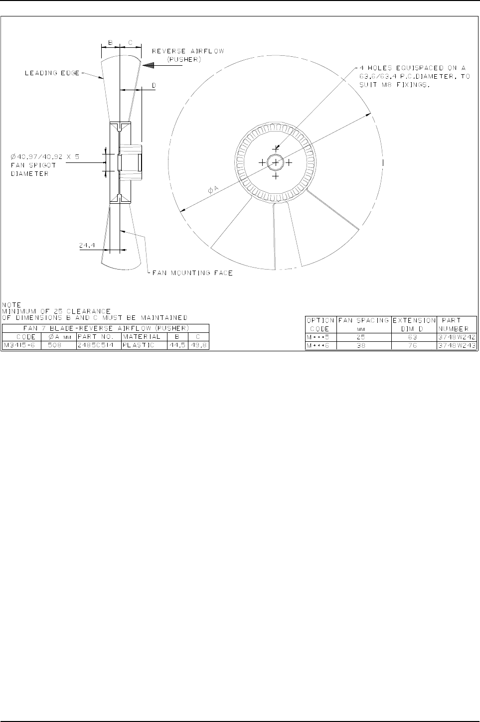

Engine Specification Manual, TPD1599 Issue 6, January 2009 99
1100 Series, 1104D, Mechanical FIE
Alternators
Standard vee belt drive
Multi vee belt drive
Alternator branding
Description Option
Not required N0000
12V, 65A, lug mounted alternator N0101
12V, 75A, lug mounted alternator N0111
12V, 85A, lug mounted alternator N0121
12V, 100A, lug mounted alternator N0131
12V, 120A, lug mounted alternator (1)
1. Incompatible with ZM121/ZM122/ZM130/ZM131.
N0171
24V, 75A, lug mounted alternator N0301
24V, 55A, lug mounted alternator N0321
Description Option
Alternator, bracket and tensioner not required N0000
Tensioner supplied using transit fixings only N0050
12V, 65A, lug mounted alternator N0101
12V, 75A, lug mounted alternator N0111
12V, 85A, lug mounted alternator N0121
12V, 100A, lug mounted alternator N0131
12V, 120A, lug mounted alternator (1)
1. Incompatible with ZM121/ZM122/ZM130/ZM131.
N0171
24V, 75A, lug mounted alternator N0301
24V, 55A, lug mounted alternator N0321
Description Option
Not applicable (1)
1. Compatible with N0000 only.
NL000
Standard NL001
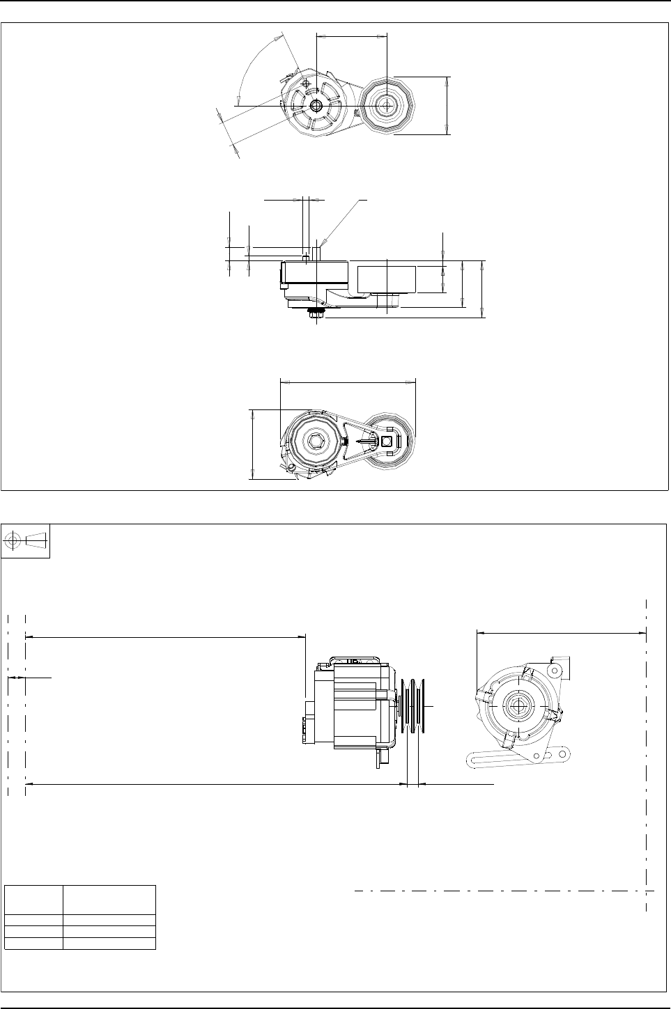
100 Engine Specification Manual, TPD1599 Issue 6, January 2009
1100 Series, 1104D, Mechanical FIE
N0050 - Automatic belt tensioner
N0101/N0111/N0121 - Alternator 65A, 75A, 85A, 12v
31
65°
90
Ø74
7,234
6,3
17,4
Ø8,1
60,1
72,6
173
89
2637A001 belt tensioner assembly
M10x1,50
code
Option Alternator
2871A302
2871A301
2871A303
N0101
N0111
N0121
3824A071 bracket 36155429 link
450,8
single pulley614,7 twin pulley18
28,6
295,5 max
Z
Z
Y
Y
X2 X
X2 X
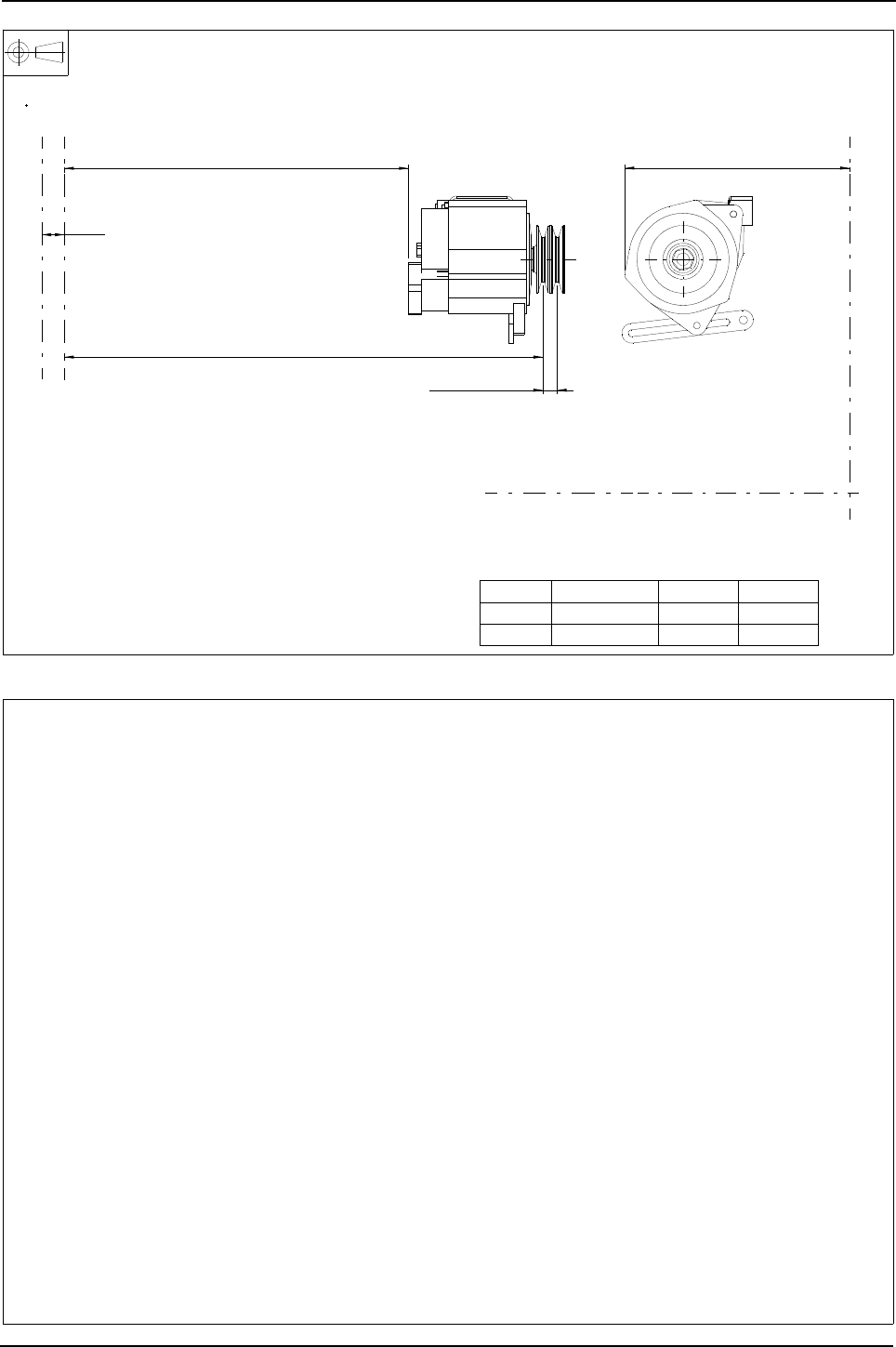
Engine Specification Manual, TPD1599 Issue 6, January 2009 101
1100 Series, 1104D, Mechanical FIE
N0131/N0171/N0301/N0321 - Alternator, 100A, 120A, 12v and 55A, 75A 24v
Multi Vee belt drive
309.5 Max
twin pulley18
608,2 single pulley
437,2
28,6
0ption Alternator Voltage Current
N0131 2871A304 12V 100A
N0321 2781A701 24V 55A
3824A071 bracket 36155429 link
Y
Y
Z
Z
X2 X
X2 X
Artwork required
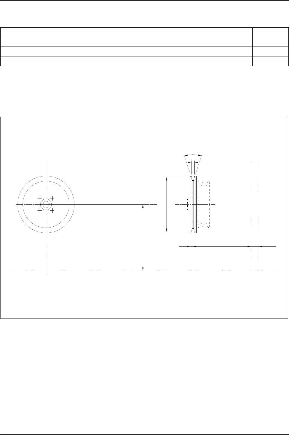
102 Engine Specification Manual, TPD1599 Issue 6, January 2009
1100 Series, 1104D, Mechanical FIE
Belt driven auxiliaries
Standard vee belt drive
P0001 - Auxiliary drive, single groove pulley, 200 mm diameter
Description (1)
1. Standard vee belts supplied with all options except when F0501/F0502/F0503/F0504 or K0000 or when F0000
with N0000 selected.
Option
Not required P0000
Auxiliary drive, single groove pulley, 200 mm diameter (2)
2. Incompatible with ZM101/ZM102/ZM103/ZM110.
P0001
Auxiliary drive, single groove pulley, 140 mm diameter (3)
3. Engine supplied with twin belts, compatible with F0062/F0063/F0061/F0064 only,
for use with fan pulley 140 mm only.
P0003
3114X191 pulley - fan drive
12,7
36°
655.5
200Ø
28,6
See 'F' options
effective
assys and fan heights
for fan drive housing
Refer to 'F' options
Y Y
Z
Z
X2X
X2X
10
the fan extension 2 mm forwards
pulley has the effect of moving
The addition of this auxilary
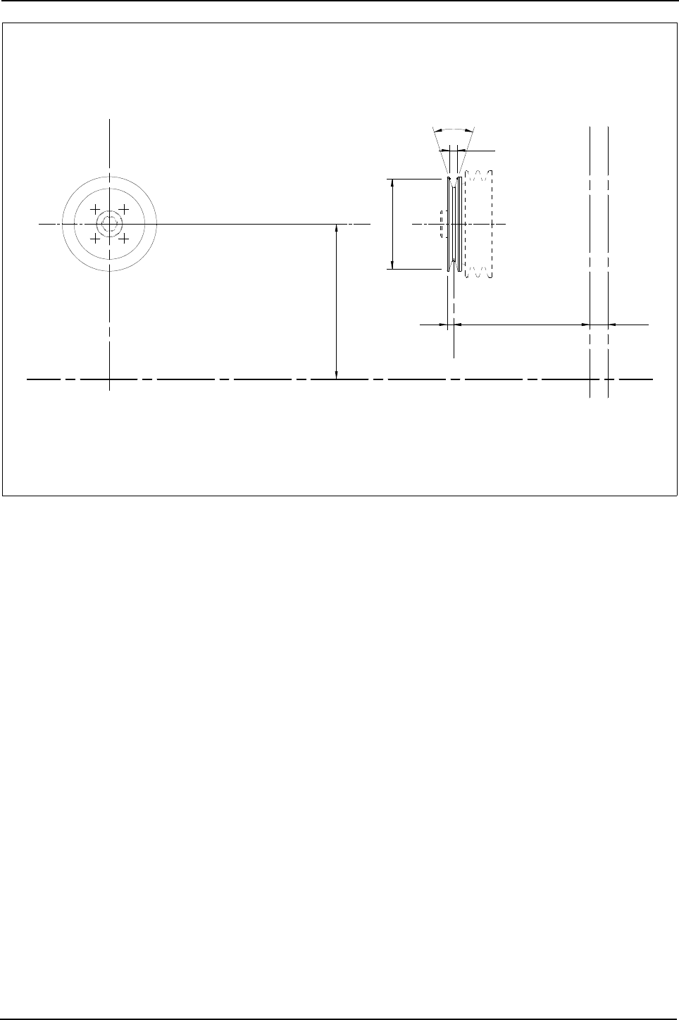
Engine Specification Manual, TPD1599 Issue 6, January 2009 103
1100 Series, 1104D, Mechanical FIE
P0003 - Auxiliary drive, single groove pulley, 140 mm diameter
10 28,6655,5
36°
See 'F' options
effective
assys and fan heights
for fan drive housing
refer to 'F' options
12,7
Y Y
Z
Z
X2X
X2X
140Ø
the fan extension 2 mm forwards
pulley has the effect of moving
The addition of this auxilary
3114X192 pulley - fan drive

104 Engine Specification Manual, TPD1599 Issue 6, January 2009
1100 Series, 1104D, Mechanical FIE
Timing case and gear driven auxiliaries
Description Option
Timing case, single LHS PTO (142 Nm Max.)
No auxiliaries (1)
1. Incompatible with HD004/HD005/HD007/HD0100, ZM110/ZM131.
Q1000
Exhauster Q1001
Hydraulic pump drive adaptor, 2 bolt fixing, SAE flange, 13 tooth spline, LHS Q1005
Hydraulic pump drive adaptor, 4 bolt fixing Q1009
Hydraulic pump drive adaptor, 2 bolt fixing, SAE flange, 11 tooth spline, LHS Q1015
Hydraulic pump drive adaptor, 2 bolt fixing, SAE flange, 9 tooth spline, LHS Q1016
Timing case, single LHS PTO (210 Nm Max.)
No auxiliaries (1) Q1030
Hydraulic pump drive adaptor, 2 bolt fixing, SAE flange, 13 tooth spline, LHS Q1035
Hydraulic pump drive adaptor, 2 bolt fixing, SAE flange, 11 tooth spline, LHS Q1036
Hydraulic pump drive adaptor, 2 bolt fixing, SAE flange, 9 tooth spline, LHS Q1037
Adaptor and extension for SAE B drive (2) Q1038
Timing case, single LHS PTO (80 Nm Max.)
Z drive adaptor with SAE B flange for customer fit compressor or auxiliaries (2) (3)
2. Incompatible with LHS dipstick options ZJ006/ZJ008.
3. Design includes a ‘Z’ drive adaptor driven from the standard duty LHS PTO timing case.
Q1020
Z drive adaptor and compressor, 225 cc with SAE flange, head unload (3) (4)
4. Only compatible with ZZ014.
Q1023
Z drive adaptor and compressor, 225 cc with DIN flange, head unload (3) (4) Q1024
Z drive adaptor and compressor, 225 cc with DIN flange, line unload (3) (4) Q1025
Z drive adaptor and compressor, 225 cc with SAE flange, line unload (3) (4) Q1026
Timing case, no PTO capability
No PTO capability (5)
5. Incompatible withHD005/HD100
Q1100
Timing case, twin PTO (210 Nm Max.)
No auxiliaries (1) Q2030
Hydraulic pump drive adaptor, 2 bolt fixing, SAE flange, 13 tooth spline, LHS (1) Q2035
Hydraulic pump drive adaptor, 2 bolt fixing, SAE flange, 11 tooth spline, LHS (1) Q2036
Hydraulic pump drive adaptor, 2 bolt fixing, SAE flange, 9 tooth spline, LHS (1) Q2037
Adaptor and extension for SAE B drive (2) Q2038
Timing case, single RHS PTO
Aluminium timing case, single RHS PTO, no auxiliaries fitted. (Medium duty 38 Nm PTO max) Q3000
No auxiliaries fitted (76 Nm Max. PTO) Q3030
Timing case, single PTO
Heavy duty to suit compressor 630cc,SAE flange, head unload (4) (6)
6. Incompatible with RHS dipstick options and timing case fillers.
Q4042
Timing case, single LHS PTO (280 Nm Max.)
Heavy duty to suit SAE B drive flange, 13 tooth spline, no auxiliaries Q4055
Heavy duty to suit SAE B drive flange, 15 tooth spline, no auxiliaries Q4059
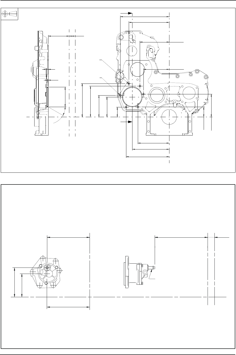
Engine Specification Manual, TPD1599 Issue 6, January 2009 105
1100 Series, 1104D, Mechanical FIE
Q1000 - Timing case LHS PTO, no auxiliaries fitted
Q1001 - Exhauster
A
A
28,6511,5
ø95,079
95,025
30°
1,8
1,0
9
151,3
178,3
208,6
48,7
110,5
47,8
104,8
96,9
149,7
161,2
124,6
141,5
195,3
236,7
Section A-A
X2
X
X2
X
YY
Z
Z
3716C571 timing case LHS PTO.
M10 x 1,5
5 - M8 x 1,25
protrusion of
14,5 Max from
rear of timing case
A1125
178,3
96,9
TO SUIT 10 I/DIA. PIPE
VACUUM CONNECTION
Y Y
Z
X
ZX
X2
X2
28,6
122,1
177,3 )4 CYL(389,2
)
6 CYL
(
622,5
)SPIGOT(
)
SPIGOT(
Exhauster 2488A296
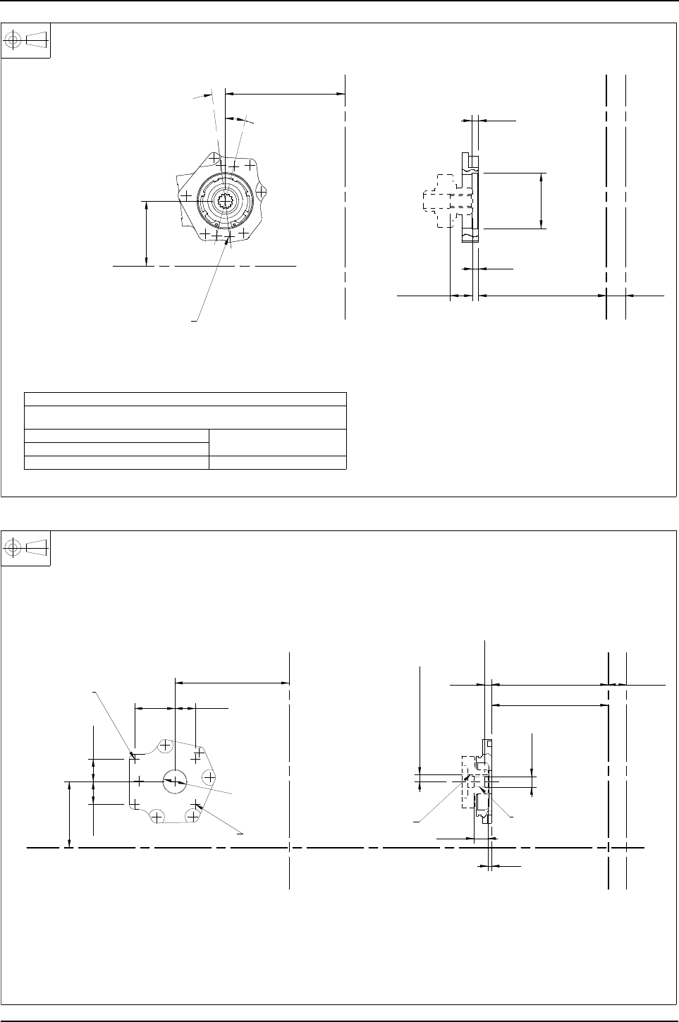
106 Engine Specification Manual, TPD1599 Issue 6, January 2009
1100 Series, 1104D, Mechanical FIE
Q1005, Q1035 and Q2035 - Hydraulic pump drive adaptor, 2 bolt fixing, SAE flange, 13 tooth spline, LHS
Q1009 - Hydraulic pump drive adaptor, 4 bolt fixing, LHS PTO
R&&&&Q1005
X2
X2
7°
14°
82,55
82,61
Ø
9,5
28,6487
178,3
96,6
YY
(2 pairs S.A.E 'A' fitting)
ON 106,4 P.C.DIA.
4 - M10 x 1,5 x 25 deep
9,1
33
to ANSI B92.1 Class 6
Flat root side fit details
spline
of
Length
Pitch - 16/32
Pressure angle - 30°
Major Dia. - 22,225
22,504
Pitch Dia. - 20,637
Number of teeth - 13
Gear spline data
YY
Z
Z
X
X
4113H092 adaptor - hydraulic pump drive L.H.S P.T.O
R&&&&Q1009
103,9
35,7
36,474
36,515
Ø
16,54
16,79
28,6 4 Cyl497
on diameter
Taper 1: 8
6 Cyl730,3
X2
X2
Z
Z
YY
X
X
Keyway width
3,20
3,25
keyway
Height of
1 - M6 x 1 x 12
3 - M6 x 1
10,77
22,2
Dia
Gauge
line
Gauge
6,1
11,8
63,7 32,5
35,7
179,8
375IK082 adaptor - hydraulic pump drive - LHS PTO
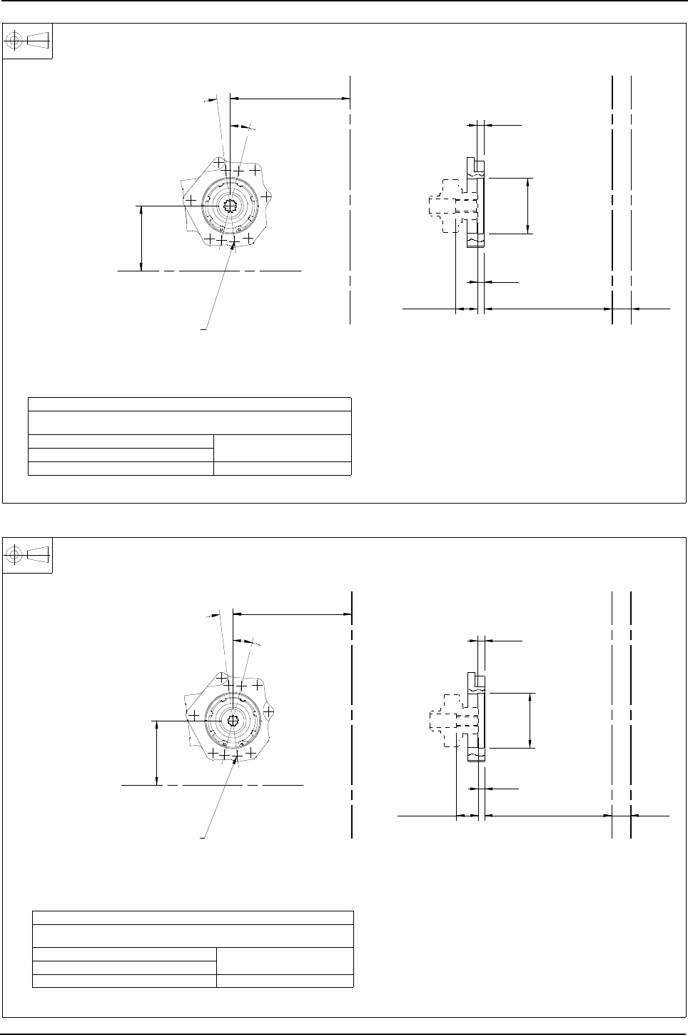
Engine Specification Manual, TPD1599 Issue 6, January 2009 107
1100 Series, 1104D, Mechanical FIE
Q1015, Q1036 and Q2036 - Hydraulic pump drive adaptor, 2 bolt fixing, SAE flange, 11 tooth spline, LHS
Q1016, Q1037 and Q2037 - Hydraulic pump drive adaptor, 2 bolt fixing, SAE flange, 9 tooth spline, LHS
R&&&&1015A
to ANSI B92.1 Class 6
Flat root side fit details
82,55
82,61
Ø
X2
X2
14°
7°
487
(2 pairs, S.A.E 'A' fitting)
On 106,4 P.C.Dia.
4- M10 X 1,5 X 25 deep 28,6
9,5
Pitch Dia. - 17,463
Major Dia. - 19,71
Number of teeth - 11
spline
of
Length
Pitch - 16/32
Pressure angle - 30°
Gear spline data
9,1
33
YY
Z
Z
X
X
96,9
178,3
4113H093 adaptor - hydraulic pump drive L.H.S. P.T.O.
R&&&&Q1016
to ANSI B92.1 Class 6
Flat root side fit details
7°
14°
96,9
178,3
82,55
82,61
Ø
9,1
33
9,5
487
(2 pairs, S.A.E 'A' fitting)
on 106,4 P.C.Dia.
4- M10 X 1,5 X 25 deep
15,875
16,154
Pitch Dia. - 14,288
Number of teeth - 9
spline
of
Length
Pitch - 16/32
Pressure angle - 30°
Major Dia. -
Gear spline data
28,6
YY
Z
Z
X
X
X2
X2
4113H094 adaptor - hydraulic pump drive L.H.S. P.T.O
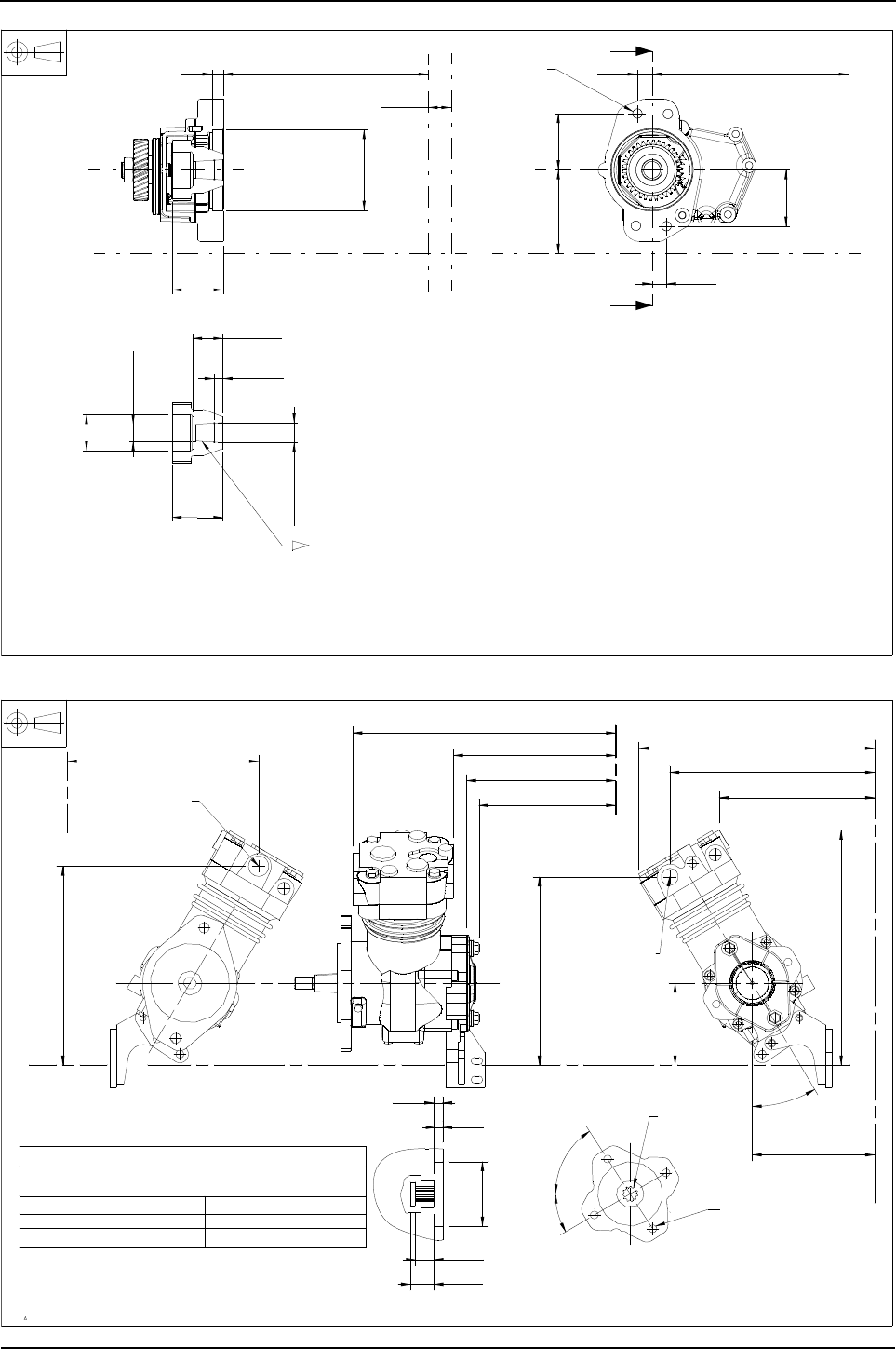
108 Engine Specification Manual, TPD1599 Issue 6, January 2009
1100 Series, 1104D, Mechanical FIE
Q1020 - Z drive adaptor with SAE B flange for customer fit compressor or auxiliaries
Q1023 - Compressor 225 cc with SAE flange, head unloader
A
A
432,7
28,6
ø101,679
101,625
gear to adaptor
mounting face
64,3
14
38,48
38,08
64,2
63,8
ø46
ø21,1
21,0
ø
Gauge Dia
24
11,18
10,58
246,7
104,870,7
70,7
18,3
18,3
Part view for
gear details
2488A299 adaptor assembly
Y
Z
Z
2-M12 X 1,75
Section A-A
Y
XX2
XX2
0,125 ±0,001:1
2488A293 COMPRESSOR 3823A059 BRACKET 4148K001 COVER
352,2
334,7
M22 X 1,5 X 14
PORT
AIR DELIVERY
M26 X 1,5 X 16
AIR INLET PORT
254,4
PITCH DIA. - 17,463
TO A.N.S.I. B92.1 1970
FLAT ROOT SIDE FIT INVOLUTE
GEAR SPLINE DATA
MAJOR DIA. - 19,71
PRESSURE ANGLE - 30°
PITCH - 16/32
NUMBER OF TEETH - 11
ON 106,4 P.C.DIA
SPACED AS SHOWN
4-HOLES M10 X 1,5
TO SUIT SAE 'A' FLANGE
MOUNTING DETAILS TO
HYDRAULIC PUMP DRIVE
30,2
23,8
11
9,5
82,59
82,64
Ø
30,5°
57°
256.3
AIR INLET417,7
AIR DELIVERY288,7
104,8
Z
YY
X
X
Z
SPLINE
11 TOOTH
Z
391,9
30,5°
Z
272
288,8
240,6
300,7
246,7
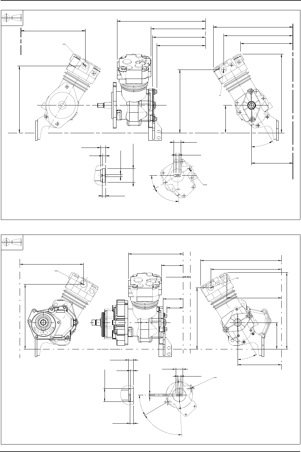
Engine Specification Manual, TPD1599 Issue 6, January 2009 109
1100 Series, 1104D, Mechanical FIE
Q1024 - Compressor 225 cc with DIN flange, head unloader
Q1025 - Z drive adaptor and compressor, 225 cc with DIN flange, line unload
267 288,8
240,6
300,7
246,7
2488A291 COMPRESSOR 3823A059 BRACKET 4148K004 COVER
352,2
334,7
M22 X 1,5 X 14
PORT
AIR DELIVERY
M26 X 1,5 X 16
AIR INLET PORT
254,4
282,6
AIR INLET417,7
AIR DELIVERY288,7
104,8
Z
YY
X
X
ZZ
391,9
30,5°
Z
12,0
12,5
Ø
104 P.C.DIA.
SPACED AS SHOWN ON
4-HOLES M10 X 1,5 X 15
52,00
52,03
Ø
18,30
19,05
11,75
13,50
MOUNTING DETAILS.
HYDRAULIC PUMP DRIVE
30,5°
27Ø
63°
7,90
7,99
12
30,5°
63°
ø27
ø12,5
12,0
7,99
7,90
30,5°
ø52,03
52,00
12
13,50
11,75
300,6
392,1
352,2
288,9
282,7
267
288,8
417,8
104,8
240,6
254,4
334,8
19,05
18,30
28,6
246,8
Hydraulic pump drive
mounting details
Z
Z
Y
XX2
XX2
Z
Z
2488A292 compressor 3823A059 bracket 4148K004 cover
Air delivery port
M22 X 1,5 X 14
Air inlet port
M26 X 1,5 X 16
4- holes M10 X 1,5 X 15
spaced as shown on
104 PCD
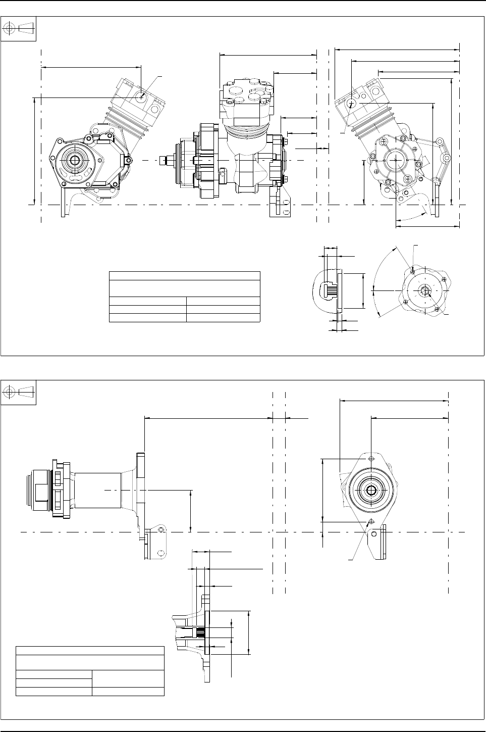
110 Engine Specification Manual, TPD1599 Issue 6, January 2009
1100 Series, 1104D, Mechanical FIE
Q1026 - Z drive adaptor and compressor, 225 cc with SAE flange, line unload
Q1038 - Adaptor and extension for SAE B drive
30,2
23,8
9,5
11
ø82,64
82,59
57°
30,5°
254,4
334,8
104,8
300,6
352,2
288,9
392,1
240,7
28,6
256,5
272,1
288,8
417,8
30,5°
246,8
Gear spline data
Flat root side fit involute
to A.N.S.I. B92.1 1970
Number of teeth - 11 Major Dia - 19.71
Pitch - 16/32 Pitch Dia - 17,463
PRessure Angle - 30°
YY
Z
Z
Z
Z
X2
X
X2
X
AIR INLET
air delivery
4-holes M10 X 1,5
spaced as shown
on 106,4 PCD
11 tooth
spline
Hydraulic pump drive
mounting details to
suit SAE "A" drive
2488A294 compressor 4148K001 cover 3823A059 bracket
Air delivery port
M22 X 1,5 X 14
Air inlet port
M26 X 1,5 X 16
297,5 28,6 178,3
24146
251,4
96,9
Spline length
19
11,7
40,3
ø23,8
12
ø101,66
101,60
Gear spline data
Flat root side fit details
to SAE standard 1963
Number of teeth - 13 22,504
Major Dia. - 22,225
Pitch - 16/32
Pressure angle - 30° Pitch Dia. - 20,637
4113H092 adaptor 3751K112 housing 3821A026 bracket
YY
X
X
X2
X2
2 - M12 X 1,75
Z
Z
Section A-A
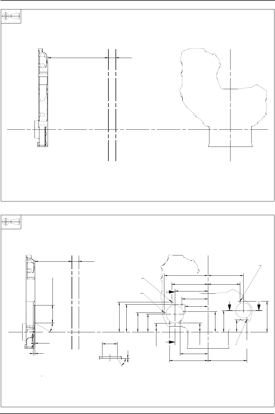
Engine Specification Manual, TPD1599 Issue 6, January 2009 111
1100 Series, 1104D, Mechanical FIE
Q1100 - Timing case with no PTO capability
Q2030 - Timing case, twin PTO
3716C462 timing case no PTO
511,6 28,6
View on rear
X
Y
X2
X2
XZ
Z
Y
3716C491 timing case twin PTO.
192,6
Section B-B
BB
165,9
115,9
M10 x 1.5
x 22
M10 x1.5
1
Min
82,575
82,600
Ø
60°
65,9
210,5
174,2
9
1,0
1,8
30°
95,025
95,079
Ø
28,6
A
A
View on rear
124,6
141,5
Section A-A
Y
M10 x 1,5
104,8
110,4
96,9
48,7
195,3
47,7
rear of timing case
bolts 14,5 Max from
protrusion of
5 - M8 x 1,25
178,3
161,2
149,7
151,3
X
208,6
511,6
236,7
X2
X2
X
Z
Z
Y
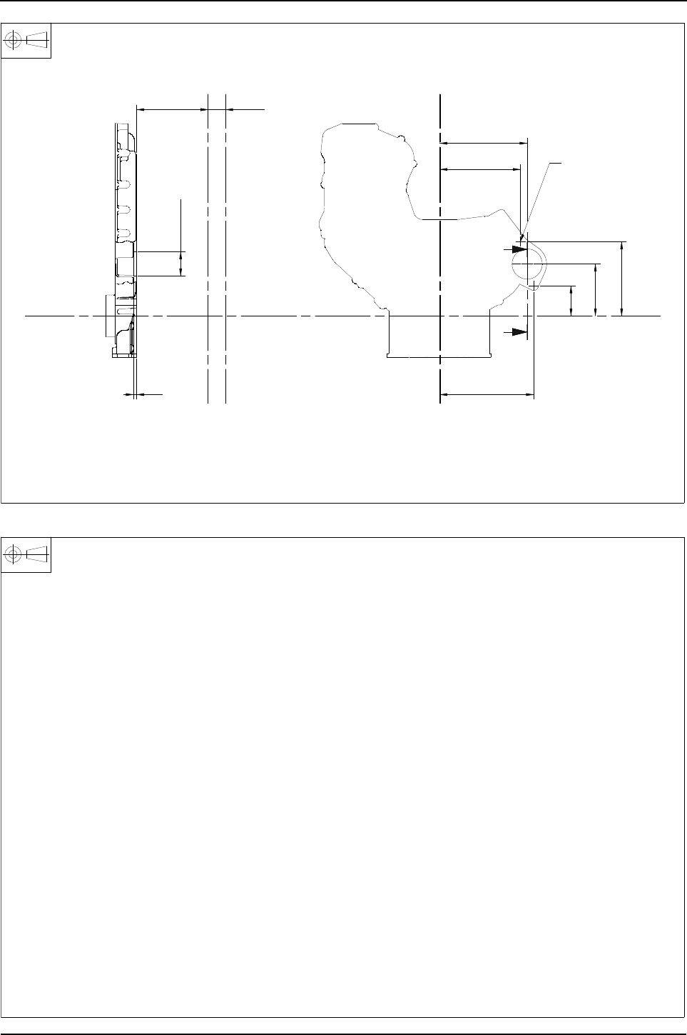
112 Engine Specification Manual, TPD1599 Issue 6, January 2009
1100 Series, 1104D, Mechanical FIE
Q3000/Q3030 - Timing case, single RHS PTO, no auxiliaries fitted
Q4042 - Heavy duty to suit compressor 630 cc, SAE flange, head unload
160,5
65,1
202,8
176,2
A
A
2 - Ø 11,0
timing case
from rear of
bolts 14,5 Max
protrusion of
Section A-A
190,6
7
65,20
65,25
Ø
112,2
28,6
X
View on rear
Y
511,6
X2
X2
X Z
Z
Y
3716C481 timing case RHS PTO
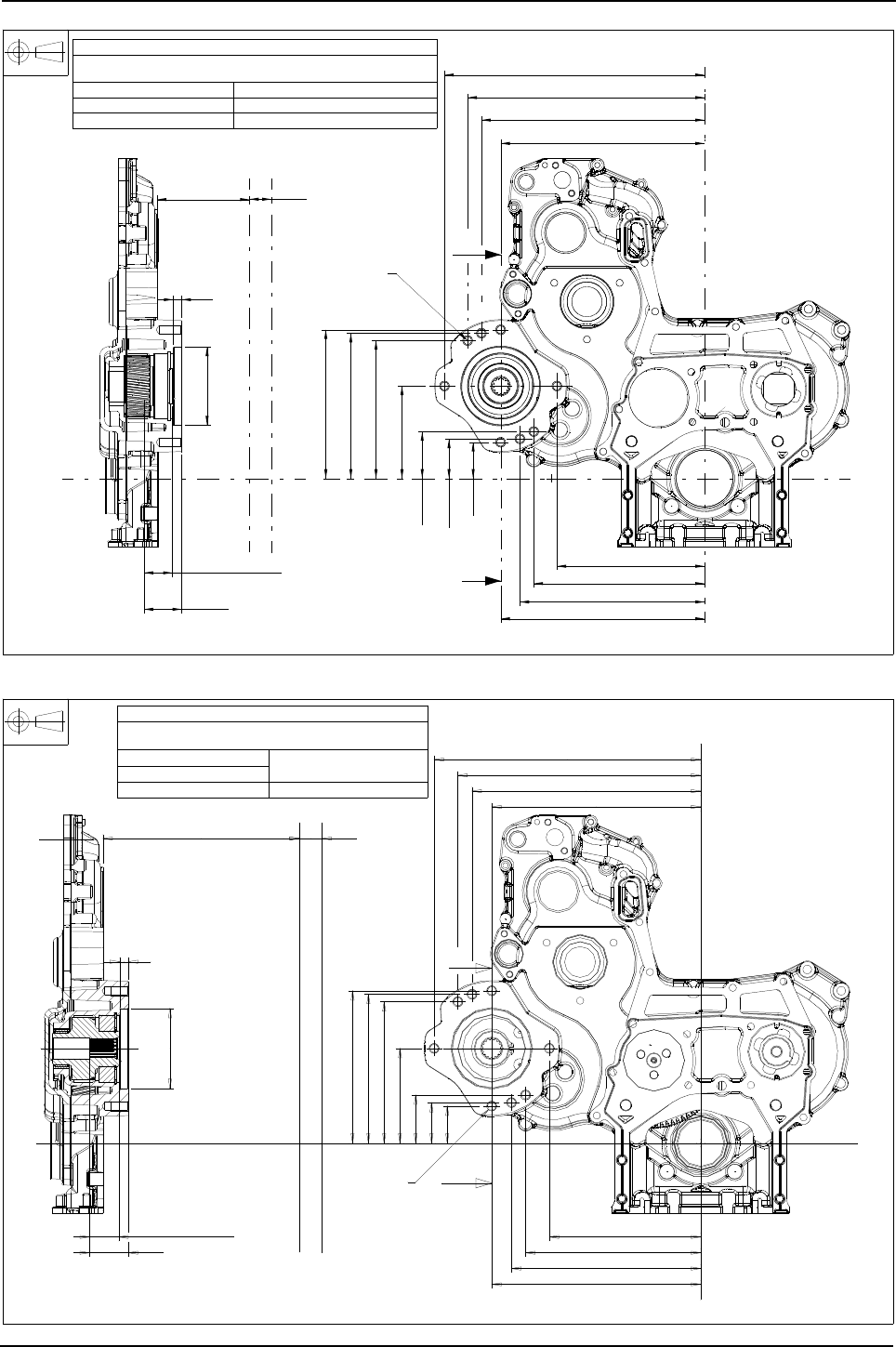
Engine Specification Manual, TPD1599 Issue 6, January 2009 113
1100 Series, 1104D, Mechanical FIE
Q4055 - Heavy duty to suit SAE B drive flange, 13 tooth spline, no auxiliaries
Q4059 - Heavy duty to suit SAE B drive flange, 15 tooth spline, no auxiliaries
A
A
ø101,625
101,600
11
193
188,6
179,1
120
60,9
51,4
47
264,9
240
191,9
222
338
307,9
289,9
264,9
49,1
511,6 28,6
SPLINE LENGTH
37
GEAR SPLINE DATA
FLAT ROOT SIDE FIT DETAILS
TO ANSI B92.1 CLASS 6
NUMBER OF TEETH - 13 MAJOR DIA - 22,504/22,225
PITCH - 16/32 PITCH DIA - 20,637
PRESSURE ANGLE - 30°
SECTION A-A
XX2
XX2
YY
Z
Z
3716E082 TIMING CASE LHS SAE B HIGH PTO
8 - M12 X 1.75
A
A
511,6 28,6
SPLINE LENGTH37
49,1
11
191,9
222
240
264,9
264,9
289,9
307,9
338
47
51,4
60,9
120
179,1
188,6
193
ø101,625
101,600
GEAR SPLINE DATA
FLAT ROOTSIDE FIT DETAILS TO
NUMBER OF TEETH-15 MAJOR DIA-26,06
PITCH-16/32
PRESSURE ANGLE-30° PITCH DIA-23,813
X
Z
3716E081 TIMING CASE SAE B HIGH PTO 15T SPLINE
X2
Y
8-M12x1,75
XX2
Y
Z
SECTION A-A
ANSI B92.1 CLASS 6

114 Engine Specification Manual, TPD1599 Issue 6, January 2009
1100 Series, 1104D, Mechanical FIE
Balancer
R0000 - Balancer not required
R0001 - Balancer fitted
Description Option
Not required R0000
Balancer fitted (1)
(1). Compatible with balanced ratings only, see A options.
Not compatible with oil filter options J0031/J0071/J0011/J0021/J0030/J0070.
See “Lubricating oil sumps and dipsticks” on page 68. for compatible sumps.
R0001

Engine Specification Manual, TPD1599 Issue 6, January 2009 115
1100 Series, 1104D, Mechanical FIE
Manifolds, elbows and air filters for turbocharged engines
Description (1) (2)
(1). No additional loading should be applied directly from the turbine housing.
(2). All exhaust outlet systems must be supported by a bracket which is independent to the turbocharger using a
floating coupling.
Option
Not required S0000
Side mounted turbo, RHS, exhaust forward, no exhaust elbow, cross over pipe to rear, end (3)
(3). Incompatible with ZM121/ZM122/ZM130/ZM131.
S0100
Side mounted turbo, RHS, exhaust forward, no exhaust elbow, cross over pipe to rear, top (3) S0101
Side mounted turbo, RHS, exhaust elbow forward up, cross over pipe to rear, end (3) (4)
(4). Incompatible with G0607.
S0110
Side mounted turbo, RHS, exhaust elbow forward up, cross over pipe to rear, top (3) (4) S0111
Side mounted turbo, RHS, exhaust elbow forward up, cross over pipe to rear, top with air filter (3) (4) (5)
(5). Incompatible with X0002.
S0114
Side mounted turbo, RHS, exhaust elbow forward up, cross over pipe to rear, top with heavy duty air filter
with ejector supplied S0115
Side mounted turbo, RHS, exhaust elbow forward down, cross over pipe to rear, end (3) (5) S0120
Side mounted turbo, RHS, exhaust elbow forward down, cross over pipe to rear, top (3) (4) (5) (6)
(6). Incompatible with G***3.
S0121
Side mounted turbo, RHS, exhaust rearward, no exhaust elbow, cross over pipe to rear, end (3) S0150
Side mounted turbo, RHS, exhaust rearward, no exhaust elbow, cross over pipe to rear, top (3) (5) S0151
Top mounted turbo, exhaust outlet rearward, no exhaust elbow, cross over pipe to rear, top (3) S0251
Side mounted turbo, RHS, exhaust forward, no exhaust elbow, compressor outlet up, for air to air cooling (7)
(7). Only compatible with ZM000/ZM121/ZM122/ZM130/ZM131.
S1101
Side mounted turbo, RHS, exhaust elbow forward up, compressor outlet up, for air to air cooling (4) (7) S1111
Side mounted turbo, RHS, exhaust elbow forward up, compressor outlet down, for air to air cooling (7) S1112
Side mounted turbo, RHS, exhaust elbow forward up, compressor outlet down, for air to air cooling, with air
filter (4) (5) (7) S1114
Side mounted turbo, RHS, exhaust elbow forward up, compressor outlet down, for air to air cooling, with
heavy duty air filter with ejector supplied S1115
Side mounted turbo, RHS, exhaust elbow forward down, compressor outlet up, for air to air cooling (4) (5) (7) S1121
Side mounted turbo, RHS, exhaust rearward, no exhaust elbow, compressor outlet up, for air to air cooling (7) S1151
Side mounted turbo, RHS, exhaust rearward, no exhaust elbow, compressor outlet down, for air to air cooling
(4) (7) S1152
Side mounted turbo, RHS, exhaust elbow rearward up, compressor outlet up, for air to air cooling (7) S1181
Side mounted turbo, RHS, exhaust elbow rearward up, compressor outlet down, for air to air cooling (4) (7) S1182
Top mounted turbo, exhaust rearward, no exhaust elbow, compressor outlet across, for air/air cooling (7) S1253
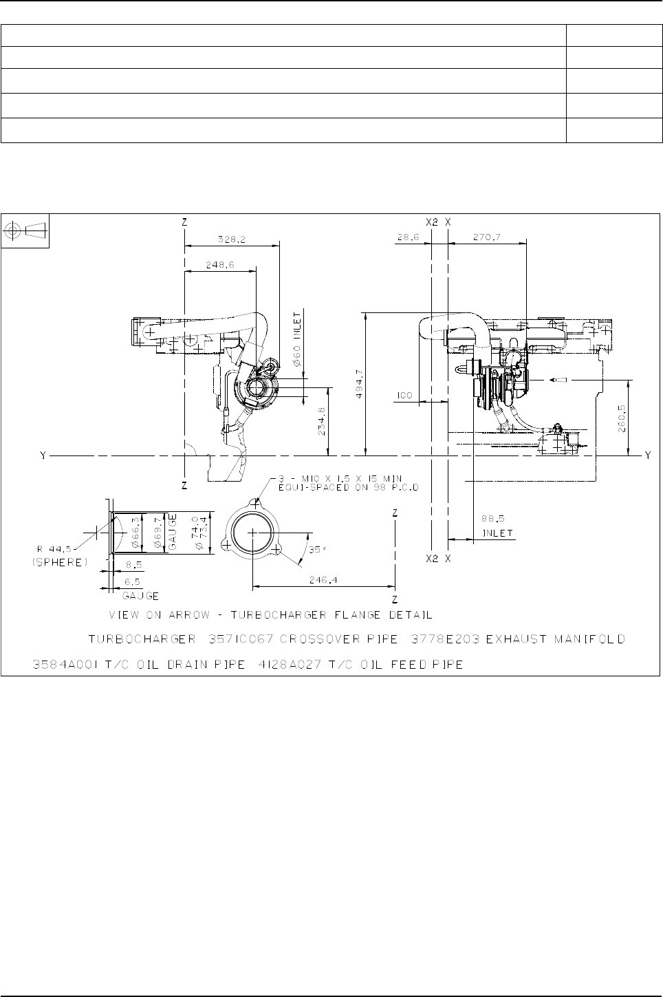
116 Engine Specification Manual, TPD1599 Issue 6, January 2009
1100 Series, 1104D, Mechanical FIE
Exhaust hardware
S0100 - Side mounted turbo, RHS, exhaust forward, no exhaust elbow, cross over pipe to rear, end
Description Option
Not required SD000
Studs and nuts only (1)
(1). Only available with turbo charged options supplied and fitted with an exhaust elbow.
SD002
Studs, nuts, flange and gasket (1) SD003
Studs, nuts only (2)
(2). Only available with turbo charged options that are not supplied and fitted with an exhaust elbow.
SD004
2674A843
2674A816
2674A817
Rating specific
}
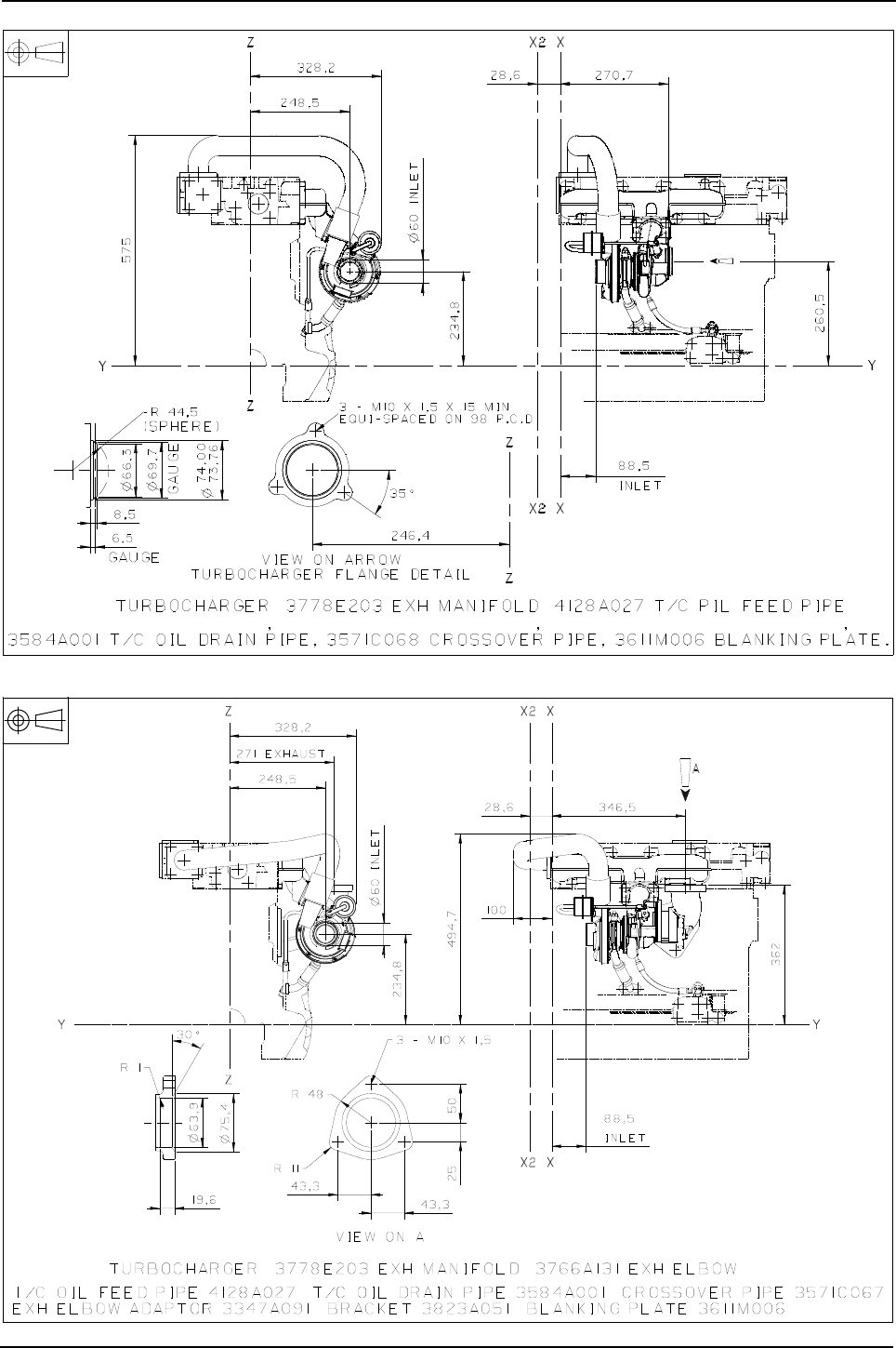
Engine Specification Manual, TPD1599 Issue 6, January 2009 117
1100 Series, 1104D, Mechanical FIE
S0101 - Side mounted turbo, RHS, exhaust forward, no exhaust elbow, cross over pipe to rear, top
S0110 - Side mounted turbo, RHS, exhaust elbow forward up, cross over pipe to rear, end
2674A843
2674A816
2674A817
Rating specific
}
2674A843
2674A816
2674A817
Rating specific
}
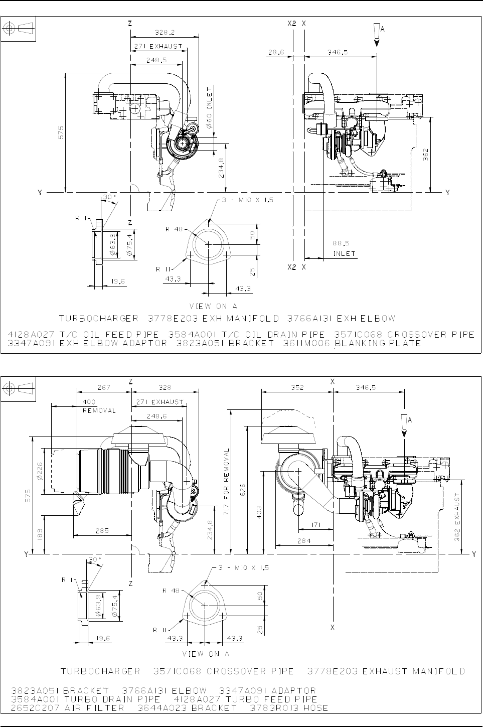
118 Engine Specification Manual, TPD1599 Issue 6, January 2009
1100 Series, 1104D, Mechanical FIE
S0111 - Side mounted turbo, RHS, exhaust elbow forward up, cross over pipe to rear, top
S0114 - Side mounted turbo, RHS, exhaust elbow forward up, cross over pipe to rear, top with air filter
2674A843
2674A816
2674A817
Rating specific
}
2674A843
2674A816
2674A817
Rating specific
}
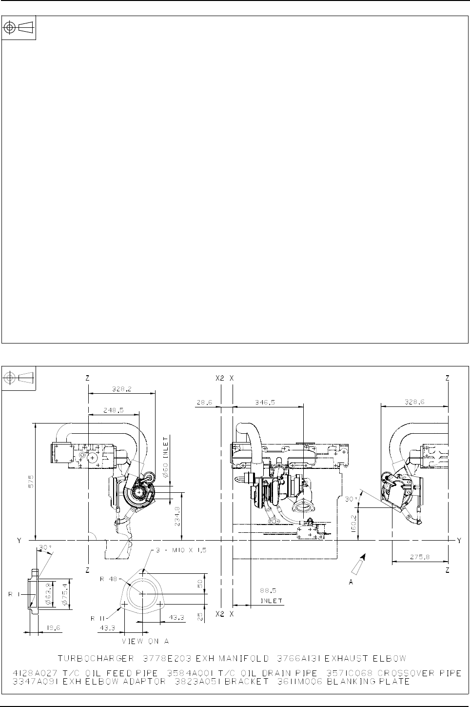
Engine Specification Manual, TPD1599 Issue 6, January 2009 119
1100 Series, 1104D, Mechanical FIE
S0120 - Side mounted turbo, RHS, exhaust elbow forward down, cross over pipe to rear, end
S0121 - Side mounted turbo, RHS, exhaust elbow forward down, cross over pipe to rear, top
2674A843
2674A816
2674A817
Rating specific
}
turbocharger
2674A843
2674A816
2674A817
Rating specific
}
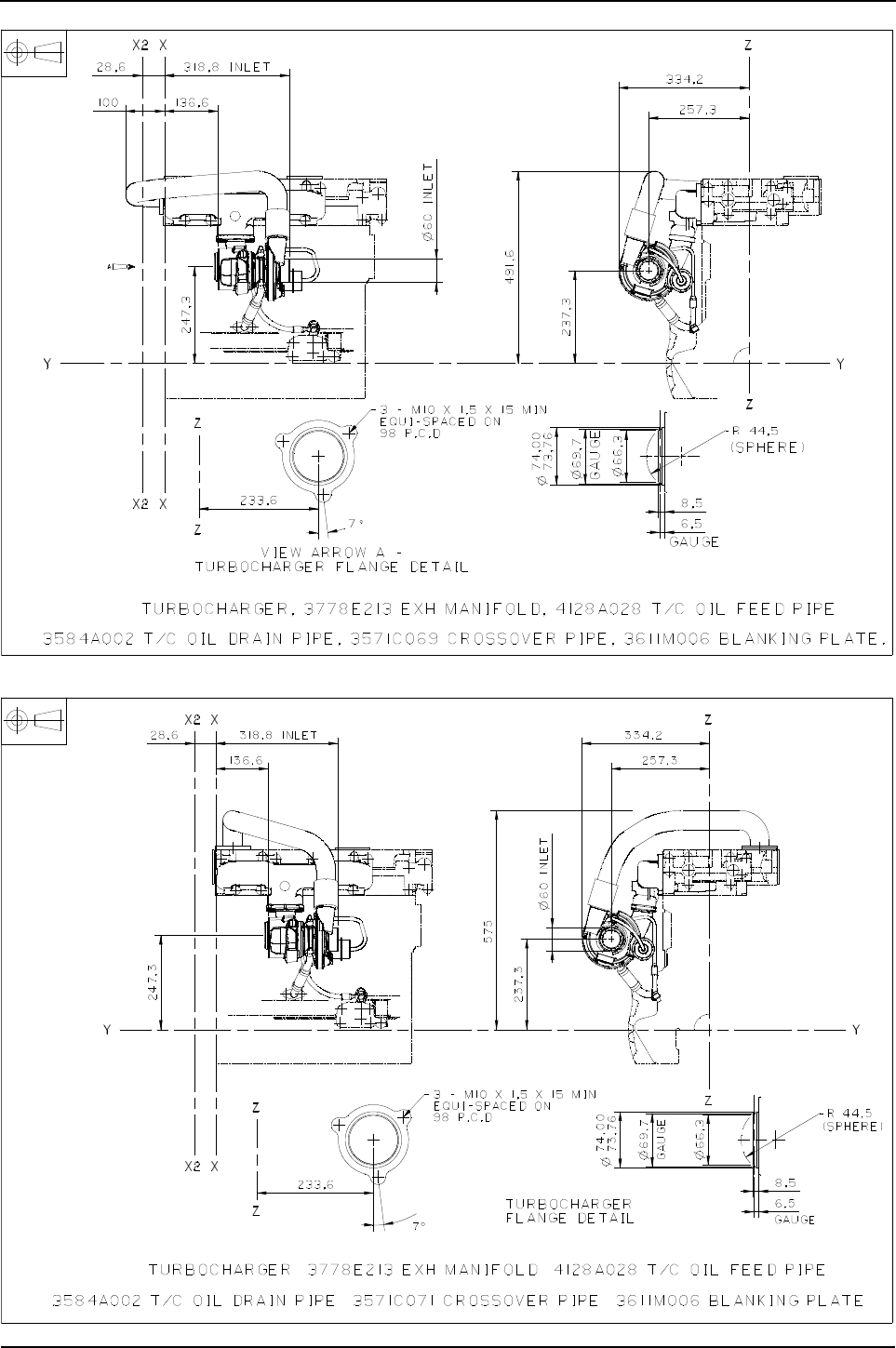
120 Engine Specification Manual, TPD1599 Issue 6, January 2009
1100 Series, 1104D, Mechanical FIE
S0150 - Side mounted turbo, RHS, exhaust rearward, no exhaust elbow, cross over pipe to rear, end
S0151 - Side mounted turbo, RHS, exhaust rearward, no exhaust elbow, cross over pipe to rear, top
2674A844
2674A819
2674A821
Rating specific
}
2674A844
2674A819
2674A821
Rating specific
}
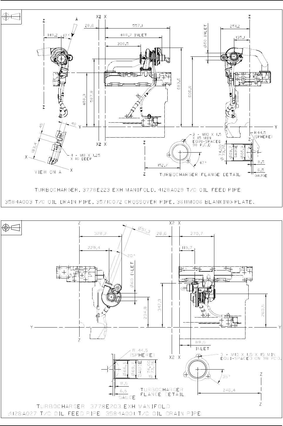
Engine Specification Manual, TPD1599 Issue 6, January 2009 121
1100 Series, 1104D, Mechanical FIE
S0251 - Top mounted turbo, exhaust outlet rearward, no exhaust elbow, cross over pipe to rear, top
S1101 - Side mounted turbo, RHS, exhaust forward, no exhaust elbow, compressor outlet up, for air to air cooling
2674A845
2674A826
2674A827
Rating specific
}
2674A835
2674A841
Rating specific
}
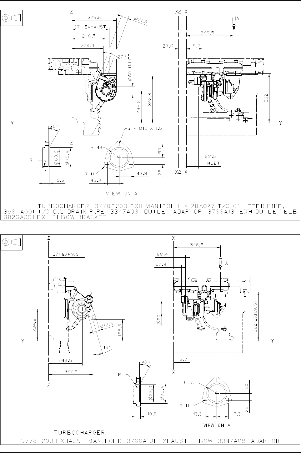
122 Engine Specification Manual, TPD1599 Issue 6, January 2009
1100 Series, 1104D, Mechanical FIE
S1111 - Side mounted turbo, RHS, exhaust elbow forward up, compressor outlet up, for air to air cooling
S1112 - Side mounted turbo, RHS, exhaust elbow forward up, compressor outlet down, for air to air cooling
2674A835
2674A841
Rating specific
}
2674A842
2674A839
Rating specific
}
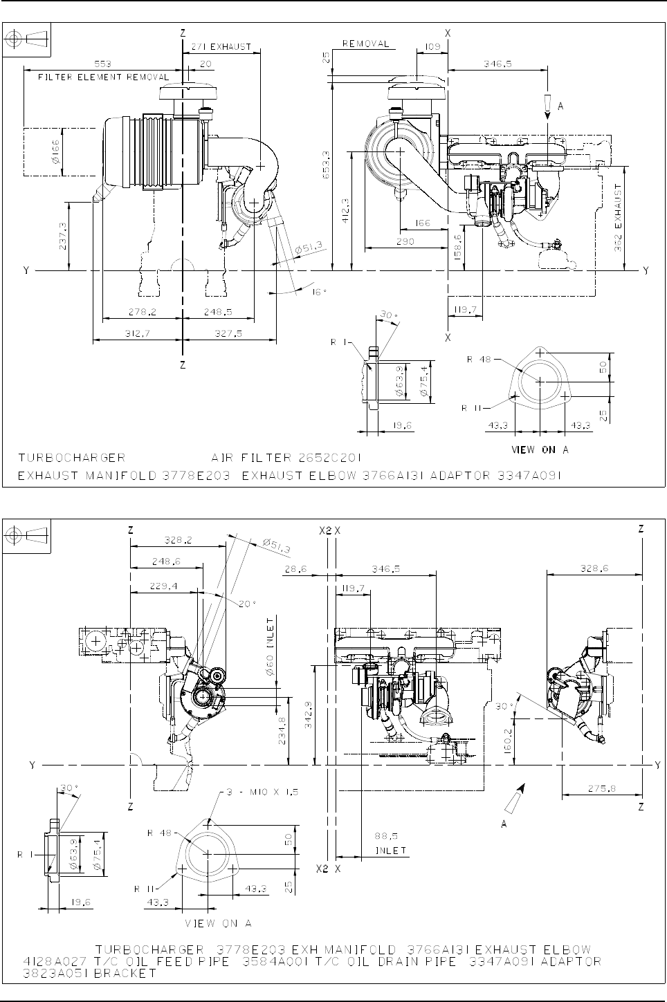
Engine Specification Manual, TPD1599 Issue 6, January 2009 123
1100 Series, 1104D, Mechanical FIE
S1114 - Side mounted turbo, RHS, exhaust elbow forward up, compressor outlet down, for air to air cooling, with air filter
S1121 - Side mounted turbo, RHS, exhaust elbow forward down, compressor outlet up, for air to air cooling
2674A842
2674A839
Rating specific
}
2674A842
2674A839
Rating specific
}
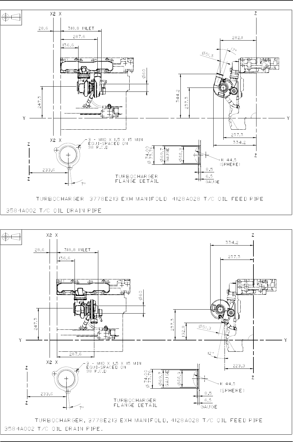
124 Engine Specification Manual, TPD1599 Issue 6, January 2009
1100 Series, 1104D, Mechanical FIE
S1151 -
Side mounted turbo, RHS, exhaust rearward, no exhaust elbow, compressor outlet up, air to air cooling
S1152 - Side mounted turbo, RHS, exhaust rearward, no exhaust elbow, compressor outlet down, for air to air cooling
2674A836
2674A818
Rating specific
}
2674A837
2674A822
Rating specific
}
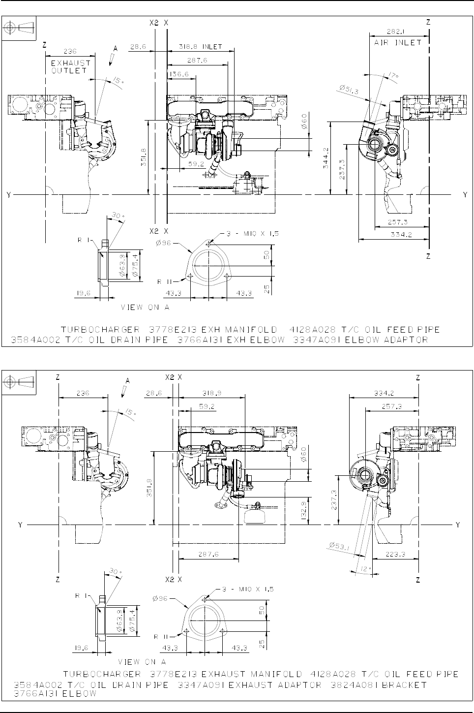
Engine Specification Manual, TPD1599 Issue 6, January 2009 125
1100 Series, 1104D, Mechanical FIE
S1181 - Side mounted turbo, RHS, exhaust elbow rearward up, compressor outlet up, for air to air cooling
S1182 - Side mounted turbo, RHS, exhaust elbow rearward up, compressor outlet down, for air to air cooling
2674A836
2674A818
Rating specific
}
2674A836
2674A818
Rating specific
}

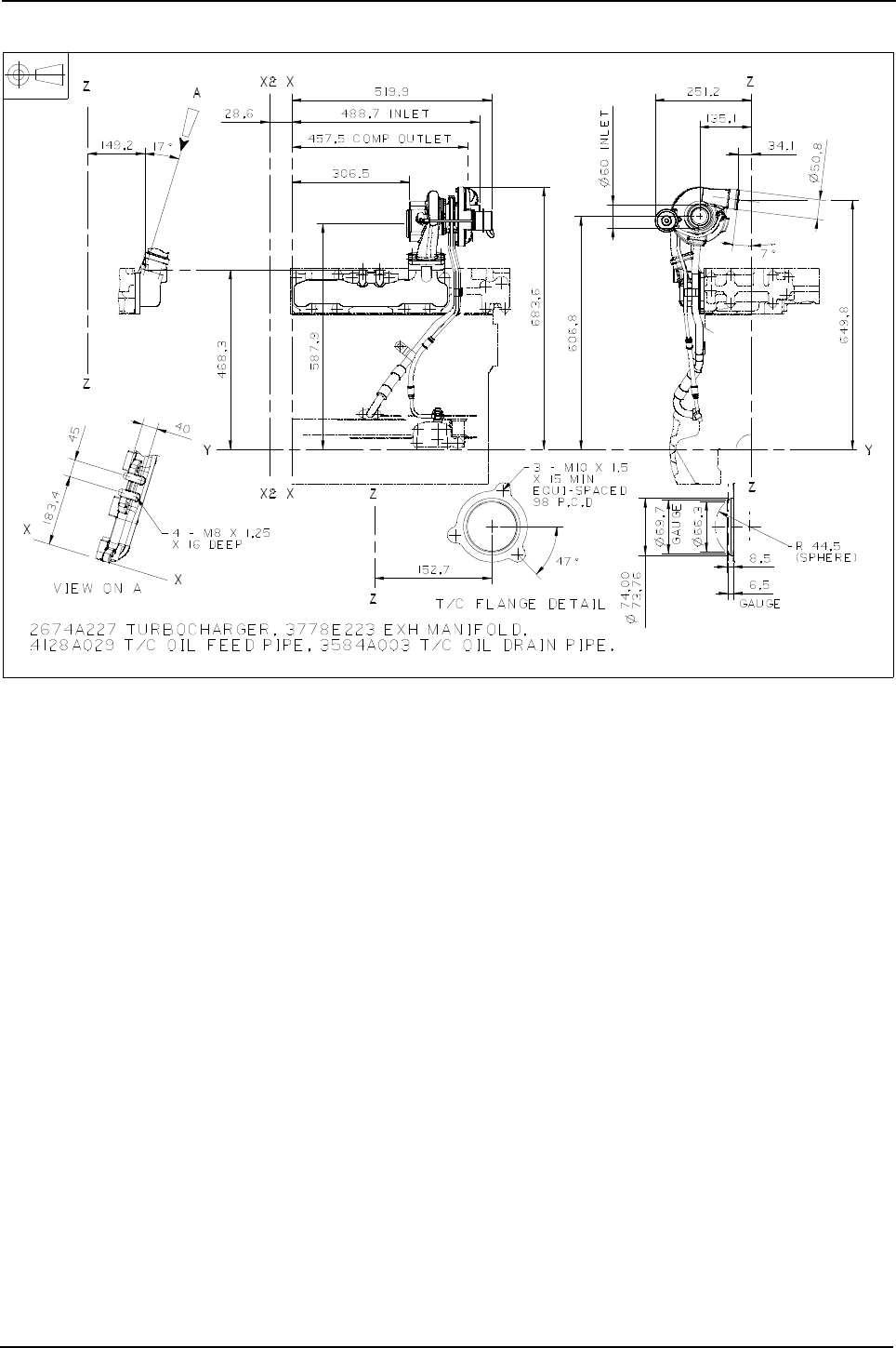
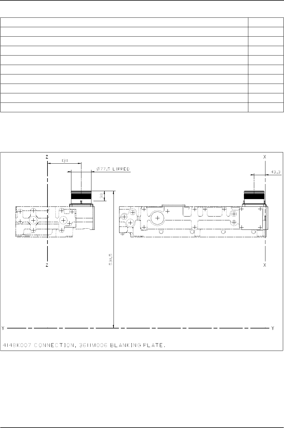
128 Engine Specification Manual, TPD1599 Issue 6, January 2009
1100 Series, 1104D, Mechanical FIE
Intake manifold, intake connections
Note: An intake manifold connection selection is required for all air to air aftercooled engines.
T4010 - Rear, top, vertical up connection
Description Option
Not required T0000
Rear, top, no inlet with blanking plug for transit only T4001
Rear, top, vertically up facing connection T4010
Rear, top, vertically up facing connection with air filter T4012
Rear, top, forward facing 90° connection T4050
Rear top, 90° forward facing connection - 60.0 mm dia T4060
Rear, top, side facing, LHS 90° connection (1)
(1). Incompatible with V2201
T4080
Rear, horizontal straight connection (2)
(2). Incompatible with S3114.
T6010
Rear with sideways, inward facing, 90° connection (2) T6070
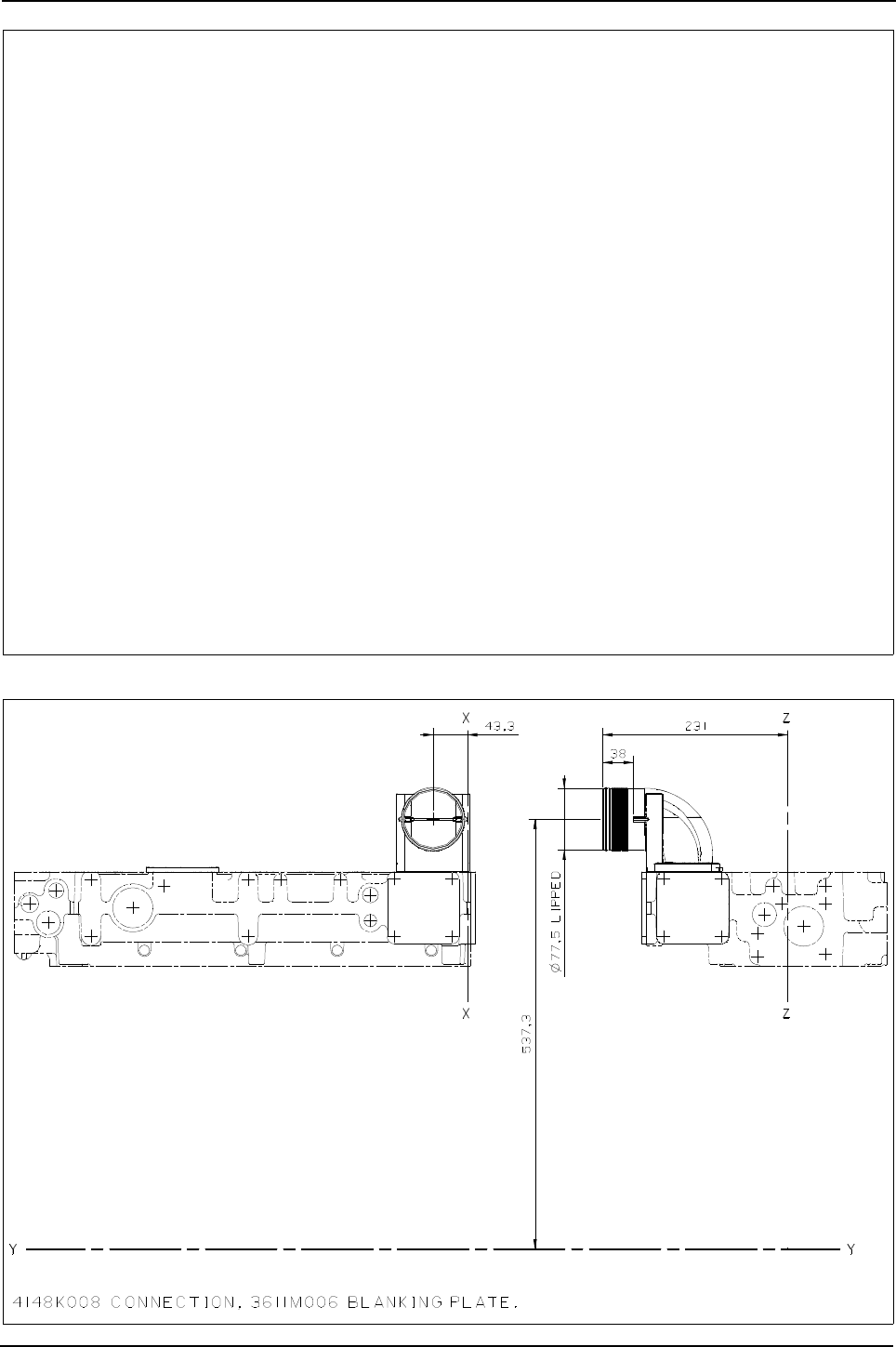
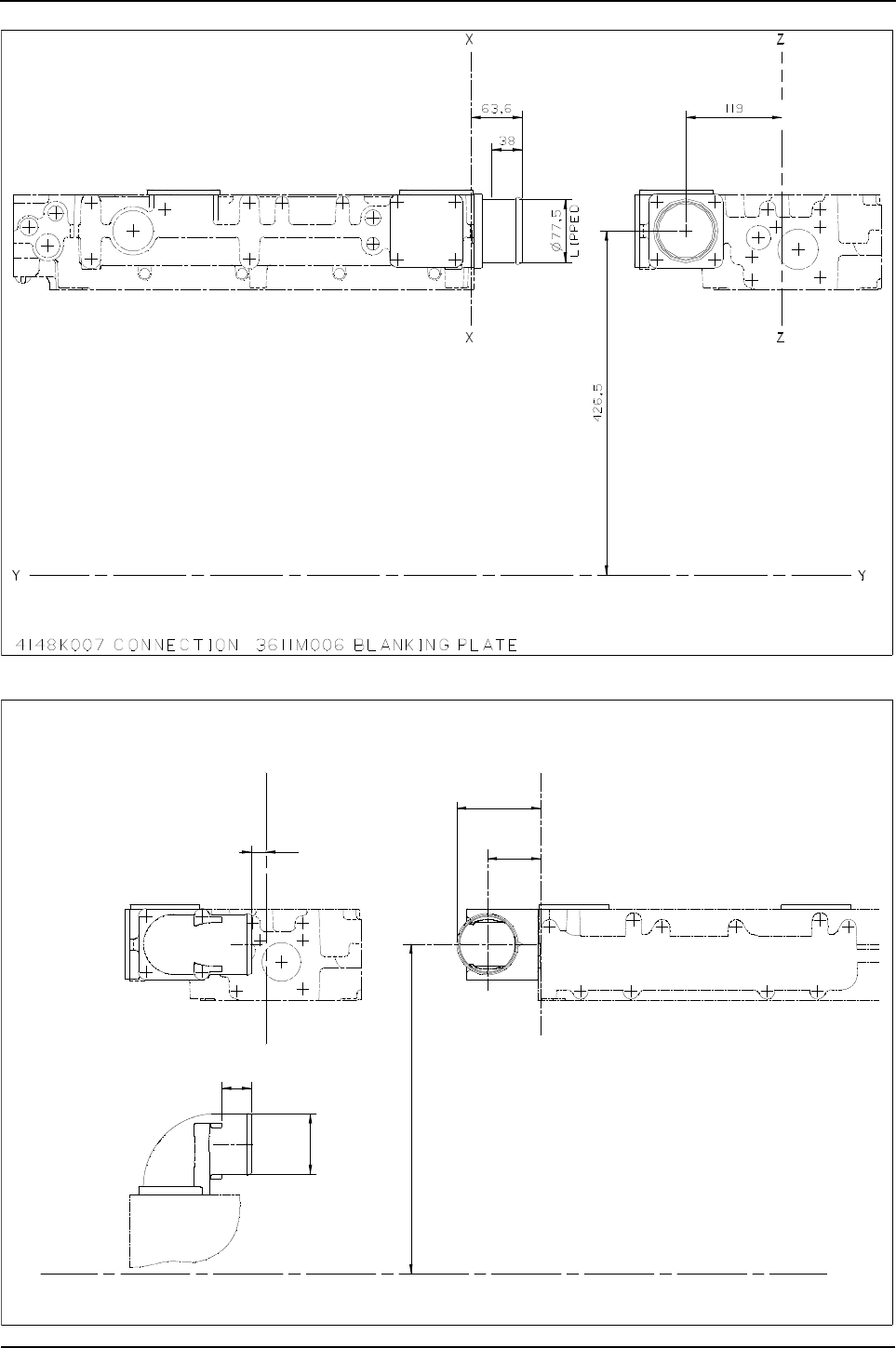
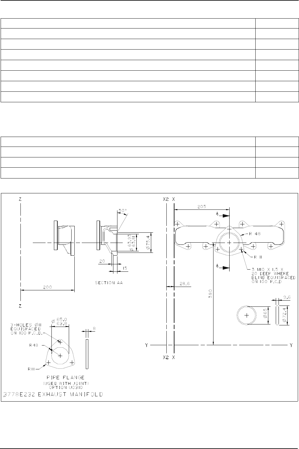
Engine Specification Manual, TPD1599 Issue 6, January 2009 131
1100 Series, 1104D, Mechanical FIE
Exhaust outlet and elbow
Exhaust hardware
U0300 - Centre side
Description Option
Not required (1)
(1). Turbocharged engines only.
U0000
Centre side U0300
Centre side, with vertical elbow U0301
Centre side, with 120° elbow U0303
Centre side, with 180° elbow U0304
Centre down U0400
Centre top (2)
(2). Incompatible with H**10/H**20.
U0500
Description Option
Not required UD000
Studs and nuts only UD002
Studs, nuts, flange and gaskets only UD003
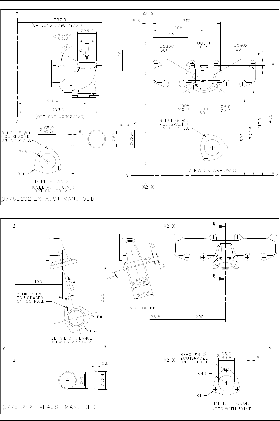
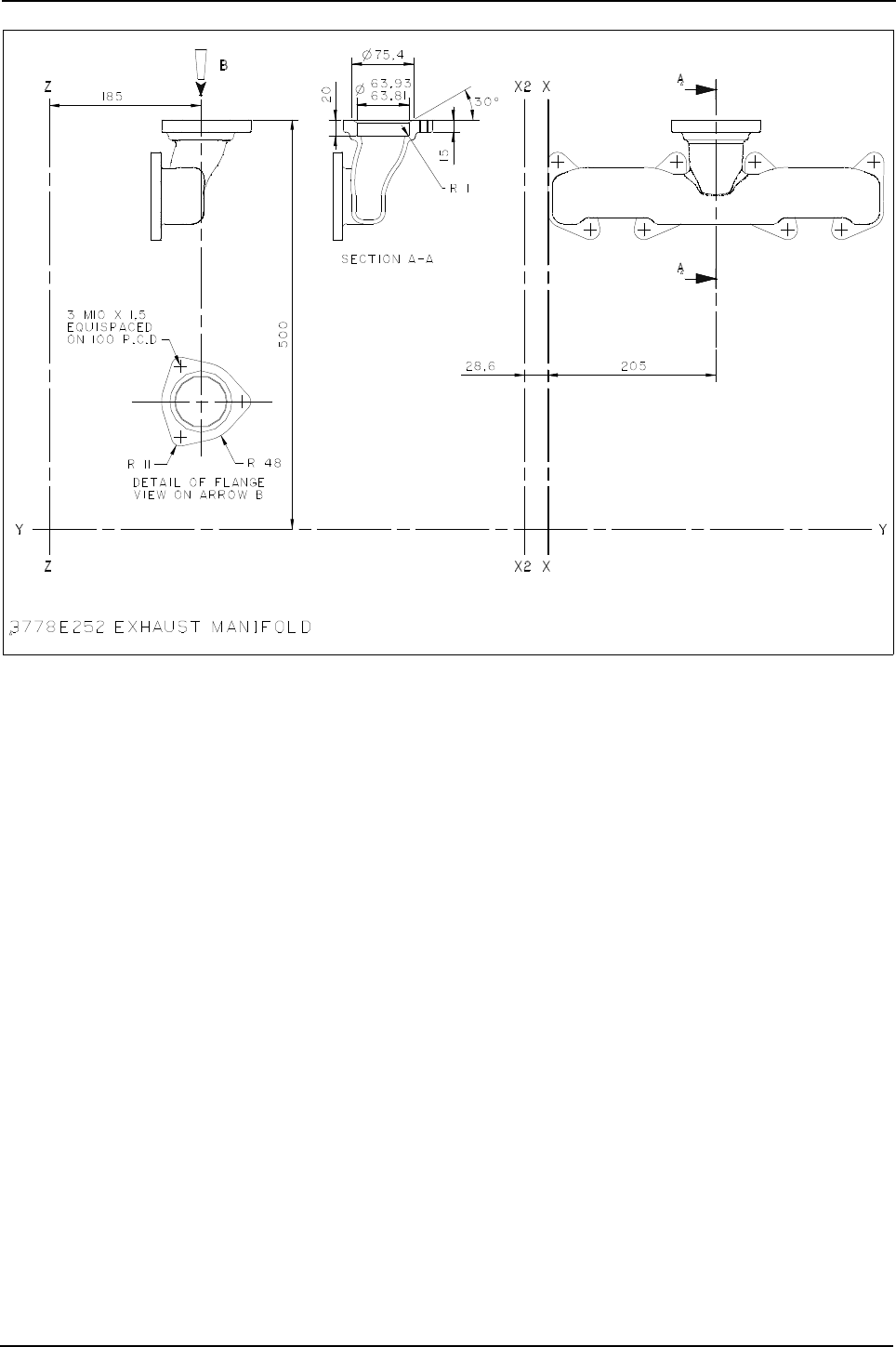

134 Engine Specification Manual, TPD1599 Issue 6, January 2009
1100 Series, 1104D, Mechanical FIE
Fuel filters secondary
Spin on filter canister
Replaceable filter elements
Due to the significance of the fuel boost control function on the 1104D-44T/1104D-44TA engines, these
engines will be offered with a choice of low pressure fuel options when using the integral electric lift pump and
filter (was option V1201).
Option V3201 will be standard and for installation will be the same as the previous option V1201.
Option V2201 provides improved engine response from low speed with the potential for increased black smoke
under certain modes of operation, these typically being rapid engine speed and load cycling e.g. truck loading
and material handling applications. Option V2201 will be most suitable for machine applications such as
agriculture tractors. Option V2201 requires a second fuel return line to be installed to the top of the fuel tank.
For further details on selecting and installing these low pressure fuel options please refer to the
PerkinsApplication team and the Application and installation guide.
Fuel filter - secondary branding
Description Option
Single, LHS, centre of cylinder head (1) (2)
(1). Electric lift pump supplied loose, only available as 12 volt.
(2). Incompatible with H03**, HD004.
V1001
Description Option
Single, LHS, centre of cylinder head, FIP boost capsule fuel return to tank (1) (2)
(1). Complete with integral electric lift pump.
(2). Incompatible with G2002/HD005
V2201
Single LHS, off centre of cylinder head, FIP boost capsule fuel return to filter (1) (3)
(3). Incompatible with HD005.
V3201
Description Option
Standard VD001
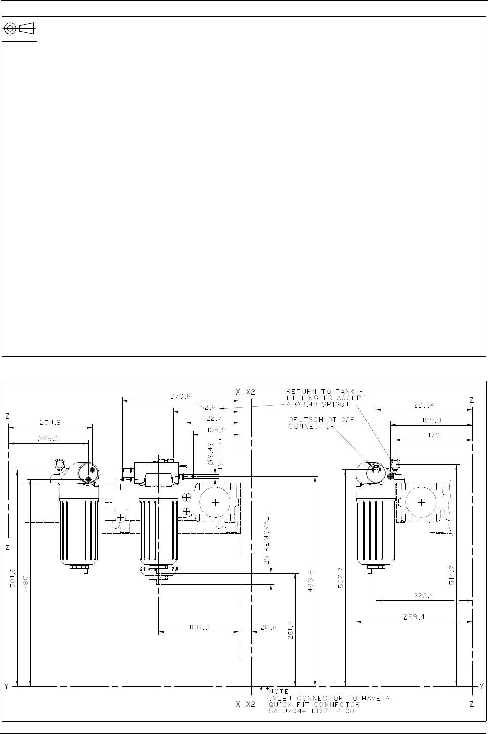

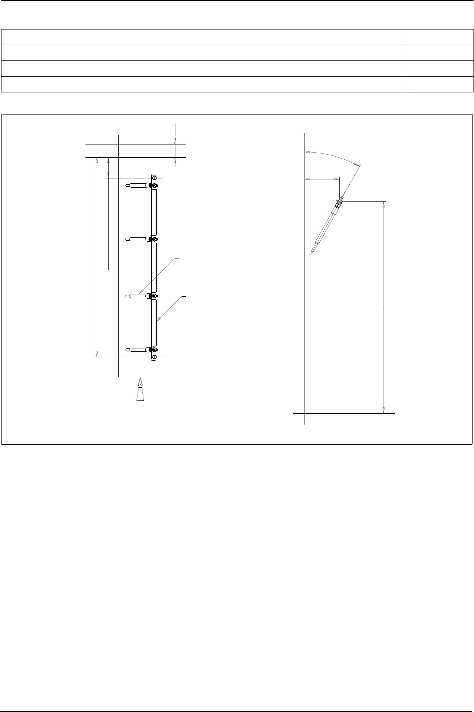
Engine Specification Manual, TPD1599 Issue 6, January 2009 137
1100 Series, 1104D, Mechanical FIE
Cold start aids
W0011 - Glow plugs, busbar with stud and nut
Description Option
Cold start not required W0000
Glow plugs, busbar, stud and Deutsch connector W0008
Glow plugs, busbar with stud and nut available Q2 2008 W0011
29°
76,6
461,7
customer connection436,2
28,6
customer connection45,7
WZ
View in direction of arrow A
2666A023 glowplug 12V 3161C072 busbar
X
X2
W
X
Glowplug
Busbar
Z
Y
X2
Y
A
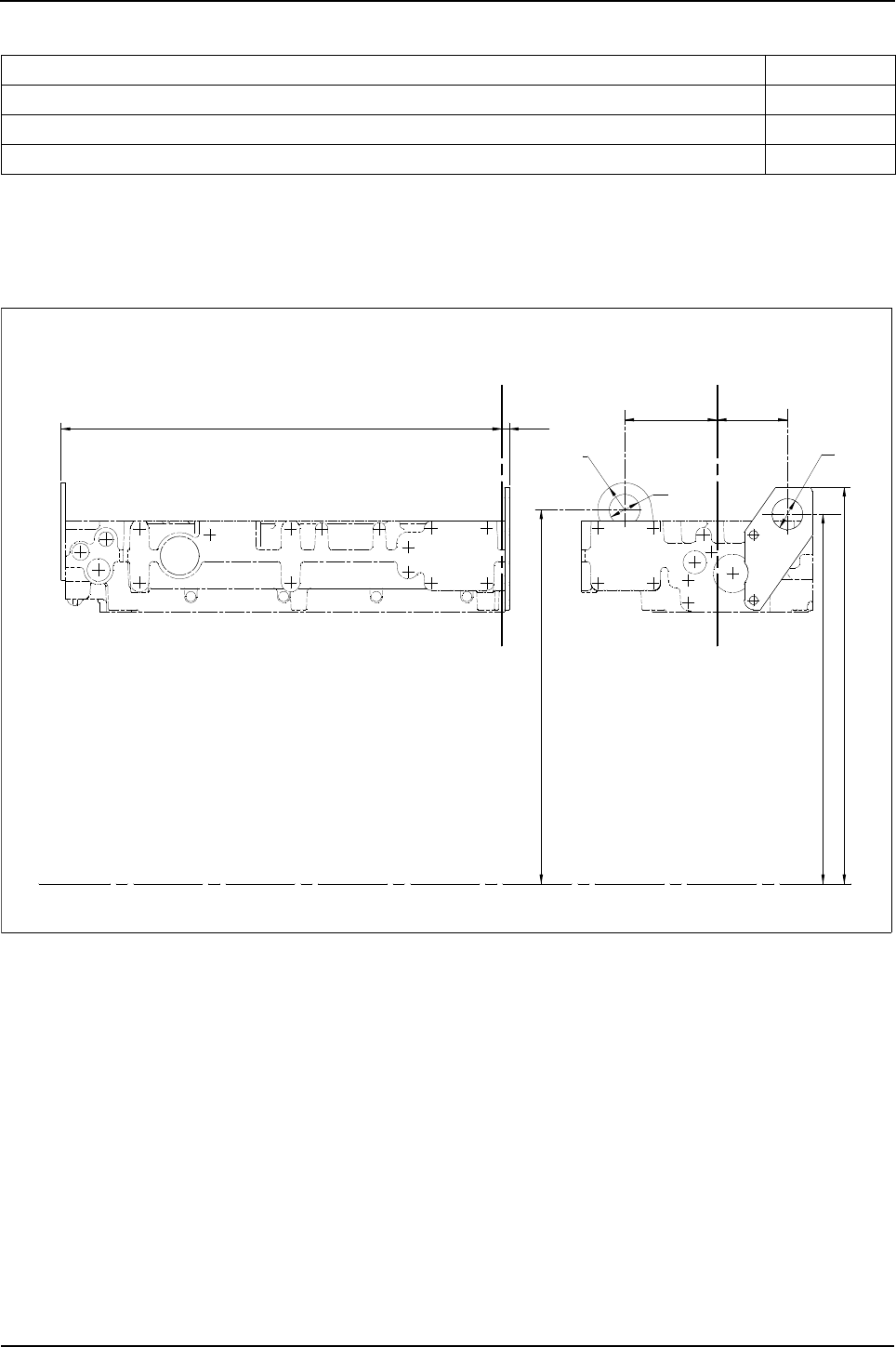
138 Engine Specification Manual, TPD1599 Issue 6, January 2009
1100 Series, 1104D, Mechanical FIE
Lifting eyes
X0001 - Front LHS and rear RHS
Description Option
Front LHS and rear RHS (1) (2)
(1). Maximum load 600 kg using a spreader bar or a two leg sling with 2 lifting eye brackets.
(2). Not compatible with L0052.
X0001
Front RHS and rear LHS (1) (3) (4)
(3). Not compatible with L0053.
(4). Incompatible with S0101/S0111/S0121/S0151/S1114/S1115.
X0002
Front RHS and rear LHS (1) (3) (4) X0003
Z
Z
Y Y
X
X
573 9,6
486,2
R 35
Ø 40
120,2 91,5
Ø 40
480,5
515,5
3617A015 front LHS, 3624A016 rear RHS
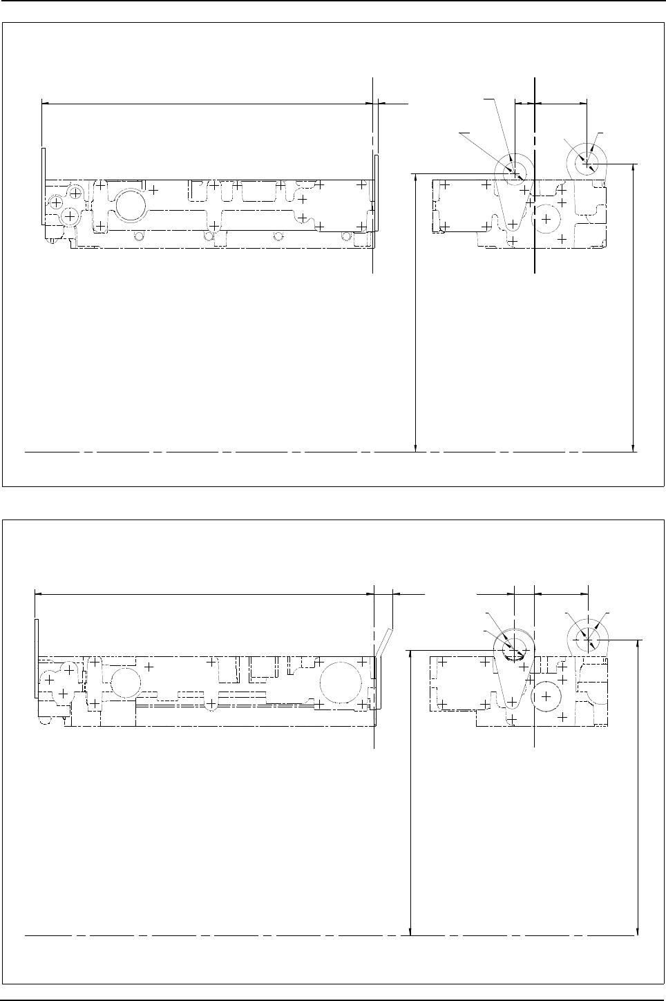
Engine Specification Manual, TPD1599 Issue 6, January 2009 139
1100 Series, 1104D, Mechanical FIE
X0002 - Front RHS and rear LHS
X0003 - Front RHS and rear LHS
Z
Z
Y Y
X
X
573 9,6
481,7
R 35
Ø 40
34 90,6
Ø 40 R 35
499,5
3617A015 rear lifting bracket, 3617A015 front lifting bracket
Z
Z
Y Y
X
X
573 32,2
481,9
33,8
R 35
Ø 40
90,6
Ø 40 R 35
499,5
Front plate 3617A015, rear 3647A007

140 Engine Specification Manual, TPD1599 Issue 6, January 2009
1100 Series, 1104D, Mechanical FIE
Paint
Y0000 - Lacquer
Y9008 - Croda protection
Y9018 - Light grey
Y9034 - Blue with heavy preservative
Y9036 - Light grey primer, with light preservative
Description Option
Lacquer Y0000
Croda protection Y9008
Light grey Y9018
Blue with heavy preservative Y9034
Light grey primer, with light preservative Y9036

Engine Specification Manual, TPD1599 Issue 6, January 2009 141
5
1100 Series, 1104D, Mechanical FIE
Accessories 5
Introduction
This chapter contains all information relating to the mechanical accessories for the 1104D (Mechanical FIE)
engine range.
Before specifying an accessory, read carefully any notes relating to the accessory as these will indicate any
restrictions if this accessory is selected.
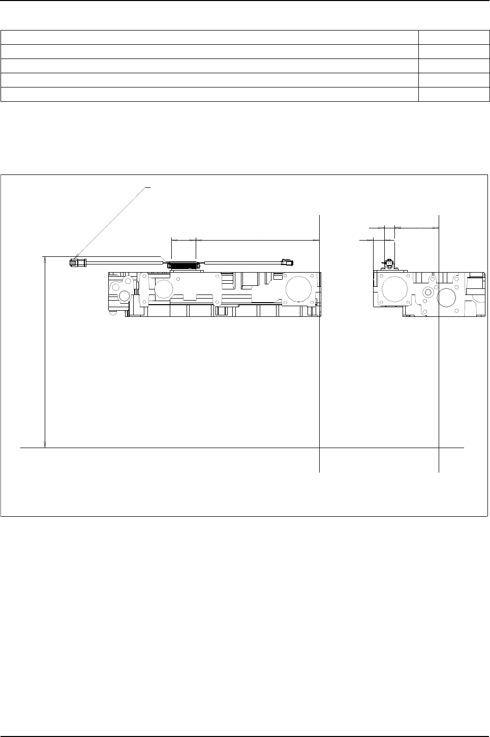
142 Engine Specification Manual, TPD1599 Issue 6, January 2009
1100 Series, 1104D, Mechanical FIE
Resistors and regulators
ZA014 - Voltage regulator front top, LHS
Description Option
Not required (1)
(1). 12 volt engines only.
ZA000
Voltage regulator front top, LHS (2) (3)
(2). 24 volt engines only.
(3). Incompatible with H03** on turbo and turbo aftercooled engines.
ZA014
Voltage regulator rear top, LHS (2) (4)
(4). Incompatible with S0111/S0114/S0115/S0121/S0151/S0251/T4010/T4050/T4060.
ZA015
Voltage regulator supplied loose (2) ZA016
500,8
119,527
332,665,1 30
X
Y
X
Y
Customer connection deutsch DT 3 way
4172H021 voltage dropper assembly
Z
Z
connector DT04-3 -E005 cable length:300mm
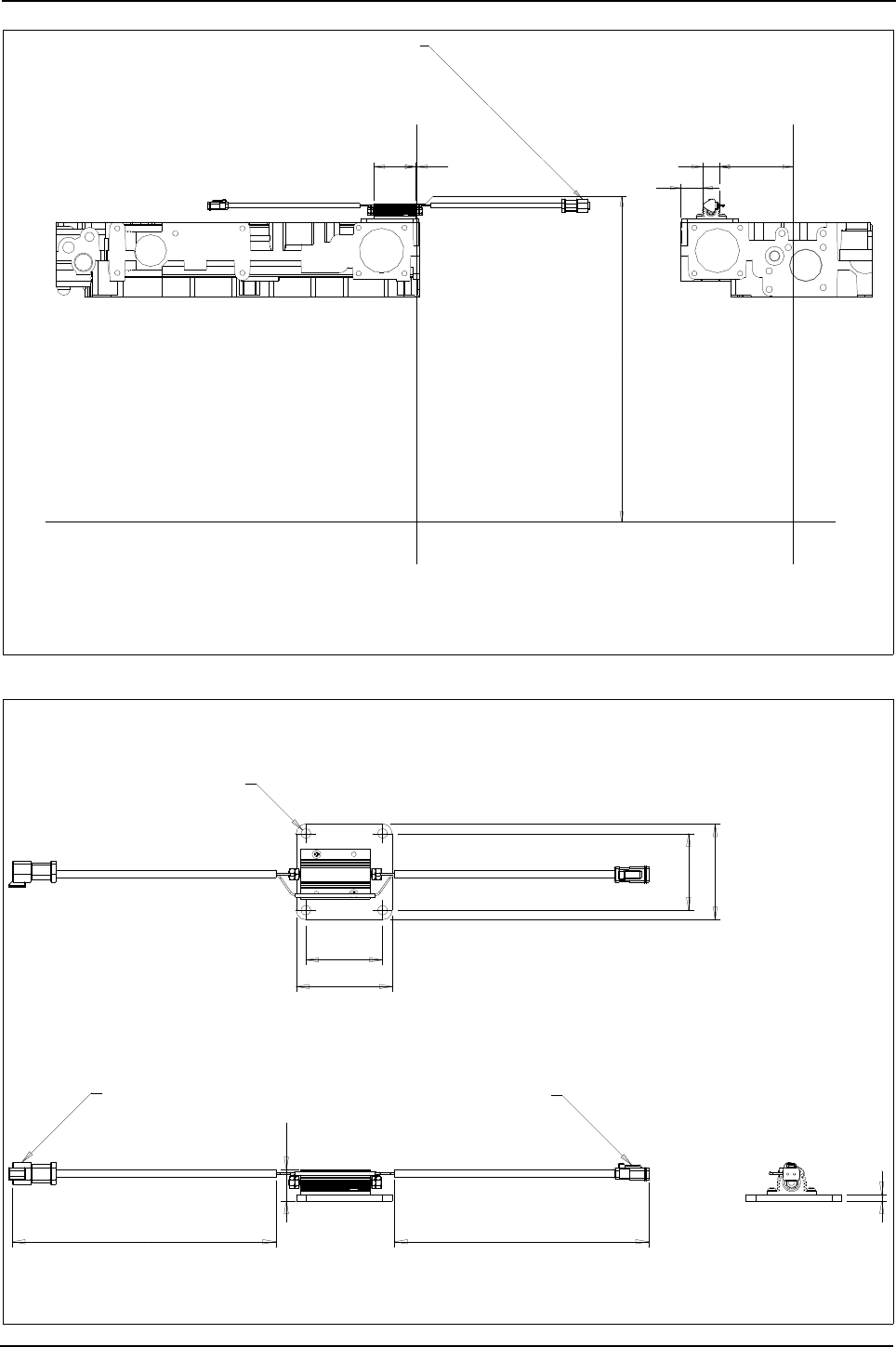
Engine Specification Manual, TPD1599 Issue 6, January 2009 143
1100 Series, 1104D, Mechanical FIE
ZA015 - Voltage regulator rear top, LHS
ZA016 - Voltage regulator supplied loose
115,527
34
2,265,1
500,8
XZ
XZ
4172H021 voltage dropper assembly
Y Y
Customer connection deutsch DT 3 way connector
DT04-3P-E005 cable length 300mm
300
90
90
72
72
29,3
6
300
4172H021 voltage dropper assembly
4-Ø9
Deutsch DT 3 way Deutsch connector DT06-2S-E 06
Connector DT04-3 -E005

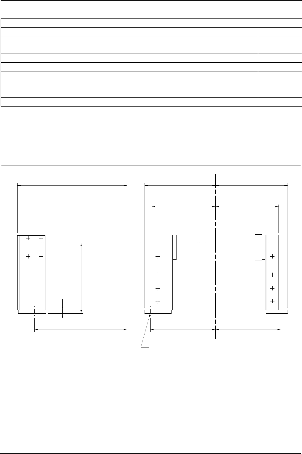
Engine Specification Manual, TPD1599 Issue 6, January 2009 145
1100 Series, 1104D, Mechanical FIE
Engine mounting brackets
ZC002 - Front pedestal mounting brackets, LHS and RHS
Description Code
Not required, blanking plugs only (1)
(1). Not available with ZM101/ZM102/ZM103/ZM110.
ZC000
Front pedestal mounting brackets, LHS and RHS (2) (3)
(2). Incompatible with Q4***.
(3). Engines with non stressed block only.
ZC002
Rear brackets, LHS and RHS (1) (3) (4)
(4). Incompatible with C0006/C0010/C0021/C0026/C0033/C0036/C0050/C0051.
ZC003
ZC002 and ZC003 (1) (2) (3) (4) ZC004
Front mounting studs only (1) (3) ZC012
Front mounting studs in rear holes only (1) (3) ZC014
Front mounting brackets, LHS and RHS (with flywheel housing plugs) (3) (5)
(5). Not for use with radiator options.
ZC016
Front pedestal brackets LHS and RHS (<75 kW) and ZC003 (3) (4) ZC018
Front mounting brackets, LHS and RHS (for high peak loads, 10g) (3) (5) (6)
(6). Incompatible with D0053/D0056/D0062/D0065/D0066/D0067/D0068, J0030/J0031/J0070/J0071.
ZC019
21D2-
Front mounting brackets 3825T018 RHS 3825T017 LHS spacer 36271052 RHS
12
260,3
Y Y
Z
Z
X
X
455,6
519 266,6262,5
233,6235,5
241,3 241,3
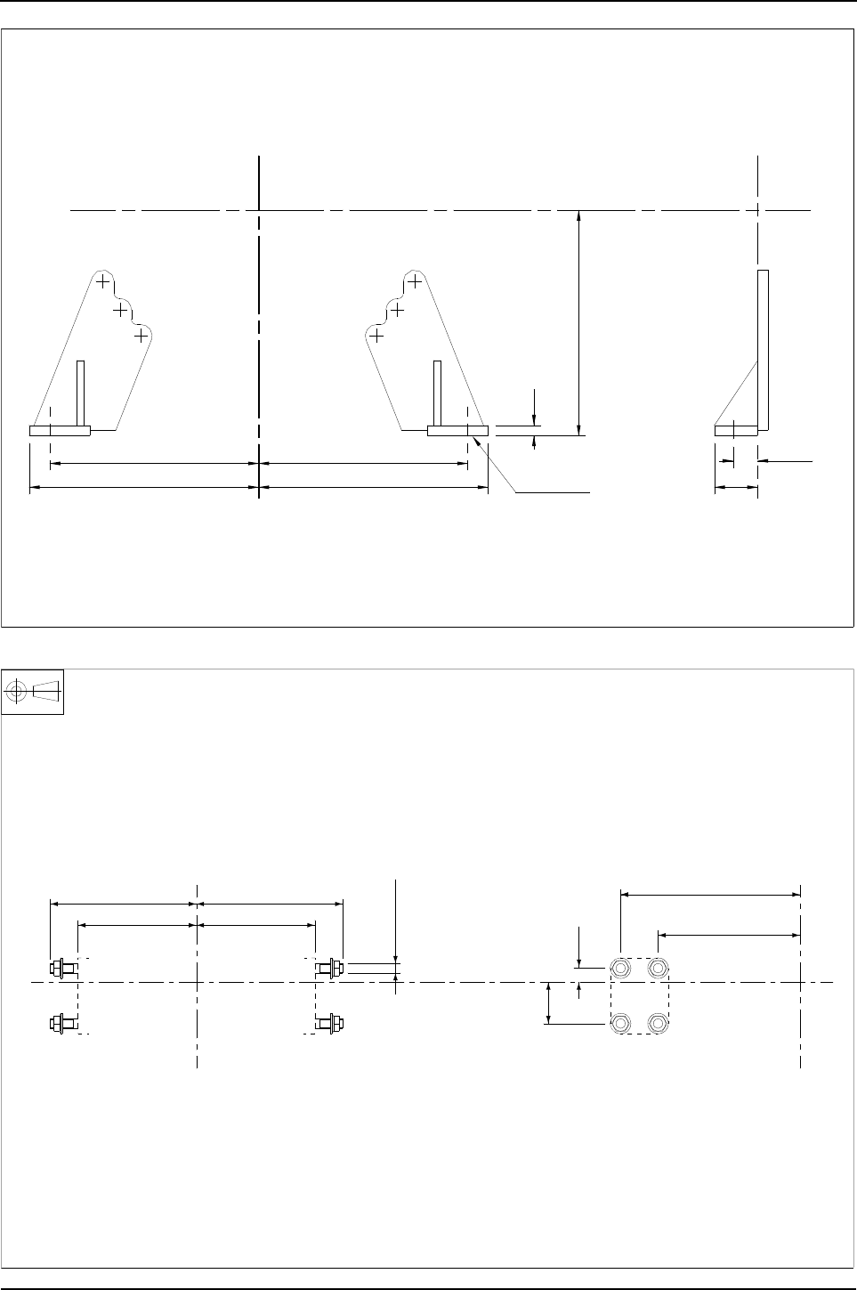
146 Engine Specification Manual, TPD1599 Issue 6, January 2009
1100 Series, 1104D, Mechanical FIE
ZC003 - Rear brackets, LHS and RHS
ZC012 - Front mounting studs only
Engine rear mounting brackets 3821M003, 3821M004.
28,6
265
241,3
20,5D2-
265
Z
Z
YY
X
X
50
241,3
260,4
12
ZC012
Stud 2312M101, nut 2318A605
Y
Z
144,5
179,0
Z
179,0
144,5
M12 x 1,75
X
X
479,5
431,8
Denotes both front mounting pads.
17,5
49,2
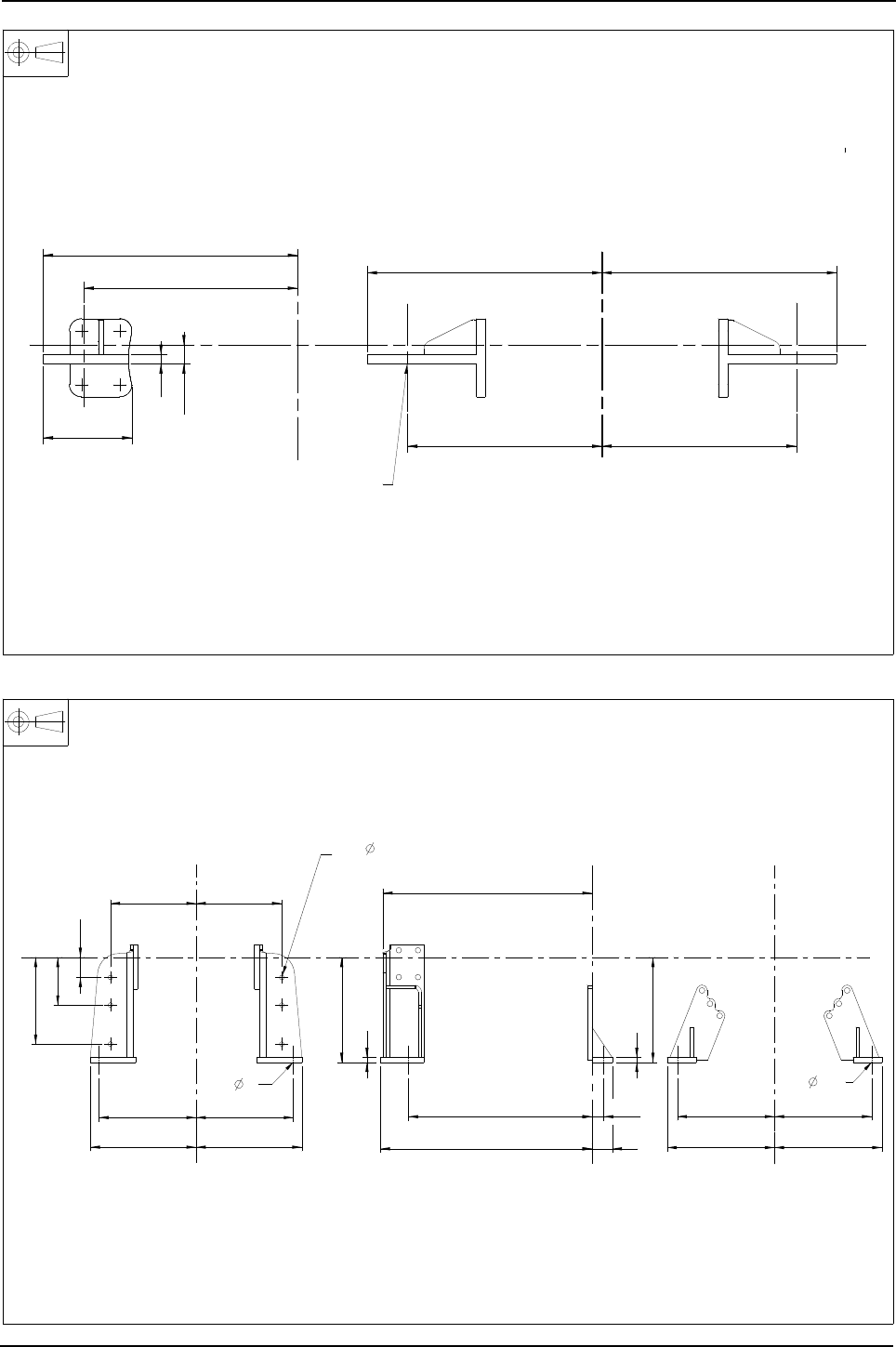
Engine Specification Manual, TPD1599 Issue 6, January 2009 147
1100 Series, 1104D, Mechanical FIE
ZC016 - Front mounting brackets, LHS and RHS (with flywheel housing plugs)
ZC018 - Front pedestal brackets, LHS and RHS
Front mounting brackets 3823A036/37
X
X
Z
Z
YY
494,5
476,4
12
110 241,5
241,5
291,5 291,5
18Ø2 -
23,5
12
519,2
525,2 50 266,5 266,5
260,4
262,5 262,5
241,3 241,3
12
28,6455,6
241,3241,3
49,9
118,3
215,2
212,5 212,5
6 - 11
260,4
3861A081 FRONT BRACKET LHS 3821M004 REAR BRACKET LHS
3861A082 FRONT BRACKET RHS 3821M003 REAR BRACKET RHS
ZZ
ZZ
X
X
Y
Y
2 - 20,5
2 - 21
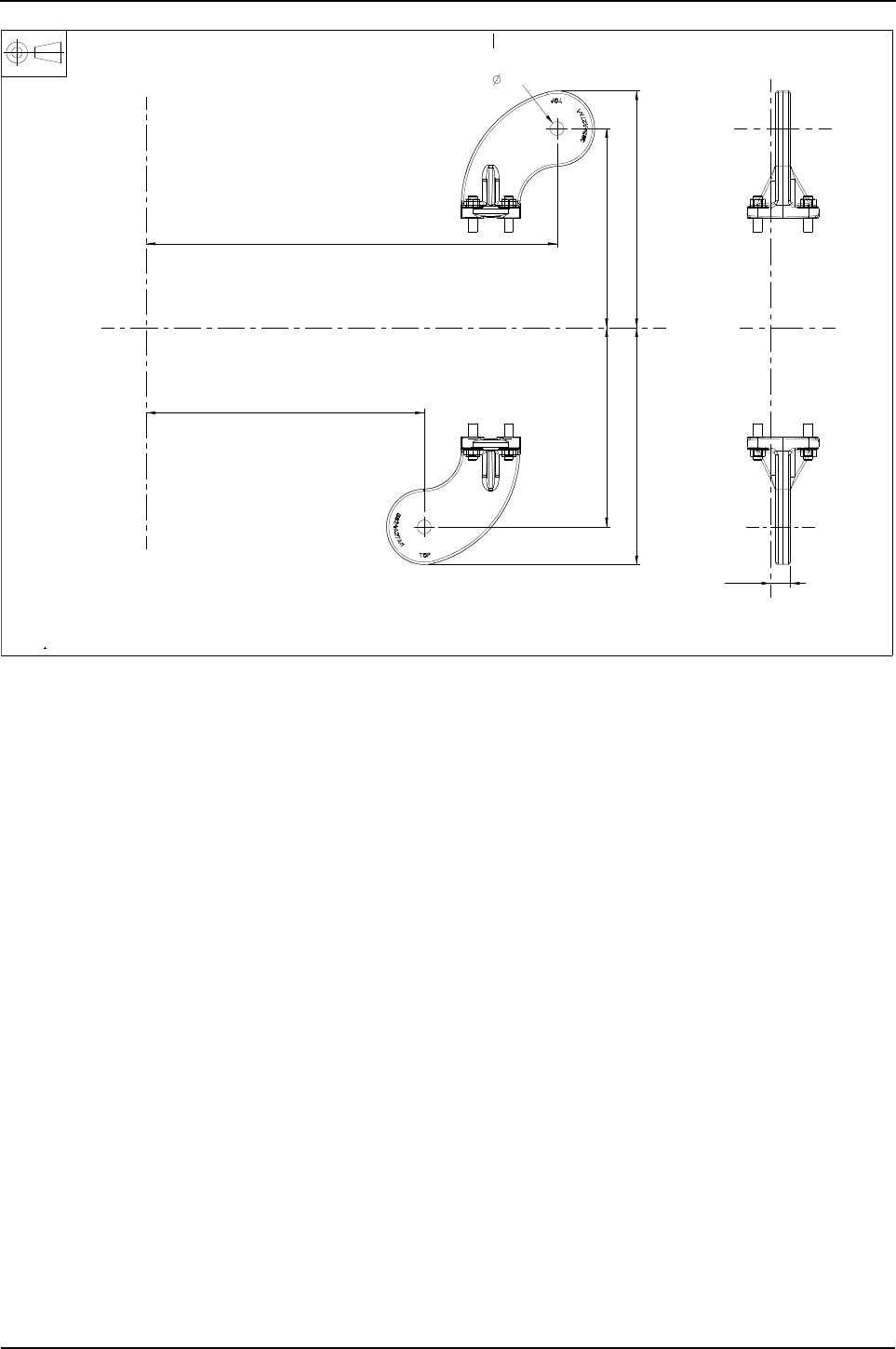
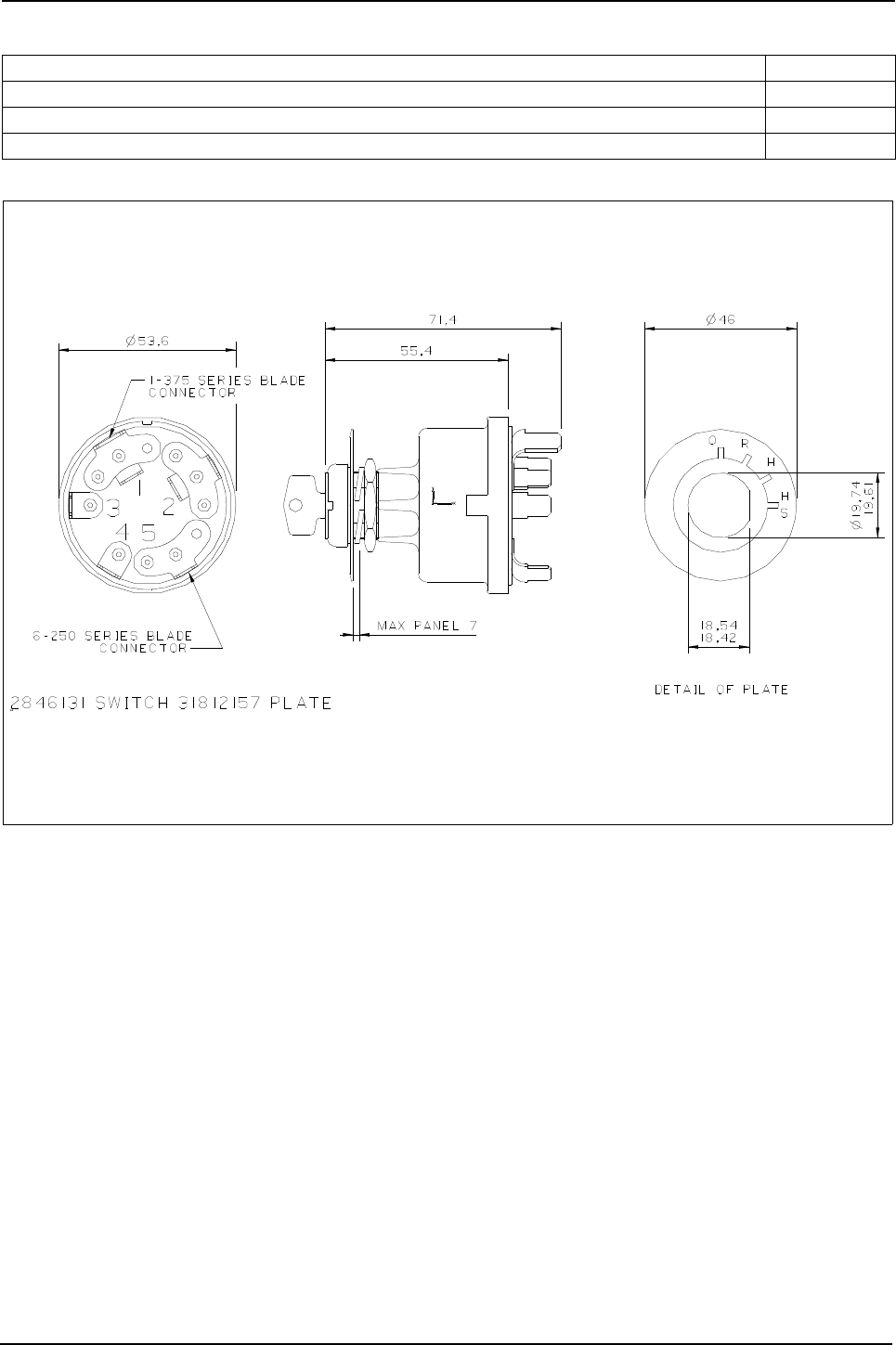
Engine Specification Manual, TPD1599 Issue 6, January 2009 149
1100 Series, 1104D, Mechanical FIE
Heater/starter switch
ZE001 - Heater/starter switch and security lock, supplied loose
Description Code
Not required ZE000
Heater/starter switch and security lock, supplied loose ZE001
Heater/starter switch, supplied loose ZE005

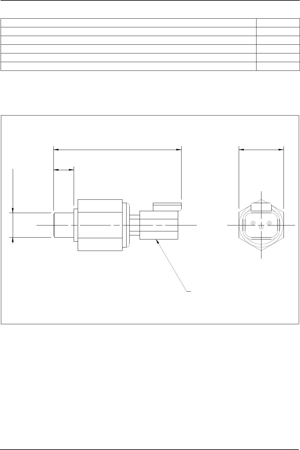
Engine Specification Manual, TPD1599 Issue 6, January 2009 151
1100 Series, 1104D, Mechanical FIE
Lubricating oil switches and valves
ZJ003 - Lubricating oil pressure switch fitted in oil filter head - Deutsch connector
Description Code
Not required ZJ000
Lubricating oil pressure switch - Deutsch (1)
(1). Not available when selected with J0011/J0021/J0060/J0061/J0130 and Q**38.
ZJ003
Lubricating oil sampling valve, fitted in lubricating oil filter head (2)
(2). Incompatible with J0130.
ZJ005
Lubricating oil pressure switch - Deutsch connector (Earth return) fitted in cylinder block (3)
(3). Incompatible with Q1023/Q1024/Q1025/Q1026/Q1038/Q2038.
ZJ006
Lubricating oil sampling valve, fitted in pressure rail (4)
(4). Incompatible with Q**28/Q**38.
ZJ008
DT04-2P
Deutsch connector
22 A/F
M12 X 1,5
10
63,1
2848A071 switch lub. oil pressure
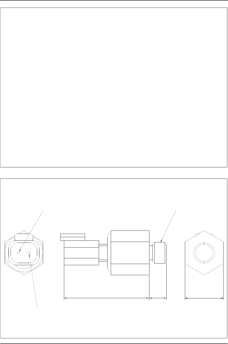
152 Engine Specification Manual, TPD1599 Issue 6, January 2009
1100 Series, 1104D, Mechanical FIE
ZJ005 - Lubricating oil sampling valve, fitted in lubricating oil filter head
ZJ006 - Lubricating oil pressure switch fitted in cylinder block - Deutsch connector
1/8 - 27 NPTF
Pin 2 - internal Earth return
Pin 1 - signal
48,3
49,3
10 22
2848A051 - lub oil pressure switch
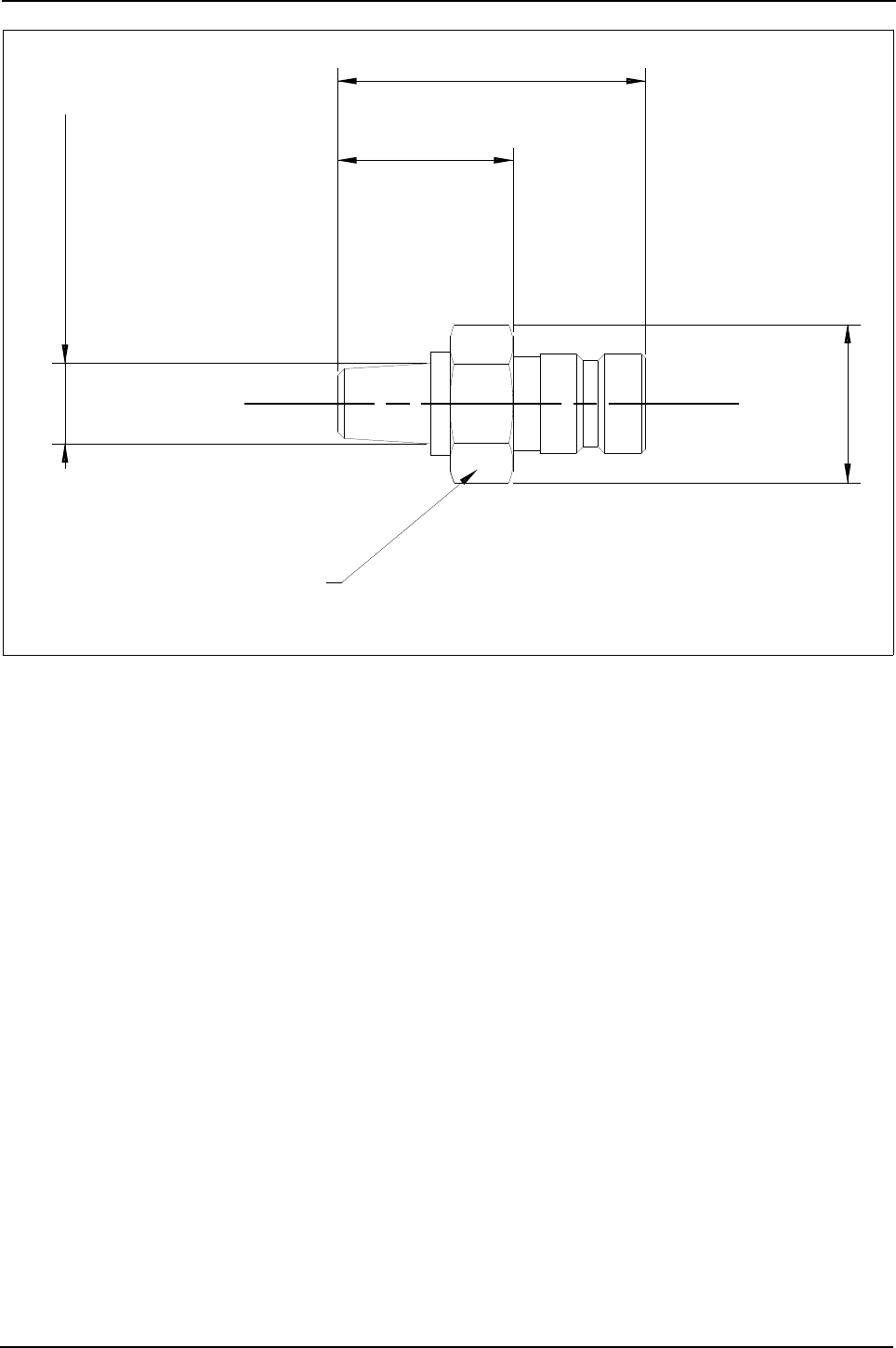


Engine Specification Manual, TPD1599 Issue 6, January 2009 155
1100 Series, 1104D, Mechanical FIE
Radiator
Notes:
zZM101/ZM102/ZM103/ZM110 to be used on turbocharged engines only.
zZM121/ZM122/ZM130/ZM131 to be used on turbocharged air to air cooled engines only.
Cautions:
zAn engine is at risk if a heat exchangers effectiveness becomes reduced through environmental
contamination.
zCustomers of Perkins engines should give appropriate maintenance details in their operator and service
documents to prevent this.
Warning! If the radiator is to be supplied without fan guards, the customer must sign a letter accepting
responsibility and liability to provide and fit fan guards.
ZM000 - Not required
ZM101 - Radiator supplied loose
ZM102 - Radiator fitted, without fan guards
ZM103 - Radiator fitted, with fan guards
ZM122 - Radiator with intercooler fitted, with fan guards
ZM124 - Radiator with intercooler fitted, with fan guards
ZM130 - Radiator with intercooler fitted, with fan guards, to suit twin PTO
Description Code
Not required ZM000
Radiator supplied loose (1)
(1). Compatible with non-stressed block only.
ZM101
Radiator fitted, without fan guards (1) ZM102
Radiator fitted, with fan guards (1) (2)
(2). Incompatible with Q4042/Q4055/Q3030.
ZM103
Radiator fitted with fan guard, to suit LHS SAE-B PTO (1) (3)
(3). Incompatible with Q1023/Q1024/Q1025/Q1026/Q1100/Q3000.
ZM110
Radiator with intercooler fitted, without fan guards (1) (2) (4) (5)
(4). Incompatible with J0030/J0070/J0071.
(5). Incompatible with G0401/G11**/G2***.
ZM121
Radiator with intercooler fitted, with fan guards (1) (2) (4) (5) (6)
(6). Incompatible with H1210/HD101.
ZM122
Radiator with intercooler fitted, with fan guards, to suit twin PTO (1) (2) (4) (5) (6) ZM130
Radiator with intercooler fitted, with fan guard to suit LHS SAE-B PTO (1) (3) (4) (5) (6) ZM131

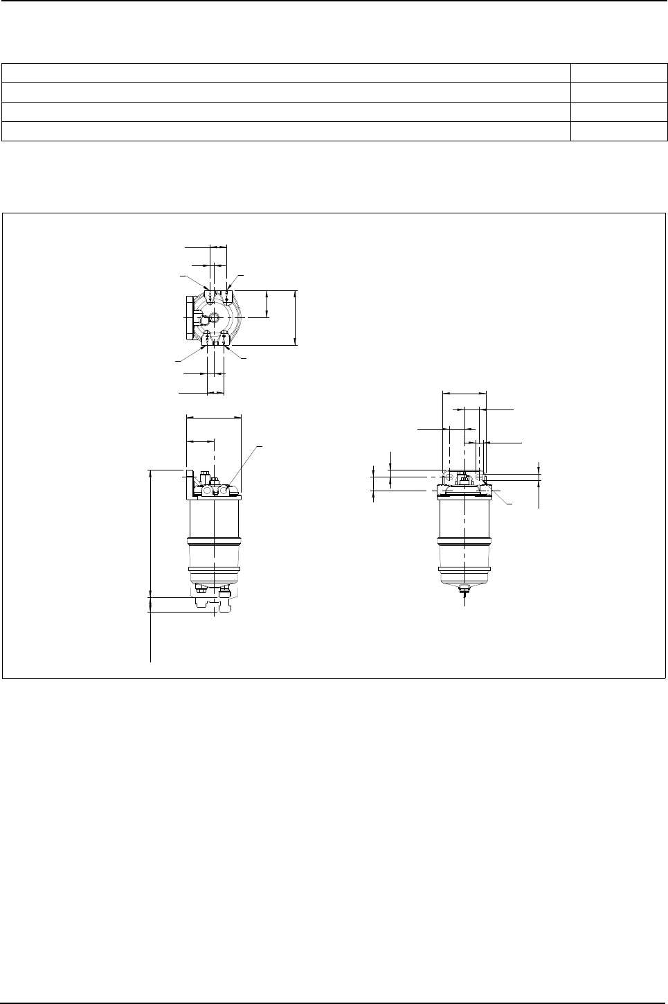
Engine Specification Manual, TPD1599 Issue 6, January 2009 157
1100 Series, 1104D, Mechanical FIE
Fuel filter-primary
Spin on filters
ZV011 - Single filter including water separator, supplied loose
Description Code
Customer to supply filter (1)
(1). A pre filter must be fitted on all engines that is capable of handling a fuel flow of between 1.5 l/min and 2.5 l/
min. Please contact Perkins Applications for more details if customer supplied.
ZV000
Single filter including water separator, supplied loose ZV011
Single filter with water separator and sensor, supplied loose ZV021
removal
25
25,9
25,9
47,5
12
28,5
7
28,5
47
94
94,2
23
74,3
219,6
12
10,6
12,6
2656F823 fuel filter water separator
Fuel in
Fuel in
Fuel out
Fuel out
½ - 20 UNF - 2B
port thread
4 - places
R

158 Engine Specification Manual, TPD1599 Issue 6, January 2009
1100 Series, 1104D, Mechanical FIE
Labels
ZY003 - Emissions, label LHS block, front low and Perkins decal
ZY004 - Emissions, label LHS block, rear low and Perkins decal
ZY005 - Emissions, label RHS block, front low and Perkins decal
ZY014 - Emissions, label LHS block, rear low
ZY023 - Emissions, label LHS block, front low and Perkins decal with additional emissions label
supplied loose
ZY024 - Emissions, label LHS block, rear low and Perkins decal with additional emissions label
supplied loose
Description Code
Emissions label, LHS block, front low and Perkins decal (1) (2)
(1). Incompatible with Q**38.
(2). Incompatible with Q1023/Q1024/Q1025/Q1026.
ZY003
Emissions label, LHS block, rear low and Perkins decal (1) ZY004
Emissions label, RHS block, front low and Perkins decal ZY005
Emissions label, LHS block, rear low (1) ZY014
Emissions label, LHS block, front low and Perkins decal with additional emissions label supplied loose
(1) (2) ZY023
Emissions label, LHS block, rear low and Perkins decal with additional emissions label supplied loose
(1) ZY024

Engine Specification Manual, TPD1599 Issue 6, January 2009 159
1100 Series, 1104D, Mechanical FIE
Cab heater connections
ZZ001 - Without connections, rear of cylinder head plugged with threaded insert
Description Code
Not required (1)
(1). Incompatible with Q1023/Q1024/Q1025/Q1026/Q4042.
ZZ000
Without connections, rear of cylinder head plugged with threaded insert (1) (2)
(2). Not compatible with T6070.
ZZ001
Feed rear cylinder head, straight return to rear of the timing case (1) (2) ZZ002
Feed LHS cylinder head, straight return to rear of the timing case (1) ZZ004
Feed rear cylinder head, angled return to rear of the timing case (1) (2) ZZ012
Feed LHS cylinder head, angled return to rear of the timing case ZZ014
Feed rear cylinder head, plugged, angled return to rear of timing case (1) (2) ZZ015
No feed, angled return to rear of timing case ZZ016
Drawing not available at time of print
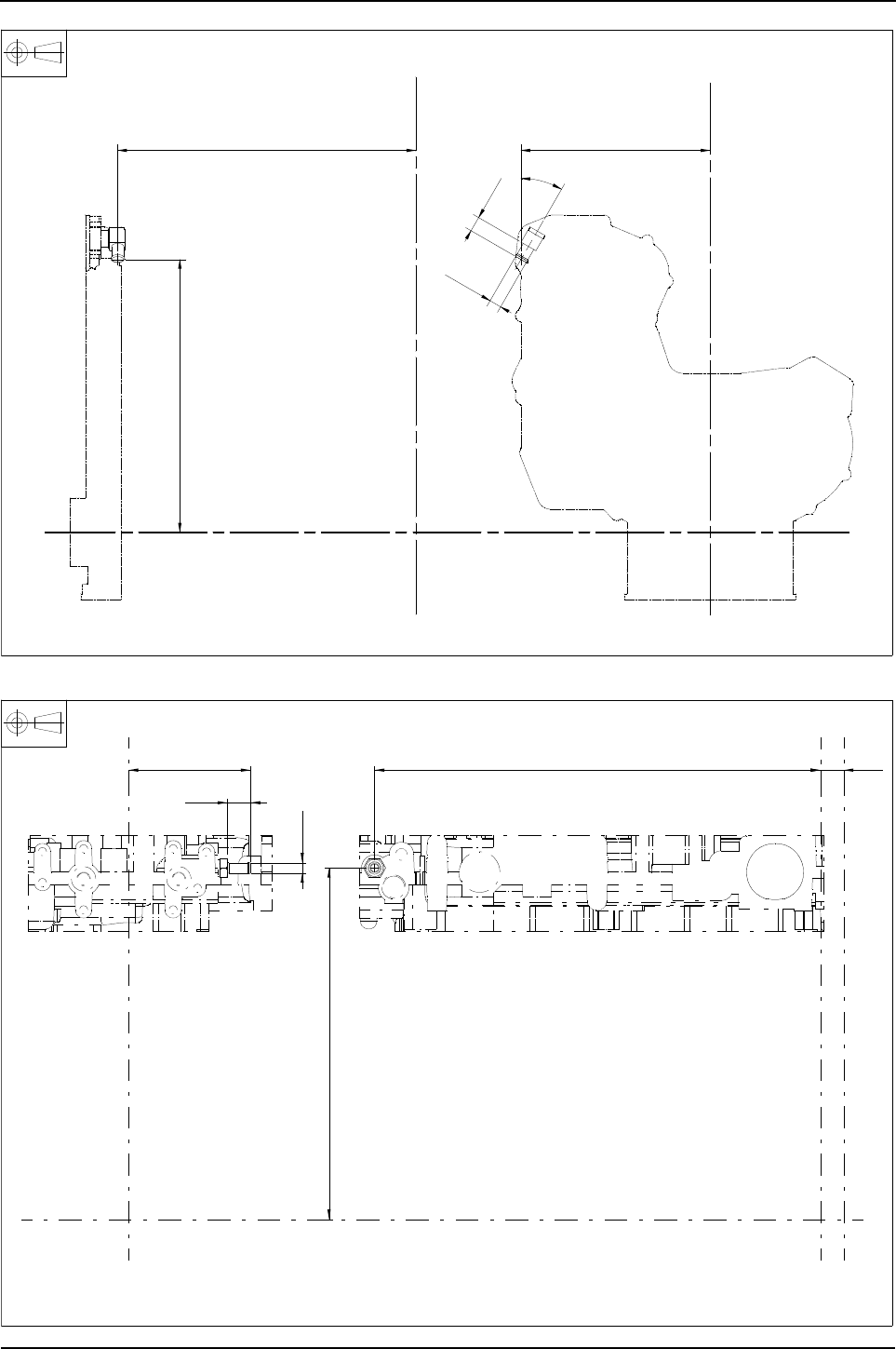
160 Engine Specification Manual, TPD1599 Issue 6, January 2009
1100 Series, 1104D, Mechanical FIE
ZZ012 - Feed rear cylinder head, angled return to rear of the timing case
ZZ014 - Feed LHS cylinder head Q1025/Q1026 only
ZX
X
YY
516,3
357,6
Ø 15,9
19,8
30°
248,1
Z
2447375 elbow
547,6 28,6
431,5
150,1
28,6
ø12,7
0470672 adaptor
Z
Z
XX2
XX2
YY
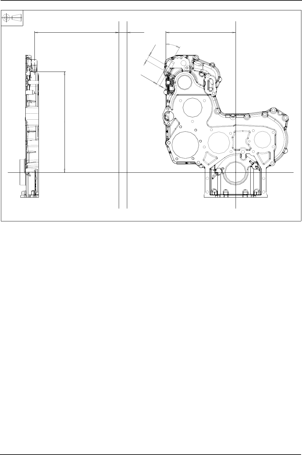


Engine Specification Manual, TPD1599 Issue 6, January 2009 163
6
1100 Series, 1104D, Mechanical FIE
Technical data 6
Introduction
The information given in the following chapter contains preliminary and target data and should only
be used for preliminary calculations to assist the user to select the option for the 1104D
(Mechanical FIE) project engine specifications.
If more information is required refer to the 1104D product team.
1100 series Electronic Applications and Installation Guide
https://ediscovery.cat.com/cda/files/124844/7/AandIguide_12.doc
1104D and 1106D Electrical and Electronic Installation Guide
https://ediscovery.cat.com/cda/files/245830/7/EEAIG_1106D_09AUG05_d3.2.pdf

164 Engine Specification Manual, TPD1599 Issue 6, January 2009
1100 Series, 1104D, Mechanical FIE
Basic technical data
Models NK
Engine type: 1104D-44
Cylinder arrangement ... ... ... ... ... ... ... ... ... ... ... ... ... ... ... ... ... ... ... ... ... ... ... ... ... ... ... ... . Vertical in-line
Cycle .. ... ... ... ... ... ... ... ... ... ... ... ... ... ... ... ... ... ... ... ... ... ... ... ... ... ... ... ... ... ... ... ... ... ... ... ... ... 4 stroke
Induction system ... ... ... ... ... ... ... ... ... ... ... ... ... ... ... ... ... ... ... ... ... ... ... ... ... ... ... ... . Naturally Aspirated
Combustion system ... ... ... ... ... ... ... ... ... ... ... ... ... ... ... ... ... ... ... ... ... ... ... ... ... ... ... ... ... Direct injection
Bore ... ... ... ... ... ... ... ... ... ... ... ... ... ... ... ... ... ... ... ... ... ... ... ... ... ... ... ... ... ... ... ... ... ..105,0 mm (4.13 in)
Stroke. ... ... ... ... ... ... ... ... ... ... ... ... ... ... ... ... ... ... ... ... ... ... ... ... ... ... ... ... ... ... ... ... ..127,0 mm (5.00 in)
Compression ratio.. ... ... ... ... ... ... ... ... ... ... ... ... ... ... ... ... ... ... ... ... ... ... ... ... ... ... ... ... ... ... ... ... 18.2 : 1
Cubic capacity ... ... ... ... ... ... ... ... ... ... ... ... ... ... ... ... ... ... ... ... ... ... ... ... ... ... ... ... ... ... 4,4 litres (269 in³)
Firing order. ... ... ... ... ... ... ... ... ... ... ... ... ... ... ... ... ... ... ... ... ... ... ... ... ... ... ... ... ... ... ... ... ... ... ..1, 3, 4, 2
Rotation.. ... ... ... ... ... ... ... ... ... ... ... ... ... ... ... ... ... ... ... ... ... ... ... ... ... ... ... .. Clockwise, viewed from front
Basic thread form... ... ... ... ... ... ... ... ... ... ... ... ... ... ... ... ... ... ... ... ... ... ... ... ... ... ... ... ... ... ... ... ... .. Metric
Cooling system .. ... ... ... ... ... ... ... ... ... ... ... ... ... ... ... ... ... ... ... ... ... ... ... ... ... ... ... ... ... ... ... ... ... .. Liquid
0verall dimensions
Note: shown on general arrangement drawings (1)
Length (2) ... ... ... ... ... ... ... ... ... ... ... ... ... ... ... ... ... ... ... ... ... ... ... ... ... ... ... ... ... ... ... ... .663 mm (26.1 in)
Width . ... ... ... ... ... ... ... ... ... ... ... ... ... ... ... ... ... ... ... ... ... ... ... ... ... ... ... ... ... ... ... ... ... .470 mm (18.5 in)
Height ... ... ... ... ... ... ... ... ... ... ... ... ... ... ... ... ... ... ... ... ... ... ... ... ... ... ... ... ... ... ... ... ... .810 mm (31.9 in)
Engine weights - non-stressed
Bare engine (dry) (3) ... ... ... ... ... ... ... ... ... ... ... ... ... ... ... ... ... ... ... ... ... ... ... ... ... ... ... ... ... ... ... ... . 291 kg
Bare engine (wet) (3)... ... ... ... ... ... ... ... ... ... ... ... ... ... ... ... ... ... ... ... ... ... ... ... ... ... ... ... ... ... ... ... ... .TBA
Engine weights - stressed
Bare engine (dry) (3) ... ... ... ... ... ... ... ... ... ... ... ... ... ... ... ... ... ... ... ... ... ... ... ... ... ... ... ... ... ... ... ... . 357 kg
Bare engine (wet) (3)... ... ... ... ... ... ... ... ... ... ... ... ... ... ... ... ... ... ... ... ... ... ... ... ... ... ... ... ... ... ... ... ... .TBA
Note: All values are with standard engine parts fitted, unless otherwise stated.
(1)(2)(3)
(1). Final weight and dimensions will depend on complete specification.
(2). Dimension from rear face of cylinder block to fan drive pulley face.
(3). Excludes flywheel housing, flywheel, and electrics.

Engine Specification Manual, TPD1599 Issue 6, January 2009 165
1100 Series, 1104D, Mechanical FIE
Models NL
Engine type: 1104D-44T
Cylinder arrangement .. ... ... ... ... ... ... ... ... ... ... ... ... ... ... ... ... ... ... ... ... ... ... ... ... ... ... ... ....Vertical in-line
Cycle ... ... ... ... ... ... ... ... ... ... ... ... ... ... ... ... ... ... ... ... ... ... ... ... ... ... ... ... ... ... ... ... ... ... ... ... ... . 4 stroke
Induction system.. ... ... ... ... ... ... ... ... ... ... ... ... ... ... ... ... ... ... ... ... ... ... ... ... ... ... ... ... ... ... Turbocharged
Combustion system . ... ... ... ... ... ... ... ... ... ... ... ... ... ... ... ... ... ... ... ... ... ... ... ... ... ... ... ... ...Direct injection
Bore . ... ... ... ... ... ... ... ... ... ... ... ... ... ... ... ... ... ... ... ... ... ... ... ... ... ... ... ... ... ... ... ... ... 105,0 mm (4.13 in)
Stroke .. ... ... ... ... ... ... ... ... ... ... ... ... ... ... ... ... ... ... ... ... ... ... ... ... ... ... ... ... ... ... ... ... 127,0 mm (5.00 in)
Compression ratio ... ... ... ... ... ... ... ... ... ... ... ... ... ... ... ... ... ... ... ... ... ... ... ... ... ... ... ... ... ... ... ... .. 18·2 : 1
Cubic capacity . ... ... ... ... ... ... ... ... ... ... ... ... ... ... ... ... ... ... ... ... ... ... ... ... ... ... ... ... ... .. 4,4 litres (269 in³)
Firing order .. ... ... ... ... ... ... ... ... ... ... ... ... ... ... ... ... ... ... ... ... ... ... ... ... ... ... ... ... ... ... ... ... ... ... 1, 3, 4, 2
Rotation ... ... ... ... ... ... ... ... ... ... ... ... ... ... ... ... ... ... ... ... ... ... ... ... ... ... ... ... Clockwise, viewed from front
Basic thread form ... ... ... ... ... ... ... ... ... ... ... ... ... ... ... ... ... ... ... ... ... ... ... ... ... ... ... ... ... ... ... ... ... Metric
Cooling system ... ... ... ... ... ... ... ... ... ... ... ... ... ... ... ... ... ... ... ... ... ... ... ... ... ... ... ... ... ... ... ... ... ... .Liquid
0verall dimensions
Note: shown on general arrangement drawings (1)
Length (2) . ... ... ... ... ... ... ... ... ... ... ... ... ... ... ... ... ... ... ... ... ... ... ... ... ... ... ... ... ... ... ... ... 663 mm (26.1 in)
Width .. ... ... ... ... ... ... ... ... ... ... ... ... ... ... ... ... ... ... ... ... ... ... ... ... ... ... ... ... ... ... ... ... ... 597 mm (23.5 in)
Height . ... ... ... ... ... ... ... ... ... ... ... ... ... ... ... ... ... ... ... ... ... ... ... ... ... ... ... ... ... ... ... ... ... 810 mm (31.9 in)
Engine weights - non-stressed
Bare engine (dry) (3) . ... ... ... ... ... ... ... ... ... ... ... ... ... ... ... ... ... ... ... ... ... ... ... ... ... ... ... ... ... ... ... ... 306 kg
Bare engine (wet) (3) ... ... ... ... ... ... ... ... ... ... ... ... ... ... ... ... ... ... ... ... ... ... ... ... ... ... ... ... ... ... ... ... ... TBA
Engine weights - stressed
Bare engine (dry) (3) . ... ... ... ... ... ... ... ... ... ... ... ... ... ... ... ... ... ... ... ... ... ... ... ... ... ... ... ... ... ... ... ... 372 kg
Bare engine (wet) (3) ... ... ... ... ... ... ... ... ... ... ... ... ... ... ... ... ... ... ... ... ... ... ... ... ... ... ... ... ... ... ... ... ... TBA
Note: All values are with standard engine parts fitted, unless otherwise stated.
(1)(2)(3)
(1). Final weight and dimensions will depend on complete specification.
(2). Dimension from rear face of cylinder block to fan drive pulley face.
(3). Excludes flywheel housing, flywheel, and electrics.

166 Engine Specification Manual, TPD1599 Issue 6, January 2009
1100 Series, 1104D, Mechanical FIE
Models NM
Engine type: 1104D-44TA
Cylinder arrangement ... ... ... ... ... ... ... ... ... ... ... ... ... ... ... ... ... ... ... ... ... ... ... ... ... ... ... ... . Vertical in-line
Cycle .. ... ... ... ... ... ... ... ... ... ... ... ... ... ... ... ... ... ... ... ... ... ... ... ... ... ... ... ... ... ... ... ... ... ... ... ... ... 4 stroke
Induction system ... ... ... ... ... ... ... ... ... ... ... ... ... ... ... ... ... ... ... ... ... ... ...Turbocharged air/air after cooling
Combustion system ... ... ... ... ... ... ... ... ... ... ... ... ... ... ... ... ... ... ... ... ... ... ... ... ... ... ... ... ... Direct injection
Bore ... ... ... ... ... ... ... ... ... ... ... ... ... ... ... ... ... ... ... ... ... ... ... ... ... ... ... ... ... ... ... ... ... ..105,0 mm (4.13 in)
Stroke. ... ... ... ... ... ... ... ... ... ... ... ... ... ... ... ... ... ... ... ... ... ... ... ... ... ... ... ... ... ... ... ... ..127,0 mm (5.00 in)
Compression ratio.. ... ... ... ... ... ... ... ... ... ... ... ... ... ... ... ... ... ... ... ... ... ... ... ... ... ... ... ... ... ... ... ... 18·2 : 1
Cubic capacity ... ... ... ... ... ... ... ... ... ... ... ... ... ... ... ... ... ... ... ... ... ... ... ... ... ... ... ... ... ... 4,4 litres (269 in³)
Firing order. ... ... ... ... ... ... ... ... ... ... ... ... ... ... ... ... ... ... ... ... ... ... ... ... ... ... ... ... ... ... ... ... ... ... ..1, 3, 4, 2
Rotation.. ... ... ... ... ... ... ... ... ... ... ... ... ... ... ... ... ... ... ... ... ... ... ... ... ... ... ... .. Clockwise, viewed from front
Basic thread form... ... ... ... ... ... ... ... ... ... ... ... ... ... ... ... ... ... ... ... ... ... ... ... ... ... ... ... ... ... ... ... ... .. Metric
Cooling system .. ... ... ... ... ... ... ... ... ... ... ... ... ... ... ... ... ... ... ... ... ... ... ... ... ... ... ... ... ... ... ... ... ... .. Liquid
0verall dimensions
Note: shown on general arrangement drawings (1)
Length (2) ... ... ... ... ... ... ... ... ... ... ... ... ... ... ... ... ... ... ... ... ... ... ... ... ... ... ... ... ... ... ... ... .663 mm (26.1 in)
Width . ... ... ... ... ... ... ... ... ... ... ... ... ... ... ... ... ... ... ... ... ... ... ... ... ... ... ... ... ... ... ... ... ... .620 mm (24.4 in)
Height ... ... ... ... ... ... ... ... ... ... ... ... ... ... ... ... ... ... ... ... ... ... ... ... ... ... ... ... ... ... ... ... ... .775 mm (30.5 in)
Engine weights - non-stressed
Bare engine (dry) (3) ... ... ... ... ... ... ... ... ... ... ... ... ... ... ... ... ... ... ... ... ... ... ... ... ... ... ... ... ... ... ... ... . 306 kg
Bare engine (wet) (3)... ... ... ... ... ... ... ... ... ... ... ... ... ... ... ... ... ... ... ... ... ... ... ... ... ... ... ... ... ... ... ... ... .TBA
Engine weights - stressed
Bare engine (dry) (3) ... ... ... ... ... ... ... ... ... ... ... ... ... ... ... ... ... ... ... ... ... ... ... ... ... ... ... ... ... ... ... ... . 372 kg
Bare engine (wet) (3)... ... ... ... ... ... ... ... ... ... ... ... ... ... ... ... ... ... ... ... ... ... ... ... ... ... ... ... ... ... ... ... ... .TBA
Note: All values are with standard engine parts fitted, unless otherwise stated.
(1)(2)(3)
(1). Final weight and dimensions will depend on complete specification.
(2). Dimension from rear face of cylinder block to fan drive pulley face.
(3). Excludes flywheel housing, flywheel, and electrics.
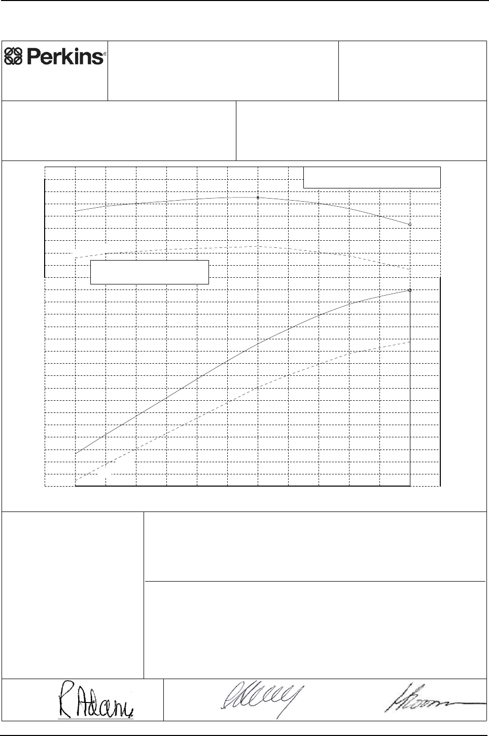
Engine Specification Manual, TPD1599 Issue 6, January 2009 167
1100 Series, 1104D, Mechanical FIE
Power curves
1104D-44 - T2968, (non-balanced)
Awaiting updated curve
Contact product team
for further details
Perkins Engines Company Limited
©2007 Commercial in Confidence,
proprietary information of
Perkins Engines Company Ltd.
Engine Model:
1104D-44
Curve:
2968T
Issue:
4
Sheet 1
Date: 20-Jul-2007
Not certified to EPA legislation.
Not for operation in USA or Canada
Development Target -
May be Subject to Change
Performance after 60 hours operation with fuel oil at 40°C at pump inlet.
Date: 13-Jul-2007 Date: 20-Jul-2007
Auxiliaries fitted to engine:
Alternator - off load.
Balancer - not fitted.
Fan - not fitted.
Notes:
1. For duty cycle refer to Perkins Engines
(Peterborough) Limited statement on
Product Duty Usage Limitations.
2. For power and torque data below 1100
rev/min refer to Perkins Engines Limited.
1100 1200 1300 1400 1500 1600 1700 1800 1900 2000 2100 2200
S
p
eed, rev/min
24
26
28
30
32
34
36
38
40
42
44
46
48
50
52
54
56
58
Power, kW
200
210
220
230
240
250
260
270
280
Torque, Nm
Governing Key
A denotes 5% +/- 2% governing.
265.0
A
55.9
Max continuous power
85%load
85%load
R.C. Adams
(Program Manager)
Approved by:
C. Herring
(PE Manager)
Accepted by:
Fuel Specification: CEC RF-06-99
Fuel Types: Europe Off Highway
Density (kg/l @ 15°C): 0.833 - 0.837
Viscosity (mm²/s @ 40°C): 2.3 - 3.5
Sulphur Content (% mass): 0.03 max
Cetane No: 52 - 54
CEC RF-06-99
Europe Off Highway
0.833 - 0.837
2.3 - 3.5
0.03 max
52 - 54
ISO 14396: 2002
Production Tolerance On Power Output: +5%, -5%
Total Barometric Pressure (kPa): 100
Vapour Pressure (kPa): 1
Air Inlet Temperature (°C): 25
Rating Standards:
J.H. Boorman
(Legislation
Engineer)
Issued by:
Certification Refs (Rated Speeds)Exhaust Quality Standard
Smoke:
Emissions:
Power Standard Certification Refs (Rated Speeds)
EU NRMM 97/68/EC Stage 3A. e11*97/68JA*2004/26*0892* (2200)
UN/ECE R120 120R-000080 (2200)

168 Engine Specification Manual, TPD1599 Issue 6, January 2009
1100 Series, 1104D, Mechanical FIE
Awaiting updated curve
Contact product team
for further details
Rating Curves Data Sheet
Sheet 2
T2968
Curve
Engine Model: 1104D-44
Number Of Cylinders: 4
Bore (mm): 105.0
Stroke (mm): 127.0
Configuration: Vertical In Line
Displacement (litres): 4.4
Injection Timing (°BTDC) - Static:
Lift Pump Pressure (Out) (kPa):
Fuel Filter Max Particle Size (micron):
Exhaust Flow (kg/min): 4.84 (12.2 m³/min)
Exhaust Temperature (°C): 685
36.8
29.1
Coolant Flow (litres/min): 184.0
Recommended Cap Pressure (kPa):
Max Top Tank Pressure (kPa):
Induction Manifold Pressure (kPa): -3.0
Max Total Pressure Drop inc Pipes (kPa): Not applicable
Not applicable
Unaided Start Limit (°C): -10
Aided Start Limit (°C): -25
General Data
Fuel System
Lubrication System
Exhaust System
Cooling System
Engine Air Flow (kg/min): 4.61 (3.96 m³/min)
Air System
Charge Air Cooler System
Turbocharger
Cold Start Capability
Performance Data
Internal References
DCP Number(s): TBD
Curve Issue No: 4
Curve Issue Date : 20-Jul-2007
TAN Number:
FIE EDR Number
Note1: Unless otherwise specified, all stated data is for maximum rated speed and 100% load.
Minimum Cranking Speed (rev/min) - unaided:
- aided:
Not applicable
250
Maximum Altitude (m): 600
For further performance data see table below.
Further Notes:
Fuel Pump Pressure (In) (kPa):
Released for operation on 48+ Cetane Number fuels only.
- Dynamic (needle lift pick-up): -0.4
Manifold Charge Air Temperature (°C): Not applicable
Heat Rejected @ Rated Speed (kW):
Heat Rejected @ Peak Torque (kW):
Charge Air Cooler Heat Rejection (kW):
Friction Power @ Rated Speed (kW):
Friction Power @ Peak Torque (kW):
Unboosted Torque @ 800 rev/min (Nm):
Compression Ratio: 18.2 : 1
Combustion Bowl: Re-entrant
Fuel Pump Model: Delphi DP310
Fuel Return System Type:
Lubricating Oil Specification: See Engine Specification Manual
Start Aid (Optional): Glowplugs fitted as standard
Thermostat - Start To Open (°C): 82
Thermostat - Fully Open (°C): 93
Charge Air Cooling System: Not applicable
Turbocharger Type: Not applicable
Performance Data
Rating Standard: ISO 14396: 2002
Aspiration: Naturally Aspirated
Unboosted Torque @ 1000 rev/min (Nm): 252
Speed
(rev/min)
Governing
Categories
(
ke
y
on sht 1
)
Max Exhaust
Back Pressure
(
kPa
)
Max Inlet
Restriction
(
kPa
)
Torque
(Nm)
Power
(kW)
2200 243 55.9 A10.0 3.0
2000 256 53.6 8.9
1800 263 49.6 7.6
1700 265 47.2 6.8
1400 262 38.4 5.3
1200 258 32.4 3.5
1100 254 29.3 3.0
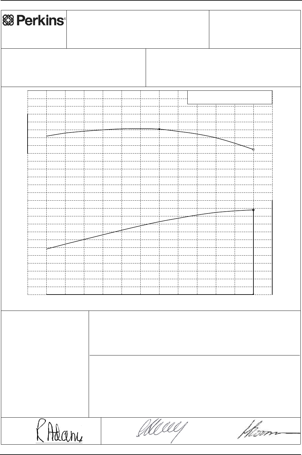
Engine Specification Manual, TPD1599 Issue 6, January 2009 169
1100 Series, 1104D, Mechanical FIE
1104D-44 - T2969, (balanced)
Awaiting updated curve
Contact product team
for further details
Perkins Engines Company Limited
©2007 Commercial in Confidence,
proprietary information of
Perkins Engines Company Ltd.
Engine Model:
1104D-44
Curve: 2969T
Issue: 4
Sheet 1
Date: 20-Jul-2007
Not certified to EPA legislation.
Not for operation in USA or Canada
Development Target -
May be Subject to Change
Performance after 60 hours operation with fuel oil at 40°C at pump inlet.
Date: 13-Jul-2007 Date: 20-Jul-2007
Auxiliaries fitted to engine:
Alternator - off load.
Balancer - fitted.
Fan - not fitted.
Notes:
1. For duty cycle refer to Perkins Engines
(Peterborough) Limited statement on
Product Duty Usage Limitations.
2. For power and torque data below 1100
rev/min refer to Perkins Engines Limited.
1100 1200 1300 1400 1500 1600 1700 1800 1900 2000 2100 2200
S
p
eed, rev/min
0
5
10
15
20
25
30
35
40
45
50
55
60
Power, kW
230
240
250
260
270
280
Torque, Nm
Governing Key
A denotes 5% +/- 2% governing.
261.0
A
54.0
R.C. Adams
(Program Manager)
Approved by:
C. Herring
(PE Manager)
Accepted by:
Fuel Specification: CEC RF-06-99
Fuel Types: Europe Off Highway
Density (kg/l @ 15°C): 0.833 - 0.837
Viscosity (mm²/s @ 40°C): 2.3 - 3.5
Sulphur Content (% mass): 0.03 max
Cetane No: 52 - 54
ISO 14396: 2002
Production Tolerance On Power Output: +5%, -5%
Total Barometric Pressure (kPa): 100
Vapour Pressure (kPa): 1
Air Inlet Temperature (°C): 25
Rating Standards:
J.H. Boorman
(Legislation
Engineer)
Issued by:
Certification Refs (Rated Speeds)Exhaust Quality Standard
Smoke:
Emissions:
Power Standard Certification Refs (Rated Speeds)
EU NRMM 97/68/EC Stage 3A. e11*97/68JA*2004/26*0892* (2200)
UN/ECE R120 120R-000080 (2200)

170 Engine Specification Manual, TPD1599 Issue 6, January 2009
1100 Series, 1104D, Mechanical FIE
Awaiting updated curve
Contact product team
for further details
Rating Curves Data Sheet
Sheet 2
T2969
Curve
Engine Model: 1104D-44
Number Of Cylinders: 4
Bore (mm): 105.0
Stroke (mm): 127.0
Configuration: Vertical In Line
Displacement (litres): 4.4
Injection Timing (°BTDC) - Static:
Lift Pump Pressure (Out) (kPa):
Fuel Filter Max Particle Size (micron):
Exhaust Flow (kg/min): 4.84 (12.1 m³/min)
Exhaust Temperature (°C): 680
36.8
29.1
Coolant Flow (litres/min): 184.0
Recommended Cap Pressure (kPa):
Max Top Tank Pressure (kPa):
Induction Manifold Pressure (kPa): -3.0
Max Total Pressure Drop inc Pipes (kPa): Not applicable
Not applicable
Unaided Start Limit (°C): -10
Aided Start Limit (°C): -25
General Data
Fuel System
Lubrication System
Exhaust System
Cooling System
Engine Air Flow (kg/min): 4.61 (3.96 m³/min)
Air System
Charge Air Cooler System
Turbocharger
Cold Start Capability
Performance Data
Internal References
DCP Number(s): TBD
Curve Issue No: 4
Curve Issue Date : 20-Jul-2007
TAN Number:
FIE EDR Number
Note1: Unless otherwise specified, all stated data is for maximum rated speed and 100% load.
Minimum Cranking Speed (rev/min) - unaided:
- aided:
Not applicable
248
Maximum Altitude (m): 600
For further performance data see table below.
Further Notes:
Fuel Pump Pressure (In) (kPa):
Released for operation on 48+ Cetane Number fuels only.
- Dynamic (needle lift pick-up):
Manifold Charge Air Temperature (°C): Not applicable
Heat Rejected @ Rated Speed (kW):
Heat Rejected @ Peak Torque (kW):
Charge Air Cooler Heat Rejection (kW):
Friction Power @ Rated Speed (kW):
Friction Power @ Peak Torque (kW):
Unboosted Torque @ 800 rev/min (Nm):
Compression Ratio: 18.2 : 1
Combustion Bowl: Re-entrant
Fuel Pump Model: Delphi DP310
Fuel Return System Type:
Lubricating Oil Specification: See Engine Specification Manual
Start Aid (Optional): Glowplugs fitted as standard
Thermostat - Start To Open (°C): 82
Thermostat - Fully Open (°C): 93
Charge Air Cooling System: Not applicable
Turbocharger Type: Not applicable
Performance Data
Rating Standard: ISO 14396: 2002
Aspiration: Naturally Aspirated
Unboosted Torque @ 1000 rev/min (Nm): 250
Speed
(rev/min)
Governing
Categories
(
ke
y
on sht 1
)
Max Exhaust
Back Pressure
(
kPa
)
Max Inlet
Restriction
(
kPa
)
Torque
(Nm)
Power
(kW)
2200 235 54.0 A10.0 3.0
2000 250 52.4 8.9
1800 258 48.6 7.6
1700 261 46.5 6.8
1400 260 38.1 5.3
1200 256 32.2 3.5
1100 252 29.0 3.0
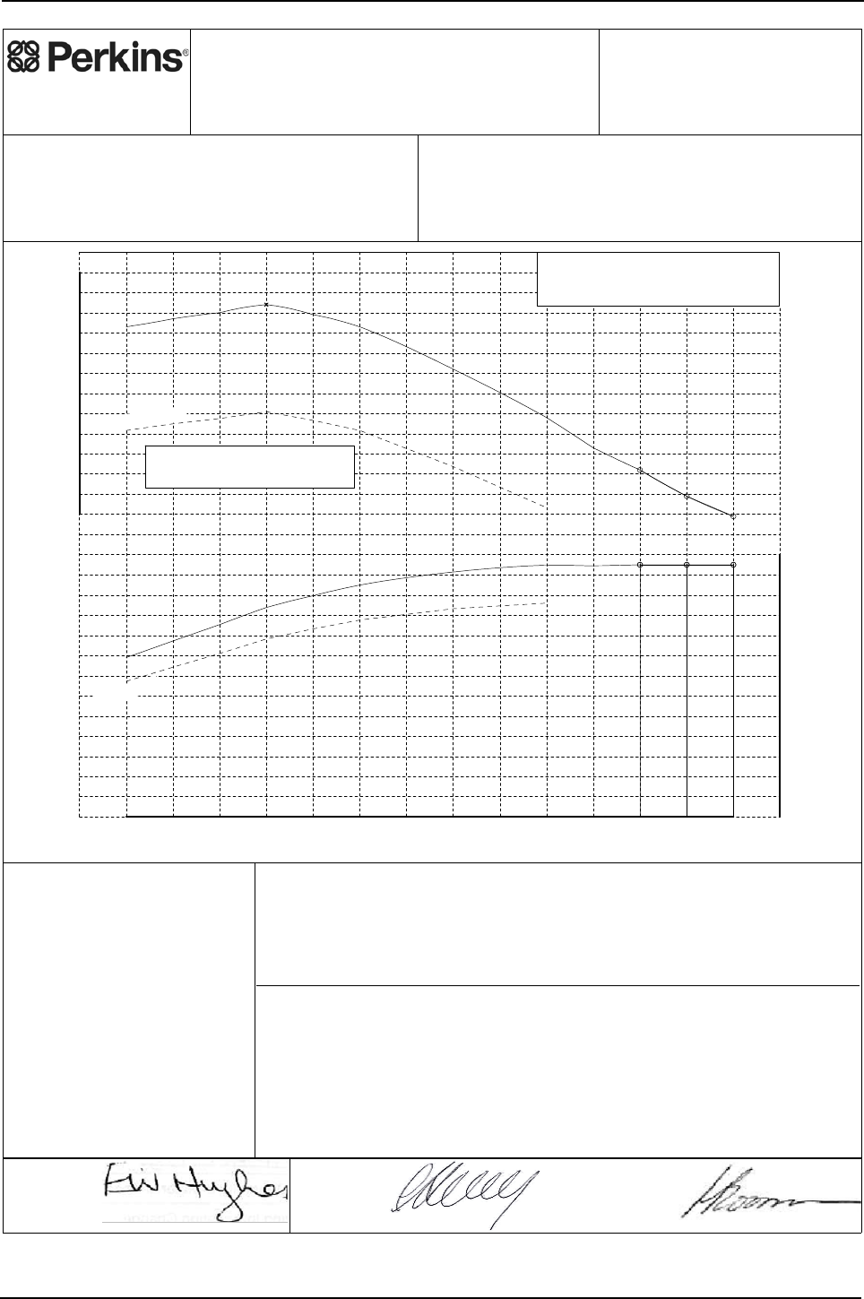
Engine Specification Manual, TPD1599 Issue 6, January 2009 171
1100 Series, 1104D, Mechanical FIE
1104D-44T - T2970, (non-balanced)
Perkins Engines Company Limited
©2007 Commercial in Confidence,
proprietary information of
Perkins Engines Company Ltd.
Engine Model:
1104D-44T
Curve: 2970T
Issue: 4
Sheet 1
Date: 9-Nov-2007
Development Target -
May be Subject to Change
Performance after 60 hours operation with fuel oil at 40°C at pump inlet.
Date: 8-Nov-2007 Date: 8-Nov-2007
Auxiliaries fitted to engine:
Alternator - off load.
Balancer - not fitted.
Fan - not fitted.
Notes:
1. For duty cycle refer to Perkins Engines
(Peterborough) Limited statement on
Product Duty Usage Limitations.
2. For power and torque data below 1100
rev/min refer to Perkins Engines Limited.
3. Smoke may be higher in some modes of
operation than equivalent 1104C rating.
For further details refer to section 6 of
ESM or contact local Perkins Applications
Team.
1100 1200 1300 1400 1500 1600 1700 1800 1900 2000 2100 2200 2300 2400
Speed, rev/min
0
5
10
15
20
25
30
35
40
45
50
55
60
65
Power, kW
250
260
270
280
290
300
310
320
330
340
350
360
370
Torque, Nm
Governing Key
A denotes 5% +/- 2% governing.
N denotes 'as found' governing.
354.0
A
N
A
62.5 62.5 62.5
Maximum gross power for
matching pump sets
85%load
85%load
E. Hughes
(Product Manager)
Approved by:
C. Herring
(PE Manager)
Accepted by:
Fuel Specification: CEC RF-06-99
Fuel Types: Europe Off Highway
Density (kg/l @ 15°C): 0.833 - 0.837
Viscosity (mm²/s @ 40°C): 2.3 - 3.5
Sulphur Content (% mass): 0.03 max
Cetane No: 52 - 54
EPA 2D 89.330 2004
USA FED Off Highway
0.840 - 0.865
2.0 - 3.2
0.03 - 0.2
40 - 48
ISO 14396: 2002
Production Tolerance On Power Output: +5%, -5%
Total Barometric Pressure (kPa): 100
Vapour Pressure (kPa): 1
Air Inlet Temperature (°C): 25
Rating Standards:
J.H. Boorman
(Legislation
Engineer)
Issued by:
Certification Refs (Rated Speeds)Exhaust Quality Standard
Smoke:
Emissions:
Power Standard Certification Refs (Rated Speeds)
See Note 3.
EU NRMM 97/68/EC Stage 3A. e11*97/68JA*2004/26*0884* (2400, 2300, 2200)
US EPA 40 CFR Part 89 Tier 3. PKXL04.4NL1 (2400, 2300, 2200)
UN/ECE R120 120R-000079 (2400, 2300, 2200)

172 Engine Specification Manual, TPD1599 Issue 6, January 2009
1100 Series, 1104D, Mechanical FIE
Rating Curves Data Sheet
Sheet 2
T2970
Curve
Engine Model: 1104D-44T
Number Of Cylinders: 4
Bore (mm): 105.0
Stroke (mm): 127.0
Configuration: Vertical In Line
Displacement (litres): 4.4
Injection Timing (°BTDC) - Static:
Lift Pump Pressure (Out) (kPa):
Fuel Filter Max Particle Size (micron):
Exhaust Flow (kg/min): 6.87 (13.9 m³/min)
Exhaust Temperature (°C): 535 (ATC)
46.7
34.5
Coolant Flow (litres/min): 201.0
Recommended Cap Pressure (kPa):
Max Top Tank Pressure (kPa):
Induction Manifold Pressure (kPa): 92.6
Max Total Pressure Drop inc Pipes (kPa): Not applicable
Not applicable
Unaided Start Limit (°C): -10
Aided Start Limit (°C): -25
General Data
Fuel System
Lubrication System
Exhaust System
Cooling System
Engine Air Flow (kg/min): 6.60 (5.67 m³/min)
Air System
Charge Air Cooler System
Turbocharger
Cold Start Capability
Performance Data
Internal References
DCP Number(s): ECR002775
Curve Issue No: 4
Curve Issue Date : 9-Nov-2007
TAN Number:
FIE EDR Number
Note1: Unless otherwise specified, all stated data is for maximum rated speed and 100% load.
Minimum Cranking Speed (rev/min) - unaided:
- aided:
Not applicable
240
Maximum Altitude (m): 3000
For further performance data see table below.
Further Notes:
Fuel Pump Pressure (In) (kPa):
- Dynamic (needle lift pick-up):
Manifold Charge Air Temperature (°C): Not applicable
Heat Rejected @ Rated Speed (kW):
Heat Rejected @ Peak Torque (kW):
Charge Air Cooler Heat Rejection (kW):
Friction Power @ Rated Speed (kW):
Friction Power @ Peak Torque (kW):
Unboosted Torque @ 800 rev/min (Nm):
Compression Ratio: 18.2 : 1
Combustion Bowl: Re-entrant
Fuel Pump Model: Delphi DP310
Fuel Return System Type:
Lubricating Oil Specification: See Engine Specification Manual
Start Aid (Optional): Glowplugs fitted as standard
Thermostat - Start To Open (°C): 82
Thermostat - Fully Open (°C): 93
Charge Air Cooling System: Not applicable
Turbocharger Type:
Performance Data
Rating Standard: ISO 14396: 2002
Aspiration: Turbocharged
Unboosted Torque @ 1000 rev/min (Nm): 240
Speed
(rev/min)
Governing
Categories
(
ke
y
on sht 1
)
Max Exhaust
Back Pressure
(
kPa
)
Max Inlet
Restriction
(
kPa
)
Torque
(Nm)
Power
(kW)
2400 249 62.5 A15.0 5.0
2300 259 62.5 N15.0 5.0
2200 272 62.5 A15.0 5.0
2100 283 62.2 13.9
2000 298 62.4 12.6
1800 322 60.7 10.5
1600 343 57.5 9.7
1500 349 54.8 9.1
1400 354 51.9 8.0 2.7
1300 350 47.6 6.9
1200 347 43.6 5.5
1100 343 39.5 4.6

Engine Specification Manual, TPD1599 Issue 6, January 2009 173
1100 Series, 1104D, Mechanical FIE
1104D-44T - T2971, (balanced)
Perkins Engines Company Limited
©2007 Commercial in Confidence,
proprietary information of
Perkins Engines Company Ltd.
Engine Model:
1104D-44T
Curve: 2971T
Issue: 4
Sheet 1
Date: 9-Nov-2007
Development Target -
May be Subject to Change
Performance after 60 hours operation with fuel oil at 40°C at pump inlet.
Date: 8-Nov-2007 Date: 8-Nov-2007
Auxiliaries fitted to engine:
Alternator - off load.
Balancer - fitted.
Fan - not fitted.
Notes:
1. For duty cycle refer to Perkins Engines
(Peterborough) Limited statement on
Product Duty Usage Limitations.
2. For power and torque data below 1100
rev/min refer to Perkins Engines Limited.
3. Smoke may be higher in some modes of
operation than equivalent 1104C rating.
For further details refer to section 6 of
ESM or contact local Perkins Applications
Team.
1100 1200 1300 1400 1500 1600 1700 1800 1900 2000 2100 2200 2300 2400
Speed, rev/min
0
5
10
15
20
25
30
35
40
45
50
55
60
65
Power, kW
240
250
260
270
280
290
300
310
320
330
340
350
360
Torque, Nm
Governing Key
A denotes 5% +/- 2% governing.
N denotes 'as found' governing.
352.0
A
N
A
60.5 60.5 60.5
Maximum gross power for
matching pump sets
85%load
85%load
E. Hughes
(Product Manager)
Approved by:
C. Herring
(PE Manager)
Accepted by:
Fuel Specification: CEC RF-06-99
Fuel Types: Europe Off Highway
Density (kg/l @ 15°C): 0.833 - 0.837
Viscosity (mm²/s @ 40°C): 2.3 - 3.5
Sulphur Content (% mass): 0.03 max
Cetane No: 52 - 54
EPA 2D 89.330 2004
USA FED Off Highway
0.840 - 0.865
2.0 - 3.2
0.03 - 0.2
40 - 48
ISO 14396: 2002
Production Tolerance On Power Output: +5%, -5%
Total Barometric Pressure (kPa): 100
Vapour Pressure (kPa): 1
Air Inlet Temperature (°C): 25
Rating Standards:
J.H. Boorman
(Legislation
Engineer)
Issued by:
Certification Refs (Rated Speeds)Exhaust Quality Standard
Smoke:
Emissions:
Power Standard Certification Refs (Rated Speeds)
See Note 3.
77/537/EEC- Includes FAS.
EU NRMM 97/68/EC Stage 3A. e11*97/68JA*2004/26*0884* (2400, 2300, 2200)
US EPA 40 CFR Part 89 Tier 3. PKXL04.4NL1 (2400, 2300, 2200)
UN/ECE R120 120R-000079 (2400, 2300, 2200)

174 Engine Specification Manual, TPD1599 Issue 6, January 2009
1100 Series, 1104D, Mechanical FIE
Rating Curves Data Sheet
Sheet 2
T2971
Curve
Engine Model: 1104D-44T
Number Of Cylinders: 4
Bore (mm): 105.0
Stroke (mm): 127.0
Configuration: Vertical In Line
Displacement (litres): 4.4
Injection Timing (°BTDC) - Static:
Lift Pump Pressure (Out) (kPa):
Fuel Filter Max Particle Size (micron):
Exhaust Flow (kg/min): 6.87 (13.9 m³/min)
Exhaust Temperature (°C): 535 (ATC)
46.7
34.5
Coolant Flow (litres/min): 201.0
Recommended Cap Pressure (kPa):
Max Top Tank Pressure (kPa):
Induction Manifold Pressure (kPa): 92.1
Max Total Pressure Drop inc Pipes (kPa): Not applicable
Not applicable
Unaided Start Limit (°C): -10
Aided Start Limit (°C): -25
General Data
Fuel System
Lubrication System
Exhaust System
Cooling System
Engine Air Flow (kg/min): 6.60 (5.67 m³/min)
Air System
Charge Air Cooler System
Turbocharger
Cold Start Capability
Performance Data
Internal References
DCP Number(s): ECR002775
Curve Issue No: 4
Curve Issue Date : 9-Nov-2007
TAN Number:
FIE EDR Number
Note1: Unless otherwise specified, all stated data is for maximum rated speed and 100% load.
Minimum Cranking Speed (rev/min) - unaided:
- aided:
Not applicable
238
Maximum Altitude (m): 3000
For further performance data see table below.
Further Notes:
Fuel Pump Pressure (In) (kPa):
- Dynamic (needle lift pick-up):
Manifold Charge Air Temperature (°C): Not applicable
Heat Rejected @ Rated Speed (kW):
Heat Rejected @ Peak Torque (kW):
Charge Air Cooler Heat Rejection (kW):
Friction Power @ Rated Speed (kW):
Friction Power @ Peak Torque (kW):
Unboosted Torque @ 800 rev/min (Nm):
Compression Ratio: 18.2 : 1
Combustion Bowl: Re-entrant
Fuel Pump Model: Delphi DP310
Fuel Return System Type:
Lubricating Oil Specification: See Engine Specification Manual
Start Aid (Optional): Glowplugs fitted as standard
Thermostat - Start To Open (°C): 82
Thermostat - Fully Open (°C): 93
Charge Air Cooling System: Not applicable
Turbocharger Type:
Performance Data
Rating Standard: ISO 14396: 2002
Aspiration: Turbocharged
Unboosted Torque @ 1000 rev/min (Nm): 238
Speed
(rev/min)
Governing
Categories
(
ke
y
on sht 1
)
Max Exhaust
Back Pressure
(
kPa
)
Max Inlet
Restriction
(
kPa
)
Torque
(Nm)
Power
(kW)
2400 241 60.5 A15.0 5.0
2300 251 60.5 N15.0 5.0
2200 263 60.5 A15.0 5.0
2100 276 60.7 13.9
2000 291 60.9 12.6
1800 317 59.8 10.5
1600 339 56.8 9.7
1500 346 54.3 9.1
1400 352 51.6 8.0
1300 348 47.4 6.9
1200 345 43.4 5.5
1100 341 39.3 4.6
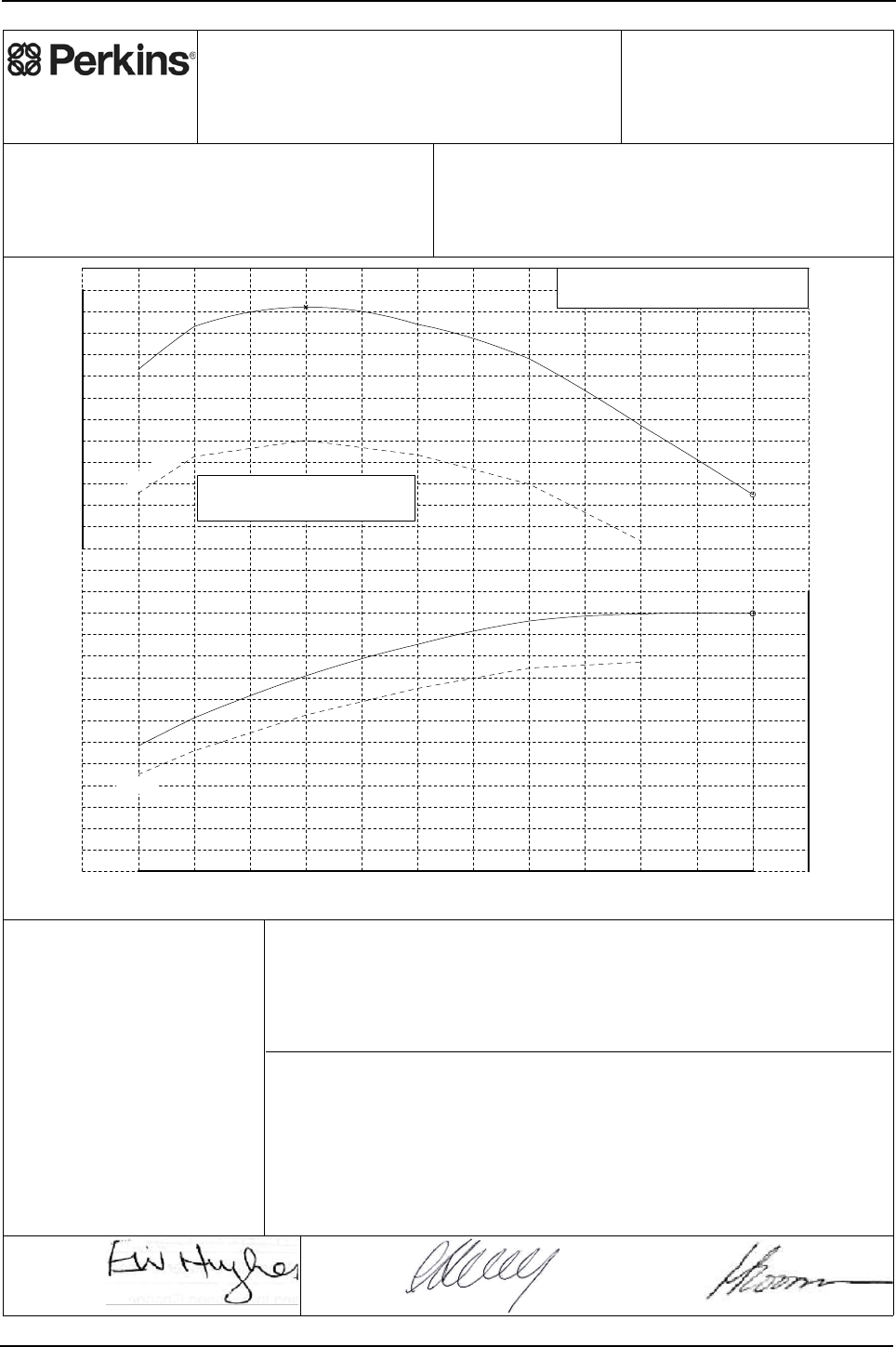
Engine Specification Manual, TPD1599 Issue 6, January 2009 175
1100 Series, 1104D, Mechanical FIE
1104D-44TA - T2972, (balanced)
Perkins Engines Company Limited
©2007 Commercial in Confidence,
proprietary information of
Perkins Engines Company Ltd.
Engine Model:
1104D-44TA
Curve: 2972T
Issue: 4
Sheet 1
Date: 9-Nov-2007
Development Target -
May be Subject to Change
Performance after 60 hours operation with fuel oil at 40°C at pump inlet.
Date: 8-Nov-2007 Date: 8-Nov-2007
Auxiliaries fitted to engine:
Alternator - off load.
Balancer - fitted.
Fan - not fitted.
Notes:
1. For duty cycle refer to Perkins Engines
(Peterborough) Limited statement on
Product Duty Usage Limitations.
2. For power and torque data below 1100
rev/min refer to Perkins Engines Limited.
3. Smoke may be higher in some modes of
operation than equivalent 1104C rating.
For further details refer to section 6 of
ESM or contact local Perkins Applications
Team.
1100 1200 1300 1400 1500 1600 1700 1800 1900 2000 2100 2200
Speed, rev/min
15
20
25
30
35
40
45
50
55
60
65
70
75
80
Power, kW
300
310
320
330
340
350
360
370
380
390
400
410
420
Torque, Nm
Governing Key
A denotes 5% +/- 2% governing.
412.0
A
74.9
Maximum gross power for
matching pump sets
85%load
85%load
E. Hughes
(Product Manager)
Approved by:
C. Herring
(PE Manager)
Accepted by:
Fuel Specification: CEC RF-06-99
Fuel Types: Europe Off Highway
Density (kg/l @ 15°C): 0.833 - 0.837
Viscosity (mm²/s @ 40°C): 2.3 - 3.5
Sulphur Content (% mass): 0.03 max
Cetane No: 52 - 54
EPA 2D 89.330 2004
USA FED Off Highway
0.840 - 0.865
2.0 - 3.2
0.03 - 0.2
40 - 48
ISO 14396: 2002
Production Tolerance On Power Output: +5%, -5%
Total Barometric Pressure (kPa): 100
Vapour Pressure (kPa): 1
Air Inlet Temperature (°C): 25
Rating Standards:
J.H. Boorman
(Legislation
Engineer)
Issued by:
Certification Refs (Rated Speeds)Exhaust Quality Standard
Smoke:
Emissions:
Power Standard Certification Refs (Rated Speeds)
See Note 3.
77/537/EEC- Includes FAS.
EU NRMM 97/68/EC Stage 3A. e11*97/68JA*2004/26*0879* (2200)
US EPA 40 CFR Part 89 Tier 3. PKXL04.4NM2 (2200)
UN/ECE R120 120R-000078 (2200)

176 Engine Specification Manual, TPD1599 Issue 6, January 2009
1100 Series, 1104D, Mechanical FIE
Rating Curves Data Sheet
Sheet 2
T2972
Curve
Engine Model: 1104D-44TA
Number Of Cylinders: 4
Bore (mm): 105.0
Stroke (mm): 127.0
Configuration: Vertical In Line
Displacement (litres): 4.4
Injection Timing (°BTDC) - Static:
Lift Pump Pressure (Out) (kPa):
Fuel Filter Max Particle Size (micron):
Exhaust Flow (kg/min): 7.94 (15.5 m³/min)
Exhaust Temperature (°C): 505 (ATC)
45.7
37.2
Coolant Flow (litres/min): 184.0
Recommended Cap Pressure (kPa):
Max Top Tank Pressure (kPa):
Induction Manifold Pressure (kPa): 101.0
Max Total Pressure Drop inc Pipes (kPa): 10.0
8.6
Unaided Start Limit (°C): -10
Aided Start Limit (°C): -25
General Data
Fuel System
Lubrication System
Exhaust System
Cooling System
Engine Air Flow (kg/min): 7.64 (6.56 m³/min)
Air System
Charge Air Cooler System
Turbocharger
Cold Start Capability
Performance Data
Internal References
DCP Number(s): ECR002775
Curve Issue No: 4
Curve Issue Date : 9-Nov-2007
TAN Number:
FIE EDR Number
Note1: Unless otherwise specified, all stated data is for maximum rated speed and 100% load.
Minimum Cranking Speed (rev/min) - unaided:
- aided:
Not applicable
265
Maximum Altitude (m): 3000
For further performance data see table below.
Further Notes:
Fuel Pump Pressure (In) (kPa):
- Dynamic (needle lift pick-up): -3.4
Manifold Charge Air Temperature (°C): 55.0
Heat Rejected @ Rated Speed (kW):
Heat Rejected @ Peak Torque (kW):
Charge Air Cooler Heat Rejection (kW):
Friction Power @ Rated Speed (kW):
Friction Power @ Peak Torque (kW):
Unboosted Torque @ 800 rev/min (Nm):
Compression Ratio: 18.2 : 1
Combustion Bowl: Re-entrant
Fuel Pump Model: Delphi DP310
Fuel Return System Type:
Lubricating Oil Specification: See Engine Specification Manual
Start Aid (Optional): Glowplugs fitted as standard
Thermostat - Start To Open (°C): 82
Thermostat - Fully Open (°C): 93
Charge Air Cooling System: Air-to-Air
Turbocharger Type:
Performance Data
Rating Standard: ISO 14396: 2002
Aspiration: Turbocharged
Unboosted Torque @ 1000 rev/min (Nm): 265
Speed
(rev/min)
Governing
Categories
(
ke
y
on sht 1
)
Max Exhaust
Back Pressure
(
kPa
)
Max Inlet
Restriction
(
kPa
)
Torque
(Nm)
Power
(kW)
2200 325 74.9 A15.0 5.0
2000 357 74.8 12.6
1800 388 73.1 11.1
1600 404 67.7 9.2
1400 412 60.4 6.7
1200 403 50.6 4.3
1100 383 44.1 3.3

Engine Specification Manual, TPD1599 Issue 6, January 2009 177
1100 Series, 1104D, Mechanical FIE
1104D-44T - T2978, (non-balanced)
Perkins Engines Company Limited
©2007 Commercial in Confidence,
proprietary information of
Perkins Engines Company Ltd.
Engine Model:
1104D-44T
Curve: 2978T
Issue: 4
Sheet 1
Date: 9-Nov-2007
Development Target -
May be Subject to Change
Performance after 60 hours operation with fuel oil at 40°C at pump inlet.
Date: 8-Nov-2007 Date: 8-Nov-2007
Auxiliaries fitted to engine:
Alternator - off load.
Balancer - not fitted.
Fan - not fitted.
Notes:
1. For duty cycle refer to Perkins Engines
(Peterborough) Limited statement on
Product Duty Usage Limitations.
2. For power and torque data below 1100
rev/min refer to Perkins Engines Limited.
3. Smoke may be higher in some modes of
operation than equivalent 1104C rating.
For further details refer to section 6 of
ESM or contact local Perkins Applications
Team.
1100 1200 1300 1400 1500 1600 1700 1800 1900 2000 2100 2200 2300
Speed, rev/min
0
5
10
15
20
25
30
35
40
45
50
55
60
65
70
75
Power, kW
280
290
300
310
320
330
340
350
360
370
380
390
400
Torque, Nm
Governing Key
A denotes 5% +/- 2% governing.
N denotes 'as found' governing.
392.0
N
A
70.0 70.0
Maximum gross power for
matching pump sets
85%load
85%load
E. Hughes
(Product Manager)
Approved by:
C. Herring
(PE Manager)
Accepted by:
Fuel Specification: CEC RF-06-99
Fuel Types: Europe Off Highway
Density (kg/l @ 15°C): 0.833 - 0.837
Viscosity (mm²/s @ 40°C): 2.3 - 3.5
Sulphur Content (% mass): 0.03 max
Cetane No: 52 - 54
EPA 2D 89.330 2004
USA FED Off Highway
0.840 - 0.865
2.0 - 3.2
0.03 - 0.2
40 - 48
ISO 14396: 2002
Production Tolerance On Power Output: +5%, -5%
Total Barometric Pressure (kPa): 100
Vapour Pressure (kPa): 1
Air Inlet Temperature (°C): 25
Rating Standards:
J.H. Boorman
(Legislation
Engineer)
Issued by:
Certification Refs (Rated Speeds)Exhaust Quality Standard
Smoke:
Emissions:
Power Standard Certification Refs (Rated Speeds)
See Note 3.
EU NRMM 97/68/EC Stage 3A. e11*97/68JA*2004/26*0884* (2300, 2200)
US EPA 40 CFR Part 89 Tier 3. PKXL04.4NL1 (2300, 2200)
UN/ECE R120 120R-000079 (2300, 2200)

178 Engine Specification Manual, TPD1599 Issue 6, January 2009
1100 Series, 1104D, Mechanical FIE
Rating Curves Data Sheet
Sheet 2
T2978
Curve
Engine Model: 1104D-44T
Number Of Cylinders: 4
Bore (mm): 105.0
Stroke (mm): 127.0
Configuration: Vertical In Line
Displacement (litres): 4.4
Injection Timing (°BTDC) - Static:
Lift Pump Pressure (Out) (kPa):
Fuel Filter Max Particle Size (micron):
Exhaust Flow (kg/min): 7.58 (15.3 m³/min)
Exhaust Temperature (°C): 530 (ATC)
50.4
40.4
Coolant Flow (litres/min): 193.0
Recommended Cap Pressure (kPa):
Max Top Tank Pressure (kPa):
Induction Manifold Pressure (kPa): 112.0
Max Total Pressure Drop inc Pipes (kPa): Not applicable
Not applicable
Unaided Start Limit (°C): -10
Aided Start Limit (°C): -25
General Data
Fuel System
Lubrication System
Exhaust System
Cooling System
Engine Air Flow (kg/min): 7.29 (6.26 m³/min)
Air System
Charge Air Cooler System
Turbocharger
Cold Start Capability
Performance Data
Internal References
DCP Number(s): ECR002775
Curve Issue No: 4
Curve Issue Date : 9-Nov-2007
TAN Number:
FIE EDR Number
Note1: Unless otherwise specified, all stated data is for maximum rated speed and 100% load.
Minimum Cranking Speed (rev/min) - unaided:
- aided:
Not applicable
240
Maximum Altitude (m): 3000
For further performance data see table below.
Further Notes:
Fuel Pump Pressure (In) (kPa):
- Dynamic (needle lift pick-up): 0.1
Manifold Charge Air Temperature (°C): Not applicable
Heat Rejected @ Rated Speed (kW):
Heat Rejected @ Peak Torque (kW):
Charge Air Cooler Heat Rejection (kW):
Friction Power @ Rated Speed (kW):
Friction Power @ Peak Torque (kW):
Unboosted Torque @ 800 rev/min (Nm):
Compression Ratio: 18.2 : 1
Combustion Bowl: Re-entrant
Fuel Pump Model: Delphi DP310
Fuel Return System Type:
Lubricating Oil Specification: See Engine Specification Manual
Start Aid (Optional): Glowplugs fitted as standard
Thermostat - Start To Open (°C): 82
Thermostat - Fully Open (°C): 93
Charge Air Cooling System: Not applicable
Turbocharger Type:
Performance Data
Rating Standard: ISO 14396: 2002
Aspiration: Turbocharged
Unboosted Torque @ 1000 rev/min (Nm): 240
Speed
(rev/min)
Governing
Categories
(
ke
y
on sht 1
)
Max Exhaust
Back Pressure
(
kPa
)
Max Inlet
Restriction
(
kPa
)
Torque
(Nm)
Power
(kW)
2300 290 70.0 A15.0 5.0
2200 303 70.0 N15.0 5.0
2000 328 68.7 13.3
1800 355 66.9 11.6
1700 367 65.3 11.0
1600 377 63.2 10.5
1500 387 60.8 9.3
1400 392 57.5 8.0
1300 390 53.1 6.9
1200 386 48.5 5.7
1100 376 43.3 4.5

Engine Specification Manual, TPD1599 Issue 6, January 2009 179
1100 Series, 1104D, Mechanical FIE
1104D-44T - T2979, (balanced)
Perkins Engines Company Limited
©2007 Commercial in Confidence,
proprietary information of
Perkins Engines Company Ltd.
Engine Model:
1104D-44T
Curve: 2979T
Issue: 4
Sheet 1
Date: 9-Nov-2007
Development Target -
May be Subject to Change
Performance after 60 hours operation with fuel oil at 40°C at pump inlet.
Date: 8-Nov-2007 Date: 8-Nov-2007
Auxiliaries fitted to engine:
Alternator - off load.
Balancer - fitted.
Fan - not fitted.
Notes:
1. For duty cycle refer to Perkins Engines
(Peterborough) Limited statement on
Product Duty Usage Limitations.
2. For power and torque data below 1100
rev/min refer to Perkins Engines Limited.
3. Smoke may be higher in some modes of
operation than equivalent 1104C rating.
For further details refer to section 6 of
ESM or contact local Perkins Applications
Team.
1100 1200 1300 1400 1500 1600 1700 1800 1900 2000 2100 2200 2300
Speed, rev/min
0
5
10
15
20
25
30
35
40
45
50
55
60
65
70
75
Power, kW
270
280
290
300
310
320
330
340
350
360
370
380
390
400
Torque, Nm
Governing Key
A denotes 5% +/- 2% governing.
N denotes 'as found' governing.
390.0
N
A
68.0 68.0
Maximum gross power for
matching pump sets
85%load
85%load
E. Hughes
(Product Manager)
Approved by:
C. Herring
(PE Manager)
Accepted by:
Fuel Specification: CEC RF-06-99
Fuel Types: Europe Off Highway
Density (kg/l @ 15°C): 0.833 - 0.837
Viscosity (mm²/s @ 40°C): 2.3 - 3.5
Sulphur Content (% mass): 0.03 max
Cetane No: 52 - 54
EPA 2D 89.330 2004
USA FED Off Highway
0.840 - 0.865
2.0 - 3.2
0.03 - 0.2
40 - 48
ISO 14396: 2002
Production Tolerance On Power Output: +5%, -5%
Total Barometric Pressure (kPa): 100
Vapour Pressure (kPa): 1
Air Inlet Temperature (°C): 25
Rating Standards:
J.H. Boorman
(Legislation
Engineer)
Issued by:
Certification Refs (Rated Speeds)Exhaust Quality Standard
Smoke:
Emissions:
Power Standard Certification Refs (Rated Speeds)
See Note 3.
77/537/EEC- Includes FAS.
EU NRMM 97/68/EC Stage 3A. e11*97/68JA*2004/26*0884* (2300, 2200)
US EPA 40 CFR Part 89 Tier 3. PKXL04.4NL1 (2300, 2200)
UN/ECE R120 120R-000079 (2300, 2200)

180 Engine Specification Manual, TPD1599 Issue 6, January 2009
1100 Series, 1104D, Mechanical FIE
Rating Curves Data Sheet
Sheet 2
T2979
Curve
Engine Model: 1104D-44T
Number Of Cylinders: 4
Bore (mm): 105.0
Stroke (mm): 127.0
Configuration: Vertical In Line
Displacement (litres): 4.4
Injection Timing (°BTDC) - Static:
Lift Pump Pressure (Out) (kPa):
Fuel Filter Max Particle Size (micron):
Exhaust Flow (kg/min): 7.58 (15.3 m³/min)
Exhaust Temperature (°C): 530 (ATC)
50.8
40.3
Coolant Flow (litres/min): 193.0
Recommended Cap Pressure (kPa):
Max Top Tank Pressure (kPa):
Induction Manifold Pressure (kPa): 112.0
Max Total Pressure Drop inc Pipes (kPa): Not applicable
Not applicable
Unaided Start Limit (°C): -10
Aided Start Limit (°C): -25
General Data
Fuel System
Lubrication System
Exhaust System
Cooling System
Engine Air Flow (kg/min): 7.29 (6.26 m³/min)
Air System
Charge Air Cooler System
Turbocharger
Cold Start Capability
Performance Data
Internal References
DCP Number(s): ECR002775
Curve Issue No: 4
Curve Issue Date : 9-Nov-2007
TAN Number:
FIE EDR Number
Note1: Unless otherwise specified, all stated data is for maximum rated speed and 100% load.
Minimum Cranking Speed (rev/min) - unaided:
- aided:
Not applicable
238
Maximum Altitude (m): 3000
For further performance data see table below.
Further Notes:
Fuel Pump Pressure (In) (kPa):
- Dynamic (needle lift pick-up): 0.1
Manifold Charge Air Temperature (°C): Not applicable
Heat Rejected @ Rated Speed (kW):
Heat Rejected @ Peak Torque (kW):
Charge Air Cooler Heat Rejection (kW):
Friction Power @ Rated Speed (kW):
Friction Power @ Peak Torque (kW):
Unboosted Torque @ 800 rev/min (Nm):
Compression Ratio: 18.2 : 1
Combustion Bowl: Re-entrant
Fuel Pump Model: Delphi DP310
Fuel Return System Type:
Lubricating Oil Specification: See Engine Specification Manual
Start Aid (Optional): Glowplugs fitted as standard
Thermostat - Start To Open (°C): 82
Thermostat - Fully Open (°C): 93
Charge Air Cooling System: Not applicable
Turbocharger Type:
Performance Data
Rating Standard: ISO 14396: 2002
Aspiration: Turbocharged
Unboosted Torque @ 1000 rev/min (Nm): 238
Speed
(rev/min)
Governing
Categories
(
ke
y
on sht 1
)
Max Exhaust
Back Pressure
(
kPa
)
Max Inlet
Restriction
(
kPa
)
Torque
(Nm)
Power
(kW)
2300 282 68.0 A15.0 5.0
2200 295 68.0 N15.0 5.0
2000 322 67.4 13.2
1800 350 66.0 11.6
1700 362 64.4 11.0
1600 373 62.5 10.5
1500 384 60.3 9.2
1400 390 57.2 8.0
1300 388 52.8 6.9
1200 384 48.3 5.7
1100 374 43.1 4.5

Engine Specification Manual, TPD1599 Issue 6, January 2009 181
1100 Series, 1104D, Mechanical FIE
1104D-44TA - T3055, (balanced)
Perkins Engines Company Limited
©2008 Commercial in Confidence,
proprietary information of
Perkins Engines Company Ltd.
Engine Model:
1104D-44TA
Curve:
3055T
Issue:
5
Sheet 1
Date: 9-Jan-2008
Development Target -
May be Subject to Change
Performance after 60 hours operation with fuel oil at 40°C at pump inlet.
Auxiliaries fitted to engine:
Alternator - off load.
Balancer - fitted.
Fan - not fitted.
Notes:
Notes:Notes:
Notes:
1. For duty cycle refer to Perkins Engines
1. For duty cycle refer to Perkins Engines 1. For duty cycle refer to Perkins Engines
1. For duty cycle refer to Perkins Engines
(Peterborough) Limited statement on
(Peterborough) Limited statement on (Peterborough) Limited statement on
(Peterborough) Limited statement on
Product Duty Usage Limitations.
Product Duty Usage Limitations.Product Duty Usage Limitations.
Product Duty Usage Limitations.
2. For power and torque data below 1100
2. For power and torque data below 1100 2. For power and torque data below 1100
2. For power and torque data below 1100
rev/min refer to Perkins Engines Limited.
rev/min refer to Perkins Engines Limited.rev/min refer to Perkins Engines Limited.
rev/min refer to Perkins Engines Limited.
1100 1200 1300 1400 1500 1600 1700 1800 1900 2000 2100 2200 2300
S
p
eed
,
rev/min
15
20
25
30
35
40
45
50
55
60
65
70
75
Power, kW
280
290
300
310
320
330
340
350
360
370
380
390
400
Torque, Nm
Governing Key
A denotes 5% +/- 2% governing.
N denotes 'as found' governing.
393.0
N
A
68.0 68.0
Approved by:
Accepted by:
Fuel Specification: CEC RF-06-99
Fuel Types: Europe Off Highway
Density (kg/l @ 15°C): 0.833 - 0.837
Viscosity (mm²/s @ 40°C): 2.3 - 3.5
Sulphur Content (% mass): 0.03 max
Cetane No: 52 - 54
EPA 2D 89.330 2004
USA FED Off Highway
0.840 - 0.865
2.0 - 3.2
0.03 - 0.2
40 - 48
ISO 14396: 2002
+5%, -5%
100
1
25
Rating Standards:
Issued by:
Certification Refs (Rated Speeds)Exhaust Quality Standard
Smoke:
Emissions:
Power Standard Certification Refs (Rated Speeds)
77/537/EEC- Includes FAS.
EU NRMM 97/68/EC Stage 3A. e11*97/68JA*2004/26*0879* (2300, 2200
US EPA 40 CFR Part 89 Tier 3. PKXL04.4NM2 (2300, 2200
UN/ECE R120 120R-000078 (2300, 2200

182 Engine Specification Manual, TPD1599 Issue 6, January 2009
1100 Series, 1104D, Mechanical FIE
Rating Curves Data Sheet
Sheet 2
T 3055
Curve
Engine Model: 1104D-44TA
Number Of Cylinders: 4
Bore (mm): 105.0
Stroke (mm): 127.0
Configuration: Vertical In Line
Displacement (litres): 4.4
Injection Timing (°BTDC) - Static:
Lift Pump Pressure (Out) (kPa):
Fuel Filter Max Particle Size (micron):
Exhaust Flow (kg/min): 7.89 (15.6 m³/min)
Exhaust Temperature (°C): 515 (ATC)
50.0
40.1
Coolant Flow (litres/min): 193.0
Recommended Cap Pressure (kPa):
Max Top Tank Pressure (kPa):
Induction Manifold Pressure (kPa): 96.4
Max Total Pressure Drop inc Pipes (kPa): 10.0
8.2
Unaided Start Limit (°C): -10
Aided Start Limit (°C): -25
General Data
Fuel System
Lubrication System
Exhaust System
Cooling System
Engine Air Flow (kg/min): 7.60 (6.53 m³/min)
Air System
Charge Air Cooler System
Turbocharger
Cold Start Capability
Performance Data
Internal References
DCP Number(s): TBD
Curve Issue No: 5
Curve Issue Date : 9-Jan-2008
TAN Number:
FIE EDR Number
Note1: Unless otherwise specified, all stated data is for maximum rated speed and 100% load.
Minimum Cranking Speed (rev/min) - unaided:
- aided:
Not applicable
288
Maximum Altitude (m): 3000
For further performance data see table below.
Further Notes:
Fuel Pump Pressure (In) (kPa):
- Dynamic (needle lift pick-up): -3.8
Manifold Charge Air Temperature (°C): 55.0
Heat Rejected @ Rated Speed (kW):
Heat Rejected @ Peak Torque (kW):
Charge Air Cooler Heat Rejection (kW):
Friction Power @ Rated Speed (kW):
Friction Power @ Peak Torque (kW):
Unboosted Torque @ 800 rev/min (Nm):
Compression Ratio: 18.2 : 1
Combustion Bowl: Re-entrant
Fuel Pump Model: Delphi DP310
Fuel Return System Type:
Lubricating Oil Specification: See Engine Specification Manual
Start Aid (Optional): Glowplugs fitted as standard
Thermostat - Start To Open (°C): 82
Thermostat - Fully Open (°C): 93
Charge Air Cooling System: Air-to-Air
Turbocharger Type:
Performance Data
Rating Standard: ISO 14396: 2002
Aspiration: Turbocharged
Unboosted Torque @ 1000 rev/min (Nm): 288
Speed
(rev/min)
Governing
Categories
(
ke
y
on sht 1
)
Max Exhaust
Back Pressure
(
kPa
)
Max Inlet
Restriction
(
kPa
)
Torque
(Nm)
Power
(kW)
2300 283 68.0 A15.0 5.0
2200 295 68.0 N15.0 5.0
2000 327 68.5
1800 356 67.1
1600 378 63.3
1400 393 57.6
1200 388 48.8
1100 378 43.5

Engine Specification Manual, TPD1599 Issue 6, January 2009 183
1100 Series, 1104D, Mechanical FIE
1104D-44TA - T3056, (non-balanced)
Perkins Engines Company Limited
©2007 Commercial in Confidence,
proprietary information of
Perkins Engines Company Ltd.
Engine Model:
1104D-44TA
Curve: 3056T
Issue: 4
Sheet 1
Date: 9-Nov-2007
Development Target -
May be Subject to Change
Performance after 60 hours operation with fuel oil at 40°C at pump inlet.
Date: 8-Nov-2007 Date: 8-Nov-2007
Auxiliaries fitted to engine:
Alternator - off load.
Balancer - not fitted.
Fan - not fitted.
Notes:
1. For duty cycle refer to Perkins Engines
(Peterborough) Limited statement on
Product Duty Usage Limitations.
2. For power and torque data below 1100
rev/min refer to Perkins Engines Limited.
3. Smoke may be higher in some modes of
operation than equivalent 1104C rating.
For further details refer to section 6 of
ESM or contact local Perkins Applications
Team.
1100 1200 1300 1400 1500 1600 1700 1800 1900 2000 2100 2200 2300 2400
Speed, rev/min
15
20
25
30
35
40
45
50
55
60
65
70
75
80
Power, kW
290
300
310
320
330
340
350
360
370
380
390
400
410
420
Torque, Nm
Governing Key
A denotes 5% +/- 2% governing.
N denotes 'as found' governing.
410.0
A
N
A
74.5 74.5 74.5
Maximum gross power for
matching pump sets
85%load
85%load
E. Hughes
(Product Manager)
Approved by:
C. Herring
(PE Manager)
Accepted by:
Fuel Specification: CEC RF-06-99
Fuel Types: Europe Off Highway
Density (kg/l @ 15°C): 0.833 - 0.837
Viscosity (mm²/s @ 40°C): 2.3 - 3.5
Sulphur Content (% mass): 0.03 max
Cetane No: 52 - 54
EPA 2D 89.330 2004
USA FED Off Highway
0.840 - 0.865
2.0 - 3.2
0.03 - 0.2
40 - 48
ISO 14396: 2002
Production Tolerance On Power Output: +5%, -5%
Total Barometric Pressure (kPa): 100
Vapour Pressure (kPa): 1
Air Inlet Temperature (°C): 25
Rating Standards:
J.H. Boorman
(Legislation
Engineer)
Issued by:
Certification Refs (Rated Speeds)Exhaust Quality Standard
Smoke:
Emissions:
Power Standard Certification Refs (Rated Speeds)
See Note 3.
EU NRMM 97/68/EC Stage 3A. e11*97/68JA*2004/26*0879* (2400, 2300, 2200)
US EPA 40 CFR Part 89 Tier 3. PKXL04.4NM2 (2400, 2300, 2200)
UN/ECE R120 120R-000078 (2400, 2300, 2200)

184 Engine Specification Manual, TPD1599 Issue 6, January 2009
1100 Series, 1104D, Mechanical FIE
Rating Curves Data Sheet
Sheet 2
T3056
Curve
Engine Model: 1104D-44TA
Number Of Cylinders: 4
Bore (mm): 105.0
Stroke (mm): 127.0
Configuration: Vertical In Line
Displacement (litres): 4.4
Injection Timing (°BTDC) - Static:
Lift Pump Pressure (Out) (kPa):
Fuel Filter Max Particle Size (micron):
Exhaust Flow (kg/min): 8.81 (16.6 m³/min)
Exhaust Temperature (°C): 478 (ATC)
46.4
36.6
Coolant Flow (litres/min): 201.0
Recommended Cap Pressure (kPa):
Max Top Tank Pressure (kPa):
Induction Manifold Pressure (kPa): 102.0
Max Total Pressure Drop inc Pipes (kPa): 10.0
10.4
Unaided Start Limit (°C): -10
Aided Start Limit (°C): -25
General Data
Fuel System
Lubrication System
Exhaust System
Cooling System
Engine Air Flow (kg/min): 8.50 (7.30 m³/min)
Air System
Charge Air Cooler System
Turbocharger
Cold Start Capability
Performance Data
Internal References
DCP Number(s): TBD
Curve Issue No: 4
Curve Issue Date : 9-Nov-2007
TAN Number:
FIE EDR Number
Note1: Unless otherwise specified, all stated data is for maximum rated speed and 100% load.
Minimum Cranking Speed (rev/min) - unaided:
- aided:
Not applicable
265
Maximum Altitude (m): 3000
For further performance data see table below.
Further Notes:
Fuel Pump Pressure (In) (kPa):
- Dynamic (needle lift pick-up): -1.7
Manifold Charge Air Temperature (°C): 55.0
Heat Rejected @ Rated Speed (kW):
Heat Rejected @ Peak Torque (kW):
Charge Air Cooler Heat Rejection (kW):
Friction Power @ Rated Speed (kW):
Friction Power @ Peak Torque (kW):
Unboosted Torque @ 800 rev/min (Nm):
Compression Ratio: 18.2 : 1
Combustion Bowl: Re-entrant
Fuel Pump Model: Delphi DP310
Fuel Return System Type:
Lubricating Oil Specification: See Engine Specification Manual
Start Aid (Optional): Glowplugs fitted as standard
Thermostat - Start To Open (°C): 82
Thermostat - Fully Open (°C): 93
Charge Air Cooling System: Air-to-Air
Turbocharger Type:
Performance Data
Rating Standard: ISO 14396: 2002
Aspiration: Turbocharged
Unboosted Torque @ 1000 rev/min (Nm): 265
Speed
(rev/min)
Governing
Categories
(
ke
y
on sht 1
)
Max Exhaust
Back Pressure
(
kPa
)
Max Inlet
Restriction
(
kPa
)
Torque
(Nm)
Power
(kW)
2400 296 74.5 A15.0 5.0
2300 310 74.5 N15.0 5.0
2200 324 74.5 A15.0 5.0
2000 356 74.6 11.0
1800 386 72.8 10.0
1600 405 67.9 9.0
1400 410 60.1 6.5
1300 409 55.7 5.3
1200 407 51.1 4.5
1100 399 46.0 3.5

Engine Specification Manual, TPD1599 Issue 6, January 2009 185
1100 Series, 1104D, Mechanical FIE
1104D-44TA - T3058, (non-balanced)
Perkins Engines Company Limited
©2007 Commercial in Confidence,
proprietary information of
Perkins Engines Company Ltd.
Engine Model:
1104D-44TA
Curve: 3058T
Issue: 6
Sheet 1
Date: 9-Nov-2007
Development Target -
May be Subject to Change
Performance after 60 hours operation with fuel oil at 40°C at pump inlet.
Date: 8-Nov-2007 Date: 8-Nov-2007
Auxiliaries fitted to engine:
Alternator - off load.
Balancer - not fitted.
Fan - not fitted.
Notes:
1. For duty cycle refer to Perkins Engines
(Peterborough) Limited statement on
Product Duty Usage Limitations.
2. For power and torque data below 1100
rev/min refer to Perkins Engines Limited.
3. Smoke may be higher in some modes of
operation than equivalent 1104C rating.
For further details refer to section 6 of
ESM or contact local Perkins Applications
Team.
1100 1200 1300 1400 1500 1600 1700 1800 1900 2000 2100 2200 2300
Speed, rev/min
15
20
25
30
35
40
45
50
55
60
65
70
75
80
85
90
Power, kW
330
340
350
360
370
380
390
400
410
420
430
Torque, Nm
Governing Key
A denotes 5% +/- 2% governing.
N denotes 'as found' governing.
418.0
N
A
83.0 83.0
Maximum gross power for
matching pump sets
85%load
85%load
E. Hughes
(Product Manager)
Approved by:
C. Herring
(PE Manager)
Accepted by:
Fuel Specification: CEC RF-06-99
Fuel Types: Europe Off Highway
Density (kg/l @ 15°C): 0.833 - 0.837
Viscosity (mm²/s @ 40°C): 2.3 - 3.5
Sulphur Content (% mass): 0.03 max
Cetane No: 52 - 54
EPA 2D 89.330 2004
USA FED Off Highway
0.840 - 0.865
2.0 - 3.2
0.03 - 0.2
40 - 48
ISO 14396: 2002
Production Tolerance On Power Output: +5%, -5%
Total Barometric Pressure (kPa): 100
Vapour Pressure (kPa): 1
Air Inlet Temperature (°C): 25
Rating Standards:
J.H. Boorman
(Legislation
Engineer)
Issued by:
Certification Refs (Rated Speeds)Exhaust Quality Standard
Smoke:
Emissions:
Power Standard Certification Refs (Rated Speeds)
See Note 3.
EU NRMM 97/68/EC Stage 3A. e11*97/68IA*2004/26*0883* (2300, 2200)
US EPA 40 CFR Part 89 Tier 3. PKXL04.4NM1 (2300, 2200)
UN/ECE R120 120R-000078 (2300, 2200)

186 Engine Specification Manual, TPD1599 Issue 6, January 2009
1100 Series, 1104D, Mechanical FIE
Rating Curves Data Sheet
Sheet 2
T3058
Curve
Engine Model: 1104D-44TA
Number Of Cylinders: 4
Bore (mm): 105.0
Stroke (mm): 127.0
Configuration: Vertical In Line
Displacement (litres): 4.4
Injection Timing (°BTDC) - Static:
Lift Pump Pressure (Out) (kPa):
Fuel Filter Max Particle Size (micron):
Exhaust Flow (kg/min): 8.95 (18.9 m³/min)
Exhaust Temperature (°C): 569 (ATC)
51.0
36.9
Coolant Flow (litres/min): 254.0
Recommended Cap Pressure (kPa):
Max Top Tank Pressure (kPa):
Induction Manifold Pressure (kPa): 115.0
Max Total Pressure Drop inc Pipes (kPa): 10.0
12.0
Unaided Start Limit (°C): -10
Aided Start Limit (°C): -20
General Data
Fuel System
Lubrication System
Exhaust System
Cooling System
Engine Air Flow (kg/min): 8.60 (7.39 m³/min)
Air System
Charge Air Cooler System
Turbocharger
Cold Start Capability
Performance Data
Internal References
DCP Number(s): ECR002775
Curve Issue No: 6
Curve Issue Date : 9-Nov-2007
TAN Number:
FIE EDR Number
Note1: Unless otherwise specified, all stated data is for maximum rated speed and 100% load.
Minimum Cranking Speed (rev/min) - unaided:
- aided:
Not applicable
250
Maximum Altitude (m): 3000
For further performance data see table below.
Further Notes:
Fuel Pump Pressure (In) (kPa):
- Dynamic (needle lift pick-up): 3.3
Manifold Charge Air Temperature (°C): 50.0
Heat Rejected @ Rated Speed (kW):
Heat Rejected @ Peak Torque (kW):
Charge Air Cooler Heat Rejection (kW):
Friction Power @ Rated Speed (kW):
Friction Power @ Peak Torque (kW):
Unboosted Torque @ 800 rev/min (Nm):
Compression Ratio: 18.2 : 1
Combustion Bowl: Re-entrant
Fuel Pump Model: Delphi DP310
Fuel Return System Type:
Lubricating Oil Specification: See Engine Specification Manual
Start Aid (Optional): Glowplugs fitted as standard
Thermostat - Start To Open (°C): 82
Thermostat - Fully Open (°C): 95
Charge Air Cooling System: Air-to-Air
Turbocharger Type: Garrett GT25 with wastegate
Performance Data
Rating Standard: ISO 14396: 2002
Aspiration: Turbocharged
Unboosted Torque @ 1000 rev/min (Nm): 250
Speed
(rev/min)
Governing
Categories
(
ke
y
on sht 1
)
Max Exhaust
Back Pressure
(
kPa
)
Max Inlet
Restriction
(
kPa
)
Torque
(Nm)
Power
(kW)
2300 345 83.0 A15.0 5.0
2200 360 83.0 N15.0 5.0
2000 387 81.1 12.3
1800 404 76.2 10.1
1600 413 69.2 8.3
1400 418 61.3 6.4
1200 409 51.4 4.6
1100 398 45.8 4.0

Engine Specification Manual, TPD1599 Issue 6, January 2009 187
1100 Series, 1104D, Mechanical FIE
1104D-44TA - T3059, (balanced)
Perkins Engines Company Limited
©2007 Commercial in Confidence,
proprietary information of
Perkins Engines Company Ltd.
Engine Model:
1104D-44TA
Curve: 3059T
Issue: 5
Sheet 1
Date: 9-Nov-2007
Development Target -
May be Subject to Change
Performance after 60 hours operation with fuel oil at 40°C at pump inlet.
Date: 8-Nov-2007 Date: 8-Nov-2007
Auxiliaries fitted to engine:
Alternator - off load.
Balancer - fitted.
Fan - not fitted.
Notes:
1. For duty cycle refer to Perkins Engines
(Peterborough) Limited statement on
Product Duty Usage Limitations.
2. For power and torque data below 1100
rev/min refer to Perkins Engines Limited.
3. Smoke may be higher in some modes of
operation than equivalent 1104C rating.
For further details refer to section 6 of
ESM or contact local Perkins Applications
Team.
1100 1200 1300 1400 1500 1600 1700 1800 1900 2000 2100 2200 2300
Speed, rev/min
15
20
25
30
35
40
45
50
55
60
65
70
75
80
85
Power, kW
320
330
340
350
360
370
380
390
400
410
420
430
Torque, Nm
Governing Key
A denotes 5% +/- 2% governing.
N denotes 'as found' governing.
416.0
N
A
81.0 81.0
Maximum gross power for
matching pump sets
85%load
85%load
E. Hughes
(Product Manager)
Approved by:
C. Herring
(PE Manager)
Accepted by:
Fuel Specification: CEC RF-06-99
Fuel Types: Europe Off Highway
Density (kg/l @ 15°C): 0.833 - 0.837
Viscosity (mm²/s @ 40°C): 2.3 - 3.5
Sulphur Content (% mass): 0.03 max
Cetane No: 52 - 54
EPA 2D 89.330 2004
USA FED Off Highway
0.840 - 0.865
2.0 - 3.2
0.03 - 0.2
40 - 48
ISO 14396: 2002
Production Tolerance On Power Output: +5%, -5%
Total Barometric Pressure (kPa): 100
Vapour Pressure (kPa): 1
Air Inlet Temperature (°C): 25
Rating Standards:
J.H. Boorman
(Legislation
Engineer)
Issued by:
Certification Refs (Rated Speeds)Exhaust Quality Standard
Smoke:
Emissions:
Power Standard Certification Refs (Rated Speeds)
See Note 3.
77/537/EEC- Includes FAS.
EU NRMM 97/68/EC Stage 3A. e11*97/68IA*2004/26*0883* (2300, 2200)
US EPA 40 CFR Part 89 Tier 3. PKXL04.4NM1 (2300, 2200)
UN/ECE R120 120R-000078 (2300, 2200)

188 Engine Specification Manual, TPD1599 Issue 6, January 2009
1100 Series, 1104D, Mechanical FIE
Rating Curves Data Sheet
Sheet 2
T3059
Curve
Engine Model: 1104D-44TA
Number Of Cylinders: 4
Bore (mm): 105.0
Stroke (mm): 127.0
Configuration: Vertical In Line
Displacement (litres): 4.4
Injection Timing (°BTDC) - Static:
Lift Pump Pressure (Out) (kPa):
Fuel Filter Max Particle Size (micron):
Exhaust Flow (kg/min): 8.96 (18.9 m³/min)
Exhaust Temperature (°C): 569 (ATC)
51.0
36.9
Coolant Flow (litres/min): 254.0
Recommended Cap Pressure (kPa):
Max Top Tank Pressure (kPa):
Induction Manifold Pressure (kPa): 115.0
Max Total Pressure Drop inc Pipes (kPa): 10.0
12.0
Unaided Start Limit (°C): -10
Aided Start Limit (°C): -20
General Data
Fuel System
Lubrication System
Exhaust System
Cooling System
Engine Air Flow (kg/min): 8.61 (7.40 m³/min)
Air System
Charge Air Cooler System
Turbocharger
Cold Start Capability
Performance Data
Internal References
DCP Number(s): ECR002775
Curve Issue No: 5
Curve Issue Date : 9-Nov-2007
TAN Number:
FIE EDR Number
Note1: Unless otherwise specified, all stated data is for maximum rated speed and 100% load.
Minimum Cranking Speed (rev/min) - unaided:
- aided:
Not applicable
248
Maximum Altitude (m): 3000
For further performance data see table below.
Further Notes:
Fuel Pump Pressure (In) (kPa):
- Dynamic (needle lift pick-up): 3.3
Manifold Charge Air Temperature (°C): 50.0
Heat Rejected @ Rated Speed (kW):
Heat Rejected @ Peak Torque (kW):
Charge Air Cooler Heat Rejection (kW):
Friction Power @ Rated Speed (kW):
Friction Power @ Peak Torque (kW):
Unboosted Torque @ 800 rev/min (Nm):
Compression Ratio: 18.2 : 1
Combustion Bowl: Re-entrant
Fuel Pump Model: Delphi DP310
Fuel Return System Type:
Lubricating Oil Specification: See Engine Specification Manual
Start Aid (Optional): Glowplugs fitted as standard
Thermostat - Start To Open (°C): 82
Thermostat - Fully Open (°C): 93
Charge Air Cooling System: Air-to-Air
Turbocharger Type: Garrett GT25 with wastegate
Performance Data
Rating Standard: ISO 14396: 2002
Aspiration: Turbocharged
Unboosted Torque @ 1000 rev/min (Nm): 248
Speed
(rev/min)
Governing
Categories
(
ke
y
on sht 1
)
Max Exhaust
Back Pressure
(
kPa
)
Max Inlet
Restriction
(
kPa
)
Torque
(Nm)
Power
(kW)
2300 337 81.0 A15.0 5.0
2200 352 81.0 N15.0 5.0
2000 381 79.8 13.0
1800 399 75.2 10.0
1600 409 68.5 8.6
1400 416 61.0 6.9
1200 407 51.1 4.7
1100 396 45.6 4.0
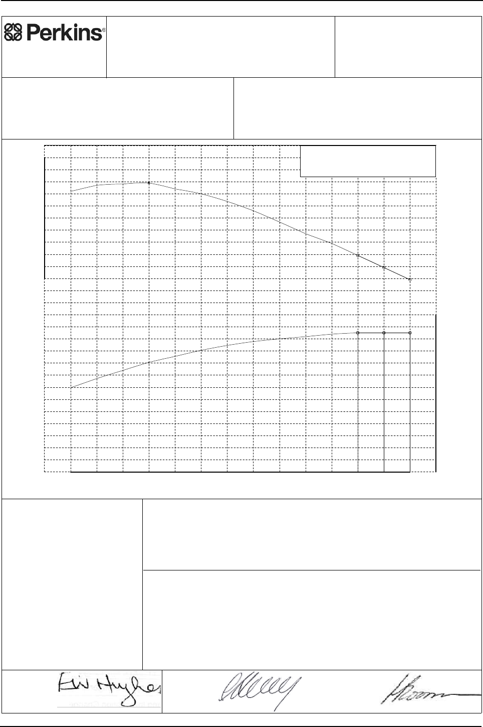
Engine Specification Manual, TPD1599 Issue 6, January 2009 189
1100 Series, 1104D, Mechanical FIE
1104D-44T - T3060, (non-balanced)
Perkins Engines Company Limited
©2007 Commercial in Confidence,
proprietary information of
Perkins Engines Company Ltd.
Engine Model:
1104D-44T
Curve: 3060T
Issue: 4
Sheet 1
Date: 9-Nov-2007
Development Target -
May be Subject to Change
Performance after 60 hours operation with fuel oil at 40°C at pump inlet.
Date: 8-Nov-2007 Date: 8-Nov-2007
Auxiliaries fitted to engine:
Alternator - off load.
Balancer - not fitted.
Fan - not fitted.
Notes:
1. For duty cycle refer to Perkins Engines
(Peterborough) Limited statement on
Product Duty Usage Limitations.
2. For power and torque data below 1100
rev/min refer to Perkins Engines Limited.
3. Smoke may be higher in some modes of
operation than equivalent 1104C rating.
For further details refer to section 6 of
ESM or contact local Perkins Applications
Team.
1100 1200 1300 1400 1500 1600 1700 1800 1900 2000 2100 2200 2300 2400
Speed, rev/min
0
5
10
15
20
25
30
35
40
45
50
55
60
65
Power, kW
230
240
250
260
270
280
290
300
310
320
330
Torque, Nm
Governing Key
A denotes 5% +/- 2% governing.
N denotes 'as found' governing.
309.0
A
N
A
57.5 57.5 57.5
E. Hughes
(Product Manager)
Approved by:
C. Herring
(PE Manager)
Accepted by:
Fuel Specification: CEC RF-06-99
Fuel Types: Europe Off Highway
Density (kg/l @ 15°C): 0.833 - 0.837
Viscosity (mm²/s @ 40°C): 2.3 - 3.5
Sulphur Content (% mass): 0.03 max
Cetane No: 52 - 54
EPA 2D 89.330 2004
USA FED Off Highway
0.840 - 0.865
2.0 - 3.2
0.03 - 0.2
40 - 48
ISO 14396: 2002
Production Tolerance On Power Output: +5%, -5%
Total Barometric Pressure (kPa): 100
Vapour Pressure (kPa): 1
Air Inlet Temperature (°C): 25
Rating Standards:
J.H. Boorman
(Legislation
Engineer)
Issued by:
Certification Refs (Rated Speeds)Exhaust Quality Standard
Smoke:
Emissions:
Power Standard Certification Refs (Rated Speeds)
See Note 3.
EU NRMM 97/68/EC Stage 3A. e11*97/68JA*2004/26*0884* (2400, 2300, 2200)
US EPA 40 CFR Part 89 Tier 3. PKXL04.4NL1 (2400, 2300, 2200)
UN/ECE R120 120R-000079 (2400, 2300, 2200)

190 Engine Specification Manual, TPD1599 Issue 6, January 2009
1100 Series, 1104D, Mechanical FIE
Rating Curves Data Sheet
Sheet 2
T3060
Curve
Engine Model: 1104D-44T
Number Of Cylinders: 4
Bore (mm): 105.0
Stroke (mm): 127.0
Configuration: Vertical In Line
Displacement (litres): 4.4
Injection Timing (°BTDC) - Static:
Lift Pump Pressure (Out) (kPa):
Fuel Filter Max Particle Size (micron):
Exhaust Flow (kg/min): 6.96 (13.5 m³/min)
Exhaust Temperature (°C): 500 (ATC)
43.6
31.3
Coolant Flow (litres/min): 201.0
Recommended Cap Pressure (kPa):
Max Top Tank Pressure (kPa):
Induction Manifold Pressure (kPa): 91.6
Max Total Pressure Drop inc Pipes (kPa): Not applicable
Not applicable
Unaided Start Limit (°C): -10
Aided Start Limit (°C): -25
General Data
Fuel System
Lubrication System
Exhaust System
Cooling System
Engine Air Flow (kg/min): 6.71 (5.76 m³/min)
Air System
Charge Air Cooler System
Turbocharger
Cold Start Capability
Performance Data
Internal References
DCP Number(s): ECR002775
Curve Issue No: 4
Curve Issue Date : 9-Nov-2007
TAN Number:
FIE EDR Number
Note1: Unless otherwise specified, all stated data is for maximum rated speed and 100% load.
Minimum Cranking Speed (rev/min) - unaided:
- aided:
Not applicable
240
Maximum Altitude (m): 3000
For further performance data see table below.
Further Notes:
Fuel Pump Pressure (In) (kPa):
- Dynamic (needle lift pick-up):
Manifold Charge Air Temperature (°C): Not applicable
Heat Rejected @ Rated Speed (kW):
Heat Rejected @ Peak Torque (kW):
Charge Air Cooler Heat Rejection (kW):
Friction Power @ Rated Speed (kW):
Friction Power @ Peak Torque (kW):
Unboosted Torque @ 800 rev/min (Nm):
Compression Ratio: 18.2 : 1
Combustion Bowl: Re-entrant
Fuel Pump Model: Delphi DP310
Fuel Return System Type:
Lubricating Oil Specification: See Engine Specification Manual
Start Aid (Optional): Glowplugs fitted as standard
Thermostat - Start To Open (°C): 82
Thermostat - Fully Open (°C): 93
Charge Air Cooling System: Not applicable
Turbocharger Type:
Performance Data
Rating Standard: ISO 14396: 2002
Aspiration: Turbocharged
Unboosted Torque @ 1000 rev/min (Nm): 240
Speed
(rev/min)
Governing
Categories
(
ke
y
on sht 1
)
Max Exhaust
Back Pressure
(
kPa
)
Max Inlet
Restriction
(
kPa
)
Torque
(Nm)
Power
(kW)
2400 229 57.5 A15.0 5.0
2300 239 57.5 N15.0 5.0
2200 249 57.5 A15.0 5.0
2100 259 57.0
2000 267 55.9
1800 286 53.9
1600 300 50.3
1500 304 47.8
1400 309 45.3 7.3
1300 308 41.9
1200 307 38.6
1100 302 34.8

Engine Specification Manual, TPD1599 Issue 6, January 2009 191
1100 Series, 1104D, Mechanical FIE
1104D-44T - T3061, (balanced)
Perkins Engines Company Limited
©2007 Commercial in Confidence,
proprietary information of
Perkins Engines Company Ltd.
Engine Model:
1104D-44T
Curve: 3061T
Issue: 4
Sheet 1
Date: 9-Nov-2007
Development Target -
May be Subject to Change
Performance after 60 hours operation with fuel oil at 40°C at pump inlet.
Date: 8-Nov-2007 Date: 8-Nov-2007
Auxiliaries fitted to engine:
Alternator - off load.
Balancer - fitted.
Fan - not fitted.
Notes:
1. For duty cycle refer to Perkins Engines
(Peterborough) Limited statement on
Product Duty Usage Limitations.
2. For power and torque data below 1100
rev/min refer to Perkins Engines Limited.
3. Smoke may be higher in some modes of
operation than equivalent 1104C rating.
For further details refer to section 6 of
ESM or contact local Perkins Applications
Team.
1100 1200 1300 1400 1500 1600 1700 1800 1900 2000 2100 2200 2300 2400
Speed, rev/min
0
5
10
15
20
25
30
35
40
45
50
55
60
Power, kW
240
250
260
270
280
290
300
310
320
Torque, Nm
Governing Key
A denotes 5% +/- 2% governing.
N denotes 'as found' governing.
307.0
A
N
A
55.5 55.5 55.5
E. Hughes
(Product Manager)
Approved by:
C. Herring
(PE Manager)
Accepted by:
Fuel Specification: CEC RF-06-99
Fuel Types: Europe Off Highway
Density (kg/l @ 15°C): 0.833 - 0.837
Viscosity (mm²/s @ 40°C): 2.3 - 3.5
Sulphur Content (% mass): 0.03 max
Cetane No: 52 - 54
EPA 2D 89.330 2004
USA FED Off Highway
0.840 - 0.865
2.0 - 3.2
0.03 - 0.2
40 - 48
ISO 14396: 2002
Production Tolerance On Power Output: +5%, -5%
Total Barometric Pressure (kPa): 100
Vapour Pressure (kPa): 1
Air Inlet Temperature (°C): 25
Rating Standards:
J.H. Boorman
(Legislation
Engineer)
Issued by:
Certification Refs (Rated Speeds)Exhaust Quality Standard
Smoke:
Emissions:
Power Standard Certification Refs (Rated Speeds)
See Note 3.
77/537/EEC- Includes FAS.
EU NRMM 97/68/EC Stage 3A. e11*97/68JA*2004/26*0884* (2400, 2300, 2200)
US EPA 40 CFR Part 89 Tier 3. PKXL04.4NL1 (2400, 2300, 2200)
UN/ECE R120 120R-000079 (2400, 2300, 2200)

192 Engine Specification Manual, TPD1599 Issue 6, January 2009
1100 Series, 1104D, Mechanical FIE
Rating Curves Data Sheet
Sheet 2
T3061
Curve
Engine Model: 1104D-44T
Number Of Cylinders: 4
Bore (mm): 105.0
Stroke (mm): 127.0
Configuration: Vertical In Line
Displacement (litres): 4.4
Injection Timing (°BTDC) - Static:
Lift Pump Pressure (Out) (kPa):
Fuel Filter Max Particle Size (micron):
Exhaust Flow (kg/min): 6.96 (13.5 m³/min)
Exhaust Temperature (°C): 500 (ATC)
43.6
31.3
Coolant Flow (litres/min): 201.0
Recommended Cap Pressure (kPa):
Max Top Tank Pressure (kPa):
Induction Manifold Pressure (kPa): 90.0
Max Total Pressure Drop inc Pipes (kPa): Not applicable
Not applicable
Unaided Start Limit (°C): -10
Aided Start Limit (°C): -25
General Data
Fuel System
Lubrication System
Exhaust System
Cooling System
Engine Air Flow (kg/min): 6.71 (5.76 m³/min)
Air System
Charge Air Cooler System
Turbocharger
Cold Start Capability
Performance Data
Internal References
DCP Number(s): ECR002775
Curve Issue No: 4
Curve Issue Date : 9-Nov-2007
TAN Number:
FIE EDR Number
Note1: Unless otherwise specified, all stated data is for maximum rated speed and 100% load.
Minimum Cranking Speed (rev/min) - unaided:
- aided:
Not applicable
238
Maximum Altitude (m): 3000
For further performance data see table below.
Further Notes:
Fuel Pump Pressure (In) (kPa):
- Dynamic (needle lift pick-up):
Manifold Charge Air Temperature (°C): Not applicable
Heat Rejected @ Rated Speed (kW):
Heat Rejected @ Peak Torque (kW):
Charge Air Cooler Heat Rejection (kW):
Friction Power @ Rated Speed (kW):
Friction Power @ Peak Torque (kW):
Unboosted Torque @ 800 rev/min (Nm):
Compression Ratio: 18.2 : 1
Combustion Bowl: Re-entrant
Fuel Pump Model: Delphi DP310
Fuel Return System Type:
Lubricating Oil Specification: See Engine Specification Manual
Start Aid (Optional): Glowplugs fitted as standard
Thermostat - Start To Open (°C): 82
Thermostat - Fully Open (°C): 93
Charge Air Cooling System: Not applicable
Turbocharger Type:
Performance Data
Rating Standard: ISO 14396: 2002
Aspiration: Turbocharged
Unboosted Torque @ 1000 rev/min (Nm): 238
Speed
(rev/min)
Governing
Categories
(
ke
y
on sht 1
)
Max Exhaust
Back Pressure
(
kPa
)
Max Inlet
Restriction
(
kPa
)
Torque
(Nm)
Power
(kW)
2400 221 55.5 A15.0 5.0
2300 231 55.5 N15.0 5.0
2200 241 55.5 A15.0 5.0
2100 253 55.6
2000 261 54.7
1800 281 53.0
1600 296 49.6
1500 301 47.3
1400 307 45.0
1300 306 41.7
1200 305 38.3
1100 300 34.6

Engine Specification Manual, TPD1599 Issue 6, January 2009 193
1100 Series, 1104D, Mechanical FIE
1104D-44T - T3066, (non-balanced)
Perkins Engines Company Limited
©2007 Commercial in Confidence,
proprietary information of
Perkins Engines Company Ltd.
Engine Model:
1104D-44T
Curve: 3066T
Issue: 4
Sheet 1
Date: 9-Nov-2007
Development Target -
May be Subject to Change
Performance after 60 hours operation with fuel oil at 40°C at pump inlet.
Date: 8-Nov-2007 Date: 8-Nov-2007
Auxiliaries fitted to engine:
Alternator - off load.
Balancer - not fitted.
Fan - not fitted.
Notes:
1. For duty cycle refer to Perkins Engines
(Peterborough) Limited statement on
Product Duty Usage Limitations.
2. For power and torque data below 1100
rev/min refer to Perkins Engines Limited.
3. Smoke may be higher in some modes of
operation than equivalent 1104C rating.
For further details refer to section 6 of
ESM or contact local Perkins Applications
Team.
1100 1200 1300 1400 1500 1600 1700 1800 1900 2000 2100 2200 2300
Speed, rev/min
15
20
25
30
35
40
45
50
55
60
65
70
75
80
Power, kW
300
310
320
330
340
350
360
370
380
390
400
410
Torque, Nm
Governing Key
A denotes 5% +/- 2% governing.
N denotes 'as found' governing.
392.0
N
A
74.5 74.5
For usage limitations please apply to local Applications
Engineering Team
E. Hughes
(Product Manager)
Approved by:
C. Herring
(PE Manager)
Accepted by:
Fuel Specification: CEC RF-06-99
Fuel Types: Europe Off Highway
Density (kg/l @ 15°C): 0.833 - 0.837
Viscosity (mm²/s @ 40°C): 2.3 - 3.5
Sulphur Content (% mass): 0.03 max
Cetane No: 52 - 54
EPA 2D 89.330 2004
USA FED Off Highway
0.840 - 0.865
2.0 - 3.2
0.03 - 0.2
40 - 48
ISO 14396: 2002
Production Tolerance On Power Output: +5%, -5%
Total Barometric Pressure (kPa): 100
Vapour Pressure (kPa): 1
Air Inlet Temperature (°C): 25
Rating Standards:
J.H. Boorman
(Legislation
Engineer)
Issued by:
Certification Refs (Rated Speeds)Exhaust Quality Standard
Smoke:
Emissions:
Power Standard Certification Refs (Rated Speeds)
See Note 3.
EU NRMM 97/68/EC Stage 3A. e11*97/68JA*2004/26*0884* (2300, 2200)
US EPA 40 CFR Part 89 Tier 3. PKXL04.4NL1 (2300, 2200)
UN/ECE R120 120R-000079 (2300, 2200)

194 Engine Specification Manual, TPD1599 Issue 6, January 2009
1100 Series, 1104D, Mechanical FIE
Rating Curves Data Sheet
Sheet 2
T3066
Curve
Engine Model: 1104D-44T
Number Of Cylinders: 4
Bore (mm): 105.0
Stroke (mm): 127.0
Configuration: Vertical In Line
Displacement (litres): 4.4
Injection Timing (°BTDC) - Static:
Lift Pump Pressure (Out) (kPa):
Fuel Filter Max Particle Size (micron):
Exhaust Flow (kg/min): 7.70 (16.2 m³/min)
Exhaust Temperature (°C): 569 (ATC)
54.1
41.1
Coolant Flow (litres/min): 193.0
Recommended Cap Pressure (kPa):
Max Top Tank Pressure (kPa):
Induction Manifold Pressure (kPa): 122.0
Max Total Pressure Drop inc Pipes (kPa): Not applicable
Not applicable
Unaided Start Limit (°C): -10
Aided Start Limit (°C): -25
General Data
Fuel System
Lubrication System
Exhaust System
Cooling System
Engine Air Flow (kg/min): 7.38 (6.34 m³/min)
Air System
Charge Air Cooler System
Turbocharger
Cold Start Capability
Performance Data
Internal References
DCP Number(s): ECR002775
Curve Issue No: 4
Curve Issue Date : 9-Nov-2007
TAN Number:
FIE EDR Number
Note1: Unless otherwise specified, all stated data is for maximum rated speed and 100% load.
Minimum Cranking Speed (rev/min) - unaided:
- aided:
Not applicable
240
Maximum Altitude (m): 2250
For further performance data see table below.
Further Notes:
Fuel Pump Pressure (In) (kPa):
For usage limitations please apply to local Applications
Engineering team.
- Dynamic (needle lift pick-up): 0.1
Manifold Charge Air Temperature (°C): Not applicable
Heat Rejected @ Rated Speed (kW):
Heat Rejected @ Peak Torque (kW):
Charge Air Cooler Heat Rejection (kW):
Friction Power @ Rated Speed (kW):
Friction Power @ Peak Torque (kW):
Unboosted Torque @ 800 rev/min (Nm):
Compression Ratio: 18.2 : 1
Combustion Bowl: Re-entrant
Fuel Pump Model: Delphi DP310
Fuel Return System Type:
Lubricating Oil Specification: See Engine Specification Manual
Start Aid (Optional): Glowplugs fitted as standard
Thermostat - Start To Open (°C): 82
Thermostat - Fully Open (°C): 93
Charge Air Cooling System: Not applicable
Turbocharger Type: Garrett GT25 with wastegate
Performance Data
Rating Standard: ISO 14396: 2002
Aspiration: Turbocharged
Unboosted Torque @ 1000 rev/min (Nm): 240
Speed
(rev/min)
Governing
Categories
(
ke
y
on sht 1
)
Max Exhaust
Back Pressure
(
kPa
)
Max Inlet
Restriction
(
kPa
)
Torque
(Nm)
Power
(kW)
2300 309 74.5 A15.0 5.0
2200 323 74.5 N15.0 5.0
2000 345 72.3 12.2
1800 362 68.2 11.2
1700 372 66.2 11.0
1600 382 64.0 9.8
1500 390 61.3 8.7
1400 392 57.5 7.6
1300 389 53.0 6.4
1200 386 48.5 5.3
1100 376 43.3 4.3

Engine Specification Manual, TPD1599 Issue 6, January 2009 195
1100 Series, 1104D, Mechanical FIE
1104D-44T - T3067, (balanced)
Perkins Engines Company Limited
©2007 Commercial in Confidence,
proprietary information of
Perkins Engines Company Ltd.
Engine Model:
1104D-44T
Curve: 3067T
Issue: 3
Sheet 1
Date: 9-Nov-2007
Development Target -
May be Subject to Change
Performance after 60 hours operation with fuel oil at 40°C at pump inlet.
Date: 8-Nov-2007 Date: 8-Nov-2007
Auxiliaries fitted to engine:
Alternator - off load.
Balancer - fitted.
Fan - not fitted.
Notes:
1. For duty cycle refer to Perkins Engines
(Peterborough) Limited statement on
Product Duty Usage Limitations.
2. For power and torque data below 1100
rev/min refer to Perkins Engines Limited.
3. Smoke may be higher in some modes of
operation than equivalent 1104C rating.
For further details refer to section 6 of
ESM or contact local Perkins Applications
Team.
1100 1200 1300 1400 1500 1600 1700 1800 1900 2000 2100 2200 2300
Speed, rev/min
15
20
25
30
35
40
45
50
55
60
65
70
75
80
Power, kW
300
310
320
330
340
350
360
370
380
390
400
Torque, Nm
Governing Key
A denotes 5% +/- 2% governing.
N denotes 'as found' governing.
390.0
N
A
72.5 72.5
Not suitable for Heavy Duty Agricultural
Tractor Applications
E. Hughes
(Product Manager)
Approved by:
C. Herring
(PE Manager)
Accepted by:
Fuel Specification: CEC RF-06-99
Fuel Types: Europe Off Highway
Density (kg/l @ 15°C): 0.833 - 0.837
Viscosity (mm²/s @ 40°C): 2.3 - 3.5
Sulphur Content (% mass): 0.03 max
Cetane No: 52 - 54
EPA 2D 89.330 2004
USA FED Off Highway
0.840 - 0.865
2.0 - 3.2
0.03 - 0.2
40 - 48
ISO 14396: 2002
Production Tolerance On Power Output: +5%, -5%
Total Barometric Pressure (kPa): 100
Vapour Pressure (kPa): 1
Air Inlet Temperature (°C): 25
Rating Standards:
J.H. Boorman
(Legislation
Engineer)
Issued by:
Certification Refs (Rated Speeds)Exhaust Quality Standard
Smoke:
Emissions:
Power Standard Certification Refs (Rated Speeds)
See Note 3.
77/537/EEC- Includes FAS.
EU NRMM 97/68/EC Stage 3A. e11*97/68JA*2004/26*0884* (2300, 2200)
US EPA 40 CFR Part 89 Tier 3. PKXL04.4NL1 (2300, 2200)
UN/ECE R120 120R-000079 (2300, 2200)

196 Engine Specification Manual, TPD1599 Issue 6, January 2009
1100 Series, 1104D, Mechanical FIE
Rating Curves Data Sheet
Sheet 2
T3067
Curve
Engine Model: 1104D-44T
Number Of Cylinders: 4
Bore (mm): 105.0
Stroke (mm): 127.0
Configuration: Vertical In Line
Displacement (litres): 4.4
Injection Timing (°BTDC) - Static:
Lift Pump Pressure (Out) (kPa):
Fuel Filter Max Particle Size (micron):
Exhaust Flow (kg/min): 7.70 (16.2 m³/min)
Exhaust Temperature (°C): 569 (ATC)
54.1
41.1
Coolant Flow (litres/min): 193.0
Recommended Cap Pressure (kPa):
Max Top Tank Pressure (kPa):
Induction Manifold Pressure (kPa): 122.0
Max Total Pressure Drop inc Pipes (kPa): Not applicable
Not applicable
Unaided Start Limit (°C): -10
Aided Start Limit (°C): -25
General Data
Fuel System
Lubrication System
Exhaust System
Cooling System
Engine Air Flow (kg/min): 7.38 (6.34 m³/min)
Air System
Charge Air Cooler System
Turbocharger
Cold Start Capability
Performance Data
Internal References
DCP Number(s): ECR002775
Curve Issue No: 3
Curve Issue Date : 9-Nov-2007
TAN Number:
FIE EDR Number
Note1: Unless otherwise specified, all stated data is for maximum rated speed and 100% load.
Minimum Cranking Speed (rev/min) - unaided:
- aided:
Not applicable
238
Maximum Altitude (m): 2250
For further performance data see table below.
Further Notes:
Fuel Pump Pressure (In) (kPa):
Not suitable for Heavy Duty Agricultural tractor applications.
- Dynamic (needle lift pick-up): 0.1
Manifold Charge Air Temperature (°C): Not applicable
Heat Rejected @ Rated Speed (kW):
Heat Rejected @ Peak Torque (kW):
Charge Air Cooler Heat Rejection (kW):
Friction Power @ Rated Speed (kW):
Friction Power @ Peak Torque (kW):
Unboosted Torque @ 800 rev/min (Nm):
Compression Ratio: 18.2 : 1
Combustion Bowl: Re-entrant
Fuel Pump Model: Delphi DP310
Fuel Return System Type:
Lubricating Oil Specification: See Engine Specification Manual
Start Aid (Optional): Glowplugs fitted as standard
Thermostat - Start To Open (°C): 82
Thermostat - Fully Open (°C): 93
Charge Air Cooling System: Not applicable
Turbocharger Type: Garrett GT25 with wastegate
Performance Data
Rating Standard: ISO 14396: 2002
Aspiration: Turbocharged
Unboosted Torque @ 1000 rev/min (Nm): 238
Speed
(rev/min)
Governing
Categories
(
ke
y
on sht 1
)
Max Exhaust
Back Pressure
(
kPa
)
Max Inlet
Restriction
(
kPa
)
Torque
(Nm)
Power
(kW)
2300 301 72.5 A15.0 5.0
2200 315 72.5 N15.0 5.0
2000 339 71.0 12.2
1800 357 67.3 11.2
1700 368 65.5 11.0
1600 378 63.3 9.8
1500 387 60.8 8.7
1400 390 57.2 7.6
1300 387 52.7 6.4
1200 384 48.3 5.3
1100 374 43.1 4.3

Engine Specification Manual, TPD1599 Issue 6, January 2009 197
1100 Series, 1104D, Mechanical FIE
1104D-44T - T3360, (non-balanced)
Perkins Engines Company Limited
©2007 Commercial in Confidence,
proprietary information of
Perkins Engines Company Ltd.
Engine Model:
1104D-44T
Curve: 3360T
Issue: 3
Sheet 1
Date: 9-Nov-2007
Development Target -
May be Subject to Change
Performance after 60 hours operation with fuel oil at 40°C at pump inlet.
Date: 8-Nov-2007 Date: 8-Nov-2007
Auxiliaries fitted to engine:
Alternator - off load.
Balancer - not fitted.
Fan - not fitted.
Notes:
1. For duty cycle refer to Perkins Engines
(Peterborough) Limited statement on
Product Duty Usage Limitations.
2. For power and torque data below 1100
rev/min refer to Perkins Engines Limited.
3. Smoke may be higher in some modes of
operation than equivalent 1104C rating.
For further details refer to section 6 of
ESM or contact local Perkins Applications
Team.
1100 1200 1300 1400 1500 1600 1700 1800 1900 2000 2100 2200 2300
Speed, rev/min
0
5
10
15
20
25
30
35
40
45
50
55
60
65
70
Power, kW
270
280
290
300
310
320
330
340
350
360
370
380
Torque, Nm
Governing Key
A denotes 5% +/- 2% governing.
N denotes 'as found' governing.
370.0
N
A
66.0 66.0
E. Hughes
(Product Manager)
Approved by:
C. Herring
(PE Manager)
Accepted by:
Fuel Specification: CEC RF-06-99
Fuel Types: Europe Off Highway
Density (kg/l @ 15°C): 0.833 - 0.837
Viscosity (mm²/s @ 40°C): 2.3 - 3.5
Sulphur Content (% mass): 0.03 max
Cetane No: 52 - 54
EPA 2D 89.330 2004
USA FED Off Highway
0.840 - 0.865
2.0 - 3.2
0.03 - 0.2
40 - 48
ISO 14396: 2002
Production Tolerance On Power Output: +5%, -5%
Total Barometric Pressure (kPa): 100
Vapour Pressure (kPa): 1
Air Inlet Temperature (°C): 25
Rating Standards:
J.H. Boorman
(Legislation
Engineer)
Issued by:
Certification Refs (Rated Speeds)Exhaust Quality Standard
Smoke:
Emissions:
Power Standard Certification Refs (Rated Speeds)
See Note 3.
EU NRMM 97/68/EC Stage 3A. e11*97/68JA*2004/26*0884* (2300, 2200)
US EPA 40 CFR Part 89 Tier 3. PKXL04.4NL1 (2300, 2200)
UN/ECE R120 120R-000079 (2300, 2200)

198 Engine Specification Manual, TPD1599 Issue 6, January 2009
1100 Series, 1104D, Mechanical FIE
Rating Curves Data Sheet
Sheet 2
T3360
Curve
Engine Model: 1104D-44T
Number Of Cylinders: 4
Bore (mm): 105.0
Stroke (mm): 127.0
Configuration: Vertical In Line
Displacement (litres): 4.4
Injection Timing (°BTDC) - Static:
Lift Pump Pressure (Out) (kPa):
Fuel Filter Max Particle Size (micron):
Exhaust Flow (kg/min): 7.55 (14.8 m³/min)
Exhaust Temperature (°C): 507 (ATC)
47.3
36.4
Coolant Flow (litres/min): 193.0
Recommended Cap Pressure (kPa):
Max Top Tank Pressure (kPa):
Induction Manifold Pressure (kPa): 118.0
Max Total Pressure Drop inc Pipes (kPa): Not applicable
Not applicable
Unaided Start Limit (°C): -10
Aided Start Limit (°C): -25
General Data
Fuel System
Lubrication System
Exhaust System
Cooling System
Engine Air Flow (kg/min): 7.28 (6.25 m³/min)
Air System
Charge Air Cooler System
Turbocharger
Cold Start Capability
Performance Data
Internal References
DCP Number(s): ECR002775
Curve Issue No: 3
Curve Issue Date : 9-Nov-2007
TAN Number:
FIE EDR Number
Note1: Unless otherwise specified, all stated data is for maximum rated speed and 100% load.
Minimum Cranking Speed (rev/min) - unaided:
- aided:
Not applicable
240
Maximum Altitude (m): 3000
For further performance data see table below.
Further Notes:
Fuel Pump Pressure (In) (kPa):
- Dynamic (needle lift pick-up): -0.5
Manifold Charge Air Temperature (°C): Not applicable
Heat Rejected @ Rated Speed (kW):
Heat Rejected @ Peak Torque (kW):
Charge Air Cooler Heat Rejection (kW):
Friction Power @ Rated Speed (kW):
Friction Power @ Peak Torque (kW):
Unboosted Torque @ 800 rev/min (Nm):
Compression Ratio: 18.2 : 1
Combustion Bowl: Re-entrant
Fuel Pump Model: Delphi DP310
Fuel Return System Type:
Lubricating Oil Specification: See Engine Specification Manual
Start Aid (Optional): Glowplugs fitted as standard
Thermostat - Start To Open (°C): 82
Thermostat - Fully Open (°C): 93
Charge Air Cooling System: Not applicable
Turbocharger Type:
Performance Data
Rating Standard: ISO 14396: 2002
Aspiration: Turbocharged
Unboosted Torque @ 1000 rev/min (Nm): 240
Speed
(rev/min)
Governing
Categories
(
ke
y
on sht 1
)
Max Exhaust
Back Pressure
(
kPa
)
Max Inlet
Restriction
(
kPa
)
Torque
(Nm)
Power
(kW)
2300 273 66.0 A15.0 5.0
2200 287 66.0 N15.0 5.0
2000 310 64.9 12.7 4.3
1800 337 63.5 12.0 3.8
1600 362 60.7 10.0 3.3
1400 370 54.2 7.2 2.6
1300 369 50.2 6.0 2.3
1200 367 46.1 5.0 2.0
1100 358 41.2 4.0 1.6
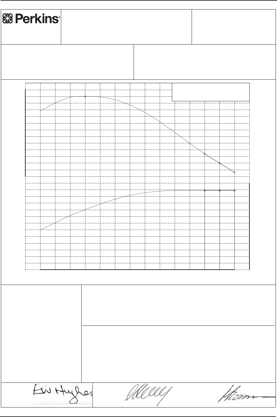
Engine Specification Manual, TPD1599 Issue 6, January 2009 199
1100 Series, 1104D, Mechanical FIE
1104D-44TA - T3496, (balanced)
Perkins Engines Company Limited
©2007 Commercial in Confidence,
proprietary information of
Perkins Engines Company Ltd.
Engine Model:
1104D-44TA
Curve: 3496T
Issue: 1
Sheet 1
Date: 11-Sep-2007
Development Target -
May be Subject to Change
Performance after 60 hours operation with fuel oil at 40°C at pump inlet.
Date: 4-Sep-2007 Date: 24-Aug-2007
Auxiliaries fitted to engine:
Alternator - off load.
Balancer - not fitted.
Fan - not fitted.
Notes:
1. For duty cycle refer to Perkins Engines
(Peterborough) Limited statement on
Product Duty Usage Limitations.
2. For power and torque data below 1100
rev/min refer to Perkins Engines Limited.
1100 1200 1300 1400 1500 1600 1700 1800 1900 2000 2100 2200 2300 2400
Speed, rev/min
15
20
25
30
35
40
45
50
55
60
65
70
75
80
Power, kW
290
300
310
320
330
340
350
360
370
380
390
400
410
420
Torque, Nm
Governing Key
A denotes 5% +/- 2% governing.
N denotes 'as found' governing.
410.0
N
N
A
74.5 74.5 74.5
E. Hughes
(Product Manager)
Approved by:
C. Herring
(PE Manager)
Accepted by:
Fuel Specification: CEC RF-06-99
Fuel Types: Europe Off Highway
Density (kg/l @ 15°C): 0.833 - 0.837
Viscosity (mm²/s @ 40°C): 2.3 - 3.5
Sulphur Content (% mass): 0.03 max
Cetane No: 52 - 54
EPA 2D 89.330 2004
USA FED Off Highway
0.840 - 0.865
2.0 - 3.2
0.03 - 0.2
40 - 48
ISO 14396: 2002
Production Tolerance On Power Output: +5%, -5%
Total Barometric Pressure (kPa): 100
Vapour Pressure (kPa): 1
Air Inlet Temperature (°C): 25
Rating Standards:
J.H. Boorman
(Legislation
Engineer)
Issued by:
Certification Refs (Rated Speeds)Exhaust Quality Standard
Smoke:
Emissions:
Power Standard Certification Refs (Rated Speeds)
77/537/EEC- Includes FAS.
EU NRMM 97/68/EC Stage 3A.
US EPA 40 CFR Part 89 Tier 3.
UN/ECE R120

200 Engine Specification Manual, TPD1599 Issue 6, January 2009
1100 Series, 1104D, Mechanical FIE
Rating Curves Data Sheet
Sheet 2
T3496
Curve
Engine Model: 1104D-44TA
Number Of Cylinders: 4
Bore (mm): 105.0
Stroke (mm): 127.0
Configuration: Vertical In Line
Displacement (litres): 4.4
Injection Timing (°BTDC) - Static:
Lift Pump Pressure (Out) (kPa):
Fuel Filter Max Particle Size (micron):
Exhaust Flow (kg/min):
Exhaust Temperature (°C): 478 (ATC)
46.4
36.6
Coolant Flow (litres/min):
Recommended Cap Pressure (kPa):
Max Top Tank Pressure (kPa):
Induction Manifold Pressure (kPa): 102.0
Max Total Pressure Drop inc Pipes (kPa): 10.0
10.4
Unaided Start Limit (°C): -10
Aided Start Limit (°C): -25
General Data
Fuel System
Lubrication System
Exhaust System
Cooling System
Engine Air Flow (kg/min): 8.50 (7.30 m³/min)
Air System
Charge Air Cooler System
Turbocharger
Cold Start Capability
Performance Data
Internal References
DCP Number(s): TBD
Curve Issue No: 1
Curve Issue Date : 11-Sep-2007
TAN Number:
FIE EDR Number
Note1: Unless otherwise specified, all stated data is for maximum rated speed and 100% load.
Minimum Cranking Speed (rev/min) - unaided:
- aided:
Not applicable
290
Maximum Altitude (m): 3000
For further performance data see table below.
Further Notes:
Fuel Pump Pressure (In) (kPa):
- Dynamic (needle lift pick-up):
Manifold Charge Air Temperature (°C): 55.0
Heat Rejected @ Rated Speed (kW):
Heat Rejected @ Peak Torque (kW):
Charge Air Cooler Heat Rejection (kW):
Friction Power @ Rated Speed (kW):
Friction Power @ Peak Torque (kW):
Unboosted Torque @ 800 rev/min (Nm):
Compression Ratio: 18.2 : 1
Combustion Bowl: Re-entrant
Fuel Pump Model: Delphi DP310
Fuel Return System Type:
Lubricating Oil Specification: See Engine Specification Manual
Start Aid (Optional): Glowplugs fitted as standard
Thermostat - Start To Open (°C): 82
Thermostat - Fully Open (°C): 93
Charge Air Cooling System: Air-to-Air
Turbocharger Type:
Performance Data
Rating Standard: ISO 14396: 2002
Aspiration: Turbocharged
Unboosted Torque @ 1000 rev/min (Nm): 290
Speed
(rev/min)
Governing
Categories
(
ke
y
on sht 1
)
Max Exhaust
Back Pressure
(
kPa
)
Max Inlet
Restriction
(
kPa
)
Torque
(Nm)
Power
(kW)
2400 296 74.5 A15.0 5.0
2300 310 74.5 N15.0 5.0
2200 324 74.5 N15.0 5.0
2000 356 74.6 11.0
1800 386 72.8 10.0
1600 405 67.9 9.0
1400 410 60.1 6.5
1300 409 55.7 5.3
1200 400 50.3 4.5
1100 388 44.7 3.5
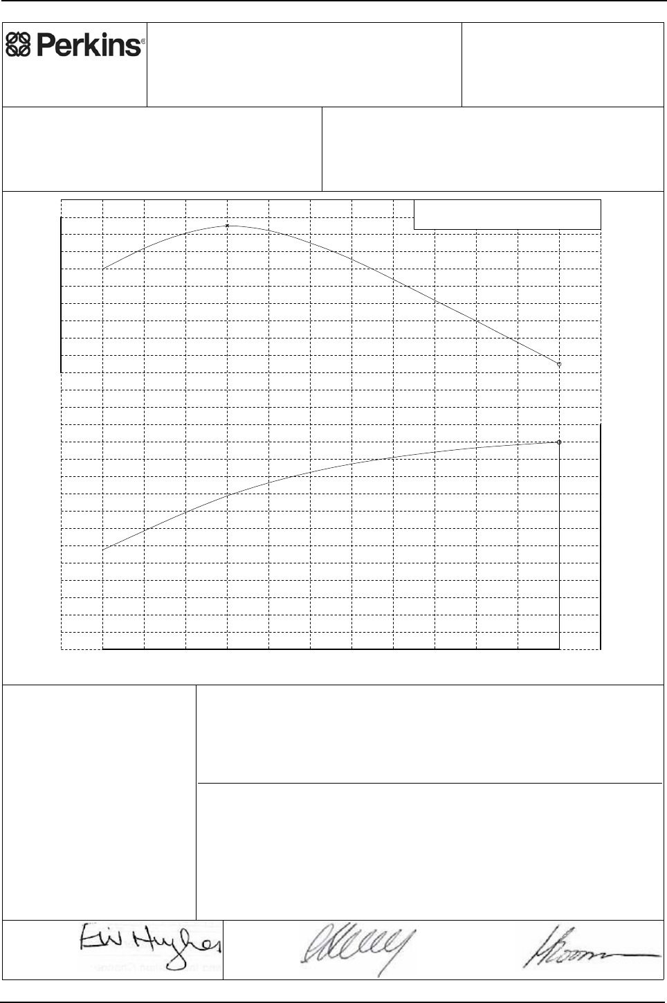
Engine Specification Manual, TPD1599 Issue 6, January 2009 201
1100 Series, 1104D, Mechanical FIE
1104D-44TA - T3499, (balanced)
Perkins Engines Company Limited
©2007 Commercial in Confidence,
proprietary information of
Perkins Engines Company Ltd.
Engine Model:
1104D-44TA
Curve: 3499T
Issue: 2
Sheet 1
Date: 17-Dec-2007
Development Target -
May be Subject to Change
Performance after 60 hours operation with fuel oil at 40°C at pump inlet.
Date: 17-Dec-2007 Date: 17-Dec-2007
Auxiliaries fitted to engine:
Alternator - off load.
Balancer - fitted.
Fan - not fitted.
Notes:
1. For duty cycle refer to Perkins Engines
(Peterborough) Limited statement on
Product Duty Usage Limitations.
2. For power and torque data below 1100
rev/min refer to Perkins Engines Limited.
1100 1200 1300 1400 1500 1600 1700 1800 1900 2000 2100 2200
S
p
eed, rev/min
15
20
25
30
35
40
45
50
55
60
65
70
75
80
Power, kW
320
330
340
350
360
370
380
390
400
410
Torque, Nm
Governing Key
A denotes 5% +/- 2% governing.
405.0
A
74.9
E. Hughes
(Product Manager)
Approved by:
C. Herring
(PE Manager)
Accepted by:
Fuel Specification: CEC RF-06-99
Fuel Types: Europe Off Highway
Density (kg/l @ 15°C): 0.833 - 0.837
Viscosity (mm²/s @ 40°C): 2.3 - 3.5
Sulphur Content (% mass): 0.03 max
Cetane No: 52 - 54
EPA 2D 89.330 2004
USA FED Off Highway
0.840 - 0.865
2.0 - 3.2
0.03 - 0.2
40 - 48
ISO 14396: 2002
Production Tolerance On Power Output: +5%, -5%
Total Barometric Pressure (kPa): 100
Vapour Pressure (kPa): 1
Air Inlet Temperature (°C): 25
Rating Standards:
J.H. Boorman
(Legislation
Engineer)
Issued by:
Certification Refs (Rated Speeds)Exhaust Quality Standard
Smoke:
Emissions:
Power Standard Certification Refs (Rated Speeds)
77/537/EEC- Includes FAS.
EU NRMM 97/68/EC Stage 3A.
US EPA 40 CFR Part 89 Tier 3.
UN/ECE R120

202 Engine Specification Manual, TPD1599 Issue 6, January 2009
1100 Series, 1104D, Mechanical FIE
Rating Curves Data Sheet
Sheet 2
T3499
Curve
Engine Model: 1104D-44TA
Number Of Cylinders: 4
Bore (mm): 105.0
Stroke (mm): 127.0
Configuration: Vertical In Line
Displacement (litres): 4.4
Injection Timing (°BTDC) - Static:
Lift Pump Pressure (Out) (kPa):
Fuel Filter Max Particle Size (micron):
Exhaust Flow (kg/min): 8.03 (17.1 m³/min)
Exhaust Temperature (°C): 575 (ATC)
46.7
Coolant Flow (litres/min): 184.0
Recommended Cap Pressure (kPa):
Max Top Tank Pressure (kPa):
Induction Manifold Pressure (kPa): 73.0
Max Total Pressure Drop inc Pipes (kPa): 10.0
7.2
Unaided Start Limit (°C): -10
Aided Start Limit (°C): -25
General Data
Fuel System
Lubrication System
Exhaust System
Cooling System
Engine Air Flow (kg/min): 7.72 (6.63 m³/min)
Air System
Charge Air Cooler System
Turbocharger
Cold Start Capability
Performance Data
Internal References
DCP Number(s): TBD
Curve Issue No: 2
Curve Issue Date : 17-Dec-2007
TAN Number:
FIE EDR Number
Note1: Unless otherwise specified, all stated data is for maximum rated speed and 100% load.
Minimum Cranking Speed (rev/min) - unaided:
- aided:
Not applicable
290
Maximum Altitude (m): 3000
For further performance data see table below.
Further Notes:
Fuel Pump Pressure (In) (kPa):
- Dynamic (needle lift pick-up): 0.5
Manifold Charge Air Temperature (°C): 50.0
Heat Rejected @ Rated Speed (kW):
Heat Rejected @ Peak Torque (kW):
Charge Air Cooler Heat Rejection (kW):
Friction Power @ Rated Speed (kW):
Friction Power @ Peak Torque (kW):
Unboosted Torque @ 800 rev/min (Nm):
Compression Ratio: 18.2 : 1
Combustion Bowl: Re-entrant
Fuel Pump Model: Delphi DP310
Fuel Return System Type:
Lubricating Oil Specification: See Engine Specification Manual
Start Aid (Optional): Glowplugs fitted as standard
Thermostat - Start To Open (°C): 82
Thermostat - Fully Open (°C): 93
Charge Air Cooling System: Air-to-Air
Turbocharger Type:
Performance Data
Rating Standard: ISO 14396: 2002
Aspiration: Turbocharged
Unboosted Torque @ 1000 rev/min (Nm): 290
Speed
(rev/min)
Governing
Categories
(
ke
y
on sht 1
)
Max Exhaust
Back Pressure
(
kPa
)
Max Inlet
Restriction
(
kPa
)
Torque
(Nm)
Power
(kW)
2200 325 74.9 A15.0 5.0
2000 350 73.3 12.6
1800 374 70.5 11.1
1600 395 66.2 9.2
1400 405 59.4 6.7
1200 392 49.3 4.3
1100 380 43.8 3.3

Engine Specification Manual, TPD1599 Issue 6, January 2009 203
1100 Series, 1104D, Mechanical FIE
1104D-44TA - T3500, (balanced)
Perkins Engines Company Limited
©2008 Commercial in Confidence,
proprietary information of
Perkins Engines Company Ltd.
Engine Model:
1104D-44TA
Curve:
3500T
Issue:
2
Sheet 1
Date: 9-Jan-2008
Development Target -
May be Subject to Change
Performance after 60 hours operation with fuel oil at 40°C at pump inlet.
Auxiliaries fitted to engine:
Alternator - off load.
Balancer - not fitted.
Fan - not fitted.
Notes:
Notes:Notes:
Notes:
1. For duty cycle refer to Perkins Engines
1. For duty cycle refer to Perkins Engines 1. For duty cycle refer to Perkins Engines
1. For duty cycle refer to Perkins Engines
(Peterborough) Limited statement on
(Peterborough) Limited statement on (Peterborough) Limited statement on
(Peterborough) Limited statement on
Product Duty Usage Limitations.
Product Duty Usage Limitations.Product Duty Usage Limitations.
Product Duty Usage Limitations.
2. For power and torque data below 1100
2. For power and torque data below 1100 2. For power and torque data below 1100
2. For power and torque data below 1100
rev/min refer to Perkins Engines Limited.
rev/min refer to Perkins Engines Limited.rev/min refer to Perkins Engines Limited.
rev/min refer to Perkins Engines Limited.
1100 1200 1300 1400 1500 1600 1700 1800 1900 2000 2100 2200 2300
S
p
eed
,
rev/min
15
20
25
30
35
40
45
50
55
60
65
70
75
Power, kW
290
300
310
320
330
340
350
360
370
380
390
400
Torque, Nm
Governing Key
A denotes 5% +/- 2% governing.
N denotes 'as found' governing.
395.0
N
A
70.0 70.0
For balanced version refer to curve T3055
Approved by:
Accepted by:
Fuel Specification: CEC RF-06-99
Fuel Types: Europe Off Highway
Density (kg/l @ 15°C): 0.833 - 0.837
Viscosity (mm²/s @ 40°C): 2.3 - 3.5
Sulphur Content (% mass): 0.03 max
Cetane No: 52 - 54
EPA 2D 89.330 2004
USA FED Off Highway
0.840 - 0.865
2.0 - 3.2
0.03 - 0.2
40 - 48
ISO 14396: 2002
+5%, -5%
100
1
25
Rating Standards:
Issued by:
Certification Refs (Rated Speeds)Exhaust Quality Standard
Smoke:
Emissions:
Power Standard Certification Refs (Rated Speeds)
77/537/EEC- Includes FAS.
EU NRMM 97/68/EC Stage 3A.
US EPA 40 CFR Part 89 Tier 3.
UN/ECE R120

204 Engine Specification Manual, TPD1599 Issue 6, January 2009
1100 Series, 1104D, Mechanical FIE
Rating Curves Data Sheet
Sheet 2
T 3500
Curve
Engine Model: 1104D-44TA
Number Of Cylinders: 4
Bore (mm): 105.0
Stroke (mm): 127.0
Configuration: Vertical In Line
Displacement (litres): 4.4
Injection Timing (°BTDC) - Static:
Lift Pump Pressure (Out) (kPa):
Fuel Filter Max Particle Size (micron):
Exhaust Flow (kg/min): 8.10 (16.8 m³/min)
Exhaust Temperature (°C): 553 (ATC)
44.9
36.3
Coolant Flow (litres/min): 193.0
Recommended Cap Pressure (kPa):
Max Top Tank Pressure (kPa):
Induction Manifold Pressure (kPa): 70.0
Max Total Pressure Drop inc Pipes (kPa): 10.0
7.2
Unaided Start Limit (°C): -10
Aided Start Limit (°C): -25
General Data
Fuel System
Lubrication System
Exhaust System
Cooling System
Engine Air Flow (kg/min): 7.80 (6.70 m³/min)
Air System
Charge Air Cooler System
Turbocharger
Cold Start Capability
Performance Data
Internal References
DCP Number(s): TBD
Curve Issue No: 2
Curve Issue Date : 9-Jan-2008
TAN Number:
FIE EDR Number
Note1: Unless otherwise specified, all stated data is for maximum rated speed and 100% load.
Minimum Cranking Speed (rev/min) - unaided:
- aided:
Not applicable
290
Maximum Altitude (m): 3000
For further performance data see table below.
Further Notes:
Fuel Pump Pressure (In) (kPa):
- Dynamic (needle lift pick-up): 2.0
Manifold Charge Air Temperature (°C): 50.0
Heat Rejected @ Rated Speed (kW):
Heat Rejected @ Peak Torque (kW):
Charge Air Cooler Heat Rejection (kW):
Friction Power @ Rated Speed (kW):
Friction Power @ Peak Torque (kW):
Unboosted Torque @ 800 rev/min (Nm):
Compression Ratio: 18.2 : 1
Combustion Bowl: Re-entrant
Fuel Pump Model: Delphi DP310
Fuel Return System Type:
Lubricating Oil Specification: See Engine Specification Manual
Start Aid (Optional): Glowplugs fitted as standard
Thermostat - Start To Open (°C): 82
Thermostat - Fully Open (°C): 93
Charge Air Cooling System: Air-to-Air
Turbocharger Type:
Performance Data
Rating Standard: ISO 14396: 2002
Aspiration: Turbocharged
Unboosted Torque @ 1000 rev/min (Nm): 290
Speed
(rev/min)
Governing
Categories
(
ke
y
on sht 1
)
Max Exhaust
Back Pressure
(
kPa
)
Max Inlet
Restriction
(
kPa
)
Torque
(Nm)
Power
(kW)
2300 291 70.0 A15.0 5.0
2200 303 70.0 N15.0 5.0
2000 333 69.7
1800 361 68.0
1600 382 64.0
1400 395 57.9
1200 390 49.0
1100 380 43.8
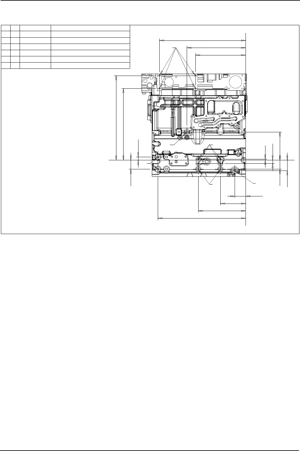
Engine Specification Manual, TPD1599 Issue 6, January 2009 205
1100 Series, 1104D, Mechanical FIE
Cylinder block views non-stressed block
Non stressed block and head - left hand side view
59,9
138,2
258,9
5,1
18,9
56,9
154
479,5
320,7
17,6
49,2
49,2
274,4
470,9
391,5
461,5
Ref Qty Size Remarks
A 4 M8x1,25x16 Available on non-electronic engines
B 1 M8x1,25x16 May be used on non-electonic engines
C 2 M12x1,75x20 Front 2 only when front mounts used
D 4 M8x1,25x16 May be used on non-electonic engines
E 2 M10x1,50x20 Customer fixing point
F 1 M12x1,75x14 Restricted tapping depth (14 mm)
X
Y
X
Y
3711H211 cyl.block 3712H193 cyl.head
A
B
C
EF
D
drawings subject to change
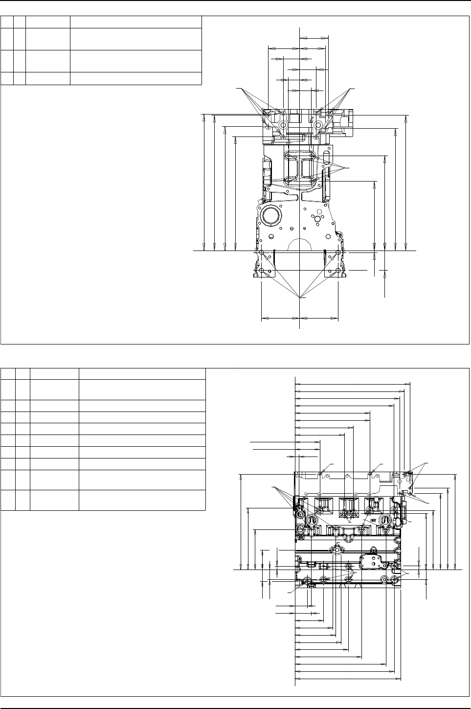
206 Engine Specification Manual, TPD1599 Issue 6, January 2009
1100 Series, 1104D, Mechanical FIE
Non stressed block and head - front view
Non stressed block and head - right side view
38
38
230,5
316,5
6,9
66,9
128 128
380
406,5
451
413,5
451,5
455
55
55
105,6 85
96
Ref Qty Size Remarks
G 8 M10x1,50x18
2 to 6 available dependant on fan drive,
H 4 M10x1,50x19
Available if head mounted fan drive
J 4 M16x2,00x25 Available if side mounting pads used
Z
Y
Z
Y
3711H211 cyl.block 3712H193 cyl.head
J
H
G
G
lifting eye and air con.bracket options
option is used
drawings subject to change
20,9
cyl.blk120,9
cyl.hd120,6
197,9
238,9
280,9
cyl.blk362,9
cyl.hd361,6
476,9
504,9
526,6
554,9
79,9
321,9
438,9
59,9
138,2
183,6
223,6
479,5
258,9
16,1
93,1
193,1
296,1
457,5
17,5
49,2
49,2
56,9
270,1
285,1
366,5
391,5
458,5
511,2
Ref Qty Size Remarks
K 2 M10x1,50x19 Available if top turbo heat shield or
L 7 M10x1,50x15 Customer fixing point
M 3 M10x1,50x15 Except on side mounted turbo engines
N 2 M8x1,25x15 Only naturally aspirated engines
P 1 M12x1,75x14 Restricted tapping depth (14 mm)
Q 4 M10x1,50x20 Customer fixing point
R 2 M12x1,75x20 Front 2 only when front mounts used
S 2 M10x1,50x19 Available if rhs air con.bracket
T 2 M10x1,50x19 Available if alternator support
X
Y
X
Y
KKS
T
M
N
R
P
LL
L
Q
3711H211 cyl.block 3712H193 cyl.head
no cross over support bracket fitted
not fitted
bracket not fitted
drawings subject to change
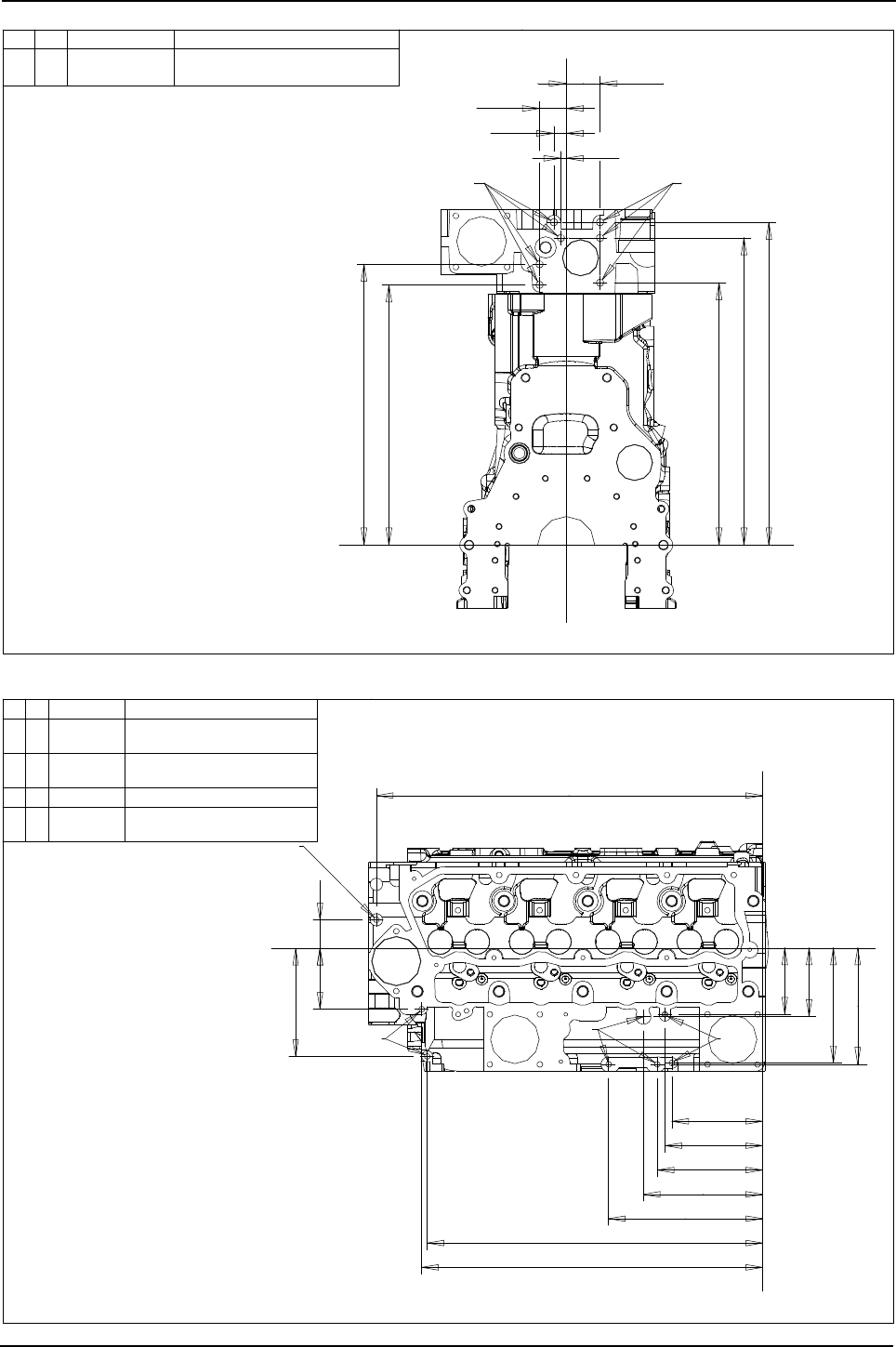
Engine Specification Manual, TPD1599 Issue 6, January 2009 207
1100 Series, 1104D, Mechanical FIE
Non stressed block and head - rear side view
Non stressed block and head - plan view
47,5
7,5
17,5
37,5
365,5
394,5
368,5
431,5
453,5
Z
Y
Z
Y
U
U
Ref Qty Size Remarks
U 7 M10x1,50x19 5 holes available dependant on lifting
3711H211 cyl.block 3712H193 cyl.head
eye option
drawings subject to change
130,6
140,6
151,6
171,6
221,6
482,6
490,6
95
98,4
165
167
87,5
155,5
41
555,8
Ref Qty Size Remarks
V 2 M8x1,25x16 Available if lhs air con.
W 3 M6x1,00x15 Available only if remote fuel
X 2 M8x1,25x16 Available dependant on option
Y 1 M8x1,25x16 Available if RHS air con.
X
W
X
W
3711H211 cyl.block 3712H193 cyl.head
Y
VWX
bracket not fitted
filter fitted (option V5301)
bracket not fitted
drawings subject to change
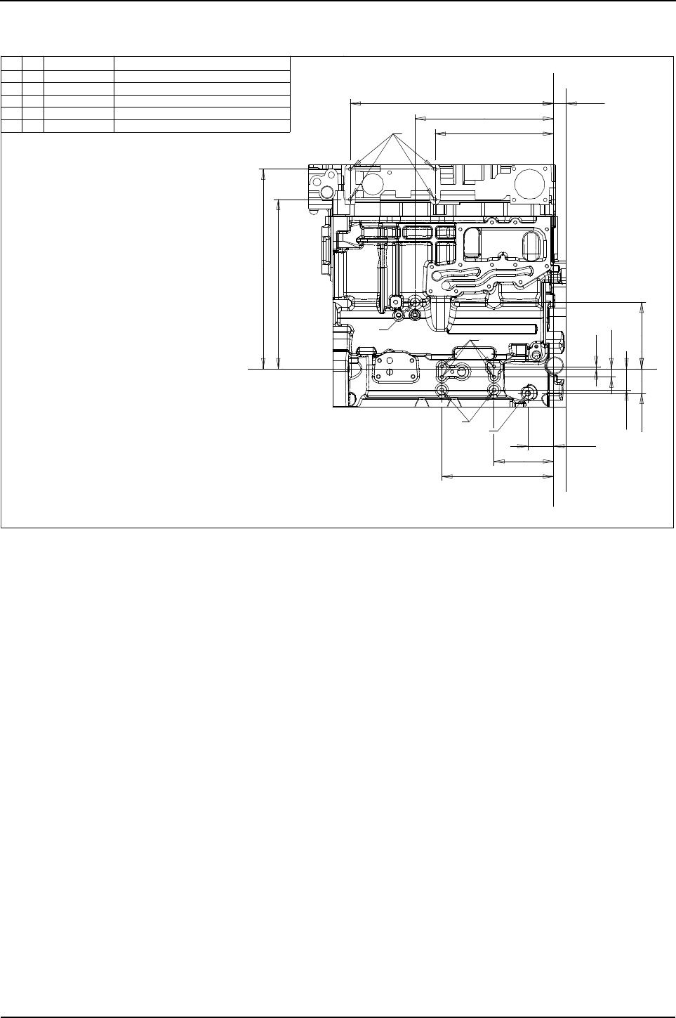
208 Engine Specification Manual, TPD1599 Issue 6, January 2009
1100 Series, 1104D, Mechanical FIE
Cylinder block views stressed block
Stressed block and head - left hand side view
274,4
470,9
320,7
391,5
461,5
5,1
18,9
49,2
56,9 154
59,9
138,2
28,6
258,9
Ref Qty Size Remarks
A 4 M8x1,25x16 Available on non-electronic engines
B 1 M8x1,25x16 Available on non-electronic engines
C 4 M8x1,25x16 Available on non-electronic engines
D 2 M10x1,50x20 Customer fixing point
E 1 M12x1,75x14 Restricted tapping depth (14 mm)
X
X2
Y
Y
X
X2
A
C
D
E
B
3711H221 cyl.block 3712H193 cyl.head
drawings subject to change
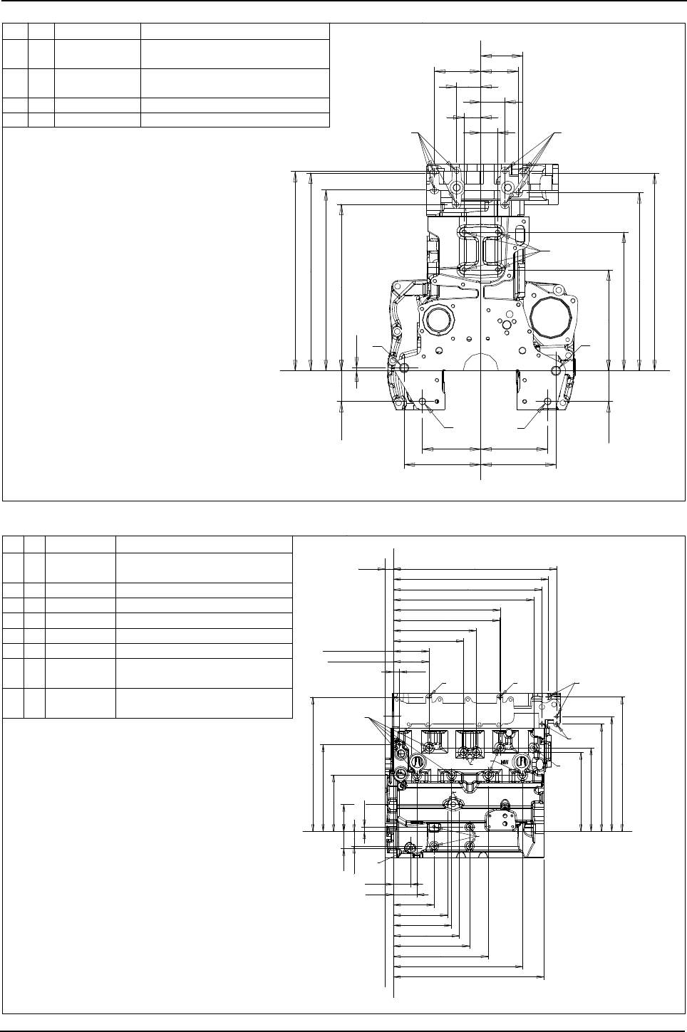
Engine Specification Manual, TPD1599 Issue 6, January 2009 209
1100 Series, 1104D, Mechanical FIE
Stressed block and head - front view
Stressed block and head - right side view
152,4
171,5
133,4
174,6
6,4
69,9
69,9 230,5
316,5
451
406,5
413,5
451,5
455
380
55
85
96
55
105,6
38
38
Ref Qty Size Remarks
F 8 M10x1,50x18 2 to 6 available dependant on fan drive,
G 4 M10x1,50x19 Available if head mounted fan drive
H 2 c17 Engine mounting
J 2 M16x2,00x32 Engine mounting
Z
Y
Z
Y
3711H221 cyl.block 3712H193 cyl.head
H
H
JJ
FF
G
lifting eye and air con. options
option is used
drawings subject to change
cyl.blk120,9
280,9
238,9
cyl.hd120,6
20,9
476,9
504,9
554,9
79,9
197,9
321,9
438,9
193,1
93,1
16,1
49,2
56,9
183,6
223,6
138,2
59,9
270,1
457,5
366,5
391,5
458,5
511,2
285,1
Cyl.blk362,9
258,9
526,6
28,6
cyl.hd361,6
296,1
Ref Qty Size Remarks
K 2 M10x1,50x19
Available if top turbo heat shield or
L 7 M10x1,50x15 Customer fixing point
M 3 M10x1,50x15 Except on side mounted turbo engines
N 2 M8x1,25x15 Only naturally aspirated engines
P 1 M12x1,75x14 Restricted tapping depth (14 mm)
Q 4 M10x1,50x20
R 2 M10x1,50x19
Available if rhs air con.bracket
S 2 M10x1,50x19
Available if alternator support
X2
X
Y
Y
3711H221 cyl.block 3712H193 cyl.head
X2
X
KKR
S
L
L
L
M
Q
P
N
cross over support bracket not fitted
not fitted
bracket not fitted
Customer fixing point
drawings subject to change
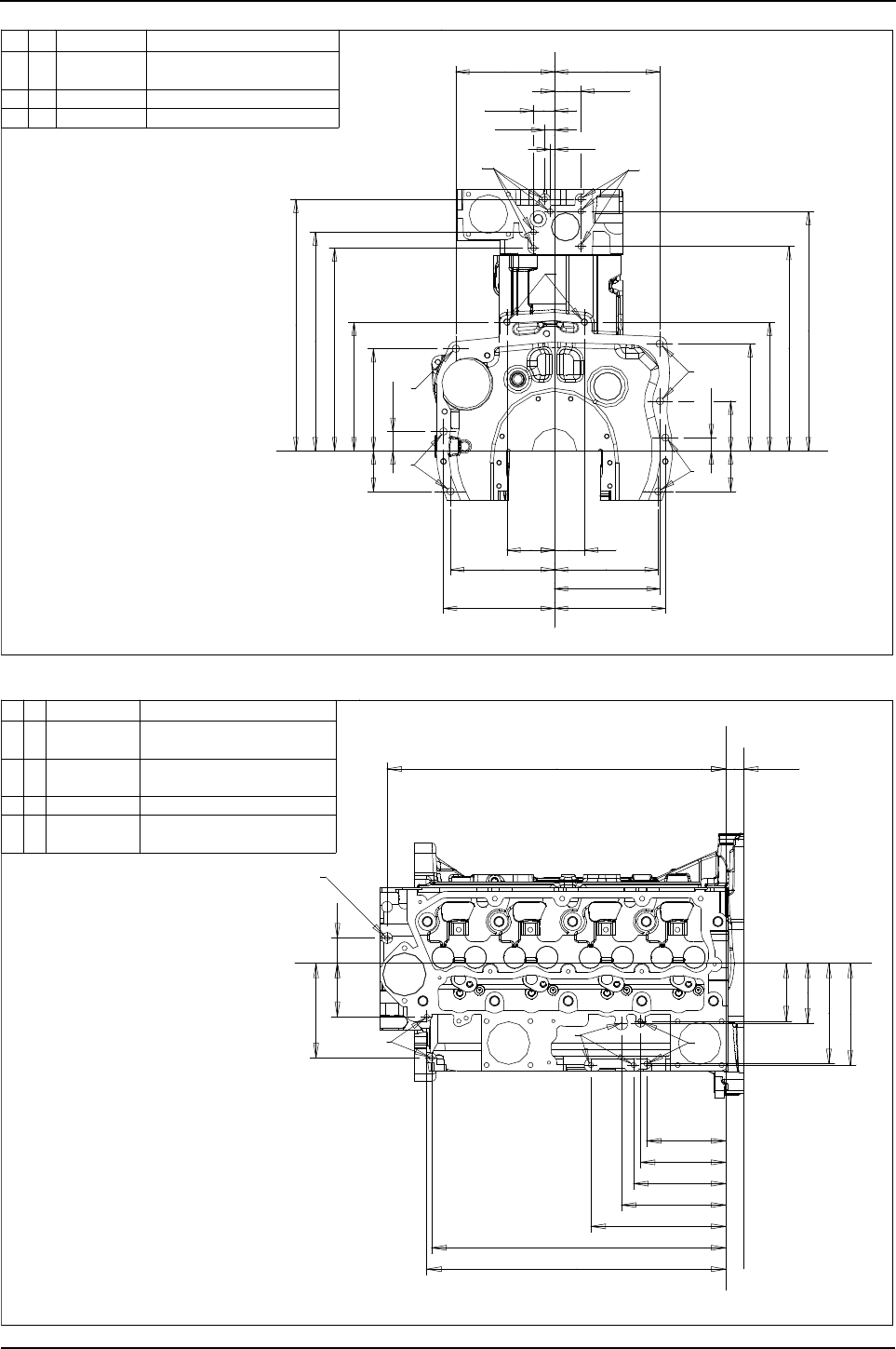
210 Engine Specification Manual, TPD1599 Issue 6, January 2009
1100 Series, 1104D, Mechanical FIE
Stressed block and head - rear side view
Stressed block and head - plan view
7,5
17,5
47,5
365,5
394,5
453,5
368,5
431,5
23,8
89,7
192,9
231,8
73
34,9
184,2
231,8
73
37,5
85,7
177,8
187,3
200
190,5
189,7
200
187,3
54
Ref Qty Size Remarks
T 7 M10x1,50x19 5 holes available dependant on
U 2 M12x1,75x25 Customer fixing point
V 7 c13 Engine mounting
3711H221 cyl.block 3712H193 cyl.head
T
T
U
V
V
V
V
Z
YY
Z
lifting eye option
drawings subject to change
4187,5
155,5
555,8 28,6
95
98,4
165
167
130,6
140,6
171,6
151,6
221,6
482,6
490,6
Ref Qty Size Remarks
W 2 M8x1,25x16 Available if lhs air con.
X 3 M6x1,00x15 Available only if remote fuel
Y 2 M8x1,25x16 Available, dependant on option
Z 1 M8x1,25x16 Available if rhs air con.
W
X
X2
3711H221 cyl.block 3712H193 cyl.head
X
X2
W
W
Z
XY
bracket not fitted
filter fitted (option V5201)
bracket not fitted
drawings subject to change

Engine Specification Manual, TPD1599 Issue 6, January 2009 211
1100 Series, 1104D, Mechanical FIE
Cold start system
The conditions which follow will decide the minimum temperatures at which the engine will start:
zStarter motor performance
zBattery type
zLubricating oil grade
zCold start aid.
For more information on the minimum start temperatures and types of starter motors etc, refer to the Perkins
Installation Manual or your local distributor.
Equipment required for cold temperatures
The chart below gives the minimum temperature at which a selection of engine oil, battery and starter motor
will start the engine. The temperatures shown are for an engine fitted to a manual gearbox and with the clutch
disengaged to give an increase in cranking speed.
Applications that use automatic gearboxes or other high drag equipment should use the next most powerful
battery combination to get the same start temperature and engine cranking speed.
Cold start performance table
Ether start
Warning! Ether start is not permitted with these engines.
1104D-44T 1104D-44TA engine tested with 75% state of charge batteries and 1.7 mΩ cable resistance
Starter
information
Temperature and oil grade
with glow plugs
Temperature and oil grade
without glow plugs
Voltage Starter
type
Max
allowable
CCA (SAE)
-5ºC
15W40
-10ºC
15W40
-15ºC
15W40
-20ºC
10W30
-25ºC
5W30
-5ºC
15W40
-10ºC
15W40
-15ºC
15W40
-20ºC
10W30
-25ºC
5W30
12V
Iskra
AZE 950 750 850 Not
used
Not
used
Not
used 750 850
Glow plugs must be
used
Iskra
AZF 2400 650 750 1125 1125 1500 650 750
Denso
R2.7 1500 650 850 1300 1300 Not
used 650 1300
Denso
R4 1900 650 850 1300 1300 1900 650 850
24V Denso
R4.5 750 650 650 650 650 650 650 650

212 Engine Specification Manual, TPD1599 Issue 6, January 2009
1100 Series, 1104D, Mechanical FIE
Battery performance
Notes:
zLarger batteries are necessary in machines with additional loads and to maintain 100 rev/min cranking
speed
zTested with 75% state of charge and 1.7 mΩ cable resistance.
Batteries that meet this specification will give suitable start performance. If the auxiliary loads are large it may
be necessary to specify a battery with a higher ampere-hour capacity (or reserve capacity) or to use a separate
battery system. Any battery which is chosen because of its higher reserve capacity must not have inferior high
rate discharge characteristics.
Battery to starter lead resistance
The resistance of the lead(s) used between the battery/batteries and the starter motor must not be more than
0.0017 ohms for the 12 volt systems and 0.0034 ohms for the 24 volt systems. more detailed information on
the types of battery is available in the Perkins Product Support Publications.
Battery selection tables, based on minimum 100 rev/min
Voltage Starter
type
Max
allowable
CCA (SAE)
Temperature and oil grade
with glow plugs
Temperature and oil grade
without glow plugs
-5°C
15/40
-10°C
15/40
-15°C
15/40
-20°C
10/30
-25°C
5/30
-5°C
15/40
-10°C
15/40
-15°C
15/40
-20°C
10/30
-25°C
5/30
12V
AZE 950 750 850 Not used 650 950
Glow plugs must be
used
AZF 2400 650 750 1125 1125 1500 650 750
R2.7 1500 650 850 1300 1300 Not
used 650 950
R4 1900 650 850 1300 1300 1900 650 850
24V R4.5 750 650 650 650 650 650 650 650
Commercial
reference number code Battery minimum performance
BS EN 50342 (1)
(1). Voltage no less than 7,5 Volts after 10 seconds, 6 Volts after 90 seconds at -18 °C (0 °F) across each 12 Volt
battery.
SAEJ 537 (BCI) (2)
(2). Voltage no less than 7,2 Volts after 30 seconds at -18 °C (0 °F) across each 12 Volt battery.
DIN 43539 (3)
(3). Voltage no less than 6,0 Volts after 150 seconds at -18 °C (0 °F) across each 12 Volt battery.
643 A 440 640 400
647 B 510 700 465
069 D 340 540 300
655 E 570 760 490
621 F 860 900 505

Engine Specification Manual, TPD1599 Issue 6, January 2009 213
1100 Series, 1104D, Mechanical FIE
Cooling system
Maximum coolant temperature
With 1,0 Bar (14.7 lbf/in²) pressure cap fitted to the system the coolant temperature must not exceed 112 °C
(234 °F) at sea level. This temperature must be reduced at high altitudes, see the tables in chapter 7 of the
Perkins Installation Manual. The minimum requirement for temperature measurement, is a warning light or dial
gauge which covers the coolant temperature range.
Note: If tests are to be conducted to establish the ambient clearance of a cooling system, the system must be
filled with a solution of 50% antifreeze and 50% coolant and be suitable for operating worldwide in ambient
temperatures of up to 46 °C (115 °F).
Engine coolant capacities - typical values
Radiators
The engine must be installed so that there is no air restriction to the flow of air through the radiator. The
discharged hot air from the radiator must not be sent through the radiator again because the ambient air
temperature will then be lifted above the safe temperature for engine operation. Baffles can be fitted to prevent
this. When the radiator is installed, or a change made to the design of the basic cooling system for the purpose
of radiator installation, or if the installation space is restricted, then a cooling test must be made before the
installation can be approved. For more information about cooling tests refer to the Perkins Product Support
Publications.
Radiator coolant flow rates
The engine must be installed to ensure that there is adequate ventilation and that the underbonnet
temperatures do not exceed 105°C (221°F).
Caution: Engine components may become damaged or fail due to excess temperature if coolers (fuel, air
charge or coolant) are allowed to become clogged with debris. Customers should be made aware of this,
particularly if their machine is likely to be operated in dirty/contaminated environment.
Note: The table above shows coolant flow rates through a typical pressurised radiator system at normal
operating temperature and with the thermostat fully open. The coolant flow rates are with a system resistance
(radiator and piping) of 35 kPa (5 psi).
Engine type Litre UK Pint US Quart
1104D 7 12.3 7.4
Engine type Coolant
pump ratio Units Engine speed rev/min
10001200140016001800200022002400
All engines
below 75 kW 2 : 1
Litre/min 84 100 117 134 151 167 184 201
UK gal/min 18.5 22 25.7 29.5 33.2 36.7 40.5 44.2
US gal/min 22.2 26.4 30.9 35.4 39.9 44.1 48.6 53.1
All engines
above 75 kW 2 : 1
Litre/min 110 133 155 177 199 221 243 265
UK gal/min 24.2 29.3 34.1 38.9 73.8 48.6 53.5 58.3
US gal/min 29.1 35.1 41 46.8 52.6 58.4 64.2 70

214 Engine Specification Manual, TPD1599 Issue 6, January 2009
1100 Series, 1104D, Mechanical FIE
Heat Balance
The following tables show the total heat passed to radiation, exhaust and coolant for typical ratings. The values
are for engines under full load conditions and different speeds. The total heat rejection figure includes the heat
remove from the lubricant, and the heat removed by the air to air charge cooler.
The result has been established at an air temperature of 25 °C (77 °F), and a stabilised coolant temperature
of 93 °C (200 °F).
Note: Data subject to change, contact Perkins for latest information.
1104D-44 Curve number T2968 (non-balanced)
1104D-44 Curve number T2969 (balanced)
1104D-44T Curve number T2970 (non-balanced)
1104D-44T Curve number T2971 (balanced)
Engine
speed
(rev/min)
Fuel energy
(kW)
Power
(kW)
Residual
heat loss
(kW)
Heat to
exhaust
(kW)
Heat to
coolant
inc oil (kW)
2200 166.3 56 12.6 60.9 36.8
2000 157.7 53.6 15 55.3 34.4
1800 140.4 49.6 13.3 47.1 31.2
1400 108 38.4 11.6 33.7 25
Engine
speed
(rev/min)
Fuel energy
(kW)
Power
(kW)
Residual
heat loss
(kW)
Heat to
exhaust
(kW)
Heat to
coolant
inc oil (kW)
2200 166.3 54 14.1 60.9 36.8
2000 157.7 52.4 16.3 55.3 34.4
1800 140.4 48.6 14.2 47.1 31.2
1400 108 38.1 11.9 33.7 25
Engine
speed
(rev/min)
Fuel energy
(kW)
Power
(kW)
Residual
heat loss
(kW)
Heat to
exhaust
(kW)
Heat to
coolant
inc oil (kW)
2400 194.4 62.5 14.9 68.6 48.4
2300 187.9 62.5 13.3 64.9 47.2
2200 182.9 62.5 12.8 61.5 46.1
2000 172.1 62.4 9.8 55.8 44.1
1800 162 60.7 7.3 52.2 41.8
1600 157 57.5 7.8 51.2 40.5
1400 139.7 51.9 7.2 44 36.6
Engine
speed
(rev/min)
Fuel energy
(kW)
Power
(kW)
Residual
heat loss
(kW)
Heat to
exhaust
(kW)
Heat to
coolant
inc oil (kW)
2400 194.4 60.5 16.9 68.6 48.4
2300 187.9 60.5 15.3 64.9 47.2
2200 182.9 60.5 14.8 61.5 46.1
2000 172.1 60.9 11.3 55.8 44.1
1800 162 59.8 8.2 52.2 41.8
1600 157 56.8 8.5 51.2 40.5
1400 139.7 51.6 7.5 44 36.6

Engine Specification Manual, TPD1599 Issue 6, January 2009 215
1100 Series, 1104D, Mechanical FIE
1104D-44TA Curve number T2972 (balanced)
1104D-44T Curve number T2978 (non-balanced)
1104D-44T Curve number T2979 (balanced)
1104D-44TA Curve number T3055 (balanced)
Engine
speed
(rev/min)
Fuel energy
(kW)
Power
(kW)
Residual
heat loss
(kW)
Heat to
exhaust
(kW)
Heat to
coolant
inc oil (kW)
Heat to
charge
cooler (kW)
2200 207.4 75 11.6 68.2 45.4 7.2
2000 202.3 74.8 12.7 64.1 44 6.7
1800 191.5 73.1 11.7 58.9 42.1 5.7
1600 185.8 67.7 16.8 56.4 39.7 5.2
1400 162.7 60.4 12.6 49 36.6 4.1
Engine
speed
(rev/min)
Fuel energy
(kW)
Power
(kW)
Residual
heat loss
(kW)
Heat to
exhaust
(kW)
Heat to
coolant
inc oil (kW)
2300 212.4 70 17.1 74.7 50.6
2200 206.6 70 15.6 71.5 49.5
2000 197.3 68.7 14.4 66.7 47.5
1800 186.5 66.9 11.1 63.1 45.4
1600 177.8 63.2 10 61 43.6
1400 163.4 57.5 10.8 54.5 40.6
Engine
speed
(rev/min)
Fuel energy
(kW)
Power
(kW)
Residual
heat loss
(kW)
Heat to
exhaust
(kW)
Heat to
coolant
inc oil (kW)
2300 212.4 68 19.1 74.7 50.6
2200 206.6 68 17.6 71.5 49.5
2000 197.3 67.4 15.7 66.7 47.5
1800 186.5 66 12 63.1 45.4
1600 177.8 62.5 10.7 61 43.6
1400 163.4 57.2 11.1 54.5 40.6
Engine
speed
(rev/min)
Fuel energy
(kW)
Power
(kW)
Residual
heat loss
(kW)
Heat to
exhaust
(kW)
Heat to
coolant
inc oil (kW)
Heat to
charge
cooler (kW)
2300 207.4 68 10.3 70.9 50 8.2
2200 199.4 68 8 66.7 48.7 8
2000 190.8 68.5 6.4 61.4 47 7.5
1800 182.9 67.1 5.7 57.7 45.5 6.9
1600 175 63.3 6.1 55.5 43.8 6.3
1400 159.1 57.6 6.7 49.4 40.1 5.3

216 Engine Specification Manual, TPD1599 Issue 6, January 2009
1100 Series, 1104D, Mechanical FIE
1104D-44TA Curve number T3056 (non-balanced)
1104D-44TA Curve number T3058 (non-balanced)
1104D-44TA Curve number T3059 (balanced)
1104D-44T Curve number T3060 (non-balanced)
Engine
speed
(rev/min)
Fuel energy
(kW)
Power
(kW)
Residual
heat loss
(kW)
Heat to
exhaust
(kW)
Heat to
coolant
inc oil (kW)
Heat to
charge
cooler (kW)
2400 223.2 74.5 15.9 77 47.3 8.5
2300 216 74.5 13 73.9 46.4 8.2
2200 208.8 74.5 10 70.6 45.8 7.9
2000 201.6 74.6 8.9 66.4 44.3 7.4
1800 201.6 72.8 12.8 65.2 43.2 7.6
1600 180 67.9 5.8 58.9 41 6.4
1400 165.6 60.1 13.4 50.6 36.7 4.8
Engine
speed
(rev/min)
Fuel energy
(kW)
Power
(kW)
Residual
heat loss
(kW)
Heat to
exhaust
(kW)
Heat to
coolant
inc oil (kW)
Heat to
charge
cooler (kW)
2300 250.6 83 14.4 90.2 51 12
2200 241.9 83 12.5 86.1 49.8 10.5
2000 226.1 81.1 11.5 76.9 47.1 9.5
1800 206.6 76.2 9.6 68.1 43.9 8.8
1600 185.8 69.2 8.5 59.9 40.4 7.8
1400 164.2 61.3 8.6 51.3 36.8 6.2
Engine
speed
(rev/min)
Fuel energy
(kW)
Power
(kW)
Residual
heat loss
(kW)
Heat to
exhaust
(kW)
Heat to
coolant
inc oil (kW)
Heat to
charge
cooler (kW)
2300 250.6 81 16.4 90.2 51 12
2200 241.9 81 14.5 86.1 49.8 10.5
2000 226.1 79.8 12.8 76.9 47.1 9.5
1800 206.6 75.2 10.6 68.1 43.9 8.8
1600 185.8 68.5 9.2 59.9 40.4 7.8
1400 164.2 61 8.9 51.3 36.8 6.2
Engine
speed
(rev/min)
Fuel energy
(kW)
Power
(kW)
Residual
heat loss
(kW)
Heat to
exhaust
(kW)
Heat to
coolant
inc oil (kW)
2400 187.2 57.5 19.8 64.5 45.4
2300 180 57.5 16.6 61.5 44.4
2200 172.8 57.5 14.5 57.7 43.1
2000 158.4 55.9 11.6 50.8 40.1
1800 151.2 53.9 13.9 45.7 37.7
1600 136.8 50.3 7.1 43.3 36.1
1400 122.4 45.3 6.4 38 32.7

Engine Specification Manual, TPD1599 Issue 6, January 2009 217
1100 Series, 1104D, Mechanical FIE
1104D-44T Curve number T3061 (balanced)
1104D-44T Curve number T3066 (non-balanced)
1104D-44T Curve number T3067 (balanced)
1104D-44T Curve number T3360 (non-balanced)
Engine
speed
(rev/min)
Fuel energy
(kW)
Power
(kW)
Residual
heat loss
(kW)
Heat to
exhaust
(kW)
Heat to
coolant
inc oil (kW)
2400 186.5 55.5 21.1 64.5 45.4
2300 181.4 55.5 20 61.5 44.4
2200 174.2 55.5 17.9 57.7 43.1
2000 160.6 54.7 15 50.8 40.1
1800 149.8 53 13.4 45.7 37.7
1600 139.7 49.6 10.7 43.3 36.1
1400 125.3 45 9.6 38 32.7
Engine
speed
(rev/min)
Fuel energy
(kW)
Power
(kW)
Residual
heat loss
(kW)
Heat to
exhaust
(kW)
Heat to
coolant
inc oil (kW)
2300 220.3 74.5 14.3 77.4 54.1
2200 213.1 74.5 12 73.5 53.1
2000 200.9 72.3 11.4 67.2 50
1800 191.5 68.2 13.6 63.1 46.6
1700 187.2 66.2 12.6 61.5 46.9
1600 181.4 64 12.2 60.3 44.9
1500 173.5 61.3 43.1 26.6 42.5
1400 156.2 57.5 6.4 51.2 41.1
Engine
speed
(rev/min)
Fuel energy
(kW)
Power
(kW)
Residual
heat loss
(kW)
Heat to
exhaust
(kW)
Heat to
coolant
inc oil (kW)
2300 220.3 72.5 16.3 77.4 54.1
2200 213.1 72.5 14 73.5 53.1
2000 200.9 71 12.7 67.2 50
1800 191.5 67.3 14.5 63.1 46.6
1600 181.4 63.3 12.9 60.3 44.9
1400 156.2 57.2 6.7 51.2 41.1
Engine
speed
(rev/min)
Fuel energy
(kW)
Power
(kW)
Residual
heat loss
(kW)
Heat to
exhaust
(kW)
Heat to
coolant
inc oil (kW)
2300 204.5 66 16 73.5 49
2200 200.2 66 15.7 70.4 48.1
2000 191.5 64.9 15.3 65.1 46.2
1800 184.3 63.5 13.8 62.1 44.9
1600 180 60.7 14 61.3 44
1400 159.1 54.2 12.3 52.9 39.7

218 Engine Specification Manual, TPD1599 Issue 6, January 2009
1100 Series, 1104D, Mechanical FIE
1104D-44T Curve number T3361 (balanced)
1104D-44TA Curve number T3496 (non-balanced)
1104D-44TA Curve number T3499 (non-balanced)
1104D-44TA Curve number T3500 (non-balanced)
Engine
speed
(rev/min)
Fuel energy
(kW)
Power
(kW)
Residual
heat loss
(kW)
Heat to
exhaust
(kW)
Heat to
coolant
inc oil (kW)
2300 204.5 64 18 73.5 49
2200 200.2 64 17.7 70.4 48.1
2000 191.5 63.7 16.5 65.1 46.2
1800 184.3 62.6 14.7 62.1 44.9
1600 180.0 60.0 14.7 61.3 44
1400 159.1 54.0 12.5 52.9 39.7
Engine
speed
(rev/min)
Fuel energy
(kW)
Power
(kW)
Residual
heat loss
(kW)
Heat to
exhaust
(kW)
Heat to
coolant
inc oil (kW)
Heat to
charge
cooler (kW)
2200 222.5 74.5 13.3 81 46.5 7.2
2000 73.5
1800 71.1
1600 66
1400 163.4 58.6 9.3 53.5 36.6 5.4
Engine
speed
(rev/min)
Fuel energy
(kW)
Power
(kW)
Residual
heat loss
(kW)
Heat to
exhaust
(kW)
Heat to
coolant
inc oil (kW)
Heat to
charge
cooler (kW)
2200 222.5 75 12.4 81.2 46.7 7.2
2000 73.3
1800 70.5
1600 66.2
1400 59.4
Engine
speed
(rev/min)
Fuel energy
(kW)
Power
(kW)
Residual
heat loss
(kW)
Heat to
exhaust
(kW)
Heat to
coolant
inc oil (kW)
Heat to
charge
cooler (kW)
2300 213.1 70 12.4 78.6 44.9 7.2
2200 207.4 70 11.2 75.2 44.1 6.9
2000 69.7
1800 68
1600 64
1400 161.3 57.9 8.6 53.2 36.3 5.3

Engine Specification Manual, TPD1599 Issue 6, January 2009 219
1100 Series, 1104D, Mechanical FIE
Exhaust system
In the table below, exhaust gas flow rate is quoted against the maximum permitted back pressure (at rated
speeds) of 15 kPa, 0,153 kgf/cm³, 112 mm Hg (4.43 in Hg) for typical ratings. Exhaust back pressure should
be measured within 305 mm (12.0 in) of the turbocharger outlet.
Note: Data subject to change, contact Perkins for latest information.
1104D-44 Curve number T2968 (non-balanced)
1104D-44 Curve number T2969 (balanced)
1104D-44T Curve number T2970 (non-balanced)
1104D-44T Curve number T2971 (balanced)
Engine speed
(rev/min)
Torque
(Nm)
Exhaust
back
pressure
(kPa)
Exhaust temp
manifold out
( ° C )
Exhaust mass
flow wet
(kg/min)
Exhaust
volume
flow wet
(m³/min)
2200 242.6 10 685 4.84 12.16
2000 256 8.9 681 4.41 11.13
1800 263 7.6 653 3.95 9.79
1400 262 5.3 608 3.06 7.38
Engine speed
(rev/min)
Torque
(Nm)
Exhaust
back
pressure
(kPa)
Exhaust temp
manifold out
( ° C )
Exhaust mass
flow wet
(kg/min)
Exhaust
volume
flow wet
(m³/min)
2200 235 10 680 4.84 12.09
2000 250 8.9 665 4.41 10.95
1800 258 7.6 649 3.95 9.75
1400 260 5.3 605 3.06 7.36
Engine speed
(rev/min)
Torque
(Nm)
Exhaust
back
pressure
(kPa)
Exhaust temp
manifold out
( ° C )
Exhaust mass
flow wet
(kg/min)
Exhaust
volume
flow wet
(m³/min)
2400 248.7 15 574 6.78 14.39
2300 259 15 565 6.57 13.8
2200 272 15 554 6.57 13.61
2000 298 12.6 532 6.05 12.47
1800 322 10.5 522 5.74 11.89
1600 343 9.7 528 5.53 11.63
1400 354 8 510 4.9 10.24
Engine speed
(rev/min)
Torque
(Nm)
Exhaust
back
pressure
(kPa)
Exhaust temp
manifold out
( ° C )
Exhaust temp
turbo in
( ° C )
Exhaust temp
turbo out
( ° C )
Exhaust mass
flow wet
(kg/min)
Exhaust
volume
flow wet
(m³/min)
2400 240.7 15 574 6.78 14.39
2300 251 15 565 6.57 13.8
2200 262.6 15 554 6.36 13.19
2000 291 12.6 532 6.05 12.47
1800 317 10.5 522 5.74 11.9
1600 339 9.7 528 5.53 11.64
1400 352 8 510 4.9 10.25

220 Engine Specification Manual, TPD1599 Issue 6, January 2009
1100 Series, 1104D, Mechanical FIE
1104D-44TA Curve number T2972 (balanced)
1104D-44T Curve number T2978 (non-balanced)
1104D-44T Curve number T2979 (balanced)
1104D-44TA Curve number T3055 (balanced)
Engine speed
(rev/min)
Torque
(Nm)
Exhaust
back
pressure
(kPa)
Exhaust temp
manifold out
( ° C )
Exhaust temp
turbo in
( ° C )
Exhaust temp
turbo out
( ° C )
Exhaust mass
flow wet
(kg/min)
Exhaust
volume
flow wet
(m³/min)
2200 325 15 638 525 7.43 14.86
2000 357 12.9 643 524 7 14.24
1800 388 10.9 664 529 6.34 13.22
1600 404 9.4 659 540 5.91 12.66
1400 412 7.5 649 535 5.2 11.26
Engine speed
(rev/min)
Torque
(Nm)
Exhaust
back
pressure
(kPa)
Exhaust temp
manifold out
( ° C )
Exhaust mass
flow wet
(kg/min)
Exhaust
volume
flow wet
(m³/min)
2300 290 15 562 7.44 15.57
2200 303 15 559 7.14 14.89
2000 328 13.2 544 6.86 14.26
1800 355 11.8 535 6.51 13.57
1600 377 10.8 544 6.26 13.31
1400 392 9.1 537 5.76 12.32
Engine speed
(rev/min)
Torque
(Nm)
Exhaust
back
pressure
(kPa)
Exhaust temp
manifold out
( ° C )
Exhaust temp
turbo in
( ° C )
Exhaust temp
turbo out
( ° C )
Exhaust mass
flow wet
(kg/min)
Exhaust
volume
flow wet
(m³/min)
2300 282 15 562 7.44 15.57
2200 295 15 559 7.14 14.89
2000 322 13.2 544 6.86 14.27
1800 350 11.8 535 6.52 13.57
1600 373 10.8 544 6.27 13.32
1400 390 9.1 537 5.76 12.33
Engine speed
(rev/min)
Torque
(Nm)
Exhaust
back
pressure
(kPa)
Exhaust temp
manifold out
( ° C )
Exhaust temp
turbo in
( ° C )
Exhaust temp
turbo out
( ° C )
Exhaust mass
flow wet
(kg/min)
Exhaust
volume
flow wet
(m³/min)
2300 283 15 515 7.89 15.58
2200 295 15 503 7.64 14.86
2000 327 495 7.15 0
1800 356 504 6.58 0
1600 378 522 6.08 0
1400 393 522 5.38 0

Engine Specification Manual, TPD1599 Issue 6, January 2009 221
1100 Series, 1104D, Mechanical FIE
1104D-44TA Curve number T3056 (non-balanced)
1104D-44TA Curve number T3058 (non-balanced)
1104D-44TA Curve number T3059 (balanced)
1104D-44T Curve number T3060 (non-balanced)
Engine speed
(rev/min)
Torque
(Nm)
Exhaust
back
pressure
(kPa)
Exhaust temp
manifold out
( ° C )
Exhaust temp
turbo in
( ° C )
Exhaust temp
turbo out
( ° C )
Exhaust mass
flow wet
(kg/min)
Exhaust
volume
flow wet
(m³/min)
2400 296 15 601 531 8.29 16.71
2300 310 15 600 527 8.03 16.1
2200 324 15 594 521 7.77 15.47
2000 356 11 593 521 7.29 15.03
1800 386 10 622 548 6.74 14.5
1600 405 9 624 541 6.19 13.33
1400 410 6.5 618 526 5.48 11.85
Engine speed
(rev/min)
Torque
(Nm)
Exhaust
back
pressure
(kPa)
Exhaust temp
manifold out
( ° C )
Exhaust temp
turbo in
( ° C )
Exhaust temp
turbo out
( ° C )
Exhaust mass
flow wet
(kg/min)
Exhaust
volume
flow wet
(m³/min)
2300 345 15 569 8.95 18.88
2200 360 15 565 8.84 18.56
2000 387 12.6 550 8.12 17.1
1800 404 10.2 528 7.49 15.69
1600 413 8.1 520 6.66 14.08
1400 418 6.1 524 5.63 12.19
Engine speed
(rev/min)
Torque
(Nm)
Exhaust
back
pressure
(kPa)
Exhaust temp
manifold out
( ° C )
Exhaust temp
turbo in
( ° C )
Exhaust temp
turbo out
( ° C )
Exhaust mass
flow wet
(kg/min)
Exhaust
volume
flow wet
(m³/min)
2300 337 15 569 8.96 18.9
2200 352 15 565 8.84 18.57
2000 381 12.6 550 8.12 17.11
1800 399 10.2 528 7.49 15.7
1600 409 8.1 520 6.67 14.1
1400 416 6.1 524 5.64 12.2
Engine speed
(rev/min)
Torque
(Nm)
Exhaust
back
pressure
(kPa)
Exhaust temp
manifold out
( ° C )
Exhaust temp
turbo in
( ° C )
Exhaust temp
turbo out
( ° C )
Exhaust mass
flow wet
(kg/min)
Exhaust
volume
flow wet
(m³/min)
2400 229 15 545 6.73 13.8 229 15
2300 239 15 533 6.58 13.3 239 15
2200 249 15 517 6.4 12.68 249 15
2000 267 12.9 486 6.04 11.71 267 12.9
1800 286 10.8 474 5.59 10.86 286 10.8
1600 300 9.6 480 5.23 10.35 300 9.6
1400 309 7.6 475 4.63 9.28 309 7.6

222 Engine Specification Manual, TPD1599 Issue 6, January 2009
1100 Series, 1104D, Mechanical FIE
1104D-44T Curve number T3061 (balanced)
1104D-44T Curve number T3066 (non-balanced)
1104D-44T Curve number T3067 (balanced)
1104D-44T Curve number T3360 (non-balanced)
Engine speed
(rev/min)
Torque
(Nm)
Exhaust
back
pressure
(kPa)
Exhaust temp
manifold out
( ° C )
Exhaust temp
turbo in
( ° C )
Exhaust temp
turbo out
( ° C )
Exhaust mass
flow wet
(kg/min)
Exhaust
volume
flow wet
(m³/min)
2400 221 15 545 6.73 13.79
2300 231 15 533 6.58 13.29
2200 241 15 516 6.4 12.66
2000 261 12.9 485 6.05 11.7
1800 281 10.8 474 5.59 10.86
1600 296 9.6 479 5.23 10.34
1400 307 7.6 475 4.64 9.29
Engine speed
(rev/min)
Torque
(Nm)
Exhaust
back
pressure
(kPa)
Exhaust temp
manifold out
( ° C )
Exhaust temp
turbo in
( ° C )
Exhaust temp
turbo out
( ° C )
Exhaust mass
flow wet
(kg/min)
Exhaust
volume
flow wet
(m³/min)
2300 309 15 686 569 7.7 16.24
2200 323 15 679 558 7.48 15.58
2000 345 12.2 662 538 7.12 14.83
1800 362 11.2 665 528 6.82 14.17
1600 382 9.8 660 527 6.53 13.72
1400 392 7.6 640 510 5.78 12.11
Engine speed
(rev/min)
Torque
(Nm)
Exhaust
back
pressure
(kPa)
Exhaust temp
manifold out
( ° C )
Exhaust temp
turbo in
( ° C )
Exhaust temp
turbo out
( ° C )
Exhaust mass
flow wet
(kg/min)
Exhaust
volume
flow wet
(m³/min)
2300 301 15 686 569 7.7 16.25
2200 315 15 679 558 7.48 15.58
2000 339 12.2 662 538 7.12 14.83
1800 357 11.2 665 528 6.83 14.17
1600 378 9.8 660 527 6.54 13.73
1400 390 7.6 640 510 5.78 12.12
Engine speed
(rev/min)
Torque
(Nm)
Exhaust
back
pressure
(kPa)
Exhaust temp
manifold out
( ° C )
Exhaust temp
turbo in
( ° C )
Exhaust temp
turbo out
( ° C )
Exhaust mass
flow wet
(kg/min)
Exhaust
volume
flow wet
(m³/min)
2300 273 15 552 7.59 15.69 273 15
2200 287 15 551 7.27 15.02 287 15
2000 310 13.3 537 6.93 14.27 310 13.3
1800 337 12 537 6.6 13.75 337 12
1600 362 11.2 551 6.32 13.49 362 11.2
1400 370 8.9 533 5.66 12.07 370 8.9

Engine Specification Manual, TPD1599 Issue 6, January 2009 223
1100 Series, 1104D, Mechanical FIE
1104D-44TA Curve number T3496 (non-balanced)
1104D-44TA Curve number T3499 (non-balanced)
1104D-44TA Curve number T3500 (non-balanced)
Engine speed
(rev/min)
Torque
(Nm)
Exhaust
back
pressure
(kPa)
Exhaust temp
manifold out
( ° C )
Exhaust temp
turbo in
( ° C )
Exhaust temp
turbo out
( ° C )
Exhaust mass
flow wet
(kg/min)
Exhaust
volume
flow wet
(m³/min)
2200 324 15 664 572 8.01 16.96
2000 351
1800 377
1600 394
1400 400 633 545 5.53 0
Engine speed
(rev/min)
Torque
(Nm)
Exhaust
back
pressure
(kPa)
Exhaust temp
manifold out
( ° C )
Exhaust temp
turbo in
( ° C )
Exhaust temp
turbo out
( ° C )
Exhaust mass
flow wet
(kg/min)
Exhaust
volume
flow wet
(m³/min)
2300 325 15 664 575 8.03 17.07
2200 350 12.6
2000 374 11.1
1800 395 9.2
1600 405 6.7
1400 325 15 664 575 8.03 17.07
Engine speed
(rev/min)
Torque
(Nm)
Exhaust
back
pressure
(kPa)
Exhaust temp
manifold out
( ° C )
Exhaust temp
turbo in
( ° C )
Exhaust temp
turbo out
( ° C )
Exhaust mass
flow wet
(kg/min)
Exhaust
volume
flow wet
(m³/min)
2300 291 15 641 553 8.1 16.76
2200 303 15 633 544 7.89 16.15
2000 333
1800 361
1600 382
1400 395 634 546 5.52 0

224 Engine Specification Manual, TPD1599 Issue 6, January 2009
1100 Series, 1104D, Mechanical FIE
Induction system
Air filters
Perkins classifies air filters according to duty, which relates to dust-holding capacity. The choice of duty
depends upon the engine type, the dust concentration in which it will operate, and the service life required. The
two duty categories considered by Perkins:
zMedium Duty: Specification – minimum dust-holding capacity (tested to S.A.E J726b or ISO 5011): 10 gram
SAE coarse test dust/cu. ft./min of airflow
zHeavy Duty: Specification – minimum dust-holding capacity (tested to S.A.E. J726b or ISO 5011): 25 gram
SAE coarse test dust/cu. ft./min of airflow.
Inlet restriction
The following table shows the maximum allowable depression at the engine for clean filters. It also shows the
depression at the engine at which dirty elements must be replaced.
Restriction indicator
For all filters a restriction indicator should be fitted, as it enables maximum life to be obtained from the air filter
element without exceeding the engine restriction limits. Without an indicator the filter must be serviced at fixed
periods. However, dust conditions vary so much that this results in either premature element renewal or
excessive induction restriction.
Details of filter restriction indicators used by Perkins:
zMechanical floating ball systems
zIndicators are set to operate at 8 kPa.
It is recommended that either vacuator valves or a cyclone system is fitted to air filters. This provides auto
emptying of dust/water from the filter; thereby increasing it’s service life.
Engine type Measurement taken at Units
Maximum permitted depression at
rated speed
Clean filter Dirty filter
1104D-44T
1104D-44TA Turbocharger intake
mm H20510 810
in H2020 32
kPa 5,0 8,0
1104D-44 kPa 3 6,5

Engine Specification Manual, TPD1599 Issue 6, January 2009 225
1100 Series, 1104D, Mechanical FIE
Air flow data tables
The following table shows airflow rates for typical ratings. The air flow rate is quoted at the maximum permitted
back pressure of (at maximum rated speed) 5 kPa, 0.051 kgf/cm², 37,5 mm Hg, (20.09 in H20).
Note: Data subject to change, contact Perkins for latest information.
1104D-44 Curve number T2968 (non-balanced)
1104D-44 Curve number T2969 (balanced)
1104D-44T Curve number T2970 (non-balanced)
1104D-44T Curve number T2971 (balanced)
Engine
speed
(rev/min)
Torque
(Nm)
Air volume
flow wet
( m³ / min )
Air mass
flow wet
(kg/min)
Air inlet
manifold
(kPa)
Air pressure inlet
filter out Peak
torque
Rating
point
Clean
(kPa)
Dirty
(kPa)
2200 242.6 3.96 4.61 -2.8 3 8 Yes
2000 256 3.6 4.19 -2.5
1800 263 3.22 3.75 -2.1
1400 262 2.5 2.91 -1.4
Engine
speed
(rev/min)
Torque
(Nm)
Air volume
flow wet
( m³ / min )
Air mass
flow wet
(kg/min)
Air inlet
manifold
(kPa)
Air pressure inlet
filter out Peak
torque
Rating
point
Clean
(kPa)
Dirty
(kPa)
2200 235 3.96 4.61 -2.8 3 8 Yes
2000 250 3.6 4.19 -2.5
1800 258 3.22 3.75 -2.1
1400 260 2.5 2.91 -1.4
Engine
speed
(rev/min)
Torque
(Nm)
Air volume
flow wet
( m³ / min )
Air mass
flow wet
(kg/min)
Air inlet
manifold
(kPa)
Air pressure inlet
filter out Peak
torque
Rating
point
Clean
(kPa)
Dirty
(kPa)
2400 248.7 5.58 6.5 86 5 8 Yes
2300 259 5.41 6.3 86 5 8
2200 272 5.41 6.3 91.5 5 8
2000 298 4.98 5.8 86.1 4.7
1800 322 4.73 5.5 85.2 4.3
1600 343 4.55 5.3 85 4
1400 354 4.04 4.7 74.8 3.2 Yes
Engine
speed
(rev/min)
Torque
(Nm)
Air volume
flow wet
( m³ / min )
Air mass
flow wet
(kg/min)
Air inlet
manifold
(kPa)
Air pressure inlet
filter out Peak
torque
Rating
point
Clean
(kPa)
Dirty
(kPa)
2400 240.7 5.58 6.5 86 5 8 Yes
2300 251 5.41 6.3 86 5 8
2200 262.6 5.24 6.1 86.4 5 8
2000 291 4.98 5.8 86.1 4.7
1800 317 4.73 5.5 85.2 4.3
1600 339 4.55 5.3 85 4
1400 352 4.04 4.7 74.8 3.2 Yes

226 Engine Specification Manual, TPD1599 Issue 6, January 2009
1100 Series, 1104D, Mechanical FIE
1104D-44TA Curve number T2972 (balanced)
1104D-44T Curve number T2978 (non-balanced)
1104D-44T Curve number T2979 (balanced)
1104D-44TA Curve number T3055 (balanced)
Engine
speed
(rev/min)
Torque
(Nm)
Air volume
flow wet
( m³ / min )
Air mass
flow wet
(kg/min)
Air inlet
manifold
(kPa)
Air pressure inlet
filter out Peak
torque
Rating
point
Clean
(kPa)
Dirty
(kPa)
2300 290 6.13 7.14 114.7 5 8 Yes
2200 303 5.88 6.85 113.4 5 8
2000 328 5.65 6.58 113.7
1800 355 5.37 6.25 113.1
1600 377 5.16 6.01 111.8
Engine
speed
(rev/min)
Torque
(Nm)
Air volume
flow wet
( m³ / min )
Air mass
flow wet
(kg/min)
Air inlet
manifold
(kPa)
Air pressure inlet
filter out Peak
torque
Rating
point
Clean
(kPa)
Dirty
(kPa)
2300 290 6.13 7.14 114.7 5 8 2300
2200 303 5.88 6.85 113.4 5 8 2200
2000 328 5.65 6.58 113.7 2000
1800 355 5.37 6.25 113.1 1800
1600 377 5.16 6.01 111.8 1600
1400 392 4.75 5.53 105.1 Yes 1400
Engine
speed
(rev/min)
Torque
(Nm)
Air volume
flow wet
( m³ / min )
Air mass
flow wet
(kg/min)
Air inlet
manifold
(kPa)
Air pressure inlet
filter out Peak
torque
Rating
point
Clean
(kPa)
Dirty
(kPa)
2300 282 6.13 7.14 111.3 5 8 Yes
2200 295 5.88 6.85 110.3 5 8
2000 322 5.65 6.58 111.7
1800 350 5.37 6.25 111
1600 373 5.16 6.01 111.5
1400 390 4.75 5.53 105.4 Yes
Engine
speed
(rev/min)
Torque
(Nm)
Air volume
flow wet
( m³ / min )
Air mass
flow wet
(kg/min)
Air inlet
manifold
(kPa)
Air Temp
BCC
( ° C )
Air pressure
drop across
ACC ( kPa )
Air Temp
ACC out
( ° C )
Air inlet
manifold
(kPa)
Air pressure inlet
filter out Peak
torque
Clean
(kPa)
Dirty
(kPa)
2300 283 6.53 7.6 119 10 55 96.4 5 8 Yes
2200 295 6.32 7.36 119 10 55 97.4 5 8
2000 327 5.91 6.88 117 98.8
1800 356 5.43 6.32 115 99.3
1600 378 5.01 5.83 113 99.2
1400 393 4.43 5.16 106 90.2 Yes

Engine Specification Manual, TPD1599 Issue 6, January 2009 227
1100 Series, 1104D, Mechanical FIE
1104D-44TA Curve number T3056 (non-balanced)
1104D-44TA Curve number T3058 (non-balanced)
1104D-44TA Curve number T3059 (balanced)
1104D-44T Curve number T3060 (non-balanced)
Engine
speed
(rev/min)
Torque
(Nm)
Air volume
flow wet
( m³ / min )
Air mass
flow wet
(kg/min)
Air inlet
manifold
(kPa)
Air Temp
BCC
( ° C )
Air pressure
drop across
ACC ( kPa )
Air Temp
ACC out
( ° C )
Air inlet
manifold
(kPa)
Air pressure inlet
filter out Peak
torque
Clean
(kPa)
Dirty
(kPa)
2400 296 6.86 7.98 120 10 55 96 5 8 Yes
2300 310 6.63 7.72 118 10 55 95.5 5 8
2200 324 6.42 7.47 117.6 10 55 95 5 8
2000 356 6.01 7 116.8 98.4
1800 386 5.55 6.46 116.4 101.7
1600 405 5.09 5.93 114.2 99.7
1400 410 4.51 5.25 108.5 91.7 Yes
Engine
speed
(rev/min)
Torque
(Nm)
Air volume
flow wet
( m³ / min )
Air mass
flow wet
(kg/min)
Air inlet
manifold
(kPa)
Air Temp
BCC
( ° C )
Air pressure
drop across
ACC ( kPa )
Air Temp
ACC out
( ° C )
Air inlet
manifold
(kPa)
Air pressure inlet
filter out Peak
torque
Clean
(kPa)
Dirty
(kPa)
2300 345 7.39 8.6 130 10 55 115 5 8 Yes
2200 360 7.3 8.5 127 10 55 116 5 8
2000 387 6.7 7.8 124 117
1800 404 6.19 7.2 123 116
1600 413 5.5 6.4 119 112
1400 418 4.64 5.4 110 45 96 Yes
2300 345 7.39 8.6 130 10 55 115 5 8 Yes
Engine
speed
(rev/min)
Torque
(Nm)
Air volume
flow wet
( m³ / min )
Air mass
flow wet
(kg/min)
Air inlet
manifold
(kPa)
Air Temp
BCC
( ° C )
Air pressure
drop across
ACC ( kPa )
Air Temp
ACC out
( ° C )
Air inlet
manifold
(kPa)
Air pressure inlet
filter out Peak
torque
Clean
(kPa)
Dirty
(kPa)
2300 337 7.4 8.61 130 10 55 115 5 8 Yes
2200 352 7.3 8.5 127 10 55 116 5 8
2000 381 6.7 7.8 124 117
1800 399 6.19 7.2 123 116
1600 409 5.5 6.4 119 112
1400 416 4.64 5.4 110 45 96 Yes
Engine
speed
(rev/min)
Torque
(Nm)
Air volume
flow wet
( m³ / min )
Air mass
flow wet
(kg/min)
Air inlet
manifold
(kPa)
Air pressure inlet
filter out Peak
torque
Rating
point
Clean
(kPa)
Dirty
(kPa)
2400 229 5.56 6.47 82.9 5 8 Yes
2300 239 5.44 6.33 83.8 5 8
2200 249 5.29 6.16 85.5 5 8
2000 267 5 5.82 85.9
1800 286 4.62 5.38 80
1600 300 4.32 5.03 75.7
1400 309 3.83 4.46 65 Yes

228 Engine Specification Manual, TPD1599 Issue 6, January 2009
1100 Series, 1104D, Mechanical FIE
1104D-44T Curve number T3061 (balanced)
1104D-44T Curve number T3066 (non-balanced)
1104D-44T Curve number T3067 (balanced)
1104D-44T Curve number T3360 (non-balanced)
Engine
speed
(rev/min)
Torque
(Nm)
Air volume
flow wet
( m³ / min )
Air mass
flow wet
(kg/min)
Air inlet
manifold
(kPa)
Air pressure inlet
filter out Peak
torque
Rating
point
Clean
(kPa)
Dirty
(kPa)
2400 221 5.56 6.47 83 5 8 Yes
2300 231 5.44 6.33 84 5 8
2200 241 5.29 6.16 86 5 8
2000 261 5 5.82 86
1800 281 4.62 5.38 80
1600 296 4.32 5.03 76
1400 307 3.83 4.46 65 Yes
Engine
speed
(rev/min)
Torque
(Nm)
Air volume
flow wet
( m³ / min )
Air mass
flow wet
(kg/min)
Air inlet
manifold
(kPa)
Air pressure inlet
filter out Peak
torque
Rating
point
Clean
(kPa)
Dirty
(kPa)
2300 309 6.34 7.38 122 5 8 Yes
2200 323 6.16 7.17 120 5 8
2000 345 5.87 6.83 119
1800 362 5.64 6.56 117
1600 382 5.4 6.28 114
1400 392 4.77 5.55 100 Yes
Engine
speed
(rev/min)
Torque
(Nm)
Air volume
flow wet
( m³ / min )
Air mass
flow wet
(kg/min)
Air inlet
manifold
(kPa)
Air pressure inlet
filter out Peak
torque
Rating
point
Clean
(kPa)
Dirty
(kPa)
2300 301 6.34 7.38 122 5 8 Yes
2200 315 6.16 7.17 120 5 8
2000 339 5.87 6.83 119
1800 357 5.64 6.56 117
1600 378 5.4 6.28 114
1400 390 4.77 5.55 100 Yes
Engine
speed
(rev/min)
Torque
(Nm)
Air volume
flow wet
( m³ / min )
Air mass
flow wet
(kg/min)
Air inlet
manifold
(kPa)
Air pressure inlet
filter out Peak
torque
Rating
point
Clean
(kPa)
Dirty
(kPa)
2300 273 6.27 7.3 118 5 8 Yes
2200 287 6.01 6.99 116 5 8
2000 310 5.72 6.66 115 4.6
1800 337 5.45 6.34 113 4.1
1600 362 5.21 6.07 114 3.7
1400 370 4.67 5.44 102 3.1 Yes

Engine Specification Manual, TPD1599 Issue 6, January 2009 229
1100 Series, 1104D, Mechanical FIE
1104D-44T Curve number T3361 (balanced)
1104D-44T Curve number T3496 (non-balanced)
1104D-44T Curve number T3499 (non-balanced)
1104D-44T Curve number T3500 (non-balanced)
Engine
speed
(rev/min)
Torque
(Nm)
Air volume
flow wet
( m³ / min )
Air mass
flow wet
(kg/min)
Air inlet
manifold
(kPa)
Air pressure inlet
filter out Peak
torque
Rating
point
Clean
(kPa)
Dirty
(kPa)
2300 265.7 6.27 7.3 118 5 8 Yes
2200 277.8 6.01 6.99 116 5 8
2000 304 5.72 6.66 115 4.6
1800 332 5.45 6.34 113 4.1
1600 358 5.21 6.07 114 3.7
1400 368 4.67 5.44 102 3.1 Yes
Engine
speed
(rev/min)
Torque
(Nm)
Air volume
flow wet
( m³ / min )
Air mass
flow wet
(kg/min)
Air inlet
manifold
(kPa)
Air pressure inlet
filter out Peak
torque
Rating
point
Clean
(kPa)
Dirty
(kPa)
2200 324 6.62 7.7 10 50 73 5
2000 351 0
1800 377 0
1600 394 0
1400 400 4.55 5.3 85
Engine
speed
(rev/min)
Torque
(Nm)
Air volume
flow wet
( m³ / min )
Air mass
flow wet
(kg/min)
Air inlet
manifold
(kPa)
Air Temp
BCC
( ° C )
Air pressure
drop across
ACC ( kPa )
Air Temp
ACC out
( ° C )
Air inlet
manifold
(kPa)
Air pressure inlet
filter out Peak
torque
Clean
(kPa)
Dirty
(kPa)
2200 325 6.63 7.72 10 50 73 5 8 Yes
2000 350 0
1800 374 0
1600 395 0
1400 405 0 Yes
Engine
speed
(rev/min)
Torque
(Nm)
Air volume
flow wet
( m³ / min )
Air mass
flow wet
(kg/min)
Air inlet
manifold
(kPa)
Air Temp
BCC
( ° C )
Air pressure
drop across
ACC ( kPa )
Air Temp
ACC out
( ° C )
Air inlet
manifold
(kPa)
Air pressure inlet
filter out Peak
torque
Clean
(kPa)
Dirty
(kPa)
2300 291 6.7 7.8 10 50 70 5 8 Yes
2200 303 6.53 7.6 10 50 70 5 8
2000 333 0
1800 361 0
1600 382 0
1400 395 4.55 5.3 84.5 Yes
2300 291 6.7 7.8 10 50 70 5 8 Yes
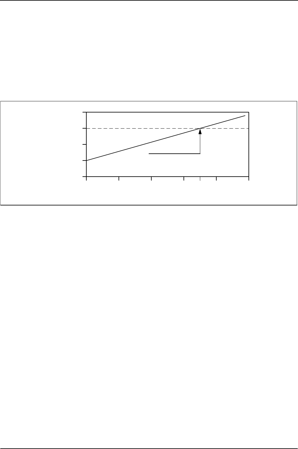
230 Engine Specification Manual, TPD1599 Issue 6, January 2009
1100 Series, 1104D, Mechanical FIE
Fuel Specifications
Perkins recommend the use of the following fuel specifications:
zDIN E 590 DERV Grade A, B, C, E, F, Class 0, 1, 2, 3, and 4
zBS2869 Class A2 Off-highway Gas Oil Red Diesel
zASTM D975-91 Class 1-1D and Class 2-2D.
For further information on fuel specifications and restrictions, refer to “Fluid Recommendations (Fuel
Specification)” in the OMM for this engine.
Fuel specific gravity
Engine power is affected by changes of the specific gravity of the fuel oil. The results are shown in the graphs
below.
Fuel tank location
The fuel oil feed pipe and the fuel oil return pipe, must be fitted to the fuel tank so that their exit and entry
positions in the fuel tank are at the same height. The distance between these points on the horizontal plane
must not be less than 150 mm (5,90 in).
For the highest and the lowest fuel tank locations see the following illustrations.
If all the conditions for tank height, pipe length, and pipe sizes cannot be met, the installation may still be
acceptable if the following conditions are met:
zIf the fuel tank is to be fitted below the level of the fuel lift pump, the depression measured at the inlet to
the fuel lift pump must not exceed -17 kPa. Fuel temperature is to be 30 °C (86 °F) for this measurement,
engine running at rated speed
zIf the fuel tank is to be fitted above the level of the fuel lift pump, a stop cock must be fitted to prevent fuel
leakages during service.
zThe return line back pressure must not exceed 10 kPa, measured at the fuel injection pump outlet with the
engine running at idle.
For recommended layouts see page 231.
- 6
- 4
Power
change
%
- 2
0
+ 2
Datum
Standard fuel
0.810 0.820 0.830 0.840 0.850 0.860
Fuel specific gravity °C
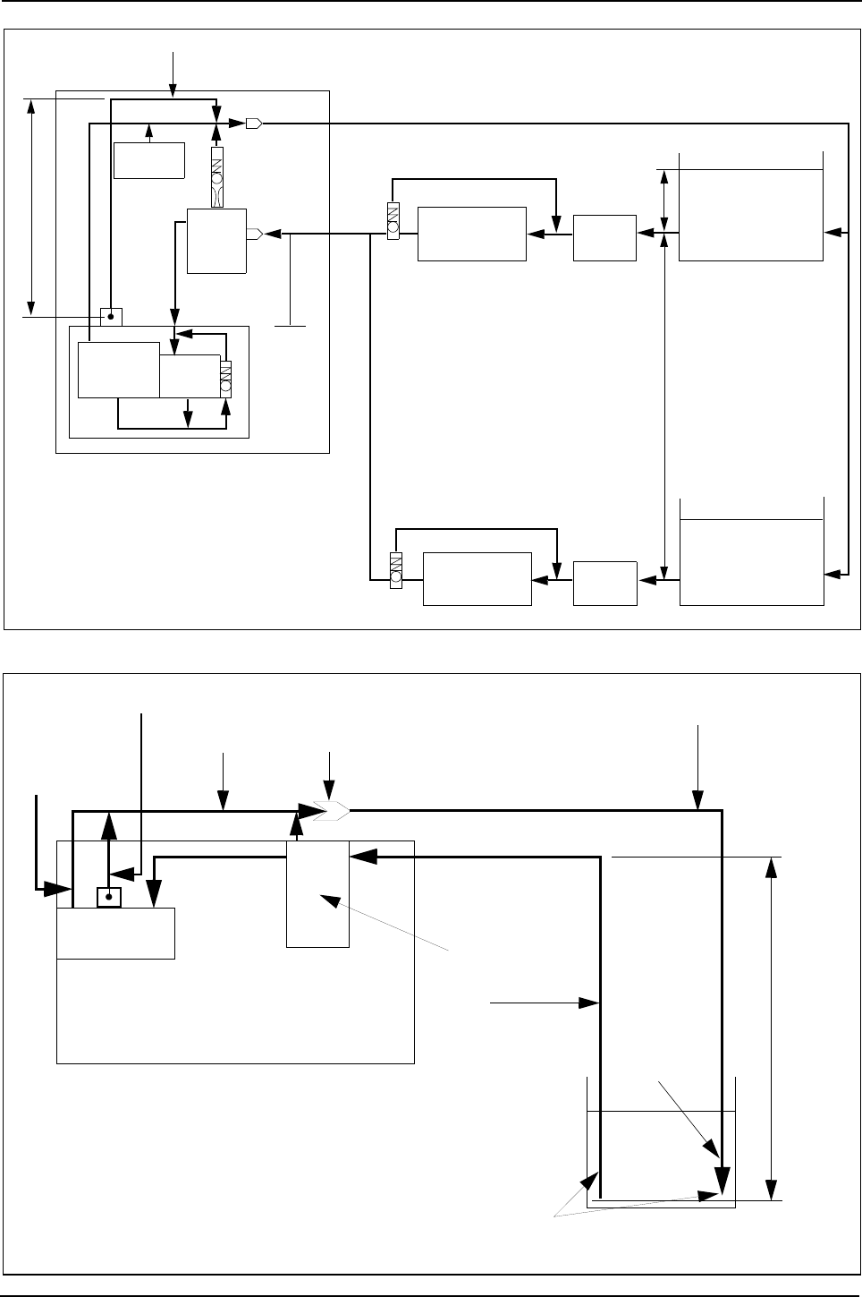
Engine Specification Manual, TPD1599 Issue 6, January 2009 231
1100 Series, 1104D, Mechanical FIE
Low pressure fuel system - fuel tank positions - ‘T’ into fuel return pipe (V1001)
Low pressure fuel system - fuel tank in lowest position - ‘T’ into fuel return pipe (V3201)
Engine
Air vent
Non-return
valve
10
micron
filter
0.3 m
Housing Transfer
pump
FIP
Regulator
valve
Electric lift pump
(Max. height)
Separator
0 - 0.3 m
High fuel
Tank position
0 - 1.5 m
Low fuel
tank position
Electric lift pump
(Min. height) Separator
Regulator
valve
Notes:
1. Lift pump pressure to be no lower than - 17 kPa.
2. FIP outlet pressure not to exceed 10 kPa.
3. Separator efficiency to be >98% for whole water
4. Up to 1.81 litres pm flow rate.
5. Separator to filter to <300 um to 1.81 litres pm flow rate.
Injector
Leak-off rail
200 mm ± 10 mm
Atmospheric fuel return line 4 mm ID
Fuel
tank
Minimum distance between
Engine
FIP
Injector
leak-off
EFPM 2000
Customer quickfit
connector
Return below
fuel level
8 mm ID
8 mm ID
fuel return pipe
feed and return pipe
in tank 150 mmin tank 150 mm
Maximum
lift
1524 mm
6 mm ID
fuel return pipe
fuel feed pipe
3048 mm maximum length
mechanical FIE
only
lift pump / filter
R162
Atmospheric fuel return line 6 mm ID
‘T’ in to FRP V3201
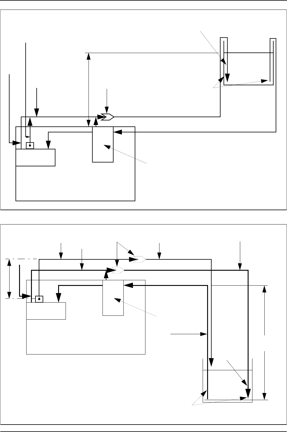
232 Engine Specification Manual, TPD1599 Issue 6, January 2009
1100 Series, 1104D, Mechanical FIE
Low pressure fuel system - fuel tank in highest position ‘T’ into fuel return pipe `(V3201)
Low pressure fuel system - fuel tank in lowest position atmospheric fuel return line (V2201)
Fuel
tank
Minimum distance between
Engine
FIP
lift pump / filter
305 mm
Customer quickfit
connector
Return below
fuel level
8 mm ID fuel feed pipe
3048 mm maximum length
6 mm ID
fuel return pipe
feed and return pipe
in tank 150 mm
Injector
leak-off
mechanical FIE
only
EFPM 2000
R1
Atmospheric fuel return line 6 mm ID
Fuel
tank
Minimum distance between
Engine
FIP
Injector
leak-off
EFPM 2000
Customer quickfit
connector
Return below
fuel level
8 mm ID
8 mm ID
fuel return pipe
feed and return pipe
in tank 150 mmin tank 150 mm
Maximum
lift
1524 mm
6 mm ID
fuel return pipe
fuel feed pipe
3048 mm maximum length
mechanical FIE
only
lift pump / filter
R
Atmospheric fuel
return line 4 mm ID
Customer return
to tank 6 mm
200 mm ± 10 mm
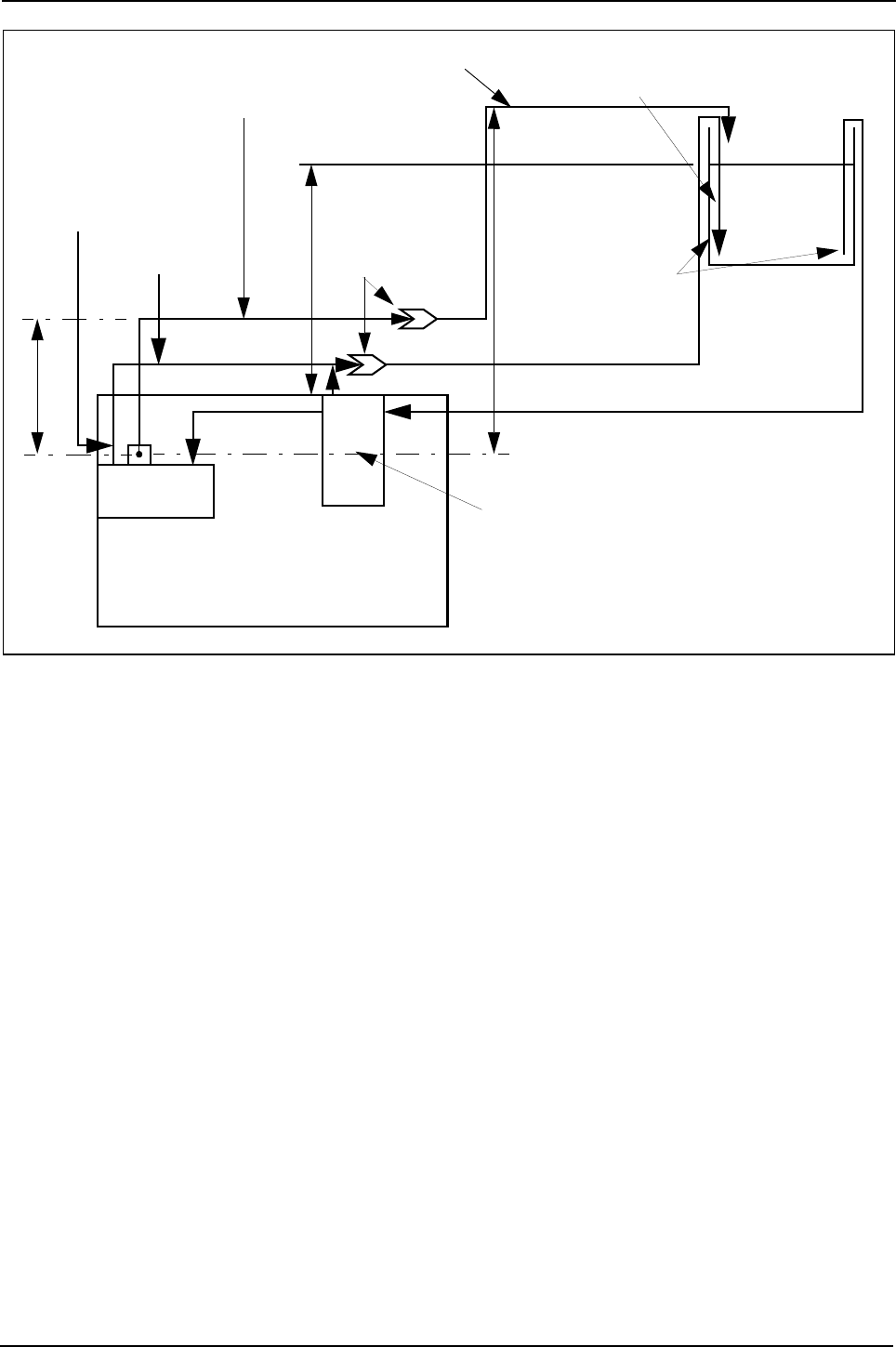
Engine Specification Manual, TPD1599 Issue 6, January 2009 233
1100 Series, 1104D, Mechanical FIE
Low pressure fuel system - fuel tank in highest position atmospheric fuel return line (V2201)
Fuel
tank
Minimum distance between
Engine
FIP
lift pump / filter
305 mm
Customer quickfit
connector
Return below
fuel level
8 mm ID fuel feed pipe
3048 mm maximum length
6 mm ID
fuel return pipe
feed and return pipe
in tank 150 mm
Injector
leak-off
mechanical FIE
only
EFPM 2000
R1629
Atmospheric fuel
return line 4 mm ID
200 mm ± 10 mm
Customer return to tank 6 mm ID
Maximum lift
of 550 mm
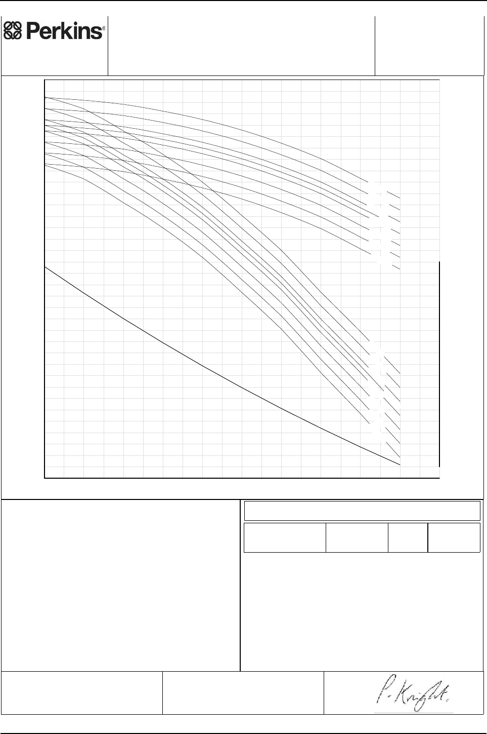
234 Engine Specification Manual, TPD1599 Issue 6, January 2009
1100 Series, 1104D, Mechanical FIE
S8001 - Altitude and temperature
0 250 500 750 1000 1250 1500 1750 2000 2250 2500 2750 3000 3250 3500 3750 4000 4250 4500 4750 5000
Altitude, m
0.38
0.40
0.42
0.44
0.46
0.48
0.50
0.52
0.54
0.56
0.58
0.60
0.62
0.64
0.66
0.68
0.70
0.72
0.74
0.76
0.78
0.80
0.82
0.84
0.86
0.88
0.90
0.92
0.94
0.96
0.98
1.00
1.02
1.04
1.06
1.08
Power Correction Factor
550
575
600
625
650
675
700
725
750
775
800
825
850
875
900
925
950
975
1000
Dry Barometric Pressure, mbar
TURBOCHARGED-SEENOTE
0DegC
NATURALLYASPIRATED
30DegC
0DegC
AMBIENT
AIR
TEMPER-
ATURE,
DRY
AMBIENT
AIR
TEMPER-
ATURE,
DRY
10DegC
20DegC
10DegC
20DegC
25DegC
40DegC
50DegC
60DegC
25DegC
30DegC
40DegC
50DegC
60DegC
Perkins Engines Company Limited
©2006 Commercial in Confidence,
proprietary information of
Perkins Engines Company Ltd.
Diagram For:
ESTIMATING THE EFFECTS OF ALTITUDE & TEMPERATURE
Curve:
8001
S
Issue:
1
Sheet 1
Date: 11-Apr-2006
ON POWER OUTPUT RELATIVE TO ISO AND SAE
REFERENCE CONDITIONS AT SEA-LEVEL.
Perkins Engines Company Limited
©2006 Commercial in Confidence,
proprietary information of
Perkins Engines Company Ltd.
NOTE
For air-to-water charge cooled turbocharged engines
the power correction shown above does not apply.
For these engines the reference temperature of 25°C
should be used and not the actual ambient (engine
inlet) air temperature.
For power correction due to humidity refer to curve
S8002.
APPLICABLE TO ENGINES WITH MECHANICAL FIE ONLY.
Drawn by:
Issued by:
Rating Standard
Total Barometric
Pressure (kPa)
Vapour
Pressure
(kPa)
Air Inlet
Temperature
(°C)
The above diagram is applicable to correct Engine Power quoted to
the following Rating Standards:
100 1 25ISO 14396: 2002
100 1 2580/1269/EEC
100 1 2588/195/EEC
100 1 25ISO 1585: 1992
100 1 25ISO 2288: 1989
100 1 25ISO 3046-1: 1995
100 1 25ISO 8665: 1994
100 1 25ISO 9249: 1989
100 1 25SAE J1349 4.2.4
100 1 25SAE J1995 3.1
100 1 25UN/ECE R120
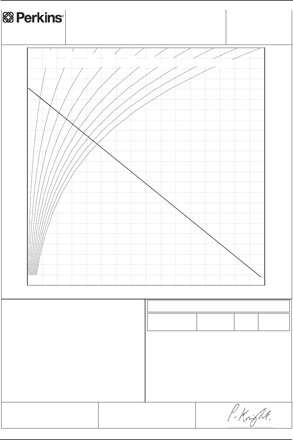
Engine Specification Manual, TPD1599 Issue 6, January 2009 235
1100 Series, 1104D, Mechanical FIE
S8002 - Humidity
-;HA?DI
0 10 20 30 40 50 60 70 80 90 100 110 120 130 140 150 160
Vapour Pressure, mbar
0.82
0.83
0.84
0.85
0.86
0.87
0.88
0.89
0.90
0.91
0.92
0.93
0.94
0.95
0.96
0.97
0.98
0.99
1.00
1.01
1.02
1.03
1.04
1.05
Power Correction Factor
-2.5
0.0
2.5
5.0
7.5
10.0
12.5
15.0
17.5
20.0
22.5
25.0
27.5
30.0
32.5
35.0
37.5
40.0
42.5
45.0
47.5
50.0
52.5
55.0
Ambient Air Temperature, Dry, DegC
10%RH
20%RH
30%RH
40%RH
50%RH
60%RH
70%RH
80%RH
90%RH
100%RH
Perkins Engines Company Limited
©2006 Commercial in Confidence,
proprietary information of
Perkins Engines Company Ltd.
Diagram For:
ESTIMATING THE EFFECTS OF HUMIDITY
Curve:
8002
S
Issue:
1
Sheet 1
Date: 11-Apr-2006
ON POWER OUTPUT RELATIVE TO ISO AND SAE
REFERENCE CONDITIONS.
Perkins Engines Company Limited
©2006 Commercial in Confidence,
proprietary information of
Perkins Engines Company Ltd.
NOTE
When estimating the power correction due to
humidity, the relative humidity must be coupled with
the AMBIENT AIR TEMPERATURE at which the
humidity is measured, and not the air inlet
temperature which may be locally heated, to obtain
the vapour pressure. The effect of inlet air
temperature on power output must be considered
separately using diagram S8001.
When humidity is expressed in terms of vapour
pressure, the power correction can be read off from
the diagonal line.
APPLICABLE TO ENGINES WITH MECHANICAL FIE ONLY.
Drawn by:
Issued by:
Rating Standard Total Barometric
Pressure (kPa)
Vapour
Pressure
(kPa)
Air Inlet
Temperature
(°C)
The above diagram is applicable to correct Engine Power quoted to
the following Rating Standards:
100 1 25ISO 14396: 2002
100 1 2580/1269/EEC
100 1 2588/195/EEC
100 1 25ISO 1585: 1992
100 1 25ISO 2288: 1989
100 1 25ISO 3046-1: 1995
100 1 25ISO 8665: 1994
100 1 25ISO 9249: 1989
100 1 25SAE J1349 4.2.4
100 1 25SAE J1995 3.1
100 1 25UN/ECE R120
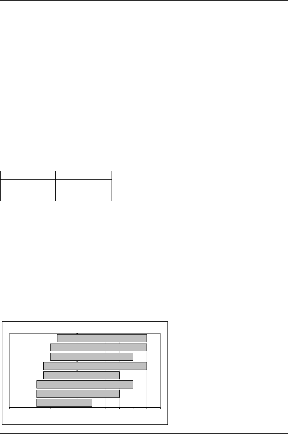
236 Engine Specification Manual, TPD1599 Issue 6, January 2009
1100 Series, 1104D, Mechanical FIE
Lubrication system
Lubricating pressure instrumentation
As a minimum, Perkins require the use of a warning light for the lubricating oil pressure.
Installation angle and gradients of operation
The installation must be designed so that air will flow freely over the engine lubricating oil sump and filters. The
operation of the engine at gradients above that approved, either on the side, or front to rear, can cause engine
failure. The installation angle must be taken into account when selecting sump gradability. The angle of
installation can be up to 10°s on the side and/or up to 7°s down at the rear. If it is necessary to install the engine
at angles greater than these, or if it is to be installed downwards at the front, then you must consult your
local distributor.
Satisfactory engine operation on significant gradients can be achieved by specification of the appropriate
lubricating oil sump. Where continuous operation under these conditions is required, contact your local
distributor.
Lubricating oil specification
Use only good quality lubricating oil which is equivalent to or above them minimum specification show in the
table below. Some oil additives may not be compatible with engine components that contain lead or copper.
This may cause the components to become chemically active and show increased levels of these elements in
the oil analysis.Consult with oil supplier and obtain commitment to ensure satisfactory performance of the
product.Target oil specifications are:
Oil change period is 500 hrs. on CH4 oils and higher specifications.
* Use of CG4 is dependant on rating, duty and application. Service period may be less than 500 hrs. Consult
the Perkins Product Team.
Lubricating oil pressure
At normal operating temperatures, the lubricating oil pressure for a warm engine throughout the maximum
torque speed to rated speed range, should be 300 - 400 kPa.
Lubricating oil temperatures
The maximum permissible lubricating oil temperature measured in the main gallery is 125 °C (257.4 °F) for
continuous operation, and 135 °C (275 °F) for intermittent operation.
Recommended viscosity grades
Caution: Always ensure that the correct viscosity grade of lubricating oil is used for the ambient temperature
range in which the engine will run as shown in the chart below.
Engine type Specification
1104D-44
1104D-44T
1104D-44TA
API CG4*/CH4/CI4
Viscostiy grade
-50 -40 -30 -20 -10 0 10 20 30 40 50 60
0W-20
0W-30
0W-40
5W-30
5W-40
10W-30
10W-40
15W-40
Ambient Temperature Deg C
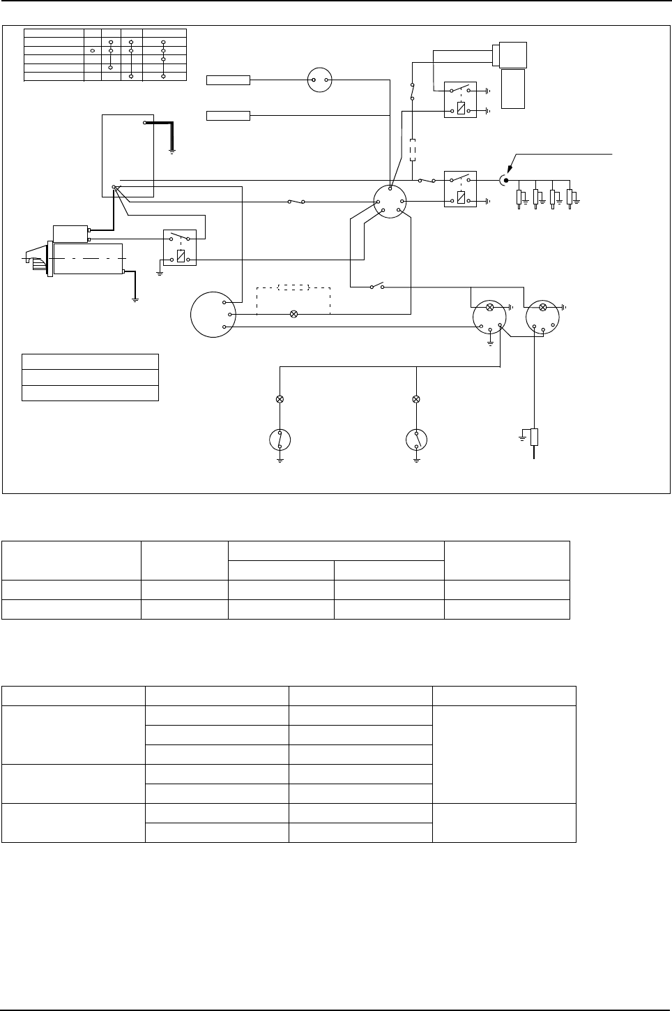
Engine Specification Manual, TPD1599 Issue 6, January 2009 237
1100 Series, 1104D, Mechanical FIE
Electrical circuit diagram
Starter motors
Note: Resistance of battery cables A, B, and C not to exceed 0.0017 ohm.
Alternators
Model Voltage Solenoid current Max volts drop in
solenoid circuit
Max pull-in amps Max hold-in amps
Iskra AZE/AZF 12 68 20 0.65
R4.5 24 45 15 1.0
Model Rating Min cable size for rating Max circuit Volt drop
A115i
14V 65A 8,50 mm²
0.5V
14V 75A 16,00 mm²
14V 85A 16,00 mm²
A127iR 14V 100A 25,00 mm²
14V 120A 25,00 mm²
A127iM 28V 55A 8,50 mm² 1.0V
28V 75A 16,00 mm²
Fuel lift pump
relay
Start aid relay
Fuel lift pump
Standard electric fuel lift
pump with supply from Aux (2)
terminal on ignition switch
Glowplugs
12v and 24v versions
Fuel injection pump
Cold start
advance Cold start
temperature switch
Electric shut-off switch
energise to run
30
50
Starter motor
GStarter relay
B+
D+
W
Resistors optional
100W (12v)
300W (24v)
12v 2.2W
24v 2W Ignition
warning light
Alternator
G+
+-
-
W
Warning light Warning light
Water temperature
switch
(make on increase of water temperature)
Oil pressure
switch
(break on increase of oil pressure)
Water temperature
sender
Tachometer Water temperature
gauge
Ignition
switch
C
Fuse
Fuse
Fuse
Battery
A
B
Terminal Off Aux Heat Heat / start
Supply
Aux
Start
W/Light
Heat
1
2
3
4
5
A
B
Typical Lucas 128SA ignition switch
Optional voltage
dropper 24 volt only Glowplug busbar connector
Deutsch DTHD series
-
+
Instrument light
switch
current rating depends on
auxiliary load
12v system - 50A slow burn fuse
24v system - 30A slow burn fuse
Glow plug fuse rating

238 Engine Specification Manual, TPD1599 Issue 6, January 2009
1100 Series, 1104D, Mechanical FIE
Suggested cable sizes
Notes:
zRatings quoted for +30 °C (86 °F) above ambient in free air. For wires bundled in harness, derate values
by 50% assuming all cables are carrying rated current at the same time
zMinimum cable size 1 mm² for mechanical strength rather than current capacity.
All cable runs to be kept as short as possible to minimise volt drop within a general limit of 0.5 volt (12V), and
1.0 volt (24V) unless specified otherwise.
Cross-section area
mm²
Max current
amps
Resistance
m ohm / m
1,00 16.5 18,5
1,25 18.5 14,9
1,50 21.0 12
2,00 25.0 8,95
2,50 29.0 7,29
3,00 33.0 6,15
4,00 39.0 4,60
6,00 50.0 3,14
8,50 63.0 2,20
10,00 70.0 1,82
16,00 94.0 1,16
25,00 125.0 0,74

Engine Specification Manual, TPD1599 Issue 6, January 2009 239
1100 Series, 1104D, Mechanical FIE
Engine mountings
Standard methods
There are four standard methods available:
1 The engine can be installed on solid mountings, independent of the driven machinery but on a common
base.
2 The complete engine and machine, can be installed on solid mountings on a frame. Install the frame on
flexible mountings on a solid base.
3 Install the engine on flexible mountings, independent of the machine and install a drive shaft between the
engine and the machine.
4 Connect the engine and machine together, and install the complete unit on flexible mountings.
Flexible mountings
The purpose of the flexible mountings must be to:
zControl the movement of the engine at normal speed and during engine start and stop procedure.
zRemove as much vibration as possible from the frame of the machine.
zGive the engine support and hold it during sudden increase or decrease in speed, shock loads or operation
on gradients.
zPrevent stress to the engine, caused through distortion of the machine and the engine frame.
zControl the movement of the engine inside the capacity of any drive shaft.
Note: Further information about engine mountings can be found in the Perkins Product Support Publications.

240 Engine Specification Manual, TPD1599 Issue 6, January 2009
1100 Series, 1104D, Mechanical FIE
Power take-off
The various methods of transmitting drive from the engine and data required for satisfactory operation is given
in this power take-off section.
Crankshaft thrust loading
Note: If additional components are to be fitted to the crankshaft pulley of the engine, installation approval must
be obtained from the Perkins Applications Department.
Crankshaft PTO
All axial PTO applications are to be approved by Perkins Applications Department.
Maximum permissible thrust loads for crankshaft (continuous operation) (1)
(1). The thrust loads shown in the table above, apply to both forward or rearward movement of the
crankshaft.
With typical torque converter transmission With clutch operation
2135 N (480 lbf) 3381 N (760 lbf)
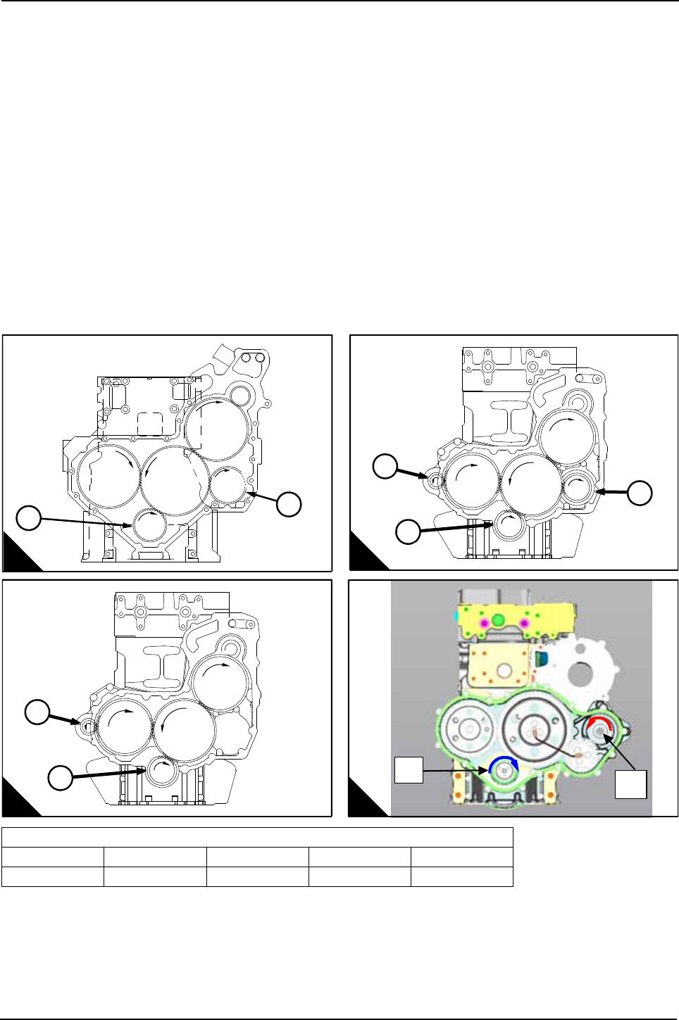
Engine Specification Manual, TPD1599 Issue 6, January 2009 241
1100 Series, 1104D, Mechanical FIE
Alternative side mounted PTO
Gear driven PTO arrangements are available in a variety of locations by selecting different options.
When viewed from the rear:
Q1000:Located at the rear of the timing case, on the left hand side of the engine - for light duty operation.
Q1030:Located at the rear of the timing case, on the left hand side - for heavy duty loads.
Q2000:Located at the rear of the timing case, on both the left and the right hand side of the engine.
Q3030:Located at the rear of the timing case, on the right hand side of the engine.
Q4***:Located at the rear of the timing case, on the left hand side hand side of the engine,
for heavy duty operation.
Note: For rotation, ratio and speed, see illustration and tables on the following pages.
Caution: The power and torque transmitted through the PTO at any speed, must not exceed the figures
shown in the following tables.
Side mounted PTO position
Note: The view of the gear train in the above illustration is when seen from the front of the engine.
PTO position
A1/B1/C1/D1 A2 B2/B3 C2 D2
Crankshaft Q1000 Q2000 Q3000/Q3030 Q4***
R1360-1
1
2
A
R1574
B
3
1
2
R1575
C
2
1
1
2
D

242 Engine Specification Manual, TPD1599 Issue 6, January 2009
1100 Series, 1104D, Mechanical FIE
Side mounted PTO operating data
Typical examples of use are lifting equipment such as loaders, telescopic handlers and fork lift trucks where
the PTO is used at a high load for short periods (approximately 30 seconds) for a relatively low proportion of
the engine life.
Where the PTO gear is not supplied by Perkins, details for suitable gear designs should be obtained from
Perkins.
Option code Rotation viewed from front
of engine PTO gear teeth Engine speed
ratio
Max PTO drive torque (1)
(1). Torque values are for intermittent use only.
Nm lbf ft
Q1000
Q1005
Q1015
Q1016
Clockwise concentric
to PTO spigot 33 1 : 1.03 138 102
Q1000
Q1009
Clockwise off-set to PTO
spigot 34 1 : 1.0 142 105
Q1030
Q1035
Q1036
Q1037
Clockwise 33 1 : 1.03 204 150
Q1030 Clockwise 34 1 : 1.0 210 155
Q2000 (2)
Q2005 (2)
Q2015 (2)
Q2016 (2)
(2). When a combination of both RHS and LHS PTO are used, the total flywheel torque should be no
more than 210 Nm, i.e. A + C must be lower or equal to 210 Nm, and B + C must be lower or equal
to 210 Nm.
Clockwise concentric to PTO
spigot 33 1 : 1.03 204 150
Q2000 (2) Clockwise off-set to PTO
spigot 34 1 : 1.0 210 155
Q2000 (2) Anti-clockwise 20 1 : 1.7 76 56
Q3000 Anti-clockwise off-set to PTO
spigot 20 1 : 1.7 38 (3)
(3). Torque values are for continuous loading
28 (3)
76 (4)
(4). Torque values for intermittent use only, defined as follows:
Maximum of 2 seconds of load up to peak rating of 130 Nm (measured at the crankshaft) with at
least 2 seconds of less than the continuous rating of 65 Nm before re-applying
Overshoot should not exceed 10%
Rate of pressure rise to be less than 4000 bar/second.
56 (4)
Q3000 Anti-clockwise concentric
to PTO spigot 17 1 : 20 33 (3) 24 (3)
65 (4) 48 (4)
Q3030 (5)
(5). Due to potential high rotational speeds of the hydraulic pump, approval should be obtained from
the pump manufacturers.
Anti-clockwise off-set to PTO
spigot 20 1 : 1.7 76 (3) 56 (3)
Anti-clockwise concentric
to PTO spigot 17 1 : 20 65 (3) 48 (3)
Q4042 TBA TBA TBA TBA TBA
Q4055
Q4059 Anti-clockwise 34 1 : 1.0 280 206
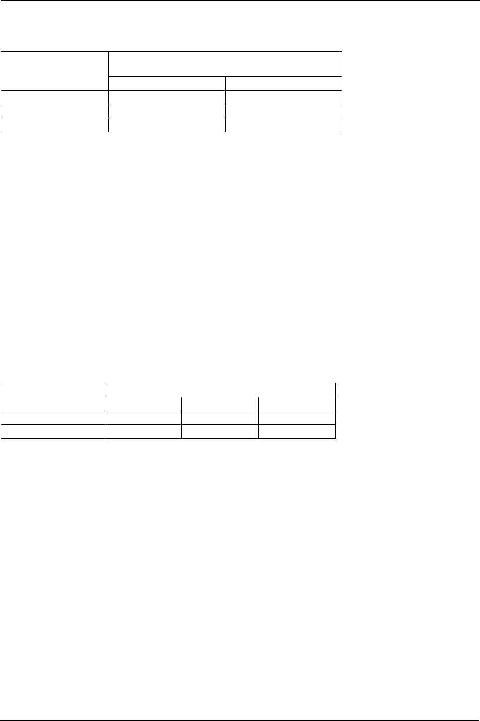
Engine Specification Manual, TPD1599 Issue 6, January 2009 243
1100 Series, 1104D, Mechanical FIE
Customer supplied pumps
Customer supplied pumps, that are driven by the side mounted PTO, must be fitted with a rear support bracket
if, the mass of the pump exceeds the static bending moments shown in the table below.
Torsional vibration
In generators, pumps and compressors etc., where the moment of inertia of the driven machinery is high,
torsional vibration can cause extra stresses at certain speeds. It is strongly recommended that applications
such as these are analysed by Perkins.
Similar stresses can also occur with low inertia equipment that is driven off the front of the engine. As a general
guideline the inertia of any equipment driven off the front of the engine should be less than 0.02 kgm². This
equipment could include auxiliary crankshaft pulleys for belt driven PTO and couplings for axial PTO taken
directly off the crankshaft nose. Higher inertia arrangements may be acceptable, however it is strongly
recommended that these be analysed by Perkins.
For the system to be analysed and to ensure the correct performance of the engine etc., the information
required by Perkins is the mass/elastic details of all the equipment driven from the front and rear of the engine.
More information about the mass/elastic system calculations is given in the Perkins installation manual.
Flywheel/cylinder block bending moments
Large static bending moments in the vertical plane at the flywheel housing/cylinder block interface should be
avoided at all times, since these can lead to a failure of either component. The table below shows the values
that should not be exceeded for safe operation. Further information can be found in the Perkins installation
manual.
Engine speed
rev/min
Maximum static bending moment
customer supplied pumps
Nm lbf ft
2200 10,0 7.3
2300 10,0 7,3
2400 7,0 5,2
Application Acceptable static bending moment values
Nm lbf ft kgf m
Off-highway vehicles 510 4500 51,8
Fork-lift truck 850 7500 86,4

244 Engine Specification Manual, TPD1599 Issue 6, January 2009
1100 Series, 1104D, Mechanical FIE
Centre of gravity
Note: For a dry engine with standard parts fitted.
Naturally aspirated - non stressed block
Naturally aspirated - stressed block
Turbocharged and turbocharged aftercooled - non stressed block
Turbocharged and turbocharged aftercooled - stressed block
Engine Specification Weight
kg (lbf)
From rear
face of
cylinder
block mm (in)
height above
crankshaft
centre-line
mm (in)
Offset to
RHS from
centre-line
mm (in)
1104D-44
Base engine 291 (642) 292.6 (11.51) 205.8 (810) -5.6 (0.22)
Fan to flywheel 386 (851) 227.2 (8.94) 160.4 (6.31) 8.1 (0.31)
Radiator to flywheel
Engine Specification Weight
kg (lbf)
From rear
face of
cylinder
block mm (in)
height above
crankshaft
centre-line
mm (in)
Offset to
RHS from
centre-line
mm (in)
1104D-44
Base engine 357 (787) 306.6 (12.07) 134.1 (5.28) 5.9 (0.23)
Fan to flywheel 395 (871) 291.4 (11.47) 132.7 (5.22) 4.7 (0.19)
Radiator to flywheel
Engine Specification Weight
kg (lbf)
From rear
face of
cylinder
block mm (in)
height above
crankshaft
centre-line
mm (in)
Offset to
RHS from
centre-line
mm (in)
1104D-44T
1104D-E44TA
Base engine 306 (675) 292.6 (11.51) 205.8 (810) -5.6 (0.22)
Fan to flywheel 401 (884) 227.2 (8.94) 160.4 (6.31) 8.1 (0.31)
Radiator to flywheel
Engine Specification Weight
kg (lbf)
From rear
face of
cylinder
block mm (in)
height above
crankshaft
centre-line
mm (in)
Offset to
RHS from
centre-line
mm (in)
1104D-44T
1104D-E44TA
Base engine 357 (787) 306.6 (12.07) 134.1 (5.28) 5.9 (0.23)
Fan to flywheel 395 (871) 291.4 (11.47) 132.7 (5.22) 4.7 (0.19)
Radiator to flywheel

Engine Specification Manual, TPD1599 Issue 6, January 2009 245
1100 Series, 1104D, Mechanical FIE
Ratings
Low speed torque
The 1104D-44T/1104D-44TA engines utilisze a boost control unit on the fuel pump to control exhaust smoke
emissions during rapid acceleration of the engine. The boost control unit will limit the maximum fuel delivery
(un-boosted fuel) and therefore torque (un-boosted torque) until the air boost pressure from the turbocharger
reaches a preset level. Once this threshold boost pressure is achieved the engine will deliver torque levels
shown on the first page of the power curves.
During operation below 1000 rev/min engine speed the intake air pressure will typically be below the threshold
to achieve fully boosted torque and therefore the real torque available will be lower than that shown in the
torque curves. This lower, un boosted torque level is shown on the second page of the power curves, at both
800 rev/min and 1000 rev/min engine speed.
As the boost control unit acts upon differential pressure between the intake manifold and ambient this feature
will not affect the engine torque as a function of the increasing altitude.
The boost control were used on many 1104C-44T/1104C-44TA ratings, the un-boosted torque levels on
1104D-44T/1104D-44TA are lower. In some machine applications this may result in a loss of performance in
terms of engine response and load acceptance when changing over to the 1104D-44T/1104D-44TA.
It is important when making engine selections that the machine torque requirements at low speed are taken
into account. For machines with high torque demands at low speed this is especially important.
For further assistance with machine torque requirements and engine suitability please refer to the Perkins
Applications department.
Transient smoke
The 1104D-44T/1104D-44TA engines have been designed to comply with the transient smoke requirements
of the US EPA 40 CFR Part 89 Tier 3 legislation and the former EU 77/537/EEC standard for agriculture
tractors.
Smoke opacity may be higher than a similarly rated 1104C-44T/1104C-44TA engine in some modes of
transient operation due to the technologies used to develop mechanical engines to the more stringent, cleaner
exhaust emission levels.
It is important when making engine selections that the customer takes into account the impact of any potential
increase in operational black smoke over their current product.
For further assistance with the transient smoke emissions and engine selection please refer to the Perkins
Applications Engineering Department.
Allowances for engine driven auxiliary equipment
If the engine operates in the ambient conditions shown on the power curve, the only allowances which must
be made are for the power used by accessories such as the fan and the alternator. The amount of power used
by accessories driven by the engine must be decided so that the net horsepower available at the flywheel can
be found. For details of the power absorbed by the compressors, the exhauster and the fans, see “Ratings” on
page 245 to page 257.
De-rating
If the engine operates in ambient conditions other than the conditions shown on the power curve, then suitable
allowances must be made for any change in inlet temperature, barometric pressure or humidity.
Inlet air temperature
High inlet air temperature to the engine can cause loss of power and heat problems with the cooling system,
the lubricating oil and hydraulic systems. This may be either due to high ambient temperatures, or because the
engine is being used inside a building or structure of a machine which requires more air flow.
Altitude
The 1104D naturally aspirated engine is capable of operating at altitudes up to 600 metres.
The 1104D turbocharged engine is capable of operating at altitudes of up to 3000 metres without derate.

246 Engine Specification Manual, TPD1599 Issue 6, January 2009
1100 Series, 1104D, Mechanical FIE
Turbochargers are approved for operation up to 3000 metres.
Note: See “S8001 - Altitude and temperature” on page 234 for further details.
Humidity
The amount by which the rating will be reduced because of humidity, will be according to the percentage
humidity and the ambient temperature (not the inlet air temperature).
Note: See “S8002 - Humidity” on page 235 for further details.
Temperature
For the effects on the fuel oil changes in temperature and specific gravity, refer to Perkins Application
Engineers.
Engine ratings given by Perkins are corrected to the reference conditions shown in the rating standards.
Note: See “S8001 - Altitude and temperature” on page 234 for further details.
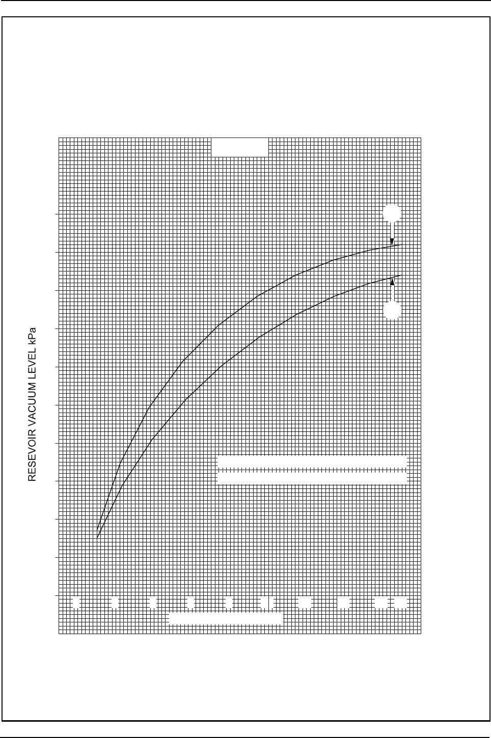
Engine Specification Manual, TPD1599 Issue 6, January 2009 247
1100 Series, 1104D, Mechanical FIE
Exhauster, curve 5608
A1313
10
20
30
40
50
60
70
80
90
100
0 2 4 6 8
10
12
14
16
17
EVACUATION TIME Sec
CURVE 1 = PUMP SPEED 4800 rev/min
CURVE 2 = PUMP SPEED 1220 rev/min
2
1
Barometric pressure - 101.6 kPa
Vacuum reservoir capacity - 8 litre
Exhauster swept volume - 87,5 cc
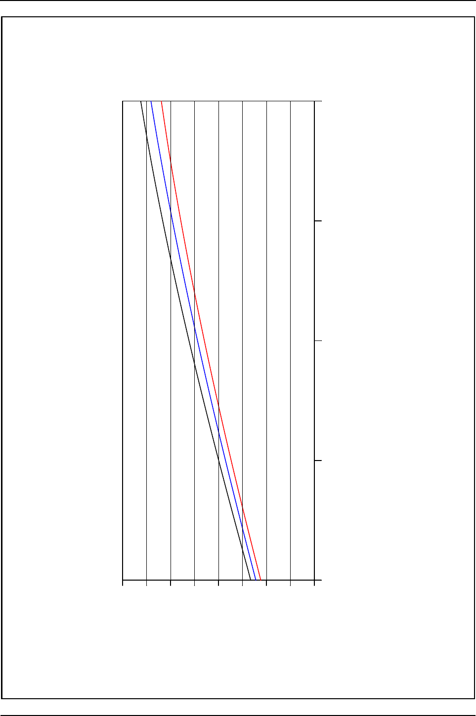
248 Engine Specification Manual, TPD1599 Issue 6, January 2009
1100 Series, 1104D, Mechanical FIE
Compressor single cylinder 225cc - free air delivery
A1623
400
350
300
250
200
150
100
50
0
1000 1500 2000 2500 3000
Speed revs/min
F.A.D. (I/min)
10 BAR
8 BAR
12 BAR
The compressor is water cooled and governor controlled
Compressor single cylinder 225cc - free air delivery
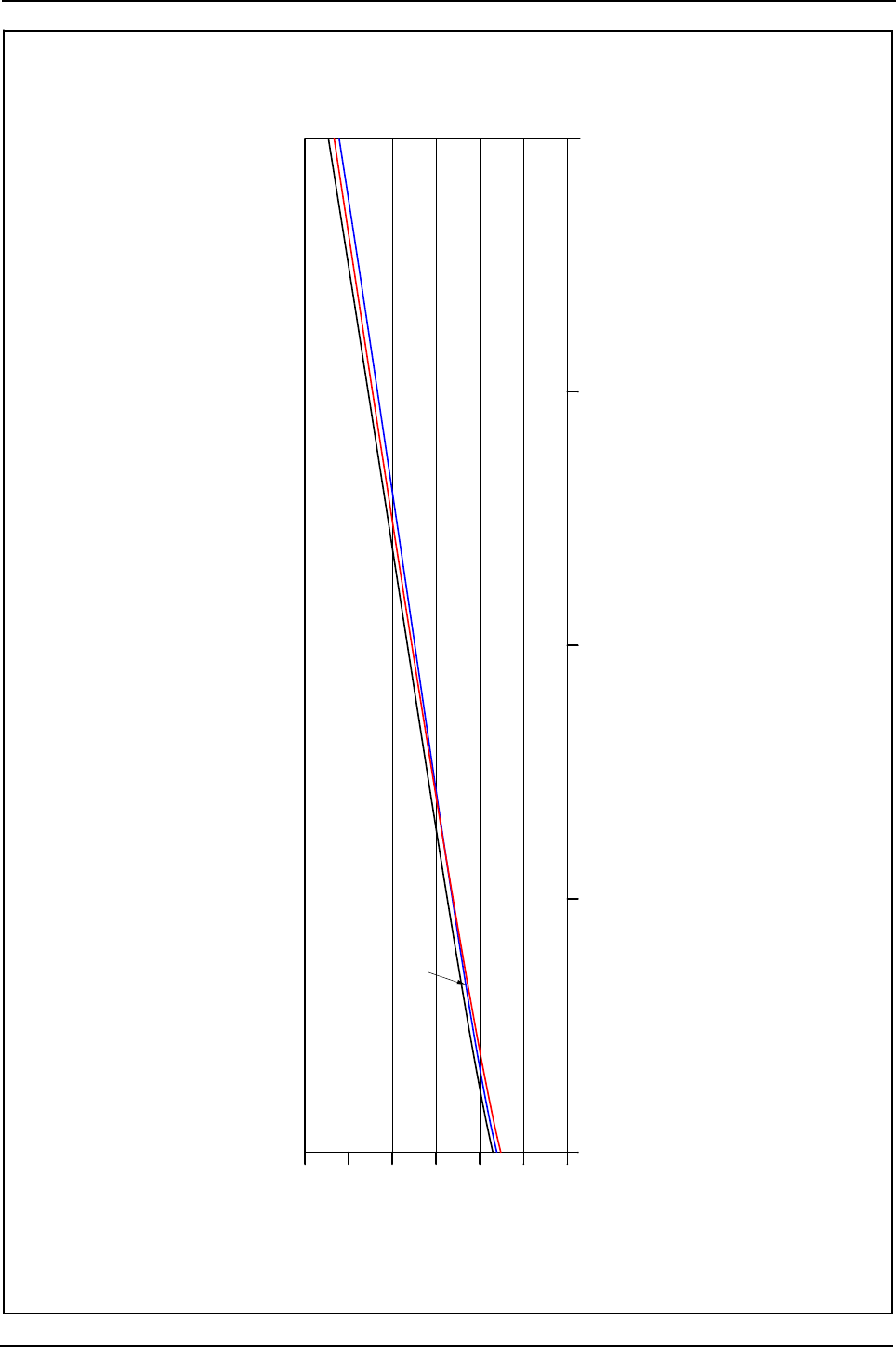
Engine Specification Manual, TPD1599 Issue 6, January 2009 249
1100 Series, 1104D, Mechanical FIE
Compressor single cylinder 225cc - delivered air temperature
A1624
15001000 2000 2500 3000
Speed (revs/min)
80
100
120
140
160
180
200
D.A.T. (Deg.C)
12 BAR
8 BAR
10 BAR
The compressor is water cooled and governor controlled
Compressor single cylinder 225cc - delivered air temperature
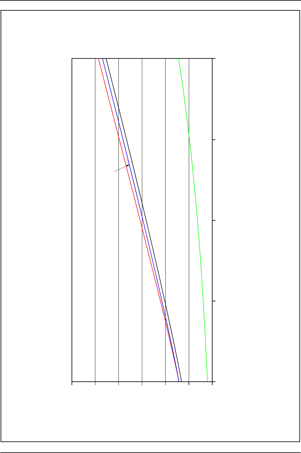
250 Engine Specification Manual, TPD1599 Issue 6, January 2009
1100 Series, 1104D, Mechanical FIE
Compressor single cylinder 225cc - power consumption
The compressor is water cooled and governor controlled
A1625
25002000 300015001000
Speed (revs/min)
0
1
2
3
4
5
6
Power Consumption ( kW)
10 BAR
8 BAR
12 BAR
0 BAR HEAD and LINE
Compressor single cylinder 225cc - power consumption
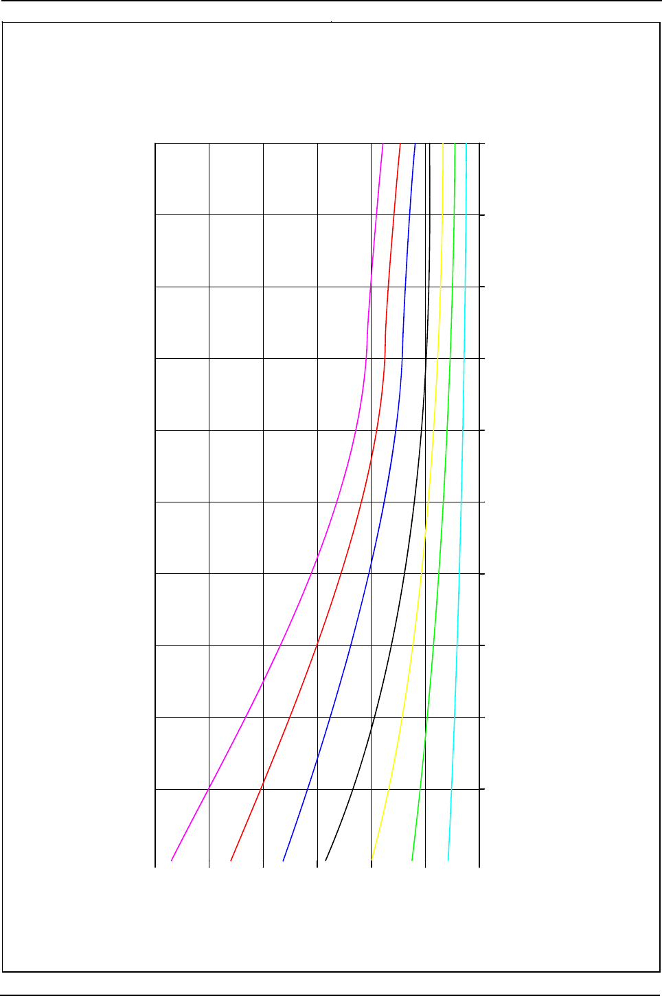
Engine Specification Manual, TPD1599 Issue 6, January 2009 251
1100 Series, 1104D, Mechanical FIE
Compressor single cylinder 225cc - air charging time to pressurise a 50 litre receiver
A1626
30002800260024002200200018001600140012001000
0
50
100
150
200
250
300
Time/secs.
Speed/revs/min
14 BAR
12 BAR
10 BAR
6 BAR
2 BAR
4 BAR
8 BAR
The compressor is water cooled and governor controlled
Compressor single cylinder 225cc - air charging time to pressurise a 50 litre receiver
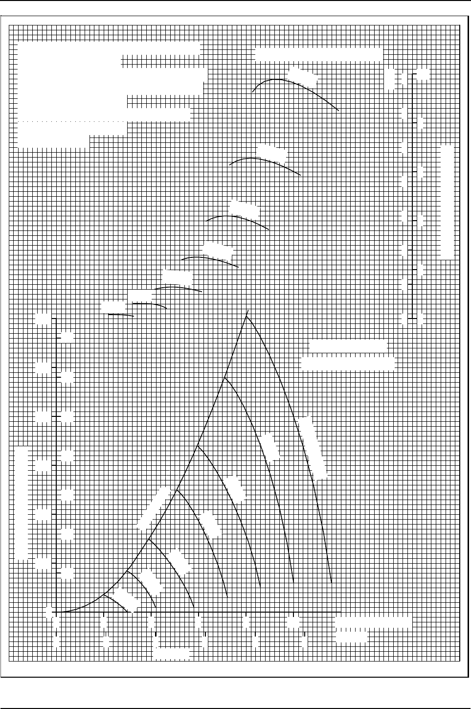
252 Engine Specification Manual, TPD1599 Issue 6, January 2009
1100 Series, 1104D, Mechanical FIE
Fan performance curve 2184/C - options M2203 to M2206
R1577
Tip clearance
0·180in (4.57mm)
Diameter 18in (457.2 mm)
No of blades 6
Blade width 4.25in (108.0 mm)
Blade angle 30°
2485C817
on 4 cylinder engines
See drawings
4000 by min
3500
3000
2500
2000
1500
1000
Fan speeds in rev/min
Blade length 6.25in (158.8 mm)
Stall line
3500
3000
2500
4000
2000
1500
60
70
3.0
1000
2.5
2.0
1.5
1.0
50
40
30
20
0.5
00
10
Static pressure in H20
0
24 6 8
1
2
3 4
10
5m³/s
Airflow
Power absorption - hp
10
6
8
4
2
00
1
2
3
4
5
6
7
kW
12 ft³/min x 10³
speed limi pplies
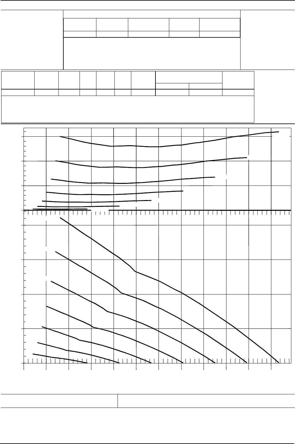
Engine Specification Manual, TPD1599 Issue 6, January 2009 253
1100 Series, 1104D, Mechanical FIE
Fan performance curve 5441 - options M3313 to M3316
0
5
10
15
0.0
0.5
1.0
1.5
2.0
0.0 0.5 1.0 1.5 2.0 2.5 3.0 3.5 4.0 4.5 5.0 5.5
Power (kW)Static Pressure (kPa)
Airflow (m³/s)
1000 rpm
1500 rpm
2000rpm
2500 rpm
3000 rpm
3500 rpm
4000 rpm
1000 rpm
1500 rpm
2000 rpm
2500 rpm
3000 rpm
3500 rpm
4000 rpm
Perkins Engines Company Limited
©2004 Commercial in Confidence,
proprietary information of
Perkins Engines Company Ltd.
Fan Performance Curve for: Curve:
5441
Issue:
2
Date: 25-Oct-2004
DCP Number: 04-0172 Based On: Borg Warner Test ID Z10705
Date: 6-Oct-2004
Drawn by:
A. Bradley
Perkins Part
Number
Manufacturer Manufacturer's
Part Number
Supplier Supplier's Part
Number
2485C517 Borg Warner 4035-41045-43 Borg Warner 4035-41045-43
Perkins Part
Number
Diameter
(mm)
Number
of
Blades
Blade
Width
(mm)
Blade
Length
(mm)
Blade
Angle
(°)
Fan Type Maximum
Continuous
Speed, rpm
Minimum Tip Clearance, mm,
for Shroud Mounted on:
Engine Radiator
508.0 781.3 167.0 45.0 42002485C517 Puller 6.00 15.00
-;HA?DI
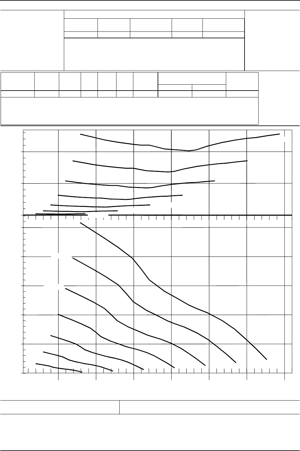
254 Engine Specification Manual, TPD1599 Issue 6, January 2009
1100 Series, 1104D, Mechanical FIE
Fan performance curve 5442 - options M3323 to M3326
Power (kW)Static Pressure (kPa)
0
10
20
0.0
0.5
1.0
1.5
2.0
2.5
1234567
Airflow (m³/s)
1000 rpm
1500 rpm
2000 rpm
2500 rpm
3000 rpm
3500 rpm
4000 rpm
1000 rpm
1500 rpm
2000 rpm
2500 rpm
3000 rpm
3500 rpm
4000 rpm
Perkins Engines Company Limited
©2004 Commercial in Confidence,
proprietary information of
Perkins Engines Company Ltd.
Fan Performance Curve for: Curve:
5442
Issue:
2
Date: 25-Oct-2004
DCP Number: 04-0172 Based On: Borg Warner Test ID Z12037
Date: 6-Oct-2004
Drawn by:
A. Bradley
Perkins Part
Number
Manufacturer Manufacturer's
Part Number
Supplier Supplier's Part
Number
2485C518 Borg Warner 4035-38449-86 Borg Warner 4035-38449-86
Perkins Part
Number
Diameter
(mm)
Number
of
Blades
Blade
Width
(mm)
Blade
Length
(mm)
Blade
Angle
(°)
Fan Type Maximum
Continuous
Speed, rpm
Minimum Tip Clearance, mm,
for Shroud Mounted on:
Engine Radiator
508.0 10 89.0 167.0 39.5 42002485C518 Puller 6.00 15.00
-;HA?DI
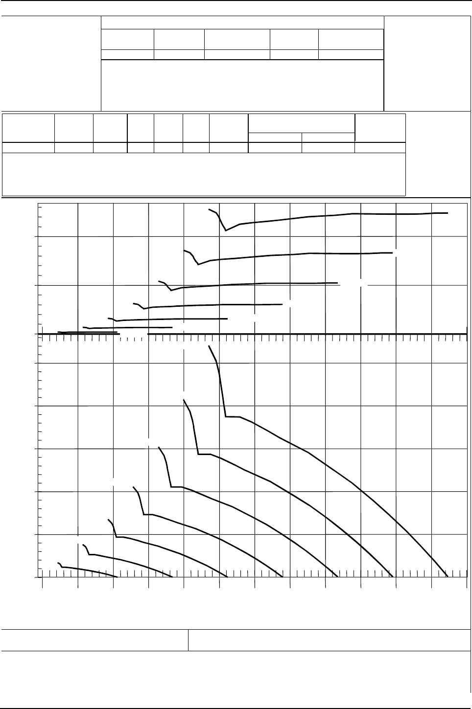
Engine Specification Manual, TPD1599 Issue 6, January 2009 255
1100 Series, 1104D, Mechanical FIE
Fan performance curve 5443 - options M3415 to M3416
0
10
20
0.0
0.5
1.0
1.5
2.0
2.5
0.5 1.0 1.5 2.0 2.5 3.0 3.5 4.0 4.5 5.0 5.5 6.0
6.
5
Power (kW)
Static Pressure (kPa)
Airflow (m³/s)
1000 rpm
1500 rpm
2000 rpm
2500 rpm
3000 rpm
3500 rpm
4000 rpm
1000 rpm
1500 rpm
2000 rpm
2500 rpm
3000 rpm
3500 rpm
4000 rpm
Perkins Engines Company Limited
©2004 Commercial in Confidence,
proprietary information of
Perkins Engines Company Ltd.
Fan Performance Curve for: Curve:
5443
Issue:
2
Date: 25-Oct-2004
DCP Number: 04-0172 Based On: Borg Warner Test ID Z10750
Date: 6-Oct-2004
Drawn by:
A. Bradley
Perkins Part
Number
Manufacturer Manufacturer's
Part Number
Supplier Supplier's Part
Number
2485C514 Borg Warner 4035-41296-03 Borg Warner 4035-41296-03
Perkins Part
Number
Diameter
(mm)
Number
of
Blades
Blade
Width
(mm)
Blade
Length
(mm)
Blade
Angle
(°)
Fan Type Maximum
Continuous
Speed, rpm
Minimum Tip Clearance, mm,
for Shroud Mounted on:
Engine Radiator
508.0 7203.0 167.0 32.0 42002485C514 Pusher 6.00 15.00
-;HA?DI
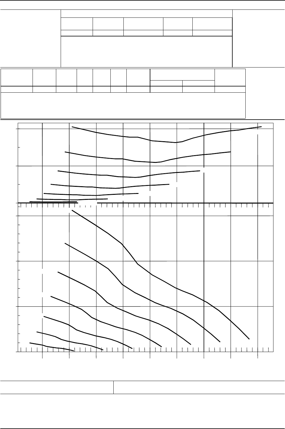
256 Engine Specification Manual, TPD1599 Issue 6, January 2009
1100 Series, 1104D, Mechanical FIE
Fan performance curve 9500 - option M4326
0
20
40
0
1
2
3
1 2 3 4 5 6 7 8 9
Power (kW)Static Pressure (kPa)
Airflow (m³/s)
1000 rpm
1500 rpm
2000 rpm
2500 rpm
3000 rpm
3500 rpm
4000 rpm
1000 rpm
1500 rpm
2000 rpm
2500 rpm
3000 rpm
3500 rpm
4000 rpm
Perkins Engines Company Limited
©2004 Commercial in Confidence,
proprietary information of
Perkins Engines Company Ltd.
Fan Performance Curve for: Curve:
9500
Issue:
1
Date: 25-Oct-2004
DCP Number: 04-0172 Based On: Borg Warner Test ID Z12037
Date: 6-Oct-2004
Drawn by:
A. Bradley
Perkins Part
Number
Manufacturer Manufacturer's
Part Number
Supplier Supplier's Part
Number
2485C521 Borg Warner 4035-38449-87 Borg Warner 4035-38449-87
Perkins Part
Number
Diameter
(mm)
Number
of
Blades
Blade
Width
(mm)
Blade
Length
(mm)
Blade
Angle
(°)
Fan Type Maximum
Continuous
Speed, rpm
Minimum Tip Clearance, mm,
for Shroud Mounted on:
Engine Radiator
558.8 10 182.4 38252485C521 Puller 6.00 15.00
-;HA?DI
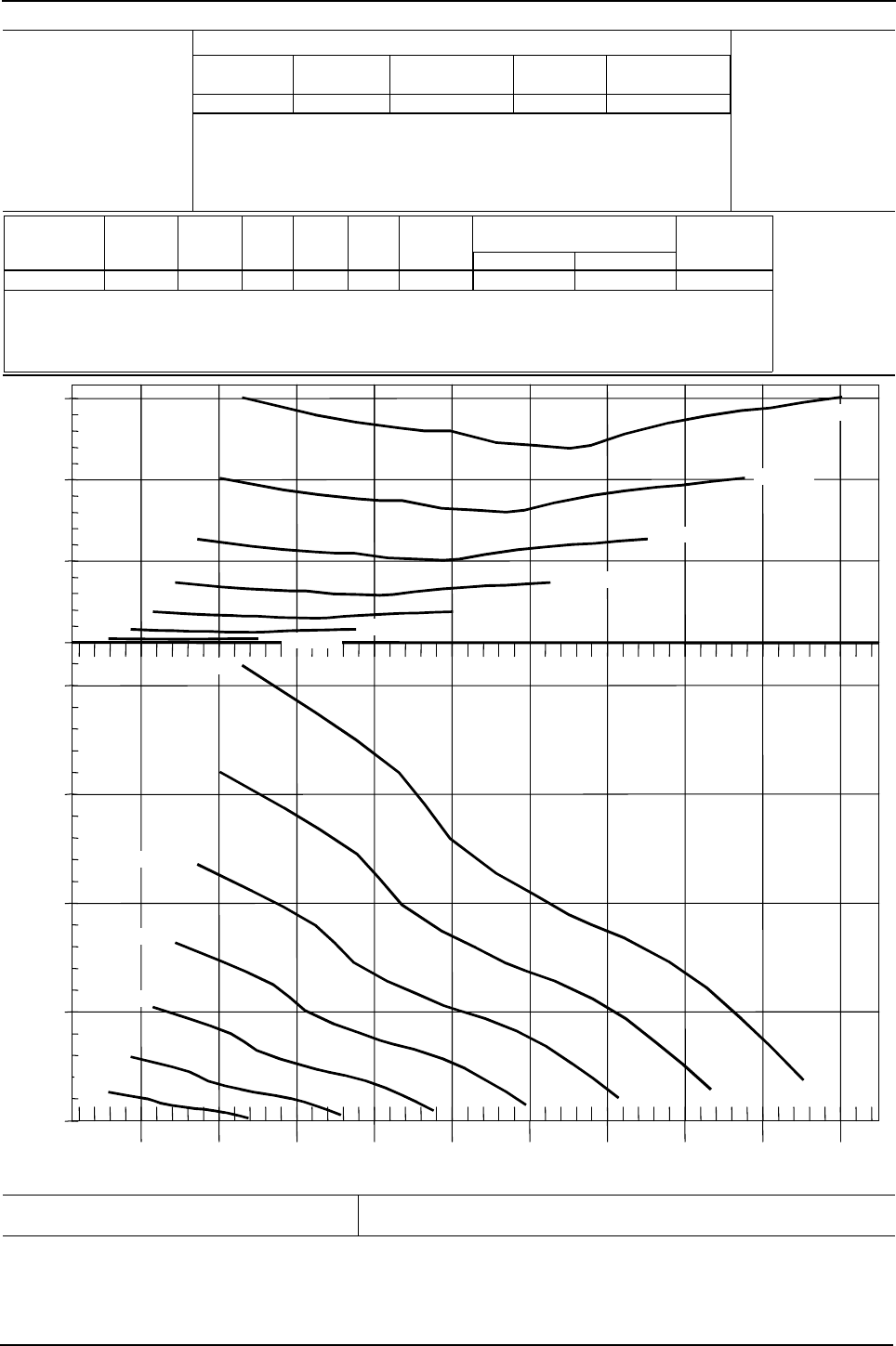
Engine Specification Manual, TPD1599 Issue 6, January 2009 257
1100 Series, 1104D, Mechanical FIE
Fan performance curve 9501 - option M2323 to M2326
0
5
10
15
0.0
0.5
1.0
1.5
2.0
0.5 1.0 1.5 2.0 2.5 3.0 3.5 4.0 4.5 5.0
Power (kW)Static Pressure (kPa-g)
Airflow (m³/s)
1000 rpm
1500 rpm
2000 rpm
2500 rpm
3000 rpm
3500 rpm
4000 rpm
1000 rpm
1500 rpm
2000 rpm
2500 rpm
3000 rpm
3500 rpm
4000 rpm
Perkins Engines Company Limited
©2004 Commercial in Confidence,
proprietary information of
Perkins Engines Company Ltd.
Fan Performance Curve for: Curve:
9501
Issue:
1
Date: 25-Oct-2004
DCP Number: 04-0172 Based On: Borg Warner Test ID Z12037
Date: 6-Oct-2004
Drawn by:
A. Bradley
Perkins Part
Number
Manufacturer Manufacturer's
Part Number
Supplier Supplier's Part
Number
2485C522 Borg Warner 4035-38449-83 Borg Warner 4035-38449-83
Perkins Part
Number
Diameter
(mm)
Number
of
Blades
Blade
Width
(mm)
Blade
Length
(mm)
Blade
Angle
(°)
Fan Type Maximum
Continuous
Speed, rpm
Minimum Tip Clearance, mm,
for Shroud Mounted on:
Engine Radiator
457.2 10 131.6 46752485C522 Puller 6.00 15.00
-;HA?DI

258 Engine Specification Manual, TPD1599 Issue 6, January 2009
1100 Series, 1104D, Mechanical FIE
Important notes
Company liability
The engine supplied must only be used for the purpose given in the Companies ‘Acknowledgement of Order’
and to the Companies specific instructions for its installation and operation. It must not be used, or passed to
any other person, for any other purpose or be installed by any other method except with the Companies written
approval.
The application and installation of the engine must be suitable for the needs of the machine in which it is
installed and the conditions in which it will have to operate.
The Company does not have direct control of the type of application and how the engine is installed and used
in it and cannot be held responsible for any loss or damage where the person or persons that installed the
engine, or the user, have not followed the advice given by the Company.
It is very important to ensure that the installation of the engine is according to the health and safety legislation
of the country in which the engine is to operate.
Installation
The engine must:
zhave the necessary power and torque characteristics for the machine in which it is installed so that it can
operate in all necessary environmental conditions
zbe connected securely and correctly to the driven load according to operation needs and torsional vibration
characteristics
zbe given protection from adverse atmospheric conditions and supplied with the correct clean fuel,
lubricating oil and air
zhave the correct maintenance and operation according to Perkins instructions as given in the installation,
operation and service books.
It is also important that:
zAll parts that rotate, such as pulleys, flywheels, fans, shafts, couplings and drive belt systems must have a
protection guard fitted over them with a warning that fingers must not be put through the guards
zElectrical terminations are shielded to prevent external short circuits. All electrical cables that supply
current must be protected by insulation and all electrical equipment must have a suitable and secure
connection to ground
zThe exhaust system must have a suitable heat shield or lagging where it can be a danger to persons.
Warning! All build lists referenced in this publication exclude any fan guarding or hot surface protection
features. To the extent that it is lawfully possible, the Company accepts no responsibility whatsoever for any
injury, damage or death, whether to property or persons, arising directly or indirectly from this exclusion.
Legislation
Specific legislation for each country cannot be given here because of the amount and continuous changes that
occur. The subjects which can effect operation are:
zNoise
zEmissions
zOperation in explosive atmosphere or areas where there are flammable materials
zOperation where ventilation is limited or health is important.
Warranty
This can be made invalid if the engine is not installed or operated/maintained according to Perkins instructions.

Engine Specification Manual, TPD1599 Issue 6, January 2009 259
1100 Series, 1104D, Mechanical FIE
California Proposition 65
California State law, USA, now stipulates that all equipment that is powered by a diesel engine must carry a
warning label that is clearly visible to the operator of that equipment. All Original Equipment Manufacturers that
fit Perkins engines to their equipment must comply with this legislation. An example of this label (actual size)
is shown below.
Warnings to place on Equipment
California
Proposition 65 Warning
Diesel engine exhaust and some of its
constituents are known to the State of
California to cause cancer, birth defects,
and other reproductive harm

