Aviom AllFrame F6 Power Requirements Modular I/O Frame Options 132
Aviom F6 Modular I/O Frame Power Options 132_F6-Power-Requirements Aviom - F6 Modular I/O Frame - Power Options
Aviom F6 Modular I/O Frame Power Options 132_f6-power-requirements Aviom - F6 Modular I/O Frame - Power Options
User Manual: Aviom F6 Modular I/O Frame Power Options Aviom - F6 Modular I/O Frame - Power Options
Open the PDF directly: View PDF ![]() .
.
Page Count: 2
ALLFRAME™
Multi-Modular I/O System
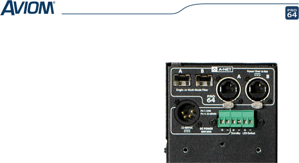
The F6 Modular I/O Frame features three power inlets: a two-pin Euroblock and a four-pin XLR for use with external
DC power supplies, as well as an RJ-45 A-Net® jack which can accept power injected on the Cat-5e cable.
The F6 does not ship with a power supply. Third-party power supplies purchased for use with the F6 may be bench-
top models, DIN rail supplies, or in-line bricks, as long as the minimum electrical specications are met. In order to
prevent the F6’s case from sitting above ground due to voltage drop on the cable, a separate power supply must be
used to power each F6 in a system. Power supplies must be installed in accordance with the manufacturer’s instruc-
tions and adhering to all local electrical codes. Aviom has tested and approved the TDK-Lambda DPP120-48-1 and
Mean Well DR-120-48 DIN rail power supplies.
All three power sources may be used simultaneously with the F6 to create a redundant power sub-system.
Because the power requirements of the F6 exceed standard PoE and PoE+, standard PoE/PoE+ power injectors are
not suitable for use in AllFrame systems. Users who wish to power AllFrame units through the RJ45 jack must pur-
chase the Aviom POA80 Power Over A-Net power supply assembly. No other power supplies have been approved
for powering AllFrame units in this manner.
While the POA80 provides certain protections against power irregularities that are common when cables are con-
nected or disconnected, Aviom recommends against plugging or unplugging a network cable utilizing Power Over
A-Net while the POA80 is on.
Note that only the A-Net B port can accept PoA and no other A-Net ports should be connected to the powered
port of the POA80. The B port on the F6 may be used to supply power but not network data if the installation
layout so requires.
F6 Power Supply
Requirements & Options
Aviom’s AllFrame Multi-Modular I/O System oers unique ex-
ibility in installation. In addition to supporting multiple I/O
complements and physical form factors, AllFrame devices can
be powered in a number of ways. This paper details the elec-
trical requirements that must be met by any power supplies
used with AllFrame devices and provides critical guidelines for
ensuring proper performance.
continued...
ALLFRAME™
Multi-Modular I/O System
Aviom, A‑Net, the A‑Net icon, Pro16, Pro64, Virtual Data Cables, m‑control, and AllFrame are trademarks of Aviom, Inc. All other trademarks are the property of their
respective owners. ©2012 Aviom, Inc. All rights reserved. Information subject to change without notice. rev. 1.3 072012
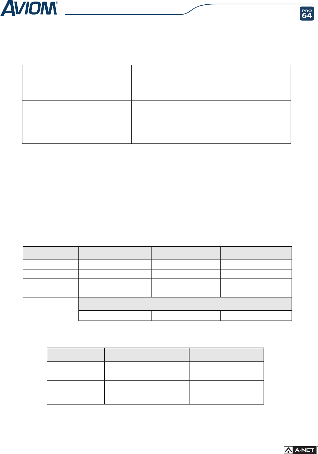
Connector Specifications
Connector Type Pinout Terminal Blocks
2-pin terminal block Pin 1: 30-60VDC (+)
Pin 2: Ground (-)
Phoenix Contact part number
17 54 44 9
Size: 5mm; 2 contacts per unit
4-pin XLR Pin 1: Ground
Pin 2/3: No Connect
Pin 4: 30-60VDC
All Aviom products are designed and manufactured in the USA.
Maximum Cable Distance For Various Power Supplies
Wire Gauge 24V, +/-5% @ 100 Watts 48V, +/-5% @ 100 Watts 48V, +/-5% @ 120 Watts
12 75 feet, 23 meters 900 feet, 274 meters 1800 feet, 548.5 meters
14 48 feet, 15 meters 550 feet, 168 meters 1150 feet, 350.5 meters
16 30 feet, 9 meters 450 feet, 137 meters 725 feet, 221 meters
18 18 feet, 5.5 meters 300 feet, 91.5 meters 450 feet, 137 meters
Power Dissipation Of Cable
2.4 Watts 8 Watts 20 Watts
DC Power supplies used with the F6 and connected to the Euroblock terminal connector or the 4-pin XLR jack must
meet the following requirements:
Power Supply Rating Requires a UL60950-1 Certied/Listed ITE power supply having a SELV (Safety Extra
Low Voltage) rated output voltage between 30 and 60V DC
Voltage
(measured at the input of the F6 Modular I/O Frame)
30-60VDC, inclusive of tolerance
Maximum Current
(varies with input voltage)
(voltage at the input of the F6 Modular I/O Frame)
1.08A @ 60VDC
1.16A @ 56VDC
1.35A @ 48VDC
1.41A @ 44VDC
2.70A @ 24VDC
2.95A @ 22VDC
In order to meet emissions standards, an inline lter such as the Cosel NAC-10-472, may be required for instal-
lations that use external switching power supplies. For proper ltering, the power supply and lter should be
separated by twelve inches or more.
Maximum usable lengths for DC power cables used with the F6 and connected to the 4-pin XLR or Euroblock
terminal block connectors will vary based on the gauge of the wire and the voltage and power rating of the supply.
The cable will dissipate some of the power as heat, resulting in a voltage drop on the cable that increases with
cable length.
The table below presents power cable length as a function of wire gauge and supply voltage/power rating.
Refer to the F6 User Guide for complete requirements and safety warnings.
