Bulletin 1609 Uninterruptible Power Supply User Manual Um009 En P
User Manual: 1609
Open the PDF directly: View PDF ![]() .
.
Page Count: 34
Bulletin 1609 Uninterruptible Power Supply
Catalog Numbers 1609-D and 1609-B
User Manual
Important User Information
Solid-state equipment has operational characteristics differing from those of electromechanical equipment. Safety
Guidelines for the Application, Installation and Maintenance of Solid State Controls (publication SGI-1.1 available from
your local Rockwell Automation® sales office or online at http://www.rockwellautomation.com/literature/) describes some
important differences between solid-state equipment and hard-wired electromechanical devices. Because of this difference,
and also because of the wide variety of uses for solid-state equipment, all persons responsible for applying this equipment
must satisfy themselves that each intended application of this equipment is acceptable.
In no event will Rockwell Automation, Inc. be responsible or liable for indirect or consequential damages resulting from the
use or application of this equipment.
The examples and Figures in this manual are included solely for illustrative purposes. Because of the many variables and
requirements associated with any particular installation, Rockwell Automation, Inc. cannot assume responsibility or
liability for actual use based on the examples and Figures.
No patent liability is assumed by Rockwell Automation, Inc. with respect to use of information, circuits, equipment, or
software described in this manual.
Reproduction of the contents of this manual, in whole or in part, without written permission of Rockwell Automation,
Inc., is prohibited.
Throughout this manual, when necessary, we use notes to make you aware of safety considerations.
Allen-Bradley, Rockwell Software, Rockwell Automation, and TechConnect are trademarks of Rockwell Automation, Inc.
Trademarks not belonging to Rockwell Automation are property of their respective companies.
WARNING: Identifies information about practices or circumstances that can cause an explosion in a hazardous environment,
which may lead to personal injury or death, property damage, or economic loss.
ATTENTION: Identifies information about practices or circumstances that can lead to personal injury or death, property
damage, or economic loss. Attentions help you identify a hazard, avoid a hazard, and recognize the consequence.
SHOCK HAZARD: Labels may be on or inside the equipment, for example, a drive or motor, to alert people that dangerous
voltage may be present.
BURN HAZARD: Labels may be on or inside the equipment, for example, a drive or motor, to alert people that surfaces may
reach dangerous temperatures.
IMPORTANT
Identifies information that is critical for successful application and understanding of the product.
WARNING: This is a category C2 UPS product. In a residential environment, this product may cause radio interference, in which
case the user may be required to take additional measures.

Rockwell Automation Publication 1609-UM009C-EN-P - February 2015 3
Preface
Additional Resources These documents contain additional information concerning related products
from Rockwell Automation
You can view or download publications at
http:/www.rockwellautomation.com/literature/. To order paper copies of
technical documentation, contact your local Allen-Bradley distributor or
Rockwell Automation sales representative.
Resource Description
Industrial Automation Wiring and Grounding Guidelines,
publication 1770-4.1
Provides general guidelines for installing a Rockwell
Automation industrial system.
Product Certifications website, http://www.ab.com Provides declarations of conformity, certificates, and
other certification details.
Publication Number:
1609-UM007_-EN-P
Bulletin 1609 UPS Management Software
User Manual
Publication Number:
1609-UM008_-EN-P
Network Management Card - Cat. No. 1609-ENET
User Manual
Publication Number:
1609-IN012_-EN-P
Bulletin 1609-D
Installation Instructions
Publication Number:
1609-IN013_-EN-P
Bulletin 1609-B
Installation Instructions
Publication Number:
1609-IN014_-EN-P
Surge Protective Device (Cat. No. 1609-SPD)
Installation Instructions
Publication Number:
1609-IN015_-EN-P
Network Management Card (Cat. No. 1609-ENET)
Installation Instructions

4Rockwell Automation Publication 1609-UM009C-EN-P - February 2015
Preface
Notes:

Rockwell Automation Publication 1609-UM009C-EN-P - February 2015 5
Table of Contents
Bul. 1609-D Installation Instructions
Battery Wiring and Installation . . . . . . . . . . . . . . . . . . . . . . . . . . . . . . . . . . . . . 7
Mount the UPS . . . . . . . . . . . . . . . . . . . . . . . . . . . . . . . . . . . . . . . . . . . . . . . . . . . 8
Hardwire UPS . . . . . . . . . . . . . . . . . . . . . . . . . . . . . . . . . . . . . . . . . . . . . . . . . . . . 9
Selection of Cables . . . . . . . . . . . . . . . . . . . . . . . . . . . . . . . . . . . . . . . . . . . . . . . . . 9
Connect Power and Equipment to the UPS . . . . . . . . . . . . . . . . . . . . . . . . . 10
Bul. 1609-D Block Figure . . . . . . . . . . . . . . . . . . . . . . . . . . . . . . . . . . . . . . . . . 10
Bul. 1609-B Installation Instructions
Battery Wiring and Installation . . . . . . . . . . . . . . . . . . . . . . . . . . . . . . . . . . . . 11
Mount the UPS . . . . . . . . . . . . . . . . . . . . . . . . . . . . . . . . . . . . . . . . . . . . . . . . . . 13
Hardwire UPS . . . . . . . . . . . . . . . . . . . . . . . . . . . . . . . . . . . . . . . . . . . . . . . . . . . 13
Selection of Cables . . . . . . . . . . . . . . . . . . . . . . . . . . . . . . . . . . . . . . . . . . . . . . . . 13
Connect Power and Equipment to the UPS . . . . . . . . . . . . . . . . . . . . . . . . . 14
1609-B Block Figure . . . . . . . . . . . . . . . . . . . . . . . . . . . . . . . . . . . . . . . . . . . . . . 14
Bul. 1609-EXBAT Installation
Instructions
Battery Wiring and Installation . . . . . . . . . . . . . . . . . . . . . . . . . . . . . . . . . . . . 15
Mount the 1609-EXBAT. . . . . . . . . . . . . . . . . . . . . . . . . . . . . . . . . . . . . . . . . . 17
Selection of Cables . . . . . . . . . . . . . . . . . . . . . . . . . . . . . . . . . . . . . . . . . . . . . . . . 18
Connect the 1609-EXBAT to the UPS . . . . . . . . . . . . . . . . . . . . . . . . . . . . . 18
General Information 1609-D and
1609-B
Recommended Battery for use with the UPS . . . . . . . . . . . . . . . . . . . . . . . . 19
Dry I/O Contacts . . . . . . . . . . . . . . . . . . . . . . . . . . . . . . . . . . . . . . . . . . . . . . . . 19
USB Communication Port . . . . . . . . . . . . . . . . . . . . . . . . . . . . . . . . . . . . . . . . 19
Manual or Remote Enable/Disable of UPS Output Selection . . . . . . . . . 20
Manual Enable/Disable/Self-test . . . . . . . . . . . . . . . . . . . . . . . . . . . . . . . . . . . 20
Remote Enable/Disable. . . . . . . . . . . . . . . . . . . . . . . . . . . . . . . . . . . . . . . . . . . . 20
Display LED Indicators. . . . . . . . . . . . . . . . . . . . . . . . . . . . . . . . . . . . . . . . . . . . 21
Troubleshooting
UPS LED Fault Indicators . . . . . . . . . . . . . . . . . . . . . . . . . . . . . . . . . . . . . . . . . 23
Output Short Circuit . . . . . . . . . . . . . . . . . . . . . . . . . . . . . . . . . . . . . . . . . 23
Output Overload . . . . . . . . . . . . . . . . . . . . . . . . . . . . . . . . . . . . . . . . . . . . . 23
Over Temperature from the Heatsink . . . . . . . . . . . . . . . . . . . . . . . . . . 23
Over Ambient Temperature . . . . . . . . . . . . . . . . . . . . . . . . . . . . . . . . . . . 23
Over Voltage from The DC/DC Converter of Inverter . . . . . . . . . . 23
Over Voltage from The Inverter . . . . . . . . . . . . . . . . . . . . . . . . . . . . . . . . 23
Under Voltage from The Inverter . . . . . . . . . . . . . . . . . . . . . . . . . . . . . . 23
Over Voltage from the Output . . . . . . . . . . . . . . . . . . . . . . . . . . . . . . . . . 24
Under Voltage from the Output . . . . . . . . . . . . . . . . . . . . . . . . . . . . . . . . 24
Fan Failure . . . . . . . . . . . . . . . . . . . . . . . . . . . . . . . . . . . . . . . . . . . . . . . . . . . 24
Charger Failure . . . . . . . . . . . . . . . . . . . . . . . . . . . . . . . . . . . . . . . . . . . . . . . 24
TMOV Failure . . . . . . . . . . . . . . . . . . . . . . . . . . . . . . . . . . . . . . . . . . . . . . . 24
Missing Battery . . . . . . . . . . . . . . . . . . . . . . . . . . . . . . . . . . . . . . . . . . . . . . . 24
Replace Batteries . . . . . . . . . . . . . . . . . . . . . . . . . . . . . . . . . . . . . . . . . . . . . . 24

6Rockwell Automation Publication 1609-UM009C-EN-P - February 2015
Table of Contents
Troubleshooting (continued)
UPS Management Software Troubleshooting. . . . . . . . . . . . . . . . . . . . . . . .25
UPS Network Managemenr Card Troubleshooting . . . . . . . . . . . . . . . . . .26
Specifications
Bul. 1609-D 120 V Specifications . . . . . . . . . . . . . . . . . . . . . . . . . . . . . . . . . .27
Bul. 1609-D 230V Specifications . . . . . . . . . . . . . . . . . . . . . . . . . . . . . . . . . . .28
Bul. 1609-B 120V Specifications . . . . . . . . . . . . . . . . . . . . . . . . . . . . . . . . . . .29
Bul. 1609-B 230V Specifications . . . . . . . . . . . . . . . . . . . . . . . . . . . . . . . . . . .30
Dimensions
Bul. 1609-D Dimensions. . . . . . . . . . . . . . . . . . . . . . . . . . . . . . . . . . . . . . . . . . .31
Bul. 1609-B Dimensions . . . . . . . . . . . . . . . . . . . . . . . . . . . . . . . . . . . . . . . . . . .31
Bul. 1609-EXBAT Dimensions. . . . . . . . . . . . . . . . . . . . . . . . . . . . . . . . . . . . .31
Bul. 1609-BRK Dimensions . . . . . . . . . . . . . . . . . . . . . . . . . . . . . . . . . . . . . . . .32
Service Instructions
Service Instructions. . . . . . . . . . . . . . . . . . . . . . . . . . . . . . . . . . . . . . . . . . . . . . . .32

Rockwell Automation Publication 1609-UM009C-EN-P - February 2015 7
Bulletin 1609-D Installation Instructions
Battery Wiring and
Installation
Note: Batteries are not included with the 1609-D UPS
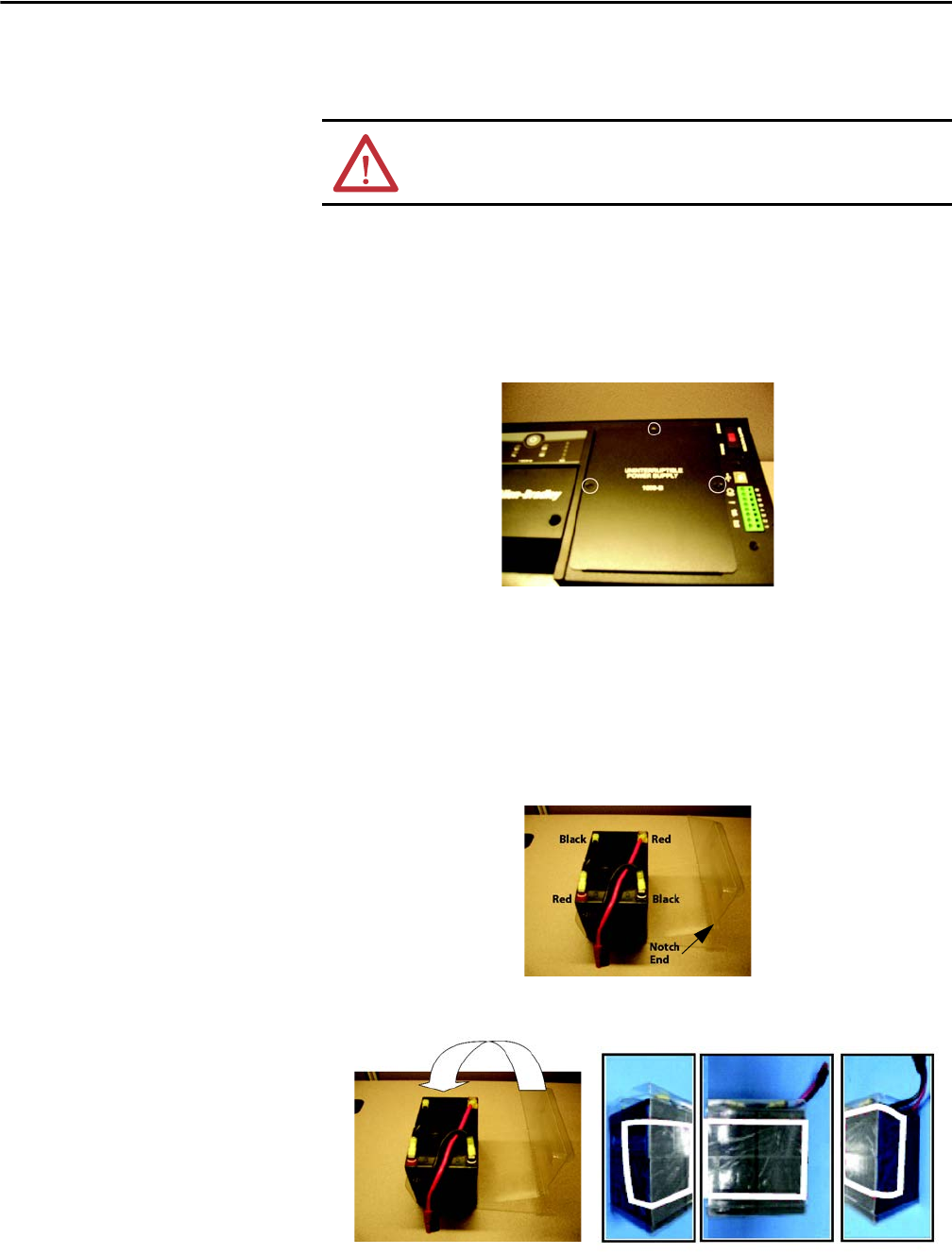
1. To access the battery compartment remove the three screws and the
battery door.
2. Remove the battery container, jumpers, and wire harness from the battery
compartment. Place the battery container and batteries onto a flat surface.
Use the provided jumper wires to connect the batteries in series. Connect
the positive terminal (red) of the battery to the negative terminal (black)
of another battery. See photo below for details.
3. Connect the red wire of the harness to the positive terminal (top red) and
the black wire of the harness to the negative terminal (bottom black). See
photo below for details.
ATTENTION: Do not service the 1609-SPD without disconnecting the power
sources due to electric shock hazard for risk of severe injury or death.
8Rockwell Automation Publication 1609-UM009C-EN-P - February 2015
Bulletin 1609 UPS
Battery Wiring and
Installation (cont.)
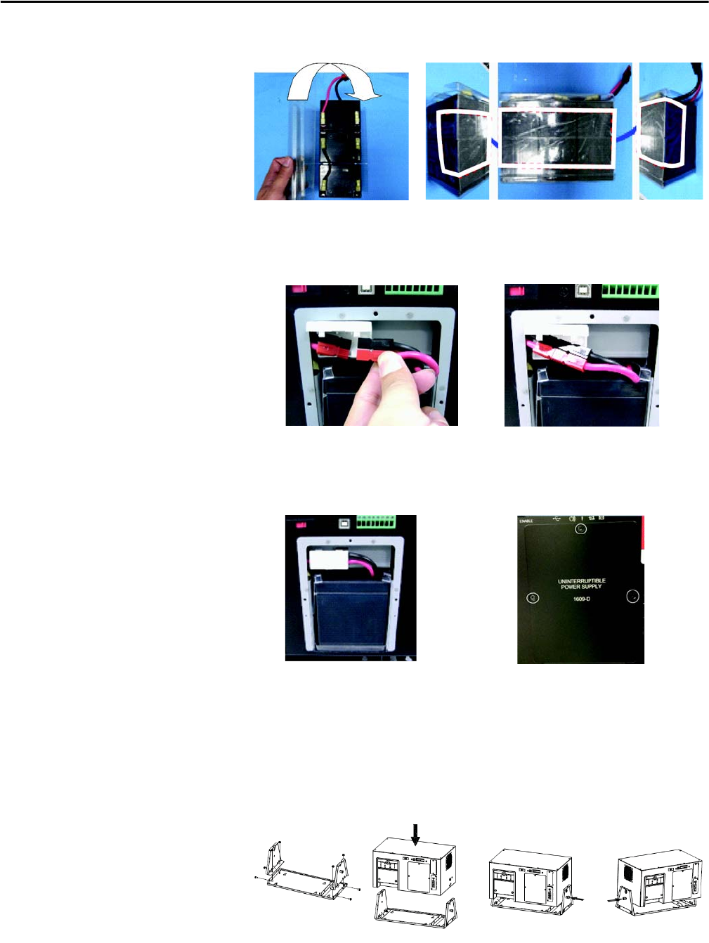
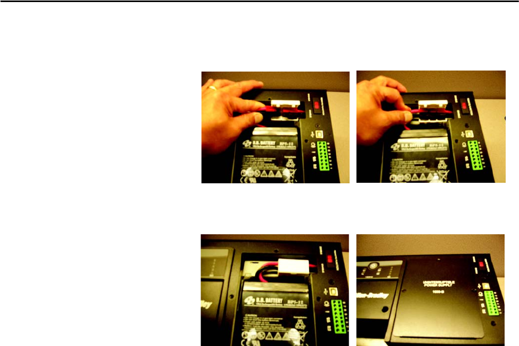
4. Fold the battery container and seal it with tape.
5. To connect the batteries to the UPS, insert the batteries into the battery
compartment, open the white connector retainer and connect the two
cables together as shown in the photo below.
6. To complete the battery installation, close the white connector
retainer and reattach the battery door with the three screws
(torque of 8.7+/-1.7 lb-in).
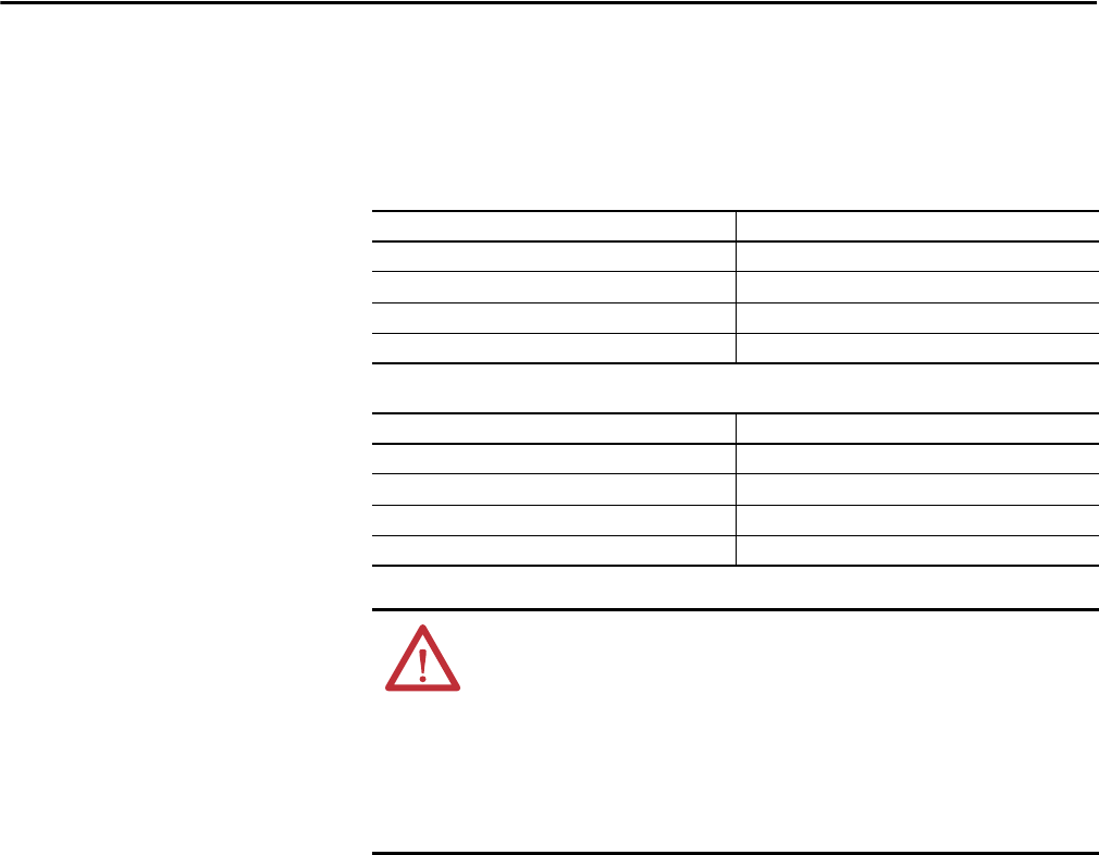
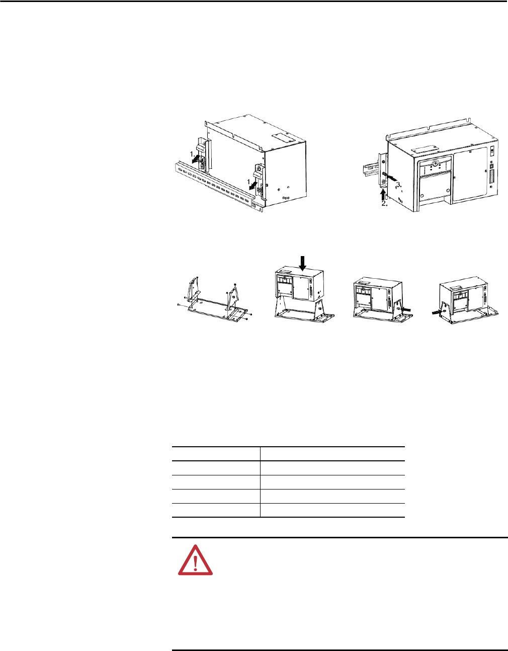
Mount the UPS The UPS-D is designed to mount on the back of the panel or to the floor of the
enclosure. The UPS mounts to a bracket assembly (1609-BRK) that allows it
to mount to either the panel or floor (see Figure 1 below).
Figure 1 - Mounting the UPS
Rockwell Automation Publication 1609-UM009C-EN-P - February 2015 9
Bulletin 1609 UPS
Hardwire UPS Wiring of the UPS should be performed by a qualified electrician using the
appropriate wire gauges.
Selection of Cables Table 1 - AC Main Input/Output Wiring for UPS:
Table 2 - DC Input / Output Wiring for External Battery Cabinet:
Item Specification
Wire Size 14 AWG
Minimum temperature 75 °C
Wire conductor material Copper only
Tightening torque for terminals 4.4 lb-in.
Item Specification
Wire Size 10 AWG
Minimum temperature 75 °C
Wire conductor material Copper only
Tightening torque for terminals 12 lb-in.
WARNING: To reduce the risk of fire, connect only to a circuit with 20 amperes
maximum branch circuit overcurrent protection in accordance with the National
Electric Code, ANSI/NFPA 70.
A disconnect switch shall be provided by others for AC output circuit.
To reduce the risk of fire, connect only to a circuit with branch circuit overcurrent
protection for 20 amperes rating in accordance with the National Electric Code,
ANSI/NFPA 70.
10 Rockwell Automation Publication 1609-UM009C-EN-P - February 2015
Bulletin 1609 UPS
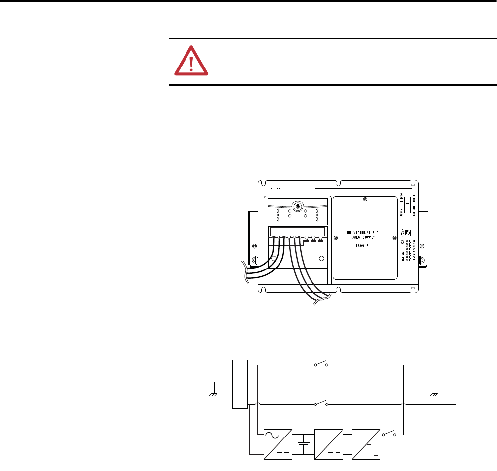
Connect Power and
Equipment to the UPS
1. Connect the appropriate input power to the UPS's input (Line, Neutral
and Ground) terminals (see Figure 2).
2. Connect the specified equipment to the UPS's output (Line, Neutral and
Ground) terminals (see Figure 2).
Figure 2 - System Wiring
3. Connect any additional optional accessories (1609-ENET card).
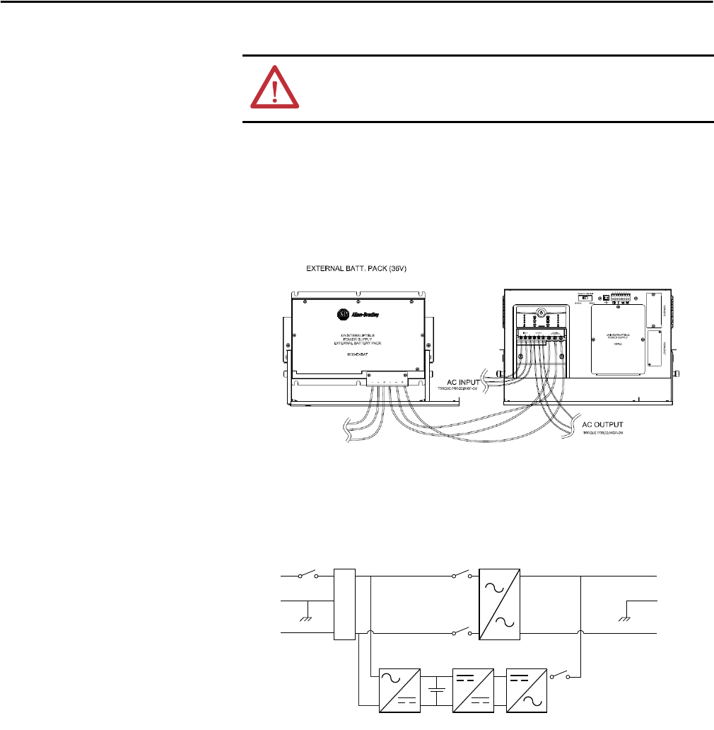
1609-D Block Figure
WARNING: This UPS features Surge Protection Device (SPD) is located
on the left front of the unit. Disconnect all power sources before servicing
due to Electric Shock Hazard for risk of severe injury or death.
L
E
N
L
E
AC
Input
AC
Output
Backfeed
Relay
Inverter
Relay
+
-
AVR
AC to AC
AC to DC DC to DC DC to AC
Backfeed
Relay
Input
Filter
Breaker
N
Rockwell Automation Publication 1609-UM009C-EN-P - February 2015 11
Bulletin 1609 UPS
1609-B Installation Instructions
Battery Wiring
and Installation
Note: Batteries are not included with the 1609-B UPS
1. To access the battery compartment remove the three screws and the
battery door.
2. Remove the battery container, jumpers, and wire harness from the battery
compartment. Place the battery container and batteries onto a flat surface.
Use the provided jumper wires to connect the batteries in series. Connect
the positive terminal (red) of the battery to the negative terminal (black)
of another battery. Connect the red wire of the harness to the positive
terminal (top red) and the black wire of the harness to the negative
terminal (bottom black). See photo below for details.
3. Fold the battery container and seal it with tape.
ATTENTION: Disconnect the 1609-SPD before servicing, due to electric shock
hazard for risk of severe injury or death.
12 Rockwell Automation Publication 1609-UM009C-EN-P - February 2015
Bulletin 1609 UPS
Battery Wiring
and Installation (cont.)
4. To connect the batteries to the UPS, insert the batteries into the battery
compartment, open the white connector retainer and connect the two
cables together as shown in the photo below.
5. To complete the battery installation, close the white connector retainer
and reattach the battery door with the three screws (torque of 8.7+/-1.7 lb-in).
Rockwell Automation Publication 1609-UM009C-EN-P - February 2015 13
Bulletin 1609 UPS
Mount the UPS The 1609-B UPS products are designed to mount to a heavy duty DIN-rail
(see Figure 3 below). The 1609-B UPS products are also designed with an
optional bracket assembly (Cat 1609-BRK) that allows it to mount to either
the panel or floor (see Figure 4 below).
Figure 3 - Standard DIN-Rail Mount
Figure 4 - Optional Panel or Floor Mount
Hardwire UPS Wiring of the UPS should be performed by a qualified electrician using the
appropriate wire gauges.
Selection of Cables Table 3 - AC Main Input / Output Wiring for UPS
Item Specification
Wire Size 14 AWG
Minimum Temperature 75 °C
Wire Conductor Material Copper only
Tightening Torque for Terminals 4.4 lb - in.
WARNING: To reduce the risk of fire, connect only to a circuit with 20 amperes
maximum branch circuit overcurrent protection in accordance with the National
Electric Code, ANSI/NFPA 70.
A disconnect switch shall be provided by others for AC output circuit.
To reduce the risk of fire, connect only to a circuit with branch circuit overcurrent
protection for 20 amperes rating in accordance with the National Electric Code,
ANSI/NFPA 70.
14 Rockwell Automation Publication 1609-UM009C-EN-P - February 2015
Bulletin 1609 UPS
Connect Power and
Equipment to the UPS
1. Connect the appropriate input power to the UPS's input (Line, Neutral
and Ground) terminals (see Figure 5).
2. Connect the specified equipment to the UPS's output (Line, Neutral and
Ground) terminals (see Figure 5).
Figure 5 - System Wiring
1609-B Block Figure
WARNING: This UPS features Surge Protective Device (SPD) located on the top
of the unit. Please disconnect all power sources before servicing due to Electric
Shock Hazard for risk of severe injury or death.
INPUT
LLNNGG
OUTPUT
AC Output
AC Input
L
E
N
L
E
AC
Input
AC
Output
Backfeed
Relay
Inverter
Relay
+
-
AC to DC (Charger) DC to DC DC to AC (Step Wave)
Backfeed
Relay
Input
Filter
N
Rockwell Automation Publication 1609-UM009C-EN-P - February 2015 15
Bulletin 1609 UPS
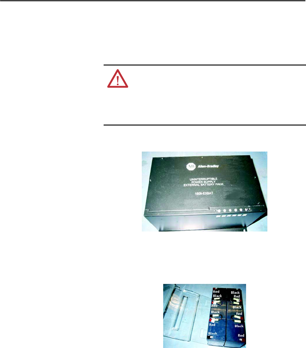
1609-EXBAT Installation Instructions
Battery Wiring
and Installation
Only use battery wires that have been provided with the 1609-EXBAT.
1. To access the battery compartment remove the six screws and the battery
door.
2. Remove the battery container, jumpers and wire harness from the battery
compartment. Place the battery container and batteries onto a flat surface.
Use the provided jumper wires to connect the batteries in series. Connect
the positive terminal (red) of the battery to the negative terminal (black)
of another battery. See photo below for details.
WARNING: A disconnect switch shall be provided by others for DC output
circuit. To reduce the risk of fire, connect only to a circuit with branch circuit
overcurrent protection for 35 amperes rating in accordance with the National
Electric Code, ANSI/NFPA 70.
Before connecting a battery pack to UPS, the emergent disconnecting device
shall be provided between the UPS and battery pack.
16 Rockwell Automation Publication 1609-UM009C-EN-P - February 2015
Bulletin 1609 UPS
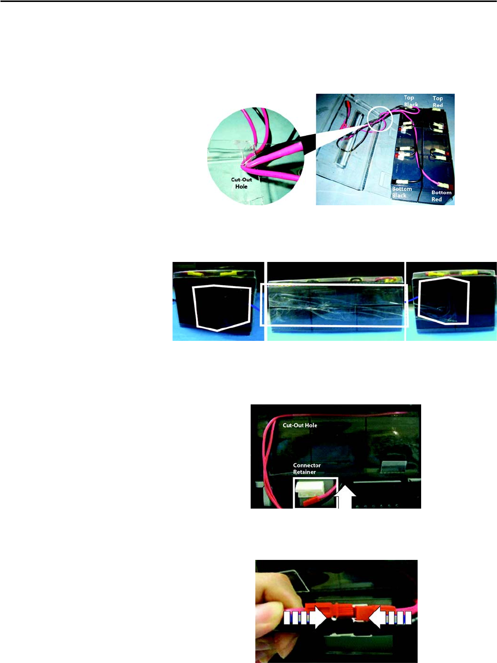
Battery Wiring
and Installation (cont.)
3. Connect the shorter set of red and black wires of the harness to the top
terminals (red - to - red and black - to - black). Connect the longer set
of red and black wires of the harness to the bottom terminals (red - to - red
and black - to - black) and route the wires through the cut-out hole. See
photo below for details.
4. Fold the battery container and seal it with tape.
5. Insert the batteries into the battery compartment in the orientation as
shown in the photo below.
6. Open the white connector retainer and connect the two cables together
as shown in the photo below.
Rockwell Automation Publication 1609-UM009C-EN-P - February 2015 17
Bulletin 1609 UPS
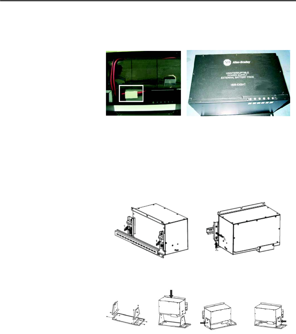
Battery Wiring
and Installation (cont.)
7. To complete the battery installation, insert the surplus wire harness into
the free space, close the white connector retainer and reattach the battery
door with the six screws (torque of 8.7+/-1.7 lb-in).
Mount the 1609-EXBAT The 1609-D UPS can be used with the External Battery Unit (1609-EXBAT).
The 1609-EXBAT unit is designed to mount to a heavy duty DIN-rail (see
Figure 6) or the optional mounting bracket assembly (1609-BRK) which
allows it to mount to either the panel or floor (see Figure 7).
Figure 6 - Heavy Duty DIN Rail Mount
Figure 7 - Panel or Floor Mount
18 Rockwell Automation Publication 1609-UM009C-EN-P - February 2015
Bulletin 1609 UPS
Selection of Cables Table 4 - DC Input/Output Wiring for External Battery Cabinet
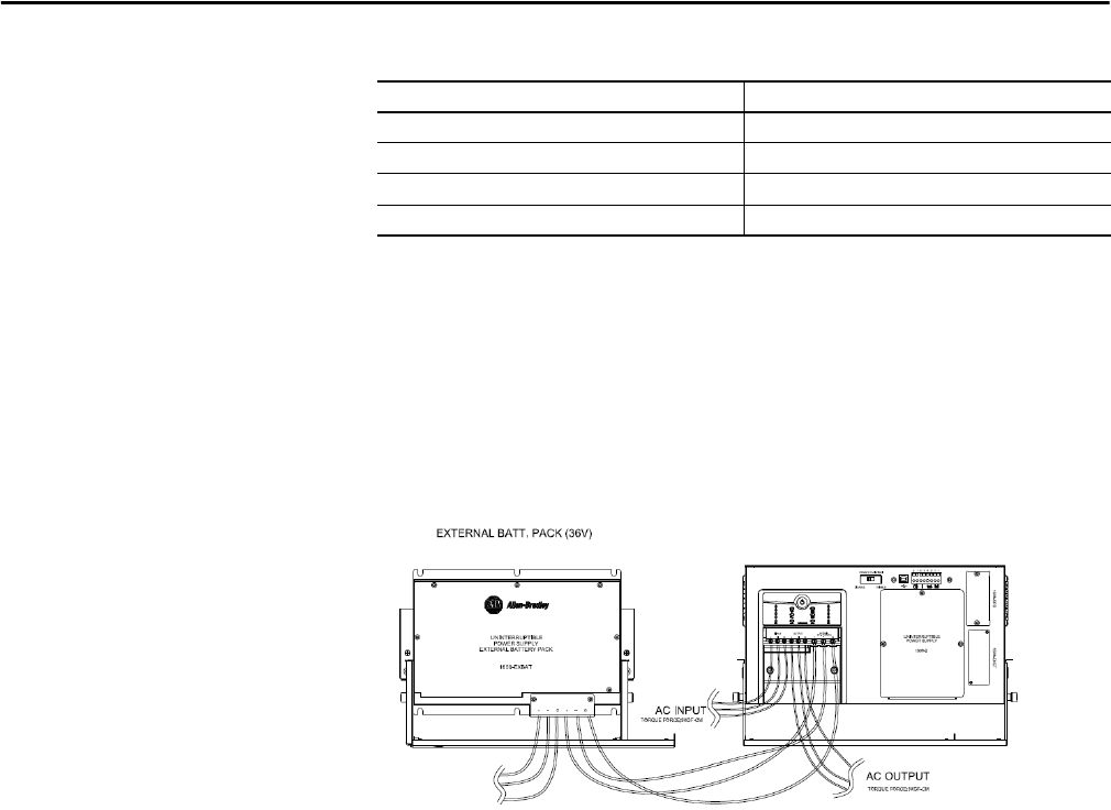
Connect 1609-EXBAT
to the UPS
To install the 1609-EXBAT unit with the 1609-D UPS, connect the three 10
AWG wires from the 1609-EXBAT terminals to the 1609-D UPS terminals
marked as ‘EXTERNAL BATT PACK (36V)’. (See Figure 8)
Dispose of used batteries according to the battery instructions.
Figure 8 - System Wiring
Item Specification
Wire Size 10 AWG
Minimum temperature 75 °C
Wire conductor material Copper only
Tightening torque for terminals 12 lb-in.
Rockwell Automation Publication 1609-UM009C-EN-P - February 2015 19
Bulletin 1609 UPS
General Information 1609-D
and 1609-B UPS Units
Recommended Battery
for Use with the UPS
and 1609-EXBAT
Rockwell Automation battery catalog numbers 1609-SBAT and 1609-HBAT
consist of the battery manufacturers listed below:
Not for use in a computer room as defined in the Standard for the Protection
of Electronic Computer/Data Processing Equipment, ANSI/NFPA 75.
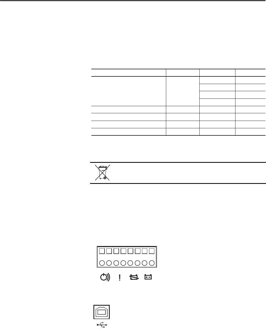
Dry I/O Contacts There is one Remote Enable/Disable Switch connection and 3 Dry I/O Contacts
available on the front of the UPS. Do not apply external power to the Remote
Enable/Disable Switch; however, the 3 sets of Dry Contacts require external
power supplies (Contacts Rating is 1A/24V DC). Each of the dry contacts is
used to provide a remote status indication of the UPS, as follows:
•1 and 2 On Battery Contact (NO)
•3 and 4 Low Battery Contact (NO)
•5 and 6 Fault (Indicates UPS has faulted see trouble shooting section)
•7 and 8 Remote On/O (Shorted (closed) for ON, Open for OFF)
USB Communication Port The UPS supports a USB communication port for the end user
to connect with a computer. The user may monitor all the UPS
status through the USB port if the 1609 UPS Management
Software is installed in the computer. The software is stored
in the CD and can be found in the accessory bag.
Manufacturer MH Number Type Rating
B & B Battery (USA) MH19884 HRLS 5.5-12 12V DC, 2.75 Ah
BP 5-12 12V DC, 5.0 Ah
HR 5.5-12 12V DC, 2.75 Ah
SHR7-12 12V DC, 3.375 Ah
GS Yuasa International Ltd. MH12970 NPH5-12 12V DC, 5.0 Ah
Shenzhen Center Power Tech Co., Ltd. MH25860 CP1250 12V DC, 5.0 Ah
Shenzhen Ritar Power Co., Ltd. MH28539 RT1250 12V DC, 5.0 Ah
CSB Battery Co., Ltd. MH14533 HR1221W 12V DC, 5.25 Ah
Dispose of used batteries according to the battery instructions.
87654321
20 Rockwell Automation Publication 1609-UM009C-EN-P - February 2015
Bulletin 1609 UPS
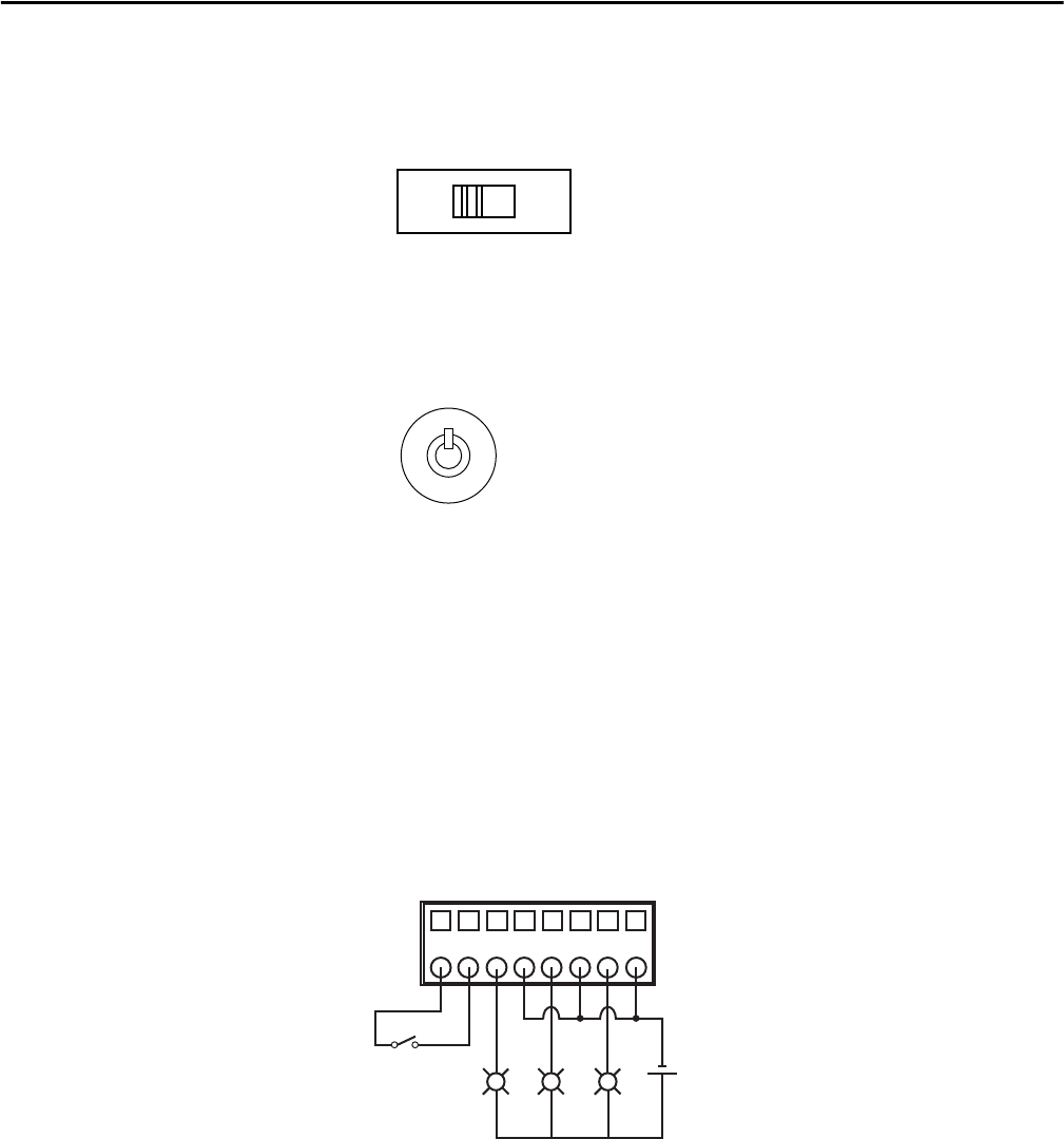
Manual or Remote
Enable/Disable
of UPS Output Selection
The 1609 UPS output is designed to be manually or remotely enabled or
disabled. User is required to enable or disable the remote function switch
on the front panel.
•Selected 'DISABLE' for Manual Enable/Disable the UPS's Output.
•Selected 'ENABLE' for Remote Enable/Disable the UPS's Output.
Manual Enable/Disable/
Self-test
The Power Button on the front of the UPS is used to
manually enable or disable the output of the 1609-D UPS.
To enable the 1609-D UPS, press and hold the power
button until one beep is heard.
To disable the 1609-D UPS, press and hold the power button until three beeps
are heard, then release immediately (takes approximately 3 seconds).
To perform a self-test, press and hold the power button until two beeps are heard,
then release immediately. (The UPS must operate for at least 4 hours before
executing this function)
Remote Enable/Disable An external switch connected to the Dry I/O terminals 7 and 8 is required
to remotely Enable or Disable the UPS output.
To enable the UPS, close the switch
that is connected to the Dry I/O
terminals 7 and 8.
To Disable the UPS, open the
switch that is connected to the
Dry I/O terminals 7 and 8.
REMOTE FUNCTION
ENABLEDISABLE
87654321
R
R
R
SW 24 Vdc
Rockwell Automation Publication 1609-UM009C-EN-P - February 2015 21
Bulletin 1609 UPS
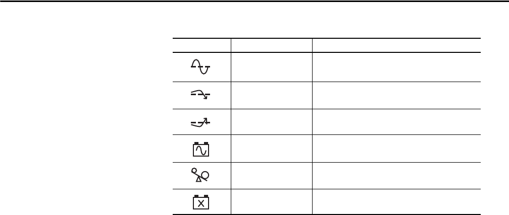
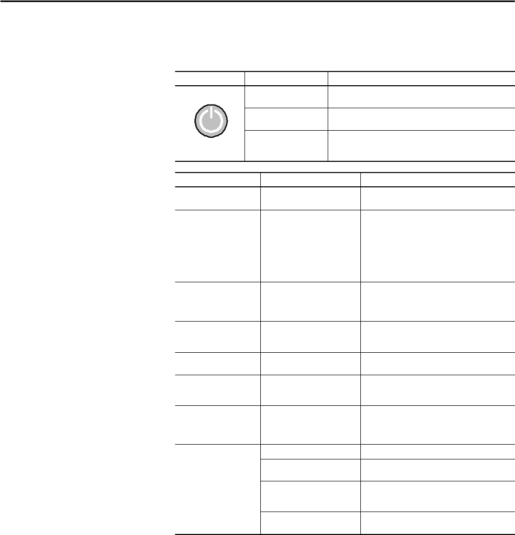
Display LED Indicators
Indicator LED Indicator Title Description
Online The UPS is supplying utility power to the connected equipment
(see Troubleshooting).
AVR Trim ➊ The UPS is compensating for a high utility voltage
(see Troubleshooting).
AVR Boost ➊The UPS is compensating for a low utility voltage
(see Troubleshooting).
On Battery The UPS is supplying battery power to the connected equipment.
Overload The connected equipment is drawing more than the UPS power
rating allows (see Troubleshooting).
Replace Battery/Disconnect The battery is disconnected or must be replaced
(see Troubleshooting).
➊ Applies to 1609-D only
22 Rockwell Automation Publication 1609-UM009C-EN-P - February 2015
Bulletin 1609 UPS
Troubleshooting
Button Function Explanation
UPS Output Enable Press and hold the button until one beep is heard, then release
immediately
UPS Output Disable Press and hold the button until three beeps are heard, then release
immediately
Self-Test Press and hold the button until two beeps are heard, then release
immediately (The UPS must operate for at least 4 hours before executing
this function)
Problem Possible Cause Solution
No LED illuminates /
No alarm
UPS output is disabled or input utility
power is not present
Have qualified electrician trouble shoot the input utility
power system and make the necessary corrections.
No UPS output The UPS has not been enabled Manually Enable - Make sure the Remote Function
selector switch is in the Disable position, then press and
hold the UPS Power button until one beep is heard and
release immediately.
Remotely Enable - Make sure the Remote Function
selector switch is in the Enable position and verify that
there is an adequate connection to the remote on/off dry
I/O connection (terminals 7 & 8)
UPS Operates on battery
although input utility
voltage exists
The system may experience high, low
or distorted input utility voltage
Reduce the UPS sensitivity by using the 1609 UPS
Management software.
If the problem persists, move or connect the UPS with a
known good quality utility power source.
Input line utility power
circuit breaker trip
The system may have experienced an
overload
Verify that the circuit breaker is sized properly.
Verify the load connected to the output of the UPS. Ensure
that the load does not exceed the output rating of the UPS.
FAULT LED illuminates An internal fault has been detected Refer to the UPS LED Fault Indicators below to identify the
specific fault that occurred and possible resolution.
ONLINE LED illuminates, but
no UPS output is available
The UPS output connection may not
be connected properly
Disable the UPS output and have qualified electrician
troubleshoot the output connection system and make the
necessary corrections.
The battery did not provide
expected runtime
The batteries might be weak or the
lifespan is due
Charge the batteries for 8 hours and retest the runtime.
If the runtime is still less than expected after charging,
replace the batteries even if the Replace Battery LED doesn’t
illuminate.
No communication
between the
UPS and your PC
Wrong cable Verify cable used.
The connection cable is not firmly
connected
Reconnect the communication cable firmly.
PC Communication Port may have
been used by another process or is
defective
Check if there is other software or service accessing the
Communication Port on your PC, or connect it to a different
communication port.
There is interference on the
connection cable
Lay the cable differently or away from other cables and
reconnect the cable.
Rockwell Automation Publication 1609-UM009C-EN-P - February 2015 23
Bulletin 1609 UPS
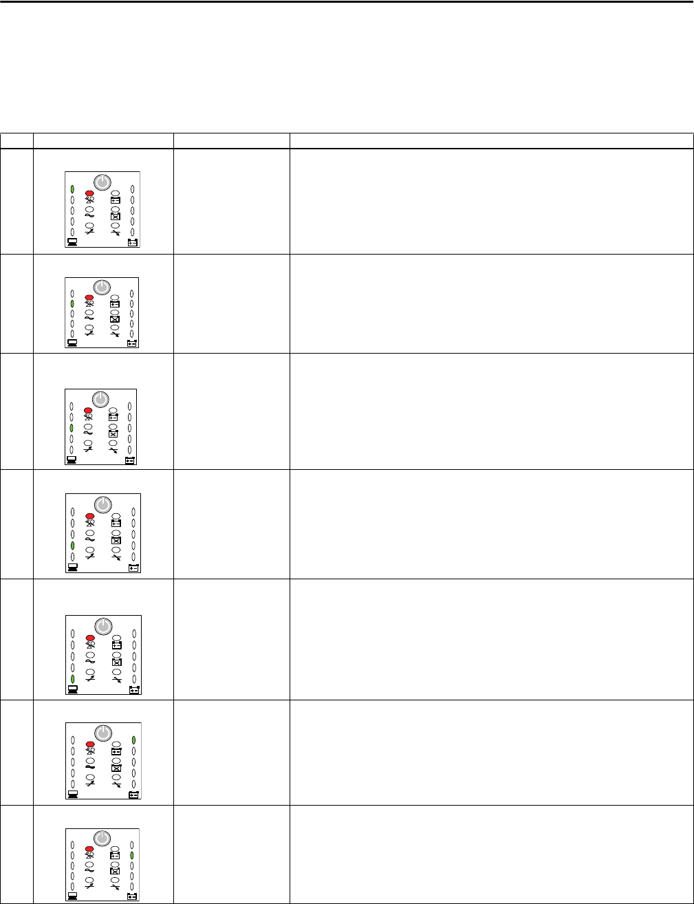
UPS LED Fault Indicators General Clear Fault Procedure
Press and hold the button until three beeps are heard then release immediately
to turn the UPS off then press and hold the button again until one beep is
heard then release to enable the output.
No. Fault Description Solution
1 Output Short Circuit The UPS has detected a
short circuit on the Output
of the UPS and disabled its
output.
Have a qualified electrician troubleshoot the load connected to the output to the UPS and remove the
short circuit if present.
2 Output Overload The UPS has detected an
overload and disabled its
output.
To clear fault, follow the General Clear Fault Procedure described above. If the problem persists, contact
Technical Support.
Verify the load connected to the output of the UPS. Ensure that the load does not exceed the output
rating of the UPS. If the load exceeds the rating of the UPS please remove excess load or select the
appropriate size UPS. If the problem persists, contact Technical Support.
To clear fault, follow the General Clear Fault Procedure described above.
3 Over Temperature from the
Heatsink
The UPS has detected an
over temperature of the
heatsink and disabled its
output.
Have a qualified electrician checked the ambient temperature to make sure that it does not exceed 40 °C
(1609-SBAT) or 50 °C (1609-HBAT). If it is over temperature, make the necessary correction to the
system. This issue may be corrected by improving the room ambient temperature (add ventilation or
provide air conditioning).
To clear fault, follow the General Clear Fault Procedure described above.
4 Over Ambient Temperature The UPS has detected an
over ambient temperature
and disabled its output.
Have a qualified electrician checked the ambient temperature to make sure that it does not exceed 40 °C
(1609SBAT) or 50 °C (1609-HBAT). If it is over temperature, make the necessary correction to the
system. This issue may be corrected by improving the room ambient temperature (add ventilation or
provide air conditioning).
To clear fault, follow the General Clear Fault Procedure described above.
5 Over Voltage from The DC/DC
Converter of Inverter
The UPS has detected an
over voltage of the DC/DC
Converter and disabled its
output.
Have a qualified electrician verify that the quality of utility voltage is within specification.
To clear the fault, follow the General Clear Fault Procedure described above.
If the fault is still present after attempting to clear fault, contact Technical Support.
6 Over Voltage from The Inverter The UPS has detected high
voltage on the inverter
and disabled its output.
Have a qualified electrician verify that the quality of utility voltage is within specification.
To clear fault, follow the General Clear Fault Procedure described above.
If the fault is still present after attempting to clear fault, contact Technical Support.
7 Under Voltage from The Inverter The UPS has detected low
voltage on the inverter
and disabled its output.
Have a qualified electrician verify that the quality of utility voltage is within specification.
To clear fault, follow the General Clear Fault Procedure described above.
If the fault is still present after attempting to clear fault, contact Technical Support.
GRN
RED
GRN
RED
GRN
RED
GRN
RED
GRN
RED
GRN
RED
GRN
RED
24 Rockwell Automation Publication 1609-UM009C-EN-P - February 2015
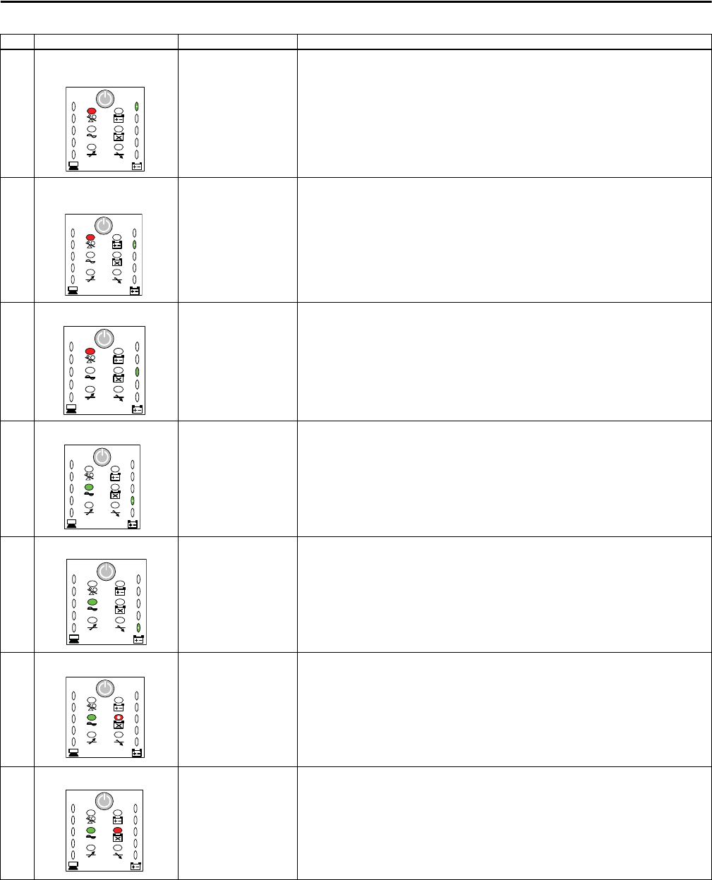
Bulletin 1609 UPS
8 Over Voltage from The Output
of AVR
The UPS has detected an
over voltage on the output
of AVR and disabled its
output.
Have qualified electrician verify that the quality of the output voltage and the input utility voltage are
within its specification.
To clear fault, follow the General Clear Fault Procedure described above and if the problem persists,
contact Technical Support.
9 Under Voltage from The Output
of AVR
The UPS has detected low
voltage on the output of
AVR and disabled its
output.
Have qualified electrician verify that the quality of the output voltage and the input utility voltage are
within its specification.
To clear fault, follow the General Clear Fault Procedure described above and if the problem persists,
contact Technical Support.
10 Fan Failure The UPS has detected that
the fan of the UPS has
failed and disabled its
output.
To clear fault, follow the General Clear Fault Procedure described above and if the Fan Failure persists,
contact Technical Support.
11 Charger Failure The UPS has detected that
the battery charger circuit
has failed; however, the
UPS will continue running.
Clear this fault by removing the input utility voltage and batteries then plug the batteries back in place
and turn the input utility voltage back on. Enable the UPS output to verify the fault.
If the Charger Failure persists, contact Technical Support.
12 TMOV Failure The UPS has detected that
the MOV circuit has failed;
however, the UPS will
continue enabling the
output.
Schedule to have a qualified electrician replace the MOV board (1609-SPD).
Remove the input utility power before service on this 1609-SPD due to risk of electrical shock.
13 Missing Battery The UPS has detected that
the batteries are missing;
however, the UPS will
continue enabling the
output.
Have a qualified electrician verify the battery connection for good contact and charge the batteries for
24 hours.
To clear fault, follow the General Clear Fault Procedure described above. If the battery status still
indicates Missing Battery, new batteries are required.
14 Replace Batteries The UPS has detected that
the batteries are bad;
however, the UPS will
continue running.
Have a qualified electrician verify the battery connection for good contact and charge the batteries for
24 hours.
To clear fault, follow the General Clear Fault Procedure described above. If the battery status still
indicates Replace Battery, new batteries are required.
No. Fault Description Solution
BLINK
GRN
RED
BLINK
GRN
RED
GRN
RED
BLINK
GRN
GRN
BLINK
GRN
GRN
BLINK
RED
GRN
GRN RED

Rockwell Automation Publication 1609-UM009C-EN-P - February 2015 25
Bulletin 1609 UPS
Bulletin 1609 UPS
Management Software
Troubleshooting
General Clear Fault Procedure
Press and hold the button until three beeps are heard then release immediately
to turn the UPS off then press and hold the button again until one beep is heard
then release to enable the output.
Status Indications Indication Description Solution
Buzzer Alarm The UPS has detected a fault and generate a buzzer
alarm.
Verify the type of fault from the Status Indicators or the LEDs on the UPS for further
troubleshooting.
Test In Progress The UPS is currently in a test mode. Do not interrupt the UPS testing. The UPS is doing battery test.
UPS Fault The UPS has detected a fault and disabled its output. Verify the type of fault from the Status Indicators or the LEDs on the UPS for further
troubleshooting.
To clear fault, follow the General Clear Fault Procedure described above and if the fault persists,
contact Technical Support.
Battery Low The UPS has detected that the batteries are low. The batteries must be charged for 24 hours and re-verify the battery status. If the batteries still
indicate to be low, replace the batteries.
Power Failed The UPS has detected that the input utility voltage
has failed.
Verify that the input utility voltage is within the UPS’s input specification.
If it is not, make the necessary correction to the input utility power system.
Overheat The ambient temperature is greater than 60 °C, or
some internal components are over temperature.
Have a qualified electrician checked the ambient temperature to make sure that it does not exceed
40 °C(1609-SBAT) or 50 °C (1609-HBAT). If the temperature exceeds the UPS rating, make the
necessary correction to the system. This issue may be corrected by improving the room ambient
temperature (add ventilation or provide air conditioning).
To clear fault, follow the General Clear Fault Procedure described above and if the fault persists,
contact Technical Support.
Overload The UPS has detected that output load of UPS is
greater than 110%.
Verify that the load does not exceed the load specification. If it is, remove the excess load from the
UPS’s output and clear its fault. If the problem persists, have a qualified electrician troubleshoot
the UPS Load System and make the necessary corrections or select the appropriate size of UPS. If
the problem persists, contact Technical Support.
Load Warning The output load over the warning threshold. Verify the output load. If it is close to 100% load, remove the excess load or select the appropriate
size of UPS.
Load Severity The output load over the severity threshold. Verify the output load. If it is actually at 100% load, remove some of the non-essential load or
select the appropriate size of UPS.
UPS Disconnect The UPS has detected a communication loss between
the UPS and the computer.
Please check the USB cable between computer and UPS for secure connection or replace the cable
with a known good cable.
If communication is established, re-open the UPS Management software. If the problem persists,
contact Technical Support.
Output Abnormal To indicate the output voltage is abnormal. Have qualified electrician verify that the quality of the output voltage and the input utility voltage
are within its specification.
To clear fault, follow the General Clear Fault Procedure described above and if the problem
persists, contact Technical Support.
Output Off The UPS is operating in standby mode, or UPS is
faulted.
If it is identified as the UPS fault shutdown then turn the UPS off, and then turn UPS on again to
reset the fault. If the fault persists, contact Technical Support.
UPS System Off The UPS system is in the standby state. If it is identified as the UPS fault shutdown then turn the UPS off. Turn UPS on again to reset the
fault. If the fault persists, contact Technical Support.
Awaiting Power The battery is depleted and the UPS awaits the return
of input utility voltage.
Apply the input utility voltage to the UPS.
Battery Need Replace The UPS has detected that the battery is bad or
opened.
Have a qualified electrician verify the battery connection for good contact and charge the
batteries for 24 hours.
To clear fault, follow the General Clear Fault Procedure described above. If the battery status still
indicates Battery Need Replace, new batteries are required.
Battery Depleted The UPS has detected that the batteries are depleted. Have a qualified electrician verify the battery connection for good contact and charge the
batteries for 24 hours.
To clear fault, follow the General Clear Fault Procedure described above. If the battery status still
indicates Battery Depleted, new batteries are required.

26 Rockwell Automation Publication 1609-UM009C-EN-P - February 2015
Bulletin 1609 UPS
Bulletin 1609
Network Management Card
Troubleshooting
General Clear Fault Procedure
Press and hold the button until three beeps are heard then release immediately
to turn the UPS off then press and hold the button again until one beep is
heard then release to enable the output.
Status Indications Indication Description Solution
UPS Disconnect The communication between UPS and
the 1609-ENET card has been
disconnected.
Check the 1609-ENET LEDs for the communication status and the operation of UPS.
If the UPS is operating normal but the LEDs of the 1609-ENET card are not working properly, make sure the
cable is securely connected from the 1609-ENET card to the computer.
If the LEDs of the 1609-ENET card is still not working properly, apply a known good 1609-ENET card to verify
whether the failure is on the UPS or the 1609-ENET.
Buzzer Alarm The UPS has detected a fault and
generated a buzzer alarm.
Please verify the type of fault from the Status Indicators or the LEDs on the UPS for further troubleshooting.
Input Out Of Range The UPS has detected that the input
utility voltage is out of range.
Verify that the input utility voltage is within the UPS’s input specification.
If it is not, makes the necessary correction to the input utility power system.
Battery Low The UPS has detected that the
batteries are low.
The batteries must be charged for 24 hours. After charging batteries verify the battery status. If the batteries
still indicate that they are low, replace the batteries.
Battery Depleted The UPS has detected that the
batteries are depleted.
Have a qualified electrician verify the battery connection for good contact and charge the batteries for 24
hours.
To clear fault, follow the General Clear Fault Procedure described above. If the battery status still indicates
Battery Depleted, new batteries are required.
Battery Need Replace The UPS has detected that the battery
is bad or opened.
Have a qualified electrician verify the battery connection for good contact and charge the batteries for 24
hours.
To clear fault, follow the General Clear Fault Procedure described above. If the battery status still indicates
Battery Need Replace, new batteries are required.
Test In Progress The UPS is currently in a test mode. Do not interrupt the UPS testing.
Test Fail The UPS has detected that the battery
is bad.
Verify that the battery is not disconnected or replace the batteries with a brand new set of batteries. Ensure
the UPS ran for at least 4 hours before test.
Output Off The UPS is operating in standby mode
or fault shutdown.
If it is identified as the UPS fault shutdown then turn the UPS off, and then turn UPS on again to reset the fault
If the fault persists, contact Technical Support.
UPS System Off The UPS system is in the standby state. If it is identified as the UPS fault shutdown then turn the UPS off, and then turn UPS on again to reset the
fault. If the fault persists, contact Technical Support.
UPS Shutdown The UPS was commanded to shut
down or fault shutdown.
If it is identified as the UPS fault shutdown then turn the UPS off, and then turn UPS on again to reset the
fault. If the fault persists, contact Technical Support.
Output Over Voltage The UPS has detected that the output
voltage is above the UPS’s output
specification.
Have qualified electrician verify that the quality of the output voltage and the input utility voltage are within
its specification.
To clear fault, follow the General Clear Fault Procedure described above and if the problem persists, contact
Technical Support.
Output Under Voltage The UPS has detected that the output
voltage is below the UPS’s output
specification.
Have qualified electrician verify that the quality of the output voltage and the input utility voltage are within
its specification.
To clear fault, follow the General Clear Fault Procedure described above and if the problem persists, contact
Technical Support.
Overload The UPS has detected that the UPS’s
output load is greater than 110%.
Verify that the load does not exceed the load specification.
If it is, remove the excess load from the UPS’s output and clear the fault. If the problem persists, have a
qualified electrician troubleshoot the UPS Load System and make the necessary corrections or select the
appropriate size of UPS. If the problem persists, contact Technical Support.
Over Temperature The UPS has detected that the
ambient temperature is greater than
60 °C, or some of the internal
components are over temperature.
Have a qualified electrician check the ambient temperature to make sure that it does not exceed 40°C (1609-
SBAT) or 50°C (1609-HBAT). If it is over, make the necessary correction to the system. This issue may be
corrected by improving the room ambient temperature (add ventilation or provide air conditioning).
Following the General Clear Fault Procedure to clear this fault.
Fan Abnormal The UPS has detected that the UPS’s
fan has failed.
To clear fault, follow the General Clear Fault Procedure described above and if the Fan Failure persists, contact
Technical Support.
Inverter Abnormal The UPS has detected that the UPS
inverter circuit has failed.
Have a qualified electrician verify that the quality of utility voltage is within specification.
To clear fault, follow the General Clear Fault Procedure described above and if the Inverter Failure persists,
contact Technical Support.
Charger Abnormal The UPS has detected that the UPS
battery charger circuit has failed.
Clear this fault by removing the input utility voltage and batteries. Plug the batteries back in place and turn
the input utility voltage back on. Enable the UPS output to verify the fault.
If the Charger Failure persists, contact Technical Support.

Rockwell Automation Publication 1609-UM009C-EN-P - February 2015 27
Bulletin 1609 UPS
Technical Specifications —1609-D, 120V 1609-D600N 1609-D1000N 1609-D1500N
Input V nom. 120V
Capacity 600 VA (390 W) 1000 VA (650 W) 1500 VA (980 W)
Voltage Range, default 90...145V
Voltage Range, widest online 90...145V
Current nom. 5.5 A 8.8 A 13 A
Capacity Frequency 50/60 Hz ± 3 Hz
PFC None
Output V nom. 120V
Capacity 600 VA (390 W) 1000 VA (650 W) 1500 VA (980 W)
Online Output Voltage Range, default 108...132V
Output Voltage Range, widest online 108...132V
Transfer Point Accuracy ± 3 %
On Battery V nom 120V (sine wave)
Frequency 50/60 Hz ± 0.5Hz
THD ≤ 10% Full Linear Load
Short Circuit Protection Crest Factor 2.2:1
Efficiency On Battery (Typical with resistive load) 75%
Online - Typical with resistive load excluding AVR mode) 86% 94% 95%
Protection Surge 380 Joules
Overload (Shutdown after 10 s) > 110...130%
Overload (Shutdown immediately) > 130%
Output Short Online/Battery Premises branch circuit over-current protection/Shutdown
Thermal Protection UPS inside temperature ≥ 60 ºC
Regulatory Safety UL1778, CSA C22.2 No. 107.3, EN/IEC62040-1
EMC FCC & CE (EN 62040-2)
Markings UL, cULus, FCC, CE, C-Tick
Battery Pack Run Time ≥5 min (at 25 °C, full R load) ≥3.5 min (25 °C, full R load) ≥2.5 min (at 25 °C, full R load)
Type Sealed Lead Acid Battery 12V/5Ah (for 0...40 °C B.B. BP5-12) 12V/5.5Ah (for 0...50 °CB.B. HRL5.5-12)
Voltage 36V
Charger Current limited, constant voltage float charger
Recharger Time Less than 8 hr to 90% capacity after discharge with full load
Lifetime 2...3 years at 25 °C ambient temperature
Environment Temperature Operating Standard Battery 0...+40 °C (+32...+104 °F) Hi-Temperature Battery 0...+50 °C (+32...+122 °F)
Non-operating/Storage -15...+45 °C (+5...+113 °F)
Altitude Operating 0...6600 feet (0... 2000 meters)
Humidity Operating/Storage 5...95% RH (Non-condensing)
Heat Output On Line, Full load: 217 BTU/hr
On Line, Full load, Charging:
296 BTU per hour
On Battery: Full Load: 1331 BTU
per hour
On Line, Full load: 142BTU/hr
On Line, Full load, Charging:
221 BTU per hour
On Battery: Full Load: 2218BTU
per hour
On Line, Full load: 176BTU/hr
On Line, Full load, Charging:
256BTU per hour
On Battery: Full Load: 3344BTU
per hour
Audible Noise < 50 dBA @ Front Side 1 Meter
Mechanical Approximate Dimensions L*W*H In. (mm)
8.66 x 16.14 x 10.24 (220 x 410 x 260)
Approximate Weight lbs (kg) 29.7 (13.5) 30.1 (13.7) 31 (14.1)

28 Rockwell Automation Publication 1609-UM009C-EN-P - February 2015
Bulletin 1609 UPS
Technical Specifications —1609-D, 230V 1609-D600E 1609-D1000E 1609-D1500E
Input V nom. 230V
Capacity 600 VA (390W) 1000 VA (650W) 1500 VA (980 W)
Voltage Range, default 180...280V
Voltage Range, widest online 180...280V
Current nom. 3.3 A 4.7 A 7.1 A
Capacity Frequency 50/60 Hz ±3Hz
PFC None (load power factor is reflected in the input line current)
Output V nom. 230V
Capacity 600 VA (390 W) 1000 VA (650 W) 1500 VA (980 W)
Online Output Voltage Range, default 207...253V
Output Voltage Range, widest online 207...253V
Transfer Point Accuracy ±3%
On Battery V nom 230V (Sine Wave)
Frequency 50/60 Hz ±0.5 Hz (Factory default: 50 Hz ± 0.5 Hz)
THD ≤ 10% (Full Linear Load)
Short Circuit Protection Crest Factor 2.2:1
Efficiency On Battery (Typical with resistive load) 75%(Typical with resistive load)
Online - Typical with resistive load excluding AVR mode) 86% 94% 95%
Protection Surge 660 Joules (Total performance rated with 10 x 1000 μs Pulse)
Overload (Shutdown after 10 s) > 110...130%
Overload (Shutdown immediately) > 130%
Output Short Online/Battery Premises branch circuit over-current protection/Shutdown
Thermal Protection UPS inside temperature ≥ 60 ºC
Regulatory Safety UL1778, CSA C22.2 No. 107.3-5, EN/IEC62040-1
EMC FCC & CE (Class A)
Markings UL, cULus, FCC, CE
Battery Pack Run Time ≥5 min (at 25 °C, full R load) ≥3.5 min (25 °C, full R load) ≥2.5 min (at 25 °C, full R load)
Type Sealed Lead Acid Battery 12V/5Ah (for 0...40 °C B.B. BP5-12) 12V/5.5Ah (for 0...50 °CB.B. HRL5.5-12)
Voltage 36V
Charger Current limited, constant voltage float charger
Recharger Time Less than 8 hr to 90% capacity after discharge with full load
Lifetime 2...3 years at 25 °C ambient temperature
Environment Temperature Operating Standard Battery 0...+40 °C (+32...+104 °F) Hi-Temperature Battery 0...+50 °C (+32...+122 °F)
Non-operating/Storage -15...+45 °C (+5...+113 °F)
Altitude Operating 0...6600 feet (0... 2000 meters)
Humidity Operating/Storage 5...95% RH (Non-condensing)
Heat Output On Line, Full load: 217 BTU/hr
On Line, Full load, Charging:
296 BTU per hour
On Battery: Full Load: 1331 BTU
per hour
On Line, Full load: 142BTU/hr
On Line, Full load, Charging:
221 BTU per hour
On Battery: Full Load: 2218BTU
per hour
On Line, Full load: 176BTU/hr
On Line, Full load, Charging:
256BTU per hour
On Battery: Full Load: 3344BTU
per hour
Audible Noise < 50 dBA @ Front Side 1 Meter
Mechanical Approximate Dimensions L*W*H In. (mm) 16.15 x 8.67 x 10.24 (410 x 220 x 260 )
Approximate Weight lbs (kg) 29.7 (13.5) 30.1 (13.7 ) 31 lb (14.1)

Rockwell Automation Publication 1609-UM009C-EN-P - February 2015 29
Bulletin 1609 UPS
Technical Specifications —1609-B, 120V 1609-B600N 1609-B1000N
Input V nom. 120V 120V
Capacity 600 VA (360 W) 1000 VA (600 W)
Voltage Range, default 96...138V
Voltage Range, widest online 96...138V
Current nom. 5.4 A 8.9 A
Capacity Frequency 50/60 Hz ± 3 Hz 50/60 Hz ± 3 Hz
PFC None None
Output V nom. 120V
Capacity 600 VA (360 W) 1000 VA (600 W)
Online Output Voltage Range, default 96...138V
Output Voltage Range, widest online 96...138V
Transfer Point Accuracy ± 3%
On Battery V nom 120V (step wave)
Frequency 50/60 Hz ± 1 Hz
THD 47.5% (step wave) 47.6% (step wave)
Short Circuit Protection Crest Factor 2.5:1
Efficiency On Battery (Typical with resistive load) 80% Typical with resistive load
Online - Typical with resistive load excluding AVR mode) 94% Typical with resistive load
Protection Surge 380 Joules (Total performance rated with 10*1000 μ s pulse)
Overload (Shutdown after 10 s) > 110...130% - shutdown after 5 sec
Overload (Shutdown immediately) 130% shutdown immediately
Output Short: Online Premises branch circuit over-current protection
Output Short: Battery Shutdown
Thermal Protection UPS inside temperature ≥ 70 °C
Regulatory Safety UL1778, CSA C22.2 No. 107.3-05, EN/IEC62040-1
EMC FCC & CE (Class A)
Markings UL, cULus, FCC, CE, C-Tick
Battery Pack Run Time ≥5 min (at 25 °C, full load = 360W, PF = 0.6...0.75) ≥2 min (at 25 °C, full load = 600W, PF = 0.6...0.75)
Type Sealed Lead Acid Battery
12V/5Ah (for 0...40 °C: B.B. BP5...12)
12V/5.5 Ah (for 0...50 °C: B.B. HRL5.5...12)
Voltage 24V
Charger Current limited, constant voltage float charger
Recharger Time Less than 12 hrs to 90% capacity after discharge with full load
Lifetime 2...3 years at 25 °C ambient temperature
Environment Temperature Operating Standard Battery 0...+40 °C (+32...+104 °F) Hi-Temperature Battery 0...+50 °C (+32...+122 °F)
Non-operating/Storage -15...+45 °C (+5...+113 °F)
Altitude Operating 0...6600 feet (0... 2000 meters)
Humidity Operating/Storage 5...95% RH (Non-condensing)
Heat Output On Line, Full load: 107 BTU/hr
On Line, Full load, Charging: 160 BTU per hour
On Battery: Full Load: 1228 BTU per hour
On Line, Full load: 178 BTU/hr
On Line, Full load, Charging: 231 BTU per hour
On Battery: Full Load: 2047 BTU per hour
Audible Noise < 45 dBA @ Front Side 1 Meter
Mechanical Approximate Dimensions L*W*H In. (mm) 6.1 x 11 x 7.09 (155 x 300 x 180)
Approximate Weight lbs (kg) 14.5 (6.6) 14.7 (6.7)

30 Rockwell Automation Publication 1609-UM009C-EN-P - February 2015
Bulletin 1609 UPS
Technical Specifications —1609-B, 230V 1609-B600E 1609-B1000E
Input V nom. 230V 230V
Capacity 600 VA (360 W) 1000 VA (600 W)
Voltage Range, default 184...265V
Voltage Range, widest online 184...265V
Current nom. 2.8 A 4.7 A
Capacity Frequency 50/60 Hz ± 3 Hz
PFC None (Load power factor is reflected in the input line current)
Output V nom. 230V
Capacity 600 VA (360 W) 1000 VA (600 W)
Online Output Voltage Range, default 184...265V
Output Voltage Range, widest online 184...265V
Transfer Point Accuracy ± 3% V AC
On Battery V nom 230V (step wave)
Frequency 50/60 Hz ± 1 Hz
THD N/A N/A
Short Circuit Protection Crest Factor 2.5:1
Efficiency On Battery (Typical with resistive load) 70% Typical with resistive load
Online - Typical with resistive load excluding AVR mode) 93% Typical with resistive load
Protection Surge 440 Joules (Total performance rated with 10*1000 μ s pulse)
Overload (Shutdown after 5s) > 110...130%
Overload (Shutdown immediately) > 130%
Output Short: Online Premises branch circuit over-current protection
Output Short: Battery Shutdown
Thermal Protection UPS inside temperature ≥ 70 °C
Regulatory Safety UL1778, CSA C22.2 No. 107.3-05, EN/IEC62040-1
EMC FCC & CE (Class A)
Markings UL, cULus, FCC, CE
Battery Pack Run Time ≥5 min (at 25 °C, full load = 360W, PF = 0.6...0.75) ≥2 min (at 25 °C, full load = 600W, PF = 0.6...0.75)
Type Sealed Lead Acid Battery
12V/5Ah (for 0...40 °C: B.B. BP5...12)
12V/5.5 Ah (for 0...50 °C: B.B. HRL5.5...12)
Voltage 24V
Charger Current limited, constant voltage float charger
Recharger Time Less than 12 hrs to 90% capacity after discharge with full load
Lifetime 2...3 years at 25 °C ambient temperature
Environment Temperature Operating Standard Battery 0...+40 °C (+32...+104 °F) Hi-Temperature Battery 0...+50 °C (+32...+122 °F)
Non-operating/Storage -15...+45 °C (+5...+113 °F)
Altitude Operating 0...6600 feet (0... 2000 meters)
Humidity Operating/Storage 5...95% RH (Non-condensing)
Heat Output On Line, Full load: 107 BTU/hr
On Line, Full load, Charging: 160 BTU per hour
On Battery: Full Load: 1228 BTU per hour
On Line, Full load: 178 BTU/hr
On Line, Full load, Charging: 231 BTU per hour
On Battery: Full Load: 2047 BTU per hour
Audible Noise < 45 dBA @ Front Side 1 Meter
Mechanical Approximate Dimensions LxWxH In. (mm) 13.4 x 7.29 x 8.27 (340 x 185 x 210)
Approximate Weight lbs (kg) 14.5 (6.6) 14.7 (6.7)
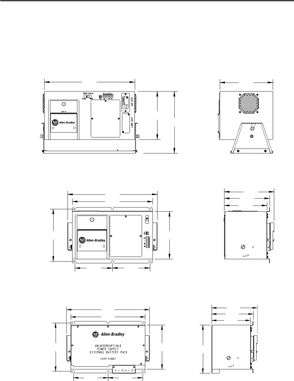
Rockwell Automation Publication 1609-UM009C-EN-P - February 2015 31
Appendix A
1609 UPS Dimensions
1609-D UPS Dimensions
1609-B UPS Dimensions
1609-EXBAT Unit Dimensions
375
200
220
257
UNINTERRUPTIBLE
POWER SUPPLY
1609-D
300
339
178
160
170
196
140 140
187
UNINTERRUPTIBLE
POWER SUPPLY
1609-B
REMOTE FUNCTION 8 7 6 5 4 3 2 1
DISAB LE ENABLE
300
339
178
140140
196
160
170
187
197
32 Rockwell Automation Publication 1609-UM009C-EN-P - February 2015
Appendix A 1609 UPS Dimensions
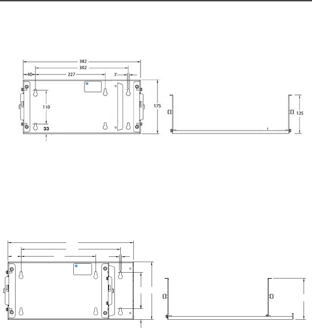
1609-BRK Dimensions
(1609-D orientation)
1609-BRK Dimensions
(1609-B orientation)
40 227
302
33
110
7
382
175
125
Rockwell Automation Publication 1609-UM009C-EN-P - February 2015 33
1609 UPS Dimensions Appendix A
Service Instructions If the UPS requires service, do not return it to the distributor. Follow these steps:
1. Servicing of batteries should be performed or supervised by personnel
knowledgeable of batteries and the required precautions. Keep
unauthorized personnel away from batteries.
2. When replacing batteries, replace with the same number of the 1609
battery packs supplied by Rockwell Automation.
3. Review the problems discussed in the Troubleshooting section of this
manual to eliminate common problems.
4. If the problem persists, contact Rockwell Automation Customer Support
at 440-646-5800.
5. Pack the UPS in its original packaging.
–Pack the UPS properly to avoid damage in transit. Never use Styrofoam
beads for packaging.
–Damage sustained in transit is not covered under warranty.
The following precautions should be observed when working on batteries:
•Remove watches, rings, or other metal objects.
•Use tools with insulated handles.
•Do not lay tools or metal parts on top of batteries.
•Determine if battery is inadvertently grounded. If inadvertently grounded, remove
source from ground. Contact with any part of a grounded battery can result in
electrical shock. The likelihood of such shock can be reduced if such grounds are
removed during installation and maintenance.
WARNING: Do not dispose of battery in a fire. The battery may explode. Do not
open or mutilate the battery or batteries. Released electrolytes are harmful to
the skin and eyes. It may be toxic. A battery can present a risk of electrical shock
and high short circuit current.
ATTENTION: Always disconnect the battery(s) before shipping, in compliance
with U.S. Department of Transportation (DOT) and IATA regulations. The
battery(s) may remain in the UPS.
Publication 1609-UM009C-EN-P - February 2015
Copyright © 2015 Rockwell Automation, Inc. All rights reserved. Printed in the U.S.A.
Rockwell Automation Support
Rockwell Automation provides technical information on the Web to assist you in using its products.
At http://www.rockwellautomation.com/support, you can find technical manuals, technical and application notes, sample
code and links to software service packs, and a MySupport feature that you can customize to make the best use of these
tools. You can also visit our Knowledgebase at http://www.rockwellautomation.com/knowledgebase for FAQs, technical
information, support chat and forums, software updates, and to sign up for product notification updates.
For an additional level of technical phone support for installation, configuration, and troubleshooting, we offer
Te c h C o nn e c t SM support programs. For more information, contact your local distributor or Rockwell Automation
representative, or visit http://www.rockwellautomation.com/support/.
Installation Assistance
If you experience a problem within the first 24 hours of installation, review the information that is contained in this
manual. You can contact Customer Support for initial help in getting your product up and running.
New Product Satisfaction Return
Rockwell Automation tests all of its products to ensure that they are fully operational when shipped from the
manufacturing facility. However, if your product is not functioning and needs to be returned, follow these procedures.
Documentation Feedback
Your comments will help us serve your documentation needs better. If you have any suggestions on how to improve this
document, complete this form, publication RA-DU002, available at http://www.rockwellautomation.com/literature/.
United States or Canada 1.440.646.3434
Outside United States or Canada Use the Worldwide Locator at http://www.rockwellautomation.com/support/americas/phone_en.html, or contact your local Rockwell
Automation representative.
United States Contact your distributor. You must provide a Customer Support case number (call the phone number above to obtain one) to your
distributor to complete the return process.
Outside United States Please contact your local Rockwell Automation representative for the return procedure.
