Catalog AC Motors DR.71 315, DT56, DR63, 19290411 BE11 G07
User Manual: BE11
Open the PDF directly: View PDF ![]() .
.
Page Count: 78

6
Drive selection
Electrical characteristics
Catalog – AC Motors DR.71 - 315, DT56, DR63 121
6Drive selection
6.1 Electrical characteristics
6.1.1 Suitability for operating with an inverter
DR.. series AC motors and AC brakemotors can be operated on inverters thanks to
the high quality windings and insulation material with which they are equipped as
standard. Please also refer to the "Drive selection – controlled motor (→ 2 179)".
6.1.2 Frequency
SEW‑EURODRIVE AC motors are designed for a line frequency of 50 Hz or 60 Hz on
request. The technical data in this motor catalog is based on a line frequency of 50 Hz
as standard.
A corresponding design is available for DRS.. and DRE.. motors that can be operated
on both a 50 Hz and 60 Hz grid: the global motor. This allows different regional electri-
cal regulations to be complied with in a single motor. In particular, it brings together
the different national regulations on minimum efficiency levels. See the "The global
motor" (→ 2 45) chapter.
6.1.3 Motor voltage
AC motors in the standard and energy efficient design are available for rated voltages
of 220 - 725 V.
2-, 4-, 6-pole DRS.., DRE.., DRP.. motors
The 2-, 4- or 6-pole motors with power ratings up to 5.5 kW are usually delivered in
the following voltage designs:
• for voltage range 220 – 242 V m / 380 – 420 V W , 50 Hz
or
• for nominal voltage 230 V m / 400 V W , 50 Hz.
These voltage ranges are available up to the following power ratings / motor sizes:
• 75 kW in energy efficiency classes IE1 and IE2 in size 280S
• 75 kW in energy efficiency class IE3 in size 280M
The 2-, 4- or 6-pole motors with power ratings up to 7.5 kW are usually delivered in
the following voltage designs:
• for voltage range 380 – 420 V m / 690 – 725 V W, 50 Hz
or
• for nominal voltage 400 V m / 690 V W , 50 Hz.
These voltage ranges are available up to the following power rating / motor size:
• 0.18 kW in size 71S
19290411/EN – 10/2014
6
6Drive selection
Electrical characteristics
Catalog – AC Motors DR.71 - 315, DT56, DR63
122
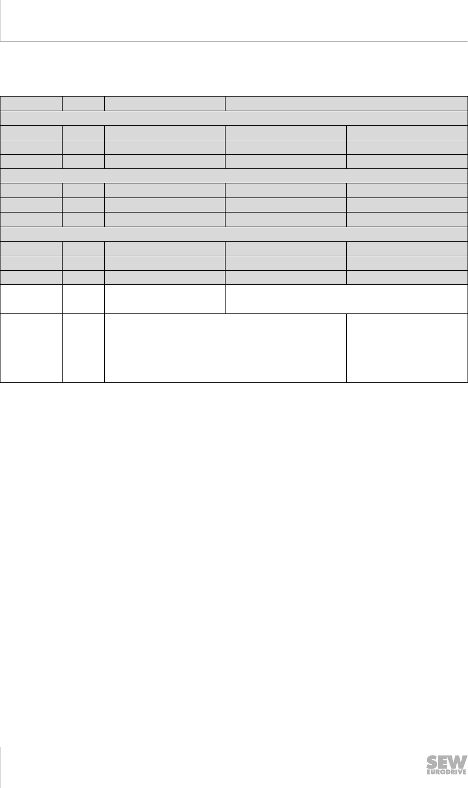
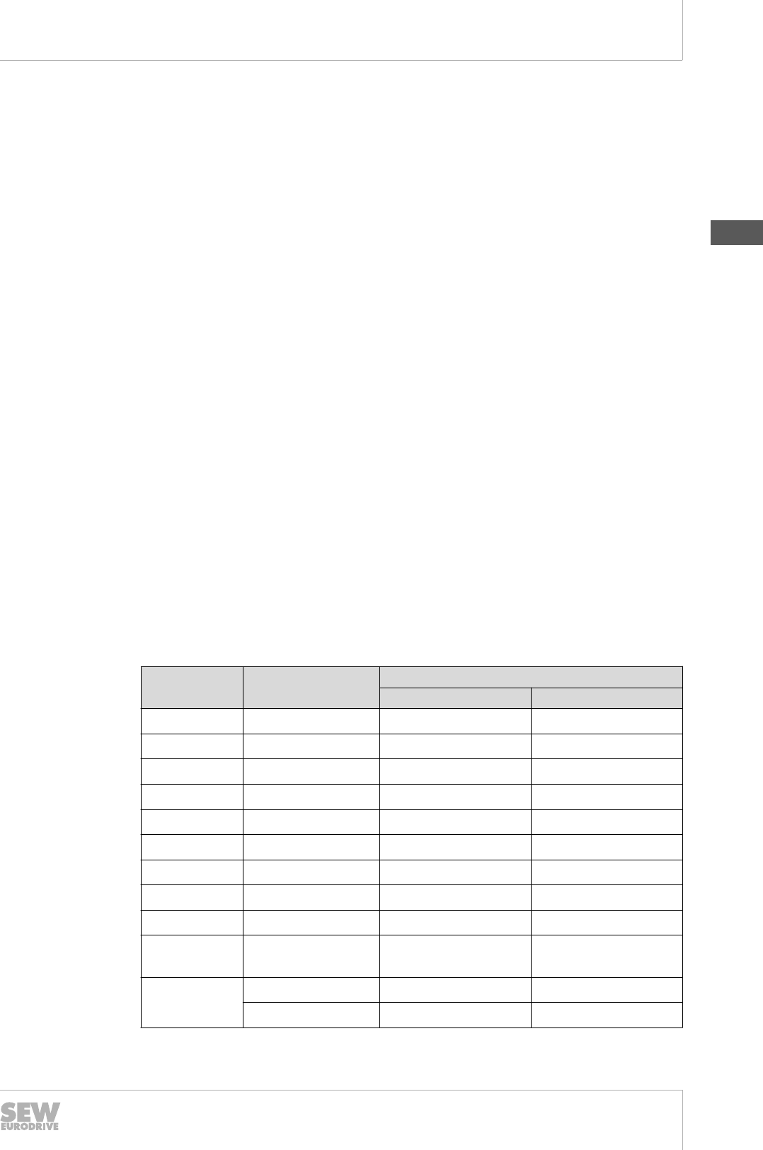
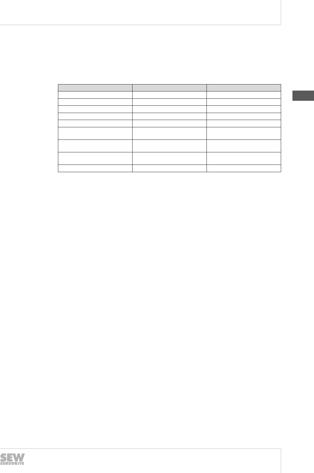
The other optional motor voltages available as standard are listed in the following ta-
ble.
Motors Motor sizes up to 5.5 kW Motor sizes from 7.5 kW
2-pole motors
Standard IE1 DRS71S2 – 132S2 DRS132M2 – 132MC2 -
High IE2 DRE80M2 – 132M2 DRE132MC2 -
Premium IE3 DRP80M2 – 132M2 - -
4-pole motors
Standard IE1 DRS71S4 – 132S4 DRS132M4 – 280S4 DRS280M4 – 315L4
High IE2 DRE80S4 – 132M4 DRE132MC4 – 280S4 DRE280M4 – 315L4
Premium IE3 DRP90M4 – 160S4 DRP160MC4 – 280M4 DRP315K4 – 315L4
6-pole motors
Standard IE1 DRS71S6 – 160S6 DRS160M6 -
High IE2 DRE71M6 – 160M6 - -
Premium IE3 DRP90L6 – 160M6 - -
Voltage
range m/W AC 220 – 242 / 380 –
420 V AC 380 – 420 / 690 – 725 V
Nominal
voltage
m/W
m/W
m/W
m/W
AC 230 / 400V
AC 290 / 500 V
AC 400 / 690 V
AC 500 / -
-
AC 290 / 500 V
AC 400 / 690 V
AC 500 / -
The table with the brake voltages is located in the "Brake voltage" (→ 2 126) chapter.
Motors and brakes for AC 230 / 400 V and motors for AC 690 V may also be operated
on supply systems with a rated voltage of AC 220 / 380 V or AC 660 V respectively.
The voltage-dependent data will change slightly.
The technical data for motor size DR.250 – DR.315 only refers to a rated voltage of
400 / 690 V. Please consult SEW‑EURODRIVE for other voltages.
4/2- and 8/4-pole DRS.. motors with Dahlander windings
Multi-speed AC motors with Dahlander windings are available for nominal voltages of
220 V – 720 V.
They are generally available in the following voltage types for a power rating of up to
5.5 kW in one of the two pole numbers:
• Nominal voltage 400 V m / WW, 50 Hz
Dahlander winding motors with a power rating over 5.5 kW in one of the two pole num-
bers are generally available with star topology capacity at low speed in the following
voltage types:
• Nominal voltage 400 V m- W/WW , 50 Hz
19290411/EN – 10/2014
6
Drive selection
Electrical characteristics
Catalog – AC Motors DR.71 - 315, DT56, DR63 123
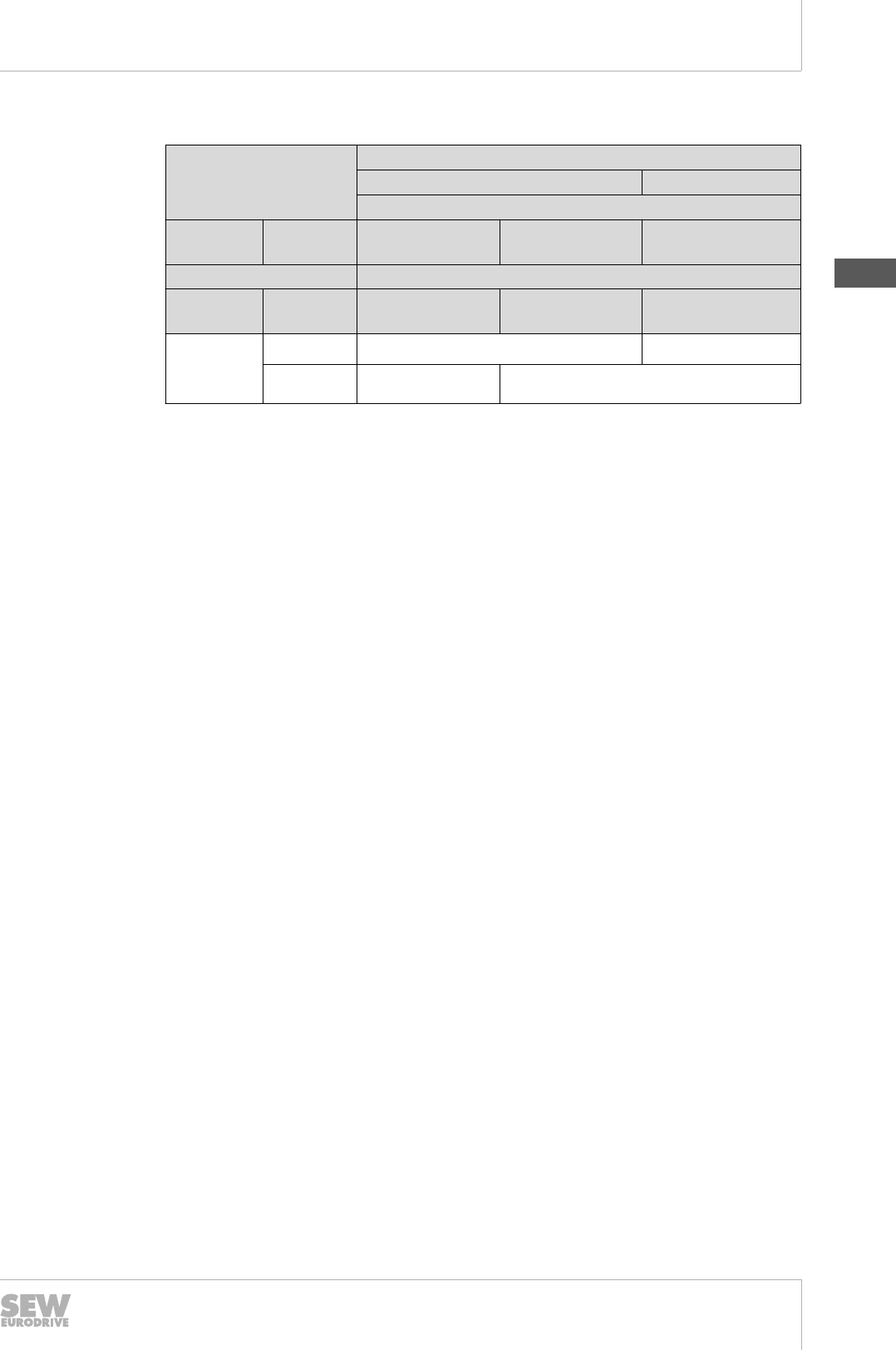
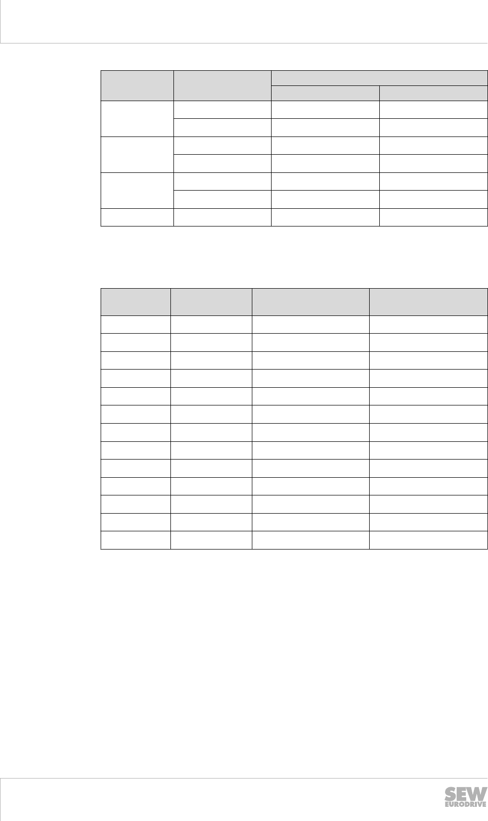
The other motor voltages available as standard are listed in the following table.
Motor sizes
up to 5.5 kW over 5.5 kW
4/2-pole motors
Standard DRS71S4/2 –
132M4/2
-DRS160S4/2 –
180L4/2
8/4-pole motors
Standard DRS71S8/4 –
100L8/4
DRS112M8/4 –
132M8/4
DRS160S8/4 –
225M8/4
Nominal
voltage
(AC)
m /WW 400 V
m- W/WW - 400 V
If not specified in the order, the motors are designed for a nominal voltage of 50 Hz in
the above-mentioned voltages.
8/2-pole DRS.. motors with separate windings
Multi-speed AC motors with separate windings are available for nominal voltages of
220 V – 690 V.
The following connection and voltage types are the only ones available for all motor
sizes:
• Nominal voltage 400 V W / W, 50 Hz
If not specified in the order, the motors are designed for a nominal voltage of 50 Hz in
the above-mentioned voltage.
12-pole DRM.. torque motors
DRM.. torque motors are only available in nominal voltage.
All sizes up to 346 V m / 600 V W, 50 Hz can be constructed in the S1 design, be-
sides the DRM71S12. The S1 limit voltage for the DRM71S12 is 277 V m / 480 V W in
the 50 Hz grid. The smallest design voltage amounts to 88 V m / 153 V W, 50 Hz for
all S1-DRM.. sizes.
All sizes up to 346 V m / 600 V W, 50 Hz can be constructed in the S3 / 15% design.
The smallest design voltage amounts to 153 V m / 266 V W, 50 Hz for all S3 / 15%
DRM.. sizes.
The standard voltage for the torque motors is 230 / 400 V, 50 Hz.
If not specified in the order, the S1 or S3 / 15% torque motors are designed for a nom-
inal voltage of 50 Hz in the above-mentioned voltage.
The torque motor values for operation on the 60 Hz grid are available separately.
Please contact SEW‑EURODRIVE in this case.
19290411/EN – 10/2014
6
6Drive selection
Electrical characteristics
Catalog – AC Motors DR.71 - 315, DT56, DR63
124
6.1.4 Voltage for the global motors
The global motors are available in three voltage blocks in the standard ≤ 0.55 kW de-
sign as motor type DRS.. and in the energy saving design ≥ 0.75 kW as motor type
DRE.., please refer to the "The global motor" (→ 2 45) chapter. The design as a volt-
age range cannot be changed and nominal voltage data cannot be provided.
The 2-, 4- and 6-pole DRS.. and DRE.. motors with power ratings of up to 5.5 kW are
available in the following variants as standard:
• voltage range 220 – 242 V m / 380 – 420 V W, 50 Hz
voltage range of 254 – 277 V m / 440 – 480 V W, 60 Hz
This voltage range version is available up to the following power rating / motor size:
• 45 kW in energy efficiency class IE2 size DRE225M4
The 2-, 4- and 6-pole DRE.. motors with power ratings of over 7.5 kW are available in
the following variants as standard:
• voltage range 380 – 420 V m / 690 – 725 V W, 50 Hz
voltage range of 440 – 480 V m, 60 Hz
This voltage range version is available up to the following power rating / motor size:
• 0.18 kW in size DRS71S
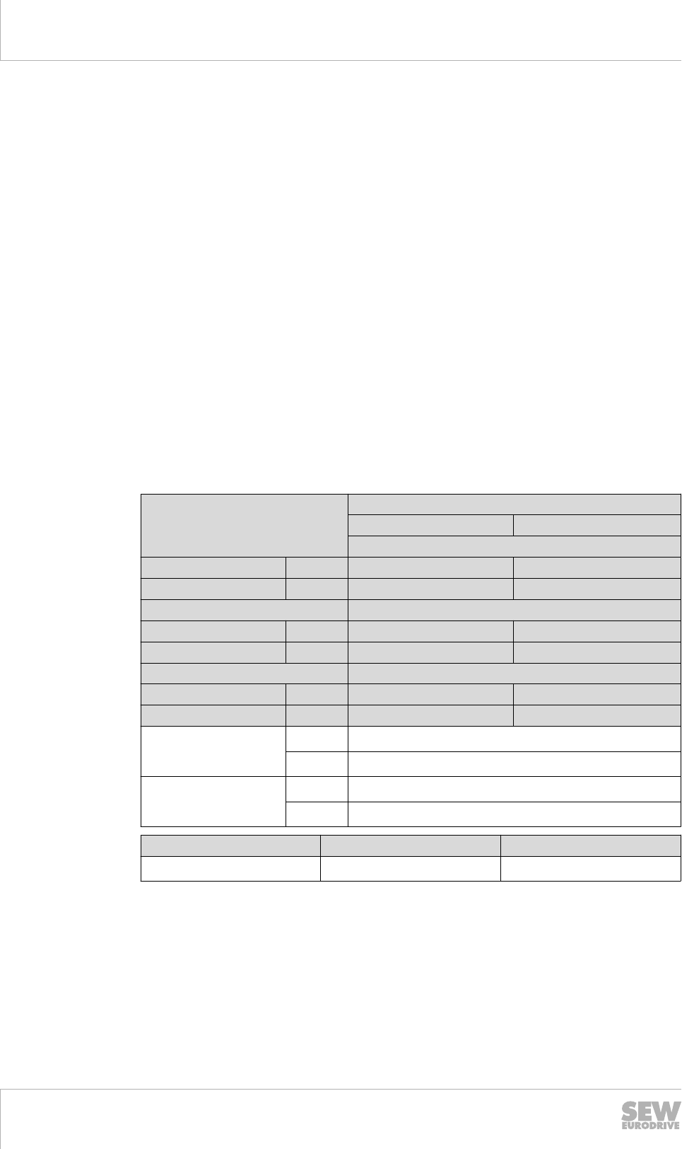
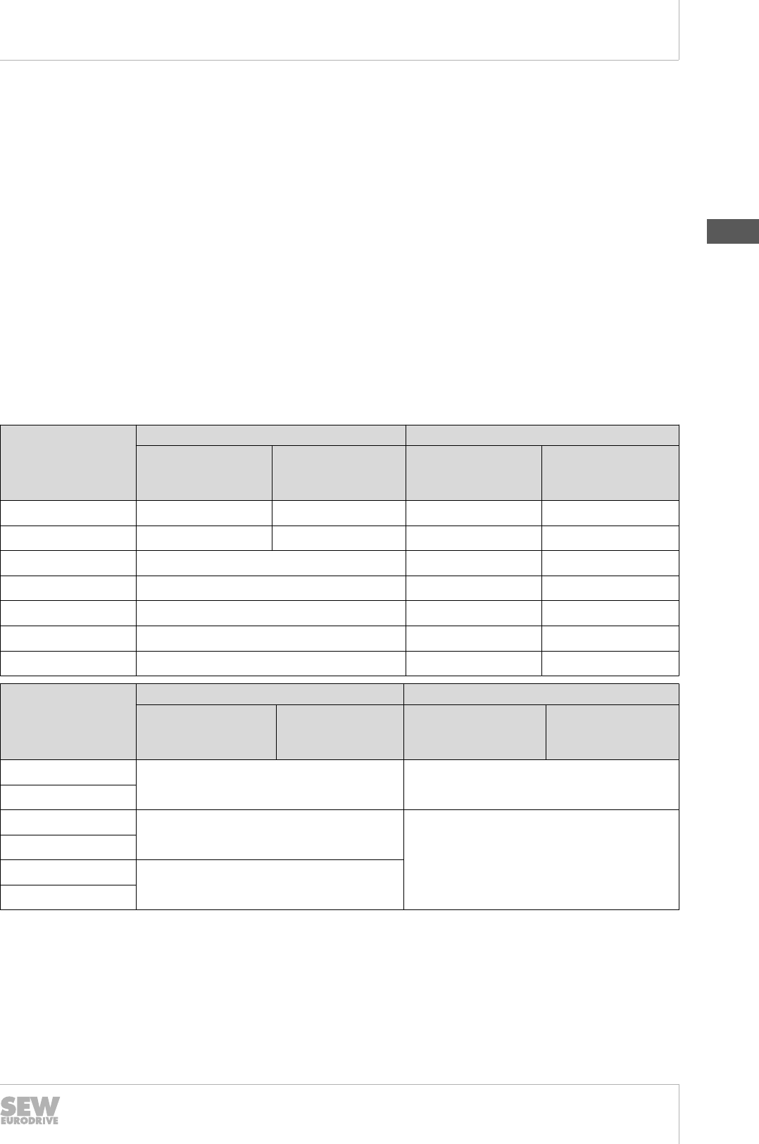
The other motor voltages available as standard are listed in the following table.
Energy efficiency class Motor sizes
up to 5.5 kW from 7.5 kW
2-pole motors
Standard IE1 DRS71S2 -
High Efficiency IE2 DRE80M2 – 132M2 DRE132MC2
4-pole motors
Standard IE1 DRS71S4 – 71M4 -
High Efficiency IE2 DRE80M4 – 132M4 DRE132MC4 – 250M4
6-pole motors
Standard IE1 DRS71S6 -
High Efficiency IE2 DRE71M6 – 160M6 -
Voltage range (AC) 50 Hz 220 – 242 V / 380 – 420 V
60 Hz 254 – 277 V / 440 – 480 V
Voltage range (AC) 50 Hz 380 – 420 V / 690 – 725 V
60 Hz 440 – 480 V / -
75 and 90 kW Voltage at 50 Hz Voltage at 60 Hz
DRE280S and 280M 380 – 420 V / 660 – 725 V 460 V
If not specified in the order, the global motors are delivered for the combined 50 Hz /
60 Hz voltage range in the standard designs mentioned above.
The DRE315 motor size is not available in the combined 50 Hz and 60 Hz global mo-
tor voltage range. The 50 Hz voltage range is possible, please refer to the "Motor volt-
age" (→ 2 121) chapter.
6.1.5 Forced cooling fan voltage
The forced cooling fan for the DR.. motor series can either be delivered in two three-
phase current-AC voltage ranges or in a DC voltage design.
19290411/EN – 10/2014
6
Drive selection
Electrical characteristics
Catalog – AC Motors DR.71 - 315, DT56, DR63 125
The three-phase current-AC voltage designs are also able to operate in the 50 Hz as
well as the 60 Hz grid and up to three versions can be operated by switching the con-
nection type.
The capacitor required for the AC voltage operation in a Steinmetz circuit is included
in the delivery by SEW-EURODRIVE and is located in the forced cooling fan's wiring
space.
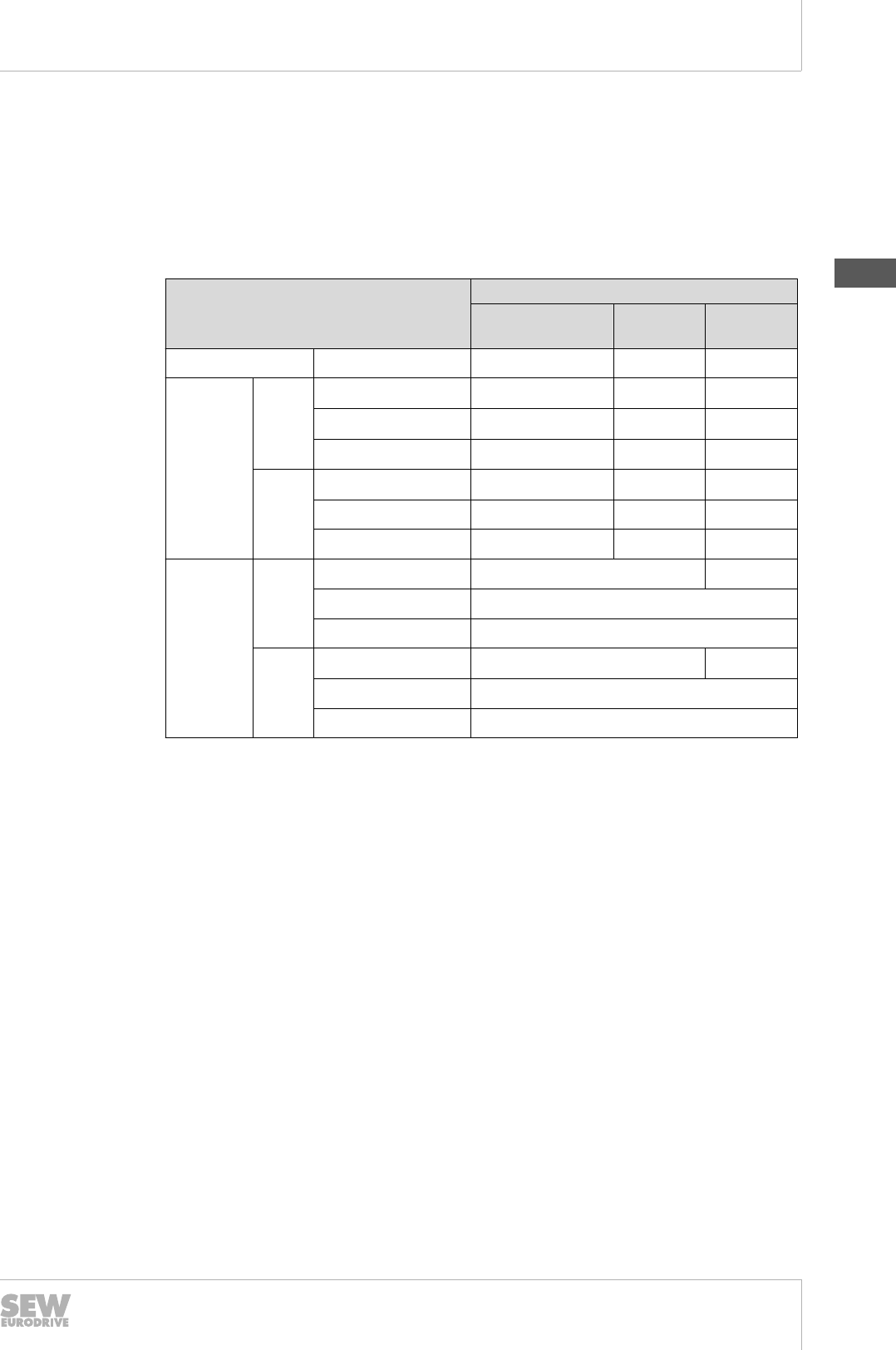
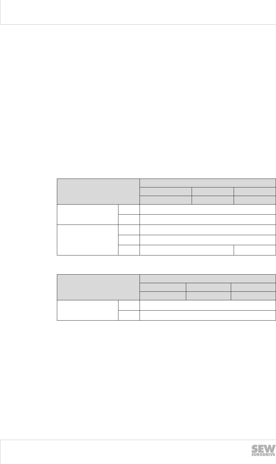
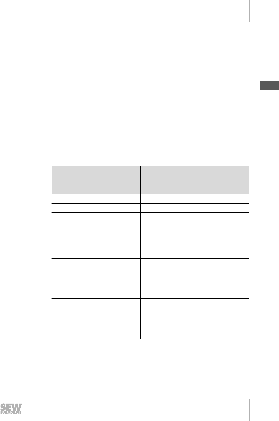
The following table shows the possible voltage designs.
Forced cooling fan Motor sizes
DR.71 – 132 DR.160 –
180
DR.200 –
315
DC 24 V + / - 1 × 24 V - -
AC 120 V
50 Hz m with capacitor 1 × 100 – 127 V - -
m 3 × 100 – 127 V - -
W 3 × 175 – 220 V - -
60 Hz m with capacitor 1 × 100 – 135 V - -
m3 × 100 – 135 V - -
W3 × 175 – 230 V - -
AC 230 V
50 Hz m with capacitor 1 × 230 – 277 V -
m3 × 200 – 290 V
W3 × 346 – 500 V
60 Hz m with capacitor 1 × 200 – 277 V -
m3 × 220 – 330 V
W3 × 380 – 575 V
19290411/EN – 10/2014
6
6Drive selection
Electrical characteristics
Catalog – AC Motors DR.71 - 315, DT56, DR63
126
6.1.6 Brake voltage
The BE brake is available in voltage designs of AC 120 V – 575 V and DC 24 V / AC
60 V.
The standard brake voltage design is
• nominal voltage AC 230 V: DR.71 BE05 – DR.132 BE11
and
• nominal voltage AC 400 V: DR.160 BE11 – DR.315 BE122
If not specified in the order, the brakes are delivered for the above mentioned voltages
as standard.
The following rules also apply:
• The brake voltage is also confirmed as a voltage range for motors that are de-
signed in the voltage range.
• The brake voltage is also indicated as a nominal voltage for motors with a con-
firmed nominal voltage.
The other optional motor voltages available as standard for the brake voltage of BE
brakes are listed in the following table.
Design Motor sizes and brake sizes
DR.71 – 132 DR.160 – 180 DR.180 – 315
BE05 – BE11 BE11 – BE20 BE30 – 122
Voltage range AC 220 – 242 V
AC 380 – 420 V
Nominal voltage
AC 230 V
AC 400 V
DC 24 V -
An extended voltage range applies for the supply voltage of brakes for the global mo-
tors:
Design Motor sizes and brake sizes
DR.71 – 132 DR.160 – 180 DR.180 – 225
BE05 – BE11 BE11 - BE20 BE30 – 32
Voltage range AC 220 – 277 V
AC 380 – 480 V
The permanent operation of the brake on the global motor with a connection voltage
above AC 254 V or AC 440 V is only permitted with the simultaneous operation of the
global motor, as otherwise the brake ventilation cannot be guaranteed.
19290411/EN – 10/2014
6
Drive selection
Electrical characteristics
Catalog – AC Motors DR.71 - 315, DT56, DR63 127
6.1.7 Standard 50 Hz connections
The standard motor connections are defined depending on the number of poles. The
following table provides an overview as well as the theoretical synchronous speed on
the 50 Hz grid based on the number of poles.
Number of poles Connection Synchronous speed nsyn on the 50
Hz grid
2-pole m / W 3000
4-pole m / W 1500
6-pole m / W 1000
12-pole
m / W 0 (500)
m 1) / W
4/2-pole
m / W W
1500 / 3000
W - m / W W
8/4-pole
m / W W
750 / 1500
W - m / W W
8/2-pole W / W 750 / 3000
1) Torque motors with tapped winding in the delta connection to limit the torque to a maximum of 3 times
the value of the star connection are available on request.
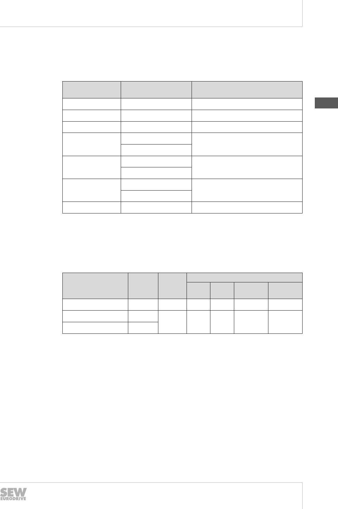
6.1.8 50 Hz motors on 60 Hz grids
The rated data of motors designed for 50 Hz grids differ as follows when the motors
are operated on 60 Hz supply systems:
Motor voltage
at 50 Hz
Connec-
tion
Voltage
at 60 Hz
Modified rated data
Speed Power torque
limit
Starting
torque
AC 230 m / 400 V Wm 230 +20 % 0 % -17 % -17 %
AC 230 m/ 400 V W W 460 +20 % +20 % 0 % 0 %
AC 400 m/ 690 V Wm
If you want to operate motors designed for 50 Hz supply systems on a 60 Hz grid,
please consult SEW‑EURODRIVE. Some countries and regions provide regulations
for the efficiency of motors for 50 Hz grids, even though only 60 Hz grids are available.
19290411/EN – 10/2014
6

6Drive selection
Electrical characteristics
Catalog – AC Motors DR.71 - 315, DT56, DR63
128
6.1.9 60 Hz motors
This motor catalog contains technical information on motors for grids with a frequency
of 50 Hz.
The motors are also available for grids with a frequency of 60 Hz. The standard and
energy-efficient designs are implemented in precisely the same manner.
Regional regulations, such as NEMA MG1 (USA), CSA C22.2 (Canada) or ABNT
(Brazil) and others are complied with.
The power assignment differs between the 60 Hz and 50 Hz motors for some sizes.
Power ratings with a local market significance and which are outside of the IEC series
are taken into account. Example: a motor with 3.7 kW / 5 hp is included as well as a
4.5 kW / 6 hp motor.
19290411/EN – 10/2014
6
Drive selection
Thermal characteristics
Catalog – AC Motors DR.71 - 315, DT56, DR63 129
6.2 Thermal characteristics
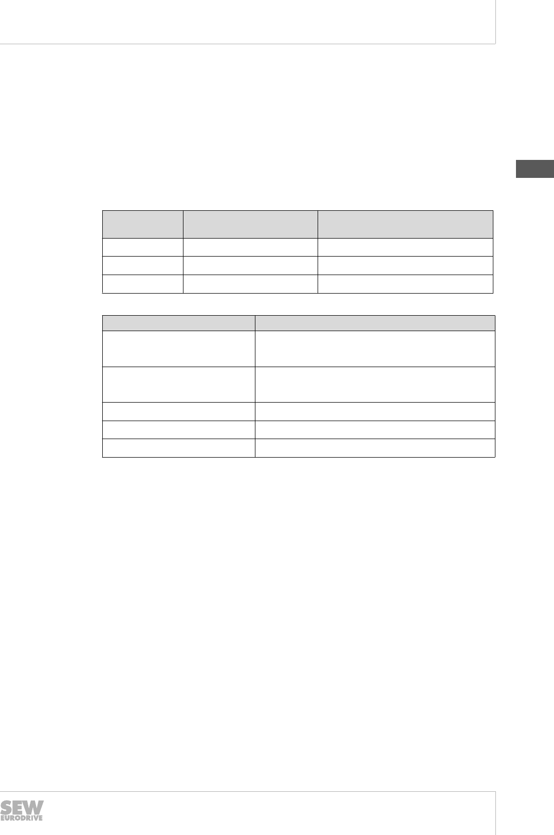
6.2.1 Thermal classes pursuant to IEC / EN60034-1 and IEC 62114
In addition to motor standard IEC / EN 60034-1, the IEC 62114 also describes the
thermal class designs and identifications. They define the limit overtemperature based
on a maximum ambient temperature of +40 °C and a reserve of 10 K or 15 K for po-
tential voltage tolerances.
A number identification is required. The addition of a long-standing letter in brackets is
permitted. SEW-EURODRIVE identifies the motors using a combination of numbers
and letters.
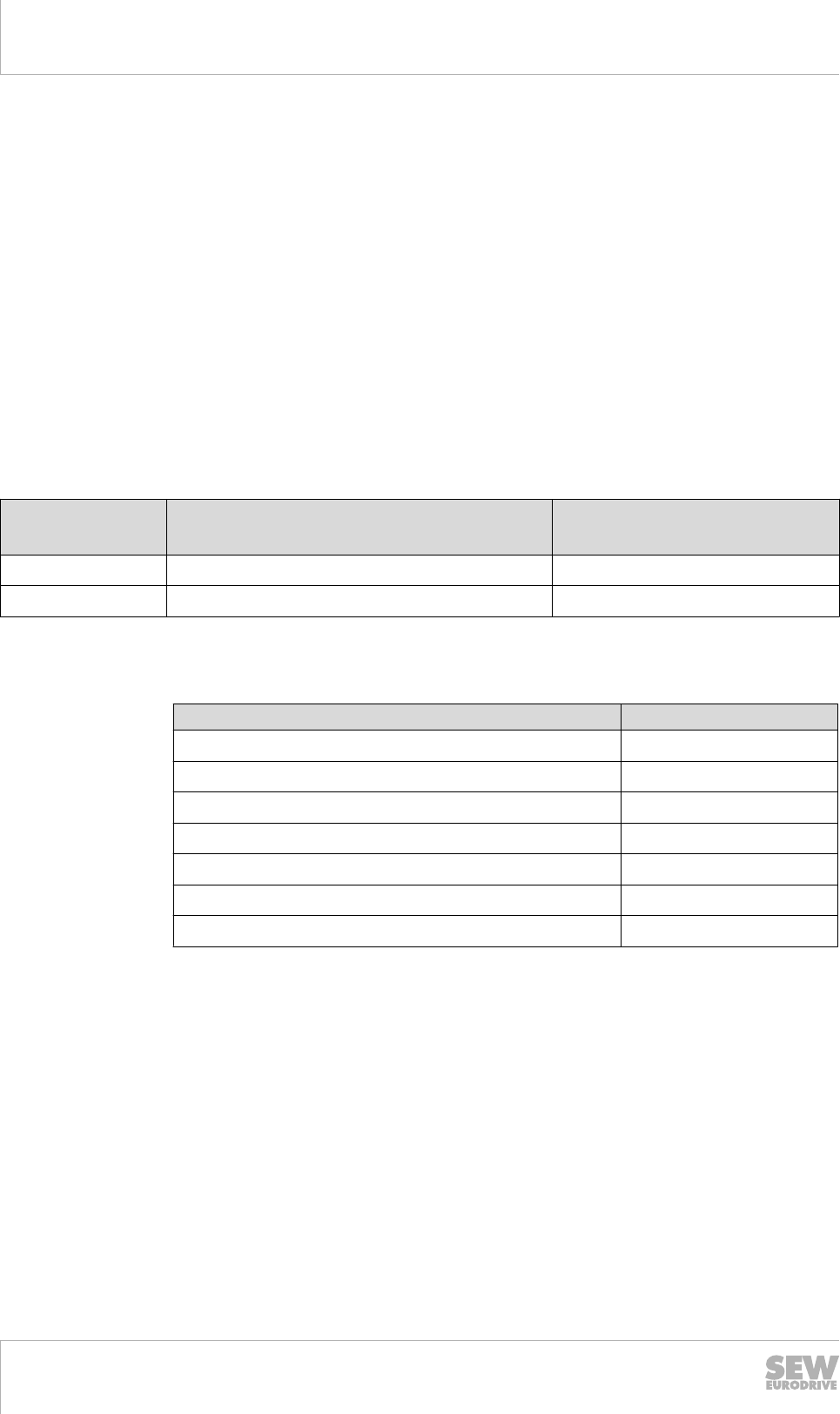
Thermal class SEW identification Limit overtemperature in K (permit-
ted heating at the rated torque)
130 130 (B) 80 K
155 155 (F) 105 K
180 180 (H) 125 K
The various motor measurements result in different basic thermal class designs.
Motor design Basic thermal class design
DRS.. (one speed) 130 (B)
with copper rotor 155 (F)
DRS.. (two speed) Dahlander winding 130 (B), occasionally 155 (F)
separate winding 130 (B)
DRE.. and DRP.. 130 (B)
DRL.. 155 (F)
DRM.. 155 (F)
The DRS.., DRE.. and DRP.. motors can also be built and delivered in higher thermal
classes 155 (F) and 180 (H). In some cases, mounted options require a higher basic
thermal class design.
DRL.. servomotors and DRM.. torque motors are not available in thermal class 180
(H), as the entire motor would then reach prohibited temperatures in the gaskets, ball
bearings and bearing lubricants. The reasons for this decision are as follows:
• the non-ventilated rated operation at a standstill for the DRM.. torque motors
• the constant ventilation of the fan-cooled DRL.. servomotors in inverter mode.
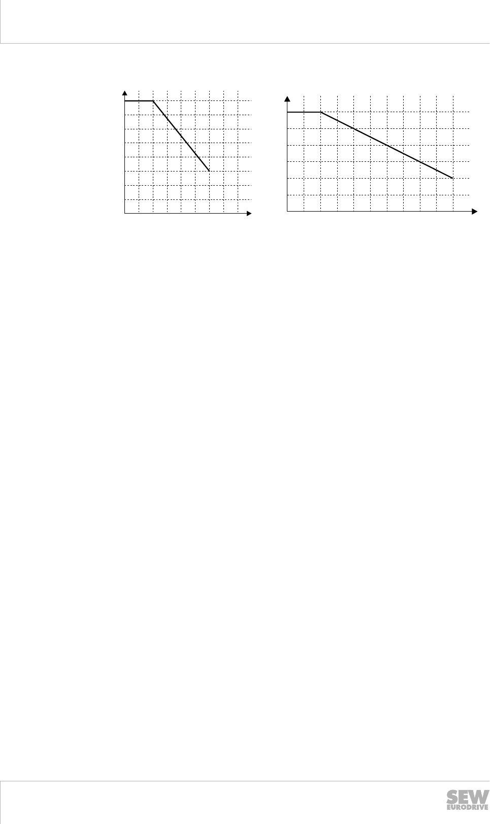
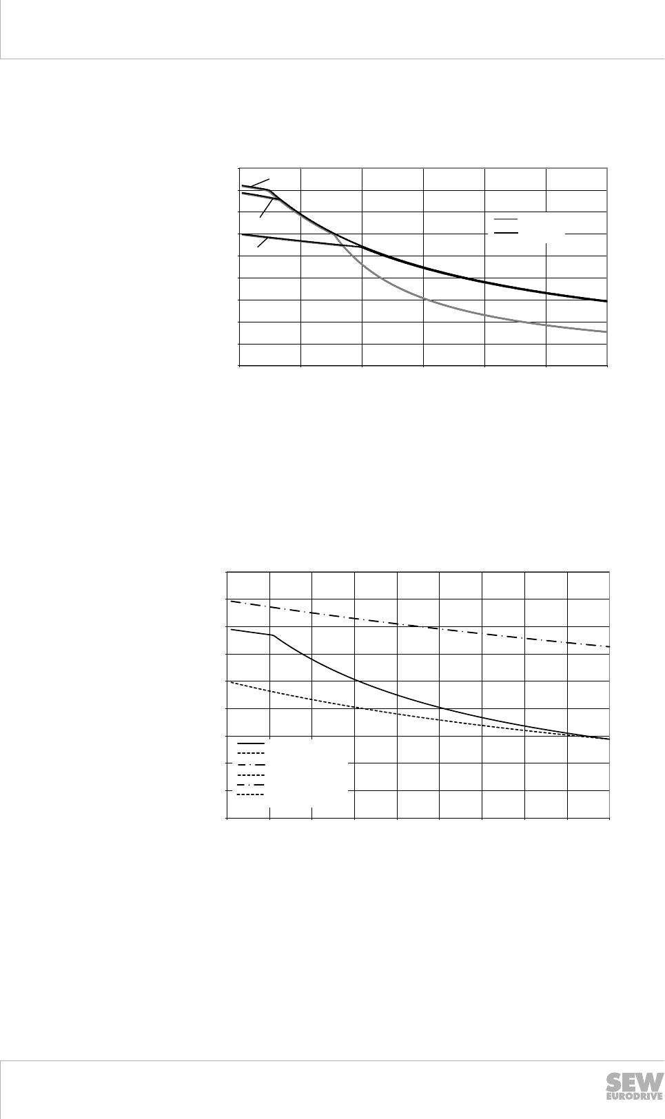
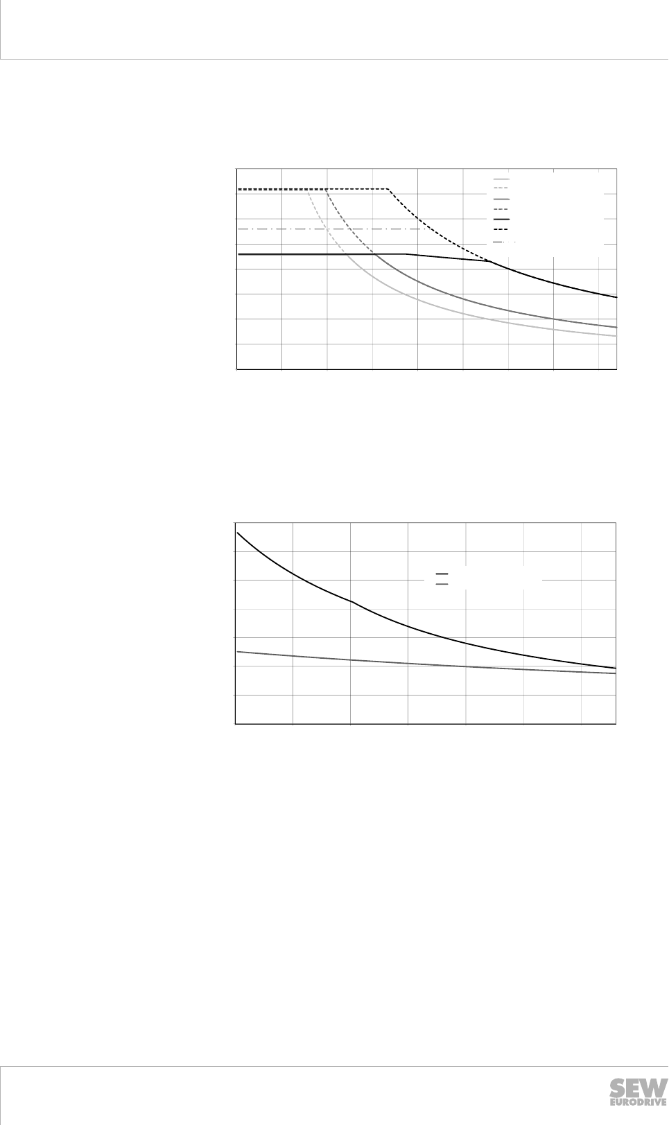
6.2.2 Power reduction
The rated power PN of a motor depends on the ambient temperature and the altitude.
The rated power stated on the nameplate applies for an ambient temperature of 40 °C
and a maximum installation altitude of 1,000 m above sea level. The rated power must
be reduced according to the following formula in the case of higher ambient tempera-
tures or altitudes:
PNred = PN × fT × fH
The following diagrams show the power reduction depending on the ambient tempera-
ture and installation altitude.
19290411/EN – 10/2014
6
6Drive selection
Thermal characteristics
Catalog – AC Motors DR.71 - 315, DT56, DR63
130
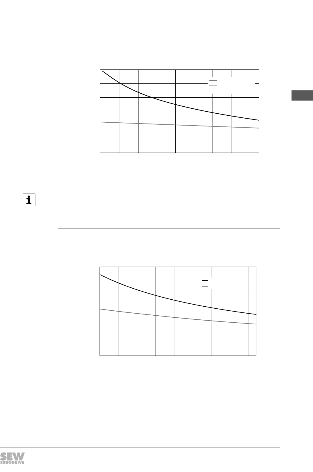
The factors fT and fH apply for the motors:
1000 2000 3000 4000 H [m]
0.6
0.7
1.0
fH
30 40 50 60 T [°C]
fT
0.7
0.8
0.9
1.0
0.5
0.8
0.9
5000
0
9007207957178763
T = ambient temperature
H= Installation altitude above sea level
Please contact SEW-EURODRIVE for ambient temperatures above 60 °C and instal-
lation altitudes over 5000 m.
19290411/EN – 10/2014

6
Drive selection
Thermal characteristics
Catalog – AC Motors DR.71 - 315, DT56, DR63 131
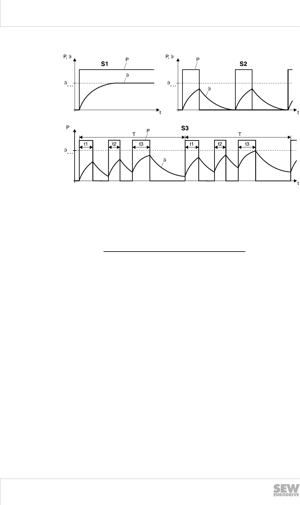
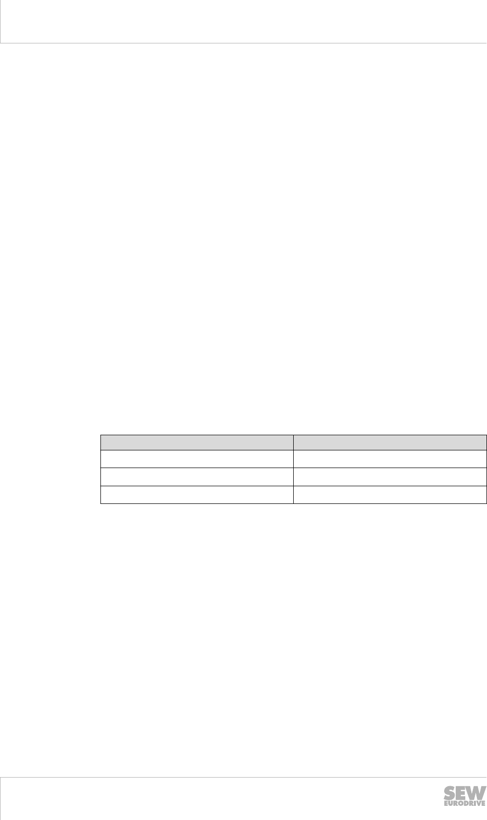
6.2.3 Operating modes
Motor standard IEC / EN 60034-1: 2011-02 defines the following operating modes,
among other things.
Designation
of the operat-
ing mode
Text explanation
S1 Continuous duty: Operation with a constant load.
Operation at a constant load, with a duration long enough for the
machine to reach a steady thermal condition.
S2 Short-time duty: Operation with a constant load and idling time.
Operation at a constant load for a time which is less than the time
required for reaching a steady thermal condition. The subsequent
standstill time when the windings are de-energized is long enough
for the motor temperature to deviate less than 2K from the tempera-
ture of the cooling agent. S2 is supplemented by the operating time
in minutes.
S3 Periodic intermittent duty: without affecting the starting procedure.
This duty is a sequence of identical duty cycles, with each cycle in-
cluding a period of operation at constant load and a standstill period
with de-energized windings. The starting current does not have any
significant effect on the temperature rise. S3 is supplemented by the
relative cyclic duration factor in %.
S6 Periodic cycle: continuous periodic operation.
This duty is a sequence of identical cycles, with each cycle including
a period of operation at constant load and a period of idle time.
There is no standstill period in which the windings are de-energized.
S6 is supplemented by the relative time under load in %.
S9 Non-periodic cycle: non-periodic load and speed changes.
Operation with usually non-periodic changes in load and speed with-
in the permitted operating range. In this cycle, overloads often occur
that significantly exceed the reference load.
A constant load in line with duty type S1 is selected as the reference
value for the overload for this duty type.
INFORMATION
S1 continuous duty is normally assumed when operating the motor on an inverter. In
the case of a high number of cycles per hour, it might be necessary to assume S9
intermittent duty.
19290411/EN – 10/2014
6
6Drive selection
Thermal characteristics
Catalog – AC Motors DR.71 - 315, DT56, DR63
132
The following figure shows duty types S1, S2 and S3.
3980471563
Determining the relative CDF
The cyclic duration factor (CDF) is the ratio between the period of loading and the du-
ration of the duty cycle. The cycle duration is the sum of the switch-on times and the
de-energized rest periods. A typical value for the cycle duration is ten minutes.
cdf = Total number of times of operation (t1 + t2 + t3)
Cycle duration (T) • 100 [%]
3980474251
19290411/EN – 10/2014

6
Drive selection
Thermal characteristics
Catalog – AC Motors DR.71 - 315, DT56, DR63 133
Power increasing factor K
Unless specified otherwise and indicated on the nameplate, the rated power of the
motor refers to duty type S1 (100 % cdf) pursuant to IEC / EN 60034. If a motor de-
signed for S1 and 100 % cdf is operated in mode S2 "short-time duty" or S3 "intermit-
tent duty", the rated power can be multiplied by the power increasing factor "K" speci-
fied on the nameplate and the motor can be loaded beyond the rated points accord-
ingly.
Duty type Power increasing
factor K
S2 Operating time 60 min
30 min
10 min
1.1
1.2
1.4
S3 Relative cyclic duration factor (cdf) 75 %
40 %
25 %
15 %
1.1
1.15
1.3
1.4
S4 –
S10
The following information must be specified to deter-
mine the rated power and the duty type: number and
type of cycles per hour, run-up time, time at load,
braking type, braking time, idle time, cycle duration,
period at rest and power demand.
On request
In the case of high counter-torques and high mass moments of inertia (heavy starting),
please contact SEW‑EURODRIVE with exact information about the technical data
when changing the duty type.
6.2.4 Thermal monitoring
In accordance with the standard, two fundamental states are taken into account when
monitoring a motor against thermal overload.
Thermal overload with gradual change
If a motor is exposed to a thermal overload with a gradual rise in temperature, the
thermal protection system must prevent a rise in the winding temperature over the fol-
lowing values.
Thermal classification Maximum winding temperature
130 (B) 145 °C
155 (F) 170 °C
180 (H) 195 °C
Possible causes could be:
• Failure of the cooling or the cooling system due to excessive dust in the cooling
ducts or the cooling fins on the motor housing.
• Reduction in the air volume due to the partial covering of the fan grille.
• Renewed drawing in of heated cooling air.
• An excessive rise in the ambient temperature or the coolant temperature.
• Gradually rising mechanical overload.
19290411/EN – 10/2014
6
6Drive selection
Thermal characteristics
Catalog – AC Motors DR.71 - 315, DT56, DR63
134
• Voltage drop, overvoltage or asymmetry in the motor supply over an extended peri-
od.
• Excessive operating time for a motor rated for intermittent duty.
• Frequency deviations.
Thermal overload with rapid change
If a motor is exposed to a thermal overload with a rapid rise in temperature, the ther-
mal protection system must prevent a rise in the winding temperature over the follow-
ing values.
Thermal classification Maximum winding temperature
130 (B) 225 °C
155 (F) 240 °C
180 (H) 260 °C
Possible causes could be:
• Motor blockage.
• Phase failure.
• Start-up under abnormal conditions, e.g. with excess mass moment of inertia, in-
sufficient voltage or abnormally high load torque.
• Sudden and marked rise in the load.
• Repeated start-up within a short space of time.
19290411/EN – 10/2014

6
Drive selection
Thermal characteristics
Catalog – AC Motors DR.71 - 315, DT56, DR63 135
Determining the right motor protection
Selecting the correct protection device is a significant factor in determining the opera-
tional reliability of the motor. We distinguish between protection devices that are cur-
rent-dependent and those that depend on the motor temperature.
Current-dependent protection devices that are generally operated from the control
cabinet, include:
• Fuses
or
• Motor overload circuit breakers.
Temperature-dependent protection devices in the winding are
• PTC thermistors (thermistor sensors)
or
• Bimetallic switches (thermostats).
PTC thermistors or bimetallic switches respond when the maximum permitted winding
temperature is reached. The advantage is that temperatures are recorded where they
actually occur.
Fuses Fuses do not protect the motor from overload. They are exclusively used as
short-circuit protection and may detect a motor blockage, as this condition is
similar to a short-circuit on the terminals.
Motor overload circuit
breaker
Motor circuit breakers offer adequate protection against overload in standard
operation with a low starting frequency, brief start-ups and starting currents that
are not excessive. The motor circuit breaker is set to the rated motor current.
Motor protection switches are not adequate as the sole means of protection giv-
en switching operation with a high starting frequency (> 60 / h) and for heavy
starting. In these cases we recommend to use a positive temperature coefficient
thermistor TF in addition.
PTC thermistor Three positive temperature coefficient (PTC) thermistors TF (PTC, characteristic
curve according to DIN 44080) are connected in series in the motor and con-
nected from the terminal box to an inverter input or to a trip switch in the control
cabinet.
Motor protection with positive temperature coefficient (PTC) thermistors (SEW
designation /TF) provide comprehensive protection against thermal overload.
Motors protected in this way can be used for high inertia starting, switching and
braking operation as well as with fluctuating power supplies. A motor circuit
breaker is usually installed in addition to the TF. SEW‑EURODRIVE recom-
mends using motors equipped with TF for inverter operation.
Bimetallic switch Three bimetallic switches (SEW designation /TH), connected in series in the
motor, are integrated directly into the motor monitoring circuit from the terminal
box. Due to the size and the insulation required for the motor winding, the TH
does not reach the reaction speed of the PTC thermistor.
The switching hysteresis may not permit a motor switching frequency depend-
ing on the design.
MOVIMOT® protection
devices
MOVIMOT® drives contain integrated protection devices to prevent thermal
damage. No other external devices are required for motor protection.
19290411/EN – 10/2014
6
6Drive selection
Thermal characteristics
Catalog – AC Motors DR.71 - 315, DT56, DR63
136
Comparison of the safety mechanisms
The following tables show the qualification of the various protection devices for differ-
ent causes of tripping.
Key:
Scope of protection Icon
Comprehensive pro-
tection
x
Limited protection •
No protection -
Reason for the additional ther-
mal load
Current-dependent protection de-
vice
Temperature-dependent pro-
tection device
Fuse Motor overload
circuit breaker
PTC thermis-
tor
/TF
/TH bimetallic
switch
Over-currents up to 200 % IN- x x x
Heavy start - • x •
Direct switching of the direction of
rotation - • x •
Switching operation up to Z = 30
1/h
- • x x
Stalling • • • •
Phase failure - • x x
Voltage deviation
(greater than tolerance B) - x x x
Frequency deviation
(greater than tolerance B) - x x x
Insufficient motor cooling - - x x
19290411/EN – 10/2014

6
Drive selection
Starting frequency
Catalog – AC Motors DR.71 - 315, DT56, DR63 137
6.3 Starting frequency
A motor is usually rated according to its thermal loading. In many applications the mo-
tor is started only once (S1 = continuous running duty = 100 % cyclic duration factor).
The power demand calculated from the load torque of the driven machine is the same
as the rated motor power.
6.3.1 High starting frequency
Many applications call for a high starting frequency at low counter-torque, such as for
a travel drive. In this case, it is not the power demand that is the decisive factor in de-
termining the size of the motor, but rather the number of times the motor has to start
up. Frequent starting means the high starting current flows every time, leading to dis-
proportionate heating of the motor.
The windings become overheated if the heat absorbed is greater than the heat dissi-
pated by the motor ventilation system. The thermal load capacity of the motor can be
increased by selecting a suitable thermal classification or by means of forced cooling
(see the "Thermal characteristics" (→ 2 129) chapter).
6.3.2 No-load starting frequency Z0
SEW‑EURODRIVE specifies the permitted starting frequency of a motor as the no-
load starting frequency Z0 at 50 % cyclic duration factor. This value indicates the num-
ber of times per hour that the motor can accelerate the mass moment of inertia of its
rotor up to speed without counter-torque at 50 % cyclic duration factor.
If an additional mass moment of inertia of a load has to be accelerated or if an addi-
tional load torque occurs, the run-up time of the motor will increase. Increased current
flows during this run-up time. This means the motor is subjected to increased thermal
load and the permitted starting frequency is reduced.
19290411/EN – 10/2014
6
6Drive selection
Starting frequency
Catalog – AC Motors DR.71 - 315, DT56, DR63
138
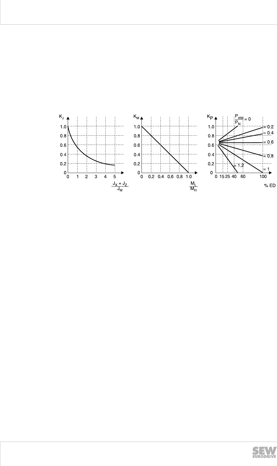
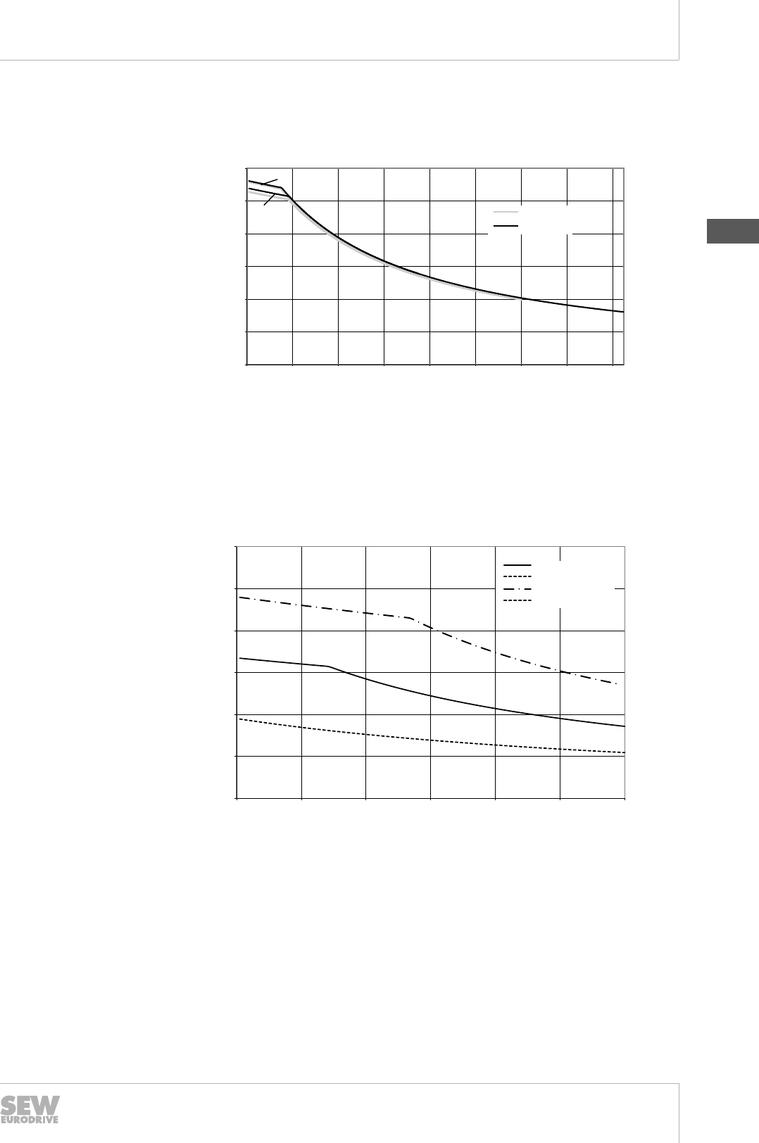
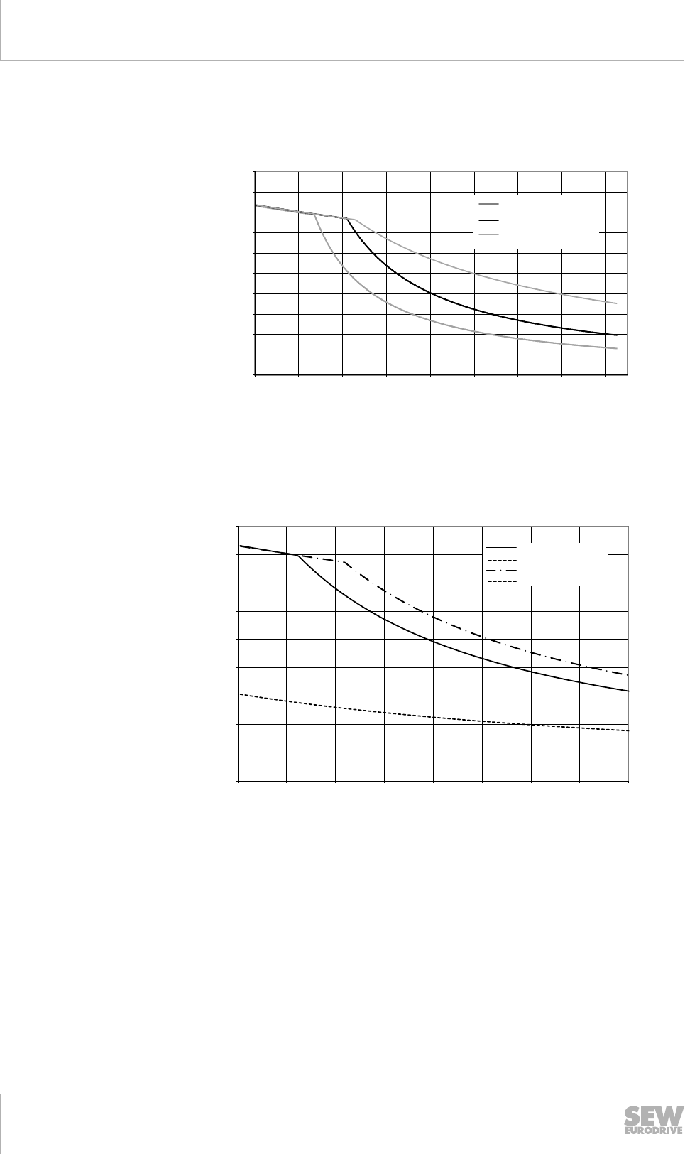
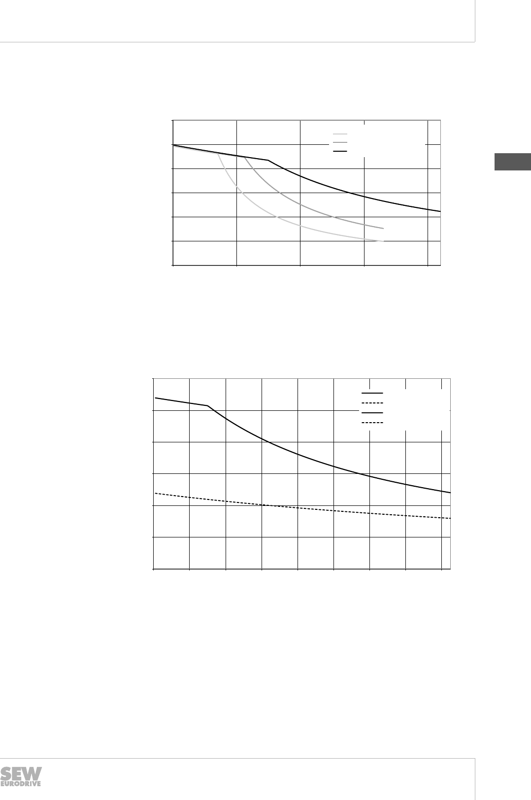
6.3.3 Permitted starting frequency of the motor
The permitted starting frequency Z of a motor in cycles/hour can be calculated using
the following formula:
Z = Z0 × KJ × KM × KP
You can determine the factors KJ, KM and KP using the following diagrams:
Depending on the addition-
al moment of inertia
Depending on the counter-
torque at startup
Depending on the static
power and the cyclic dura-
tion factor (cdf)
3980481035
JX = Total of all external mass mo-
ments of inertia in relation to the
motor axis
MH = Acceleration torque motor
JZ = Mass moment of inertia flywheel
fan
Pstat = Power requirement after
start-up (static power)
JM = Mass moment of inertia of the
motor
PN = Rated motor power
ML = Counter-torque during startup %cdf = cyclic duration factor
Example
Brakemotor: DRS71M4 BE1
No-load starting frequency Z0 = 11000 1/h
1. (JX + JZ) / JM = 3.5 : KJ = 0.2
2. ML / MH = 0.6 : KM = 0.4
3. Pstat / PN = 0.6 and 60 % cdf : KP = 0.65
Z = Z0 × KJ × KM × KP = 11000 1/h × 0.2 × 0.4 × 0.65 = 572 1/h
The cycle duration amounts to 6.3 s.
The switch-on time amounts to 3.8 s.
6.3.4 Permitted work done by the brake
If you are using a brakemotor, you have to check whether the brake is approved for
use with the required duty type. Please also refer to the information in the "Permitted
braking work of the BE brake during working brake actions (→ 2 376)" or the "Permit-
ted braking work of the BE brake in case of an emergency stop (→ 2 385)" chapters.
19290411/EN – 10/2014

6
Drive selection
Mechanical designs
Catalog – AC Motors DR.71 - 315, DT56, DR63 139
6.4 Mechanical designs
6.4.1 Degrees of protection pursuant to EN /IEC 60034-5
Designs
AC motors and AC brakemotors are available with degree of protection IP54 as stand-
ard. Degrees of protection IP55, IP56, IP65 or IP66 are available upon request.
IP 1. digit 2. digit
Touch guard Protection against foreign ob-
jects
Protection against water
0No protection No protection No protection
1 Protected against access to haz-
ardous parts with the back of
your hand
Protection against solid foreign
objects Ø 50 mm and larger Protected against dripping water
2 Protected against access to haz-
ardous parts with a finger
Protection against solid foreign
objects Ø 12 mm and larger
Protection against dripping wa-
ter when tilted up to 15°
3 Protected against access to haz-
ardous parts with a tool
Protection against solid foreign
objects Ø 2.5 mm and larger
Protected against spraying wa-
ter
4
Protected against access to haz-
ardous parts with a wire
Protected against solid foreign
objects Ø 1 mm and larger
Protected against splashing wa-
ter
5 Dust-proof Protection against water jets
6Dust-proof Protection against powerful wa-
ter jets
7 - - Protection against temporary im-
mersion in water
8 - - Protection against permanent
immersion in water
In addition to the protection classification using the above code, further identification
with more information may be required pursuant to the standard.
SEW-EURODRIVE uses the additional designation with the letter "W" to identify inter-
nal corrosion protection.
Example:
• IP55: Dust- and water jet-resistant
• IP55W: Corrosion- Dust- and water jet-resistant
6.4.2 Vibration class
The motors comply with vibration class A. If special requirements for the mechanical
running smoothness exist, 2-, 4-, or 6-pole motors without add-ons (no brake, forced
cooling fan, encoder, etc.) can be delivered in a low-vibration design in vibration class
B.
For vibration classes A or B, the motor rotors are always dynamically balanced with a
half key.
19290411/EN – 10/2014
6
6Drive selection
Mechanical designs
Catalog – AC Motors DR.71 - 315, DT56, DR63
140
6.4.3 Vibration stress
The normal motor setup requires a vibration-free attachment and duty type. Make sure
that the supports are even, the foot or flange mounting is correct and if there is direct
coupling, align with precision. Resonances between the rotational frequency and the
double network frequency caused by the structure are to be avoided.
Only install the (gear)motor in the mounting position specified on the nameplate on a
level, vibration-free and torsionally rigid support structure. Align the (gear)motor and
the driven machine carefully in order to prevent the output shaft from being exposed to
unacceptable strain. Pay attention to the permitted overhung and axial loads and
avoid impacts on the shaft end when applying transmission elements. We recommend
heating the elements prior to assembly.
If all of these requirements cannot be ensured in the application, the motors can be
delivered in a design for vibration stress.
Vibration level 1 (VL1) ensures that the motors are able to deal with an external influ-
ence. The values in the following table are based on standardized information pur-
suant to DIN ISO 10816-1.
Motor size Periodic vibrations Shock stress
1g = 9.81 m/s²
DR.71 – DR.132 Effective vibration speed ≤ 4.5 mm/s Maximum acceleration = 10 g
DR.160 – DR.315 Effective vibration speed ≤ 7.1 mm/s Maximum acceleration = 15 g
If you require a drive in line with VL1, or if the required values exceed the information
for VL1, please contact SE-EURODRIVE.
The following design types and options are not available for vibration stress:
Term Designation
Brake monitoring /DUB
Built-in encoder /EI7.
Air filter /LF
Forced cooling fan /V
MOVIMOT®/MM
MOVI‑SWITCH®/MSW
Foot-mounted motors DR.71 – DR.132 /FI
19290411/EN – 10/2014
6
Drive selection
Mechanical designs
Catalog – AC Motors DR.71 - 315, DT56, DR63 141
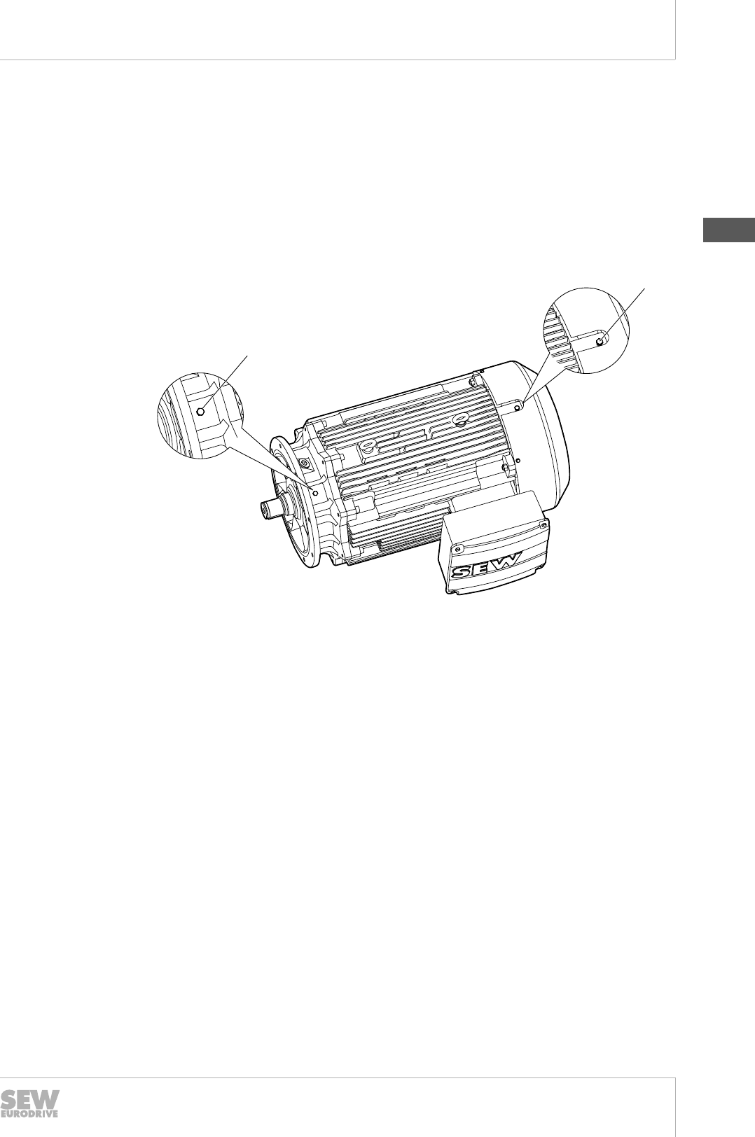
6.4.4 Vibration monitoring
External influences can gradually lead to the failure of important motor functions, such
as defects in the bearings. In particular, for motors with higher power ratings, the in-
vestments can be maintained by preventive maintenance and inspection. Vibration
monitoring supports the timely detection of the need for maintenance.
SEW-EURODRIVE provides a mounting adapter for vibration recorders and tapped
holes for SPM measuring nipples.
Tapped holes to mount the measuring nipple can be applied on the A- and B-side in
the flanges and covers of motor sizes DR.160 – 315.
[1]
[1]
2706206475
The SEW-EURODRIVE delivery components may include:
• only the bores
• the bores and the mounted measuring nipple.
Please contact SEW‑EURODRIVE if required.
6.4.5 Shaft ends
The A-side shaft ends of the foot- and/or flange-mounted motor design are usually de-
livered with a keyway pursuant to DIN 6885 Sheet 1 (ISO 773). The shaft ends can
also be delivered smooth and without a key and keyway on request.
Motors are balanced with a half key as standard, please also refer to the "Vibration
class" (→ 2 139) chapter.
In particular, when replacing older motors, there may be a need to balance the motors
with a full key in order to continue using the existing transmission and connecting ele-
ments, such as couplings.
The full-key balancing must be specified in the order if required. SEW-EURODRIVE
identifies motor rotors balanced in this manner with a "V" on the front shaft end face in
line with the standard regulations.
Whether balanced with a full- or half-key, the motors are always delivered with full
keys, which are secured against loss during transport.
19290411/EN – 10/2014
6
6Drive selection
Mechanical designs
Catalog – AC Motors DR.71 - 315, DT56, DR63
142
The special form of the A-side shaft end for direct mounting to the SEW gear units is
the pinion shaft end. A standardized diameter is provided depending on the number of
poles, power and motor size. Smaller dimensions must be precisely inspected with the
application data. Larger pinion shaft ends limit the potential reduction ratio variations,
but are required in rare cases due to the high dynamic loads.
6.4.6 Integral motors
If the motor or gear unit is replaced for a SEW-EURODRIVE gearmotor, the following
needs to be observed:
To ensure an oil-tight reassembly, SEW-EURODRIVE recommends using the sealant
included in the delivery.
Both the gear unit housing and the motor flange are made from aluminum as well as
gray cast iron. This must be noted during assembly.
6.4.7 Flange-mounted motors
The flange-mounted motors in the DR.. modular motor system are available in three
different specifications.
• Flange-mounted design with metric through bore, also referred to as B5 motors in
the standard for the basic design.
• Flange-mounted design with metric thread, also referred to as B14 motors in the
standard for the basic design.
• Flange-mounted design with inch thread, also referred to as C-Face in the US
standard for the basic design.
The regulations for the metric flange dimensions are provided in IEC 72-1, while the
dimensions for inch flanges are provided in MENA MG1.
Flange-mounted motor in possible sizes
IM B5 design DR.71 – DR.315
IM B14 design DR.71 – DR.100
C-Face design DR.71 – DR.80
All motor flanges pursuant to standard IEC 72-1, also generally referred to as IEC mo-
tors, are produced from gray cast iron (GG20).
If the dimensions of the metric flange are also designed for the respective motor pow-
er in the size in line with EN 50347, this is indicated as follows in the catalog designa-
tion:
• For B5 motors, with /FF.
• For B14 motors, with /FT.
• For flanges that deviate from EN, with /FL.
The inch flanges pursuant to C-Face are identified with /FC in the SEW catalog desig-
nation.
The parallel design as a flange- and foot-mounted design is possible for flanges with
metric measurements. These combinations have their own type and catalog designa-
tions.
19290411/EN – 10/2014
6
Drive selection
Mechanical designs
Catalog – AC Motors DR.71 - 315, DT56, DR63 143
6.4.8 Foot-mounted motors
The foot-mounted motor design follows a range of construction principles:
• Aluminum bed plates for sizes DR.71 – DR.132.
• Two single gray cast iron feet for sizes DR.160 – DR.315.
As standard, the only parts of the motor that are treated are the sides and surfaces to
which the bed plate/feet are connected. A retroactive modification to attach the bed
plate/feet to another side of the motor is generally not possible without great expense.
If the required position of the bed plate/feet is not in place when ordering, all sides of
the motor can be machined to attach the bed plate/feet at the factory for DR.71 – 132
and DR.250/280 motors. This means that the customer can freely select the position
of the bed plate/feet.
When ordering the DR.250/280, it is possible to specify if the feet should be delivered
unattached or attached. SEW-EURODRIVE identifies this decision by attaching the
letter A or B to the selected foot-mounted design.
Example:
Designation Type Explanation
/FE
Foot- and flange-moun-
ted design
A position machined, feet attached
/FEA Three positions machined, feet delivered
unattached
/FEB Three positions machined, feet attached to
a position
6.4.9 Oil seals
The motors are constructed as flange-mounted motors, gearmotors or integral motors
with oil seals. In the standard designs, nitrite butadiene rubber (NBR) oil seals are
used.
Fluorocarbon rubber (FKM) oil seals can also be used up to a lower temperature limit
of -25 °C.
The following motors are constructed using fluorocarbon rubber (FKM) oil seals in the
series design up to a minimum temperature of -20 °C.
• 2-pole motors
• 4-pole motors
For gearmotors, the lubricant also influences the oil seal.
19290411/EN – 10/2014
6

6Drive selection
Mounting positions
Catalog – AC Motors DR.71 - 315, DT56, DR63
144
6.5 Mounting positions
The motor standard IEC 60034-7 only recognizes mounting positions that are rotated
or tilted within a 90° grid, please also refer to the "Motor design designation" (→ 2 89)
chapter.
6.5.1 Inclined mounting positions
In most cases, the defined and established positions in line with the standard are suffi-
cient. The standard does not recognize inclined mounting positions.
The motors are also available for inclined mounting positions if the initial design, target
design and the angle are specified. There is a restriction for two position specifica-
tions. Further rotation towards a third position is not possible.
Example: IM B3 → IM V5: with an angle of 40°
SEW-EURODRIVE confirms the permissibility of the inclined mounting position by pro-
viding the following information on the nameplate and the order confirmation in line
with the data specified by the customer:
B3/V5/40°
The mounting position-dependent designs on the motor side are identified, defined
and attached depending on this information, e.g. the condensation drain holes.
If a gearmotor is delivered for an inclined mounting position, the lubricant quantities
and the placement of the oil fittings are adapted accordingly.
Any application that deviates from the specification may only be performed in coordi-
nation with SEW-EURODRIVE.
6.5.2 Moving mounting position
Depending on the application, it may be necessary for the DR. motor to cyclically
and/or permanently switch between two mounting positions. This situation is also not
described in the standard.
The motors are also available for moving mounting positions if the initial design, target
design and the angle are specified. There is a restriction for two position specifica-
tions. A further switching movement towards a third position is not possible.
Example: IM B3 → IM V5: with a starting angle of 10°, with an end angle of 80°
SEW-EURODRIVE confirms the permissibility of the moving mounting position by pro-
viding the following information on the nameplate and the order confirmation in line
with the data specified by the customer:
B3/V5/10-80°
The mounting position-dependent designs on the motor side are identified, defined
and attached in multiple position, if necessary, depending on this information, e.g. the
condensation drain holes.
If a gearmotor is delivered for a moving mounting position, the lubricant quantities and
the placement of the oil fittings are adapted accordingly.
Any application that deviates from the specification may only be performed in coordi-
nation with SEW-EURODRIVE.
Please also contact SEW-EURODRIVE for moving mounting positions with angles
over 90°.
19290411/EN – 10/2014
6
Drive selection
Maximum speeds
Catalog – AC Motors DR.71 - 315, DT56, DR63 145
6.6 Maximum speeds
The duty cycle of motors and gearmotors on the 50 Hz and 60 Hz grid will never reach
a critical value, if you follow the information and regulations described in this chapter.
The maximum speed is irrelevant for multi-speed motors and brakemotors. The "Drive
selection of pole-changing motors" (→ 2 170) chapter covers the torque behavior of
this drive type.
For electric motors that operate on a frequency inverter, the maximum torque and the
maximum speed must be viewed as mechanical limits.
The maximum torque is based on the load limit of the mechanical design of the shaft,
the bearings and the shaft sealing system.
Motors in the DRL.. design can be briefly and dynamically operated and loaded with a
higher torque due to their better dimensioned mechanical design. Please also refer to
the "Drive selection – DRL.. motors" (→ 2 186) chapter.
Additional loads that arise at the customer's location must be taken into account for all
DR. motors, e.g. additionally occurring overhung or axial loads due to belt drives.
The motor's maximum speed must not be exceeded. The following table displays
these values for standard motors. They apply to motors with fluorocarbon rubber oil
seals (FKM).
Additional motor options will influence these speeds. Please contact
SEW‑EURODRIVE in such cases.
Please also pay attention to the following for brakemotors:
• The applicable drive selection regulations with regard to the braking work.
• Braking from speeds of over 1800 rpm is not permitted for brake sizes BE30 and
above. Use the controller to reduce the speed before activating the mechanical
brake.
• For 4/2-pole brakemotors with brake sizes BE30 and BE32, first switch from the 2-
pole speed to the 4-pole speed. The motor can then be switched off and the brake
activated when the 4-pole speed is reached.
Motor size Mounted brakes Maximum mechanical speed nmax in rpm
Motor Brakemotor
DT56 BMG02 6000 4500
DR 63 BR03 6000 4500
DR.71 BE05 or BE1 6000 4500
DR.80 BE05, BE1 or BE2 6000 4500
DR.90 BE1, BE2 or BE5 6000 4500
DR.100 BE2 or BE5 6000 3600
DR.112 BE5 or BE11 5000 3600
DR.132 BE5 or BE11 5000 3600
DR.160 BE11 or BE20 4500 3600
DR.180 BE20, BE30 or
BE32
4500 3600
DR.200 BE30 or BE32 3500 3600
BE60 or BE621) 2600 2500
19290411/EN – 10/2014
6
6Drive selection
Maximum speeds
Catalog – AC Motors DR.71 - 315, DT56, DR63
146
Motor size Mounted brakes Maximum mechanical speed nmax in rpm
Motor Brakemotor
DR.225 BE30 or BE32 3500 3600
BE60 or BE621) 2600 2500
DR.250 BE60 or BE62 2600 2500
BE120 or BE122 2500 2500
DR.280 BE60 or BE62 2600 2500
BE120 or BE122 2500 2500
DR.315 BE120 or BE122 2500 2500
1) Please contact SEW‑EURODRIVE when attaching the BE60/62 to the DR.200/225.
If a motor is equipped with a backstop, the sprag's lift-off speed represents the lower
speed limit during operation on a frequency inverter. The upper speed limit is limited to
5000 rpm, please also refer to the "Backstop" (→ 2 471) chapter.
Motor size Locking torque
in Nm
Sprag lift-off speed in
rpm
Maximum speed in rpm
DR.71 95 890 5000
DR.80 130 860 5000
DR.90 370 750 5000
DR.100 370 750 5000
DR.112 490 730 5000
DR.132 490 730 5000
DR.160 700 700 4500
DR.180 1400 610 4500
DR.200 2500 400 3500
DR.225 2500 400 3500
DR.250 2600 400 2600
DR.280 2600 400 2600
DR.315 6300 320 2500
19290411/EN – 10/2014
6
Drive selection
Bearings
Catalog – AC Motors DR.71 - 315, DT56, DR63 147
6.7 Bearings
6.7.1 Bearing types used
The standard motor bearings for sizes 71 – 225 are deep groove ball bearings, design
2Z-C3, on the A- and B-side.
2RS-C3 bearings are installed on the B-side for brakemotors up to motor size DR.
225.
If insufficient load values are achieved for axial and overhung loads with the deep
groove ball bearings, cylindrical roller bearings (SEW designation /ERF) can be instal-
led on the A-side instead of the deep groove ball bearings for motor sizes 250 – 315.
The cylindrical roller bearings can only be used in connection with the relubrication de-
vice (SEW designation /NS).
To prevent destructive shaft currents during operation on the inverter, the standard
deep groove ball bearings on the B-side for motor sizes 250 – 315 can be replaced
with ball bearings with insulated bearing surface. The bearing sizes remain un-
changed, but the designation changes to C3-EI or J-C3-EI.
The following tables display the bearing sizes used.
Motor type A-side bearings B-side bearings
Foot-mounted
and/or Flange-
mounted motor
Gearmotor Motor Brakemotor
DR.71 6204-2Z-J-C3 6303-2Z-J-C3 6203-2Z-J-C3 6203-2RS-J-C3
DR.80 6205-2Z-J-C3 6304-2Z-J-C3 6304-2Z-J-C3 6304-2RS-J-C3
DR.90/100 6306-2Z-J-C3 6205-2Z-J-C3 6205-2RS-J-C3
DR.112/132 6308-2Z-J-C3 6207-2Z-J-C3 6207-2RS-J-C3
DR.160 6309-2Z-J-C3 6209-2Z-J-C3 6209-2RS-J-C3
DR.180 6312-2Z-J-C3 6213-2Z-J-C3 6213-2RS-J-C3
DR.200/225 6314-2Z-J-C3 6214-2Z-J-C3 6214-2RS-J-C3
Motor type A-side bearings A-side bearings
Foot-mounted
and/or Flange-
mounted motor
Gearmotor Foot-mounted
and/or Flange-
mounted motor
Gearmotor
DR.250 6317-2Z-C4 6315-2Z-C3
DR.280
DR.250../NS 6317-C4
6315-C3
DR.280../NS
DR.250../ERF/NS NU 317 E C3
DR.280../ERF/NS
19290411/EN – 10/2014
6

6Drive selection
Bearings
Catalog – AC Motors DR.71 - 315, DT56, DR63
148
Motor type A-side bearings A-side bearings
Foot-mounted
and/or Flange-
mounted motor
Gearmotor Foot-mounted
and/or Flange-
mounted motor
Gearmotor
DR.315K
DR.315K../NS
6319-J-C3
6319-J-C3
6319-J-C3
6319-J-C3
DR.315S
DR.315S../NS
DR.315M
DR.315M../NS 6322-J-C3 6322-J-C3
DR.315L
DR.315L../NS
DR.315K../ERF/NS
NU 319 E 6319-J-C3
6319-J-C3
DR.315S../ERF/NS
DR.315M../ERF/NS 6322-J-C3
DR.315L../ERF/NS
19290411/EN – 10/2014
6
Drive selection
Ventilation on the motor
Catalog – AC Motors DR.71 - 315, DT56, DR63 149
6.8 Ventilation on the motor
6.8.1 Standard ventilation
The standard motor ventilation consists of a plastic fan that generates an air flow. The
air is conducted directly onto and into the cooling fins on the motor's stator housing by
the structural design of the fan guard and the fan grille. The fan guard consists of a
galvanized sheet steel.
Free air access
The fan-cooled motors require adequate space behind the fan guard in order to draw
in the air required for cooling. A distance of half the diameter of the fan guard is nor-
mally sufficient.
In order to inspect and maintain the brake, SEW-EURODRIVE recommends extending
this distance to the full diameter of the fan guard for the brakemotor. This ensures that
the fan guard can be removed in an axial direction.
When integrating a motor or brakemotor into a machine or system, ensure that the
heated air is not immediately drawn back in.
Space required to disassemble the fan guard.
Motor size Mounted brakes Free space required
Axial for normal
motor fan guards in
mm
Axial for normal
brakemotor fan
guards in mm
DR.71 BE05 or BE1 70 139
DR.80 BE05, BE1 or BE2 80 156
DR.90 BE1, BE2 or BE5 90 179
DR.100 BE2 or BE5 100 197
DR.112 BE5 or BE11 115 221
DR.132 BE5 or BE11 115 221
DR.160 BE11 or BE20 135 270
DR.180 BE20, BE30 or BE32 160 316
DR.200 BE30, BE32, BE60 or
BE62 200 394
DR.225 BE30, BE32, BE60 or
BE62 200 394
DR.250 BE60, BE62, BE120 or
BE122 255 510
DR.280 BE60, BE62, BE120 or
BE122 255 510
DR.315 BE120 or BE122 315 624
6.8.2 Low noise fan guard
Low-noise fan guards (SEW designation /LN) are available for motor and brakemotor
sizes DR.71 – 132, either as an option or as part of the design. The noise is reduced
by 3 – 5 dB(A).
These guards are not available for encoder mounting and for forced cooling fans.
19290411/EN – 10/2014
6
6Drive selection
Ventilation on the motor
Catalog – AC Motors DR.71 - 315, DT56, DR63
150
The low-noise fan guard is part of the series production for:
• 2-pole motors in sizes DR.71 – 132,
• MOVIMOT® combinations in delta connection type.
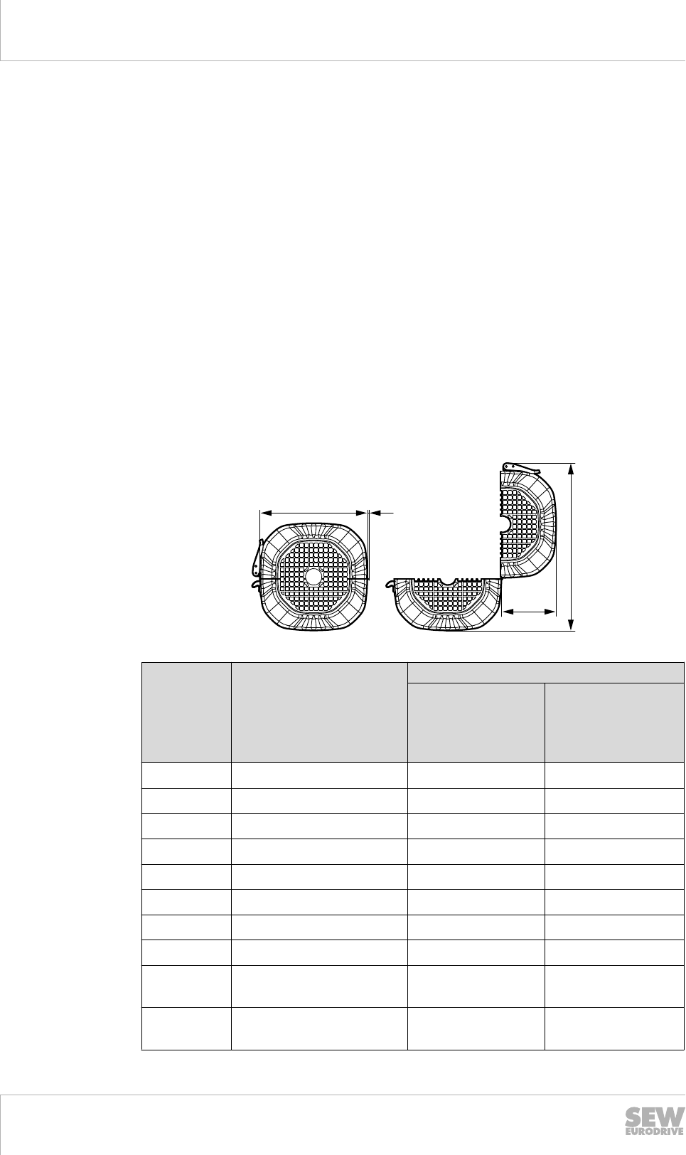
6.8.3 Axially separable fan guards on the brakemotor, brakemotor with encoder or with a second
shaft end
Brake wear parts must be inspected and maintained on a cyclical basis for brakemo-
tors. The information in the dimension sheets refers to the sufficient extra space in the
axial direction in order to be able to remove the brakemotor fan guard.
If this space is not structurally possible in the system or machine due to the installation
situation, the axially separable fan guard is an option that still allows the brake to
be inspected. This special brakemotor fan guard design is available for motor
sizes DR.71 – DR.225.
In this case, the brakemotor fan guard is split in half, please refer to the following dia-
gram. The closing lever is normally positioned so it is aligned with the terminal box.
Please contact SEW‑EURODRIVE for different orientations.
When using the axially separable fan guards, please note that radial space is available
for opening the guard, please refer to the following diagram.
G
H
A E
8937666955
Motor size Mounted brakes Free space required
Axial for normal
brakemotor fan
guards
in mm
Radial for separa-
ted brakemotor fan
guards (A+E+G) × H
in mm × mm
DR.71 BE05 or BE1 139 230 × 230
DR.80 BE05, BE1 or BE2 156 250 × 250
DR.90 BE1, BE2 or BE5 179 285 × 285
DR.100 BE2 or BE5 197 315 × 315
DR.112 BE5 or BE11 221 350 × 350
DR.132 BE5 or BE11 221 350 × 350
DR.160 BE11 or BE20 270 425 × 425
DR.180 BE20, BE30 or BE32 316 485 × 485
DR.2001) BE30, BE32, BE60 or
BE62
394 610 × 610
DR.2251) BE30, BE32, BE60 or
BE62
394 610 × 610
19290411/EN – 10/2014

6
Drive selection
Ventilation on the motor
Catalog – AC Motors DR.71 - 315, DT56, DR63 151
Motor size Mounted brakes Free space required
Axial for normal
brakemotor fan
guards
in mm
Radial for separa-
ted brakemotor fan
guards (A+E+G) × H
in mm × mm
DR.250 BE60, BE62, BE120 or
BE122
510 -
DR.280 BE60, BE62, BE120 or
BE122
510 -
DR.315 BE120 or BE122 624 -
1) Please contact SEW-EURODRIVE when attaching the BE60/62 to the DR.200/225.
19290411/EN – 10/2014
6
6Drive selection
Ventilation on the motor
Catalog – AC Motors DR.71 - 315, DT56, DR63
152
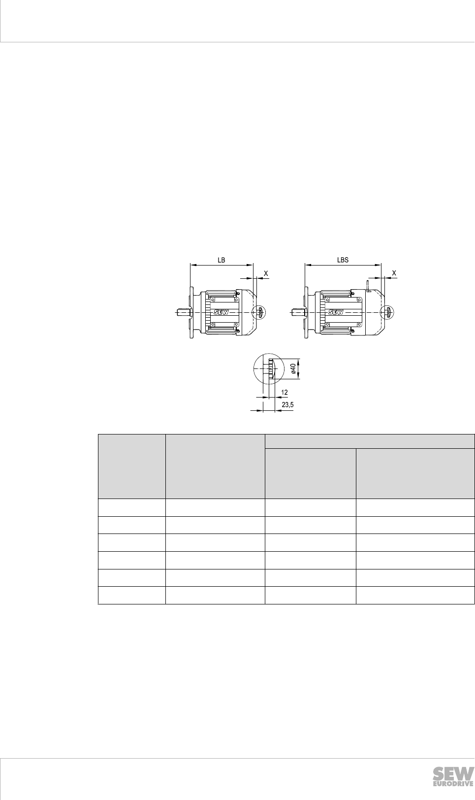
6.8.4 Air filter
In an environment with high amounts of dust or suspended particles, the air required
to cool the motor blows these dirt particles around. In unfavorable conditions, this
leads to the constant increase in particle deposits between the cooling fins, so that the
dirt can no longer be blown away by the cooling air flow. In the worst case, the space
between the cooling fins is completely filled and the motor is no longer cooled, result-
ing in the thermal risk that the motor may be destroyed.
In these cases, an air filter can prevent this swirling effect and the resulting damage to
the motor. Conversely, the filtered particles must continuously be removed from the fil-
ter, as otherwise ventilation can no longer take place.
As a result, the air filter is fastened to the inner guard by an additional external guard
using a single bolt.
When using an air filter, please consider the space required to remove the additional
filter guard.
8937755787
Motor size Mounted brakes Free space required
Additional length
X (LB or LBS, see
dimension sheet)
in mm
Axial for disassembling
the attachment guard in
mm
DR.71 BE05 or BE1 10 70
DR.80 BE05, BE1 or BE2 13 78
DR.90 BE1, BE2 or BE5 17 90
DR.100 BE2 or BE5 16 99
DR.112 BE5 or BE11 23 111
DR.132 BE5 or BE11 23 111
19290411/EN – 10/2014

6
Drive selection
Ventilation on the motor
Catalog – AC Motors DR.71 - 315, DT56, DR63 153
6.8.5 Non-ventilated motors – without fan
The improvements described in the "Air filter" (→ 2 152) chapter can also be achieved
by not installing a fan. The lack of cooling means that the rated power in the sizes up
to DR.225 has to be reduced to about 50% of the ventilated operation. The required
power reduction is higher for sizes DR.250 and above.
In general, this means that the motor has to be two to three sizes larger for the same
power output.
Please contact SEW-EURODRIVE to obtain the precise size.
The non-ventilated design is released from the efficiency provisions in all countries. As
a result, non-ventilated motors are generally selected based on the DRS.. motor
types.
6.8.6 Non-ventilated motors – closed B-side
An alternative to the non-ventilated motor (without fan) is the motor design for which
the fan guard is not installed and the rotor is shortened so that the B-side endshield
can be designed in a closed form.
Once again, the motor only has a rated power of about 50% of the ventilated operation
for sizes up to DR.225. The required power reduction is also higher for sizes DR.250
and above.
This design is possible for sizes DR.71 – DR.280. Please contact SEW-EURODRIVE
to obtain the precise size.
6.8.7 Canopy
If a vertical motor design with upright fan guard is installed in the system or machine,
ensure that foreign bodies cannot penetrate through the fan grille into the fan wheel.
Two options are available:
• structural measures in the system or the machine
or
• the use of a canopy.
The canopy extends the motor or brakemotor. The specifications are provided in the
"Dimension sheets" (→ 2 199) chapter.
Please contact SEW-EURODRIVE if there is the risk that parts may penetrate through
the side of the canopy, between the fan guard and the canopy. A canopy with a differ-
ent design may be a solution.
19290411/EN – 10/2014
6

6Drive selection
Second shaft end
Catalog – AC Motors DR.71 - 315, DT56, DR63
154
6.9 Second shaft end
The motors are also available with a B-side shaft end. This so-called second shaft end
is constructed with a traditional keyway and key in accordance with DIN 6885 Sheet 1
(ISO 773).
These are available in the following designs for the series:
• with a cover for motors/brakemotors DR.71 – DR.132
• without a cover for motors/brakemotors DR.160 – DR.315, as the diameter of the
second shaft end is so large that damage during transport is unlikely.
A cover can be ordered for these sizes as an additional option.
6.9.1 Standard design
The standard design of the second shaft end for motors is generally smaller than de-
scribed in EN 50347 for each number of poles and power.
SEW-EURODRIVE has decided to take this path in order to meet the demand for
combination with different brake sizes.
6.9.2 Reinforced design
The reinforced design of the second shaft end was developed as an alternative. This
design considers the maximum possible dimension of the second shaft end and can
only be combined with one brake size.
6.9.3 Second shaft end combinations with other design types
The second shaft end can be combined with the following design types and options.
Brakes
•With fields marked with "•": Standard design and reinforced design is possible for
the second shaft end.
• Fields marked with "x": only possible with a standard design of the second shaft
end.
BE05 BE1 BE2 BE5 BE11 BE20 BE30 BE32
DR.71S • •
DR.71M • •
DR.80S • • •
DR.80M x x •
DR.90M x x •
DR.90L x x •
DR.100M x •
DR.100L x •
DR.100LC x •
DR.112M x •
DR.132S x •
DR.132M x •
19290411/EN – 10/2014
6
Drive selection
Second shaft end
Catalog – AC Motors DR.71 - 315, DT56, DR63 155
BE05 BE1 BE2 BE5 BE11 BE20 BE30 BE32
DR.132MC x •
DR.160S x •
DR.160M x •
DR.160MC x •
DR.180S x • •
DR.180M x • •
DR.180L x • •
DR.180LC • •
DR.200L • •
DR.225S • •
DR.225M • •
DR.225MC • •
Built-in encoder
Built-in encoders EI71, EI72, EI76 or EI7C can only be combined with the standard
design of the second shaft end, not with the reinforced second shaft end.
Fan guards
The second shaft end can be combined with normal fan guards for motors and brake-
motors or the separated fan guards for the brakemotor.
19290411/EN – 10/2014
6
6Drive selection
Overhung and axial loads
Catalog – AC Motors DR.71 - 315, DT56, DR63
156
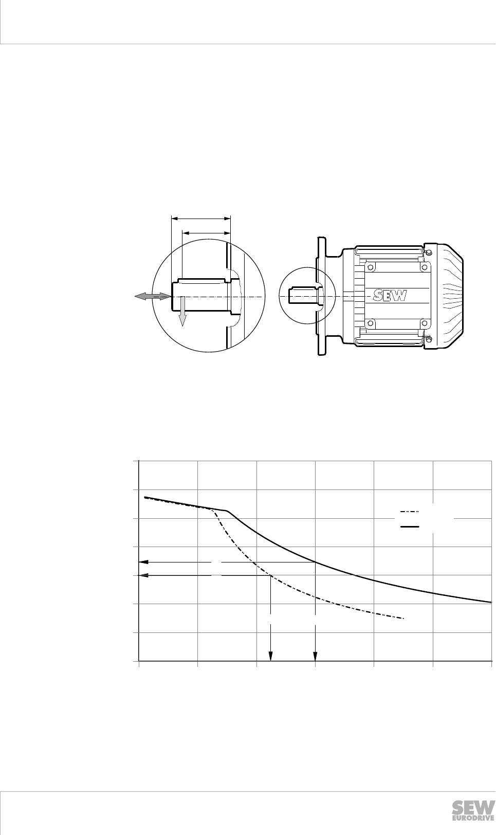
6.10 Overhung and axial loads
Refer to the following diagrams for the permitted overhung load FRx for AC motors/
brakemotors. In order to read the permitted overhung load from the diagram, you must
know what the distance x is between the force application point of the overhung load
FR and the shaft shoulder.
All overhung load diagrams are designed for a bearing service life of 20000 hours. A
detailed bearing service life calculations is available on request.
The following figure shows the point of force application of the overhung load FRx at
point X.
l
x
FA
FRx
3980490891
l= Length of the shaft end
x = Distance between overhung load application point and shaft shoulder
FRx = Overhung load at force application point
FA= Axial force
The following diagram shows an example of how you can read the overhung load from
the diagram:
0
200
400
600
800
1000
1200
1400
0 10 20 30 40 50 60
x [mm]
FRx [N]
Ø14x30
Ø19x40
[1] [2]
[2]
[1]
3980492555
[1] Motor with shaft diameter 14 mm, force application x at 22 mm, permitted overhung load FRx = 600 N
[2] Motor with shaft diameter 19 mm, force application x at 30 mm, permitted overhung load FRx = 700 N
19290411/EN – 10/2014
6
Drive selection
Overhung and axial loads
Catalog – AC Motors DR.71 - 315, DT56, DR63 157
During determining the overhung load, the transmission element factors fZ must be
considered. The transmission element factor depends on the used transmission ele-
ment, such as gears, chains, V-belts, flat belts or toothed belts. When belt pulleys are
used, the initial belt tension must be considered as well. The overhung loads FR calcu-
lated with the transmission element factor must not exceed the permitted overhung
load of the motor.
Transmission element Transmission element factor fZComments
Direct drive 1.0 –
Gears 1.0 ≥ 17 teeth
Gears 1.15 < 17 teeth
Sprockets 1.0 ≥ 20 teeth
Sprockets 1.25 < 20 teeth
Narrow V-belt 1.75 Influence of the pre-tensioning
force
Flat belt 2.50 Influence of the pre-tensioning
force
Toothed belt 1.50 Influence of the pre-tensioning
force
Gear rack 1.15 < 17 teeth (pinion)
The following equation is used to calculate the overhung load with the transmission el-
ement factor fZ:
FR = fz × FRx
6.10.1 Permitted overhung load – 2-, 4-, 6-, 12-pole motors
The permitted overhung loads for 2-, 4-, 6- and 12-pole motors are displayed in the
individual size diagrams in the "Overhung load diagrams for 2-, 4-, 6- and 12-pole mo-
tors" (→ 2 159) chapter.
Only the sizes, not the design lengths, are displayed separately. The different shaft
ends are shown as separate curves, parallel in the diagram, if available.
6.10.2 Permitted overhung load – pole-changing motors
The determined FRx value for the motors is multiplied by a factor of 0.8 in order to de-
fine the permitted overhung load FRx-DRx/y for the relevant pole-changing motors.
FRx-DRx/y = 0.8 × FRx
The assignment for the conversion is as follows:
• 2-pole motors are used for the
– 4/2-pole motors with Dahlander winding
– 8/2-pole motors with separate winding
• 4-pole motors are used for the
– 8/4-pole motors with Dahlander winding
6.10.3 Permitted overhung load of DRL.. motors
The determined FRx value for the 4-pole DRL.. motors of the same size is multiplied by
a factor of 0.8 in order to define the permitted overhung load FRx-DRL for the 4-pole
DRL.. motors.
FRx-DRL = 0.8 × FRx
19290411/EN – 10/2014
6

6Drive selection
Overhung and axial loads
Catalog – AC Motors DR.71 - 315, DT56, DR63
158
6.10.4 Permitted overhung load of DRM.. motors
The permitted overhung loads for the 12-pole torque motors are identical to the over-
hung loads for the 6-pole motors, please refer to the "Overhung load diagrams for 2-,
4-, 6-, 12-pole motors" (→ 2 159).
6.10.5 Permitted axial load
The permitted axial load FA is calculated by multiplying the determined overhung load
FRx by a factor of 0.2 for all DR.. series motor types:
• FA = 0.2 × FRx
The axial load FA can load the motor's shaft end at the same time as the calculated
overhung load FR.
6.10.6 Overhung and axial loads at the second shaft end
The "Overhung load diagrams for 2-, 4-, 6-, 12-pole motors" (→ 2 159) also displays
the diagrams for the permitted overhung loads at the second shaft end for every motor
size. A distinction is made between motors and brakemotors as well as between
standard and reinforced second shaft ends.
Axial loads at the second shaft end may not exceed the information from the "Permit-
ted axial load" (→ 2 158) chapter based on a directional addition.
6.10.7 Torques and duty types
The customer's motor shaft and bearings are designed for the overhung and axial
loads in the following diagrams in this chapter. The information is based on the nomi-
nal speed nN and the superimposed nominal torque MN in S1, S2 and S3 motor opera-
tion.
The second shaft end of the motor, shown as /2W in the diagrams, can transfer a
maximum of the motor's nominal torque MN in S1 operation.
If conditions occur which are not considered in the descriptions or diagrams in this
chapter, consult SEW‑EURODRIVE.
19290411/EN – 10/2014
6
Drive selection
Overhung and axial loads
Catalog – AC Motors DR.71 - 315, DT56, DR63 159
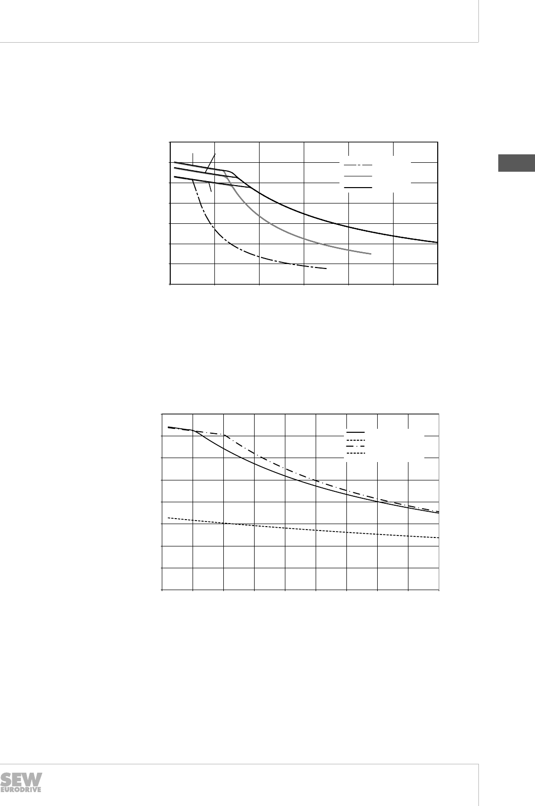
6.10.8 Overhung load diagrams for 2-, 4-, 6-, 12-pole motors
Overhung load diagram for DR.71
Overhung load diagrams for 2-, 4-, 6-, 12-pole DR.71 motors:
DR.71
0
200
400
600
800
1000
1200
1400
0 10 20 30 40 50 60
x [mm]
FRx [N]
Ø14x30
Ø11x23
Ø19x40
2
4
6,12
9007203235240331
2: 2-pole 4: 4-pole 6, 12: 6- and 12-pole
Overhung load diagram for DR.71 at the second shaft end
Overhung load diagram for 2-, 4-, 6-, 12-pole DR.71 motors at the second shaft end:
DR.71/2W
0
50
100
150
200
250
300
350
400
0 5 10 15 20 25 30 35 40 45
x [mm]
Ø11x23
Ø11x23 BE/RS
Ø14x30
Ø14x30 BE/RS
FRx [N]
3980502027
19290411/EN – 10/2014
6
6Drive selection
Overhung and axial loads
Catalog – AC Motors DR.71 - 315, DT56, DR63
160
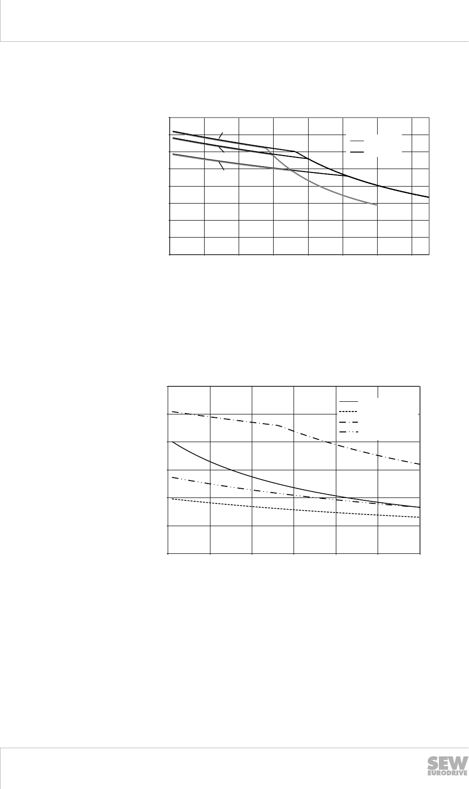
Overhung load diagram for DR.80
Overhung load diagram for 2-, 4-, 6-, 12-pole DR.80 motors:
DR.80
0
200
400
600
800
1000
1200
1400
1600
0 10 20 30 40 50 60 70
x [mm]
FRx [N]
Ø19x40
Ø24x50
2
4
6,12
9007203235245707
2: 2-pole 4: 4-pole 6, 12: 6- and 12-pole
Overhung load diagram for DR.80 at the second shaft end
Overhung load diagram for 2-, 4-, 6-, 12-pole DR.80 motors at the second shaft end:
0
100
200
300
400
500
600
0 10 20 30 40 50 60
DR.80 /2.WE
Ø14x30
Ø14x30 BE/RS
Ø19x40
Ø19x40 BE/RS
FRx [N]
x [mm]
9007203235248395
19290411/EN – 10/2014
6
Drive selection
Overhung and axial loads
Catalog – AC Motors DR.71 - 315, DT56, DR63 161
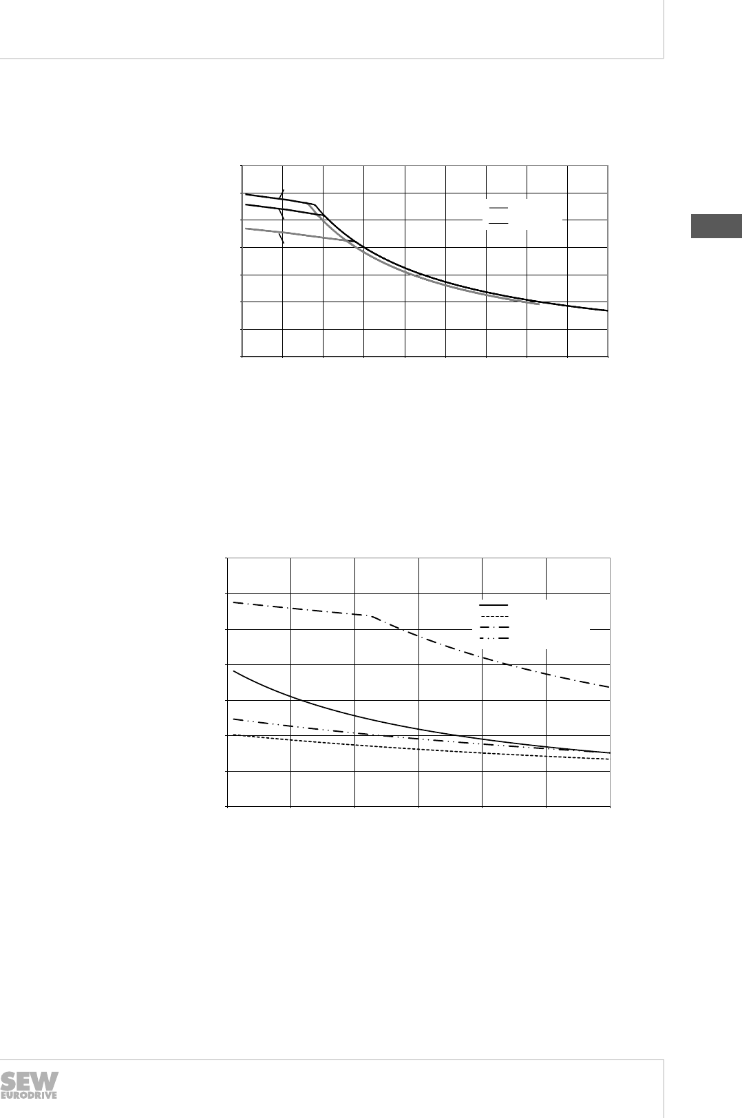
Overhung load diagram for DR.90 and DR.100
Overhung load diagram for 2-, 4-, 6-, 12-pole DR.90 and DR.100 motors:
0
500
1000
1500
2000
2500
3000
0 10 20 30 40 50 60 70 80 90
x [mm]
FRx [N]
Ø24x50
Ø28x60
3500
2
4
6,12
DR.90/100
9007203235251083
2: 2-pole 4: 4-pole 6, 12: 6- and 12-pole
Overhung load diagram for DR.90 and DR.100 at the second shaft end
Overhung load diagram for 2-, 4-, 6-, 12-pole DR.90 and DR.100 motors at the second
shaft end:
0
100
200
300
400
500
600
700
0 10 20 30 40 50 60
DR.90-100 /2.WE
Ø14x30
Ø14x30 BE/RS
Ø19x40
Ø19x40 BE/RS
FRx [N]
x [mm]
9007203235253771
19290411/EN – 10/2014
6
6Drive selection
Overhung and axial loads
Catalog – AC Motors DR.71 - 315, DT56, DR63
162
Overhung load diagram for DR.112 and DR.132
Overhung load diagram for 2-, 4-, 6-, 12-pole DR.112 and DR.132 motors:
DR.112/132
0
500
1000
1500
2000
2500
3000
3500
4000
0 20 40 60 80 100 120
x [mm]
FRx [N]
Ø28x60
Ø38x80
2
4
6,12
4500
9007203235256459
2: 2-pole 4: 4-pole 6, 12: 6- and 12-pole
Overhung load diagram for DR.112 and DR.132 at the second shaft end
Overhung load diagram for 2-, 4-, 6-, 12-pole DR.112 and DR.132 motors at the sec-
ond shaft end:
0
100
200
300
400
500
600
700
800
900
0 10 20 30 40 50 60 70 80 90
DR.112-132 /2.WE
Ø19x40
Ø19x40 BE/RS
Ø24x50
Ø24x50 BE/RS
Ø28x60
Ø28x60 BE/RS
FRx [N]
x [mm]
9007203235259147
19290411/EN – 10/2014
6
Drive selection
Overhung and axial loads
Catalog – AC Motors DR.71 - 315, DT56, DR63 163
Overhung load diagram for DR.160
Overhung load diagram for 4- and 6-pole DR.160 motors:
DR.160
0
1000
2000
3000
4000
5000
6000
0 20 40 60 80 100 120 140 160
x [mm]
Ø38x80
Ø42x110
FRx [N]
4
6
3980520843
4: 4-pole 6: 6-pole
Overhung load diagram for DR.160 at the second shaft end
Overhung load diagram for 4- and 6-pole DR.160 motors at the second shaft end:
0
500
1000
1500
2000
2500
3000
0 20 40 60 80 100 120
DR.160 /2.WE
Ø28x60
Ø28x60 BE/RS
Ø38x80
Ø38x80 BE/RS
FRx [N]
x [mm]
9007203235264523
19290411/EN – 10/2014
6
6Drive selection
Overhung and axial loads
Catalog – AC Motors DR.71 - 315, DT56, DR63
164
Overhung load diagram for DR.180
Overhung load diagram for 4-pole DR.180 motors:
DR.180
0
1000
2000
3000
4000
5000
6000
7000
8000
9000
10000
0 20 40 60 80 100 120 140 160
F [N]
Rx
x [mm]
Ø42x110
Ø48x110
Ø55x110
9007203235267211
Overhung load diagram for DR.180 at the second shaft end
Overhung load diagram for 4-pole DR.180 motors at the second shaft end:
0
500
1000
1500
2000
2500
3000
3500
4000
4500
0 20 40 60 80 100 120 140 160
DR 0 /2.WE
Ø38x80
Ø38x80 BE /RS
Ø48x110
Ø48x110 BE /RS
FRx [N]
x [mm]
9007203235269899
19290411/EN – 10/2014
6
Drive selection
Overhung and axial loads
Catalog – AC Motors DR.71 - 315, DT56, DR63 165
Overhung load diagram for DR.200 and DR.225
Overhung load diagram for 4-pole DR.200 and DR.250 motors:
DR.200/225
0
2000
4000
6000
8000
10000
12000
0 50 100 150 200
F [N]
Rx
x [mm]
Ø60x140 /
Ø55x110
Ø48x110
Ø65x140
3980531595
Overhung load diagram for DR.200 and DR.225 at the second shaft end
Overhung load diagram for 4-pole DR.200 and DR.225 motors at the second shaft
end:
0
1000
2000
3000
4000
5000
6000
0 20 40 60 80 100 120 140 160
DR..200-225 /2.WE
Ø48x110
Ø48x110 /BE
/RS
Ø55x110
Ø55x110 BE /RS
FRx [N]
x [mm]
9007203235275275
19290411/EN – 10/2014
6
6Drive selection
Overhung and axial loads
Catalog – AC Motors DR.71 - 315, DT56, DR63
166
Overhung load diagram for DR.250 and DR.280
Overhung load diagram for 4-pole DR.250 and DR.280 motors:
0
2500
5000
7500
10000
12500
15000
17500
20000
0 25 50 75 10 0 12 5 150 1 75 200
FRx [N]
x [mm]
DR250/280
Ø60x140
Ø60x140 ERF
Ø65x140
Ø65x140 /ERF
Ø75x140
Ø75x140 /ERF
Begrenzung Fuß
AH 250
7290617227
Overhung load diagram for DR.250 and DR.280 at the second shaft end
Overhung load diagram for 4-pole DR.250 and DR.280 motors at the second shaft
end:
0
1000
2000
3000
4000
5000
6000
7000
0 25 50 75 100 125 150
F
Rx [N]
x [mm]
DR.250/280 /2W
Ø55x110
Ø55x110 BE/RS
9007206545360651
19290411/EN – 10/2014
6
Drive selection
Overhung and axial loads
Catalog – AC Motors DR.71 - 315, DT56, DR63 167
Overhung load diagram for DR.315
Overhung load diagram for 4-pole DR.315 motors:
0
5000
10000
15000
20000
25000
30000
0 20 40 60 80 100 120 140 160
x [mm]
F [N]
Rx
DR.315
Ø80x170../ERF/NS
Ø80x170
3980536971
INFORMATION
The conversion of the overhung load into the axial load (→ 2 158) must not be used
with reinforced bearings (../ERF).
The standard bearing value (lower curve) at point x is used for the conversion instead
of the value for /ERF (upper curve).
Overhung load diagram for DR.315 at second shaft end
Overhung load diagram for 4-pole DR.315 motors at the second shaft end:
0
2000
4000
6000
8000
10000
0 25 50 75 100 125 150 175 200
x [mm]
DR.315 /2W
Ø70x140../2W
Ø70x140..BE../2W
FRx [N]
9007203235281035
19290411/EN – 10/2014
6
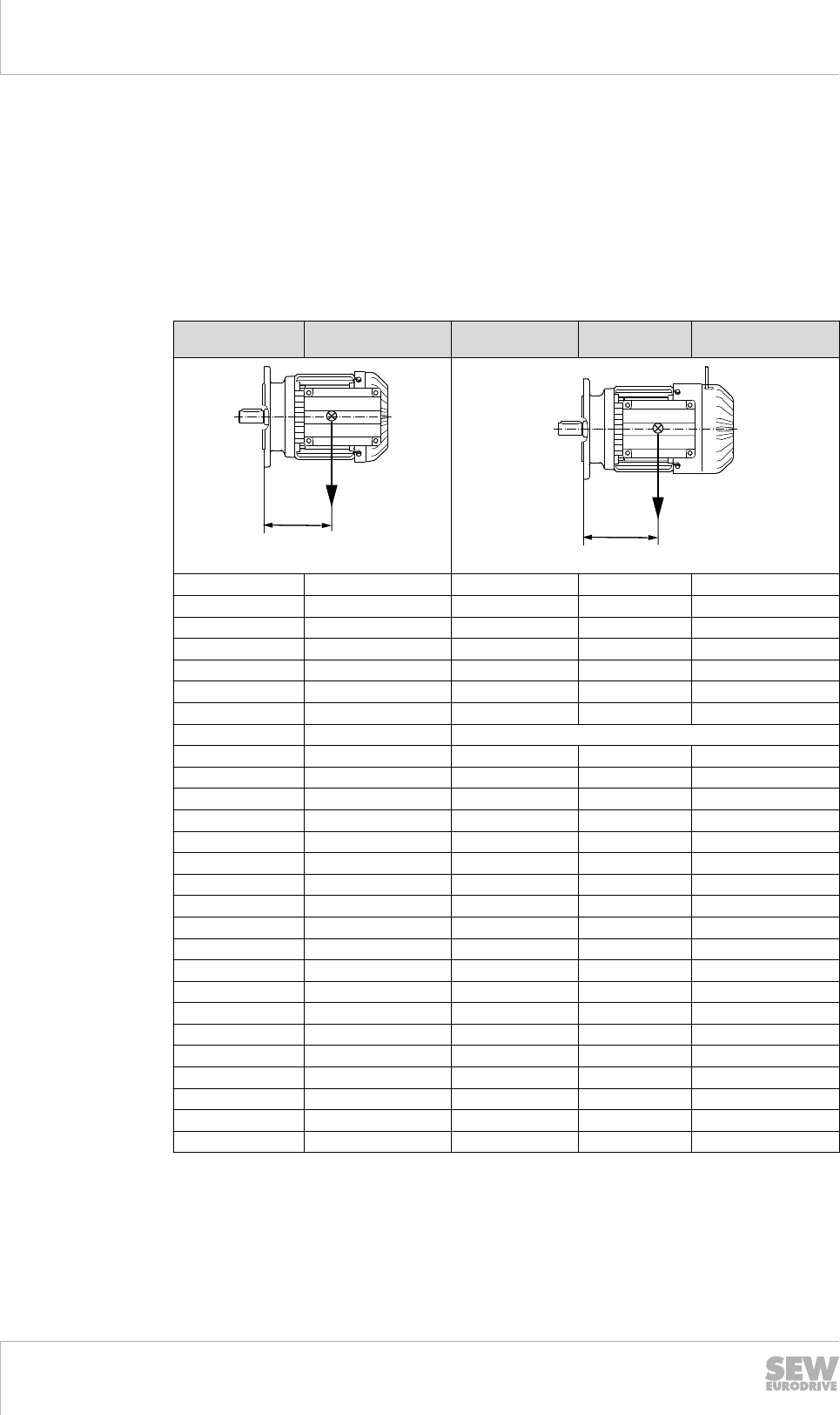
6Drive selection
Center of gravity of motors
Catalog – AC Motors DR.71 - 315, DT56, DR63
168
6.11 Center of gravity of motors
The center of gravity of a motor is a theoretical variable which assumes that the entire
mass of the motor is concentrated in one point and acts on this point with the weight
Fq. The mass of the motor can be found in the chapter "Technical motor
data" (→ 2 91).
The center of gravity of the motor must also be taken into account when combining
gear units with flange motors and, if applicable, with feet attached with the aid of
adapters.
Motor type Center of gravity S
in mm
Brakemotor type Brake Center of gravity S
in mm
S
Fq
3980543755
S
Fq
3980546443
DR.71S 86 DR.71S BE05 108
DR.71M 92 DR.71M BE1 112
DR.80S 106 DR.80S BE1 148
DR.80M 119 DR.80M BE2 150
DR.90M 118 DR.90M BE2 142
DR.90L 124 DR.90L BE5 151
DR.100M 137 DR.100M BE5 165
DRP100M 140
DR.100L / LC 153 DR.100L / LC BE5 180
DR.112M 153 DR.112M BE5 179
DR.132S 167 DR.132S BE11 202
DR.132M / MC 193 DR.132M / MC BE11 226
DR.160S 205 DR.160S BE20 265
DR.160M / MC 205 DR.160M / MC BE20 255
DR.180S 224 DR.180S BE20 287
DR.180M 224 DR.180M BE30 302
DR.180L 237 DR.180L BE32 321
DR.180LC 237 DR.180LC BE32 318
DR.200L 228 DR.200L BE32 340
DR.225S 250 DR.225S BE32 340
DR.225M 264 DR.225M BE32 363
DR.225MC 264 DR.225MC BE32 354
DR.250M 321 DR.250M BE62 420
DR.280S 341 DR.280S BE62 433
DR.280M 341 DR.280M BE122 442
DR.315K / S 419 DR.315K / S BE122 489
DR.315M / L 505 DR.315M / L BE122 550
19290411/EN – 10/2014

6
Drive selection
Drive selection – non-controlled motor
Catalog – AC Motors DR.71 - 315, DT56, DR63 169
6.12 Drive selection – non-controlled motor
The following flow diagram illustrates the project planning procedure for a non-control-
led drive. The drive consists of a gearmotor operated on the grid.
6.12.1 Flow diagram
Necessary information on the machine to be driven
• Technical data and environmental conditions
• Positioning accuracy
• Speed setting range
• Calculation of the travel cycle
↓
Calculation of the relevant application data
• Travel diagram
• Speeds on 50 Hz or 60 Hz supply system
• Static, dynamic torques
• Regenerative power
↓
Gear unit selection
• Define gear unit size, gear unit ratio, and gear unit type
• Check positioning accuracy
• Check gear unit utilization (Ma max ≥ Ma (t))
• Check input speed (churning losses)
↓
Motor selection
• Maximum torque
• With dynamic drives: effective torque at medium speed
• Maximum speed
• Determine energy efficiency class IE
• Observe dynamic and thermal torque curves
• Select the correct encoder
• Motor equipment (brake, plug connector, thermal motor protection, etc.)
↓
Braking resistor selection
• Based on the calculated regenerative power, cdf, and peak breaking power.
↓
Make sure that all requirements have been met.
19290411/EN – 10/2014
6
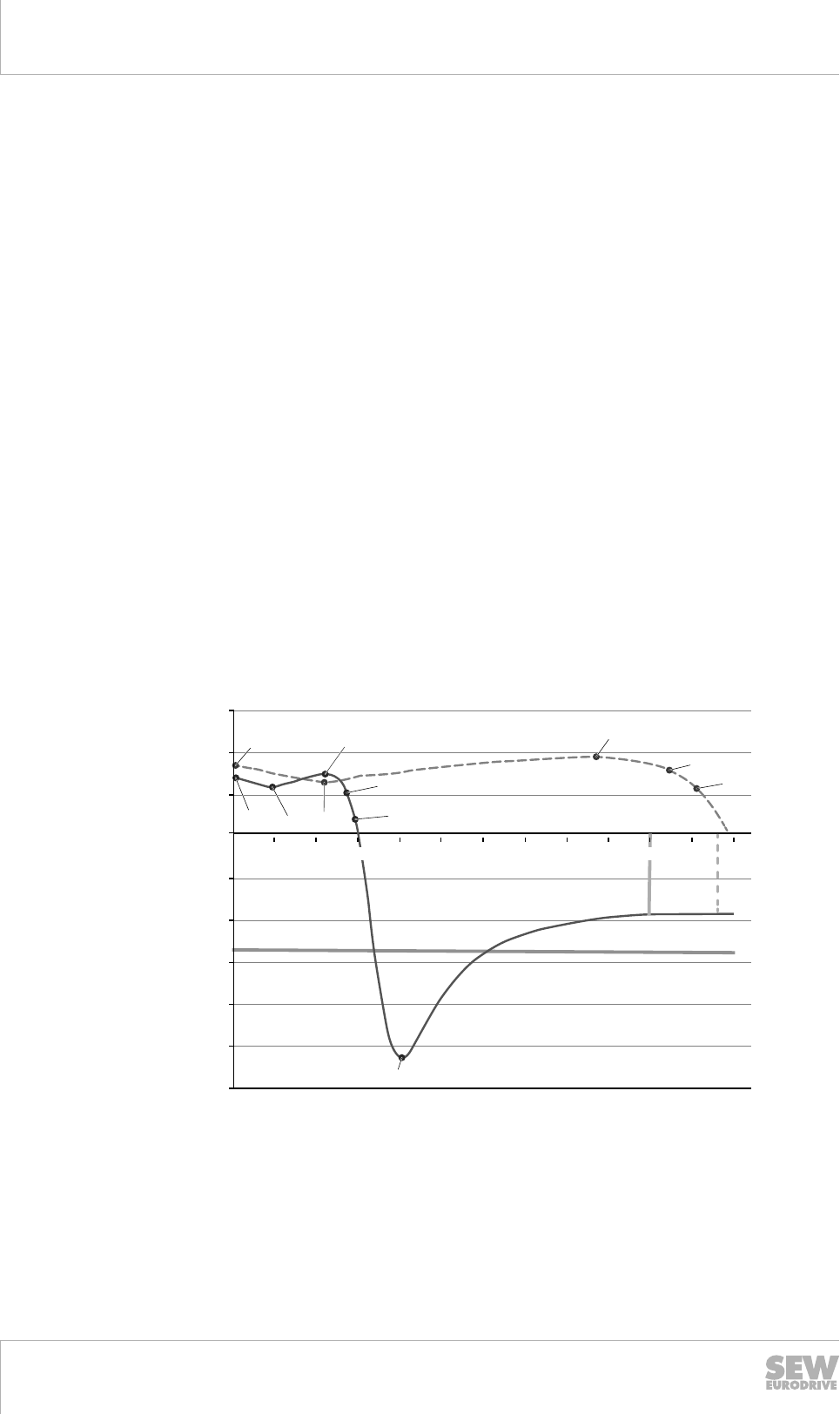
6Drive selection
Drive selection – non-controlled motor
Catalog – AC Motors DR.71 - 315, DT56, DR63
170
6.12.2 Drive selection for pole-changing motors
The following windings are distinguished for pole-changing motors:
• Separate winding: 8/2-pole DRS.. motors
• Dahlander winding: 4/2, 8/4-pole DRS.. motors
Description of switching torque
The functioning of the switchover from the 2-pole to the 8-pole winding is explained on
the basis of the 8/2 pole motor.
If the 8-pole winding is connected to the supply system from the operation of the 2-
pole speed, with virtually no period of no-load operation, the motor briefly functions as
a generator due to the above-synchronous speed. The transformation of kinetic ener-
gy into electrical energy decelerates it to the lower speed in a low-loss, wear-free
manner.
To be able to calculate the mean switching torque as a first approximation, the availa-
ble kinematic data is employed.
MU = fU × MA8
MU = geometrically averaged switching torque from high to low speed in Nm.
MA8 = starting torque in low speed in Nm.
fU = averaged factor of 8-pole winding's regenerative torque curve.
If the switching torque is too high, SEW-EURODRIVE recommends the use of the
WPU smooth-pole change unit.
MA2
MH2
MA8
Mkmot(8)
Mn,S3(8)
MH8
Mn,S1(8)
Mkgen(8)
Mkmot(2)
Mn,S3(2)
Mn,S1(2)
0
5
10
15
-20
-15
-10
-5
-30
-25
250 500 1000 1250 1500 1750 2000 2250 2750
750 2500 3000
M [Nm] DRS90M8/2
n [1/min]
[1]
[2] MU
9007204661919627
[1] Characteristic curve:
2-pole
Mkmot = motor breakdown torque
[2] Characteristic curve:
8-pole
Mkgen = regenerative breakdown torque
MA8 = starting torque: 8-pole MH = acceleration torque
MA2 = starting torque: 2-pole MU = mean switching torque from high to low
speed
19290411/EN – 10/2014
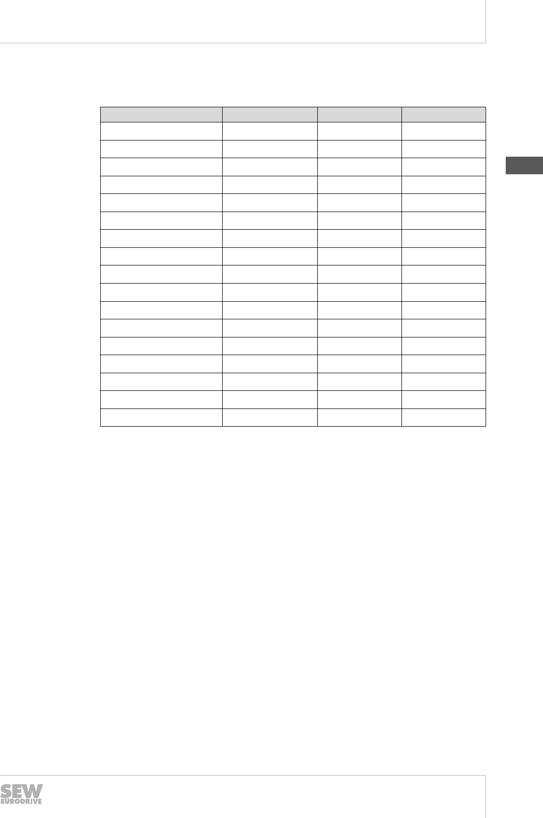
6
Drive selection
Drive selection – non-controlled motor
Catalog – AC Motors DR.71 - 315, DT56, DR63 171
MU values of 8/4 pole motors (S1)
The following table shows the factors fU and the MU torques of the 8/4-pole motors.
Motor type MA8 in Nm fUMU in Nm
DRS71S8/4 2.3 2.4 5.5
DRS71M8/4 3.8 2.4 9.1
DRS80M8/4 5.3 2.3 12.3
DRS90M8/4 8.5 2.2 18.6
DRS90L8/4 10.8 2.2 23.8
DRS100M8/4 15.5 2.0 31.0
DRS100L8/4 21.3 2.0 42.5
DRS112M8/4 32.3 2.0 64.6
DRS132S8/4 45.0 2.0 90.0
DRS132M8/4 56.0 2.0 112
DRS160S8/4 74.8 2.0 150
DRS160M8/4 99.4 2.0 199
DRS180S8/4 158 2.0 316
DRS180L8/4 234 2.0 468
DRS200L8/4 343 2.0 686
DRS225S8/4 455 2.0 910
DRS225M8/4 557 2.0 1114
19290411/EN – 10/2014
6
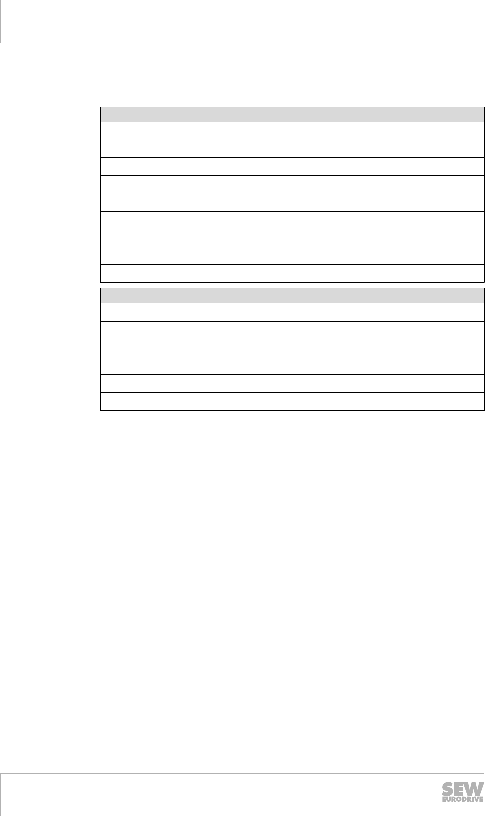
6Drive selection
Drive selection – non-controlled motor
Catalog – AC Motors DR.71 - 315, DT56, DR63
172
MU values of 8/2 pole motors
The following table shows the factors fU and the MU torques of the 8/2-pole motors.
Motor type (S3/40/60%) MA8 in Nm fUMU in Nm
DRS71S8/2 1.42 2.1 2.98
DRS71M8/2 2.29 2.5 5.72
DRS80S8/2 3.26 2.3 7.49
DRS80M8/2 5.25 2.1 11.0
DRS90M8/2 5.64 2.3 13.0
DRS90L8/2 8.36 1.8 15.0
DRS100M8/2 12.0 1.8 21.6
DRS112M8/2 16.2 1.8 29.2
DRS132M8/2 22.2 2.2 48.8
Motor type (S1) MA8 in Nm fUMU in Nm
DRS71S8/2 1.04 2.1 2.19
DRS80S8/2 3.26 2.3 7.49
DRS80M8/2 5.25 2.1 11.0
DRS90L8/2 7.47 1.8 13.5
DRS100M8/2 10.0 1.8 18.0
DRS132M8/2 22.2 2.2 48.8
19290411/EN – 10/2014
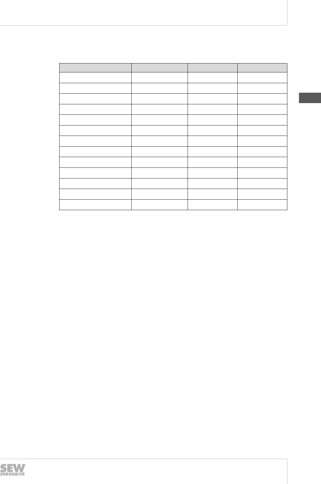
6
Drive selection
Drive selection – non-controlled motor
Catalog – AC Motors DR.71 - 315, DT56, DR63 173
MU values of 4/2 pole motors
The following table shows the factors fU and the MU torques of the 4/2-pole motors.
Motor type MA4 in Nm fUMU in Nm
DRS71S4/2 2.57 3.1 7.95
DRS71M4/2 4.43 3.1 13.7
DRS80M4/2 10.1 3.4 34.4
DRS90M4/2 14.7 3.3 48.5
DRS90M4/2 19.1 3.3 63.0
DRS100M4/2 27.0 3.5 94.5
DRS100L4/2 37.6 3.5 132
DRS132S4/2 39.1 2.0 78.1
DRS132M4/2 54.9 2.0 110
DRS160S4/2 97.5 2.0 195
DRS160M4/2 126 2.0 253
DRS180L4/2 219 2.0 440
DRS180L4/2 288 2.0 575
19290411/EN – 10/2014
6
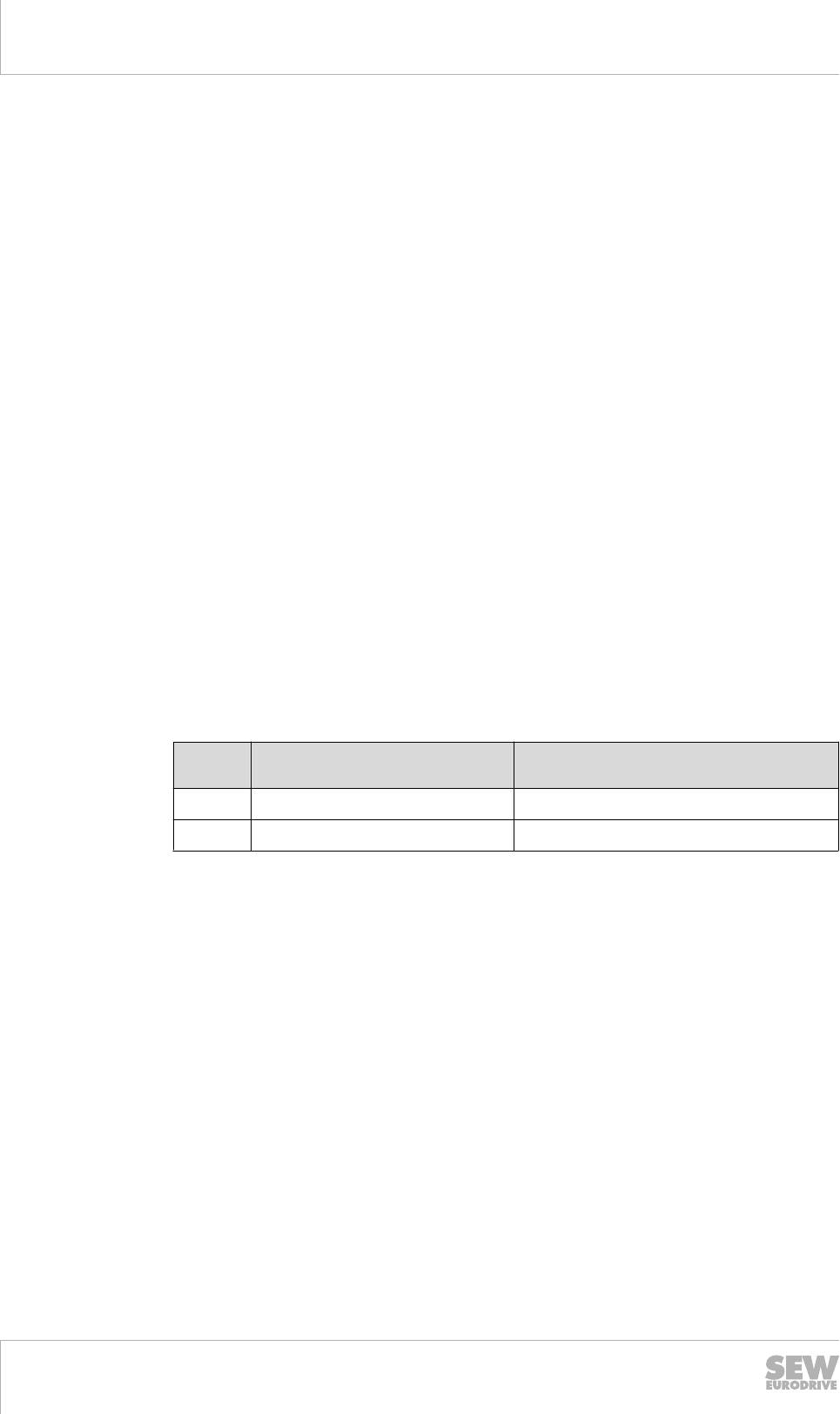
6Drive selection
Drive selection – global motor
Catalog – AC Motors DR.71 - 315, DT56, DR63
174
6.13 Drive selection – global motor
When selecting a global motor, the following properties should be taken into account.
6.13.1 Gear unit reduction ratios for the global motor
The global motor is supplied with the electrical specifications for 50 Hz and 60 Hz. If
the motor is combined with an additional transmission or a gear unit, it should be no-
ted that the reduction ratio is generally only determined for one of the two frequencies.
If the reduction ratio is calculated for 50 Hz and the gear unit configured accordingly,
this results in the behavioral changes described in the chapter "50 Hz motors on 60 Hz
supply systems" (→ 2 127) when operated on a 60 Hz system.
If operation on the 60 Hz supply system represents the initial situation, the ratios from
the chapter "50 Hz motors on 60 Hz supply systems" (→ 2 127) are reversed.
These ratio changes must be taken into account when designing machines and sys-
tems.
6.13.2 Identification of degrees of protection
SEW-EURODRIVE classifies the motor degrees of protection according to the interna-
tional standard IEC 60034-5; see chapter "Degrees of protection to EN/IEC
60034-5" (→ 2 139).
In North America, on the other hand, identification of a different degree of protection is
required by the relevant standards.
The degree of protection is represented by an abbreviation made up of four charac-
ters. In the case of the global motor, SEW-EURODRIVE employs the following identifi-
cations and includes this information on the nameplate.
Abbrevi-
ation
English designation German translation
TEFC Totally Enclosed Fan Cooled völlig geschlossen, Lüfter gekühlt
TEBC Totally Enclosed Blower Cooled völlig geschlossen, Fremdlüfter gekühlt
In NEMA MG1, degrees of protection IP54 to IP66 are all classified as fully enclosed.
6.13.3 Voltage tolerances
If multiple voltages are included on a motor nameplate, the actual limit values and tol-
erances must be considered.
The motor standard IEC 60034 comprises two tolerance ranges. If no tolerance is
specified on the nameplate, a voltage tolerance of ± 5% applies. For more information,
refer to the chapter "Motor standard IEC 60034" (→ 2 25).
The voltages in 50 Hz supply systems are generally based on the standard IEC 38.
Here, the tolerance range is ±10%.
In 60 Hz systems, the usual tolerance is ±10 % and normally indicated without addi-
tional information on the nameplate.
In order to implement motor and supply system standards for products such as the
global motor, the voltage range was created.
The specification of an upper and lower voltage, each with a ± 5% tolerance, results in
a combined tolerance of ± 10% for the median voltage.
This procedure is employed for the tolerances of the voltage blocks specified in the
chapter "Global motor" (→ 2 45).
19290411/EN – 10/2014

6
Drive selection
Drive selection – global motor
Catalog – AC Motors DR.71 - 315, DT56, DR63 175
6.13.4 Global motor with brake
In many drive situations and applications, it is sufficient to tap the brake voltage from
the supply voltage of the motor.
If the motor is configured for the 50 Hz and 60 Hz voltage range, the brake voltage
covers a very large range.
As described in the chapter "Brake voltage" (→ 2 126), the brake must not be released
at the upper voltages in these cases without activating the motor in order to cool the
brake with the motor cooling air.
19290411/EN – 10/2014
6
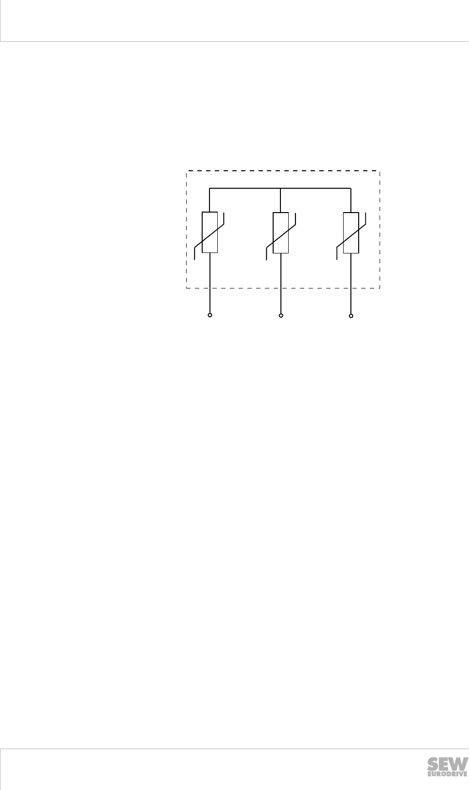
6Drive selection
Drive selection – DRM.. torque motors
Catalog – AC Motors DR.71 - 315, DT56, DR63
176
6.14 Drive selection – DRM.. torque motors
6.14.1 Special aspects of torque motors and low-speed motors
Due to the design of torque motors and low-speed motors, very high induction voltag-
es may be generated when they are switched off. SEW‑EURODRIVE recommends
using the varistor circuit shown below for protection. The size of the varistors depends,
amongst other factors, on the starting frequency. This must be taken into account dur-
ing project planning.
U
U1
UU
V1W1
4754651531
The varistor protection circuit can be obtained from SEW-EURODRIVE. Please speci-
fy the desired starting frequency with your order.
6.14.2 R13 wiring diagram
The conventional torque motor operation is measured in a star connection in S1 con-
tinuous duty.
If the same torque motor is used in a delta connection, the usual factor of 3 for AC
motors no longer applies due to the weak magnetic field saturation of the star connec-
tion. The influence of the magnetic stray fields in the star or delta connection is no lon-
ger proportional. As a result, the torque motor in the delta connection develops a high-
er torque than that produced by the factor of 3. In return, the operating time must be
reduced to S3/15%.
Alternatively, the reduction of the operating time can be compensated by means of a
forced cooling fan.
6.14.3 R23 wiring diagram
For applications that use the two connection types star and delta alternately and must
not have more than the 3 times the torque of the star connection in the delta connec-
tion, SEW‑EURODRIVE offers the connection type R23. Only part of the winding is
activated in the case of the delta connection.
Please consult SEW‑EURODRIVE if necessary.
6.14.4 Restrictions due to combinations with options and variations
As a result of the non-ventilated operation, the components and component parts of
the torque motors are subject to greater thermal stress at a standstill than a normal
AC motor.
Therefore, all variations and options that cannot be subjected to high thermal loads
must be excluded from the combination with torque motors.
19290411/EN – 10/2014

6
Drive selection
Drive selection – DRM.. torque motors
Catalog – AC Motors DR.71 - 315, DT56, DR63 177
These include:
• The backstop: The grease used within the backstop to ensure the mobility of the
blocking bodies reaches impermissibly high temperatures, which can affect the tor-
que motor when at a standstill.
• The EI7 built-in encoders: When used with a torque motor, the installation space
before the fan and behind the B-side flange is heated to a point that the electronic
components of the sensor technology may be damaged.
• The EI7 built-in encoders are only approved for use in combination with the option-
al /V forced cooling fan. Without additional cooling, the rise in temperature before
the fan and behind the B-side flange is too high.
• The add-on encoders with direct shaft-shaft connection: Due to the transfer of heat
energy from the rotor to the shaft of the encoder, the latter reaches impermissibly
high temperatures. The use of a coupling for the encoder mounting, as a means of
interrupting the heat transfer, is permitted.
• The thermal class 180 (H): Use of the thermal class 180 (H) would stress the gas-
kets, bearings, and bearing lubricants beyond the permitted temperature thresh-
olds.
6.14.5 Flow diagram
The following diagram illustrates the basic drive selection process for a geared torque
motor.
INFORMATION
SEW-EURODRIVE recommends the use of a /TF temperature sensor in duty type
S3/15% cdf or when operated with a /V forced cooling fan.
19290411/EN – 10/2014
6
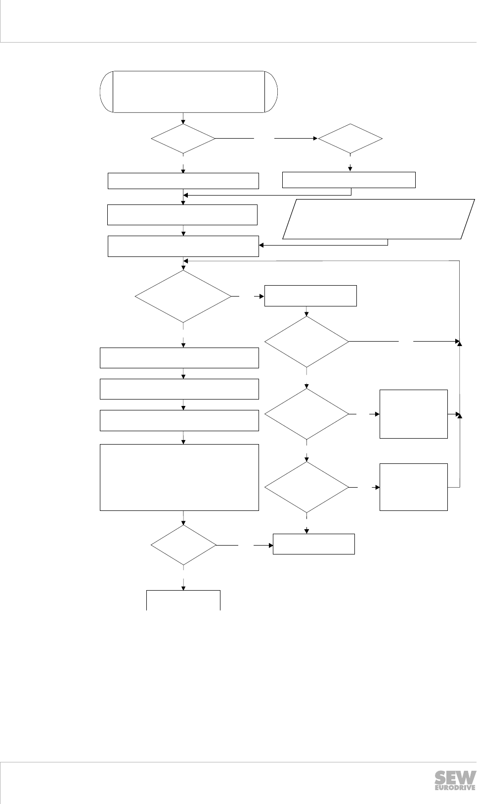
6Drive selection
Drive selection – DRM.. torque motors
Catalog – AC Motors DR.71 - 315, DT56, DR63
178
Frequency
= 60 Hz?
Yes
Yes
Choose the next largest
torque motors
Is intermittent
duty possible?
No
M is lower
than the required
tightening torque
0
Required output speed on the gear unit
Required output torque on the gear unit
Required tightening torque (force) on the gear unit
Required cyclic duration factor
Motor torque [Nm] =
Required output torque [Nm] / i
i = 400 [rpm]/output speed [rpm] 1)
Technical data:
Tightening torque M of the torque motor at
500 rpm / 50 Hz
600 rpm / 60 Hz
Consultation with
SEW EURODRIVE needed.
Is forced
air cooling
allowed?
No
Definition of the gear unit type: Helical gear, parallel,
bevel gear, SPIROPLAN or helical-worm gear unit
Required tightening torque of the torque motor
= twice the motor torque (continuous duty S1)
No
Yes
No
Frequency
= 50 Hz?
i = 480 [rpm]/output speed [rpm] 1)
Is a larger
torque motor
available?
M x i = calculated tightening torque
of the gear unit torque motors
0
Determination of the variant and gear unit size
of the gear unit torque motors2)
Checking the gear unit
– calculated i within the possible range according to
overview of combinations
– calculated tightening torque
M < M of the gear unit
– check overhung loads
– dimension sheet with the installation dimensions
2)
2)
2)
Is the
check OK?
Submit order
to SEW
No
No
change from rating I
to rating III
with forced air
cooling. Notice:
approx. triple Ma
Yes
change from rating I
to rating III
with forced air
cooling. Notice:
approx. triple Ma
Yes
Yes
Yes
3)
3)
aamax
o
®
4754659339
1) The speeds of 400 and 480 rpm during operation with approx. half the initial torque
only serve to calculate the required gear ratio
2) See "Geared torque motor" catalog
3) Rating I: duty type S1/100% cdf;
Rating II: duty type S3/15% cdf: 3x to 5x standstill torque (R13)
Rating III: duty type S3/15% cdf: 3x standstill torque (R23)
Rating IV: duty type S1 with /V forced cooling fan
19290411/EN – 10/2014

6
Drive selection
Drive selection – controlled motor
Catalog – AC Motors DR.71 - 315, DT56, DR63 179
6.15 Drive selection – controlled motor
6.15.1 Flow diagram
The following flow diagram illustrates the drive selection procedure for a positioning
drive. The drive consists of a gearmotor that is powered by an inverter.
Necessary information on the machine to be driven
• Technical data and environmental conditions
• Positioning accuracy
• Speed setting range
• Calculation of the travel cycle
↓
Calculation of the relevant application data
• Travel diagram
• Speeds on 50 Hz or 60 Hz supply system
• Static, dynamic torques
• Regenerative power
↓
Gear unit selection
• Define gear unit size, gear unit ratio, and gear unit type
• Check positioning accuracy
• Check gear unit utilization (Ma max ≥ Ma (t))
• Check input speed (churning losses)
↓
Motor selection
• Maximum torque
• With dynamic drives: effective torque at medium speed
• Maximum speed
• Determine the necessary energy efficiency class IE
• Observe dynamic and thermal torque curves
• Select the correct encoder based on the required positioning
• Motor equipment (brake, plug connector, thermal motor protection, etc.)
↓
Inverter selection
• Motor/inverter assignment
• Continuous current and peak current for current-controlled inverters/axes
↓
Braking resistor selection
• Based on the calculated regenerative power, cdf
• Based on the cyclic duration factor and peak braking power
↓
19290411/EN – 10/2014
6

6Drive selection
Drive selection – controlled motor
Catalog – AC Motors DR.71 - 315, DT56, DR63
180
Options
• EMC measures
• Operation/communication
• Additional functions
↓
Make sure that all requirements have been met.
19290411/EN – 10/2014
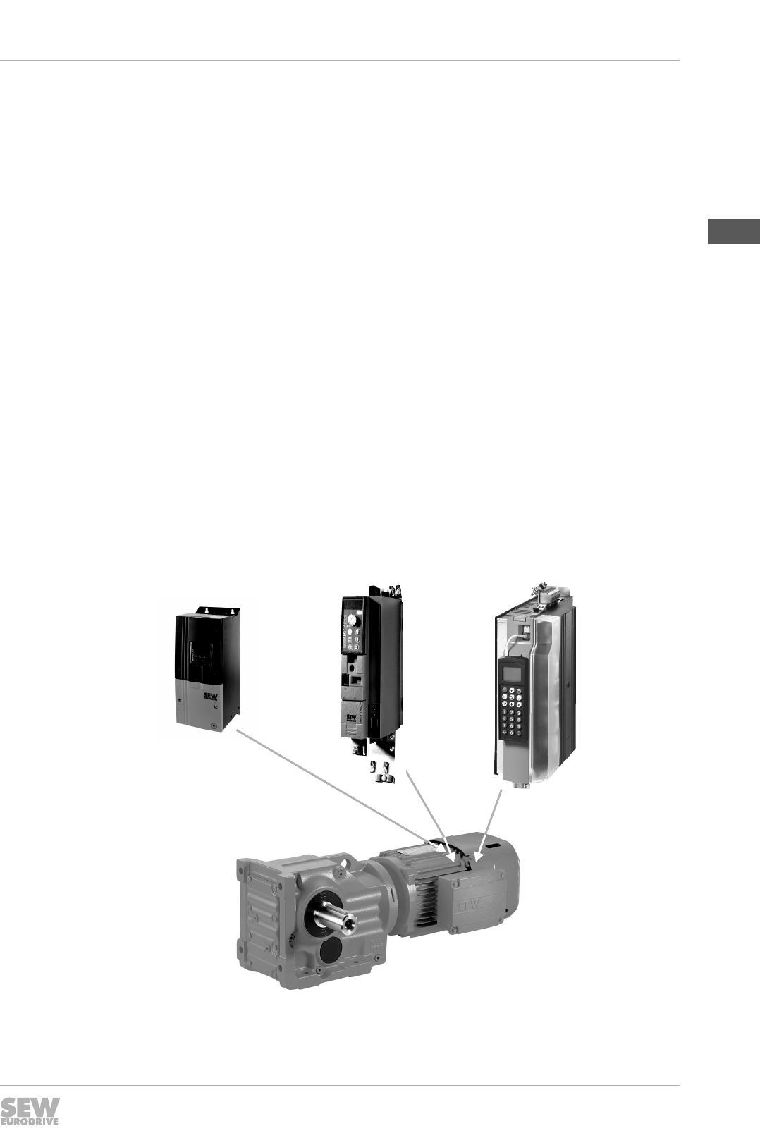
6
Drive selection
Drive selection – controlled motor
Catalog – AC Motors DR.71 - 315, DT56, DR63 181
6.15.2 Inverter operation in VFC and VFC-n mode
SEW frequency inverter range
The extensive product range of SEW‑EURODRIVE inverters is available for designing
electronically controlled drives.
The following inverters are available for voltage-controlled flux vector control (VFC):
•MOVITRAC® LTP-B: Simple and inexpensive frequency inverter for the 0.75 – 160
kW power range. Single-phase line connection for 230 V AC (up to 2.2 kW power
rating) and three-phase 200 – 240 V AC / 380 – 480 V AC / 500 – 600 V AC (as of
0.75 kW power rating).
•MOVITRAC® 07B: Compact and inexpensive frequency inverter for the 0.25 – 160
kW power range. Single-phase and three-phase line connection for 230 V AC and
three-phase line connection for 400 – 500 V AC.
•MOVIDRIVE® MDX60/61B: High-performance drive inverter for dynamic drives in
the 0.55 – 250 kW power range. Great diversity of applications due to extensive
expansion options with technology and communication options. Three-phase line
connection for 230 V AC and 400 – 500 V AC.
The following inverter is available for voltage-controlled flux vector control with speed
feedback (VFC-n):
•MOVIDRIVE® MDX60/61B: High-performance drive inverter for dynamic drives in
the 0.55 – 250 kW power range. Great diversity of applications due to extensive
expansion options with technology and communication options. Three-phase line
connection for 230 V AC and 400 – 500 V AC
The DRS.., DRE.., DRP.. AC motors can be operated with the inverters listed above.
MOVITRAC® 07B MOVIDRIVE®
MDX60/61B
MOVITRAC® LTP-B
8723978507
19290411/EN – 10/2014
6

6Drive selection
Drive selection – controlled motor
Catalog – AC Motors DR.71 - 315, DT56, DR63
182
Product characteristics of inverters
The following table lists the most important product characteristics for the various in-
verter series. You can choose the inverter series matching your application based on
these product characteristics.
Product character-
istics
MOVITRAC® LTP-B MOVITRAC® 07B MOVIDRIVE® MDX60/61B
Voltage range 1 × 200 – 240 V AC
(0.75 to 2.2 kW)
3 × 200 – 240 V AC
(0.75 to 75 kW)
3 × 380 – 480 V AC
(0.75 to 160 kW)
3 × 500 – 600 V AC
(0.75 to 110 kW)
1 × 200 – 240 V AC (limi-
ted power range)
3 × 200 – 240 V AC (limi-
ted power range)
3 × 380 – 500 V AC
3 × 200 – 240 V AC (limi-
ted power range)
3 × 380 – 500 V AC
Power range 0.75 – 15 kW (IP20)
0.75 – 160 kW (IP55)
0.25 – 75 kW 0.55 – 250 kW
Nominal current
range of the axis
modules
– 4 – 250 A
Overload capacity 150% IN for 60 seconds
175% IN for 2 seconds
150% IN1) briefly and 125% IN continuously in operation
without overload
4Q capable Yes, with integrated brake chopper as standard.
Integrated line filter At 1 × 200 – 240 V AC: ac-
cording to limit value class
B
At 3 × 200 – 240 V AC and
3 × 380 – 480 V AC: ac-
cording to limit value class
A
At 1 × 200 – 240 V AC: ac-
cording to limit value class
B
At 3 × 200 – 240 V AC and
3 × 380 – 500 V AC: ac-
cording to limit value class
A for sizes 0, 1, and 2
According to limit value
class A for sizes 0, 1, and
2
TF input Yes
Control modes U/f or voltage-controlled
flux vector control (VFC)
U/f or voltage-controlled
flux vector control (VFC)
U/f or voltage-controlled
flux vector control (VFC),
with speed feedback speed
control and current-control-
led flux vector control
(CFC).
Speed feedback Option in preparation No Option
Integrated position-
ing and sequence
control system
No No Standard
Serial interfaces System bus (SBus) and RS485
19290411/EN – 10/2014

6
Drive selection
Drive selection – controlled motor
Catalog – AC Motors DR.71 - 315, DT56, DR63 183
Product character-
istics
MOVITRAC® LTP-B MOVITRAC® 07B MOVIDRIVE® MDX60/61B
Fieldbus interfaces CANopen, Modbus RTU,
optional via gateway
PROFIBUS, EtherCAT®,
PROFINET, DeviceNet,
Ethernet/IP
Optional via gateway
PROFIBUS, INTERBUS,
CANopen, DeviceNet,
Ethernet
Optional PROFIBUS-DP,
INTERBUS, INTERBUS
LWL, CANopen,
DeviceNet, Ethernet
Technology options No IEC-61131 control Input/output card
Synchronous operation
Absolute encoder card
IEC-61131 control
Max. speed 30,000 rpm at 500 Hz 5,500 rpm 6,000 rpm
STO – Safe Torque
Off
Yes Yes Yes
Approvals UL and cUL approval, C-Tick
1) Only for MOVIDRIVE® MDX60/61B: The temporary overload capacity of size 0 units (0005 – 0014) is 200% IN.
19290411/EN – 10/2014
6
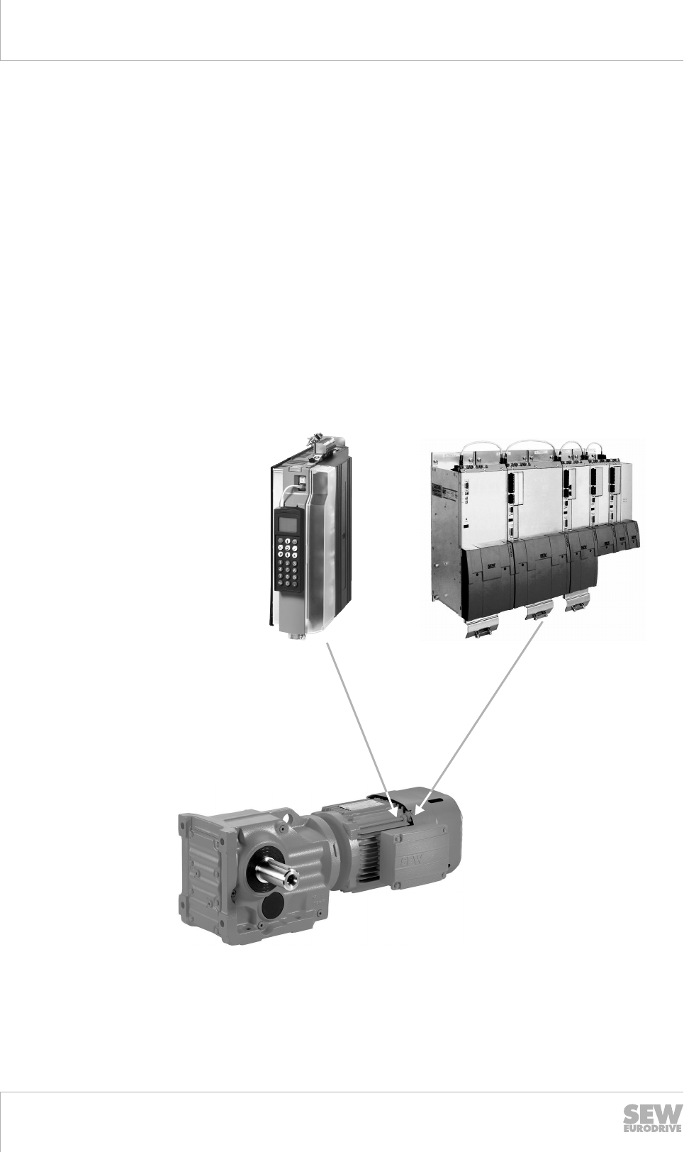
6Drive selection
Drive selection – controlled motor
Catalog – AC Motors DR.71 - 315, DT56, DR63
184
6.15.3 Inverter operation of DRL.. motors in CFC mode
Range of products
The extensive product range of SEW‑EURODRIVE inverters is available for designing
electronically controlled drives with current-controlled flux vector control (CFC).
•MOVIDRIVE® MDX60/61B: High-performance drive inverter for dynamic drives in
the 0.55 – 250 kW power range. Great diversity of applications due to extensive
expansion options with technology and communication options. Three-phase line
connection for 230 V AC and 400 – 500 V AC.
•MOVIAXIS® MX: Powerful and versatile multi-axis servo inverter with axis module
nominal currents of 2 – 133 A. Great diversity of applications thanks to extensive
expansion options with technology and communication options, as well as optional
sinusoidal or block-shaped regenerative power supply. Three-phase line connec-
tion for 380 – 500 V AC.
The asynchronous DRL.. servomotors can be operated with the inverters listed above.
MOVIDRIVE®
MDX60/61B
MOVIAXIS® MX
3980579083
19290411/EN – 10/2014
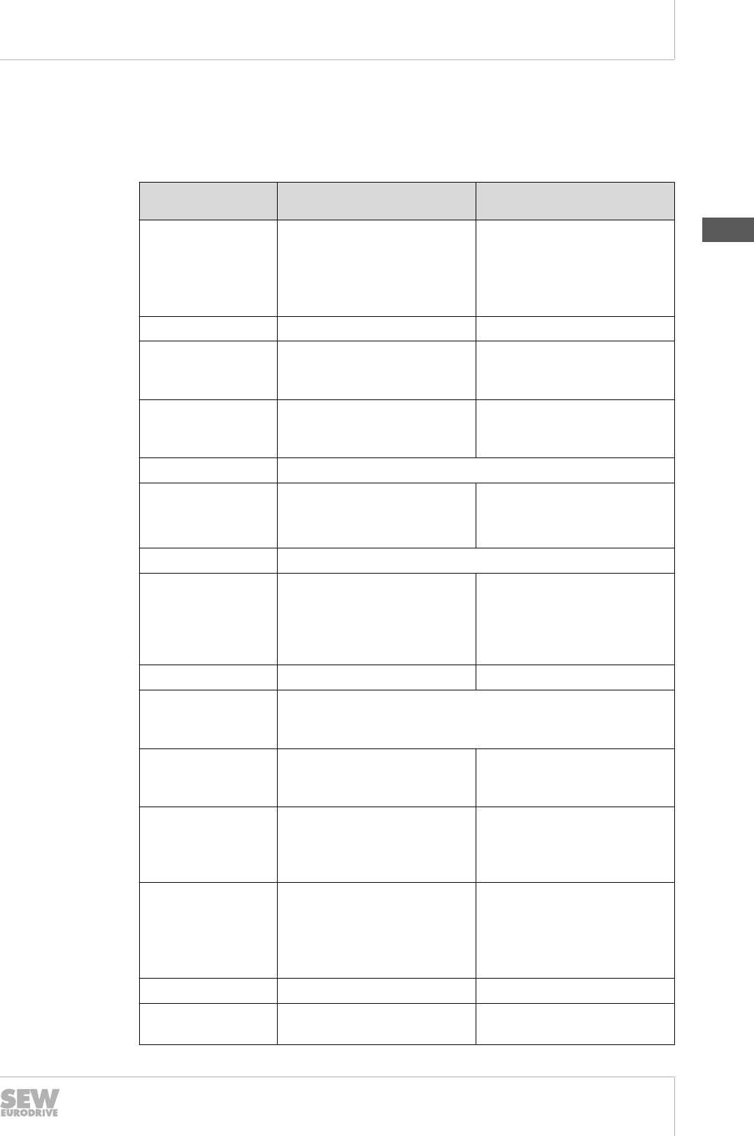
6
Drive selection
Drive selection – controlled motor
Catalog – AC Motors DR.71 - 315, DT56, DR63 185
Product characteristics
The following table lists the most important product characteristics for the various in-
verter series. You can choose the inverter series matching your application based on
these product characteristics.
Product character-
istics
MOVIDRIVE® MDX60/61B MOVIAXIS® MX
Voltage range 3 × 200 – 240 V AC
(1.5 to 30 kW)
3 × 380 – 500 V AC
(0.55 to 250 kW)
3 × 380 – 500 V AC
Power range 0.55 – 250 kW 10 – 75 kW
Nominal current
range of the axis
modules
4 – 250 A 2 – 133 A
Overload capacity 150 % IN1) briefly and 125% IN
continuously in operation with-
out overload
250% for max. 1 second
4Q capable Yes, with integrated brake chopper as standard.
Integrated line filter Sizes 0, 1, and 2
according to limit value class
A
External line filter
TF input Yes
Control modes U/f or voltage-controlled flux
vector control (VFC), with
speed feedback speed control
and current-controlled flux
vector control (CFC).
Current-controlled flux vector
control
Speed feedback Option Integrated in basic unit
Integrated position-
ing and sequence
control system
Standard
Serial interfaces System bus (SBus)
and RS485
CAN-based system bus, op-
tional EtherCAT®-compatible
system bus
Fieldbus interfaces Optional PROFIBUS-DP, IN-
TERBUS, INTERBUS LWL,
CANopen, DeviceNet, Ether-
net
Optional PROFIBUS-DP,
EtherCAT®
Technology options Input/output card
Synchronous operation
Absolute encoder card
IEC-61131 control
Synchronous operation, elec-
tronic gear unit, touch probe,
event control, electronic cam,
virtual encoder, single-axis po-
sitioning
Max. speed 6,000 rpm 10,000 rpm
STO – Safe Torque
Off
Yes Option
19290411/EN – 10/2014
6

6Drive selection
Drive selection – controlled motor
Catalog – AC Motors DR.71 - 315, DT56, DR63
186
Product character-
istics
MOVIDRIVE® MDX60/61B MOVIAXIS® MX
Approvals UL and cUL approval, C-Tick
1) The temporary overload capacity of size 0 units (0005 – 0014) is 200% IN.
6.15.4 Drive selection –DRL.. motors
Tapping the full potential of an asynchronous servomotor requires the selection of an
appropriate drive.
The schematic procedure is detailed in the chapter "Drive selection – controlled mo-
tor" (→ 2 179).
Dynamics package D1 or D2
During the drive selection, you must decide which dynamics package is required and
will be implemented.
Predeterminations will then be made on this basis, particularly with regard to the size
of the inverter.
The higher inertia levels of the DRL.. motor when compared to synchronous servomo-
tors – roughly a factor of 10 or more – are of great benefit when controlling loads with
high mass moments of inertia, even when taking gear unit reduction ratios into ac-
count.
For detailed information, refer to the chapter "Product description – asynchronous ser-
vomotors of the DRL.. series" (→ 2 50).
The technical data for the DRL.. motors and the limit values of the D1 or D2 dynamics
packages are provided in the chapter "Technical data – DRL.. asynchronous servomo-
tors.." (→ 2 117).
Sine encoder
The standard drive package of the of the DRL.. motors includes a sine encoder:
• DRL71 – DRL132 with ES7S
• DRL160 – DRL225 with EG7S
This sine encoder has a resolution of 1024 sine cycles.
The interpolation of the sin/cos signals in the inverter greatly increases the available
speed information, resulting in a usable speed setting range of 1:5000 and highly ac-
curate operation at speeds below 1 rpm.
Startup is simplified by the electronic nameplate included in the encoder.
Detailed information can be found in the chapter "Encoders" (→ 2 431).
Absolute encoder
Instead of the sine encoder, an absolute encoder can be installed at the same location
without additional length.
• DRL71 – DRL132 with AS7W or AS7Y
• DRL160 – DRL225 with AG7W or AG7Y
The SSI encoder (A.7Y) establishes the connection to the functional safety elements
in the control cabinet.
Startup is simplified by the electronic nameplate included in the encoder.
Detailed information can be found in the chapter "Encoders" (→ 2 431).
19290411/EN – 10/2014

6
Drive selection
Drive selection – controlled motor
Catalog – AC Motors DR.71 - 315, DT56, DR63 187
Forced cooling fan
The use of a /V forced cooling fan prevents the reduction in permissible load torque at
speeds below 900 rpm.
In fact, the relationship is reversed, meaning that the permitted torque at speed "0" is
approx. 10 – 15% higher than the nominal torque when a forced cooling fan is used.
Detailed information can be found in the chapter "Forced cooling fans" (→ 2 503).
The limit characteristic curves of the DRL.. motors are covered separately in the man-
ual "AC motors – inverter assignments and characteristic curves".
Inverter utilization
When selecting the drive for an asynchronous servomotor, the following variables ap-
ply:
• The mean (effective) speed
• The mean (effective) torque
• The maximum speed
• The maximum dynamic torque
To select a suitable inverter, you must check the thermally decisive elements in the
limit characteristic curves with 100% IN and the peak values in the diagrams with
150%/200% IN.
Technical data for the DRL.. motors can be found in the chapter "Technical data –
asynchronous DRL.. servomotors" (→ 2 117).
The combinations and limit characteristic curves of the DRL.. motors with
MOVIDRIVE® and MOVIAXIS® are covered in full in the manual "AC motors – inverter
assignments and characteristic curves".
The maximum speeds of the motors are specified in the chapter "Maximum
speeds" (→ 2 145).
6.15.5 Drive selection example – asynchronous DRL.. servomotor
The schematic drive selection procedure is detailed below using the example of a ve-
hicle.
Description of the application
The following data is provided.
Description Symbol Value Unit
Mass of the load mL300 kg
Mass of the carriage mW800 kg
Traveling velocity v 2 m/s
Acceleration a12 m/s2
Deceleration a22 m/s2
Diameter of gear rack pinion D080 mm
Resistance to vehicle motion FF 90 N/t
Efficiency of the system η 90 %
19290411/EN – 10/2014
6
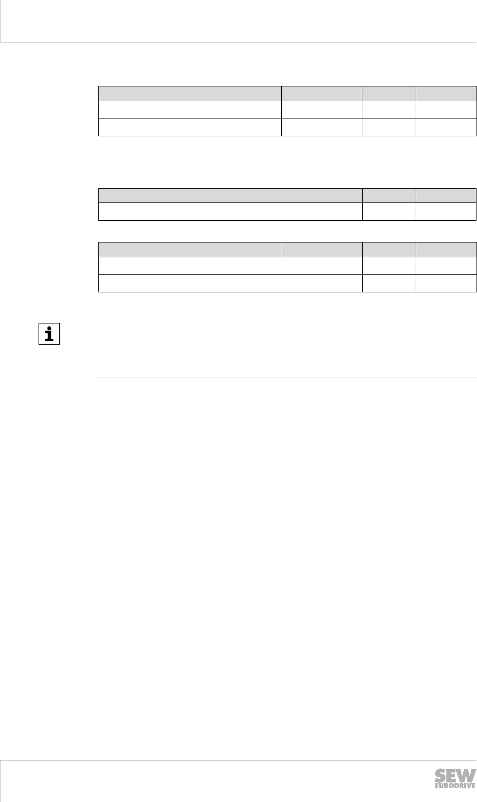
6Drive selection
Drive selection – controlled motor
Catalog – AC Motors DR.71 - 315, DT56, DR63
188
This results in the following data.
Description Symbol Value Unit
Maximum output torque M 102.2 Nm
Maximum output speed n 477.5 rpm
Gear unit selection
The following data is provided:
Description Symbol Value Unit
Gear unit ratio itarget 6.28 -
Selecting the gear unit size and reduction ratio:
Description Symbol Value Unit
Gear unit size K47 - -
Gear unit ratio iactual 5.81 -
INFORMATION
The overhung load is too high with the recommended transmission element factor for
gear rack pinions of fz = 2 (FR = 5437 N); see section "Overhung and axial
loads" (→ 2 156). This must either be compensated by a suitable bearing for the gear
rack pinion, or a larger gear unit must be selected.
Motor selection
Maximum operating point
Conversion of the torque to the motor side:
Mmax = M / η / iactual
Mmax = 102.2 Nm / 0.9 / 5.81
Mmax = 19.56 Nm
Conversion of the speed to the motor side:
nmax = n × iactual
nmax = 477.5 rpm × 5.81
nmax = 2774 rpm
Mmax and nmax denote the maximum operating point; in this case, Mmax is required at
nmax.
Effective operating point
The effective operating point was calculated as
Meff = 8.26 Nm
at a speed of
nn = 1981 rpm
Motor preselection
The motor size DRL90L4 was preselected.
Mbase = 19.9 Nm
19290411/EN – 10/2014
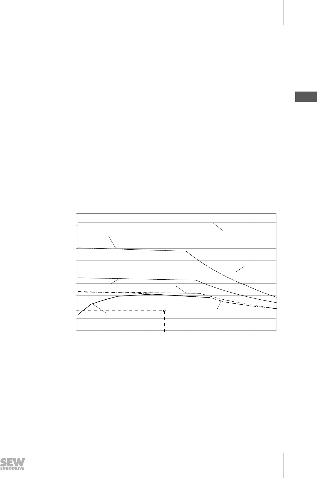
6
Drive selection
Drive selection – controlled motor
Catalog – AC Motors DR.71 - 315, DT56, DR63 189
nbase = 2683 rpm
Checking the relationship of the mass moment of inertia results in the following:
Jext/Jmot = 12.03
The ratio of 12.03 is acceptable for a dynamic vehicle drive.
MOVIDRIVE® B inverter selection
• The effective operating point (F) for the motor must be below the S1 limit curve. The
thermal load on the motor is thus within the permitted range.
• The effective operating point (F) in the speed/torque diagram for 100% inverter uti-
lization must be below the characteristic curve for the motor/inverter combination to
be selected. The load on the inverter (continuous duty) is thus within the permitted
range.
• In the speed/torque diagram for 150% inverter utilization, the maximum operating
point (M) (possibly two different points for maximum speed and maximum torque)
must be below the characteristic curve for the motor/inverter combination to be se-
lected. The load on the inverter (maximum operation) is thus within the permitted
range.
DRL90L4, nN = 3000 rpm, 100% IN
Determining the effective operating point:
0
5
10
15
20
25
30
35
40
45
50
0 500 1000 1500 2000 2500 3000 3500 4000 4500
M in Nm
n in 1/min
DRL 90L4 n = 3000 1/min 100% IN
[4]
[13]
[15]
[14]
[2]
[1]
[3]
F
8.26
1981
9007203235308555
[1] S1 characteristic curve [13] 5.5 kW inverter power
[2] S1 characteristic curve with forced cooling
fan
[14] 7.5 kW inverter power
[3] Maximum limit torque of dynamics package
1
[15] 11 kW inverter power
[4] Maximum limit torque of dynamics package
2
DRL90L4, nN = 3000 rpm, 150% IN
19290411/EN – 10/2014
6
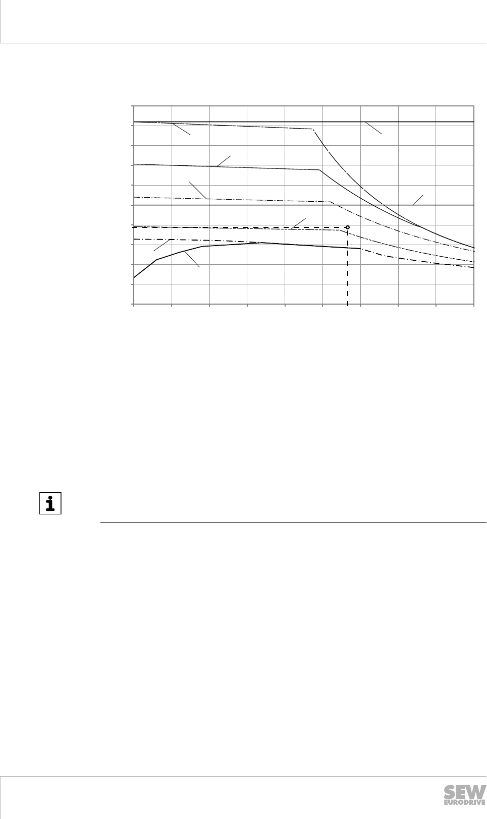
6Drive selection
Drive selection – controlled motor
Catalog – AC Motors DR.71 - 315, DT56, DR63
190
Determining the maximum operating point:
0
5
10
15
20
25
30
35
40
45
50
0 500 1000 1500 2000 2500 3000 3500 4000 4500
M in Nm
n in 1/min
DRL 90L4 n = 3000 1/min 150% IN
[4]
[14]
[15]
[13]
[12]
[1]
[2]
[3]
M
19.56
2774
9007203235312267
[1] S1 characteristic curve [12] 4 kW inverter power
[2] S1 characteristic curve with forced cooling
fan
[13] 5.5 kW inverter power
[3] Maximum limit torque of dynamics package
1
[14] 7.5 kW inverter power
[4] Maximum limit torque of dynamics package
2
[15] 11 kW inverter power
INFORMATION
The inverter current at motor standstill should be less than 70% of the nominal motor
current.
The required drive inverter has thus been determined:
• MDX61B0055-5A3
Result of the drive selection
Selected gearmotor in dynamics package 1 and speed class 3000 rpm:
• K47 DRL90L4/F./TF/ES7S
Selected drive inverter:
• MDX61B0055-5A3 with 5.5 kW inverter power
19290411/EN – 10/2014

6
Drive selection
Drive selection – controlled motor
Catalog – AC Motors DR.71 - 315, DT56, DR63 191
6.15.6 Reinforced insulation for inverter operation > 500 V AC
Standard insulation
The operation of an AC asynchronous motor with a frequency inverter places a much
greater load on the winding than in the case of non-controlled operation.
The inverters pulse the DC voltage of the DC link (Uz) to the supply cables to the mo-
tor. This pulsing takes place in the kHz range, which means several thousand ON and
OFF switchings per second – at SEW-EURODRIVE usually with 4, 8, 16 kHz.
The standard windings of the motors are constructed with copper wires and surface
insulating materials, which can easily withstand the voltage peaks specified below.
• Line-to-line voltages ULL = 1560 V
• Line-to-ground voltages ULG = 1100 V
The DR. motors can therefore be used with the normal winding on frequency inverters
with up to 500 V.
If a DR. motor is operated with a frequency inverter supplied with 600 V or 690 V, or
the DC link voltage of which is raised to over 742.5 V DC, the double voltage pulse
can exceed the maximum permissible value of the standard winding of 1560 V.
Design measures must therefore be taken to protect the motor from these high voltag-
es.
Reinforced insulation (/RI)
The electric strength of the winding insulation is achieved by reinforcing the coat thick-
ness of the inner layer for the copper wires.
This insulating system for motors carries the type and catalog designation /RI.
The standard surface insulating materials are sufficient for line-to-line and line-to-
ground insulation.
The RI windings of the motors withstand voltage peaks of up to
• Line-to-line voltages ULL = 1800 V
• Line-to-ground voltages ULG = 1250 V
See also chapter "DR.. AC motors on non-SEW inverters" (→ 2 198).
19290411/EN – 10/2014
6

6Drive selection
Drive selection – controlled motor
Catalog – AC Motors DR.71 - 315, DT56, DR63
192
Reinforced insulation with increased resistance against partial discharge (/RI2)
If the voltage peaks exceed the 1800 V threshold, enameled wires with higher resist-
ance against partial discharge must be used. This higher resistance is achieved by the
addition of inorganic additives to the coating of the inner layer.
The standard surface insulating materials for line-to-line and line-to-ground separation
are also no longer sufficient. To protect against these very high voltages, thicker sur-
face insulating materials and enhanced impregnation must be used.
This insulating system for DR.. motors carries the type and catalog designation /RI2.
The RI2 windings of the DR.. motors easily withstand voltage peaks of up to
• Line-to-line voltages ULL = 2150 V
• Line-to-ground voltages ULG = 1800 V
See also chapter "DR.. AC motors on non-SEW inverters" (→ 2 198).
6.15.7 Limit characteristic curves of the motors in inverter operation
The thermal curves for the asynchronous AC motors of the DR.. series are distinguish-
ed with regard to their energy efficiency class.
The asynchronous servomotors are distinguished according to their speed class.
Thermally permitted torques – DRS.. motors
When DRS.. motors are used with inverters, the thermally permitted torque must be
observed during the drive selection. The following factors determine the thermally per-
mitted torque:
• Energy efficiency class: none or IE1
• Operating mode
• Type of cooling: Self-cooling or forced cooling
• Base frequency: fbase = 50 Hz (400 V W) or fbase = 87 Hz (400 V m)
You can determine the thermally permitted torque on the basis of torque limit curves.
The effective torque calculated during project planning must be below the limit curve
with regard to the mean speed.
Below are the limit curves for 4-pole DRS.. motors with the following line frequencies:
• fbase = 50 Hz
• fbase = 87 Hz
The following conditions apply to the shown limit curves:
• Motor in duty type S1 on 50 Hz supply system
• Line voltage of motor 230 V m / 400 V W or corresponding voltage range
• Supply voltage of the inverter Uline = 3 × 400 V AC
• Motor in thermal class 155 (F)
19290411/EN – 10/2014
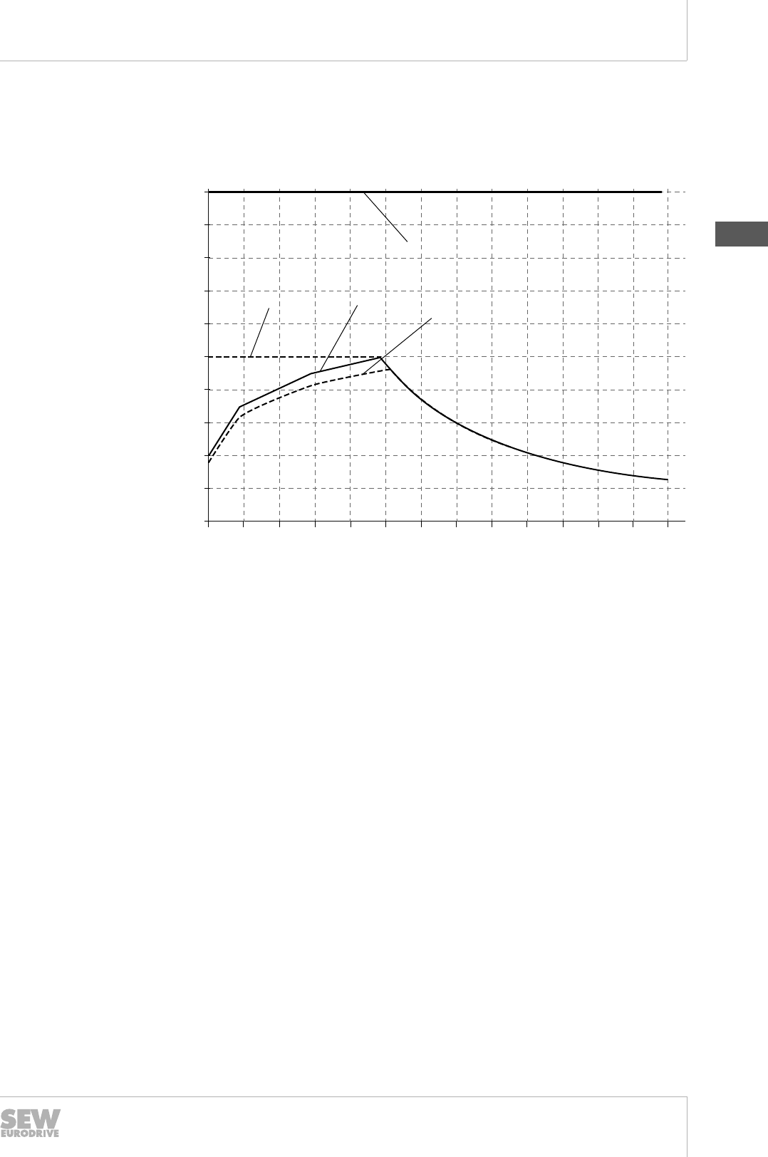
6
Drive selection
Drive selection – controlled motor
Catalog – AC Motors DR.71 - 315, DT56, DR63 193
fbase = 50 Hz (400 V
W
, 50 Hz) – DRS.. motor
The following diagram shows the limit curves of the DRS.. motor for operation at base
frequency fbase = 50 Hz. Separate curves are provided for motors with self-cooling and
forced cooling (optional /V forced cooling fan).
10 %
20 %
40 %
60 %
80 %
100 %
120 %
140 %
160 %
180 %
200 %
0 300 600 900 1200 1500 1800 2100 2400 2700 3000 3300 3600 3900
M / Mn
min -1
[1]
[2]
[3]
[4]
9007208204121099
[1] S1 operation with self-cooling (= without optional forced cooling fan)
[2] S1 operation with self-cooling (= without optional forced cooling fan) for
DRS280M4
[3] S1 operation with forced cooling (= with optional forced cooling fan)
[4] Mechanical limitations for gearmotors
19290411/EN – 10/2014
6
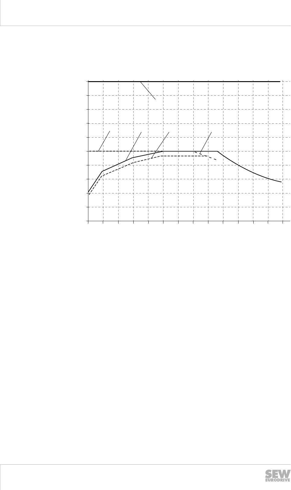
6Drive selection
Drive selection – controlled motor
Catalog – AC Motors DR.71 - 315, DT56, DR63
194
fbase = 87 Hz (400 V
m
, 50 Hz) – DRS.. motor
The following diagram shows the limit curves of the DRS.. motor for operation at base
frequency fbase = 87 Hz. Separate curves are provided for motors with self-cooling and
forced cooling (optional /V forced cooling fan).
10 %
20 %
40 %
60 %
80 %
100 %
120 %
140 %
160 %
180 %
200 %
0 300 600 900 1200 1500 1800 2100 2400 2700 3000 3300 3600 3900
M / Mn
min -1
[5]
[1] [2] [3]
[4]
9007208204123531
[1] S1 operation with self-cooling (= without optional forced cooling fan)
[2] S1 operation with self-cooling (= without optional forced cooling fan) for
DRS280M4
[3] S1 operation with forced cooling (= with optional forced cooling fan) for DRS250
– 315
[4] S1 operation with forced cooling (= with optional forced cooling fan)
[5] Mechanical limitations for gearmotors
Thermally permitted torques – DRE.. and DRP.. motors
When DRE.. or DRP.. motors are used with inverters, the thermally permitted torque
must be observed during the drive selection. The following factors determine the ther-
mally permitted torque:
• Energy efficiency class: IE2 or IE3
• Operating mode
• Type of cooling: Self-cooling or forced cooling
• Base frequency: fbase = 50 Hz (400 V W) or fbase = 87 Hz (400 V m)
Due to the lower thermal load of the IE2/IE3 design, the nominal torque of the motor
on the supply system can be subjected to a constant load down to approx 20 Hz.
The thermally permitted torque is determined on the basis of torque limit curves. The
effective torque calculated during project planning must be below the limit curve with
regard to the mean speed.
19290411/EN – 10/2014

6
Drive selection
Drive selection – controlled motor
Catalog – AC Motors DR.71 - 315, DT56, DR63 195
Below are the limit curves for 4-pole DRE.. and DRP.. motors with the following line
frequencies:
• fbase = 50 Hz
• fbase = 87 Hz
The following conditions apply to the shown limit curves:
• Motor in duty type S1 on 50 Hz supply system
• Line voltage of motor 230 V m / 400 V W or corresponding voltage range
• Supply voltage of the inverter Uline = 3 × 400 V AC
• Motor in thermal class 155 (F)
fbase = 50 Hz (400 V
W
, 50 Hz) – DRE.. and DRP.. motor
The following diagram shows the limit curves of the DRE.. / DRP.. motors for opera-
tion at base frequency fbase = 50 Hz, star connection "W" at 400 V. Separate curves are
provided for motors with self-cooling and forced cooling (optional /V forced cooling
fan).
10 %
20 %
40 %
60 %
80 %
100 %
120 %
140 %
160 %
180 %
200 %
0 300 600 900 1200 1500 1800 2100 2400 2700 3000 3300 3600 3900
M / Mn
min -1
[4]
[2][1]
[3]
9007208204127243
[1] S1 operation with self-cooling (= without optional forced cooling fan)
[2] S1 operation with self-cooling (= without optional forced cooling fan) for
DRE280M4
[3] S1 operation with forced cooling (= with optional forced cooling fan)
[4] Mechanical limitations for gearmotors
19290411/EN – 10/2014
6
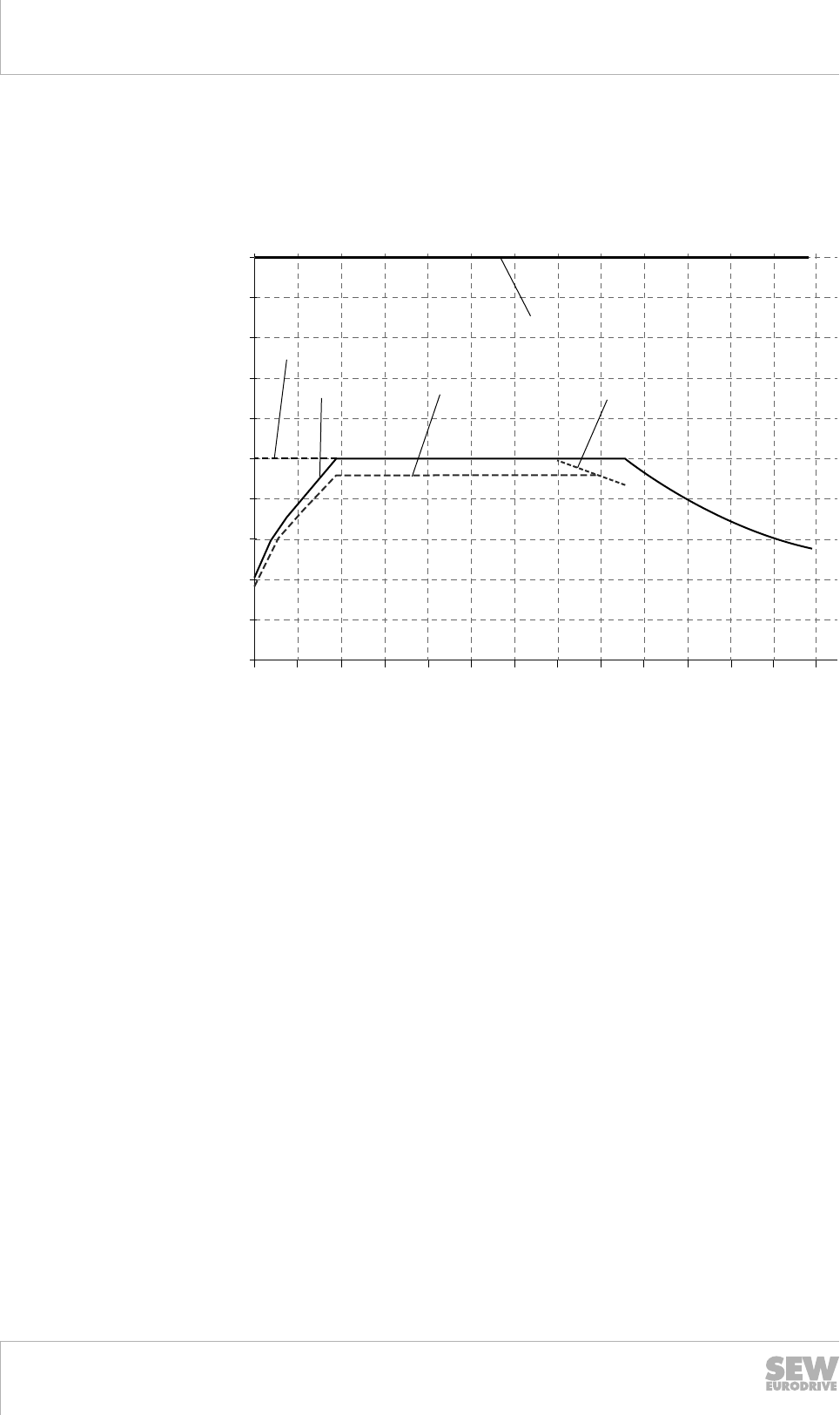
6Drive selection
Drive selection – controlled motor
Catalog – AC Motors DR.71 - 315, DT56, DR63
196
fbase = 87 Hz (400 V
m
, 50 Hz) – DRE.. and DRP.. motor
The following diagram shows the limit curves of the DRE.. / DRP.. motors for opera-
tion at base frequency fbase = 87 Hz, delta connection "m" at 400 V. Separate curves
are provided for motors with self-cooling and forced cooling (optional /V forced cooling
fan).
10 %
20 %
40 %
60 %
80 %
100 %
120 %
140 %
160 %
180 %
200 %
0 300 600 900 1200 1500 1800 2100 2400 2700 3000 3300 3600 3900
M / Mn
min -1
[1] [2] [3]
[4]
[5]
9007208204180875
[1] S1 operation with self-cooling (= without optional forced cooling fan)
[2] S1 operation with self-cooling (= without optional forced cooling fan) for
DRE280M4
[3] S1 operation with forced cooling (= with optional forced cooling fan) for DRE250
– 315
[4] S1 operation with forced cooling (= with optional forced cooling fan)
[5] Mechanical limitations for gearmotors
Thermally permitted torques – DRL.. motor
When asynchronous DRL.. servomotors are used with inverters, the thermally and dy-
namically permitted torque must be observed during the drive selection. The following
factors determine the thermally permitted torque:
• Type of cooling: Self-cooling or forced cooling
• Speed class
The thermally permitted torque is determined on the basis of torque limit curves. The
effective torque calculated during project planning must be below the limit curve with
regard to the mean speed. The limit curves for the 4-pole asynchronous DRL.. servo-
motors in the following speed classes are provided in the manual "AC motors – inver-
ter assignments and characteristic curves":
• 1200 rpm (corresponds to fbase of approx. 41 – 43 Hz)
• 1700 rpm (corresponds to fbase of approx. 58 – 61 Hz)
19290411/EN – 10/2014

6
Drive selection
Drive selection – controlled motor
Catalog – AC Motors DR.71 - 315, DT56, DR63 197
• 2100 rpm (corresponds to fbase of approx. 72 – 76 Hz)
• 3000 rpm (corresponds to fbase of approx. 102 – 108 Hz)
The dynamically permitted torque is limited by the following:
• The mechanical limit value according to dynamics package D1 or D2, which is in-
dependent of the selected speed class
• The dynamic maximum and temporary current of the inverter
The following conditions apply to the basic limit curves shown:
• DRL.. motor according to technical data, see chapter "Asynchronous DRL.. servo-
motors" (→ 2 117)
• Supply voltage of the inverter Uline = 3 × 400 V AC
• /TF thermal motor protection
The potential dynamics of the inverter and motor are illustrated by the diagram for
150% current of the inverter, while the thermal limit for the inverter and motor is shown
in the diagram for 100% current of the inverter.
A separate overview of all limit curves is provided in the manual "AC motors – inverter
assignments and characteristic curves".
19290411/EN – 10/2014
6
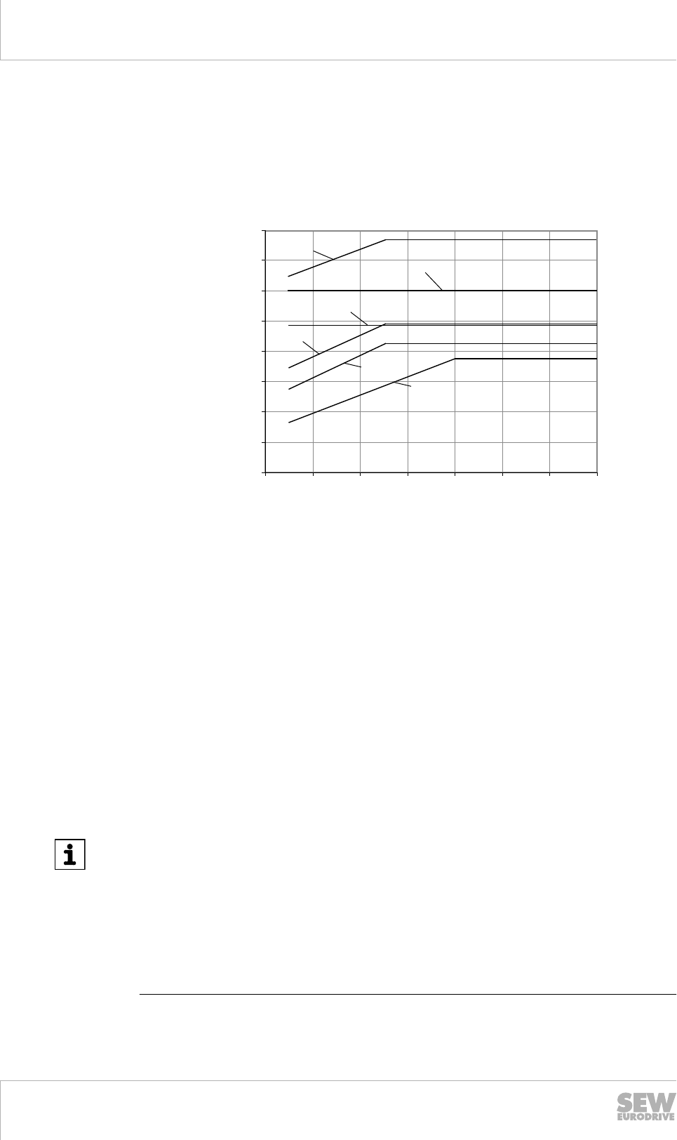
6Drive selection
Drive selection – controlled motor
Catalog – AC Motors DR.71 - 315, DT56, DR63
198
6.15.8 DR.. AC motors on non-SEW inverters
In the case of inverter-supplied motors, you must adhere to the wiring instructions is-
sued by the inverter manufacturer. It is essential to observe the operating instructions
for the frequency inverter.
Operating SEW motors on non-SEW frequency inverters is permitted if the pulse vol-
tages at the motor terminals indicated in the following figure are not exceeded.
0.6
0.8
1.0
1.2
1.4
1.6
1.8
2.0
0 0.2 0.4 0.6 0.8 1 1.2 1.4
[1]
[2]
[3]
2.2
[4]
[5]
[6]
[µs]
ULL [kV]
[7]
[8]
9007203235332235
[1] Permitted pulse voltage for motors with reinforced insulation and increased re-
sistance against partial discharge (/RI2)
[2] Permitted pulse voltage for motors with reinforced insulation (/RI)
[3] Permitted pulse voltage according to NEMA MG1 part 31, UN ≤ 500 V
[4] Permitted pulse voltage according to IEC 60034-25, limit value curve A for nom-
inal voltage UN ≤ 500 V, star connection
[5] Permitted pulse voltage according to IEC 60034-25, limit value curve A for nom-
inal voltage UN ≤ 500 V, delta connection
[6] Permitted pulse voltage according to IEC 60034-17
[7] Duration of voltage increase
[8] Permitted pulse voltage
INFORMATION
Compliance with the limit values must be checked and taken into account as follows:
• The supply voltage level at the non-SEW inverter
• The threshold of the brake chopper voltage
• The operating mode of the motor (motoring/regenerative operation)
→If the permitted pulse voltage is exceeded, limiting measures, such as filters,
chokes, or special motor cables must be used. Contact the manufacturer of the
frequency inverter for more information.
19290411/EN – 10/2014
