2003 04catalog
User Manual: 2003-04catalog
Open the PDF directly: View PDF ![]() .
.
Page Count: 625 [warning: Documents this large are best viewed by clicking the View PDF Link!]
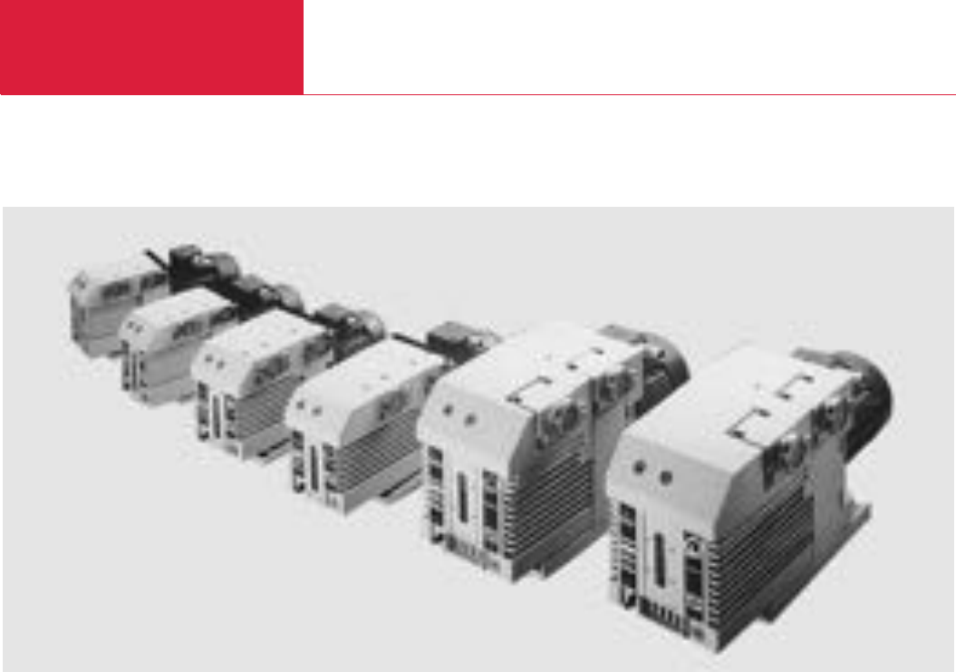
- LEYBOLD VACUUM Catalog 2003/2004
- Rotary Vane Vacuum Pumps TRIVAC E and B
- Rotary Vane Vacuum Pumps SOGEVAC
- Dry Compressing Piston Vacuum Pumps EcoDry M and L
- Diaphragm Vacuum Pumps DIVAC
- Dry Compressing Screw Vacuum Pump SCREWLine
- Rotary Piston Vacuum Pumps E and DK
- Roots Vacuum Pumps RUVAC
- Vacuum Pump Systems RUTA
- Turbomolecular Pumps
- Turbomolecular Pump Systems PTand CS
- Oil Diffusion Pumps DIP
- Cryopumps, Cryogenics
- Vacuum Fittings and Feedthroughs
- Vacuum Valves
- Ultra-high Vacuum Components
- Total Pressure Gauges
- Leak Testing Instruments
- Turboradial Blowers TURBOSTREAM
- High Vacuum Experimentation Systems UNIVEX
- Telefax Inquiry (EU)
- Telefax Inquiry (USA)
- Product Index

2003 04
LEYBOLD VACUUM
101.01.02
Vacuum Solutions Application Support Service LEYBOLD VACUUM
LV_05301 GK 3.27.03.2003
Printed in Germany on chlorine-free bleached paper Technical alterations reserved
LEYBOLD VACUUM
PRODUCTS AND REFERENCE BOOK
2003
2004
PRODUCTS AND
REFERENCE BOOK
C01
TRIVAC
Rotary Vane Vacuum Pumps, Oil-Sealed,
1.5 to 65 m3x h-1, (0.7 to 38.3 cfm)
S 1.5, Single-Stage
TRIVAC E, Two-Stage
TRIVAC B, Two-Stage

Contents
Rotary Vane Vacuum Pumps
C01.02 LEYBOLD VACUUM PRODUCTS AND REFERENCE BOOK 2003/2004
General
Applications and Accessories . . . . . . . . . . . . . . . . . . . . . . . . . . . . . . . . . . . . . . . . . . . . . . . C01.03
Pumps
Small Compact Pump S 1.5 . . . . . . . . . . . . . . . . . . . . . . . . . . . . . . . . . . . . . . . . . . . . . . . C01.04
TRIVAC E, Two-Stage Rotary Vane Vacuum Pumps . . . . . . . . . . . . . . . . . . . . . . . . . . . . . . C01.06
TRIVAC D 2.5 E. . . . . . . . . . . . . . . . . . . . . . . . . . . . . . . . . . . . . . . . . . . . . . . . . . . . . . . . . C01.08
TRIVAC B, Two-Stage Rotary Vane Vacuum Pumps. . . . . . . . . . . . . . . . . . . . . . . . . . . . . . C01.10
TRIVAC D 4 B and D 8 B . . . . . . . . . . . . . . . . . . . . . . . . . . . . . . . . . . . . . . . . . . . . . . . . . . C01.12
TRIVAC D 16 B and D 25 B . . . . . . . . . . . . . . . . . . . . . . . . . . . . . . . . . . . . . . . . . . . . . . . . C01.16
TRIVAC D 40 B and D 65 B . . . . . . . . . . . . . . . . . . . . . . . . . . . . . . . . . . . . . . . . . . . . . . . . C01.20
TRIVAC D 16 B-DOT . . . . . . . . . . . . . . . . . . . . . . . . . . . . . . . . . . . . . . . . . . . . . . . . . . . . . C01.22
TRIVAC D 16 B-Ex (Explosion Blast Wave Resistant) . . . . . . . . . . . . . . . . . . . . . . . . . . . . . C01.24
TRIVAC BCS, Two-Stage Rotary Vane Vacuum Pumps. . . . . . . . . . . . . . . . . . . . . . . . . . . . C01.26
TRIVAC D 16 BCS to D 65 BCS . . . . . . . . . . . . . . . . . . . . . . . . . . . . . . . . . . . . . . . . . . . . . C01.28
TRIVAC D 16 BCS-PFPE to D 65 BCS-PFPE . . . . . . . . . . . . . . . . . . . . . . . . . . . . . . . . . . . . C01.32
Motor Dependant Data for the TRIVAC B, BCS and BCS-PFPE . . . . . . . . . . . . . . . . . . . . . . . C01.36
Accessories for TRIVAC E and B
Exhaust Filters AF 8 to AF 25 . . . . . . . . . . . . . . . . . . . . . . . . . . . . . . . . . . . . . . . . . . . . . . . C01.40
Condensate Traps AK 8 to AK 25 . . . . . . . . . . . . . . . . . . . . . . . . . . . . . . . . . . . . . . . . . . . . C01.40
Exhaust Filter Drain Tap, Oil Drain Tap, Oil Drain Kit . . . . . . . . . . . . . . . . . . . . . . . . . . . . . . C01.42
Oil Suction Facility Controlled by Solenoid Valve AR-V . . . . . . . . . . . . . . . . . . . . . . . . . . . . C01.43
Manually Operated Oil Suction Facility AR-M. . . . . . . . . . . . . . . . . . . . . . . . . . . . . . . . . . . . C01.43
Dust Separators AS 8-16 and AS 30-60 . . . . . . . . . . . . . . . . . . . . . . . . . . . . . . . . . . . . . . . C01.44
Molecular Filters MF 8-16 and MF 30-60. . . . . . . . . . . . . . . . . . . . . . . . . . . . . . . . . . . . . . . C01.44
Fine Vacuum Adsorption Traps FA 2-4 to FA 30-60 . . . . . . . . . . . . . . . . . . . . . . . . . . . . . . . C01.45
Dust Filters FS 2-4 to FS 30-60 . . . . . . . . . . . . . . . . . . . . . . . . . . . . . . . . . . . . . . . . . . . . . C01.46
Cold Trap TK 4-8 . . . . . . . . . . . . . . . . . . . . . . . . . . . . . . . . . . . . . . . . . . . . . . . . . . . . . . . . C01.47
RST Refillable Traps. . . . . . . . . . . . . . . . . . . . . . . . . . . . . . . . . . . . . . . . . . . . . . . . . . . . . . C01.48
SE Smoke Eliminator . . . . . . . . . . . . . . . . . . . . . . . . . . . . . . . . . . . . . . . . . . . . . . . . . . . . . C01.49
Compact Oil Mist Exhaust Filter . . . . . . . . . . . . . . . . . . . . . . . . . . . . . . . . . . . . . . . . . . . . . C01.50
Accessories for TRIVAC B
Condensate Traps AK 4-8, AK 16-25, AK 40-65. . . . . . . . . . . . . . . . . . . . . . . . . . . . . . . . . . C01.52
Exhaust Filters AK 4-8, AK 16-25, AK 40-65 . . . . . . . . . . . . . . . . . . . . . . . . . . . . . . . . . . . . C01.53
Exhaust Filters with Lubricant Return ARP 4-8, AR 4-8, AR 16-25, AR 40-65. . . . . . . . . . . . C01.54
Exhaust Filters with Lubricant Return ARS 16-25 and ARS 40-65 . . . . . . . . . . . . . . . . . . . . C01.55
Mechanical Oil Filters OF 4-25 and OF 40-65. . . . . . . . . . . . . . . . . . . . . . . . . . . . . . . . . . . . C01.56
Chemical Oil Filters CF 4-25 and CF 40-65 . . . . . . . . . . . . . . . . . . . . . . . . . . . . . . . . . . . . . C01.56
Chemical Oil Filters with Safety Isolation Valve CFS 16-25 and CFS 40-65 . . . . . . . . . . . . . . C01.57
Inert Gas System, IGS 16-25 and IGS 40-65. . . . . . . . . . . . . . . . . . . . . . . . . . . . . . . . . . . . C01.58
Limit Switch System LSS 16-25 and LSS 40-65 . . . . . . . . . . . . . . . . . . . . . . . . . . . . . . . . . C01.59
Electrical Indicator System EIS 16-25 and EIS 40-65. . . . . . . . . . . . . . . . . . . . . . . . . . . . . . C01.60
Roots Pump Adaptor . . . . . . . . . . . . . . . . . . . . . . . . . . . . . . . . . . . . . . . . . . . . . . . . . . . . . C01.61
Oil Filtering System OF1000 . . . . . . . . . . . . . . . . . . . . . . . . . . . . . . . . . . . . . . . . . . . . . . . C01.62
General Accessories
Flange Components, Valves . . . . . . . . . . . . . . . . . . . . . . . . . . . . . . . . . . . . . . . . . . . . . . . . C01.64
Oil . . . . . . . . . . . . . . . . . . . . . . . . . . . . . . . . . . . . . . . . . . . . . . . . . . . . . . . . . . . . . . . . . . . C01.65
Miscellaneous
60 Hz Curves . . . . . . . . . . . . . . . . . . . . . . . . . . . . . . . . . . . . . . . . . . . . . . . . . . . . . . . . . . . C01.70
TRIVAC BCS
S 1.5
TRIVAC B
TRIVAC E

LEYBOLD VACUUM PRODUCTS AND REFERENCE BOOK 2003/2004
General
Rotary Vane Vacuum Pumps
C01.03
Applications and Accessories
Production of semiconductors
Vacuum coating
Research and development
Chemistry/pharmaceuticals
Metallurgy/furnaces
Lamps and tubes manufacture
Car industry
Laser engineering
Space simulation
Analytical engineering
Environment engineering
Cooling and air-conditioning
Electrical engineering
Mechanical engineering
Medicine technology
Vacuum drying cabinets
Chemistry and research labs
Freeze drying systems
Backing pump for high vacuum pump systems
AK condensate trap C01.40/52
AF exhaust filters C01.40/53
Exhaust filter drain tap C01.42
Oil drain tap C01.42
Oil drain kit C01.42
AR-V oil suction facility *)C01.43
AR-M oil suction facility *)C01.43
AS dust separators C01.44
MF molecular filters C01.44
FA fine vacuum adsorption traps C01.45
FS dust filters C01.46
TK cold trap C01.47
AR exhaust filters
with lubricant return C01.54
ARS exhaust filters
with lubricant return C01.55
OF mechanical oil filters C01.56
CF chemical oil filters C01.56
CFS chemical oil filters
with safety blocking valve C01.57
IGS inert gas system C01.58
LSS limit switch system C01.59
EIS electrical indicator system C01.60
RIS remote indicator system
(remote monitoring) C01.61
Roots pump adaptors C01.62
Valves, flange components C01.64
Vacuum pump oils C01.65
◆◆◆◆◆◆
◆ ◆ ◆ ◆
◆ ◆ ◆ ◆ ◆ ◆
◆◆◆◆◆◆◆ ◆◆◆
◆ ◆
◆◆◆◆ ◆◆
◆ ◆ ◆ ◆
◆
◆ ◆
◆◆◆◆◆
◆◆◆◆◆◆◆
◆ ◆ ◆ ◆ ◆ ◆ ◆ ◆
◆◆◆◆◆◆◆◆
◆◆◆◆◆◆◆◆
◆◆◆◆◆
◆ ◆ ◆ ◆
◆◆◆◆◆
◆◆◆◆◆◆◆
◆◆◆◆◆◆◆
◆◆◆◆◆◆◆◆◆ ◆◆◆◆◆◆
◆◆◆◆◆◆◆◆ ◆◆◆
◆
◆◆◆◆◆◆◆◆◆◆◆◆◆◆◆◆
◆◆◆◆◆◆◆◆◆◆◆◆◆◆◆◆
◆
◆
◆ ◆◆◆◆◆ ◆◆◆◆◆◆
◆◆◆◆◆◆◆ ◆◆◆◆◆◆
◆◆◆◆◆◆◆◆ ◆◆◆◆◆◆
◆◆◆◆◆◆◆◆ ◆◆◆◆◆◆
◆◆◆
◆◆◆◆◆◆◆ ◆◆◆
◆◆◆◆◆◆
◆◆◆◆◆◆
◆◆◆◆◆◆ ◆◆◆◆◆◆
◆◆◆◆◆◆
◆◆◆◆◆◆
◆◆◆◆◆◆
◆◆◆◆◆◆
◆◆◆◆◆◆
◆ ◆ ◆ ◆ ◆ ◆
◆◆◆◆◆◆◆◆◆◆◆◆◆◆◆◆
◆◆◆◆◆◆◆◆◆◆◆◆◆◆◆ ◆
Applications
Accessories
Pumps
S 1.5
TRIVAC D 2.5 E
TRIVAC D 4 B
TRIVAC D 8 B
TRIVAC D 16 B
TRIVAC D 25 B
TRIVAC D 40 B
TRIVAC D 65 B
TRIVAC D 16 B-DOT
TRIVAC D 16 B-Ex
TRIVAC D 16 BCS, D 25 BCS
TRIVAC D 40 BCS
TRIVAC D 65 BCS
TRIVAC D 16 + D 25 BCS-PFPE
TRIVAC D 40 BCS-PFPE
Page
TRIVAC D 65 BCS-PFPE
*)For pumps with gas ballast only
C01
Small Compact Pump
Rotary Vane Vacuum Pumps
C01.04 LEYBOLD VACUUM PRODUCTS AND REFERENCE BOOK 2003/2004
bb1
b2
h1
DN 16 KF DN 6
d
h
a
l1l
c
10-3
0
x
m
10-2 10-1 10 010 110 3
mbar
0,5
0,25
0,75
1,0
1,25
1,75
1,5
2,0
3 -1
h
Torr
-3
10 10-2 10 -1 110 750
cfm
1
0.5
0
0.75
0.25
Pressure
Pumping speed
10-3
Pressure
min
0
Time
10-2
10-1
100
101
102
103
mbar
102 4 6 8
Torr
-3
10
10-2
10 -1
1
10
750
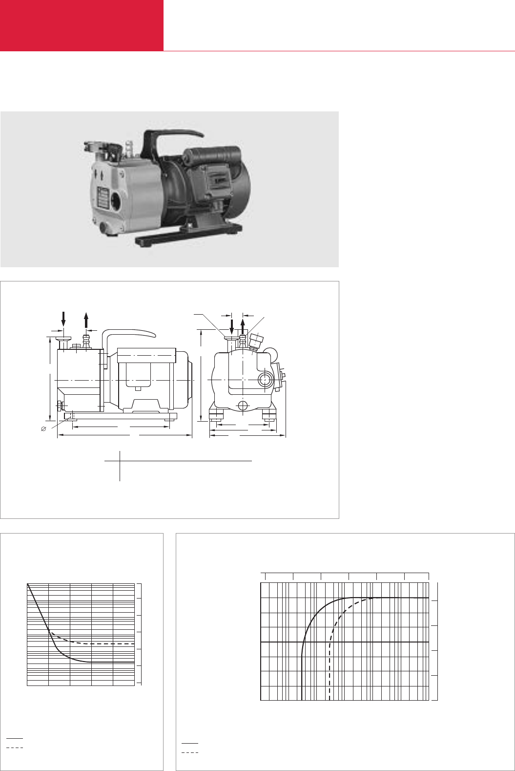
S 1.5 Small Compact Pump
The S 1.5 is a single-stage, oil-sealed rotary vane
pump with a gas ballast valve. It is driven by a
flange mounted AC motor. The shaft of the pump
and the shaft of the motor are linked by means of
a pinned coupling.
Advantages to the User
♦Very small and light-weight
♦Low ultimate pressure
♦High water vapor tolerance
♦Low noise operation
♦Simple to connect
♦Easy to maintain and use
Typical Applications
♦In all areas of vacuum engineering where a
low intake pressure is required
♦Evacuation of refrigerant circuits
♦For suction, lifting, emptying, filling and
tensioning
♦For installation in mobile instruments
Supplied Equipment
♦DN 16 small flange connection on the intake
side
♦Centering ring and clamping ring
♦Exhaust port designed as a DN 6 hose nozzle
♦Carrying handle
♦Built-in ON/OFF switch and overcurrent
circuit breaker
♦Oil filling
Dimensional drawing for the S 1.5
Pumping speed characteristics at 50 Hz (60 Hz curves at the end of the section)
Pump-down characteristics of a 10 l vessel at 50 Hz
without gas ballast
with gas ballast without gas ballast
with gas ballast
a b b1b2c d h h1
mm 45 ≈185 145 100 9 20 160 192
in. 1.77 ≈7.3 5.71 3.94 .35 .79 6.30 7.56

Small Compact Pump
Rotary Vane Vacuum Pumps
C01.05
C01
LEYBOLD VACUUM PRODUCTS AND REFERENCE BOOK 2003/2004
Technical Data S 1.5
50 Hz 60 Hz
Ordering Information S 1.5
S 1.5 with AC motor, 230 V (208-252 V ±5%),
50/60 Hz, with 2 m long mains cord and EURO plug
AK 8 condensate trap
Oil drain tap (M 16 x 1.5)
Connection components
Elbow (1x) DN 16 KF
Centering ring with O-ring (2x) DN 16 KF
Clamping ring (2x) DN 16 KF
Part No. 101 01
Part No. 190 60
Part No. 190 90
Part No. 184 36
Part No. 183 26
Part No. 183 41
1) To DIN 28 400 and following numbers
Nominal pumping speed 1) m3x h-1 (cfm)
Pumping speed 1) m3x h-1 (cfm)
Ultimate partial pressure
without gas ballast 1) mbar (Torr)
Ultimate total pressure with gas ballast 1) mbar (Torr)
Water vapor tolerance 1) mbar (Torr)
Water vapor capacity g/h (lbs/hr)
Oil filling, min./max. l (qt)
Admissible ambient temperature °C (°F)
Motor rating W (hp)
Nominal speed rpm
Type of protection IP
Weight kg (lbs)
Connections,
Intake DN
Exhaust DN
1.9 (1.1) 2.3 (1.3)
1.75 (1) 2.1 (1.2)
3 x 10⁻² (2.3 x 10⁻²)
5 x 10⁻¹ (3.8 x 10⁻¹)
> 15 (> 11.3)
19 (42)
0.11/0.14
40 (104)
80 (.11)
1500 1800
54
10 (22.1)
16 KF
6
Rotary Vane Vacuum Pumps
C01.06 LEYBOLD VACUUM PRODUCTS AND REFERENCE BOOK 2003/2004
Typical Applications
♦Mass spectrometers
♦Electron beam microscopes
♦Sterilizers
♦Freeze-drying systems
♦Chemical and research labs
♦TV tube
♦General vacuum engineering
♦Backing pump for high vacuum pump
systems
Supplied Equipment
♦Dirt trap
♦Oil filling included separately (standard N 62;
special oil HE-200 in the U:S:)
♦Gas ballast device
♦Main cord with the specific plug for Euro,
USA and Japan motors
♦Optional: Main cord with country specific plug
for the world motor
♦With handle
ALL PUMPS ARE SUBJECTED TO A VACUUM
TEST BEFORE DELIVERY!
TRIVAC E, Two-Stage, Oil-Sealed Rotary Vane Vacuum Pump
Advantages to the User
♦Highly reliable
♦Small and compact
♦Quiet operation
♦Environmentally compatible (low oil consump-
tion, EMI compatible; IP 54 protection)
♦Process quality (little backstreaming of oil)
♦Motors for all standard supply voltages and
frequencies
♦Safe and intelligent vacuum protection
(hermetically sealed)
♦Free of yellow metals
♦Compliance with international standards
(CE, UL and CSA)
♦Suitable for continuous operation at
1000 mbar (750 Torr)
♦Low power consumption
♦Better individual performance given by
3 stage gas ballast device
♦High water vapor tolerance
♦Simplified customizing ability
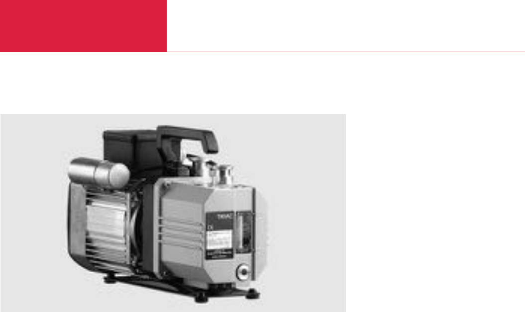
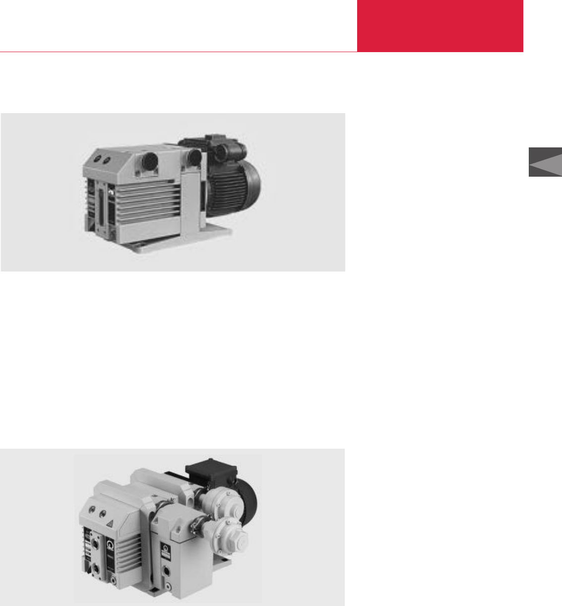
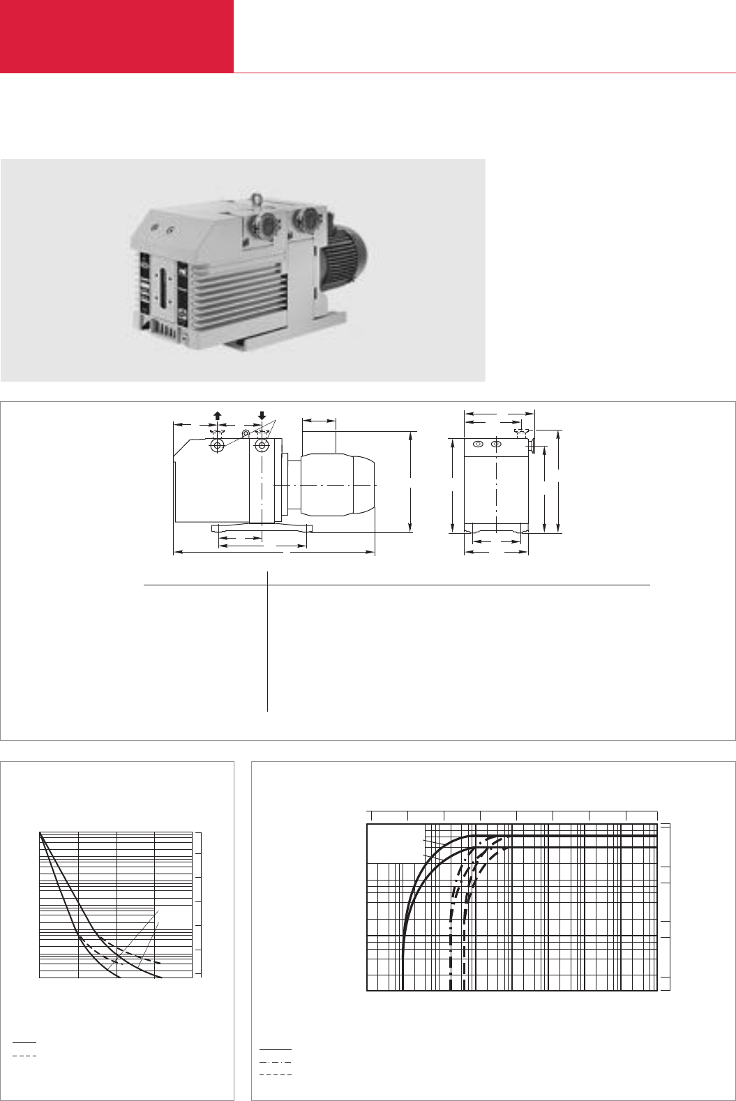
TRIVAC D 2.5 E
The TRIVAC E pump is an oil-sealed vacuum
pump operating according to the rotary vane
principle. Oil which is injected into the pump
chamber is used for sealing, lubrication and
cooling purposes.
New customers’ requirements as well as increased
environmental requirements gave rise to the
further development of the successful range of
TRIVAC B pumps.
The result is the new TRIVAC E rotary vane
vac
uum
pump.
Beyond the usual quality and reliability of the
B series pumps, the TRIVAC E pump offers
improvements in the area of quieter operation,
smaller size and improved service-friendliness.
The intake and exhaust ports are equipped with
small flanges. Besides standard voltages and fre-
quencies, LEYBOLD offers world motors, which
are specially required by OEMs.
The new TRIVAC E pump includes also a set of ac-
cessories which also fits to the TRIVAC D 4 - 16 B.
TRIVAC E
Rotary Vane Vacuum Pumps
C01.07
LEYBOLD VACUUM PRODUCTS AND REFERENCE BOOK 2003/2004
DN
DN
OUT
IN
OUT
IN
OIL
M
L
K
J
G
EF
A
H
NCD
B
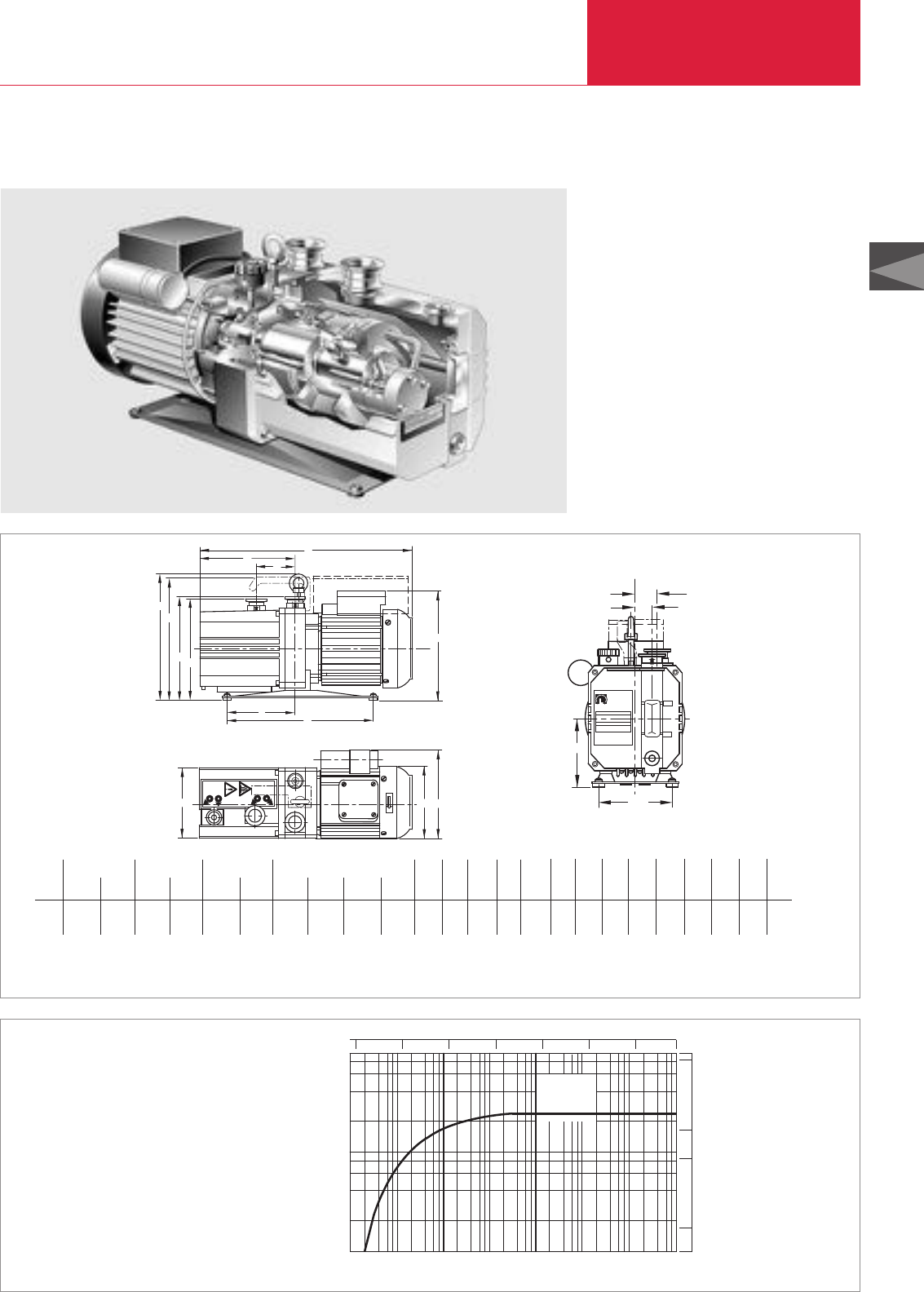
Dimensional drawing for the TRIVAC D 2.5 E
A B C D
EURO World EURO World EURO World EURO JAP USA
JAP, USA 1 ~JAP ,USA 1 ~JAP, USA 1 ~
mm 388.5 393.5 210.5 227.5 127 127 148.5 153.5 153.5
in. 15.3 15.7 8.29 8.96 5 5 5.85 6.04 6.04
E F G H J K L M N O P
World
1 ~
*162.5 75.5 119.5 225 231.5 225 182 177 113 27 15
6.40 2.97 4.70 8.86 9.90 8.86 7.16 6.97 4.45 1.06 .59
Q R DN
83 84.5 16 KF
3.27 3.33 16 KF
* Condensors in the connection box
10-4 2
10-1
Pumping speed
Pressure
x h
3
m
101
100
8
6
4
2
864 10-3 10-2 10-1 101
100mbar 103
102
-1
D 2,5 E
Torr
-4
10 -3
10 10-2 10-1 1 10 750
5
cfm
0.1
0.5
1
Pumping speed of the TRIVAC D 2.5 E at 50 Hz (60 Hz curves at the end of the section)
TRIVAC E
TRIVAC
P
O
Q
R
TRIVAC E
C01

Rotary Vane Vacuum Pumps
C01.08 LEYBOLD VACUUM PRODUCTS AND REFERENCE BOOK 2003/2004
Technical Data D 2.5 E
50 Hz 60 Hz
Nominal pumping speed 1) m3x h-1 (cfm)
Pumping speed 1) m3x h-1 (cfm)
Ultimate partial pressure without gas ballast mbar (Torr)
Ultimate total pressure without gas ballast 2) mbar (Torr)
Ultimate total pressure with gas ballast
Step 2 2) mbar (Torr)
Water vapor tolerance
Step 1 mbar (Torr)
Step 2 mbar (Torr)
Step 3 mbar (Torr)
Water vapor capacity
Step 1 gm/h
Step 2 gm/h
Step 3 gm/h
Oil filling, max./min. l (qt)
Noise level dB(A)
Admissible ambient temperature °C (°F)
Motor rating 50/60 Hz W (HP)
Nominal speed 50/60 Hz rpm
Type of protection IP
Weight (with oil filling) kg (lbs)
Dimensions (W x H x D) mm (in.)
Connections (Intake and Exhaust) DN
3.2 (1.9) 3.6 (2.1)
2.7 (1.6) 3.3 (1.9)
≤5 x 10⁻⁴ (≤3.8 x 10⁻⁴)
≤2 x 10⁻³ (≤1.5 x 10⁻³)
≤3 x 10⁻² (≤2.3 x 10⁻²)
10 (7.5)
20 (15)
30 (22.5)
20
40
60
0.7/0.4 (0.7/0.4 )
≤47
10 to 50 (50 - 122) (EURO motor) / 10 to 40 (50 - 104) (USA/Japan motor)
250 (0.34) 300 (0.41)
1400 1600
54
15.3 (33.7)
127 x 225 x 383 (5 x 8.86 x 15)
16 KF
Motor Dependent Data
Motors for Voltage Frequency Voltage Power consumption Nominal current Protection Nominal speed
D 2.5 E V Hz tolerance W (HP) A rpm
Euro 1 ~ 220-240/230 50/60 +/– 5 % 250/300 (0.34/0.41) 1.8/1.4 IP 54 1400/1600
Japan 1 ~ 100 50/60 +/– 5 % 250/300 (0.34/0.41) 5.5/4.0 IP 54 1400/1600
USA 1 ~ 110-120 60 +/– 5 % 300 (0.41) 3.3 IP 54 1600
World 1 ~ 100-120; 50/60 +/– 5 % 250/300 (0.34/0.41) 4.4/3.0 IP 54 1400/1600
200-240 2.2/1.5
1) To DIN 28 426 T1 2) To DIN 28 400 and following numbers
TRIVAC E

LEYBOLD VACUUM PRODUCTS AND REFERENCE BOOK 2003/2004 C01.09
C01
TRIVAC E
Rotary Vane Vacuum Pumps
Ordering Information D 2.5 E
TRIVAC E with 1.8 m long mains cord
EURO-Version, 1-ph., 220-240 V, 50 Hz; 230 V, 60 Hz
Earthed plug
UK plug
CH plug
US version, 1-ph., 110-120 V, 60 Hz, NEMA plug
Japan version,1-ph.,100 V, 50/60 Hz, NEMA plug
Single phase world motor (without mains cord)
Further variants upon request
Accessories
Connection cable for single phase world motor
230 V earthed plug
230 V UK plug
230 V CH plug
230 V NEMA plug (200-240 V)
115 V NEMA plug (100-120 V)
Exhaust filter AF 8
Replacement filter elements for AF 8 (pack of 5)
FE 8
Exhaust filter drain tap (G 1/4")
Manual oil return AR-M via gas ballast inlet
(kit for AF 8-16)
Oil suction AR-V controlled by a solenoid valve
via the gas ballast inlet (kit for AF 8-16)
Condensate trap AK 8
Oil drain tap (M 16 x 1.5)
Oil drain kit (M 16 x 1.5)
Connection components
Elbow (1x) DN 16 KF
Centering ring with O-ring (2x) DN 16 KF
Clamping ring (2x) DN 16 KF
Spare parts
Maintenance kit 1
(oil separation, oil box seal)
Repair set 1
(valves, oil separation, oil box seal)
Complete set
(oil separation, sealing, wearing parts)
For further accessories see Section
“Accessories for TRIVAC E and B”
Part No. 140 000
Part No. 140 004
Part No. 140 005
Part No. 140 002
Part No. 140 003
Part No. 140 001
Part No. 200 81 091
Part No. 200 81 097
Part No. 200 81 099
Part No. 200 81 141
Part No. 200 81 090
Part No. 190 50
Part No. 190 80
Part No. 190 95
Part No. 190 93
Part No. 190 92
Part No. 190 60
Part No. 190 90
Part No. 190 94
Part No. 184 36
Part No. 183 26
Part No. 183 41
Part No. 200 40 022
Part No. 200 40 024
Part No. E 100 000 347
LEYBOLD VACUUM PRODUCTS AND REFERENCE BOOK 2003/2004
TRIVAC B
Rotary Vane Vacuum Pumps
C01.10
The TRIVAC B is the logical step ahead within the
well-proven TRIVAC concept. Here the perfor-
mance and the characteristics of the pumps have
been adapted without compromise to market
requirements. The TRIVAC-B pumps with their
comprehensive range of accessories have proven
themselves time and again as rugged pumps in
many and varied applications.
The pump body is assembled from individual
parts without sealing components. The parts are
pinned in order to ensure easy disassembly and
reassembly of the parts.
All pumps from the D 4 B to the D 25 B model
are equipped either with single-phase AC or
three-phase AC motors. D 40 - 65 B models are
equipped with three-phase motors. Moreover, all
pumps of the B series are available also without
the motor.
In the TRIVAC B, the pump unit and the motor
are linked by an elastic coupling.
The TRIVAC B range is a modular system which
divides into three groups:
TRIVAC 4/8 Series
TRIVAC 16/25 Series
TRIVAC 40/65 Series
Advantages to the User
♦High water vapor tolerance
♦Continuous operation even at 1000 mbar
♦Built-in oil pump; pressure-lubricated sliding
bearings
♦All controls as well as the oil sight glass are
located on the front face
♦Either vertical or horizontal intake and exhaust
ports
♦Exchangeable inner body
♦Anti-suckback valve controlled via the oil
pressure
♦Free of yellow metals
♦Service-friendly
♦Ideal as backing pump for medium and high
vacuum applications, because of low oil
backstreaming
♦Highly leaktight (He
3
capable)
Typical Applications
See section “General, Applications and
Accessories”
Supplied Equipment
Small flanges, centering and clamping rings. The
intake flange contains a dirt trap.
A carrying handle is standard for all pumps up to
the D 25 B. TRIVAC B pumps with single phase
motors are delivered with main cord and main
plug, ready for immediate operation.
Standard TRIVAC B pumps come with a filling of
N 62 special oil (HE-200 in the U.S.), others with
special oil fillings can be specified.
ALL PUMPS ARE SUBJECTED TO A VACUUM
TEST BEFORE DELIVERY!
Custom Models
♦Brake fluid
♦Oils for refrigerating machines, e.g. ester oils
for refrigerant circuits with R 134 a
♦Pressure burst resistant (for the new
refrigerants propane and isobutane)
♦He
3
-tight (for cryostats)
♦Special motors
TRIVAC B, Two-Stage Rotary Vane Vacuum Pumps TRIVAC D 4 B to D 65 B
TRIVAC B
Rotary Vane Vacuum Pumps
C01.11
C01
LEYBOLD VACUUM PRODUCTS AND REFERENCE BOOK 2003/2004
TRIVAC D 16 B-DOT
The TRIVAC B-DOT pumps operate with brake
fluid (DOT 4) as the sealing and lubricating agent.
Therefore these pumps are equipped with EPDM
seals. EPDM is highly compatible with brake
fluid.
As to the D 8 B-DOT, D 25 B-DOT and D 40 B-
DOT please ask us for a quotation.
Advantages to the User
♦Matching exhaust filters with EPDM gaskets
(AF-DOT)
♦Except for the seals and the operating agent
the TRIVAC B-DOT pumps are identical to the
oil-sealed TRIVAC B pumps
Typical Applications
♦For filling of brake fluid circuits in the auto-
motive industry
Supplied Equipment
♦Oil fill screws have been screwed out and are
included separately (European pumps only)
♦Pump is supplied in an air-tight bag
containing silica gel (European pumps only)
♦The remaining quantity of brake fluid (0.7 l) is
supplied separately in a bottle
TRIVAC D 16 B-Ex, Explosion Protected and Pressure Burst Resistant
Today the manufacturers of modern air-condition-
ing and refrigerating equipment must be capable
of reliably complying with the relevant standards.
For the new flammable refrigerants propane and
isobutane (R 290 and R 600a) and their mixtures,
any risk of personal injury in the event of an
explosion must be avoided. This is to comply
with the European safety regulations for com-
pressors and vacuum pumps EN 1012 in force
since January 1, 1995.
Due to the pressure burst resistant design, such
a hazard to persons or equipment can be exclud-
ed in the case of explosions.
Flame arresters on the intake and the exhaust
sides prevent the propagation of an explosion to
upstream or downstream parts of the system.
Advantages to the User
♦Pressure burst resistant (12 bar abs.
(160 psi, gauge) test pressure)
Typical Applications
♦Application in the refrigerating and air-condi-
tioning and cooling industry, for pumping of
R 290 and R 600 a only.
Supplied Equipment
♦Including pressure burst resistant exhaust
filter AF 16-25
♦Without flame arresters
Technical Note
For approval regarding other flammable sub-
stances please ask for a quotation.
All TRIVAC B pumps are available with explosion
protected motors.
ATEX products upon request!
TRIVAC B
Rotary Vane Vacuum Pumps
C01.12 LEYBOLD VACUUM PRODUCTS AND REFERENCE BOOK 2003/2004
b
2
b
h1
h
h2
b1
h3
o
l
m
n
DN
c
a
1
e
e
h4
l1
mbar
10-1
100
101
102
-5
10 -4
10 -3
10 10-2 10-1 100101103
D 8 B
D 4 B
Pressure
Pumping speed
mx h
3-1
50
cfm
1
0.5
5
10
0.1
Torr
-5
10 -4
10 -3
10 10-2 10-1 110 750
10
-3
Pressure
min
0 4
Time
6 8
10
-2
10
-1
100
101
102
103
mbar
D 8 B
D 4 B
1 2 3 5
Torr
-3
10
10-2
10 -1
1
10
750
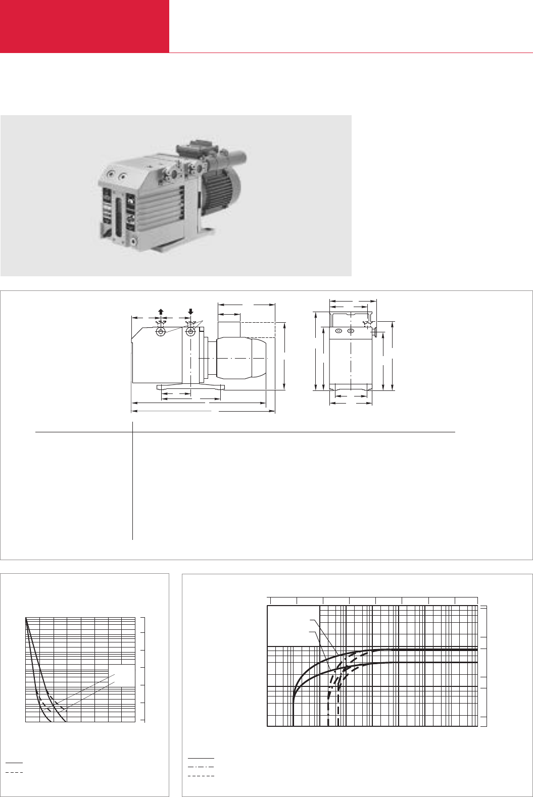
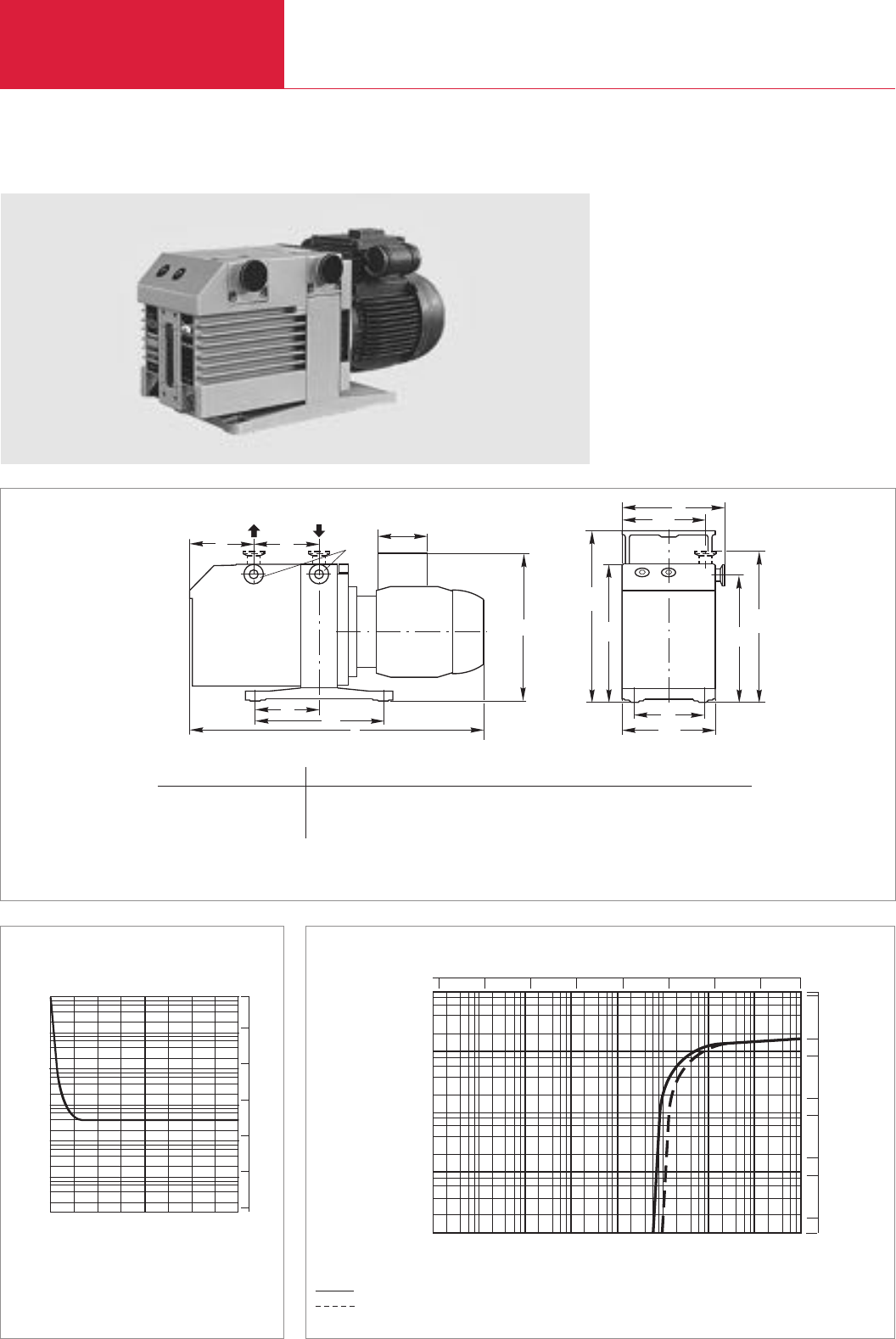
TRIVAC D 4 B and D 8 B
TRIVAC D 8 B
Pumping speed characteristics at 50 Hz (60 Hz curves at the end of the section)
Dimensional drawing for the TRIVAC D 4 B and D 8 B
Pump-down characteristics of a 10 l vessel at 50 Hz
Ultimate partial pressure without gas ballast
Ultimate total pressure without gas ballast
Ultimate total pressure with gas ballast
without gas ballast
with gas ballast
* Depending on the motor
USA pumps max. length
D 4 B 485 mm (19.1“)
D 8 B 555 mm (21.9“)
Type DN a b b1b2c e e1h h1h2h3h4l l1m n o
D 4 B (Part No. 113 04, 113 08, 113 09) 16 KF mm 75 162 147 132 100 – 170 265 215 200 230 259 – 455 198 99 108
in. 2.95 6.38 5.79 5.23 3.94 – 6.69 10.43 8.46 7.87 9.06 10.20 – 17.91 7.80 3.90 4.25
D 4 B (Part No. 113 03, 112 45) 16 KF mm 75 162 147 132 100 102 – 265 215 200 230 234 437 – 198 99 108
in. 2.95 6.38 5.79 5.23 3.94 4.02 – 10.43 8.46 7.87 9.06 9.21 17.21 – 7.80 3.90 4.25
D 4 B (Part No. 112 46) 16 KF mm 75 162 147 132 100 89 – 265 215 200 230 223 438 – 198 99 108
in. 2.95 6.38 5.79 5.23 3.94 3.5 – 10.43 8.46 7.87 9.06 8.78 17.24 – 7.80 3.90 4.25
D 8 B (Part No. 113 14, 113 18, 113 21) 16 KF mm 100 162 147 132 100 – 170 265 215 200 230 259 – 480 198 99 108
in. 3.94 6.38 5.79 5.23 3.94 – 6.69 10.43 8.46 7.87 9.06 10.20 – 18.90 7.80 3.90 4.25
D 8 B (Part No. 113 13, 113 55) 16 KF mm 100 162 147 132 100 102 – 265 215 200 230 234 462 – 198 99 108
in. 3.94 6.38 5.79 5.23 3.94 4.02 – 10.43 8.46 7.87 9.06 9.21 18.19 – 7.80 3.90 4.25
D 8 B (Part No. 113 56) 16 KF mm 100 162 147 132 100 89 – 265 215 200 230 223 463 – 198 99 108
in. 3.94 6.38 5.79 5.23 3.94 3.5 – 10.43 8.46 7.87 9.06 8.78 18.23 – 7.80 3.90 4.25

TRIVAC B
Rotary Vane Vacuum Pumps
C01.13
C01
LEYBOLD VACUUM PRODUCTS AND REFERENCE BOOK 2003/2004
Technical Data TRIVAC D 4 B TRIVAC D 8 B
50 Hz 60 Hz 50 Hz 60 Hz
Nominal pumping speed 1) m3x h-1 (cfm)
Pumping speed 1) m3x h-1 (cfm)
Ultimate partial pressure
without gas ballast 1) mbar (Torr)
Ultimate total pressure without gas ballast 1) mbar (Torr)
Ultimate total pressure with gas ballast 1) mbar (Torr)
Water vapor tolerance 1) mbar (Torr)
Water vapor capacity gm/h
Oil filling, min./max. l (qt)
Noise level 2) to DIN 45 635,
without/with gas ballast dB(A)
Admissible ambient temperature °C (°F)
Motor rating 2) W (HP)
Nominal speed rpm
Type of protection 3) IP
Weight 2) kg (lbs)
Connections, Intake and Exhaust DN
1) To DIN 28 400 and following numbers
2) Weight, motor rating and noise levels for the pumps with 230 V, 50 Hz AC motor only.
Any data that deviate from the above for pumps with other motors, and other motor-dependent data are given in section “Products”,
paragraph “Motor Dependent Data for the TRIVAC B, BCS and BCS-PFPE”
3) Global versions only. North and South American versions are TEFC
4.8 (2.8) 5.8 (3.4) 9.7 (5.7) 11.6 (6.9)
4.2 (2.5) 5 (3) 8.5 (5) 10.2 (6)
10-4 (0.75 x 10⁻⁴)
< 2 x 10⁻³ (< 1.5 x 10⁻³)
< 5 x 10⁻³ (< 3.8 x 10⁻³)
30 (22.5) 25 (18.8)
93 157
0.3 / 0.8 (.3 / .85) 0.3 / 0.9 (.3 / .95)
50 / 52
12 - 40 (54 - 104)
370 (.50)
1500 1800 1500 1800
54
18.7 (41.2) 21.2 (46.7)
16 KF

TRIVAC B
Rotary Vane Vacuum Pumps
C01.14 LEYBOLD VACUUM PRODUCTS AND REFERENCE BOOK 2003/2004
Ordering Information TRIVAC D 4 B TRIVAC D 8 B
two-stage two-stage
TRIVAC B,
with 1-phase motor
230 V, 50 Hz
230 V, 50/60 Hz
115 V, 60 Hz
100 V, 50 Hz / 110 V, 60 Hz
100 V, 50 Hz / 110 V, 60 Hz
with 3-phase motor
230/400 V, 50 Hz / 250/440 V, 60 Hz
230/400 V, 50 Hz, Exe II T3
Accessories
FS 2-4 dust filter
FA 2-4 fine vacuum adsorption trap
Adsorption trap with aluminium oxide
Activated aluminium oxide, 1.3 kg (2 l approx.)
TK 4-8 cold trap
AF 4-8 exhaust filter
AR 4-8 exhaust filter with lubricant return
AK 4-8 condensate trap
OF 4-25 mechanical oil filter
CF 4-25 chemical oil filter
Connector for gas ballast inlet M 16 x 1.5 – DN 16 KF
Oil drain tap M 16 x 1.5
Spare parts
Inside section
Seal kit
Part No. 112 45 Part No. 112 55
Part No. 113 09 Part No. 113 21
Part No. 113 03 Part No. 113 13
Part No. 113 04 Part No. 113 14
Part No. 113 08 (SHC 224) Part No. 113 18 (SHC 224)
Part No. 112 46 Part No. 112 56
Part No. 113 06 Part No. 113 16
Part No. 186 05
Part No. 187 05
Part No. 854 14
Part No. 854 10
Part No. 188 20
Part No. 189 06
Part No. 189 20
Part No. 188 06
Part No. 101 91
Part No. 101 96
Part No. 168 40
Part No. 190 90
Part No. E 200 10 989 Part No. E 200 10 991
Part No. 197 20
Ordering Information TRIVAC D 4 B TRIVAC D 8 B
two-stage two-stage
TRIVAC B,
with 1-phase motor
115 V, 60/50 Hz, NEMA plug
208-230 V, 60/50 Hz, NEMA plug
with 3-phase motor
208-230/460 V, 60 Hz / 200-220/380 V, 50 Hz
Part No.
912 45-1
Part No.
912 55-1
Part No.
912 45-2
Part No.
912 55-2
Part No.
912 46-2
Part No.
912 56-2
Version for the North and South American Continents
Global Version

TRIVAC B
Rotary Vane Vacuum Pumps
C01.15
C01
LEYBOLD VACUUM PRODUCTS AND REFERENCE BOOK 2003/2004
Notes
TRIVAC B
Rotary Vane Vacuum Pumps
C01.16 LEYBOLD VACUUM PRODUCTS AND REFERENCE BOOK 2003/2004
b
2
b
h1
h
h2
b1
h3
o
l
m
n
DN
c
a
1
e
e
h4
l1
mbar
10-1
100
101
102
-5
10 -4
10 -3
10 10-2 10-1 100101103
D 25 B
D 16 B
Torr
-5
10 -4
10 -3
10 10-2 10-1 110 750
50
cfm
1
0.5
5
10
0.1
Pressure
Pumping speed
mx h
3-1
10-3
Pressure
min
0 2
Time
3 41
10-2
10-1
100
101
102
103
D 25 B
D 16 B
mbar Torr
-3
10
10-2
10 -1
1
10
750
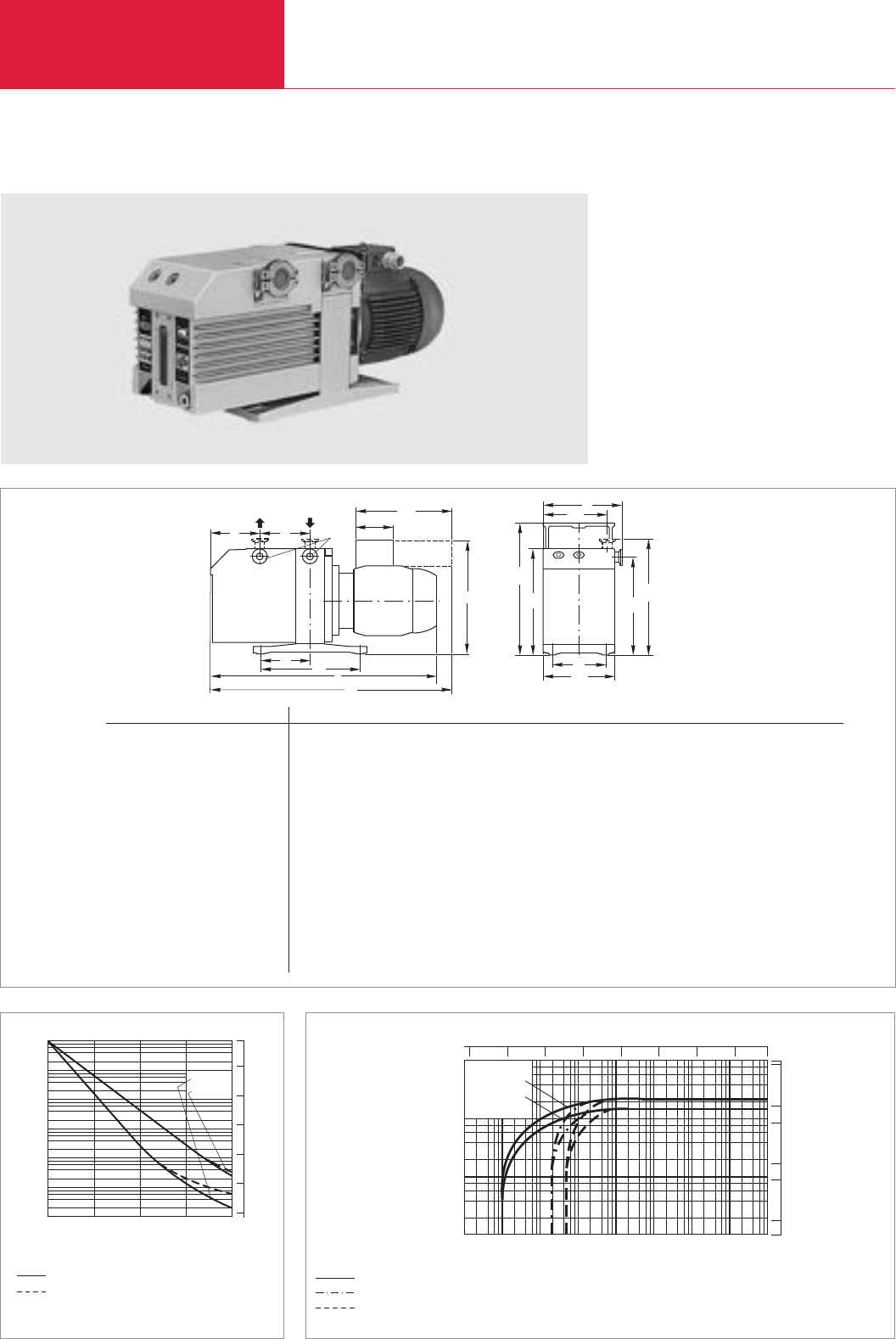
TRIVAC D 16 B and D 25 B
TRIVAC D 25 B
Pumping speed characteristics at 50 Hz (60 Hz curves at the end of the section)
Dimensional drawing for the TRIVAC D 16 and D 25 B u. r. = upun request
Pump-down characteristics of a 100 l vessel at 50 Hz
Ultimate partial pressure without gas ballast
Ultimate total pressure without gas ballast
Ultimate total pressure with gas ballast
without gas ballast
with gas ballast
* Depending on the motor
USA pumps max. length
D 16 B 560 mm (22.1“)
D 25 B 660 mm (26“)
Type DN a b b1b2c e e1h h1h2h3h4l l1m n o
D 16 B (Part No. 113 25, 113 29) 25 KF mm 82 190 177 150 135 – 266 298 250 226 263 271 – 566 280 140 132
in. 3.23 7.48 6.97 5.91 5.32 – 10.47 11.73 9.84 8.90 10.35 10.67 – 22.28 11.02 5.51 5.20
D 16 B (Part No. 112 65) 25 KF mm 82 190 175 150 135 – 170 298 250 226 263 274 – 507 280 140 132
in. 3.23 7.48 6.89 5.91 5.32 – 6.69 11.73 9.84 8.90 10.35 10.79 – 19.96 11.02 5.51 5.20
D 16 B (Part No. 112 66, 113 33) 25 KF mm 82 190 175 150 135 89 – 298 250 226 263 236 490 – 280 140 132
in. 3.23 7.48 6.89 5.91 5.32 3.50 – 11.73 9.84 8.90 10.35 9.29 19.29 – 11.02 5.51 5.20
D 16 B (Part No. 113 27) 25 KF mm 82 190 175 150 135 u. r. u. r. u. r. u. r. u. r. u. r. u. r. u. r. u. r. u. r. u. r. u. r.
in. 3.23 7.48 6.89 5.91 5.32 u. r. u. r. u. r. u. r. u. r. u. r. u. r. u. r. u. r. u. r. u. r. u. r.
D 16 B (Part No. 113 34) 25 KF mm 82 190 175 150 135 111 – 298 250 226 263 262 507 – 280 140 132
in. 3.23 7.48 6.89 5.91 5.32 4.37 – 11.73 9.84 8.90 10.35 10.32 19.96 – 11.02 5.51 5.20
D 25 B (Part No. 113 36, 113 39, 112 75) 25 KF mm 142 190 177 150 135 – 266 298 250 226 263 271 – 626 280 140 132
in. 5.59 7.48 6.97 5.91 5.32 – 10.47 11.73 9.84 8.90 10.35 10.67 – 24.65 11.02 5.51 5.20
D 25 B (Part No. 112 76) 25 KF mm 142 190 177 150 135 111 – 298 250 226 263 262 566 – 280 140 132
in. 5.59 7.48 6.97 5.91 5.32 4.37 – 11.73 9.84 8.90 10.35 10.32 22.28 – 11.02 5.51 5.20
D 25 B (Part No. 112 37) 25 KF mm 142 190 177 150 135 u. r. u. r. u. r. u. r. u. r. u. r. u. r. u. r. u. r. u. r. u. r. u. r.
in. 5.59 7.48 6.97 5.91 5.32 u. r. u. r. u. r. u. r. u. r. u. r. u. r. u. r. u. r. u. r. u. r. u. r.

TRIVAC B
Rotary Vane Vacuum Pumps
C01.17
C01
LEYBOLD VACUUM PRODUCTS AND REFERENCE BOOK 2003/2004
Technical Data TRIVAC D 16 B TRIVAC D 25 B
50 Hz 60 Hz 50 Hz 60 Hz
Nominal pumping speed 1) m3x h-1 (cfm)
Pumping speed 1) m3x h-1 (cfm)
Ultimate partial pressure
without gas ballast 1) mbar (Torr)
Ultimate total pressure without gas ballast 1) mbar (Torr)
Ultimate total pressure with gas ballast 1) mbar (Torr)
Water vapor tolerance 1) mbar (Torr)
Water vapor capacity gm/h
Oil filling, min./max. l (qt)
Noise level 2) to DIN 45 635,
without/with gas ballast dB(A)
Admissible ambient temperature °C (°F)
Motor rating 2) W (HP)
Nominal speed rpm
Type of protection 3) IP
Weight 2) kg (lbs)
Connections, Intake and Exhaust DN
1)
To DIN 28 400 and following numbers
2)
Weight, motor rating and noise levels for the pumps with AC motor, 50 Hz, only.
Any data that deviate from the above for pumps with other motors, and other motor-dependent data are given in section “Products”,
paragraph “Motor Dependent Data for the TRIVAC B, BCS and BCS-PFPE”
3) Global versions only. North and South American versions are TEFC
18.9 (11.1) 22.7 (13.4) 29.5 (17.4) 35.4 (20.9)
16.5 (9.7) 19.8 (11.7) 25.7 (15.1) 30.8 (18.2)
10-4 (0.75 x 10⁻⁴)
< 2 x 10⁻³ (1.5 x 10⁻³)
< 5 x 10⁻³ (3.8 x 10⁻³)
25 (18.8)
305 476
0.5 / 1.0 (0.5 / 1.1) 0.6 / 1.4 (0.6 / 1.5)
52 / 54
12 - 40 (54 - 104)
750 (1)
1500 1800 1500 1800
54
26 (57.3) 32 (70.6)
25 KF

TRIVAC B
Rotary Vane Vacuum Pumps
C01.18 LEYBOLD VACUUM PRODUCTS AND REFERENCE BOOK 2003/2004
Ordering Information TRIVAC D 16 B TRIVAC D 25 B
two-stage two-stage
TRIVAC B,
with 1-phase motor
230 V, 50 Hz
230 V, 50/60 Hz
100 V, 50 Hz / 110 V, 60 Hz
100 V, 50 Hz / 110 V, 60 Hz
115 V, 60 Hz
115 V, 60/50 Hz, NEMA plug
208-230 V, 60/50 Hz, NEMA plug
with 3-phase motor
230/400 V, 50 Hz / 250/440 V, 60 Hz
230/400 V, 50 Hz / 250/440 V, 60 Hz
230/400 V, 50 Hz, Exe II T3
200/346 V, 50 Hz / 208/360 V, 60 Hz
208-230/460 V, 60 Hz / 200-220/380 V, 50 Hz
Accessories
FS 8-16 dust filter
AS 8-16 dust separator
MF 8-16 molecular filter
FA 8-16 fine vacuum adsorption trap
Adsorption trap with aluminium oxide
Activated aluminium oxide, 1.3 kg (2 l approx.)
AF 16-25 exhaust filter
AR 16-25 exhaust filter with lubricant return
AK 16-25 condensate trap
OF 4-25 mechanical oil filter
CF 4-25 chemical oil filter
Connector for gas ballast inlet M 16 x 1.5 – DN 16 KF
Oil drain tap
Spare parts
Inside section
Seal kit
Part No. 112 65 Part No. 112 75
Part No. 113 25 Part No. 113 35
–Part No. 113 36
Part No. 113 29 (SHC 224)
Part No. 113 39 (SHC 224)
–Part No. 113 48
Part No. 912 65-1 –
Part No. 912 65-2 Part No. 912 75-2
Part No. 112 66 Part No. 112 76
Part No. 113 33 (RCF - E68N)
–
Part No. 113 27 Part No. 113 37
Part No. 113 34 (RCF - E68N)
–
Part No. 912 66-2 Part No. 912 76-2
Part No. 186 10
Part No. 186 11
Part No. 186 12
Part No. 187 10
Part No. 854 15
Part No. 854 10
Part No. 189 11
Part No. 189 21
Part No. 188 11
Part No. 101 91
Part No. 101 96
Part No. 168 40
Part No. 190 90
Part No. E 200 10 956 Part No. E 200 10 960
Part No. 197 21
Ordering Information TRIVAC D 16 B TRIVAC D 25 B
two-stage two-stage
TRIVAC B,
with 1-phase motor
115 V, 60/50 Hz, NEMA plug
208-230 V, 60/50 Hz, NEMA plug
with 3-phase motor
208-230/460 V, 60 Hz / 200-220/380 V, 50 Hz
Part No.
912 65-1 –
Part No.
912 65-2
Part No.
912 75-2
Part No.
912 66-2
Part No.
912 76-2
Version for the North and South American Continents
Global Version

TRIVAC B
Rotary Vane Vacuum Pumps
C01.19
C01
LEYBOLD VACUUM PRODUCTS AND REFERENCE BOOK 2003/2004
Notes
TRIVAC B
Rotary Vane Vacuum Pumps
C01.20 LEYBOLD VACUUM PRODUCTS AND REFERENCE BOOK 2003/2004
h2
b1
h
o
l
m
n
DN
c
ab
2
b
h1
e
h3
D 65 B
D 40 B
Pressure
mbar
Pumping speed
-1
mx h
3-1
100
101
102
-5
10 -4
10 -3
10 10-2 10-1 100101103
10
50
cfm
1
0.5
5
10
0.1
Torr
-5
10 -4
10 -3
10 10-2 10-1 110 750
10-3
Pressure
min
0 1 2 3 4
Time
10-2
10-1
100
101
102
103
D 65 B
D 40 B
mbar Torr
-3
10
10-2
10 -1
1
10
750
TRIVAC D 40 B and D 65 B
TRIVAC D 65 B
Pumping speed characteristics at 50 Hz (60 Hz curves at the end of the section)
Dimensional drawing for the TRIVAC D 40 and D 65 B u. r. = upon request
Pump-down characteristics of a 100 l vessel at 50 Hz
Ultimate partial pressure without gas ballast
Ultimate total pressure without gas ballast
Ultimate total pressure with gas ballast
without gas ballast
with gas ballast
* Depending on the motor
USA pumps max. length
D 40 B 760 mm (30“)
D 65 B 840 mm (33.1“)
Type DN a b b1b2c e h h1h2h3l m n o
D 40 B (Part No. 112 86) 40 KF mm 135 264 234 206 166 111 355 336 308 302 676 382 191 190
in. 5.32 10.39 9.21 8.11 6.54 4.37 13.98 13.23 12.13 11.89 26.61 15.04 7.52 7.48
D 40 B (Part No. 113 45) 40 KF mm 135 264 234 206 166 u. r. u. r. u. r. u. r. u. r. u. r. 382 191 190
in. 5.32 10.39 9.21 8.11 6.54 u. r. u. r. u. r. u. r. u. r. u. r. 15.04 7.52 7.48
D 40 B (Part No. 113 47) 40 KF mm 135 264 234 206 166 111 355 336 308 302 667 382 191 190
in. 5.32 10.39 9.21 8.11 6.54 4.37 13.98 13.23 12.13 11.89 26.26 15.04 7.52 7.48
D 65 B (Part No. 112 96, 113 57) 40 KF mm 213 264 234 206 166 111 355 336 308 302 750 382 191 190
in. 8.39 10.39 9.21 8.11 6.54 4.37 13.98 13.23 12.13 11.89 29.53 15.04 7.52 7.48
D 65 B (Part No. 113 55) 40 KF mm 213 264 234 206 166 u. r. u. r. u. r. u. r. u. r. u. r. 382 191 190
in. 8.39 10.39 9.21 8.11 6.54 u. r. u. r. u. r. u. r. u. r. u. r. 15.04 7.52 7.48

TRIVAC B
Rotary Vane Vacuum Pumps
C01.21
C01
LEYBOLD VACUUM PRODUCTS AND REFERENCE BOOK 2003/2004
Technical Data TRIVAC D 40 B TRIVAC D 65 B
50 Hz 60 Hz 50 Hz 60 Hz
Nominal pumping speed 1) m3x h-1 (cfm)
Pumping speed 1) m3x h-1 (cfm)
Ultimate partial pressure without gas ballast 1) mbar (Torr)
Ultimate total pressure without gas ballast 1) mbar (Torr)
Ultimate total pressure with gas ballast 1) mbar (Torr)
Water vapor tolerance 1) mbar (Torr)
Water vapor capacity gm/h
Oil filling, min./max. l (qt)
Noise level 2) to DIN 45 635,
without/with gas ballast dB(A)
Admissible ambient temperature °C (°F)
Motor rating 2) W (HP)
Nominal speed rpm
Type of protection 3) IP
Weight 2) kg (lbs)
Connections, Intake and Exhaust DN
1)
To DIN 28 400 and following numbers
2) Weight, motor rating and noise levels for the pumps with 3-phase motor, 50 Hz, only.
Any data that deviate from the above for pumps with other motors, and other motor-dependent data are given in section “Products”, paragraph “Motor Dependent Data for the TRIVAC B, BCS and BCS-PFPE”
3) Global versions only. North and South American versions are TEFC
46 (27) 55 (32.5) 75 (44) 90 (53)
40 (24) 48 (28) 65 (38) 78 (46)
10-4 (0.75 x 10⁻⁴)
< 2 x 10⁻³ (< 1.5 x 10⁻³)
< 5 x 10⁻³.(< 3.8 x 10⁻³)
40 (30)
1184 1925
1.7 / 2.6 (1.8 / 2.7) 2.0 / 3.3 (2.1 / 3.5)
57/59
12 - 40 (54 - 104)
2200 (3)
1500 1800 1500 1800
54
68 (150) 80 (177)
40 KF
Ordering Information TRIVAC D 40 B TRIVAC D 65 B
two-stage two-stage
TRIVAC B,
with 3-phase motor
230/400 V, 50 Hz / 250/440 V, 60 Hz
230/400 V, 50 Hz, Exe II T3
200/346 V, 50 Hz / 208/360 V, 60 Hz
Accessories
Roots pump adaptor
FS 30-60 dust filter
AS 30-60 dust separator
MF 30-60 molecular filter
FA 30-60 fine vacuum adsorption trap
Adsorption trap with aluminium oxide
Activated aluminium oxide, 1.3 kg (2 l approx.)
AF 40-65 exhaust filter
AR 40-65 exhaust filter with lubricant return
AK 40-65 condensate trap
OF 40-65 mechanical oil filter
CF 40-65 chemical oil filter
Connector for gas ballast inlet M 16 x 1.5 – DN 16 KF
Oil drain tap
Spare parts
Inside section
Seal kit
Part No. 112 86 Part No. 112 96
Part No. 113 45 Part No. 113 55
Part No. 113 47 Part No. 113 57
Part No. 168 30
Part No. 18615
Part No. 186 16
Part No. 186 17
Part No. 187 15
Part No. 854 16
Part No. 854 10
Part No. 189 16
Part No. 189 22
Part No. 188 16
Part No. 101 92
Part No. 101 97
Part No. 168 40
Part No. 190 90
Part No. E 200 10 933 Part No. E 200 10 944
Part No. 197 22
Version for the North and South American Continents
Ordering Information TRIVAC D 40 B TRIVAC D 65 B
two-stage two-stage
TRIVAC B,
with 3-phase motor
208-230/460 V, 60 Hz / 200-220/380 V, 50 Hz
Part No.
912 86-2
Part No.
912 96-2
Global Version
TRIVAC B
Rotary Vane Vacuum Pumps
C01.22 LEYBOLD VACUUM PRODUCTS AND REFERENCE BOOK 2003/2004
b
2
b
h1
h
h2
b1
h3
o
l
m
n
DN
c
ae
h4
-4
10 -3
10 10-2 10-1 100101103
mbar
-5
10
10-2
10-1
100
101
102
Pressure
Pumping speed
mx h
3-1
50
cfm
1
0.5
5
10
0.1
Torr
-5
10 -4
10 -3
10 10-2 10-1 110 750
0.05
0.01
8
0
Pressure
10 -3
Time
mbar
6min
42
10 -2
10 -1
10 0
10 1
10 2
10 3
Torr
-3
10
10-2
10-1
1
10
750
TRIVAC D 16 B-DOT
TRIVAC D 16 B-DOT
Pumping speed characteristics at 50 Hz (60 Hz curves at the end of the section)
Dimensional drawing for the TRIVAC D 16 B-DOT
Pump-down characteristics of a 10 l vessel at 50 Hz
Type DN a b b1b2c h h1h2h3l m n o
D 16 B-DOT (Part No. 114 06/10) 25 KF mm 82 190 175 150 135 298 250 226 265 482 280 140 132
in. 3.23 7.48 6.89 5.91 5.31 11.7 9.84 8.90 10.4 19 11 5.51 5.20
Ultimate total pressure without gas ballast
Ultimate total pressure with gas ballast

TRIVAC B
Rotary Vane Vacuum Pumps
C01.23
C01
LEYBOLD VACUUM PRODUCTS AND REFERENCE BOOK 2003/2004
Technical Data TRIVAC D 16 B-DOT
50 Hz 60 Hz
Ordering Information TRIVAC D 16 B-DOT
Global version North and South America version
TRIVAC B-DOT,
with 3-phase motor
230/400 V, 50 Hz; 250/440 V, 60 Hz
230/400 V, 50 Hz; 250/440 V, 60 Hz
with 1-phase motor 115 V, 60 Hz
with 3-phase motor 208-230/460 V, 60 Hz
208-220/380 V, 50 Hz
AF 16-25 DOT exhaust filter
Seal kit
Part No. 114 06
Part No. 114 10 (with float switch)
Part No. 914 62
Part No. 914 63
Part No. 124 16
Part No. 200 39 059
Nominal pumping speed 1) m3x h-1 (cfm)
Pumping speed 1) m3x h-1 (cfm)
Ultimate partial pressure without gas ball.1) mbar (Torr)
Ultimate total pressure without gas ballast 1) mbar (Torr)
Ultimate total pressure with gas ballast 1) mbar (Torr)
Water vapor tolerance 1) mbar (Torr)
Water vapor capacity gm/h
Brake fluid filling, min./max. l (qt)
Noise level to DIN 45 635,
without/with gas ballast dB(A)
Admissible ambient temperature °C (°F)
Motor rating W (HP)
Nominal speed rpm
Type of protection 2) IP
Weight kg (lbs)
Connections, Intake and Exhaust DN
18.9 (11.1) 22.7 (13.4)
16.5 (9.7) 19.8 (11.7)
–
< 6 x 10⁻¹ (< 4.5 x 10⁻¹)
< 9 x 10⁻¹ (< 6.75 x 10⁻¹)
25 (18.75)
259
0.45 / 1.0 (0.5 / 1.1)
52 / 52
12 - 40 (54 - 104)
550 (0.75)
1500 1800
54
26 (57.3)
25 KF
1) To DIN 28 400 and following numbers
2) Global versions only. North and South American versions are TEFC
As to the D 8 B-DOT, D 25 B-DOT and D 40 B-DOT please ask us for a quotation.
TRIVAC B
Rotary Vane Vacuum Pumps
C01.24 LEYBOLD VACUUM PRODUCTS AND REFERENCE BOOK 2003/2004
-4
10 -3
10 10-2 10-1 100101103
mbar
-5
10
10-2
10-1
100
101
102
Pressure
Pumping speed
mx h
3-1
50
cfm
1
0.5
5
10
0.1
Torr
-5
10 -4
10 -3
10 10-2 10-1 110 750
0.05
0.01
8
0
Pressure
10 -3
Time
mbar
6min
42
10 -2
10 -1
10 0
10 1
10 2
10 3
Torr
-3
10
10-2
10-1
1
10
750
ll1
b2
b1
b
h1
b3
h
l2
TRIVAC D 16 B-Ex (Explosion Blast Wave Resistant)
TRIVAC D 16 B-Ex
Pumping speed characteristics at 50 Hz (60 Hz curves at the end of the section)
Pump-down characteristics of a 10 l vessel at 50 Hz
Dimensional drawing for the TRIVAC 16 B-Ex (explosion blast wave resistant)
Ultimate partial pressure without gas ballast
Ultimate total pressure without gas ballast
Ultimate total pressure with gas ballast
without gas ballast
with gas ballast
Type b b1b2b3h h1l l1l2
D 16 B-Ex mm 230 362 405 132 310 250 578 232 280
in. 9.06 14.3 15.9 5.20 12.2 9.84 22.8 9.13 11

TRIVAC B
Rotary Vane Vacuum Pumps
C01.25
C01
LEYBOLD VACUUM PRODUCTS AND REFERENCE BOOK 2003/2004
Technical Data TRIVAC D 16 B-Ex (Explosion Blast Wave Resistant)
Two-Stage
Ordering Information TRIVAC D 16 B-Ex (Explosion Blast Wave Resistant)
Two-Stage
TRIVAC D 16 B-Ex (according to 94/9 EC) 2)
TRIVAC D 16 B-Ex (for propane and butane only) 3)
with explosion protected 3-phase motor
(Exe II T 3) 230/400 V, 50 Hz,
includes AF 16-25 exhaust filter,
specially modified for burst resistant
1) To DIN 28 400 and following numbers
2) Available in June 2003
3) The pump is checked at pressures up to 12 bar absolute (160 psi, gauge)
Upon request
Part No. 113 30
Nominal pumping speed 1) m3x h-1 (cfm)
Pumping speed 1) m3x h-1 (cfm)
Ultimate partial pressure without gas ballast 1)mbar (Torr)
Ultimate total pressure without gas ballast 1) mbar (Torr)
Ultimate total pressure with gas ballast 1) mbar (Torr)
Water vapor tolerance 1) mbar (Torr)
Water vapor capacity gm/h
Oil filling, min./max. l (qt)
Noise level to DIN 45 635,
without/with gas ballast dB(A)
Admissible ambient temperature °C (°F)
Motor rating W (HP)
Nominal speed rpm
Type of protection IP
Weight
with flame arresters kg (lbs)
Connections
intake side Inside thread
pressure side Inside thread
18.9 (11.1)
16.5 (9.7)
10-4 (0.75 x 10⁻⁴)
< 2 x 10⁻³ (< 1.5 x 10⁻³)
< 5 x 10⁻³ (< 3.8 x 10⁻³)
25 (18.75)
305
0.45 / 1.0 (0.5 / 1.1)(N 62)
52 / 54
12 - 40 (54 - 104)
750 (1)
1500
54
50 (110.3)
G 3/4"
G 1"
TRIVAC BCS
Rotary Vane Vacuum Pumps
C01.26 LEYBOLD VACUUM PRODUCTS AND REFERENCE BOOK 2003/2004
The TRIVAC BCS pumps are oil-sealed vacuum
pumps operating according to the rotary vane
principle. Oil which is injected into the pump
chamber is used for sealing, lubrication and
cooling purposes.
The pump body is assembled from individual
parts without sealing components. The parts are
pinned in order to ensure easy disassembly and
reassembly of the parts.
The TRIVAC BCS are available with a three-phase
motor (The North and South American TRIVAC
D 16/25 BCS are also available with single-phase
motors). The motor is connected to the pumping
section via an elastic coupling.
In addition, the TRIVAC BCS is ready for system
integration (adaptable to different applications).
Advantages to the User
♦Compact design
♦Low noise operation with hardly any
vibrations
♦Built-in oil pump
♦Continuous operation even at 1000 mbar
(750 Torr)
♦Pressure-lubricated sliding bearings
♦Anti-suckback valve controlled via the oil
pressure, no backstreaming of oil, indepen-
dent of the operating mode, with or without
gas ballast
♦Low backstreaming of oil within the pump
♦High pumping speed down to ultimate pres-
sure
♦Either vertical or horizontal intake and exhaust
ports
♦All controls as well as the oil sight glass are
located on the face side
♦Low power consumption
♦Produces very little heat
♦Exchangeable inner section
♦Main flow oil filters may be fitted
♦Very long service life
♦Modular system
♦Service-friendly
♦Built-in temperature switch for temperature
monitoring
♦Corrosion protected – the use of yellow
metals has been avoided; only grey cast iron,
surface treated aluminium, steel and stainless
steel is used.
♦Double shaft seal
Typical Applications
♦In all areas of vacuum engineering
♦Pumping of corrosive or aggressive media
♦Production of semiconductors and in the area
of chemistry
♦Research and production
♦Generation of rough and medium vacuum
♦Backing pump in pump sets, i.e. in connection
with Roots, diffusion, turbo or cryo pumps
Supplied Equipment
♦Small flanges
♦Centering, sealing and clamping rings
♦The intake port includes a dirt trap
BCS pumps are supplied with a filling of mineral
oil N 62, HE-200 oil or perfluoropolyether (PFPE)
synthetic oil.
ALL PUMPS ARE SUBJECTED TO A VACUUM
TEST BEFORE DELIVERY!
TRIVAC BCS, Two-Stage Rotary Vane Vacuum Pumps
TRIVAC SYSTEM

TRIVAC BCS
Rotary Vane Vacuum Pumps
C01.27
C01
LEYBOLD VACUUM PRODUCTS AND REFERENCE BOOK 2003/2004
TRIVAC BCS-PFPE
In many applications the use of synthetic lubri-
cants like perfluoropolyether (PFPE) offers for
superior characteristics compared to mineral oils.
Advantages of perfluoropolyther (PFPE) NC 1/14
and HE-1600:
♦Practically inert against all chemical and
oxidizing influences.
♦No polymerization under the influence of high
energy radiation.
♦PFPE is non-flammable. Leybold NC1/14 has
the approval of BAM (Federal Institute for
Materials Research and Testing) for pumping
of pure oxygen.
♦In part significantly increased oil change inter-
vals.
♦Thermally highly stable. Thermal decompo-
sition will only occur at temperatures over
290 °C (554 °F).
TRIVAC SYSTEM
The TRIVAC BCS and its accessories
♦CFS, chemical filter with safety isolation valve
♦ARS, exhaust filter with lubricant return
♦IGS, inert gas system
♦LSS, limit switch system and
♦EIS, electrical indicator system
make up the TRIVAC SYSTEM.
BCS-PFPE pumps have been especially prepared
for operation with PFPE and are supplied without
the oil filling. We recommend using our operating
fluid PFPE NC 1/14 or HE-1600 and always to
install a chemical oil filter CF/CFS.
TRIVAC BCS
Rotary Vane Vacuum Pumps
C01.28 LEYBOLD VACUUM PRODUCTS AND REFERENCE BOOK 2003/2004
10-2
10-1
10 0
10 1
10 2
103
101mbar
100
10-1
10-2
-3
10
-4
10
-5
10
D 16 BCS
D 25 BCS
D 40 BCS
D 65 BCS
Pressure
Pumping speed
mx h
3-1
Torr
-5
10 -4
10 -3
10 10-2 10-1 110 750
50
cfm
1
0.5
5
10
0.1
0.05
0.01
0
Pressure
10-3
Time
mbar
6 8
min
42
10-2
10-1
100
101
102
103
D 16 BCS
D 25 BCS
D 65 BCS
D 40 BCS
Torr
-3
10
10-2
10 -1
1
10
750
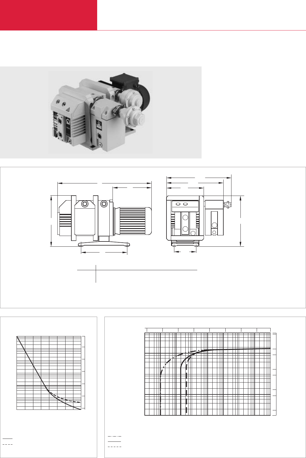
TRIVAC D 16 BCS to D 65 BCS
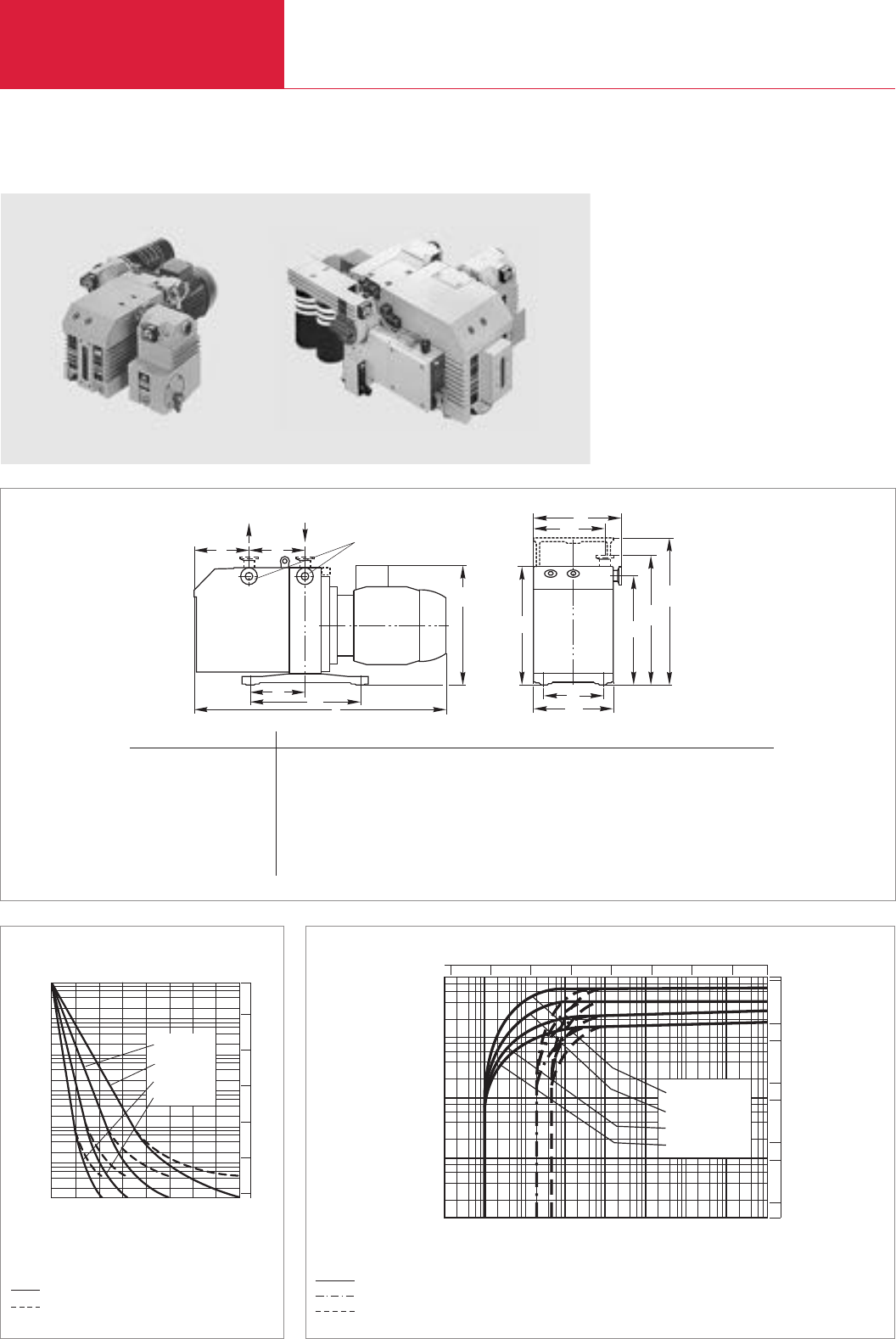
TRIVAC D 25 BCS with ARS and CFS (left) and TRIVAC D 65 BCS with CFS, ARS, IGS, LSS, EIS – TRIVAC SYSTEM (right)
Pumping speed characteristics at 50 Hz (60 Hz curves at the end of the section)
Dimensional drawing for the TRIVAC D 16 to D 65 BCS
Pump-down characteristics of a 100 l vessel at 50 Hz
without gas ballast
with gas ballast
Ultimate partial pressure without gas ballast
Ultimate total pressure without gas ballast
Ultimate total pressure with gas ballast
m
c
a
l
DN
n
1
h
2
h
4
h
h
2
bb
1
b
o
3
h
1
h
2
h
4
h
2
bb
1
b
o
3
h
Type DN a b b1b2c e h h1h2h3h4l m n o
D 16 BCS (Part No. 113 68) 40 KF mm 82 190 175 150 135 89 263 226 250 298 236 490 280 140 132
in. 3.23 7.48 6.89 5.91 5.32 3.50 10.35 8.90 9.84 11.73 9.29 19.29 11.02 5.51 5.20
D 25 BCS (Part No. 113 78) 40 KF mm 143 190 175 150 135 111 236 226 250 298 262 566 280 140 132
in. 5.63 7.48 6.89 5.91 5.32 4.37 9.29 8.90 9.84 11.73 10.32 22.28 11.02 5.51 5.20
D 40 BCS (Part No. 113 88) 40 KF mm 135 264 234 206 166 111 355 308 336 – 302 676 382 191 190
in. 5.32 10.39 9.21 8.11 6.54 4.37 13.98 12.13 13.23 – 11.89 26.61 15.04 7.52 7.48
D 65 BCS (Part No. 118 98) 40 KF mm 213 264 234 206 166 111 355 308 336 – 302 747 382 191 190
in. 8.39 10.39 9.21 8.11 6.54 4.37 13.98 12.13 13.23 – 11.89 29.41 15.04 7.52 7.48
* Depending on the motor
USA pumps max. length
D 16 BCS 560 mm (22.1“)
D 25 BCS 660 mm (26“)
D 40 BCS 760 mm (30“)
D 65 BCS 840 mm (33.1“)

TRIVAC BCS
Rotary Vane Vacuum Pumps
C01.29
C01
LEYBOLD VACUUM PRODUCTS AND REFERENCE BOOK 2003/2004
Technical Data
1)
To DIN 28 400 and following numbers
2) Weight, motor rating and noise levels for the pumps with 3-phase motor, 50 Hz, only.
Any data that deviate from the above for pumps with other motors, and other motor-dependent data are given in section “Products”,
paragraph “Motor Dependent Data for the TRIVAC B, BCS and BCS-PFPE”
3) Global versions only. North and South American versions are TEFC
TRIVAC TRIVAC TRIVAC TRIVAC
D 16 BCS D 25 BCS D 40 BCS D 65 BCS
Nominal pumping speed 50/60 Hz 1) m3x h-1 (cfm)
Pumping speed 50/60 Hz 1) m3x h-1 (cfm)
Ultimate partial pressure
without gas ballast 1) mbar (Torr)
Ultimate total pressure without gas ballast 1) mbar (Torr)
Ultimate total pressure with gas ballast 1) mbar (Torr)
Water vapor tolerance 1) mbar (Torr)
Water vapor capacity gm/h
Oil filling, min./max. l (qt)
Noise level 2) to DIN 45 635,
without/with gas ballast dB(A)
Admissible ambient temperature °C (°F)
Motor rating 2) W (HP)
Nominal speed 50/60 Hz rpm
Type of protection 3) IP
Weight 2) kg (lbs)
Connections, Intake and Exhaust DN
18.9 (11.1) / 22.7 (13.4) 29.5 (17.4) / 35.4 ( 20.9) 46 (27) / 55 (32.5) 75 (44) / 90 (53)
16.5 (9.7) / 19.8 (11.7) 25.7 (15.1) / 30.8 (18.2) 40 (24) / 48 (28) 65 (38) / 78 (46)
10-4 (0.75 x 10⁻⁴)
< 2 x 10⁻³ (< 1.5 x 10⁻³)
< 5 · 10-3 (< 3.8 x 10⁻³)
25 (18.8) 25 (18.8) 40 (30) 40 (30)
305 476 1184 1925
0.45 / 1.0 (0.5/1.1) 0.6 / 1.4 (0.6/1.5) 1.7 / 2.6 (1.8/2.7) 2.0 / 3.3 (2.1/3.5)
52 / 54 52 / 54 57 / 59 57 / 59
12 - 40 (54 - 104)
750 (1) 750 (1) 1500 (2) 2200 (3)
1500 / 1800
54
26 (57.3) 32 (70.6) 68 (150) 80 (176.4)
25 KF 25 KF 40 KF 40 KF

TRIVAC BCS
Rotary Vane Vacuum Pumps
C01.30 LEYBOLD VACUUM PRODUCTS AND REFERENCE BOOK 2003/2004
Ordering Information TRIVAC TRIVAC TRIVAC TRIVAC
D 16 BCS D 25 BCS D 40 BCS D 65 BCS
two-stage two-stage two-stage two-stage
TRIVAC BCS
with 3-phase motor
230/400 V, 50 Hz / 250/440 V, 60 Hz
Accessories
Roots pump adaptor
Exhaust filter with lubricant return
ARS 16-25
ARS 40-65
Condensate separator
AK 16-25
AK 40-65
Chemical filter with safety blocking valve
CFS 16-25
CFS 40-65
Inert gas system
IGS 16-25
IGS 40-65
Limit switch system
LSS 16-25
LSS 40-65
Electrical indicator system
EIS 16-25
EIS 40-65
RIS remote indicator system, remote monitoring
MBS moisture barrier system
Spare parts
Inside section
Seal kit
Part No. 113 68 Part No. 113 78 Part No. 113 88 Part No. 113 98
– – Part No. 168 30 Part No. 168 30
Part No. 189 56 Part No. 189 56 – –
– – Part No. 189 57 Part No. 189 57
Part No. 188 11 Part No. 188 11 – –
– – Part No. 188 16 Part No. 188 16
Part No. 101 76 Part No. 101 76 – –
– – Part No. 101 77 Part No. 101 77
Part No. 161 76 Part No. 161 76 – –
– – Part No. 161 77 Part No. 161 77
Part No. 161 06 Part No. 161 06 – –
– – Part No. 161 07 Part No. 161 07
Part No. 160 96 Part No. 160 96 – –
– – Part No. 160 97 Part No. 160 97
Part No. 188 96
Part No. 189 67
Part No. 200 39 762 Part No. 200 39 764 Part No. 200 39 758 Part No. 200 39 760
Part No. 197 31 Part No. 197 31 Part No. 197 32 Part No. 197 32
Version for the North and South American Continents
Global Version
Ordering Information TRIVAC TRIVAC TRIVAC TRIVAC
D 16 BCS D 25 BCS D 40 BCS D 65 BCS
two-stage two-stage two-stage two-stage
TRIVAC BCS,
with 1-phase motor
115 V, 60/50 Hz, NEMA plug
200-230 V, 60 Hz, NEMA plug
with 3-phase motor
208-230/460 V, 60 Hz / 200-220/380 V, 50 Hz
Part No. 913 68-1 – – –
– Part No. 913 78-2 – –
Part No. 913 68-2 Part No. 913 78-3 Part No. 913 88-2 Part No. 913 98-2

TRIVAC BCS
Rotary Vane Vacuum Pumps
C01.31
C01
LEYBOLD VACUUM PRODUCTS AND REFERENCE BOOK 2003/2004
Notes
TRIVAC BCS-PFPE
Rotary Vane Vacuum Pumps
C01.32 LEYBOLD VACUUM PRODUCTS AND REFERENCE BOOK 2003/2004
10-2
10-1
100
101
102
103
101mbar
100
10-1
10-2
-3
10
-4
10
-5
10
D 16 BCS-PFPE
D 25 BCS-PFPE
D 40 BCS-PFPE
D 65 BCS-PFPE
Pressure
Pumping speed
mx h
3-1
Torr
-5
10 -4
10 -3
10 10-2 10-1 110 750
50
cfm
1
0.5
5
10
0.1
0.05
0.01
0
Pressure
10-3
Time
mbar
6 8
min
42
10-2
10-1
100
101
102
103
D 16 BCS-PFPE
D 25 BCS-PFPE
D 40 BCS-PFPE
D 65 BCS-PFPE
Torr
-3
10
10-2
10 -1
1
10
750
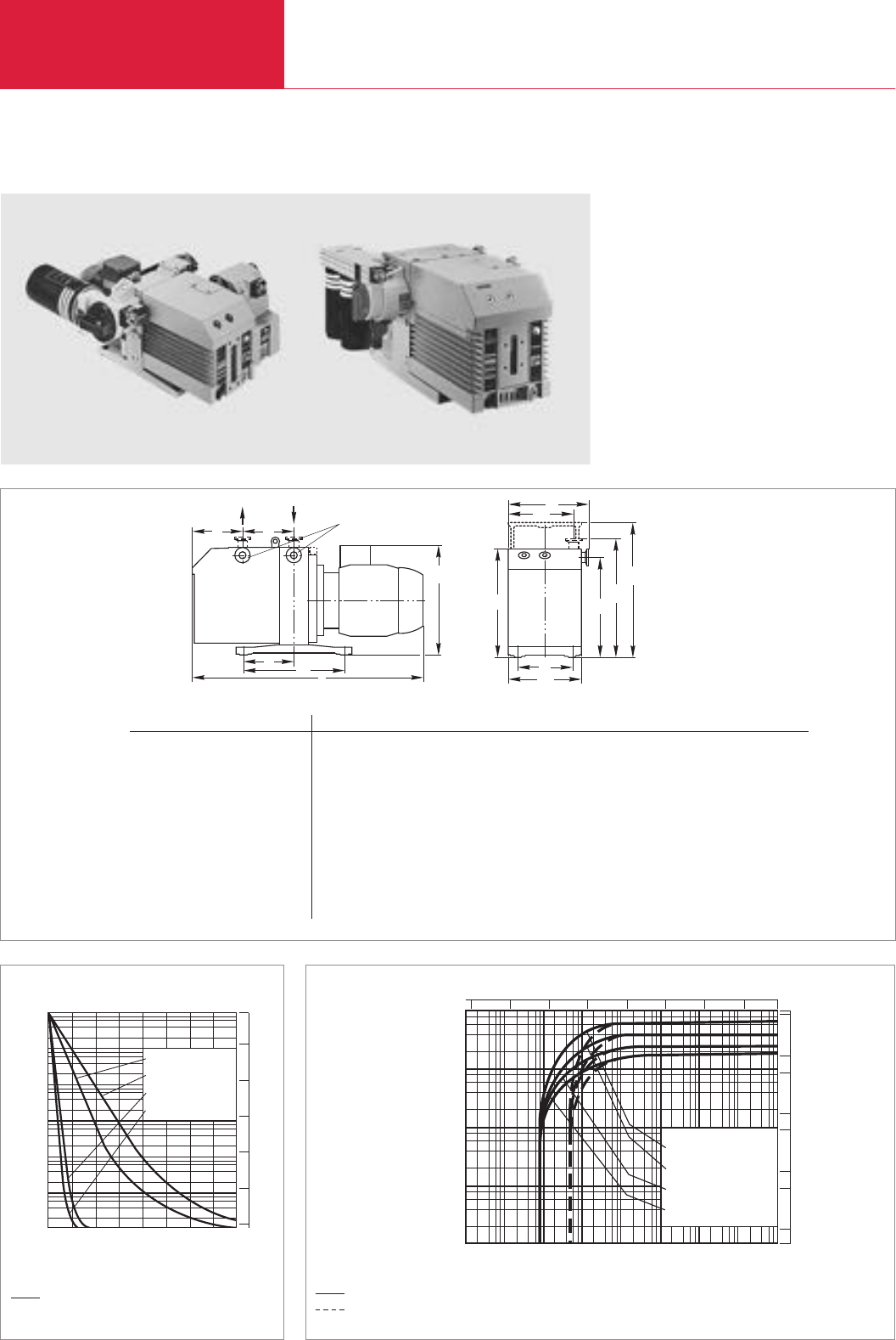
TRIVAC D 16 BCS-PFPE to D 65 BCS-PFPE
TRIVAC D 25 BCS-PFPE with CFS 16-25 and ARS 16-25 (left) and TRIVAC D 65 BCS-PFPE with CFS 40-65 (right)
Pumping speed characteristics at 50 Hz (60 Hz curves at the end of the section)
Dimensional drawing for the TRIVAC D 16 to D 65 BCS-PFPE
Pump-down characteristics of a 100 l vessel at 50 Hz
without gas ballast Ultimate partial pressure without gas ballast
Ultimate total pressure with gas ballast
m
c
a
l
DN
n
1
h
2
h
4
h
h
2
bb
1
b
o
3
h
1
h
2
h
4
h
2
bb
1
b
o
3
h
Type DN a b b1b2c e h h1h2h3h4l m n o
D 16 BCS-PFPE (Part No. 113 69, 154 50) 25 KF mm 82 190 175 150 135 111 263 226 250 298 262 507 280 140 132
in. 3.23 7.48 6.89 5.91 5.32 4.37 10.35 8.90 9.84 11.73 10.32 19.96 11.02 5.51 5.20
D 25 BCS-PFPE (Part No. 113 79, 154 51) 25 KF mm 142 190 175 150 135 111 263 226 250 298 262 566 280 140 132
in. 5.59 7.48 6.89 5.91 5.32 4.37 10.35 8.90 9.84 11.73 10.32 22.28 11.02 5.51 5.20
D 40 BCS-PFPE (Part No. 113 89) 40 KF mm 135 264 234 206 166 111 355 308 336 – 302 670 382 191 190
in. 5.32 10.39 9.21 8.11 6.54 4.37 13.98 12.13 13.23 – 11.90 26.38 15.04 7.52 7.48
D 40 BCS-PFPE (Part No. 154 52) 40 KF mm 135 264 234 206 166 111 355 308 336 – 302 714 382 191 190
in. 5.32 10.39 9.21 8.11 6.54 4.37 13.98 12.13 13.23 – 11.90 28.11 15.04 7.52 7.48
D 65 BCS-PFPE (Part No. 113 99) 40 KF mm 213 264 234 206 166 111 355 308 336 – 302 750 382 191 190
in. 8.39 10.39 9.21 8.11 6.54 4.37 13.98 12.13 13.23 – 11.90 29.53 15.04 7.52 7.48
D 65 BCS-PFPE (Part No. 54 54) 40 KF mm 213 264 234 206 166 111 355 308 336 – 302 796 382 191 190
in. 8.39 10.39 9.21 8.11 6.54 4.37 13.98 12.13 13.23 – 11.90 31.34 15.04 7.52 7.48
* Depending on the motor
USA pumps max. length
D 16 BCS-PFPE 560 mm (22.1“)
D 25 BCS-PFPE 660 mm (26“)
D 40 BCS-PFPE 760 mm (30“)
D 65 BCS-PFPE 840 mm (33.1“)

TRIVAC BCS-PFPE
Rotary Vane Vacuum Pumps
C01.33
C01
LEYBOLD VACUUM PRODUCTS AND REFERENCE BOOK 2003/2004
Technical Data
Nominal pumping speed 50/60 Hz 1) m3x h-1 (cfm)
Pumping speed 50/60 Hz 1) m3x h-1 (cfm)
Ultimate partial pressure
without gas ballast 1) mbar (Torr)
Ultimate total pressure without gas ballast 1) mbar (Torr)
Ultimate total pressure with gas ballast 1) mbar (Torr)
Ultimate total pressure with
reduced gas ballast, 200 l x h-1 1) mbar (Torr)
Lubricant filling
min./max. l (qt)
upon delivery l (qt)
Noise level 2) to DIN 45 635,
without/with gas ballast dB(A)
Admissible ambient temperature °C (°F)
Motor rating 2) W (HP)
Nominal speed 50/60 Hz rpm
Type of protection 4) IP
Weight 2) kg (lbs)
Connections, Intake and Exhaust DN
1)
To DIN 28 400 and following numbers
2)
Weight, motor rating and noise levels for the pumps with 3-phase motor, 50 Hz, only.
Any data that deviate from the above for pumps with other motors, and other motor-dependent data are given in section “Products”,
paragraph “Motor Dependent Data for the TRIVAC B, BCS and BCS-PFPE”
3)
Cold start temperature to DIN
4) Global versions only. North and South American versions are TEFC
18.9 (11.1) / 22.7 (13.4) 29.5 (17.4) / 35.4 ( 20.9) 46 (27) / 55 (32.5) 75 (44) / 90 (53)
16.5 (9.7) / 19.8 (11.7) 25.7 (15.1) / 30.8 (18.2) 40 (24) / 48 (28) 65 (38) / 78 (46)
< 8 · 10-4 (< 6 x 10⁻⁴)
< 2 · 10-3 (< 1.5 x 10⁻³)
< 5 · 10-3 (< 3.8 x 10⁻³)
< 2 · 10-3 (< 1.5 x 10⁻³) < 2 · 10-3 (< 1.5 x 10⁻³) – –
0.45 / 1.0 (0.5 / 1.1) 0.6 / 1.4 (0.6 / 1.5) 1.5 / 2.5 (1.6 / 2.6) 2.0 / 3.5 (2.1 / 3.7)
0.2 (0.2) 0.4 (0.4) 0.6 (0.6) 0.75 (0.8)
52 / 54 52 / 54 57 / 59 57 / 59
12 3) - 40 (54 - 104) 12 - 40 (54 - 104) 12 - 40 (54 - 104) 12 - 40 (54 - 104)
550 (0.75) 750 (1) 2200 (3) 2200 (3)
1500 / 1800
54
27 (59.5) 33 (72.8) 71 (156.6) 83 (183)
25 KF 25 KF 40 KF 40 KF
TRIVAC D 16 TRIVAC D 25 TRIVAC D 40 TRIVAC D 65
BCS-PFPE BCS-PFPE BCS-PFPE BCS-PFPE

TRIVAC BCS-PFPE
Rotary Vane Vacuum Pumps
C01.34 LEYBOLD VACUUM PRODUCTS AND REFERENCE BOOK 2003/2004
Ordering Information
TRIVAC BCS-PFPE,
with 3-phase motor
230/400 V, 50 Hz / 250/440 V, 60 Hz
200/400 V, 50 Hz / 220/440 V, 60 Hz
Accessories
Roots pump adaptor
Exhaust filter with lubricant return
ARS 16-25
ARS 40-65
Condensate trap
AK 16-25
AK 40-65
Chemical filter with safety isolation valve
CFS 16-25
CFS 40-65
Inert gas system
IGS 16-25
IGS 40-65
Limit switch system
LSS 16-25
LSS 40-65
Electrical indicator system
EIS 16-25
EIS 40-65
RIS remote indicator system, remote monitoring
MBS moisture barrier system
Spare parts
Inside section
Seal kit
Part No. 113 69 Part No. 113 79 Part No. 113 89 Part No. 113 99
Part No. 154 50 Part No. 154 51 Part No. 154 52 Part No. 154 54
– – Part No. 168 30 Part No. 168 30
Part No. 189 56 Part No. 189 56 – –
– – Part No. 189 57 Part No. 189 57
Part No. 188 11 Part No. 188 11 – –
– – Part No. 188 16 Part No. 188 16
Part No. 101 76 Part No. 101 76 – –
– – Part No. 101 77 Part No. 101 77
Part No. 161 76 Part No. 161 76 – –
– – Part No. 161 77 Part No. 161 77
Part No. 161 06 Part No. 161 06 – –
– – Part No. 161 07 Part No. 161 07
Part No. 160 96 Part No. 160 96 – –
– – Part No. 160 97 Part No. 160 97
Part No. 188 96
Part No. 189 67
Part No. 200 39 763 Part No. 200 39 765 Part No. 200 39 154 Part No. 200 39 156
Part No. 197 41 Part No. 197 41 Part No. 197 42 Part No. 197 42
TRIVAC D 16 TRIVAC D 25 TRIVAC D 40 TRIVAC D 65
BCS-PFPE BCS-PFPE BCS-PFPE BCS-PFPE
two-stage two-stage two-stage two-stage
Version for the North and South American Continents
Global Version
Ordering Information
TRIVAC D 16 TRIVAC D 25 TRIVAC D 40 TRIVAC D 65
BCS-PFPE BCS-PFPE BCS-PFPE BCS-PFPE
two-stage two-stage two-stage two-stage
TRIVAC BCS,
with 1-phase motor
115 V, 60/50 Hz, NEMA plug
200-230 V, 60 Hz, NEMA plug
with 3-phase motor
208-230/460 V, 60 Hz / 200-220/380 V, 50 Hz
Part No. 913 69-1 – – –
– Part No. 913 79-2 – –
Part No. 913 69-2 Part No. 913 79-3 Part No. 913 89-2 Part No. 913 99-2

TRIVAC BCS-PFPE
Rotary Vane Vacuum Pumps
C01.35
C01
LEYBOLD VACUUM PRODUCTS AND REFERENCE BOOK 2003/2004
Notes

TRIVAC B, BCS, BCS-PFPE
Rotary Vane Vacuum Pumps
C01.36 LEYBOLD VACUUM PRODUCTS AND REFERENCE BOOK 2003/2004
Motor Dependent Data for the TRIVAC B, BCS and BCS-PFPE
Part No. Part No.
D 4 B D 8 B
113 04 / 113 08 (SHC 224) 113 14 / 113 18 (SHC 224)
113 03 113 13
112 45 112 55
113 09 113 21
112 46 112 56
113 06 113 16
912 45-1 –
912 45-2 –
912 46-2 –
– 912 55-1
– 912 55-2
– 912 56-2
D 16 B D 25 B
D 16 BCS D 25 BCS
D 16 BCS-PFPE D 25 BCS-PFPE
113 29 (SHC 224) 113 36 / 113 39 (SHC 224)
– –
– –
– 113 48
– –
– –
113 25 112 75
– –
– –
112 65 –
– –
– –
112 66 / 113 33 (RCF - E68N) –
113 68 –
– –
– 112 76
– 113 78
113 69 113 79
113 27 / 113 30 (Ex) 113 37
– –
– –
113 34 (RCF - E68N) –
– –
– –
114 06 DOT / 114 10 DOT LSS –
– –
– –
– –
– –
154 50 154 51
912 65-1 –
913 68-1 –
913 69-1 –
912 65-2 –
– –
– –
912 66-2 –
913 68-2 –
913 69-2 –
– 912 75-2
– 913 78-2
– 913 79-2
– 912 76-2
– 913 78-3
– 913 79-3
TRIVAC D 4 + 8 BTRIVAC D 16 + 25 B (BCS(-PFPE))

TRIVAC B, BCS, BCS-PFPE
Rotary Vane Vacuum Pumps
C01.37
C01
LEYBOLD VACUUM PRODUCTS AND REFERENCE BOOK 2003/2004
Ref. No. 1- or 3-ph Motor voltage (V) Frequency (Hz)
Voltage range (V)
Power Nominal current (A) 1) Size Region
±5% kW HP
200 10 404 100 50 95-105 0.37 0.5 8.7 80 Japan
1 ~ 110 60 95-115 6.1
200 10 403 115 60 109-121 0.37 0.5 5.6 70 USA
1 ~
380 66 008 230 50 218-242 0.37 0.5 2.9 70 Euro
1 ~
200 39 867 230 50 208-252 0.37 0.5 2.9 70 Wide range
1 ~ 60 208-252
380 66 006 230/400 50 218-242/380-420 0.37 0.5 1.95/1.12 70 Euro (USA)
3 ~ 250/440 60 240-277/415-480 1.73/1.0
200 10 406 230/400 50 218-242/380-420 0.37 0.5 1.92/1.11 70 Euro
3 ~ EXE II CT3
722 60 095 115 60 103-126 0.25 0.33 7 NEMA 56 C USA
1 ~ 110 50 99-121 8.8
722 60 096 200-230 60 180-253 0.25 0.33 3.2-3.5 NEMA 56 C USA
1 ~ 200-220 50 180-220 3.6-4.4
722 60 067 200-230/460 60 180-253/414-506 0.25 0.33 1.5-1.6/0.8 NEMA 56 C USA
3 ~ 200/380 50 180-220/342-418 1.6/0.8
722 60 117 115 60 103-126 0.55 0.75 9.4 NEMA 56 C USA
1 ~ 115 50 103-126 13
722 60 005 208-230 60 187-253 0.55 0.75 4.8-4.7 NEMA 56 C USA
1 ~ 208-230 50 187-253 5.5-6.5
722 60 135 208-230/460 60 187-253/414-506 0.75 1 3.4-3.4/1.7 NEMA 56 C USA
3 ~ 208-220/380 50 187-242/342-418 3.1 -/1.7
200 10 679 115 60 109-121 0.75 1 12.5 90 USA
1 ~
200 10 408 100 50 95-105 0.75 1 14.5 90 Japan
1 ~ 110 60 95-115 14.5
380 66 004 230 50 208-252 0.75 1 6.3 90 Euro
1 ~
380 66 003 230 50 218-242 0.55 0.75 5.0 80 Euro
1 ~
380 66 001 230/400 50 218-242/380-420 0.55 0.75 2.85/1.65 70 Euro (USA)
3 ~ 250/440 60 240-277/415-480 2.5/1.45
380 66 002 230/400 50 218-242/380-420 0.75 1 3.55/2.05 80 Euro (USA)
3 ~ 250/440 60 240-277/415-480 3.25/1.85
200 10 409 230/400 50 218-242/380-420 0.75 1 3.4/1.97 80 Euro
3 ~ Exe II CT3
200 10 410 200/346 50 190-210/330-365 0.75 1 4.3/2.5 80 Japan, South
3 ~ 208/360 60 190-230/330-400 4.3/2.5 and Central America
USA
200 10 299 230/400 50 218-242/380-420 0.55 0.75 3.2/1.85 70 Euro
3 ~ 250/440 60 240-265/415-460 2.8/1.6
100 000 807 200/400 50 190-220/380-440 0.75 1 4.3/2.15 80 Wide range
3 ~ 220/440 60 190-240/380-480 4.0/2.0
722 60 117 115 60 103-126 0.55 0.75 9.4 NEMA 56 C USA
1 ~ 115 50 103-126 13
722 60 005 208-230 60 187-253 0.55 0.75 4.8-4.7 NEMA 56 C USA
1 ~ 208-230 50 187-253 5.5-6.5
722 60 135 208-230/460 60 187-253/414-506 0.75 1 3.4-3.4/1.7 NEMA 56 C USA
3 ~ 208-220/380 50 187-242/342-418 3.1/1.7
722 60 022 200-230 60 180-253 1.1 1.5 9.6-9.2 NEMA 56 C USA
1 ~
722 60 071 200-230/460 60 180-253/414-506 1.1 1.5 9.0-8.0 NEMA 56 C USA
3 ~ 200/380 50 180-220/342-418 9.6-9.2
TRIVAC D 4 + 8 B
TRIVAC D 16 + 25 B (BCS(-PFPE))
1) Will be changed for engineering reasons in 2003

TRIVAC B, BCS, BCS-PFPE
Rotary Vane Vacuum Pumps
C01.38 LEYBOLD VACUUM PRODUCTS AND REFERENCE BOOK 2003/2004
Motor Dependent Data for the TRIVAC B, BCS and BCS-PFPE
Part No. Part No.
D 40 B D 65 B
D 40 BCS D 65 BCS
D 40 BCS-PFPE D 65 BCS-PFPE
112 86 112 96
113 88 113 98
113 89 113 99
113 45 113 55
– –
113 47 113 57
– –
– –
– –
– –
154 52 154 54
912 86-2 912 96-2
913 88-2 913 98-2
913 89-2 913 99-2
TRIVAC D 40 + 65 B
(BCS(-PFPE))
D 4/8 B D 16/25 D 40 D 65 B S 1.5
Shaft dimensions ld / l 14 / 30 19 / 40 24 / 50 28 / 60 11 / 23
Size of flange A/B 140 / 95 160 / 110 160 / 110 160 / 110 120 / 100
Type of protection: IP 54
Type of motor: B 14
Rotational speed 50/60 Hz: 1500 / 1800

TRIVAC B, BCS, BCS-PFPE
Rotary Vane Vacuum Pumps
C01.39
C01
LEYBOLD VACUUM PRODUCTS AND REFERENCE BOOK 2003/2004
Ref. No. Motor voltage (V) Frequency (Hz)
Voltage range (V)
Power Nominal current (A) 1) Size Region
1- or 3-ph ± 5% kW HP
380 66 012 230/400 50 218-242/380-420 2.2 3 8.65/5.0 90 Euro (USA)
3 ~ 250/440 60 240-277/414-480 7.8/4.5
200 10 411 230/400 50 218-242/380-420 2.2 3 9.4/5.4 100 Euro
3 ~ Exe II CT3
200 10 412 200/346 50 190-210/330-365 2.2 3 10.1/5.85 90 Japan, South
3 ~ 208/360 60 190-230/330-400 10.1/5.85 and Central America
USA
200 15 402 200/400 50 190-220/380-440 2.2 3 11.8/5.9 100 Wide range
3 ~ 220/440 60 190-240/380-480 10/5
722 60 011 200-230/460 60 180-253/414-506 3 4 9.0-8.4/4.2 NEMA 182 TC USA
3 ~ 200-220/380-415 50 180-242/342-418 9.4-9.6/4.6-4.7
TRIVAC D 40 + 65 B
(BCS(-PFPE))
1) Will be changed for engineering reasons in 2003
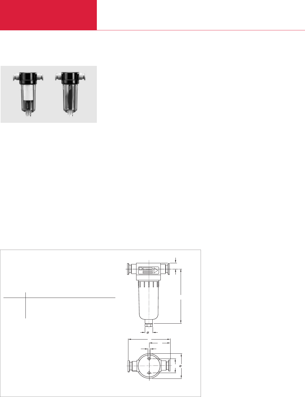
Accessories for TRIVAC E and B
Rotary Vane Vacuum Pumps
C01.40 LEYBOLD VACUUM PRODUCTS AND REFERENCE BOOK 2003/2004
h
1
b
c
1a
h
d
a
1
b
Exhaust Filters AF 8, AF 25 / Condensate Traps AK 8, AK 25
Dimensional drawing for the exhaust filters and condensate trap
Exhaust-Filter
Oil mists and aerosols are retained in the exhaust
filter.
Advantages to the User
♦Filtering of the exhaust gas by removal of
entrained lubricant particles
♦Emptying via drain screw or exhaust filter
drain tap
♦Separation efficiency > 99 %
♦Filter elements (made of glass fiber) are
exchangeable
Type a a1b b1c d h h1
AF 8/AK 8 mm 66.4 38 115 57.5 M 6 20 145 15.5
in. 2.61 1.50 4.53 2.26 0.79 5.71 0.61
AF 25/AK 25 mm 115 80 165 82.5 M 10 20 250 30
in. 4.53 3.15 6.50 3.25 0.79 9.84 1.18
Exhaust filter (left) and condensate trap (right)
Condensate Trap
Condensate traps prevent the formation of con-
densate in the pump as well as the backstream-
ing of fluids.
Advantages to the User
♦Can be connected to either the intake or the
exhaust side
♦Protects against condensate forming from
sucked in vapors or gases (intake line)
♦Protects against backstreaming liquids
(exhaust line)
♦Emptying via drain screw/drain tap
Technical Information
The exhaust filter is not capable of retaining toxic
and/or aggressive gases. For such applications
we recommend the use of an exhaust gas line
(e.g. a gas washer).
Since the material is not resistant to all gases and
solvents, a materials compatibility chart is avail-
able upon request.

Accessories for TRIVAC E and B
Rotary Vane Vacuum Pumps
C01.41
C01
LEYBOLD VACUUM PRODUCTS AND REFERENCE BOOK 2003/2004
Technical Data AF 8 AK 8 AF 25 AK 25
Connection to pump TRIVAC
(necessary accessories: elbow)
Connection flanges DN
Max. filling level (for vertical installation) ml (qt)
Permissible leak rate mbar x l x s-1
Max. continuous temperature °C (°F)
Material
D 2.5 E; D 4 B D 2.5 E; D 4 B D 16 B D 16 B
D 8 B D 8 B D 25 B D 25 B
16 KF 16 KF 25 KF 25 KF
60 (0.06) 60 (0.06) 285 (0.3) 285 (0.3)
≤1 · 10-5
90 (194)
PA 6
Ordering Information
Exhaust filter
Exhaust filter drain tap
Condensate trap
Replacement filter element (pack of 5)
FE 8
FE 25
Elbow (1x)
Centering ring with O-ring (2x)
aluminium / NBR
stainless steal / FPM
Clamping ring (2x)
Part No. 190 50 – Part No. 190 53 –
Part No. 190 95
–Part No. 190 60 – Part No. 190 63
Part No. 190 80 – – –
– – Part No. 190 83 –
Part No. 184 36 Part No. 184 36 Part No. 184 37 Part No. 184 37
Part No. 183 26 Part No. 183 26 Part No. 183 27 Part No. 183 47
Part No. 883 46 Part No. 883 46 Part No. 883 47 Part No. 883 47
Part No. 183 41 Part No. 183 41 Part No. 183 42 Part No. 183 42
AF 8 AK 8 AF 25 AK 25
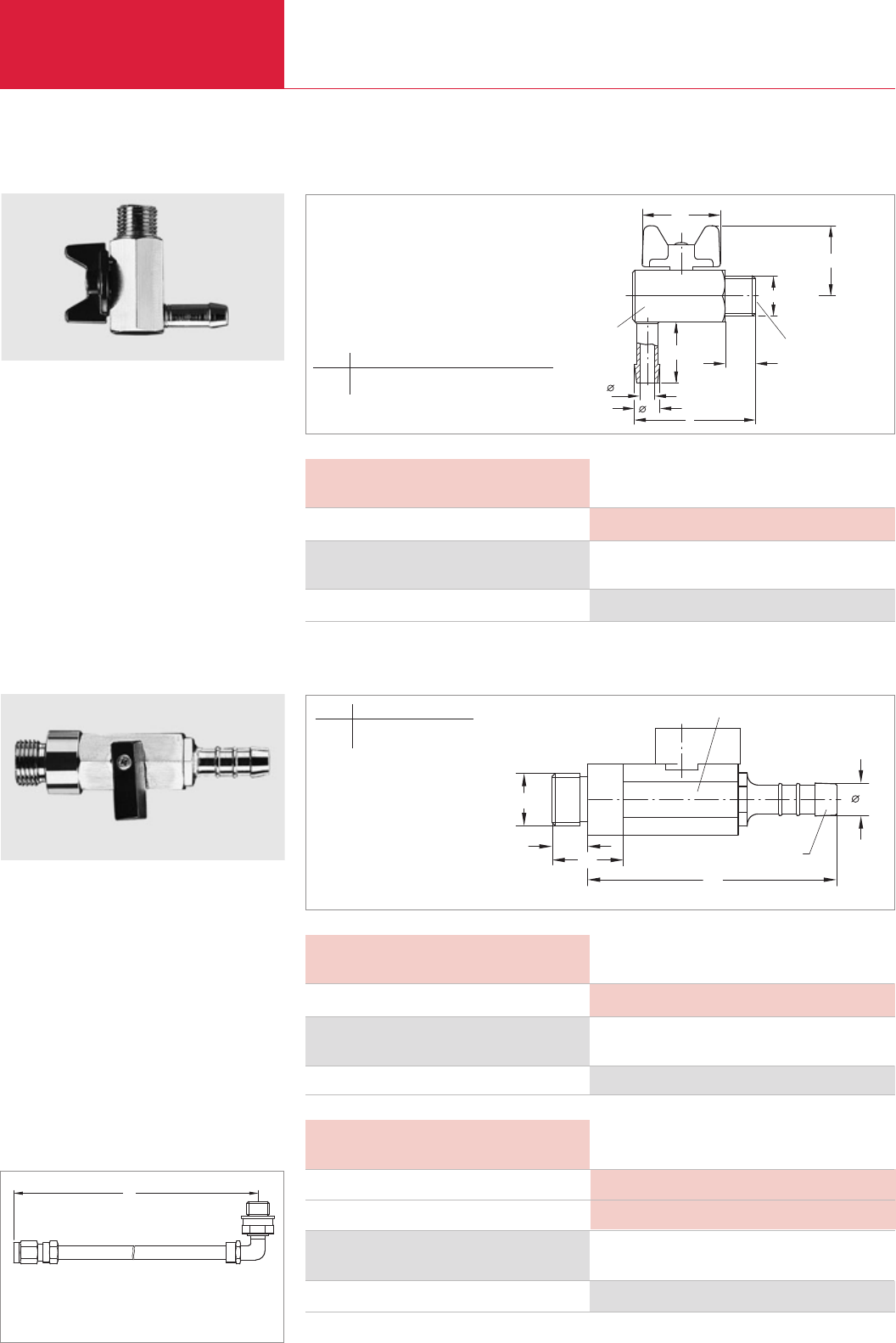
Accessories for TRIVAC E and B
Rotary Vane Vacuum Pumps
C01.42 LEYBOLD VACUUM PRODUCTS AND REFERENCE BOOK 2003/2004
Exhaust Filter Drain Tap
Oil Drain Tap
The exhaust filter drain tap simplifies draining of
the oil from the exhaust filter.
Technical Note
May also be used in connection with the conden-
sate separator AK.
This oil drain tap may be screwed into the oil
drain when wanting to change the oil in the rotary
vane pumps. It is also suited for the condensate
separators and exhaust filters of the TRIVAC B
series.
Ordering Information
Exhaust filter drain tap
Part No. 190 95
l1
l
l2
a1
SW 17
b1
a
SW 6
G1/4" BPS
b
M16 x 1,5
l
l2
SW 19
a
Hose nozzle
l1
Exhaust Filter Drain Tap
Technical Data
Leak rate mbar x l x s
mbar x l x s-1
-1 ≤10-5
Exhaust Filter Drain Tap
Dimensional drawing for the exhaust filter drain tap
Dimensional drawing for the oil drain tap
Ordering Information
Oil drain tap
Part No. 190 90
Oil Drain Tap
Technical Data
Leak rate mbar x l x s-1 ≤10-5
Oil Drain Tap
Ordering Information
Oil drain kit
Part No. 190 94
Oil Drain Kit
Technical Data
Length mm (in.)
Leak rate mbar x l x s-1
280 (11)
≤10-5
Oil Drain Kit
Oil Drain Kit
l
Dimensional drawing for the oil drain kit
a a1b b1l l1l2
mm 8.5 5 23 20 41 26 10
in. 0.33 0.20 0.90 0.79 1.61 1,02 0,39
a l l1l2
mm 10.5 76 22 11
in. 0.41 2.99 0.87 0.43
l = 280 mm = 11 in.
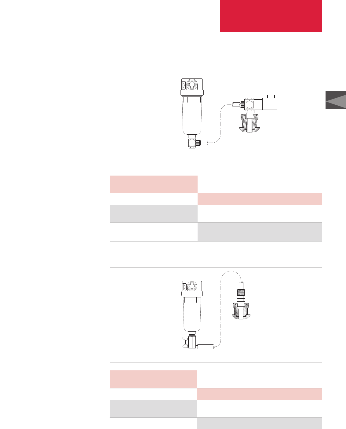
Accessories for TRIVAC E and B
Rotary Vane Vacuum Pumps
C01.43
C01
LEYBOLD VACUUM PRODUCTS AND REFERENCE BOOK 2003/2004
AR-V Oil Suction Facility Controlled by Solenoid Valve
AR-M Manually Operated Oil Suction Facility
The oil suction facility AR-V with its solenoid
valve allows the removal of oil via the gas ballast
which has collected in the exhaust filter. When
the valve is closed the gas ballast remains fully
operational.
For this, a hose link is provided between the
exhaust filter and the gas ballast.
Technical Note
If oil which has collected in the exhaust filter is to
be removed, the solenoid valve is opened briefly.
Ordering Information
AR-V oil suction facility controlled by solenoid valve
24 V DC, 4 W, normally closed
Part No. 190 92
AR-V Oil Suction Facility
Controlled by Solenoid Valve
Technical Data
Leak rate mbar x l x s-1 ≤10-5
AR-V Oil Suction Facility
Controlled by Solenoid Valve
AR-V oil suction facility controlled by solenoid valve (kit without exhaust filter)
AR-M manually operated oil suction facility (kit without exhaust filter)
Ordering Information
AR-M manually operated oil suction facility
Part No. 190 93
AR-M Manually Operated
Oil Suction Facility
Technical Data
Leak rate mbar x l x s-1 ≤10-5
AR-M Manually Operated
Oil Suction Facility
The oil suction facility AR-M allows the removal
of oil via the gas ballast which has collected in
the exhaust filter, whereby the gas ballast
remains fully operational as long as the angled
ball valve remains closed.
For this, a hose link is provided between the
exhaust filter and the gas ballast.
Technical Note
If oil which has collected in the exhaust filter is to
be removed, the angled ball valve is manually
opened briefly.
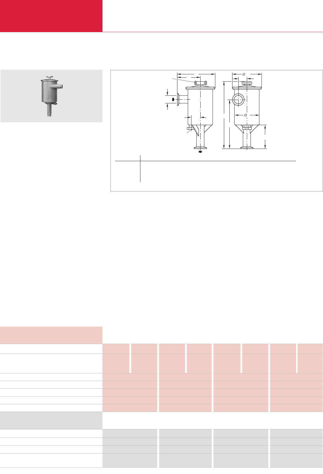
Rotary Vane Vacuum Pumps
C01.44 LEYBOLD VACUUM PRODUCTS AND REFERENCE BOOK 2003/2004
Accessories for TRIVAC E and B
h1
d1
DN
c
a
h2
DN 40 KF
DN 40 KF
khd
1
a
Technical Data AS 8-16 AS 30-60 MF 8-16 MF 30-60
Ordering Information
Dust separator
Molecular filter
Replacement filter insert
Replacement active charcoal insert
Active charcoal, undried, 5 kg (11 lbs)
Connection to pump TRIVAC
Throttling of the pumping speed
at 1 mbar (0.75 Torr) intake pressure, approx. %
at 10 mbar (7.5 Torr) intake pressure, approx. %
Capacity for dust l (qt)
Capacity for resin vapors or similar kg (lbs)
Impact ring filling l (qt)
Active charcoal filling kg (lbs)
Weight kg (lbs)
Dust Separators AS 8-16, AS 30-60 / Molecular Filters MF 8-16, MF 30-60
Dimensional drawing for the AS dust separators and MF molecular filters
Type DN a a1cldld1h h1h2k
AS/MF 8-16 25 KF mm 181 100 43 133 162 247 150 37 –
in. 7.13 3.94 1.69 5.24 6.38 9.72 5.91 1.46 –
AS/MF 30-60 40 KF mm 310 190 70 205 234 530 395 190 75
in. 12.2 7.48 2.76 8.07 9.12 20.9 15.6 7.48 2.95
Dust separators protect pumps against contami-
nation and damage by sucked-in dust.
Advantages to the User
♦Dust separators for large quantities of dust
♦Two-stage, thus hardly any throttling
♦Cyclone (for coarse dust) and wet filter (for
fine dust)
♦Dust separator and molecular filter have the
same housing (for easy conversion)
Typical Application
♦Separation of coarse and medium size dust
starting at a grain size of 2 µm.
Technical Information
Installing a dust filter in the intake line of the
pump will throttle its pumping speed at low
intake pressures more than at higher intake
pressures. This must be taken into account when
designing a vacuum system.
Even when large quantities of dust are deposited,
the throttling effect will hardly increase.
D 16 B D 25 B D 40 B D 65 B D 16 B/BCS D 25 B/BCS D 40 B/BCS D 65 B/BCS
10 15 8 16 10 15 8 16
5 7 4 9 5 7 4 9
0.6 (0.6) 2.0 (2.1) – –
– – 0.15 (0.3) 0.35 (0.8)
0.5 (0.5) 3.5 (3.7) – –
– – 0.6 (1.3) 1.4 (3.1)
4.5 (9.9) 18.4 (40.6) 4.5 (9.9) 18.4 (40.6)
Part No. 186 11 Part No. 186 16 – –
– – Part No. 186 12 Part No. 186 17
– Part No. 178 43 – –
– – Part No. 178 07 Part No. 178 08
– – Part No. 178 10 Part No. 178 10
AS 30-60 dust separator (MF 30-60 molecular filter is similar)
Supplied Equipment
Blanked off drain port.
Molecular filters are used to separate vapors of
a high molecular weight (i. e. monomers, vapors
from resins).
Advantages to the User
♦Molecular filter and dust separator have the
same housing (for easy conversion)
♦Separation of high-molecular weight vapors
♦Protection of the pump’s oil against damaging
vapors
Technical Information
Installing a molecular filter in the intake line of
the pump will throttle its pumping speed at low
intake pressures more than at higher intake pres-
sures. This must be taken into account when
designing a vacuum system.
Supplied Equipment
Blanked off drain port.
AS 8-16 AS 30-60 MF 8-16 MF 30-60
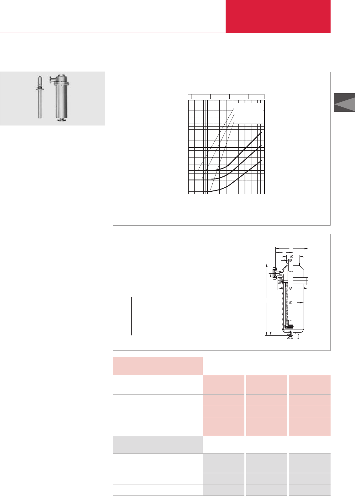
Rotary Vane Vacuum Pumps
C01.45
C01
LEYBOLD VACUUM PRODUCTS AND REFERENCE BOOK 2003/2004
Accessories für TRIVAC E and B
3
d
1
h
h
2
d
1
d
d
b
a
Technical Data FA 2-4 FA 8-16 FA 30-60
Ordering Information FA 2-4 FA 8-16 FA 30-60
Fine vacuum adsorption trap filled with zeolite,
without heating rod
Heating rod for adsorption trap
Molecular sieve zeolite 13 X, 1 kg (2.2 lbs)
Connection to pump TRIVAC
Zeolite filling, approx. kg (lbs)
Conductance below 10-2 mbar (0.075 Torr)
l x s-1
Power rating of the heating rod
at a main voltage of 220 V W
Fine Vacuum Adsorption Traps FA 2-4, FA 8-16, FA 30-60
Conductances of fine vacuum adsorption traps as a function of the intake pressure of the TRIVAC
Fine vacuum adsorption traps are vacuum-tight
vessels which offer a high adsorption capacity
especially for water vapor.
Advantages to the User
♦Total pressures of 1.5 x 10
-5
mbar (1.125 x
10
-5
Torr) can be attained with a two-stage
rotary vane vacuum pump
♦Zeolite filling can be easily regenerated (baked
at 300 °C (572 °F))
♦High conductance
Typical Application
♦Producing a vacuum which is free of water
vapor
Technical Information
Liquid nitrogen in the adsorption trap will in-
crease its adsorption capacity.
The conductance of the adsorption trap is higher
than the pumping speed of the corresponding
pump. See figure where the average pressure
ahead and after the fine vacuum adsorption trap
is plotted on the horizontal axis.
The adsorption traps may be installed in the
intake line.
D 2.5 E
D 4/8 B D 16/25 B/BCS D 40/65 B/BCS
0.3 (0.7) 0.7 (1.5) 1.25 (2.8)
149
200 200 300
Part No. 187 05 Part No. 187 10 Part No. 187 15
Part No. 854 21 Part No. 854 21 Part No. 854 23
Part No. 854 20 Part No. 854 20 Part No. 852 20
Heating rod and
fine vacuum adsorption trap
Dimensional drawing for the FA fine vacuum adsorption trap
Type DN a b d d1d2d3h h1
FA 2-4 16 KF mm 70 128 42 38 115 80 330 291
in. 2.76 5.04 1.65 1.50 4.53 3.15 13 11.5
FA 8-16 25 KF mm 90 157.5 52 48 135 100 390 345
in. 3.54 6.20 2.05 1.89 5.34 3.94 15.4 13.6
FA 30-60 40 KF mm 110 200 62 58 160 120 460 406
in. 4.33 7.87 2.44 2.28 6.30 4.72 18.1 16
Pumping speed
Pressure
10-3
2
4
6
8
24 6 8
10-2 10-1 100101
mbar
100
101
102
103
104
ls-1
.FA 30 - 60
FA 8 - 16
FA 2 - 4
Torr
0.01 0.1 7.5
0.001
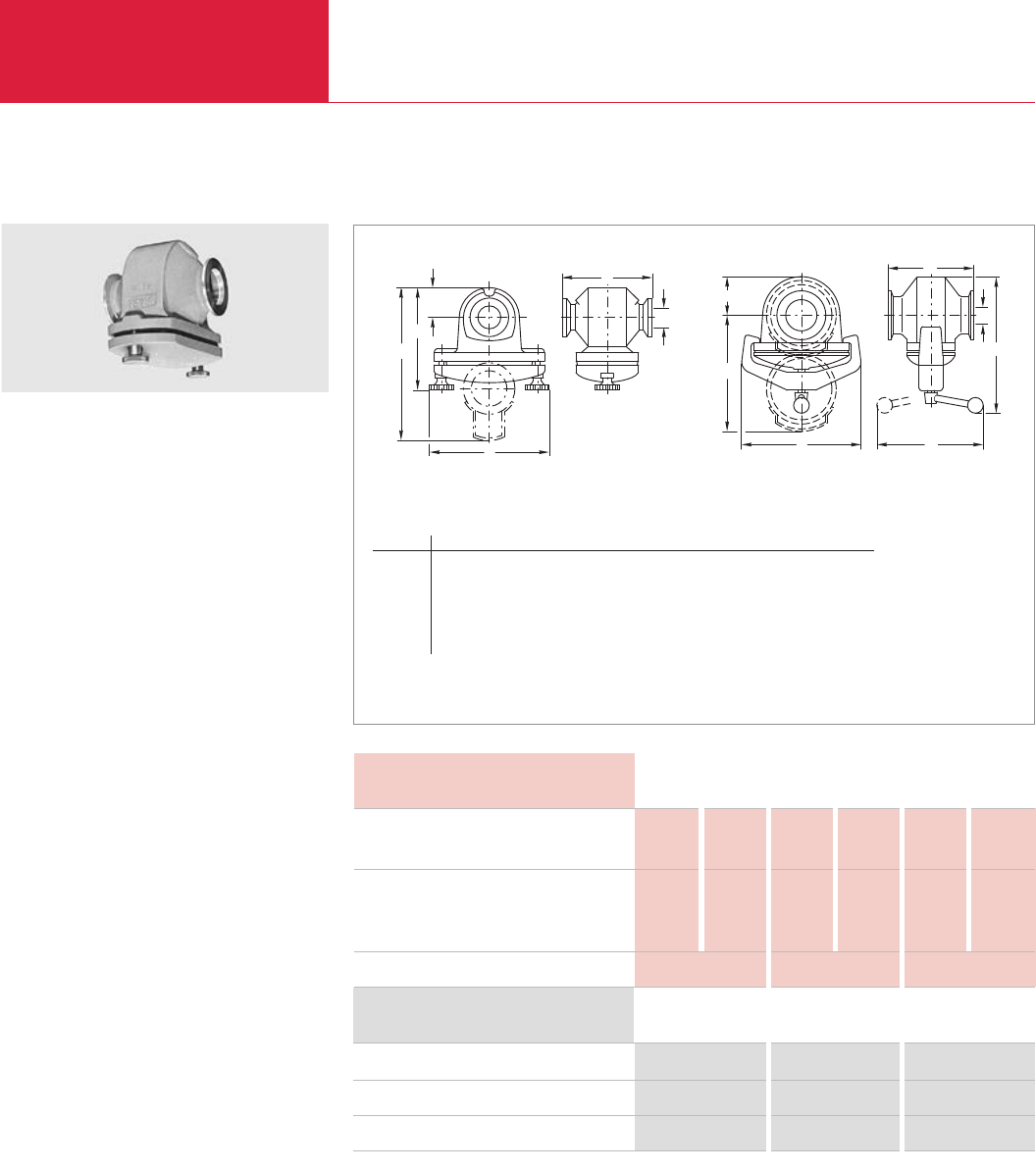
Rotary Vane Vacuum Pumps
C01.46 LEYBOLD VACUUM PRODUCTS AND REFERENCE BOOK 2003/2004
Accessories for TRIVAC E and B
b
h
1
h
c
a
DN
Technical Data FS 2-4 FS 8-16 FS 30-60
Ordering Information FS 2-4 FS 8-16 FS 30-60
Dust filter
Replacement filter insert
Replacement wadding cartridges (1 set = 10 pieces)
Connection to pump TRIVAC
Throttling of the pumping speed
at 1 mbar (0.75 Torr), approx. %
at 10 mbar (7.5 Torr), approx. %
Weight kg (lbs)
Dust Filters FS 2-4, FS 8-16, FS 30-60
Dimensional drawing for the FS dust filters
Type DN a b lb1c h, approx. h1, approx.
FS 2-4 16 KF mm 90 112 – 30 105 165
in. 3.54 4.41 – 1.18 4.13 6.50
FS 8-16 25 KF mm 110 150 – 50 125 205
in. 4.33 5.91 – 1.97 4.92 8.07
FS 30-60 40 KF mm 130 190 170 60 225 250
in. 5.12 7.48 6.69 2.36 8.86 9.84
The dust filters protect the pumps against the
intake of dust.
Advantages to the User
♦Easy to disassemble
♦Vacuum-tight cast iron casing
♦Replacement filters may be easily exchanged
♦Separates dusts from a grain size of 1 µm
Technical Information
Installing a dust filter in the intake line of the
pump will throttle its pumping speed at low
intake pressures more than at higher intake
pressures. This must be taken into account when
designing a vacuum system.
Since the dust filters have only a small dust
collecting chamber, we recommend – in the case
of larger dust quantities – the two-stage dust
separators from the AS range.
The dust filters should be installed in a horizontal
flow so that the filter insert may be removed by
pulling it down and out.
D 2.5 E S 8 B D 16 B D 25 B D 40 B D 65 B
D 4 B D 8 B
6 10 12 18 12 25
4 7 6 9 3 8
1.0 (2.2) 1.6 (3.5) 7.5 (16.5)
Part No. 186 05 Part No. 186 10 Part No. 186 15
Part No. 178 32 Part No. 178 33 Part No. 178 35
Part No. 200 39 050 Part No. 200 39 051 Part No. 971 98 251
Dust filter
c
DN
a
1
h
h
b1
b
FS 2-4, FS 8-16 FS 30-60
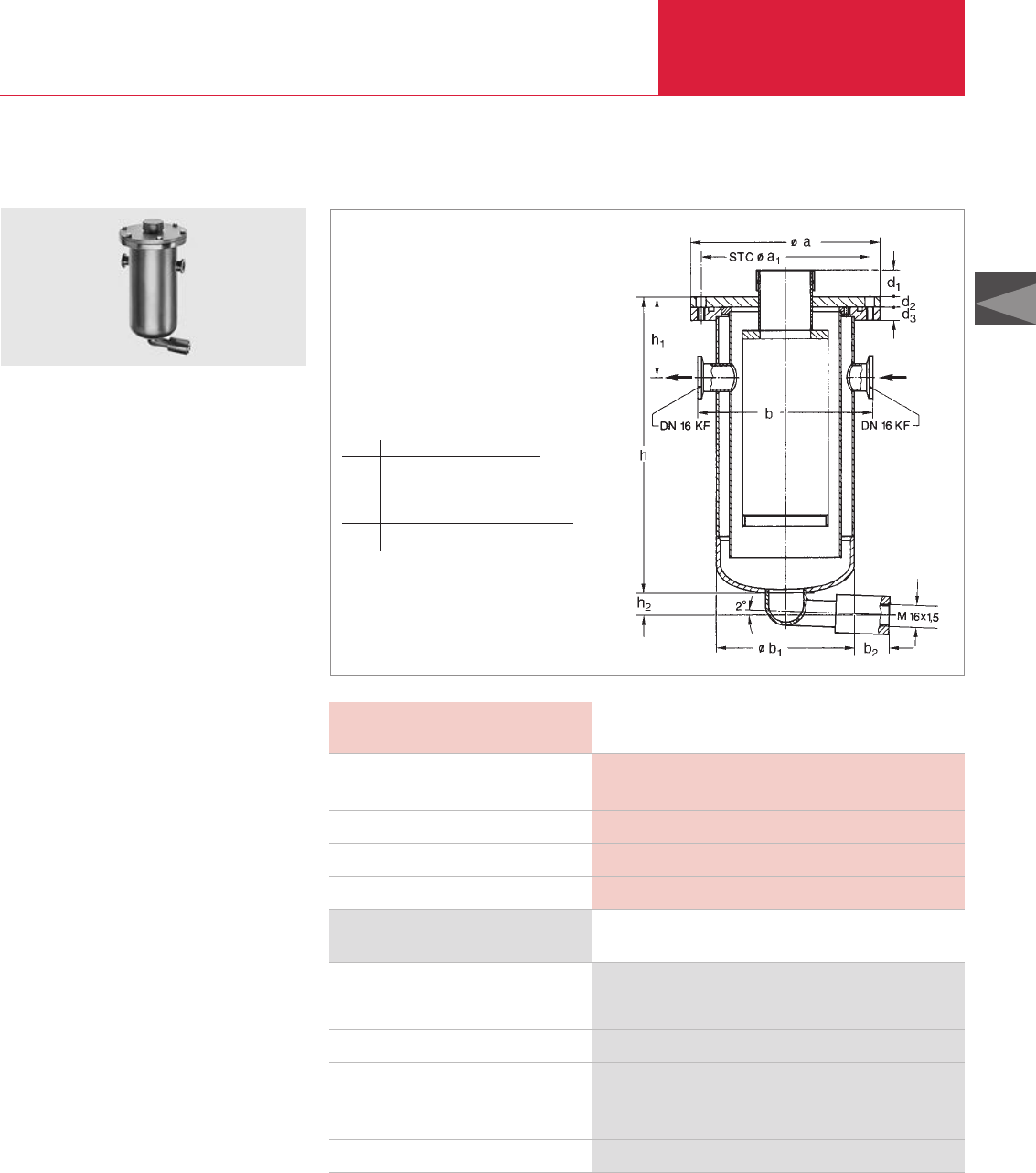
Rotary Vane Vacuum Pumps
C01.47
C01
LEYBOLD VACUUM PRODUCTS AND REFERENCE BOOK 2003/2004
Accessories for TRIVAC E and B
Technical Data TK 4-8
Ordering Information TK 4-8
Cold trap
Drain tap for the intake side, vacuum-tight
Elbow (1x)
Centering ring
aluminum/NBR (2x)
stainless steel/FPM (2x)
Clamping ring (2x)
Connection to pump TRIVAC
Capacity for refrigerant, approx. l (qt)
Connections DN
Weight kg (lbs)
TK 4-8 Cold Trap
Dimensional drawing for the TK 4-8 cold trap
The cold trap protects the pump against
damaging vapors.
Advantages to the User
♦Rugged and implosion resistant
♦May be fitted directly on the flange of the
pump
♦Safe draining of the condensate without
problems
♦Casing made of corrosion resistant stainless
steel
♦Simple filling with refrigerant (liquid nitrogen
(LN
2
) or a mixture of acetone and carbon di-
oxide ice)
Typical Applications
♦Prevention of oil from backstreaming into the
vacuum system when operating at ultimate
pressure
♦Freezing of gases and vapors in the laboratory
D 2.5 E
D 4/8 B
0.4 (0.4)
16 KF
4 (8.8)
Part No. 188 20
Part No. 190 90
Part No. 184 36
Part No. 183 26
Part No. 183 46
Part No. 183 41
TK 4-8 cold trap
d1d2d3h h1h2
mm 20 8 10 220 60 ≈16
in. 0.79 0.31 0.39 8.66 2.36 ≈0.6
a a1b b1b2
mm 140 125 130 102 ≈26
in. 5.51 4.92 5.12 4.02 ≈1
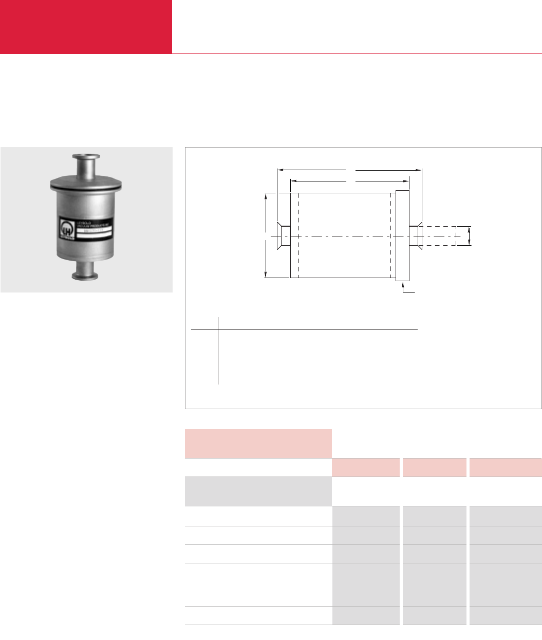
Accessories for TRIVAC E and B
Rotary Vane Vacuum Pumps
C01.48 LEYBOLD VACUUM PRODUCTS AND REFERENCE BOOK 2003/2004
B
C
D
A
CLAMP
RST Refillable Traps
Dimensional drawing for the RST
The RST traps are made from 304 stainless steel,
and when specified with stainless steel filtration
media, are fully suited for corrosive applications.
The media is inserted directly into the trap. This
ensures direct contact with the trap walls. There
is no oil path between the trap wall and the retai-
ner gasket to reduce trap effectiveness.
Advantages to the User
♦Refillable
♦Two Filtration Media
♦Easy to Clean
♦Easy to Recharge
♦KF Flanges
Applications
Foreline traps are utilized whenever long-term
effects of mechanical pump oil back migration
into the pumped chamber or higher vacuum (oil
diffusion) pump may be undesirable. Copper
wool for standard applications and stainless steel
wool for corrosive applications are available.
RST Refillable trap
Model Flange Dimension l Al B C D
RST16KF DN 16 KF both ends mm KF 16 63 83 133
in. 21/231/451/4
RST25KF DN 25 KF both ends mm KF 25 76 108 171
in. 3 41/463/4
RST40KF DN 40 KF both ends mm KF 40 102 102 178
in. 4 4 7
Technical Data RST16KF RST25KF RST40KF
Ordering Information RST16KF RST25KF RST40KF
RST16KF, 1.9 lb (0.9 kg)
RST25KF, 2.6 lb (1.2 kg)
RST40KF, 4.1 lb (1.9 kg)
Filtering media
Stainless steel
RF Copper
BUNA-N Gasket
Connection to pump TRIVAC D 4/8 B/BCS D 16/25 B/BCS D 40/65 B/BCS
Part No. 99 171 135
– –
–
Part No. 99 171 136
–
– –
Part No. 99 171 137
Part No. 99 171 141 Part No. 99 171 141 Part No. 99 171 141
Part No. 99 171 145 Part No. 99 171 146 Part No. 99 171 147
Part No. 725 80 005 Part No. 725 80 006 Part No. 725 80 007
Version for the North and South American Continents
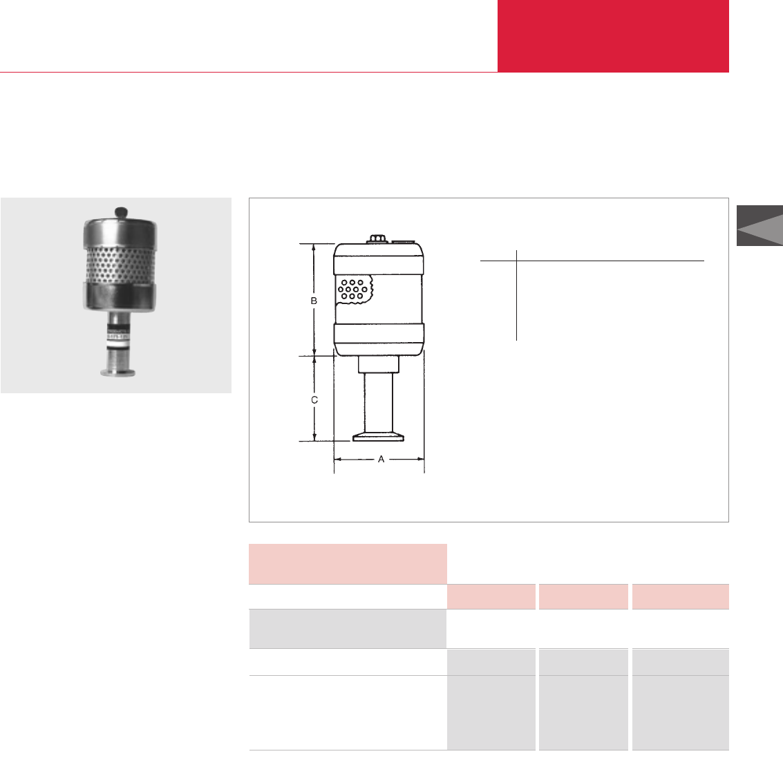
Accessories for TRIVAC E and B
Rotary Vane Vacuum Pumps
C01.49
C01
LEYBOLD VACUUM PRODUCTS AND REFERENCE BOOK 2003/2004
SE Smoke Eliminator
Dimensional drawing for the SE
The Leybold SE Smoke Eliminator can be utilized
on all TRIVAC B Rotary Vane Pumps where pump
fluid loss at the exhaust port must be eliminated.
These filters consist of a replaceable two-stage
coalescing element mounted in a steel housing.
For maintenance purposes, the top of the hou-
sing can be removed by loosening a single bolt.
The filter assembly attaches to the exhaust port
of the TRIVAC pump by means of a KF flange.
Since three models are available, an SE Smoke
Eliminator is available for each TRIVAC pump
model.
Advantages to the User
♦Two Stage Design
♦Three Sizes For All TRIVAC B Models
♦KF Flanges
Applications
When any oil sealed mechanical vacuum pump is
used to pump a fixed volume from atmospheric
pressure to some lower pressure or when a
dynamic gas flow from a process stream is
pumped, some mechanical pump fluid loss will
occur at the exhaust of the pump. The more often
a fixed volume is cycled from atmospheric pres-
sure to a lower pressure or the longer a pump
operates at a relatively high inlet pressure in a
dynamic flow condition, the greater will be the
fluid loss at the exhaust port of the pump.
SE Smoke eliminator
Model Flange Dimension A B C
SE 2-4 DN 16 KF mm 64 76 70
in. 21/23 23/4
SE 8-16 DN 25 KF mm 127 152 51
in. 5 6 2
SE 30-60 DN 40 KF mm 267 121 57
in. 101/243/421/4
Technical Data SE 2-4 SE 8-18 SE 30-60
Ordering Information SE 2-4 SE 8-18 SE 30-60
Smoke Eliminator
Replacement Element
RE 2-4
RE 8-16
RE 30-60
Connection to pump TRIVAC D 4/8 B D 16/25 B D 40/65 B
Part No. 99 171 125 Part No. 99 171 126 Part No. 99 171 127
Part No. 99 171 128
– –
–
Part No. 99 171 129
– –
Part No. 99 171 130
By utilizing a coalescing exhaust filter for these
applications, the fluid and exhaust gases are
separated, and in the case of the SE Smoke Eli-
minator, the coalesced fluid is allowed to drain
back into the pump fluid reservoir. Annoying oil
fog to the atmosphere is thus eliminated.
Eventually, after about a year's normal operation,
the coalescing element will become totally satura-
ted and oil fog will be apparent when high inlet
pressures are prevailing. The low cost coalescing
element can be easily replaced.
Version for the North and South American Continents
NOTE - For applications where toxic, corrosive,
radioactive or precious gases are pumped, we
highly recommend the use of our AF Coalescing
Exhaust Filters instead of the SE Smoke Elimina-
tor. The AF is an in-line type coalescing filter and
much more suitable for these applications.
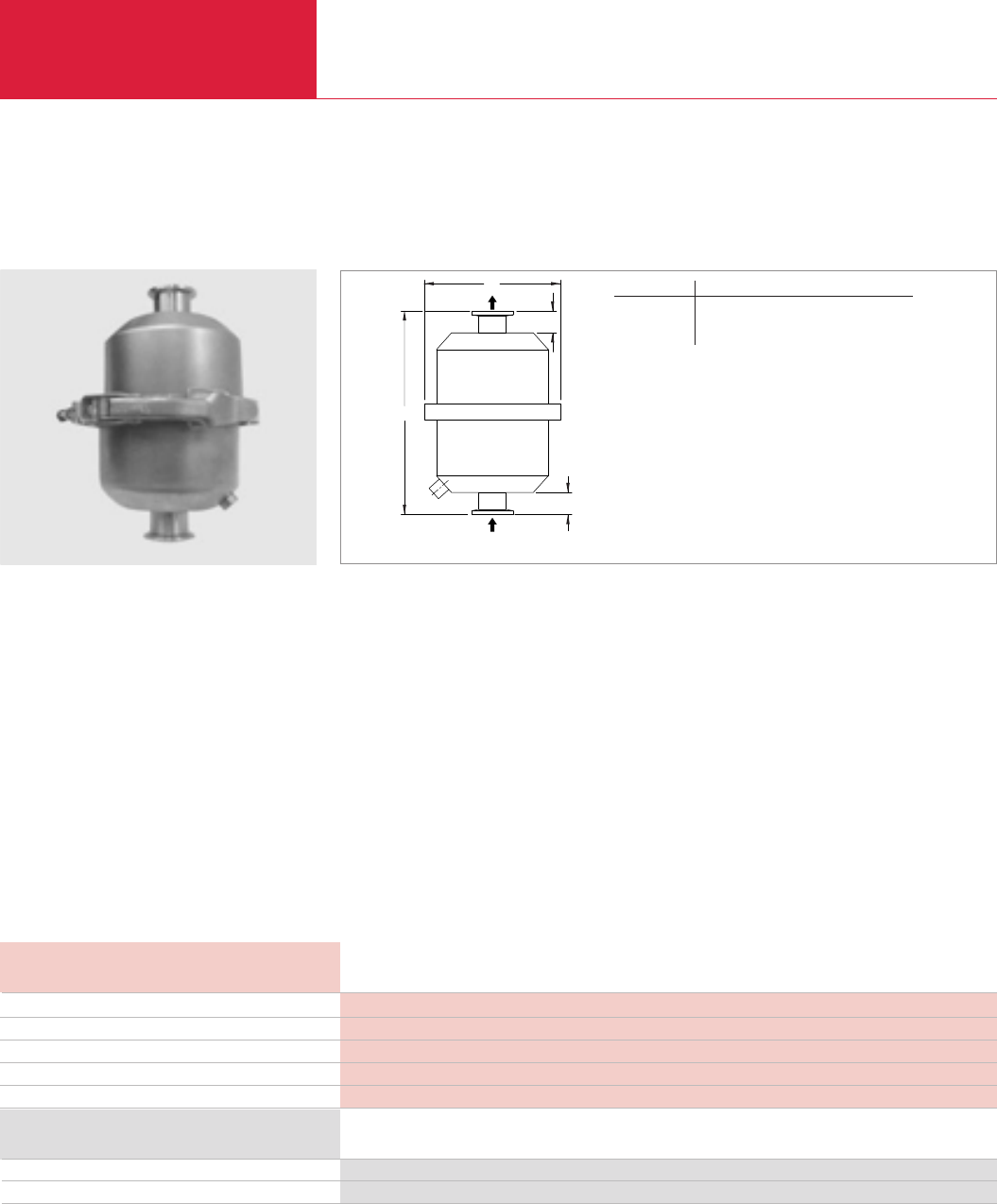
Accessories for TRIVAC E and B
Rotary Vane Vacuum Pumps
C01.50 LEYBOLD VACUUM PRODUCTS AND REFERENCE BOOK 2003/2004
Version for the North and South American Continents
Compact Oil Mist Exhaust Filters
Features and Specifications
♦Minimum 99.97 % D.O.P. on 3 micron
particles
♦Captures oil fog, mist or smoke from exhaust
of oil lubricated vacuum pumps
♦Compact, low profile design
♦Stainless steel housing and internals
♦Pleated filter element provides increased sur-
face area for low back pressure
C
B
D
A
Dimensional drawing for the compact oil mist exhaust filterCompact oil mist exhaust filter
Typ A B lC D
DN 25 mm 196.85 22.23 133.35 22.23
in. 7 3/4 7/8 5 1/4 7/8
Applications and Equipment
♦Rotary vane pumps
♦Vacuum furnaces, ovens and degassing
♦Refrigeration and air condition
♦Vacuum freeze drying
♦Vacuum metallizing
♦Vacuum coating
♦Laboratory furnaces, test stands
♦Autoclaving, sterilization
♦Leak detection
♦Back pressure valve designed to release
element at 7.35 PSI (0.5 bar) differential for
pump safety
♦1/8
"
NPT oil drain
♦Easy release V-band clamp
♦Seamless drawn housings - no welds to rust
or vibrate apart
♦Easy field maintenance
♦Operating temperature:
40 °F (4 °C) to 220 °F (104 °C)
Connection to pump TRIVAC D16/25B
ISO inlet and outlet DN 25
Nominal vacuum pump rating scfm (m3/hr) 20 (34)
Element rating scfm (m3/hr) 20 (34)
Weight, approx. kg (lbs) 1 (2.2)
Compact oil mist exhaust filter Part No. 721-87-113
Replacement filter insert filter Part No. 721-87-099
Technical Data
Ordering Information
Compact Oil Mist Exhaust Filter
Compact Oil Mist Exhaust Filter

Accessories for TRIVAC E and B
Rotary Vane Vacuum Pumps
C01.51
C01
LEYBOLD VACUUM PRODUCTS AND REFERENCE BOOK 2003/2004
Notes
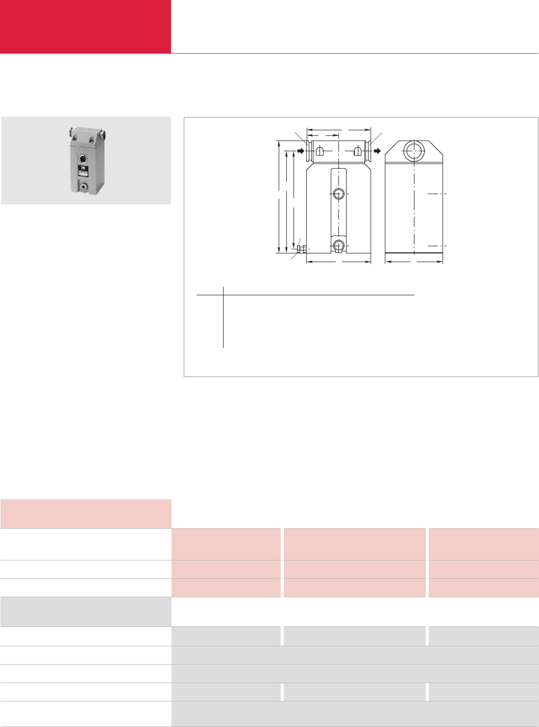
Rotary Vane Vacuum Pumps
C01.52 LEYBOLD VACUUM PRODUCTS AND REFERENCE BOOK 2003/2004
Accessories for TRIVAC B
Technical Data AK 4-8 AK 16-25 AK 40-65
Ordering Information AK 4-8 AK 16-25 AK 40-65
Condensate separator
Drain tap for the intake side, vacuum-tight
Oil drain tap (exhaust side)
Adaptor DN 16 KF – hose nozzle DN 7
For further accessories see Section
“Accessories for TRIVAC E and B”
Connection to pump TRIVAC
Capacity for condensate l (qt)
Weight kg (lbs)
Condensate Separators AK 4-8, AK 16-25, AK 40-65
Separators protect the pump against condensate.
Advantages to the User
♦May be installed without accessories
♦May be used either on the intake or the
exhaust side
♦Independent of the direction of flow
♦Condensate level check via inspection glass
♦Resists solvents
♦All seals madeof FPM
♦Simple to clean
♦Easy to use
♦Drained via drain screw or drain tap
D 4 B D 16 B/BCS (-PFPE) D 40 B/BCS (-PFPE)
D 8 B D 25 B/BCS (-PFPE) D 65 B/BCS (-PFPE)
0.66 (0.7) 1.2 (1.3) 3.0 (3.2)
1.7 (3.7) 2.4 (5.3) 5.5 (12.1)
Part No. 188 06 Part No. 188 11 Part No. 188 16
Part No. 190 90
Part No. 190 90
Part No. 182 90 – –
AK 4-8 condensate separator
Typical Application
♦Prevention of the collection of liquids in
the intake line
Technical Information
Depending upon the layout and pipe run of an
exhaust line, it may be necessary to install a
separator to prevent condensate draining back to
the pump.
DN DN
2
h
h
c
1
h
)
M8x30
DIN 933
e
ab
*
Dimensional drawing for the AK condensate separators
*)Supporting screw, only for AK 40-65
Type DN a b c e h h1h2
AK 4-8 16 KF mm 90 90 120 60 194 178 –
in. 3.54 3.54 4.72 2.36 7.64 7.01 –
AK 16-25 25 KF mm 110 125 142 71 214 193 –
in. 4.33 4.92 5.59 2.80 8.43 7.60 –
AK 40-65 40 KF mm 140 156 170 85 300 271 261
in. 5.51 6.14 6.69 3.35 11.8 10.7 10.3
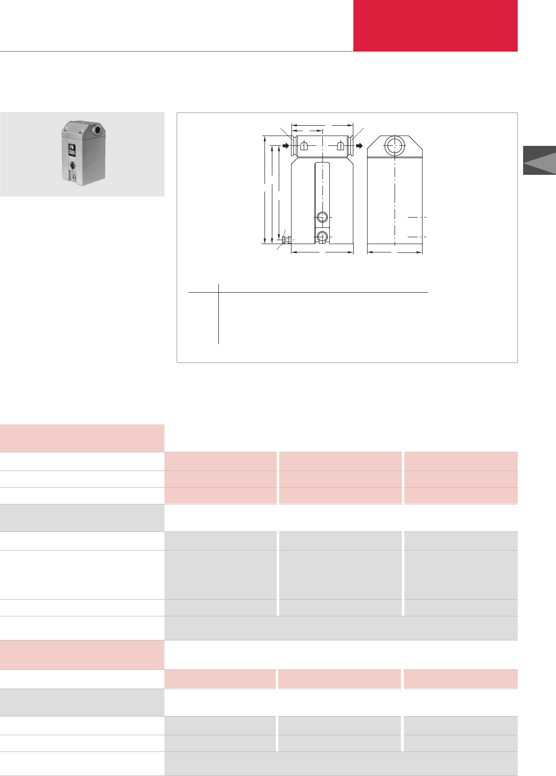
Rotary Vane Vacuum Pumps
C01.53
C01
LEYBOLD VACUUM PRODUCTS AND REFERENCE BOOK 2003/2004
Accessories for TRIVAC B
Technical Data AF 4-8 AF 16-25 AF 40-65
Ordering Information AF 4-8 AF 16-25 AF 40-65
Exhaust filter
Replacement filter element
FE 4-8
FE 16-25
FE 40-65
Oil drain tap
For further accessories see Section
“Accessories for TRIVAC E and B”
Connection to pump TRIVAC
Max. capacity for condensate, approx. l (qt)
Weight kg (lbs)
Exhaust Filters AF 4-8, AF 16-25, AF 40-65
Exhaust filters retain oil mists and aerosols.
Advantages to the User
♦Can be fitted without additional accessories
♦Separation efficiency over 99 %
♦Exchangeable filter inserts
♦Built-in over-pressure relief valve (threshold
at about 1.5 bar (7.2 psi, differential))
♦Sight glass for checking of the quantity of
collected oil
♦Resistant against solvents
♦All seals made of FPM
♦Easy to clean and use
♦Retains dirt and cracked products
AF 4-8 exhaust filter
Part No. 189 06 Part No. 189 11 Part No. 189 16
Part No. 189 71 – –
– Part No. 189 72 –
– – Part No. 189 73
Part No. 190 90 Part No. 190 90 Part No. 190 90
Typical Application
♦Improvement of oil separating capacity
Technical Information
An exhaust line must be connected in case of
hazardous exhaust gases.
Technical Data AF 16-25 DOT
Connection to pump TRIVAC – D 16 B-DOT –
Ordering Information AF 16-25 DOT
Exhaust filter
Replacement filter element, FE 16-25 DOT
For further accessories see Section
“Accessories for TRIVAC E and B”
–Part No. 124 16 –
– Part No. 200 10 304 –
DN DN
2
h
h
c
1
h
M8x30
DIN 933
e
ab
)
*
Dimensional drawing for the AF exhaust filter
*)Supporting screw only for AF 40-65
Type DN a b c e h h1h2
AF 4-8 16 KF mm 90 90 120 60 194 178 –
in. 3.54 3.54 4.72 2.36 7.64 7.01 –
AF 16-25 25 KF mm 110 125 142 71 214 193 –
in. 4.33 4.92 5.59 2.80 8.43 7.60 –
AF 40-65 40 KF mm 140 156 170 85 300 271 261
in. 5.51 6.14 6.69 3.35 11.8 10.7 10.3
D 4/8 B D 16/25 B/BCS D 40/65 B/BCS
0.4 (0.4) 0.5 (0.5) 1.0 (1)
1.9 (4.1) 3.2 (7.1) 6.5 (14.3)
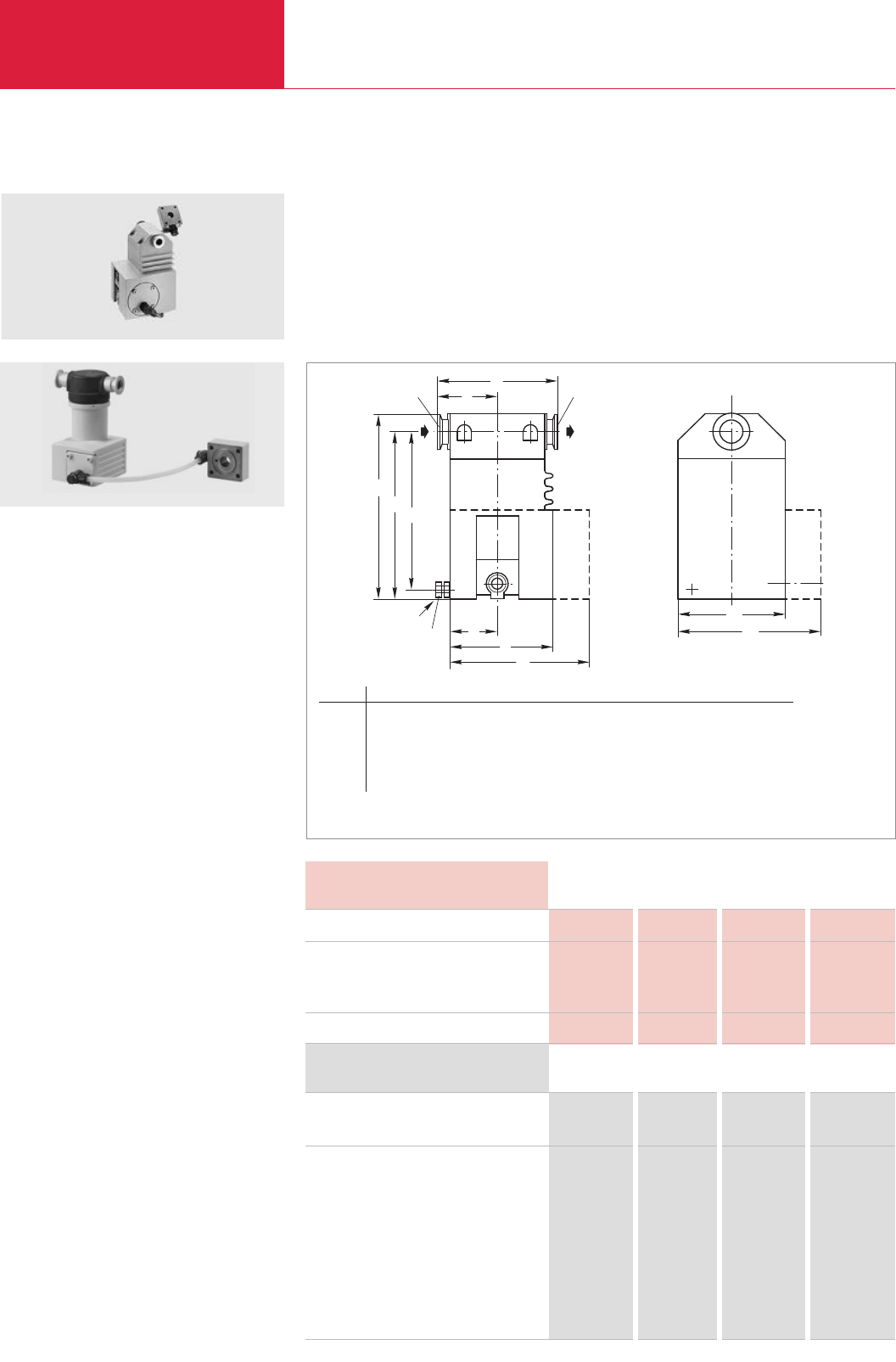
Rotary Vane Vacuum Pumps
C01.54 LEYBOLD VACUUM PRODUCTS AND REFERENCE BOOK 2003/2004
Accessories for TRIVAC B
1
b
2
b
2
h
a
fg
M8x40,
DIN 933
1)
1
h
h
DN
c
eDN
Technical Data ARP 4-8 AR 4-8 AR 16-25 AR 40-65
Ordering Information ARP 4-8 AR 4-8 AR 16-25 AR 40-65
Exhaust filter with oil return
Replacement filter element
FE 8
FE 4-8
FE 16-25
FE 40-65
Connection to pump TRIVAC
For opening the float-controlled valve
required amount of oil N 62 cm3(qt)
remaining amount of oil N 62 cm3(qt)
Weight kg (lbs)
Exhaust Filters with Lubricant Return ARP 4-8, AR 4-8, AR 16-25, AR 40-65
Dimensional drawing for the AR exhaust filters with lubricant return
1)
Supporting screw only for AR 40-65
(dimensions for the ARP exhaust filter with lubricant return upon request)
This combination of an exhaust filter with a float-
controlled valve considerably extends the mainte-
nance intervals for the TRIVAC B.
Advantages to the User
♦Filtering the exhaust air of entrained lubricant
particles
♦Lubricant return with the aid of a float-
controlled valve back into the intake port
♦No operating costs caused by lost lubricant
♦Hardly any oil consumption
♦Standard filter element
♦Built-in over-pressure relief valve
♦Resists solvents
♦All seals made of FPM
♦The top head may be easily rotated (either
parallel or perpendicular to bottom body)
[Only AR 4-8 to AR 16-25]
Typical Application
♦Extending the maintenance intervals
D 4/8 B D 4/8 B D 16/25 B/BCS D 40/65 B/BCS
– 430 (0.45) 510 (0.54) 760 (0.80)
– 350 (0.37) 430 (0.45) 700 (0.74)
1.7 (3.8) 3.1 (6.8) 4.7 (10.4) 8.5 (18.7)
Part No. Part No. Part No. Part No.
140 065 189 20 189 21 189 22
Part No. – – –
190 80
Part No. – –
189 71
– – Part No. –
189 72
– – – Part No.
189 73
AR 4-8 exhaust filter with lubricant return
Type DN a b1b2c e f g h h1h2
AR 4-8 16 KF mm 45 90 136 120 60 100 113 194 179 167
in. 1.77 3.54 5.35 4.72 2.36 3.94 4.37 7.64 7.05 6.57
AR 16-25 25 KF mm 55 125 167 142 71 120 – 214 194 182
in. 2.17 4.92 6.57 5.59 2.80 4.72 – 8.43 7.64 7.17
AR 40-65 40 KF mm 70 156 – 170 85 152 195 300 271 261
in. 2.76 6.14 – 6.69 3.35 5.98 7.68 11.8 10.7 10.3
ARP 4-8 exhaust filter with lubricant return
Supplied Equipment
Intermediate flange, connecting lines with hollow
screws, required gaskets as well as mounting
screws for the intake flange.
Technical Information
The AR is connected to the exhaust port of the
TRIVAC B, the return line is connected at the
intermediate flange under the intake port.
An exhaust line must be connected in case of
hazardous exhaust gases.
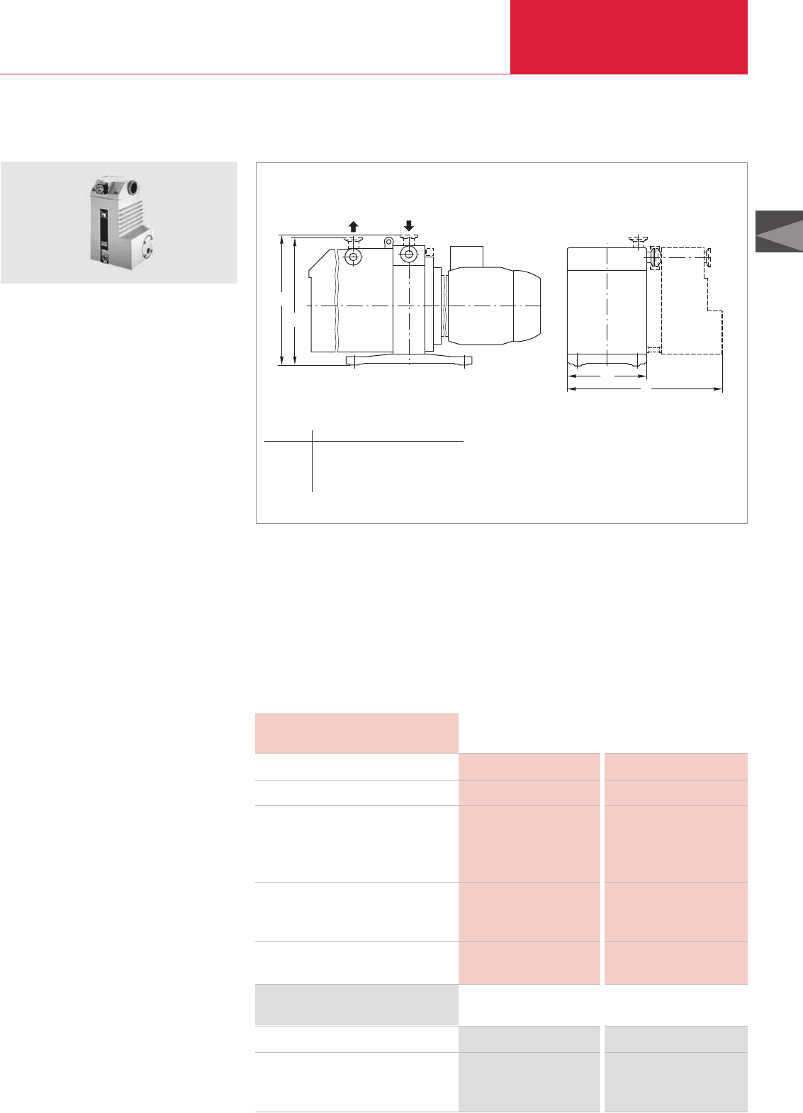
Rotary Vane Vacuum Pumps
C01.55
C01
LEYBOLD VACUUM PRODUCTS AND REFERENCE BOOK 2003/2004
Accessories for TRIVAC B
h
h1
1
b
b
Technical Data ARS 16-25 ARS 40-65
Ordering Information ARS 16-25 ARS 40-65
Exhaust filter with lubricant return
Replacement filter element
FE 16-25
FE 40-65
Connection to pump TRIVAC
Connection flanges DN
Amount of oil required for opening
the float-controlled valve
N 62 /HE-200 cm3(qt)
PFPE cm3(qt)
Remaining amount of oil
N 62 /HE-200 cm3(qt)
PFPE cm3(qt)
Weight with intermediate flange, tubing
and filter, without lubricant kg (lbs)
Exhaust Filters with Lubricant Return ARS 16-25, ARS 40-65
Dimensional drawing for the ARS mounted on a TRIVAC BCS
This combination of an exhaust filter with a float-
controlled valve considerably extends the mainte-
nance intervals of the TRIVAC BCS.
The ARS is part of the TRIVAC SYSTEM.
Advantages to the User
♦Lubricant return with the aid of a float-
controlled valve back into the intake port
♦The intake port may be easily exchanged
(either vertical or horizontal orientation)
♦No operating costs caused by lost lubricant
♦Hardly any oil consumption
♦Visual indication of the differential pressure
♦Standard filter element
♦All aluminium parts are surface protected
♦Built-in over-pressure relief valve
♦Resists solvents
♦All seals made of FPM
♦May also be used on the TRIVAC B
Typical Application
♦Filtering the exhaust air of entrained lubricant
particles
Technical Information
An exhaust line must be connected in case of
hazardous exhaust gases.
The ARS is connected to the exhaust port of the
TRIVAC BCS, the return line is connected at the
intermediate flange under the intake port.
The ARS is cleaned in the factory to such an
extent, that it may be operated either with mineral
oil (e.g. N 62 or HE-200) or perfluoropolyther
(PFPE e.g. NC 1/14 or HE-1600).
D 16/25 B; D 16/25 BCS (-PFPE) D 40/65 B/BCS (-PFPE)
25 KF 40 KF
510 (0.54) 760 (0.80)
340 (0.36) 420 (0.44)
430 (0.45) 700 (0.74)
300 (0.31) 390 (0.41)
4.7 (10.4) 8.5 (18.7)
Part No. 189 56 Part No. 189 57
Part No. 189 72 –
– Part No. 189 73
ARS 40-65
Type b b1h h1
ARS 16-25 mm ≈360 176 282 264
in. ≈14.2 6.93 11.1 10.4
ARS 40-65 mm ≈468 234 381 356
in. ≈18.4 9.21 15 14
Supplied Equipment
Intermediate flange, connecting lines with hollow
screws, required gaskets as well as mounting
screws for the intake flange.
Wrapped in foil for shipping.
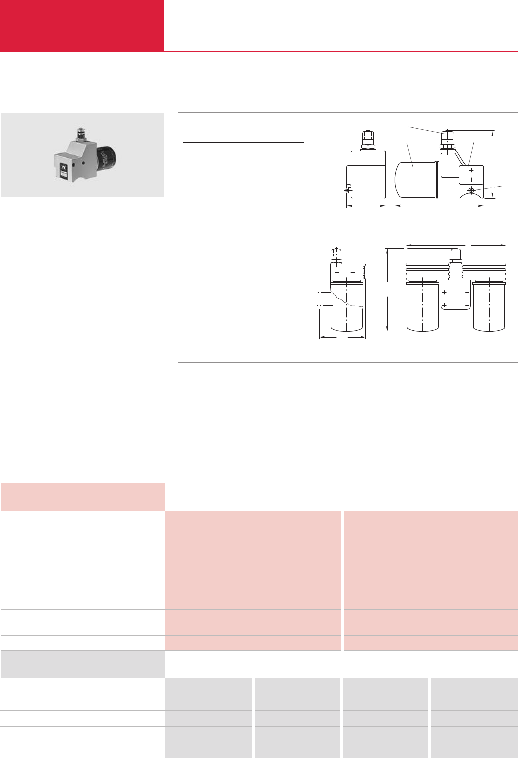
Rotary Vane Vacuum Pumps
C01.56 LEYBOLD VACUUM PRODUCTS AND REFERENCE BOOK 2003/2004
Accessories for TRIVAC B
Technical Data
Ordering Information OF 4-25 CF 4-25 OF 40-65 CF 40-65
Mechanical oil filter
Chemical oil filter
WF 4-25 interchangeable filter, paper, 0.5 l (0.5 qt)
WF 40-65 interchangeable filter, paper 0.75 l (0.8 qt)
WF Alu 4-65 interchangeable filter, paper and Al2O3, 1 l (1 qt)
Connection to pump TRIVAC
Nominal throughput l x h-1
Separation, mechanical oil filter µm
chemical oil filter µm
Permissible operating pressure bar (psig)
Opening pressure, non-return valve bar (psid)
bypass valve bar (psid)
Topping up amount during first time installation l (qt)
filter exchange l (qt)
Weight, ready for operation, dry kg (lbs)
Mechanical Oil Filters OF 4-25, OF 40-65 / Chemical Oil Filters CF 4-25, CF 40-65
Since there is a pressure-lubrication system with
an oil pump in every TRIVAC B, it is possible to
connect main flow oil filters.
These filters are available either for mechanical
filtering (OF types) or combined chemical/mechan
-
ical filtering (CF types).
Advantages to the User
♦Main flow oil filter
♦Longer service life for the oil depending on
the type of application
♦Can be installed without problems to the
TRIVAC B
♦Hose connections are not required
♦Easily interchangeable filters
♦Only a small amount of oil needs to be added
when changing the filters
♦Expansion of the range of applications in case
of special requirements
♦Same casing for OF and CF types
D 4/8 B, D 16/25 B D 40/65 B
900 2000
5 to 10 5 to 10
to 3 to 3
2.5 (21.7) 2.5 (21.7)
0.12 (1.7) 0.12 (1.7)
2.5 ± 0.3 (21.7 ± 4.3) 2.5 ± 0.3 (21.7 ± 4.3)
1 (1) 2.5 (2.6)
1 (1) 2 (2.1)
4.0 (8.8) 10 (22.1)
Part No. 101 91 – Part No. 101 92 –
–Part No. 101 96 – Part No. 101 97
Part No. 189 91 – – –
– – Part No. 189 92 (2x) –
– Part No. 189 96 – Part No. 189 96 (2x)
OF 4-25 mechanical oil filter
♦Greater reliability by standard maintenance
indicator
♦Built-in bypass valve
♦Owing to the highly effective adsorbent for
polar substances, an up to ten-fold adsorption
effect is attained over normal bleaching
earth (CF)
♦Prevents mechanical damage to the pump
Typical Application
♦Separation of fine particles from the
pump’s oil (sizes between 5 and
10 µm (OF))
OF 4-25 CF 4-25 OF 40-65 CF 40-65
1
2
b
a
h
4
3
Dimensional drawings for the OF mechanical oil filters and CF chemical oil filters
l
h
a
OF/CF 4-25
OF/CF 40-65
1 Interchangeable filter 3 Connection flange
2 Maintenance indicator 4 Pin for protection against twisting
Type a b h l
OF 4-25 mm ≈100 200 150 –
in. ≈4 7.87 5.91 –
CF 4-25 mm ≈100 315 160 –
in. ≈4 12.4 6.30 –
OF 40-65 mm 135 – 239 296
in. 5.31 – 9.41 11.7
CF 40-65 mm 135 – 307 296
in. 5.31 – 12.1 11.7
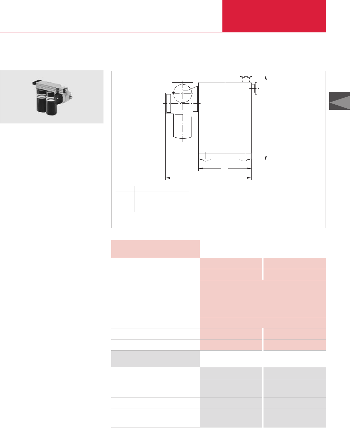
Rotary Vane Vacuum Pumps
C01.57
C01
LEYBOLD VACUUM PRODUCTS AND REFERENCE BOOK 2003/2004
Accessories for TRIVAC B
b
b1
h
Chemical Filters with Safety Isolation Valve CFS 16-25, CFS 40-65
Dimensional drawing for the CFS (mounted on a TRIVAC BCS)
The CFS chemical filters with safety isolation
valve are main flow oil filters for the TRIVAC B
and BCS pumps.
The CFS is part of the TRIVAC SYSTEM.
Advantages to the User
♦The CFS is included in the main lubricant flow
♦Rapid filter exchange – the pump may contiue
to operate while changing the filters
♦Visual indication of the filter’s condition
through a maintenance indicator
♦Aluminium component with isolation valve for
one or two interchangeable filters
♦All aluminium parts are surface protected
♦May be operated with different interchange-
able filters
♦Over-pressure relief valve in the interchange-
able filters
♦Prepared for connection of a differential pres-
sure switch and an oil pressure switch
♦May also be used on the TRIVAC B pumps
Technical Information
The CFS is cleaned in the factory to such an
extent, that it may be operated either with mineral
oil (e.g. N 62 or HE-200) or perfluoropolyther
(PFPE e.g. NC 1/14 or HE-1600).
Supplied Equipment
All gaskets and mounting parts required for
installation.
Aluminium particle filters (WF Alu-Part) sealed
for shipping are included separately.
CFS 40-65
Type b b1h
CFS 16-25 mm ≈327 176 264
in. ≈12.9 6.9 10.4
CFS 40-65 mm ≈390 234 356
in. ≈15.4 9.21 14
Technical Data CFS 16-25 CFS 40-65
Ordering Information CFS 16-25 CFS 40-65
Chemical filter with safety isolation valve
WF Alu-Part combination filter,
paper and Al2O3, 1.6 l (1.7 qt)
WF particle filter, paper, 1.6 l (1.7 qt)
WFG particle filter,
paper with support mesh, 1 l (1 qt)
Connection to pump TRIVAC
Nominal throughput l x h-1
Permissible operating pressure bar (psig)
Opening pressure
Non-return valve bar (psid)
Bypass valve bar (psid)
Filter medium
Lubricant filling when using WF Alu-Part l (qt)
Weight, ready for operation, dry kg (lbs)
D 16/25 BCS (-PFPE) D 40/65 BCS (-PFPE)
900 2000
2.5 (21.7)
0.12 (1.7)
2.5 ± 0.3 (21.7 ± 4.3)
Al2O3
1.4 (1.5) 3.3 (3.5)
7.0 (15.4) 15.5 (34.1)
Part No. 101 76 Part No. 101 77
Part No. 189 99 Part No. 189 99 (2x)
Part No. 200 09 804 Part No. 200 09 804 (2x)
Part No. 189 90 Part No. 189 90 (2x)
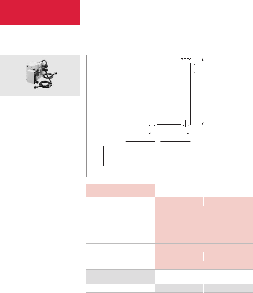
Rotary Vane Vacuum Pumps
C01.58 LEYBOLD VACUUM PRODUCTS AND REFERENCE BOOK 2003/2004
Accessories for TRIVAC B
b
h
1
b
Technical Data IGS 16-25 IGS 40-65
Ordering Information IGS 16-25 IGS 40-65
Inert gas system
Connection to pump TRIVAC
Min. amount of admitted gas at a
reservoir pressure of 3.0 bar (29 psig) l x h-1
Max. amount of admitted gas at a
reservoir pressure of 6.0 bar (72.5 psig) l x h-1
Supply voltage for the solenoid valves V DC
Power consumption W
Weight kg (lbs)
Connection thread G (BPS)
Inert Gas System IGS 16-25, IGS 40-65
Dimensional drawing for the IGS (mounted on a TRIVAC BCS)
This accessory, which is controlled via solenoid
valves, permits the controlled admission of
special gases into the TRIVAC BCS.
The IGS is part of the TRIVAC SYSTEM.
Advantages to the User
♦Ready for connection to an inert gas supply
♦Solenoid valve for reduced gas ballast
♦Solenoid valve for purging the oil box
♦Float throughput gauge with throttling valve
adjustable from 200 to 700 l x h
-1
♦The flowing quantity can be read directly
♦System protection by a non-return valve
(requires a reservoir pressure of at least
3 bar (29 psi, gauge)) – this reliably prevents
the reservoir vessel from being evacuated
♦Connects directly on to the TRIVAC BCS
Typical Applications
♦Reduction of the contamination levels in the
lubricant
♦Reduction in the dwell time of volatile sub-
stances within the pump
Technical Information
The amount of inert gas ballast is restricted by a
nozzle to 200 l x h
-1
. Larger quantities are used
for purging.
Supplied Equipment
Solenoid valves with connection cables and plugs
for connection to the electric indicator system
EIS, the required connecting pieces, mounting
screws and cover panel.
D 16/25 BCS (-PFPE) D 40/65 BCS (-PFPE)
200
1450
24
10
1.0 (2.2) 1.4 (3.1)
1/8"
Part No. 161 76 Part No. 161 77
IGS
Type b b1h
IGS 16-25 mm 176 ≈294 264
in. 6.93 ≈11.6 10.4
IGS 40-65 mm 234 ≈369 356
in. 9.21 ≈14.5 14
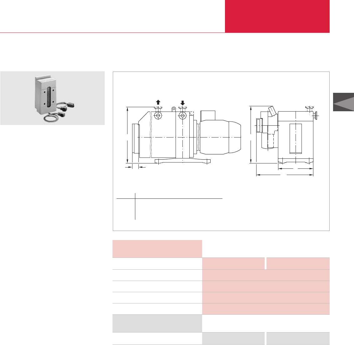
Rotary Vane Vacuum Pumps
C01.59
C01
LEYBOLD VACUUM PRODUCTS AND REFERENCE BOOK 2003/2004
Accessories for TRIVAC B
s
h
b1
h
b
1
Technical Data LSS 16-25 LSS 40-65
Ordering Information LSS 16-25 LSS 40-65
Limit switch system
Connection to pump TRIVAC
Operating voltage V DC
Switching capacity W/A
Type of protection IP
Weight, approx. kg (lbs)
Limit Switch System LSS 16-25, LSS 40-65
Dimensional drawing for the LSS (mounted on a TRIVAC BCS)
This accessory consists of a package of limit
switches. It is used to monitor system functions.
The LSS is part of the TRIVAC-SYSTEM.
The package of limit switches includes:
♦Differential pressure switch to monitor the
CFS
♦Oil pressure switch to monitor the operating
pressure
♦Flow switch to monitor the inert gas flow
♦Pressure switch to monitor the pressure in
the oil box of the pump
♦Connection cable and plug for the temperature
switch used for temperature monitoring
♦Float switch with housing to monitor the oil
level
Advantages to the User
♦Errors are indicated well in advance so that it
will in most cases be possible to complete the
process for the running batch
♦The switching action is independent of the
optical displays (for optimum reliability)
♦The temperature switch is already present in
the TRIVAC BCS
Typical Application
♦Changing the status in case operating conditi-
ons arise which are not permissible
Supplied Equipment
Fully wired-up switches with plugs as well as all
required gaskets and mounting parts.
D 16/25 BCS (-PFPE) D 40/65 BCS (-PFPE)
24
10/0.4
54
2.5 (5.5)
Part No. 161 06 Part No. 161 07
LSS
Type b b1h h1s
LSS 16-25 mm 176 ≈327 264 ≈279 60
in. 6.9 ≈12.9 10.4 ≈11 2.36
LSS 40-65 mm 234 ≈390 356 ≈371 60
in. 9.21 ≈15.4 14 ≈14.6 2.36
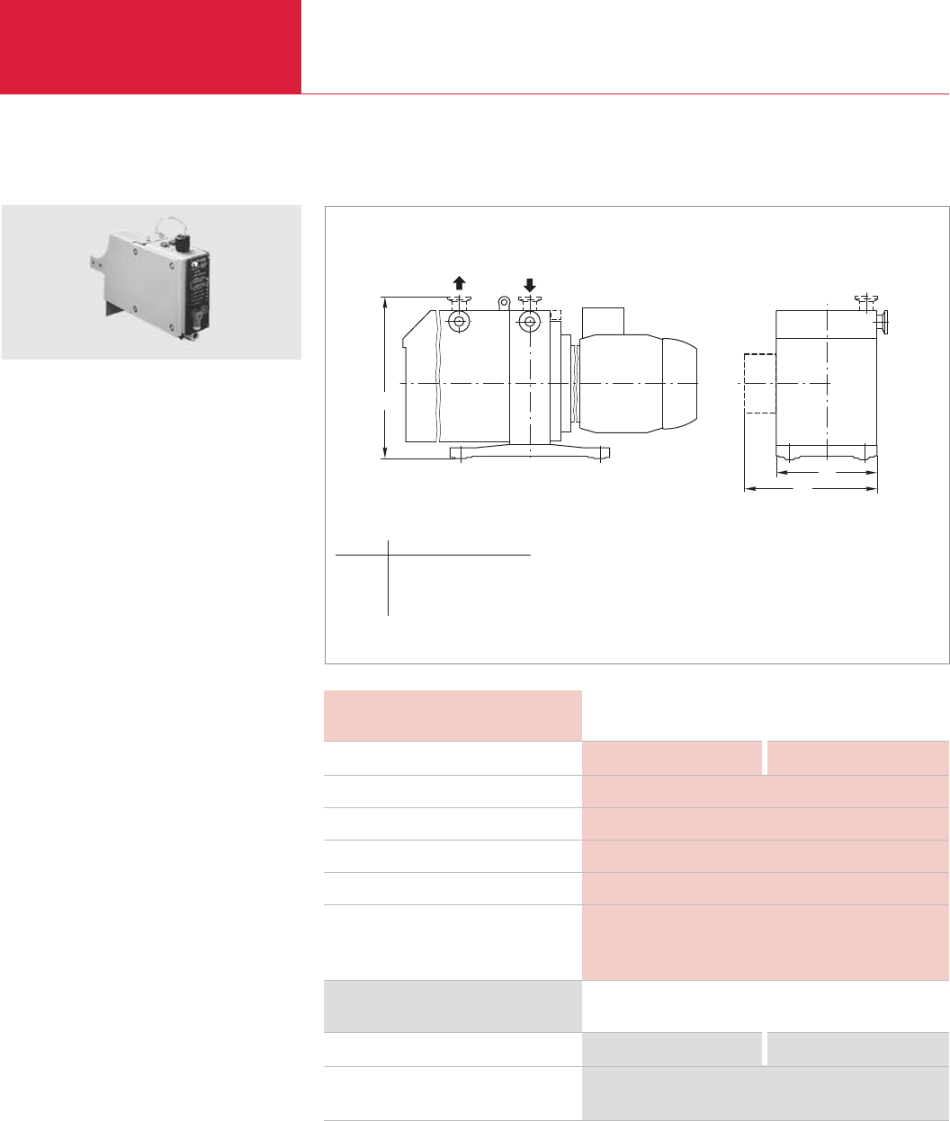
Rotary Vane Vacuum Pumps
C01.60 LEYBOLD VACUUM PRODUCTS AND REFERENCE BOOK 2003/2004
Accessories for TRIVAC B
h
1
b
b
Technical Data EIS 16-25 EIS 40-65
Ordering Information EIS 16-25 EIS 40-65
Electrical indicator system
Connection plug for transmission
of the “green” signals
Connection to pump TRIVAC
Input voltage V DC
Output voltage V DC
Maximum current A
Type of protection IP
Weight
without cover panel kg (lbs)
with cover panel kg (lbs)
Electrical Indicator System EIS 16-25, EIS 40-65
Dimensional drawing for the EIS (mounted on a TRIVAC BCS)
This accessory electrically links all switches from
the limit switch system and the electrical indica-
tor system so that the position of each switch is
indicated optically by LEDs.
The EIS is part of the TRIVAC SYSTEM.
Advantages to the User
♦Connects directly to the LSS
♦LEDs arranged conveniently on the side of the
BCS which carries the controls
♦Socket and plug for supplying and controlling
the connected valves, no soldering is required
♦Socket for remote signal transmission
♦For direct, compact installation to the IGS
♦IP 54 protection
♦Each pair of LEDs (red or green) is clearly
marked
Supplied Equipment
Housing, complete with all sockets for the com-
ponents of the system.
Socket and plug for 24 V DC supply.
Socket for operating the solenoid valves of the
IGS and remote data transmission.
Cover panel and all required mounting screws.
D 16/25 BCS (-PFPE) D 40/65 BCS (-PFPE)
24
24
3
54
2.5 (5.5)
4.0 (8.8)
Part No. 160 96 Part No. 160 97
Part No. 200 80 078
EIS
Type b b1h
EIS 16-25 mm 176 ≈256 264
in. 6.93 ≈10.1 10.4
EIS 40-65 mm 234 ≈314 356
in. 9.21 ≈12.4 14
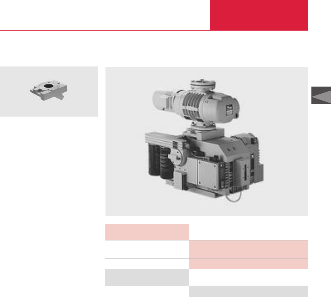
Rotary Vane Vacuum Pumps
C01.61
C01
LEYBOLD VACUUM PRODUCTS AND REFERENCE BOOK 2003/2004
Accessories for TRIVAC B
Roots Pump Adaptor
Pump system consisting of a TRIVAC D 65 BCS and a RUVAC WS 251
The Roots pump adaptor allows the direct
installation of a Roots pump on a TRIVAC
D 40/65 B/BCS.
Advantages to the User
♦Compact and space-saving
♦Short and direct connection between the
pumps
♦Minimal conductance loss
♦Easy installation
Typical Application
♦Simple assembly of a small pump system
Roots pump adaptor
Technical Data
Ordering Information
Roots pump adaptor
Connection to pump TRIVAC
Weight, approx. kg (lbs)
D 40/65 B/BCS (-PFPE)
and RUVAC WA/WAU/WS/WSU 251
11.5 (25.4)
Part No. 168 30
Roots Pump Adaptor
Roots Pump Adaptor

Rotary Vane Vacuum Pumps
C01.62 LEYBOLD VACUUM PRODUCTS AND REFERENCE BOOK 2003/2004
Accessories for TRIVAC B
OF1000 Oil Filtering System
Advantages to the User
♦Choice of Single- and Dual-Canister Models
for Standard or Chemically Severe Applicati-
ons
♦Compact Design
♦Reliable Operation
♦Choice of Four Filtering Elements
♦Dripless Quick Disconnects for Easy Removal
and Replacement of Filter Elements
♦Recessed Lid and Oil Level – No Oil Spillage
♦Conductive Teflon Hoses for Static Charge
Dissipation – No Oil Leakage Due to Static
Burning
♦Integral Gear Pump with Built-In Bypass
♦Fluid Sight Glass and Flow Monitor
♦Pressure Gauge
♦Small Precharge Fluid Volume
♦Single Phase 50/60 Hz Motors Standard
Version for the North and South American Continents
OF1000 Oil Filtering System
Applications
Standard series models are widely used in silicon
production processes, including LPCVD, low-
pressure epitaxy, ion implantation, reactive ion
etching and several plasma processes. Such pro-
cesses employ a variety of gases which can react
with pump fluid, resulting in the formation of
sludge, particulates and acids. The standard
OF1000 model has proven effective at extending
maintenance intervals in such applications.
Similarly, chemically resistant OF1000C models
have proven successful in aluminum etching and
other processes where boron trichloride and
other highly toxic gases are employed. The canis-
ter, gear pump, fittings and quick disconnects of
the corrosive-service model have been specially
treated with a fluorocarbon material that substan-
tially increases the life of these components.
OF 1000 Oil Filtering Systems are designed to
remove acids and particulates from the lubrica-
ting fluid used in Leybold mechanical vacuum
pumps. The systems are located externally from
the vacuum pump, and utilize their own integral
gear pump in conjunction with a bypass to conti-
nuously recycle fluid through a filtering medium;
the medium is housed in an element/canister
assembly which additionally serves to absorb
heat, and thus reduce the operating temperature
of the vacuum pump.
OF1000 Systems are available in both single- and
dual-canister designs. Both types are highly com-
pact and reliable, and can be supplied in models
for standard or chemically severe applications.
Single-canister OF1000 models are distinguished
by their smaller footprint while dual-canister con-
figurations afford the advantages of multi-media
filtration and increased oil capacity. Dual-canister
models are designed for series flow through two
side-by-side mounted canisters, and thus can be
used to filter oil through two different media on
the same pass or for double filtration through
elements containing the same medium. The
models also enable the vacuum pump to operate
at somewhat lower temperatures, while providing
it with a larger supply of clean, filtered oil.
All OF1000 models are supplied with a choice of
four filtering elements. The Fullers Earth element
provides high capacity for standard acids and can
be used to trap particulates down to 10 micron in
size. Hydrophilic, activated alumina and fiberglass
particulate elements are also available. The
hydrophilic element is particularly effective for
hydrolized acids, and can also be used to trap
particles as small as 1 micron. The activated
alumina element provides 10 micron particulate
retention and is extremely effective for Lewis
acids and polar compounds. The fiberglass ele-
ment is suitable for particulate removal down to
10 micron.
The element/canister assembly of OF1000
systems is easy to install, extremely easy to
remove and replace. The recessed lid and oil level
of the assembly safeguards against the possibility
of spillage. Dripless quick disconnects are also
provided for easy canister removal and safer dis-
posal of the filtering element and oil.
OF1000 Systems also come equipped with fle-
xible Teflon hoses designed to resist dielectric
breakdown. The systems thus ward against the
possibility of oil leaks due to pinholing or static
burning of the hose.

Rotary Vane Vacuum Pumps
C01.63
C01
LEYBOLD VACUUM PRODUCTS AND REFERENCE BOOK 2003/2004
Accessories for TRIVAC B
Version for the North and South American Continents
Technical Data
Single-Canister Dual-Canister
Systems Systems
Gear Pump Motor
Gear Pump
Pressure Gauge
Pump Fluid Capacity
Flexible Hoses
Dimensions in. (mm)
Flow Arrangement
Weight (Dry) lb
1) Hazardous duty models and special voltages also available
2) Optional 6, 10 and 15 feet hoses available
3) 0ptional parallel flow arrangement also available
1/6 HP, 115/208/220V, single phase, 50/60Hz,
wired for 115V, with on/off switch 1)
0.7 gpm @ 1800 RPM
0 to 100 psig (0 to 70 kPa)
15 lb perfluorinated polyether 29 lb perfluorinated polyether
or 3.75 qt hydrocarbon oil or 7.25 qt hydrocarbon oil
3/8 in. l.D. teflon/carbon black with stainless steel braid – 4 ft lengths 2)
16 x 14 x 11 (406 x 356 x 279) 23 x 14 x 11 (585 x 356 x 279)
– series 3)
45 60
Ordering Information
Single-Canister Dual-Canister
Systems Systems
Oil Filtering System
OF1000 Less Filtering Element and Oil
OF1000 Prepared for PFPE,
Less Filtering Element and Oil
OF1000C Chemically Severe Service.
Prepared for PFPE Fluid
Accessories
Spare Filter Canister Assembly
With Quick Disconnect
Prepared for PFPE, With Quick Disconnect
Chemically Severe Service
Filtering Elements
Aluminum Oxide — High Capacity for Reagent Grade
HCI; Removes Lewis Acids and PolarCompounds;
10 Micron Particulate Retention
Fullers Earth — Acid and Particulate Filter with
Capacity of 34 ml Reagent Grade HCI;
10 Micron Particulate Retention
Hydrophilic — Water and HCI Acid Absorbing
Capabilities; 1 Micron Particulate Retention
Particulate — Fiberglass Element with 10 Micron
Particulate Retention
Part No. 898 550 Part No. 898 552
Part No. 898 551 Part No. 898 553
Part No. 898 561 Part No. 898 554
Part No. 898 555 Part No. 898 557 (front), Part No. 898 555 (rear)
Part No. 898 556 Part No. 898 558 (front), Part No. 898 556 (rear)
Part No. 898 566 Part No. 898 559 (front), Part No. 898 566 (rear)
Part No. 898 504 Part No. 898 504
Part No. 898 505 Part No. 898 505
Part No. 898 506 Part No. 898 506
Part No. 898 507 Part No. 898 507
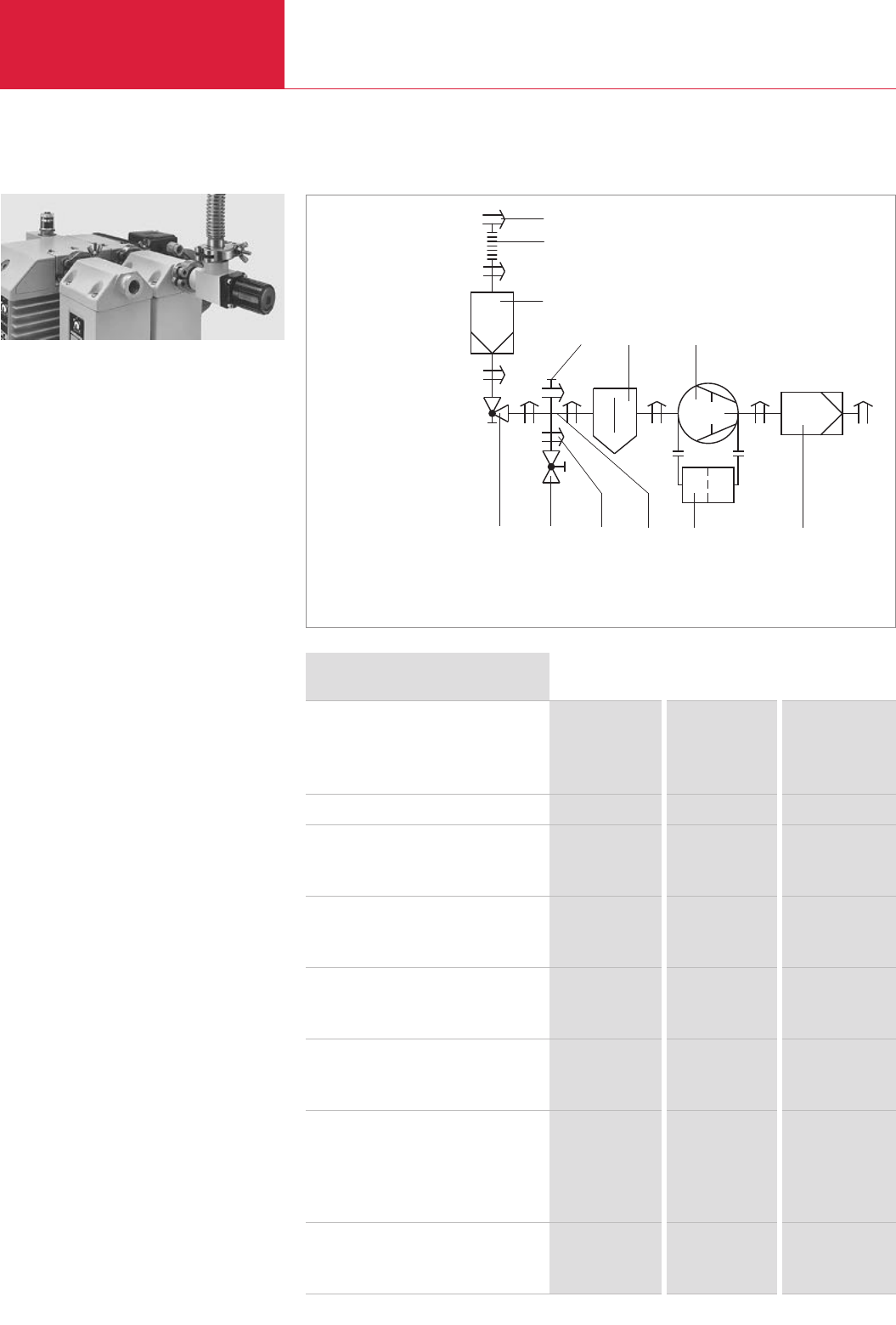
General Accessories
Rotary Vane Vacuum Pumps
C01.64 LEYBOLD VACUUM PRODUCTS AND REFERENCE BOOK 2003/2004
1
2
3
4 5 6
8912 11 10 7
Ordering Information DN 16 KF DN 25 KF DN 40 KF
Small flange connection
Clamping ring
Centering ring, aluminum/CR
Centering ring, stainless steel/FPM
Bellows
Right-angled valve, manually operated
Aluminum casing
Stainless steel casing
Blank flange for (reducing) cross
Aluminium
Stainless steel
Reducing cross (to DN 10 KF)
Aluminum
Stainless steel
Cross DN 16 KF
Aluminum
Stainless steel
Small flange connection for venting valve
or blank flange
Clamping ring
(Adaptor) centering ring, aluminum/NBR
(Adaptor) centering ring, stainless steel/FPM
Venting valve DN 10 KF
Aluminum
Stainless steel
Flange Components, Valves
Example of connecting a pump with accessories
Our range of flange components and valves is
described in detail in Product Sections C13 and
C14.
Given in the following are only some components
which you might find particularly useful when
planning your system.
Isolation Valve
♦The pump is allowed to warm up with the
intake line isolated
♦The pump may continue to operate in the
energy-saving and environmentally compatible
ultimate pressure mode when the vacuum
chamber is vented briefly
♦The pump may be left on after completion of
the process so as to regenerate the oil
Branch (Cross)
♦Installing a cross in the intake line permits the
connection of a vacuum gauge and a venting
valve
Flange Connections
Each flange connection requires one each center-
ing and clamping ring.
Part No. 183 41 Part No. 143 42 Part No. 183 43
Part No. 183 26 Part No. 183 27 Part No. 183 28
Part No. 883 46 Part No. 883 47 Part No. 883 48
Part No. 872 41 Part No. 872 43 Part No. 872 45
Part No. 287 11 Part No. 287 12 Part No. 287 13
Part No. 288 11 Part No. 288 12 Part No. 288 13
Part No. 184 46 Part No. 184 41 Part No. 184 41
Part No. 884 36 Part No. 884 41 Part No. 884 41
–Part No. 184 17 Part No. 184 19
–Part No. 884 92 Part No. 884 94
Part No. 184 71 – –
Part No. 884 85 – –
Part No. 183 41 Part No. 183 41 Part No. 183 41
Part No. 183 56 Part No. 183 21 Part No. 183 21
Part No. 883 56 Part No. 883 21 Part No. 883 21
Part No. 173 24 Part No. 173 24 Part No. 173 24
Part No. 173 37 Part No. 173 37 Part No. 173 37
1 Small flange connection
2 Bellows
3 Dust filter
4 Blank flange
5 Condensate separator
6 Rotary vane pump
7 Exhaust filter
8 Oil filter
9 Cross
10 Small flange connection
for the venting valve
or for a blank flange
11 Venting valve DN 10 KF
12 Right-angled valve,
manually operated

General Accessories
Rotary Vane Vacuum Pumps
C01.65
C01
LEYBOLD VACUUM PRODUCTS AND REFERENCE BOOK 2003/2004
Lubricating oils for rotary vacuum pumps need to
fulfil demanding requirements. Their vapor pres-
sure must be low at high temperatures and the
water content and water uptake must be minimal.
Their viscosity characteristics need to be flat,
lubricating properties need to be excellent and
they must resist cracking upon being mechanical-
ly stressed.
All the vacuum pump oils listed in the following
have been subjected in our factory laboratories to
very comprehensive tests closely resembling the
conditions encountered in practice by the pumps
from the TRIVAC series.
We therefore recommend the exclusive use of
vacuum pump oils fully qualified by Leybold so
as to ensure optimum performance of the Ley-
bold vacuum pumps and also to ensure optimum
oil change intervals.
Under vacuum conditions lubricating oils, especi-
ally those with additives may behave quite diffe-
rently than expected. Additives may adversely
affect the attainable ultimate pressure and may
react with the media being pumped.
When using not suitably qualified third party oils,
the oil change intervals and the performance of
the vacuum pump may be reduced. Also unwan-
ted deposits may occur which may even cause
severe damage to the vacuum pump.
In order to adapt the pumps to the different appli-
cations of our customers, different types of oil
are used in the TRIVAC pumps.
In order to adapt the pumps to the different appli-
cations of our customers, different types of oil
are used in the TRIVAC pumps.
Please note that owing to differing properties not
all types of oil may be used in all pumps of the
TRIVAC series. If you can not find the combinati-
on of pump and oil you require please ask us for
a quotation.
Vacuum Pump Oils
Lubricant Types
Mineral Oils
Mineral oils are products distilled and refined
from crude oil. These do not consist of precisely
defined compounds but rather consist of a com-
plex mixture. The way in which the mineral oil is
pre-treated and its composition is decisive as to
the applications it will be suited for. Depending
on the distribution of the hydrocarbons and the
dominance of certain properties, mineral oils are
grouped according to paraffin-base, naphthenic
and aromatic. For the purpose of attaining espe-
cially low ultimate pressures, mineral oils must
be selected on the basis of a core fraction.
The thermal and chemical resistance of mineral
oils has been found to be adequate in the majori-
ty of applications. They offer a high degree of
compatibility with elastomers and resistance to
hydrolysis.
Synthetic Oils
Synthetic oils are produced by a chemical reac-
tion. The group of synthetic oils includes liquids
differing widely as to their chemical structure and
composition. Correspondingly their physical and
chemical properties differ considerably. Synthetic
oils are used in those cases where special pro-
perties of the oil are required which can not be
fulfiled by mineral oils.
The oils given in the following belong to the
group of synthetic oils:
Polyalphaolefin (PAO) Oils
Polyalphaolefin oils are synthetic hydrocarbons
which are paraffin like, but have a uniform struc-
ture. Thermal and chemical resistance is better
compared to mineral oils. Elastomer compatibility
and resistance against hydrolysis are comparable
to mineral oils.
Ester oils
Ester oils are organic compounds which excel
especially through their high thermal resistance
to cracking compared to mineral oils. Chemical
resistance is generally quite good, but will
depend on the type of ester oil. Elastomer com-
patibility and resistance against hydrolysis are
not so good compared to mineral oils.
Perfluorinated polyether
(PFPE)
These are oils which are only composed of carb-
on (C), fluorine (F) and oxygen atoms (O). The
existing C-O and C-F bonds are highly stable. For
this reason PFPE oils are practically inert against
all chemical and oxidising influences.
Perfluorinated polyethers will not polymerise
under the influence of high energy radiation.
PFPE is non-flammable. Leybold NC1/14 has the
approval of BAM (Federal Institute for Materials
Research and Testing) for pumping of pure oxy-
gen.
Perfluorinated polyethers are used when pum-
ping strongly reactive substances like oxygen
(O
2
), fluorine F
2
and uranium hexafluoride UF
6
.
Regarding Lewis acids (for example, boron triflu-
oride BF
3
, aluminum trichloride AlCl
3
) they are
not completely inert. Here reactions may take
place at temperatures over 100 °C (212 °F).
Perfluorinated polyethers are thermally highly
stable. Thermal decomposition may only take
place at temperatures of over 290 °C (554 °F).
Caution: Perfluorinated polyethers will – when
decomposed – release toxic and corrosive gases:
hydrogen fluoride HF, carbonyl difluoride COF
2
.
For this reason open fires must be avoided in the
workspace where PFPE is being used. Do not
smoke in the workspace where PFPE is being
used.
Only suitably prepared pumps must be used in
connection with perfluorinated polyethers, since
it is essential that the pump be free of hydrocar-
bons. Changing from one basic type of oil to
PFPE must be left exclusively to authorised Servi-
ce Centers. The pumps will have to be fully disas-
sembled and carefully cleaned. Gaskets and fil-
ters will have to be exchanged and suitable grea-
ses will have to be used.
For all lubricants from our line of products you may obtain Safety Data Sheets from the Dept. Technical
Support in Cologne.

Rotary Vane Vacuum Pumps
C01.66 LEYBOLD VACUUM PRODUCTS AND REFERENCE BOOK 2003/2004
General Accessories
Technical Data
Special Oil White Oil
N62 NC2 PROTELEN SHC 224
90
10
> 260 (500)
< 1 x 10⁻⁵ (< 8 x 10⁻⁶)
< 1 x 10⁻³ (< 8 x 10⁻⁴)
0.87 2)
< -15 (5)
530
140
11
250 (482)
4 x 10⁻⁴ (3 x 10⁻⁴) 3)
1 x 10⁻² (8 x 10⁻³)
0.90
-30 (- 22)
450
29
5.6
230 (446)
1 x 10⁻⁵ (0,75 x 10⁻⁵)
8 x 10⁻³ (6 x 10⁻³)
0.83
< - 55 (- 67)
476
Oil recommendations for various areas of application
90
10
> 255 (491)
< 1 x 10⁻⁵ (< 8 x 10⁻⁶)
< 3 x 10⁻³ (< 2 x 10⁻³)
0.88 2)
< -9 (16)
550
Viscosity
at 040 °C (104 °F) mm2/s (= cSt)
at 100 °C (212 °F) mm2/s (= cSt)
Flash point °C (°F)
Vapor pressure
at 020 °C (68 °F) mbar (Torr)
at 100 °C (212 °F) mbar (Torr)
Density at 15 °C (59 °F) g/ml
Pour point °C (°F)
Middle molecular weight g/mol
Application Data
Special Oil White Oil
N62 NC2 PROTELEN SHC 224
Type of oil
Examples of areas of application
and process media
Remarks
Elastomer compatibility
FPM (Viton)
NBR (Perbunan) 1)
EPDM
Medicinal, high purity white oil, paraf-
fin-base, core fraction, free of additi-
ves, sulphur and aromatic compounds
For pumping small quantities of
chemically reactive substances like
halogens (for example, bromine Br2,
iodine I2), halogen acids (for example.
hydrogen chloride HCl, hydrogen bro-
mide HBr), halogenated hydrocarbons
(for example, bromomethane CH3Br,
trichloromethane CHCl3), Lewis acids
(for example, aluminum chloride AlCl3,
titanium tetrachloride TiCl4),
acetic acid CH3COOH
When pumping the aforementioned
process media, humidity must be
avoided
Service life may be extended through
the use of an oil filter
Suited
Conditionally suited
Not suited
Mixed base mineral oil
For pumping corrosive contaminants
in the gas, acid vapors (for example,
sulfuric acid H2SO4), organic acid
chlorides (for example
acetyl chloride CH3COCl).
When pumping the aforementioned
process media, humidity must be
avoided
Do not use chemical oil filters
Avoid corrosion at standstill
Suited
Conditionally suited
Not suited
Polyalphaolefin PAO
Cold starting at low temperatures is
possible. Pumping of chemically inert
permanent gases (for example,
noble gases) water vapor in small
quantities, refrigerants R 717
(ammonia NH3)
Service life may be extended through
the use of an oil filter
Suited
Conditionally suited
Not suited
Paraffin-base mineral oil,
core faction, free of additives
Standard oil for Leybold Germany
For pumping air, chemically inert
permanent gases
(noble gases, for example),
water vapor, solvent vapors
in the case of laboratory pumps ope-
rated with cold traps
The ultimate pressures stated in our
catalogs are based on operation of
the pump with N62 (except
for the DOT and PFPE pumps)
Service life may be extended through
the use of an oil filter
Suited
Conditionally suited
Not suited
Ordering
Information Special oil White Oil
N62 NC2 PROTELEN SHC 224
01 litre (1.06 qt)
05 litres (5.29 qt)
20 litres (21.14 qt)
180 kg (397.35 lbs)
–
Part No. 177 29
Part No. 177 27
–
–
Part No. 177 07
Part No. 177 08
Part No. 177 10
Part No. 200 28 181
–
–
–
Part No. 177 01
Part No. 177 02
Part No. 177 03
Part No. 177 05
Please note that the technical data stated are only typical data. Slight variations from batch to batch must be expected.
The technical data stated here can not be taken as assured properties
1) Resistance to decomposing is very much dependent on the share of acrylonitrile in the NBR
2) at 20 °C (68 °F)
3) at 60 °C (140 °F)

Rotary Vane Vacuum Pumps
C01.67
C01
LEYBOLD VACUUM PRODUCTS AND REFERENCE BOOK 2003/2004
General Accessories
Rotary Vane Vacuum Pumps
Technical Data
ANDEROL®555 ANDEROL®RCF-E68N
NC 10
68
10
260 (500)
No known
No known
1.00
-54 (-65)
Not applicable
38
4
225 (437)
1 x 10⁻⁴ (8 x 10⁻⁵)
No known
1.05 2)
-30 (-22)
Not applicable
94
9
250 (482)
7 x 10⁻⁵ (5 x 10⁻⁵)
1.5 x 10⁻³ (1 x 10⁻³)
0.96
-42 (-44)
530
Viscosity
at 040 °C (104 °F) mm2/s (= cSt)
at 100 °C (212 °F) mm2/s (= cSt)
Flash point °C (°F)
Vapor pressure
at 020 °C (68 °F) mbar (Torr)
at 100 °C (212 °F) mbar (Torr)
Density at 15 °C (59 °F) g/ml
Pour point °C (°F)
Middle molecular weight g/mol
Application Data
ANDEROL®555 ANDEROL®RCF-E68N
NC 10
Type of oil
Examples of areas of application
and process media
Remarks
Elastomer compatibility
FPM (Viton)
NBR (Perbunan) 1)
EPDM
Polycarboxylic acid ester
Cooling and air-conditioning
applications. For refrigerants
(for example halocarbon, R134a),
HCFC (for example, R123),
HFC (for example, R218),
CFC (for example, R12) and
HC (for example, R600a)
Use only correspondingly
modified pumps
Mixing with other types of oil must
be absolutely avoided
Do not pump any inorganic acids
(for example HCl, HF)
Suited
Conditionally suited
Not suited
Alkyl sulphonic acid ester
When pumping process media
which tend to polymerise
(for example, styrene C8H8,
butadiene C4H6).
Do not use a chemical oil filter
Mixing with other types of oil must
be absolutely avoided
Do not pump any inorganic acids
(for example HCl, HF)
Suited
Not suited
Not suited
Diester oil
Used at elevated temperatures,
pumping of air, chemically inert
permanent gases (noble gases,
for example), carbon dioxide CO2,
carbon monoxide CO, aliphatic compounds (for
example methane CH4, propane C3H8, ethylene
C2H4), organic solvent vapors
Do not pump any inorganic acids
(HCL, HF, for example),
no free halogens (CL2, F2, for example)
or alkaline media (NH3, for example)
Suited
Conditionally suited
Not suited
Ordering
Information
ANDEROL®555 ANDEROL®RCF-E68N
NC 10
01 litre (1.06 qt)
05 litres (5.29 qt)
20 litres (21.14 qt)
Part No. 200 02 754
–
–
–
–
Part No. 177 25
Part No. 200 10 272
Part No. 200 10 891
Part No. 200 00 193
Please note that the technical data stated are only typical data. Slight variations from batch to batch must be expected.
The technical data stated here can not be taken as assured properties
2) at 20 °C (68 °F)
1) Resistance to decomposing is very much dependent on the share of acrylonitrile in the NBR
ANDEROL®is a trademark of ANDEROL BV

Rotary Vane Vacuum Pumps
C01.68 LEYBOLD VACUUM PRODUCTS AND REFERENCE BOOK 2003/2004
General Accessories
Technical Data
Application Data
Type of oil
Examples of areas of application
and process media
Remarks
Elastomer compatibility
FPM (Viton)
NBR (Perbunan) 1)
EPDM
Ordering
Information
Please note that the technical data stated are only typical data. Slight variations from batch to batch must be expected.
The technical data stated here can not be taken as assured properties
1) Resistance to decomposing is very much dependent on the share of acrylonitrile in the NBR
2) Caution: Perfluorinated polyether compounds will, when being decomposed at temperatures over 290 °C (554 °F), release toxic and corrosive gases.
For this reason open fires must be avoided in the workspace where PFPE is being used. Do not smoke in the workspace where PFPE is being used
3) at 20 °C (68 °F)
DOT 4 NC 1/14
No known
> 2
> 120 (248)
1.3 (0.98)
No known
1.05
Not applicable
Not applicable
47
5
– 2)
3 x 10⁻⁷ (2.25 x 10⁻⁷)
6 x 10⁻⁴ (4.5 x 10⁻⁴)
1.89 3)
- 40 (- 40)
2500
Viscosity
at 040 °C (104 °F) mm2/s (= cSt)
at 100 °C (212 °F) mm2/s (= cSt)
Flash point °C (°F)
Vapor pressure
at 020 °C (68 °F) mbar (Torr)
at 100 °C (212 °F) mbar (Torr)
Density at 15 °C (59 °F) g/ml
Pour point °C (°F)
DOT 4 NC 1/14
Brake fluid
Filling of brake fluid circuits in the car industry
Use only in pumps modified for DOT 4
Mixing with other types of oil
must be absolutely avoided
Not suited
Not suited
Suited
Perfluorinated polyether
PFPE
For pumping strong oxidants like oxygen,
O2, ozone O3, nitrogen oxides NOx and
sulphur oxides (SO2, SO3) as well as reactive
substances like halogens
(for example fluorine F2,
chlorine Cl2), hydrogen halides
(for example hydrogen chloride HCl,
hydrogen bromide HBr), uranium hexafluoride UF6,
and conditionally Lewis acids (for example,
boron trichloride BCl3)
Use only in pumps modified for PFPE
Mixing with other types of oil must be absolutely avoided
Avoid pumping water vapour,
especially with corrosive media (see above)
The use of a chemical oil filter CF / CFS
is strongly recommended
Suited
Suited
Suited
DOT 4 NC 1/14
1 litre (1.06 qt)
Part No. 200 10 037 Part No. 177 38

General Accessories
Rotary Vane Vacuum Pumps
C01.69
C01
LEYBOLD VACUUM PRODUCTS AND REFERENCE BOOK 2003/2004
Version for the North and South American Continents
Technical Data
HE-200 HE-1600
58
9.1
224 (435)
4.7 x 10⁻⁶ (3.5 x 10⁻⁶)
3.9 x 10⁻⁴ (2.9 x 10⁻⁴)
0.88
- 10 (14)
480
Viscosity
at 040 °C (104 °F) mm2/s (= cSt)
at 100 °C (212 °F) mm2/s (= cSt)
Flash point °C (°F)
Vapor pressure
at 025 °C (77 °F) mbar (Torr)
at 100 °C (212 °F) mbar (Torr)
Density at 20 °C (68 °F) g/ml
Pour point °C (°F)
Molecular weight
Application Data
HE-200 HE-1600
Type of oil
Examples of areas of application
and process media
Remarks
Elastomer compatibility
FPM (Viton)
NBR (Perbunan) 1)
EPDM
Paraffin-base mineral oil, core faction, free of additives
Standard oil for Leybold USA
For pumping air, chemically inert permanent gases
(noble gases, for example),
water vapor, solvent vapors
in the case of laboratory pumps operated with cold traps
The ultimate pressures stated in our catalogs are based on
operation of the pump with HE-200
(except for the DOT and PFPE pumps)
Service life may be extended through the use of an oil filter
Suited
Conditionally suited
Not suited
Ordering
Information HE-200 HE-1600
01 qt (1 l)
01 gal (3.8 l)
05 gal (18.9 l)
55 gal (208 l)
Bottle 02 lb (0.91 kg)
Bottle 04 lb (1.81 kg)
Bottle 16 lb (7.25 kg)
Part No. 98 198 006
Part No. 98 198 007
Part No. 98 198 008
Part No. 98 198 010
–
–
–
Please note that the technical data stated are only typical data. Slight variations from batch to batch must be expected.
The technical data stated here can not be taken as assured properties
1) Resistance to decomposing is very much dependent on the share of acrylonitrile in the NBR
2) at 20 °C (68 °F)
3) Caution: Perfluorinated polyether compounds will, when being decomposed at temperatures over 290 °C (554 °F), release toxic and corrosive gases.
For this reason open fires must be avoided in the workspace where PFPE is being used. Do not smoke in the workspace where PFPE is being used
Perfluorinated polyether
PFPE
For pumping strong oxidants like oxygen,
O2, ozone O3, nitrogen oxides NOx and
sulphur oxides (SO2, SO3)
as well as reactive substances like
halogens (for example fluorine F2,
chlorine Cl2), hydrogen halides
(for example hydrogen chloride HCl,
hydrogen bromide HBr),
uranium hexafluoride UF6,
and conditionally Lewis acids
(for example, boron trichloride BCl3)
Use only correspondingly modified pumps
Mixing with other types of oil must be
absolutely avoided
The uptake of water vapor must be avoided
The use of an oil filter is strongly recommended
Suited
Suited
Suited
140 2)
7
– 3)
7 x 10⁻⁷ (5 x 10⁻⁷) 2)
3 x 10⁻⁴ (2 x 10⁻⁴)
1.86
- 40 (- 40)
3000
–
–
–
–
Part No. 898 564-1
Part No. 898 564-2
Part No. 898 564-4
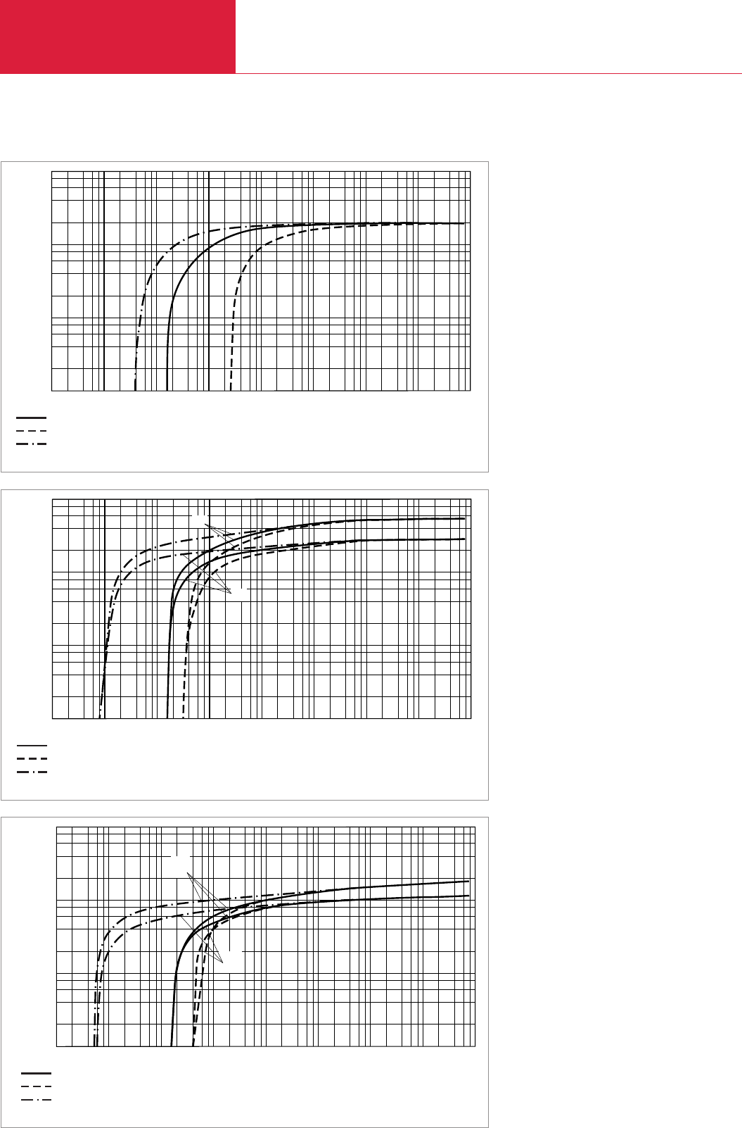
60 Hz Curves
Rotary Vane Vacuum Pumps
C01.70 LEYBOLD VACUUM PRODUCTS AND REFERENCE BOOK 2003/2004
Version for the North and South American Continents
Total Pressure with gas ballast
Total Pressure without gas ballast
Partial Pressure without gas ballast
10-2
10-3 101
100
10-1 102
Torr 103
10-4
10-5 2 4 6 8
Pressure
10-2
cfm
101
100
10-1
8
6
4
2
Pumping Speed
D4B
D8B
Pumping speed characteristics for the TRIVAC D 4 B and D 8 B at 60 Hz
Total Pressure with gas ballast
Total Pressure without gas ballast
Partial Pressure without gas ballast
10-2
10-3 101
100
10-1 102
Torr 103
10-4
10-5 2 4 6 8
Pressure
10-2
cfm
101
100
10-1
8
6
4
2
Pumping Speed
Pumping speed characteristics for the TRIVAC D 2.5 E at 60 Hz
Total Pressure with gas ballast
Total Pressure without gas ballast
Partial Pressure without gas ballast
10-2
10-3 101
100
10-1 102
Torr 103
10-4
10-5 2 4 6 8
Pressure
10-1
cfm
102
101
100
8
6
4
2
Pumping Speed
D25B
D16B
Pumping speed characteristics for the TRIVAC D 16 B and D 25 B at 60 Hz
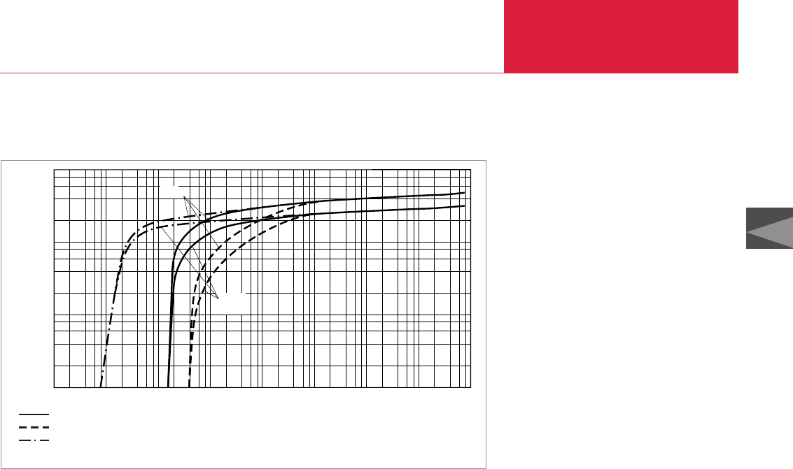
60 Hz Curves Rotary Vane Vacuum Pumps
C01.71
C01
LEYBOLD VACUUM PRODUCTS AND REFERENCE BOOK 2003/2004
Version for the North and South American Continents
Total Pressure with gas ballast
Total Pressure without gas ballast
Partial Pressure without gas ballast
D65B
D40B
10-2
10-3 101
100
10-1 102
Torr 103
10-4
10-5 2 4 6 8
Pressure
10-1
cfm
102
101
100
8
6
4
2
Pumping Speed
Pumping speed characteristics for the TRIVAC D 40 B and D 65 B at 60 Hz

Rotary Vane Vacuum Pumps
C01.72 LEYBOLD VACUUM PRODUCTS AND REFERENCE BOOK 2003/2004
C02
Rotary Vane Vacuum Pumps
single-stage, oil-sealed,
10 - 1200 m3x h-1 (5.9 - 707 cfm)
SOGEVAC

LEYBOLD VACUUM PRODUCTS AND REFERENCE BOOK 2003/2004
Contents
Rotary Vane Vacuum Pumps
C02.02
General
Product Range, Features and Design . . . . . . . . . . . . . . . . . . . . . . . . . . . . . . . . . . . . . . . . . C02.03
Products
Rotary Vane Vacuum Pumps
SOGEVAC SV 10 B/SV 16 B. . . . . . . . . . . . . . . . . . . . . . . . . . . . . . . . . . . . . . . . . . . . . . C02.04
SOGEVAC SV 25 B . . . . . . . . . . . . . . . . . . . . . . . . . . . . . . . . . . . . . . . . . . . . . . . . . . . . C02.06
SOGEVAC SV 40 B/SV 65 B. . . . . . . . . . . . . . . . . . . . . . . . . . . . . . . . . . . . . . . . . . . . . . C02.08
SOGEVAC SV 100 B . . . . . . . . . . . . . . . . . . . . . . . . . . . . . . . . . . . . . . . . . . . . . . . . . . . C02.12
SOGEVAC SV 16/SV 25. . . . . . . . . . . . . . . . . . . . . . . . . . . . . . . . . . . . . . . . . . . . . . . . . C02.16
SOGEVAC SV 40/SV 65/SV 100 . . . . . . . . . . . . . . . . . . . . . . . . . . . . . . . . . . . . . . . . . . C02.18
SOGEVAC SV 200/SV 300 . . . . . . . . . . . . . . . . . . . . . . . . . . . . . . . . . . . . . . . . . . . . . . . C02.22
SOGEVAC SV 500 . . . . . . . . . . . . . . . . . . . . . . . . . . . . . . . . . . . . . . . . . . . . . . . . . . . . . C02.26
SOGEVAC SV 630/SV 630 F/SV 750 . . . . . . . . . . . . . . . . . . . . . . . . . . . . . . . . . . . . . . . C02.28
SOGEVAC SV 1200 . . . . . . . . . . . . . . . . . . . . . . . . . . . . . . . . . . . . . . . . . . . . . . . . . . . . C02.32
Accessories
Dust Filters (Suction Side) . . . . . . . . . . . . . . . . . . . . . . . . . . . . . . . . . . . . . . . . . . . . . . . . . C02.34
SL Condensate Traps . . . . . . . . . . . . . . . . . . . . . . . . . . . . . . . . . . . . . . . . . . . . . . . . . . . . . C02.36
SEP Separators and SEPC Condensers. . . . . . . . . . . . . . . . . . . . . . . . . . . . . . . . . . . . . . . . C02.37
Special Oil Sight Glass. . . . . . . . . . . . . . . . . . . . . . . . . . . . . . . . . . . . . . . . . . . . . . . . . . . . C02.38
Gas Ballast Valve . . . . . . . . . . . . . . . . . . . . . . . . . . . . . . . . . . . . . . . . . . . . . . . . . . . . . . . . C02.38
Thermal Switch . . . . . . . . . . . . . . . . . . . . . . . . . . . . . . . . . . . . . . . . . . . . . . . . . . . . . . . . . C02.38
Ball Valves and Valves . . . . . . . . . . . . . . . . . . . . . . . . . . . . . . . . . . . . . . . . . . . . . . . . . . . . C02.39
Oil Filtering System OF3000. . . . . . . . . . . . . . . . . . . . . . . . . . . . . . . . . . . . . . . . . . . . . . . . C02.40
Other Accessories . . . . . . . . . . . . . . . . . . . . . . . . . . . . . . . . . . . . . . . . . . . . . . . . . . . . . . . C02.41
Mounting Accessories . . . . . . . . . . . . . . . . . . . . . . . . . . . . . . . . . . . . . . . . . . . . . . . . . . . . C02.42
Exhaust Filter Gauge . . . . . . . . . . . . . . . . . . . . . . . . . . . . . . . . . . . . . . . . . . . . . . . . . . . . . C02.42
Bourdon Vacuum Gauges. . . . . . . . . . . . . . . . . . . . . . . . . . . . . . . . . . . . . . . . . . . . . . . . . . C02.43
Connection Fittings
for SOGEVAC SV 16, SV 25 and SV 10 B, SV 16 B, SV 25 B . . . . . . . . . . . . . . . . . . . . . C02.44
for SOGEVAC SV 40, SV 65, SV 100 and SV 40 B, SV 65 B, SV 100 B . . . . . . . . . . . . . . C02.45
for SOGEVAC SV 200, SV 300 . . . . . . . . . . . . . . . . . . . . . . . . . . . . . . . . . . . . . . . . . . . C02.46
for SOGEVAC SV 500, SV 630, SV 630 F, SV 750. . . . . . . . . . . . . . . . . . . . . . . . . . . . . . C02.47
for SOGEVAC SV 1200 . . . . . . . . . . . . . . . . . . . . . . . . . . . . . . . . . . . . . . . . . . . . . . . . . C02.48
Miscellaneous
Central Vacuum Systems . . . . . . . . . . . . . . . . . . . . . . . . . . . . . . . . . . . . . . . . . . . . . . . . . . C02.49
Vacuum Pump Oils . . . . . . . . . . . . . . . . . . . . . . . . . . . . . . . . . . . . . . . . . . . . . . . . . . . . . . C02.55
60 Hz Curves. . . . . . . . . . . . . . . . . . . . . . . . . . . . . . . . . . . . . . . . . . . . . . . . . . . . . . . . . . . C02.59
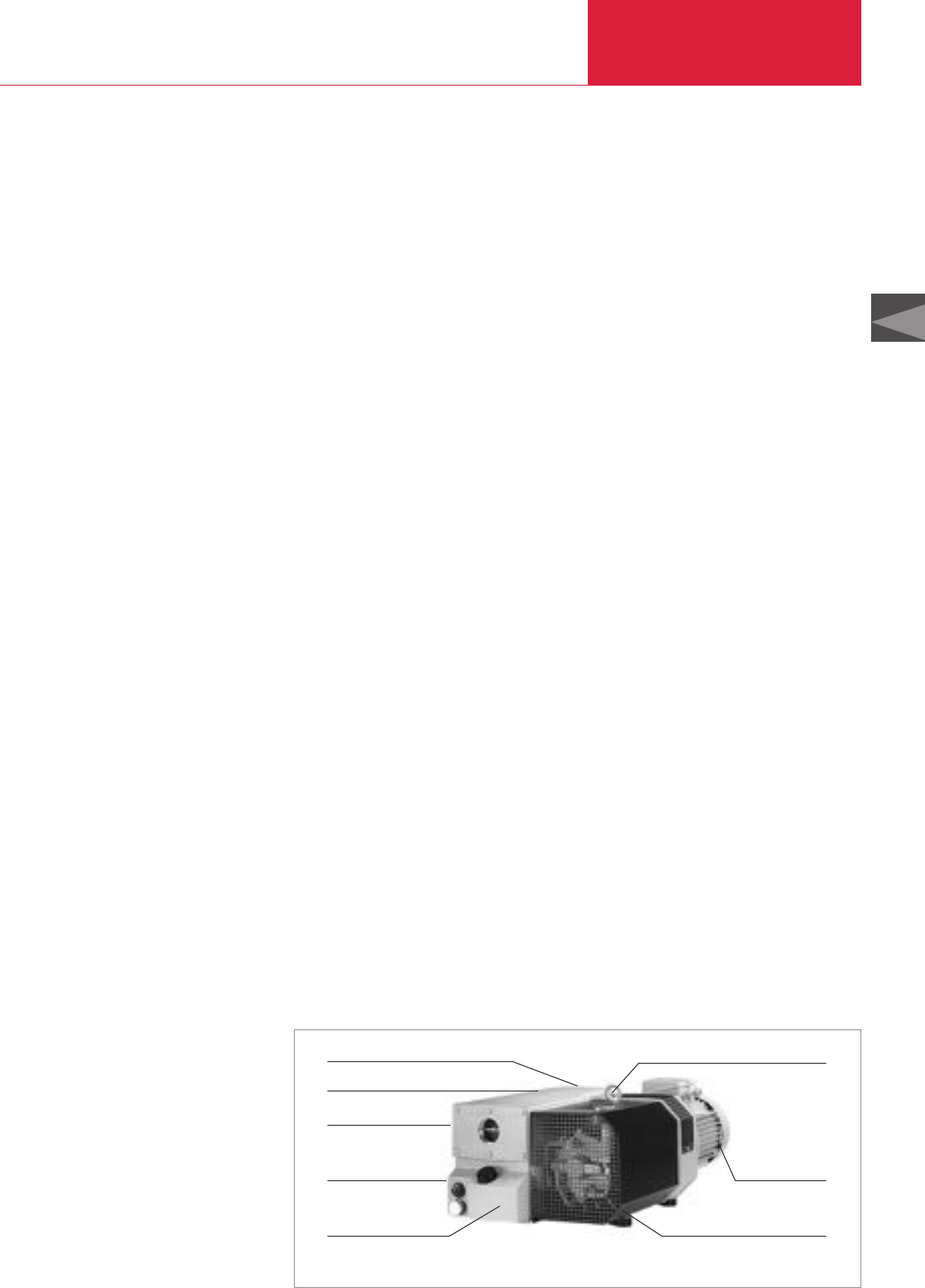
C02
LEYBOLD VACUUM PRODUCTS AND REFERENCE BOOK 2003/2004
General
Rotary Vane Vacuum Pumps
C02.03
Product Range, Features and Design
Oil sealed rotary vane vacuum pumps are being
used in all areas of vacuum engineering. They are
equally suited for both industrial production and
research applications. They may be used to gene-
rate a rough and medium vacuum or as backing
pumps in pump combinations with Roots pumps
or high vacuum pumps. By design, rotary vane
pumps run quietly and do not produce much
noise.
Many years of experience in vacuum engineering
and the latest developments in pump technology
combine in the SOGEVAC range the capability to
adapt to the requirements of both the industry
and the environment. The comprehensive range
(pumping speeds ranging from 16 to
1200 m
3
x h
-1
(9.4 to 707 cfm)) allows every
customer to select the right pump for his parti-
cular needs.
With the new range of compact pumps from 10 to
100 m
3
x h
-1
1 these characteristics are even
more pronounced.
Application Examples
◆Car industry
◆Food industry
◆Furnaces and plants
◆Laser technology
◆Medicinal technology
◆Metallurgy
◆Power engineering, long-distance energy
◆Space simulation
◆Vacuum coating
Advantages to the User
◆Operation from atmospheric pressure to
ultimate pressure
◆High pumping speed also at low pressures
◆Low noise level
◆Low vibrations
◆Integrated exhaust filter, up to 99.9% efficient
◆No oil loss owing to the integrated
oil return line
◆Exhaust gas free of oil mists
◆Efficient air cooling (standard)
◆Water cooling (optional)
◆Low space requirement, easy to install
◆Rugged
◆Maintenance-friendly
◆Compact design
◆For direct fitting to Roots pumps
from SV 100 B or SV 100 up
◆Optimum size-to-performance ratio
◆High water vapor tolerance
◆For use in various applications
◆Wide range of accessories available for adap-
tation to differing problems
Design Principle
SOGEVAC pumps are oil sealed rotary vane
pumps. Oil injected into the pump chamber for
sealing, lubrication and cooling of the pump is
recycled from the pump’s oil reservoir and filte-
red before it is injected. The lubricant system is
rated for continuous operation at high intake
pressures so that the pumps may be used in a
versatile manner in most rough vacuum applicati-
ons (accessories are required for some pumps).
The oil carried with the process gas is roughly
separated in the oil box before the discharged
gas enters the integrated exhaust filters where
the fine oil mist is trapped. The thus filtered oil is
collected in the oil box and then supplied back to
the pump.
This demister system, optimized to suit all opera-
ting conditions of the vacuum pump ensures oil-
mist free exhaust gas (degree of separation over
99.9%) even at high intake pressures and when
pumping vapors.
LEYBOLD rotary vane pumps from the SOGEVAC
series excel through numerous special features:
Compact Design
The pumps have been so designed that efficiency
of the pumps will be high.
Except for the SV 10 B to SV 65 B, the motor is
linked depending on requirements to the pump-
ing section directly via a coupling or via V-belts
as a pedestal motor. All vacuum components like
anti-suckback, exhaust filter with oil return line
needed for a complete vacuum unit as well as the
optimized placement of all controls and monito-
ring components allow for an extremely compact
unit.
Outstanding features of the SOGEVAC pumps
Quiet Operation
SOGEVAC pumps are designed throughout to
keep the noise level as low as possible. This is
ensured by optimized running and sliding speeds
and the selection of low-noise drive motors, as
well as perfected manufacturing techniques using
CNC automatic machines for optimized tolerances
and reproducibility of the individual components.
Anti-Suckback Valve
A valve is built into the intake of the SOGEVAC
pumps. This “anti-suckback valve” is protected
by a metal wire-mesh filter. During standstill of
the pump (for example due to shutting down or a
power failure) this valve closes the intake. This
prevents the pressure from rising in the connect-
ed chamber while the pump is vented at the same
time. Any suck-back of pump oil into the vacuum
system is thus also effectively prevented. This
blocking process operates under all operating
conditions (below 800 mbar (600 Torr)) and even
when the gas ballast valve is open.
Protection of the
Environment
The built-in exhaust filter ensures an oil-mist free
exhaust gas over the entire range of operating
pressures – from atmospheric pressure to ulti-
mate pressure.
Supplied Equipment
All pumps are delivered with the required quantity
of oil: SV 10 B to SV 65 (B) in a separate
canister, whereas the SV 100 (B) to SV 1200
already contain the oil and are thus ready for
operation.
Integrated anti-suckback valve High pumping speed right down to ultimate pressure
Efficient air cooling
Low noise level
Wide range of accessories
Protection of the environment with
integrated exhaust filters
Maintenance friendly
Compact design
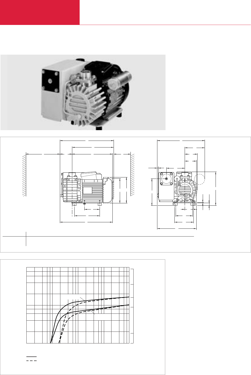
Rotary Vane Vacuum Pumps
C02.04 LEYBOLD VACUUM PRODUCTS AND REFERENCE BOOK 2003/2004
SOGEVAC SV 10 B/SV 16 B
h
l
h1
l1
l2
l3
l4l5
h2
h3h4
h5
l6
l7
l8
b
b1
b2
b3
b4b5
b6
b7
b8
b9
1)
4)
2)
2)
1)
2)
1)
3)
Dimensional drawing for the SOGEVAC SV 10 B and SV 16 B
Pumping Speed
2
4
6
8
102
101
100
CFM
20
10
5
1
50
-1
h
x
3
m
Pressure
10-1 2 4 6 8
100101102103
mbar
SV 16 B
without gas ballast
with gas ballast
SV 10 B
Pumping speed characteristics of the SOGEVAC SV 10 B and SV 16 B at 50 Hz (60 Hz curves at the end of the section)
SOGEVAC SV 16 B
Type b b1b2b3b4b5b6b7b8b9h h1h2h3h4h5l l1l2
SV 10 B/16 B mm 279 117 72 67 7 109 52 100 112 230 142 152 158 4 15 199 200 72 315
in. 10.98 4.61 2.83 2.64 0.28 4.29 2.05 3.94 4.41 9.06 5.59 5.98 6.22 0.16 0.59 7.83 7.87 2.83 12.4
l3l4l5l6l7l8
244 237 100 90 148 309
9.91 9.33 3.94 3.54 5.83 12.17
1) 1 ph. motor
2) 3 ph. motor
3) Space for fitting the exhaust filter
4) Space for the motor’s ventilation

Rotary Vane Vacuum Pumps
C02.05
LEYBOLD VACUUM PRODUCTS AND REFERENCE BOOK 2003/2004
C02
Technical Data SOGEVAC SV 10 B SOGEVAC SV 16 B
50 Hz 60 Hz 50 Hz 60 Hz
Ordering Information
SOGEVAC SV 10 B/SV 16 B 1)
with three-phase motor, with gasballast
230/400 V, 50 Hz und 230/460 V, 60 Hz (CEI)
200 V, 50/60 Hz
with single-phase motor, with gasballast
230 V, 50/60 Hz (CEI)
115 V, 60 Hz
100 V, 50/60 Hz
Other voltages/frequencies 4)
Filling with special oil
Accessories
Spare parts
1) To DIN 28 400 and following numbers
2) Operated at the ultimate pressure without gas ballast, free-field measurement at a distance of 1 m
3) Please indicate when ordering a pump
Technical description see Section “General”
Part No. 960 100 Part No. 960 160
Part No. 960 115 Part No. 960 175
Part No. 960 105 Part No. 960 165
Part No. 960 110 Part No. 960 170
Part No. 960 114 Part No. 960 174
upon request upon request
upon request upon request
upon request
upon request
SOGEVAC SV 10 B SOGEVAC SV 16 B
50 Hz 60 Hz 50 Hz 60 Hz
Nominal speed 1) m3x h-1 (cfm)
Pumping speed 1) m3x h-1 (cfm)
Ultimate partial pressure without gas ballast 1
mbar (Torr)
Ultimate total pressure with gas ballast 1) mbar (Torr)
Water vapor tolerance 1) mbar (Torr)
Water vapor capacity kg x h-1 (qt/hr)
Oil capacity l (qt)
Noise level 2) dB(A)
Admissible ambient temperature °C (°F)
Motor power kW (hp)
Nominal speed min-1 (rpm)
Type of protection IP
Weight (with oil filling) kg (lbs)
Dimensions (W x H x D) mm (in.)
Connections
intake (Inside thread) G
11 (6.5) 13 (7.7) 16 (9.4) 19 (11.2)
9.5 (5.6) 11.5 (6.8) 15 (8.8) 17 (10)
≤1 (≤0.75) ≤1 (≤0.75)
≤2 (≤1.5) ≤2 (≤1.5)
10 (7.5) 15 (11.3) 10 (7.5) 15 (11.3)
20 (21) 30 (32) 30 (32) 50 (53)
0.5 (0.53) 0.5 (0.53)
62 (1f) - 60 (3f) 66 (1f) - 64 (3f) 62 (1f) - 60 (3f) 66 (1f) - 64 (3f)
12 to 40 (54 to 104) 12 to 40 (54 to 104)
0.55 (1) 0.75 (1.5) 0.55 (1) 0.75 (1.5)
3000 (3000) 3000 (3000)
55-F 55-F
20 (41.15) 20.5 (45.25)
315 x 281 x 199 (12.4 x 11.06 x 7.83) 315 x 281 x 199 (12.4 x 11.06 x 7.83)
3/4" + 1/2" 3/4" + 1/2" 3/4" + 1/2" 3/4" + 1/2"
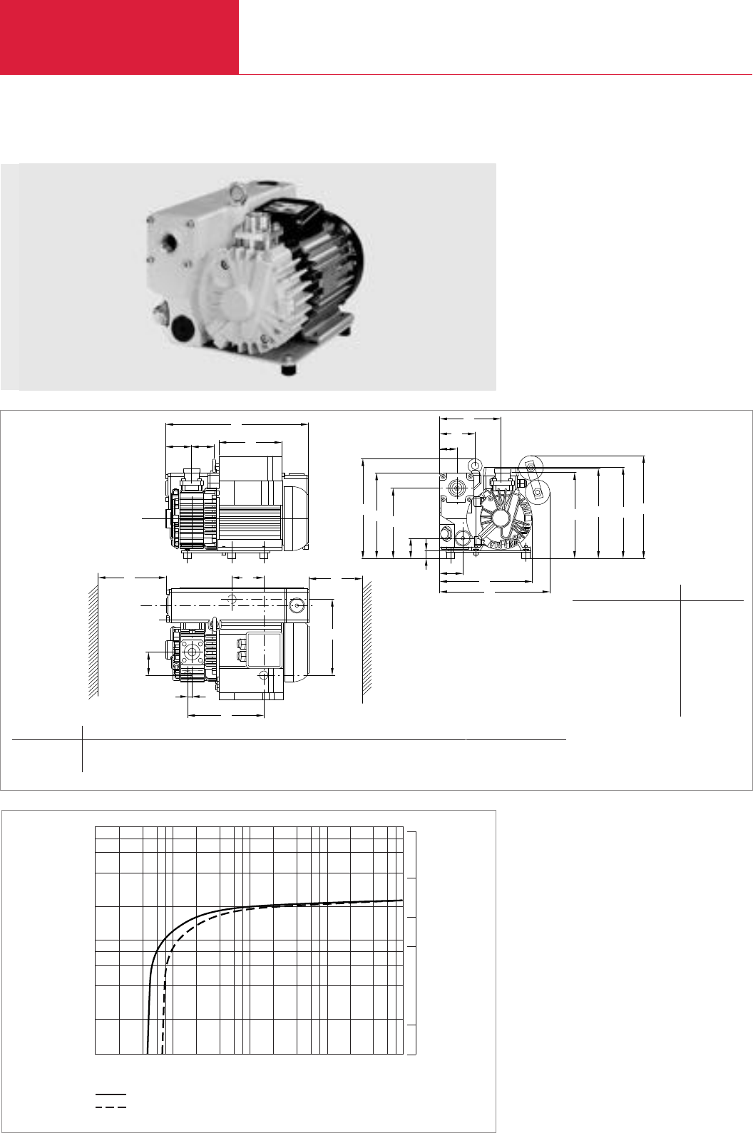
Rotary Vane Vacuum Pumps
C02.06 LEYBOLD VACUUM PRODUCTS AND REFERENCE BOOK 2003/2004
SOGEVAC SV 25 B
Pumping Speed
2
4
6
8
102
101
100
CFM
20
10
5
1
50
-1
h
3
m
Pressure
10-1 2 4 6 8
100101102103
mbar
without gas ballast
with gas ballast
x
Pumping speed characteristics of the SOGEVAC SV 25 B at 50 Hz (60 Hz curves at the end of the section)
SOGEVAC SV 25 B
l2
l1l3
l
b7
l6
l7
l5
b6
h2hh1
b5
b4
b3
b1
h6
h7h5h4
b
h3
h8
l4
l8
b2
))
12
Type b b1b2b3b4b5h h1h2h3h4h5h6h7h8l l1l2l3
SV 25 B mm 1) 231 58 44 89 157 211 173 246 50 2) 3) 211 211 19 280 65 356 56
in. 1) 9.09 2.28 1.73 3.50 6.18 8.31 6.81 9.69 1.97 2) 3) 8.31 8.31 0.75 11.02 2.56 14.02 2.20
l4l5l6l7l8
155 190 80 11 100
6.10 7.48 3.15 0.43 3.94
1), 2), 3) b h4h5
Part No. 960 255 / 256 / 257 275 193 208
10.83 7.6 8.19
Part No. 960 261 275 235 224
10.83 9.25 8.82
Part No. 960 266 275 253 224
10.83 9.96 8.82
Part No. 960 250 / 251 / 252 / 253 231 – 209
9.09 – 8.23
Dimensional drawing for the SOGEVAC SV 25 B
1) Space for fitting the exhaust filter
2) Space for the motor’s ventilation

Rotary Vane Vacuum Pumps
C02.07
LEYBOLD VACUUM PRODUCTS AND REFERENCE BOOK 2003/2004
C02
Technical Data SOGEVAC SV 25 B
50 Hz 60 Hz
Ordering Information
SOGEVAC SV 25 B 1)
with three-phase motor, without gasballast
200-230/400 V, 50 Hz (CEI)
200-230/400-460 V, 60 Hz (CEI)
200-230/400 V, 50 Hz, NPT flanges (CEI)
200-230/400-460 V, 60 Hz, NPT flanges (CEI)
with three-phase motor, with gasballast
200-230/400 V, 50 Hz (CEI)
200-230/400-460 V, 60 Hz (CEI)
200-230/400 V, 50 Hz, NPT flanges (CEI)
200-230/400-460 V, 60 Hz, NPT flanges (CEI)
with single-phase motor, without gasballast
230 V, 50/60 Hz (CEI)
230 V, 50/60 Hz, NPT flanges (CEI)
115 V, 60 Hz
100 V,50/60 Hz
with single-phase motor, with gasballast
230 V, 50/60 Hz (CEI)
230 V, 50/60 Hz, NPT flanges (CEI)
115 V, 60 Hz
100 V,50/60 Hz
Other voltages/frequencies 4)
Filling with special oil
Accessories
Spare parts
1) To DIN 28 400 and following numbers
2) Operated at the ultimate pressure without gas ballast, free-field measurement at a distance of 1 m
3) European and Japanese pumps have BSP, North and South American versions have NPT
4) Please indicate when ordering a pump
Technical description see Section “General”
Part No. 960 250
–
Part No. 960 252
–
Part No. 960 251
–
Part No. 960 253
–
Part No. 960 255
–
–
–
Part No. 960 256
Part No. 960 257
Part No. 960 261
Part No. 960 266
upon request
upon request
upon request
upon request
SOGEVAC SV 25 B
50 Hz 60 Hz
Nominal speed 1) m3x h-1 (cfm)
Pumping speed 1) m3x h-1 (cfm)
Ultimate partial pressure without gas ballast 1)
mbar (Torr)
Ultimate total pressure with gas ballast 1) mbar (Torr)
Water vapor tolerance 1) mbar (Torr)
Water vapor capacity kg x h-1 (qt/hr)
Oil capacity l (qt)
Noise level 2) dB(A)
Admissible ambient temperature °C (°F)
Motor power kW (hp)
Nominal speed min-1 (rpm)
Type of protection IP
Weight (with oil filling) kg (lbs)
Dimensions (W x H x D) mm (in.)
Connections
intake G
exhaust G
26 (15.3) 31 (18.3)
22.5 (13.3) 25 (14.7)
≤0.5 (≤0.4)
≤0.8 (≤0.6)
10 (7.5)
85 (90) 100 (???)
0.5 (0.53)
64 67
12 to 40 (54 to 104)
0.9 (1.2) 1.1 (1.5)
3000 (3000)
55-F
26 (57.4) 27 (59.6)
356 x 275 x 246 (14.02 x 10.83 x 9.69)
3/4" + 1/2"
3/4"
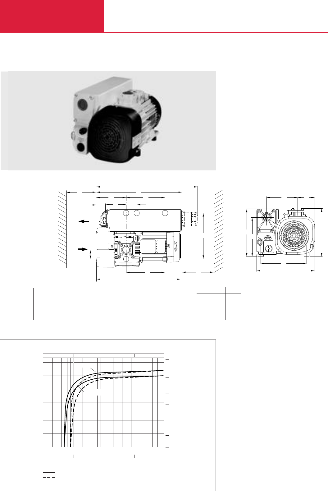
Rotary Vane Vacuum Pumps
C02.08 LEYBOLD VACUUM PRODUCTS AND REFERENCE BOOK 2003/2004
SOGEVAC SV 40 B/SV 65 B
Pumping Speed
2
4
6
8
102
101
100
CFM
20
10
5
1
50
-1
x h
3
m
Pressure
10-1 2 4 6 8
100101102103
mbar
101102103104105
Pa
29.918 29.9 29.530 25.980 0
Inches.Hg
without gas ballast
with gas ballast
SV 40 B
SV 65 B
Pumping speed characteristics of the SOGEVAC SV 40 B and SV 65 B at 50 Hz (60 Hz curves at the end of the section)
SOGEVAC SV 65 B
b4
l
l3
l2
l1l4
h1
b3
b
h
b1b2
h2
l6l7
l8
b3
l5
l9
1
2
)
)
Dimensional drawing for the SOGEVAC SV 40 B and SV 65 B with standard motor, European version
Type b b1b2b3b4h h1h2l l1l2l3l4l5l6l7l8
SV 40 B mm 284 160 74 235 46 255 265 217 350 143 425 510 – 40 1) 150 43
in. 11.2 6.3 2.9 9.25 1.8 10.04 10.43 8.54 13.78 6.63 16.7 20.1 – 1.57 1) 5.91 1.69
SV 65 B mm 320 170 95 254 50 266 264 216 350 166 480 565 215 – 215 150 52
in. 12.6 6.69 3.74 10 1.97 10.47 10.39 8.50 13.78 6.54 18.9 22.2 8.46 – 8.46 5.91 2.05
1) l6
Europe 220
8.66
USA / JPN / TWN 226
8.89
1) Space for fitting the exhaust filter
2) Space for the motor’s ventilation
3) Only SV 65 B

Rotary Vane Vacuum Pumps
C02.09
LEYBOLD VACUUM PRODUCTS AND REFERENCE BOOK 2003/2004
C02
Technical Data SOGEVAC SV 40 B SOGEVAC SV 65 B
50 Hz 60 Hz 50 Hz 60 Hz
Nominal speed 1) m3x h-1 (cfm)
Pumping speed 1) m3x h-1 (cfm)
Ultimate partial pressure without gas ballast 1)
mbar (Torr)
Ultimate total pressure
with standard gasballast 1) mbar (Torr)
with small gasballast 2) mbar (Torr)
Water vapor tolerance
with standard gasballast 1) mbar (Torr)
with small gasballast mbar (Torr)
Water vapor capacity, max.
with standard gasballast kg x h-1 (qt/hr)
with small gasballast kg x h-1 (qt/hr)
Oil capacity l (qt)
Mean noise level 3) dB(A)
Admissible ambient temperature °C (°F)
Motor power kW (hp)
Nominal speed min-1 (rpm)
Type of protection IP
Weight (with oil filling) kg (lbs)
Dimensions (W x H x D)
Eur mm (in.)
USA / JPN / TWN mm (in.)
Connections
intake G
exhaust G
1) To DIN 28 400 and following numbers
2) Ordering Information see Section “Accessories”
3) Operated at the ultimate pressure without gas ballast, free-field measurement at a distance of 1 m
4) IEC-Motor (Europa) 50/60 Hz in IP 55, NEMA-Motor in TEFC
5) European and Japanese pumps have BSP, North and South American versions have NPT
Technical description see Section “General”
44 (25.9) 53 (31.2) 59 (34.8) 71 (41.8)
38.5 (22.7) 47 (27.7) 54 (31.8) 64 (37.7)
≤0.5 (≤0.4) ≤0.5 (≤0.4)
≤1.5 (≤1.1) ≤1.5 (≤1.1)
≤0.8 (≤0.6) ≤0.8 (≤0.6)
30 (22.5) 30 (22.5)
10 (7.5) 10 (7.5)
0.76 (0.80) 0.90 (0.95) 1.0 (1.1) 1.25 (1.32)
0.28 (0.30) 0.34 (0.36) 0.36 (0.38) 0.42 (0.44)
1.0 (1.05) 2.0 (2.1)
60 63 60 64
12 to 40 (54 to 104) 12 to 40 (54 to 104)
1.1 (1.5) 1.5 (2.0) 1.5 (2.0) 1.8 (2.5)
1500 (v) 1800 (1800) 1500 (1500) 1800 (1800)
55-F 55-F
43 (94.9) 45 (99.3) 49 (108.2) 52 (114.8)
425 x 284 x 265 (16.7 x 11.2 x 10.4) 480 x 320 x 264 (18.9 x 12.6 x 10.4)
455 x 284 x 265 (16.7 x 11.2 x 10.4 480 x 320 x 264 (18.9 x 12.6 x 10.4)
1 1/4" 1 1/4" 1 1/4" 1 1/4"
1 1/4" 1 1/4" 1 1/4" 1 1/4"

Rotary Vane Vacuum Pumps
C02.10 LEYBOLD VACUUM PRODUCTS AND REFERENCE BOOK 2003/2004
Ordering Information
SOGEVAC SV 40 B/SV 65 B 1)
with three-phase motor,
without gasballast, without oilfilter
230/400 V, 50 Hz and 460 V, 60 Hz (CEI)
230/460 V, 60 Hz and 400 V, 50 Hz (CEI)
230/400 V, 50/60 Hz (CEI)
200 V, 50/60 Hz
with three-phase motor,
without gasballast, with oilfilter
230/400 V, 50 Hz and 460 V, 60 Hz (CEI)
230/460 V, 60 Hz and 400 V, 50 Hz (CEI)
230/400 V, 50/60 Hz (CEI)
200 V, 50/60 Hz
with three-phase motor,
with small gasballast, without oilfilter
230/400 V, 50 Hz and 460 V, 60 Hz (CEI)
230/460 V, 60 Hz and 400 V, 50 Hz (CEI)
230/400 V, 50/60 Hz (CEI)
200 V, 50/60 Hz
with three-phase motor,
with small gasballast, with oilfilter
230/400 V, 50 Hz and 460 V, 60 Hz (CEI)
230/460 V, 60 Hz and 400 V, 50 Hz (CEI)
230/400 V, 50/60 Hz (CEI)
200 V, 50/60 Hz
with three-phase motor,
with standard gasballast, without oilfilter
230/400 V, 50 Hz and 460 V, 60 Hz (CEI)
230/460 V, 60 Hz and 400 V, 50 Hz (CEI)
230/400 V, 50/60 Hz (CEI)
200 V, 50/60 Hz
with three-phase motor,
with standard gasballast, with oilfilter
230/400 V, 50 Hz and 460 V, 60 Hz (CEI)
230/460 V, 60 Hz and 400 V, 50 Hz (CEI)
230/400 V, 50/60 Hz (CEI)
200 V, 50/60 Hz
Other voltages/frequencies 2)
Filling with special oil 2)
Accessories
Spare parts
1) European and Japanese pumps have BSP, North and South American versions have NPT
2) Please indicate when ordering a pump
Part No. 960 300 Part No. 960 400
– –
– –
–
Part No. 960 302 Part No. 960 402
– –
– –
– –
Part No. 960 301 Part No. 960 401
Part No. 960 311 Part No. 960 411
Part No. 960 321 Part No. 960 421
Part No. 960 316 Part No. 960 416
Part No. 960 303 Part No. 960 403
Part No. 960 313 Part No. 960 413
Part No. 960 323 Part No. 960 423
Part No. 960 316 Part No. 960 418
Part No. 960 305 Part No. 960 405
Part No. 960 312 Part No. 960 412
Part No. 960 322 Part No. 960 422
Part No. 960 317 Part No. 960 417
Part No. 960 307 Part No. 960 407
Part No. 960 314 Part No. 960 414
Part No. 960 324 Part No. 960 424
Part No. 960 319 Part No. 960 419
upon request upon request
upon request upon request
upon request upon request
upon request upon request
SOGEVAC SV 40 B SOGEVAC SV 65 B
50 Hz 60 Hz 50 Hz 60 Hz

Rotary Vane Vacuum Pumps
C02.11
LEYBOLD VACUUM PRODUCTS AND REFERENCE BOOK 2003/2004
C02
Notes
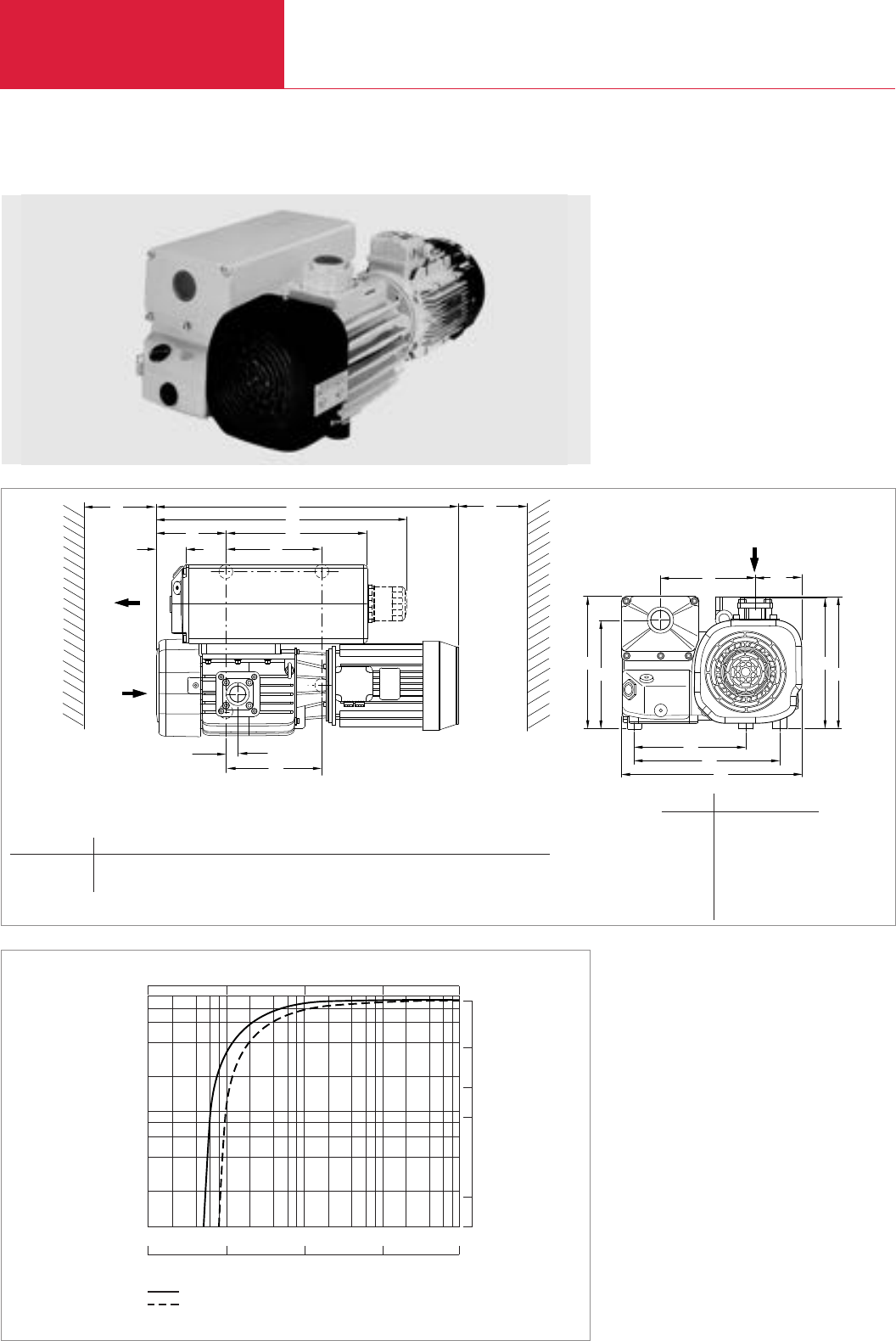
Rotary Vane Vacuum Pumps
C02.12 LEYBOLD VACUUM PRODUCTS AND REFERENCE BOOK 2003/2004
SOGEVAC SV 100 B
SOGEVAC SV 100 B
Pumping Speed
2
4
6
8
102
101
100
CFM
20
10
5
1
50
-1
h
x
3
m
Pressure
10-1 2 4 6 8
100101102103
mbar
101102103104105
Pa
29.918 29.9 29.530 25.980 0
Inches.Hg
without gas ballast
with gas ballast
Pumping speed characteristics of the SOGEVAC SV 100 B at 50 Hz (60 Hz curves at the end of the section)
h1
b1b2
h2
b5
ll2
l3
l1l4
l5l6
l7
l8
l9
b4
b3
h3h4
Dimensional drawing for the SOGEVAC SV 100 B
Type b1b2b3b4b5h1h2h3h4l l1l2l3l4l5l6l7l8l9
SV 100 B mm 209 95 258 320 400 271 220 271 1) 350 160 1) 590 330 53 225 27 225 150
in. 8.23 3.74 10.16 12.60 15.75 10.67 8.66 10.67 1) 13.78 6.30 1) 23.23 12.99 2.09 8.86 1.06 8.86 5.91
1) h4l2
Europe mm 270 695
in. 10.63 27.36
USA mm 290 755
in. 11.42 29.72
JPN / TWN mm 275 715
in. 10.83 28.15
1) Space for fitting the exhaust filter and cooling
2) Space for the motor’s ventilation

Rotary Vane Vacuum Pumps
C02.13
LEYBOLD VACUUM PRODUCTS AND REFERENCE BOOK 2003/2004
C02
Technical Data SOGEVAC SV 100 B
50 Hz 60 Hz
Nominal speed 1) m3x h-1 (cfm)
Pumping speed 1) m3x h-1 (cfm)
Ultimate partial pressure without gas ballast 1)mbar (Torr)
Ultimate total pressure
with standard gasballast 1) mbar (Torr)
with small gasballast 2) mbar (Torr)
Water vapor tolerance
with standard gasballast 1) mbar (Torr)
with small gasballast mbar (Torr)
Water vapor capacity, max.
with standard gasballast kg x h-1 (qt/hr)
with small gasballast kg x h-1 (qt/hr)
Oil capacity l (qt)
Mean noise level 3) dB(A)
Admissible ambient temperature °C (°F)
Motor power kW (hp)
Nominal speed min-1 (rpm)
Type of protection IP
Weight (with oil filling) kg (lbs)
Dimensions (W x H x D)
Eur mm (in.)
USA mm (in.)
JPN / TWN mm (in.)
Connections
intake G
exhaust G
1) To DIN 28 400 and following numbers
2) Ordering Information see Section “Accessories”
3) Operated at the ultimate pressure without gas ballast, free-field measurement at a distance of 1 m
4) IEC-Motor (Europa) 50/60 Hz in IP 55, NEMA-Motor in TEFC
5) European and Japanese pumps have BSP, North and South American versions have NPT
Technical description see Section “General”
97.5 (57.4) 117 (68.9)
87.5 (51.5) 105 (61.8)
≤0.5 (≤0.38)
≤1.5 (≤1)
≤0.8 (≤0.6)
30 (22.5)
15 (11.3)
1.60 (1.69) 1.70 (1.80)
0.45 (0.48) 0.60 (0.63)
2.0 (2.1)
61 64
12 to 40 (54 to 104)
2.2 (3.0) 3.0 (4.0)
1500 (1500) 1800 (1800)
55-F
75 (165.6) 88 (194.3)
695 x 400 x 270 (27.4 x 15.7 x 10.6)
755 x 400 x 290 (29.7 x 15.7 x 11.4)
715 x 400 x 275 (28.1 x 15.7 x 10.8)
1 1/4" 1 1/4"
1 1/4" 1 1/4"

Rotary Vane Vacuum Pumps
C02.14 LEYBOLD VACUUM PRODUCTS AND REFERENCE BOOK 2003/2004
Ordering Information
SOGEVAC SV 100 B 1)
with three-phase motor,
without gasballast, without oilfilter
230/400 V, 50 Hz and 460 V, 60 Hz (CEI)
230/460 V, 60 Hz and 400 V, 50 Hz (NEMA)
230/400 V, 50/60 Hz (CEI)
200 V, 50/60 Hz (JIS)
with three-phase motor,
without gasballast, with oilfilter
230/400 V, 50 Hz and 460 V, 60 Hz (CEI)
230/460 V, 60 Hz and 400 V, 50 Hz (NEMA)
230/400 V, 50/60 Hz (CEI)
200 V, 50/60 Hz (JIS)
with three-phase motor,
with small gasballast, without oilfilter
230/400 V, 50 Hz and 460 V, 60 Hz (CEI)
230/460 V, 60 Hz and 400 V, 50 Hz (NEMA)
230/400 V, 50/60 Hz (CEI)
200 V, 50/60 Hz (JIS)
with three-phase motor,
with small gasballast, with oilfilter
230/400 V, 50 Hz and 460 V, 60 Hz (CEI)
230/460 V, 60 Hz and 400 V, 50 Hz (NEMA)
230/400 V, 50/60 Hz (CEI)
200 V, 50/60 Hz (JIS)
with three-phase motor,
with standard gasballast, without oilfilter
230/400 V, 50 Hz and 460 V, 60 Hz (CEI)
230/460 V, 60 Hz and 400 V, 50 Hz (NEMA)
230/400 V, 50/60 Hz (CEI)
200 V, 50/60 Hz (JIS)
with three-phase motor,
with standard gasballast, with oilfilter
230/400 V, 50 Hz and 460 V, 60 Hz (CEI)
230/460 V, 60 Hz and 400 V, 50 Hz (NEMA)
230/400 V, 50/60 Hz (CEI)
200 V, 50/60 Hz (JIS)
Other voltages/frequencies 2)
Filling with special oil 2)
Accessories
Spare parts
1) European and Japanese pumps have BSP, North and South American versions have NPT
2) Please indicate when ordering a pump
Part No. 960 500
–
–
–
Part No. 960 502
–
–
–
Part No. 960 501
Part No. 960 511
Part No. 960 521
Part No. 960 516
Part No. 960 503
Part No. 960 513
Part No. 960 523
Part No. 960 516
Part No. 960 505
Part No. 960 512
Part No. 960 522
Part No. 960 517
Part No. 960 507
Part No. 960 514
Part No. 960 524
Part No. 960 519
upon request
upon request
upon request
upon request
SOGEVAC SV 100 B
50 Hz 60 Hz

Rotary Vane Vacuum Pumps
C02.15
LEYBOLD VACUUM PRODUCTS AND REFERENCE BOOK 2003/2004
C02
Notes
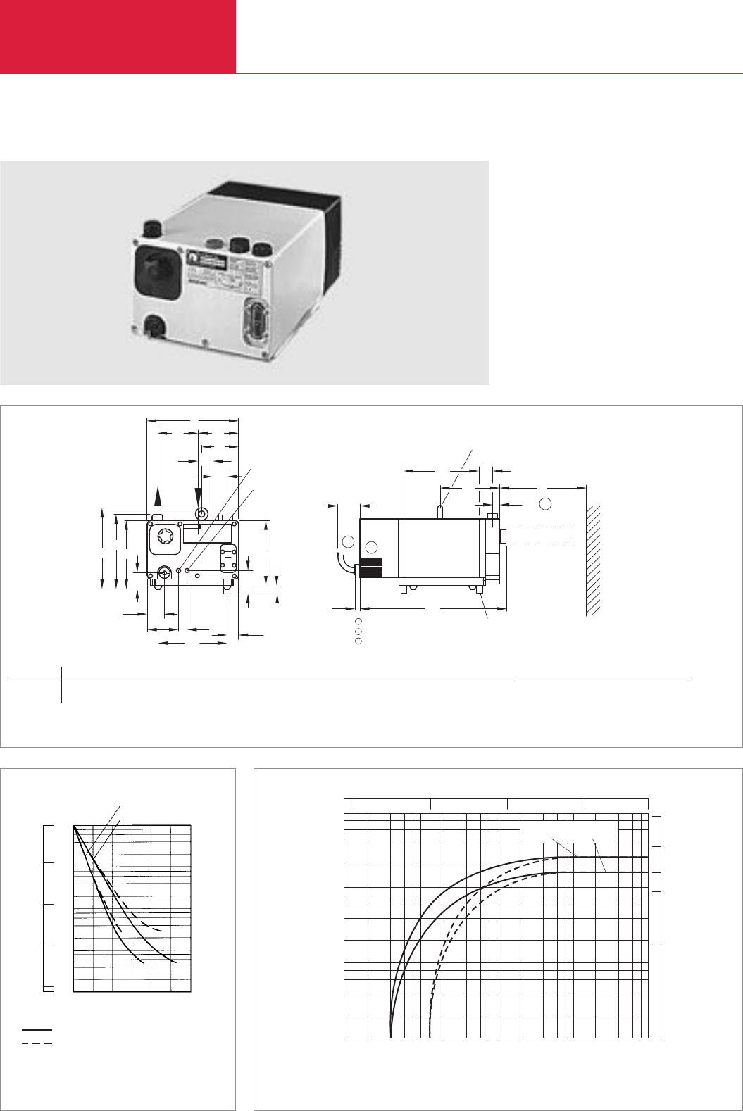
Rotary Vane Vacuum Pumps
C02.16 LEYBOLD VACUUM PRODUCTS AND REFERENCE BOOK 2003/2004
SOGEVAC SV 16/SV 25
SOGEVAC SV 25
ø G 1/2"
ø G 1/2"
Option: 712 34 720
Water cooling
Water supply
Water discharge
Option: 710 42 890
Lifting lug
1
2
3
Ventilation
Electrical connection
Space for fitting the exhaust filter
1
2
3
b1b2
b3
b4
b5
b
h3
h2
h1
b7
b9b8
b6
b10
hh4
h6
h5
a1l
a2
l1l2
l3l4
a
Dimensional drawing for the SOGEVAC SV 16 and SOGEVAC SV 25
750
Torr
100
10-1
1
10
103
102
101
100
10-1
mbar
Time
without gas ballast
with gas ballast
0 5 10 15 20 25 3099,99
99,9
99
90
0
Vacuum
Pressure
SV 25
SV 16
s
2
4
6
8
%
cfm
50
Pressure
Pumping speed
2 4 6 8
2
4
6
8
10-1
100
10-1
100
101102103
101
102
20
10
5
1
SV 25 SV 16
Torr
10
-1
110 100 750
mbar
m
3
x
h
-1
Pump-down characteristics of a 10 l vessel at 50 Hz Pumping speed characteristics of the SOGEVAC SV 16 and SV 25 at 50 Hz (60 Hz curves at the end of the section)
Type SV a a1a2b b1b2b3b4b5b6b7b8b9b10 h h1h2h3h4
16 / 25 mm 250 15 65 263 116 115 105 45 40 198 50 25 90 34 200 49 218 236 192
in. 9.84 0.59 2.56 10.35 4.57 4.53 4.13 1.77 0.46 7.8 1.97 0.98 3.54 1.34 7.87 1.93 8.58 9.29 7.56
h5h6l l1l2l3l4
20 67 422 218 36 170 20
0.79 2.64 16.61 8.58 0.71 6.69 0.79

C02
LEYBOLD VACUUM PRODUCTS AND REFERENCE BOOK 2003/2004
Rotary Vane Vacuum Pumps
C02.17
Rotary Vane Vacuum Pumps
Technical Data SOGEVAC SV 16 SOGEVAC SV 25
50 Hz 60 Hz 50 Hz 60 Hz
Ordering Information
SOGEVAC SV 16/SV 25 3)
with three-phase motor and
integrated gas ballast valve
230/400 V, 50 Hz
208 - 230/460 V, 60 Hz
200 V, 50/60 Hz
with single-phase motor and
integrated gas ballast valve
100 V, 50 Hz
230 V, 50 Hz
115 V, 60 Hz
230 V, 60 Hz
Other voltages/frequencies 4)
Filling with special oil
Accessories
Water cooling kit 4), 5)
Oil level monitor 4), 5)
Exhaust filter gauge, mechanical 4), 5)
Spare parts
Exhaust filter cartridge
Vanes, set of 3 pieces
Set of gaskets NBR (standard)
Set of gaskets FPM
Repair kit complete
Pump module complete
1) To DIN 28 400 and following numbers
2) Operated at the ultimate pressure without gas ballast, free-field measurement at a distance of 1 m
3) European and Japanese pumps have BSP, North and South American versions have NPT
4) Please indicate when ordering a pump
5) Can be retrofitted
Technical description see Section “General”
Part No. 109 01 Part No. 109 03
Part No. 109 80 Part No. 109 90
Part No. 955 01 Part No. 955 03
Part No. 955 30 Part No. 955 32
Part No. 109 00 Part No. 109 02
Part No. 109 81 Part No. 109 91
Part No. 109 82 Part No. 109 92
upon request
upon request
Part No. 712 34 720
Part No. 711 19 108
Part No. 951 91
Part No. 712 32 023
Part No. 712 34 370
Part No. 971 97 152
Part No. 712 30 010
Part No. 712 41 270
Part No. 712 32 230 Part No. 712 32 220
SOGEVAC SV 16 SOGEVAC SV 25
Nominal speed 1) m3x h-1 (cfm)
Pumping speed 1) m3x h-1 (cfm)
Ultimate partial pressure without gas ballast 1)mbar (Torr)
Ultimate total pressure with gas ballast 1) mbar (Torr)
Water vapor tolerance 1) mbar (Torr)
Water vapor capacity kg x h-1 (qt/hr)
Oil capacity l (qt)
Noise level 2) dB(A)
Admissible ambient temperature °C (°F)
Motor power kW (hp)
Nominal speed min-1 (rpm)
Type of protection IP
Weight (with oil filling) kg (lbs)
Dimensions (W x H x D) mm (in.)
Connections
Intake 3) G ((BSP) Inside thread)
Exhaust 3) G ((BSP) Inside thread)
16 (9.4) 19 (11) 25 (14.7) 29 (17)
14.5 (8.5) 17 (10) 22.5 (13.3) 25.5 (15)
<0.5 (≤0.4)
<1.5 (≤1.1)
40 (30)
0.3 (0.32) 0.45 (0.47)
1.8 (2)
56
12 to 40 (54 to 104)
0.55 (1) 0.75 (1.5)
1500 (1500)
23
23 (50.7) 24 (52.9)
422 x 263 x 236 (16.61 x 10.35 x 9.29)
1/2" 1/2"
1/2" 1/2"
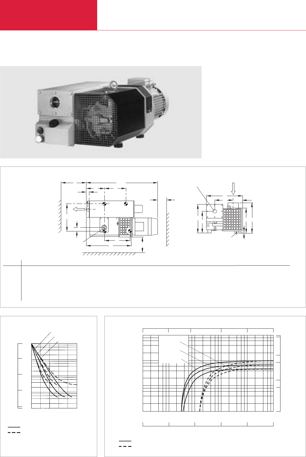
LEYBOLD VACUUM PRODUCTS AND REFERENCE BOOK 2003/2004
Rotary Vane Vacuum Pumps
C02.18
SOGEVAC SV 40/SV 65/SV 100
SOGEVAC SV 100
1
b
2
b
a4
Amax
a23
a
X
1
a
Z
ANSAUGSTUTZEN
ø a
Y
H
2
h
3
b
4
b
B
1
h3
h
PøD
AUSPUFFSTUTZEN
0
a
DRAUFSICHT
ø b
Dimensional drawing for the SOGEVAC SV 40 to SV 100 with standard motor, European version
103
102
101
100
10-1
mbar
Time
0 20 40 60 80 10099,99
99,9
99
90
0
Vacuum
SV 100
SV 65
s
SV 40
750
Torr
100
10-1
1
10
Pressure
without gas ballast
with big gas ballast (option)
%
500
cfm
Inches
x Hg
025.98029.530
1000
29.91829.921
100
10
1
10-1
10-2 10 010 110 210 3
mbar
10 210 310 410 5
10 1
10 0
29.9
10
5
50
100
Pa
SV 40
SV 65
SV 100
Pressure
Pumping speed
m
3
x
h
-1
without gas ballast
with gas ballast
Pumping speed characteristics of the SOGEVAC SV 40 to SV 100 at 50 Hz (60 Hz curves at the end of the section)Pump-down characteristics of a 100 l vessel at 50 Hz
Type la (G) lb (G) Amax (Europe) Amax (USA) a0a1a2a3a4B (Europe) B (USA) b1(Europe) b1(USA) b2b3b4(Europe) b4(USA) l D/P H
SV 40 mm 1 1/4" 1 1/4" 655 660 365 190 167 163 45 300 325 183 198 0 98 145 160 M8/8 260
in. 1 1/4" 1 1/4" 25.79 25.99 14.37 7.48 6.57 6.42 1.77 11.8 12.8 7.20 8.20 0 3.86 5.71 6.30 M8/8 10.24
SV 65 mm 1 1/4" 1 1/4" 695 750 405 230 167 163 45 300 325 183 198 0 98 145 160 M8/8 260
in. 1 1/4" 1 1/4" 27.36 22.56 15.94 9.06 6.57 6.42 1.77 11.8 12.8 7.20 8.20 0 3.86 5.71 6.30 M8/8 10.24
SV 100 mm 1 1/4" 2" 800 810 470 250 285 195 42 440 440 185 185 44 119 219 219 M10/8 280
in. 1 1/4" 2" 31.5 31.9 18.5 9.94 11.22 7.68 1.65 17.32 17.32 7.28 7.28 1.73 4.69 8.62 8.62 M10/8 11
h1h2h3X Y Z
237 216 270 350 100 150
9.3 8.5 10.63 13.78 3.94 5.9
237 216 270 350 100 150
9.3 8.5 10.63 13.78 3.94 5.9
273 220 300 350 100 200
10.75 8.66 11.81 3.78 3.94 7.87
Exhaust port
l b
Inlet port
la
Top view

C02
LEYBOLD VACUUM PRODUCTS AND REFERENCE BOOK 2003/2004
Rotary Vane Vacuum Pumps
C02.19
Technical Data SOGEVAC SV 40 SOGEVAC SV 65 SOGEVAC SV 100
50 Hz 60 Hz 50 Hz 60 Hz 50 Hz 60 Hz
Nominal speed 1) m3x h-1 (cfm)
Pumping speed 1) m3x h-1 (cfm)
Ultimate partial pressure without
gas ballast 1) mbar (Torr)
Ultimate total pressure
with standard gas ballast 1) mbar (Torr)
with big gas ballast (Option) 2) mbar (Torr)
Water vapor tolerance
with standard gas ballast 1) mbar (Torr)
with big gas ballast mbar (Torr)
Water vapor tolerable load
with standard gas ballast kg x h-1 (qt/hr)
with big gas ballast kg x h-1 (qt/hr)
Oil capacity, min. l (qt)
Noise level 3) dB(A)
Admissible ambient temperature °C (°F)
Motor power kW (hp)
Nominal speed min-1 (rpm)
Type of protection IP
Weight (with oil filling) kg (lbs)
Dimensions (W x H x D) mm (in.)
Connection 5)
Intake, thread G (BSP)
Exhaust, thread G (BSP)
1) To DIN 28 400 and following numbers
2) Ordering Information see Section “Accessories”
3) Operated at the ultimate pressure without gas ballast, free-field measurement at a distance of 1 m
4) CEI motor (Europe) 50/60 Hz has IP 55, NEMA motor (North and South America) has TEFC
5) European and Japanese pumps have BSP, North and South American versions have NPT
Technical description see Section “General”
45 (26.5) 55 (32.4) 65 (38.3) 78 (45.9) 100 (58.9) 120 (70.6)
40 (23.6) 48 (28.3) 53 (31.2) 64 (37.7) 94 (55.4) 113 (66.5)
<0.5 (≤0.4) < 0.5 (≤0.4) < 0.5 (≤0.4) < 0.5 (≤0.4) < 0.5 (≤0.4) < 0.5 (≤0.4)
< 1.5 (≤1.1) < 1.5 (≤1.1) < 1.5 (≤1.1) < 1.5 (≤1.1) < 1.5 (≤1.1) < 1.5 (≤1.1)
< 4 (≤3) < 4 (≤3) < 4 (≤3) < 4 (≤3) < 4 (≤3) < 4 (≤3)
15 (11.3) 20 (15) 25 (18.8) 25 (18.8) 25 (18.8) 30 (22.5)
30 (22.5) 40 (30) 50 (37.5) 40 (30) 50 (37.5) 60 (45)
0.3 (0.32) 0.7 (0.73) 1.0 (1.05) 1.2 (1.3) 1.7 (1.8) 2.0 (2.1)
0.6 (0.63) 1.25 (1.3) 2.0 (2.1) 1.9 (2.0) 3.5 (3.7) 4.2 (4.4)
2.0 (2.1) 2.0 (2.1) 2.0 (2.1) 2.0 (2.1) 3.5 (3.7) 3.5 (3.7)
63 68 64 69 70 74
12 - 40 (54 - 104) 12 - 40 (54 - 104) 12 - 40 (54 - 104) 12 - 40 (54 - 104) 12 - 40 (54 - 104) 12 - 40 (54 - 104)
1.1 (1.5) 1.5 (2.0) 1.5 (2.0) 1.8 (2.5) 2.2 (3.0) 3 (4.0)
1450 (1450) 1750 (1750) 1450 (1450) 1750 (1750) 1450 (1450) 1750 (1750)
55 TEFC/55 4) 55 TEFC/55 4) 55 TEFC/55 4)
40 (88.2) 41 (90.4) 46 (101.4) 47 (103.4) 96 (211.2) 97 (213.4)
655 x 300 x 260 655 x 300 x 260 695 x 300 x 260 695 x 300 x 260 800 x 440 x 280 800 x 440 x 280
(25.79x11.81x10.24) (25.79x11.81x10.24) (25.95x11.81x10.24) (25.95x11.81x10.24) (31.50x17.32x11.02) (31.50x17.32x11.02)
1 1/4" 1 1/4" 1 1/4" 1 1/4" 1 1/4" 1 1/4"
1 1/4" 1 1/4" 1 1/4" 1 1/4" 2" 2"

Rotary Vane Vacuum Pumps
C02.20 LEYBOLD VACUUM PRODUCTS AND REFERENCE BOOK 2003/2004
Ordering Information
SOGEVAC SV 40/SV 65/SV 100 1)
with three-phase motor, without gas ballast
230/400 V, 50 Hz and 230/460 V, 60 Hz (CEI)
230/400 V, 50 Hz and 460 V, 60 Hz (CEI)
200 V, 50/60 Hz (JIS)
with three-phase motor and
integrated gas ballast valve
230/400 V, 50 Hz and 230/460 V, 60 Hz (CEI)
230/400 V, 50 Hz and 460 V, 60 Hz (CEI)
208 - 230/460 V, 60 Hz (NEMA) [400 V, 50 Hz]
200 V, 50/60 Hz (JIS)
Other voltages/frequencies 2)
Filling with special oil 2)
Accessories
Adaptor for Roots pump RUVAC 251 or 501 2), 3)
Oil level monitor 2)
Thermal switch 2), 3)
Water cooling kit 2), 3)
Exhaust filter gauge, mechanical 2), 3)
Great gasballast 2), 3)
Gas ballast valve, electromagnetic 24 V DC 2), 3)
Spare parts
Oil filter
Exhaust filter cartridge
Vanes, set of 3 pieces
Set of gaskets NBR (standard)
Set of gaskets FPM
Set of gaskets EPDM
Repair kit complete
Pump module complete
1) European (CEI motor) and Japanese (JIS motor) pumps have BSP, North and South American (NEMA motor) versions have NPT
2) Please indicate when ordering a pump
3) Can be retrofitted
Part No. 109 04 Part No. 109 06 –
– – Part No. 109 10
Part No. 955 04 Part No. 955 06 Part No. 955 10
Part No. 109 05 Part No. 109 07 –
– – Part No. 109 11
Part No. 950 05 Part No. 950 07 Part No. 950 11
Part No. 955 05 Part No. 955 07 Part No. 955 11
upon request
upon request
– – Part No. 953 30
Part No. 711 19 108 Part No. 711 19 108 Part No. 711 19 108
Part No. 711 19 111 Part No. 711 19 111 Part No. 711 19 111
Part No. 711 19 171 Part No. 711 19 171 Part No. 711 19 172
Part No. 951 94 Part No. 951 94 Part No. 951 94
Part No. 951 23 Part No. 951 23 Part No. 951 28
Part No. 196 60 Part No. 196 60 Part No. 951 32
Part No. 712 12 718 Part No. 712 12 718 Part No. 712 13 158
Part No. 710 64 763 Part No. 710 64 763 Part No. 710 64 763
(2 pieces required)
Part No. 714 01 060 Part No. 714 01 070 Part No. 714 01 510
Part No. 971 97 252 Part No. 971 97 252 Part No. 971 97 452
Part No. 714 03 490 Part No. 714 03 490 Part No. 714 03 500
Part No. 714 03 510 Part No. 714 03 510 –
Part No. 714 03 540 Part No. 714 03 550 Part No. 714 03 560
Part No. 710 01 710 Part No. 710 01 730 Part No. 710 01 750
SOGEVAC SV 40 SOGEVAC SV 65 SOGEVAC SV 100
50 Hz 60 Hz 50 Hz 60 Hz 50 Hz 60 Hz

Rotary Vane Vacuum Pumps
C02.21
LEYBOLD VACUUM PRODUCTS AND REFERENCE BOOK 2003/2004
C02
Notes
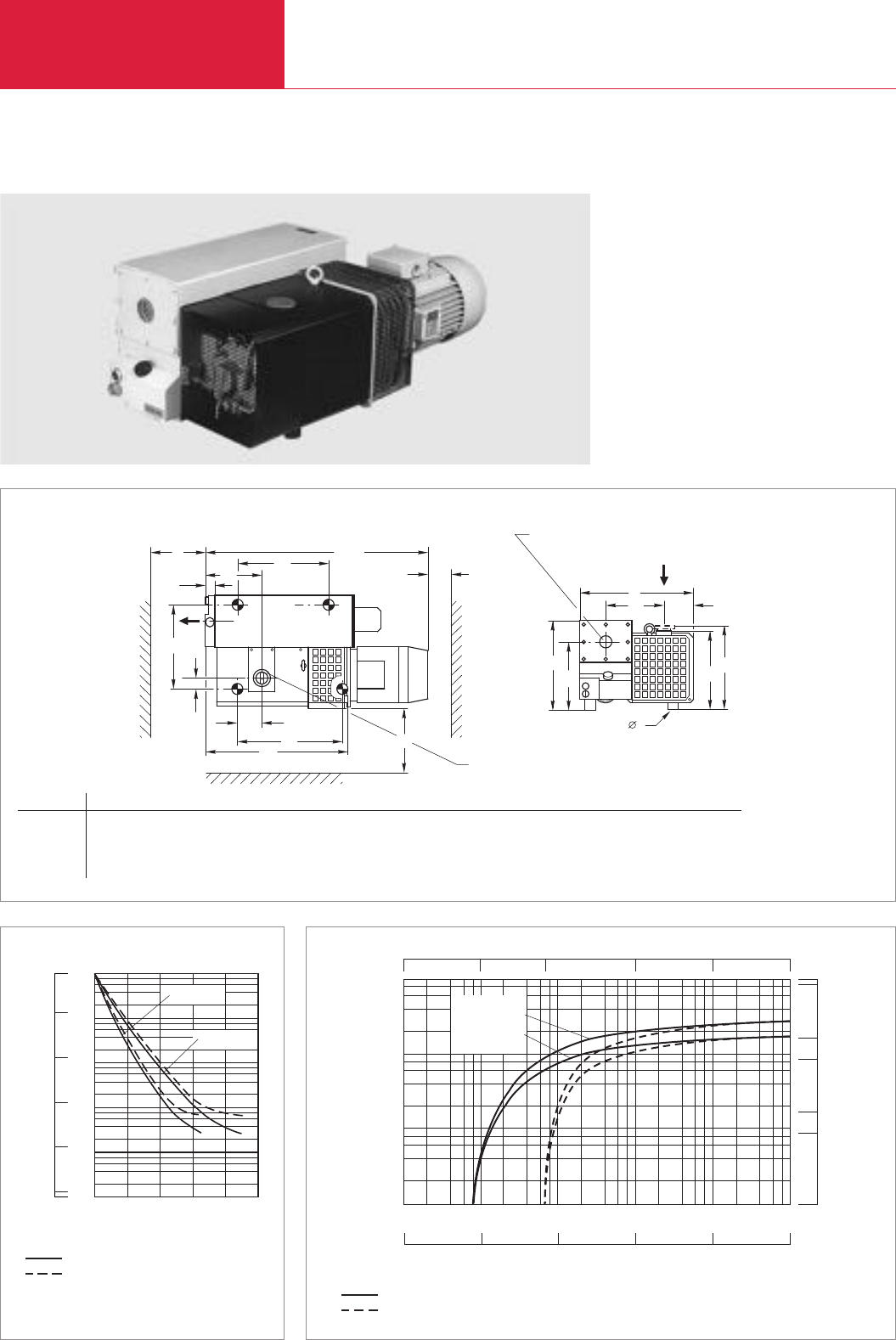
LEYBOLD VACUUM PRODUCTS AND REFERENCE BOOK 2003/2004
Rotary Vane Vacuum Pumps
C02.22
SOGEVAC SV 200/SV 300
SOGEVAC SV 300
B
DRAUFSICHT
H
4
b3
b
1
h2
h
c
3
h
(Option 63 ISO-K)
3
a
Z
1
a
0
a
1
b
2
b
5
b4
a2
a
XAmax.
AUSPUFFSTUTZEN b
ANSAUGSTUTZEN Øa
Y
Dimensional drawing for the SOGEVAC SV 200 and SV 300, European version
without gas ballast
with gas ballast
103
102
101
100
10-1
10-2
mbar
750
Torr
100
10-2
0” 60” 120” 180” 240” 300”
0’ 1’ 2’ 3’ 4’ 5’
10-1
1
10
Pressure
SV 200
SV 300
Time
s
min
500
cfm
Inches
x Hg
025.98029.530
1000
29.91829.921
100
10
1
10-1
10-2 100101102103
mbar
102103104105
101
100
29.9
10
5
50
100
Pa
SV 200
SV 300
Pressure
Pumping speed
m
3
x
h
-1
without gas ballast
with gas ballast
Pumping speed characteristics of the SOGEVAC SV 200 and SV 300 at 50 Hz (60 Hz curves at the end of the section)Pump-down characteristics of a 1000 l vessel at 50 Hz
Type la (G) lb (G) Amax a0a1a2a3a4B b1b2b3b4b5c H h1h2h3
SV 200 mm 2" 2" 940 548 390 252 62 214 535 394 50 140 269 40 M10 415 352 392 318
in. 2" 2" 37.0 21.57 15.35 9.92 2.44 8.43 21.06 15.51 1.97 5.51 10.59 1.57 M10 16.34 13.86 15.43 12.52
SV 300 mm 2" 2" 1080 656 378 313 0 264 535 394 50 140 269 40 M10 415 352 392 318
in. 2" 2" 42.52 25.83 14.88 12.32 0 10.39 21.06 15.51 1.97 5.51 10.59 1.57 M10 16.34 13.86 15.43 12.52
Top view
Exhaust port
lb
Inlet port
la
X Y Z
350 150 300
13.78 5.91 11.81
350 150 300
13.78 5.91 11.81

C02
LEYBOLD VACUUM PRODUCTS AND REFERENCE BOOK 2003/2004
Rotary Vane Vacuum Pumps
C02.23
Technical Data SOGEVAC SV 200 SOGEVAC SV 300
50 Hz 60 Hz 50 Hz 60 Hz
Nominal speed 1) m3x h-1 (cfm)
Pumping speed 1) m3x h-1 (cfm)
Ultimate partial pressure without
gas ballast 1) mbar (Torr)
Ultimate total pressure with gas ballast 1) mbar (Torr)
Water vapor tolerance
with standard gas ballast 1) mbar (Torr)
with big gas ballast 2) mbar (Torr)
Water vapor capacity
with standard gas ballast kg x h-1) (qt/hr)
Oil capacity, min. l (qt)
Noise level 3) dB(A)
Admissible ambient temperature °C (°F)
Motor power kW (hp)
Nominal speed min-1 (rpm)
Type of protection IP
Weight (with oil filling) kg (lbs)
Dimensions (W x H x D)) mm (in.)
Connections 4)
Intake, thread G (BSP)
Exhaust, thread G (BSP)
1) To DIN 28 400 and following numbers
2) Ordering Information see Section “Accessories”
3) Operated at the ultimate pressure without or with gas ballast, free-field measurement at a distance of 1 m
4) European and Japanese pumps have BSP, North and South American versions have NPT
5) CEI motor (Europe) 50/60 Hz has IP 55, NEMA motor (North and South America) has TEFC
Technical description see Section “General”
180 (106) 220 (129.5) 280 (164.9) 340 (200.3)
170 (100.1) 200 (117.8) 240 (141.4) 290 (170.8)
<8 x 10⁻² (≤6 x 10⁻²) < 8 x 10⁻² (≤6 x 10⁻²) < 8 x 10⁻² (≤6 x 10⁻²) < 8 x 10⁻² (≤6 x 10⁻²)
< 0.7 (≤0.5) < 0.7 (≤0.5) < 0.7 (≤0.5) < 0.7 (≤0.5)
30 (22.5) 40 (30) 30 (22.5) 40 (30)
50 (37.5) 50 (37.5) 50 (37.5) 50 (37.5)
3.4 (3.6) 5.4 (5.7) 5.4 (5.7) 7.4 (7.8)
5.0 (5.3) 5.0 (5.3) 8.5 (8.9) 8.5 / 11.5
69 73 70 74
12 to 40 (54 to 104) 12 to 40 (54 to 104) 12 to 40 (54 to 104) 12 to 40 (54 to 104)
4.0 (5.5) 5.5 (7.5) 5.5 (7.5) 7.5 (10.0)
1450 (1450) 1750 (1750) 1450 (1450) 1750 (1750)
55 TEFC/55 5) 55 TEFC/55 5)
140 (308.7) 155 (341.8) 180 (396.9) 195 (430)
940 x 535 x 415 940 x 535 x 415 1080 x 535 x 415 1080 x 535 x 415
(37 x 21.06 x 17.71) (37 x 21.06 x 17.71) (42.51 x 21.06 x 17.71) (42.51 x 21.06 x 17.71)
2" 2" 2" 2"
2" 2" 2" 2"

Rotary Vane Vacuum Pumps
C02.24 LEYBOLD VACUUM PRODUCTS AND REFERENCE BOOK 2003/2004
Ordering Information
SOGEVAC SV 200/SV 300 1)
with three-phase motor, without gas ballast
230/400 V, 50 Hz and 460 V, 60 Hz (CEI)2)
200 V, 50/60 Hz (JIS)
with three-phase motor and
integrated gas ballast valve
230/400 V, 50 Hz and 460 V, 60 Hz (CEI) 2)
208 - 230/460 V, 60 Hz (NEMA) [400 V, 50 Hz] 2)
200 V, 50/60 Hz (JIS)
Other voltages/frequencies 3)
Filling with special oil 3)
Accessories
Adaptor for Roots pump 3), 4)
RUVAC 501 (BR 2)
RUVAC 1001 (BR 2)
Mounting pedestal for fitting to a Roots pump
Oil level monitor 3), 4)
Thermal switch 3), 4)
Exhaust filter gauge, mechanical 3), 4)
Exhaust filter monitoring switch, electric
3)
Great gasballast 3), 4)
Gas ballast valve, electromagnetic 24 V DC 3), 4)
Two gas ballasts 3)
Water cooling with thermostatic valve 3)
Spare parts
Oil filter
Exhaust filter cartridge (4x required)
Vanes, set of 3 pieces
Set of gaskets NBR (standard)
Set of gaskets FPM
Repair kit complete
Pump module complete
1) European and Japanese pumps have BSP, North and South American versions have NPT
2) CEI motor (Europe) 50/60 Hz has IP 54, NEMA motor (North and South America) has TEFC
3) Please indicate when ordering a pump
3) Can be retrofitted
Note: Further pump options upon request (for example, water cooled pumps)
Part No. 109 26 Part No. 109 30
Part No. 955 26 Part No. 955 36
Part No. 109 27 Part No. 109 31
Part No. 950 27 Part No. 950 31
Part No. 955 27 Part No. 955 37
upon request
upon request
Part No. 953 90 Part No. 953 90
Part No. 953 91 Part No. 953 91
Part No. 711 19 209 Part No. 711 19 209
Part No. 953 96 Part No. 953 96
Part No. 951 36 Part No. 951 36
Part No. 951 94 Part No. 951 94
upon request upon request
Part No. 951 30 Part No. 951 30
Part No. 951 31 Part No. 951 31
upon request upon request
upon request upon request
Part No. 710 18 858 Part No. 710 18 858
Part No. 710 64 763 Part No. 710 64 773
Part No. 714 12 000 Part No. 714 12 010
Part No. 971 97 552 Part No. 971 97 652
Part No. 714 36 730 Part No. 714 36 740
Part No. 714 36 190 Part No. 714 36 200
Part No. 714 36 770 Part No. 714 36 780
SOGEVAC SV 200 SOGEVAC SV 300
50 Hz 60 Hz 50 Hz 60 Hz

Rotary Vane Vacuum Pumps
C02.25
LEYBOLD VACUUM PRODUCTS AND REFERENCE BOOK 2003/2004
C02
Notes
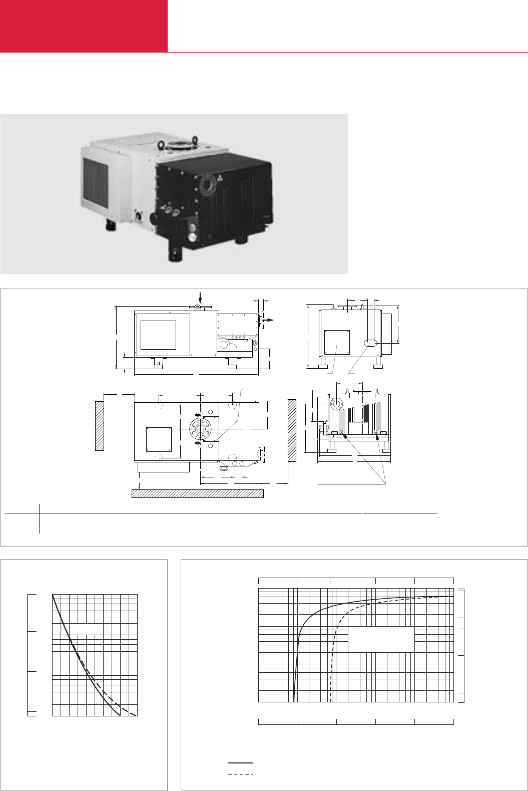
Rotary Vane Vacuum Pumps
C02.26 LEYBOLD VACUUM PRODUCTS AND REFERENCE BOOK 2003/2004
SOGEVAC SV 500
Pressure
Vacuum %
s
Time
mbar
100
101
102
103
020 40 60 80 100
99,9
99
90
0
2
4
6
8
750
Torr
1
10
100 SV 500
500
cfm
Inches
x Hg
025.98029.53029.91829.921
-1
hx
3
m
10-1
10-2 2 4 6 8
100101102103
mbar
102103104105
101
100
29.9
10
5
50
100
Pa
1
100
2
4
6
8
103
102
101
Pressure
without gas ballast
Pumping speed
SV 500
with gas ballast
Pumping speed characteristics of the SOGEVAC SV 500 at 50 Hz (60 Hz curves at the end of the section)Pump-down characteristics of a 1000 l vessel at 50 Hz
SOGEVAC SV 500
GAS BALLAST VALVE
ELECTRICAL BOX WATER CONNECTION
a3Y
Za4a5
b5
b7
b6
a1a2
X
h5
h6
b2
b1
b
h3
h2
b3b4
h4
a6
a
h1
h
OF- 3000
FILTER SYSTEM CONNECTION
Dimensional drawing for the SOGEVAC SV 500
Type a a1a2a3a4a5a6b b1b2b3b4b5b6b7h h1h2h3
SV 500 mm 1543 510 400 722 424 90 63 894 878 315 241 80 353 303 372 780 140 240 800
in. 60.75 20.08 15.75 28.43 16.69 3.54 2.48 35.2 34.57 12.4 9.49 3.15 13.9 11.93 14.65 30.71 5.51 9.45 31.5
h4X Y Z
471 > 500 > 500 > 500
18.54 > 19.69 > 19.69 > 19.69

Rotary Vane Vacuum Pumps
C02.27
LEYBOLD VACUUM PRODUCTS AND REFERENCE BOOK 2003/2004
C02
Nominal speed 1) m3x h-1 (cfm)
Pumping speed 1) m3x h-1 (cfm)
Ultimate partial pressure 1)
without gas ballast mbar (Torr)
Gas ballast Number / base type
Ultimate total pressure
with standard gas ballast mbar (Torr)
Water vapor tolerance
with 1 gas ballast mbar (Torr)
with 2 gas ballast mbar (Torr)
Water vapor capacity
with 1 gas ballast kg x h-1 (qt/hr)
with 2 gas ballast kg x h-1 (qt/hr)
Noise level 2) dB(A)
Motor power
rated rotational speed kW (hp) - min-1
Mains voltage V
Type of protection IP
Pump rated rotational speed min-1 (rpm)
Thermal switch (pump)
Oil type / Capacity l (qt)
Weight (with oil filling) kg (lbs)
Cooling
Connection
Intake DN
Exhaust DN
1) Junction box with six terminals for star/delta circuit
2) Please indicate when ordering a pump
3) Can be retrofitted
4) Option
Note: Further pump options upon request (pump, water cooled, for example)
570 (335.7)
510 (300.4)
< 8 x 10⁻² (≤6x 10⁻²)
1 + (1 option) / manual
<1 (≤0.75)
40 (30)
60 (45)
13 (14)
19.5 (???)
71
11 (15) - 1500
400 ∆(± 10 %)
54 F
880 (880)
yes
GS 77 / 35 (37)
630 (1389)
Air (option: water 4))
100 PN 10 4" ANSI 150 -
& 100 ISO-K 100 ISO-K
l80 4" ANSI 150 -
100 ISO-K
DN 100 PN 10 –
& 100 ISO-K 4)
Technical Data SOGEVAC SV 500
SOGEVAC SV 500 1)
with three-phase motor, integrated
gas ballast valve (manual), air-cooled
and over-temperature switch (pump)
200 V, 50/60 Hz (JIS)
400cV, 50 Hz (+10% -6%) (CEI)
230/460 V, 60 Hz (NEMA) [400 V, 50 Hz]
Other voltages/frequencies 2)
Filling with special oil 2)
Accessories
Adaptor for Roots pump 2), 3)
RUVAC 1001
RUVAC 2001
Oil level monitor 3), 4)
Exhaust filter gauge
mechanical
2), 3)
Exhaust filter monitoring switch
electric
2)
Water cooling with thermostatic valve 2)
Second gas ballast valve 2), 3)
Exhaust DN 100 PN 10 - 100 ISO-K
(Europe only) 2), 3)
Intake flange, DN 100 ISO-K 2), 3)
Side exhaust, DN 100 ISO-K 2), 3)
Spare parts
Oil filter
Exhaust filter cartridge (8x required)
Vanes, set of 3 pieces
Set of gaskets NBR / FPM (standard)
Set of gaskets FPM
Pump module complete
Part No. 956 54
Part No. 956 55
Part No. 956 57
upon request
upon request
Part No. 953 47
Part No. 953 48
Part No. 953 97
Part No. 951 95
upon request
upon request
upon request
Part No. 951 89
standard
Part No. 951 88
Part No. 714 05 318
Part No. 710 64 773
Part No. 714 12 020
Part No. 971 97 701
Part No. 714 05 380
Part No. 714 19 360
Ordering Information SOGEVAC SV 500
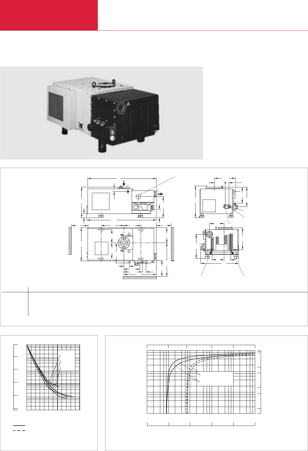
LEYBOLD VACUUM PRODUCTS AND REFERENCE BOOK 2003/2004
Rotary Vane Vacuum Pumps
C02.28
SOGEVAC SV 630/SV 630 F/SV 750
h2
h3
h4
a
h5h6
b11 b12
b10
WASSER AUSLASS
M 22x1,5
a1
OPTION: SEITLICHER AUSPUFF
DN
h9
h
h1
M 16x14
a2a3
XY
b4
b5
Z
a4a5
a6a7
a8
b1
b2b3
bh7
h8
b6
1
DN2
b9
b7b8
WASSER EINLASS
OF- 3000
FILTER SYSTEM CONNECTION
Dimensional drawing for the SOGEVAC SV 630 (F) and SV 750
Type a a1a2a3a4a5a6a7a8b b1b2b3b4b5b6b7b8b9
SV 630/750 mm 1606 – 510 400 – – 424 90 785 880 303 372 – 353 >900 315 255 173 878
in. 63.23 – 20.08 15.75 – – 16.69 3.54 30.91 34.65 11.93 14.65 – 13.9 35.43 12.4 10.04 6.81 34.57
SV 630 F mm 1601 1614 510 400 120 369 424 90 785 774 303 372 462 353 >900 315 255 173 878
in. 63.03 63.54 20.08 15.75 4.72 14.53 16.69 3.54 30.91 30.47 11.93 14.65 18.19 13.9 35.43 12.4 10.04 6.81 34.57
SOGEVAC SV 630
b10 b11 b12 h h1h2h3h4h5h6h7h8X Y Z
– 241 80 780 140 240 – 800 392 471 605 530 >500 >500 >500
– 9.49 3.15 30.71 5.51 9.45 – 31.5 15.43 18.54 23.82 20.87 >19.69 >19.69 >19.69
460 242 80 638 40 140 447 698 351 429 505 488 >500 >500 >500
18.11 9.53 3.15 25.12 1.58 5.51 17.6 27.48 13.82 16.89 19.88 19.21 >19.69 >19.69 >19.69
100
101
103
102
10-1
10-2
mbar
120
Time s
0 10020 40 60 80
0
%
Vacuum
99,999
99,99
99,9
99
90
SV 630
SV 630 F
SV 750
without gas ballast
with gas ballast
750
Torr
100
10
-2
10
-1
1
10
Pressure
Pump-down characteristics of a 1000 l vessel at 50 Hz
500
cfm
Inches
x Hg
025.98029.53029.91829.921
-1
h
.
3
m
10-1
10-2 100101102103
mbar
102103104105
101
100
29.9
10
5
50
100
Pa
1
100
103
102
101
Pressure
Pumping speed
SV 750
SV 630 (F)
Pumping speed characteristics of the SOGEVAC SV 630 (F) and SV 750 at 50 Hz (60 Hz curves at the end of the section)
Water discharge
Water supply
Lateral exhaust (optional)

C02
LEYBOLD VACUUM PRODUCTS AND REFERENCE BOOK 2003/2004
Rotary Vane Vacuum Pumps
C02.29
Technical Data
SOGEVAC SV 630 SOGEVAC SV 630 F SOGEVAC SV 750
50 Hz 60 Hz 50 Hz 60 Hz 50 Hz
Nominal speed 1) m3x h-1 (cfm)
Pumping speed 1) m3x h-1 (cfm)
Ultimate partial pressure without
gas ballast 1) mbar (Torr)
Ultimate total pressure
with standard gas ballast 1) mbar (Torr)
Gas ballast Number/ Type
Water vapor tolerance
with 1 gas ballast mbar (Torr)
with 2 gas ballasts mbar (Torr)
Water vapor capacity
with 1 gas ballast kg x h-1) (qt/hr)
with 2 gas ballasts kg x h-1) (qt/hr)
Oil capacity min. l (qt)
Noise level 2) dB(A)
Admissible ambient temperature °C (°F)
Motor power kW (hp)
Nominal motor speed / Pump speed min-1 (rpm)
Type of protection IP
Cooling
Weight (with oil filling) kg (lbs)
Dimensions (W x H x D) mm (in.)
Connection
Intake (EUROPE/USA) DN1
Exhaust (EUROPE/USA) DN2
1) To DIN 28 400 and following numbers
2) Operated at the ultimate pressure without gas ballast, free-field measurement at a distance of 1 m
3) CEI motor (Europe) 50/60 Hz has IP 54, NEMA motor (North and South America) has TEFC
4) Option
Technical description see Section “General”
700 (412.3) 840 (494.8) 700 (412.3) 840 (494.8) 840 (494.8)
640 (377) 755 (444.7) 640 (377) 755 (444.7) 755 (444.7)
< 8 x 10⁻² (< 6 x 10⁻²) < 8 x 10⁻² (< 6 x 10⁻²) < 8 x 10⁻² (< 6 x 10⁻²)
≤0.7 (≤0.53) ≤0.7 (≤0.53) ≤0.7 (≤0.53)
1 (+1 option) / manual 1 (+1 option) / EM 24 VDC 1 (+1 option) / manual
40 (30) 50 (37.5) 25 (18.8) 30 (22.5) 50 (22.5)
60 (45) 70 (52.5) 35 (26.3) 40 (30) 70 (30)
17 (18) 24 (25) 11 (12) 14 (15) 24 (25)
26 (27) 34 (35) 15 (16) 19 (20) 34 (35)
35 (37) 35 (37) 35 (37)
≤75 ≤78 ≤75 ≤78 ≤78
12 to 40 (54 to 104) 12 to 40 (54 to 104) 12 to 40 (54 to 104) 12 to 40 (54 to 104) 12 to 40 (54 to 104)
15 (20) 18.5 (25) 15 (20) 18.5 (25) 18.5 (25)
1500 / 990 (1500 / 990) 1800/1170 (1800/1170) 1500 / 990 (1500 / 990) 1800/1170 (1800/1170) 1500 / 1170 (1500 / 990)
54 - F 54 - F/TEFC 3) 54 - F 54 - F/TEFC 3) 54 - F
air (water)
4)
water (+ thermostatic valve) air (water)
4)
630 (1389) 630 (1389) 630 (1389)
1606 x 880 x 800 1601 x 878 x 698 1606 x 880 x 800
(63.23 x 34.64 x 31.49) (63.03 x 34.56 x 27.48) (63.23 x 34.64 x 31.49)
100 ISO-K + 100 PN 10 / 100 ISO-K + 4" ASA 150 160 DIN 100 ISO-K + 100 PN 10
l80 (100 ISO-K 3), 4)) / 100 ISO-K + 4" ASA 150 100 ISO-K l80 (100 ISO-K 4))

Rotary Vane Vacuum Pumps
C02.30 LEYBOLD VACUUM PRODUCTS AND REFERENCE BOOK 2003/2004
Ordering Information
SOGEVAC SV 630 1)
with three-phase motor,
integrated gas ballast valve (manual),
air-cooled and over-temperature switch (pump)
200 V, 50/60 Hz (JIS)
400cV, 50 Hz (+10% -6%) and
460 V, 60 Hz (±10%) (CEI)
230/460 V, 60 Hz (NEMA) [400 V, 50 Hz]
SOGEVAC SV 630 F 1)
with three-phase motor,
integrated gas ballast valve (EM 24 V DC),
controlled anti-suckback valve (EM 24 V DC),
water-cooled and over-temperature switch
(pump and motor)
200 V, 50/60 Hz (JIS)
400cV, 50 Hz (+10% -6%) and
460 V, 60 Hz (±10%) (CEI)
230/460 V, 60 Hz (NEMA) [400 V, 50 Hz]
SOGEVAC SV 750 1)
with three-phase motor,
integrated gas ballast valve (manual),
air-cooled and over-temperature switch (pump)
400cV, 50 Hz (±10%) (CEI)
Other voltages/frequencies 2)
Filling with special oil 2)
Accessories
Adaptor for Roots pump 2), 3)
RUVAC 1001
RUVAC 2001
Oil level monitor 2), 3
Exhaust filter gauge, mechanical 2), 3
Exhaust filter monitoring switch, electric
2)
Second gas ballast valve 2), 3)
Water cooling with thermostatic valve 2)
Exhaust DN 100 PN 10 - 100 ISO-K (Europe only) 2), 3
Intake flange, DN 100 ISO-K 2), 3
Lateral exhaust, DN 100 ISO-K 2), 3
Spare parts
Oil filter
Exhaust filter cartridge (10x required)
Vanes, set of 3 pieces
Set of gaskets NBR / FPM (standard)
Set of gaskets FPM
Repair kit complete
Pump module complete
1)
Junction box with 6 terminals for star/delta circuit – SV 750 works only at 50 Hz
2) Please indicate when ordering a pump 3) Can be retrofitted
Note: Further pump options upon request (for example, water cooled pumps)
Part No. 956 62 – –
Part No. 956 63 – –
Part No. 956 65 – –
–Part No. 956 66 –
–Part No. 956 67 –
–Part No. 956 69 –
– – Part No. 956 75
upon request upon request upon request
upon request upon request upon request
Part No. 953 47 Part No. 953 47 Part No. 953 47
Part No. 953 48 Standard Part No. 953 48
Part No. 953 97 Part No. 953 97 Part No. 953 97
Part No. 951 95 Part No. 951 95 Part No. 951 95
upon request upon request upon request
upon request upon request upon request
upon request Standard upon request
Part No. 951 89 Standard Part No. 951 89
Standard Part No. 714 03 480 Standard
Part No. 951 88
Part No. 714 05 318
Part No. 710 64 773
Part No. 714 12 020
Part No. 971 97 701
Part No. 714 05 380
Part No. 714 05 390 Part No. 714 05 390 Part No. 714 18 560
Part No. 714 08 510
SOGEVAC SV 630 SOGEVAC SV 630 F SOGEVAC SV 750
50 Hz 60 Hz 50 Hz 60 Hz 50 Hz

Rotary Vane Vacuum Pumps
C02.31
LEYBOLD VACUUM PRODUCTS AND REFERENCE BOOK 2003/2004
C02
Notes
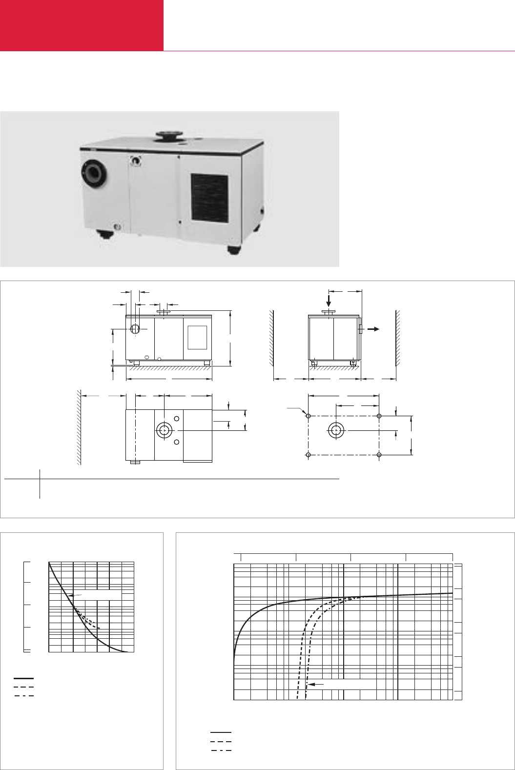
LEYBOLD VACUUM PRODUCTS AND REFERENCE BOOK 2003/2004
Rotary Vane Vacuum Pumps
C02.32
SOGEVAC SV 1200
DN 125
DN 160 ISO-K
h
h
l
l1
l3l4l5
l6
b1 1)
ød
h1
b2
b3b4b5
b6
b
b1 1)
l2 2)
Dimensional drawing for the SOGEVAC SV 1200
1) Clearance for cooling air 2) Clearance for filter exchange
0
90
99
99,9
99,99
Vacuum
%
mbar
2
8
103
6
4
Time
0
10-1
100
101
102
s
10 20 30 40 50 70
SV 1200
without gas ballast
with 1 gas ballast
with 2 gas ballasts
750
Torr
100
10
-1
1
10
Pressure
mbar
2100
Pumping speed
4 8
100
6
101
102
103
104
10-1 101102103
Pressure
8
4
2
6
SV 1200
without gas ballast
with 1 gas ballast
with 2 gas ballasts
m
3
x
h
-1
10
-1
110 100 750
Torr
500
100
50
10
5
1
1000
5000
cfm
Pumping speed characteristics of the SOGEVAC SV 1200 at 50 Hz (60 Hz curves at the end of the section)Pump-down characteristics of a 1000 l vessel at 50 Hz
SOGEVAC SV 1200
Type b b1b2b3b4b5b6ld h h1h2l l1l2l3l4l5l6
SV 1200 mm 640 600 1021 180 380 268 740 100 660 1010 40 185 1638 500 548 915 1345 823
in. 25.20 23.62 40.20 7.09 14.96 10.55 29.13 3.94 25.98 39.76 1.57 7.28 64.49 19.69 21.57 36.02 52.95 32.40

C02
LEYBOLD VACUUM PRODUCTS AND REFERENCE BOOK 2003/2004
Rotary Vane Vacuum Pumps
C02.33
Nominal speed 1) m3x h-1 (cfm)
Pumping speed 1) m3x h-1 (cfm)
Ultimate partial pressure without
gas ballast 1) mbar (Torr)
Ultimate total pressure
with 1 standard gas ballast 1) mbar (Torr)
with 2 gas ballasts 2) mbar (Torr)
Water vapor tolerance
with 1 gas ballast mbar (Torr)
with 2 gas ballasts mbar (Torr)
Water vapor capacity
with 1 gas ballast kg x h-1 (qt/hr)
with 2 gas ballasts kg x h-1 (qt/hr)
Oil capacity min. l (qt)
Noise level 3) dB(A)
Admissible ambient temperature °C (°F)
Motor power kW (hp)
Nominal motor speed / Pump speed
min-1 (rpm)
Type of protection IP
Weight (with oil filling) kg (lbs)
Dimensions (W x H x D) mm (in.)
Connection
Intake DN
Exhaust DN
Option 6) DN
1) To DIN 28 400 and following numbers
2) With 2 gas ballasts
3) Operated at the ultimate pressure without gas ballast,
free-field measurement at a distance of 1 m
4) Junction box with 6 terminals for star/delta circuit
5) NEMA (for North and South American versions)
6) Please indicate when ordering a pump
7) CEI motor (Europe) 50/60 Hz has IP 54, NEMA motor (North and South America) has TEFC
8) Can be retrofitted
Technical description see Section “General”
1150 (677)
1070 (630)
<0.1 (≤0.08)
< 1.5 (≤1.1)
< 2.0 (≤1.5)
20 (15)
40 (30)
12.5 (13)
25 (26)
60 (63)
75 78
12 to 40 (54 to 104)
22 (30)
1460/700 (1460/700) 1750/700 (1750/700)
54 54-F TEFC 7)
1370 (3021)
1660 x 1005 x 1050
(65.35 x 39.57 x 41.34)
125 PN 10 ANSI 150 - 6" 5)
160 ISO-K ANSI 150 - 6" 5)
125 PN 10 –
Technical Data SOGEVAC SV 1200
50 Hz 60 Hz
SOGEVAC SV 1200
with three-phase motor,
integrated gas ballast valves,
air-cooled and over-temperature switch
400cV, 50 Hz (CEI) 4)
208 - 230/460 V, 60 Hz (NEMA) 5)
Other voltages/frequencies 6)
Filling with special oil 6)
Accessories
Water cooling with thermostatic valve 2)
Adaptor for Roots pump 6), 8)
RUVAC 2001
RUVAC 3001
Oil level monitor 6), 8)
Exhaust filter monitoring switch
electric
6)
Spare parts
Oil filter
Exhaust filter cartridge (14x required)
Vanes, set of 3 pieces
Set of gaskets NBR (standard)
Set of gaskets FPM
Repair kit complete (50 Hz)
Pump module complete (50 Hz)
Part No. 109 70
Part No. 950 70
upon request
upon request
upon request
Part No. 953 37
Part No. 953 38
Part No. 953 99
upon request
Part No. 712 14 598
Part No. 710 64 773
Part No. 712 14 310
Part No. 971 96 681
Part No. 712 36 060
Part No. 712 34 800
Part No. 712 26 820
Ordering Information SOGEVAC SV 1200
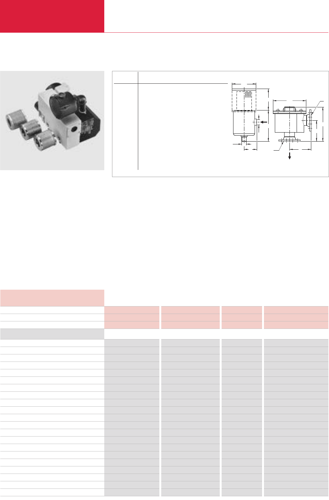
LEYBOLD VACUUM PRODUCTS AND REFERENCE BOOK 2003/2004
Rotary Vane Vacuum Pumps
Accessories
C02.34
Dust Filters (Suction Side)
The filters consist of a steel housing and a lid
with three quick locking clips
Advantages to the User
◆Same housing for different cartridges
◆High separation capacity
◆Quickly exchangeable cartridge
Paper Filter Cartridge
(Standard)
◆Separates particles down to 1 µm
(Dry process: dust, powers, chips etc.)
øA
øB
CC
øE
C
D
D
F
øE
øB
øA
Dimensional drawing for the dust filters F 16-25 to F 1200
Polyester Filter Cartridge
◆Separation of particles down to 3 µm
(Moist process: dust, powers, chips etc.)
Metal Filter Cartridge
◆0.08 mm mesh
◆Collects solid particles down to 0.08 mm (pla-
stics, paper, packaging materials, food stuffs)
Activated Charcoal Cartridge
◆Absorbs vapors of high molecular weight
(solvent and acid vapors, alkaline solutions
etc.)
Technical Notes
We recommend installing the filters horizontally
on a 90° bend. This will prevent separated par-
ticles from falling into the intake line when disas-
sembling the filter.
When using an activated charcoal filter it is
recommended to also install a paper cartridge fil-
ter between the pump and the activated charcoal.
SOGEVAC SV 40 with connected F 40 dust filter
and different types of filter cartridges
Dust Filter Paper cartridge Polyester Filter Cartridge Metal cartridge Activated charcoal cartridge
Throttling of pumping speed through a clean filter 2 % 2 % 1 % 2 %
Efficiency for 1 µm particles 98 % 98 % – –
Dust Filter
Paper cartridge Polyester-Filterpatrone Metal cartridge Activated charcoal cartridge
F 16-25 for SV 16, SV 25 (G 1/2") Part No. 951 50 Part No. 711 27 094 Part No. 711 27 093 Part No. 711 27 092
Spare cartridge for F 16-25 Part No. 710 40 762 Part No. 710 40 762 Part No. 710 65 813 Part No. 710 65 713
F 40 for SV 40 (G 1 1/4") Part No. 951 55 Part No. 711 27 104 Part No. 711 27 103 Part No. 711 27 102
Spare cartridge for F 40 Part No. 710 46 118 Part No. 710 46 118 Part No. 710 49 083 Part No. 710 49 103
F 65-100 for SV 65, SV 100 (G 1 1/4") Part No. 951 60 Part No. 711 27 114 Part No. 711 27 113 Part No. 711 27 112
Spare cartridge for F 65-100 Part No. 712 13 283 Part No. 712 13 283 Part No. 712 13 324 Part No. 712 13 304
F 200-300 for SV 200, SV 300 (G 2") Part No. 951 65 Part No. 711 27 124 Part No. 711 27 123 Part No. 711 27 122
F 200-300 for SV 200, SV 300 (63 ISO-K) Part No. 951 68 — Part No. 711 27 126 Part No. 711 27 125
Spare cartridge for F 200-300 (G 2" or 63 ISO-K) Part No. 712 13 293 Part No. 712 13 293 Part No. 712 13 334 Part No. 712 13 314
F 630 for SV 630 (F), SV 750 (DN 100 PN 10) Part No. 951 71 Part No. 711 27 164 Part No. 711 27 163 Part No. 711 27 162
F 630 for SV 630 (F), SV 750 (100 ISO-K) Part No. 951 72 — Part No. 711 27 167 Part No. 711 27 166
Spare cartridge for F 630 (DN 100 PN or 100 ISO-K) Part No. 710 35 242 Part No. 712 61 508 Part No. 710 37 734 Part No. 710 37 724
F 1200 for SV 1200 (DN 125 PN 10) Part No. 951 75 Part No. 711 27 144 Part No. 711 27 143 Part No. 711 27 142
Spare cartridge for F 1200 (2 are required) Part No. 710 35 242 Part No. 712 61 508 Part No. 710 37 734 Part No. 710 37 724
Spare parts
Set of gaskets for F 16-25 NBR Part No. 714 10 820 Part No. 714 10 820 Part No. 714 10 820 Part No. 714 10 820
Set of gaskets for F 40 NBR Part No. 714 10 830 Part No. 714 10 830 Part No. 714 10 830 Part No. 714 10 830
Set of gaskets for F 65-100 NBR Part No. 714 10 840 Part No. 714 10 840 Part No. 714 10 840 Part No. 714 10 840
Set of gaskets for F 200-300 NBR Part No. 714 10 850 Part No. 714 10 850 Part No. 714 10 850 Part No. 714 10 850
O-ring gasket for F 630 / F 1200 NBR Part No. 712 41 032 Part No. 712 41 032 Part No. 712 41 032 Part No. 712 41 032
Ordering Information
Technical Data
Typ lAlB C D lE F Weight
(kg/lbs)
F 16-25 mm G 1/2" G 1/2" 54 104 100 70 1
in. G 1/2" G 1/2" 2.13 4.09 3.94 2.76 2.2
F 40 mm G 1 1/4" G 1 1/4" 74 115 135 75 1.5
in. G 1 1/4" G 1 1/4" 2.91 4.53 5.31 2.95 3.31
F 65-100 mm G 1 1/4" G 1 1/4" 98 172 172 130 2
in. G 1 1/4" G 1 1/4" 3.86 6.77 6.77 5.12 4.4
F 200-300 mm G 2" G 2" 118 287 200 230 4.5
in. G 2" G 2" 4.65 11.3 7.87 9.06 9.9
F 200-300 mm 63 ISO-K 63 ISO-K 160 357 258 250 15
in. 63 ISO-K 63 ISO-K 6.3 14.06 10.16 9.84 33.1
F 630 mm DN 100 PN 10 DN 100 PN 10 220 358 340 250 33
in. DN 100 PN 10 DN 100 PN 10 8.66 14.09 13.39 9.84 72.8
F 630 mm 100 ISO-K 100 ISO-K 220 358 340 250 32
in. 100 ISO-K 100 ISO-K 8.66 14.09 13.39 9.84 70.6F
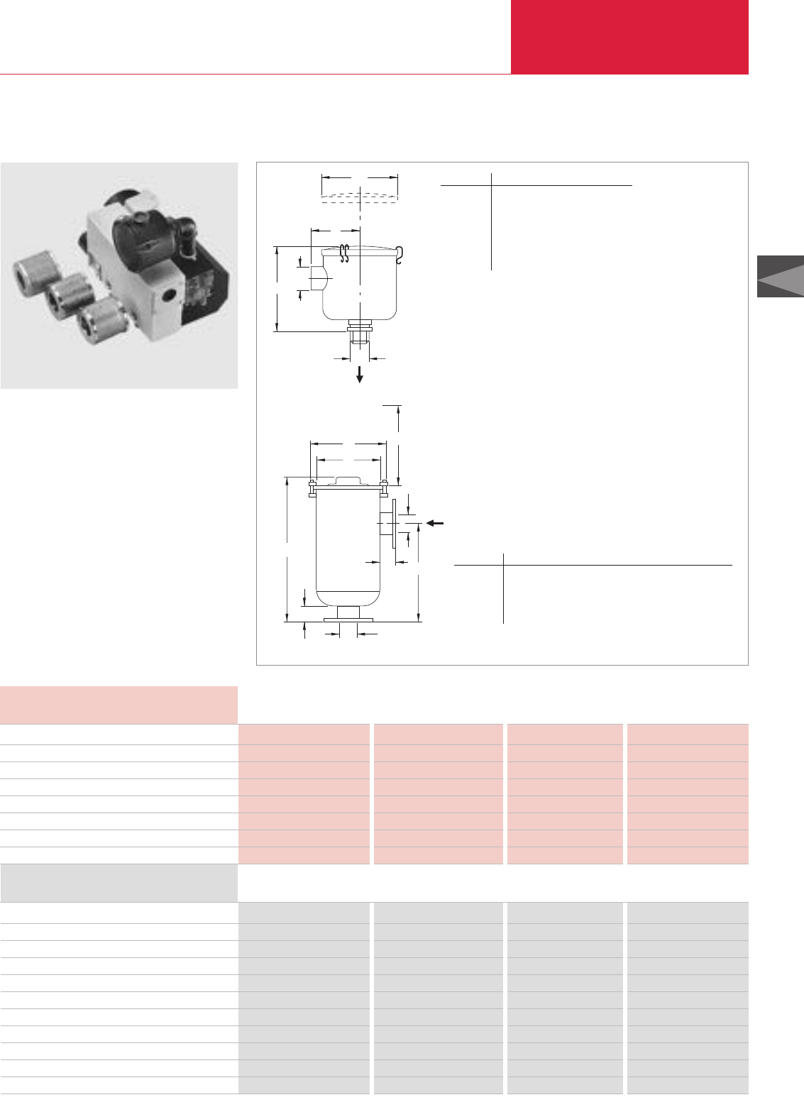
C02
LEYBOLD VACUUM PRODUCTS AND REFERENCE BOOK 2003/2004
Rotary Vane Vacuum Pumps
Accessories
C02.35
Dust Filters F (Suction Side)
High efficiency F filters are recommended for use
at the inlet of SOGEVAC Rotary Vane Vacuum
Pumps for protection against process contami-
nants, e.g., fiberglass particles, plastic dusts,
resins and food-processing by-products. The fil-
ters are available with easily replaceable cartridge
elements for particle filtration of dusts and parti-
culates down to ten microns, or activated carbon
elements for the adsorption of chemical vapor.
C
Service area needed
H
D
F
E
G
A
B
F
Dimensional drawings for the dust filters F 50 to F 200 (top) and F 600 to F 1200 (bottom)
SOGEVAC SV 40 with connected F-100 dust filter
and different types of filter cartridges
Typ A B lDlF
F-50 mm 111 76 151 1/2 NPT
in. 4.38 3 15.94 1/2 NPT
F-100 mm 171 107 187 1 1/4 NPT
in. 6.75 4.19 7.38 1 1/4 NPT
F-200 mm 267 124 222 2 NPT
in. 10.5 4.88 8.75 2 NPT
Dust Filter
Polyester Metal Paper Carbon
New cartridge pressure loses % 2 1 2 2
Efficiency for 10 micron particulates % 98 – 98 –
Filter for SV 16, SV 25, UV 25 – – F-50 –
Filter for SV 40, SV 65, SV 100 – F-100 F-100 F-100
Filter for SV 200, 300 – F-200 F-200 F-200
Filter for SV 500, 630 F-600 – – –
Filter for SV 1200 F-1200 – – –
Ordering Information
Technical Data
Version for the North and South American Continents
Dust Filter
Polyester Metal Paper Carbon
F-50 – – Part No. 899 460 –
Replacement element for F-50 – – Part No. 899 461 –
F-100 – Part No. 898 527 Part No. 898 528 Part No. 898 529
Replacement element for F-100 – Part No. 704 44 400 Part No. 704 13 901 Part No. 704 13 906
F-200 – Part No. 898 530 Part No. 898 531 Part No. 898 532
Replacement element for F-200 – Part No. 704 45 400 Part No. 704 14 901 Part No. 704 14 908
F-600 Part No. 898 470 – – –
Replacement element for F-600 Part No. 898 471 – – –
F-1200 Part No. 898 475 – – –
Replacement element for F-1200 Part No. 898 476 – – –
Typ A B C lD E lF G H
F-600 mm 689 76 356 470 76 4“ ANSI 381 305
in. 27.13 3 14 18.5 3 4“ ANSI 15 12
F-1200 mm 740 102 483 521 102 6“ ANSI 381 406.5
in. 29.13 4 19 20.5 4 6“ ANSI 15 16
F
D
B
AF
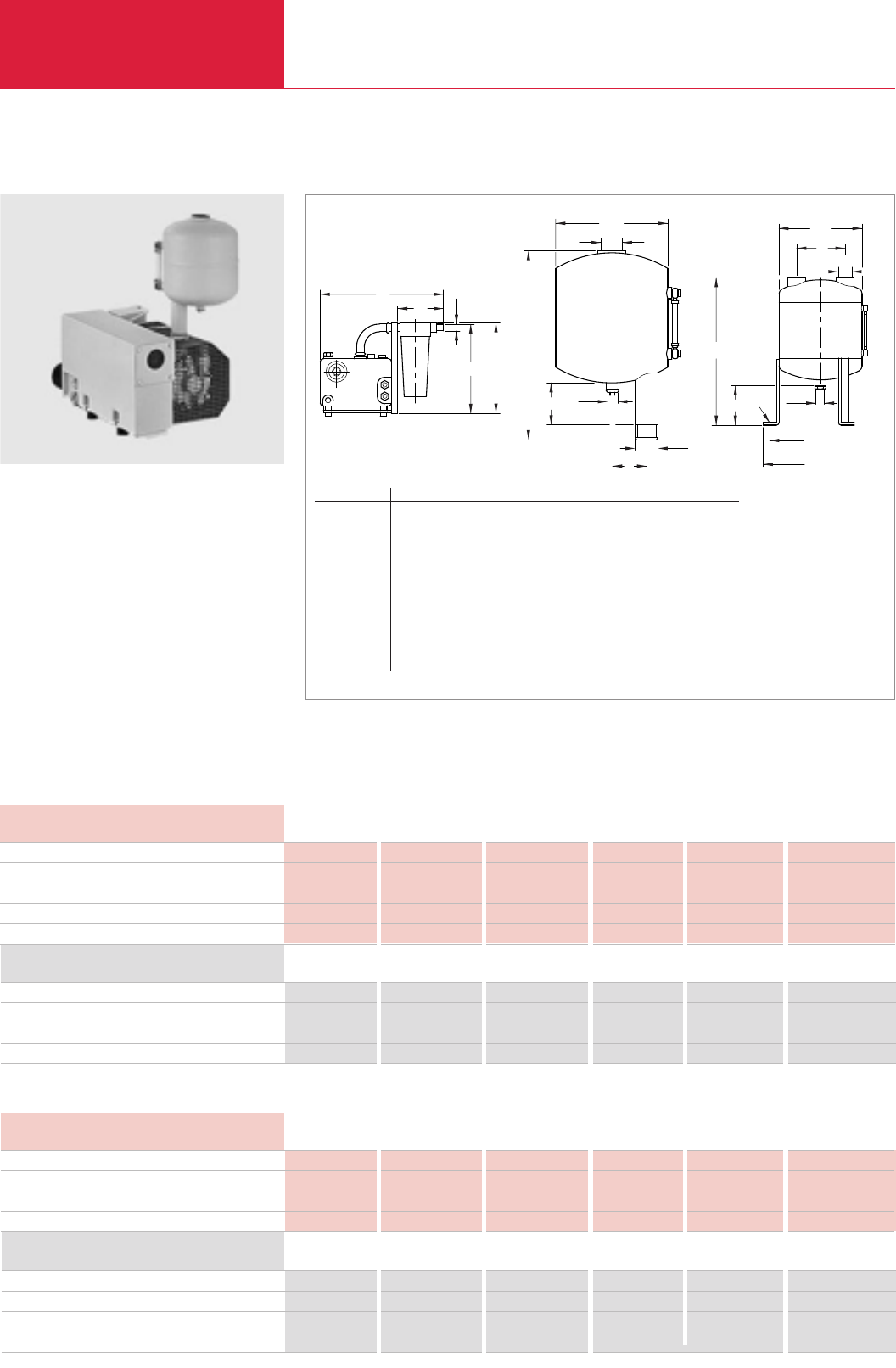
Accessories
Rotary Vane Vacuum Pumps
C02.36 LEYBOLD VACUUM PRODUCTS AND REFERENCE BOOK 2003/2004
SL Condensate Traps
The SL 16-25 condensate trap consists of a steel
separator whereas the collection vessel is made
of transparent plastic.
Condensate traps SL 40 to SL 1200 are welded
steel collection vessels acting as condensate
traps. These are equipped with connecting
threads.
Advantages to the User
◆Protection of the pumps against liquids which
might condense in the intake or the exhaust
line when pumping vapors
A
EøH
øH
E
C
B
øF
øJ; 3x120°
øG
øD
øH
øD
øA
C
C
B
B
øA
øD
E
Type A B C D E F G J H
SL 40 mm 200 350 100 G 1 1/4" 60 - - - G 3/8"
in. 7.87 13.78 3.94 G 1 1/4" 2.36 - - - G 3/8"
SL 65-100 mm 300 510 150 G 1 1/4" 170 12 400 360 G 1/2"
in. 11.81 20.08 5.91 G 1 1/4" 6.69 0.47 15.75 14.17 G 1/2"
SL 200-300 mm 300 865 150 G 2" 170 12 400 360 G 1/2"
in. 11.81 34.06 5.91 G 2" 6.69 0.47 15.75 14.17 G 1/2"
SL 630 mm 550 880 210 G 3" 300 9 600 514 G 1 1/4"
in. 21.65 34.65 8.27 G 3" 11.81 0.35 23.62 20.24 G 1 1/4"
SL 1200 mm 550 880 210 G 4" 300 9 600 514 G 1 1/4"
in. 21.65 34.65 8.27 G 4" 11.81 0.35 23.62 20.24 G 1 1/4"
Dimensional drawings for the condensate traps; SL 16-25 (left), SL 40 (middle) and SL 65-100 up to SL 1200 (right)
Technical Data
Condensate Trap SL 16-25 SL 40 SL 65-100 SL 200-300 SL 630 SL 1200
For pump SOGEVAC SV 16/25 and 40 and 40/65/100 and 200/300 500/630/750 500/630/750/1200
10 B/16 B/25 B 40 B 40 B/65 B/100 B
Condensate capacity l (qt) 2 (2.1) 4 (4.2) 16 (16.9) 40 (42.3) 80 (84.6) 80 (84.6)
Weight kg (lbs) 3.5 (7.7) 5 (11) 11 (24.3) 17 (37.5) 58 (127.9) 59 (130.1)
Technical Notes
The condensate traps are equipped with a sight
glass tube, so that it is easy to determine when to
empty the vessels. The condensate drain is sea-
led by a screw-in cap. This cap may be
replaced by a drain cock.
SOGEVAC SV 40 with SL 40 condensate trap
Ordering Information
Condensate Trap SL 16-25 SL 40 SL 65-100 SL 200-300 SL 630 SL 1200
Condensate trap Part No. 951 38 951 40 951 42 951 44 951 47 951 48
Drain cock Part No. – 711 30 111 711 30 113 711 30 113 711 30 105 711 30 105
Double spigot for drain cock Part No. – – – – 711 18 033 711 18 033
Condensate Trap SL 16-25 SL 40 SL 65-100 SL 200-300 SL 630 SL 1200
Condensate trap Part No. 951 38 (BSP) 951 43 (NPT) 951 43 (NPT) 951 45 (NPT) 951 47 (BSP) 951 48 (BSP)
Drain cock Part No. – 711 30 113 711 30 113 711 30 113 711 30 105 711 30 105
Double spigot for drain cock Part No. – – – – 711 18 033 711 18 033
Condensate Trap SL 16-25 SL 40 SL 65-100 SL 200-300 SL 630 SL 1200
For pump SOGEVAC SV 16/25 + UV 25 40 65/100 200/300 500/630/750 630/750/1200
Condensate capacity l (qt) 2 (2.1) 4 (4.2) 16 (16.9) 40 (42.3) 80 (84.6) 80 (84.6)
Weight kg (lbs) 3.5 (7.7) 5 (11) 11 (24.3) 17 (37.5) 58 (127.9) 59 (130.1)
Technical Data
Ordering Information
Version for the North and South American Continents
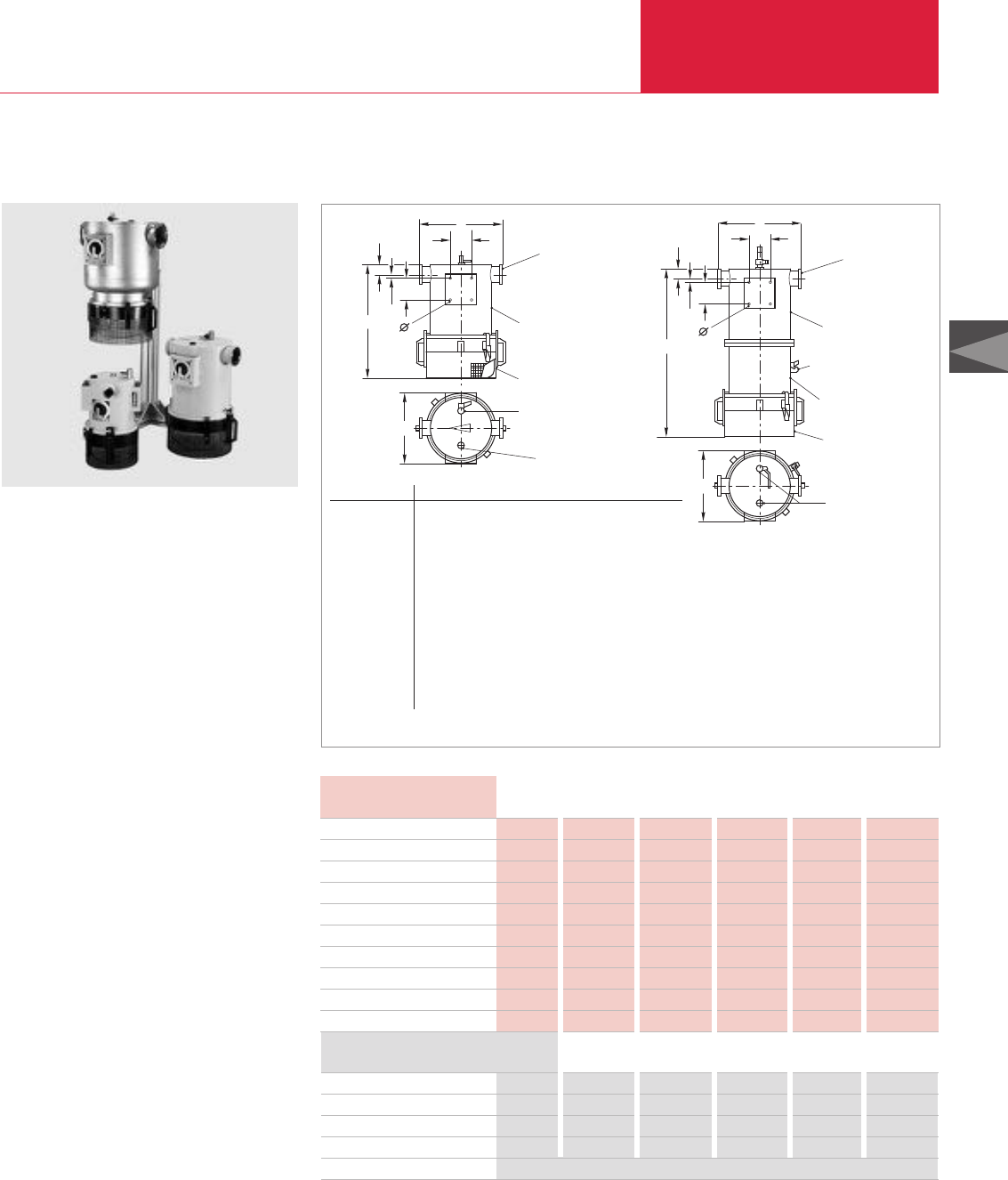
Accessories
Rotary Vane Vacuum Pumps
C02.37
LEYBOLD VACUUM PRODUCTS AND REFERENCE BOOK 2003/2004
C02
SEP Separators and SEPC Condensers
The separators from the SEP and the condensers
from the SEPC range have been designed to be
integrated in the vacuum circuit. They are
employed in all those cases where the pumped
gases may contain liquid drops (SEP), condens-
able vapors (SEPC) or solid particles which may
impair proper operation of the pumps.
Advantages to the User
◆Large capacity for solids
◆Large condensation surface (SEPC)
◆Visible level
◆Easy to disassemble for cleaning
◆Easy to drain, even in the presence of solids
Typical Applications
◆Draining (SEP)
◆Packaging (SEP)
◆Conveying/filling under vacuum (SEP/SEPC)
◆Drying (SEPC)
◆Degassing (SEPC)
◆and many more
FE
C
B
G
Abscheider
DN
A
D
Glasschale
Wasser-
anschlüsse
Kondensator
Belüftungsventil
Type A B C l/ D x E F G
SEP 40 mm 310 417 33 07 / 080 x 080 15 260
in. 12.2 16.42 1.3 0.28 / 3.15 x 3.15 0.59 10.24
SEP 63 mm 400 567 50 11 / 110 x 110 20 350
in. 15.75 22.32 1.97 0.43 / 4.33 x 4.33 0.79 13.78
SEP 100 mm 480 624 65 11 / 110 x 110 20 460
in. 18.9 24.57 2.56 0.43 / 4.33 x 4.33 0.79 18.11
SEPC 40 mm 310 700 33 07 / 080 x 080 15 260
in. 12.2 27.56 1.3 0.28 / 3.15 x 3.15 0.59 10.24
SEPC 63 mm 400 835 50 11 / 110 x 110 20 350
in. 15.75 32.87 1.97 0.43 / 4.33 x 4.33 0.79 13.78
SEPC 100 mm 480 900 65 11 / 110 x 110 20 460
in. 18.9 35.43 2.56 0.43 / 4.33 x 4.33 0.79 18.11
Dimensional drawings for the separators (left) and condensers (right)
Abscheider
Glasschale
Belüftungs-
ventil
DN
G
B
FE
C
A
D
1/2 "
Seperator
Glass bowl
Venting valve
Seperator
Glass bowl
Venting valve
Condenser
Water
connections
Separator SEP 40 SEP 63 SEP 100 – – –
Condenser – – – SEPC 40 SEPC 63 SEPC 100
For pump SOGEVAC SV 40/65/100 200/300 630/750 40/65/100 200/300 630/750
Connection flange DN 40 KF 63 ISO-K 100 ISO-K 40 KF 63 ISO-K 100 ISO-K
Capacity of the bowl l (qt) 6 (6.3) 12 (12.7) 12 (12.7) 6 (6.3) 12 (12.7) 12 (12.7)
Condensation area m2– – – 2.5 5 5
Condensation capacity 1) l/h – – – 10 20 20
For water 2) l/h – – – 1500 3000 3000
Water connection dia. mm (in.) – – – 19 (0.75) 19 (0.75) 19 (0.75)
Weight kg (lbs) 15 (33.1) 20 (44.1) 40 (88.2) 30 (66.2) 40 (88.2) 65 (143.3)
Technical Data
Separator SEP 40 SEP 63 SEP 100 – – –
Condenser – – – SEPC 40 SEPC 63 SEPC 100
Steel design Part No. 953 54 953 56 953 60 953 64 953 66 953 68
Stainless steel design Part No. 953 55 953 57 953 61 953 65 953 67 953 69
Support Part No. 712 43 380
1) For water vapor at a vapor pressure of 60 mbar (45 Torr)
2) Cooling water at a supply temperature of 10 °C (50 °F) and a discharge temperature < 15 °C (< 59 °F)
Ordering Information
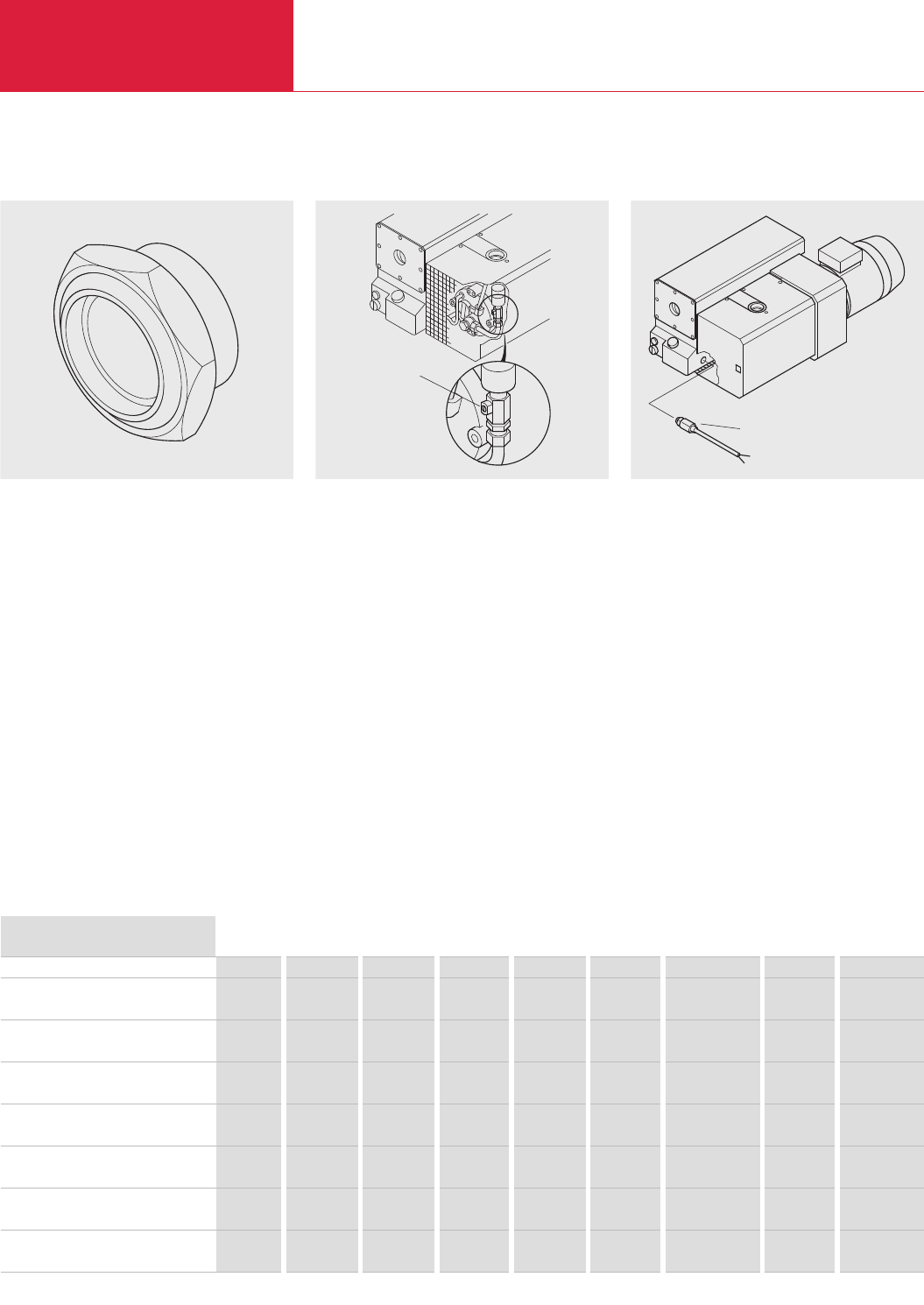
LEYBOLD VACUUM PRODUCTS AND REFERENCE BOOK 2003/2004
Rotary Vane Vacuum Pumps
Accessories
C02.38
Special Oil Sight Glass Gas Ballast Valve Thermal Switch
Geöffneter Gasballast
Öltemperatur-Thermoschalter
The special oil sight glass may be used instead of
the standard one. It is equipped with a glass win-
dow and may be installed when wanting to pump
aggressive gases or vapors.
The pumps SOGEVAC SV 16, SV 25, SV 500,
SV 630 (F) and SV 750 are equipped as standard
with a gas ballast.
The SV 1200 is equipped as standard with two
manual gas ballast valves.
Pumps SV 40 to SV 300 may be ordered either
with or without gas ballast valve.
The gas ballast valve may also easily be retro-
fitted to the SV 40 to SV 300 (either standard,
large or solenoid).
Technical Notes
The gas ballast valve permits pumping of con-
densable vapors.
The permissible quantities of water are stated in
the technical data section.
The thermal switch is built into the oil circuit. It
responds as soon as the temperature of the
pump exceeds the maximum operating tempera-
ture. This accessory is recommended when oper-
ating the pump at high ambient temperatures.
Ratings for the normally closed contact:
250 V AC, 50 Hz - 10 A
125 V AC, 50 Hz - 12 A
30 V DC - 5 A
The SV 500, SV 630 (F), SV 750 and SV 1200
include this switch as a standard.
Ordering Information
SOGEVAC SV 16/25 SV 40 SV 65 SV 100 SV 200 1, 2) SV 300 1, 2)
SV 500/630/750
1, 2)
SV 630 F 1, 2) SV 1200 1, 2)
Gas ballast valve integrated Part No. Part No. Part No. Part No. Part No. integrated integrated integrated
(standard) 951 26 951 26 951 27 951 29 951 29 (manual) (24 V DC) (manual)
Thermal switch – Part No. 2) Part No. 2) Part No. 2) Part No. 2) Part No. 2) integrated integrated integrated
711 19 111 711 19 111 711 19 111 951 36 951 36
Special oil sight glass – Part No. Part No. Part No. Part No. Part No. integrated integrated integrated
712 19 488 712 19 488 712 19 488 712 19 488 712 19 488
Oil level monitor Part No. Part No. Part No. Part No. Part No. Part No. Part No. Part No. Part No.
711 19 108 711 19 108 2) 711 19 108 2) 711 19 108 2) 953 96 953 96 953 97 953 97 953 99
Gas ballast, big – Part No. Part No. Part No. Part No. Part No. Part No. Part No. –
196 60 196 60 951 32 951 30 951 30 951 33 1) 951 34 1)
Gas ballast, – Part No. Part No. Part No. Part No. Part No. Part No. standard upon request 2)
with EM 24 V DC valve 951 23 951 23 951 28 951 31 951 31 951 34 2)
Exhaust filter monitoring switch
electric – – – – upon request upon request upon request upon request upon request
1) Second gas ballast possible. Contact LEYBOLD
2) Please state when ordering the pump
Gas ballast open
Thermal switch for the oil
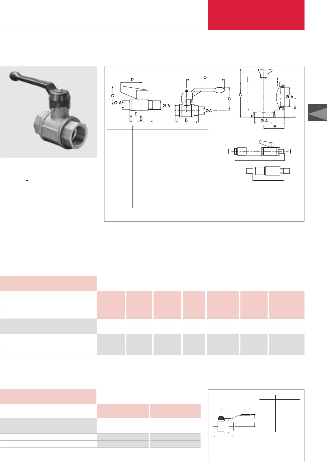
C02
LEYBOLD VACUUM PRODUCTS AND REFERENCE BOOK 2003/2004
Rotary Vane Vacuum Pumps
Accessories
C02.39
C
B
A
Ball Valves and Valves
Dimensional drawings for the ball valves; G 3/8
"
and G 1/2
"
(left), G 1 1/4
"
and G 2
"
(middle) and right-angle valves (right)
and for the control valves (bottom)
Type A B C D E
Ball valve mm G 3/8"45 38 43 25
in. G 3/8"1.77 1.5 1.69 0.98
Ball valve mm G 1/2"53 44 50 29
in. G 1/2"2.09 1.73 1.97 1.14
Ball valve mm G 1 1/4"103 96 140 –
in. G 1 1/4"4.06 3.8 5.51 –
Ball valve mm G 2"134 120 175 –
in. G 2"5.28 4.72 6.89 –
Right-angle valve mm 100 ISO-K – 345 – 108
in. 100 ISO-K – 13.58 – 4.25
Control valve mm G 1/2"128 – – –
in. G 1/2"5.04 – – –
Control valve with
blocking valve mm G 1/2"175 – – –
in. G 1/2"6.89 – – –
Advantages to the User
◆Leak rate < 1 x 10
-6
mbar x l x s
-1
(≤0.75 x 10
-6
Torr x l x s
-1
)
◆Seals on both sides against the atmosphere
◆Opens against atmospheric pressure
◆Small size
◆Simple and quick to operate
◆Pressure range from 10
-2
to 1000 mbar
(0.75 x 10
-2
to 750 Torr)
◆Smaller models serve as venting valves
Information on the blocking components is provid-
ed in the Product Section C14 “Vacuum Valves”.
Technical Data
Type Ball valve Ball valve Ball valve Ball valve Right-angle valve Control valve Control valve with
blocking valve
Connection F/M 3/8" BSP F/M 1/2" BSP F/F 1 1/4" BSP F/F 2" BSP DN 100 ISO-K F/M 1/2" BSP F/M 1/2" BSP
Weight kg (lbs) 0.12 (0.3) 0.15 (0.33) 1.24 (2.7) 3.22 (7.1) 8.0 (17.6) 0.135 (0.3) 0.369 (0.81)
Ball valve 1 1/4"
Type Ball valve Ball valve Ball valve Ball valve Right-angle valve Control valve Control valve with
blocking valve
Part No. 711 30 111 711 30 113 711 30 105 711 30 107 107 81 951 86 951 87
Ordering Information
Materials
The housing of the ball valves is made of brass,
the ball of hard-chrome plated brass, the valve
seat of PTFE.
B
B
Ø A
Ø A
Ø A
Ø A
The housing of the right angle valve is made of
aluminium, the spindle and valve plate are sealed
with an O-ring and are made of stainless steel.
Version for the North and South American Continents
Technical Data
Type Ball valve Ball valve
Connection 1/2-inch NPT(F) 1 1/4-inch NPT(F)
Type BV50 BV100
Part No. 899 810 899 800
Ordering Information
Dimensional drawing for the ball valves BV
Type A B C
BV50
mm 54 41 102
in. 2.13 1.63 4
BV100
mm 102 67 140
in. 4 2.63 5.5
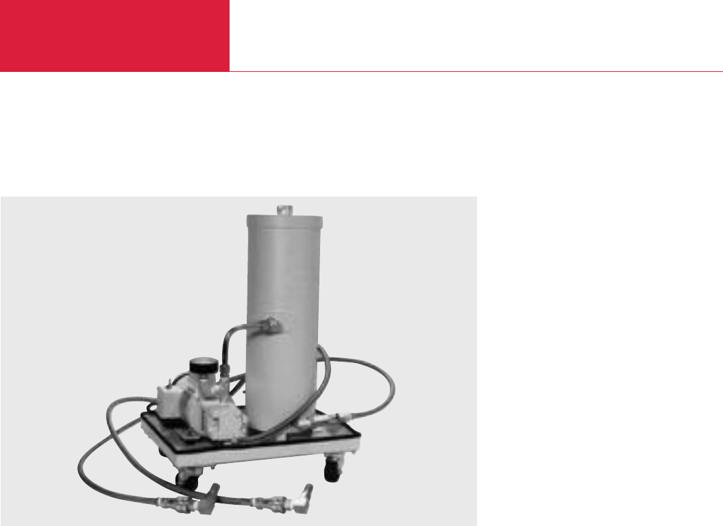
Accessories
Rotary Vane Vacuum Pumps
C02.40 LEYBOLD VACUUM PRODUCTS AND REFERENCE BOOK 2003/2004
Version for the North and South American Continents
OF3000 Oil Filtering System for SOGEVAC
OF3000
Advantages to the User
◆Compact, mobile design
◆Choice of five filter elements
◆Dripless quick disconnects for easy removal
and replacement of filter elements
◆No spillage - recessed lid and oil level
◆Conductive teflon hoses for static charge dis-
sipation
◆Integral gear pump with built-in bypass
◆Pressure gauge
◆Oil sight glass
◆Single phase 50/60 Hz motor standard
◆Tangential flow inlets - improves oil flow
◆Canister drain valve
The OF3000 is a compact, highly mobile filtering
system designed for use with mechanical pumps
in applications generating large volumes of heavy
particulate filtration.
A positive feed gear pump and check valve
assembly protect against excessive backpressure
in the canister should the filter element become
clogged. Flexible hoses and matched dripless
connectors ensure easy maneuverability of the
OF3000’s rollaround cart, while also eliminating
the possibility of oil spills.
Operation
Contaminated oil is removed from the drain loca-
tion on the vacuum pump and is cycled to the
element assembly. Clean oil is subsequently cir-
culated back to the oil fill port of the vacuum
pump.
The tangential flow inlet port to the oil filter cani-
ster allows full oil flow while utilizing the entire
filter capability of the element. This translates
into longer filter life, fewer element changes, and
less oil loss.
Similarly, chemically severe OF3000C models
have proven successful in aluminum etching and
other processes where boron tricloride and other
highly toxic gases are employed. the canister,
gear pump, fittings and quick disconnects of the
corrosive-service model have been specially trea-
ted with a fluorocarbon material that subtantially
increases the life of these components.
Filtering Elements
Fullers Earth - Provides high capacity for stan-
dard acids and can be used to trap particulates
down to 10 micron size.
Hydrophylic - Effective for hydrolized acids and
particulates as low as one micron.
Activated Alumina - Effective on Lewis acids and
polar compounds. Can be used to trap particula-
tes down to 10 microns.
Particulate (Paper) - Suitable for particulate
removal down to 10 microns.
Particulate (Fiberglass) - Suitable for particulate
removal down to 10 microns.

Accessories
Rotary Vane Vacuum Pumps
C02.41
LEYBOLD VACUUM PRODUCTS AND REFERENCE BOOK 2003/2004
C02
Version for the North and South American Continents
Gear pump motor
Gear pump
Pressure gauge
Fluid capacity (approx.) gal
Flexible hoses in. I.D.
Dimensions in. (mm)
Weight (dry) lbs (kg)
1/6 HP, 115/208/220 V,single phase, 50/60 Hz,
wired for 115 V, with on/off switch
0.7 gpm @ 1800 rpm
0 to 100 psig (0 to 70 kPa)
3
78 teflon/carbon black with stainless steel braid
- 6 ft lengths
18 x 14 x 26 (457 x 355 x 661)
65 (29.4)
Technical Data OF3000
OF3000, less element and oil (standard)
OF3000C, coated, prepared for PFPE
OF3000, prepared for PFPE
Accessories
Aluminum oxide
Hydrophilic
Fullers earth
Particulate (paper)
Particulate (fiberglass)
Part No. 898 625
Part No. 899 450
Part No. 899 455
Part No. 898 523
Part No. 898 525
Part No. 99 171 159
Part No. 898 599
Part No. 99 171 158
Ordering Information OF3000
Other Accessories
Version for the North and South American Continents
Model Fits Pump Thread Size Part No. Replacement
Models Element
SVXCXF 50 SV 16/25/UV 25 1/2" NPTF 899 502 899 503
SVXCXF 100 SV 40/65 1 1/2" NPTF 899 500 899 501
SVXCXF 200 SV 100/200/300 2" NPTF 899 498 899 499
External Carbon Exhaust Filters
An external type spin-on filter made of activated
carbon on a polxester cloth housed in wire mesh.
Used for providing additional protection from oil
odor or mist expelled from pump exhaust.
requires NPT type nipple and street elbow for
perferred vertical mounting. SV 16/25 requires
nipple only.
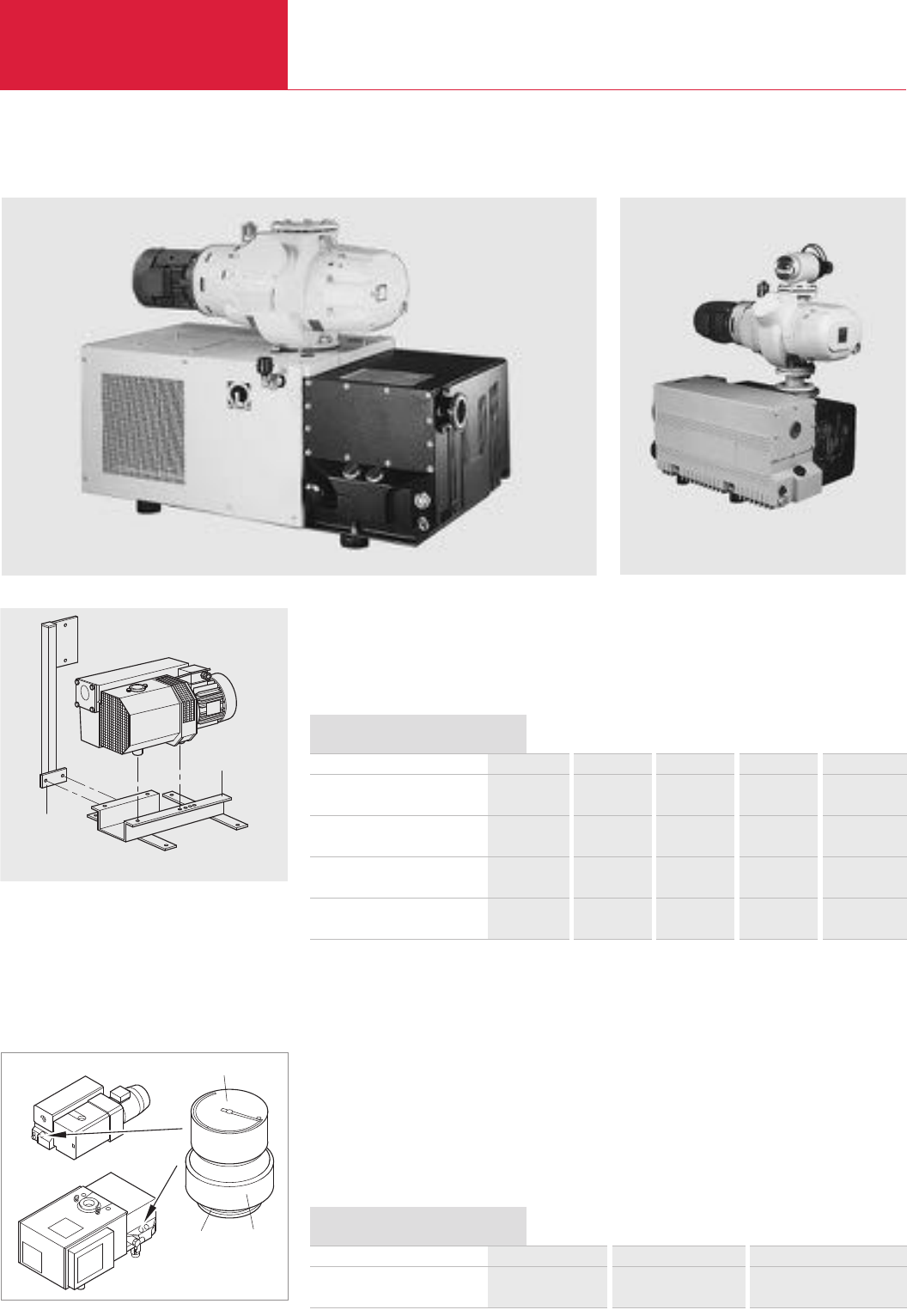
Accessories
Rotary Vane Vacuum Pumps
C02.42 LEYBOLD VACUUM PRODUCTS AND REFERENCE BOOK 2003/2004
2
1
SV 40 - SV 300
SV 500 - SV 1200
Manometer
Dichtung Adapter
SOGEVAC SV 630 F with RUVAC WAU 2001 SOGEVAC SV 300 with RUVAC WAU 501
Seal
SOGEVAC SV 40 SV 65 SV 100 SV 200 SV 300
Base frame Part No. Part No. Part No. Part No. Part No.
711 19 203 711 19 203 711 19 205 711 19 208 711 19 208
Oil drain cock G 3/4" Part No. Part No. Part No. Part No. Part No.
711 30 114 711 30 114 711 30 114 711 30 114 711 30 114
Bracket for electric connections Part No. Part No. Part No. Part No. Part No.
711 19 223 711 19 223 711 19 223 711 19 226 711 19 226
Base frame for not not Part No. Part No. Part No.
Roots installation possible possible 711 19 204 711 19 209 711 19 209
1) Required for mounting the WAU 1001 on to the SV 200/300
Ordering Information
Mounting Accessories
Installation accessories are available for the
SOGEVAC SV 40 to SV 300.
The base frame (1) simplifies installation of the
pump in systems and also simplifies any mainte-
nance work. The bracket for electrical connec-
tions (2) is attached to the base frame; the sole-
noid control system is attached to this bracket.
Exhaust Filter Gauge
The manometer (40 mm dia.), glued in the adap-
ter, will replace the oil filling plug. Dial has 2
colors:
green: 1000 < P < 1450 mbar abs.
(< 1087.5 Torr abs.)
Exhaust filter OK
For pump SOGEVAC SV 16/25 SV 40 to SV 300 SV 500 to SV 1200 2)
Manometer
(with adapter and seal) Part No. 951 91 951 94 951 95
2) Not visible over SV 1200
Ordering Information
red: P > 1450 mbar abs.
(> 1087.5 Torr abs.)
Exhaust filter clogged
Technical Information
Indication of the manometer is only valid when
the pump has reached its working temperature.
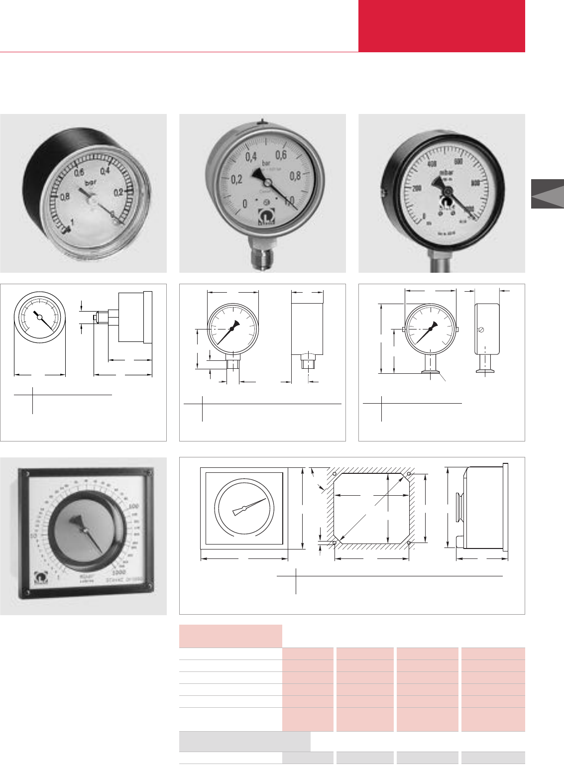
Accessories
Rotary Vane Vacuum Pumps
C02.43
LEYBOLD VACUUM PRODUCTS AND REFERENCE BOOK 2003/2004
C02
Bourdon Vacuum Gauges
0
0,4
0,6
0,8 0,2
l
ø a l
1
ø d
1
01,0
0,6
0,4
0,8
l1
ødb1
b
l
øa
0,2
b
1000
600
400
800
0
200
DN 16 KF
l1
l
øa
Advantages to the User
◆Simple, rugged and vibration insensitive
vacuum gauges for the rough vacuum range
◆Linear response
◆Clear dial which can also be read from a great
distance
◆Readings independent of atmospheric
pressure
Measuring range 0 to 100 % 0 to 1 bar 0 to 1020 mbar 1 to 1000 mbar
Vacuum connection M 1/8" BSP M 1/2" BSP DN 16 KF DN 40 KF
Scale length mm (in.) 55 (2.17) 140 (5.51) 140 (5.51) 270 (10.63)
Overall height mm (in.) 48 (1.89) 115 (4.53) 105 (4.13) 166 (6.54)
Weight g (lbs) 60 (0.13) 560 (1.24) 300 (0.66) 2700 (5.96)
Indication low pressure absolute pressure absolute pressure absolute pressure
in bar in mbar in mbar in mbar
Technical Data
Bourdon vacuum gauge Part No. 951 90 Part No. 951 92 Part No. 160 40 Part No. 160 67
Standard vacuum gauge for all SOGEVAC pumps is Part No. 951 92.
Further information on other vacuum gauges (1) is provided in Product Section C16 “Total Pressure Gauges”
Ordering Information
DIAVAC DV 1000 (1)
a
b
45°
d
a1
lb1
a2c
b2h
Dimensional drawing and panel cut-out for the DIAVAC DV 1000
Dimensional drawing for the Bourdon vacuum gauge Part No. 951 90 Dimensional drawing for the Bourdon vacuum gauge Part No. 951 92 Dimensional drawing for the Bourdon vacuum gauge Part No. 160 40
a d l l1
mm 40 G 1/8“ 48 36
in. 1.57 G 1/8“ 1.89 1.42
a b b1d l l1
mm 90 55 30 G 1/8“ 70 15
in. 3.54 2.17 1.18 G 1/8“ 2.76 0.59
a b l l1
mm 80 36 105 64
in. 3.15 1.42 4.13 2.52
a a1a2b b1b2c d h l
mm 180 170 166 166 156 152 166 4.5 155 203.5
in. 7.09 6.69 6.54 6.54 6.14 5.98 6.54 0.18 6.10 8.01
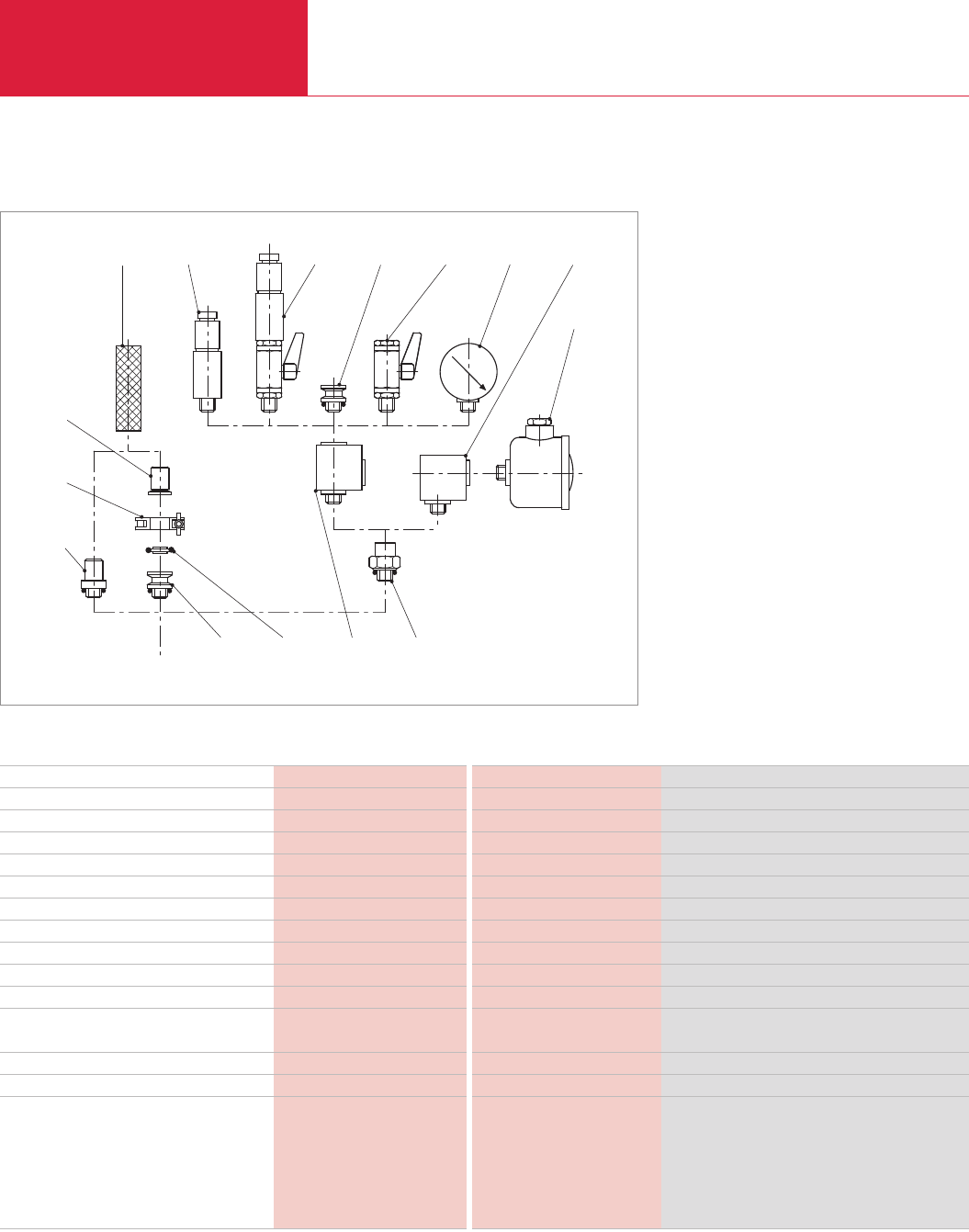
Accessories
Rotary Vane Vacuum Pumps
C02.44 LEYBOLD VACUUM PRODUCTS AND REFERENCE BOOK 2003/2004
Connection Fittings for SOGEVAC SV 16, SV 25 and SV 10 B, SV 16 B, SV 25 B
9 1210 2 11 13
14
7
82 3 1
4
6
5
SV 16/25
The fittings presented have been specially matched
to the SOGEVAC pumps. We recommend to use
only these or other components from LEYBOLD
for connecting SOGEVAC pumps, so as not to
impair the pumping speed of the pumps or the
leak tightness of the system.
More information on further fittings is provided in
Product Section C13 “Vacuum Fittings and
Feedthroughs”.
Item Description Connection Material SV 16, SV 25
1 Screw coupling G M/F 1/2" Al Part No. 711 18 020
2 Threaded flange adaptor 1) G M 1/2" – DN 16 KF Al, anodized Part No. 711 18 120
3 Centering ring 1) DN 16 KF Al Part No. 183 26
4 Clamping ring DN 10/16 KF Al Part No. 183 41
5 Hose connection DN 16 KF – DN 25 mm Al, anodized Part No. 711 18 300
6 Hose connection 1) G M 1/2" – DN 25 mm Al, anodized Part No. 711 18 011
7 PVC tubing Ø 25 mm, 1 m long PVC Part No. 711 18 323
8 Tee piece G M/F/F 1/2" Al, anodized Part No. 711 18 250
9 Vacuum control valve G M 1/2" Brass/Al Part No. 951 86
10 Vacuum control valve with blocking valve G M 1/2" Brass, nickeled/Al Part No. 951 87
11 Ball valve G M/F 1/2" Brass, nickeled Part No. 711 30 113
G M/F 1/2" NPTF Brass, nickeled Part No. 899 810
12 Bourdon vacuum gauge G M 1/2" Part No. 951 92
13 Elbow 90° G M/F 1/2" Al, anodized Part No. 711 18 210
14 Dust filter 2)
with paper cartridge G M/F 1/2" Part No. 951 50
G M/F 1/2" NPT Part No. 899 460
with activated charcoal cartridge G M/F 1/2" Part No. 711 27 092
with metal cartridge G M/F 1/2" Part No. 711 27 093
with polyester filter cartridge Part No. 711 27 094
1) With NBR-O-Ring
2) See “Dust Filters F (Suction Side)” for other options
M =Outside thread
F = Inside thread
Technical Data and Ordering Information
Connection fittings for SOGEVAC SV 16, SV 25 and SV 10 B, SV 16 B, SV 25 B
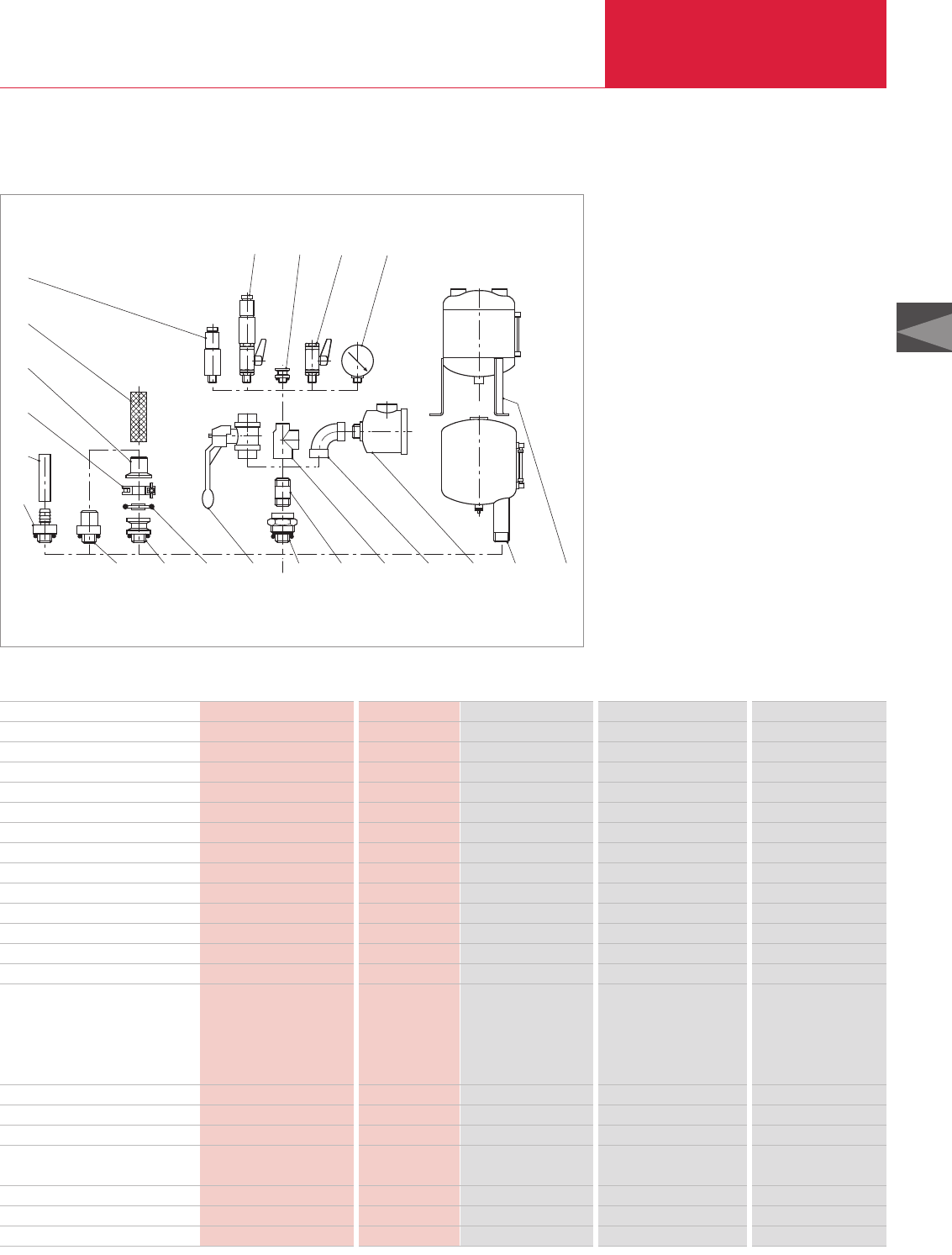
C02
LEYBOLD VACUUM PRODUCTS AND REFERENCE BOOK 2003/2004
Rotary Vane Vacuum Pumps
Accessories
C02.45
Technical Data and Ordering Information
Connection Fittings for SOGEVAC SV 40, SV 65, SV 100 and SV 40 B, SV 65 B, SV 100 B
8
9
6
1518 17 16
14 5 3 2 12 13 14
7 20 21
10
11
19
Connection fittings for SOGEVAC SV 40, SV 65, SV 100 and SV 40 B, SV 65 B, SV 100 B
Item Description Connection Material SV 40 SV 65 SV 100
1 Screw coupling 1) G M/F 1 1/4" Al, NBR Part No. 711 18 023 Part No. 711 18 023 Part No. 711 18 023
2 Double nipple G M/M 1 1/4" Steel Part No. 711 18 033 Part No. 711 18 033 Part No. 711 18 033
3 Ball valve G F/F 1 1/4" Brass, nickeled Part No. 711 30 105 Part No. 711 30 105 Part No. 711 30 105
4 Threaded flange adaptor 1) G M 1 1/4" BSP – DN 40 KF Al, anodized Part No. 711 18 123 Part No. 711 18 123 Part No. 711 18 123
5 Centering ring DN 40 KF Al Part No. 183 28 Part No. 183 28 Part No. 183 28
6 Clamping ring DN 32/40 KF Al Part No. 183 43 Part No. 183 43 Part No. 183 43
7 Hose connection 1) G M 1 1/4" / DN 40 mm Al, anodized Part No. 711 18 013 Part No. 711 18 013 Part No. 711 18 013
8 Rubber hose ll10 x 25 mm, 1 m long Part No. 172 03 Part No. 172 03 Part No. 172 03
9 Hose connection 1) G M 1 1/4" – DN 10 Al, anodized Part No. 711 18 153 Part No. 711 18 153 Part No. 711 18 153
10 Hose connection DN 40 KF/DN 40 mm Al, anodized Part No. 711 18 303 Part No. 711 18 303 Part No. 711 18 303
11 PVC tubing ll40 mm, 1 m long Part No. 711 18 324 Part No. 711 18 324 Part No. 711 18 324
12 Tee reducer bush G F/F/F 1 1/4" – 1 1/4" – 1/2" Gray cast iron Part No. 711 18 263 Part No. 711 18 263 Part No. 711 18 263
13 Elbow 90° G F/F 1 1/4" Gray cast iron Part No. 711 18 213 Part No. 711 18 213 Part No. 711 18 213
14 Dust filter 2) G M/F 1 1/4"
with paper cartridge Part No. 951 55 Part No. 951 60 Part No. 951 60
with activated charcoal cartridge Part No. 711 27 102 Part No. 711 27 112 Part No. 711 27 112
with metal cartridge Part No. 711 27 103 Part No. 711 27 113 Part No. 711 27 113
wit h polyester filter cartridge Part No. 711 27 104 Part No. 711 27 114 Part No. 711 27 114
15 Bourdon vacuum gauge G M 1/2" Part No. 951 92 Part No. 951 92 Part No. 951 92
16 Ball valve G M/F 1/2" Brass, nickeled Part No. 711 30 113 Part No. 711 30 113 Part No. 711 30 113
17 Threaded flange adaptor 1) G M 1/2" – DN 16 KF Al, anodized Part No. 711 18 120 Part No. 711 18 120 Part No. 711 18 120
18 Vacuum control valve
with blocking valve G M 1/2" Brass, nickeled/Al Part No. 951 87 Part No. 951 87 Part No. 951 87
19 Vacuum control valve G M 1/2" Brass, nickeled/Al Part No. 951 86 Part No. 951 86 Part No. 951 86
20 Condensate trap G M/F 1 1/4" – 1 1/4" – 3/8" Part No. 951 40 – –
21 Condensate trap G F/F/F 1 1/4" – 1 1/4" – 1/2" Part No. 951 42 Part No. 951 42 Part No. 951 42
1) incl. O-ring
2) See “Dust Filters F (Suction Side)” for other options
M = Outside thread
F = Inside thread
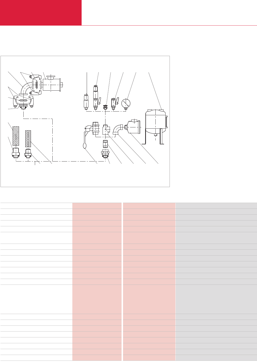
LEYBOLD VACUUM PRODUCTS AND REFERENCE BOOK 2003/2004
Rotary Vane Vacuum Pumps
Accessories
C02.46
Connection Fittings for SOGEVAC SV 200, SV 300
110 2 11 12 13
8
9
3
1617 15 14 195
20 4 21
5
4
76
18
Connection fittings for SOGEVAC SV 200 and SV 300
Technical Data and Ordering Information
Item Description Connection Material SV 200 and SV 300
1 Screw coupling 1) G M/F 2" Al, anodized Part No. 711 18 025
2 Double nipple G M/M 2" – 150 mm Steel Part No. 711 18 035
3 Threaded flange adaptor 1) G M 2" – DN 63 ISO-K Steel, zinc coated Part No. 711 18 126
4 Centering ring with outer ring 1) DN 63 ISO-K Al, CR Part No. 268 05
5 Set of clamping screws DN ISO-K
(4 pieces) M10 x 24 Steel, zinc coated Part No. 267 01
6 Hose connection 1) G M 2" – DN 50 mm Al, anodized Part No. 711 18 015
7 PVC tubing ll50 mm, 1 m long PVC Part No. 711 18 325
8 Hose connection 1) G M 2" – DN 60 mm Al, anodized Part No. 711 18 016
9 PVC tubing ll60 mm, 1 m long Part No. 711 18 326
10 Ball valve G F/F 2" Brass, nickeled Part No. 711 30 107
11 Tee reducer G F/F/F 2" – 2" – 1/2" Gray cast iron Part No. 711 18 265
12 Elbow 90° G F/F 2" Gray cast iron Part No. 711 18 215
13 Dust filter 2) G M/F 2"
with paper cartridge Part No. 951 65
with activated charcoal cartridge Part No. 711 27 122
with metal cartridge Part No. 711 27 123
with polyester filter cartridge Part No. 711 27 124
14 Bourdon vacuum gauge G M 1/2" Part No. 951 92
15 Ball valve G M/F 1/2" Brass, nickeled/Al Part No. 711 30 113
16 Threaded KF small-flange adaptor 1) G M 1/2" – DN 16 KF Al, anodized Part No. 711 18 120
17 Vacuum control valve with blocking valve G M 1/2" Brass, nickeled/Al Part No. 951 87
18 Vacuum control valve G M 1/2" Brass, nickeled/Al Part No. 951 86
19 Condensate trap G F/F/F 2" – 2" – 1/2" Part No. 951 44
20 Elbow 90° DN 63 ISO-K Stainless steel Part No. 887 25
21 Dust filter with paper cartridge DN 63 ISO-K Part No. 951 68
1) incl. O-ring
2) See “Dust Filters F (Suction Side)” for other options
M = Outside thread
F = Inside thread
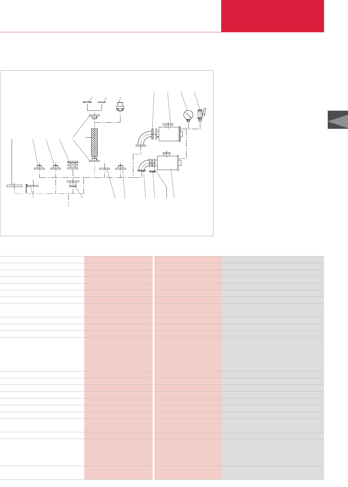
C02
LEYBOLD VACUUM PRODUCTS AND REFERENCE BOOK 2003/2004
Rotary Vane Vacuum Pumps
Accessories
C02.47
Connection Fittings for SOGEVAC SV 500, SV 630, SV 630 F, SV 750
1711 16
8 9
10
2
31
5 4
12
7
15 14
13 211918 20
6
Connection fittings for SOGEVAC SV 500, SV 630, SV 630 F and SV 750
Technical Data and Ordering Information
Item Description Connection Material SV 500, SV 630, SV 630 F and SV 750
1 PVC tubing ll90 mm, 1 m long Part No. 711 18 329
2 Hose connection DN 100 PN 10 – DN 90 mm Steel Part No. 711 18 362
3 Coupling DN 100 – PN 10 Stainless steel/Al/Rubber Part No. 711 18 342
4 Adaptor flange DN 100 PN 10 – G 4" F Steel Part No. 711 18 372
5 Adaptor flange DN 100 PN 10 – F3" G Steel Part No. 711 18 370
6 Hose connection G 4" M – DN 90 Steel/NBR Part No. 711 18 017
7 Roots adaptor RUVAC 1001 Steel/NBR Part No. 953 47
Roots adaptor RUVAC 2001 Steel/FPM Part No. 953 48
8 O-ring ll110 x 5 NBR Part No. 712 42 882
9 Centering ring with O-ring DN 100 PN 10 – DN 100 ISO-K Al/NBR Part No. 711 18 391
10 Elbow 90° DN 100 PN 10 Steel Part No. 711 18 284
11 Dust filter F 630 1) DN 100 PN 10
with paper cartridge Part No. 951 71
with activated charcoal cartridge Part No. 711 27 162
with metal cartridge Part No. 711 27 163
with polyester filter cartridge Part No. 711 27 164
12 Manually operated blocking valve DN 100 PN 10 Gray cast iron Part No. 711 30 116
13 Adaptor DN 100 PN 10 – 100 ISO-K Al Part No. 711 18 336
14 Adaptor flange with tubulation DN 100 PN 10 (Tube ll108) Steel Part No. 711 18 351
15 Collar flange DN 100 PN 10 – DN 100 ISO-K Steel Part No. 711 18 383
16 Ball valve G 1/2" M/F Brass, nickeled/Al Part No. 711 30 113
17 Bourdon vacuum gauge G 1/2" M Part No. 951 92
18 Elbow 90° DN 100 ISO-K Stainless steel Part No. 887 26
19 Set of clamps for DN ISO-K M 10 x 24 Steel, zinc coated Part No. 267 01
Set = 4 pieces
20 Centering ring 2) DN 100 ISO-K Al/CR Part No. 268 06
21 Dust filter 1) DN 100 ISO-K
with paper cartridge Part No. 951 72
with activated charcoal cartridge Part No. 711 27 166
with metal cartridge Part No. 711 27 167
Screwset (not drawn)
Set = 8 Screws and 8 nuts DN 100 PN 10 Steel, zinc coated Part No. 714 12 440
M = Outside thread F = Inside thread 1) See “Dust Filters F (Suction Side)” for other options 2) incl. O-ring
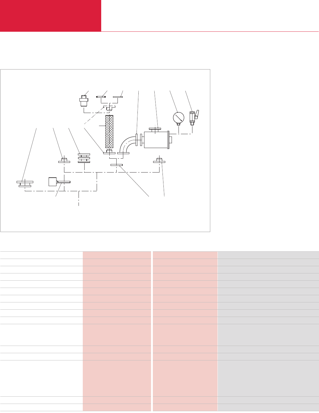
LEYBOLD VACUUM PRODUCTS AND REFERENCE BOOK 2003/2004
Rotary Vane Vacuum Pumps
Accessories
C02.48
Connection Fittings for SOGEVAC SV 1200
1413 1510 11 12
23 15 4
8 7 6
9
Connection fittings for SOGEVAC SV 1200
Technical Data and Ordering Information
Item Description Connection Material SV 1200
1 PVC tubing ll90 mm, 1 m long PVC Part No. 711 18 329
2 Hose connection DN 125 PN 10 – DN 90 mm Steel Part No. 711 18 363
3 Kupplung DN 125 PN 10 Stainless steel/Al/Rubber Part No. 711 18 343
4 Flange with tubulation 1) DN 125 (Tube 139.7) Steel Part No. 712 28 863
5 Roots adaptor RUVAC 2001 Steel Part No. 953 37
6 Adaptor flange DN 125 PN 10 – G 4" F Steel Part No. 711 18 117
7 Collar flange DN 125 PN 10 – DN 160 ISO-K Steel Part No. 711 18 386
8 Electropneumatic valve DN 125 PN 10 Gray cast iron Part No. 715 69 202
9 Hose connection G 4" M – DN 90 mm Steel/NBR Part No. 711 18 017
10 O-ring
165 x 5 NBR Part No. 712 42 902
165 x 5 FPM Part No. 712 42 912
11 Centering ring 1) DN 125 PN 10 – DN 160 ISO-K Al Part No. 711 18 396
12 Elbow 90° DN 125 PN 10 Steel Part No. 711 18 287
13 Dust filter 2) DN 125 PN 10
with paper cartridge Part No. 951 75
with activated charcoal cartridge Part No. 711 27 142
with metal cartridge Part No. 711 27 143
with polyester filter cartridge Part No. 711 27 144
14 Bourdon vacuum gauge G 1/2" M Part No. 951 92
15 Ball valve G 1/2" M/F Brass, nickeled/Al Part No. 711 30 113
1) incl. O-ring
2) See “Dust Filters F (Suction Side)” for other options
M = Outside thread
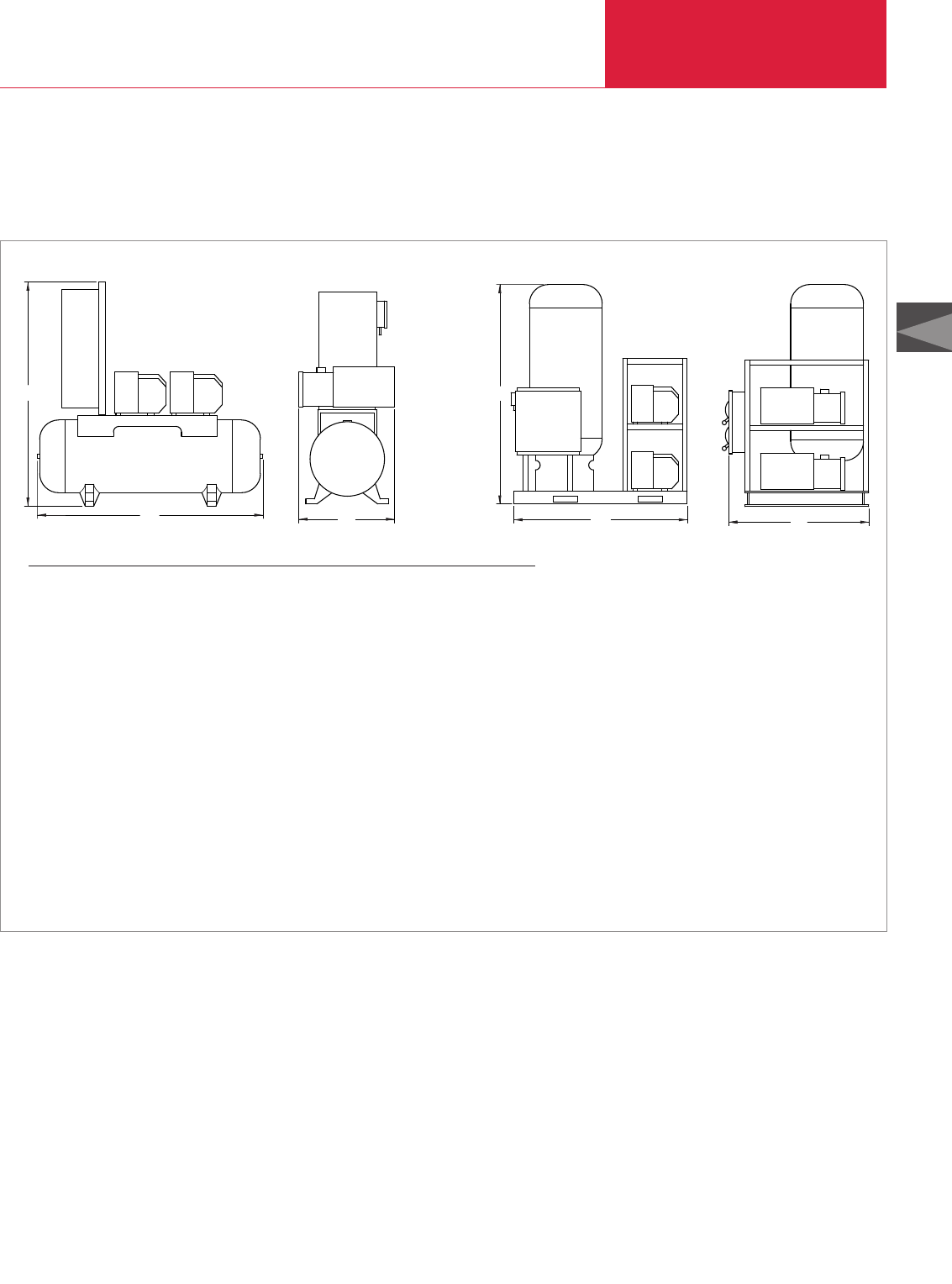
C02
LEYBOLD VACUUM PRODUCTS AND REFERENCE BOOK 2003/2004
Rotary Vane Vacuum Pumps
Miscellaneous
C02.49
Central Vacuum Systems
Version for the North and South American Continents
H
LW
H
LW
Central vacuum systems, tank mounted [left] and stack mounted [right]; dimensions in inch, dimensions in brackets ( ) are in mm
Pump model Tank size (gal) L W H
Tank mount - simplex
SV 16, UV 25 30 42 (1067) 20 (508) 51 (1295)
SV 40, SV 65 60 50 (1270) 25 (635) 48 (1219)
SV 100 80 65 (1651) 25 (635) 56 (1422)
SV 200, SV 300 120 70 (1778) 28 (711) 58 (1473)
Tank mount - duplex
SV 16, UV 25 60 50 (1270) 27 (686) 53 (1346)
SV 40, SV 65 80 65 (1651) 30 (762) 53 (1346)
SV 100 120 71 (1803) 32 (813) 53 (1346)
SV 200 240 84 (2134) 38 (965) 64 (1626)
SV 300 240 84 (2134) 43 (1092) 64 (1626)
Stack mount - duplex and triplex
SV 16, UV 25 60 45 (1143) 38 (965) 56 (1422)
SV 40 80 49 (1245) 42 (1067) 56 (1422)
SV 65 120 62 (1575) 45 (1143) 88 (2235)
SV 100 120 68 (1727) 42 (1067) 88 (2235)
SV 200 200 68 (1727) 50 (1270) 91 (1626)
SV 300 200 68 (1727) 58 (1473) 91 (1626)
Standard Equipment
♦ASME® rated receiver tank
♦Flexible configurations for one, two, or three
SOGEVAC pumps
♦Manual isolation valves
♦Simple operation, high reliability, easy
maintenance
♦Complete package with gauges and NEMA12
controls
Options
♦Tank or stack mounted pumps
♦Larger receiver tank
♦Special inlet filters
♦Automatic isolation valves
♦Special design controls per customer
specification
♦Standard “ON/OFF/AUTO” switch
♦Elapsed time meters
♦Inlet particulate filters
♦Lead/Lag or continuous operation of pumps
♦Adjustable pressure switch for control of
vacuum level
♦Air cooled Sogevac pumps with built-in “anti-
suckback” valves
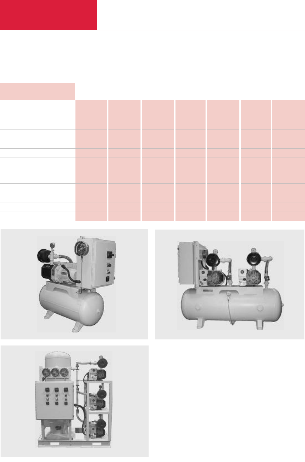
Miscellaneous
Rotary Vane Vacuum Pumps
C02.50 LEYBOLD VACUUM PRODUCTS AND REFERENCE BOOK 2003/2004
Version for the North and South American Continents
Technical Data Performance Characteristics
SV 16 UV 25 SV 40 SV 65 SV 100 SV 200 SV 300
Free air displacement cfm (m3x h-1)
Actual pumping speed cfm (m3x h-1)
Guaranteed base pressure in HgVac
Base pressure with gas ballast in HgVac
Water vapor tolerance in HgVac
Water vapor pumping with gas ballast qt/hr
Noise level at 3 feet with 1 pump running
without gas ballast dB(A)
Motor hp
Pump rotational speed rpm
Oil capacity qt
Inlet / exhaust-NPT in.
Pump weight lbs
11 (18.6) 17.7 (30) 32.4 (55) 45.9 (77.9) 70.6 (119.8) 129.5 (219.8) 200.3 (340)
10 (16.9) 15.3 (26) 28.3 (48) 37.7 (64) 66.5 (112.9) 117.8 (200) 170.8 (289.9)
29.89 29.89 29.89 29.89 29.89 < 29.99 < 29.99
29.80 29.80 29.80 29.80 29.80 < 29.90 < 29.90
29.01 29.01 28.74 28.74 28.74 28.80 28.80
0.5 0.5 0.73 1.3 2.1 5.7 7.8
58 59 64 65 72 73 74
1 1.5 2 3 5 7.5 10
1750 1750 1750 1750 1750 1750 1750
2 2 2 2.5 3.75 5.5 9
1/2 /1/2 1/2 /3/4 1-1/4 /1-1/4 1-1/4 /1-1/4 1-1/4 /2 2 /2 2 /2
50.7 83.8 90.4 103.4 213.4 341.8 430.0
Central Vacuum Systems
Central vacuum system, simplex
Central vacuum system, triplex
Central vacuum system, duplex
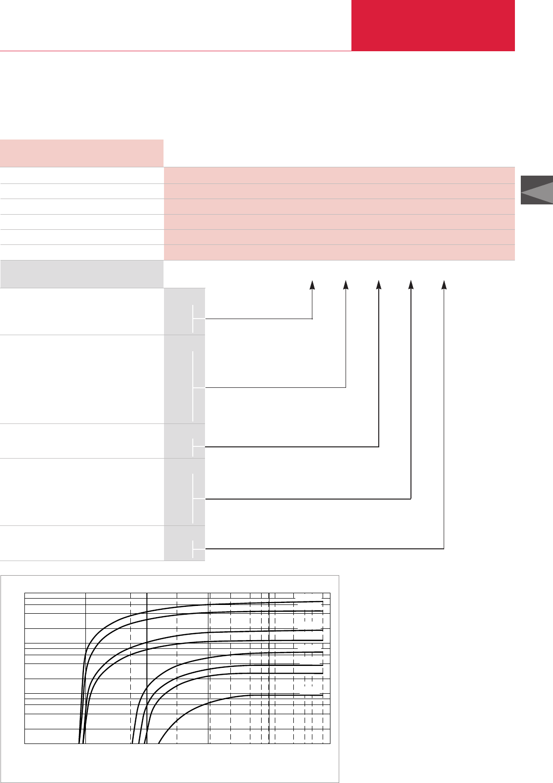
Miscellaneous
Rotary Vane Vacuum Pumps
C02.51
LEYBOLD VACUUM PRODUCTS AND REFERENCE BOOK 2003/2004
C02
Version for the North and South American Continents
Technical Data
Tank Mount Tank Mount Stack Mount
Simplex Duplex Duplex and Simplex
SV 16, UV 25 Tank size (gal)
SV 40 Tank size (gal)
SV 65 Tank size (gal)
SV 100 Tank size (gal)
SV 200 Tank size (gal)
SV 300 Tank size (gal)
30 60 60
60 80 80
60 120 120
80 120 120
120 240 200
120 240 200
System
Simplex
Duplex
Triplex
Pumps
SV 16 (1 hp)
UV 25 (1.5 hp)
SV 40 (2 hp)
SV 65 (3 hp)
SV 100 (5 hp)
SV 200 (7 hp)
SV 300 (10 hp)
Mounting
Tank mount
Stack mount
Voltage
460/3/60
230/3/60
230/1/60 (available for SV 16/UV 25 only)
208/3/60
115/1/60 (available for SV 16/UV 25 only)
Duty
Continuous
Demant Start/Stop
S
D
T
016
025
040
065
100
200
300
T
S
A
B
C
D
E
C
D
C – –––– –––– –––– –––– –––– ––––
Part No.
Ordering Information XX
Central Vacuum Systems
29.9(inHgVAC) 0
20 15 10252627282929.529.8
SV40
SV65
SV100
SV200
SV300
SV630
SV1200
cfm
10-2 101
100
10-1 102
Torr 103
103
102
101
100
8
6
4
2
Total Pressure
Pumping Speed
SV16
Pumping speed characteristics for the Central Vacuum Systems at 60 Hz
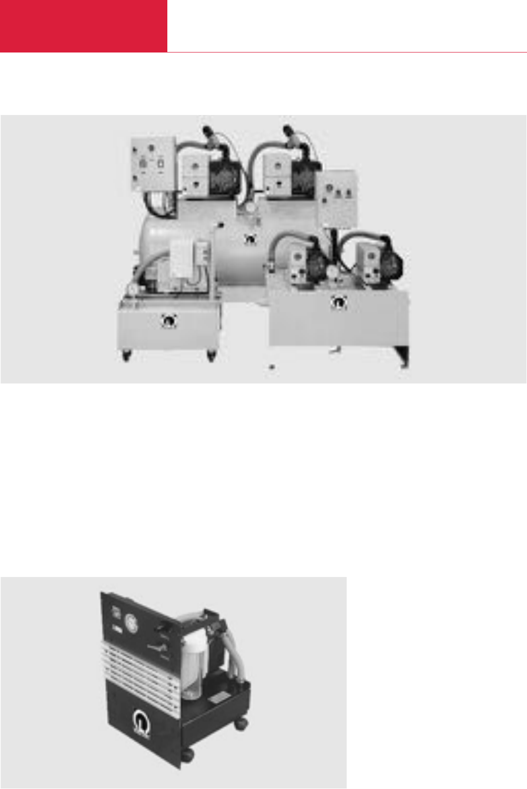
LEYBOLD VACUUM PRODUCTS AND REFERENCE BOOK 2003/2004
Rotary Vane Vacuum Pumps
Central Vacuum Systems
Description
Independently of the properties of the gases
which are to be pumped, central vacuum systems
are defined according to the following enginee-
ring requirements:
◆Operating pressure
◆Quantity of gas to be pumped
◆Duration of the pumping cycle
◆Choice of control system
Mobile vacuum station CV 30-LABO for laboratories
Many Combinations
◆Modular system
◆Pumps having pumping speeds from
16 to 1200 m
3
/h (9.4 to 706.8 cfm)
◆Backup volumes from 30 to 1500 l (32 qt to
1586 l) (larger buffer volumes upon request)
◆Very short delivery time (due to the modular
system)
Contact us for further information.
Miscellaneous
C02.52
CV 300 – 2/65
CV 60 M – 1/40
CV 1000 – 2/300
Advantages to the User
◆Two different types of control
◆Pressure control between two adjustable
pressures for central systems with one or
two pumps
◆Changeover and safety unit for two or three
pumps
◆Simple process-independent set-up
◆Operating hours counter for each pump

C02
LEYBOLD VACUUM PRODUCTS AND REFERENCE BOOK 2003/2004
Rotary Vane Vacuum Pumps
Miscellaneous
C02.53
Central type Vessel Nominal Connection Mains voltage Required Part No.
size pumping speed at 50 Hz Power
l (qt) m3x h-1 BSP V kW (hp)
60M – 1 x 25 60 (63.42) 25 1 1/4"230, 1~ 0.75 (1) 954 00
60 – 1 x 25 60 (63.42) 25 1 1/4"400, 3~ 0.75 (1) 954 01
60M – 1 x 40 60 (63.42) 40 1 1/4"230, 1~ 1.1 (1.5) 954 02
60 – 1 x 40 60 (63.42) 40 1 1/4"400, 3~ 1.1 (1.5) 954 03
60M – 1 x 65 60 (63.42) 65 1 1/4"230, 1~ 1.5 (2) 954 04
60 – 1 x 65 60 (63.42) 65 1 1/4"400, 3~ 1.5 (2) 954 05
150 – 1 x 40 150 (158.56) 40 1 1/4"400, 3~ 1.1 (1.5) 954 06
150 – 1 x 65 150 (158.56) 65 1 1/4"400, 3~ 1.5 (2) 954 07
300 – 1 x 40 300 (317.12) 40 2"400, 3~ 1.1 (1.5) 954 08
300 – 1 x 65 300 (317.12) 65 2"400, 3~ 1.5 (2) 954 09
300 – 1 x 100 300 (317.12) 100 2"400, 3~ 2.5 (3.4) 954 10
500 – 1 x 40 500 (528.54) 40 2"400, 3~ 1.1 (1.5) 954 11
500 – 1 x 65 500 (528.54) 65 2"400, 3~ 1.5 (2) 954 12
500 – 1 x 100 500 (528.54) 100 2"400, 3~ 2.5 (3.4) 954 13
500 – 1 x 200 500 (528.54) 200 2"400, 3~ 4 (5.4) 954 14
500 – 1 x 300 500 (528.54) 300 2"400, 3~ 5.5 (7.5) 954 15
750 – 1 x 100 750 (792.81) 100 2"400, 3~ 2.5 (3.4) 954 16
750 – 1 x 200 750 (792.81) 200 2"400, 3~ 4 (5.4) 954 17
750 – 1 x 300 750 (792.81) 300 2"400, 3~ 5.5 (7.5) 954 18
1000 – 1 x 100 1000 (1057.08) 100 2"400, 3~ 2.5 (3.4) 954 19
1000 – 1 x 200 1000 (1057.08) 200 2"400, 3~ 4 (5.4) 954 20
1000 – 1 x 300 1000 (1057.08) 300 2"400, 3~ 5.5 (7.5) 954 21
150 – 2 x 40 150 (158.56) 80 1 1/4"400, 3~ 2.2 (3) 954 52
150 – 2 x 65 150 (158.56) 130 1 1/4"400, 3~ 3 (4.1) 954 53
300 – 2 x 40 300 (317.12) 80 1 1/4"400, 3~ 2.2 (3) 954 54
300 – 2 x 65 300 (317.12) 130 1 1/4"400, 3~ 3 (4.1) 954 55
300 – 2 x 100 300 (317.12) 200 1 1/4"400, 3~ 5 (6.8) 954 56
500 – 2 x 40 500 (528.54) 80 2"400, 3~ 2.2 (3) 954 57
500 – 2 x 65 500 (528.54) 130 2"400, 3~ 3 (4.1) 954 58
500 – 2 x 100 500 (528.54) 200 2"400, 3~ 5 (6.8) 954 59
500 – 2 x 200 500 (528.54) 360 2"400, 3~ 8 (10.9) 954 60
750 – 2 x 100 750 (792.81) 200 2"400, 3~ 5 (6.8) 954 61
750 – 2 x 200 750 (792.81) 360 2"400, 3~ 8 (10.9) 954 62
750 – 2 x 300 750 (792.81) 560 2"400, 3~ 11 (15) 954 63
1000 – 2 x 100 1000 (1057.08) 200 2"400, 3~ 5 (6.8) 954 64
1000 – 2 x 200 1000 (1057.08) 360 2"400, 3~ 8 (10.9) 954 65
1000 – 2 x 300 1000 (1057.08) 560 2"400, 3~ 11 (15) 954 66
150 – 2 x 40 MAS 150 (158.56) 40 / 80 1 1/4"400, 3~ 2.2 (3) 954 77
150 – 2 x 65 MAS 150 (158.56) 65 / 130 1 1/4"400, 3~ 3 (4.1) 954 78
300 – 2 x 40 MAS 300 (317.12) 40 / 80 1 1/4"400, 3~ 2.2 (3) 954 79
300 – 2 x 65 MAS 300 (317.12) 65 / 130 1 1/4"400, 3~ 3 (4.1) 954 80
300 – 2 x 100 MAS 300 (317.12) 100 / 200 1 1/4"400, 3~ 5 (6.8) 954 81
500 – 2 x 40 MAS 500 (528.54) 40 / 80 2"400, 3~ 2.2 (3) 954 82
500 – 2 x 65 MAS 500 (528.54) 65 / 130 2"400, 3~ 3 (4.1) 954 83
500 – 2 x 100 MAS 500 (528.54) 100 / 200 2"400, 3~ 5 (6.8) 954 84
500 – 2 x 200 MAS 500 (528.54) 180 / 360 2"400, 3~ 8 (10.9) 954 85
750 – 2 x 100 MAS 750 (792.81) 100 / 200 2"400, 3~ 5 (6.8) 954 86
750 – 2 x 200 MAS 750 (792.81) 180 / 360 2"400, 3~ 8 (10.9) 954 87
750 – 2 x 300 MAS 750 (792.81) 280 / 560 2"400, 3~ 11 (15) 954 88
1000 – 2 x 100 MAS 1000 (1057.08) 100 / 200 2"400, 3~ 5 (6.8) 954 89
1000 – 2 x 200 MAS 1000 (1057.08) 180 / 360 2"400, 3~ 8 (10.9) 954 90
1000 – 2 x 300 MAS 1000 (1057.08) 280 / 560 2"400, 3~ 11 (15) 954 91
Technical Data and Ordering Information
Central Vacuum System with 2 Pumps and Changeover and Safety Unit
Central Vacuum System with 2 Pumps and Basic Control
Central Vacuum System with 1 Pump and Basic Control
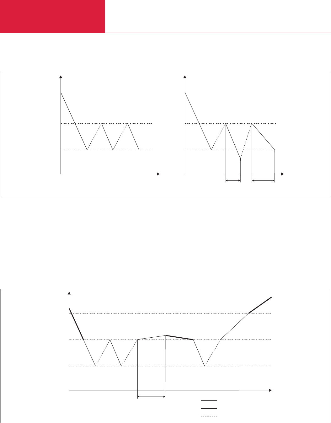
Miscellaneous
Rotary Vane Vacuum Pumps
C02.54 LEYBOLD VACUUM PRODUCTS AND REFERENCE BOOK 2003/2004
Control Principles for Central Vacuum Systems
S1
S0
p
t
S1
S0
p
t
> 10 min< 10 min
Central vacuum system with basic controller
Central vacuum system with one pump (general) Central vacuum system with one pump > 100m3·h-1
S1
S0
p
t
S2
Verzögerung = 10 min 1 Pumpe
2 Pumpen
Pumpvorgang gestoppt
Central vacuum system with switching and safety module (MAS)
Central Vacuum System with
Basic Controller
The basic controller is controlled through 2 freely
selectable switching thresholds. The controller
drives the vacuum pump or a valve. In the case
of pumps with pumping speeds over 100 m
3
/h
(58.9 cfm) the switching frequency is either
restricted to 6 times per hour or they are
controlled by a valve.
Central Vacuum System with
Switching and Safety Module
This controller has 3 switching thresholds and is
for 2 pumps running in parallel. At peak demand
both pumps, and during normal demand only one
pump will be running. After pre-defined intervals
the pumps will change so as to evenly spread the
number of operating hours across both pumps.
Delay= 10 min 1 pump
2 pumps
Pumping stopped

General Accessories
Rotary Vane Vacuum Pumps
C02.55
LEYBOLD VACUUM PRODUCTS AND REFERENCE BOOK 2003/2004
C02
Lubricating oils for rotary vacuum pumps need to
fulfil demanding requirements. Their vapor pres-
sure must be low at high temperatures and the
water content and water uptake must be minimal.
Their viscosity characteristics need to be flat,
lubricating properties need to be excellent and
they must resist cracking upon being mechanical-
ly stressed.
All the vacuum pump oils listed in the following
have been subjected in our factory laboratories to
very comprehensive tests closely resembling the
conditions encountered in practice by the pumps
from the SOGEVAC series.
We therefore recommend the exclusive use of
vacuum pump oils fully qualified by Leybold so
as to ensure optimum performance of the
Leybold vacuum pumps and also to ensure opti-
mum oil change intervals.
Under vacuum conditions lubricating oils may
behave quite differently than expected. When
using not suitably qualified third party oils, the
oil change intervals and the performance of the
vacuum pump may be reduced. Also unwanted
deposits may occur which may even cause
severe damage to the vacuum pump.
For these reasons please understand that we
must make our warranty commitment dependent
on the use of oils which have been qualified by
us. Damages caused by the use of not suitably
qualified lubricating oils are not covered by our
warranty.
In order to adapt the pumps to the different appli-
cations of our customers, different types of oil
are used in the SOGEVAC pumps.
Please note that owing to differing properties not
all types of oil may be used in all pumps of the
SOGEVAC series. If you can not find the combi-
nation of pump and oil you require by way of a
Part. No., please ask us for a quotation.
Vacuum Pump Oils
Lubricant types
Mineral oils
Mineral oils are products distilled and refined
from crude oil. These do not consist of precisely
defined compounds but rather consist of a com-
plex mixture. The way in which the mineral oil is
pre-treated and its composition is decisive as to
the applications it will be suited for. Depending
on the distribution of the hydrocarbons and the
dominance of certain properties, mineral oils are
grouped according to paraffin-base, naphthenic
and aromatic. For the purpose of attaining espe-
cially low ultimate pressures, mineral oils must
be selected on the basis of a core fraction. The
thermal and chemical resistance of mineral oils
has been found to be adequate in the majority of
applications. They offer a high degree of compati-
bility with elastomers and resistance to hydroly-
sis.
Synthetic oils
Synthetic oils are produced by a chemical reac-
tion. The group of synthetic oils includes liquids
differing widely as to their chemical structure and
composition. Correspondingly their physical and
chemical properties differ considerably. Synthetic
oils are used in those cases where special pro-
perties of the oil are required which can not be
fulfilled by mineral oils.
The oils given in the following belong to the
group of synthetic oils:
Ester oils
Ester oils are organic compounds which excel
especially through their high thermal resistance
to cracking compared to mineral oils. Chemical
resistance is generally quite good, but will
depend on the type of ester oil. Elastomer com-
patibility and resistance against hydrolysis are
not so good compared to mineral oils.
Perfluorinated polyether
(PFPE)
These are oils which are only composed of carb-
on (C), fluorine (F) and oxygen atoms (O). The
existing C-O and C-F bonds are highly stable. For
this reason PFPE oils are practically inert against
all chemical and oxidising influences.
Perfluorinated polyether will not polymerise
under the influence of high energy radiation.
PFPE is non-flammable. Leybold NC1/14 has the
approval of BAM (Federal Institute for Materials
Research and Testing) for pumping of pure oxy-
gen.
Perfluorinated polyether are used when pumping
strongly reactive substances like oxygen (O
2
),
fluorine F
2
and uranium hexafluoride UF
6
.
Regarding Lewis acids (for example, boron triflu-
oride BF
3
, aluminum trichloride AlCl
3
) they are
not completely inert. Here reactions may take
place at temperatures over 100 °C (212 °F).
Perfluorinated polyether are thermally highly sta-
ble. Thermal decomposition may only take place
at temperatures of over 290 °C (554 °F).
Caution: Perfluorinated polyether will – when
decomposed – release toxic and corrosive gases:
hydrogen fluoride HF, carbonyl difluoride COF
2
.
For this reason open fires must be avoided in the
workspace where PFPE is being used. Do not
smoke in the workspace where PFPE is being
used.
Only suitably prepared pumps must be used in
connection with perfluorinated polyether, since it
is essential that the pump be free of hydrocar-
bons. Changing from one basic type of oil to
PFPE must be left exclusively to authorised
Service Centers. The pumps will have to be fully
disassembled and carefully cleaned. Gaskets and
filters will have to be exchanged and suitable
greases will have to be used.
For all lubricants in our line of products you may obtain Safety Data Sheets from the Dept. Technical
Support in Cologne.

General Accessories
Rotary Vane Vacuum Pumps
C02.56 LEYBOLD VACUUM PRODUCTS AND REFERENCE BOOK 2003/2004
Viscosity at 40 °C (104 °F) mm2/s 30 77 32 68
Viscosity at 100 °C (212 °F) mm2/s 6 10 6 9
Flash point °C (°F) 220 (428) 245 (473) 228 (442) 260 (500)
Vapor pressure
at 100 °C (212 °F) mbar (Torr) 5 x 10⁻³ (6.7 x 10⁻³) 1 x 10⁻³ (0.75 x 10⁻³) 5 x 10⁻³ (6.7 x 10⁻³) 1 x 10⁻³ (0.75 x 10⁻³)
Density at 15 °C g/ml 0.86 0.87 0.87 0.87
Pour point °C (°F) -27 (17) -24 (11) -9 (-16) -18 (0)
Technical Data
Special oil GS 32 Special oil GS 77 FM 32 FM 68
Oil recommendations for various areas of application
Application Data
Special oil GS 32 Special oil GS 77 FM 32 FM 68
Type of oil
Examples of areas of application
and process media
Remarks
Elastomer compatibility
FPM (Viton)
NBR (Perbunan) 1)
EPDM
Paraffin-base mineral oil with
additives to improve oxidization
stability and wearing properties
Standard oil
For pumping air, chemically inert
permanent gases (noble gases, for
example), water vapor, solvent
vapors pumped by laboratory
pumps operated with cold traps
The ultimate pressures stated in
our catalogs are based on operati-
on of the pump with GS 77 (except
for the DOT and PFPE pumps)
Suited
Suited
Not suited
Medicinal white oil with additives –
in accordance with FDA and
USDA H1
Food sector acc. to USDA H1
approved for accidental contact
with foodstuffs
Suited
Suited
Not suited
Medicinal white oil with additives –
in accordance with FDA and
USDA H1
Food sector acc. to USDA H1
approved for accidental contact
with foodstuffs
Suited
Suited
Not suited
Paraffin-base mineral oil with
additives to improve oxidization
stability and wearing properties
Standard oil
For pumping air, chemically inert
permanent gases (noble gases, for
example), water vapor, solvent
vapors pumped by laboratory
pumps operated with cold traps
The ultimate pressures stated in
our catalogs are based on operati-
on of the pump with GS 32 (except
for the DOT and PFPE pumps)
Suited
Suited
Not suited
Ordering
Information Special oil GS 32 Special oil GS 77 FM 32 FM 68
001 litre (1.06 qt) Part No. 711 17 772 – Part No. 711 17 782 –
002 litres (2.1 qt) Part No. 711 17 723 – – –
005 litres (5.29 qt) Part No. 711 17 724 Part No. 711 17 774 Part No. 711 17 783 Part No. 711 17 784
025 litres (26.43 qt) – Part No. 711 17 776 – Part No. 711 17 786
060 litres (63.42 qt) Part No. 711 17 727 – – –
200 litres (211.42 qt) – Part No. 711 17 779 – –
Please note that the technical data stated are only typical data. Slight variations from batch to batch must be expected.
The technical data stated here can not be taken as assured properties
1) Resistance to decomposing is very much dependent on the share of acrylonitrile in the NBR

General Accessories
Rotary Vane Vacuum Pumps
C02.57
LEYBOLD VACUUM PRODUCTS AND REFERENCE BOOK 2003/2004
C02
Viscosity at 40 °C (104 °F) mm2/s 28 94 38 N/I 47
Viscosity at 100 °C (212 °F) mm2/s 6 9 4 > 2 5
Flash point °C (°F) 245 (473) 250 (482) 210 (410) > 120 (> 248) No known 3)
Vapor pressure
at 20 °C (68 °F) mbar (Torr) No known 7 x 10⁻⁵ (9.3 x 10⁻⁵) 1 x 10⁻⁴ (0.75 x 10⁻⁴) 1.3 (1) 3 x 10⁻⁷ (2.5 x 10⁻⁷)
Vapor pressure
at 100 °C (212 °F) mbar (Torr) No known 1,5 x 10⁻³ (2 x 10⁻³) No known No known 6 x 10⁻⁴ (8 x 10⁻⁴)
Density at 15 °C (59 °F) g/ml 0.92 0.96 1.05 2) 1.05 1.89 2)
Pour point °C (°F) -57 (-71) -42 (-44) -15 (-5) No known -40 (-40)
Middle molecular weight g/mol No known 530 No known No known 2,500
Technical Data
Anderol®495 Anderol®555 NC 10 DOT 4 NC 1/14
Application Data
Anderol®495 Anderol®555 NC 10 DOT 4 NC 1/14
Type of oil
Examples of areas of application
and process media
Remarks
Elastomer compatibility
FPM (Viton)
NBR (Perbunan) 1)
EPDM
Ester oil
Used at elevated tempera-
tures, pumping of air, che-
mically inert permanent
gases (noble gases, for
example),
carbon dioxide CO2, carbon
monoxide CO, aliphatic
compounds (for example
methane CH4, propane
C3H8, ethylene C2H4),
organic solvent vapors
Do not pump any
inorganic acids
(HCL, HF, for example),
no free halogens
(CL2, F2, for example) or
alkaline media (NH3,
for example)
Suited
Conditionally suited
Not suited
Alkyl sulphonic acid ester
Used for pumping process
media which tend to polyme-
rise (for example, styrene
C8H8, butadiene C4H6)
Do not use a chemical
oil filter
Mixing with other types of oil
must be absolutely avoided
Do not pump any
inorganic acids
(for example HCl, HF)!
Suited
Not suited
Not suited
Brake fluid
Filling of brake fluid cir-
cuits in the car industry
only
Use only in pumps
modified for DOT 4
Mixing with other types
of oil must be absolutely
avoided
Not suited
Not suited
Suited
Ester oil
Used at elevated
temperatures.
Starting of the pump at
temperatures between
0 and 12 °C
(32 and 54 °F)
Do not pump any
inorganic acids
(HCL, HF, for example),
no free halogens
(CL2, F2, for example) or
alkaline media (NH3,
for example)
Suited
Conditionally suited
Not suited
Ordering
Information Anderol®495 Anderol®555 NC 10 DOT 4 NC 1/14
001 litre (1.06 qt) – – – Part No. 200 10 037 Part No. 177 38/Part No. 711 17 792
002 litres (2.1 qt) Part No. 711 17 763 – – – –
005 litres (5.29 qt) Part No. 711 17 764 Part No. 711 17 754 – – –
020 litres (26.43 qt) Part No. 711 17 766 Part No. 711 17 756 Part No. 177 25 – –
060 litres (63.42 qt) Part No. 711 17 767 Part No. 711 17 757 – – –
200 litres (211.42 qt) – Part No. 200 03 257 – – –
Perfluorinated polyether PFPE
For pumping strong oxidants like oxy-
gen, O2, ozone O3, nitrogen oxides NOx
and sulphur oxides (SO2, SO3) as well
as reactive substances like halogens
(for example fluorine F2, chlorine Cl2),
halogen hydracide (for example hydro-
gen chloride HCl, hydrogen bromide
HBr), uranium hexafluoride UF6, and
conditionally Lewis acids (for example,
boron trichloride BCl3)
Use only in pumps modified for PFPE
Mixing with other types of oil must be
absolutely avoided
Avoid pumping water vapour, especial-
ly in connection with corrosive media
(see above)
The use of a chemical oil filter CF / CFS
is strongly recommended
Suited
Suited
Suited
Please note that the technical data stated are only typical data. Slight variations from batch to batch must be expected.
The technical data stated here can not be taken as assured properties
1) Resistance to decomposing is very much dependent on the share of acrylonitrile in the NBR 2) at 20 °C (68 °F)
3) Caution: When being decomposed at temperatures over 290 °C (554 °F), toxic and corrosive gases will be released. For this reason open fires must be avoided in the workspace where PFPE is
being used. Do not smoke in the workspace where PFPE is being used
ANDEROL®is a trademark of ANDEROL BV

General Accessories
Rotary Vane Vacuum Pumps
C02.58 LEYBOLD VACUUM PRODUCTS AND REFERENCE BOOK 2003/2004
Version for the North and South American Continents
Viscosity at 40 °C (104 °F) mm2/s 32 79
Viscosity at 100 °C (212 °F) mm2/s 5.3 9.5
Flash point °C (°F) 206 (403) 224 (435)
Vapor pressure
at 93 °C (200 °F) mbar (Torr) 2.1 x 10⁻³ (1.6 x 10⁻³) 1.6 x 10⁻² (1.2 x 10⁻²)
Pour point °C (°F) -27 (-17) -20 (-4)
Technical Data
HE-100 HE-700
Application Data
HE-100 HE-700
Type of oil
Examples of areas of application
and process media
Remarks
Elastomer compatibility
FPM (Viton)
NBR (Perbunan) 1)
EPDM
Paraffin-base mineral oil with
additives to improve oxidization
stability and wearing properties
Standard oil
For pumping air, chemically inert
permanent gases (noble gases, for
example), water vapor, solvent
vapors pumped by laboratory
pumps operated with cold traps
The ultimate pressures stated in
our catalogs are based on operation
of the pump with HE-100 (except
for the DOT and PFPE pumps)
Suited
Suited
Not suited
Ordering
Information HE-100 HE-700
01 qt Part No. 898 537 –
01 gal Part No. 898 538 Part No. 726 25 023
55 gal Part No. 898 539 Part No. 726 25 022
Paraffin-base mineral oil with
additives to improve oxidization
stability and wearing properties
Standard oil
For pumping air, chemically inert
permanent gases (noble gases, for
example), water vapor, solvent
vapors pumped by laboratory
pumps operated with cold traps
The ultimate pressures stated in our
catalogs are based on operation of
the pump with HE-700 (except for
the DOT and PFPE pumps)
Suited
Suited
Not suited
Please note that the technical data stated are only typical data. Slight variations from batch to batch must be expected.
The technical data stated here can not be taken as assured properties
1) Resistance to decomposing is very much dependent on the share of acrylonitrile in the NBR
Note: HE-100 is the standard oil for SV 16 to SV 100, HE-700 is the standard oil for SV 200 to SV 1200
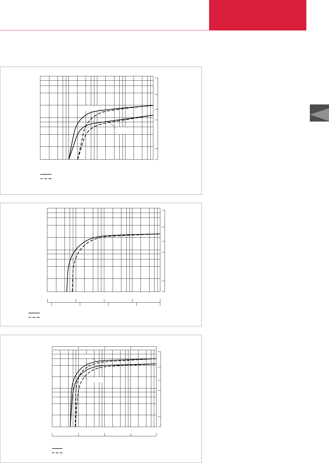
60 Hz Curves
Rotary Vane Vacuum Pumps
C02.59
LEYBOLD VACUUM PRODUCTS AND REFERENCE BOOK 2003/2004
C02
Pumping Speed
2
4
6
8
102
101
100
CFM
20
10
5
1
50
-1
h
x
3
m
Pressure
10-1 2 4 6 8
100101102103
mbar
SV 16 B
without gas ballast
with gas ballast
SV 10 B
Pumping speed characteristics for the SOGEVAC SV 10 B and SV 16 B at 60 Hz
Version for the North and South American Continents
Pumping Speed
2
4
6
8
102
101
100
CFM
20
10
5
1
50
-1
h
.
3
m
Pressure
2 4 6 8
without gas ballast
with gas ballast
10-1 100101102103
mbar
10-1 100101Torr
102750
Pumping Speed
2
4
6
8
102
101
100
CFM
20
10
5
1
50
-1
x h
3
m
Pressure
10-1 2 4 6 8
100101102103
mbar
101102103104105
Pa
29.918 29.9 29.530 25.980 0
Inches.Hg
without gas ballast
with gas ballast
SV 40 B
SV 65 B
Pumping speed characteristics for the SOGEVAC SV 40 B and SV 65 B at 60 Hz
without gas ballast
with gas ballast
Pumping speed characteristics for the SOGEVAC SV 25 B at 60 Hz
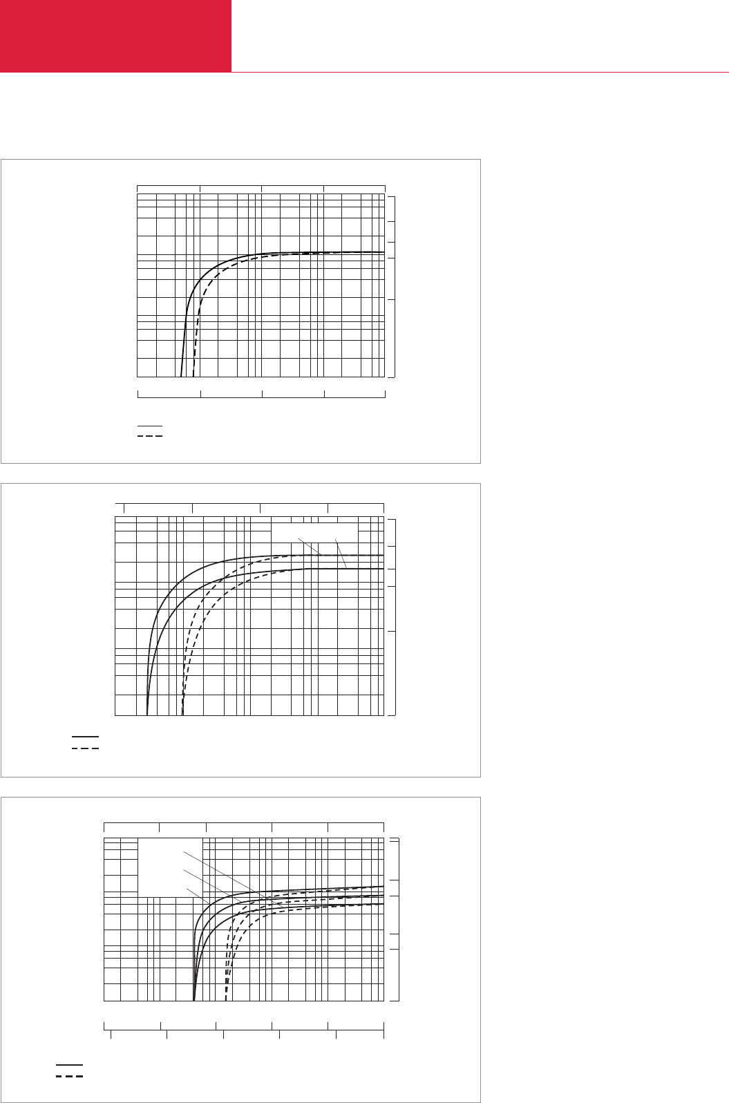
60 Hz Curves
Rotary Vane Vacuum Pumps
C02.60 LEYBOLD VACUUM PRODUCTS AND REFERENCE BOOK 2003/2004
CFM
500
Pumping speed
2 4 6 8
2
4
6
8
10
101
102
103
200
100
50
1
m
3
x
h
-1
29.918 29.9 29.530 25.980 0
Inches.Hg
Pressure
10-1 100101102103
mbar
101102103104105
Pa
without gas ballast
with gas ballast
0
Pumping speed characteristics for the SOGEVAC SV 100 B at 60 Hz
Version for the North and South American Continents
cfm
50
Pressure
Pumping speed
2 4 6 8
2
4
6
8
10-1
100
10-1
100
101102103
101
102
20
10
5
1
SV 25 SV 16
Torr
10
-1
110 100 750
mbar
m
3
x
h
-1
without gas ballast
with gas ballast
500
cfm
Inches
x Hg
025.98029.530
1000
29.91829.921
100
10
1
10-1
10-2 100101102103
mbar
29.9
10
5
50
100
Torr
SV 40
SV 65
SV 100
Pressure
Pumping speed
m
3
x
h
-1
without gas ballast
with gas ballast
10-2 10-1 100101102750
2 4 6 8
2
4
6
8
Pumping speed characteristics for the SOGEVAC SV 40 to SV 100 at 60 Hz
Pumping speed characteristics for the SOGEVAC SV 16 and SV 25 at 60 Hz
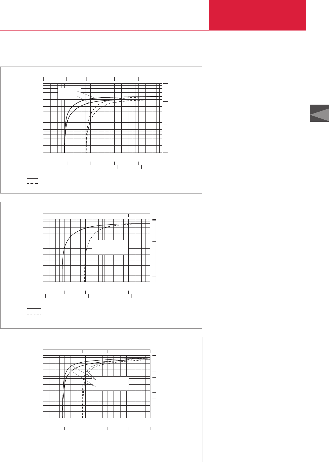
Rotary Vane Vacuum Pumps
C02.61
LEYBOLD VACUUM PRODUCTS AND REFERENCE BOOK 2003/2004
C02
Version for the North and South American Continents
500
cfm
Inches
x Hg
025.98029.530
1000
29.91829.921
100
10
1
29.9
10
5
50
100
SV 200
SV 300
Pressure
Pumping speed
m
3
x
h
-1
without gas ballast
with gas ballast
10-1
10-2 100101102103
mbar
Torr
10-2 10-1 100101102750
2 4 6 8
2
4
6
8
Pumping speed characteristics for the SOGEVAC SV 200 and SV 300 at 60 Hz
500
cfm
Inches
x Hg
025.98029.53029.91829.921
-1
hx
3
m
2 4 6 8
29.9
10
5
50
100
1
100
2
4
6
8
103
102
101
Pressure
without gas ballast
Pumping speed
SV 500
with gas ballast
10-1
10-2 100101102103
mbar
Torr
10-2 10-1 100101102750
Pumping speed characteristics for the SOGEVAC SV 500 at 60 Hz
500
cfm
Inches
x Hg
025.98029.53029.91829.921
-1
h
.
3
m
10-1
10-2 100101102103
mbar
102103104105
101
100
29.9
10
5
50
100
Pa
1
100
103
102
101
Pressure
Pumping speed
SV 750
SV 630 (F)
Pumping speed characteristics for the SOGEVAC SV 630 (F) and SV 750 at 60 Hz
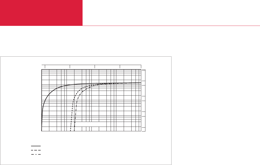
60 Hz Curves
Rotary Vane Vacuum Pumps
C02.62 LEYBOLD VACUUM PRODUCTS AND REFERENCE BOOK 2003/2004
Version for the North and South American Continents
mbar
2100
Pumping speed
4 8
100
6
101
102
103
104
10-1 101102103
Pressure
8
4
2
6
SV 1200
without gas ballast
with 1 gas ballast
with 2 gas ballasts
m
3
x
h
-1
10
-1
110 100 750
Torr
500
100
50
10
5
1
1000
5000
cfm
Pumping speed characteristics for the SOGEVAC SV 1200 at 60 Hz
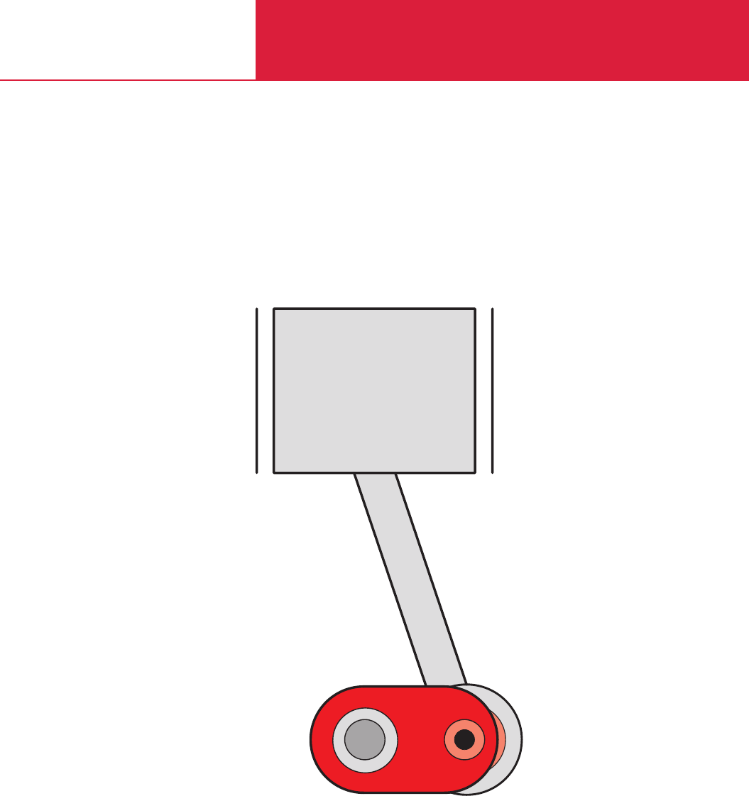
C03
EcoDry L
EcoDry M
Dry Compressing Piston
Vacuum Pumps

Contents
C03.02 LEYBOLD VACUUM PRODUCTS AND REFERENCE BOOK 2003/2004
Dry Compressing Piston Vacuum Pumps
General
Applications and Accessories . . . . . . . . . . . . . . . . . . . . . . . . . . . . . . . . . . . . . . . . . . . . . . . C03.03
General Information on the EcoDry L and M . . . . . . . . . . . . . . . . . . . . . . . . . . . . . . . . . . . . C03.04
Products
EcoDry L . . . . . . . . . . . . . . . . . . . . . . . . . . . . . . . . . . . . . . . . . . . . . . . . . . . . . . . . . . . . . . C03.06
EcoDry M. . . . . . . . . . . . . . . . . . . . . . . . . . . . . . . . . . . . . . . . . . . . . . . . . . . . . . . . . . . . . . C03.10
Accessories
EcoDry L
Cart . . . . . . . . . . . . . . . . . . . . . . . . . . . . . . . . . . . . . . . . . . . . . . . . . . . . . . . . . . . . . . . . C03.14
Roots Pump Adapter . . . . . . . . . . . . . . . . . . . . . . . . . . . . . . . . . . . . . . . . . . . . . . . . . . . C03.15
Gasballast Valve, manually operated (Retrofit Kit) . . . . . . . . . . . . . . . . . . . . . . . . . . . . . . C03.16
EcoDry M
Exhaust Silencer. . . . . . . . . . . . . . . . . . . . . . . . . . . . . . . . . . . . . . . . . . . . . . . . . . . . . . . C03.17
Vibration Absorbing Feet . . . . . . . . . . . . . . . . . . . . . . . . . . . . . . . . . . . . . . . . . . . . . . . . C03.17
Vibration Absorbing Kit . . . . . . . . . . . . . . . . . . . . . . . . . . . . . . . . . . . . . . . . . . . . . . . . . C03.18
EcoDryL and EcoDryM 15/20
Solenoid Gas Ballast Valve . . . . . . . . . . . . . . . . . . . . . . . . . . . . . . . . . . . . . . . . . . . . . . . C03.19
Miscellaneous
60 Hz Curves. . . . . . . . . . . . . . . . . . . . . . . . . . . . . . . . . . . . . . . . . . . . . . . . . . . . . . . . . . . C03.20

C03
C03.03
LEYBOLD VACUUM PRODUCTS AND REFERENCE BOOK 2003/2004
Application and Accessories
Applications in physics
Applications in loadlock
Vacuum locks
Mass spectrometers
Electron microscope
Lamps and bulbs manufacture
Coating systems
Freeze drying
Backing of Turbomolecular pumps and Compound-Turbomolecular pumps
Applications
Accessories
Pump
EcoDryL
♦ ♦
♦ ♦
♦ ♦
♦ ♦
♦ ♦
♦ ♦
♦ ♦
♦
♦ ♦
Page
Cart C03.14
Roots pump adapter C03.15
Gas ballast valve, manually operated (retrofit kit) C03.16
Exhaust silencer C03.17
Vibration absorbing feet C03.17
Vibration absorbing kit C03.18
Solenoid gas ballast valve C03.19
♦
♦
♦
♦
♦
♦
♦ ♦
Applications and Accessories
Dry Compressing Piston Vacuum Pumps
EcoDryM 15/20/30
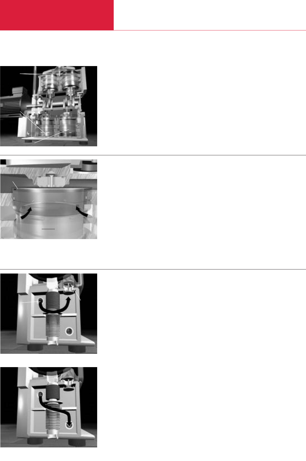
General Information on the EcoDry L
C03.04 LEYBOLD VACUUM PRODUCTS AND REFERENCE BOOK 2003/2004
Dry Compressing Piston Vacuum Pumps
The EcoDry L (see Fig. 1) is a 4-stage absolutely
dry compressing piston vacuum pump of the
latest generation.
It does not have any oil lubricated components
and does not contain hydrocarbon lubricants.
The four pistons are of the double-action type.
This means that there is a compression chamber
both at the top and the bottom of each piston.
The gas which is pumped enters through slits
which are controlled by the action of the piston,
into the compression chamber where it is
compressed against a large valve which extends
over the entire cross section of the piston (see
Fig. 2).
These valves have been designed to be extremely
rugged and will operate very reliably.
Compared to other vacuum pumps, the rational
speed is very low (about 900 to 1100 rpm; for
50/60 Hz operation).
For the purpose of an optimised distribution of
the moving mass and also for the purpose of
reducing the noise and vibration levels, the
pistons have been arranged opposing each other.
During the compression cycle the pistons move
at low contact forces and entirely dry so that the
bushings are hardly subject to any wear at all.
Sealing is performed through dynamic seals
which provide a dry seal in the direction of the
drive unit and a grease seal (free of hydrocarbons)
in the direction of the atmosphere.
The extremely favourable and low coefficient of
friction between the surface of the piston or the
sealing surface and the bushing is the basis for
the very high level of reliability and the low power
consumption of this pump.
In combination with the standard integrated
bypass valve (see Fig. 3 and 4) which drives the
compression stages mechanically and for this
reason most reliably, the amount of power
consumed is highly attractive over the entire
operating pressure range.
The EcoDry L is simple by design and consists
only of a few components. Therefore, no special
tools will be required for servicing.
Moreover, during servicing of the pump no
special alignments or adjustments will be
required since the components which replace the
wearing parts have already been adapted to the
pump so as to ensure reliable operation.
During operation, any maintenance or care
requirements have been reduced to a minimum
because it is not necessary to check any oil levels
or exchange and replace any exhaust filter
components and alike.
The EcoDry L is available for three-phase mains
supplies and with its standard motor it may be
installed almost anywhere in the world without
modifications.
The standard operating hours counter in the
junction box of the motor allows the user to
precisely check the number of operating hours.
The accessories which are available have been
adapted specifically to the areas of application for
this pump and allow the EcoDry L to be adapted
in the best possible way to the requirements of
the specific application.
EcoDry L - The New Dry Compressing Piston Vacuum Pump for Clean Processes
Fig. 1 Cross section of the EcoDry L
Fig. 2 Piston and valve arrangement
Fig. 4 Bypass valve, < 200 mbar (< 150 Torr) intake pressure
Fig. 3 Bypass valve, > 200 mbar (> 150 Torr) intake pressure
1st stage
3rd and 4th stage
2nd stage
Valve
Piston
from the
1st stage
Exhaust
to 2nd,
3rd
and 4th
stage
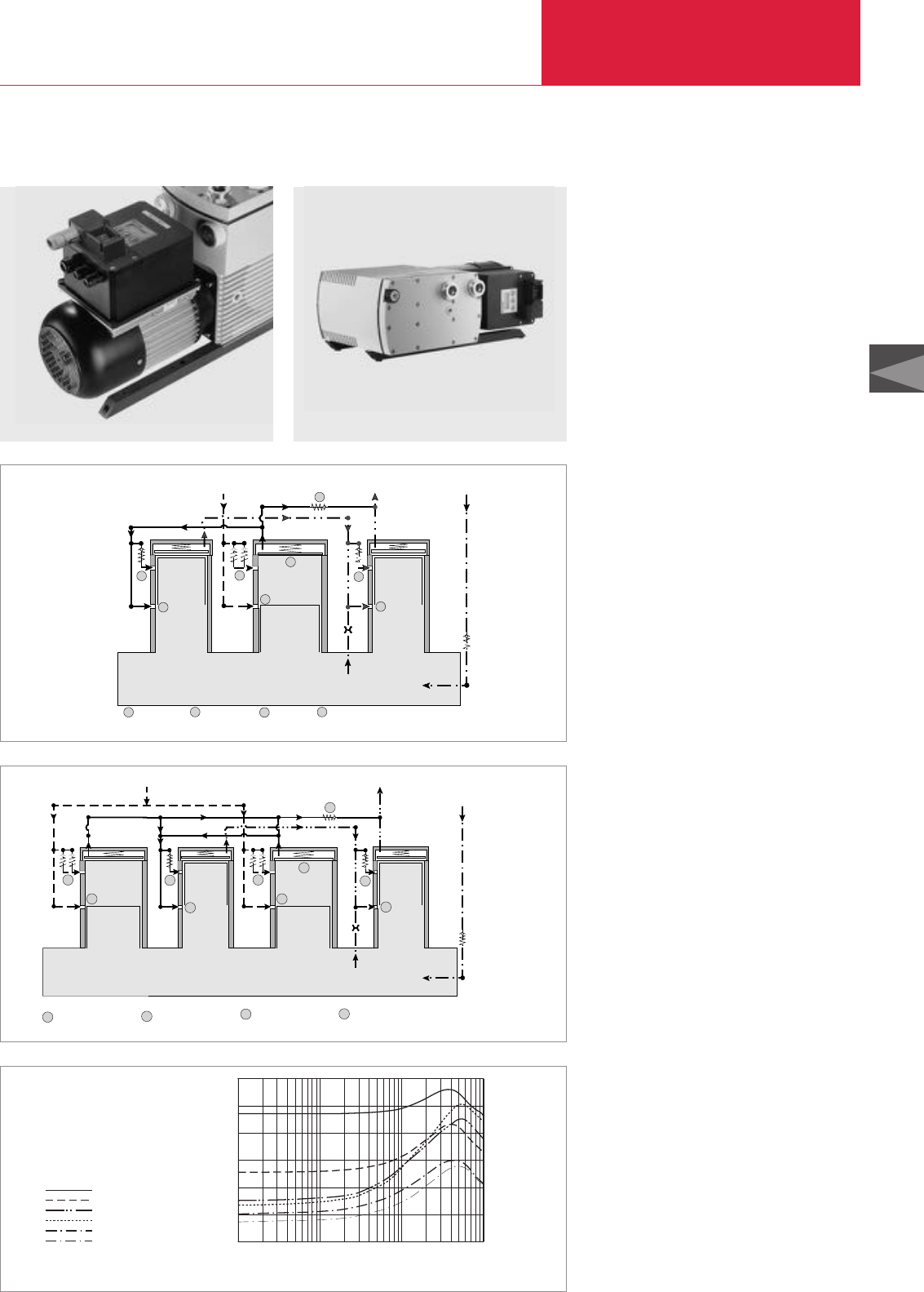
General Information on the EcoDry M
C03.05
LEYBOLD VACUUM PRODUCTS AND REFERENCE BOOK 2003/2004
C03
Dry Compressing Piston Vacuum Pumps
EcoDry M - Extension of the Product Range of Piston Vacuum Pumps
Gasflow diagram for the E
CO
D
RY
M 15
Current / power vs. inlet pressure for the E
CO
D
RY
M 15 with EMOD 3-phase motor 400 V, 50/60 Hz
Like the well-proven EcoDry L, the EcoDry M
incorporates a dry sliding mechanism without the
need for oil or hydrocarbons.
Through the further development and optimisa-
tion of the compression cycle, the EcoDry
M 15/30 attains through its three compression
stages a base pressure (total) in the lower part of
the 10
-2
mbar range.
Since the EcoDry M 15/20/30 may be operated
either vertically (as normally delivered) or
horizontally, this pump is highly flexible when it
has to be integrated into the customer’s system.
In contrast to the EcoDry L, the EcoDry
M 15/20/30 is equipped, besides the well-proven
inlet slits, also with pressure controlled inlet
valves. These cut the power requirement during
the intake phase of the individual compression
stages.
This results is a lower overall power requirement
of the pump, thereby making operation of the
pump more cost-effective.
The EcoDry M 15/20/30 does not require any
external cooling media like cooling water for
example.
The EcoDry M 15/20/30 is offered with different
motor versions allowing operation of the pump
off almost any mains voltage and frequency in
the world (see technical data)
Also new is the universal frequency controlled
motor which may be operated off all single phase
mains world-wide (90 to 264 V, 50/60 Hz).
Gas ballast
V1, V2, V3
Crank case
Inlet Exhaust
Bypass valve
1. stage2. stage 3. stage
Exhaust valve Inlet valve Load reduction valve
Evacuation port
for crank case
2
3
1234
1
4
33
4
Integrated
non-return valve
4
1. stage
3
4
Gasflow diagram for the EcoDry M 30 (three compressing stages)
kW
Current
A
0,0110 100 1000
0,5
1,0
1,5
2,0
2,5
3,0
0
0,2
0,4
0,6
0,8
1,2
1,4
1,6
1,8
2
1
Inlet Pressure mbar
Power requirements 50Hz 400V (M 15)
Power requirements 60Hz 400V (M 30)
Current 50 Hz (M 15)
Power requirements 50Hz 400V (M 30)
Power requirements 60Hz 400V (M 15)
Current 60 Hz (M 15)
Current / power consumption vs. inlet pressure for the EcoDry M 15 to 30 with 400 V, 50/60 Hz three-phase motor
Gas ballast
V1, V2, V3
Crank case
Inlet Exhaust
Bypass valve
1. stage2. stage 3. stage
Exhaust valve Inlet valve Load reduction valve
Evacuation port
for crank case
2
3
1234
1
4
33
4
integrated
non-return valve
4
Gasflow diagram for the EcoDry M 15
EcoDry M vertical (as delivered) EcoDry M horizontal
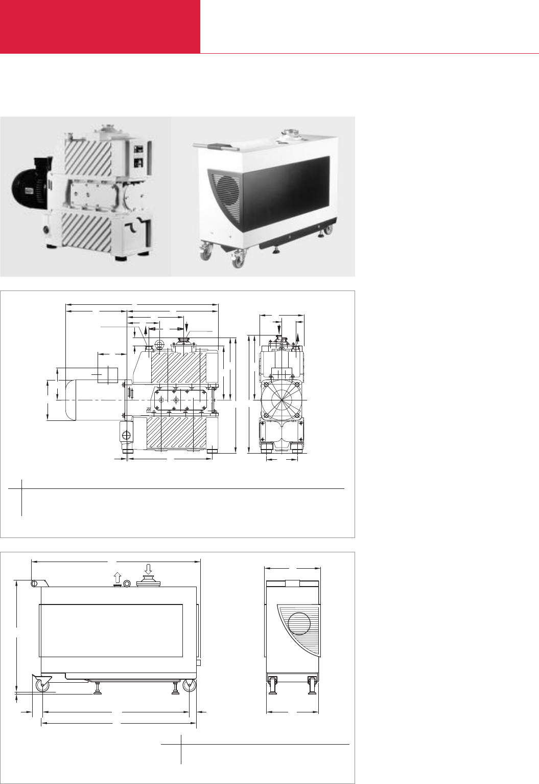
EcoDry L
C03.06 LEYBOLD VACUUM PRODUCTS AND REFERENCE BOOK 2003/2004
Dry Compressing Piston Vacuum Pumps
Dry Compressing Piston Vacuum Pump
EcoDry L, right with silencing hood on cart
DN 40 KF
DN 25 KF
h5
l5
l1
l4l8
l3
l2
l
k6
d
h2
l7
l6
h
h1
h3
b2
h4
b1
b
Dimensional drawing for the EcoDry L
Our positive displacement pump EcoDry L is
really very simple: No blower, no water cooling,
no grease-lubricated bearings in the vacuum, and
of course
no
oil.
In fact, the design principle of the EcoDry L is so
simple that the unit can operate for approximately
two years with no maintenance (depending on
the application).
For proper use of the
EcoDry L please contact our
sales department.
Maintenance is simple and can be done world-
wide by Leybold Service.
The EcoDry L is available as a complete system
with silencing hood and fitted on to a cart. This
helps to cut the already low noise level to an even
much lower level (see ordering information).
h
h1
l3l4b1
b
l2
l
l1
Dimensional drawing for the EcoDry L on cart with silencing hood
b b1h h1l l1l1l1l2
mm 324 300 642 13 974 892 845.5 59.5 40
in. 12.76 11.81 26.85 0.51 38.35 35.12 33.29 2.34 1.57
b b1b2ld h h1h2h3h4h5h6l l1l2l3l4l5l6
mm 220 70 154 200 572 267 309 585 322 159 40 755 304 451 281 161 145 4
in. 8.66 2.76 6.06 7.87 22.52 10.51 12.17 23.03 12.68 6.26 1.57 29.72 11.97 17.76 11.06 6.34 5.71 0.16
l7l8
417 172
16.42 6.77
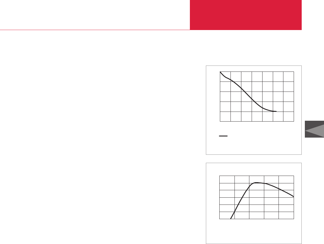
EcoDry L
C03.07
LEYBOLD VACUUM PRODUCTS AND REFERENCE BOOK 2003/2004
C03
Dry Compressing Piston Vacuum Pumps
Advantages to the User
♦Maintenance-poor, free of oil and
bearing lubrication, free of hydrocarbons
♦Low level of particle emmissions
♦Long service life and most reliable
♦Low power consumption
♦Low operating costs (no waste disposal costs
for oil etc.)
♦Service friendly
♦No additional blower and water cooling
system is required
♦Plug & play
♦High pumping speed at low pressure
♦No grease-lubricated bearing in the vacuum
section
♦Totally dry compression chamber
♦Leak tight
♦Runs at 1100 rpm (60 Hz mains)
♦Integrated operating hours counter in the
motor junction box
♦Full cross section valves
♦Gas ballast (optional)
♦High water vapor tolerance with gas ballast
(optional)
♦For both horizontal and vertical operation
1)
Typical Applications
♦Applications in physics
♦Loadlock chambers
♦Transfer chambers
♦Mass spectrometers
♦Electron microscopes
♦Lighting
♦Thinfilm coaters
♦Forevacuum pump for dry high-vacuum
systems
♦Pumping of oxygen concentrations over
21 percent by volume upon request
Intake Pressure
1000
100
10
1
0,1
0,01
mbar
0 20 40 60 80 100 120 140
EcoDry L
Time s
Pump down curve of the EcoDry L connected to a 83 l vessel at 60 Hz
without gas ballast
Pumping Speed
60
0,01
3
50
40
30
20
10
0,1 1 10 100 1000
mbar
Inlet Pressure
0
m /h
Pumping speed characteristic for the
EcoDry
L without gas ballast
(50 Hz)
1)
When planning to operate the EcoDry L horizontally please
contact LEYBOLD sales first.
The versions equipped with a silencing hood can only be
operated vertically!

C03.08 LEYBOLD VACUUM PRODUCTS AND REFERENCE BOOK 2003/2004
EcoDry L
Dry Compressing Piston Vacuum Pumps
Max. pumping speed
50 Hz m3x h-1 (cfm)
60 Hz m3x h-1 (cfm)
Ultimate total pressure
50 Hz, without gas ballast 1) mbar (Torr)
Max. permissible inlet pressure mbar (Torr)
Max. permissible permanent inlet pressure mbar (Torr)
1.5 kW (2.0 hp) motor mbar (Torr)
2.2 kW (3.0 hp) motor mbar (Torr)
Water vapor tolerance, max. 2) mbar (Torr)
Main voltage
Motor power requirements 3) W (hp)
Motor rating, max. 3) W (hp)
Max. ambient temperature °C (°F)
Speed
50 Hz min-1
60 Hz min-1
Type of protection IP
Weight, approx. kg (lbs)
with silencing hood
Part No. 130 106, approx. kg (lbs)
Part No. 130 105, approx. kg (lbs)
Noise level (60 Hz operation) 4) dB(A)
Versions with silencing hood (60 Hz operation) 4) dB(A)
Connections
Inlet port fitting DN
Exhaust port fitting DN
Technical Data EcoDry L
38 (22)
48 (28)
6 x 10⁻² (3 x 10⁻²)
1000 (750)
≤30 (22.5)
1000 (750)
30 (22.5)
3 P - AC 190 - 210 V, 50 Hz
3 P - AC 190 - 250 V, 60 Hz
3 P - AC 380 - 420 V, 50 Hz
3 P - AC 380 - 500 V, 60 Hz
≤500 (≤0.7) at ultimate pressure
1500 (2.0)
≤+ 50 (≤+ 122)
approx. 900
approx. 1100
54
95 (209.5)
140 (309)
145 (320)
64
≤58
40 KF
25 KF
Ordering Information 5)
EcoDry L with 1.5 kW (2.0 hp) 7)
EcoDry L with 1.5 kW (2.0 hp) motor and gasballast 7)
EcoDry L (1.5 kW motor) with silencing hood
(fitted to cart, fan 230 V) 6)
EcoDry L with 2.2 kW (3.0 hp) motor 7)
EcoDry L (2.2 kW motor) with silencing hood
(fitted to cart, fan 230 V) 6)
Cart
Roots pump adapter
Gas ballast valve
manually operated
solenoid
1)
By delivery
2)
Version with gas ballast (position III)
3)
Version with 1.5 kW
(2.0 hp)
motor
4)
Operating at ultimate pressure
5)
Other EcoDry L versions upon request
6)
Other EcoDry L versions with silencing hood upon request
7)
Higher pumped off volumes > 100 l (3.5 ft
3
) < 1 m
3
are possible with optional 2.2 kW (3.0 hp) motors
Part No. 139 50
Part No. 123 15
Part No. 130 106
Part No. 123 00
Upon request
Part No. 139 52
Part No. 139 55
Part No. 123 05
Part No. 169 50
EcoDry L

C03.09
LEYBOLD VACUUM PRODUCTS AND REFERENCE BOOK 2003/2004
EcoDry L
C03
Dry Compressing Piston Vacuum Pumps
Notes
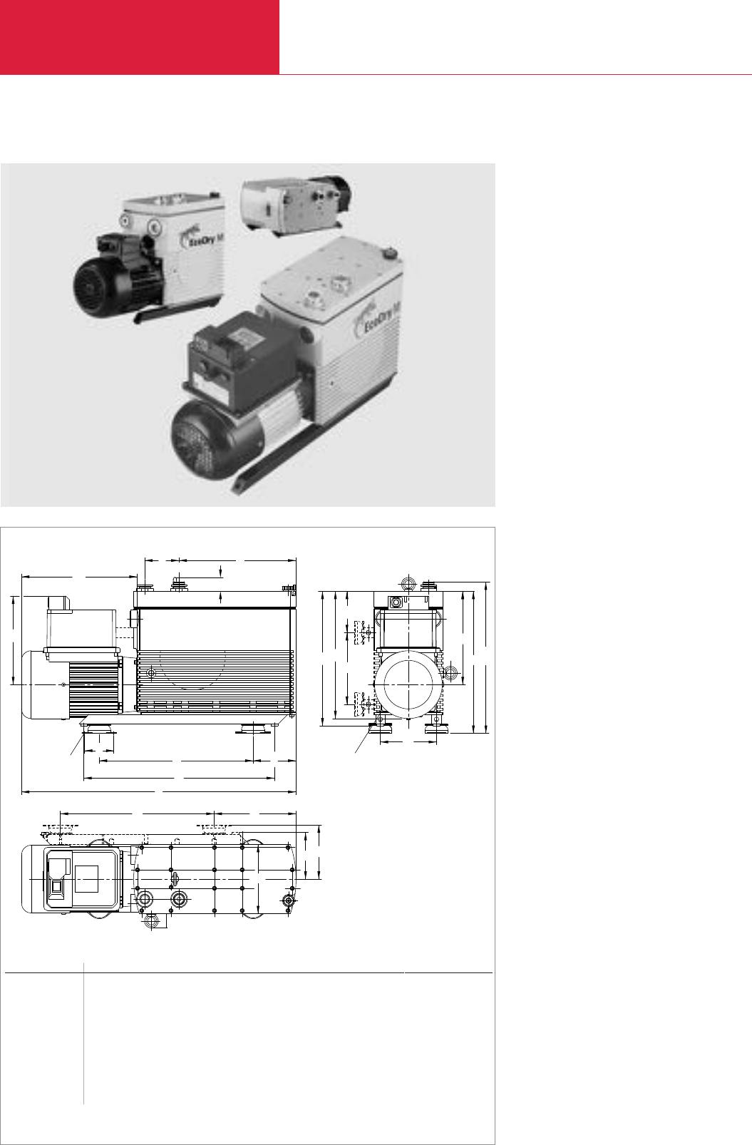
EcoDry M
C03.10 LEYBOLD VACUUM PRODUCTS AND REFERENCE BOOK 2003/2004
Dry Compressing Piston Vacuum Pumps
EcoDry M - Modular Line of Dry Compressing Piston Vacuum Pumps
Like the well-proven EcoDry L, the EcoDry M
incorporates a dry sliding mechanism, and thus
neither oil nor lubricants containing hydrocarbons.
Through the further development and optimisa-
tion of the compression cycle, the EcoDry
M 15/30 attains through its three compression
stages a base pressure (total) in the lower part of
the 10
-2
mbar (0.75 x 10
-2
Torr) range.
The modular design of the EcoDry M allows us to
offer besides the EcoDry M 15 (S
eff
about
15 m
3
/h (8.8 cfm)), also the EcoDry M 20 (S
eff
about 20 m
3
/h (11.8 cfm)) and the EcoDry M 30
(S
eff
≈30 m
3
/h (17.8 cfm)).
These pumps basically differ by the way in which
the third stage of the pump is arranged.
In the EcoDry M 15 the three compression
stages are connected in series.
In the EcoDry M 20 the 1st and 2nd stage are
connected in parallel and the 3rd stage in series.
In the M 30 all stages operate like those of the M
15 in 3 compressing stages whereby the 2nd and
the 4th stage form the single compressing stage
(1st stage).
This results in the higher pumping speed of
about 20 m
3
/h (11.8 cfm) and a base pressure
(total) in the middle of the 10
-1
mbar range for
the EcoDry M 20.
l3
l1l2
h7
h2
l
h3h4
h5
h6
h1
b1
h
l4
l5
l8
l7
al6
b3
b
b2
Durchgangsloch 6,5 für M6
Ø 6,5
h8
Dimensional drawing for the EcoDry M 15/20 and M 30 with FC motor; DS and WS motor similaire (dimensions listed are with standard feet)
EcoDry M line
vertically installed
Type a b b1b2b3h h1h2h3h4h5h6h7h8l l1l2l3
M 15/20 FC-Motor mm 76 180 146 138 121 352.5 228 230 335 316 186 93 37.5 373,5 598 89 191 300.5
in. 2.99 7.09 5.75 5.43 4.76 13.88 8.98 9.06 13.19 12.44 7.32 3.66 1.48 14.7 23.54 3.5 7.52 11.83
M 30 FC-Motor mm 76 180 146 140.5 121 369 242.5 230 349.5 330.5 186 107.5 36 390 713 89 304 300.5
in. 2.99 7.09 5.75 5.53 4.76 14.53 9.55 9.06 13.76 13.01 7.32 4.23 1.42 15.35 28.07 3.5 11.97 11.83
M 15/20 DS-Motor mm 76 180 146 138 121 352.5 228 148 335 316 186 93 37.5 373,5 594 89 191 269.5
in. 2.99 7.09 5.75 5.43 4.76 13.88 8.98 5.83 13.19 12.44 7.32 3.66 1.48 14.7 23.39 3.5 7.52 10.61
M 30 DS-Motor mm 76 180 146 140.5 121 369 242.5 148 344.5 330.5 186 107.5 36 390 709 89 304 269.5
in. 2.99 7.09 5.75 5.53 4.76 14.53 9.55 5.83 13.56 13.01 7.32 4.23 1.42 15.35 27.91 3.5 11.97 10.61
M 15/20 WS-Motor mm 76 180 146 138 121 352.5 228 150 335 316 186 93 37.5 388 598 89 191 300.5
in. 2.99 7.09 5.75 5.43 4.76 13.88 8.98 5.91 13.19 12.44 7.32 3.66 1.48 12.28 23.54 3.5 7.52 11.83
M 30 WS-Motor mm 76 180 146 140.5 121 369 242.5 150 349.5 330.5 186 107.5 36 390 723 89 304 300.5
in. 2.99 7.09 5.75 5.53 4.76 14.53 9.55 5.91 13.76 13.01 7.32 4.23 1.42 15.35 28.46 3.5 11.97 11.83
l4l5l6l7l8
495 289 105.5 289 101
19.49 11.28 4.15 11.28 3.98
495 399.5 111.5 399.5 213
19.49 15.73 4.39 15.73 8.39
495 289 105.5 289 101
19.49 11.28 4.15 11.28 3.98
495 399.5 111.5 399.5 213
19.49 15.73 4.39 15.73 8.39
495 289 105.5 289 101
19.49 11.28 4.15 11.28 3.98
495 399.5 111.5 399.5 213
19.49 15.73 4.39 15.73 8.39
l8
l7
b3
b
b2
horizontal
hole dia. 6.5 for M6

EcoDry M
C03.11
LEYBOLD VACUUM PRODUCTS AND REFERENCE BOOK 2003/2004
C03
Dry Compressing Piston Vacuum Pumps
Avantages to the User
♦Maintenance-poor, free of oil and
bearing lubrication, free of hydrocarbons
♦Extremely low particle emissions on the intake
and exhaust sides
♦Rugged and most reliable
♦Low power consumption
♦Service friendly
♦Air cooling
♦Plug & play
♦Good pumping speed characteristic at low
base pressure
♦High water vapour tolerance (gas ballast
standard)
♦No grease lubricated bearings in the vacuum
section
♦Leak tight
♦Compact size
♦Runs at 750 rpm (60 Hz mains)
♦Rugged full cross section exhaust valves
♦For both horizontal and vertical operation
Typical Applications
♦Applications in physics
♦Loadlock chambers
♦Transfer chambers
♦Mass spectrometers
♦Electron microscopes
♦Lighting
♦Thinfilm coaters
♦Freeze drying
♦Forevacuum pump for dry high-vacuum
systems
♦Pumping of oxygen concentrations over
21 percent by volume upon request
Inlet Pressure
m3/h
mbar
0
5
10
15
20
25
Pumping Speed
30
M 15 - 60 Hz
M 20 - 60 Hz
M 30 - 60 Hz
10-2 10-1 100101102103
Pumping speed vs. inlet pressure for the EcoDry M 15 to M 30
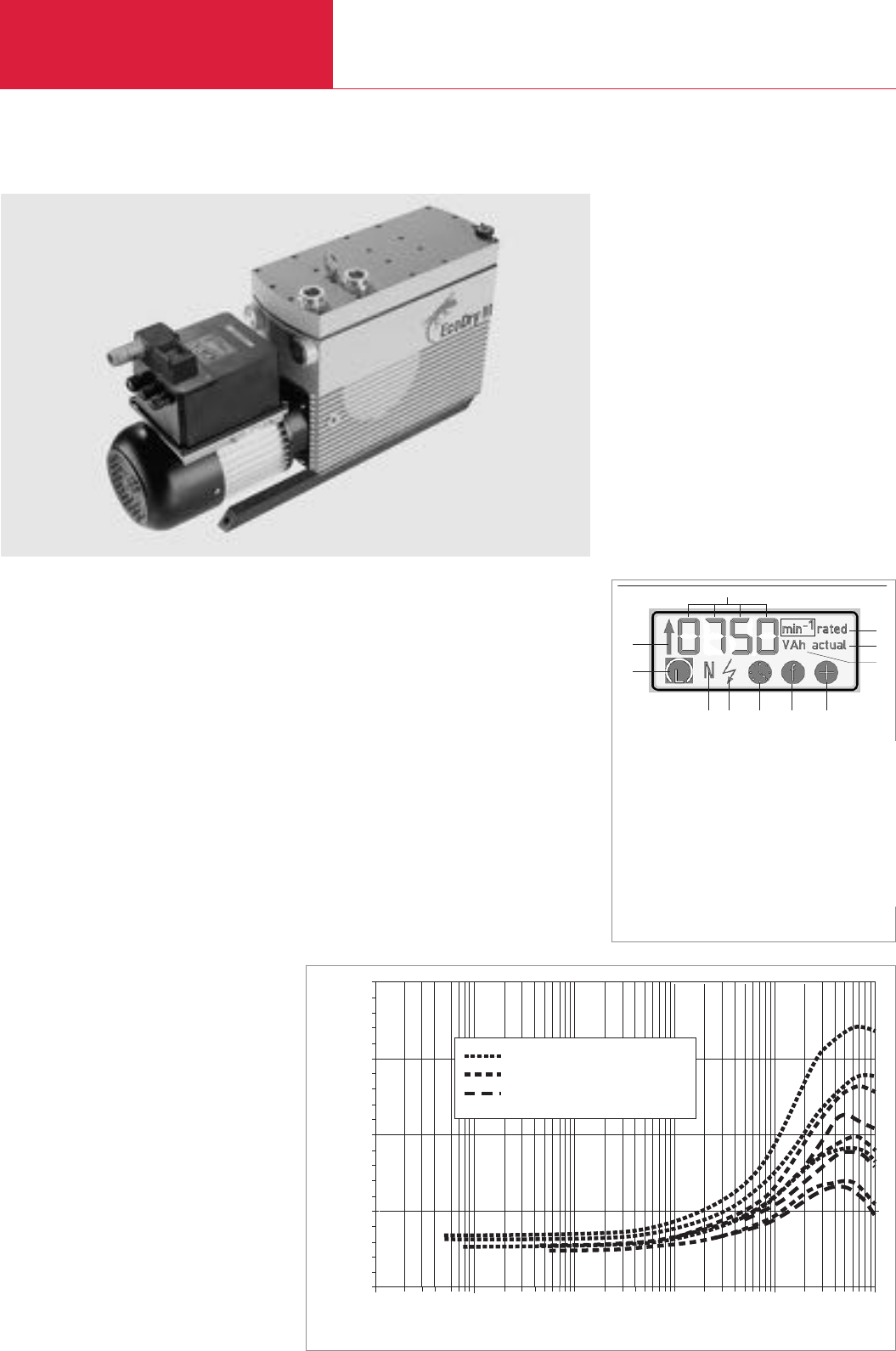
EcoDry M
C03.12 LEYBOLD VACUUM PRODUCTS AND REFERENCE BOOK 2003/2004
Dry Compressing Piston Vacuum Pumps
Smart Drive Technology for a Tailor-made Vacuum
To increase the performance of the EcoDry M
piston vacuum pumps, the use of a frequency
converter integrated within the motor is
recommended.
LEYBOLD VACUUM is now offering this universal
feature for the entire EcoDry M line
(EcoDry M 15, M 20 and M30).
EcoDry M with FC motor
Avantages to the User
♦Universal – can be run off all AC mains world-
wide (50 and 60 Hz)
♦Cost-effective to purchase and operate
♦Increased pumping speed by up to 18%
compared to standard 50 Hz AC mains
powered versions
♦Menu controlled two key operation for
selecting the required speed range of 750,
1000 or 1200 rpm
♦Infinitely variable speed control from 750 to
1200 rpm via analog interface
♦Process and application control is possible by
connecting vacuum gauges with an analog
output (0-10 V); THERMOVAC TM 21, for
example
♦“Economy” operation (load optimised
operation) can be set up in a well-defined
manner to reduce power consumption,
vibration and noise levels.
♦Conserving, low-wear operation through well-
defined speed control
♦LC display for indicating operational infor-
mation like speed, operating hours, status
♦CE and NRTL compliant
Technical Data
♦Mains supply voltage range 90 to 264 V
(13 A – 7 A) at 50/60 Hz
♦Motor speed manually adjustable in three
steps to 750, 1000 and 1200 rpm
♦RS 485 C and analog interface (0-10 V)
LC display on the operating unit
1
2
3
4
5
7891011
6
EcoDrEcoDry M 20 @ 1200/1000/750 rpmy M 20 @ 1200/1000/750 rpm
EcoDrEcoDry M 30 @ 1200/1000/750 rpmy M 30 @ 1200/1000/750 rpm
EcoDrEcoDry M 15 @ 1200/1000/750 rpmy M 15 @ 1200/1000/750 rpm
Inlet Pressure / mbar
Current / W
2000
1500
1000
500
0
0.01 0.1 1 10 100 1000
Current/power uptake vs. inlet pressure for the EcoDry M 15 to 30
1 Ready to operate / control via serial protocol
2 Accelerate
3 4 x 7 segment display
4 Nominal speed
5 Actual speed
6 Volt, Amps, hours
7Overspeed
8 Frequency select
9 Operating hours
10 Fault
11 Normal operation

EcoDry M
C03.13
LEYBOLD VACUUM PRODUCTS AND REFERENCE BOOK 2003/2004
C03
Dry Compressing Piston Vacuum Pumps
Technical Data EcoDry M 15 EcoDry M 20 EcoDry M 30
3-phase motor FC motor *) 3-phase motor FC motor 3-phase motor FC motor
No. of cylinders
No. of stages
Max. pumping speed
50 Hz
1)
m3x h-1 (cfm)
60 Hz
1)
m3x h-1 (cfm)
at 0750 min-1 50/60 Hz
1)
m3x h-1 (cfm)
at 1000 min-1 50/60 Hz
1)
m3x h-1 (cfm)
at 1200 min-1 50/60 Hz
1)
m3x h-1 (cfm)
Ultimate pressure (absolute)
2)
3-phase motor 60 Hz mbar (Torr)
FC motor *) at 1000 min-1 50/60 Hz mbar (Torr)
Max. permissible inlet pressure
Max. permissible permanent inlet pressure mbar (Torr)
Water vapor tolerance (with gas ballast) mbar (Torr)
Leak rate (integral)
mbar x l x s-1 (atm x cc x sec (within 2%))
Power consumption
at < 10 mbar (7.5 Torr) inlet pressure W (hp)
Motors
3-phase, 50 Hz (IP 54) V
3-phase, 60 Hz (IP 54) V
FC motor, 50/60 Hz (IP 44) V
Rotational speed
with 3-phase motor 50 / 60 Hz min-1
with FC motor 50 / 60 Hz min-1
via analog interface 0-10 V, 50/60 Hz min-1
Noise level at ultimate pressure without gas ballast
(50 Hz at 3-phase and 750 min-1 with FC motor) dB(A)
Ambient temperature °C (°F)
Connections
Inlet port fitting DN
Exhaust port fitting DN
Dimensions, approx. (L x W x H)
standard,flanges at motor side
standing mm
(in.)
lying mm
(in.)
Weight, approx. kg (lbs)
Ordering Information EcoDry M 15 EcoDry M 20 EcoDry M 30
Part No. 130 000 – Part No. 130 010 – Part No. 130 030 –
Part No. 130 001 – Part No. 130 011 – Part No. 130 031 –
Part No. 130 002 – Part No. 130 012 – Part No. 130 032 –
– Part No. 130 005 – Part No. 130 015 – Part No. 130 033
– Part No. 130 006 – – – Part No. 130 034
Part No. 130 050 Part No. 130 050 Part No. 130 050
Part No. 130 051 Part No. 130 051 Part No. 130 051
Part No. 130 052 Part No. 130 052 Part No. 130 052
Part No. 169 50 Part No. 169 50 Part No. 169 50
Part No. 130 056 Part No. 130 056 Part No. 130 056
Part No. 130 057 Part No. 130 057 Part No. 130 057
Part No. 130 058 Part No. 130 058 Part No. 130 058
Part No. 130 059 Part No. 130 059 Part No. 130 059
3 3 4
3 2 3
14 (8.2) – 19 (11.2) – 27 (15.9) –
16 (9.4) – 22 (12.9) – 30 (17.7) –
– 11 (6.5) – 14 (8.2) – 19 (11.2)
– 15 (8.8) – 18 (10.5) – 25 (14.7)
– 16 (9.4) – 22 (12.9) – 30 (17.7)
5.5 x 10
-2
(4.1 x 10
-2
) – 8 x 10
-1
(6 x 10
-1
) – 5.5 x 10
-2
(4.1 x 10
-2
) –
– 5.5 x 10
-2
(4.1 x 10
-2
) – 8 x 10
-1
(6 x 10
-1
) – 5.5 x 10
-2
(4.1 x 10
-2
)
Atmosphere Atmosphere Atmosphere
100 (75) 100 (75) 100 (75)
25 (18.8) 25 (18.8) 25 (18.8)
≤1 x 10
-4
≤1 x 10
-4
≤1 x 10
-4
300 (0.41) 280 (0.38) 300 (0.41) 280 (0.38) 450 (0.6) 330 (0.45)
- 10 % to + 5 % - 10 % to + 5 % - 10 % to + 5 %
220-240/346-415 – 220-240/346-415 – 220-240/346-415 –
200-277/380-480 – 200-277/380-480 – 200-277/380-480 –
– 90-264 – 90-264 – 90-264
1000 / 1200 – 1000 / 1200 – 1000 / 1200 –
– 750/1000/1200 – 750/1000/1200 – 750/1000/1200
– 750-1200, variable – 750-1200, variable – 750-1200, variable
≤59 ≤59 ≤59
0 to + 50 (32 to + 122) 0 to + 50 (32 to + 122) 0 to + 50 (32 to + 122)
25 KF 25 KF 25 KF
25 KF 25 KF 25 KF
545
x
182
x
356 598
x
182
x
356 545
x
182
x
356 598
x
182
x
356 709
x
182
x
369 713
x
182
x
369
(
21.5
x
7.17
x
14.0)
(
23.5
x
7.17
x
14.0)
(
21.5
x
7.17
x
14.0)
(
23.5
x
7.17
x
14.0)
(
27.9
x
7.17
x
14.5)
(
28.1
x
7.17
x
14.5)
545
x
356
x
211 598
x
356
x
211 545
x
356
x
211 598
x
356
x
211 709
x
369
x
211 713
x
369
x
211
(
21.5
x
14.0
x
8.3)
(
23.5
x
14.0
x
8.3)
(
21.5
x
14.0
x
8.3)
(
23.5
x
14.0
x
8.3)
(
27.9
x
14.5
x
8.3)
(
28.1
x
14.5
x
8.3)
40.5 (89.4) 47 (103.8) 40.5 (89.4) 47 (103.8) 53 (117) 59 (130.2)
EcoDry M
3-phase DC motor
1-phase AC motor
115 V, 50/60 Hz (USA)
230 V, 50/60 Hz (EURO)
FC motor, 90 - 264 V
FC motor, 90 - 264 V and silencing hood
Exhaust silencer
Vibration absorber (set of 4 pieces)
Vibration absorbing kit
Solenoid gas ballast valve
Universal silencing hood
Cable set for universal silencing hood
for FC motor
for 3-phase DC motor
for 1-phase AC motor
1)
According to DIN 28400 and subsequent numbers
2)
By delivery
*)
FC motor = Frequency Controlled Motor
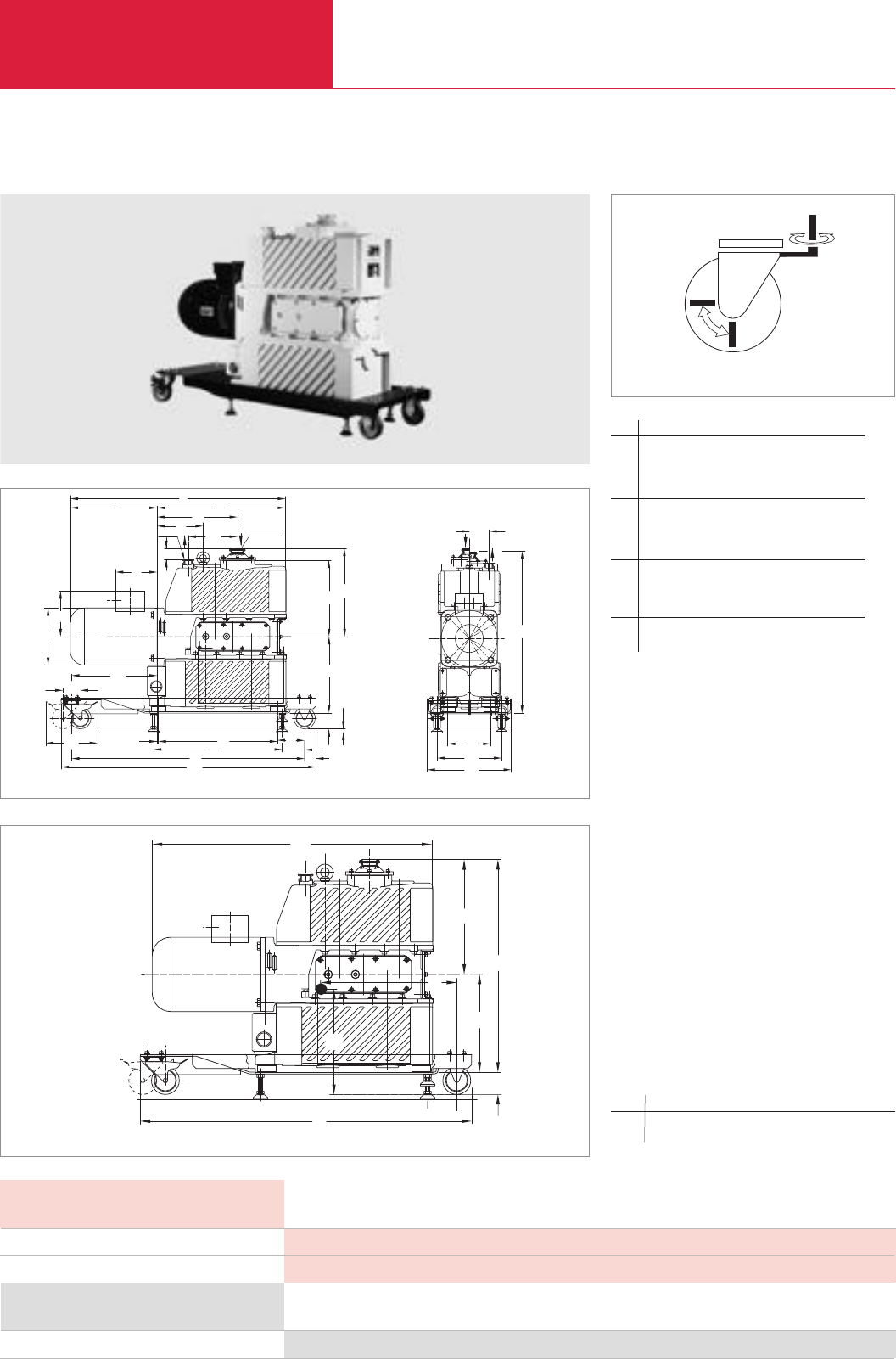
Cart
C03.14 LEYBOLD VACUUM PRODUCTS AND REFERENCE BOOK 2003/2004
Accessories EcoDry L
Cart
DN 25 KF DN 40 KF
h1
h3
h7h6
b
b3
b2
h2
h
b1
l1
l5
h5
d1
d2
d
h4
l2
l3
l4l14
l
l15
l6l7
l8
l9
l10
l13
l11
l12
Avantages to the User
♦Makes the EcoDry L easy to move
♦Compact
♦Rugged and safe design
♦2 rotatable and two fixed castors
(the rotatable castors are arrestable)
♦Feet for secure positioning
♦Can be retrofitted to any EcoDry L
♦Silencing hood may be retrofitted
Technical Note
This cart has been designed to accept any
EcoDry L alone and it has not been designed as
a platform for an EcoDry L with a Roots pump.
Only the vertical version of the EcoDry L (as
shown) may be placed on the cart.
Dimensional drawing for the cart with the EcoDry L
Technical Data Cart
Ordering Information Cart
Part No. 139 52
Dimensions (W x H x D) mm (in.)
Weight, approx. kg (lbs)
892 x 108 x 300 (35.12 x 4.25 x 11.81)
15.5 (34.2)
EcoDry L on the cart
h1
h3
h4
h
h2
l2
l
l1
Center of gravity for the EcoDry L on its cart (values in brackets apply to the pump alone without the cart)
Rotatable castors, arrestable in both directions of rotation
b b1b2b3ldld1ld1h
mm 300 70 154 226 200 61 180 572
in. 11.81 2.76 6.06 8.90 7.87 2.40 7.09 22.52
h1h2h3h4h5h6h7l
mm 267 309 263 40 159 13 60 755
in. 10.51 12.17 10.35 1.57 6.26 0.5 10.35 29.72
l1l2l3l4l5l6l7l8
mm 304 451 261 161 145 4 417 450
in. 11.97 17.76 10.28 6.34 5.71 0.16 16.42 17.72
l9l10 l11 l12 l13 l14 l15
mm 815 892 95 78.5 40 172 299
in. 32.09 35.12 3.74 3.09 1.57 6.77 11.77
h h1h2h3h4ll1l2
mm 572 60 283 263 309 892 755 368
in. 22.52 2.36 11.14 10.35 12.17 35.12 29.72 14.49
Dry Compressing Piston Vacuum Pumps
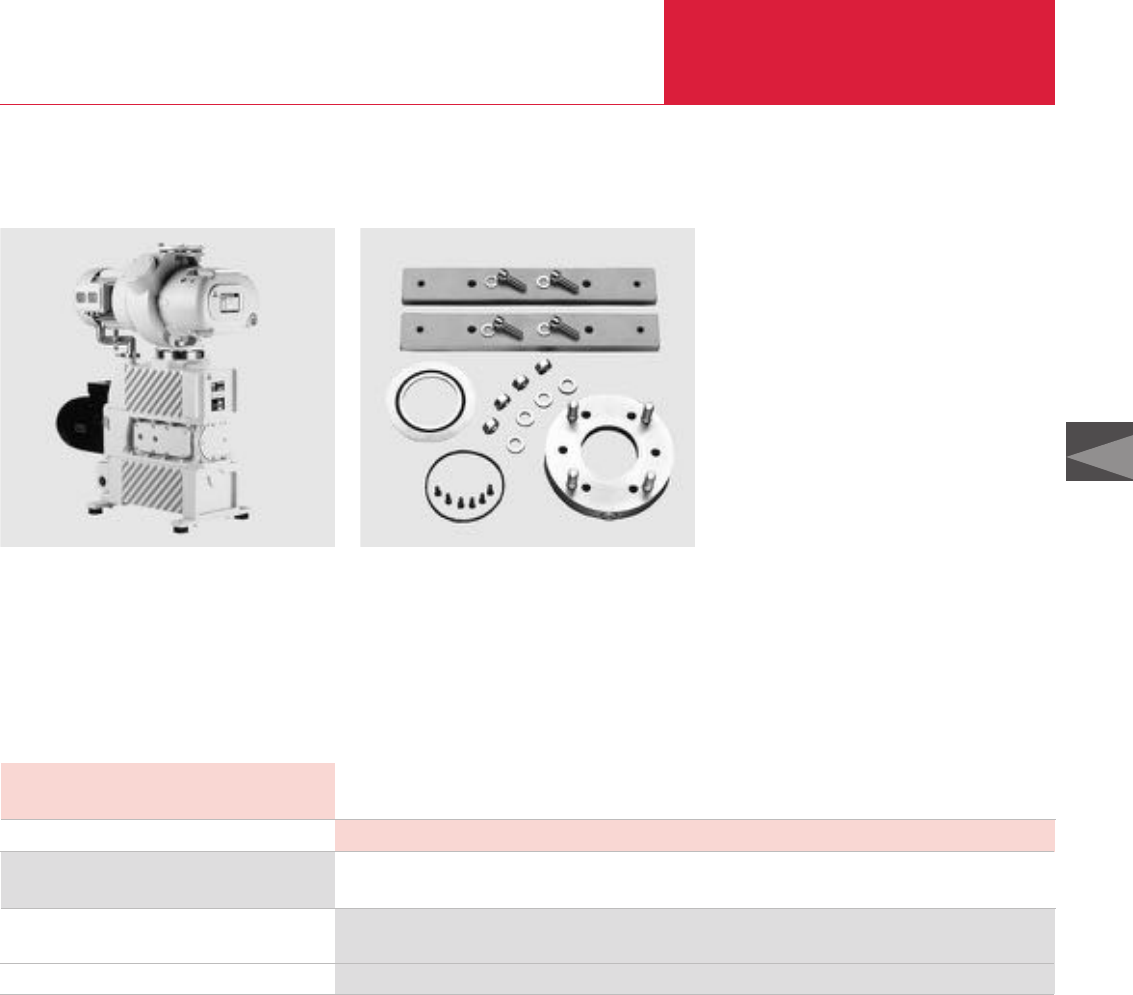
C03.15
LEYBOLD VACUUM PRODUCTS AND REFERENCE BOOK 2003/2004
C03
Accessories EcoDry L
Dry Compressing Piston Vacuum Pumps
Roots Pump Adapter
Advantages to the User
♦Short link to the Roots pump
♦Wider feet for secure positioning
♦Measurement flange may be screwed-in
directly
Technical Data Roots Pump Adapter
Weight, approx. kg (lbs)
Ordering Information Roots Pump Adapter
The Roots pump adapter permits direct
installation of a RUVAC WS/WSU 251 Roots
pump to an EcoDry L.
Roots pump adapter consisting of adapter,
O-ring, feet and bolts
DN 10/16 KF / M 16 x 1.5 measurement flange
Part No. 139 55
Part No. 168 40
Supplied equipmentEcoDry L with WSU 251
Technical Note
Please contact our sales department when plann-
ing to operate the EcoDry L in connection with a
Roots pump.
The Roots pump can not be placed on a cart.
4.4 (9.7)
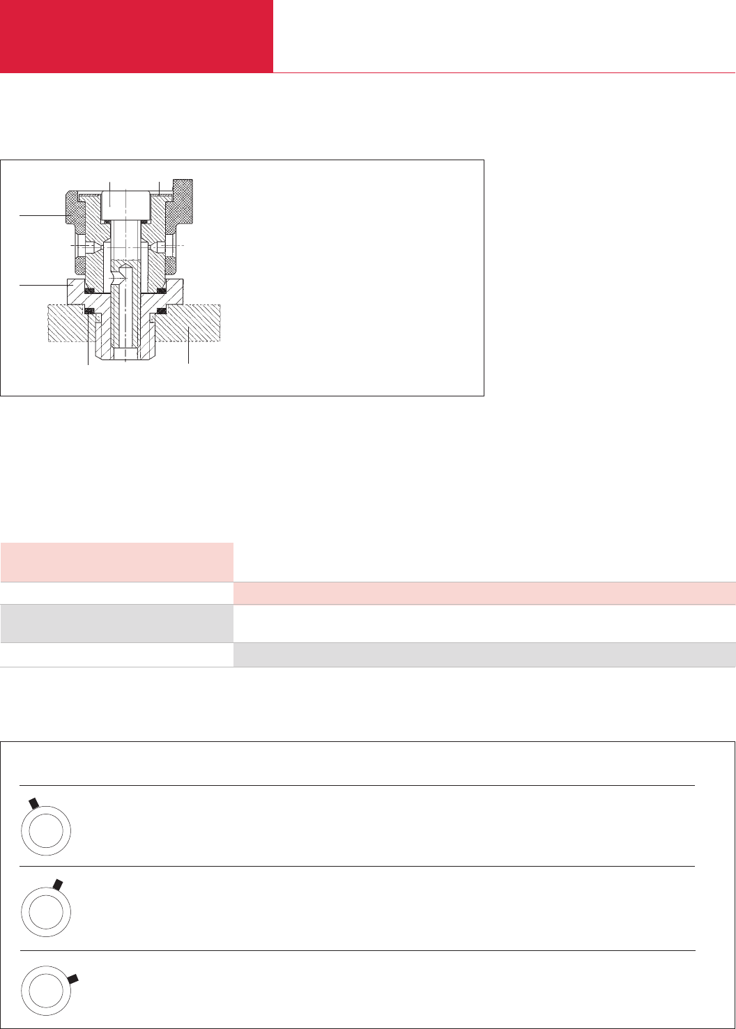
C03.16 LEYBOLD VACUUM PRODUCTS AND REFERENCE BOOK 2003/2004
Accessories EcoDry L
Gas Ballast Valve, manually operated (Retrofit Kit)
Avantages to the User
♦Easy retrofitting
♦Simple to use
♦Water vapor tolerance down to 30 mbar
(22.5 Torr) guaranteed
Technical Data Gas Ballast Valve, manually operated
Dimensions (dia. x h) mm (in.)
Ordering Information Gas Ballast Valve, manually operated
Gas ballast valve, manually operated
The manually operated gas ballast valve is used
to operate the EcoDry L pump in connection with
condensable media, like water vapor, for example.
This valve has three different positions which
ensure that the gas ballast flow can be adapted to
suit the particular application.
By using the retro-fit kit, the range of applications
covered by a standard EcoDry L (without gas
ballast) is extended to applications involving
water vapor.
45 x 45 (1.77 x 1.77)
Part No. 123 05
1
2
3
56
4
Sectional view through the fitted gas ballast valve
1 Hex. adapter (SW 27)
2 Rubber adjustment ring
3 Hex. socket screw
4 Scale
5 Housing cover
6 Flat gasket
Position on the Pumped quantity ‰Water vapor
gas ballast valve in m3x h-1 (cfm) in kg x h-1
0.37 (0.22) 0.025
1.0 (0.59) 0.09
2.25 (1.32) 1.0
= 30 mbar (22.5 Torr) water vapor tolerance
2
1
3
0
GB
2
1
3
0
GB
2
1
3
0
GB
Gas Ballast Quantities
Dry Compressing Piston Vacuum Pumps
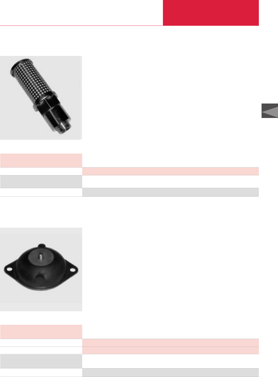
Accessories EcoDry M
C03.17
LEYBOLD VACUUM PRODUCTS AND REFERENCE BOOK 2003/2004
C03
Dry Compressing Piston Vacuum Pumps
Exhaust Silencer
Technical Data Exhaust Silencer
Dimensions (dia. x h) mm (in.)
Ordering Information Exhaust Silencer
Exhaust silencer
The noise level of the EcoDry M is similar to that
of oil-sealed rotary vane vacuum pumps and is
setting new standards for dry-compressing
vacuum pumps. If no exhaust line is required,
this simple exhaust silencer may be fitted when
pumping only inert or permanent gases. The
silencer is fitted simply by exchanging the
exhaust port on the pump against the exhaust
silencer.
48 x 122 (1.89 x 4.80)
Part No. 130 050
Vibration Absorbing Feet
Technical Data Vibration Absorbing Feet
Bore diameter mm (in.)
Distance between the bores mm (in.)
Ordering Information Vibration Absorbing Feet
Vibration absorbing feet, Set of 4
Owing to the innovative arrangement of the
pistons within the EcoDry M, the vibration levels
are basically low.
However, for most vibration sensitive applications
these vibration absorbing feet are needed to
decouple the vibrations from the surface
supporting the pump.
6.5 (0.26)
76 (2.99)
Part No. 130 051
Exhaust silencer
Vibration absorbing foot
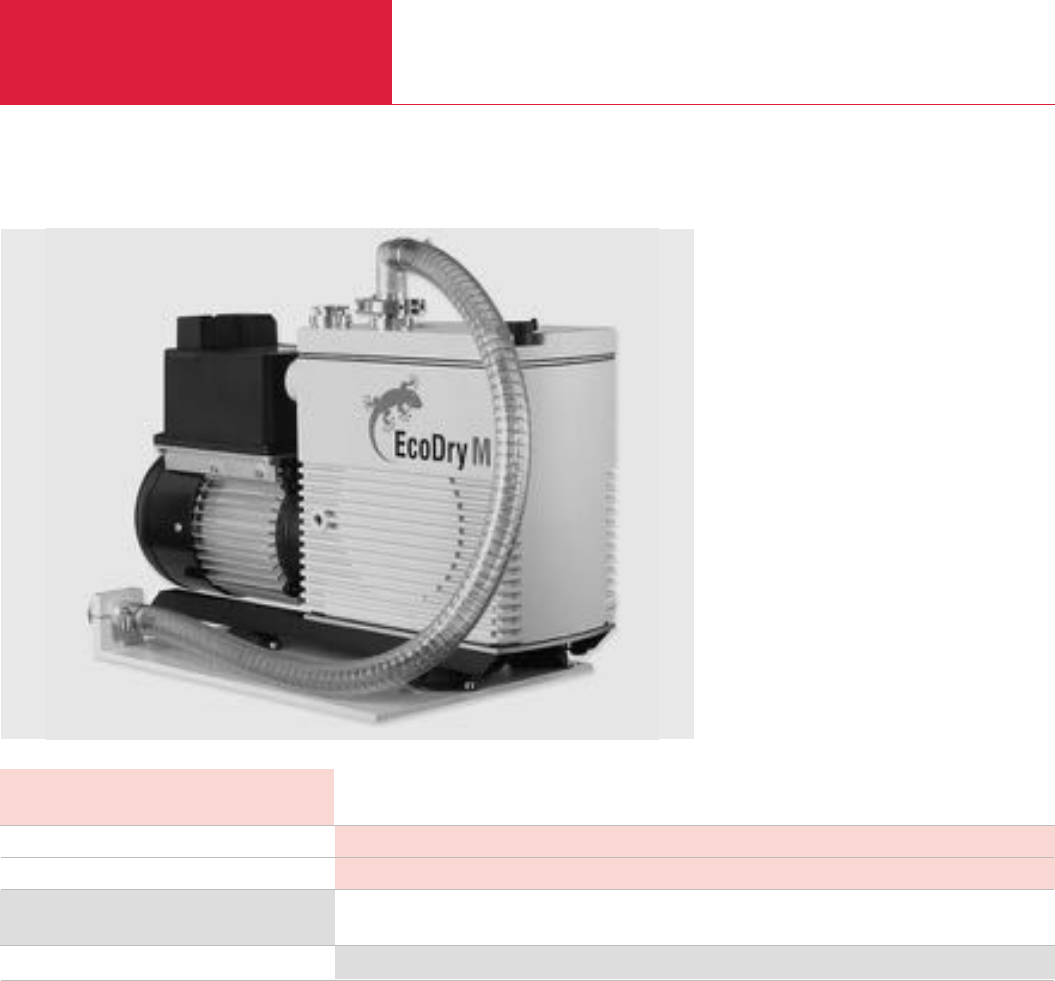
Accessories EcoDry M
C03.18 LEYBOLD VACUUM PRODUCTS AND REFERENCE BOOK 2003/2004
Dry Compressing Piston Vacuum Pumps
Vibration Absorbing Kit
Technical Data Vibration Absorbing Kit
Dimensions (W x H x D) mm (in.)
Weight, approx. kg (lbs)
Ordering Information Vibration Absorbing Kit
Vibration absorbing kit
This vibration absorbing kit was specifically
developed for those applications which are most
demanding vibration-wise, like some analytical
applications.
The vibration absorbing kit reduces the vibrations
transferred to the pump’ supporting surface and
the intake line to a level significantly below the
vibration levels produced by a rotary vane
vacuum pump.
440 x 315 x 70 (17.32 x 12.40 x 2.76)
4.7 (10.38)
Part No. 130 052
Vibration absorbing kit
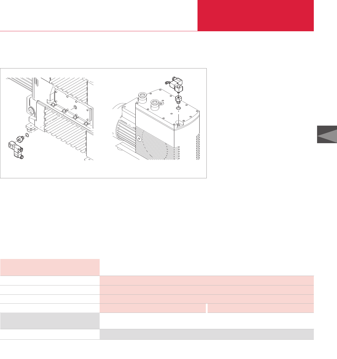
Accessories EcoDry L and M
C03.19
LEYBOLD VACUUM PRODUCTS AND REFERENCE BOOK 2003/2004
C03
Dry Compressing Piston Vacuum Pumps
Solenoid Gas Ballast Valve
Fitting the solenoid gas ballast valve to the EcoDry L (left) and the EcoDry M (right)
Avantages to the User
♦Protection against condensation within the
pump
♦No contamination by the ambient air (when
using inert gas)
♦Low consumption of inert gas
♦Can be used on all EcoDry L and M versions
Technical Data Solenoid Gas Ballast Valve
EcoDry L EcoDry M
Control voltage V DC
Permissible inert gas pressure, absolute bar
Inert gas connection
Inert gas flow m3· h-1 (cfm)
Ordering Information Solenoid Gas Ballast Valve
Solenoid gas ballast valve
The solenoid gas ballast valve allows preventive
operation with gas ballast when pumping
condensable media.
The gas ballast may be operated either with
ambient air or an inert gas like nitrogen, for
example. A coupling for connecting a PVC hose
of 6 mm dia. x 1 is provided.
This valve is of the normally open type and may
thus be used as a permanent gas ballast. When
wanting to cyclically supply the gas ballast into
the pump, a voltage of 24 V DC is required to
drive the gas ballast valve.
24
1 to 4
Hose connection for PVC hose 6 mm dia. x 1 (0.24 in. dia. x 0.04 in.)
0.15 to 0.7 (0.09 x 0.4) 0.10 to 0.55 (0.06 x 0.32)
Part No. 169 50
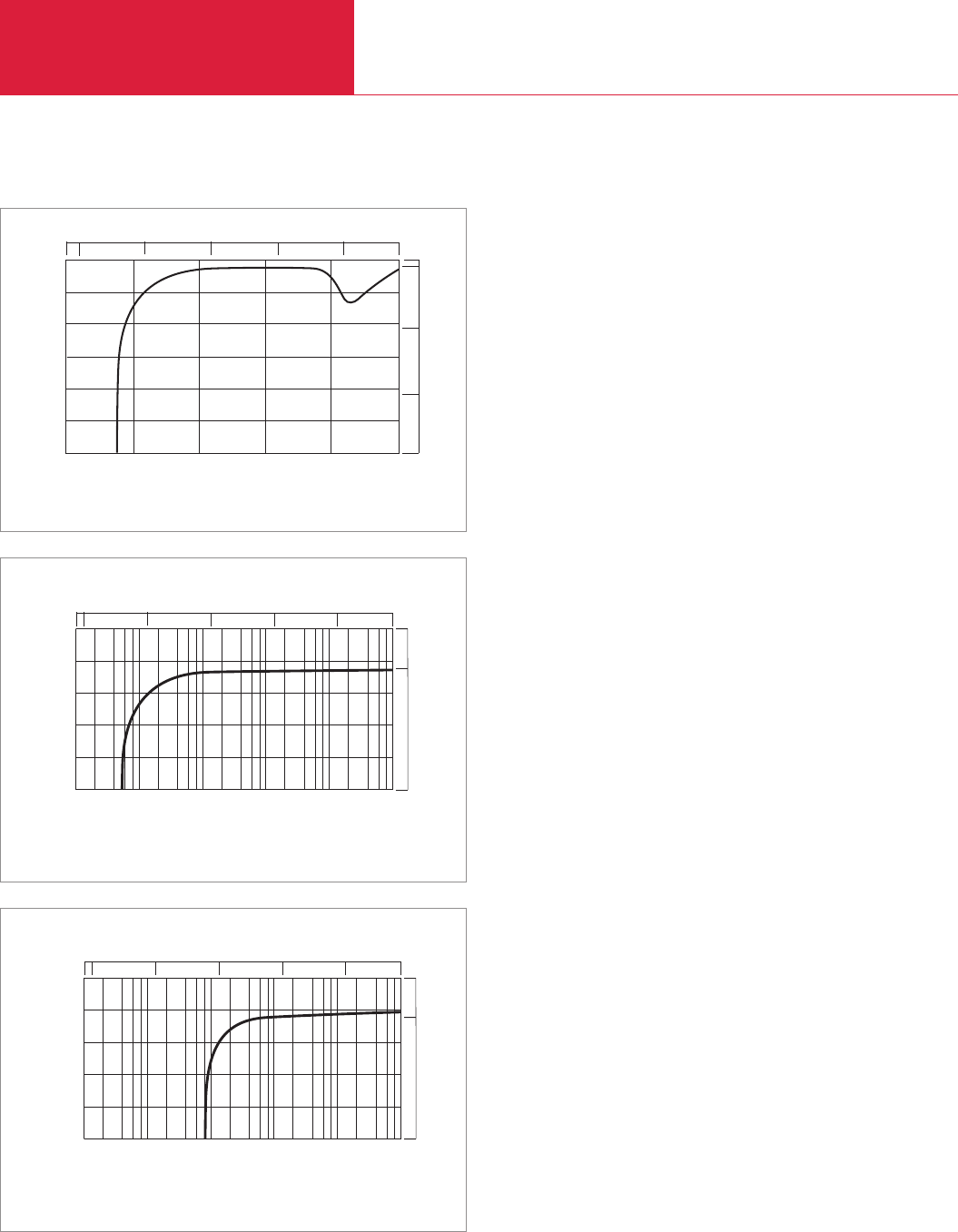
60 Hz Curves
C03.20 LEYBOLD VACUUM PRODUCTS AND REFERENCE BOOK 2003/2004
Dry Compressing Piston Vacuum Pumps
Pumping speed
60
m /h
3
50
40
30
20
10
0
mbar
Inlet Pressure
cfm
10
20
Torr
-2
10 750
30
-1
10 0
10 1
10
-2
10 -1
10 0
10 1
10 2
10 3
10
Pumping speed characteristics for the
EcoDry
L for 60 Hz, without gas ballast
Version for the North and South American Continents
Intake Pressure
m3/h
mbar
0
5
10
15
20
25
Pumping speed
Torr
cfm
750
101102
100
10-1
10-2 103
101102
100
10-1
10-2
10
Pumping speed vs. inlet pressure for the EcoDry M 15/30 at 60 Hz
Intake Pressure
m3/h
mbar
0
5
10
15
20
25
Pumping speed
Torr
cfm
750
101102
100
10-1
10-2 103
101102
100
10-1
10-2
10
Pumping speed vs. inlet pressure for the EcoDry M 20 at 60 Hz
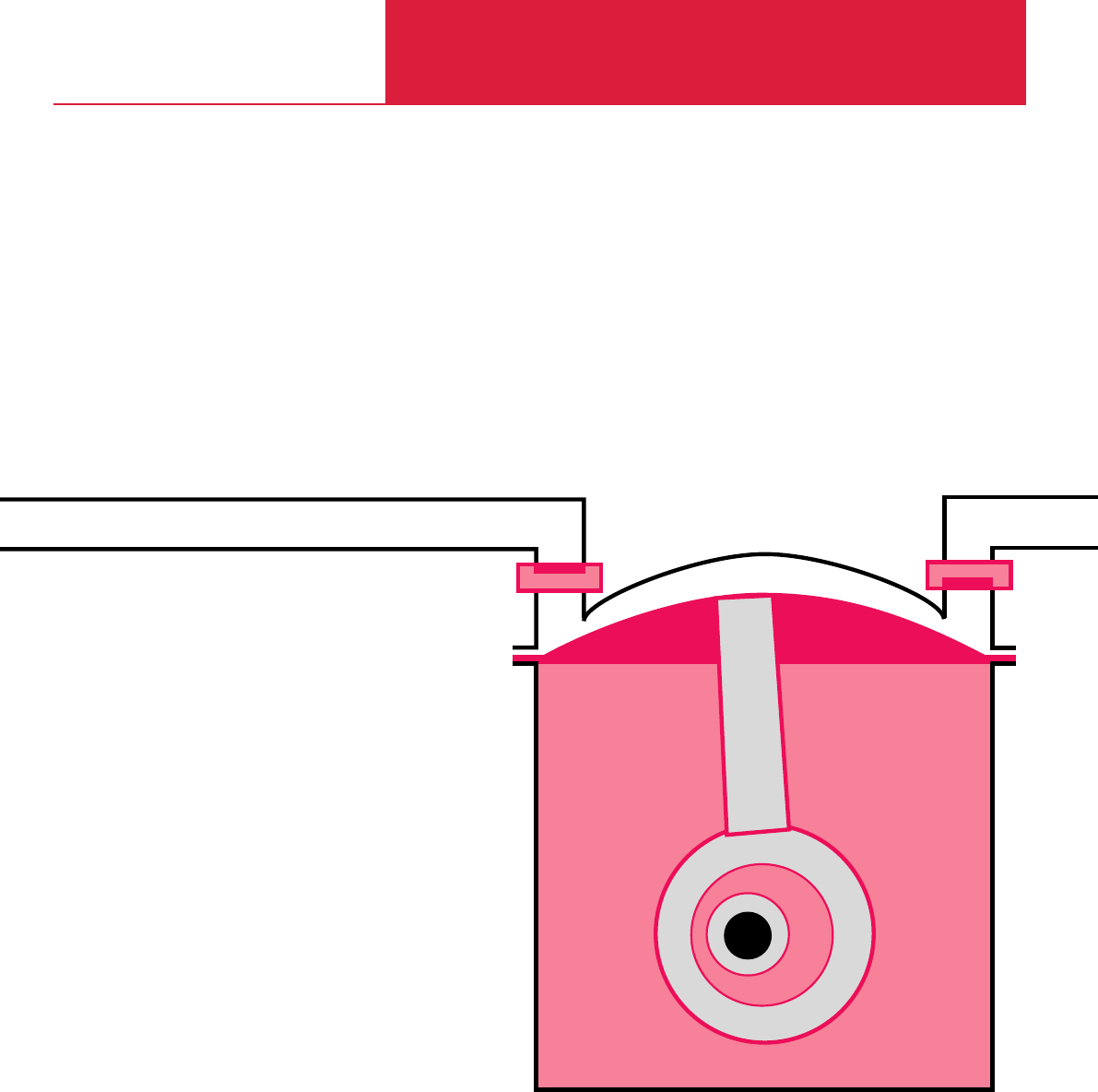
C04
Diaphragm Vacuum Pumps
DIVAC

Contents
Diaphragm Vacuum Pumps
C04.02 LEYBOLD VACUUM PRODUCTS AND REFERENCE BOOK 2003/2004
General
Survey of the range for the DIVAC . . . . . . . . . . . . . . . . . . . . . . . . . . . . . . . . . . . . . . . . . . . C04.03
The customized diaphragm pump and
the accessories recommended for your application in the chemical laboratory. . . . . . . . . . . C04.04
Products
Diaphragm Vacuum Pumps for the Chemical Laboratory
Single-Stage Diaphragm Vacuum Pumps DIVAC 0.6, 1.2, 2.2 . . . . . . . . . . . . . . . . . . . . . C04.06
Dual-Stage Diaphragm Vacuum Pumps DIVAC 0.6 L, 1.2 L, 2.2 L . . . . . . . . . . . . . . . . . . C04.08
Dual-Stage Diaphragm Vacuum Pumps with Automatic Drying System
DIVAC 1.2 L AD, 2.2 L AD. . . . . . . . . . . . . . . . . . . . . . . . . . . . . . . . . . . . . . . . . . . . . . . . C04.10
Modular Laboratory Pump Concept . . . . . . . . . . . . . . . . . . . . . . . . . . . . . . . . . . . . . . . . . . C04.12
Components for the modular DIVAC System. . . . . . . . . . . . . . . . . . . . . . . . . . . . . . . . . . . . C04.13
DIVAC SR, SH, SC Sub-assemblies. . . . . . . . . . . . . . . . . . . . . . . . . . . . . . . . . . . . . . . . . . . C04.14
Dry Compressing Backing Pumps for Turbomolecular Pumps . . . . . . . . . . . . . . . . . . . . . . C04.16
DIVAC 0.8 T and 0.8 LT . . . . . . . . . . . . . . . . . . . . . . . . . . . . . . . . . . . . . . . . . . . . . . . . . C04.18
DIVAC 2.5 T and 2.5 VT . . . . . . . . . . . . . . . . . . . . . . . . . . . . . . . . . . . . . . . . . . . . . . . . . C04.20
DIVAC 3.6 TC and 4.8 VT . . . . . . . . . . . . . . . . . . . . . . . . . . . . . . . . . . . . . . . . . . . . . . . . C04.22

C04.03
LEYBOLD VACUUM PRODUCTS AND REFERENCE BOOK 2003/2004
General Informations
Diaphragm Vacuum Pumps
C04
What this Series Offers
This range of vacuum pumps was developed
especially for laboratory operations and as
backing pumps for (wide range) turbomolecular
pumps. It satisfies the highest expectations in
terms of precision, reliability and ease of use.
The DIVAC line of vacuum pumps is the logical
continuation of diaphragm pump technology
which has proven its quality in decades of
service.
Laboratory Pumps
Through the laboratory pumps and the three
different pumping speeds available for the same
base pressure and through the modular design,
the optimum DIVAC L pump system*
)
can be
implemented in each case.
DIVAC L diaphragm pumps are suited for almost
all requirements in the chemistry lab. They are
basically corrosion and solvent resistant since
their parts in contact with the pumped medium
are made of PTFE (Teflon), FFPM (Kalrez) and
PVDF (Solef).
The newly developed automatic drying system is
used in all applications where very moist and wet
gases need to be pumped over extended periods
of time. Here the pumping speed remains
constant and the service life of the pumps is not
impaired by the liquid.
Application Examples
Laboratory Pumps
♦Vacuum filtration
♦Vacuum distillation
♦Vacuum drying
♦On rotary evaporators
♦To extract and transfer gases
♦Gel drying
♦Steam sterilization
Backing Pumps
♦Backing pump for wide range turbomolecular
pumps
♦Mass spectrometry
♦Medicine technology
♦Analytical technology
♦General rough and medium vacuum
applications
Backing Pumps
The DIVAC T range of diaphragm pumps
comprises backing pumps which are used in all
applications requiring an especially low base
pressure while having to maintain an oil-free
vacuum.
The DIVAC T pumps have been specially
developed as backing pumps for wide range
high-vacuum turbomolecular pumps. They meet
the requirements for a dry vacuum and a long
service life.
The DIVAC TC pumps are capable of handling
aggressive and corrosive gases as encountered in
research or in connection with sputtering
processes. The parts of the pump in contact with
the medium are made of PTFE (Teflon), FFPM
(Kalrez) and PVDF (Solef), and for this reason the
pumps are highly resistant to the media
mentioned.
DIVAC T pumps may be used both free-standing
and integrated in applications or certain devices,
and for this reason they are used in the areas of
mass spectrometry, analytical and in general
applications.
*
)
Comprising the DIVAC diaphragm pump and a DIVAC sub-assembly
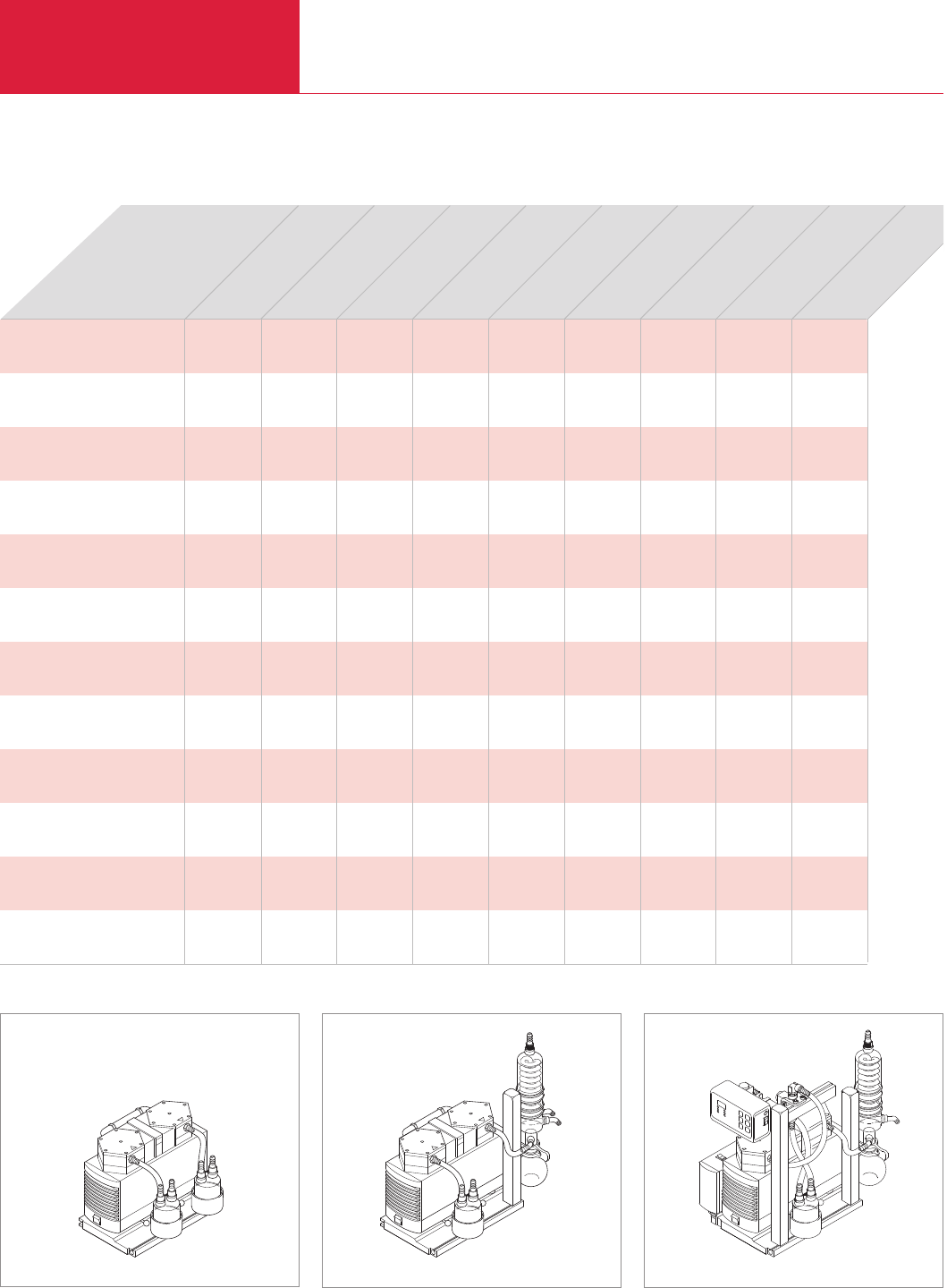
Modular Diaphragm Pump System for the Chemical Laboratory
Diaphragm Vacuum Pumps
C04.04 LEYBOLD VACUUM PRODUCTS AND REFERENCE BOOK 2003/2004
Modular
diaphragm pump system
DIVAC 0.6 L
DIVAC 1.2 L
DIVAC 2.2 L
DIVAC 1.2 L AD
DIVAC 2.2L AD
Base plate
Separator
(intake side)
Separator
(exhaust side)
High-performance condenser
(including stand and holder)
Vacuum controller
Gas ballast unit
Corresponds to the DIVAC system
Filtration
Distillation
Drying in the
drying cabinet
Drying cabinets
(2 cabinets with one pump)
Rotary evaporator
Steam sterilisation
♦ ♦ ♦ ♦ ♦
♦ ♦
♦ ♦
♦ ♦ ♦ ♦ ♦
♦ ♦ ♦ ♦ ♦
♦ ♦ ♦ ♦ ♦ ♦ ♦ ♦ ♦
♦ ♦ ♦ ♦ ♦ ♦ ♦
♦ ♦ ♦ ♦ ♦ ♦ ♦
♦ ♦ ♦ ♦
♦
♦ ♦
– – – SR 0.6 L SH 0.6 L SH 2.2 L SH 2.2 L SC 1.2 L –
DIV
DIVAC system: SR 0.6 L, 1.2 L, 2.2 L DIVAC system: SH 0.6 L, 1.2 L, 2.2 L DIVAC system: SC 0.6 L, 1.2 L, 2.2 L
Sublimation
Analysis preparation
The customized diaphragm pump and the accessories recommended for your application in the chemical laboratory

Modular Diaphragm Pump System for the Chemical Laboratory
Diaphragm Vacuum Pumps
C04.05
LEYBOLD VACUUM PRODUCTS AND REFERENCE BOOK 2003/2004
C04
Features of the Modular
Designed Laboratory
Pumpsystem
♦All system components are combined to form
assemblies which can be easily replaced or
retrofitted
♦Easy relocation since the entire assembly is
mounted as a unit on a stable base plate for
easy transportation
♦Individual components with plug connectors
for easy removal and mounting
♦Compact design – Small footprint
♦For the SC configuration – with separator,
high-performance condenser and controller –
all electrical connections are arranged inside
the control unit and made by way of plug
connectors
♦Trouble-free provisions for mounting
additional laboratory equipment in grooved
rails, on laboratory stands and crossbars in
the assembly
♦Simple replacement of diaphragms and valves
Advantages to the User
♦Good base vacuum of 8 mbar (100 mbar for
single-head DIVAC pumps)
♦All parts of the pump head in contact with the
gas are resistant against aggressive media
through the use of PTFE (Teflon), FFPM
(Kalrez) and PVDF (Solef)
♦Dry compressing, oil-free
♦Very high water vapour tolerance
♦Low maintenance costs and long service
intervals through the use of high-quality
components which are well-proven
♦Simple maintenance by staff of the customer
♦Low noise operation
♦Portable, compact, small footprint
♦Can be operated in any orientation
♦Illuminated mains switch on the pump
♦Overheat protection for the vacuum pump by
means of a thermofuse
♦Available in three pumping speed categories
♦Modular system
– can easily be adapted to special
requirements
♦Wide range of accessories like separator,
condenser, base plate, vacuum controller
Additional Benefits of the
Automatic Drying System
♦High vapour and condensate tolerance through
the newly developed automatic drying system
♦Maintaining of maximum pumping speed
♦Longer durability of the structured diaphragm
♦Individual adaptation of the drying cycle to
different processes
♦Vacuum chamber is not vented during the
drying phase
♦Overnight evacuations are possible through
the automatic cycling system
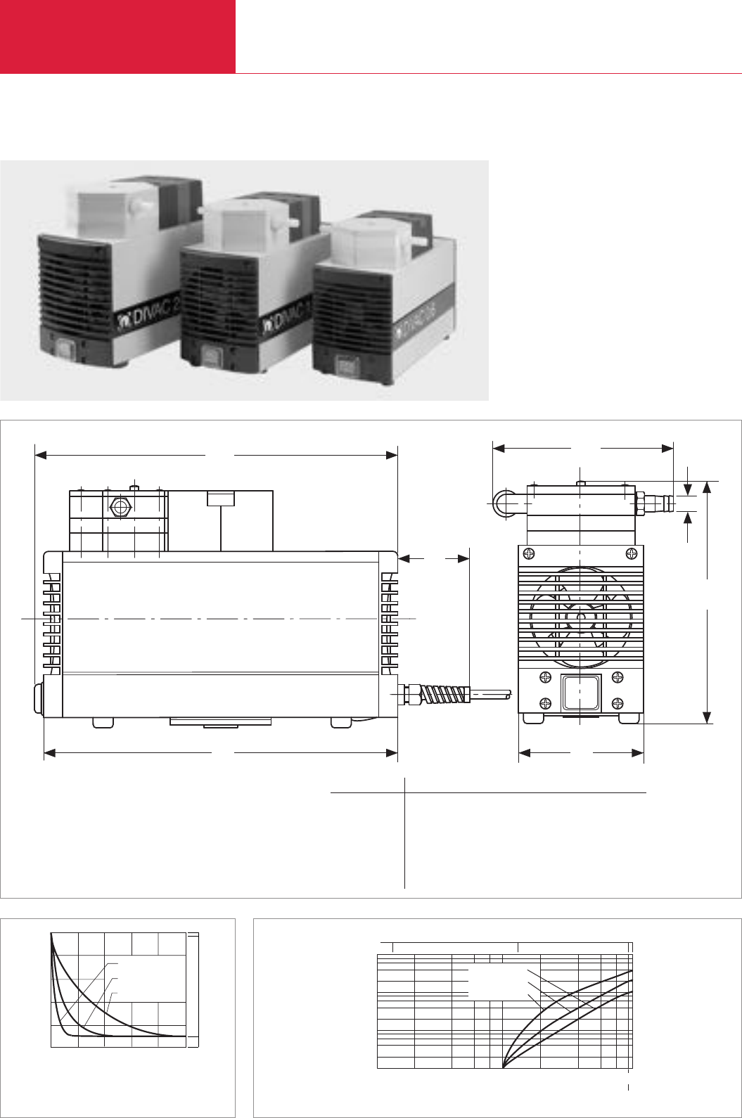
Modular Diaphragm Pump System for the Chemical Laboratory
C04.06 LEYBOLD VACUUM PRODUCTS AND REFERENCE BOOK 2003/2004
Diaphragm Vacuum Pumps
Single-Stage Diaphragm Vacuum Pumps DIVAC 0.6, 1.2, 2.2
Typical Applications
Vacuum generation for
♦Rotary evaporators
♦Drying chambers
♦Filtration units
♦Distillation configurations
♦Gel dryers
DIVAC 1.2
DIVAC 0.6
DIVAC 2.2
1013
00
Time
Pressure
mbar
Torr
200 100
750
400
600
min
2 4 6 10
Curves of pump-down time of a 10 l vessel
1000
mbar
100
10
1
0
1011021013
l / min DIVAC 0.6
DIVAC 1.2
DIVAC 2.2
Pressure
Pumping Speed
10 100 Torr 750
Curves of pumping capacity
lb
1
l1
l2
h
b
d
Dimensional drawing for the DIVAC 0.6, 1.2 and 2.2
Type b b1ld(Turned out) h l l1l2
DIVAC 0.6 mm 98 146 10 G 1/8“ 187 248 256 55
in. 3.86 5.75 0.39 G 1/8“ 7.36 9.76 10.08 2.17
DIVAC 1.2 mm 110 159 10 G 1/4“ 207 260 268 59
in. 4.33 6.26 0.39 G 1/4“ 8.15 10.24 10.55 2.32
DIVAC 2.2 mm 122 171 10 G 1/4“ 226 289 297 59
in. 4.8 6.73 0.39 G 1/4“ 8.9 11.38 11.69 2.32

Modular Diaphragm Pump System for the Chemical Laboratory
C04.07
LEYBOLD VACUUM PRODUCTS AND REFERENCE BOOK 2003/2004
C04
Diaphragm Vacuum Pumps
Technical Data
Ordering Information DIVAC 0.6 DIVAC 1.2 DIVAC 2.2
Diaphragm vacuum pump, 230 V, 50 Hz,
with 2.3 m (8 ft) power cord and earthed plug
Diaphragm vacuum pump, 100 V, 50/60 Hz,
with 2.3 m (8 ft) power cord and NEMA plug
Diaphragm vacuum pump, 115 V, 60 Hz,
with 2.3 m (8 ft) power cord and NEMA plug
Spare partsparts kit consisting of
1 diaphragm, 2 gasket rings, 2 valve disks
Hose nozzles
(1 exhaust port and 2 inlet ports)
*)for 230 V / 50 Hz version
Part No. 127 60
upon request
upon request
Part No. 127 63
Part No. 200 650 25 (2x)
Part No. 127 61
upon request
upon request
Part No. 127 64
Part No. 200 650 26 (2x)
Part No. 127 62
upon request
upon request
Part No. 127 65
Part No. 200 650 26 (2x)
Max. pumping speed (atm.) m3· h-1 (cfm)
Ultimate pressure mbar (Torr)
Max. exhaust back pressure (absolute) mbar (Torr)
Pump heads
Connections
Inlet (suction side) DN
Exhaust (delivery side) DN
Thread G
Noise level acc. to DIN 45 635 Part 13, approx. dB(A)
Permissible gas admission temperature, approx. °C (°F)
Permissible ambient temperature, approx. °C (°F)
Voltage / nominal frequency (1 ph. motor)
Earthed plug V/Hz
NEMA plug V/Hz
NEMA plug V/Hz
Protective class IP
Motor power *)W
Current consumption *)A
Motordrehzahl
50 Hz min-1
60 Hz min-1
Dimensions (W *)x H *)x D), approx. mm (in.)
Weight, approx. kg (lbs)
Material
Pump head
Structured diaphragm
Valves
Nozzles
0.6 (0.4) 1.2 (0.7) 2.0 (1.2)
≤100 (≤75)
2000 (1500)
1
Hose nozzle ID 10
Hose nozzle ID 10
G 1/8" G 1/4" G 1/4"
47 50 52
+ 5 bis + 40 (+41 to +104)
+ 5 bis + 40 (+41 to +104)
230 ± 10% / 50
115 ± 10% / 60
100 ± 10% / 50/60
44
100 130 180
0.6 0.9 1.35
1500
1800
256 x 146 x 187 (10.08 x 5.75 x 7.36) 268 x 159 x 207 (10.55 x 6.3 x 8.15) 297 x 171 x 226 (11.69 x 6.73 x 8.9)
5.9 (13.02) 7.1 (15.57) 10.3 (22.74)
PTFE (Teflon)
PTFE coated
FFPM (Kalrez)
PVDF (Solef)
DIVAC 0.6 DIVAC 1.2 DIVAC 2.2
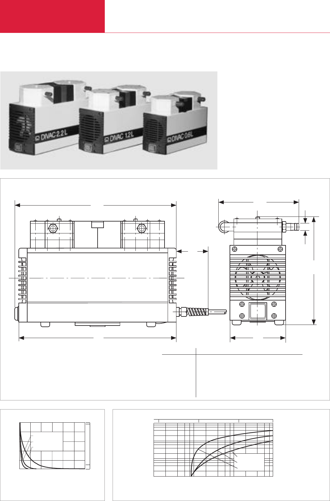
C04.08 LEYBOLD VACUUM PRODUCTS AND REFERENCE BOOK 2003/2004
Modular Diaphragm Pump System for the Chemical Laboratory
Diaphragm Vacuum Pumps
Dual-Stage Diaphragm Vacuum Pumps DIVAC 0.6 L, 1.2 L, 2.2 L
Typical Applications
Vacuum generation for
♦Rotary evaporators
♦Drying chambers
♦Filtration units
♦Distillation configurations
♦Gel dryers
1013
00
Time
Pressure
mbar
Torr
200 100
750
400
600
min
4 8 12 16 24
DIVAC 1.2 L
DIVAC 2.2 L
DIVAC 0.6 L
Curves of pump-down time of a 10 l vessel
Pressure mbar
102
101
100
10-1
101
100102103
l / min
DIVAC 0.6 L
DIVAC 1.2 L
DIVAC 2.2 L
62 8
4
Pumping Speed
100101102750
Torr
Curves of pumping capacity
lb
1
l1
l2
h
b
d
Dimensional drawing for the DIVAC 0.6 L, 1.2 L and 2.2 L
Type b b1ld(Turned out) h l l1l2
DIVAC 0.6 L mm 98 140 10 G 1/8“ 187 273 281 55
in. 3.86 5.51 0.39 G 1/8“ 7.36 10.75 11.06 2.17
DIVAC 1.2 L mm 110 159 10 G 1/4“ 207 304 312 59
in. 4.33 6.06 0.39 G 1/4“ 8.15 11.97 12.28 2.32
DIVAC 2.2 L mm 122 166 10 G 1/4“ 226 334 341 59
in. 4.8 6.54 0.39 G 1/4“ 8.9 13.15 13.43 2.32

C04.09
LEYBOLD VACUUM PRODUCTS AND REFERENCE BOOK 2003/2004
Modular Diaphragm Pump System for the Chemical Laboratory
Diaphragm Vacuum Pumps
Technical Data
Ordering Information
Diaphragm vacuum pump, 230 V, 50 Hz,
with 2.3 m (8 ft) power cord and earthed plug
Diaphragm vacuum pump, 100 V, 50/60 Hz,
with 2.3 m (8 ft) power cord and NEMA plug
Diaphragm vacuum pump, 115 V, 60 Hz,
with 2.3 m (8 ft) power cord and NEMA plug
Spare parts set comprising
2 diaphragms, 4 gasket rings, 4 valve plates
Hose nozzle kit consisting of
2 hose nippel, piping
*)for 230 V / 50 Hz version
Part No. 135 00
Part No. 135 02
Part No. 135 03
Part No. 135 23
Part No. 200 650 05
Part No. 135 06
Part No. 135 08
Part No. 135 09
Part No. 135 24
Part No. 200 650 06
Part No. 135 12
Part No. 135 14
Part No. 135 15
Part No. 135 25
Part No. 200 650 0
Max. pumping speed (atm.) m3· h-1 (cfm)
Ultimate pressure mbar (Torr)
Max. exhaust back pressure (absolute) mbar (Torr)
Pump heads
Connections
Inlet (suction side) DN
Exhaust (delivery side) DN
Thread G
Noise level acc. to DIN 45 635 Part 13, approx. dB(A)
Permissible gas admission temperature, approx. °C (°F)
Permissible ambient temperature, approx. °C (°F)
Voltage / nominal frequency (1 ph. motor)
Earthed plug V/Hz
NEMA plug V/Hz
NEMA plug V/Hz
Protective class IP
Motor power *)W
Current consumption *)A
Motor speed
50 Hz min-1
60 Hz min-1
Dimensions (W *)x H *)x D), approx. mm (in.)
Weight, approx. kg (lbs)
Material
Pump head
Structured diaphragm
Valves
Nozzles
0.6 (0.4) 1.2 (0.7) 2.0 (1.2)
≤8 (≤6)
2000 (1500)
2
Hose nozzle ID 10
Hose nozzle ID 10
G 1/8" G 1/4" G 1/4"
47 50 52
+ 5 bis + 40 (+41 to +104)
+ 5 bis + 40 (+41 to +104)
230 ± 10% / 50
115 ± 10% / 60
100 ± 10% / 50/60
44
90 120 245
0.6 0.7 1.8
1500
1800
281 x 140 x 187 (11.06 x 5.51 x 7.36) 312 x 154 x 207 (12.28 x 6.06 x 8.15) 341 x 166 x 226 (13.43 x 6.54 x 8.9)
6.9 (15.2) 9.3 (20.5) 12.6 (27.8)
PTFE (Teflon)
PTFE coated
FFPM (Kalrez)
PVDF (Solef)
C04
DIVAC 0.6 L DIVAC 1.2 L DIVAC 2.2 L
DIVAC 0.6 L DIVAC 1.2 L DIVAC 2.2 L
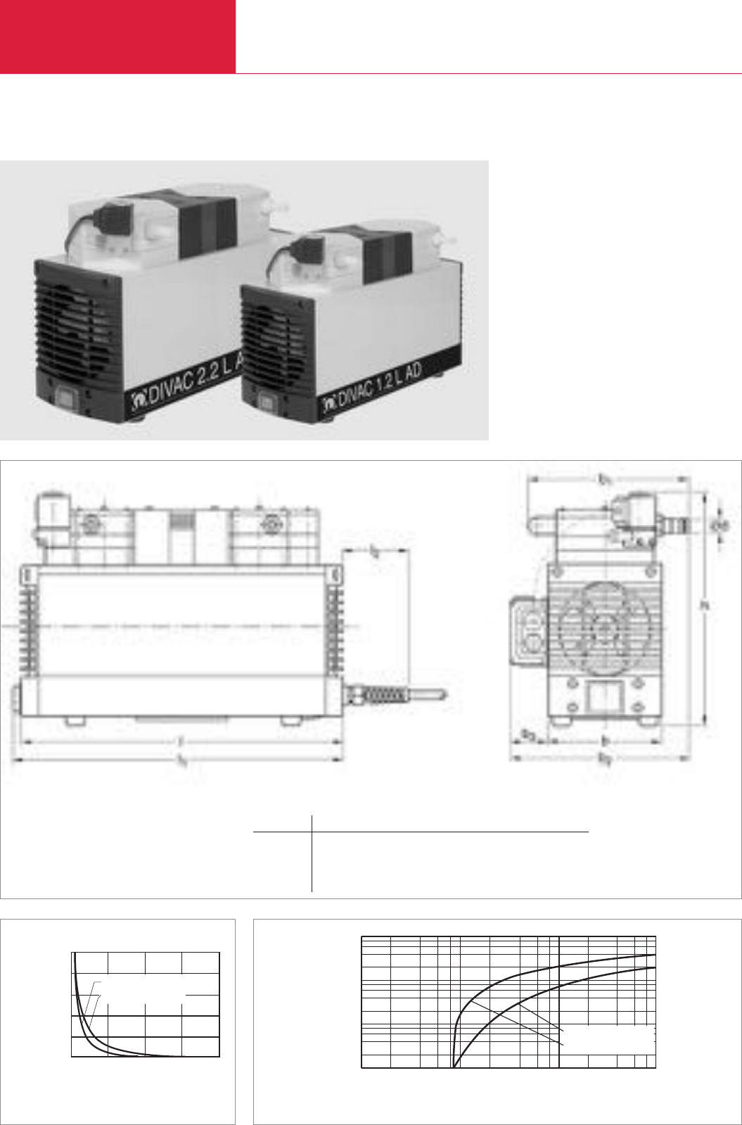
Modular Diaphragm Pump System for the Chemical Laboratory
Diaphragm Vacuum Pumps
C04.10 LEYBOLD VACUUM PRODUCTS AND REFERENCE BOOK 2003/2004
Dual-Stage Diaphragm Vacuum Pumps DIVAC 1.2 L AD, 2.2 L AD
Dimensional drawing for the DIVAC 1.2 L AD und 2.2 L AD
Typ b b1b2b3ld(Turned out) h l l1l2
DIVAC 1.2 L AD mm 110 154 177 42 10 G 1/4“ 220 304 312 59
in. 4.33 6.06 6.97 1.65 0.39 G 1/4“ 8.666 11.97 12.28 2.32
DIVAC 2.2 L AD mm 122 165 189 42 10 G 1/4“ 239 334 341 59
in. 4.80 6.5 7.44 1.65 0.39 G 1/4“ 9.41 13.15 13.43 2.32
DIVAC 1.2 L AD
DIVAC 2.2 L AD
1013
00
Time
Pressure
mbar
200
400
600
min
48
Curves of pump-down time of a 10 l vessel
Pressure mbar
100
10
1
0,1110 100 1000
l / min
Pumping speed
62 8
4
DIVAC 1.2 L AD
DIVAC 2.2 L AD
Curves of pumping capacity
The automatic drying system of this dual-stage
diaphragm pump enables problem-free pumping
of very damp and wet vapors.
With the automatic function, resulting liquid is
blown out of the pump head using individually
adjustable parameters, restoring the maximum
suction capacity. The vacuum in the recipient is
maintained during drying.

Modular Diaphragm Pump System for the Chemical Laboratory
Diaphragm Vacuum Pumps
C04.11
LEYBOLD VACUUM PRODUCTS AND REFERENCE BOOK 2003/2004
C04
Technical Data DIVAC 1.2 L AD DIVAC 2.2 L AD
Ordering Information DIVAC 1.2 L AD DIVAC 2.2 L AD
Diaphragm vacuum pump 230 V, 50 Hz,
with 2.3 m power cord and earthed plug
Diaphragm vacuum pump 100 V, 50/60 Hz,
with 2.3 m power cord and NEMA plug
Diaphragm vacuum pump 115 V, 60 Hz,
with 2.3 m power cord and NEMA plug
Spare parts kit consisting of
2 diaphragms, 4 gasket rings, 4 valve plates
Hose nozzle kit consisting of
2 hose nippel, piping
Accessories
Separating vessel on the delivery side
Neoprene hose, 10 mm ID
Base panel
*)for 230 V / 50 Hz version
Part No. 500 750 Part No. 500 755
Part No. 500 751 Part No. 500 756
Part No. 500 752 Part No. 500 757
Part No. 135 24 Part No. 135 25
Part No. 200 650 06 Part No. 200 650 07
Part No. 135 20 Part No. 135 20
Part No. 200 650 02 Part No. 200 650 02
Part No. 135 18 Part No. 135 19
Pumping speed, max. (Atm.) m3· h-1 (cfm)
Ultimate pressure mbar (Torr)
Max. exhaust back pressure (absolute) mbar (Torr)
Pump heads
Connections
Inlet (suction side) DN
Exhaust (delivery side) DN
Thread G
Noise level acc. to DIN 45 635 Part 13, ca. dB(A)
Permissible gas admission temperature, max. °C (°F)
Permissible ambient temperature, max. °C (°F)
Voltage / nominal frequency (1 ph. motor)
Earthed plug V/Hz
NEMA plug V/Hz
NEMA plug V/Hz
Protective class IP
Motor power *)W
Current consumption *)A
Motor speed
50 Hz min-1
60 Hz min-1
Dimensions (W *)x H *) x D), approx. mm (in.)
Weight, approx. kg (lbs)
Material
Pump head
Structured diaphragm
Valves
Nozzles
1.2 (0.7) 2.0 (1.2)
≤10 (≤7.5)
2000 (1500)
2
hose nozzle ID 10
hose nozzle ID 10
G 1/4"
50 52
+ 5 bis + 40 (+41 to +104)
+ 5 bis + 40 (+41 to +104)
230 ± 10% / 50
115 ± 10% / 60
100 ± 10% / 50/60
44
120 245
0.7 1.8
1500
1800
312 x 177 x 220 (12.28 x 6.97 x 8.66) 341 x 189 x 239 (13.43 x 7.44 x 9.41)
9.6 (21.2) 12.9 (28.48)
PTFE (Teflon)
PTFE coated
FFPM (Kalrez)
PVDF (Solef)
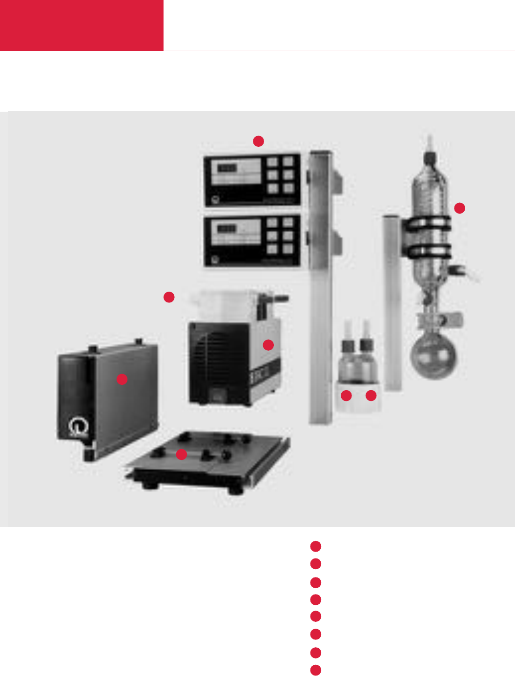
C04.12 LEYBOLD VACUUM PRODUCTS AND REFERENCE BOOK 2003/2004
Modular Diaphragm Pump System for the Chemical Laboratory
Diaphragm Vacuum Pumps
Modular Laboratory Pump Concept
Advantages to the User
♦Modular
♦Quiet-running
♦Compact
♦Environmentally friendly
♦Resistant to chemicals
♦Good ultimate vacuum
♦Reliable
♦Versions for different supply voltages
are available
DIVAC 0.6 L, 1.2 L, 2.2 L
Base plate
Separator intake side
Separator exhaust side (only included with module SR)
High-performance condenser
Vacuum controller NC 800
Gas ballast unit (optional)
Control unit
1
5
4
3
2
8
7
6
6
1
34
5
2
8
7
DIVAC system SCC 1.2 L (consisting of DIVAC module SC and DIVAC pump 1.2 L)
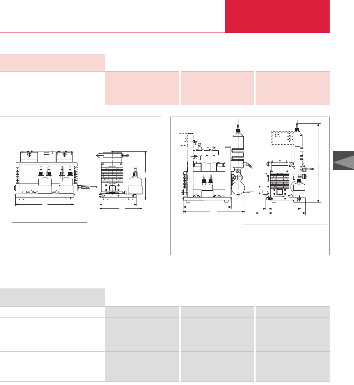
C04.13
LEYBOLD VACUUM PRODUCTS AND REFERENCE BOOK 2003/2004
Modular Diaphragm Pump System for the Chemical Laboratory
Diaphragm Vacuum Pumps
Electrical Data DIVAC SC System
100 V 115 V 230 V
Power drawn
Vacuum controller NC 800 W
Fuses (2 each, slow-blow) A
Control unit fuses (2 each, slow-blow) A
14
6.3
6.3
14
6.3
6.3
14
3.15
3.15
l
b1
b
h
b
h
b2b
b1
b3
l1
l
Dimensional drawing for the DIVAC SR system Dimensional drawing for the DIVAC SH, SC systems
____ SH
- - - - SC
Type b b1b2b3h l l1
SH mm 199 227 – – 506 312 397
in. 7.83 8.94 – – 19.92 12.28 15.63
SC mm 199 227 19 19 506 312 397
in. 7.83 8.94 0.75 0.75 19.92 12.28 15.63
Type b b1h l
SR mm 199 227 260 312
in. 7.83 8.94 10.24 12.28
Ordering Information DIVAC 0.6 L DIVAC 1.2 L DIVAC 2.2 L
Base plate for system mounting
Separator (intake or exhaust side)
High-performance condenser
Gas ballast valve
Vacuum controller
90 - 260 V, 50/60 Hz
Neoprene hose, inside dia. 10 mm (0.39 in.)
Part No. 135 18 Part No. 135 18 Part No. 135 19
Part No. 135 20 Part No. 135 20 Part No. 135 20
Part No. 135 21 Part No. 135 21 Part No. 135 21
– Part No. 135 27 Part No. 135 27
Part No. 500 760 Part No. 500 760 Part No. 500 760
Part No. 200 65 002 Part No. 200 65 002 Part No. 200 65 002
Components for the modular DIVAC system
C04
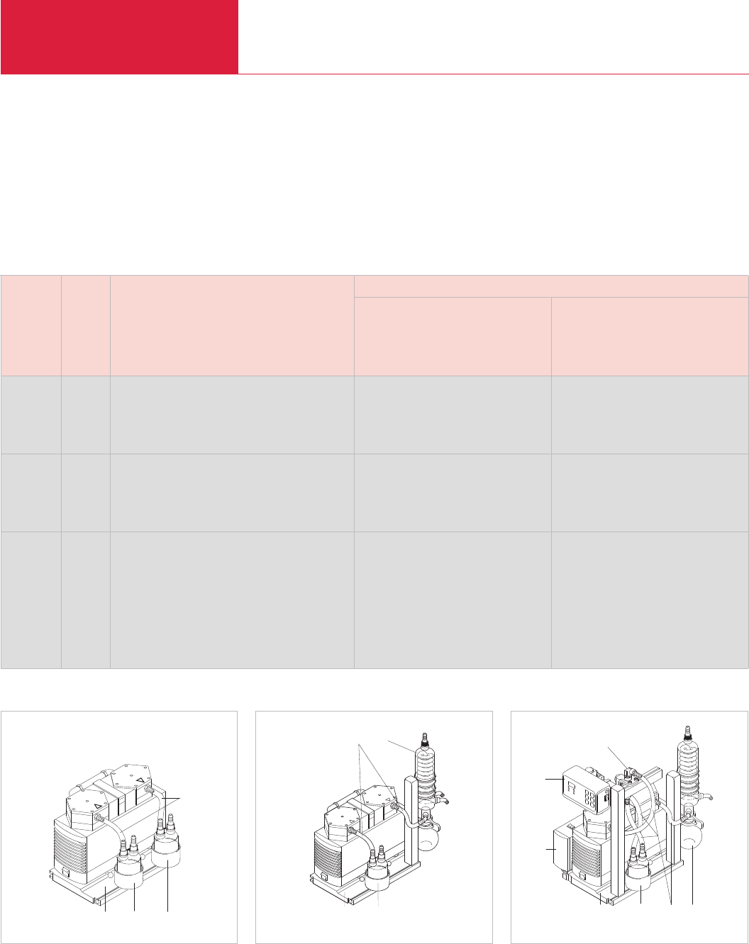
C04.14 LEYBOLD VACUUM PRODUCTS AND REFERENCE BOOK 2003/2004
Modular Diaphragm Pump System for the Chemical Laboratory
Diaphragm Vacuum Pumps
Part No.
European USA/Japan
Module Item Comprises version version
230 V, 50 Hz 115 V, 60 Hz
Euro-plug 100 V, 50/60 Hz
USA/Japan plug
1 Base plate and system mount
SR 2 Separator, intake side 135 40 135 40
3 Separator, exhaust side
4 Hose connectors
1 Base plate and system mount
SH 2 Separator, intake side 135 50 135 50
4 Hose connectors
5 High-performance condenser
1 Base plate and system mount
SC 2 Separator, intake side 135 60 upon request
4 Hose connectors
5 High-performance condenser
6 Vacuum controller
7 Pump relief valve
8 Control unit (incl. cable)
1
8
2 5
DIV
4
6
7
SC module
123
4
SR module
AC
2
1
45
SH module
Assemble your own pump system, selecting from the variety of modules available
Additional Ordering Information
When placing your order please also indicate the catalog number for the required pump (see section “Modular Laboratory
Pump Concept”)
Example: The DIVAC SH 0.6 L system comprises the DIVAC SH module (Part No. 135 50) and the DIVAC 0.6 L pump (Part No. 135 00)
Note: The SR to SC sub-assemblies do not include the pump!

C04.15
LEYBOLD VACUUM PRODUCTS AND REFERENCE BOOK 2003/2004
Modular Diaphragm Pump System for the Chemical Laboratory
Diaphragm Vacuum Pumps
C04
Notes
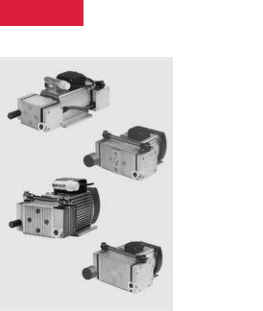
Dry Compressing Backing Pumps for Turbomolecular Pumps
Diaphragm Vacuum Pumps
C04.16 LEYBOLD VACUUM PRODUCTS AND REFERENCE BOOK 2003/2004
DIVAC 0.8 T to 4.8 VT
Vacuum pumps for pure pumping and evacuation
of air and gases owing to oil-free operation.
The requirements regarding technology are ever
increasing. In the area of vacuum technology the
demand for a dry vacuum, i.e. a vacuum which is
free of oil and thus free of hydrocarbons, is
increasing more and more.
We are able to meet this requirement through our
dry compressing backing pumps for turbo-
molecular pumps.
These are ideally suited for all applications in the
rough and medium vacuum range where clean
media need to be pumped. But also for corrosive
media we have solutions for you.
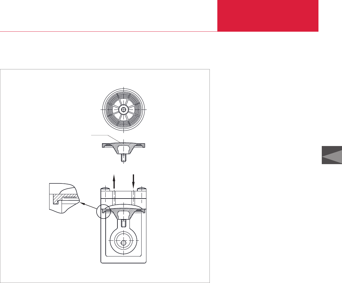
Dry Compressing Backing Pumps for Turbomolecular Pumps
Diaphragm Vacuum Pumps
C04.17
LEYBOLD VACUUM PRODUCTS AND REFERENCE BOOK 2003/2004
C04
Advantages to the User
♦Dry compressing, free of oil and hydro-
carbons
♦Matched to the turbomolecular pumps from
LEYBOLD (TW 70 to TW 1600)
♦Low ultimate pressure
♦KF flange at the intake port
♦Fully equipped with cable, switch (ON/OFF)
and plug
♦Better performance and smaller size through
the use of structured diaphragms
Typical Applications
♦Backing pump for wide pressure range
turbomolecular pumps
♦Masspectrometers
♦Medical equipment
♦Analyzes
♦For laboratory applications also with corrosive
media (DIVAC 3.6 TC only)
♦General use for rough and fine vacuum
applications
Structured diaphragm,
bottom side
Closed surface
Sealing rim
Structured diaphragm,
sectional view
The structured diaphragm with its sealed surface
provides the basis for a long service life and a
low base pressure.
♦Low vibration levels through dynamic mass
balancing (in VT pumps)
♦Lower maintenance costs and long
maintenance intervals through the use of
high-quality and well-proven components
♦Simple maintenance by staff of the customer
♦Favourable price-to-performance ratio
♦Uniform appearance
♦Can be operated in any position
Diaphragm pump with structured diaphragm
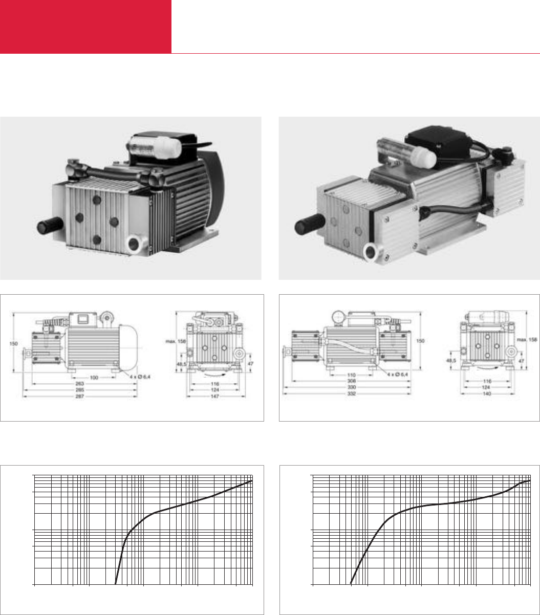
Dry Compressing Backing Pumps for Turbomolecular Pumps
Diaphragm Vacuum Pumps
C04.18 LEYBOLD VACUUM PRODUCTS AND REFERENCE BOOK 2003/2004
DIVAC 0.8 T and 0.8 LT
DIVAC 0.8 T DIVAC 0.8 LT
Dimensional drawing for the DIVAC 0.8 T Dimensional drawing for the DIVAC 0.8 LT
Pressure
Pumping speed
0,1 0,5 1 5 10 50 100 500 1000
0,01
0,05
0,1
0,5
1
[mbar abs.]
[m3 · h-1]
Pumping speed curve of the DIVAC 0.8 T
Pressure
Pumping speed
0,1 0,5 1 5 10 50 100 500 1000
0,01
0,05
0,1
0,5
1
[mbar abs.]
[m3 · h-1]
Pumping speed curve of the DIVAC 0.8 LT
Dimensional drawings are also available by way of .DXF files (sales@leyboldvakuum.com)
Direction of rotation
Direction of rotation

Dry Compressing Backing Pumps for Turbomolecular Pumps
Diaphragm Vacuum Pumps
C04.19
LEYBOLD VACUUM PRODUCTS AND REFERENCE BOOK 2003/2004
C04
Technical Data
Ordering information
Diaphragm, vacuum backing pumps
for turbomolecular pumps
including 1 m long mains cord, country-specific plug,
silencer 1), rubber feet, as well as ON/OFF switch
198-264 V / 50/60 Hz
090-127 V / 50/60 Hz
230 V / 50 Hz ± 10%
115 V / 60 Hz ± 10%
Spare parts kit consisting of
2 diaphragms, 4 valves, 4 valve gaskets,
4 gaskets
Exhaust silencer
T = For use in connection with Turbomolecular pumps
L = Very low ultimate pressure (Low pressure)
V = Low vibration levels (Vibration less)
C = Chemical (Corrosive)
Part No. 127 80
–
Part No. 127 81
–
–
Part No. 127 83
–
Part No. 127 84
Part No. 127 95 Part No. 127 95 (2x)
Part No. 127 98 Part No. 127 98
Pumping speed, max. (Atm.) m3/h (cfm)
Ultimate pressure (absolute) mbar (Torr)
Max. exhaust back pressure (absolute) mbar (Torr)
Pump heads
Connections
Inlet (suction side) DN
Exhaust (delivery side) DN
Thread G
Noise level acc. to DIN 45 635 Part 13, ca. dB(A)
Permissible gas admission temperature, max. °C (°F)
Permissible ambient temperature, max. °C (°F)
Voltage / nominal frequency (1 ph. motor)
Earthed plug V/Hz
NEMA plug V/Hz
Protective class IP
Motor power W
Current consumption A
Nominal speed, approx. (50/60 Hz) min-1
Dimensions (W x H x D), approx. mm (in.)
Weight, approx. kg (lbs)
Material
Diaphragm
Valves
Pump head
0.77 (0.45)
≤3 (≤2.25) ≤0.5 (≤0.38)
2000 (1500)
2 4
16 KF
Silencer
G 1/8"
49 53
+ 5 to + 40 (+ 41 to +104)
+ 5 to + 40 (+ 41 to +104)
198-264 / 50/60 230/50 ± 10%
90-127 / 50/60 115/60 ± 10%
44
50 80
0.4 0.5
1500/1800
285 x 150 x 150 (11.22 x 5.9 x 5.9) 332 x 150 x 150 (13.07 x 5.9 x 5.9)
5.9 (13.02) 7.5 (3.4)
Neoprene
EPDM
Aluminum
DIVAC 0.8 T DIVAC 0.8 LT
DIVAC 0.8 T DIVAC 0.8 LT
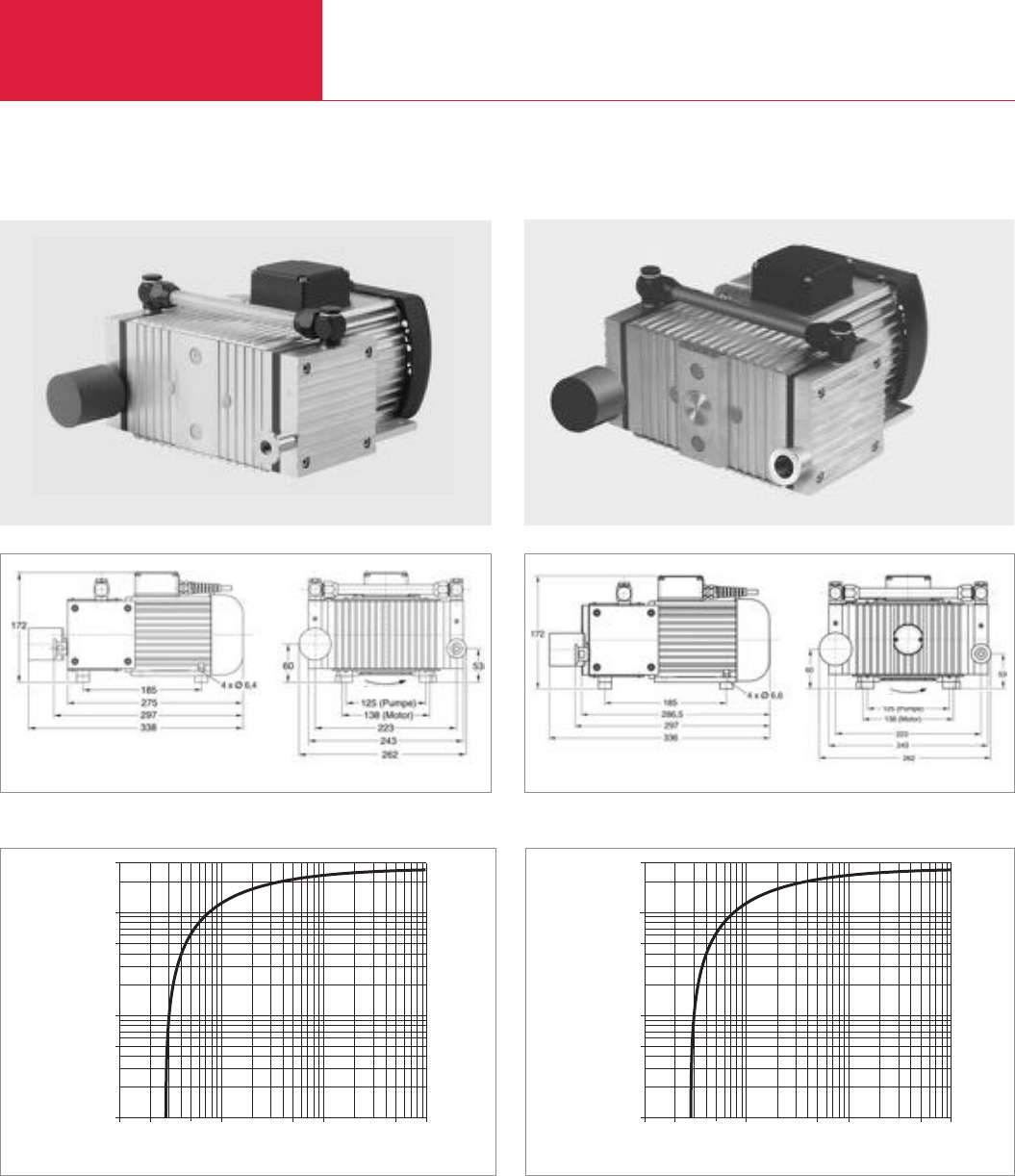
Dry Compressing Backing Pumps for Turbomolecular Pumps
Diaphragm Vacuum Pumps
C04.20 LEYBOLD VACUUM PRODUCTS AND REFERENCE BOOK 2003/2004
DIVAC 2.5 T and 2.5 VT
DIVAC 2.5 VT
DIVAC 2.5 T
Dimensional drawing for the DIVAC 2.5 VT
Pressure
1 5 10 50 100 500 1000
[mbar abs.]
Pumping speed
0,01
0,05
0,1
0,5
1
[m3 · h-1]
3
2
Pumping speed curve of the DIVAC 2.5 T
Pressure
1 5 10 50 100 500 1000
[mbar abs.]
Pumping speed
0,01
0,05
0,1
0,5
1
[m3 · h-1]
3
2
Pumping speed curve of the DIVAC 2.5 VT
Dimensional drawing for the DIVAC 2.5 T
Dimensional drawings are also available by way of .DXF files (sales@leyboldvakuum.com)
Direction of rotation Direction of rotation

Dry Compressing Backing Pumps for Turbomolecular Pumps
Diaphragm Vacuum Pumps
C04.21
LEYBOLD VACUUM PRODUCTS AND REFERENCE BOOK 2003/2004
C04
Technical Data
Ordering information
Diaphragm, vacuum backing pumps
for turbomolecular pumps
including 1 m long mains cord, country-specific plug,
silencer 1), rubber feet, as well as ON/OFF switch
230 V / 50 Hz ± 10%
115 V / 60 Hz ± 10%
Spare parts kit consisting of
2 diaphragms, 4 valves, 4 valve gaskets,
4 gaskets
Exhaust silencer
T = For use in connection with Turbomolecular pumps
L = Very low ultimate pressure (Low pressure)
V = Low vibration levels (Vibration less)
C = Chemical (Corrosive)
Part No. 127 86 Part No. 127 89
Part No. 127 87 Part No. 127 90
Part No. 127 96 Part No. 127 96
Part No. 127 99 Part No. 127 99
Pumping speed, max. (Atm.) m3/h (cfm)
Ultimate pressure (absolute) mbar (Torr)
Max. exhaust back pressure (absolute) mbar (Torr)
Pump heads
Connections
Inlet (suction side) DN
Exhaust (delivery side)
Thread G
Noise level acc. to DIN 45 635 Part 13, ca. dB(A)
Permissible gas admission temperature, max. °C (°F)
Permissible ambient temperature, max. °C (°F)
Voltage / nominal frequency (1 ph. motor)
Earthed plug V/Hz
NEMA plug V/Hz
Protective class IP
Motor power W
Current consumption A
Nominal speed, approx. (50/60 Hz) min-1
Dimensions (W x H x D), approx. mm (in.)
Weight, approx. kg (lbs)
Material
Diaphragm
Valves
Pump head
2.57 (1.51)
≤3 (≤2.25)
2000 (1500)
2
16 KF
Silencer
G 1/4"
49 53
+ 5 to + 40 (+ 41 to +104)
+ 5 to + 40 (+ 41 to +104)
230/50 ± 10%
115/60 ± 10%
54
300
1.4
1500/1800
336 x 262 x 172 (13.23 x 10.31 x 6.77)
12.9 (5.84) 13.1 (5.93)
EPDM
Neoprene
Aluminum
DIVAC 2.5 T DIVAC 2.5 VT
DIVAC 2.5 T DIVAC 2.5 VT
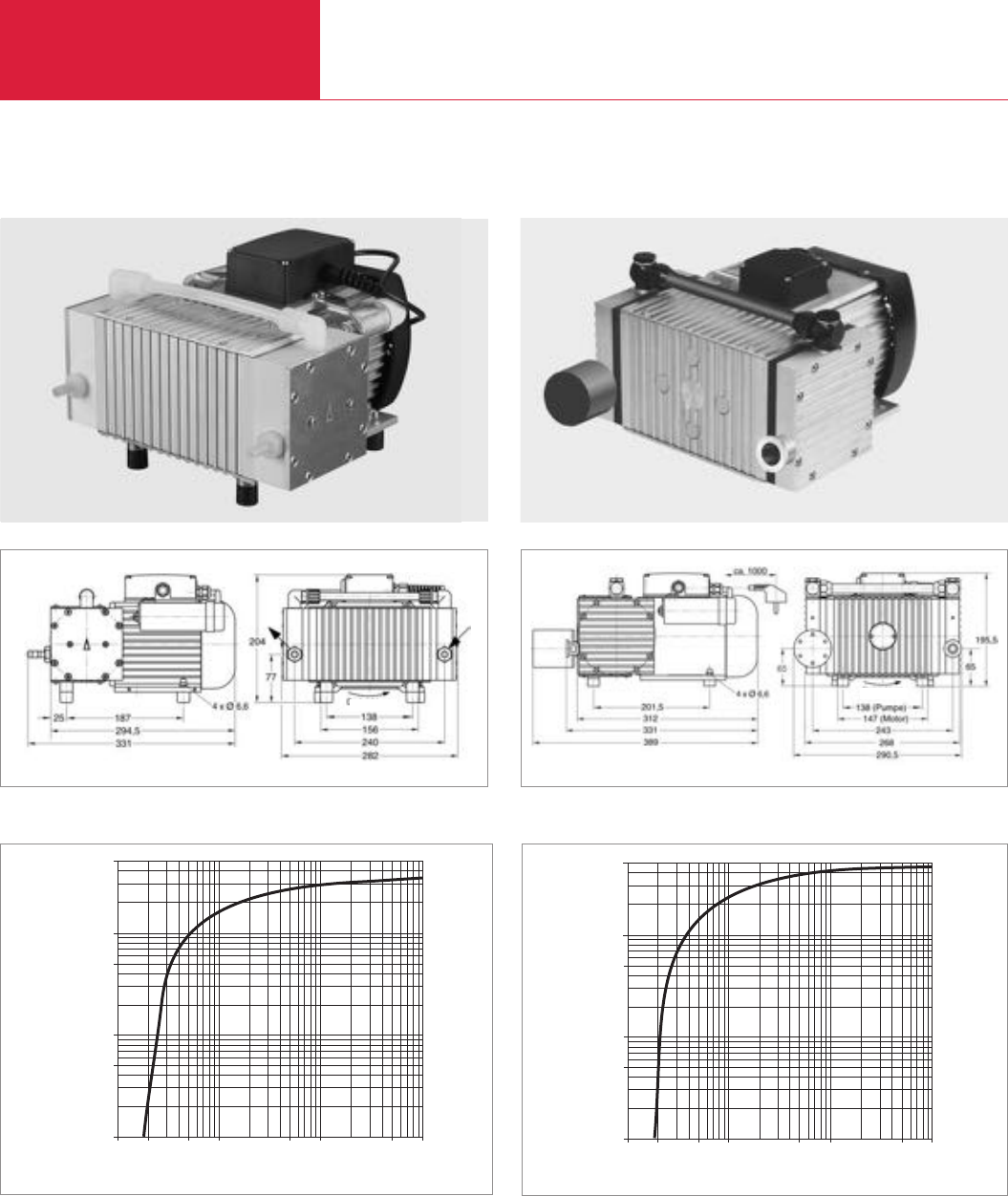
Dry Compressing Backing Pumps for Turbomolecular Pumps
Diaphragm Vacuum Pumps
C04.22 LEYBOLD VACUUM PRODUCTS AND REFERENCE BOOK 2003/2004
DIVAC 3.6 TC and 4.8 VT
DIVAC 3.6 TC
Dimensional drawing for the DIVAC 4.8 VT
Pressure
1 5 10 50 100 500 1000
[mbar abs.]
Pumping speed
0,01
0,05
0,1
0,5
1
[m3 · h-1]
2
5
Pumping speed curve of the DIVAC 3.6 TC
Pressure
1 5 10 50 100 500 1000
[mbar abs.]
Pumping speed
0,01
0,05
0,1
0,5
1
[m3 · h-1]
2
5
Pumping speed curve of the DIVAC 4.8 VT
DIVAC 4.8 VT
Dimensional drawings are also available by way of .DXF files (sales@leyboldvakuum.com)
Dimensional drawing for the DIVAC 3.6 TC
Direction of rotation
Direction of rotation

Dry Compressing Backing Pumps for Turbomolecular Pumps
Diaphragm Vacuum Pumps
C04.23
LEYBOLD VACUUM PRODUCTS AND REFERENCE BOOK 2003/2004
C04
Technical Data
Ordering information
Diaphragm, vacuum backing pumps
for turbomolecular pumps
including 1 m long mains cord, country-specific plug,
silencer 1), rubber feet, as well as ON/OFF switch
as well as ON/OFF switch
230 V / 50 Hz ± 10%
115 V / 60 Hz ± 10%
100 V / 50/60 Hz
Spare parts kit consisting of
2 diaphragms, 4 valves, 4 valve gaskets,
4 gaskets 2)
Exhaust silencer
Hose nippel 3/8" PVDF
1)
For the DIVAC 3.6 TC hose nozzle instead of silencer
2)
Not required for DIVAC 3.6 TC
T = For use in connection with Turbomolecular pumps
L = Very low ultimate pressure (Low pressure)
V = Low vibration levels (Vibration less)
C = Chemical (Corrosive)
Part No. 500 210 Part No. 127 92
Part No. 500 211 Part No. 127 93
Part No. 500 212
–
Part No. 500 215 Part No. 127 97
– Part No. 127 94
Part No. 500 214 –
Pumping speed, max. (Atm.) m3/h (cfm)
Ultimate pressure (absolute) mbar (Torr)
Max. exhaust back pressure (absolute) mbar (Torr)
Pump heads
Connections
Inlet (suction side) DN
Exhaust (delivery side)
Thread G
Noise level acc. to DIN 45 635 Part 13, approx. dB(A)
Permissible gas admission temperature, max. °C (°F)
Permissible ambient temperature, max. °C (°F)
Voltage / nominal frequency (1 ph. motor)
earthed plug V/Hz
NEMA plug V/Hz
Protective class IP
Motor power W
Current consumption A
Nominal speed, approx. (50/60 Hz) min-1
Dimensions (W x H x D), approx. mm (in.)
Weight, approx. kg (lbs)
Material
Diaphragm
Valves
Pump head
3.6 (2.12) 4.8 (2.83)
≤2 (≤1.5)
2000 (1500)
2
hose nozzle DN 10 + 16 KF
1m long chemical hose
Hose nozzle DN 10 Silencer
G 3/8" G 3/8"
50 55
+ 5 to + 40 (+ 41 to +104)
+ 5 to + 40 (+ 41 to +104)
230/50 ± 10%
115/60 ± 10%
54
220 350
1.6 2.6
1500/1800
329 x 277 x 205 (12.95 x 10.91 x 8.07) 324 x 273 x 220 (12.76 x 10.75 x 8.66)
14.3 (6.48) 18.0 (8.15)
PTFE (Teflon) EPDM
PTFE coated Viton
FFPM (Kalrez) Aluminum
DIVAC 3.6 TC DIVAC 4.8 VT
DIVAC 3.6 TC DIVAC 4.8 VT

C04.24 LEYBOLD VACUUM PRODUCTS AND REFERENCE BOOK 2003/2004
Diaphragm Vacuum Pumps
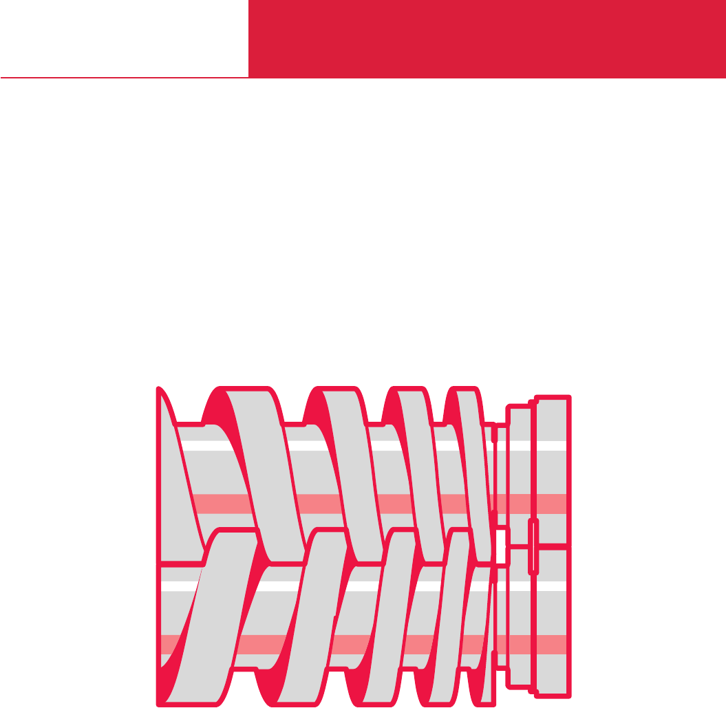
C05
Dry Compressing Screw Vacuum Pump
for Industrial Applications
SCREWLine SP630
SCREWLine

Contents
Dry Compressing Screw Vacuum Pump
C05.02 LEYBOLD VACUUM PRODUCTS AND REFERENCE BOOK 2003/2004
General
SCREWLine SP630 Dry Compressing Screw Vacuum Pump . . . . . . . . . . . . . . . . . . . . . . . . . C05.03
Products
SCREWLine SP630 . . . . . . . . . . . . . . . . . . . . . . . . . . . . . . . . . . . . . . . . . . . . . . . . . . . . . . . C05.04
Accesories
Vacuum Pump Oils . . . . . . . . . . . . . . . . . . . . . . . . . . . . . . . . . . . . . . . . . . . . . . . . . . . . . . C05.07
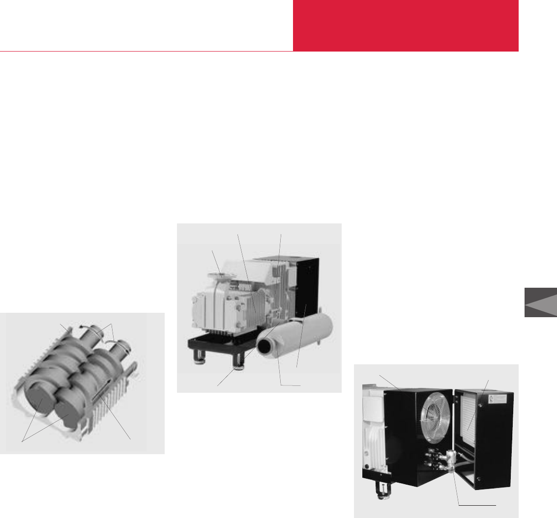
General Dry Compressing Screw Vacuum Pump
C05.03
C05
LEYBOLD VACUUM PRODUCTS AND REFERENCE BOOK 2003/2004
Dry Compressing Screw Vacuum Pump SCREWLine
Principle of Operation
The ScrewLine is a dry compressing vacuum
pump, the operation of which is based on the
screw principle.
The pump chamber is formed by two synchroni-
sed displacing rotors and the housing in which
the rotors are accommodated. Owing to the
opposing direction of rotation of the rotors, the
chambers “move” continuously from the inlet to
the exhaust side (see figure below) so that a low-
pulsation gas flow is produced. The ScrewLine
uses a minimum of parts since only one pair of
rotors is needed to compress the gas in several
stages. This considerably simplifies any main-
tenance and servicing work.
The ScrewLine is relatively insensitive to foreign
materials, since the gas flow does not have to be
deflected several times from stage to stage as is
the case in other types of dry compressing
pumps.
This ensures a high uptime of the pump on indu-
strial processes.
In dry compressing vacuum pumps it needs to be
observed that shaft sealing rings and bearings on
the vacuum side of a pump can always cause
problems. On the one hand lubricants may enter
into the vacuum process from the bearings and
on the other hand aggressive process media
endanger the bearings and the gaskets.
In the ScrewLine the two shaft seals are non-
contacting and almost free of wear. In standard
applications no seal gas is required. However, a
seal gas supply may optionally be connected to
the seals if the process application should require
this. Owing to the cantilevered rotors of the
ScrewLine, a potential source which might cause
a breakdown of the bearings on the intake side
has been completely eliminated.
A further advantage of the cantilevered arrange-
ment is that the pump chamber is easily acces-
sible without having to disassemble any bearings.
This is important in the case of applications
which are likely to contaminate the pump.
The figure below shows the ScrewLine SP630
with covers removed and equipped with the
optionally available silencer.
The ScrewLine SP630 is driven by an integrated
three-phase asynchronous motor driving one of
three shafts. This shaft also drives an oil supply
pump, a fan and via a gear the two rotor shafts.
The oil pump pumps the oil from the oil sump
through a filter and the oil/air heat exchanger into
the rotors and back into the oil sump.
Besides the integrated oil cooling arrangement
for the rotors, the entire machine is air cooled.
The fan sucks in the cooling air through the
oil/air heat exchanger and injects the pre-warmed
air via the motor’s housing into the pump cham-
ber housing.
This cooling arrangement ensures a close corre-
lation of all components temperatures so that
these may adapt themselves automatically to the
prevailing operating condition.
During the development of the ScrewLine pump
special emphasis was placed on a maintenance-
friendly servicing concept.
This is achieved by the cantilevered rotors and
also that all parts of the pump which need to be
accessed when making connections and for runn-
ing maintenance are accessible from one side,
resulting in a high degree of flexibility as to posi-
tioning the pump. Maintenance will in most appli-
cations, be limited to a regular check on the
pump (visual inspection) and an annual change
of the gear oil and the oil filter. The filter is readily
accessible and can be replaced when changing
the oil. Also the air/oil heat exchanger may be
easily cleaned by blowing out the radiator with
compressed air.
The ScrewLine offers to the user a high degree of
flexibility. The standard universal flanges ensure
easy integration into the system, and with the
accessories available for the ScrewLine, the
pump may be optimally adapted to the specific
requirements of differing applications.
Pump chamber housing
Direction of pumping action
Direction of rotation
Rotors
Pump chamber housing
Radiator housing
Motor and gear housing
Intake flange
Exhaust flange Silencer
S
CREW
Line SP630 without covers
Covers of the cooler removed for access to the oil filter and the heat exchanger
of the S
CREW
Line SP630
Air/oil heat exchangerRadiator
Oil filter
Operating principle of the ScrewLine SP630 screw vacuum pump
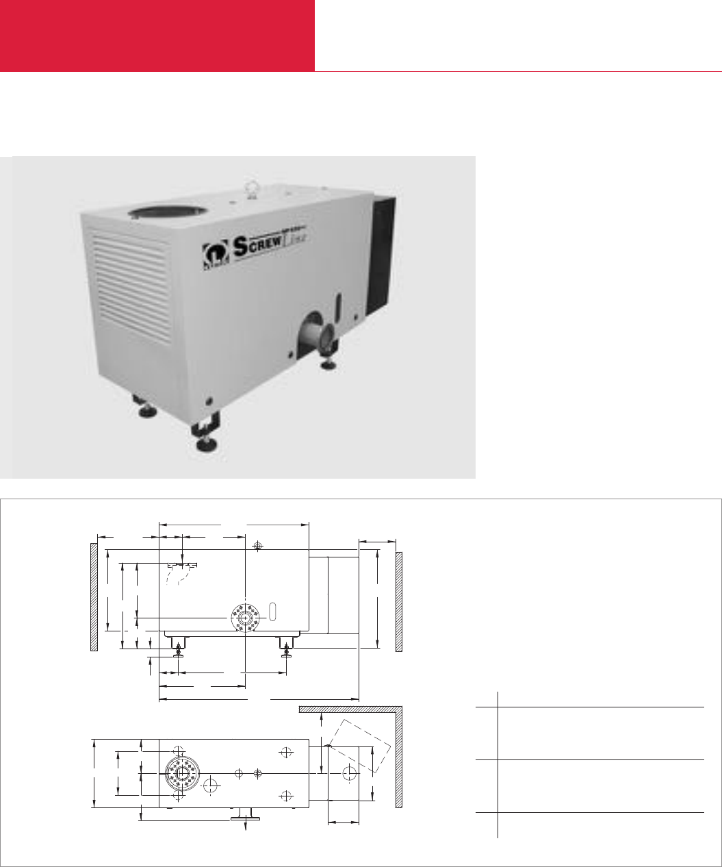
Produkte
Dry Compressing Screw Vacuum Pump
C05.04 LEYBOLD VACUUM PRODUCTS AND REFERENCE BOOK 2003/2004
The New Dry Compressing Screw Vacuum Pump for Industrial Applications
S
CREW
Line SP630
a
l
l
6
l
5
h
1
h
2
h
3
h
4
h
5
l
4
l
3
l
1
l
2
bb
1
b
3
b
2
b
4
a
l
7
h
a
1
The dry compressing screw vacuum pump
ScrewLine SP630 was developed for the special
requirements of industrial applications.
The innovative design allows this pump to be
used where a reliable, compact and low-mainten-
ance vacuum solution is required.
Dimensional drawing for the S
CREW
Line SP630
a a1b b1b2b3b4
mm > 500 > 300 555 360 276 380 439
in. > 19.69 > 11.81 21.85 14.17 10.87 14.96 17.28
h h1h2h3h4h5l
mm 806 636 698 450 248 68 1220
in. 31.73 25.04 27.48 17.72 9.76 2.68 48.03
l1l2l3l4l5l6l7
mm 1626 703 880 157 514 189 250
in. 64.02 27.68 34.65 6.18 20.24 7.44 9.84
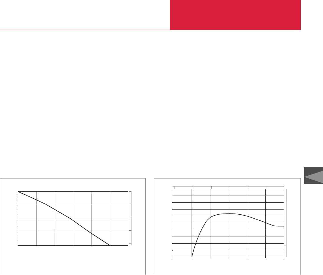
Dry Compressing Screw Vacuum Pump
C05.05
C05
LEYBOLD VACUUM PRODUCTS AND REFERENCE BOOK 2003/2004
Advantages to the User
♦Low cost of ownership
- No purge gas and no cooling water is
required in standard applications
- Low power consumption
♦Cost-wise optimized product
- Basic model and accessories allows the
pump to be equipped according to
requirements
♦Minimized downtimes, maximum availability
- Highly rugged due to the application
oriented design
♦Low waste disposal costs
- No contaminated waste oil is produced
♦Rugged and reliable
- No bearings on the intake side
♦Good compatibility with particles and vapours
(gas ballast is optional)
♦Long maintenance intervals and easy
servicing
- Only an annual change of the gear oil is
necessary
- Simple and quick access to all parts
which need to be serviced
- Cleaning of the rotors is possible on-site
♦Highly flexible
- The modular concept allows this pump to
adapt the pumping speed up to 2000 m
3
/h
in combination with RUVAC Roots pumps
- The universal flanges on the pump permit
simple integration and flexible adaptation
to your system
♦High pumping speed at low base pressure
Typical Applications
♦Industrial furnaces
(hardening, annealing, sintering,
carburizing, melting and many more)
♦Coating technology
♦Metallurgical systems
♦Packaging technology
♦Drying processes
0.0 0.4
0.2 0.6 0.8 1.0 1.2
Pump Down Time
Pressure
mbar
Vessel volume: 1.0 m
3
min
103
102
101
100
10-1 10-1
1
10
750
Torr
Pump down curve for the S
CREW
Line SP630
Pressure mbar
0
100
200
300
400
500
600
700
800
Pumping Speed
m3/h
10-3 10-2 10-1 100101102103
1000
10-1 110
Torr
750
10-2
10-3
500
cfm
50
100
Pumping speed diagram for nitrogen for the SP630

Dry Compressing Screw Vacuum Pump
C05.06 LEYBOLD VACUUM PRODUCTS AND REFERENCE BOOK 2003/2004
Technical Data SCREWLine SP630
50 Hz 60 Hz
Pumping speed, max. m3x h-1 (cfm)
Ultimate total pressure
without gas ballast mbar (Torr)
Intake pressure limits
Continouos operation mbar (Torr)
Cooling
Power supply ∆∆
∆
Motor
Nominal power kW (hp)
Nominal voltage (∆∆ / ∆/ ±10%) V
Max. ambient temperature °C (°F)
Type of protection IP
Lubricant filling (gear chamber) l
Noise level 1) dB(A)
Connections
Intake and Exhaust
Weight, approx. kg (lbs)
Dimensions (W x D x H) mm (in.)
630 (371)
≤0.01 (≤0.0075)
1030 (773)
Air
52 A at 190 V - 210 V ± 5% 52 A at 190 V - 240 V ± 5%
26 A at 380 V - 420 V ± 5% 26 A at 380 V - 480 V ± 5%
15 (20)
200 / 400
+40 (+104)
55
12 – 15
≤75 upon request
DN 100 / PN 6 (EN 1092-2)
DN 100 / PN 10 (EN 1092-2)
NPS 4 Class 150 (in accordance with ASME B 16.5-1996)
DN 100 ISO-K (in accordance with ISO 1609-1986 (E))
530 (1166)
1630 x 660 x 880 (64 x 26 x 35)
Ordering Information
SCREWLine 630
Exhaust silencer
Roots pump adapter
for RUVAC 2001
Dust filter 2)
1) With closed exhaust line or exhaust silencer
2) For information on the dust filter please refer to Product Section C02, Chapter “Accessories”
*)Available from July 2003
SCREWLine SP630
50 Hz 60 Hz
Part No. 117 001 *
)
Part No. 117 002 *
)
Part No. 119 001 *)
Part No. 119 021 *)
Part No. 951 72

Accessories Dry Compressing Screw Vacuum Pump
C05.07
C05
LEYBOLD VACUUM PRODUCTS AND REFERENCE BOOK 2003/2004
Lubricating oils for vacuum pumps must meet
tough requirements. They need to have excellent
lubricating properties and resist cracking when
subjected to mechanical loads.
The vacuum pump oil ANDEROL
®
555 listed in
the following has undergone extensive testing
under application conditions in our own laborato-
ries and has been fully qualified for use in the
ScrewLine pumps.
If other types of oil shall be used please get in
touch with LEYBOLD first.
We therefore recommend the exclusive use of
vacuum pump oils fully qualified by Leybold so
as to ensure optimum performance of the Ley-
bold vacuum pumps and also to ensure optimum
oil change intervals.
Under vacuum conditions lubricating oils, especi-
ally those with additives may behave quite diffe-
rently than expected. Additives may adversely
affect the attainable ultimate pressure and may
react with the media being pumped.
Vacuum Pump Oils
The oils given in the following belong to the
group of synthetic oils:
Ester oils
Ester oils are organic compounds which excel
especially through their high thermal resistance
to cracking compared to mineral oils. Chemical
resistance is generally quite good, but will
depend on the type of ester oil. Elastomer com-
patibility and resistance against hydrolysis are
not so good compared to mineral oils.
Polyalphaolefin (PAO) Oils
Polyalphaolefin oils are synthetic hydrocarbons
which are paraffin like, but have a uniform struc-
ture. Thermal and chemical resistance is better
compared to mineral oils. Elastomer compatibility
and resistance against hydrolysis are comparable
to mineral oils.
For all lubricants in our line of products you may obtain Safety Data Sheets from the Dept. Technical
Support in Cologne.
Technical Data
ANDEROL®555
Ordering Information
Part No. EK110000792
Viscosity
at 040 °C (104 °F) mm2/s (= cSt)
at 100 °C (212 °F) mm2/s (= cSt)
Flash point °C (°F)
Vapor pressure
at 020 °C (68 °F) mbar (Torr)
at 100 °C (212 °F) mbar (Torr)
Density at 15 °C (59 °F) g/ml
Pour point °C (°F)
Middle molecular weight g/mol
Maintenance kit Stage 1, SP630 for changing the gear oil
15 l ANDEROL®555, oil filter cartridge and gasket
Please note that the technical data stated are only typical data. Slight variations from batch to batch must be expected.
The technical data stated here can not be taken as assured properties
1) Resistance to decomposing is very much dependent on the share of acrylonitrile in the NBR
ANDEROL®is a trademark of ANDEROL BV
Maintenance Kit for changing the Gear Oil
94
9
250 (482)
7 x 10⁻⁵ (5.25 x 10⁻⁵)
1.5 x 10⁻³ (1.1 x 10⁻⁵)
0,96
-42 (-44)
530
ANDEROL®555
Type of oil
Elastomer compatibility
FPM (Viton)
NBR (Perbunan) 1)
EPDM
Diester oil
Suited
Conditionally suited
Not suited
Application Data
For these reasons please understand that we
must make our warranty commitment dependent
on the use of oils which have been qualified by
us. Damages caused by the use of not suitably
qualified lubricating oils are not covered by our
warranty.
Lubricant Types
Synthetic Oils
Synthetic oils are produced by a chemical reac-
tion. The group of synthetic oils includes liquids
differing widely as to their chemical structure and
composition. Correspondingly their physical and
chemical properties differ considerably. Synthetic
oils are used in those cases where special pro-
perties of the oil are required which can not be
fulfiled by mineral oils.

Dry Compressing Screw Vacuum Pump
C05.08 LEYBOLD VACUUM PRODUCTS AND REFERENCE BOOK 2003/2004

C06
Rotary Piston Vacuum Pumps
Single- and two-stage, oil-sealed,
200 - 250 m3x h-1 (117.8 - 147 cfm)
E and DK

Contents
Rotary Piston Vacuum Pumps
LEYBOLD VACUUM PRODUCTS AND REFERENCE BOOK 2003/2004
General
Applications and Operation. . . . . . . . . . . . . . . . . . . . . . . . . . . . . . . . . . . . . . . . . . . . . . . . . C06.03
Application and Accessories . . . . . . . . . . . . . . . . . . . . . . . . . . . . . . . . . . . . . . . . . . . . . . . . C06.03
Products
Single-Stage Rotary Piston Vacuum Pump E 250 . . . . . . . . . . . . . . . . . . . . . . . . . . . . . . . . C06.04
Two-Stage Rotary Piston Vacuum Pump DK 200. . . . . . . . . . . . . . . . . . . . . . . . . . . . . . . . . C06.06
Accessories
Global Versions
Valves . . . . . . . . . . . . . . . . . . . . . . . . . . . . . . . . . . . . . . . . . . . . . . . . . . . . . . . . . . . . . . . . C06.08
Exhaust Filter Box AFK 2 . . . . . . . . . . . . . . . . . . . . . . . . . . . . . . . . . . . . . . . . . . . . . . . . . . C06.09
Oil Filter Unit . . . . . . . . . . . . . . . . . . . . . . . . . . . . . . . . . . . . . . . . . . . . . . . . . . . . . . . . . . . C06.10
Oil Control Unit . . . . . . . . . . . . . . . . . . . . . . . . . . . . . . . . . . . . . . . . . . . . . . . . . . . . . . . . . C06.10
Condensate Separator AK 100-250 . . . . . . . . . . . . . . . . . . . . . . . . . . . . . . . . . . . . . . . . . . . C06.11
Exhaust Filter AF 100-250 A . . . . . . . . . . . . . . . . . . . . . . . . . . . . . . . . . . . . . . . . . . . . . . . . C06.11
Dust Filter FS 100-250 . . . . . . . . . . . . . . . . . . . . . . . . . . . . . . . . . . . . . . . . . . . . . . . . . . . . C06.12
Dust Separator AS 100-250 . . . . . . . . . . . . . . . . . . . . . . . . . . . . . . . . . . . . . . . . . . . . . . . . C06.13
Versions for the North and South American Continents
Oil Filtering System OF1000 . . . . . . . . . . . . . . . . . . . . . . . . . . . . . . . . . . . . . . . . . . . . . . . . C06.14
Oil Filtering System OF3000 . . . . . . . . . . . . . . . . . . . . . . . . . . . . . . . . . . . . . . . . . . . . . . . . C06.16
Vibration Absorber . . . . . . . . . . . . . . . . . . . . . . . . . . . . . . . . . . . . . . . . . . . . . . . . . . . . . . . C06.17
Condensate Separator AK 100-250 . . . . . . . . . . . . . . . . . . . . . . . . . . . . . . . . . . . . . . . . . . . C06.18
Exhaust Filter AF 100-250 A . . . . . . . . . . . . . . . . . . . . . . . . . . . . . . . . . . . . . . . . . . . . . . . . C06.18
Miscellaneous
Vacuum Pump Oils . . . . . . . . . . . . . . . . . . . . . . . . . . . . . . . . . . . . . . . . . . . . . . . . . . . . . . C06.19
60 Hz Curves . . . . . . . . . . . . . . . . . . . . . . . . . . . . . . . . . . . . . . . . . . . . . . . . . . . . . . . . . . . C06.22
C06.02
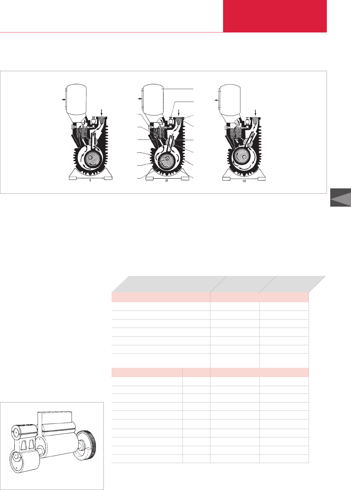
C06
General
Rotary Piston Vacuum Pumps
LEYBOLD VACUUM PRODUCTS AND REFERENCE BOOK 2003/2004
Advantages to the User
♦Gas ballast facility
♦Easy maintenance
♦Good ultimate pressure with and without gas
ballast
♦High pumping speed at low intake pressures
♦Compact design with flange mounted motor
♦High water vapor tolerance
♦Reliable continuous operation
♦Tolerant and rugged, due to non-contact
rotary piston within the pump chamber
♦Very smooth operation due to dynamically
balanced masses
♦Separate oil filling for the gear protects the
gear against contaminated pump oil
♦Oil is used for sealing, lubrication and cooling
♦A built-in anti-reverse lock prevents incorrect
rotation of the piston and also stops it being
pulled back when the pump is switched off
while under vacuum
♦Air cooling makes the pump environmentally-
friendly and economic
♦Clear design and service-friendly due to the
modular design
Functional diagram of a rotary piston vacuum pump
Rotary piston
Eccentric
Shaft
Oil channel
Exhaust valve
Oil level glass
Gas ballast
actuator
Dirt trap
Exhaust box
Intake port
Sliding vane
Hinge bar
Cooling fins
Housing
Applications and Operation
Balancing the masses within a rotary piston vacuum pump:
Eccentric shaft, 2 pistons and toothed wheel
Application
Manufacture of semiconductors ♦ ♦
Coating ♦ ♦
Chemistry ♦ ♦
Metallurgy ♦ ♦
Electrical engineering ♦ ♦
Mechanical engineering ♦ ♦
Backing pump for a Roots vacuum pump
in diffusion pump systems
♦ ♦
Accessories
Page
AFK Exhaust Filter Box C06.09 ♦ ♦
Oil Filter Unit C06.10 ♦ ♦
Oil Control Unit C06.10 ♦ ♦
AK Condensate Separator C06.11/18 ♦ ♦
AF Exhaust Filter C06.11/18 ♦ ♦
FS Dust Filter C06.12 ♦ ♦
AS Dust Separator C06.13 ♦ ♦
Oil Filtering System OF1000 C06.14 ♦ ♦
Oil Filtering System OF3000 C06.16 ♦ ♦
Vibration Absorber C06.17 ♦ ♦
Pumps
E 250
DK 200
C06.03
Technical Note
♦By installing a filter, the oil may be cleaned
simultaneously
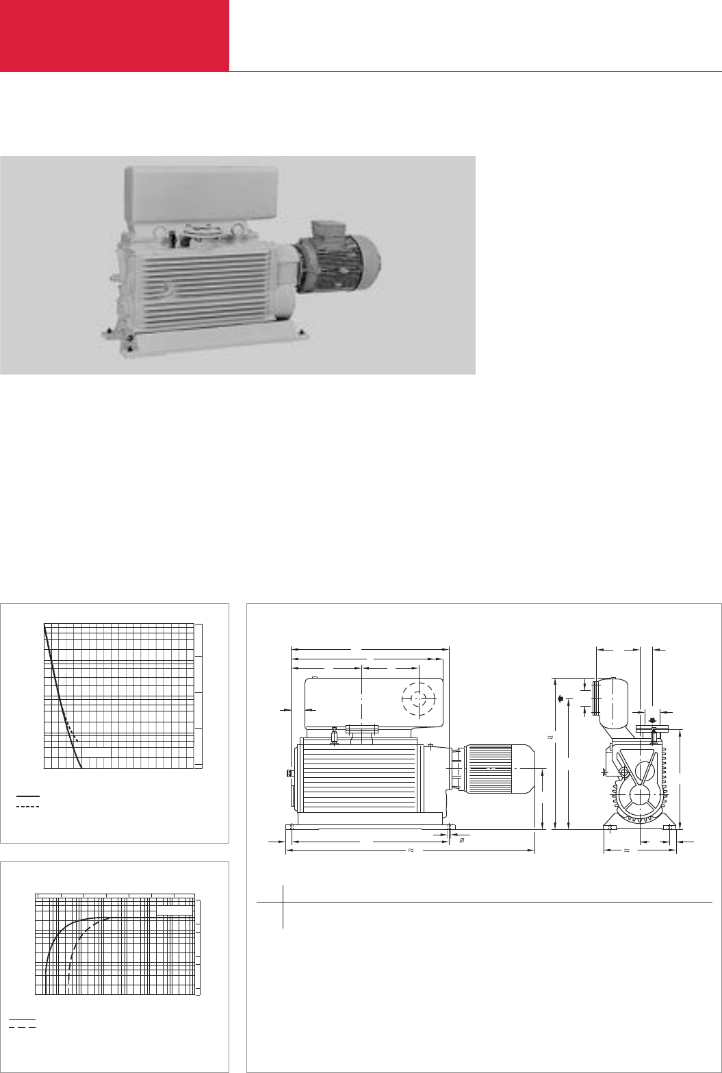
Pumping speed
m3 x
h-1
without gas ballast
2 4 6 8
8
6
4
2
with gas ballast
10-2
103
10-2 10-1 100101102103Torr
cfm
75000
102
101
100
100101102mbar
Pressure
103105
10-1
500
50
5
1
10
100
E 250
250 m3x h-1 (147.3 cfm)
Rotary Piston Vacuum Pumps
Single-Stage Rotary Piston Vacuum Pump E 250
Typical Applications
♦Chemical, metallurgical and electronic vacuum
processes
♦Impregnating, degassing and drying process-
es in experimentation systems, in drying
cabinets, extrusion etc.
♦Pressure range down to 4 x 10
-2
mbar
(2.4 x 10
-2
Torr) without gas ballast or to
5 x 10
-1
mbar (3 x 10
-1
Torr) with gas ballast
♦Backing pump for Roots vacuum pumps at
intake pressure down to 10
-3
mbar
(0.75 x 10
-3
Torr)
Supplied Equipment
♦With DN 65 DIN flanges on the intake and
exhaust sides for direct connection of
DN 63 ISO-K flange components
♦Ready for operation, complete with oil filling
♦Special models for different motor voltages,
motor frequencies and other protection class
ratings are available.
Details on these upon request.
LEYBOLD VACUUM PRODUCTS AND REFERENCE BOOK 2003/2004
Pump flanges to DIN 2501 with sealing disc and collar flange for the connection of ISO-K (KF) components
DN DN1a 1) a1a2b b1b2b3ld e f g h h1h2h3k l
mm 63 ISO-K 63 ISO-K 1190 780 30 340 140 202 52 14 777 750 65 740 475 636 295 337 290
in. 63 ISO-K 63 ISO-K 4.17 2.73 1.05 1.19 0.49 0.71 0.18 0.05 2.72 2.63 0.23 2.59 1.66 2.23 1.03 1.78 1.02
1) Only for the motor which is supplied as standard
DN
d
h3
h1
gDN1
h2
a
a1
a2
l
kf
eb2b3
bb130
h
min
Time
mbar Torr
Pressure
0
2
4
6
8
1 2 3 4 5 6 7 8 10
Without gas ballast
With gas ballast
100
10-1
101
102
103
10-1
100
101
102
750
E 250
Pumpdown characteristic of a 1000 l vessel for the E 250 rotary piston
vacuum pump
(60 Hz curves at the end of the section)
Pumping speed characteristic of the E 250 rotary piston vacuum pump
(60 Hz curves at the end of the section)
Dimensional drawing for the single-stage rotary piston vacuum pump E 250
C06.04

C06
250 m3x h-1 (147.3 cfm)
Rotary Piston Vacuum Pumps
LEYBOLD VACUUM PRODUCTS AND REFERENCE BOOK 2003/2004
Technical Data E 250
50 Hz 60 Hz
Ordering Information E 250
Single-stage rotary piston vacuum pump
E 250, with 50 Hz-motor 3)
(220 / 380 V +/- 10%)
E 250, with 460 V/50 Hz motor 3)
(220-230 V / 460 V +/- 10%)
E 250, with 460 V/60 Hz motor 3), *)
(200-230 V / 460 V +/- 10%) USA version
E 250, without motor, with 50 Hz gear 3) 4)
Sealing kit, pump
Vibration absorbing metal feet
SECUVAC valve
200-230 V, 50/60 Hz
115 V, 50/60 Hz
ANSI adaptor
1) To DIN 28 400 and following numbers
2) Operated at ultimate pressure without gas ballast, free field measurement at a distance of 1 m (3.5 ft). When fitting accessories, for example AFK2, the noise level may change by 2 to 3 dB(A)
3) For operation at a different frequency, the gear will have to be exchanged. Please state the main frequency and connection (star or delta) in your order
4) The maximum speed must not exceed 1,500 rpm at 50 Hz. The motor rating must be at least 5 kW (6.8 hp)
*)Continuous operation from 60 mbar (45 Torr)
Part No. 105 36
Part No. 895 08
Part No. 895 09
Part No. 166 37
Part No. 192 63
Part No. 101 55
Part No. 215 207
Part No. 215 206
upon request
C06.05
Nominal pumping speed 1) m3x h-1 (cfm)
Pumping speed 1) m3x h-1 (cfm)
Ultimate partial pressure without gas ballast
1)
mbar (Torr)
Water vapour tolerance 1) mbar (Torr)
Average noise level to DIN 45 635 2) dB(A)
Mains voltage 3-ph. V
Motor power at
220 / 380 V, 50 Hz kW (hp)
220-230 / 460 V, 50 Hz kW (hp)
200-230 V / 460 V, 60 Hz kW (hp)
Nominal motor speed rpm
Speed of the pump rpm
Motor protection IP
Oil filling l (qt)
Weight kg (lbs)
Intake port DN
Exhaust port DN
290 (170.8)
250 (147.3)
< 4x 10⁻² (< 2.4 x 10⁻²)
60 (45)
< 76
230/400 208-230/460
5.5 (7.5)
5.5 (7.5)
5.5 (7.5)
1500 1800
540
54
8.4 (8.9)
375 (827)
63 ISO-K
63 ISO-K
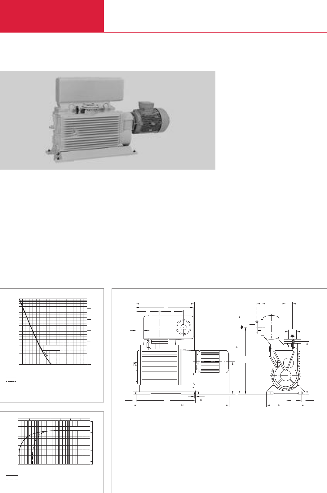
200 m3x h-1 (117.8 cfm)
Rotary Piston Vacuum Pumps
LEYBOLD VACUUM PRODUCTS AND REFERENCE BOOK 2003/2004
Two-stage Rotary Piston Vacuum Pump DK 200
Typical Applications
♦For particularly low ultimate pressures
♦High vacuum stage with degassed oil from a
separate oil reservoir
♦
For all chemical, metallurgical and electronic
vacuum processes in the pressure range down
to 5 x 10
-4
mbar (3 x 10
-4
Torr) without gas
ballast and 4 x 10
-3
mbar (2.4 x 10
-3
Torr) with
gas ballast
♦Backing pump for Roots vacuum pumps
♦Use as backing pump in pump systems in
connection with diffusion, booster-type
diffusion and vapor pumps
Supplied Equipment
♦With DN 65 DIN flanges on the intake and
exhaust sides for direct connection of
DN 63 ISO-K flange components
♦Ready for operation, complete with oil filling
♦Special models for different motor voltages,
motor frequencies and other protection class
ratings available
DN DN1a 1) a1a2b b1b2b3ld e f g h h1h2h3k l
mm 63 ISO-K 63 ISO-K 1190 780 30 340 140 202 52 14 777 750 65 740 475 636 295 337 290
in. 63 ISO-K 63 ISO-K 4.17 2.73 1.05 1.19 0.49 0.71 0.18 0.05 2.72 2.63 0.23 2.59 1.66 2.23 1.03 1.78 1.02
DN
DN
d
g
h
h3
h1
1
h2
k l
f
eb2b3
a1
a2
a b 1
30
b
Pump flanges to DIN 2501 with sealing disc and collar flange for the connection of ISO-K (KF) components
1) Only for the motor which is supplied as standard
min
Time
mbar Torr
Pressure
0
2
4
6
8
1 2 3 4 5 6 7 8 10
Without gas ballast
With gas ballast
10-3 10-3
10-2
100
10-1
101
10-2
100
10-1
101
750
103
DK 200
DK 200
Pumping speed
m3 x
h-1
without gas ballast
2 4 6 8
8
6
4
2
with gas ballast
10-4
103
10-4 10-3 10-2 10-1 100101Torr
cfm
750
102
101
100
10-2 10-1 100mbar
Pressure
101103
10-3
500
50
5
1
10
100
Pumpdown characteritics of a 1000 l vessel for the DK type rotary piston
vacuum pump
(60 Hz curves at the end of the section)
Pumping speed characteristic of the DK rotary piston vacuum pump
(60 Hz curves at the end of the section)
Dimensional drawing for the DK 200 two-stage rotary piston vacuum pump
C06.06

C06
200 m3x h-1 (117.8 cfm)
Rotary Piston Vacuum Pumps
LEYBOLD VACUUM PRODUCTS AND REFERENCE BOOK 2003/2004
Ordering Information DK 200
Technical Data DK 200
50 Hz 60 Hz
Two-stage rotary piston vacuum pump
DK 200, with 50 Hz motor 3)
(220 / 380 V +/- 10%)
DK 200, with 60 Hz motor 3), *)
(200-230 V / 460 V +/- 10%) USA version
DK 200, without motor, 50 Hz gear 3) 4)
Sealing kit, pump
Vibration absorbing metal feet
SECUVAC valve
ANSI adaptor
1) To DIN 28 400 and following numbers
2) Operated at ultimate pressure without gas ballast, free field measurement at a distance of 1 m (3.5 ft). When fitting accessories, for example AFK2, the noise level may change by 2 to 3 dB(A)
3) For operation at a different frequency, the gear will have to be exchanged. Please state the main frequency in your order
4) The maximum speed must not exceed 1,500 rpm at 50 Hz. The motor rating must be at least 5 kW (6.8 hp)
*)Continuous operation from 30 mbar (22.5 Torr)
Part No. 111 16
Part No. 895 10
Part No. 166 17
Part No. 192 63
Part No. 101 55
Part No. 105 62
upon request
Nominal pumping speed 1) m3x h-1 (cfm)
Pumping speed 1) m3x h-1 (cfm)
Ultimate partial pressure without gas ballast 1) mbar (Torr)
Water vapour tolerance 1) mbar (Torr)
Average noise level to DIN 45 635 2) dB(A)
Main voltage V
Motor power at
220 / 380 V, 50 Hz kW (hp)
200-230 V / 380 V, 60 Hz kW (hp)
Nominal motor speed rpm
Speed of the pump rpm
Motor protection IP
Oil filling l (qt)
Weight kg (lbs)
Intake port DN
Exhaust port DN
225 (132.5)
200 (117.8)
< 5 x 10⁻⁴ (< 3 x 10⁻⁴)
26 (19.5)
< 76
230/400/3/50 208-230/460/3/60
5.5 (7.5)
5.5 (7.5)
1500 1800
540
54
4.4 (4.6)
375 (827)
63 ISO-K
63 ISO-K
C06.07
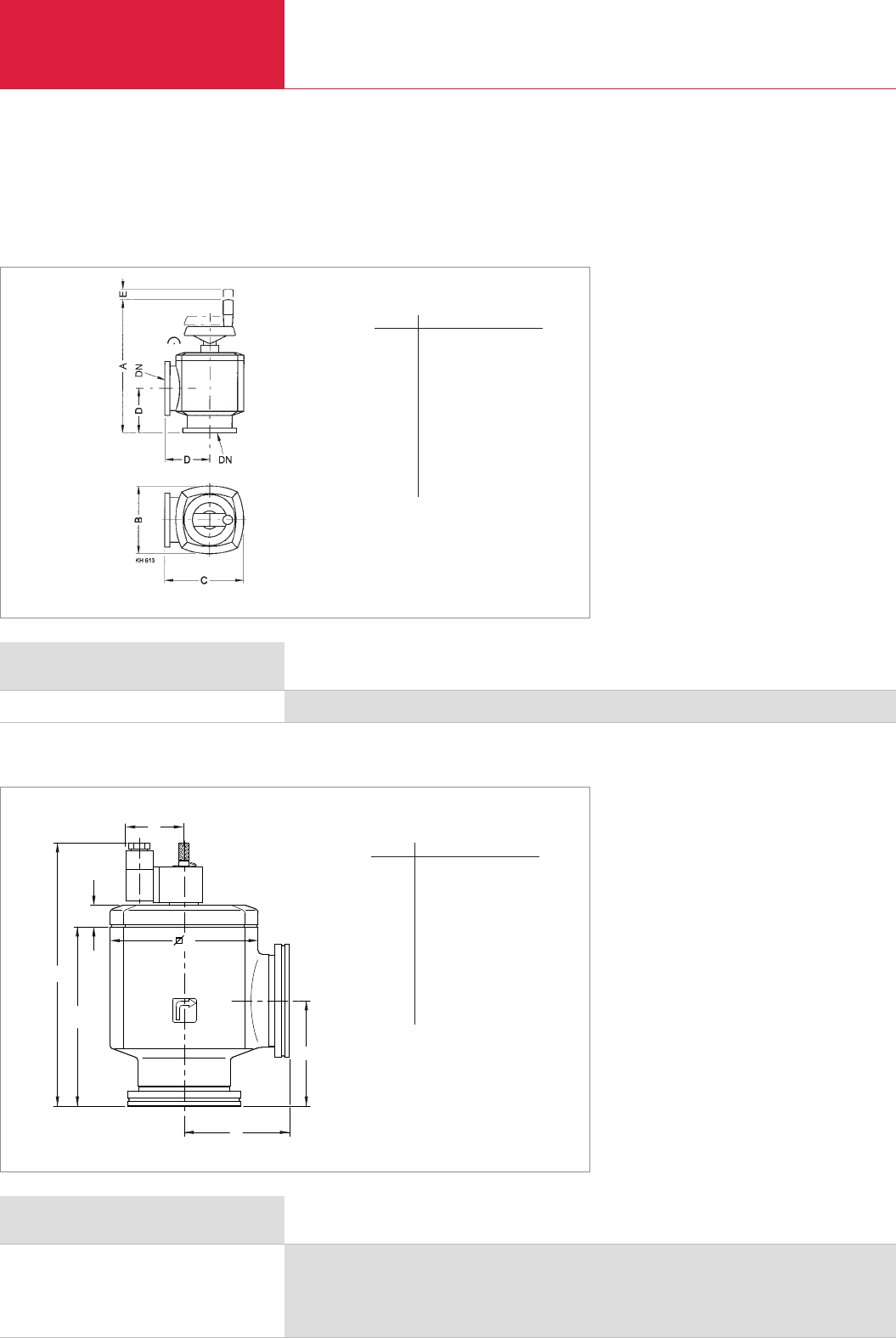
Accessories
Rotary Piston Vacuum Pumps
LEYBOLD VACUUM PRODUCTS AND REFERENCE BOOK 2003/2004
Valves
Advantages to the User
♦The pump may warm up while the intake line
is isolated
♦Energy-conserving and environmentally-
friendly operation at ultimate pressure
♦The pump may continue to operate while the
vacuum chamber is vented for brief periods
♦After completion of a process the pump may
continue to operate so as to regenerate the oil
Ordering Information Right Angle Valve
Right angle valve DN 63 ISO-K, Al, manually operated
Part No. 107 80
C06.08
Ordering Information SECUVAC Valve
SECUVAC valve DN 63 ISO-K
0
24 V DC
100 - 115 V AC
200 - 230 V AC
Part No. 215 205
Part No. 215 206
Part No. 215 207
Dimensional drawing for the right-angle valve, bellows-sealed, manually operated
h
D
h2
a
a
h1
b
Dimensional drawing for the SECUVAC valves with ISO-K clamp flanges
DN 63 ISO-K
a mm 88
in. 0.35
b mm 150
in. 0.59
D mm 124
in. 0.49
h mm 220.5
in. 0.87
h1mm 150
in. 0.59
h2mm 18.2
in. 0.07
Advantages to the User
Two valve functions in one:
♦Fast-closing high vacuum isolation valve for
separating the vacuum chamber or a vapor jet
pump (a diffusion pump, for example) from
the backing pump
♦Venting valve for venting of the valve’s cham-
ber and thus the pump (backing pump)
♦Immediate closing action upon power failure
♦Opening action only after the intake line has
been evacuated
♦Delayed isolation of the vacuum chamber and
venting the vacuum pump (negligible “gulp”)
The flange components which are required for installation of the accessories to the pump must be ordered separately.
For flange components and valves please refer to the corresponding Product Sections C13 and C14.
DN 63 ISO-K
A mm 266
in. 1.05
B mm 124
in. 0.49
C mm 150
in. 0.59
D mm 88
in. 0.35
E mm 20
in. 0.08
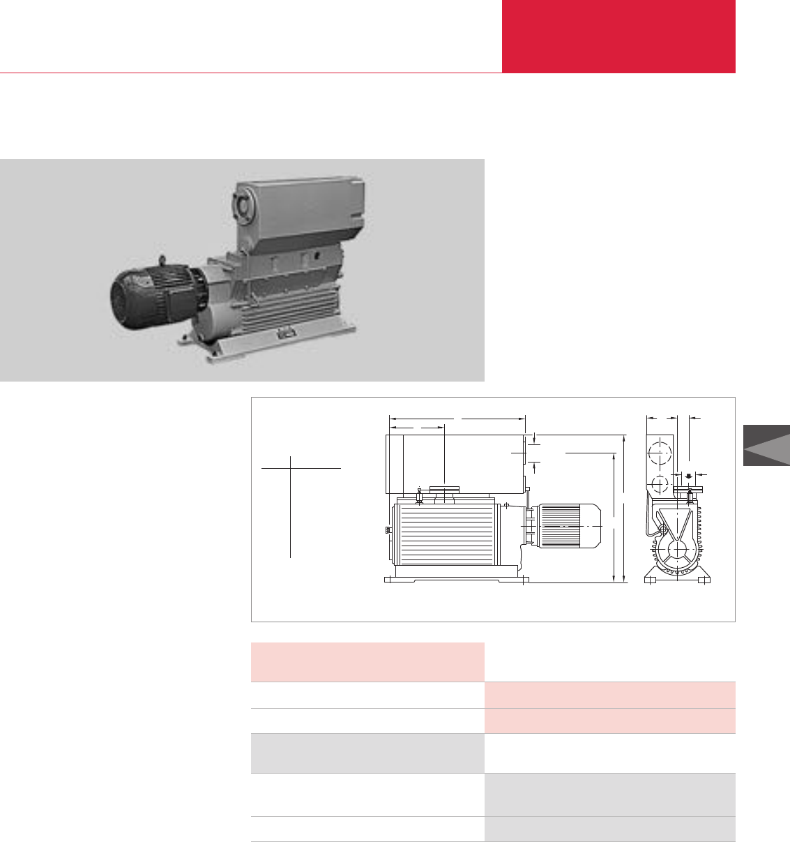
C06
Accessories
Rotary Piston Vacuum Pumps
LEYBOLD VACUUM PRODUCTS AND REFERENCE BOOK 2003/2004
Exhaust Filter Box AFK 2
The oil mists entrained in the exhaust gas from
the pump are cleaned in the exhaust filter box.
The exhaust filter box is installed instead of the
standard filter box on the rotary piston vacuum
pump.
Advantages to the User
♦At intake pressures below 100 mbar (75 Torr)
this is a space saving alternative to the sepa-
rate exhaust filter
♦Almost oil-free exhaust gas, over 99 %
effective
♦Exchangeable filter elements
♦Built-in overpressure valves
♦Low oil consumption due to the integrated oil
return line
Technical Notes
In case of toxic or hazardous gases and vapors
the exhaust lines must comply with the safety
regulations.
DN 65 DIN
a
h1
h
cb1b2
DN 63 ISO-K
Type AFK 2
a 337 (1.18)
b1170 (0.60)
b252 (0.18)
c 593 (2.08)
h 665 (2.33)
h1761 (2.66)
Technical Data AFK 2
Ordering Information AFK 2
AFK 2 exhaust filter box,
for E 250, DK 200
Replacement filter element (FE) (2 are required)
Part No. 189 47
Part No. 189 85
Weight kg (lbs)
Connection for collar flange DN
10 (22.1)
63 ISO-K
Dimensional drawing for the AFK 2 exhaust filter box; dimensions in brackets ( ) are in inch
C06.09
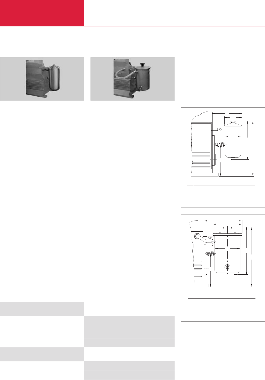
Accessories
Rotary Piston Vacuum Pumps
LEYBOLD VACUUM PRODUCTS AND REFERENCE BOOK 2003/2004
Oil Control Unit
Adding the oil can be automated through the oil
control unit without having to interrupt operation.
For this purpose, an additional oil reservoir hol-
ding 7 liters (7.4 qt) is connected to the pump.
Advantages to the User
♦Optimum oil level over long periods of opera-
tion
♦Reduction of oil losses
♦Visual function check (transparent connecting
hose)
♦Simple installation of the unit without the
need to disassemble the pump
♦Closed circuit by connection of oil reservoir,
vessel and pump
♦Built-in filter insert separates mechanical con-
tamination
Technical Notes
You must under all circumstances use a
SECUVAC valve, otherwise the oil reservoir
will be emptied by the pump as soon as it is
switched off.
Oil Filter Unit
Mechanical oil filters are required when a severe
contamination of the pump’s oil can be expected
due to solid particles like dust, for example.
Advantages to the User
♦Protection of the pump against contamination
of its oil
♦Longer service life for the oil
♦Easy to fit without having to disassemble the
pump
Mechanical Oil Filter Unit
♦Automatic oil circulation from the oil reservoir
on the exhaust side via the filter to the intake
chamber
♦Filter insert which is easy to exchange
(bypass filter)
♦Particulate retention to 3 microns
Technical Notes
Increases the required quantity of oil by about
1.3 liters (1.34 qt).
When using the oil filter, the pump must be vent-
ed
when shut down in order to prevent the oil from
rising into the intake line; for this we suggest you
install a SECUVAC valve.
aød1
l1
ød l
l2
l2
ød
ød1
a
l1
l
Oil Control Unit
Oil control unit
Replacement filter
Part No. 101 37
Part No. 101 32
Ordering Information Oil Filter Unit
Mechanical oil filter unit with special filter insert,
complete with adaptor screw and mount
for attachment to the pump
Replacement filter
Part No. 101 31
Part No. 101 32
Dimensional drawing for the oil filter unit
Dimensional drawing for the oil control unit
Ordering Information
C06.10
aldld1l l1l2
mm 230 115 127 290 465 270
in. 0.81 0.40 0.44 1.02 1.63 0.95
aldld1l l1l2
mm 310 204 235 390 490 270
in. 1.09 0.71 0.82 1.37 1.72 0.95
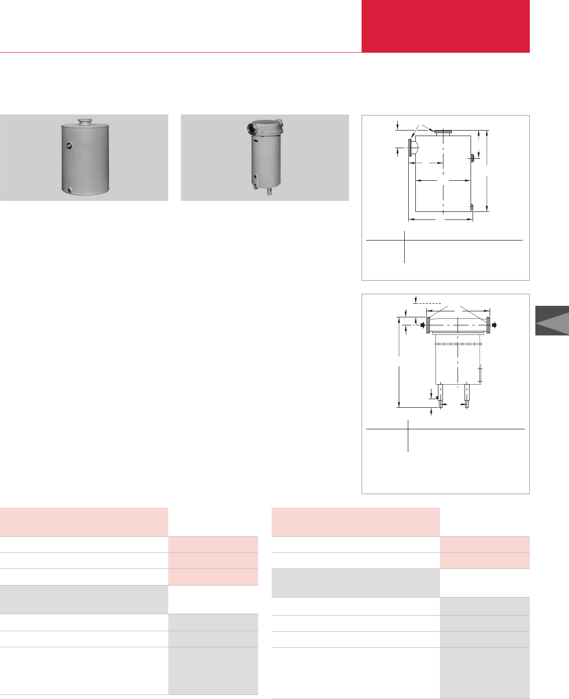
C06
Accessories
Rotary Piston Vacuum Pumps
LEYBOLD VACUUM PRODUCTS AND REFERENCE BOOK 2003/2004
AK 100-250 Condensate Separator
Welded condensate collecting vessels.
Advantages to the User
♦May be used either on the intake or the
exhaust side
♦Corrosion-protected
♦Condensate level glass
♦Protects the pump against condensate which
collects in the exhaust line and the intake line
♦Effect independent of the direction of flow
Technical Notes
When used on the intake side the drain cock
must provide a vacuum-tight seal.
Half of the quantity of required clamping screws
is provided.
DN
h2h1
h
a1
a
ød
Technical Data AK 100-250
Ordering Information AK 100-250
AK 100-250 condensate separator
Drain cock, vacuum-tight
Connection components
Connection to the intake side of the E 250, DK 200
Elbow
Centering ring
Part No. 188 45
Part No. 190 90
Part No. 887 25
Part No. 268 07
Capacity for condensate l (qt)
Weight kg (lbs)
Connection DN
Dimensional drawing for the AK 100-250 condensate separator
AF 100-250 A Exhaust Filter
h12)
h1
h3
h
a
DN
ød1)
1) 3 feet around the circumference
2) Clearance required for exchanging the filter elements
Dimensional drawing for the AF 100-250 A exhaust filter
To remove oil mists entrained in the exhaust gas.
Advantages to the User
♦Over 99% effective
♦
Optimally matched to our rotary piston vacuum
pumps
♦Exchangeable filter insert
♦Built-in overpressure valves
♦Sight glass for checking the amount of sepa-
rated oil
♦Solvent-resistant, helium-tight
♦Cast aluminium housing
♦Oil return (optional)
Technical Notes
In case of toxic or hazardous gases and vapors
the exhaust lines must comply with the safety
regulations.
Technical Data AF 100-250 A
Ordering Information AF 100-250 A
AF 100-250 A exhaust filter
Replacement filter element (2 are required)
Drain cock, vacuum-tight
Connection components
Connection to the E 250, DK 200
Bellows
Centering ring ISO-K
Part No. 189 45
Part No. 189 85
Part No. 190 90
Part No. 887 70
Part No. 268 07
Weight kg (lbs)
Connection DN
12 (26.5)
63 ISO-K
10 (9.46)
12 (26.5)
63 ISO-K
C06.11
DN a a1ld h h1h2
63 ISO-K mm 182,5 333 280 342 162 108
63 ISO-K in. 0.64 1.17 0.98 1.20 0.57 0.38
DN ald h h1h2
63 ISO-K mm 380 200 650 - 690 47,5 450
63 ISO-K in. 1.33 0.7 2.28 - 2.42 0.17 1.58
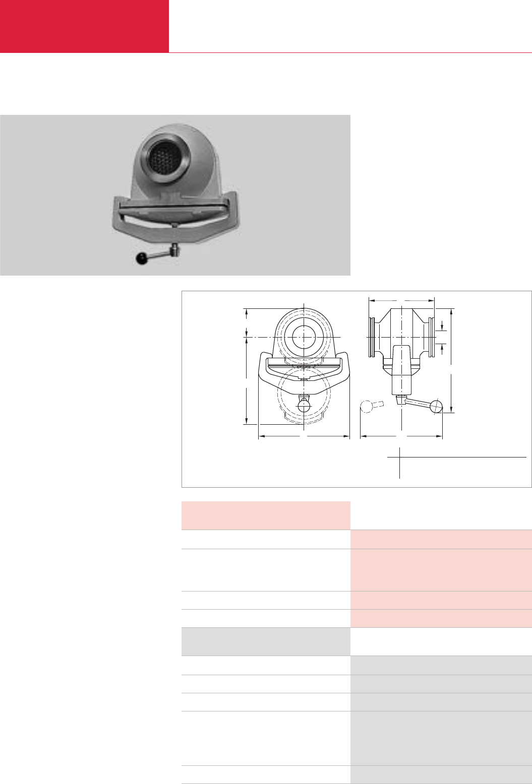
Accessories
Rotary Piston Vacuum Pumps
C06.12 LEYBOLD VACUUM PRODUCTS AND REFERENCE BOOK 2003/2004
FS 100-250 Dust Filter
Dust filters protect the pumps against the intake
of dust.
Advantages to the User
♦Easy to disassemble
♦Vacuum-tight cast housing
♦Replacement filters
♦Separates dust from a grain size of 1 µm
Technical Notes
Install horizontally so that the filter insert may be
removed from below.
In case of very large quantities of dust use a dust
separator.
Only throttles the pumping speed significantly at
very low intake pressures.
Supplied Equipment
Half of the quantity of required clamping screws
is provided.
DN
h1
h
aød
h2
b
Ordering Information FS 100-250
FS 100-250 dust filter
Filter insert
Replacement cotton wadding cartridges (1 set = 10 pieces)
Connection components
Connection to the E 250, DK 200
Elbow
Centering ring
ANSI adaptor
Part No. 278 17
Part No. 178 37
Part No. 178 27
Part No. 887 25
Part No. 268 07
upon request
Technical Data FS 100-250
Connection to pump
Throttling of pumping speed
at an intake pressure of 13 mbar (9.8 Torr) approx.
%
at an intake pressure of 1.3 mbar (0.98 Torr) approx.
%
Weight kg (lbs)
Connection DN
E 250, DK 200
28
38
11 (24.3)
63 ISO-K
Dimensional drawing for the FS 100-250 dust filter
a b ld h h1h2
mm 255 175 170 ≈340 85 ≈265
in. 0.89 0.61 0.60 ≈1.19 0.30 ≈0.93
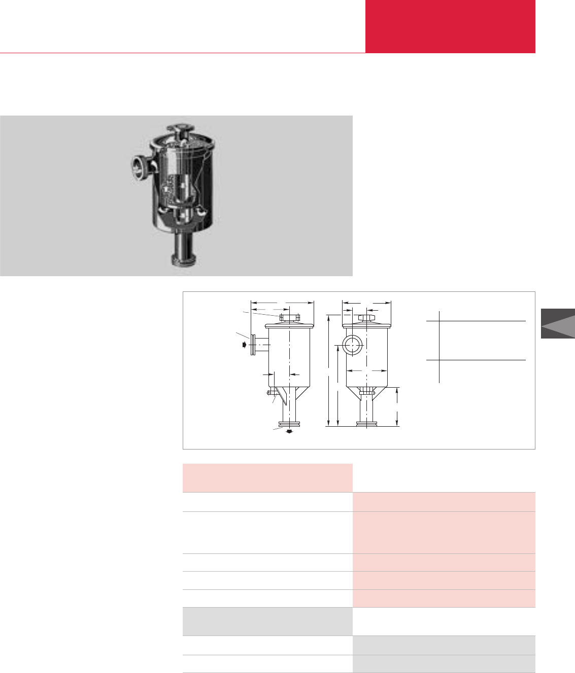
Accessories
C06.13
Rotary Piston Vacuum Pumps
LEYBOLD VACUUM PRODUCTS AND REFERENCE BOOK 2003/2004
C06
Ordering Information
AS 100-250 dust separator
Filter insert
Part No. 178 02
Part No. 178 06
Technical Data AS 100-250
AS 100-250 Dust Separator
Dust separators protect the pumps against being
contaminated by dust.
Advantages to the user
♦Dust separator for large quantities of dust
♦Dual-stage, thus low throttling effect
♦Cyclone and wet filter
♦Replacement inserts for both filters
♦Dust of a grain size of 2 µm and more are
separated in a cyclone
♦Finer dust is separated in an insert moistened
with oil
Technical Notes
Dust separator filters throttle the pumping speed
only at low intake pressures.
Supplied Equipment
Half of the quantity of required clamping screws
is provided.
DN 40 KF
DN 40 KF
l
DN 63 ISO-K
DN 63 ISO-K
a1
a2h1
h2
ød
ød1
h
a
Dimensional drawing for the AS 100-250 dust separator
AS 100-250
E 250, DK 200
3.5
7
4.0
27 (59.5)
63 ISO-K
Connection to pump
Throttling of pumping speed
at an intake pressure of 13 mbar (9.8 Torr) approx. %
at an intake pressure of 1.3 (0.98 Torr) mbar approx. %
Capacity for dust l
Weight kg (lbs)
Connection DN
a a1a2ld
mm 220 385 115 285
in. 8.66 15.16 4.53 11.22
ld1h h1h2
mm 330 530 685 240
in. 12.99 20.87 26.97 9.45
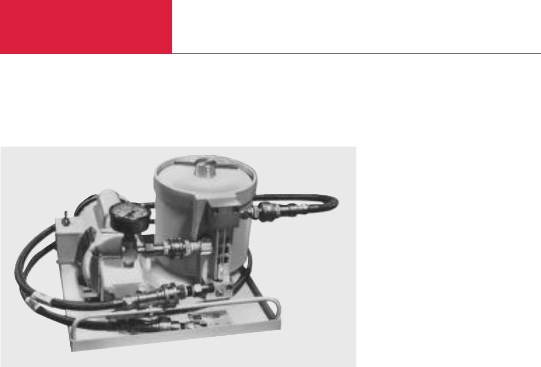
Accessories
Rotary Piston Vacuum Pumps
C06.14 LEYBOLD VACUUM PRODUCTS AND REFERENCE BOOK 2003/2004
Version for the North and South American Continents
OF1000 Oil Filtering System
Advantages to the User
♦Choice of Single- and Dual-Canister Models
for Standard or Chemically Severe
Applications
♦Compact Design
♦Reliable Operation
♦Choice of Four Filtering Elements
♦Dripless Quick Disconnects for Easy Removal
and Replacement of Filter Elements
♦Recessed Lid and Oil Level – No Oil Spillage
♦Conductive Teflon Hoses for Static Charge
Dissipation – No Oil Leakage Due to Static
Burning
♦Integral Gear Pump with Built-In Bypass
♦Fluid Sight Glass and Flow Monitor
♦Pressure Gauge
♦Small Precharge Fluid Volume
♦Single Phase 50/60 Hz Motors Standard
OF1000 Oil Filtering System
Applications
Standard series models are widely used in silicon
production processes, including LPCVD, low-
pressure epitaxy, ion implantation, reactive ion
etching and several plasma processes. Such pro-
cesses employ a variety of gases which can react
with pump fluid, resulting in the formation of
sludge, particulates and acids. The standard
OF1000 model has proven effective at extending
maintenance intervals in such applications.
Similarly, chemically resistant OF1000C models
have proven successful in aluminum etching and
other processes where boron trichloride and
other highly toxic gases are employed. The canis-
ter, gear pump, fittings and quick disconnects of
the corrosive-service model have been specially
treated with a fluorocarbon material that substan-
tially increases the life of these components.
OF 1000 Oil Filtering Systems are designed to
remove acids and particulates from the lubrica-
ting fluid used in Leybold mechanical vacuum
pumps. The systems are located externally from
the vacuum pump, and utilize their own integral
gear pump in conjunction with a bypass to conti-
nuously recycle fluid through a filtering medium;
the medium is housed in an element/canister
assembly which additionally serves to absorb
heat, and thus reduce the operating temperature
of the vacuum pump.
OF1000 Systems are available in both single- and
dual-canister designs. Both types are highly com-
pact and reliable, and can be supplied in models
for standard or chemically severe applications.
Single-canister OF1000 models are distinguished
by their smaller footprint while dual-canister con-
figurations afford the advantages of multi-media
filtration and increased oil capacity. Dual-canister
models are designed for series flow through two
side-by-side mounted canisters, and thus can be
used to filter oil through two different media on
the same pass or for double filtration through
elements containing the same medium. The
models also enable the vacuum pump to operate
at somewhat lower temperatures, while providing
it with a larger supply of clean, filtered oil.
All OF1000 models are supplied with a choice of
four filtering elements. The Fullers Earth element
provides high capacity for standard acids and can
be used to trap particulates down to 10 micron in
size. Hydrophilic, activated alumina and fiberglass
particulate elements are also available. The
hydrophilic element is particularly effective for
hydrolized acids, and can also be used to trap
particles as small as 1 micron. The activated
alumina element provides 10 micron particulate
retention and is extremely effective for Lewis
acids and polar compounds. The fiberglass ele-
ment is suitable for particulate removal down to
10 micron.
The element/canister assembly of OF1000
systems is easy to install, extremely easy to
remove and replace. The recessed lid and oil level
of the assembly safeguards against the possibility
of spillage. Dripless quick disconnects are also
provided for easy canister removal and safer dis-
posal of the filtering element and oil.
OF1000 Systems also come equipped with fle-
xible Teflon hoses designed to resist dielectric
breakdown. The systems thus ward against the
possibility of oil leaks due to pinholing or static
burning of the hose.

Accessories
C06.15
Rotary Piston Vacuum Pumps
LEYBOLD VACUUM PRODUCTS AND REFERENCE BOOK 2003/2004
C06
Version for the North and South American Continents
Technical Data
Single-Canister Dual-Canister
Systems Systems
Gear Pump Motor
Gear Pump
Pressure Gauge
Pump Fluid Capacity
Flexible Hoses
Dimensions in. (mm)
Flow Arrangement
Weight (Dry) lbs
1) Hazardous duty models and special voltages also available
2) Optional 6, 10 and 15 feet hoses available
3) 0ptional parallel flow arrangement also available
1/6 HP, 115/208/220V, single phase, 50/60Hz,
wired for 115V, with on/off switch 1)
0.7 gpm @ 1800 RPM
0 to 100 psig (0 to 70 kPa)
15 lb perfluorinated polyether 29 lb perfluorinated polyether
or 3.75 qt hydrocarbon oil or 7.25 qt hydrocarbon oil
3/8 in. l.D. teflon/carbon black with stainless steel braid – 4 ft lengths 2)
16 x 14 x 11 (406 x 356 x 279) 23 x 14 x 11 (585 x 356 x 279)
– series 3)
45 60
Ordering Information
Single-Canister Dual-Canister
Systems Systems
Oil Filtering System
OF1000 Less Filtering Element and Oil
OF1000 Prepared for PFPE,
Less Filtering Element and Oil
OF1000C Chemically Severe Service,
Prepared for PFPE Fluid
Accessories
Spare Filter Canister Assembly
With Quick Disconnect
Prepared for PFPE, With Quick Disconnect
Chemically Severe Service
Filtering Elements
Aluminum Oxide — High Capacity for Reagent Grade
HCI; Removes Lewis Acids and PolarCompounds;
10 Micron Particulate Retention
Fullers Earth — Acid and Particulate Filter with
Capacity of 34 ml Reagent Grade HCI;
10 Micron Particulate Retention
Hydrophilic — Water and HCI Acid Absorbing
Capabilities; 1 Micron Particulate Retention
Particulate — Fiberglass Element with 10 Micron
Particulate Retention
Part No. 898 550 Part No. 898 552
Part No. 898 551 Part No. 898 553
Part No. 898 561 Part No. 898 554
Part No. 898 555 Part No. 898 557 (front), Part No. 898 555 (rear)
Part No. 898 556 Part No. 898 558 (front), Part No. 898 556 (rear)
Part No. 898 566 Part No. 898 559 (front), Part No. 898 566 (rear)
Part No. 898 504 Part No. 898 504
Part No. 898 505 Part No. 898 505
Part No. 898 506 Part No. 898 506
Part No. 898 507 Part No. 898 507
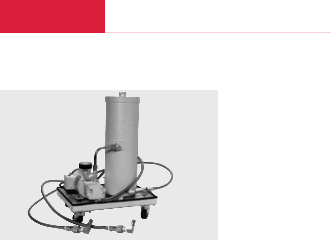
Accessories
Rotary Piston Vacuum Pumps
C06.16 LEYBOLD VACUUM PRODUCTS AND REFERENCE BOOK 2003/2004
Version for the North and South American Continents
OF3000 Oil Filtering System
OF3000
Advantages to the User
◆Compact, mobile design
◆Choice of five filter elements
◆Dripless quick disconnects for easy removal
and replacement of filter elements
◆No spillage - recessed lid and oil level
◆Conductive teflon hoses for static charge dis-
sipation
◆Integral gear pump with built-in bypass
◆Pressure gauge
◆Oil sight glass
◆Single phase 50/60 Hz motor standard
◆Tangential flow inlets - improves oil flow
◆Canister drain valve
The OF3000 is a compact, highly mobile filtering
system designed for use with mechanical pumps
in applications generating large volumes of heavy
particulate filtration.
A positive feed gear pump and check valve
assembly protect against excessive backpressure
in the canister should the filter element become
clogged. Flexible hoses and matched dripless
connectors ensure easy maneuverability of the
OF3000’s rollaround cart, while also eliminating
the possibility of oil spills.
Operation
Contaminated oil is removed from the drain loca-
tion on the vacuum pump and is cycled to the
element assembly. Clean oil is subsequently cir-
culated back to the oil fill port of the vacuum
pump.
The tangential flow inlet port to the oil filter cani-
ster allows full oil flow while utilizing the entire
filter capability of the element. This translates
into longer filter life, fewer element changes, and
less oil loss.
Similarly, chemically severe OF3000 models have
proven successful in aluminum etching and other
processes where boron tricloride and other highly
toxic gases are employed. the canister, gear
pump, fittings and quick disconnects of the cor-
rosive-service model have been specially treated
with a fluorocarbon material that subtantially
increases the life of these components.
Filtering Elements
Fullers Earth - Provides high capacity for stan-
dard acids and can be used to trap particulates
down to 10 micron size.
Hydrophylic - Effective for hydrolized acids and
particulates as low as one micron.
Activated Alumina - Effective on Lewis acids and
polar compounds. Can be used to trap particula-
tes down to 10 microns.
Particulate (Paper) - Suitable for particulate
removal down to 10 microns.
Particulate (Fiberglass) - Suitable for particulate
removal down to 10 microns.
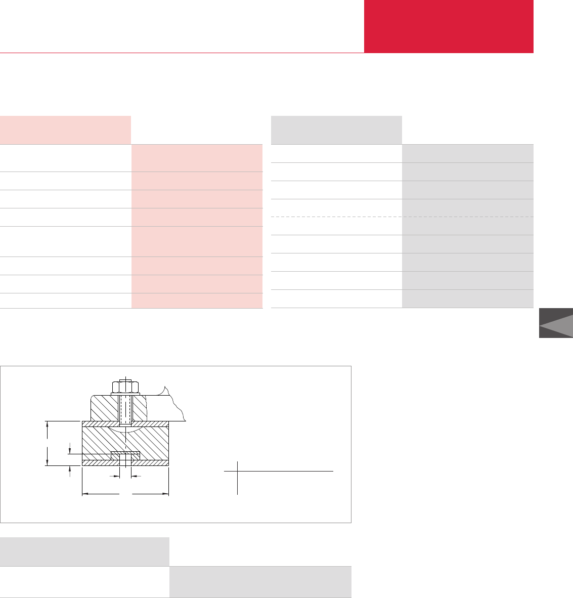
Accessories
C06.17
Rotary Piston Vacuum Pumps
LEYBOLD VACUUM PRODUCTS AND REFERENCE BOOK 2003/2004
C06
Version for the North and South American Continents
Gear pump motor
Gear pump
Pressure gauge
Fluid capacity (approx.) gal
Flexible hoses in. I.D.
Dimensions in. (mm)
Weight (dry) lbs (kg)
1/6 HP, 115/208/220 V,single phase, 50/60 Hz,
wired for 115 V, with on/off switch
0.7 gpm @ 1800 rpm
0 to 100 psig (0 to 70 kPa)
3
78 teflon/carbon black with stainless steel braid
- 6 ft lenghts
18 x 14 x 26 (457 x 355 x 661)
65 (29.4)
Technical Data OF3000
OF3000, less element and oil (standard)
OF3000C, coated, prepared for PFPE
OF3000, prepared for PFPE
Accessories
Aluminum oxide
Hydrophilic
Fullers earth
Particulate (paper)
Particulate (fiberglass)
Part No. 898 625
Part No. 898 450
Part No. 898 455
Part No. 898 523
Part No. 898 525
Part No. 99 171 159
Part No. 898 599
Part No. 99 171 158
Ordering Information OF3000
Vibration Absorber
ød1
h1
h
ød
Ordering Information Vibration Absorber
Vibration absorber (set of 4)
(for E 250, DK 200)
Part No. 101 55-1
E and DK series rotary piston mechanical pumps
are dynamically balanced for vibration-free per-
formance in normal. In applications where pumps
must be installed on light frames or wooden
flooring, however, excess vibration can result
from the lack of solid support.
Advantages to the User
♦Reduce transmitted vibration by 60%
♦Rubber vibration-absorbent varies in hardness
for pumps of different weights
♦Tapped holes provided in absorbers for atta-
ching to frame or floor
♦Shipped complete with all necessary mount-
ing hardware
Dimensional drawing for the vibration absorber
ldld1h h1
mm 337 1/2"13NC 665 761
in. 2.95 1/2"13NC 1.57 0.43
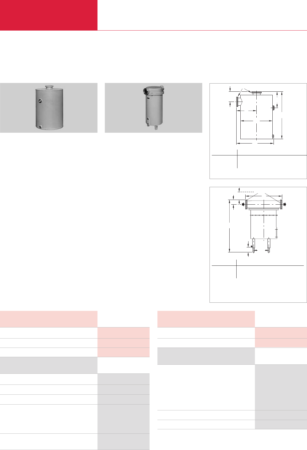
Accessories
Rotary Piston Vacuum Pumps
C06.18 LEYBOLD VACUUM PRODUCTS AND REFERENCE BOOK 2003/2004
Version for the North and South American Continents
AK 100-250 Condensate Separator
Welded condensate collecting vessels.
Advantages to the User
♦May be used either on the intake or the
exhaust side
♦Corrosion-protected
♦Condensate level glass
♦Protects the pump against condensate which
collects in the exhaust line and the intake line
♦Effect independent of the direction of flow
Technical Notes
When used on the intake side the drain cock
must provide a vacuum-tight seal.
Half of the quantity of required clamping screws
is provided.
DN
h2h1
h
a1
a
ød
Technical Data AK 100-250
Ordering Information AK 100-250
AK 100-250 condensate separator, DN 63 ISO-K
AK 100-250 condensate separator, ASA
Vacuum-tight draining tap (pump inlet)
Inlet position (E 150, E 250, DK 100, DK 200)
3" elbow (1 is required)
3" ANSI rotatable flanges (2 are required)
3" ANSI seal disc (2 are required)
Exhaust position (E 250, DK 200)
3" ANSI seal disc (2 are required)
Part No. 188 45
Part No. 188 45-M
Part No. 190 90
Part No. 98-278-0347
Part No. 98-278-0700
Part No. 910-181-605
Part No. 910-181-605
Capacity for condensate l (qt)
Weight kg (lbs)
Connection DN
Dimensional drawing for the AK 100-250 condensate separator
AF 100-250 A Exhaust Filter
h12)
h1
h3
h
a
DN
ød1)
1) 3 feet around the circumference
2) Clearance required for exchanging the filter elements
Dimensional drawing for the AF 100-250 A exhaust filter
To remove oil mists entrained in the exhaust gas.
Advantages to the User
♦Over 99% effective
♦
Optimally matched to our rotary piston vacuum
pumps
♦Exchangeable filter insert
♦Built-in overpressure valves
♦Sight glass for checking the amount of sepa-
rated oil
♦Solvent-resistant, helium-tight
♦Cast aluminium housing
♦Oil return (optional)
Technical Notes
In case of toxic or hazardous gases and vapors
the exhaust lines must comply with the safety
regulations.
Technical Data AF 100-250 A
Ordering Information AF 100-250 A
AF 100-250 A exhaust filter, DN 63 ISO-K
AF 100-250 A exhaust filter, ASA
Kit includes
Exhaust filter
ANSI bellows
ANSI sealing disc (2 are required)
ANSI rotatable flange
Spare filter elements for E 250, DK 200 (2 are required)
Drain tap
Note: Fittings will adapt filter only to exhaust port of pump.
Kit does not include fittings to adapt exit port of filter.
Please refer to section C13 “Vacuum Fittings” for aditional options
Part No. 189 45
Part No. 189 45-M
Part No. 189 45
Part No. 991-051-013
Part No. 910-181-605
Part No. 982-780-700
Part No. 390-261-44
Part No. 188 90
Weight kg (lbs)
Connection DN
12 (26.5)
63 ISO-K
10 (9.46)
12 (26.5)
63 ISO-K
DN a a1ld h h1h2
3"ANSI / 63 ISO-K mm 182,5 333 280 342 162 108
3"ANSI / 63 ISO-K in. 0.64 1.17 0.98 1.20 0.57 0.38
DN ald h h1h2
63 ISO-K mm 380 200 650 - 690 47,5 450
63 ISO-K in. 1.33 0.7 2.28 - 2.42 0.17 1.58

Accessories
C06.19
Rotary Piston Vacuum Pumps
LEYBOLD VACUUM PRODUCTS AND REFERENCE BOOK 2003/2004
C06
Lubricating oils for rotary vacuum pumps need to
fulfil demanding requirements. Their vapor pres-
sure must be low also at high temperatures,
water content and water uptake must be minimal.
Their viscosity characteristics need to be flat,
lubricating properties need to be excellent and
they must resist cracking upon being mechanical-
ly stressed.
All the vacuum pump oils listed in the following
have been subjected in our factory laboratories to
very comprehensive tests closely resembling the
conditions encountered in practice by the pumps
from the E + DK series.
We therefore recommend the exclusive use of
vacuum pump oils fully qualified by Leybold so
as to ensure optimum performance of the
Leybold vacuum pumps and also to ensure opti-
mum oil change intervals.
Under vacuum conditions lubricating oils, especi-
ally those with additives may behave quite diffe-
rently than expected. Additives may adversely
affect the attainable ultimate pressure and may
react with the media being pumped.
When using not suitably qualified third party oils,
the oil change intervals and the performance of
the vacuum pump may be reduced. Also unwan-
ted deposits may occur which may even cause
severe damage to the vacuum pump.
For these reasons please understand that we
must make our warranty commitment dependent
on the use of oils which have been qualified by
us. Damages caused by the use of not suitably
qualified lubricating oils are not covered by our
warranty.
In order to adapt the pumps to the different appli-
cations of our customers, different types of oil
are used in the E + DK pumps.
Please note that owing to differing properties not
all types of oil may be used in all pumps of the
E + DK series. If you can not find the combinati-
on of pump and oil you require please ask us for
a quotation.
Vacuum Pump Oils
Lubricant Types
Mineral Oils
Mineral oils are products distilled and refined
from crude oil. These do not consist of precisely
defined compounds but rather consist of a com-
plex mixture. The way in which the mineral oil is
pre-treated and its composition are decisive as to
the applications it will be suited for. Depending
on the distribution of the hydrocarbons and the
dominance of certain properties, mineral oils are
grouped according to paraffin-base, naphthenic
and aromatic. For the purpose of attaining espe-
cially low ultimate pressures, mineral oils must
be selected on the basis of a core fraction.
The thermal and chemical resistance of mineral
oils has been found to be adequate in the majori-
ty of applications. They offer a high degree of
compatibility with elastomers and resistance to
hydrolysis.
Perfluorinated polyether
(PFPE)
These are oils which are only composed of carb-
on (C), fluorine (F) and oxygen atoms (O). The
existing C-O and C-F bonds are highly stable. For
this reason PFPE oils are practically inert against
all chemical and oxidising influences.
Perfluorinated polyether will not polymerise
under the influence of high energy
radiation.
PFPE is non-flammable. Leybold NC1/14 has the
approval of BAM (Federal Institute for Materials
Research and Testing) for pumping of pure oxy-
gen.
Perfluorinated polyether are used when pumping
strongly reactive substances like oxygen (O
2
),
fluorine F
2
and uranium hexafluoride UF
6
.
Regarding Lewis acids (for example, boron
trifluoride BF
3
, aluminum trichloride AlCl
3
) they
are not completely inert. Here reactions may take
place at temperatures over 100 °C (212 °F).
Perfluorinated polyether are thermally highly
stable. Thermal decomposition may only take
place at temperatures of over 290 °C (554 °F).
Caution: Perfluorinated polyether will – when
decomposed – release toxic and corrosive gases:
hydrogen fluoride HF, carbonyl difluoride COF
2
.
For this reason open fires must be avoided in the
workspace where PFPE is being used. Do not
smoke in the workspace where PFPE is being
used.
Only suitably prepared pumps must be used in
connection with perfluorinated polyether, since it
is essential that the pumps be free of
hydrocarbons.
Changing from one basic type of oil to PFPE
must be left exclusively to authorised Service
Centers. The pump will have to be fully disassem-
bled and carefully cleaned. Gaskets and filters will
have to be exchanged and suitable greases will
have to be used.
For all lubricants from our line of products you may obtain Safety Data Sheets from the Dept. Technical
Support in Cologne.

Accessories
Rotary Piston Vacuum Pumps
C06.20 LEYBOLD VACUUM PRODUCTS AND REFERENCE BOOK 2003/2004
Technical Data Special Oil
N62 NC 1/14
Ordering Information
Part No. 177 01 Part No. 177 38
Part No. 177 02 –
Part No. 177 03 –
Part No. 177 05 –
Viscosity
at 040 °C (104 °F) mm2/s
at 100 °C (212 °F) mm2/s
Flash point °C (°F)
Vapor pressure
at 020 °C (68 °F) mbar (Torr)
at 100 °C (212 °F) mbar (Torr)
Density at 20 °C (68 °F) g/ml
Pour point °C (°F)
Middle molecular weight g/mol
01 litre (1.06 qt)
05 litres (5.29 qt)
20 litres (21.14 qt)
180 kg (397.4 lbs)
Please note that the technical data stated are only typical data. Slight variations from batch to batch must be expected.
The technical data stated here can not be taken as assured properties
1)
Resistance to decomposing is very much dependent on the share of acrylonitrile in the NBR
2)
Caution: Perfluorinated polyether will, when being decomposed at temperatures over 290 °C (554 °F), release toxic and corrosive gases
For this reason open fires must be avoided in the workspace where PFPE is being used. Do not smoke in the workspace where PFPE is being used
Special Oil
N62 NC 1/14
90 47
10 5
> 255 (> 491) – 2)
< 1 x 10⁻⁵ (< 0.75 x 10⁻⁵) 3 x 10⁻⁷ (2.25 x 10⁻⁷)
< 3 x 10⁻³ (< 2.25 x 10⁻³) 6 x 10⁻⁴ (4.5 x 10⁻⁴)
0.88 1.89
< -9 (< -16) -40 (40)
550 2500
Special Oil
N62 NC 1/14
Type of oil
Examples of areas of application and process media
Remarks
Elastomer compatibility
FPM (Viton)
NBR (Perbunan) 1)
EPDM
Paraffin-base mineral oil, core faction, free of additives Perfluorinated polyether PFPE
Standard oil For pumping strong oxidants like oxygen, O2,
ozone O3, nitrogen oxides NOx and sulphur oxides
For pumping air, chemically inert permanent gases (SO2, SO3) as well as reactive substances like
(noble gases, for example), water vapor, halogens (for example fluorine F2, chlorine Cl2),
solvent vapors in the case of laboratory hydrogen halides (for example hydrogen
pumps operated with cold traps chloride HCl, hydrogen bromide HBr), uranium
hexafluoride UF6, and conditionally Lewis acids
(for example boron trichloride BCl3)
Use only in pumps modified for PTFE
The ultimate pressures stated in our catalogs Avoid pumping water vapour, in particular in connection
are based on operation of the pump with N62 with corrosive media (see above)
(except for the PFPE pumps) In ingress of water vapor must be avoided
Service life may be extended through the use of an oil filter The use of an oil filter is strongly recommended
Suited Suited
Conditionally suited Suited
Not suited Suited
Application Data

Accessories
C06.21
Rotary Piston Vacuum Pumps
LEYBOLD VACUUM PRODUCTS AND REFERENCE BOOK 2003/2004
C06
Version for the North and South American Continents
Technical Data
HE-200 HE-2700
–
58
9.1
224 (435)
–
4.7 x 10⁻⁶ (3.5 x 10⁻⁶)
3.9 x 10⁻⁴ (2.9 x 10⁻⁴)
0.88
- 10 (14)
480
Viscosity
at 020 °C (068 °F) mm2/s (= cSt)
at 040 °C (104 °F) mm2/s (= cSt)
at 100 °C (212 °F) mm2/s (= cSt)
Flash point °C (°F)
Vapor pressure
at 020 °C (068 °F) mbar (Torr)
at 025 °C (077 °F) mbar (Torr)
at 100 °C (212 °F) mbar (Torr)
Density at 20 °C (68 °F) g/ml
Pour point °C (°F)
Molecular weight
Application Data
HE-200 HE-2700
Type of oil
Examples of areas of application
and process media
Remarks
Elastomer compatibility
FPM (Viton)
NBR (Perbunan) 1)
EPDM
Paraffin-base mineral oil, core faction, free of additives
Standard oil for Leybold USA
For pumping air, chemically inert permanent gases
(noble gases, for example),
water vapor, solvent vapors
in the case of laboratory pumps operated with cold traps
The ultimate pressures stated in our catalogs are based on operation
of the pump with HE-200
(except for the DOT and PFPE pumps)
Service life may be extended through the use of an oil filter.
Suited
Conditionally suited
Not suited
Ordering
Information HE-200 HE-2700
01 qt (1 l)
01 gal (3.8 l)
05 gal (18.9 l)
55 gal (208 l)
Bottle 02 lb (0.91 kg)
Bottle 04 lb (1.81 kg)
Bottle 16 lb (7.25 kg)
Part No. 98 198 006
Part No. 98 198 007
Part No. 98 198 008
Part No. 98 198 010
–
–
–
Please note that the technical data stated are only typical data. Slight variations from batch to batch must be expected.
The technical data stated here can not be taken as assured properties
1)
Resistance to decomposing is very much dependent on the share of acrylonitrile in the NBR
2)
Caution: Perfluorinated polyether will, when being decomposed at temperatures over 290 °C (554 °F), release toxic and corrosive gases
For this reason open fires must be avoided in the workspace where PFPE is being used. Do not smoke in the workspace where PFPE is being used
Perfluorinated polyether
PFPE
For pumping strong oxidants like oxygen,
O2, ozone O3, nitrogen oxides NOx and
sulphur oxides (SO2, SO3)
as well as reactive substances like
halogens (for example fluorine F2,
chlorine Cl2), hydrogen halides
(for example hydrogen chloride HCl,
hydrogen bromide HBr),
uranium hexafluoride UF6,
and conditionally Lewis acids
(for example, boron trichloride BCl3)
Use only correspondingly modified pumps
Mixing with other types of oil must be
absolutely avoided
The uptake of water vapor must be avoided
The use of an oil filter is strongly recommended
Suited
Suited
Suited
250
–
10
Not known 2)
6.7 x 10⁻⁷ (5 x 10⁻⁷)
–
6.7 x 10⁻⁵ (5 x 10⁻⁵)
1.89
- 34 (- 30)
4600
–
–
–
–
Part No. 898 565-1
Part No. 898 565-2
Part No. 898 565-4
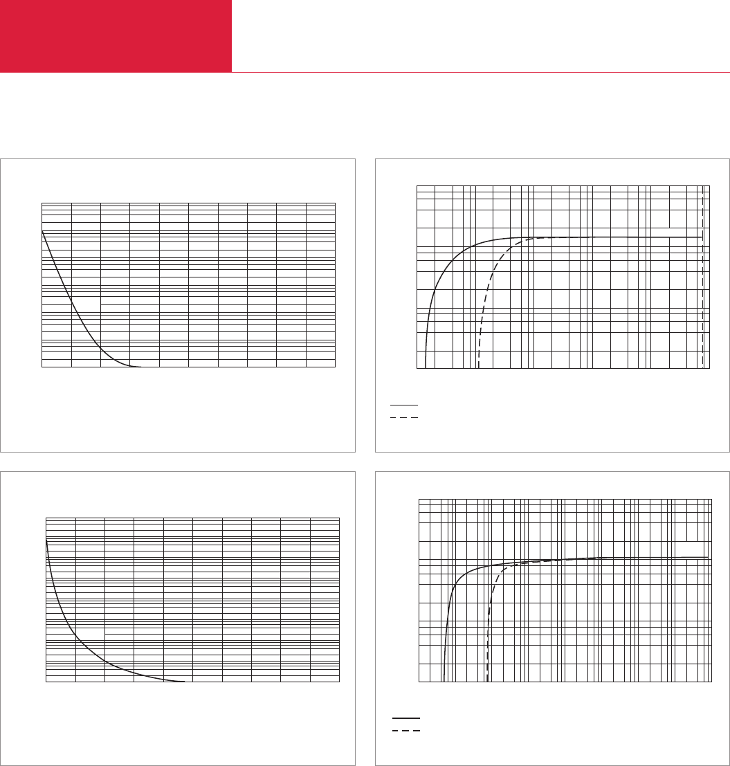
Accessories
Rotary Piston Vacuum Pumps
C06.22 LEYBOLD VACUUM PRODUCTS AND REFERENCE BOOK 2003/2004
Version for the North and South American Continents
2 4 6 8
10-2 10-1 100101102103
Torr
Inlet Pressure
E 250
2
4
6
8
100
103
102
101
Pumping speed
without gas ballast
with gas ballast
cfm
0 8 12 16 20 24 28 32 404 min
Time
2
4
6
8
0.01
0.1
10,000
1000
10
1
100
Pressure
E250
Torr
ATM
Pumpdown characteristic of a 1000 l vessel for the E type rotary piston vacuum pump
(60 Hz)
Pumping speed characteristic of the E type rotary piston vacuum pump
(60 Hz)
2 4 6 8
10-5 10-3 10-2 10-1 100101103
10-4 Torr
Inlet Pressure
2
4
6
8
100
103
102
101
Pumping speed
without gas ballast
with gas ballast
cfm
DK200
0 20 30 40 50 60 70 80 10010 min
Time
2
4
6
8
0.01
0.001
0.0001
0.1
10,000
10
1
100
Pressure
DK200
Torr
ATM
Pumpdown characteristic of a 1000 l vessel for the DK type rotary piston vacuum pump
(60 Hz)
Pumping speed characteristic of the DK type rotary piston vacuum pump
(60 Hz)

C07
Roots Vacuum Pumps
Single-Stage
250 - 13 000 m3x h-1 (147.3 - 7657 cfm)
RUVAC

Roots Vacuum Pumps
C07.02 LEYBOLD VACUUM PRODUCTS AND REFERENCE BOOK 2003/2004
Contents
General
Applications and Accessories . . . . . . . . . . . . . . . . . . . . . . . . . . . . . . . . . . . . . . . . . . . . . . . C07.02
General Information on Roots Vacuum Pumps . . . . . . . . . . . . . . . . . . . . . . . . . . . . . . . . . . C07.03
Products
RUVAC WA/WAU Roots Vacuum Pumps with Flange-Mounted Motors . . . . . . . . . . . . . . . . C07.06
RUVAC WS/WSU/PFPE Roots Vacuum Pumps with Canned Motors . . . . . . . . . . . . . . . . . . C07.08
RUVAC WSLF Roots Vacuum Pumps for Laser Gas Systems . . . . . . . . . . . . . . . . . . . . . . . C07.10
RUVAC RA Roots Vacuum Pumps with Flange-Mounted Motors (50 Hz) . . . . . . . . . . . . . . . C07.12
RUVAC RA Roots Vacuum Pumps with Direct-Coupled Motors (60 Hz) . . . . . . . . . . . . . . . . C07.14
Accessories
Pressure Switches . . . . . . . . . . . . . . . . . . . . . . . . . . . . . . . . . . . . . . . . . . . . . . . . . . . . . . . C07.16
Miscellaneous
Vacuum Pump Oils . . . . . . . . . . . . . . . . . . . . . . . . . . . . . . . . . . . . . . . . . . . . . . . . . . . . . . C07.17
Applications and Accessories
◆
◆ ◆
◆ ◆
◆ ◆
◆ ◆ ◆
◆
◆
◆
◆ ◆
◆ ◆
◆
◆ ◆ ◆
◆ ◆
◆◆◆◆◆
◆◆◆◆◆
◆◆◆◆◆
WA/WAU
WS/WSU
WS/PFPE
WSLF
RA
Roots Vacuum Pumps
Semiconductor production
Vacuum coating
Large scale research
Chemistry/Pharmaceutical
Metallurgy/Furnaces
Lamps and tubes manufacture
Laser engineering
Packaging
Central vacuum supplies
Freeze drying
Leak testing systems
Electrical engineering
High purity gases/closed refrigerant cycles
Mechanical engineering
Automotive industry
Accessories
Pressure switches
Page
C07.16
Applications
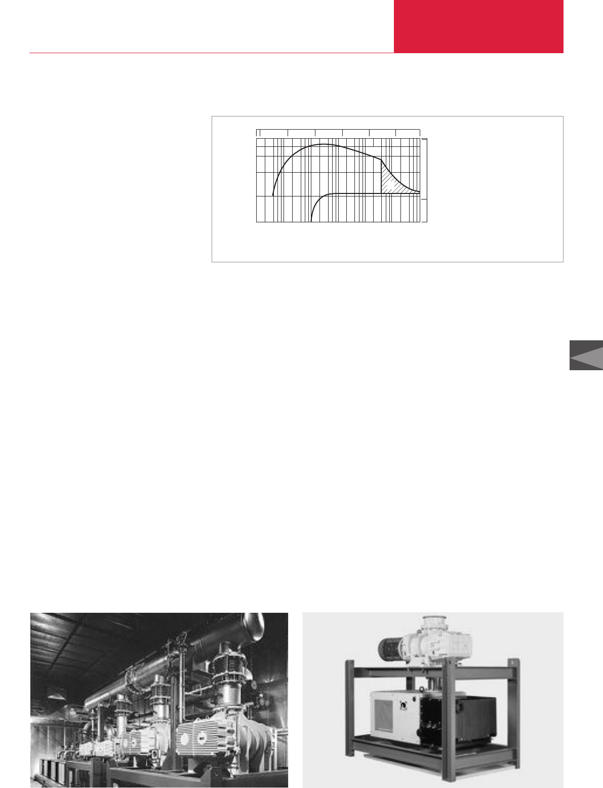
Roots Vacuum Pumps
C07.03
C07
LEYBOLD VACUUM PRODUCTS AND REFERENCE BOOK 2003/2004
General
Pump system with RA Roots vacuum pumps Pump system with RA Roots vacuum pump and SOGEVAC rotary vane vacuum pump
General Information on Roots Vacuum Pumps
Applications
For many years now Roots vacuum pumps have
been well established in the area of vacuum tech-
nology. In combination with backing pumps,
which compress against the atmosphere, these
pumps offer the following advantages:
Shifting the Operating Pressure
into the High Vacuum Range
As a rule of the thumb one may say that Roots
vacuum pumps are capable of improving the
attainable ultimate pressure of a pump system by
a factor of 10. With two Roots vacuum pump
stages and a corresponding backing pump it is
possible to attain pressures in the range down to
10
-5
mbar (0.75 x 10
-5
Torr). Under certain
circumstances this will make the use of additional
high vacuum pumps (turbomolecular pumps or
diffusion pumps) unnecessary.
Multiplied Pumping Speed
D
ue to the non-contact rotation of the impellers,
Roots vacuum pumps are able to run at higher
speeds. Thus a high pumping speed is obtained
with a relatively small size pump. Pumping speeds
in excess of 1000 m
3
/h (589 cfm) can only be
attained with Roots vacuum pumps.
When selecting the right kind of backing pump
(sizing) it will be possible to pump large quantities
of gas in connection with smaller backing pumps.
Energy consumption of such a pump system is
much less compared to a single backing pump
offering the same pumping speed.
The use of Roots vacuum pumps in the area of
vacuum technology has resulted in further
specializations and improvements:
♦
Through an integrated bypass (pressure equal-
ization line) it is also possible to utilize the pum-
ping speed of the Roots
vacuum
pump at high
pressures and large quantities of gas at an early
stage.This reduces the pumpdown time especi-
ally for cyclic operation (see figure).
♦High-purity gases or hazardous gases impose
strict requirements on the leak-tightness of the
system. Canned motors are hermetically sealed.
There are no seals in contact with the atmos-
phere which might be subject to wear. This pre-
vents leaks and failures due to oil leaks. A servi-
ce life of over 20 000 hours without maintenance
is quite common.
♦Tolerances and the quality of the balancing com-
bined with force-fed lubricated bearings and
toothed gears permit high speeds and the use of
frequency converters. Thus it is possible to
attain a high pumping speed while the process
is in progress and to reduce the speed when the
process has been stopped or while changing the
batch. This results in a lower consumption of
energy and a longer service life with uncompro-
mised reliability.
♦Conversion from vertical to horizontal flow is
easily implemented and can be performed at the
place where the pump has been installed. Thus
the pump can be adapted more closely to the
operating conditions of your system.
Lately, a further characteristic is gaining promi-
nence: Roots
vacuum
pumps are capable of com-
pressing the media in the pump chamber without
the presence of any further media. This mostly
avoids interaction between different media in the
pump itself and also in the connected vacuum
chamber. Therefore
♦the medium which is pumped is not contamina-
ted with lubricants or sealants; complex acces-
sories (exhaust filters, separators, etc.) are not
needed;
♦the lubricant in the side chambers is hardly
affected, so that service life is not reduced;
♦
backstreaming of oil from the backing pump into
the connected vacuum chamber is prevented.
The effective air cooling arrangement reduces
operating costs to a minimum. Cooling water is
not required. These characteristics make the
Roots
vacuum
pump attractive for almost all
rough and medium vacuum applications.
3
Pressure
-3
10
mbar
1000
Pumping speed
100
200
600
400
m x h
-1
2 4 6 8
-2
10
-1
10 10
0
10
1
10
3
10
2
2,3
2
3
1
4
-3
10
-2
10
-1
10 10
0
10
1
10
2
100
500
cfm
750
Comparison of pumping speed characteristics with and without pressure equalization line
1 Pumping speed of the backing
pump
2 Pumping speed of the Roots pump
system without pressure
equalization line
3 Pumping speed of the Roots pump
system with pressure equalization
line
4 Pumping speed gained by the
pressure equalization line
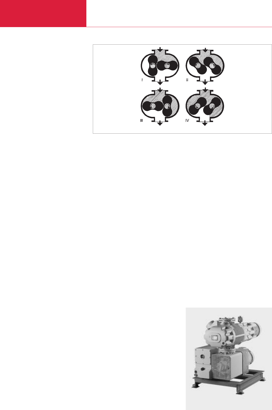
General
Roots Vacuum Pumps
C07.04 LEYBOLD VACUUM PRODUCTS AND REFERENCE BOOK 2003/2004
Pump system consisting of RUVAC WAU 1001 and SOGEVAC SV 200
Operational diagram of a single-stage Roots vacuum pump (with vertical pumping action)
Semiconductor Technology
In the area of semiconductor technology, Roots
vacuum pumps are found in etching processes
among others, and in use with dry compressing
vacuum pumps.
The pumping speed of the combination of
backing pumps amounts to 200 to 500 m
3
/h (118
to 295 cfm) and it ensures a cut-in pressure of
10
-1
mbar (0.75 x 10
-1
Torr) for the turbomolecu-
lar pump. In the case of dry compression, corro-
sive gases which also have a high particulate
content must be pumped.
Canned motors and PFPE fluids provide a good
seal against the outside and allow long periods
between servicing, high reliability and thus very
low operating costs (WS-PFPE-types).
Central Vacuum Supply Systems
Large Roots vacuum pumps, usually in connec-
tion with single-stage rotary vane vacuum pumps
serve several consumers of vacuum (packaging
machines, for example) at the same time.
Due to the uncontrolled influx of gas, a high of
pumping speed must be attained quickly, in order
to keep the vacuum (1 to 30 mbar (0.75 to
22.5 Torr)) permanently available to all consumers.
This in particular, is implemented by Roots vacuum
pumps having a pressure equalization line (WAU-
types).
Chemistry
Replacement of vapor jet or gas jet pumps on
liquid ring pumps in drying and distillation plants
is necessary for attaining the required operating
pressure of about 1 mbar (0.75 Torr). Reduction
of operating costs by entirely eliminating vapor or
gas quantities includes separation of these on the
pressure side (WA and RA-types).
Laser Systems
Continuous circulation of the gas in order to
remove heat from a closed cycle in which pres-
sure differentials of up to 100 mbar (75 Torr)
must be maintained. The tough requirements
regarding purity necessitate a total absence of
contamination by oil and dust. This is ensured by
reducing the pressure level in the oil chambers as
well as by coating the pump chamber. The pumps
are assembled and tested under clean room
conditions.
The canned motor ensures a high degree of leak-
tightness to the outside and permits operation in
connection with a frequency converter (WSLF-
types).
Operating Principle
Roots vacuum pumps, which are also called
Roots blowers, are rotary plunger type pumps
where two symmetrically shaped impellors rotate
in opposite directions inside the pump housing.
The figure-of-eight rotors are synchronized by a
gear which ensures that the impellors are
counter-rotating in such a way, that they are near
to one another and to the housing without actual
contacting.
In rotor positions I and II (see figure) the volume
of the intake is increased. As the rotors turn fur-
ther to position III a part of the volume is cut off
from the intake side.
In position IV this volume is opened to the
exhaust side and gas under fore-vacuum pressure
(higher than the intake pressure) flows in. This
gas compresses the gas coming from the intake.
As the rotors turn further the compressed gas is
ejected through the exhaust flange.
This process repeats itself twice for each rotor
per full turn.
As the rotors do not come into contact with the
pump’s housing Roots vacuum pumps may be
operated at high speeds. Thus a high pumping
speed is obtained from comparably small pumps.
The pressure difference and the compression
ratio between intake and exhaust is limited in
Roots vacuum pumps.
In practice the maximum attainable pressure
difference is of significance only in the rough
vacuum range (p > 10 mbar (p > 7.5 Torr)) where-
as in the medium vacuum range (p < 1 mbar
(p < 0.75 Torr)) the attainable compression ratio
is of importance.
Roots vacuum pumps from LEYBOLD have been
designed to specially meet the requirements of
the fine vacuum range. They are normally used in
connection with backing pumps (exception RAV)
or in closed gas cycles (WSLF series).
Design
The pump chamber of Roots vacuum pumps is
free of any sealing agents or lubricants. Only the
toothed wheels of the synchronous gear are
lubricated with oil. Toothed gear wheels and bear-
ings of the RUVAC are placed in two side cham-
bers which also contain the oil reservoir. These
two side chambers are separated from the pump
chamber by piston ring seals.
Suitably designed oil supply systems in both
chambers ensure that a sufficient quantity of oil
is supplied to the gear wheels and bearings at all
permissible speeds.
Almost all RUVAC Roots vacuum pumps are de-
signed for a horizontal and vertical pumping
action.
Types
Various types of Roots vacuum pumps have been
developed to ensure optimum adaptation to the
widely varying applications for this type of pump.
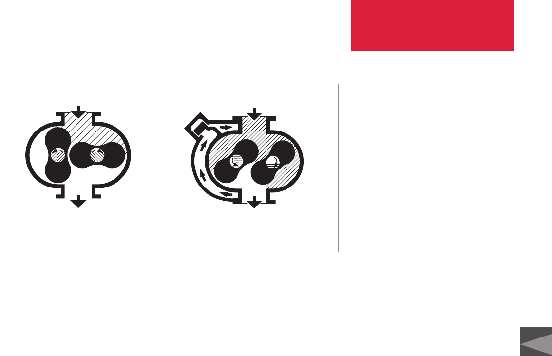
General
Roots Vacuum Pumps
C07.05
C07
LEYBOLD VACUUM PRODUCTS AND REFERENCE BOOK 2003/2004
♦Flange mounted motor
The drive shaft of the pump is directly
connected to an electric motor via a flexible
coupling. The required seal of the drive shaft
against atmospheric pressure is obtained by
oiled shaft seals.
♦Canned motor
In the canned motor, rotor and stator pack are
separated by a vacuum-tight can made of a
non-magnetic material. The rotor operates on
the drive shaft of the pump in the vacuum, so
that a shaft seal which would be subject to
wear is not required.
♦Pressure equalization line
The integrated pressure equalization line
connects the exhaust flange to the intake flange
through a differential pressure valve.
This valve opens at a high pressure differen-
tial between the flanges. Part of the gas then
flows through this line back to the intake
flange. This is why the Roots vacuum pump
may be switched on at atmospheric pressure
together with the backing pump. This also
increases the pumping speed of the pump
combination at high intake pressures.
♦Special ACE vibration absorber
These pumps are best used in applications
involving frequent pumpdown cycles. The
vibration absorber is of an oil sealed or filled
design where minute amounts of oil may
enter the vacuum system via the piston of the
vibration attenuator.
RUVAC WA/WAU, WS/WSU
The series WA/WAU Roots vacuum pumps are
provided with directly flange-mounted standard
three-phase motors. The oiled radial sealing rings
of the RUVAC WA/WAU for sealing the shaft
against the atmosphere are made of FPM (fluor
caoutchouc).
The WS/WSU series pumps are driven by canned
motors.
Roots vacuum pumps of the series WAU/WSU
are provided with an additional integrated pres-
sure equalization line and a differential pressure
valve.
Pumps from these series are supplied with
a vertical pumping action as standard.
RUVAC WSLF
The pumps of these series are especially adapted
Roots vacuum pumps from the RUVAC WS
series which are intended for operation with gas
lasers.
They are driven by a canned motor so that a shaft
seal for sealing against atmospheric pressure is
not required.
Air-cooled series with nominal pumping speeds
of 1000 m
3
x h
-1
(589 cfm) are available.
The RUVAC WSLF series with increased motor
ratings is intended for operation in connection
with frequency converters.
These pumps are available with nickel-plated or
plasma-nitrated surface as standard.
All pumps of these series are supplied with a
horizontal pumping action.
Vertical pumping action is available upon request.
RUVAC RA
RA series Roots vacuum pumps are equipped
with a directly flange-mounted three-phase motor
(RA 13 000 via V-belt drive).
Backing Pumps
The backing pumps from LEYBOLD listed in the
following are recommended for connection to the
RUVAC Roots vacuum pumps:
♦Rotary vane vacuum pumps
- TRIVAC B with pumping speeds between
16 and 65 m
3
x h
-1
(9.4 and 38.3 cfm)
- SOGEVAC with pumping speeds between
16 and 1200 m
3
x h
-1
(9.4 and 707 cfm)
♦Dry compressing piston vacuum pumps
- EcoDry L with pumping speeds between
38 and 48 m
3
x h
-1
(22 and 28 cfm)
♦Dry compressing screw vacuum pump for PI
- SCREWLine SP630 with pumping speed
of 630 m
3
x h
-1
(371 cfm)
♦Rotary piston vacuum pumps
- E and DK with pumping speeds between
200 and 250 m
3
x h
-1
(117.8 and 147.3 cfm)
♦Roots vacuum pumps with pre-inlet cooling
- RUVAC RAV G with pumping speeds
between 250 and 8100 m
3
x h
-1
(147.3 and
4770.9 cfm)
♦Liquid ring vacuum pumps upon request
Schematic section through a RUVAC WA/WS (left) and a RUVAC WAU/WSU (rights)
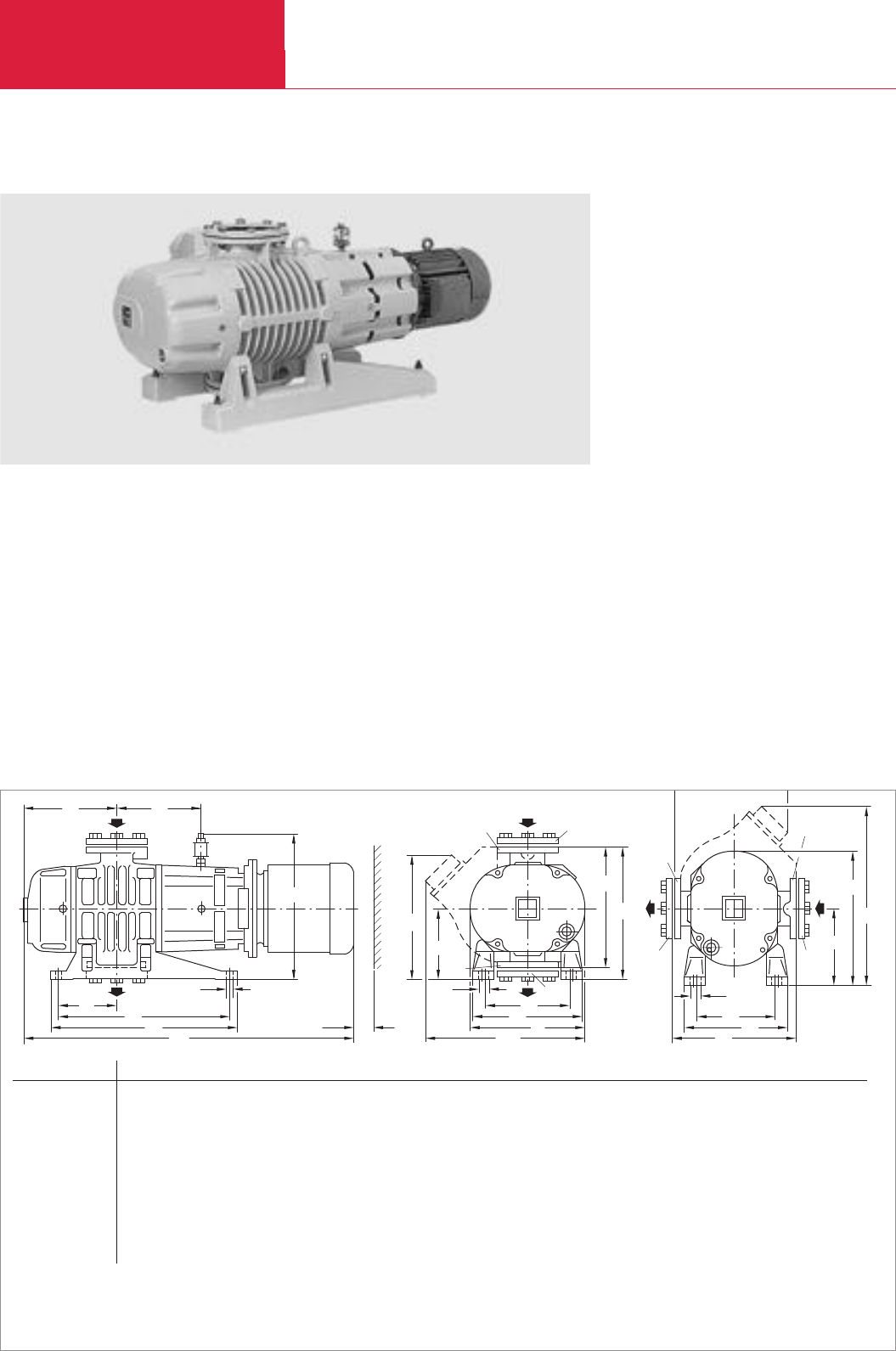
RUVAC WA/WAU
Roots Vacuum Pumps
C07.06 LEYBOLD VACUUM PRODUCTS AND REFERENCE BOOK 2003/2004
Roots Vacuum Pumps
Advantages to the User
♦Two air-cooled series, each with four models
♦Reliable and trouble-free
♦Sealing rings with their housing can be readily
replaced
♦Shaft seals and elastomer seals made of
FPM/Viton
♦Standard motors in accordance with IEC
dimensions
♦Easy to exchange with custom motors
♦Integrated pressure equalization line for pro-
tection against overloading at high pressures
on WAU models
♦Pumping direction may be changed as
required
♦Ex T3 and T4 motor possible
Typical Applications
♦For oil-free compression of gases and vapors
in combination with a backing pump
♦Short cycle pumping processes also in the
presence of large quantities of gas and vapor
Supplied Equipment
♦RUVAC WA/WAU are supplied as standard for
a vertical pumping action, horizontal pumping
action upon request
♦Gasket in the intake flange with dirt sieve
♦The required oil filling is included in separate
bottles
RUVAC WA/WAU Roots Vacuum Pumps with Flange-Mounted Motors
RUVAC WAU 2001 single-stage Roots vacuum pump shown with ISO-K 160 collar flanges
h3
b5
DN1
h4
h5
2)
DN
DN
DN1
h2
h
b6
b4
b3
2)
b6
DN1
DN
b2
DN1
DN
h1
b1b
b7
h6
a3
1)
a5a2a1a
a6
a4
50
8
h7
Dimensional drawing for the RUVAC WA/WAU pumps
1) Dimension a refers to the standard type of motor supplied by us
2) RUVAC WAU only
DN1= ND 6 pump flange in accordance with DIN 2501
DN
1
= Collar flange with gasket for connecting ISO-K standard components
1
DN/DN
1
WA/WAU 251 mm 63 ISO-K
in. 63 ISO-K
WA/WAU 501 mm 63 ISO-K
in. 63 ISO-K
WA/WAU 501H mm 63 ISO-K
in. 63 ISO-K
WA/WAU 1001 mm 100 ISO-K
in. 100 ISO-K
WA/WAU 1001H mm 100 ISO-K
in. 100 ISO-K
WA/WAU 2001 mm 160 ISO-K
in. 160 ISO-K
WA/WAU 2001H mm 160 ISO-K
in. 160 ISO-K
a
1)
a
1
a
2
a
3
a
4
a
5
a
6
b b
1
b
2
b
3
b
4
b
5
b
6
b
7 2)
b
8
h h
1
h
2
h
3
732 405 365 14 212 120 194 250 270 210 280 230 170 24 305 285 300 160 280 180
28.82 15.94 14.37 0.55 8.35 4.72 7.64 9.84 10.63 8.27 11.02 9.06 6.69 0.94 12.01 11.22 11.81 6.30 11.02 7.09
835 486 450 14 239 155 218 307 299 229 320 271 201 24 390 313 340 180 320 194
32.87 19.13 17.72 0.55 9.41 6.10 8.58 12.09 11 77 9.02 12.60 10.67 7.91 0.94 15.35 12 32 13.39 7.09 12.60 7.48
835 486 450 14 239 155 218 307 299 229 320 271 201 24 414 330 340 180 320 194
32.87 19.13 17.72 0.55 9.41 6.10 8.58 12.09 11 77 9.02 12.60 10.67 7.91 0.94 16.30 12 99 13.39 7.09 12.60 7.48
1050 560 520 16.5 300 180 262 372 352 278 370 320 246 24 490 366 396 211 370 227
41.34 22.05 20.47 0.65 9.41 6.10 10.31 14.65 13 86 10.94 14.57 12.60 7.91 0.94 19.29 14.41 15.59 8.31 14.57 8.94
1050 560 520 16.5 300 180 262 372 352 278 370 320 246 24 524 398 396 211 370 227
41.34 22.05 20.47 0.65 9.41 6.10 10.31 14.65 13.86 10.94 14.57 12.60 7.91 0.94 20.63 15.67 15.59 8.31 14.57 8.94
1275 800 740 18 369 220 310 457 518 388 460 422 292 23 635 456 530 300 460 351
50.20 31.50 29.13 0.71 14.53 8.66 12.20 17.99 20.39 15.28 18.11 16.61 11.50 0.91 25.0 17.95 20.87 11.81 18.11 13.82
1275 800 740 18 369 220 310 457 518 388 460 422 292 23 642 460 530 300 460 351
50.20 31.50 29.13 0.71 14.53 8.66 12.20 17.99 20.39 15.28 18.11 16.61 11.50 0.91 25.28 18.11 20.87 11.81 18.11 13.82
h
4
h
5 2)
h
6
h
7
306 360 330 307
12.05 14.17 12.99 12.09
348 430 370 332
13.70 16.93 14.57 13.07
348 450 370 350
13.70 17.72 14.57 13.78
414 532 425 392
16.30 20.94 425 15.43
414 564 425 424
16.30 22.20 425 16.69
578 753 541 523
22.76 29.65 21.3 20.59
578 760 541 530
22.76 29.92 21.3 20.87
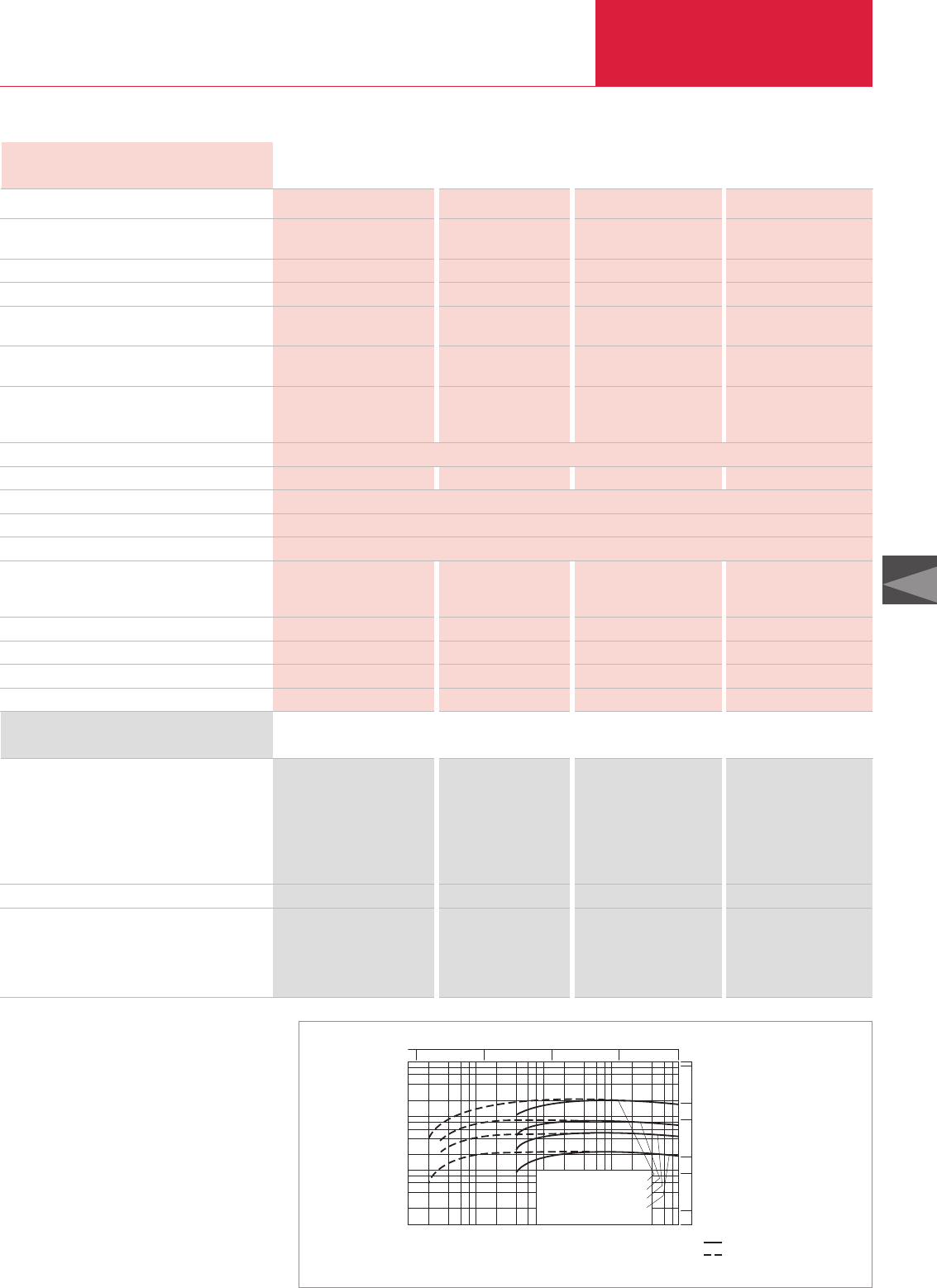
RUVAC WA/WAU
Roots Vacuum Pumps
C07.07
C07
LEYBOLD VACUUM PRODUCTS AND REFERENCE BOOK 2003/2004
Technical Data WA/WAU WA/WAU(H) WA/WAU(H) WA/WAU(H)
251 501 1001 2001
Ordering Information WA/WAU WA/WAU(H) WA/WAU(H) WA/WAU(H)
251 501 1001 2001
Roots vacuum pump
RUVAC WA
RUVAC WA (60 Hz, 3 phase) 7)
RUVAC WAU
RUVAC WAU (60 Hz, 3 phase) 7)
RUVAC WA, without motor
RUVAC WAU(H), with special ACE vibration absorber
RUVAC WA/WAU(H) seal kit
Flange adapter set, consisting of
Flange adapter with screws, bolts,
washers and nuts for ANSI flange
WA/WS pump
WAU/WSU pump
Part No. 117 20 Part No. 117 30 Part No. 117 40 Part No. 117 50
Part No. 917 20 Part No. 917 30 Part No. 917 40 Part No. 917 50
Part No. 117 21 Part No. 117 31 Part No. 117 41 Part No. 117 51
Part No. 917 21 Part No. 917 31 Part No. 917 41 Part No. 917 51
Part No. 117 24 Part No. 117 34 Part No. 117 44 –
–Part No. 118 31 Part No. 118 41 Part No. 118 51
Part No. 194 60 Part No. 194 64 Part No. 194 68 Part No. 194 72
(3" ANSI) (3" ANSI) (4" ANSI) (6" ANSI)
Part No. 200 03 179 Part No. 200 03 179 Part No. 200 03 180 Part No. 200 03 181
Part No. 200 03 179 Part No. 200 03 179 Part No. 200 03 180 Part No. 200 03 182
Nominal pumping speed 1) m3x h-1 (cfm)
Max. pumping speed m3x h-1 (cfm)
at a pumping speed for the backing pump of
m3x h-1 (cfm)
Ultimate partial pressure 2) mbar (Torr)
Ultimate total pressure 2) mbar (Torr)
Permissible cut-in pressure RUVAC WA mbar (Torr)
at a pumping speed for the backing pump of
m3x h-1 (cfm)
Max. permissible pressure difference
during continuous operation 3) mbar (Torr)
Main supply, 50 Hz ∆/Y V
60 Hz ∆/Y V
60 Hz 3 phase V
Insulation class
Motor power kW (hp)
Nominal speed, approx. (50/60 Hz) rpm
Max. permissible speed rpm
Type of protection IP
Oil filling for the bearing chamber 4)
vertical pumping action, approx. l (qt)
horizontal pumping action, approx. l (qt)
Oil filling of the shaft sealing ring housing l (qt)
Connection flanges *) DN
Weight WA/WAU kg (lbs)
Noise level 6) dB(A)
1) To DIN 28 400 and subsequent numbers
2) With single-stage rotary vane vacuum pump
TRIVAC, SOGEVAC
3) Applicable for ratio up to 1 : 10 between backing pump
and Roots vacuum pump
4) Authoriative, however, is the oil level at the oil-level glass
5) After a complete disassembly
6) At an operating pressure below < 10-1 mbar
(< 0.75 x 10⁻¹ Torr)
7) 60 Hz pumps supplied with ANSI adapter flanges
*) US models ASA flanges
253 (149) 505 (297.4) 1000 (589) 2050 (1207.5)
210 (123.7) 450 (265.1) 890 (524.2) 1850 (1089.7)
65 (38.3) 160 (94.2) 250 (147.3) 630 (371.3)
< 2 x 10⁻³ (1.5 x 10⁻³) < 3 x 10⁻³ (2.25 x 10⁻³) < 3 x 10⁻³ (2.25 x 10⁻³) < 3 x 10⁻³ (2.25 x 10⁻³)
< 4 x 10⁻² (3 x 10⁻²) < 4 x 10⁻² (3 x 10⁻²) < 4 x 10⁻² (3 x 10⁻²) < 4 x 10⁻² (3 x 10⁻²)
31 (23.3) 37 (27.8) 27 (20.3) 22 (16.5)
65 (38.3) 160 (94.2) 250 (147.3) 630 (371.3)
80 (60) 80 (60) 80 (60) 50 (37.5)
220-240/380-420 220-240/380-420 220-240/380-420 380-420
250-277/440-480 250-277/440-480 250-277/440-480 380-480/655-725
200-230/460 200-230/460 200-230/460 460
F
1.1 (1.5) 2.2 (3.0) 4.0 (5.4) 7.5 (10.2)
3000/3600
3600
54
1. Filling
5)
/ 2. Filling 1. Filling
5)
/ 2. Filling 1. Filling
5)
/ 2. Filling 1. Filling
5)
/ 2. Filling
0.65
(0.69)
/ 0.6
(0.63)
0.9
(0.95)
/ 0.8
(0.85)
2.0
(2.11)
/ 1.8
(1.90)
3.85
(4.07)
/ 3.6
(3.81)
0.5
(0.53)
/ 0.45
(0.48)
0.75
(0.79)
/ 0.7
(0.74)
1.2
(1.27)
/ 1.1
(1.16)
2.6
(2.75)
/ 2.4
(2.54)
0.6 (0.63) 1.0 (1.06) 1.3 (1.37) 1.6 (1.69)
63 ISO-K 63 ISO-K 100 ISO-K 160 ISO-K
85/89 (187.4/196.2) 128/133 (282.2/293.3) 220/225 (485.1/496.1) 400/406 (882/895.2)
< 64 < 67 < 75 < 80
Pressure
mbar
Pumping speed
10
10
50
1
-3
10
2
4
6
8
10
2
10
3
10
4
42 86
-2
10 10
7.5
1
10
0-1
10
WA/WAU 2001 + SV 630
WA/WAU 1001 + SV 300
WA/WAU 501 + SV 200
WA/WAU 251 + D 65 B
100
500
1000
5000
cfm
Torr
110
-1
10
-2
10
-3
m
3
x
h
-1
Total pressure
Patial pressure
Pumping speed of the RUVAC WA/WAU, 50 Hz
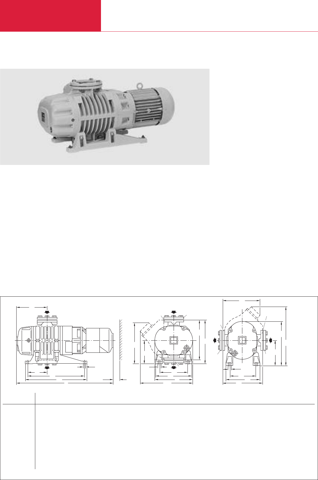
RUVAC WS/WSU PFPE
Roots Vacuum Pumps
C07.08 LEYBOLD VACUUM PRODUCTS AND REFERENCE BOOK 2003/2004
RUVAC WS/WSU PFPE Roots Vacuum Pumps with Canned Motors
Single stage Roots vacuum pump RUVAC WSU 1001 shown with ISO-K 160 rotatable flanges
h3
b5
DN 1
h4
h5
1)
DN
DN
DN1
h2
h
b6
b4
b3
1)
b6
DN1
b2
DN1
DN
h1
b1b
b7
a3
a5a2a1a
a4
DN
h6
b8
50
DN
DIN 2501 DN
1
WS/WSU 251 mm 65 63 ISO-K
in. 65 63 ISO-K
WS/WSU 501 mm 65 63 ISO-K
in. 65 63 ISO-K
WS/WSU 501H mm 65 63 ISO-K
in. 65 63 ISO-K
WS/WSU 1001 mm 100 100 ISO-K
in. 100 160 ISO-K
WS/WSU 1001H mm 100 160 ISO-K
in. 100 160 ISO-K
WS/WSU 2001 mm 150 160 ISO-K
in. 150 160 ISO-K
WS/WSU 2001H mm 150 160 ISO-K
in. 150 160 ISO-K
Dimensional drawing for the RUVAC WS/WSU pumps
Advantages to the User
♦Two series, each with four models
♦Highly leak-tight air-cooled pumps driven by a
canned motor
♦Lubricated with mineral oil. RUVAC WS/WSU
PFPE with perfluoropolyether (PFPE)
♦WS and WS PFPE pumps are identical except
for the lubricant and the shipping package
♦No thermal problems due to the speed inde-
pendent cooling arrangement using a separa-
tely connected fan, thus no thermal problems
at low speeds
♦Over-temperature switch in the stator coil of
the motor
♦All elastomer seals made of FPM/Viton
♦Integrated pressure equalization line with
differential pressure valve prevents over-
loading on WSU model
♦RUVAC WS 251 to 2001 for use with a fre-
quency converter for a wide frequency range
♦No shaft feedthrough to the atmosphere, thus
particularly leaktight
♦Pumping direction may be changed as
required
Typical Applications
♦
For applications which require a high pumping
speed at pressures between 10
-2
and 10
-4
mbar
(0.75 x 10
-2
and 0.75 x 10
-4
Torr)
♦Used where the possibility of contamination
due air ingress or pumped media leakage
must be avoided
♦Suction or pumping of high-purity or radio-
active gases
Supplied Equipment
♦The required oil or PFPE filling is included in
separate bottle
♦Purged with nitrogen for corrosion protection
♦Gasket in the intake flange with integrated dirt
sieve
a a
1
a
2
a
3
a
4
a
5
a
6
b b
1
b
2
b
3
b
4
b
5
b
6
b
7 1)
b
8
h h
1
h
2
h
3
732 405 365 14 212 120 194 250 270 210 280 230 170 24 305 285 300 160 280 180
28.82 15.94 14.37 0.55 8.35 4.72 7.64 9.84 10.63 8.27 11.02 9.06 6.69 0.94 12.01 11.22 11.81 6.30 11.02 7.09
835 486 450 14 239 155 218 307 299 229 320 271 201 24 390 313 340 180 320 194
32.87 19.13 17.72 0.55 9.41 6.10 8.58 12.09 11 77 9.02 12.60 10.67 7.91 0.94 15.35 12 32 13.39 7.09 12.60 7.48
835 486 450 14 239 155 218 307 299 229 320 271 201 24 414 330 340 180 320 194
32.87 19.13 17.72 0.55 9.41 6.10 8.58 12.09 11 77 9.02 12.60 10.67 7.91 0.94 16.30 12 99 13.39 7.09 12.60 7.48
1050 560 520 16.5 300 180 262 372 352 278 370 320 246 24 490 366 396 211 370 227
41.34 22.05 20.47 0.65 9.41 6.10 10.31 14.65 13 86 10.94 14.57 12.60 7.91 0.94 19.29 14.41 15.59 8.31 14.57 8.94
1050 560 520 16.5 300 180 262 372 352 278 370 320 246 24 524 398 396 211 370 227
41.34 22.05 20.47 0.65 9.41 6.10 10.31 14.65 13.86 10.94 14.57 12.60 7.91 0.94 20.63 15.67 15.59 8.31 14.57 8.94
1275 800 740 18 369 220 310 457 518 388 460 422 292 23 635 456 530 300 460 351
50.20 31.50 29.13 0.71 14.53 8.66 12.20 17.99 20.39 15.28 18.11 16.61 11.50 0.91 25.0 17.95 20.87 11.81 18.11 13.82
1275 800 740 18 369 220 310 457 518 388 460 422 292 23 642 460 530 300 460 351
50.20 31.50 29.13 0.71 14.53 8.66 12.20 17.99 20.39 15.28 18.11 16.61 11.50 0.91 25.28 18.11 20.87 11.81 18.11 13.82
h
4
h
5 1)
h
6
h
7
306 – 330 307
12.05 – 12.99 12.09
348 360 330 332
13.70 14.17 12.99 13.07
348 450 330 350
13.70 17.72 12.99 13.78
414 360 330 392
16.30 14.17 12.99 15.43
414 564 330 424
16.30 22.20 12.99 16.69
578 430 370 523
22.76 16.93 14.57 20.59
578 760 370 530
22.76 29.92 14.57 20.87
1) RUVAC WSU only DN
1
= Collar flange with gasket for connecting ISO-K standard componentsDN = ND 6 pump flange in accordance with DIN 2501
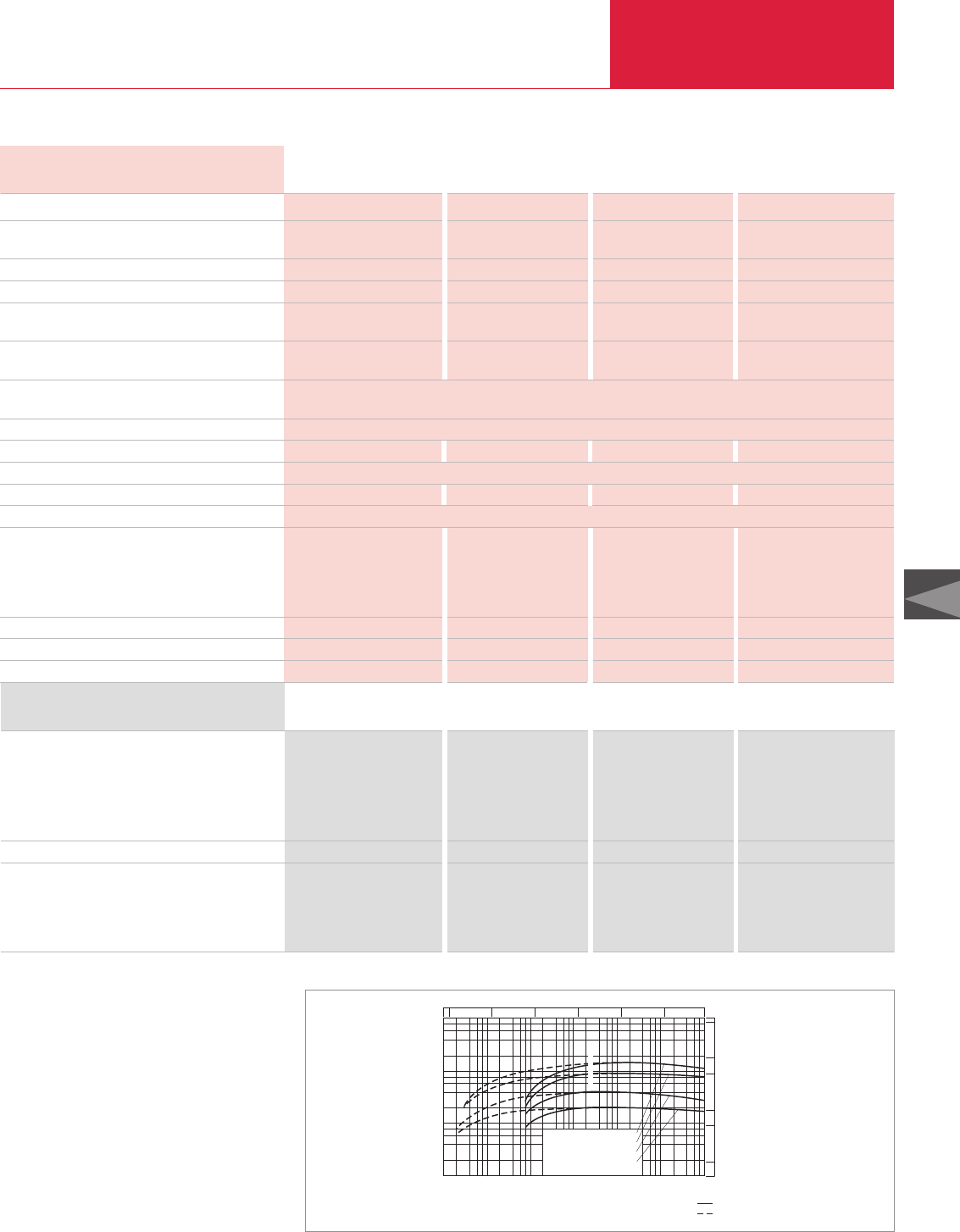
RUVAC WS/WSU PFPE
Roots Vacuum Pumps
C07.09
C07
LEYBOLD VACUUM PRODUCTS AND REFERENCE BOOK 2003/2004
Technical Data WS/WSU WS/WSU(H) WS/WSU(H) WS/WSU(H)
251 501 1001 2001
Ordering Information WS/WSU WS/WSU(H)WS/WSU(H)WS/WSU(H)
251 501 1001 2001
Roots vacuum pump
RUVAC WS
RUVAC WSU
RUVAC WS PFPE
RUVAC WSU PFPE
RUVAC WSU(H), with special ACE vibration absorber
RUVAC WS/WSU(H) seal kit
Flange adapter set, consisting of
Flange adapter with screws, bolts,
washers and nuts for ANSI flange
WA/WS pump
WAU/WSU pump
Part No. 117 22 Part No. 117 32 Part No. 117 42 Part No. 117 52
Part No. 117 23 Part No. 117 33 Part No. 117 43 Part No. 117 53
Part No. 117 27 Part No. 117 37 Part No. 117 47 Part No. 117 57
Part No. 117 28 Part No. 117 38 Part No. 917 48
*)
–
–Part No. 118 33 Part No. 118 43 Part No. 118 53
Part No. 194 62 Part No. 194 66 Part No. 194 70 Part No. 194 74
(3" ANSI) (3" ANSI) (4" ANSI) (6" ANSI)
Part No. 200 03 179 Part No. 200 03 179 Part No. 200 03 180 Part No. 200 03 181
Part No. 200 03 179 Part No. 200 03 179 Part No. 200 03 180 Part No. 200 03 182
Nominal pumping speed 1) m3x h-1 (cfm)
Max. pumping speed m3x h-1 (cfm)
at a pumping speed for the backing pump of
m3x h-1 (cfm)
Ultimate partial pressure 2) mbar (Torr)
Ultimate total pressure 2) mbar (Torr)
Permissible cut-in pressure RUVAC WS at mbar (Torr)
a pumping speed for the backing pump of
m3x h-1 (cfm)
Max. permissible pressure difference
during continuous operation 3) mbar (Torr)
Main supply, 50 Hz ∆/Y V
60 Hz ∆/Y V
Insulation class
Motor power, 50/60 Hz kW (hp)
Nominal speed, approx. (50/60 Hz) rpm
Max. permissible speed rpm
Type of protection IP
Oil filling for the bearing chamber 5)
PFPE, vertical pumping action, approx. l (qt)
horizontal pumping action, approx. l (qt)
other oils, vertical pumping action, approx. l (qt)
horizontal pumping action, approx. l (qt)
Connection flanges DN
Weight WS/WSU kg (lbs)
Noise level 7) dB(A)
1) To DIN 28 400 and subsequent numbers
2) With single-stage rotary vane vacuum pumps TRIVAC
3) Applicable for ratio up to 1 : 10 between backing pump
and Roots vacuum pump
4) Also 6 000 rpm upon order
5) Authoriative, however, is the oil level at the oil-level glass
6) After a complete disassembly
7) At an operating pressure < 10-1 mbar (< 0.75 x 10⁻¹ Torr)
*) 60 Hz pumps supplied with ANSI adapter flanges
253 (149) 505 (297.4) 1000 (589) 2050 (1207.5)
210 (123.7) 450 (265.1) 890 (524.2) 1850 (1089.7)
65 (38.3) 160 (94.2) 250 (147.3) 630 (371.3)
< 2 x 10⁻⁵ (1.5 x 10⁻⁵) < 3 x 10⁻⁵ (2.3 x 10⁻⁵) < 3 x 10⁻⁵ (2.3 x 10⁻⁵) < 3 x 10⁻⁵ (2.3 x 10⁻⁵)
< 8 x 10⁻⁴ (6 x 10⁻⁴) < 8 x 10⁻⁴ (6 x 10⁻⁴) < 8 x 10⁻⁴ (6 x 10⁻⁴) < 8 x 10⁻⁴ (6 x 10⁻⁴)
31 (23.3) 37 (27.8) 27 (20.3) 22 (16.5)
65 (38.3) 100 (58.9) 250 (147.3) 250 (147.3)
80 (60) 80 (60) 80 (60) 50 (37.5)
200/230/400
208/230/265/460
F
1.1 (1.5) / 1.4 (1.9) 2.2 (3.0) / 2.4 (3.3) 4.0 (5.4) / 4.4 (6.0) 7.5 (10.2) / 8.5 (11.6)
3000/3600
6000 6000 6000 4200 4)
20
1. Filling 6) / 2. Filling 1. Filling 6) / 2. Filling 1. Filling 6) / 2. Filling 1. Filling 6) / 2. Filling
0.6 (0.63) / 0.55 (0.58) 0.85 (0.9) / 0.75 (0.79) 1.95 (2.06) / 1.75 (1.85) 3.8 (4.02) / 3.5 (3.7)
0.5 (0.53) / 0.45 (0.48) 0.75 (0.79) / 0.7 (0.74) 1.2 (1.27) / 1.1 (1.16) 2.6 (2.75) / 2.4 (2.54)
0.65
(0.69)
/ 0.6
(0.63)
0.9
(0.95)
/ 0.8
(0.85)
2.0
(2.11)
/ 1.8
(1.90)
3.85
(4.07)
/ 3.6
(3.81)
0.5
(0.53)
/ 0.45
(0.48)
0.75
(0.79)
/ 0.7
(0.74)
1.2
(1.27)
/ 1.1
(1.16)
2.6
(2.75)
/ 2.4
(2.54)
63 ISO-K 63 ISO-K 100 ISO-K 160 ISO-K
90/95 (198.5/209.5) 130/135 (286.7/297.7) 228/233 (502.7/513.8)
458/465 (1009.9/1025.3)
< 63 < 63 < 68 < 72
m
3
x
h
-1
Pressure
mbar
Pumping speed
2
10
0
10
1
10
1
864
-1
10
-3
10
-2
10
-4
10
-5
10
2
4
6
8
10
2
10
3
10
4
WS/WSU 2001 + SV 630
WS/WSU 1001 + SV 300
WS/WSU 501 + SV 200
WS/WSU 251 + D 65 B
10
50
100
500
1000
5000
cfm
10
-3
10
-3
10
-4
10
-5
10
-2
10
-1
17.5
Torr
Total pressure
Patial pressure
Pumping speed of the RUVAC WS/WSU, 50 Hz
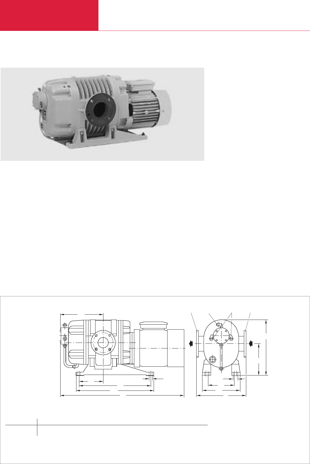
RUVAC WSLF
Roots Vacuum Pumps
C07.10 LEYBOLD VACUUM PRODUCTS AND REFERENCE BOOK 2003/2004
TRIVAC D 8 B
RUVAC WSLF Roots Vacuum Pumps for Laser Gas Systems
RUVAC WSLF 1001 LF Roots vacuum pump
a
h
DN DN1) 2)
h1
a1
a2
a5
a4
a3
b
b1
b2
b3
DN
mm 100
WSLF 1001 in. 100
a a
1
a
2
a
3
a
4
a
5
b b
1
b
2
b
3
h h
1
990 560 520 16.5 360 180 370 320 246 24 227 414
39.0 22.05 20.47 0.65 14.17 7.09 14.57 12.60 9.69 0.94 8.94 16.302
Dimensional drawing for the RUVAC WSLF pumps
1)
Connection for a vacuum pump
2)
4 mm water connection for the oil separator
DN = ND 6
*)
pump flange to DIN 2501
*)
ND = nominal pressure
Advantages to the User
♦A gas mixture of helium, nitrogen and carbon
monoxide is continuously circulated at a re-
duced system pressure
♦High pumping speed from a small, quiet run-
ning pump
♦Operation with a frequency converter is
possible
♦Nickel-plated pump chamber surfaces
♦Through an additional vacuum pump the bear-
ing chambers may be evacuated to a pressure
lower than the pressure within the pumping
chamber of the RUVAC
Supplied Equipment
♦Horizontal pumping action as standard
♦With oil pressure switch and oil drain facility
♦The required oil filling is included separately
(special oil ANDEROL
®
2100 HTCL)
♦Purged with nitrogen for corrosion protection
Roots vacuum pumps driven by canned motors
are available for gas laser systems.
♦Water-cooled oil separating system
♦Integrated oil separating system for extended
maintenance intervals
Typical Applications
♦Processing of ferrous and non-ferrous mate-
rials like welding, cutting and surface refine-
ment
Technical Note
♦The gas circulation system must be very clean
and entirely free of hydrocarbons

RUVAC WSLF
Roots Vacuum Pumps
C07.11
C07
LEYBOLD VACUUM PRODUCTS AND REFERENCE BOOK 2003/2004
Technical Data WSLF 1001
Ordering Information WSLF 1001
Part No. 117 94
Part No. 194 70
Nominal pumping speed 1) m3x h-1 (cfm)
Max. permissible pressure difference
during continuous operation mbar (Torr)
Main supply, 50 Hz ∆/Y V
60 Hz ∆/Y V
Motor power, 50/60 Hz kW (hp)
Nominal speed, 50/60 Hz rpm
Max. permissible speed rpm
Type of protection IP
Oil filling of the bearing chambers l (qt)
Connection flange DIN 2501 DN
Weight kg (lbs)
Cooling water pressure bar (psi)
Cooling water throughput l x h-1(cfm)
Hose connection for hose
1) To DIN 28 400 and subsequent numbers
1000 (589)
80 (60)
200-230/400
200-265/460
7.5 (10.2) / 8.5 (11.6)
3000/3600
6000
20
1.2 (1.27)
100
275 (606.4)
1 - 5 (14.5 - 72.5)
200 (0.9)
6 x 1
RUVAC WSLF Roots vacuum pump
RUVAC WSLF 1001
RUVAC WSLF seal kit
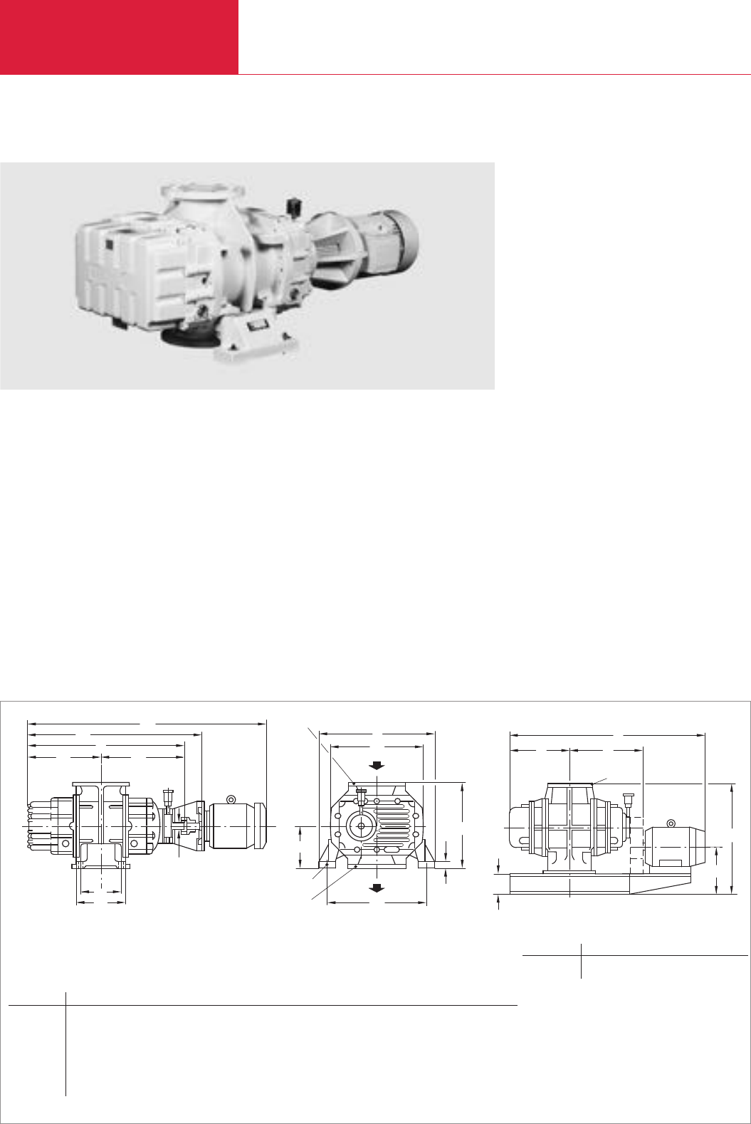
RUVAC RA
Roots Vacuum Pumps
C07.12 LEYBOLD VACUUM PRODUCTS AND REFERENCE BOOK 2003/2004
RUVAC RA Roots Vacuum Pumps with Flange-Mounted Motors (50 Hz)
RUVAC RA 5001 single-stage Roots vacuum pump
b
h
1
h
1
b
DN
220
2
h
2
b
d1
DN
2110*
RUVAC RA 13 000
* Breite = 1000
420
782
685
DN 300
DIN 2532
d
a
6
a
5
a
2
a
1
a
3
a
4
a
930
Dimensional drawing for the RUVAC RA pumps
DN1= PN 10 pump flange to DIN-EN 1092-2
DN a a
1
a
2
a
3
a
4
a
5
a
6
b b
1
b
2
ø d
k6
ø d
1
h h
1
h
2
RA 3001 200 mm 980 470 510 290 350 1101 1570 652 538 600 35 23 500 35 250
200 in. 38.58 18.50 20.08 11.42 13.78 43.35 61.81 25.67 21.18 23.62 1.38 0.91 19.69 1.38 9.84
RA 5001 200 mm 1013 468 545 280 360 1136 1610 800 652 720 42 23 630 50 315
200 in. 39.88 18.43 21.46 11.02 14.17 44.72 63.39 31.50 25.67 28.35 1.65 0.91 24.80 1.97 12.40
RA 7000 250 mm 1143 533 610 410 490 1266 1740 800 652 720 42 23 630 50 315
250 in. 45.0 20.98 24.02 16.14 19.29 49.84 68.50 31.50 25.67 28.35 1.65 0.91 24.80 1.97 12.40
RA 9001 300 mm 1467 685 782 655 800 1594 2220 910 810 830 55 27 710 30 355
300 in. 57.76 26.97 30.79 25.79 31.50 62.76 87.40 35.83 31.89 32.68 2.17 1.06 27.95 1.18 13.98
Advantages to the User
♦Oil immersed radial shaft seals made of FPM
for sealing against the atmosphere
♦If required with external pressure equalisation
line and differential pressure valve so that the
pump may be switched on jointly with the
backing pump at atmospheric pressure
♦Motors can easily be exchanged for special
voltage motors. Explosion protected motors
and motors for special main frequencies upon
request
♦Over-temperature switch in the stator coil of
the motor
♦Rugged dry compressing vacuum pump
♦Most reliable even under rough operating
conditions
Typical Applications
♦Large vacuum systems like sintering and
annealing furnaces which require multi-stage
pumpsets
♦In large vacuum rectification systems Roots
vacuum pumps with postcondensers for com-
pressing of vapors
Custom Pumps
♦If required the RA pumps are also available as
C versions (chemical versions)
♦Pumps made of special materials may be
specified as well as pressure burst resistant
pumps
♦Custom designed pumps for pumping speeds
of
250 m
3
/h to 2000 m
3
/h (147.3 to
1178 cfm)
Technical Note
♦
For operation ordering of oil is necessary
(see section “Accessories”)
Roots vacuum pumps offering a high pumping
speed.
DN l l
1
l
2
h h
1
h
2
RA 13 000 300 mm 2110 685 782 930 420 220
300 in. 83.07 26.97 30.79 36.61 16.54 8.66
RUVAC RA 13 000
* Breite = 1000
DN 300
DIN 2532
h
h1
h2
l2
l1
l
*
RUVAC RA 13 000
* Width = 1000
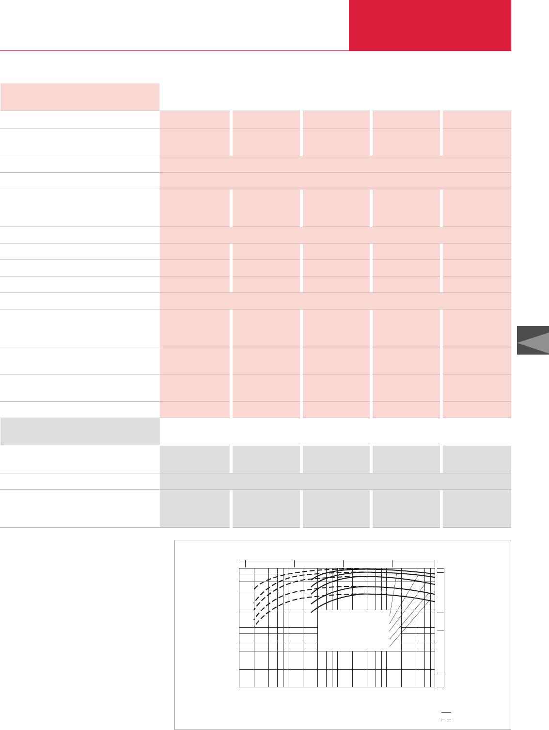
RUVAC RA
Roots Vacuum Pumps
C07.13
C07
LEYBOLD VACUUM PRODUCTS AND REFERENCE BOOK 2003/2004
Technical Data RA RA RA RA RA
3001 5001 7001 9001 13000
Ordering Information RA RA RA RA RA
3001 5001 7001 9001 13000
RUVAC RA Roots vacuum pump
with motor 400 V, 50 Hz, coupling and lantern 6)
RUVAC RA seal kit
Adapter flange package for suction and pressure side,
including centering ring with integrated
dirt sieve in the intake flange
Part No. 119 50 Part No. 119 53 Part No. 119 60 Part No. 119 63 upon request
upon request
Part No. 200 14 472 Part No. 200 14 472 – – –
Nominal pumping speed 1) m3x h-1 (cfm)
Max. pumping speed m3x h-1 (cfm)
at a pumping speed for the backing pump of
m3x h-1 (cfm)
Ultimate partial pressure 2) mbar (Torr)
Ultimate total pressure 2) mbar (Torr)
Max. permissible pressure difference
during continuous operation 3) mbar (Torr)
for < 3min. mbar (Torr)
Main supply, 50 Hz V
Motor power kW (hp)
Nominal speed, 50 Hz rpm
Max. permissible speed rpm
Type of protection IP
Oil filling, approx.
vertical pumping action l (qt)
horizontal pumping action l (qt)
Connection flange, suction side 4, 5) DN
pressure side 4, 5) DN
Adapter flange package, suction side DN
pressure side DN
Weight complete, approx. kg (lbs)
1) To DIN 28 400 and subsequent numbers
2) With single-stage rotary vane vacuum pumps SOGEVAC
3) Valid for a ratio of 1 : 5 between backing pump
and Roots vacuum pump
4) According to DIN 2532
5) Without adapter flange to ISO-K flange
6) Without oil filling
3900 (2297) 5550 (3269) 7470 (4400) 9720 (5725) 13000 (7657)
2900 (1708) 4100 (2415) 5600 (3298) 7500 (4418) 10000 (5890)
630 (371) 800 (471) 1260 (742) 1890 (1113) 2500 (1473)
< 2 x 10⁻³ (< 1.5 x 10⁻³)
< 3 x 10⁻² (< 2.3 x 10⁻²)
53 (39.8) 53 (39.8) 53 (39.8) 66 (49.5) 93 (69.8)
93 (69.8) 93 (69.8) 93 (69.8) 133 (99.8) 93 (69.8)
400 D
11 (15) 15 (20.4) 18.5 (25.2) 22 (30) 30 (40.8)
3000 3000 3000 1500 2000
3600 3600 3600 1800 2000
54
7.0 (7.4) 12.0 (12.7) 12.0 (12.7) 11.0 (11.6) 11.0 (11.6)
3.5 (3.7) 5.4 (5.7) 5.4 (5.7) 7.6 (8.0) 7.6 (8.0)
200 200 250 300 300
200 200 250 300 300
250 ISO-K 250 ISO-K 250 ISO-K 320 ISO-K 320 ISO-K
160 ISO-K 160 ISO-K 250 ISO-K 250 ISO-K 250 ISO-K
620 (1367.1) 770 (1697.9) 870 (1918.4) 1500 (3307.5) upon request
Pressure
mbar
Pumping speed
-3
10
2
10
2
10
4
10
3
8
6
4
2 8
-2
10
64
10
1
10
0-1
10
RA 13000 + 4 x SV 630
RA 9001 + 3 x SV 630
RA 7001 + 2 x SV 630
RA 5001 + 2 x SV 630
RA 3001 + 1 x SV 630
m
3
x
h
-1
17.5
Torr
10
-3
10
-2
10
-1
100
500
1000
5000
cfm
Pumping speed curves for the RUVAC RA, 50 Hz
Total pressure
Partial pressure
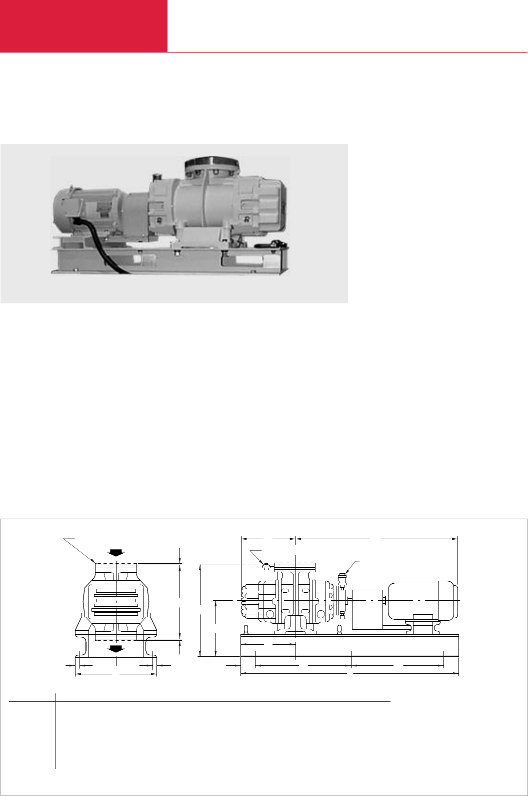
RUVAC RA
Roots Vacuum Pumps
C07.14 LEYBOLD VACUUM PRODUCTS AND REFERENCE BOOK 2003/2004
RUVAC RA Roots Vacuum Pumps with Frame Mounted Motors (60 Hz)
RUVAC RA 3001 single-stage Roots vacuum pump with frame mounted motor
K
K
GE
F
D
MA
J
C
Oiler
B
L
H
LJ
Pressure Switch
Optional ANSI Sealing Disc
Dimensional drawing for the RUVAC RA pumps
DN1= PN 10 pump flange to DIN-EN 1092-2
ANSI Inlet ANSI Outlet A B C D E F G H J K
RA 3001 mm 8“ 4“ 1448 470 1092 470 693 403 582 652 572 3
in. 8 4 57 18 1/2 43 18 1/2 27 9/32 15 7/8 22 29/32 25 21/32 22 1/2 1/8
RA 5000 mm 8“ 4“ 1727 468 1184 484 823 468 712 797 711 3
in. 8 4 68 18 7/16 46 5/8 19 1/16 32 13/32 18 7/16 28 1/32 31 3/8 28 1/8
RA 7001 mm 10“ 6“ 1778 533 1276 518 874 519 712 797 737 3
in. 10 6 70 21 50 1/4 20 3/8 34 13/32 20 7/16 28 1/32 31 3/8 29 1/8
RA 9001 mm 12“ 8“ 2108 686 1481 686 954 559 792 906 902 3
in. 12 8 83 27 58 8/16 27 37 9/16 22 31 3/16 35 11/16 35 1/2 1/8
Advantages to the User
♦Oil immersed radial shaft seals made of
FPM/Viton for sealing against the atmosphere
♦External pressure equalization line and differ-
ential pressure valve so that the pump may be
switched on simultaneously with the backing
pump at atmospheric pressure
♦Motors can easily be exchanged for special
voltage motors. Explosion protected motors
and motors for special main frequencies upon
request
♦Over-temperature switch in the stator coil of
the motor
♦Rugged dry compressing vacuum pump
♦Most reliable even under rough operating
conditions
Typical Applications
♦Large vacuum systems like sintering and
annealing furnaces which require multi-stage
pumpsets
♦In large vacuum rectification systems Roots
vacuum pumps with postcondensers for com-
pressing of vapors
Custom Pumps
♦If required the RA pumps are also available as
C versions (chemical versions)
♦Pumps made of special materials may be
specified as well as pressure burst resistant
pumps
♦Custom designed pumps for pumping speeds
of
250 m
3
/h to 2000 m
3
/h (147.3 to
1178 cfm)
Technical Note
♦
For operation ordering of oil is necessary
(see section “Accessories”)
Roots vacuum pumps offering a high pumping
speed.
Version for the North and South American Continents

RUVAC RA
Roots Vacuum Pumps
C07.15
C07
LEYBOLD VACUUM PRODUCTS AND REFERENCE BOOK 2003/2004
Technical Data RA RA RA RA
3001 5001 7001 9001
Ordering Information RA RA RA RA
3001 5001 7001 9001
RUVAC RA Roots vacuum pump
with 3-phase, T.E.F.C. motor (standard), 230/460 V, 60 Hz,
base,flexible coupling, coupling guard, screen,
ANSI flanges, PS 115 pressure switch and lubricant
Sealing disc, inlet
Sealing disc, outlet
Pressure switch amplifier SV 110
Part No. Part No. Part No. Part No.
98-236-3001 98-236-5001 98-236-7001 98-236-9001
Part No. Part No. Part No. Part No.
910-181-608 910-181-608 910-181-609 910-181-610
Part No. Part No. Part No. Part No.
910-181-606 910-181-606 910-181-607 910-181-608
Part No. 160 78-1
Displacement at 60 Hz m3x h-1 (cfm)
Backing pump speed m3x h-1 (cfm)
Rotation speed (nominal) rpm
Motor power (standard motor) kW (hp)
Oil filling, approx. l (qt)
Normal starting pressure for continuous
operation with recommended forepump
(standard motor) mbar (Torr)
Maximum differential pressure during
continuous operation (standard motor) mbar (Torr)
Starting pressure for intermittent operation
(≤3 min) with recommended forepump
(standard motor) mbar (Torr)
Maximum differential pressure during intermittent
operation (≤3 min - standard motor) mbar (Torr)
Weight, approx. kg (lbs)
4555 (2681) 6475 (3814) 8723 (5134) 11356 (6684)
773 (455) 1546 (910) 1546 (910) 2319 (1365)
3600 3600 3600 1800
15 (20.4) 20 (27.2) 25 (34) 30 (40.8)
8 (8.5) 9 (9.5) 9 (9.5) 13 (14)
13 (10) 20 (15) 13 (10) 27 (20)
53 (40) 53 (40) 53 (40) 67 (50)
27 (20) 33 (25) 20 (15) 53 (40)
93 (70) 93 (70) 93 (70) 133 (100)
634 (1400) 815 (1800) 906 (2000) 1540 (2400)
Version for the North and South American Continents

Roots Vacuum Pumps
C07.16 LEYBOLD VACUUM PRODUCTS AND REFERENCE BOOK 2003/2004
Pressure Switches
The RUVAC vacuum pumps may be switched on
and off automatically through a pressure switch
driven by a SV 110 switching amplifier and a
contactor.
The pressure switch may be installed in the in-
take of the RUVAC using a screw-in adaptor, an
elbow and two centering and two clamping rings.
Upon request the pressure switch may be set by
LEYBOLD to a fixed value. Please state this
pressure value in your order.
Accessories
Roots Vacuum Pumps
Ordering Information Pressure Switches
Pressure switch
PS 115, adjustable setting
Pressure switch setting
Accessories for fitting the PS pressure switch
Screw-in adaptor DN 16 KF, M 16 x 1.5 mm (0.06 in.)
Elbow DN 16 KF
Centering ring DN 16 KF (2 are required)
Clamping ring DN 16 KF (2 are required)
SV 110 switching amplifier (for PS 114/115)
Oil pressure switch for RUVAC WSLF 1001 and WS-PFPE
Part No. 160 04
Part No. 160 05
Part No. 168 40
Part No. 184 36
Part No. 183 26
Part No. 183 41
Part No. 160 78
Part No. 194 82

Miscellaneous
Roots Vacuum Pumps
C07.17
C07
LEYBOLD VACUUM PRODUCTS AND REFERENCE BOOK 2003/2004
Lubricating oils for rotary vacuum pumps need to
fulfil demanding requirements. Their vapor pres-
sure must be low also at high temperatures,
water content and water uptake must be minimal.
Their viscosity characteristics needs to be flat,
lubricating properties need to be excellent and
they must resist cracking upon being mechanical-
ly stressed.
All the vacuum pump oils listed in the following
have been subjected in our factory laboratories to
very comprehensive tests closely resembling the
conditions encountered in practice by the pumps
from the RUVAC series.
We therefore recommend the exclusive use of
vacuum pump oils fully qualified by Leybold so
as to ensure optimum performance of the
Leybold vacuum pumps and also to ensure opti-
mum oil change intervals.
Under vacuum conditions lubricating oils, especi-
ally those with additives may behave quite diffe-
rently than expected. Additives may adversely
affect the attainable ultimate pressure and may
react with the media being pumped.
When using not suitably qualified third party oils,
the oil change intervals and the performance of
the vacuum pump may be reduced. Also unwan-
ted deposits may occur which may even cause
severe damage to the vacuum pump.
For these reasons please understand that we
must make our warranty commitment dependent
on the use of oils which have been qualified by
us. Damages caused by the use of not suitably
qualified lubricating oils are not covered by our
warranty.
In order to adapt the pumps to the different appli-
cations of our customers, different types of oil
are used in the RUVAC pumps.
Please note that owing to differing properties not
all types of oil may be used in all pumps of the
RUVAC series. If you can not find the combinati-
on of pump and oil you require please ask us for
a quotation.
Vacuum Pump Oils
Lubricant Types
Mineral Oils
Mineral oils are products distilled and refined
from crude oil. These do not consist of precisely
defined compounds but rather consist of a com-
plex mixture. The way in which the mineral oil is
pre-treated and its composition are decisive as to
the applications it will be suited for. Depending
on the distribution of the hydrocarbons and the
dominance of certain properties, mineral oils are
grouped according to paraffin-base, naphthenic
and aromatic. For the purpose of attaining espe-
cially low ultimate pressures, mineral oils must
be selected on the basis of a core fraction.
The thermal and chemical resistance of mineral
oils has been found to be adequate in the majori-
ty of applications. They offer a high degree of
compatibility with elastomers and resistance to
hydrolysis.
Synthetic Oils
Synthetic oils are produced by a chemical reac-
tion. The group of synthetic oils includes liquids
differing widely as to their chemical structure and
composition. Correspondingly their physical and
chemical properties differ considerably. Synthetic
oils are used in those cases where special pro-
perties of the oil are required which can not be
fulfilled by mineral oils.
The oils given in the following belong to the
group of synthetic oils:
Ester Oils
Ester oils are organic compounds which excel
especially through their high thermal resistance
to cracking compared to mineral oils. Chemical
resistance is generally quite good, but will
depend on the type of ester oil. Elastomer com-
patibility and resistance against hydrolysis are
not so good compared to mineral oils.
Perfluorinated polyether
(PFPE)
These are oils which are only composed of carb-
on (C), fluorine (F) and oxygen atoms (O). The
existing C-O and C-F bonds are highly stable. For
this reason PFPE oils are practically inert against
all chemical and oxidising influences.
Perfluorinated polyether will not polymerise
under the influence of high energy radiation.
PFPE is non-flammable. Leybold NC1/14 has the
approval of BAM (Federal Institute for Materials
Research and Testing) for pumping of pure oxy-
gen.
Perfluorinated polyether are used when pumping
strongly reactive substances like oxygen (O
2
),
fluorine F
2
and uranium hexafluoride UF
6
.
Regarding Lewis acids (for example, boron
trifluoride BF
3
, aluminum trichloride AlCl
3
) they
are not completely inert. Here reactions may take
place at temperatures over 100 °C (212 °F).
Perfluorinated polyether are thermally highly
stable. Thermal decomposition may only take
place at temperatures of over 290 °C (554 °F).
Caution: Perfluorinated polyether will – when
decomposed – release toxic and corrosive gases:
hydrogen fluoride HF, carbonyl difluoride COF
2
.
For this reason open fires must be avoided in the
workspace where PFPE is being used. Do not
smoke in the workspace where PFPE is being
used.
Only suitably prepared pumps must be used in
connection with perfluorinated polyether, since it
is essential that the pumps be free of hydrocar-
bons.
Changing from one basic type of oil to PFPE
must be left exclusively to authorised Service
Centers. The pump will have to be fully disassem-
bled and carefully cleaned. Gaskets and filters will
have to be exchanged and suitable greases will
have to be used.
For all lubricants from our line of products you may obtain Safety Data Sheets from the Dept. Technical
Support in Cologne.

Miscellaneous
Roots Vacuum Pumps
C07.18 LEYBOLD VACUUM PRODUCTS AND REFERENCE BOOK 2003/2004
Technical Data Special Oil N62 ANDEROL®555 ANDEROL®2100 HTCL NC 1/14
Ordering Information
Part No. 177 01 Part No. 200 10 272 Part No. 200 14 333 Part No. 177 38
Part No. 177 02 Part No. 200 10 891 – –
Part No. 177 03 Part No. 200 00 193 – –
Part No. 177 05 – – –
Viscosity
at 040 °C (104 °F) mm2/s
at 100 °C (212 °F) mm2/s
Flash point °C (°F)
Vapor pressure
at 020 °C (68 °F) mbar (Torr)
at 100 °C (212 °F) mbar (Torr)
Density at 15 °C (59 °F) g/ml
Pour point °C (°F)
Middle molecular weight g/mol
Overview Oils
01 litre (1.06 qt)
05 litres (5.29 qt)
20 litres (21.14 qt)
180 kg (397.35 lbs)
Please note that the technical data stated are only typical data. Slight variations from batch to batch must be expected.
The technical data stated here can not be taken as assured properties
1)
Resistance to decomposing is very much dependent on the share of acrylonitrile in the NBR
2)
Caution: Perfluorinated polyether will, when being decomposed at temperatures over 290 °C (554 °F), release toxic and corrosive gases
For this reason open fires must be avoided in the workspace where PFPE is being used. Do not smoke in the workspace where PFPE is being used
3)
at 20 °C (68 °F)
ANDEROL®is a trademark of ANDEROL BV
Special Oil N62 ANDEROL 555 ANDEROL 2100 HTCL NC 1/14
90 94 94 47
10 9 13 5
> 255 (491) 250 (482) 265 (509) – 2)
< 1 x 10⁻⁵ (< 0.75 x 10⁻⁵) 7 x 10⁻⁵ (5.3 x 10⁻⁵) 5 x 10⁻⁵ (3.8 x 10⁻⁵) 3 x 10⁻⁷ (2.3 x 10⁻⁷)
< 3 x 10⁻³ (< 2.3 x 10⁻³) 1.5 x 10⁻³ (1.1 x 10⁻³) 8.5 x 10⁻⁴ (6.4 x 10⁻⁴) 6 x 10⁻⁴ (4.5 x 10⁻⁴)
0.88 3) 0.96 0.92 1.89 3)
< -9 (< -16) -42 (-44) -35 (-31) -40 (-40)
550
530 No known
2500
Special Oil N62 ANDEROL®555 ANDEROL®2100 HTCL NC 1/14
Type of oil
Examples of areas of application and process media
Remarks
Elastomer compatibility
FPM (Viton)
NBR (Perbunan) 1)
EPDM
Paraffin-base mineral oil, Diester oil Polyolester Perfluorinated polyether PFPE
core faction, free of
additives
Standard oil Used at elevated temperatures. Used in the RUVAC WSLF For pumping strong oxidants
Pumping of air, for operation in connection like oxygen, O2, ozone O3,
For pumping air, chemically inert with gas lasers nitrogen oxides NOx and
chemically inert permanent gases (noble sulphur oxides (SO2, SO3)
permanent gases gases, for example), as well as reactive substances
(noble gases, for example), carbon dioxide CO2, like halogens (for example
water vapor carbon monoxide CO, fluorine F2, chlorine Cl2),
aliphatic compounds hydrogen halides (for
(for example, methane CH4, example hydrogen
propane C3H8, chloride HCl, hydrogen
ethylene C2H4), bromide HBr), uranium
organic solvent vapors hexafluoride UF6and
conditionally Lewis acids
(for example, boron
trichloride BCl3)
The ultimate pressures Use only PFPE
stated in our catalogs are modified pumps. For
based on operation of the operation with PFPE we
pump with N62 (except recommend the exclusive
for the PFPE pumps) use of such pump types
which are equipped with a
split-pole motor
Mixing with other types of
oil must be absolutely
avoided
Suited Suited Suited Suited
Conditionally suited Conditionally suited Conditionally suited Suited
Not suited Not suited Not suited Suited
Application Data

Miscellaneous
Roots Vacuum Pumps
C07.19
C07
LEYBOLD VACUUM PRODUCTS AND REFERENCE BOOK 2003/2004
Version for the North and South American Continents
Viscosity at 40 °C (104 °F) mm2/s 58 –
Viscosity at 20 °C (68 °F) mm2/s – 140
Viscosity at 100 °C (212 °F) mm2/s 9
Viscosity at 99 °C (210 °F) mm2/s – 7
Flash point °C (°F) 224 (435) Not known 2)
Vapor pressure
at 100 °C (212 °F) mbar (Torr) 3.9 x 10⁻⁴ (2.9 x 10⁻⁴) 2.7 x 10⁻⁴ (2.0 x 10⁻⁴)
Pour point °C (°F) -10 (14) -40 (-40)
Middle molecular weight g/mol 480 3000
Technical Data
HE-200 HE-1600
Application Data
HE-200 HE-1600
Type of oil
Examples of areas of application
and process media
Remarks
Elastomer compatibility
FPM (Viton)
NBR (Perbunan) 1)
EPDM
Perfluorinated polyether PFPE
For pumping strong oxidants like
oxygen, O2, ozone O3, nitrogen
oxides NOx and sulphur oxides
(SO2, SO3) as well as reactive
substances like halogens (for
example fluorine F2, chlorine Cl2),
hydrogen halides (for example
hydrogen chloride HCl, hydrogen
bromide HBr), uranium hexafluoride
UF6and conditionally Lewis acids
(for example, boron trichloride BCl3)
Use only correspondingly modified
pumps. For operation with PFPE we
recommend the exclusive use of
such pump types which are
equipped with a split-pole motor
Mixing with other types of oil must
be absolutely avoided
Suited
Suited
Suited
Paraffin-base mineral oil,
core faction, free of additives
Standard oil for Leybold USA
For pumping air, chemically inert
permanent gases (noble gases, for
example), water vapor, solvent
vaporsin the case of laboratory
pumps operated with cold traps
The ultimate pressures stated in
operation of the pump with HE-200
(except for the PFPE pumps)
Service life may be extended
through the use of an oil filter
Suited
Conditionally suited
Not suited
Ordering
Information HE-200 HE-1600
01.0 litre (1 qt) Part No. 98-198-006 –
03.8 litres (1 gal) Part No. 98-198-007 –
18.9 litres (5 gal) Part No. 98-198-008 –
208 litres (55gal) Part No. 98-198-010 –
0.9 kg (2 lbs) – Part No. 898 564-1
1.8 kg (4 lbs) – Part No. 898 564-2
7.2 kg (16 lbs) – Part No. 898 564-4
Please note that the technical data stated are only typical data. Slight variations from batch to batch must be expected.
The technical data stated here can not be taken as assured properties
1) Resistance to decomposing is very much dependent on the share of acrylonitrile in the NBR
2) Caution: Perfluorinated polyether compounds will, when being decomposed at temperatures over 290 °C (554 °F), release toxic and corrosive gases.
For this reason open fires must be avoided in the workspace where PFPE is being used. Do not smoke in the workspace where PFPE is being used

Roots Vacuum Pumps
C07.20 LEYBOLD VACUUM PRODUCTS AND REFERENCE BOOK 2003/2004
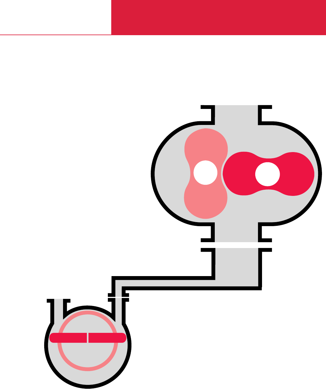
C08
Vacuum Pump Systems
250 - 13 000 m3x h-1
(147.3 - 7657 cfm)
RUTA

Contents
Vacuum Pump Systems
C08.02 LEYBOLD VACUUM PRODUCTS AND REFERENCE BOOK 2003/2004
General
Applications and Accessories . . . . . . . . . . . . . . . . . . . . . . . . . . . . . . . . . . . . . . . . . . . . . . . C08.03
Overview on the Types of Pumps Systems . . . . . . . . . . . . . . . . . . . . . . . . . . . . . . . . . . . . . C08.03
Products
Pump Systems (Global Versions)
Three-Stage RUTA Pump Systems with Two-Stage TRIVAC Backing Pumps. . . . . . . . . . . C08.06
Two-Stage RUTA Pump Systems with Single-Stage SOGEVAC Backing Pumps,
Adaptor Version . . . . . . . . . . . . . . . . . . . . . . . . . . . . . . . . . . . . . . . . . . . . . . . . . . . . . . . C08.08
Two-Stage RUTA Pump Systems with Single-Stage SOGEVAC Backing Pumps,
Frame Version . . . . . . . . . . . . . . . . . . . . . . . . . . . . . . . . . . . . . . . . . . . . . . . . . . . . . . . . C08.10
Two- and Three-Stage RUTA Pump Systems with Single- and Two-Stage
Rotary Piston Vacuum Pumps as Backing Pumps . . . . . . . . . . . . . . . . . . . . . . . . . . . . . . C08.12
Dry Compressing RUTA Pump System with EcoDry L Backing Pump. . . . . . . . . . . . . . . . C08.14
Dry Compressing RUTA Pump Systems with SCREWLine SP630 Backing Pump . . . . . . . . C08.16
RUVAC RAV Roots Vacuum Pumps with Pre-Admission Cooling . . . . . . . . . . . . . . . . . . . C08.18
Two- and Three-Stage RUTA RAV Pump Systems with RUVAC RAV Roots Vacuum Pumps
. . C08.20
TVD Pump Systems for Drying, Evaporation and Distillation Applications. . . . . . . . . . . . . C08.22
Pump Systems (Versions for the North and South American Continents)
RBS - B/BCS Roots Pump Systems with Two-Stage TRIVAC Backing Pumps . . . . . . . . . . C08.24
HTS Close-Coupled Pump Systems with Single-Stage SOGEVAC Backing Pumps. . . . . . . C08.28
HTS Frame Mounted Pump Systems with Single-Stage SOGEVAC Backing Pumps. . . . . . C08.32
RM - Roots / Mechanical Pump Systems
with Single- and Two-Stage Rotary Piston Vacuum Pumps as Backing Pumps . . . . . . . . . C08.34
Dry Compressing Vacuum Pump Systems with EcoDry L Backing Pump . . . . . . . . . . . . . C08.36
Miscellaneous
Checklist for Inquiries (Fax Form) . . . . . . . . . . . . . . . . . . . . . . . . . . . . . . . . . . . . . . . . . . . . C08.38
Overview
A continually increasing number of applications
in industry and research are relying on vacuum
technology. Thus widely differing requirements
result regarding the vacuum generating
systems.
The comprehensive range of vacuum pumps
from LEYBOLD offers, in combination with the
matching accessories, all options of selecting
the optimum pump system for your application
in each case.
Based on the long-standing experience in the
design and manufacture of vacuum pump
systems, LEYBOLD offers standardized pump
systems which will match most applications –
the RUTA pump systems.
RUTA pump systems excel by being compact,
reliable and service-friendly.
The pump systems are equipped as standard
with 400 V, 50 Hz three-phase motors.
Motors for special supply voltages, special
mains frequencies or explosion protected
pumps are available.
Standards
LEYBOLD vacuum pump systems are rated
according to CE, ISO, DIN and VDE regulations.
Compliance with other standards is possible
upon request.
The technical data of the vacuum pump systems
given in this product section are based on the
PNEUROP Acceptance Specifications for Vacuum
Pumps, Part 1, and comply with DIN 28 426. The
characteristic curves in our pumping speed dia-
grams are plotted in accordance with DIN
28 426
.
The curves represent the mean of several measu-
rements. Our warranty refers to the values indica-
ted in the technical data table.
LEYBOLD pump combinations of Roots vacuum
pumps with backing pumps are called “RUTA”.
In order to identify the standard pump systems
the name “RUTA” is followed by the brief
designations of the pumps which make up a
particular pump system.
RUTA WAU 2001 / WAU 501 / K / S 65 B / A
The pump system designation is arranged as fol-
lows:
Brief designation of the largest Roots vacuum pump
(Pumping speed of the pump system)
Brief designation of the smaller Roots vacuum pump
Cooler or condenser (if present)
Brief designation of the backing pump
Type of pump system (adaptor (A) or frame (G))
Designation of Roots Vacuum Pump Systems
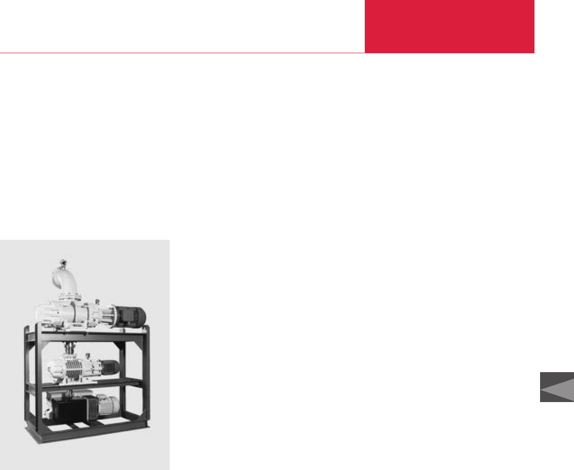
General
Vacuum Pump Systems
C08.03
LEYBOLD VACUUM PRODUCTS AND REFERENCE BOOK 2003/2004
C08
Applications and Accessories
Typical areas of application for RUTA pump
systems are industry, research and chemistry.
Here the focus is on processes for metal produc-
tion and processing, drying and degassing, ther-
mal treatment, coating in the area of semicon-
ductor manufacture as well as surface refine-
ment. RUTA pump systems are also used as
backing pump sets for high vacuum systems in
combination with diffusion pumps, turbomolecu-
lar pumps and cryo pumps.
Overview on the Types of
Pump Systems
The RUTA pump systems described here have
been designed for rough and medium vacuum
operation, i. e. for the pressure range from atmos-
pheric pressure down to 10
-4
mbar (0.75 Torr).
RUTA pump systems consist of a combination of
individual pumps whereby Roots vacuum pumps
are employed on the intake side. Further com-
pression to atmospheric pressure may be perfor-
med either by oil-sealed or dry-compressing
vacuum pumps, liquid ring pumps or Roots
vacuum pumps with pre-inlet cooling. All combi-
nations may be equipped at suitable places with
condensers. The selection criteria for a RUTA
pump system are as follows:
♦
Pumping speed
♦
Operating pressure
♦
Process conditions
♦
Characteristics of the media
♦
Standards and regulations which depend on
the area of application and the produced pro-
ducts.
Standard RUTA Pump
Systems
Our Roots vacuum pumps WA, WS and RA or
WAU and WSU with integrated bypass line or RA
with external bypass line (RAU) are combined
with oil-sealed backing pumps for conventional
generation of the vacuum. Single stage arrange-
ments are capable of delivering pumping speeds
of 250 to 16 000 m
3
/h (147.3 to 9424 cfm).
Higher pumping speeds can be attained by paral-
leling several pumps. The attainable operating
pressures depend on the number of pumping sta-
ges.
For higher pumping speeds or lower ultimate
pressures, three or multi-stage pump systems
equipped with single or two-stage backing pumps
are available (see figure).
RUTA Pump Systems with
Condensers
If vacuum systems must pump larger quantities
of vapor or vapor-gas mixtures, it is economical
to insert condensers which are cooled with water
or a different coolant at a suitable place within
the pump system. Cooled condensers are them-
selves effective partial pumps which condense
most of the vapors from the pumped media. The
downstream mechanical pumps will then only
need to pump those gases which have not alrea-
dy condensed.
The quantity of vapor present in each case deter-
mines the size of the condenser and the tempera-
ture at which it is operated. The size of the down-
stream pump is determined by the quantity of
non-condensable gases, the required pressure
and the required pump-down time for the
system.
All pump systems of the WA/WAU and RA/RAU
series may be equipped with one or several con-
densers. These are often used in the chemical
industry. Here RUTA vacuum pump systems with
condensers are not only used to generate a
vacuum, but they are also often employed in the
recovery of solvents. When installing one or
several Roots pumps upstream of a condenser,
low operating pressures and high condensation
pressures can be attained. Thus the condenser
may in many cases be operated with cooling
water instead of brine. The vapor components
pumped together with inert gases may be separa-
ted once more in an emission condenser on the
exhaust side so that the quality of the exhaust
gas can be maintained within close tolerance
regarding its cleanness.
Dry-Compressing RUTA
Vacuum Pump Systems
Increasing environmental awareness, pumping of
condensable vapors or high requirements regard-
ing cleanness when pumping high-quality media
which must not be contaminated by other media
for recycling, often requires the use of universal
pumps where the pump chamber is free of opera-
ting agents (dry pumps).
Here LEYBOLD offers three solutions:
1. Composite pumping systems combining an
EcoDry pump with one or more Roots blower
pumps.
2. Pump systems consisting of the SCREWLine
screw vacuum pump developed specifically for
the process industry in combination with one or
several Roots vacuum pumps.
3. Single or multi-stage RUTA RAV vacuum pump
systems, consisting of Roots vacuum pumps
with pre-admission cooling.
T
he operating pressure ranges of the pump
systems depend on the number of Roots vacuum
pumps, but will extend in any case without inter-
ruptions to atmospheric pressure.
Combinations of
EcoDry
and Roots blower
achieve an ultimate pressure of 2 x 10
-3
mbar
(1.5 x 10
-3
Torr)
.
Already in connection with one Roots pump,
pump systems with a SCREWLine pump are capa-
ble of attaining base pressures of < 1 x 10
-3
mbar
(7.5 x 10
-4
Torr)
.
Single-stage RAV combinations attain an ultimate
pressure of 150 mbar (112.5 Torr) and two-stage
combinations 50 mbar (37.5 Torr).
Multi-stage combinations with Roots vacuum
pumps of all three systems are capable of attain-
ing pressures below 10
-4
mbar
(7.5 x 10
-5
Torr)
.
RUTA Custom Pump Systems
Most users will be able to select the right pump
system for their application from our range of
standard pump systems. In special cases a
custom design may be required for special pro-
cesses and high pumping speeds.
We are prepared to design and manufacture
custom pump systems according to customers
specifications. If required we will use - besides
oil-sealed and dry-compressing backing pumps -
liquid ring and ejector pumps.
RUTA RA 3001/WAU1001/SV300
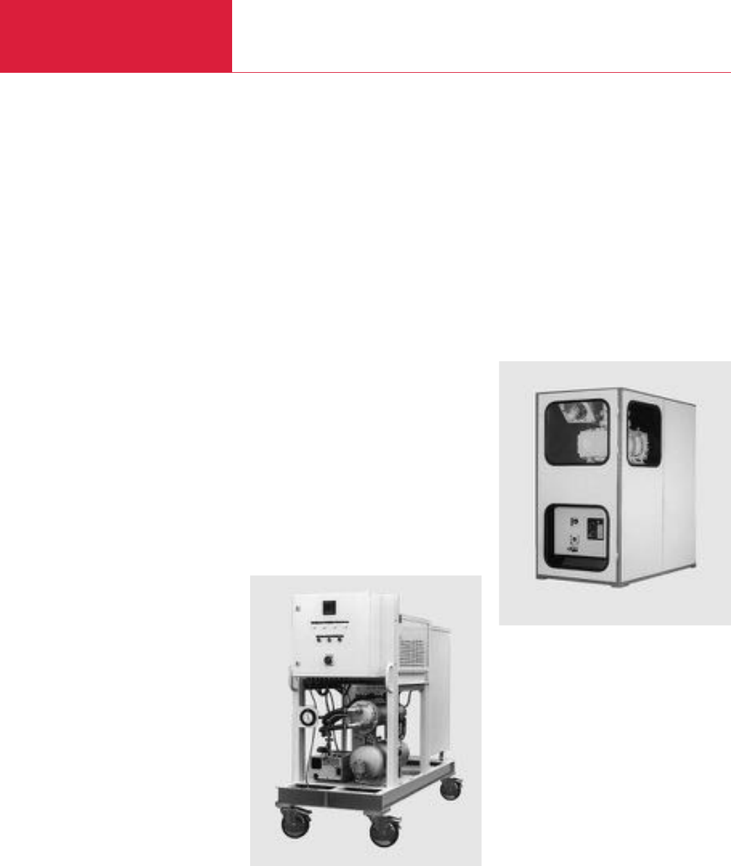
General
Vacuum Pump Systems
C08.04 LEYBOLD VACUUM PRODUCTS AND REFERENCE BOOK 2003/2004
RUTA Pump Systems for the
Metal Producing and
Processing Industry
In common vacuum furnace processes such as
hardening, annealing, brazing, melting and
casting, preferably oil-sealed or dry compressing
standard vacuum pump systems are usually
used. The oil-sealed systems consist of a combi-
nation of Roots vacuum pumps with a single or
two-stage rotary vane or rotary piston pump.
In the dry compressing systems our screw vacu-
um pump SCREWLine is used as the backing
pump.
The vacuum pumps are mounted in a rugged
frame. The design of the pump systems is
service-friendly, modular and can be easily
upgraded with additional equipment.
On smaller furnaces RUVAC WAU Roots vacuum
pumps are the most suitable because these may
be cut-in at a higher operating pressure, while on
larger furnaces and particularly where short
pump-down cycles are required, the use of
RUVAC RA Roots vacuum pumps with suitably
sized backing pumps is advisable. For special
processes, e.g. fusion or degassing of molten
masses, due to the high dust contents, the addi-
tional use of a dust separator is required as well
as equipping the backing pumps with oil filtering
units.
RUTA Pump Systems for the
Chemical Industry
In chemical processes it is often necessary to
remove corrosive, condensable and reactive
gases and vapors. LEYBOLD designs and manu-
factures custom-built pump systems for specific
process applications. Depending on the applica-
tion, the backing pump used in such systems
may be a rotary vane vacuum pump, a liquid ring
vacuum pump or a combination of an ejector
pump and a liquid ring pump.
To ensure dependable monitoring of the system,
the following monitoring devices, among others,
may be installed:
♦
Temperature sensors to monitor the gas temp-
eratures between the pump stages and the
pump body temperature,
♦
Water flow monitors for the cooling water
supply to pumps and condensers,
♦
Differential pressure indicator with control set-
point to monitor the exhaust filters of the
rotary vane vacuum pump.
Pump Systems for Drying,
Evaporation and Distillation
Applications (TVD)
More and more vacuum applications are finding
their way into the areas of environmental protec-
tion, recycling and waste disposal. “Waste dispos-
al of used oil and aromatic compounds” and
“Cleaning processes in metal-processing factor-
ies” demonstrate that the combination of vacuum
know-how, innovative engineering and applicati-
ons know-how is indispensable for the successful
application of vacuum technology in most widely
differing applications.
The product is no longer in the foreground, solu-
tions to problems are demanded instead.
LEYBOLD Vacuum has developed some contin-
uously operating vacuum pump systems for
these applications. These systems basically con-
sist of a rotary vane pump with a condenser unit.
Upon request the condenser arrangement may
also be equipped with a cold water set. This ver-
sion will then be independent of any cooling
water connections and – being a mobile system –
it is well-suited for operation at varying locations.
Accessories
Sound Proofing
A sound proofing box is available as an optional
extra so as to reduce the noise down to the per-
missible level.
Depending on the size of the pumping system,
noise reductions between 15 and 20 dB(A) are
obtained using our standard sound-proofing
arrangements.
Custom designs of the sound proofing box allow
the noise level to be reduced by up to 35 dB(A).
The maintenance side is designed as a door com-
ponent. A window insert may be provided in the
door or in the side walls to facilitate checking of
the oil levels.
Ventilation is performed by means of an electric
fan, the fresh air and exhaust ducts are located
within the sound proofing box. Further optional
extras which may be fitted include closed air cir-
culation with integrated, water-cooled heat
exchanger and a connection port for a central
exhaust system.
Isolation against Vibrations
RUTA vacuum pump systems produce only slight
vibrations. To reduce these vibrations even
further, vibration absorbers can be fitted under
the pump system.
Dust Separators
Vacuum processes where large amounts of par-
ticles or dusts are contributed by the process
require special devices to protect the vacuum
pumps.
LEYBOLD has developed – even for high flow rate
applications – special dust separators, which can
be installed ahead of the intake of the RUTA
vacuum pump systems. The dust separators have
two stages. The first stage is a cyclone that
collects dust particles of coarse and medium
size, the fine dust are trapped in filter elements.
Dust separators are custom-designed for the spe-
cific process and the required pumping speed.
RUTA RA 3001/S630F/G with sound proofing box
TVD pump system, mobile with control cabinet
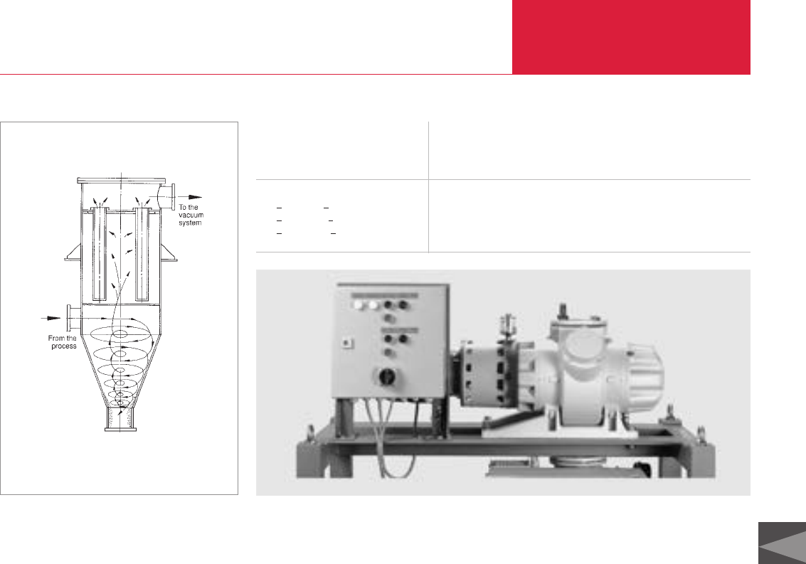
Filtering surface m20.2 0.5 1.0 2.0 3.0 5.0
suitable for pumping speeds
min. m3x h-1 (cfm) 100 (58.9) 300 (176.7) 600 (353.4) 1000 (589) 1 500 (883.5) 3 000 (1767)
max. m3x h-1 (cfm) 300 (176.7) 800 (471.2) 1500 (883.5) 3 000 (1767) 4 000 (2356) 8 000 (4712)
Reduction of pumping speed at
<01 mbar (< 0.75 Torr) % 11 11 11 11 11 11
<06 mbar (< 4.5 Torr) % 9 9 9 9 9 9
< 20 mbar (< 15 Torr) % 5 5 5 5 5 5
without dust load
General
Vacuum Pump Systems
C08.05
LEYBOLD VACUUM PRODUCTS AND REFERENCE BOOK 2003/2004
C08
Electric Control Facilities
In order to drive all electrical appliances within
the pump systems, the pump systems may be
equipped with standard control cabinets which
contain:
♦
Motor protection switch (rated for the pumps
used in each case)
♦
Contactors
♦
Main switch interlocked in accordance with
VDE 0113
♦
Relays for necessary control/sub-systems
♦
ON/OFF push-button for each pump
♦
Power supply for the installed monitoring
facilities
♦
Fault indicators arranged on a lamp panel
♦
Switch-over (through an external contact) from
local to remote operation.
The control cabinet may be fitted either to the
frame of the pump system or it may be wall-
mounted.
Beside the standard systems, we manufacture
control systems for much more complex
systems:
♦
Remote control module as a 19" rack module
(1/4 width, 3 HU). The start/stop push-buttons
and the related indicators for operation and
fault are located on the front panel
♦
Pre- and post-operation control
♦
Pressure dependant control
♦
Time-dependant control
♦
Program control
♦
Control for explosion hazard areas
♦
Combinations of the aforementioned versions
♦
Programmable control (PC)
♦
Vacuum gauge with pressure read-out in the
control cabinet.
Pressure Control
Basically there are several ways in which to con-
trol the pressure.
The equipment which is supplied as standard for
the DOWNSTREAM or BYPASS control systems
selected by LEYBOLD consists of:
♦
Pressure measurement
♦
Controller with control unit
♦
Control valve with position indicator
♦
Engineering.
The Downstream Control System throttles the
pumping speed of the vacuum pump by
changing the conductance of the valve.
The advantages offered by this arrangement are:
♦
No supply of other gases
♦
Closed system
♦
The intake pressure of the pump system is
lower than its operating pressure (thus saving
energy, among other things).
The second method is the Bypass Control
System. Here the pressure is maintained at a
constant level by admitting an additional quantity
of gas.
The advantages offered by this arrangement are:
♦
Simple design
♦
Much smaller valve
♦
No reduction of the intermediate pressure
within the pump.
In order to design a pressure control system we
need the following information:
♦
Amount of gas
♦
Type of gas
♦
Pressure
♦
Length of the piping
♦
Type of auxiliary energy (electric/pneumatic)
♦
Explosion protection required yes/no
Additional complex control arrangements are
available, for example with:
♦
Adjustable pressure characteristic
♦
Adjustable timing
♦
Speed control
♦
Combination with other control facilities.
Control panel on RUTA WAU1001/SV200/G
Diagrammatic section through a dust separator
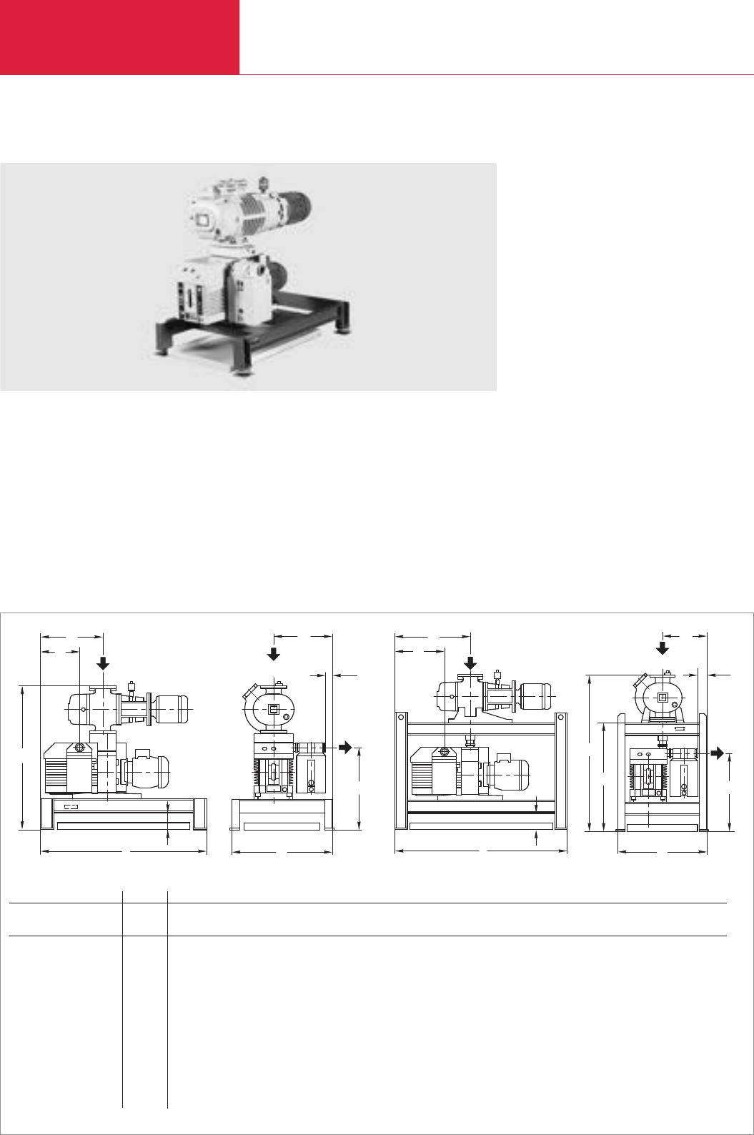
Vacuum Pump Systems
C08.06 LEYBOLD VACUUM PRODUCTS AND REFERENCE BOOK 2003/2004
Three-Stage RUTA Pump Systems with Two-Stage TRIVAC Backing Pumps
Standard Equipment
♦Exhaust filter
♦Oil collecting pan
♦Manually operated gas ballast
♦Crane eyes on the frame
♦Floor mounting
♦CE approval
♦The oil is supplied with the pump
Options
♦Frequency converter for controlling the speed
of the Roots pump
♦Oil filter
♦24 V DC gas ballast valve
♦Sound proofing box
♦Vibration absorbers
♦Castors
♦Different types of floor mounts
♦Oil drain valve on each pump
♦Exhaust filter with oil return line
♦Special motors
♦Electric control systems
h
b
2
l
c
h1
1
ll
DN2
2b1
b
DN1
1
lb
h2
DN2
1
l
h
b
c
1
b
l2
DN1
RUTA 251/D40B/A 251/D65B/A 501/D65B/A 251/D40B/G 251/D65B/G 501/D65B/G 1001/D65B/G
RUVAC WA/WAU/WS/WSU P2 251 251 501 251 251 501 1001
TRIVAC backing pump P1 D 40 B D 65 B D 65 B D 40 B D 65 B D 65 B D 65 B
DN163 ISO-K 63 ISO-K 63 ISO-K 63 ISO-K 63 ISO-K 63 ISO-K 100 ISO-K
DN240 KF 40 KF 40 KF 40 KF 40 KF 40 KF 40 KF
l 1000 (39.37) 1000 (39.37) 1000 (39.37) 1000 (39.37) 1100 (43.31) 1150 (45.28) 1300 (51.18)
l1375 (14.76) 375 (14.76) 375 (14.76) 400 (15.75) 480 (18.90) 480 (18.90) 480 (18.90)
l2234 (9.21) 234 (9.21) 234 (9.21) 234 (9.21) 314 (12.36) 314 (12.36) 314 (12.36)
b 600 (23.62) 600 (23.62) 600 (23.62) 560 (22.05) 560 (22.05) 560 (22.05) 600 (23.62)
b1350 (13.78) 350 (13.78) 350 (13.78) 280 (11.02) 280 (11.02) 280 (11.02) 280 (11.02)
b240 (1.57) 40 (1.57) 40 (1.57) 59 (2.32) 59 (2.32) 59 (2.32) 59 (2.32)
h 854 (33.62) 854 (33.62) 894 (35.20) 977 (38.46) 977 (38.46) 1017 (40.04) 1067 (42.01)
h1488 (19.21) 488 (19.21) 488 (19.21) 488 (19.21) 488 (19.21) 488 (19.21) 488 (19.21)
h2– – – 677 (26.65) 677 (26.65) 677 (26.65) 671 (26.42)
c 100 (3.94) 100 (3.94) 100 (3.94) 100 (3.94) 100 (3.94) 100 (3.94) 100 (3.94)
Dimensional drawing for the pump systems with TRIVAC D40/65 B backing pumps on pallet [left] and in a frame [right]; dimensions in brackets ( ) are in inch
RUTA WAU 501/D65B/A
h
c
1
l
2
l
b
h1
b2
1
b
l
DN1
DN2
1
b
b2
h1
1
l
2
l
l b
h2
h
DN1
DN2
c
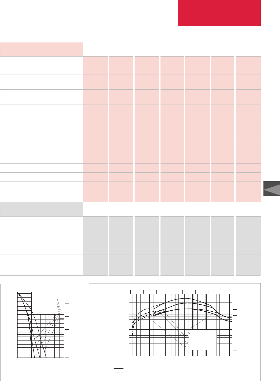
Vacuum Pump Systems
C08.07
LEYBOLD VACUUM PRODUCTS AND REFERENCE BOOK 2003/2004
C08
Technical Data, 50 Hz
Ordering Information
RUVAC (WA/WAU/WS/WSU possible) P2
TRIVAC backing pump P1
Pump system, complete (adaptor version),
pallet mounted,
with RUVAC WAU Roots vacuum pump
Pump system, complete (frame version),
frame mounted,
with RUVAC WAU Roots vacuum pump
WAU 251 WAU 251 WAU 501 WAU 251 WAU 251 WAU 501 WAU 1001
D 40 B D 65 B D 65 B D 40 B D 65 B D 65 B D 65 B
Part No. Part No. Part No. – – – –
023 06 023 07 023 08
– – – Part No. Part No. Part No. Part No.
023 16 023 17 023 18 023 19
RUVAC (WA/WAU/WS/WSU possible) P2
TRIVAC backing pump P1
Pumping speed, 50 Hz
at 10-1 mbar (0.75 x 10⁻¹ Torr) m3x h-1 (cfm)
Ultimate partial pressure mbar
(Torr)
Ultimate total pressure with gas ballast mbar
(Torr)
Installed motor power kW (hp)
Power consumption
at 10-1 mbar (0.75 x 10⁻¹ Torr) kW (hp)
Noise level to DIN 45 635
max. dB(A)
without gas ballast at 1 mbar (0.75 x 1 Torr) dB(A)
Oil filling, total, approx. l (qt)
Weight, total, approx. kg (lbs)
Connecting flanges
Inlet port DN1
Outlet port DN2
251 251 501 251 251 501 1001
D 40 B D 65 B D 65 B D 40 B D 65 B D 65 B D 65 B
200 (117.8) 210 (123.7) 380 (223.8) 185 (109) 205 (120.7) 340 (200.3) 620 (365.2)
< 2 x 10⁻⁵ < 2 x 10⁻⁵ < 2 x 10⁻⁵ < 2 x 10⁻⁵ < 2 x 10⁻⁵ < 2 x 10⁻⁵ < 2 x 10⁻⁵
(< 1.5 x 10⁻⁵) (< 1.5 x 10⁻⁵) (< 1.5 x 10⁻⁵) (< 1.5 x 10⁻⁵) (< 1.5 x 10⁻⁵) (< 1.5 x 10⁻⁵) (< 1.5 x 10⁻⁵)
< 8 x 10⁻⁴ < 8 x 10⁻⁴ < 8 x 10⁻⁴ < 8 x 10⁻⁴ < 8 x 10⁻⁴ < 8 x 10⁻⁴ < 8 x 10⁻⁴
(< 6 x 10⁻⁴) (< 6 x 10⁻⁴) (< 6 x 10⁻⁴) (< 6 x 10⁻⁴) (< 6 x 10⁻⁴) (< 6 x 10⁻⁴) (< 6 x 10⁻⁴)
2.6 (3.5) 3.3 (4.5) 4.4 (6.0) 2.6 (3.5) 3.3 (4.5) 4.4 (6.0) 6.2 (8.4)
2.0 (2.7) 2.5 (3.4) 2.7 (3.7) 2.0 (2.7) 2.5 (3.4) 2.7 (3.7) 3.0 (4.1)
64 65 67 64 65 67 77
62 63 63 62 63 63 70
3.3 (3.49) 4 (4.23) 4.3 (4.55) 3.3 (3.49) 4 (4.23) 4.3 (4.55) 5.3 (5.60)
245 (540.2) 260 (573.3) 305 (627.5) 280 (617.4) 310 (683.6) 350 (771.8) 460 (1014.3)
63 ISO-K 63 ISO-K 63 ISO-K 63 ISO-K 63 ISO-K 63 ISO-K 100 ISO-K
40 KF 40 KF 40 KF 40 KF 40 KF 40 KF 40 KF
0
10-2
103
min
Pressure
mbar
Pump-down time
102 4 6 8
102
101
100
10-1
4
2
6
8
WAU 251 +D40B
WAU 251 +D65B
WAU 501 +D65B
WAU 1001+D65B
10-2
102
101
100
10-1
750
Torr
10-5 103
mbar
Pressure
101
2
4
6
8
100
102
103
m3x h-1
Pumping speed
101
100
10-1
10-2
10-3
10-4
2 4 6 8
WAU 251 +D 40 B
WAU 251 +D 65 B
WAU 501 +D 65 B
WAU 1001+D 65 B
Total pressure
Partial pressure
10-5 Torr
10 1
10 0
10 -1
10 -2
10 -3 10
-4 750
500
5
50
100
10
1
cfm
Pump-down time diagram for a 1000 l tank at 50 Hz Pumping speed diagram at 50 Hz
RUTA WAU
251/D40B/A 251/D65B/A 501/D65B/A 251/D40B/G 251/D65B/G 501/D65B/G 1001/D65B/G
RUTA WAU
15251/D40B/A 251/D65B/A 501/D65B/A 251/D40B/G 251/D65B/G 501/D65B/G 1001/D65B/G
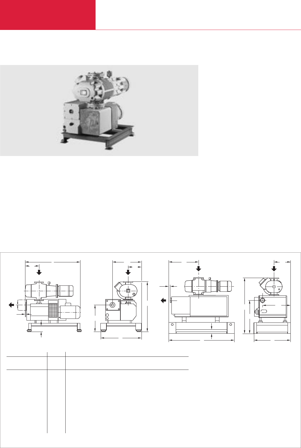
Vacuum Pump Systems
C08.08 LEYBOLD VACUUM PRODUCTS AND REFERENCE BOOK 2003/2004
Two-Stage RUTA Pump Systems with Single-Stage SOGEVAC Backing Pumps, Adaptor Version
Standard Equipment
♦Exhaust filter with oil return line
♦Oil filter
♦Oil collecting pan
♦Manually operated gas ballast
♦Floor mounting
♦CE approval
♦The oil is supplied with the pump
Options
♦Frequency converter for controlling the speed
of the Roots pump
♦24 V DC gas ballast valve
♦Sound proofing box
♦Vibration absorbers
♦Castors
♦Different types of floor mounts
♦Oil drain valve on each pump
♦Special motors
♦Electric control systems
h
b
2
l
c
h1
1
ll
DN2
2b1
b
DN1
1
lb
h2
DN2
1
l
h
b
c
1
b
l2
DN1
Dimensional drawing for the pump systems with SOGEVAC SV 200 and 300 backing pumps [left], SOGEVAC SV 630 [right]; dimensions in brackets ( ) are in inch
RUTA 501/SV 200/A 1001/SV 200/A 1001/SV 300/A 2001/SV 630/A
RUVAC WA/WAU/WS/WSU P2 501 1001 1001 2001
SOGEVAC backing pump P1 SV 200 SV 200 SV 300 SV 630
DN163 ISO-K 100 ISO-K 100 ISO-K 160 ISO-K
DN22" 2" 2" 100 ISO-K
l 962 (37.87) 1050 (41.34) 1082 (42.60) 1800 (70.87)
l1242 (9.53) 303 (11.93) 303 (11.93) 820 (32.28)
l270 (2.76) 77 (3.03) 77 (3.03) 35 (1.38)
b 700 (27.56) 700 (27.56) 700 (27.56) 1000 (39.37)
b1230 (9.06) 230 (9.06) 230 (9.06) 450 (17.72)
b2499 (19.65) 499 (19.65) 499 (19.65) 764 (30.08)
h 873 (34.37) 923 (36.34) 923 (36.34) 1402 (55.20)
h1468 (18.43) 468 (18.43) 468 (18.43) 805 (31.69)
c 100 (3.94) 100 (3.94) 100 (3.94) 100 (3.94)
RUTA WAU1001/SV200/A
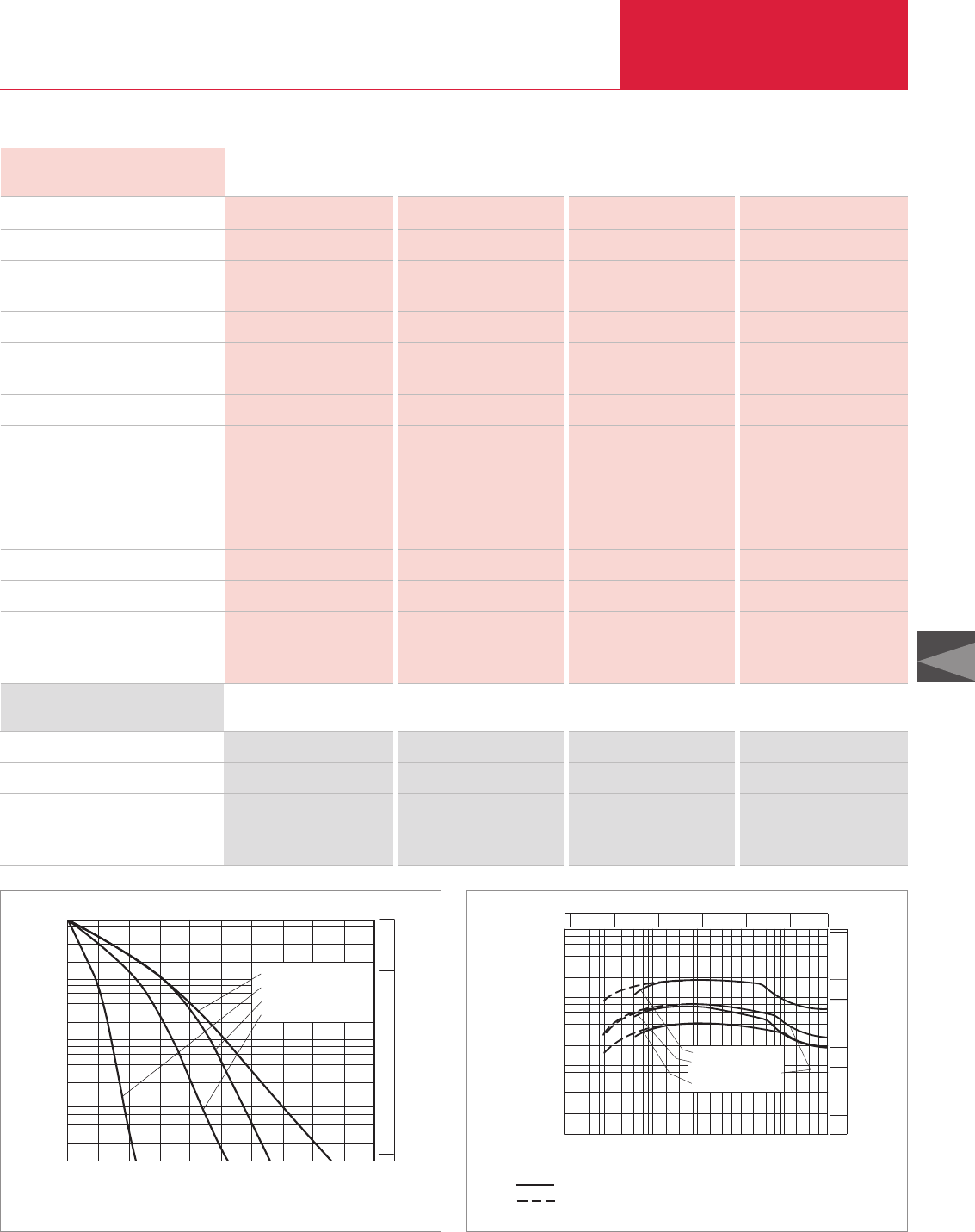
Vacuum Pump Systems
C08.09
LEYBOLD VACUUM PRODUCTS AND REFERENCE BOOK 2003/2004
C08
Technical Data, 50 Hz
RUTA WAU
501/SV200/A 1001/SV200/A 1001/SV300/A 2001/SV630F/A
Ordering Information RUTA WAU
501/SV200/A 1001/SV200/A 1001/SV300/A 2001/SV630F/A
RUVAC (WA/WAU/WS/WSU possible) P2
SOGEVAC backing pump P1
Pump system, complete (adaptor version),
pallet mounted,
with RUVAC WAU Roots vacuum pump
WAU 501 WAU 1001 WAU 1001 WAU 2001
SV 200 SV 200 SV 300 SV 630 F
Part No. 022 06 Part No. 022 08 Part No. 022 09 Part No. 022 11
RUVAC (WA/WAU/WS/WSU possible) P2
SOGEVAC backing pump P1
Pumping speed, 50 Hz
at 10-1 mbar (0.75 x 10⁻¹ Torr)
m
3
x h
-1
(cfm)
Ultimate partial pressure mbar (Torr)
Ultimate total pressure with gas ballast
mbar (Torr)
Installed motor power kW (hp)
Power consumption at
10-1 mbar (0.75 x 10⁻¹ Torr) kW (hp)
Noise level to DIN 45 635
without gas ballast
at 10-1 mbar (0.75 x 10⁻¹ Torr) dB(A)
Oil filling, total, approx. l (qt)
Weight, total approx. kg (lbs)
Connecting flanges
Inlet port DN1
Outlet port DN2
501 1001 1001 2001
SV 200 SV 200 SV 300 SV 630 F
365 (215) 715 (421) 730 (430) 1690 (995.4)
< 8 x 10⁻³ (< 6 x 10⁻³) < 8 x 10⁻³ (< 6 x 10⁻³) < 8 x 10⁻³ (< 6 x 10⁻³) < 8 x 10⁻³ (< 6 x 10⁻³)
< 4 x 10⁻² (< 3 x 10⁻²) < 4 x 10⁻² (< 3 x 10⁻²) < 4 x 10⁻² (< 3 x 10⁻²) < 4 x 10⁻² (< 3 x 10⁻²)
6.2 (8.4) 8 (10.9) 9.5 (12.9) 22.5 (30.6)
3 (4.1) 3.5 (4.8) 4 (5.4) 16.5 (22.4)
70 75 76 80
6 (6.34) 7 (7.4) 11 (11.63) 39 (41.23)
335 (738.7) 430 (948.2) 480 (1058.4) 1 140 (2513.7)
63 ISO-K 100 ISO-K 100 ISO-K 160 ISO-K
2" 2" 2" 100 ISO-K
0
1008
10-1
102
103
min
Pressure
mbar
Pump-down time
6
4
2
101
204 8 12 16
WAU 501 + SV200
WAU 1001 + SV300
WAU 2001 + SV630F
WAU 1001 + SV200
10
10
10
10
750
Torr
0
-1
2
1
10-32 4 68
10-1
10-2 100101102103
102
2
4
6
8
101
103
104
mbar
Pressure
m3h-1
Pumping speed
WAU 1001+SV 300
WAU 501 +SV 200
WAU 1001+SV 200
WAU 2001+SV 630F
x
cfm
10
50
5000
1000
500
100
Torr
1
0
-1
-2
-3
10 10 10 10 10 750
Total pressure
Partial pressure
Pump-down time diagram for a 10 m3tank at 50 Hz Pumping speed diagram at 50 Hz
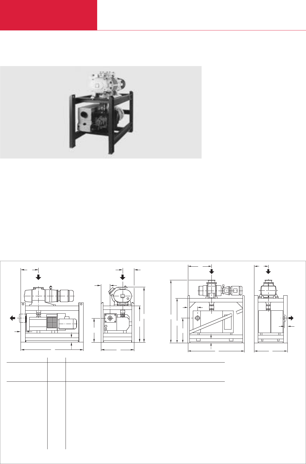
Vacuum Pump Systems
C08.10 LEYBOLD VACUUM PRODUCTS AND REFERENCE BOOK 2003/2004
Two-Stage RUTA Pump Systems with Single-Stage SOGEVAC Backing Pumps, Frame Version
Standard Equipment
♦Exhaust filter with oil return line
♦Oil filter
♦Oil collecting pan
♦Manually operated gas ballast
♦Crane eyes on the frame
♦Floor mounting
♦CE approval
♦The oil is supplied with the pump
Options
♦Frequency converter for controlling the speed
of the Roots pump
♦24 V DC gas ballast valve
♦Sound proofing box
♦Vibration absorbers
♦Castors
♦Different types of floor mounts
♦Oil drain valve on each pump
♦Special motors
♦Electric control systems
h2
h
b
l
b2
2
l
DN1
1
l
DN2
h1
1
b
c
Dimensional drawing for the pump systems with SOGEVAC SV 300 and 630 backing pumps [left], SOGEVAC SV 1200 [right]; dimensions in brackets ( ) are in inch
RUTA 1001/SV300/G 2001/SV300/G 3001/SV630/G 5001/SV630/G 7001/SV1200/G
RUVAC RA P2 – – 3001 5001 7001
RUVAC WA/WAU/WS/WSU P2 1001 2001 – – –
SOGEVAC backing pump P1 SV 300 SV 300 SV 630 SV 630 SV 1200
DN1100 ISO-K 160 ISO-K 250 ISO-K 250 ISO-K 250 ISO-K
DN22" 2" 100 ISO-K 100 ISO-K 160 ISO-K
l 1340 (52.76) 1340 (52.76) 2150 (84.65) 2150 (84.65) 2325 (91.54)
l1380 (14.96) 380 (14.96) 950 (37.40) 950 (37.40) 975 (38.39)
l2110 (4.33) 110 (4.33) 165 (6.5) 165 (6.5) 405 (15.94)
b 710 (27.95) 780 (30.71) 1100 (43.31) 1100 (43.31) 1360 (53.54)
b1250 (9.84) 320 (12.60) 500 (19.69) 500 (19.69) 580 (22.83)
b2191 (7.52) 191 (7.52) 285 (11.22) 285 (11.22) 158 (6.22)
h 1176 (46.30) 1259 (49.57) 1792 (70.55) 1896 (74.65) 2580 (101.58)
h1518 (20.39) 518 (20.39) 745 (29.33) 745 (29.33) 1020 (40.16)
h2780 (30.71) 729 (28.70) 1177 (46.34) 1151 (45.31) 1835 (72.24)
c 100 (3.94) 100 (3.94) 100 (3.94) 100 (3.94) 100 (3.94)
RUTA WAU2001/SV300/G
l
l
b
h
1
h
2
h
2
b
1
l
DN2
2
1
b
DN1
c

Vacuum Pump Systems
C08.11
LEYBOLD VACUUM PRODUCTS AND REFERENCE BOOK 2003/2004
C08
0
10-1
103
min
Pressure
mbar
Pump-down time
4 8 14
RA7001 + SV1200
RA3001 + SV630F
RA5001 + SV630F
WAU2001 + SV300
WAU1001 + SV300
2 6 10
102
101
100
2
4
8
6
10
10
10
10
750
Torr
0
-1
2
1
Technical Data, 50 Hz
RUTA
1001/SV300/G 2001/SV300/G 3001/SV630F/G 5001/SV630F/G 7001/SV1200/G
Ordering Information RUTA
1001/SV300/G 2001/SV300/G 3001/SV630F/G 5001/SV630F/G 7001/SV1200/G
RUVAC P2
RUVAC (WA/WAU/WS/WSU possible) P2
SOGEVAC backing pump P1
Pumping system, complete (frame version)
frame mounted,
with Roots vacuum pump
RUVAC RA
RUVAC WAU
– – RA 3001 RA 5001 RA 7001
WAU 1001 WAU 2001 – – –
SV 300 SV 300 SV 630 F SV 630 F SV 1200
– – Part No. 022 35 Part No. 022 37 Part No. 022 39
Part No. 022 31 Part No. 022 33 – – –
RUVAC RA P2
RUVAC (WA/WAU/WS/WSU possible) P2
SOGEVAC backing pump P1
Pumping speed, 50 Hz
at 10-1 mbar (0.75 x 10⁻¹ Torr)
m
3
x h
-1
(cfm)
Ultimate partial pressure mbar (Torr)
Ultimate total pressure
with gas ballast
mbar (Torr)
Installed motor power kW (hp)
Power consumption
at 10-1 mbar (0.75 x 10⁻¹ Torr) kW (hp)
Noise level to DIN 45 635
without gas ballast
at 10-1 mbar (0.75 x 10⁻¹ Torr) dB(A)
Oil filling, total, approx. l (qt)
Weight, total, approx. kg (lbs)
Connecting flanges
Inlet port DN1
Outlet port DN2
– – 3001 5001 7001
1001 2001 – – –
SV 300 SV 300 SV 630 F SV 630 F SV 1200
730 (430) 1445 (850) 3090 (1818) 4210 (2478) 5520 (3250)
< 8 x 10⁻³ (< 6 x 10⁻³) < 8 x 10⁻³ (< 6 x 10⁻³) < 8 x 10⁻³ (< 6 x 10⁻³) < 8 x 10⁻³ (< 6 x 10⁻³) < 9 x 10⁻³ (< 6.75 x 10⁻³)
< 4 x 10⁻² (< 3 x 10⁻²) < 4 x 10⁻² (< 3 x 10⁻²) < 4 x 10⁻² (< 3 x 10⁻²) < 4 x 10⁻² (< 3 x 10⁻²) < 4 x 10⁻² (< 3 x 10⁻²)
9.5 (12.9) 13 (17.7) 26 (35.4) 30 (40.8) 33.5 (45.6)
4 (5.4) 4.5 (6.1) 17 (23.1) 17.5 (23.8) 18 (24.5)
75 79 82 80 82
11 (11.63) 13 (13.74) 42 (44.4) 47 (49.68) 62 (65.54)
560 (1234.8) 740 (1631.7) 1750 (3858.8) 1900 (4189.5) 3000 (6615)
100 ISO-K 160 ISO-K 250 ISO-K 250 ISO-K 250 ISO-K
2" 2" 100 ISO-K 100 ISO-K 160 ISO-K
Pump-down time diagram for a 10 m3tank at 50 Hz
10-32 4 68
10-1
10-2 100101102103
102
2
4
6
8
101
103
104
mbar
Pressure
m3h-1
Pumping speed
RA 7001 +SV 1200
RA 3001 +SV 630F
RA 5001 +SV 630F
WAU 2001+SV 300
WAU 1001+SV 300
x
cfm
10
50
5000
1000
500
100
Torr
1
0
-1
-2
-3
10 10 10 10 10 750
Total pressure
Partial pressure
Pumping speed diagram at 50 Hz
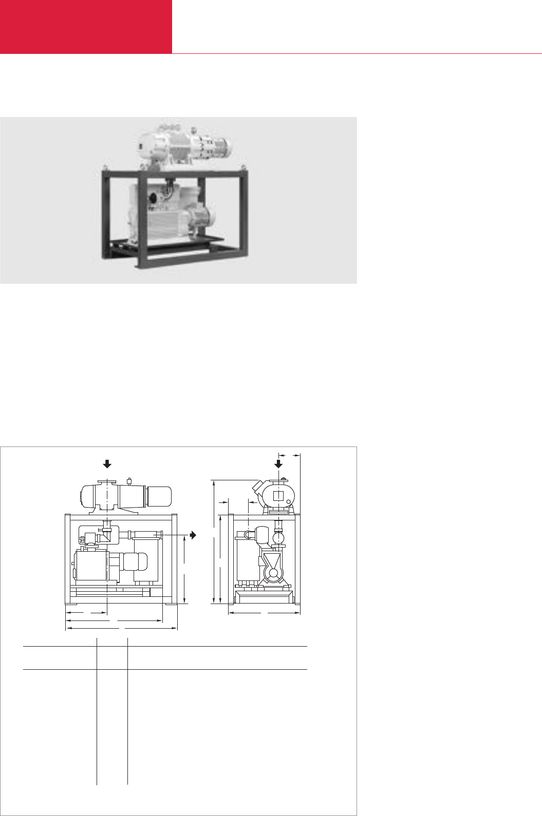
Vacuum Pump Systems
C08.12 LEYBOLD VACUUM PRODUCTS AND REFERENCE BOOK 2003/2004
Two and Three-Stage RUTA Pump Systems with
Single- and Two-Stage Rotary Piston Vacuum Pumps as Backing Pumps
Standard Equipment
♦Exhaust filter attached
♦Oil collecting pan
♦SECUVAC valve 24 V DC
♦Backing pump removable by a fork lifter
♦Crane eyes on the frame
♦Floor mounting
♦CE approval
♦The oil is supplied with the pump
Options
♦Frequency converter for controlling the speed
of the Roots pump
♦Oil filter
♦24 V DC gas ballast valve
♦Sound proofing box
♦Vibration absorbers
♦Different types of floor mount
♦Oil drain valve on each pump
♦Exhaust filter box with oil return
♦Special motors
♦Electric control systems
h
b
h
1
b2
1l2
l
l
h2
DN2
1
b
DN1
Dimensional drawing for the pump systems with E and DK backing pumps; dimensions in brackets ( ) are in inch
RUTA 1001/E250/G 2001/E250/G 1001/DK200/G
RUVAC WA/WAU/WS/WSU P2 1001 2001 1001
Rotary piston vacuum pump P1 E 250* E 250* DK 200*
DN1100 ISO-K 160 ISO-K 100 ISO-K
DN263 ISO-K 63 ISO-K 63 ISO-K
l 1650 (64.96) 1650 (64.96) 1650 (64.96)
l1680 (26.77) 680 (26.77) 680 (26.77)
l21398 (55.04) 1395 (54.92) 1398 (55.04)
b 850 (33.46) 910 (35.83) 850 (33.46)
b1260 (10.24) 335 (13.19) 260 (10.24)
b2238 (9.37) 223 (8.78) 238 (9.37)
h 1523 (59.96) 1705 (67.13) 1523 (59.96)
h1872 (34.33) 894 (35.20) 872 (34.33)
h21127 (44.37) 1175 (46.26) 1127 (44.37)
RUTA WAU 2001/E250/G
* Alternatively with AFK exhaust filter box instead of the exhaust filter; then dimensions l1and b2 will change
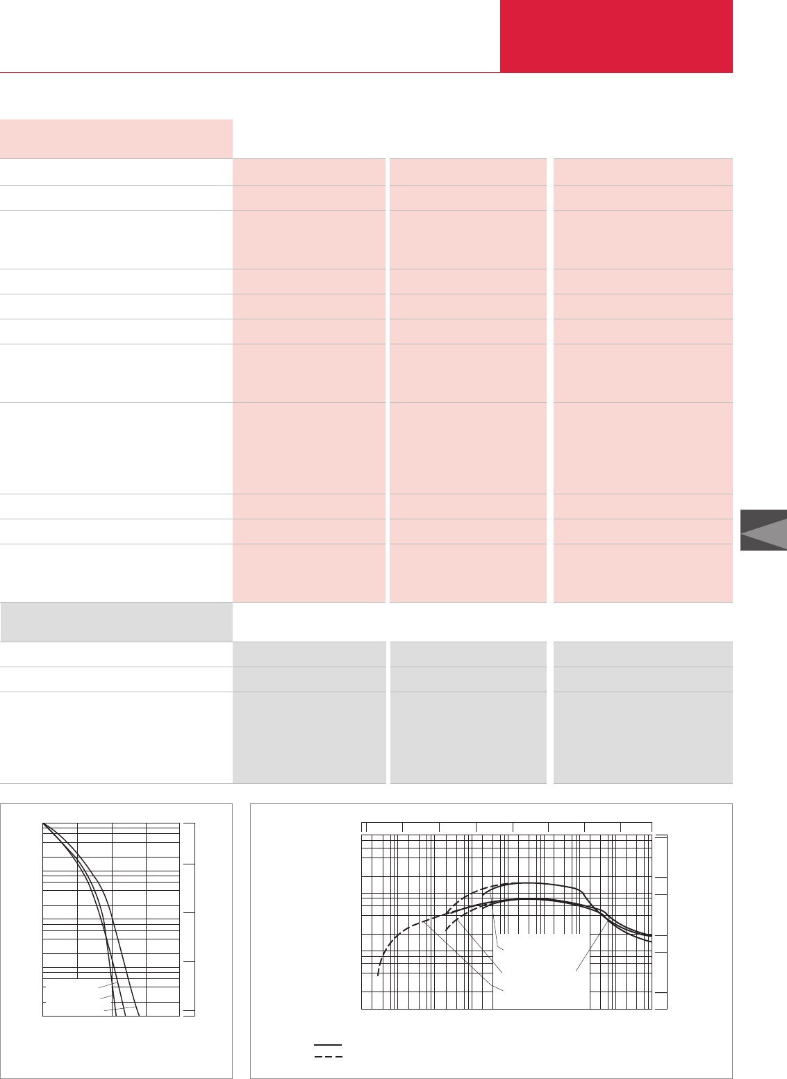
Vacuum Pump Systems
C08.13
LEYBOLD VACUUM PRODUCTS AND REFERENCE BOOK 2003/2004
C08
min
mbar
10-1
100
101
102
103
010 20
2
4
6
8
WAU 1001+E 250
WAU 2001+E 250
WAU 1001+DK 200
Pressure
Pump-down time
102
101
100
10-1
750
Torr
Technical Data, 50 Hz RUTA
WAU RUTA WSU
1001/E250/G 2001/E250/G 1001/DK200/G
Ordering Information RUTA
WAU RUTA WSU
1001/E250/G 2001/E250/G 1001/DK200/G
RUVAC (WA/WAU/WS/WSU possible) P2
Rotary piston vacuum pump P1
Pumping system, complete (frame version)
frame mounted,
with Roots vacuum pumps
RUVAC WAU
RUVAC WSU
WAU 1001 WAU 2001 WSU 1001
E 250 E 250 DK 200
Part No. 023 36 Part No. 023 45 –
– – Part No. 025 36
RUVAC (WA/WAU/WS/WSU possible) P2
Rotary piston vacuum pump P1
Pumping speed, 50 Hz
at 1 mbar (0.75 Torr) m3x h-1 (cfm)
at 10-1 mbar (0.75 x 10⁻¹ Torr) m3x h-1 (cfm)
Ultimate partial pressure mbar (Torr)
Ultimate total pressure with gas ballast mbar (Torr)
Installed motor power kW (hp)
Power consumption
at 1 mbar (0.75 Torr) kW (hp)
at 10-1 mbar (0.75 x 10⁻¹ Torr) kW (hp)
Noise level to DIN 45 635
max. dB(A)
without gas ballast at 1 mbar (0.75 Torr) dB(A)
without gas ballast
at 10-1 mbar (0.75 x 10⁻¹ Torr) dB(A)
Oil filling, total, approx. l (qt)
Weight, total, approx. kg (lbs)
Connecting flanges
Inlet port DN1
Outlet port DN2
1001 2001 1001
E 250 E 250 DK 200
800 (471.2) 1350 (795.2) –
– – 815 (480)
2 x 10⁻³ (1.5 x 10⁻³) 2 x 10⁻³ (1.5 x 10⁻³) 3 x 10⁻⁵ (2.3 x 10⁻⁵)
2 x 10⁻² (1.5 x 10⁻²) 2 x 10⁻² (1.5 x 10⁻²) 3 x 10⁻⁴ (2.3 x 10⁻⁴)
9.5 (12.9) 13 (17.7) 9.5 (12.9)
4.0 (5.4) 4.7 (6.4) –
– – 4.4 (6.0)
80 83 80
75 80 –
– – 75
11 (11.63) 12 (12.68) 6 (6.34)
895 (1973.5) 1080 (2381.4) 930 (2050.7)
100 ISO-K 160 ISO-K 100 ISO-K
63 ISO-K 63 ISO-K 63 ISO-K
10-5 103
mbar
Pressure
102
2
4
6
8
101
103
104
m3x h-1
Pumping speed
101
100
10-1
10-2
10-3
10-4
2 4 6 8
WAU 2001+E 250
WAU 1001+E 250
WSU 1001+DK 200
cfm
10
50
5000
1000
500
100
Total pressure
Partial pressure
10-5 Torr
10 1
10 0
10 -1
10 -2
10 -3 10
-4 750
Pump-down time diagram for a 10 m3tank at 50 Hz Pumping speed diagram at 50 Hz
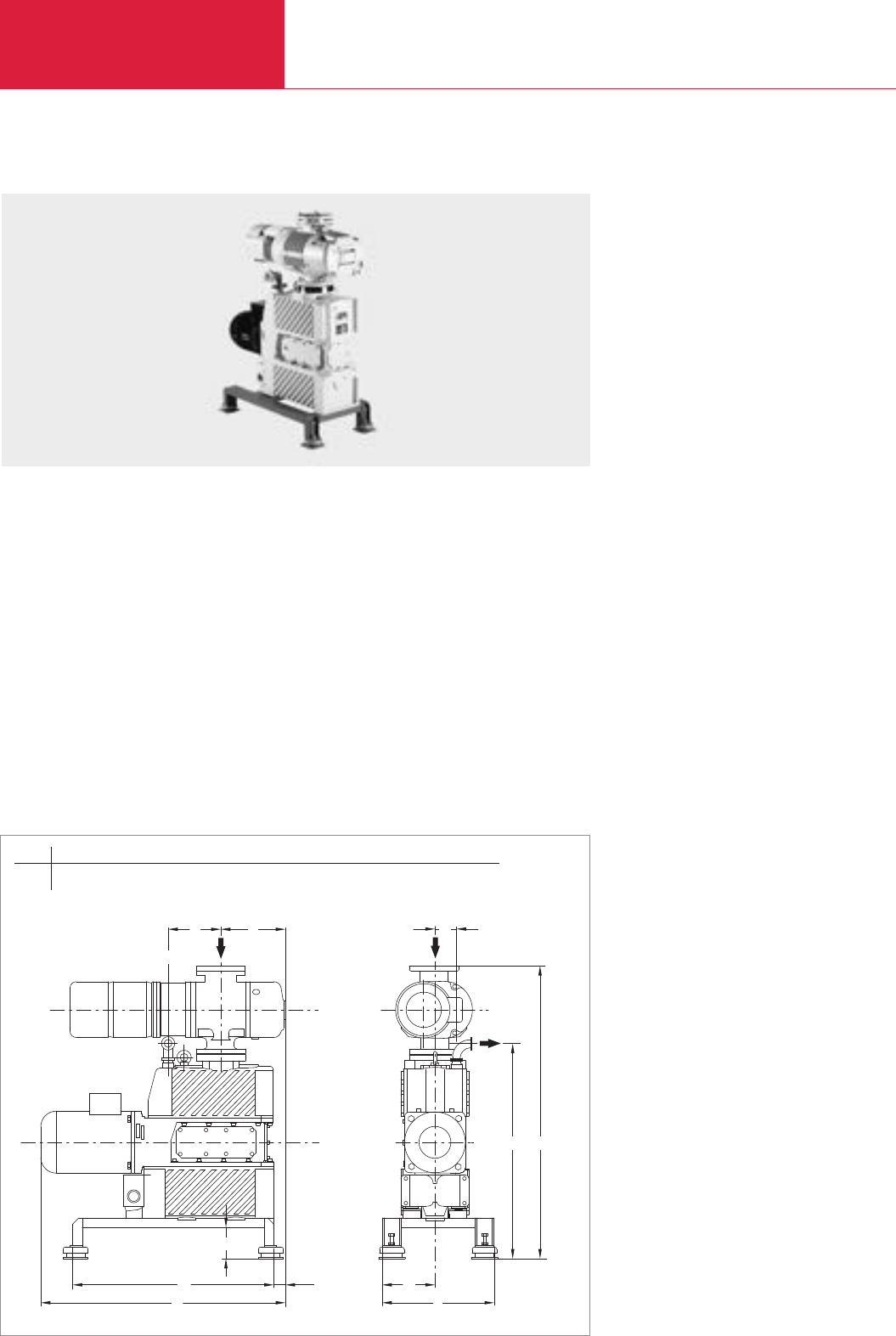
Vacuum Pump Systems
C08.14 LEYBOLD VACUUM PRODUCTS AND REFERENCE BOOK 2003/2004
Dry-Compressing Vacuum Pump System RUTA with EcoDry L Backing Pump
Advantages to the User
♦Maintenance-free, oil-free and
hydrocarbon-free
♦No particle generation
♦Low power consumption
♦Requires no cooling water
♦High pumping speed at low pressure
♦Tolerates liquids, particles and water vapor
♦No grease-lubricated bearing in the vacuum
section
♦Low noise and low vibration
♦Compact size
♦CE approval
Typical Applications
♦Applications in physics
♦Loadlock applications
♦Vacuum locks
♦Lamps manufacture
♦Coating systems
♦Sterilizers
♦Generation of the forevacuum in dry high
vacuum pump systems
DN 63 ISO-K
l1
lb
l3
h2
l2
l4
b1
b2
h
h1
Dimensional drawing for the dry-compressing vacuum pump system RUTA WSU 251/EcoDry L/A
Standard Equipment
♦Pallet with vibration absorbers
♦100 mm (3.94 in.) floor clearance for easy
moving
♦Connection for horizontal exhaust line
♦Roots pump with mineral oil filling (required
oil is supplied with the system upon delivery)
Options
♦Frequency converter for controlling the speed
of the Roots pump
♦EcoDry L with 2.2 kW (3 hp) motor for
sustained operation at high intake pressures
♦Soft start valve on the EcoDry L
♦Gas ballast
♦Different types of floor mount
♦Castors
♦DN 10/16 KF measurement flange between the
pumps
♦PFPE Roots pump model
♦Custom motors (voltage/frequency/protection)
♦Electrical control system
RUTA WSU 251/EcoDry L/A
b b1b2h h1h2l l1l2l3l4
mm 360 170 70 944 696 100 795 650 40 172 210
in. 14.17 6.69 2.76 37.17 27.40 3.94 31.30 25.59 1.57 6.77 8.27
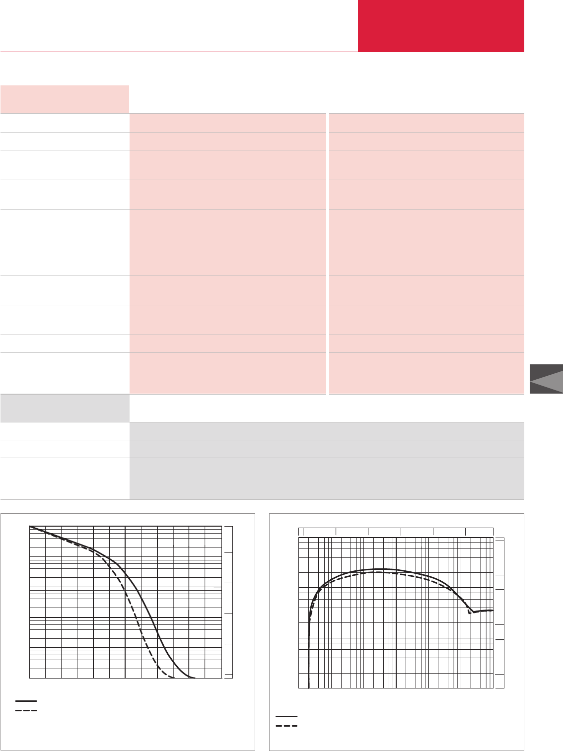
Vacuum Pump Systems
C08.15
LEYBOLD VACUUM PRODUCTS AND REFERENCE BOOK 2003/2004
C08
0 10 20 30 40 50 60
Pressure
mbar
Pump-down time
s
100
101
102
10-1
10-2
Torr
100
101
102
103
10-1
10-2
(50Hz) WSU 251 + ECODRY L
(60Hz) WSU 251 + ECODRY L
103
Technical Data
RUTA WSU 251/EcoDry L/A
50 Hz 60 Hz
Ordering Information
RUVAC (WA/WAU/WS/WSU possible) P2
Backing pump P1
Pumping system, complete (adaptor version),
pallet mounted
400 V / 50 Hz and 460 V / 60 Hz
WSU 251
EcoDry L
Part No. 127 41
RUVAC (WA/WAU/WS/WSU possible) P2
Backing pump P1
Pumping speed
at 10-1 mbar (0.75 x 10⁻¹ Torr)
m
3
x h
-1
(cfm)
Ultimate total pressure without gas ballast
mbar (Torr)
Installed motor power
WSU 251 kW (hp)
EcoDry L
Standard / Option kW (hp)
Total kW (hp)
Power consumption at
10
-1
mbar (0.75 x 10
-1
Torr)
kW (hp)
Noise level to DIN 45 635 without
gas ballast at 1 mbar
(0.75 Torr)
dB(A)
Weight total, approx. kg (lbs)
Connecting flanges
Inlet port DN1
Outlet port DN2
WSU 251 WSU 251
EcoDry L EcoDry L
185 (109) 230 (135.5)
2 x 10⁻³ (1.5 x 10⁻³) 2 x 10⁻³ (1.5 x 10⁻³)
1.1 (1.5) 1.4 (1.9)
1.5 / 2.2 (2.0 / 3.0) 1.8 / 2.6 (2.4 / 3.5)
2.6 / 3.3 (3.5 / 4.5) 3.2 / 4.0 (4.4 / 5.4)
0.9 (1.2) 1.0 (1.4)
67 69
210 (463.1) 210 (463.1)
63 ISO-K 63 ISO-K
25 KF 25 KF
Pump-down time diagram for a 100l tank
RUTA WSU 251/EcoDry L/A
Pressure
mbar
Pumping speed
m h
3 -1
2 4 6 8
x
2
4
6
8
500
5
50
100
10
1
cfm
100
101
102
103
100101102103
10-1
10-2
10-3
Torr
10010110275010-1
10-2
10-3
(50Hz) E D L+WSU 251
CO
CO
RY
(60Hz) E D L+WSU 251
RY
Pumping speed diagram for 50 and 60 Hz
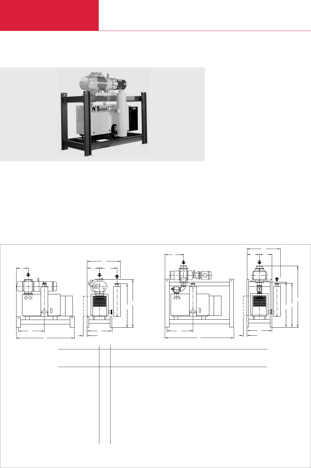
Vacuum Pump Systems
C08.16 LEYBOLD VACUUM PRODUCTS AND REFERENCE BOOK 2003/2004
Dry Compressing RUTA Pump Systems with SCREWLine SP630 Backing Pump
Standard Equipment
♦Silencer
♦SECUVAC valve (not for adapter version)
♦Gear oil collecting pan
♦Crane eyes on the frame
♦Floor mounting
♦Gear oil is supplied with the pump
Options
♦Frequency converter for controlling the speed
of the Roots pump
♦Condensate drain valve at the silencer
♦Sound proofing box
♦Vibration absorbers
♦Castors
♦Different types of floor mounts
♦Gear oil drain valve on each pump
♦Electric control systems
l1
DN2
b
b1
h1
h
b2
DN1
b4*
b3
l2
l
Dimensional drawing of the pump systems with dry compressing S
CREW
Line SP630 backing pump; adapter version (left) frame version (right).; dimensions in brackets ( ) are in inch
RUTA 2001/SP630/A 2001/SP630/G 3001/SP630/G 5001/SP630/G 7001/SP630/G 9001/SP630/G
RUVAC RA P2 – – 3001 5001 7001 9001
RUVAC WA/WAU/WS/WSU P2 2001 2001 – – – –
SCREWLine backing pump P1 SP630 SP630 SP630 SP630 SP630 SP630
DN1160 ISO-K 160 ISO-K 250 ISO-K 250 ISO-K 250 ISO-K 320 ISO-K
DN2100 ISO-K 100 ISO-K 100 ISO-K 100 ISO-K 100 ISO-K 100 ISO-K
l 1850 (72.84) 2200 (86.62) 2200 (86.62) 2400 (94.49) 2400 (94.49) 2400 (94.49)
l1380 (14.96) 600 (23.62) 600 (23.62) 720 (28.35) 720 (28.35) 720 (28.35)
l2892 (35.12) 892 (35.12) 892 (35.12) 1012 (39.84) 1012 (39.84) 1012 (39.84)
b 1064 (41.89) 1064 (41.89) 1064 (41.89) 1129 (44.45) 1129 (44.45) 1129 (44.45)
b1400 (15.75) 400 (15.75) 400 (15.75) 465 (18.31) 465 (18.31) 465 (18.31)
b2554 (21.81) 554 (21.81) 554 (21.81) 554 (21.81) 554 (21.81) 554 (21.81)
b3800 (31.50) 800 (31.50) 800 (31.50) 930 (36.61) 930 (36.61) 930 (36.61)
b470 (2.76) 70 (2.76) 70 (2.76) – – –
h 1518 (59.76) 1789 (70.43) 2030 (79.92) 2220 (87.40) 2220 (87.40) 2300 (90.55)
h11380 (54.33) 1380 (54.33) 1380 (54.33) 1440 (56.69) 1440 (56.69) 1440 (56.69)
h2– 1259 (49.57) 1415 (55.71) 1475 (58.07) 1475 (58.07) 1475 (58.07)
RUTA WAU 2001/SP630/G
DN1
DN2
b
b1
h1
h
b2
l1
l
h2
l2
b4*
b3
* Clearance for maintenance
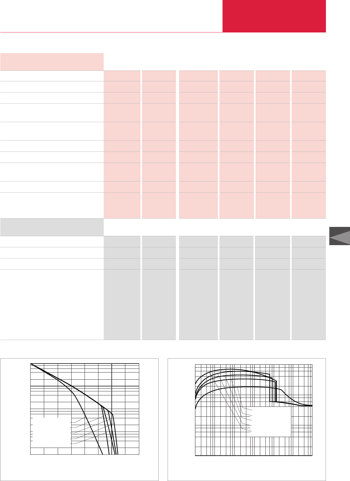
Vacuum Pump Systems
C08.17
LEYBOLD VACUUM PRODUCTS AND REFERENCE BOOK 2003/2004
C08
0
10-1
103
Presure
mbar
4 8
RA9001 + SP630
RA5001 + SP630
RA7001 + SP630
RA3001 + SP630
WAU2001 + SP630
2 6
102
101
100
2
4
8
6
min
Pump-down time
Pump-down time diagram for a 10 m3tank at 50 Hz
10-32 4 68
10-1
10-2 100101102103
102
2
4
6
8
101
103
104
mbar
m.
3h-1
Pumping speed
RA9001 + SP630
RA5001 + SP630
RA7001 + SP630
RA3001 + SP630
WAU2001 + SP630
Pressure
Pumping speed diagram at 50 Hz
Technical Data, 50 Hz RUTA WAU RUTA RA
2001/SP630/A 2001/SP630/G 3001/SP630/G 5001/SP630/G 7001/SP630/G 9001/SP630/G
Ordering Information RUTA WAU RUTA RA
2001/SP630/A 2001/SP630/G 3001/SP630/G 5001/SP630/G 7001/SP630/G 9001/SP630/G
– – RA 3001 RA 5001 RA 7001 RA 9001
WAU 2001 WAU 2001 – – – –
SP630 SP630 SP630 SP630 SP630 SP630
Part No. 500 740 – – – – –
– Part No. 500 741 – – – –
– – Part No. 500 742 Part No. 500 743 Part No. 500 744 Part No. 500 745
RUVAC RA P2
RUVAC (WA/WAU/WS/WSU possible) P2
SCREWLine backing pump P1
Pumping speed, 50 Hz
at 10
-1
mbar
(7.5 x 10⁻² Torr) m3x h-1 (cfm)
Ultimate total pressure without gas ballast mbar
(Torr)
Installed motor power kW (hp)
Electrical power consumption at 10-1 mbar kW (hp)
Noise level in accordance with DIN 45 635
with silencer at 10-1 mbar (7.5 x 10⁻² Torr) dB(A)
Weight, total, approx. kg (lbs)
Connecting flanges
Inlet port DN1
Outlet port DN2
– – 3001 5001 7001 9001
2001 2001 – – – –
SP630 SP630 SP630 SP630 SP630 SP630
1780 (1050) 1780 (1050) 3280 (1930) 4510 (2660) 5940 (3500) 6920 (4070)
< 1 x 10⁻³ < 1 x 10⁻³ < 1 x 10⁻³ < 1 x 10⁻³ < 1 x 10⁻³ < 1 x 10⁻³
(< 7.5 x 10⁻⁴) (< 7.5 x 10⁻⁴) (< 7.5 x 10⁻⁴) (< 7.5 x 10⁻⁴) (< 7.5 x 10⁻⁴) (< 7.5 x 10⁻⁴)
22.5 (30) 22.5 (30) 26 (35) 30 (40) 33.5 (45) 37 (50)
11.7 (15.7) 11.7 (15.7) 12.2 (16.4) 12.6 (16.9) 13.0 (17.4) 13.5 (18.1)
79 79 81 79 82 80
1100 (2430) 1300 (2870) 1550 (3420) 1900 (4190) 2000 (4410) 2630 (5800)
160 ISO-K 160 ISO-K 250 ISO-K 250 ISO-K 250 ISO-K 320 ISO-K
100 ISO-K 100 ISO-K 100 ISO-K 100 ISO-K 100 ISO-K 100 ISO-K
RUVAC P2
RUVAC (WA/WAU/WS/WSU possible P2
SCREWLine backing pump P1
Complete pump system (adapter version)
fitted on to a p a l l e t,
with Roots vacuum pump
RUVAC WAU
Complete pump system (frame version),
mounted in a f r a m e,
with Roots vacuum pump
RUVAC WAU
RUVAC RA
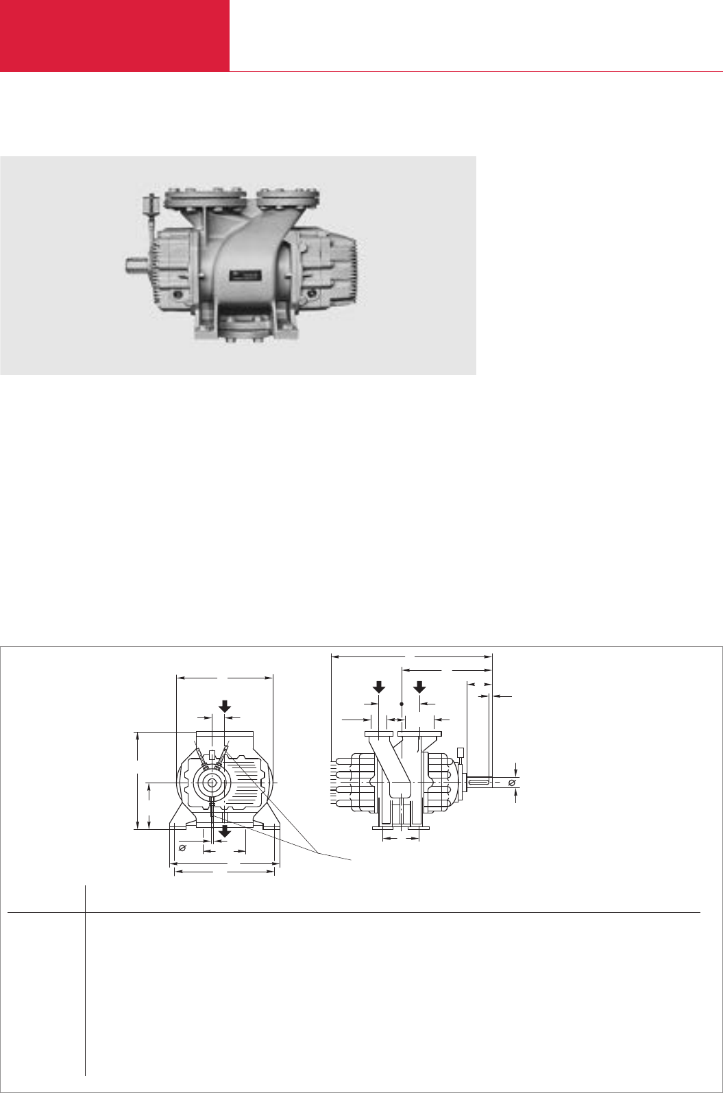
Vacuum Pump Systems
C08.18 LEYBOLD VACUUM PRODUCTS AND REFERENCE BOOK 2003/2004
RUVAC RAV Roots Vacuum Pumps with Pre-Admission Cooling
Advantages to the User
♦RUVAC RAV G:
Operating pressure range of 150 mbar
(112.5 Torr) against atmospheric pressure;
Total leak rate < 10
-1
mbar x l x s
-1
(0.75 x 10⁻² Torr
x l x s
-1
)
♦RUVAC RAV F:
In combination with backing pumps the
attainable operating pressures extend down
into the medium vacuum range; leak rate
< 10
-2
mbar x l x s
-1
(0.75 x 10⁻² Torr
x l x s
-1
)
♦
When series-connected the operating pressures
extend down into the medium vacuum range:
– two-stages to 25 mbar (18.75 Torr)
–
multiple stage to 10-3 mbar (0.75 x 10⁻³ Torr)
♦Motors for special supply voltages and fre-
quencies or protected types are available
♦Pre-admission silencer and filter for the
cooling gas inlet as well as silencers for the
exhaust side (option/single-stage)
♦Downstream gas cooler (option/multistage)
♦C version (chemical version/option)
♦Special materials (option)
♦Pressure burst resistant version (option)
Typical Applications
♦Short pump-down cycles on large volumes
♦Oil-free compression of high volume flows of
gases and vapors against atmospheric pres-
sure
♦Single-stage (G) or in combination with RAV F
as backing pump
♦Operating pressures in the rough vacuum
range
♦CE approval
b
h1
b2
1
h
b
b3
10
Cooling water connection for
RAV 4000 F, RAV 8000 F
DN1
DN
l4
l5
d
l6
l1
l
l3
l2
DN
DN DN1Type F Type G
RUVAC RAV DIN 2533 DIN 2533 l l1l2l3l4l5l6b b1b2b3d d h h1
0250 F/G mm 80 50 529 283 90 100 125 50 5 321 332 34 300 25 k6 28 k6 313 132
in. 80 50 20.83 11.14 3.54 3.94 4.92 1.97 0.20 12.64 13.07 1.34 11.81 0.98 k6 1.10 k6 12.32 5.20
0500 F/G mm 100 50 604 324 120 100 150 70 5 321 390 42.6 350 25 k6 38 k6 370 160
in. 100 50 23.78 12.76 4.72 3.94 5.91 2.76 0.20 12.64 15.35 1.68 13.78 0.98 k6 1.50 k6 14.57 6.30
1000 F/G mm 100 80 705 380 125 115 210 90 5 427 440 53.3 400 42 k6 45 k6 410 180
in. 100 80 27.76 14.96 4.92 4.53 8.27 3.54 0.20 16.81 17.32 2.10 15.75 1.65 k6 1.77 k6 16.14 7.09
2000 F/G mm 150 100 806 423 160 130 270 80 5 476 570 67.6 510 42 k6 55 k6 450 200
in. 150 100 31.73 16.65 6.30 5.12 10.63 3.15 0.20 18.74 22.44 2.66 20.08 1.65 k6 2.17 k6 17.72 7.87
4000 F/G mm 250*)150 1143 610 250 200 410 95 5 682 800 106 720 55 k6 70 m6 680 315
in. 250*)150 45.0 24.02 9.84 7.87 16.14 3.74 0.20 26.85 31.50 4.17 28.35 2.17 k6 2.76 m6 26.77 12.40
8000 F/G mm 300*)200*)1337 717 300 230 525 100 8 954 910 135 830 70 k6 90 m6 760 355
in. 300*)200*)52.64 28.23 11.81 9.06 20.67 3.94 0.31 37.56 35.83 5.31 32.68 2.76 k6 3.54 m6 29.92 13.98
Dimensional drawing for the RUVAC RAV pumps
*)DIN 2532 DN1= Pre-inlet
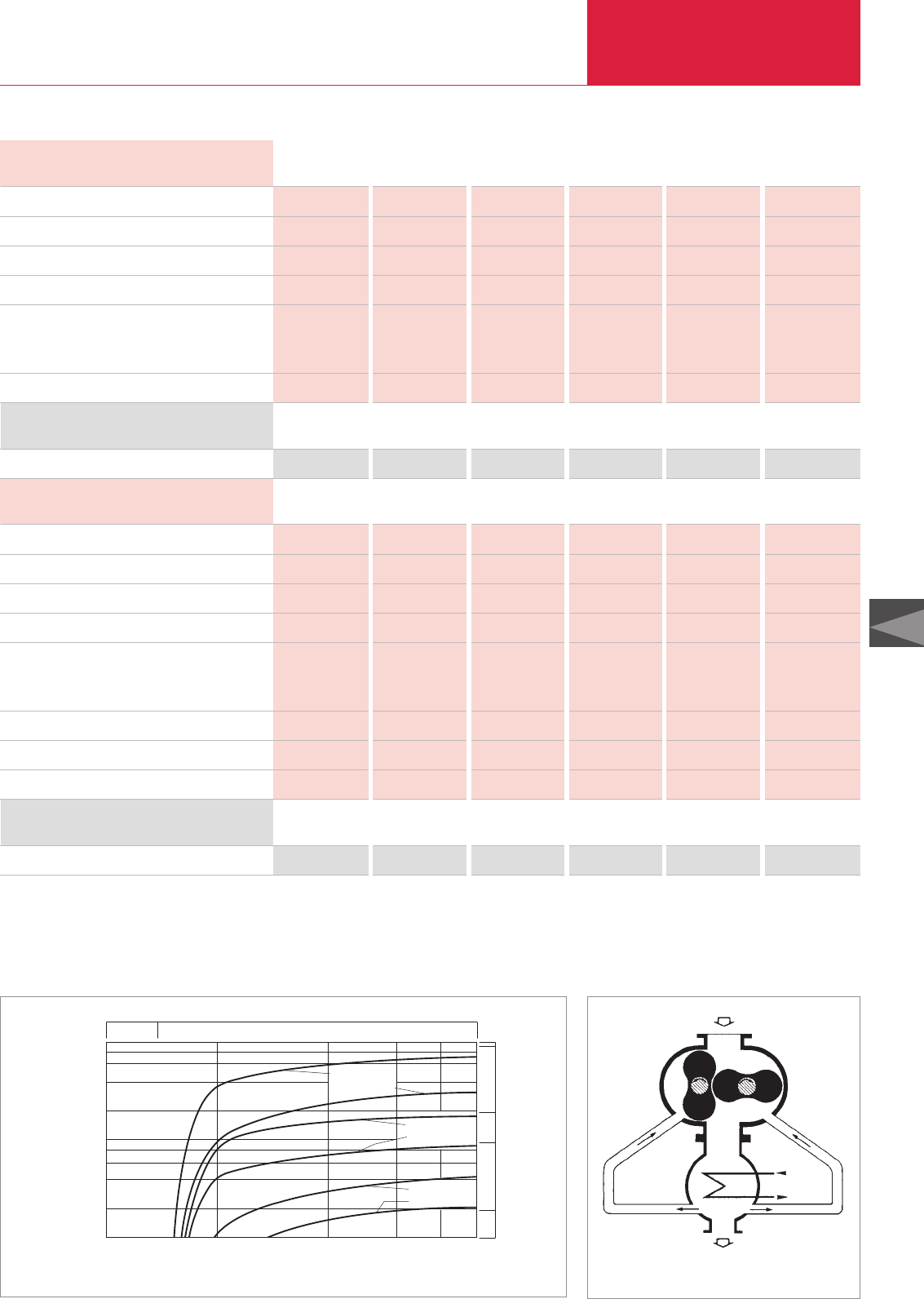
Vacuum Pump Systems
C08.19
LEYBOLD VACUUM PRODUCTS AND REFERENCE BOOK 2003/2004
C08
mbar
m x h -1
4 86 10 3
10
10 3
2
4
6
8
10 2
10 4
Pumping speed
3
Pressure
2
RAV 8000 G
RAV 4000 G
RAV 2000 G
RAV 1000 G
RAV 500 G
RAV 250 G
2
Torr
10 2
500
5000
1000
100
cfm
750
Pumping speed diagram of RUVAC RAV at 50 Hz –
––– Total pressure
Operating diagram of RUVAC RAV vacuum pumps
with pre-admission cooling
Technical Data, 50 Hz RUVAC RAV
250 G 500 G 1000 G 2000 G 4000 G 8000 G
Ordering Information RUVAC RAV
250 G 500 G 1000 G 2000 G 4000 G 8000 G
upon request upon request upon request upon request upon request upon request
Pumping speed 1) m3x h-1 (cfm)
Nominal speed min-1
Max. permissible pressure difference 2) mbar (Torr)
Connecting flange DN
Max. permissible motor power
for direct drive kW (hp)
for belt drive kW (hp)
Weight kg (lbs)
250 (147.3) 500 (294.5) 1 000 (589) 2 000 (1178) 3 700 (2179.3) 8 100 (4770.9)
3000 3 000 3 000 3 000 1 500 1 500
850 (637) 850 (637) 850 (637) 850 (637) 850 (637) 850 (637)
80 100 100 150 250 300
11 (15) 18.5 (25.2) 30 (40.8) 55 (74.8) 95 (129.3) 200 (272.1)
11 (15) 18.5 (25.2) 30 (40.8) 55 (74.8) 95 (129.3) 200 (272.1)
95 (210) 160 (353) 225 (496) 310 (684) 720 (1588) 1230 (2712)
Technical Data, 50 Hz RUVAC RAV
250 F 500 F 1000 F 2000 F 4000 F 8000 F
Ordering Information RUVAC RAV
250 F 500 F 1000 F 2000 F 4000 F 8000 F
RUVAC RAV F Roots vacuum pump
1) To DIN 28 400 and following numbers
2) RUVAC RAV G and RAV F with direct drive
upon request upon request upon request upon request upon request upon request
Pumping speed 1) m3x h-1 (cfm)
Nominal speed min-1
Max. permissible pressure difference 2) mbar (Torr)
Connecting flange DN
Max. permissible motor power
for direct drive kW (hp)
for belt drive kW (hp)
Weight, approx. kg (lbs)
Cooling water connection, fitting for tube
Cooling water requirement, approx. l x h-1
250 (147.3) 500 (294.5) 1 000 (589) 2000(1178) 3 700 (2179.3) 8 100 (4770.9)
3000 3 000 3 000 3 000 1 500 1 500
850 (637) 850 (637) 850 (637) 850 (637) 850 (637) 850 (637)
80 100 100 150 250 300
11 (15) 18.5 (25.2) 30 (40.8) 55 (74.8) 95 (129.3) 200 (272.1)
4 (5.4) 4 (5.4) 7.5 (10.2) 15 (20.4) 37 (50.3) 75 (102.0)
95 (210) 160 (353) 225 (496) 310 (684) 720 (1588) 1230 (2712)
– – – – 10 x 1 10 x 1
– – – – 60 60
RUVAC RAV G Roots vacuum pump
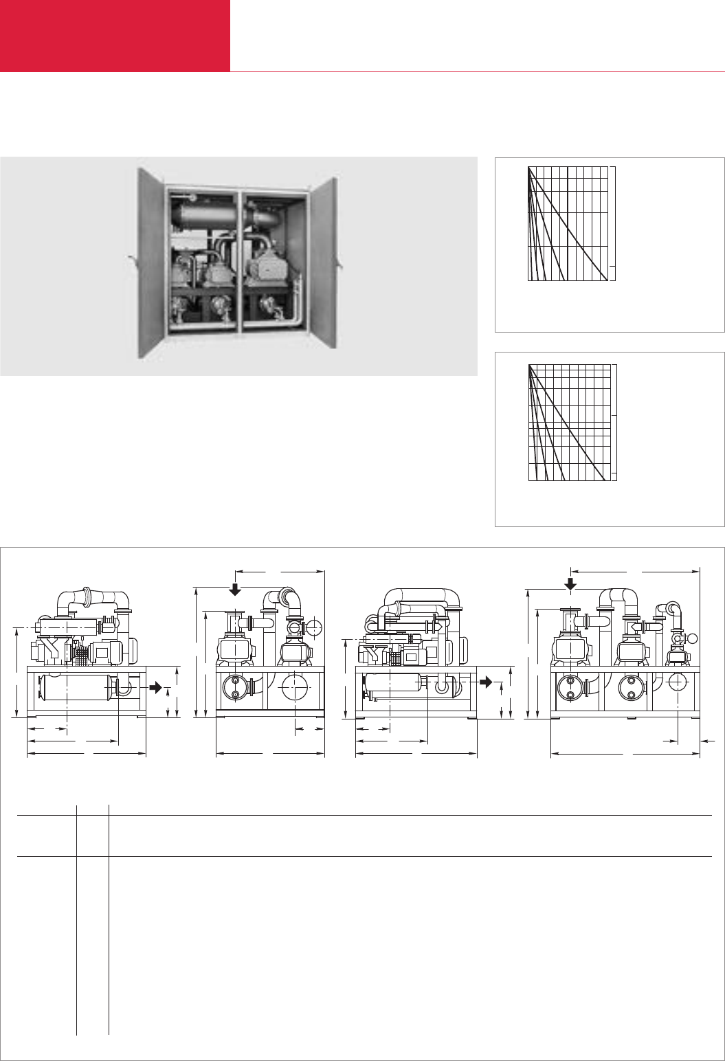
Vacuum Pump Systems
C08.20 LEYBOLD VACUUM PRODUCTS AND REFERENCE BOOK 2003/2004
Two- and Three-Stage RUTA RAV Pump Systems with RUVAC RAV Roots Vacuum Pumps
Standard Equipment
♦Roots vacuum pumps with pre-admission
cooling
♦One or two RAV F pumps are connected
upstream of the RUVAC RAV G pump
operating as a backing pump
♦CE approval
♦Ultimate pressures below 10 mbar (7.5 Torr)
can be attained
♦Gas cooler, pre-admission silencer and filter
♦Non-return flap
♦Exhaust silencer
h
h4
b2
1
b
1
l
2
l
lb
h3
h2
h1
DN2
DN1
h
h4
bb2
1
l
2
l
l
1
b
h3
h2
h1
DN2
DN1
Dimensional drawing for two-stage RUTA RAV pump systems [left] and three-stage RUTA RAV pump systems [right]; dimensions in brackets ( ) are in inch
RUTA 500 F/250 G 1000 F/500 G 2000 F/1000 G 4000 F/2000 G 8000 F/4000 G 1000 F/500 F/250 G 2000 F/1000 F/500 G 4000 F/2000 F/1000 G 8000 F/4000 F/2000 G
RUVAC RAV P3 – – – – – 1000 F 2000 F 4000 F 8000 F
RUVAC RAV P2 500 F 1000 F 2000 F 4000 F 8000 F 500 F 1000 F 2000 F 4000 F
RUVAC RAV P1 250 G 500 G 1000 G 2000 G 4000 G 250 G 500 G 1000 G 2000 G
DN1100 (3.94) 100 (3.94) 150 (5.91) 250 (9.84) 300 (11.81) 100 (3.94) 150 (5.91) 250 (9.84) 300 (11.81)
DN280 (3.15) 100 (3.94) 100 (3.94) 150 (5.91) 250 (9.84) 80 (3.15) 100 (3.94) 100 (3.94) 150 (5.91)
l 1290 (50.79) 1560 (61.42) 1830 (72.03) 2400 (94.49) 2790 (109.84) 1560 (61.42) 1830 (72.05) 2400 (94.49) 2790 (109.84)
l1420 (16.54) 480 (18.90) 570 (22.44) 800 (31.50) 950 (37.40) 480 (18.90) 570 (22.44) 800 (31.50) 950 (37.40)
l21050 (41.34) 1100 (43.31) 1300 (51.18) 1650 (64.96) 2150 (84.65) 1050 (41.34) 1100 (43.31) 1350 (53.15) 1650 (64.96)
b 1300 (51.18) 1500 (59.06) 1680 (66.14) 2050 (80.71) 2600 (102.36) 2170 (85.43) 2400 (94.49) 2850 (112.20) 3400 (133.86)
b11050 (41.34) 1180 (46.46) 1300 (51.18) 1550 (61.02) 2100 (82.68) 1850 (72.83) 2000 (78.74) 2400 (94.49) 2950 (116.14)
b2400 (15.75) 400 (15.75) 450 (17.72) 500 (19.69) 700 (27.56) 400 (15.75) 400 (15.75) 450 (17.72) 500 (19.69)
h 1550 (61.02) 1700 (66.93) 1930 (75.98) 2550 (100.39) 3100 (122.05) 1720 (67.72) 1950 (76.77) 2550 (100.39) 3000 (118.11)
h1720 (28.35) 820 (32.28) 1000 (39.37) 1100 (43.31) 1200 (47.24) 800 (31.5) 1000 (39.37) 1150 (45.28) 1200 (47.24)
h2500 (19.69) 570 (22.44) 750 (29.53) 700 (27.56) 700 (27.56) 600 (23.62) 750 (29.53) 850 (33.46) 850 (33.46)
h31180 (46.46) 1340 (52.76) 1540 (60.63) 1750 (68.90) 2100 (82.68) 1280 (50.39) 1500 (59.06) 1700 (66.93) 1830 (72.05)
h41370 (53.94) 1520 (59.84) 1750 (68.90) 2210 (87.01) 2500 (98.43) 1520 (59.84) 1750 (68.90) 2210 (87.01) 2500 (98.43)
2
6
4
Time
10 200 min
102
103
mbar
Pressure
1 RAV 500 F + RAV 250 G
2 RAV 1000 F + RAV 500 G
3 RAV 2000 F + RAV 1000 G
4 RAV 4000 F + RAV 2000 G
5 RAV 8000 F + RAV 4000 G
1
2
3
4
5
Torr
102
750
4
8
6
2
Pressure
1
mbar
10 200 min
101
Time
102
103
2
3
4
2 RAV 2000 F + RAV 1000 F
+
RAV500G
3 RAV 4000 F + RAV 2000 F
+
RAV 1000 G
4 RAV 8000 F + RAV 4000 F
+
RAV 2000 G
Torr
101
750
102
Pump-down time diagram for a 50 m
3
tank for RAV F, F + G at 50 Hz
1 RAV 1000 F + RAV 500 F +
RAV 250 G
2 RAV 2000 F + RAV 1000 F +
RAV 500 G
3 RAV 4000 F + RAV 2000 F +
RAV 1000 G
4 RAV 8000 F + RAV 4000 F +
RAV 2000 G
1 RAV 500 F + RAV 250 G
2 RAV 1000 F + RAV 500 G
3 RAV 2000 F + RAV 1000 G
4 RAV 4000 F + RAV 2000 G
5 RAV 8000 F + RAV 4000 G
Pump-down time diagram for a 50 m
3
tank for RAV F+G at 50 Hz
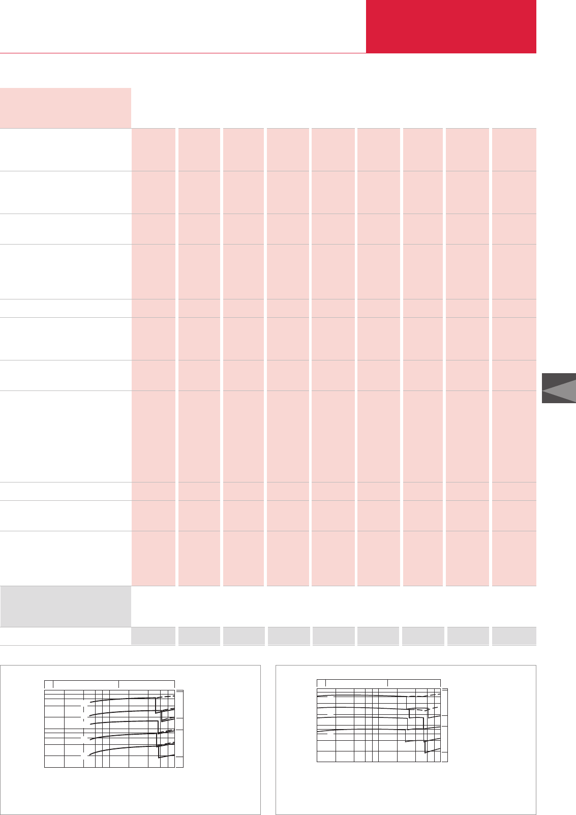
Vacuum Pump Systems
C08.21
LEYBOLD VACUUM PRODUCTS AND REFERENCE BOOK 2003/2004
C08
1 RAV 500 F + RAV 250 G
2 RAV 1000 F + RAV 500 G
3 RAV 2000 F + RAV 1000 G
4 RAV 4000 F + RAV 2000 G
5 RAV 8000 F + RAV 4000 G
5
4
3
Pressure
8
mh
3-1
Pumping speed
103
6
42 103
102
mbar
101
2
4
8
6
104
102
2
1
x
cfm
5000
1000
500
100
Torr
1
10 750
2
10
Technical Data, 50 Hz
Ordering Information
Pump system
*)With exhaust flap and bypass line 1013 mbar (760 Torr) 1) to DIN 25 33
upon request upon request upon request upon request upon request upon request upon request upon request upon request
RUVAC RAV P3
RUVAC RAV P2
RUVAC RAV P1
Pumping speed, 50 Hz
at 200 mbar (150 Torr) m3x h-1 (cfm)
at 100 mbar (75 Torr) m3x h-1 (cfm)
Ultimate total pressure mbar (Torr)
(other motors are required)
Cut-in pressure
P3 *)mbar (Torr)
P2 *)mbar (Torr)
P1 mbar (Torr)
Installed motor power kW (hp)
Power consumption
at 200 mbar (150 Torr) kW (hp)
at 100 mbar (75 Torr) kW (hp)
Cooling water consumption (T< 30°, DT< 10 K),
max. (gas coolers and pumps) m3x h-1 (cfm)
Noise level to DIN 45 635
with pre-inlet and pulsation
silencers and pump exhaust
leading outside dB(A)
plus additional
sound proofing box dB(A)
(a further reduction is possible)
Oil filling, total, approx. l (qt)
Total weight, incl. silencers for pre-
admission and exhaust, approx. kg (lbs)
Connecting flanges (pipe connection) 1)
Inlet port DN1
Outlet port DN2
Gas admission port without filter
DN
– – – – – 1 000 F 2 000 F 4 000 F 8 000 F
500 F 1 000 F 2 000 F 4 000 F 8 000 F 500 F 1 000 F 2 000 F 4 000 F
250 G 500 G 1 000 G 2 000 G 4 000 G 250 G 500 G 1 000 G 2 000 G
322 (189.7) 708 (417) 1 518 (894.1) 2 685 (1581.5) 5 821 (3428.6) – – – –
– – – – – 741 (436.4) 1 573 (926.5) 2862 (1685.7) 6243 (3677.1)
< 50 (< 37.5) < 50 (< 37.5) < 50 (< 37.5) < 50 (< 37.5) < 50 (< 37.5) < 10 (< 7.5) < 10 (< 7.5) < 10 (< 7.5) < 10 (< 7.5)
– – – – – 278 (208.5) 265 (198.8) 312 (234) 289 (216.8)
576 (432) 538 (403.5) 548 (411) 630 (472.5) 502 (376.5) 576 (432) 538 (403.5) 548 (411) 630 (472.5)
1013 (760) 1 013 (760) 1 013 (760) 1013 (760) 1 013 (760) 1013 (760) 1013 (760) 1 013 (760) 1 013 (760)
15 (20.4) 22 (29.9) 44 (59.9) 82 (111.6) 165 (224.5) 22.5 (30.6) 37 (50.3) 62.5 (85.0) 157 (213.6)
7.8 (10.6) 15.8 (21.5) 31.5 (42.9) 56.4 (76.7) 122 (166.0) – – – –
– – – – – 12 (16.3) 24.4 (33.2) 42.3 (57.6) 90.6 (123.3)
0.5 (0.3) 1 (0.6) 2 (1.2) 3 (1.8) 7 (4.1) 1 (0.6) 2 (1.2) 4 (2.4) 8 (4.7)
86 88 93 104 106 88 95 106 108
72 74 80 84 86 75 77 86 88
2 (2.11) 2.5 (2.64) 4 (4.23) 14.5 (15.33) 23 (24.31) 3.5 (3.70) 5 (5.29) 16 (16.91) 25 (26.43)
1000 (2205) 1 600 (3528) 2 200 (4851) 4000 (8820) 7 500 (16538) 2 000 (4410) 3 000 (6615) 5 000 (11025) 8 500 (18743)
100 100 150 250 300 100 150 250 300
80 100 100 150 250 80 100 100 150
50 50 80 100 150 50 50 80 100
Pressure
8
mh
3-1
Pumping speed
2
103
6
4
2103
102mbar
101
4
8
6
104
102
1
2
3
4
1 RAV 1000 F + RAV 500 F +
RAV 250 G
2 RAV 2000 F + RAV 1000 F +
RAV 500 G
3 RAV 4000 F + RAV 2000 F +
RAV 1000 G
4 RAV 8000 F + RAV 4000 F +
RAV 2000 G
x
cfm
5000
1000
500
100
Torr
1
10 750
2
10
Pumping speed diagram of RAV F+G at 50 Hz Pumping speed diagram of RAV F, F + G at 50 Hz
500 F/
250 G 1000 F/
500 G 2000 F/
1000 G 4000 F/
2000 G 8000 F/
4000 G
1000 F/
500 F/
250 G
2000 F/
1000 F/
500 G
4000 F/
2000 F/
1000 G
8000 F/
4000 F/
2000 G
500 F/
250 G 1000 F/
500 G 2000 F/
1000 G 4000 F/
2000 G 8000 F/
4000 G
1000 F/
500 F/
250 G
2000 F/
1000 F/
500 G
4000 F/
2000 F/
1000 G
8000 F/
4000 F/
2000 G
RUTA RAV
RUTA RAV
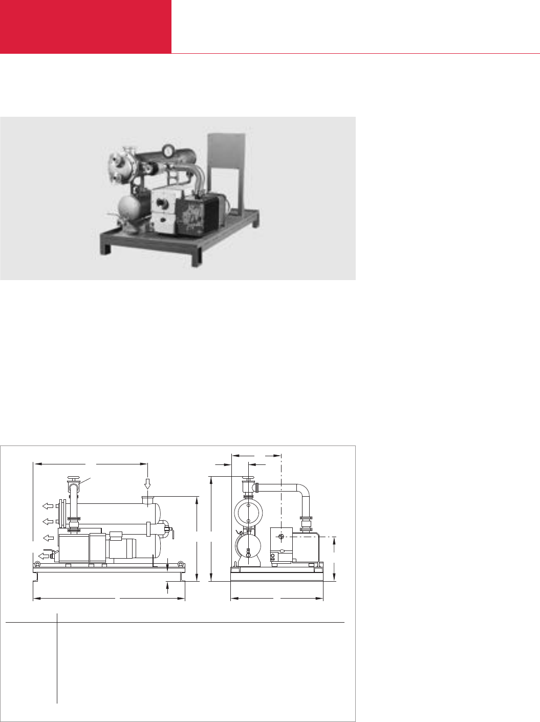
Vacuum Pump Systems
C08.22 LEYBOLD VACUUM PRODUCTS AND REFERENCE BOOK 2003/2004
TVD Pump Systems for Drying, Evaporation and Distillation Applications
Advantages to the User
♦Operating agent may be re-used, for example
by returning cleaned water to the process
♦Reduction of the quantities which need to be
disposed of by 80 %
♦Low temperature distillation/drying
♦Condensate may be drained during vacuum
operation
♦CE approval
Typical Applications
♦Drying of powders and solids, for example
♦Cleaning of waste water
♦Vacuum distillation
Standard Equipment
♦Condenser at the intake side
♦Receiver with condensate level indicator
♦Manually operated valves on the receiver
♦SOGEVAC rotary vane pump with integrated
exhaust filters, anti-suckback valve and gas
ballast valve
Options
♦Valve between condenser and rotary vane
pump
♦Pressure gauge for checking the condensate
pressure
♦Solenoid valves at the receiver
♦Receiver with proximity switch for monitoring
the condensate level
♦Electric control for automatic operation of the
pump system
♦Mobile pallet with castors
♦Cold water replacement for mobile applica-
tions
DN
c
l1
l
b
h
b
Handventil
DN 63 ISO-K DN
h
b
h
1
2
2
1
1
3
DN3
DN2
DN3
Dimensional drawing for the TVD pump systems
TVD 200
DN1DN2DN3l l1b b1b2h h1h2c
TVD 040 mm 63 ISO-K 1 1/4" 1" 1000 590 700 160 445 1000 785 341 100
in. 63 ISO-K 1 1/4" 1" 39.37 23.23 27.56 6.30 17.52 39.37 30.91 13.43 3.94
TVD 065 mm 63 ISO-K 1 1/4" 1" 1280 755 700 160 445 1165 950 341 100
in. 63 ISO-K 1 1/4" 1" 50.39 29.72 27.56 6.30 17.52 45.87 33.46 13.43 3.94
TVD 100 mm 100 ISO-K 2" 1" 1400 755 940 160 561 1165 950 345 100
in. 100 ISO-K 2" 1" 55.12 29.72 37.01 6.30 22.09 45.87 33.46 13.58 3.94
TVD 200 mm 100 ISO-K 2" 1" 1800 765 940 150 501 1175 960 473 100
in. 100 ISO-K 2" 1" 70.87 30.12 37.01 6.30 19.72 46.25 37.80 18.62 3.94
Hand valve

Vacuum Pump Systems
C08.23
LEYBOLD VACUUM PRODUCTS AND REFERENCE BOOK 2003/2004
C08
Ordering Information TVD 40 TVD 65 TVD 100 TVD 200
Pump system
*) Operating at ultimate pressure with gas ballast
Part No. 021 01 Part No. 021 02 Part No. 021 03 Part No. 021 04
Technical Data, 50 Hz SV 40 SV 65 SV 100 SV 200
Weight (with oil filling), approx. kg (lbs)
Oil filling l (qt)
Connecting flanges
Inlet port DN1
Outlet port DN2
125 (276) 150 (331) 200 (441) 300 (662)
2.0 (2.11) 2.0 (2.11) 3.5 (3.70) 5.0 (5.29)
63 ISO-K 63 ISO-K 100 ISO-K 100 ISO-K
1 1/4" 1 1/4" 2" 2"
Technical Data, 50 Hz TVD 40 TVD 65 TVD 100 TVD 200
Condenser, effective surface area, approx. m2
Receiver, usable volume l (qt)
Rotary vane vacuum pump SOGEVAC
Nominal pumping speed m3x h-1 (cfm)
Pumping speed at 50 Hz
for air
m3x h-1 (cfm)
for water vapor at 50 mbar (37.5 Torr)
m3x h-1 (cfm)
Ultimate total pressure
with standard gas ballast mbar (Torr)
Noise level to DIN 45635 *) dB(A)
Condensing capacity for water l x h-1
Installed motor power kW (hp)
1 2 3 5
30 (31.71) 50 (52.85) 50 (52.85) 50 (52.85)
SV 40 SV 65 SV 100 SV 200
46 (27.1) 65 (38.3) 100 (58.9) 180 (106)
46 (27.1) 53 (31.2) 94 (55.4) 170 (100.1)
280 (165) 560 (330) 840 (495) 1400 (825)
< 1.5 (< 1.1) < 1.5 (< 1.1) < 1.5 (< 1.1) < 0.7 (< 0.53)
63 64 70 69
10 20 30 50
1.1 (1.5) 1.5 (2.0) 2.2 (3.0) 4.0 (4.2)
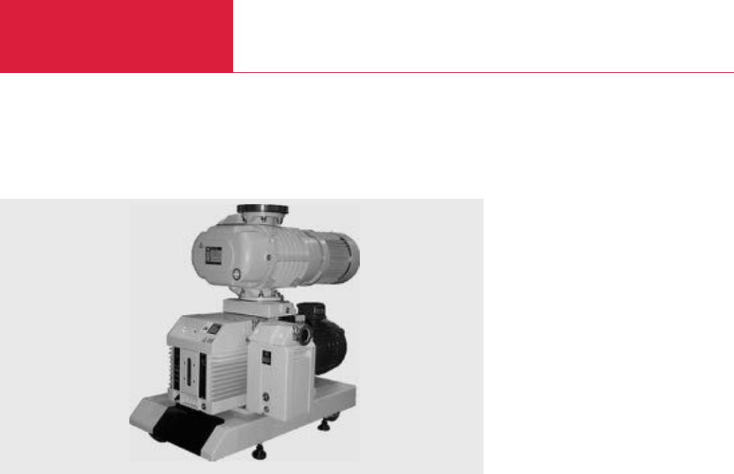
Vacuum Pump Systems
C08.24 LEYBOLD VACUUM PRODUCTS AND REFERENCE BOOK 2003/2004
Version for the North and South American Continents
RBS - B/BCS Roots Pump Systems with Two-Stage TRIVAC Backing Pumps
Options
♦All TRIVAC accessories, Exhaust filter,
24 V DC gas ballast valve, chemical oil filter,
and electrical limit switch system
♦Full frame drip pan
♦Oil drain valves
♦Special motor voltages and frequencies
♦Special oil for unique applications
♦Full NEMA 12 electrical controls for control
start/stop and monitoring of system from
remote and local locations – PSS/LOS/ROS
system
Standard Equipment
♦System consists of TRIVAC dual stage B or
BCS direct drive vane pump and RUVAC
blower
♦Complete air cooled system
♦Frame equipped with caster wheels and
leveling pads
♦Compact construction with quiet operation
♦Available with either 18 inch or 26 inch wide
frame
♦Manual operation of gas ballast
♦
Frame mounted or close-coupled RUVAC blower
RBS - B/BCS Roots Pumping Systems
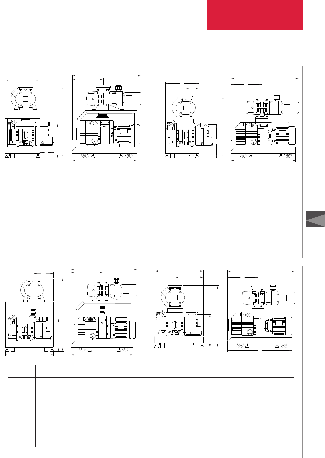
Vacuum Pump Systems
C08.25
LEYBOLD VACUUM PRODUCTS AND REFERENCE BOOK 2003/2004
C08
Version for the North and South American Continents
h
h1
b1
b
System b b1b2h h1l l1l2
Frame Close-coupled
D 40 B/BCS
WA/WAU 251 18 (457) 8 (203) 7 (178) 38 3/16 (967) 33 3/16 (853) 17 15/16 (456) 34 29/32 (887) 14 (356) 34 (864)
WS/WSU 251 18 (457) 8 (203) 7 (178) 38 3/16 (967) 33 3/16 (853) 17 15/16 (456) 32 3/4 (832) 14 (356) 34 (864)
WA/WAU 501 18 (457) 8 (203) 7 (178) 39 5/16 (999) 34 3/4 (883) 17 15/16 (456) 40 13/32 (1026) 14 (356) 34 (864)
WS/WSU 501 18 (457) 8 (203) 7 (178) 39 5/16 (999) 34 3/4 (883) 17 15/16 (456) 33 13/16 (859) 14 (356) 34 (864)
D 65 B/BCS
WA/WAU 251 18 (457) 8 (203) 7 (178) 38 3/16 (967) 33 3/16 (853) 17 15/16 (456) 36 29/32 (937) 16 (406) 34 (864)
WS/WSU 251 18 (457) 8 (203) 7 (178) 38 3/16 (967) 33 3/16 (853) 17 15/16 (456) 34 3/4 (883) 16 (406) 34 (864)
WA/WAU 501 18 (457) 8 (203) 7 (178) 39 5/8 (1007) 34 3/4 (883) 17 15/16 (456) 42 13/32 (1007) 16 (406) 34 (864)
WS/WSU 501 18 (457) 8 (203) 7 (178) 39 5/8 (1007) 34 3/4 (883) 17 15/16 (456) 35 13/16 (910) 16 (406) 34 (864)
Dimensional drawing for the RBS - B/BCS Roots pumping pystems 18“ with TRIVAC D40/65 B backing pumps, frame mounted package [left] and close-coupled package [right]; dimensions in brackets ( ) are in mm
b2
h1
h
b
h
h1
b2
b
System b b1b2h h1l l1l2
Frame Close-coupled Frame Close-coupled Frame Close-coupled
D 40 B/BCS
WA/WAU 251 26 (660) 15 1/2 (394) 10 15/16 (278) 41 3/16 (1046) 33 3/16 (853) 17 15/16 (456) 35 29/32 (912) 34 29/32 (887) 15 (381) 14 (356) 34 (864)
WS/WSU 251 26 (660) 15 1/2 (394) 10 15/16 (278) 41 3/16 (1046) 33 3/16 (853) 17 15/16 (456) 33 3/4 (857) 32 3/4 (832) 15 (381) 14 (356) 34 (864)
WA/WAU 501 26 (660) 15 1/2 (394) 10 15/16 (278) 42 3/4 (1086) 34 3/4 (883) 17 15/16 (456) 41 13/32 (1052) 40 13/32 (1026) 15 (381) 14 (356) 34 (864)
WS/WSU 501 26 (660) 15 1/2 (394) 10 15/16 (278) 42 3/4 (1086) 34 3/4 (883) 17 15/16 (456) 34 13/16 (884) 33 13/16 (859) 15 (381) 14 (356) 34 (864)
D 65 B/BCS
WA/WAU 251 26 (660) 15 1/2 (394) 10 15/16 (278) 41 3/16 (1046) 33 3/16 (853) 17 15/16 (456) 37 29/32 (963) 36 29/32 (937) 17 (432) 16 (406) 34 (864)
WS/WSU 251 26 (660) 15 1/2 (394) 10 15/16 (278) 41 3/16 (1046) 33 3/16 (853) 17 15/16 (456) 35 3/4 (908) 34 3/4 (883) 17 (432) 16 (406) 34 (864)
WA/WAU 501 26 (660) 15 1/2 (394) 10 15/16 (278) 42 3/4 (1086) 34 3/4 (883) 17 15/16 (456) 43 13/32 (1103) 42 13/32 (1077) 17 (432) 16 (406) 34 (864)
WS/WSU 501 26 (660) 15 1/2 (394) 10 15/16 (278) 42 3/4 (1086) 34 3/4 (883) 17 15/16 (456) 36 13/16 (935) 35 13/16 (910) 17 (432) 16 (406) 34 (864)
WA/WAU 1001 26 (660) 15 1/2 (394) 10 15/16 (278) 44 31/32 (1142) – 17 15/16 (456) 48 7/8 (1241) – 17 (432) – 34 (864)
WS/WSU 1001 26 (660) 15 1/2 (394) 10 15/16 (278) 44 31/32 (1142) – 17 15/16 (456) 39 29/32 (1014) – 17 (432) – 34 (864)
Dimensional drawing for the RBS - B/BCS Roots Pumping Systems 26“ with TRIVAC D40/65 B backing pumps, frame mounted package [left] and close-coupled package [right]; dimensions in brackets ( ) are in mm
b1
h1
h
b
l
l1
l2
l1
l2
l
l1
l2
l
l
l1
l2
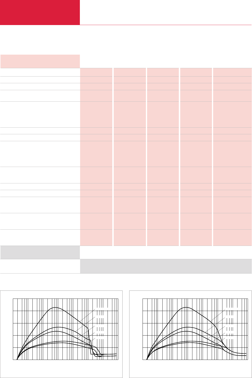
Vacuum Pump Systems
C08.26 LEYBOLD VACUUM PRODUCTS AND REFERENCE BOOK 2003/2004
Version for the North and South American Continents
Technical Data
RUVAC (WA/WAU/WS/WSU possible)
TRIVAC backing pump
Pumping speed @ 0.1 Torr cfm (m3x h-1)
Ultimate total pressure Torr
(mbar)
Connecting flanges
Inlet port
WA/WAU
WS/WSU
Outlet port
Operating voltage
Phase / Frequency 1) Hz
Full load amps 2)
RUVAC
WA/WAU
WS/WSU
TRIVAC
Displacement
RUVAC cfm
TRIVAC cfm
Maximum differential pressure Torr
Normal starting pressure 3) Torr
Oil capacity
RUVAC WA/WAU/WS/WSU qt
TRIVAC qt
Nominal rotation speed
RUVAC rpm
TRIVAC rpm
Motor power
RUVAC WA/WAU/WS/WSU hp
TRIVAC hp
251 251 501 501 1001
D 40 B/BCS D 65 B/BCS D 40 B/BCS D 65 B/BCS D 65 B/BCS
140 (1237) 150 (1254) 232 (394) 267 (453) 427 (725)
2 x 10⁻⁴ 2 x 10⁻⁴ 2 x 10⁻⁴ 2 x 10⁻⁴ 2 x 10⁻⁴
(< 4 x 10⁻⁴) (< 4 x 10⁻⁴) (< 4 x 10⁻⁴) (< 4 x 10⁻⁴) (< 4 x 10⁻⁴)
3" ANSI 3" ANSI 3" ANSI 3" ANSI 4" ANSI
63 ISO-K 63 ISO-K 63 ISO-K 63 ISO-K 100 ISO-K
40 KF 40 KF 40 KF 40 KF 40 KF
208/230/460 208/230/460 208/230/460 208/230/460 208/230/460
3 / 60 3 / 60 3 / 60 3 / 60 3 / 60
4.6/4.2/2.1 4.6/4.2/2.1 9.4/8.2/4.1 9.4/8.2/4.1 15.2/13.2/6.1
5.5/5.5/3.2 5.5/5.5/3.2 9.0/9.0/5.2 9.0/9.0/5.2 15.7/15.7/9.1
9.0/8.8/4.5 9.0/8.8/4.5 9.0/8.8/4.5 9.0/8.8/4.5 9.0/8.8/4.5
179 179 357 357 707
32 53 32 53 53
60 60 60 60 60
20 30 12 16 8
1.49 /0.75 1.49 /0.75 1.40 /1.10 1.40 /1.10 4.00 /2.10
2.70 3.40 2.70 3.40 3.40
3600 3600 3600 3600 3600
1800 1800 1800 1800 1800
1.5 /1.7 1.5 /1.7 3.0 /3.4 3.0 /3.4 5.0 /6.1
3.0 3.0 3.0 3.0 3.0
0
cfm
10-3 10-2
10-4 101
100
10-1 102
Torr 103
500
200
400
100
2 4 6 8
Total Pressure
Pumping Speed
300
1001/D65B
501/D65B
251/D40B
251/D65B
501/D40B
Pumping speed diagram for the RBS systems with WAU/WSU series Roots blowers at 60 Hz
RBS - B/BCS Roots Pump Systems
251/D40B 251/D65B 501/D40B 501/D65B 1001/D65B
RBS - B/BCS Roots pump system
(supplied with hydrocarbon oil)
1) For 50 Hz systems, consult the factory 2) Determined by operating voltage 3) WAU/WSU pumps start at atmospheric pressure (760 Torr)
For more detailed gauge specifications see Product Section C16 “Total Pressure Gauges”
See Price List for the “North American Continent” for Ordering Information
Ordering Information RBS - B/BCS Roots Pump Systems
1001/D65B
501/D65B
251/D40B
251/D65B
501/D40B
0
cfm
10-3 10-2
10-4 101
100
10-1 102
Torr 103
500
200
400
100
2 4 6 8
Total Pressure
Pumping Speed
300
Pumping speed diagram for the RBS systems with WA/WS series Roots blowers at 60 Hz

Vacuum Pump Systems
C08.27
LEYBOLD VACUUM PRODUCTS AND REFERENCE BOOK 2003/2004
C08
Notes
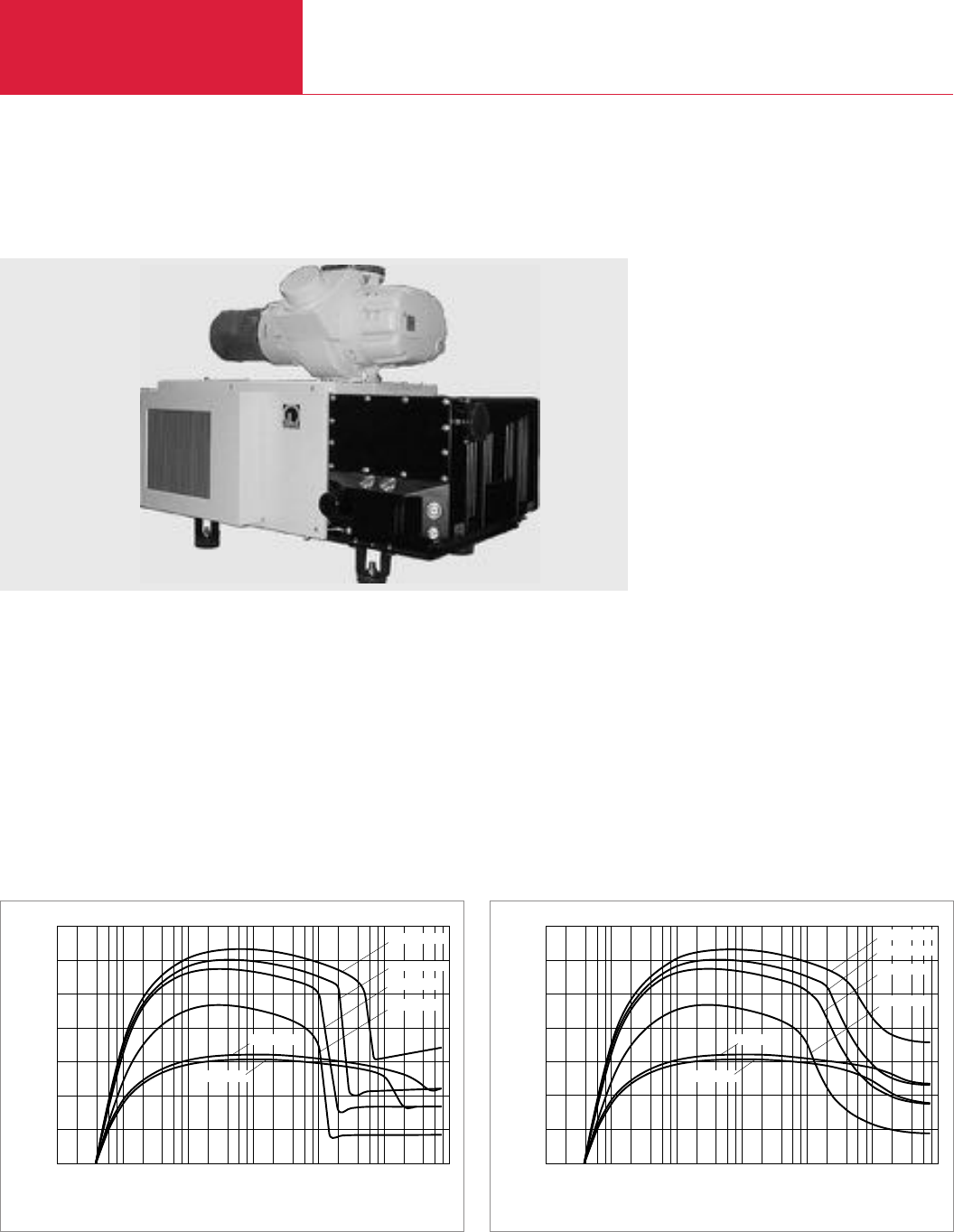
Vacuum Pump Systems
C08.28 LEYBOLD VACUUM PRODUCTS AND REFERENCE BOOK 2003/2004
Version for the North and South American Continents
HTS Close-Coupled Systems with Single-Stage SOGEVAC Backing Pumps
Standard Equipment
♦System consists of single stage SOGEVAC
vane pump
♦Complete air cooled system
♦Frame mounted or close-coupled RUVAC
blower
♦Compact construction with quiet operation
♦Manual operation of gas ballast
♦Spin-on type oil filter
Options
♦SOGEVAC accessories: oil level monitoring,
exhaust case gauge, 24 V DC gas ballast
purge, water-cooling
♦Full frame drip pan for frame mounted
systems
♦Frame mounted caster wheels
♦Frame mounted leveling pads
♦Oil drain valves
♦Special motor voltages and frequencies
♦Special oil for unique applications
♦Full NEMA12 electrical controls for stand/stop
operation and monitoring of system from
remote and local locations
♦24 V DC gas ballast valve
HTS close coupled System
2001/SV630
2001/SV1200
2001/SV300
1001/SV630
1001/SV500
2001/SV500
10-2
10-3 101
100
10-1 102
Torr 103
2 4 6 8
Total Pressure
0
cfm
1400
600
1000
200
400
Pumping Speed
800
Pumping speed diagram for the HTS close-coupled systems with WAU/WSU series Roots blowers at 60 Hz
2001/SV630
2001/SV1200
2001/SV300
1001/SV630
1001/SV500
2001/SV500
10-2
10-3 101
100
10-1 102
Torr 103
2 4 6 8
Total Pressure
0
cfm
1400
600
1000
200
400
Pumping Speed
800
Pumping speed diagram for the HTS close-coupled systems with WA/WS series Roots blowers at 60 Hz
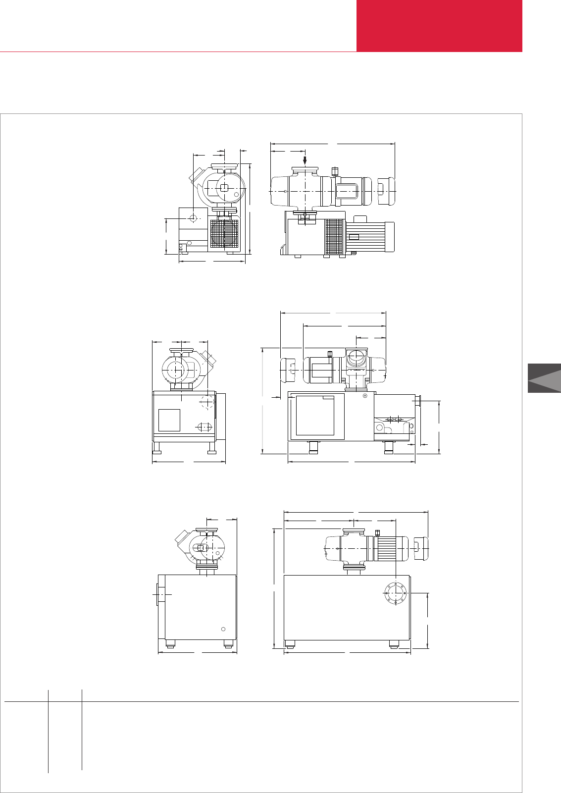
Vacuum Pump Systems
C08.29
LEYBOLD VACUUM PRODUCTS AND REFERENCE BOOK 2003/2004
C08
Version for the North and South American Continents
l1
RIGHT SIDE VIEW FRONT VIEW
w3
h1
w2
l2
08.03.M.019-E (WAU/WSU+SV)
h2
w1
Dimensional drawing for the HTS close-coupled system with single-stage SOGEVAC backing pumps; dimensions in brackets ( ) are in mm
Roots Pump Vane Pump h1h2l1l2l3l4l5l6w1w2w3
WAU/WSU 501 SV 200 29 7/16 (748) 12 17/32 (318) 40 7/32 (1029) 9 17/32 (242) – – – – 21 11/16 (551) 6 1/8 (156) 10 19/32 (269)
WAU/WSU 501 SV 300 29 7/16 (748) 12 17/32 (318) 43 7/8 (1114) 9 17/32 (242) – – – – 21 11/16 (551) 6 1/8 (156) 10 19/32 (269)
WAU/WSU 1001 SV 200 31 7/16 (799) 12 17/32 (318) 42 25/32 (1087) 11 15/16 (303) – – – – 21 1/16 (535) 5 1/2 (140) 10 19/32 (269)
WAU/WSU 1001 SV 300 31 7/16 (799) 12 17/32 (318) 45 7/16 (1154) 11 15/16 (303) – – – – 22 13/16 (579) 7 1/4 (184) 10 19/32 (269)
WAU/WSU 2001 SV 500 48 5/16 (1227) 23 13/16 (605) 50 3/16 (1275) 39 9/16 (1005) 14 9/16 (370) 3 5/16 (84) 60 3/4 (1543) 2 1/2 (64) 34 15/16 (887) 13 7/8 (352) 12 13/32 (315)
WAU/WSU 2001 SV 630 48 5/16 (1227) 23 13/16 (605) 50 3/16 (1275) 39 9/16 (1005) 14 9/16 (370) 3 5/16 (84) 60 3/4 (1543) 2 1/2 (64) 34 15/16 (887) 13 7/8 (352) 12 13/32 (315)
WAU/WSU 2001 SV 1200 61 9/16 (1564) 27 9/16 (700) 73 5/32 (1858) 21 1/4 (540) 36 1/32 (915) – 64 9/16 (1640) – 39 9/16 (1005) 15 5/32 (385) –
W1
W2W3
Dimensions for SV 200 and SV 300 only
Dimensions for SV 500 and 630 only
Dimensions for SV 1200 only
h2
l6
l4
l5
h1
l3
l2
l1
l1
l3l2
l5
h2
h1
l1
l2
w2
w1

Vacuum Pump Systems
C08.30 LEYBOLD VACUUM PRODUCTS AND REFERENCE BOOK 2003/2004
Version for the North and South American Continents
Technical Data HTS Close-Coupled Systems
501/SV200 501/SV300 1001/SV200 1001/SV300 2001/SV500 2001/SV630 2001/SV1200
RUVAC (WA/WAU/WS/WSU possible)
SOGEVAC
Pumping speed @ 0.1 Torr cfm (m3x h-1)
Ultimate total pressure Torr
(mbar)
Connecting flanges
Inlet port
WA/WAU
WS/WSU
Outlet port
Operating voltage
Phase / Frequency 1) – / Hz
Full load amps 2)
RUVAC
WA/WAU
WS/WSU
SOGEVAC
Displacement
RUVAC cfm
SOGEVAC cfm
Oil capacity
RUVAC
WA/WAU qt
WS/WSU qt
SOGEVAC qt
Nominal rotation speed
RUVAC WAU/WSU rpm
SOGEVAC rpm
Motor power
RUVAC WAU/WSU hp
SOGEVAC hp
501 501 1001 1001 2001 2001 2001
SV 200 SV 300 SV 200 SV 300 SV 500 SV 630 SV 1200
277 (470) 285 (483) 504 (855) 545 (925) 1123 (1906) 1186 (2031) 1250 (2122)
< 8 x 10⁻³ < 8 x 10⁻³ < 8 x 10⁻³ < 8 x 10⁻³ < 8 x 10⁻³ < 8 x 10⁻³ < 8 x 10⁻³
(< 1 x 10⁻²) (< 1 x 10⁻²) (< 1 x 10⁻²) (< 1 x 10⁻²) (< 1 x 10⁻²) (< 1 x 10⁻²) (< 1 x 10⁻²)
3" ANSI 3" ANSI 4" ANSI 4" ANSI 6" ANSI 6" ANSI 6" ANSI
63 ISO-K 63 ISO-K 100 ISO-K 100 ISO-K 160 ISO-K 160 ISO-K 160 ISO-K
2" NPT 2" NPT 2" NPT 2" NPT 4" ANSI 4" ANSI 6" ANSI
208/230/460 208/230/460 208/230/460 208/230/460 208/230/460 208/230/460 208/230/460
3 / 60 3 / 60 3 / 60 3 / 60 3 / 60 3 / 60 3 / 60
9.4/8.2/4.1 9.4/8.2/4.1 15.2/13.2/6.1 15.2/13.2/6.1 28.0/24.8/12.4 28.0/24.8/12.4 28.0/24.8/12.4
7.8/10.0/5.8 7.8/10.0/5.8 13.0/14.7/8.5 13.0/14.7/8.5 21.0/26.0/15.0 21.0/26.0/15.0 21.0/26.0/15.0
21.0/18.0/9.0 29.0/25.0/12.5 21.0/18.0/9.0 29.0/25.0/12.5 41.1/35.7/17.9 65.0/58.0/29.5 78.0/70.0/35.0
357 357 707 707 1449 1449 1449
130 200 130 200 335 495 677
1.40 1.40 4.00 4.00 6.10 6.10 6.10
1.10 1.10 2.10 2.10 4.20 4.20 4.20
5.30 9.00 5.30 9.00 37.00 37.00 42.00
3600 3600 3600 3600 3600 3600 3600
1800 1800 1800 1800 880 1170 700
3.0 /3.4 3.0 /3.4 5.0 /6.1 5.0 /6.1 5.0 /6.1 10.0 /11.4 10.0 /11.4
7.5 10.0 7.5 10.0 15.0 25.0 30.0
HTS - close-coupled systems
1) For 50 Hz systems, consult the factory
2) Determined by operating voltage
See Price List for the “North American Continent” for Ordering Information
Ordering Information HTS Close-Coupled Systems

Vacuum Pump Systems
C08.31
LEYBOLD VACUUM PRODUCTS AND REFERENCE BOOK 2003/2004
C08
Notes
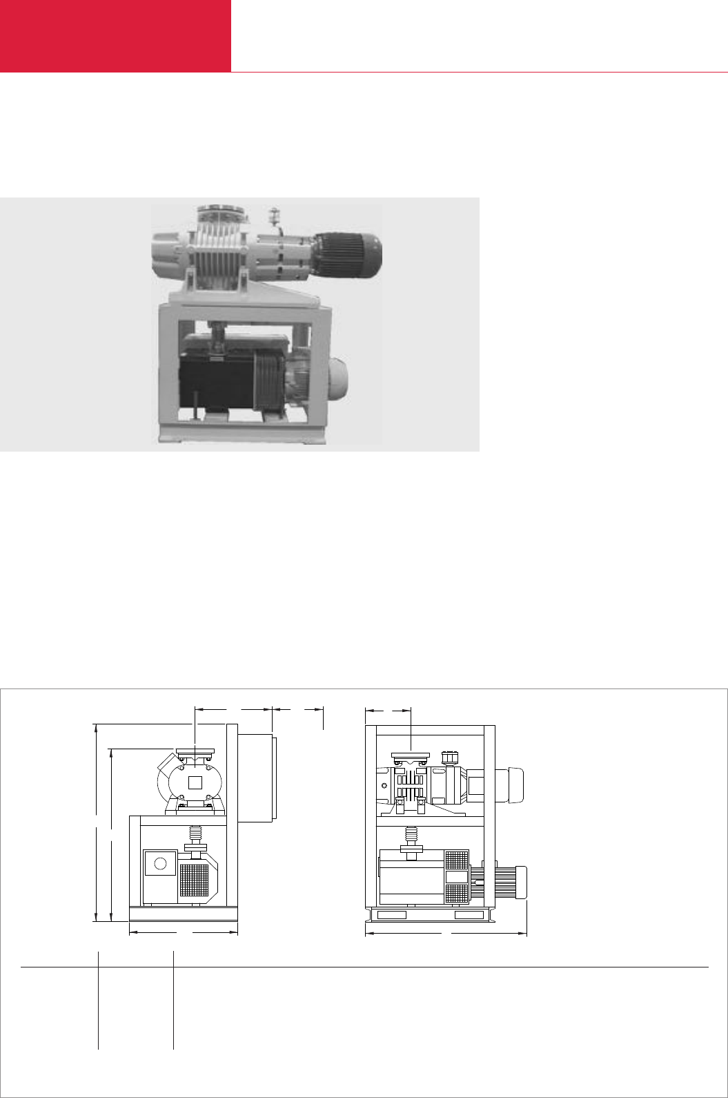
Vacuum Pump Systems
C08.32 LEYBOLD VACUUM PRODUCTS AND REFERENCE BOOK 2003/2004
Version for the North and South American Continents
HTS Frame Mounted Systems with Single-Stage SOGEVAC Backing Pumps
Standard Equipment
♦System consists of single stage SOGEVAC
direct drive vane pump
♦Complete air cooled system
♦Frame mounted RUVAC blower
♦Compact construction with quiet operation
♦Manual operation of Gas Ballast
♦Spin-on type oil filter
Options
♦SOGEVAC accessories: oil level monitoring,
exhaust case gauge, 24 V DC gas ballast
purge, supplemental water-cooling.
♦Full frame drip pan for frame mounted
systems
♦Frame mounted caster wheels
♦Frame mounted leveling pads
♦Oil drain valves
♦Special motor voltages and frequencies
♦Special oil for unique applications
♦Full NEMA12 electrical controls for stand/stop
operation and monitoring of system from
remote and local locations
Dimensional drawing for the HTS frame mounted system with single-stage SOGEVAC backing pumps; dimensions in brackets ( ) are in mm
Roots Pump Vane Pump h1h2l1l2w1w2w3
WAU/WSU 251 SV 100 58 1/2 (1486) 41 1/2 (1054) 10 11/16 (272) 34 3/4 (883) 23 (584) 30 (762) 24 (610)
WAU/WSU 501 SV 100 58 1/2 (1486) 43 (1092) 10 11/16 (272) 34 3/4 (883) 23 (584) 30 (762) 24 (610)
WAU/WSU 501 SV 200 58 1/2 (1486) 43 (1092) 10 11/16 (272) 40 5/8 (1032) 23 (584) 30 (762) 24 (610)
WAU/WSU 501 SV 300 58 1/2 (1486) 43 (1092) 10 11/16 (272) 44 1/8 (1121) 23 (584) 30 (762) 24 (610)
WAU/WSU 1001 SV 300 58 1/2 (1486) 45 1/2 (1156) 11 15/16 (278) 44 1/8 (1121) 23 (584) 32 (813) 24 (610)
WAU/WSU 2001 SV 300 58 1/2 (1486) 50 3/4 (1290) 14 11/16 (373) 53(1346) 23 (584) 32 (813) 24 (610)
HTS frame mounted System
h2
h1
w2
w1w3
clearance
required for
electrical box
l1
l2
Note: Dimension h for systems supplied with electrical controls
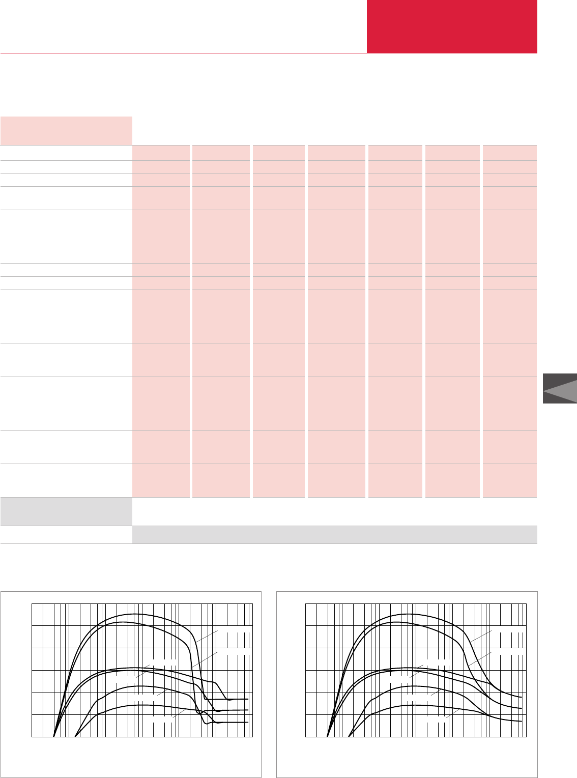
Vacuum Pump Systems
C08.33
LEYBOLD VACUUM PRODUCTS AND REFERENCE BOOK 2003/2004
C08
Version for the North and South American Continents
Technical Data HTS Frame Mounted Systems
251/SV100 501/SV100 501/SV200 501/SV300 1001/SV300 1001/SV500 2001/SV300
RUVAC (WA/WAU/WS/WSU possible)
SOGEVAC
Pumping speed @ 0.1 Torr cfm (m3x h-1)
Ultimate total pressure Torr
(mbar)
Connecting flanges
Inlet port
WA/WAU
WS/WSU
Outlet port
Operating voltage
Phase / Frequency 1) – / Hz
Full load amps 2)
RUVAC
WA/WAU
WS/WSU
SOGEVAC
Displacement
RUVAC cfm
SOGEVAC cfm
Oil capacity
RUVAC
WA/WAU qt
WS/WSU qt
SOGEVAC qt
Nominal rotation speed
RUVAC WAU/WSU rpm
SOGEVAC rpm
Motor power
RUVAC WAU/WSU hp
SOGEVAC hp
251 501 501 501 1001 1001 2001
SV 100 SV 100 SV 200 SV 300 SV 300 SV 500 SV 300
138 (234) 232 (393) 277 (470) 285 (483) 545 (925) 614 (1042) 912 (1548)
2 x 10⁻² 2 x 10⁻² < 8 x 10⁻³ < 8 x 10⁻³ < 8 x 10⁻³ < 8 x 10⁻³ < 8 x 10⁻³
(3 x 10⁻²) (3 x 10⁻²) (< 1 x 10⁻²) (< 1 x 10⁻²) (< 1 x 10⁻²) (< 1 x 10⁻²) (< 1 x 10⁻²)
3" ANSI 3" ANSI 3" ANSI 3" ANSI 4" ANSI 4" ANSI 6" ANSI
63 ISO-K 63 ISO-K 63 ISO-K 63 ISO-K 100 ISO-K 100 ISO-K 160 ISO-K
2" NPT 2" NPT 2" NPT 2" NPT 2" NPT 4" ANSI 2" NPT
208/230/460 208/230/460 208/230/460 208/230/460 208/230/460 208/230/460 208/230/460
3 / 60 3 / 60 3 / 60 3 / 60 3 / 60 3 / 60 3 / 60
4.6/4.2/4.1 9.4/8.2/4.1 9.4/8.2/4.1 9.4/8.2/4.1 15.2/13.2/6.1 15.2/13.2/6.1 28.0/24.8/12.4
4.8/5.5/3.2 7.8/10.0/5.8 7.8/10.0/5.8 7.8/10.0/5.8 13.0/14.7/8.5 13.0/14.7/8.5 21.0/26.0/15.0
14.2/13.0/6.5 14.2/13.0/6.5 21.0/18.0/9.0 29.0/25.0/12.5 29.0/25.0/12.5 41.1/35.7/17.9 29.0/25.0/12.5
179 357 357 357 707 707 1449
71 71 130 200 200 335 200
1.50 1.40 1.40 1.40 4.00 4.00 6.10
0.80 1.10 1.10 1.10 2.10 2.10 4.20
3.70 3.70 5.30 9.00 9.00 37.00 9.00
3600 3600 3600 3600 3600 3600 3600
1800 1800 1800 1800 1800 880 1800
1.5 /1.7 3.0 /3.4 3.0 /3.4 3.0 /3.4 5.0 /6.1 5.0 /6.1 10.0 /11.4
5.0 5.0 7.5 10.0 10.0 15.0 10.0
HTS - frame mounted systems
1) For 50 Hz systems, consult the factory
2) Determined by operating voltage
See Price List for the “North American Continent” for Ordering Information
Ordering Information HTS Frame Mounted Systems
501/SV100
251/SV100
501/SV300
501/SV200
10-2
10-3 101
100
10-1 102
Torr 103
2 4 6 8
Total Pressure
0
cfm
600
300
500
100
200
Pumping Speed
400 1001/SV200
1001/SV300
Pumping speed diagram for the HTS frame mounted systems
with WAU/WSU series Roots blowers at 60 Hz
1001/SV200
1001/SV300
501/SV100
251/SV100
501/SV300
501/SV200
10-2
10-3 101
100
10-1 102
Torr 103
2 4 6 8
Total Pressure
0
cfm
600
300
500
100
200
Pumping Speed
400
Pumping speed diagram for the HTS frame mounted systems
with WA/WS series Roots blowers at 60 Hz
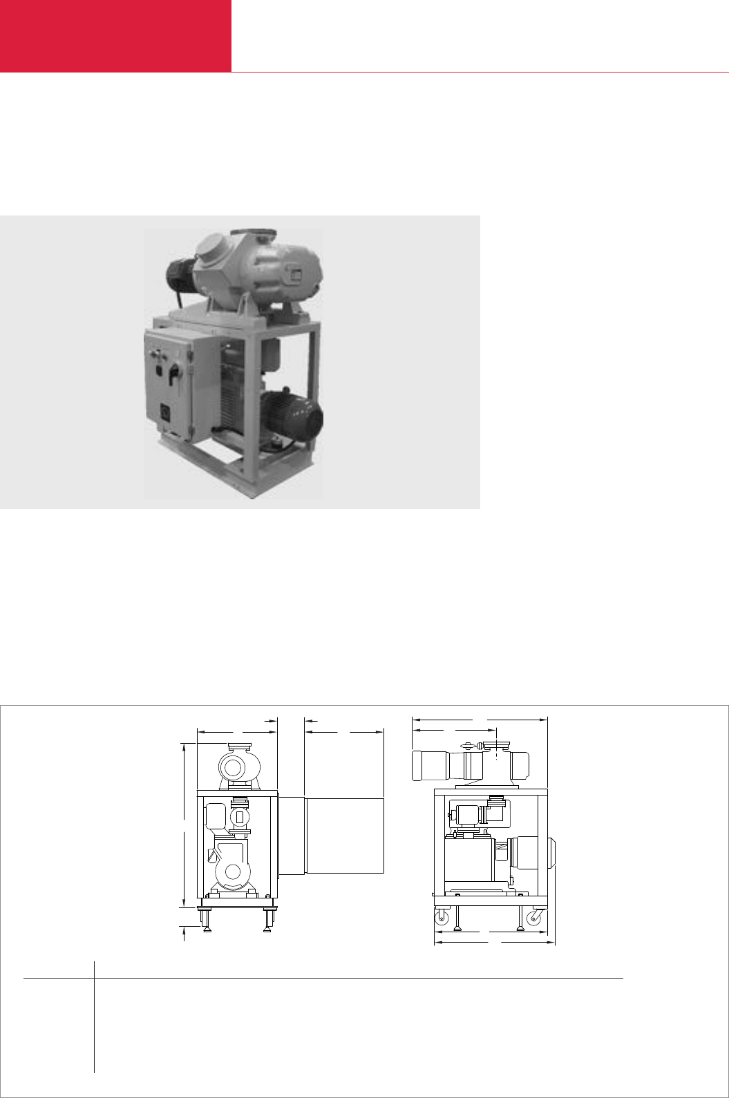
Vacuum Pump Systems
C08.34 LEYBOLD VACUUM PRODUCTS AND REFERENCE BOOK 2003/2004
Version for the North and South American Continents
l3
l1
l2
l
b2
b1
b
h
h1
Dimensional drawing for the RM - Roots / mechanical pump system; dimensions in brackets ( ) are in mm
System b b1b2h h1l l1l2l3
1001/E250/DK200
WA/WAU 1001 24 (609.6) 9 1/16 (230.5) 24 (609.6) 55 13/16 (1418) 6 1/2 (165) 37 (940) 30 1/16 (764) 48 3/8 (1229) 42 11/16 (1084)
WS/WSU 1001 24 (609.6) 9 1/16 (230.5) 24 (609.6) 55 13/16 (1418) 6 1/2 (165) 37 (940) 20 9/16 (522) 48 3/8 (1229) –
2001/E250/DK200
WA/WAU 2001 24 (609.6) 9 1/16 (230.5) 24 (609.6) 60 3/8 (1534) 6 1/2 (165) 40 (1016) 37 1/32 (941) 48 5/16 (1227) 47 19/32 (1209)
WS/WSU 2001 24 (609.6) 9 1/16 (230.5) 24 (609.6) 60 3/8 (1534) 6 1/2 (165) 40 (1016) 26 7/32 (674) 48 5/16 (1227) –
RM - Roots / Mechanical Pump Systems
with Single- and Two-Stage Rotary Piston Vacuum Pumps as Backing Pumps
Standard Equipment
♦System consist of Single stage or Dual stage
rotary piston pump
♦Proven rugged Piston pump design
♦Air cooled pumps
♦Mechanical pump mounted on vibration
absorbers
Options
♦Piston pump oil regulator
♦Remote gear drive oil filtration system -
OF1000/3000
♦Full frame drip pan
♦Oil drain valve
♦Frame caster wheels
♦Frame leveling pads
♦Special motor voltages and frequencies
♦Special oil for unique applications
♦Full NEMA12 electrical controls for control
start/stop of system from remote and local
locations
♦SECUVAC, Foreline
♦Frame mounted pumps
♦Interconnecting bellows and spool adapter
♦Manual operation of Gas Ballast
♦Vertical or horizontal mounting of RUVAC
blower
RM - Roots / Mechanical Pump System
l3
l1
l2
l
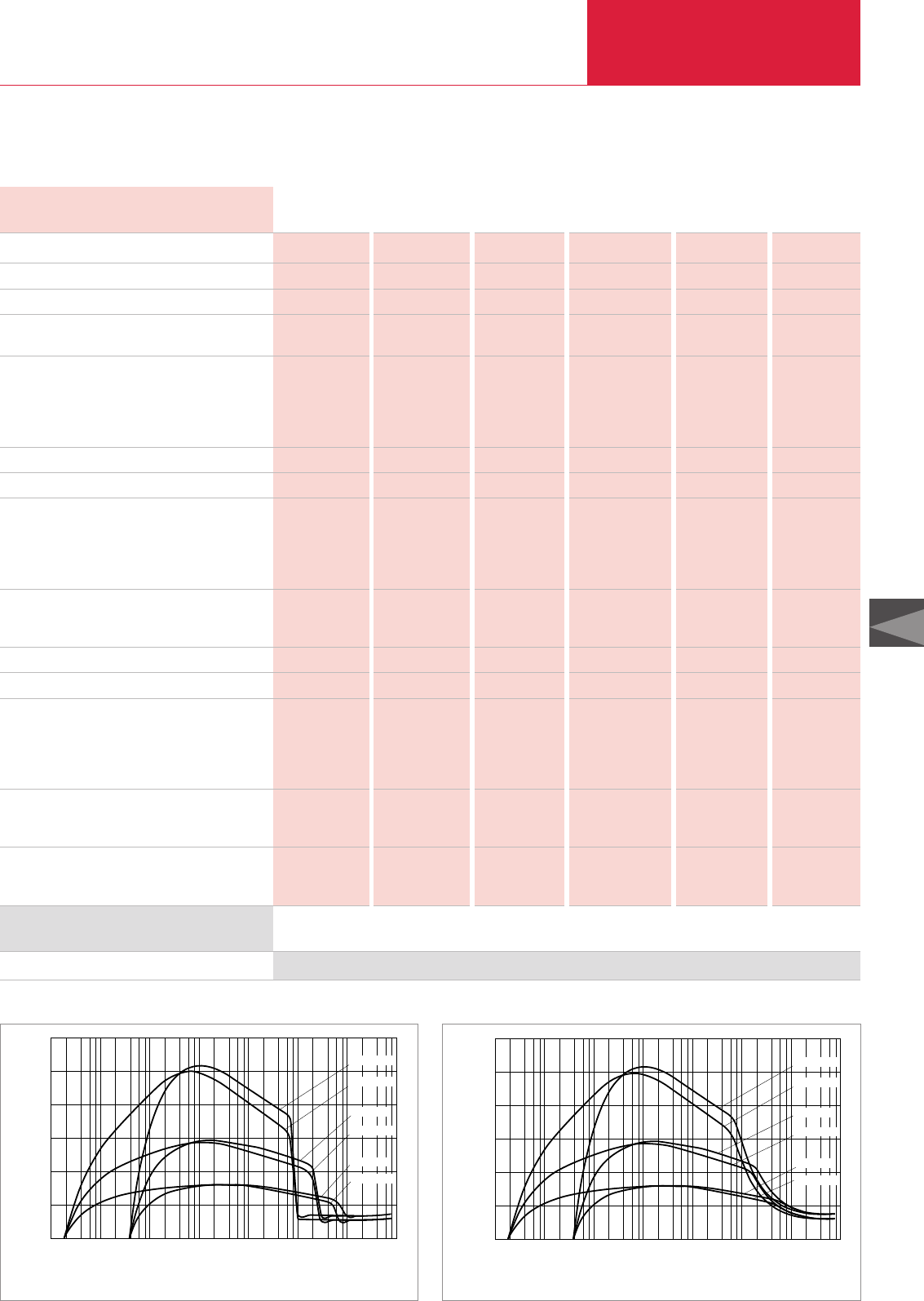
Vacuum Pump Systems
C08.35
LEYBOLD VACUUM PRODUCTS AND REFERENCE BOOK 2003/2004
C08
Version for the North and South American Continents
Technical Data
RUVAC (WA/WAU/WS/WSU possible)
Rotary piston vacuum pump
Pumping speed @ 0.1 Torr cfm (m3x h-1)
Ultimate total pressure with gas ballast Torr
(mbar)
Connecting flanges
Inlet port
WA/WAU
WS/WSU
Outlet port
Operating voltage
Phase / Frequency 1) – / Hz
Full load amps 2)
RUVAC
WA/WAU
WS/WSU
Rotary piston vacuum pump
Displacement
RUVAC cfm
Rotary piston vacuum pump cfm
Maximum differential pressure Torr
Normal starting pressure 3) Torr
Oil capacity
RUVAC
WA/WAU qt
WS/WSU qt
Rotary piston vacuum pump qt
Nominal rotation speed of pump
RUVAC rpm
Rotary piston vacuum pump rpm
Motor power
RUVAC WA/WAU/WS/WSU hp
Rotary piston vacuum pump hp
501 501 1001 1001 2001 2001
E 250 DK 200 E 250 DK 200 E 250 DK 200
312 (529) 313 (531) 574 (974) 570 (967) 1031 (1750) 985 (1672)
4 x 10⁻³ 2 x 10⁻⁴ 4 x 10⁻³ 2 x 10⁻⁴ 4 x 10⁻³ 2 x 10⁻⁴
(< 6 x 10⁻³) (< 3 x 10⁻⁴) (< 6 x 10⁻³) (< 3 x 10⁻⁴) (< 6 x 10⁻³) (< 3 x 10⁻⁴)
3" ANSI 3" ANSI 4" ANSI 4" ANSI 6" ANSI 6" ANSI
63 ISO-K 63 ISO-K 100 ISO-K 100 ISO-K 160 ISO-K 160 ISO-K
3" ANSI 3" ANSI 3" ANSI 3" ANSI 3" ANSI 3" ANSI
208/230/460 208/230/460 208/230/460 208/230/460 208/230/460 208/230/460
3 / 60 3 / 60 3 / 60 3 / 60 3 / 60 3 / 60
9.2/8.5/4.8 9.2/8.5/4.8 15.2/13.2/6.1 15.2/13.2/6.1 28/24.8/12.4 28/24.8/12.4
9.0/9.0/5.2 9.0/9.0/5.2 15.7/15.7/9.1 15.7/15.7/9.1 26/26/15 26/26/15
24/21/10.5 24/21/10.5 24/21/10.5 24/21/10.5 24/21/10.5 24/21/10.5
357 357 707 707 1449 1449
171 132 171 132 171 132
60 60 60 60 38 38
53 38 18 14 7 6
1.40 1.40 4.00 4.00 6.10 6.10
1.10 1.10 2.10 2.10 4.20 4.20
8.90 4.60 8.90 4.60 8.90 4.60
3600 3600 3600 3600 3600 3600
540 540 540 540 1800 1800
1.5 /1.7 1.5 /1.7 5.0 /6.1 5.0 /6.1 10.0 /11.4 10.0 /11.4
7.5 7.5 7.5 7.5 7.5 7.5
RM - Roots / Mechanical Pumping System
501/E250 501/DK200 1001/E250 1001/DK200 2001/E250 2001/DK200
RM - Roots / mechanical pumping system
1) For 50 Hz systems, consult the factory 2) Determined by operating voltage 3) WAU/WSU pumps start at atmospheric pressure (760 Torr)
See Price List for the “North American Continent” for Ordering Information
Ordering Information RM - Roots / Mechanical Pumping System
2001/DK200
2001/E250
501/E250
501/DK200
1001/E250
1001/DK200
0
cfm
10-3 10-2
10-4 101
100
10-1 102
Torr 103
1200
600
1000
200
400
2 4 6 8
Total Pressure
Pumping Speed
800
Pumping speed diagram for the RM - Roots/mechanical pumping systems
with WAU/WSU series Roots blowers at 60 Hz
2001/DK200
2001/E250
501/E250
501/DK200
1001/E250
1001/DK200
0
cfm
10-3 10-2
10-4 101
100
10-1 102
Torr 103
1200
600
1000
200
400
2 4 6 8
Total Pressure
Pumping Speed
800
Pumping speed diagram for the RM - Roots/mechanical pumping systems
with WA/WS series Roots blowers at 60 Hz
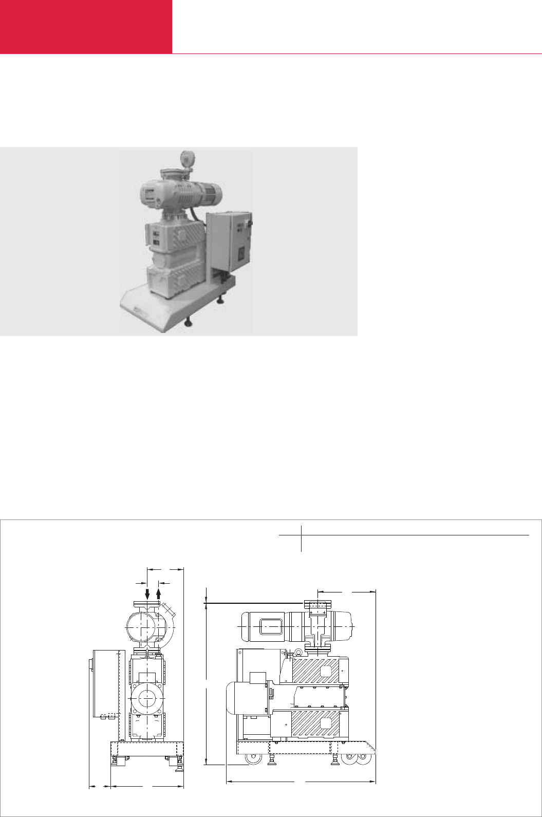
Vacuum Pump Systems
C08.36 LEYBOLD VACUUM PRODUCTS AND REFERENCE BOOK 2003/2004
Version for the North and South American Continents
Dry-Compressing Vacuum Pump System with EcoDry L Backing Pump
Advantages to the User
♦Maintenance-free, oil-free and hydrocarbon-
free
♦Air cooled pumps
♦Simple operation, high reliability, easy
maintenance
♦Compact frame base
♦Frame base equipped with caster wheels and
leveling pads
♦Close-coupled RUVAC blower
Options
♦Special motor voltages and frequencies
♦Full NEMA 12 electrical controls for control
start/stop of system
♦Special design controls
♦Gas ballast valve on EcoDry L
l1
h1
h
l
b2
bb1
b3
Dimensional drawing for the dry-compressing vacuum pump system with EcoDry L
Dry-compressing system with EcoDry L
b b1b2b3h h1l l1
mm 457.2 128.6 228.6 69.85 985.0 3.96 927.9 355.6
in. 18.00 5 1/16 9.00 2 3/4 38 25/32 5/32 36 17/32 14.00
b2
bb1
b3
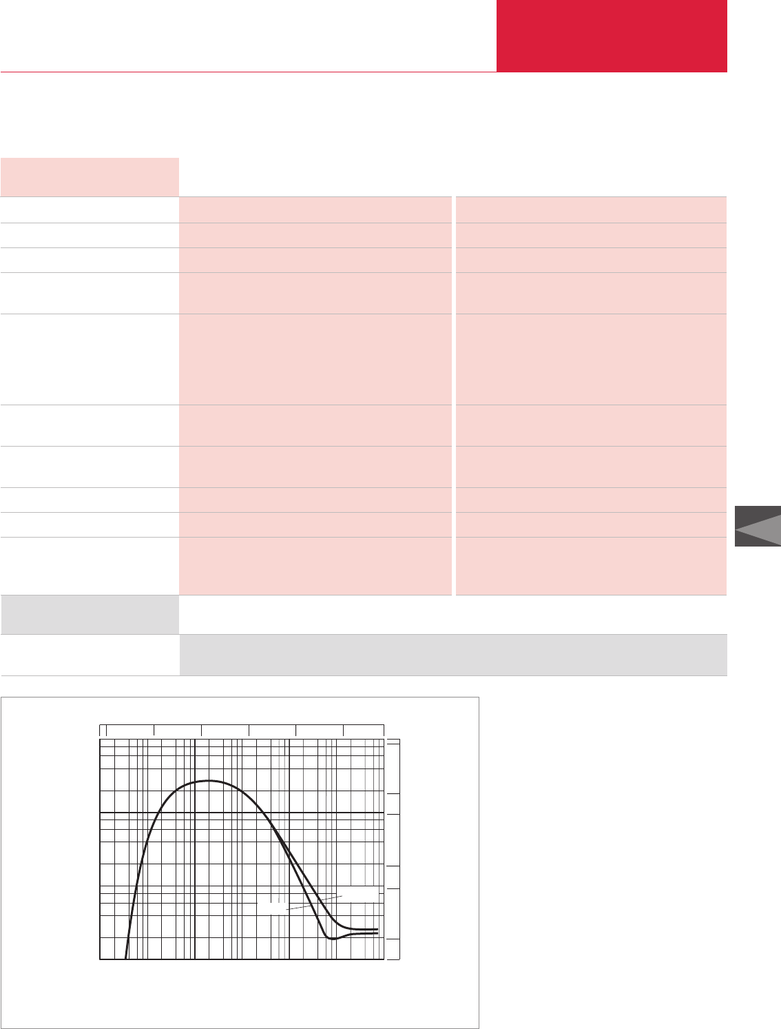
Vacuum Pump Systems
C08.37
LEYBOLD VACUUM PRODUCTS AND REFERENCE BOOK 2003/2004
C08
Version for the North and South American Continents
Technical Data
EcoDry L Dry-Compressing Pump System with EcoDry L
50 Hz 60 Hz
Ordering Information
Pumping system, complete (adaptor version),
base frame mounted
See Price List for the “North American Continent” for Ordering Information
RUVAC (WS/WSU possible)
Backing pump
Pumping speed at 0.1 Torr m
3
x h
-1
(cfm)
Ultimate total pressure without gas ballast
mbar (Torr)
Installed motor power
WSU 251 kW (hp)
EcoDry L
Standard / Option kW (hp)
Total kW (hp)
Power consumption at
10
-1
mbar (0.75 x 10
-1
Torr)
kW (hp)
Noise level to DIN 45 635 without
gas ballast at 1 mbar
(0.75 Torr)
dB(A)
Total oil filling, approx. l (qt)
Weight total, approx. kg (lbs)
Connecting flanges
Inlet port DN1
Outlet port DN2
WS/WSU 251 WS/WSU 251
EcoDry L EcoDry L
195 (115) 236 (139)
2 x 10⁻³ (1.5 x 10⁻³) 2 x 10⁻³ (1.5 x 10⁻³)
1.1 (1.5) 1.4 (1.9)
1.5 / 2.2 (2.0 / 3.0) 1.8 / 2.6 (2.4 / 3.5)
2.6 / 3.3 (3.5 / 4.5) 3.2 / 4.0 (4.4 / 5.4)
0.9 (1.2) 1.0 (1.4)
67 69
0.7 (0.74) 0.7 (0.74)
210 (463.1) 210 (463.1)
63 ISO-K 63 ISO-K
25 KF 25 KF
WS/WSU 251/EcoDry L
Pressure
mbar
Pumping speed
m h
3 -1
2 4 6 8
x
2
4
6
8
500
5
50
100
10
1
cfm
100
101
102
103
100101102103
10-1
10-2
10-3
Torr
10010110275010-1
10-2
10-3
WS251
WSU251
Pumping speed diagram at 60 Hz (EcoDry L + RUVAC WS/WSU 251)

LEYBOLD VACUUM PRODUCTS AND REFERENCE BOOK 2003/2004
1.In what kind of application will the pump
system be used (e.g. drying, distillation)?
______________________________________
______________________________________
______________________________________
2.Is the process run
❑continuously ❑in batches:
______________________________________
______________________________________
______________________________________
3.What is the volume of the vacuum
chamber?
___________________________________ m
3
______________________________________
4.What pump-down times are required/
desired?
_________________________________ min/h
______________________________________
5.What operating pressures are planned?
_____________________________ mbar
(Torr)
______________________________________
6.How high is the ambient temperature?
- when installed in the building:
min. ________ °C (°F) / max. ________ °C (°F)
- when installed out in the open
min. ________ °C (°F) / max. ________ °C (°F)
7.How high is the intake temperature?
_________________________________°C (°F)
8.What is the composition of the gas which
is to be pumped? Designation:
a) ________________ b) __________________
c) ________________ d) __________________
e)_________________ f) __________________
9.Quantity(kg/h or Nm
3
/h), traces (%):
a) ________________ b) __________________
c) ________________ d) __________________
e)_________________ f) __________________
10. In the case of materials which are not
commonly listed in the tables please state:
a) Molecular weight_______________________
b) Thermal capacity_______________________
c) Vapor pressure _________________________
d) Viscosity _____________________________
e) Melting point __________________________
f) Special characteristics ___________________
11.Must explosion hazard regulations be
observed?
❑yes ❑no
if yes, which? ___________________________
______________________________________
______________________________________
12.What kind of electrical supplies are
available?
a) Voltage ______________________________
b) Frequency ____________________________
13.What kind of mechanical connection
specifications are planned?
a) Length of the intake line _________________
b) Diameter of the intake line _______________
14.Which cooling media are available
(water, brine etc.)? Which temperature?
______________________ min. ______°C (°F)
______________________ max. ______°C (°F)
To LEYBOLD VAKUUM GmbH
Dept. Pump Systems and Systems
Fax: +49 (0)221/347 - 1277
From company: __________________________
Name/Department:________________________
Phone: _________________________________
Fax: ___________________________________
Date: __________________________________
First page of: ____________________________
CHECKLIST FOR VACUUM PUMP SYSTEMS
FAX
MAKE USE OF OUR KNOW-HOW !
Simply fax the completed checklist to us. Our engineers will design a pump system which exactly matches your requirements.
You will receive an offer shortly.
C08.38

C09
35 - 3 200 l x s-1
Turbomolecular Pumps

Contents
Turbomolecular Pumps
C09.02 LEYBOLD VACUUM PRODUCTS AND REFERENCE BOOK 2003/2004
General
General . . . . . . . . . . . . . . . . . . . . . . . . . . . . . . . . . . . . . . . . . . . . . . . . . . . . . . . . . . . . . . . C09.03
Application and Accessories. . . . . . . . . . . . . . . . . . . . . . . . . . . . . . . . . . . . . . . . . . . . . . . . C09.07
Products and Accessories
Turbomolecular Pumps with Mechanical Rotor Suspension
without Compound Stage. . . . . . . . . . . . . . . . . . . . . . . . . . . . . . . . . . . . . . . . . . . . . . . . C09.08
with Compound Stage . . . . . . . . . . . . . . . . . . . . . . . . . . . . . . . . . . . . . . . . . . . . . . . . . . C09.16
Electronic Frequency Converters
for Turbomolecular Pumps with Mechanical Rotor Suspension . . . . . . . . . . . . . . . . . . . . C09.32
Turbomolecular Pumps with Magnetic Rotor Suspension
without Compound Stage. . . . . . . . . . . . . . . . . . . . . . . . . . . . . . . . . . . . . . . . . . . . . . . . C09.38
with Compound Stage . . . . . . . . . . . . . . . . . . . . . . . . . . . . . . . . . . . . . . . . . . . . . . . . . . C09.46
Electronic Frequency Converters
for Turbomolecular Pumps with Magnetic Rotor Suspension . . . . . . . . . . . . . . . . . . . . . C09.56
Other Accessories
Vibration Absorber . . . . . . . . . . . . . . . . . . . . . . . . . . . . . . . . . . . . . . . . . . . . . . . . . . . . . . C09.61
Air Cooling Unit. . . . . . . . . . . . . . . . . . . . . . . . . . . . . . . . . . . . . . . . . . . . . . . . . . . . . . . . . C09.61
Flange Heater for CF High Vacuum Flange . . . . . . . . . . . . . . . . . . . . . . . . . . . . . . . . . . . . . C09.61
Fine Filter . . . . . . . . . . . . . . . . . . . . . . . . . . . . . . . . . . . . . . . . . . . . . . . . . . . . . . . . . . . . . C09.61
Purge Gas and Venting Valve . . . . . . . . . . . . . . . . . . . . . . . . . . . . . . . . . . . . . . . . . . . . . . . C09.62
Power Failure Venting Valve. . . . . . . . . . . . . . . . . . . . . . . . . . . . . . . . . . . . . . . . . . . . . . . . C09.62
Solenoid Venting Valve . . . . . . . . . . . . . . . . . . . . . . . . . . . . . . . . . . . . . . . . . . . . . . . . . . . C09.62
Accessories for Serial Interfaces RS 232 C and RS 485 C. . . . . . . . . . . . . . . . . . . . . . . . . . C09.63
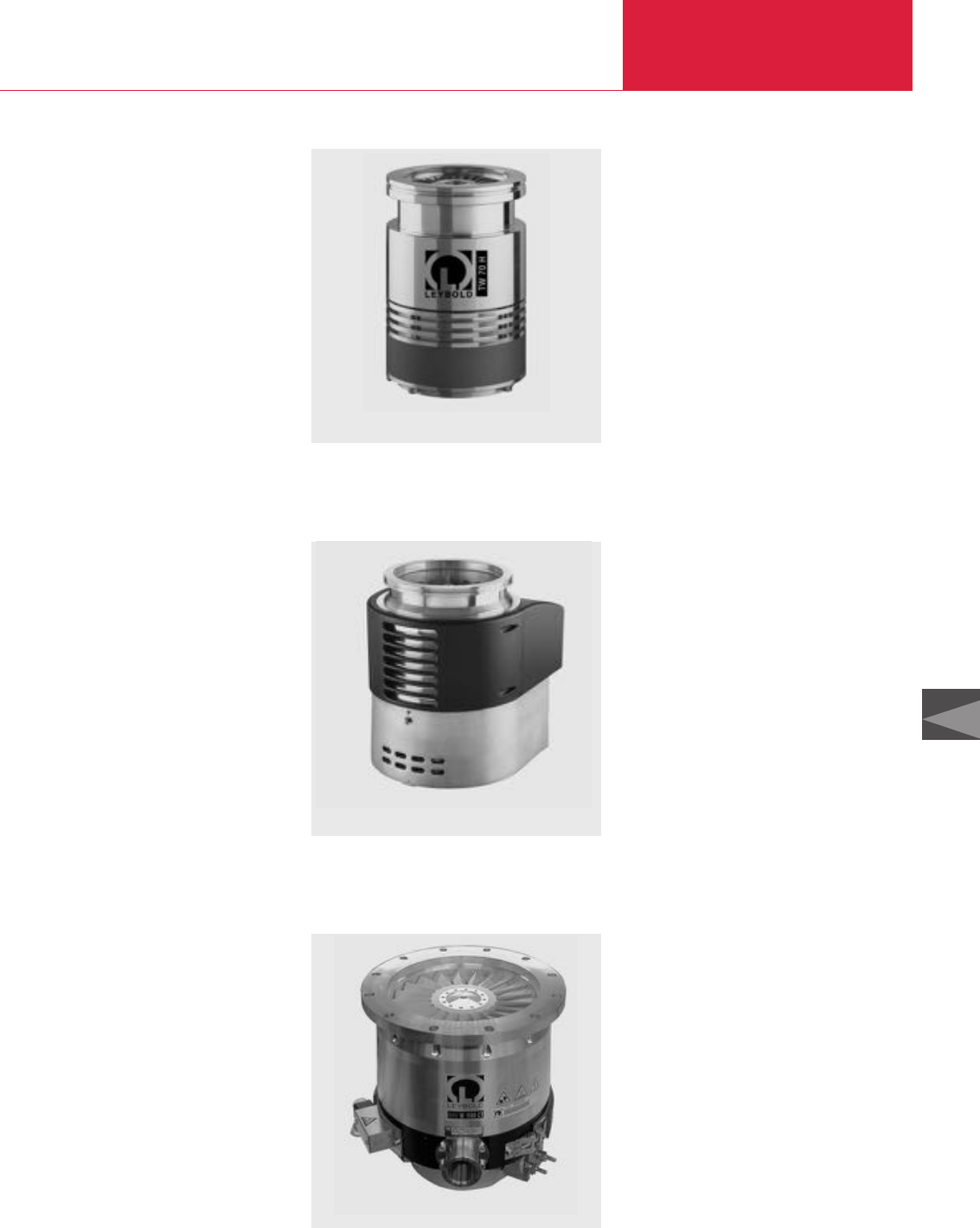
Turbomolecular Pumps
Turbomolecular Pumps
C09.03
LEYBOLD VACUUM PRODUCTS AND REFERENCE BOOK 2003/2004
C09
General Information
The turbomolecular pumps from Leybold genera-
te a clean high and ultra-high vacuum, are easy
to operate and are exceptionally reliable. In
connection with a well rated backing pump, pres-
sures below 10
-10
mbar (0.75 x 10
-10
Torr) can
be attained.
LEYBOLD offers two product lines:
1. TURBOVAC line
Turbomolecular pumps with mechanical
rotor suspension
2. TURBOVAC MAG line
Turbomolecular pumps with magnetic rotor
suspension
Each of the two product lines contains “classic”
turbomolecular pumps as well as turbomolecu-
lar pumps with a compound stage.
LEYBOLD is one of the world’s leading manufac-
turer of turbomolecular pumps. Consequently, the
TURBOVAC and the TURBOVAC MAG pumps are
successfully used in many applications. A list of
the most important ones is given in the section
“Applications and Accessories”.
Principle of Operation
The turbomolecular pump is a turbine with bla-
des. By the momentum transfer from the rapidly
rotating rotor blades to the gas molecules their
initially non-directed thermal motion is changed
to a directed motion.
Hence, the pumping process in a turbomolecular
pump results from the directed motion of the gas
molecules from the inlet flange to the fore-
vacuum port.
In the
molecular flow range
- i.e. at pressures below
10
-3
mbar (0.75 x 10
-3
Torr) - the mean free path
of the gas molecules is larger than the spacing
between rotor and stator blades (typically some
tenths of a millimeter). Consequently, the molecu-
les collide primarily with the rotor blades with the
result that the pumping process is highly efficient.
In the
range of laminar flow
, i.e. at pressures
over 10
-1
mbar the situation is completely diffe-
rent. The effect of the rotor is impaired by the
frequent collisions between the molecules.
Therefore, a turbomolecular pump is not capable
of pumping gases at atmospheric pressure thus
necessitating the use of a suitably rated fore-
vacuum pump.
To create the directed motion of the gas molecu-
les, the tips of the rotor blades have to move at
high speeds. Hence, a high rotational speed of
the rotor is required. In the case of LEYBOLD
turbomolecular pumps the rotor speeds vary
from about 36,000 rpm for the larger rotor dia-
meters (e.g. TURBOVAC 1000 about 20 cm
(7.87 in.)) to 72,000 rpm. for small rotor diame-
ters (e.g. TURBOVAC 50 about 6 cm (2.36 in.))
Characteristic Quantities
Pumping speed (volume flow rate), S, [l x s
-1
]
The pumping speed for a given type of gas
depends on the diameter of the high-vacuum
flange, the rotor/stator design, the speed at which
the rotor revolves and the molecular weight of
the gas.
The pumping speed S is a non-linear function of
the inlet pressure p1: S = S(p
1
)
Gas throughput, Q, [mbar x l x s
-1
]
Gas throughput Q is linked to the pumping speed
S and the inlet pressure p1 through the relation-
ship Q = Q(p
1
) = p
1
. S(p
1
).
The maximum permissible gas throughput Q
max
is attained at the maximum permissible inlet
pressure p
1, max
: Q
max
= Q(p
1, max
).
Compression, K
For a given type of gas, compression K is defined
as the ratio between fore-vacuum pressure p
VV
(= pressure on the fore-vacuum side of the turbo-
molecular pump) and the high-vacuum pressure
p
HV
(= pressure on the high-vacuum side of the
turbomolecular pump):
K = K(p
VV
) = p
VV
/ p
HV
= p
VV
/ p
HV
(p
VV
).
Compression depends very much on the gas
throughput: at a given fore-vacuum pressure,
compression increases when the gas throughput
is reduced.
Idle compression, K
0
Idle compression K
0
of a turbomolecular pump
is defined as the amount of compression of this
pump at “Zero” gas throughput. What is proble-
matic about this definition is the fact that the de-
manded “Zero” throughput can never be imple-
mented in practice (finite leak rate, degassing of
sealing components, desorption from wall sur-
faces). Data on idle compression need therefore
to be gained from measurements run at extreme-
ly low throughputs.
Idle compression of a pump equipped with metal
seals is significantly higher compared to the
same pump sealed with O-rings.
Ultimate pressure (base pressure), p
ult
, [mbar]
The ultimate pressure of a turbomolecular pump
is defined as that pressure which is attained in
the test chamber 48 hours after a 24 hour degas-
sing period of the measurement system.
The ultimate pressure will chiefly depend on the
foreline pump used and the type of seal used at
the high-vacuum flange.
TURBOVAC TW 701 turbomolecular pump
with mechanical rotor suspension and compound stage
TURBOVAC TW 70 H turbomolecular pump
with mechanical rotor suspension and dual compound stage
MAG W 1500 CT turbomolecular pump
with magnetic rotor suspension and compound stage
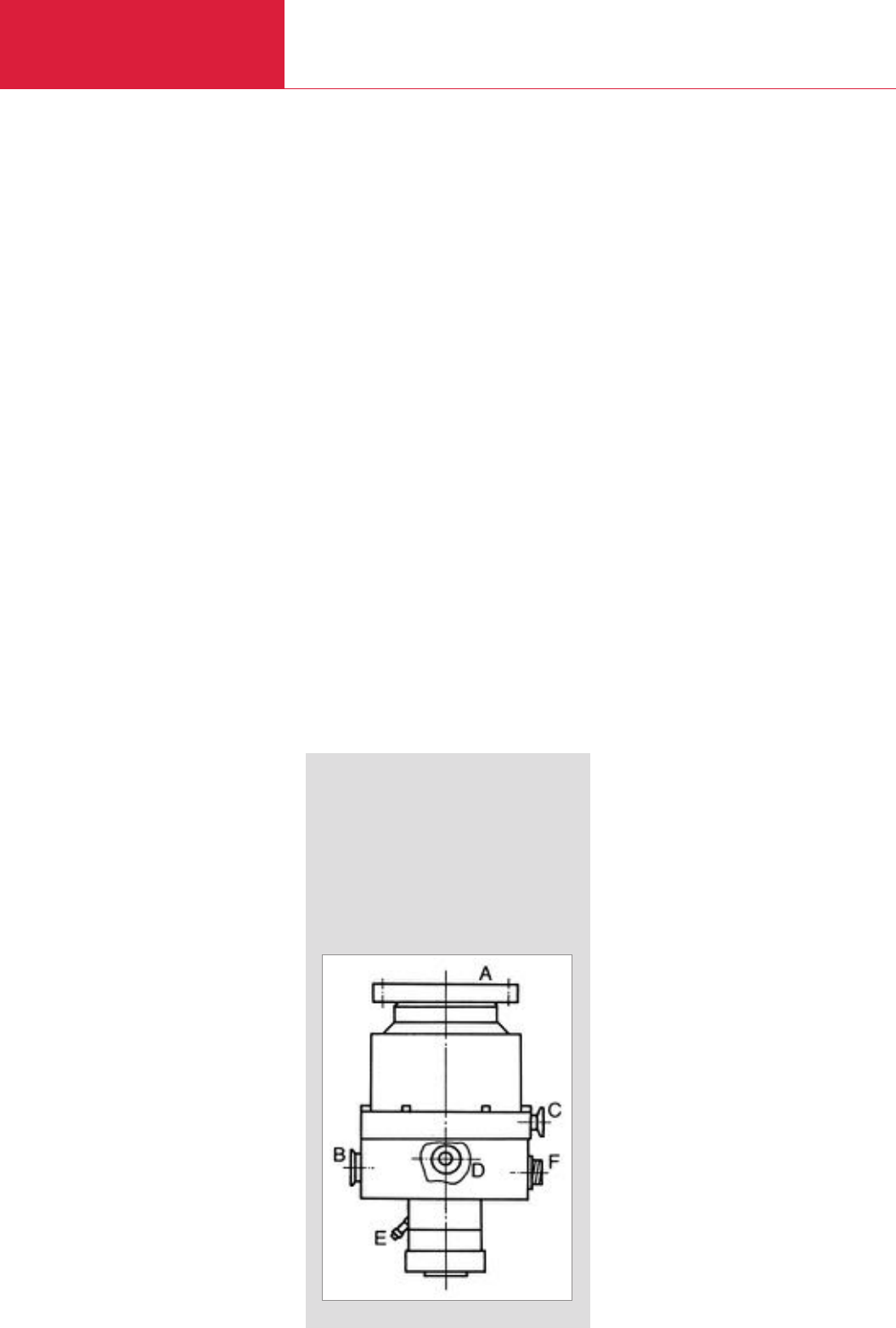
Turbomolecular Pumps
Turbomolecular Pumps
C09.04 LEYBOLD VACUUM PRODUCTS AND REFERENCE BOOK 2003/2004
TURBOVAC Product Line
The TURBOVAC pumps are turbomolecular
pumps with mechanical rotor suspension which
are used in the pressure range from 10
-1
mbar
(0.75 x 10
-1
Torr) to 10
-10
mbar (0.75 x
10
-10
Torr). Pumping speeds for air vary from
35 l x s
-1
(inlet flange diameter = 40 mm (1.57 in.))
to 1,600 l x s
-1
(inlet flange diameter = 250 mm
(9.84 in.)
).
Through the compact design, the most reliable
ceramics ball bearings and the simplicity of
operation, this line of pumps is used in all
high-vacuum and ultrahigh vacuum areas of
application.
In particular the TURBOVAC pumps are very
successfully operated in mass spectroscopy
applications, gas and liquid chromatographic
analysis, CD, DVD and hard disk production,
manufacturing of large-surface optical layers,
and non-corrosive semiconductor fabrication
processes.
The most important advantages of the
TURBOVAC product line are
◆Oil-free pumps for the generation of clean
high-and ultra-high-vacuum conditions
◆Highly performance in any orientation
◆Highly degree of operating reliability
◆Easy to operate
◆Compact design
TURBOVAC MAG
Product Line
The TURBOVAC MAG pumps are turbomolecular
pumps with magnetic rotor suspension which
are used in the pressure range from 10
-1
mbar
(0.75 x 1
0
-1
Torr) to 10
-10
mbar (0.75 x
10
-10
Torr).
Pumping speeds for air vary from
300 l x s
-1
(inlet flange diameter = 100 mm
(3.94 in.)) to 2,000 l x s
-1
(inlet flange diameter =
250 mm
(9.84 in.)
).
The TURBOVAC MAG pumps are mostly installed
on semiconductor processing lines like etching,
CVD, PVD and ion implantation, i.e. in applicati-
ons where corrosive gases need to be pumped.
Also electron beam microscopy is an important
area of application for these pumps.
The most important advantages of the
TURBOVAC MAG product line are
◆Hydrocarbon-free pumps for the generation
of clean high- and ultra-high-vacuum
conditions
◆High performance in any orientation
◆High degree of operating reliability
◆Extremely low vibration
◆Designed for pumping of corrosive gases
Magnetic Bearings
Technology
The world-wide success of the TURBOVAC MAG
product line results from more than 25 years of
experience in developing and manufacturing tur-
bomolecular pumps with magnetic rotor suspen-
sion.
In 1976 LEYBOLD started the market introduction
of the famous TURBOVAC 560 M. This pump
was the first magnetically levitated turbomolecu-
lar pump which became commercially available.
Nowadays LEYBOLD uses two design principles
for the magnetic rotor suspension:
1. One axis with active bearing
The rotor is suspended by permanent
magnets. In addition, the axial position of
the rotor is controlled electromagnetically.
The TURBOVAC 340 M and MAG 400 pumps
are fitted with such a type of rotor suspen-
sion.
2. Five axes with active bearings
The position of the rotor is actively controlled
by the precision magnetic bearing in all five
degrees of freedom. The TURBOVAC
MAG 830/1300, MAG 1500, MAG 2000,
MAG 2200 and MAG 2800/3200 are equipped
with such a bearing system.
Ceramic Ball Bearings
Technology
All TURBOVAC pumps are fitted with ceramic
ball bearings, i.e. ceramic balls are running in
steel races. The bearings are lubricated for life
by grease.
Ceramic balls are lighter, harder and smoother
than balls made of steel. Therefore, with ceramic
balls the wear on the races is significantly redu-
ced. Consequently, the lifetime of the bearings,
and hence the lifetime of the pump, is increased.
The TURBOVAC pumps fitted with grease-lubrica-
ted ceramic ball bearings can be mounted in any
orientation. As the ball bearing is encapsulated,
the grease cannot enter the high-vacuum space,
even if the pump is mounted up-side-down.
Components supplied with
the Turbomolecular Pumps
High-vacuum Flange:
KF and ISO models
◆Centering ring with FPM O-ring
ANSI Models:
◆FPM O-ring for the groove in the flange
CF Models:
◆Without gaskets *
)
Fore-vacuum Port:
◆Centering rings, O-rings and clamps for all
KF type fore-vacuum flanges are included.
Purge / vent ports are blanked-off
*)For CF gaskets, see Product Section C15
Flange Designations used in this
Product Section
A High vacuum flange E Water cooling
B Forevacuum flange connection
C Venting flange F Electrical
D Purge gas flange connection

Turbomolecular Pumps
Turbomolecular Pumps
C09.05
LEYBOLD VACUUM PRODUCTS AND REFERENCE BOOK 2003/2004
C09
FC
PS
TURBOVAC 50,
TURBOVAC 1100 C
NT 10
NT 20
Connecting cable,
20 m max.
FC PS
TW 70 H,
TW 300, TW 300 H
24 V DC
Connecting cable,
5 m max. Mains cable
DC cable,
20 m max.
TDS
P
P
FC PS
TW 70 H,
TW 300, TW 300 H,
TW 701
24 V DC
59 V DC
Mains cable
DC cable,
20 m max.
P
FC
PS Mains cable
P
Mains cable
T 1600,
TW 1600
Pump / Converter Configurations for TURBOVAC Product Line
P = Pump
FC = Frequency Converter
PS = Power Supply
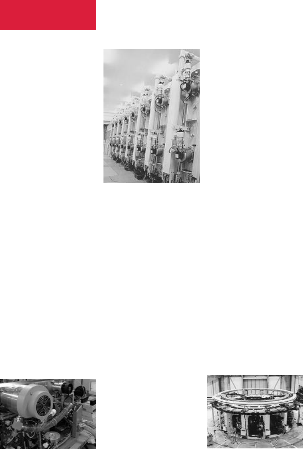
Applications
Turbomolecular Pumps
C09.06 LEYBOLD VACUUM PRODUCTS AND REFERENCE BOOK 2003/2004
Use of Turbomolecular
Pumps in Analytical
Instruments
All modern analytical methods for gas, liquid and
plasma analysis – like for example GC-MS, LC-
MS and ICP-MS – rely on mass spectrometers
and for this reason require adequate high-
vacuum conditions. Also in electron microscopes
and many surface analysis instruments the pro-
duction of a high-vacuum is essential.
In over 90 % of all high-vacuum applications, the
turbomolecular pump has been found to be ideal.
Thanks to the hydrocarbon-free vacuum, most
simple operation, compact design and almost
maintenance-free operation it has in many cases
displaced above all the diffusion pump.
On the basis of decades of experience and in co-
operation with research facilities and the manu-
facturers of analytical instruments, LEYBOLD
Vacuum has continually optimised its products.
The new TURBOVAC wide range series is a furt-
her innovative step forward making available pro-
ducts which are most flexible and reliable.
Owing to the modular concept the user may
◆adapt his vacuum system precisely to his
requirements
◆perfectly integrate the components within his
system and
◆find the most cost-effective system configura-
tion for his needs.
In combination with backing pumps like the
TRIVAC or EcoDry, LEYBOLD Vacuum is able to
offer the best vacuum system optimised for all
major applications in the area of analytical instru-
mentation.
Use of Turbomolecular
Pumps in the Area of
Semiconductor Processes
In the semiconductor industry turbomolecular
pumps are used on the following processes,
among others:
◆Etching
◆Sputtering
◆Ion implantation
◆Lithography.
In these applications pumping of aggressive
gases is often required.
This may necessitate the use of pumps equipped
with a purge gas facility or a magnetic suspensi-
on in order to avoid damaged bearings.
Especially during metal etching, deposits may
occur in the fore-vacuum space of the turbomole-
cular pump. In order to prevent this the pumps
must be heated to a certain temperature. Such
temperature controlled variants are optionally
available for the MAG 1500 C and MAG 2000 C.
In contrast to turbomolecular pumps with mecha-
nical bearings, magnetically levitated pumps pro-
vide the advantage that they prevent overheating
of the bearings at high gas flows and effectively
exclude any damage to the magnetic bearings by
aggressive media.
Similar to electron microscopes, lithographic
equipment requires very low vibration levels. For
this reason, magnetically levitated turbomolecular
pumps are also useful for these applications.
The recommended backing pumps are either
dry compressing EcoDry pumps or rotary vane
pumps from the TRIVAC range, possibly fitted
with the BCS system.
Use of Turbomolecular
Pumps in the Area of
Coating Systems
Coating of optical and magnetic storage media,
optical components as well as architectural glass
requires high-vacuum conditions. This is the only
way to ensure that the formed layers will be uni-
form and adhere to the substrate.
The way in which the vacuum is generated has a
significant impact on the quality of the coating.
By pumping the vacuum chamber down to pres-
sures in the range of 10
-6
mbar (0.75 x 10
-6
Torr),
interfering gas and water molecules are removed
from the processing chamber. In the case of
sputtering the coating process is run in the
pressure range between 10
-3
and 10
-2
mbar
(0.75 x 10
-3
and 0.75 x
10
-2
Torr)
, and in the
case of evaporation coating, pressures below
10
-4
mbar
(0.75 x 10
-4
Torr)
are utilised.
The turbomolecular pump meets all requirements
of the customers as to a hydrocarbon-free vacu-
um, very simple operation, compact design and
almost maintenance-free operation in an almost
ideal manner. The range of pumps from LEYBOLD
includes pumps with flange diameters ranging
from 40 mm to 250 mm
(1.57 in. to 9.84 in.)
nominal width. Thus the right pump is available
for each application, be it coating of data memo-
ries (CD, DVD, hard discs), coating of tools and
coating of precision lenses in the area of optical
components, displays or architectural glass.
Research and Development
In the area of research, all types of turbomolecu-
lar pumps from LEYBOLD are being used.
In the case of particularly stringent requirements
as such low vibration levels, a TURBOVAC with
magnetic bearings should be selected; the same
applies to those applications in which entirely
hydrocarbon-free pump systems are required.
High performance glass coating plant
Nuclear fusion technology
Mass spectrometer

Applications and Accessories
Turbomolecular Pumps
C09.07
LEYBOLD VACUUM PRODUCTS AND REFERENCE BOOK 2003/2004
C09
Analytical Instruments
Leak detectors
Mass spectrometers
Gas chromatography (GC-MS)
Liquid chromatography (LC-MS)
Quadrupol time of flight (Q-TOF)
Matrix assisted laser desorption time of flight (MALDI-TOF)
Inductively coupled plasma mass spectrometry (ICP-MS)
Electron beam microscopy
Coating
Data storage / optical
Data storage / magnetic
Flat panel displays
Optical coating
Large area coating
Decorative coating
Metallization
Wear protection
Metallurgy
TV tube manufacturing
R & D (Research and Development)
Surface analysis
UHV / XHV systems
Particle accelerators
Fusion experiments
Space simulation
Semiconductor Processes
Load locks and transfer chambers
Etch
CVD
PVD
Ion implantation
Pumps
50
361
1100 C
T 1600
TW 70 H
TW 300
TW 300 H
TW 701
TW 1600
340 M
MAG 400 C/CT
MAG 1500 C/CT
MAG 2000 C/CT
MAG W 830/1300 C
MAG W 1500 C/CT
MAG W 2200 C
MAG W 2000 C/CT
MAG W 2800/3200 C/CT
◆ ◆ ◆ ◆
◆ ◆ ◆ ◆ ◆ ◆
◆ ◆ ◆
◆ ◆ ◆
◆ ◆
◆ ◆ ◆
◆ ◆ ◆
◆ ◆ ◆
◆ ◆
◆ ◆ ◆ ◆ ◆ ◆
◆ ◆ ◆ ◆ ◆ ◆
◆ ◆ ◆ ◆ ◆ ◆ ◆
◆ ◆ ◆ ◆
◆ ◆ ◆ ◆
◆ ◆ ◆ ◆
◆ ◆ ◆ ◆
◆ ◆ ◆ ◆
◆ ◆
◆ ◆ ◆
◆ ◆ ◆ ◆ ◆
◆ ◆ ◆ ◆ ◆
◆ ◆ ◆
◆ ◆
◆ ◆ ◆ ◆ ◆ ◆ ◆ ◆
◆ ◆ ◆ ◆ ◆ ◆ ◆
◆ ◆ ◆ ◆ ◆ ◆ ◆
◆ ◆ ◆ ◆ ◆ ◆ ◆
◆ ◆ ◆ ◆ ◆ ◆ ◆ ◆
Frequency converters
NT 10 C09.32
NT 20 C09.32
NT 361 C09.34
TURBO.DRIVE S C09.35
Power supply PS 700 C09.36
Power supplies for TURBO.DRIVE S C09.37
NT 340 M C09.56
NT 340 MA C09.57
MAG.DRIVE
digital
C09.58
MAG.DRIVE 2000 C09.60
Vibration absorber C09.61
Air cooling unit C09.61
Flange heaters for CF flanges C09.61
Fine filter C09.61
Venting valves C09.62
Purge gas and venting valve C09.62
Power fallure venting valve C09.62
Water cooling –
Accessories for serial interfaces
RS 232 C and RS 485 C C09.63
◆
◆ ◆
◆
◆ ◆ ◆
◆
◆ ◆ ◆ ◆
◆
◆
◆ ◆ ◆ ◆ ◆
◆ ◆
◆ ◆ ◆ ◆ ◆ ◆ ◆ ◆
◆ ◆
◆ ◆ ◆ ◆ ◆ ◆
◆
◆ ◆ ◆ ◆ ◆ ◆
◆
◆ ◆
◆
◆
◆
◆
◆
◆ ◆
◆ ◆ ◆ ◆ ◆ ◆ ◆
◆
◆ ◆ ◆ ◆ ◆ ◆ ◆ ◆ ◆ ◆
Applications
Accessories Page
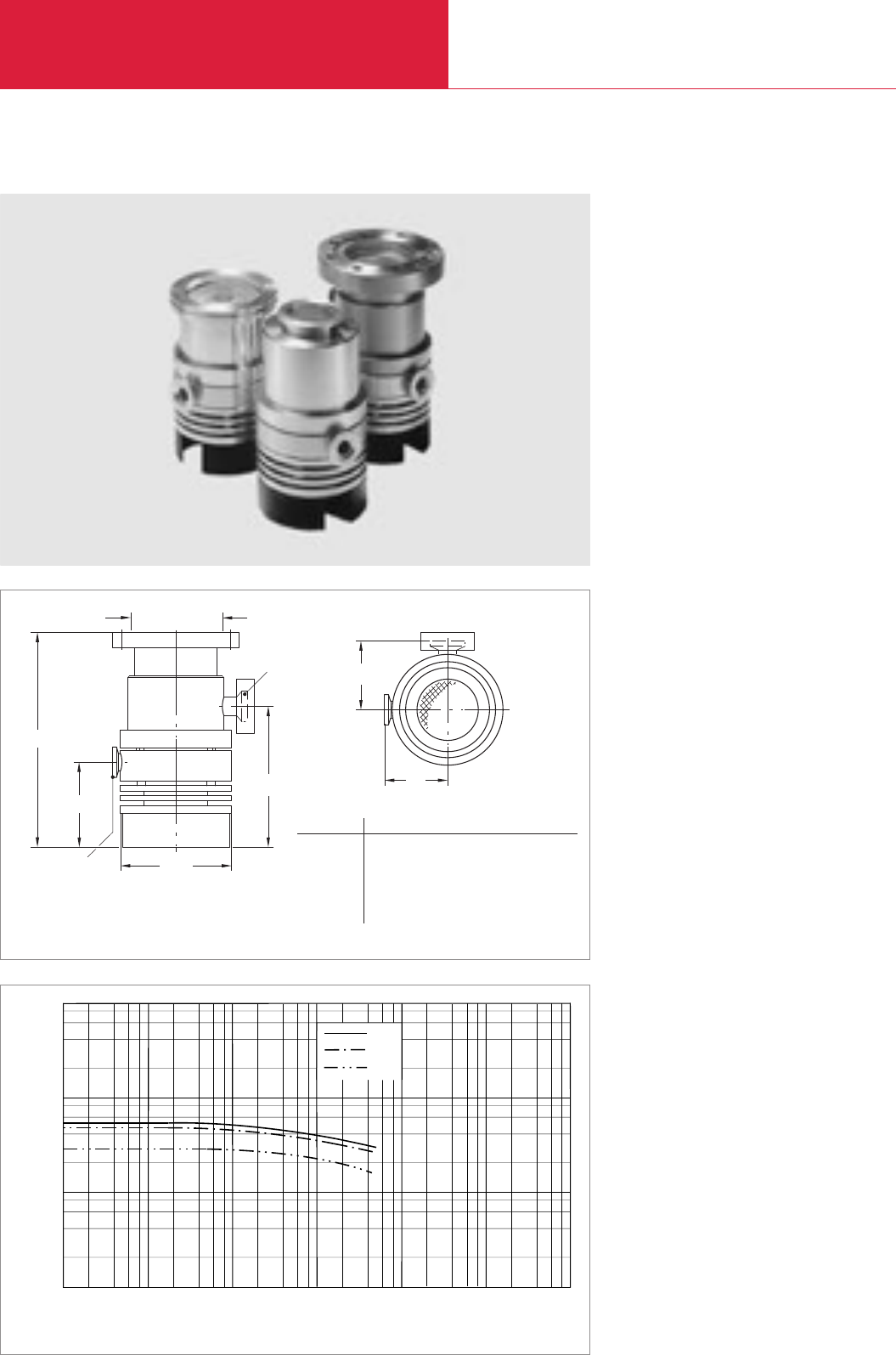
without Compound Stage
Turbomolecular Pumps with Mechanical Rotor Suspension
C09.08 LEYBOLD VACUUM PRODUCTS AND REFERENCE BOOK 2003/2004
TURBOVAC 50
Typical Applications
◆Leak detectors
◆Mass spectrometers
◆Electron beam microscopy
◆TV tube manufacturing
◆Load locks and transfer chambers
10
Pumping Speed
l x s-1
Inlet Pressure mbar
10
10
10
N2
He
H2
0
1
2
3
10-5 10-4 10-3 10-2 10-1 100101
2 4 6 8
DN a b d h h1h2
40 KF mm 54.5 55 93 166 71.5 119
in. 2.15 2.17 3.66 6.54 2.81 4.69
63 ISO-K mm 54.5 55 93 157.5 71.5 119
in. 2.15 2.17 3.66 6.20 2.81 4.69
63 CF mm 54.5 55 93 178 71.5 119
in. 2.15 2.17 3.66 7.01 2.81 4.69
Pumping speed as a function of the inlet pressure (TURBOVAC 50 with DN 63 ISO-K flange)
Technical Features
◆Compact design
◆Operation in any orientation
◆Cooling by convection is sufficient for most
applications
◆Air and water cooling can be added easily
◆Oil-free pump for generating clean high- and
ultrahigh-vacuum conditions
Advantages to the User
◆Space-saving
◆Easy to integrate into complex vacuum
systems
◆Low operating costs
◆Highly reliable operation also in processes
loaded with particles
Dimensional drawing for the TURBOVAC 50 with DN 63 CF flange
Ø dDN 16 KF
DN 10 KF *
C
A
B
C
DN
b
a
h
B
h1
h2
Top view
* drawn offset by 90°
Flange DN 10 KF, for 63 CF version only

C09
LEYBOLD VACUUM PRODUCTS AND REFERENCE BOOK 2003/2004
without Compound Stage
Inlet flange Foreline flange Cooling method Interface
DN 40 KF DN 16 KF Convection –
DN 63 ISO-K DN 16 KF Convection –
DN 63 CF DN 16 KF Convection –
Accessories, necessary for all pumps
Electronic frequency converter NT 10
090 - 140 V
180 - 260 V
Connecting cable NT 10-Pumpe
3 m (10.5 ft)
5 m (17.5 ft)
Accessories, optional
Air cooling unit
230 V AC
110 V AC
Water cooling kit
Flange heater 63 CF, 230 V, 50 Hz
Vibration absorber
DN 63 ISO-K
DN 63 CF
*)for continuous operation when water-cooled
TURBOVAC 50
Turbomolecular Pumps with Mechanical Rotor Suspension
C09.09
Technical Data TURBOVAC 50
O-ring sealed Metal sealed
40 KF 63 ISO-K 63 CF
Aluminum Stainless steel
33 55 55
36 48 48
28 30 30
0.30 0.40 0.40
0.25 0.35 0.35
0.20 0.25 0.25
2 x 1062 x 108
< 5 x 10⁻⁸ (< 3.75 x 10⁻⁸) < 2 x 10⁻¹⁰ (< 1.5 x 10⁻¹⁰)
1 x 10⁻¹ (< 0.75 x 10⁻¹)
TRIVAC D 2,5 E
2
10 (0.39)
2 (4.4)
45 / 15
Part No.
854 00
854 01
854 02
859 01
859 00
121 08
121 09
854 05
854 06
854 08
854 04
800131V0063
500 070
Ordering Information
Inlet flange DN
Pump housing
Pumping speed at 10-3 mbar
N2I x s-1
He I x s-1
H2I x s-1
Max. gas throughput *)at 10-2 mbar
N2mbar x I x s-1
He mbar x I x s-1
H2mbar x I x s-1
Max. compression when idle
N2
Ultimate pressure with TRIVAC D 2,5 E mbar (Torr)
Max. fore-line pressure for N2mbar (Torr)
Recommended fore-vacuum pump
Run-up time to 95% of nominal speed min
Cooling water connection (hose nozzles)
(for Part No. 854 08) mm (in.)
Weight, approx. kg (lbs)
Max. power consumption / ultimate presure W
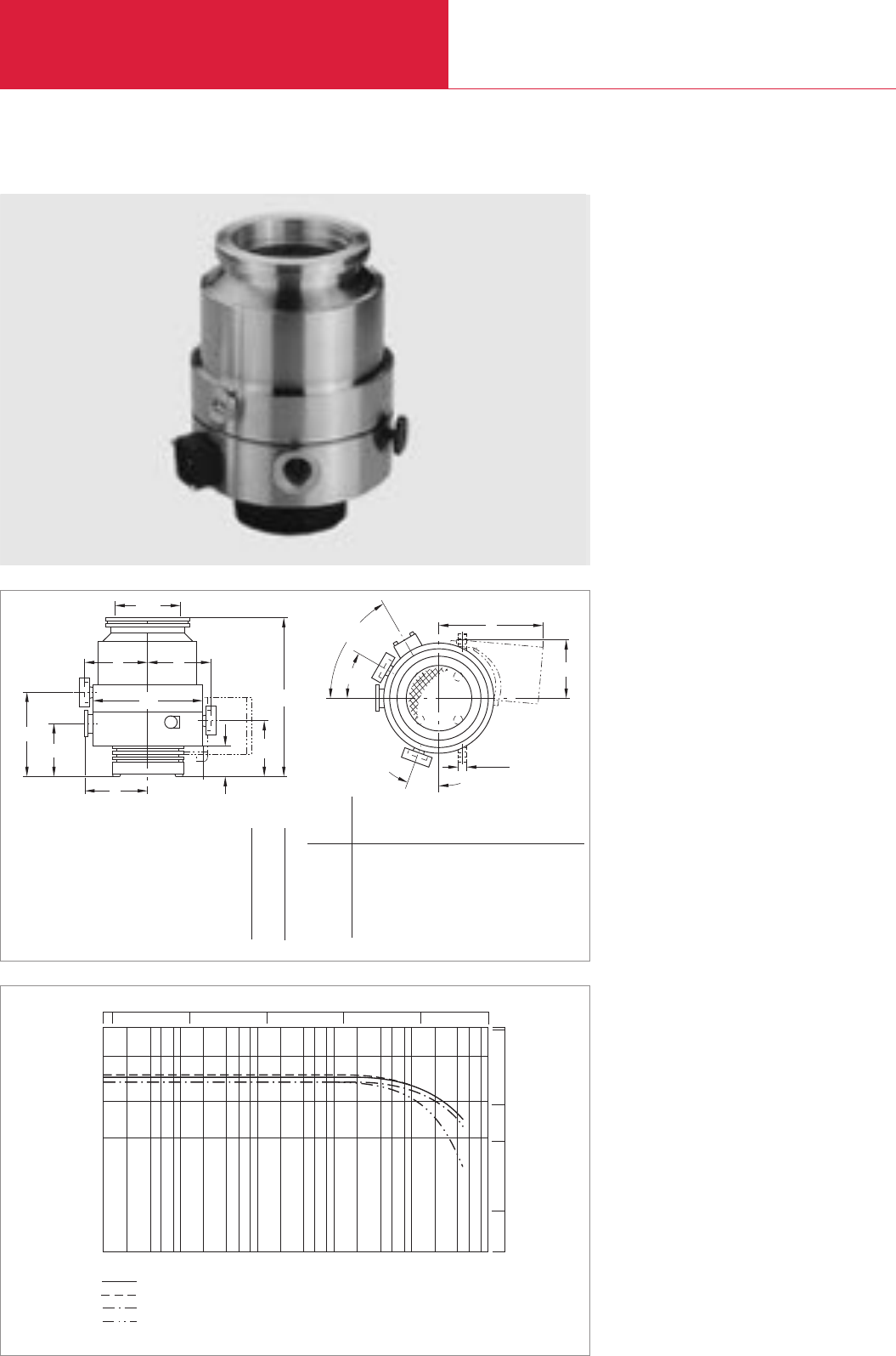
without Compound Stage
Turbomolecular Pumps with Mechanical Rotor Suspension
C09.10 LEYBOLD VACUUM PRODUCTS AND REFERENCE BOOK 2003/2004
Advantages to the User
◆Space-saving
◆Easy to integrate into complex vacuum
systems
◆Low operating costs
◆Highly reliable operation also in processes
loaded with particles
Pumping speed
mbar
Intake Pressure
Ar
N2
He
H2
10-6 2 4 6 8
200
500
I x s-1
10-5 10-4 10-3 10-2 10-1
10-6 10-5 10-4 10-3 10-2
10
100
1000
cfm
500
100
10
50
Torr 750
Pumping speed as a function of the intake pressure (TURBOVAC 361 with DN 100 flange)
Dimensional drawing for the TURBOVAC 361 and 361 C
Typical Applications
◆Leak detectors
◆Mass spectrometers
◆Data storage
◆Optical coating
◆R & D, e.g.
- UHV systems
- Particle accelerators
◆Load locks and transfer chambers
Technical Features
◆Compact design
◆Operation in any orientation
◆Oil-free pump for generating clean high- and
ultrahigh-vacuum conditions
361 361 C
DN h h h1h2h3h4a
b d1l
100 ISO-K mm 254 254 88 47 135 84 98 94 10 166
in. 10 10 3.46 1.85 5.31 3.31 3.86 3.70 0.39 6.54
100 CF mm 268 – – 47 135 84 98 94 10 166
in. 10.55 – – 1.85 5.31 3.31 3.86 3.70 0.39 6.54
160 ISO-K mm 227 227 88 47 135 84 98 94 10 166
in. 8.94 8.94 3.46 1.85 5.31 3.31 3.86 3.70 0.39 6.54
160 CF mm 226 – – 47 135 84 98 94 10 166
TURBOVAC 361, 361 C
C
BED
AC
B
E
D
F
DN
h1
ød
ø
20°
l
b
h
60°
30°
aa
a
h2
h3
h4
d1
Top view
C
BED
A
DN
h1
ød h
aa
a
h2
h3
h4

without Compound Stage
Turbomolecular Pumps with Mechanical Rotor Suspension
C09.11
LEYBOLD VACUUM PRODUCTS AND REFERENCE BOOK 2003/2004
C09
Inlet flange Foreline flange Cooling method Item
DN 100 ISO-K DN 25 KF Water-cooled TURBOVAC 361
DN 100 ISO-K DN 25 KF Water-cooled TURBOVAC 361 C
DN 100 CF DN 25 KF Water-cooled TURBOVAC 361
DN 160 ISO-K DN 25 KF Water-cooled TURBOVAC 361
DN 160 ISO-K DN 25 KF Water-cooled TURBOVAC 361 C
DN 160 CF DN 25 KF Water-cooled TURBOVAC 361
Accessories, optional
Air cooling unit
230 V AC
110 V AC
Flange heater 100 CF
230 V AC
110 V AC
Flange heater 160 CF
230 V AC
110 V AC
Accessories, for all pumps
Electronic frequency converter NT 20
230 V AC
120 V AC
100 V AC
Connecting cable NT 20-pump
03 m (10.5 ft)
05 m (17.5 ft)
10 m (35.0 ft)
20 m (70.0 ft)
*)water-cooled 1) with purge port
TURBOVAC 361
Technical Data TURBOVAC 361
100 ISO-K • 100 CF 160 ISO-K • 160 CF
345 400
350 –
340 380
340 370
7.5 –
7.5 –
1 x 10⁹
6 x 10⁴
3 x 10³
< 1 x 10⁻¹⁰ (< 0.75 x 10⁻¹⁰)
5 x 10⁻² (3.75 x 10⁻²)
5 x 10⁻¹ (3.75 x 10⁻¹)
From TRIVAC D 16 B to D 25 B
≈2
10 KF
10 (0.39)
12 (26)
680 / 480
Part No.
856 70
856 75
1)
856 71
856 72
856 77
1)
856 73
855 31
894 08
854 27
854 28
854 37
854 38
857 20
857 21
857 22
857 65
857 66
857 67
857 68
Ordering Information
Inlet flange DN
Pumping speed
N2I x s-1
Ar I x s-1
He I x s-1
H2I x s-1
Max. gas throughput
N2mbar x I x s-1
Ar mbar x I x s-1
Compression ratio
N2
He
H2
Ultimate pressure mbar (Torr)
Max. continuous inlet pressure *)mbar (Torr)
Max. foreline pressure for N2mbar (Torr)
Recommended fore-vacuum pump
Run-up time to 95% speed min
Purge / vent port DN
Cooling water connections, hose nozzle mm (in.)
Weight, approx. kg (lbs)
Max. power consumption / at ultimate pressure VA
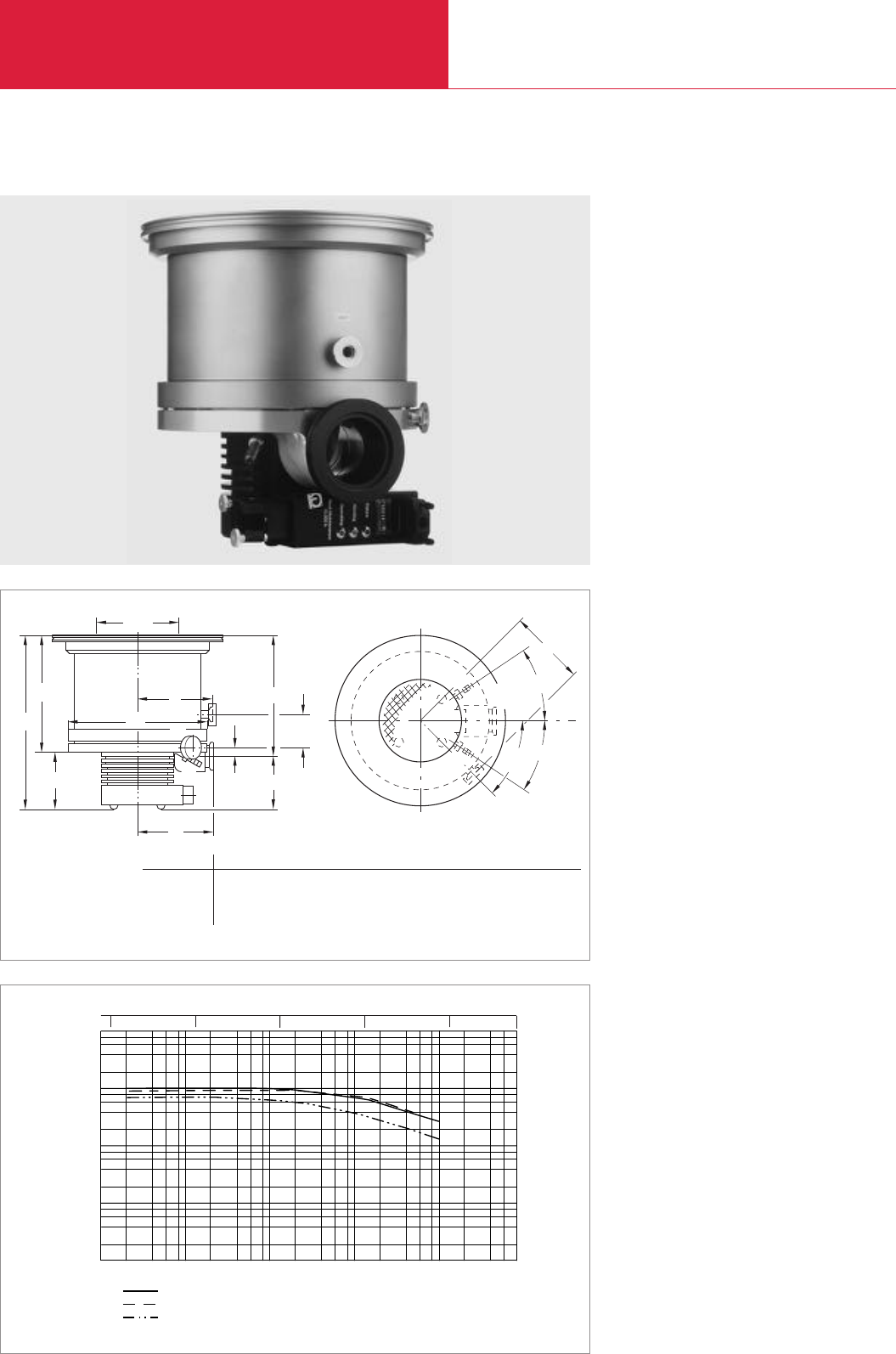
without Compound Stage
Turbomolecular Pumps with Mechanical Rotor Suspension
C09.12 LEYBOLD VACUUM PRODUCTS AND REFERENCE BOOK 2003/2004
TURBOVAC 1100 C
Advantages to the User
◆Space-saving
◆Easy to integrate into complex vacuum
systems
◆High productivity
◆Low operating costs
◆Highly reliable operation also in processes
loaded with particles
10-5 10-3
10-4 10-2 10-1 10
mbar
Inlet Pressure
Pumping Speed
N2
Ar
H2
2 4 6 8
2
4
6
8
I x s-1
101
100
102
103
104
10-5 10-4 10-3 10-2 10-1 Torr 750
Pumping speed as a function of the inlet pressure (TURBOVAC 1100 C with DN 250 flange)
Dimensional drawing for the TURBOVAC 1100 C
Typical Applications
◆Data storage
◆Flat panel displays
◆Optical coating
◆Large area coating
◆R & D, e.g.
- Fusion experiments
- Space simulation
◆Load locks and transfer chambers
Technical Features
◆Robust rotor design
◆Operation in any orientation
◆Highest pumping speed and throughput
◆Integrated control system for monitoring the
temperature of the bearings
◆Oil-free pump for generating clean high- and
ultrahigh-vacuum conditions
b
A
E
FB
E
D
DN
ød
a
h
F
C
B
E
D
(C)
h2
45°
h1
h5
h4
h3
a1
h6
45°
45°
DN h h1h2h3h4h5h6a a1b d
200 ISO-K mm 325 214 231 111 94 63 28.5 133 153 141 258
in. 12.80 8.43 9.09 4.37 3.70 2.48 1.12 5.24 6.02 5.55 10.16
250 ISO-K mm 310 200 217 111 94 63 28.5 133 153 141 258
in. 12.20 7.87 8.54 4.37 3.70 2.48 1.12 5.24 6.02 5.55 10.16
Top view

without Compound Stage
Turbomolecular Pumps with Mechanical Rotor Suspension
C09.13
LEYBOLD VACUUM PRODUCTS AND REFERENCE BOOK 2003/2004
C09
Inlet flange Foreline flange Cooling method Interface
DN 200 ISO-K DN 63 ISO-K Water-cooled –
DN 250 ISO-K DN 63 ISO-K Water-cooled –
Accessories, for all pumps
Electronic frequency converter NT 20
230 V AC
120 V AC
Connecting cable NT 20-pump
03 m (10.5 ft)
05 m (17.5 ft)
10 m (35.0 ft)
20 m (70.0 ft)
Purge / vent valve
24 V DC, 0.6 mbar x I x s-1 = 36 sccm
Note for the North and South American Continents:
For special application we recommend the TURBOVAC 1000 C. Please contact your sale office
TURBOVAC 1100 C
Technical Data TURBOVAC 1100 C
200 ISO-K 250 ISO-K
830 1050
760 980
750 850
600 630
25
15
25
30
1 x 10⁵
1 x 10⁵
1 x 10⁴
< 3 x 10⁻¹⁰ (< 2.2 x 10⁻¹⁰)
0.1 (0.075)
TRIVAC D 65 B / EcoDry M15/20
9
10 KF
10 (0.39)
22 (48)
42
400
Part No.
894 83
894 80
857 20
857 21
857 65
857 66
857 67
857 68
121 33
Ordering Information
Inlet flange DN
Pumping speed
N2I x s-1
Ar I x s-1
He I x s-1
H2I x s-1
Max. gas throughput
N2mbar x I x s-1
Ar mbar x I x s-1
He mbar x I x s-1
H2mbar x I x s-1
Compression ratio
N2
Ar
H2
Ultimate pressure mbar (Torr)
Max. foreline pressure for N2mbar (Torr)
Recommended fore-vacuum pump
Run-up time to 95% speed min
Purge / vent port DN
Cooling water connections,hose nipple mm (in.)
Weight, approx. kg (lbs)
Supply voltage V AC
Max. power consumption VA
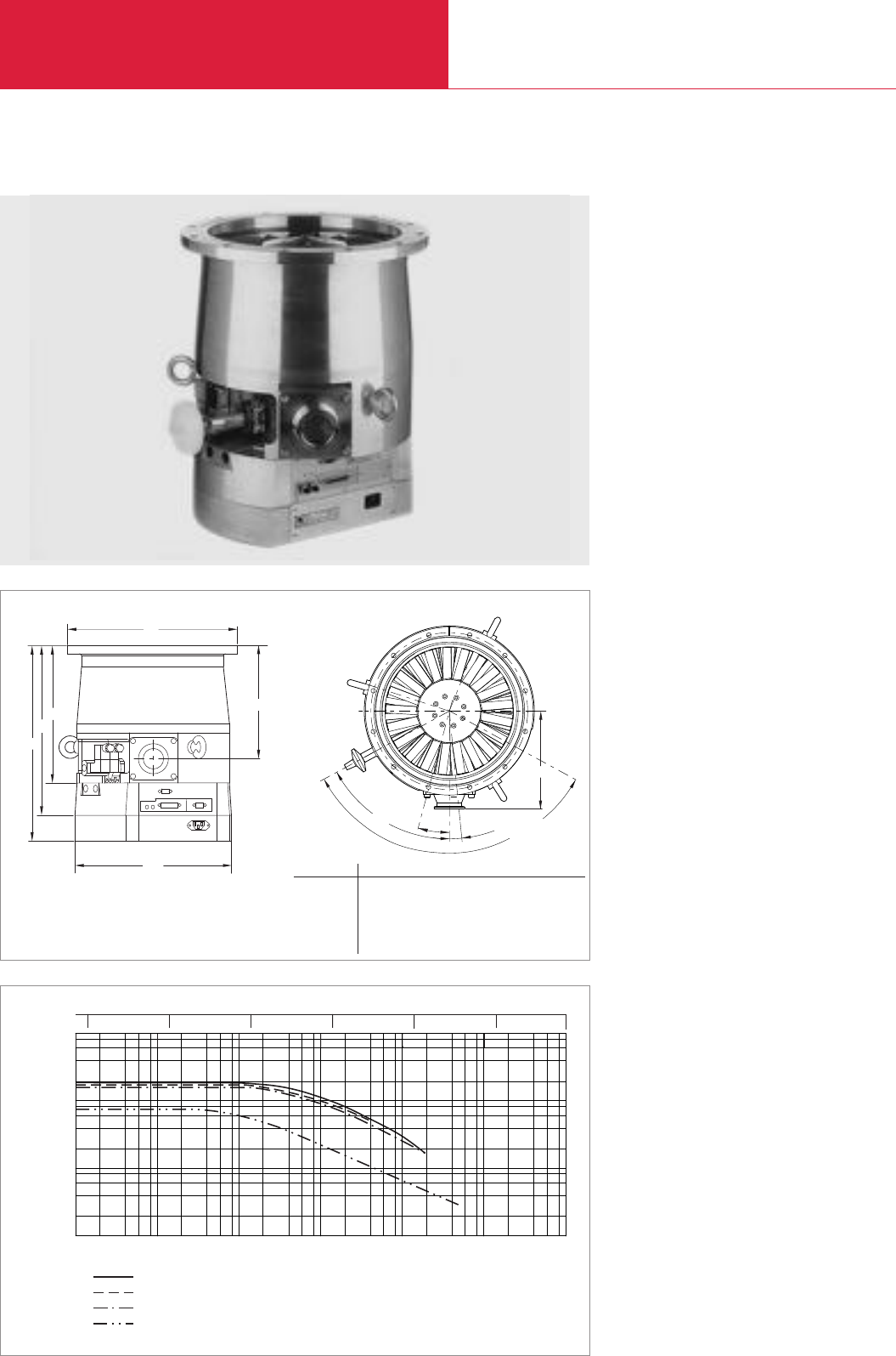
without Compound Stage
Turbomolecular Pumps with Mechanical Rotor Suspension
C09.14 LEYBOLD VACUUM PRODUCTS AND REFERENCE BOOK 2003/2004
TURBOVAC T 1600
104
103
102
10-5 10-4 10-3 10-2 10-1 101
N2
Ar
He
H2
mbar
Inlet Pressure
Pumping Speed
I x s-1
4
2
6
8
2 4 6 8
10-5 10-4 10-2 10-1 1Torr 1010-3
101
Advantages to the User
◆Space-saving
◆Easy to integrate into complex vacuum
systems
◆High productivity
◆Low operating costs
◆Highly reliable operation also in processes
loaded with particles
Typical Applications
◆Data storage
◆Flat panel displays
◆Optical coating
◆Large area coating
◆R & D, e.g.
- Fusion experiments
- Space simulation
Technical Features
◆Frequency converter and power supply
integrated
◆Robust rotor design
◆Operation in any orientation
◆Highest pumping speed and throughput
◆Oil-free pump for generating clean high and
ultrahigh-vacuum conditions
◆Purge gas and venting valve integrated
Dimensional drawing for the TURBOVAC T 1600
Pumping speed as a function of the inlet pressure (TURBOVAC T 1600 with DN 250 flange)
15°
62°
5.625°
h2
a
h
ø
ød
h3
123.50°
h1
d1
Top view
h2
h
ø
ød
h3
h1
d1
DN a d d1h h1h2h3
200 ISO-F mm 176 285 308 393 342 277 255
in. 6.93 11.22 12.13 15.47 13.86 10.91 10.04
250 ISO-F mm 176 335 308 425 369 304 228
in. 6.93 13.19 12.13 16.73 14.53 11.97 8.98
250 CF mm 176 304 308 413 357 292 243
in. 6.93 11.97 12.13 16.26 14.06 11.50 9.57

without Compound Stage
Turbomolecular Pumps with Mechanical Rotor Suspension
C09.15
LEYBOLD VACUUM PRODUCTS AND REFERENCE BOOK 2003/2004
C09
Inlet flange Foreline flange Cooling method Interface
DN 200 ISO-F DN 40 KF Water-cooled –
DN 200 ISO-F DN 40 KF Water-cooled ProfiBus
DN 250 ISO-F DN 40 KF Water-cooled –
DN 250 ISO-F DN 40 KF Water-cooled ProfiBus
DN 250 ISO-F DN 63 ISO-K Water-cooled –
DN 250 CF DN 40 KF Water-cooled –
Accessories for RS 232 C and RS 485 C interfaces
TURBOVAC T 1600
Technical Data TURBOVAC T 1600
200 ISO-F 250 ISO-F / 250 CF
1100 1550
960 1410
1150 1300
690 720
30
20
30
20
5 x 10⁵
1 x 10⁶
1 x 10⁴
2 x 10²
< 3 x 10⁻¹⁰ (< 2.2 x 10⁻¹⁰)
0.5 (0.375)
TRIVAC D 65 B + RUVAC WA 501
TRIVAC D 65 B
EcoDry M
< 10
G 1/4"
G 3/8"
40 (88)
100 - 240
700
Part No.
800040V1144
800040V2144
800040V1444
800040V2444
800040V1544
800040V1844
see chapter “Turbomolecular Pumps”, para. “Accessories”
Ordering Information
Inlet flange DN
Pumping speed
N2I x s-1
Ar I x s-1
He I x s-1
H2I x s-1
Max. gas throughput
N2mbar x I x s-1
Ar mbar x I x s-1
He mbar x I x s-1
H2mbar x I x s-1
Compression ratio
N2
Ar
He
H2
Ultimate pressure mbar (Torr)
Max. foreline pressure for N2mbar (Torr)
Recommended fore-vacuum pump (alternatively)
Run-up time to 95% speed min
Purge / vent port (valve integrated) DN
Cooling water connections DN
Weight, approx. kg (lbs)
Supply voltage V
Max. power consumption (while running up) VA
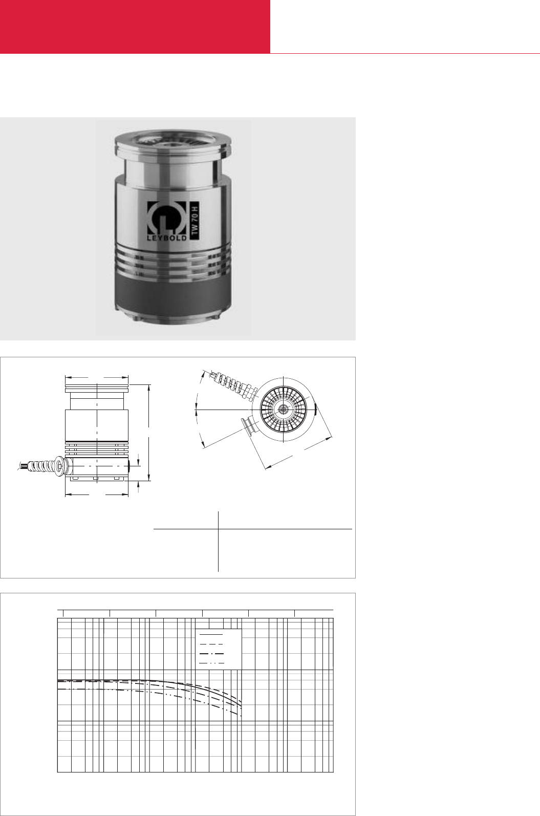
with Compound Stage
Turbomolecular Pumps with Mechanical Rotor Suspension
C09.16 LEYBOLD VACUUM PRODUCTS AND REFERENCE BOOK 2003/2004
10-5 10-4 10-3 10-2 10-1 101
100mbar
Inlet Pressure
103
101
102
100
Pumping speed
I x s-1
2 864
10-5 10-4 10-3 10-2 10-1 100Torr
Ar
N2
He
H2
TURBOVAC TW 70 H
Advantages to the User
◆Space-saving
◆Easy to integrate into complex vacuum
systems
◆Allows the use of down-sized
fore-vacuum pumps
◆Low operating costs
◆Highly reliable operation
Typical Applications
◆Mass spectrometers
◆Electron beam microskopy
◆Leak detectors
◆R & D, e.g.
- UHV systems
◆Load locks and transfer chambers
Dimensional drawing for the TURBOVAC TW 70 H
Pumping speed as a function of the inlet pressure
Technical Features
◆Integrated or external frequency converter
◆Compact design
◆Operation in any orientation
◆High foreline tolerance
◆Oil-free pump for generating clean high and
ultrahigh-vacuum conditions
ø95
22
h
ød
26°
26°
111
Heights for different inlet flanges
Inlet flange
DN a h h1d d1
63 ISO-K mm 111 145 22 95 95
in. 4.37 5.71 0.87 3.74 3.74
63 CF mm 111 169 22 113.5 95
in. 4.37 6.65 0.87 4.47 3.74
Top view
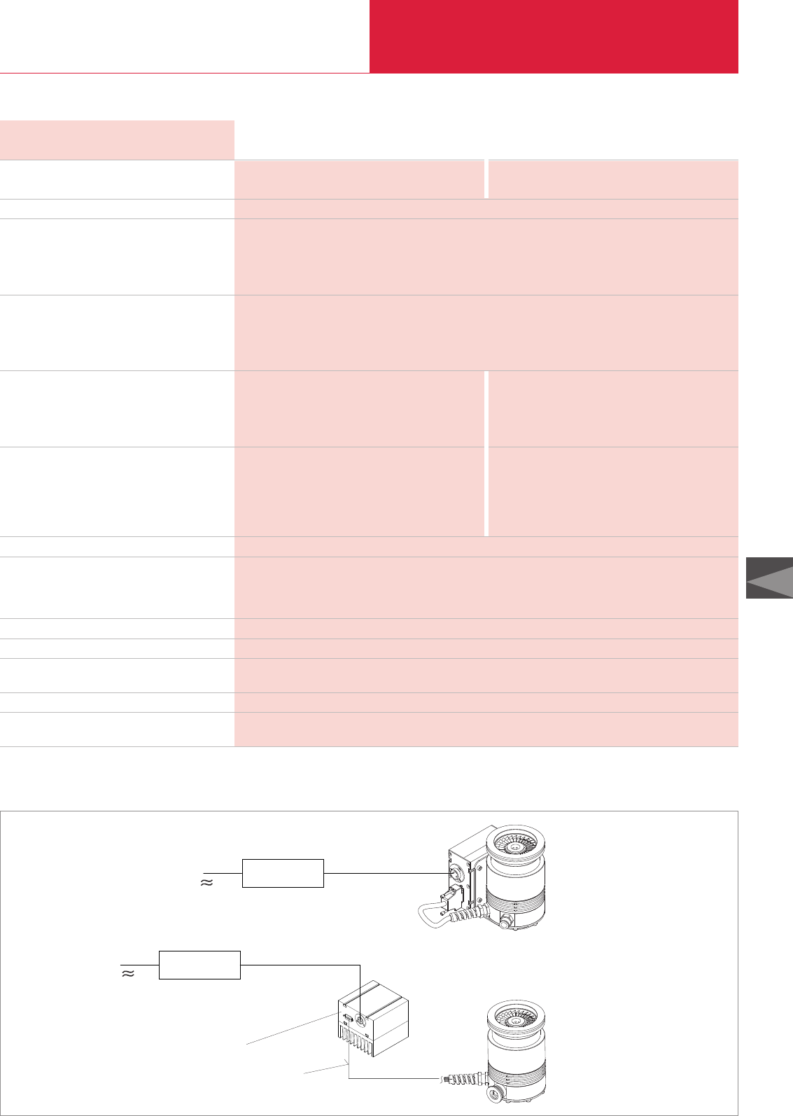
with Compound Stage
Turbomolecular Pumps with Mechanical Rotor Suspension
C09.17
LEYBOLD VACUUM PRODUCTS AND REFERENCE BOOK 2003/2004
C09
Technical Data TURBOVAC TW 70 H
O-ring sealed Metal sealed
63 ISO-K 63 CF
Aluminum Stainless stel
60 / 56
56 / 54
40 / 38
52 / 50
1.9
2.4
1.3
1.9
1 x 10⁸at 14 mbar 1 x 10¹⁰ at 10 mbar
1 x 10⁷at 14 mbar
4 x 10³at 0.2 mbar
2 x 10⁵at 2 mbar
< 5 x 10⁻⁸ (< 3.75 x 10⁻⁸ Torr) < 2 x 10⁻¹⁰ (< 1.5 x 10⁻¹⁰ Torr)
< 4 x 10⁻¹⁰ (< 3 x 10⁻¹⁰ Torr)
< 5 x 10⁻⁹ (< 3.75 x 10⁻⁹ Torr)
20 (15 Torr)
TRIVAC D 2,5 E
EcoDry M15
DIVAC 0,8 T
1.5
2 x G 1/8"
3.0 / 2.3 (6.62 / 5.08)
24
150 / 30
Inlet flange DN
Pump housing
Pumping speed at 10-5 / 10-3 mbar
N2I x s-1
Ar I x s-1
H2I x s-1
He I x s-1
Max. gas throughput *)at 10-1 mbar
N2mbar x I x s-1
Ar mbar x I x s-1
H2mbar x I x s-1
He mbar x I x s-1
Max. compression when idle
N2
Ar
H2
He
Ultimate pressure
with two-stage oil-sealed
rotary vane vacuum pump TRIVAC D 2,5 E mbar
with dry compressing
piston vacuum pump EcoDry M15 mbar
with diaphragm pump DIVAC 0,8 T mbar
Max. fore-line pressure for N2mbar
Recommended fore-vacuum pump
two-stage oil-sealed rotary vane vacuum pump
dry compressing piston vacuum pump
diaphragm pump
Run-up time to 95% of nominal speed min
Cooling water connection (option)
Weight, approx.
with / without frequency converter kg (lbs)
Operating voltage V DC
Max. power consumption
Run up / ultimate presure W
*)for continuous operation when water-cooled
The modular concept
24 V DC cable
with shield,
20 m max.
24 V DC cable
with shield,
20 m max.
TW 70 H and external frequency converter TURBO.DRIVE S
TW 70 H with integrated frequency converter TURBO.DRIVE S
Frequency converter TURBO.DRIVE S with heat sink
Connecting cable, 5 m max.
The modular concept
Mains
Mains
Power supply unit
Power supply unit, e.g.
TURBO.POWER 300
TURBO.CONTROL 300
Power supply unit, e.g.
TURBO.POWER 300
TURBO.CONTROL 300

with Compound Stage
Turbomolecular Pumps with Mechanical Rotor Suspension
C09.18 LEYBOLD VACUUM PRODUCTS AND REFERENCE BOOK 2003/2004
TW 70 H with integrated frequency converter TURBO.DRIVE S
Inlet flange Foreline flange Cooling method Interface
DN 63 ISO-K DN 16 KF Air-cooled RS 485 C
DN 63 ISO-K DN 16 KF Air-cooled RS 232 C
DN 63 ISO-K DN 16 KF Water-cooled RS 485 C
DN 63 ISO-K Camozzi coupling *)Air-cooled RS 485 C
DN 63 ISO-K Camozzi coupling *)Water-cooled RS 485 C
DN 63 CF DN 16 KF Air-cooled RS 232 C
DN 63 CF DN 16 KF Water-cooled RS 485 C
TW 70 H without frequency converter TURBO.DRIVE S
Inlet flange Foreline flange Cooling method Interface
DN 63 ISO-K DN 16 KF Convection –
DN 63 ISO-K Camozzi coupling Convection –
DN 63 CF DN 16 KF Convection –
For operation, one frequency converter TURBO.DRIVE S is necessary
Electronic frequency converter TURBO.DRIVE S with heat sink, RS 485 C interface
Electronic frequency converter TURBO.DRIVE S with heat sink, RS 232 C interface
Connecting cable (TURBO.DRIVE S - pump)
1 m (3.5 ft)
3 m (10.5 ft)
5 m (17.5 ft)
Accessories, necessary for all pumps
START/STOP switch for manual opertion of the turbomolecular pump
Power supplies
TURBO.POWER 300
TURBO.CONTROL 300
Accessories, optional
Water cooling unit with 2 x G 1/8" connection
including 2 hose nozzles G 1/8", OD 8 mm for water hose,
2 gaskets (copper) 10 x 14 x 1
Air cooling unit
Flange heater 63 CF, 230 V, 50 Hz
Splinter guard
DN 63 ISO-K
DN 63 CF
Vibration absorber
DN 63 ISO-K
DN 63 CF
Accessories for serial interfaces RS 232 C and RS 485 C
*)Quick coupling for plastic vacuum hoses with an OD of 10 mm. We recommend polyamide hoses
TURBOVAC TW 70 H
Part No.
800002V1235
800002V1236
800002V1435
800002V1215
800002V1415
800002V2236
800002V2435
800002V1934
800002V1914
800002V2934
800070V0006
800070V0005
152 47
864 40
864 50
152 48
800100V0002
800100V0001
800135V0001
800136V0001
854 04
200 17 170
200 17 171
800131V0063
500 070
see chapter “Turbomolecular Pumps”, para. “Accessories”
Ordering Information
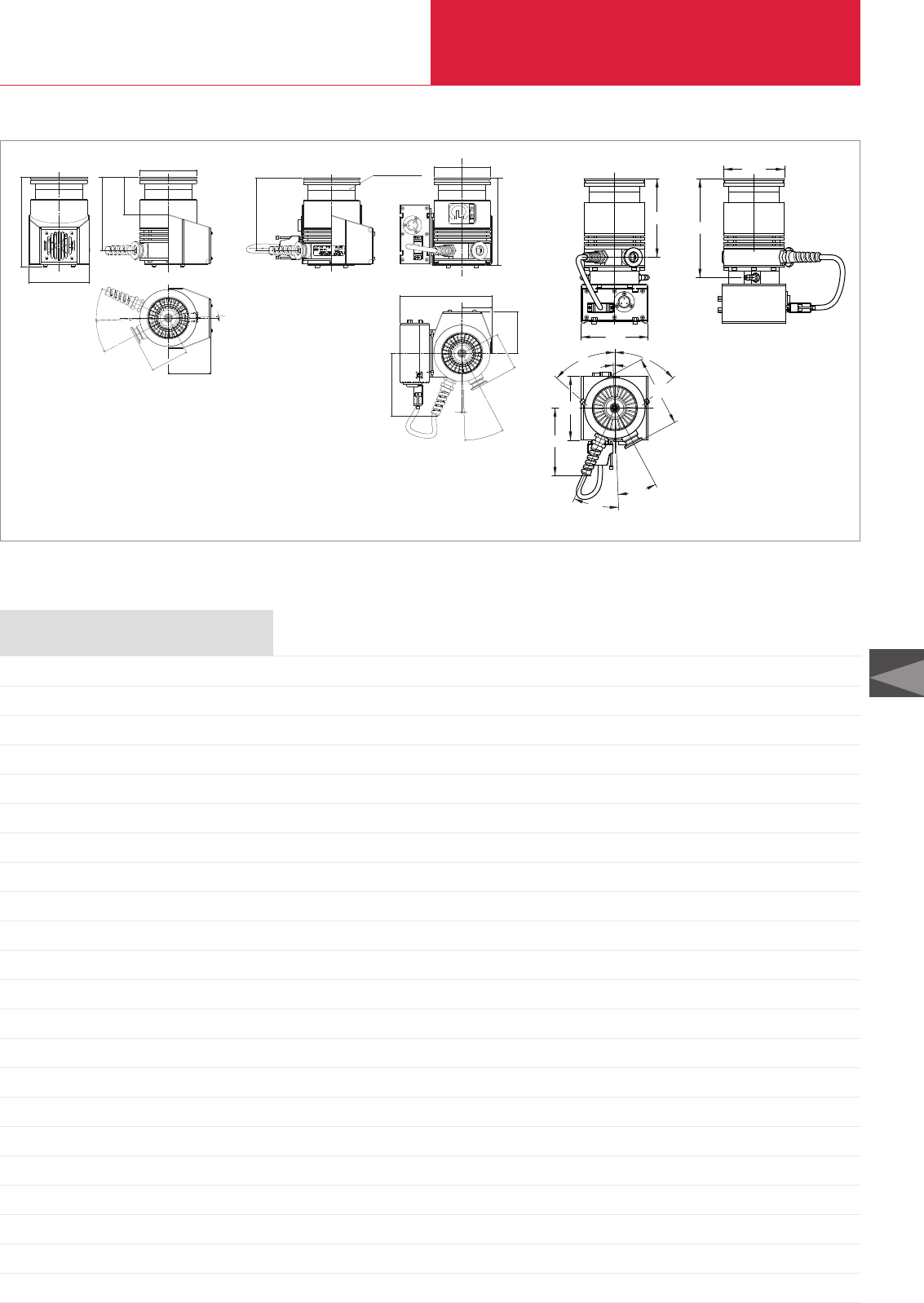
with Compound Stage
Turbomolecular Pumps with Mechanical Rotor Suspension
C09.19
LEYBOLD VACUUM PRODUCTS AND REFERENCE BOOK 2003/2004
C09
Selected dimensional drawings for the TURBOVAC TW 70 H versions
111
ø95
48°48°
26°
26°
100
106
2°
105
123 155
Part No. 800002V1231
TW 70 H with DN 63 ISO-K flange,
water-cooled,
foreline connection DN 16 KF,
with frequency converter
cable
lenght
400 mm
26°
26°2°
Ø 95
123
63
71
64
101
150
Part No. 800002V1234
TW 70 H with DN 63 ISO-K flange,
air-cooled,
foreline connection DN 16 KF,
without frequency converter
TURBO.DRIVE S
123
DN 63 ISO-K Ø 95
148
71
64
50.5
155.5
26°
2°
106
Part No. 800002V1235
TW 70 H with DN 63 ISO-K flange,
air-cooled,
foreline connection DN 16 KF,
with frequency converter
Notes

10-5 10-4 10-3 10-2 10-1 101
100mbar
Inlet Pressure
102
101
100
Pumping Speed
I x s-1
2 864
2
4
6
8
N2
Ar
He
H2
10-5 10-4 10-3 10-2 10-1 100Torr 750
with Compound Stage
Turbomolecular Pumps with Mechanical Rotor Suspension
C09.20 LEYBOLD VACUUM PRODUCTS AND REFERENCE BOOK 2003/2004
TURBOVAC TW 300
Advantages to the User
◆Space-saving
◆Easy to integrate into complex vacuum
systems
◆High foreline tolerance allows the use of
downsized fore-vacuum pumps
◆High productivity
◆Low operating costs
a
LEYBOLD VAKUUM GMBH BONNER STR.498
MADE IN GERMANY 50968 K@RLN
l
b
h1
h
Ø a1
DN
TYP X
Ser.Nr. XXXXXXXXXXX
XXX XX XXX Hz
Ø a2
Top view
b1
h2
h3
05.01.M.037-E(TW300)
Typical Applications
◆Mass spectrometers
◆Production of thin films
◆CD and DVD coating
◆R & D, e.g.
- UHV systems
- Particle accelerators
◆Load locks and transfer chambers
Dimensional drawing for the TURBOVAC TW 300
Pumping speed as a function of the inlet pressure
Technical Features
◆Integrated or external frequency converter
◆Compact design
◆Operation in any orientation
◆Highest pumping speed for Nitrogen and
Argon
◆Highly effective air-cooling unit
◆Oil-free pump for generating clean high and
ultrahigh-vacuum conditions
Top view
DN a a1a2h h1h2h3b b1l
100 ISO-K mm 160 130 171 217 243 50 55 154 77 186
in. 6.30 5.12 6.73 8.54 9.57 1.97 2.17 6.06 3.03 7.32
160 ISO-K mm 160 180 202 221 247.5 50 55 154 77 186
in. 6.30 7.09 7.95 8.70 9.74 1.97 2.17 6.06 3.03 7.32
100 CF mm 160 151.5 – 219.4 – 50 55 154 77 186
in. 6.30 5.96 – 8.64 – 1.97 2.17 6.06 3.03 7.32
a

with Compound Stage
Turbomolecular Pumps with Mechanical Rotor Suspension
C09.21
LEYBOLD VACUUM PRODUCTS AND REFERENCE BOOK 2003/2004
C09
Technical Data TURBOVAC TW 300
O-ring sealed Metal sealed
100 ISO-K 160 ISO-K 100 CF
Aluminum Stainless stel
240 / 240
230 / 230
140 / 125
230 / 220
3.7
2.0
2.3
4.5
3,5 x 10⁸at 7 mbar 6 x 10⁹at 4 mbar
1 x 10⁸at 10 mbar
4 x 10³at 0.,4 mbar
1 x 10⁵at 2 mbar
< 2 x 10⁻⁸ (< 1.5 x 10⁻⁸ Torr) < 2 x 10⁻¹⁰ (< 1.5 x 10⁻¹⁰ Torr)
< 8 x 10⁻¹⁰ (< 6 x 10⁻¹⁰ Torr)
< 4 x 10⁻⁹ (< 3 x 10⁻⁹ Torr)
10 (15 Torr)
TRIVAC D 2,5 E
EcoDry M 15
DIVAC 2,5 VT
4
16 KF
2x G 1/8"
6.8 / 6.0 (15 / 13.2)
24
150 / 30
Inlet flange DN
Pump housing
Pumping speed at 10-5 / 10-3 mbar
N2I x s-1
Ar I x s-1
H2I x s-1
He I x s-1
Max. gas throughput *)at 10-1 mbar
N2at 2 x 10⁻² mbar mbar x I x s-1
Ar at 1 x 10⁻² mbar mbar x I x s-1
H2at 1 x 10⁻¹ mbar mbar x I x s-1
He at 1 x 10⁻¹ mbar mbar x I x s-1
Max. compression when idle
N2
Ar
H2
He
Ultimate pressure (for CF pumps)
with two-stage oil-sealed
rotary vane vacuum pump TRIVAC D 2,5 E mbar
with dry compressing
piston vacuum pump EcoDry M15 mbar
with diaphragm pump DIVAC 2,5 VT mbar
Max. fore-line pressure for N2mbar
Recommended fore-vacuum pump
two-stage oil-sealed rotary vane vacuum pump
dry compressing piston vacuum pump
diaphragm pump
Run-up time to 95% of nominal speed min
Purge / vent port DN
Cooling water connection (option)
Weight, approx.
with / without frequency converter kg (lbs)
Operating voltage V DC
Max. power consumption
Run up / ultimate presure W
*)for continuous operation when water-cooled
Note: TURBOVAC TW 250 S available for specific applications. Please consult factory

with Compound Stage
Turbomolecular Pumps with Mechanical Rotor Suspension
C09.22 LEYBOLD VACUUM PRODUCTS AND REFERENCE BOOK 2003/2004
TW 300 with integrated frequency converter TURBO.DRIVE S
Inlet flange Foreline flange Cooling method Interface
DN 100 ISO-K DN 16 KF Convection RS 485 C
DN 100 ISO-K DN 16 KF Air-cooled RS 485 C
DN 100 ISO-K DN 16 KF Air-cooled RS 232 C
DN 100 ISO-K DN 16 KF Water-cooled RS 485 C
DN 160 ISO-K DN 16 KF Air-cooled RS 485 C
DN 160 ISO-K DN 16 KF Water-cooled RS 485 C
DN 100 CF DN 16 KF Convection RS 485 C
DN 100 CF DN 16 KF Air-cooled RS 485 C
DN 100 CF DN 16 KF Air-cooled RS 232 C
DN 100 CF DN 16 KF Water-cooled RS 485 C
TW 300 without frequency converter TURBO.DRIVE S
Inlet flange Foreline flange Cooling method Interface
DN 100 ISO-K DN 16 KF Convection –
DN 100 ISO-K DN 16 KF Air-cooled –
DN 100 ISO-K DN 16 KF Water-cooled –
DN 100 CF DN 16 KF Convection –
DN 100 CF DN 16 KF Air-cooled –
DN 100 CF DN 16 KF Water-cooled –
For operation, one frequency converter TURBO.DRIVE S is necessary
Electronic frequency converter TURBO.DRIVE S with heat sink, RS 485 C interface
Electronic frequency converter TURBO.DRIVE S with heat sink, RS 232 C interface
Connecting cable (TURBO.DRIVE S - pump)
1 m (03.5 ft)
3 m (10.5 ft)
5 m (17.5 ft)
Accessories, necessary for all pumps
START/STOP switch for manual opertion of the turbomolecular pump
Power supplies
TURBO.POWER 300
TURBO.CONTROL 300
Accessories, optional
Water cooling unit with 2x G 1/8" connection
including 2 hose nozzles G 1/8", OD 10 mm for water hose,
4 gaskets, 2 blank-off plugs
Air cooling unit
Flange heater
100 CF, 230 V, 50 Hz
100 CF, 110 V, 60 Hz
Splinter guard
DN 100 ISO-K/CF
coarse (3.2 x 3.2 mm (0.13 x 0.13 in.))
fine (1.6 x 1.6 mm (0.06 x 0.06 in.))
DN 160 ISO-K
Vibration absorber
DN 100 ISO-K
DN 100 CF
Accessories for serial interfaces RS 232 C and RS 485 C
TURBOVAC TW 300
Part No.
800011V0007
800011V0009
800011V0018
800011V0011
800011V0016
800011V0013
800011V0008
800011V0010
800011V0019
800011V0012
800011V0001
800011V0003
800011V0005
800011V0002
800011V0004
800011V0006
800070V0006
800070V0005
152 47
864 40
864 50
152 48
800100V0002
800100V0001
800135V0002
800 000 249
854 27
854 28
200 18 692
200 18 340
200 00 307
800131V0100
500 071
see chapter “Turbomolecular Pumps”, para. “Accessories”
Ordering Information
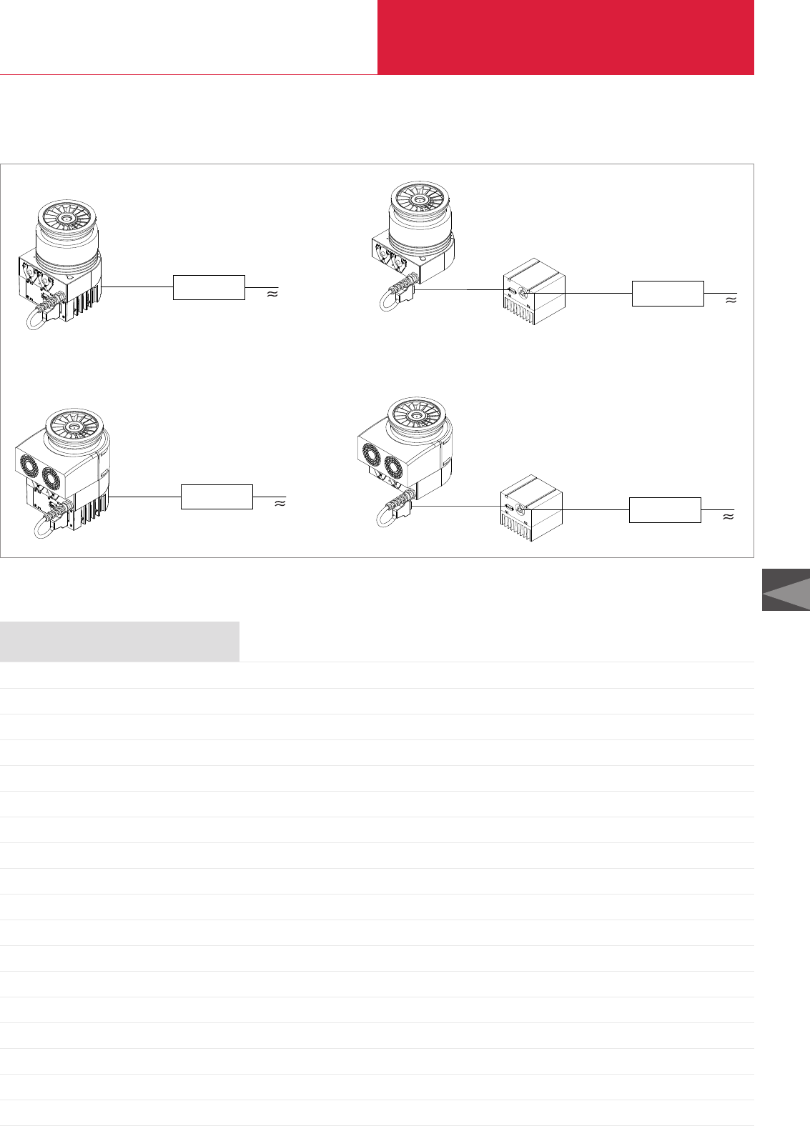
with Compound Stage
Turbomolecular Pumps with Mechanical Rotor Suspension
C09.23
LEYBOLD VACUUM PRODUCTS AND REFERENCE BOOK 2003/2004
C09
Notes
The modular concept
24 V DC
cable,
20 m max.
Mains
Mains
Drive (X3)
HEAT SINK
DC 24 V
(X4)
TW 300 (cooled by convection)
without integrated frequency converter
TURBO.DRIVE S
Drive (X3)
HEAT SINK
DC 24 V
(X4)
TW 300 (with air cooling)
without integrated frequency converter
TURBO.DRIVE S
Connecting
cable,
5 m max.
Mains
Mains
24 V DC
cable,
20 m max.
24 V DC
cable,
20 m max.
24 V DC
cable,
20 m max.
Connecting
cable,
5 m max.
Power supply unit Power supply unit
Power supply unit
Power supply unit
TW 300 (cooled by convection)
with integrated frequency converter
TURBO.DRIVE S
TW 300 (with air cooling)
with integrated frequency converter
TURBO.DRIVE S
e.g.
TURBO.POWER 300
TURBO.CONTROL 300
e.g.
TURBO.POWER 300
TURBO.CONTROL 300
e.g.
TURBO.POWER 300
TURBO.CONTROL 300
e.g.
TURBO.POWER 300
TURBO.CONTROL 300
TURBO.DRIVE S with heat sink
TURBO.DRIVE S with heat sink
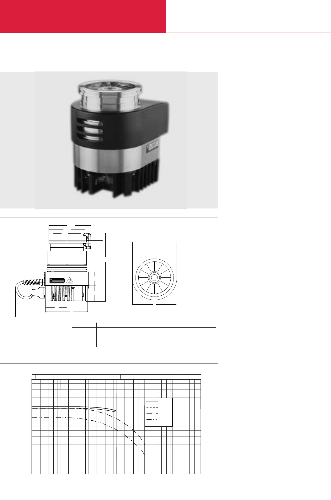
with Compound Stage
Turbomolecular Pumps with Mechanical Rotor Suspension
C09.24 LEYBOLD VACUUM PRODUCTS AND REFERENCE BOOK 2003/2004
10-5 10-4 10-3 10-2 10-1 101
100mbar
Inlet Pressure
103
102
101
Pumping Speed
I x s-1
2 864
N2
Ar
He
H2
10-5 10-4 10-3 10-2 10-1 100Torr
TURBOVAC TW 300 H
Advantages to the User
◆Space-saving
◆Easy to integrate into complex vacuum
systems
◆High foreline tolerance allows the use of
downsized fore-vacuum pumps
◆Low operating costs
Typical Applications
◆Mass spectrometers
◆R & D, e.g.
- UHV systems
- Particle accelerators
◆Load locks and transfer chambers
Pumping speed as a function of the inlet pressure
Technical Features
◆Integrated or external frequency converter
◆Compact design
◆Operation in any orientation
◆High pumping speed and compression for
light gases
◆Highly effective air-cooling unit
◆Oil-free pump for generating clean high and
ultrahigh-vacuum conditions
a
LEYBOLD VAKUUM GMBH BONNER STR.498
MADE IN GERMANY 50968 K@RLN
l
b
h1
h
Ø a1
DN
TYP X
Ser.Nr. XXXXXXXXXXX
XXX XX XXX Hz
Ø a2
Top view
b1
h2
h3
05.01.M.037-E(TW300)
Dimensional drawing for the TURBOVAC TW 300 H
Top view
DN a a1a2h h1h2h3b b1l
100 ISO-K mm 160 130 171 217 243 50 55 154 77 186
in. 6.30 5.12 6.73 8.54 9.57 1.97 2.17 6.06 3.03 7.32
100 CF mm 160 151.5 – 219.4 – 50 55 154 77 186
in. 6.30 5.96 – 8.64 – 1.97 2.17 6.06 3.03 7.32
a

with Compound Stage
Turbomolecular Pumps with Mechanical Rotor Suspension
C09.25
LEYBOLD VACUUM PRODUCTS AND REFERENCE BOOK 2003/2004
C09
Technical Data TURBOVAC TW 300 H
O-ring sealed Metal sealed
100 ISO-K 100 CF
Aluminum Stainless stel
240 / 240
240 / 240
160 / 140
240 / 230
3.7
2.1
2.6
4.5
5,5 x 10⁸at 8 mbar 1 x 10¹⁰ at 6 mbar
1,5 x 10⁸at 10 mbar
1,5 x 10⁴at 0.4 mbar
4 x 10⁵at 2 mbar
< 1 x 10⁻⁸ (< 0.75 x 10⁻⁸ Torr) < 1 x 10⁻¹⁰ (< 0.75 x 10⁻¹⁰ Torr)
< 2 x 10⁻¹⁰ (< 1.5 x 10⁻¹⁰ Torr)
< 1 x 10⁻⁹ (< 0.75 x 10⁻⁹ Torr)
12 (9 Torr)
TRIVAC D 2,5 E
EcoDry M15
DIVAC 2,5 VT
4
16 KF
2x G 1/8"
6.8 / 6.0 (15 / 13.2)
24
150 / 30
Inlet flange DN
Pump housing
Pumping speed at 10-5 / 10-3 mbar
N2I x s-1
Ar I x s-1
H2I x s-1
He I x s-1
Max. gas throughput *)at 10-1 mbar
N2at 2 x 10⁻² mbar mbar x I x s-1
Ar at 1 x 10⁻² mbar mbar x I x s-1
H2at 1 x 10⁻¹ mbar mbar x I x s-1
He at 1 x 10⁻¹ mbar mbar x I x s-1
Max. compression when idle
N2
Ar
H2
He
Ultimate pressure (for CF pumps)
with two-stage oil-sealed
rotary vane vacuum pump TRIVAC D 2,5 E mbar
with dry compressing
piston vacuum pump EcoDry M15 mbar
with diaphragm pump DIVAC 2,5 VT mbar
Max. fore-line pressure for N2mbar
Recommended fore-vacuum pump
two-stage oil-sealed rotary vane vacuum pump
dry compressing piston vacuum pump
diaphragm pump
Run-up time to 95% of nominal speed min
Purge / vent port DN
Cooling water connection (option)
Weight, approx.
with / without frequency converter kg (lbs)
Operating voltage V DC
Max. power consumption
Run up / ultimate presure W
*)for continuous operation when water-cooled
Note: TURBOVAC TW 250 S available for specific applications. Please consult factory

with Compound Stage
Turbomolecular Pumps with Mechanical Rotor Suspension
C09.26 LEYBOLD VACUUM PRODUCTS AND REFERENCE BOOK 2003/2004
TW 300 H with integrated frequency converter TURBO.DRIVE S
Inlet flange Foreline flange Cooling method Interface
DN 100 ISO-K DN 16 KF Convection RS 485 C
DN 100 ISO-K DN 16 KF Air-cooled RS 485 C
DN 100 ISO-K DN 16 KF Air-cooled RS 232 C
DN 100 ISO-K DN 16 KF Water-cooled RS 485 C
DN 100 CF DN 16 KF Convection RS 485 C
DN 100 CF DN 16 KF Air-cooled RS 485 C
DN 100 CF DN 16 KF Air-cooled RS 232 C
DN 100 CF DN 16 KF Water-cooled RS 485 C
TW 300 H without frequency converter TURBO.DRIVE S
Inlet flange Foreline flange Cooling method Interface
DN 100 ISO-K DN 16 KF Convection –
DN 100 ISO-K DN 16 KF Air-cooled –
DN 100 ISO-K DN 16 KF Water-cooled –
DN 100 CF DN 16 KF Convection –
DN 100 CF DN 16 KF Air-cooled –
DN 100 CF DN 16 KF Water-cooled –
For operation, one frequency converter TURBO.DRIVE S is necessary
Electronic frequency converter TURBO.DRIVE S with heat sink, RS 485 C interface
Electronic frequency converter TURBO.DRIVE S with heat sink, RS 232 C interface
Connecting cable (TURBO.DRIVE S - pump)
1 m (3.5 ft)
3 m (10.5 ft)
5 m (17.5 ft)
Accessories, necessary for all pumps
START/STOP switch for manual opertion of the turbomolecular pump
Power supplies
TURBO.POWER 300
TURBO.CONTROL 300
Accessories, optional
Water cooling unit with G 1/8" connection
including 2 hose nozzles G 1/8", OD 10 mm for water hose,
4 gaskets, 2 blank-off plugs
Air cooling unit
Flange heater
100 CF, 230 V, 50 Hz
100 CF, 110 V, 60 Hz
Splinter guard DN 100 ISO-K/CF
coarse (3,2 x 3,2 mm)
fine (1,6 x 1,6 mm)
Vibration absorber
DN 100 ISO-K
DN 100 CF
Accessories for serial interfaces RS 232 C and RS 485 C
TURBOVAC TW 300 H
Part No.
800012V0007
800012V0009
800012V0013
800012V0011
800012V0008
800012V0010
800012V0014
800012V0012
800012V0001
800012V0003
800012V0005
800012V0002
800012V0004
800012V0006
800070V0006
800070V0005
152 47
864 40
864 50
152 48
800100V0002
800100V0001
800135V0002
800 000 249
854 27
854 28
200 18 692
200 18 340
800131V0100
500 071
see chapter “Turbomolecular Pumps”, para. “Accessories”
Ordering Information
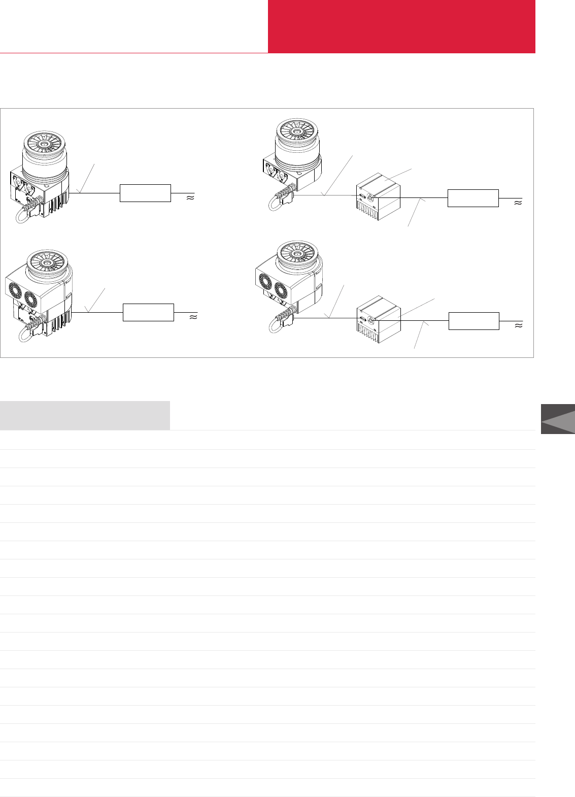
with Compound Stage
Turbomolecular Pumps with Mechanical Rotor Suspension
C09.27
LEYBOLD VACUUM PRODUCTS AND REFERENCE BOOK 2003/2004
C09
Notes
Drive (X3)
HEAT SINK
DC 24 V
(X4)
The modular concept
Mains
Mains
Drive (X3)
HEAT SINK
DC 24 V
(X4)
TW 300 H (without forced cooling)
without integrated frequency converter
TURBO.DRIVE S
Connecting cable, 5 m max.
Mains
Mains
Power supply unit, e.g.
TURBO.POWER 300
TURBO.CONTROL 300
TW 300 H (without forced cooling)
with integrated frequency converter
TURBO.DRIVE S
TW 300 H (with air cooling)
with integrated frequency converter
TURBO.DRIVE S
TURBO.DRIVE S with heat sink
TURBO.DRIVE S
with heat sink
TW 300 H (with air cooling)
without integrated frequency converter
TURBO.DRIVE S
Power supply unit
24 V DC cable with shield, 20 m max.
24 V DC cable with shield, 20 m max.
Connecting cable, 5 m max.
24 V DC cable with shield, 20 m max.
24 V DC cable
with shield, 20 m max.
Power supply unit, e.g.
TURBO.POWER 300
TURBO.CONTROL 300
Power supply unit, e.g.
TURBO.POWER 300
TURBO.CONTROL 300
Power supply unit, e.g.
TURBO.POWER 300
TURBO.CONTROL 300
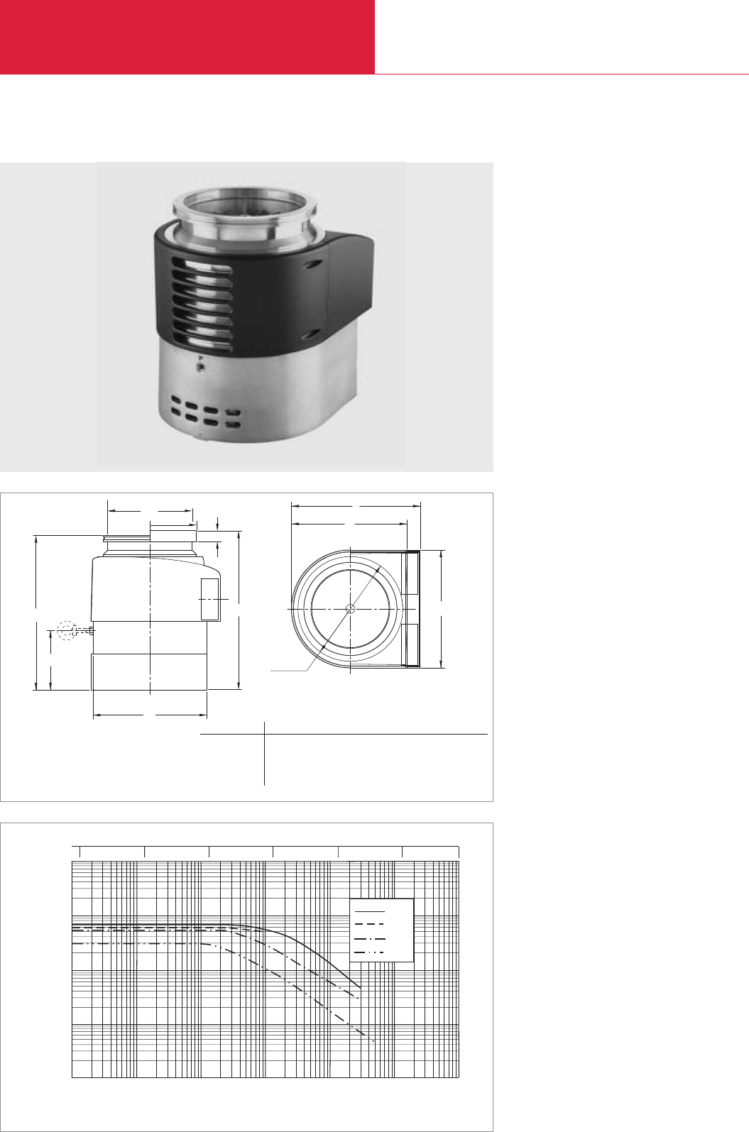
Ar
N2
He
H2
10-5 10-4 10-3 10-2 10-1 101mbar
Inlet Pressure
104
103
102
101
100
Pumping Speed
I x s-1
10-5 10-4 10-3 10-2 10-1 Torr 750
100
with Compound Stage
Turbomolecular Pumps with Mechanical Rotor Suspension
C09.28 LEYBOLD VACUUM PRODUCTS AND REFERENCE BOOK 2003/2004
TURBOVAC TW 701
Advantages to the User
◆Space-saving
◆Easy to integrate into complex vacuum
systems
◆High productivity
◆Low operating costs
◆Highly reliable operation
b
l
h1
h
ød l1
d2
ø
b1
d1
ø
h3
h2
Typical Applications
◆Mass spectrometers
◆Data storage
◆Flat panel displays
◆R & D, e.g.
- UHV systems
- Particle accelerators
◆Load locks and transfer chambers
Dimensional drawing for the TURBOVAC TW 700
Pumping speed as a function of the inlet pressure
Technical Features
◆Integrated frequency converter
◆Operation in any orientation
◆Highest pumping speed and throughput for
Nitrogen and Argon
◆High foreline tolerance allows the use of
downsized fore-vacuum pumps
◆Highly effective air-cooling unit
◆Oil-free pump for generating clean high- and
ultrahigh-vacuum conditions
Top view
b b1d d1d2h h1h2h3l l1
DN160 ISO-K mm 228 219 180 150 180 – – 285 115 264 223
in. 8.98 8.82 7.09 5.91 7.09 – – 11.22 4.53 10.39 8.78
DN 160 CF mm 228 219 – 150 180 295 12 – 115 264 223
in. 8.98 8.82 – 5.91 7.09 11.61 0.47 – 4.53 10.39 8.78

with Compound Stage
Turbomolecular Pumps with Mechanical Rotor Suspension
C09.29
LEYBOLD VACUUM PRODUCTS AND REFERENCE BOOK 2003/2004
C09
Inlet flange Foreline flange Cooling method Interface
DN 160 ISO-K DN 25 KF Air-cooled RS 232 C
DN 160 ISO-K DN 25 KF Water-cooled RS 232 C
DN 160 ISO-K DN 25 KF Air-cooled RS 485 C
DN 160 ISO-K DN 25 KF Water-cooled RS 485 C
DN 160 CF DN 25 KF Air-cooled RS 485 C
DN 160 CF DN 25 KF Water-cooled RS 485 C
DN 200 CF (incl. splinter guard) DN 25 KF Water-cooled RS 232 C
Power supply TURBO.CONTROL 700
Accessories, optional
Inlet screen
DN 160 ISO-K
DN 160 CF
Flange heater 160 CF
230 V AC
110 V AC
Vibration absorber
DN 160 ISO-K
DN 160 CF
OEM power supply, 59 V DC
59 V DC cable
03 m (10.5 ft)
05 m (17.5 ft)
10 m (35 ft)
20 m (70 ft)
Plug with integrated START/STOP switch
Purge gas and venting valve, 24 V DC, 0.6 mbar x I x s-1 = 36 sccm (purge gas pressure, abs.; 1.5 to 6 bar)
Accessories for RS 232 C and RS 485 C interfaces
Accessories, for the water connection
Adaptor G (BPS) 1/8" – G (BPS) 1/4" pipe (Swagelok *))
Gasket
Adaptor G (BPS) 1/8" – 10 mm (0.39 in.) hose nozzle
Gasket
Adaptor G (BPS) 1/8" – NPT 1/8"
Gasket
*)Adapts German threads of water cooling to a more common Englisch thread. The Part Number is for one each, but two are used for almost all installations
TURBOVAC TW 701
Technical Data TURBOVAC TW 701
160 ISO-K 160 CF
680
600
530
330
12
5 (water cooled)
7
2.5
8 x 10⁸
1 x 10⁸
1 x 10⁶
2 x 10⁴
< 5.0 x 10⁻⁹ (< 3.75 x 10⁻⁹) < 1.5 x 10⁻¹⁰ (< 1.1 x 10⁻¹⁰)
14 (10.5)
TRIVAC D 65 B, EcoDry M15, DIVAC 4.8 VT
≈5
16 KF
2x G 1/8" (internal threads)
19 (42)
59
500
Part No.
800051V0021
800051V0025
800051V0024
800051V0023
800051V0027
800051V0026
800051V0022
see chapter “Turbomolecular Pumps
with Mechanical Rotor Suspension”
para. “Electronic Frequency Converter”
200 00 307
200 17 247
854 37
854 38
500 073
500 072
864 45
200 12 729
200 12 730
200 12 731
200 15 064
152 48
121 33
see chapter “Turbomolecular Pumps”, para. “Accessories”
200 91 671 (2x required)
224 01 207 (2x required)
200 18 366 (2x required)
230 02 106 (2x required)
200 12 742 (2x required)
238 20 110 (2x required)
Ordering Information
Inlet flange DN
Pumping speed
N2I x s-1
Ar I x s-1
He I x s-1
H2I x s-1
Max. gas throughput
N2mbar x I x s-1
Ar mbar x I x s-1
He mbar x I x s-1
H2mbar x I x s-1
Compression ratio
N2
Ar
He
H2
Ultimate pressure mbar (Torr)
Max. foreline pressure for N2mbar (Torr)
Recommended fore-vacuum pump
Run-up time to 95% speed min
Purge port DN
Cooling water connections
Weight, approx. kg (lbs)
Supply voltage, nominal V DC
Max. power consumption W

with Compound Stage
Turbomolecular Pumps with Mechanical Rotor Suspension
C09.30 LEYBOLD VACUUM PRODUCTS AND REFERENCE BOOK 2003/2004
104
103
102
10-5 10-4 10-3 10-2 10-1 101mbar
Inlet Pressure
Pumping Speed
I x s-1
4
2
6
8
2 4 6 8
10-5 10-4 10-2 10-1 1Torr 1010-3
101
N2
Ar
TURBOVAC TW 1600
Advantages to the User
◆Space-saving
◆Easy to integrate into complex vacuum
systems
◆High productivity
◆Low operating costs
◆Operation with dry backing pumps
Typical Applications
◆Data storage
◆Flat panel displays
◆Optical coating
◆Large area coating
◆R & D, e.g.
- Fusion experiments
- Space simulation
- UHV applications
Dimensional drawing for the TURBOVAC TW 1600
Pumping speed as a function of inlet pressure
Technical Features
◆Frequency converter and power supply
integrated
◆Robust rotor design
◆Operation in any orientation
◆Highest pumping speed and high throughput
◆Oil-free pump for generating clean high and
ultrahigh-vacuum conditions
◆Purge gas and venting valve integrated
◆High fore-vacuum tolerance
Top view
57°
61,5°
h3
a
h4
h1
h
ø d
ø d1
h2
bb1
DN aa b b1d d1h h1h2h3h4
200 ISO-F mm 15° 178 190 156 285 308 425 349 315 277 256
inch 15° 7.01 7.48 6.14 11.22 12.13 16.73 13.74 12.40 10.91 10.08
250 ISO-F mm 15° 178 190 156 335 308 398 322 288 249 228
inch 15° 7.01 7.48 6.14 13.19 12.13 15.67 12.68 11.34 9.80 8.98
250 CF mm 5.6° 178 190 156 304 308 413 337 303 264 243
inch 5.6° 7.01 7.48 6.14 11.97 12.13 16.26 13.27 11.93 10.39 9.57

with Compound Stage
Turbomolecular Pumps with Mechanical Rotor Suspension
C09.31
LEYBOLD VACUUM PRODUCTS AND REFERENCE BOOK 2003/2004
C09
Technical Data TURBOVAC TW 1600
200 ISO-F 250 ISO-F / 250 CF
1000 1420
820 1200
7.4
6.8
1 x 10⁷
1 x 10⁸
< 3 x 10⁻¹⁰ (< 2.25 x 10⁻¹⁰)
8 (6)
TRIVAC D 65 B + RUVAC WA 501
DIVAC 4.8 VT
EcoDry M
SOGEVAC SV 25
< 10
G 1/4"
G 3/8"
40 (88.3)
100 - 240
700
Inlet flange DN
Pumping speed
N2I x s-1
Ar I x s-11
Max. gas throughput
N2mbar x I x s-1
Ar mbar x I x s-1
Compression ratio kOfor O-ring sealed pumps
N2
Ar
Ultimate pressure mbar (Torr)
Max. foreline pressure for N2mbar (Torr)
Recommended fore-vacuum pump (alternatively)
Run-up time to 95% speed min
Purge / Vent port DN
Cooling water connections
Weight, approx. kg (lbs)
Supply voltage V AC
Max. power consumption W
Inlet flange Foreline flange Cooling method Interface
DN 200 ISO-F DN 40 KF Water cooled ProfiBus
DN 250 ISO-F DN 40 KF Water cooled ProfiBus
DN 250 CF DN 40 KF Water cooled ProfiBus
Accessories for RS 232 C and RS 485 C interfaces
TURBOVAC TW 1600
Part No.
800041V2144
800041V2444
800041V2844
see chapter “Turbomolecular Pumps”, para. “Accessories”
Ordering Information
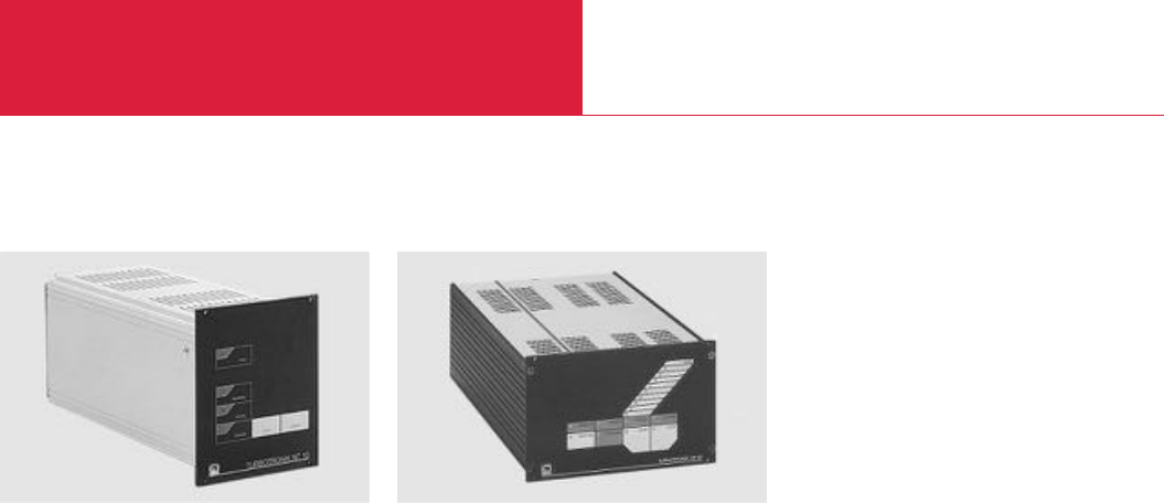
Electronic Frequency Converters
Turbomolecular Pumps with Mechanical Rotor Suspension
C09.32 LEYBOLD VACUUM PRODUCTS AND REFERENCE BOOK 2003/2004
TURBOTRONIK NT 10 TURBOTRONIK NT 20
Technical Features
◆For operating the TURBOVAC 361 (C) and
1100 C turbomolecular pump
◆Front panel with membrane keypad and LCD
Advantages to the User
◆Remote control and process control via
analog and programmable control inputs and
outputs
◆Connection for backing pump, venting valve,
flange heater and air cooler
◆Operation direct at the unit or via interface
◆Floating connection of external monitoring
devices via a terminal strip on the rear
Technical Features
◆For operating the TURBOVAC 50
turbomolecular pump
◆Bench top unit
◆Also for rack mounting (1/4 19", 3 HU)
◆Controls and indicators on the front panel
◆Inputs fpr remote control and process
controller
◆Freely assignable relays (e.g. to control the
backing pumps)

Electronic Frequency Converters
Turbomolecular Pumps with Mechanical Rotor Suspension
C09.33
LEYBOLD VACUUM PRODUCTS AND REFERENCE BOOK 2003/2004
C09
NT 10 NT 20 1)
Ordering Information
090 - 140 V (with US plug)
100 V (with US plug)
120 V (with US plug)
180 - 260 V (with EURO plug)
230 V (with EURO plug)
Pump/ converter connecting line
03 m (10.5 ft)
05 m (17.5 ft)
10 m (35.0 ft)
20 m (70.0 ft)
1) If NT 20 is beeing ordered to replace NT 150/360, NT 151/361, then an NT 20 cable must also be ordered.
(NT 20 has round connector on back, the other controller had a rectangular connector back.)
2) Not suitable for driving the TURBOVAC 1100 C
Part No. 859 01 –
–Part No. 857 22
2)
–Part No. 857 21
Part No. 859 00 –
–Part No. 857 20
Part No. 121 08 Part No. 857 65 1)
Part No. 121 09 Part No. 857 66 1)
– Part No. 857 67 1)
– Part No. 857 68 1)
Main connection, 50 to 60 Hz V
Main, 50 to 60 Hz, selectable V
Max. output voltage V
Overload current limit A
Permissible ambient temperature °C (°F)
Dimensions (W x H x D) mm
(in.)
Weight, approx. kg (lbs)
90-140/180-260 –
– 85 to 265
3 x 150 3 x 42
0.22 5
0 to +40 (32 to +104) 0 to +45 (32 to +113)
106 x 128 x 233 213 x 129 x 320 (1/2 19", 3 HU)
(4.17 x 5.04 x 9.17) (8.39 x 5.08 x 12.60 (1/2 19", 3 HU))
1.5 (3.3) 7 (15.4)
Technical Data NT 10 NT 20
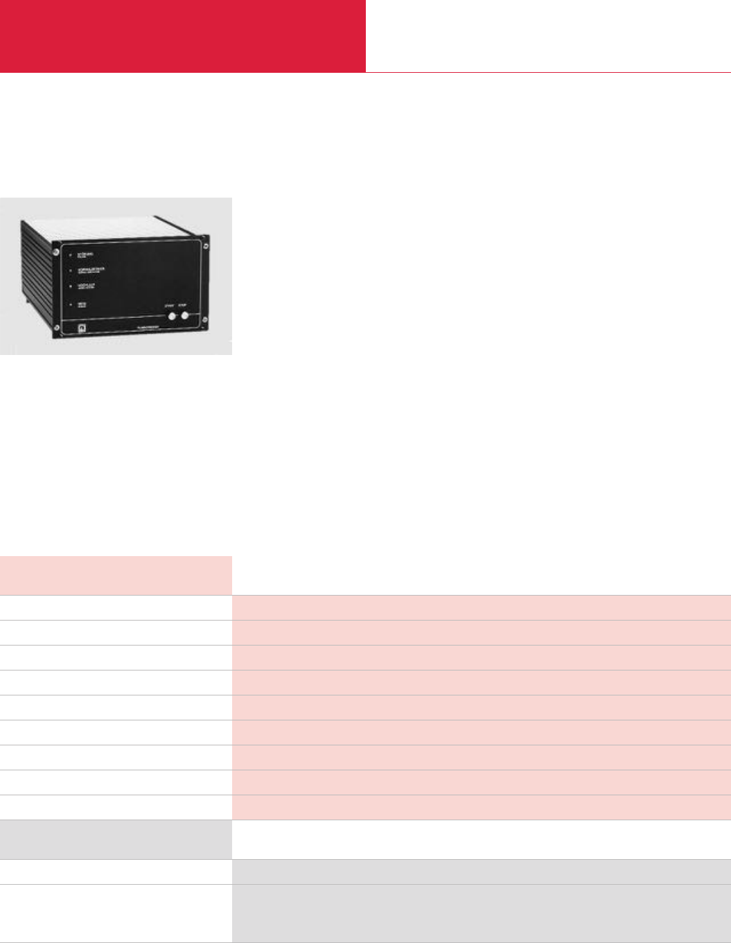
Electronic Frequency Converters
Turbomolecular Pumps with Mechanical Rotor Suspension
C09.34 LEYBOLD VACUUM PRODUCTS AND REFERENCE BOOK 2003/2004
NT 361Ordering Information
120 V (Main cord with US plug)
Pump/ converter connecting line
3 m (10.5 ft)
5 m (17.5 ft)
Part No. 854 72-6
Part No. 857 60
Part No. 857 61
TURBOTRONIK NT 361
Advantages to the User
◆For operating the TURBOVAC 361 turbo-
molecular pumps
◆Sensing of the pump model via a resistance
code
◆Operation via pushbuttons
◆Terminal strip for remote control and display
functions
Main connection, 60 Hz V
Max. power consumption during run-up VA
Power consumption during normal operation, approx. VA
Max. output voltage / run-up current V / A
Overload current limit A
Nominal frequency Hz
Permissible ambient temperature °C (°F)
Dimensions (W x H x D) mm (in.)
Weight, approx. kg (lbs)
120
750
130
3 x 45 / 5.5
3.5
833/750
0 to +40 (32 to +104)
210 x 129 x 288 (8.27 x 5.08 x 11.34)
8.5 (18.7)
Technical Data NT 361
Version for the North and South American Continents
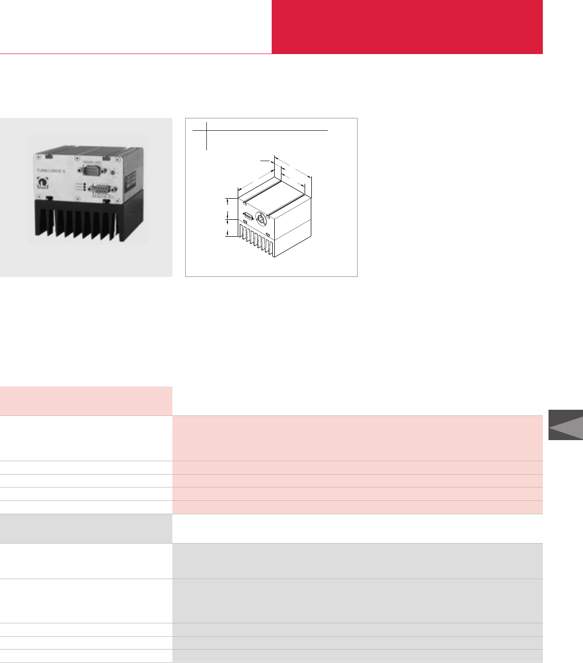
Electronic Frequency Converters
Turbomolecular Pumps with Mechanical Rotor Suspension
C09.35
LEYBOLD VACUUM PRODUCTS AND REFERENCE BOOK 2003/2004
C09
TURBO.DRIVE S (TDS) for TW 70, TW 300 and TW 300 H Turbomolecular Pumps
Ordering Information
Technical Data
TURBO.DRIVE S with RS 232 C interface and heat sink
TURBO.DRIVE S with RS 485 C interface and heat sink
with Profibus
Connecting cable TDS–pump
01 m (03.5 ft)
03 m (10.5 ft)
05 m (17.5 ft)
START/STOP switch (for manual operation)
Hat rail adaptor as mounting aid
Accessories for RS 232 C and RS 485 C interfaces
TURBO.DRIVE S
TURBO.DRIVE S
Input
Voltage V DC
Max. continuos current A
Max. continuos power consumption W
Ambient temperature °C (°F)
Dimensions (W x H x D), including heat sink mm (in.)
Weight kg (lbs)
Serial Interface
24 ± 5%
7
170
+10 to +45 (+50 to +113)
100 x 90 x 100 (3.94 x 3.54 x 3.94)
1.4 (3.1)
RS 232 C or RS 485 C
Part No. 800070V0005
Part No. 800070V0006
upon request
Part No. 152 47
Part No. 864 40
Part No. 864 50
Part No. 152 48
Part No. 800110V0003
see chapter "Accessories for Turbomolecular Pumps”, para. “Accessories”
Drive (X3)
HEAT SINK
DC 24 V
(X4)
l
b
h
b1
b2
h1
Dimensional drawing for the TURBO.DRIVE STURBO.DRIVE S with heat sink
Technical Features
◆Compact size
◆RS 232 C or RS 485 C interface
◆Configurations
- as a separate frequency converter
- integrated within turbomolecular pump
◆Remote control via remote control interface
◆Flexible mounting
◆Cost-effective supply of 24 V DC power
b b1b2h h1l
mm 100 18.1 63.8 50 40 100
in. 3.94 0.71 2.51 1.97 1.57 100
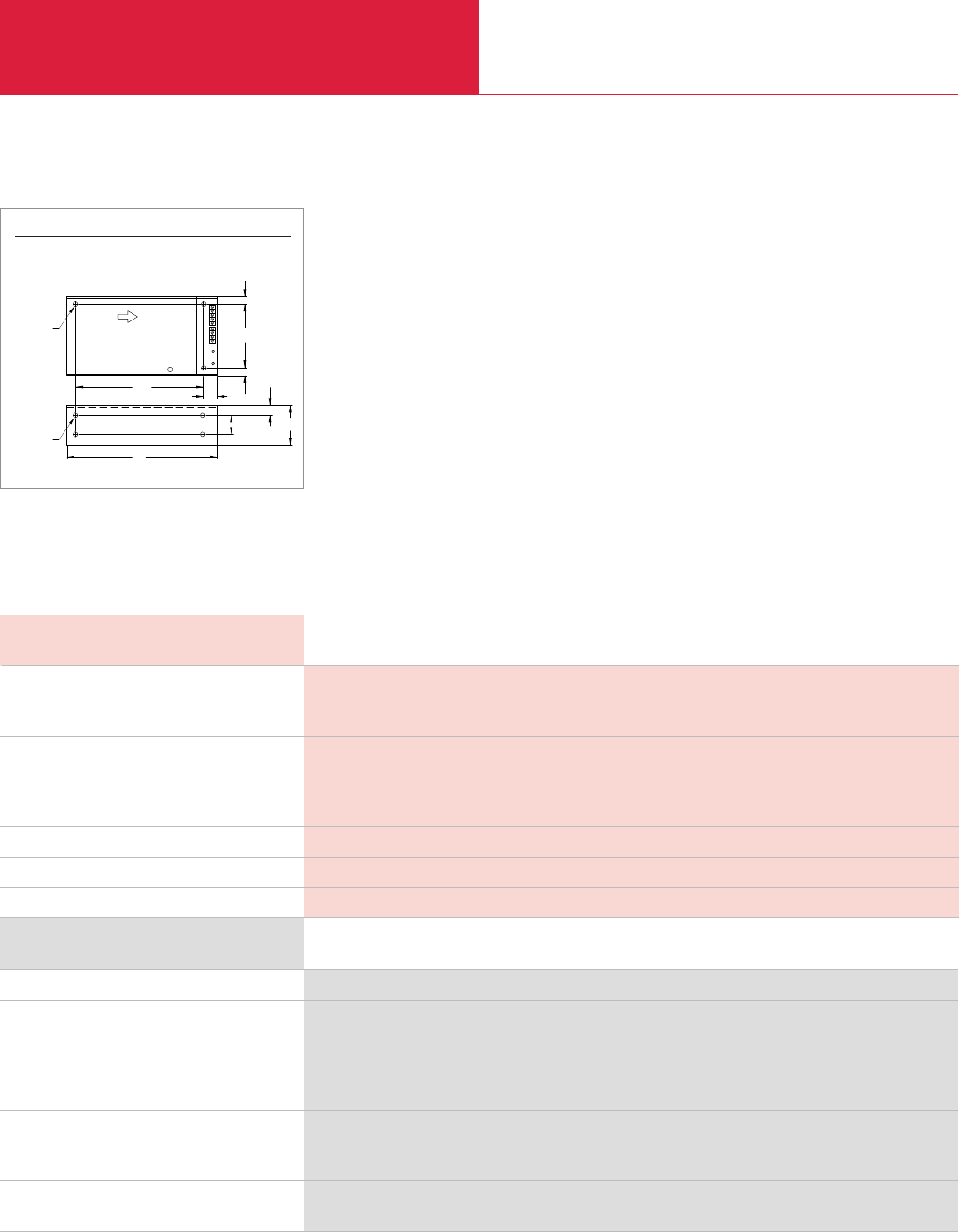
Electronic Frequency Converters
Turbomolecular Pumps with Mechanical Rotor Suspension
C09.36 LEYBOLD VACUUM PRODUCTS AND REFERENCE BOOK 2003/2004
Power Supply PS 700 for TW 701 Turbomolecular Pumps
Ordering Information
Technical Data
OEM power supply 59 V DC
59 V DC cable TW 700–power supply
03 m (10.5 ft)
05 m (17.5 ft)
10 m (35.0 ft)
20 m (70.0 ft)
Mains cable for OEM power supply, 2 m (7 ft)
with EURO plug
with US plug
START/STOP switch for TURBO.DRIVE S/L
(for manual operation)
Note: See the TPC and TPS controllers in the Product Section C10 “Turbomolecular Pump Systems” for additinal controllers for the TURBOVAC TW 300 and TW 700
Power Supply PS 700
Power Supply PS 700
Input
Mains voltage V
Max. continuos power consumption W
Output
Voltage, nominal V DC
Max. continuos current A
Max. power output W
Ambient temperature °C (°F)
Dimensions (W x H x D) mm (in.)
Weight kg (lbs)
85-265
850
59
13
750
0 to +70 (32 to +158)
227 x 63 x 127 (8.94 x 2.48 x 5.0)
2 (4.4)
Part No. 864 45
Part No. 200 12 729
Part No. 200 12 730
Part No. 200 12 731
Part No. 200 15 064
Part No. 800102V0001
Part No. 800102V1001
Part No. 152 48
AIRFLOW
l
3 x M4
b
h
4 x M4
h1
h1
b1
b2
l1l2
Dimensional drawing for the power supply PS 700
Technical Features
◆59 V DC OEM power supply for screw fixing
in electrical cabinets
b b1b2h h1l l1l2
mm 63 15 30 105 11 227 197 18
in. 2.48 0.59 1.18 4.13 0.43 8.94 7.76 0.71
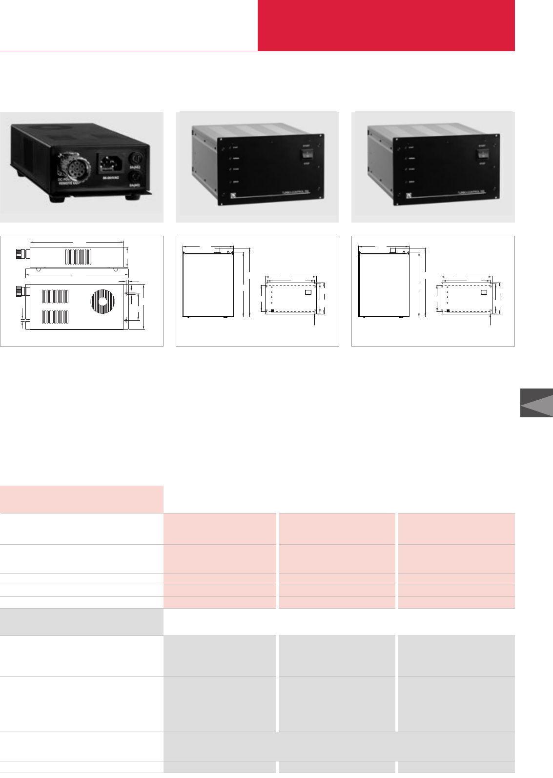
Electronic Frequency Converters
Turbomolecular Pumps with Mechanical Rotor Suspension
C09.37
LEYBOLD VACUUM PRODUCTS AND REFERENCE BOOK 2003/2004
C09
Ordering Information
Technical Data
Power supply
TURBO.POWER 300
TURBO.CONTROL 300
TURBO.CONTROL 700
DC cable frequency converter – power supply unit
01 m (03.5 ft)
03 m (10.5 ft)
05 m (17.5 ft)
10 m (35.0 ft)
20 m (70.0 ft)
Mains cable, 3 m (10.5 ft)
with EURO plug
with US plug 6-15 P
Hat rail adaptor as mounting aid
Power Supplies
TURBO.POWER 300 TURBO.CONTROL 300 TURBO.CONTROL 700
Power Supplies
TURBO.POWER 300 TURBO.CONTROL 300 TURBO.CONTROL 700
Input
Mains voltage
Max. power consumption V A
Output
Voltage, nominal V DC
Max. continuos current A
Ambient temperature °C (°F)
Dimensions (W x H x D) mm (in.)
Weight kg (lbs)
85-264 V / 50/60 Hz 85-264 V / 50/60 Hz 85-264 V / 50/60 Hz
300 300 805
24 24 56
8,4 8,4 8,5
0 to +40 (32 to +104) 0 to +40 (32 to +104) 0 to +40 (32 to +104)
116 x 53 x 260 (4.57 x 2.09 x 10.24) 213 x 129 x 320 (8.39 x 5.08 x 12.6) 213 x 129 x 320 (8.39 x 5.08 x 12.6)
1.5 (3.31) 1.5 (3.31) 2.5 (5.52)
Part. No. 800100V0002 – –
–Part. No. 800100V0001 –
– – Part. No. 800101V0001
24 V DC power cable 24 V DC control cable 56 V DC control cable
Part. No. 800094V0100 Part. No. 800091V0100 Part. No. 800093V0100
Part. No. 800094V0300 Part. No. 800091V0300 Part. No. 800093V0300
Part. No. 800094V0500 Part. No. 800091V0500 Part. No. 800093V0500
Part. No. 800094V1000 Part. No. 800091V1000 Part. No. 800093V1000
Part. No. 800094V2000 Part. No. 800091V2000 Part. No. 800093V2000
Part. No. 800102V0002
Part. No. 800102V1002
Part. No. 800102V0002 – –
Power Supply Units for TURBO.DRIVE S and TW 700/701
Technical Features
◆Cost-effective supply of 24 V DC power for
TURBO.DRIVE S
◆Plug & play
◆Bench top unit or for cabinet mounting
Technical Features
◆For supplying 24 V DC power to the
TURBO.DRIVE S
◆Plug & play
◆Bench top unit or for cabinet mounting
◆Mains switch
◆
START/STOP switch for the turbomolecular pump
◆Remote control via remote interface
◆Status indicating LEDs and status relays
246
266
Ø 4
5
53
4
116
70
Dimensional drawing for the power supply TURBO.POWER 300
START
NORMAL
POWER
ERROR
START
STOP
TURBO.CONTROL 300/700
1
0
211
263
315
111
213 198,1
122,4
128,4
Ø 3,2
Dimensional drawing for the power supply TURBO.CONTROL 700
START
NORMAL
POWER
ERROR
START
STOP
TURBO.CONTROL 300/700
1
0
211
263
315
111
213 198,1
122,4
128,4
Ø 3,2
Dimensional drawing for the power supply TURBO.CONTROL 300
Technical Features
◆For supplying 56 V DC power to the
TW 700/701
◆Plug & play
◆Bench top unit or for cabinet mounting
◆Mains switch
◆
START/STOP switch for the turbomolecular pump
◆Remote control via remote interface
◆Status indicating LEDs and status relays
Front View Front View
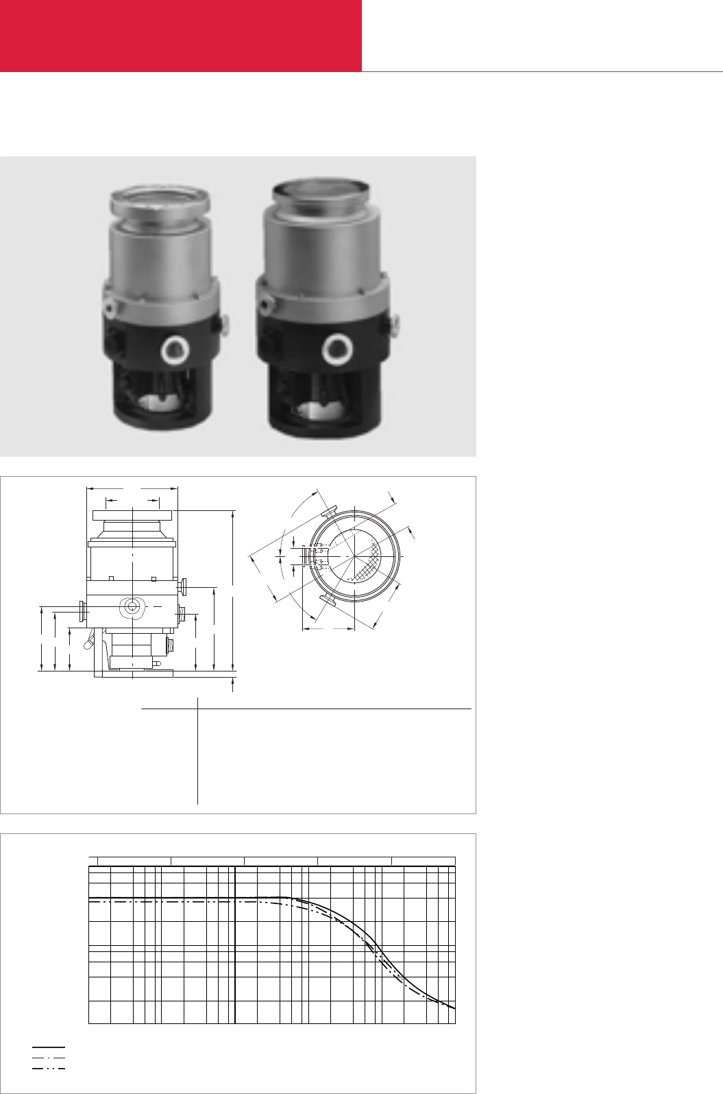
ød
b
60°
60°
DN 100 A
C
E
BF1
F2
F3
B
D
C
F
E
h2
h1
a
h
h3
ød1
b1
a1
h6
h5
h4
LEYBOLD VACUUM PRODUCTS AND REFERENCE BOOK 2003/2004
without Compound Stage
Turbomolecular Pumps with Magnetic Rotor Suspension
C09.38
TURBOVAC 340 M
Advantages to the User
◆Maintenance-free
◆Convection cooling
◆No batteries are required because of integrat-
ed generator mode in case of power failures
Typical Applications
◆Gas analysis systems
◆Particle accelerators
◆Electron beam microscopy
◆Research instruments and systems
Inlet Pressure
mbar
Pumping Speed
10
-6 2 4 6 8
4
2
6
8
10
-5
10
-4
10
-3
10
-2
10
-1
I x s-1
He
H2
N2
Torr
10-6 10-5 10-4 10-3 10-2 0.075
101
102
103
Technical Features
◆Magnetic suspension
◆Absolutely free of any lubricants
◆Low noise and vibration levels
◆Operation in any orientation
◆Convection cooling
◆Purge gas design
Dimensional drawing for the TURBOVAC 340 M
Pumping speed of the TURBOVAC 340 M as a function of the inlet pressure
Top view
DN a a1b b1d d1h h1h2h3h4h5h6
100 ISO-K mm 99 101 101 50 178 28 311 12 162 109 123 114 80
in. 3.90 3.98 3.98 1.97 7.01 1.10 12.24 0.47 6.38 4.29 4.84 4.49 3.15
100 CF mm 99 101 101 50 178 28 322 12 162 109 123 114 80
in. 3.90 3.98 3.98 1.97 7.01 1.10 12.24 0.47 6.38 4.29 4.84 4.49 3.15
160 ISO-K mm 99 101 101 50 178 28 311 12 162 109 123 114 80
in. 3.90 3.98 3.98 1.97 7.01 1.10 12.24 0.47 6.38 4.29 4.84 4.49 3.15
160 CF mm 99 101 101 50 178 28 308 12 162 109 123 114 80
in. 3.90 3.98 3.98 1.97 7.01 1.10 12.13 0.47 6.38 4.29 4.84 4.49 3.15

C09
LEYBOLD VACUUM PRODUCTS AND REFERENCE BOOK 2003/2004
without Compound Stage
Turbomolecular Pumps with Magnetic Rotor Suspension
C09.39
Inlet flange DN
Pumping speed
N2I x s-1
He I x s-1
H2I x s-1
Speed rpm
Compression ratio
N2
He
H2
Ultimate pressure mbar (Torr)
Max. foreline pressure for N2mbar (Torr)
Recommended fore-vacuum pump
Run-up time min
Fore-vacuum flange DN
Purge / vent port DN
Cooling water connections, hose nipple
Weight, approx. kg (lbs)
100 ISO-K • 100 CF 160 ISO-K • 160 CF
250 400
370 400
340 370
51,600
> 109
6.4 x 10⁴
2.5 x 10³
< 10-10 (< 0.75 x 10⁻¹⁰)
5 x 10⁻¹ (3.75 x 10⁻¹)
TRIVAC D 16 B
EcoDry L
3.5
25 KF
10 KF
not required
16 (35)
Technical Data
Part No. 855 80
Part No. 855 81
Part No. 855 82
Part No. 855 83
Part No. 854 27
Part No. 854 37
Part No. 854 38
Part No. 857 31
Part No. 857 30
Part No. 857 29
see TURBOTRONIK
TURBOVAC 340 M
TURBOVAC 340 M
TURBOVAC turbomolecular pump
with high-vacuum connection flange
DN 100 ISO-K
DN 100 CF
DN 160 ISO-K
DN 160 CF
Accessories for all pumps
Flange heater
DN 100 CF, 230 V
DN 160 CF, 230 V
DN 160 CF, 110 V
Electronic frequency converter TURBOTRONIK NT 340 M
100 V
120 V
230 V
Connection line
Ordering Information
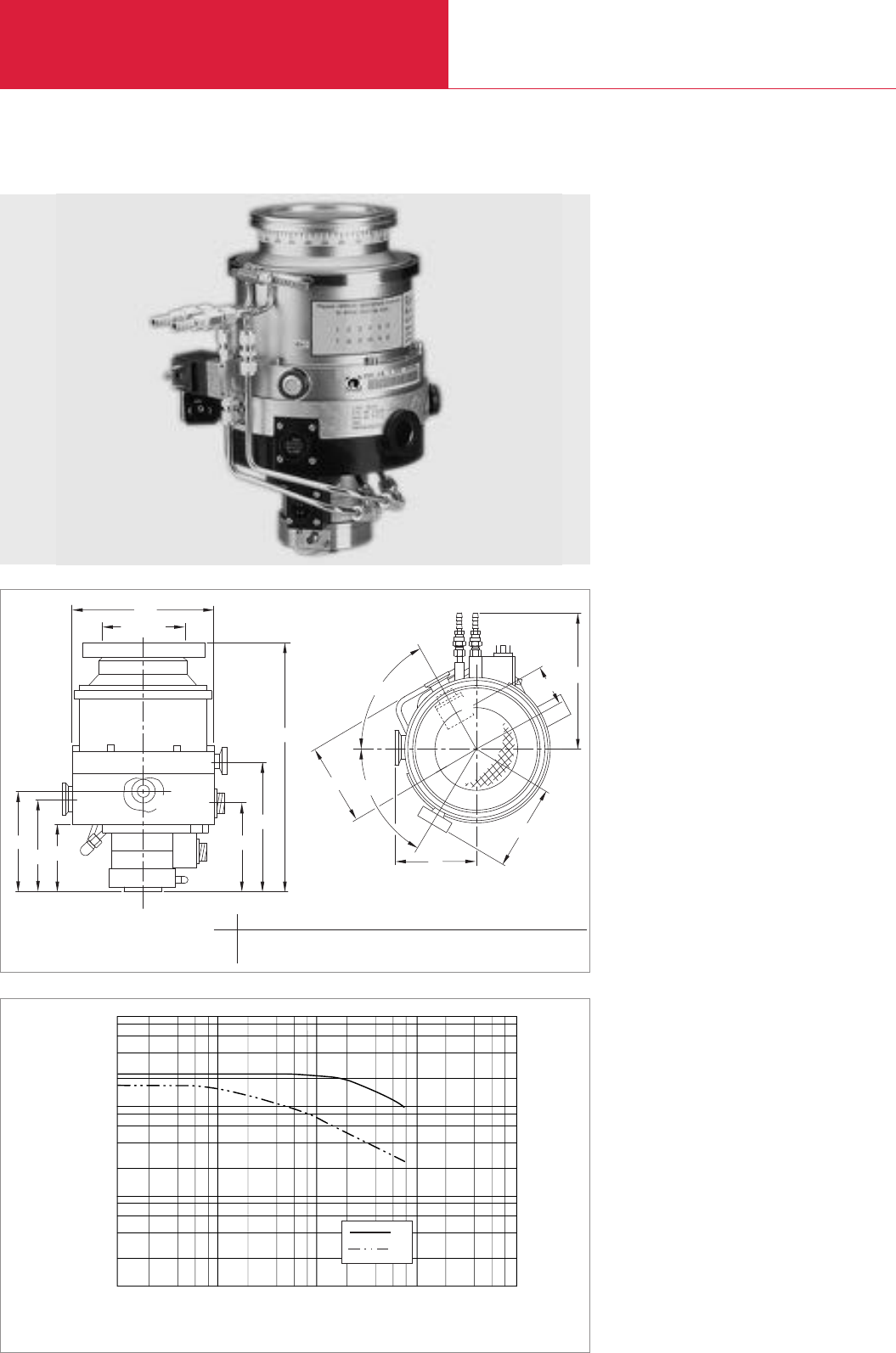
without Compound Stage
Turbomolecular Pumps with Magnetic Rotor Suspension
C09.40 LEYBOLD VACUUM PRODUCTS AND REFERENCE BOOK 2003/2004
MAG 400 C/CT
Advantages to the User
◆Maintenance-free
◆Optimized vacuum performance
◆Resistant against corrosive gases and process
by-products
◆Robust against shock-venting
◆Temperature control for metal etch
◆No deposition of etch by products due to TMS
Typical Applications
◆All major semiconductor processes such as
Etch, CVD and Ion Implantation
◆Gas analysis systems
◆Particle accelerators
◆Electron beam microscopy
◆Research instruments and systems
◆Load locks and transfer chambers
Technical Features
◆Magnetic suspension
◆Patented KEPLA-COAT
®
for rotor and stator
to prevent corrosion
◆Low noise and vibration levels
◆Operation in any orientation
◆Optimized corrosion-resistant advanced rotor
design
◆High temperature and high stress tolerance
material
◆Temperature management system (TMS) for
etch application
Inlet Pressure
mbar
Pumping Speed
10-4 2 4 6 8
1
2
4
6
8
10
100
1000
10-3 10-2 10-1 10
I x s-1
H2
N2
Pumping speed of the MAG 400 as a function of the inlet pressure
A
DN 100
B
C
F1
F2
F3
D
E
E
D
B
a
60˚
60˚b
h3h4h5
h2
h1
h
a1
a2
b1
F
ød
Top view
Dimensional drawing for the MAG 400 CT
a a1b b1d h h1h2h3h3h4h5
mm 100 114 111 186 178 50 300 162 109 123 114 80
in. 3.94 4.49 4.37 7.32 7.01 1.97 11.81 6.38 4.29 4.84 4.49 3.15

C09.41
LEYBOLD VACUUM PRODUCTS AND REFERENCE BOOK 2003/2004
C09
without Compound Stage
Turbomolecular Pumps with Magnetic Rotor Suspension
Inlet flange DN
Pumping speed
N2I x s-1
H2I x s-1
Speed (high / low) rpm
Compression ratio
N2
H2
Ultimate pressure mbar (Torr)
Max. foreline pressure for N2mbar (Torr)
Recommended fore-vacuum pump
Run-up time min
Fore-vacuum flange DN
Purge / vent port DN
Cooling water connections,hose nipple mm (in.)
Weight, approx. kg (lbs)
100 ISO-K
235
174
51,600 / 43,860
> 109
2.5 x 10³
< 10-10 (< 0.75 x 10⁻¹⁰)
5 x 10⁻¹ (3.75 x 10⁻¹)
TRIVAC D 65 BCS
3.5
25 KF
10 KF
7.5 (0.30)
16 (35)
Technical Data MAG
400 C 400 CT
MAG
400 C 400 CT
Ordering Information
MAG turbomolecular pump
Frequency converter TURBOTRONIK NT 340 MA (120 V)
Connection line motor
Connection line bearing
Accessories for the temperature control
Purge gas and venting valve
110 V, 50/60 Hz
230 V, 50/60 Hz
024 V DC, 5 W
Seal kit
Seal kit and Operating Instructions
Part No. 894 62 Part No. 894 63
Part No. 857 32
Part No. 859 10
Part No. 859 11
– see TURBOTRONIK
Part No. 855 48
Part No. 855 49
Part No. 174 17
Part No. 200 91 240
Part No. 200 91 437
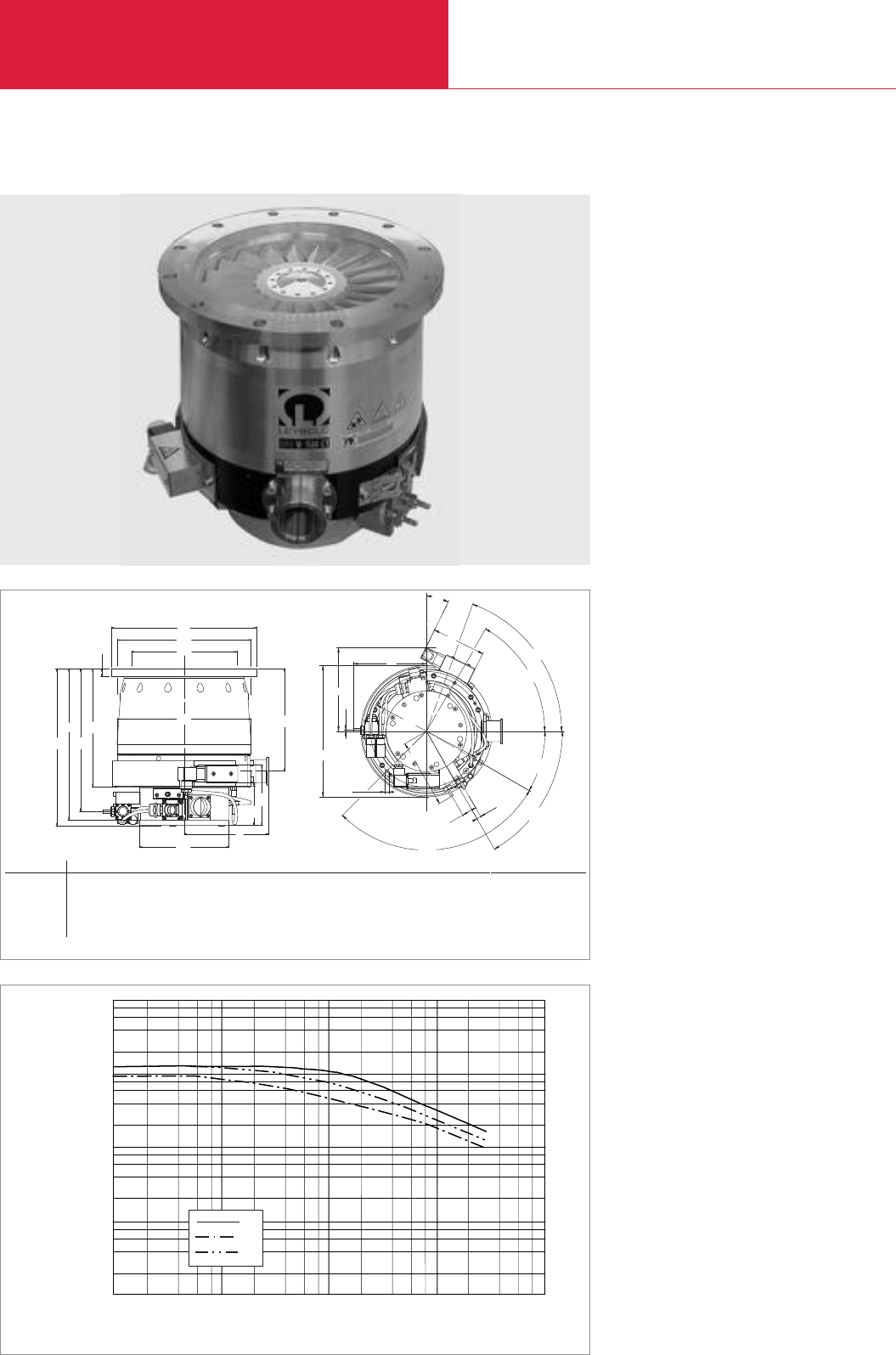
C09.42 LEYBOLD VACUUM PRODUCTS AND REFERENCE BOOK 2003/2004
without Compound Stage
Turbomolecular Pumps with Magnetic Rotor Suspension
MAG 1500 C/CT
Advantages to the User
◆Maintenance-free
◆High throughput for all process gases
◆High pumping speed at low pressure
◆High foreline pressure tolerance:
up to 1.7 mbar (1.13 Torr)
◆High resistance against corrosive gases
◆Robust against particles and deposits
◆Temperature control up to 90 °C (194 °F) to
avoid condensation
◆Lowest weight and size in its class
◆Application specific design
Technical Features
◆Active 5-axis magnetic bearing system
◆Patented KEPLA-COAT
®
for rotor and stator
to prevent corrosion
◆Low noise and vibration levels
◆Operation in any orientation
◆Advanced rotor design for high throughput
◆Integrated purge gas system
◆CT versions: Integrated temperature
management system
◆Bearing and temperature system are control-
led digitally
◆Intelligent power control system
Typical Applications
◆All major semiconductor processes such as
Etch, CVD, PVD and Ion Implantation
◆Load locks and transfer chambers
2
4
6
8
2 4 6 8
Inlet Pressure
Pumping Speed
10-4
1
10
100
1000
10000
10-3 10-2 10-1
mbar 10
He
H2
I x s-1
N2
Pumping speed of the MAG 1500 as a function of the inlet pressure
a
60°
70°
30°
105°
60°
26°
Heatband
DN 40 KF
dø
d1
ø
d2
ø
d3
ø
d4
ø
d5
ø
a3
b1
b
h4
a1
a2
a4
a5
b2
d6
ø
hh2
h3
h1
h7
h7
h6
Dimensional drawing for the MAG 1500 CT
Top view
a a1a2a3a4a5b b1b2d d1d2d3d4d5d6h h1h2
200 ISO-F mm 164.5 159 116.5 M8 x 15 32 9 182 3 150 285 260 213 262 175 285 243 307 296 279
in. 6.48 6.26 4.59 M8 x 0.6 1.26 0.35 7.17 0.12 5.91 11.22 10.24 8.39 10.31 6.89 11.22 9.57 12.0911.65 10.98
250 ISO-F mm 164.5 159 116.5 M8 x 15 32 9 182 3 150 335 310 213 262 175 285 243 307 296 279
in. 6.48 6.26 4.59 M8 x 0.6 1.26 0.35 7.17 0.12 5.91 11.22 12.20 10.28 10.31 6.89 11.22 9.57 12.0911.65 10.98
h3h4h5h6h7
231 200 118 84 16
9.09 7.87 4.65 3.31 0.63
231 200 118 84 16
9.09 7.87 4.65 3.31 0.63

C09.43
LEYBOLD VACUUM PRODUCTS AND REFERENCE BOOK 2003/2004
C09
without Compound Stage
Turbomolecular Pumps with Magnetic Rotor Suspension
Inlet flange DN
Pumping speed
N2I x s-1
He I x s-1
H2I x s-1
Speed rpm
Compression ratio
N2
Ultimate pressure mbar (Torr)
Max. foreline pressure for N2mbar (Torr)
Recommended fore-vacuum pump
Rotary vane pump
or dry compressing pump offering
a pumping speed of 100 m3/h
Run-up time min
Fore-vacuum flange DN
Purge / vent port VCR Nut
Cooling water connections,hose nipple mm (in.)
Weight, approx. kg (lbs)
200 ISO-F 250 ISO-F 200 ISO-F 250 ISO-F
1100 1220 1100 1220
1150 1220 1150 1220
920 1020 920 1020
36,000
> 108
< 10-8 (< 0.75 x 10⁻⁸)
1.7 (1.2)
TRIVAC D 65 BCS
< 6
40 KF
1/4"
6.4 (0.25)
32 (70)
Technical Data MAG
1500 C 1500 CT
MAG
1500 C 1500 CT
Ordering Information
MAG turbomolecular pump
MAG.DRIVE
digital
converter
Plug-in control
MAG.DRIVE
digital
with DeviceNet
with Echolon
Connecting cables converter–pump
1.5 m (5.25 ft) DRIVE/BEARING
1.5 m (5.25 ft) TMS
05 m (17.5 ft) DRIVE/BEARING
05 m (17.5 ft) TMS
10 m (35 ft) DRIVE/BEARING
10 m (35 ft) TMS
20 m (70 ft) DRIVE/BEARING
20 m (70 ft) TMS
Seal kit
DN 200 standard
DN 250 standard
DN 250 metal
Part No. 400020V0001 Part No. 400021V0001 Part No. 400020V0002 Part No. 400021V0002
Part No. 400035V0001
Part No. 121 36
upon request
upon request
Part No. 400036V0001
Part No. 400037V0001
Part No. 400036V0004
Part No. 400037V0004
Part No. 400036V0002
Part No. 400037V0002
Part No. 400036V0003
Part No. 400037V0003
upon request
upon request
Part No. 200 07 901

without Compound Stage
Turbomolecular Pumps with Magnetic Rotor Suspension
C09.44 LEYBOLD VACUUM PRODUCTS AND REFERENCE BOOK 2003/2004
MAG 2000 C/CT
Inlet Pressure
Pumping Speed
10
100
1000
10000
10-3 10-2 10-1 10
He
H2
N2
I x s-1
2
4
6
8
2 4 6 8
10-4
1
DN 40
ød
h
Only CT
Only CT
Only CT
ød1
h1h2
h330°
ød4
ød3
h4
h5
Only CT
ød5
Pumping speed of the MAG 2000 CT (DN 250) as a function of the inlet pressure
Dimensional drawing for the MAG 2000 C/CT
Top view
Advantages to the User
◆Maintenance-free
◆High throughput for all etch gases
◆High pumping speed at low pressure
◆High foreline pressure tolerance: up to 2 mbar
(1.5 Torr)
◆High resistance against corrosive gases
◆Robust against particles and deposits
◆Temperature management system to avoid
condensation
◆Application specific design
Technical Features
◆Active 5-axis magnetic bearing system
◆Patented KEPLA-COAT
®
for rotor and stator
to prevent corrosion
◆Low noise and vibration levels
◆Operation in any orientation
◆Advanced rotor design for high throughput
◆Integrated purge gas system
◆CT versions: Integrated temperature
management system
Typical Applications
◆All major semiconductor processes such as
Etch, CVD, PVD and Ion Implantation
◆Load locks and transfer chambers
d d1d2d3d4d5h h1h2h3h4h5
mm 335 310 335 199 284 11 303 272 318 386 40 16
in. 13.19 12.20 13.19 7.83 11.18 0.43 11.93 10.71 12.52 15.20 1.57 0.63

without Compound Stage
Turbomolecular Pumps with Magnetic Rotor Suspension
C09.45
LEYBOLD VACUUM PRODUCTS AND REFERENCE BOOK 2003/2004
C09
Inlet flange DN
Pumping speed
N2I x s-1
He I x s-1
H2I x s-1
Speed rpm
Compression ratio
N2
Ultimate pressure mbar (Torr)
Max. foreline pressure for N2mbar (Torr)
Recommended fore-vacuum pump
Rotary vane pump
or dry compressing pump offering
a pumping speed of 100 m3/h
Run-up time min
Fore-vacuum flange DN
Purge / vent port VCR nut
Cooling water connections,hose nipple mm (in.)
Weight, approx. kg (lbs)
250 ISO-F 250 ISO-F
1550
1780
1390
28,800
> 108
< 10-8 (< 0.75 x 10⁻⁸)
1.6 (1.2)
TRIVAC D 65 BCS
< 8
40 KF
1/4"
6.4 (0.25)
68 (150)
Technical Data MAG
2000 C 2000 CT
MAG
2000 C 2000 CT
Ordering Information
MAG turbomolecular pump
MAG.DRIVE 2000 converter
Plug-in control
Connecting cables converter–pump
1.5 m (5.25 ft) BEARING
1.5 m (5.25 ft) DRIVE/TMS
03 m (10.5 ft) BEARING
03 m (10.5 ft) DRIVE/TMS
05 m (17.5 ft) BEARING
05 m (17.5 ft) DRIVE/TMS
10 m (35 ft) BEARING
10 m (35 ft) DRIVE/TMS
20 m (70 ft) BEARING
20 m (70 ft) DRIVE/TMS
Seal kit
DN 200
DN 250
Part No. 894 16 Part No. 894 30
Part No. 121 35
Part No. 121 36
Part No. 121 29
Part No. 121 30
Part No. 121 17
Part No. 121 18
Part No. 121 19
Part No. 121 20
Part No. 121 21
Part No. 121 22
Part No. 121 25
Part No. 121 26
Part No. 200 91 684
Part No. 200 91 641
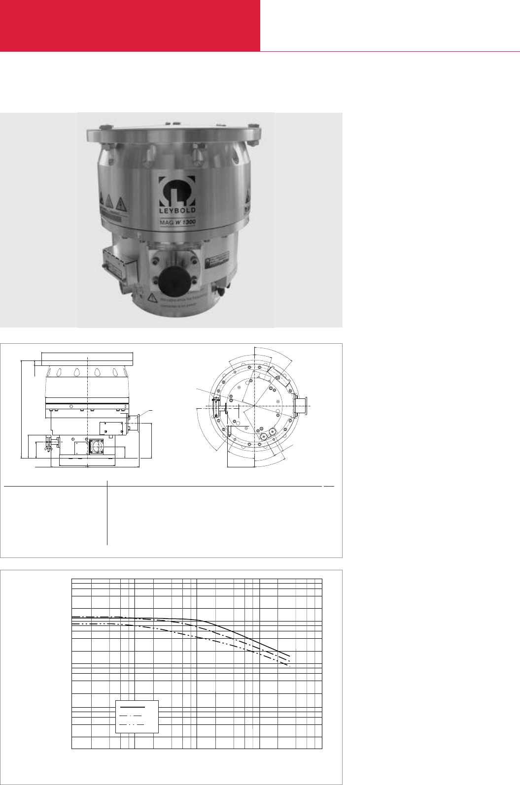
with Compound Stage
Turbomolecular Pumps with Magnetic Rotor Suspension
C09.46 LEYBOLD VACUUM PRODUCTS AND REFERENCE BOOK 2003/2004
Advantages to the User
◆Maintenance-free
◆High throughput for all process gases
◆High pumping speed at low pressure
◆
High foreline pressure tolerance: up to 2 mbar
(1.5 Torr)
◆Lowest weight and size in its class
◆Application specific design
Technical Features
◆Active 5-axis magnetic bearing system
◆Digital monitoring of the bearing system
◆Low noise and vibration levelssystem
◆Operation in any orientationlevelssystem
◆Advanced rotor design for high throughput
◆Purge gas system
◆Intelligent power control system
Typical Applications
◆Semiconductor processes, like PVD and ion
implantation
◆Transfer chambers
◆Particle accelerators
◆Research
◆Coaters
MAG W 830/1300 C
2
4
6
8
2 4 6 8
Inlet Pressure
Pumping Speed
10-4
1
10
100
1000
10000
10-3 10-2 10-1
mbar 10
He
H2
I x s-1
N2
Pumping speed of the MAG W 1300 C (DN 250) as a function of the inlet pressure
31
50°
30°
30°
30°
30°
20°
40°
S
Ø N
M8
PO
Q
R
Upper View
J
Ø C
A
Ø B
M
Ø D
Forevacuum
connection
H
G
F
E
L
K
Fore vacuum Inlet A B C D E F G H J K L M N O P Q R
flange flange
MAG W 830 C DN 40 KF 160 ISO-F mm 225 262 260 175 16 353 72 50 113 35 109.5 163 243 103 114.7 98 8.3
DN 40 KF 160 ISO-F in. 8.86 10.3110.24 6.89 0.63 13.9 2.83 1.97 4.45 1.38 4.31 6.42 9.57 4.06 4.52 3.86 0.33
MAG W 1300 C DN 40 KF/ 200 ISO-F mm 285 262 260 175 16 306 72 50 113 35 109.5 163 243 103 114.7 98 8.3
DN 25 KF
DN 40 KF/ 250 ISO-F in. 11.2210.3110.24 6.89 0.63 12.05 2.83 1.97 4.45 1.38 4.31 6.42 9.57 4.06 4.52 3.86 0.33
DN 25 KF
MAG W 1300 C DN 40 KF 250 ISO-F mm 335 262 260 175 16 306 72 50 113 35 109.5 163 243 103 114.7 98 8.3
DN 40 KF 250 ISO-F in. 13.1910.3110.24 6.89 0.63 12.05 2.83 1.97 4.45 1.38 4.31 6.42 9.57 4.06 4.52 3.86 0.33
S
85
3.35
85
3.35
85
3.35
Dimensional drawing for the MAG W 830/1300 C

with Compound Stage
Turbomolecular Pumps with Magnetic Rotor Suspension
C09.47
LEYBOLD VACUUM PRODUCTS AND REFERENCE BOOK 2003/2004
C09
Inlet flange DN
Pumping speed
N2I x s-1
He I x s-1
H2I x s-1
Speed min-1
Compression
N2
Ultimate pressure mbar (Torr)
Max. fore-line pressure for N2mbar (Torr)
Recommended fore-vacuum pump
Rotary vane pump
or dry compressing pump offering
a pumping speed of 100 m3/h
Run-up time min
Fore vacuum flange DN
Purge / vent port DN
Cooling water connection (tube AD) mm (in.)
Weight, approx. kg (lbs)
160 ISO-F 200 ISO-F 250 ISO-F
700 1100 1220
650 1050 1180
300 920 1020
24000 36000
> 5 x 10⁷> 108
< 10-8 (< 0.75 x 10⁻⁸)
2 (1.5)
TRIVAC D 65 BCS
< 4 < 6
40 KF
10/16 KF
1/4" 6 (0.24)
32 (70.6)
Technical Data MAG
W 830 C W 1300 C
MAG
W 830 C W 1300 C
Ordering information
MAG turbomolecular pump
MAG.DRIVE
digital
converter
Plug-in control
Purge gas valve
Connecting cable converter–pump
1.5 m (5.25 ft) DRIVE/BEARING
03 m (10.5 ft) DRIVE/BEARING
05 m (17.5 ft) DRIVE/BEARING
10 m (35 ft) DRIVE/BEARING
20 m (70 ft) DRIVE/BEARING
Connecting cable for purge gas valve
1.5 m (5.25 ft) pump/converter
03 m (10.5 ft) pump/converter
10 m (35 ft) pump/converter
Sealing kit
DN 200 standard
DN 250 standard
DN 250 metal
Part No. 400100V0005 Part No. 400110V0011 Part No. 400110V0021
Part No. 400035V0001
Part No. 121 36
Part No. 121 33
Part No. 400036V0001
Part No. 400036V0006
Part No. 400036V0004
Part No. 400036V0002
Part No. 400036V0003
Part No. 400038V0001
Part No. 400038V0006
Part No. 400038V0002
upon request
upon request
Part No. 200 07 901

C09.48 LEYBOLD VACUUM PRODUCTS AND REFERENCE BOOK 2003/2004
with Compound Stage
Turbomolecular Pumps with Magnetic Rotor Suspension
MAG W 1500 C/CT
Advantages to the User
◆Maintenance-free
◆High throughput for all process gases
◆High pumping speed at low pressure
◆High foreline pressure tolerance:
up to 2.6 mbar (1.95 Torr)
◆High resistance against corrosive gases
◆Robust against particles and deposits
◆Temperature control up to 90 °C (194 °F) to
avoid condensation
◆Lowest weight and size in its class
◆Application specific design
Technical Features
◆Active 5-axis magnetic bearing system
◆Bearing and temperature system are control-
led digitally
◆Corrosion resistant
◆Low noise and vibration levels
◆Operation in any orientation
◆Compound rotor design for high pumping
speed and foreline pressure
◆Integrated purge gas system
◆CT versions: Integrated temperature
management system
◆Intelligent power control system
Typical Applications
◆All major semiconductor processes such as
Etch, CVD, PVD and Ion Implantation
Inlet Pressure
Pumping Speed
10-4
1
10
100
1000
10000
10-3 10-2 10-1
mbar 10
He
H2
I x s-1
N2
2
4
6
8
2 4 6 8
Pumping speed of the MAG W 15000 CT (DN 250) as a function of the inlet pressure
a
60°
70°
30°
105°
60°
26°
Heatband
DN 40 KF
dø
d1
ø
d2
ø
d3
ø
d4
ø
d5
ø
a3
b1
b
h4
a1
a2
a4
a5
b2
d6
ø
hh2
h3
h1
h7
h7
h6
Top view
a a1a2a3a4a5b b1b2d d1d2d3d4d5d6h h1h2
200 ISO-F mm 164.5 159 116.5 M8 x 15 32 9 182 3 150 285 260 213 262 175 285 243 307 296 279
in. 6.48 6.26 4.59 M8 x 0.6 1.26 0.35 7.17 0.12 5.91 11.22 10.24 8.39 10.31 6.89 11.22 9.57 12.09 11.65 10.98
250 ISO-F mm 164.5 159 116.5 M8 x 15 32 9 182 3 150 335 310 213 262 175 285 243 307 296 279
in. 6.48 6.26 4.59 M8 x 0.6 1.26 0.35 7.17 0.12 5.91 11.22 12.20 10.28 10.31 6.89 11.22 9.57 12.09 11.65 10.98
h3h4h5h5
231 200 118 84
9.09 7.87 4.65 3.31
231 200 118 84
9.09 7.87 4.65 3.31
Dimensional drawing for the MAC W 1500 CT

C09.49
LEYBOLD VACUUM PRODUCTS AND REFERENCE BOOK 2003/2004
C09
with Compound Stage
Turbomolecular Pumps with Magnetic Rotor Suspension
Inlet flange DN
Pumping speed
N2I x s-1
He I x s-1
H2I x s-1
Speed rpm
Compression ratio
N2
Ultimate pressure mbar
(Torr)
Max. foreline pressure for N2mbar (Torr)
Recommended fore-vacuum pump
Rotary vane pump
or dry compressing pump offering
a pumping speed of 100 m3/h
Run-up time min
Fore-vacuum flange DN
Purge / vent port VCR Nut
Cooling water connections, hose nipple mm (in.)
Weight, approx. kg (lbs)
200 ISO-F 250 ISO-F 200 ISO-F 250 ISO-F 200 CF
1100 1220 1100 1220 1100
1150 1220 1150 1220 1150
920 1020 920 1020 920
36000
> 108
< 10-8 < 10-8 < 10-8 < 10-9
(< 0.7 x 10⁻⁸) (< 0.7 x 10⁻⁸) (< 0.7 x 10⁻⁸) (< 0.7 x 10⁻⁹)
2.6 (1.95)
TRIVAC D 65 BCS
< 6
40 KF
1/4"
6.4 (0.25)
32 (70.64)
Technical Data MAG
W 1500 C W 1500 CT
MAG
W 1500 C W 1500 CT
Ordering Information
MAG turbomolecular pump
MAG.DRIVE
digital
converter
Plug-in control
Connecting cables converter–pump
1.5 m (5.25 ft) DRIVE/BEARING
1.5 m (5.25 ft) TMS
05 m (17.5 ft) DRIVE/BEARING
05 m (17.5 ft) TMS
10 m (35 ft) DRIVE/BEARING
10 m (35 ft) TMS
20 m (70 ft) DRIVE/BEARING
20 m (70 ft) TMS
Seal kit
DN 200 standard
DN 250 standard
DN 250 metal
Part No. Part No. Part No. Part No. Part No.
400026V0001 400027V0001 400026V0002 400027V0002 400030V0002
400035V0001
Part No. 121 36
Part No. 400036V0001
Part No. 400037V0001
Part No. 400036V0004
Part No. 400037V0004
Part No. 400036V0002
Part No. 400037V0002
Part No. 400036V0003
Part No. 400037V0003
upon request
upon request
Part No. 200 07 901
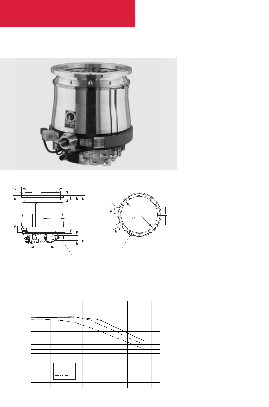
with Compound Stage
Turbomolecular Pumps with Magnetic Rotor Suspension
C09.50 LEYBOLD VACUUM PRODUCTS AND REFERENCE BOOK 2003/2004
MAG W 2000 C/CT
2
4
6
8
2 4 6 8
1
Inlet Pressure
Pumping Speed
10-4
10
100
1000
10000
10-3 10-2 10-1
mbar 10
He
H2
N2
I x s-1
Pumping speed of the MAG W 2000 CT (DN 250) as a function of the inlet pressure
Dimensional drawing for the MAG W 2000 C/CT
Advantages to the User
◆Maintenance-free
◆High throughput for all etch gases
◆High pumping speed at low pressure
◆High foreline pressure tolerance: up to
5.3 mbar (4 Torr)
◆High resistance against corrosive gases
◆Robust against particles and deposits
◆Temperature management system to avoid
condensation
◆Application specific design
Technical Features
◆Active 5-axis magnetic bearing system
◆Patented KEPLA-COAT
®
for rotor and stator
to prevent corrosion
◆Low noise and vibration levels
◆Operation in any orientation
◆Compound rotor design for high pumping
speed and foreline pressure
◆Integrated purge gas system
◆CT versions: Integrated temperature
management system
Typical Applications
◆All major semiconductor processes such as
Etch, CVD, PVD and Ion Implantation
DN 40
ød
h
Only CT
Only CT
Only CT
ød1
h1h2
h330°
ød4
ød3
h4
h5
Only CT
ød5
Top view
d d1d2d3d4d5h h1h2h3h4h5
mm 335 310 335 199 284 11 303 272 318 386 40 16
in. 13.19 12.20 13.19 7.83 11.18 0.43 11.93 10.71 12.52 15.20 1.57 0.63

with Compound Stage
Turbomolecular Pumps with Magnetic Rotor Suspension
C09.51
LEYBOLD VACUUM PRODUCTS AND REFERENCE BOOK 2003/2004
Inlet flange DN
Pumping speed
N2I x s-1
He I x s-1
H2I x s-1
Speed rpm
Compression ratio
N2
Ultimate pressure mbar (Torr)
Max. foreline pressure for N2mbar (Torr)
Recommended fore-vacuum pump
Rotary vane pump
or dry compressing pump offering
a pumping speed of 100 m3/h
Run-up time min
Fore-vacuum flange DN
Purge / vent port VCR nut
Cooling water connections, hose nipple mm (in.)
Weight, approx. kg (lbs)
250 ISO-F 250 ISO-F
1650
1800
1720
28,800
> 108
< 10-8 (< 0.75 x 10⁻⁸)
3.5 (2.625)
TRIVAC D 65 BCS
< 8
40 KF
1/4"
6.4 (0.25)
62 (137)
Technical Data MAG
W 2000 C W 2000 CT
MAG
W 2000 C W 2000 CT
Ordering Information
MAG turbomolecular pump
MAG.DRIVE 2000 converter
Plug-in control
Connecting cables converter–pump
1.5 m (5.25 ft) BEARING
1.5 m (5.25 ft) DRIVE/TMS
03 m (10.5 ft) BEARING
03 m (10.5 ft) DRIVE/TMS
05 m (17.5 ft) BEARING
05 m (17.5 ft) DRIVE/TMS
10 m (35 ft) BEARING
10 m (35 ft) DRIVE/TMS
20 m (70 ft) BEARING
20 m (70 ft) DRIVE/TMS
Seal kit
DN 200
DN 250
Part No. 894 17 Part No. 894 31
Part No. 121 35
Part No. 121 36
Part No. 121 29
Part No. 121 30
Part No. 121 17
Part No. 121 18
Part No. 121 19
Part No. 121 20
Part No. 121 21
Part No. 121 22
Part No. 121 25
Part No. 121 26
Part No. 200 91 684
Part No. 200 91 641
C09
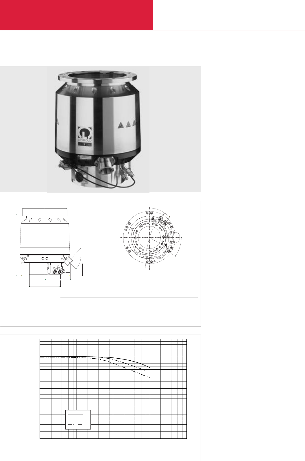
with Compound Stage
Turbomolecular Pumps with Magnetic Rotor Suspension
C09.52 LEYBOLD VACUUM PRODUCTS AND REFERENCE BOOK 2003/2004
Advantages to the User
◆Maintenance-free
◆High throughput for all process gases
◆High pumping speed at low pressure
◆
High foreline pressure tolerance: up to 2 mbar
(1.5 Torr)
◆High resistance against corrosive gases
◆Robust against particles and deposits
◆Temperature control up to 90 °C (194 °F) to
avoid condensation
◆Lowest weight and size in its class
◆Application specific design
Technical Features
◆Active 5-axis magnetic bearing system
◆Bearing and temperature system are control-
led digitally
◆Corrosion resistant
◆Low noise and vibration levels
◆Operation in any orientation
◆Compound rotor design for high pumping
speed and foreline pressure
◆Integrated purge gas system
◆CT versions: Integrated temperature
management system
◆Intelligent power control system
Typical Applications
◆All major semiconductor processes such as
Etch, CVD, PVD and Ion Implantation
◆Coaters
MAG W 2200 C
2
4
6
8
2 4 6 8
Inlet Pressure
Pumping Speed
10-4
1
10
100
1000
10000
10-3 10-2 10-1
mbar 10
He
H2
I · s-1
N2
Pumping speed of the MAG W 2200 C (DN 250) as a function of the inlet pressure
Dimensional drawing for the MAG W 2200 C
F
Ø B
Ø A
45°
Ø C
DN 40 KF
D
EH
G
8°
39
36.5°
36°
J
K
L
Upper View
A B C D E F G H J K L
200 ISO-F mm 285 317 199 396 85.5 164.6 23 78 117 120 155
in. 11.22 12.48 7.83 15.59 3.37 6.48 0.91 3.07 4.61 4.72 6.10
250 ISO-F mm 335 317 199 371 85.5 164.6 23 78 117 120 155
in. 13.19 12.48 7.83 14.61 3.37 6.48 0.91 3.07 4.61 4.72 6.10

with Compound Stage
Turbomolecular Pumps with Magnetic Rotor Suspension
C09.53
LEYBOLD VACUUM PRODUCTS AND REFERENCE BOOK 2003/2004
C09
Inlet flange DN
Pumping speed
N2I x s-1
Ar I x s-1
H2I x s-1
Speed min-1
Compression
N2
Ultimate pressure mbar
Max. fore-line pressure for N2mbar (Torr)
Recommended fore-vacuum pump
Rotary vane pump
or dry compressing pump offering
a pumping speed of 100 m3/h
Run-up time to 95% speed min
Fore vacuum flange DN
Purge / vent port VCR
Cooling water connection (tube AD) mm (in.)
Weight, approx. kg (lbs)
200 ISO-F 250 ISO-F
1600 2000
1450 1900
1650 1800
29400
> 108
< 10-8
2 (1.5)
TRIVAC D 65 BCS
< 8
40 KF
1/4"
1/2"
48 (106)
Technical Data MAG W 2200 C
MAG W 2200 COrdering information
MAG turbomolecular pump
MAG.DRIVE
digital
converter
Plug-in control
Connecting cable converter–pump
1.5 m (5.25 ft) DRIVE/BEARING
1.5 m (5.25 ft) TMS
03 m (10.5 ft) DRIVE/BEARING
03 m (10.5 ft) TMS
05 m (17.5 ft) DRIVE/BEARING
05 m (17.5 ft) TMS
10 m (35 ft) DRIVE/BEARING
10 m (35 ft) TMS
20 m (70 ft) DRIVE/BEARING
20 m (70 ft) TMS
Sealing kit
DN 200 standard
DN 250 standard
DN 250 metal
Part No. 400081V0011 Part No. 400081V0021
Part No. 400035V0001
Part No. 121 36
Part No. 400036V0001
Part No. 400037V0001
Part No. 400036V0008
Part No. 400037V0008
Part No. 400036V0004
Part No. 400037V0004
Part No. 400036V0002
Part No. 400037V0002
Part No. 400036V0003
Part No. 400037V0003
upon request
upon request
Part No. 200 07 901
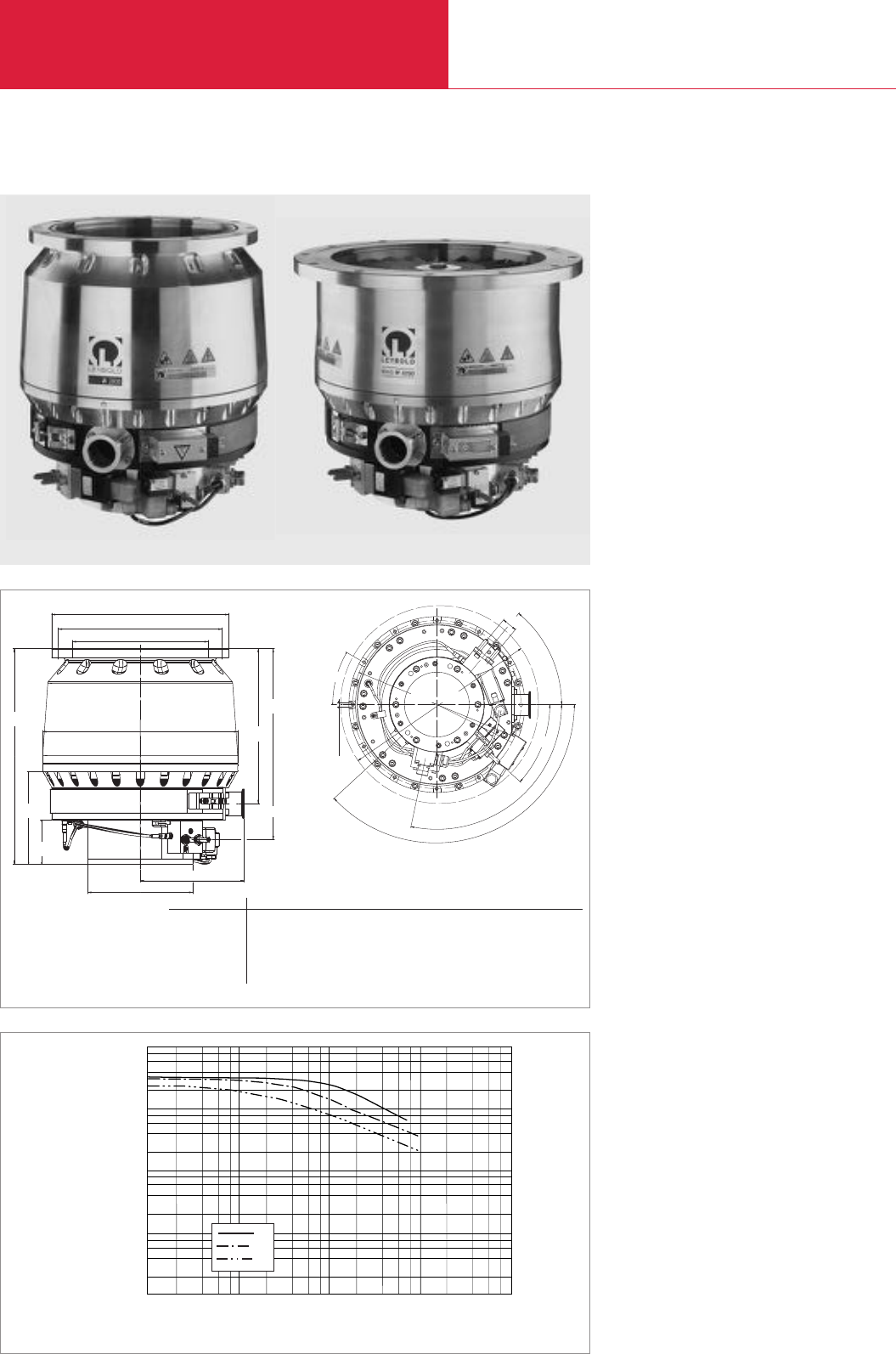
with Compound Stage
Turbomolecular Pumps with Magnetic Rotor Suspension
C09.54 LEYBOLD VACUUM PRODUCTS AND REFERENCE BOOK 2003/2004
Advantages to the User
◆Maintenance-free
◆High throughput for all process gases
◆High pumping speed at low pressure
◆
High foreline pressure tolerance: up to 2 mbar
(1.5 Torr)
◆High resistance against corrosive gases
◆Robust against particles and deposits
◆Temperature control up to 90 °C (194 °F) to
avoid condensation
◆Lowest weight and size in its class
◆Application specific design
Technical Features
◆Active 5-axis magnetic bearing system
◆Bearing and temperature system are control-
led digitally
◆Corrosion resistant
◆Low noise and vibration levelssystem
◆Operation in any orientationlevelssystem
◆Compound rotor design for high pumping
speed and foreline pressure
◆Integrated purge gas system
◆CT versions: Integrated temperature
management system
◆Intelligent power control systemt
Typical Applications
◆All major semiconductor processes such as
Etch, CVD, PVD and Ion Implantation
MAG W 2800/3200 C/CT
2
4
6
8
2 4 6 8
Inlet Pressure
Pumping Speed
10-4
1
10
100
1000
10000
10-3 10-2 10-1
mbar 10
He
H2
I · s-1
N2
Pumping speed of the MAG W 3200 C (DN 250) as a function of the inlet pressure
MAG W 2800 CT (left) and MAG W 3200 CT (right)
Top View
ø D
ø A
ø B
ø C
L
F
G
K
ø M ø N
137 ° 102 °
42 °
O
50,5 °
M 8, 14 depth
Inlet flange A B C D E F G H J K L M N O
250 ISO-F mm 335 310 261 369 408 176 84 361 293 199 196.5 353 415 32
250 ISO-F in. 13.19 12.2 10.28 14.53 16.06 6.93 3.31 14.21 11.54 7.83 7.74 13.9 16.34 1.26
320 ISO-F mm 425 395 318 369 363 176 84 361 248 199 196.5 353 415 32
320 ISO-F in. 16.73 15.55 12.52 14.53 14.29 6.93 3.31 14.21 9.76 7.83 7.74 13.9 16.34 1.26
350 JIS mm 450 420 318 369 363 176 84 361 248 199 196.5 353 415 32
350 JIS in. 17.72 16.54 12.52 14.53 14.29 6.93 3.31 14.21 9.76 7.83 7.74 13.9 16.34 1.26
E
H
J
Dimensional drawing for the MAG W 2800/3200 C/CT
30 °
DN 40 KF

with Compound Stage
Turbomolecular Pumps with Magnetic Rotor Suspension
C09.55
LEYBOLD VACUUM PRODUCTS AND REFERENCE BOOK 2003/2004
C09
Inlet flange DN
Pumping speed
N2I x s-1
Ar I x s-1
H2I x s-1
Speed min-1
Compression ratio
N2
Ultimate pressure mbar (Torr)
Max. fore-line pressure for N2mbar (Torr)
Recommended fore-vacuum pump
Rotary vane pump
or dry compressing pump offering
a pumping speed of 100 m3/h
Run-up time min
Fore vacuum flange DN
Purge / vent port VCR
Cooling water connection Swagelok tube
Weight, approx. kg (lbs)
250 ISO-F 250 ISO-F 320 ISO-F 350 JIS
2650 3200
2450 3000
2100 2250
28800
> 108
< 10-8 (< 0.75 x 10⁻⁸)
2 (1.5)
TRIVAC D 65 BCS
< 10
40 KF
1/4"
1/4"
64 (141.3) 65 (143.5) 66 (145.7)
Technical Data MAG
W 2800 C W 2800 CT W 3200 CT
MAG
W 2800 C W 2800 CT W 3200 CT
Ordering information
MAG turbomolecular pump
MAG.DRIVE
digital
converter
Plug-in control
Connecting cable converter–pump
1,5 m (5.25 ft) DRIVE/BEARING
1,5 m (5.25 ft) TMS
03 m (10.5 ft) DRIVE/BEARING
03 m (10.5 ft) TMS
05 m (17.5 ft) DRIVE/BEARING
05 m (17.5 ft) TMS
10 m DRIVE/BEARING
10 m TMS
20 m (70 ft) DRIVE/BEARING
20 m (70 ft) TMS
Sealing kit
DN 200 standard
DN 250 standard
DN 250 metal
Part No. 400000V0001 Part No. 400000V0002 Part No. 400003V0002 Part No. 400004V0002
Part No. 400035V0001
Part No. 121 36
Part No. 400036V0001
Part No. 400037V0001
Part No. 400036V0008
Part No. 400037V0008
Part No. 400036V0004
Part No. 400037V0004
Part No. 400036V0002
Part No. 400037V0002
Part No. 400036V0003
Part No. 400037V0003
upon request
upon request
Part No. 200 07 901
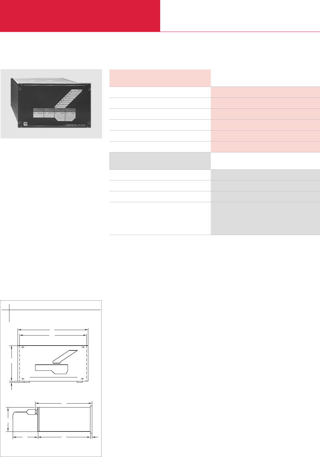
Electronic Frequency Converters
Turbomolecular Pumps with Magnetic Rotor Suspension
C09.56 LEYBOLD VACUUM PRODUCTS AND REFERENCE BOOK 2003/2004
TURBOTRONIK NT 340 M
Technical Features
◆For operating the TURBOVAC 340 M
turbomolecular pump
◆Compact control unit 1/2 19", 3 HU
◆No batteries are required because of integrat-
ed generator mode in case of power failures
◆Front panel with membrane keypad and LCD
Advantages to the User
◆Convenient control and monitoring facilities
◆Remote control and process control via
analog and programmable control inputs and
outputs
◆Connection for backing pump, venting valve
and flange heater
◆V.24/RS 232 C interface
l
b1
b
h
h1
l3
h2
l2l1
Dimensional drawing for the TURBOTRONIK NT 340 M
Ordering Information
Technical Data NT 340 M
Mains connection, 50 to 60 Hz; selectable V
Max. output voltage V
Overload current limit A
Permissible ambient temperature °C (°F)
Dimensions (W x H x D) mm (in.)
Weight, approx. kg (lbs)
100 V (Main cord with US plug)
120 V (Main cord with US plug)
230 V (Main cord with EURO plug)
Connecting line leading to the connection
of the TURBOVAC
3 m (10.5 ft)
5 m (17.5 ft)
100/120/220/240, +10%/-15 %
860/733
7
0 to +45 (32 to +113)
213 x 129 x 340 (8.39 x 5.08 x 13.39)
7 (15.4)
Part No. 857 31
Part No. 857 30
Part No. 857 29
Part No. 857 70
Part No. 857 71
NT 340 M
b b1h h1h2l l1l2l3
mm 213 211 129 4.5 111 316 4.5 130 326
in. 8.39 8.31 5.08 0.18 4.37 12.44 0.18 5.12 12.83
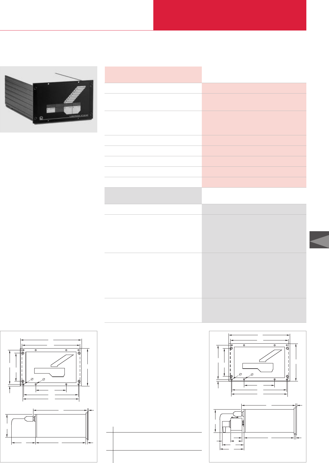
Electronic Frequency Converters
Turbomolecular Pumps with Magnetic Rotor Suspension
C09.57
LEYBOLD VACUUM PRODUCTS AND REFERENCE BOOK 2003/2004
C09
TURBOTRONIK NT 340 MA
Technical Features
◆For operating the TURBOVAC 400 C/CT
turbomolecular pump
◆Compact control unit 1/2 19", 3 HU
◆No batteries are required because of integrat-
ed generator mode in case of power failures
◆Front panel with membrane keypad and LCD
Advantages to the User
◆Convenient control and monitoring facilities
◆Remote control and process control via
analog and programmable control inputs and
outputs
◆Connection for backing pump, venting valve
and flange heater
◆V.24/RS 232 C interface
◆Temperature control for Aluminum etching
processes
Ordering Information
Technical Data NT 340 MA
Main connection, 50-60 Hz V
Power consumption TURBOVAC VA
including connected consumers VA
Max. output voltage
Motor / current limiting V / A
Magnetic suspension / current limiting V / A
Nominal frequency Hz
Overload current limit A
Permissible ambient temperature °C (°F)
Dimensions (W x H x D) mm (in.)
Weight, approx. kg (lbs)
120 V (Main cord with US plug)
Connecting line leading to the
motor of the TURBOVAC
3 m (10.5 ft)
bearing of the TURBOVAC
3 m (10.5 ft)
Connection lines
to the heater (HEATER)
to the cooling water magnet valve (COOLER)
to the valve
to the temperature controll unit (I/O)
to the Pt 100
Accessories for temperature control
Temperature control unit (TCU)
Temperature sensor Pt 100
120, +10%/-15 %
< 400
< 1 000
50 / 7
± 16 / ± 7
860/733
7
0 to +45 (32 to +113)
213 x 129 x 340 (8.39 x 5.08 x 13.39)
7 (15.4)
Part No. 857 32
Part No. 859 10
Part No. 859 11
Part No. 859 31
Part No. 859 32
Part No. 859 33
Part No. 859 34
Part No. 859 39
Part No. 859 20
Part No. 859 22
NT 340 MA
d
l
b1
b
h
h1h3
d1
h2b2
b3
b4
l4
l3
h4
l2l1
Dimensional drawing for the TURBOTRONIK NT 340 MA
d
l
b1
b
h
h1h3
d1
h2b2
b3
b4
l4
l3
h4
l1
l5
l6
l8
l2
l7
Dimensional drawing for the TURBOTRONIK NT 340 MA with
TCU temperature controll unit attached
b b1b2b3b4h h1h2h3
mm 219 211 109.5 198 202 132.5 122.5 5 99
in. 8.62 8.31 4.31 7.80 7.95 5.22 4.82 0.20 3.90
h4l l1l2l3l4l5l6l7l8
mm 111 316 4.5 130 326 3 12 55 38 105
in. 4.37 12.44 0.18 5.12 12.83 0.12 0.47 0.17 1.50 4.13
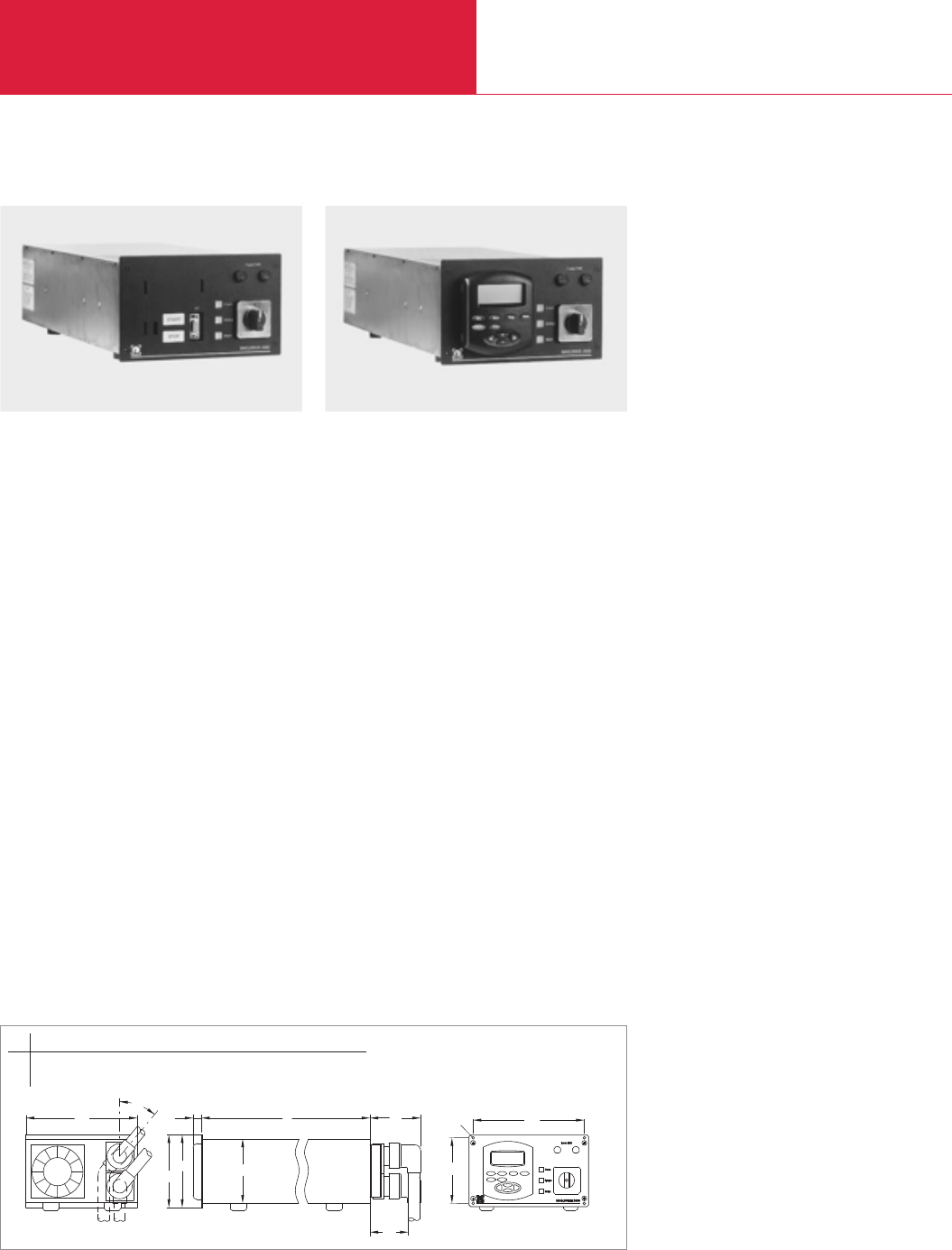
Electronic Frequency Converters
Turbomolecular Pumps with Magnetic Rotor Suspension
C09.58 LEYBOLD VACUUM PRODUCTS AND REFERENCE BOOK 2003/2004
MAG.DRIVE
digital
Advantages to the User
◆Operation of turbomolecular pumps with
magnetically levitad rotors:
MAG W 830/1300 C, MAG W 1500 C/CT,
MAG W 2200 C und MAG W 2800/3200 C/CT
◆Easy operation through the controls or the
use of plug-in control unit
◆Communication to host computer of the
customer via serial interface and conventional
interface possible
◆Setting of speed, temperature of the basic
flange and other functions
◆Warning in case the pump is runnung out of
specification
◆Storing of all parameters in the pump’s
memory
◆Plug-in control
◆Small size and low weight
◆Integrated fan
◆Integrated temperature management system
magnetic bearing control system
l
h
b
40°
b1
h3
l3
l2
l1
h2
h1
ød
Dimensional drawing for the MAG.DRIVEdigital
MAG.DRIVEdigital without plug-in control MAG.DRIVEdigital with plug-in control
b b1d h h1h2h3l l1l2l3
mm 213 198 3.3 113 135 128 122.4 455 27 100 70
in. 8.39 7.80 0.13 4.45 5.31 5.04 4.82 17.91 1.06 3.94 2.76

Electronic Frequency Converters
Turbomolecular Pumps with Magnetic Rotor Suspension
C09.59
LEYBOLD VACUUM PRODUCTS AND REFERENCE BOOK 2003/2004
C09
Ordering Information
MAG.DRIVE
digital
Plug-in control
Connection line leading to the
DRIVE/Bearing of the MAG
Converter cable outlet Pump cable outlet
DRIVE/BEARING X20 DRIVE/BEARING X23 PK X24
01.5 m (5.25 ft) bended 225° straight straight
01.5 m (5.25 ft) straight straight straight
03.0 m (10.5 ft) straight bended 180° straight
03.0 m (10.5 ft) bended 225° straight straight
03.0 m (10.5 ft) straight bended 270° straight
05.0 m (17.5 ft) bended 225° straight straight
05.0 m (17.5 ft) straight straight straight
08.0 m (28 ft) bended 225° straight straight
10.0 m (35 ft) bended 225° straight straight
20.0 m (70 ft) bended 225° straight straight
23.0 m (80.5 ft) bended 225° straight straight
30.0 m (105 ft) bended 225° straight straight
MAG (only for CT versions)
Converter cable outlet Pump cable outlet
TMS X21 TMS X30 Heater X31
01.5 m (5.25 ft) bended 225° straight bended 180°
01.5 m (5.25 ft) straight straight bended 180°
03.0 m (10.5 ft) bended 225° straight bended 180°
05.0 m (17.5 ft) bended 225° straight bended 180°
08.0 m (28 ft) bended 225° straight bended 180°
10.0 m (35 ft) bended 225° straight bended 180°
20.0 m (70 ft) bended 225° straight bended 180°
Purge / Vent (only for optional purge vent valve Part No. 121 33)
Converter cable outlet Pump cable outlet
TMS X21 Purge Vent
03.0 m (10.5 ft) bended 225° bended bended
10.0 m (35 ft) bended 225° bended bended
Connector for hardware interface
19" installation frame
Part No. 400035V0001
Part No. 121 36
Part No. 400036V0001
Part No. 400036V0007
Part No. 400036V0006
Part No. 400036V0008
Part No. 400036V0009
Part No. 400036V0004
Part No. 400036V0010
Part No. 400036V0005
Part No. 400036V0002
Part No. 400036V0003
Part No. 400036V0012
Part No. 400036V0012
Part No. 400037V0001
Part No. 400037V0007
Part No. 400037V0008
Part No. 400037V0004
Part No. 400037V0005
Part No. 400037V0002
Part No. 400037V0003
Part No. 400038V0006
Part No. 400038V0002
upon request
Part No. 161 00
MAG.DRIVE
digital
Technical Data MAG.DRIVE
digital
Main connection, 50/60 Hz V
Current for connected consumers, max. A
Max. motor voltage V
Nominal frequency Hz
Permissible ambient temperature °C (°F)
Dimensions (W x H x D) mm (in.)
Weight, approx. kg (lbs)
200 - 240, +10%/-15%
20
60
50/60
0 to +45 (32 to +113)
483 x 213 x 1/2 19"(19.02 x 8.39 x 1/2 19")
10 (22)
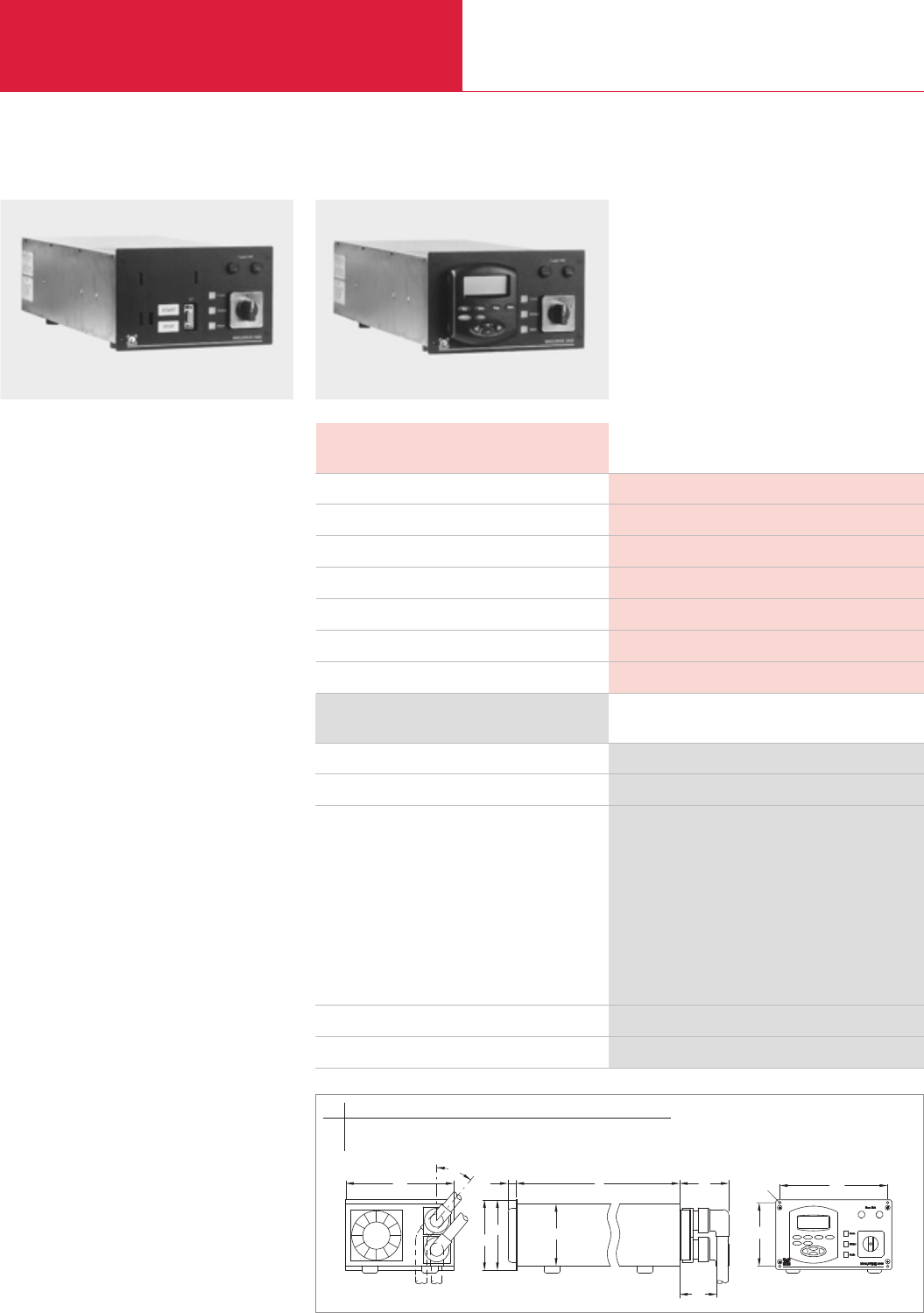
Electronic Frequency Converters
Turbomolecular Pumps with Magnetic Rotor Suspension
C09.60 LEYBOLD VACUUM PRODUCTS AND REFERENCE BOOK 2003/2004
MAG.DRIVE 2000
Advantages to the User
◆Designed to operate the MAG 2000 C/CT and
MAG W 2000 C/CT turbomolecular pumps
◆Easy operation through the controls or the
use of plug-in control unit
◆Communication to host computer of the
customer via serial interface and conventional
interface possible, bus adapter optional
◆Setting of speed, temperature of the basic
flange and other functions
◆Warning in case the pump is runnung out of
specification
◆Storing of all parameters in the pump’s
memory
◆Plug-in control
◆Small size and low weight
◆Integrated fan
◆Integrated temperature management system
Technical Data MAG.DRIVE 2000
Main connection, 50/60 Hz V
Current for connected consumers, max. A
Max. output voltage V
Nominal frequency Hz
Permissible ambient temperature °C (°F)
Dimensions (W x H x D) mm (in.)
Weight, approx. kg (lbs)
200 - 240, +10%/-15%
20
60
50/60
0 to +45 (32 to +113)
483 x 213 x 1/2 19"(19.02 x 8.39 x 1/2 19")
10 (22)
Ordering Information
MAG.DRIVE 2000
Plug-in control
Connection line leading to the
bearing of the TURBOVAC
1.5 m (5.25 ft)
10 m (35 ft)
20 m (70 ft)
motor of the TURBOVAC
1.5 m (5.25 ft)
10 m (35 ft)
20 m (70 ft)
Connector for hardware interface
19" installation frame
Part No. 121 35
Part No. 121 36
Part No. 121 29
Part No. 121 21
Part No. 121 25
Part No. 121 30
Part No. 121 22
Part No. 121 26
upon request
Part No. 161 00
MAG.DRIVE 2000
MAG.DRIVE 2000 without plug-in control MAG.DRIVE 2000 with plug-in control
l
h
b
40°
b1
h3
l3
l2
l1
h2
h1
ød
b b1d h h1h2h3l l1l2l3
mm 213 198 3.3 113 135 128 122.4 455 27 100 70
in. 8.39 7.80 0.13 4.45 5.31 5.04 4.82 17.91 1.06 3.94 2.76
Dimensional drawing for the MAG.DRIVE 2000
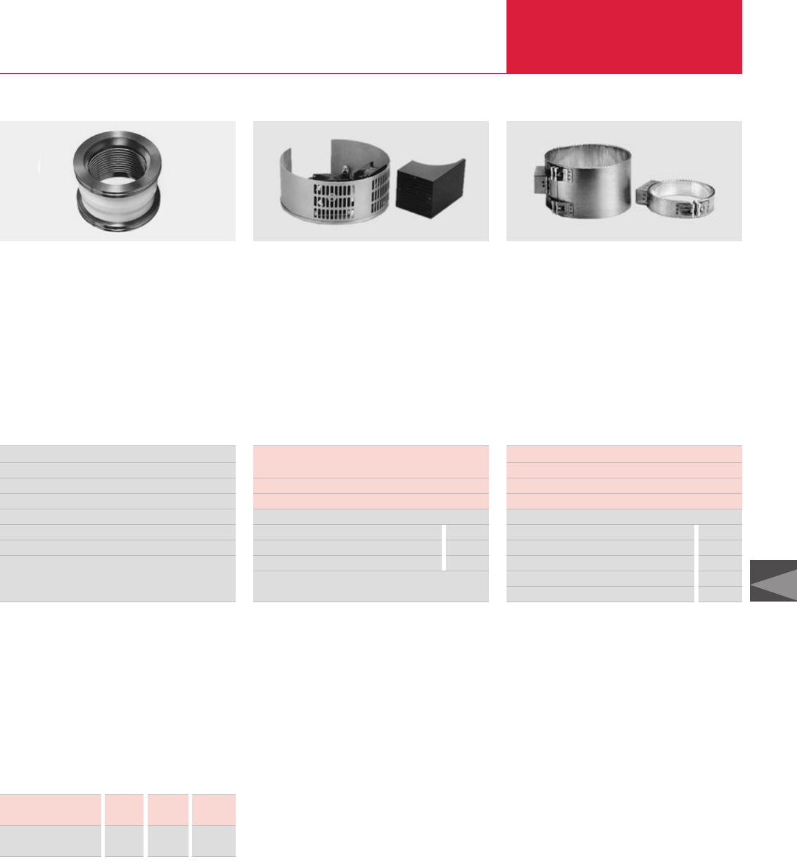
Accessories
Turbomolecular Pumps
C09.61
LEYBOLD VACUUM PRODUCTS AND REFERENCE BOOK 2003/2004
C09
Technical Data and Ordering Information
Vibration absorber Part No.
DN 63 ISO-K 854 25
DN 63 CF 500 070
DN 100 ISO-K 800131V0100
DN 100 CF 500 071
DN 160 ISO-K 500 073
DN 160 CF 500 072
Rated power consumption of the air cooling unit
when connected to
TURBOVAC 50, 151/361 10.5 W
TURBOVAC 1100 C 21.0 W
Part No.
Air cooling unit for 230 V 110 V
TURBOVAC 50 854 05 854 06
TURBOVAC 151/361 855 31 894 08
Rated power consumption of the flange heater
DN 40 CF 17 W
DN 63 CF, DN 100 CF 100 W
DN 160 CF 150 W
Part No.
Flange heater 230 V 110 V
DN 40 CF 853 97 –
DN 63 CF 854 04 854 07
DN 100 CF 854 27 –
DN 160 CF 854 37 854 38
Vibration Absorber
Vibration absorbers are used to inhibit the pro-
pagation of vibrations from the turbomolecular
pump to highly sensitive instruments like electron
beam microscopes, micro-balances or analytical
instruments.
Air Cooling Unit
Also an air cooling unit is available as a retrofit
kit for convection cooling of the TURBOVAC 50
pump with air. This kit can be easily fitted to the
pump in each case using the mounting compo-
nents contained in the kit.
Flange Heaters for CF High-
Vacuum Flanges
Most TURBOVAC pumps can be baked out in
order to improve the ultimate pressure attained in
the UHV range. Degassing of the turbomolecular
pump will only be useful when simultaneously
baking out the vacuum chamber.
Fine Filter
A fine filter integrated in the centering ring pro-
tects the pump against particles and dust on the
high-vacuum side.
Technical Data and Ordering Information
Connection
flange
DN 40 KF 63 ISO-K 100 ISO-K 160 ISO-K
Fine
filter
Part No. 883 98 887 20 887 21 887 22
The following accessories are also available:
Vacuum gauge COMBIVAC 2T
Part No. 230 000
(see Product Section C16)
Delayed venting unit
Part No. 500 441
(see Product Section C10)
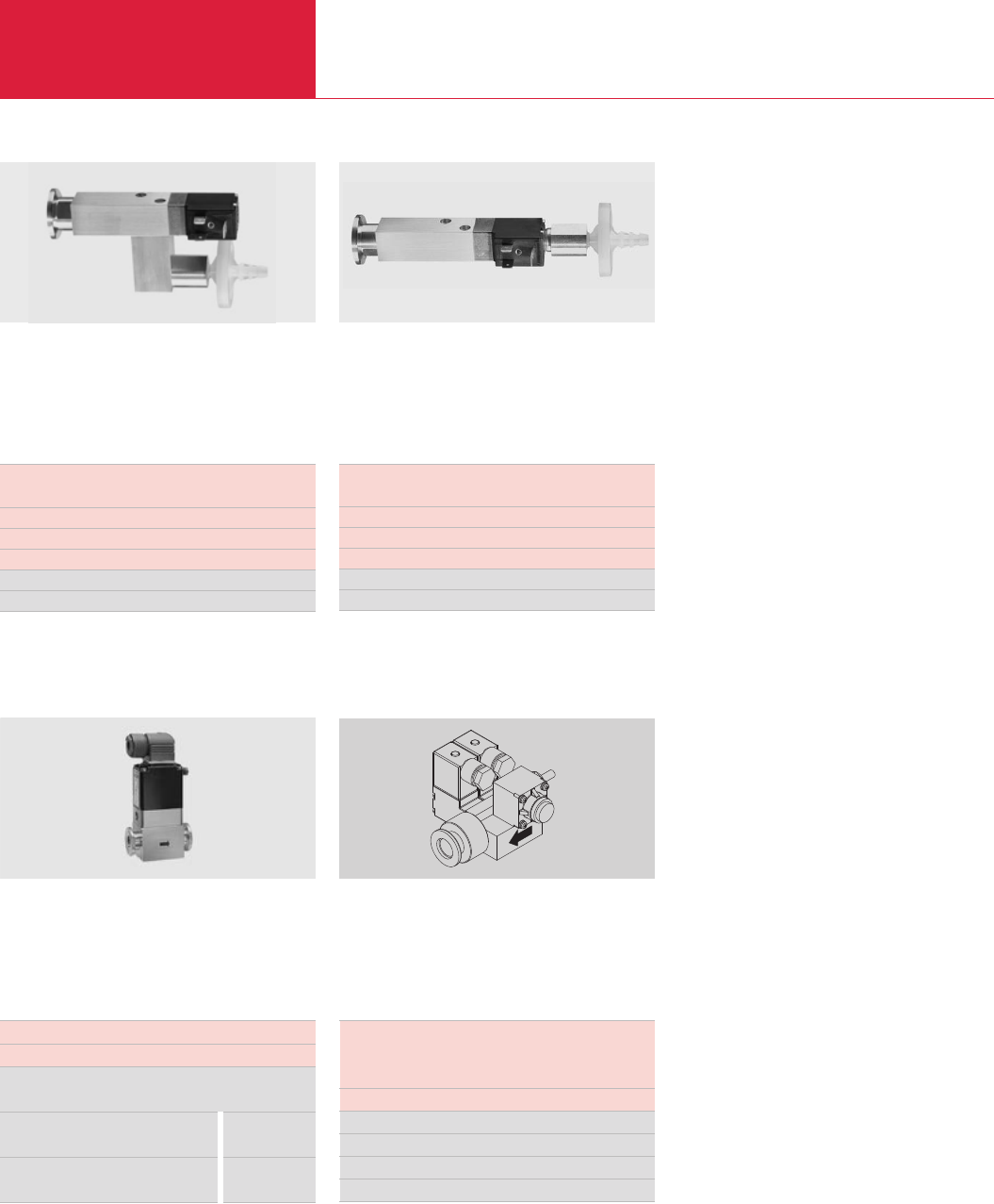
Turbomolecular Pumps
C09.62 LEYBOLD VACUUM PRODUCTS AND REFERENCE BOOK 2003/2004
Accessories
Power Failure Venting Valve
Technical Data and Ordering Information
Solenoid Venting Valve
Purge Gas and Venting Valve
Connecting flange DN 10 KF
Weight, approx. 0.7 kg (1.55 lbs)
Purge gas
and venting valve 230 V 110 V
0.2 mbar x l x s-1
(12 sccm) Part No. 855 19 Part No. 855 18
0.4 mbar x l x s-1
(24 sccm) Part No. 855 29 Part No. 855 28
Further 0.6 mbar x l x s-1 valves upon request
Technical Data and Ordering Information
Solenoid venting valve,
normally closed
Drive voltage 24 V DC
Power consumption 4 W
Weight, approx. 0.3 kg (0.66 lbs)
Part No.
Solenoid venting valve 800120V0011
Further valves are described in
Product Section C14.
Power failure venting valve,
normally open
Drive voltage 24 V DC
Power consumption 4 W
Weight, approx. 0.3 kg (0.66 lbs)
Part No.
Solenoid venting valve 800120V0021
Purge Gas and Venting Valve
Connecting flanges
Inlet 1/4" pipe
Outlet pump specifc or DN 16 KF
Weight, approx. 0.5 kg (1.1 lbs)
Purge gas and venting valve 24 V DC
Purge gas pressure, abs. 1.5 to 6.0 bar
0.6 mbar x l x s-1 (36 sccm) Part No. 121 33
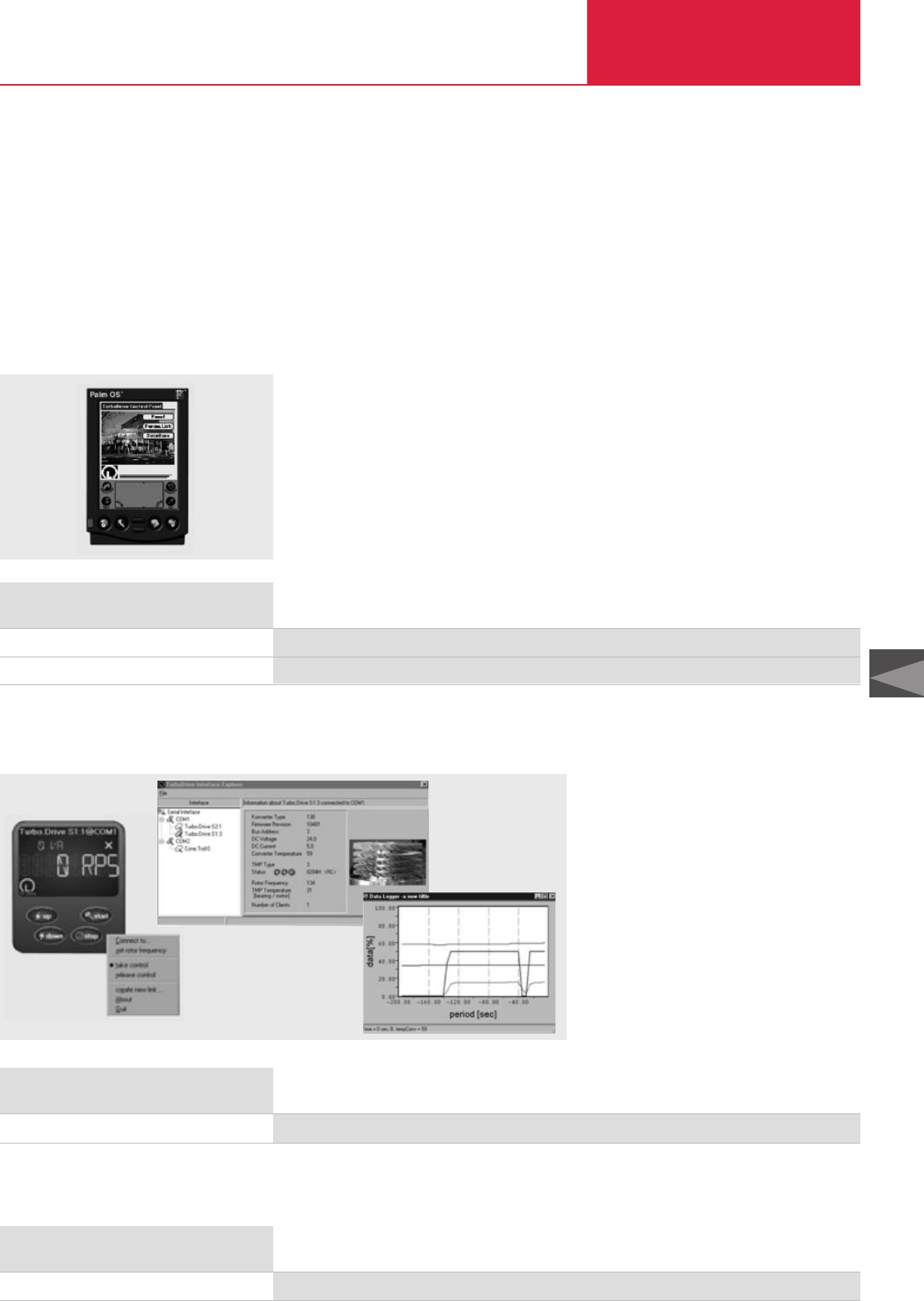
Turbomolecular Pumps
C09.63
LEYBOLD VACUUM PRODUCTS AND REFERENCE BOOK 2003/2004
C09
Accessories
Turbomolecular Pumps
C09.60
Accessories for Serial Interfaces RS 232 C and RS 485 C
Ordering Information
Portable Display Unit
Software “Turbo.Drive Panel”, 3.5 in. floppy
Display Unit
Upon request
Part No. 800110V0104
Through these accessories many control,
monitoring and information capabilities can be
implemented in connection with the electronic
frequency converters and turbomolecular pumps.
The following turbomolecular pumps or
electronic frequency converters are supported:
TW 70 H / TURBO.DRIVE S
TW 300, TW 300 H / TURBO.DRIVE S
TW 701
T 1600, TW 1600
Display Unit
Display unit for displaying parameters, for
starting and stopping the turbomolecular pump
and for changing the rotor’s speed.
Ordering Information
Mains connection 220 V, 50 Hz, EURO plug
Adapter RS 232 C/RS 485 C
Part No. 800110V0101
PC Software
PC software for Windows 95 or higher
Technical Features
◆Convenient graphical user interface
◆Several turbomolecular pumps can be
operated in parallel
◆Display, modify, save and compare the
parameter lists of the turbomolecular pumps
◆Integration of customer’s software
◆Recording parameter data over time (for
example, temperatures, rotor frequency)
Adaptor RS 232 C / RS 485 C for Frequency Converters with RS 485 C Interface
Ordering Information
PC software “Turbo.Drive Server”, CD-ROM
PC Software
Part No. 800110V0102

Turbomolecular Pumps
C09.64 LEYBOLD VACUUM PRODUCTS AND REFERENCE BOOK 2003/2004
Turbomolecular Pumps
C09.64
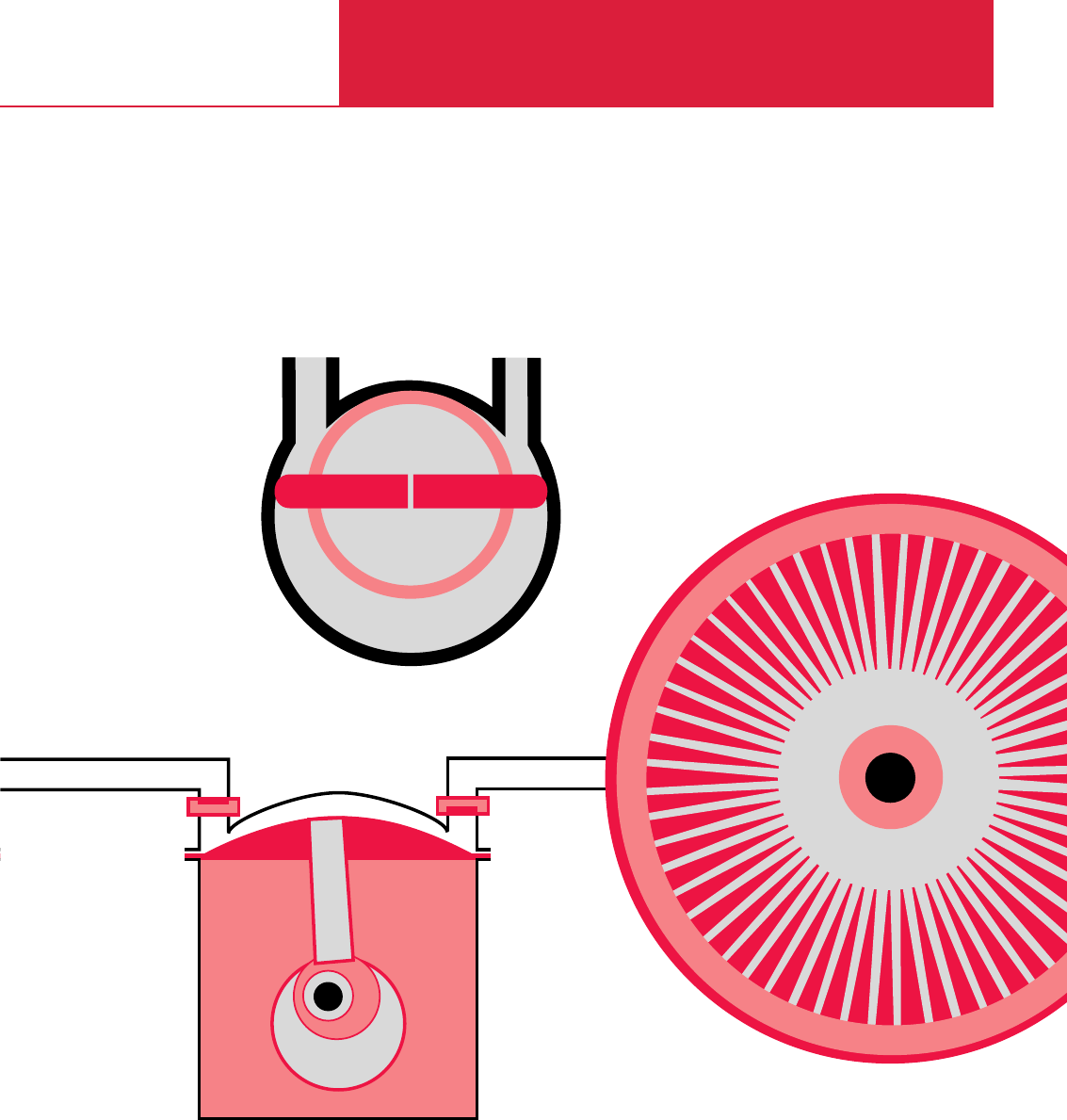
C10
Turbomolecular Pump Systems
30 - 400 l x s-1
Calibration Systems
PT, CS

Turbomolecular Pump Systems
C10.02 LEYBOLD VACUUM PRODUCTS AND REFERENCE BOOK 2003/2004
Contents
General
General . . . . . . . . . . . . . . . . . . . . . . . . . . . . . . . . . . . . . . . . . . . . . . . . . . . . . . . . . . . . . . . C10.03
Applications and Accessories . . . . . . . . . . . . . . . . . . . . . . . . . . . . . . . . . . . . . . . . . . . . . . . C10.03
Products
Turbomolecular Pump Systems (Global Versions)
PT 50 . . . . . . . . . . . . . . . . . . . . . . . . . . . . . . . . . . . . . . . . . . . . . . . . . . . . . . . . . . . . . . . C10.04
PT 151/PT 361 . . . . . . . . . . . . . . . . . . . . . . . . . . . . . . . . . . . . . . . . . . . . . . . . . . . . . . . . C10.06
PT 50 KIT, . . . . . . . . . . . . . . . . . . . . . . . . . . . . . . . . . . . . . . . . . . . . . . . . . . . . . . . . . . . C10.08
PT 151 KIT, PT 361 KIT . . . . . . . . . . . . . . . . . . . . . . . . . . . . . . . . . . . . . . . . . . . . . . . . . C10.08
PT 300 Dry . . . . . . . . . . . . . . . . . . . . . . . . . . . . . . . . . . . . . . . . . . . . . . . . . . . . . . . . . . . C10.10
PT 301 Dry . . . . . . . . . . . . . . . . . . . . . . . . . . . . . . . . . . . . . . . . . . . . . . . . . . . . . . . . . . . C10.12
Calibration Systems
CS3, CS5, CS7 . . . . . . . . . . . . . . . . . . . . . . . . . . . . . . . . . . . . . . . . . . . . . . . . . . . . . . . . C10.14
Adsorption Traps with Aluminium Oxide Insert . . . . . . . . . . . . . . . . . . . . . . . . . . . . . . . . . . C10.16
Delayed Venting Unit . . . . . . . . . . . . . . . . . . . . . . . . . . . . . . . . . . . . . . . . . . . . . . . . . . . . . C10.17
Turbomolecular Pump Systems (Versions for the North and South American Continents)
TOSS 50. . . . . . . . . . . . . . . . . . . . . . . . . . . . . . . . . . . . . . . . . . . . . . . . . . . . . . . . . . . . . C10.18
MINI-TOPS 50 . . . . . . . . . . . . . . . . . . . . . . . . . . . . . . . . . . . . . . . . . . . . . . . . . . . . . . . . C10.20
TOPS 151/361 . . . . . . . . . . . . . . . . . . . . . . . . . . . . . . . . . . . . . . . . . . . . . . . . . . . . . . . . C10.22
TURBOVAC TMV 40 000. . . . . . . . . . . . . . . . . . . . . . . . . . . . . . . . . . . . . . . . . . . . . . . . . C10.24
TOPiX. . . . . . . . . . . . . . . . . . . . . . . . . . . . . . . . . . . . . . . . . . . . . . . . . . . . . . . . . . . . . . . C10.25
TiPS. . . . . . . . . . . . . . . . . . . . . . . . . . . . . . . . . . . . . . . . . . . . . . . . . . . . . . . . . . . . . . . . C10.26
BMH70 Dry . . . . . . . . . . . . . . . . . . . . . . . . . . . . . . . . . . . . . . . . . . . . . . . . . . . . . . . . . . C10.28
TSC TurboSystem Controller . . . . . . . . . . . . . . . . . . . . . . . . . . . . . . . . . . . . . . . . . . . . . . . C10.30
TPC TurboPump Controller . . . . . . . . . . . . . . . . . . . . . . . . . . . . . . . . . . . . . . . . . . . . . . . . C10.31
Miscellaneous
60 Hz Curves . . . . . . . . . . . . . . . . . . . . . . . . . . . . . . . . . . . . . . . . . . . . . . . . . . . . . . . . . . . C10.32

Turbomolecular Pump Systems
C10.03
LEYBOLD VACUUM PRODUCTS AND REFERENCE BOOK 2003/2004
C10
General
The requirements of production or research
engineers concerning the vacuum technology
they have to employ are usually widely different.
In most cases pumping speed and operating
pressure must be accurately matched to suit a
particular process. The wide range of vacuum
pumps and standard accessories available offers
many options.
Sometimes it is just this flexibility which causes
difficulties when having to decide between the
various configurations of a particular pump
system. Based on our experience and by listening
to our customers´ demands, we have therefore
compiled a range of turn-key vacuum systems
based on standard components. Before leaving
the factory they are subjected to both functional
tests and leak tests. By adding components from
our standard range of accessories they may be
easily adapted to meet specific requirements.
Application and Accessories
Applications
Microbalances
◆ ◆ ◆ ◆ ◆ ◆ ◆ ◆ ◆ ◆ ◆ ◆ ◆ ◆ ◆
Sputtering
◆ ◆ ◆ ◆ ◆ ◆ ◆ ◆ ◆ ◆ ◆ ◆ ◆ ◆ ◆
Spectroscopy
◆ ◆ ◆ ◆ ◆ ◆ ◆ ◆ ◆ ◆ ◆ ◆ ◆ ◆ ◆
Production of TV and monitor picture tubes
◆ ◆ ◆ ◆ ◆ ◆ ◆ ◆ ◆ ◆ ◆ ◆ ◆ ◆ ◆
Surface refining
◆ ◆ ◆ ◆ ◆ ◆ ◆ ◆ ◆ ◆ ◆ ◆ ◆ ◆ ◆
Evaporation coating systems
◆ ◆ ◆ ◆ ◆ ◆ ◆ ◆ ◆ ◆ ◆ ◆ ◆ ◆ ◆
Beam guidance systems
◆ ◆ ◆ ◆ ◆ ◆ ◆ ◆ ◆ ◆ ◆ ◆ ◆ ◆ ◆
Laboratory pump systems
◆ ◆ ◆ ◆ ◆ ◆ ◆ ◆ ◆ ◆ ◆ ◆ ◆ ◆ ◆
Accessories Page
Air cooling unit –
◆ ◆ ◆ ◆ ◆ ◆ ◆ ◆ ◆ ◆ ◆ ◆
Flange heater –
◆ ◆ ◆ ◆ ◆ ◆ ◆ ◆ ◆ ◆ ◆ ◆
Delayed venting unit C10.17
◆ ◆ ◆ ◆ ◆ ◆ ◆ ◆ ◆ ◆ ◆
Venting valve –
◆ ◆ ◆ ◆ ◆ ◆ ◆ ◆ ◆ ◆ ◆ ◆
Power failure venting valve –
◆ ◆ ◆ ◆ ◆ ◆ ◆ ◆ ◆ ◆ ◆ ◆
Purge gas and venting valve –
◆ ◆ ◆ ◆
Adsorption traps with aluminium oxide insert C10.16
◆ ◆ ◆ ◆ ◆ ◆ ◆ ◆ ◆ ◆ ◆ ◆
Exhaust filter –
◆ ◆ ◆ ◆ ◆ ◆ ◆ ◆ ◆ ◆ ◆ ◆
Water flow monitor –
◆ ◆ ◆ ◆ ◆ ◆ ◆
Water cooling unit –
◆ ◆ ◆ ◆ ◆
Pumps
BMH 70 Dry
PT 151
PT 50
PT 361
PT 50 KIT
PT 151 KIT
PT 361 KIT
PT 300 Dry
PT 301 Dry
TOSS 50
MINI-TOPS 50
TOPS 151/361
TURBOVAC TMV 40000
TOPiX
TIPS
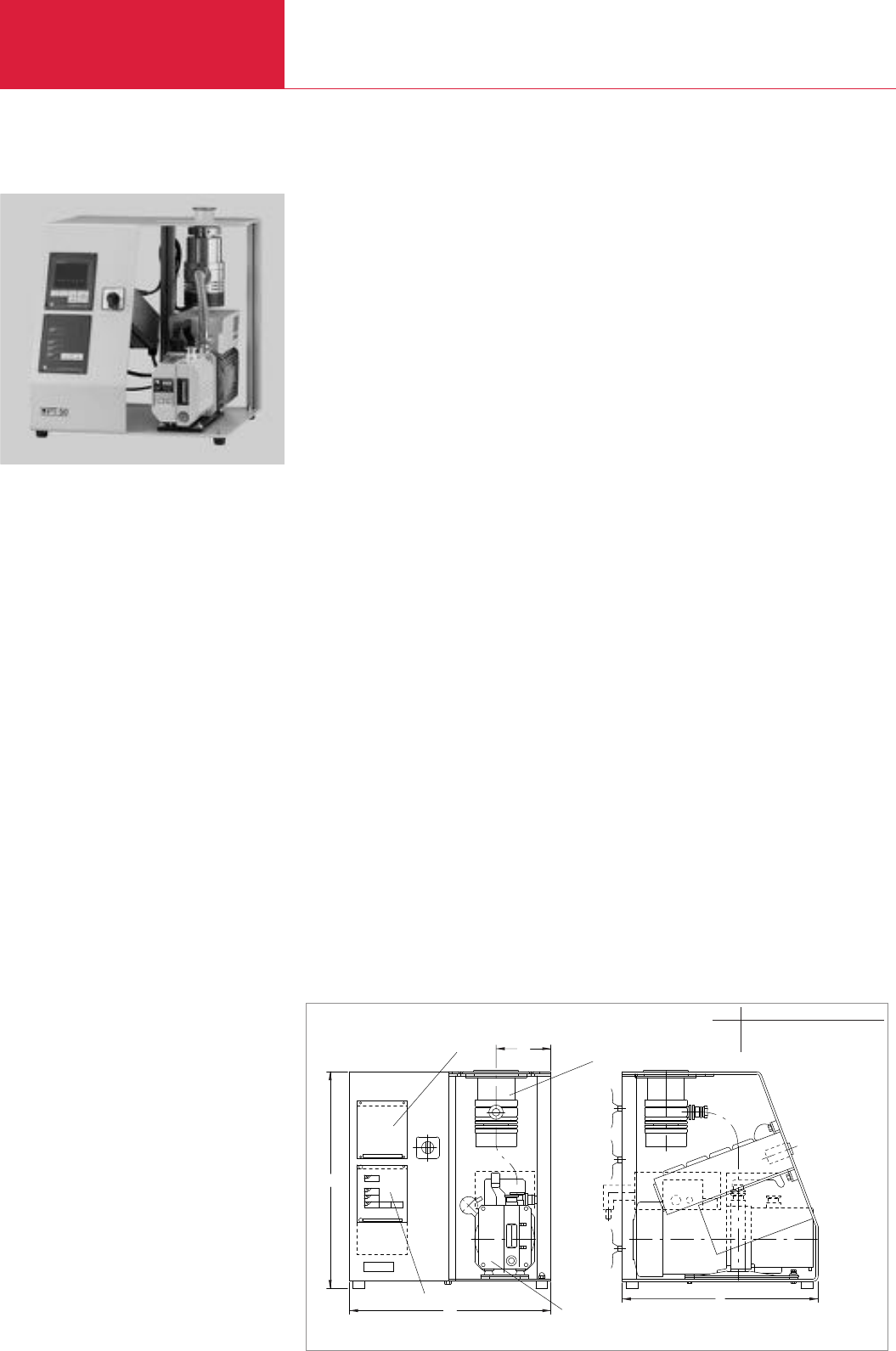
Turbomolecular Pump Systems
C10.04 LEYBOLD VACUUM PRODUCTS AND REFERENCE BOOK 2003/2004
PT 50 Turbomolecular Pump System
Advantages to the User
◆High effective pumping speed
◆Low ultimate pressure (< 10
-8
mbar
(< 0.75 x 10
-8
Torr))
◆High pumping speed of the backing pump
◆Compact, small, rugged unit
◆Simple to operate
◆High level of reliability
◆Maintenance-friendly design
◆For use world-wide
◆Installation of standard vacuum components
in an open frame
◆Components such as the backing pump,
frequency converter, vacuum gauge and
power failure venting valve are controlled via
a rotary switch
◆Service friendly assembly for maintenance
without the need to disassemble backing or
high vacuum pump
◆The high vacuum pump can be removed from
the pump system
◆CE approval
The turbomolecular pump system consists of the
following principal components:
◆Grease lubricated turbomolecular pump
TURBOVAC 50 with ceramic ball bearings,
convection cooling and splinter guard
◆Electronic frequency converter NT 10
◆Dual-stage, oil sealed rotary vane vacuum
pump TRIVAC D 2,5 E as backing pump
◆Switchbox with rotary switch for driving the
backing pump, the turbomolecular pump, a
vacuum gauge (optional) and a power failure
venting valve (optional)
◆Mains connection 230 V, 50 Hz with EURO
plug
◆Rugged table top unit which may also carry
heavy assemblies
◆All required connecting and sealing compo-
nents are located within the pump system
assembly
The pump system is prepared for installation of
further components:
◆Vacuum gauge
◆Power failure venting valve
◆Air cooling unit
◆Assembly on the intake side with manifold,
valves, gauge heads etc.
◆Adsorption trap
◆Exhaust filter
◆Rotatable castors
◆Mains cable with connection plug for UK,
USA, Switzerland, Japan
This turbomolecular pump system is a fully
assembled and ready-to-operate ultra high
vacuum system as a table top unit which
requires a hydrocarbon-free high and ultra high
vacuum.
Vacuum gauge (option)
Frequency converter
TRIVAC E backing pump
Turbomolecular pump
b1
b
h
l
Dimensional drawing for the turbomolecular pump system PT 50 / DN 63 ISO-K
Typical Applications
◆Spectroscopy
◆Tube manufacturing
◆Beam guidance systems
◆Micro balances
◆Sputtering and evaporation systems
◆Surface physics
◆Laboratory pump systems
◆Production of gas Lasers
h b b1l
mm 456 430 117.5 420
in. 17.95 16.93 4.63 16.54

Turbomolecular Pump Systems
C10.05
LEYBOLD VACUUM PRODUCTS AND REFERENCE BOOK 2003/2004
C10
PT 50 turbomolecular pump system
DN 40 KF
DN 63 ISO-K
DN 63 CF
Air cooling unit
115 V
230 V
Flange heater
DN 63 CF, 115 V
DN 63 CF, 230 V
Delayed venting unit 2)
Venting valve, DN 10 KF
manually operated
Power failure venting valve, DN 10 KF
024 V DC
115 V, 60 Hz
230 V, 50/60 Hz
Adsorption trap, DN 16 KF
Adsorbent
AF 8 exhaust filter
Mains cord
USA/JAP 115 V, 50/60 Hz
USA/JAP 230 V, 50/60 Hz
CH 230 V, 50/60 Hz
UK 230 V, 50/60 Hz
Connecting cable for operating the TURBOVAC
outside the pump system
03 m (10.0 ft)
05 m (17.5 ft)
10 m (35.0 ft)
1) use only for CF flanges
2) for 24 V DC valves
Ordering Information PT 50
Turbomolecular pump
High vacuum connection DN
Pumping speed for N2l x s-1
Compression for N2/H2
Speed of the TURBOVAC rpm
Dual-stage rotary vane vacuum pump
Nominal pumping speed acc. to PNEUROP
m3x h-1 (cfm)
Ultimate total pressure mbar (Torr)
Attainable ultimate pressure
with FPM gasket mbar (Torr)
with aluminum or Cu gasket 1) mbar (Torr)
Main supply, 50/60 Hz V
Rated power consumption, approx. VA
Dimensions (W x H x D) mm (in.)
Weight, approx. kg (lbs)
Technical Data PT 50
TURBOVAC 50
40 KF 63 ISO-K 63 CF
33 55 55
2 x 10⁷/ 102
72 000
TRIVAC D 2,5 E
2.7 (1.6)
10-3 (0.75 x 10⁻³)
< 10-6 (< 0.75 x 10⁻⁶) < 10-6 (< 0.75 x 10⁻⁶) < 10-6 (< 0.75 x 10⁻⁶)
– – < 10-8 (< 0.75 x 10⁻⁸)
100-120 / 200-240 ± 5%
500
430 x 456 x 420 (16.93 x 17.95 x 16.54)
27 (59.4)
Part No. 128 80 – –
–Part No. 128 81 –
– – Part No. 128 83
Part No. 854 06
Part No. 854 05
Part No. 854 07
Part No. 854 04
Part. No. 500 441
Part. No. 173 24
Part No. 174 46
Part No. 200 06 420
Part No. 173 26
Part No. 854 14
Part No. 854 10
Part No. 190 50
Part No. 200 81 090
Part No. 200 81 141
Part No. 200 81 099
Part. No. 200 81 097
Part No. 121 08
Part No. 121 09
Part No. 119 90
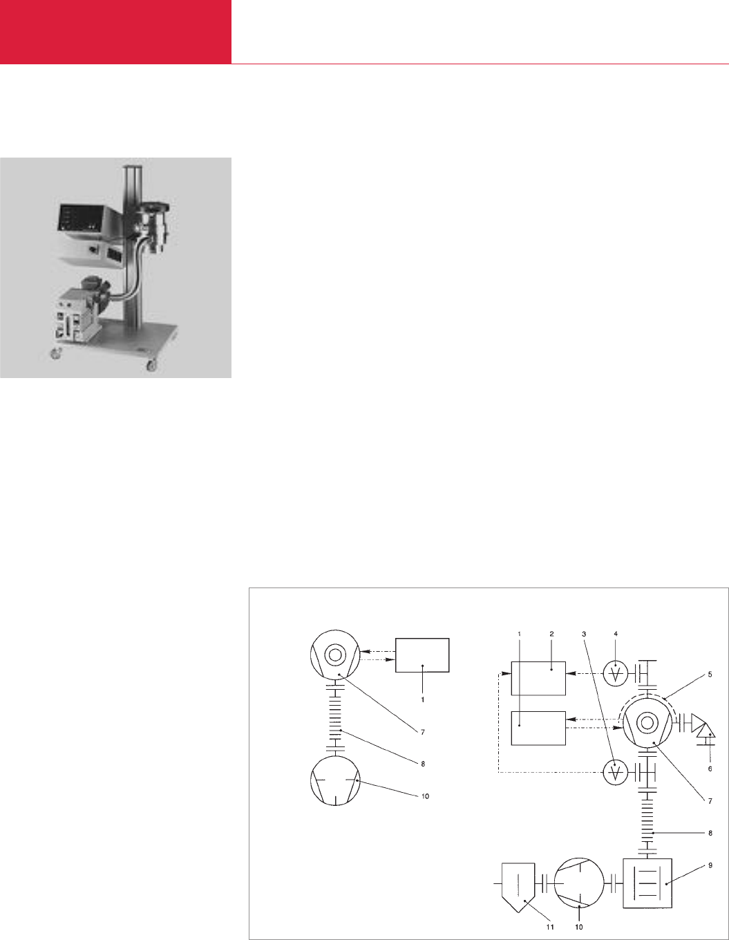
Turbomolecular Pump Systems
C10.06 LEYBOLD VACUUM PRODUCTS AND REFERENCE BOOK 2003/2004
PT 151/PT 361 Turbomolecular Pump Systems
Advantages to the User
◆Low ultimate pressure (< 10
-7
mbar (Torr)),
free of hydrocarbons
◆High effective pumping speed
◆Compact, mobile unit
◆Simple to operate
◆High level of reliability
◆Purge gas and venting ports
◆Components such as backing pump,
frequency converter and TURBOVAC, as well
as venting or degassing are controlled via a
single multi function switch
◆Service friendly assembly for maintenance
without the need to disassemble backing or
high vacuum pump
◆Pump systems prepared for installation of lar-
ger backing pumps (for barrier gas operation,
for example)
◆Additional mains sockets for accessories
◆CE approval
The turbomolecular pump systems consists of
the following principal components:
◆Grease lubricated turbomolecular pump
TURBOVAC 151 or 361 with splinter guard
◆Electronic frequency converter NT 20
◆
Dual-stage, oil sealed TRIVAC D 4 B or D 16 B
rotary vane vacuum pump as backing pump
◆Switch box with mains power outlet and
rotary switch to operate the connected units
The pump systems are prepared for installation
of further components:
◆Vacuum gauges (up to two)
◆Adsorption trap
◆Exhaust filter
◆Air cooling unit
◆Flange heater
◆Venting valve
These turbomolecular pump systems are ready-
to-operate vacuum units for generating a vacuum
in the high and ultra high vacuum range which is
free of hydrocarbons.
When pumping aggressive or abrasive process
gases, a purge gas facility must be used for the
pumps.
Standard system Systems with accessories
1 TURBOTRONIK 7 TURBOVAC
2 Vacuum gauge (optional) 8 Corrugated tube
3Forevacuum gauge (optional) 9 Adsorption trap (optional)
4 High vacuum gauge (optional) 10 TRIVAC backing pump
5 Flange heater (optional) 11 Exhaust filter (optional)
6 Venting valve (optional)
Vacuum diagram of the PT 151/ PT 361 turbomolecular pump systems
Typical Applications
♦Spectroscopy
♦Tube manufacturing
♦Beam guidance systems
♦Micro balances
♦Sputtering and evaporation systems
♦Surface physics
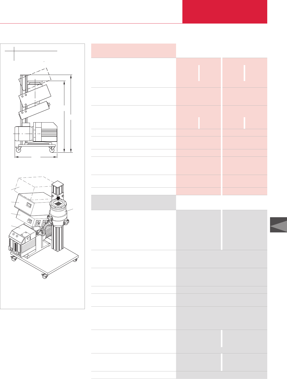
Turbomolecular Pump Systems
C10.07
LEYBOLD VACUUM PRODUCTS AND REFERENCE BOOK 2003/2004
C10
Ordering Information
Turbomolecular pump
High vacuum connection DN
Pumping speed for N2l x s-1
Compression for N2/H2
Speed of the TURBOVAC rpm
Dual-stage rotary vane vacuum pump
Nominal pumping speed (DIN 28 400)
m
3
x h
-1
(cfm)
Exhaust connection DN
Attainable ultimate pressure
with FPM seal mbar (Torr)
with Cu seal mbar
(Torr)
Cooling water consumption l/h
Cooling water connection, hose nozzle, outside dia.
mm (in.)
Power consumption kVA
Mains supply
EURO version V
USA version V
Dimensions (W x H x D) mm
(in.)
Weight, approx. kg (lbs)
TURBOVAC 151 TURBOVAC 361
100 ISO-K 100 CF 100 ISO-K 100 CF
145 145 345 345
> 1098.5 x 102> 1093.5 x 103
50 000 50 000
TRIVAC D 4 B TRIVAC D 16 B
4.8 (2.83) 18.9 (11.13)
16 KF 25 KF
10-8 (0.75 x 10⁻⁸) 10-8 (0.75 x 10⁻⁸)
– 10-10 – 10-10
– (0.75 x 10⁻¹⁰) – (0.75 x 10⁻¹⁰)
20 20
11 (0.43) 11 (0.43)
0.7 1.5
230 V, 50 Hz 230 V, 50 Hz
115 V, 60 Hz 115 V, 60 Hz
500 x 890 x 484 500 x 890 x 484
(19.69 x 35.04 x 19.06) (19.69 x 35.04 x 19.06)
45 (99.2) 62 (136.7)
Technical Data PT 151 PT 361
PT 151 / PT 361 turbomolecular pump system
EURO version, 230 V / 50 Hz, Schuko plug
DN 100 ISO-K
DN 100 CF
USA version, 115 V / 60 Hz, USA plug
DN 100 ISO-K
DN 100 CF
Air cooling unit
115 V
230 V
Flange heater, DN 100 CF
115 V
230 V
Delayed venting unit *)
Venting valve, DN 10 KF
manually operated
Power failure venting valve, DN 10 KF
024 V DC
115 V, 60 Hz
230 V, 50/60 Hz
Adsorption trap
DN 16 KF
DN 25 KF
Adsorbent
Exhaust filter
AF 4-8
AF 16-25
Purge gas and venting valve, 230 V
*) for 24 V DC valves
Part No.128 84 Part No.128 86
Part No.128 85 Part No.128 88
Part No.152 57 Part No.152 59
Part No.152 58 Part No.152 60
Part No. 894 08
Part No. 855 31
Part No. 854 28
Part No. 854 27
Part. No. 500 441
Part. No. 173 24
Part No. 174 46
Part No. 200 06 420
Part No. 173 26
Part No. 854 14 –
– Part No. 854 15
Part No. 854 10
Part No. 189 06 –
– Part No. 189 11
Part No. 855 19
PT 151 PT 361
1
4
3
2
5
484
800
875
500 wide
1 TRIVAC backing pump 4 Vacuum gauge (optional)
2 Switch box 5 TURBOVAC
3 TURBOTRONIK
PT 151 Turbomolecular pump system
484
800
890
500 breit
500 wide
h h1l wide
mm 800 890 484 500
in. 31.50 35.04 19.06 19.69
h
h1
l
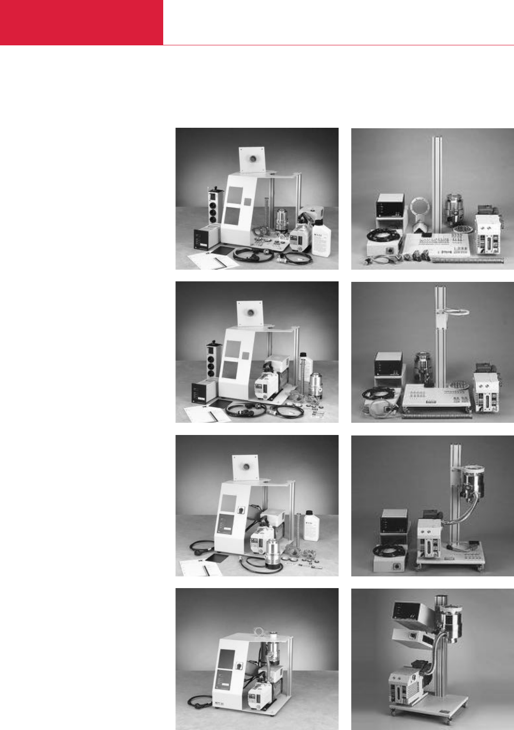
Turbomolecular Pump Systems
C10.08 LEYBOLD VACUUM PRODUCTS AND REFERENCE BOOK 2003/2004
PT 50 KIT, PT 151 KIT, PT 361 KIT Turbomolecular Pump Systems
PT 50 KIT PT 151 KIT / PT 361 KIT
Under the motto
“
Do-it-yourself and save money
”
you may assemble the turbomolecular pump
systems PT 50 KIT, PT 151 KIT and PT 361 KIT
yourself.
The turbomolecular pump systems PT 50 KIT,
PT 151 KIT and PT 361 KIT are made of the
same components as used for the turn-key
systems:
◆Base panel with column
◆TURBOVAC 50 turbomolecular pump
(PT 50 KIT) or 151 or 361 (PT 151 KIT or
PT 361 KIT)
◆Rotary vane vacuum pump
TRIVAC D 2,5 E (PT 50 KIT) or D 4 B or
D 16 B (PT 151 KIT or PT 361 KIT)
◆TURBOTRONIK NT 10 electronic frequency
converter (PT 50 KIT) or NT 20 (PT 151 KIT
and PT 361 KIT)
◆All necessary mounting parts, connection
parts and gaskets are supplied
◆Simple and accurate assembly instructions
◆Detailed exploded view
◆Description which is easy to understand
◆Additional detailed knowledge is gained about
the product by assembling it yourself
◆CE approval
The technical data, the areas of application and
the design characteristics correspond to the
turbomolecular pump systems PT 50, PT 151
and PT 361 described on the preceding pages.
Typical Applications
◆Spectroscopy
◆Tube manufacturing
◆Beam guidance systemse
◆Micro balances
◆Sputtering and evaporation systems
◆Surface physics
◆Laboratory pump systems
◆Production of gas Lasers
Unpacking, 15 minutes, approx. Unpacking, 15 minutes, approx.
After further 20 minutes After further 30 minutes
After further 20 minutes After further 30 minutes
After further 30 minutes After further 50 minutes

Turbomolecular Pump Systems
C10.09
LEYBOLD VACUUM PRODUCTS AND REFERENCE BOOK 2003/2004
C10
PT 50 KIT turbomolecular pump system
DN 40 KF
DN 63 ISO-K
DN 63 CF
PT 151 KIT turbomolecular pump system, water-cooled
DN 100 ISO-K
DN 100 CF
PT 361 KIT turbomolecular pump system, water-cooled
DN 100 ISO-K
DN 100 CF
DN 160 ISO-K
DN 160 CF
Air cooling unit,
230 V
115 V
Flange heater
DN 63 CF, 230 V
DN 63 CF, 115 V
DN 100 CF, 230 V
DN 100 CF, 115 V
Adsorption trap
DN 16 KF
DN 25 KF
Adsorbent
Exhaust filter
AF 4-8
AF 8
AF 16-25
Delayed venting unit *)
Venting valve, DN 10 KF
manually operated
Purge gas and venting valve, 230 V
Power failure venting valve, DN 10 KF
024 V DC
115 V, 60 Hz
230 V, 50/60 Hz
Water cooling unit for the TURBOVAC
Mains cord
USA/JAP, 115 V, 50/60 Hz
USA/JAP, 230 V, 50/60 Hz
CH, 230 V, 50/60 Hz
UK, 230 V, 50/60 Hz
Connecting cable for operating the TURBOVAC
outside the pump system
03 m (10.0 ft)
05 m (17.5 ft)
10 m (35.0 ft)
*) for 24 V DC valves
Part No. 128 70 – –
Part No. 128 71 – –
Part No. 128 73 – –
–Part No. 128 74 –
–Part No. 128 75 –
– – Part No. 128 76
– – Part No. 128 78
– – upon request
– – upon request
Part No. 854 05 Part No. 855 31 Part No. 855 31
Part No. 854 06 Part No. 894 08 Part No. 894 08
Part No. 854 04 – –
Part No. 854 07 – –
– Part No. 854 27 Part No. 854 27
– – Part No. 854 28
Part No. 854 14 Part No. 854 14 –
– – Part No. 854 15
Part No. 854 10 Part No. 854 10 Part No. 854 10
– Part No. 189 06 –
Part No. 190 05 – –
– – Part No. 189 11
Part No. 500 441 Part No. 500 441 Part No. 500 441
Part No. 173 24 Part No. 173 24 Part No. 173 24
– Part No. 855 19 Part No. 855 19
Part No. 174 46 Part No. 174 46 Part No. 174 46
Part No. 174 26 Part No. 174 26 Part No. 174 26
Part No. 200 06 420 – –
Part No. 854 08 – –
Part No. 200 81 090 – –
Part No. 200 81 141 Part No. 200 81 141 Part No. 200 81 141
Part No. 200 81 099 Part No. 200 81 099 Part No. 200 81 099
Part No. 200 81 097 Part No. 200 81 097 Part No. 200 81 097
Part No. 121 08 – –
Part No. 121 09 Part No. 857 66 Part No. 857 66
– Part No. 857 67 Part No. 857 67
Ordering Information PT 50 KIT PT 151 KIT PT 361 KIT
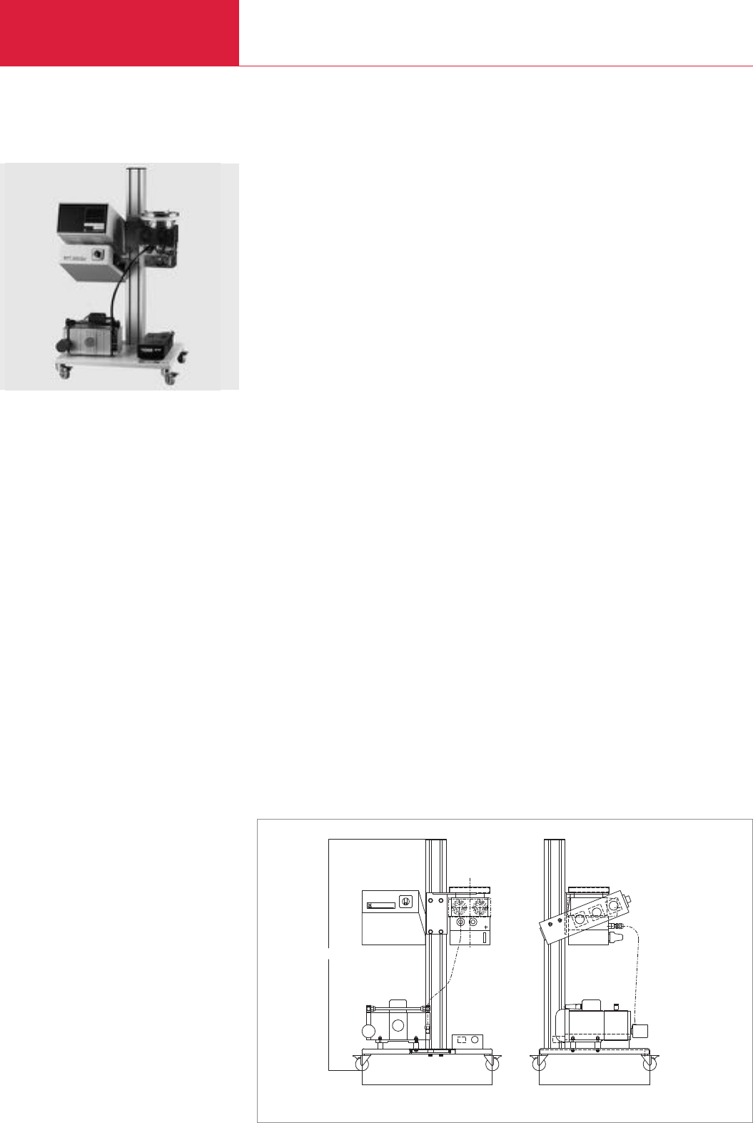
Turbomolecular Pump Systems
C10.10 LEYBOLD VACUUM PRODUCTS AND REFERENCE BOOK 2003/2004
PT 300 Dry Turbomolecular Pump System
Advantages to the User
◆
Absolutely oil-free
◆
Low ultimate pressure free of hydro-
carbons (10-8 mbar)
◆
High effective pumping speed
◆
Compact and mobile unit
◆
Simple operation
◆
High level of reliability
◆
Maintenance-friendly design
◆
Installation in any orientation for TW 300
◆
Air cooling
◆
Installation of standard vacuum compo-
nents in an open frame with installation
column and castors
◆
Components such as the diaphragm
backing pump and turbomolecular pump as
well as venting or degassing are controlled
via a single rotary switch
◆
Service-friendly assembly for maintenance
without the need to disassemble backing or
high vacuum pump
◆
Pump systems prepared for installation of
larger backing pumps
◆
Additional mains sockets for accessories
◆
The pump systems are subjected to a full
functional test and a leak test before deli-
very
The turbomolecular pump system consists of the
following principal componentes:
◆
TW 300 hybrid turbomolecular pump
◆
Dual-stage, absolutely oil-free
DIVAC 2,5 VT diaphragm vacuum pump
used as the backing pump
◆
Switchbox for driving and interlocking of
the two vacuum pumps.
◆
Mobile base plate with column
◆
All required connection and sealing compo-
nents are located within the pump system
assembly
The pump systems are prepared for installation
of further components.
◆
Vacuum gauges
◆
Flange heater
◆
Venting valve
Typical Applications
◆
Spectroscopy
◆
Valve manufacturing
◆
Beam guidance systems
◆
Micro balances
◆
Sputtering and evaporation systems
◆
Surface physics
◆
Laboratory pump systems
The PT 300 Dry turbomolecular pump system
is a fully assembled, ready-to-operate and
mobile high vacuum pump system which is
based on a column design.
500 425
887
PT300DRY
Dimensional drawing for the PT 300 Dry

Turbomolecular Pump Systems
C10.11
LEYBOLD VACUUM PRODUCTS AND REFERENCE BOOK 2003/2004
C10
H
ybrid turbomolecular pump
High vacuum connection
DN
Pumping speed for nitrogen
l x s-1
D
iaphragm pump
Pumping speed
,
approx.
m3x h-1 (cfm)
Ultimate pressure
,
approx.
mbar (Torr)
Attainable ultimate pressure
with rotary vane pump
mbar (Torr)
with diaphragm pump
mbar (Torr)
Mains connection
, 50/60 Hz V
Power consumption
,
approx.
W
Dimensions (W x H x D)
mm (in.)
Weight, approx.
kg (lbs)
TW 300
100 ISO-K 100 CF
240
DIVAC 2,5 VT
2.5 (1.5)
3 (2.25)
10-9 (0.75 x 10⁻⁹)
10-8 (0.75 x 10⁻⁸)
230 / 115
600
500 x 887 x 425 (19.68 x 34.92 x 16.73)
44 (97.13)
Technical Data PT 300 Dry
PT 300 Dry turbomolecular pump system
DN 100 ISO-K, 230 V, 50 Hz
DN 100 ISO-K, 115 V, 60 Hz
DN 100 CF, 230 V, 50 Hz
DN 100 CF, 115 V, 60 Hz
Mains adapter Schuko/US
Mains cable for junction box
EURO, 230 V, 50 Hz
CH, 230 V, 50/60 Hz
UK, 230 V, 50/60 Hz
USA/Japan, 230 V, 50/60 Hz
USA/Japan, 115 V, 60 Hz
Power failure airing valve
, 230 V, 50/60 Hz
F
lange heater for flange
DN 100 CF, 230 V
24 V DC
mains cable
3 m
5 m
10 m
20 m
Part No. 500 687 –
Part No. 500 693 –
–Part No. 500 688
–Part No. 500 694
Part No. 200 11 119
Part No. 200 81 091
Part No. 200 81 099
Part No. 200 81 097
Part No. 200 81 141
Part No. 200 81 090
Part No. 174 26
Part No. 854 27
Part No. 800094V0300
Part No. 800094V0500
Part No. 800094V1000
Part No. 800094V2000
Ordering Information PT 300 Dry
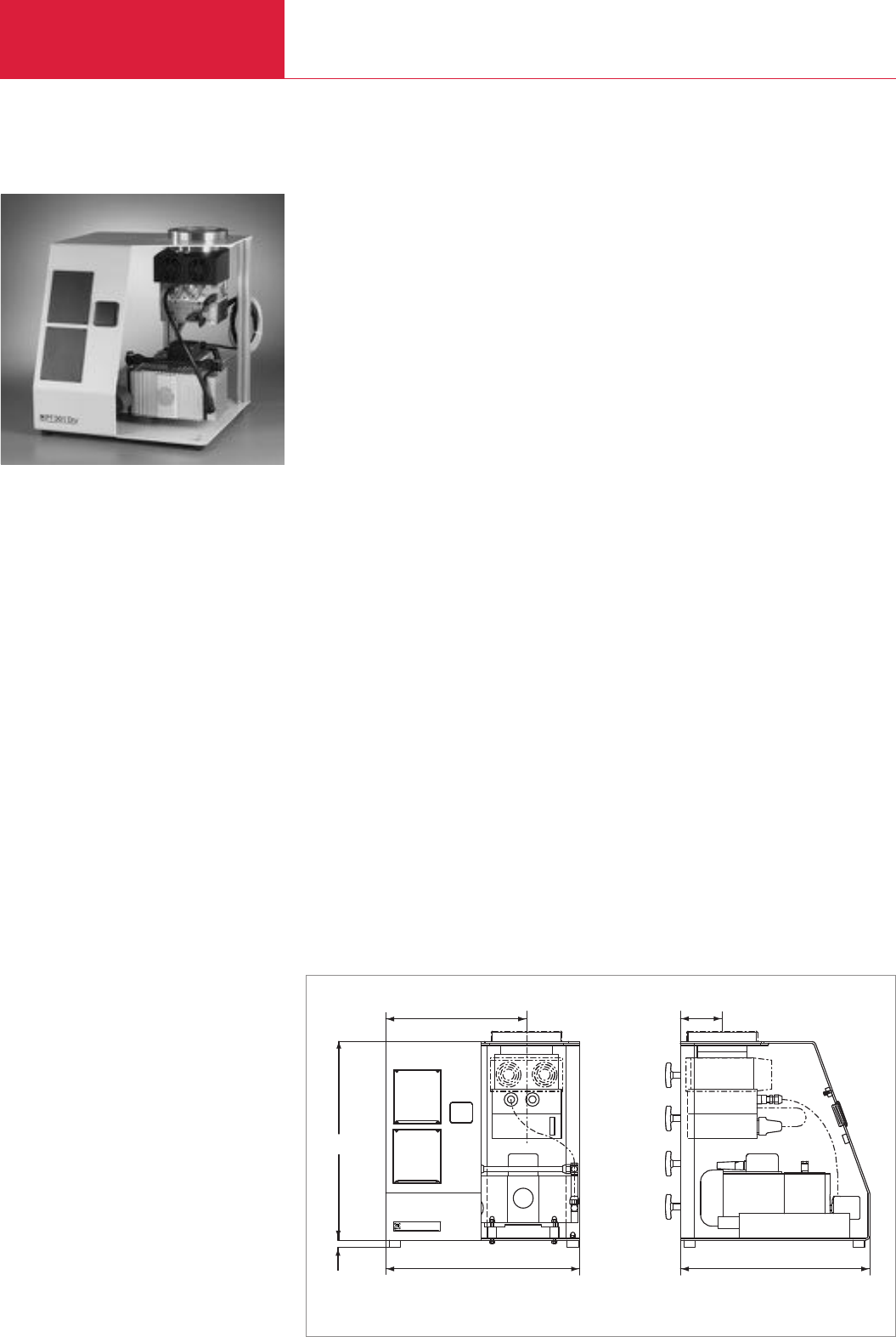
Turbomolecular Pump Systems
C10.12 LEYBOLD VACUUM PRODUCTS AND REFERENCE BOOK 2003/2004
PT 301 Dry Turbomolecular Pump System
Advantages to the User
◆
Absolutely oil-free
◆
Low ultimate pressure free of hydro-
carbons (10-8 mbar)
◆
High effective pumping speed
◆
Compact and small unit
◆
Simple operation
◆
High level of reliability
◆
Maintenance-friendly design
◆
Installation in any orientation for TW 300
◆
Air cooling
◆
Installation of standard vacuum
components in an open frame
◆
Components such as the diaphragm
backing pump and turbomolecular pump
are controlled via switches
◆
Service-friendly assembly for maintenance
without the need to disassemble backing or
high vacuum pump
◆
The high vacuum pump can be removed
◆
The pump systems are subjected to a full
functional test and a leak test before deli-
very
The turbomolecular pump system consists of the
following principal componentes:
◆
TW 300 hybrid turbomolecular pump
system
◆
TURBO.POWER 300 power supply
◆
Dual-stage, absolutely oil-free
DIVAC 2,5 VT diaphragm vacuum pump
used as the backing pump
◆
All required connection and sealing compo-
nents are located within the pump system
assembly
The pump systems are prepared for installation
of further components.
◆
Vacuum gauges
◆
Venting valve /
Power failure venting valve
◆
Junction box
Typical Applications
◆
Spectroscopy
◆
Valve manufacturing
◆
Beam guidance systems
◆
Micro balances
◆
Sputtering and evaporation systems
◆
Surface physics
◆
Laboratory pump systems
The PT 301 Dry turbomolecular pump system
is a fully assembled and ready-to-operate high
vacuum system designed as a table top unit.
93
420
430
16
440
313
PT301Dry
Dimensional drawing for the PT 301 Dry

Turbomolecular Pump Systems
C10.13
LEYBOLD VACUUM PRODUCTS AND REFERENCE BOOK 2003/2004
C10
PT 300 Dry turbomolecular pump system
DN 100 ISO-K, 230 V, 50 Hz
DN 100 ISO-K, 115 V, 60 Hz
DN 100 CF, 230 V, 50 Hz
DN 100 CF, 115 V, 60 Hz
Junction box
Mains adapter Schuko/US
Mains cable for junction box
EURO, 230 V, 50 Hz
CH, 230 V, 50/60 Hz
UK, 230 V, 50/60 Hz
USA/Japan, 230 V, 50/60 Hz
USA/Japan, 115 V, 60 Hz
Power failure venting valve
, 230 V, 50/60 Hz
24 V DC
mains cable
3 m
5 m
10 m
20 m
Part No. 500 685 –
Part No. 500 691 –
–Part No. 500 686
–Part No. 500 692
Part No. 200 06 393
Part No. 200 11 119
Part No. 200 81 091
Part No. 200 81 099
Part No. 200 81 097
Part No. 200 81 141
Part No. 200 81 090
Part No. 174 26
Part No. 800094V0300
Part No. 800094V0500
Part No. 800094V1000
Part No. 800094V2000
Ordering Information PT 301 Dry
H
ybrid turbomolecular pump
High vacuum connection
DN
Pumping speed for nitrogen
l x s-1
D
iaphragm pump
Pumping speed
,
approx.
m3x h-1 (cfm)
Ultimate pressure
,
approx.
mbar (Torr)
Attainable ultimate pressure
mbar (Torr)
Mains connection
, 50/60 Hz V
Power consumption
,
approx.
W
Dimensions (W x H x D)
mm (in.)
Weight, approx.
kg (lbs)
TW 300
100 ISO-K 100 CF
240
DIVAC 2,5 VT
2.5 (1.5)
3 (2.25)
10-8 (0.75 x 10⁻⁸)
230 / 115
600
430 x 456 x 420 (16.93 x 17.95 x 16.54)
31 (68.43)
Technical Data PT 301 Dry
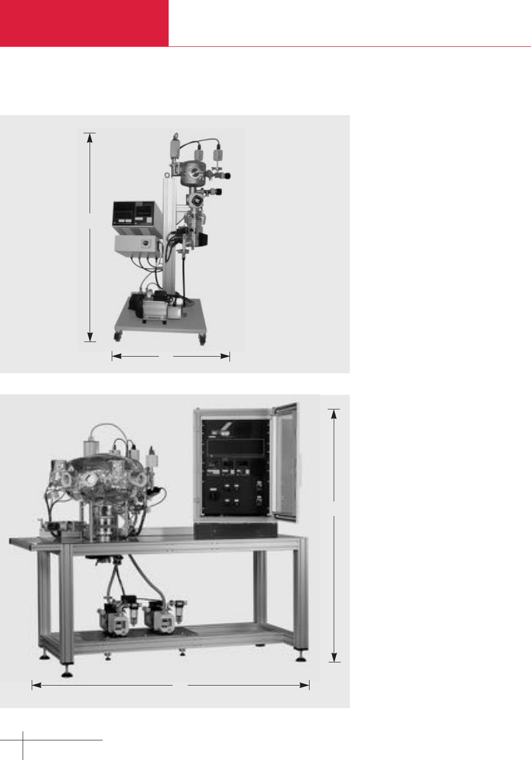
Turbomolecular Pump Systems
C10.14 LEYBOLD VACUUM PRODUCTS AND REFERENCE BOOK 2003/2004
CS Calibration Systems
The requirements imposed on vacuum enginee-
ring with regard to accuracy of the measure-
ments, reproducibility and unambiguity of the
determined vacuum pressures have increased
significantly over the last years.
Routine calibrations of vacuum gauges are an
important component of quality assurance sche-
mes. The calibration systems from LEYBOLD put
the customer in a position to check and recalibrate
on his own the specified and necessary accuracy
of his vacuum gauges.
Calibration systems are available for this purpose
which cover a calibration range from 1000 mbar
to 3 x 10
-7
mbar (750 to 2.3 x 10
-7
Torr).
Each system is equipped with several certified
reference pressure sensors (transmitter
standards), which each cover a part of the
specified range of calibration pressures. In the
pump system, turbomolecular pumps with
TRIVAC rotary vane or DIVAC diaphragm pumps
are used. A variable leak valve is used to admit
the gas into the calibration chamber. Moreover, in
calibration systems CS5 and CS7 the gas inlet
line is equipped with its own pump system.
Calibration systems CS5 and CS7 are equip-
ped with heating collars for the calibration
chamber so that low chamber pressures may
be attained within a shorter time. The tempe-
rature of the heating collars can be controlled
whereby the maximum degassing temperature
will depend on the components installed
(flanges, pressure sensors, valves).
Advantages to the User
◆Vacuum gauges and measurement systems of
any make may be calibrated
◆Designed in accordance with DIN 28 418/
ISO/DIS 3567
◆Transfer standards with PTB-, DKD- or factory
certificate
◆Easier DIN/ISO 9000 approval
◆Reliable and reproducible measurements
◆Quick start-up
◆
Measurement system free of hydrocarbons
when using dry compressing vacuum
pumps
◆Simple operation
◆CE approval
Calibration system CS7
Calibration system CS3
b
1
b
h h1b b1
mm 1200 1700 600 2000
in. 47.24 66.93 23.62 78.74
h
h
1

Turbomolecular Pump Systems
C10.15
LEYBOLD VACUUM PRODUCTS AND REFERENCE BOOK 2003/2004
C10
CS3 CS5 CS7Technical Data
Calibration range mbar (Torr)
Pressure measurement range mbar (Torr)
Vacuum chamber connections
(in brackets:
qty. available on the side of the customer’s system)
Admitting gas
Extra pump system for admitting gas
Heater for the vacuum chamber
1000 to 1 x 10⁻³
(
750 to 0.75 x 10⁻³
)
1000 to1 x 10-5
(
750 to0.75 x 10-5
)
1000 to 1 x 10⁻⁷
(
750 to 0.75 x 10⁻⁷
)
1000 to 2 x 10⁻⁶
(
750 to 1.5 x 10⁻⁶
)
1000 to 2 x 10⁻⁷
(
750 to 1.5 x 10⁻⁷
)
1000 to 2 x 10⁻⁹
(
750 to 1.5 x 10⁻⁹
)
5 (3) x DN 16 KF 5 (3) x DN 16 KF 6 (3) x DN 16 CF
1 (0) x DN 25 KF 1 (0) x DN 25 KF 6 (4) x DN 40 CF
1 (1) x DN 40 KF 3 (2) x DN 40 KF
via variable leak valve via variable leak valve via variable leak valve
no yes yes
no yes yes
Ordering Information and options upon request
CS3 CS5 CS7
Application examples: Which pressure sensors may be calibrated with which system?
Typ of Sensor
Diaphragm sensors
BOURDONVAC
Capsule vacuum gauges
DIAVAC DV 1000
DI 200, DI 2000
CTR90 and CTR91 (1000 - 1 Torr full scale)
CTR91 (0.1 Torr full scale)
THERMOVAC sensors
TR 301, TR 306
TR 211, TR 216, TTR 211, TTR 216, TTR 90
VISCOVAC sensor (spinning rotor viscosity gauge)
VK 201
PENNINGVAC sensors
PR 25, PR 26, PR 27, PR 35, PR 36, PR 37, PTR 225
IONIVAC sensors
ITR 90, ITR 100
IE 414, IE 514
X X X
X X X
X X X
X X X
X X X
– X X
X X X
X X X
– X X
– – X
– – X
– – X
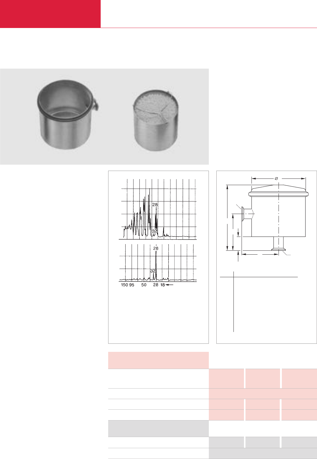
Accessories
Turbomolecular Pump Systems
C10.16 LEYBOLD VACUUM PRODUCTS AND REFERENCE BOOK 2003/2004
Adsorption Traps with Aluminium Oxide Insert
Advantages to the User
◆Backstreaming of oil is reduced by 99 %
◆Longer service life
◆High conductance
◆Filling can be easily exchanged
◆Improvement in the ultimate pressure attained
by backing pumps by one order of magnitude
◆Stainless steel housing and insert
◆NBR seal
Typical Applications
◆Product of an oil-free vacuum
Supplied Equipment
◆Complete with insert
◆Without adsorbent
Adsorption traps are installed in all those cases
where an oil-free vacuum is to be produced with
oil-sealed vacuum pumps.
Adsorption trap (left) and insert (right)
Technical Data 16 KF 25 KF 40 KF
4 6 12
3
0.5 (0.53) 1.0 (1.06) 2.0 (2.1)
1.3 (2.9) 1.3 (2.9) 4 (8.8)
Ordering Information 16 KF 25 KF 40 KF
Adsorption trap
Activated aluminum oxide, 2 l (approx. 1.3 kg (2.8 lbs))
Part No. 854 14 Part No. 854 15 Part No. 854 16
Part No. 854 10
Conductance at 10-2 mbar (Torr)
mbar x l x s-1 (Torr x l x sec)
Service live with Al oxide Months
Al oxide filling l (qts)
Weight, approx. kg (lbs)
Residual gas spectrum; top ahead of a rotary vacuum pump,
bottom ahead of a rotary vacuum pump with adsorption trap
d
1
DN
a
h
1
h
DN
a
Dimensional drawing for the adsorption traps
Mass number
DN a a1ld h h1
16 KF
mm 82 82 135 147 32
in. 3.23 3.23 5.31 5.79 1.25
25 KF
mm 102 102 175 155 33
in. 4.02 4.02 6.89 6.10 1.26
40 KF
mm 132 65 235 160 20
in. 5.19 2.56 9.25 6.3 0.79
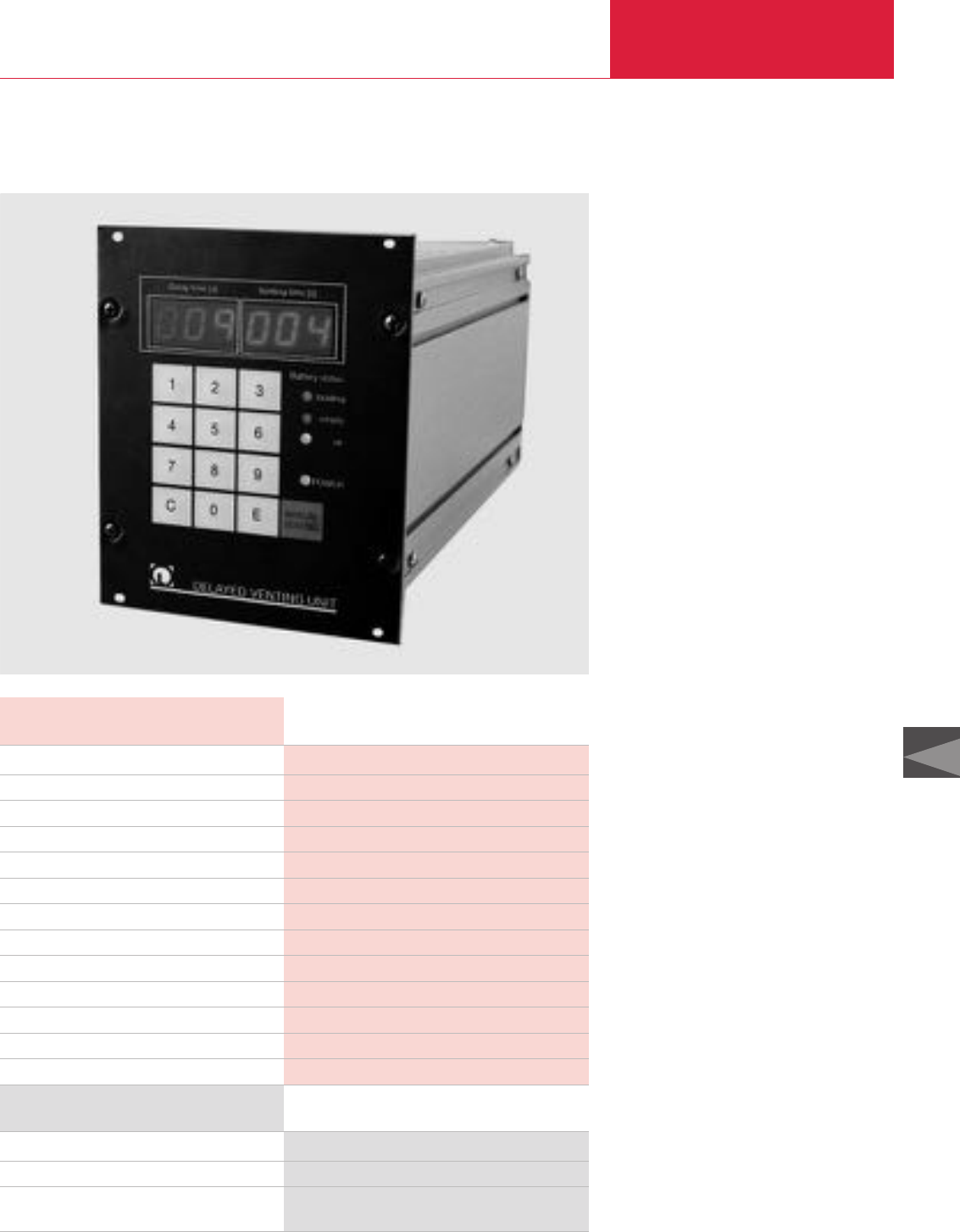
Turbomolecular Pump Systems
C10.17
LEYBOLD VACUUM PRODUCTS AND REFERENCE BOOK 2003/2004
C10
Technical Data Delayed Venting Unit
Ordering Information Delayed Venting Unit
Delayed venting unit
Power failure venting valve, DN 10 KF, 24 V DC
Mains cord
with German style mains plug (Schuko)
Part No. 500 441
Part No. 174 46
Part No. 200 27 549
Mains connection
Power supply V AC / Hz
Output V DC / mA
Rechargeable lead battery V / Ah
Rated battery service life, approx. years
Max. number of venting cycles with fully charged battery
Controls
Display
Delay time s
Venting time s
Dimensions (W x H x D) mm (in.)
Housing
Weight, approx. kg (lbs)
Delayed Venting Unit
The delayed venting unit serves the purpose of
venting vacuum systems with a delay in that it
bridges power failures.
The unit is equipped with rechargeable
batteries. Any unwanted venting of the
turbomolecular pump can thus be reliably
prevented in the event of short power
blackouts.
Both normally open valves (power failure
venting valves) and normally closed valves
(venting valves) may be connected.
The unit is equally suited for benchtop use and
rack mounting.
The present operating condition is showed by
different displays and controls:
◆
“Delay Time”
Displays the entered delay time
(when mains powered) and the delay time
counting to 0 (in case of power failure).
◆
“Venting Time”
Displays the entered venting time
(when mains powered and during delay
time in case of power failure) and, after
elapsed delay time, the venting time
counting to 0.
◆
“Battery status”
-LED “loading” battery charges
-LED “empty” battery is flat or defective
-LED “ok”
battery has been recharged sufficiently
◆
LED “POWER”
the unit is mains powered
Advantages to the User
◆
Adjustable venting time for power failure
venting valve: 0 to 999 seconds
◆
Adjustable venting time for venting valve:
0 to 999 seconds
◆
Automatic driving of failure venting valve
and venting valve in case of short power
failures
◆
Manual venting
◆
Remote controlled venting
Delayed venting unit
Mains socket
100 - 240 / 50/60
24 - 26.4 / 400 max.
2 x 12 / 1.3
5 (depending on utilization)
4 times after each other
Foil key pad
numerical, 2 x 3 digits, 4x LED
0 - 999, adjustable
0 - 999, adjustable
106.5 x 128.5 x 220 (4.19 x 5.06 x 8.66)
1/4 19", for rack mounting or as benchtop unit
2.5 (5.58)
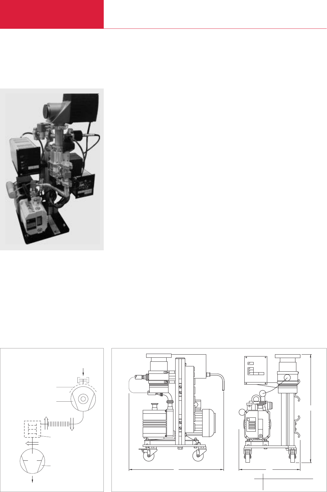
Turbomolecular Pump Systems
C10.18 LEYBOLD VACUUM PRODUCTS AND REFERENCE BOOK 2003/2004
Version for the North and South American Continents
Turbomolecular Pump System TOSS 50
Standard Equipment
♦TURBOVAC 50 ceramic bearing standard
proven turbomolecular vacuum pump
♦High effective pumping speed
♦Compact portable tabletop construction base
with support rail
♦Simple operation, high reliability, easy
maintenance
♦Adjustable inlet height of the TURBOVAC 50
♦Complete package with backing pump and
frequency converter
♦Wired for 115 V, single phase, 60 Hz
operation
Options
♦Base caster wheels
♦Foreline trap
♦TRIVAC pump accessories
♦Complete line of vacuum gauges for
monitoring of pressure
♦Air cooling option
♦Vent valve kits
1
4
2
3
b b1
h
Schematic diagram of the TOSS 50 turbomolecular pump system Dimensional drawing for the TOSS 50 turbomolecular pump system
1 TRIVAC D 2.5 E-stage
rotary vane vacuum pump
2 TURBOVAC 50
turbomolecular pump
3 Flange heater (accessory)
4 Adsorption trap (accessory)
b b1h
mm 457 286 495
in. 18.00 11.25 19.50

Turbomolecular Pump Systems
C10.19
LEYBOLD VACUUM PRODUCTS AND REFERENCE BOOK 2003/2004
C10
Version for the North and South American Continents
TOSS 50
(includes TURBOVAC 50 / NT 10 solid state converter /
D 2.5 E rotary vane vacuum pump / pump stand / fittings)
DN 40 KF
DN 63 ISO-K
DN 63 CF
Air cooling unit, 115 V
Flange heater
DN 63 CF, 115 V
Vent kits
CF flanges
Normally open
Normally closed
KF 40 flange
Normally open
Normally closed
KF 63 flange
Normally open
Normally closed
AK condensate trap kit
AF exhaust filter kit
Adsorption trap, Al2O3
Activated Al2O3media, 2 litres (2.11 qt)
Other accessories such as valves and gauges
Part No. 899 213
Part No. 899 214
Part No. 899 215
Part No. 854 06-1
Part No. 854 07
Part No. 899 838
Part No. 720-53-191
Part No. 720-53-186
Part No. 720-53-187
Part No. 720-53-188
Part No. 720-53-189
Part No. 720-53-105
Part No. 720-53-104
Part No. 854 14
Part No. 854 10
See appropriate catalog section
Ordering Information TOSS 50
Turbomolecular pump
High vacuum connection DN
Pumping speed for N2l x s-1
Pumping speed for H2l x s-1
Compression for N2
Compression for H2
Speed of the TURBOVAC rpm
Dual-stage rotary vane vacuum pump
Nominal pumping speed acc. to PNEUROP
m3x h-1 (cfm)
Exhaust connection DN
Attainable ultimate pressure mbar (Torr)
Attainable ultimate pressure
with FPM gasket mbar (Torr)
with aluminum or Cu gasket mbar (Torr)
Mains supply, 50/60 Hz V
Rated power consumption, approx. VA
Dimensions (W x H x D) mm (in.)
Weight, approx. kg (lbs)
Technical Data TOSS 50
TURBOVAC 50
40 KF 63 ISO-K/63 CF
33 55
28 30
2 x 10⁷
102
72 000
TRIVAC D 2.5 E
3.3 (1.9)
16 KF
≤2 x 10⁻³ (≤1.5 x 10⁻³)
< 10-6 (< 0.75 x 10⁻⁶)
< 10-8 (< 0.75 x 10⁻⁸)
115
400
286 x 495 x 451 (11.25 x 19.5 x 18)
22.1 (56)
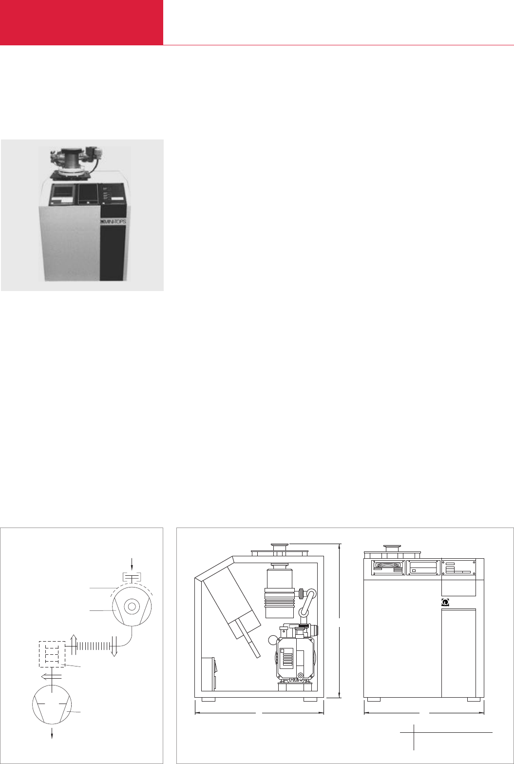
Turbomolecular Pump Systems
C10.20 LEYBOLD VACUUM PRODUCTS AND REFERENCE BOOK 2003/2004
Version for the North and South American Continents
Turbomolecular Pump System MINI-TOPS 50
Standard Equipment
♦TURBOVAC 50 ceramic bearing standard
proven turbomolecular vacuum pump
♦High effective pumping speed
♦Compact portable tabletop construction frame
♦Vibration-absorbing mounting plate for stress
free mounting of the TURBOVAC 50
♦Simple operation, high reliability, easy
maintenance
♦Complete package with backing pump and
frequency converter
♦Integration with Gauge controller
♦Wired for 115 V, single phase, 60 Hz
operation
Options
♦Frame caster wheels
♦Foreline trap
♦TRIVAC pump accessories
♦Complete line of vacuum gauges for
monitoring of pressure
♦Air cooling option
♦Vent valve kits
♦Conflat
®
flange heater
b1
h
b
MINI-TOPS
Dimensional drawing for the MINI-TOPS 50 turbomolecular pump system
1
4
2
3
Schematic diagram of the MINI-TOPS 50 turbomolecular pump system
1 TRIVAC D 2.5 E-stage
rotary vane vacuum pump
2 TURBOVAC 50
turbomolecular pump
3 Flange heater (accessory)
4 Adsorption trap (accessory)
b b1h
mm 457 432 508
in. 18 17 20

Turbomolecular Pump Systems
C10.21
LEYBOLD VACUUM PRODUCTS AND REFERENCE BOOK 2003/2004
C10
Version for the North and South American Continents
MINI-TOPS 50 turbomolecular vacuum pump system
(includes TURBOVAC 50 / NT 10 / D 2.5 E /
appropriate frame / foreline bellows)
See Price List for the “North American Continent” for Ordering Information
Ordering Information MINI-TOPS 50
Turbomolecular pump
High vacuum connection DN
Pumping speed for N2l x s-1
Pumping speed for H2l x s-1
Compression for N2
Compression for H2
Speed of the TURBOVAC rpm
Dual-stage rotary vane vacuum pump
Nominal pumping speed acc. to PNEUROP
m3x h-1 (cfm)
Exhaust connection DN
Attainable ultimate pressure mbar (Torr)
Attainable ultimate pressure
with FPM gasket mbar (Torr)
with aluminum or Cu gasket mbar (Torr)
Mains supply, 50/60 Hz V
Rated power consumption, approx. VA
Dimensions (W x H x D) mm (in.)
Weight, approx. kg (lbs)
NT 10 frequency converter (TMP power supply)
Voltage (two ranges) V AC
Input power
Maximum W
Continuous W
Relay I/O
Input
Output
Available sensors and controllers
THERMOVAC TM 22, dual station
CAPACITRON DM 22, dual station
COMBIVAC CM 31
Dual station pirani
Single station PENNINGVAC cold cathode
COMBIVAC IT23, ionization
Smart sensor controller
Technical Data MINI-TOPS 50
TURBOVAC 50
40 KF 63 ISO-K/63 CF
33 55
28 30
2 x 10⁷
102
72 000
TRIVAC D 2.5 E
3.3 (1.9)
16 KF
≤2 x 10⁻³ (≤1.5 x 10⁻³)
< 10-6 (< 0.75 x 10⁻⁶)
< 10-8 (< 0.75 x 10⁻⁸)
115
400
406 x 483 x 432 (16 x 19 x 17)
30.0 (66)
90-140 or 180-265, single phase
45
18
Remote Start/Stop
System status relay NO/NC contacts (contacts 4 amp/250 V AC)
Sensor type Pressure range
PIRANI 760 to 5 x 10⁻⁴ Torr
Capacitance diaphragm 1000 to 1 x 10⁻⁴ Torr
PIRANI 760 to 5 x 10⁻⁴ Torr
PENNINGVAC cold cathode 2 x 10⁻² to 1 x 10⁻⁸ Torr
PENNINGVAC or PIRANI 1500 to 1 x 10⁻¹⁰ Torr
Absolute pressure transducer and one channel hot ionization
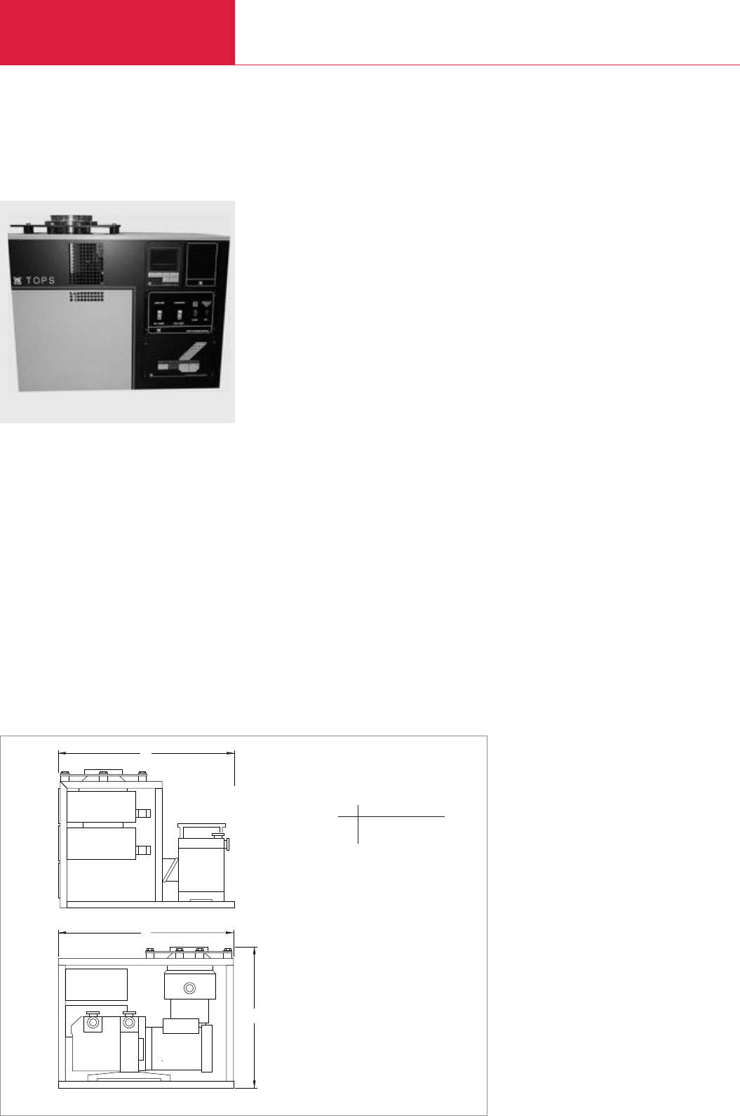
Turbomolecular Pump Systems
C10.22 LEYBOLD VACUUM PRODUCTS AND REFERENCE BOOK 2003/2004
Turbomolecular Pump System TOPS 151/361
Standard Equipment
♦TURBOVAC 151 or 361 ceramic bearing
standard proven turbomolecular vacuum
pump
♦High effective pumping speed
♦Compact tabletop construction frame
♦Vibration-absorbing mounting plate for stress
free mounting of turbomolecular pump
♦Simple operation, high reliability, easy
maintenance
♦Complete package with backing pump,
frequency converter and Start/Stop controls
♦Integration with Gauge controller
Options
♦Air and water cooling options
♦Frame caster wheels
♦Foreline trap
♦TRIVAC pump accessories
♦Complete line of vacuum gauges for
monitoring of pressure
♦Vent valve kits
♦Conflat
®
flange heaters
♦Larger backing pumps
♦Purge valve for corrosive applications.
♦Inlet accessories – Gate valves, bell jar
assemblies, special spools
♦Special design controls
Version for the North and South American Continents
h
l
b
Dimensional drawing for the TOPS 151/361 turbomolecular pump system
b h l
mm 610 508 610
in. 24.0 20.0 24.0

Turbomolecular Pump Systems
C10.23
LEYBOLD VACUUM PRODUCTS AND REFERENCE BOOK 2003/2004
C10
Version for the North and South American Continents
Turbomolecular pump
High vacuum connection DN
Backing pumps
Standard Model m3/hr (cfm)
for use with purge option Model m3/hr (cfm)
Cooling
Max. power requirements
(Backing pump determines actual requirements)
Electrical panel controls
Vane pump
TMP control panel
Gate valve
Flange heater
NT 20 frequency converter (TMP power supply)
Relay I/O
Input
Output
Gauge controller (optional)
Available sensors and controllers
THERMOVAC TM 22, dual station
CAPACITRON DM 22, dual station
COMBIVAC CM 31
Dual station pirani
Single station PENNINGVAC cold cathode
COMBIVAC IT23, ionization
Smart sensor controller
TURBOVAC 151 TURBOVAC 361
100 ISO-K / 100 CF 100 ISO-K / 160 ISO-K / 100 CF / 160 CF
TRIVAC D 4 B (5.1 / 3.0) TRIVAC D 16 B (19.7 / 11.6)
TRIVAC D 8 B (10.2 / 6.0)
TRIVAC D 16 B (19.7 / 11.6) TRIVAC D 25 B (35.7 / 21.0)
Water (air optional) Water (air optional)
110 V AC, 1 phase, 50/60 Hz, 30 Amps
220 V AC, 1 phase, 50/60 Hz, 20 Amps
Start/Stop
Start/Stop / Gauge On/Off
Open/Close
On/Off
Remote Start/Stop
System status relay NO/NC contacts
Integrated into system
Sensor type Pressure range
PIRANI 760 to 5 x 10⁻⁴ Torr
Capacitance diaphragm 1000 to 1 x 10⁻⁴ Torr
PIRANI 760 to 5 x 10⁻⁴ Torr
PENNINGVAC cold cathode 2 x 10⁻² to 1 x 10⁻⁸ Torr
PENNINGVAC or PIRANI 1500 to 1 x 10⁻¹⁰ Torr
Absolute pressure transducer and one channel hot ionization
Technical Data TOPS 151/361
TOPS 151/361 turbomolecular vacuum pump system
(supplied with hydrocarbon oil)
See Price List for the “North American Continent” for Ordering Information
Ordering Information TOPS 151/361
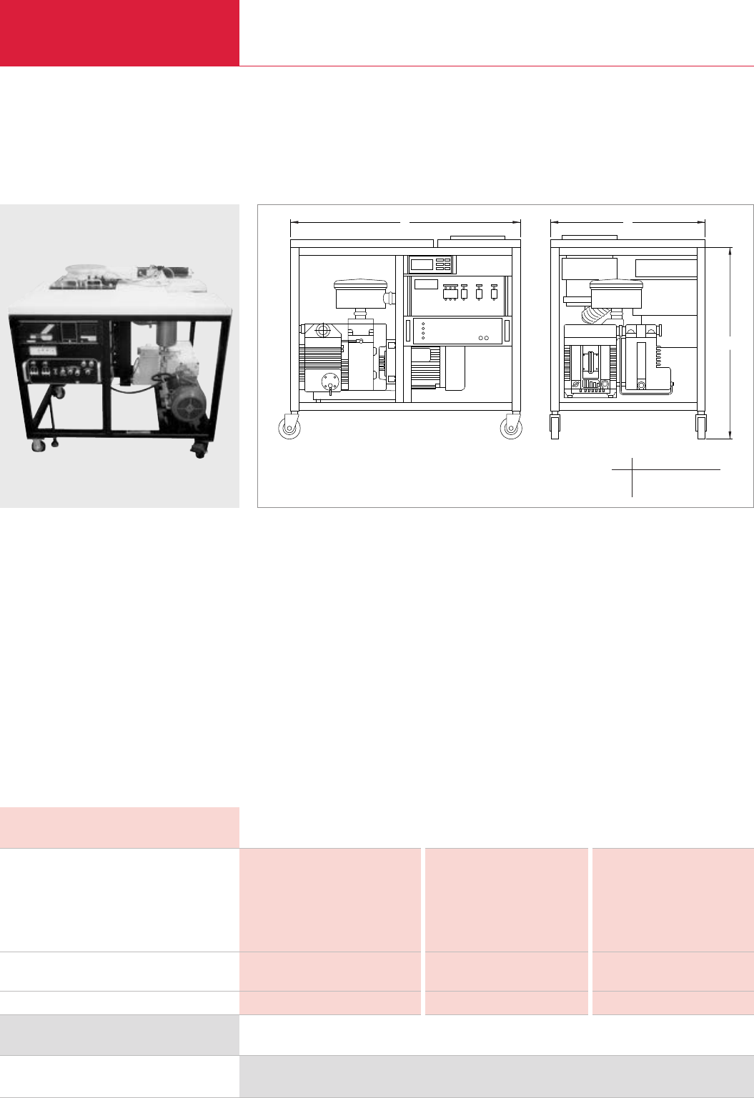
Turbomolecular Pump Systems
C10.24 LEYBOLD VACUUM PRODUCTS AND REFERENCE BOOK 2003/2004
Version for the North and South American Continents
Turbomolecular Pump System TURBOVAC TMV 40000
Standard Equipment
♦Open frame construction for use with larger
pumps
♦Flexible configuration
♦Vibration-absorbing mounting plate for stress
free mounting of Turbomolecular pump
♦Simple operation, high reliability, easy
maintenance
♦Complete package with backing pump fre-
quency converter, and Start/Stop controls
♦Integration with Gauge controller
Options
♦Air cooling options
♦Frame caster wheels
♦Foreline trap
♦TRIVAC pump accessories
♦Complete line of vacuum gauges for
monitoring of pressure
♦Vent valve kits
♦Larger backing pumps
♦Purge valve for corrosive applications
♦Inlet accessories – Gate valves, bell jar
assemblies, special spools
♦Removable enclosure panels
♦Special design controls
♦Levellers
h
b
l
Dimensional drawing for a typical TURBOVAC TMV 40 000 turbomolecular pump system
Turbomolecular pump
High vacuum connection DN
Backing pumps Model m3/hr (cfm)
Cooling
TURBOVAC TW 700 TURBOVAC 1000C TURBOVAC T 1600
160 ISO-K 160 ISO-K 250 ISO-F
160 CF 250 ISO-K 250 ISO-K
160 CF
200 CF
6" ANSI
TRIVAC D 16 B (19.7 / 11.6) TRIVAC D 40 B (48.1 / 28.3.) TRIVAC D 65 B (78.0 / 45.9)
TRIVAC D 25 B (30.9 / 18.2) TRIVAC D 65 B (78.0 / 45.9)
Water (air optional) Water (air optional) Water
Technical Data TURBOVAC TMV 40 000
TMV 40 000 turbomolecular pump system
(supplied with hydrocarbon oil)
See Price List for the “North American Continent” for Ordering Information
Ordering Information TURBOVAC TMV 40 000
b h l
mm 686 965 1016
in. 27.0 38.0 40.0
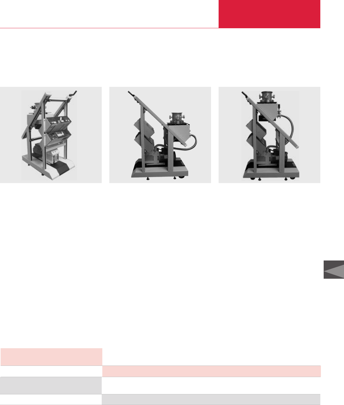
Turbomolecular Pump Systems
C10.25
LEYBOLD VACUUM PRODUCTS AND REFERENCE BOOK 2003/2004
C10
Version for the North and South American Continents
TOPiX turbomolecular pump system
Contact Factory‚ for Complete Product Offering
Technical Data TOPiX
Turbomolecular Pump System TOPiX
Standard Equipment
♦Compact free-standing mobile system
♦Flexible platform for customer process
vacuum systems
♦Frame base caster wheels and levelers
♦Flexible configuration accepting any
Turbomolecular pump
♦Vibration-absorbing mounting plate
♦Simple operation, high reliability, easy
maintenance
♦Manually adjustable inlet height for precise
connections
♦Complete package with backing pump,
frequency converter, and Start/Stop controls
♦Integration with Gauge controller
Options
♦Air and water cooling options
♦Electrically controlled height adjustment
♦Foreline trap
♦TRIVAC pump accessories
♦Complete line of vacuum gauges for
monitoring of pressure
♦Vent valve kits
♦Larger backing pumps
♦Inlet accessories – Gate valves, bell jar
assemblies, special spools
♦Special design controls for automation into
custom processes
♦“One-button” operation controls
TOPiX turbomolecular pump system
See Price List for the “North American Continent” for Ordering Information
Ordering Information TOPiX
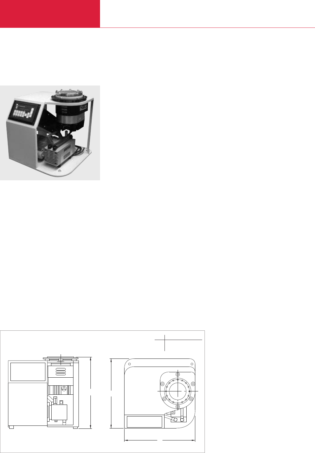
Turbomolecular Pump Systems
C10.26 LEYBOLD VACUUM PRODUCTS AND REFERENCE BOOK 2003/2004
Version for the North and South American Continents
Turbomolecular Pump System TiPS
Standard Equipment
♦All new LEYBOLD Wide-Range and Classic
turbomolecular pumps
♦High effective pumping speed
♦Compact tabletop construction frame
♦Vibration-absorbing mounting plate for stress
free mounting of turbomolecular pumps
♦Simple operation, high reliability, easy
maintenance
♦Complete universal integrated package with
supply, controls and display for backing
pump, valves and gauging
◆TSC integrated Turbomolecular System
Controller provides “All-in-one” vacuum
system control and information
Options
♦Water cooling options
♦Frame caster wheels
♦Conflat
®
flange heaters
♦Complete line of vacuum sensors for
monitoring of pressure
♦Vent valve or purge valve for corrosive
applications
♦TRIVAC backing pumps for higher gas loads
Including all standard TRIVAC pump
accessories:
foreline traps; inlet, exhaust and oil filtration
♦Inlet accessories - gate valves, bell jar assem-
blies, special spools
♦Special design controls
h
b
a
Dimensional drawing for the turbomolecular pump system TiPS (TW 300/diaphragm pump)
h a b
mm 445 432 432
in. 17.5 17.0 17.0

Turbomolecular Pump Systems
C10.27
LEYBOLD VACUUM PRODUCTS AND REFERENCE BOOK 2003/2004
C10
Version for the North and South American Continents
TiPS integrated turbomolecular pump system
See Price List for the “North American Continent” for Ordering Information
Ordering Information TiPS
Turbomolecular pump
High vacuum connection DN
DN
Backing pumps
Cooling
Max. power requirements
(Backing pump determines actual requirements)
TSC Turbomolecular System Controller provides
One-button automatic pumpdown
or manually controls
Diaphragm/vane pump
Turbomolecular pump
Inlet, foreline and roughing valve
Vent/purge valve
Inlet, foreline and roughing vacuum sensors
Flange heater
Ion sensor degas
Turbomolecular System Controller provides Operating Info
Turbomolecular rotational speed (rpm & Hz)
Turbomolecular bearing temperature
Turbomolecular motor current
Turbomolecular heatsink temperature
Turbomolecular supply voltage
Turbomolecular cumulative operating hours
Operating mode (Auto or Manual)
Available sensors
ITR 90 combination hot cathode Ion/Pirani
PTR 225 cold cathode Ion
TTR 90 /Pirani
CTR90 ceramic diaphragm
Others
Technical Data TiPS
TURBOVAC TW 70 TURBOVAC TW 300 TURBOVAC TW 700
63 ISO-K 100 ISO-K 160 ISO-K
63 CF 100 CF 160 CF
Diaphragm, EcoDry or
TRIVAC (up to D 16 B)
Air Air (water optional) Air (water optional)
110 V AC, 1 phase, 50/60 Hz, 15 Amps
220 V AC, 1 phase, 50/60 Hz, 7.5 Amps
Start/Stop
On/Off
Start/Stop
Open/Close
Open/Close or Vent/Purge flow
Displays pressure readings
On/Off
On/Off
Plus
Backing pump cumulative operating hours
Current turbomolecular pump status (Start, Accel, Norm. Op., Decel, Stop)
Current valve status
Pressure readings for all sensors (Torr, mbar or Pa)
Flange heater status
Current operating mode
Last failure reason (due to improper operation)
760 to 3.8 x 10⁻¹⁰ Torr
7.5 x 10⁻³ to 7.5 x 10⁻¹⁰ Torr
760 to x 10-4 Torr
1, 10, 100, 1000 Torr full-range (each covers 4 decades)
Upon request
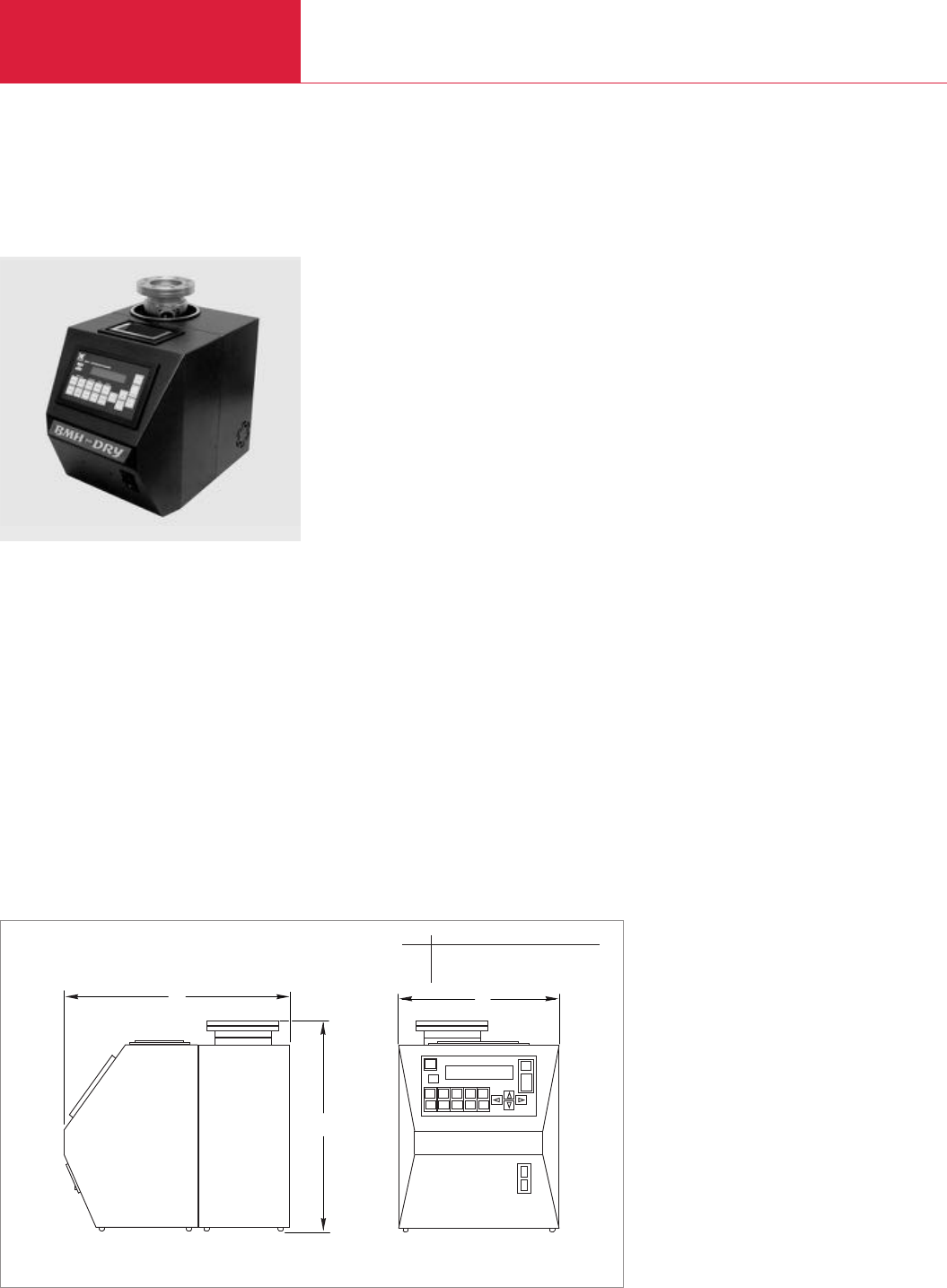
Turbomolecular Pump Systems
C10.28 LEYBOLD VACUUM PRODUCTS AND REFERENCE BOOK 2003/2004
Version for the North and South American Continents
Dry Oil Free HV Pump System BMH70 Dry
Standard Equipment
♦Portable HV station for TW 70 H and
DIVAC 0.8 T
♦60 l/s, pumping speed for N
2
, ultimate of
< 5 x 10
-9
Torr
♦Automated one-button operation for full fea-
tured model
♦Power supply for operation of pumps, gauges
and valves
♦Display of TW 70 H Turbo operation parame-
ters include:
- Rotation frequency (Hz)
- Rotation speed (rpm)
- Bearing temperature (deg C)
- Motor current (amps)
- Motor temperature (deg C)
- Supply voltage (V)
- Head sink temperature (deg C)
- Cumulative operating time (hours)
♦Standard air cooling
◆Small footprint of 14
"
x 10
"
x 14
"
(W x H x D)
◆32 lbs
◆Full-featured and basic versions available
◆Optional 230/1/50/60 operation
b
h
a
Dimensional drawing for the dry oil free HV pump system BMH70 Dry)
a b h *)
mm 254.0 355.6 330.2 to 355.6
in. 10 14 13 to 14
h
*)
The overall height depends on which TW 70 H is used

Turbomolecular Pump Systems
C10.29
LEYBOLD VACUUM PRODUCTS AND REFERENCE BOOK 2003/2004
C10
Version for the North and South American Continents
Integrated gauge display
Standard inlet sensor
Optional inlet sensor
Optional foreline sensor
System control
Vent valve control
TW main status display
TW operating parameters display
No Yes
(optional, see below) Power ITR 90 inlet sensor (atm - 10-10 Torr)
with display on system controller
Power ITR 90 inlet sensor (atm - 10-10 Torr) NA
with integral LCD display
N/A Power TTR 90 sensor (atm - 5 x 10⁻⁴ Torr)
with display on system controller
Manual Automatic control (one button) or manual
Vent valve control 1) Vent valve control 1)
Start, Accel., Norm. Op., Decel., Stop Start, Accel., Norm. Op., Decel., Stop
Speed, Temps, Current Draw, etc. Speed, Temps, Current Draw, etc.
Technical Data BMH70 Dry
Basic Version Full-featured Version
BMH70 Dry
with inlet flange DN 63 CF
with inlet flange DN 63 ISO-K
1) The vent valve is optional on a basic and a full-featured system
2) An ITR 90 sensor shipped with a BMH70 Dry system will have a flange compatible with the turbomolecular pumps flange type unless otherwise requested.
(i.e., DN 63 CF turbomolecular pump = CF 40-flanged ITR 90; DN 63 ISO-K turbomolecular pump = KF 25-flanged ITR 90)
3) An optional ITR 90 sensor when ordered with a basic BMH70 Dry system will include an integrated display on the sensor for the pressure readout
4) The standard ITR 90 sensor shipped with the full-featured BMH70 Dry system does not include an integrated display on the sensor for the pressure readout.
(It is available as an option)
Part No. 180000V2000 Part No. 180000V2400
Part No. 180000V1000 Part No. 180000V1200
Ordering Information BMH70 Dry
Basic Version 2), 3) Full-featured Version 2), 4)
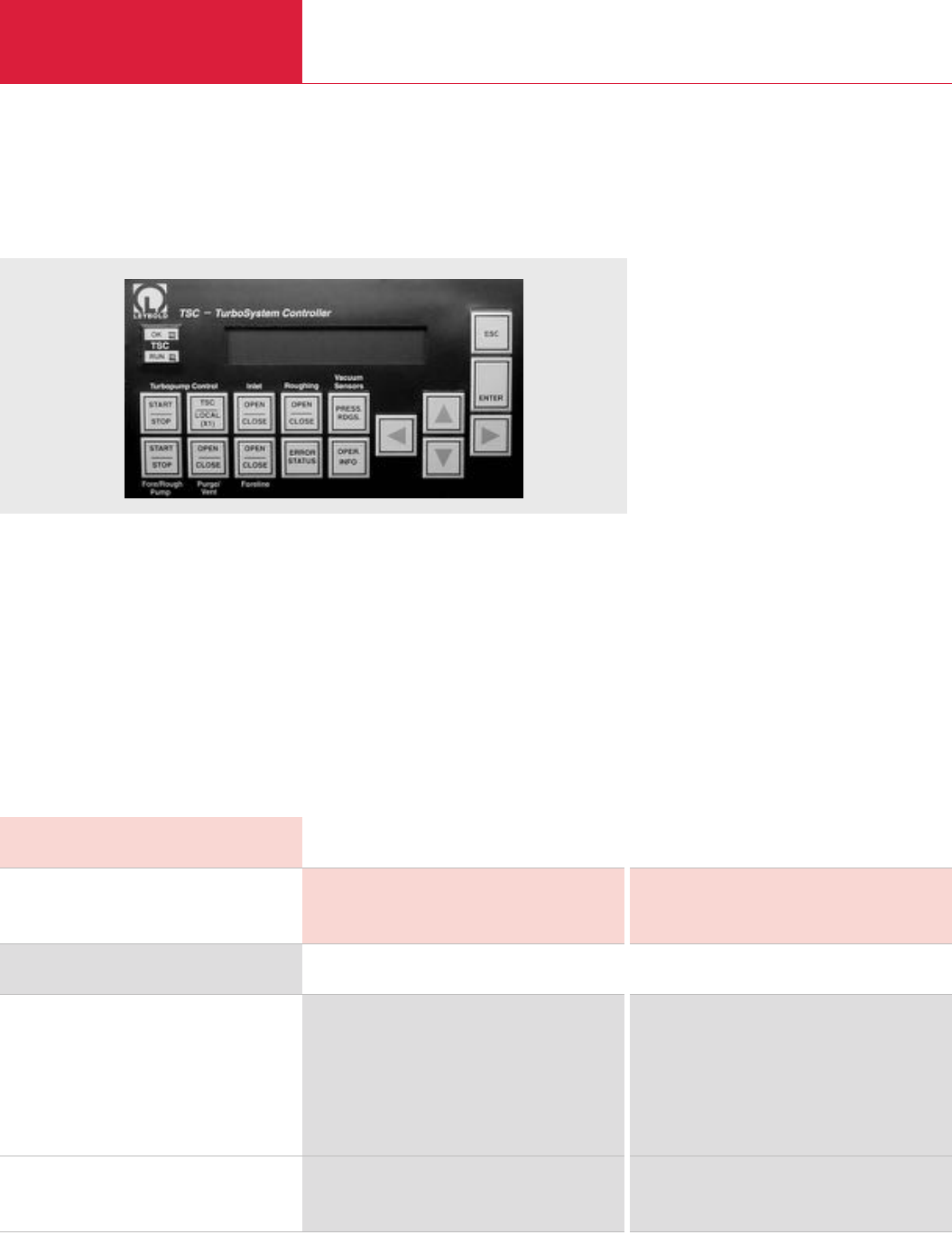
Accessories
Turbomolecular Pump Systems
C10.30 LEYBOLD VACUUM PRODUCTS AND REFERENCE BOOK 2003/2004
Version for the North and South American Continents
TSC - TurboSystem Controller
The TSC controler will:
♦Display all relevant turbo information:
– Connected pump model
– Rotation frequency (Hz)
– Rotation speed (rpm)
– Bearing temperature (°C)
– Motor current (Amps)
– Motor temperature (°C)
– Supply voltage (V)
– Heatsink temperature (°C)
– Cumulative operating time (hours)
♦Power the turbomolecular pump
♦Power the fore/rough pump (up to TRIVAC
D 16 B or EcoDry M15, 115 V single phase)
♦Power and display up to three of any manu-
facturer’s smart gauges (must have 0 - 10 V
or 4 - 20 mA output capability)
♦Provide degas capability for a hot-cathode ion
gauge sensor
TSC - TurboSystem Controller
110 V, RS 485 C
TSC-S
TSC-L
110 V, RS 232 C
TSC-S
TSC-L
Venting valve
24 V DC, normally open
24 V DC, normally closed
Note:
All controllers include:
15 ft. (5 m) long cables between TSC controller and turbomolecular pump (power & communication)
06 ft. (2 m) power cord
Mating connectors for all accessoring outlets
Operating manual ~ / electrical schematic and spare parts list
Part No. 899 287 –
–Part No. 899 288
Part No. 899 289 –
–Part No. 899 290
Part No. 899 813 Part No. 899 813
Part No. 899 814 Part No. 899 814
Ordering Information TSC - TurboSystem Controller
For operating turbomolecular pump
TSC-S TurboSystem Controller
TSC-L TurboSystem Controller
Technical Data TSC - TurboSystem Controller
TURBOVAC TW 300 / TW 70 H –
– TURBOVAC TW 700
♦Power up to three system valves (electro
pneumatic with 24 V DC coils) – typically an
inlet valve, foreline valve and roughing valve
♦Power a turbomolecular pump vent or
purge/vent valve
♦Power an inlet flange heater (CF flanged
pumps only)
♦Control the turbomolecular pump, fore/rough
pump and all valves
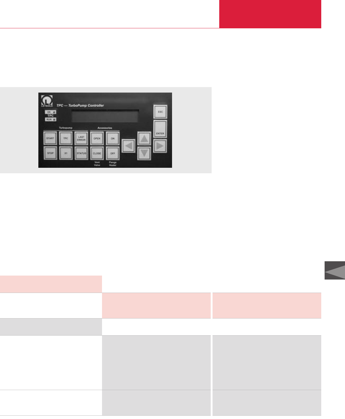
Accessories
Turbomolecular Pump Systems
C10.31
LEYBOLD VACUUM PRODUCTS AND REFERENCE BOOK 2003/2004
C10
Version for the North and South American Continents
TPC - TurboPump Controller
The TPC controler will:
♦Display all relevant turbo information:
– Connected pump model
– Rotation frequency (Hz)
– Rotation speed (rpm)
– Bearing temperature (°C)
– Motor current (Amps)
– Motor temperature (°C)
– Supply voltage (V)
– Heatsink temperature (°C)
– Cumulative operating time (hours)
♦Power the turbomolecular pump
♦Power a turbomolecular pump vent or
purge/vent valve
♦Power an inlet flange heater (CF flanged
pumps only)
♦Control the turbomolecular pump, flange
heater and purge/vent valve
TPC - TurboPump Controller
110 V, RS 485 C
TPC-S
TPC-L
110 V, RS 232 C
TPC-S
TPC-L
Venting valve
24 V DC, normally open
24 V DC, normally closed
Note:
All controllers include:
15 ft. (5 m) long cables between TSC controller and turbomolecular pump (power & communication)
06 ft. (2 m) power cord
Mating connectors for all accessoring outlets
Operating manual ~ / electrical schematic and spare parts list
Part No. 899 281 –
–Part No. 899 282
Part No. 899 283 –
–Part No. 899 284
Part No. 899 813 Part No. 899 813
Part No. 899 814 Part No. 899 814
Ordering Information TPC - TurboPump Controller
For operating turbomolecular pump
TPC-S TurboPump Controller
TPC-L TurboPump Controller
Technical Data TPC - TurboPump Controller
TURBOVAC TW 300 / TW 70 H –
– TURBOVAC TW 700
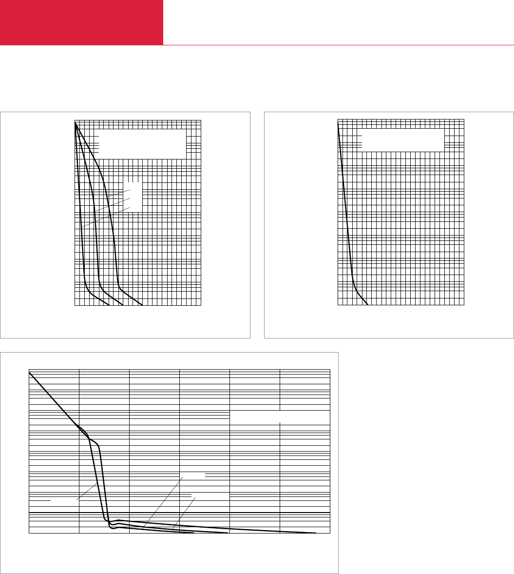
Miscellaneous
Turbomolecular Pump Systems
C10.32 LEYBOLD VACUUM PRODUCTS AND REFERENCE BOOK 2003/2004
3210 54 6 7 8 9 10 11 13
Time
Pressure
TMP151 with TRIVAC® Backing Pumps:
a) D16B
b) D8B
c) D4B
min
10-5
Torr
c
b
a
103
101
100
10-1
10-4
10-3
10-2
8
6
4
2
Pumpdown curves for the TOPS 151 system at 60 Hz (25 l volume)
3210 54 6 7 8 9 10 11 13
Time
Pressure
TMP361with TRIVAC® Backing Pump
D16B
min
10-5
Torr
103
101
100
10-1
10-4
10-3
10-2
8
6
4
2
Pumpdown curves for the TOPS 361 system at 60 Hz (25 l volume)
Version for the North and South American Continents
Backing/Roughing Pump: D65B
TW700
T1600
TMP1000
3210
Time
Pressure
min
10-5
Torr
103
101
100
10-1
10-4
10-3
10-2
8
6
4
2
Pumpdown curves for the TMV 40 000 system at 60 Hz (25 l volume)
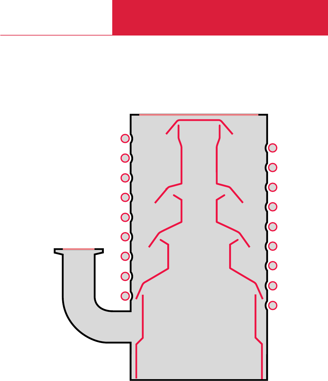
C11
DIP Oil Diffusion Pumps
3000 - 50000 l x s-1
Oils, Baffles, Accessories,
Adsorption Traps
DIP

Contents
Oil Diffusion Pumps
C11.02 LEYBOLD VACUUM PRODUCTS AND REFERENCE BOOK 2003/2004
General
Operating Principle of Fluid Entrainment Vacuum Pumps . . . . . . . . . . . . . . . . . . . . . . . . . . C11.02
Applications and Accessories . . . . . . . . . . . . . . . . . . . . . . . . . . . . . . . . . . . . . . . . . . . . . . . C11.02
Diffusion Pumps . . . . . . . . . . . . . . . . . . . . . . . . . . . . . . . . . . . . . . . . . . . . . . . . . . . . . . . . C11.03
Operating Oil Diffusion Pumps . . . . . . . . . . . . . . . . . . . . . . . . . . . . . . . . . . . . . . . . . . . . . . C11.03
Program Range of Diffusion Pumps . . . . . . . . . . . . . . . . . . . . . . . . . . . . . . . . . . . . . . . . . . C11.04
Pump Fluids for Diffusion Pumps . . . . . . . . . . . . . . . . . . . . . . . . . . . . . . . . . . . . . . . . . . . . C11.05
Products
DIP Pumps, Water-Cooled . . . . . . . . . . . . . . . . . . . . . . . . . . . . . . . . . . . . . . . . . . . . . . . . . C11.06
Accessories
Astrotorus Baffles . . . . . . . . . . . . . . . . . . . . . . . . . . . . . . . . . . . . . . . . . . . . . . . . . . . . . . . C11.09
Monitoring Instruments . . . . . . . . . . . . . . . . . . . . . . . . . . . . . . . . . . . . . . . . . . . . . . . . . . . C11.10
Adsorption Traps with Aluminium Oxide Insert . . . . . . . . . . . . . . . . . . . . . . . . . . . . . . . . . . C11.12
Operating Principle of Fluid Entrainment Vacuum Pumps
The main components of diffusion pumps, the
operation of which relies on vapor-phase pump
fluids are:
♦Cooled pump body with intake and exhaust
ports
♦System of nozzles
♦Pump boiler
In the case of diffusion pumps a pump fluid con-
tained in a boiler is heated to such an extent that
it is vaporized. The vapor is then forced through
nozzles within the pump. The nozzles are gene-
rally designed in such a way, that they accelerate
the vapor to a speed exceeding the speed of
sound (Laval nozzles), thus creating a high
speed vapor jet. The vapor is then deflected by
the nozzles at a specific angle onto the pump
body. The pump body is cooled, so that the
vaporized pump fluid condenses and is returned
back to the boiler as a liquid. The pumping
action of diffusion pumps and fluid entrainment
pumps in general is based on the transporting
capacity of the vapor jet.
The gas which is to be pumped is compressed
sufficiently at the forevacuum port so that it can
be pumped out by a backing pump.
Application
Vacuum coating ♦ ♦ ♦ ♦ ♦ ♦
Research and development ♦ ♦ ♦ ♦ ♦ ♦
Metallurgy/furnaces ♦ ♦ ♦ ♦ ♦ ♦
Mechanical engineering ♦ ♦ ♦ ♦ ♦ ♦
Accessories
Page
Pump fluids C11.05 ♦ ♦ ♦ ♦ ♦ ♦
Astrotorus baffle C11.09 ♦ ♦ ♦ ♦ ♦ ♦
Water flow monitor C11.10 ♦ ♦ ♦ ♦ ♦ ♦
Overtemperature protection switch C11.11 ♦ ♦ ♦ ♦ ♦ ♦
Contact thermometer C11.11 ♦ ♦ ♦ ♦ ♦ ♦
Adsorption trap C11.12 For generating an oil-free vacuum with oil-sealed backing pumps
Pumps
DIP 3 000
DIP 8 000
DIP 12 000
DIP 20 000
DIP 30 000
DIP 50 000
Applications and Accessories
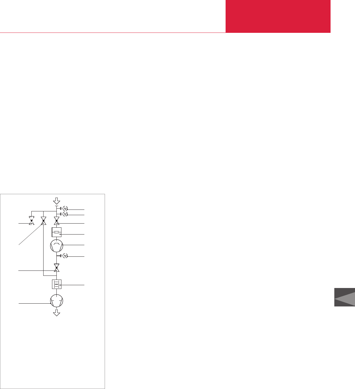
General
Oil Diffusion Pumps
C11.03
C11
LEYBOLD VACUUM PRODUCTS AND REFERENCE BOOK 2003/2004
Diffusion Pumps
Compared to other fluid entrainment pumps the
density of the vapor in the boiler and in the vapor
jet is fairly low so that the gas molecules may
almost completely diffuse into the vapor jet. Thus
most of the molecules which enter the vapor jet
are also pumped out.
For this reason, the pumping speed of diffusion
pumps is extremely high with respect to the in-
take area and constant – starting at a pressure of
approximately 10
-3
mbar (0.75 x 10
-3
Torr) down
to very low pressures – as within the pressure
range the vapor jet is not influenced in any way
by the pressure within the vacuum vessel.
Operating
Oil Diffusion Pumps
Forevacuum
In all cases diffusion pumps require a sufficiently
sized backing pump (see Technical Data). The
size and type of forevacuum pump depends on
the operating conditions and the quantities of gas
which are to be pumped.
1. Continuous operation at operating pressures
above 10
-4
mbar (0.75 x 10
-4
Torr) – large
quantities of gas.
2. Continuous operation at operating pressures
below 10
-4
mbar (0.75 x 10
-4
Torr) – smaller
quantities of gas.
In applications which rely on diffusion pumps,
the vacuum chamber must be connected via a
valve (3) and a roughing line directly to the
backing pump. This is done so that the vacuum
chamber may be pre-evacuated by the backing
pump down to a pressure where the diffusion
pump can take over. Until the high vacuum valve
(4) opens, both diffusion pump and pump fluid
are preserved. Before venting the vacuum cham-
ber the forevacuum valve (2) and the high vacu-
um valve (4) must be closed, whereby the diffusi-
on pump remains in the ready status.
Pumping Speed
The pumping speed of any pump is equivalent to
the volume throughput through the intake ope-
ning of a pump. In the case of diffusion pumps
the pumping speed for lighter gases is higher
compared to heavier gases.
Backstreaming of the Pump
Fluid
Undesirable backstreaming of molecules from the
pump fluid is caused by the effect that some
molecules are able to leave the vapor jet and thus
do not arrive at the cooled pump body. Because
of collisions between each other and due to
reflection at the pump body, these molecules are
then able to move in the direction of the vacuum
chamber.
For DIP pumps the backstreaming effect amounts
only to a few µg per cm
2
of intake area per minute.
Backstreaming may be almost completely sup-
pressed by including a cold cap baffle or an addi-
tional Astrotorus baffle.
Backstreaming of Oil in the
Case of Diffusion Pumps
♦Pump without baffle
approx. 1 x 10
-2
mg x cm
-2
x min
-1
♦Pump with cold cap baffle
approx. 1 x 10
-3
mg x cm
-2
x min
-1
♦
Pump with Astrotorus baffle
(T = 10 °C (50 °F))
approx. 1 x 10
-5
mg x cm
-2
x min
-1
General
The values stated were measured at the ultimate
pressure and apply to DIFFELEN normal. When
using DC 705 the values may improve on average
by one order of magnitude.
Attainable Ultimate Pressure
The attainable ultimate pressure for a particular
vacuum system depends not only on the type and
pumping speed rating of the diffusion pump, but
also on the vapor pressure of the pump fluid,
shape and temperature of the baffle, leaks at
connecting flanges or welded joints and the con-
dition of the surfaces within the vacuum cham-
ber. When excluding all effects which contribute
to an increase in pressure within the vacuum
chamber due to leaks and contamination of the
vacuum chamber walls, it will be possible to
attain the ultimate pressures stated in the table
“Attainable Ultimate Presures with Oil Diffusion
Pumps (DIP)” given in section “General”.
In practice the following combination has been
found to work very well when needing a low
vacuum free of oil vapors.
♦Water-cooled cold cap baffle as a integral part
of the diffusion pump together with a water-
cooled Astrotorus baffle which may be installed
as an additional component on the high vacu-
um flange of the diffusion pump.
BV
2
3
1
HM
VM1
VM2
4
5
6
7
1 Two-stage rotary vane vacuum pump
2 Forevacuum valve
3 Rough vacuum valve
4 High vacuum valve
5 Baffle
6 Oil diffusion pump
7 Adsorption trap
HM High vacuum gauge
VM1Forevacuum gauge/diffusion pump
VM2Forevacuum gauge/roughing line
BV Venting valve
Diagram of a pump system with diffusion pump

General
Oil Diffusion Pumps
C11.04 LEYBOLD VACUUM PRODUCTS AND REFERENCE BOOK 2003/2004
Sealing Methods
For ultimate pressures down to 10
-8
mbar (0.75 x
10
-8
Torr) bakeout temperatures of up to 150 °C
(302 °F) are sufficient. FPM (FPM = Fluor caout-
chouc, temperature resistant up to 150 °C
(302 °F) sealing rings or ultra sealing rings made
of aluminum must be used.
In order to prevent pressure variations, ultra seal-
ing rings must be used in the connections,
between diffusion pump and baffle.
Ultimate pressures below 10
-8
mbar (0.75 x
10
-8
Torr) require bakeout temperatures up to
400 °C (752 °F). However, it is only necessary to
bake out the vacuum chamber to 400 °C (752 °F)
and to maintain a temperature gradient across
the baffle or the cold trap so that a temperature
of 150 °C (302 °F) is not exceeded at the intake
flange of the pump.
In this way, it is still acceptable to use FPM seal-
ing rings or ultra sealing rings made of aluminium.
Attainable Ultimate Pressures with Oil Diffusion Pumps (DIP)
Attainable Ultimate
Pressure 1) DIFFELEN DIFFELEN DIFFELEN DC 705
light normal ultra or DC 704
Without baffle mbar (Torr)
With cold cap baffle mbar (Torr)
With Astrotorus baffle mbar (Torr)
1) Attained in consideration of the notes given under “Sealing Methods” in the section “General” and after degassing the connected vacuum chamber for several hours at 200 °C (392 °F)
1.5 x 10⁻⁵ (1.1 x 10⁻⁵) 1.5 x 10⁻⁶ (1.1 x 10⁻⁶) 6.0 x 10⁻⁷ (4.5 x 10⁻⁷) 4.0 x 10⁻⁷ (3.0 x 10⁻⁷)
6 x 10⁻⁶ (4.5 x 10⁻⁶) 6 x 10⁻⁷ (4.5 x 10⁻⁷) 3.0 x 10⁻⁷ (2.3 x 10⁻⁷) 1.5 x 10⁻⁷ (1.1 x 10⁻⁷)
1.5 x 10⁻⁶ (1.1 x 10⁻⁶) 1.5 x 10⁻⁷ (1.1 x 10⁻⁷) 3.0 x 10⁻⁸ (2.3 x 10⁻⁸) 1.5 x 10⁻⁸ (1.1 x 10⁻⁸)
Technical Data DIP 3 000 DIP 8 000 DIP 12 000 DIP 20 000 DIP 30 000 DIP 50 000
Ordering Information DIP 3 000 DIP 8 000 DIP 12 000 DIP 20 000 DIP 30 000 DIP 50 000
Diffusion pump
Part No. 222 10 Part No. 222 20 Part No. 222 25 Part No. 222 30 Part No. 222 35 Part No. 222 40
Pumping speed for air (in range < 10-4 mbar) l x s-1
Operating range mbar (Torr)
Ult. total press. with DC 705 and baffle, approx.
mbar (Torr)
Max. permissible forevacuum pressure mbar (Torr)
Heating power kW
Heating up time min
Cooling water (minimum throughput)
Pump l x h-1 (gal/min)
Cold cap baffle l x h-1 (gal/min)
Weight, approx. kg (lbs)
Recommended backing pump 2)
at operating pressures > 10-4 mbar (> 0.75 x 10⁻⁴ Torr)
at operating pressures < 10-4 mbar(< 0.75 x 10⁻⁴ Torr)
3000 8 000 12000 20000 30 000 50 000
< 10-2 (0.75 x < 10-2)
< 10-8 (0.75 x < 10-8)
0.6 (0.45) 0.6 (0.45) 0.6 (0.45) 0.6 (0.45) 0.6 (0.45) 0.6 (0.45)
2.4 4.8 7.2 12 18 24
< 25 < 25 < 25 < 25 < 30 < 30
160 (10) 290 (18.3) 500 (31.5) 600 (37.8) 900 (56.7) 1500 (94.5)
20 (1.3) 40 (2.5) 50 (3.2) 80 (5.0) 80 (5.0) 150 (9.5)
29 (64.0) 70 (154.5) 102 (225.2) 172 (379.7) 296 (653.4) 560 (1236.2)
TRIVAC D 65 B + DK 200 + W 251 DK 200 + W 501 SV 200 + W 501 SV 300 + W 1001 SV 630 + W 2001
W 251
TRIVAC D 25 B TRIVAC D 65 B + TRIVAC D 65 B + TRIVAC D 65 B + DK 200 + W 251 DK 200 + W 501
W 251 W 251 W 251
Program Range of Diffusion Pumps
Cooling
The cooling water temperature should not exceed
25 °C (77 °F) at the intake and 30 °C (86 °F) at
the discharge, otherwise sufficient condensation
of the pump fluid cannot be ensured. When
connecting the cooling pipes of the pump and the
baffle in series, the cooling water must be made
to flow through the baffle first and then through
the diffusion pump, because the attainable ulti-
mate
pressure in the vacuum chamber depends
strong
ly on the condensation temperature of the
pump fluid in the baffle.
2)
Singe- or two-stage rotary vane (TRIVAC; SV) or rotary piston vacuum pumps (E/DK) from our range of backing pumps jointly with Roots vacuum pumps (RUVAC) in pump systems

General
Oil Diffusion Pumps
C11.05
C11
LEYBOLD VACUUM PRODUCTS AND REFERENCE BOOK 2003/2004
Pump Fluids for
Diffusion Pumps
Pump fluids for oil diffusion pumps must exhibit
a low vapor pressure at room temperature and
must be able to resist thermal decomposition and
oxidization to a large extent. Surface tension of
the pump fluids must be high to reduce creep of
oil films. They must be chemically inert, exhibit
high flash point and evaporation heat must be
low. Moreover, the pump fluids should permit
high pumping speeds over a wide range of pres-
sures and be cost-effective.
One type of pump fluid alone cannot meet these
comprehensive requirements. It is therefore
required to select a pump fluid according to the
operating pressure and the requirements of the
application in each case.
The pump fluids given below are subjected to an
extensive series of tests in our factory laborato-
ries under conditions commonly encountered in
practice by diffusion pumps.
We recommend the use of the pump fluids speci-
fically qualified by Leybold, since only this will
ensure that the specifications will be met by our
diffusion pumps in practice. Equally we recom-
mend the use of qualified pump fluids to attain
the optimum oil change intervals and prevent the
accumulation of unwanted deposits.
Mineral Oil Pump Fluid
DIFFELEN
The various types of this kind of pump fluid are
closely toleranced fractions of a high quality base
product distilled with particular care. During the
distillation process the pressure and temperature
conditions are maintained continuously within
close limits, so that individual fractions are obtai-
ned which are of consistent quality.
♦DIFFELEN light is the lightest fraction. It even
provides full pumping speed at high pressu-
res. It is the ideal pump fluid for pressures
down to 10
-5
mbar. The attainable ultimate
pressure is 10
-7
mbar.
♦DIFFELEN normal is the most frequently used
pump fluid. It is the ideal pump fluid for high
vacuum applications. The attainable ultimate
pressure is below 10
-7
mbar
(0.75 x 10⁻⁷ Torr)
.
♦DIFFELEN ultra is used in connection with
ultrahigh vacuum pump systems. With a
water-cooled baffle the attainable ultimate
pressure is about 10
-8
mbar
(0.75 x 10⁻⁸ Torr)
.
Silicone Oil
Silicone oil differs from DIFFELEN oil in that sili-
cone oil is a defined chemical compound which is
extremely resistant to decomposition. Because of
the extremely low vapor pressure, silicone oil is
especially well suited as a pump fluid in diffusion
pumps. Even after a great number of air inrushes,
silicone oil will remain unaffected by aging even
when subjected to mass spectrometric analysis.
DC 704 is a pump fluid for high vacuum and ultra
high vacuum applications with stringent require-
ments concerning resistance against oxidization
and decomposition.
DC 705 is a special pump fluid (an organic silicon
compound) for ultrahigh vacuum applications
which require an extremely low vapor pressure
together with stringent requirements concerning
resistance against oxidization and decomposition.
Technical Data Mineral Oil/DIFFELEN Silicone Oil
light normal ultra DC 704 DC 705
Ordering Information *)
Part No. 176 69 Part No. 176 73 Part No. 176 71 Part No. 176 94 Part No. 176 96
Part No. 176 68 Part No. 176 72 – Part No. 500 600 2) –
– – – Part No. 981 98 069 –
– – – Part No. 981 98 070 –
Vapor pressure
at 20 °C (68 °F) mbar (Torr)
at 25 °C (77 °F) mbar (Torr)
Middle molecular weight g/mol
Flash point °C (°F)
Dyn. viscosity at 25 °C (77 °F) mPas
Kin. viscosity at 40 °C (104 °F) mm2/s
Density at 20 °C (68 °F) g/ml
Overview Pump Fluids
0.5 l (0.47 qts)
5.0 l (4.7 qts)
1.0 gal (DC 704 CA)
5.0 gal (DC 704 CP)
1) At 25 °C (77 °F)
2) 5 kg (11.04 lbs)
*) Oil must be puchased separately
Please note that the technical data stated are only typical data. Slight variations from batch to batch must be expected.
The technical data given here can not be taken as assured data
For all lubricants in our line of products you may obtain Safety Data Sheets from the Dept. Technical Support in Cologne.
Mineral Oil/DIFFELEN Silicone Oil
light normal ultra DC 704 DC 705
2 x 10⁻⁸ (1.5 x 10⁻⁸) 4 x 10⁻⁹ (3 x 10⁻⁹) 4 x 10-11 (3 x 10-11) 3 x 10⁻⁸ (2.3 x 10⁻⁸) 4 x 10⁻¹⁰ (3 x 10⁻¹⁰)
– – – – –
500 510 600 485 545
> 240 (> 464) > 258 (> 496) > 270 (> 518) 221 (430) 243 (469)
115 200 220 47 190
60 100 110 24 66
0.86 0.87 0.87 1.07 1) 1.09 1)
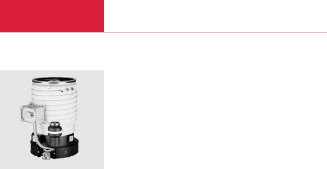
3000 - 50000 l x s-1
Oil Diffusion Pumps
C11.06
DIP Pumps, Water-Cooled
LEYBOLD VACUUM PRODUCTS AND REFERENCE BOOK 2003/2004
The DIP range of pumps was developed for ope-
ration in industrial systems. Excellent vacuum
performance data combined with the inherent
ruggedness of this kind of pump, make our DIP
pumps a reliable component in high and medium
vacuum applications.
Advantages to the User
♦High pumping speeds in the fine and high
vacuum ranges
♦Low attainable ultimate pressure
♦Integrated, water-cooled cold cap baffle guar-
antees low oil backstreaming rates into the
vacuum chamber
♦Low oil losses – even at high gas throughputs
– by integrated, water-cooled forevacuum baf-
fle
♦High forevacuum resistance even at reduced
heating power
♦The heating cartridges are accessible from the
outside via heating inserts which are built into
the boiler. This ensures a quick exchange of
single heating cartridges – even when the
pump is hot
♦A separate automatic circuit breaker for each
heating cartridge ensures a high level of elec-
trical safety
♦A temperature monitor which is built-in as
standard acts as a thermal overload switch
and ensures that the heating cartridges can
not overheat
♦All pumps are prepared for installation with an
over-temperature switch (optional) for
checking the cooling water circuit, and a
contact thermometer (optional) to monitor the
operating temperature of the diffusion pump
♦Indication of the oil level by sight-glass per-
mits simple checking of the current oil level
♦All DIP pumps are delivered with their inside
chamber cleaned in such a manner that it is
free of oil. The inside is evacuated. In the
condi
tion as delivered, the pumps may be also
oper
ated with silicone oil
Typical Applications
The diffusion pumps from the DIP range are used
in coating systems, vacuum melting and drying
systems as well as in vacuum furnaces in the
area of metallurgy.
Supplied Equipment
The DIP pumps are supplied ready for connection
but without the filling of pump fluid.
The inside of the pump is cleaned before delivery
to such an extent that it is free of oil. The inside
is evacuated. High and forevacuum flanges are
equipped with gaskets and centering rings having
shipping flanges and complete with clamping
components.
DIP 12 000

3000 - 50000 l x s-1
Oil Diffusion Pumps
C11.07
C11
LEYBOLD VACUUM PRODUCTS AND REFERENCE BOOK 2003/2004
Technical Data DIP 3 000 DIP 8 000 DIP 12 000 DIP 20 000 DIP 30 000 DIP 50 000
High vacuum/forevacuum connection DN
Pumping speed for air 1)
below 1 x 10⁻⁴ mbar l x s-1
Operating range mbar (Torr)
Ultimate total pressure 2) mbar (Torr)
Max. permissible forevacuum pressure
mbar (Torr)
Pump fluid filling, min./max. l (qts)
Main connection
Standard, 50/60 Hz V
Special, 50/60 Hz V
Heating power kW
Number of heating cartridges
Heating up time min
Cooling water (minimum)
for pump 3) l x h-1 (gal/min)
for cold cap baffle l x h-1 (gal/min)
Max. supply pressure bar (psig)
Number of cooling circuits
(including cold cap baffle)
Cooling water connection
for pump G (BPS)
for cold cap baffle G (BPS)
Weight, approx. kg (lbs)
Recommended backing pump
4)
at operating pressures
> 10-4 mbar (> 0.75 x 10⁻⁴ Torr)
at operating pressures
< 10-4 mbar (< 0.75 x 10⁻⁴ Torr)
250 ISO-K/63 ISO-K 400 ISO-K/63 ISO-K 500 ISO-K/100 ISO-K 630 ISO-F/100 ISO-K 800 ISO-F/160 ISO-K 1000 ISO-F/160 ISO-K
3 000 8 000 12 000 20 000 30 000 50 000
< 10
-2
to 10
-7
(0.75 x 10
-2
to 0.75 x 10
-7
)
< 5 x 10
-7
(6.7 x 10
-7
)
6 x 10
-1
(4.5 x 10
-1
)
1.0 / 1.4 (1.1 / 1.5) 2.0 / 3.4 (2.1 / 3.6) 3.0 / 5.5 (3.2 / 5.8) 6.0 / 9.0 (6.3 / 9.5) 10 / 15 (10.6 / 15.9) 15 / 25 (15.9 / 26.4)
230 ~ 1 Ph 230/400 ~ 3 Ph D/Y 400 ~ 3 Ph Y 230/400 ~ 3 Ph D/Y 230/400 ~ 3 Ph D/Y 230/400 ~ 3 Ph D/Y
460 ~ 3 PhD460 ~ 3 Ph D460 ~ 3 Ph D460 ~ 3 Ph D
2.4 4.8 7.2 12 18 24
2 6 9 12 18 24
< 25 < 25 < 25 < 25 < 30 < 30
160 (10) 290 (18.3) 500 (31.5) 600 (37.8) 900 (56.7) 1500 (94.5)
20 (1.3) 40 (2.5) 50 (3.2) 80 (5.0) 80 (5.0) 150 (9.5)
6 (87) 6 (87) 6 (87) 6 (87) 6 (87) 6 (87)
2 2 2 2 3 3
3/8" 1/2" 1/2" 1/2" 1/2" 1/2"
1/4" 3/8" 3/8" 3/8" 3/8" 3/8"
29 (64) 70 (154) 102 (225) 172 (379) 296 (653) 560 (1235)
TRIVAC D 65 B + DK 200 + W 251 DK 200 + W 501 SV 200 + W 501 SV 300 + W 1001 SV 630 + W 2001
W 251
TRIVAC D 25 B TRIVAC D 65 B + TRIVAC D 65 B + TRIVAC D 65 B + DK 200 + W 251 DK 200 + W 501
W 251 W 251 W 251
Ordering Information DIP 3 000 DIP 8 000 DIP 12 000 DIP 20 000 DIP 30 000 DIP 50 000
Oil diffusion pump
Astrotorus baffle
Water flow monitor
LR 10
LR 20
Over-temperature protection switch
Contact thermometer
Resistance thermometer PT 100 sensor
Pump fluid 5)
Part No. 222 10 Part No. 222 20 Part No. 222 25 Part No. 222 30 Part No. 222 35 Part No. 222 40
Part No. 227 50 Part No. 227 60 Part No. 227 65 Part No. 227 70 Part No. 227 75 Part No. 227 80
Part No. 122 82 Part No. 122 82 – – – –
– – Part No. 122 83 Part No. 122 83 Part No. 122 83 Part No. 122 83
Part No. 122 84
Part No. 218 81
Part No. 200 02 958
see
“
Pump Fluids for Diffusion Pumps
”
in section
“
General
”
1)
Measured to DIN 28 427 with DIFFELEN normal as the pump fluid
2)
Measured to DIN 28 427 with DIFFELEN normal as the pump fluid. With pump fluids DC 705 and FPM gaskets the DIP pumps - when equipped with water-cooled baffles and after running a suitable
degassing processes - are capable of attaining pressures below 1 x 10
-8
mbar (0.75 x 10
-8
Torr)
3)
The required quantity of cooling water refers to DT = 10 °C (50 °F). The discharge temperature should not exceed 30 °C (86 °F)
4)
Single- or two-stage rotary vane (TRIVAC; SV) or rotary piston vacuum pumps (E/DK) from our range of forevacuum pumps jointly with Roots vacuum pumps (RUVAC) in pump systems
5)
Oil must be puchased separately
Version for the North and South American Continents
Oil diffusion pump
Special connection flange
– Part No. 222 20-460 V Part No. 222 25-460 V Part No. 222 30-460 V Part No. 222 35-460 V Part No. 222 40-460 V
upon request
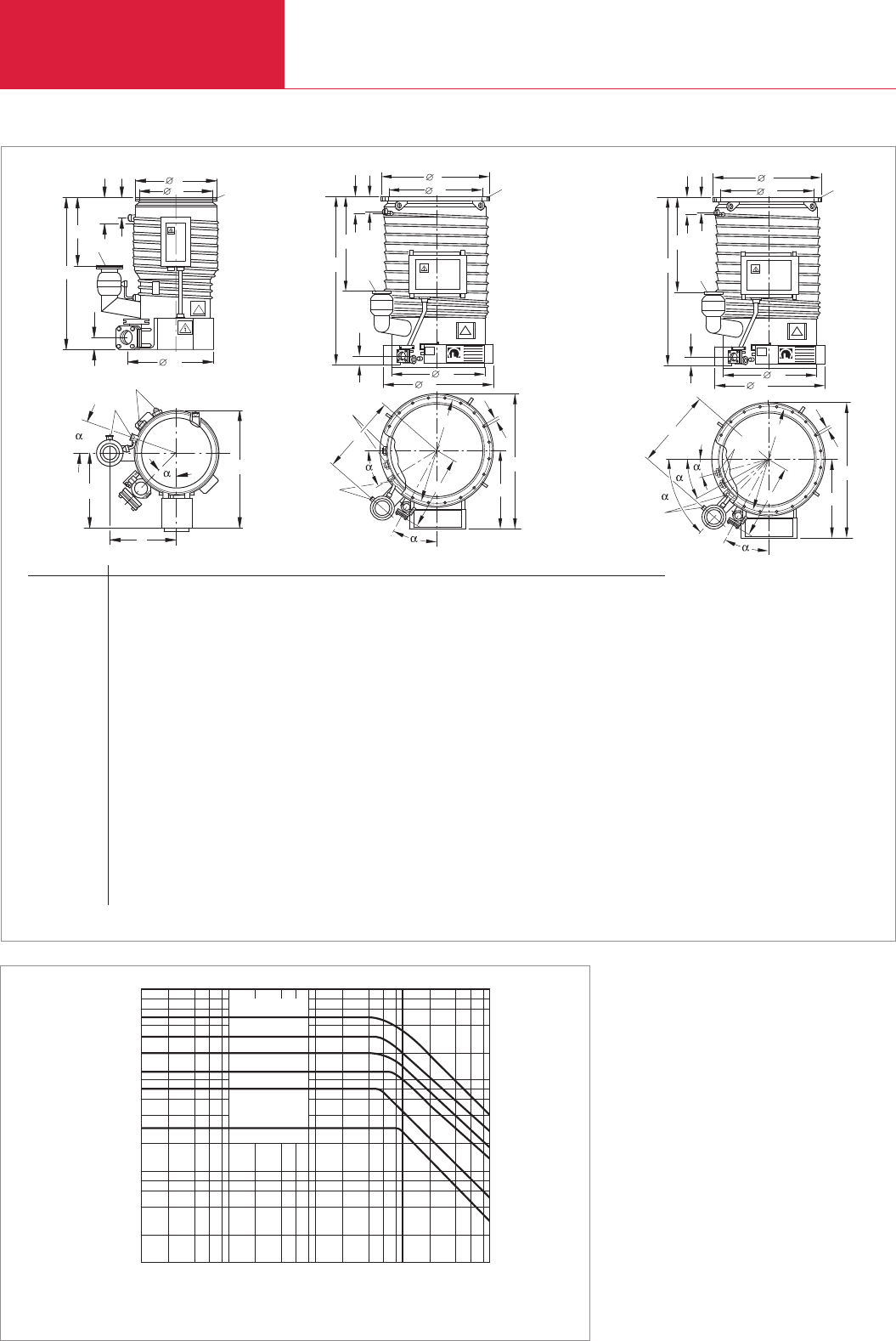
3000 - 50000 l x s-1
Oil Diffusion Pumps
C11.08 LEYBOLD VACUUM PRODUCTS AND REFERENCE BOOK 2003/2004
d1
dDN
h3
DN1
h1
h4
h
d3
b1
b
a
G1/4"
G3/8"
h2
1
10-6 2 4 6 8
2
4
6
8
10-5 10-4 10-3 10-2
mbar
Intake pressure
Pumping speed
103
102
104
105
l x s-1
DIP 8000
DIP 12000
DIP 20000
DIP 50000
DIP 30000
DIP 3000
Pumping speed characteristics of the DIP pumps as a function of intake pressure
Dimensional drawing for the DIP 3000 [left], DIP 8000 to DIP 30 000 [middle] and DIP 50 000 [right]; dimensions in brackets ( ) are in inch
d1
dDN
h3
h2
DN1
h1
h4
h
d3
d2
a
1
a1
b
b1
d4d5
G3/8"
G1/2"
O
LEYBLD
d1
dDN
h3
h2
DN1
h1
h4
h
d3
d2
a
3
a1
b
b1
2
1
d4d5
G3/8"
G1/2"
DIP 3 000 8 000 12 000 20 000 30 000 50 000
DN 250 ISO-K 400 ISO-K 500 ISO-K 630 ISO-F 800 ISO-F 1000 ISO-F
DN163 ISO-K 63 ISO-K 100 ISO-K 100 ISO-K 160 ISO-K 160 ISO-K
a 240 (9.45) 350 (13.78) 420 (16.54) 540 (21.26) 600 (23.62) 800 (31.5)
a1250.5 (9.86) 375.5 (14.78) 432 (17) 496 (19.53) 536 (21.10) 636 (25.04)
b 443 (17.44) 643 (25.41) 775 (30.51) 920 (36.22) 1090 (42.91) 1290 (50.79)
b1276 (10.87) 373 (14.69) 460 (18.11) 540 (21.26) 630 (24.8) 730 (28.74)
d 290 (11.42) 450 (17.72) 550 (21.65) 750 (29.53) 920 (36.22) 1120 (44.09)
d1261 (10.28) 400 (15.75) 50119.72) 651 (25.63 800 (31.5) 1000 (39.37)
d2– 405 (15.94) 506 (19.92) 636 (25.04) 716 (28.19) 916 (36.06)
d3278 (10.94) 530 (20.87) 630 (24.80) 760 (29.92) 840 (33.07) 1040 (40.94)
d4– – – 720 (28.35) 890 (35.04) 1090 (42.91)
d5– – – 14 (0.55) 14 (0.55) 14 (0.55)
Quantity of holes – – – 20 24 32
h 560 (22.05) 785 (30.91) 940 (37) 1130 (44.49) 1450 (57.09) 1880 (74.02)
h1250 (9.84) 400 (15.75) 470 18.5) 620 (24.41) 870 (34.25) 1275 (50.2)
h368 (2.68) 88 (3.46) 92 (3.62) 97 (3.82) 102 (4.02) 102 (4.02)
h275 (2.95) 102 (4.02) 106 (4.17) 110 (4.33) 116 (4.57) 116 (4.57)
h445 (1.77) 68 (2.68) 68 (2.68) 74 (2.91) 70 (2.76) 70 (2.76)
α45 ° 30 ° 30 ° 30 ° 20 ° 25 °
α120 ° 30 ° 30 ° 30 ° 30 ° 45 °
α2– – – – – 25 °
α3– – – – – 15 °
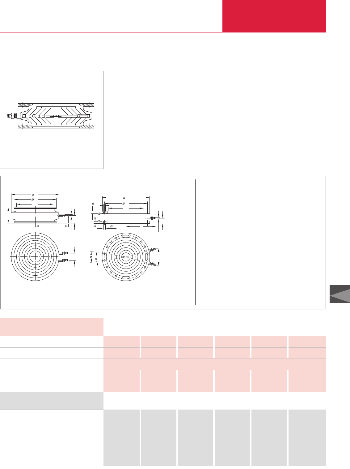
Section through an Astrotorus baffle
Astrotorus Baffles
The cooling inserts of the astrotorus baffles are
made of copper, whereas the housing and the
connection flange are made of standard steel.
Technical Data Astrotorus Baffles
Ordering Information
Astrotorus baffle
0250 ISO-K
0400 ISO-K
0500 ISO-K
0630 ISO-F
0800 ISO-F
1000 ISO-F
Part No. 227 50 – – – – –
– Part No. 227 60 – – – –
– – Part No. 227 65 – – –
– – – Part No. 227 70 – –
– – – – Part No. 227 75 –
– – – – – Part No. 227 80
Connection to pump DIP
HV connection flanges DN
Throttling of the pumping speed, approx. %
Conductance l x s-1
Weight kg (lbs)
3 000 8 000 12 000 20 000 30 000 50 000
250 ISO-K 400 ISO-K 500 ISO-K 630 ISO-F 800 ISO-F 1000 ISO-F
30
3000 9000 12 000 18 000 28 000 50 000
25 (55.2) 30 (66.2) 65 (143.5) 120 (264.9) 170 (375.3) 190 (419.4)
Hose nozzle, 14 mm dia.
DN
1
d
d
a
1
h
h
b
Dimensional drawing for the Astrotorus baffle ISO-K (left) and ISO-F (right)
Astrotorus Baffles
Oil Diffusion Pumps
C11.09
C11
LEYBOLD VACUUM PRODUCTS AND REFERENCE BOOK 2003/2004
Accessories
DN a b ldld1ld2Quantity h h1α α 1
250 ISO-K
mm 265 30 416 290 – – 195 97 – –
in. 10.4 0.18 16.4 11.4 – – 7.68 3.82 – –
400 ISO-K
mm 362 120 512 450 – – 193 96 – –
in. 14.25 4.72 20.2 17.7 – – 7.6 3.78 – –
500 ISO-K
mm 412 120 612 550 – – 193 96 – –
in. 16.22 4.72 24.1 21.7 – – 7.6 3.78 – –
630 ISO-F
mm 440 – 750 720 14 20 – – 18 ° 9 °
in. 17.32 – 29.53 28.35 0.55 20 – – 18 ° 9 °
800 ISO-F
mm 546 – 920 890 14 24 – – 15 ° 7.5 °
in. 21.5 – 36.22 35.04 0.55 24 – – 15 ° 7.5 °
1000 ISO-F
mm 599 – 1120 1090 14 32 – – 11.25 ° 5.625 °
in. 23.58 – 44.09 42.91 0.55 32 – – 11.25 ° 5.625 °
140
24
2
d
2
d
a
130°
DN
1
d
d
24 Hose nozzle, 14 mm dia.
57
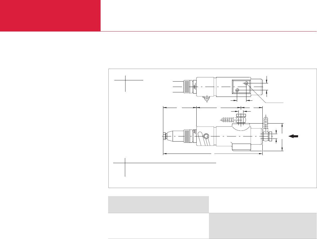
LEYBOLD VACUUM PRODUCTS AND REFERENCE BOOK 2003/2004
Oil Diffusion Pumps
C11.10
Accessories
Protection against
Overheating
Water flow monitors are installed in the cooling
water return section of the diffusion pump. When
the cooling water throughput drops below a cer-
tain level, either the heater in the diffusion pump
is switched off or a warning light or signal is trig-
gered, depending of the type of circuit.
Type LR 10 for 060 to 0600 l x h
-1
(3.78 to 37.8 gal/min)
Type LR 20 for 600 to 2400 l x h
-1
(37.8 to 151.2 gal/min)
The water throughput may be set within the limits
stated with a high degree of reproducibility.
Water flow monitors may be installed in any
orientation.
Max. switching capacity:
100 VA (230 V, 50/60 Hz).
Protection against
Power Failure
A SECUVAC valve (see Product Section C14
“Vacuum Valves”) must be installed in the fore-
vacuum line in order to prevent damage to the
diffusion pump or the pump fluid in the event of
a power failure affecting backing pumps which
are not equipped with an automatic isolation
valve. Rotary vane vacuum pumps from the
TRIVAC B Series are equipped with an automatic
safety valve (intake isolation valve) as standard.
Protection against Pressure
Increases in the Forevacuum
Line
For protection against a pressure increase in the
forevacuum line which is not caused by a power
failure you may use our vacuum gauges which
offer an adjustable switching threshold (see
Product Section C16 “Total Pressure Gauges”).
l2l1l3
c
a
a
b
l
c1
M6 x 8
Dimensional drawing for the water flow monitors LR 10 and LR 20
*
Only LR 10
Monitoring Instruments
Ordering Information Monitoring Instruments
Water flow monitor
LR 10
LR 20
Part No. 122 82
Part No. 122 83
a
LR 10 M 12 x 1.5
LR 20 G 3/4 "
≈l l1l2l3b c c1
mm 230 102 - 112 72 46 62 20 15
in. 9.06 4.02 - 4.41 2.83 1.81 2.44 0.79 0.59
*
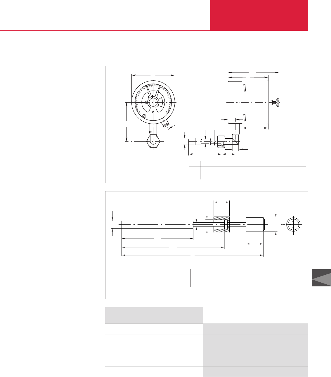
Oil Diffusion Pumps
C11.11
C11
LEYBOLD VACUUM PRODUCTS AND REFERENCE BOOK 2003/2004
Accessories
400
350
250
300
200
150
100
50
0
d1
c
d2d3
a3
a2
a
l1
d
l
a1
b
30°
Dimensional drawing for the contact thermometer
Temperature dependant
Switching Components for
Automatic Pump System Control
The operational status of the diffusion pump
depends on the temperature of the pump fluid in
the pump boiler. Through temperature dependent
switching components which are inserted into the
pump boiler it is possible to monitor the opera-
tional status of the diffusion pump and signal its
status to a process controller.
For this, the diffusion pump requires two thres-
holds.
Depending on the type of pump, the upper thres-
hold should be between 180 and 200 °C (356 and
392 °F) and the lower threshold between 90 and
100 °C (194 and 212 °F).
The upper threshold indicates that the diffusion
pump is ready for operation and thus actuates
certain devices, for example opening of the high
vacuum valve ahead of the diffusion pump.
The lower threshold indicates that the diffusion
pump has cooled down to such an extent that the
backing pump and the cooling water supply may
be switched off.
Over-temperature protection switches are used
to monitor the temperature of the cooling water
in the cooling water circuit of the diffusion
pumps. When the temperature rises to unaccept-
ably high levels – for example when the cooling
water supply fails – the heater in the diffusion
pump is switched off (correct electrical connec-
tion to the main supply is required). The use of
over-temperature protection switches avoids
unnecessary alarms that may be triggered by
contaminated water when only a water flow
monitor is used. The over-temperature protection
switch is screwed on to a contact plate which is
soldered to the cooling pipe on the pump’s body.
Max. switching current: 5 A (230 V, 50/60 Hz)
Contact thermometer with a range from 0 to
400 °C (752 °F). Through a trailing pointer two
switching thresholds may be set up independent-
ly. The current oil temperature and the thresholds
which have been set up can be read off at the
location of the diffusion pump. The contacting
thermometer is not suited for remote signalling
of temperatures.
Resistance thermometer PT 100 sensor. The
measurement range of this sensor depends on
the temperature display unit used by the custo-
mer where also the required thresholds are set
up. The PT 100 sensor is ideal for remote signal-
ling of temperatures.
d2
l3
d1
l4
l
l2
l1
dd3
Dimensional drawing for the resistance thermometer PT 100 sensor
a a1a2a3b c ldld1ld2ld3l l1
mm 95 119.5 17.5 62 101.5 92 14 12 9 G 1/2 170 33
in. 3.74 4.70 0.69 2.44 4.00 3.62 0.55 0.47 0.35 G 1/2 6.70 1.30
ldld1ld2ld3l l1l2l3l4
mm 12 6 G 1/2 22 230 115 170 25 30
in. 0.47 0.24 G 1/2 0.87 9.06 4.53 6.69 0.98 1.18
Ordering Information Monitoring Instruments
Over-temperature protection switch
Contact thermometer
(Measurement range 0 to 400 °C (32 to 752 °F),
Rating at 220 V AC: 250 mA [resistive load],
Weight: 1.7 kg (3.7 lbs))
Resistance thermometer PT 100 sensor
Part No. 122 84
Part No. 218 81
Part No. 200 02 958

Accessories
Oil Diffusion Pumps
C11.12 LEYBOLD VACUUM PRODUCTS AND REFERENCE BOOK 2003/2004
Technical Data 16 KF 25 KF 40 KF
4 6 12
3
0.5 (0.53) 1.0 (1.06) 2.0 (2.1)
1.3 (2.9) 1.3 (2.9) 4 (8.8)
Ordering Information 16 KF 25 KF 40 KF
Adsorption trap
Activated aluminum oxide, 2 l (approx. 1.3 kg (2.8 lbs))
Part No. 854 14 Part No. 854 15 Part No. 854 16
Part No. 854 10
Conductance at 10-2 mbar (Torr)
mbar x l x s-1 (Torr x l x sec)
Service live with Al oxide Months
Al oxide filling l (qts)
Weight, approx. kg (lbs)
Adsorption Traps with Aluminum Oxide Insert
Advantages to the User
♦Backstreaming of oil is reduced by 99 %
♦Long service life
♦High conductance
♦Filling can be easily exchanged
♦Improvement in the ultimate pressure attained
by backing pumps by one order of magnitude
♦Stainless steel housing and insert
♦NBR gasket
Typical Applications
♦Product of an oil-free vacuum
Supplied Equipment
♦Complete with insert
♦Without adsorbent
Adsorption traps are used in all those cases
where a vacuum free of oil is to be produced with
the aid of oil-sealed vacuum pumps.
Adsorption trap (left) and inserts (right)
Residual gas spectrum; top ahead of a rotary vacuum pump,
bottom ahead of a rotary vacuum pump with adsorption trap
d
1
DN
a
h
1
h
DN
a
Dimensional drawing for the adsorption traps
Mass number
DN a a1ld h h1
16 KF
mm 82 82 135 147 32
in. 3.23 3.23 5.31 5.79 1.25
25 KF
mm 102 102 175 155 33
in. 4.02 4.02 6.89 6.10 1.26
40 KF
mm 132 65 235 160 20
in. 5.19 2.56 9.25 6.3 0.79
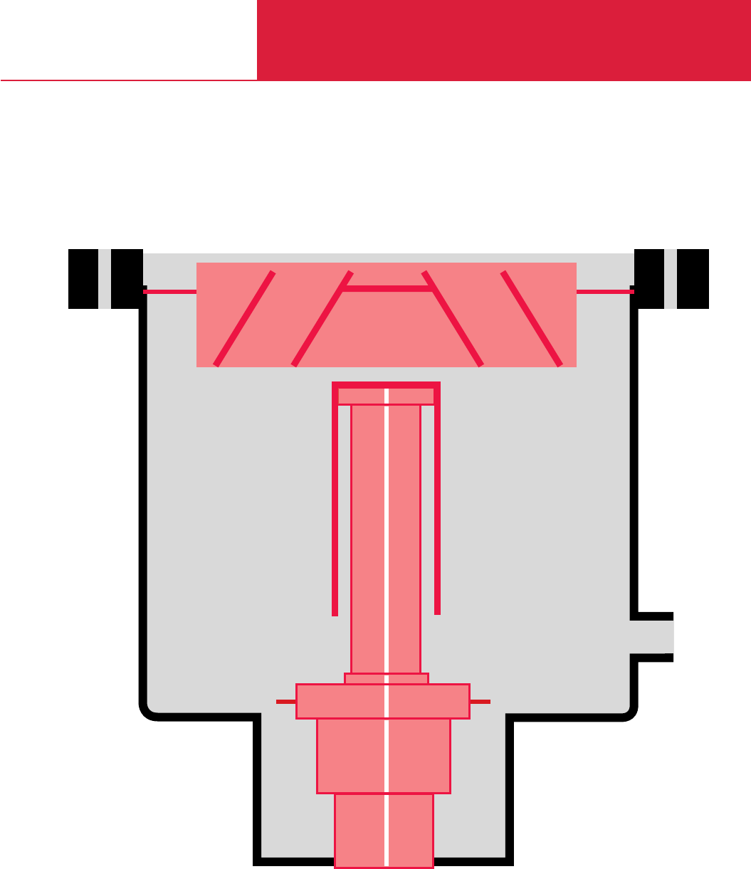
C12
Cryopumps, Cryogenics

LEYBOLD VACUUM PRODUCTS AND REFERENCE BOOK 2003/2004
Contents
C12.02
General
Applications and Accessories
Cryopumps . . . . . . . . . . . . . . . . . . . . . . . . . . . . . . . . . . . . . . . . . . . . . . . . . . . . . . . . . . C12.03
Cold Heads . . . . . . . . . . . . . . . . . . . . . . . . . . . . . . . . . . . . . . . . . . . . . . . . . . . . . . . . . . C12.04
General
Cryopumps . . . . . . . . . . . . . . . . . . . . . . . . . . . . . . . . . . . . . . . . . . . . . . . . . . . . . . . . . . C12.05
Multiple-Operation of Refrigerator Cryopumps . . . . . . . . . . . . . . . . . . . . . . . . . . . . . . . . C12.06
Regenerating Cryopumps . . . . . . . . . . . . . . . . . . . . . . . . . . . . . . . . . . . . . . . . . . . . . . . . C12.06
Refrigerating Capacity of Cold Heads . . . . . . . . . . . . . . . . . . . . . . . . . . . . . . . . . . . . . . . C12.07
Cold Heads . . . . . . . . . . . . . . . . . . . . . . . . . . . . . . . . . . . . . . . . . . . . . . . . . . . . . . . . . . C12.07
Compressor Units . . . . . . . . . . . . . . . . . . . . . . . . . . . . . . . . . . . . . . . . . . . . . . . . . . . . . C12.09
Products
Cryopumps
Standard Cryopumps
COOLVAC 800 . . . . . . . . . . . . . . . . . . . . . . . . . . . . . . . . . . . . . . . . . . . . . . . . . . . . . . . . C12.10
Cryopumps with Fully Automatic Control
ClassicLine
COOLVAC 1.500 CL, 2.000 CL, 3.000 CL . . . . . . . . . . . . . . . . . . . . . . . . . . . . . . . . . . C12.12
COOLVAC 5.000 CL, 10.000 CL . . . . . . . . . . . . . . . . . . . . . . . . . . . . . . . . . . . . . . . . . C12.18
COOLVAC 18.000 CL, 30.000 CL . . . . . . . . . . . . . . . . . . . . . . . . . . . . . . . . . . . . . . . . C12.22
SemiLine
COOLVAC 1500 SL . . . . . . . . . . . . . . . . . . . . . . . . . . . . . . . . . . . . . . . . . . . . . . . . . . C12.24
System Controller SC / Power Supply PS. . . . . . . . . . . . . . . . . . . . . . . . . . . . . . . . . . . . C12.25
Cryogenics
Cold Heads
Single Stage Cold Head COOLPOWER 120 T . . . . . . . . . . . . . . . . . . . . . . . . . . . . . . . . . C12.28
Dual Stage Cold Heads
COOLPOWER 7/25, 5/100 and 5/100 T . . . . . . . . . . . . . . . . . . . . . . . . . . . . . . . . . . . C12.30
Compressor Units COOLPAK 4000/4200, COOLPAK 6000/6200. . . . . . . . . . . . . . . . . . . . . . C12.32
General Accessories for Compressor Units COOLPAK . . . . . . . . . . . . . . . . . . . . . . . . . . . . . C12.34
Refrigerator Cryostats
Based on RDK 6-320 . . . . . . . . . . . . . . . . . . . . . . . . . . . . . . . . . . . . . . . . . . . . . . . . . . . C12.35
Optical, based on RDK 6-320 . . . . . . . . . . . . . . . . . . . . . . . . . . . . . . . . . . . . . . . . . . . . . C12.36
Accessories
Cryopumps / Cryogenics
Controllers and Monitoring Units for Cryopumps . . . . . . . . . . . . . . . . . . . . . . . . . . . . . . . . C12.38
COOLVAC ClassicLine, System Configuration
Single Operation. . . . . . . . . . . . . . . . . . . . . . . . . . . . . . . . . . . . . . . . . . . . . . . . . . . . . . . C12.39
Dual Operation . . . . . . . . . . . . . . . . . . . . . . . . . . . . . . . . . . . . . . . . . . . . . . . . . . . . . . . . C12.40
Dual and Mutiple Operation . . . . . . . . . . . . . . . . . . . . . . . . . . . . . . . . . . . . . . . . . . . . . . C12.41
Modell 9700 Low Temperature Controller . . . . . . . . . . . . . . . . . . . . . . . . . . . . . . . . . . . . . . C12.42
MODEL 1901 Low Temperature Measuring Instrument . . . . . . . . . . . . . . . . . . . . . . . . . . . . C12.43
Temperature Sensors (Silicon Diode) . . . . . . . . . . . . . . . . . . . . . . . . . . . . . . . . . . . . . . . . . C12.44
Safety Valve. . . . . . . . . . . . . . . . . . . . . . . . . . . . . . . . . . . . . . . . . . . . . . . . . . . . . . . . . . . . C12.45
Precision Manometer . . . . . . . . . . . . . . . . . . . . . . . . . . . . . . . . . . . . . . . . . . . . . . . . . . . . . C12.45
Cryopumps, Cryogenics
Conversion of Units
Celsius, Fahrenheit, Kelvin
Kelvin (abbreviated as K) is the unit of
temperature.
Temperatures on the Kelvin scale are converted
into temperatures on the Celsius scale as follows:
n °C ;(n + 273.15) K.
Since the following equation applies between
Celsius scale and Fahrenheit scale
n °F ;5/9 (n – 32) °C
it follows that
n °F ;5/9 (n + 459.67) K.
The inverse equations are as follows:
m K ;(m – 273.15) °C
m °C ;(1.8 m + 32) °F
m K ;(1.8 m – 459.67) °F.
The following applies in particular to absolute
Zero:
0 K ;-273.15 °C ;-459.67 °F.
1 bar = 14.5 psi
1 MPa = 10 bar
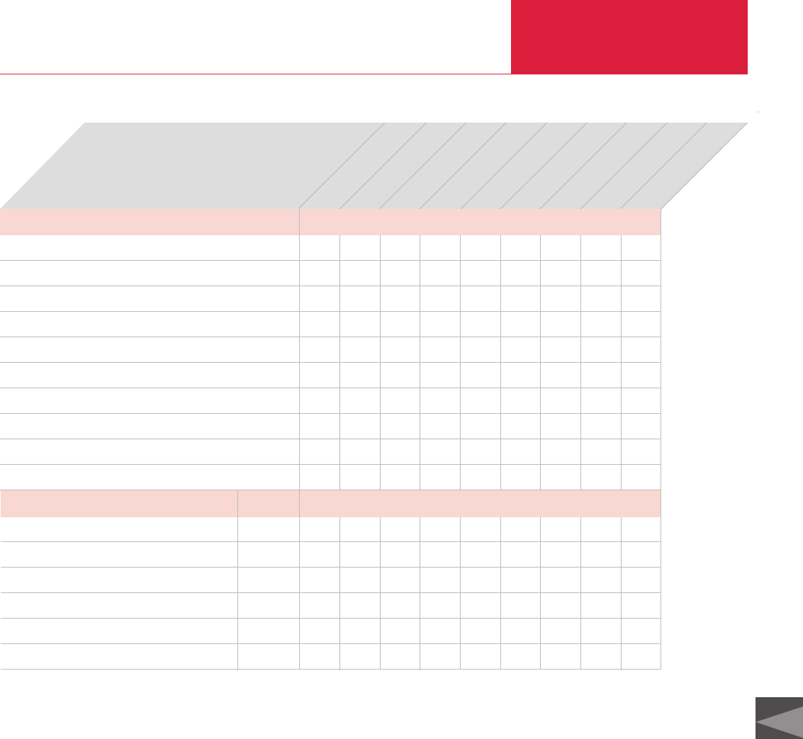
C12
LEYBOLD VACUUM PRODUCTS AND REFERENCE BOOK 2003/2004
Cryopumps, Cryogenics
C12.03
Applications and Accessories, Cryopumps and Stirling Cooler
UHV systems
Beam tubes in particle accelerators
Transfer chambers / Loadlock
General research
Evaporation coating systems
Sputtering systems
Ion implanters
Metallization systems
Space simulation chambers
Electron beam welding systems
◆ ◆ ◆ ◆
◆
◆ ◆ ◆ ( ◆)◆
◆◆◆◆◆◆◆◆◆
◆◆◆◆◆◆◆◆
◆ ◆ ◆ ◆
◆ ◆ ◆ ( ◆)◆
◆ ◆ ◆ ◆ ◆ ◆ ◆
◆◆◆◆◆
◆ ◆ ◆
Accessories
Cryo pumps
COOLVAC 5.000 CL
COOLVAC 10.000 CL
COOLVAC 18.000 CL
COOLVAC 30.000 CL
COOLPAK 4000/4200 compressor unit
COOLPAK 6000/6200 compressor unit
MODEL 1901 low temperature measuring instrument
Temperature sensors (silicon diode)
GD 2 gas manifold
GD 4 gas manifold
( ◆)=
Only conditionally suited
[ ◆]=
For dual operation only
◆ ◆ ◆ ◆ ◆
[ ◆ ]◆ ◆ ◆ ◆
◆
◆
◆ ◆ ◆ ◆ ◆ ◆
◆ ◆ ◆ ◆
Page
C12.32
C12.32
C12.43
C12.44
C12.34
C12.34
COOLVAC 3.000 CL
COOLVAC 2.000 CL
COOLVAC 800
COOLVAC 1.500 CL
COOLVAC 1.500 SL
Application

LEYBOLD VACUUM PRODUCTS AND REFERENCE BOOK 2003/2004
Cryopumps, Cryogenics
C12.04
Applications and Accessories, Cold Heads
Cooling of samples and detectors
Cooling of superconductors
Cooling of cryopanels
Cleaning of gases
Calibration of sensors
Optical spectroscopy
Infrared spectroscopy
Matrix spectroscopy
Testing of superconductors
Cooling of superconducting magnets, coils and components HTC+ LTC
◆ ◆ ◆ ◆
◆ ◆ ◆
◆ ◆ ◆ ◆
◆ ◆ ◆ ◆
◆
◆ ◆ ◆
◆ ◆ ◆
◆ ◆
◆
◆ ◆
Accessories
Cold Heads
COOLPOWER 7/25
COOLPAK 4000/4200 compressor unit
COOLPAK 6000/6200 compressor unit
Modell 9700 low temperature controller
MODEL 1901 low temperature measuring instrument
Temperature sensors (silicon diode)
◆
◆ ◆ ◆
◆ ◆ ◆
◆ ◆ ◆ ◆
◆ ◆ ◆ ◆
Page
C12.32
C12.32
C12.42
C12.43
C12.44
COOLPOWER 5/100
COOLPOWER 120 T
COOLPOWER 5/100 T
Application
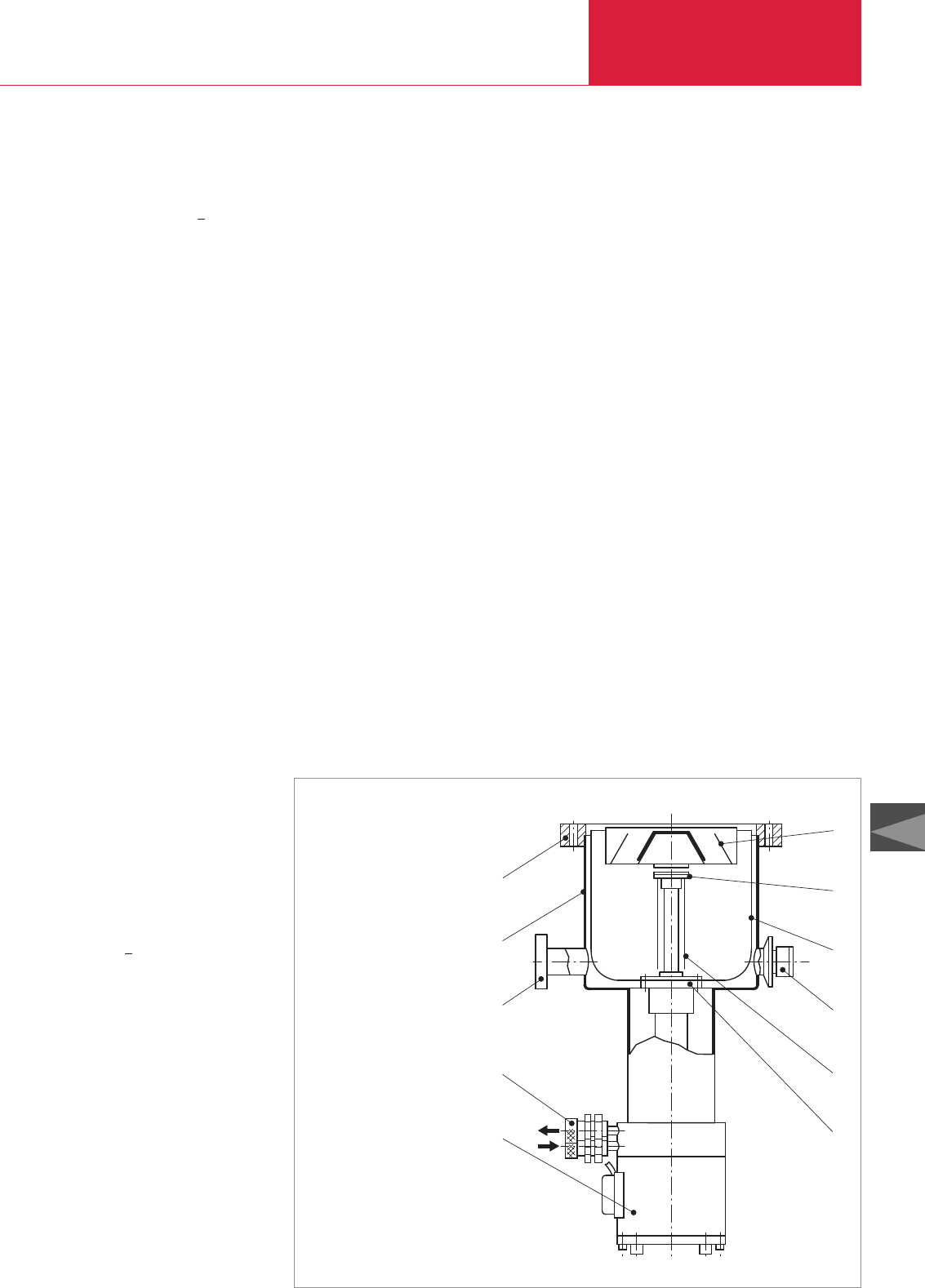
Cryopumps, Cryogenics
C12.05
General
LEYBOLD VACUUM PRODUCTS AND REFERENCE BOOK 2003/2004
C12
Cryopumps
The second stage of the cold head (7) is used to
cool the cryopanels (8). Depending on the operat-
ing conditions, operating temperatures of 10 to
20 K are attained.
Here the process of cryocondensation of N
2
, O
2
and argon will take place.
The active pumping surfaces are made of copper
of high thermal conductivity and they are tightly
linked thermally to the second stage of the cold
head. H
2
, Ne and He are also adsorbed on to
these surfaces which are partly covered with
activated charcoal.
All cryopumps from the COOLVAC range are
equipped with a safety valve which is set in the
factory so that it will open at an overpressure of
150 mbar (113 Torr). In order to be able to safely
remove any gases which may present a health
hazard when the safety valve responds, the valve
is equipped with an additional DN 40 KF flange
where an exhaust line is connected.
The pump’s body, all flanges and the safety valve
are made of high-quality stainless steel.
Upon request we will be pleased to mail you
our special publication SO 182.04.02 “Benefits
of modern refrigerator cryopumps in industrial
processes and research”.
Cryopumps are gas entrapment vacuum pumps
for the pressure range from 10
-3
to < 10
-11
mbar
(0.75 x 10
-3
to ≤0.75 x 10
-11
Torr). The principle
of operation is that gaseous substances are
bound to the cold surfaces within the pump by
means of cryocondensation, cryosorption or
cryotrapping.
In order to be able to produce a high or ultra high
vacuum the cold surfaces (cryopanels) must be
cooled to a sufficiently low temperature. Depend-
ing on the type of cooling system used a difference
is made between refrigerator cryopumps, bath
cryopumps and evaporator cryopumps.
LEYBOLD manufactures only cryopumps which
are cooled by means of a refrigerator.
Advantages to the User
Advantages offered by the Pumping Principle
♦High effective pumping speed for all gases
♦Extremely high pumping speed for water
vapor
For a given diameter of the high vacuum flange,
the cryopump offers the highest pumping speed
of all high vacuum pumps.
Advantages offered by Design
In contrast to gas transfer high vacuum pumps
(mechanically suspended turbomolecular pumps,
for example), cryopumps do not have any
mechanically moving, oil, or grease lubricated
parts on the vacuum side.
The following advantages are a direct result of
this design characteristic:
♦Hydrocarbon-free vacuum in the pressure
range from 10
-3
to < 10
-11
mbar (0.75 x 10
-3
to ≤0.75 x 10
-11
Torr).
♦Insensitivity to mechanical disturbances from
particles coming from the process or external
vibrations.
Further Advantages
♦Much more compact than comparable pump
systems offering a pumping speed of over
1500 l x s
-1
♦Backing pump is only required during start-up
and during regeneration
♦Easy process control and pump control via
computer
♦Favorable price-to-performance ratio and low
running costs especially at higher pumping
speeds
The cryopumps are cooled by the well-proven
two-stage cold heads from LEYBOLD’s
COOLPOWER line (Gifford/McMahon principle).
The design of a refrigerator cryopump from the
COOLVAC range is shown schematically in the
figure below.
The first stage of the cold head (9) cools the
thermal radiation shield (5) and the baffle (6) of
the pump. Depending on the type of pump and
the operating conditions operating temperatures
of 45 to 80 K are attained.
Correspondingly water vapor condenses at this
temperature.
The thermal shield and baffle are made of copper
which conducts heat very well so as to optimally
utilize the refrigerating capacity which is availa-
ble.
Moreover, the thermal shield is metallized so that
reflective losses will be minimal.
6
7
5
4
8
9
1
2
3
10
11
COOLVAC refrigerator cryopump
1 High vacuum flange
2 Pump body
3 Foreline flange
4 Safety valve with flange connection
for connection of an exhaust line
5 Thermal radiation shield
6 Baffle
7 Second stage of the cold head
8 Cryopanels
9 First stage of the cold head
10 Helium gas connections
11 Cold head motor with housing and
electrical connections
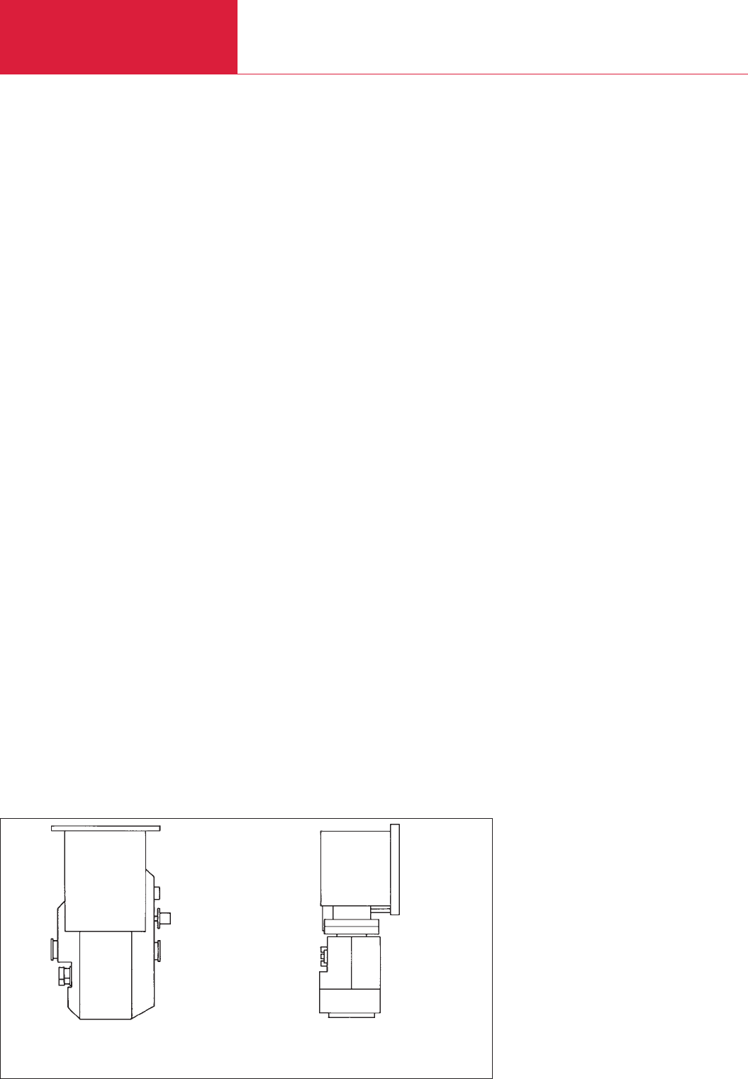
General
Cryopumps, Cryogenics
C12.06 LEYBOLD VACUUM PRODUCTS AND REFERENCE BOOK 2003/2004
Regenerating Cryopumps
An important aspect in the operation of cryo-
pumps is that of regeneration. Since a cryopump
is a gas entrapment pump, the gasses which
have accumulated in the pump during the
“pumping” mode must from time to time be
removed from the pump. This is done by swit-
ching the compressor unit off and by warming up
the cryopanels to room temperature or sightly
higher so that the released substances can be
pumped out by a forevacuum pump.
Cryopumps without Electric Regeneration
System
The cryopump is warmed up to room tempera-
ture by purging the inside of the pump with a dry,
pre-warmed inert gas (such as nitrogen). In this
case it is not possible to set up defined and con-
trolled temperatures within the cryopump. Thus
the simultaneous presence of gases such as
hydrogen and oxygen in the pump can not be
entirely excluded. The formation of ignitable gas
mixtures is only prevented by the diluting effect
of the dry inert gas.
Cryopumps with Fully Automatic Electric
Regeneration System from LEYBOLD
The cryopump is warmed up to room tempera-
ture by heating the 1st and 2nd stages of the cold
head with electric heaters. In this case, a defined
and controlled temperature distribution within the
cryopump can be set up. This controlled warming
process ensures that the pumped gases are
removed sequentially, i.e. the pumped gases are
released one after the other in the following
sequence:
♦Gases adsorbed at the cryopanels
(e.g. hydrogen, helium, neon),
♦Gases condensed at the cryopanels
(e.g. nitrogen, oxygen, argon),
♦Gases and vapors which have condensed on
to the baffle and thermal radiation shield (e.g.
water vapor).
The electric method of regeneration from
LEYBOLD prevents gases such as hydrogen and
oxygen from being present in the pump at the
same time. This excludes the formation of ignita-
ble gas mixtures right from the start.
Multiple Operation of
Refrigerator Cryopumps
The powerful LEYBOLD compressor units
COOLPAK 4000 D and 6000 D open up the possi-
bility of operating two cold heads or refrigerator
cryopumps simultaneously.
Multiple operation means operation of several
cryopumps with one compressor unit.
Advantages to the User
♦Significantly reduced investment and operat-
ing costs
♦Small footprint
The warming up process is fully automatic.
Pressure and temperature distribution within the
pump are set up and controlled by the control
system at all times. T
he sequential regeneration of
pump
ed gases prevents the formation of ignitable
gases right from the start. This ensures the
utmost safety during the regeneration of cryo-
pumps from LEYBOLD.
In the case of cryogenic pumps with fully auto-
matic control there exist two cryo pump lines.
1. The COOLVAC ClassicLine (COOLVAC CL)
offering the following pumping speed
classes for nitrogen in l/s: 1500, 2000, 3000,
5000, 10.000, 18.0000 and 30.000;
COOLVAC 1500 CL, for example.
2. The COOLVAC SemiLine (COOLVAC SL)
offering a pumping speed for nitrogen of
1500 l/s: COOLVAC 1500 SL.
The pumps of the ClassicLine offer total regene-
ration as standard and the COOLVAC 1500 SL
offers in addition the possibility of fast regenera-
tion.
In the price list the designators “V” and “H” appear
in connection with the pump designations.
“H”:
The high-vacuum flange is located at the side
and the cold head below, as is the case for the
COOLVAC 1500 SL-H, DN 200 CF.
“V”:
The high-vacuum flange is located at the top
and the cold head below, as is the case for the
COOLVAC 1500 CL-V, DN 200 CF.
Installation orientations for the COOLVAC
COOLVAC V
High-vacuum flange at the top,
cold head at the bottom
COOLVAC H
High-vacuum flange at the side,
cold head at the bottom
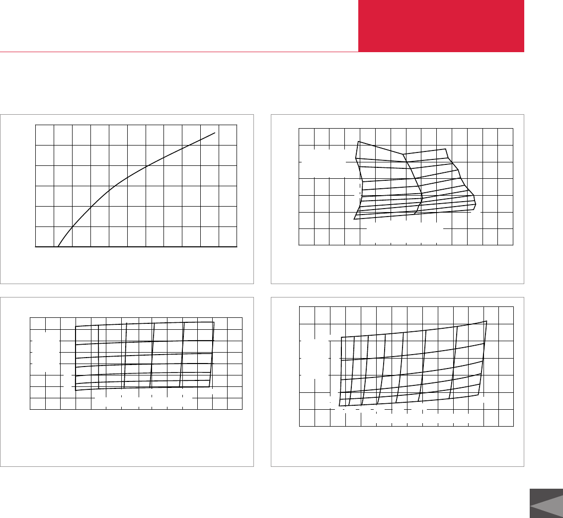
Cryopumps, Cryogenics
C12.07
General
LEYBOLD VACUUM PRODUCTS AND REFERENCE BOOK 2003/2004
C12
Refrigerating Capacity of Cryogenic Cold Heads
2nd Stage Temperature
0
5
10
15
20
25
30
35
020 40 60 80 100 120 140
K
K
1st Stage Temperature
0W
1W
2W
3W
4W
8W
9W
10W
25W
35W
5W
6W
7W
10W 1st Stage
Refrigeration Capacity
2nd Stage
Refrigeration
Capacity
0 10020 40 60 80
0
5
10
15
20
25
30
K
K
120 140
0W 20W 40W 80W 120W 140W
2W
4W
6W
8W
0W
2nd
Stage
Refrige-
ration
Capacity
1st Stage Refrigeration Capacity
60W 100W
10W
1st Stage Temperature
2 nd Stage Temperature
0 10020 40 60 80
0
5
10
15
20
35
40
K
K
120 140
25
30
40W
0W
2W
4W
6W
8W
10W
12W
80W 100W 120W 140W
2nd
Stage
Refriga-
ration
Capacity
1st Stage Refrigaration Capacity
1st Stage Temperature
2 nd Stage Temperature
0 10010 20 30 40 50 60 70 80 90
0
25
50
75
100
125
150
110
Temperature K
W
Cooling Capacity
Typical refrigerating capacity of the cold head COOLPOWER 120 T Typical refrigerating capacity of the cold head COOLPOWER 7/25
Typical refrigerating capacity of the cold head COOLPOWER 5/100 Typical refrigerating capacity of the cold head COOLPOWER 5/100 T
The refrigerating capacities stated apply to vertical operation with the cold end at the bottom.
Cold Heads
A refrigerator (cold head) is a gas cooling
machine which operates on the basis of a
thermodynamic cycle to produce cryogenic
temperatures (T < 120 K).
Refrigerators operating according to the Gifford/
McMahon principle have succeeded over other
methods of cooling cryopumps and cryostats.
It is thus employed exclusively by LEYBOLD.
In order to account for individual requirements
from customers, LEYBOLD offers customized
cryostats as well.
Gifford/McMahon-
Refrigerators
Advantages to the User
♦Low temperatures on a single key press
♦No liquid helium and no liquid nitrogen are
required
♦Very simple to operate
♦High refrigerating capacity from a small
volume
♦Easy process control and temperature control
via a computer
Advantages by Design
♦No space problems since cold head and com-
pressor unit can be installed and operated
apart
♦Installation of the cold head basically in any
orientation
♦High reliability
♦Long periods of operation without
maintenance
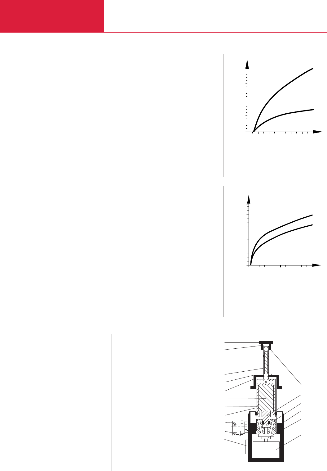
General
Cryopumps, Cryogenics
C12.08 LEYBOLD VACUUM PRODUCTS AND REFERENCE BOOK 2003/2004
Typical Applications
♦Cooling of cryopanels in cryopumps thereby
producing high or ultra high vacuum
♦Cooling of superconducting magnets; in
magnetic resonance tomographs, for example
♦Cooling of samples and detectors; especially
for cooling of
– samples for spectroscopic analysis in the
areas of solid state and surface physics
– high temperature superconductors
– superconductors and semiconductors
– infrared and gamma detectors
♦Calibration of sensors
Cold Heads from the
COOLPOWER Range
The standard range of single-stage and two-stage
cold heads matches a wide range of applications.
LEYBOLD is offering refrigerators with usable
refrigerating powers of 120 W at 80 K
(COOLPOWER 120, single-stage) and down to
3.5 W at 10 K (COOLPOWER 5/100 T; dual-
stage).
The cold heads basically consist of three subas-
semblies:
♦Drive and control unit for the displacer
♦Displacer
♦First stage of the cold head (and second stage
in the case of two-stage cold heads).
Pneumatically driven
Cold Heads
Advantages
♦Simple Design
The pneumatic drive system for the displacer
of these cold heads from LEYBOLD consists
of only two mechanically moving compo-
nents: the rotating control valve and the
synchronous motor driving the control valve.
♦Easy and quick maintenance
All LEYBOLD cryopumps from the COOLVAC
range are equipped with pneumatically driven
LEYBOLD cold heads. Owing to the simple
design of the built-in cold heads, maintenance
is easy. Maintenance can be performed in
place without detaching the cryopump from
the vacuum chamber.
Advantages Through High
Reliability
As to reliability, LEYBOLD cold heads are top per-
formers.
Especially high reliability is required for medical
instrumentation, specifically in connection with
nuclear spin tomographs. In this application cold
heads are used to cool superconducting magnets
and they are thus exposed to strong magnetic
fields.
The leading manufacturers of nuclear spin tomo-
graphs have therefore decided to use LEYBOLD
cold heads to cool the superconducting magnets.
200
150
100
50
0
Q1
W
T1
050 100 150 200 250 300 K
7/25
5/100
Refrigerating capacity as a function of temperature; operation in connection
with the recommended compressor unit at 50 Hz; measured under standard
acceptance conditions:
Refrigerating capacity Q
.
1 of the first stage as a function of temperature T1
of the first stage (2nd stage: Q
.
2 = 0)
5/100
0
Q2
T2
0 50 100 150 200 250 300 K
W
5
10
15
20
25
30
7/25
Refrigerating capacity Q
.
2 of the second stage as a function of temperature T2,
of the second stage (1st stage: T1= 80 K = constant)
Standard acceptance conditions:
Cold head in a vacuum, 2nd cold stage thermally shielded by a radiation
shield (high-gloss nickel-plated) attached to the 1st stage,
thermal loading Q
. simulated by electrical heating.
.
.
13
12
11
10
9
8
7
6
5
4
3
2
1
14
15
16
17
18
19
Dual-stage Gifford/McMahon cold head (schematic diagram)
1 Electrical connection and current lead-through for
cold head motor
2 Helium high pressure connection
3 Helium low pressure connection
4 Cylinder, 1st stage
5 Displacement piston, 1st stage
6 Regenerator, 1st stage
7 Expansion volume, 1st stage
8 1st (refrigerator) stage (copper flange)
9 Cylinder, 2nd stage
10 Displacement piston, 2nd stage
11 Refrigerator, 2nd stage
12 Expansion volume, 2nd stage
13 2nd (refrigerator) stage (copper flange)
14 Vapor pressure measurement chamber
15 Control piston
16 Control volume
17 Control disc
18 Control valve
19 Cold head motor
Cryopumps, Cryogenics
C12.09
General
LEYBOLD VACUUM PRODUCTS AND REFERENCE BOOK 2003/2004
C12
COOLPAK 4000 to 6000 compressors are availa-
ble for single operation of the remaining cold
heads from the COOLPOWER line
as well as for
multiple oper
ation of cryopumps and cryostats.
The period during which no maintenance will be
required on the LEYBOLD compressor units
depends on the service life of the adsorber. If the
For the operation of
Compressor unit Cold heads Cryopumps
COOLPAK 4000 D 2 x COOLPOWER 7/25 2 x COOLVAC 800/1500/2000
COOLPAK 4000/4200 – 2 x COOLVAC 1500/2000
COOLPAK 6000 D 2 x COOLPOWER 7/25 2 x COOLVAC 1500/2000
up to 2 x COOLPOWER 5/100 1) 2 x COOLVAC 3000
COOLPAK 6000/6200 – up to 3 x COOLVAC 1500/2000
– 2 x COOLVAC 3000
1) at reduced power
The possibilities for multiple operation of refrigerator cryo pumps are given in the following table:
values for the ambient temperature and the cool-
ing water entry temperature remain within the
specified range, LEYBOLD guarantees a service
life for the adsorber – and thus a period during
which no maintenance will be required – of
18000 operating hours.
♦Measurement of electric and thermal transport
quantities, as a function of the temperature,
such as
– electric and thermal conductance
– electromotive force
Especially in connection with:
♦Spectroscopic investigations in the infrared,
visible and ultraviolet spectral ranges
♦Matrix spectroscopy
♦Moessbauer spectroscopy
♦Magneto-optic experiments
Refrigerator Cryostats
(Basic Units)
Advantages to the User
♦Can be installed basically in any orientation
thereby offering a high degree of flexibility in
experimental arrangements
♦Can be set to any temperature within 10 and
320 K
♦High refrigerating capacity, constant tempera-
tures
♦No liquid refrigerants are required
♦Very simple to operate
♦Temperature control without problems
through standardized control- and connecting
components
♦Possible high throughput of samples due to
short cooldown and warming-up periods
Typical Applications
♦Cooling of
– high temperature superconductors
– superconductors and semiconductors
– infrared and gamma detectors
UL Approval
The LEYBOLD refrigerators in this catalog (consi-
sting of compressor unit COOLPAK (4000/4200,
6000/6200, flex lines FL and the cold head
COOLPOWER
2)
meet – as complete systems –
the requirements of the Underwriter Laboratories
(UL) as Recognised Components (Urus) as well
as the approval cUR performed through the
Underwriter Laboratories for the Canadian Stan-
dards Association.
LEYBOLD refrigerators are listed under the UL/cUL
reference number SA 8676. The marks as shown
on the right for the entire system can only be
found on the name plate of the compressor unit.
C
®
US
2)
resp. formerly RGD
Compressor Units
CE Approval
The LEYBOLD compressor units RW and
COOLPAK meet the basic requirements regar-
ding safety and health of the relevant EC direc-
tives. They carry on the name plates of the
compressor units the following mark.
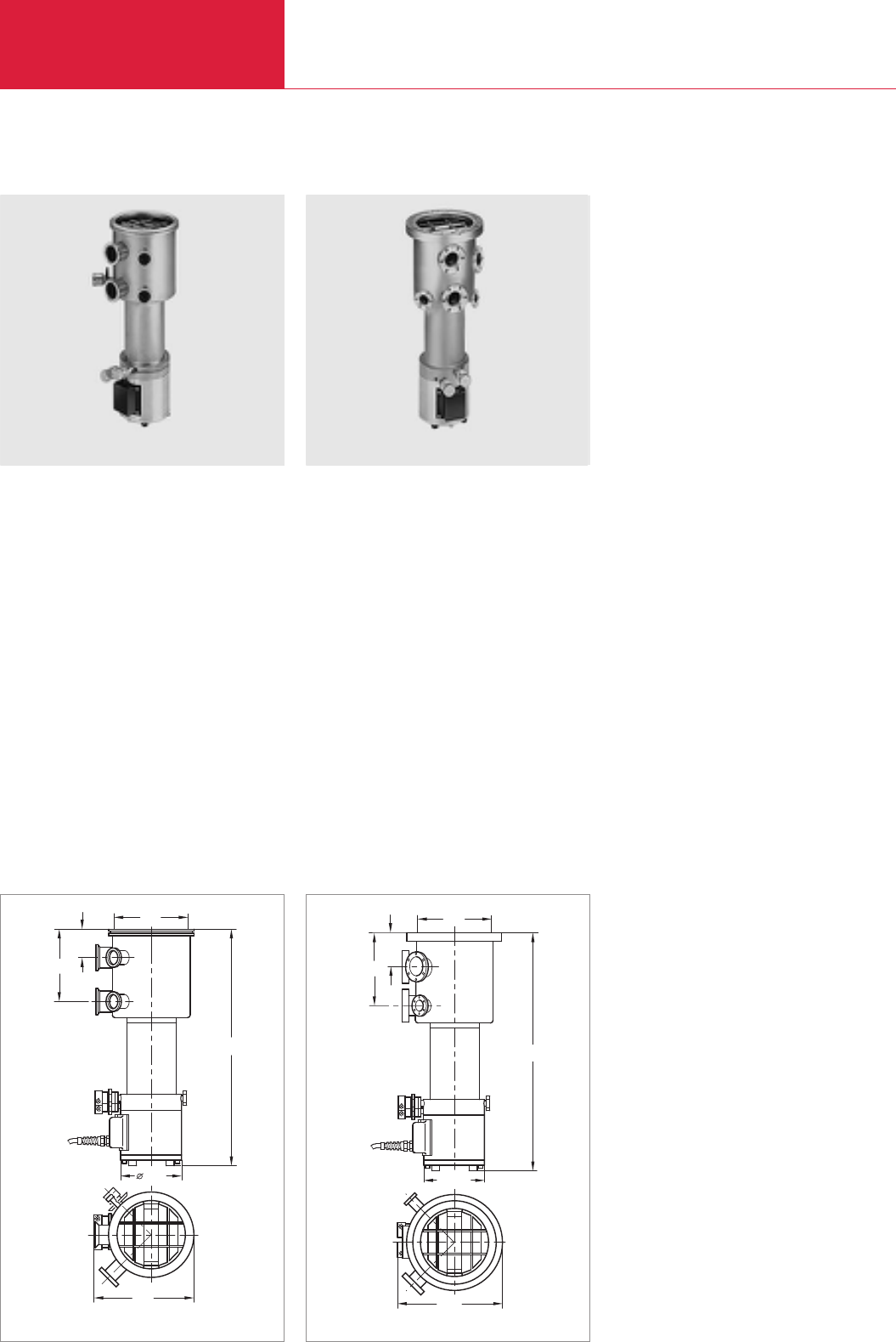
Standard Cryopumps
Cryopumps
C12.10 LEYBOLD VACUUM PRODUCTS AND REFERENCE BOOK 2003/2004
COOLVAC 800
COOLVAC 800 (160 ISO-K) COOLVAC 800 (160 CF)
Advantages to the User
♦Hydrocarbon-free high vacuum
♦High capacity for argon and hydrogen
♦High pumping speed for water vapor, argon
and hydrogen
♦Fast, safe and efficient regeneration with an
electric regeneration system
Typical Applications
♦Lamps and tubes manufacture
♦Transfer chambers / Loadlock
♦General research
Advantages to the User
♦Hydrocarbon-free ultrahigh vacuum
♦High pumping speed for water vapor,
nitrogen and hydrogen
Typical Applications
♦Beam tubes in particle accelerators
♦UHV systems
130
59
DN
152
533
211
78
540
ø130
DN
158
222
Dimensional drawing for the COOLVAC 800 (160 ISO-K) Dimensional for the COOLVAC 800 (160 CF)

Cryopumps
C12.11
Standard Cryopumps
LEYBOLD VACUUM PRODUCTS AND REFERENCE BOOK 2003/2004
C12
Ordering Information COOLVAC 800 (ISO-K) COOLVAC 800 (CF)
COOLVAC 800
Accessories
compressor unit
COOLPAK 4000
COOLPAK 4200
Power supply cable
Connecting cable
Compressor – cold head, 4,5 m
Flexlines
FL 4.5 (1/2", 1/2")
or FL 9.0 (1/2", 1/2")
and EL 4.5 (electric extension cable)
MODEL 1901 low temperature measuring instrument
Cable for the silicon diode, 10 m long
Part No. 844160V1006 Part No. 844160V1002
Part No. 892 31 Part No. 892 31
Part No. 892 33 Part No. 892 33
see Ordering Information for the Compressor Units COOLPAK
Part No. 400 000 323 Part No. 400 000 323
Part No. 892 87 Part No. 892 87
Part No. 892 88 Part No. 892 88
Part No. 893 74 Part No. 893 74
Part No. 136 45 Part No. 136 45
Part No. 500 085 Part No. 500 201
Technical Data COOLVAC 800 (ISO-K) COOLVAC 800 (CF)
High vacuum flange DN
Fore vacuum flange DN
Flange for other purposes DN
Safety valve with DN 40 FK flange connection
for gas exhaust line
Pumping speed
H2O l x s-1
Ar/N2l x s-1
H2/He l x s-1
Capacity
Ar/N2bar x l (Torr x l)
H2at 10-6 mbar bar x l (Torr x l)
He bar x l (Torr x l)
Built-in cold head COOLPOWER
Max. throughput
Ar/N2mbar x l x s-1 (Torr x l x s-1)
H2mbar x l x s-1 (Torr x l x s-1)
Crossover value mbar x l (Torr x l)
Cool down time to 20 K min
Overall height mm
Weight kg (lbs)
Silicon diode for temperature measurements
at second stage of the cold head
160 ISO-K 160 CF
40 KF 40 CF
16 KF (1x), 25 KF (1x), 40 KF (1x) 40 CF (2x)
burst disk
welded-in mounted on DN 16 CF
2600
640/800
1000/300
270 (270 000)
4.3 (3225)
0.5 (375)
7/25
4 (3)
2 (1.5)
60 (45)
70
503 508
12 (26.5) 14 (30.9)
built-in to a DN 25 KF with two-way built-in to a DN 16 CF with
HV current feedthrough UHV feedthrough
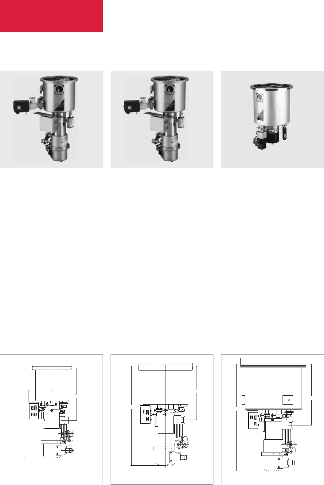
Cryopumps with Fully Automatic Control
ClassicLine
Cryopumps
C12.12 LEYBOLD VACUUM PRODUCTS AND REFERENCE BOOK 2003/2004
COOLVAC 1.500 CL COOLVAC 2.000 CL COOLVAC 3.000 CL
COOLVAC 1.500 CL
Advantages to the User
♦Hydrocarbon-free high vacuum
♦High capacity for argon and hydrogen
♦High crossover value
♦Simple operation
♦Trouble-free integration into complex systems
♦Fully automatic regeneration through Cryo
Compact Control
♦Easy servicing
Typical Applications
♦Evaporators
♦Sputtering systems
♦Ion implanters
♦Optical coating systems
♦Metallization systems
549
143
Ø 240
320
Ø 304
300
559
Dimensional drawing for the COOLVAC 1.500 CL (DN 200 ISO-K) Dimensional drawing for the COOLVAC 2.000 CL (DN 250 CF)
Advantages to the User
♦Hydrocarbon-free high vacuum
♦High capacity for argon and hydrogen
♦High crossover value
♦Simple operation
♦Trouble-free integration into complex systems
♦Fully automatic regeneration through Cryo
Compact Control
♦Easy servicing
Typical Applications
♦Evaporators
♦Sputtering systems
♦Ion implanters
♦Optical coating systems
♦Metallization systems
345
Ø 370
604
Dimensional drawing for the COOLVAC 3.000 CL (DN 320 ISO-K)
Advantages to the User
♦Hydrocarbon-free high vacuum
♦High capacity for argon and hydrogen
♦High crossover value
♦Simple operation
♦Trouble-free integration into complex systems
♦Fully automatic regeneration through Cryo
Compact Control
♦Easy servicing
Typical Applications
♦Evaporators
♦Sputtering systems
♦Ion implanters
♦Optical coating systems
♦Metallization systems
COOLVAC 2.000 CL similar COOLVAC 3.000 CL similar

Cryopumps
C12.13
Cryopumps with Fully Automatic Control
ClassicLine
LEYBOLD VACUUM PRODUCTS AND REFERENCE BOOK 2003/2004
C12
Technical Data COOLVAC 1.500 CL COOLVAC 2.000 CL COOLVAC 3.000 CL
High vacuum (HV) flange DN
Fore vacuum flange DN
Flange for connection a gauge head DN
Flange for the electrical connection DN
Safety valve with flange connection
for gas exhaust line DN
4-way current feedthrough for
Si diode on a flange DN
Heaters
1st stage W
V AC
2nd stage W
V AC
Temperature sensor
1st stage
2nd stage
Built-in cold head COOLPOWER
Weight kg (lbs)
Cooldown time to T2= 20 K min
Crossover value mbar x l (Torr x l)
Pumping speed
H2O l x s-1
Ar / N2l x s-1
H2l x s-1
Capacity
Ar/N2bar x l
H2at 10-6 mbar bar x l
H2O bar x l
Max. throughput
Ar/N2mbar x l x s-1 (Torr x l x s-1)
H2O mbar x l x s-1 (Torr x l x s-1)
Helium connections DN
(Self-sealing couplings: outside thread, type 5400-S2-8)
200 ISO-K / 200 CF / 6"ANSI 250 ISO-K / 250 CF / 8"ANSI 320 ISO-K / 10"ANSI
25 KF
16 KF
40 KF
40 KF
16 KF
160 160 160
35 35 35
90 90 90
35 35 35
Pt 100
Si diode
7/25
25 (55.2) 25 (55.2) 35 (77.3)
90 60 80
180 (135) 250 (187) 250 (187)
4600 7000 10 500
1000 / 1300 1600 / 2100 2400 / 2800
2300 3200 4500
1600 1400 2500
12 12 12
not applicable 190 460
14 (10.5) 12 (9) 15 (11.2)
8 (6) 6.5 (4.8) 10 (7.5)
1/2"1/2"1/2"

Cryopumps with Fully Automatic Control
ClassicLine
Cryopumps
C12.14 LEYBOLD VACUUM PRODUCTS AND REFERENCE BOOK 2003/2004
Ordering Information COOLVAC 1.500 CL
Single Operation Dual Operation Multiple Operation
Europe USA/Japan Europe Europe USA/Japan Europe USA/Japan
COOLVAC 1.500 CL
DN 200 CF
DN 6" ANSI
DN 200 ISO-K
Electronics and cables
System Controller SC
Power Supply PS
230 V, 1 ph.
200 V, 3 ph.
Network communication cable – System Controller
to the pump(s)
10 m
20 m
Network PM cable for the link between
the pumps
03 m
10 m
Power supply cable from power supply to pump
10 m
20 m
Remote control cable CP, 1 m
Cable compressor – Power Supply
10 m
20 m
Cable System Controller – Power Supply, 1 m
Cable pump module PM – Power Supply
10 m
20 m
Connecting cable compressor – pump, 4.5 m
Compressors and flexlines
Compressor
CP 4000 D
CP 4000
CP 4200
CP 6000
CP 6200
Accessories
Water cooling discharge throttle
Power supply cable for compressor
Set of flexlines
FL 4.5 (1/2", 1/2")
or FL 9.0 (1/2", 1/2")
and EL 4.5 (electric extension cable)
Gas manifold
GD 2
GD 4
The arrangement of the components is shown in the section “Accessories” under the heading “COOLVAC ClassicLine, System Components”
Part No. Part No. Part No.
844200V0002 844200V0002 (2x) 844200V0002 (3x)
844200V0004 844200V0004 (2x) 844200V0004 (3x)
844200V0006 844200V0006 (2x) 844200V0006 (3x)
844 230 844 230 844 230
844 135 844 135 – – –
– – 844 235 844 235 844 235
844 261 844 261 844 261
844 262 844 262 844 262
– 844 256 844 256 (2x)
– 844 258 844 258 (2x)
– – 844 251 (2x) 844 251 (2x) 844 251 (3x)
– – 844 252 (2x) 844 252 (2x) 844 252 (3x)
– – 844 265 844 265 844 265
844 129 844 129 – – –
844 139 844 139 – – –
844 141 844 141 – – –
844 128 844 128 (2x) – – –
844 138 844 138 (2x) – – –
400 000 323 400 000 323 (2x) – – –
– 892 3000 – – –
892 31 – – 892 31 – –
– 892 33 – – 892 33 –
– – 892 36
– – – 892 37
840 000 133 840 000 133 840 000 133
see Ordering Information for the Compressor Units COOLPAK
892 87 892 87 (2x) 892 87 (2x) 892 87 (2x) 892 87 (3x)
892 88 892 88 (2x) 892 88 (2x) 892 88 (2x) 892 88 (3x)
893 74 893 74 (2x) – – –
– 891 02 891 02 891 02 –
– – – – 891 03

Cryopumps
C12.15
Cryopumps with Fully Automatic Control
ClassicLine
LEYBOLD VACUUM PRODUCTS AND REFERENCE BOOK 2003/2004
C12
Ordering Information COOLVAC 2000 CL
Single Operation Dual Operation Multiple Operation
Europe USA/Japan Europe Europe USA/Japan Europe USA/Japan
COOLVAC 2000 CL
DN 250 CF
DN 8" ANSI
DN 250 ISO-K
Electronics and cables
System Controller SC
Power Supply PS
230 V, 1 ph.
200 V, 3 ph.
Network communication cable – System Controller
to the pump(s)
10 m
20 m
Network PM cable for the link between
the pumps
03 m
10 m
Power supply cable from power supply to pump
10 m
20 m
Remote control cable CP, 1 m
Cable compressor – Power Supply
10 m
20 m
Cable System Controller – Power Supply, 1 m
Cable pump module PM – Power Supply
10 m
20 m
Connecting cable compressor – pump, 4.5 m
Compressors and flexlines
Compressor
CP 4000 D
CP 4000
CP 4200
CP 6000
CP 6200
Accessories
Water cooling discharge throttle
Power supply cable for compressor
Set of flexlines
FL 4.5 (1/2", 1/2")
or FL 9.0 (1/2", 1/2")
and EL 4.5 (electric extension cable)
Gas manifold
GD 2
GD 4
The arrangement of the components is shown in the section “Accessories” under the heading “COOLVAC ClassicLine, System Components”
Part No. Part No. Part No.
844250V0002 844250V0002 (2x) 844250V0002 (3x)
844250V0004 844250V0004 (2x) 844250V0004 (3x)
844250V0006 844250V0006 (2x) 844250V0006 (3x)
844 230 844 230 844 230
844 135 844 135 – – –
– – 844 235 844 235 844 235
844 261 844 261 844 261
844 262 844 262 844 262
– 844 256 844 256 (2x)
– 844 258 844 258 (2x)
– – 844 251 (2x) 844 251 (2x) 844 251 (3x)
– – 844 252 (2x) 844 252 (2x) 844 252 (3x)
– – 844 265 844 265 844 265
844 129 844 129 – – –
844 139 844 139 – – –
844 141 844 141 – – –
844 128 844 128 (2x) – – –
844 138 844 138 (2x) – – –
400 000 323 400 000 323 (2x) – – –
– 892 3000 – – –
892 31 – – 892 31 – –
– 892 33 – – 892 33 –
– – 892 36
– – – 892 37
840 000 133 840 000 133 840 000 133
see Ordering Information for the Compressor Units COOLPAK
892 87 892 87 (2x) 892 87 (2x) 892 87 (2x) 892 87 (3x)
892 88 892 88 (2x) 892 88 (2x) 892 88 (2x) 892 88 (3x)
893 74 893 74 (2x) – – –
– 891 02 891 02 891 02 –
– – – – 891 03

Cryopumps with Fully Automatic Control
ClassicLine
Cryopumps
C12.16 LEYBOLD VACUUM PRODUCTS AND REFERENCE BOOK 2003/2004
Ordering Information COOLVAC 3000 CL
Single Operation Dual Operation
Europe USA/Japan Europe Europe USA/Japan
COOLVAC 3000 CL
DN 10" ANSI
DN 320 ISO-K
Electronics and cables
System Controller SC
Power Supply PS
230 V, 1 ph.
200 V, 3 ph.
Network communication cable – System Controller
to the pump(s)
10 m
20 m
Network PM cable for the link between
the pumps
03 m
10 m
Power supply cable from power supply to pump
10 m
20 m
Remote control cable CP, 1 m
Cable compressor – Power Supply
10 m
20 m
Cable System Controller – Power Supply, 1 m
Cable pump module PM – Power Supply
10 m
20 m
Connecting cable compressor – pump, 4.5 m
Compressors and flexlines
Compressor
CP 4000
CP 4200
CP 6000 D
CP 6000
CP 6200
Accessories
Water cooling discharge throttle
Power supply cable for compressor
Set of flexlines
FL 4.5 (1/2", 1/2")
or FL 9.0 (1/2", 1/2")
and EL 4.5 (electric extension cable)
Gas manifold
GD 2
The arrangement of the components is shown in the section “Accessories” under the heading “COOLVAC ClassicLine, System Components”
Part No. Part No.
844320V0004 844320V0004 (2x)
844320V0006 844320V0006 (2x)
844 230 844 230
844 135 844 135 – –
– – 844 235 844 235
844 261 844 261
844 262 844 262
– 844 256
– 844 258
– – 844 251 (2x) 844 251 (2x)
– – 844 252 (2x) 844 252 (2x)
– – 844 265 844 265
844 129 844 129 – –
844 139 844 139 – –
844 141 844 141 – –
844 128 844 128 (2x) – –
844 138 844 138 (2x) – –
400 000 323 400 000 323 (2x) – –
892 31 – – – –
– 892 33 – – –
– 892 46 – –
– – 892 36 –
– – – 892 37
840 000 133 840 000 133
see Ordering Information for the Compressor Units COOLPAK
892 87 892 87 (2x) 892 87 (2x) 892 87 (2x)
892 88 892 88 (2x) 892 88 (2x) 892 88 (2x)
893 74 893 74 (2x) – –
– 891 02 891 02 891 02

Cryopumps
C12.17
Cryopumps with Fully Automatic Control
ClassicLine
LEYBOLD VACUUM PRODUCTS AND REFERENCE BOOK 2003/2004
C12
Notes
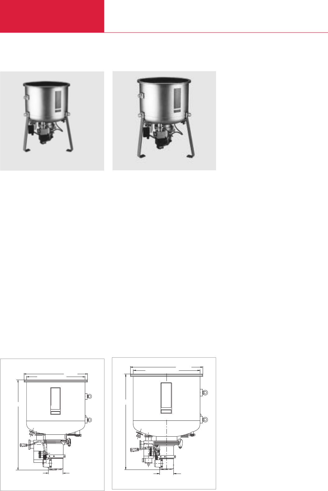
Cryopumps with Fully Automatic Control
ClassicLine
Cryopumps
C12.18 LEYBOLD VACUUM PRODUCTS AND REFERENCE BOOK 2003/2004
COOLVAC 5.000 CL COOLVAC 10.000 CL
Advantages to the User
♦Hydrocarbon-free high vacuum
♦High capacity for argon and hydrogen
♦High crossover value
♦Simple operation
♦Trouble-free integration into complex systems
♦Fully automatic regeneration through Cryo
Compact Control
♦Easy servicing
Typical Applications
♦Evaporators
♦Ion implanters
♦Electron beam welding systems
♦Optical coating systems
♦Metallization systems
COOLVAC
5.000
Ø 105
DN 400 ISO-K Ø 450
640
COOLVAC
10.000
DN 500 ISO-K Ø 550
Ø 105
704
Dimensional drawing for the COOLVAC 5.000 CL Dimensional drawing for the COOLVAC 10.000 CL
Advantages to the User
♦Hydrocarbon-free high vacuum
♦High capacity for argon and hydrogen
♦High crossover value
♦Simple operation
♦Trouble-free integration into complex systems
♦Fully automatic regeneration through Cryo
Compact Control
♦Easy servicing
Typical Applications
♦Evaporators
♦Space simulation chambers
♦Electron beam welding systems
♦Optical coating systems
♦Metallization systems
COOLVAC 5.000 CL COOLVAC 10.000 CL

Cryopumps
C12.19
Cryopumps with Fully Automatic Control
ClassicLine
LEYBOLD VACUUM PRODUCTS AND REFERENCE BOOK 2003/2004
C12
Technical Data COOLVAC 5.000 CL COOLVAC 10.000 CL
High vacuum (HV) flange DN
Fore vacuum flange DN
Flange for connection of a gauge head DN
Flange for the electrical connection DN
Safety valve with flange connection
for gas exhaust line DN
4-way current feedthrough for
Si diode on a flange DN
Heaters
1st stage W
V AC
2nd stage W
V AC
Temperature sensor
1st stage
2nd stage
Built-in cold head COOLPOWER
Weight kg (lbs)
Cooldown time to T2= 20 K min
Crossover value mbar x l (Torr x l)
Pumping speed
H2O l x s-1
Ar / N2l x s-1
H2l x s-1
Capacity
Ar/N2bar x l
H2at 10-6 mbar bar x l
H2O bar x l
Max. throughput
Ar/N2mbar x l x s-1 (Torr x l x s-1)
H2mbar x l x s-1 (Torr x l x s-1)
400 ISO-K 500 ISO-K
40 KF
16 KF
40 KF
40 KF
16 KF
160
35
90
35
Pt 100
Si diode
5/100
42 (92.7) 50 (110.4)
120 160
700 (525) 800 (600)
18 000 30 000
3 700 / 5 000 8 400 / 10 000
5 200 12 000
3 000 5 000
32 40
790 not applicable
10 (7.5)
7 (5.3)

Cryopumps with Fully Automatic Control
ClassicLine
Cryopumps
C12.20 LEYBOLD VACUUM PRODUCTS AND REFERENCE BOOK 2003/2004
Ordering Information COOLVAC 5.000 CL COOLVAC 10.000 CL
Europe USA/Japan Europe USA/Japan
COOLVAC
05.000 CL, DN 400 ISO-K
10.000 CL, DN 500 ISO-K
Electronics and cables
System Controller SC
Power Supply PS
230 V, 1 ph.
Network communication cable – System Controller
to the pump(s)
10 m
20 m
Cable compressor – Power Supply PS
10 m
20 m
Cable System Controller – Power Supply, 1 m
Cable pump module PM – Power Supply
10 m
20 m
Compressors and flexlines
Compressor
CP 6000
CP 6200
Accessories
Water cooling discharge throttle
Power supply cable for compressor
Set of flexlines
FL 4.5 (1/2", 1/2")
or FL 9.0 (1/2", 1/2")
and EL 4.5 (electric extension cable)
The arrangement of the components is shown in the section “Accessories” under the heading “COOLVAC ClassicLine, System Components”
Part No. 844 410 –
–Part No. 844 610
Part No. 844 230 Part No. 844 230
Part No. 844 135 Part No. 844 135
Part No. 844 261 Part No. 844 261
Part No. 844 262 Part No. 844 262
Part No. 844 129 Part No. 844 129
Part No. 844 139 Part No. 844 139
Part No. 844 141 Part No. 844 141
Part No. 844 128 Part No. 844 128
Part No. 844 138 Part No. 844 138
Part No. 892 36 – Part No. 892 36 –
– Part No. 892 37 – Part No. 892 37
Part No. 840 000 133 Part No. 840 000 133
see Ordering Information for the Compressor Units COOLPAK
Part No. 892 87 Part No. 892 87
Part No. 892 88 Part No. 892 88
Part No. 893 74 Part No. 893 74

Cryopumps
C12.21
Cryopumps with Fully Automatic Control
ClassicLine
LEYBOLD VACUUM PRODUCTS AND REFERENCE BOOK 2003/2004
C12
Notes
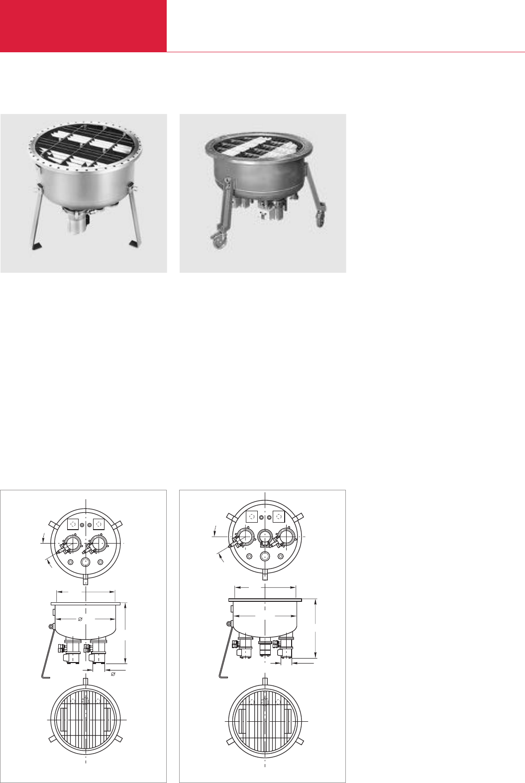
Cryopumps with Fully Automatic Control
ClassicLine
Cryopumps
C12.22 LEYBOLD VACUUM PRODUCTS AND REFERENCE BOOK 2003/2004
COOLVAC 30.000 CL
COOLVAC 30.000 CL
Advantages to the User
♦Hydrocarbon-free high vacuum
♦High pumping speed for water vapor and
nitrogen
♦Fast, safe and efficient regeneration with the
electric regeneration system
♦Simple operation
Typical Applications
♦Space simulation chambers
♦Evaporators
♦General research
♦Optical coating systems
DN
ø658
608
30°
ø130
Dimensional drawing for the COOLVAC 30.000 CL
COOLVAC 18.000 CL
COOLVAC 18.000 CL with special flanges
Advantages to the User
♦Hydrocarbon-free high vacuum
♦High pumping speed for water vapor and
nitrogen
♦Fast, safe and efficient regeneration with the
electric regeneration system
♦Simple operation
Typical Applications
♦Space simulation chambers
♦Evaporators
♦Electron beam welding systems
♦Optical coating systems
♦Metallization systems
DN
658
608
30°
130
Dimensional drawing for the COOLVAC 18.000 CL

Cryopumps
C12.23
Cryopumps with Fully Automatic Control
ClassicLine
LEYBOLD VACUUM PRODUCTS AND REFERENCE BOOK 2003/2004
C12
Technical Data COOLVAC 18.000 CL COOLVAC 30.000 CL
High vacuum flange DN
Fore vacuum flange DN
Flange with current feedthrough *)for silicon diode DN
Flange for other purposes DN
Safety valve with DN 40 KF flange connection
for gas exhaust line
Pumping speed
H2O l x s-1
Ar/N2l x s-1
H2/He l x s-1
Capacity
Ar/N2bar x l
H2at 10-6 mbar bar x l
H2O bar x l
Built-in cold head COOLPOWER
Max. throughput
Ar/N2mbar x l x s-1 (Torr x l x s-1)
H2mbar x l x s-1 (Torr x l x s-1)
Crossover value mbar x l (Torr x l)
Cool down time to 20 K min
Overall height min
Weight kg (lbs)
Silicon diode for temperature measurements
at the second stage of the cold head
Regeneration heaters at the first
and second stage of the cold head
630 ISO-F 35“ ANSI (892 mm)
63 ISO-K 63 ISO-K
25 KF (2x) 25 KF (2x), *)2 way
40 KF 40 KF
welded-in welded-in (2x)
46 000 93 000
13 500/18 000 25 000/30 000
14 000/4 000 30 000/7 000
5 000 6 500
65 120
945 –
5/100 (2x) 5/100 (2x) + 120
14 (10.5) 14 (10.5)
7 (5.25) 7 (5.25)
850 (638) 1200 (900)
180 260
606 711
65 (143) 245 (540)
built-in (2x) built-in (2x)
built-in (2x) built-in (2x)
Ordering Information COOLVAC 18.000 CL COOLVAC 30.000 CL
Cryopump
COOLVAC 18.000 CL, 630 ISO-F
COOLVAC 30.000 CL, 35" ANSI
Accessories
Compressor unit
COOLPAK 6000
COOLPAK 6200
Power supply cable
Set of flexlines
FL 4.5 (1/2", 1/2")
or FL 9.0 (1/2", 1/2")
and EL 4.5 (electric extension cable)
Compact Controller and cable kit
upon request –
– upon request
upon request (2x) upon request (3x)
upon request (2x) upon request (3x)
see Ordering Information for the Compressor Units COOLPAK
Part No. 892 87 (2x) Part No. 892 87 (3x)
Part No. 892 88 (2x) Part No. 893 74 (3x)
Part No. 893 74 (2x) Part No. 893 74 (3x)
upon request

Cryopumps with Fully Automatic Control
SemiLine
Cryopumps
C12.24 LEYBOLD VACUUM PRODUCTS AND REFERENCE BOOK 2003/2004
COOLVAC 1500 SemiLine
COOLVAC 1500 SL
LEYBOLD, world-wide leader in vacuum and
cryo technology has added a new cryopump
system to meet the needs for current and
future demands in state-of-the-art cryopump
applications: COOLVAC 1500 SemiLine.
This system is the unique cryopump technolo-
gy that cuts “cold to cold” regeneration from
several hours to 45 minutes or less.
This significant reduction of regeneration
time has been achieved by combining the
COOLVAC 1500 SL cryopumps with a
compact and intelligent control system that
allows control and monitoring of up to
30 cryopumps by only a single control unit.
COOLVAC 1500 SemiLine system is designed
for a high level of tool integration. The cryo-
pumps can easily be adapted to the process
chambers because of their proven drop-in
compatibility.
For remote control the cryopump system can
be fully integrated to the equipment’s host
computer via the standard RS 232 C interface
of the System Controller SC.
Existing tools can be upgraded fast and with-
out any modifications because the system has
proven their “plug and play” compatibility to
other cryopump systems.
COOLVAC 1500 SemiLine system is uniquely
designed for a simple and fast entire service
and maintenance procedure direct on the
process chamber.
A complete displacer change is done within
20 minutes without breaking the vacuum
connection. After cryopump maintenance no
leak check and no vacuum or process requali-
fication is required.
Advantages to the User
♦
Qualified at all major OEM’s
♦
Drop-in compatible to all major
equipments
♦
Higher flexibility and availability of the
process system
♦
Increased productivity and improved yield
♦
No extra tool downtime caused by
regeneration
♦
Lowest Cost of Ownership
Typical Applications
COOLVAC 1500 SemiLine system should be
used wherever production time, optimized
quality, higher tool availability and improved
CoO are important issues.
In particular, the overall equipment performan-
ces of
♦
Sputtering (PVD) Systems
♦
Ion Implanters
♦
Vacuum Coating Systems
♦
Transfer Chambers
♦
Load Lock Chambers
can be increased significantly.
Design Features
♦
“Fast Regeneration” capability from
“cold to cold” in 45 minutes or less.
During the fast regeneration of the
COOLVAC 1500 SL only the second stage
of the pump is regenerated.
Consequently, “Fast Regeneration” is
synonymous with the regeneration of all
gases pumped by the cryo’s second stage,
e.g. H2, Ar, N2, O2.
♦
“Total Regeneration” capability from
“cold to cold” in about 2.5 hours.
During the total regeneration of the
COOLVAC 1500 SL the second stage as
well as the first stage of the pump are
regenerated and all gases are released,
e.g. H2, Ar, N2, O2as well as H2O and
other easily condensable gases.
♦
The fast as well as the total regeneration
cycle is optimized with respect to
- time
- safety
- cleanness of the pump.
Only with clean pumping surfaces can a
low base pressure, maximum pumping
speeds and capacities be attained.
♦
Easy to operate
- only one compact control unit for up to
30 pumps
- simple push button operation
- fully automatic regeneration
-complete monitoring of pump operation
470
597
220
149
294
Dimensional drawing for the COOLVAC 1500 SL
149
294
470
597
220
Cryopumps
C12.25
Cryopumps with Fully Automatic Control
SemiLine
LEYBOLD VACUUM PRODUCTS AND REFERENCE BOOK 2003/2004
C12
♦
Easy to integrate
-compatible pump sizes and connectors to
replace other cryopumps
-drop-in tool compatibility at all major
equipments
- designed to be fully integrated to the
equipment’s host computer via the
standard RS 232 C interface
- optional network and 24 V DC interface
capabilities
♦
Electrical heaters for regeneration only
- no expensive and complex purge gas
system
- sequential regeneration of all pumped
gases
-better control of the regeneration cycles
- highest safety standards during
regeneration
♦
Suitable for multiple operation
-up to 30 COOLVAC 1500 SL cryopumps
can be operated by one compact
System Controller SC.
- up to 3 COOLVAC 1500 SL cryopumps
can be supported by one multiple
Power Supply PS.
- up to 3 COOLVAC 1500 SL cryopumps
can be supported by one Compressor
Unit CP.
♦
Easy to service
- displacer exchange is possible without
removing the COOLVAC from the
production system.
- back-up pool needs just displacer rather
than expensive pumps
- Extended service and maintenance
intervals
- data collection for service and trend
analysis
♦
All known features of cryopumps are
maintained:
- high pumping speeds and capacity for
H2O, H2, Ar, N2
- high crossover values
- hydrocarbon-free vacuum
System Controller SC
Power Supply PS
System Controller SC for COOLVAC 1500 SL
Power Supply PS for COOLVAC 1500 SL
Design Features
♦
1/4 19
"
rack module
♦
3 height units
♦
Dimensions (W x H x W)
106 x 129 x 178 mm
Design Features
♦
19
"
rack module
♦
4 height units
♦
Dimensions (W x H x W)
435 x 190 x 440 mm
The intelligent COOLVAC System Controller SC
automatically controls and monitors up to
30 COOLVAC pumps.
Online monitoring, help functions and a
service interface for easy diagnostic are just a
few user friendly features.
It can be installed as a “stand alone system”
or remote controlled via an interface.
The COOLVAC Power Supply PS provides the
power for the cold head motor, the electrical
heaters and the supplies voltage to the electro-
nics for up to 3 COOLVAC pumps.
Controlled via the System Controller SC the
PS turns the compressor unit on and off if
required by the connected pumps.

Cryopumps with Fully Automatic Control
SemiLine
Cryopumps
C12.26 LEYBOLD VACUUM PRODUCTS AND REFERENCE BOOK 2003/2004
Technical Data COOLVAC 1500 SL
High vacuum (HV) flange DN
Fore vacuum flange
Regeneration valve
Pumping speed
H2O / Ar / H2l x s-1
O2l x s-1
Ultimate pressure mbar
Capacity for
Ar bar x l
H2 at 10-6 mbar bar x l
H2O bar x l
Max. pumping speed for
Ar / N2mbar x l x s-1(sccm)
H2mbar x l x s-1 (sccm)
Crossover value mbar x l (Torr x )
Recovery time from 10 mTorr to ≤5 x 10⁻⁷ Torr s
Regeneration times
Fast regeneration (cold to cold, 2nd stage at 20 K) min
Total regeneration (cold to cold, 2nd stage at 20 K) min
Warm-up from operating temperature to 300 K min
Cool-down from 300 K up to operating temperature min
Fast regeneration cycles between total regeneration
Noise, measured at 1 m (3 ft.) radius from the pump dB(A)
Heaters
1. stage W
V AC
2. stage W
V AC
Temperature measurement
1. stage
2. stage
Built-in coldhead COOLPOWER
Weight kg (lbs)
DN 200 CF
DN 25 KF
DN 40 KF
4600 / 1300 / 2500
1600
≤5 x 10⁻¹⁰
1800
16
190
14 (840)
6 (360)
210 (160)
< 4
< 50
< 170
< 30
< 80
> 50
< 70
160
35
90
35
Pt 100
Si diode
7/25
25 (55.2)

Cryopumps
C12.27
Cryopumps with Fully Automatic Control
SemiLine
LEYBOLD VACUUM PRODUCTS AND REFERENCE BOOK 2003/2004
C12
Ordering Information COOLVAC 1.500 SL
Single Operation Dual Operation Multiple Operation
Europe USA/Japan Europe Europe USA/Japan Europe USA/Japan
COOLVAC 1.500 SL
DN 200 CF
other flanges
Solenoid fore-vacuum valve, DN 25 KF
with electric valve position indicator and
for 24 V DC supplies
Electronics and cables
System Controller SC
Power Supply PS
230 V, 1 ph.
200 V, 3 ph.
Network communication cable – System Controller
to the pump(s)
10 m
20 m
Network-PM cable between the pumps
03 m
10 m
Power supply cable for the pump
10 m
20 m
Remote control cable CP, 1 m
Cable compressor – Power Supply
10 m
20 m
Cable System Controller – Power Supply, 1 m
Cable pump module PM – Power Supply
10 m
20 m
Connecting cable compressor – pump, 4.5 m
Compressors and flexlines
Compressor
CP 4000 D
CP 4000
CP 4200
CP 6000
CP 6200
Accessories
Water cooling discharge throttle
Power supply cable for compressor
Set of flexlines
FL 4.5 (1/2", 1/2")
or FL 9.0 (1/2", 1/2")
and EL 4.5 (electric extension cable)
Gas manifold
GD 2
GD 4
The arrangement of the components is shown in the section “Accessories” under the heading “COOLVAC ClassicLine, System Components”
Part No. Part No. Part No.
844 212 844 212 (2x) 844 212 (3x)
upon request upon request (2x) upon request (3x)
287 46 287 46 (2x) 287 46 (3x)
844 230 844 230 844 230
844 135 844 135 – – –
– – 844 235 844 235 844 235
844 261 844 261 844 261
844 262 844 262 844 262
– 844 256 844 256 (2x)
– 844 258 844 258 (2x)
– – 844 251 (2x) 844 251 (2x) 844 251 (3x)
– – 844 252 (2x) 844 252 (2x) 844 252 (3x)
– – 844 265 844 265 844 265
844 129 844 129 – – –
844 139 844 139 – – –
844 141 844 141 – – –
844 128 844 128 (2x) – – –
844 138 844 138 (2x) – – –
400 000 323 400 000 323 (2x) – – –
– 892 3000 – – –
892 31 – – 892 31 – –
– 892 33 – – 892 33 –
– – 892 36
– – – 892 37
840 000 133 840 000 133 840 000 133
see Ordering Information for the Compressor Units COOLPAK
892 87 892 87 (2x) 892 87 (2x) 892 87 (2x) 892 87 (3x)
892 88 892 88 (2x) 892 88 (2x) 892 88 (2x) 892 88 (3x)
893 74 893 74 (2x) – – –
– 891 02 891 02 891 02 –
– – – – 891 03
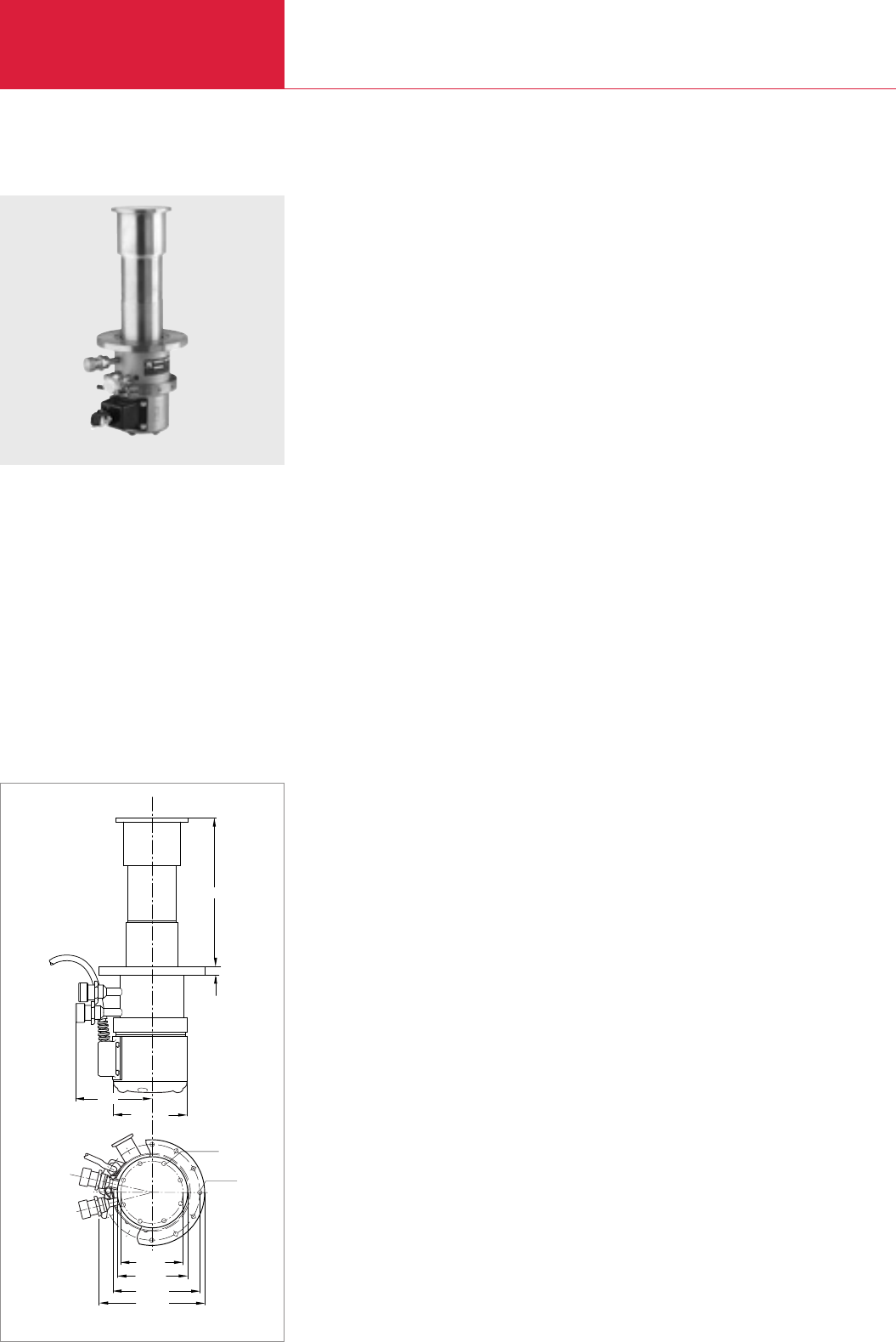
Cold Heads
Cryogenics
C12.28 LEYBOLD VACUUM PRODUCTS AND REFERENCE BOOK 2003/2004
COOLPOWER 120 T Single Stage Cold Heads
COOLPOWER 120 T single stage cold head
ø105
ø105
M4
ø165
ø178
12 01 M 071 CP120T
250
12,7
129
ø6,2
ø115
Advantages to the User
♦For installation mostly in any orientation
♦High refrigerating capacity
♦No liquid refrigerants are required
♦Very simple to operate
♦Short cooldown time
Typical Applications
♦Cooling of cryopanels in cryopumps and thus
generation of high vacuum and ultra high
vacuum pressures
♦Cooling of samples and detectors;
especially for cooling of
- samples for spectroscopic investigations
in solid state and surface physics
- high temperature superconductor and
semiconductor conditions
- infrared and gamma detectors
♦Calibration of sensors
Dimensional drawing for the COOLPOWER 120 T

Cryogenics
C12.29
Cold Heads
LEYBOLD VACUUM PRODUCTS AND REFERENCE BOOK 2003/2004
C12
Technical Data COOLPOWER 120 T
Refrigeration capacity at 50/60 Hz 1)
1st stage at 80 K, approx. W
2st stage at 20 K, approx. W
Lowest attainable temperature 1) K
Cooldown time down to 20 K min
Permissible ambient temperature °C
He filling pressure at room temperature bar
He connections
Self-sealing screwed connections
High pressure connection
Low pressure connection
Weight kg (lbs)
Length of the electrical connection line
to the compressor unit m
120
25
≤15
≤55
10 to 40
16
1/2"(#8 2))
1/2"(#8)
13 (29)
15
Ordering Information COOLPOWER 120 T
Cold head COOLPOWER 120 T
Accessories
Compressor unit (for operation of one cold head)
COOLPAK 6000, 400 V/50 Hz; 470 V/60 Hz
COOLPAK 6200, 200 V/50 Hz; 200 V, 230 V/60 Hz
Power supply cable
Set of flexlines
FL 4.5 (1/2", 1/2")
or FL 9.0 (1/2", 1/2")
Options
Temperature measurement
Silicon diode
MODEL 1901 low temperature measuring instrument
Measuring cable
1) The refrigerating capacities and temperatures stated apply to vertical operation with the cold end at the bottom
2) Series 8 from Aeroquip
Part No. 103 59
Part No. 892 36
Part No. 892 37
see Ordering Information for the Compressor Units COOLPAK
Part No. 892 87
Part No. 892 88
Part No. 890 89
Part No. 136 45
see Ordering Information for the MODEL 1901 low temperature measuring instrument
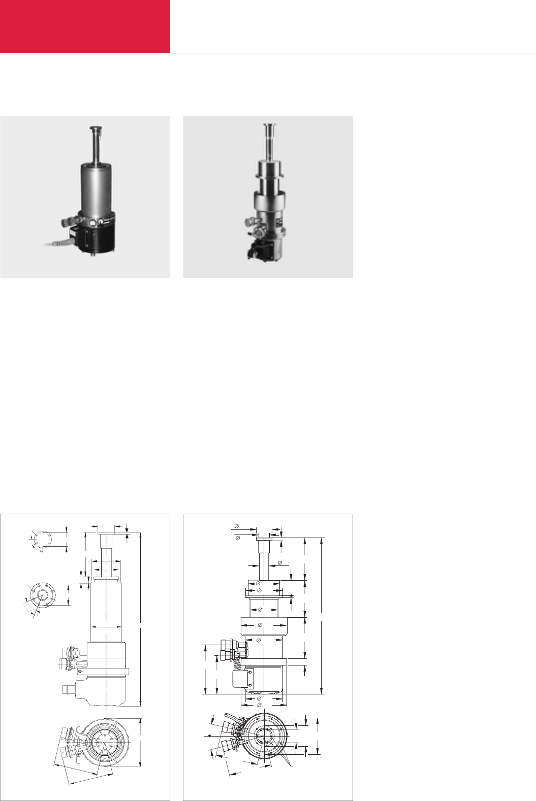
Cold Heads
Cryogenics
C12.30 LEYBOLD VACUUM PRODUCTS AND REFERENCE BOOK 2003/2004
COOLPOWER 7/25, 5/100 and 5/100 T Dual Stage Cold Heads
COOLPOWER 7/25 dual stage cold head
A
B
Ansicht A
Ansicht B
30°
6x60°
45°
8 x 45°
ø 47,5
125,5
ø 69
ø 87
innen ø 75,5 490
M4
40
60
M4 x 7
82,1
3
ca. 120
ca. 120
6
135
18
Dimensional drawing for the COOLPOWER 7/24
Advantages to the User
♦For installation in any orientation
♦High refrigerating capacity
♦No liquid refrigerants are required
♦Very simple to operate
♦Short cooldown time
Typical Applications
♦Cooling of cryopanels in cryopumps and thus
generation of high vacuum and ultra high
vacuum pressures
♦Cooling of samples and detectors;
especially for cooling of
- samples for spectroscopic investigations
in solid state and surface physics
- high temperature superconductors
- superconductors and semiconductors
- infrared and gamma detectors
135
108,5
80
110
19
47,5
6
27
92,2
115
6
32,2
129
474,5
149
117,5
105
40 60 105
M4
13,5°
13,5°
128,7
127
47,5
130
129
Dimensional drawing for the COOLPOWER 5/100 and COOLPOWER 5/100 T
♦Calibration of sensors
♦Cooling of accelerator components in the area
of high energy physics
♦Cooling of superconducting magnets; in
nuclear magnetic resonance tomographs,
for example (only COOLPOWER 5/100 and
5/100 T)
COOLPOWER 5/100 dual stage cold head, COOLPOWER 5/100 T similar
View A
View B
ID 75.5
ca. = approx.

Cryogenics
C12.31
Cold Heads
LEYBOLD VACUUM PRODUCTS AND REFERENCE BOOK 2003/2004
C12
Technical Data COOLPOWER
7/25 5/100 5/100 T
Refrigeration capacity at 50/60 Hz 1)
1st stage at 80 K, approx. W
2st stage at 20 K, approx. W
1st stage at 10 K, approx. W
2st stage at 40 K, approx. W
Lowest attainable temperature 1)
1st stage, approx. K
2nd stage, approx. K
Cooldown time of the
2nd stage to 20 K, approx. min
1st stage to 80 K, approx. min
2nd stage to 10 K,, approx. min
1st stage to 40 K, approx. min
2nd stage to 6 K,, approx. min
1st stage to 30 K,, approx. min
Permissible ambient temperature °C
He filling pressure at room temperature bar
He connections
Self-sealing screwed connections
High pressure connection
Low pressure connection
Weight kg (lbs)
Length of the electrical connection line
to the compressor unit (included with cold head) m
25 100 100
7 5 7.5
– – 3.5
– – 35
≤35 ≤35 28
≤10 ≤10 6
20 20 20
20 20 20
– – 35
– – 30
– – 45
– – 40
5 to 40
16
1/2" (#8 2))
1/2" (#8)
11 (24.3)
4.5
Ordering Information COOLPOWER
7/25 5/100 5/100 T
Cold head
COOLPOWER 7/25
COOLPOWER 5/100
COOLPOWER 5/100 T
Accessories
Connecting cable
Compressor – cold head, 4.5 m
Compressor unit (for operation of one cold head)
COOLPAK 4000
COOLPAK 4200
COOLPAK 6000
COOLPAK 6200
Power supply cable
Set of flexlines
FL 4.5 (1/2", 1/2")
or FL 9.0 (1/2", 1/2")
and EL 4.5 (electric extension cable)
Options
Temperature measurement / control
Silicon diode
MODEL 1901 low temperature measuring instrument
Measuring cable
Electrical heaters
Modell 9700 low temperature controller
Measuring cable, 3 m long
1) The refrigerating capacities and temperatures stated apply to vertical operation with the cold end at the bottom
2) Series 8 from Aeroquip
Part No. 842 040 – –
–Part No. 893 05 –
– – Part No. 129 78
Part No. 400 000 323 included with the cold head included with the cold head
Part No. 892 31 – –
Part No. 892 33 – –
– Part No. 892 36 Part No. 892 36
– Part No. 892 37 Part No. 892 37
see Ordering Information for the Compressor Units COOLPAK
Part No. 892 87
Part No. 892 88
Part No. 893 74
Part No. 890 89
Part No. 136 45
see Ordering Information for the MODEL 1901 low temperature measuring instrument
upon request
Part No. 842 400
Part No. 842 401
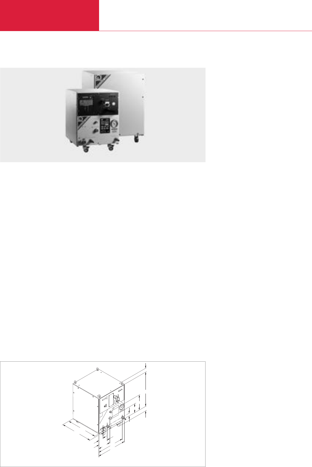
Compressor Units
Cryogenics
C12.32 LEYBOLD VACUUM PRODUCTS AND REFERENCE BOOK 2003/2004
COOLPAK 4000/4200, COOLPAK 6000/6200
61
36
448
511
70
146
199 407
440
152
51
230
528
Dimensional drawing for the COOLPAK 4000/4200 and COOLPAK 6000/6200
Advantages to the User
♦Highly effective and even more powerful when
connected with LEYBOLD cryopumps and
refrigerators
♦Excellent long-term reliability owing to the
modular design and the longlife components
♦Silent and low vibration operation through
scroll compressors
♦Easy to install and operate
♦Global power supply compatibility
♦Easy integration in complex systems due to
24 V DC or RS 232 C interfaces
♦Almost maintenance-free
♦Small footprint
♦Low cost of ownership
Compressor units COOLPAK 4000/4200/(COOLPAK 6000/6200, COOLPAK 6000 MD/6200 MD similar)

Cryogenics
C12.33
Compressor Units
LEYBOLD VACUUM PRODUCTS AND REFERENCE BOOK 2003/2004
C12
Technical Data
COOLPAK 4000 COOLPAK 4200 COOLPAK 6000 COOLPAK 6200
50 Hz 60 Hz 50 Hz 60 Hz 50 Hz 60 Hz 50 Hz 60 Hz
Number of electrical connections for cold heads
Helium system filling pressure at room temperature bar
Ambient temperature °C
Cooling-water consumption 1) l/min
Cooling-water entry temperature °C
Main voltage (3 phase)
upon delivery V
alternative setting V
Operating currents
with the cold head cool A
with the cold head warm A
Electrical power consumption
with the cold head cool kW
with the cold head warm kW
Remote control via interface
Helium connections
Self-sealing couplings
High pressure side
Low pressure side
Water connections
Sound level (at 1 m distance) dB(A)
Dimensions (W x H x D) mm
Weight kg (lbs)
1111
14 13 14 13 15 14 14 13
5 to 40 5 to 40 5 to 40 5 to 40
3.5 3.5 5.0 5.0
5 to 25 5 to 25 5 to 25 5 to 25
400 – 200 200 2) 400 – 230 3) 230
± 10% ± 10% + 10% - 5% ± 10% - 10% ± 10 %
– 470 230 3) 230 – 470 200 200
± 10% - 10% ± 10% ± 10% ± 10% ± 10%
6.4 to 7.4 6,2 to 7,3 14.6 to 16.5 13.8 to 17.0 9.5 to 10.5 9.0 to 10.0 15.5 to 22.0 16.0 to 23.0
8.5 8.1 18.3 19.5 13.7 12.0 25.0 25.0
3.8 to 4.5 4.2 to 5.3 4.0 to 4.6 4.4 to 5.3 6.0 to 6.5 6.5 to 6.9 5.5 to 6.2 5.9 to 6.7
5.3 5.8 5.3 5.9 8.2 8.7 7.6 7.8
24 V DC or RS 232 C 24 V DC or RS 232 C 24 V DC or RS 232 C 24 V DC or RS 232 C
1/2" 1/2" 1/2" 1/2"
1/2" 1/2" 1/2" 1/2"
Hose nozzle DN 12 / G 1/2" outside thread Hose nozzle DN 12 / G 1/2" outside thread
53 53 53 53
440 x 589 x 511 440 x 589 x 511 440 x 589 x 511 440 x 589 x 511
93 (205) 93 (205) 94 (207) 94 (207)
Ordering Information
Compressor unit without power supply cable
Single cold head operation
Dual cold head operation
Power supply cable
3.5 m, CEE plug, 32 A/6h, 3 pole + N + PE
3.5 m, NEMA plug, L 16-20 P,
20 A/480 V, 3 pole + PE (AWG 12)
3.5 m, NEMA plug, L 15-20 P,
20 A/250 V, 4 pole - PE (AWG 12)
10 m, with end splice (AWG 10)
Spare part
Adsorber CACP 4000 / 6000
1) At a cooling water entry temperature of 25 °C
2) ± 10% at 12 bar filling pressure
3) At 13 bar filling pressure
4) COOLPAK 4000 D
5) COOLPAK 6000 D
Part No. 892 31 Part No. 892 33 Part No. 892 36 Part No. 892 37
Part No. 892 3000
4)
–Part No. 892 46
5)
–
Part No. 893 95 – – Part No. 893 95 – –
– Part No. 893 96 – – Part No. 893 96 –
– Part No. 840 110 – –
– Part No. 840 111 – Part No. 840 111
Part No. 893 52 Part No. 893 52 Part No. 893 52 Part No. 893 52
COOLPAK 4000 COOLPAK 4200 COOLPAK 6000 COOLPAK 6200
Europe USA/Japan USA/Japan Europe USA/Japan USA/Japan

Compressor Units
Cryogenics
C12.34 LEYBOLD VACUUM PRODUCTS AND REFERENCE BOOK 2003/2004
General Accessories for Compressor Units COOLPAK
Technical Data Length Connections on both sides (inside thread)
High pressure line Low pressure line
Ordering Information
Flexlines 1), 2)
FL 4.5 (1/2", 1/2")
FL 9.0 (1/2", 1/2")
Adaptor
AD (1/2" m, 3/4" f)
AD (1/2" f, 3/4" m)
Elbow 1/2"
Coupling 1/2"
Gas manifold
GD 2 (for dual operation) 2)
GD 4 (for dual operation) 2)
EL 4.5 extension cable for linking cold head
and compressor unit 2)
All flexible pressure lines, adaptor pieces, bends, isolating pieces, line couplings and gas manifolds are equipped with self-sealing Aeroquip fittings and filled in the factory with high-purity helium gas (purity: 99.999 %).
The filling pressure is 16 bar
1) Minimum bending radius: 30 cm
2) Only suited for pneumatically driven cold heads and cryopumps
Part No. 892 87
Part No. 892 88
Part No. 892 89
Part No. 892 90
Part No. 891 73
Part No. 891 71
Part No. 891 02
Part No. 891 03
Part No. 893 74
Adaptor
Outside thread (m) Inside thread (f)
Connections
Outside thread (m) Inside thread (f)
Connections on both sides
Outside thread (m)
Number of Gas manifold - Connections
gas distributors At the compressor (inside thread) At the cold head (outside thread)
Length
4.5 m 1/2"1/2"
9.0 m 1/2"1/2"
1/2"3/4"
3/4"1/2"
1/2"1/2"
1/2"1/2"
1/2"
2 1/2"2 x 1/2"
4 1/2"4 x 1/2"
4.5 m
Flexlines 1), 2)
FL 4.5 (1/2", 1/2")
FL 9.0 (1/2", 1/2")
Accessories for Flexlines
Adapter for flexlines
AD (1/2" m, 3/4" f)
AD (1/2" f, 3/4" m)
Elbow 1/2" for flexlines
Isolating piece 1/2" for flexlines
Coupling 1/2" for interconnecting two 1/2" flexlines
Gas manifold for dual operation 2)
(consisting of two Tees)
GD 2 (for dual operation)
GD 4 (for up to quad operation)
EL 4.5 extension cable for linking cold head
and compressor unit
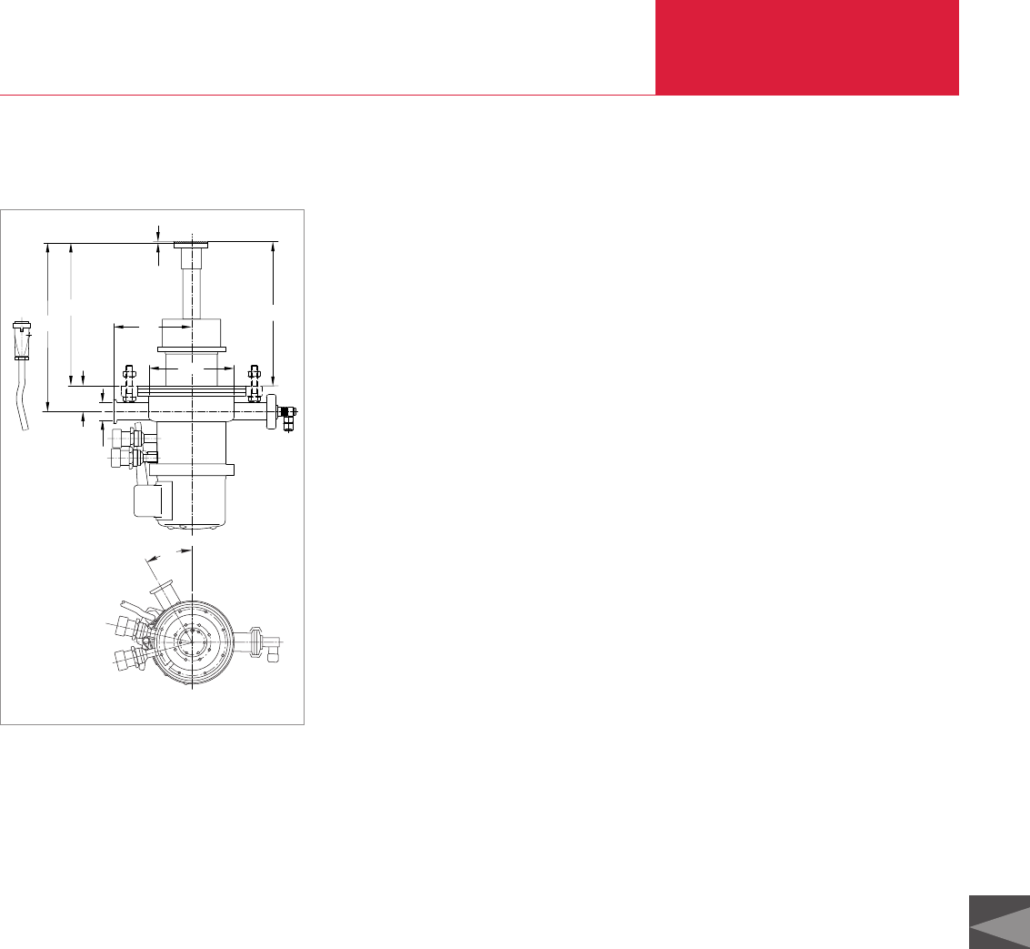
Cryogenics
C12.35
Refrigerator Cryostats
LEYBOLD VACUUM PRODUCTS AND REFERENCE BOOK 2003/2004
C12
Refrigerator Cryostats based on the RDK 6-320
The RDK 6-320 basic unit includes the
COOLPOWER 5/100 T two-stage cold head. Its
high refrigerating capacity at low temperatures
permits experiments which previously could not
be performed by relying on refrigerators and
which required the use of liquid helium.
The RDK 6-320 basic unit is a complete system
for measurements in the temperature range
between 6 and 320 K.
The COOLPOWER 5/100 cold head is augmented
by:
♦Silicon diode for measuring the temperatures
at the second stage of the cold head
♦Heater at the second stage of the cold head
provided with overheating protection
♦11-way current feedthrough with matching
external connector
♦DN 25 KF pumpdown port
♦DN 160 ISO-K vacuum flange
274,5
232
1
42,5
124
ø130
ø30,2
233
30°
RDK 6-320 basic unit
Isolating Vacuum
A two-stage rotary vacuum pump will normally
be adequate to produce an isolating vacuum.
However, this pump should be equipped on the
suction side with an adsorption trap and a isola-
tion valve.
If the application requires that the cold surfaces
remain free of hydrocarbons, we recommend the
use of our small turbomolecular pump system
PT 50 (see Product Section C10).
Advantages to the User
♦Compact
♦Very reliable
♦Comprehensive range of accessories from one
source
♦For installation in any orientation
♦Simple to operate
♦Short cooldown time
♦Cost-effective in long-term experiments since
no liquid helium is required
♦Simple and rapid servicing through the use of
the standard COOLPOWER 5/100 cold head
with pneumatic drive system for the displacer
Typical Applications
♦Cooling of samples and detectors
♦Material research and testing
♦Spectroscopic applications
♦Matrix isolation spectroscopy with neon and
argon
General Remarks on Refrigerator Cryostats
Temperature Measurement
In order to avoid measurement errors due to
thermal resistances, the temperature at the sam-
ple should preferably be measured by a second
optional silicon diode which is installed as close
to the sample as possible. If possible it should be
maintained at the same temperature level as that
of the probe.
Temperature Control
The temperature at the second stage of the cold
head (or that of the probe) is controlled by heat-
ing against the cooling effect produced by the
refrigerator (while the cold head is running).
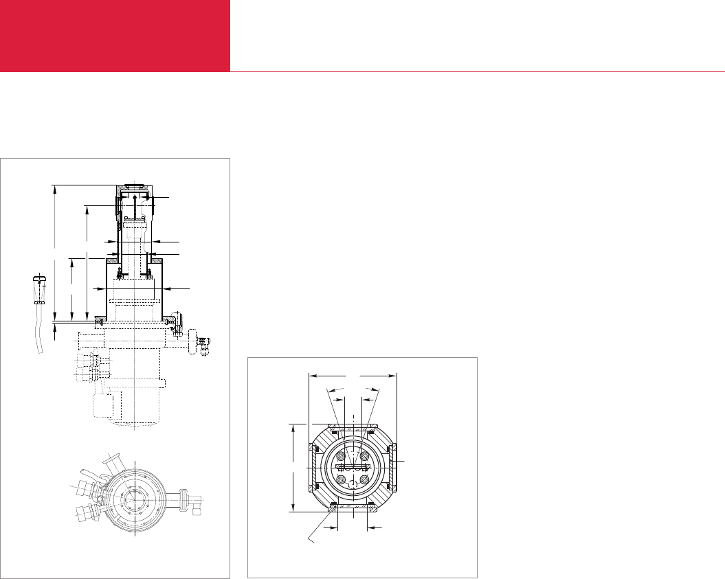
Refrigerator Cryostats
Cryogenics
C12.36 LEYBOLD VACUUM PRODUCTS AND REFERENCE BOOK 2003/2004
Optical Refrigerator Cryostat based on the RDK 6-320
ø130
317
145
269
4
ø26
ø80
ø60
Dimensional drawing for the optical refrigeration cryostat
Upgraded as an optical cryostat (option) the
RDK 6-320 is tailor-made for experiments
involving temperatures down to about 7 K.
Supplied Equipment
♦Basic unit RDK 6-320
♦Temperature attenuation disk out of Pb Sn
♦Sample holder out of Al 99.5
♦Thermal radiation shield out of E-Cu
♦Vacuum jacket out of aluminum / stainless
steel
♦Five exchangeable windows (four windows on
the sides, one window in the longitudinal axis
of the cryostat);
two windows on the sides and the window in
the longitudinal axis are made of SUPRASIL I,
the two other windows are blanked off and
are made of brass
ø15
ø26
Suprasil I Scheibe
Blind-
platte
86
86
37,8°
Section through the window area
Suprasil I window
Blank
panel

Cryogenics
C12.37
Refrigerator Cryostats
LEYBOLD VACUUM PRODUCTS AND REFERENCE BOOK 2003/2004
C12
Technical Data RDK 6-320
Temperature range
2nd stage of the cold head K
1st stage of the cold head K
Silicon diode for temperature measurements
at the 2nd stage of the cold head
Heater
at the 2nd stage of the cold head
Heating power W
Heating current A
Heating voltage V DC
Permissible ambient temperature °C
He filling pressure at room temperature bar
He connections
Self-sealing screwed connections
High pressure connection (outside thread)
Low pressure connection (outside thread)
Length of the connection cable
to the compressor unit m
Weight kg (lbs)
6 to 320
28 to 320
built-in
built-in
50
1
50
5 to 40
16
1/2"
1/2"
4.5 (included)
13 (28.7)
Ordering Information RDK 6-320
Basic unit RDK 6-320
Optical cryostat consisting of
RDK 6-320 and Expansion Kit ROK
Accessories
Compressor unit
COOLPAK 6000, 400 V/50 Hz; 470 V/60 Hz
COOLPAK 6200, 200 V/50 Hz; 200 V, 230 V/60 Hz
Power supply cable
Flexlines
FL 4.5 (1/2", 1/2")
Temperature measurement at 2nd stage with
Modell 9700 low temperature controller
Measuring cable, 3 m long
Part No. 842 403
Part No. 842 404
Part No. 892 36
Part No. 892 37
see Ordering Information for the Compressor Units COOLPAK
Part No. 892 87
Part No. 842 400
Part No. 842 401
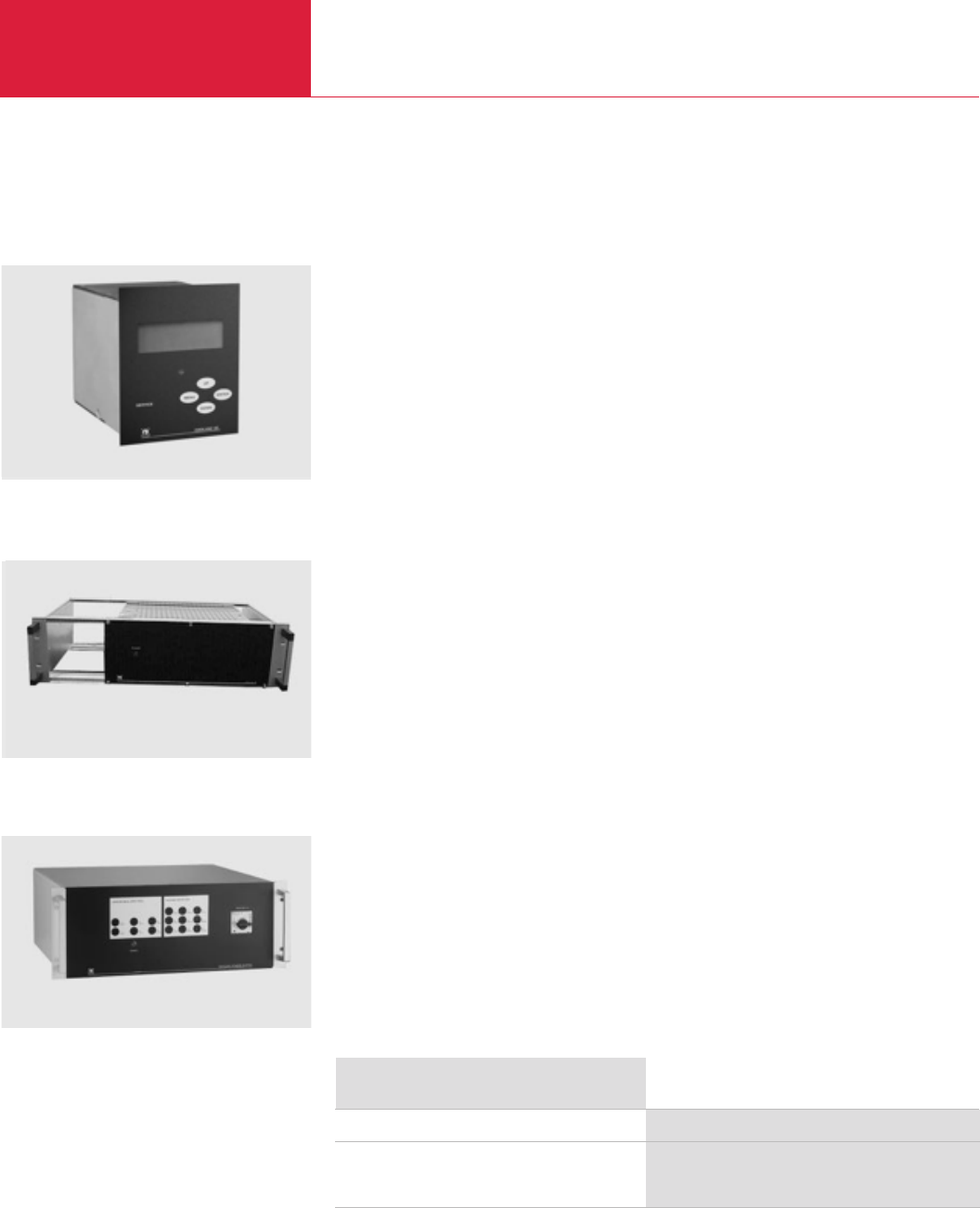
Accessories for Cryopumps
Cryopumps, Cryogenics
C12.38 LEYBOLD VACUUM PRODUCTS AND REFERENCE BOOK 2003/2004
System Controller COOLVAC SC
Advantages to the User
♦Interface to external system controller
♦For easy integration with external system
controllers
♦For safe pumping of hydrogen
Typical Applications
♦For automated operation of the COOLVAC
cryopums of the ClassicLine and the SemiLine
Ordering Information
System Controller
Power Supply PS
for up to 2 Cryo pumps
for up to 3 Cryo pumps
Part No. 844 230
Part No. 844 135
Part No. 844 235
Controllers and Monitoring Units for Cryopumps
Design Features
♦
1/4 19
"
rack module
♦
3 height units
♦
Dimensions (W x H x D)
106 x 129 x 178 mm
♦
Operation through pushbuttons
The intelligent COOLVAC System Controller SC
automatically controls and monitors up to
30 COOLVAC pumps.
Online monitoring, help functions and a
service interface for easy diagnostic are just a
few user friendly features.
It can be installed as a “stand alone system”
or remote controlled via an interface.
System Controller COOLVAC SC
Power Supply PS for up to Two Cryopumps
Design Features
♦
19
"
rack module
♦
3 height units
♦
Dimensions (W x H x D)
485 x 135 x 320 mm
The System Controller COOLVAC SC (not
included) will fit into the empty space.
The COOLVAC Power Supply PS provides the
power for the cold head motor, the electrical
heaters and the supplies voltage to the electro-
nics for up to 2 COOLVAC pumps.
Controlled via the System Controller SC the
PS turns the compressor unit on and off if
required by the connected pumps.
Power Supply PS for up to Three Cryopumps
Design Features
♦
19
"
rack module
♦
4 height units
♦
Dimensions (W x H x D)
435 x 190 x 440 mm
♦
Single LED indicates correct direction of
rotation for the rotating field
Power supply PS
Power supply PS
The COOLVAC Power Supply PS provides the
power for the cold head motor, the electrical
heaters and the supplies voltage to the electro-
nics for up to 3 COOLVAC pumps.
Controlled via the System Controller SC the
PS turns the compressor unit on and off if
required by the connected pumps.
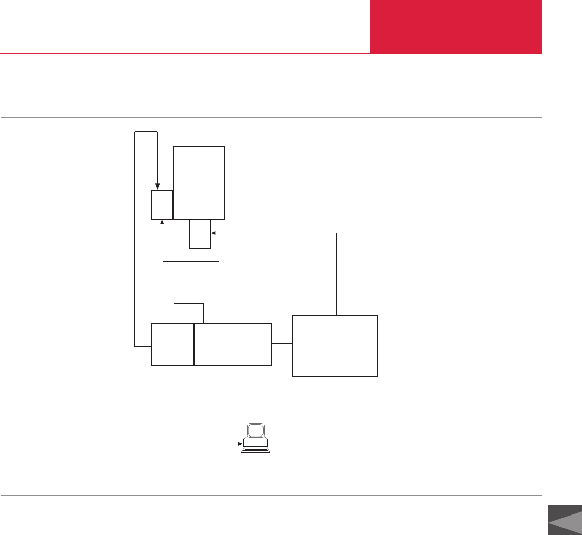
Cryopumps, Cryogenics
C12.39
Accessories for Cryopumps
LEYBOLD VACUUM PRODUCTS AND REFERENCE BOOK 2003/2004
C12
COOLVAC ClassicLine, Single System Configuration
SC
COOLVAC
# 1
PM
RS 232 C
PS COMPRESSOR
External PC
1
4
2
3
5
6
Key to the diagram “Single System Configuration”
PM = Pump Module (included with the pump)
SC = System Controller
PS = Power Supply
1 = e. g. Part No. 844 262
2 = e. g. Part No. 844 139
3 = e. g. Part No. 844 138
4 = Part No. 400 000 323
5 = Part No. 844 141
6 = to be provided by the customer
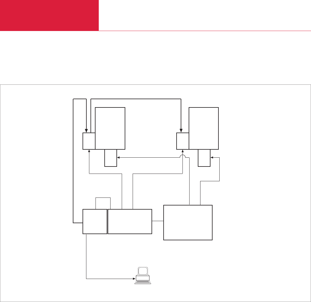
Accessories for Cryopumps
Cryopumps, Cryogenics
C12.40 LEYBOLD VACUUM PRODUCTS AND REFERENCE BOOK 2003/2004
COOLVAC ClassicLine, Dual System Configuration
COOLVAC
# 2
PM
SC
COOLVAC
# 1
PM
RS 232 C
PS COMPRESSOR
for dual operation
External PC
1
4
2
3
5
6
3
4
7
Only for European mains voltages and for compressors suited for dual operation
Key to the diagram “Dual System Configuration”
PM = Pump Module (included with the pump)
SC = System Controller
PS = Power Supply
1 = e. g. Part No. 844 262
2 = e. g. Part No. 844 139
3 = e. g. Part No. 844 138
4 = Part No. 400 000 323
5 = Part No. 844 141
6 = to be provided by the customer
7 = e. g. Part No. 844 256
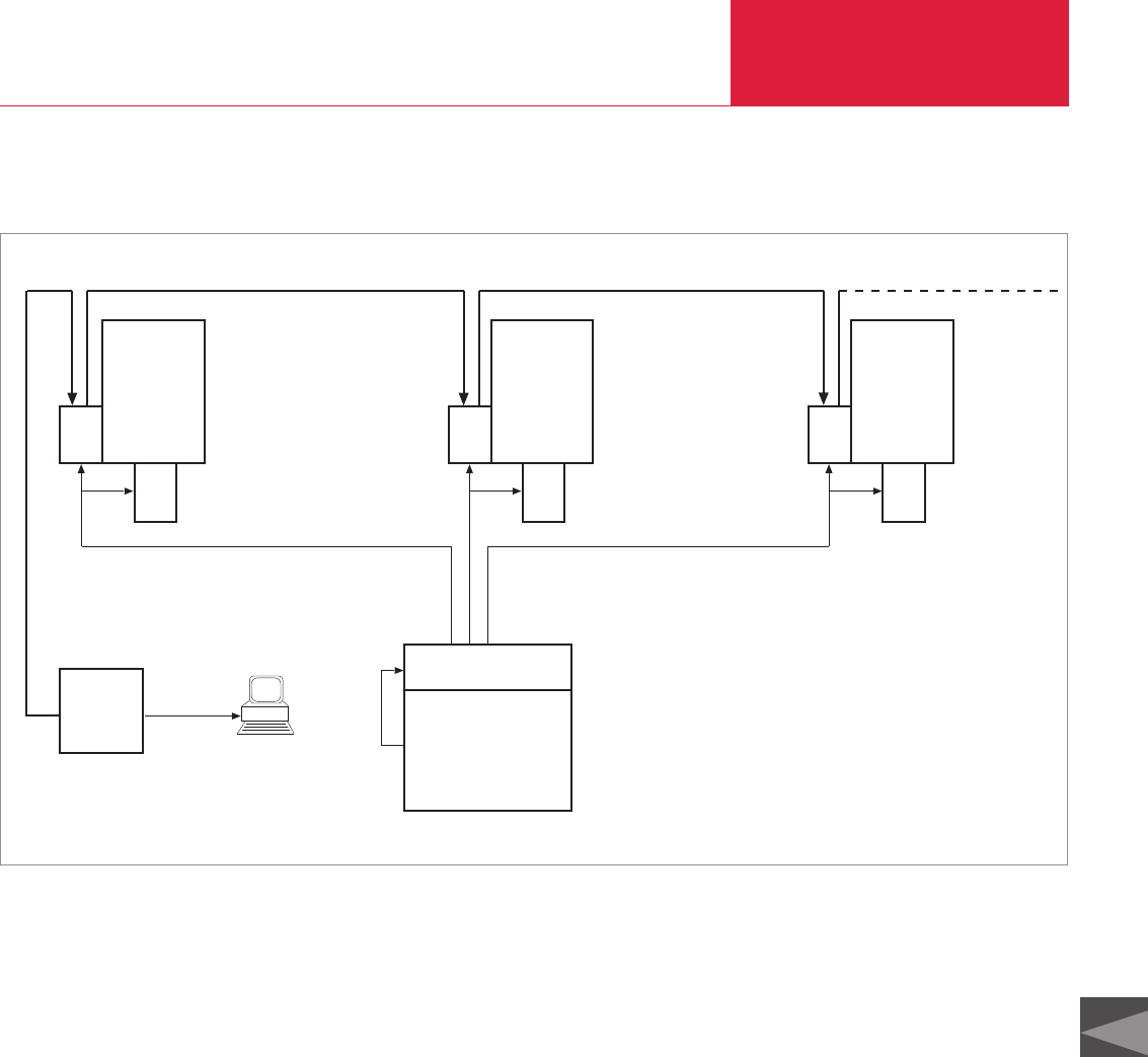
Cryopumps, Cryogenics
C12.41
Accessories for Cryopumps
LEYBOLD VACUUM PRODUCTS AND REFERENCE BOOK 2003/2004
C12
COOLVAC ClassicLine, Dual and Mutiple System Configuration
COOLVAC
# 3
PM
COOLVAC
# 2
PM
SC
COOLVAC
# 1
PM
RS 232 C
PS
External PC
1
7
8
8
9
6
8
7
7
COMPRESSOR
Key to the diagram “Dual and Mutiple System Configuration”
PM = Pump Module (included with the pump)
SC = System Controller
PS = Power Supply
1 = e. g. Part No. 844 262
6 = to be provided by the customer
7 = e. g. Part No. 844 256
8 = e. g. Part No. 844 252
9 = Part No. 844 265
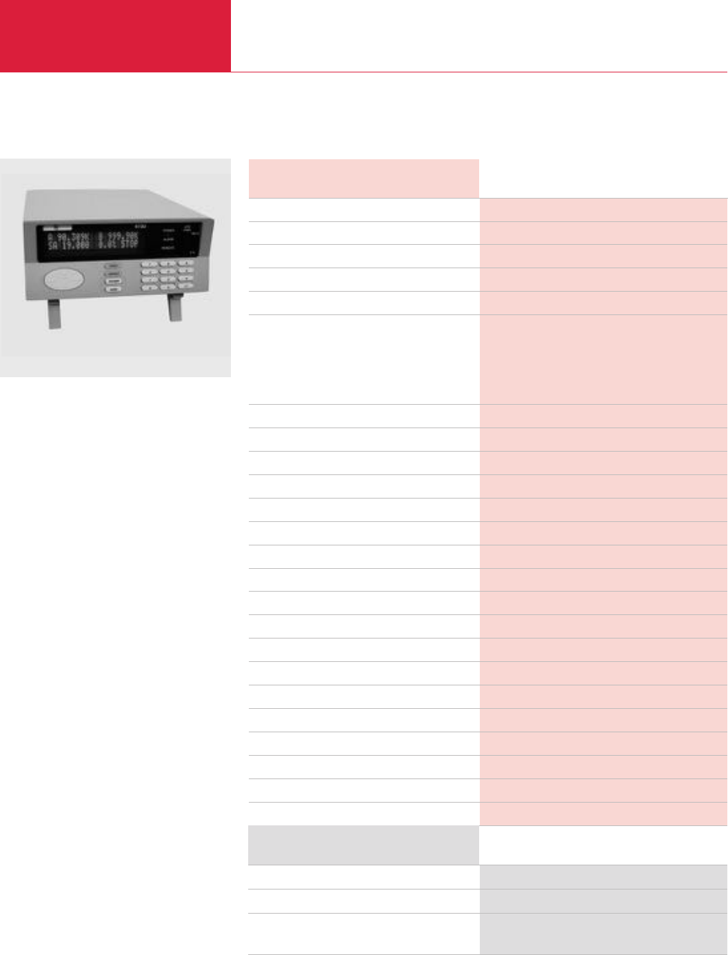
Accessories
Cryopumps, Cryogenics
C12.42 LEYBOLD VACUUM PRODUCTS AND REFERENCE BOOK 2003/2004
Modell 9700 Low Temperature Controller
Modell 9700 low temperature controller
Advantages to the User
♦Microprocessor controlled PID controller
♦Digital temperature readout in Kelvin
♦Control by means of counter heating
♦High control accuracy over the entire tempera-
tur range (1.5 to 450 K)
♦Electric heating power up to 50 W
♦Programmable heater power limit
♦Generation of linear temperature ramps
♦Up to 50 program steps are programmable
♦Standard interface RS 232 C and IEEE-488
♦Data from two sensors can be displayed
♦Analogue temperature outputs for both
channels
♦Can be used in three operating modes
– Manual
– Program
– External computer control
Typical Applications
♦Temperature control at refrigerator cryostats
Technical Data Modell 9700
Mains connection, 50/60 Hz V AC
Power consumption, max. W
Entry of data
Data memory
Display
Temperature measurement
Sensors
Measurement current µA
Measurement range K
Measurement range of the silicon diode type D K
Number of channels
Resolution
A/D converter resolution bit
Switching outputs
Temperature resolution K
Temperature control
Heating power, max. W
Heating current, max. A
Heating voltage, max. V DC
Computer interface
Permissible ambient temperature °C
Mechanical design/cabinet
Dimensions (W x H x D) [high H without feet] mm
Weight kg (lbs)
Dimensions of the packaging (W x H x D) mm
Weight (including packaging, approx.) kg (lbs)
Length of mains cord m
85-240
150
3 x 4 membrane key pad
EPROM
Two line, 20 digit LED digital display
2 x silicon diodes type D or 2 x silicon diodes
with standard temperature resistance characteristics
10
1.5 to 450
1.4 to 325 K
2
Simultaneous display of both channels
24
2 relays (n.o. and n.c. contacts)
0.1
PID controller
50
1
0 to 50
RS 232 C and IEEE-488
+ 10 to + 30
Table-top unit (8.5"x 3.5"x 12")
215.9 x 88 x 304.8
2.3 (5)
360 x 230 x 450
4.2 (9.3)
2.5
Ordering Information Modell 9700
Modell 9700 low temperature controller
Sensor cable, 3 m long
Silicon diode type D
with connection cable and miniature plugs
Part No. 842 400
Part No. 842 401
Part No. 890 89
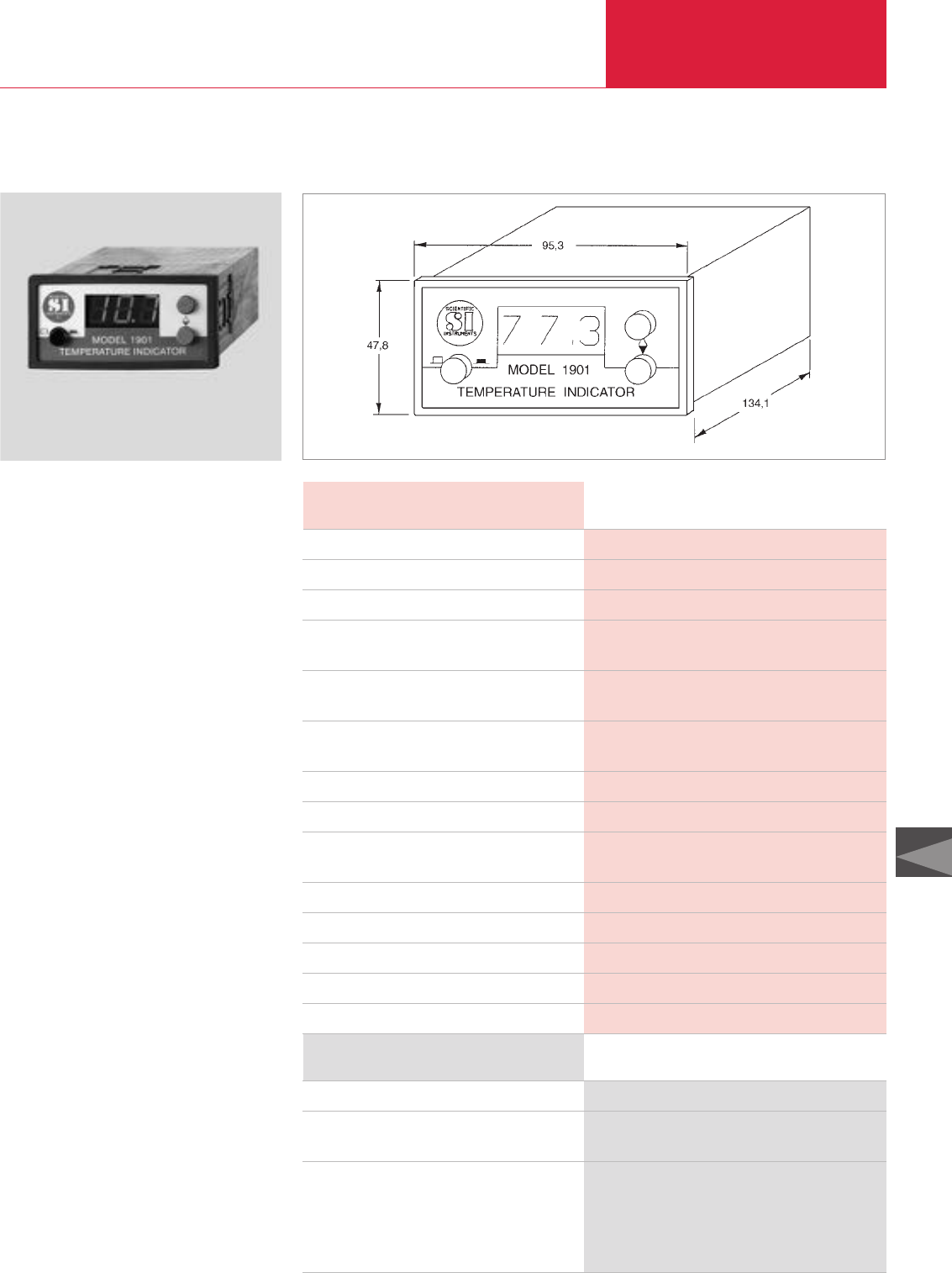
Cryopumps, Cryogenics
C12.43
Accessories
LEYBOLD VACUUM PRODUCTS AND REFERENCE BOOK 2003/2004
C12
MODEL 1901 Low Temperature Measuring Instrument
MODEL 1901 low temperature measuring instrument Dimensions and panel cut-out for the MODEL 1901
Advantages to the User
♦Supports one silicon diode
♦3-digit LED display
♦Temperature readout between 1 and
450 Kelvin
♦Two trigger thresholds
♦RS 232 C interface
Typical Applications
♦Temperature measurements on cryostats
♦Temperature measurements on cryopumps
for monitoring their operation and to control
pump systems
Technical Data MODEL 1901
Measurement current µA
Display
Temperature range K
Resolution
Accuracy
Power supply voltage
Trigger thresholds
Switched output
RS 232 C interface
Admissible ambient temperature °C
Mechanical design/housing
Dimensions (W x H x D) mm
Packaging dimensions (W x H x D) mm
Weight (including packaging) kg (lbs)
10
LED, 3-digits
1.5 to 450
0.1 K from 1.5 to 99.9 K
1.0 K from 100 to 450 K
±0.1 K from 1.5 to 99.9 K
±1.0 K from 100 to 450 K
9 V DC @ 500 mA
through the supplied 220 V AC / 9 V DC power adaptor
2
2 relays (n.c. and n.o.)
a) Temperature output
b) External adjustment of switching thresholds
+10 to +35
Benchtop unit
95.3 x 47.8 x 134.1
320 x 180 x 120
1.5 (3.3)
Ordering Information MODEL 1901
MODEL 1901 low temperature measurement instrument
HV cable with plug, 10 m long *)
UHV cable with plug, 10 m long *)
Silicon diode, type D,
with connecting cable and micro plugs
- without current feedthrough
HV current feedthrough on a flange DN 25 KF, 2 way
UHV current feedthrough on a flange DN 16 KF, 2 way
*)for COOLPOWER and COOLVAC pumps
Part No. 136 45
Part No. 500 085
Part No. 500 201
Part No. 890 89
Part No. 200 19 256
Part No. 500 217
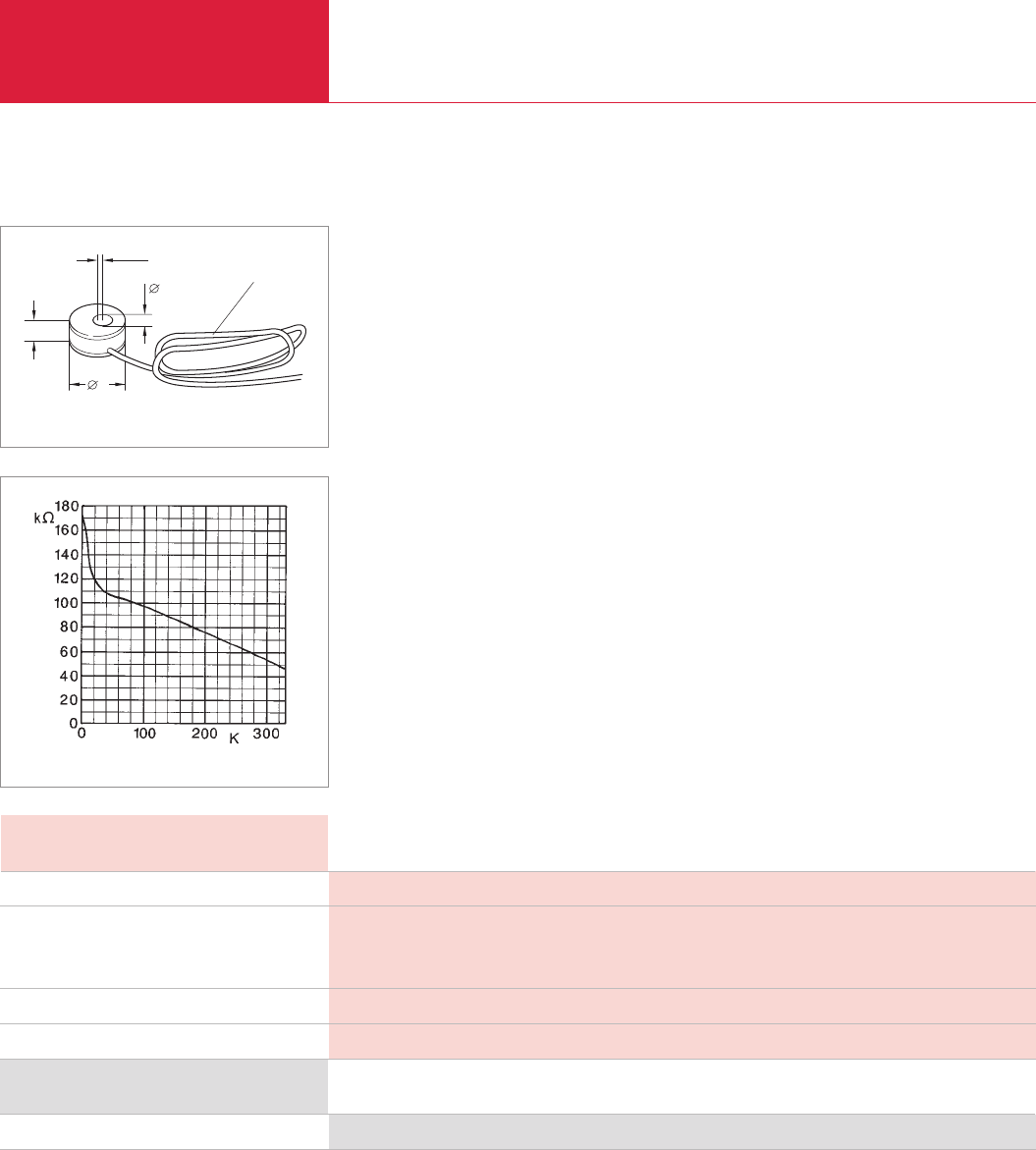
Accessories
Cryopumps, Cryogenics
C12.44 LEYBOLD VACUUM PRODUCTS AND REFERENCE BOOK 2003/2004
Temperature Sensors
2,9
3,8
0,76
8
600 mm long
Dimensional drawing for the silicon diode, type D
In contrast to vapor pressure thermometers,
electric temperature sensors can be used for
continuous measurements within a wide range of
temperatures.
Silicon diodes offer a negative temperature
coefficient of resistance, i.e. their resistance
drops as the temperature increases. The slope of
the temperature/resistance characteristic and the
absolute resistance are decisive regarding the
suitability of these diodes. The slope determines
the sensitivity of the sensor and a high electrical
resistance permits accurate measurements while
keeping the thermal load small (microwatts).
In systems which are degassed at high tempera-
tures, silicon diodes can only be fitted after
degassing has been completed.
The type D silicon diode is compatible to the
MODEL 1901 low temperature display unit.
Technical Data Type D Silicon Diode
Temperature range K
Temperature coefficient (dR/dT)
qualitative
quantitative Ω/K
Measurement current µA
Bakeable to °C
1.4 to 325
Negative in the entire temperature range
Non-linear characteristic
10
60
Ordering Information Type D Silicon Diode
Temperature Sensors
Part No. 890 89
Standard characteristic of the silicon diode
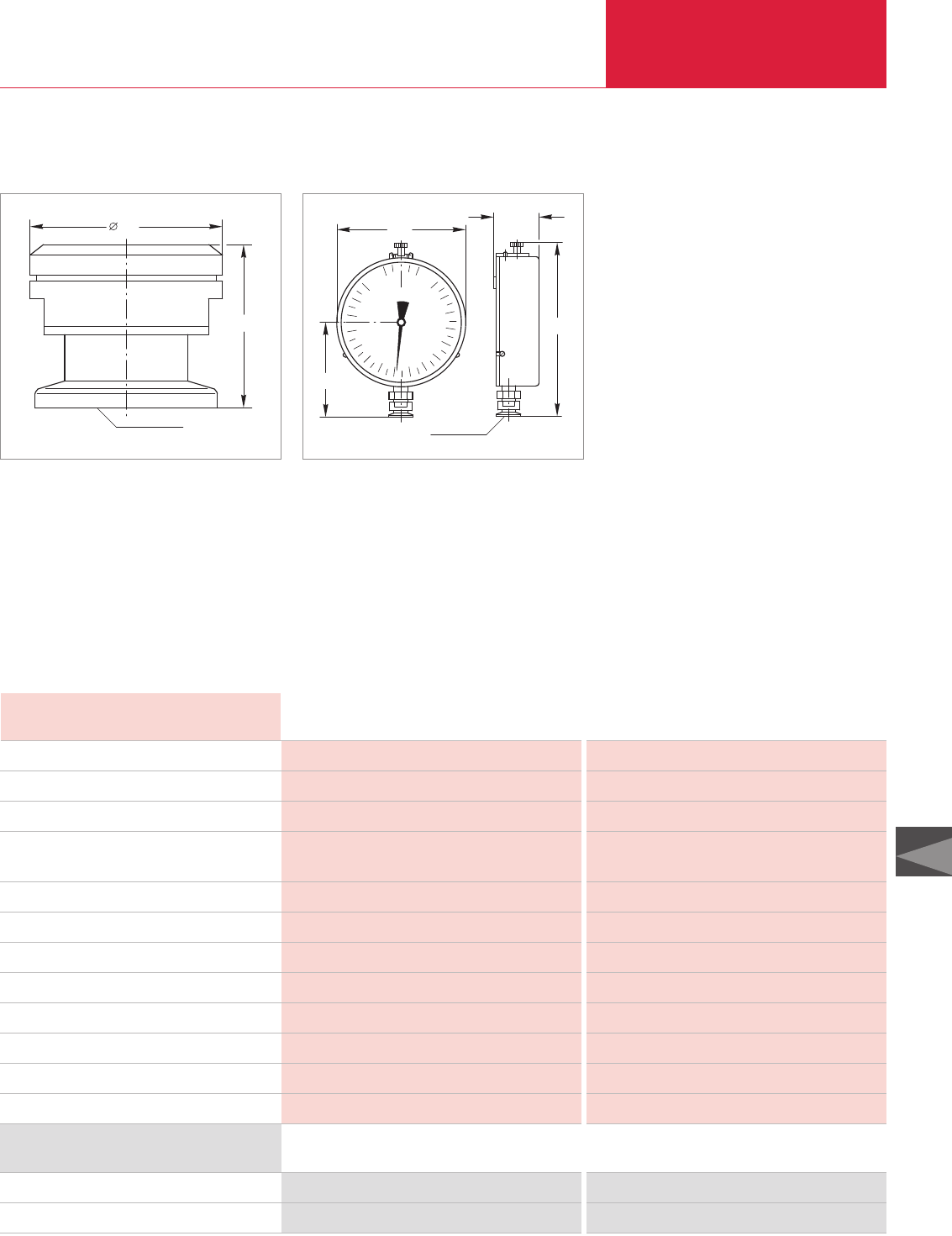
Cryopumps, Cryogenics
C12.45
Accessories
LEYBOLD VACUUM PRODUCTS AND REFERENCE BOOK 2003/2004
C12
Safety Valve / Precision Manometer
32
28
DN 16 KF
Typical Applications
♦Protecting sealed vacuum systems like cryo-
pumps, cryostats, lifting devices, for example
against internal overpressures
♦Mandatory for systems which are separated
when cold, as a means of protection against
overpressures
Typical Applications
♦Pressure readout for vapor pressure thermo-
meters
160
2000 0
50
226
DN 10 KF
133
Technical Data Safety Valve Precision Manometer
Responding pressure mbar
Flow at 140 mbar l x h-1
Valve disk
Leak rate in the closed state
mbar x l x s-1 (Torr x l x s-1)
Connection DN
Measurement range mbar (Torr)
Accuracy
Diameter mm
Length of the dial mm
Internal volume, approx. cm3
Overall height mm
Weight kg (lbs)
120 to 160, over-pressure –
500 –
Spring loaded, with O-ring seal –
< 1 x 10⁻⁸ (< 0.75 x 10⁻⁸) –
16 KF 10 KF
– 0 to 2000 (0 to 1500)
– 1 % of full scale
32 160
– 320
– 20
28 226
0.3 (0.7) 1.4 (3.1)
Ordering Information Safety Valve Precision Manometer
Safety valve on DN 16 KF flange
Precision manometer
Part No. 890 39 –
–Part No. 890 50
Technical Information
For operation and measurements at pressures
exceeding 1013 mbar the small flange seal
must be equipped with an outer centering ring
Part No. 183 53.
Dimensional drawing for the safety valve Dimensional drawing for the precision manometer

Cryopumps, Cryogenics
C12.46 LEYBOLD VACUUM PRODUCTS AND REFERENCE BOOK 2003/2004

Vacuum Fittings
and Feedthroughs
C13

Vacuum Fittings and Feedthroughs
C13.02 LEYBOLD VACUUM PRODUCTS AND REFERENCE BOOK 2003/2004
Contents
General
Materials . . . . . . . . . . . . . . . . . . . . . . . . . . . . . . . . . . . . . . . . . . . . . . . . . . . . . . . . . . . . . . C13.03
The Right Connection from LEYBOLD . . . . . . . . . . . . . . . . . . . . . . . . . . . . . . . . . . . . . . . . . C13.04
Flange Connections . . . . . . . . . . . . . . . . . . . . . . . . . . . . . . . . . . . . . . . . . . . . . . . . . . . . . . C13.05
Products
Global Versions
ISO-KF Flange Fittings and Components . . . . . . . . . . . . . . . . . . . . . . . . . . . . . . . . . . . . . C13.06
Adaptors . . . . . . . . . . . . . . . . . . . . . . . . . . . . . . . . . . . . . . . . . . . . . . . . . . . . . . . . . . . . C13.16
(ISO-K) Clamp Flange Fittings and Components . . . . . . . . . . . . . . . . . . . . . . . . . . . . . . . C13.18
ISO-F and DIN 2501 Fixed Flange Fittings, ND6. . . . . . . . . . . . . . . . . . . . . . . . . . . . . . . . C13.26
ISO-F Fixed Flange Fittings . . . . . . . . . . . . . . . . . . . . . . . . . . . . . . . . . . . . . . . . . . . . . . . C13.27
DIN 2501 Fixed Flange Fittings . . . . . . . . . . . . . . . . . . . . . . . . . . . . . . . . . . . . . . . . . . . . C13.28
Vacuum Greases . . . . . . . . . . . . . . . . . . . . . . . . . . . . . . . . . . . . . . . . . . . . . . . . . . . . . . C13.29
Observation Windows . . . . . . . . . . . . . . . . . . . . . . . . . . . . . . . . . . . . . . . . . . . . . . . . . . C13.30
Electrical Feedthroughs . . . . . . . . . . . . . . . . . . . . . . . . . . . . . . . . . . . . . . . . . . . . . . . . . C13.32
High Current Feedthroughs. . . . . . . . . . . . . . . . . . . . . . . . . . . . . . . . . . . . . . . . . . . . . . . C13.35
Rotary Feedthroughs . . . . . . . . . . . . . . . . . . . . . . . . . . . . . . . . . . . . . . . . . . . . . . . . . . . C13.36
Rotary / Linear Motion Feedthroughs . . . . . . . . . . . . . . . . . . . . . . . . . . . . . . . . . . . . . . . C13.37
Liquid Feedthroughs. . . . . . . . . . . . . . . . . . . . . . . . . . . . . . . . . . . . . . . . . . . . . . . . . . . . C13.38
Versions for the North and South American Continents
ISO-KF Flange Fittings and Components . . . . . . . . . . . . . . . . . . . . . . . . . . . . . . . . . . . . . C13.39
Adaptors . . . . . . . . . . . . . . . . . . . . . . . . . . . . . . . . . . . . . . . . . . . . . . . . . . . . . . . . . . . . C13.41
(ISO-K) Clamp Flange Fittings and Components . . . . . . . . . . . . . . . . . . . . . . . . . . . . . . . C13.42
ISO-F and DIN 2501 Fixed Flange Fittings . . . . . . . . . . . . . . . . . . . . . . . . . . . . . . . . . . . . C13.43
ANSI Fittings . . . . . . . . . . . . . . . . . . . . . . . . . . . . . . . . . . . . . . . . . . . . . . . . . . . . . . . . . C13.44
♦Availability of all components at short notice
♦World-wide advice at any time to answer
your questions relating to vacuum systems
♦Utilization of most advanced manufacturing
methods
♦Environment-friendly cleaning baths with
complete waste disposal and recycling faci-
lities
♦Environment-friendly and secure packaging
♦Total Quality Management methods during
all processing stages
♦Controlled material quality
♦Compatible to your existing flanges of the
same system
♦Highly leak-tight down to leak rates of
1 x 10
-9
mbar x l x s
-1
; all components are
subjected to a helium leak test
♦Low outgassing rates of the materials
through
- choice of the right material quality,
especially for vacuum apparatus
- excellent cleaning methods
♦Documentation available for all components
These arguments should convince you in favor of
flange components from LEYBOLD:

Vacuum Fittings and Feedthroughs
C13.03
C13
LEYBOLD VACUUM PRODUCTS AND REFERENCE BOOK 2003/2004
General
General
Vacuum systems (i.e. systems for pressures rang-
ing from 2.5 bar to 10
-9
mbar (1.9 x 10
-3
Torr to
0.75 x 10
-9
Torr)) are quickly and easily assemb-
led owing to the modular construction principle
which is based on interchangeable standard com-
ponents by means of vacuum-tight, demountable
flange connections. Individual components may
be exchanged easily at any time. Depending on
the intended use and size of the connection, flan-
ges of different types have been developed. The
KF flange connection was developed by
LEYBOLD many years ago and has been widely
accepted by all users of vacuum equipment. This
product section lists all flange connections and
fittings including adaptors for ultra high vacuum
components.
Components marked with [< 1000 mbar
(< 750 Torr)] are not allowed for use at pressures
exceeding 1000 mbar abs.
The components and flange connections are
intended for use in connection with vacuum
systems. They have not been designed to support
mechanical loads. All loads must be supported
separately at the connection components.
Ultra High Vacuum Components are described in
Product Section C15.
Flange Designations
The designations used by LEYBOLD for clamp
flanges, fixed flanges (bolted) and collar flanges
with retaining rings correspond both to the inter-
national standards
1)
and to the usual nomencla-
ture in vacuum technology.
1) The nominal width DN corresponds only approximately to the inner
diameter, i.e. is is not necessarily identical to the inner diameter.
Differences in the actual inner diameter are quite normal in practice
and do not contravene standards.
Stainless Steel
German AISI/ DIN Designation
Material No. SAE
1.4301 304 X5 CrNi 18 10
1.4305 303 X10 CrNi S 18 9
1.4306 304 L X2 CrNi 19 11
1.4310 301 X12 CrNi 17 7
1.4401 316 X5 CrNiMo 17 12 2
1.4404 316 L X2 CrNiMo 17 12 2
1.4435 316 L X2 CrNiMo 18 14 3
1.4541 321 X10 CrNiTi 18 9
1.4571 316 Ti X6 CrNiMoTi 17 12 2
1.4552 – X5 CrNiNb 18 9
Gaskets
Code Chemical Typical
Designation Designation Trade Name
CR Chloroprenecaoutchouc Neoprene
FPM Fluorcaoutchouc Viton®
NBR Acrylonitrile-
butadienrubber Perbunan®
PTFE Polytetrafluorethylene Teflon®
EPDM Ethylene propylene –
dien rubber
Materials
Aluminum
German AISI DIN Designation
Material No.
3.0255.10 AA 150 1-0 Al 99.5w
3.0615.71 AA 6012-T6 AlMgSiPb
3.1655.53 AA 2011-T352 AlCuBiPb
3.2162.05 380.0 (AA) GD-AlSi8Cu8
3.2315.08 6082-F (AA) AlMgSi1
3.2315.71 6082-T6 AlMgSi1
3.2315.72 6063 (AA) Al Mg Si1
3.2381.02 520.0 (AA) GK AlSi 10 Mg
3.2381.62 520.0 (AA) GK AlSi 10 Mgwa
3.2582.05 160 X GD-AlSi 12
Hoses and Tubes
Code Chemical Typical
Designation Designation Trade Name
NR Natural rubber –
PVC Polyvinylchloride –
Steel
German AISI DIN Designation
Material No.
1.0037 – St 37-2
1.0308.07 – St 35
1.1141 – CK 15
1.1181 – CK 35
LEYBOLD VACUUM PRODUCTS AND REFERENCE BOOK 2003/2004
C13.04
ISO-F
1Flange
2Vacuum sealing disk consisting of
centering ring and O-ring gasket
with outer support ring
3ISO-K flange
4Bolt with nut
5Collar flange with retaining ring
CF
2. Reducer / ISO-K-CF
3. Adaptor CF-ISO-K/KF
4. Double cross
5. Adjustment piece
6. Elbow
7. Ceramic intermediate piece
8. Tee
9. UHV observation window
10. Blank flange
CF flange connection
10
11
2
3
4
5
6
10
7
8
9
General
Vacuum Fittings and FeedthroughsVacuum Fittings and Feedthroughs
1. ISO-K flange
2. Centering ring with O-ring gasket and outer support ring
3. Clamp
4. Tee
5. Cross with lateral DN 10/40 KF flanges
6. Elbow
7. Flexible vacuum tubing
8. Cross
9. Intermediate flange with gauge port
10. Clamp flange with tubulation
11. Blank flange
12. Flexible compensation element
THE RIGHT
CONNECTION
FROM LEYBOLD
2. Adaptor reducer ISO-K – KF
3. Centering ring with O-ring gasket
4. Flexible vacuum tubing
5. Clamping quick-release ring
6. Tee
7. Clamp
8. Elbow
9. PVC coiled vacuum tubing
10. Cross
11. Blank flange
12. Small flange with hose nozzle
1
4
2
1
3
1KF flanges
2Centering ring with O-ring gasket
3Clamping ring
KF clamp flange connection
KF
1ISO-K flange
2Centering ring with O-ring gasket
and outer support ring
3Clamp
ISO-K clamp flange connection
ISO-K
8
12
7
6
7
5
4
9
2
3
5
4
6
7
11 8
9
12 10
1
7
3
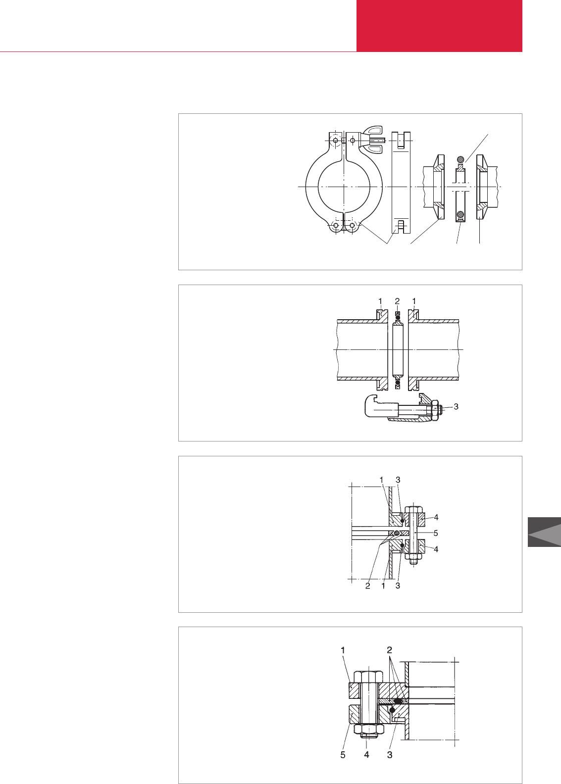
General
Vacuum Fittings and Feedthroughs
C13.05
C13
LEYBOLD VACUUM PRODUCTS AND REFERENCE BOOK 2003/2004
14
2
13
Flange Connections
ISO-KF Connection
The ISO-KF connection (to DIN 28 403 and
ISO 2861) permits rapid fitting and replacement of
components in vacuum systems. It consists of
two symmetrical KF flanges (1), a centering ring
with O-ring gasket (2) and a clamping ring (3).
High vacuum tight KF connections can be made
without the use of tools simply by turning the
wing nut of the clamping ring.
ISO-K Clamp
Flange Connection
The clamp flange connection (to DIN 28 404 and
ISO 1609) allows components from DN 63 to
DN 630 to be connected in any position regard-
less of the bolt hole arrangement on any fixed
flanges.
It consists of two clamp flange components (1),
a centering ring (2) with an outer ring enclosing
the O-ring gasket, and several clamps (3) which
the connection is assembled and tightened with.
Since the centering ring can be firmly inserted
into the centering groove of the flange, even hori-
zontal connections are quickly and easily fitted.
ISO-F / DIN
Fixed Bolted Flange Fittings
With the appropriate collar flanges, the clamp
flange can be connected to various fixed bolted
flange systems (ISO-F, DN 2501, etc.) see figures
in section “ISO-F and DIN 2501 Fixed Flange
Fittings”.
Bake Out Temperatures
for the Gaskets
CR and FPM gaskets can be inserted in all listed
flange types, while aluminum gaskets may be
used for higher vacuum requirements.
CR gaskets can be used in the temperature
range
from -40 °C to +100 °C [-40 °F to +212 °F] (max.
bakeout temperature), FPM gaskets from -15 °C
to +150 °C [+5 °F to +302 °F] (max. bakeout
temperature). Aluminum gaskets from -196 °C to
+200 °C [-321 °F to +392 °F] (max. bakeout
temperature gradient; ∆T max. 2.5 °/min).
1 Small flange
2 Centering ring with O-ring
3 Clamping ring
4 Outer centering ring with O-ring
KF flange connection
1 Clamp flange
2 Centering ring and O-ring
with outer supporting ring
3 Clamp
ISO-K clamp flange connection
1 ISO-K flanges
2 Vacuum sealing disk consisting
of centering ring and O-ring
with outer support ring
3 Retaining rings
4 ISO-F collar flanges
5 Bolt with nut
Clamped flange connection with collar flanges
1 Flange to DIN 2501 ND6
2 Sealing disk consisting of
centering ring and O-ring with outer support ring
3 ISO-K flange
4 Bolt with nut
5 Collar flange with retaining ring to DIN 2501 ND6
Connection between a DIN 2501 ND 6 flange and an ISO-K flange with DIN 2501 collar flange

ISO-KF Flange Fittings and Components
Vacuum Fittings and Feedthroughs
C13.06 LEYBOLD VACUUM PRODUCTS AND REFERENCE BOOK 2003/2004
DN 16 KF to DN 50 KF
Aluminum Design
(to DIN 28 403)
[Tubes similar DIN 28 403]
The small flange connection developed by
LEYBOLD has become the basis of the inter-
national standard for vacuum technology.
Advantages to the User
◆Quick, safe and reliable
◆No tools are need to provide a vacuum-tight
seal
◆Suitable down to pressures of 10
-7
mbar
(0.75 x 10
-7
Torr)
◆Easy to disassemble and clean
◆In the case of special requirements as to
degassing for the purpose of reducing the
outgassing rate and in case of special require-
ments as to corrosion resistance, we recom-
mend the use of stainless steel components.
Quick Clamping Ring
Advantages to the User
◆Quick and effective fitting and disassembly
◆Can be fitted with one hand
◆Closing action via lever with clamping spring
◆Corrosion resistant
DN 16 KF to 50 KF
Stainless Steel Design
(to DIN 28 403)
[Tubes similar DIN 28 403]
Advantages to the User
◆Quick, safe and reliable
◆Can be baked out up to 200 °C (392 °F) when
using metal seals
◆Can be degassed up to 150 °C (302 °F) with
FPM
gaskets
◆With metal seals suitable for pressures down
to 10
-9
mbar (0.75 x 10
-9
Torr)
◆Corrosion resistant
◆Low degassing rate
◆For standard applications involving pressures
up to 2.5 bar (1.9 x 10
+3
Torr) abs.
◆Can be degassed up to 200 °C (392 °F) with
UHV aluminum rings or disks
Flexible Compensation
Elements
Vacuum systems and pump systems often re-
quire components which are capable of protect-
ing sensitive instruments against impacts or
excessive vibrations while linking tubes at the
same time.
Advantages to the User
◆Easy and quick to install
◆Safe and reliable
◆Tubes may be turned in any direction
◆No centering and sealing ring required
◆Capable of withstanding temperatures up to
80 °C (176 °F)
◆Suitable for pressures down to 10
-5
mbar
(0.75 x 10
-5
Torr)
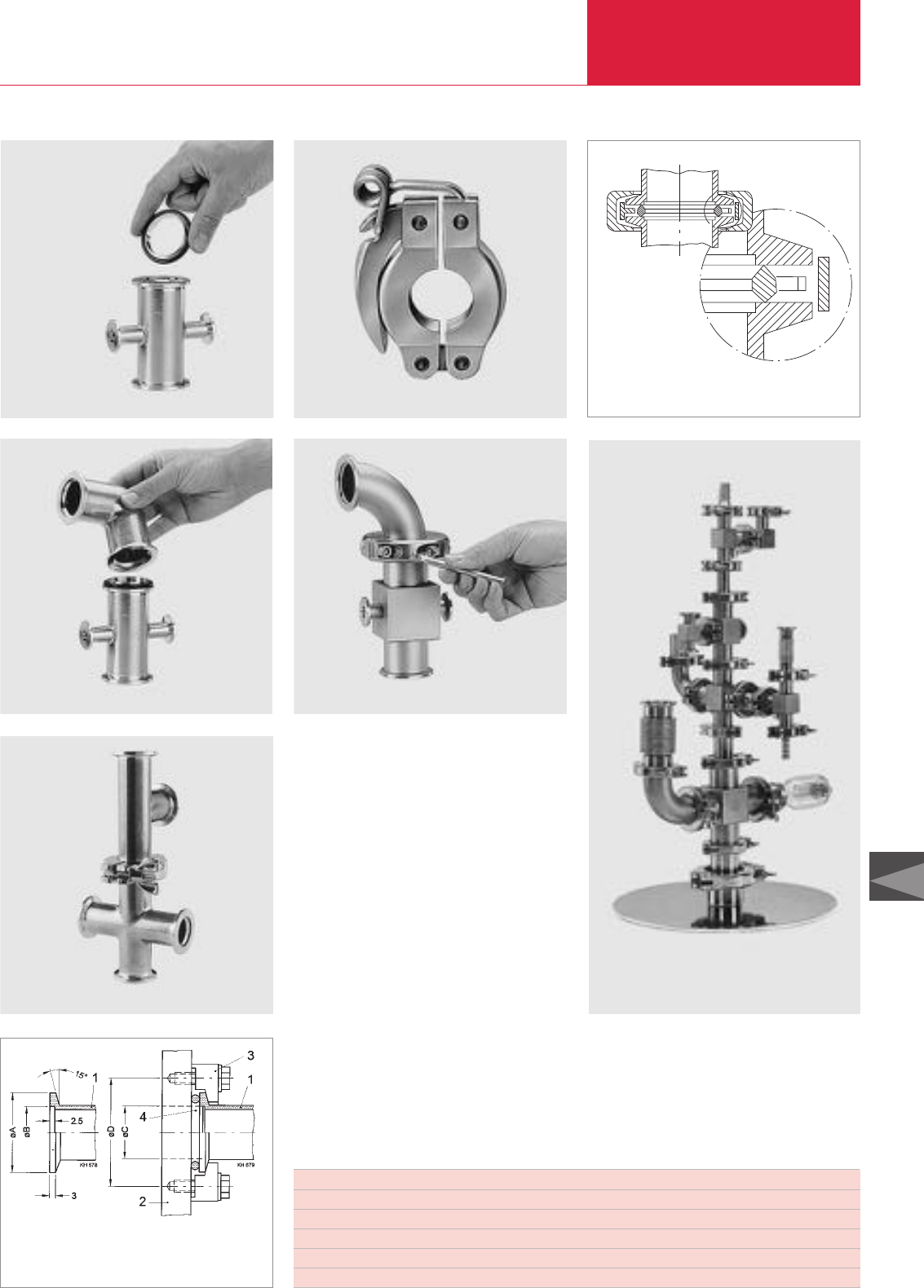
ISO-KF Flange Fittings and Components
Vacuum Fittings and Feedthroughs
C13.07
C13
LEYBOLD VACUUM PRODUCTS AND REFERENCE BOOK 2003/2004
Fitting a centering ring to a KF component
Fitting an elbow
Small flange connection with clamping ring
Clamping ring for ultra sealing disk
Small flange components made of stainless steel
Quick clamping ring Small flange connection with ultra sealing ring
Nominal diameter A B C D Number of claws
DN 10 ISO-KF 30 12.2 12.2 45 4
DN 16 ISO-KF 30 17.2 17.2 45 4
DN 25 ISO-KF 40 26.2 26.2 55 4
DN 40 ISO-KF 55 41.2 41.2 71 4
DN 50 ISO-KF 75 52.4 52.4 91 4
1 Small flange port
2 Housing wall with threaded tap
3 Claw
4 Centering ring
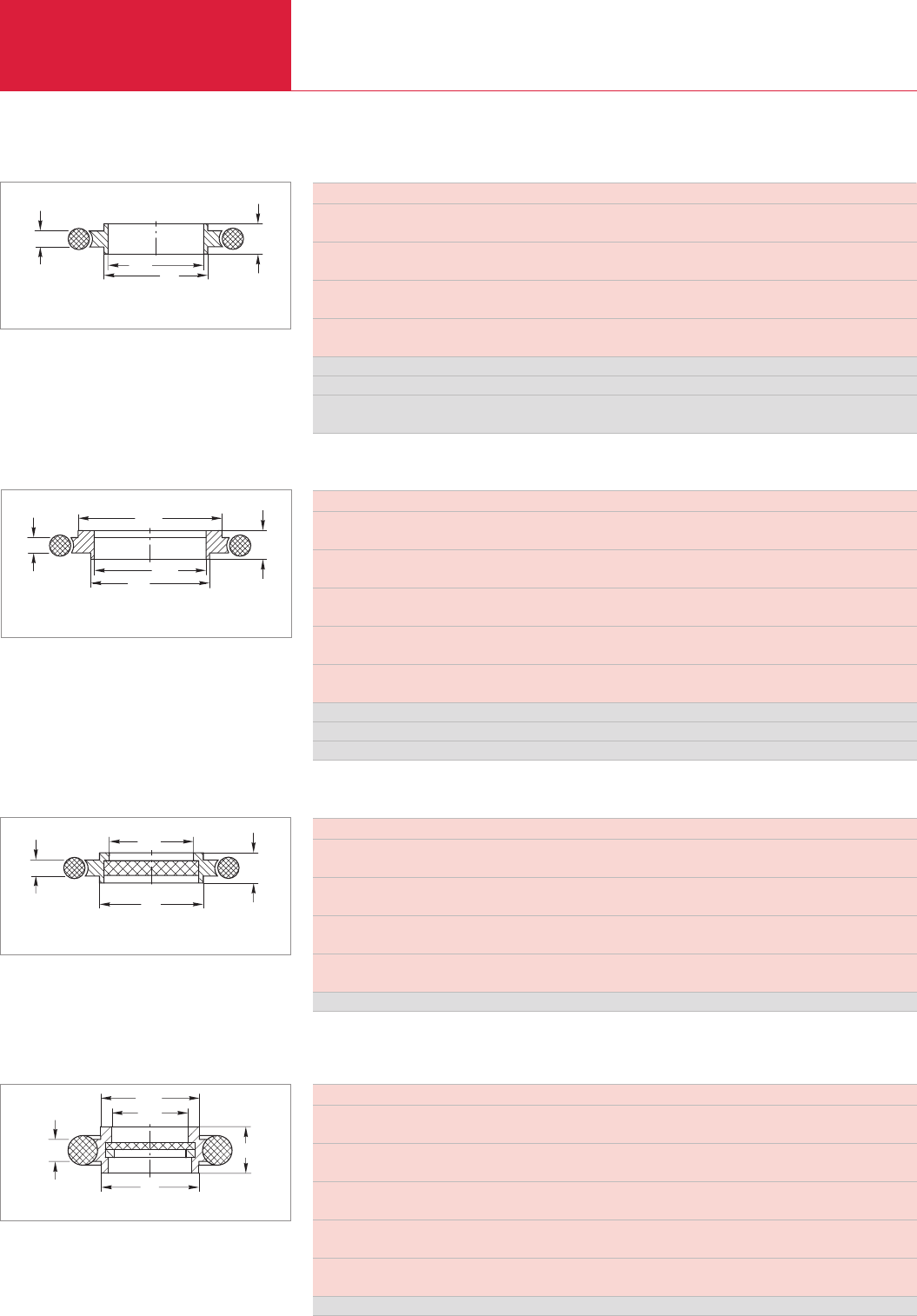
Important: In the table of Section “General” the German designation for the type of steel is also stated in accordance with AISI.
ISO-KF Flange Fittings and Components
Vacuum Fittings and Feedthroughs
C13.08 LEYBOLD VACUUM PRODUCTS AND REFERENCE BOOK 2003/2004
DN KF 10 16 20 25 32 40 50
d mm 12 17 22 26 34 41 52
in. 0.47 0.67 0.87 1.02 1.34 1.61 2.05
d1mm 10 16 20 25 32 40 50
in. 0.40 0.63 0.79 0.98 1.26 1.57 1.97
h mm8888888
in. 0.31 0.31 0.31 0.31 0.31 0.31 0.31
h1mm 3.9 3.9 3.9 3.9 3.9 3.9 3.9
in. 0.15 0.15 0.15 0.15 0.15 0.15 0.15
Aluminum/CR Part No. 183 21 183 26 183 22 183 27 183 23 183 28 183 25
Aluminum/FPM Part No. 182 01 182 06 182 02 182 07 182 03 182 08 182 05
Stainless steel/FPM
Part No. 883 21 883 46 883 22 883 47 883 23 883 48 883 25
ød1ød
h1h
Centering Rings (Aluminum 3.1655.53/Stainless Steel 1.4305) with O-Ring (CR/FPM)
Dimensional drawing for the centering rings with O-ring
ød1
ød2
ød
h1h
Dimensional drawing for the centering ring adaptors with O-ring
Centering Ring Adaptors (Aluminum 3.1655.53/Stainless Steel 1.4301) with O-ring (CR/FPM)
DN KF 10/16 20/25 32/40
d mm 12 22 34
in. 0.47 0.87 1.34
d1mm 10 20 32
in. 0.40 0.79 1.26
d2mm 17 26 41
in. 0.67 1.02 1.61
h mm 8 8 8
in. 0.31 0.31 0.31
h1mm 3.9 3.9 3.9
in. 0.15 0.15 0.15
Aluminum/FPM Part No. 182 56 182 57 182 58
Aluminum/CR Part No. 183 56 183 57 183 58
Stainless steel/FPM
Part No. 883 56 883 57 883 58
Centering Rings (Stainless Steel) with Sintered Metal Filter (Stainless Steel 1.4404 and O-Ring (FPM)
DN KF 10 16 25 40 50
d mm 12 17 26 41 52
in. 0.47 0.67 1.02 1.61 2.05
d1mm 8 14 23 38 48
in. 0.31 0.55 0.91 1.50 1.89
h mm 8 8 8 8 8
in. 0.31 0.31 0.31 0.31 0.31
h1mm 3.9 3.9 3.9 3.9 3.9
in. 0.15 0.15 0.15 0.15 0.15
Stainless steel Part No. 883 50 883 51 883 52 883 53 883 54
Air throughput at 20 °C and 200 mbar differential pressure approx. 1m3x h-1 x cm2; pore size: 20 µm
ød1
ød
h1h
Dimensional drawing for the centering rings with sintered metal filter
and O-ring
Important: In the table of Section “General” the German designation for the type of steel is also stated in accordance with AISI.
Centering Rings with Fine Filter (Stainless Steel 1.4305), O-Ring (FPM)
ød2
ød1
ød
h1h
Dimensional drawing for the centering rings with fine filter
DN KF 10 16 25 40 50
d mm 12 17 26 41 52
in. 0.47 0.67 1.02 1.61 2.05
d1mm 12 17 26 41 52
in. 0.47 0.67 1.02 1.61 2.05
d2mm 9 13.5 22 35.5 46
in. 0.35 0.53 0.87 1.4 1.81
h mm 8 8 8 8 8
in. 0.31 0.31 0.31 0.31 0.31
h1mm 3.9 3.9 3.9 3.9 3.9
in. 0.15 0.15 0.15 0.15 0.15
Stainless Steel Part No. 883 95 883 96 883 97 883 98 883 99
Filter material: Stainless steel mesh 1.4404, size of pore: 4 µm, separation grade: 1 µm particles to 98 %
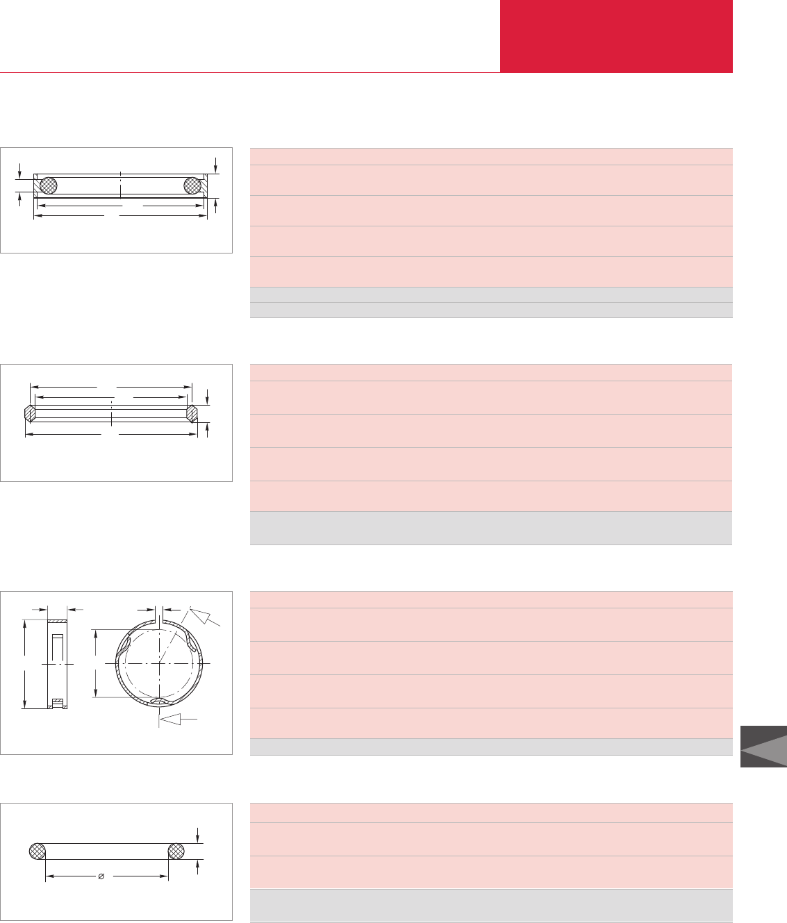
ISO-KF Flange Fittings and Components
Vacuum Fittings and Feedthroughs
C13.09
C13
LEYBOLD VACUUM PRODUCTS AND REFERENCE BOOK 2003/2004
Important: In the table of Section “General” the German designation for the type of steel is also stated in accordance with AISI.
DN KF 10/16 20/25 32/40 50
d mm 32 42 57 77
in. 1.26 1.65 2.24 3.03
d1mm 30.2 40.2 55.2 75.2
in. 1.19 1.58 2.17 2.96
h mm 7 7 7 7
in. 0.28 0.28 0.28 0.28
h1mm 3.9 3.9 3.9 3.9
in. 0.15 0.15 0.15 0.15
Aluminum/CR Part No. 183 50 183 51 183 52 183 59
Aluminum/FPM Part No. 183 53 183 54 183 55 183 60
Outer Centering Rings (Aluminum 3.1655.53) with O-Ring (CR/FPM)
ød1
ød
h1h
Dimensional drawing for the outer centering rings with O-ring
DN KF 10/16 20/25 32/40 50
d mm 25.6 35.6 50.6 65.6
in. 1.01 1.40 1.99 2.58
d1mm 22.6 32.6 47.6 62.6
in. 0.89 1.38 1.87 2.46
d2mm 19.6 29.6 44.6 59.6
in. 0.77 1.17 1.76 2.35
h mm 4.5 4.5 4.5 4.5
in. 0.18 0.18 0.18 0.18
Aluminum
(set of 3 pieces) Part No. 883 73 883 75 883 77 883 79
Ultra Sealing Rings (Aluminum 3.2315.71)
ød1ød2
ød
h
Dimensional drawing for the ultra sealing rings
DN KF 10/16 20/25 32/40 50
a mm 3 3 3 3
in. 0.12 0.12 0.12 0.12
D mm 32 42 57 77
in. 1.26 1.65 2.24 3.03
d mm 25 35 50 65
in. 0.98 1.38 1.97 2.56
h mm 7 7 7 7
in. 0.28 0.28 0.28 0.28
Stainless steel Part No. 883 74 883 76 883 78 883 69
h
ød
øD
a
Dimensional drawing for the outer support rings
Outer Support Rings (Stainless Steel 1.4310) for Ultra Sealing Rings
DN KF 10 16 1) 20 25 1) 32 40 1) 50
d mm 15 18 25 28 40 42 55
in. 0.59 0.71 0.98 1.10 1.57 1.65 2.17
s mm 5 5 5 5 5 5 5
in. 0.20 0.20 0.20 0.20 0.20 0.20 0.20
FPM (set of 10 pieces)
Part No. 210 600 210 605 210 610 210 615 210 620 210 625 210 630
1) Also for adaptor/centering rings
Spare O-Ring Gaskets for KF Flange Connections
d
s
Dimensional drawing for the spare O-ring gaskets for KF flange connections
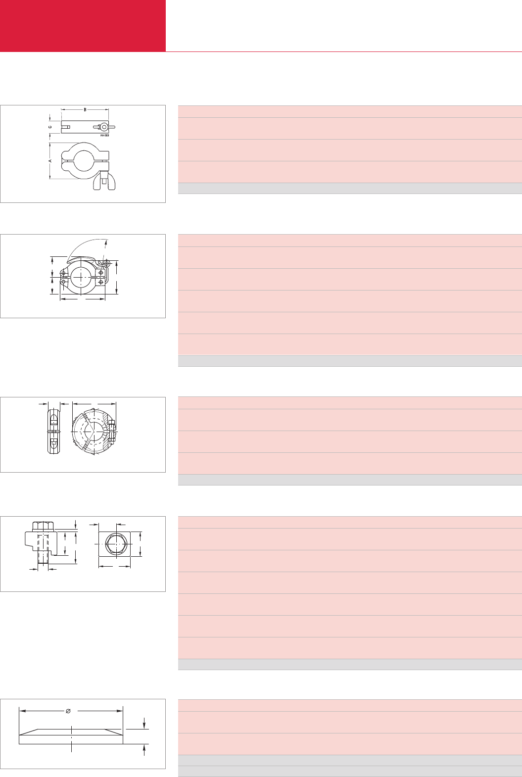
Important: In the table of Section “General” the German designation for the type of steel is also stated in accordance with AISI.
ISO-KF Flange Fittings and Components
Vacuum Fittings and Feedthroughs
C13.10 LEYBOLD VACUUM PRODUCTS AND REFERENCE BOOK 2003/2004
DN KF 10/16 20/25 32/40 50
A mm 45 55 70 95
in. 1.77 2.17 2.76 3.74
B mm 61 72 90 123
in. 2.40 2.83 3.54 4.84
C mm 16 16 18 25
in. 0.63 0.63 0.71 0.98
Aluminum Part No. 183 41 183 42 183 43 183 45
Max. torque at the wing nut: 2 Nm
Clamping Rings (Aluminum 3.2582.05)
Dimensional drawing for the clamping rings
DN KF 10/16 20/25 32/40
b mm 45 55 70
in. 1.77 2.17 2.76
b1mm 61 72 90
in. 2.40 2.83 3.54
r mm 48 56 74
in. 1.89 2.20 2.91
x mm 22 27 35
in. 0.87 1.06 1.38
x1mm 30 34 44
in. 1.18 1.34 1.73
Aluminum Part No. 183 46 183 47 183 48
Quick Clamping Rings (Aluminum 3.2582.05)
x1
x
b1
b
r
Dimensional drawing for the quick clamping rings
DN KF 10/16 20/25 32/40 50
D mm 52 75 90 115
in. 2.05 2.95 3.54 4.52
h mm 18 20 23 28
in. 0.71 0.79 0.90 1.10
Hexagon socket screw to DIN 912 mm M 4 x 30 M 6 x 30 M 8 x 35 M 8 x 50
in. M 4 x 1.18 M 6 x 1.18 M 8 x 1.38 M 8 x 1.97
Aluminum Part No. 882 75 882 77 882 78 882 79
Clamping Collars (Aluminum 3.2162.05) for Ultra Sealing Rings
D
h
Dimensional drawing for the clamping collars for ultra sealing rings
DN KF 10 - 50
a mm 19.5
in. 0.77
a1mm 11.5
in. 0.45
b1mm 14.0
in. 0.55
h mm 12.5
in. 0.49
h1mm 1.6
in. 0.06
h2mm 20.0
in. 0.79
Aluminum (1 set = 4 claws) Part No. 885 00
Claw, complete (Aluminum 3.2315.08)
M6
h
h1
a
h2
a1
b1
Dimensional drawing for the claw, complete
DN KF 10 16 25 40 50
d mm 30 30 40 55 75
in. 1.18 1.18 1.57 2.17 2.95
h mm 5 5 5 5 6
in. 0.20 0.20 0.20 0.20 0.24
Aluminum Part No. 184 41 184 46 184 47 184 48 184 45
Stainless steel Part No. 884 41 884 36 884 37 884 38 884 45
Blank Flanges (Aluminum 3.2315.71 / Stainless Steel 1.4301)
d
h
Dimensional drawing for the blank flanges
Top View
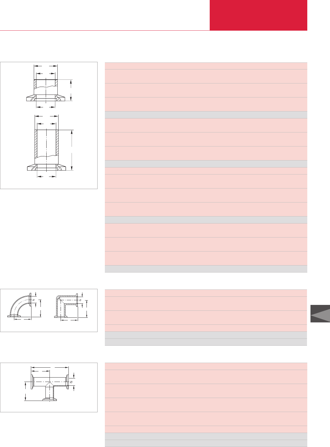
ISO-KF Flange Fittings and Components
Vacuum Fittings and Feedthroughs
C13.11
C13
LEYBOLD VACUUM PRODUCTS AND REFERENCE BOOK 2003/2004
Important: In the table of Section “General” the German designation for the type of steel is also stated in accordance with AISI.
DN (short tubulation) KF 10 16 25 40 50
d1mm 16 20 30 45 55
in. 0.63 0.79 1.18 1.77 2.17
d2mm 12 16 26 41 51
in. 0.47 0.63 1.02 1.61 2.01
l mm 20 20 20 20 20
in. 0.79 0.79 0.79 0.79 0.79
Steel Part No. 182 31 182 32 182 33 182 34 182 35
d1mm 16 20 30 45 54
in. 0.63 0.79 1.18 1.77 2.13
d2mm 12 16 26 41 50
in. 0.47 0.63 1.02 1.61 1.97
l mm 20 20 20 20 20
in. 0.79 0.79 0.79 0.79 0.79
Stainless steel Part No. 866 31 866 32 866 33 866 34 866 35
DN (long tubulation) 10 KF 16 KF 25 KF 40 KF 50 KF
d1mm 16 20 30 45 55
in. 0.63 0.79 1.18 1.77 2.17
d2mm 12 16 26 41 51
in. 0.47 0.63 1.02 1.61 2.01
l mm 70 70 70 70 70
in. 2.76 2.76 2.76 2.76 2.76
Steel Part No. 182 81 182 82 182 83 182 84 182 85
d1mm 16 20 30 45 54
in. 0.63 0.79 1.18 1.77 2.13
d2mm 12 16 26 41 50
in. 0.47 0.63 1.02 1.61 1.97
l mm 70 70 70 70 70
in. 2.76 2.76 2.76 2.76 2.76
Stainless steel Part No. 866 81 866 82 866 83 866 84 866 85
KF Flanges with Short / Long Tubulation (Steel 1.0037 / Stainless Steel 1.4301)
2
ød
DN
l
1
ød
Dimensional drawing for the KF flanges with short and long tubulation
DN
l
2
ød
1
ød
Elbows 90°(Aluminum 3.2315.08 / Stainless Steel 1.4301)
a
a
d1
d1
a
a
Dimensional drawing for the elbows 90°;
stainless steel (left) and aluminum (right)
DN KF 16 25 40 50
a mm 40 50 65 70
in. 1.57 1.97 2.56 2.76
d1mm 16 15 25 39 40.5 49
in. 0.63 0.59 0.98 1.34 1.59 1.93
Conductance l/s 6.5 – 18.9 – 56.5 – –
Aluminum Part No. 184 36 – 184 37 – 184 38 – –
Stainless steel
Part No. – 884 61 – 884 62 – 884 64 884 65
DN KF 16 25 40 50
a mm 40 50 65 70
in. 1.57 1.97 2.56 2.76
b mm 80 100 130 140
in. 3.15 3.94 5.12 5.51
d1 (Aluminum) mm 16 25 39 –
in. 0.63 0.98 1.54 –
d1 (Stainless steel) mm 16 25 40.5 53
in. 0.63 0.98 1.59 2.09
Conductance l/s 6.5 – 18.9 – 56.5 – –
Aluminum Part No. 184 06 – 184 07 – 184 08 – –
Stainless steel Part No. – 884 71 – 884 72 – 884 74 884 75
Tees (Aluminum 3.2315.08 / Stainless steel 1.4301)
d
a
ab
1
Dimensional drawing for the tees
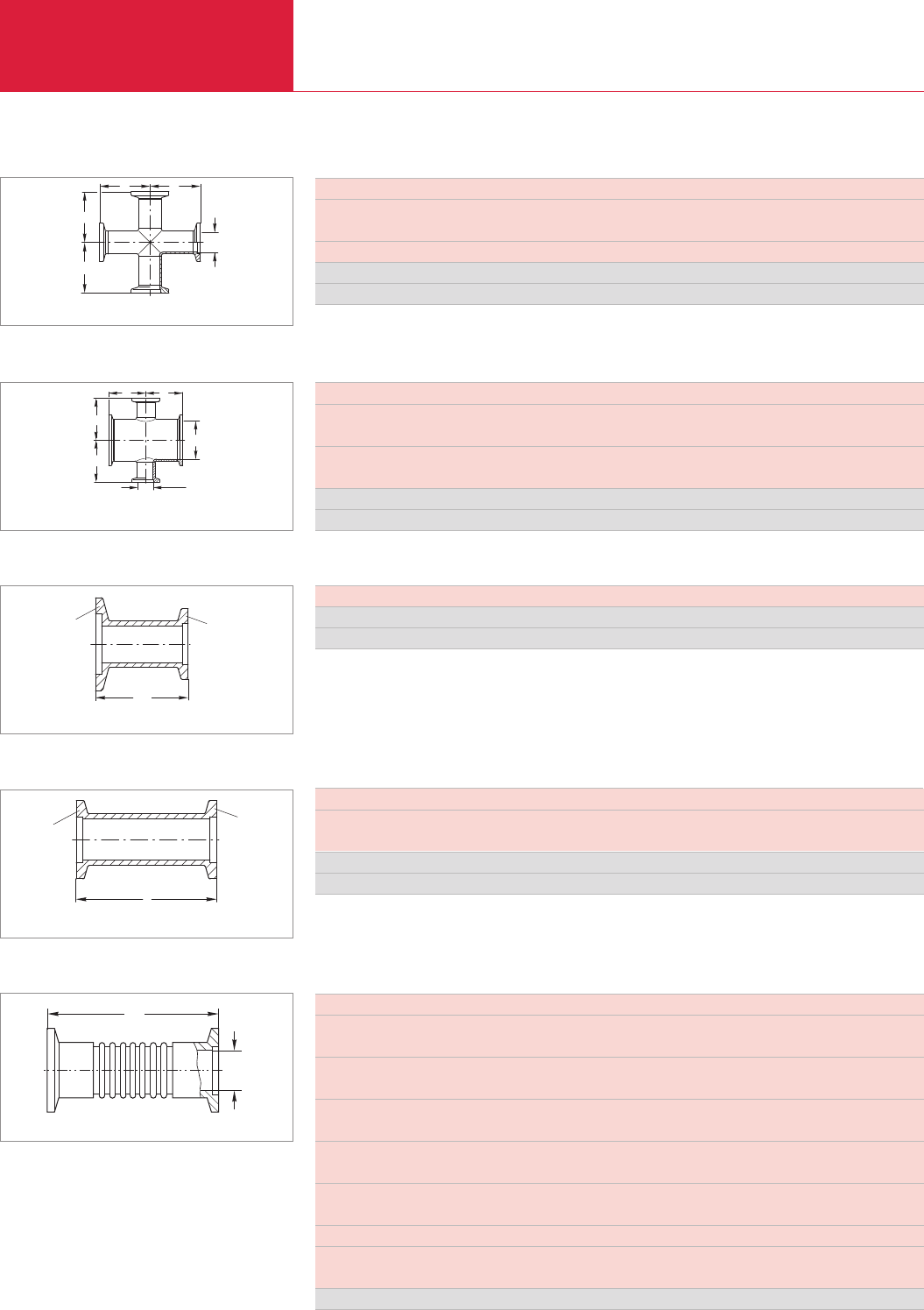
Important: In the table of Section “General” the German designation for the type of steel is also stated in accordance with AISI.
ISO-KF Flange Fittings and Components
Vacuum Fittings and Feedthroughs
C13.12 LEYBOLD VACUUM PRODUCTS AND REFERENCE BOOK 2003/2004
DN KF 16 25 40 50
a mm 40 50 65 70
in. 1.57 1.97 2.56 2.67
Conductance l/s 6.5 – 18.9 – 56.5 – –
Aluminum Part No. 184 71 – 184 74 – 184 75 – –
Stainless steel Part No. – 884 85 – 884 86 – 884 87 884 88
4-Way Crosses (Aluminum 3.2315.08 / Stainless 1.4301)
DN
aa
a
a
Dimensional drawing for the 4-way crosses
DN/DN1KF 25/16 40/16 50/16
a mm 35 40 50
in. 1.38 1.57 1.97
a1mm 35 45 50
in. 1.38 1.77 1.97
Aluminum Part No. 184 57 184 58 –
Stainless steel Part No. 884 96 884 97 884 98
4-Way Reducer Crosses with DN 10 Flanges (Aluminum 3.2315.08 / Stainless steel 1.4301)
a
DN
a
1
a
1
a
1
DN
Dimensional drawing for the 4-way reducer crosses with lateral DN 10 flanges
DN/DN1KF 25/16 40/16 40/25 50/40
Aluminum Part No. 183 86 183 89 183 87 183 88
Stainless steel Part No. 885 04 885 07 885 05 885 06
Reducers (Aluminum 3.2315.72 / Stainless Steel 1.4305)
1
40
DN DN
Dimensional drawing for the reducers
DN KF 16 25 40
l mm 80 100 130
in. 3.15 3.94 5.12
Aluminum Part No. 184 80 184 81 184 82
Stainless steel Part No. 884 17 884 18 884 19
Intermediate Pieces (Aluminum 3.2315.72 / Stainless Steel 1.4301)
DN DN
l
Dimensional drawing for the intermediate pieces
DN KF 16 25 40 50
l mm 70 80 100 100
in. 2.76 3.15 3.94 3.94
Wall thickness mm 0.13 0.13 0.15 0.2
in. 0.005 0.005 0.006 0.008
Max. extension, axial mm 10.5 13 18 16
in. 0.41 0.51 0.71 0.63
Compression mm 6.5 8 11 10
in. 0.26 0.31 0.43 0.39
Tension mm 4 5 7 6
in. 0.16 0.20 0.28 0.24
Max. angle degress 1) ± 21 ± 17 ± 15 ± 15
Lateral motion mm ± 4 ± 3.5 ± 7 ± 8
in. ± 0.16 ± 0.14 ± 0.28 ± 0.31
Stainless steel Part No. 872 41 872 43 872 45 872 46
1) When utilizing the maximum bending angle, no extension along the axial axis will be possible !
Bellows (Stainless Steel 1.4571) with Flanges (Stainless Steel 1.4301)
DN
l
Dimensional drawing for the bellows with flanges
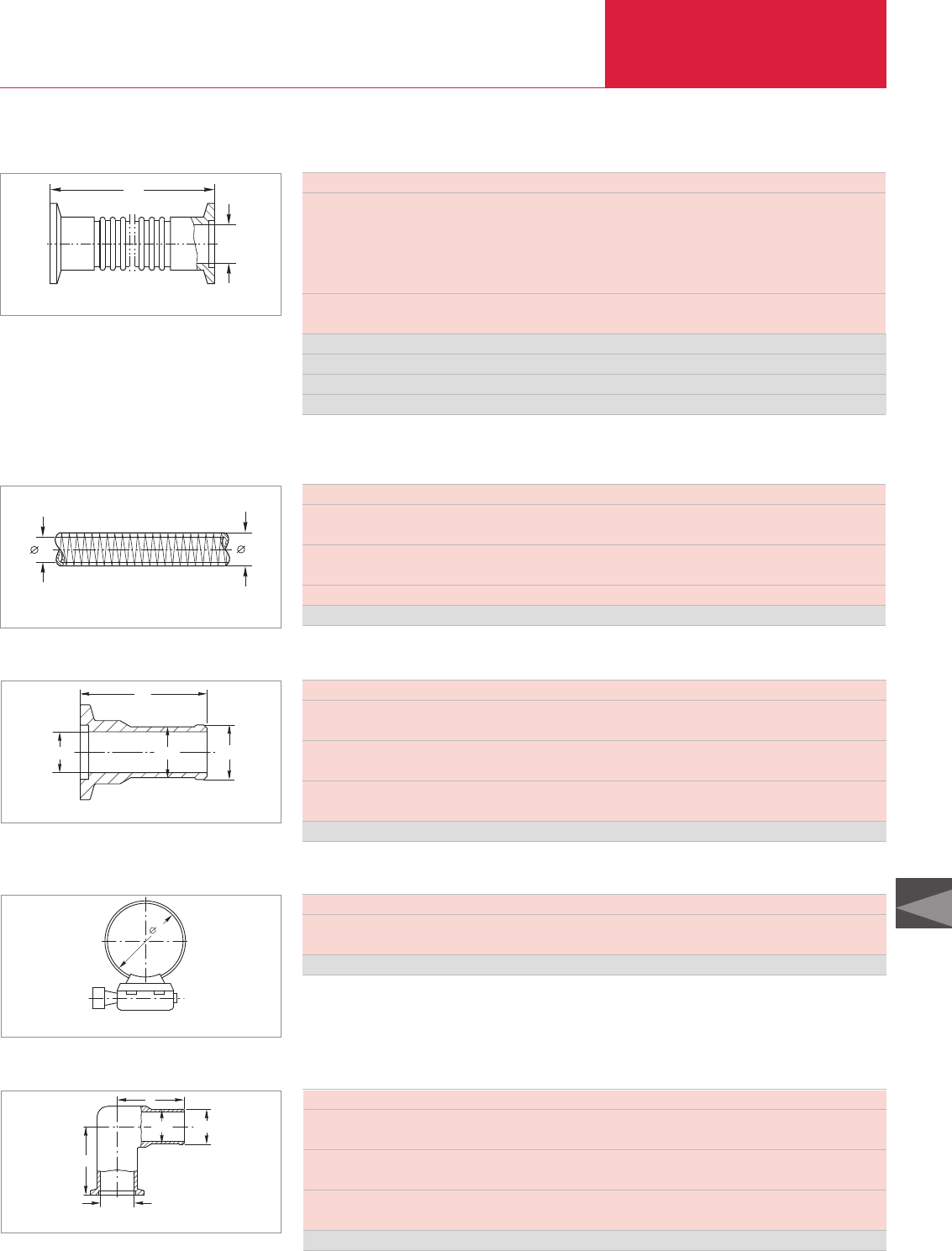
Important: In the table of Section “General” the German designation for the type of steel is also stated in accordance with AISI.
Vacuum Fittings and Feedthroughs
C13.13
LEYBOLD VACUUM PRODUCTS AND REFERENCE BOOK 2003/2004
ISO-KF Flange Fittings and Components
C13
Vacuum Hoses1) with Flanges (Stainless Steel 1.4571)
DN
l
Dimensional drawing for the vacuum hoses with flanges
DN KF 16 25 40 50
Max. bending radius (inside)
with multiple bending mm 68.5 103 129 198
in. 2.70 4.06 5.08 7.80
with single bend mm 50 63 100 130
in. 1.97 2.48 3.94 5.12
Wall thickness mm 0.2 0.2 0.2 0.3
in. 0.008 0.008 0.008 0.01
l = 250 mm (9.84 in.) Part No. 867 81 867 83 867 85 867 86
l = 500 mm (19.69 in.) Part No. 867 91 867 93 867 95 867 96
l = 750 mm (29.53 in.) Part No. 867 41 867 43 867 45 867 46
l = 1000 mm (39.37 in.) Part No. 868 01 868 03 868 05 868 06
1) Flexible vacuum hoses must be linked to an external mechanical assembly
DN KF 16 25 40
d mm 23 33 53
in. 0.91 1.30 2.09
d1mm 16 25 40
in. 0.63 0.98 1.57
Length m by the metre
PVC coiled vacuum hose Part No. 172 41 172 42 172 43
PVC Coiled Vacuum Hoses without Flanges
1d
d
Dimensional drawing for the PVC vacuum hoses
DN KF 16 25 40
DN1(tube) mm 17 26 41
in. 0.67 1.02 1.61
l mm 40 40 40
in. 1.57 1.57 1.57
d1mm 13 22 37
in. 0.51 0.87 1.46
Aluminum Part No. 182 45 182 46 182 47
KF Flanges with Hose Nozzle (Aluminum 3.0615.71)
DN1
ød1DN
l
Dimensional drawing for the KF flanges with hose nozzle
DN KF 16 25 40
d (min/max.) mm 13/32 19/44 29/76
in. 0.51/1.26 0.75/1.73 1.14/2.99
Stainless steel Part No. 866 21 866 22 866 23
Hose Clamps (Stainless Steel 1.4301)
d
Dimensional drawing for the hose clamps
DN KF 16 25 40
DN1(tube) mm 17 26 41
in. 0.67 1.02 1.61
a mm 40 50 65
in. 1.57 1.97 2.56
d1mm 16 25 39
in. 0.63 0.98 1.54
Aluminum Part No. 182 15 182 16 182 17
Elbows 90°with Hose Nozzle (Aluminum 3.2381.02)
a
a
ød1
DN1
DN
Dimensional drawing for the elbows 90° with hose nozzle
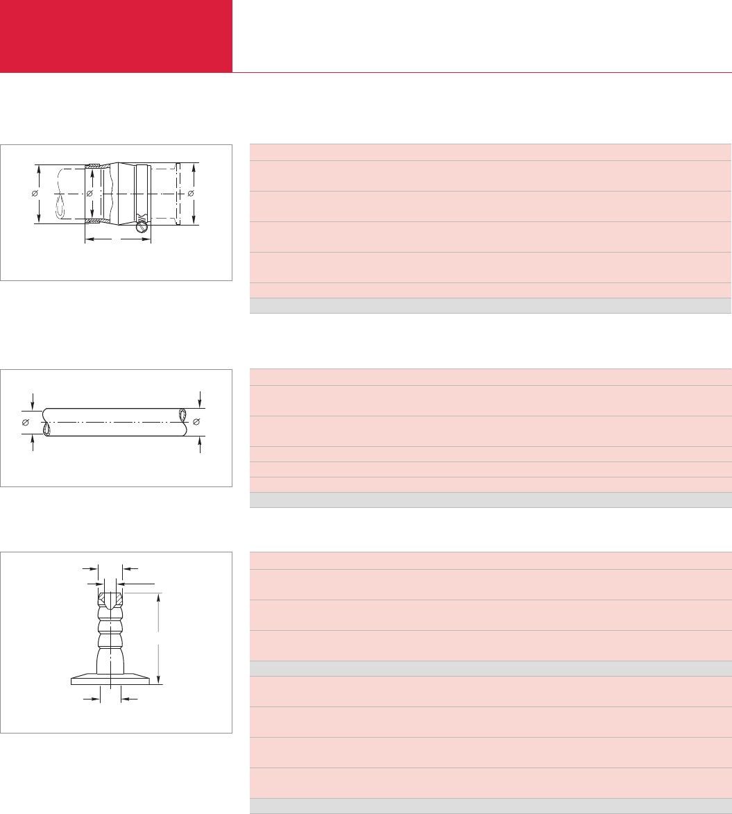
ISO-KF Flange Fittings and Components
Vacuum Fittings and Feedthroughs
C13.14 LEYBOLD VACUUM PRODUCTS AND REFERENCE BOOK 2003/2004
DN KF 16 25 40
D mm 44 50 68
in. 1.73 1.97 2.68
d – tube tolerance mm 16 25 40
in. 0.63 0.98 1.57
d1mm 24 33 48
in. 0.94 1.30 1.89
l mm 58 60 64
in. 2.28 2.36 2.52
Leak rate mbar x l x s-1 ≤1 x 10⁻⁵
Stainless Steel/CR Part No. 182 78 1) 182 79 1) 182 80 1)
1) Is supplied complete with stainless steel hose clamps
CR Compensation Elements with Integrated Support Ring
l
D
d
d1
Dimensional drawing for the compensation elements with integrated
support ring
DN KF 10 16 20
d mm 17 25 32
in. 0.66 0.98 1.26
d1mm 7 10 16
in. 0.28 0.39 0.63
Length m by the metre
Hardness – Shore A – 55 ± 5
Temperature range °C (°F) -30 to +85 (-22 to +176)
Rubber vacuum hose Part No. 172 02 172 03 172 04
Rubber Vacuum Hoses (NR) for Hose Nozzles
1d
d
Dimensional drawing for rubber vacuum hoses
DN KF 16 25 40
d mm 12 12 12
in. 0.47 0.47 0.47
d11) mm 7 7 7
in. 0.26 0.26 0.26
l mm 40 40 40
in. 1.57 1.57 1.57
Aluminum Part No. 182 90 182 91 182 92
DN KF 16 25 40
in. 0.63 0.98 1.57
d mm 12 12 12
in. 0.47 0.47 0.47
d11) mm 7 7 7
in. 0.26 0.26 0.26
l mm 40 40 40
in. 1.57 1.57 1.57
Stainless steel Part No. 885 14 885 08 885 09
1) Also recommended inside diameter for the hose
KF Flanges with Hose Nozzles (Aluminum 3.0615.71 and Stainless Steel 1.4305)
DN
l
ød1
ød1
Dimensional drawing for the KF flanges with hose nozzle
Important: In the table of Section “General” the German designation for the type of steel is also stated in accordance with AISI.
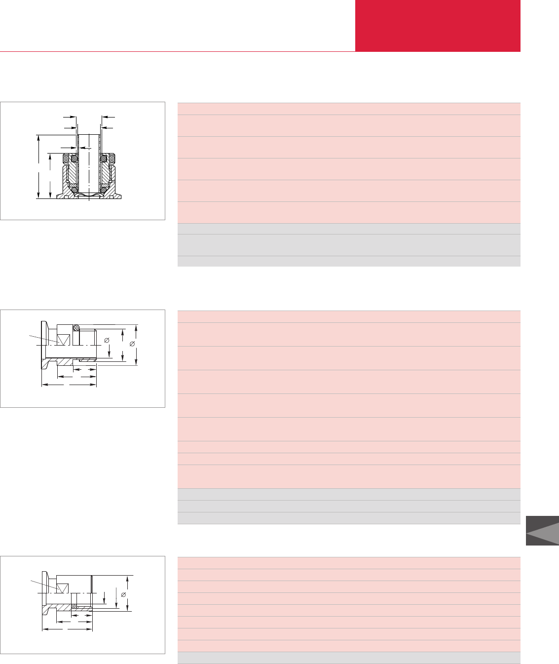
Important: In the table of Section “General” the German designation for the type of steel is also stated in accordance with AISI.
LEYBOLD VACUUM PRODUCTS AND REFERENCE BOOK 2003/2004
Vacuum Fittings and Feedthroughs
C13.15
ISO-KF Flange Fittings and Components
C13
DN KF 10 16 16 25 16 40
l mm 35 35 42 45 26 50
in. 1.34 1.34 1.65 1.77 1.02 1.97
l1mm 25 25 – 35 – 40
in. 0.98 0.98 – 1.34 – 1.57
l2mm 15 15 11,5 25 8 30
in. 0.59 0.59 0.45 0.98 0.31 1.18
d mm 12 16 5 25 5 41
in. 0.47 0.63 0.20 0.98 0.20 1.61
d1mm 22 26 – 39 – 54
in. 0.87 1.02 – 1.54 – 2.13
G 3/8" 1/2" M 16 x 1.5 1" 1/8" 1 1/2"
G inch 3/8" 1/2" M 16 x 0.06 1" 1/8" 1 1/2"
SW (width across flats) mm 19 22 17 36 13 50
in. 0.75 0.87 0.67 1.42 0.51 1.97
Stainless steel Part No. 886 30 886 31 – 886 32 – 886 33
Stainless steel 1.4571 Part No. – – – – 160 26 –
Nickel-plated steel Part No. – – 168 40 – – –
dG
SW
l1
l2
l
1
d
Dimensional drawing for the screw-in flanges
Screw-in Flanges (Stainless Steel 1.4305 / FPM)
DN KF 10 16 25 40
l mm 35 35 45 50
l1mm 25 25 35 40
l2mm 15 15 25 30
d mm 10 15 24 38
d1mm 20 25 39 54
G inch 3/8" 1/2" 1" 1 1/2"
SW (width across flats) mm 17 21 36 50
Stainless steel Part No. 884 25 884 26 884 27 884 28
SW
dG
l1
l2
l
1
d
Dimensional drawing for the screw-on flanges
Screw-on Flanges (Stainless Steel 1.4305 / FPM)
KF Flanges with Compression Fitting for Glass/Metal/Plastic Tubes (Aluminum 3.0615 /
ød
b
ømax. bore
Di
l1l
Dimensional drawing for the KF flanges with compression fitting
DN KF 10 40
b mm 1.5 1.5
in. 0.06 0.06
d (glass) mm 10 26
in. 0.39 1.02
l mm 30 45
in. 1.18 1.77
l1mm 50 65
in. 1.97 2.56
DiBore-max. ± 0.2 mm 11 27
± 0.008 in. 0.43 1.06
Compression Fitting Part No. 184 61 184 66
Sealing set (FPM) for high temperatures
(150 °C (302 °F)), set = 10 pieces Part No. 105 94 210 610
Only for pressure ≤1000 mbar ( ≤750 Torr)
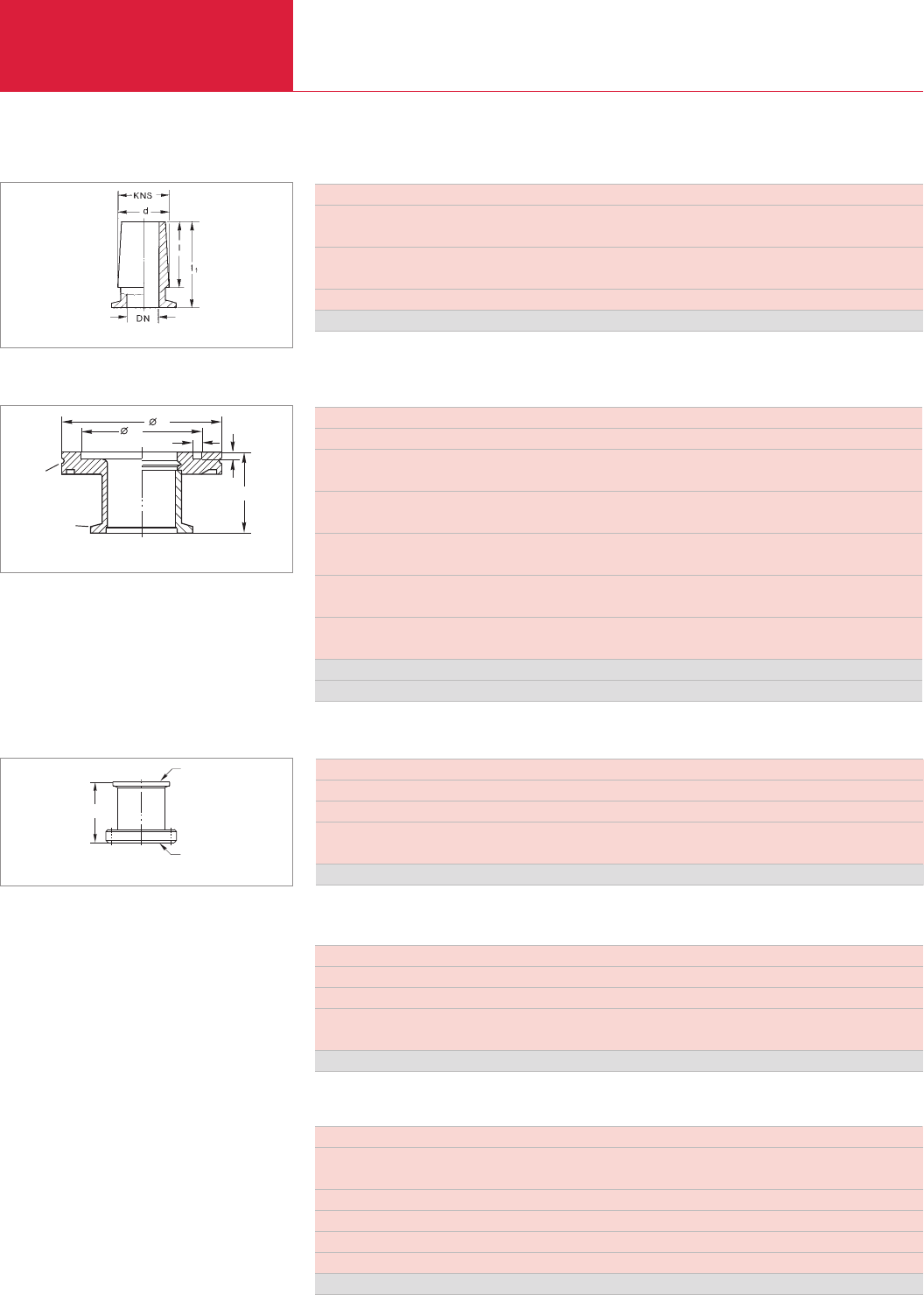
Adaptors
Vacuum Fittings and Feedthroughs
C13.16 LEYBOLD VACUUM PRODUCTS AND REFERENCE BOOK 2003/2004
Important: In the table of Section “General” the German designation for the type of steel is also stated in accordance with AISI.
DN KF 16 25 40
KNS - d / l mm 19 / 26 29 / 32 45 / 40
in. 0.75 / 1.02 1.14 / 1.26 1.77 / 1.57
l1mm 40 45 55
in. 1.57 1.77 2.17
Taper 1 : 10 1 : 10 1 : 10
Stainless steel Part No. 184 87 184 85 184 86
Dimensional drawing for the KF flanges with ground cone
KF Flanges with Ground Cone (Stainless Steel 1.4301)
DN KF 40 50 40
DN1ISO-K 63 63 100
d1mm 70 70 102
in. 2.76 2.76 4.02
l mm 40 45 40
in. 1.57 1.77 1.57
s mm 5 5 5
in. 0.2 0.2 0.2
t mm 4.5 4.5 4.5
in. 0.18 0.18 0.18
Weight kg 0.5 0.6 0.8
lbs 1.10 1.32 1.77
Stainless steel 1.4301 Part No. 887 40 887 41 887 42
Aluminum 3.2315.71 Part No. 269 40 269 41 –
l
d1st
d
DN
DN1
Adaptors/Reducers KF – ISO-K
Dimensional drawing for the adaptor reducers KF – ISO-K;
left: aluminum; right: stainless steel
DN KF 16 16 25 25 40
DN1CF 16 40 16 40 40
or inch 1 5/16" 2 3/4" 1 5/16" 2 3/4" 2 3/4"
l mm 35 30 35 30 50
in. 1.38 1.18 1.38 1.18 2.17
Stainless steel 1.4301 Part No. 837 81 837 82 837 83 837 84 837 36
DN
DN1
l
Adaptors KF – CF (Stainless Steel 1.4301)
Dimensional drawing for the adaptors CF – ISO-KF
Copper Gaskets for CF-Flanges (OFHC-Copper - Oxygen-Free)
DN CF 16 40 63 100 160 200 250
Set of 10 x x x x x x –
Set of 5 – – – – – – x
Inside diameter mm 16.2 39 63.6 101.8 152.6 203.4 254
in. 0.64 1.54 2.5 4.0 6.0 8.0 10
OFHC-Copper Part No. 839 41 839 43 839 44 839 45 839 46 839 47 839 48
DN CF 16 40 63 100 160 200 250
Set of 5 x x – – – – 1 FPM O-ring
with Support Ring
Profile seal, set of 2 – – x x x x –
Gasket with support ring – – – – – – x
Degassing temperature °C 160 160 160 160 160 160 160
°F 320 320 320 320 320 320 320
FPM Part No. 839 21 839 23 839 34 839 35 839 36 839 37 839 03
FPM Gaskets for CF-Flanges

Adaptors
Vacuum Fittings and Feedthroughs
C13.17
C13
LEYBOLD VACUUM PRODUCTS AND REFERENCE BOOK 2003/2004
Important: In the table of Section “General” the German designation for the type of steel is also stated in accordance with AISI.
DN CF 16 40 63/100 160 200/250
Dimensions (d x l) mm M 4 x 20 M 6 x 35 M 8 x 50 M 8 x 55 M 8 x 60
in. M 4 x 0.79 M 6 x 1.38 M 8 x 1.97 M 8 x 2.17 M 8 x 2.36
Torque Nm 4 10 20 20 20
Quantity per set
Bolts 25 25 25 25 25
Nuts 25 25 25 25 25
Bolts – – – – –
Washers 25 25 25 25 25
Set Part No. 839 00 839 01 839 04 839 05 839 07
Bolts, Nuts and Washers for CF-Flanges
For details on UHV seals and further components, see Product Section C15.
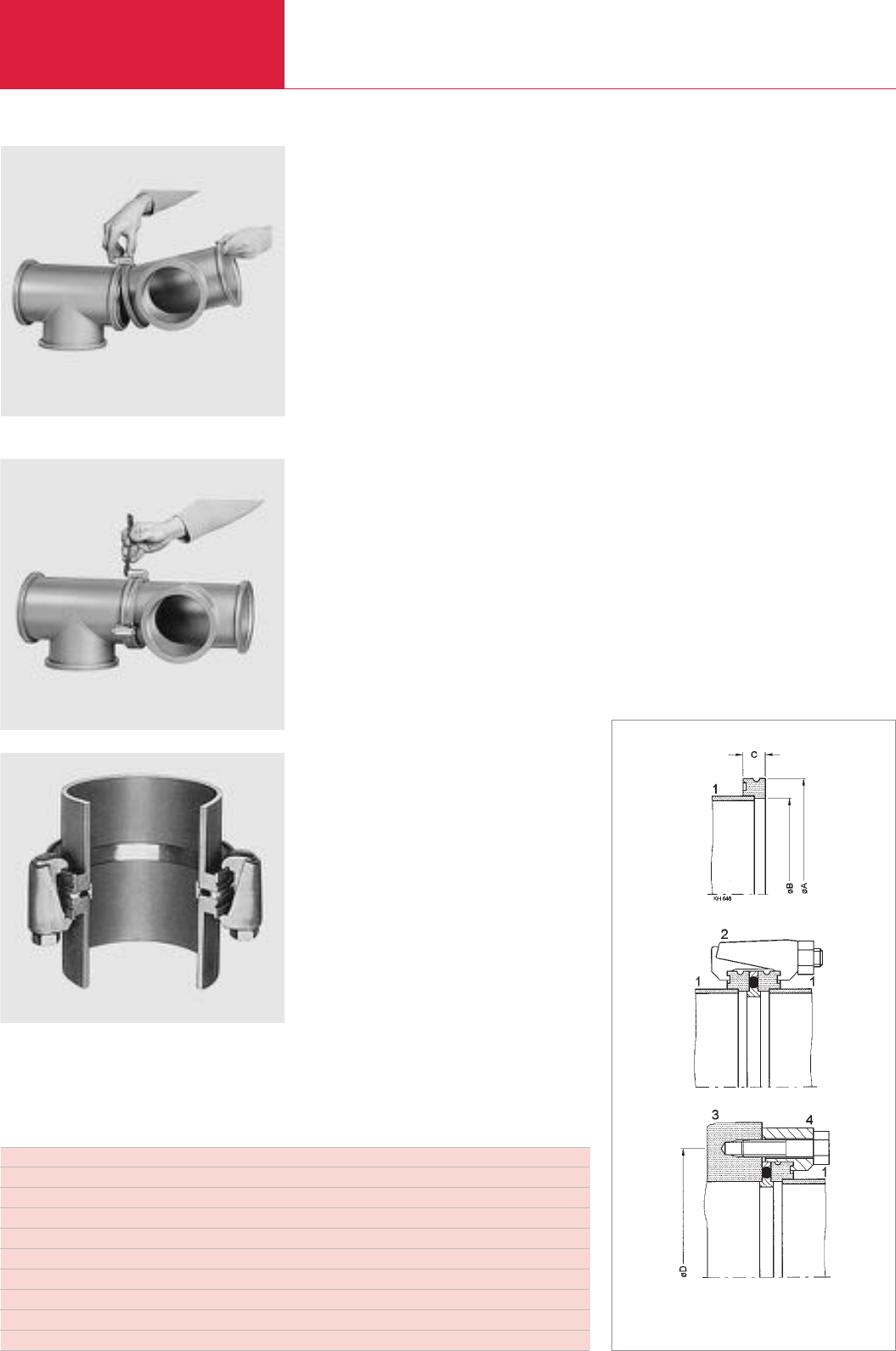
(ISO-K) Clamp Flange Fittings and Components
Vacuum Fittings and Feedthroughs
C13.18 LEYBOLD VACUUM PRODUCTS AND REFERENCE BOOK 2003/2004
Attaching a clamp flange component and fitting of the clamp
Tightening the clamping bolt
ISO-K clamp flange connection
Flange Components
DN 63 to DN 630 ISO-K
(to DIN 28 404 in line with
ISO 1609/3669)
The clamp flange connection was introduced to
the vacuum industry by LEYBOLD. Since the
fitting of clamp flanges does not depend on any
bolt holes in the flange, these components may
be installed in any orientation.
Advantages to the User
◆Quick to fit
◆Safe and reliable
◆Can be turned in any direction
◆Easy to disassemble, thus easy to clean
◆Suitable for pressures down to 10
-7
mbar
(0.75 x 10
-7
Torr) when using O-rings and
down to 10
-9
mbar (0.75 x 10
-9
Torr) when
using metal gaskets
◆Easily adaptable to other flange systems
◆Mounted by means of clamps (ISO-K) or
collar flange with retaining ring (ISO-F,
DIN 2501)
◆Clamp flange components are used with CR
or FPM gaskets or with ultra sealing disks
made of aluminum
◆Degassing temperatures
for CR, max. 100 °C (212 °F)
for FPM, max. 150 °C (302 °F)
for the ultra sealing disk, max.
200 °C (392 °F)
The pressure range for the application depends in
each case on the sealing method which is used
and is thus limited for ultra sealing disks to
10
-9
mbar (0.75 x 10
-9
Torr), for FPM gaskets to
10
-8
mbar (0.75 x 10
-8
Torr) and for CR sealed
components to 10
-7
mbar (0.75 x 10
-7
Torr).
Flexible Compensation
Elements (CR)
Vacuum systems and pump systems often re-
quire components which are capable of protect-
ing sensitive instruments against impacts or
excessive vibrations while linking tubes at the
same time.
Advantages to the User
◆Easy and quick to install
◆Safe and reliable
◆Tubes may be turned in any direction
◆No centering ring and sealing ring is needed
since the seal is provided by the smooth tube
surface
◆Capable of withstanding temperatures up to
100 °C (212 °F)
◆Suitable for pressures down to 10
-5
mbar
(0.75 x 10
-5
Torr)
Nominal diameter A B C Number of clamps D Screws for claws Number of claws
DN 63 ISO-K 95 70 12 4 110 M 8 x 35 4
DN 100 ISO-K 130 102 12 4 145 M 8 x 35 8
DN 160 ISO-K 180 153 12 4 200 M 10 x 35 8
DN 200 ISO-K 240 213 12 6 260 M 10 x 35 12
DN 250 ISO-K 290 261 12 6 310 M 10 x 35 12
DN 320 ISO-K 370 318 17 8 395 M 12 x 50 12
DN 400 ISO-K 450 400 17 8 480 M 12 x 50 16
DN 500 ISO-K 550 501 17 12 580 M 12 x 50 16
DN 630 ISO-K 690 651 22 12 720 M 12 x 55 20
1 Clamp flange
2 Claw
3 Base plate
4 Claw
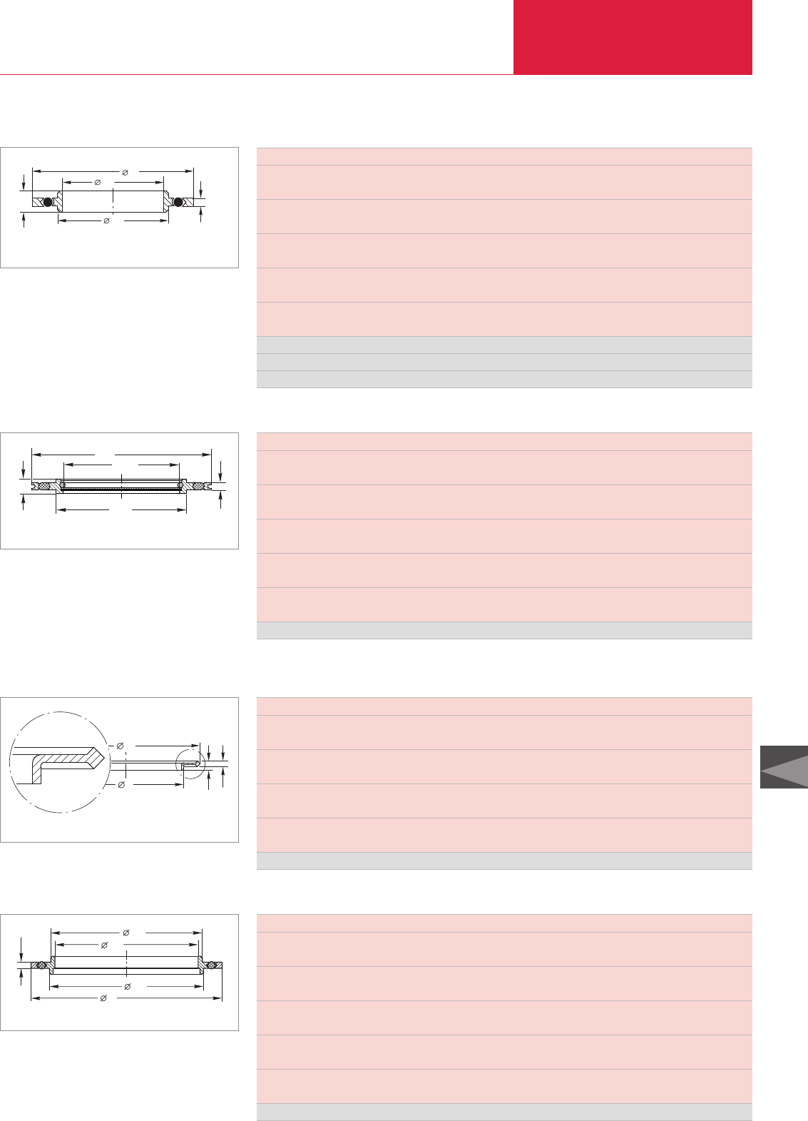
(ISO-K) Clamp Flange Fittings and Components
Vacuum Fittings and Feedthroughs
C13.19
C13
LEYBOLD VACUUM PRODUCTS AND REFERENCE BOOK 2003/2004
Important: In the table of Section “General” the German designation for the type of steel is also stated in accordance with AISI.Important: In the table of Section “General” the German designation for the type of steel is also stated in accordance with AISI.
DN ISO-K 63 100 160 200 250 320 400 500 630 800 1000
d mm 96 128 179 239 287 358 440 541 691 840 1040
in. 3.78 5.04 6.93 9.41 11.30 14.09 17.32 21.9 27.2 33.07 40.94
d1mm 70 102 153 213 261 318 400 501 651 800 1000
in. 2.76 4.02 6.02 8.39 10.28 12.52 15.75 19.72 25.65 31.5 39.37
d2mm 67 99 150 210 258 313 395 496 643 795 995
in. 2.64 3.9 5.91 8.27 10.16 12.32 15.55 19.53 25.43 31.18 39.17
h mm 8 8 8 8 8 14 14 14 14 14 14
in. 0.31 0.31 0.31 0.31 0.31 0.55 0.55 0.55 0.55 0.55 0.55
s mm 3.9 3.9 3.9 3.9 3.9 5.6 5.6 5.6 5.6 5.6 5.6
in. 0.15 0.15 0.15 0.15 0.15 0.22 0.22 0.22 0.22 0.22 0.22
Aluminum/FPM Part No. 268 41 268 42 268 43 268 44 268 45 268 46 268 47 268 48 268 49 268 50 268 51
Aluminum/CR Part No. 268 05 268 06 268 09 268 19 268 17 268 18 268 14 268 15 268 16 – –
Stainless Steel/FPM
Part No. 887 03 887 04 887 07 887 02 887 08 – – – – – –
Centering Rings (Aluminum / Stainless Steel) with O-Ring (NBR)
h
d1
d2
ds
Dimensional drawing for the centering rings with O-ring
DN ISO-K 63 100
b mm 8 8
in. 0.31 0.31
b1mm 4 4
in. 0.16 0.16
d mm 96 128
in. 3.78 5.04
d1mm 70 102
in. 2.76 4.02
d2mm 62 94
in. 2.44 3.7
Stainless steel Part No. 887 20 887 21
Filter material: Stainless steel 1.4404, size of pores: 4 µm, separation grade: 1 µm particles to 98 %
Centering Rings with Fine Filter (Stainless Steel 1.4301), O-Ring (FPM)
ød ød2
ød1
b
b1
Dimensional drawing for the centering rings with fine filter
DN ISO-K / ISO-F 63 100 160 250
b mm 4.5 4.5 4.5 4.5
in. 0.18 0.18 0.18 0.18
b1mm 2.6 2.6 2.6 2.6
in. 0.10 0.10 0.10 0.10
d mm 69.8 101.8 152.8 260.8
in. 2.75 4.01 6.02 10.27
d1mm 85.6 116.6 166.6 276.6
in. 3.37 4.59 6.56 10.89
Aluminum Part No. 886 24 886 25 886 26 886 27
Ultra Sealing Disks (Aluminum 3.2315.70)
d
1
d
bb1
Dimensional drawing for the ultra sealing disks
Centering Ring Adaptors (Aluminum) with O-Ring (FPM), ISO-K to LF Standard
b
2
d
3
d
1
d
d
Dimensional drawing for the centering ring adaptors with O-ring
DN ISO-K / LF 100 / 100 160 / 150 250 / 250
b mm 4 4 4
in. 0.16 0.16 0.16
d mm 126 177 285
in. 4.96 6.97 11.22
d1mm 100 150 250
in. 3.94 5.91 9.84
d2mm 102 153 261
in. 4.02 6.02 10.28
d3mm 95 145 244
in. 3.74 5.71 9.61
Aluminum/FPM Part No. 105 25 105 35 105 45
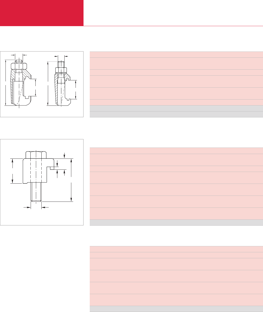
(ISO-K) Clamp Flange Fittings and Components
Vacuum Fittings and Feedthroughs
C13.20 LEYBOLD VACUUM PRODUCTS AND REFERENCE BOOK 2003/2004
Important: In the table of Section “General” the German designation for the type of steel is also stated in accordance with AISI.
DN ISO-K 63 / 250 63 / 250 320 / 400 630 320 / 630
Number of required clamps
per connection 4 / 6 4 / 6 8 / 12 12 8 / 12
d thread M 10 M 10 M 12 M 12 M 12
l mm 60 68 78 88 82.5
in. 2.36 2.68 3.07 3.46 3.25
l1mm 17 to 27 25 to 35 27 to 39 31 to 49 29 to 47
in. 0.67 to 1.06 0.98 to 1.38 1.06 to 1.54 1.22 to 1.93 1.14 to 1.85
1 set = 4 clamps
Galvanized steel 1.1181 Part No. 267 01 267 02 267 10 267 11 –
Stainless steel 1.4401 Part No. 887 99 – – – 210 061
Exact numbers of clamps see first page of the section “(ISO-K) Clamp Flange Fittings and Components”
Clamps for ISO-K
DN ISO-K 63 / 100 160 / 250 320 / 500 630
Number of required clamps
per connection 4 / 8 8 / 12 12 / 16 20
d thread M 8 M 10 M 12 M 12
l mm 35 35 50 55
in. 1.38 1.38 1.97 2.17
l1mm 22.5 23 36.5 41.5
in. 0.89 0.91 1.44 1.63
l2mm 8.6 9.1 15.9 16
in. 0.34 0.36 0.63 0.63
l3mm 2.5 2.5 2.5 2.5
in. 0.10 0.10 0.10 0.10
1 set = 4 claws Part No. 268 25 268 26 268 27 268 28
Exact numbers of claws see first page of the section “(ISO-K) Clamp Flange Fittings and Components”
Claws
Claws (Galvanized Steel 1.1181) for ISO-K
l1
ød
l
2
l
l3
Dimensional drawing for the claws
DN ISO-K 63/100 160/250 320/500 630
d thread M 8 M 10 M 12 M 12
l mm 30 35 45 50
in. 1.18 1.38 1.77 1.97
l1mm 18.6 19 31 36.5
in. 0.73 0.75 1.22 1.44
l2mm 8.6 9.0 16.0 15.9
in. 0.34 0.35 0.63 0.63
l3mm 2.5 2.5 2.5 2.5
in. 0.10 0.10 0.10 0.10
1 set = 4 claws Part No. 268 76 268 77 268 78 268 27
Exact numbers of claws see first page of the section “(ISO-K) Clamp Flange Fittings and Components”
Claws for Sealing Groove in Base Plate (Galvanized Steel 1.1181) for ISO-K
l
l
1
M
l
M
l1
Dimensional drawing for the clamps, right Part No. 210 061
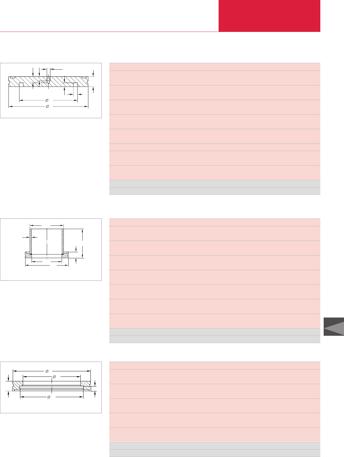
(ISO-K) Clamp Flange Fittings and Components
Vacuum Fittings and Feedthroughs
C13.21
C13
LEYBOLD VACUUM PRODUCTS AND REFERENCE BOOK 2003/2004
Important: In the table of Section “General” the German designation for the type of steel is also stated in accordance with AISI.
DN ISO-K 63 100 160 200 250 320 400 500 630
a mm 555555555
in. 0.20 0.20 0.20 0.20 0.20 0.20 0.20 0.20 0.20
b mm 12 12 12 12 12 17 17 17 22
in. 0.47 0.47 0.47 0.47 0.47 0.67 0.67 0.67 0.87
b1mm 4.5 4.5 4.5 4.5 4.5 6.5 6.5 6.5 6.5
in. 0.18 0.18 0.18 0.18 0.18 0.26 0.26 0.26 0.26
d mm 95 130 180 240 290 370 450 550 690
in. 3.74 5.12 7.09 9.45 11.42 14.57 17.72 21.65 27.17
d1mm 70 102 153 213 261 318 400 501 651
in. 2.76 4.02 6.02 8.39 10.28 12.52 15.75 19.72 25.63
d2thread M 8 M 8 M 8 M 8 M 8 M 8 M 8 M 8 M 8
t mm 888888888
in. 0.31 0.31 0.31 0.31 0.31 0.31 0.31 0.31 0.31
t1mm 12 12 12 12 12 12 12 12 12
in. 0.47 0.47 0.47 0.47 0.47 0.47 0.47 0.47 0.47
Nickel-plated steel Part No. 269 47 269 48 269 49 – 269 56 – – – –
Stainless steel Part No. 887 55 887 56 887 57 887 54 887 58 887 59 887 60 887 61 887 62
M 8 threaded bore from nominal size DN 500
Blank Flanges (Nickel-Plated Steel 1.0037 / Stainless Steel 1.4301)
d1
b
d
t1tød2
b1a
Dimensional drawing for the blank flanges
DN ISO-K 63 100 160 200 250 320 400 500 630
d mm 95 130 180 240 290 370 450 550 690
in. 3.74 5.12 7.09 9.45 11.42 14.57 17.72 21.65 27.17
d1mm 70 102 153 213 261 318 400 501 651
in. 2.76 4.02 6.02 8.39 10.28 12.52 15.75 19.72 25.63
d2mm 76.1 108 159 219.1 267 324 406 508 660
in. 3.00 4.25 6.26 8.63 10.51 12.76 15.98 20.00 25.98
h mm 100 100 100 100 100 100 100 100 100
in. 3.94 3.94 3.94 3.94 3.94 3.94 3.94 3.94 3.94
s (steel) mm 2.9 2.9 2.9 – 3 3 3 4 5
in. 0.11 0.11 0.11 – 0.12 0.12 0.12 0.16 0.20
s (stainless steel) mm 2.3 2 2 3 3 3 3 4 5
in. 0.09 0.08 0.08 0.12 0.12 0.12 0.12 0.16 0.20
b mm 12 12 12 12 12 17 17 17 22
in. 0.47 0.47 0.47 0.47 0.47 0.67 0.67 0.67 0.87
Steel Part No. 269 04 269 05 269 06 – 269 17 – – – –
Stainless steel Part No. 886 40 886 41 886 42 886 43 887 18 887 19 886 46 886 47 886 48
Clamp Flanges with Tubulation (Steel 1.0831, 1.0308 / Stainless Steel 1.4301)
ød2
s
ød1ød
b
h
Dimensional drawing for the clamp flanges with tubulation
DN ISO-K 63 100 160 200 250
b mm 12 12 12 12 12
in. 0.47 0.47 0.47 0.47 0.47
b1mm 6 6 6 6 6
in. 0.24 0.24 0.24 0.24 0.24
d mm 95 130 180 240 290
in. 3.74 5.12 7.09 9.45 11.42
d1mm 70 102 153 213 261
in. 2.76 4.02 6.02 8.39 10.28
d2mm 76.6 108.7 159.8 219.8 267.8
in. 3.02 4.28 6.29 8.65 10.54
Steel 1.0831 Part No. 269 61 269 62 269 63 – 269 65
Stainless steel 1.4301 Part No. 886 61 886 62 886 63 886 64 886 65
Welding Flanges
d1
d2
d
bb1
Dimensional drawing for the welding flanges
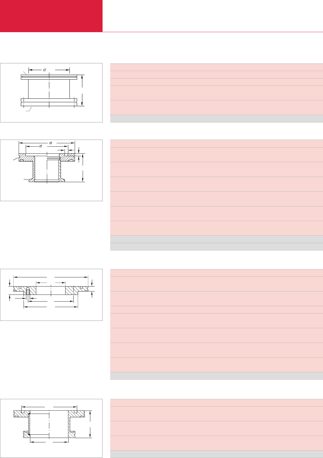
(ISO-K) Clamp Flange Fittings and Components
Vacuum Fittings and Feedthroughs
C13.22 LEYBOLD VACUUM PRODUCTS AND REFERENCE BOOK 2003/2004
Important: In the table of Section “General” the German designation for the type of steel is also stated in accordance with AISI.
DN ISO-K 160/63 160/100 200/100 200/160 250/160
b mm 22 25 20 25 22
in. 0.87 0.98 0.79 0.98 0.87
b1mm 12 12 12 12 12
in. 0.47 0.47 0.47 0.47 0.47
d thread M 8 M 8 M 8 M 10 M 10
d1mm 180 180 240 240 290
in. 7.09 7.09 9.49 9.49 11.42
d2mm 130 165 165 225 225
in. 5.12 6.50 6.50 8.86 8.86
d3mm 70 102 102 153 153
in. 2.76 4.02 4.02 6.02 6.02
k mm 110 145 145 200 200
in. 4.33 5.71 5.71 7.87 7.87
Stainless steel Part No. 886 14 886 15 886 17 886 16 886 50
Reducing Flanges (Stainless Steel 1.4301)
bb1
ød3
ød2
ød1
øk
ød
Dimensional drawing for the reducing flanges
ød1
ød
h
Dimensional drawing for the reducers
DN ISO-K 100/63 250/200
d mm 70 213
in. 2.76 8.39
d1mm 102 261
in. 4.02 10.28
h mm 50 50
in. 1.97 1.97
Stainless steel Part No. 887 89 887 93
Reducers (Stainless Steel 1.4305)
DN CF 63 100 160
Outside diameter in. 4 1/2" 6" 8"
DN1ISO-K 63 100 160
DN2mm 63 100 150
in. 2.48 3.94 5.91
h mm 90 90 90
in. 3.54 3.54 3.54
Stainless steel DIN 1.4301 Part No. 837 01 837 02 837 03
Adaptors ISO-K – CF
h
DN1
DN
2
DN
Dimensional drawing for the adaptors ISO-K – CF
DN ISO-K / KF 63 / 40 63 / 50 100 / 40
d mm 95 95 130
in. 3.74 3.74 5.12
d1mm 70 70 102
in. 2.76 2.76 4.02
l mm 40 45 40
in. 1.57 1.77 1.57
s mm 5 5 5
in. 0.2 0.2 0.2
t mm 4.5 4.5 4.5
in. 0.16 0.16 0.16
Weight kg 0.5 0.6 0.8
lbs 1.1 1.32 1.77
Stainless steel 1.4305 Part No. 887 40 887 41 887 42
Aluminum 3.2315.71 Part No. 269 40 269 41 –
Adaptors-Reducers ISO-K – KF
l
d1st
d
DN
DN1
Dimensional drawing for the adaptors-reducer ISO-K – KF;
left: aluminum; right: stainless steel
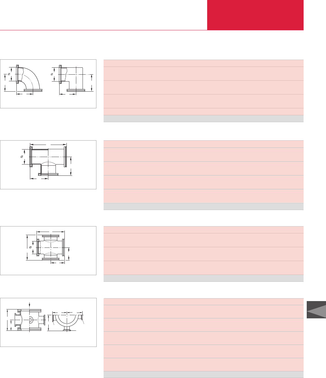
(ISO-K) Clamp Flange Fittings and Components
Vacuum Fittings and Feedthroughs
C13.23
C13
LEYBOLD VACUUM PRODUCTS AND REFERENCE BOOK 2003/2004
Important: In the table of Section “General” the German designation for the type of steel is also stated in accordance with AISI.
DN ISO-K 63 100 160 250
a mm 88 108 138 208
in. 3.46 4.25 5.43 8.19
d1mm 70 102 153 261
in. 2.76 4.02 6.02 10.28
Weight kg 1.1 2.2 5.9 9.9
lbs 2.43 4.8 13.02 21.85
Conductance l/s 208 470 1200 3700
Stainless steel Part No. 887 25 887 26 887 27 887 28
Elbows (Stainless Steel 1.4301); from DN 160 ISO-K Mitred Elbow
d1
a
a
d1
a
a
Dimensional drawing for the elbows (left) and mitred elbow (right)
DN ISO-K 63 100 160 250
a mm 88 108 138 208
in. 3.46 4.25 5.43 8.19
b mm 176 216 276 416
in. 6.93 8.50 10.87 16.38
d1mm 70 102 153 261
in. 2.76 4.02 6.02 10.28
Weight kg 1.6 3.2 7.6 17.0
lbs 3.53 7.06 16.78 37.53
Stainless steel Part No. 887 35 887 36 887 37 887 38
Tees (Stainless Steel 1.4301)
d
b
1
a
a
Dimensional drawing for the tees
DN ISO-K 63 100 160 250
a mm 88 108 138 208
in. 3.46 4.25 5.43 8.19
b mm 176 216 276 416
in. 6.93 8.50 10.87 16.38
d1mm 70 102 153 261
in. 2.76 4.02 6.02 10.28
Stainless steel Part No. 887 45 887 46 887 47 887 48
4-Way Crosses (Stainless Steel 1.4301)
d1
b
a
a
b
Dimensional drawing for the 4-way crosses
Branching Pieces with Lateral DN 16/25/40 KF Flanges (Stainless Steel 1.4301)
h
AAnsicht: A
ac
cc
DN 25
DN 40 DN 16
12
Dimensional drawing for the branching pieces
with lateral DN 16/25/40 flanges
DN ISO-K 63 100 160
a mm 44 50 50
in. 1.73 1.97 1.97
h mm 88 100 100
in. 3.46 3.94 3.94
c mm 66 82 107
in. 2.60 3.23 4.21
c1mm 59 77 105
in. 2.32 3.03 4.13
c2mm 64 80 107
in. 2.52 3.15 4.21
Stainless steel Part No. 886 71 886 72 886 73
Can not be used with collar flanges ISO-F and DIN 2501
View:
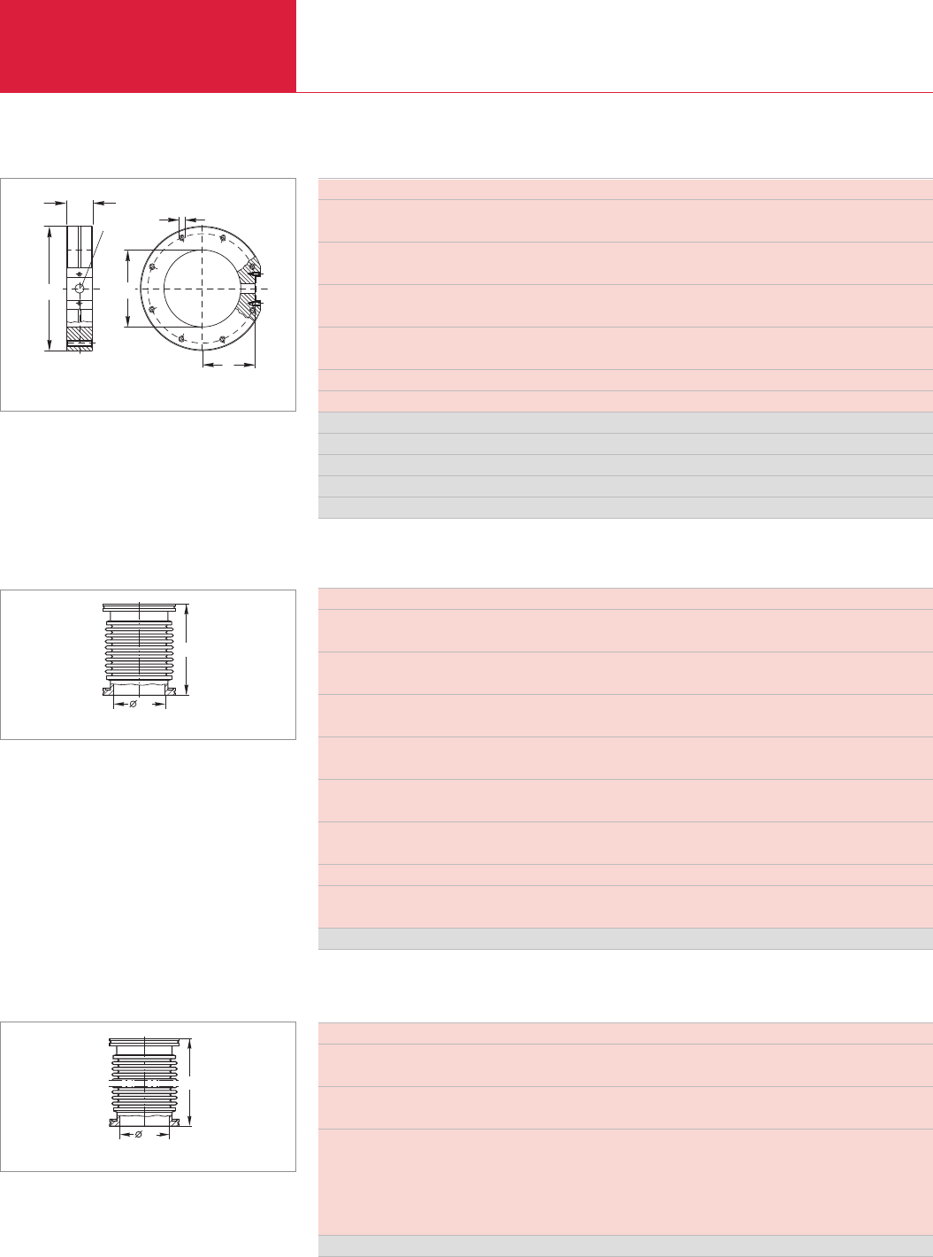
(ISO-K) Clamp Flange Fittings and Components
Vacuum Fittings and Feedthroughs
C13.24 LEYBOLD VACUUM PRODUCTS AND REFERENCE BOOK 2003/2004
Important: In the table of Section “General” the German designation for the type of steel is also stated in accordance with AISI.
DN ISO-K 63 100 160
a mm 52.3 71.3 102.3
in. 2.06 2.81 4.03
b mm 30 30 30
in. 1.18 1.18 1.18
d mm 130 165 225
in. 5.12 6.50 8.86
d1mm 70 102 153
in. 2.76 4.02 6.02
d2thread M 8 M 8 M 10
Number of threaded holes 4 8 8
Stainless steel 1.4301 Part No. 286 60 286 61 286 62
Aluminum 3.2315.62 Part No. – 272 61 272 62
Recommended centering ring Part No. 2 x 887 03 2 x 887 04 2 x 887 07
Required claws kits Part No. 268 25 2 kits 4 kits –
Required claws kits Part No. 268 26 – – 4 kits
Claws, complete for DN 16 KF are included
Measurement Flanges
a
DN 16
30
ød
d2
1
d
Dimensional drawing for the measurement flanges
DN ISO-K 63 100 160 250
d1mm 70 102 153 261
in. 2.76 4.02 6.02 10.78
l mm 132 132 150 200
in. 5.20 5.20 5.91 7.87
Weight kg 1.0 3.9 6.2 9.3
lbs 2.21 8.61 13.69 20.53
Max. extension, axial mm 40 56 44 60
in. 1.57 2.20 1.73 2.36
Compression mm 20 28 22 30
in. 0.79 1.10 0.87 1.18
Tension mm 20 28 22 30
in. 0,79 1.10 0.87 1.18
Max. bending angle
Degress 1)
± 30° ± 30° ± 14° ± 13°
Laterial displacement mm 7 9 3.5 4.5
in. 0.28 0.35 0.14 0.18
Stainless steel Part No. 887 70 887 71 887 72 887 68
1) When utilizing the maximum bend, no extension along the axial axis will be possible!
Bellows (Stainless Steel 1.4571) with Flanges (Stainless Steel 1.4391)
d1
l
Dimensional drawing for the bellows
DN ISO-K 63 63 63 63 100 100 100 100
d1mm 70 70 70 70 102 102 102 102
in. 2.76 2.76 2.76 2.76 2.76 4.02 4.02 4.02
l mm 250 500 750 1000 250 500 750 1000
in. 9.84 19.69 29.53 39.37 9.84 19.69 29.53 39.37
Max. bending radius
with multiple bending mm 250 250 250 250 370 370 370 370
in. 9.84 9.84 9.84 9.84 14.57 14.57 14.57 14.57
with single bend mm 160 160 160 160 240 240 240 240
in. 8.30 8.30 8.30 8.30 9.45 9.45 9.45 9.45
Stainless steel Part No. 868 37 867 97 868 34 868 07 868 38 867 98 868 35 868 08
Flexible Vacuum Hoses (Stainless Steel 1.4571) with Flanges (Stainless Steel 1.4301)
d1
l
Dimensional drawing for the flexible vacuum hoses
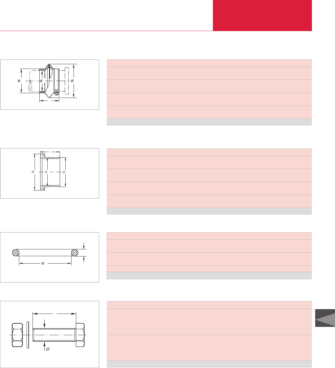
(ISO-K) Clamp Flange Fittings and Components
Vacuum Fittings and Feedthroughs
C13.25
C13
LEYBOLD VACUUM PRODUCTS AND REFERENCE BOOK 2003/2004
Important: In the table of Section “General” the German designation for the type of steel is also stated in accordance with AISI.
Connections for Flexible Compensation Elements (Aluminum 3.2315.71)
d
l
1
d
2d
Dimensional drawing for the connections for flexible compensation elements
DN ISO-K 63 100 160
d mm 70 102 150
in. 2.76 4.02 5.91
d1mm 76 107 156
in. 2.99 4.21 6.14
d2mm 95 130 180
in. 3.74 5.12 7.09
l mm 51 56 56
in. 2.01 2.20 2.20
Aluminum Part No. 272 35 272 36 272 37
Flexible Compensation Elements (CR)
b
d
d1D
Dimensional drawing for the flexible compensation elements
DN ISO-K 63 100 160
D mm 120 150 200
in. 4.72 5.91 7.87
d mm 75 106 155
in. 2.95 4.17 6.10
d1mm 85 116 165
in. 3.35 4.57 6.50
b mm 70 72 72
in. 2.76 2.83 2.83
CR Part No. 272 23 1) 272 24 1) 272 25 1)
1) Is supplied complete with stainless steel hose clamps
DN ISO-K 63 100 160 200 250 320 400 500 630 800 1000
d mm 75 107 158 208 253 329 405 506 658 808 1006
in. 2.95 4.21 6.22 8.19 9.96 12.95 15.94 19.92 25.90 31.80 39.61
s mm 5 5 5 5 5 7 7 7 7 7 7
in. 0.20 0.20 0.20 0.20 0.20 0.28 0.28 0.28 0.28 0.28 0.28
Quantity per set 5 5 5 5 5 1 1 1 1 1 1
FPM Part No.
210 635 210 645 210 650 210 655 210 660 210 665 210 670 210 675 210 680 210 685 210 690
Spare O-Ring Gaskets for Clamp Flange Fittings
d
s
Dimensional drawing for the spare O-ring for clamp flange fittings
DN ISO-K 63 - 100 160 - 250 320 - 500 630
Dimensions
d thread M 8 M 10 M 12 M 12
l mm 40 50 70 80
in. 1.57 1.97 2.76 3.15
Quantity per set
Bolts 8 12 16 20
Nuts 8 12 16 20
Washers 8 12 16 20
Set Part No. 887 81 887 82 887 83 887 84
l
d
Bolts for Clamp Flange Fittings (Steel 8.8, zinc coated)
Dimensional drawing for the bolts for clamp flange fittings
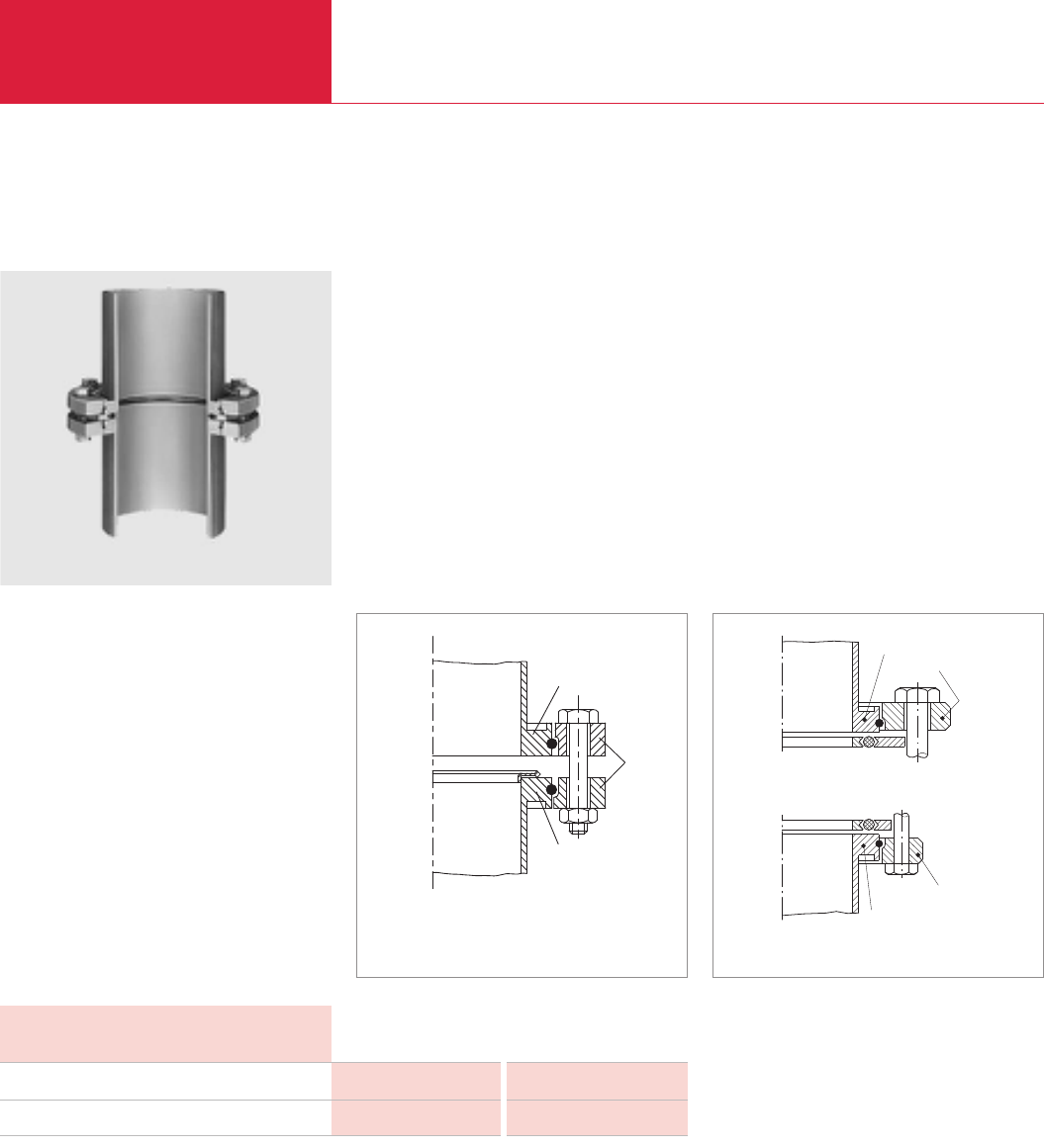
ISO-F and DIN 2501 Fixed Flange Fittings
Vacuum Fittings and Feedthroughs
C13.26 LEYBOLD VACUUM PRODUCTS AND REFERENCE BOOK 2003/2004
Important: In the table of Section “General” the German designation for the type of steel is also stated in accordance with AISI.
ISO-F and DIN 2501 Fixed Flange Fittings, ND 6
Mating clamp flanges with tubulation
using collar rings and sealing disk
Advantages to the User
◆A high vacuum seal is maintained also at large
nominal width and high mechanical loads
◆Evenly distributed sealing force through a
large number of bolts
◆Can be easily adapted to other flange systems
◆Vacuum sealing disks consist of a CR O-ring
seal with inner and outer aluminum ring
◆Fixed flanges and collar flanges may also be
constructed as all-metal seals by using ultra
sealing disks
ISO-K
ISO-F
ISO-K
ISO-K
DIN 2501
DIN 28 404 (ISO-F)
ISO-K
Mating clamp flanges using bolted collar rings and
ultra sealing disk
Comparison: Clamp flange with collar flange to DIN 2501
and clamp flange with collar flange to DIN 28 404; ISO-F
Collar Flange Steel Stainless Steel
Bolts and nuts
Retaining ring
Galvanized 8.8 steel 1.4401
Steel 1.4310
Note: ND 6 states a dimension and does not refer to an operating pressure of 6 bar!
In addition to clamp flange connections, fixed
welded flanges (ISO-F or to DIN 2501) are used
in the area of vacuum engineering to interconnect
valves, pumps and other components.
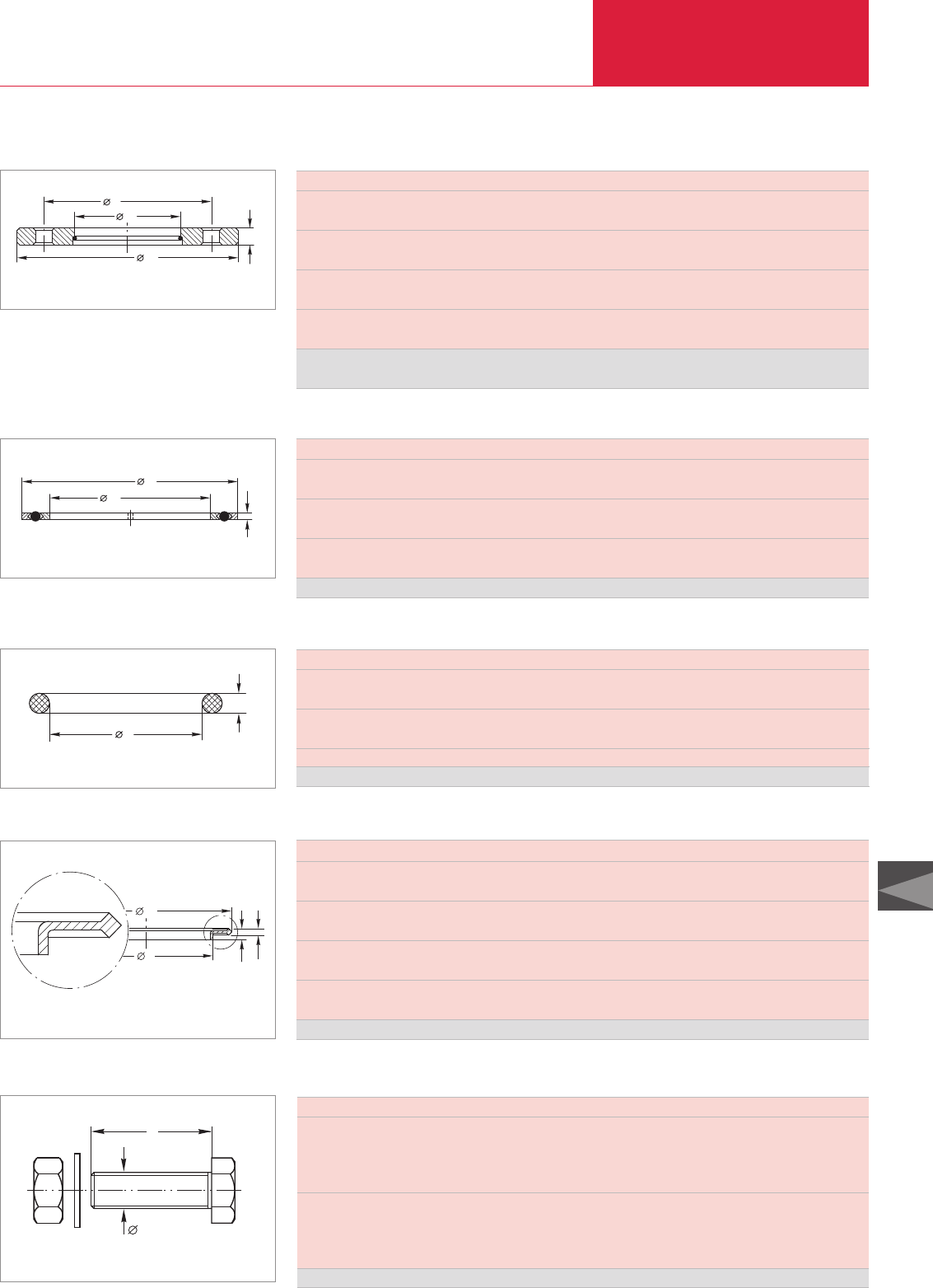
ISO-F Fixed Flange Fittings
Vacuum Fittings and Feedthroughs
C13.27
C13
LEYBOLD VACUUM PRODUCTS AND REFERENCE BOOK 2003/2004
Important: In the table of Section “General” the German designation for the type of steel is also stated in accordance with AISI.
ISO-F Collar Flanges with Retaining Ring for use with Clamp Flange Fittings (Steel 1.0037)
d2
k
b
d1
Dimensional drawing for collar flanges with retaining ring
DN ISO-F 63 100 160 200 250 320 400 500 630
d1mm 130 165 225 285 335 425 510 610 750
in. 5.12 6.50 8.86 11.22 13.19 16.73 20.08 24.02 29.53
d2mm 95.6 130.6 180.9 240.9 290.9 370.8 451 551 691
in. 3.76 5.14 7.12 9.48 11.45 14.60 17.76 21.69 27.2
k mm 110 145 200 260 310 395 480 580 720
in. 4.93 5.71 7.87 10.24 12.20 15.51 18.90 22.83 28.35
b mm 12 12 16 16 16 20 20 20 24
in. 0.47 0.47 0.63 0.63 0.63 0.79 0.79 0.79 0.79
Nickel-plated steel
Part No. 267 67 267 70 267 71 267 68 267 72 267 76 267 74 267 75 267 77
Vacuum Sealing Disks for ISO-F Flanges (Aluminum/CR)
b
d
d1
Dimensional drawing for vacuum sealing disks
DN ISO-F 63 100 160 250 320 400 500 630 800 1000
d mm 98 132 185 295 375 460 560 701 870 1070
in. 3.86 5.20 7.28 11.61 14.76 18.11 22.05 27.60 34.25 42.13
d1mm 73 107 160 270 330 415 515 656 825 1025
in. 2.87 4.21 6.3 10.63 12.99 16.34 20.28 25.83 32.48 40.35
b mm4444666666
in. 0.16 0.16 0.16 0.16 0.24 0.24 0.24 0.24 0.24 0.24
AI/CR Part No. 171 09 171 10 171 11 171 12 171 19 171 14 171 15 171 16 171 17 171 18
DN ISO-F 63 100 160 250 320 400 500 630 800 1000
d mm 80 110 165 265 325 412 510 640 820 1023
in. 3.15 4.33 6.50 10.43 12.75 16.22 20.08 25.20 32.28 40.28
s mm 5 5 5 5 8 8 8 8 8 8
in. 0.20 0.20 0.20 0.20 0.31 0.31 0.31 0.31 0.31 0.31
Quantity per set 5 5 5 5 1 1 1 1 1 1
CR Part No.
210 701 210 711 210 716 210721 210 726 210 731 210 736 210 741 210 746 210 751
Spare O-Ring Gaskets ISO-F Flange Connection
d
s
Dimensional drawing for O-rings
DN ISO-K / ISO-F 63 100 160 250
b mm 4.5 4.5 4.5 4.5
in. 0.18 0.18 0.18 0.18
b1mm 2.6 2.6 2.6 2.6
in. 0.10 0.10 0.10 0.10
d mm 69.8 101.8 152.8 260.8
in. 2.75 4.01 6.02 10.27
d1mm 85.6 116.6 166.6 276.6
in. 3.37 4.59 6.56 10.89
Aluminum Part No. 886 24 886 25 886 26 886 27
Ultra Sealing Disks (Aluminum 3.2315.71) for ISO-F Flanges
d
1
d
bb1
Dimensional drawing for the ultra sealing disks for ISO-F flanges
DN ISO-K 63 - 100 160 - 250 320 - 500 630
Dimensions
d thread M 8 M 10 M 12 M 12
l mm 40 50 70 80
in. 1.57 1.97 2.76 3.15
Quantity per set
Bolts 8 12 16 20
Nuts 8 12 16 20
Washers 8 12 16 20
Set Part No. 887 81 887 82 887 83 887 84
l
d
Bolts for ISO-F Flange Connection (Steel 8.8, zinc coated)
Dimensional drawing for the bolts for ISO-F flange fconnections

DIN 2501 Fixed Flange Fittings
Vacuum Fittings and Feedthroughs
C13.28 LEYBOLD VACUUM PRODUCTS AND REFERENCE BOOK 2003/2004
Important: In the table of Section “General” the German designation for the type of steel is also stated in accordance with AISI.
DN DIN 63 100 160 250
Dimensions
d thread M 12 M 16 M 16 M 15
l mm 40 50 50 50
in. 1.57 1.97 1.97 3.15
Number of bolts/nuts required 4 8 8 12
1 bolt (galvanized 8.8 steel) Part No. 201 02 381 201 02 434 201 02 434 201 02 434
1 nut (galvanized 8.8 steel) Part No. 211 01 115 211 01 117 211 01 117 211 01 117
DN DIN 63 100 160
d mm 80 110 165
in. 3.15 4.23 6.50
s mm 5 5 5
in. 0.20 0.20 0.20
Quantity per set 5 5 5
CR Part No. 210 701 210 711 210 716
DIN 2501 Fixed Flange Fittings; Dimensions to DIN 2501, ND 6
DN DIN 63 100 160 250
d1mm 160 210 265 375
in. 6.30 8.27 10.43 14.76
d2mm 95.6 130.6 180.9 290.9
in. 3.76 5.14 7.12 11.45
k mm 130 170 225 335
in. 5.12 6.69 8.86 13.19
b mm 12 15 15 15
in. 0.47 0.59 0.59 0.59
Part No. 267 47 267 50 267 51 267 52
Collar Flanges with Retaining Ring (Steel 1.0037)
d2
k
b
d1
Dimensional drawing for collar flanges with retaining ring
Note: ND 6 states a dimension and does not refer to an operating pressure of 6 bar!
Spare O-Ring Gaskets for Vacuum Sealing Disks DIN 2501
d
s
Dimensional drawing for O-ring gaskets
Bolts and Nuts for DIN Collar Flange
Dimensional drawing for bolts and nuts
For sealing ISO-K flanges see the centering rings described in the section “(ISO-K) Clamp
Flange Fittings and Components”.
DN 40 CF 63-100 ISO-F / 63-200 CF 160-250 ISO-F
Dimensions (d x l) mm (in.) M 6 x 35 (1.38) M 8 x 45 (1.77) M 10 x 55 (2.17)
s mm (in.) 3 (0.12) 4 (0.16) 6 (0.24)
Quantity per set
Set screws 6 16 12
Nuts 6 16 12
Washers 6 16 12
Set Part No. 839 11 839 13 210 071
d
l
s
Bolts, Nuts and Washers for Joints with VAT Gate Valves
Dimensional drawing for the set screws, nuts and washers

Vacuum Greases
Vacuum Fittings and Feedthroughs
C13.29
C13
LEYBOLD VACUUM PRODUCTS AND REFERENCE BOOK 2003/2004
Vacuum Greases
Ramsay greases for lubricating ground joints
and drain valve in fore-vacuum lines consist of
special grades of paraffin jelly to which caout-
chouc is added for attaining the specific consi-
stence.
Ramsay grease, thick is used to lubricate
ground joints. Usable down to 10
-2
mbar
(0.75 x 10
-2
Torr).
Ramsay grease, soft is used to lubricate drain
valves. Usable down to 10
-2
mbar (0.75 x
10
-2
Torr).
Technical Data
Ramsay Ramsay Gleitlen LITHELEN Silicone high- DYNAFAT
grease, thick grease, soft vacuum grease
Overview Sealing Greases
10-4 (0.75 x 10⁻⁴ Torr) 10-4 (0.75 x 10⁻⁴ Torr) 10-4 (0.75 x 10⁻⁴ Torr) 10-10 (0.75 x 10⁻¹⁰ Torr) 10-7 (0.75 x 10⁻⁷ Torr)
10-3 (0.75 x 10⁻³ Torr)
> 56 (> 133) > 56 (> 133) > 50 (> 122) > 210 (> 410) 1) 148 (298)
30 (86) 30 (86) 30 (86) 150 (302) 200 (392) 110 (230)
Vapor pressure at 20 °C (68 °F) mbar
Dripping point °C (°F)
Max. working temperature °C (°F)
Ordering
Information
Ramsay Ramsay Gleitlen LITHELEN Silicone high- DYNAFAT
grease, thick grease, soft vacuum grease
Tin 50 g (0.11 lbs)
Tube 050 g (0.11 lbs)
Tube 100 g (0.22 lbs)
1) over 220 °C (428 °F) polymerisation
Part No. 177 42
–
–
Part No. 176 38
–
–
–
Part No. 176 44
–
Part No. 177 32
–
–
–
Part No. 210 502
–
–
–
Part No. 210 500
Gleitlen is a special grease used to lubricate
stirrer shafts (KPG stirrers, among others) of all
sizes in the laboratory. Usable down to 10
-2
mbar
(0.75 x 10
-2
Torr).
Lithelen contains lithium compounds, and all
components contributing to higher vapor pressu-
res have been removed through high-vacuum
pre-processing. It may be used within a wide
temperature range (from 0 °C to 150 °C (32 °F to
302 °F)) and in all applications from atmospheric
pressure down to 10
-8
mbar (0.75 x 10
-8
Torr).
Silicone high-vacuum grease Dow Corning con-
tains compounds of a high molecular weight
together with chain elements containing silicon
and oxygen.
At temperatures over 220 °C (428 °F) the silicone
grease will polymerise giving off gas. It may be
used within a wide temperature range (from
-40 °C to 200 °C (-40 °F to 392 °F)) and in all
applications from atmospheric pressure down to
10
-6
mbar (0.75 x 10
-6
Torr).
DYNAFAT is used to lubricate gaskets.
Application Data
Ramsay Ramsay Gleitlen LITHELEN Silicone high- DYNAFAT
grease, thick grease, soft vacuum grease
Greasing of ground joints
and drain valves, usable
down to pressures of
10-2 mbar
(0.75 x 10⁻² Torr)
Lubrication of
stirrer shafts
(KPG stirrers)
Greasing of ground
joints and drain val-
ves at low pressures
and high working
temperatures
Greasing of ground
joints and drain val-
ves at low pressures
and high working
temperatures
Lubrication of
gaskets
Greasing of ground joints
and drain valves, usable
down to pressures of
10-2 mbar
(0.75 x 10⁻² Torr)
Purpose
For all lubricants in our line of products you may obtain Safety Data Sheets from the Dept. Technical Support in Cologne.

Observation Windows
Vacuum Fittings and Feedthroughs
C13.30 LEYBOLD VACUUM PRODUCTS AND REFERENCE BOOK 2003/2004
Observation Windows for Vacuum Systems
DN 50
DN 40
DN 63
DN 100
DN 160
86°
108°
112°123°
66°
Mounting: Place the window in the flange and evenly press the O-ring into
its groove.
Dismounting: Hold the observation window with the window showing to
the bottom. Use both thumbs to press the window out of the flange ring. Viewing angle into vacuum chamber through observation window
DN 40 KF - DN 160 ISO-K (mounting on matching flanges with tubulation)
Observation of the phenomena in the vacuum
chamber is very important for many vacuum pro-
cesses. Measurements and monitoring can often
be accomplished only by means of external
instruments used under normal atmospheric
pressure conditions.
This calls for highly transparent, rugged observa-
tion windows featuring a wide angle view.
Advantages to the User
◆Flat design
◆Easy to fit and remove
◆Easy to clean
◆Wide viewing angle
◆Can be baked out up to 150 °C (302 °F)
◆May be combined with KF and ISO-K
components
◆No special mounting components are required
◆The FPM O-ring seals against the atmosphere
(integrated centering ring)
◆Each observation window is subjected to a
leak test (thereby ensuring safe operation!)
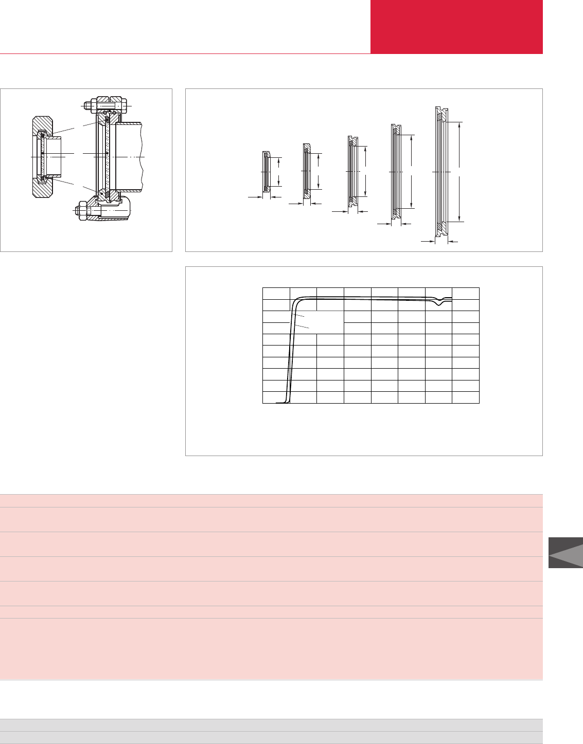
Observation Windows
Vacuum Fittings and Feedthroughs
C13.31
C13
LEYBOLD VACUUM PRODUCTS AND REFERENCE BOOK 2003/2004
DN 40 KF 50 KF 63 ISO-K 100 ISO-K 160 ISO-K
Thickness of glass window mm 4 4 4 5 9
in. 0.16 0.16 0.16 0.20 0.35
Diameter of glass window mm 44 54 75 109 160
in. 1.73 2.13 2.95 4.29 6.30
b mm 10 10 13.5 13 17
in. 0.39 0.39 0.53 0.51 0.67
d mm 40 50 70 102 153
in. 1.57 1.97 2.76 4.02 6.02
Viewing angle ° 112 123 66 86 108
The glass used is a borosilicate glass (BOROFLOAT®33) with a refractive index of n = 1.472
Dielectric number (at 25 °C (77 °F)) 4.8 at 1 MHz
Flange material Stainless steel 1.4301
Glass material Borosilicate
O-ring material FPM
2
1
3
bb
ød
ød
b
ød
b
ød
40 KF
50 KF 63 ISO-K
100 ISO-K
160 ISO-K
ød
b
KF and ISO-K observation windows, fully installed Window dimensions for the observation windows
1 O-ring
2 Glass
3 Flange
Transmission
DN 40-100
DN 160
100
0
10
20
30
40
50
60
70
80
(%)
100
300 500 700 900
Wellenlänge
1100 1300 (nm) 1700
Transmittance as a function of the wavelength for LEYBOLD viewports DN 40 KF to DN 160 ISO-K for different window thicknesses
Technical Data
DN 40 KF 50 KF 63 ISO-K 100 ISO-K 160 ISO-K
Part No. 210 131 210 132 210 133 210 134 210 135
Ordering Information
Wavelength

Feedthroughs
Vacuum Fittings and Feedthroughs
C13.32 LEYBOLD VACUUM PRODUCTS AND REFERENCE BOOK 2003/2004
Electrical Feedthroughs
General
Electrical feedthroughs for vacuum applications,
as well as their corresponding connectors, com-
ply with the German VDE Regulations 0100, 0660
and 0110, Section 1. The latter refers to air gaps
and leakage paths.
◆All current feedthroughs are tested according
to VDE Regulations
Important
The special regional safety regulations must be
observed! These may differ from the regulations
which apply in Germany! The voltages stated on
the following pages apply to atmospheric pres-
sure and the right connector from LEYBOLD. The
voltage specifications apply also to that part of
the feedthrough which is exposed to the vacuum,
provided the pressure in these areas is less than
10
-1
mbar (0.75 x 10
-1
Torr).
At pressures over 10
-1
mbar (0.75 x 10
-1
Torr)
voltage breakdowns may occur depending on the
distance between the electrodes, the type of
rarefied gas, the type of contamination, the distri-
bution of the electric field, etc.
Operators are advised to check each application
individually or to get in touch with LEYBOLD for
advice.
In applications where VDE regulations need not
be applied, higher operating voltages are permis-
sible. Please contact us for further information
regarding your particular application.
The test and operating voltages refer to a vacuum
pressure of < 1 x 10
-4
mbar (< 0.75 x 10
-4
mbar)
and when using the connectors recommended by
LEYBOLD. Electrical power may only be applied
via the external plugs.
Abbreviations used in con-
nection with feedthroughs:
FFeedthrough
EElectric
LLiquid
NNormal
PPrecision
FFrequency
HC Current
HV Voltage
LLinear
RRotary
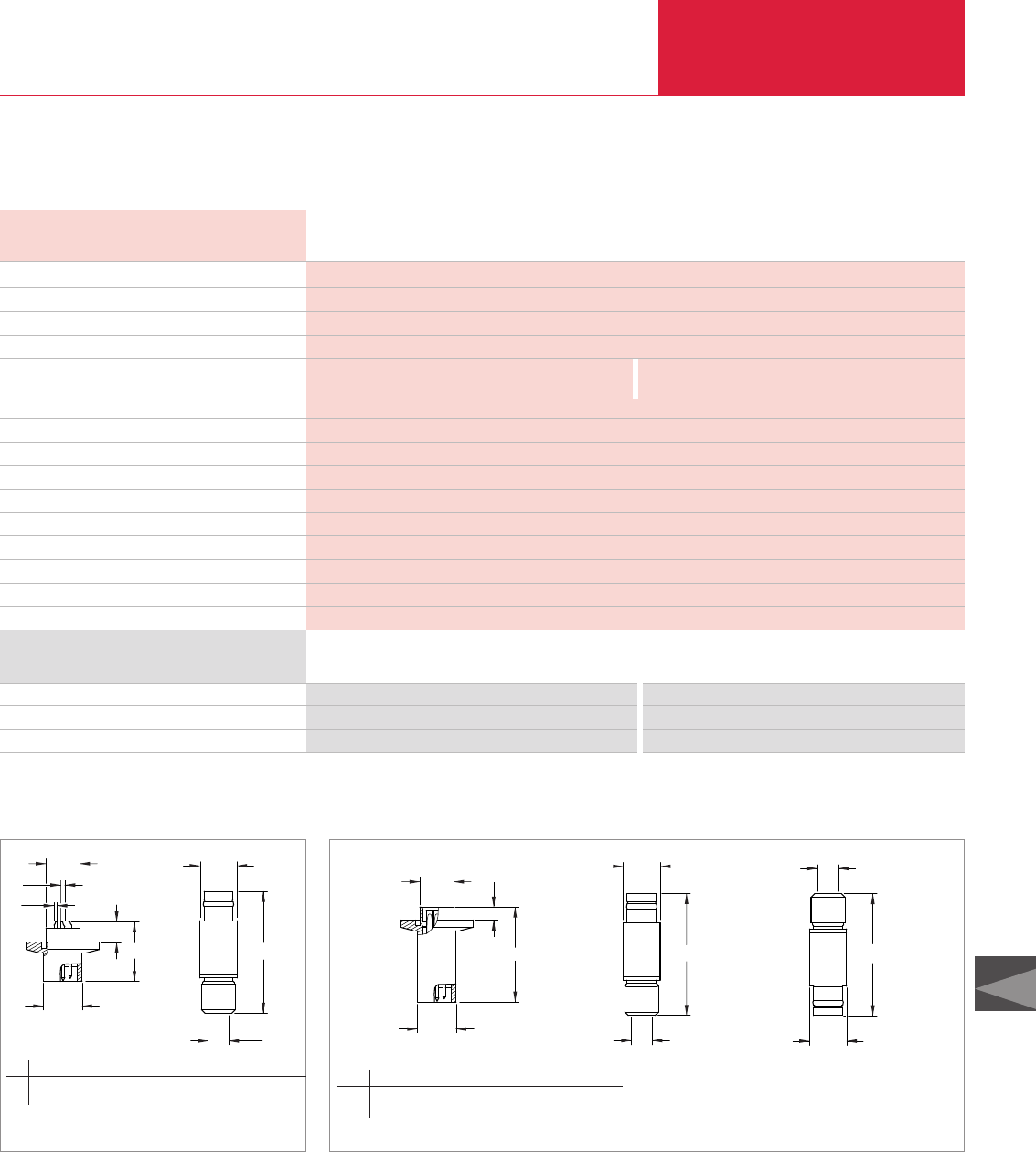
Feedthroughs
Vacuum Fittings and Feedthroughs
C13.33
C13
LEYBOLD VACUUM PRODUCTS AND REFERENCE BOOK 2003/2004
Electrical Feedthroughs
DN 16 ISO-KF
9
50
2
solder connection connector
connector
1.2 (0.05)
500 / 50
1 x 10⁻⁹
1 x 10⁻⁸ to 2.5 (0.75 x 10⁻⁸ to 1.9)
130 (266)
nickel-plated brass
PEEK / Araldit
FPM
gold-plated brass
Technical Data FE 16 / 9S FE 16 / 9
Vacuum connection
Number of feedthroughs
Voltage per pole 1) V
Current per pole 1) A
Connection
Vacuum side
Air side
Diameter of connecting wire mm (in.)
Test voltage V / Hz
Tigthness mbar x l x s-1
Pressure (absolute) 2) mbar (Torr)
Bakeout temperature (feedthrough, connector) °C (°F)
Housing
Insulator
Seal
Contact (feedthrough, connector)
Ordering Information
Electrical Feedthroughs
Connector: vacuum side
Connector: air side
Part No. 210 302 Part No. 210 304
– Part No. 210 305
Part No. 210 303 Part No. 210 303
FE 16 / 9S FE 16 / 9
ød5
ød4
b2
ød1
ød2
ød3
b1
ød
b
ød1
ød3ød2
b1
b2b2
ød2
ød3
b
ød
Dimensional drawing for the feedthrough FE 16/9S (left) and the connector
for air side (right) Dimensional drawing for the feedthrough FE 16/9 (left), the connector for vacuum side (middle) and the connector for air side (right)
1) Local regulations concerning use must be followed
2) Pressure max. 10 bar (7.5 Torr) with external centering ring
d d1d2d3d4d5b b1b2
mm 16 14 1.2 0.8 15 8.7 23.2 6.8 50
in. 0.63 0.55 0.05 0.03 0.59 0.34 0.91 0.27 1.97
d d1d2d3b b1b2
mm 16 14 8.7 15 40 5.5 50
in. 0.63 0.55 0.34 0.59 1.57 0.22 1.97
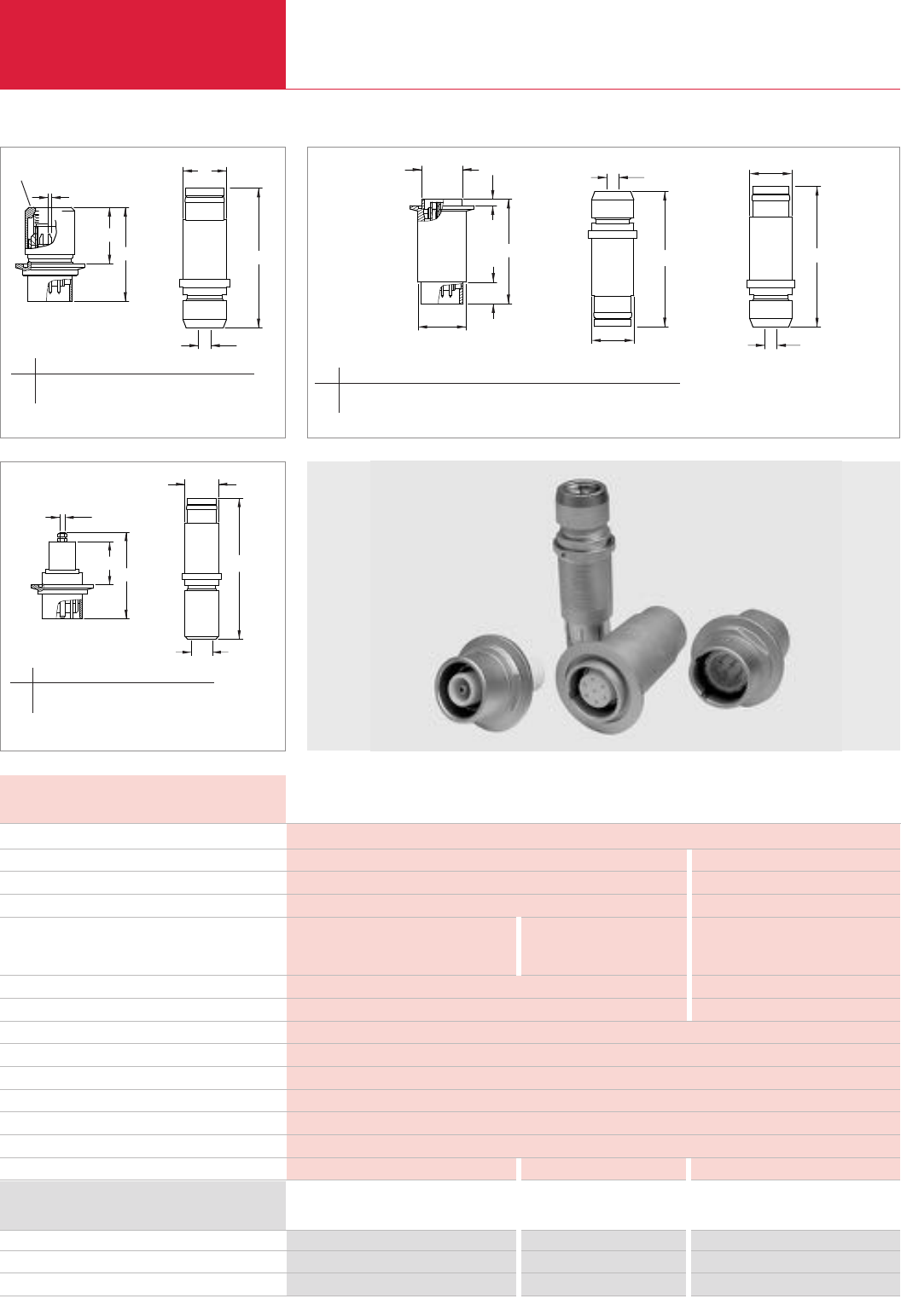
Feedthroughs
Vacuum Fittings and Feedthroughs
C13.34 LEYBOLD VACUUM PRODUCTS AND REFERENCE BOOK 2003/2004
DN 40 ISO-KF
7 1
380 6000
16 25
solder connection connector screw coupling
connector connector connector
l1.6 (l0.06) l5 (l0.2)
– 15 / 50
1 x 10⁻⁹
1 x 10⁻⁸ mbar x l x s-1 to 2.5 bar (1.9 Torr)
130 (266)
chrom-plated steel
PTFE / Araldit
FPM
gold-plated stainless steel gold-plated stainless steel nickel-plated brass
Technical Data FE 40 / 7S FE 40 / 7 FEHV 40 / 1
Vacuum connection
Number of feedthroughs
Voltage per pole 1) V
Current per pole 1) A
Connection
Vacuum side
Air side
Diameter of connecting wire mm (in.)
Test voltage kV / Hz
Tigthness mbar x l x s-1
Pressure (absolute) 2)
Bakeout temperature (feedthrough, connector) °C (°F)
Housing
Insulator
Seal
Contact (feedthrough, connector)
Ordering Information
Electrical Feedthroughs
Connector: vacuum side
Connector: air side
Part No. 210 325 Part No. 210 326 Part No. 210 350
– Part No. 210 328 –
Part No. 210 327 Part No. 210 327 Part No. 210 351
FE 40 / 7S FE 40 / 7 FEHV 40 / 1
1) Local regulations concerning use must be followed
2) Pressure max. 10 bar (7.5 Torr) with external centering ring
l1
ød2
l2
ød1
l
ød
ød1
l2
l1
M4
l
ød
l1
l
l2
ød3ød2
l3
ød2
ød3
l4
ød
ød1
Dimensional drawing for the feedthrough FE 40/7S (left) and
the connector for air side (right)
Dimensional drawing for the feedthrough FEHV 40/1 (left) and
the connector for air side (right)
Dimensional drawing for the feedthrough FE 40/7 (left), the connector for vacuum side (middle) and the connector for air side (right)
Screw off tube
d d1d2l l1l2
mm 1.6 11.2 35 75 45 113
in. 0.06 0.44 1.38 2.92 1.77 4.45
d d1d2d3l l1l2l3l4
mm 40 39 35 11.2 92 19 5.5 110 113
in. 1.57 1.54 1.38 0.44 3.62 0.75 0.22 4.33 4.45
d d1l l1l2
mm 22.7 34 76.1 38.1 135
in. 0.89 1.34 3.00 1.50 5.31
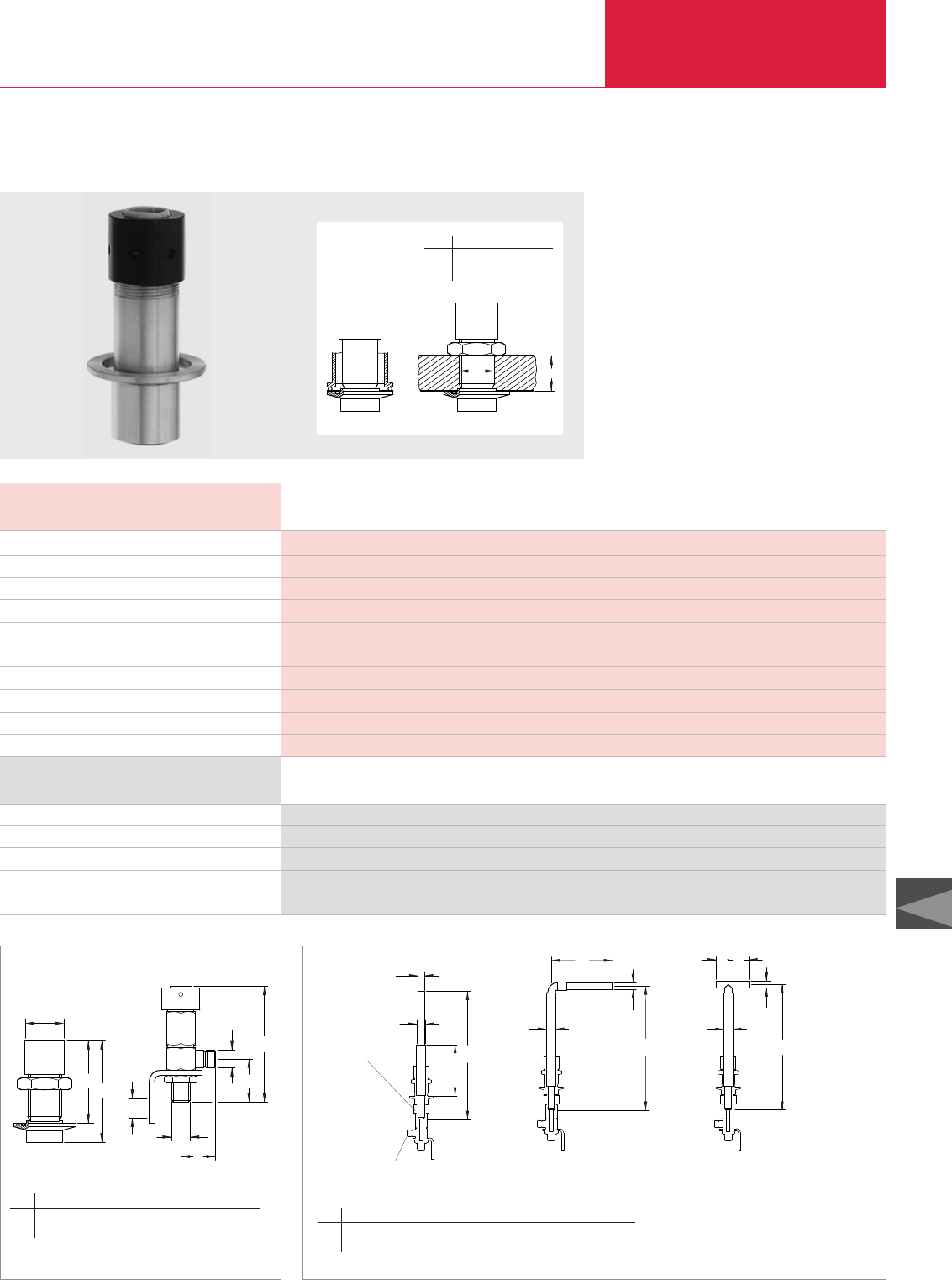
Feedthroughs
Vacuum Fittings and Feedthroughs
C13.35
C13
LEYBOLD VACUUM PRODUCTS AND REFERENCE BOOK 2003/2004
High Current Feedthroughs
DN 40 ISO-KF
1
50
5000
1 x 10⁻⁹
1 x 10⁻⁸ mbar to 2.5 bar (max. 10 bar with external centering ring)
110 (230)
aluminium
thermoplast
FPM
Technical Data FEHC 40/1
Vacuum connection
Number of feedthroughs
Voltage V
Current, with water cooling A
Tigthness mbar x l x s-1
Pressure (absolute)
Bakeout temperature °C (°F)
Housing
Insulator
Seal
Selection of electrodes
Slide into mounted feedthrough
Current connection with water cooling
Ordering Information
High Current Feedthroughs
Current connection with water cooling
Straight electrode
Angle electrode
T-electrode
Part No. 210 352
Part No. 210 356
Part No. 210 353
Part No. 210 354
Part No. 210 355
FEHC 40/1
h
ød
l1l
b
a
ød
ød
l3
l2
ød
a b
ød
ød1
l3
T-electrodeangle electrodeStraight electrode
ød
ød1
b1
ød1
l2
l1
l
ød
Dimensional drawing for the feedthrough FEHC 40/1 (left) and
current connection with water cooling (right) Dimensional drawings for the copper electrodes for the feedthrough FEHC 40/1
d h
mm 32.5 3 - 30
in. 1.28 0.12 - 1.18
a b d l l1l2l3
mm 32.5 18 G 3/8“ 90 73 110 41
in. 1.28 0.71 G 3/8“ 3.54 2.87 4.33 1.61
a b b1d d1l l1l2l3
mm 28 50 145 20 16 300 175 290 295
in. 1.10 1.97 5.71 0.79 0.63 11.8 6.89 11.42 11.61
Feedthrough
Current connection
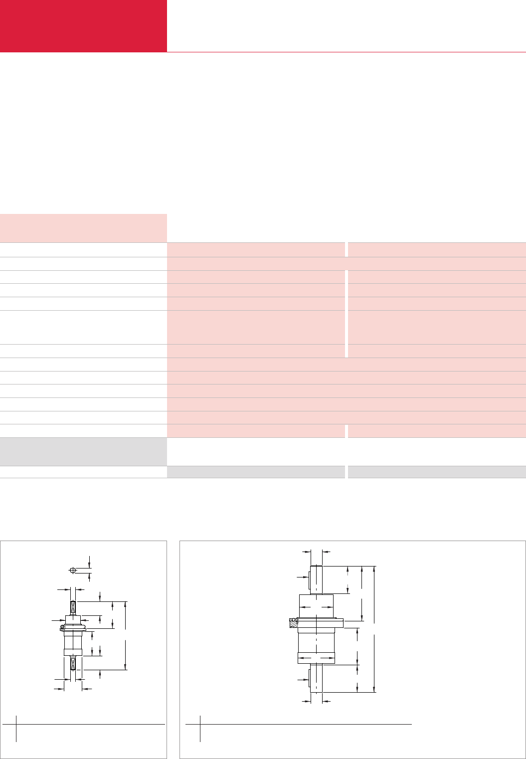
Feedthroughs
Vacuum Fittings and Feedthroughs
C13.36 LEYBOLD VACUUM PRODUCTS AND REFERENCE BOOK 2003/2004
Rotary Feedthroughs
DN 25 ISO-KF DN 63 ISO-KF
FPM
l8 (0.31) l20 (0.79)
6 100
1000 500
150 500
50 100
20 000 000 10 000 000
1 x 10⁻⁹
1 x 10⁻⁹ mbar to 1 bar
50 (122)
110 (230)
stainless steel, aluminum, FPM
0.2 (0.44) 2 (4.42)
Technical Data FR 25/50 N FR 63/100 N
Vacuum connection
Feedthrough / seal
Shaft connection mm (in.)
Transferable torque Nm
Rotational speed 1) 1/min
Shaft load
Radial N
Axial N
Service life (revolutions)
Tightness, static mbar x l x s-1
Pressure (absolute)
Operating temperature, max. °C (°F)
Bakeout temperature °C (°F)
Materials exposed to process media
Weight kg (lbs)
ISO-KF
For transmitting high torque
With FPM shaft seal and ball bearings
Ordering Information
Rotary Feedthrough Part No. 210 151 Part No. 210 153 2)
FR 25/50 N FR 63/100 N
1) When a reduced service life is acceptable, the rotational speed can be increased by up to a factor of two
2) Centering ring
CR/aluminum Part No. 268 05
FPM/stainless steel Part No. 887 03
b
ød1
ød2
ød1
l2l3
l
l1
l2
ød
ød
al2
ød2
l3
l1
l2
a
l
ød1
ød
Dimensional drawing for the feedthrough FR 63/100 N
b d d1d2l l1l2l3
mm 7 28 g6 8 g6 23 105 37 20 41.5
in. 0.28 1.10 g6 0.31 g6 0.91 4.13 1.46 0.79 1.64
a d d1d2l l1l2l3
mm 6 h9 x 32 20 g6 66 g6 60 230 68 50 100
in. 0.24 h9 x 1.26 0.79 g6 2.60 g6 2.36 9.06 2.68 1.97 3.94
Dimensional drawing for the feedthrough FR 25/50 N
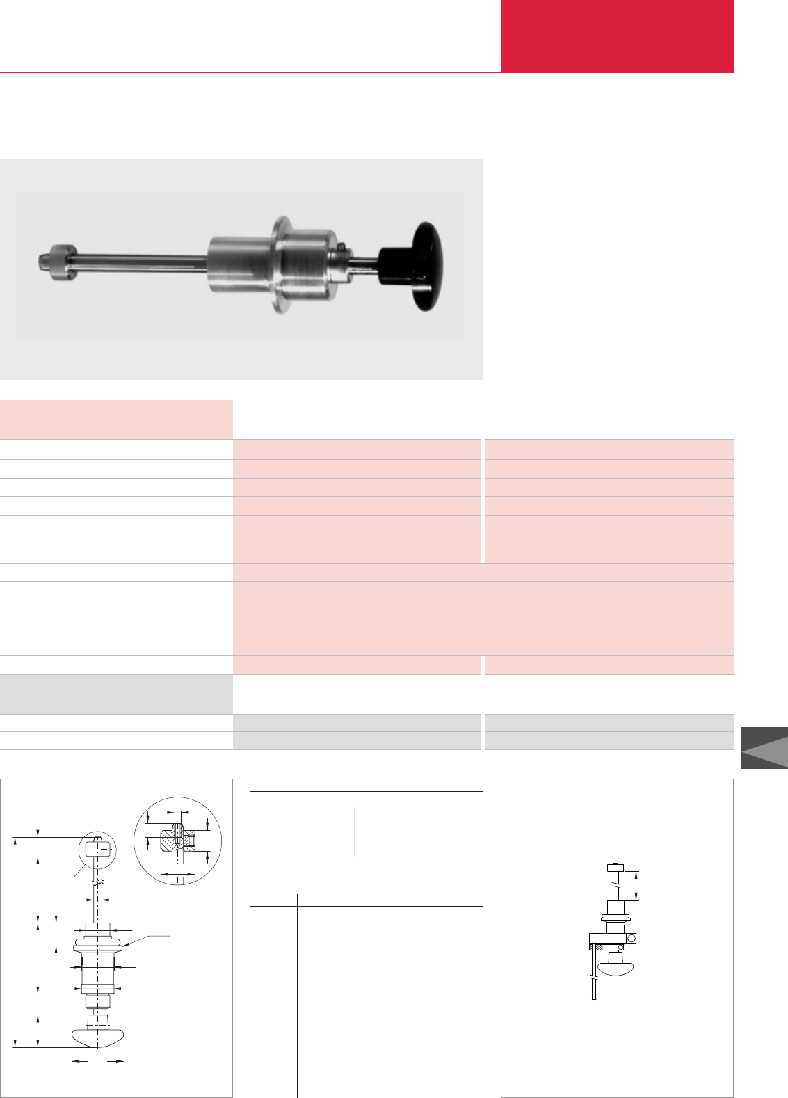
l8
M3
l6
l7
ød2
l3
ød1DN 16 ISO-KF
l5
ød
A
Detail A
ød3
l2
l
l1
l4
ød4
ød
Feedthroughs
Vacuum Fittings and Feedthroughs
C13.37
C13
LEYBOLD VACUUM PRODUCTS AND REFERENCE BOOK 2003/2004
Rotary / Linear Motion Feedthroughs
DN 16 ISO-KF DN 25 ISO-KF
FPM FPM
M 3 x 6 / l5 (0.2) M 4 x 8 / l8 (0.31)
50 (1.97) 100 (3.94)
10 15
2 8
1 x 10⁻⁹
1 x 10⁻⁸ mbar to 1 bar
50 (122)
110 (230)
stainless steel, aluminum, FPM
0.1 (0.22) 0.2 (0.44)
Technical Data FNRL 16/50 FNRL 25/100
Vacuum connection
Feedthrough / seal
Shaft connection mm (in.)
Stroke mm (in.)
Shaft load
Radial, at. max. displacement N
Torsion Nm
Tightness, static mbar x l x s-1
Operating pressure range (absolute)
Operating temperature, max. °C (°F)
Bakeout temperature °C (°F)
Materials exposed to process media
Weight kg (lbs)
Two FPM shaft seals
Direct push/pull and rotary actuation
With locking ring and optional anti-rotation
device
Ordering Information
Rotary / linear feedthrough
Anti-rotation device
Part No. 210 200 Part No. 210 201
Part No. 210 225 Part No. 210 226
FNRL 16/50 FNRL 25/100
Dimensional drawing for the feedthroughs FNRL
DN d d1d2d3d4l
FNRL 16/50
-0.03
mm 16 20 g6 15 15 532 134
-0.05
in. 0.63 0.79 g6 0.59 0.59 0.20 1.26 5.28
FNRL 25/100
-0.03
mm 25 25 g6 23 22 850 210
-0.05
in. 0.98 0.98 g6 0.91 0.87 0.31 1.97 8.27
l1max l2l3l4l5l6l7
FNRL 16/50
mm 50 44 14 20 10.5 8 7
in. 1.97 1.73 0.55 0.79 0.41 0.31 0.28
FNRL 25/100
mm 100 58 24 32 11 9 8
in. 3.94 2.28 0.94 1.26 0.43 0.35 0.31
l8= l1 from FNRL 16/50 FNRL 25/100
Anti-rotation device
Part No. 210 225 mm 50 –
in. 1.97 –
Part No. 210 226 mm – 100
in. – 3.94
Dimensional drawing for the anti-rotation device
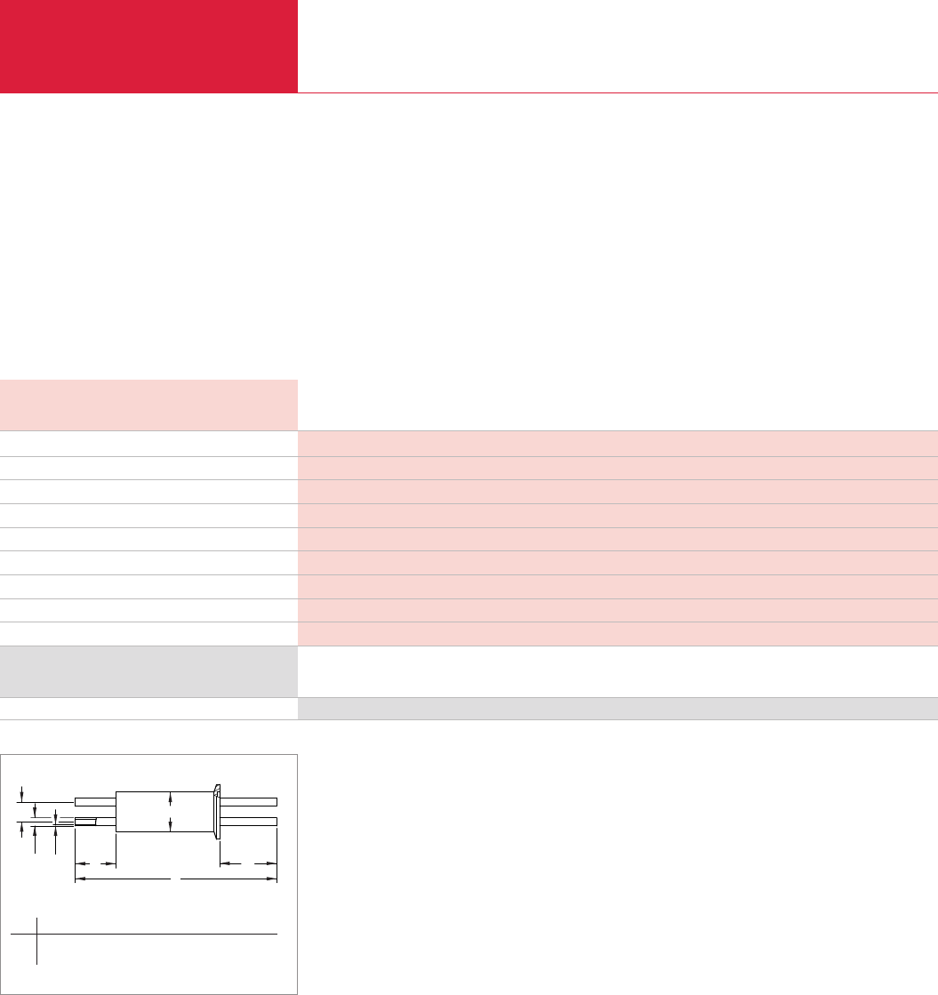
Feedthroughs
Vacuum Fittings and Feedthroughs
C13.38 LEYBOLD VACUUM PRODUCTS AND REFERENCE BOOK 2003/2004
Liquid Feedthroughs
DN 40 ISO-KF
welded
l8 x 1 (0.31 x =.04)
2
1 x 10⁻⁹
1 x 10⁻⁹ mbar to 2.5 bar (0.75 x 10⁻⁹ Torr to 1.9 Torr) [max. 10 bar (max. 7.5 Torr) with external centering ring]
-200 to +150 (-328 to +302)
stainless steel
0.3 (0.66)
Technical Data FL 40K/2
Vacuum connection
Feedthrough / seal
Connection mm (in.)
Number of tubes
Tightness mbar x l x s-1
Pressure (absolute)
Temperature range °C (°F)
Material
Weight kg (lbs)
For H
2
O and LN
2
Thermically insulated
Especially suited for very hot and very cold
applications
Ordering Information
Liquid feedthrough Part No. 210 275
FL 40K/2
l1
b1
ød1
ødb
l2
l
Dimensional drawing for the liquid feedthrough FL 40K/2
b b1d d1l l1l2
mm 20 140 8 200 40 57
in. 0.79 0.04 1.57 0.31 7.87 1.57 2.24
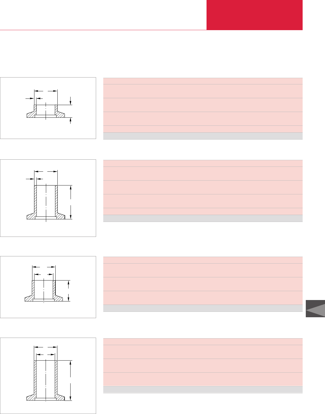
ISO-KF Flange Fittings and Components
Vacuum Fittings and Feedthroughs
C13.39
C13
LEYBOLD VACUUM PRODUCTS AND REFERENCE BOOK 2003/2004
Version for the North and South American Continents
DN KF 16 25 40 50
∅A mm 19 25.4 38.1 50.8
in. 0.75 1.00 1.50 2.00
B mm 1.7 1.7 2.1 2.1
in. 0.065 0.065 0.083 0.083
C mm 12.7 12.7 19.0 19.0
in. 0.50 0.50 0.75 0.75
Tube fitting O. D. size 3/4 " 1 " 1 1/2 " 2 "
Stainless steel Part No. 899 611 899 612 899 614 899 615
KF Flanges with Short Weld Stub, Standard-Inch Diameters
B
A
C
Dimensional drawing for the KF flanges with short weld stub
DN KF 16 25 40 50
∅A mm 19 25.4 38.1 50.8
in. 0.75 1.00 1.50 2.00
B mm 1.7 1.7 2.1 2.1
in. 0.065 0.065 0.083 0.083
C mm 40.0 40.0 40.0 40.0
in. 1.575 1.575 1.575 1.575
Tube fitting O. D. size 3/4 " 1 " 1 1/2 " 2 "
Stainless steel Part No. 899 621 899 622 899 624 899 625
KF Flanges with Long Weld Stub, Standard-Inch Diameters
C
B
A
Dimensional drawing for the KF flanges with long weld stub
DN KF 16 25 40 50
∅A mm 16 25 40 50
in. 0.630 0.984 1.575 1.968
∅B mm 20 28 45 55
in. 0.787 1.102 1.772 1.165
C mm 16 19 25 25
in. 0.630 0.750 0.984 0.984
Stainless steel Part No. 884 21 884 22 884 23 883 85
KF Flanges with Weld Stub, Metric Diameters
A
B
C
Dimensional drawing for the KF flanges with weld stub
DN KF 16 25 40
∅A mm 16 25 40
in. 0.630 0.984 1.575
∅B mm 20 28 45
in. 0.787 1.102 1.772
C mm 57 57 57
in. 2.250 2.250 2.250
Stainless steel Part No. 884 31 884 32 884 33
KF Flanges with Weld Neck, Metric Diameters
C
A
B
Dimensional drawing for the KF flanges with weld neck
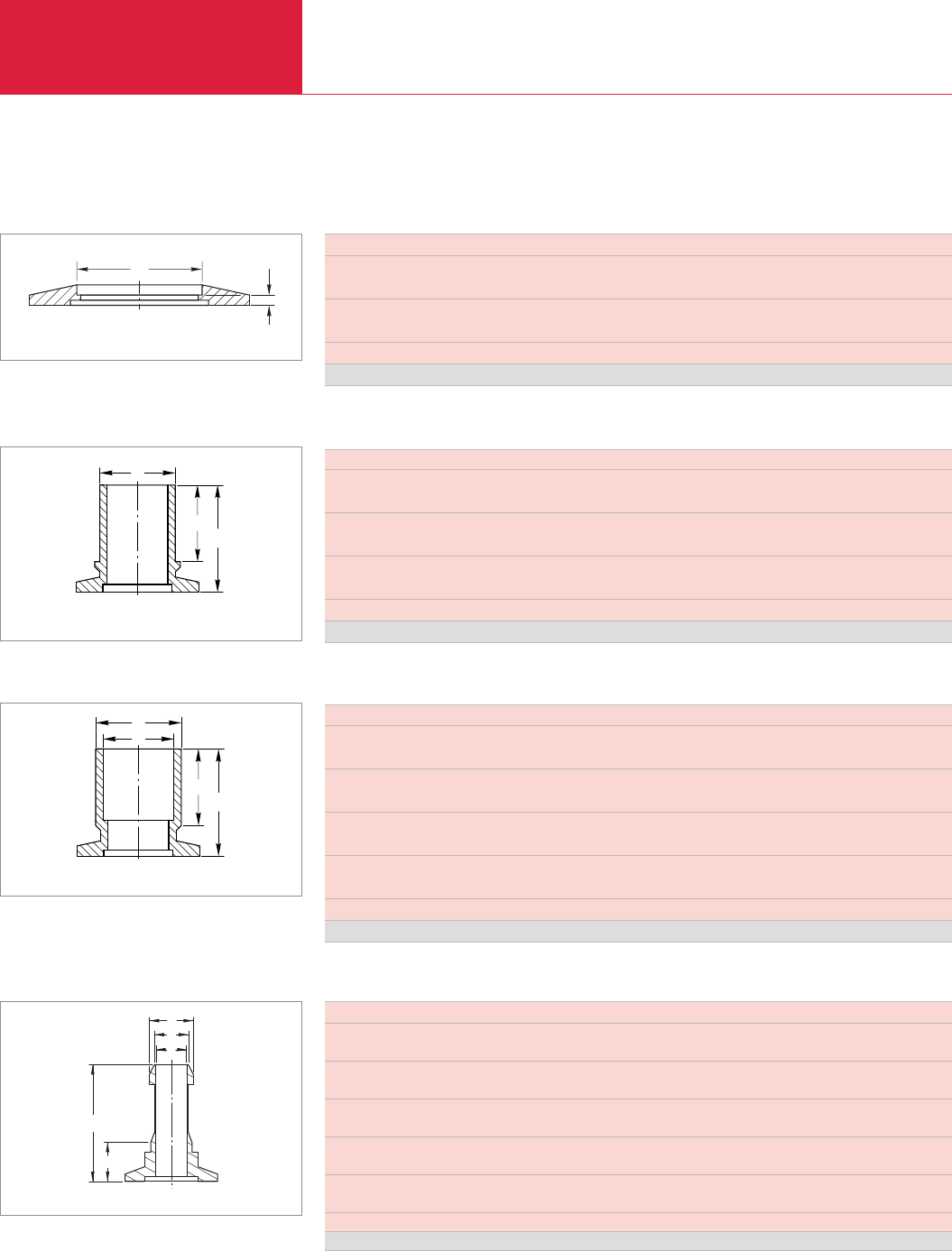
ISO-KF Flange Fittings and Components
Vacuum Fittings and Feedthroughs
C13.40 LEYBOLD VACUUM PRODUCTS AND REFERENCE BOOK 2003/2004
DN KF 16 25 40 50
∅A mm 17.3 26.2 41.1 52.1
in. 0.68 1.03 1.62 2.05
B mm 3.0 3.0 3.0 3.0
in. 0.12 0.12 0.12 0.12
Tube fitting O. D. size 3/4 " 1 " 1 1/2 " 2 "
Stainless steel Part No. 899 631 899 632 899 634 899 635
Flanges with Welded Socket
A
B
Dimensional drawing for the flanges with welded sockets
DN KF 16 25 40 40
∅A mm 19.0 29.0 44.5 41.0
in. 0.750 1.125 1.750 1.625
B mm 17.5 29.0 29.0 29.0
in. 0.688 1.125 1.125 1.125
C mm 29.0 35.0 46.0 46.0
in. 1.125 1.375 1.812 1.812
Tube fitting I. D. size 3/4 " 1 1/8 " 1 3/4 " 1 5/8 "
Stainless steel Part No. 910280119 910280120 910280126 910280121
KF Flanges for Tube Fittings, Male
C
A
B
Dimensional drawing for the KF flanges for tube fittings, male
DN KF 16 25 40 40
∅A mm 19.0 29.0 54.0 41.0
in. 0.754 1.130 2.130 1.630
∅B mm 22.0 32.0 57.0 44.5
in. 0.875 1.250 2.240 1.750
C mm 25.4 35.0 35.0 35.0
in. 1.000 1.375 1.375 1.375
D mm 13.0 17.0 16.0 19.0
in. 0.500 0.672 0.625 0.750
Tube fitting O. D. size 3/4 " 1 1/8 " 2 1/8 " 1 5/8 "
Stainless steel Part No. 910280122 910280123 910280124 910280125
KF Flanges for Tube Fittings, Female
C
A
B
D
Dimensional drawing for the KF flanges for tube fittings, female
Version for the North and South American Continents
DN KF 16 16 25
∅ A mm 9.5 16.1 16.1
in. 0.375 0.635 0.635
∅ B mm 7.6 14.3 14.3
in. 0.300 0.563 0.563
∅ C mm 5.6 11.9 11.9
in. 0.219 0.469 0.469
D mm 40 40 40
in. 1.575 1.575 1.575
E mm 12.7 12.7 12.7
in. 0.500 0.500 0.500
Tubing size 1/4 " 1/2 " 1/2 "
Aluminum Part No. 899 674 899 675 899 676
KF Nipple, American Standard
C
D
E
B
A
Dimensional drawing for the KF nipple
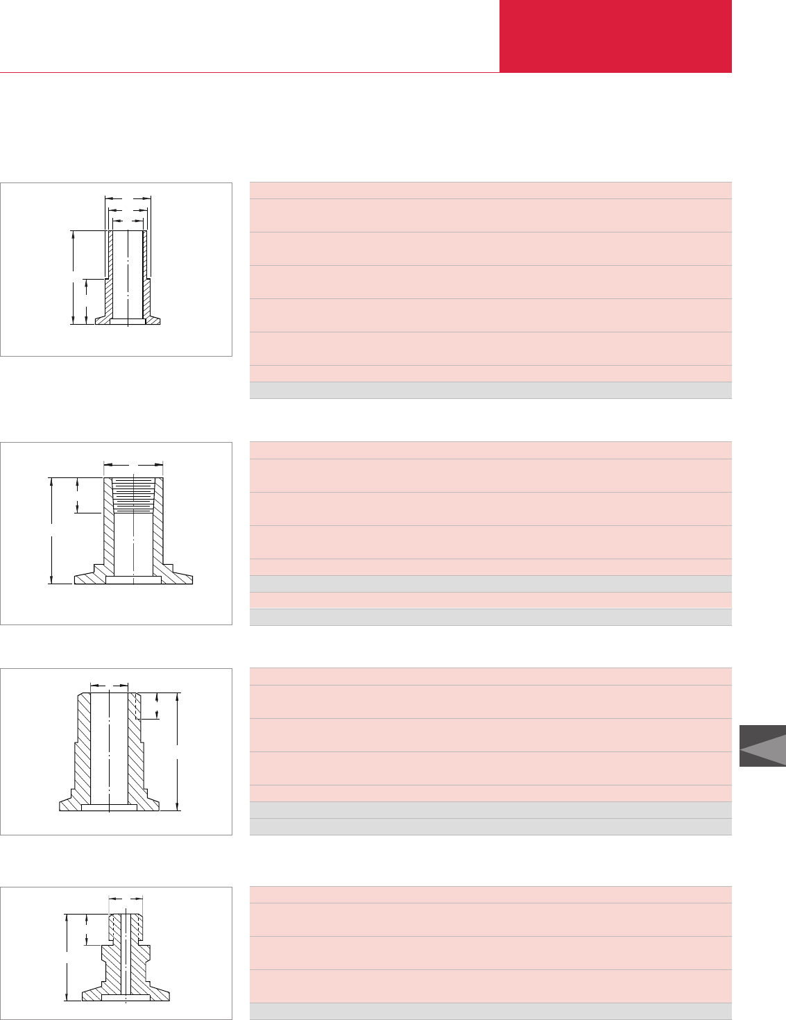
Adaptors
Vacuum Fittings and Feedthroughs
C13.41
LEYBOLD VACUUM PRODUCTS AND REFERENCE BOOK 2003/2004
Version for the North and South American Continents
C13
DN KF 16 25 40
∅A mm 16 21 32
in. 0.625 0.813 1.250
∅B mm 19.5 26 39
in. 0.770 1.020 1.540
∅C mm 20 28 45
in. 0.787 1.102 1.772
D mm 29 29 29
in. 1.125 1.125 1.125
E mm 13 13 13
in. 0.500 0.500 0.500
Nominal I. D. hose 3/4" 1" 1 1/2"
Stainless steel Part No. 992780668 992780670 992780672
Hose Adapter
E
D
A
B
C
Dimensional drawing for the hose adaptors
DN KF 16 25 40
∅A mm 16 25 38
in. 0.620 0.995 1.500
B mm 10 10 10
in. 0.394 0.394 0.394
C mm 25.4 25.4 25.4
in. 1.000 1.000 1.000
Pipe size NPT 1/8" 1/8" 1/8"
Stainless steel Part No. 899 604 899 605 899 606
Pipe size NPT 1/4" 1/4" 1/4"
Stainless steel Part No. 899 643 899 644 899 645
KF/NPT Female Adapter
A
B
C
Dimensional drawing for the KF/NPT female adaptors
DN KF 16 25 25 40 40 40 40
∅A mm 9.5 16.0 23.8 25.4 31.8 38.1 38.2
in. 0.375 0.625 0.937 1.000 1.250 1.500 1.503
B mm 10.0 13.5 17.0 17.0 18.0 18.4 19.2
in. 0.402 0.534 0.683 0.683 0.707 0.724 0.757
C mm 38.0 46.0 63.5 50.8 63.5 63.5 63.5
in. 1.500 1.813 2.500 2.000 2.500 2.500 2.500
Pipe size NPT 1/4" 1/2" 1" 1" 1 1/4" 1 1/2" 2"
Carbon steel Part No.
992780678 992780679
–
992780680
– – 899 619
Stainless steel Part No. 899 601 899 602 899 626 899 603 899 627 899 628 899 629
KF/NPT Male Adapter
A
B
C
Dimensional drawing for the KF/NPT male adaptors
DN KF 16
A mm 50.8
in. 2.000
B mm 12.7
in. 0.500
∅D /thread) mm M 16 x 1.5
in. M 16 x 0.06
Carbon steel Part No. 99258004
KF/Metric Adapter
C
B
A
Dimensional drawing for the KF/metric adaptors
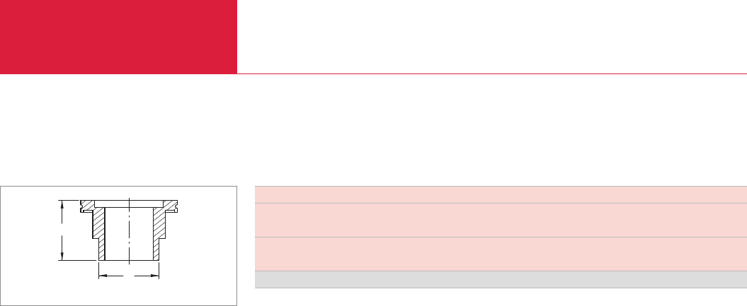
(ISO-K) Clamp Flange Fittings and Components
Vacuum Fittings and Feedthroughs
C13.42 LEYBOLD VACUUM PRODUCTS AND REFERENCE BOOK 2003/2004
Version for the North and South American Continents
A
B
Dimensional drawing for the ISO-K / NPT adapter
DN 63 ISO-K / 2" NPT
A mm 60
in. 2.362
∅B mm 51
in. 2" NPT
Stainless steel Part No. 72103040
ISO-K to NPT Adapter
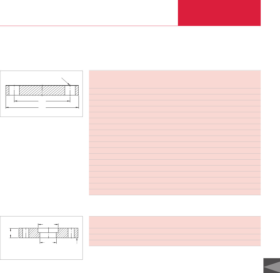
Vacuum Fittings and Feedthroughs
C13.43
C13
LEYBOLD VACUUM PRODUCTS AND REFERENCE BOOK 2003/2004
ISO-F and DIN 2501 Fixed Flange Fittings
Version for the North and South American Continents
B.C
Bolt Holes Size and Number of Holes
O.D
Dimensional drawing for bold type flanges
Bold Type Flanges
Bolt holes
Size Bolt circle (B.C.) in in. Outside diameter (O.D.) in in. Size No. of holes
dimensions in brakets ( ) in mm
DIN 63 ISO-K 5.118 (130) 6.299 (160) 0.551 (14) 4
DIN 100 ISO-K 6.693 (170) 8.268 (210) 0.709 (18) 8
DIN 160 ISO-K 8.858 (225) 10.433 (265) 0.709 (18) 8
DIN 250 ISO-K 13.189 (335) 14.764 (375) 0.709 (18) 12
DIN 350 ISO-K 17.520 (445) 19.291 (490) 0.906 (23) 12
DIN 500 ISO-K 23.622 (600) 25.394 (645) 0.906 (23) 20
ANSI 3 inch 6.000 (152.4) 7.500 (190.5) 0.750 (19) 4
ANSI 4 inch 7.500 (190.5) 9.000 (228.6) 0.750 (19) 8
ANSI 6 inch 9.500 (241) 11.000 (279.4) 0.875 (22) 8
ANSI 8 inch 11.750 (298) 13.500 (343) 0.875 (22) 8
ANSI 10 inch 14.250 (362) 16.000 (406.4) 1.000 (25.4) 12
ANSI 12 inch 17.000 (432) 19.000 (483) 1.000 (25.4) 12
ANSI 16 inch 21.250 (540) 23.500 (597) 1.125 (29) 16
DIN 63 ISO-F 4.311 (110) 5.118 (130 0.393 (10) 4
DIN 100 ISO-F 5.709 (145) 6.496 (165) 0.393 (10) 8
DIN 160 ISO-F 7.874 (200) 8.858 (225) 0.453 (11.5) 8
DIN 250 ISO-F 12.205 (310) 13.189 (335) 0.453 (11.5) 12
DIN 400 ISO-F 18.890 (480) 20.080 (510) 0.551 (14) 16
Bore Sealing Side
C-Bore
Thickness
Dimensional drawing for counter bore for ANSI blank flange
(dimensions in inches)
Maximum Recommended Counter Bore for ANSI Blank Flanges (for Carbon or Stainless Steel Pipe)
Bolt holes
ANSI size Outside diameter (O.D.) Bolt circle (B.C.) No. of holes Diameter Thickness Max. C-Bore
3 7 1/2 6 4 3/4 7/8 4 1/4
4 9 7 1/2 8 3/4 7/8 5 3/4
6 11 9 1/2 8 7/8 15/16 7 1/2
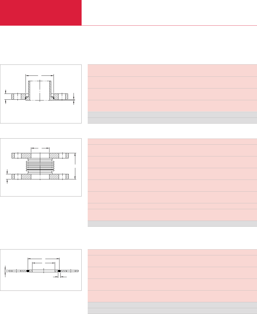
ANSI Fittings
Vacuum Fittings and Feedthroughs
C13.44 LEYBOLD VACUUM PRODUCTS AND REFERENCE BOOK 2003/2004
Version for the North and South American Continents
DN ISO-K 63 100 160 250
to ANSI 3 in. 4 in. 6 in. 10 in.
A mm 13 13 16 22
in. 0.500 0.500 0.625 0.875
∅B mm 95.5 131 181 291
in. 3.760 5.140 7.120 11.453
C mm 1 1 1 1
in. 0.039 0.039 0.039 0.039
Carbon steel Part No. 982780700 982780701 982780702 982780703
Spare retaining ring Part No. 23102401 23102402 23102412 23102413
Flanges, Rotatable Bolt Type
A
B
C
Dimensional drawing for the flanges, rotatable type
(tube piece shown in phantom not included)
DN ANSI 3 in. 4 in. 6 in.
A mm 120 120 200
in. 4.720 4.720 7.870
∅B mm 78 102 154
in. 3.070 4.030 6.070
C mm 12.7 12.7 12.7
in. 0.500 0.500 0.500
Rated deflection in axial mm 15 18 29.5
in. 0.580 0.700 1.160
Rated deflection in lateral mm 5 6 8
in. 0.190 0.220 0.310
Spring rate lb/in. 263 340 260
Compression / tension mm 12 / 4 15 / 4 23 / 7
in. 0.460 / 0.140 0.560 / 0.140 0.900 / 0.260
Stainless steel bellows with carbon steel flanges Part No. 991051013 991051014 991051016
Combined axial/lateral deflection cannot exceed 100 %. Example: 75 % axial rating - 25 % lateral rating
C
B
A
Bellows
Dimensional drawing for the bellows
Sealing Disk Assembly
D
B
A
C
Dimensional drawing for the sealing disk assembly
DN ANSI 3 in. 4 in. 6 in.
∅A mm 91 121 171
in. 3.600 4.750 6.720
∅B mm 78 102 154
in. 3.070 4.030 6.070
C mm 3.2 3.2 3.2
in. 0.125 0.125 0.125
∅D mm 4 4 4
in. 0.157 0.157 0.157
Aluminum Part No. 910181605 910181606 910181607
Stainless steel Part No. 910181616 910181617 910181618
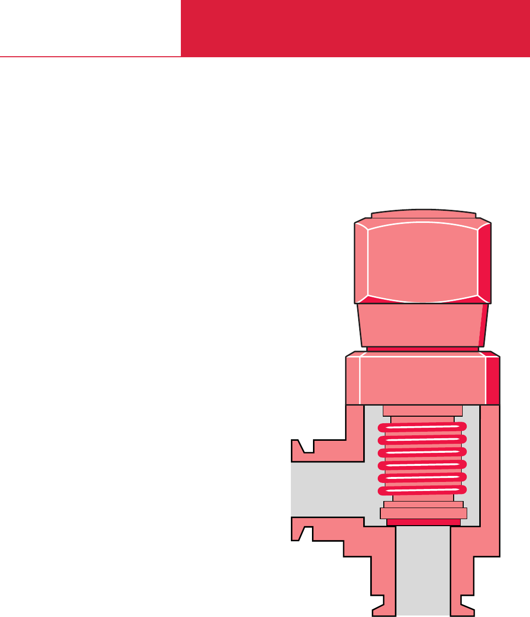
C14
Manually Operated
Electropneumatically Operated
Electromagnetically Operated
Special Valves
Gate Valves
Vacuum Valves

Contents
Vacuum Valves
C14.02 LEYBOLD VACUUM PRODUCTS AND REFERENCE BOOK 2003/2004
General
The LEYBOLD Valve Program . . . . . . . . . . . . . . . . . . . . . . . . . . . . . . . . . . . . . . . . . . . . . . . C14.03
Products
Small Valves of the “micro” Range
Overview . . . . . . . . . . . . . . . . . . . . . . . . . . . . . . . . . . . . . . . . . . . . . . . . . . . . . . . . . . . . . . C14.06
Right-Angle and Straight-Through Valves . . . . . . . . . . . . . . . . . . . . . . . . . . . . . . . . . . . . . . C14.07
Valves with KF Flanges
Overview . . . . . . . . . . . . . . . . . . . . . . . . . . . . . . . . . . . . . . . . . . . . . . . . . . . . . . . . . . . . . . C14.08
Nominal Width DN 16 KF to DN 40 KF
Right-Angle and Straight-Through Valves, Bellows-Sealed, Manually Operated. . . . . . . . . . . C14.09
Right-Angle Valves, Bellows-Sealed, Electropneumatically Operated . . . . . . . . . . . . . . . . . . C14.10
Straight-Through Valves, Bellows-Sealed, Electropneumatically Operated . . . . . . . . . . . . . . C14.11
Right-Angle Valves, Bellows-Sealed, Electromagnetically Operated . . . . . . . . . . . . . . . . . . . C14.12
Valves with ISO-K or ISO-F Flanges
Overview . . . . . . . . . . . . . . . . . . . . . . . . . . . . . . . . . . . . . . . . . . . . . . . . . . . . . . . . . . . . . . C14.13
Nominal Width DN 63 ISO-K to DN 160 ISO-K
Right-Angle Valves, Bellows-Sealed, Manually Operated . . . . . . . . . . . . . . . . . . . . . . . . . . . C14.14
Right-Angle Valves, Bellows-Sealed, Electropneumatically Operated . . . . . . . . . . . . . . . . . . C14.15
Nominal Width DN 250
Right-Angle Valves, Bellows-Sealed, Electropneumatically Operated . . . . . . . . . . . . . . . . . . C14.16
Special Valves
Overview . . . . . . . . . . . . . . . . . . . . . . . . . . . . . . . . . . . . . . . . . . . . . . . . . . . . . . . . . . . . . . C14.17
Nominal Width DN 10 KF to DN 40 KF or ISO-K
SECUVAC Vacuum Safety Valves . . . . . . . . . . . . . . . . . . . . . . . . . . . . . . . . . . . . . . . . . . . . C14.18
Variable-Leak Valves with and without Isolation Valve . . . . . . . . . . . . . . . . . . . . . . . . . . . . . C14.20
Venting Valves . . . . . . . . . . . . . . . . . . . . . . . . . . . . . . . . . . . . . . . . . . . . . . . . . . . . . . . . . . C14.21
Power Failure Venting Valves / Ball Valves . . . . . . . . . . . . . . . . . . . . . . . . . . . . . . . . . . . . . C14.22
Vacuum Locks / Sealing Valves . . . . . . . . . . . . . . . . . . . . . . . . . . . . . . . . . . . . . . . . . . . . . C14.23
Right-Angle Valve for Mobile Systems in Accordance with the Regulations of the
Department of Transportation (DOT). . . . . . . . . . . . . . . . . . . . . . . . . . . . . . . . . . . . . . . . . . C14.24
Accessories for the Electropneumatically Operated Valves. . . . . . . . . . . . . . . . . . . . . . . . . . C14.25
High Vacuum Gate Valves
Overview . . . . . . . . . . . . . . . . . . . . . . . . . . . . . . . . . . . . . . . . . . . . . . . . . . . . . . . . . . . . . . C14.26
Miniature HV and UHV Gate Valves, Manually Operated, KF and CF Flange . . . . . . . . . . . . . C14.27
Miniature HV and UHV Gate Valves, Electropneumatically Operated, KF and CF Flange . . . . C14.28
HV Gate Valves, Manually Operated, ISO-F Flange . . . . . . . . . . . . . . . . . . . . . . . . . . . . . . . C14.29
HV Gate Valves, Electropneumatically Operated, ISO-F Flange . . . . . . . . . . . . . . . . . . . . . . C14.30
UHV Gate Valves, Manually Operated, CF Flange . . . . . . . . . . . . . . . . . . . . . . . . . . . . . . . . C14.31
UHV Gate Valves, Electropneumatically Operated, ISO-F Flange . . . . . . . . . . . . . . . . . . . . . C14.32
UHV Gate Valves, Electropneumatically Operated, CF Flange . . . . . . . . . . . . . . . . . . . . . . . . C14.33
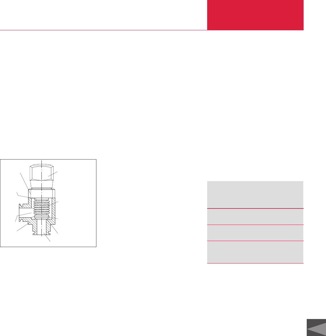
General
Vacuum Valves
C14.03
LEYBOLD VACUUM PRODUCTS AND REFERENCE BOOK 2003/2004
C14
The LEYBOLD Valve Program
The long-standing experience of LEYBOLD in the
area of vacuum engineering is reflected in the
selection and the design of the valves and vac-
uum protection components for a wide variety of
applications. The range of products is such that a
reliable solution can be offered for every vacuum
engineering application. Many years of service
and the reliability of the valves is ensured by
design. LEYBOLD vacuum valves are well-proven
in many widely varying areas of research and
industry.
The Design of a Vacuum
Valve
Scope of the Range of
Valves
The range of LEYBOLD valves comprises:
♦Small valves micro
♦Right-angle and straight-through valves
(no slanted seat valve) with a nominal width of
DN 16 to DN 40 with KF flanges
♦Right-angle valves with a nominal width of
DN 63 to DN 250 with ISO-K flanges
♦Gate valves with a nominal width of DN 16
to DN 250 with various flanges
♦Ball valves
♦Special valves
It is the aim of LEYBOLD to meet, through the
offered range of isolation components and val-
ves, the customers requirements regarding the
design of such components. For this reason all
valves are available with different driving
systems.
With the exception of the special valves you may
select between a stepped rotary knob manual
drive, an electropneumatic drive or an electro-
magnetic drive system.
Right-angle valves DN 16 to DN 40 KF as well as
DN 63 to DN 160 ISO-K are either available with
an aluminium or stainless steel body (the latter
up to DN 100 ISO-K only).
The special characteristics of the application in
each case result in special requirements con-
cerning features of the valves, for example:
♦Coating:
– Short switching cycles (e. g. 1.5 s)
– Very high number of opening and switching
cycles (e. g. over 10 million cycles)
♦Analytical engineering:
–
High conductance (similar to the correspond-
ing flange components, like bends, for
example)
– High integral leak tightness for the valves
(leak rates below 10
-9
mbar l/s)
♦Lamps and tubes manufacture:
– Temperature resistant
– Permissible ambient temperatures,
50 °C max.
♦Accelerator technology:
– Materials capable of resisting radiation,
high temperatures and corrosion at the
same time
♦Metallurgy and furnace manufacture:
– Rugged and insensitive to contamination
♦Chemistry
– Choice of materials in contact with the
medium for the valve body
All applications have the following requirements
in common:
♦Quiet opening action with very little vibration
♦Compact design, low weight
♦Highlyl visible, unambiguous position indicator
♦For use within the pressure range from 10
-8
to 2500 mbar, if not stated otherwise
♦Fully operational within the entire specified
pressure range
LEYBOLD valves meet these requirements,
unless otherwise stated by the technical data.
Quality Assurance
The various markets, like Analytical or Coating,
for example are very demanding regarding certain
important features for the valves which are to be
used in the new generation of instruments cur-
rently under development. Demanded are, among
other things, high reliability during the entire ser-
vice life, high integral leak tightness, a high num-
ber of opening/closing cycles as well as a fast
response.
The valves from LEYBOLD meet all these
demanding requirements!
Flange Designations
The flange designations used in this Product
Section are in line with the international stan-
dards and the nomenclature used in practice:
In the case of gate valves equipped with CF flan-
ges the following must be noted:
The designation DN 35 CF for UHV flanges has
been changed to DN 40 CF with the sealing para-
meters remaining unchanged; the same applies
to DN 150 CF which has changed to DN 160 CF.
For further information on flange connections and
flange components please refer to Product
Section C13 “Vacuum Fittings and Feedthroughs”
as well as C15 “Ultra-high Vacuum Components”.
BellowBellow
Vacuum
Housing
Valve disk with
vacuum seal
Valve
Type of
-stepped rotary knob
-electropneumatic
Valve cover
Housing
seal
Vacuum
-electromagnetic
operation:
Designation
Flange Type Standard with standardized
nominal width *
)
(DN)
Small flanges ISO 2861/I “KF
”
DIN 28 403 e.g. DN 40 KF
Clamp flanges ISO 1609 “ISO-K
”
DIN 28 404 e.g. DN 100 ISO-K
Fixed flanges/ ISO 1609 “ISO-F
”
collar flanges with DIN 28 404 “F
”
for fixed flange
retaining ring e. g. DN 250 ISO-F
*) The standardized nominal width (DN) corresponds appro-
ximately to the inside diameter, but need not necessarily
be identical to the inside diameter.

General
Vacuum Valves
C14.04 LEYBOLD VACUUM PRODUCTS AND REFERENCE BOOK 2003/2004
Advantages to the User
♦Compact design
♦Integral leak rate less than 10
-8
mbar l x s
-1
♦FPM sealed
♦For pressures up to 2000 mbar
♦Seal in both directions
1)
♦Principal dimensions comparable to LEYBOLD
flange components of the same nominal width
♦Reliable operation ensured regardless of the
valve’s orientation
♦Optical valve position indicator as standard
(not for valves of the “micro” range)
♦Electrical valve position indicator as standard
(not for valves of the “micro” range)
♦
Operation of electromagnetic KF valves off
supply voltages ranging from 100 to 230 V AC
♦The inside of the housing in contact with the
medium is sealed off against the atmosphere
by a bellows type seal which is absolutely free
of any lubricants.
All further technical data as well possible
devia-tions from the general specifications
stated here can be found along with the
descriptions for the individual valve types.
For various applications and special design require-
ments LEYBOLD offers a range of special valves:
♦SECUVAC vacuum safety valves
(DN 16 KF to DN 100 ISO-K)
♦Venting valves / power failure venting valves
♦Vacuum locks / sealing valves
♦Variable leak valves
♦Ball valves (straight-through valve)
♦Right-angle valves for mobile systems which
comply with the American standard of the
Department of Transportation (DOT)
Accessories
All connecting components like centering rings,
clamps or clamping rings needed to connect the
valves must be ordered separately (see Product
Section C13 “Vacuum Fittings and
Feedthroughs”).
Materials
The valve bodies and the inside parts are made of
selected, vacuum compatible materials, like
wrought aluminum or cast stainless steel.
The raw components are subjected to a 100%
test before they are further processed.
The materials which are used are described in the
tables at the end of the section “General”.
Gaskets
Shown in the table at the end of the section
“General” are the types of gasket used in the val-
ves together with their brief or chemical designa-
tions and their thermal ratings.
Other Materials
Plastic: Polyamide 6 (PA 6)
Grey cast iron: GG 20 (0.6020)
Brass: Ms 58
Brass (nickel-plated): CuZn39Pb3
Nimonic
Bronze
Spring steel
1) High vacuum systems are very demanding as to the leak
tightness of the vacuum components used. For this reason
each individual LEYBOLD valve is subjected to a helium
leak test before delivery. The valves are only considered as
leak tight, if a leak rate of less than 10-9 mbar x l x s-1 can
be measured for the body and the valve seat.
In the case of our high vacuum valves with KF and ISO-K
flanges a leak rate of less than 10-9 mbar x l x s-1 is main-
tained also during actuation.
This means that in the case of a gas flow of the mentioned
order of magnitude the pressure would increase only by
3 mbar in a vessel of 1 liter and in 100 years.

General
Vacuum Valves
C14.05
LEYBOLD VACUUM PRODUCTS AND REFERENCE BOOK 2003/2004
C14
Standard Steels
Material No. Brief Designation
DIN DIN
1.0388 St4/St14
1.0425 H II
Aluminum Alloys
Material No. Brief Designation
DIN AA DIN
3.0615 – AlMgSiPbF28
3.2153 – G AlSi7Cu3
3.2315 6081 AlMgSi1F28
3.2341 – G AlSi5Mg wa
3.2371 – G AlSi7Mg wa
3.2373 – G AlSi9Mg
3.2381 – G AlSi10Mg wa
3.3527 – AlMg2Mn0,8F20
Stainless Steels
Material No. Brief Designation
DIN AISI DIN
1.4034 420 X 46 Cr 13
1.4301 304 X5 CrNi 18 10
1.4305 303 X8 CrNiS 18 9
1.4306 304 L X2 CrNi 18 10
1.4308 – G-X6 CrNi 18 10
1.4310 301 X10 CrNi 17 7
1.4404 316 L X2 CrNiMo 17 13 3
1.4435 316 L X2 CrNiMo 18 14 3
1.4541 321 X6 CrNiTi 18 10
1.4571 316 Ti X6 CrNiMoTi 17 12 2
Brief Designation Chemical Designation Typical Trade Name Degassing
Temperature
FPM Fluor caoutchouc Viton up to 150 °C
NBR Acrylonitrile-
butadiene rubber Perbunan up to 80 °C
PTFE Polytetrafluor ethylene Teflon up to 250 °C
EPDM Ethylene-propylenedien
caoutchouc – up to 150 °C
Materials used for the Gaskets
Abbreviation Valve type
EMD Solenoid straight-through valve
EME Solenoid right-angle valve
EPD Electro-pneumatic straight-through valve
EPE Electro-pneumatic right-angle valve
MAN Manual operation
PD Pneumatic straight-through valve
PE Pneumatic right-angle valve
Abbreviations used in the valve designations
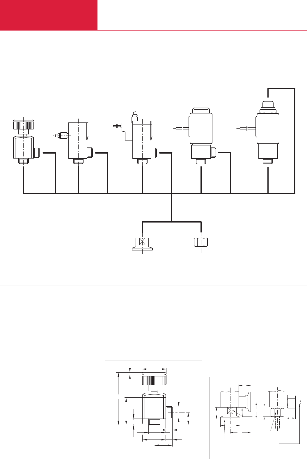
Overview
Small Valves
C14.06 LEYBOLD VACUUM PRODUCTS AND REFERENCE BOOK 2003/2004
2 3
56
789
1
4
Tube ø6 x 0,5
Tube ø1/4" x 0,7
31
DN 10 ISO-KF
26 14,5
SW 17
14,5
SW17
ø30h11
18
18
Connection dimensions for small valves “micro”
21
8
6,5
27,5
ø35
8
34,5
66,1
Hub 2
M14x1
M14x1
16
Dimensional drawing for the micro MAN
LEYBOLD small valves micro are available with
any of four drive systems, two types of body and
three adapters.
Technical Information
micro valves are supplied without adaptor.
The adaptors must be ordered additionally.
Types of drive
♦Manual (1)
♦Pneumatic (2)
♦Electropneumatic (3)
♦Electromagnetic (4)
Types of valve body
♦Right-angle valve (5)
♦Straight-through valve (6)
as well as adapter
♦DN 10 KF flange (7)
♦1/4" tube (8)
♦6 mm tube (9)
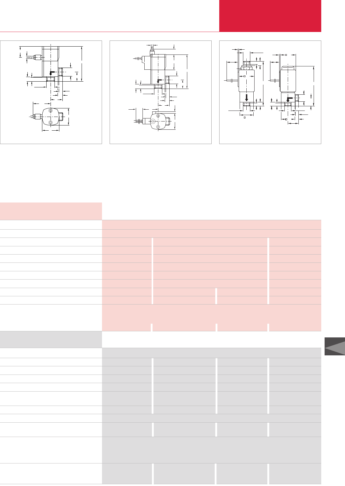
Small Valves
C14.07
LEYBOLD VACUUM PRODUCTS AND REFERENCE BOOK 2003/2004
C14
Advantages to the User
♦Small size
♦High conductance in the molecular flow range
♦Long service life of over 2 million switching
cycles
6,5
6,5
30,5
29
29
8
21
59,5
ø4
20
16
M14x1
M14x1
8
6,5
ø4
32
29
6,5
8
21
64
10,3
16
M14x1
M14x1
29,5
500
3,5
8
Dimensional drawing for the pneumatically actuated small valve “micro”
Dimensional drawing for the electropneumatically actuated
small valves “micro”
6,5
M14x1
25
/
2
6,5
6,5
30
2
500
8
8
SW19
500
16
8
21
8
82
M14x1 M14x1
76
M14x1
/
8
6,5
30
/
25
/
Dimensional drawing for the electromagnetic actuated small valves “micro”
Right-angle valves
Type
Manual MAN
Without pilot valve normally closed PE
With pilot valves normally closed EPE
With pilot valve normally open EPE
With pilot valve normally closed,
with flanges PE DN 10 KF
Electromagnetic, normally closed EME
Straight-through valves
Electromagnetic, normally closed EMD
Electromagnetic, normally open EMD
Adapter (1 piece)
Flange DN 10 KF
Tube 1/4 "
Tube 6 mm
Spare parts
Seal kit
Inside section
Part No. 284 48 – – –
– – Part No. 284 40 –
–Part No. 284 41 – –
–Part No. 284 42 – –
– – Part No. 284 47 –
– – – Part No. 284 44
– – – Part No. 284 45
– – – Part No. 284 46
Part No. 284 50
Part No. 284 51
Part No. 284 52
Part No. 105 80 Part No. 105 81 Part No. 105 81 Part No. 108 82
Part No. 105 80 Part No. 105 82 Part No. 105 82 Part No. 105 83/84/89
Ordering Information
Nominal width mm
Integral leak rate mbar x l/s
Switching cycles
Max. pressure differential bar abs.
Closure time ms
Opening time ms
Max. switching frequency min-1
Conductance, molecular l/s
Supply voltage VDC
Max. power consumption W
Materials
5
10-9
– 5 Mio. > 2 Mio.
4 3 1
– 35 7
– 35 30
– 150 300
0.4 0.4 0.3
– 24 (with pilot valve) – 24
– 1 – 10
Valve body: Stainless steel (1.4301); Inside section: stainless steel (1.4301);
Gaskets: O-rings made of FPM
Drive:
Aluminum / Plastic Aluminum anodized Aluminum anodized stainless steel 1.4105
Technical Data Small Valve “micro”
Manual Electropneumatic Pneumatic Electromagnetic
Small Valve “micro”
Manual Electropneumatic Pneumatic Electromagnetic
Typical Applications
♦Gas handling systems in production machines
♦Latest generation analytical equipment
Right-Angle and Straight-Through Valves, Bellows-Sealed, Various Drives
♦High switching frequency
♦Protection class IP 50
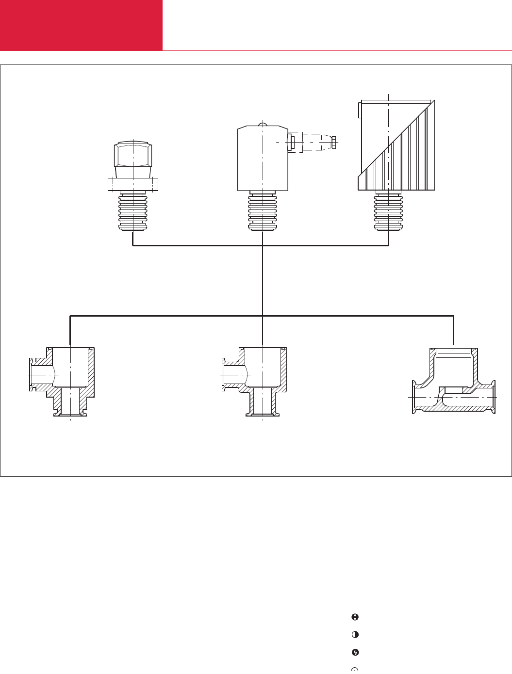
Valves with KF Flanges
C14.08 LEYBOLD VACUUM PRODUCTS AND REFERENCE BOOK 2003/2004
Overview
LEYBOLD KF valves are available with any of
three drive systems and three types of body
having a nominal width of DN 16, 25 and
40 KF.
Types of drive
♦Stepped rotary knob (1) with bellows seal
♦Electropneumatic with bellows seal (2)
♦Solenoid with bellows seal (3)
Types of valve body
♦Right-angle valve, aluminum body (4)
♦Right-angle valve, stainless steel body (5)
♦Straight-through valve, stainless steel body (6)
6
45
2
1
3
Nicht für Position 3
Not for item 3
Position indicator connection
Compressed air connection
Power connection
Position indicator
Connection Pictograms
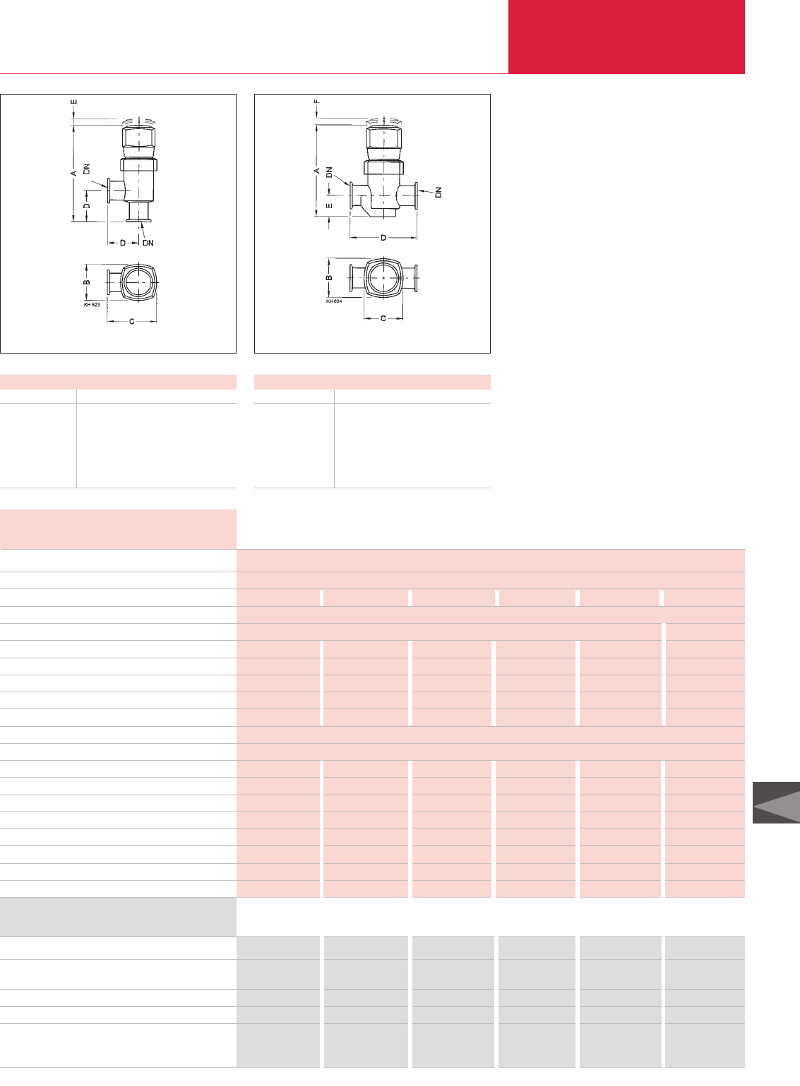
Valves with KF Flanges
C14.09
LEYBOLD VACUUM PRODUCTS AND REFERENCE BOOK 2003/2004
C14
Advantages to the User
Valves with Rotary Knob
Isolation component with handy and easy to ope-
rate four position rotary knob
♦Permits careful venting of systems
♦Suited as a manually operated variable leak
valve to roughly control gas flows
♦Leak tight in both directions up to a pressure
of 2.0 etc. 1.5 bar and easy to open
♦Installation in any orientation
Dimensions for the Right-Angle Valves
DN KF 16 25 40
A mm 118.3 154.5 173.8
B mm 44 58 82
C mm 62 79 106
D mm 40 50 65
E mm 5 10 12
Dimensional drawing for the manually operated, bellows-sealed
right-angle valves
Dimensional drawing for the manually operated, bellows-sealed
straight-through valves
Dimensions for the Straight-Through Valves
DN KF 16 25 40
A mm 100.3 136 154.3
B mm 44 58 82
C mm 44 58 82
D mm 80 100 130
E mm 22 31.5 44.5
F mm 5 10 12
Right-Angle and Straight-Through Valves, Bellows-Sealed, Manually
Right-Angle Valves, rotary knob
Aluminum body
Stainless steel body
Straight-Through Valves, rotary knob
Stainless steel body
Spare parts
Seal kit
Inside section
Part No. 285 30 Part No. 285 31 Part No. 285 32
Part No. 286 30 Part No. 286 31 Part No. 286 32
–
Part No. 286 00
–
Part No. 286 01
–
Part No. 286 02
Part No. 215 025 Part No. 215 025 Part No. 215 075 Part No. 215 075 Part No. 215 125 Part No. 215 125
Part No. 215 042 Part No. 215 042 Part No. 215 092 Part No. 215 092 Part No. 215 142 Part No. 215 142
Ordering Information DN 16 KF DN 25 KF DN 40 KF
Aluminum / Stainless Aluminum / Stainless Aluminum / Stainless
Right-Angle Valves
Service life cycles
Conductance at molecular flow l x s-1
Leak rate mbar x l x s-1
Operating pressure range mbar
Differential pressure, closing and opening direction bar
Opening against differential pressure bar
Ambient / operating temperature, max. °C
Seal
Weight kg
Straight-Through Valves
Service life cycles
Conductance at molecular flow l x s-1
Leak rate mbar x l x s-1
Operating pressure range mbar
Differential pressure, closing and opening direction bar
Opening against differential pressure bar
Ambient / Operating temperature, max. °C
Seal
Weight kg
10000
4.5 4.5 16 16 40 40
1 x 10⁻⁹
10-8 - 2000 10-8 - 1500
2 / 2 2 / 2 2 / 2 2 / 2 2 / 2 2 / 1.5
2 2 3 3 4 4
50 50 50 50 50 50
FPM FPM FPM FPM FPM FPM
0.30 0.43 0.40 0.68 0.55 1.35
10000
– 2.5 – 8 – 20
– 1 x 10⁻⁹ – 1 x 10⁻⁹ – 1 x 10⁻⁹
– 10-8 / 2000 – 10-8 / 2000 – 10-8 / 1500
– 2/2 – 2/2 – 2/1.5
– 2 – 3 – 4
– 50 – 50 – 50
– FPM – FPM – FPM
– 0.48 – 0.7 – 1.4
Technical Data DN 16 KF DN 25 KF DN 40 KF
Aluminum / Stainless Aluminum / Stainless Aluminum / Stainless
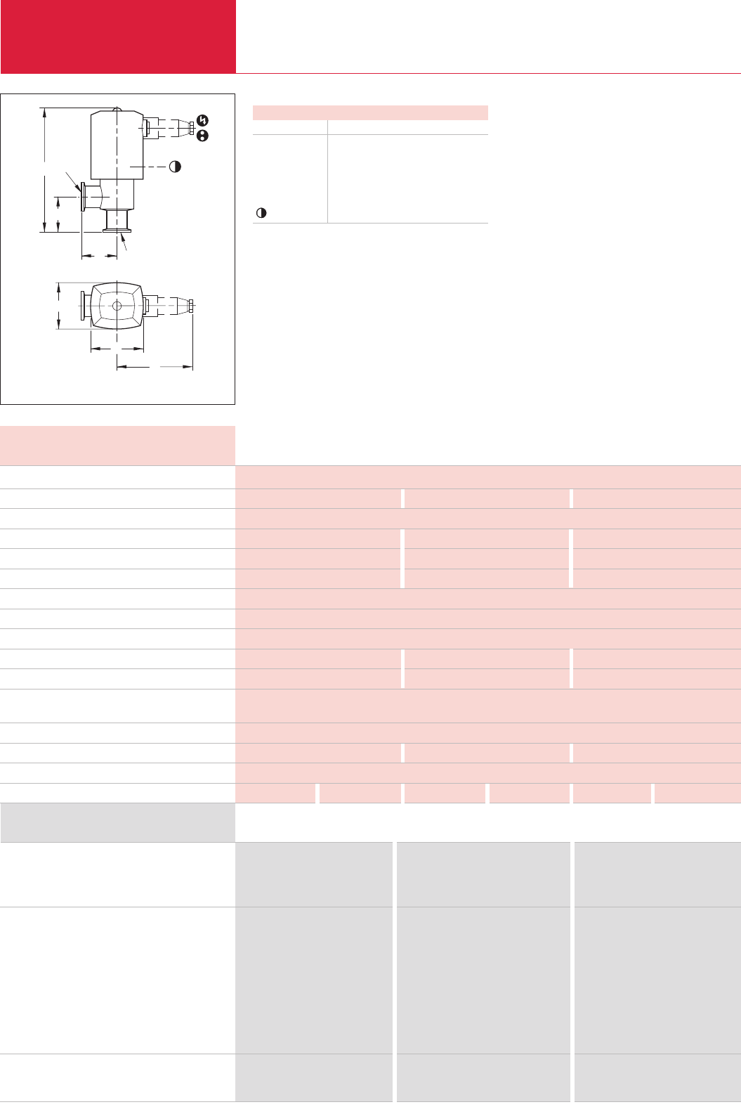
Valves with KF Flanges
C14.10 LEYBOLD VACUUM PRODUCTS AND REFERENCE BOOK 2003/2004
Right-Angle Valves, Bellows-Sealed, Electropneumatically Operated
♦Very low leak rate and insensitive to particles
owing to bellows seal. Always closed in case
the compressed air supply fails
♦Electric position indicator is standard
♦With and without pilot valve as standard
♦Standard electrical and compressed air
connections
♦Protection class IP 50
♦The valves are closed by the restoring force of
a spring
♦Installation in any orientation and no restric-
tions as to the direction of flow
DN
DN
A
D
D
B
E
C
M5
Dimensional drawing for the aluminum right-angle valves with built-in pilot valve
Dimensions
DN KF 16 25 40
A mm 154 176 196.5
B mm 51 63 83
C mm 60 74 98
D mm 40 50 65
E mm 100 108 120
mm l 4l 4l 4
Service life cycles
Conductance at molecular flow l x s-1
Leak rate mbar x l x s-1
Operating pressure range mbar
Differential pressure, closing and opening direction bar
Opening against differential pressure at the valve disk
bar
Ambient / Operating temperature, max. °C
Seal
Closing time
ms
Opening time
ms
Switching frequency 1/min
Electrical position indicator, load capacity V AC / A
V DC / A
Compressed air, overpressure bar
Air cylinder, volume cm3
Compressed air connection mm
Weight, with pilot valve kg
Technical Data DN 16 KF DN 25 KF DN 40 KF
Aluminum / Stainless Aluminum / Stainless Aluminum / Stainless
10 Million
4.5 16 40
1 x 10⁻⁹
10-8 - 2000 10-8 - 2000 10-8 - 1500
4 / 2 4 / 2 2 / 1.5
4 4 2
50
FPM
200 290 250
100 110 150
100 100 75
250 /0.1
50 / 0.25
3 to 5 3 to 5 3 to 6
5.5 12.1 26.2
4 and 6
0.3 0.4 0.4 0.7 0.9 1.6
Right-angle valves, bellows sealed, Electropneumatic
drive, without pilot valve
aluminum body
stainless steel body
Right-angle valves, bellows sealed, Electropneumatic
drive, with pilot valve
024 V DC aluminum body
024 V DC stainless steel body
024 V AC aluminum body
024 V AC stainless steel body
100 - 115 V AC aluminum body
100 - 115 V AC stainless steel body
200 - 240 V AC aluminum body
200 - 240 V AC stainless steel body
Spare parts
Seal kit
Inside section
Part No. 287 15 Part No. 287 16 Part No. 287 17
Part No. 288 15 Part No. 288 16 Part No. 288 17
Part No. 287 45 Part No. 287 46 Part No. 287 47
Part No. 288 45 Part No. 288 46 Part No. 288 47
Part No. 287 28 Part No. 287 29 Part No. 287 30
Part No. 288 28 Part No. 288 29 Part No. 288 30
Part No. 287 55 Part No. 287 56 Part No. 287 57
Part No. 288 55 Part No. 288 56 Part No. 288 57
Part No. 287 75 Part No. 287 76 Part No. 287 77
Part No. 288 35 Part No. 288 36 Part No. 288 37
Part No. 215 025 Part No. 215 075 Part No. 215 125
Part No. 215 027 Part No. 215 077 Part No. 215 127
Ordering Information DN 16 KF DN 25 KF DN 40 KF
Advantages to the User
♦Quiet opening and closing action with very
little vibration
♦Short opening and closing times
♦Optical valve position indicator as standard
♦Optical valve position indicator as standard
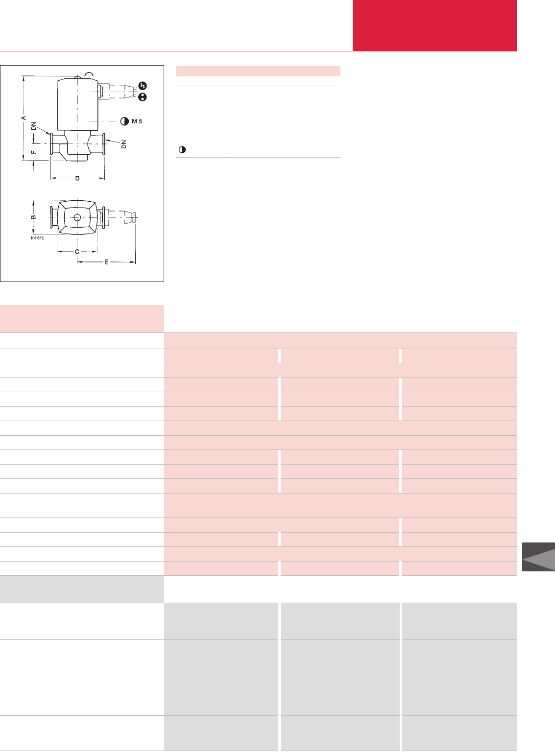
Valves with KF Flanges
C14.11
LEYBOLD VACUUM PRODUCTS AND REFERENCE BOOK 2003/2004
C14
Advantages to the User
♦Quiet opening and closing action with very
little vibration
♦Short opening and closing times
♦Optical valve position indicator as standard
♦Very low leak rate and insensitive to particles
owing to bellows seal – thus always closed in
case the compressed air supply fails
♦Electric position indicator is standard
♦With and without pilot valve as standard
♦Protection class IP 50
♦Standard electrical and compressed air
connections
♦The valves are closed by the restoring force of
a spring
Dimensional drawing for the stainless steel straight-through valves
Dimensions
DN KF 16 25 40
A mm 139.5 157.5 177
B mm 51 63 83
C mm 60 74 98
D mm 80 100 130
E mm 100 108 120
F mm 22 31.5 45.5
mm l 4l 4l 4
Straight-Through Valves, Bellows-Sealed, Electropneumatically Operated
Straight-through valve, bellows sealed,
Electropneumatic drive, without pilot valve,
stainless steel body
Straight-through valve, bellows sealed,
Electropneumatic drive, with pilot valve,
stainless steel body
24 V DC
24 V AC
100 - 115 V AC
200 - 240 V AC
Spare parts
Seal kit
Inside section
Part No. 289 15 Part No. 289 16 Part No. 289 17
Part No. 289 45 Part No. 289 46 Part No. 289 47
Part No. 289 28 Part No. 289 29 Part No. 289 30
Part No. 289 55 Part No. 289 56 Part No. 289 57
Part No. 289 35 Part No. 289 36 Part No. 289 37
Part No. 215 025 Part No. 215 075 Part No. 215 125
Part No. 215 027 Part No. 215 077 Part No. 215 127
Ordering Information DN 16 KF DN 25 KF DN 40 KF
Service life cycles
Conductance at molecular flow l x s-1
Leak rate mbar x l x s-1
Operating pressure range mbar
Differential pressure, closing and opening direction bar
Opening against differential pressure at the valve disk
bar
Ambient / Operating temperature, max. °C
Seal
Closing time ms
Opening time ms
Switching frequency 1/min
Electrical position indicator, load capacity V AC / A
V DC / A
Compressed air, overpressure bar
Air cylinder, volume cm3
Compressed air connection mm
Weight, with pilot valve kg
10 Million
2.5 8 20
1 x 10⁻⁹
10-8 - 2000 10-8 - 2000 10-8 - 1500
4 / 2 4 / 2 2 / 1.5
4 4 2
50
FPM
200 290 250
100 110 150
100 100 75
250 / 0.1
50 / 0.25
3 to 5 3 to 5 3 to 6
5.5 12.1 26.2
4 and 6
0.5 1.0 1.5
Technical Data DN 16 KF DN 25 KF DN 40 KF
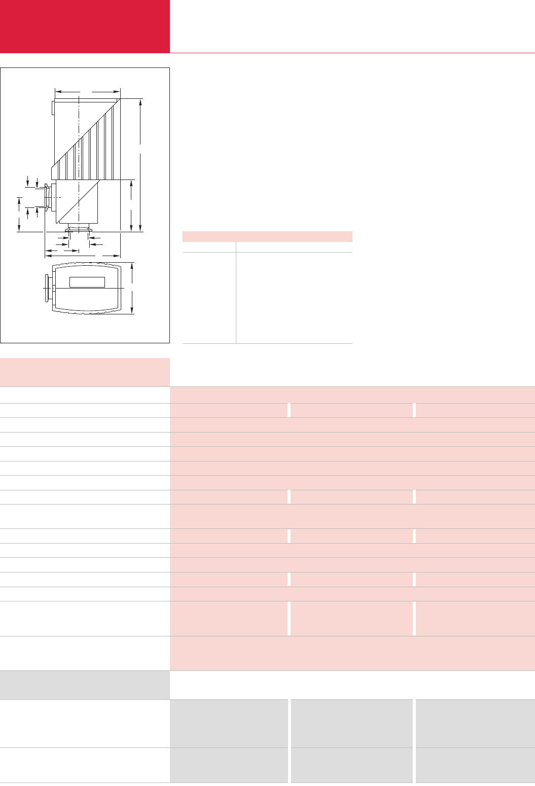
LEYBOLD VACUUM PRODUCTS AND REFERENCE BOOK 2003/2004
C14.12
Valves with KF Flanges
Right-Angle Valves, Bellows-Sealed, Electromagnetically Operated
DN
c
h
b1
d1DN h1
a
d1
ab
Dimensional drawing for the stainless steel right-angle valves, bellows-sealed
Advantages to the User
♦Selectable operating mode:
– Remote control via programmable control
or personal computer
– direct operation by switching the supply
voltage on and off
♦Well visible, unambiguous optical position
indicator: open (green LED) and closed (red
LED)
♦Integrated electrically floating position indica-
tor (opto-coupler for 24 V DC)
♦Optical overload indicator (red flashing LED)
♦Protection class IP 54
♦Spring action closure, thus closed when the
power fails
♦Low operating temperature
♦Inverting operation of the remote control logic
♦Installation in any orientation and no restric-
tions as to the direction of flow
Dimensions
DN KF 16 25 40
DN mm 14.5 23.2 38.5
d1mm 18.5 27.5 42.5
a mm 40 50 65
b mm 96 111 138
b1mm 84.5 96.5 119.5
c mm 59 75 96
h mm 160 194 230
h1mm 58 76 98
Travel mm 4 6.25 10
Electromagnetic valves are particularly well suited
for vacuum systems in which the valves need to
be remotely controlled and where compressed air
is not readily available.
Right-angle valve, bellows-sealed,
electromagnetic actuator, microprocessor controlled
aluminum body
stainless steel body
Spare parts
Seal kit
Inside section
Part No. 287 65 Part No. 287 66 Part No. 287 67
Part No. 288 65 Part No. 288 66 Part No. 288 67
Part No. 289 75 Part No. 289 76 Part No. 289 77
Part No. 288 88 Part No. 288 89 Part No. 288 90
Ordering Information DN 16 KF DN 25 KF DN 40 KF
Service life cycles
Conductance at molecular flow l x s-1
Leak rate mbar x l x s-1
Operating pressure range mbar
Differential pressure, closing and opening direction bar
Opening against differential pressure at the valve disk
bar
Ambient / Operating temperature, max. °C
Opening/closing time ms
Switching frequency 1/min
at ambient temperature °C
Switch-off delay ms
Rating for the valve position indicator V DC / mA
Power consumption, max. W
Actuation and holding current A
Supply voltage / Frequency V AC / Hz
Weight
aluminum body kg
stainless steel body kg
Materials
2 Million
4 16 40
1 x 10⁻⁹
10-9 to 1 300
1.3
1.3
50
100 / 240 120 / 240 230 / 700
30, 20
40, 50
50 170 500
15-30 / 100
400
5.2 / 0.7 5.3 / 0.7 4.8 / 0.7
100-230. +8 %/-15 %; 50/60 Hz
1.3 2.2 4
1.5 2.9 5.4
Valve body: aluminum alloy (G AlSi7Mg06) or stainless steel (1.4308);
Inside section: stainless steel (1.4301/1.4541); Gaskets: O-rings made of FPM;
Lid: high-quality plastic, temperature-resistant to 80 °C
Technical Data DN 16 KF DN 25 KF DN 40 KF
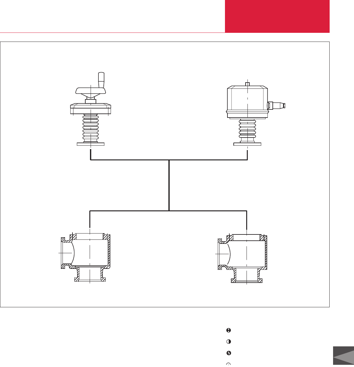
C14
LEYBOLD VACUUM PRODUCTS AND REFERENCE BOOK 2003/2004 C14.13
Overview
Valves with ISO-K/F Flanges
LEYBOLD valves with ISO-K flanges are available
with any of two drives and either of two bodies.
Types of drive
♦Handwheel (1)
♦Electropneumatic drive, bellows-sealed (2)
Body types
♦Right-angle valve with aluminum body (3)
♦Right-angle valve with stainless steel body (4)
From DN 63 ISO-K only right-angle valves are
available.
Nominal widths DN 63 ISO-K and DN 100 ISO-K
are available in aluminum and stainless steel,
DN 160 ISO-K in aluminum only.
Advantages to the User
♦Full exchangeability of the subassemblies
♦Three types of drive
♦Two body options
♦Standard nominal widths to DIN 28 404 and
ISO 1609
♦Simplified stocking of spare parts
3 4
1 2
Position indicator connection
Compressed air connection
Power connection
Position indicator
Connection Pictograms
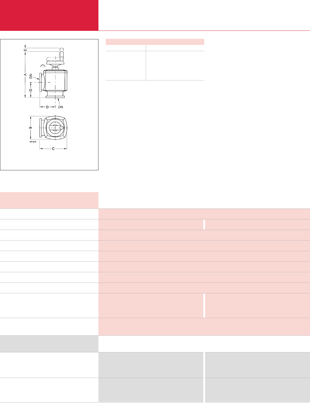
LEYBOLD VACUUM PRODUCTS AND REFERENCE BOOK 2003/2004
C14.14
Right-Angle Valves, Bellows-Sealed, Manually Operated
Valves with ISO-K Flanges
These universal valves are ideal especially for
smaller systems, where remote control is not
essential. They may be also installed in larger
systems, where backing pumps or condensate
separators or similar units are to be cut off at
longer intervals for maintenance purposes by
maintenance personnel.
Advantages to the User
♦Gentle venting of systems
♦Seal in both directions up to a pressure
difference of 1.5 bar
♦Easy manual operation, for an effortless
vacuum-tight seal
♦May also be used as a variable leak valve to
roughly control gas flows
♦Installation in any orientation and no restric-
tions as to the direction of flow
Dimensions
DN ISO-K 63 100
A mm 266 320
B mm 124 164
C mm 150 190
D mm 88 108
E mm 20 25
Dimensional drawing for the right-angle valves, bellows-sealed,
manually operated
Right-angle valve, bellows-sealed, manually operated
aluminum body
stainless steel body
Spare parts
Seal kit
Inside section
Part No. 107 80 Part No. 107 81
Part No. 107 83 Part No. 107 84
Part No. 215 251 Part No. 215 271
Part No. 215 254 Part No. 215 274
Ordering Information DN 63 ISO-K DN 100 ISO-K
Service life cycles
Conductance at molecular flow l x s-1
Leak rate mbar x l x s-1
Operating pressure range mbar
Differential pressure, closing and opening direction bar
Opening against differential pressure at the valve disk
bar
Ambient / Operating temperature, max. °C
Seal
Weight
aluminum body kg
stainless steel body kg
Materials
> 1.5 Million
140 330
1 x 10⁻⁹
10-8 - 1500
1.5
1.5
60
FPM
3.6 6.1
6.5 11.1
Valve body: aluminum alloy (3.2373.63) or stainless steel (1.4305);
Inside section: stainless steel (1.4541/1.4301); Lid: grey cast iron (GG 20); Gaskets: O-rings made of FPM
Technical Data DN 63 ISO-K DN 100 ISO-K
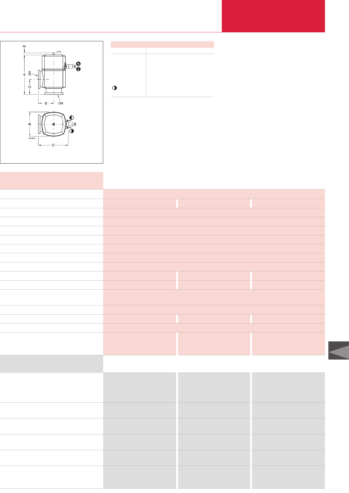
C14
LEYBOLD VACUUM PRODUCTS AND REFERENCE BOOK 2003/2004 C14.15
Right-Angle Valves, Bellows-Sealed, Electropneumatically Operated
Valves with ISO-K Flanges
Dimensional drawing for the electropneumatically actuated right-angle valves
Electropneumatically actuated right-angle valves
are used in automated vacuum systems which
need to be controlled electrically.
Advantages to the User
♦Pneumatic or electropneumatic opening
♦Short opening and closing times
♦Optical position indicator
♦Electric position indicator
♦With and without pilot valve IP 54
♦Protection class IP 54
♦The valves are closed by the restoring force
of a spring
Dimensions
DN ISO-K 63 100 160
A mm 250 282 366
B mm 130 170 221
C mm 168 208 264
D mm 88 108 138
E mm 14 14 14
mm +6 +6 +6
Right-angle valve, bellows-sealed,
electropneumatic drive, without solenoid coil
Aluminum housing
Stainless steel housing
Valve with pilot valve 24 V DC Aluminum housing
Stainless steel housing
Valve with pilot valve 24 V AC Aluminum housing
Stainless steel housing
Valve with pilot valve 100 - 115 V AC
Aluminum housing
Stainless steel housing
Valve with pilot valve 200 - 240 V AC
Aluminum housing
Stainless steel housing
Spare parts
Seal kit
Inside section
Part No. 107 90 Part No. 107 91 Part No. 107 92
Part No. 107 93 Part No. 107 94 –
Part No. 108 00 Part No. 108 01 Part No. 108 02
Part No. 108 10 Part No. 108 11 –
Part No. 108 03 Part No. 108 04 Part No. 108 05
Part No. 108 13 Part No. 108 14 –
Part No. 108 20 Part No. 108 21 Part No. 108 22
Part No. 108 30 Part No. 108 31 –
Part No. 108 25 Part No. 108 26 Part No. 108 27
Part No. 108 35 Part No. 108 36 –
Part No. 215 251 Part No. 215 271 Part No. 215 291
Part No. 215 253 Part No. 215 273 Part No. 215 293
Ordering Information DN 63 ISO-K DN 100 ISO-K DN 160 ISO-K
Service life, cycles Million
Conductance for molecular flow l x s-1
Leak rate mbar x l x s-1
Operating pressure range mbar
Differential pressure, closing and opening direction bar
Opening against differential pressure at the valve disk
bar
Ambient / Operating temperature, max. °C
Seal
Closing time ms
Opening time ms
Switching frequency 1/min
Position indicator, rating V AC/A
V DC/A
Compressed air, overpressure bar
Compressed air volume cm3
Compressed air connection mm
Weight with pilot valve
Aluminum housing kg
Stainless steel housing kg
1,5
140 330 800
1 x 10⁻⁹
1 x 10⁻⁸ - 1500
1.5
1.5
60
FPM
250 300 550
300 450 450
60 60 40
250/0.125
50/0.25
4 to 8
75 195 570
6
4 6.7 11.4
6.8 11.7 –
Technical Data DN 63 ISO-K DN 100 ISO-K DN 160 ISO-K
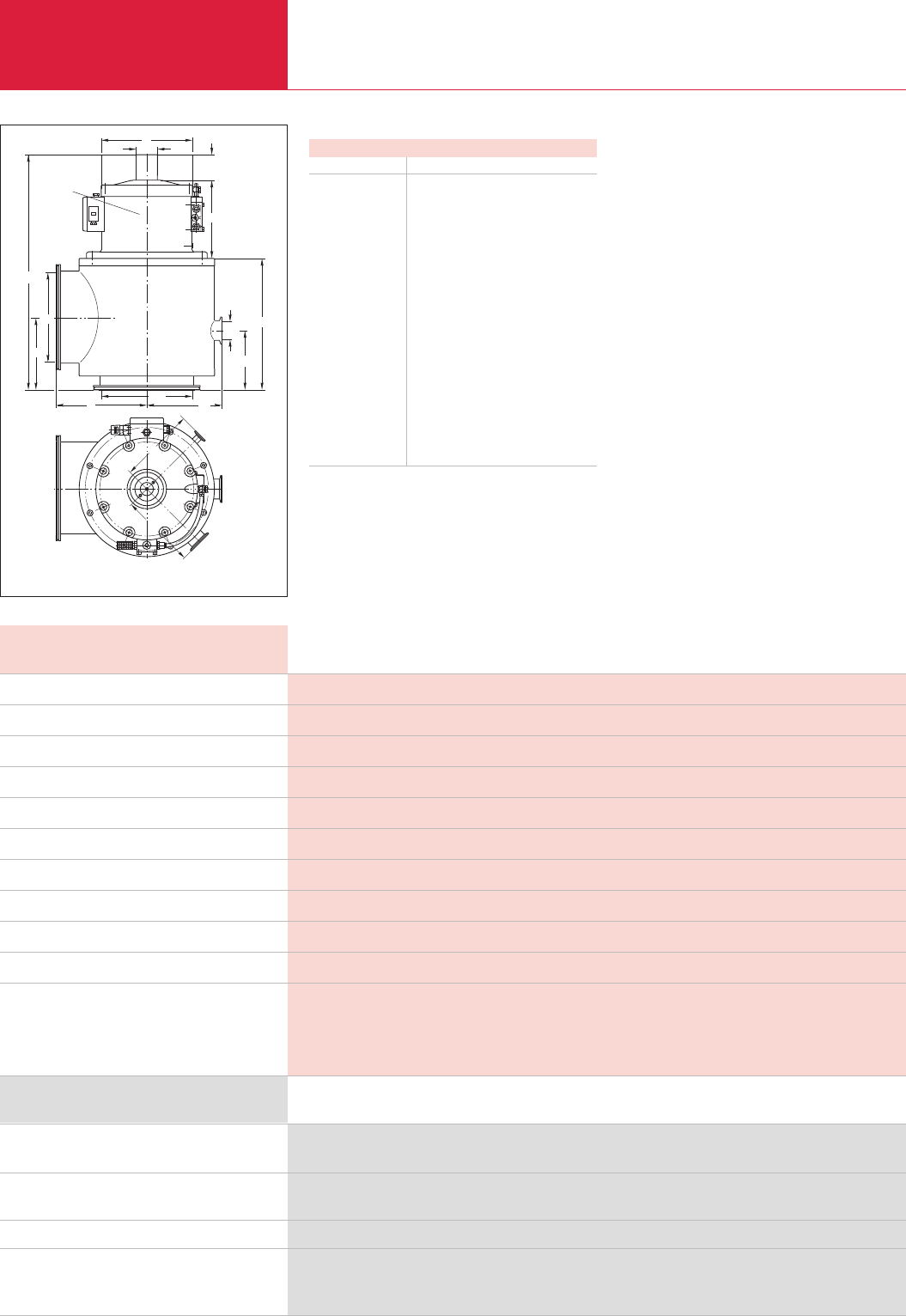
LEYBOLD VACUUM PRODUCTS AND REFERENCE BOOK 2003/2004
C14.16
Right-Angle Valves, Bellows-Sealed, Electropneumatically Operated
Valves with ISO-K Flanges
DN
DN1
h
c
b
e
d
h1
f
aa3
DN
1
a
DN1
DN3
DN2
a2
a4
Antrieb um
90° versetzt
gezeichnet
Dimensional drawing for the right-angle valves with bellows
Right-angle valves of this size are used, for
example in metallurgy, large coaters, in the area
of space simulation.
Advantages to the User
♦No vibrations when the valve open or closes
♦Low leak rate (< 10
-9
mbar x l x s
-1
) – drive
system basically insensitive to particles
♦Non-contact valve position indicator for
reliable indication of the valve’s position
(open/closed)
♦Wide range of different solenoid coils for all
commonly used control voltages
♦Additional flange for bypass lines and for
connecting vacuum gauges (see Product
Section C16 “Total Pressure Gauges”)
Dimensions
DN 250 ISO-K
DN mm 261
h, approx. mm 650
amm 250
a1mm 200
a2, a4mm 208
a3mm 205
h1mm 163
DN1, for bypass 1 50 KF
DN2, for bypass 2 40 KF
DN3, for meas. conn. 16 KF
bmm 69.5
cmm 218
dmm 250
emm 58
fmm 363
Travel mm 62.5
Travel/DN* mm 1/4
* For example travel = 1/4 DN
Drive drawn
offset by 90°
Right-angle valve, bellows-sealed, electropneumatic
drive, without solenoid coil, stainless steel body
Solenoid coil for
various supply voltages
Interference suppression kits for different voltages
Spare parts
Seal kit
Inner part
X = Part Nos. see section “Accessories for the Electropneumatically Operated Valves, Valves with KF/ISO-K Flanges”
Part No. 281 84
X
X
Part No. 105 65
Part No. 105 75
Ordering Information
DN 250 ISO-K
Service life cycles
Conductance at molecular flow l x s-1
Leak rate mbar x l x s-1
Opening / closing time, at 6 bar compr. air pressure s
Compressed air, overpressure bar
Hose diameter mm
Compressed air cylinder, volume cm3
Max. ambient temperature °C
Weight kg
Supply voltage V
Materials
1 x 10⁶
2700
1 x 10⁻⁹
6/6
4 to 8
6 x 1
2100
40
66
Various voltages are possible; see Accessoires
Body, valve disk: stainless steel;
Drive/compressed air cylinder: aluminum/cast aluminum (3.2153);
Piston rod, intermediate flange: stainless steel (1.4305);
Gaskets: FPM; Lid: aluminum (3.2341); Hood: plastic (PA 6)
Technical Data
DN 250 ISO-K
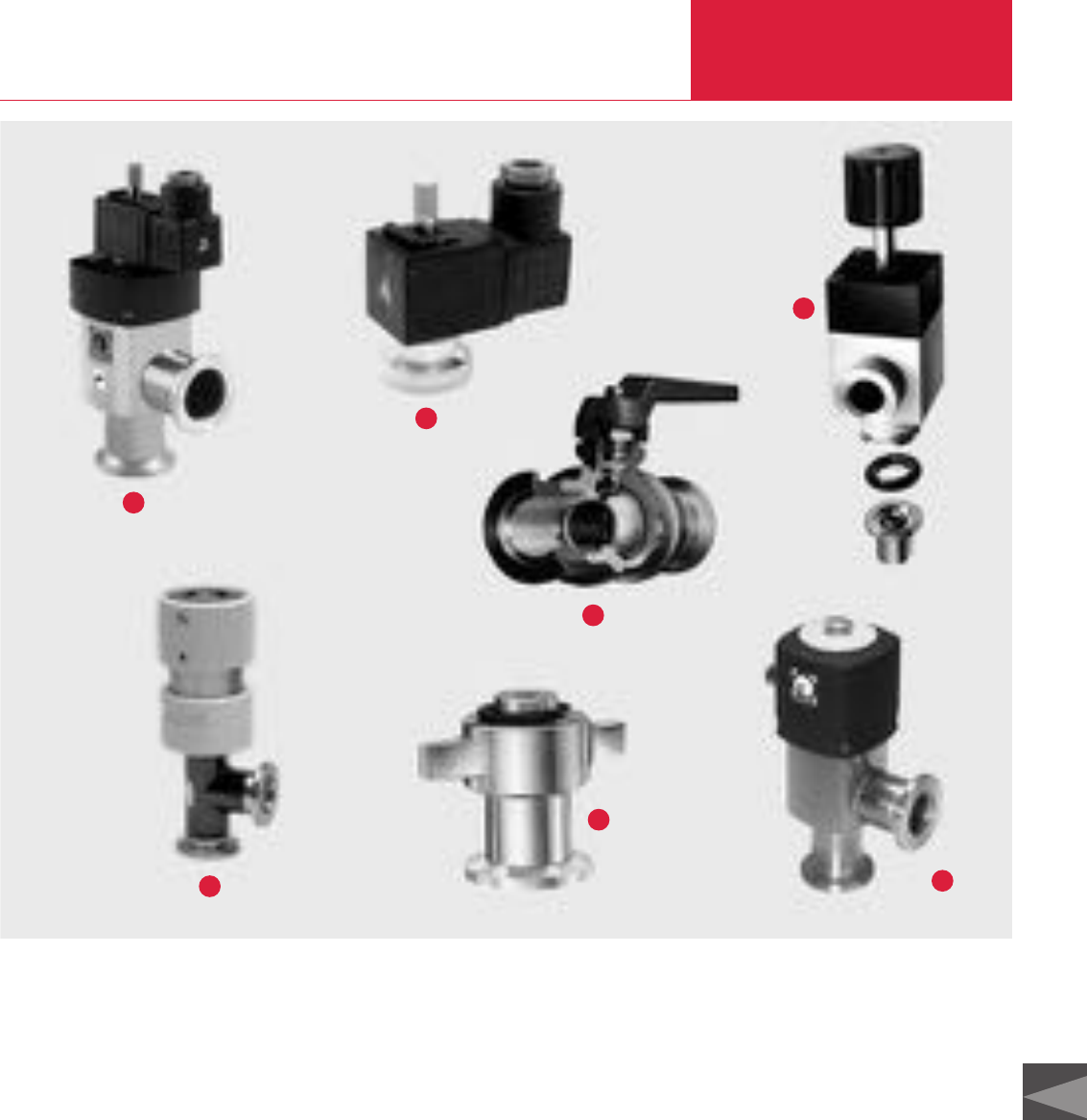
C14
LEYBOLD VACUUM PRODUCTS AND REFERENCE BOOK 2003/2004 C14.17
Overview
Special Valves with KF/ISO-K Flanges
LEYBOLD offers a range of special valves for a
variety of different applications and to meet
special design requirements of customers.
Among these are:
♦SECUVAC vacuum safety valves ➊
(DN 16 KF to DN 100 ISO-K)
♦Venting valves ➋/
power failure venting valves ➌
♦Vacuum locks / sealing valves ➍
♦Variable leak valves ➎
♦Ball valves ➏
♦Right-angle valves for mobile systems in
accordance with the American standard of the
Department of Transportation (DOT) ➐
These valves ideally supplement our range of
KF- and ISO-K valves.
6
7
3
4
2
1
5
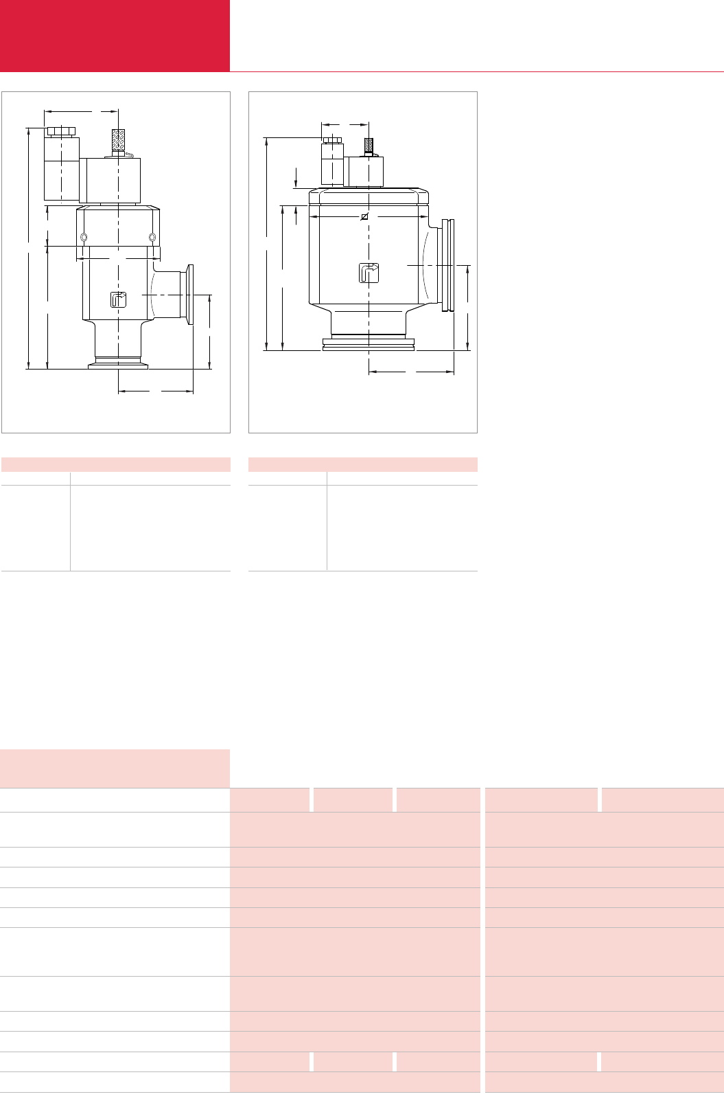
LEYBOLD VACUUM PRODUCTS AND REFERENCE BOOK 2003/2004
C14.18
SECUVAC Vacuum Safety Valves
Special Valves
Conductance at molecular flow l x s-1
Current consumption DC W
Actuation/holding AC VA
Leak tightness, body mbar x l x s-1
Leak tightness, valve disk mbar x l x s-1
Installation orientation
Operating pressure range mbar
Differential pressure Dp
for opening mbar
for closing mbar
Opening time s
Closing time/reaction time ms
Ambient temperature °C
Protection IP
Weight kg
Materials
3.8 11 30.5
2,5
5/3.7
< 1 x 10⁻⁹
< 1 x 10⁻⁵
any
1 · 10-8 - 1000
150
150
< 15
< 100/< 50
5 to 50
65
0.3 0.5 0.9
Valve body: aluminum; Gaskets FPM
Technical Data DN 16 KF DN 25 KF DN 40 KF
126 300
2,5
5/3.7
< 1 x 10⁻⁹
< 1 x 10⁻⁵
any
1 · 10-8 - 1000
150
150
< 30
< 100/< 50
5 to 50
65
2.4 5.1
Valve body: aluminum; Gaskets: FPM
DN 63 ISO-K DN 100 ISO-K
h
D
h2
a
a
h1
b
Dimensional drawing for the SECUVAC valves with ISO-K clamp flanges
These solenoid right-angle valves were specially
developed for use with rotary vacuum pumps
which are not equipped with a built-in anti-
suckback valve.
The SECUVAC safety valve protects the vacuum
system against unplanned venting via the backing
pump in case of a power failure
and
it ensures
that the vacuum system remains sealed until the
backing pump, after it has restarted, has
evacuated the connecting lines.
h2
h1
a
h
øD
a
b
Dimensional drawing for the SECUVAC valves with KF small flanges
Dimensions – SECUVAC valves with KF small flanges
DN 16 KF 25 KF 40 KF
a mm 40 50 65
b mm 49 49 49
D mm 44 56 82
h mm 138.6 161.8 178.3
h1mm 62.3 82.5 100
h2mm 24 27 26
Dimensions – SECUVAC valves with ISO-K clamp flanges
DN 63 ISO-K 100 ISO-K
a mm 88 108
b mm 150 190
D mm 124 164
h mm 220.5 263.5
h1mm 150 175
h2mm 18.2 36.2
Advantages to the User
Two valve functions in one:
♦Fast-closing high vacuum isolation valve for
separating the vacuum chamber or a vapor jet
pump (a diffusion pump, for example) from
the backing pump
♦Venting valve for venting of the valve’s cham-
ber and thus the pump (backing pump)
♦Immediate closing action upon power failure
♦Opening action only after the intake line has
been evacuated
♦Delayed isolation of the vacuum chamber and
venting the vacuum pump (negligible “gulp”)
Typical Applications
♦Safety isolation valve between backing pump
and vacuum chamber or vapour jet pumps
(protection of the vacuum chamber against
venting in the event of a power failure)

C14
Special Valves
C14.19
LEYBOLD VACUUM PRODUCTS AND REFERENCE BOOK 2003/2004
SECUVAC Vacuum Safety Valves
Part No.
215 015
Part No. 215 065 Part No. 215 135 Part No. 215 205 Part No. 215 225
Part No. 215 016 Part No. 215 066 Part No. 215 136 Part No. 215 206 Part No. 215 226
Part No. 215 017 Part No. 215 067 Part No. 215 137 Part No. 215 207 Part No. 215 227
Part No. 105 02 Part No. 105 04 Part No. 105 05 Part No. 105 07 Part No. 105 08
Part No. 215 242
Part No. 215 241
Part No. 215 240
Part No. 215 701
Ordering Information DN 16 KF DN 25 KF DN 40 KF DN 63 ISO-K DN 100 ISO-K
Interference Suppression Kit
- Illuminated
As an option for the solenoid coil, an interference
suppression kit is offered which reliably prevents
any interferences from affecting other equipment
operating in the vicinity.
Interference Suppression Kit
Ordering Information
Interference suppression kit
0
24 V DC
110 - 230 V AC
Part No. 104 96
Part No. 104 95
SECUVAC valve
0
24 V DC
100 - 115 V AC
200 - 230 V AC
Spare parts
Seal kit
Solenoid coils
for SECUVAC valves and power failure venting valves
0
24 V DC
100 - 115 V AC/50-60 Hz
200 - 230 V AC/50-60 Hz
Filter for SECUVAC valves
and power failure venting valves (set of 5 pcs.)
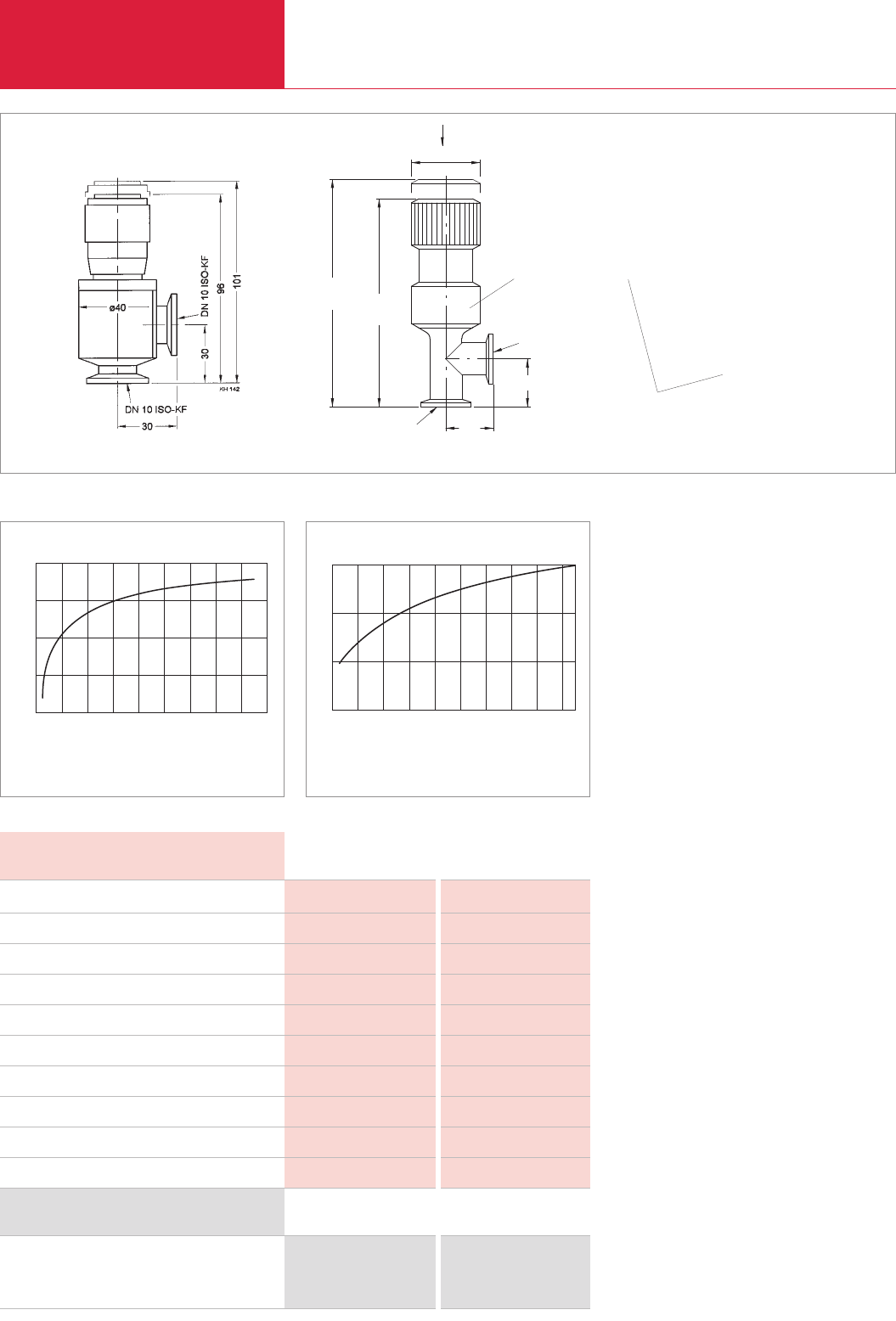
Variable Leak Valves with and without Isolation Valve
Special Valves with KF Flanges
C14.20 LEYBOLD VACUUM PRODUCTS AND REFERENCE BOOK 2003/2004
With variable leak valves precisely defined quanti-
ties of gas may be admitted within a controllable
period of time into evacuated vessels.
Variable leak valves with a isolation valve permit
an interruption of the gas supply without chang-
ing the gas admission rate setting.
Applications
♦Gas admission rates of 1000 to 5 x 10
-6
mbar x l x s
-1
allow variable leak valves to be
used in almost all applications
♦Through the integrated digital display, the
opening point may be accurately set at any
time or a certain gas flow may be defined
♦Blocking valve
Technical Note
When using helium as the process gas, it must
be taken into account that the needle sleeve made
of modified PTFE is to a certain extent permeable
to helium.
Dimensional drawings for the variable leak valves Part No. 215 020 (left) and Part No. 215 010 (right) Dimensions in ( ) = dimensions in inch
DN 10 ISO-KF DN 16 ISO-KFTechnical Data
Gas flow controllable mbar x l x s-1
Tightness mbar x l x s-1
Differential pressure bar
Dead volume cm3
Operating temperature °C
Bakeout temperature, flanges °C
Housing, needle, filter
Needle sleeve
Seal
Weight kg
40 - 1700 5 · 10-6 - 1000
1 x 10⁻⁹ 1 x 10⁻⁹
3 2.5
– 0.032
– 80
100 150
aluminum stainless steel
– flourplastomer
FPM FPM
0.2 0.4
DN 10 ISO-KF DN 16 ISO-KF
Ordering Information
Variable leak valve
without isolation valve
with isolation valve
Part No. 215 020
–
–
Part No. 215 010
100
10-6 10-5 10-4 10-3 10-2
Grasstrom
10-1 100101
mbar · I/s
103
101
102
103
Variable leak characteristic for the variable leak valve 215 010
Gas flow
DN 16 ISO-KF
DN 16 ISO-KF
Ansicht A
A
ø42 (1,65")
30 (1,18")
117,5
(4,63")
130
(5,12")
30
(1,18")
C
l
o
s
e
243
View A
Quick shut off ring
0
0
10
20
30
40
Skalenteile (1 Umdrehung = 12 Skalenteile)
Gasstrom
200 400 600 800 1000 1200 1400 1800
mbar · l/s
Variable leak characteristic for the variable leak valve 215 020
Scale divisions [1 rotation = 12 scale divisions]
Gas flow
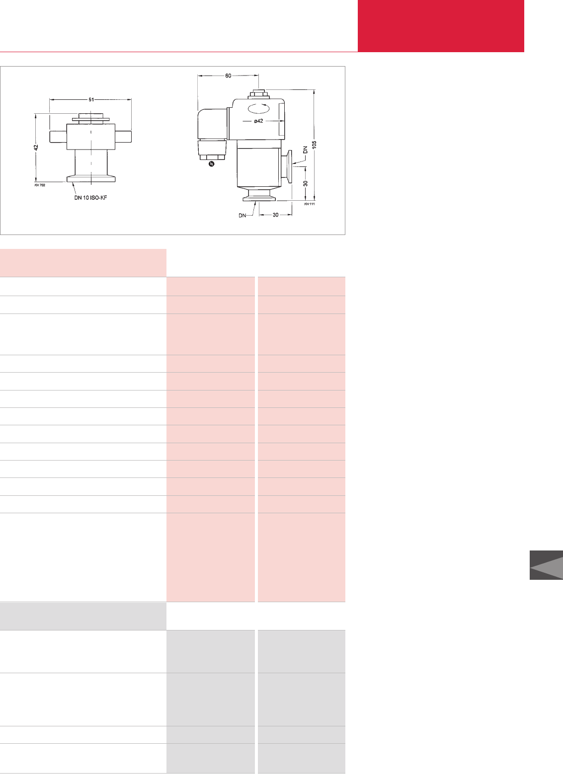
Venting Valves
Special Valves with KF Flanges
C14.21
LEYBOLD VACUUM PRODUCTS AND REFERENCE BOOK 2003/2004
C14
Venting valves are used to vent small vacuum
systems and are closed when no power is
applied.
Advantages to the User
Venting valve with screw cap, manual operation
♦Simple opening and closing of the valve by
loosening or tightening the screw cap
Venting valve, electromagnetically actuated
♦Open when power is applied, closed with no
power
♦Seals on one side against atmospheric
pressure
♦Protected against dirt by a filter
Dimensional drawings for the venting valves with screw cap (left) and the electromagnetic venting valves (right)
DN 10 KF
Manual Electromagnetically
Technical Data
DN 10 KF
Manual Electromagnetically
Ordering Information
Leak rate mbar x l x s-1
Venting time for a 100 l chamber s
Mains connection V / Hz
V / Hz
V DC
Power consumption, actuation/holding VA
Differential pressure in closing / opening direction bar
Can be opened to a pressure difference of bar
Service life cycles
Switching frequency 1/min
Opening / closing time ms
Conductance for molecular flow l x s-1
Weight kg
Dimensions (W x H x D) mm
Materials
Valve body
Inside section
Gasket
Screw cape
< 1 x 10⁻⁹ < 1 x 10⁻⁹
– 23
– 230 / 50 / 60
– 115 / 50 / 60
– 24
– 35 / 15
– 10 / 1
– 2
– 1.5 million
– 50
– 60 / 45
– 1
0.15 0.46
51 x 42 x 30 105 x 120 x 42
Aluminum (3.0615) Aluminum
Stainless steel (1.4301)
Aluminum (3.0615)
Stainless steel (1.4301) –
FPM FPM
Brass (nickel-plated) –
Part No. 173 24 –
Part No. 173 37 –
–Part No. 215 021
–Part No. 215 023
–Part No. 215 024
– Part No. 883 50
– Part No. 215 208
Venting valve with screw cap
Aluminum
Stainless steel
Venting valve, electromagnetic
024 V DC
115 V AC
230 V AC
Centering ring with sintered metal filter, DN 10 KF
Spare parts
Seal kit
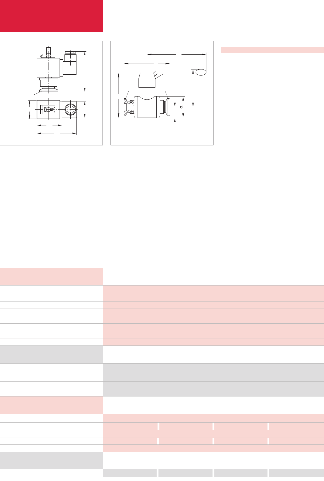
Special Valves with KF Flanges
C14.22 LEYBOLD VACUUM PRODUCTS AND REFERENCE BOOK 2003/2004
DN 10 ISO-KF
30 27
65,8
64
41
Ordering Information
Part No. 174 26
Part No. 174 46
Part No. 883 50
see SECUVAC valves
DN 10 KF Power Failure Venting Valve
Technical Data
Leak tightness mbar x l x s-1
Venting time for a 50 l vessel s
Opening time / closing time 1) ms
Protection class to DIN 40050 IP
Permissible ambient temperature °C
Weight kg
Dimensions (B x H x T) mm
Materials
< 1 x 10⁻⁷
270
30 / 30
65
50
0.1
64 x 66 x 30
Valve body: aluminum; Gasket: NBR; Armature: brass; Filter: bronze
Ball valve, brass body (nickel-plated)
1) at a differential pressure of Dp= 0 bar
Part No. 174 94 Part No. 174 95 Part No. 174 96 Part No. 174 97
Ordering Information Ball valves
DN 10 KF DN 16 KF DN 25 KF DN 40 KF
DN
h1
h2
DN
b
b1
D
h
Dimensional drawing for the DN 10 KF ball valve
Dimensions - Ball Valves
DN 10 KF 16 KF 25 KF 40 KF
b mm 75 100 130 160
b1mm 80 80 110 138
h mm 55 55 62 90
h1mm 55 58 80 110
h2mm 15 15 20 27.5
D mm 26 30 42 60
Leak rate mbar x l x s-1
Conductance for molecular flow l x s-1
Pressure absolute, min. / max. mbar / bar
Weight kg
Materials
Technical Data Ball Valves
DN 10 KF DN 16 KF DN 25 KF DN 40 KF
< 1 x 10⁻⁶
60 130 350 550
10-5 / 5
0.35 0.4 0.75 2.6
Valve body: brass (nickel-plated); Gaskets: PTFE; Ball: brass (hard chromium-plated); KF flanges: aluminum (3.0615)
Dimensional drawing for the power failure venting valve
Power failure venting valve, with inlet filter
230 V / 50-60 Hz
024 V DC
Centering ring DN 10 KF with sinter filter
Spare solenoid valves
DN 10 KF Power Failure Venting Valve
Power Failure Venting Valves and Ball Valves
Power Failure Venting
Valves
Power failure venting valves are, when
deenergized at a pressure below 2.5 bar, open on
the vacuum side and are used to automatically
vent pumps, systems or vacuum chambers in the
event of a power failure.
Advantages to the User
♦Can be installed in any orientation
♦Protection against being contaminated by
filtering of the inflowing air
♦Easy to install
♦Simple filter exchange
Ball Valves
Ball valves are rugged and cost-effective straight-
through valves of small size, which are opened or
closed simply by operating a lever. The valve
position (OPEN/CLOSED) can be determined from
the lever’s position. The lever may be detached.
Ball valves are provided with lubricated gaskets
and when open they permit an unobstructed
passage.
Advantages to the User
♦Leak tight on both sides against the atmos-
phere; can be opened against atmospheric
pressure
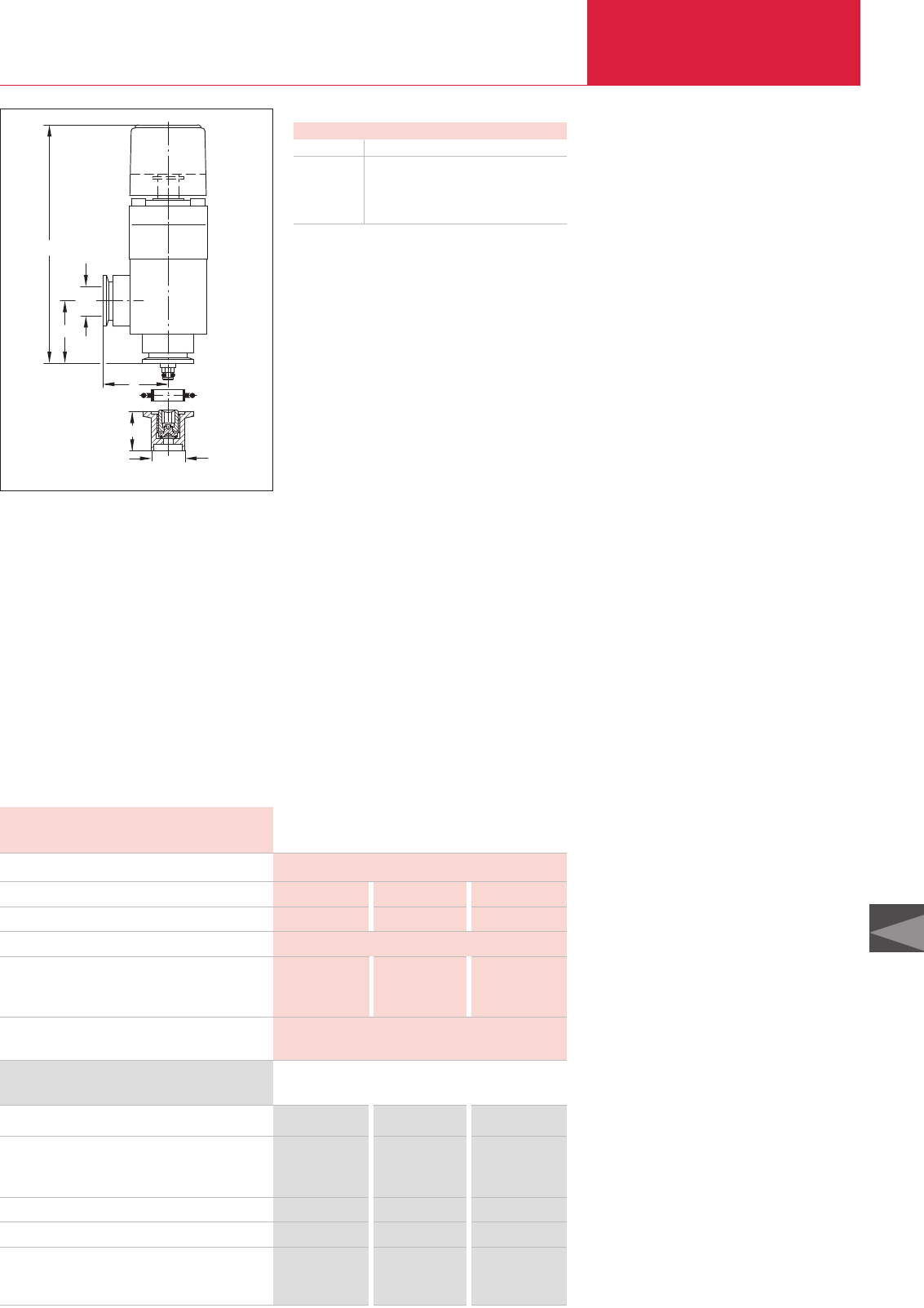
Vacuum Locks and Sealing Valves
Special Valves with KF Flanges
C14.23
LEYBOLD VACUUM PRODUCTS AND REFERENCE BOOK 2003/2004
C14
DN
a
h
a
h2
d
Dimensional drawing for the sealing valves
Vacuum lock, aluminum body
Sealing valve, stainless steel body
with tubulation (stainless steel)
with KF flanges (stainless steel)
Clamping ring
Centering ring
Repair kit
sealing valve
vacuum lock
Part No. 283 25 Part No. 283 26 Part No. 283 27
Part No. 283 21 Part No. 283 22 Part No. 283 23
Part No. 283 51 Part No. 283 52 Part No. 283 53
Part No. 183 41 Part No. 183 42 Part No. 183 43
Part No. 883 46 Part No. 883 47 Part No. 883 48
Part No. 215 055 Part No. 215 056 Part No. 215 057
Part No. 107 70 Part No. 107 71 Part No. 107 72
Ordering Information DN 16 KF DN 25 KF DN 40 KF
Leak rate (Sealing valve / vacuum lock) mbar x l x s-1
Travel for the vacuum lock mm
Free passage in the sealing valve mm
Absolute pressure bar
Weight
vacuum lock kg
sealing valve kg
Materials
1 x 10⁻⁷ / 1 x 10⁻⁹
56 76 108
3 8 18
2.5
0.5 1.0 1.8
0.04 0.1 0.12
Bearing lid: aluminum
Gasket: FPM
Technical Data DN 16 KF DN 25 KF DN 40 KF
Dimensions
DN 16 KF 25 KF 40 KF
a mm 40 50 65
d mm 16 25 38
h mm 124 160 190
h2mm 30 30 40
Vacuum Locks and Sealing
Valves
A screw-in sealing element with a hex. socket
into which the spindle of the gas lock is inserted
for actuation has been integrated within the tubu-
lation.
After having filled in the gas or evacuated the
chamber, the gas lock is detached from the small
flange and may thus be reused for an unlimited
number of times on other sealing valves.
Advantages to the User
♦Simple to use, handy knob
♦Compact, low weight
♦Also well-suited for operating older types of
sealing valves from LEYBOLD
♦Long travel and high conductance, thus short
pumpdown times
♦Spindle can be arrested in its end position
♦Double O-ring seal offering a very low leak
rate (
<
1 x 10
-7
mbar x l x s
-1
) and a long
service life
♦May be used in the entire rough and medium
vacuum range
♦Long service life
♦Secured against inadvertent opening
♦Temperature resistant
Vacuum lock 60 °C
Blocking valve 100 °C
♦May be protected by a standard blank flange
against becoming dirty
Typical Applications
♦Sealing of evacuated or gas-filled chambers
♦Post-evacuation of vessels
♦Topping up and exchanging the gas filling in
vessels
♦Sealing valves with stainless steel KF connec-
tion and stainless steel tubulation for welding
to the chamber
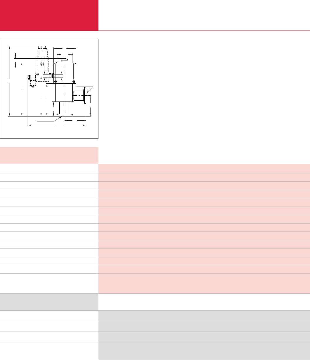
Right-Angle Valves for Mobile Systems according to DOT
Special Valves with KF Flanges
C14.24 LEYBOLD VACUUM PRODUCTS AND REFERENCE BOOK 2003/2004
Advantages to the User
♦High degree of reliability and safety due to
EPDM gaskets at the valve disk as well as
within the body
♦Stronger spring action on the valve disk
♦Long service life
♦Pilot valves for adaptation to all common con-
trol voltages and the interference suppression
kit can be retrofitted
♦Visual valve position indicator is standard
♦Installation in any orientation and no restric-
tions as to the direction of flow
6
109,5
DN 16 ISO-KF
42
30,5
104,2
77,5 63
28
M5 M5
134,4
40
40
DN 16 ISO-KF
Dimensional drawing for the stainless steel right-angle valves with pilot valve
This valve was especially developed for applica-
tions which involve brake fluid (in accordance
with DOT) and with special attention regarding
safety in the presence of increased differential
pressures.
Special valve - DOT
DN 16 KF
Ordering Information
Right-angle valve, without pilot valve, aluminum body
Pilot valves
Interference suppression kits for different voltages
Spare parts
Seal kit EPDM
X = for part numbers see section “Accessories for the electropneumatically operated valves, valves with KF / ISO K flanges”
Part No. 215 009
X
X
Part No. 215 012
Special valve - DOT
DN 16 KF
Technical Data
Service life cycles
Conductance at molecular flow l x s-1
Leak rate mbar x l x s-1
Operating pressure range mbar
Differential pressure, closing and opening direction bar
Opening against differential pressure bar
Ambient / Operating temperature, max. °C
Opening / closing time for compressed air at 6 bar ms
Switching frequency 1/min
Compressed air, overpressure bar
Compressed air volume cm3
Compressed air connection mm
Weight with pilot valve
Materials
10 million
4.5
1 x 10⁻⁹
10-8 - 5000
5 / 5
5
50
100 / 100
100
4 - 8
5,5
4 and 6
0.3
Valve body: aluminum alloy (3.2381);
Inside section: stainless steell (1.4541 / 1.4301);
Gaskets: EPDM
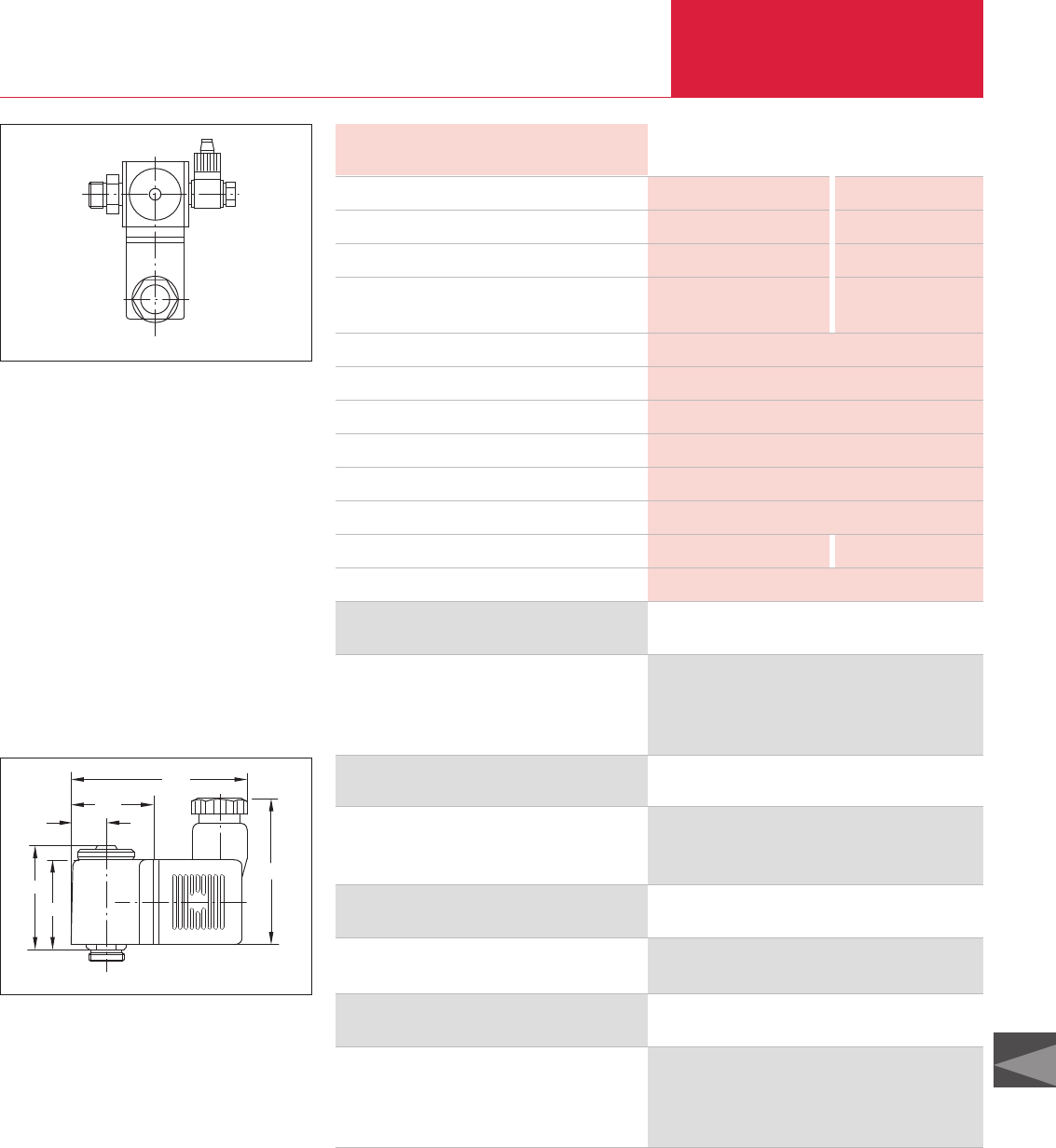
Accessories for the Electropneumatically Operated Valves
Valves with KF Flanges
C14.25
LEYBOLD VACUUM PRODUCTS AND REFERENCE BOOK 2003/2004
C14
Pilot Valves
A range of pilot valves is available for actuation of
the electropneumatic KF valves, which cover all
commonly used control voltages.
Advantages to the User
♦Easy to fit to the pneumatic cylinder,
adapter is included with the DOT valve
Supplied Equipment
♦Hose connection and gasket for connection to
the compressed air supply
Pilot valve
KF Pilot Valves for DOT valves
(incl. Solenoid Coil)
Ordering Information
230 V/50-60 Hz (normally closed)
110 - 120 V/50-60 Hz (normally closed)
024 V DC (normally closed)
Part No. 280 70
Part No. 280 72
Part No. 280 74
12,5
35,5
29
48
29,5
60,5
Dimensional drawing for the solenoid coils
Solenoid Coils for DN 250 ISO-K
LEYBOLD is offering a range of solenoid coils for
the purpose of adapting the electropneumatically
operated valve to different commonly used con-
trol voltages.
Advantages to the User
♦Easy to fit (plug on and tighten with a knurled
screw)
Solenoid Coils for Pilot Valves
DN 250 ISO-K or as Spare Part
Ordering Information
230 V AC/50-60 Hz
110 - 120 V/50-60 Hz
024 V AC/50-60 Hz
024 V DC
Part No. 280 77
Part No. 280 78
Part No. 280 79
Part No. 280 80
Solenoid Coils for Pilot Valves
V DC V AC
Technical Data
Voltage V
Permissible voltage variation %
Permissible frequency variation %
Power consumption at nominal operating voltage W
Operating time
Type of protection to DIN 0450 IP
Hose connection
Class of insulation material to VDE 0580
Test mark
Max. response time ms
Weight kg
Torque for the knurled screw, min./max Ncm
12/24 DC 24/110/230 AC; 50/60 Hz
± 10 ± 10 at nominal frequency
– ± 10 at nominal frequency
4.1 at 12 V Actuate: 7.5 VA
4.5 at 24 V Hold: 6.0 VA
100 %
65
Pg 9
F
VDE
10
0.065 0.055
100/150
Interference Suppression Kit
for different voltages
Ordering Information
Interference suppression kit
024 V DC/AC
110 V AC
230 V AC
Part No. 287 84
Part No. 287 82
Part No. 287 83
Replacement Pilot Valves
for ISO-K valves from DN 250, without coil
Ordering Information
Pilot valve for
DN 250 ISO-K to DN 630 ISO-K
Part No. 200 07 927
Interference Suppression Kit
- Illuminated
As an option for the solenoid coil and the pilot
valves an interference suppression kit is offered
so as to reliably prevent any pick-up of interfe-
rence by sensitive equipment in the vicinity of the
solenoid coils.
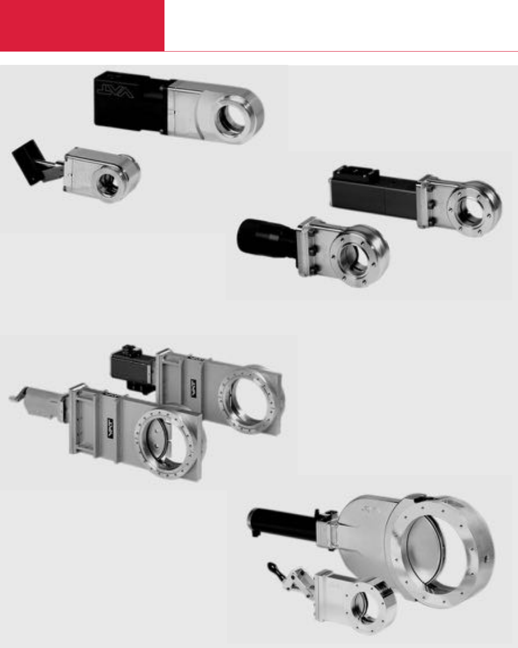
Overview
Gate Valves
C14.26 LEYBOLD VACUUM PRODUCTS AND REFERENCE BOOK 2003/2004
➊Miniature UHV gate valves, KF flange
➋Miniature UHV gate valves, CF flange
➌UHV gate valve
➍HV gate valve
➊
➌
➍
➋
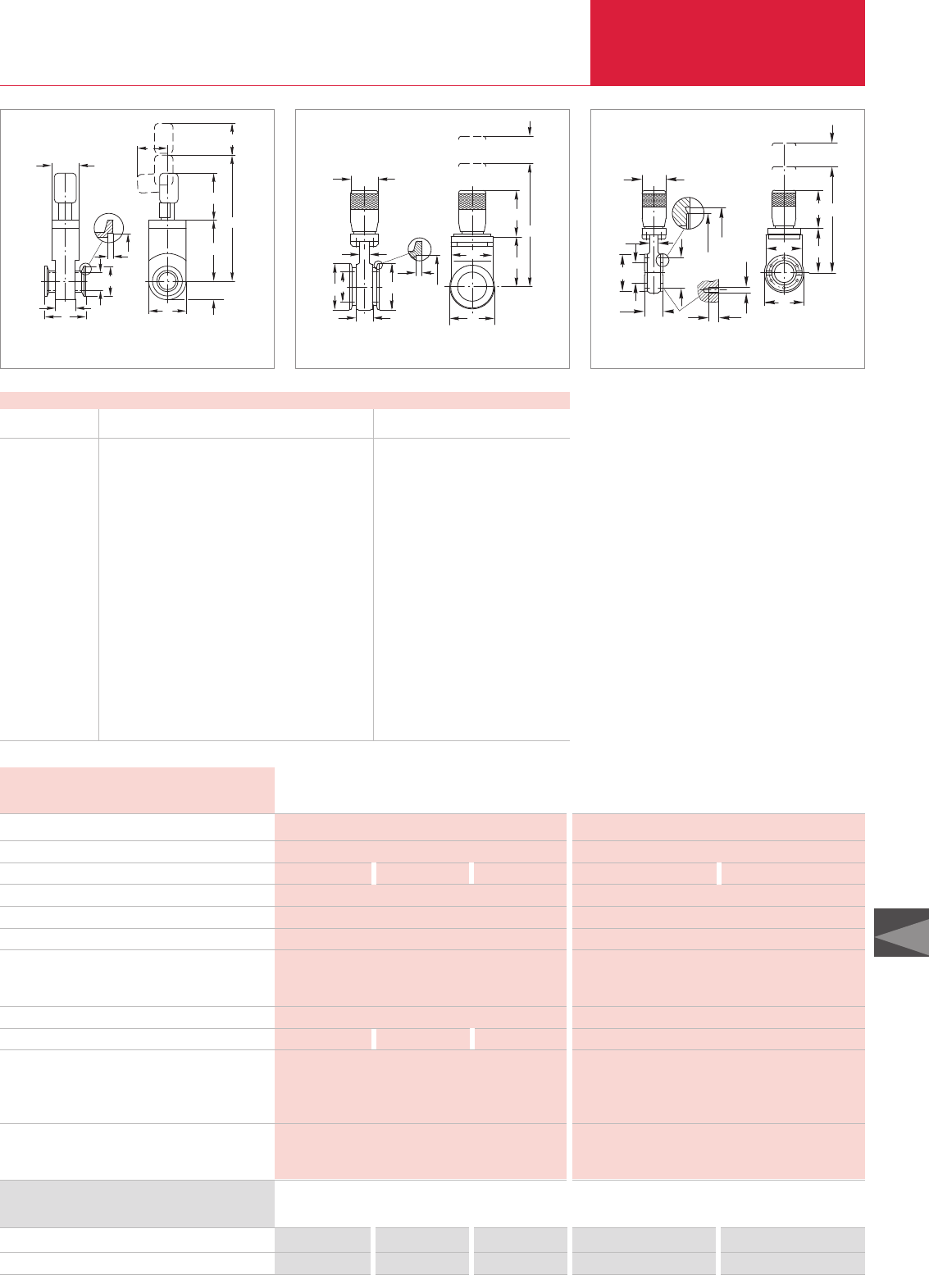
Miniature HV and UHV Gate Valves, Manually Operated
Gate Valves with KF/CF Flanges
C14.27
LEYBOLD VACUUM PRODUCTS AND REFERENCE BOOK 2003/2004
C14
Miniature gate valve, manually operated
6 set screws with nuts and washers *)
*)For dimensions E x F see table “Dimensions for CF”
Part No. 286 06 Part No. 286 08 Part No. 286 09
– – –
Ordering Information DN 16 KF DN 25 KF DN 40 KF
Articulated lever
U
V
L
Q
B
D
H
I
KO
A
N
T
M
Dimensional drawing for the miniature UHV gate valves, articulated lever,
KF flange
Dimensions
DN KF 16 KF 25 KF 40 KF 40 KF 40 CF
Articulated lever Manually operated
A mm 40 50 51 50 35
B mm 30 40 55 72 72
B1mm – – – 55 –
C mm – – – – 58.7
D mm 15 24 39 40 40
E x F mm – – – – 6 x M6
G mm – – – – 7
H mm 17.2 26.2 41.2 41.2 –
H1mm – – – – 48.3
H2mm – – – – 42
I mm 3 3 3 3 –
K mm 25 32 31 16 16
L mm 100 139 208 198 198
M mm 15 22 32.5 – –
N mm 39 59 93 82 82
O mm 30 44 65 76 76
O1mm – – – 70 70
Q mm 25 35 55 55 55
T mm 37 50 85 73 73
U mm 25 32 40 45 45
V mm 30 30 50 – –
Leak tightness: body / valve seat mbar x l x s-1
Pressure range, abs.
High vacuum conductance l x s-1
Differential pressure at the valve disk bar
Max. differential pressure during opening mbar
Service life until first maintenance cycles
Degassing temperature
for the valve °C
manual open / closed °C
Installation orientation
Weight kg
Materials
Valve body
Valve disk
Bellows
Seals
Head
Disk
< 1 x 10⁻⁹ / < 1 x 10⁻⁹
1 x 10⁻⁷ mbar to 2 bar
10 34 140
≤2 in both directions
≤30
50000
100 / 100
80
any
0.4 0.4 0.7
AlMgSi1 (3.2315)
AlSI 301 (1.4310)
–
Viton
Viton
Technical Data DN 16 KF DN 25 KF DN 40 KF
Articulated lever
Part No. 286 15 Part No. 286 84
– Part No. 839 11
5 x 10⁻¹⁰ / < 1 x 10⁻⁹
1 x 10⁻¹⁰ mbar to 2 bar
160 220
≤2 in both directions
≤30
50000
250 / 200
250
any
1.5
AlSI 304 (1.4301)
AlSI 304 (1.4301)
AlSI 316 L (1.44435)
metal
Viton
DN 40 KF DN 40 CF
Manually operated
DN 40 KF DN 40 CF
Manually operated
U
O
N
T
L
Q
I
K
B1H
BD
A
O1
Dimensional drawing for the miniature UHV gate valves, manually operated,
DN 40 KF
G
E x F
2
H1
H
BD
K
C
A
U
N
L
O1
O
Q
T
Dimensional drawing for the miniature UHV gate valves, manually operated,
DN 40 CF
Advantages to the User
♦Manually actuated; bellows-sealed push gate
feedthrough
♦Valve technology with only one moving part
♦Equipped with a mechanical position indicator
♦Low particle generating and vibration free
actuation
♦Compact, light-weight design
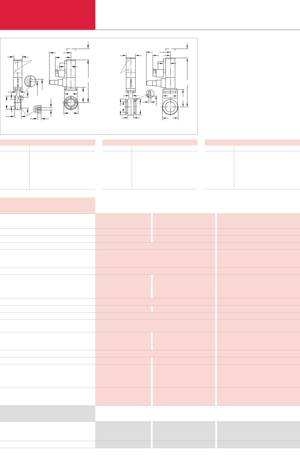
C14.28 LEYBOLD VACUUM PRODUCTS AND REFERENCE BOOK 2003/2004
Miniature HV and UHV Gate Valves, Electropneumatically Operated
Gate Valves with KF/CF Flanges
Advantages to the User
♦Double-acting electropneumatic actuator (with
position indicator and pilot valve); bellows-
sealed push gate feedthrough
♦Valve technology with only one moving part
♦Equipped with a mechanical position indicator
♦Actuation free of particles and vibrations
♦Short closing time, very long service life
♦Compact, light-weight design
O
N
L
G
ExF
O1
Q
119
R 1/8" 68
V
2
H1
H
BD
K
C
A
U
Dimensional drawing for the miniature UHV gate valves; electropneumatically operated, CF flange (left) and KF flange (right)
Dimensions
DN 40 KF 40 CF
A mm 50 35
B mm 72 72
B1mm 55 –
C mm – 58.7
D mm 40 40
E x F – 6 x M6
G mm – 7
Dimensions
DN 40 KF 40 CF
H mm 41.2 –
H1mm – 48.3
H2mm – 42
I mm 3 –
K mm 16 16
L mm 198 230
N mm 82 82
Leak tightness, valve body mbar x l x s-1
valve seat mbar x l x s-1
Pressure range, abs.
High vacuum conductance l x s-1
Differential pressure at the valve disk bar
Max. differential pressure
during opening mbar
at reduced service live bar
Service life until first maintenance cycles
Bakeout temperature
Valve open / closed °C
pneumatic actuation °C
Position indicator / pilot valve °C
Warming-up and cooling down speed °C x h-1
Compressed air min./max. bar
Closing/opening time s
Pilot valve
supply voltage / power consumption – / W
Switching capacity of the pos. indicator, at 080 °C A
at 200 °C A
Installation orientation
Weight kg
Materials
Valve body
Disk
Bellows
Seals
Head
Disk
< 1 x 10⁻⁹ < 5 x 10⁻¹⁰ < 5 x 10⁻¹⁰
< 1 x 10⁻⁹ < 1 x 10⁻⁹ < 1 x 10⁻⁹
1 x 10⁻⁷ mbar to 2 bar 1 x 10⁻¹⁰ mbar to 2 bar 1 x 10⁻¹⁰ mbar to 2 bar
140 160 220
≤2 in both directions ≤2 in both directions
≤30 ≤30
1 1
50000 50000
≤100 / 100 ≤250 / 200 ≤250 / 200
≤80 ≤200 ≤200
≤80 / 50 80 (optional: 200) / 50 80 (optional: 200) / 50
80 80
4.5/7 4.5/7 4.5/7
1.1 0.7 0.7
24 V DC / 6 or 230 V AC, 50/60 Hz / 224 V DC / 6 or 230 V AC, 50/60 Hz / 2
0.5 at 50 V AC; max. 10 W / 5 at 250 V AC; 3 at 50 V DC 5 at 250 V AC; 3 at 50 V DC
0.5 at 75 V DC; max. 10 W
– 1 at 48 V AC; 1 at 72 V DC 1 at 48 V AC; 1 at 72 V DC
any any
1.2 1.8 1.8
AlMgSi1 (3.2315) AISI 304 (1.4301) AISI 304 (1.4301)
AISI 301 (1.4310) AISI 304 (1.4301) AISI 304 (1.4301)
– AISI 316 L (1.44435) AISI 316 L (1.44435)
Viton metal metal
Viton Viton Viton
Technical Data DN 40 KF DN 40 CF
Aluminum body Stainless steel body Stainless steel body
Dimensions
DN 40 KF 40 CF
O mm 76 76
O1mm 70 70
Q mm 55 55
T mm 73 73
U mm 45 45
V mm – 32.5
Miniature gate valve, electropneumatically operated
024 V DC / 6 W
230 V AC, 50/60 Hz / 2 W
6 set screws with nuts and washers *)
*)For dimensions E x F see table “Dimensions for CF”
Part No. 286 54 Part No. 286 36 Part No. 286 99
Part No. 286 44 Part No. 286 35 Part No. 286 94
– –
Part No. 839 11
Ordering Information DN 40 KF DN 40 CF
Aluminum body Stainless steel body Stainless steel body
O
O1
I
K
B1H
BD
A
U
R 1/8"
N
L
119 68 Q
V
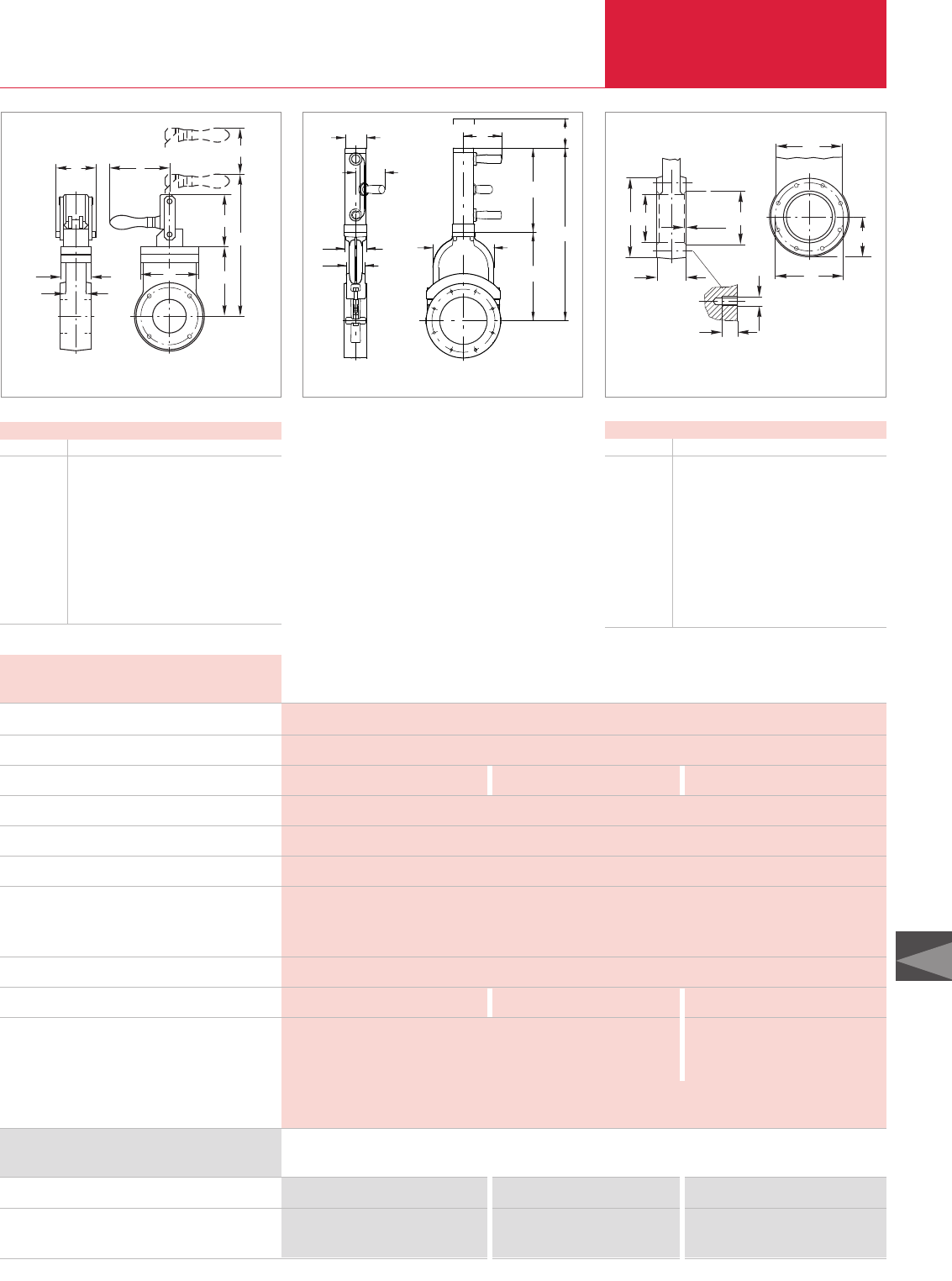
C14
C14.29
LEYBOLD VACUUM PRODUCTS AND REFERENCE BOOK 2003/2004
Gate Valves with ISO-F Flanges
HV Gate Valves, Manually Operated
HV gate valve, manually operated
Set screws with nuts and washers *)
Package each containing pieces
*)For dimensions E x F see table “Dimensions for ISO-F (HV)”
Part No. 286 25 Part No. 286 26 Part No. 215 633
Part No. 839 13 Part No. 839 13 Part No. 210 071
16 16 16
Ordering Information DN 63 ISO-F DN 100 ISO-F DN 160 ISO-F
Advantages to the User
♦Cost-effective gate valve for industrial
applications with elastomer-sealed push gate
feedthrough
♦Aluminum body
♦Slim and light-weight
♦Low play in the locked state and low wear
O
L
N
U
P
K
T
Q
V
Dimensional drawing for the HV gate valves; manually operated,
DN 63 ISO-F and DN 100 ISO-F
Dimensions of ISO-F Connections (HV)
DN ISO-F 63 100 160 200 250
A mm 60 60 70 80 100
B mm 130 165 235 288 350
C mm 110 145 200 260 310
D mm 65 100 150 200 261
E x F 4 x M8 8 x M8 8 x M10 12 x M10 12 x M10
G mm 12 12 16 16 16
H mm 70 102 153 213 –
J mm 3 3 5 5 –
M mm 65.5 83 117.5 144 175
O1mm 131 166 237 290 352
C
B
H
A
M
O1
D
E x F
G
J
Connection dimensions for ISO-F flanges (HV gate valves)
Leak tightness: Body / valve seat mbar x l x s-1
Pressure range, abs.
High vacuum conductance l x s-1
Differential pressure at the valve disk bar
Max. differential pressure during opening mbar
Service life until first maintenance cycles
Degassing temperature
valve °C
manual drive °C
Installation orientation
Weight kg
Materials
Valve body
Disk
Bellows
Seals (head, disk)
< 1 x 10⁻⁹
1 x 10⁻⁷ mbar to 1.2 bar
550 2000 6000
1.2 in both directions
≤30
50000
120
80
any
3 5 9
AlMg4.5Mn G-AlSi7Mg
AlSI 304 (1.4301) AlMgSi1
AlMgSi1, AlSI 303 (1.4305) AlSI 301 (1.4310), AlSI 304 (1.4301), AlSI 420 (1.4034)
Viton
Technical Data DN 63 ISO-F DN 100 ISO-F DN 160 ISO-F
Dimensions
DN 63 ISO-F 100 ISO-F 160 ISO-F
K mm 38 38 58
L mm 277 365 547
N mm 136 191 280
O mm 112 150 192
P mm 60 60 70
Q mm 90 125 60
T mm 100 116 267
U mm 77 77 65
V mm 114 114 122
W mm – – 95
U
W
PO
K
N
T
L
Q
V
Dimensional drawing for the HV gate valves; manually operated,
DN 160 ISO-F

C14.30 LEYBOLD VACUUM PRODUCTS AND REFERENCE BOOK 2003/2004
Gate Valves with ISO-F Flanges
HV Gate Valves, Electropneumatically Operated
Dimensional drawing for the gate valves; DN 63 ISO-F and DN 100 ISO-F (left), DN 160 ISO-F to DN 250 ISO-F (right)
Dimensions
DN ISO-F 63 100 160 200 200 250
K mm 38 38 58 66 76
L mm 351 443 547 688 843
L1mm 311 366 –––
N mm 136 191 280 363.5 453
O mm 112 150 192 240 308
P mm 60 60 70 80 96
C
B
H
A
M
O1
D
E x F
G
J
Connection dimensions for ISO-F flanges
(For dimensions see table
“Dimensions of ISO-F Connections (HV Gate Valves)”)
Advantages to the User
♦Cost-effective gate valve for industrial
applications with elastomer-sealed push gate
feedthrough
♦Aluminum body
♦Slim and light-weight
♦Low play in the locked state and low wear
Dimensions
DN ISO-F 63 100 160 200 250
Q mm 90 125 60 80 100
T mm 174 211 267 324.5 390
U mm 55 55 65 75 86
V mm 80 80 71.5 76.5 84.5
W mm 50 50 – – –
X mm 59 59 57 62 67
HV gate valve, electropneumatically operated
024 V DC / 2.5 W
024 V DC / 6 W
230 V AC, 50 Hz / 7.1 W
Set screws with nuts and washers *)
Package each containing pieces
*)For dimensions E x F see table “Dimensions for ISO-F (HV)”
Part No. 286 55 Part No. 286 56 – – –
– – Part No. 215 643 Part No. 215 644 Part No. 215 645
Part No. 286 45 Part No. 286 46 Part No. 215 653 Part No. 215 654 Part No. 215 655
Part No. 839 13 Part No. 839 13 Part No. 210 071 Part No. 210 071 Part No. 210 071
16 16 12 12 12
Ordering Information DN 63 ISO-F DN 100 ISO-F DN 160 ISO-F DN 200 ISO-F DN 250 ISO-F
Leak tightness: Body / valve seat mbar x l x s-1
Pressure range, abs.
High vacuum conductance l x s-1
Diff. press. at the valve disk/during opening, max. mbar
Compressed air min./max. bar
Closing/opening time s
Service life until first maintenance cycles
Degassing temperature
valve °C
pneumatic drive °C
position indicator °C
pilot valve °C
Switching capacity for the position indicator A
Installation orientation
Weight kg
Materials
Valve body
Disk
Bellows
Seals (head, disk)
< 1 x 10⁻⁹
1 x 10⁻⁷ mbar to 1.2 bar
550 2 000 6 000 12 000 22 000
≤1000 in both directions / ≤30
4/7
0.7 1 2 3 5
50000 100000
120
80
80
50
5 at 230 V AC; 3 at 50 V DC
any
4 6 9 18 25
G-AlSi7Mg
AlSI 304 (1.4301)
AlMgSi1, AlSI 303 (1.4305) AlSI 301 (1.4310), AlSI 304 (1.4301), AlSI 420 (1.4034)
Viton
Technical Data DN 63 ISO-F DN 100 ISO-F DN 160 ISO-F DN 200 ISO-F DN 250 ISO-F
Q
L
R1/8" 1
O
L
N
T
V
U
X W
P
K
P
K
UXVQ
T
N
O
L
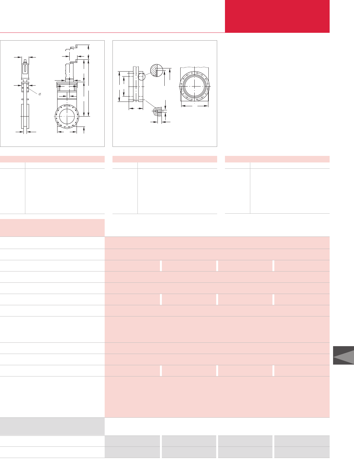
C14
C14.31
LEYBOLD VACUUM PRODUCTS AND REFERENCE BOOK 2003/2004
Gate Valves with CF Flanges
UHV Gate Valves, Manually Operated
U
P
KO1
M
S
N
L
O
T
U1
VQ
10
DN 160/200
Dimensional drawing for the gate valves DN 63 CF to DN 200 CF
Dimensions
DN 63 CF 100 CF 160 CF 200 CF
K mm 27 27 27 35
L mm 408 462 552 660
M mm 57 73 99 125
N mm 192 247 336 430
O mm 115 145 200 250
O1mm 112 142 192 240
P mm 70 70 70 80
Advantages to the User
♦Valve and wheel can be degassed at
temperatures up to 250 °C
♦Steel body (non-rusting)
♦Bellows-sealed push gate feedthrough
♦Low play in the locked state and low wear
♦Compact
♦Mechanically locked in the closed state
Dimensions
DN 63 CF 100 CF 160 CF 200 CF
Q mm 180 220 290 350
S mm 11 9 25 38.5
T mm 184 184 184 200
U mm 70 70 70 90
U1mm 83 83 83 103
V mm 77 77 77 94
UHV gate valve, manually operated
16 set screws with nuts and washers *)
*)For dimensions E x F see table “Dimensions for CF”
Part No. 286 85 Part No. 286 86 Part No. 286 87 Part No. 286 88
Part No. 839 13 Part No. 839 13 2 x Part No. 839 13 2 x Part No. 839 13
Ordering Information DN 63 CF DN 100 CF DN 160 CF DN 200 CF
Leak tightness: Body / valve seat mbar x l x s-1
Pressure range, abs.
High vacuum conductance l x s-1
Differential pressure at the valve disk bar
Max. differential pressure during opening mbar
Number of spindle turns for full travel
Service life until first maintenance cycles
Degassing temperature
valve open / closed °C
manual drive °C
Warming-up and cooling down speed °C x h-1
Installation orientation
Weight kg
Materials
Valve body
Bellows
Mechanism
Gaskets (head / disk)
< 5 x 10⁻¹⁰ / < 1 x 10⁻⁹
1 x 10⁻¹⁰ mbar to 1.6 bar
600 1 700 6 000 12 000
≤1.6 in both directions
30
10 13 17 17
50000
250 / 200
250
80
any
9 12 18 28
AlSI 304 (1.4301)
AlSI 316 L (1.4435)
AlSI 304 (1.4301), AlSI 316 L (1.4404), AlSI 301 (1.4310), AlSI 420 (1.4034)
metal / Viton
Technical Data DN 63 CF DN 100 CF DN 160 CF DN 200 CF
C
2
H1
H
13
E x F
A
D
B
Connection dimensions for CF flanges (UHV gate valves)
Dimensions of CF Connections (UHV)
DN 63 CF 100 CF 160 CF 200 CF
A mm 70 70 70 80
B mm 113.5 151.6 202.4 253.2
C mm 92.1 130.2 181 231.8
D mm 70 100 150 200
E x F 8 x M8 16 x M8 20 x M8 24 x M8
H1mm 82.5 120.65 171.45 222.3
H2mm 77.4 115.5 166 217
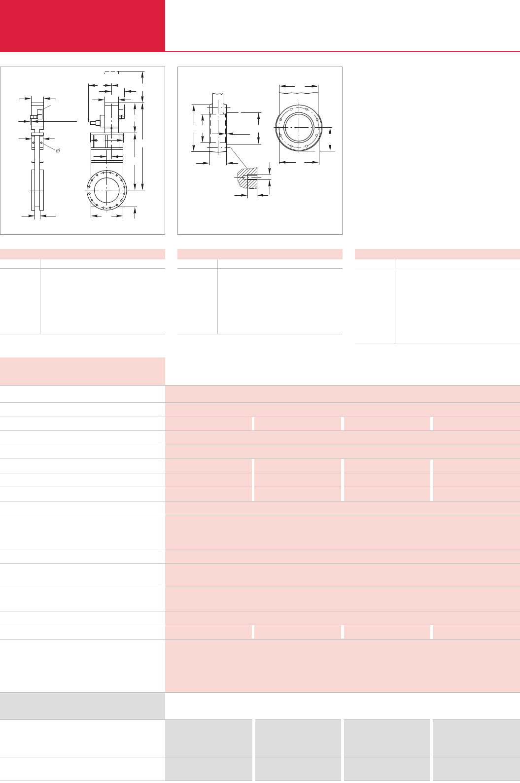
UHV Gate Valves, Electropneumatically Operated
Gate Valves with ISO-F Flanges
C14.32 LEYBOLD VACUUM PRODUCTS AND REFERENCE BOOK 2003/2004
U
P
KO1
M
S
N
L
O
T
Q
U1
VW
10
DN 160
3,5
DN 63-160
R 1/8"
Dimensional drawing for the gate valves ISO-F
Dimensions
DN 63 ISO-F 100 ISO-F 160 ISO-F 250 ISO-F
K mm 27 27 27 41
L mm 346 418 523 800
M mm 57 73 99 161
N mm 192 247 336 560
O mm 115 145 200 345
O1mm 112 142 192 322
P mm 70 70 70 80
Advantages to the User
♦Valve and pneumatic drive can be degassed at
temperatures up to 250 °C and 200 °C
respectively
♦Steel body (non-rusting)
♦Double-acting electropneumatic actuator
(with position indicator and pilot valve)
♦Bellows-sealed push gate feedthrough
♦Low play in the locked state and low wear
♦Compact
♦Mechanically locked in the closed state
UHV gate valve, electropneumatically operated
024 V DC / 6 W
230 V AC, 50 Hz / 7.1 W
Set screws with nuts and washers *)
Package each containing pieces
*)For dimensions E x F see table “Dimensions for ISO-F (UHV)”
Part No. 286 72 Part No. 286 73 Part No. 286 74 Part No. 286 81
Part No. 286 75 Part No. 286 76 Part No. 286 77 –
Part No. 839 13 Part No. 839 13 Part No. 210 071 Part No. 210 071
16 16 12 12
Ordering Information DN 63 ISO-F DN 100 ISO-F DN 160 ISO-F DN 250 ISO-F
Leak tightness: Body / valve seat mbar x l x s-1
Pressure range, abs.
High vacuum conductance l x s-1
Differential pressure at the valve disk bar
Max. differential pressure during opening mbar
Compressed air min./max. bar
Closing/opening time s
Compressed air cylinder, volume m3
Service life until first maintenance cycles
Degassing temperature
valve open/closed / pneumatic drive °C
position indicator / pilot valve °C
Warming-up and cooling down speed °C x h-1
Pilot valve
supply voltage / power consumption – / W
Switching capacity for position indicator, at 080 °C A
at 200 °C A
Installation orientation
Weight kg
Materials
Valve body
Bellows
Mechanism
Gaskets (head / disk)
< 5 x 10⁻¹⁰ / < 1 x 10⁻⁹
1 x 10⁻¹⁰ mbar to 1 bar
600 1 700 6 000 26 000
1 in both directions
30
4/7 4/7 4/7 5/7
1 1.2 1.5 4
0.08 0.11 0.14 0.35
50000
250/200 / 200
80 (optional: 200) / 50
80
24 V DC / 6 or 230 V AC, 50 Hz / 7.1
5 at 250 V AC; 3 at 50 V DC
1 at 48 V AC; 1 at 72 V DC
any
9 12 18 42
AlSI 304 (1.4301)
AlSI 316 L (1.4435)
AlSI 304 (1.4301), AlSI 316 L (1.4404) AlSI 301 (1.4310 ), AlSI 420 (1.4034)
metal / Viton
Technical Data DN 63 ISO-F DN 100 ISO-F DN 160 ISO-F DN 250 ISO-F
Dimensions
DN 63 ISO-F 100 ISO-F 160 ISO-F 250 ISO-F
Q mm 180 220 290 450
S mm 11 9 25 65
T mm 154 171 187 240
U mm 70 70 70 90
U1mm 83 83 83 103
V mm 145 145 145 155
W mm 77 77 77 87
C
B
H
A
M
O1
D
E x F
G
J
Connection dimensions for ISO-F flanges (UHV gate valves)
Dimensions of ISO-F Connections (UHV)
DN 63 ISO-F 100 ISO-F 160 ISO-F 250 ISO-F
A mm 70 70 70 100
B mm 130 165 225 350
C mm 110 145 200 310
D mm 70 100 150 261
E x F 4 x M8 8 x M8 8 x M10 12 x M10
G mm 13 13 15 15
H mm – 102 153 –
J mm – 3 5 –
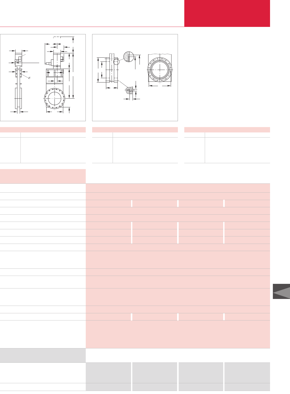
C14
C14.33
LEYBOLD VACUUM PRODUCTS AND REFERENCE BOOK 2003/2004
Gate Valves with CF Flanges
UHV Gate Valves, Electropneumatically Operated
U
P
KO1
M
S
N
L
O
T
Q
U1
VW
10
DN 160
3,5
DN 63-160
R 1/8"
Dimensional drawing for the CF gate valves
Dimensions
DN 63 CF 100 CF 160 CF 200 CF
K mm 27 27 27 35
L mm 346 418 523 630
M mm 57 73 99 125
N mm 192 247 336 430
O mm 115 145 200 250
Advantages to the User
♦Double-acting electropneumatic actuator
(with position indicator and pilot valve)
♦Bellows-sealed push gate feedthrough
♦Valve and pneumatic drive can be degassed
at temperatures up to 250 °C and 200 °C
respectively
♦Steel body (non-rusting)
♦Low play in the locked state and low wear
♦Compact
♦Mechanically locked in the closed state
UHV gate valve, electropneumatically operated
024 V DC / 6 W
230 V AC, 50 Hz / 7.1 W
Set screws with nuts and washers *)
*)For dimensions E x F see table “Dimensions for CF”
Part No. 286 89 Part No. 286 90 Part No. 286 91 Part No. 286 92
Part No. 286 95 Part No. 286 96 Part No. 286 97 Part No. 286 98
Part No. 839 13 Part No. 839 13 2 x Part No. 839 13 2 x Part No. 839 13
Ordering Information DN 63 CF DN 100 CF DN 160 CF DN 200 CF
Leak tightness: Body / valve seat mbar x l x s-1
Pressure range, abs.
High vacuum conductance l x s-1
Differential pressure at the valve disk bar
Max. differential pressure during opening mbar
Compressed air min./max. bar
Closing/opening time s
Compressed air cylinder, volume m3
Service life until first maintenance cycles
Degassing temperature
valve open/closed / pneumatic drive °C
position indicator / pilot valve °C
Warming-up and cooling down speed °C x h-1
Pilot valve
supply voltage / power consumption – / W
Switching capacity for position indicator
at 080 °C A
at 250 °C A
Installation orientation
Weight kg
Materials
Valve body
Bellows
Mechanism
Gaskets (head / disk)
< 5 x 10⁻¹⁰ / < 1 x 10⁻⁹
1 x 10⁻¹⁰ mbar to 1 bar
600 1 700 6 000 12 000
1 in both directions
30
4/7 4/7 4/7 5/7
1 1.2 1,5 4
0.08 0.11 0.14 0.35
50000
250/200 / 200
80 (optional: 200) / 50
80
24 V DC / 6 or 230 V AC, 50 Hz / 7.1
5 at 250 V AC; 3 at 50 V DC
1 at 48 V AC; 1 at 72 V DC
any
9 12 18 28
AlSI 304 (1.4301)
AlSI 316 L (1.4435)
AlSI 304 (1.4301), AlSI 316 L (1.4404) AlSI 301 (1.4310 ), AlSI 420 (1.4034)
metal / Viton
Technical Data DN 63 CF DN 100 CF DN 160 CF DN 200 CF
Dimensions
DN 63 CF 100 CF 160 CF 200 CF
O1mm 112 142 192 240
P mm 70 70 70 80
Q mm 180 220 290 350
S mm 11 9 25 38,5
T mm 154 171 187 200
Dimensions
DN 63 CF 100 CF 160 CF 200 CF
U mm 70 70 70 90
U1mm 83 83 83 103
V mm 145 145 145 155
W mm 77 77 77 87
C
2
H1
H
13
E x F
A
D
B
Connection dimension for CF flanges
(For dimensions see table “Dimensions of CF Flanges (UHV Gate Valves)”)

C14.34 LEYBOLD VACUUM PRODUCTS AND REFERENCE BOOK 2003/2004
Vacuum Valves
C15
Flange Components, Valves
and Feedthroughs
Ultra-high Vacuum
Components

LEYBOLD VACUUM PRODUCTS AND REFERENCE BOOK 2003/2004
Contents
C15.02
General
. . . . . . . . . . . . . . . . . . . . . . . . . . . . . . . . . . . . . . . . . . . . . . . . . . . . . . . . . . . . . C15.02
Products
CF Flanges . . . . . . . . . . . . . . . . . . . . . . . . . . . . . . . . . . . . . . . . . . . . . . . . . . . . . . . . . . . . . C15.03
UHV Components. . . . . . . . . . . . . . . . . . . . . . . . . . . . . . . . . . . . . . . . . . . . . . . . . . . . . . . . C15.07
Accessories for UHV Components . . . . . . . . . . . . . . . . . . . . . . . . . . . . . . . . . . . . . . . . . . . C15.10
UHV Observation Windows . . . . . . . . . . . . . . . . . . . . . . . . . . . . . . . . . . . . . . . . . . . . . . . . C15.12
UHV Sapphire Observation Windows . . . . . . . . . . . . . . . . . . . . . . . . . . . . . . . . . . . . . . . . . C15.12
UHV All-Metal Right-Angle Valves. . . . . . . . . . . . . . . . . . . . . . . . . . . . . . . . . . . . . . . . . . . . C15.13
UHV All-Metal Variable Leak Valves . . . . . . . . . . . . . . . . . . . . . . . . . . . . . . . . . . . . . . . . . . C15.14
UHV Feedthroughs, Mechanical . . . . . . . . . . . . . . . . . . . . . . . . . . . . . . . . . . . . . . . . . . . . . C15.15
UHV Feedthroughs, Electric . . . . . . . . . . . . . . . . . . . . . . . . . . . . . . . . . . . . . . . . . . . . . . . . C15.17
Connectors . . . . . . . . . . . . . . . . . . . . . . . . . . . . . . . . . . . . . . . . . . . . . . . . . . . . . . . . . . . . . C15.19
UHV Liquid Feedthroughs. . . . . . . . . . . . . . . . . . . . . . . . . . . . . . . . . . . . . . . . . . . . . . . . . . C15.21
Ultra-high Vacuum Components
Introduction
According to DIN 28400, the term “Ultra-high
Vacuum (UHV)” designates the pressure range below
10
-7
mbar.
Several physical quantities, such as mean free path,
monolayer time, flow density of the particles imping-
ing on the walls, leak rate and the degassing rate are
of significance in the characterization of this pressure
range. For the definitions of these quantities refer to
technical publications on this subject.
In order to attain or maintain pressures below
10
-7
mbar, the following pre-conditions must be met:
♦The vapor pressure of the pump fluid or lubricant
should be in accordance with the desired ultimate
pressure
♦the leak and degassing rates of the entire appara-
tus including its installations must be extremely
low.
Generally, both leak rate and backstreaming effects
through the pump can be kept at sufficiently low
levels by using suitable UHV sealing materials and
pumps.
However, a sufficiently low outgassing rate can only
be achieved by baking out the entire apparatus at
temperatures of about 300 °C for a longer period of
time. It is only under these conditions that the mono-
layers of atoms or molecules, which attach quite
firmly to the surfaces of the vacuum apparatus
including its installations, are desorbed.
Consequently, components for UHV systems are
generally made of stainless steel. Metal gaskets, cera-
mic feedthroughs and bakeable observation windows
are used exclusively.
For applications in the extreme UHV range (XHV) the
outgassing rate of the CF flanges and the UHV com-
ponents can be reduced by about two orders of
magnitude by a special degassing process.
The high standard of development and manufacture
combined with the use of high quality materials gua-
rantee that UHV components from LEYBOLD are able
to meet even the most demanding requirements.
Advantages to the User
♦Stabilized LEYBOLD knife-edge
♦High reliability
♦Special knife edge profiles ensure the highest
degree of leak tightness
♦Flange connection can be baked out up to
450 °C
♦Easy to assemble, helium-tight
♦Symmetrical flange connection
♦Equal sealing profiles
♦Small outside diameter with respect to the
nominal width
♦Can be joined by welding or brazing using any
desired process, also with other nickel chro-
mium steel grades
♦For use either with a flat gasket made of OFHC
copper (oxygen-free) or FPM O-ring
♦Self-centering
♦Fixed and rotary flanges in almost any size
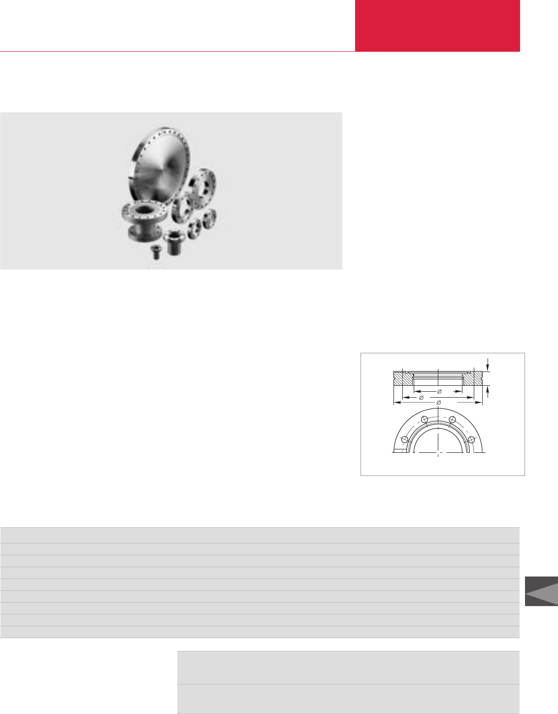
Ultra-high Vacuum Components
C15.03
C15
LEYBOLD VACUUM PRODUCTS AND REFERENCE BOOK 2003/2004
CF Flanges
CF Flanges
Sealing Principle
When assembling the CF flange connection, the
flat copper gasket fits with a slight clearance into
the outer recess of the flanges and thus assures
good centering of the flange connection. If the
flange bolts are properly tightened according to
the instructions, the knife edge of the flanges
penetrates into the flat copper gasket, whereby
the shear action of the outer face of the cutting
edge – as seen from the flange axis - produces a
yield pressure on the copper gasket, while the
inner face of the edge produces a cutting action.
During this process the copper gasket adapts it-
self optimally to the microstructure of the outer
knife edge. This explains the high sealing effect
The CF flange connection consists of two identi-
cal flanges with a flat gasket made of OFHC
copper, bolts, nuts and washers.
o.D
ki.D
h
Dimensional drawing for CF flanges
and the especially low leak rates of CF flange
connections. A radial grove extending right up to
the sealing ring is provided for leak testing of the
flange connection. In order to ensure that the
sealing knife edge is not damaged during fre-
quent use of the flanges, the conventional geo-
metry of such knife edges for CF flanges has
been developed further. By using the LEYBOLD-
developed obtuse angled knife edge profile the
strength of the sealing knife edges has been sig-
nificantly stabilized. In addition to the actual knife
edge, the flanges are provided with a concentric
sealing surface for placement of a FPM gasket or
a supporting ring with FPM O-ring, which may be
baked up to 150 °C (does not apply to observa-
tion windows).
1. Magnetizing field H, unit: A x m-1
Previously used unit: Oerstedt (Oe) 1 Oe = 79.577 (A x m-1)
2. Strength of the magnetic field B, unit: Vs x m2= Tesla (T)
Previously used unit: Gauß (G) 1 G = 10-4 Vs x m2= 10-4 T
Conversion Factors
DN CF 16 40 63 100 160 200 250
Outside diameter o. D. inch 1 5/16" 2 3/4" 4 1/2" 6" 8" 10" 12"
Outside diameter o. D. mm 34 69.5 113.5 152 202.5 253.0 305.0
Inside diameter i. D. inch 5/8" 1 3/8" 2 1/2" 4" 6" 8" 10"
Inside diameter i. D. mm 16 36.8 66 104 155 200 250
Bolt circle diameter k mm 27 58.7 92.2 130.3 181 231.8 284.0
High h mm 7.5 13 17.5 20 22 24.5 24.5
Number of holes 6 6 8 16 20 24 32
Hole diameter mm 4.3 6.6 8.4 8.4 8.4 8.4 8.4
Technical Data
This design has the advantage, that it is possible
to equip the apparatus with elastomer gaskets
prior to final assembly, so that the system can be
tested under normal high vacuum conditions.
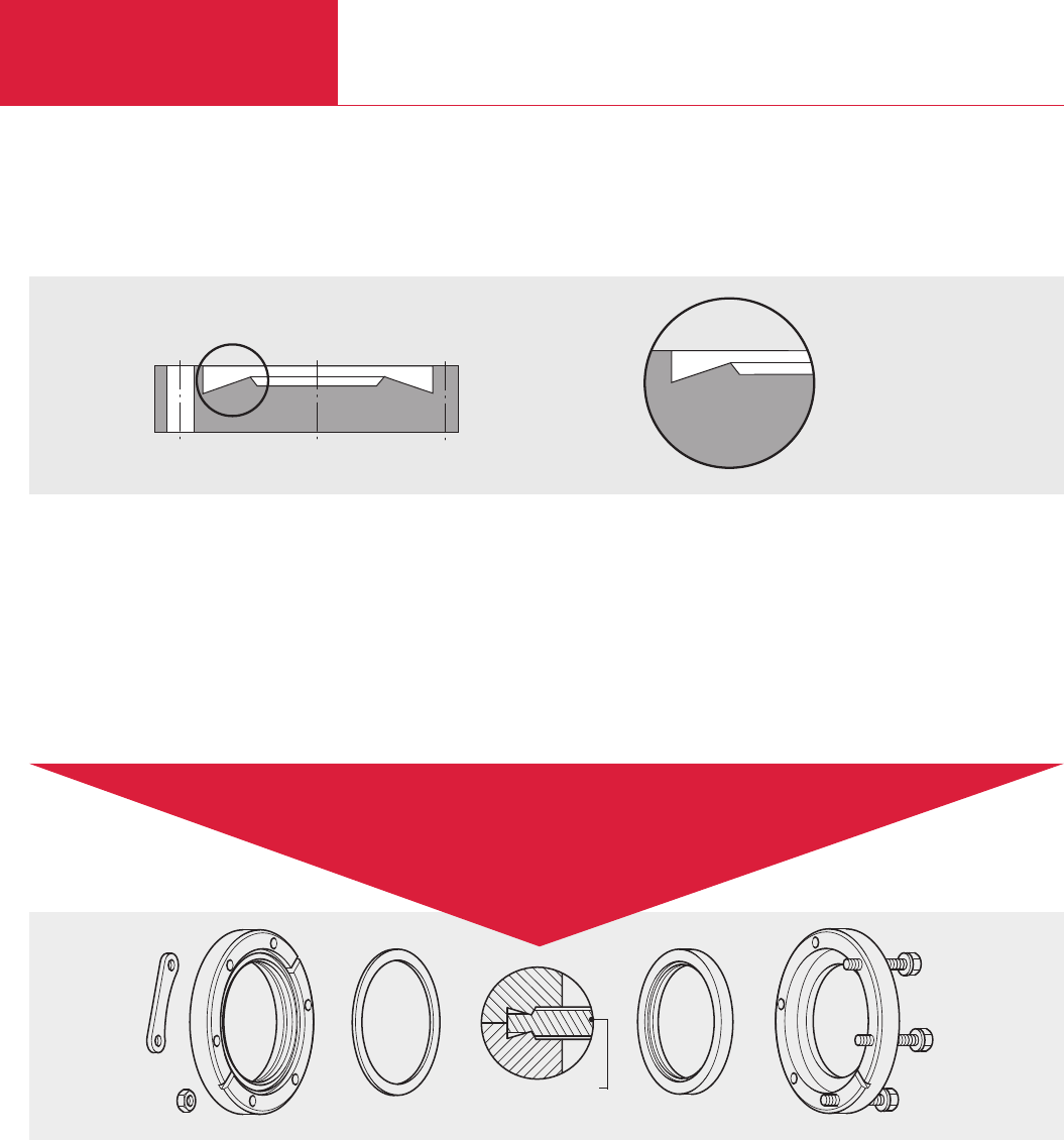
CF Flanges
Ultra-high Vacuum Components
C15.04 LEYBOLD VACUUM PRODUCTS AND REFERENCE BOOK 2003/2004
These Arguments Prove LEYBOLD’s QUALITY
The well-proven LEYBOLD geometry for the cutting edges
The stabilized LEYBOLD profile for the cutting edges
Diagrammatic view Partial view
Forged steel materials of high tensile strength and density
Material quality for standard applications DIN 1.4301 corresponds to AISI 304
Tightly checked, close dimensional tolerances for the entire sealing geometry
Low degassing rates of the tube material used
◆
◆
Advantages
Reliable sealing of UHV connections
over hundreds of
heating cycles
Nut
Bolt nut plate
Fixed CF flange
Copper gasket
Copper gasket
Inner part Bolts
Rotatable
CF flange
◆
◆
◆
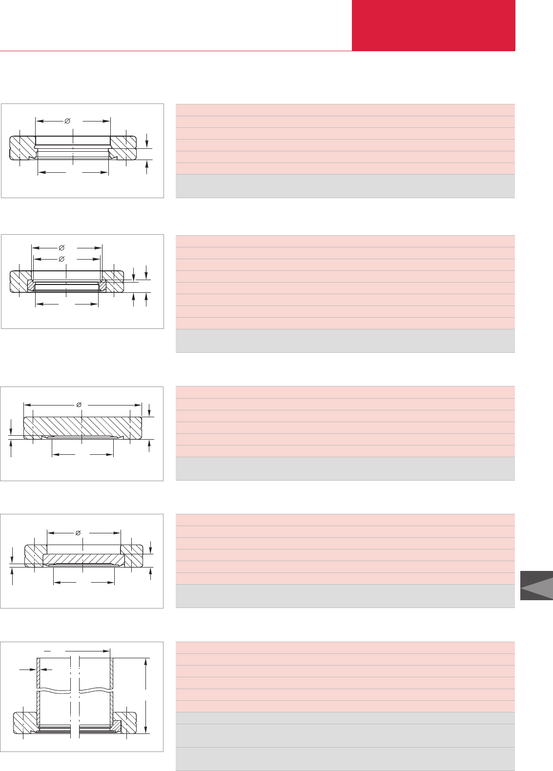
CF Flanges
Ultra-high Vacuum Components
C15.05
C15
LEYBOLD VACUUM PRODUCTS AND REFERENCE BOOK 2003/2004
DN CF 16 40 63 100 160 200 250
Outside diameter inch 1 5/16" 2 3/4" 4 1/2" 6" 8" 10" 12"
Inside diameter mm 14 38 66 104 155 205 256
d1mm 18.6 41 71 109 160 206 257
h1mm 5.8 7.6 12.6 14.3 15.8 17.1 18
For dimensions not given, see Technical Data
Material
DIN 1.4301 Part No. 835 21 835 23 835 24 835 25 835 26 835 27 835 29
DN CF 16 40 63 100 160 200 250
Outside diameter inch 1 5/16" 2 3/4" 4 1/2" 6" 8" 10" 12"
Inside diameter mm 14 38 66 104 155 205 256
d mm 34 69.5 113.5 152 202.5 253 305
h mm 7.5 13 17.5 20 22 24.5 24.5
For dimensions not given, see Technical Data
Material
DIN 1.4301 Part No. 835 01 835 03 835 04 835 05 835 06 835 07 835 09
DN CF 16 40 63 100 160 200 250
Outside diameter inch 1 5/16" 2 3/4" 4 1/2" 6" 8" 10" 12"
Inside diameter mm 16 36.8 66 104 155 200 250
d1mm 18.3 40.3 70.3 108.5 159.5 205.5 256.5
h1mm 4.2 5.5 9.5 11 12 12.5 12.5
For dimensions not given, see Technical Data
Material
DIN 1.4301 Part No. 835 41 835 37 835 38 835 39 835 40 835 47 835 49
DN CF 16 40 63 100 160 200 250
Outside diameter inch 1 5/16" 2 3/4" 4 1/2" 6" 8" 10" 12"
Inside diameter mm 16 36.8 66 104 155 200 250
d1mm 18.3 40.3 70.3 108.5 159.5 205.5 256.5
d2mm 18.6 41 71 109 160 206 257
h1mm 4.2 5.5 9.5 11 12 12.5 12.5
h2mm 5.8 7.6 12.6 14.3 15.8 17.1 18
For dimensions not given, see Technical Data
Material
DIN 1.4301 Part No. 835 61 835 58 835 59 835 60 835 69 835 67 835 78
i.D
d1
h1
CF Bore Flanges, Fixed
Dimensional drawing for the CF bore flanges, fixed
i.D
d1
h1
d2
h2
CF Bore Flanges, Rotatable
Dimensional drawing for the CF bore flanges, rotatable
h
i.D
dd
1,4
CF Blank Flanges, Fixed
Dimensional drawing for the CF blank flanges, fixed
i.D
d1
1,4
h1
CF Blank Flanges, Rotatable
Dimensional drawing for the CF blank flanges, rotatable
DN CF 16 40 63 100 160
Outside diameter inch 1 5/16" 2 3/4" 4 1/2" 6" 8"
Inside diameter mm 16 36.8 66 104 155
s mm 1 1.6 2 2 2
h mm 38 63 105 135 167
For dimensions not given, see Technical Data
Material
Tube end, fixed
DIN 1.4301 Part No. 835 51 835 31 835 32 835 33 835 34
Tube end, rotatable
DIN 1.4301 Part No. 835 71 835 82 835 74 835 75 835 76
i.D
s
h
CF Flanges with Tube End
Dimensional drawing for the CF flanges with tube end; left fixed, right rotatable
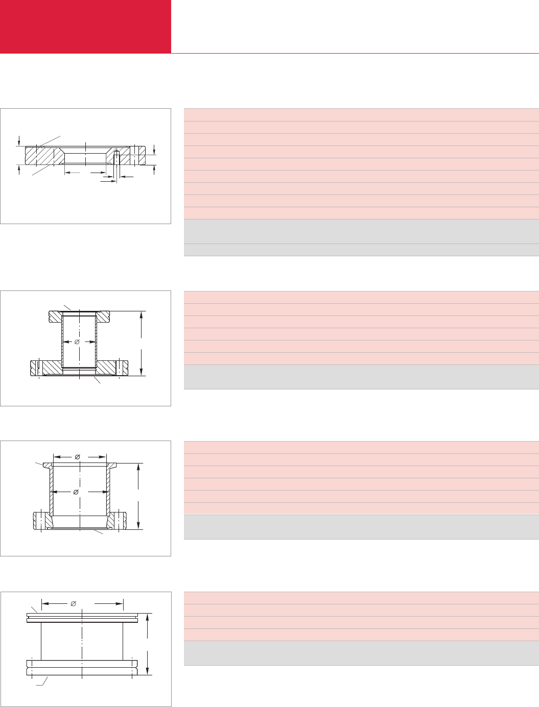
CF Flanges
Ultra-high Vacuum Components
C15.06 LEYBOLD VACUUM PRODUCTS AND REFERENCE BOOK 2003/2004
DN CF 40 63 100 100 160 160
Outside diameter inch 2 3/4" 4 1/2" 6" 6" 8" 8"
DN1CF 16 40 40 63 40 100
k mm 27 58.7 58.7 92.15 58.7 130
h mm 13 17.5 20 20 22 22
h1mm 5.5 9 9 11 9 11
d 16 39 39 66 39 104
d1M 4 M 6 M 6 M 8 M 6 M 8
For dimensions not given, see Technical Data
Material
DIN 1.4301 Part No. 836 85 836 86 836 87 836 89 836 90 836 91
Matching stud bolts Part No. 839 10 839 11 839 11 839 13 839 11 839 13
DN
DN1
ød
øk
hh1
d1
CF Reducing Flanges
Dimensional drawing for the CF reducing flanges, fixed
DN CF 40 63 100 100 160
Outside diameter inch 2 3/4" 4 1/2" 6" 6" 8"
DN1CF 16 40 40 63 100
h mm 45 75 75 95 105
d (tube) mm 18 40 40 70 108
For dimensions not given, see Technical Data
Material
DIN 1.4301 Part No. 837 10 837 15 837 16 837 19 837 22
DN
h
d
DN1
CF Reducing Pieces
Dimensional drawing for the CF reducing pieces
DN CF 16 16 40 40 40 63
Outside diameter inch 1 5/16" 1 5/16 2 3/4" 2 3/4" 2 3/4" 4 1/2"
DN1KF 16 25 16 25 40 40
d mm 16 16 16 26 37 41
h mm 35 35 30 30 50 35
d1(tube) mm 20 20 20 30 41 45
Material
DIN 1.4301 Part No. 837 81 837 83 837 82 837 84 837 36 837 86
DN
h
d1
dd
DN1
UHV CF/KF Adaptors
Dimensional drawing for the CF/KF adapötors
DN CF 63 100 160
Outside diameter inch 4 1/2" 6" 8"
DN1ISO-K 63 100 160
DN2mm 66 104 157
Material
DIN 1.4301 Part No. 837 01 837 02 837 03
90
DN1
DN
2
DN
UHV CF/ISO-K Adaptors
Dimensional drawing for the CF/ISO-K adaptors
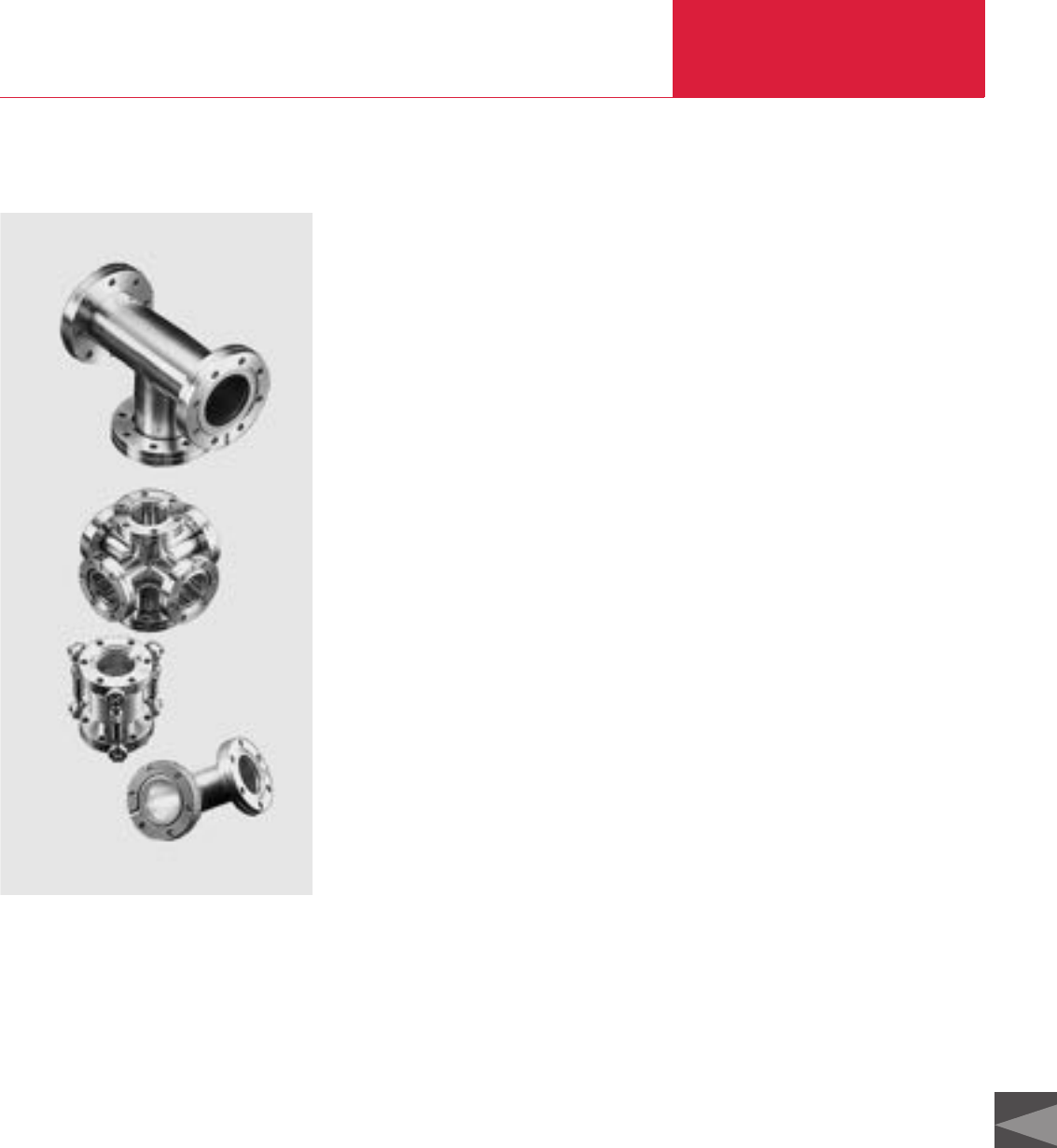
Ultra-high Vacuum Components
C15.07
C15
LEYBOLD VACUUM PRODUCTS AND REFERENCE BOOK 2003/2004
UHV Components
UHV Components
UHV components are manufactured according to
the requirements outlined in the introductory
chapter. They are made from selected and corro-
sion resistant types of stainless steel. Both
design and production methods are such, that
the components meet the requirements of UHV
applications. All components are fusion welded
from the inside to prevent fissures and pocket
holes (virtual leaks which cannot be located by
leak detection methods from the outside). If
welding from the outside cannot be avoided due
to design constraints, the welding seam penetra-
tes to the inner side, the side of the vacuum.
A carefully implemented cleaning process and
suitable packaging for the components are essen-
tial pre-requisites for obtaining pressures in the
UHV range within reasonably short pump down
times after assembly (providing the remainder of
the apparatus is clean too).
For applications in the extreme UHV range (XHV)
the outgassing rate of the CF flanges and the
UHV components can be reduced by about two
orders of magnitude by a special degassing
process.
Advantages to the User
♦Low degassing rates
♦High degassing temperature
♦Leak rates below 1 x 10
-11
mbar x l x s
-1
♦Basic dimensions correspond to those of the
components from other international manu-
facturers
♦Bolts may be inserted from the side of the
body
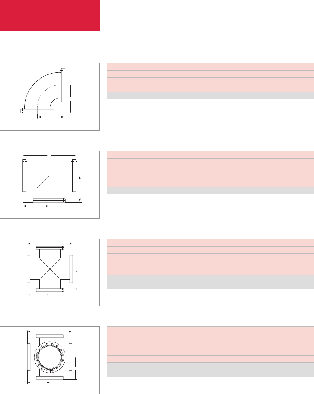
Ultra-high Vacuum Components
C15.08 LEYBOLD VACUUM PRODUCTS AND REFERENCE BOOK 2003/2004
UHV Components
DN CF 16 40 63 100 160
Outside diameter inch 1 5/16" 2 3/4" 4 1/2" 6" 8"
a mm 38 63 105 135 167
For dimensions not given, see Technical Data
Elbow 90° with a rotatable flange Part No. 836 04 836 05 836 06 836 07 836 08
a
a
Elbows 90°; from DN 160 CF Pipe Bend
Dimensional drawing for the 90° elbows/pipe bends
DN CF 16 40 63 100 160
Outside diameter inch 1 5/16" 2 3/4" 4 1/2" 6" 8"
a mm 38 63 105 135 167
h mm 76 126 210 270 334
For dimensions not given, see Technical Data
Tee with a rotatable flange on each axis Part No. 836 14 836 15 836 16 836 17 836 18
a
a
h
Tees
Dimensional drawing for the tees
DN CF 16 40 63 100 160
Outside diameter inch 1 5/16" 2 3/4" 4 1/2" 6" 8"
a mm 38 63 105 135 167
h mm 76 126 210 270 334
For dimensions not given, see Technical Data
Cross with a rotatable flange
on each axis Part No. 836 34 836 35 836 36 836 37 836 38
a
a
h
Crosses
Dimensional drawing for the crosses
DN CF 40 63 100 160
Outside diameter inch 2 3/4" 4 1/2" 6" 8"
a mm 63 105 135 167
h mm 126 210 270 334
For dimensions not given, see Technical Data
Double cross with a rotatable flange
on each axis Part No. 836 45 836 46 836 47 836 48
a
a
h
Double Crosses
Dimensional drawing for the double crosses
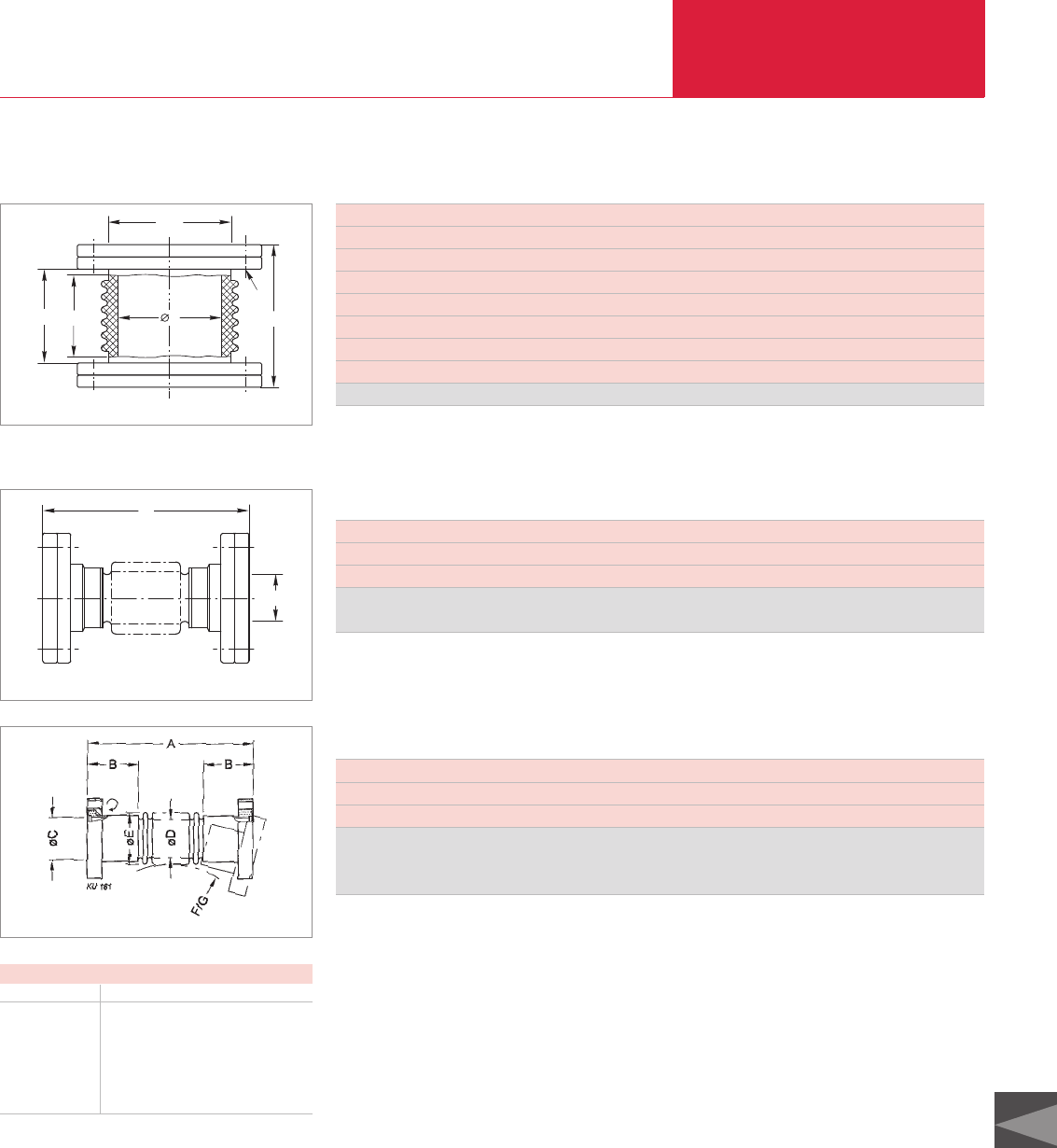
Ultra-high Vacuum Components
C15.09
C15
LEYBOLD VACUUM PRODUCTS AND REFERENCE BOOK 2003/2004
UHV Components
DN CF 40 63
Outside diameter inch 2 3/4" 4 1/2"
Breakdown voltage *)kV 90 140
d mm 25 53
h mm 70 90
h1mm 44 55
h2(length of the ceramic piece) mm 30 45
x (allowed length for the screws) mm 35 45
Caramic nipple with one rotatable flange Part No. 836 71 836 70
*)With reference to the wall thickness of the ceramic material
DN
h
d
h1h2
x
Ceramic Nipples (1 rotatable Flange)
Dimensional drawing for the ceramic nipples
Flexible Connecting Components
h
DN
Dimensional drawing for the CF bellows
DN CF 16 40 63 100 160
o. D. inch 1 5/16" 2 3/4" 1 1/2" 6" 8"
h mm 76 ±1,5 126 ±2 139 ±2 142 ±2 250 ±3
CF bellows with one
rotatable flange Part No. 880 01 880 02 880 03 880 04 880 05
CF Bellows
DN CF 16 16 16 16 40 40 40 40
o. D. inch 1 5/16" 1 5/16" 1 5/16" 1 5/16" 2 3/4" 2 3/4" 2 3/4" 2 3/4"
A = length mm 250 500 750 1000 250 500 750 1000
CF corrugated
hose with one
rotatable flange Part No. 885 56 885 68 885 65 885 73 885 57 885 69 885 66 885 75
CF Corrugated Hoses
Dimensional drawing for the CF corrugated hoses
Dimensions
DN CF 16 40
B mm 23 46
C mm 16 36.8
D mm 15 40.5
E mm 22.5 53
F mm 70 130
G mm 50 100
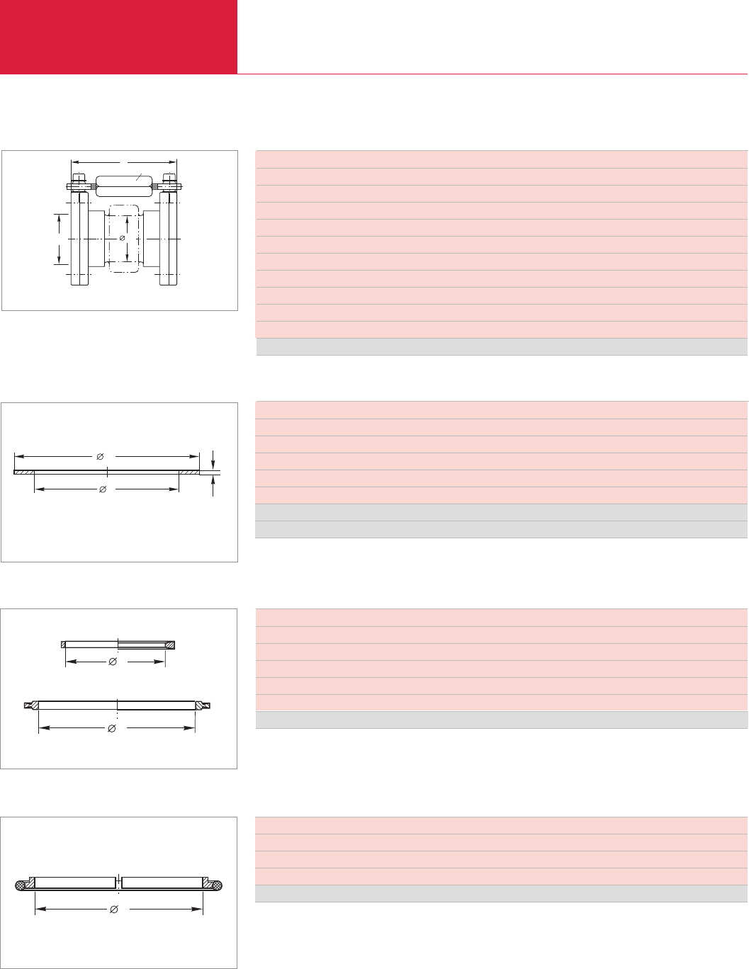
Ultra-high Vacuum Components
C15.10 LEYBOLD VACUUM PRODUCTS AND REFERENCE BOOK 2003/2004
Accessories for UHV Components
DN CF 16 40 63 100 160 200 250
Outside diameter inch 1 5/16" 2 3/4" 4 1/2" 6" 8" 10" 12"
d mm 16.2 39 63.6 101.8 152.6 203.4 254
d1mm 21.3 48.1 82.4 120.5 171.3 222.1 272.7
Set of 5 – – – – – – x
Set of 10 x x x x x x –
Quality
Standard Part No. 839 41 839 43 839 44 839 45 839 46 839 47 839 48
1
d
d
2
Copper Gaskets for CF Flanges (OFHC Copper – Oxygen-Free)
Dimensional drawing for the copper gaskets
DN (both flanges fixed) CF 40 63 100
Outside diameter inch 2 3/4" 4 1/2" 6"
Type bellows bellows bellows
d1(inside dia.) mm 36.8 62 92
hmax. mm 130 150 157
hmin. mm 120 130 127
sw mm 10 13 13
3 joints individually adjustable
Max. angular deviation, approx. °C 10 12 12
Permissible temperature of the hinges °C 200 200 200
Bakeout temperature of the bellows without hinges °C 400 400 400
Part No. 880 11 880 12 880 13
DN
hSW
d1
Compensators
Dimensional drawing for the compensators
d
d
DN 16 CF DN 40 CF
DN 63 - 200 CF
FPM Profiled Gasket without Support Ring
Dimensional drawing for the profiled gaskets without support ring
DN CF 16 40 63 100 160 200
Outside diameter inch 1 5/16" 2 3/4" 4 1/2" 6" 8" 10"
d mm 16 42 69.7 107.8 156 1206
Bakeout temperature °C 160 160 160 160 160 160
Set of 2 – – x x x x
Set of 5 x x – – – –
Part No. 839 21 839 23 839 34 839 35 839 36 839 37
DN CF 250
Outside diameter inch 12"
d mm 248.3
Bakeout temperature °C 160
Part No. 839 03
d
FPM O-ring with Support Ring
Dimensional drawing for the FPM O-rings with support ring
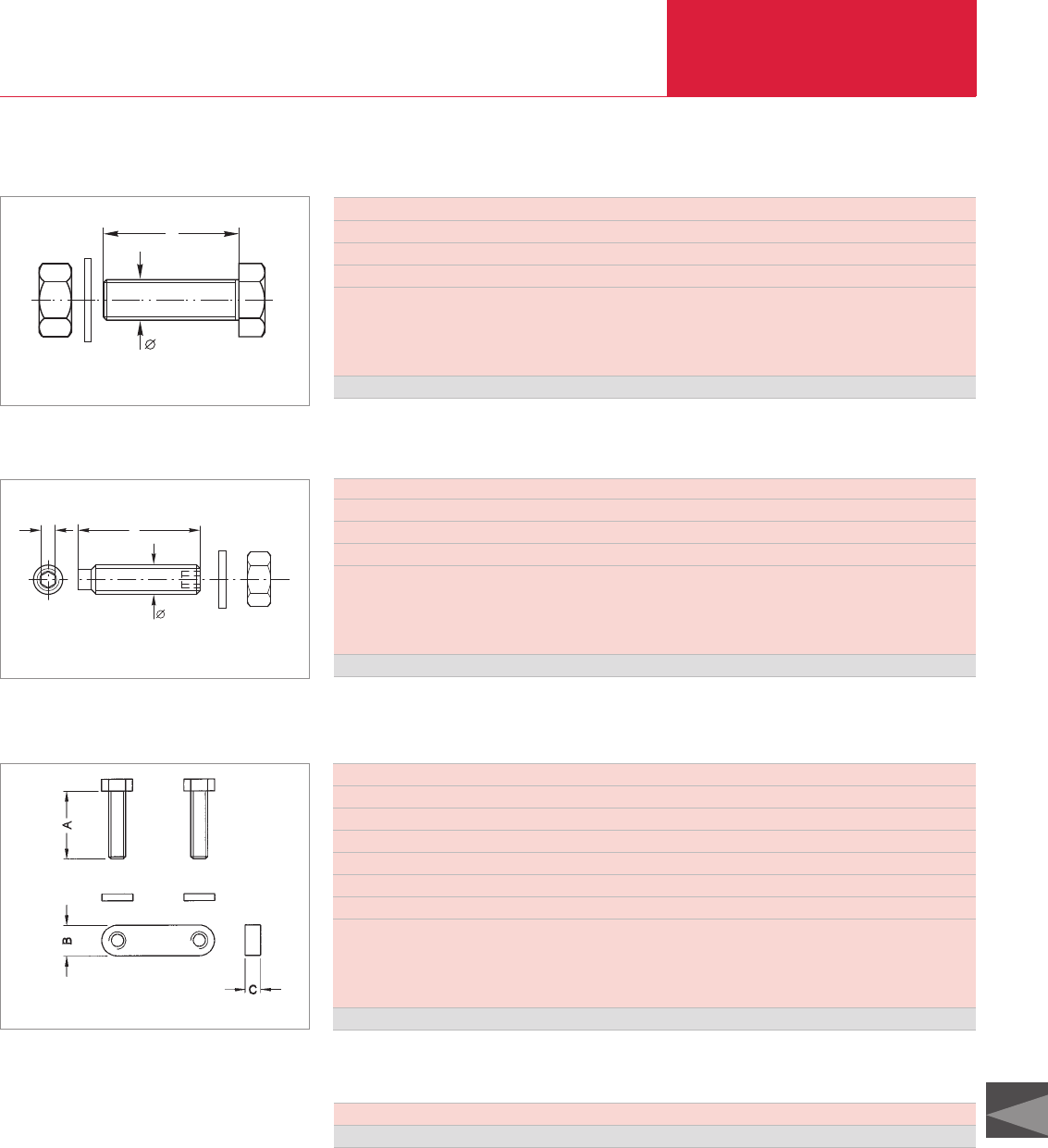
Ultra-high Vacuum Components
C15.11
C15
LEYBOLD VACUUM PRODUCTS AND REFERENCE BOOK 2003/2004
Accessories for UHV Components
DN CF 16 40 63 100 160 200 250
Outside diameter inch 1 5/16" 2 3/4" 4 1/2" 6" 8" 10" 12"
Dimensions (d x l) mm M 4 x 20 M 6 x 35 M 8 x 45 M 8 x 50 M 8 x 55 M 8 x 60 M 8 x 60
Sealing torque 1) Nm 4 10 20 20 20 20 20
Quantity per set
Bolts 25 25 25 25 25 25 25
Nuts 25 25 25 25 25 25 25
Washers 25 25 25 25 25 25 25
Set Part No. 839 00 839 01 838 81 839 04 839 05 839 07 839 07 2)
1) With separating agent 2) 2 sets are required
l
d
Hexagon Bolts, Set for CF Flanges
Dimensional drawing for the hexagon bolts for CF flanges
DN CF 16 40 63-100
Dimensions (d x l) mm M 4 x 20 M 6 x 35 M 8 x 45
s mm 2 3 4
Torque1) Nm 4 10 20
Quantity per set
Set screws 6 6 16
Nuts 6 6 16
Washers 6 6 16
Set Part No. 839 10 839 11 839 13
1) With separating agent
d
l
s
Set Screws, Nuts and Washers for CF Flanges
Dimensional drawing for the set screws, nuts and washers for CF flanges
DN CF 16 40 63 100/160
Outside diameter inch 1 5/16" 2 3/4" 4 1/2" 6"/8"
Dimensions (d x l) mm M 4 x 20 M 6 x 35 M 8 x 50 M 8 x 55
A mm 20 35 45 55
B mm 7 10 12 12
C mm 4 5 8 8
Torque 1) Nm 4 10 20 20
Quantity per set
Bolts 6 6 8 20
Bolt nut plate 3 3 4 10
Washers 6 6 8 20
Set Part No. 838 87 838 88 838 89 838 91
1) With separating agent
Bolts with Bolt Nut Plate and Washers
Dimensional drawing for the bolts with bolt nut plate and washers
Lubricant for Threads
This thread lubricant is preferably applied to
stainless steel joints and is used to prevent bolts
from seizing due to high temperatures or high
mechanical stresses.
Temperature up to 1000 °C
Lubricant for threads, 28 g tube Part No. 839 99
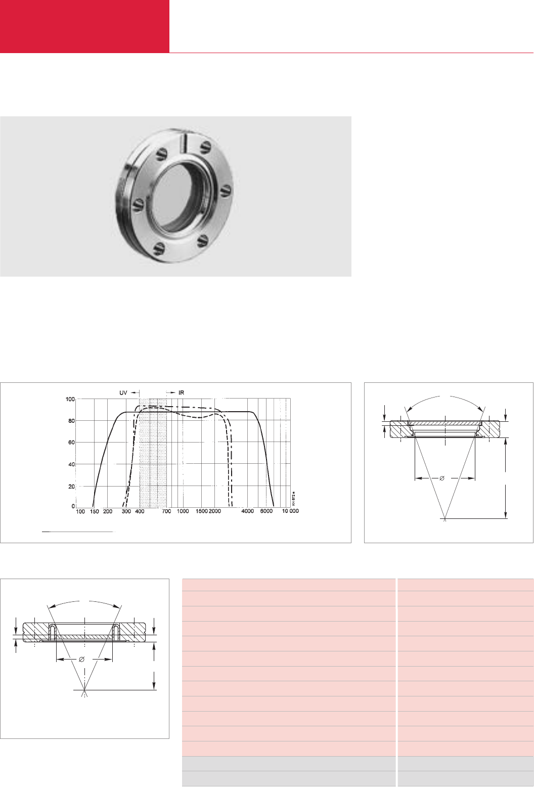
Ultra-high Vacuum Components
C15.12 LEYBOLD VACUUM PRODUCTS AND REFERENCE BOOK 2003/2004
DN CF 40 40 63 100 160
Thickness of the glass (s) mm 3,0 3.0 3.5 6 8.0
Diameter of viewing area (d) mm 23 38 65 90 135
Viewing angle (α) ° 23 38 57 71 92
Spacing of the glass (h), approx. mm 10 11 16.4 8 10
Viewing distance mm 50 50 50 50 50
Wavelength range nm 250 to 5500 400 to 3000
Material – Vacon (compensation ring)
Mean transmission ratio % > 80 93 in the visible range
Type of glass Sapphire Kodial
Max. heating rate min 5 5
Max. bakeout temperature °C 400 400
UHV observation window Part No. – 210 112 210 114 210 115 210 116
UHVUHV sapphire observation windows Part No. 210 122 – – – –
UHV Observation Windows
Advantages to the User
♦Embedded design
♦Optically plane-parallel almost up to the
glass/metal seal
♦Flange offering a wide viewing angle
UHV Observation Windows
All UHV observation windows with CF flanges are
of a flat and embedded design (Zero-length
design). This design provides a much wider view-
ing angle compared to observation windows
manufactured according to a pot-type design.
UHV Sapphire Observation
Windows
The transmission range of sapphire lies between
250 nm and 5500 nm. The infrared limit is shift-
ed far into the infrared range. Therefore these
observation windows are used, for example, in
solar simulation tests, laser experiments, high-
temperature plasma research and spectrophoto-
metric measurements.
Standard types of glass are normally used for
visual observations, for taking photographs of
experimental details and, among other things, for
pyrometric measurements.
α
s
50d
h
Dimensional drawing for the UHV observation windows
Observation windows
UHV Observation Windows
d
h
50
s
α
Dimensional drawing for the UHV sapphire observation windows
Wavelength [nm]
Transmissivity [%]
Optical transmissivity for the UHV observation windows ––––– Sapphire –– · –– Kodial - - - - - - Borosilicate
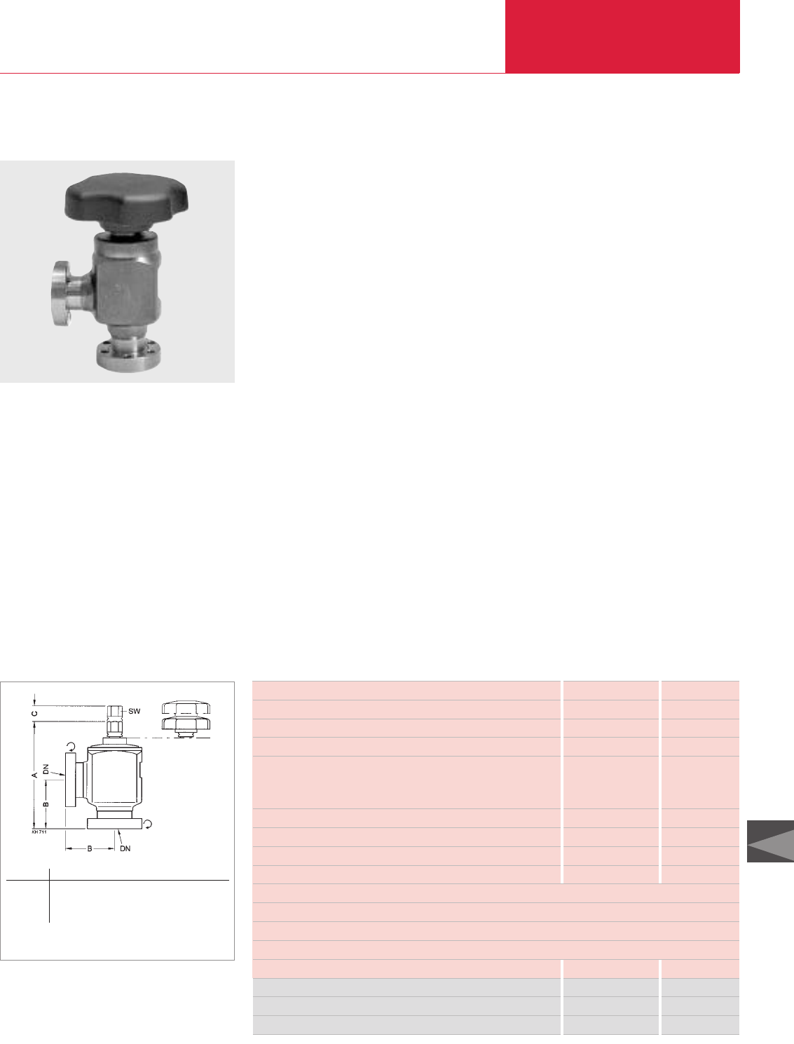
Ultra-high Vacuum Components
C15.13
C15
LEYBOLD VACUUM PRODUCTS AND REFERENCE BOOK 2003/2004
Valves
DN 16 40 63
Connection flange rotatable DN 16 CF-R 40 CF-R 63 CF-R
Service life cycles 1000
Conductance for molecularflow l/ s 3 38 100
Pressure, absolute
min. mbar 1 x 10-11
max. bar 4
Mounting orientation mm any
Bake out temperature without handwheel °C 300
Bake out temperature with handwheel °C 80
Max. heating and cooling rate °C/min 4 4 2
Bellows stainless steel 1.4541
Housing stainless steel 1.4301 welded
Valve disk copper
Valve disk seal copper
Weight kg 0.4 2.0 5.0
UHV All-Metal Right-angle Valves Part No. 289 80 289 81 289 82
Spare valve disk, 2 pieces Part No. 215 410 215 440 215 470
Spare hand wheel, plastic Part No. 215 412 215 442 215 472
UHV All-Metal Right-Angle Valves
Advantages to the User
♦Leak rate at the valve seat below
10
-11
mbar x l x s
-1
♦Absolutely reliable sealing of valve seat
♦Simplest operation
♦No lubrication of the spindle is necessary
after bakeout
♦Large removable handwheel for easy
operation
Due to the specific properties of copper (ductility)
this design offers great advantages over other
materials: long service life and low closing forces
when operating the valve.
A very high leak tightness achieved, even with a
low closing force.
The compact design offers good operational cha-
ra
cteristics also in view of temperature changes,
offers a short flow path and hence improved con-
ductance.
Dimensional drawing for the UHV all-metal right-angle valve
The all-metal right-angle valves are of a fully weld-
ed design. The valve disk may be exchanged
through the side flange.
Due to the selection of suitable materials, the
valve stem need not be lubricated after every
bake-out cycle.
The drive spindle of the valves transfers the moti-
on via a pressure plate onto the sleeve-guided
valve stem carrying the screwed-on valve disk.
The valve disk consists of a copper plate.
UHV All-Metal Right-Angle Valves,
with Rotatable Flanges on Both Sides
DN A B C SW
16 CF-R 88 38 15.5 8
40 CF-R 140 63 26 17
63 CF-R 211 105 36.4 22
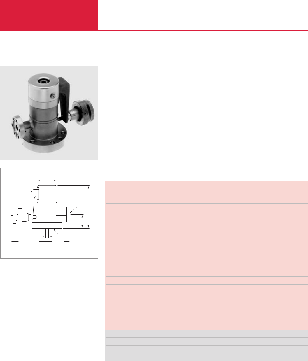
Valves
Ultra-high Vacuum Components
C15.14 LEYBOLD VACUUM PRODUCTS AND REFERENCE BOOK 2003/2004
Connection flanges
Input DN 16 CF-R
Output DN 40 CF-R
Gas flow, min. for
Pure gas mbar x l x s-1 10-10
Air mbar x l x s-1 10-9
Gas flow
max. mbar x l x s-1 600
adjustable, max. mbar x l x s-1 100
Tightness mbar x l x s-1 1 x 10-11
Pressure absolute
min. mbar 1 x 10⁻¹⁰
max. bar 30
Conductance for molecular flow l x s-1 0.7
Operating temperature °C 200
Bakeout temperature °C 350
Valve seat copper alloy
Valve plate sapphire
Housing stainless steel
Weight kg 1.4
UHV All-Metal variable Leak Valve Part No. 289 90
Spare valve plate Part No. 289 87
Spare valve seat Part No. 289 88
Tool kit for valve seat Part No. 290 97
UHV All-Metal Variable Leak Valves
UHV All-Metal Variable Leak Valves
85,5 (3.37") 50 (2")
ø46
(1.81")
DN 40 CF-F
DN 16 CF-R
32,5
(1.28")
98,2 (3.87")
M5
Dimensional drawing for the all-metal variable leak valves
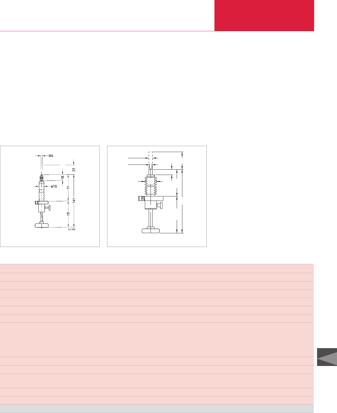
Ultra-high Vacuum Components
C15.15
C15
LEYBOLD VACUUM PRODUCTS AND REFERENCE BOOK 2003/2004
Feedthroughs
Feedthrough FNL 16/25 FNL 40/50
Nominal width DN 16 CF-R 40 CF-R
Shaft connection mm M 4 x 16 M 6 x 10, ∅10
Feedthrough/seal bellow bellow
Actuator manually manually
Travel mm 25 50
Scale division mm 5 10
Shaft load
Radial at max. displacement N 20 200
Axial, against vacuum N 85 140
Axial, against vatmoshere N 100 200
Torsion Nm 0.2 0.5
Tightness mbar x l x s-1 1 x 10⁻¹⁰ 1 x 10⁻¹⁰
Pressure absolute 1 x 10⁻⁹ mbar – 2 bar 1 x 10⁻⁹ mbar – 2 bar
Bakeout temperature
Feedthrough °C 300 300
Weight kg 0.15 0.75
Materials exposed to process media stainless steel stainless steel
Linear motion feedthrough Part No. 210 250 210 251
UHV Feedthroughs
15
50
77,5105,5
ø33
M6x10
ø10 0
-0.1
183
UHV feedthroughs are available in a variety of
field-proven designs, specifically:
♦Linear motion mechanical feedthroughs,
♦Rotary motion mechanical feedthroughs,
Technical Data and Ordering Information
Dimensional drawing for the FNL 16/25 linear motion feedthrough Dimensional drawing for the FNL 40/50 linear motion feedthrough
A stainless steel bellows is used to seal off the
UHV linear, rotary and multi-motion feedthroughs
against the atmosphere.
All feedthroughs can be installed in the vacuum
systems in any orientation.
Linear Motion Mechanical Feedthroughs
Abbreviations used in con-
nection with feedthroughs:
FFeedthrough
EElectric
LLiquid
NNormal
PPrecision
FFrequency
HC Current
HV Voltage
LLinear
RRotary
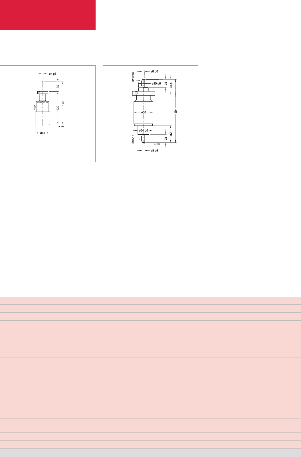
Ultra-high Vacuum Components
C15.16 LEYBOLD VACUUM PRODUCTS AND REFERENCE BOOK 2003/2004
Feedthrough FPR 16/5 N FNR 40/20 N
Nominal width DN 16 CF-F 40 CF-F
Shaft connection mm ∅4∅8
Feedthrough/seal bellow bellow
Transferable torque
Dynamic Nm 0.4 4
Dynamic, at 300 °C Nm 0.2 2
Static Nm 0.2 3
Rotational speed rpm 200 1000
at max. torque rpm – 500
Scale division mm 10° –
Shaft load
Radial N 10 60
Axial N 5 20
Tightness mbar x l x s-1 1 x 10⁻¹⁰ 1 x 10⁻¹⁰
Pressure absolute 1 x 10⁻⁹ mbar – 2 bar 1 x 10⁻⁹ mbar – 2 bar
Operating temperature °C 300 300
Bakeout temperature °C 300 300
Weight kg 0.3 1.5
Materials exposed to process media stainless steel stainless steel
Rotary feedthrough Part No. 210 154 210 155
Technical Data and Ordering Information
The rotation of the drive knob is translated via a
gearless drive system to the shaft on the vacuum
side. This shaft runs on ball bearings which do
not require any maintenance during the entire
service life.
Feedthroughs
Dimensional drawing for the FPR 16/5 N rotary feedthrough Dimensional drawing for the FNR 40/20 N rotary feedthrough
Linear Motion Mechanical Feedthroughs
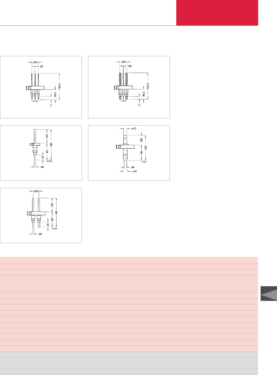
Ultra-high Vacuum Components
C15.17
C15
LEYBOLD VACUUM PRODUCTS AND REFERENCE BOOK 2003/2004
Feedthroughs
Feedthrough FE 40/4 FE 40/9 FEHC 16/1 FEHC 40/1 FEHC 40/2
Nominal width DN CF 40-F CF 40-F CF 16-F CF 40-F CF 40-F
Number of feedthroughs 4 9 1 1 2
Number of connection pieces
vacuum side (set) 5 10 2 1 2
atmospheric side (set) 5 10 2 1 2
Voltage per pole 1) kV 1 1 4 1 4
Current per pole 1) A 8 1 150 250/1000 2) 150
Bakeout temperature °C 400
Temperature rise at max. current °C/min 5 5 5 4 4
Tightness mbar x l x s-1 1 x 10⁻¹⁰
Pressure absolute 1 x 10⁻¹⁰ mbar – 2 bar
Flange stainless steel
Conductor stainless steel stainless steel copper copper copper
Insulator Al2O3
Weight kg 0.3 0.4 0.15 0.5 0.45
Current feedthrough Part No. 210 310 210 313 210 335 210 338 210 342
Connection piece, vacuum side (set) Part No. 210 312 2x 210 312 210 337 210 340 210 337
Connector, atmospheric side (set) Part No. 210 311 2x 210 311 210 336 210 339 210 336
Connector, atmospheric side, H2O cooled Part No. – – – 210 341 –
1) Local safety regulations must be met
2) with water-cooling
Technical Data and Ordering Information
The electric UHV feedthroughs comply with the
relevant VDE regulations.
Concerning the air gaps and creepage paths, they
have been designed in accordance with
VDE 0100, i.e. both sides of the feedthrough are
tested under atmospheric pressure conditions.
Technical Note
All electric specifications of the described voltage
and current feedthroughs are rated in accordance
with overvoltage class 1 and contamination
grade 2.
Electrical Feedthroughs
Dimensional drawing for the FE 40/4 electrical feeedthrough Dimensional drawing for the FE 40/9 electrical feeedthrough
Dimensional drawing for the FEHC 16/1 electrical feeedthrough Dimensional drawing for the FEHC 40/1 electrical feeedthrough
Dimensional drawing for the FEHC 40/2 electrical feeedthrough
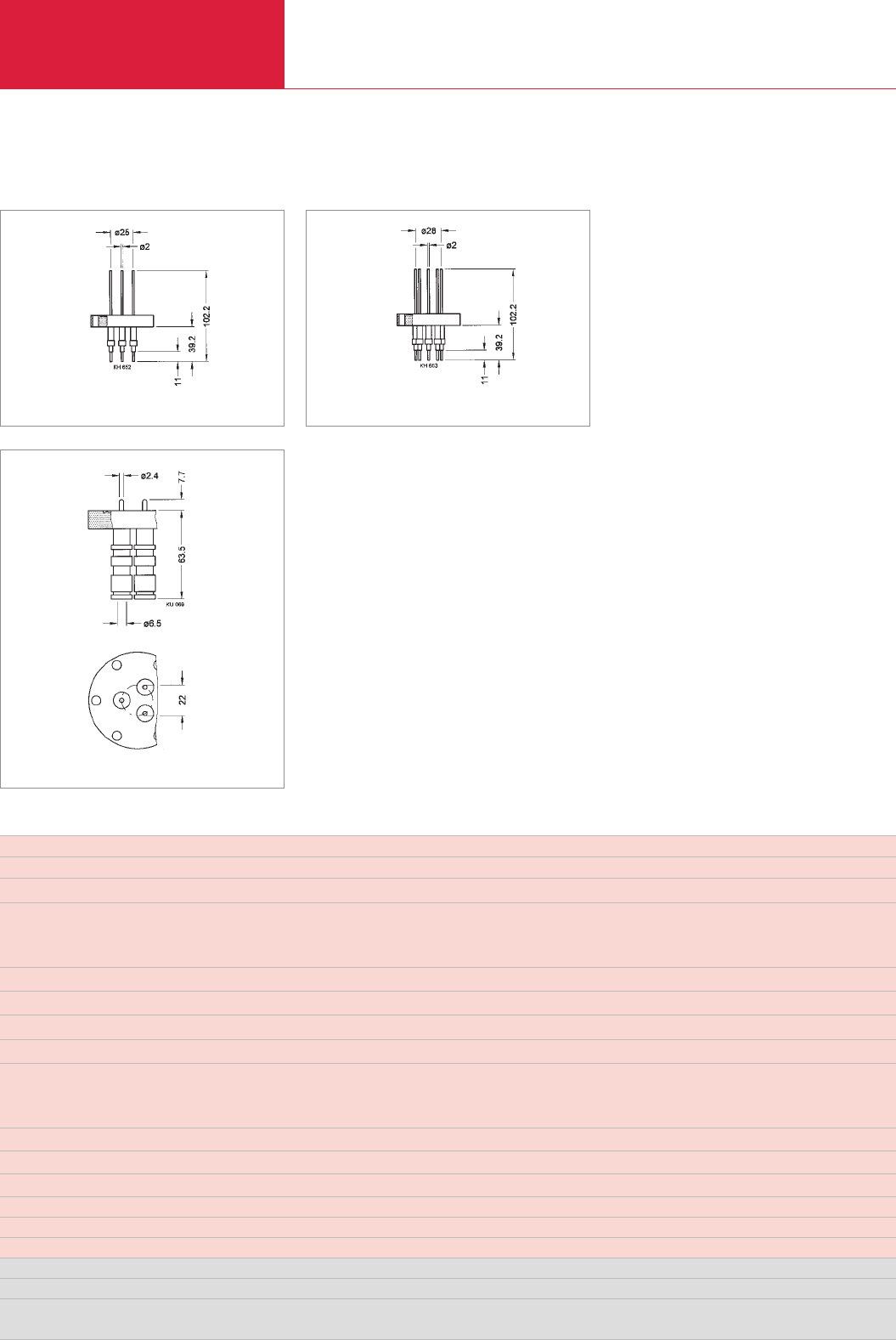
Feedthroughs
Ultra-high Vacuum Components
C15.18 LEYBOLD VACUUM PRODUCTS AND REFERENCE BOOK 2003/2004
Feedthrough FEF 16/1 FEHV 16/1 FEHV 40/3
Nominal width DN CF 16-F CF 16-F CF 40-F
Number of feedthroughs 1 1 3
Voltage
AC, 50 Hz kV 0.35 3.5 3.5
DC kV 0.5 5.0 5.0
Current A 3 3 3
Frequency MHz 150 – –
Impedance Ö50 - 60 – –
Insulation resistance at 20 °C Ö10-10 10-10 10-10
Bakeout temperature
with connector °C 50 50 50
without connector °C 400 400 400
Temperature rise at max. current °C/min 5 5 5
Tightness mbar x l x s-1 1 x 10⁻¹⁰ 1 x 10⁻¹⁰ 1 x 10⁻¹⁰
Pressure absolute 1 x 10⁻⁸ mbar – 10 bar 1 x 10⁻⁸ mbar – 10 bar 1 x 10⁻⁸ mbar – 10 bar
Housing, flange, conductor stainless steel stainless steel stainless steel
Feedthrough, seal Al2O3Al2O3Al2O3
Weight kg 0.14 0.14 0.5
Current feedthrough Part No. 210 404 210 402 210 403
Inside plug Part No. 846 47 846 47 846 47
Outside plug BNC MHV MHV
U6 88/U U6 932/U U6 932/U
1) with elastomer seal up to 150 °C
Technical Data and Ordering Information
The electric UHV feedthroughs comply with the
relevant VDE regulations.
Concerning the air gaps and creepage paths, they
have been designed in accordance with
VDE 0100, i.e. both sides of the feedthrough are
tested under atmospheric pressure conditions.
Technical Note
All electric specifications of the described voltage
and current feedthroughs are rated in accordance
with overvoltage class 1 and contamination
grade 2.
Dimensional drawing for the FEF 16/1 electrical feeedthrough Dimensional drawing for the FEHV 16/1 electrical feeedthrough
Dimensional drawing for the FEHV 40/3 electrical feeedthrough
Electrical Feedthroughs
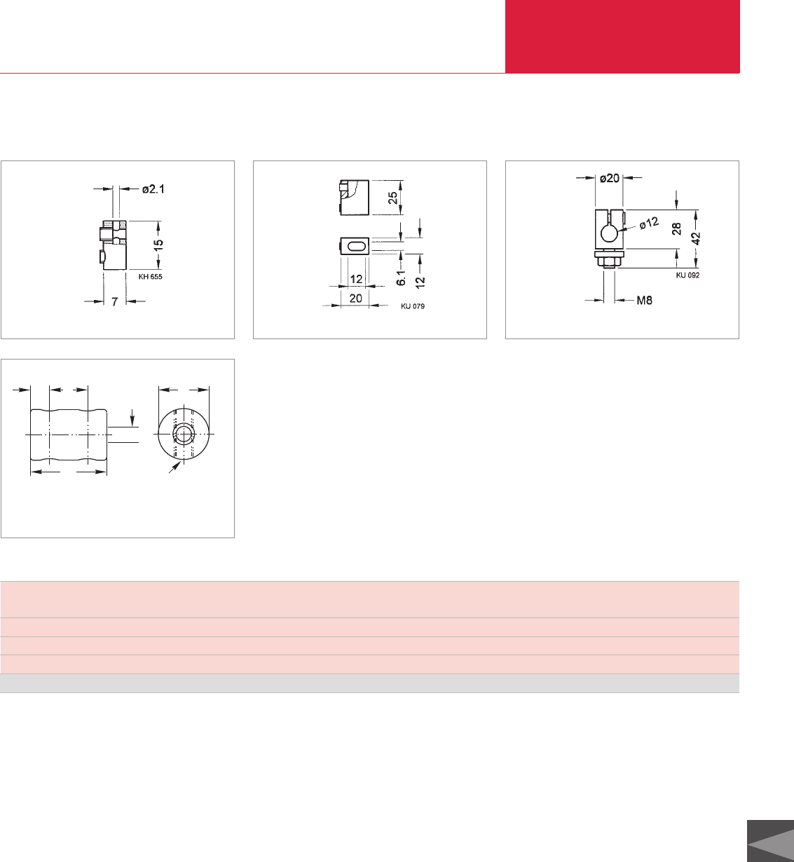
Ultrahigh Vacuum Components
C15.19
C15
LEYBOLD VACUUM PRODUCTS AND REFERENCE BOOK 2003/2004
Feedthroughs
Dimensional drawing for the connector used on FE 40/4 / FE 40/9 Dimensional drawing for the connector used on FEHC 40/1
Dimensional drawing for the connector
used on FE 16/1, FEHC 40/2 and FEHC 16/1
Connector for feedthrough FE 40/4 / FE 40/9 FE 16/1 / FEHC 40/1 FEHV 16/1 / FEHV 40/3
FEHC 40/2 / FEHC 16/1 FEF 16/1
Current max. A 12 90 1000 3
Bakeout temperature °C 400 400 400 350
Material stainless steel stainless steel copper copper
Connector, vacuum side Part No. 210 312 (set of 5) 210 337 (set of 2 210 340 846 47
Technical Data and Ordering Information
Connectors, vacuum side
12
8
63
M3
2,4
Dimensional drawing for the connector
used on FEHV 16/1, FEHV 40/3 and FEF 16/1
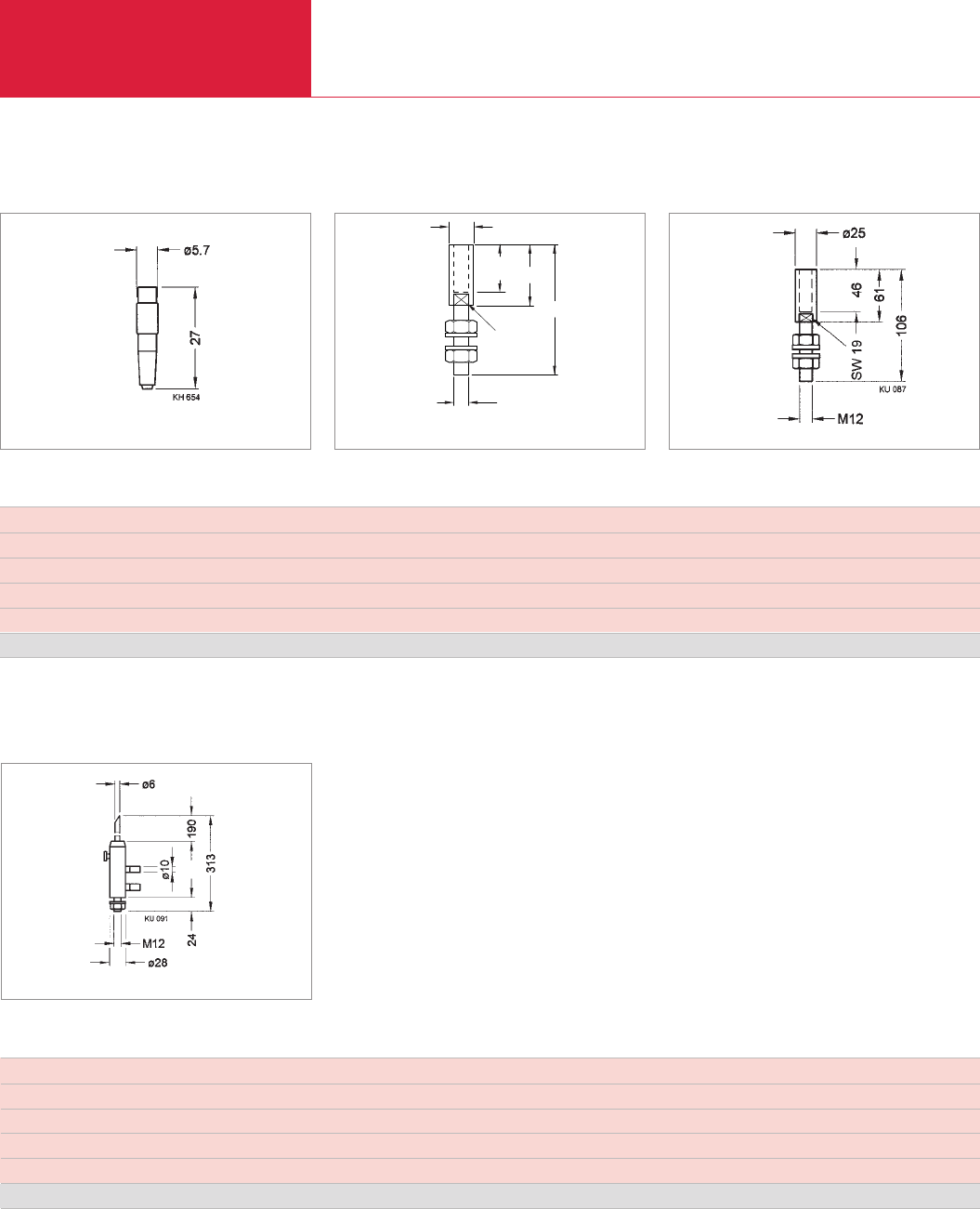
Feedthroughs
Ultrahigh Vacuum Components
C15.20 LEYBOLD VACUUM PRODUCTS AND REFERENCE BOOK 2003/2004
Dimensional drawing for the outside plug used on FE 40 /4 and FE 40/9
M6
SW8 19,5
25
53
ø10
Dimensional drawing for the outside plug
used on FE 16/1, FEHC 40/2 and FEHC 16/1 Dimensional drawing for the outside plug used on FEHC 40/1
Connector for feedthrough FE 40/4 / FE 40/9 FE 16/1 / FEHC 40/2 / FEHC 16/1 FEHC 40/1
Current max. A 12 90 250
Not insulated, for use up to V 50 50 50
Bakeout temperature °C 50 150 150
Material gold-plated brass silver-plated brass silver-plated brass
Connector, atmospheric side Part No. 2 x 210 311 (set of 5) 210 336 (set of 2) 210 339
Technical Data and Ordering Information
Connectors, atmospheric side
Dimensional drawing for the connector used on FEHC 40/1
Connector for feedthrough FEHC 40/1
Current max. A 1000
Not insulated, for use up to V 24
Bakeout temperature °C 120
Material silver-plated brass
Connector, atmospheric side, with water-cooling Part No. 210 341
Technical Data and Ordering Information
Connectors, atmospheric side, H2O cooled
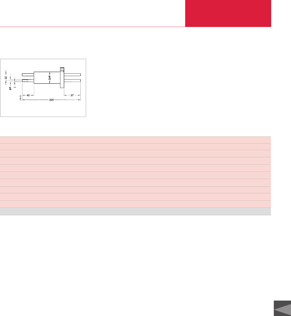
Ultrahigh Vacuum Components
C15.21
C15
LEYBOLD VACUUM PRODUCTS AND REFERENCE BOOK 2003/2004
Feedthroughs
Feedthrough FL 40C/2
Nominal width DN 40 CF-F
Feedthrough / seal welded / brazed
Connection mm ∅8 x 1
Number of tubes 2
Tightness mbar x l x s-1 1 x 10⁻¹⁰
Pressure absolute 10-9 mbar – 10 bar (at 400 °C max. 2 bar)
Temperature range °C -400 – +400
Material stainless steel
Weight kg 0.4
Part No. 210 276
Dimensional drawing for the FL 40C/2 UHV liquid feedthrough
The thermally insulated UHV liquid feedthroughs
are used to convey cold or hot gases, liquids or
liquid nitrogen.
Technical Data and Ordering Information
Technical Note
The ends of the tubes are long enough that they
may be bent apart so that an UHV compatible
connection can be provided.
UHV Liquid Feedthroughs

Ultrahigh Vacuum Components
C15.22 LEYBOLD VACUUM PRODUCTS AND REFERENCE BOOK 2003/2004

C16
Vacuum Gauges and Control Instruments
10-12 – 2 000 mbar (10-12 – 1 500 Torr),
Calibration Service
Total Pressure Gauges
–1
–6
–4
–2
+1
+3

LEYBOLD VACUUM PRODUCTS AND REFERENCE BOOK 2003/2004
Contents
Total Pressure Gauges
C16.02
General
Basic Terms of Vacuum Metrology . . . . . . . . . . . . . . . . . . . . . . . . . . . . . . . . . . . . . . . . . . . C16.03
Connection Accessories for Small Flanges . . . . . . . . . . . . . . . . . . . . . . . . . . . . . . . . . . . . . C16.04
Products
Rough Vacuum Gauges, Mechanical Instruments
Bourdon Vacuum Gauges. . . . . . . . . . . . . . . . . . . . . . . . . . . . . . . . . . . . . . . . . . . . . . . . . . C16.05
Capsule Vacuum Gauges . . . . . . . . . . . . . . . . . . . . . . . . . . . . . . . . . . . . . . . . . . . . . . . . . . C16.06
DIAVAC DV 1000 . . . . . . . . . . . . . . . . . . . . . . . . . . . . . . . . . . . . . . . . . . . . . . . . . . . . . . . C16.07
Active Sensors
CTR90/CTR91 CERAVAC Transmitters . . . . . . . . . . . . . . . . . . . . . . . . . . . . . . . . . . . . . . . C16.08
TTR 90/TTR 90S THERMOVAC Transmitters . . . . . . . . . . . . . . . . . . . . . . . . . . . . . . . . . . . C16.10
TTR 211/TTR 216 S THERMOVAC Transmitters . . . . . . . . . . . . . . . . . . . . . . . . . . . . . . . . C16.12
PTR 225/PTR 225 S/PTR 237 PENNINGVAC Transmitters . . . . . . . . . . . . . . . . . . . . . . . . . C16.14
ITR 90 IONIVAC Transmitter . . . . . . . . . . . . . . . . . . . . . . . . . . . . . . . . . . . . . . . . . . . . . . . C16.16
ITR 100 IONIVAC Transmitter . . . . . . . . . . . . . . . . . . . . . . . . . . . . . . . . . . . . . . . . . . . . . . C16.18
Connection Cable for Active Sensors . . . . . . . . . . . . . . . . . . . . . . . . . . . C16.20
Operating Units for Active Sensors
DISPLAY ONE . . . . . . . . . . . . . . . . . . . . . . . . . . . . . . . . . . . . . . . . . . . . . . . . . . . . . . . . . . C16.22
CENTER ONE. . . . . . . . . . . . . . . . . . . . . . . . . . . . . . . . . . . . . . . . . . . . . . . . . . . . . . . . . . . C16.24
CENTER TWO / THREE. . . . . . . . . . . . . . . . . . . . . . . . . . . . . . . . . . . . . . . . . . . . . . . . . . . . C16.26
COMBIVAC 2T . . . . . . . . . . . . . . . . . . . . . . . . . . . . . . . . . . . . . . . . . . . . . . . . . . . . . . . . . . C16.28
Operating Units for Passive Sensors
PIEZOVAC PV 20 . . . . . . . . . . . . . . . . . . . . . . . . . . . . . . . . . . . . . . . . . . . . . . . . . . . . . . . C16.30
MEMBRANOVAC DM 11/DM 12 . . . . . . . . . . . . . . . . . . . . . . . . . . . . . . . . . . . . . . . . . . . . C16.32
Fine Vacuum Gauges
THERMOVAC TM 21/TM 22/TM 23 . . . . . . . . . . . . . . . . . . . . . . . . . . . . . . . . . . . . . . . . . . C16.34
High and Ultra High Vacuum Gauges
PENNINGVAC PM 31. . . . . . . . . . . . . . . . . . . . . . . . . . . . . . . . . . . . . . . . . . . . . . . . . . . . . C16.36
COMBIVAC CM 31/CM 32/CM 33 . . . . . . . . . . . . . . . . . . . . . . . . . . . . . . . . . . . . . . . . . . . C16.38
Sensors
DI 200/DI 201/DI 2000/DI 2001/DI 2001 rel Linear Pressure Sensors . . . . . . . . . . . . . . . . C16.40
Series 200 THERMOVAC Sensor . . . . . . . . . . . . . . . . . . . . . . . . . . . . . . . . . . . . . . . . . . . . C16.42
PR 25/PR 26/PR 27/PR 37 PENNINGVAC Sensors. . . . . . . . . . . . . . . . . . . . . . . . . . . . . . . C16.43
IE 414/IE 514 IONIVAC Sensors . . . . . . . . . . . . . . . . . . . . . . . . . . . . . . . . . . . . . . . . . . . . C16.44
Spare Sensors for Older Operating Units . . . . . . . . . . . . . . . . . . . . . . . . . . . . . . . . . . . . . . C16.45
Pressures Switches and Control Instruments
PS 113 A Low Pressure Safety Switch. . . . . . . . . . . . . . . . . . . . . . . . . . . . . . . . . . . . . . . . C16.46
PS 115 Pressure Switches . . . . . . . . . . . . . . . . . . . . . . . . . . . . . . . . . . . . . . . . . . . . . . . . . C16.47
SV 110 Switching Amplifier . . . . . . . . . . . . . . . . . . . . . . . . . . . . . . . . . . . . . . . . . . . . . . . . C16.48
MR 16/MR 50 Diaphragm Pressure Regulators . . . . . . . . . . . . . . . . . . . . . . . . . . . . . . . . . C16.49
Miscellaneous
LEYBOLD Calibration Service . . . . . . . . . . . . . . . . . . . . . . . . . . . . . . . . . . . . . . . . . . . . . . . C16.50

General Total Pressure Gauges
C16.03
C16
LEYBOLD VACUUM PRODUCTS AND REFERENCE BOOK 2003/2004
Basic Terms of Vacuum Metrology
Today, the total range of vacuum pressure acces-
sible to measurement extends from atmospheric
pressure (about 1000 mbar (750 Torr)) down to
10
-12
mbar/Torr, i.e. it extends over 15 powers of
ten. The instruments used for measuring the pres-
sure within this wide range are called vacuum
gauges. For physical reasons it is not possible to
create a single vacuum sensor through which it
might be possible to perform quantitative measure-
ments within the entire pressure range. Therefore,
a variety of different vacuum gauges are available,
each with their own characteristic measurement
range which commonly extends over several
powers of ten. A difference is made between
direct and indirect pressure measurements. In
the
case of direct (or absolute) pressure measure-
ments, the readings obtained through the vacuum
gauge are independent of the type of gas and the
pressure which is to be measured. Common are
so-called mechanical vacuum gauges where the
pressure is determined directly by recording the
force acting on the surface of a diaphragm. In the
case of so-called indirect pressure measurements
the pressure is determined as a function of a
pressure dependant property of the gas (thermal
conductivity, ionization probability, for example).
These properties do not only depend on the pres-
sure, but also on the molar mass of the gases.
For this reason, the pressure readings obtained
through vacuum gauges which rely on indirect
pressure measurements, depend on the type of
gas. The readings usually relate to air or nitrogen
as the measurement gas. For the measurement of
other vapors or gases the corresponding
correction factors must be applied.
Vacuum Gauges where the
Pressure Readings are
Independent of the Type of
Gas (Mechanical Vacuum
Gauges)
BOURDON Vacuum Gauge
The inside of a tube which is bent into a circular
arc (the so-called Bourdon tube) is connected to
the vacuum system. Due to the effect of the
external atmospheric pressure, the end of the
tube bends more or less during the evacuation
process. This actuates the pointer arrangement
which is attached to this point. The correspond-
ing pressure can be read off on a linear scale.
With Bourdon gauges it is possible to roughly
determine pressures between 10 mbar (7.5 Torr)
and atmospheric pressure.
Capsule Vacuum Gauge
This vacuum gauge contains a hermetically
sealed, evacuated, thin-walled diaphragm capsule
which is located within the instrument. As the
vacuum pressure reduces, the capsule bulges.
This movement is transferred via a system of
levers to a pointer and can then be read off as the
pressure on a linear scale.
Diaphragm Vacuum Gauge
In the case of the diaphragm vacuum gauge
which is capable of absolute pressure measure-
ments, a sealed and evacuated vacuum chamber
is separated by a diaphragm from the vacuum
pressure to be measured. This serves as the refe-
rence quantity. With increasing evacuation, the
difference between the pressure which is to be
measured and the pressure within the reference
chamber becomes less, causing the diaphragm
flex. This flexure may be transferred by mechani-
cal means like a lever, for example, to a pointer
and scale, or electrically by means of a strain
gauge or a bending bar for conversion into an
electrical measurement signal. The measurement
range of such diaphragm vacuum gauges extends
from 1 mbar (0.75 Torr) to over 2000 mbar
(1500 Torr).
Capacitance Vacuum Gauge
The pressure sensitive diaphragm of these capac-
itive absolute pressure sensors is made of Al
2
O
3
ceramics. The term “capacitive measurement”
means that a plate capacitor is created by the dia-
phragm with a fixed electrode behind the dia-
phragm. When the distance between the two pla-
tes of this capacitor changes, a change in capaci-
tance will result. This change, which is proportio-
nal to the pressure, is then converted into a cor-
responding electrical
measurement signal. Here
too, an evacuated refer
ence chamber serves as
the reference for the pressure measurements.
With capacitance gauges it is possible to accura-
tely measure pressures from 10
-5
mbar/Torr to
well above atmospheric pressure, whereby diffe-
rent capacitance gauges having diaphragms of
different thickness (and therefore sensitivity) will
have to be used.
Vacuum Gauges where the
Pressure Readings Depend
of the Type of Gas
Thermal Conductivity Gauge
(Pirani)
This measurement principle utilizes the thermal
conductivity of gases for the purpose of pressure
measurements in the range from 10
-4
mbar/Torr
to atmospheric pressure. Today, only the princi-
ple of the controlled Pirani gauge is used by
LEYBOLD in order to attain a quick response.
The filament within the gauge head forms one
arm of a Wheatstone bridge. The heating voltage
which is applied to the bridge is controlled in
such a way, that the filament resistance and thus
the temperature of the filament remains constant
regardless of the quantity of heat given off by the
filament. Since the heat transfer from the filament
to the gas increases with increasing pressures,
the voltage across the bridge is a measure of the
pressure.
Improvements with regard to temperature
compensation have resulted in stable pressure
readings also in the face of large temperature
changes, in particular when measuring low
pressures.
Cold Cathode Ionization
Vacuum Gauge (Penning)
Here the pressure is measured through a gas
discharge within a gauge head whereby the gas
discharge is ignited by applying a high tension.
The resulting ion current is output as a signal
which is proportional to the prevailing pressure.
The gas discharge is maintained also at low pres-
sures with the aid of a magnet.
New concepts for the design of such sensors
permit safe and reliable operation of these so-
called Penning sensors in the pressure range
from 10
-2
to 1 x 10
-9
mbar/Torr.

LEYBOLD VACUUM PRODUCTS AND REFERENCE BOOK 2003/2004
General
Total Pressure Gauges
C16.04
Hot Cathode Ionization
Vacuum Gauge
These sensors commonly use three electrodes. A
hot cathode emits electrons which impinge on an
anode. The gas, the pressure of which is to be
measured, is thus ionized. The resulting positive
ion current is detected through the third electrode
- the so-called ion detector - and this current is
used as the signal which is proportional to the
pressure.
The hot cathode sensors which are mostly used
today, are based on the Bayard-Alpert principle.
With this electrode arrangement it is possible to
make measurements in the pressure range from
10
-10
to 10
-2
mbar/Torr. Other electrode arrange-
ments permit access to a higher range of pres-
sures from 10-1 mbar/Torr down to 10-10 mbar/Torr.
For the measurement of pressures below
10
-10
mbar/Torr so-called extractor ionization
sensors after Redhead are employed. In extractor
ionization gauges the created ions are focused
onto a very thin and short ion detector. Due to
the geometrical arrangement of this system,
interfering influences such as X-ray effects and
ion desorption can be almost completely elimina-
ted. The extractor ionization gauge permits pres-
sure measurements in the range from 10
-4
to
10
-12
mbar/Torr.
Selection of the Right
Vacuum Gauge
When selecting a suitable instrument for pres-
sure measurements, the pressure range is not
the only critera. The operating conditions for the
instrument play an important part. If, for exam-
ple, there is the risk of excessive contamination,
vibrations, or if air inrushes are to be expected
etc., the instrument must be rugged enough.
Thus for industrial applications diaphragm gau-
ges, controlled thermal conductivity gauges as
well as cold cathode ionization gauges after
Penning are strongly recommended. Precision
instruments are very often quite sensitive to
rough operating conditions. These should there-
fore only be used while observing the correspon-
ding applications information.
Connection Accessories for Small Flanges
Ordering Information
Outer centering ring with O-ring Aluminium / FPM (Viton)
Fine filter on centering ring with O-ring
Stainless steel / FPM (Viton)
Connection accessories for metal seals
or degassing room up to 150 °C
Ultra sealing ring, aluminum (Set of 3)
Outer support ring
Clamping ring
Connection accessories for CF connections
Copper seals, (set of 10 pieces)
Screw (set of 25 pieces)
Part No. 183 53 Part No. 183 54 Part No. 183 55 – –
Part No. 883 95 Part No. 883 96 Part No. 883 97 – Part No. 883 98 – –
Part No. 883 73 Part No. 883 75 – Part No. 883 75 – –
Part No. 883 74 Part No. 883 76 – Part No. 883 78 – –
Part No. 882 75 Part No. 882 77 – Part No. 882 78 – –
– – – – – Part No. 839 41 Part No. 839 43
– – – – – Part No. 839 40 Part No. 839 01
DN 10 KF DN 16 KF DN 25 KF DN 32 KF DN 40 KF DN 16 CF DN 40 CF
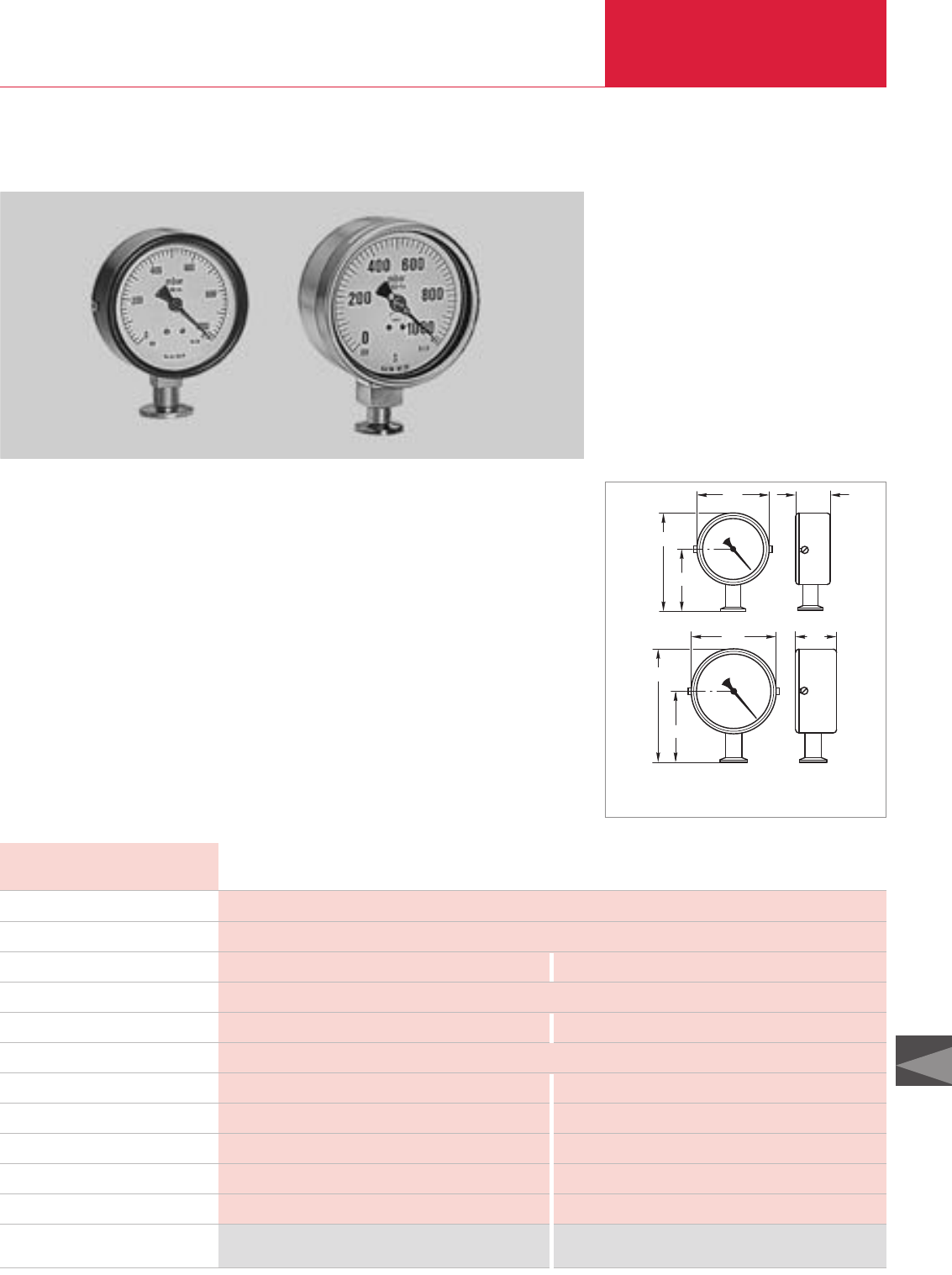
Rough Vacuum Gauges Total Pressure Gauges
C16.05
C16
LEYBOLD VACUUM PRODUCTS AND REFERENCE BOOK 2003/2004
Bourdon Vacuum Gauges
Rugged vacuum gauges based on the Bourdon
principle covering the pressure range from 1 to
1020 mbar (0.75 to 765 Torr).
36
80
105
64
Dimensional drawing for the BOURDONVAC A (top) and the
BOURDONVAC C (bottom)
Advantages to the User
◆Highly reliable, rugged, insensitive to
vibrations
◆Linear readout, independent of the type of gas
◆Excellent media compatibility owing to the
stainless steel movement (BOURDONVAC C)
◆IP 54 protection (BOURDONVAC C)
◆Safety gauge which complies with
UW-VBG 61 § 16 (BOURDONVAC C)
Typical Applications
◆Vacuum distillation
◆Drying processes
◆For explosion hazard applications
◆Vacuum conveying systems
50
101
81
135
Part No. 160 40 Part No. 161 20
Ordering Information
Measurement range mbar
Measurement uncertainty % FS
Overload range (abs. briefly) bar
Storage temperature range °C
Nominal temperature range °C
Flange connection DN
Length of scale mm
Diameter mm
Overall height mm
Weight kg (lbs)
Materials in contact with the medium
1.5
10 to 60
140
79
105
0.25 (0.55)
Nickel plated standard steel, bronze, soft solder
1.3
10 to 100 (max.)
207
101
136
0.6 (1.3)
Stainless steel 1.4571
Technical Data BOURDONVAC A BOURDONVAC C
1 to 1020
1
-25 to +60
16 KF
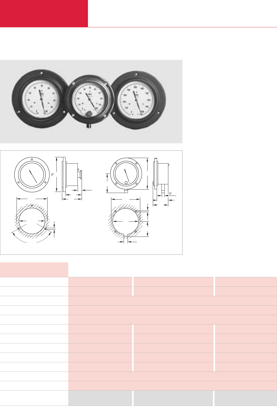
LEYBOLD VACUUM PRODUCTS AND REFERENCE BOOK 2003/2004
Rough Vacuum Gauges
Total Pressure Gauges
C16.06
Capsule Vacuum Gauges
Rugged absolute pressure gauges for the
pressure range from 1 to 1000 mbar
(0.75 to 765 Torr).
Advantages to the User
◆Rugged and insensitive to vibrations
◆
Models available for two measurement
ranges (1 to 100 mbar/Torr and
1 to 1000 mbar/Torr)
◆Readout independent of the type of gas and
changes in atmospheric pressure
◆Linear pressure readout
◆Installation direct via the connection flange or
panel mounting
◆Model with integrated isolation valve for use
on packaging machines (Part No. 160 68)
Typical Applications
◆Measurement of absolute pressures (for inert
gases only)
◆Vacuum conveying systems
◆Operation monitoring
◆Packaging
101+1
120°
132
60
73
14,5
116
4,5
68
53
110
3,5
10
100
13
92
40
53
Dimensional drawings and panel cut-outs for the capsule vacuum gauges (left) 160 63/64 and 160 68 (right)
Part No. 160 63 Part No. 160 68 Part No. 160 64
Measurement range mbar
Measurement uncertainty % FS
Overload range (abs.) bar
Storage temperature range °C
Nominal temperature range °C
Length of scale mm
Dead volume, approx. cm3
Diameter mm
Weight kg (lbs)
Vacuum connection DN
Max. inclination when installed
Materials in contact with the medium
1 to 100
1.0
205
235
132
0.7 (1.54)
16 KF
1 to 1000
1.6
205
235
132
0.7 (1.54)
16 KF
1 to 100
2.5
1.5
-25 to +60
10 to 50
180
167
110
0.6 (1.32)
10 mm dia. hose nozzle with integrated isolation valve
45°
Technical Data Capsule Vacuum Gauges
Ordering Information
Brass, standard steel nickel-plated, glass, NBR, aluminum, copper beryllium, soft and hard solder, resin
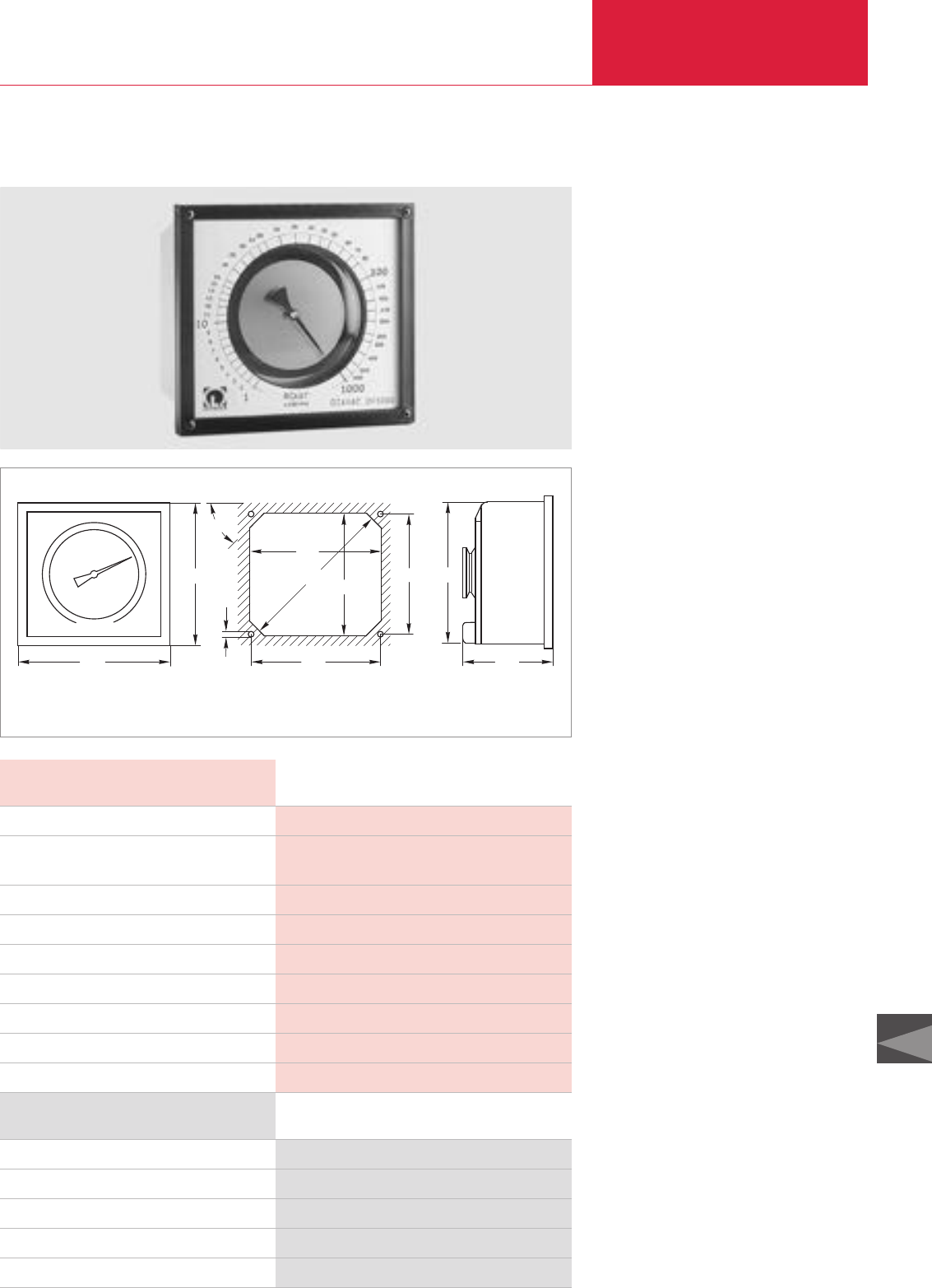
Rough Vacuum Gauges Total Pressure Gauges
C16.07
C16
LEYBOLD VACUUM PRODUCTS AND REFERENCE BOOK 2003/2004
DIAVAC DV 1000
Rugged mechanical diaphragm vacuum gauge of
high accuracy for the rough vacuum range from
1 to 1000 mbar (1 to 750 Torr).
180
166
45°
4,5
170
203,5 156
166 166
152 155
Dimensional drawing and panel cut-out for the DIAVAC DV 1000
Advantages to the User
◆Wide measurement range from 1 to
1000 mbar (1 to 750 Torr) with high resoluti-
on in the range from 1 to 100 mbar
(1 to 75 Torr)
◆
The scale of each gauge is individually calibrat-
ed; with factory certificate
◆Absolute pressure gauge
◆Readout independent of the type of gas and
changes in atmospheric pressure
◆Stainless steel diaphragm for excellent com-
patibility with most media
◆Laser welding technology for high precision
diaphragm mount
◆Rugged table-top housing, can be freely
mounted above the flange connection; also for
panel mounting
◆Measurement chamber can be easily cleaned
owing to the detachable measurement flange
Typical Applications
◆Chemical processes
◆Vacuum distillation
◆Absolute pressure measurements for
gas mixtures
◆For use in explosion hazard rated areas
◆Drying processes
◆Lamp manufacture
1 to 1 000 (1 to 750)
± 1 mbar (Torr) / ± 10 % of meas. value
-25 to +60 / 0 to 60
3
270 / 130
40 KF
180 x 166 x 100
2.7 (5.95)
Stainless steel 1.4301, 1.4310 (diaphragm), FPM
Technical Data DIAVAC DV 1000
Ordering Information
DIAVAC DV 1000, mbar readout
DIAVAC DV 1000, Torr readout
DKD calibration
Replacement sintered filter with DN 40 KF centering ring
Replacement housing, complete
Part No. 160 67 *
)
Part No. 896 06 *
)
Part No. 157 12
Part No. 231 93 515
Part No. 240 000
DIAVAC DV 1000
Measurement range mbar (Torr)
Measurement uncertainty
1 x 10 mbar (Torr) / 10 x1 000 mbar (Torr)
Storage / nominal temperature range °C
Permissible overload (abs.) bar
Length of scale / dead volume mm / cm3
Vacuum connection DN
Dimensions (W x H x D) mm
Weight kg (lbs)
Materials in contact with the medium
*)Complete with centering ring and sintered filter
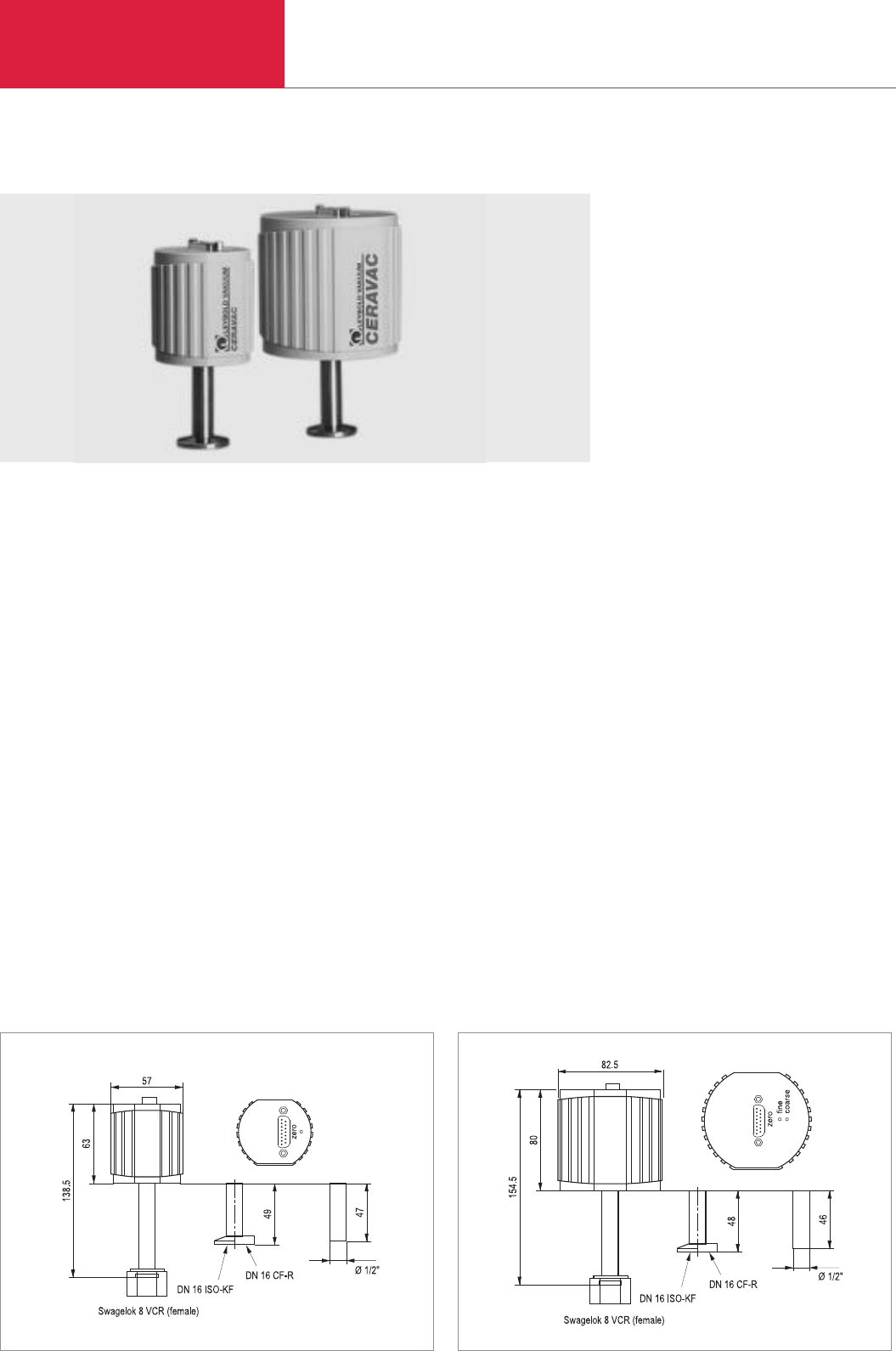
LEYBOLD VACUUM PRODUCTS AND REFERENCE BOOK 2003/2004
Active Sensors
Total Pressure Gauges
C16.08
CTR90/CTR91 CERAVAC Transmitters
Advantages to the User
◆Excellent accuracy
◆Corrosion resistant
◆High resolution
◆Very good temperature stability
◆Electrically and mechanically compatible with
the conventional capacitance manometers
with stainless steel diaphragm
◆Heated and unheated types are available
Typical Applications
◆General purpose pressure measurements in
the medium and rough vacuum range, also
for corrosive process gases
◆Chemical process engineering
◆Semiconductor production processes
◆Suited as a reference sensor for monitoring
test instruments in accordance with
DIN/ISO 9000
The CERAVAC Transmitter with its diaphragm
made of pure aluminium oxide ceramics offers
excellent accuracy and reproducibility.
CTR90
Dimensional drawing for the CERAVAC Transmitter CTR90
The Ceramics Diaphragm
The stiffness of aluminium oxide ceramics is
greater than that of metal so that the ceramics
material will offer improved long term stability
characteristics when exposed to frequent pressu-
re changes or overpressures. For this reason the
aluminium oxide ceramics diaphragm of the
CERAVAC sensors is capable of returning preci-
sely to its initial position with respect to a certain
pressure so that the measurements will be highly
reproducible. Since the diaphragm is not impai-
red by overpressures or frequent pressure chan-
ges, no blocking valves will be required – a signi-
ficant contribution towards reducing costs.
Moreover, aluminium oxide ceramics diaphragms
return faster to their initial position compared to
metal diaphragms; the time need between the
processes for the measurement to stabilise is
reduced. This is particularly important in the case
of measurements close to Zero where metal
diaphragms will take several minutes to return to
their resting position.
Whereas metal diaphragms suffer from residual
tensions and unavoidable irregularities due to
their production process, diaphragms made of
aluminium oxide ceramics are exceptionally
homogeneous, and owing to the firing process at
2500 °C entirely free of tensions. This considera-
bly helps to reduce part to part variations in the
sensors.
CTR91
Dimensional drawing for the CERAVAC Transmitter CTR91
↓↓↓↓
AA
View A
View A
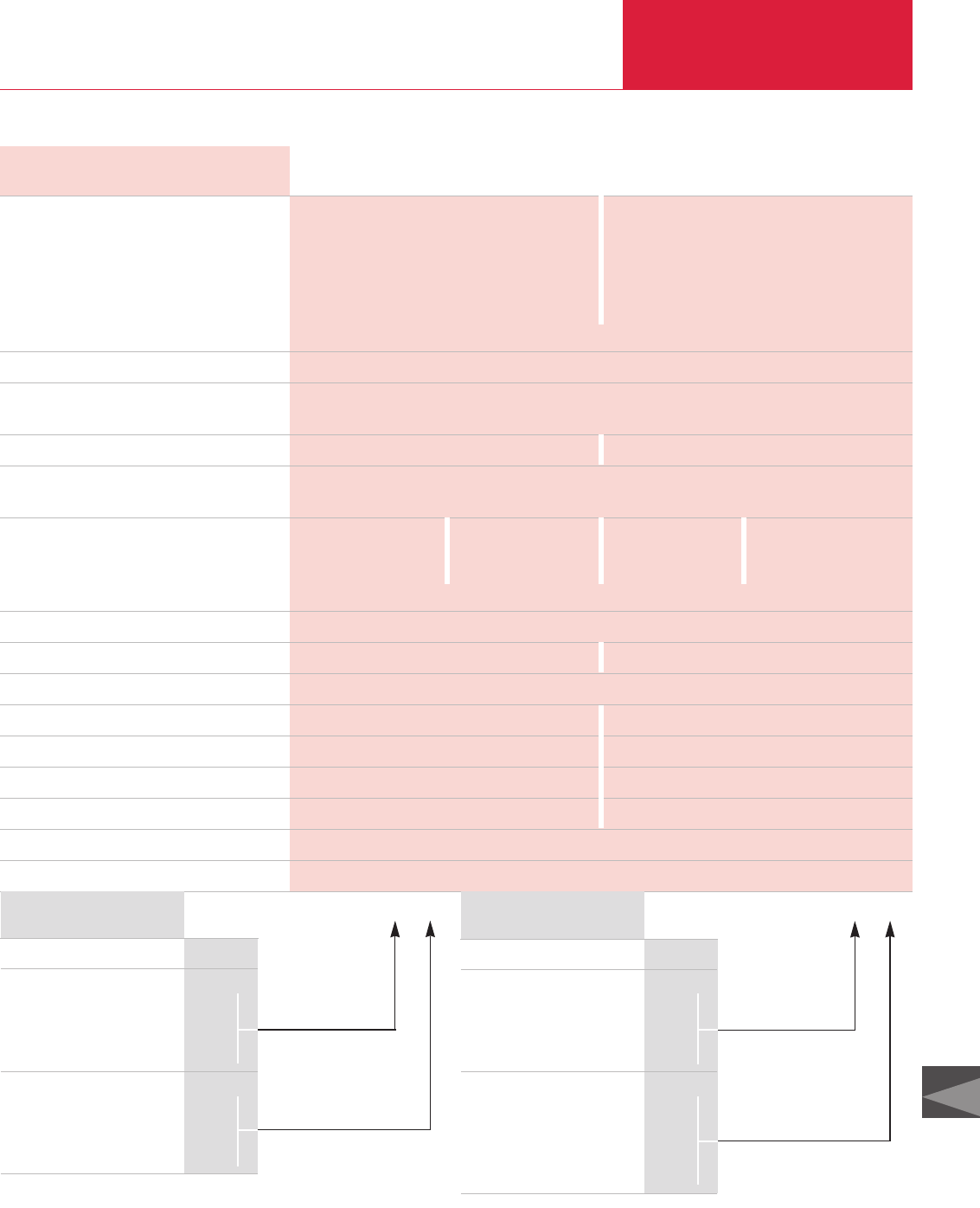
Total Pressure Gauges
C16.09
C16
LEYBOLD VACUUM PRODUCTS AND REFERENCE BOOK 2003/2004
Active Sensors
Technical Data
Full scale (FS)
1000 Torr
0100 Torr
0010 Torr
0001 Torr
000.1 Torr
Materials exposed to gases
Max. overrange pressure
Measurement uncertainty
Resolution
Temperature effects
Zero coefficient
% / °C
Span coefficient %/ °C
Reaction time ms
Nominal temperature range °C
Supply voltage V DC
Current consumption mA
Signal output V
Weight, approx kg (lbs)
Dead volume cm3
Connection cable
Calibration
CTR90 (Temperature Compensated) CTR91 (45 °C Heated)
Measurement range Measurement range
0.1 - 1000 Torr 0.1 - 1000 Torr
0.01 - 100 Torr 0.01 - 100 Torr
1 · 10-3 - 10 Torr 1 · 10-3 - 10 Torr
1 · 10-4 - 1 Torr 1 · 10-4 - 1 Torr
– 1 · 10-5 - 0.1 Torr
Pressure units: 1 Torr = 1.33 mbar = 133 Pascal
Ceramic (Al2O3), stainless steel 316, Vacon 70
1000 Torr for 0.1 Torr sensors, 2000 Torr for 1/10/100 Torr sensors
3000 Torr for 1000 Torr sensors
0.2% of reading ± temperature effects 0.15 % of reading ± temperature effects
0.0025% of FS for 0.1/1 Torr sensors
0.0015% of FS for 10/100/1000 Torr sensors
1 Torr sensor 10/100/1000 Torr sensor 0.1 Torr sensor 1/10/100/1000 Torr sensor
0.015 of FS 0.005 of FS 0.005 of FS 0.0025 of FS
0.01 of reading
≤30
5 to 50 15 to 40
either ± 15 or +24
23 300
0 - 10; linear 0 - 10; linear
0.26 (0.57) 0.485 (1.07)
6 7
see section “Connection Cable for active Sensors”
see section “Miscellaneous”, para. “LEYBOLD Calibration Service”
CTR90 (temperature compensated)
Vacuum fitting
DN KF 16
DN CF 16
Cajon 8 VCR
1/2" tube
Measurement range
1000 Torr
100 Torr
10 Torr
1 Torr
2
3
4
5
1
2
3
4
Ordering information Part No. 159 – ___ ___
CTR91 (45 °C heated)
Vacuum fitting
DN KF 16
DN CF 16
Cajon 8 VCR
1/2" tube
Measurement range
1000 Torr
100 Torr
10 Torr
1 Torr
0.1 Torr
2
3
4
5
5
6
7
8
9
Ordering information Part No. 159 – ___ ___
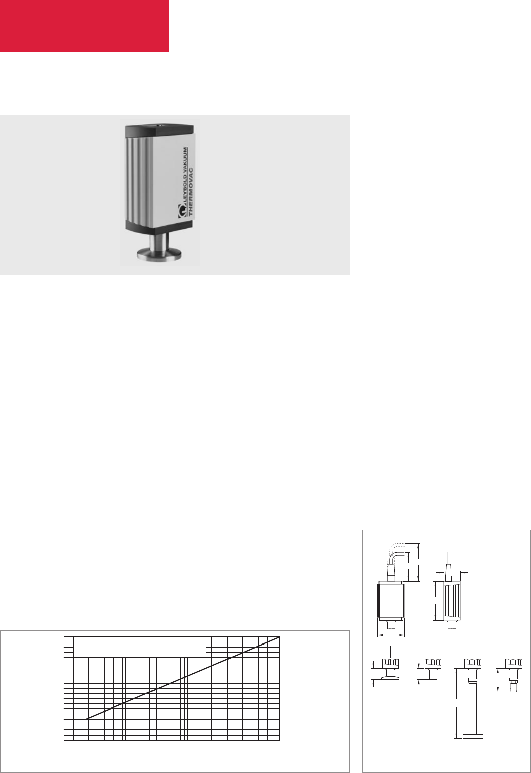
Active Sensors
Total Pressure Gauges
C16.10 LEYBOLD VACUUM PRODUCTS AND REFERENCE BOOK 2003/2004
TTR 90/TTR 90 S THERMOVAC Transmitters
Advantages to the User
◆Rugged sensing cells made of stainless steel
◆Compact design
◆Stabile measurements owing to optimized
temperature compensation
◆Highly resistant to overpressures
◆Exchangeable sensing cells
◆Extremely fast response
◆Upon request also available with integrated
switching relay
Typical Applications
◆Analytical engineering
◆Safety circuits in vacuum systems
◆Controlling ionization gauges
◆General pressure measurement and control on
systems in the fine and rough vacuum range
which have the following requirements:
◆Immediate data transfer to a program-
mable control/computer via analog interface
◆Coverage of greater distances between the
point of the measurement and processing
location
◆Several locations which are to be
monitored continuously
◆Low voltage supply
◆Simple, cost and space saving installation
◆Increased reliability
◆Simple operation
The further developed THERMOVAC transmitter
with improved temperature compensation,
reduced size and optimized price-to-performance
ratio.
The value of the trigger point can be switched
easily on the analog output and be shown on the
display of the operating unit.
Sensor
The highly compact sensing cell is equipped with
two filaments. Whereas one filament is used to
measure the pressure, the second filament serves
the purpose of temperature compensation by
directly detecting the gas temperature.
0
10-3
2 4 6 8
10-4 10-2 10-1 100101102103
mbar
Druck
U(a) / Volt
1
2
3
4
5
6
7
8
9
10 Formel
p = 10 0,778 (U(a) - 6,143) mbar
Characteristic of the THERMOVAC Transmitters
65
50
45
19.4
DN 16 ISO-KF
DN 16 CF-R
1/2" tube
1/8" NPT
68.3
19.35
121.6
41.4
28
Dimensional drawing for the TTR 90 / TTR 90S
Pressure
U(a) / Volt
Equation

Active Sensors Total Pressure Gauges
C16.11
C16
LEYBOLD VACUUM PRODUCTS AND REFERENCE BOOK 2003/2004
Display range mbar (Torr)
Measurement uncertainty
Principle of measurement
Supply voltage
Power consumption VA
Storage/nominal temperature range °C
Max. rel. humidity % n.c.
Protection class
Weight, approx. kg (lbs)
Sensor
Degassing temperature, max °C
Dead volume, approx. cm3
Materials in contact with the medium
Over-pressure rating, abs. bar
Signal output (Ra> 10 kΩ)
Measurement signal
Status signal
Trigger (only TTR 90 S)
Adjustment range mbar (Torr)
Hysteresis
Reaction time ms
Rating
Error status
Status indicators (only TTR 90 S)
Electrical connection
Cable length, max. m
TTR-Transmitter
Without switching threshold
TTR 90, DN 16 KF
TTR 90, 1/8" NPT
TTR 90, DN 16 CF
TTR 90, 1/2" Tube
With switching threshold
TTR 90 S, DN 16 KF
TTR 90 S, 1/8" NP,
TTR 90 S, DN 16 CF
TTR 90 S, 1/2" Tube
Replacement sensing cell
DN 16 KF
1/8" NPT
DN 16 CF
1/2“ Tube
Calibration
Connecting cable, FCC 68 on both ends,
8 way with shield
5 m
10 m
15 m
20 m
30 m
40 m
50 m
75 m
100 m
TTR-Transmitter
Technical Data Ordering Information
5 x 10⁻⁴ to 1000 (3.75 x 10⁻⁴ to 750)
15 % in the Range
1 x 10⁻³ to 100 mbar
Thermal conductivity acc. to Pirani
14 to 32 V DC
Hum voltage ≤1 Vss
≤1
-20 to +65 / 5 to 60
≤80
IP 40
0.15 (0.34)
Exchangeable sensing cell
KF: 80 / CF: 250
KF: 2 / CF: 10
Stainless steel, tungsten, nickel, glass, copper
10
0 to 10.3 V
1.9 to 10 V,
corresp.
5 x 10
-4
to 1 x 10
3
mbar
1.286 V/
decade
Error: ≤0.5 V
Normally open relay contact
2 x 10⁻³ to 500 (1.5 x 10⁻³ to 375)
30 %
50
60 V, 0.5 A DC
Relay contact open
Trigger (active): Green LED
FCC-68 socket, 8 way with shield
100
Part No. 128 10
Part No. 128 11
Part No. 128 12
Part No. 128 13
Part No. 128 20
Part No. 128 21
Part No. 128 22
Part No. 128 23
Part No. 128 15
Part No. 128 16
Part No. 128 17
Part No. 128 18
see section “Miscellaneous”,
para. “LEYBOLD Calibration Service”
Type A
Part No. 124 26
Part No. 230 012
Part No. 124 27
Part No. 124 28
Part No. 124 29
Part No. 124 30
Part No. 124 31
Part No. 124 32
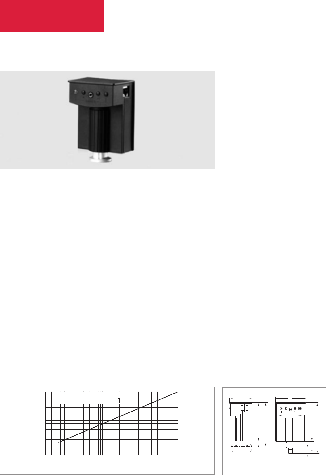
Active Sensors
Total Pressure Gauges
C16.12 LEYBOLD VACUUM PRODUCTS AND REFERENCE BOOK 2003/2004
TTR 211/TTR 216 S THERMOVAC Transmitters
Advantages to the User
◆Rugged Pirani sensing cells also for corrosive
media
◆Logarithmic signal output (algrithm supplied)
◆High reproducibility
◆Easily exchangeable sensing cells
◆Switching threshold adjustable over a wide
range (1 x 10
-3
to 500 mbar (1 x 10
-3
to
375 Torr)) and relay contact
◆LED indicator for operation and trigger active
◆Easily accessible monitoring connection to
check the measurement signal and the trigger
setting (voltmeter)
◆High EMI compatibility through screened hou-
sing, FCC-68 connector and cables
◆Computer interface
◆Field bus: Profibus DP/DeviceNet
◆CE mark
Typical Applications
◆Analytical engineering
◆Safety circuits in vacuum systems
◆Controlling ionization gauges
◆Vacuum furnaces
◆General pressure measurement and control on
systems in the fine and rough vacuum range
which have the following requirements:
◆Immediate data transfer to a program-
mable control/computer via analog interface
◆Coverage of greater distances between the
point of the measurement and processing
location
◆Several locations which are to be
monitored continuously
◆Low voltage supply
◆Simple, cost and space saving installation
◆Increased reliability
◆Simple operation
◆Increased requirements concerning elec-
tromagnetic compatibility (EMI)
The THERMOVAC transmitters have been develop-
ed especially for integration into vacuum
systems. Being active sensors (pressure to vol-
tage converters) with a well-proven Pirani
sensing cell and new operating and processing
electronics these units offer a measurement
range which spans 5 x 10
-4
to 1000 mbar (3.75 x
10
-4
to 750 Torr).
Sensor
The well-proven Pirani sensing cells with tung-
sten filament and a DN 16 KF flange are built into
the TTR 211 THERMOVAC transmitters. The
TTR 216 S transmitter is equipped with a stain-
less steel sensing cell, with a platinum filament
and an Al
2
O
3
ceramics current feedthrough for
use in connection with corrosive media or where
much water vapor is present. The sensing cells
can be easily exchanged on all transmitters.
If required, the sensing cell can easily be aligned
at atmospheric pressure and “Zero” pressure
through two potentiometers.
Integration of the transmitter in programmable
control systems is facilitated by the straight
characteristic which may be defined by entering a
simple equation into the computer.
Through the built-in relays it is possible to per-
form important switching functions directly
through the transmitter without the need of a
programmable control.
13
1/8" NPT
Trigger
0
16
121
DN 16 KF
92
7
107
(116)
56 73
Dimensional drawing for the TTR 211; 216 S in brackets
0
10-3
2 4 6 8
10-4 10-2 10-1 100101102103
mbar
Pressure
U(a)/Volt
1
2
3
4
5
6
7
8
9
10 Equation
U(a) = lg (p/mbar) 1.286 + 6.143 Volt
Characteristic of the TTR 211/216 S

Active Sensors Total Pressure Gauges
C16.13
C16
LEYBOLD VACUUM PRODUCTS AND REFERENCE BOOK 2003/2004
Display range mbar (Torr)
Measurement uncertainty
Principle of measurement
Supply voltage
Power consumption VA
Storage/nominal temperature range °C
Max. rel. humidity (climatic class F) % n.c.
Protection class
Dimensions (H x W x D) mm
Weight, approx. kg (lbs)
Inflammability
Sensor
Filament
Vacuum connection DN
Degassing temperature, max °C
Dead volume, max. cm3
Materials in contact with the medium
Over-pressure rating, abs.
Signal output (Ra> 10 kΩ)
Measurement signal
Status signal
Trigger
Adjustment range mbar (Torr)
Hysteresis
Reaction time ms
Rating
Error status
Status indicators
Monitor output (Ra> 100 kΩ)
Electrical connection
Cable length, max. m
Interface
TTR 211 D
TTR 211 PB
TTR Transmitter
TTR 211 D, DN 16 KF
Tungsten filament (1 trigger)
DeviceNet interface
Replacement sensing cell
TTR 211 PB, DN 16 KF
Tungsten filament (1 trigger)
Profibus DP interface
Replacement sensing cell
TTR 216 S, DN 16 KF,
Platinum filament (1 trigger)
Replacement sensing cell
TTR 216 D, DN 16 KF
Platinum filament (1 trigger)
DeviceNet interface
Replacement sensing cell
TTR 216 PB, DN 16 KF
Platinum filament (1 trigger)
Profibus PB interface
Replacement sensing cell
Calibration
Connecting cable, FCC 68 on both ends,
8 way with shield
5 m
10 m
15 m
20 m
30 m
40 m
50 m
75 m
100 m
TTR Transmitter
Technical Data Ordering Information
5 x 10⁻⁴ to 1000 (3.75 x 10⁻⁴ to 750)
20 % in the range 1 x 10
-3
to 1 x 10
-2
mbar
(0.75 x 10
-3
to 0.75 x 10
-2
Torr)
15 % in the range 1 x 10
-2
to 30 mbar
(0.75 x 10
-2
to 22.5 Torr)
Thermal conductivity acc. to Pirani
14.5 to 36 V DC, typ. 24 V DC
Hum voltage < 2 Vpp
< 2
-20 to +70/10 to 50
95
IP 40
106 x 73 x 56
0.29 (0.64)
UL 94 - V 2
Exchangeable sensing cell
Tungsten (TTR 211)/platinum (TTR 216)
16 KF
80 at the flange
11
TTR 211: Aluminum,
nickel-plated steel, Vacon, tungsten, CrNi8020,
glass, epoxy cement;
TTR 216 S: Stainless steel, CrNi,
Al2O3ceramics, NiFe, Mo, Ni, platinum
TTR 211: 3 bar, TTR 216: 10 bar
0 to 10.6 V
1.9 to 10 V, corresp. 5 x 10⁻⁴ to 1 x 10³mbar
logarithmic divisions 1.286 V/decade
broken filament 10.5 V
n.o./changeover relay contact
1 x 10⁻³ to 500 (0.75 to 375)
about 30 % of the adjusted pressure
< 50
60 V, 0.5 A DC
contact open in case of broken filament
or supply off
Operation (Power): Orange LED
Trigger (active): Green LED
Jack socket (3.5 mm) at which the measure-
ment signal and the trigger setting is available
FCC-68 socket, 8 way with shield
100
DeviceNet
Profibus DP
Part No. 896 51
Part No. 157 75
Part No. 896 50
Part No. 157 75
Part No. 157 31
Part No. 157 77
Part No. 896 53
Part No. 157 77
Part No. 896 52
Part No. 157 77
see section “Miscellaneous”,
para. “LEYBOLD Calibration Service”
Type A
Part No. 124 26
Part No. 230 012
Part No. 124 27
Part No. 124 28
Part No. 124 29
Part No. 124 30
Part No. 124 31
Part No. 124 32
Part No. 124 33
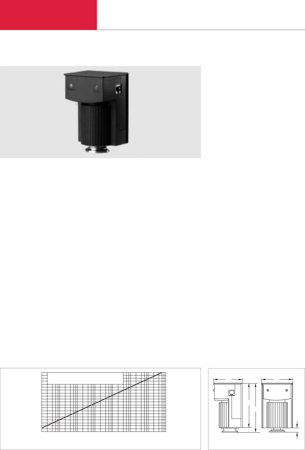
Active Sensors
Total Pressure Gauges
C16.14 LEYBOLD VACUUM PRODUCTS AND REFERENCE BOOK 2003/2004
PTR 225/PTR 225 S/PTR 237 PENNINGVAC Transmitters
Advantages to the User
◆All-metal cold cathode sensors (inverted
Penning)
◆High reproducibility
◆Good ignition characteristics through the new
design for the electrodes
◆Low tendency to collect contamination (also
during argon operation) due dropping of the
high voltage after the plasma has been ignited
and through the use of titanium cathodes
◆Switching threshold adjustable over a wide
range (1 x 10
-9
to 1 x 10
-3
mbar (0.75 x 10
-9
to 0.75 x 10
-2
Torr)) and relay contact
(PTR 225 S)
◆Low stray magnetic field
◆
High EMI compatibility through screened hous-
ing, FCC-68 connector and cables
◆LED indicator for operation
◆Logarithmic signal output (algrithm supplied)
◆Intelligent interface (in preparation)
◆CE mark
◆High resistance against sputtering due to
titanium cathode plates
Typical Applications
◆Evaporation and sputtering systems
◆Analytical engineering
◆Vacuum furnaces
◆High vacuum systems
◆General pressure measurement and control on
systems in the fine and rough vacuum range
which have the following requirements:
◆Immediate data transfer to a program-
mable control/computer via analog interface
◆Coverage of greater distances between the
point of the measurement and processing
location
◆Several locations which are to be
monitored continuously
◆Low voltage supply
◆Simple, cost and space saving installation
◆Increased reliability (sputtering)
◆Simple operation
◆Increased requirements concerning
electromagnetic compatibility (EMI)
The PENNINGVAC transmitters have been develo-
ped especially for integration into systems. Being
active sensors (pressure to voltage converters)
equipped with a rugged cold cathode sensing cell
and matching operating and processing elec-
tronics these units offer a wide measurement
range of 1 x 10
-9
to 1 x 10
-2
mbar (0.75 x 10
-9
to
0.75 x 10
-2
Torr). The measurement signal may
be transmitted over great distances without
problems.
Sensor
Cold cathode sensors based on the well proven
principle of the inverted PENNINGVAC having a
DN 25 KF or DN 40 CF flange are built into the
PENNINGVAC transmitters PTR 225/225 S/237 S.
For degassing of the all-metal sensor with Al
2
O
3
current feedthrough the housing of the transmit-
ter with its electronics as well as the magnet may
easily be removed. The magnet used offers a
closed magnetic field so that its stray field is
negligible. Thus the PTR 225/225 S/237 may also
be installed close to sensitive parts within a
system.
The anode ring and the titanium cathode plates
may be exchanged easily for quick maintenance
of the sensors should they be contaminated. The
shape of the newly designed cathode plates is
such that they also act as a baffle for the sensors.
Integration of the transmitter in programmable
control systems is facilitated by the straight
characteristic which may be defined by entering a
simple equation into the computer.
Through the built-in relay (PTR 225 S) it is possi-
ble to perform important switching functions
directly through the transmitter without the need
of a programmable control.
126
114
73
POWER
12
READY
80
Dimensional drawing for the PTR 225/225 S/237
0
10-8
2 4 6 8
10-9 10-7 10-6 10-5 10-4 10-3 10-2
mbar
Pressure
U(a)/Volt
1
2
3
4
5
6
7
8
9
10 Equation
U(a) = [1.33 * lg (p/mbar) + 12.66] Volt
Characteristic of the PTR 225/225 S/237

Active Sensors Total Pressure Gauges
C16.15
C16
LEYBOLD VACUUM PRODUCTS AND REFERENCE BOOK 2003/2004
Part No. 157 34
Part No. 164 34
Part No. 896 41
Part No. 157 36
Part No. 896 42
Part No. 162 91
Part No. 240 002
see section “Miscellaneous”,
para. “LEYBOLD Calibration Service”
Type A
Part No. 124 26
Part No. 230 012
Part No. 124 27
Part No. 124 28
Part No. 124 29
Part No. 124 30
Part No. 124 31
Part No. 124 32
Part No. 124 33
Display range mbar (Torr)
Measurement uncertainty
Principle of measurement
Supply voltage
Power consumption VA
Storage/nominal temperature range °C
Max. rel. humidity (climatic-class F) % n.c.
Protection class
Dimensions (H x W x D) mm
Weight, approx. kg (lbs)
Inflammability
Sensor
Vacuum connection DN
Degassing temperature, max. °C
Dead volume, max. cm3
Materials in contact with the medium
Over-pressure rating (abs.) bar
Signal output (Ra> 10 kΩ)
Measurement signal
Trigger (PTR 225 S)
Adjustment range mbar (Torr)
Hysteresis
Rating
Error status
High voltage control input
Status output
Ready to measure
Error (no ignition)
Status indicators
Monitor output (Ra> 100 kΩ)
Electrical connection
Cable length, max. m
Interface
PTR 225 PB
PTR 237 D
PTR Transmitter
PTR 225, DN 25 KF
PTR 225 S, DN 25 KF
PTR 225 PB, DN 25 KF
Profibus interface
PTR 237, DN 40 CF
PTR 237 D, DN 40 CF
DeviceNet interface
Replacement cathode plates, titanium
(set of 5 pieces)
Replacement anode ring
Calibration
Connecting cable, FCC 68 on both ends,
8 way with shield
5 m
10 m
15 m
20 m
30 m
40 m
50 m
75 m
100 m
PTR TransmitterTechnical Data Ordering Information
1 x 10
-9
to 1 x 10
-2
(0.75 x 10
-9
to 0.75 x 10
-2
)
30 % in the range 1 x 10⁻⁸ to 1 x 10⁻⁴ mbar
(0.75 x 10⁻⁸ to 0.75 x 10⁻⁴ Torr)
Cold cathode ionization after Penning
14.5 to 36 V DC typ. 24 V DC
hum voltage < 2 Vpp
< 2
-20 to +70 /10 to 50
95
IP 40
125 x 80 x 73
0.5 (1.1)
UL 94 - V 2
Detachable for cleaning
25 KF or 40 CF
350 with electronics detached
21
Stainless steel, CrNi, Al2O3ceramics, NiFe, Mo,
Cu, Ni, titanium
10
0 to 10.6 V
0.66 to 10 V,
corresponds to 1 x 10⁻⁹ to 1 x 10⁻² mbar
logarithm. divisions 1.333 V/decade
Changeover relay contact
1 x 10⁻⁹ to 1 x 10⁻³ (0.75 x 10⁻⁹ to 0.75 x 10⁻³)
about 30 % of the adjusted pressure
60 V, 0.5 A DC
Contact in its rest position when
“no ignition” / “HT off”
ON: At U < 2.9 V, or U > 12 V
OFF: At U > 3 V, or U < 7 V
Voltage level
HIGH (typ. 24 V DC)
LOW (0 V)
Operation: Orange LED
Ready to measure (ignited): Green LED
Trigger (active): Green LED
Jack socket (3.5 mm)
at which the trigger setting is available
FCC-68 socket, 8 way with shield
100
Profibus DP
DeviceNot
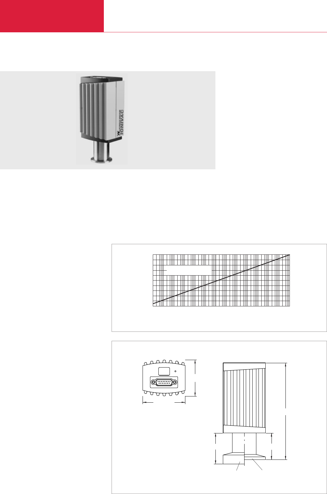
Active Sensors
Total Pressure Gauges
C16.16 LEYBOLD VACUUM PRODUCTS AND REFERENCE BOOK 2003/2004
ITR 90 IONIVAC Transmitter
The ITR 90 is a new type of combination trans-
mitter. The combination of a hot cathode ionisa-
tion sensor after Bayard-Alpert and a Pirani
sensor permits vacuum pressure measurements
on non-ignitable gases and gas mixtures in the
pressure range from 5 x 10
-10
to 1000 mbar.
If needed, the pressure can be displayed via the
integrated display.
Advantages to the User
◆Continuous pressure measurements from
10
-10
mbar to atmospheric pressure
◆High degree of reproducibility within the typi-
cal range for process pressures of 10
-2
to
10
-8
mbar
◆Controlled switching on and off sequencing
through the integrated double Pirani optimises
the service life of the yttrium coated iridium
cathodes
◆Compact design
◆Enclosed, rugged electrode geometry in a
rugged metal housing
◆Efficient degassing by electron bombardment
◆Simple fitting of the sensor
◆Extension for higher degassing temperatures
during the measurements
◆Insertable baffle for potentially contaminating
applications and for protection against char-
ged particles.
◆One signal covering 13 decades
◆One flange joint for 13 decade
◆ITR 90 model with built-in display for
stand-alone operation without additional
display components
◆RS 232 C interface
Typical Applications
◆Analytical
◆Evaporation and coating
◆Vacuum furnaces
◆General purpose pressure measurements in
the medium and high-vacuum ranges
Sensor
The sensor of the ITR 90 contains a dual filament
Pirani system as well as a Bayard-Alpert
measurement system.
When using the degassing extension, measure-
ments will be possible also at flange temperatu-
res up to 150 °C.
02
10-10
Druck/mbar
U(a) / Volt
4 6 8
10-910-8 10-7 10-610-5 10-4 10-3 10-2 10-1 100mbar
3
4
5
6
2
1
7
8
10
10 1000
Volt
Formel
p = 10(u-7,75)/ 0,75
Characteristic of the ITR 90
67 (2.64 )
58 (2.28 )
153 (6 )
48 (1.89 )
DN 40 CF-R DN 25 ISO-KF
42 (1.65 )
Dimensional drawing for the ITR 90; dimensions in brackets ( ) are in inch
Top view
Equation
Pressure
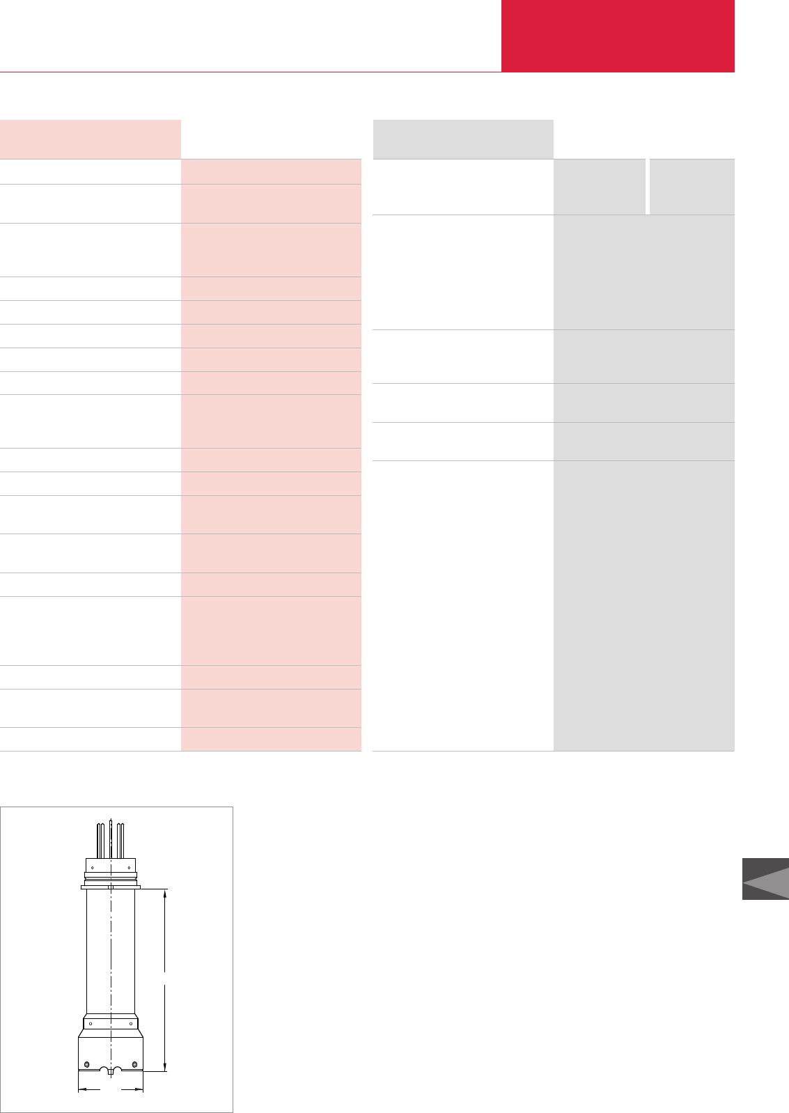
Active Sensors Total Pressure Gauges
C16.17
C16
LEYBOLD VACUUM PRODUCTS AND REFERENCE BOOK 2003/2004
Without display With display
Part No. 120 90 Part No. 120 91
Part No. 120 92 Part No. 120 94
Part No. 121 06
Part No. 127 06
Part No. 121 07
Part No. 121 02
Part No. 121 03
see section “Miscellaneous”,
para. “LEYBOLD Calibration Service”
see section
“Connection Cable for active Sensors”
ITR 90, DN 25 ISO KF
ITR 90, DN 40 CF-R, rotatable CF flange
Options
Power supply for IONIVAC transmitter
100 V - 240 V AC / 24 V DC
incl. 5 m connection cable and
5 m RS 232 C cable
Degassing extension (100 mm, approx.)
Baffle
Replacement sensor
IE 90, DN 25 ISO KF **)
IE 90, DN 40 CF-R **)
Calibration
Connection cable
ITR-TransmitterOrdering Information
Display range mbar (Torr)
Measurement uncertainty, 10-8 - 10-2 mbar
Reproducibility, 10-8 - 10-2 mbar
Principles of measurement
Degas
Supply voltage
Power consumption, max. W
Storage / nominal temperature range °C
Protection class
Weight, approx.
ITR 90, DN 25 KF kg (lbs)
ITR 90, DN 40 CF kg (lbs)
Sensor
Degassing temperature, max. °C
Dead volume, max. cm3
Materials in contact with the medium
Over-pressure rating (abs.) bar
Signal output (Ra≥10 kΩ)
Measurement signal
Error signal
Interface
Electrical connection
Cable length, max. m
ITR-TransmitterTechnical Data
5 x 10⁻¹⁰ to 1000 (3.75 x 10⁻¹⁰ to 750)
15 % of the meas. value
5 % of the meas. value
Thermal conductivity after Pirani
Hot cathode ionization vacuum gauge after
Bayard-Alpert
Electron bombardment 3 minutes, max.
20 to 28 V DC, typ. 24 V DC
16
-20 to +70 / 0 to +50
IP 30
0.285 (0.64)
0.550 (1.24)
Fully sealed, exchangeable
150 *)
24 at DN 25 KF
34 at DN 40 CF
Cu, W, Glas, NiFe, Mo, Stainl. steel, Al,
Iridium, Yttrium, NiCr,
2
0 - 10 V,
0.774 - 10 V, 0.75 V pro decade
< 0,5 V
RS 232 C
15 way Sub-D male connector/
Pin contacts
100 / 30 at RS 232 C
*)Flange temperature when using the degassing extension **)including hex. socket screw key
ø40
~105
Dimensional drawing for the degassing extension
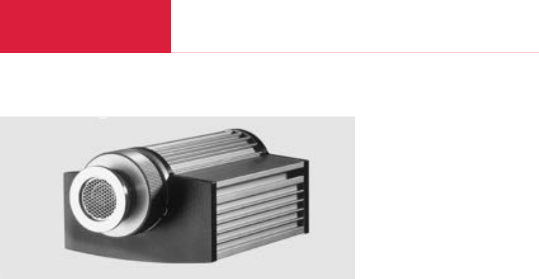
Active Sensors
Total Pressure Gauges
C16.18 LEYBOLD VACUUM PRODUCTS AND REFERENCE BOOK 2003/2004
ITR 100 IONIVAC Transmitter
These IONI transmitters have been developed
especially for integration into vacuum systems.
Being active sensors (pressure to voltage convert-
ers) with the newly developed wide-range
Bayard-Alpert sensing system, this type of gauge
offers a measurement range which spans
2 x 10
-10
to 1 x 10
-1
mbar (1.5 x 10
-10
to
0.75 x 10
-1
Torr) and IP 54 protection.
Advantages to the User
◆Wide measurement range of 2 x 10
-10
to
1 x 10
-1
mbar (1.5 x 10
-10
to 0.75 x 10
-1
Torr)
with a single sensor
◆High reproducibility of ±10 % of the meas.
value within the process pressure range
◆Fully encapsulated sensor with a very stable
geometry for the electrodes
◆Increased service life through dual cathodes –
automatic switchover in case of failure
◆Long-life iridium cathodes with yttriumoxide
coating
◆Uninterrupted measurements in the degas
mode through electron bombardment
◆Easy to exchange sensors with automatic
self-calibration
◆Switching threshold adjustable over a wide
range (1 x 10
-9
to 1 x 10
-1
mbar (0.75 x 10
-9
to 0.75 x 10
-1
Torr)) and relay contact
◆Standardized measurement and control
signals
◆0 to 10 V analog output with selectable
logarithmic/linear characteristic (algrithm
supplied)
◆Computer interfaces:
– RS 232 C
– Field bus: Profibus DP/DeviceNet
◆LEDs to indicate operating modes, and for
selfdiagnosis
◆Rugged IP 54 metal enclosure
◆High EMI compatibility through screened
enclosure, screened sensor and electric inter-
ference suppression on all inputs and outputs
◆CE mark
Typical Applications
◆Analytical engineering
◆Evaporation and coating systems
◆Vacuum furnaces
◆General pressure measurement and control on
systems in the fine and rough vacuum range
which have the following requirements:
◆Immediate data transfer to a program-
mable control/computer via analog interface
◆Coverage of greater distances between the
point of the measurement and processing
location
◆Several locations which are to be
monitored continuously
◆Low voltage supply
◆Simple, cost and space saving installation
◆Increased reliability
◆Simple operation
◆Increased requirements concerning elec-
tromagnetic compatibility (EMI)
Sensor
The wide range Bayard-Alpert sensing system is
mechanically protected by the metal tube which
surrounds it. The rugged arrangement of the
electrodes ensures highly reproducible measure-
ments over the entire range.
Each sensor is individually calibrated in the
factory. The calibration data is stored in an
EEPROM and is fully integrated into the sensor.
When exchanging the sensor, the electronics of
the transmitter are automatically adjusted to the
connected sensor, so that the specified reprodu-
cibility can be guaranteed.
The sensor with a CF flange is equipped with a
welded current feedthrough which enables degas-
sing of the sensor at a temperature of 150 °C
with the electronics in place.
Sensor supply and processing of the measure-
ment data is performed by microprocessor con-
trolled electronics, which require a 24 V power
supply and draw a very low current.
The microcontroller also controls the ITR 100 in
that it monitors the emission, converts and cor-
rects the measurement data (automatic correc-
tion of the sensor’s sensitivity, matching of the
unit etc.) and monitoring of the trigger thresholds
for the relay.
The selectable signal output characteristics (line-
ar/logarithmic) as well as the digital computer
interfaces permits easy integration in existing or
future system concepts.
ITR 100 with tungsten filament ia available upon
request.
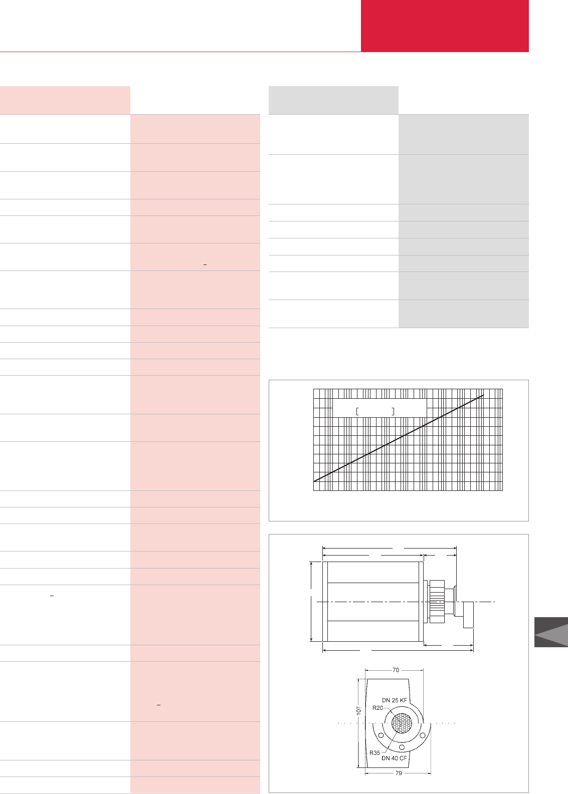
Active Sensors Total Pressure Gauges
C16.19
C16
LEYBOLD VACUUM PRODUCTS AND REFERENCE BOOK 2003/2004
Part No. 163 60
Part No. 163 61
Part No. 163 66
Part No. 163 67
Part No. 163 70
Part No. 163 72
Part No. 163 74
Part No. 163 75
see section “Miscellaneous”,
para. “LEYBOLD Calibration Service”
see section
“Connection Cable for active Sensors”
ITR 100, DN 25 KF
(RS 232 C interface)
Replacement sensor IE 100, DN 25 KF
ITR 100, DN 40 CF
(RS 232 C interface)
and rotatable CF flange
Replacement sensor IE 100, DN 40 CF
ITR 100, DN 25 KF, with Profibus DP
ITR 100, DN 40 CF, with Profibus DP
ITR 100, DN 25 KF, with DeviceNet
ITR 100, DN 40 CF, with DeviceNet
Calibration
Connection cable
ITR TransmitterOrdering Information
02
10-10
Druck
U(a) / Volt
4 68
10-9 10-8 10-7 10-6 10-5 10-4 10-3 10-2 100
mbar
3
4
5
6
2
1
7
8
9
10
11
Formel
U(a) = lg (p/mbar) + 11 Volt
Characteristic of the ITR 100
107
168
127 41
62
189
DN 40 CF
DN 25 KF
Dimensional drawing for the ITR 100
Display range mbar (Torr)
Reproducibility (standard
deviation to DIN 1319-1)
Principle of measurement
Degas
Emission current
(automatic switching)
Supply voltage
Current consumption A
A
A
Storage / nominal temperature range °C
Max. rel. humidity (climatic class F) % n.c.
Protection class
Dimensions (H x W x D) mm
Weight, approx.
ITR 100, DN 25 KF kg (lbs)
ITR 100, DN 40 CF kg (lbs)
Sensor
Cathode
Vacuum connection DN
Degassing temperature, max. °C
Dead volume, max. cm3
Materials in contact with the medium
Over-pressure rating (abs.) bar
Signal output (Ra> 10 kΩ)
Measurement signal (selectable)
Signal rise time ms
Trigger
Adjustment range mbar (Torr)
Hysteresis
Reaction time ms
Contact rating
Control input (RE= 11 kΩ)
Programmable control compatible, 24 V logic
Electrical connection
Cable length, max. m
ITR TransmitterTechnical Data
2 x 10
-10
to 1 x 10
-1
(1.5 x 10
-10
to 0.75 x 10
-1
)
Threshold 1 x 10⁻¹⁰ (0.75 x 10⁻¹⁰)
±10 % of the meas. value,
in proc. press. range 1 x 10⁻⁷ to 1 x 10⁻² mbar
Wide range Bayard-Alpert
ionization gauge
Electron bombardment 3 minutes, max.
5 mA to about 5 x 10⁻⁵ mbar
25 µA from about 5 x 10⁻⁵ to 1 x 10⁻¹ mbar
20 to 28 V DC, typ. 24 V DC
Hum voltage < 2 Vpp
0.5 in the measurement mode
0.8 in the degassing mode
1.4 during start-up (about 1 s.)
-20 to +70 / 0 to +50
95
IP 54
See dimensional drawing
0.98 (2.2)
1.28 (2.8)
Fully sealed, exchangeable,
with automatic self-calibration
2 x yttriumoxide coated
iridium cathode,
capable of withstanding air inrushes,
automatic switch off in case of overpressures
25 KF or 40 CF-R
80 (DN 25 KF flange), 150 (DN 40 CF flange)
24 at DN 25 KF
34 at DN 40 CF-R
Stainl. steel, yttriumoxide, glass, NiFe, NiCr, tungsten
2
0 to 10 V, 1 V/decade, logarithm. divisions
or 3 decades selectable out of 9 decades;
linear over 9 decades, mantissa 0.8 to 10 V
with extra output for the exponent:
1 V increments/decade
< 100 (at p > 1 x 10⁻⁶ mbar)
1 normally open relay contact
1 x 10⁻⁹ to 1 x 10⁻¹ (0.75 x 10⁻⁹ to 0.75 x 10⁻¹)
about 10 % of the value
< 100 (at p > 1 x 10⁻⁶ mbar)
60 V, 0.5 A DC
Emission: ON/OFF; DEGAS: ON/OFF
Switchover between
measurement signal/trigger level
15 way Sub-D male connector
100 / 30 at RS 232 C
Equation
Pressure

Total Pressure Gauges
C16.20 LEYBOLD VACUUM PRODUCTS AND REFERENCE BOOK 2003/2004
Connection Cable for Active Sensors
THERMOVAC
TTR 90, TTR 90S, TTR 211 S, TTR 216 S
PENNINGVAC
PTR 225, PTR 225 S, PTR 237
CERAVAC
CTR90, CTR91
IONIVAC
ITR 90
ITR 100
1) Not in CENTER TWO and THREE
Operating Units for Active Sensors
Active Sensors
Type A Type A Type A – –
– Type A Type A – –
– Type B Type B Type D –
– Type C Type C – Type E
– Type C
1)
Type C – Type E
DISPLAY ONE CENTER ONE COMBIVAC IT 23 CAPACITRON DM 21 Bare
CENTER TWO COMBIVAC IT 2 CAPACITRON DM 22 wire ends
CENTER THREE COMBIVAC CM 33
Cables
Type A
Type B
Type C
Type D
Type E
Connection Cable
FCC 68 (RJ45) on both ends, 8 way, shielded
Sub-D 15 way female to FCC 68 (RJ45), 8 way, shielded
Sub-D 15 way female to Sub-D 15 way male, shielded
Sub-D 15 way female to MAS 70 S, shielded
Sub-D 15 way female to bare wire ends, shielded
Technical Data
Cable lenght
005 m
010 m
015 m
020 m
030 m
040 m
050 m
075 m
100 m
*)Longer cable runs are not specified because of the RS 232 C connection
Connection Cable
Type A Type B Type C Type D Type E
Part No. 124 26 Part No. 230 013 Part No. 124 55 Part No. 157 64 Part No. 124 63
Part No. 230 012 Part No. 230 014 Part No. 230 022 Part No. 124 41 Part No. 230 023
Part No. 124 27 Part No. 230 015 Part No. 124 56 Part No. 124 42 Part No. 124 64
Part No. 124 28 Part No. 230 016 Part No. 124 57 Part No. 124 43 Part No. 124 65
Part No. 124 29 Part No. 230 017 Part No. 124 58 Part No. 124 44 Part No. 124 66
Part No. 124 30 Part No. 230 018 * Part No. 124 45 Part No. 124 67
Part No. 124 31 Part No. 230 019 * Part No. 124 46 Part No. 124 68
Part No. 124 32 Part No. 230 020 * Part No. 124 47 Part No. 124 69
Part No. 124 33 Part No. 230 021 * Part No. 124 48 Part No. 124 70
Ordering Information

Total Pressure Gauges
C16.21
C16
LEYBOLD VACUUM PRODUCTS AND REFERENCE BOOK 2003/2004
Notes
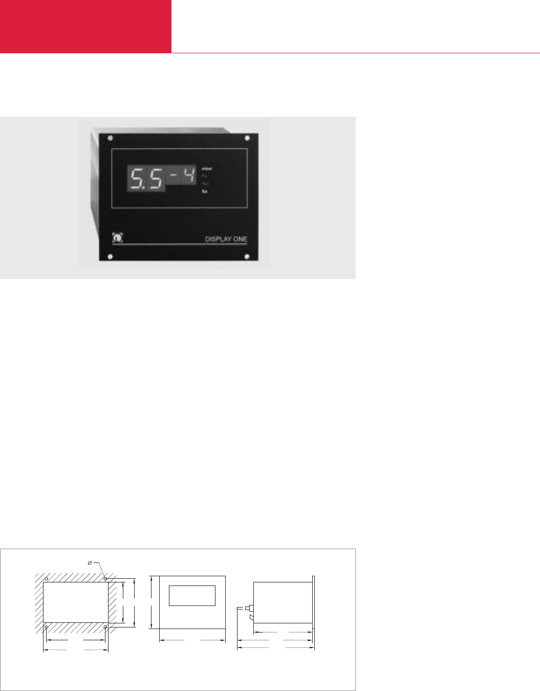
Operating Units for Active Sensors
Total Pressure Gauges
C16.22 LEYBOLD VACUUM PRODUCTS AND REFERENCE BOOK 2003/2004
DISPLAY ONE
Cost-effective, compact single channel and
display unit for the transmitters from the
THERMOVAC line.
Advantages to the User
◆Power supply voltage for the transmitters
◆Two-digit mantissa in the range from 5 x 10
-4
to 1 x 10
3
mbar
◆Readout selectable between mbar, Torr or
Pascal
◆0 to 10 V chart recorder output via plug-in
screw terminals
◆The switching thresholds of the transmitters
have been looped through to plug-in terminals
◆Transmitter threshold settings can be
displayed by a single key press on the
transmitter
◆Compact bench top enclosure
(1/4 19 in., 2 HU)
◆For fitting into 19 in., 3 HU racks
Connectable Sensors
◆TTR 211
◆TTR 216
◆TTR 90
◆TTR 90 S
M3 - 3,2 mm
66 78
105,5
91,5
102
172,5
170
106,5
85
Dimensional drawing and panel cut-out for the DISPLAY ONE

Operating Units for Active Sensors Total Pressure Gauges
C16.23
C16
LEYBOLD VACUUM PRODUCTS AND REFERENCE BOOK 2003/2004
Part No. 230 001
Part No. 235 001
Part No. 128 10
Part No. 128 11
Part No. 128 12
Part No. 128 13
Part No. 128 20
Part No. 128 21
Part No. 128 22
Part No. 128 23
Type A
Part No. 124 26
Part No. 157 33
Part No. 124 27
Part No. 124 28
Part No. 124 29
Part No. 124 30
Part No. 124 31
Part No. 124 32
Part No. 124 33
Part No. 230 005
EU version, including mains cord
US version, including mains cord
THERMOVAC Transmitter
TTR 90, DN 16 KF
TTR 90, 1/8" NPT
TTR 90, DN 16 CF-R
TTR 90, 1/2" Tube
TTR 90 S, DN 16 KF
TTR 90 S, 1/8" NPT
TTR 90 S, DN 16 CF-R
TTR 90 S, 1/2" Tube
Connecting cable, FCC 68 on both ends,
8 way, shielded
5 m
10 m
15 m
20 m
30 m
40 m
50 m
75 m
100 m
Adapter panel for installation in a
3 HU, 19 in. rack
DISPLAY ONEOrdering Information
Number of measurement channels
Display for measured values
Display range mbar (Torr)
Unit of measurement (selectable)
Switching thresholds
Chart recorder output (Ra> 2.5 kΩ)
Main connection
EU version
US version
DISPLAY ONETechnical Data
1
Digital, 7 segment LED
5 x 10⁻⁴ to 1 x 10³(3.8 x 10⁻⁴ to 7.5 x 10²)
mbar, Torr, Pascal
from the transmitter are run to a terminal strip
0 - 10 Volt, characteristic corresponds to the
connected transmitter
180 V - 250 V / 50-60 Hz
90 V - 130 V / 50-60 Hz
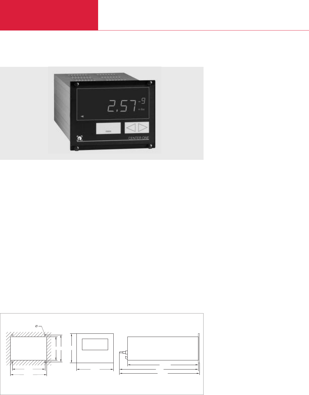
Operating Units for Active Sensors
Total Pressure Gauges
C16.24 LEYBOLD VACUUM PRODUCTS AND REFERENCE BOOK 2003/2004
CENTER ONE
Universal and compact display and operating unit
for operating the active sensors from the
CERAVAC, THERMOVAC, PENNINGVAC and
IONIVAC series.
Advantages to the User
◆Power supply voltage for the transmitters
◆Display range from 1 x 10
-10
to 1330 mbar
◆Automatic switchover to exponential readout
of the measured data depending on the
pressure range
◆Readout selectable between mbar, Torr or
Pascal
◆Adjustable switching threshold with variable
hysteresis, floating changeover contact and
visual indication of the switching status on the
display
◆Zero correction for both display and chart
recorder output through a key when using
CERAVAC transmitters
◆Option of entering gas correction factors
◆Chart recorder output 0 - 10 Volt
◆RS 232 C interface with adjustable baud rate
◆Relay output for error signalling
◆Compact bench top enclosure
(1/4 19 in., 2 HU)
◆For fitting into 19 in., 3 HU racks
Connectable Sensors
◆THERMOVAC TTR 90, TTR 90 S, TTR 216
◆PENNINGVAC PTR 225 and PTR 237
◆CERAVAC CTR90 and CTR91
◆IONIVAC ITR 90 and ITR 100
M3 - 3,2 mm
68 78
106,5
105
85
91,2
204,5
287,5
285
Dimensional drawing and panel cut-out for the CENTER ONE

Operating Units for Active Sensors Total Pressure Gauges
C16.25
C16
LEYBOLD VACUUM PRODUCTS AND REFERENCE BOOK 2003/2004
Part No. 230 002
Part No. 235 002
Type A
Part No. 124 26
Part No. 230 012
Part No. 124 27
Part No. 124 28
Part No. 124 29
Part No. 124 30
Part No. 124 31
Part No. 124 32
Part No. 124 33
Type B
Part No. 230 013
Part No. 230 014
Part No. 230 015
Part No. 230 016
Part No. 230 017
Part No. 230 018
Part No. 230 019
Part No. 230 020
Part No. 230 021
Type C
Part No. 124 55
Part No. 230 022
Part No. 124 56
Part No. 124 57
Part No. 124 58
Part No. 230 005
Part No. 230 006
EU version with 2 m EURO mains cord
US-Version with 2 m US mains cord
Connecting cable
THERMOVAC and PENNINGVAC
5 m
10 m
15 m
20 m
30 m
40 m
50 m
75 m
100 m
Connecting cable
CERAVAC
5 m
10 m
15 m
20 m
30 m
40 m
50 m
75 m
100 m
Connecting cable
IONIVAC
5 m
10 m
15 m
20 m
30 m
Adapter panel for installation in a
3 HU, 19 in. rack
Screw terminal for the 25 way output socket
CENTER ONEOrdering Information
Number of measurement channels
Display for measured values
Display range mbar (Torr)
Unit of measurement (selectable)
Gas type correction
Sensor connection
Sensor power supply V DC
Electrical inputs and outputs
Switching threshold
Number
Adjustment range
Hysteresis
Relay contact
Load rating
Error message
Relay contact
Load rating
Chart recorder output (Ra> 10 kΩ)
Control input
Interface RS 232 C
Mains connection V AC / Hz
Power consumption W
Weight kg (lbs)
Protection class IP
CENTER ONETechnical Data
1
Digital, 7 segment LED, 5 digits
1 x 10⁻¹⁰ to 1330 (0.75 x 10⁻¹⁰ to 1000)
mbar, Torr, Pascal, Micron
Factor adjustable
15 way Sub-D socket FCC68 (RJ45)
24
9 way Sub-D plug
1
sensor dependent
adjustable
Floating changeover contact
60 V, 0.5 A DC / 30 V, 0.5 A AC
Floating normally open contact
60 V, 0.5 A DC / 30 V, 0.5 A AC
0 - 10 Volt, characteristic corresponds to
the connected transmitter
PTR: high voltage on / ITR 100: emission on
9 way Sub-D socket
85 V - 264 / 50-60
< 30
0.85 (1.9)
30
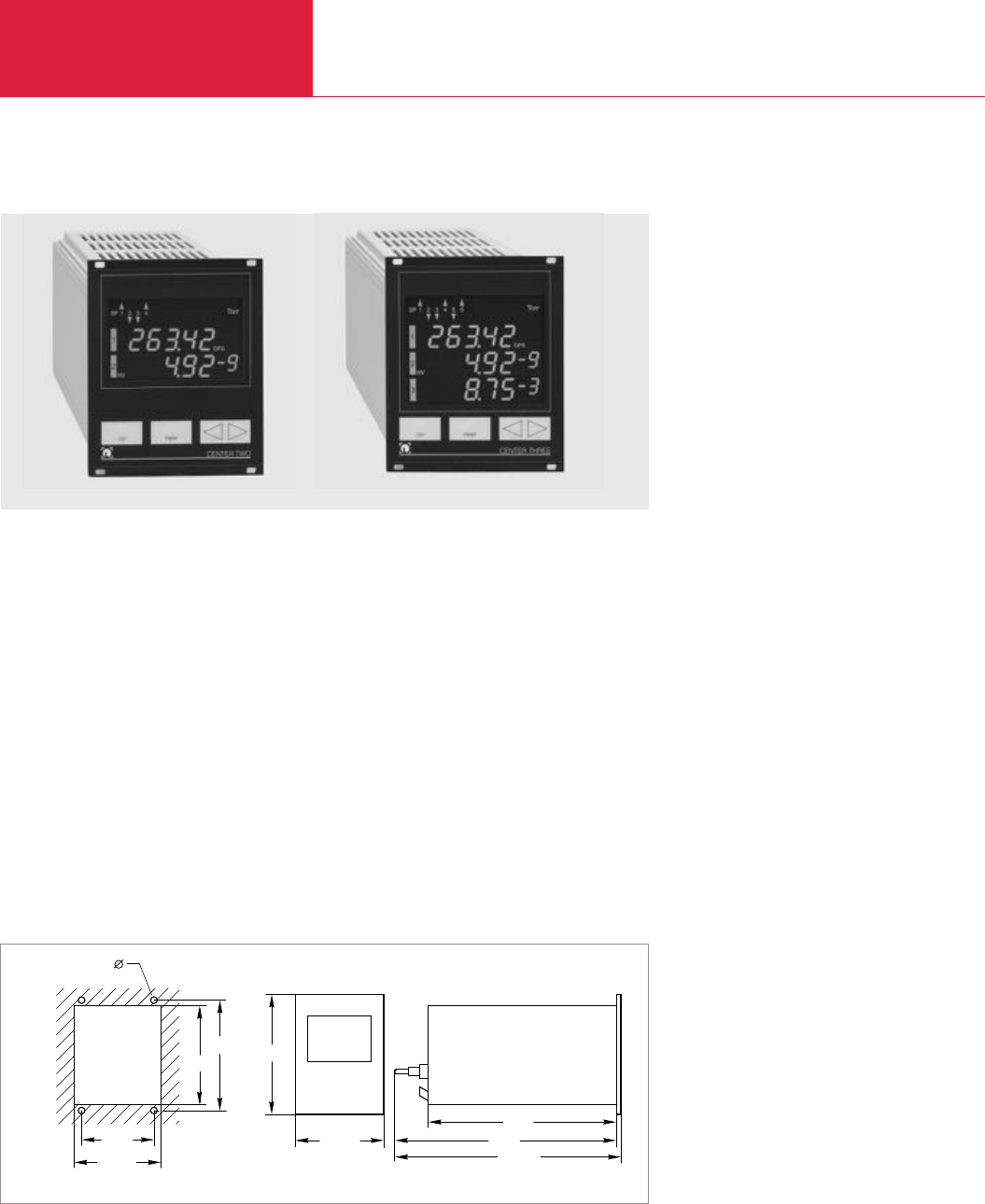
Operating Units for Active Sensors
Total Pressure Gauges
C16.26 LEYBOLD VACUUM PRODUCTS AND REFERENCE BOOK 2003/2004
CENTER TWO / THREE
Universal display and operating units for
operating the active sensors from the CERAVAC,
THERMOVAC, PENNINGVAC and IONIVAC series.
all channels are displayed simultaneously.
Advantages to the User
◆Power supply voltage for the transmitters
◆Display range from 1 x 10
-10
to 1330 mbar
◆Automatic switchover to exponential readout
of the measured data depending on the
pressure range
◆Readout selectable between mbar, Torr,
Micron or Pascal
◆Adjustable switching thresholds with variable
hysteresis, floating changeover contacts and
visual indication of the switching status in the
display, freely assignable to the individual
measurement channels
◆Zero correction for both display and chart
recorder output through a key when using
CERAVAC transmitters
◆Option of entering gas correction factors
◆Separate chart recorder outputs 0-10 V for
each measurement channel
◆Additional chart recorder output 0-10 V
programmable to several measurement
channels
◆RS 232 C interface with adjustable baud rate
◆Relay output for error signalling
◆Compact bench top enclosure
(1/4 19 in., 2 HU)
◆For fitting into 19 in., 3 HU racks
Connectable Sensors
◆THERMOVAC TTR 90, TTR 90 S, TTR 211 S,
TTR 216 S
◆PENNINGVAC PTR 225 und PTR 237
◆CERAVAC CTR90 und CTR91
◆IONIVAC ITR 90
M3 - 3,2 mm
112
122,5
206
106,5
104,5
128,5
91,5 290
293,5
Dimensional drawing and panel cut-out for the CENTER TWO and THREE

Operating Units for Active Sensors Total Pressure Gauges
C16.27
C16
LEYBOLD VACUUM PRODUCTS AND REFERENCE BOOK 2003/2004
Part No. 230 004 Part No. 230 003
Part No. 235 004 Part No. 235 003
Type A
Part No. 124 26
Part No. 230 012
Part No. 124 27
Part No. 124 28
Part No. 124 29
Part No. 124 30
Part No. 124 31
Part No. 124 32
Part No. 124 33
Type B
Part No. 230 013
Part No. 230 014
Part No. 230 015
Part No. 230 016
Part No. 230 017
Part No. 230 018
Part No. 230 019
Part No. 230 020
Part No. 230 021
Type C
Part No. 124 55
Part No. 230 022
Part No. 124 56
Part No. 124 57
Part No. 124 58
Part No. 230 006
EU-Version with 2 m EURO mains cord
US-Version with 2 m US mains cord
Connecting cable
THERMOVAC and PENNINGVAC
5 m
10 m
15 m
20 m
30 m
40 m
50 m
75 m
100 m
Connecting cable
CERAVAC
5 m
10 m
15 m
20 m
30 m
40 m
50 m
75 m
100 m
Connecting cable
IONIVAC
5 m
10 m
15 m
20 m
30 m
Screwed connection for
9 way Sub-D socket
CENTER TWO CENTER THREE
Ordering Information
Number of measurement channels
Display for measured values
Display range mbar
Unit of measurement (selectable)
Gas type correction
Sensor connection
Sensor power supply V DC
Relaisausgänge
Switching threshold
Number
Adjustment range
Hysteresis
Relay contact
Load rating
Error message
Relay contact
Load rating
Chart recorder output (Ra> 10 kΩ)
Control input
Interface RS 232 C
Mains connection V AC / Hz
Power consumption W
Nominal temperature range °C
Weight kg (lbs)
Protection class IP
CENTER TWO CENTER THREE
Technical Data
2 3
Digital, 7 segment LED, 5 digits
1 x 10⁻¹⁰ to 1330 (0.75 x 10⁻¹⁰ to 1000)
mbar, Torr, Pascal, Micron
Factor adjustable
15 way Sub-D socket FCC68 (RJ45)
24
25 way Sub-D socket
independently assignable
4 6
sensor dependent
adjustable
Floating changeover contact
60 V, 0.5 A DC / 30 V, 0.5 A AC
Floating normally open contact
60 V, 0.5 A DC / 30 V, 0.5 A AC
0 - 10 V per measurement channel,
output characteristic corresponds to
the connected sensorr, in addition one
chart recorder output can be programmed
PENNINGVAC PTR: high voltage on
9 way Sub-D socket
90 - 250 / 50 - 60
< 45 < 65
+ 5 to + 50
1.1 (2.43) 1.2 (2.65)
20
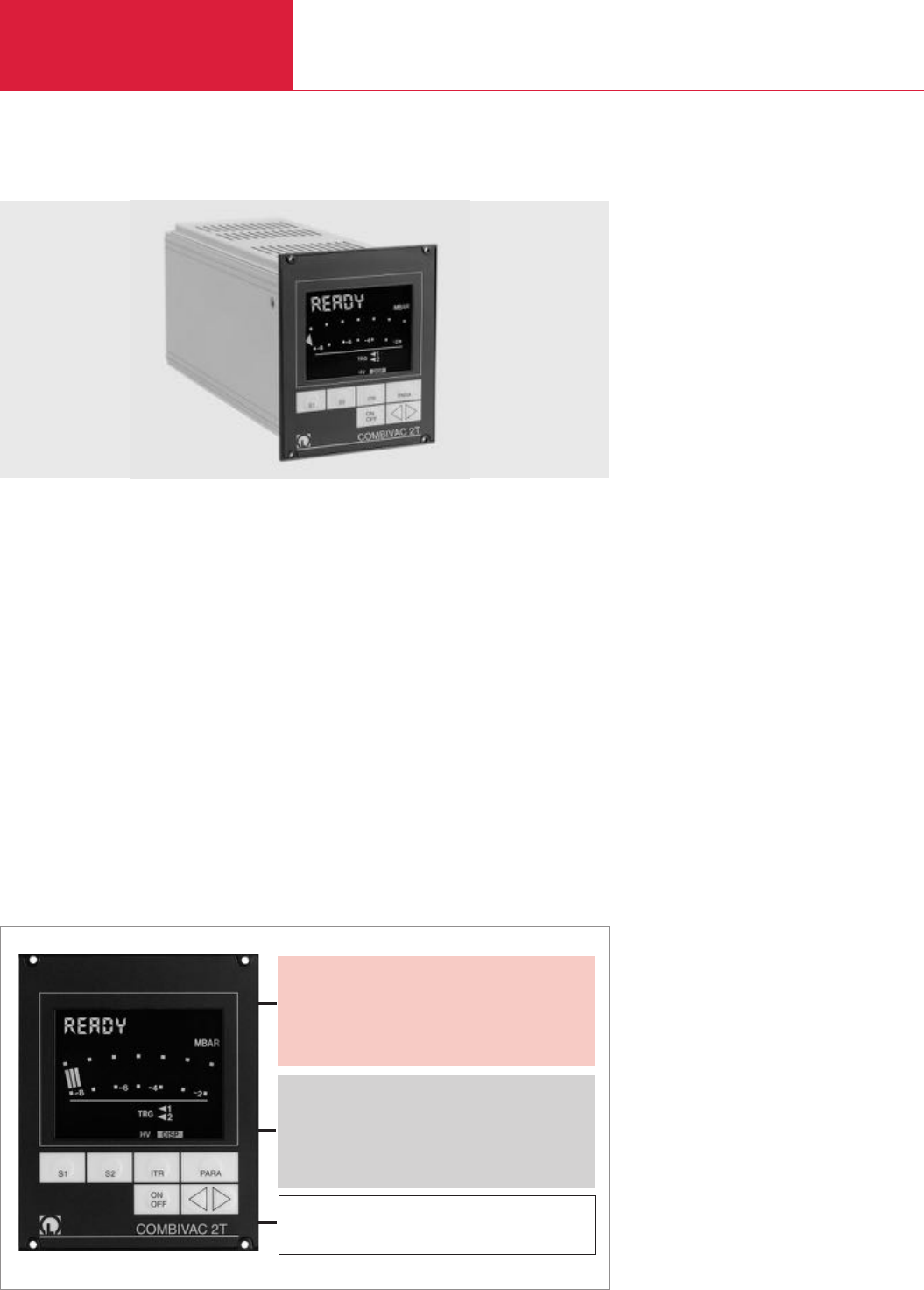
Operating Units for Active Sensors
Total Pressure Gauges
C16.28 LEYBOLD VACUUM PRODUCTS AND REFERENCE BOOK 2003/2004
COMBIVAC 2T
Advantages to the User
◆Wide measurement and display range from
2000 to 1 x 10
-10
mbar (1500 to 0.75 x
10
-10
Torr) by combinating two transmitters
max. with automatic switchover of the display
◆Analog baragraph display runs simultaneously
with digital readouts
◆Three adjustable thresholds with relay
contacts and adjustable hysteresis, assignable
to each channel
◆Userfriendly adjustment to each application,
e. g. by
- selectable measurement unit
- automatic switch on of emission with
IONI transmitter
- automatic switch on of the ignition voltage
with the Penning transmitter
◆Separate 0 to 10 V chart recorder outputs for
each measurement channel
◆Additional 0 to 10 V chart recorder output,
programmable for coverage of several
measurement channels
◆Full remote control via RS 232 C interface
◆Compact bench-top unit (1/4 19 in., 3 HU)
which can also be installed in panel cutouts
and 19 in. racks
◆CE mark
The COMBIVAC 2T covers through its combinati-
on of up to two transmitter types the entire
range of vacuum pressures from 10
-10
mbar to
2000 bar.
Moreover, the unit offers a manually or pressure
controlled switching function to START and STOP
the high-vacuum pumps from the TW line.
The pump status “normal operation”, “run-up”,
“standby” and “fail” is indicated on the display.
Connectable Sensors
◆THERMOVAC TTR 90, TTR 90S, TTR 216
◆PENNINGVAC PTR 225 and PTR 237
◆IONIVAC ITR 90 and ITR 100
◆DI 200 and DI 2000
Typical Applications
◆General pressure measurements on high
vacuum pump systems
◆Vacuum furnaces
◆Coating systems
◆Analytical instruments
Measurement channel TW Pump
Series TW 70
or
1 Series TW 300
or
Series TW 700
TTR
or
2 PTR
or
DI
3 ITR
Connectable transmitters COMBIVAC 2T

Operating Units for Active Sensors Total Pressure Gauges
C16.29
C16
LEYBOLD VACUUM PRODUCTS AND REFERENCE BOOK 2003/2004
COMBIVAC 2T, 90 - 250 V AC
Calibration
Connecting cable
THERMOVAC and PENNINGVAC
5 m
10 m
15 m
20 m
30 m
40 m
50 m
75 m
100 m
Connecting cable
IONIVAC
5 m
10 m
15 m
20 m
30 m
Connecting cable DI-Sensor IT23, 5 m
Connecting cable
TW 70, TW 300 and TW 700
5 m
10 m
15 m
20 m
Part No. 230 000
see section “Miscellaneous”,
para. “LEYBOLD Calibration Service”
Type A
Part No. 124 26
Part No. 230 012
Part No. 124 27
Part No. 124 28
Part No. 124 29
Part No. 124 30
Part No. 124 31
Part No. 124 32
Part No. 124 33
Type C
Part No. 124 55
Part No. 230 022
Part No. 124 56
Part No. 124 57
Part No. 124 58
Part No. 163 84
Part No. 230 007
Part No. 230 008
Part No. 230 009
Part No. 230 010
Ordering Information 2T
Number of measurement channels
Measurement display (backlit)
Display range mbar (Torr)
Connectable transmitters with
display range
DI 200 mbar (Torr)
DI 2000 mbar (Torr)
TTR 90 mbar (Torr)
PTR 225 mbar (Torr)
ITR 90 mba (Torr)r
ITR 100 mbar (Torr)
Unit of measurement (selectable)
Type of gas (selectable)
Switching thresholds
adjustment range
hysteresis
relay contact
capacity
Ready indication
Chart recorder output (Ra> 10 kΩ)
Electric outputs
Interface
Main supply
Power consumption VA
Nominal temperature range °C
Max. rel. humidity % n. c.
Weight kg (lbs)
Dimensions (W x H x D) mm
Technical Data 2T
2
digital, 7-segments LCD
analog LCD-bargraph
display can be switched over by hand
or automatically to the connected sensors
2000 to 2 x 10⁻¹⁰ (1500 to 1.5 x 10⁻¹⁰)
1 to 200 (0.75 to 150)
1 to 2000 (0.75 to 1500)
5 x 10⁻⁴ to 1000 (3.75 x 10⁻⁴ to 750)
1 x 10⁻⁹ to 1 x 10⁻² (0.75 x 10⁻⁹ to 0.75 x 10⁻²)
5 x 10⁻¹⁰ to 1000 (3.75 x 10⁻¹⁰ to 750)
1 x 10
-10
to 1x 10
-1
(0.75 x 10
-10
to 0.75 x 10
-1
)
mbar, Torr, Pascal, Micron
Air, Ar, N2(only ITR 100)
3, independently assignable
according to the assigned sensor
adjustable
potential free changeover contact
60 V, 0.5 A DC
1 relay contact 60 V, 0.5 A DC
for all channels
4,
each 0 to 10 V per channel:
initial characteristics dependent on
connected transmitters
one 0 to 10 V analog output per one or
several linear or logarithmic channels
relay contacts and chart recorder outputs
over 25 pin Sub-D-socket
RS 232 C
90 - 250 V AC
40
0 to 50
85
1.5 (3.31)
106.5 x 128.5 x 240
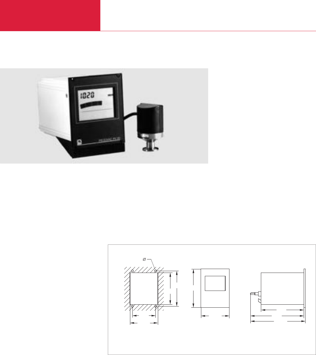
Operating Units for Passive Sensors
Total Pressure Gauges
C16.30 LEYBOLD VACUUM PRODUCTS AND REFERENCE BOOK 2003/2004
PIEZOVAC PV 20
Advantages to the User
◆Complete instrument: Sensor and sensor
cable included
◆Dual LCD display – combines the advantages
of analog and digital readouts
◆Clear display of pressure and operating status
with analog trend indication, can also be read
from a great distance.
◆Logarithmic/linear 0 to 10 V chart recorder
output
◆Compact bench-top unit (1/4 19 in., 3 HU),
which may also be installed in panel cut-outs
and 19 in. racks
◆Ceramic absolute pressure sensor which is
highly corrosion resistant
◆THERMOVAC or absolute pressure sensors
may be alternatively connected
◆CE mark
Typical Applications
◆General pressure measurements in the fine
and rough vacuum range, in connection with
vacuum furnaces and analytical instruments
◆Monitoring the operation of backing pumps
and vacuum systems
◆Replacement of mercury manometers in the
lab and in production lines
This complete vacuum gauge offers accurate and
cost-effective measurements in the range
between 1 and 2000 mbar (0.75 and 1500 Torr)
or 0.1 and 200 mbar (0.075 and 150 Torr).
M3 - 3,2 mm
112
122,5
106,5
104,5
128,5
91,5
172
258,5
255
Dimensional drawing and panel cut-out for the PIEZOVAC PV 20
Sensors
The PIEZOVAC PV 20 is delivered complete with
a DI 2000 or DI 200 sensor. The sensor is sup-
plied fully aligned for operation.
For information on the THERMOVAC sensors, see
the chapter “Sensors”.

Operating Units for Passive Sensors
Total Pressure Gauges
C16.31
C16
LEYBOLD VACUUM PRODUCTS AND REFERENCE BOOK 2003/2004
Display range mbar (Torr)
Display
Measurement uncertainty
with DI 200/201/2000 Sensor % FS
Unit of measurement (selectable)
Chart recorder output (Ra> 2,5 kΩ)
Main connection 50/60 Hz (selectable) V
Power consumption VA
Storage temperature range °C
Nominal temperature range °C
Max. rel. humidity % n.c.
Weight, approx. kg (lbs)
Dimensions (W x H x D) mm
Cable length, max. m
Connectable sensors
Technical Data PIEZOVAC PV 20
Complete with 2 m long main cord
DI 2000 sensor,
with 5 m long cable, 230 V AC,
measurement range 1 - 2 000 mbar
(0.75 - 1500 Torr)
Complete with 2 m long main cord
DI 200 sensor,
with 5 m long sensor cable, 230 V AC,
measurement range 0.1 - 200 mbar
(0.075 - 150 Torr)
Calibration
Options
19"installation frame
1/4 19"blank panel
Part No. 157 96
Part No. 157 97
see section “Miscellaneous”,
para. “LEYBOLD Calibration Service”
Part No. 161 00
Part No. 161 02
Ordering Information PIEZOVAC PV 20
0.1 to 2 000 (0.075 to 1500)
Digital: 7-segment LCD,
Analog: LCD bar
0.2
mbar, Torr, Pa, Micron
0 to 10 V, linear divisions for
absolute pressure sensors,
about 10.5 V during faults
0 to 10 V, logarithmic divisions for
THERMOVAC sensors (1.67 V/decade)
90 to 130 / 180 to 250
9
-40 to +60
0 to 40
80
2 (4.4)
106.5 x 128.5 x 172
100
TR 211/212/216, DI 200/201/2000/2001
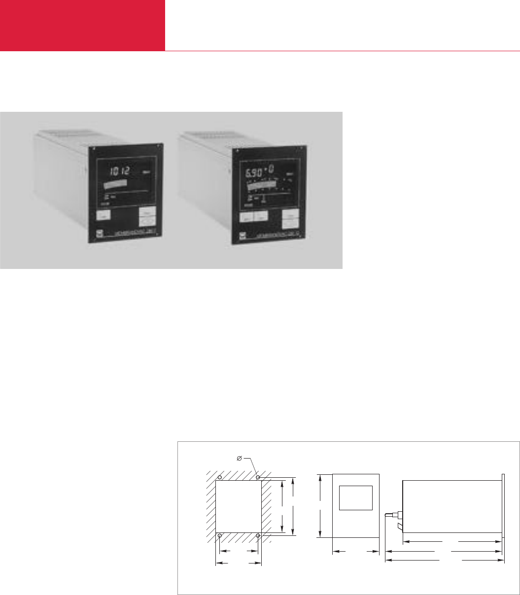
Operating Units for Passive Sensors
Total Pressure Gauges
C16.32 LEYBOLD VACUUM PRODUCTS AND REFERENCE BOOK 2003/2004
MEMBRANOVAC DM 11/DM 12
Advantages to the User
◆Illuminated dual LCD display combining the
advantages of analog and digital readouts
◆Clear display of pressure and operating status
with analog trend indication, can also be read
from a great distance
◆Simple trend indication through analog bar-
graph
◆Locking of the keypad via softlock keylock
◆Two adjustable switching thresholds with
relay contacts per measurement channel; can
also be operated as a three-position controller
◆Logarithmic/linear 0 to 10 V chart recorder
output
◆Full remote control via RS 232 C interface
◆Compact bench-top unit (1/4 19 in., 3 HU),
which may also be installed in panel cut-outs
and 19 in. racks
◆Wide measurement and display range, freely
adjustable from -1000 mbar up to 20 bar
depending on the type of pressure sensor
delivering an output signal of 4 to 20 mA
◆Universal connection for linear absolute, rela-
tive and differential pressure sensors with a
typical 24 V supply voltage requirement and a
measurement signal output of 4 to 20 mA
(2 wire connection)
◆THERMOVAC sensors (TR 300 series) can be
connected for measurements in the fine
vacuum range
◆Single or two channel instrument with
automatic channel switching
◆CE mark
Typical Applications
◆General pressure measurement and control in
the rough and fine vacuum ranges, in connec-
tion with vacuum furnaces
◆Measurement of operating and filling pressure
during the production of lamps
◆Vacuum packaging
◆Chemical process engineering
◆Drying processes
Compact general purpose measurement and
control instruments for absolute, relative and
differential pressure measurements, measure-
ments in the vacuum and over-pressure ranges,
with a wide measurement and display range.
Sensors
These operating units have been universally
designed to accommodate the capacitive
pressure sensors DI 200, DI 201, DI 2000,
DI 2001 and DI 2001 rel are equipped with a
ceramic diaphragm (see chapter “Sensors”).
Moreover, the thermal conductivity sensors from
the THERMOVAC series TR 300 can be connected
(see chapter “Sensors”).
M3 - 3,2 mm
112
122,5
282
106,5
104,5
128,5
91,5 350
353,5
Dimensional drawing and panel cut-out for the MEMBRANOVAC DM 11/DM 12

Operating Units for Passive Sensors
Total Pressure Gauges
C16.33
C16
LEYBOLD VACUUM PRODUCTS AND REFERENCE BOOK 2003/2004
DM 11 DM 12Technical Data
Number of measurement channels
Display range mbar (Torr)
Display (backlit)
Unit of measurement (selectable)
Display rate
Type of gas (selectable)
Switching thresholds
Operating mode
Adjustment range
Hysteresis (adjustable)
Reaction time ms
Ready relay
Rating of the relay contacts
Contact life at 5 A
Chart recorder output (Ra< 2.5 kΩ)
Control signal for external setting of the
reference pressure for 3 position control V
Interface
Main connection 50/60 Hz (selectable) V
Power consumption VA
Storage temperature range °C
Nominal temperature range °C
Max. rel. humidity % n.c.
Weight, approx. kg (lbs)
Dimensions (W x H x D) mm
Sensor supply
Sensors
(see chapter “Sensors”)
1 2
-1000 to +20000 (-750 to +15 000),
freely adjustable for linear sensors,
10-3 to 1 000 (10-3 to 750) for THERMOVAC
Digital: 7 segment LCD, analog: LCD bar graph
mbar, Torr, Pa, Micron
4 x s-1
Linear sensors independent of the type of gas,
THERMOVAC sensors air/argon
2 floating changeover contacts per channel
single/interval/3 position controller
Linear sensors: Sensor range,
THERMOVAC sensors: 1 x 10⁻³ to 500 mbar
(0.75 x 10⁻³ to 375 Torr)
0.1 to 9.9 % of sensor fullscale
< 50
Floating contact,
Closed when ready
AC 240 V/5 A, DC 60 V/0.7 A
> 6 x 10⁴cycles
1 x per measurement channel,
0 to 10 V linear for linear sensors,
0 to 10 V logarithmic for
TM sensors, about 10.5 V in case of a fault
0 to 10
RS 232 C
100/120/200/230 V +10/-15 %
25
-20 to +60
0 to 40
80
2.1 (4.6)
106.5 x 128.5 x 282
24 to 30 V DC,
Signal current 4 to 20 mA or 8 to 48 mA
for THERMOVAC sensors
DI 200/201/2000/2001/2001 rel,
THERMOVAC TR 301/306,
all common sensors on the market having a
supply voltage requirement of 24 V and
a measurement signal of 4 to 20 mA
MEMBRANOVAC DM 11 (single channel)
Euro model, with 2 m long main cord,
mbar readout, 230 V AC
US model, with 2 m long main cord,
Torr readout, 120 V AC
MEMBRANOVAC DM 12 (two-channel)
Euro model, with 2 m long main cord,
mbar readout, 230 V AC
US model, with 2 m long main cord,
Torr readout, 120 V AC
Calibration
Options
19" installation frame
1/4 19" blank panel
Linear pressure sensors
DI 200, 0.1 - 200 mbar
(0.075 - 150 Torr)
(incl. 5 m long connection cable)
DI 201, 0.1 - 200 mbar
(0.075 - 150 Torr)
(incl. 5 m long connection cable)
DI 2000, 1 - 2000 mbar
(0.75 - 1500 Torr)
(incl. 5 m long connection cable)
DI 2001, 1 - 2000 mbar
(0.75 - 1500 Torr)
(incl. 5 m long connection cable)
DI 2001 rel, -1000 – +1000 mbar
(-750 - +750 Torr)
(incl. 5 m long connection cable)
THERMOVAC sensors *)
TR 301, tungsten filament
Connection cable for TR 301/306,
05 m long
10 m long
15 m long
20 m long
30 m long
40 m long
50 m long
*)to be discontinued
Part No. 157 91 –
Part No. 896 91 –
–Part No. 157 92
–Part No. 896 92
see section “Miscellaneous”,
para. “LEYBOLD Calibration Service”
Part No. 161 00
Part No. 161 02
Part No. 158 12
Part No. 158 14
Part No. 158 13
Part No. 158 15
Part No. 245 000
Part No. 157 40
Part No. 157 63
Part No. 124 71
Part No. 124 72
Part No. 124 73
Part No. 124 74
Part No. 124 75
Part No. 124 76
Ordering Information DM 11 DM 12
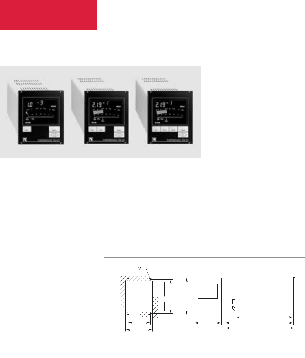
Fine Vacuum Gauges
Total Pressure Gauges
C16.34 LEYBOLD VACUUM PRODUCTS AND REFERENCE BOOK 2003/2004
THERMOVAC TM 21/TM 22/TM 23
Advantages to the User
◆One, two or three continuously operating
measurement channels, with selectable
display
◆Dual LCD display combines the advantages of
analog and digital readouts
◆Clear display of pressure and operating status
with analog trend indication, can also be read
from a great distance
◆Aligned and temperature compensated
sensors having a low filament temperature
◆Simple to operate
◆Cost-effective sensing cell replacements
◆Fault indication in case of a broken filament
◆Two adjustable switching thresholds with
relay contacts per measurement channel )
◆Logarithmic/linear 0 to 10 V chart recorder
output
◆Compact bench-top unit (1/4 19 in., 3 HU),
which may also be installed in panel cut-outs
and 19 in. racks
◆Pirani principle
◆Full remote control via RS 232 C interface
(TM 21/TM 22)
◆Locking of the keypad via softlock keylock
(TM 21/TM 22/TM 23)
◆CE mark
Typical Applications
◆General purpose pressure measurement and
control in the fine and rough vacuum ranges,
vacuum furnaces and analytical instruments
◆Monitoring the operation of backing pumps
and vacuum systems
◆Safety circuits in vacuum systems
◆Control of ionization vacuum gauges
Instruments for operating thermal conductivity
sensors (PIRANI gauges) covering a measuring
range of 5 x 10
-4
to 1000 mbar (5 x 10
-4
to
750 Torr). The relays built into the TM 21/
TM 22/TM 23 make these instruments the ideal
choice for process control systems.
Sensors
Either the TR 211/TR 212 and TR 216 (corrosion
protected) may be connected to the THERMOVAC
TM 21/TM 22/TM 23 (see chapter “Sensors”).
Upon delivery the sensors are supplied fully align-
ed and ready for operation.
M3 - 3,2 mm
112
122,5
282
106,5
104,5
128,5
91,5 350
353,5
Dimensional drawing and panel cut-out for the THERMOVAC TM 21/TM 22/TM 23

Fine Vacuum Gauges Total Pressure Gauges
C16.35
C16
LEYBOLD VACUUM PRODUCTS AND REFERENCE BOOK 2003/2004
Number of measurement channels
Display range mbar (Torr)
Unit of measurement (selectable)
Display
Type of gas (selectable)
Measurement uncertainty with THERMOVAC sensors
(after warming up)
Switching thresholdskte
Adjustment range for the switching mbar (Torr)
Ready relay
Rating of the relay contacts
Contact life at 5 A
Chart recorder output (Ra> 2.5 kΩ)
Main connection 50/60 Hz (selectable) V
Power consumption VA
Storage temperature range °C
Nominal temperature range °C
Max. rel. humidity % n.c.
Weight, approx. kg (lbs)
Dimensions (W x H x D) mm
Cable length, max. m
Interface
1 2 3
5 x 10⁻⁴ to 1000 (3.75 x 10⁻⁴ to 750)
mbar, Torr, Pa, Micron
Digital, 7 segment-LCD, analog, LCD bar graph
Air, N2, Ar
≤20 % of the meas. value in the range 10-3 to 10-2 mbar, ≤15 % v. of the meas. value in the range 10-2 to 102mbar
2 floating changeover contacts per measurement channel
5 x 10⁻³ to 500 (3.75 x 10⁻³ to 375)
Contact closed when ready
AC 240 V/5 A (resistive load) / DC 60 V/0.7 A (resistive load)
≥6 x 10⁴cycles
0 to 10 V, selectable: logarithmic/linear; logarithmic divisions: 1.67 V/decade,
linearly adjustable over 3 decades; 0 V corresponds to 10-3 mbar, 10.5 V for faults
100/120/200/230, +10/-15 %
12 14
-40 to +60
0 to 40
80
2 (4.4)
106.5 x 128.5 x 282
100
RS 232 C –
Technical Data TM 21 TM 22 TM 23
TM 21 TM 22 TM 23
Euro model, with 2 m long main cord,
mbar readout, 230 V AC
US model, with 2 m long main cord,
Torr readout, 120 V AC
Calibration
Options
19" installation frame
1/4 19" blank panel
THERMOVACsensors
TR 211, DN 16 KF
TR 211, 1/8" NPT
TR 212, DN 16 KF
TR 212, DN 16 CF
TR 216, DN 16 KF
Connection cables
05 m
10 m
15 m
20 m
30 m
40 m
50 m
75 m
100 m
Ordering Information
Part No. 157 83 Part No. 157 84 Part No. 157 98
Part No. 896 83 Part No. 896 84 Part No. 896 98
see section “Miscellaneous”, para. “LEYBOLD Calibration Service”
Part No. 161 00
Part No. 161 02
Part No. 157 85
Part No. 896 33
Part No. 158 52
Part No. 158 86
Part No. 157 87
Part No. 162 26
Part No. 162 27
Part No. 124 34
Part No. 162 28
Part No. 124 35
Part No. 124 36
Part No. 124 37
Part No. 124 38
Part No. 124 39
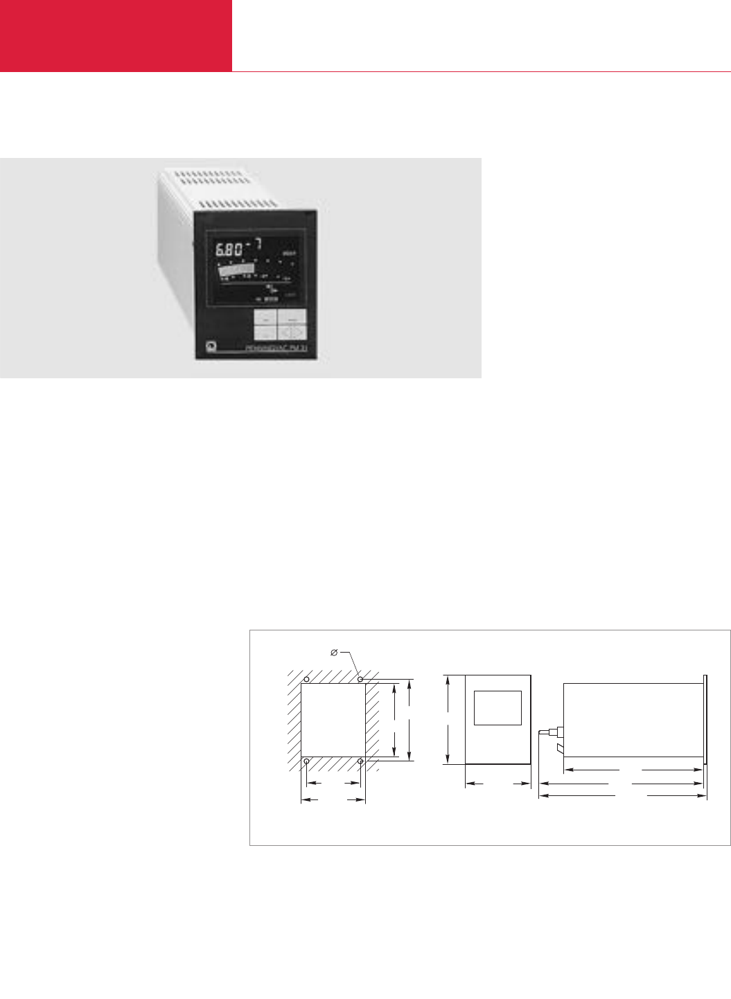
High and Ultra High Vacuum Gauges
Total Pressure Gauges
C16.36 LEYBOLD VACUUM PRODUCTS AND REFERENCE BOOK 2003/2004
M3 - 3,2 mm
112
122,5
282
106,5
104,5
128,5
91,5 350
353,5
Dimensional drawing and panel cut-out for the PENNINGVAC PM 31
PENNINGVAC PM 31
Advantages to the User
◆Illuminated dual LCD display combining the
advantages of analog and digital readouts
◆Clear display of pressure and operating status
with analog trend indication, can also be read
from a great distance
◆Locking of the keypad via softlock keylock
◆Two adjustable switching thresholds with
relay contact
◆Logarithmic/linear 0 to 10 V chart recorder
output
◆Easy to operate
◆All-metal sensor with ceramics feedthrough
◆Compact, rugged Penning gauge which is
capable of withstanding operation at high
pressures
◆Principle of measurement based on cold
cathode ionization, thus no gas is emitted by
hot electrodes
◆Cost-effective replacement cathodes
◆Fault indication in the event of a broken cable
of failed discharge
◆Compact bench-top unit (1/4 19 in., 3 HU),
with metal enclosure which may also be
installed in panel cut-outs and 19 in. racks
◆Full remote control via RS 232 C interface
◆CE mark
Typical Applications
◆Pressure measurements on pump systems,
for example:
– Diffusion pump systems
– Turbomolecular pump systems
– Cryo pump systems
◆Pressure measurements in the high vacuum
range, for example on vacuum melting,
soldering and annealing furnaces
◆Analytical instruments
◆Coating systems
The PENNINGVAC PM 31 offers reliable
measurements as well as monitoring and control
functions in the vacuum range between 10
-9
and
10
-2
mbar/Torr.
Sensors
Sensors PR 25, PR 26, PR 27 or PR 37 may be
connected to the PENNINGVAC PM 31
For information, see the chapter “Sensors”.

High and Ultra High Vacuum Gauges Total Pressure Gauges
C16.37
C16
LEYBOLD VACUUM PRODUCTS AND REFERENCE BOOK 2003/2004
Display range 1) mbar (Torr)
Unit of measurement (selectable)
Measurement uncertainty
Measurement display (illuminated)
Type of gas (selectable)
Switching thresholds
Operating mode
Adjustment range mbar (Torr)
Hysteresis for the switching relay
Ready indication
Rating of the relay contacts
Contact life at 5 A
Chart recorder output (Ra> 2.5 kΩ)
High voltage control input
Interface
Main connection 50/60 Hz (selectable) V
Power consumption VA
Storage temperature range °C
Nominal temperature range °C
Max. rel. humidity % n.c.
Weight, approx. kg (lbs)
Dimensions (W x H x D) mm
Cable length, max. m
1) For a cable length of 20 m max.
1 x 10⁻⁹ to 10-2 (0.75 x 10⁻⁹ to 10-2)
mbar, Torr, Pa, Micron
± 30 % of the meas. value
in the range 1 x 10⁻⁸ to 10-4 mbar
(0.75 x 10⁻⁸ to 10-4 Torr)
digital, 7 segment LCD, analog, LCD bargraph
with logarithmic divisions
Air, N2, Ar
2 floating changeover contacts
single, interval
1 x 10⁻⁸ to 9.9 x 10⁻³
(0.75 x 10⁻⁸ to 7.4 x 10⁻³)
standard 10 % of trigger value, free adjustable
Contact, closed when ready
AC 240 V/5 A (Resistive load),
DC 60 V/0.7 A (Resistive load)
> 6 x 10⁴cycles
0 to 10 V,
selectable: logarithmic/linear;
logarithmic divisions: 1.43 V/decade,
linearly adjustable over 3 decades;
0 V corresponds to 10-9 mbar/Torr,
about 10.5 V in case of a fault
Prog. contr. compatible, digital 24 V input,
logic level (LOW) < 7 V, 0 A,
logic level (HIGH) > 13 V, 7 mA
RS 232 C
100/120/200/230, +10/-15 %
20
-40 to +60
0 to 40
80
2.1 (4.6)
106.5 x 128.5 x 282
100
Technical Data PENNINGVAC PM 31
Euro model, with 2 m long main cord,
mbar readout, 230 V AC
US model, with 2 m long main cord,
Torr readout, 120 V AC
Options
19" installation frame
1/4 19" blank panel
PENNINGVAC sensors
PR 25, DN 25 KF
PR 26, DN 40 KF
PR 27, DN 40 CF
PR 37, DN 40 CF, bakeable
Replacement cathode plates, titanium
(set of 5 pcs.)
Replacement anode ring
Sensor cables
5 m
10 m
15 m
20 m
30 m
40 m
50 m
75 m
100 m
Part No. 157 88
Part No. 896 88
Part No. 161 00
Part No. 161 02
Part No. 157 52
Part No. 136 46
Part No. 136 47
Part No. 157 54
Part No. 162 91
Part No. 240 002
Part No. 162 88
Part No. 162 89
Part No. 124 49
Part No. 157 56
Part No. 124 50
Part No. 124 51
Part No. 124 52
Part No. 124 53
Part No. 124 54
Ordering Information PENNINGVAC PM 31
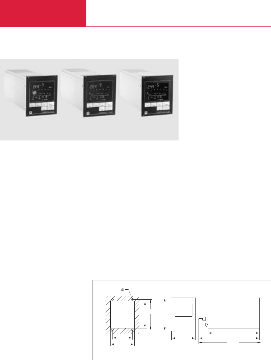
High and Ultra High Vacuum Gauges
Total Pressure Gauges
C16.38 LEYBOLD VACUUM PRODUCTS AND REFERENCE BOOK 2003/2004
M3 - 3,2 mm
112
122,5
282
106,5
104,5
128,5
91,5 350
353,5
COMBIVAC CM 31/CM 32/CM 33
Advantages to the User
◆Selectable dual LCD display combining the
advantages of analog and digital readouts
(over 12 decades)
◆Automatic switchover from THERMOVAC to
Penning (cold cathode) operation
◆Clear display of pressure and operating status
with analog trend indication, can also be read
from a great distance
◆Easy to operate
◆Locking of the keypad via softlock keylock
◆Two adjustable switching thresholds with
relay contact per measurement channel
◆Logarithmic/linear 0 to 10 V chart recorder
output
◆Compact, rugged Penning gauge which is
capable of withstanding operation at high
pressures (see section “Sensors”)
◆Aligned and temperature compensated
THERMOVAC sensors (see section “Sensors”)
◆Precision absolute pressure sensors with
ceramics or Inconel diaphragm (see section
“Sensors”)
◆Cost-effective replacement sensing cells and
electrodes
◆Fault indication for each channel in the event
of a broken filament, a broken cable or failed
plasma discharge
◆Compact bench-top unit (1/4 19 in., 3 HU)
with metal enclosure, which may also be
installed in panel cut-outs and 19 in. racks
◆Full remote control via RS 232 C interface
◆CE mark
Typical Applications
◆General pressure measurements on pump
systems, for example:
– Turbomolecular pump systems
– Diffusion pump systems
– Cryo pump systems
◆Vacuum melting, soldering and annealing
furnaces
◆Coating systems
◆Analytical instruments
COMBIVAC CM 31
This combination instrument for standard applic-
ations covers with its three measurement chan-
nels (2 x THERMOVAC and 1 x PENNINGVAC) the
entire range of 12 decades between 1 x 10
-9
and
1000 mbar.
By combining two/three principles of measure-
ment – absolute pressure sensor, Pirani and
Penning – the COMBIVAC CM 31/CM 32/CM 33
cover the entire pressure range from 10
-9
to
2000 mbar (10
-9
to 1500 Torr) while offering
monitoring and control functions.
Dimensional drawing and panel cut-out for the COMBIVAC CM 31/CM 32/CM 33
COMBIVAC CM 32
For over-pressure measurements and pressure
measurements which do not depend on the type
of gas, the CM 32 offers the facility of connecting
a linear pressure sensor (DI 200/201/2000/2001/
2001 rel – see chapter “Sensors”) in combination
with THERMOVAC and PENNINGVAC sensors.
Suitable 4 to 20 mA pressure sensors having a
range up to 20000 mbar (15 000 Torr) may be
connected.
COMBIVAC CM 33
If the utmost is required regarding accuracy and
resolution, then the CM 33 is the right choice. In
combination with THERMOVAC and PENNINGVAC
sensors, capacitive absolute pressure sensors may
be connected (see chapter “Sensors”) which offer,
depending on the type, a range of 2 x 10
-4
to
13300 mbar (1.5 x 10
-4
to 10 000 Torr).

High and Ultra High Vacuum Gauges Total Pressure Gauges
C16.39
C16
LEYBOLD VACUUM PRODUCTS AND REFERENCE BOOK 2003/2004
Number of measurement channels
Display range, CM 31 mbar (Torr)
CM 32 mbar (Torr)
CM 33 mbar (Torr)
Unit of measurement (selectable)
Measurement uncertainty
PENNINGVAC
THERMOVAC
Absolute pressure sensor
Measurement display (backlit)
Type of gas (selectable)
Switching thresholds
Operating mode
Adjustment range
PENNINGVAC mbar (Torr)
THERMOVAC mbar (Torr)
Hysteresis for the switching relay
Ready indication
Rating of the relay contacts
Contact life at 5 A
Chart recorder output (Ra > 2.5 kΩ)
PENNINGVAC
THERMOVAC
Absolute pressure sensor
Control input for PENNINGVAC
Interface
Main connection 50/60 Hz
CM 31/32 (selectable) V
CM 33 V
Power consumption VA
Storage temperature range °C
Nominal temperature range °C
Max. rel. humidity % n.c.
Weight kg (lbs)
Dimensions (W x H x D) mm
*)When using suitable sensors
COMBIVAC CM 31/32/33
Euro version with 2 m long main cord
mbar readout, 230 V AC
CM 31
CM 32
CM 33
US version with 2 m long main cord
Torr readout, 120 V AC
CM 31
CM 32
CM 33
Calibration
Options
19" installation frame
1/4 19" blank panel
THERMOVAC sensors for CM 31/32/33
TR 211, DN 16 KF
TR 211, 1/8" NPT
TR 212, DN 16 KF
TR 216, DN 16 KF
Sensor cable for TR sensors 5 m
10 m
15 m
20 m
30 m
40 m
50 m
75 m
100 m
PENNINGVAC sensors for CM 31/32/33
PR 25, DN 25 KF
PR 26, DN 40 KF
PR 27, DN 40 CF
PR 37, DN 40 CF, bakeable
Sensor cable for PR sensors 5 m
10 m
15 m
20 m
30 m
40 m
50 m
75 m
100 m
Pressure sensors for CM 32
DI 200, 200 mbar, DN 16 KF,
incl. 5 m long cable
DI 201, 200 mbar, DN 16 KF,
incl. 5 m long cable
DI 2000, 2000 mbar, DN 16 KF,
incl. 5 m long cable
DI 2001, 2000 mbar, DN 16 KF,
incl. 5 m long cable
DI 2001 rel, 1000 mbar, DN 16 KF,
incl. 5 m long cable
Absolute pressure sensors for CM 33
CTR90, 1 Torr, DN 16 KF
CTR90, 10 Torr, DN 16 KF
CTR90, 100 Torr, DN 16 KF
CTR90, 1000 Torr, DN 16 KF
CTR90, 1 Torr, DN 16 CF
CTR90, 10 Torr, DN 16 CF
CTR90, 100 Torr, DN 16 CF
CTR90, 1000 Torr, DN 16 CF
Connection cables Type D 5 m
10 m
15 m
20 m
30 m
40 m
50 m
75 m
100 m
COMBIVAC CM 31/32/33Technical Data Ordering Information
3
1 x 10⁻⁹ to 1000 (0.75 x 10⁻⁹ to 750)
1 x 10⁻⁹ to 2000 (or 20 000 *))
(0.75 x 10⁻⁹ to 1500 (or 15000 *)))
1 x 10⁻⁹ to 1330 (or 13 300 *))
(0.75 x 10⁻⁹ to 998 (or 9980 *)))
mbar, Torr, Pa, Micron
±30 % of the meas. value
in the range 10-8 to 10-4 mbar/Torr
< 20 % of the meas. value
in the range 10-3 to 10-2 mbar/Torr
< 15 % of the meas. value
in the range 10-2 to 102mbar/Torr
Depending on the type of sensor used
digital, 7 segment LCD, analog,
LCD bar graph,
with logarithmic divisions (selectable)
Air, N2, Ar
6, 2 per channel, floating changeover contacts
single, interval
1 x 10
-8
to 9.9 x 10
-3
(0.75 x 10
-8
to 7.4 x 10
-3
)
5 x 10⁻³ to 500 (3.75 x 10⁻³ to 375)
standard 10 % of trigger value, free adjustable
for THERMOVAC and PENNINGVAC
1 contact per channel,
closed when ready
AC 240 V/5A (Resistive load)
DC 60 V/0.7 A (Resistive load)
>6 x 10⁴cycles
0 to 10 V, log./lin. divisions
logarithm.: (0 V ; 1 x 10⁻⁹ mbar/Torr),
1.43 V/decade
linear: 3 decades, about 10.5 V for fault
logarithm.: (0 V ; 1 x 10⁻³ mbar/Torr),
1.67 V/decade
linear: 3 decades, about 10.5 V for fault
log./lin. 0 to 10 V
Prog. contr. compatible digital 24 V input
Logic level (LOW) < 7 V, 0 A;
(HIGH) > 13 V, 7 mA
RS 232 C
100/120/200/230, +10/-15 %
90 to 250
35
-40 to +60
0 to 40
80
2.3 (5)
106.5 x 128.5 x 282
Part No. 157 89
Part No. 157 90
Part No. 157 95
Part No. 896 89
Part No. 896 90
Part No. 896 95
see para. “LEYBOLD Calibration Service”
Part No. 161 00
Part No. 161 02
Part No. 157 85
Part No. 896 33
Part No. 158 52
Part No. 157 87
Part No. 162 26
Part No. 162 27
Part No. 124 34
Part No. 162 28
Part No. 124 35
Part No. 124 36
Part No. 124 37
Part No. 124 38
Part No. 124 39
Part No. 157 52
Part No. 136 46
Part No. 136 47
Part No. 157 54
Part No. 162 88
Part No. 162 89
Part No. 124 49
Part No. 157 56
Part No. 124 50
Part No. 124 51
Part No. 124 52
Part No. 124 53
Part No. 124 54
Part No. 158 12
Part No. 158.14
Part No. 158 13
Part No. 158 25
Part No. 245 000
Part No. 159 24
Part No. 159 23
Part No. 159 22
Part No. 159 21
Part No. 159 34
Part No. 159 33
Part No. 159 32
Part No. 159 31
Part No. 157 64
Part No. 124 41
Part No. 124 42
Part No. 124 43
Part No. 124 44
Part No. 124 45
Part No. 124 46
Part No. 124 47
Part No. 124 48
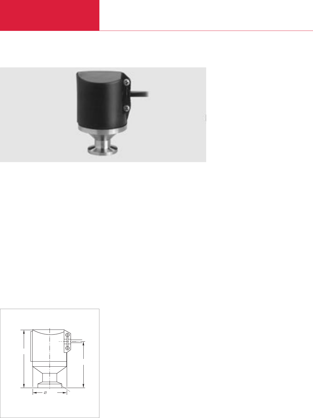
Sensors
Total Pressure Gauges
C16.40 LEYBOLD VACUUM PRODUCTS AND REFERENCE BOOK 2003/2004
DI 200/DI 201/DI 2000/DI 2001/DI 2001 rel Linear Pressure Sensors
Advantages to the User
◆Pressure sensor of the two-wire type
◆Absolute pressure ranges from 0.1 to 200
mbar or 1 to 2000 mbar
◆Relative pressure range
from -1000 mbar to +1000 mbar
◆Excellent overload characteristic due to the
AI
2
O
3
ceramics diaphragm
◆Highly corrosion resistant
◆Independent of the type of gas
◆Vibration resistant
◆Supply voltage range of 12 to 30 V DC
◆Linear output signal of 4 to 20 mA
◆Compact design
Typical Applications
◆Pressure measurements in the rough vacuum
range, and for corrosive media
◆Chemical process engineering
◆Vacuum packaging
◆Drying processes
◆Measurement of operating and filling
pressure, during the production of lamps
◆Filling systems for brake fluids
(DI 201/DI 2001)
◆Filling systems for refrigerants
◆Measurement of pressure relative to atmos-
pheric pressure (DI 2001 rel)
Capacitive pressure sensor based on ceramics
technology.
Available as absolute or relative pressure sensor
48,5
80
58
DN 16 KF
Dimensional drawing for the sensors DI 200/DI 201/DI 2000/DI 2001/DI 2001 rel

Sensors Total Pressure Gauges
C16.41
C16
LEYBOLD VACUUM PRODUCTS AND REFERENCE BOOK 2003/2004
DI 200 DI 201 DI 2000 DI 2001 DI 2001 relTechnical Data
Ordering Information
Measurement range mbar
(Torr)
Overload range, max. bar
Nominal temperature range °C
Measurement uncertainty 1)
(± temperature error) % FS
Resolution % FS
Reproducibility % FS
Linearity % FS
Temperature error
Zero drift % FS/10°K
Sensitivity drift % FS/10°K
Principle of measurement
Sensing head supply
Output signal mA
Supply voltage V DC
Operating range V
Dead volume cm3
Vacuum connection DN
Weight, approx. kg
Protection class IP
Materials in contact with the medium
Operating units
Linear absolute pressure sensor, complete
with 5 m long connection cable and connecting plug
1) Sum of linearity, hysteresis and reproducibility
Part No. 158 12 Part No. 158 14 Part No. 158 13 Part No. 158 15 Part No. 245 000
0.1 to 200 1 to 2 000 - 1000 to + 1000
(0.075 to 150) (0.75 to 1500) (- 750 to + 750)
5 10
0 to 60
0.2
0.05
0.1
0.1
0.1
0.15
Capacitive
Two-wire system
4 to 20
+ 24 typ.
12 to 30, Ripple 1 Vpp
3
16 KF
0.55
44
Stainless steel 1.4305, Stainless steel 1.4305, Stainless steel 1.4305, Stainless steel 1.4305,
Al2O3(96 %) ceramics, Al2O3(96 %) ceramics, Al2O3(96 %) ceramics, Al2O3(96 %) ceramics,
FKM EPDM FKM EPDM
MEMBRANOVAC DM 11, DM 12 / PIEZOVAC PV 20 / COMBIVAC CM 32 MEMBRANOVAC DM 11/12 /
COMBIVAC CM 32
DI 200 DI 201 DI 2000 DI 2001 DI 2001 rel
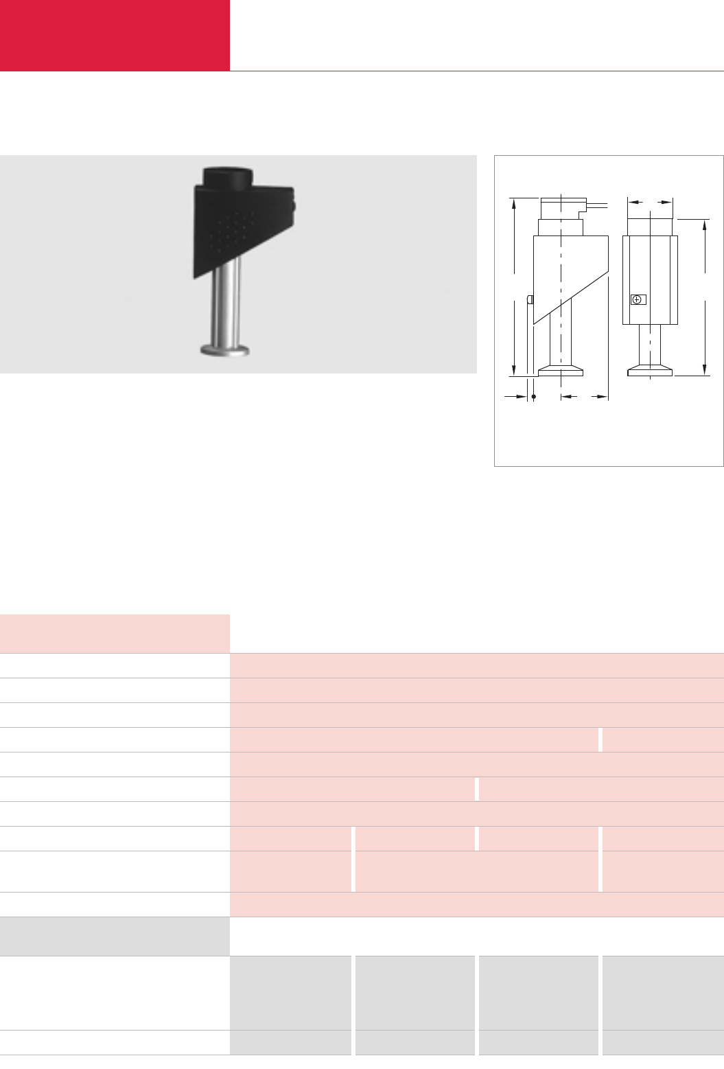
Sensors
Total Pressure Gauges
C16.42 LEYBOLD VACUUM PRODUCTS AND REFERENCE BOOK 2003/2004
Series 200 THERMOVAC Sensor
Advantages to the User
◆Measurement range 5 x 10
-4
to 1 000 mbar
(3.75 x 10
-4
to 750 Torr)
◆Tungsten or platinum filament
◆Cost-effective sensing cell
◆Fully aligned and temperature compensated
0 to 40 °C
◆Constant filament temperature
TR 211
◆Aluminum sensing cell with tungsten filament
◆Improved temperature compensation
TR 211 NPT/TR 212
◆Stainless steel sensing cell with tungsten
filament
◆Overpressure resistant
20 40
135
(144)
5
133
(122)
35
Dimensional drawing for the TR 211, TR 212 and TR 216;
TR 211 NPT in brackets
TR 216
◆Stainless steel sensing cell with platinum/
tungsten filament and ceramics feedthrough
◆Well suited for corrosive processes and water
vapour atmospheres, for furnace and heat
treating application
THERMOVAC sensors Series 200
DN 16 KF
DN 16 CF
DN 1/8" NPT
Replacement sensing cell
Ordering Information
Part No. 157 85 – Part No. 158 52 Part No. 157 87
– – Part No. 158 86 –
–Part No. 896 33 – –
Part No. 157 75 Part No. 896 34 – Part No. 157 77
TR 211 TR 211 NPT TR 212 TR 216Technical Data
Measurement range mbar (Torr)
Operating temperature range (compensated) °C
Storage temperature range, max. °C
Filament
Filament temperature °C
Permissible overload (abs.), max. bar
Volume of the sensing cell, approx. cm3
Vacuum connection DN
Materials in contact with the medium
Operating units
5 x 10⁻⁴ to 1000 (3.75 x 10⁻⁴ to 750)
0 to 40
80
Tungsten Platinum
110
3 10
11
16 KF 1/8" NPT 16 KF/CF 16 KF
Aluminum, Vacon, glass, tungsten Stainless steel, Vacon, glass, Stainless steel 1.4301 (SS 304),
CrNi 8020, epoxy cement tungsten, CrNi 8020, epoxy cement Al2O3-ceramics, CrNi 8020
THERMOVAC TM 20, 21, 22 / COMBIVAC CM 31, 32, 33 / PIEZOVAC PV 20
TR 211 TR 211 NPT TR 212 TR 216
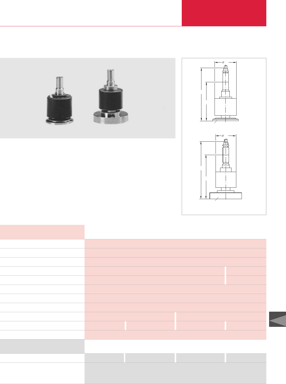
Sensors Total Pressure Gauges
C16.43
C16
LEYBOLD VACUUM PRODUCTS AND REFERENCE BOOK 2003/2004
PR 25/PR 26/PR 27/PR 37 PENNINGVAC Sensors
Advantages to the User
◆Rugged
◆Insensitive to air inrushes and vibrations
◆
Easy disassembly and cleaning of the measure-
ment system
◆Exchangeable cathode plate
◆Improved ignition characteristic through
titanium cathodes
Note
In applications involving significant contaminati-
on we recommend the use of a fine filter, see
chapter “General”, para. “Connection Accessories
for Small Flanges”.
DN 25 KF / DN 40 KF
94
132
50
Dimensional drawing for the PENNINGVAC PR Sensors
PR 25 PR 26 PR 27 PR 37
PENNINGVAC sensors
Replacement cathode plate, titanium
(5 pcs., incl. 5 ceramics discs)
Replacement anode ring
1) When using an ultra sealing gasket at the vacuum connection
2) For PR 25 also PTR 225
PR 25 PR 26 PR 27 PR 37
Technical Data
Ordering Information
Measurement range mbar (Torr)
High voltage supply (anode potential) kV
Storage temperature range °C
Nominal temperature range °C
Degassing temperature (flange) °C
Permissible overload (abs.) bar
Dead volume cm3
Materials in contact with the medium
Weight, approx. kg (lbs)
Vacuum connection DN
Operating units 2)
1 x 10⁻⁹ bis 10-2 (0.75 x 10⁻⁹ to 10-2 1))
+ 3.3/+1.6
-25 to +80
0 to 80 0 to 200
– 350
61)
21
Stainless steel, nichrome, ceramics, titanium
0.75 (1.7) 0.8 (1.8)
25 KF 40 KF 40 CF 40 CF
COMBIVAC CM 31, 32, 33 / PENNINGVAC PM 31
Part No. 157 52 Part No. 136 46 Part No. 136 47 Part No. 157 54
Part No. 162 91
Part No. 240 002
107
147
50
DN 40 CF
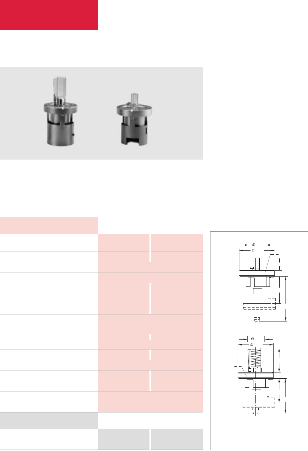
Sensors
Total Pressure Gauges
C16.44 LEYBOLD VACUUM PRODUCTS AND REFERENCE BOOK 2003/2004
IE 414/IE 514 IONIVAC Sensors
Advantages to the User
◆Exchangeable cathode
◆High accuracy of the measurements due to
individually calibrated sensing system
IE 414
◆Bayard-Alpert sensing system
◆Measurement range to 2 x 10
-11
mbar
(1.5 x 10
-11
Torr)
◆Protection shied welded in place
IE 414 IE 514
IONIVAC sensors
Replacement cathode
1) With bakeable gauge head cable
2) With gauge head cable detached
IE 414 IE 514
Technical Data
Ordering Information
69,4
33
DN 40 CF
66
25
12,8
98
58
12,8
DN 40 CF
55
90
69,4
33
Dimensional drawing IE 414 (bottom) and IE 514 (top)
Measurement range mbar (Torr)
X-ray limit mbar (Torr)
Operating temperature range °C
Degassing temperature at the flange, max. °C
Material, Cathode
Feedthrough pins
Anode
Vacuum connection DN
Adjustment data, Ion detector potential V
Cathode potential V
Anode potential V
Emission current mA
Heating current for the hot cathode A
Heating voltage for the hot cathode V
Sensitivity for nitrogen mbar-1
Degassing operation / Electron bombardment V / mA
Operating units
2 x 10-11 to 10-2 10-12 to 9.98 x 10⁻⁵
(1.5 x 10⁻¹¹ to 10-2) (10-12 to 750 x 10-5)
≤10-11 (≤10-11)≤10-12 (≤10-12)
0 to 80
250 1) / 350 2)
Iridium with Iridium with
yttric oxide coating yttric oxide coating
NiFe 42 NiFe 42
Pt/Ir 90/10/pt wire Mo and CoNiCr
40 CF
0
80 100
220
0.06 to 0.6 1.6
1.4
2.7 3.7
17 6.6
700 / 30
IM 520, 510
Part No. 158 66 Part No. 158 67
Part No. 158 63 Part No. 158 61
IE 514
◆Extractor sensing system
◆Reliable to 1 x 10
-12
mbar (0.75 x 10
-12
Torr)
◆Significant reduction of X-ray and
ion desorption effects
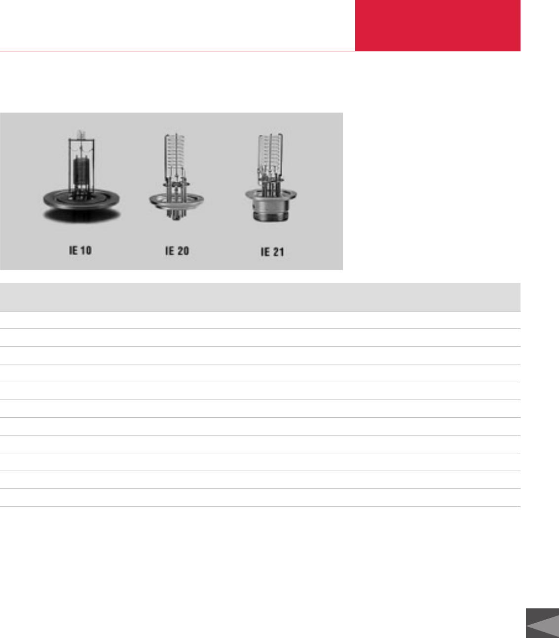
Sensors Total Pressure Gauges
C16.45
C16
LEYBOLD VACUUM PRODUCTS AND REFERENCE BOOK 2003/2004
Spare Sensors for Older Operating Units
Part No. Type Corresponding Sensors / Operating Units
163 43 IE 10 IM 110, IM 110 D
163 14 IE 20 IM 210, IM 210 D, IT 230
158 58 Cathode IE 220
896 30 TR 901 KF IG3 / CM 3
896 31 TR 901 NPT IG3 / CM 3
162 09 *)Sensing cell TR 201/901 DN 16 KF
896 76 *)Sensing cell TR 201/901 NPT
157 40 *)TR 301 TM 320, CM 350, IM 520, DM 11, DM 12, CM 32
157 43 *)Sensing cell TR 301
158 82 VK 201 VISCOVAC VM 212
158 17 IE 21 IM 210, IM 221
*)to be discontinued
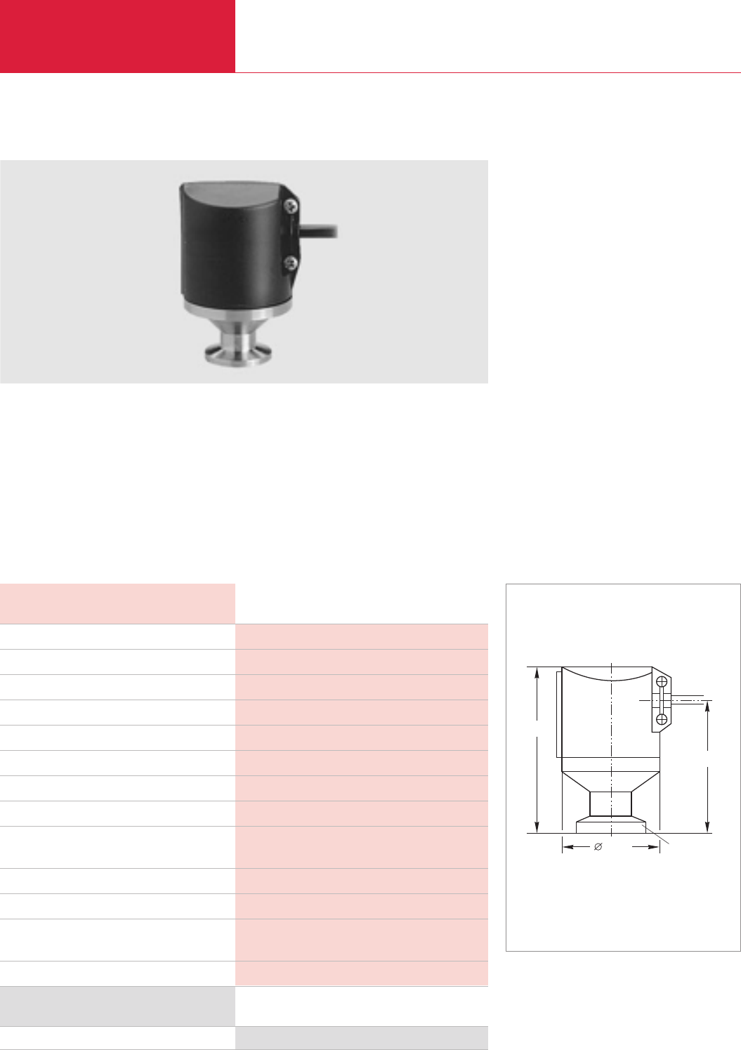
Pressure Switches and Control Instruments
Total Pressure Gauges
C16.46 LEYBOLD VACUUM PRODUCTS AND REFERENCE BOOK 2003/2004
PS 113 A Low Pressure Safety Switch
Advantages to the User
◆Rugged design
◆High switching capacity
◆Corrosion protected
◆Easy to use
◆IP 44 protection
◆Can be connected to a programmable control
Typical Applications
◆Venting facilities
◆Safety shutdown of vacuum systems
◆Load locks
Switch indicating whether or not after venting the
pressure has reached the level of the atmospheric
pressure.
Preset diaphragm pressure switch set to a pres-
sure of 6 mbar (4 Torr) below atmospheric pres-
sure.
Technical Note
Due to the diaphragm material used (EPDM) the
PS 113 A is not suited for applications in which
the process gas contains large quantities of heli-
um. Owing to diffusion effects the leak rate of the
diaphragm settles at about 1 x 10
-6
mbar x l x s
-1
for helium.
Part No. 230 011
PS 113 A
PS 113 A, DN 16 KF; complete with 3 m long cable
PS 113 A
Technical Data
Ordering Information
48,5
72
50
DN 16 KF
Dimensional drawing for the PS 113 A low pressure safety switch
Switching pressure mbar (Torr)
Return switching pressure mbar (Torr)
Switching inaccuracy mbar (Torr)
Max. permissible operating pressure (abs.) mbar (Torr)
Storage temperature range °C
Nominal temperature range °C
Switching contact
Contact life (at 5 A)
Switching capacity
Electrical connection
Vacuum connection DN
Materials in contact with the medium
Protection class IP
Approx. 6 below atmospheric pressure
3 below atmospheric pressure
2 (1.5)
2000 (1 500)
-25 to +85
0 to 85
Changeover contacts, gold-plated, for prog. controls
> 105switching cycles
100mA / 24 V AC
30mA / 24 V DC
6.3 mm flat plug
16 KF
Stainless steel 1.4305, 1.4310,
Stainless steel 1.4300 PTFE coated
44
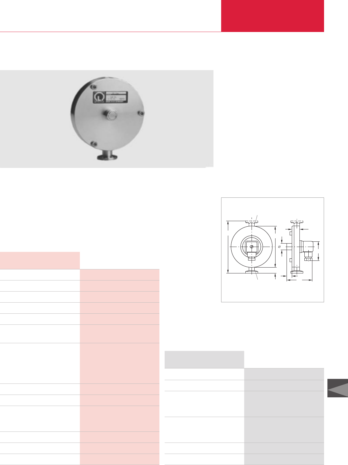
Pressure Switches and Control Instruments Total Pressure Gauges
C16.47
C16
LEYBOLD VACUUM PRODUCTS AND REFERENCE BOOK 2003/2004
Switching range mbar (Torr)
Overload limit mbar (Torr)
Sensitivity mbar (Torr)
Switching hysteresis mbar (Torr)
Temperature coefficient %/°K
Nominal temperature range
Briefly (max. 8 h)/continuous °C
Switching contact
Switching voltage V
Switching current (max.) mA
Contact resistance, max. kΩ
Electrical connection
Protection class IP
Vacuum connection DN
Materials in contact with the medium
Measurement chamber
Reference chamber
Volume of the measurement chamber cm3
Volume of the reference chamber cm3
Weight kg (lbs)
PS 115
PS 115, DN 16 KF
Pressure switch adjustment
For floating installations without SV 110,
Clamping ring DN 16 KF, plastic
Centering ring, DN 16 KF, plastic
Option
Differential pressure adapter, DN 16 KF,
for connection to the PS 115
Spare parts kit PS 115
SV 110 switching amplifier
PS 115
Technical Data
Ordering Information
PS 115 Pressure Switches
Advantages to the User
◆High switching accuracy (± 0.1 mbar)
◆Stable long term operating characteristics
◆Rugged, corrosion protected design
◆Increased switching capacity (floating) when
using the SV 110 switching amplifier
◆Switching contact (n.c.) in the reference
chamber and thus protected against corrosion
◆For operating pressures up to 3 bar
◆For high ambient temperatures
◆Upon request, the switching threshold may be
set in the factory
Rugged absolute pressure switch with electrical
switching contact and a switching pressure bet-
ween 0.5 and 2000 mbar (0.4 and 1500 Torr).
Through the differential pressure adapter (option-
al) the PS 115 pressure switch may be converted
to operate as a differential pressure switch. The
adapter consists of a DN 16 KF flange with screw-
in thread and a sealing arrangement, and it is
screwed into the PS 115 instead of the adjust-
ment valve. The operating range extends to
2 000 mbar (1500 Torr). Brief overloading to
3 000 mbar (2250 Torr) is permissible without
impairing switching accuracy. In this operating
range differential values of +5 to -20 mbar
(+3.75 to -15 Torr) can be adjusted via the set
screw.
51
DN 16 KF
Option:
Differential pressure
adapter DN 16 KF
85
18
14
105
21
19
133
Dimensional drawing for the PS 115
0.5 to 2 000 (0.375 to 1500)
3000 (2250)
0.1 (0.75)
0.5 (0.375)
0.4 of the switching value
120 / 0 to 90
Normally closed, gold-plated, for prog. controls
24
10
1
Plug (DIN 43 650)
65
16 KF
Stainl. steel 1.4301; 1.4401; 1.4310; 1.3541; FPM
Stainl. steel
1.4301; 1.4401; 1.3541; glass; gold
4
20
1.3 (2.87)
Part No. 160 04
Part No. 160 05
Part No. 200 28 306
Part No. 200 28 307
Part No. 160 74
Part No. 160 06
Part No. 160 78
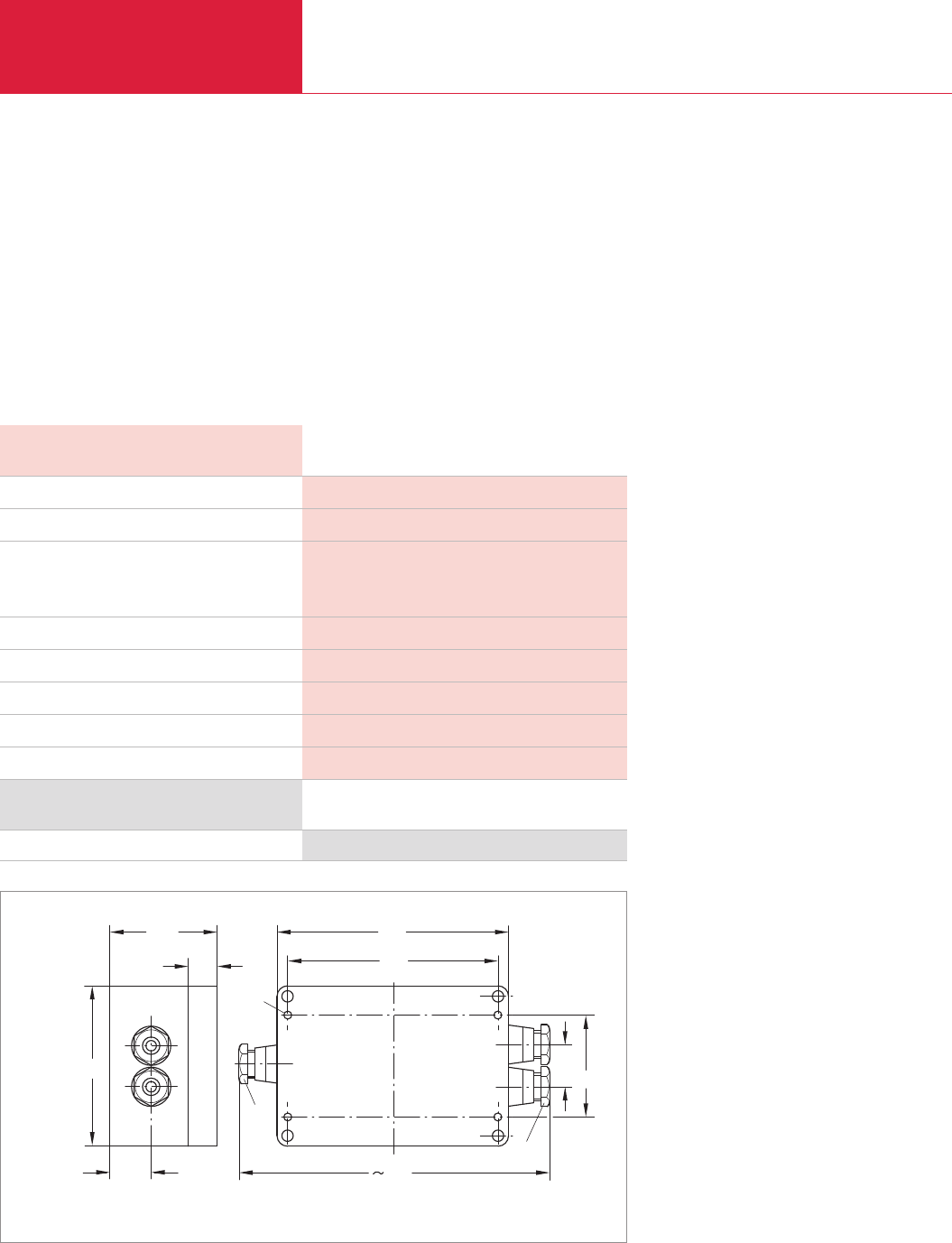
Pressure Switches and Control Instruments
Total Pressure Gauges
C16.48 LEYBOLD VACUUM PRODUCTS AND REFERENCE BOOK 2003/2004
SV 110 Switching Amplifier
The diaphragm contact of the pressure swit-
ches is connected on one side to ground and
is rated 24 V / 10 mA max. When wanting to
switch higher voltages or currents, a switching
amplifier will be needed. The switching ampli-
fier is equipped with powerful floating change-
over contacts. The output relay is energized as
soon as the pressure drops below the swit-
ching threshold set up on the pressure switch.
The electrical connections are provided via
screw terminals and are run out of the plastic
enclosure through PG fittings.
Advantages to the User
◆Increased ratings for the switch
◆Changeover contact
21,5
80
4,2
15 109
121
55,5
Pg 9
Pg 9
2150,5
163
Dimensional drawing for the SV 110 switching amplifier
Part No. 160 78
SV 110
Switching Amplifier
SV 110
Technical Data
Ordering Information
Mains supply, 50/60 Hz
Power consumption VA
Output relay
Switching voltage/current V / A
Switching power, max. VA
Response time ms
Relaise time ms
Control circuit V / mA
Ambient temperature, max. °C
Weight, approx kg (lbs)
110/130/220/240 V, selectable
3
250 / 5
500
30
7
24 / 10
50
0.36 (0.79)
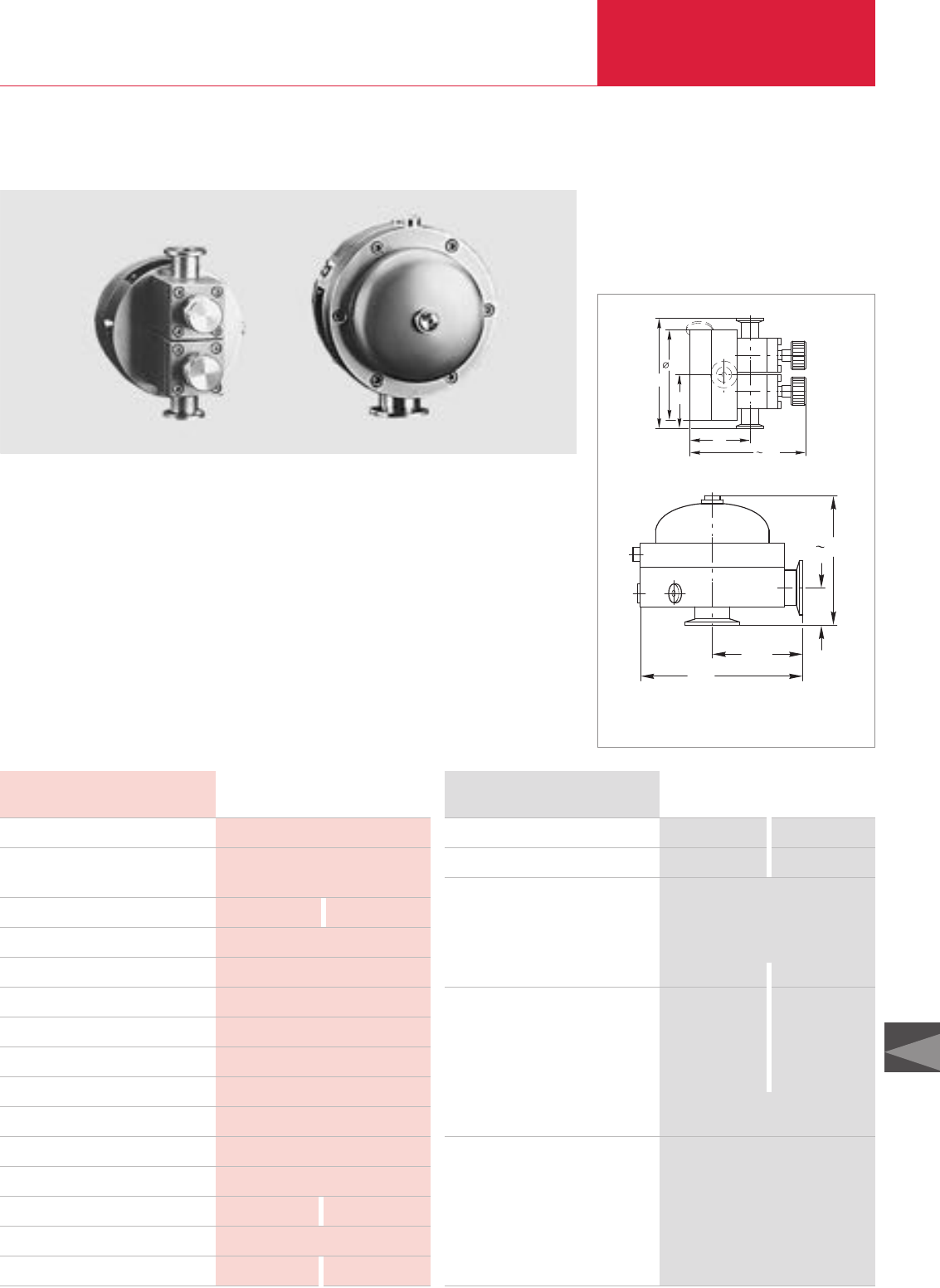
Pressure Switches and Control Instruments Total Pressure Gauges
C16.49
C16
LEYBOLD VACUUM PRODUCTS AND REFERENCE BOOK 2003/2004
Control range mbar (Torr)
Control inaccuracy
Throughput m3/h
Nominal temperature range °C
Storage temperature range °C
Temperature coefficient %/K
Settling time ms
Permissible overload for brief periods bar
Diaphragm material
Housing material
Installation orientation
Dimensions
Vacuum connection 2x DN
Measurement connection 3x thread R
Weight, approx. kg (lbs)
MR 16 MR 50
MR 16, DN 16 KF
MR 50, DN 40 KF
Options
Stainless steel measurement flange,
DN 16 KF for connection to a reference
and/or process chamber or pumping stud
KALREZ diaphragm
Spare parts
EPDM diaphragm and seal kit
Viton diaphragm and seal kit
Seal kit MR 50,
incl. EPDM and Viton diaphragms
Adjustment screw of the adjustable valve,
complete with seal
MR 16 MR 50
Technical Data Ordering Information
MR 16/MR 50 Diaphragm Pressure Regulators
Advantages to the User
◆Non-incremental, automatic pressure control
◆Simple setting of the control pressures
◆High control accuracy
◆Corrosion protected stainless steel design
◆Easy to disassemble for cleaning and
maintenance
◆Trouble-free operation in ex. areas
◆Built-in isolation valves for the process
connection and the vacuum pump (MR 16)
Typical Applications
◆Distillation processes of all kinds
◆Solvent recovery
◆Drying processes
◆Temperature control on bath cryostats
◆Degassing of liquids and plastics
The MR 16/50 diaphragm regulators are absolute
pressure regulators which automatically adapt the
pumping speed of a vacuum pump depending on
the amount of gas, without the need for an extern-
al power supply.
67
130
98
120
58,5
39
135
92,5
165
Dimensional drawing for the MR 16 diaphragm regulator (top)
and MR 50 diaphragm regulator (bottom)
10 to 1 000 (7.5 to 750)
± 2 % of the control pressure
(10 - 90 % of flow)
16 50
5 to 100
-25 to +60
0.3
5
3
FPM/EPDM
Stainless steel 1.4571
Any
See dimensional drawing
16 KF 40 KF
1/8"
2.7 (6) 8 (17.6)
Part No. 160 25 –
–Part No. 160 27
Part No. 160 26
– Part No. 200 28 597
Part No. 160 29 –
Part No. 160 31 –
– Part No. 160 32
Part No. 240 001
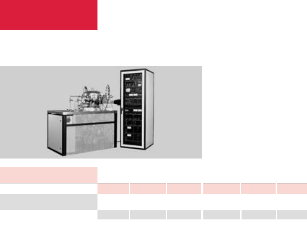
Miscellaneous
Total Pressure Gauges
C16.50 LEYBOLD VACUUM PRODUCTS AND REFERENCE BOOK 2003/2004
LEYBOLD Calibration Service
Advantages to the User
◆Clear reference to the reference quantities
◆Reproducible measurements
◆Constantly high quality over time
◆Reliable checking of existing gauges
◆Unambiguous description of the process
Since 1981 LEYBOLD has been offering to all
customers an impartial calibration service for
gauges and sensors of any make. A DKD calibra-
tion certificate or a factory calibration certificate
is issued for every calibration. Instruments with
insufficient long-term stability or such instru-
ments where the principle of measurement is not
suited for calibration, can not be calibrated.
Typical Applications
Calibrated vacuum gauges are used under the fol-
lowing conditions:
◆If the requirements concerning reproducibility
and comparability of experiment runs are high
◆If an unambiguous reference is required for a
large number of pressure gauges
◆If an unambiguous description for processes
is required
◆If for experiments and processes unambig-
uous traceability of the measured pressures
to basic quantities is demanded by the author-
ities
◆If testing to DIN/ISO 9000 is required in the
following areas
◆Research
◆Thin-film engineering
◆Manufacture of systems
◆Military
◆Energy
◆Chemistry production
◆Production of pharmaceuticals and
herbicides
◆Sputtering systems
◆Aircraft and space industry
◆Manufacture of lamps
DKD Calibration
It is the task of the German Calibration Service
(DKD) to ensure traceability of industrial
measurements and testing to national standards.
The German Calibration Service is run jointly by
the Federal Institution for Physics and
Technology (PTB), the industry, the Federal
Minister for Economics and the Western
European Metrology Club (WEMC).
The transfer standards employed in the DKD
calibration facility run by LEYBOLD are checked
regularly (recalibrated) by the PTB.
Within the framework of the German Calibration
Service, the calibration pump system at
LEYBOLD has been checked and approved by the
PTB and the transfer standards employed have
been calibrated by the PTB.
Factory calibrations are run with standards which
have not been calibrated directly at the PTB;
instead the transfer standards of the in-house
DKD calibration service are used. Thus traceabili-
ty to national standards is ensured in both cases.
Calibration of vacuum gauges in the pressure
range from 10
-9
to 1 000 mbar (10
-9
to 750 Torr)
through two systems.
DKD Calibration Factory Calibration
Technical Data
Calibration range mbar to 10-3 to 10-5 to 10-9 to 10-3 to 10-5 to 10-8
157 12 157 13 157 14 157 22 157 23 157 24
Part No.
DKD Calibration Factory Calibration
Ordering Information
Note
For US we offer NIST Calibration upon request.
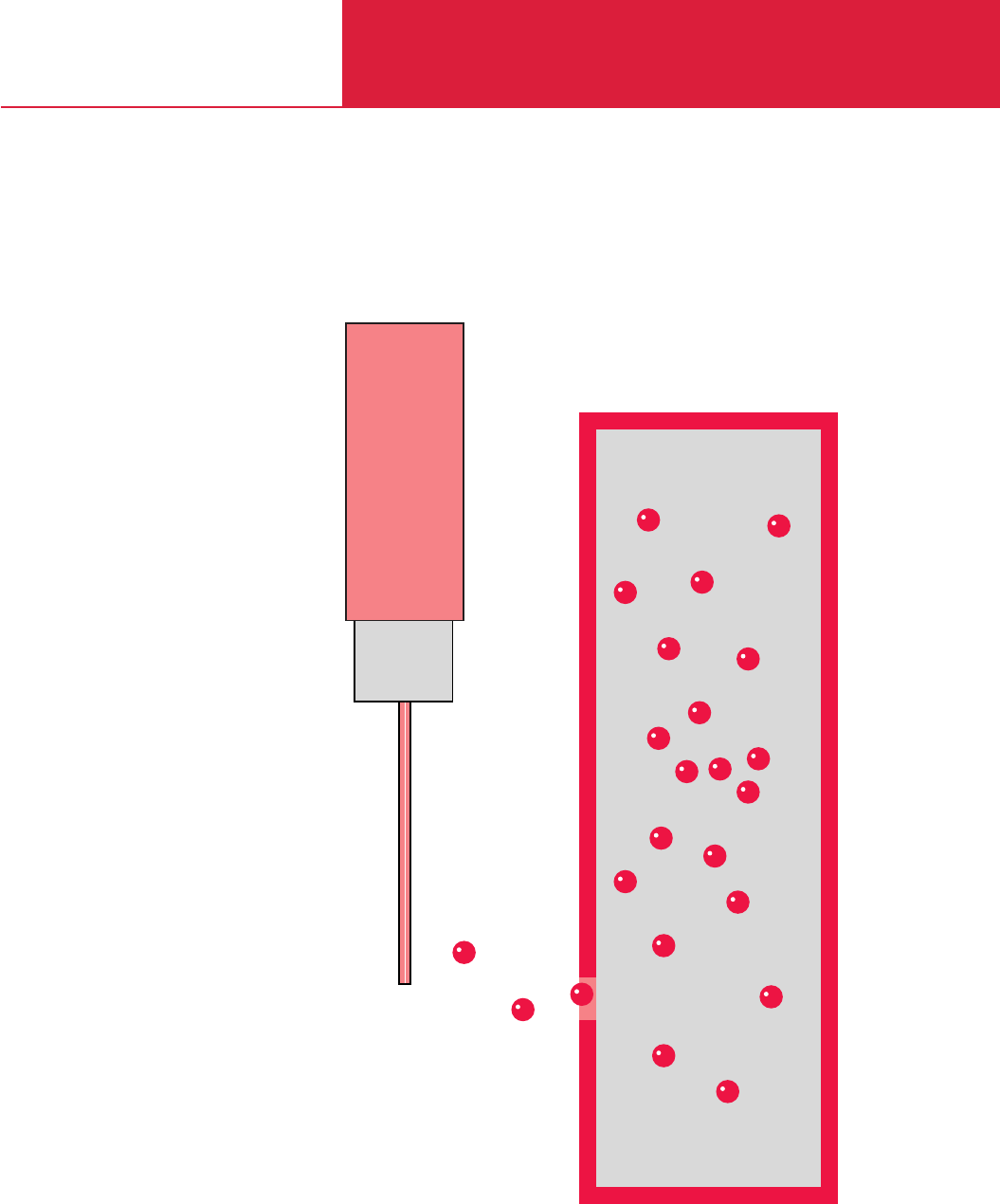
C17
Helium Leak Detectors
Leak Testing Instruments

Leak Testing Instruments
C17.02 LEYBOLD VACUUM PRODUCTS AND REFERENCE BOOK 2003/2004
Contents
General
Applications and Accessories . . . . . . . . . . . . . . . . . . . . . . . . . . . . . . . . . . . . . . . . . . . . . . . C17.03
Leak Detection - Leak Testing . . . . . . . . . . . . . . . . . . . . . . . . . . . . . . . . . . . . . . . . . . . . . . . C17.04
Leak Detection Methods. . . . . . . . . . . . . . . . . . . . . . . . . . . . . . . . . . . . . . . . . . . . . . . . . . . C17.05
Operating Principles of the Helium Leak Detectors . . . . . . . . . . . . . . . . . . . . . . . . . . . . . . . C17.06
Products
Helium Leak Detectors
L 200
plus
. . . . . . . . . . . . . . . . . . . . . . . . . . . . . . . . . . . . . . . . . . . . . . . . . . . . . . . . . . . C17.08
L 200 dry . . . . . . . . . . . . . . . . . . . . . . . . . . . . . . . . . . . . . . . . . . . . . . . . . . . . . . . . . . . C17.09
Modul L 200
plus
. . . . . . . . . . . . . . . . . . . . . . . . . . . . . . . . . . . . . . . . . . . . . . . . . . . . . C17.10
Mobile Leak Detection Systems fitted to the CART 200 . . . . . . . . . . . . . . . . . . . . . . . . . . . . C17.12
Product-Related Accessories
Calibrated Leaks for Vacuum and Sniffer Aplications . . . . . . . . . . . . . . . . . . . . . . . . . . . . . . C17.14
Screw-in Calibrated Leaks . . . . . . . . . . . . . . . . . . . . . . . . . . . . . . . . . . . . . . . . . . . . . . . . . . C17.16
Accessories
for the L 200
plus
, L 200 dry and Modul L 200
plus
. . . . . . . . . . . . . . . . . . . . . . . . . . . C17.18
Helium Sample Probes (Sniffers). . . . . . . . . . . . . . . . . . . . . . . . . . . . . . . . . . . . . . . . . . . . . C17.20
Other Accessories
Connection Flanges . . . . . . . . . . . . . . . . . . . . . . . . . . . . . . . . . . . . . . . . . . . . . . . . . . . . . . . C17.21
Connection Components . . . . . . . . . . . . . . . . . . . . . . . . . . . . . . . . . . . . . . . . . . . . . . . . . . . C17.21

General Leak Testing Instruments
C17.03
LEYBOLD VACUUM PRODUCTS AND REFERENCE BOOK 2003/2004
C17
Semiconductor production
Vacuum coating
Research and development
Chemistry/pharmaceutical
Metallurgy/furnaces
Lamps and tube manufacture
Automotive industry
Laser engineering
Particle accelerators
Analytical engineering
Systems with cryo pumps
Cooling and air conditioning
Electrical engineering
Mechanical engineering
Power plants
Systems engineering
UHV applications
Applications
Accessories
Test Instruments /
Leak Detectors
L 200
plus
L 200 dry
Calibrated leaks
Screw-in calibrated leaks
Transportation means
Partial flow system
PC software LeakWare
Helium sniffers
Exhaust filter sets
Interfaces
Gas ballast facilities
Trigger relay boards
Seal kits
Page
C17.14 ◆ ◆ ◆ ◆
C17.16 ◆ ◆ ◆ ◆
C17.18 ◆ ◆ ◆ ◆
C17.18 ◆ ◆
C17.18 ◆ ◆ ◆ ◆
C17.20 ◆ ◆ ◆ ◆
standard standard
standard standard standard standard
standard
standard standard standard standard
◆ ◆ ◆ ◆
Applications and Accessories
◆ ◆ ◆
◆ ◆
◆ ◆ ◆
◆ ◆ ◆ ◆
◆ ◆
◆ ◆
◆ ◆
◆ ◆
◆ ◆
◆ ◆ ◆ ◆
◆ ◆ ◆ ◆
◆ ◆
◆ ◆
◆ ◆
◆ ◆
◆ ◆
◆ ◆ ◆ ◆
Modul L 200
plus
,
(oil-free)
Modul L 200
plus
,
(oil-sealed)
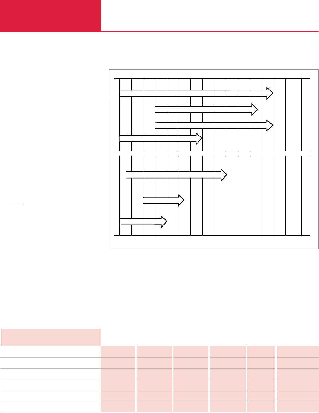
General
Leak Testing Instruments
C17.04 LEYBOLD VACUUM PRODUCTS AND REFERENCE BOOK 2003/2004
Leak Detection – Leak Testing
Whether a component or a system is leak-tight
depends on the application it is to be used in and
the leak rate that is acceptable. Absolutely leak-
tight components and systems do not exist. A
component is considered technically leak-tight if
its leak rate remains below a value defined for
this particular component. In order to provide a
quantitative measure, the term “leak rate” with
the symbol “q
L
” was introduced. In vacuum tech-
nology mbar x l x s
-1
is used as the unit for leak
rates.
A leak rate of 1 mbar x l x s
-1
exists in a closed
vessel having a volume of 1 liter when the pres-
sure increases by 1 mbar within one second, or
in case of an overpressure it decreases by
1 mbar within one second.
qL =V x Dp(mbar x l x s
-1
)
Dt
The wide range of leak rates from several
100 mbar x l x s
-1
to below 10
-11
mbar x l x s
-1
as they occur in practice necessitates the use of
different leak detection principles and hence leak
detectors (see figure).
Besides the determination of the total leak tight-
ness, it is usually important to locate the leak,
quickly and precisely, in order to seal it. Instru-
ments for local leak detection are called leak
detectors. The leak detectors presented in this
product section can be used for the localization
of leaks, and in addition some are suitable for
determining the total leak rate of test objects.
Vacuum method
Overpressure method
Helium leak detector L 200
plus
with helium sniffer
103................10010-1 10-2 10-3 10-4 10-5 10-6 10-7 10-8 10-9 10-10 10-11 10-12 mbar · l · s-1
Pressure rise
Helium leak detector L 200
plus
with partial flow pump set
Helium leak detector L 200
plus
/ Modul L 200
plus
Helium leak detector L 200 dry
Bubble test
Pressure drop test
Leak Rate atm x cm3x s-1 * kg x h-1 g/a
Pa x m3x s-1 mbar x l x s-1 cm3x s-1 * torr x l s-1 * air C2H2F4 (R 134a)
1 10 9.87 7.5 4.28 x 10⁻² 2.28 x 10⁶
0.1 1 0.99 0.75 4.3 x 10⁻³ 2.28 x 10⁵
0.101 1.01 1 0.76 4.3 x 10⁻³ 2.3 x 10⁵
0.133 1.33 1.33 1 5.7 x 10⁻³ 3.0 x 10⁵
23.4 234 234 175 1 –
6.41 x 10⁻⁷ 7.58 x 10⁻⁶ 6.3 x 10⁻⁶ 4.8 x 10⁻⁶ – 1
Pa x m3x s-1
1 mbar x l x s-1 (He)
1 atm x cm3x s-1 * = cm3(STP) x s-1
1 torr x l x s-1*
1 kg x h-1 air
1 g/a C2H2F4(R 134a)
* According to international system of units only Pa x m3x s-1 is permissible
Overview of the leak rate detection ranges

General Leak Testing Instruments
C17.05
LEYBOLD VACUUM PRODUCTS AND REFERENCE BOOK 2003/2004
C17
Leak Detection Methods
There are two main groups of leak detection
methods; for both there are special instruments
available:
Vacuum Methods
The equipment to be tested is evacuated. The
pressure ratio between inside and outside is 0:1.
Overpressure Methods
The equipment to be tested is pressurized with a
search gas or a search gas mixture. The pressure
ratio between inside and outside is over 1:1.
Between the two methods there exist many varia-
tions depending on the particular application.
General Notes
1. The lowest leak rates can only be measured by
employing the vacuum method, whereby the fol-
lowing applies: The lower the leak rate, the higher
the requirements are concerning cleanness and
ultimate vacuum.
2. If possible the test objects should be tested
under the same conditions that will be used in
their final application, i.e. parts for vacuum oper-
ation should be tested according to the vacuum
method and parts for overpressure operation
should be tested using the overpressure method.
Leak Testing Based on
Vacuum Methods
(Vacuum inside the test object)
Pressure Rise Method
With this method it is only possible to determine
the total leak rate. The test object is evacuated
with a vacuum pump or a vacuum pump system.
A valve is used to isolate the test object from the
vacuum pump. The pressure will then rise as a
function of time. Curve (a) shows the theoretical
pressure rise if there is only a leak. Curve (b)
shows the pressure rise due to outgassing from
the surfaces of the test object. This pressure rise
tends to tail off in the direction of a saturation
level. If in such a case the time allowed for moni-
toring the pressure rise is too short, a leak will be
indicated which in reality does not exist. If one
waits long enough for the pressure to rise, i.e.
after the bend of curve (b) the outgassing pro-
cess can then be disregarded, so that the leak
rate can be determined from the known volume
of the test object and the measured pressure rise
over a fixed rise time (see equation on page 4).
Curve (c) shows the pressure rise as it occurs in
practice, where outgassing and leak rate add. The
detectable leak rate depends on the volume of the
test object, the obtained ultimate pressure and
the outgassing from the test object. In connec-
tion with very large test objects this method is
time consuming if extremely low leak rates are to
be determined in the fine and rough vacuum
range.
Local Leak Detection
The test object is evacuated by a vacuum pump
(auxiliary pump) until the pressure is low enough
for the leak detector to operate. When using a
helium leak detector, its own pump system will
take care of further evacuation. Suspicious spots
on the test object will then be sprayed with a fine
jet of search gas. Search gas entering through
leaks into the test object is pumped out by the
vacuum pump and it is converted by the leak
detector into an electrical signal which is then
displayed. This permits rapid detection and deter-
mination of the size of even the smallest leaks.
Integral Method
Determination of the total leak rate of a test
object. The testing arrangement is the same as
for local leak detection, but in this case the test
object is not sprayed with search gas on selected
areas, but it is surrounded by a hood or a cham-
ber which is filled with the search gas. Thus the
entire outer surface of the test object comes into
contact with the search gas. If the search gas
enters the test object, the total leak rate is indi-
cat-ed independently of the number of existing
leaks. With helium leak detectors it is possible to
determine the helium content of the air. This is
utilized in the detection of gross leaks.
Leak Testing Based on
Overpressure Methods
(Overpressure within the test object)
Pressure Drop Method
The test object is filled with a gas (for example
air or nitrogen) until the testing pressure is
reached. Precision vacuum gauges are used to
detect a possible pressure drop during the testing
period. This method is simple to implement, it is
suitable for the determination of gross leaks and
can be improved upon by using differential pres-
sure gauges. By applying soap solutions or simi-
lar, leaks can be located.
Local Leak Detection with Leak Detectors
– Sniffing
The test object is filled with the search gas or the
search gas/air mixture to which the leak detector
is sensitive. The leak detector is equipped with a
sniffer probe, whereby there is a low pressure at
the probe tip. If the sniffer tip passes suspicious
points on the test object the search gas coming
a) Pressure rise due to leakage
b) Pressure rise due to outgassing from the chamber walls
c) Both effects combined
Pressure rise in a vacuum chamber after switching off the pump;
double log. plot
1
2
3
4
5
LD
HELIUM
Local leak detection – Evacuated test object
2
3
4
LD
HELIUM
1
5
Integral method – Evacuated test object
Key to the Figures
1 Test object
2 Leak detector
3 Search gas cylinder
4 Vacuum pump
5 Hood
6 Spray gun for search gas
7 Sniffer probe
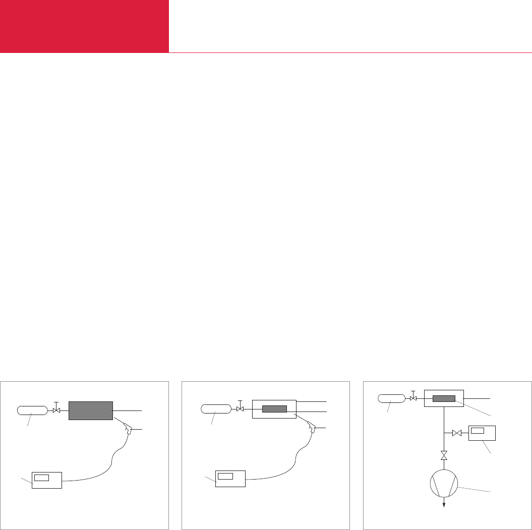
General
Leak Testing Instruments
C17.06 LEYBOLD VACUUM PRODUCTS AND REFERENCE BOOK 2003/2004
out of the leak is sucked in and transferred to the
detection system of the leak detector. After con-
version into electrical signals these are displayed
optically and acoustically by the leak detector.
Integral Method – Hood Test
To determine the total leak rate of a test object
subjected to a search gas overpressure, the test
object is surrounded by a hood of a known
volume. The search gas which escapes through
the leaks collects in the hood.
After a fixed accumulation period a sniffer probe
is used to measure the concentration of the
search gas which has collected in the hood.
Before this the leak detector should be calibrated
by a reference measurement using a known
search gas concentration.
The leak rate can then be determined by the
equation for q
L
where V is the volume of the
hood, Dp is the partial pressure difference of the
search gas (concentration change) and t is the
accumulation period.
Uncertainties in the determination of the volume,
leaks in the hood and a wrong accumulation peri-
od make precise leak rate measurements based
on this method very questionable.
Integral Method – Vacuum Hood Test
This test is a variation of the hood test described
above, which has considerable advantages. A
vacuum chamber which is evacuated by an auxili-
ary pump and which is connected to a leak detect-
or is used as the hood. The search gas escaping
through the leaks is converted by the detection
system of the leak detector into electrical signals
which are immediately displayed. After calibration
of the leak detector with a calibrated leak it is
possible to quantitatively determine the total leak
rate.
This method permits the detection of very small
leaks and is especially suited for automatic indus-
trial leak detection.
Integral Method – Bombing-Test
This method is used for testing hermetically sealed
components such as transistors, IC-packages or
dry reed relays. It is basically a variation of the
vacuum hood test. Here the test objects are
placed in a vessel which is pressurized with the
search gas - preferably helium. At a fairly high
search gas pressure and after a period of up to
several hours it is tried to enrich the search gas
inside leaky test objects. This is the actual so
called “bombing” process.
After this, the test objects are transferred to a
vacuum chamber and their total leak rate is deter-
mined in the same way as in the vacuum hood
test. During evacuation of the vacuum chamber
down to the required testing pressure, those test
objects which have a gross leak already lost their
accumulated search gas. These parts are not
detected as leaking during the actual leak test.
Therefore the test with the vacuum chamber is
often preceded by a “bubble test”.
This method permits the detection of the lowest
leak rates and is used mainly in automatic indus-
trial leak testing especially when it is not possible
to fill the parts with gas in any other way.
2
3
LD
HELIUM
1
7
Leak detection – Search gas overpressure in the test object
2
3
LD
HELIUM
1
7
5
Integral method (search gas accumulation)
Search gas overpressure in the test object
2
3
4
LD
HELIUM
1
5
Integral method – Search gas overpressure in the test object
Operating Principles of the Helium Leak Detectors
Operating Principle
A helium leak detector permits the localization of
leaks and the quantitative determination of the
leak rate, i.e. the gas flow through the leak. Such
a leak detector is therefore a helium flow meter.
In practice the leak detector performs this task by
firstly evacuating the part which is to be tested,
so that gas from the outside may enter through
an existing leak due to the pressure difference
present. If only helium is brought in front of the
leak (for example by using a spray gun) this heli-
um flows through the leak and is pumped out by
the leak detector. The helium partial pressure
present in the leak detector is measured by a
sector mass spectrometer and is displayed as a
leak rate. This is usually given in terms of volume
flow of the helium (pV-flow).
Important Specifications
The two most important features of a leak detec-
tor are its measurement range (detection limits)
and its response time.
The measurement range is limited by the lowest
and the highest detectable leak rate. The lowest
detectable leak rate is defined by the sum of drift
and noise in the most sensitive measurement
range. Usually the sum of noise amplitude and
zero drift per minute is made to be equivalent to
the lowest detectable leak rate. With leak detec-
tors the amount of drift is so low, that the noise
amplitude alone determines the detection limit.
The highest detectable leak rate depends strongly
on the method employed. Especially the counter-
flow method and partial flow operation (see
description below) permit the measurement of
very high leak rates even with a sensitive helium
leak detector. In addition the multi-stage switcha-
ble high impedance input amplifiers of the leak
detectors also permit the measurement of high
leak rates.
In practical applications, especially in the localiza-
tion of leaks the response time is of great signifi-
cance. This is the time it takes from spraying the
test object with helium until a measured value is
displayed by the leak detector. The response time
of the electronic signal conditioning circuitry is
an important factor in the overall response time.
In the case of leak detectors the response time of
the electronic circuitry is well below 1 s.
The volume flow rate for helium at the point of
the test object is of decisive significance to leak
detection on components which are pumped
down solely by the leak detector. This volume
flow rate provided by the leak detector takes care
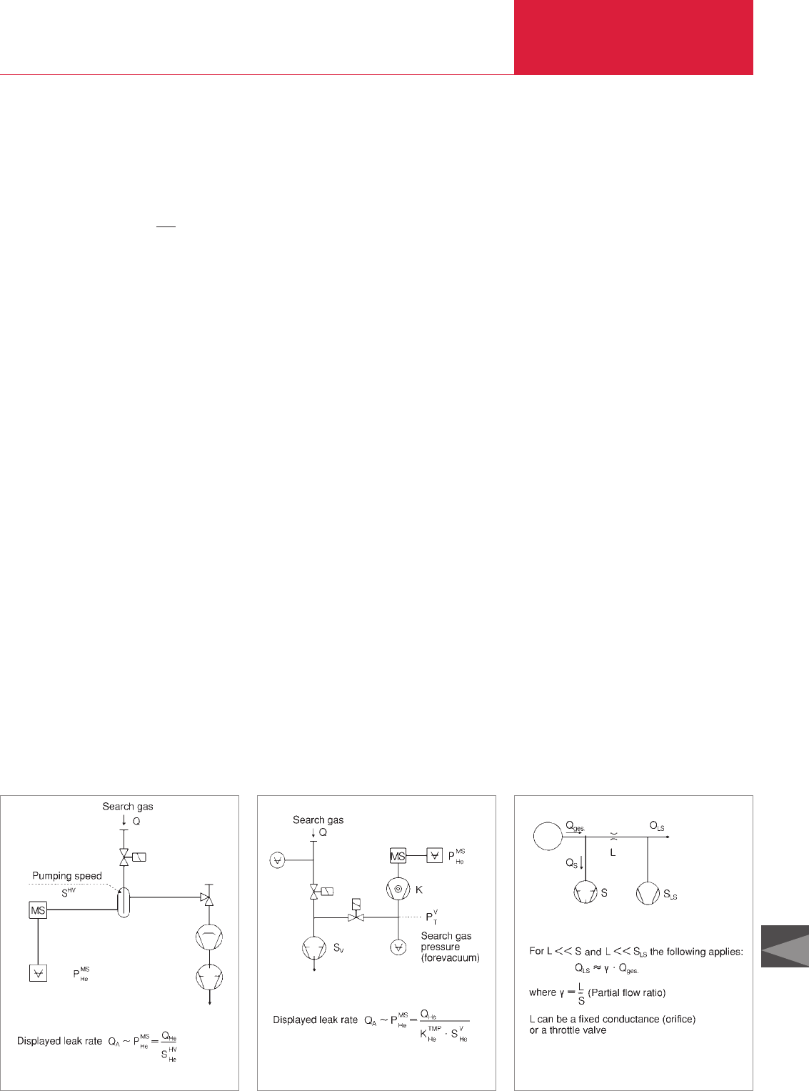
of the helium entering through a leak and it en-
sures quick detection by the leak detector. On the
other hand the volume of the test object delays
the arrival of the helium signal. The response
time can be calculated on the basis of the follow-
ing simple equation:
Response time for helium t
A
= 3
(for 95% of the final value)
with V = Volume of the test object
S
He
= Volume flow rate for helium at
the point of the test object
(or at the inlet of the leak detec-
tor, if it alone pumps down the
test object).
Main Flow Method
The classic operating principle of helium leak
detectors is based on the main flow method.
Here the entire helium flow passes through the
high vacuum system of the leak detector, where
the mass spectrometer measures the partial pres-
sure of the helium. In this, the use of a liquid
nitrogen cold trap is essential to remove water
vapor or other condensible gases in the vacuum
system which impair the operation. Moreover, the
use of a cold trap permits the low operating pres-
sures for the mass spectrometer to be reached
(below 10
-4
mbar) despite the directly connected
(and possibly contaminated) test object.
The advantages of the main flow method are:
– Highest sensitivity, i.e. low detection limit
– Short response time due to a high volume
flow rate at the inlet.
The main flow method is thus especially suitable
for stationary leak detection on components.
Leak detection on systems having their own
pump sets and at higher pressures requires the
use of an external throttling valve, i.e. a partial
flow with subsequently reduced sensitivity is uti-
lized.
General Leak Testing Instruments
C17.07
LEYBOLD VACUUM PRODUCTS AND REFERENCE BOOK 2003/2004
C17
Counterflow Method
With this method the test object is not connected
to the high vacuum. Instead it is connected to the
forevacuum (between turbomolecular pump and
backing pump), so that the entire gas flow (espe-
cially water vapor) does not contribute to the
pressure increase in the mass spectrometer. Thus
a cold trap is no longer required!
The helium which now enters the forevacuum can
still be detected, as it is able to flow against the
pumping direction of the turbomolecular pump
into the mass spectrometer. This is due to the
high particle velocity of the helium. The sensitivi-
ty of this counterflow arrangement is equal to
that of the main flow principle, provided the right
combination of volume flow rate of the backing
pump and helium compression of the turbomolec-
ular pump is used.
The advantages of the counterflow method are:
– No liquid nitrogen is required
– High permissible inlet pressures (i.e. pressure
within the test object)
This makes the counterflow method especially
suitable for mobile leak detection on systems. For
leak detection on larger components where a
short response time is essential (i.e. high volume
flow rate) an additional turbomolecular pump
stage is required at the inlet of the leak detector.
Partial Flow Method
In order to expand the measurement range in the
direction of higher leak rates and for operation at
higher inlet pressures, helium leak detectors
incorporate a partial flow or a gross leak system.
This consists basically of a throttle and a rotary
vane pump. At pressures above the normal inlet
pressure (main flow: above 10
-2
mbar, counter-
flow: above 10
-1
mbar) or in the case of high heli-
um leak rates, the inlet valve is closed and the
main flow is allowed to enter the partial flow
pump, whereas only a small part enters the leak
Partial flow methodMain flow method Counterflow method
detector via the partial flow throttle. Thus the
total pressure and the helium pressure are
dropped to values suitable for operation of the
leak detector.
To obtain correct leak rate readings in the partial
flow mode, the partial flow ratio, i.e. the ratio
between the actually measured gas flow and the
total gas flow must be known and stable.
In all leak detectors this is achieved by
a partial
flow throttle made of ruby with a precise
ly machi-
ned hole. This ensures that the quantitatively
determined leak rates are always correct without
calibration, even for gross leaks.
Calibration of Helium Leak
Detectors with Calibrated
Leaks
In the process of leak detection one expects that
a test object which does not have a leak produces
a zero reading on the leak detector. In this any
malfunctions are excluded. Thus calibrated leaks,
i.e. artificial leaks which produce a known helium
leak rate are essential for reliable results.
To obtain a quantitatively correct leak rate reading
the sensitivity of the leak detector must also be
adjusted. This requires the use of a calibrated
leak.
LEYBOLD offers calibrated helium leaks of
various designs covering the range between 10
-9
to 10
-4
mbar x l x s
-1
as part of the standard
range of products. All leak rates are traceable to
the standards of the German Calibration Service
controlled by the PTB (Federal Institution of Phy-
sics and Technology). If requested each helium
calibrated leak can be supplied with a calibration
certificate issued by the German Calibration
Service. The calibration itself is performed by the
German Calibration Service for Vacuum which is
run by LEYBOLD on behalf of the PTB.
V
S
He
Test
leak
Main flow or
counterflow
leak detector

Leak Testing Instruments
C17.08 LEYBOLD VACUUM PRODUCTS AND REFERENCE BOOK 2003/2004
Helium Leak Detectors
Helium Leak Detector L 200
plus
Advantages to the User
◆Quick start-up
◆Extremely fast response time
◆Oil-free gas admission system
◆One of the smallest helium leak detectors in
the world
◆High sensitivity
◆Ergonomically designed
◆Hand unit can be operated with one hand
equally well by right and left-handers
◆Fast leak rate readout also at low leak rates
Typical Applications
Leak tests in connection with
◆Quality assurance
◆Automotive industry
◆Analytical instruments
◆Systems manufacture
◆Power station engineering
◆Research and development
◆Semiconductor industry
◆High vacuum and ultra-high vacuum
engineering
◆Ideal tool for industrial series production
testing – in the cooling and air conditioning
industries, for example
In connection with the sniffer lines which are
available as accessories the L 200
plus
may also
be used as a sniffer leak detector.
In connection with a partial flow pump set the
L 200 may also be used for the detection of leaks
on large vessels.
Technical Data L 200
plus
Ordering Information L 200
plus
L 200
plus
230 V / 50/60 Hz, mbar readout, with TL 7
230 V / 50/60 Hz, mbar readout, without TL 7
PC software LeakWare
Seal kit
Calibrated leak TL 7 for fitting into the L 200
For further accessories see Section
“Accessories for L 200
plus
, L 200 dry and Modul L 200
plus
”
Smallest detectable helium leak rate
(Vacuum mode) mbar x l x s-1
Smallest detectable helium leak rate
(Sniffer mode) mbar x l x s-1
Max. detectable helium leak rate
(Vacuum mode) mbar x l x s-1
Max. inlet pressure mbar (Torr)
with partial flow pump set mbar (Torr)
Pumping speed during the evacuation process
50 Hz m3x h-1 (cfm)
60 Hz m3x h-1 (cfm)
Pumping speed for helium at the inlet l/s
Time constant of the leak signal
(blanked off, 63 % of final value) s
Leak rate measurement range mbar x l x s-1
Units of measurement (selectable)
Time until ready for operation min
Mass spectrometer
Ion source
Detectable masses amu
Test port DN
Length of the cable on the hand unit m
Dimensions (W x H x D) mm
Weight kg (lbs)
< 10 x 10-12
< 1 x 10⁻⁷
1 x 10⁻¹
3 (2.25)
1000 (760)
2.5 (1.5)
3.0 (1.8)
1
< 1
1 x 10-12 to 1 x 10⁻¹
mbar x l x s-1, atm x cc x sec-1, Pa x m3x s-1, ppm,
Torr x l x s-1, g/a, oz/y
< 3
180° magnetic sector field
2 yttrium/iridium long-life cathodes
2, 3 and 4
1 x 25 KF
4
490 x 430 x 250
35.5 (78.4)
Part No. 140 00 L
Part No. 140 01 L
Part No. 140 90
Part No. 200 99 150
Part No. 140 23
The L 200
plus
is a portable multi-purpose heli-
um leak detector and equally well suited to both
service and series production testing.
Its rugged design and its ease of use make the
L 200
plus
to the best selling leak detector in the
world.
L 200 plus
Leak Testing Instruments
C17.09
LEYBOLD VACUUM PRODUCTS AND REFERENCE BOOK 2003/2004
C17
Helium Leak Detectors
Portable and Dry Helium Leak Detector L 200 dry
Based on the well-proven technology of the
L 200, but equipped with an oil-free pump
system, the L 200
dry
meets the highest require-
ments concerning cleanness while at the same
time being small in size.
Advantages to the User
◆Oil-free “dry” pump system
◆Small footprint
◆Quick start-up
◆Extremely fast response
Typical Applications
Leak tests with stringent requirements concern-
ing cleanness, for example
◆Semiconductor industry
– after repairs or maintenance work
◆Semiconductor industry
– Production of semiconductor components
◆Pharmaceutical/medicine
◆Laser
Technical Data L 200 dry
Ordering Information L 200 dry
L 200 dry
230 V / 50/60 Hz, mbar readout, with TL 7
PC software LeakWare
Seal kit
For further accessories see Section
“Accessories for L 200
plus
, L 200 dry and Modul L 200
plus
”
Smallest detectable helium leak rate
(Vacuum mode) mbar x l x s-1
Smallest detectable helium leak rate
(Sniffer mode) mbar x l x s-1
Max. detectable helium leak rate
(Vacuum mode) mbar x l x s-1
Max. permissible inlet pressure mbar (Torr)
Pumping speed during the evacuation process
50 Hz m3x h-1 (cfm)
60 Hz m3x h-1 (cfm)
Pumping speed for helium at the inlet l/s
Time constant of the leak signal
(blanked off, 63 % of final value) s
Leak rate measurement range mbar x l x s-1
Units of measurement (selectable)
Time until ready for operation min
Mass spectrometer
Ion source
Detectable masses amu
Test port DN
Length of the cable on the hand unit m
Dimensions (W x H x D) mm
Weight kg (lbs)
< 3 x 10⁻¹⁰
< 1 x 10⁻⁷
1 x 10⁻¹
3.5 (2.63)
1.6 (0.94)
1.9 (1.12)
0.6
< 1
1 x 10-11 to 1 x 10⁻¹
mbar x l x s-1, atm x cc x sec-1, Pa x m3x s-1, ppm
Torr x l x s-1, g/a, oz/y
< 3
180° magnetic sector field
2 yttrium/iridium long-life cathodes
2, 3 and 4
1 x 25 KF
4
490 x 430 x 250
33 (72.8)
Part No. 140 15 L
Part No. 140 90
Part No. 200 99 150
The L 200 dry is a compact portable helium leak
detector capable of meeting the highest clean-
ness requirements.
L 200 dry
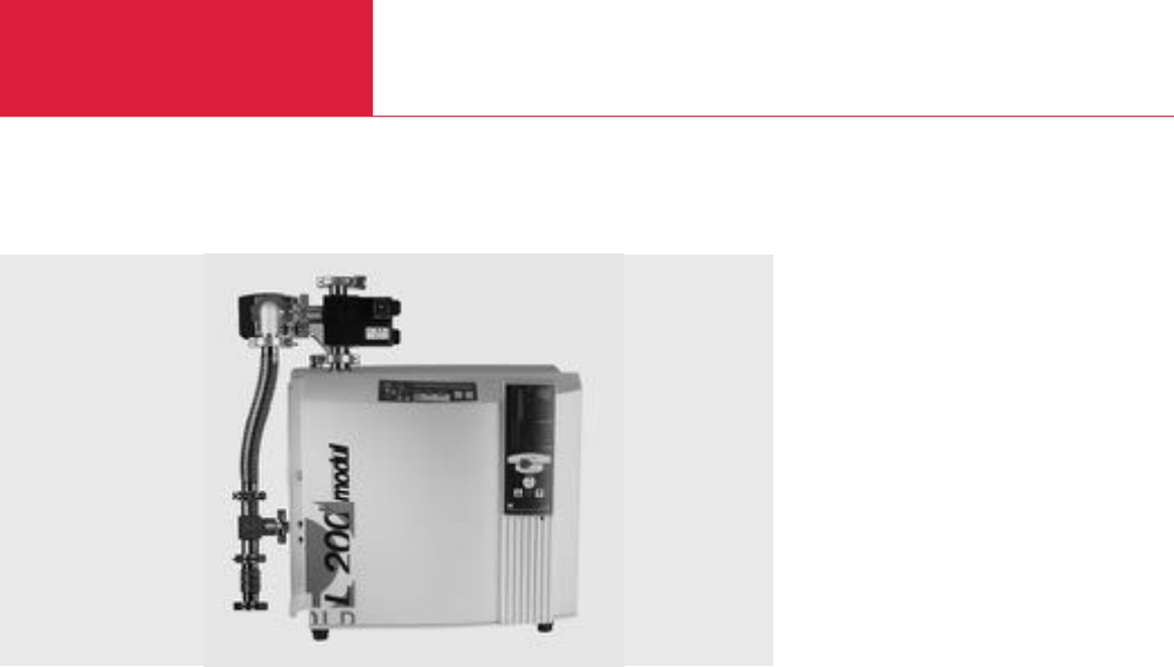
Leak Testing Instruments
C17.10 LEYBOLD VACUUM PRODUCTS AND REFERENCE BOOK 2003/2004
Helium Leak Detectors
Mobile and Flexible Helium Leak Detector Modul L 200
plus
The
Modul L
200
plus
combines the excellent
character-
istics of the L 200
plus
with those of
the pump system which has been added to the
basic leak detector module.
This results in two basic groups:
◆Dry, mobile leak detectors with selectable
pumping speed
◆Oil-sealed, mobile leak detectors offering a
high pumping speed at an optimum price-to-
performance ratio.
Modul L 200
plus
with
Dry-Compressing Scroll Pump
This combination represents a dry high-perfor-
mance leak detector.
Advantages to the User
◆Very high pumping speed which is also
acceptable for testing semiconductor produc-
tion chambers without having to use their
own pump systems
◆Fast response
◆Quick recovery (after helium contamination)
◆Absolutely dry
◆High sensitivity
Typical Applications
All applications which demand a clean process,
like for example:
◆Semiconductor industry (chip manufacturers)
◆Semiconductor industry (tool manufacturers
and subcontractors)
◆High purity gas industry
◆Research and development
◆UHV applications
Modul L 200
plus
with
Oil-Sealed Backing Pump
This combination represents a powerful leak
detector, the pumping speed of which is adapted
to the particular application in each case.
Advantages to the User
◆Cost-effective leak detector
◆Pumping speed optimized for the particular
application
◆Fast response
◆Quick recovery
◆High sensitivity
◆Fast leak rate readout also at low leak rates
Typical Applications
All applications involving short cycles and/or larg-
er volumes and which require a mobile system,
like for example:
◆Automotive industry
◆Cooling and air conditioning
◆Manufacturers of furnaces/machines/systems
◆Packaging
The Modul L 200
plus
represents the basic unit
of an entire family of leak detectors. It is based
on the L 200
plus
, is not equipped with an inte-
grated backing pump and may be easily adapted
by adding an external backing pump to suit a
wide range of applications.
Modul L 200 plus

Helium Leak Detectors Leak Testing Instruments
C17.11
LEYBOLD VACUUM PRODUCTS AND REFERENCE BOOK 2003/2004
C17
Technical Data Modul L 200
plus
with Rotary Vane Vacuum Pump with Scroll Pump
Smallest detectable helium leak rate
(Vacuum mode) mbar x l x s-1
Smallest detectable helium leak rate
(Sniffer mode) mbar x l x s-1
Max. detectable helium leak rate
(Vacuum mode) mbar x l x s-1
Max. permissible inlet pressure mbar (Torr)
Pumping speed during the evacuation process
Scroll pump / TRIVAC D 25 B pump m3x h-1 (cfm)
Pumping speed for helium at the inlet flange l/s
Time constant of the leak signal
(blanked off, 63 % of final value) s
Leak rate measurement range mbar x l x s-1
Units of measurement (selectable)
Time until ready for operation min
Mass spectrometer
Ion source
Detectable masses amu
Test port DN
Length of the cable on the hand unit m
Dimensions (W x H x D) mm
Weight (without pump) kg (lbs)
< 10 x 10-12
< 1 x 10⁻⁷
10-1
3 (2.25)
25 (14.7) 25 (14.7)
8 8
< 1
1 x 10-12 to 1 x 10⁻¹
mbar x l x s-1, atm x cc x sec-1, Pa x m3x s-1, ppm
,
Torr x l x s-1, g/a, oz/y
< 3
180° magnetic sector field
2 yttrium/iridium long-life cathodes
2, 3 and 4
1 x 25 KF
4
490 x 430 x 250
30.5 (67)
The following Part Nos. contain only the individual components needed for assembly by the customer. For building a
portable system we recommend our factory tested and pre-assembled systems (see next page
“
Mobile Leak
Detection Systems fitted to the CART 200
”
).
Part No. 140 34 L
Part No. 140 90
Part No. 200 99 150
Part No. 113 35
Part No. 200 000 214
Part No. 140 93
Ordering Information Modul L 200
plus
Modul L 200
plus
without pump 1)
Euro, 230 V / 50/60 Hz
PC software LeakWare
Seal kit
Pumps
TRIVAC D 25 B; 230 V, 50/60 Hz
Scroll, 230 V / 50/60 Hz
CART 200
For further accessories see Section
“Accessories for L 200
plus
, L 200 dry and Modul L 200
plus
”
1) But without integrated backing pump
Please order cart separately
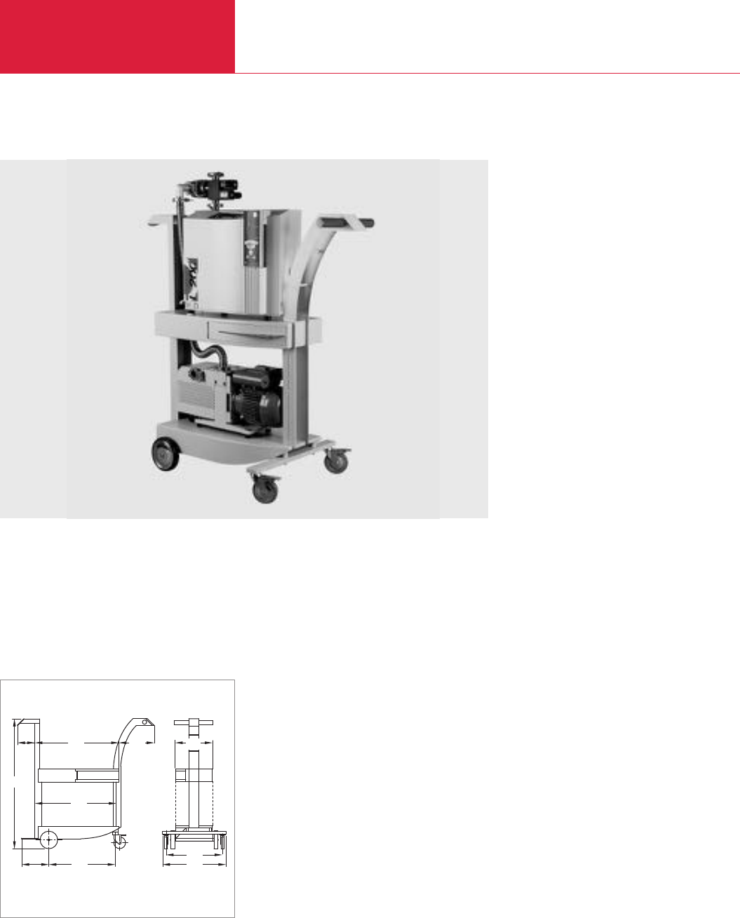
Helium Leak Detectors
Leak Testing Instruments
C17.12 LEYBOLD VACUUM PRODUCTS AND REFERENCE BOOK 2003/2004
Mobile Leak Detection Systems fitted to the CART 200
CART 200
The CART 200 is a special transport cart made of
painted steel with an integrated holder for gas
cylinders and space for small parts and docu-
ments. The leak detector and the pump are
accommodated on two levels.
The pre-assembled and tested system according
to the Part Nos. on the next page include all
required connecting components between leak
detector and backing pump.
Then only the upper section of the system will be
packaged separately.
The helium cylinder is not part of the delivery.
These mobile systems are accommodated on the
CART 200. Placed on these carts are the leak
detectors L 200
plus
, L 200 dry or Modul
L 200
plus
.
Additional backing pumps (depending on the
version required) are accommodated on the
bottom level of the carts.
225
148 320
540
480
540
560
300
705
685
1108
Dimensional drawing for the CART 200
Advantages to the User
◆Complete, fully operational leak detection
system
◆Simple to operate
◆Choice of either oil-sealed or dry compressing
backing pump
◆In the case of these systems, the transport
cart CART 200 is included
CART 200 with Modul L 200 plus and TRIVAC D 25 B

Helium Leak Detectors Leak Testing Instruments
C17.13
LEYBOLD VACUUM PRODUCTS AND REFERENCE BOOK 2003/2004
C17
CART L 200
plus
with partial flow pump set
TRIVAC D 25 B
CART L 200 dry with partial flow pump set
Scroll pump
CART Modul 200
plus
1) with
Scroll pump
TRIVAC D 25 B
1) Without integrated backing pump
CART L 200
plus
CART L 200 dry CART Modul L 200
plus
Part No. 140 85 L
– –
–
Part No. 140 75 L
–
– –
upon request
– –
upon request
Technical Data CART L 200
plus
CART L 200 dry CART Modul L 200
plus
Smallest detectable leak rate for air
(Vacuum mode) mbar x l x s-1
Smallest detectable leak rate for helium
(Sniffer mode) mbar x l x s-1
Max. detectable leak rate for helium
(Vacuum mode) mbar x l x s-1
Max. inlet pressure mbar (Torr)
Pumping speed during the evacuation process with
Scroll m3x h-1
TRIVAC D 25 B, Euro m3x h-1
Max. pumping speed for helium at the inlet flange l/s
Time constant of the leak signal
(blanked off, 63 % of final value) s
Leak rate measurement range mbar x l x s-1
Units of measurement (selectable)
Time until ready for operationmin
Mass spectrometer
Ion source
Detectable massesamu
Test port DN
Cable length for the hand unit m
Dimensions (W x H x D) mm
Weight kg (lbs)
< 10 x 10-12 < 3 x 10⁻¹⁰ < 10 x 10-12
< 1 x 10⁻⁷
10-1
1000 (752) 3.5 (2.63) 3 (2.25)
25
25
8
< 1
1 x 10-12 to 1 x 10⁻¹ 1 x 10-11 to 1 x 10⁻¹ 1 x 10-12 to 1 x 10⁻¹
mbar x l x s-1, atm x cc x sec-1, Pa x m3x s-1, ppm
, Torr
x
l
x
s-1
, g/a, oz/y
< 3
180° magnetic sector field
2 yttrium/iridium long-life cathodes
2, 3 and 4
1 x 25 KF
4
540 x 1350 x 1150
119 (263) 128 (283) 115 / 125 (254 / 276)
Ordering Information
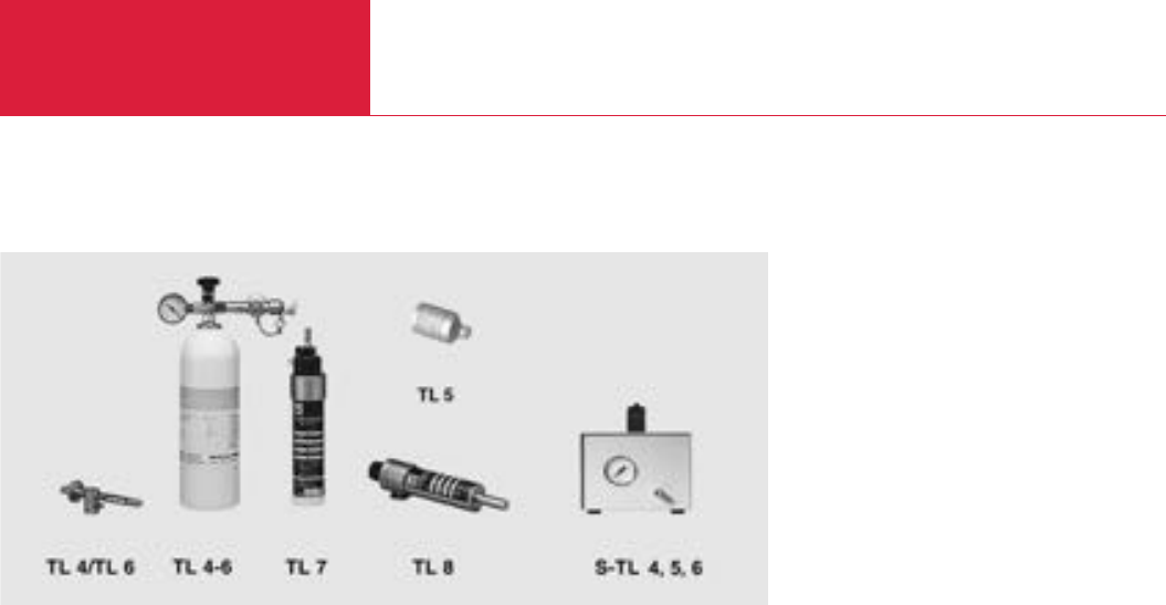
Leak Testing Instruments
C17.14 LEYBOLD VACUUM PRODUCTS AND REFERENCE BOOK 2003/2004
Accessories
Calibrated Leaks for Vacuum and Sniffer Applications
TL 4 and TL 6
Calibrated leaks without gas reservoir (capillary
type of leak) for sensitivity and signal response
time determinations during vacuum leak detec-
tion and for determination of sniffer sensitivity for
overpressure leak detection. Nominal leak rate
ranges 10
-4
mbar x l x s
-1
for TL 4 and
10
-6
mbar x l x s
-1
for TL 6. Suitable for helium.
A purging valve with hose nozzle permits a rapid
exchange of the gas in the dead volume.
TL 4-6
Helium calibrated leak (capillary leak) for gross
leaks, adjustable in the range between 10
-4
to
10
-6
mbar x l x s
-1
, with exchangeable helium
reservoir, pressure gauge and two manually oper-
ated valves. For calibration of leak rate readings
and the alignment of helium mass spectrometers
in the vacuum pressure range and for determin-
ing the sensitivity of sniffers in the overpressure
range.
TL 5
Calibrated helium leak (capillary leak) with reser-
voir which may be refilled and with a leak rate in
the range of 10
-5
mbar x l x s
-1
. Special calibra-
ted leak for use in a vacuum.
TL 7
Helium calibrated leak (capillary leak) with helium
reservoir and electromagnetically operated valve,
for installation in the ULTRATEST L 200. Leak
rate range 10
-7
mbar x l x s
-1
. The electromagnet-
ically operated valve provided permits the
opening and closing of the calibrated leak to be
controlled by the leak detector’s software.
TL 8 and TL 9
Helium calibrated leak calibrated for a leak rate in
the range of 10
-8
mbar x l x s
-1
(helium leak rate)
for TL 8 and 10
-9
mbar x l x s
-1
for TL 9
,
with gas
reservoir and diaphragm shutoff valve. For align-
ment of a helium mass spectrometer, for calibra-
tion of the leak rate display of helium leak detec-
tors and for response time measurements in
connection with larger volumes.
Note
All calibrated leaks with the exception of the TL 5
are not suited for use in a vacuum.
Advantages to the User
◆Factory certificate (included) in accordance
with DIN 55 350-18-4.2.2
◆Highly accurate
◆Very low temperature dependence
◆Determination of the nominal leak rate by
comparison with a calibrated leak having a
PTB
1)
certificate
◆DKD
2)
certificate (optional) traceable to PTB
◆Custom models for special applications
The nominal leak rate applies only if the calibrat-
ed leak has been connected to a vacuum system
at a pressure of less than 1 mbar.
1)
Federal Institution of Physics and Technology
2)
German Calibration Service
Calibrated leaks are required for the alignment of
mass spectrometers, for the calibration of leak
rates and for determining the response time of
vacuum systems.
Calibrated Leaks for Vacuum Applications
Helium calibrated leaks
S-TL 4 to S-TL 6 with leak rates from 10
-4
to
10
-6
mbar x l x s
-1
.
Calibrated Leaks for Sniffer Applications
These calibrated leaks have been set to a fixed
value within the typical leak rate range (see
Ordering Information).
The exchangeable calibration gas reservoir is
monitored through the built-in manometer.
Test leaks
Set of Calibrated Leaks for Power Plants
These three calibrated leaks of 1000, 100 and
10 mbar x l x s
-1
allow leak tests under partial
flow conditions under the ambient conditions of
power plants.

Leak Testing Instruments
C17.15
LEYBOLD VACUUM PRODUCTS AND REFERENCE BOOK 2003/2004
C17
Accessories
Technical Data Leak Rate Range Leak Detection Method Connection Flange
TL 4, without helium gas reservoir
TL 6, without helium gas reservoir
TL 4-6, with helium gas reservoir
TL 5, mit He-Gasvorrat
TL 7, with helium gas reservoir
TL 8, with helium gas reservoir
TL 9, with helium gas reservoir
S-TL 4, with helium gas reservoir
S-TL 5, with helium gas reservoir
S-TL 6, with helium gas reservoir
10-4 mbar x l x s-1 Vacuum and sniffer DN 16 KF
10-6 mbar x l x s-1 Vacuum and sniffer DN 16 KF
10-4 to 10-6 mbar x l x s-1 Vacuum and sniffer DN 16 KF
10-5 mbar x l x s-1 Vacuum Discharging opening
10-7 mbar x l x s-1 Vacuum (for installation in the L 200
plus
) DN 10 KF
10-8 mbar x l x s-1 Vacuum DN 10 KF
10-9 mbar x l x s-1 Vacuum DN 10 KF
10-4 mbar x l x s-1 Sniffer Nozzle
10-5 mbar x l x s-1 Sniffer Nozzle
10-6 mbar x l x s-1 Sniffer Nozzle
TL 4, without helium gas reservoir *)
TL 6, without helium gas reservoir *)
TL 4-6, with helium gas reservoirt *)
TL 5, mit He-Gasvorrat *)
TL 7, with helium gas reservoir,
for installation within the L 200 *)
TL 8, with helium gas reservoir *)
TL 9, with helium gas reservoir *)
S-TL 4, with helium gas reservoir *)
S-TL 5, with helium gas reservoir *)
S-TL 6, with helium gas reservoir *)
Set of calibrated leaks for power plants
1000, 100, 10 mbar x l x s-1
Rubber bladder
Hose clamp
Helium can; 1 l, 12 bar (for TL 4-6)
DKD calibriation for TL 7/8
*)with factory certificate
Ordering Information Calibrated Leak
Part No. 155 65
Part No. 155 66
Part No. 155 80
Part No. 122 67
Part No. 140 23
Part No. 165 57
Part No. 144 08
Part No. 122 37
Part No. 122 38
Part No. 122 39
Part No. 115 16
Part No. 200 20 218
Part No. 200 20 217
Part No. 252 001
Part No. 154 15
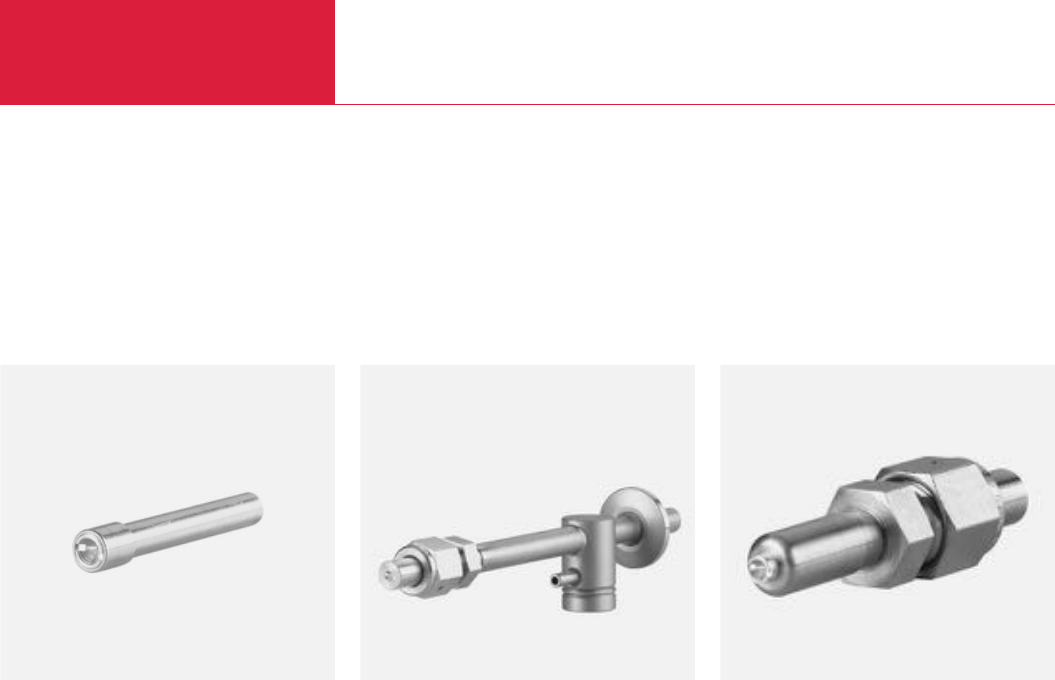
Accessories
Leak Testing Instruments
C17.16 LEYBOLD VACUUM PRODUCTS AND REFERENCE BOOK 2003/2004
Screw-in Calibrated Leaks
Calibrated Leak with
Screw-in Sleeve
Is used as a so-called master leak to check the
entire helium leak testing system.
Generally two leaktight test samples are equipped
with these calibrated leaks. These will ensure
proper separation between “passed and rejected”
parts.
They are fitted to the customer’s test samples
either by a welded joint or the screw-in sleeve is
glued in place.
Typical Applications
◆As a master calibrated leak built-in directly
into the test sample
◆Directly installed to the test chamber
◆Use as a calibrated leak for sniffer
applications
Advantages to the User
◆Various types adapted to different customer
requirements
◆Simple to operate
◆Easy to install
◆Ideal installation dimensions
◆As a rule, all calibrated leaks are supplied with
a certificate (factory certificate) indicating the
leak rate which has been set up
Calibrated Leak with
Pin Type Casing
Serves as a calibrated leak for the entire helium
leak testing system without being influenced by
the presence of a test sample.
Here a dummy is placed in the test chamber. The
connection to the test chamber is directly by a
DN 10 KF fitting. The test gas connection is
either by a VCO fitting or a hose nozzle for
flexible connections.
Connections on the side of the customer’s
system are
- 16 KF running to the vacuum chamber
- Hose nozzle, 10 mm in diameter or
VCO fitting, 10 mm in diameter
Calibrated Leak with
Cylindrical Casing
Is used to check the sensitivity of a sniffing
facility.
Before and after the actual test, the operator
checks the sensitivity of his test facility within
the scope of a plausibility check.
The connection on the side of the customer’s
system is provided via a VCO fitting for a
diameter of 10 mm.
LEYBOLD is now offering a new family of
calibrated leaks which are capable of meeting the
requirements concerning type and required leak
rate.
The manufacturers of helium leak testing systems
are in need of calibrated leaks of various sizes
with individually adjusted leak rates for the
purpose of setting up and calibrating their
systems.
Depending on the type of application these
calibrated leaks are either installed in the test
sample as a master leak or used as a continually
available facility in the test chamber itself.
Calibrated leak with screw-in sleeve Calibrated leak with pin type casing Calibrated leak with cylindrical casing
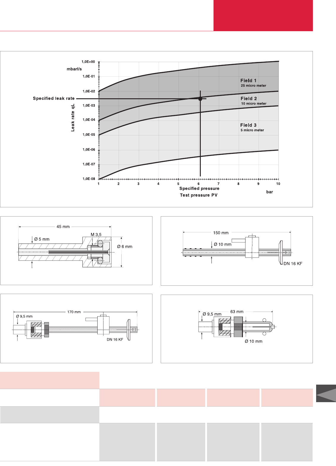
Accessories Leak Testing Instruments
C17.17
LEYBOLD VACUUM PRODUCTS AND REFERENCE BOOK 2003/2004
C17
Calibrated leak
with screw-in sleeve
with pin type casing and VCO fitting
with pin type casing and hose nozzle
with cylindrical casing and VCO fitting
*)When ordering please always state leak rate, test pressure and helium concentration
Ordering Information *)Calibrated Leak
–Part No. 143 00 Part No. 143 01 Part No. 143 02
Part No. 143 03 Part No. 143 04 Part No. 143 05 Part No. 143 06
Part No. 143 07 Part No. 143 08 Part No. 143 09 Part No. 143 10
Part No. 143 11 Part No. 143 12 Part No. 143 13 Part No. 143 14
Technical Data Calibrated Leak
Leak rate mbar x l x s-1
Casing Field 1 Field 2 Field 3
only 1 - 10-4 10-2 - 10-5 10-3 - 10-8
Leak rate as a function of applied test pressure vs. 0 bar
Calibrated leak with screw-in sleeve
Calibrated leak with pin type casing and VCO fitting
Calibrated leak with pin type casing and hose nozzle
Calibrated leak with cylindrical casing and VCO fitting
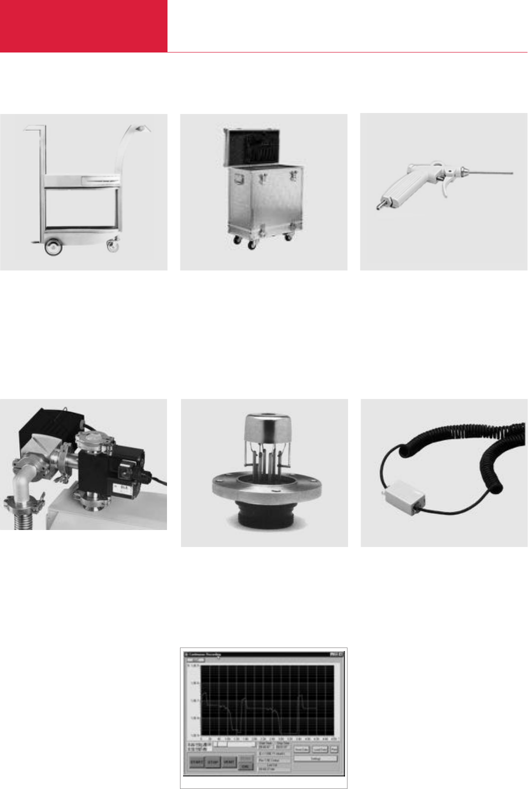
Accessories
Leak Testing Instruments
C17.18 LEYBOLD VACUUM PRODUCTS AND REFERENCE BOOK 2003/2004
Accessories for the L 200
plus
, L 200 dry and Modul L 200
plus
PC software LeakWare
The Windows PC software is used for data acqui-
sition, documentation of the measurements and
to control the operation of the leak detector.
Hardware > 486 DX and 8 MB Ram
Software Windows 95, 98, NT, 2000.
CART 200 (standard steel, painted) Transport case
Extension linePartial flow system without pump
CART 200
For the L 200
plus
, L 200 dry and Modul
L 200
plus
; including shelf and holder for gas
cylinders; made of painted sheet steel.
The CART’s are prepared for accommodating the
Scroll and the TRIVAC D 25 B pumps.
Transport Case
For impact protected transportation of the L 200
plus
;
complete with strong carrying handles and plastic
castors. Separate case for accessories.
Partial Flow System L 200
plus
and L 200 dry
For evacuation of test objects up to 100 l.
Gross leak detection up to 10 mbar x l x s
-1
.
Maximum test pressure: 1000 mbar.
Equipment:
Valve block (with inlet valve, venting valve,
bypass or purging valve) plus right-angle bellows
valve DN 25 KF made of stainless steel, solenoid
drives, suited for remote control by the L 200
plus
,
mains power 230 V / 50/60 Hz.
The partial flow systems are available without
pumps or in mobile systems with oil-sealed
TRIVAC D 25 B rotary vane pumps or dry scroll
pumps.
8 m Extension Line
The use of extension lines permits operation of
the L 200
plus
up to 30 m away from the test
objects. A maximum of three extension lines (of 8
m each) may be connected in series.
Replacement Ion Source
Complete replacement component, including two
built-in yttrium coated iridium cathodes
Replacement ion source
Search Gas Spray Gun
The search gas spray gun with PVC hose (5 m
long) is used for well aimed spraying of search
gas at places where a leak is suspected.
Search gas spray gun
PC software LeakWare

Accessories Leak Testing Instruments
C17.19
LEYBOLD VACUUM PRODUCTS AND REFERENCE BOOK 2003/2004
C17
Ordering Information Accessories
Transport case
Transport cart CART 200
Partial flow system *)
for L 200; 230 V / 50/60 Hz, without pump
for L 200 dry; 230 V / 50/60 Hz, without pump
Pumps
TRIVAC D 25 B, 230 V / 50/60 Hz
Scroll, 230 V / 50/60 Hz
AF 16-25 exhaust filter, for partial flow system
Replacement ion source
PC software LeakWare
8 m long extension line
Search gas spray gun
*)
5 centering rings, 5 clamping rings and 1 vacuum hose 1 m with DN 25 KF are included
Part No. 140 96
Part No. 140 93
Part No. 140 20
Part No. 140 29
Part No. 113 35
Part No. 200 000 214
Part No. 189 11
Part No. 165 04
Part No. 140 90
Part No. 140 22
Part No. 165 55
Technical Data Accessories
Transport case kg (lbs)
Transport cart CART 200 kg (lbs)
Partial flow system
for L 200; 230 V / 50/60 Hz, without pump kg (lbs)
for L 200 dry; 230 V / 50/60 Hz, without pump kg (lbs)
16.5 (36.4)
39 (86.1)
5.3 (11.7)
5.8 (12.8)

Accesssories
Leak Testing Instruments
C17.20 LEYBOLD VACUUM PRODUCTS AND REFERENCE BOOK 2003/2004
Helium Sample Probes (Sniffers)
Advantages to the User
Helium Sniffer Line SL 200 for L 200
plus
◆Sniffer line connects directly at the test
connection
◆Very fast response
◆Extremely low detection limit
< 1 x 10
-7
mbar x l x s
-1
◆Rigid sniffer tips 120 mm (included)
◆Very rugged industrial design
Helium Sniffers QUICK-TEST QT 100 for L 200
plus
◆Sniffer leak detection for greater distances
between test object and leak detector
◆Diaphragm pump for sucking the search gas
◆Smallest detectable leak rate 1 x 10
-6
mbar x l x s
-1
◆Short response and decay times
◆High sniffer velocity
◆Switching power supply, can be run off mains
voltages from 100 to 230 V AC
Typical Applications
◆Storage and transportation vessels for gases
and liquids
◆Gas supply systems
◆Gas compressors
◆Components for the cooling and air
conditioning industries
◆Heat pumps and components for thermal
energy recovery units
◆Chemical production plants
◆Supply and phone lines laid in the ground
◆Power station condensers and turbines
◆Window and door seals of car bodies, refrige-
rators and alike
◆Revision checks on leak testing systems
◆Measurement of helium concentrations rang-
ing from ppm to %
◆All hollow objects exposed to overpressures
Helium sniffers in connection with the leak detec-
tors are used for leak testing test samples in
which a helium overpressure is present. Besides
accurate pinpointing of leaks it is also possible to
determine the leak rate of the escaping helium.
Technical Data SL 200 QT 100
Smallest detectable leak rate mbar x l x s-1
Supply voltage
Signal response time, approx.
at a length of 05 m s
20 m s
50 m s
Connection flange DN
Weight kg (lbs)
Helium sniffer line SL 200
4 m long, straight handle
with red/green LED for go/no-go indication,
rigid and flexible sniffer tip 120 mm
Helium sniffer QUICK-TEST QT 100
Sniffer line for the QT 100
05 m
20 m
50 m
Ordering Information SL 200 QT 100
Part No. 140 05 –
–Part No. 155 94
– Part No. 140 08
– Part No. 140 09
– Part No. 121 83
Helium sniffer line SL 200
< 10-7 10-6
– 100-230 V, 50/60 Hz
< 1 1
– < 6
– 20
25 KF 25 KF
0.6 (1.3) 3.5 (7.7)
Helium sniffer QUICK-TEST QT 100 with sniffer

Accessories Leak Testing Instruments
C17.21
LEYBOLD VACUUM PRODUCTS AND REFERENCE BOOK 2003/2004
C17
Connection Flanges
If components of the same nominal width are connected, only one centering ring and one clamping ring will be required.
Connection Components
When wanting to connect accessories (helium sniffer and calibrated leaks) to a leak detector, the following reducers and compo-
nents may be necessary:
The following metal hoses are recommended to connect the leak detectors to systems:
Further connecting components, like quick clamping rings and other components are described in Product Section C13
“Vacuum Fittings and Feedthroughs”
L 200
plus
– DN 25 KF
L 200 dry – DN 25 KF
Modul L 200
plus
– DN 25 KF
Leak Detectors Helium Sniffers Calibrated Leaks
SL 200 – DN 25 KF
QT – DN 25 KF
ST 100 – DN 25 KF
TL 4 – DN 16 KF
TL 6 – DN 16 KF
TL 4-6 – DN 16 KF
Nominal Width Length Ordering Information
DN 16 KF
DN 16 KF
DN 25 KF
DN 25 KF
DN 40 KF
DN 40 KF
1.0 m
0.5 m
1.0 m
0.5 m
1.0 m
0.5 m
Part No. 868 01
Part No. 867 91
Part No. 868 03
Part No. 867 93
Part No. 868 01
Part No. 867 95
DN 25 / 16 KF
DN 40 / 25 KF
DN 40 / 16 KF
Reduction Reducers Centering Rings Clamping Rings
Stainless steel/FPM Aluminium
Part No. 183 86, aluminium or
Part No. 885 04, stainless steel
Part No. 183 87, aluminium or
Part No. 885 05, stainless steel
Part No. 183 89, aluminium or
Part No. 885 07, stainless steel
DN 25 KF, Part No. 883 47
DN 16 KF, Part No. 883 46
DN 25 KF, Part No. 883 47
DN 40 KF, Part No. 883 48
DN 16 KF, Part No. 883 46
DN 40 KF, Part No. 883 48
DN 20 / 25 KF, Part No. 183 42
DN 10 / 16 KF, Part No. 183 41
DN 20 / 25 KF, Part No. 183 42
DN 32 / 40 KF, Part No. 183 43
DN 10 / 16 KF, Part No. 183 41
DN 32 / 40 KF, Part No. 183 43

Leak Testing Instruments
C17.22 LEYBOLD VACUUM PRODUCTS AND REFERENCE BOOK 2003/2004
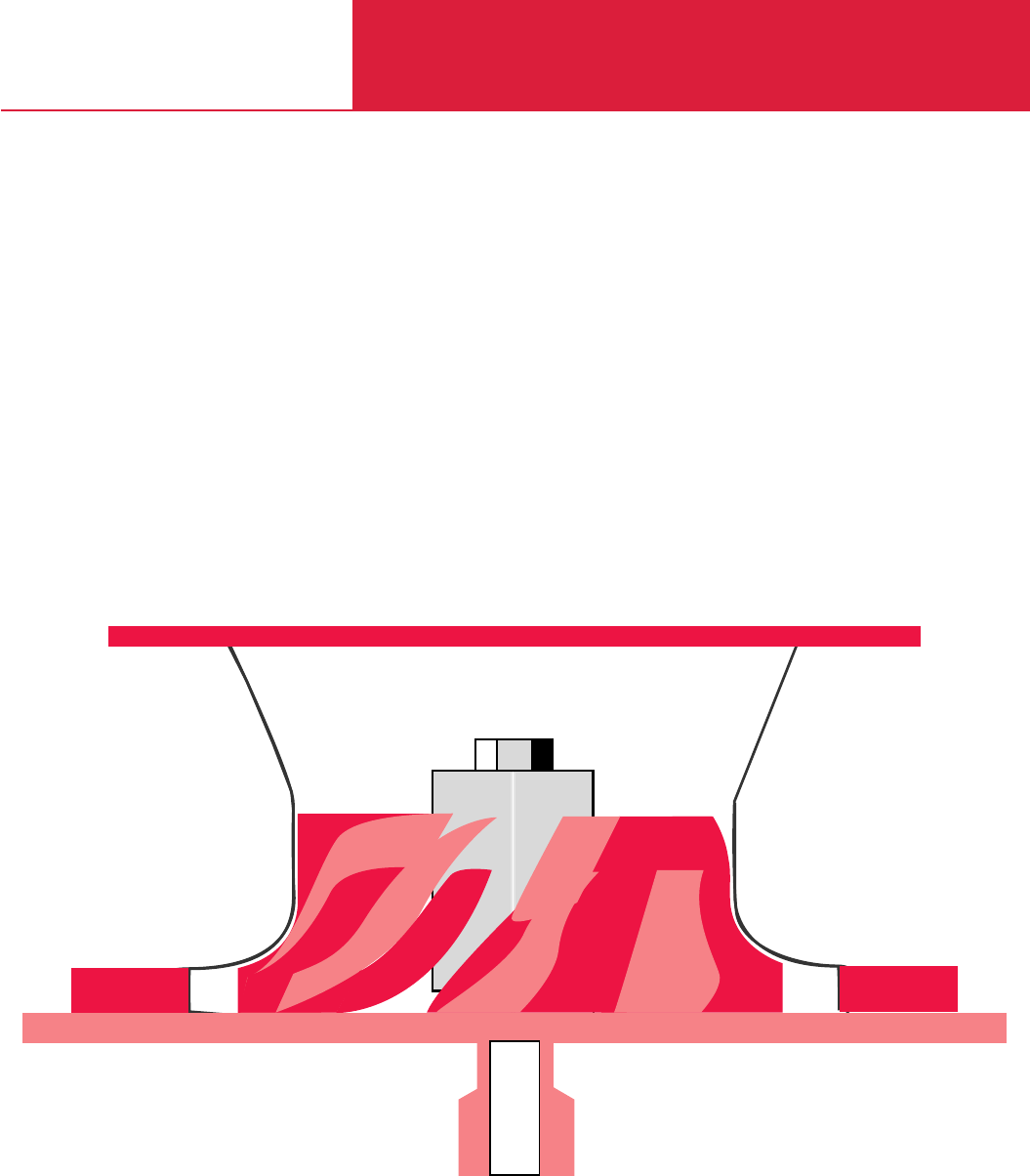
C18
Turboradial Blowers
TURBOSTREAM
Single-Stage and Dual-Stage
TST S und D
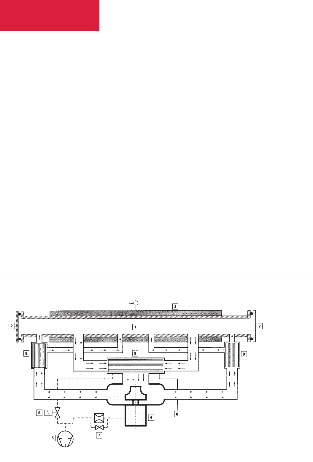
Contents
Turboradial Blowers
LEYBOLD VACUUM PRODUCTS AND REFERENCE BOOK 2003/2004
General
TURBOSTREAM Blowers for the Laser Industry . . . . . . . . . . . . . . . . . . . . . . . . . . . . . . . . . C18.02
Products
Turboradial Blowers
TURBOSTREAM TST S (single-stage) . . . . . . . . . . . . . . . . . . . . . . . . . . . . . . . . . . . . . . C18.04
TURBOSTREAM TST D (dual-stage) . . . . . . . . . . . . . . . . . . . . . . . . . . . . . . . . . . . . . . . C18.08
TURBOSTREAM Blowers for the Laser Industry
Gas circulation in a fast axial flow CO2laser with TURBOSTREAM blower
Beginning in 1988, the TURBOSTREAM technolo-
gy was introduced by LEYBOLD VAKUUM GmbH.
Since that time improvements have been worked
out and implemented together with our custo-
mers on a continual basis. This was very much
facilitated by the modular concept of the units,
which also today puts us in a position where we
are able to fulfil your future requirements as to a
tailor-made solution.
Today the unique TURBOSTREAM range from
LEYBOLD is capable of improving the capabilities
of your Laser system both at the Laser manufac-
turer and the end user with regard to:
♦Quality
♦Productivity
♦Compactness
♦Efficiency
♦Reliability and
♦Saving of costs
Just see how this works for you!
TURBOSTREAM Blower and
Fast-flow CO2Laser
The CO
2
containing gas mixture which maintains
in the resonator the laser effect is discharged
from the resonator in the hot state and is cooled
in the heat exchanger. After the gas has passed
through the TURBOSTREAM, the gas is cooled
once more in the downstream heat exchanger
before it is returned back into the resonator.
C18.02
1 Resonator
2 Laser mirror
3 Power supply
4 TURBOSTREAM blower
5 SOGEVAC vacuum pump
6 Control valve / roughing line
7 Metering orifice and bypass valve
8 Fresh gas supply
9 Heat exchanger
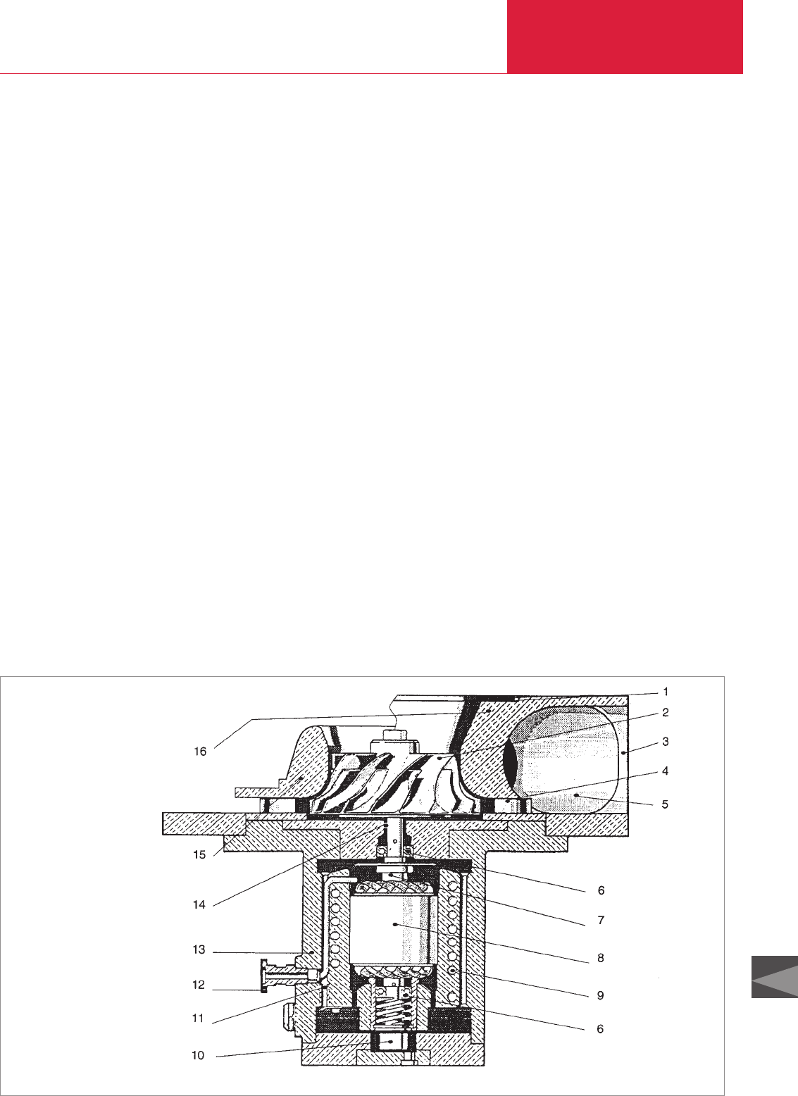
C18
General Turboradial Blowers
LEYBOLD VACUUM PRODUCTS AND REFERENCE BOOK 2003/2004
Design Principle
The gas flows via the inlet flange (1) into the
pump chamber of the blower. There it is radially
accelerated by the rotating blade wheel (2) and is
deflected via diffuser (4) into the ducts (5).
The gas then leaves the TURBOSTREAM through
the outlet flanges (3).
The TURBOSTREAM blower is driven by a medi-
um-frequency 3-phase asynchronous motor (8).
Blade wheel (2) and motor rotor are located on
one shaft (7). The stator of the motor has been
built into the motor housing (13). The two hybrid
ball bearings (6) of the shaft are oil-lubricated.
An oil pump (10) feeds the oil through the shaft
to the bearings. The motor housing of the
TURBOSTREAM is water-cooled (9).
Pump chamber housing and motor housing are
separated by a wear-free sealing gap.
Pump chamber housing and motor housing are
separated by a wear-free sealing gap. To prevent
small amounts of oil mist from enter-ing the
pump chamber via the gap (14), a small quantity
of gas is constantly extracted (12) from the
motor housing by the vacuum pump of the laser
system. This ensures a steady gas flow from the
pump chamber to the motor housing, reliably
excluding the entry of oil into the pump chamber.
Supplied Equipment
Depending on customer requirements the mecha-
nical interface to the resonator can be designed
either as a pump chamber housing or a shroud.
The pump chamber housing completely matches
the contour of the blade wheel. Only the intake
piping and the two gas discharge pipings need to
be provided for integrating this blower flow-wise
in the resonator circuit. The shroud version of the
blower utilises for a partial section of the blade
wheel the matching structures provided by the
system. This arrangement of “resonator / TURBO-
STREAM with shroud” can thus be more com-
pact.
♦Generally all TURBOSTREAM blowers are
equipped with a vibration sensor (GUARD)
which monitors the ball bearings. The electri-
cal connection between vibration sensor and
frequency converter is provided by a connec-
ting cable which is laid separately.
♦The TURBOSTREAM is equipped with an inte-
grated motor temperature monitoring facility
(PTC) which will protect the motor against
overheating in case the motor cooling facility
fails because of an inadequate supply of coo-
ling water, for example.
♦Some versions of the TURBOSTREAM are
equipped with an oil level monitoring facility
which automates regular monitoring of the oil
level.
Electric Power Supply
The TURBOSTREAM blower is supplied with
power from a separate frequency converter, the
COMBIVERT unit. TURBOSTREAM blower and
COMBIVERT are connected to each other by a
connecting cable and by a PTC monitoring cable.
The COMBIVERT must be installed in an electrical
cabinet. It is short-circuit proof, can sustain short
circuits to ground and is protected against over-
loading. It is provided with a 5 digit display for
displaying the operating status, has a floating
contact for error status and is equipped with a
connector for the PTC resistor which monitors the
motor temperature.
The GUARD vibration sensor is supplied with
power from the frequency converter. The error
status generated when the GUARD comes into
action is evaluated by the frequency converter
and results in an interruption of the power supply
to the TURBOSTREAM blower and an error mes-
sage on the frequency converter.
The drive of the TURBOSTREAM blower and the
COMBIVERT are perfectly matched to each other.
Cross-section of a TURBOSTREAM blower, left upper half: with shroud; right upper half: with pump chamber housing
01 Inlet flange
02 Blade wheel
03 Outlet flanges
04 Diffuser
05 Ducts
06 Ball bearings
07 Shaft
08 Motor
09 Cooling coils
10 Oil pump
11 Oil supply system
12 Connection for vacuum pump
13 Motor housing
14 Sealing gap
15 Shroud for
TST S 1000 S, S 1500 S
16 Pump chamber housing for
TST S 1500, S 2500
C18.03
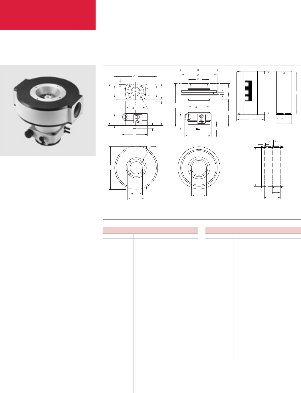
Turboradial Blowers
TURBOSTREAM TST S (single-stage)
Advantages to the User
♦High flow rate at small size
♦Pump chamber free of hydrocarbons
♦Non-wearing seal for the pump chamber
♦Low gas exchange rates
♦Pump sections in contact with the medium
are made of a special corrosion resistant
aluminium alloy
♦Prefect integration in gas laser systems
♦Simple to operate, minimum maintenance
requirements
♦Low-vibration and low-noise operation
♦Gas flow free of pulsations
♦Reliable and rugged owing to oil lubricated
hybrid ball bearings
♦Motor protection via built-in PTC resistor
♦Water cooled motor casing
♦Vibration sensor for monitoring the bearings
♦Free of non-ferrous metals, including the coo-
ling water circuit
LEYBOLD VACUUM PRODUCTS AND REFERENCE BOOK 2003/2004
Dimensions for TURBOSTREAMs with pump chamber
TST S 1500 S 2500
DN1160 ISO-F 160 ISO-F
DN2100 ISO-F 100 ISO-F
a mm 200.5 250
in. 7.89 9.84
b mm 423 423
in. 16.65 16.65
c mm 5 5
in. 0.20 0.20
ld mm 420 420
in. 16.54 16.54
ld1mm 170 170
in. 6.69 6.69
ld2mm 145 145
in. 5.71 5.71
ld3mm 200 200
in. 7.87 7.87
e1mm M 8 x 15 M 8 x 15
in. M 8 x 15 M 8 x 15
e2mm M 10 x 18 M 10 x 18
in. M 10 x 18 M 10 x 18
h mm 355 357
in. 13.98 14.06
h1mm 77.5 77.5
in. 3.05 3.05
h2mm 210 210
in. 8.27 8.27
h3mm 128.5 128.5
in. 5.06 5.06
h4mm 19 19
in. 0.75 0.75
Dimensions for TURBOSTREAMs with shroud
TST S 1000 SNG S 1500 SN/SG/SNX
a mm 250 250
in. 9.84 9.84
d mm 320 320
in. 12.6 12.6
ld1mm 170 170
in. 6.69 6.69
f mm 167.5 167.5
in. 6.59 6.59
g mm 280 280
in. 11.02 11.02
h mm 322.5 325
in. 12.7 12.7
h1mm 77.5 77.5
in. 3.05 3.05
h2mm 207 207
in. 8.15 8.15
h3mm 97.5 100
in. 3.84 3.94
i mm 99.5 111
in. 3.92 4.37
k mm 10.0 12.5
in. 0.39 0.49
h4mm 19 19
in. 0.75 0.75
C18.04
g
a
b
øc
h1
h
e2
DN1
d3
b
h2
h3
k
d1
a
h
h1
f
g
d
i
h4
b1
g
h1
a1
c
h2
d1
ah
h3
h1
h
d
e1
c
DN2
2
d
4
Dimensional drawing for the TURBOSTREAM TST S with pump chamber housing (left), with shroud (center)
and COMBIVERT (right top: dimensions, right bottom: connection dimensions)

C18
Turboradial Blowers
LEYBOLD VACUUM PRODUCTS AND REFERENCE BOOK 2003/2004 C18.05
Technical Data
Main supply voltage, 50/60 Hz V AC
Power consumption kVA
Main fuse rating max. A
Permissible ambient temperature °C (°F)
Cooling
Type of protection to DIN 40 050 IP
Weight kg (lbs)
305 - 500
4.1 8.3 11
10 20 25
0 to 45 (32 to 113)
air
20
14 (30.9) 19 (41.8) 31 (68.4)
Technical Data
1) For laser gas 70 % He, 25 % H2, 5 % CO2
2) Gas consumption referred to operating pressure
3) To DIN 45 635
4) Only for the models with pump chamber housing
TURBOSTREAM TST
S 1 000 S 1 500 S 2500
COMBIVERT
6 A 12 A 16,5 A
Pumping speed (max. volume flow rate
within the specified operating range) m3x h-1 (cfm)
Compression ratio, max.1)
Permissible intake pressure, max.1) mbar (Torr)
Nominal speed rpm
Cooling water connections, inside thread
Cooling water consumption, approx.
(max. 6 bar (4.5 x 10³Torr)) l x h-1
Evacuation connection as an angled
fitting for the hose mm (in.)
Minimum extraction rate at the motor casing 2) l x h-1
Maximum extraction rate at the motor casing 2) l x h-1
Noise level at zero throughput 3) dB(A)
Gas admission flange 4) DN
Gas discharge flange (2 pieces) 4) DN
Weight
with pump chamber housing kg (lbs)
with shroud kg (lbs)
800 to 1500 (472 to 885) 1400 to 2100 (824 to 1236) 1900 to 3000 (1118 to 1766)
1 : 1.35 1 : 1.45 1 : 1.35
120 (90)
41400 44 040 39000
G 3/8"
80 110 (180 for SNX version) 120
Elbow union 8/6 (0.31/0.24)
80
400
≤56
– 160 ISO-F 160 ISO-F
100 ISO-F 100 ISO-F
– 56 (123.6) 56 (123.6)
26 (57.4) 26 (57.4) –

Turboradial Blowers
C18.06 LEYBOLD VACUUM PRODUCTS AND REFERENCE BOOK 2003/2004
Part No. 858 69 – –
–Part No. 858 70 –
–Part No. 858 79 –
–Part No. 858 77 –
–Part No. 858 74 –
– – Part No. 858 80
Part. No. 858 03
Part. No. 896 201
Part. No. 870 000 136
Part. No. 870 000 137
Part. No. 858 54
Part. No. 858 56
Part. No. 858 01
Part. No. 896 152
Part. No. 119 99
Part. No. 896 102
Part. No. 109 01 21
Part. No. 09 03 51
Ordering Information TURBOSTREAM TST
S 1 000 S 1 500 S 2500
TURBOSTREAM
S 1000 SN (with shroud and oil level sensor)
S 1500 (with pump chamber housing)
S 1500 SN (with shroud and oil level sensor)
S 1500 SG (with shroud and vibration sensor)
S 1500 SNX (with shroud, oil level sensor and
stronger motor 1)
S 2500 (with pump chamber housing)
Hybrid bearing sensor
Guard 2 (retrofit kit)
with 2.5 m cable
Guard 3 (retrofit kit)
without cable
cable 2.5 m
cable 5 m
Motor/PTC-cable set for COMBIVERT
2.5 m
4 m
Metering orifice
DN 16 KF, approx. 08 NL x h-1
DN 16 KF, approx. 26 NL x h-1
Oil level sensor with 2 m long cable (retrofit kit)
TURBOSTREAM oil
TST oil F 12 600 ml (0.64 qt)
SOGEVAC SV 16 SL Rotary vane vacuum pump
with Motor for 220 - 240 V / 380 - 415 V, 50 Hz
with Motor for 208 - 230 V / 440 - 460 V, 60 Hz
SOGEVAC SV 25 SL Rotary vane vacuum pump
with Motor for 220 - 240 V / 380 - 415 V, 50 Hz
with Motor for 208 - 230 V / 440 - 460 V, 60 Hz
upon request – –
–Part No. 858 78 Part No. 858 78
– upon request upon request
Ordering Information COMBIVERT
10.F4 13.F4 16.F4
COMBIVERT with motor-filter
6 A
12 A
16,5 A
1) Only in connection with COMBIVERT 16.5 A

Turboradial Blowers
C18.07
LEYBOLD VACUUM PRODUCTS AND REFERENCE BOOK 2003/2004
C18
Notes
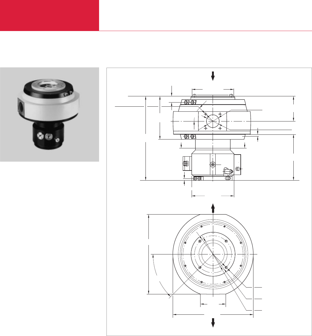
Turboradial Blowers
C18.08 LEYBOLD VACUUM PRODUCTS AND REFERENCE BOOK 2003/2004
TURBOSTREAM TST D (dual-stage)
The dual-stage TURBOSTREAM D 2500 is a
market-orientated development based on our
well-proven single-stage series.
Advantages to the User
♦High flow rate at small size
♦Pump chamber free of hydrocarbons
♦Non-wearing seal for the pump chamber
♦Low gas exchange rates
♦Pump sections in contact with the medium
are made of a special corrosion resistant
aluminium alloy
♦Prefect integration in gas laser systems
♦Simple to operate, minimum maintenance
requirements
♦Low-vibration and low-noise operation
♦Gas flow free of pulsations
♦Reliable and rugged owing to oil lubricated
hybrid ball bearings
♦Motor protection via built-in PTC resistor
♦Water cooled motor casing
♦Vibration sensor for monitoring the bearings
♦Free of non-ferrous metals, including the
cooling water circuit for cooling the motor
Dimensional drawing for the TURBOSTREAM TST D 2 500 NG
Ø 240
232
31
110
45°
4 x M8 x 14
10
BA
DN 63 ISO-F
133
250,5
456
45°
430
137
434
4 x M10 x 18
200
DN 160 ISO-F
11
Ø 230

Turboradial Blowers
C18.09
LEYBOLD VACUUM PRODUCTS AND REFERENCE BOOK 2003/2004
C18
Technical Data TURBOSTREAM TST
D 2 500 G D 2500 NG D 2500 SN
Technical Data COMBIVERT 33 A with Motor filter
Main supply voltage, 50/60 Hz V AC
Power consumption kVA
Main fuse rating, max. A
Permissible ambient temperature °C (°F)
Cooling
Sype of protection to DIN 40 050 IP
Weight kg (lbs)
1) For laser gas 70 % He, 25 % H2, 5 % CO2
2) Gas consumption referred to operating pressure
3) To DIN 45 635
4) Only for the models with pump chamber housing
Pumping speed (max. volume flow rate
within the specified operating range) m3x h-1 (cfm)
Compression ratio 1), max.
Permissible intake pressure, max.1) mbar (Torr)
Nominal speed rpm
Cooling water connections, inside thread
Cooling water flow, min. at. a max.
admission temperature of 30 °C
l x h-1
Extraction connection at the motor housing
for connecting a vacuum pump
as a small flange DN
as angled fitting for hose link mm (in.)
Minimum extraction rate at the motor casing 2) l x h-1
Maximum extraction rate at the motor casing 2) l x h-1
Noise level at zero throughput 3) dB(A)
Gas admission flange 4) DN
Gas discharge flange (2 pcs.) 4) DN
Weight kg (lbs)
1800 to 2800 (1062 to 1648)
1 : 1,8
120 (90.0)
40 200
G 3/8"
300
16 KF 16 KF –
– – 8/6
80
400
≤60
160 ISO-F
63 ISO-F
80 (176.6) 80 (176.6) 50 (110.4)
305 - 500
23
50
0 bis 45 (32 to 113)
water air
20
43 (94.8) 38 (83.8)

Turboradial Blowers
LEYBOLD VACUUM PRODUCTS AND REFERENCE BOOK 2003/2004
C18.10
Ordering Information TURBOSTREAM TST
D 2 500 G D 2500 NG D 2500 SN
TURBOSTREAM
with pump chamber housing, vibration sensor,
metering orifice and motor cable, 2.5 m long
with pump chamber housing, oil level sensor
and vibration sensor
with pump chamber housing and oil level sensor
Vibration sensor
Guard 2 (retrofit kit)
with 2.5 m cable
Guard 3 (retrofit kit)
without cable
cable 2.5 m
cable 5.0 m
Motor/PTC-cable set for COMBIVERT
2.5 m
4.0 m
Metering orifice
DN 16 KF, ca. 8 NL x h-1
DN 16 KF, ca. 26 NL x h-1
Oil level sensor with 2 m long cable (retrofit kit)
TURBOSTREAM oil
TST oil F 12 300 ml
TST oil 22 600 ml
SOGEVAC SV 16SL Rotary vane vacuum pump
with Motor for 220 - 240 V / 380 - 415 V, 50 Hz
with Motor for 208 - 230 V / 440 - 460 V, 60 Hz
SOGEVAC SV 25SL Rotary vane vacuum pump
with Motor for 220 - 240 V / 380 - 415 V, 50 Hz
with Motor for 208 - 230 V / 440 - 460 V, 60 Hz
Part No. 877 011 – –
–Part No. 858 46 –
– – Part No. 858 48
Part No. 858 03
Part No. 896 201
Part No. 870 000 136
Part No. 870 000 137
Part No. 120 40
Part No. 858 08
Part No. 858 01
Part No. 896 152
Part No. 119 99
– Part No. 896 101 Part No. 896 101
Part No. 896 112 – –
Part No. 109 01 21
Part No. 109 03 21
Ordering Information COMBIVERT 16.F4
COMBIVERT with motor-filter
33 A, air cooled
33 A, water cooled
Part No. 120 30
Part No. 858 51
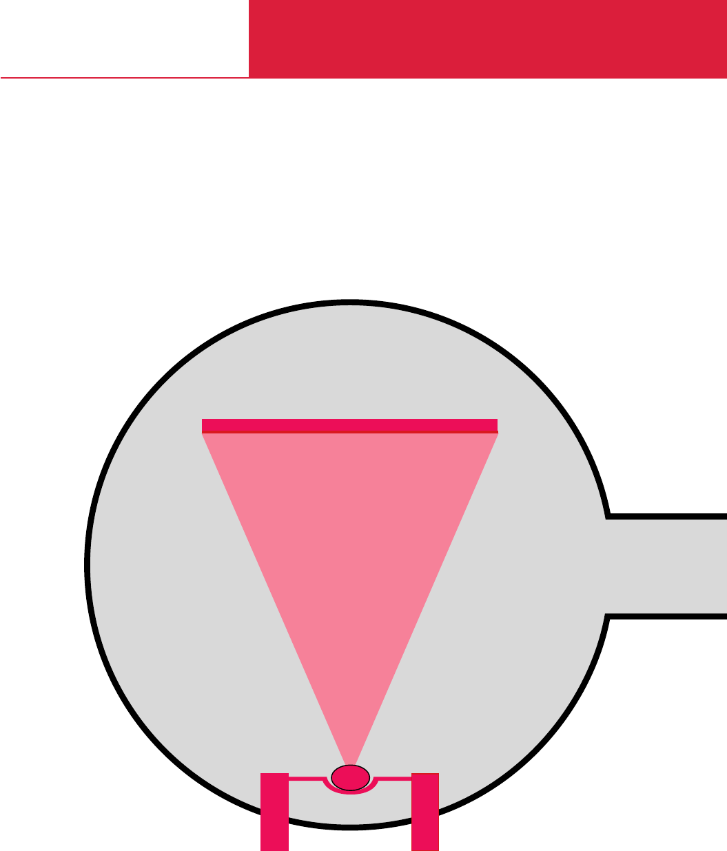
C19
High Vacuum Experimentation Systems
UNIVEX 300, UNIVEX 450
UNIVEX 350, UNIVEX 450 B
Special plants
UNIVEX

LEYBOLD VACUUM PRODUCTS AND REFERENCE BOOK 2003/2004
Contents
High Vacuum Experimentation Systems
General
Applications and Accessories / Process Components . . . . . . . . . . . . . . . . . . . . . . . . . . . . . . C19.02
General . . . . . . . . . . . . . . . . . . . . . . . . . . . . . . . . . . . . . . . . . . . . . . . . . . . . . . . . . . . . . . . . C19.03
Products
Bell Jar System
UNIVEX 300. . . . . . . . . . . . . . . . . . . . . . . . . . . . . . . . . . . . . . . . . . . . . . . . . . . . . . . . . . C19.04
UNIVEX 450. . . . . . . . . . . . . . . . . . . . . . . . . . . . . . . . . . . . . . . . . . . . . . . . . . . . . . . . . . C19.06
Door System
UNIVEX 350. . . . . . . . . . . . . . . . . . . . . . . . . . . . . . . . . . . . . . . . . . . . . . . . . . . . . . . . . . C19.08
Accessories
Standard Accessories for UNIVEX 300, 350, 450 and 450 B . . . . . . . . . . . . . . . . . . . . . . . . . C19.10
Components
for Glow Discharge Cleaning . . . . . . . . . . . . . . . . . . . . . . . . . . . . . . . . . . . . . . . . . . . . . C19.11
for Thermal Evaporation . . . . . . . . . . . . . . . . . . . . . . . . . . . . . . . . . . . . . . . . . . . . . . . . . C19.12
for Electron-Beam Evaporation . . . . . . . . . . . . . . . . . . . . . . . . . . . . . . . . . . . . . . . . . . . . C19.13
for High Rate Sputtering. . . . . . . . . . . . . . . . . . . . . . . . . . . . . . . . . . . . . . . . . . . . . . . . . C19.14
for Film Thickness Measurements . . . . . . . . . . . . . . . . . . . . . . . . . . . . . . . . . . . . . . . . . C19.14
Miscellaneous
Special Units
UNIVEX 450 B . . . . . . . . . . . . . . . . . . . . . . . . . . . . . . . . . . . . . . . . . . . . . . . . . . . . . . . . C19.15
UNIVEX 450 for Daktyloscopy, UNIVEX 450 C, Test systems . . . . . . . . . . . . . . . . . . . . . C19.16
C19.02
Passive components
Sensor technology
Opto-electronics
Tribology
Soldering
Dactyloscopy
Glove box applications
Special applications
Thermal conduction experiments
◆ ◆ ◆ ◆
◆ ◆ ◆ ◆
◆ ◆ ◆ ◆
◆ ◆ ◆ ◆
◆ ◆ ◆ ◆
◆
◆ ◆ ◆ ◆
◆ ◆ ◆ ◆
◆ ◆
Applications
Accessories / Process Components
UNIVEX 450
UNIVEX 300
UNIVEX 350
Standard accessories
Base plate and bell jar
Lifting facility, manually operated
Vacuum chamber with door
Auxiliary operation
Substrate holder
Substrate heater
Gas admission
Process equipment
Shutters
Thin film measurement
Sources
Custom installations
Glow discharge cleaning
Thermal evaporation
Electron-beam evaporation
DC high rate sputtering
RF high rate sputtering
Page
C19.05 + 07 ◆ ◆
C19.07 ◆
C19.09 + 15 ◆ ◆
C19.03 ◆ ◆ ◆ ◆
C19.03 ◆ ◆ ◆ ◆
C19.03 ◆ ◆ ◆ ◆
C19.12 ◆ ◆ ◆ ◆
C19.14 ◆ ◆ ◆ ◆
C19.03 ◆ ◆ ◆ ◆
C19.11 ◆ ◆ ◆ ◆
C19.12 ◆ ◆ ◆ ◆
C19.13 ◆ ◆ ◆ ◆
C19.14 ◆ ◆ ◆ ◆
C19.14 ◆ ◆
Bell jar system Door system
UNIVEX 450 B
Special plants

High Vacuum Experimentation Systems
C19
LEYBOLD VACUUM PRODUCTS AND REFERENCE BOOK 2003/2004
General
The UNIVEX multi-purpose experimentation
systems were developed by LEYBOLD for appli-
cations in research and development, as well as
for setting up pilot production systems.
The range of applications for these systems
covers primarily vacuum coating as well as
exper
iments in vacuum process engineering.
The multi-purpose experimentation systems from
LEYBOLD are based on a modern modular con-
cept. The high vacuum pumps are installed hori-
zontally at the level of the base plate or the
vacuum chamber.
Special Accessories for
UNIVEX 300, 350, 450
and 450 B
Besides standard process components we can
also supply installations according to customers
requirements, for example for:
♦Vacuum soldering experiments
♦Metallurgical experiments
♦Thermal conduction experiments
♦Diffusion experiments
♦Dactyloscopy.
Automatic Pressure Control
Various processes require a constant pressure in
the UNIVEX vacuum chamber. For this purpose
LEYBOLD offers a wide range of different pres-
sure or flow control systems.
Special designs which are manufactured accord-
ing to customer’s specifications are available
upon request.
Substrate Heater
For the purpose of heating substrates, LEYBOLD
offers a variety of heating facilities (radiation heat-
ers, heaters with quartz lamps, for example).
These systems may be combined with different
temperature controllers.
Special designs which are manufactured accord-
ing to customer’s specifications are available
upon request.
Cooling and
Heating Systems
Special experiments require that the temperature
of the samples be maintained constant within a
wide temperature range for the setpoint.
For this LEYBOLD delivers upon request cooling/
heating facilities with LN
2
as the refrigerant and
an electric heater, complete with temperature
controller.
Special designs which are manufactured accord-
ing to customer’s specifications are also avail-
able upon request.
Substrate Holders
Upon request LEYBOLD is able to supply sub-
strate holders according to customer’s specifica-
tions.
Substrate holders with planetary gear for the
UNIVEX 450 and UNIVEX 450 B are available
upon request.
C19.03
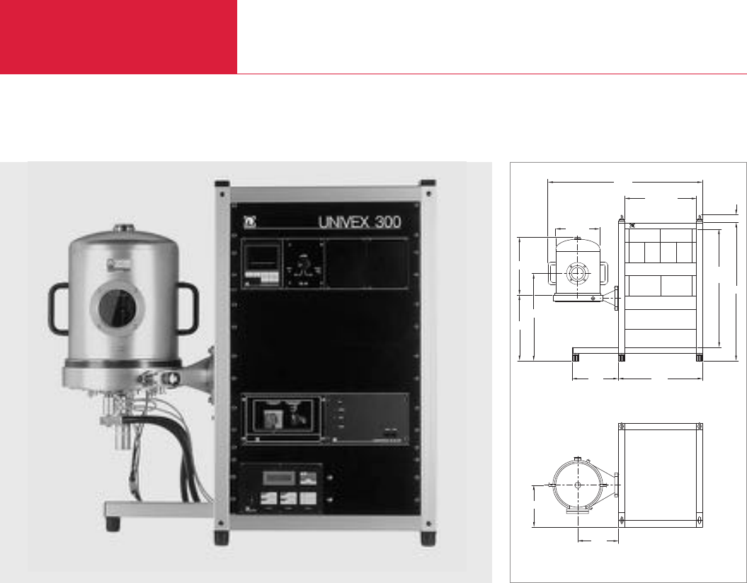
LEYBOLD VACUUM PRODUCTS AND REFERENCE BOOK 2003/2004
High Vacuum Experimentation Systems
Bell Jar System
UNIVEX 300
Table-Top System with
300 mm dia. Chamber
Advantages to the User
♦Modular system design
♦Any kind of process component may be
installed
♦Process components may be retrofitted
without problems
♦Freely accessible vacuum chamber
♦Freely accessible base plate
♦Very simple to operate and use
♦Pump system adapted to the individual
process
Typical Applications
♦Vacuum coating in research and development
♦Special experiments
Basic Unit
♦The pump system and the electrical supply
system are housed in a 19" rack cabinet.
♦Moreover, the 19" cabinet provides space
(max. 6 height units) for a vacuum gauge and
a thickness measuring instrument as well as
power supply units for the process compo-
nents.
♦The basic unit may be placed on a bench top.
Vacuum Chamber
♦The base plate is attached to the lateral intake
port of the basic unit.
♦Either a vacuum chamber made of stainless
steel or glass may be placed on the base
plate.
C19.04
Pump System
♦The standard pumping equipment comprises
a TRIVAC D 8 B two-stage rotary vane pump
and a TURBOVAC 151 turbomolecular pump.
♦For processes which develop increased quan-
tities of gas or which require low operating
pressures, the TURBOVAC 361 may be built-
in.
♦For processes which involve pumping of
aggressive media, a barrier gas version of the
turbomolecular pump and a rotary vane pump
with a filling of special oil may be supplied.
♦For especially sensitive processes also a dry
compressing vacuum pump like the EcoDry M
may be used as the backing pump.
Vacuum Measurement
♦Depending on the type of application, a com-
bination vacuum gauge operating according to
the cold cathode or hot cathode principle may
be installed.
486 = 19"
UNIVEX 300
LEYBOLD
1040
803
= 18 HE
928
61
Ø 300
398
462
620
566
304
280
269
Dimensional drawing for the UNIVEX 300 with base plate and bell jar
UNIVEX 300, typical arrangement with stainless steel bell jar and process components
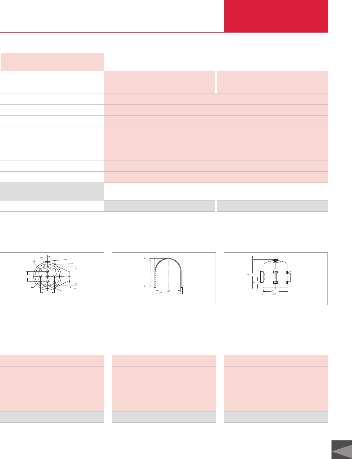
High Vacuum Experimentation Systems
C19
LEYBOLD VACUUM PRODUCTS AND REFERENCE BOOK 2003/2004
Technical Data UNIVEX 300
Standard Special
High vacuum pump
Pumping speed for N2l x s-1
Backing pump / nominal pumping speed
Supply unit for high vacuum pump
Control
High vacuum connection flange DN
Electrical connection
Cooling water connection; DN 10 hose bar
Cooling water consumption l x h-1
Weight kg
TURBOVAC 151 TURBOVAC 361
145 345
TRIVAC D 8 B / 9.7 m3x h-1
TURBOTRONIK NT 20
Power supply with main switch plug-in
100 ISO-F, lateral
230 V, 50 Hz, max. 16 A *)
4 to 7
50
130
Ordering Information Standard Special
Basic unit
*)Other voltages and frequencies upon request
Part No. 030 60 upon request
Special Accessories for UNIVEX 300
120
170
Height = 14
230
30°15°DN 40 KF
DN 10 KF
DN 10 KF
DN 100 ISO-K
Dimensional drawing for the base plate on the UNIVEX 300
350
341 300
373
Dimensional drawing for the glass bell jar with implosion protection
321
380
190
Drawn offset
by 90°
160
10
Dimensional drawing for the stainless steel bell jar
Lateral high vacuum connection flange DN 100 ISO-K
Dimensions (H x dia.) 60 x 350 mm
Installation holes 34.5 mm dia. (13 x)
Lateral connections 2 x DN 10 KF, 1 x DN 40 KF
Weight 19 kg
Base plate, stainless steel Part No. 030 61
Dimensions (H x dia.) 350 x 300 mm
Height, cylindrical section 200 mm
Seal FPM
Weight 5.6 kg
Bell jar, Pyrex glass Part No. 030 10 1)
1) With punched steel cover for implosion protection
Dimensions (H x dia.) 380 x 300 mm
Height, cylindrical section 300 mm
Seal FPM
Weight 9.6 kg
Bell jar, stainless steel Part No. 030 12 1)
1) With DN 100 viewing window and 2 carrying handles; hole at the
top (34.5 mm dia.)
Stainless Steel Base Plate Pyrex Glass Bell Jar
(Vacuum Chamber)
Stainless Steel Bell Jar
(Vacuum Chamber)
Technical Data and Ordering Information
Bell Jar System
C19.05
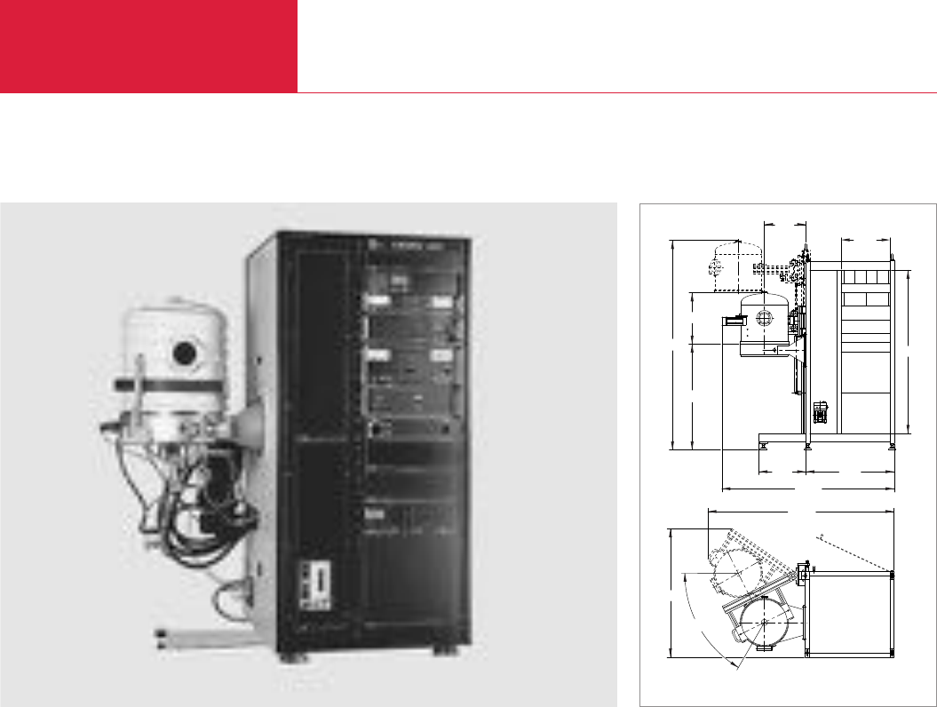
Bell Jar System
High Vacuum Experimentation Systems
LEYBOLD VACUUM PRODUCTS AND REFERENCE BOOK 2003/2004
UNIVEX 450
Cabinet Housed System with
450 mm dia. Vacuum
Chamber
Advantages to the User
♦Modular system design
♦Any kind of process component may be
installed
♦Process components may be retrofitted
without problems
♦Freely accessible vacuum chamber
♦Freely accessible base plate
♦Very simple to operate and use
♦Pump system adapted to the individual
process
Typical Applications
♦Vacuum coating in research and development
♦Pre-production trials
♦Dactyloscopy
♦Special experiments
Basic Unit
♦The pump system and the electrical supply
system are housed in the UNIVEX 450 cabi-
net.
♦Moreover, the 19" cabinet provides space
(max. 20 height units) for a vacuum gauge
and a thickness measuring instrument as well
as power supply units for the process compo-
nents.
Vacuum Chamber
♦The base plate is attached to the lateral intake
port of the basic unit.
♦A vacuum chamber made of stainless steel
may be placed on this base plate.
♦A water-cooled vacuum chamber can also be
supplied.
♦The vacuum chamber is moved by the hoist
attached to the basic unit.
C19.06
Pump System
♦The standard pumping equipment comprises
a TRIVAC D 40 B two-stage rotary vane pump
and a TURBOVAC 1000 turbomolecular pump.
♦For processes which develop increased quan-
tities of gas or which require low operating
pressures, the UNIVEX 450 can also be equip-
ped with cryo pumps.
♦For processes which involve pumping of
aggressive media, a barrier gas version of the
turbomolecular pump and a rotary vane pump
with a filling of special oil may be supplied.
♦For especially sensitive processes also a dry
compressing vacuum pump like the EcoDry M
may be used as the backing pump.
Vacuum Measurement
♦Depending on the type of application, a com-
bination vacuum gauge operating according to
the cold cathode or hot cathode principle may
be installed.
1260
1606
60°
1835
2058
1040
500
404
486
454 870
1690
UNIVEX 450, with turbomolecular pump system and various installations Dimensional drawing for the UNIVEX 450; with base plate, bell jar and hoist
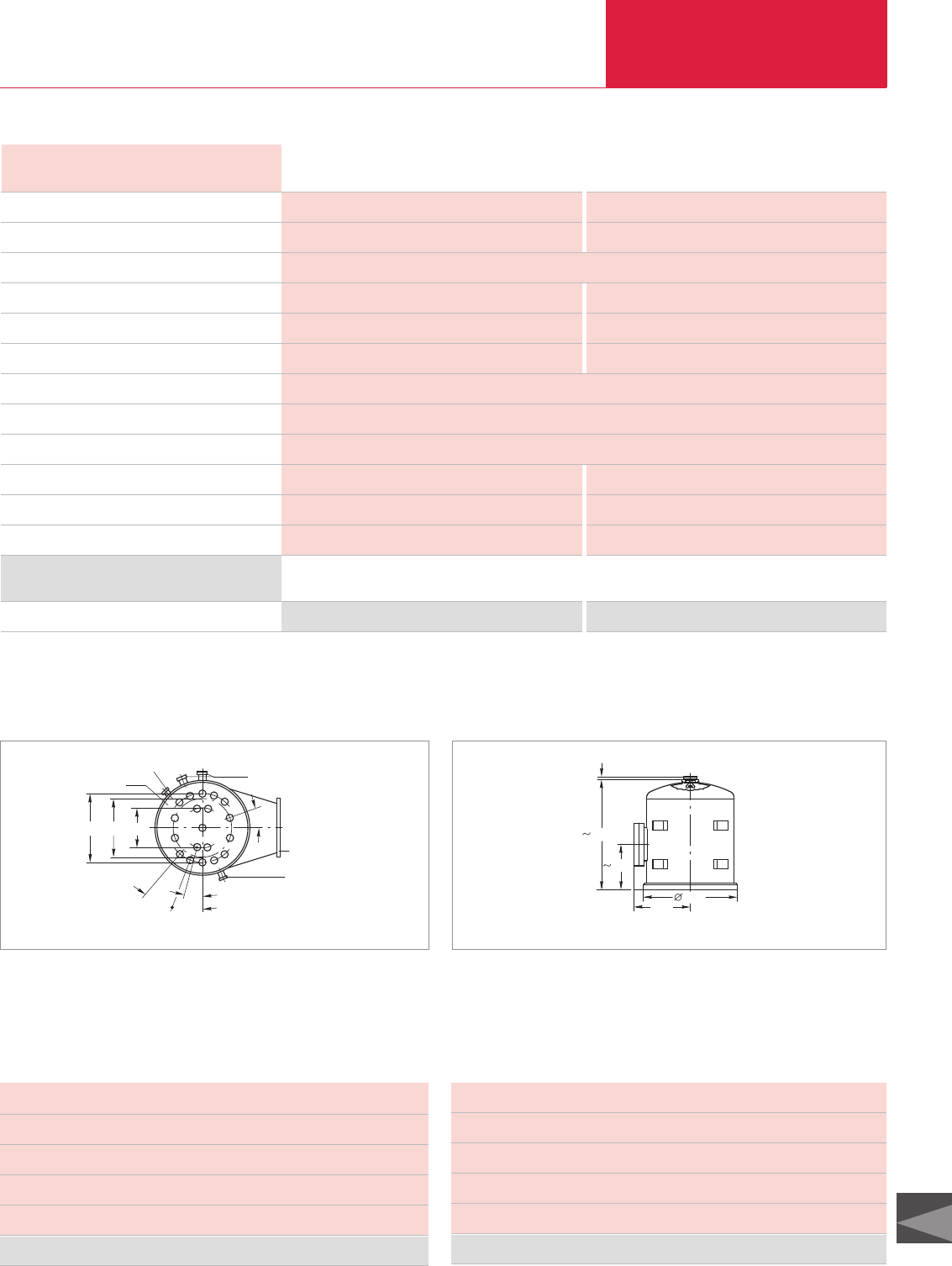
High Vacuum Experimentation Systems
C19
LEYBOLD VACUUM PRODUCTS AND REFERENCE BOOK 2003/2004
Technical Data UNIVEX 450
Standard Special
High vacuum pump
Pumping speed for N2l x s-1
Backing pump / nominal pumping speed
Supply unit for high vacuum pump
Control
Built-in electro-pneumatic valves
High vacuum connection flange DN
Electrical connection
Cooling water connection; DN 10 hose bar
Cooling water consumption l x h-1
Compressed air connection, DN 10 bar
Weight kg
TURBOVAC 1100 COOLVAC 1500 CL
1150 1500
TRIVAC D 40 B / 46 m3x h-1
TURBOTRONIK NT 20 Compressor unit
Power supply Power supply with automatic pump system control
– Push gate valve DN 250 ISO-F, 2 angled valves DN 40 KF
250 ISO-F, lateral
400 V, 3 ph., 50 Hz, max. 32 A *)
4 to 7
100 140
– 6 to 10
225 350
Ordering Information Standard Special
Basic unit
*)Other voltages and frequencies upon request
Part No. 030 70 upon request
Specific Accessories for UNIVEX 450
Stainless Steel Base Plate Stainless Steel Bell Jar (Vacuum Chamber)
Bell Jar System
C19.07
Höhe = 15
220
15°
DN 40 KF
DN 16 KF
DN 250 ISO-K
DN 16 KF
280340
20,5°20,5°
20°
Dimensional drawing for the base plate for UNIVEX 450
500
255
468
265
10
Dimensional drawing for the stainless steel bell jar for UNIVEX 450
Lateral high vacuum connection flange DN 250 ISO-K
Dimensions (H x dia.) 115 x 475 mm
Installation holes 34.5 mm dia. (19 x)
Lateral connections 2 x DN 16 KF, 2 x DN 40 KF
Weight 27 kg
Base plate Kat.-Nr. 030 71
Dimensions (H x dia.) 500 x 450 mm
Height, cylindrical section 400 mm
Seal FPM
Weight 23 kg
Bell jar, stainless steel Part No. 030 16 1)
1) With DN 100 viewing window; hole at the top fitted with a blank flange. Upon request the stainless steel
bell jar may be supplied with a coiled cooling or heating pipe
Technical Data and Ordering Information
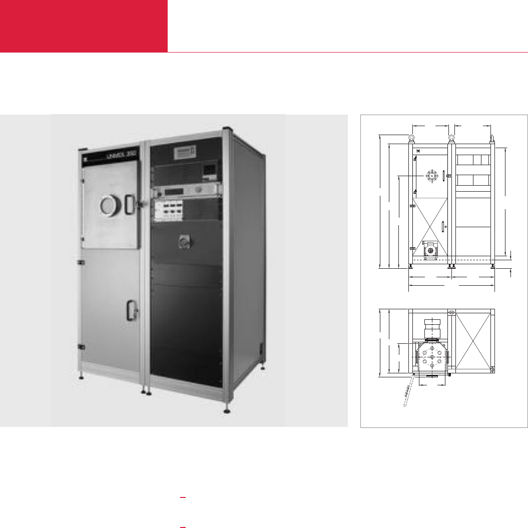
Door System
High Vacuum Experimentation Systems
LEYBOLD VACUUM PRODUCTS AND REFERENCE BOOK 2003/2004
UNIVEX 350
Door System with 350 mm
dia. Vacuum Chamber
Advantages to the User
♦Modular system design
♦Any kind of process component may be
installed
♦Process components may be retrofitted
without problems
♦Vacuum chamber with a door
♦Freely accessible base plate
♦Very simple to operate and use via pro-
grammable control
♦For installation into clean-room walls
♦For RF sputtering
♦Pump system adapted to the individual
process
Typical Applications
♦Vacuum coating in research and development
♦Pre-production trials
♦Special experiments
Basic Unit
♦The UNIVEX 350 consists of two separable
19" rack mount cabinets.
♦The process chamber and the pump system
are accommodated in one cabinet.
♦The electric power supply with the pump
system controller based on a PLC with display
and operating unit is accommodated in the
second cabinet. This cabinet also houses the
vacuum gauge as well as the power supply
units for the process components.
Vacuum Chamber
♦The base plate is attached to the base fame.
♦The door is equipped with a viewing window.
♦Bottom plate and lid are provided with instal-
lation holes.
♦Additional lateral flanges for installing process
components.
♦A water-cooled vacuum chamber can also be
supplied.
♦Evaporation protection plates which may be
easily disassembled are available.
C19.08
Pump System
♦The standard pumping equipment comprises
a TRIVAC D 16 B two-stage rotary vane pump
and a TURBOVAC TW 700 turbomolecular
pump.
♦For processes which develop increased quan-
tities of gas or which require low operating
pressures, the UNIVEX 350 can also be equip-
ped with a turbomolecular pump having a
higher pumping speed (TURBOVAC 1000, for
example) or with cryopumps.
♦For processes which involve pumping of
aggressive media, a barrier gas version of the
turbomolecular pump and a rotary vane pump
with a filling of special oil may be supplied.
♦For especially sensitive processes also a dry
compressing vacuum pump like the EcoDry M
may be used as the backing pump.
Vacuum Measurement
Depending on the type of application, a combina-
tion vacuum gauge operating according to the
cold cathode or hot cathode principle may be
installed.
UNIVEX 350
1472
= 33 HE
486
UNIVEX 350
LEYBOLD
486 = 19"
380
894
840
370
100
566 566
1132
1233
1652
1742
Dimensional drawing for the UNIVEX 350
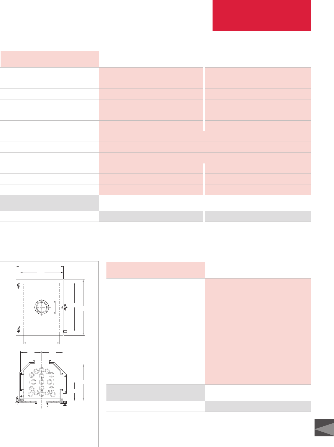
High Vacuum Experimentation Systems
C19
LEYBOLD VACUUM PRODUCTS AND REFERENCE BOOK 2003/2004
Technical Data UNIVEX 350
Standard Special
High vacuum pump
Pumping speed for N2l x s-1
Backing pump / nominal pumping speed
Supply unit for high vacuum pump
Control
Built-in electro-pneumatic valves
High vacuum connection flange DN
Electrical connection
Cooling water connection; DN 10 hose bar
Cooling water consumption l x h-1
Compressed air connection, DN 10 bar
Weight kg
TURBOVAC TW 700 COOLVAC 1500 CL
680 1500
TRIVAC D 16 B / 18.9 m3x h-1 TRIVAC D 25 B / 29.5 m3x h-1
OEM power supply 59 V DC Compressor unit
Power supply with programmable control Power supply with programmable control
1 x DN 16 KF 1 x gate valve DN 160, 2 x right-angle valve DN 25, DN 16 KF
160 ISO-K
400 V, 3 ph., 50/60 Hz *)
4 to 7
25 140
– 6 to 10
350 425
Ordering Information Standard Special
Basic unit
*)Other voltages and frequencies upon request
upon request upon request
Vacuum Chamber
Door System
Technical Data Vacuum Chamber for UNIVEX 350
Material
Dimensions
Inside width mm
Inside depth mm
Inside height mm
Connections
Front side
Bottom plate
Lid
Rear DN
Left side DN
Right side DN
Weight kg
Stainless steel
370
380
500
Door with window
15 installation holes, 34.5 mm dia.
7 installation holes, 34.5 mm dia.
160 ISO-K, 2 x 10 KF, 2 x 40 KF
160 ISO-K, further flanges optional
160 ISO-K, further flanges optional
55
Ordering Information Vacuum Chamber for UNIVEX 350
Vacuum chamber Is included with the UNIVEX 350
C19.09
484
440
500 580
370
220 220
195
380
Dimensional drawing for the vacuum camber
The position, number and size of the flanges and the installation
holes may be varied almost freely according to requirements!

Accessories
High Vacuum Experimentation Systems
C19.10 LEYBOLD VACUUM PRODUCTS AND REFERENCE BOOK 2003/2004
Standard Accessories for UNIVEX 300, 350, 450 and 450 B
Blank-off screw fitting Rotary feedthrough with attached drive motor and control cable
Material Stainless steel
Gasket FPM
Weight 0.1 kg
Blank-off screw fitting Part No. 030 40
Total length 400 mm
Shaft dia.; atmosphere/vacuum 8/10 mm
Max. rotational speed 150 rpm
Permissible torque 2 Nm
Weight 2 kg
Rotary Feedthrough Part No. 030 63
Dimensions 70 mm dia., 300 mm long
Speed 0 to 150 rpm, load dependent control
Electrical power supply 24 V/DC
Weight 2 kg
Motor drive for rotary feedthrough Part No. 030 64
Blank-Off Screw Fitting
For 34.5 mm dia. hole.
Rotary Feedthrough
With mount for substrate holder; for all common
bell jar sizes; suitable for 34.5 mm dia. holes.
Motor Drive for
Rotary Feedthrough
With connection flange and coupling; is
electrically operated through the VS 024 supply
unit.
Technical Data and Ordering Information
Control Cable, 6-Way
Used to connect the motor to the power supply,
complete with plugs.
Supply Unit VS 024
For driving the motor.
Length 3 m
Weight 0.2 kg
Control cable Part No. 030 56
Cabinet 1/2 19" rack module, 3 HU
Output 24 V/DC, load dependent control
via potentiometer
Connection 230 V, 50/60 Hz
Weight 3 kg
Supply unit VS 024 Part No. 200 02 466
Technical Data and Ordering Information
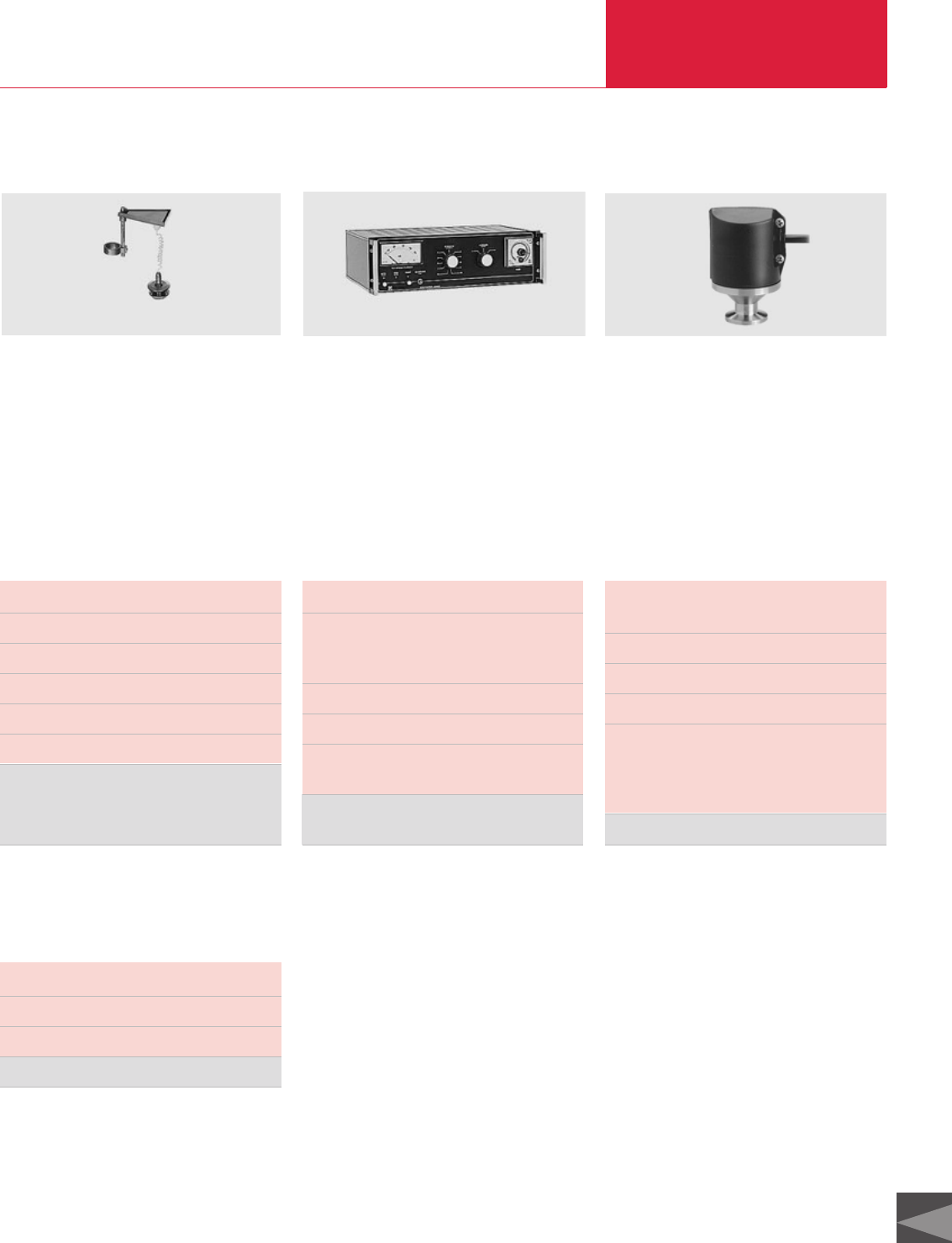
High Vacuum Experimentation Systems
C19.11
C19
LEYBOLD VACUUM PRODUCTS AND REFERENCE BOOK 2003/2004
Components for Glow Discharge Cleaning
Glow discharge assembly with high voltage feedthrough
and connection cable C 2000 high voltage power supply unit
Electrode material Aluminium
Insulation Ceramics
Max. ratings 2000 V/65 mA
Sealing material of the high voltage feedthrough FPM
Length of the connection cable 2 m
Weight 1 kg
Glow discharge assembly
for UNIVEX 300 and 350 Part No. 030 34
for UNIVEX 450 and 450 B Part No. 030 35
Cabinet 19 " rack module, 3 HU
Output 2000 V/65 mA, max.
continuously adjustable,
selectable + / – and 50 Hz AC
Timer 0 to 6 h max.
Connection 230 V, 50/60 Hz, 150 VA
Remote control
and locking input included
C 2000 High voltage
power supply unit Part No. 032 95
Gas admission rate qL5 x 10-6 to 1 x 10³mbar x l x s-1
Connection flange DN 16 KF
(see also Product Section C14 “Vacuum Valves”)
Variable leak valve Part No. 215 010
Glow Discharge Assembly
With glow discharge electrode, high voltage feed-
through for 34.5 mm dia. hole and connection
cable for fitting to the central rotary feedthrough.
C 2000 High Voltage
Power Supply Unit
For supplying the glow discharge assembly;
with selector switch, meter and timer.
PS 113 Safety Switch
For pressure-dependant locking of the high volt-
age power supply C 2000.
Connecting the PS 113 to the C 2000 requires the
6-way control cable (Part No. 030 56) (
see section
“Accessories”, paragraph “Standard Accessories”
).
Technical Data and Ordering Information
Switching pressure 5 mbar below
atmospheric pressure
Connection flange DN 16 KF
Switching capacity 5 A at 250 V/AC
Weight 0.2 kg
PS 113 safety switch Part No. 160 14
Variable Leak Valve with
Isolation Valve
Accessories
PS 113 Safety Switch
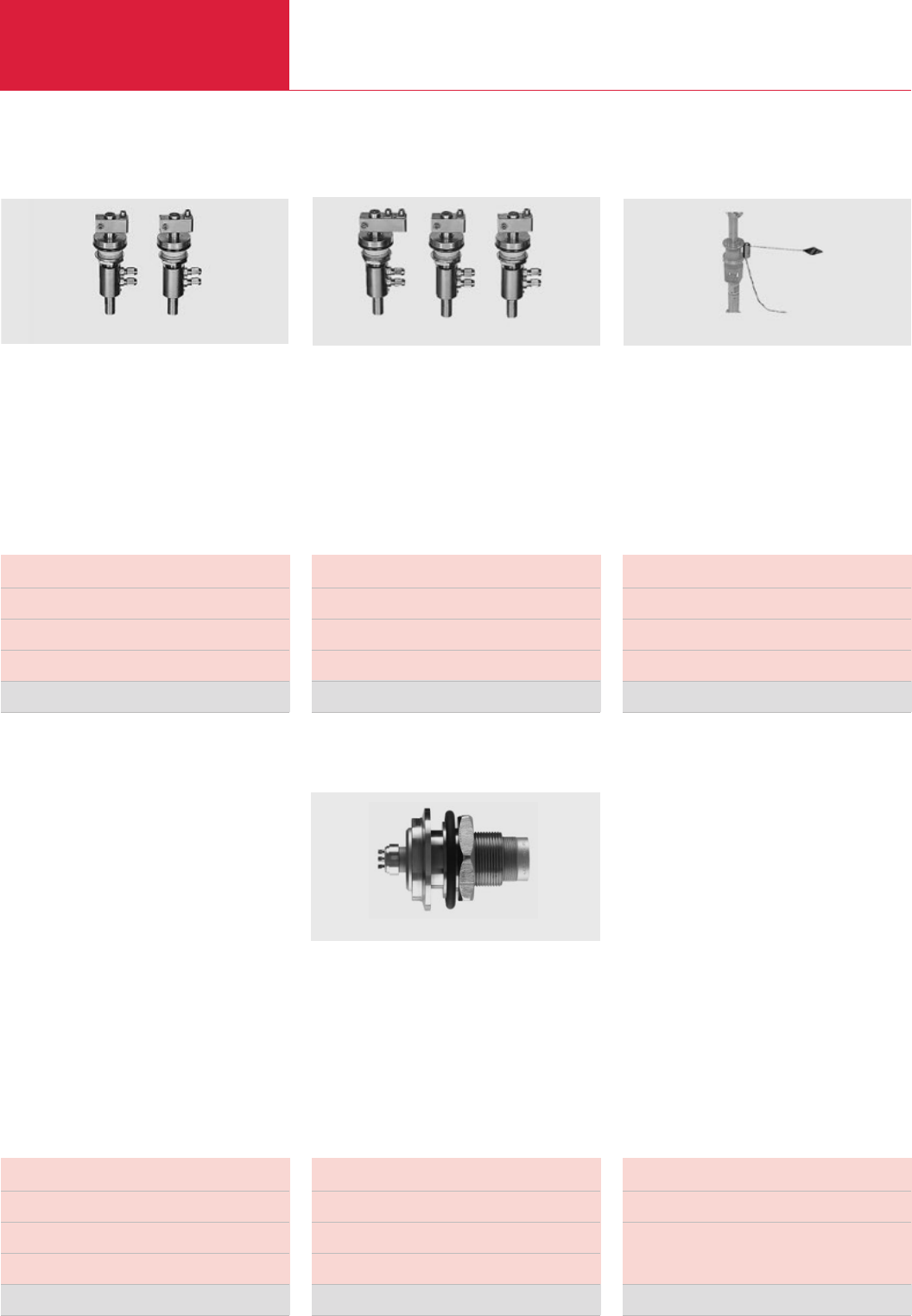
Accessories
High Vacuum Experimentation Systems
C19.12 LEYBOLD VACUUM PRODUCTS AND REFERENCE BOOK 2003/2004
Single thermal evaporator Dual thermal evaporator
Rating per conductor max. 100 V/500 A
Seals FPM
Water connection hose 4/6 mm dia.
Weight 2.5 kg
Single thermal evaporator Part No. 030 20
Rating per conductor max. 100 V/500 A
Seals FPM
Water connection hose 4/6 mm dia.
Weight 3.9 kg
Dual thermal evaporator Part No. 030 21
Connection for actuation 24 V = 1 s pulse
Dimensions of the shutter screen 50 x 50 mm
Weight 0.2 kg
Vapor source shutter Part No. 030 59
Single Thermal Evaporator
Consisting of two water-cooled high voltage feed-
throughs with terminal blocks for 34.5 mm dia.
holes.
Dual Thermal Evaporator
Consisting of three water-cooled high voltage
feedthroughs with terminal blocks for 34.5 mm
dia. holes.
Solenoid Actuated Vapor
Source Shutter
With rotary magnet and shutter screen;
for installation to the rotary feedthrough
Technical Data and Ordering Information
Components for Thermal Evaporation
Vapor source shutter, attached to the rotary feedthrough
Power Supply Cables
For single and dual thermal evaporators, equip-
ped with terminals and clamping pieces.
6-Way Measurement
Feedthroughs
For connection of the vapor source shutter; for
34.5 mm holes, plug-in soldered contact on the
inside.
Control cable, 6-way
For connection between measurement feed-
through and power supply unit for the vapor
source shutter, complete with connection plugs.
Length 2 m
Rating max. 100/500 A
Cross section 120 mm2
Weight 3.5 kg
Power supply cables (set of 2) Part No. 030 53 *)
Rating per conductor max. 700 V/16 A
Seal FPM
Weight 0.3 kg
Measurement feedthrough Part No. 500 001 543
Length 3 m
Weight 0.2 kg
9 way control cable Part No. 500 001 549
Technical Data and Ordering Information
*) Two sets of power supply cables are needed for the dual thermal evaporator
6-way measurement feedthrough
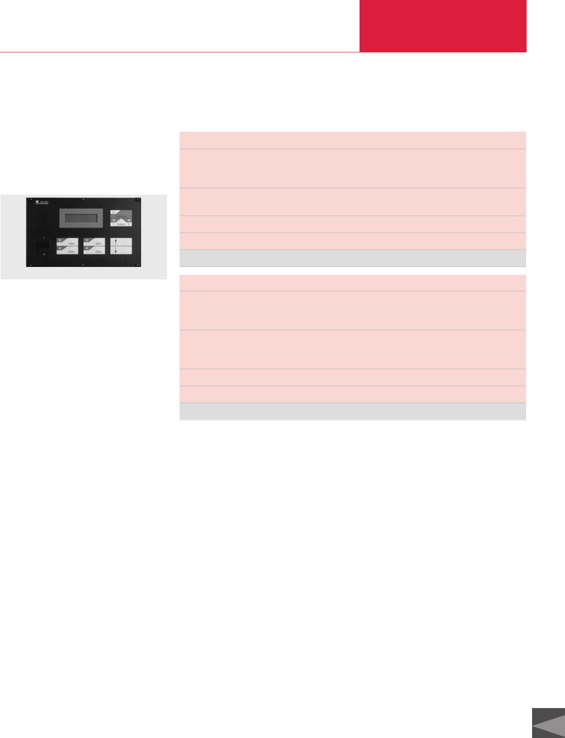
High Vacuum Experimentation Systems
C19.13
C19
LEYBOLD VACUUM PRODUCTS AND REFERENCE BOOK 2003/2004
Cabinet 1/2 19" rack module, 3 HU, 400 mm deep
Outputs 1 x evaporator output, 5 V, 400 A max.
can be rewired to 10 V, 200 A max.
1 x shutter output, 24 V DC, 1 s pulse
Inputs Remote control unit for controlling the evaporation power (0 to 10 V)
Remote control for the shutter
Main power supply 230 V, 50/60 Hz, 10 A
Weight 15 kg
AS 053 power supply unit Part No. 200 23 209
AS 053 Power Supply Unit
For supplying thermal evaporators and one
solenoid-actuated source shutter.
With LCD display for current read out; with
membrane key pad.
Components for Thermal Evaporation
Technical Data and Ordering Information
General
Various types of electron-beam evaporators are
available for installation in the UNIVEX systems.
For the UNIVEX 300: electron-beam evaporator
ESV 4 as well as makes of other manufacturers.
For the UNIVEX 350: electron-beam evaporator
ESV 4 and ESV 6 as well as makes of other
manufacturers.
For the UNIVEX 450: electron-beam evaporator
ESV 4 and ESV 6 as well as makes of other
manufacturers.
The selection of a suitable electron-beam evapo-
rator depends mostly on the space available, the
demanded evaporation rate, number and type of
materials which need to be evaporated.
Electron-beam evaporator ESV 4
The electron-beam evaporator ESV 4 consists of
a beam generating system and a beam deflection
unit with electromagnetic deflection for the x-axis
and a holder for accommodating various evapo-
ration crucibles.
The ESV 4 has been designed to evaporate small
to medium amounts of material.
Accessories
AS 053 power supply unit
Electron-beam evaporator ESV 6
The electron-beam evaporator ESV 6 consists of
a beam generating system and a beam deflection
unit with electromagnetic deflection for the x and
y-axis, and a holder. Through the system of
interchangeable crucibles the ESV 6 may be used
to solve almost any evaporation problem. It is
suited to evaporate small to large amounts of
material.
Electron-beam evaporators of other manufactu-
rers
For the UNIVEX system exclusively evaporators
with high tension power supplies are used which
comply with EC regulations and directives.
However, depending on the kind of application
the customer may select the required evaporator
from a broad range of different power ratings and
crucible variants.
Power supplies
The selection of the power supply unit for the
individual electron-beam evaporator depends on
the manufacturer and the demanded maximum
evaporation power. As a rule, the maximum out-
put power of the power supply unit must not
exceed the maximum power specified for the eva-
porator.
Safety regulations
When installing electron-beam evaporators in
UNIVEX bell jar systems only a stainless steel bell
jar must be used.
In this application the bell jar must be secured in
place by an interlocking kit with a key operated
switch.
Interlocking kit with key-operated switch for
UNIVEX 300: Part No. 030 84
Interlocking kit with key-operated switch for
UNIVEX 450: Part No. 030 85
Interlocking kit with key-operated switch for
UNIVEX 350: included with the basic system.
UNIVEX 450 B: included with the basic system.
As further safety means a water flow monitor is
required for each electron-beam evaporation unit
so as to ensure intensive cooling of the electron-
beam evaporator. This water flow monitor is
included with each electron-beam evaporator.
As further safety means a water flow monitor is
required for each electron-beam evaporation unit
so as to ensure intensive cooling of the electron-
beam evaporator.
Components for Electron-Beam Evaporation
Cabinet 19" rack module, 3 HU, 400 mm deep
Outputs 2 x evaporator output, 5 V, 400 A max.
can be rewired to 10 V, 200 A max.
2 x shutter output, 24 V DC, 1 s pulse
Inputs Remote control unit for controlling the evaporation power (0 to 10 V)
Remote control for the shutter
Switchover evaporator 1 / 2
Main power supply 230 V, 50/60 Hz, 10 A
Weight 30 kg
AS 053-2 power supply unit Part No. 200 02 461
AS 053-2 Power Supply Unit
For supplying power to two thermal evaporators
with vapor source shutters.
With LCD display for current read out; with mem-
brane key pad.

Accessories
High Vacuum Experimentation Systems
C19.14 LEYBOLD VACUUM PRODUCTS AND REFERENCE BOOK 2003/2004
RF Sputtering
Various RF sputtering sources may be built into
the UNIVEX 350 and UNIVEX 450 B. The selec-
tion depends on the size of the substrate, the
required target material and the available installa-
tion space. RF sputtering sources from 50 mm to
200 mm as well as corresponding RF sputtering
Components for High Rate Sputtering
Various DC sputtering sources may be built into
the UNIVEX units. The selection depends on the
size of the substrate, the required target material
and the available installation space. DC sputtering
sources from 50 mm to 200 mm as well as
corresponding DC sputtering power supply units
from 500 W to 3000 W are available. The power
supply units may be built into the basic units.
Further information upon request.
power supply units from 150 W to 1000 W are
available. The power supply units may be built
into the basic units.
Further information upon request.
Safety regulations:
When installing electron beam evaporators in the
UNIVEX 300 the stainless steel ball jar must be
used. Moreover, a safety interlocking arrange-
ment is required. For the UNIVEX 300 and 450 a
separate interlocking kit is available; in the case
of the UNIVEX 350 and 450 B this kit is already
included.
Interlocking kit for UNIVEX 300 UNIVEX 450 UNIVEX 350 UNIVEX 450 B
Part No. 030 84 030 85 Included Included
DC Sputtering
Components for Film Thickness Measurements
Various thin film thickness measuring instru-
ments may be installed in the UNIVEX units.
The selection depends on the demanded measure-
ments tasks and the required degree of automati-
on.
We especially recommend the thin film thickness
measuring instruments which rely on quartz
oscillators XTM/2 in the case of simple tasks, and
the XTC/2 for complex control tasks.
Further thin film measuring instruments which
may be used to check complex multi-layer films
are available.
Further information upon request.
DC sputtering sources are suited for all UNIVEX systems.
RF sputtering sources are only suited for the UNIVEX 350 and UNIVEX 450 B.
Sputtering sources can only be operated with gas
admission. For this, manually operated variable
leak valves up to automatically controlled mass
flow controllers are available.
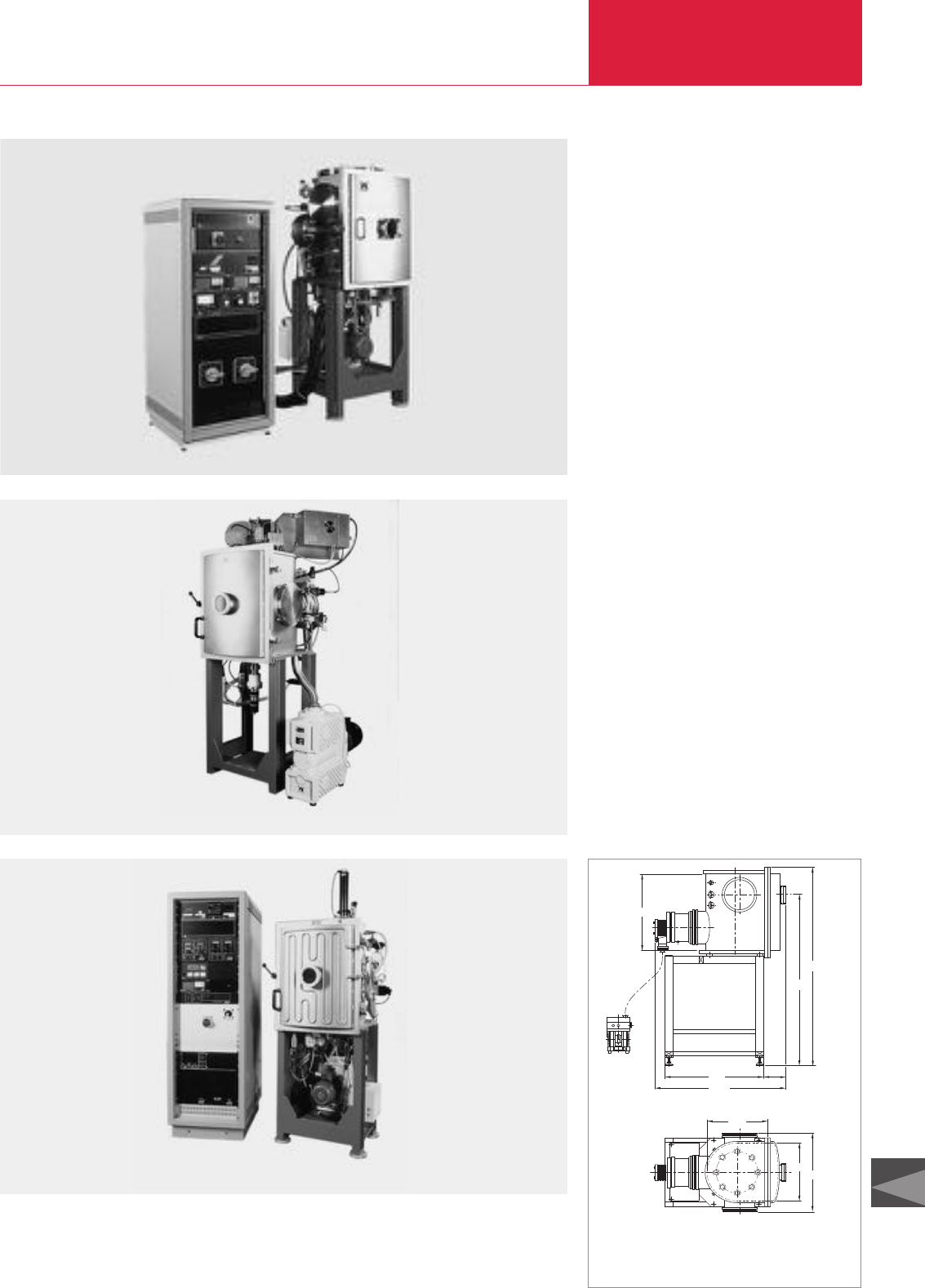
High Vacuum Experimentation Systems
C19.15
C19
LEYBOLD VACUUM PRODUCTS AND REFERENCE BOOK 2003/2004
UNIVEX 450 B having a chamber diameter of 490 mm and with RF sputter sources and dry compressing vacuum pump system; with EcoDry L pump
UNIVEX 450 B having a chamber diameter of 490 mm and with a 10-fold thermal evaporator
UNIVEX 450 B having a chamber diameter of 490 mm and with electron-beam evaporator
with heatable and coolable chamber walls; with COOLVAC 3010 cryopump
UNIVEX 450 B (Chamber systems)
Besides the standard UNIVEX systems we are
also prepared to deliver modified systems for
special applications.
Besides the standard chamber system UNIVEX
350 we can also supply UNIVEX systems with
other chamber sizes. These are then so designed
that the chamber containing the processing com-
ponents and the pump system are mounted to a
separate frame. The door flange of the chamber
may then easily be integrated in the wall of a
clean room. The electric power supply and the
system controller are accommodated in a separa-
te 19" electrical cabinet. This will simplify installa-
tion and subsequent operation.
All processing components commonly used in
thin-film processing may be installed in the
chamber.
The scope of the pump system used will in each
case depend on the requirements of the desired
processes to be run in the chamber.
Design of the entire system in accordance with
customer requirements will be undertaken upon
request.
Special Units
1415
173
1645
780
1060
666
520
500672
Dimensional drawing for the UNIVEX 450 B
The position, number and size of the flanges and the installation
holes may be varied almost freely according to requirements!
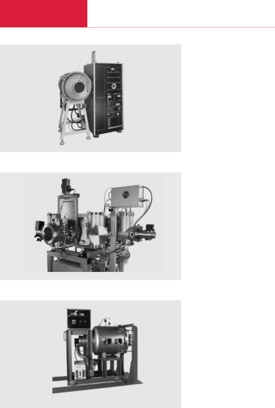
High Vacuum Experimentation Systems
C19.16 LEYBOLD VACUUM PRODUCTS AND REFERENCE BOOK 2003/2004
UNIVEX 450 for dactyloscopy
Test system with a 700 mm dia. chamber
UNIVEX 450 for Dactyloscopy
Dactyloscopy is a term from the area of criminal
investigation meaning: “Identification of a person
through his fingerprints”. Depending on the
material of the part which was touched, different
methods are used to render the fingerprints
visible.
In the case of materials like plastic shopping
bags, for example, foils, handlebars etc. evapora-
tion methods have been found to be most useful.
The method itself utilises the effect well known
from normal evaporation processes where the
evaporated material will adhere better (and
thicker) on the skin material (water, amino acids,
fat and alike) deposited by the finger compared
to the surrounding untouched material. An opti-
mum contrast is attained by selecting a suitable
evaporation material, usually gold or zinc.
Benefits of this method:
♦No “smearing” of existing traces compared to
conventional methods
♦Large surface areas (up to 80 x 40 cm max.)
carrying fingerprints can be checked comple-
tely in one pass
♦The time needed for one pass is only about
10 minutes (depending on the material carry-
ing the fingerprints)
♦Good contrast also in the case of multicolour
surfaces
♦Fixation of the deposited material with the tra-
ces is easy – the results may be well docu-
mented (can be photographed)
♦The carrier of the fingerprints is not destroy-
ed.
UNIVEX 450 C
For special applications we can also supply
cluster systems based on the UNIVEX concept.
These clusters are equipped according to custo-
mers requirements and incorporate separate
processing and load lock and transfer chambers.
Test systems with a vacuum chamber
We can also supply vacuum chambers with
custom pump systems for testing of various
components.
Cluster system with lock, transfer chamber and with the possibility of adding up to six processing chambers.

Please send me an offer for the following products:
Inquiry Form
Name:
Company:
Position:
Street:
Code/City:
Phone:
Fax:
e-mail:
TELEFAX INQUIRYTELEFAX INQUIRY
To
LEYBOLD VAKUUM GmbH
(for Europe)
Fax: +49 (0)221 3 47-12 45
e-mail: sales@leyboldvakuum.com
✄
Brief DesignationQuantityCatalog No.
Place/date Signature Company stamp
LEYBOLD VACUUM PRODUCTS AND REFERENCE BOOK 2003/2004

Please send me an offer for the following products:
Inquiry Form
Name:
Company:
Position:
Street:
Code/City:
Phone:
Fax:
e-mail:
TELEFAX INQUIRYTELEFAX INQUIRY
To
LEYBOLD VACUUM USA INC.
(for USA)
Fax: +41-724-733-12 17
✄
Brief DesignationQuantityCatalog No.
Place/date Signature Company stamp
LEYBOLD VACUUM PRODUCTS AND REFERENCE BOOK 2003/2004

Product Index
B00
B00.01
LEYBOLD VACUUM PRODUCTS AND REFERENCE BOOK 2003/2004
A
Accessories
for Compressor Units COOLPAK . . . . . . . . . . . . . . . . . . . . . C12.34
for Serial Interfaces . . . . . . . . . . . . . . . . . . . . . . . . . . . . . . C09.63
for SOGEVAC . . . . . . . . . . . . . . . . . . . . . . . . . . . . . . . . . . . C02.39
for the Electropneumatically Operated Valves . . . . . . . . . . . . C14.25
for UHV Components . . . . . . . . . . . . . . . . . . . . . . . . . . . . . C15.10
for L 200
plus
, L 200 dry and Modul L 200
plus
. . . . . . . . . C17.18
for UNIVEX . . . . . . . . . . . . . . . . . . . . . . . . . . . . . . . . . . . . . C19.10
Adaptors . . . . . . . . . . . . . . . . . . . . . . . . . . . . . . . . . C13.16 + C13.41
Adsorption Traps with Aluminium Oxide Insert . . . . . C10.16 + C11.12
Air Cooling Unit . . . . . . . . . . . . . . . . . . . . . . . . . . . . . . . . . . . C09.61
ANSI Fittings . . . . . . . . . . . . . . . . . . . . . . . . . . . . . . . . . . . . . C13.44
Astrotorus Baffles . . . . . . . . . . . . . . . . . . . . . . . . . . . . . . . . . . C11.09
B
Ball Valves . . . . . . . . . . . . . . . . . . . . . . . . . . . . . . . . . . . . . . . C14.22
for SOGEVAC . . . . . . . . . . . . . . . . . . . . . . . . . . . . . . . . . . . C02.37
Bourdon Vacuum Gauges . . . . . . . . . . . . . . . . . . . . . C02.41 + C16.05
C
Calibrated Leaks . . . . . . . . . . . . . . . . . . . . . . . . . . . . . . . . . . . C17.14
Calibration Service from LEYBOLD . . . . . . . . . . . . . . . . . . . . . C16.50
Calibration Systems CS . . . . . . . . . . . . . . . . . . . . . . . . . . . . . C10.14
Capsule Vacuum Gauges . . . . . . . . . . . . . . . . . . . . . . . . . . . . C16.06
Cart (for EcoDry L) . . . . . . . . . . . . . . . . . . . . . . . . . . . . . . . . . C03.14
CENTER ONE . . . . . . . . . . . . . . . . . . . . . . . . . . . . . . . . . . . . . C16.24
CENTER TWO / THREE . . . . . . . . . . . . . . . . . . . . . . . . . . . . . . C16.26
Central Vacuum Systems . . . . . . . . . . . . . . . . . . . . . . . . . . . . C02.47
CERAVAC Transmitters . . . . . . . . . . . . . . . . . . . . . . . . . . . . . . C16.08
CF Flanges . . . . . . . . . . . . . . . . . . . . . . . . . . . . . . . . . . . . . . . C15.03
Checklist for Inquiries (Vacuum Pump Systems) . . . . . . . . . . . C08.38
Clamp Flange Fittings and Components (ISO-K) . . . . . C13.18 + C13.42
Cold Heads
COOLPOWER,
Single Stage . . . . . . . . . . . . . . . . . . . . . . . . . . .
C12.28
COOLPOWER,
Dual Stage . . . . . . . . . . . . . . . . . . . . . . . . . . . .
C12.30
Cold Trap TK . . . . . . . . . . . . . . . . . . . . . . . . . . . . . . . . . . . . . C01.47
COMBIVAC
CM . . . . . . . . . . . . . . . . . . . . . . . . . . . . . . . . . . . . . . . . . . . C16.38
2T . . . . . . . . . . . . . . . . . . . . . . . . . . . . . . . . . . . . . . . . . . . C16.28
Compact Oil Mist Exhaust Filter . . . . . . . . . . . . . . . . . . . . . . . C01.50
Components
for Electron-Beam Evaportion . . . . . . . . . . . . . . . . . . . . . . . C19.13
for Film Thickness Measurements . . . . . . . . . . . . . . . . . . . . C19.14
for Glow Discharge Cleaning . . . . . . . . . . . . . . . . . . . . . . . . C19.11
for High Rate Sputtering . . . . . . . . . . . . . . . . . . . . . . . . . . . C19.14
for Leak Testing Instruments . . . . . . . . . . . . . . . . . . . . . . . . C17.21
for the modular DIVAC System . . . . . . . . . . . . . . . . . . . . . . C04.13
for Thermal Evaporation . . . . . . . . . . . . . . . . . . . . . . . . . . . C19.12
Compressor Units COOLPAK . . . . . . . . . . . . . . . . . . . . . . . . . . C12.32
Condensate Separators AK
for E and DK Pumps . . . . . . . . . . . . . . . . . . . . . . .C06.11 + C11.12
for TRIVAC B . . . . . . . . . . . . . . . . . . . . . . . . . . . . . . . . . . . . . C01.52
Condensate Traps AK
for TRIVAC E and B . . . . . . . . . . . . . . . . . . . . . . . . . . . . . . . C01.40
Condensate Traps SL . . . . . . . . . . . . . . . . . . . . . . . . . . . . . . . C02.34
Condensers SEPC . . . . . . . . . . . . . . . . . . . . . . . . . . . . . . . . . . C02.35
Connection Cables for Active Sensors . . . . . . . . . . . . . . . . . . . C16.20
Connection Components (for Leak Testing Instruments) . . . . . C17.21
Connection Fittings (for SOGEVAC) . . . . . . . . . . . . . . . . . . . . . C02.42
Connection Flanges (for Leak Testing Instruments) . . . . . . . . . C17.21
Connectors (for Feedthroughs) . . . . . . . . . . . . . . . . . . . . . . . . C15.19
Controllers and Monitoring Units for Cryopumps . . . . . . . . . . . C12.38
Cryopumps COOLVAC
Standard . . . . . . . . . . . . . . . . . . . . . . . . . . . . . . . . . . . . . . C12.10
with fully automatic Control
ClassicLine
. . . . . . . . . . . . . . . . . . . . . . . . . . . . . . . . . . . . C12.12
SemiLine
. . . . . . . . . . . . . . . . . . . . . . . . . . . . . . . . . . . . . C12.24
D
Delayed Venting Unit . . . . . . . . . . . . . . . . . . . . . . . . . . . . . . . C10.17
Diaphragm Pressure Regulators MR . . . . . . . . . . . . . . . . . . . C16.49
Diaphragm Vacuum Pumps
DIVAC, Single-Stage . . . . . . . . . . . . . . . . . . . . . . . . . . . . . . C04.06
DIVAC L
Dual-Stage . . . . . . . . . . . . . . . . . . . . . . . . . . . . . . . . . . . . C04.08
Dual-Stage with automatic Drying System . . . . . . . . . . . . C04.10
DIAVAC DV 1000 . . . . . . . . . . . . . . . . . . . . . . . . . . . . . . . . . . C16.07
DISPLAY ONE . . . . . . . . . . . . . . . . . . . . . . . . . . . . . . . . . . . . . C16.22
DIVAC Sub-assemblies . . . . . . . . . . . . . . . . . . . . . . . . . . . . . . C04.14
Modular Laboratory Pump Concept . . . . . . . . . . . . . . . . . . . . . C04.12
Dry Compressing Backing Pumps for Turbomolecular Pumps
DIVAC T . . . . . . . . . . . . . . . . . . . . . . . . . . . . . . . . . . . . . . . C04.18
MZ D . . . . . . . . . . . . . . . . . . . . . . . . . . . . . . . . . . . . . . . . . C04.24

Product Index
B00.02 LEYBOLD VACUUM PRODUCTS AND REFERENCE BOOK 2003/2004
Dry Compressing Piston Vacuum Pump
EcoDry L . . . . . . . . . . . . . . . . . . . . . . . . . . . . . . . . . . . . . . C03.06
EcoDry M . . . . . . . . . . . . . . . . . . . . . . . . . . . . . . . . . . . . . . C03.10
Dry Compressing Screw Vacuum Pump . . . . . . . . . . . . . . . . . C05.03
Dust Filters FS
for E and DK Pumps . . . . . . . . . . . . . . . . . . . . . . . . . . . . . . C06.12
for TRIVAC E and B . . . . . . . . . . . . . . . . . . . . . . . . . . . . . . . C01.46
Dust Filters (Suction Side) for SOGEVAC . . . . . . . . . . . . . . . . . C02.32
Dust Separators AS
for E and DK Pumps . . . . . . . . . . . . . . . . . . . . . . . . . . . . . . C06.13
for TRIVAC E and B . . . . . . . . . . . . . . . . . . . . . . . . . . . . . . . C01.44
E
Electrical Feedthroughs . . . . . . . . . . . . . . . . . . . . . . . . . . . . . . C13.32
Electrical Indicator System EIS . . . . . . . . . . . . . . . . . . . . . . . . C01.60
Electronic Frequency Converters
for Turbomolecular Pumps
with Mechanical Rotor Suspension . . . . . . . . . . . . . . . . C09.32
with Magnetic Rotor Suspension . . . . . . . . . . . . . . . . . C09.56
Exhaust Filter Box . . . . . . . . . . . . . . . . . . . . . . . . . . . . . . . . . . C06.09
Exhaust Filter Drain Tap . . . . . . . . . . . . . . . . . . . . . . . . . . . . . C01.42
Exhaust Filters
AF for E and DK Pumps . . . . . . . . . . . . . . . . . . . . .C06.11 + C13.39
AF for TRIVAC E and B . . . . . . . . . . . . . . . . . . . . . . . . . . . . C01.40
with Lubricant Return ARP / AR . . . . . . . . . . . . . . . . . . C01.54
with Lubricant Return ARS . . . . . . . . . . . . . . . . . . . . . . C01.55
AK for TRIVAC B . . . . . . . . . . . . . . . . . . . . . . . . . . . . . . . . . C01.53
Exhaust Filter Gauge . . . . . . . . . . . . . . . . . . . . . . . . . . . . . . . . C02.40
Exhaust Silencer . . . . . . . . . . . . . . . . . . . . . . . . . . . . . . . . . . . C03.17
F
Fine Filter . . . . . . . . . . . . . . . . . . . . . . . . . . . . . . . . . . . . . . . . C09.61
Fine Vacuum Adsorption Traps FA . . . . . . . . . . . . . . . . . . . . . . C01.45
Fixed Flange Fittings
DIN 2501 . . . . . . . . . . . . . . . . . . . . . . . . . . . . . . . . . . . . . . C13.28
ISO-F . . . . . . . . . . . . . . . . . . . . . . . . . . . . . . . . . . . . . . . . . C13.27
ISO-F and DIN 2501, ND6 . . . . . . . . . . . . . . . . . . . . . . . . . . C13.26
ISO-F and DIN 2501 . . . . . . . . . . . . . . . . . . . . . . . . . . . . . . C13.43
Flange Components . . . . . . . . . . . . . . . . . . . . . . . . . . . . . . . . C01.64
Flange Fittings and Components, ISO-KF . . . . . . . . . C13.06 + C13.39
Flange Heaters for CF High Vacuum Flanges . . . . . . . . . . . . . . C09.61
G
Gas Ballast Valve . . . . . . . . . . . . . . . . . . . . . . . . . . . . . . . . . . C02.36
manually operated (Retrofit Kit) . . . . . . . . . . . . . . . . . . . . . C03.16
H
Helium Leak Detector
Mobile and Flexible
Modul L 200
plus
. . . . . . . . . . . . . . . . . . . . . . . . . . . . . C17.10
Portable
L 200
plus
. . . . . . . . . . . . . . . . . . . . . . . . . . . . . . . . . . . C17.08
L 200 dry . . . . . . . . . . . . . . . . . . . . . . . . . . . . . . . . . . . . C17.09
Helium Sample Probes (Sniffers) . . . . . . . . . . . . . . . . . . . . . . C17.20
High Current Feedthroughs . . . . . . . . . . . . . . . . . . . . . . . . . . . C13.35
High Vacuum Experimentation Systems
Bell Jar System
UNIVEX 300 . . . . . . . . . . . . . . . . . . . . . . . . . . . . . . . . . . C19.04
UNIVEX 450 . . . . . . . . . . . . . . . . . . . . . . . . . . . . . . . . . . C19.06
Door System
UNIVEX 350 . . . . . . . . . . . . . . . . . . . . . . . . . . . . . . . . . . C19.08
Special Units . . . . . . . . . . . . . . . . . . . . . . . . . . . . . . . . . . . C19.15
High Vacuum Gate Valves . . . . . . . . . . . . . . . . . . . . . . . . . . . . C14.26
I
Inert-Gas-System IGS . . . . . . . . . . . . . . . . . . . . . . . . . . . . . . . C01.58
IONIVAC Transmitter ITR . . . . . . . . . . . . . . . . . . . . . . . . . . . . C16.16
IONIVAC Sensors IE (Extractors) . . . . . . . . . . . . . . . . . . . . . . . C16.44
J
K
L
Leak Detection Systems
mobile, fitted to the CART 200 . . . . . . . . . . . . . . . . . . . . . . C17.12
Limit Switch System LSS . . . . . . . . . . . . . . . . . . . . . . . . . . . . C01.59
Linear Pressure Sensors DI . . . . . . . . . . . . . . . . . . . . . . . . . . C16.40
Liquid Feedtroughs . . . . . . . . . . . . . . . . . . . . . . . . . . . . . . . . . C13.38
Low Pressure Safety Switch PS 113 A . . . . . . . . . . . . . . . . . . C16.46
Low Temperature Controller Modell 970 . . . . . . . . . . . . . . . . . C12.42
Low Temperature Measuring Instrument MODEL 1901 . . . . . . C12.43
M
MEMBRANOVAC DM . . . . . . . . . . . . . . . . . . . . . . . . . . . . . . . C16.32
Molecular Filters MF . . . . . . . . . . . . . . . . . . . . . . . . . . . . . . . . C01.44
Monitoring Instruments . . . . . . . . . . . . . . . . . . . . . . . . . . . . . C11.10
Mounting Accessories for SOGEVAC Pumps . . . . . . . . . . . . . . C02.40

Product Index
B00.03
LEYBOLD VACUUM PRODUCTS AND REFERENCE BOOK 2003/2004
B00
N
O
Observation Windows . . . . . . . . . . . . . . . . . . . . . . . . . . . . . . . C13.30
Oil Control Unit . . . . . . . . . . . . . . . . . . . . . . . . . . . . . . . . . . . . C06.10
Oil Diffusion Pumps DIP, Water-Cooled . . . . . . . . . . . . . . . . . . C11.06
Oil Drain Kit . . . . . . . . . . . . . . . . . . . . . . . . . . . . . . . . . . . . . . C01.42
Oil Drain Tap . . . . . . . . . . . . . . . . . . . . . . . . . . . . . . . . . . . . . C01.42
Oil Filter Unit . . . . . . . . . . . . . . . . . . . . . . . . . . . . . . . . . . . . . C06.10
Oil Filters
CF, Chemical . . . . . . . . . . . . . . . . . . . . . . . . . . . . . . . . . . . . C01.56
CFS, Chemical, with Safety Isolation Valve . . . . . . . . . . . . . C01.57
OF, Mechanical . . . . . . . . . . . . . . . . . . . . . . . . . . . . . . . . . C01.56
Oil Filtering System
OF1000 . . . . . . . . . . . . . . . . . . . . . . . . . . . . . . . . C01.62 + C06.14
OF3000 . . . . . . . . . . . . . . . . . . . . . . . . . . . . . . . . C02.38 + C06.16
Oil Suction Facility
AR-M, Manually Operated . . . . . . . . . . . . . . . . . . . . . . . . . . C01.43
AR-V, Controlled by Solenoid Valve . . . . . . . . . . . . . . . . . . . C01.43
P
PENNINGVAC PM 31 . . . . . . . . . . . . . . . . . . . . . . . . . . . . . . . C16.36
PENNINGVAC Sensors PR . . . . . . . . . . . . . . . . . . . . . . . . . . . C16.43
PENNINGVAC Transmitters PTR . . . . . . . . . . . . . . . . . . . . . . . C16.14
PIEZOVAC PV 20 . . . . . . . . . . . . . . . . . . . . . . . . . . . . . . . . . . C16.30
Power Failure Venting Valves . . . . . . . . . . . . . . . . . . . . . . . . . C14.22
for Turbomolecular Pumps . . . . . . . . . . . . . . . . . . . . . . . . . C09.62
Power Supply . . . . . . . . . . . . . . . . . . . . . . . . . . . . . C12.25 + C12.38
Precision Manometer . . . . . . . . . . . . . . . . . . . . . . . . . . . . . . . C12.45
Pressure Switches . . . . . . . . . . . . . . . . . . . . . . . . . . . . . . . . . C07.16
PS . . . . . . . . . . . . . . . . . . . . . . . . . . . . . . . . . . . . . . . . . . . C16.47
Purge Gas and Venting Valve . . . . . . . . . . . . . . . . . . . . . . . . . C09.62
Q
R
Refrigerator Cryostats
Based on RDK
6-320
. . . . . . . . . . . . . . . . . . . . . . . . . . . . . . C12.35
Optical, Based on RDK
6-320
. . . . . . . . . . . . . . . . . . . . . . . C12.36
Refillable Traps RST . . . . . . . . . . . . . . . . . . . . . . . . . . . . . . . . C01.48
Right-Angle Valves for Mobile Systems in Accordance with
the Regulations of the Department of Transportation . . . . . . . . C14.24
Roots Pump Adaptor
for EcoDry L . . . . . . . . . . . . . . . . . . . . . . . . . . . . . . . . . . . . C03.15
for TRIVAC B . . . . . . . . . . . . . . . . . . . . . . . . . . . . . . . . . . . C01.61
Roots Vacuum Pumps
RUVAC RA
with Flange-Mounted Motors (50 Hz) . . . . . . . . . . . . . . . C07.12
with Direct-Coupled Motors (60 Hz) . . . . . . . . . . . . . . . . C07.14
RUVAC RAV with Pre-Admission Cooling . . . . . . . . . . . . . . . C08.18
RUVAC WA/WAU with Flange-Mounted Motors . . . . . . . . . . C07.06
RUVAC WS/WSU/PFPE with Canned Motors . . . . . . . . . . . . C07.08
RUVAC WSLF for Laser Gas Systems . . . . . . . . . . . . . . . . . C07.10
Rotary Feedtroughs . . . . . . . . . . . . . . . . . . . . . . . . . . . . . . . . C13.36
Rotary / Linear Motion Feedtroughs . . . . . . . . . . . . . . . . . . . . C13.37
Rotary Piston Vacuum Pumps
DK, Two-stage . . . . . . . . . . . . . . . . . . . . . . . . . . . . . . . . . . C06.06
E, Single-Stage . . . . . . . . . . . . . . . . . . . . . . . . . . . . . . . . . . C06.04
Rotary Vane Vacuum Pumps
SOGEVAC SV . . . . . . . . . . . . . . . . . . . . . . . . . . . . . . . . . . . C02.14
SOGEVAC SV B . . . . . . . . . . . . . . . . . . . . . . . . . . . . . . . . . . C02.04
TRIVAC B, Two-Stage . . . . . . . . . . . . . . . . . . . . . . . . . . . . . C01.10
TRIVAC BCS, Two-Stage . . . . . . . . . . . . . . . . . . . . . . . . . . . C01.26
TRIVAC BCS-PFPE, Two-Stage . . . . . . . . . . . . . . . . . . . . . . C01.32
TRIVAC B-DOT, Two-Stage . . . . . . . . . . . . . . . . . . . . . . . . . C01.22
TRIVAC B-Ex, Two-Stage . . . . . . . . . . . . . . . . . . . . . . . . . . . C01.24
TRIVAC E, Two-Stage . . . . . . . . . . . . . . . . . . . . . . . . . . . . . C01.06
S
Safety Valve . . . . . . . . . . . . . . . . . . . . . . . . . . . . . . . . . . . . . . C12.45
Screw-in Calibrated Leaks . . . . . . . . . . . . . . . . . . . . . . . . . . . . C17.16
Sealing Valves . . . . . . . . . . . . . . . . . . . . . . . . . . . . . . . . . . . . C14.23
Separators SEP . . . . . . . . . . . . . . . . . . . . . . . . . . . . . . . . . . . C02.35
Small Compact Pump S 1.5 . . . . . . . . . . . . . . . . . . . . . . . . . . C01.04
Small Valves micro . . . . . . . . . . . . . . . . . . . . . . . . . . . . . . . . . C14.06
Smoke Eliminator SE . . . . . . . . . . . . . . . . . . . . . . . . . . . . . . . C01.49
Solenoid Gas Ballast Valve . . . . . . . . . . . . . . . . . . . . . . . . . . . C03.19
Solenoid Venting Valve . . . . . . . . . . . . . . . . . . . . . . . . . . . . . . C09.62
Spare Sensors for Older Operating Units
(Total Pressure Gauges) . . . . . . . . . . . . . . . . . . . . . . . . . . . . . C16.45
Special Oil Sight Glass . . . . . . . . . . . . . . . . . . . . . . . . . . . . . . C02.36
Special Units (UNIVEX) . . . . . . . . . . . . . . . . . . . . . . . . . . . . . . C19.15
Special Valves . . . . . . . . . . . . . . . . . . . . . . . . . . . . . . . . . . . . C14.17
System Controller . . . . . . . . . . . . . . . . . . . . . . . . . . C12.25 + C12.38
Switching Amplifier SV 110 . . . . . . . . . . . . . . . . . . . . . . . . . . C16.48

Product Index
B00.04 LEYBOLD VACUUM PRODUCTS AND REFERENCE BOOK 2003/2004
T
Temperature Sensors (Silicon Diode) . . . . . . . . . . . . . . . . . . . C12.44
Thermal Switch . . . . . . . . . . . . . . . . . . . . . . . . . . . . . . . . . . . C02.36
THERMOVAC Sensors Series 200 . . . . . . . . . . . . . . . . . . . . . . C16.42
THERMOVAC TM . . . . . . . . . . . . . . . . . . . . . . . . . . . . . . . . . . C16.34
THERMOVAC Transmitters TTR . . . . . . . . . . . . . . . . . . . . . . . . C16.10
Turbomolecular Pump Systems
BMH70 Dry . . . . . . . . . . . . . . . . . . . . . . . . . . . . . . . . . . . . C10.28
MINI-TOPS 50 . . . . . . . . . . . . . . . . . . . . . . . . . . . . . . . . . . C10.20
PT . . . . . . . . . . . . . . . . . . . . . . . . . . . . . . . . . . . . . . . . . . . C10.04
PT Dry . . . . . . . . . . . . . . . . . . . . . . . . . . . . . . . . . . . . . . . C10.10
PT KIT . . . . . . . . . . . . . . . . . . . . . . . . . . . . . . . . . . . . . . . . C10.08
TiPS . . . . . . . . . . . . . . . . . . . . . . . . . . . . . . . . . . . . . . . . . . C10.26
TOPiX . . . . . . . . . . . . . . . . . . . . . . . . . . . . . . . . . . . . . . . . . C10.25
TOPS 151/361 . . . . . . . . . . . . . . . . . . . . . . . . . . . . . . . . . . C10.22
TOSS 50 . . . . . . . . . . . . . . . . . . . . . . . . . . . . . . . . . . . . . . . C10.18
TURBOVAC TMV 40 000 . . . . . . . . . . . . . . . . . . . . . . . . . . . C10.24
Turbomolecular Pumps
with Mechanical Rotor Suspension
without Compound Stage . . . . . . . . . . . . . . . . . . . . . . . . C09.08
with Compound Stage . . . . . . . . . . . . . . . . . . . . . . . . . . . C09.16
with Magnetic Rotor Suspension
without Compound Stage . . . . . . . . . . . . . . . . . . . . . . . . C09.38
with Compound Stage . . . . . . . . . . . . . . . . . . . . . . . . . . . C09.46
TurboPump Controller . . . . . . . . . . . . . . . . . . . . . . . . . . . . . . C10.31
Turboradial Blowers
TURBOSTREAM TST D (dual-stage) . . . . . . . . . . . . . . . . . . C18.08
TURBOSTREAM TST S (single-stage) . . . . . . . . . . . . . . . . . C18.04
TurboSystem Controller . . . . . . . . . . . . . . . . . . . . . . . . . . . . . C10.30
U
UHV All-Metal Right-Angle Valves . . . . . . . . . . . . . . . . . . . . . . C15.13
UHV All-Metal Variable Leak Valves . . . . . . . . . . . . . . . . . . . . . C15.14
UHV Components . . . . . . . . . . . . . . . . . . . . . . . . . . . . . . . . . . C15.07
UHV Feedthroughs
Electric . . . . . . . . . . . . . . . . . . . . . . . . . . . . . . . . . . . . . . . . C15.17
Mechanical . . . . . . . . . . . . . . . . . . . . . . . . . . . . . . . . . . . . . C15.15
UHV Liquid Feedthroughs . . . . . . . . . . . . . . . . . . . . . . . . . . . . C15.21
UHV Observation Windows . . . . . . . . . . . . . . . . . . . . . . . . . . . C15.12
UHV Sapphire Observation Windows . . . . . . . . . . . . . . . . . . . . C15.12
V
Vacuum Greases (for Vacuum Fittings and Feedthroughs) . . . . C13.29
Vacuum Locks . . . . . . . . . . . . . . . . . . . . . . . . . . . . . . . . . . . . C14.23
Vacuum Pump Oils . . . . C01.65 + C02.53 + C05.07 + C06.19 + C07.17
Vacuum Pump Systems (Checklist for Inquiries) . . . . . . . . . . . C08.36
Vacuum Pump Systems
Dry Compressing
with EcoDry L Backing Pump . . . . . . . . . . . . . . .C08.14 + C08.34
with SCREWLine Backing Pump . . . . . . . . . . . . . . . . . . . . C08.16
RUTA
with RUVAC RAV Roots Vacuum Pumps . . . . . . C08.20
with Single- and Two-Stage Rotary Piston Vacuum Pumps
as Backing Pumps . . . . . . . . . . . . . . . . . . . . . . . C08.12
with Single-Stage SOGEVAC Backing Pumps
Adapter Version . . . . . . . . . . . . . . . . . . . . . . . C08.08
Frame Version . . . . . . . . . . . . . . . . . . . . . . . . . . . . . . . C08.10
with Two-Stage TRIVAC Backing Pumps . . . . . . . . . . . . . C08.06
HTS
with Single-Stage SOGEVAC Backing Pumps
Close-Coupled . . . . . . . . . . . . . . . . . . . . . . . . . . . . . . . C08.28
Frame Mounted . . . . . . . . . . . . . . . . . . . . . . . . . . . . . . C08.32
RBS - B/BCS
with Two-Stage TRIVAC Backing Pumps . . . . . . . . . . . . . C08.24
RM
with Single- and Two-Stage Rotary Piston Vacuum Pumps
as Backing Pumps . . . . . . . . . . . . . . . . . . . . . . . . . . . . . C08.34
TVD for Drying, Evaporation and Destillation Application . . . C08.22
Vacuum Safety Valves SECUVAC . . . . . . . . . . . . . . . . . . . . . . . C14.18
Valves . . . . . . . . . . . . . . . . . . . . . . . . . . . . C01.64 + C02.37 + C06.08
with ISO-K or ISO-F Flanges . . . . . . . . . . . . . . . . . . . . . . . . C14.13
with KF Flanges . . . . . . . . . . . . . . . . . . . . . . . . . . . . . . . . . C14.08
Variable-Leak Valves with and without Isolation Valve . . . . . . . C14.20
Venting Valves . . . . . . . . . . . . . . . . . . . . . . . . . . . . . . . . . . . . C14.21
Vibration Absorber . . . . . . . . . . . . . . . . . . . . . . . . . . C06.17 + C09.61
Vibration Absorbing Feet . . . . . . . . . . . . . . . . . . . . . . . . . . . . . C03.17
Vibration Absorbing Kit . . . . . . . . . . . . . . . . . . . . . . . . . . . . . . C03.18
W
X
Y
Z
