04_3749_NI654 NI PXI 6561 20044548101dlr
User Manual: NI PXI-6561
Open the PDF directly: View PDF ![]() .
.
Page Count: 3
400 and 200 Mb/s LVDS Digital
Waveform Generator/Analyzers
Description
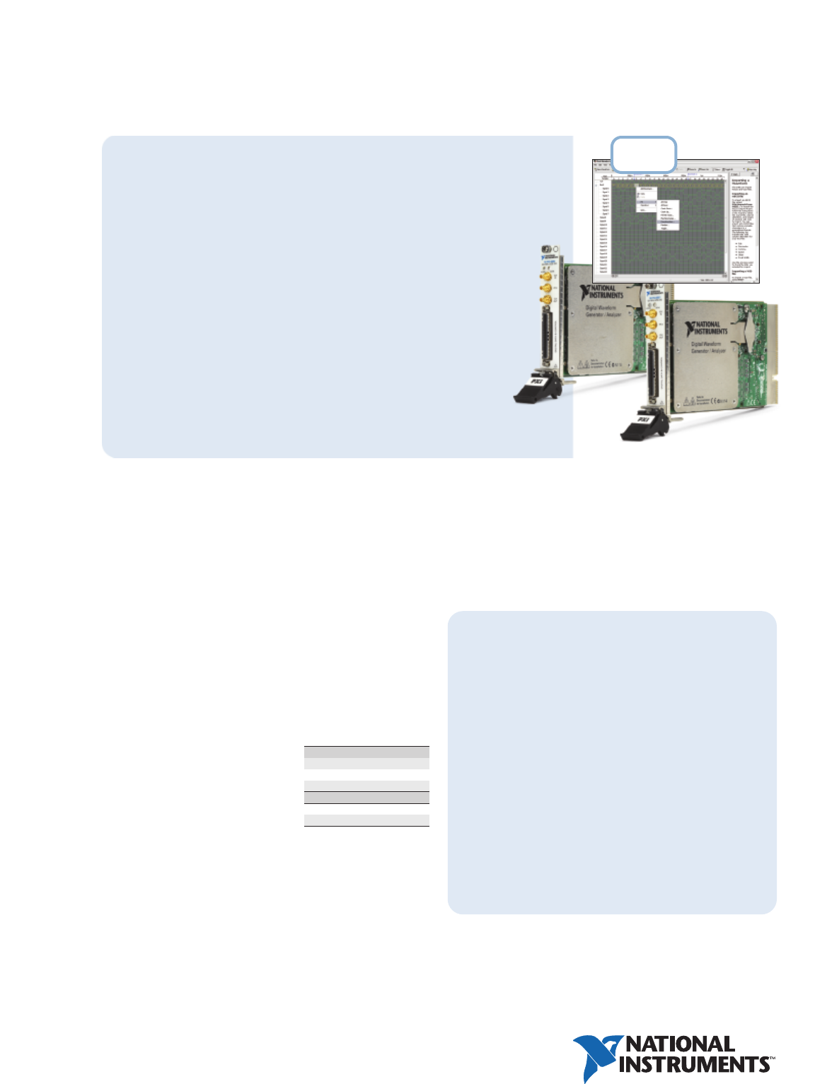
The National Instruments PXI-6562 and PXI-6561 are 400 and 200 Mb/s
digital waveform generator/analyzers, respectively, for interfacing to
LVDS digital electronics. These modules feature 200 and 100 MHz clock
rates, respectively, single and double data rate modes, 16 channels with
per-channel direction control (in single data rate mode) and deep
onboard memory with triggering and pattern sequencing. You can also
use the modules with the NI Digital Waveform Editor, an interactive
software tool for creating and editing digital waveforms. With the SMC,
you can create mixed-signal test systems with digitizers, arbitrary
waveform generators, and other digital waveform generator/analyzers, or
you can synchronize multiple digital devices to build low-skew
multichannel systems for interfacing to high-pin-count digital ICs
and electronics.
Design High-Density Interfaces
• 400 Mb/s (NI 6562) or 200 Mb/s
(NI 6561) maximum data rate in
double data rate (DDR) mode
• 200 MHz (NI 6562) or 100 MHz
(NI 6561) maximum clock rate
• Data delay for clock frequencies ≥25 MHz
• Data delay resolution as small as 60 ps
(see specifications on following page for valid delay ranges)
• Internal or external clock sources
•Tight channel-channel skew of ±215 ps (generation) or ±330 ps
(acquisition) (typical for clock frequencies at or above 25 MHz)
• 16 channels with per-channel direction control in single data rate
(SDR) mode
Create and Edit Patterns Interactively
with the Digital Waveform Editor
• Import existing waveforms into LabVIEW from VHDL simulation
and spreadsheet tools in Value Change Dump (.VCD) or ASCII formats
• Create new waveforms using built-in fill patterns
•Edit waveforms interactively in the user interface
• 400 Mb/s (PXI-6562) or 200 Mb/s
(PXI-6561) maximum data rate in
double data rate (DDR) mode
•200 MHz (PXI-6562) or 100 MHz
(PXI-6561) maximum clock rate
• LVDS signaling for fast clock rates
and low power consumption
• 16 channels with per-channel
direction control (single data
rate mode)
• 2, 16, or 128 Mb/channel
onboard memory
• Interactive waveform and script
editor software
• Synchronization and Memory Core
(SMC) for tight synchronization
with other SMC-based devices
Operating Systems
• Windows 2000/NT/XP
Recommended Software
• LabVIEW
• LabWindows/CVI
Driver and Editing
Software (included)
• NI-HSDIO driver
•Express VIs for
LabVIEW 7.1 and later
• Script Editor
• Digital Waveform Editor (included
with 16 and 128 Mb/channel models)
NI PXI-6562, NI PXI-6561
Applications
Aerospace/Defense
Avionic subsystem communications
Surveillance systems
Satellite testing
Semiconductor
Analog-to-digital converters
Digital-to-analog converters
NI PXI-6561 ..............................................................778993-0M1
NI PXI-6562 ..............................................................778994-0M1
1Where M is: 1 (2 Mb/channel), 2 (16 Mb/channel), or 3 (128 Mb/channel)
Includes NI-HSDIO driver and Script Editor. The 16 and 128 Mb/channel models
also include the Digital Waveform Editor.
Software
NI Digital Waveform Editor ........................................778724-03
Cable
SHB12X-B12X LVDS cable ..........................................192344-01
Accessories
SMA-2164 prototyping board ......................................779323-01
Mating connector for custom load boards..................779157-01
BUY NOW!
For complete product specifications, pricing, and accessory
information, call (800) 813-3693 (U.S. only) or go to
ni.com/modularinstruments.
Ordering Information
NEW
400 and 200 Mb/s LVDS Digital
Waveform Generator/Analyzers
2
National Instruments • info@ni.com • ni.com
For detailed specifications, please visit ni.com/info and enter pxi6561 or pxi6562.
These specifications are valid for PXI for the temperature range 0 to 55 °C.
Channel Characteristics
Data channels .................................................. 16
Generation Signal Characteristics (data, and PFI <0:3> channels)
Output impedance (LVDS channels)................. 100 Ωdifferential
Channel power-up state................................... Drivers disabled, 100 Ωdifferential impedance
Acquisition Signal Characteristics (Data, Strobe, and PFI <0:3> Channels)
Input impedance............................................... 100 Ωdifferential
Timing Characteristics
Sample Clock
Sample clock sources....................................... 1. Onboard clock (internal VCXO with divider)
2. CLK IN (SMB)
3. PXI_STAR (PXI only)
4. STROBE (DDC connector) – acquisition only
On board clock frequency range ..................... NI 6561: 48 Hz to 100 MHz.
(Settable to 200 MHz / N; 2 ≤N ≤4,194,304)
NI 6562: 48 Hz to 200 MHz.
(Settable to 200 MHz / N; 1 ≤N ≤4,194,304)
Exported Sample Clock Delay Range
Exported sample clock delay resolution .......... 1/256 of sample clock period for clock frequencies ≥25 MHz
or 60 ps, whichever is greater
Exported Sample Clock Jitter (Typical Using Onboard Clock)
Generation Signal Characteristics (Data, DDC Clk Out LVDS, DDC Clk Out PECL,
and PFI <0:3> Channels)
Data channel-to-channel skew ........................ ±215 (typical across all data channels and PFI <1:2>)
Maximum data channel toggle rate ................ NI 6561: 100 MHz; NI 6562: 200 MHz
Data position modes ........................................ Rising edge, falling edge, delayed relative to sample clock
Generation data delay range ........................... See Exported Sample Clock Delay Range table
Generation data delay resolution .................... 1/256 of sample clock period for clock frequencies ≥25 MHz
or 60 ps, whichever is greater
Acquisition Signal Characteristics (Data, Strobe, and PFI <0:3> Channels)
Data channel-to-channel skew ........................ ±600 ps for sample clock rates < 25
±330 ps for sample clock rates >25 MHz
(typical across all data channels and PFI<1:2>)
Acquisition data delay range ........................... See Exported Sample Clock Delay Range table
Acquisition data delay resolution .................... 1/256 of sample clock period for clock frequencies ≥25 MHz
or 60 ps, whichever is greater
Waveform Characteristics
Triggers (Inputs to the NI 656x)
Trigger types..................................................... Start trigger, pause trigger, script trigger <0:3>
(generation sessions only), reference trigger
(acquisition sessions only), advance trigger
(acquisition sessions only)
Sources ............................................................ 1. PFI <0> (SMB jack connectors)
2. PFI <1:3> (DDC connector)
3. PXI_TRIG<0:7> (PXI backplane, PXI only)
4. PXI STAR (PXI backplane, PXI only)
5. Pattern match (acquisition sessions only)
6. Software (user function call)
7. Disabled (do not wait for a trigger)
Trigger detection .............................................. 1. Start trigger (edge detection: rising or falling)
2. Pause trigger (level detection: high or low)
3. Script trigger <0:3> (edge detection: rising or falling,
Level detection: high or low)
4. Reference triggers (edge detection: rising or falling)
5. Advance trigger (edge detection: rising or falling)
Minimum required trigger pulse width............ 30 ns
Destinations ..................................................... 1. PFI <0> (SMB jack connector)
2. PFI <1:3> (DDC connector)
3. PXI_TRIG <0:6> (PXI backplane)
Each of the triggers can be routed to any of the
destinations with the exception of pause trigger.
Pause trigger can not be exported.
Events (Outputs from the NI 656x)
Event types....................................................... Marker <0..3>, data active event, ready for start event,
ready for advance event, End of Record Event
Destinations ..................................................... 1. PFI <0> (SMB jack connectors)
2. PFI <1:3> (DDC connector)
3. PXI_TRIG <0:6> (PXI backplane)
Each of the events can be routed to any of the destinations
with the exception of data active event. Data active event
can only be routed to the PFI channels.
Miscellaneous
Onboard Clock Characteristics (Only Valid When PLL Reference Source is Set to None)
Frequency accuracy.......................................... ±100 ppm (typical)
Temperature stability ....................................... ±30 ppm (typical)
Aging ................................................................ ±5 ppm first year (typical)
Power Requirements
Maximum.......................................................... 16.4 W
Physical
PXI ............................................................ Single 3U CompactPCI slot. PXI Compatible
Environment
Operating temperature..................................... PXI: 0 to 55 °C in all NI PXI chassis except the following:
0 to 45 °C when installed in an NI PXI-1000/B and
PXI-101x chassis. (Meets IEC-60068-2-1 and IEC-60068-2-2)
Storage temperature........................................ -20 to 70 °C
Relative humidity ............................................. 10 to 90%, noncondensing (meets IEC-60068-2-56)
Storage relative humidity................................. 5 to 95%, noncondensing (meets IEC-60068-2-56)
Compliance
Safety
NI 656x devices meet the requirements of the following standards for safety and electrical equipment for
measurement, control, and laboratory use:
IEC 61010-1, EN 61010-1
UL 3111-1, UL 61010B-1
CAN/CSA C22.2 No. 1010.1
Note: For full EMC compliance, you must operate this device with shielded cabling. In addition, all covers and
filler panels must be installed. See the Declaration of Conformity (DoC) for this product for any additional
regulatory compliance information. To obtain the DoC for this product, visit ni.com/hardref.nsf.
Period jitter Cycle-to-cycle jitter
19 ps (rms) 29 ps (rms)
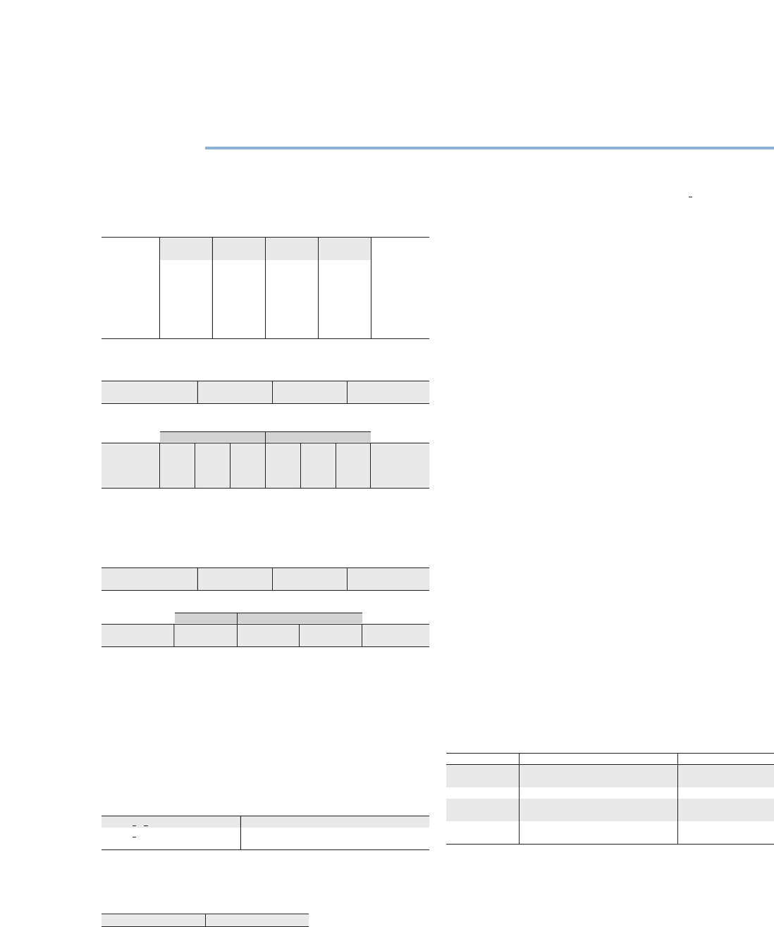
Specifications
I/O Panel Connectors
Label External Function(s) Connector Type
CLK IN External sample clock, External PLL SMB jack
reference input
PFI 0 Events, triggers SMB jack
CLK OUT Exported sample clock, SMB jack
exported reference clock
Digital data and Digital data channels, exported 12X InfiniBand
control (DDC) sample clock, STROBE, events, triggers
Specification Single Data Rate (SDR) Double Data Rate (DDR) Comments
Direction control Data <0..15> Per channel Data <0:7> Dedicated for Using SDR, data
of data channels data generation is clocked using
Data <8:15> Dedicated for the rising or
data acqusition falling edge of the
Sample clock.
Using DDR, data
is clocked using
both edges of the
Sample clock.
Generation Signal Type Data<0:15>, PFI<1:2> PFI 0 PFI 3
Generation LVDS LVCMOS LVCMOS or LVDS
voltage families (software selectable)
Generation Offset (Vos) Differential Voltage (Vod)
Voltage Levels Typical Min Max Min Max Typical Comments
Generation 1.2 V 1.125 V 1.375 V 247 mV 454 mV 305 mV Into 100 Ω
voltage levels differential load,
TIA/EIA-644
compliant
Acquisition Data<0:15>, PFI<1:2>
Voltage Families (V) and Strobe PFI 0 PFI 3
Acquisition voltage families LVDS LVCMOS LVCMOS or LVDS
(software selectable)
Acquisition Voltage Threshold Voltage Range
Voltage Levels Max Min Max Comments
Acquisition voltage ±50 mV 0 V 2.4 V TIA/EIA-644
levels (LVDS) compliant
Sample Clock Frequency (ƒ) Delay Range (Sample Clock Period)
50 MHz < ƒ < maximum clock rate 0 to 1 sample clock period
25 MHz <ƒ < 50 MHz 0 to 1 sample clock period except
[0.25 ± (0.25 - 5 ns x ƒ)] and [0.75 ± (0.25 - 5 ns x ƒ)]
© 2005 National Instruments Corporation. All rights reserved. CVI, LabVIEW, National Instruments Alliance Partner, ni.com, and SCXI are
trademarks of National Instruments. Other product and company names listed are trademarks or trade names of their respective companies.
NI Services and Support
NI has the services and support to meet
your needs around the globe and through
the application life cycle – from planning
and development through deployment
and ongoing maintenance. We offer
services and service levels to meet
customer requirements in research,
design, validation, and manufacturing.
Visit ni.com/services.
Training and Certification
NI training is the fastest, most certain route to productivity with our
products. NI training can shorten your learning curve, save
development time, and reduce maintenance costs over the
application life cycle. We schedule instructor-led courses in cities
worldwide, or we can hold a course at your facility. We also offer a
professional certification program that identifies individuals who
have high levels of skill and knowledge on using NI products.
Visit ni.com/training.
Professional Services
Our Professional Services
Team is comprised of NI
applications engineers, NI
Consulting Services, and
a worldwide NI Alliance
Partner Program of more than 600 independent consultants and
integrators. Services range from start-up assistance to turnkey system
integration. Visit ni.com/alliance.
OEM Support
We offer design-in consulting and product integration assistance if
you want to use our products for OEM applications. For information
about special pricing and services for OEM customers, visit
ni.com/oem.
Local Sales and Technical Support
In offices worldwide, our staff is local to the country, giving you
access to engineers who speak your language. NI delivers industry-
leading technical support through online knowledge bases, our
applications engineers, and access to 14,000 measurement and
automation professionals within NI Developer Exchange forums.
Find immediate answers to your questions at ni.com/support.
We also offer service programs that provide automatic upgrades to
your application development environment and higher levels of
technical support. Visit ni.com/ssp.
Hardware Services
NI Factory Installation Services
NI Factory Installation Services (FIS) is the fastest and easiest way to
use your PXI or PXI/SCXI combination systems right out of the box.
Trained NI technicians install the software and hardware and
configure the system to your specifications. NI extends the standard
warranty by one year on hardware components (controllers, chassis,
modules) purchased with FIS. To use FIS, simply configure your
system online with ni.com/pxiadvisor.
Calibration Services
NI recognizes the need to maintain properly calibrated devices for
high-accuracy measurements. We provide manual calibration
procedures, services to recalibrate your products, and automated
calibration software specifically designed for use by metrology
laboratories. Visit ni.com/calibration.
Repair and Extended Warranty
NI provides complete repair services for our products. Express repair
and advance replacement services are also available. We offer
extended warranties to help you meet project life-cycle requirements.
Visit ni.com/services.
National Instruments • info@ni.com
ni.com
SERVICE
NEEDS
2004_4548_101_D
