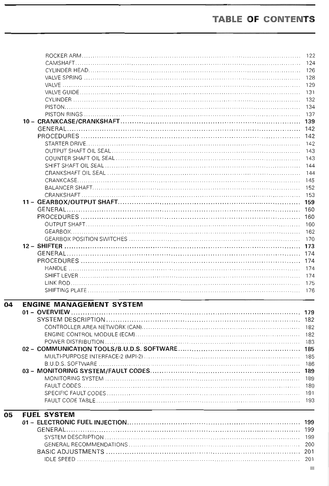
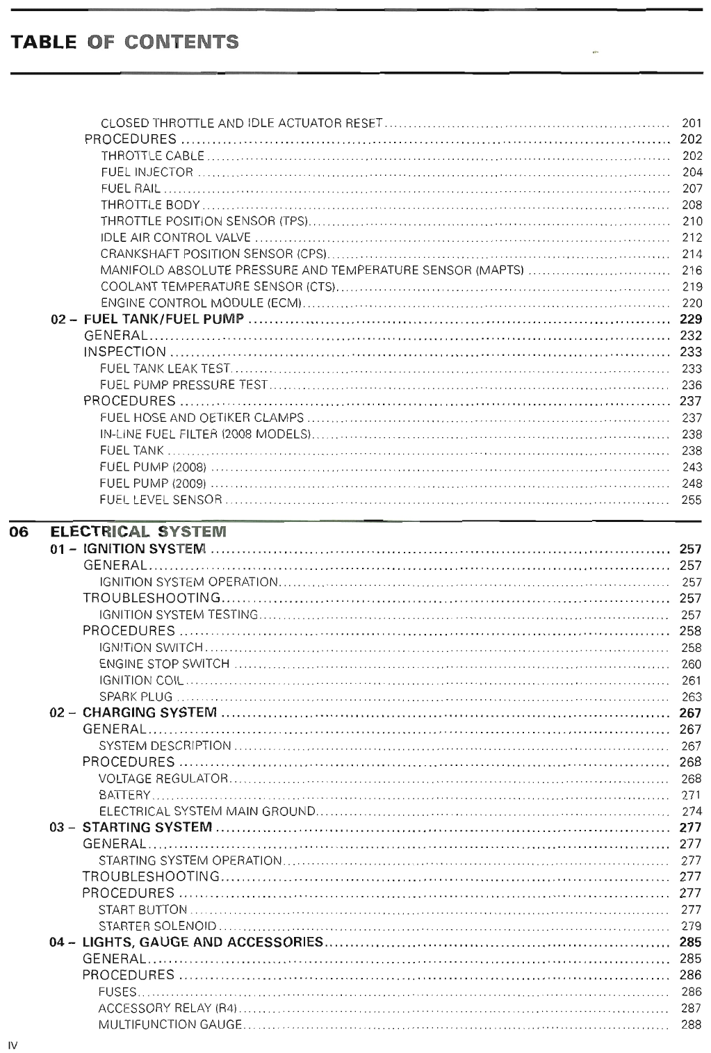
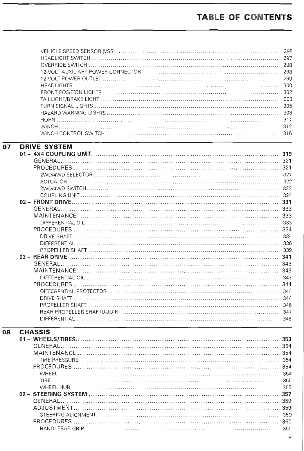
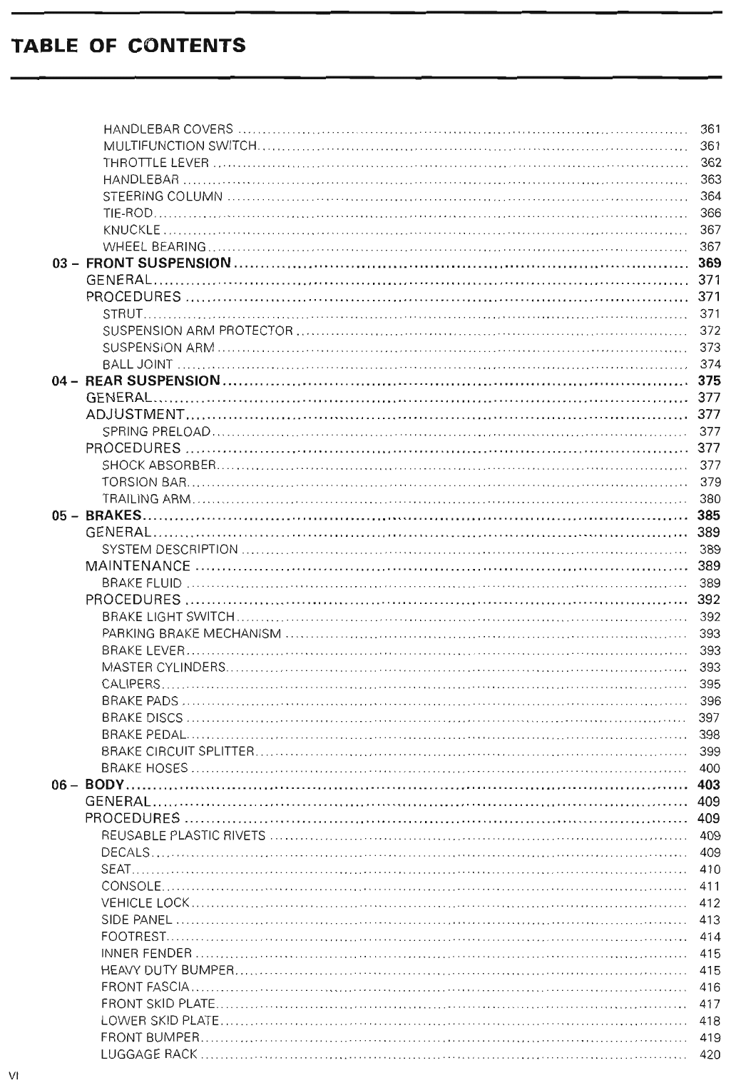
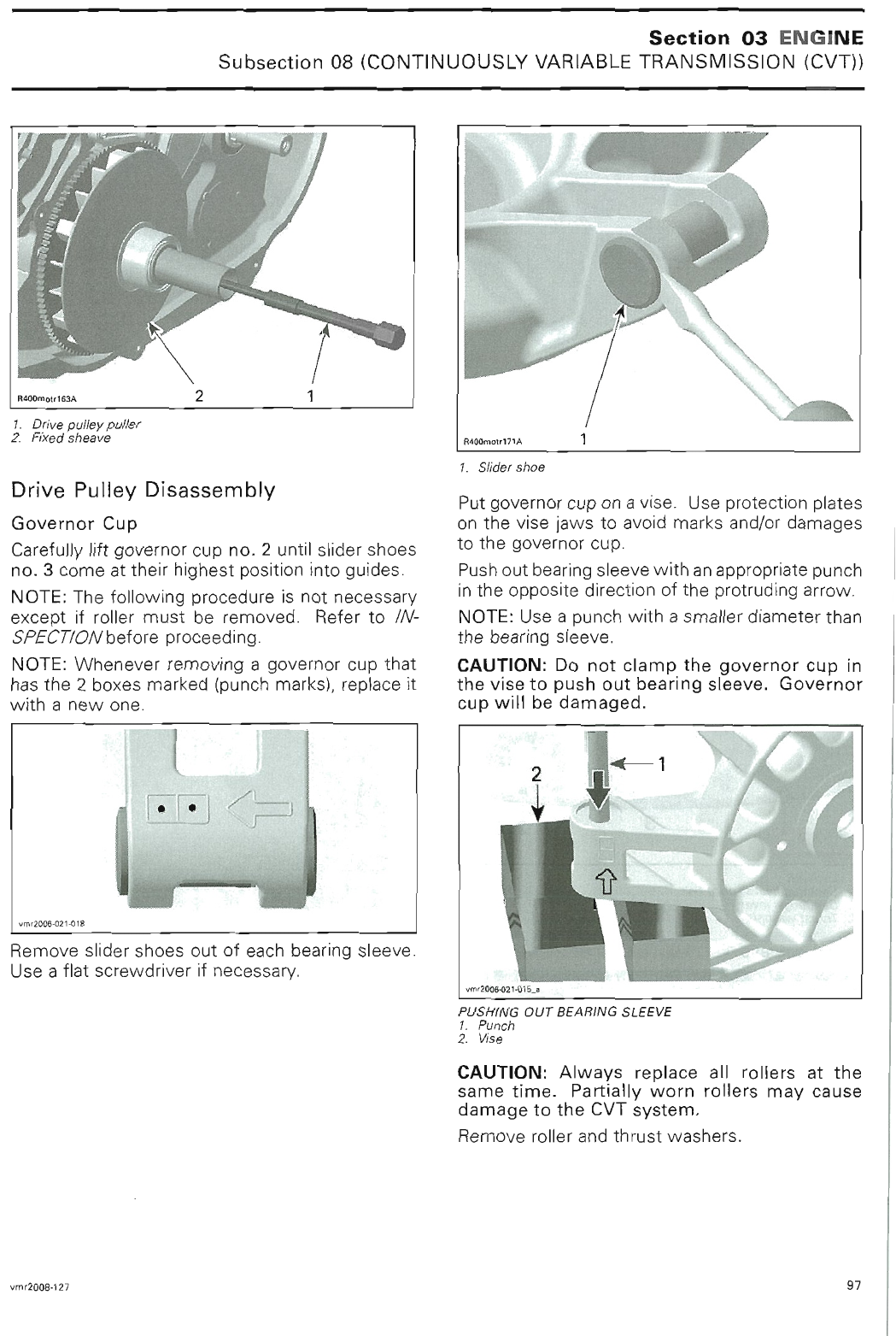
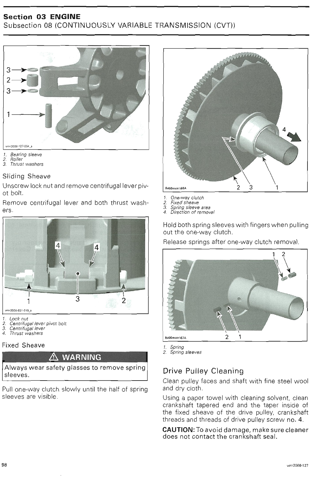
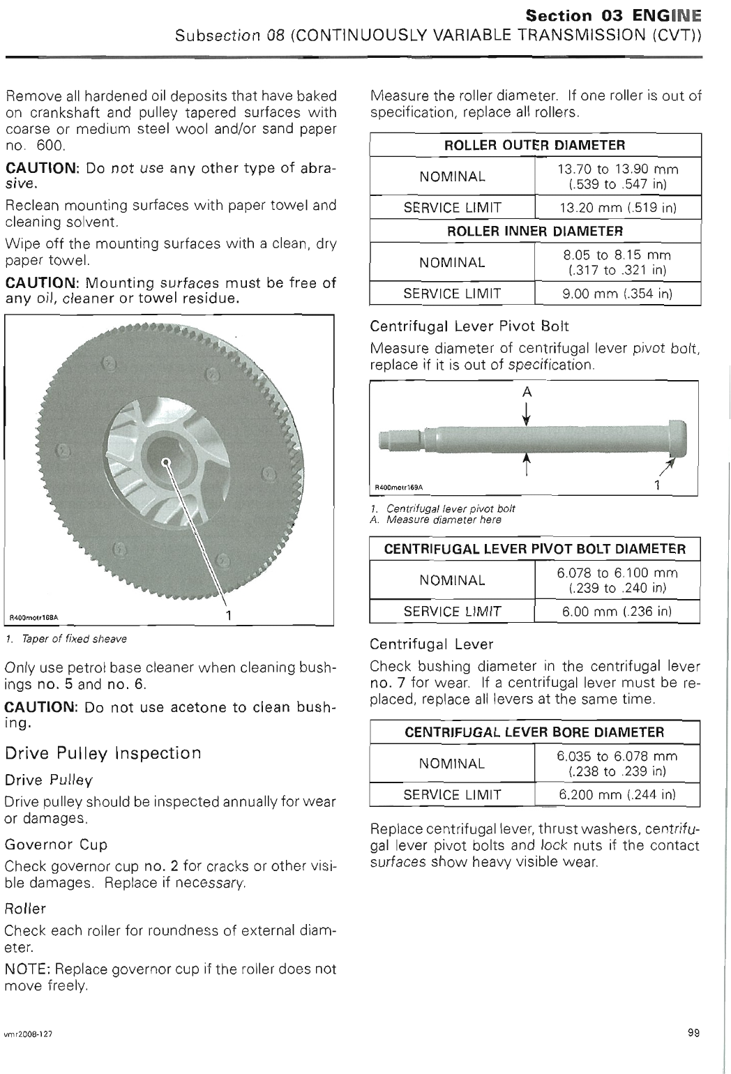
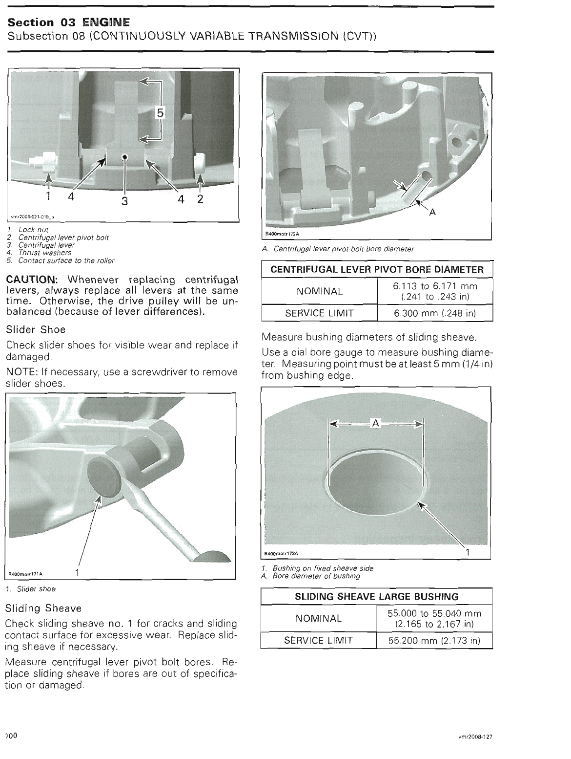
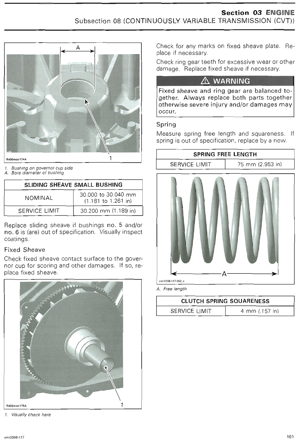
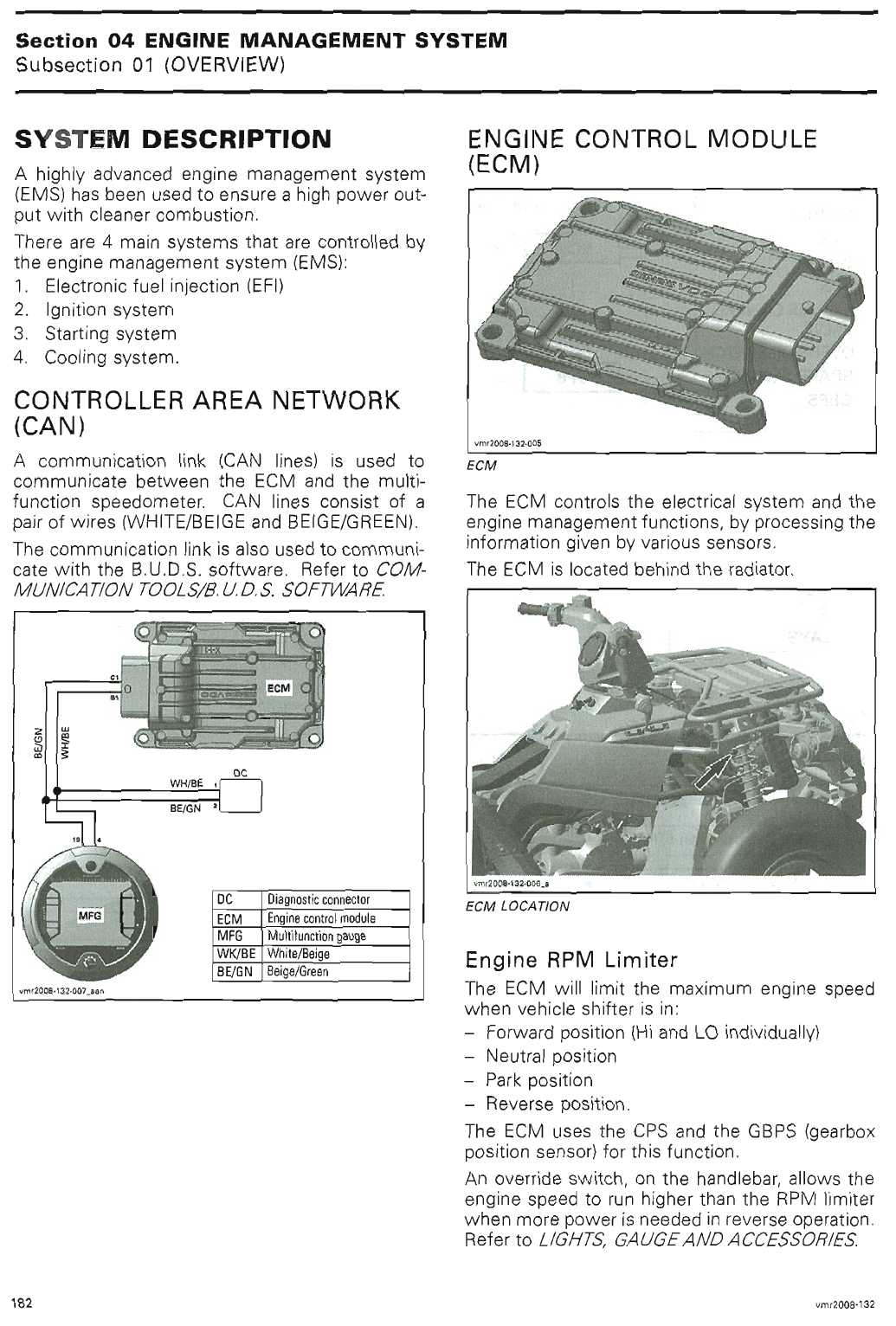
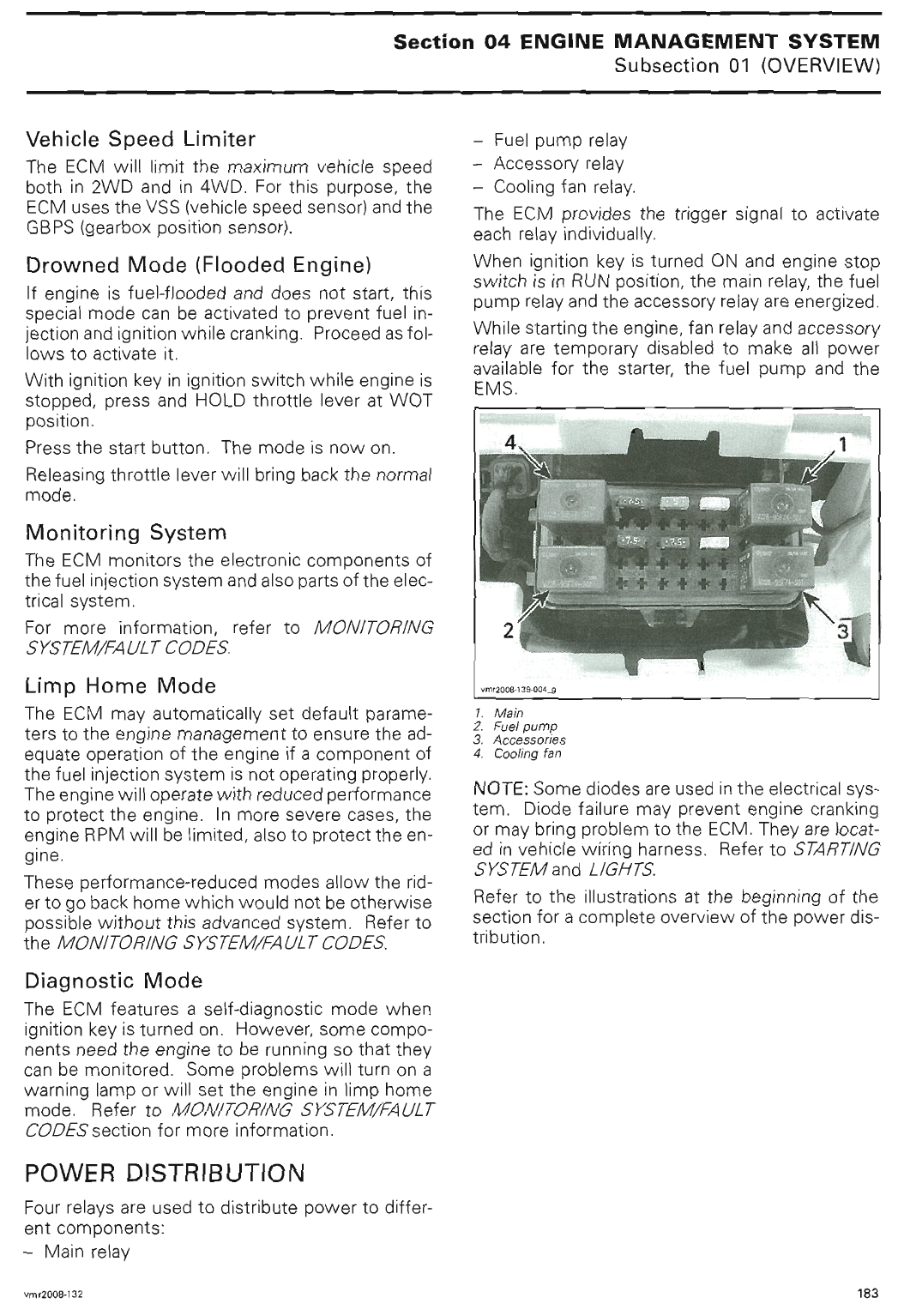
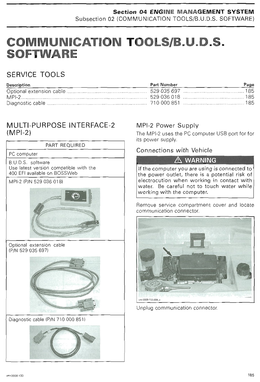
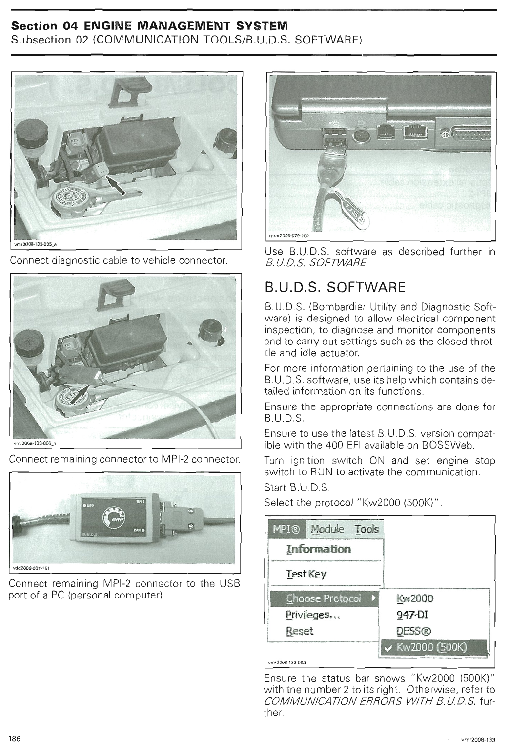
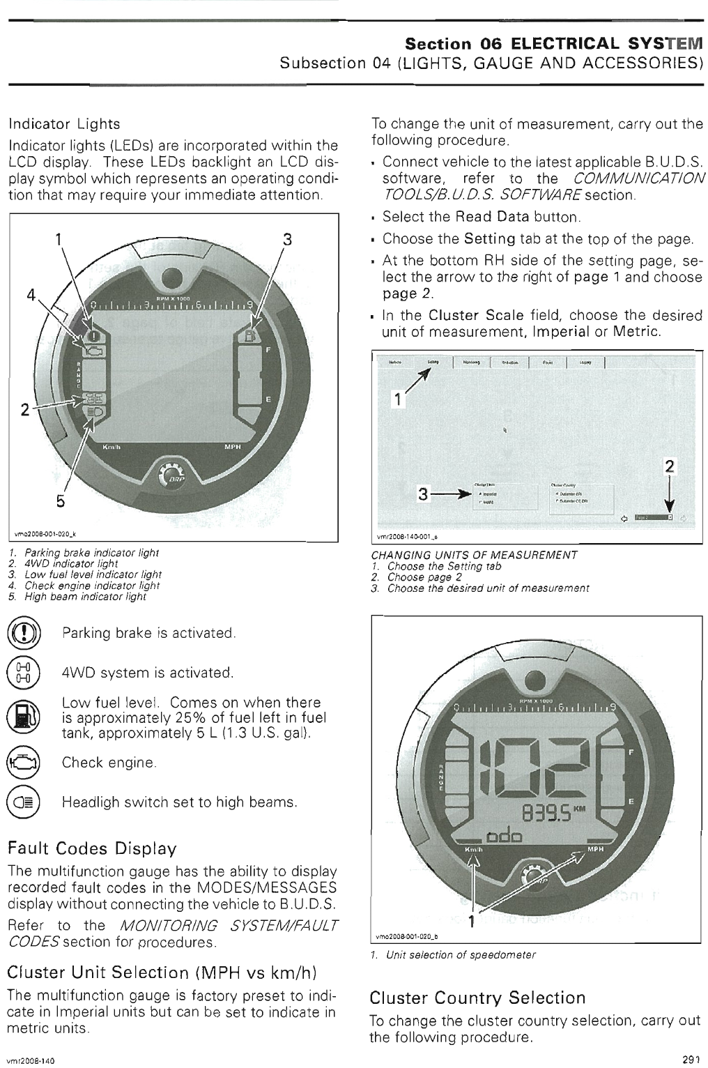
2008 2009_Outlander_400_Efi_Atv_Service_Manual 2009 Outlander 400 Efi Atv Service Manual
User Manual: 2008-2009_Outlander_400_Efi_Atv_Service_Manual
Open the PDF directly: View PDF ![]() .
.
Page Count: 599 [warning: Documents this large are best viewed by clicking the View PDF Link!]
sales@midwestmanuals.com
sales@midwestmanuals.com
sales@midwestmanuals.com
sales@midwestmanuals.com
sales@midwestmanuals.com
sales@midwestmanuals.com
sales@midwestmanuals.com
sales@midwestmanuals.com
sales@midwestmanuals.com
sales@midwestmanuals.com
sales@midwestmanuals.com
sales@midwestmanuals.com
sales@midwestmanuals.com
sales@midwestmanuals.com
sales@midwestmanuals.com
sales@midwestmanuals.com
sales@midwestmanuals.com
sales@midwestmanuals.com
sales@midwestmanuals.com
sales@midwestmanuals.com
sales@midwestmanuals.com
sales@midwestmanuals.com
sales@midwestmanuals.com
sales@midwestmanuals.com
sales@midwestmanuals.com
sales@midwestmanuals.com
sales@midwestmanuals.com
sales@midwestmanuals.com
sales@midwestmanuals.com
sales@midwestmanuals.com
sales@midwestmanuals.com
sales@midwestmanuals.com
sales@midwestmanuals.com
sales@midwestmanuals.com
sales@midwestmanuals.com
sales@midwestmanuals.com
sales@midwestmanuals.com
sales@midwestmanuals.com
sales@midwestmanuals.com
sales@midwestmanuals.com
sales@midwestmanuals.com
sales@midwestmanuals.com
sales@midwestmanuals.com
sales@midwestmanuals.com
sales@midwestmanuals.com
sales@midwestmanuals.com

sales@midwestmanuals.com
sales@midwestmanuals.com
sales@midwestmanuals.com
sales@midwestmanuals.com

sales@midwestmanuals.com
sales@midwestmanuals.com
sales@midwestmanuals.com
sales@midwestmanuals.com
sales@midwestmanuals.com
sales@midwestmanuals.com
sales@midwestmanuals.com
sales@midwestmanuals.com
sales@midwestmanuals.com
sales@midwestmanuals.com
sales@midwestmanuals.com
sales@midwestmanuals.com
sales@midwestmanuals.com
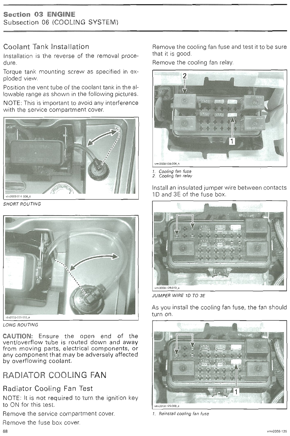
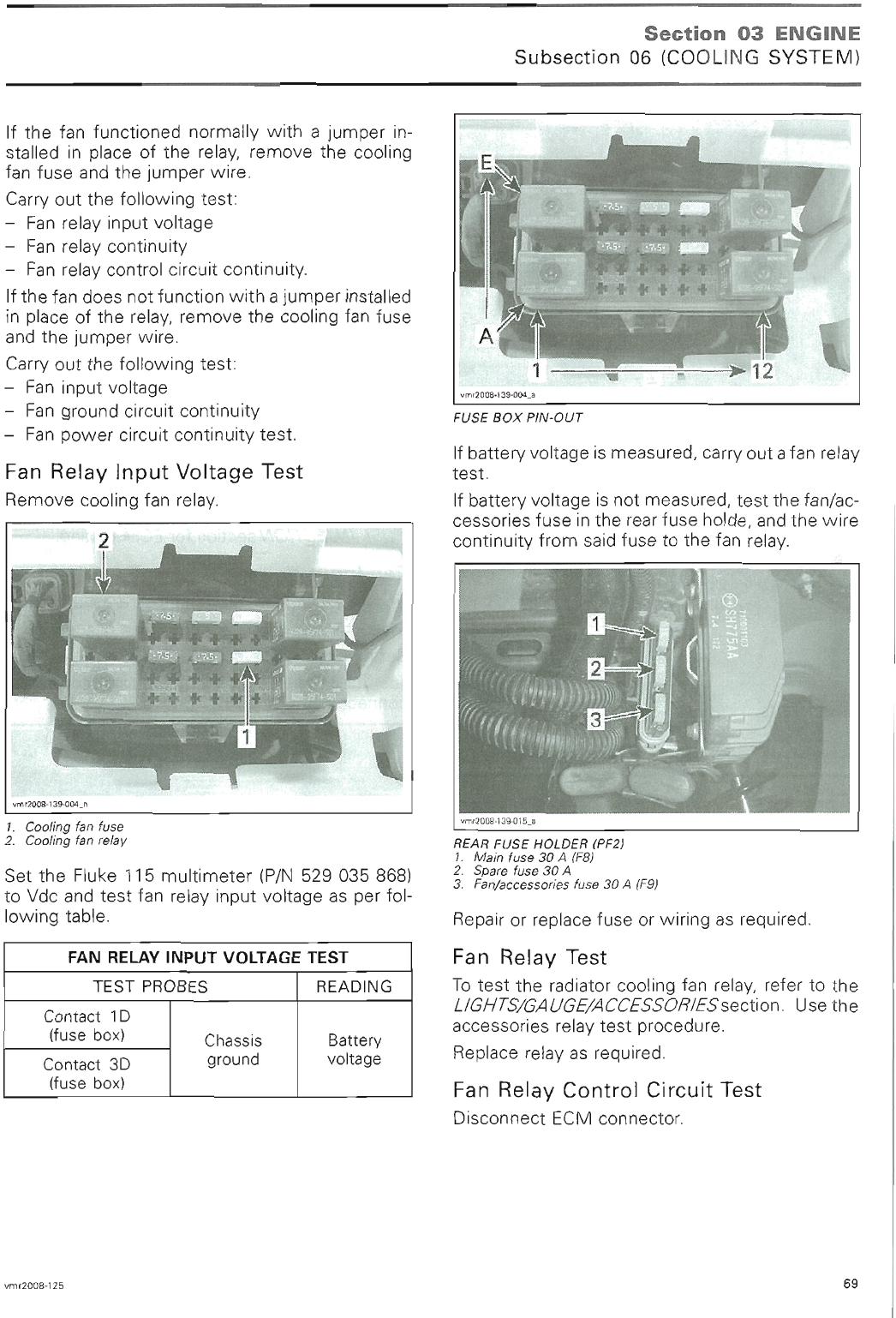
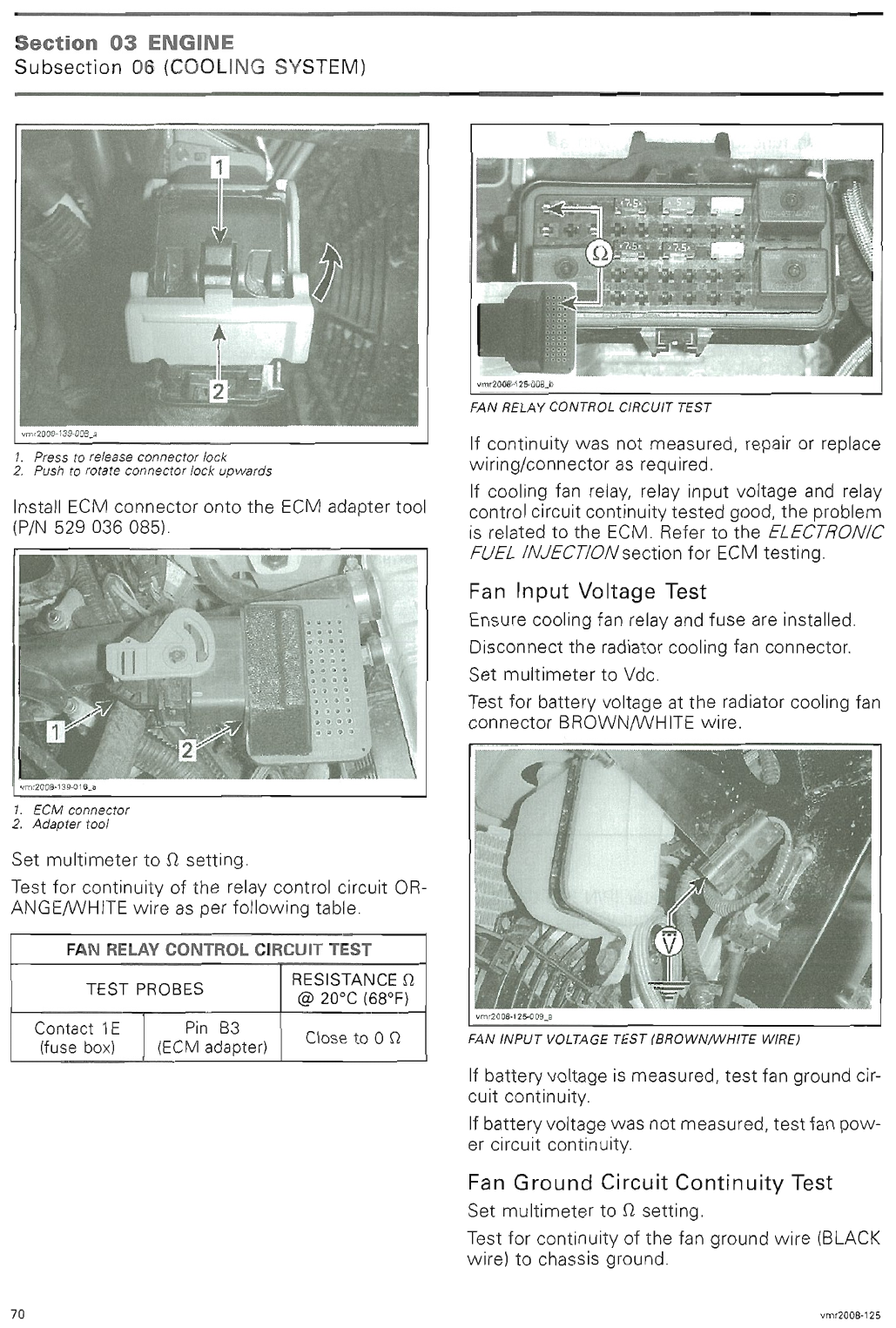
sales@midwestmanuals.com
sales@midwestmanuals.com
sales@midwestmanuals.com
sales@midwestmanuals.com
sales@midwestmanuals.com
sales@midwestmanuals.com
sales@midwestmanuals.com
sales@midwestmanuals.com
sales@midwestmanuals.com
sales@midwestmanuals.com
sales@midwestmanuals.com
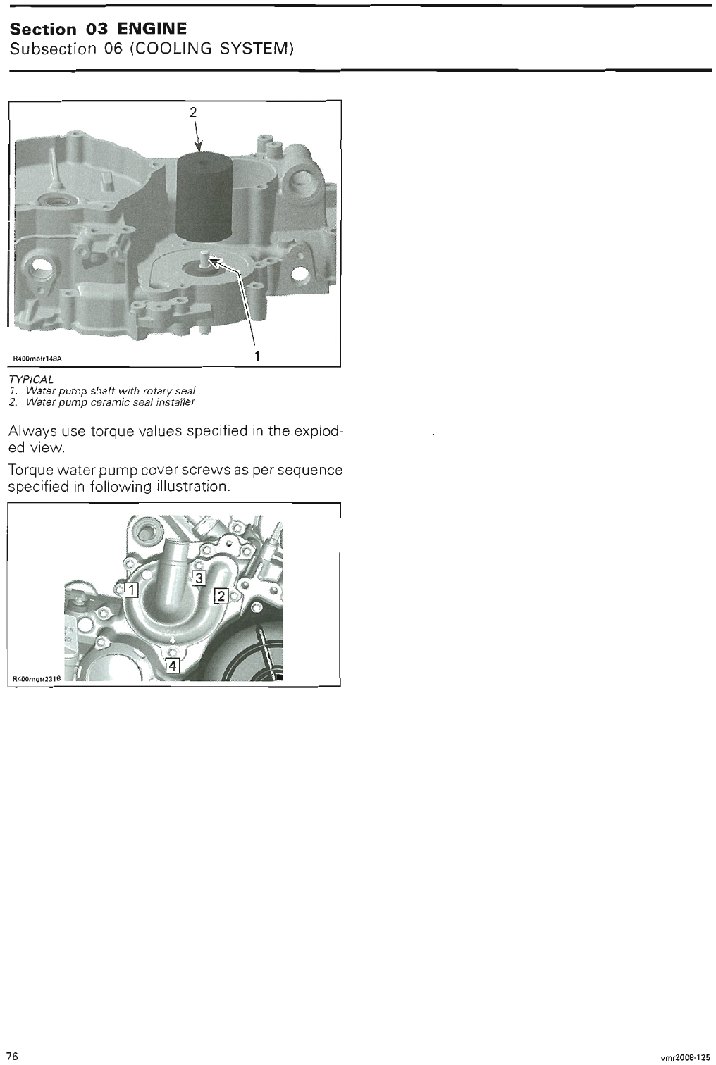
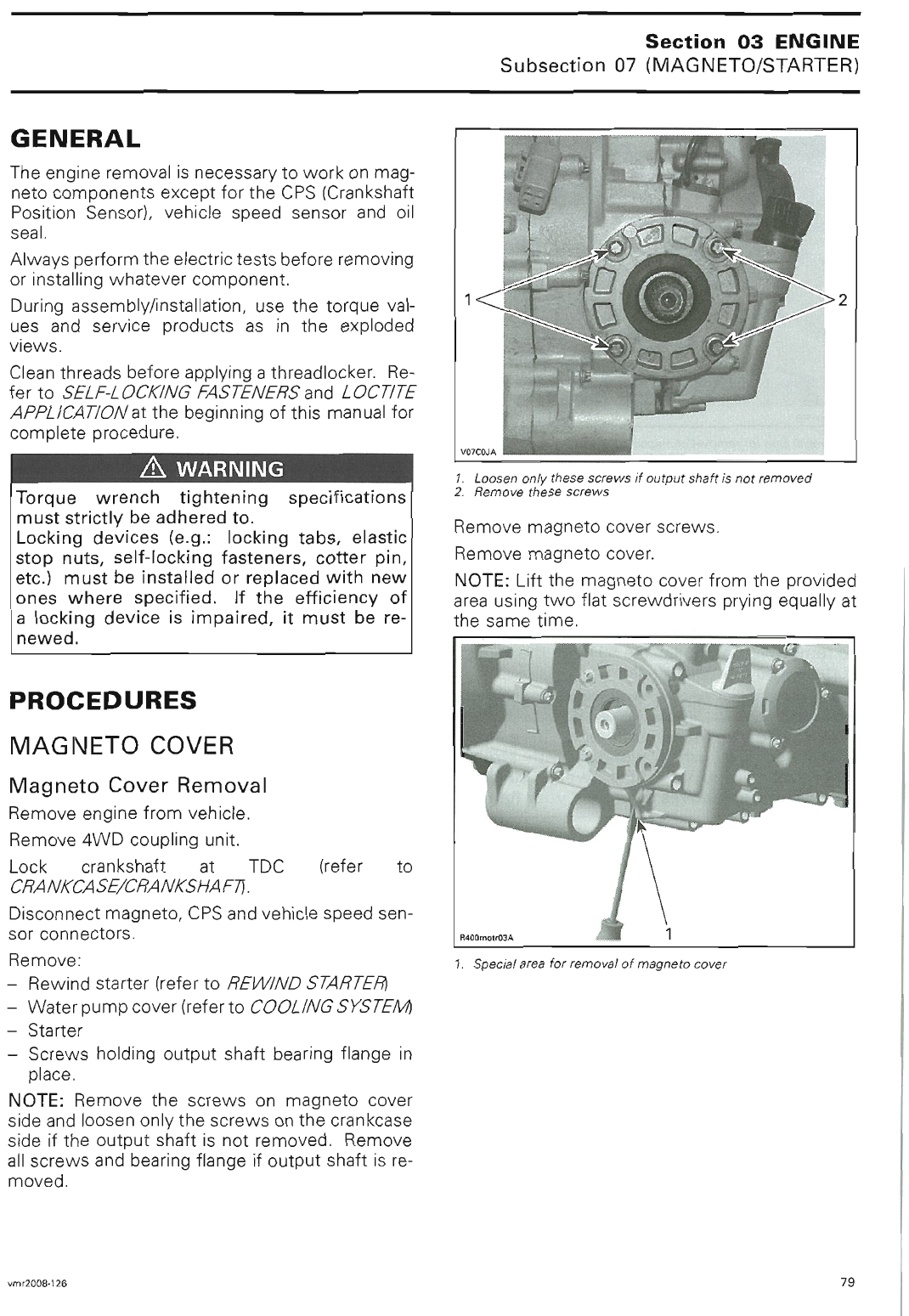
sales@midwestmanuals.com
sales@midwestmanuals.com
sales@midwestmanuals.com
sales@midwestmanuals.com
sales@midwestmanuals.com
sales@midwestmanuals.com
sales@midwestmanuals.com
sales@midwestmanuals.com
sales@midwestmanuals.com
sales@midwestmanuals.com
sales@midwestmanuals.com
sales@midwestmanuals.com
sales@midwestmanuals.com
sales@midwestmanuals.com
sales@midwestmanuals.com
sales@midwestmanuals.com
sales@midwestmanuals.com
sales@midwestmanuals.com
sales@midwestmanuals.com
sales@midwestmanuals.com
sales@midwestmanuals.com
sales@midwestmanuals.com
sales@midwestmanuals.com
sales@midwestmanuals.com

sales@midwestmanuals.com
sales@midwestmanuals.com
sales@midwestmanuals.com
sales@midwestmanuals.com
sales@midwestmanuals.com
sales@midwestmanuals.com

sales@midwestmanuals.com
sales@midwestmanuals.com

sales@midwestmanuals.com
sales@midwestmanuals.com
sales@midwestmanuals.com
sales@midwestmanuals.com
sales@midwestmanuals.com
sales@midwestmanuals.com
sales@midwestmanuals.com
sales@midwestmanuals.com
sales@midwestmanuals.com
sales@midwestmanuals.com
sales@midwestmanuals.com
sales@midwestmanuals.com
sales@midwestmanuals.com
sales@midwestmanuals.com
sales@midwestmanuals.com
sales@midwestmanuals.com
sales@midwestmanuals.com
sales@midwestmanuals.com
sales@midwestmanuals.com
sales@midwestmanuals.com
sales@midwestmanuals.com
sales@midwestmanuals.com
sales@midwestmanuals.com
sales@midwestmanuals.com
sales@midwestmanuals.com
sales@midwestmanuals.com
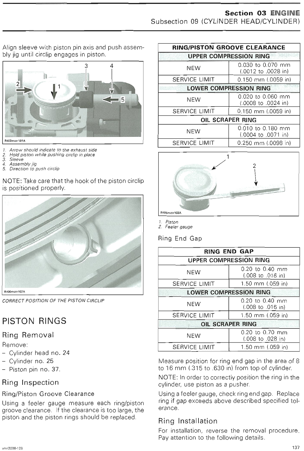
sales@midwestmanuals.com
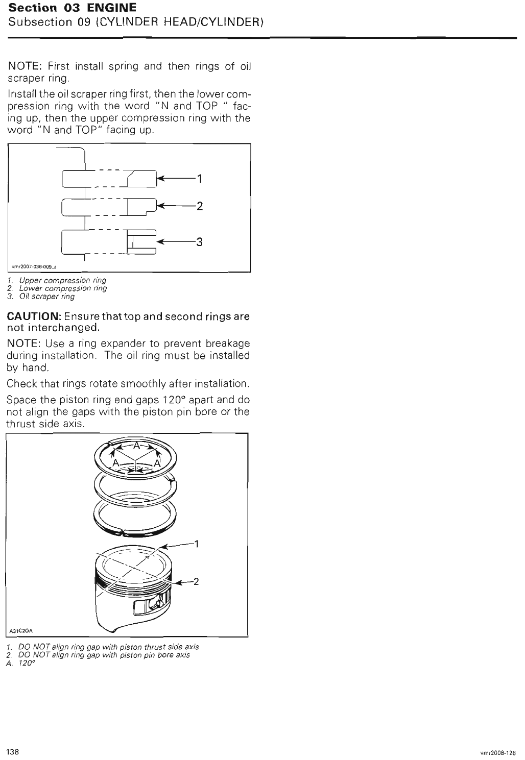
sales@midwestmanuals.com
sales@midwestmanuals.com
sales@midwestmanuals.com
sales@midwestmanuals.com
sales@midwestmanuals.com
sales@midwestmanuals.com
sales@midwestmanuals.com
sales@midwestmanuals.com
sales@midwestmanuals.com
sales@midwestmanuals.com
sales@midwestmanuals.com
sales@midwestmanuals.com
sales@midwestmanuals.com
sales@midwestmanuals.com
sales@midwestmanuals.com
sales@midwestmanuals.com
sales@midwestmanuals.com
sales@midwestmanuals.com
sales@midwestmanuals.com
sales@midwestmanuals.com
sales@midwestmanuals.com
sales@midwestmanuals.com
sales@midwestmanuals.com
sales@midwestmanuals.com
sales@midwestmanuals.com
sales@midwestmanuals.com
sales@midwestmanuals.com
sales@midwestmanuals.com
sales@midwestmanuals.com
sales@midwestmanuals.com
sales@midwestmanuals.com
sales@midwestmanuals.com
sales@midwestmanuals.com
sales@midwestmanuals.com
sales@midwestmanuals.com
sales@midwestmanuals.com
sales@midwestmanuals.com
sales@midwestmanuals.com
sales@midwestmanuals.com
sales@midwestmanuals.com
sales@midwestmanuals.com
sales@midwestmanuals.com
sales@midwestmanuals.com
sales@midwestmanuals.com
sales@midwestmanuals.com
sales@midwestmanuals.com
sales@midwestmanuals.com
sales@midwestmanuals.com
sales@midwestmanuals.com
sales@midwestmanuals.com
sales@midwestmanuals.com
sales@midwestmanuals.com
sales@midwestmanuals.com
sales@midwestmanuals.com
sales@midwestmanuals.com
sales@midwestmanuals.com
sales@midwestmanuals.com
sales@midwestmanuals.com
sales@midwestmanuals.com
sales@midwestmanuals.com
sales@midwestmanuals.com
sales@midwestmanuals.com
sales@midwestmanuals.com
sales@midwestmanuals.com
sales@midwestmanuals.com
sales@midwestmanuals.com
sales@midwestmanuals.com
sales@midwestmanuals.com
sales@midwestmanuals.com
sales@midwestmanuals.com
sales@midwestmanuals.com
sales@midwestmanuals.com
sales@midwestmanuals.com
sales@midwestmanuals.com
sales@midwestmanuals.com
sales@midwestmanuals.com
sales@midwestmanuals.com
sales@midwestmanuals.com
sales@midwestmanuals.com
sales@midwestmanuals.com
sales@midwestmanuals.com
sales@midwestmanuals.com
sales@midwestmanuals.com
sales@midwestmanuals.com
sales@midwestmanuals.com

sales@midwestmanuals.com
sales@midwestmanuals.com
sales@midwestmanuals.com
sales@midwestmanuals.com
sales@midwestmanuals.com
sales@midwestmanuals.com
sales@midwestmanuals.com
sales@midwestmanuals.com
sales@midwestmanuals.com
sales@midwestmanuals.com
sales@midwestmanuals.com
sales@midwestmanuals.com
sales@midwestmanuals.com
sales@midwestmanuals.com
sales@midwestmanuals.com
sales@midwestmanuals.com
sales@midwestmanuals.com
sales@midwestmanuals.com
sales@midwestmanuals.com
sales@midwestmanuals.com
sales@midwestmanuals.com
sales@midwestmanuals.com
sales@midwestmanuals.com
sales@midwestmanuals.com
sales@midwestmanuals.com
sales@midwestmanuals.com
sales@midwestmanuals.com
sales@midwestmanuals.com
sales@midwestmanuals.com
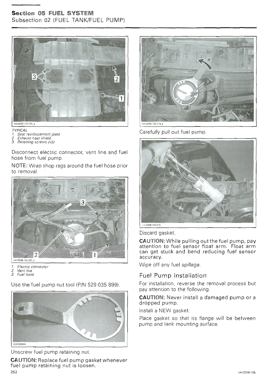
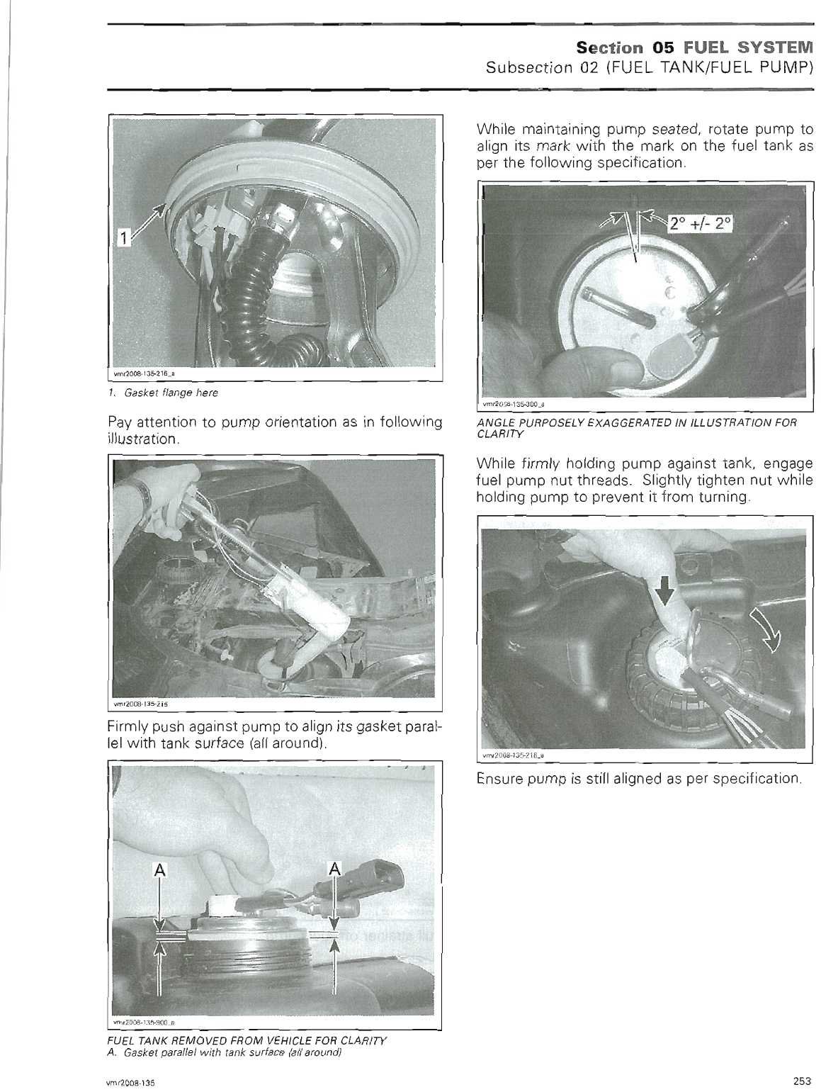
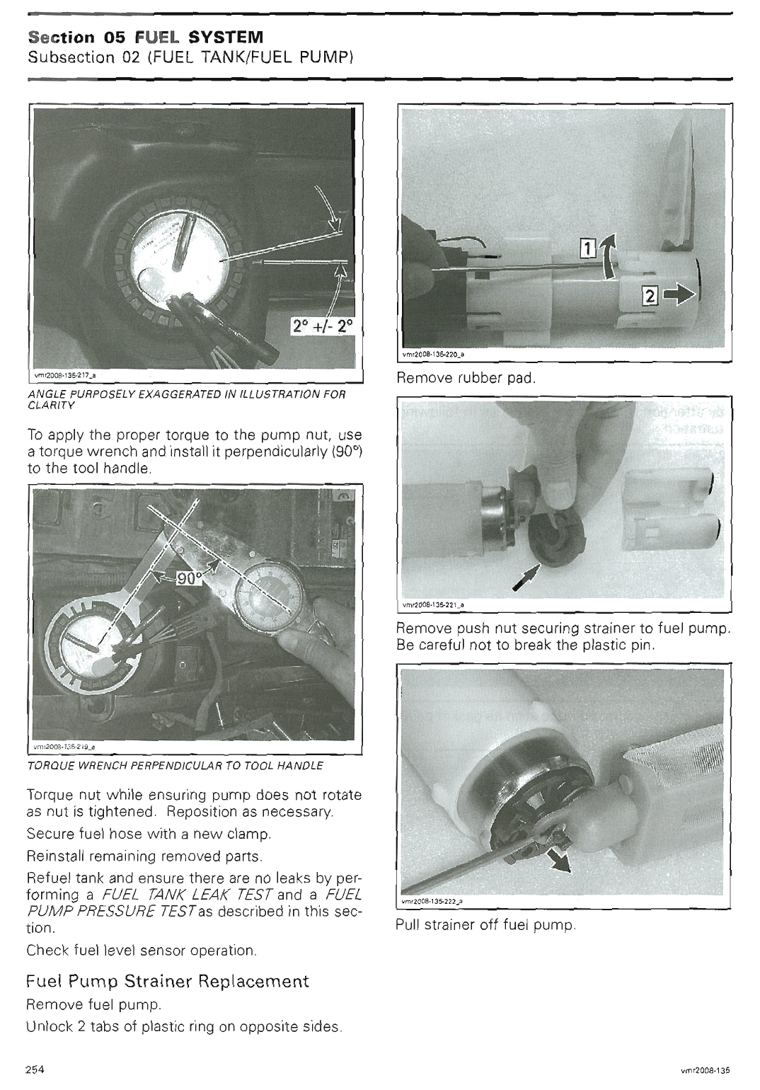
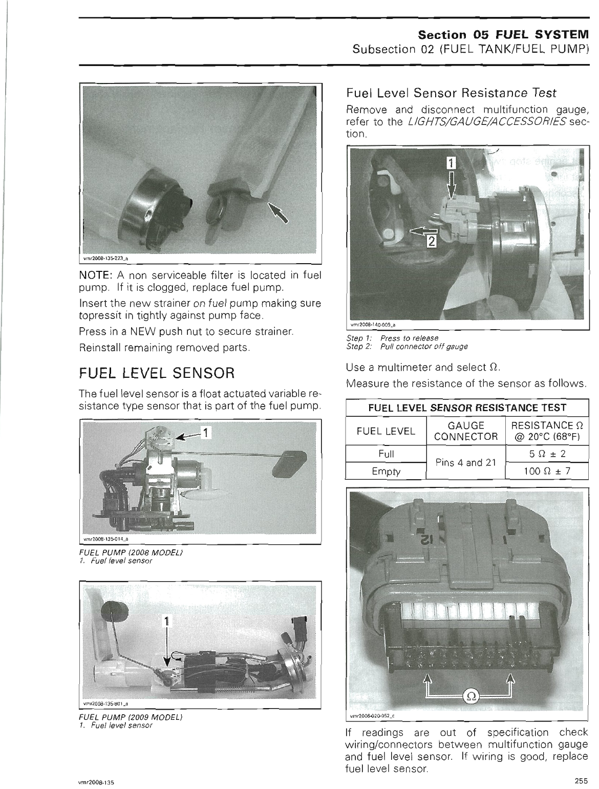
sales@midwestmanuals.com
sales@midwestmanuals.com
sales@midwestmanuals.com
sales@midwestmanuals.com
sales@midwestmanuals.com
sales@midwestmanuals.com
sales@midwestmanuals.com
sales@midwestmanuals.com
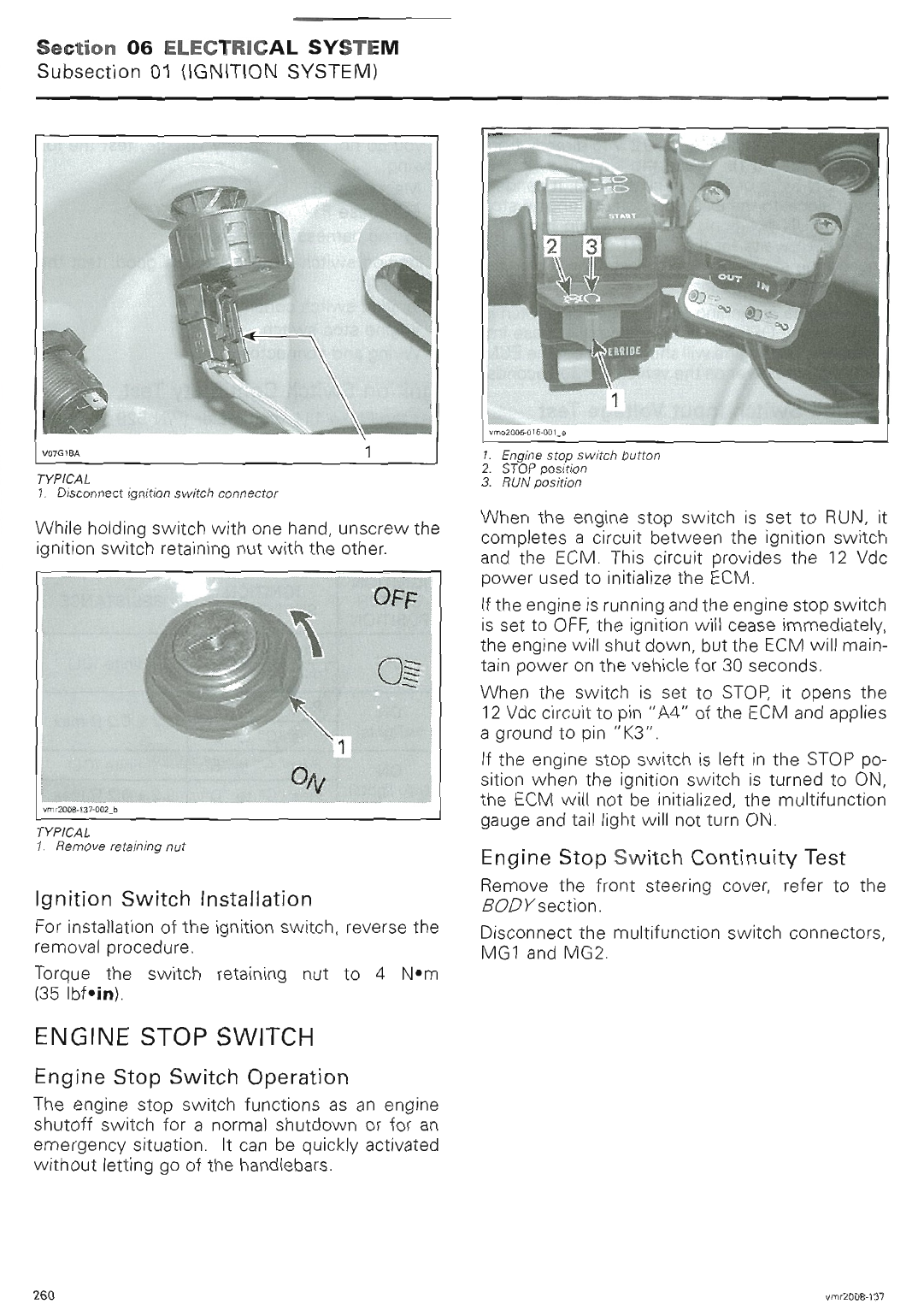
sales@midwestmanuals.com
sales@midwestmanuals.com
sales@midwestmanuals.com
sales@midwestmanuals.com
sales@midwestmanuals.com
sales@midwestmanuals.com
sales@midwestmanuals.com
sales@midwestmanuals.com
sales@midwestmanuals.com
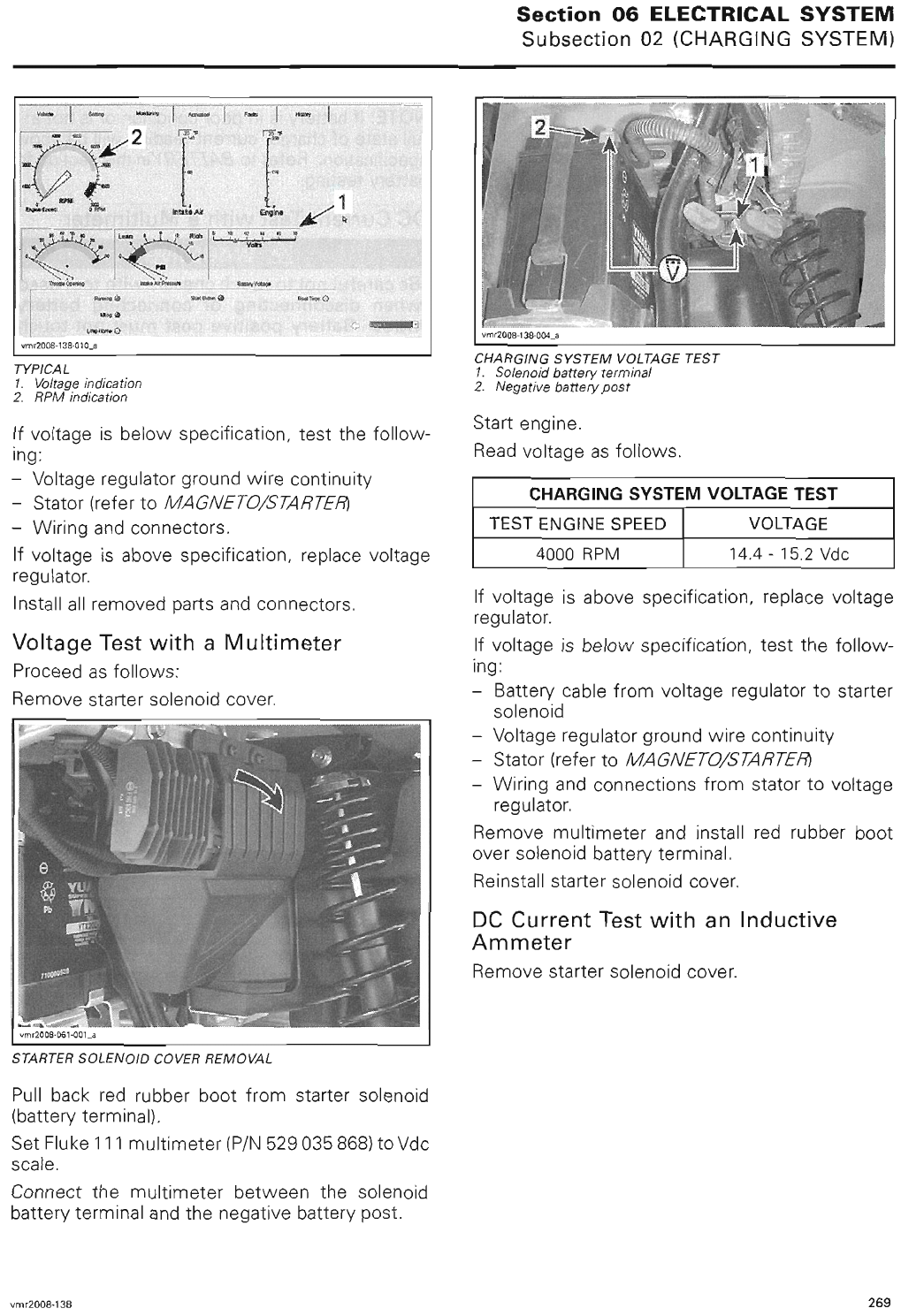
sales@midwestmanuals.com
sales@midwestmanuals.com
sales@midwestmanuals.com
sales@midwestmanuals.com
sales@midwestmanuals.com
sales@midwestmanuals.com
sales@midwestmanuals.com
sales@midwestmanuals.com
sales@midwestmanuals.com
sales@midwestmanuals.com
sales@midwestmanuals.com
sales@midwestmanuals.com
sales@midwestmanuals.com
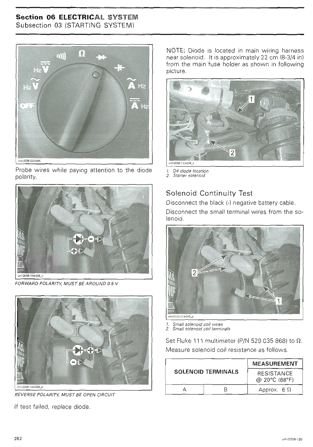
sales@midwestmanuals.com
sales@midwestmanuals.com
sales@midwestmanuals.com
sales@midwestmanuals.com
sales@midwestmanuals.com
sales@midwestmanuals.com
sales@midwestmanuals.com
sales@midwestmanuals.com
sales@midwestmanuals.com
sales@midwestmanuals.com
sales@midwestmanuals.com
sales@midwestmanuals.com
sales@midwestmanuals.com
sales@midwestmanuals.com
sales@midwestmanuals.com
sales@midwestmanuals.com
sales@midwestmanuals.com
sales@midwestmanuals.com
sales@midwestmanuals.com
sales@midwestmanuals.com
sales@midwestmanuals.com
sales@midwestmanuals.com
sales@midwestmanuals.com
sales@midwestmanuals.com
sales@midwestmanuals.com
sales@midwestmanuals.com
sales@midwestmanuals.com
sales@midwestmanuals.com
sales@midwestmanuals.com
sales@midwestmanuals.com
sales@midwestmanuals.com
sales@midwestmanuals.com
sales@midwestmanuals.com
sales@midwestmanuals.com
sales@midwestmanuals.com
sales@midwestmanuals.com
sales@midwestmanuals.com
sales@midwestmanuals.com
sales@midwestmanuals.com
sales@midwestmanuals.com
sales@midwestmanuals.com
sales@midwestmanuals.com
sales@midwestmanuals.com
sales@midwestmanuals.com
sales@midwestmanuals.com
sales@midwestmanuals.com
sales@midwestmanuals.com
sales@midwestmanuals.com
sales@midwestmanuals.com
sales@midwestmanuals.com
sales@midwestmanuals.com
sales@midwestmanuals.com
sales@midwestmanuals.com
sales@midwestmanuals.com
sales@midwestmanuals.com
sales@midwestmanuals.com
sales@midwestmanuals.com
sales@midwestmanuals.com
sales@midwestmanuals.com
sales@midwestmanuals.com
sales@midwestmanuals.com
sales@midwestmanuals.com
sales@midwestmanuals.com
sales@midwestmanuals.com
sales@midwestmanuals.com
sales@midwestmanuals.com
sales@midwestmanuals.com
sales@midwestmanuals.com
sales@midwestmanuals.com
sales@midwestmanuals.com
sales@midwestmanuals.com
sales@midwestmanuals.com
sales@midwestmanuals.com
sales@midwestmanuals.com
sales@midwestmanuals.com
sales@midwestmanuals.com
sales@midwestmanuals.com
sales@midwestmanuals.com
sales@midwestmanuals.com
sales@midwestmanuals.com
sales@midwestmanuals.com
sales@midwestmanuals.com
sales@midwestmanuals.com
sales@midwestmanuals.com
sales@midwestmanuals.com
sales@midwestmanuals.com
sales@midwestmanuals.com
sales@midwestmanuals.com
sales@midwestmanuals.com
sales@midwestmanuals.com
sales@midwestmanuals.com
sales@midwestmanuals.com
sales@midwestmanuals.com
sales@midwestmanuals.com
sales@midwestmanuals.com
sales@midwestmanuals.com
sales@midwestmanuals.com
sales@midwestmanuals.com
sales@midwestmanuals.com
sales@midwestmanuals.com
sales@midwestmanuals.com
sales@midwestmanuals.com
sales@midwestmanuals.com
sales@midwestmanuals.com
sales@midwestmanuals.com
sales@midwestmanuals.com
sales@midwestmanuals.com
sales@midwestmanuals.com
sales@midwestmanuals.com
sales@midwestmanuals.com
sales@midwestmanuals.com
sales@midwestmanuals.com
sales@midwestmanuals.com
sales@midwestmanuals.com
sales@midwestmanuals.com
sales@midwestmanuals.com
sales@midwestmanuals.com

sales@midwestmanuals.com
sales@midwestmanuals.com
sales@midwestmanuals.com
sales@midwestmanuals.com
sales@midwestmanuals.com
sales@midwestmanuals.com
sales@midwestmanuals.com
sales@midwestmanuals.com
sales@midwestmanuals.com
sales@midwestmanuals.com
sales@midwestmanuals.com
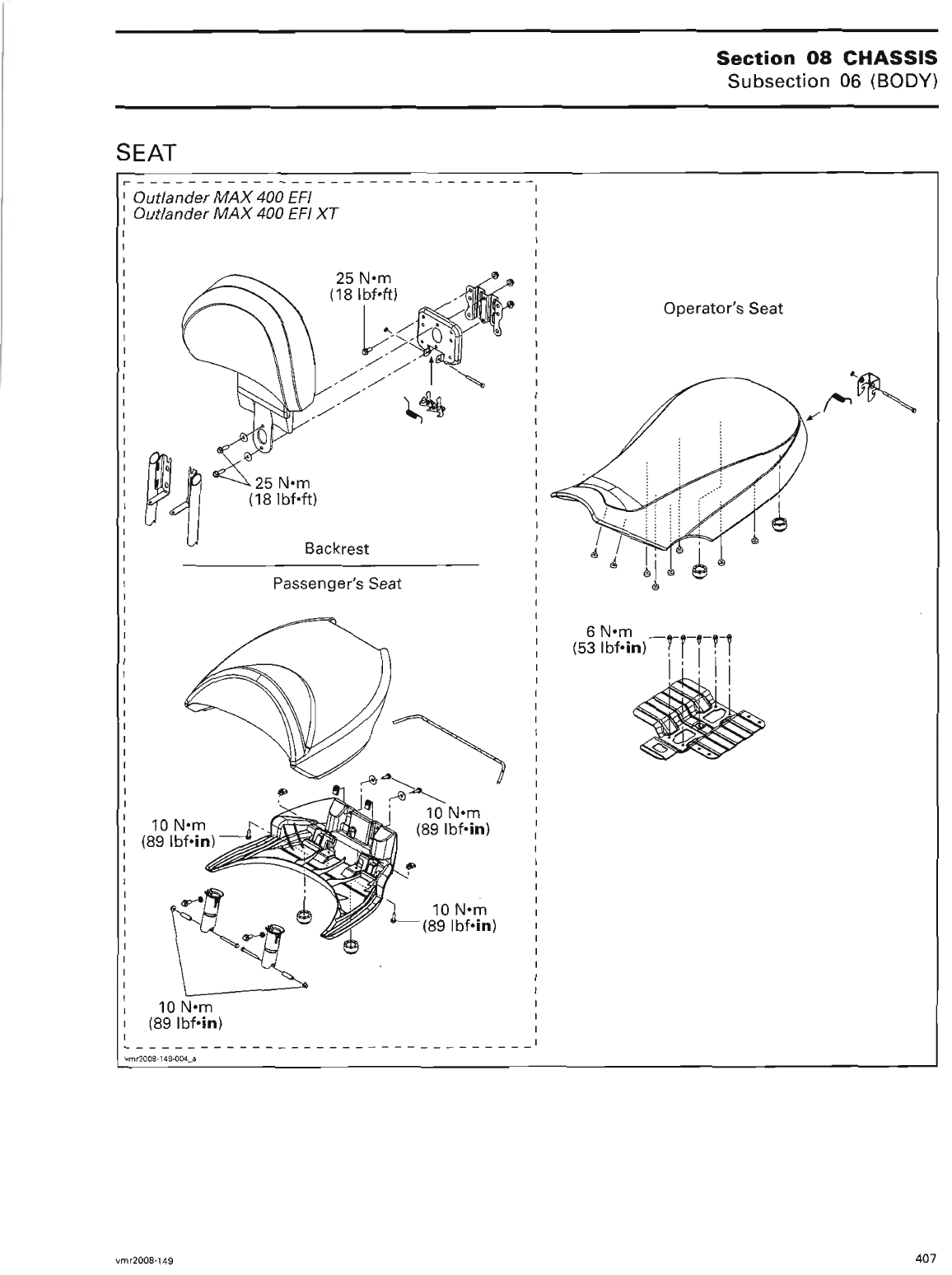
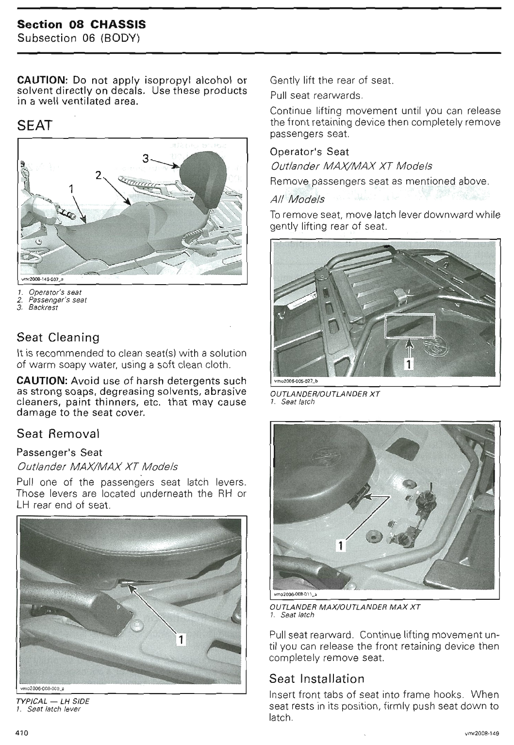
sales@midwestmanuals.com
sales@midwestmanuals.com
sales@midwestmanuals.com
sales@midwestmanuals.com
sales@midwestmanuals.com
sales@midwestmanuals.com
sales@midwestmanuals.com
sales@midwestmanuals.com
sales@midwestmanuals.com
sales@midwestmanuals.com
sales@midwestmanuals.com
sales@midwestmanuals.com
sales@midwestmanuals.com
sales@midwestmanuals.com
sales@midwestmanuals.com
sales@midwestmanuals.com
sales@midwestmanuals.com
sales@midwestmanuals.com
sales@midwestmanuals.com
sales@midwestmanuals.com
sales@midwestmanuals.com
sales@midwestmanuals.com
sales@midwestmanuals.com
sales@midwestmanuals.com
sales@midwestmanuals.com
sales@midwestmanuals.com
sales@midwestmanuals.com
sales@midwestmanuals.com
sales@midwestmanuals.com
sales@midwestmanuals.com
sales@midwestmanuals.com
sales@midwestmanuals.com
sales@midwestmanuals.com
sales@midwestmanuals.com
sales@midwestmanuals.com
sales@midwestmanuals.com
sales@midwestmanuals.com
sales@midwestmanuals.com
sales@midwestmanuals.com
sales@midwestmanuals.com
sales@midwestmanuals.com
sales@midwestmanuals.com
sales@midwestmanuals.com
sales@midwestmanuals.com
sales@midwestmanuals.com
sales@midwestmanuals.com
sales@midwestmanuals.com
sales@midwestmanuals.com
sales@midwestmanuals.com
sales@midwestmanuals.com
sales@midwestmanuals.com
sales@midwestmanuals.com
sales@midwestmanuals.com
sales@midwestmanuals.com
sales@midwestmanuals.com
sales@midwestmanuals.com
sales@midwestmanuals.com
sales@midwestmanuals.com
sales@midwestmanuals.com
sales@midwestmanuals.com
sales@midwestmanuals.com
sales@midwestmanuals.com
sales@midwestmanuals.com
sales@midwestmanuals.com
sales@midwestmanuals.com
sales@midwestmanuals.com
sales@midwestmanuals.com
sales@midwestmanuals.com
sales@midwestmanuals.com
sales@midwestmanuals.com
sales@midwestmanuals.com
sales@midwestmanuals.com
sales@midwestmanuals.com
sales@midwestmanuals.com
sales@midwestmanuals.com
sales@midwestmanuals.com
sales@midwestmanuals.com
sales@midwestmanuals.com
sales@midwestmanuals.com
sales@midwestmanuals.com
sales@midwestmanuals.com
sales@midwestmanuals.com
sales@midwestmanuals.com
sales@midwestmanuals.com
sales@midwestmanuals.com
sales@midwestmanuals.com
sales@midwestmanuals.com
sales@midwestmanuals.com
sales@midwestmanuals.com
sales@midwestmanuals.com
sales@midwestmanuals.com
sales@midwestmanuals.com
sales@midwestmanuals.com
sales@midwestmanuals.com
sales@midwestmanuals.com
sales@midwestmanuals.com
sales@midwestmanuals.com
sales@midwestmanuals.com
sales@midwestmanuals.com
sales@midwestmanuals.com
sales@midwestmanuals.com
sales@midwestmanuals.com
sales@midwestmanuals.com
sales@midwestmanuals.com
sales@midwestmanuals.com
sales@midwestmanuals.com
sales@midwestmanuals.com
sales@midwestmanuals.com
sales@midwestmanuals.com
sales@midwestmanuals.com
sales@midwestmanuals.com
sales@midwestmanuals.com
sales@midwestmanuals.com
sales@midwestmanuals.com
sales@midwestmanuals.com
sales@midwestmanuals.com
sales@midwestmanuals.com
sales@midwestmanuals.com
sales@midwestmanuals.com
sales@midwestmanuals.com
sales@midwestmanuals.com
sales@midwestmanuals.com
sales@midwestmanuals.com
sales@midwestmanuals.com
sales@midwestmanuals.com
sales@midwestmanuals.com
sales@midwestmanuals.com
sales@midwestmanuals.com
sales@midwestmanuals.com
sales@midwestmanuals.com
sales@midwestmanuals.com
sales@midwestmanuals.com
sales@midwestmanuals.com
sales@midwestmanuals.com
sales@midwestmanuals.com
sales@midwestmanuals.com
sales@midwestmanuals.com
sales@midwestmanuals.com
sales@midwestmanuals.com
sales@midwestmanuals.com
sales@midwestmanuals.com
sales@midwestmanuals.com
sales@midwestmanuals.com
sales@midwestmanuals.com
sales@midwestmanuals.com
sales@midwestmanuals.com
sales@midwestmanuals.com
sales@midwestmanuals.com
sales@midwestmanuals.com
sales@midwestmanuals.com
sales@midwestmanuals.com
sales@midwestmanuals.com
sales@midwestmanuals.com
sales@midwestmanuals.com
sales@midwestmanuals.com
sales@midwestmanuals.com
sales@midwestmanuals.com
sales@midwestmanuals.com
sales@midwestmanuals.com
sales@midwestmanuals.com
sales@midwestmanuals.com
sales@midwestmanuals.com
sales@midwestmanuals.com
sales@midwestmanuals.com
sales@midwestmanuals.com

sales@midwestmanuals.com
sales@midwestmanuals.com
sales@midwestmanuals.com
sales@midwestmanuals.com
sales@midwestmanuals.com
sales@midwestmanuals.com
sales@midwestmanuals.com
sales@midwestmanuals.com
sales@midwestmanuals.com
sales@midwestmanuals.com
sales@midwestmanuals.com
sales@midwestmanuals.com
sales@midwestmanuals.com
sales@midwestmanuals.com
sales@midwestmanuals.com
sales@midwestmanuals.com
sales@midwestmanuals.com
sales@midwestmanuals.com
sales@midwestmanuals.com
sales@midwestmanuals.com

sales@midwestmanuals.com
sales@midwestmanuals.com
sales@midwestmanuals.com
sales@midwestmanuals.com
sales@midwestmanuals.com
sales@midwestmanuals.com
sales@midwestmanuals.com
sales@midwestmanuals.com
sales@midwestmanuals.com
sales@midwestmanuals.com
sales@midwestmanuals.com
sales@midwestmanuals.com
sales@midwestmanuals.com
sales@midwestmanuals.com
sales@midwestmanuals.com
sales@midwestmanuals.com

sales@midwestmanuals.com
sales@midwestmanuals.com
sales@midwestmanuals.com
sales@midwestmanuals.com
sales@midwestmanuals.com
sales@midwestmanuals.com
sales@midwestmanuals.com
sales@midwestmanuals.com
sales@midwestmanuals.com
sales@midwestmanuals.com
sales@midwestmanuals.com
sales@midwestmanuals.com
sales@midwestmanuals.com
sales@midwestmanuals.com
sales@midwestmanuals.com
sales@midwestmanuals.com
sales@midwestmanuals.com
sales@midwestmanuals.com
sales@midwestmanuals.com
sales@midwestmanuals.com
sales@midwestmanuals.com
sales@midwestmanuals.com
sales@midwestmanuals.com
sales@midwestmanuals.com
sales@midwestmanuals.com
sales@midwestmanuals.com
sales@midwestmanuals.com
sales@midwestmanuals.com
sales@midwestmanuals.com
sales@midwestmanuals.com
sales@midwestmanuals.com
sales@midwestmanuals.com
sales@midwestmanuals.com
sales@midwestmanuals.com
sales@midwestmanuals.com
sales@midwestmanuals.com
sales@midwestmanuals.com
sales@midwestmanuals.com
sales@midwestmanuals.com
sales@midwestmanuals.com
sales@midwestmanuals.com
sales@midwestmanuals.com
sales@midwestmanuals.com
sales@midwestmanuals.com
sales@midwestmanuals.com
sales@midwestmanuals.com
sales@midwestmanuals.com
sales@midwestmanuals.com
sales@midwestmanuals.com
sales@midwestmanuals.com
sales@midwestmanuals.com
sales@midwestmanuals.com
sales@midwestmanuals.com
sales@midwestmanuals.com
sales@midwestmanuals.com
sales@midwestmanuals.com
sales@midwestmanuals.com
sales@midwestmanuals.com
sales@midwestmanuals.com
sales@midwestmanuals.com
sales@midwestmanuals.com
sales@midwestmanuals.com
sales@midwestmanuals.com
sales@midwestmanuals.com
sales@midwestmanuals.com
sales@midwestmanuals.com
sales@midwestmanuals.com
sales@midwestmanuals.com

sales@midwestmanuals.com
sales@midwestmanuals.com
sales@midwestmanuals.com
sales@midwestmanuals.com
sales@midwestmanuals.com
sales@midwestmanuals.com
sales@midwestmanuals.com
sales@midwestmanuals.com
sales@midwestmanuals.com
sales@midwestmanuals.com
sales@midwestmanuals.com
sales@midwestmanuals.com
sales@midwestmanuals.com
sales@midwestmanuals.com
sales@midwestmanuals.com
sales@midwestmanuals.com
sales@midwestmanuals.com
sales@midwestmanuals.com
sales@midwestmanuals.com
sales@midwestmanuals.com
sales@midwestmanuals.com
sales@midwestmanuals.com
sales@midwestmanuals.com
sales@midwestmanuals.com

sales@midwestmanuals.com
sales@midwestmanuals.com
sales@midwestmanuals.com
sales@midwestmanuals.com
sales@midwestmanuals.com
sales@midwestmanuals.com
sales@midwestmanuals.com
sales@midwestmanuals.com
sales@midwestmanuals.com
sales@midwestmanuals.com
sales@midwestmanuals.com
sales@midwestmanuals.com
sales@midwestmanuals.com
sales@midwestmanuals.com
sales@midwestmanuals.com
sales@midwestmanuals.com
sales@midwestmanuals.com
sales@midwestmanuals.com
sales@midwestmanuals.com
sales@midwestmanuals.com
sales@midwestmanuals.com
sales@midwestmanuals.com
sales@midwestmanuals.com
sales@midwestmanuals.com
sales@midwestmanuals.com
sales@midwestmanuals.com
sales@midwestmanuals.com
sales@midwestmanuals.com
sales@midwestmanuals.com
sales@midwestmanuals.com
sales@midwestmanuals.com
sales@midwestmanuals.com
sales@midwestmanuals.com
sales@midwestmanuals.com
sales@midwestmanuals.com
sales@midwestmanuals.com
sales@midwestmanuals.com
sales@midwestmanuals.com
sales@midwestmanuals.com
sales@midwestmanuals.com
sales@midwestmanuals.com
sales@midwestmanuals.com
sales@midwestmanuals.com
sales@midwestmanuals.com

sales@midwestmanuals.com
sales@midwestmanuals.com
sales@midwestmanuals.com
sales@midwestmanuals.com
sales@midwestmanuals.com
sales@midwestmanuals.com
sales@midwestmanuals.com
sales@midwestmanuals.com
sales@midwestmanuals.com
sales@midwestmanuals.com
sales@midwestmanuals.com
sales@midwestmanuals.com
sales@midwestmanuals.com
sales@midwestmanuals.com
sales@midwestmanuals.com
sales@midwestmanuals.com
sales@midwestmanuals.com
sales@midwestmanuals.com
sales@midwestmanuals.com
sales@midwestmanuals.com
sales@midwestmanuals.com
sales@midwestmanuals.com
sales@midwestmanuals.com
sales@midwestmanuals.com
sales@midwestmanuals.com
sales@midwestmanuals.com
sales@midwestmanuals.com
sales@midwestmanuals.com
sales@midwestmanuals.com
sales@midwestmanuals.com
sales@midwestmanuals.com
sales@midwestmanuals.com
sales@midwestmanuals.com
sales@midwestmanuals.com
sales@midwestmanuals.com
sales@midwestmanuals.com
sales@midwestmanuals.com
sales@midwestmanuals.com
sales@midwestmanuals.com
sales@midwestmanuals.com
sales@midwestmanuals.com
sales@midwestmanuals.com
sales@midwestmanuals.com
sales@midwestmanuals.com
sales@midwestmanuals.com
sales@midwestmanuals.com
sales@midwestmanuals.com
sales@midwestmanuals.com
sales@midwestmanuals.com
sales@midwestmanuals.com
sales@midwestmanuals.com
sales@midwestmanuals.com
sales@midwestmanuals.com
sales@midwestmanuals.com
sales@midwestmanuals.com
sales@midwestmanuals.com
sales@midwestmanuals.com
sales@midwestmanuals.com
sales@midwestmanuals.com
sales@midwestmanuals.com
sales@midwestmanuals.com
sales@midwestmanuals.com
sales@midwestmanuals.com
sales@midwestmanuals.com
sales@midwestmanuals.com
sales@midwestmanuals.com
sales@midwestmanuals.com
sales@midwestmanuals.com
sales@midwestmanuals.com
sales@midwestmanuals.com
sales@midwestmanuals.com
sales@midwestmanuals.com
sales@midwestmanuals.com
sales@midwestmanuals.com
sales@midwestmanuals.com
sales@midwestmanuals.com
sales@midwestmanuals.com
sales@midwestmanuals.com
sales@midwestmanuals.com
sales@midwestmanuals.com
sales@midwestmanuals.com
sales@midwestmanuals.com
sales@midwestmanuals.com
sales@midwestmanuals.com
sales@midwestmanuals.com
sales@midwestmanuals.com
sales@midwestmanuals.com
sales@midwestmanuals.com
sales@midwestmanuals.com
sales@midwestmanuals.com
sales@midwestmanuals.com
sales@midwestmanuals.com
sales@midwestmanuals.com
sales@midwestmanuals.com
sales@midwestmanuals.com
sales@midwestmanuals.com
sales@midwestmanuals.com
sales@midwestmanuals.com
sales@midwestmanuals.com
sales@midwestmanuals.com

sales@midwestmanuals.com
sales@midwestmanuals.com
sales@midwestmanuals.com
sales@midwestmanuals.com
sales@midwestmanuals.com
sales@midwestmanuals.com
sales@midwestmanuals.com
sales@midwestmanuals.com
sales@midwestmanuals.com
sales@midwestmanuals.com
sales@midwestmanuals.com
sales@midwestmanuals.com
sales@midwestmanuals.com
sales@midwestmanuals.com
sales@midwestmanuals.com
sales@midwestmanuals.com
sales@midwestmanuals.com
sales@midwestmanuals.com
sales@midwestmanuals.com
sales@midwestmanuals.com
sales@midwestmanuals.com
sales@midwestmanuals.com
sales@midwestmanuals.com
sales@midwestmanuals.com
sales@midwestmanuals.com
sales@midwestmanuals.com
sales@midwestmanuals.com
sales@midwestmanuals.com
sales@midwestmanuals.com
sales@midwestmanuals.com
sales@midwestmanuals.com
sales@midwestmanuals.com
sales@midwestmanuals.com
sales@midwestmanuals.com
sales@midwestmanuals.com
sales@midwestmanuals.com
sales@midwestmanuals.com
sales@midwestmanuals.com
sales@midwestmanuals.com
sales@midwestmanuals.com
sales@midwestmanuals.com
sales@midwestmanuals.com
sales@midwestmanuals.com
sales@midwestmanuals.com

sales@midwestmanuals.com
sales@midwestmanuals.com
sales@midwestmanuals.com
sales@midwestmanuals.com
sales@midwestmanuals.com
sales@midwestmanuals.com
sales@midwestmanuals.com
sales@midwestmanuals.com
sales@midwestmanuals.com
sales@midwestmanuals.com
sales@midwestmanuals.com
sales@midwestmanuals.com
sales@midwestmanuals.com
sales@midwestmanuals.com
sales@midwestmanuals.com
sales@midwestmanuals.com
sales@midwestmanuals.com
sales@midwestmanuals.com
sales@midwestmanuals.com
sales@midwestmanuals.com
sales@midwestmanuals.com
sales@midwestmanuals.com
sales@midwestmanuals.com
sales@midwestmanuals.com
sales@midwestmanuals.com
sales@midwestmanuals.com
sales@midwestmanuals.com
sales@midwestmanuals.com
sales@midwestmanuals.com
sales@midwestmanuals.com
sales@midwestmanuals.com
sales@midwestmanuals.com
sales@midwestmanuals.com
sales@midwestmanuals.com
sales@midwestmanuals.com
sales@midwestmanuals.com
sales@midwestmanuals.com
sales@midwestmanuals.com
sales@midwestmanuals.com
sales@midwestmanuals.com
sales@midwestmanuals.com
sales@midwestmanuals.com
sales@midwestmanuals.com
sales@midwestmanuals.com
sales@midwestmanuals.com
sales@midwestmanuals.com
sales@midwestmanuals.com
sales@midwestmanuals.com
sales@midwestmanuals.com
sales@midwestmanuals.com
sales@midwestmanuals.com
sales@midwestmanuals.com

sales@midwestmanuals.com
sales@midwestmanuals.com
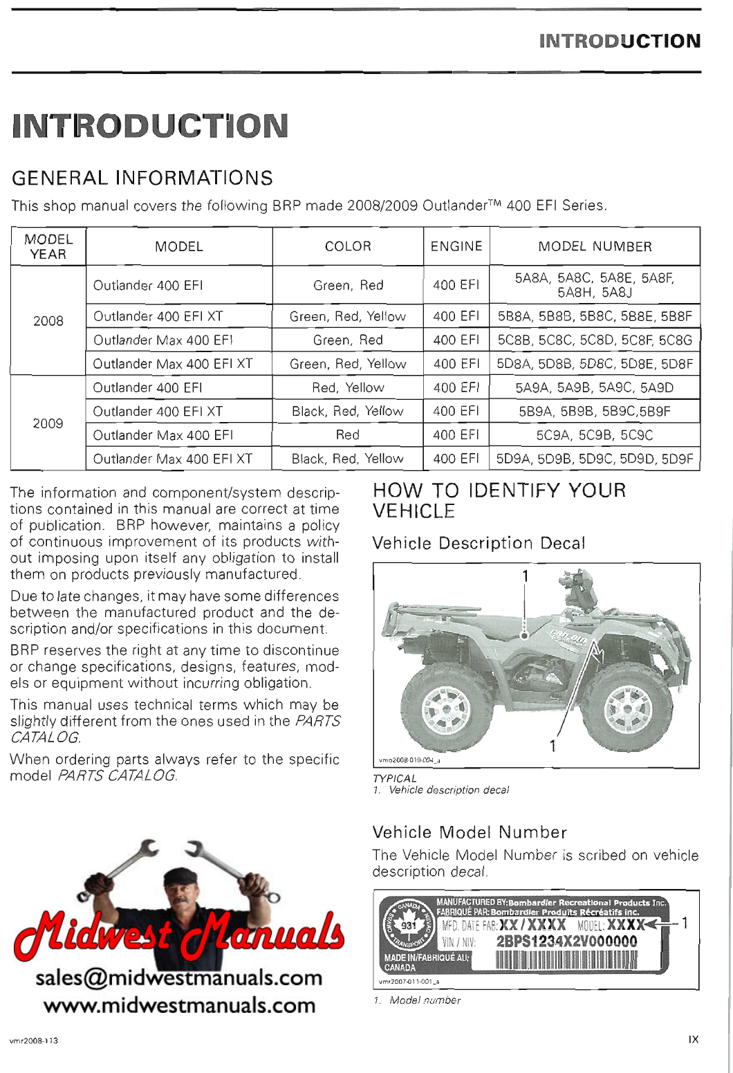
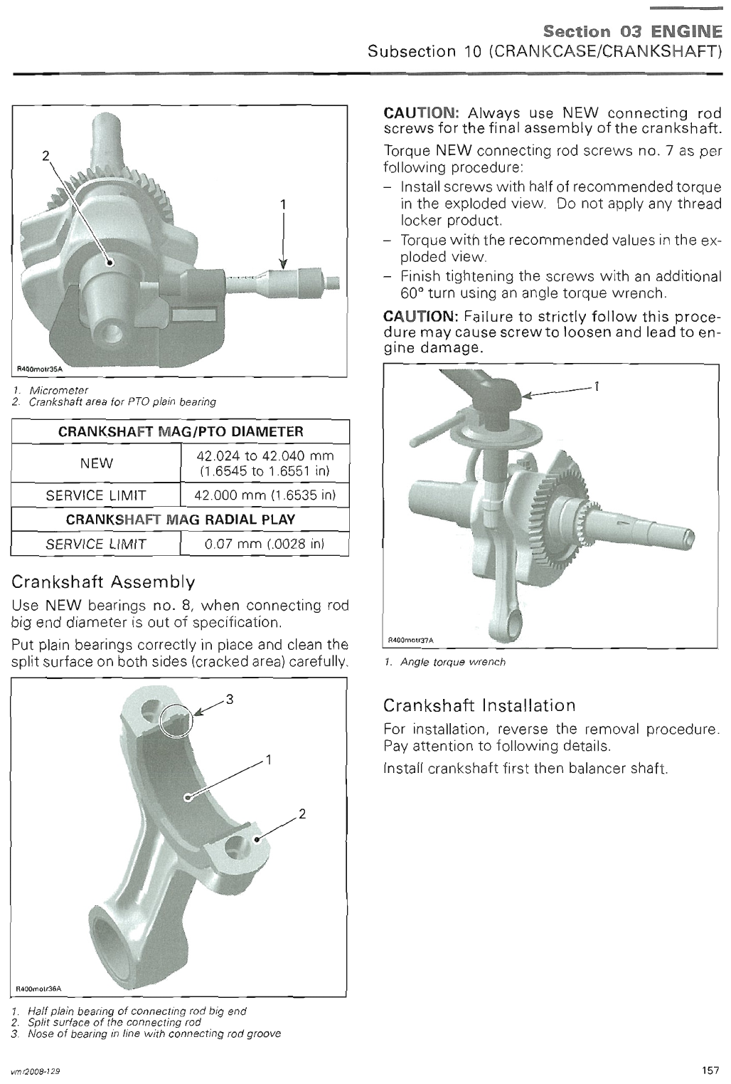
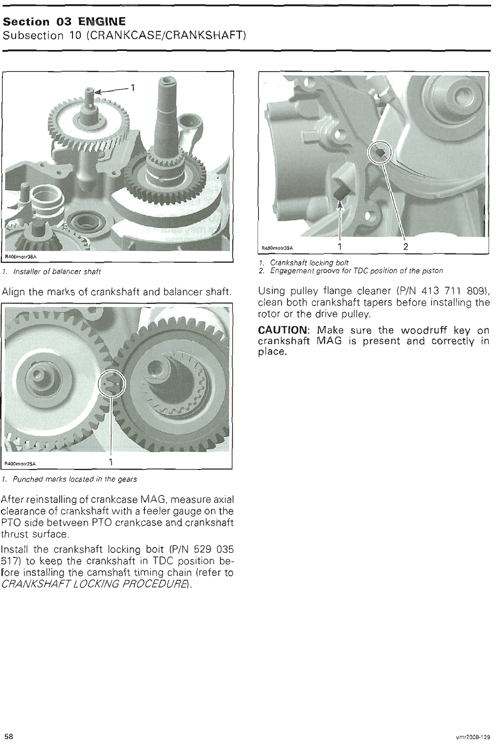
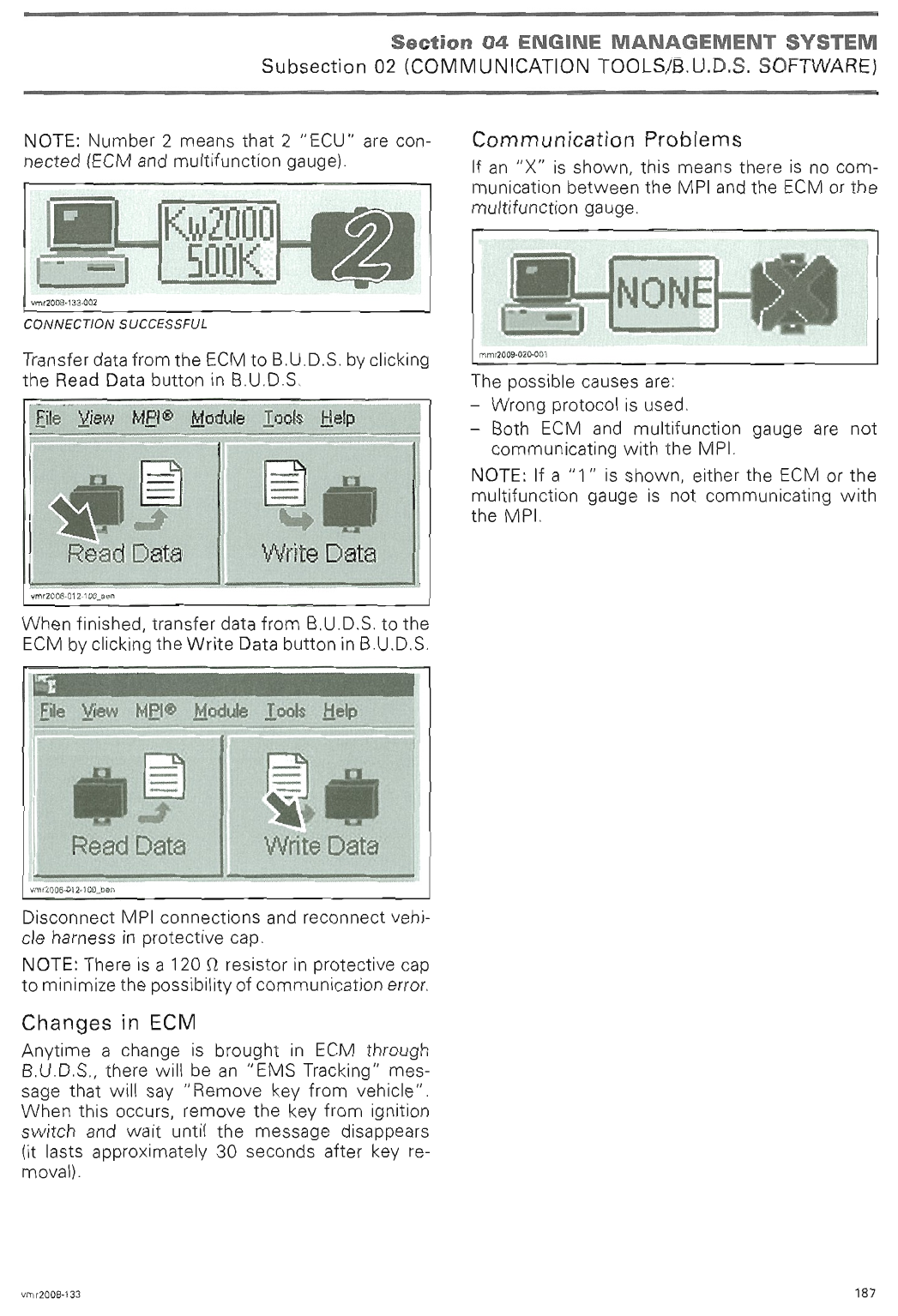
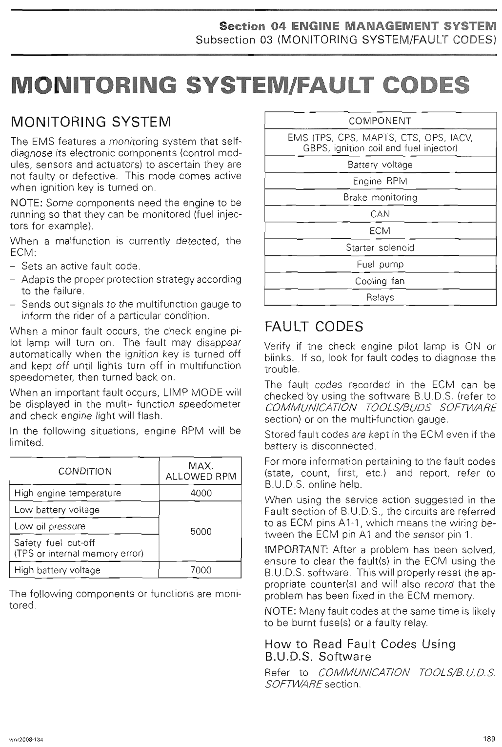
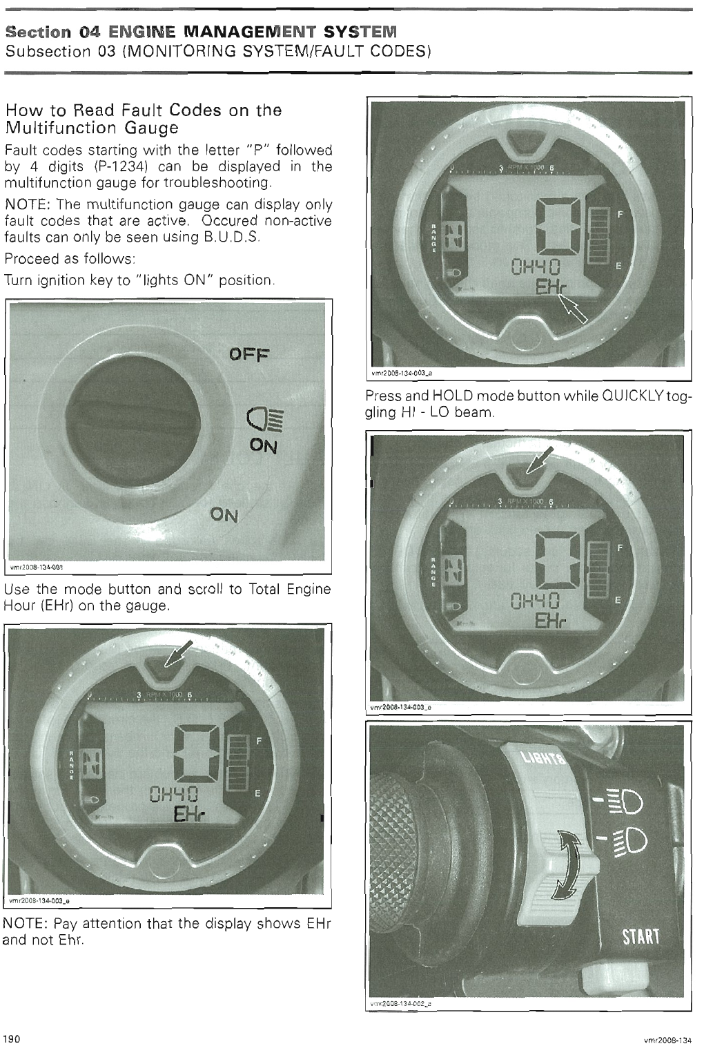
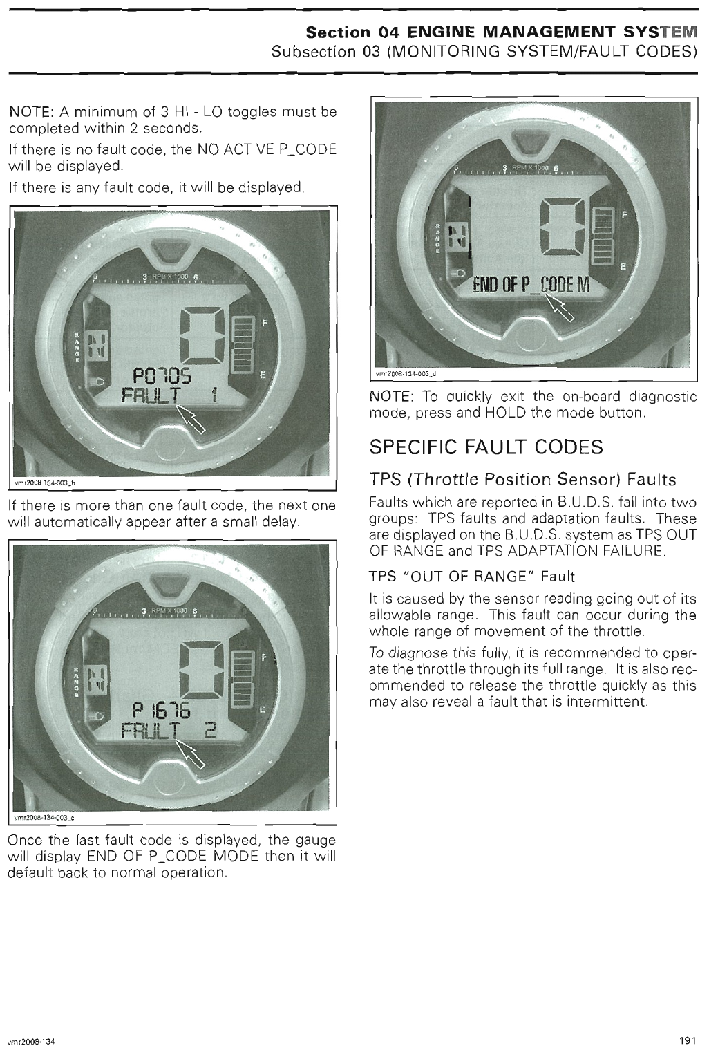
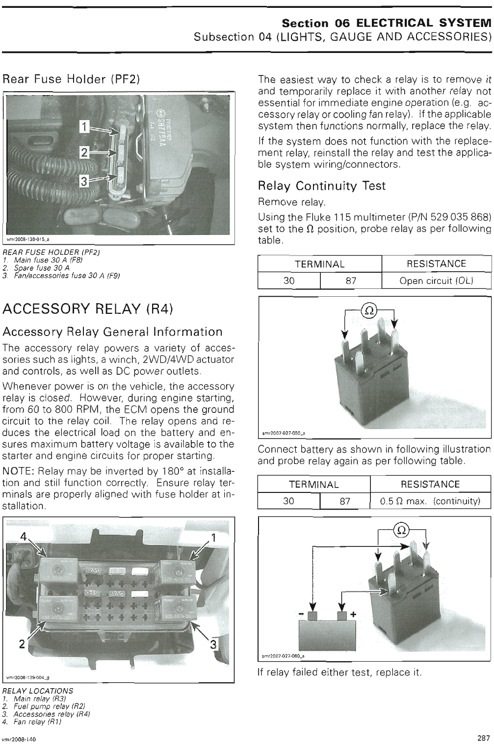
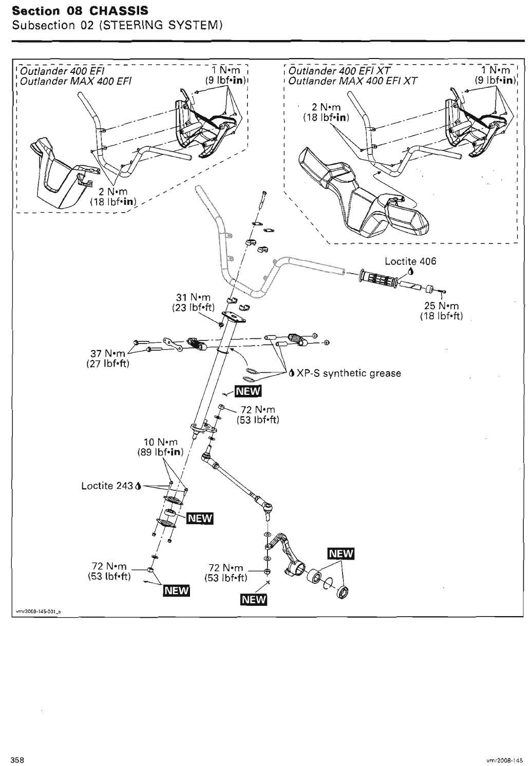
August 29, 2008 Subject:Outlander XT and LTD
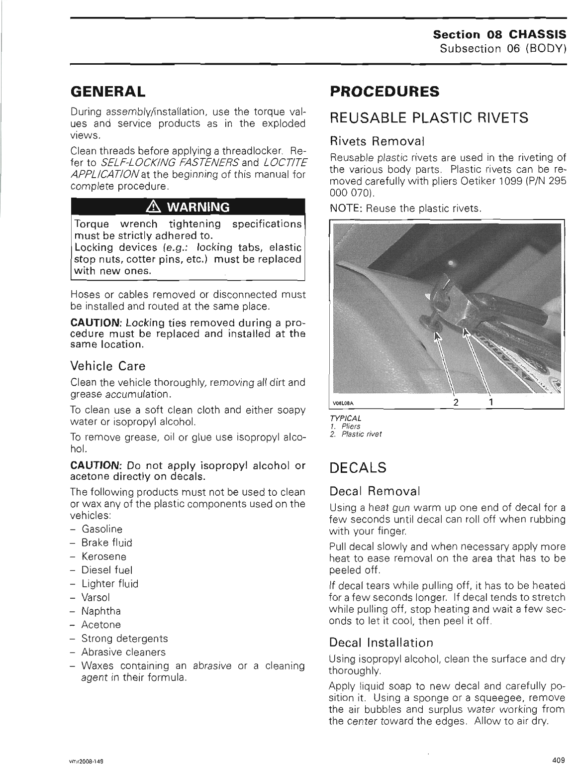
Radiator Expansion Bottle Vent Tube
Routing
No. 2009-7
YEAR MODEL PACKAGE MODEL NUMBER SERIAL NUMBER
2009 Outlander™ XT™ and LTD All All
When servicing the above-mentioned vehicles, it
is important to pay special attention to the radiator
expansion bottle vent tube routing.
Located in the front maintenance compartment,
this vent tube needs to be routed between the
routings shown in the following pictures.
vbs2008-014 006_c
SHORT ROUTING
vbs2009-009-002_a
LONG ROUTING
This action is to avoid any interference, when clos-
ing cover, with the winch remote control storage
compartment located under the cover.
vbs2009-009-001_a
NOTICE Not doing so could cause a restriction
to the vent tube which may lead to over pres-
sure in the engine cooling system.
NOTE: It is not recommended to store articles
such as a rain coat, ropes or other objects in the
front service compartment; such items could inter-
fere with components normal operation.
NOTICE Make sure to keep end of tube away
from any component that could be affected
should antifreeze drip on it, such as brake disc,
etc.
NOTE: This special attention also applies when
servicing vehicles modified as per
SERVICE BUL-
LETIN 2008-14
, dated May 5, 2008.
Please notify all involved personnel.
vbs2009-009 en MD
©2008 Bombardier Recreational Products Inc. and BRP US Inc. All rights reserved. 1/1
®™ and the BRP logo are trademarks of Bombardier Recreational Products Inc. or its affiliates.
sales@midwestmanuals.com
sales@midwestmanuals.com
September 24, 2008 Subject:Throttle Plate Opening (All Models Except
CE) No. 2009-8
YEAR MODEL MODEL NUMBERSERIAL NUMBER
2009 Outlander™ and Renegade™ All All
To ensure optimum engine performance on vehi-
cles produced before October 2008, at PDI, the
throttle plate opening should be checked using
B.U.D.S.
THROTTLE PLATE
OPENING VERIFICATION
1. Using B.U.D.S. software, select the Setting
tab. The display shows the actual throttle open-
ing in degrees.
vmr2006-014-084_b
1. Throttle opening display
NOTE: Do not click on the Reset button.
2. Fully depress throttle lever (wide open position)
and hold. Read throttle opening.
THROTTLE OPENING
82° to 86°
If opening is out of specification, perform the
THROTTLE LEVER STOPPER SCREW SETTING
.
THROTTLE LEVER
STOPPER SCREW
SETTING
1. Loosen the stopper screw lock nut.
2. Fully depress throttle lever (wide open position)
and hold.
3. Loosen stopper screw until it just releases throt-
tle lever.
vmr2006-014-068_a
1. Lock nut
2. Stopper screw
4. Turn stopper screw clockwise until it contacts
throttle lever again.
5. From this point, tighten stopper screw 1/2 turn
(to remove strain on the cable).
6. Keep the stopper screw from turning and tight-
en lock nut.
7. Read throttle opening. If throttle opening is out
of specification, perform adjustment again.
NOTE: If the proper adjustment is impossible to
reach with this procedure, perform a throttle cable
adjustment, refer to the appropriate Shop Manual.
Printed in Canada. (vbs2009-011 en AG)
©2008 Bombardier Recreational Products Inc. and BRP US Inc. All rights reserved. 1/ 1
®™ and the BRP logo are trademarks of Bombardier Recreational Products Inc. or its affiliates.
sales@midwestmanuals.com
sales@midwestmanuals.com
August 12, 2008 Subject:Spring Chart /
Accessory Shock Absorber / Spring Kits
No. 2009-4
YEAR MODEL MODEL NUMBER SERIAL NUMBER
1999 - 2009 All (except youth models) All All
SECTION 1: SPRING
APPLICATIONS
It is a quick reference chart which provides au-
thorized spring application for each ATV model. It
contains the standard spring part number as in-
stalled at the factory.
SECTION 2: SPRING
SPECIFICATIONS
Refers to spring specifications.
NOTE: The information in this bulletin supersedes
all information previously published.
Please update involved
SHOP MANUALS
by in-
dicating the number of this bulletin in the proper
section of the manual.
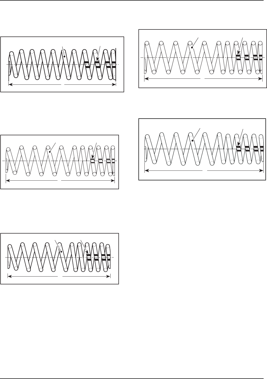
COIL SPRINGS
NOTE: Read color codes when spring is upright
and stripes are down.
The illustrations show:
[1] color code stripes,
[2] wire diameter,
[3] free length.
Type R (straight at both ends)
A00F0PA
1
2
23
Single Rate Spring
Type V (barrel shape at both
ends)
A06F02A
1
2
33
SingleRateSpring
Printed in Canada (vbs2009-002 en MD)
©2008 Bombardier Recreational Products Inc. and BRP US Inc. All rights reserved. 1/10
®™ and the BRP logo are trademarks of Bombardier Recreational Products Inc. or its affiliates.
sales@midwestmanuals.com
sales@midwestmanuals.com
Type W (barrel shape at one
end)
1
3
A00F19A
2
Single Rate Spring
Type 1 (barrel shape at one
end)
2
V00J05A
3
1
Dual Rate Spring
Type 2, 6, 7
(barrel shape at both ends)
3
A00F20A
2 1
Dual Rate Spring
Type 5 (straight on both ends)
2
V00J06A
3
1
Type 8 (barrel shape at both
ends)
2 1
3
vbs2008-002-001_a
Dual Rate Spring
2 / 10 2009-4 SERVICE
sales@midwestmanuals.com
sales@midwestmanuals.com

SECTION 1
SPRING APPLICATIONS
SPRING P/N
MODEL MODEL
YEAR MODEL NUMBER FRONT REAR
2000 - 2002 All 706 200 348 706 000 077 (long)
706 000 059 (short)
2003 All 706 200 296 706 000 199
STD
2004 - 2005 All 706 200 315 706 000 255
2002 All 706 200 348 706 000 077
2003 All 706 200 348 706 000 242Baja
2004 - 2005 All 706 200 337 706 000 270
DS 650
Baja X 2004 - 2007 All 706 200 348 706 000 292
STD/XT 2003 - 2005 All 706 200 216 706 000 245
CAMO/CAMO XT 2004 - 2005 All 706 200 355 706 000 289Outlander
MAX 2004 - 2005 All 706 200 353 706 000 261
650-800 STD All 706 200 409 706 000 476
706 000 338
650-800 XT All 706 200 590
706 200 564
706 000 476
706 000 338
650-800 MAX All 706 200 486 706 000 476
706 000 443
650-800 MAX XT All 706 200 590
706 200 566
706 000 476
706 000 443
400 STD/XT/CAMO All 706 200 355 706 000 289
400 MAX/MAX XT
2006 - 2007
All 706 200 516 706 000 465
800 MAX Limited All 706 200 590
706 200 566
706 000 476
706 000 443
500 STD All 706 200 626 706 000 476
706 000 338
500 XT All 706 200 637 706 000 476
706 000 338
500 MAX All 706 200 626 706 000 476
706 000 443
500 MAX XT
2007
All 706 200 637 706 000 476
706 000 443
650-800 STD All 706 200 409 706 000 549
650-800 XT All 706 200 697 706 000 549
650-800 MAX All 706 200 486 706 000 551
650-800 MAX XT All 706 200 702 706 000 551
400 STD/XT/CAMO All 706 200 355 706 000 289
400 MAX/MAX XT All 706 200 711 706 000 465
800 MAX Limited All 706 200 702 706 000 551
500 STD All 706 200 713 706 000 549
500 XT All 706 200 715 706 000 549
500 MAX All 706 200 713 706 000 551
Outlander
500 MAX XT
2008
All 706 200 715 706 000 551
SERVICE 2009-4 3 / 10
sales@midwestmanuals.com
sales@midwestmanuals.com

SECTION 1
SPRING APPLICATIONS
SPRING P/N
MODEL MODEL
YEAR MODEL NUMBER FRONT REAR
400 STD / XT All 706 200 819 706 000 649
400 MAX / MAX XT All 706 200 818 706 000 650
500 STD All 706 200 825 706 000 651
500 XT All 706 200 824 706 000 651
500 MAX All 706 200 825 706 000 652
500 MAX XT All 706 200 824 706 000 652
650 / 800 STD All 706 200 820 706 000 651
650 / 800 XT All 706 200 823 706 000 651
650 / 800 MAX All 706 200 821 706 000 652
650 / 800 MAX XT All 706 200 822 706 000 652
Outlander
800 MAX LTD
2009
All 706 200 822 706 000 652
800 2007 All 706 200 632 706 000 511
800 All 706 200 632 706 000 511
800 X All 706 200 701 706 000 570
500
2008
All 706 200 632 706 000 568
500 All 706 200 829 706 000 653
800 All 706 200 829 706 000 654
Renegade
800 X
2009
All 706 200 827 706 000 656
450 2008 All 706 200 481 706 000 505
450 All 706 200 481 706 000 677
450 XXC All 706 200 830 706 000 659
DS
450 XMX
2009
All 706 200 833 706 000 609
STD 500 2002 All 706 200 006 706 000 172
STD 650/XT 2002 All 706 200 006 706 000 172
STD/XT 2003 All 706 200 006 706 000 172
CAMO/
CAMO XT 2003 All 706 200 307 706 000 244
STD/XT 2004 All 706 200 301 706 000 301
CAMO 2004 All 706 200 358 706 000 304
MAX/MAX XT 2004 All 706 200 301 706 000 306
Quest
MAX CAMO 650/
MAX CAMO XT 650 2004 All 706 200 358 706 000 306
2003 - 2004 All 706 200 240 706 000 154
Rally STD 2005 - 2006
-2007 All A51401179000 A52405179000
DS 250 2006 - 2007 - 2008
- 2009 not applicable
4 / 10 2009-4 SERVICE
sales@midwestmanuals.com
sales@midwestmanuals.com

SECTION 1
SPRING APPLICATIONS
SPRING P/N
MODEL MODEL
YEAR MODEL NUMBER FRONT REAR
2001 - 2003 All 706 200 006 706 000 068
2004 All 706 200 301 706 000 301Autoshift
2005 All 706 200 467 706 000 301
Footshift 2001 All 706 200 006 706 000 068
2003 All 706 200 301 706 000 236
2004 All 706 200 301 706 000 306MAX
2005 All 706 200 467 706 000 306
MAX XT 2005 All 706 200 470 706 000 306
1999 - 2000 7400, 7401, 7413,
7414 706 200 006 706 000 003
1999 - 2000
7405, 7406, 7407,
7408, 7415, 7416,
7417, 7418
706 200 006 706 000 068
STD
2001 All 706 200 006 706 000 068
2001 - 2003 All 706 200 006 706 000 114
2004 All 706 200 301 706 000 114XL
2005 All 706 200 467 706 000 398
2001 - 2003 All 706 200 006 706 000 068
2004 All 706 200 301 706 000 301
Traxter
XT
2005 All 706 200 470 706 000 301
500 2005 All 706 200 467 706 000 301
All
(except CAMO) 706 200 467 703 000 301
650 2005
CAMO 706 200 469 706 000 304
All
(except CAMO) 706 200 470 706 000 301
650 XT 2005
CAMO 706 200 472 706 000 304
MAX 2005 All 706 200 467 706 000 306
Traxter CVT
MAX XT 2005 All 706 200 470 706 000 306
SERVICE 2009-4 5 / 10
sales@midwestmanuals.com
sales@midwestmanuals.com

SECTION 2
SPRING SPECIFICATIONS
COIL SPRINGS SPECIFICATIONS (REAR SHOCK ABSORBER)
P/N TYPE
SPRING RATE
(LB/IN) ± 10
__________________
(RATE 1 / RATE 2
WHERE APPLICABLE)
FREE LENGTH
(MM) ± 3
WIRE DIAMETER
(MM) ± .05
COLOR CODE
STRIPES
COLOR OF
SPRING
A52405179000 N/A 114.8 284.2 9.2 N/A Full Moon
706 000 003 5 68 / 90 355 7.77 BL/BK/BK Yellow
706 000 059 W 700 52.7 10.31 BL/YL/BK Red
706 000 068 R 68 355 7.77 GN/WH/BK Yellow
706 000 077 W 350 ±15 251.5 12.19 BL/RD/RD Yellow
706 000 114 5 74 / 237 360.7 8.25 BK/SI/BK Yellow
706 000 154 R 115 / 155 294 8.71 BK/BK Full Moon
706 000 172 R 45.7 ±4.5 345 6.91 GN/BK/RD Yellow
706 000 199 7 242 ±15 304.8 12.19 YL/GD/BK Red
706 000 236 5 62.8 395 7.92 SI/BK/BK Yellow
706 000 242 7 242 ±15 / 350 ±15 304.8 12.19 SI/BK Yellow
706 000 244 R 45.7 ±4.5 345 6.91 WH/GN/YL Deep Black
706 000 245 2 66 ±5 / 106 ±5 371 8.41 BL/BK/BL Full Moon
706 000 255 7 228 ±5 / 416.6 ±5 320 11.89 WH/YL/BK Red
706 000 261 2 84 / 128.5 413 8.71 BL/GN/BL Full Moon
706 000 270 7 228 ±5 / 416.8 ±5 320 11.89 SI/YL/BK Orange
706 000 289 2 66 ±5 / 106 ±5 371 8.41 BL/WH/BL Deep Black
706 000 292 7 228 ±5 / 416.8 ±5 320 11.89 GD/WH/BK Full Moon
706 000 301 R 40 429 6.65 GN/BK/BL Yellow
706 000 304 R 40 429 6.65 GN/RD/BL Deep Black
706 000 306 R 68.5 / 102.8 401 7.92 BL/BK/RD Yellow
706 000 338 W 108.5 308.1 8.25 GN/GD/BL Deep Black
706 000 398 6 65.4 / 199.5 353 8.25 GN/SI/RD Yellow
706 000 443 W 108.5 318.1 8.41 GD/BL/BL Deep Black
706 000 465 2 84 / 128.5 413 8.71 SI/BL/YL Black
706 000 476 W 235.1 98.1 8.25 GD/RD/BL Deep Black
706 000 505 S 251 272 10.3 WH/BL/WH Yellow
706 000 511 8 74.2 / 131.3 348 8.83 GD/GD/GN Yellow
706 000 549 874.2 / 108.5 354 8.83 GD/BL/GD Deep Black
706 000 551 874.2 / 108.5 364 8.83 GD/GN/GD Deep Black
706 000 568 874.2 / 114.2 380 8.83 SI/RD/WH Yellow
706 000 570 885.6 / 131.3 383 9.19 SI/GD/BL Yellow
706 000 609 8187.3 / 250 311 10.3 GN/BL Yellow
706 000 649 266 ±5 / 106 ±5 371 8.41 SI/YL/WH Deep Black
706 000 650 284 / 128.5 413 8.71 SI/GD/GD Deep Black
6 / 10 2009-4 SERVICE
sales@midwestmanuals.com
sales@midwestmanuals.com

SECTION 2
SPRING SPECIFICATIONS
COIL SPRINGS SPECIFICATIONS (REAR SHOCK ABSORBER)
706 000 651 874.2 ±5 / 108.5 ±5 354 8.83 SI/WH/GD Deep Black
706 000 652 874.2 ±5 / 108.5 ±5 364 8.83 SI/SI/GD Deep Black
706 000 653 874.2 ±5 / 114.2 ±5 380.8 8.83 WH/SI/GD Deep Black
706 000 654 874.2 ±5 / 131.3 ±5 348 9.19 SI/RD/SI Yellow
706 000 656 885.6 ±5 / 131.3 ±5 383.7 9.19 SI/BL/SI Yellow
706 000 659 6187.3 / 250 286.4 9.98 RD/RD Yellow
SPRING COLOR CODES
BK = BLACK BL = BLUE GD = GOLD GN = GREEN
OR = ORANGE PI = PINK RD = RED SI = SILVER
WH = WHITE YL = YELLOW
SERVICE 2009-4 7 / 10
sales@midwestmanuals.com
sales@midwestmanuals.com

SECTION 2
SPRING SPECIFICATIONS
COIL SPRINGS SPECIFICATIONS (FRONT SHOCK ABSORBER)
P/N TYPE
SPRING RATE
(LB/IN) ± 10
______________________
(RATE1/RATE2
WHERE APPLICABLE)
FREE LENGTH
(MM) ± 3
WIRE DIAMETER
(MM) ± .05
COLOR CODE
STRIPES
COLOR OF
SPRING
A51401179000 N/A 99.9 232.7 8.1 N/A Full Moon
706 200 006 V 140 270 8.25 OR/BK/BK Yellow
706 200 082 2 90 / 140 368.3 9.53 BK/WH/BK Yellow
706 200 216 2 60 ±5 / 100 ±5 354 8.25 BL/RD/BL Full Moon
706 200 240 1 100 / 140 261 7.49 RD/RD Full Moon
706 200 296 2 90 / 140 368.3 9.53 GD/GD/BK Red
706 200 301 6 108.5 / 165.6 290 8.71 SI/RD/BK Yellow
706 200 307 V 140 270 7.92 GN/RD/RD Deep Black
706 200 315 2 90 / 140 368.3 9.19 GD/BL/BK Red
706 200 337 2 90 / 140 368.3 9.19 GD/GN/BK Orange
706 200 348 2 90 / 140 368.3 9.19 GN/GN/BK Full Moon
706 200 353 2 60 ±5 / 114.2 ±5 375 8.71 BL/YL/BL Full Moon
706 200 355 2 60 ±5 / 100 ±5 354 8.25 RD/YL/RD Deep Black
706 200 358 6 108.5 / 165.6 290 8.71 GN/YL/GN Deep Black
706 200 409 6 60 / 114.2 349 8.25 GN/GD/GN Black
706 200 467 6 108.5 / 165.6 290 8.25 SI/BK/BL Yellow
706 200 469 6 108.5 / 165.6 290 8.25 WH/SI/RD Black
706 200 470 6 108.5 / 165.3 307 9.19 GN/SI/BL Yellow
706 200 472 6 108.5 / 165.3 307 9.19 WH/WH/RD Black
706 200 481 1108.5 / 199.9 280 8.83 WH/RD/WH Black / Yellow
706 200 486 6 60 / 114.2 358 8.41 GD/YL/BL Black
706 200 516 2 60 / 114.2 375 8.71 GD/SI/RD Black
706 200 564 W 171.3 228.7 8.25 SI/RD/BL Black
706 200 566 W 170 238.7 8.41 SI/BL/BL Black
706 200 590 W 92.35 117.6 6.65 SI/GD/BL Black
706 200 626 2 54.8 / 125.6 372 8.41 SI/GD/YL Black
706 200 637 2 54.8 / 125.6 387 8.83 SI/YL/GN Black
706 200 697 660 / 159.9 359.2 8.83 WH/RD/GD Deep Black
706 200 702 660 / 159.9 369.2 9.19 SI/RD/GD Deep Black
706 200 711 860 / 114.2 375 8.25 SI/YL/GD Deep Black
706 200 713 854.8 / 125.6 372 8.41 SI/BL/GD Deep Black
706 200 715 854.8 / 125.6 387 8.41 WH/BL/GD Deep Black
706 200 632 687.9 / 131.3 319 8.83 SI/WH/GN Yellow
706 200 701 887.9 / 131.3 328.7 8.25 SI/GN/GD Yellow
706 200 818 860 ±5 / 114.2 ±5 375 8.25 SI/GD/WH Deep Black
706 200 819 260 ±5 / 100 ±5 354 8.25 SI/WH/WH Deep Black
706 200 820 660 ±5 / 114.2 ±5 349 8.25 SI/YL/SI Deep Black
706 200 821 660 ±5 / 114.2 ±5 358 8.41 WH/SI/WH Deep Black
8 / 10 2009-4 SERVICE
sales@midwestmanuals.com
sales@midwestmanuals.com

SECTION 2
SPRING SPECIFICATIONS
COIL SPRINGS SPECIFICATIONS (FRONT SHOCK ABSORBER)
706 200 822 660 ±5 / 159.9 ±5 369.2 9.19 GD/SI/GD Deep Black
706 200 823 660 ±5 / 159.9 ±5 359.2 8.83 SI/GD/SI Deep Black
706 200 824 854.8 ±5 / 125.6 ±5 387 8.41 GD/RD/GD Deep Black
706 200 825 854.8 ±5 / 125.6 ±5 372 8.41 SI/SI/SI Deep Black
706 200 827 887.9 ±5 / 131.3 ±5 328.67 8.25 SI/GN/SI Yellow
706 200 829 687.9 ±5 / 131.3 ±5 319 8.83 SI/BL/WH Yellow
706 200 830 6127.9 / 222.7 226.8 8.83 RD/RD/BK Yellow
706 200 833 8101 ±5 / 174.7 301.6 9.19 RD/BK/BK Yellow
SPRING COLOR CODES
BK = BLACK BL = BLUE GD = GOLD GN = GREEN
OR = ORANGE PI = PINK RD = RED SI = SILVER
WH = WHITE YL = YELLOW
SERVICE 2009-4 9 / 10
sales@midwestmanuals.com
sales@midwestmanuals.com
vbs2009-002-001_en
10 / 10 2009-4 SERVICE
sales@midwestmanuals.com
sales@midwestmanuals.com
June 01, 2008 Subject:Can-Am™ Outlander™ and Renegade™
Predelivery Inspection
No. 2009-2
YEAR MODEL MODEL NUMBER SERIAL
NUMBER
Outlander 400 EFI / 500 EFI / 650 EFI / 800R EFI
2009 Renegade 500 EFI / 800R EFI / 800R EFI X™
Refer to table on next pages
for complete listing All
TABLE OF CONTENTS
Page Page
IMPORTANT NOTICE ....................... 2
MODELLISTING............................. 3
UNCRATING.................................. 4
PARTSTOBEINSTALLED.................. 5
Battery ........................................... 5
FrontBumper.................................... 6
Mirrors ........................................... 7
WinchSwitch.................................... 7
FlagHolder....................................... 7
LockingDevice.................................. 8
Backrest ......................................... 8
HandlebarGuard................................ 9
Mudguard........................................ 10
AccessoriesInstallation........................ 10
VehicleDecals................................... 10
WindDeflector.................................. 10
CentralSkidPlate ............................... 12
FLUIDS......................................... 12
GeneralGuidelines.............................. 12
Fuel............................................... 12
EngineOil........................................ 13
GearboxOil ...................................... 14
EngineCoolant.................................. 14
BrakeFluid....................................... 15
FrontandRearDifferentialOil ................. 16
SET-UP......................................... 17
TiresPressure ................................... 17
BrakeDiskCleanup............................. 18
ProtectiveMaterials ............................ 18
ADJUSTMENTS ............................. 18
GeneralGuidelines.............................. 18
TransmissionLever............................. 18
Suspension ...................................... 18
BrakePedalandLever.......................... 20
B.U.D.S.Programming......................... 20
ASSEMBLYINSPECTION .................. 22
FINALINSPECTION ......................... 22
VehicleTestRun................................. 22
VehicleCleaning................................. 22
DeliveryToCustomer........................... 22
TECHNICALDATA ........................... 23
Printed in Canada (vbl2009-002 en DM)
©2008 Bombardier Recreational Products Inc. and BRP US Inc. All rights reserved. 1/34
®™ and the BRP logo are trademarks of Bombardier Recreational Products Inc. or its affiliates.
sales@midwestmanuals.com
sales@midwestmanuals.com

IMPORTANT NOTICE
IMPORTANT NOTICE
This bulletin must be used in conjunction with the check list enclosed in the bag with the
OPERATOR’S
GUIDE
.Makesurethat
PREDELIVERY CHECK LIST
is completed and signed.
WARNING
To obtain warranty coverage, pre delivery procedures must be performed by an authorized BRP
Can-Am ATV dealer/distributor. Apply all necessary torques as indicated.
NOTE: The information and components/system descriptions contained in this document are correct
at the time of publication. BRP however, maintains a policy of continuous improvement of its products
without imposing upon itself any obligation to install them on products previously manufactured.
Due to late changes, there might be some differences between the manufactured product and the
descriptions and/or specifications in this document. BRP reserves the right at any time to discontinue or
change specifications, designs, features, models or equipment without incurring obligation.
The illustrations in this document show the typical construction of the different assemblies and may not
reproduce the full detail or exact shape of the parts. However, they represent parts that have the same or
similar function.
The content of this bulletin is designed as a guideline only. All mechanics performing pre delivery
procedures should have attended the current model-year service training.
Further information or inquiries should be directed to your service representative and/or specific
SHOP MANUAL
sections.
Please complete the
PREDELIVERY CHECK LIST
for each vehicle and retain a customer-signed copy.
Make sure the customer receives the
OPERATOR’S GUIDE
,
PRE DELIVERY CHECK LIST
signed copy
and
SAFETY DVD
.
WARNING
Torque wrench tightening specifications must be strictly adhered to. Where specified, install new
locking devices (e.g. lock tabs, elastic stop nuts). If the efficiency of a locking device is impaired, it
must be renewed.
2 / 34 2009-2 PREDELIVERY
sales@midwestmanuals.com
sales@midwestmanuals.com

MODEL LISTING
MODEL LISTING
YEAR MODEL MODEL NUMBER CE MODEL
NUMBER
SERIAL
NUMBER
Outlander 400 5A9A / 5A9B / 5A9C 5A9D
Outlander 400 XT 5B9A / 5B9B / 5B9C 5B9F
Outlander 400 MAX 5C9A / 5C9B 5C9C
Outlander 400 MAX XT 5D9A / 5D9B / 5D9C / 5D9D 5D9F
Outlander 500 2T9A / 2T9B ---
Outlander 500 XT 2U9A / 2U9B / 2U9C / 2U9D / 2U9E 2U9F
Outlander 500 MAX 2W9A ---
Outlander 500 MAX XT 2X9A / 2X9B / 2X9C / 2X9D / 2X9E 2X9F
Outlander 650 2N9A / 2N9B / 2N9C 2N9D
Outlander 650 XT 2P9A / 2P9B / 2P9C / 2P9D / 2P9E / 2P9G 2P9H
Outlander 650 MAX 2R9A / 2R9B / 2R9C 2R9D
Outlander 650 MAX XT 2S9A / 2S9B / 2S9C / 2S9D / 2S9E / 2S9G 2S9H
Outlander 800R 2H9E / 2H9F / 2H9G ---
Outlander 800R XT 2J9J / 2J9K / 2J9L / 2J9M / 2J9N ---
Outlander 800R MAX 2K9A / 2K9B / 2K9C 2K9D
Outlander 800R MAX XT 2L9A / 2L9B / 2L9C / 2L9D / 2L9E / 2L9F 2L9G
Outlander 800R MAX LTD 2M9A / 2M9B / 2M9D / 2M9E 2M9C / 2M9F
Renegade 500 4E9A / 4E9B / 4E9C 4E9D
Renegade 800R 4B9A / 4B9B /4B9C/4B9E 4B9D / 4B9F
2009
Renegade 800R X 4C9A / 4C9B 4C9C
All
PREDELIVERY 2009-2 3 / 34
sales@midwestmanuals.com
sales@midwestmanuals.com
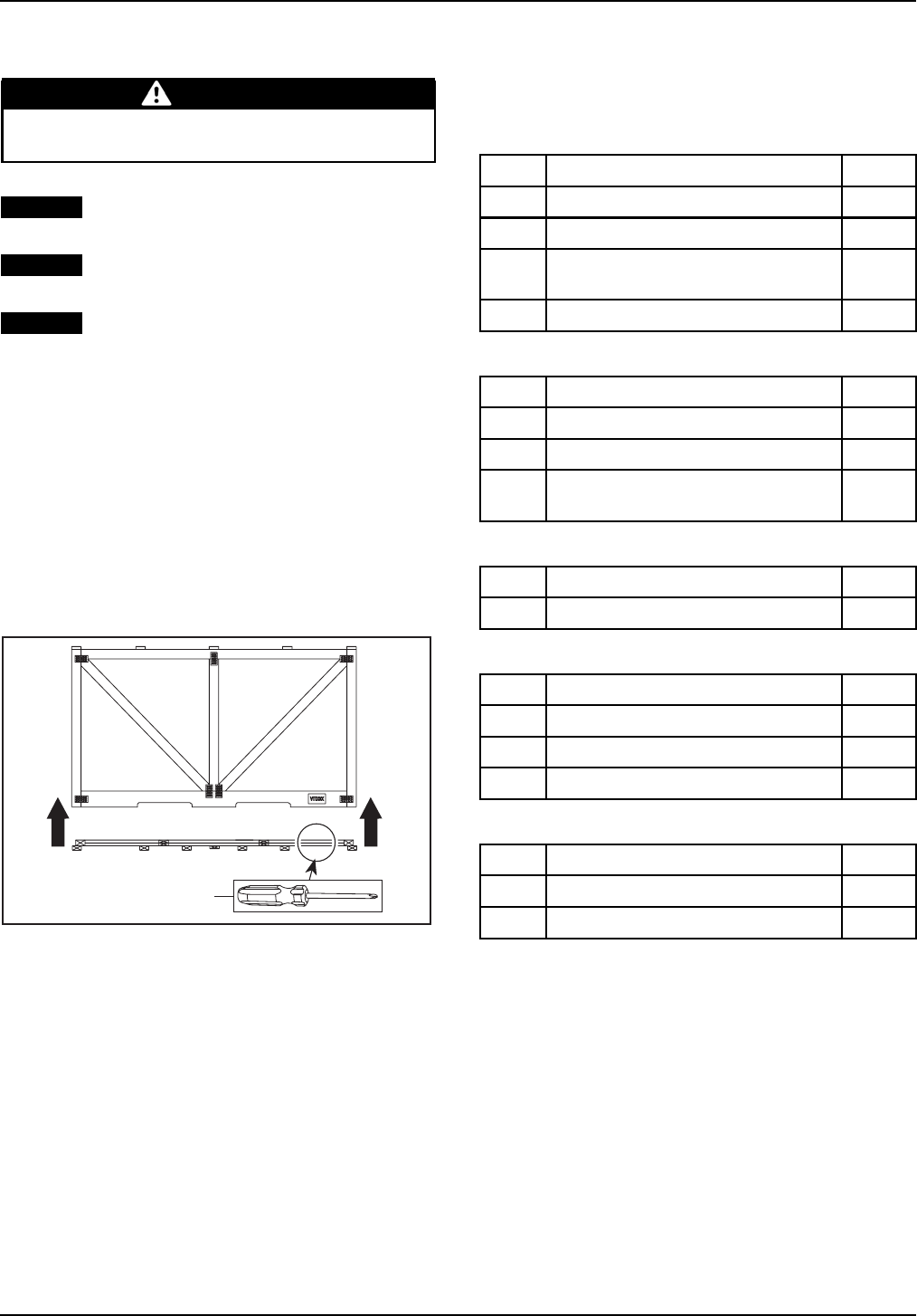
UNCRATING
UNCRATING
WARNING
Never stand at front or at rear of the vehicle
while straps are being cut.
NOTICE Allowing the crate to drop may cause
serious damages to vehicle.
NOTICE While manipulating to cut, take care
not to damage trim components with blade.
NOTICE Never tip cover toward the front or
rear of the vehicle while lifting it.
NOTE: Screws that are used are Robertson†#2
type that require the use of an appropriate bit
(Scrulox #2 from Snap-on†† Tools or ECAR.1 from
Facom††† Tools).
1. Carefully lay the crate on its bottom.
2. Remove all screws retaining crate cover to
crate base.
3. Assisted by another person, lift up crate cover.
4. Raise cover vertically from both ends at the
same time.
2
2
1
1. Screw
2. Lift up crate cover
5. Remove protective wrapping from the vehicle.
6. Remove boxes from crate base.
7. Remove parts and equipments from crate
base.
8. Remove straps, hooks and brackets retaining
vehicle to crate base.
9. Move vehicle out of the crate base.
10. Ensure that the crate includes the following
items:
LTD Models
ITEM DESCRIPTION QTY
1Handlebar guard with fasteners kit 1
2 Front bumper with fasteners kit 1
3 Winch kit (already installed on front
bumper) 1
4Mudguard kit1
XT Models
ITEM DESCRIPTION QTY
1Handlebar guard with fasteners kit 1
2 Front bumper with fasteners kit 1
3 Winch kit (already installed on front
bumper) 1
MAX Models
ITEM DESCRIPTION QTY
1Rear backrest 1
CE Models
ITEM DESCRIPTION QTY
1Mirror 2
2 Locking device keys 2
3 Flag holder kit 1
X Models
ITEM DESCRIPTION QTY
1Wind deflector with fasteners kit 2
2Central skid plate with fasteners kit 1
NOTE:This vehicle comes with a hang tag and la-
bels containing important safety information. Do
not remove hang tag from vehicle, they are consid-
ered permanent parts of the vehicle.
† Robertson is a registered trademark of Robertson Inc.
†† Snap-on is a trademark of Snap-on Inc.
††† FACOM is a brand of the International tools Group, subsidiary of FIMALAC.
4 / 34 2009-2 PREDELIVERY
sales@midwestmanuals.com
sales@midwestmanuals.com
PARTSTOBEINSTALLED
PARTS TO BE INSTALLED
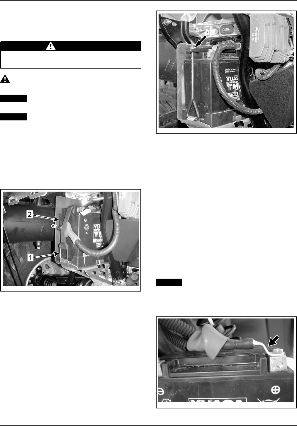
Battery
WARNING
Always connect RED positive cable first and
then BLACK negative cable.
CAUTION Never charge or boost battery
while installed on vehicle.
NOTICE Always charge battery before its in-
stallation on the vehicle.
NOTICE Make sure not to squeeze battery ca-
bles between vehicle components.
Battery Installation
1. Refer to the latest edition of
CAN-AM ATV BAT-
TERIES SERVICE BULLETIN
for proper activat-
ing, charging and maintenance procedures.
Outlander Models
2. Unhook battery retaining strap.
vbl2008-007-004_a
1. Retaining strap
2. Battery
Renegade Models
3. Unscrew battery retaining rod.
vmr2007-047-001_a
BATTERY RETAINING ROD
All Models
4. Remove battery from vehicle.
5. Charge battery. Refer to
CAN-AM ATV BAT-
TERIES SERVICE BULLETIN
.
6. Install charged battery on vehicle.
7. Properly route battery cables. Refer to
BAT-
TERY CABLE ROUTING
below.
8. Connect RED positive cable to positive battery
post.
9. Connect BLACK negative cable to negative
battery post.
10. Apply dielectric grease (P/N 293 550 004) on
battery posts.
11. Cover positive post with rubber boot.
Battery Cable Routing
NOTICE Always respect the specific cable
routing. Refer to the following illustrations.
1. Ensure that the cable end is installed as illus-
trated and the cable is routed over the battery.
vbl2008-005-250_a
CORRECT WAY OF SECURING POSITIVE (+) POST
PREDELIVERY 2009-2 5 / 34
sales@midwestmanuals.com
sales@midwestmanuals.com
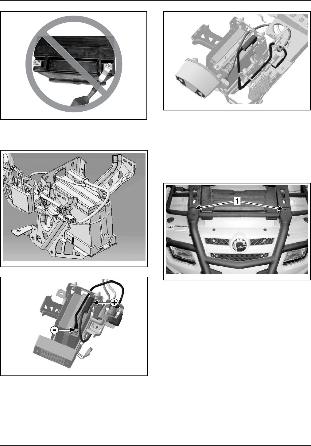
PARTSTOBEINSTALLED
vbl2008-005-103
WRONG WAY OF SECURING THE POSITIVE (+) POST
2. Ensure that the cables is routed as per the fol-
lowing illustrations.
vbl2008-005-100
OUTLANDER 400
vbl2008-005-100_a
OUTLANDER 500-650-800R
vbl2007-008-888_a
RENEGADE 500-800R
Front Bumper
Outlander XT Models
1. Install upper part of the bumper with:
– 2x M8 x 20 bolts
– 2x M8 flat washers
– 2x M8 nuts
vbl2008-007-005_a
1. Upper retaining bolts
2. Do not torque upper retaining M8 nuts yet.
3. Install lower part of the bumper with :
–4xM8x40screws
6 / 34 2009-2 PREDELIVERY
sales@midwestmanuals.com
sales@midwestmanuals.com
PARTSTOBEINSTALLED
vbl2008-007-006_a
1. Lower retaining screws
4. Secure upper retaining nuts to 11 N•m
(97 lbf•in).
5. Secure lower retaining screws to 25 N•m
(18 lbf•ft).
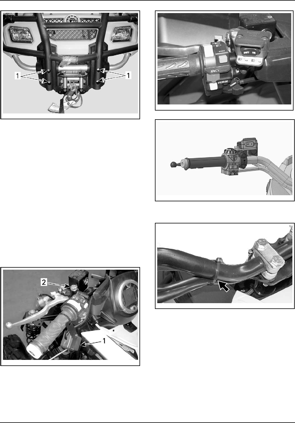
Mirrors
Outlander CE Models
1. Remove mirrors from the storage compart-
ment.
2. Install mirrors on their supports.
Winch Switch
Outlander XT and LTD Models
1. Remove winch switch from vehicle by cutting
retaining locking tie.
2. Remove bolt from brake housing.
vbl2008-007-007_a
1. Winch switch
2. Brake housing bolt
3. Secure winch switch to the brake housing with
the existing bolt.
vdd2006-001-017
OUTLANDER XT AND LTD
vbl2009-002-102
OUTLANDER XT AND LTD (CE)
4. Attach wires to handlebar, using a locking tie.
vbl2008-005-101_a
Flag Holder
Renegade CE Models
1. Position flag holder on vehicle rear support.
2. Install retaining bolt.
3. Tighten retaining nut.
PREDELIVERY 2009-2 7 / 34
sales@midwestmanuals.com
sales@midwestmanuals.com
PARTSTOBEINSTALLED
vbl2009-002-001_a
1. Flag holder
2. Retaining bolt
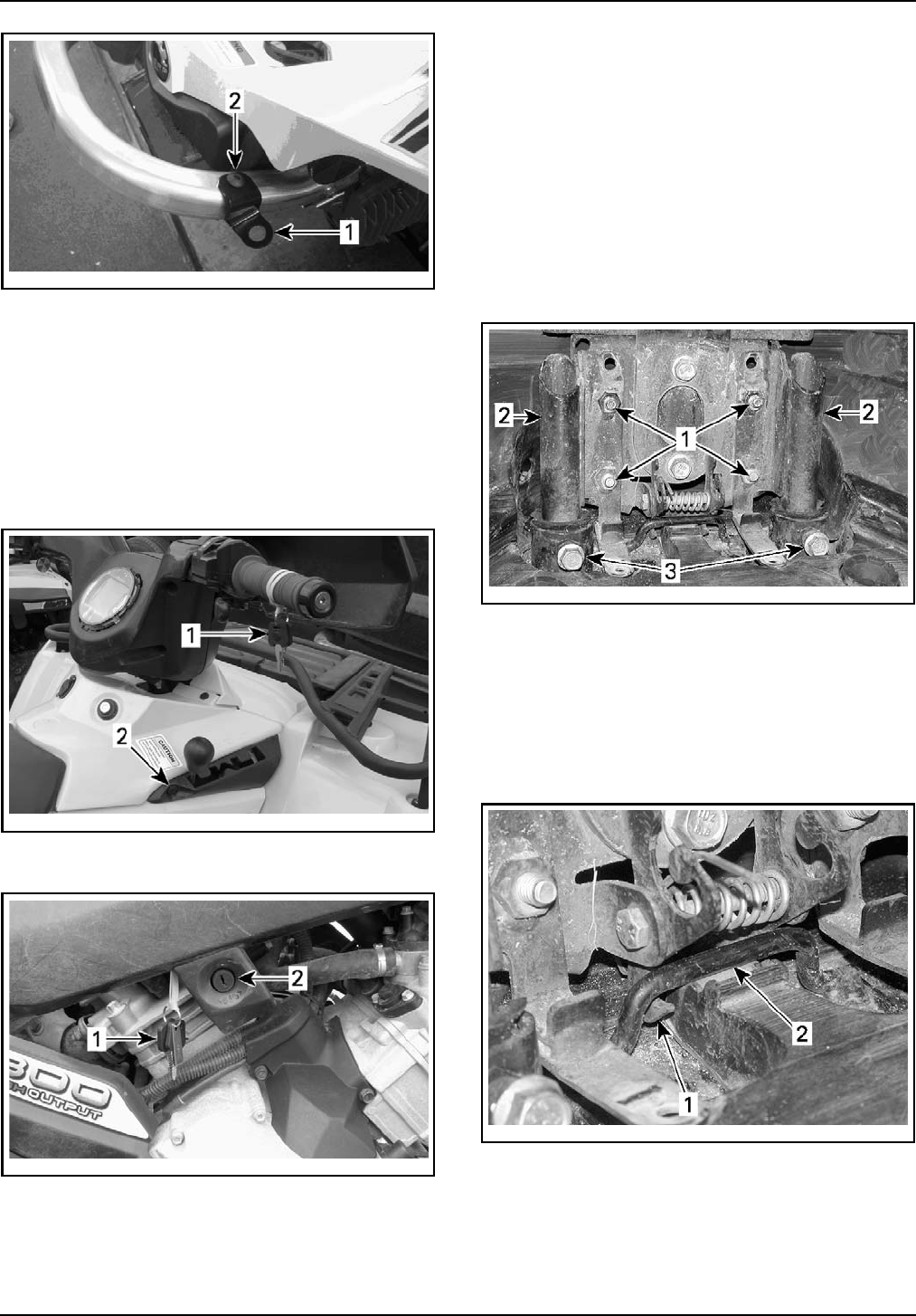
Locking Device
CE Models
For the European Community models a locking
device is required to avoid vehicle from moving
when needed. This locking device is located on
the transmission lever. Refer to the following pic-
tures.
vbl2009-002-104_a
OUTLANDER 400 SERIES
1. Keys
2. Locking device
vbl2009-002-105_a
OUTLANDER AND RENEGADE 500-650-800R SERIES
1. Keys
2. Locking device
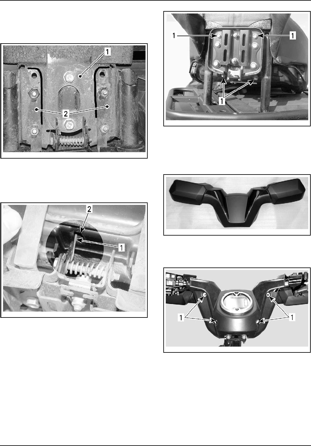
Backrest
Outlander MAX Models
Install the backrest on passenger's seat as per the
following steps :
1. Loosen bolts holding backrest plate to backrest
support.
2. Install the backrest tubes into theirs locations
in frame.
3. Install backrest tube bolts.
4. Do not torque bolts for the moment.
vbl2006-003-001_a
1. Backrest holding bolts
2. Backrest tubes
3. Backrest tube bolts
5. Check if the latch hooks are inserted under at-
tachment rod.
6. Tighten backrest tube bolts to prevent back
and forth movements.
7. Do not torque bolts for the moment.
vbl2006-003-002_A
1. Latch hooks
2. Attachment rod
8. Mark the position of backrest plate on the
backrest support using a marker.
9. Remove backrest from vehicle.
8 / 34 2009-2 PREDELIVERY
sales@midwestmanuals.com
sales@midwestmanuals.com
PARTSTOBEINSTALLED
10. Align backrest support with the mark on back-
rest plate.
11. Torque bolts to 25 N•m (18 lbf•ft).
vbl2006-003-003_A
1. Backrest plate
2. Backrest support
12. Place the long end of spring in the seat recess.
13. Position the seat release rod into the backrest
latch slot.
vbl2006-003-004_a
1. Long end of spring
2. Seat recess
14. Screw-in backrest to passenger's seat.
15. Torque to 5 N•m(44 lbf•in).
NOTE: If required, you may add a very small
amount of general purpose grease on the back-
rest tubes insertion plastic guides to ease tubes
insertion.
vbl2006-003-008_a
1. Screw-in backrest
Handlebar Guard
Outlander 400 XT Models
1. Remove handlebar guard from its box.
vbl2008-007-008
2. Install handlebar guard to the steering cover.
3. Secure handlebar guard using the 4 retaining
screws.
vbl2008-007-009_a
1. Retaining screws location
NOTE: The retaining screws are included in the
handlebar guard box.
Outlander 500 XT / 650 XT / 800R XT / 800R LTD
4. Remove handlebar guard from its box.
5. Install handlebar guard to the handlebar.
PREDELIVERY 2009-2 9 / 34
sales@midwestmanuals.com
sales@midwestmanuals.com
PARTSTOBEINSTALLED
2
2
1
vsi2006-028-002_a
1. Handlebar guard
2. U-clamps
6. Install U-clamps with the arrows pointed to-
ward the front of vehicle.
7. Secure handlebar guard using U-clamps and re-
taining screws.
vmr2006-025-005_a
1. U-clamp
NOTE: The U-clamps and retaining screws are in-
cluded in the handlebar guard box.
Mudguard
LTD Models
1. Install mudguard kit as per their installation in-
structions (included in the kit).
Accessories Installation
1. Install accessories (if any) as per their installa-
tion instructions (included in each kit).
2. Install any other equipment required by law (if
any).
Vehicle Decals
1. Install decals on vehicle according to customer
country language and local legislation.
2. Ensure that the new decals are installed at the
same location and over the factory installed de-
cals.
Wind Deflector
X Models
1. Install M8 screw in full wrap support.
2. Insert beveled bracket in M8 screw.
3. Screw on threaded beveled bracket into M8
screw.
vsi2008-018-004_b
1. Full wrap support
2. M8 screw
3. Beveled bracket
4. Threaded beveled bracket
4. Align wind deflector on full wrap support
5. Install M4 bolt and M4 nut.
6. Torque M4 nut to 3 N•m (27 lbf•in).
vsi2008-018-007_b
1. M4 bolt
2. M4 nut
7. Insert M5 nut in full wrap support middle hous-
ing.
10 / 34 2009-2 PREDELIVERY
sales@midwestmanuals.com
sales@midwestmanuals.com
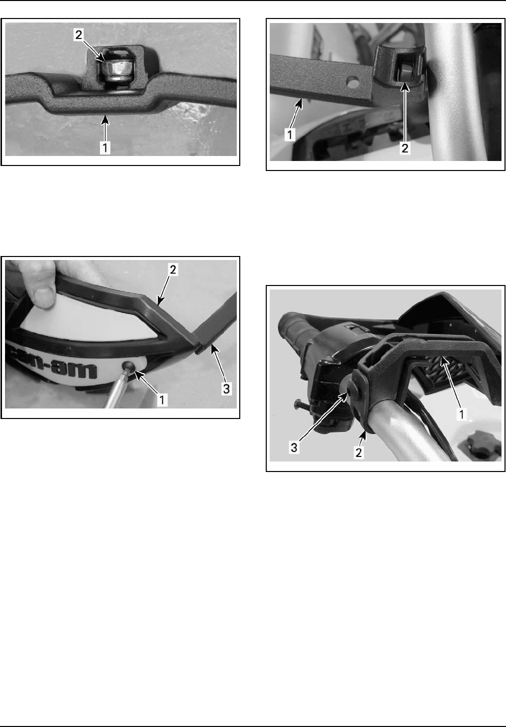
PARTSTOBEINSTALLED
vsi2008-018-005_b
1. Full wrap support
2. M5 nut
8. Align wind deflector on full wrap support.
9. Using support as a guide, drill a ø6 mm hole
through wind deflector.
10. Install and tighten M5 bolt.
vsi2008-018-006_b
1. M5 bolt
2. Wind deflector
3. Full wrap support
11. If necessary, loosen brake lever(s) to make
sure that there is enough space to install sup-
port bolts.
12. Remove existing handlebar end caps.
13. Insert the beveled brackets inside the handle-
bar end.
14. Insert M6 nut in full wrap support end housing.
vsi2008-018-008_b
1. Full wrap support
2. M6 nut
15. Install full wrap support on handlebar using
U-clamp.
16. Install M6 x 16 bolt.
NOTE: For an easier installation, as per the follow-
ing illustration, completely rotate support to install
bolt, and then, reposition at the normal position.
vsi2008-018-009_b
1. Full wrap support
2. U-clamp
3. M6 x 16 bolt
17. Install M6 x 20 bolt and M6 nut.
18. Adjust wind deflector horizontally.
19. Torque M6 nut to 10 N•m (89 lbf•in).
20. Torque M8 bolt to 24 N•m (18 lbf•ft).
PREDELIVERY 2009-2 11 / 34
sales@midwestmanuals.com
sales@midwestmanuals.com
FLUIDS
vsi2008-018-010_b
1. M6 x 20 bolt
2. M6 nut
21. Reposition brake lever (s) as previously set
then tighten bolt.
WARNING
Make sure brake lever (s) is properly secured
in place and will not rotate by pushing it
downward and upward.
WARNING
Make sure that there is clearance at all time
between the deflectors and the brake lever (s)
and all other moving components.
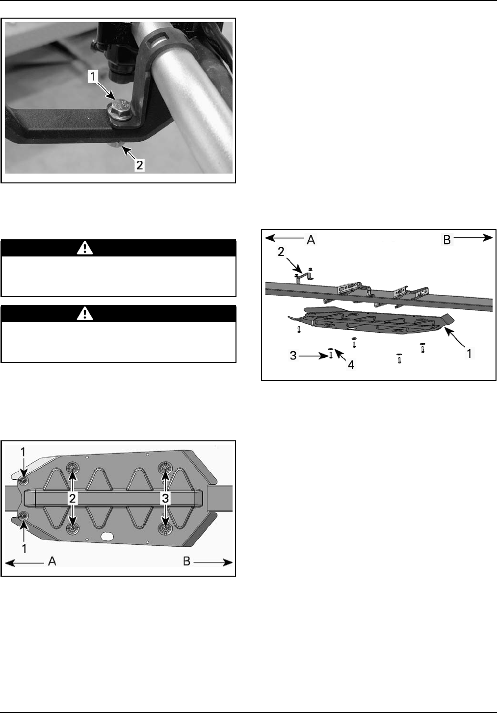
Central Skid Plate
X Models
1. Put skid plate in place.
vsi2008-020-007_b
A. Front of vehicle
B. Rear of vehicle
1. Front holes
2. Middle holes
3. Rear holes
2. Place skid plate bracket on vehicle frame.
3. Align skid plate front holes with skid plate
bracket holes.
4. Assemble skid plate using front M8 retaining
bolts and M8 nuts.
5. Do not tighten front bolts for the moment.
6. Align M8 U-nuts with skid plate middle holes.
7. Insert M8 U-nuts on vehicle frame.
8. Assemble skid plate using middle M8 retaining
bolts, M8 flat washers and M8 U-nuts.
9. Do not tighten middle bolts for the moment.
10. Align M8 U-nuts with skid plate rear holes.
11. Insert M8 U-nuts on vehicle frame.
12. Assemble skid plate using rear M8 retaining
bolts, M8 flat washers and M8 U-nuts.
NOTE: Washers must be installed between retain-
ing bolts and skid plate.
13. Torque all M8 retaining bolts to 11 N•m
(97 lbf•in).
vbl2008-005-500_b
A. Front of vehicle
B. Rear of vehicle
1. Skid plate
2. Skid plate bracket
3. M8 retaining bolt
4. M8 flat washer
FLUIDS
General Guidelines
All fluids (except fuel) have already been filled at
factory, it is only necessary to validate them. How-
ever, if refill is needed, refer to the appropriate
ATV
SHOP MANUAL
for the proper procedure.
Fuel
1. Add a small amount of fuel in the fuel reservoir.
Recommended Fuel
Use regular unleaded gasoline or gasohol contain-
ing less than 10% of ethanol or methanol, available
from most service stations.
Refer to the following table for recommended
minimum octane number:
12 / 34 2009-2 PREDELIVERY
sales@midwestmanuals.com
sales@midwestmanuals.com
FLUIDS
LOCATION MINIMUM OCTANE NUMBER
North America 87 (RON + MON) / 2
Elsewhere 92 RON
WARNING
Always stop engine before refueling. Open
cap slowly. If a differential pressure condi-
tion is noticed (whistling sound heard when
loosening fuel tank cap) have vehicle inspect-
ed and/or repaired before further operation.
Fuel is flammable and explosive under cer-
tain conditions. Never use an open flame
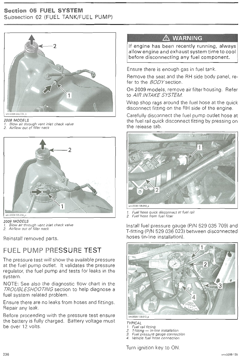
to check fuel level. Never smoke or allow
flame or spark in vicinity. Always work in a
well-ventilated area. Never top up the fu-
el tank before placing the vehicle in a warm
area. As temperature increases, fuel expands
and may overflow. Always wipe off any fuel
or oil spillage from the vehicle.
NOTICE Never place anything over fuel tank
cap as this could block the vent hole, leading to
engine misfire.
NOTICE Never experiment with other fuels.
The use of non-recommended fuels can re-
sult in vehicle performance deterioration and
damage to critical parts in the fuel system and
engine components.
NOTICE Never mix oil with fuel, these vehicles
are equipped with a 4-stroke engine.
Engine Oil
NOTICE Do not overfill. Operating the engine
with an improper oil level may severely dam-
age engine. Wipe off any oil spillage.
Recommended Engine Oil
Use a 5W 30 4-stroke engine oil that meets or
exceeds the requirements for API service clas-
sification SM, SL or SJ. Refer to label on the oil
container.
The XP-S 5W 30 4-stroke oil (P/N 219 700 706) is
recommended for all seasons.
For improved overall performance and all season
application, use XP-S 5W40 synthetic oil (P/N 293
600 039).
NOTE: For Outlander 400 series, the same oil lubri-
cates both engine and transmission.
NOTE: Other viscosity should be used if the av-
erage temperature is outside the range of the
recommended oil. Refer to the following table.
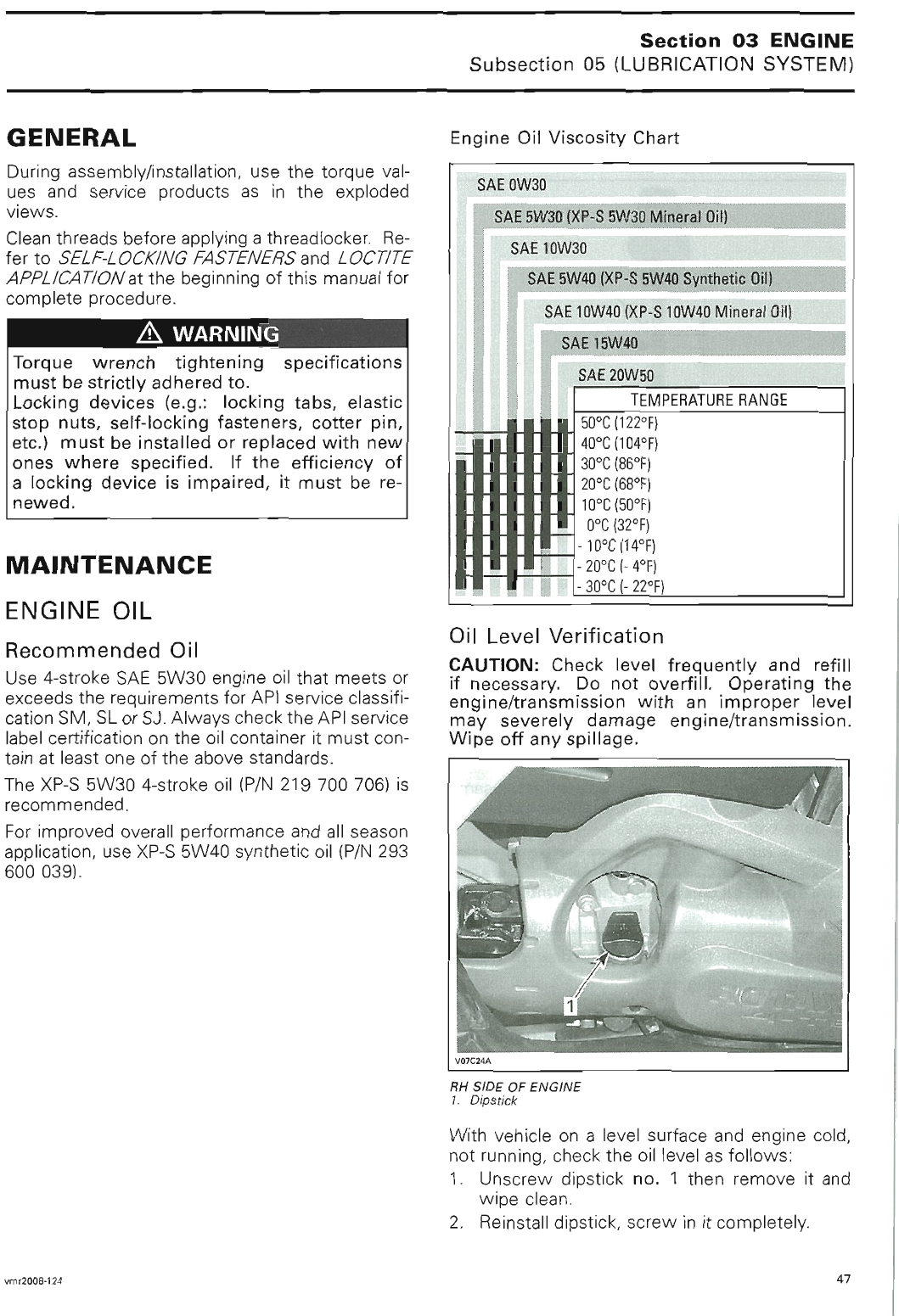
XP-S 5W40 Synthetic Oil (P/N 293 600 039)
XP-S 5W30 Mineral Oil (P/N 219 700 706)
XP-S 10W40 Mineral Oil (P/N 219 700 346)
Temperature Range
50°C (122°F)
40°C (104°F)
30°C (86°F)
20°C (68°F)
10°C (50°F)
0°C (32°F)
-10°C (14°F)
-20°C (- 4°F)
-30°C (- 22°F)
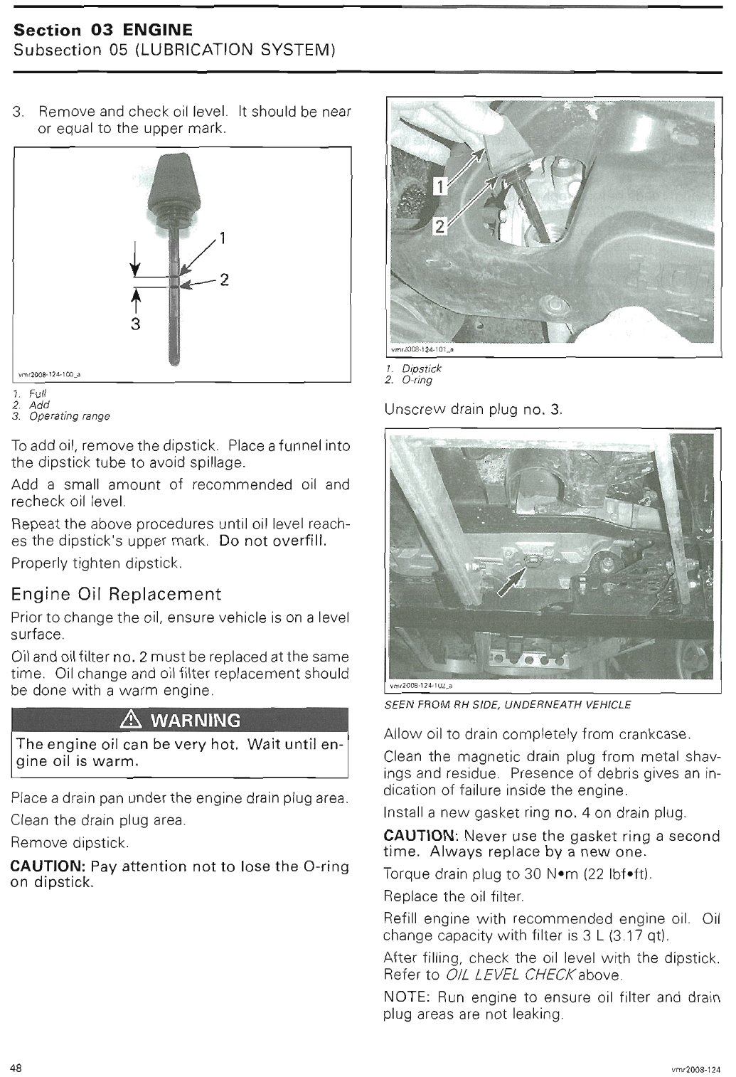
Engine Oil Level Verification
1. Ensure that engine is cold and not running.
2. Park vehicle straight on a level surface.
3. Unscrew and remove oil dipstick.
vmo2008-019-015_a
TYPICAL - RH SIDE OF ENGINE
1. Oil Dipstick
4. Wipe dipstick.
5. Reinstall and screw in the dipstick completely.
6. Unscrew and remove the dipstick.
7. Check oil level as per the following illustration.
PREDELIVERY 2009-2 13 / 34
sales@midwestmanuals.com
sales@midwestmanuals.com
FLUIDS
31
2
OIL DIPSTICK
1. Full
2. Add
3. Operating Range
8. Ensure that oil level is between ADD and FULL
marks.
9. If necessary, add recommended engine oil.
10. Reinstall and screw in the dipstick completely.
Gearbox Oil
NOTICE Do not overfill. Operating the gear-
box with an improper level may severely dam-
age gearbox. Wipe off any oil spillage.
NOTICE Do not use non recommended types
of oil when servicing. Do not mix with other
types of oil.
NOTE: For Outlander 400 series, the same oil lu-
bricates both engine and transmission. Refer to
ENGINE OIL
.
Recommended Gearbox Oil
Use XP-S chaincase oil (P/N 413 801 900).
Gearbox Oil Level Verification
1. Park vehicle straight on a level surface.
2. Select transmission lever to NEUTRAL posi-
tion.
3. Apply parking brake.
4. Check oil level by removing the gearbox oil lev-
el plug.
vmo2006-007-018_b
1. Oil level plug
5. Ensure that gearbox oil is level with the bottom
of the oil plug hole.
6. If necessary, add recommended gearbox oil.
7. Reinstall and screw in the gearbox oil level
plug.
Engine Coolant
WARNING
Check coolant level with engine cold. Never
add coolant in cooling system when engine is
hot.
NOTICE Do not overfill coolant reservoir.
Recommended Coolant
Always use ethylene-glycol antifreeze containing
corrosion inhibitors specifically for internal com-
bustion aluminum engines.
Cooling system must be filled with water and an-
tifreeze solution (50% water, 50% antifreeze) or
with BRP premixed coolant (P/N 219 700 362).
Coolant Level Verification
NOTICE Do not overfill coolant reservoir.
1. Park vehicle straight on a level surface.
2. Remove front service compartment panel.
3. Check that radiator is filled with coolant by re-
moving the radiator cap.
4. If necessary, add recommended coolant.
5. Reinstall radiator cap.
14 / 34 2009-2 PREDELIVERY
sales@midwestmanuals.com
sales@midwestmanuals.com
FLUIDS
vbl2009-002-101_a
OUTLANDER SERVICE COMPARTMENT
1. Radiator cap
2. Coolant reservoir cap
vbl2009-002-103_a
RENEGADE SERVICE COMPARTMENT
1. Radiator cap
2. Coolant reservoir cap
6. From underneath LH front fender, remove
plastic cover.
7. Check the coolant reservoir level.
8. Ensure that fluid is between MIN. and MAX
marks.
vmo2008-019-013_a
TYPICAL - UNDERNEATH LH FRONT FENDER
1. Coolant reservoir
2. MAX. level mark
3. MIN. level mark
9. If necessary, add recommended coolant.
10. Reinstall plastic cover
11. Reinstall front service compartment panel.
NOTE: When checking level at temperature low-
er than 20°C (69°F), it may be slightly lower than
MIN. mark.
Brake Fluid
NOTICE To avoid serious damage to the brak-
ing system, do not use fluids other than the
recommended one, nor mix different fluids for
topping up.
NOTICE Be sure to clean reservoir caps before
removing it to avoid contaminating the oil.
NOTICE Be careful not to damage the di-
aphragm while removing and installing han-
dlebar reservoir caps.
NOTICE Do not overfill brake fluid reservoir.
Recommended Fluid
Always use brake fluid meeting the specification
DOT 4, from a sealed container.
Brake Lever Fluid Level Verification
1. Park vehicle straight on a level surface.
2. Turn steering in the straight-ahead position to
ensure reservoir is level.
vmo2006-016-004_a
TYPICAL
3. Check brake fluid level in reservoir.
PREDELIVERY 2009-2 15 / 34
sales@midwestmanuals.com
sales@midwestmanuals.com
FLUIDS
vmo2008-019-016_a
1. MIN. mark
2. MAX. mark
4. Ensure that fluid reaches top of window.
5. If necessary, add recommended brake fluid.
Brake Pedal Fluid Level Verification
1. Park vehicle straight on a level surface.
2. Remove front service compartment panel.
vbl2009-002-101_b
OUTLANDER SERVICE COMPARTMENT
1. Brake pedal reservoir
vbl2009-002-103_b
RENEGADE SERVICE COMPARTMENT
1. Brake pedal reservoir
3. Check the brake fluid level.
vmo2008-019-017_a
TYPICAL
1. MAX. mark
2. MIN. mark
4. Ensure that fluid is between MIN. and MAX.
marks.
5. If necessary, add recommended brake fluid.
6. Reinstall front service compartment panel.
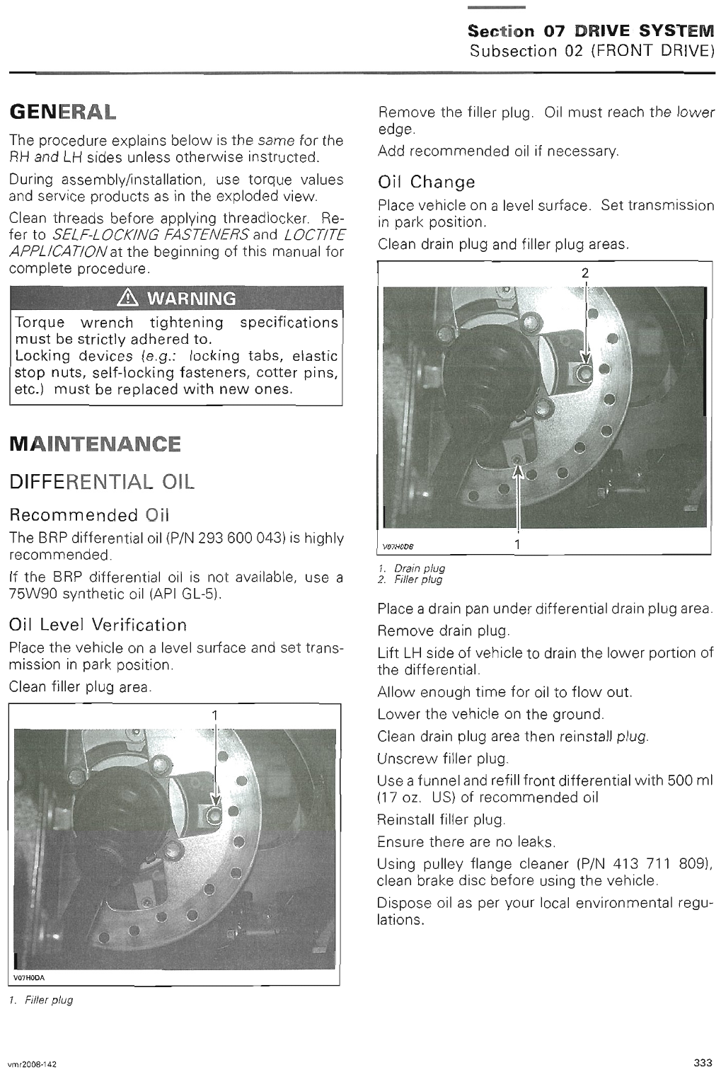
Front and Rear Differential Oil
Recommended Oil
Always use XP-S synthetic gear oil (P/N 293 600
043) or a 75W90 synthetic oil (API GL-5).
Front Differential Oil Level Verification
1. Park vehicle straight on a level surface.
2. Clean filler plug.
3. Remove filler plug.
4. Check front differential oil level.
5. Ensure that oil reaches the lower edge of filler
hole.
6. If necessary, add recommended oil.
7. Install filler plug then torque to 22 N•m
(16 lbf•ft).
16 / 34 2009-2 PREDELIVERY
sales@midwestmanuals.com
sales@midwestmanuals.com
SET-UP
1
V07H0DA
OUTLANDER SERIES
1. Filler plug
vmr2007-053-003_a
RENEGADE SERIES
1. Filler plug
Rear Differential Oil Level Verification
NOTE: The rear differential oil is not level with the
filler hole.
1. Park vehicle straight on a level surface.
2. Clean filler plug.
3. Remove filler plug.
4. Check rear differential oil level by inserting a
wire with a 90° bend through oil filler hole.
5. Ensure that oil is between 25 to 32 mm (1 to
1-1/4 in) from the bottom of oil filler hole.
6. If necessary, add recommended oil.
7. Install filler plug then torque to 22 N•m
(16 lbf•ft).
V07H26A
1
1. Filler plug
V07H28A
A
1
2
TYPICAL
A. 25 to 32 mm (1 to 1-1/4 in)
1. Filler plug
2. Oil level
SET-UP
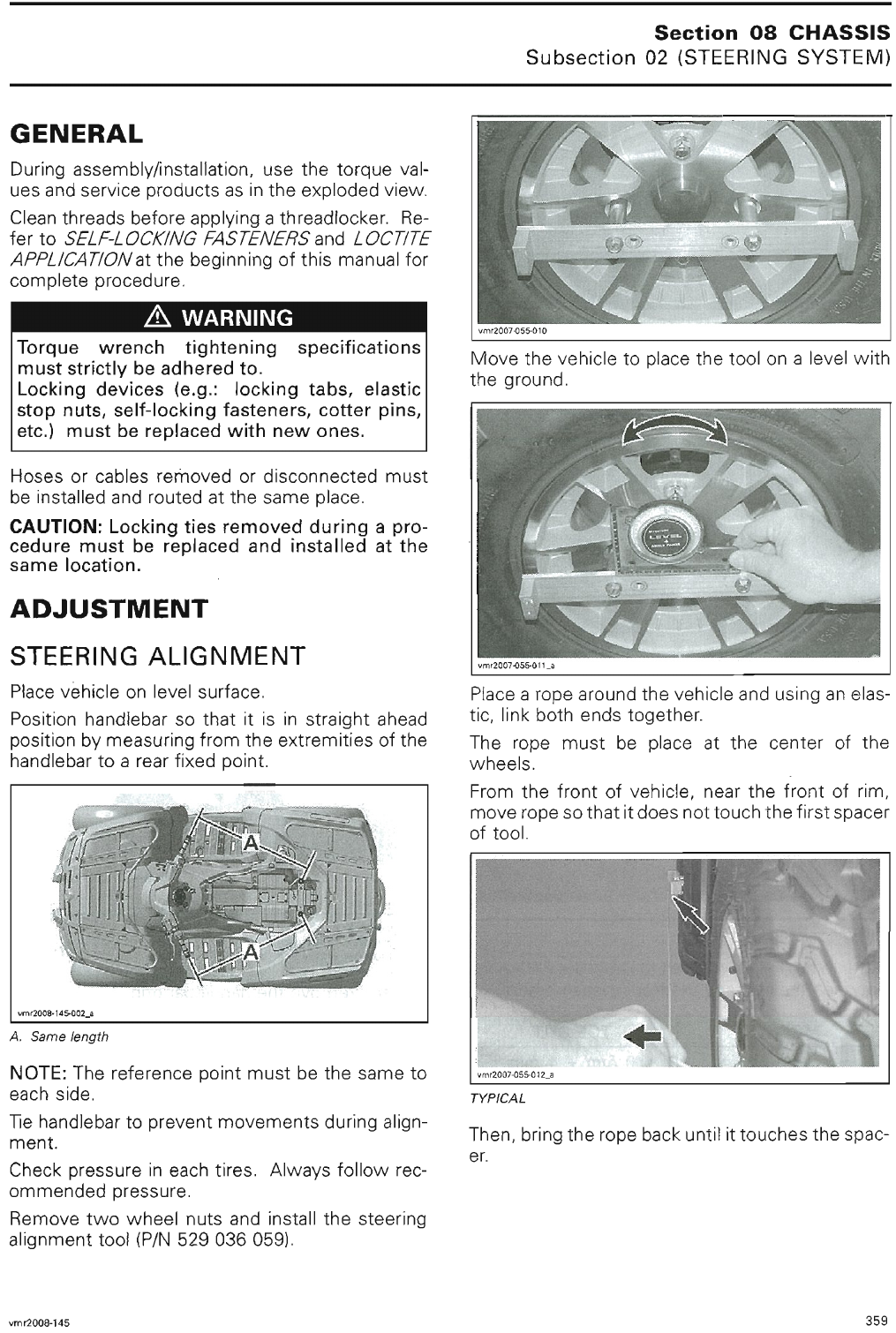
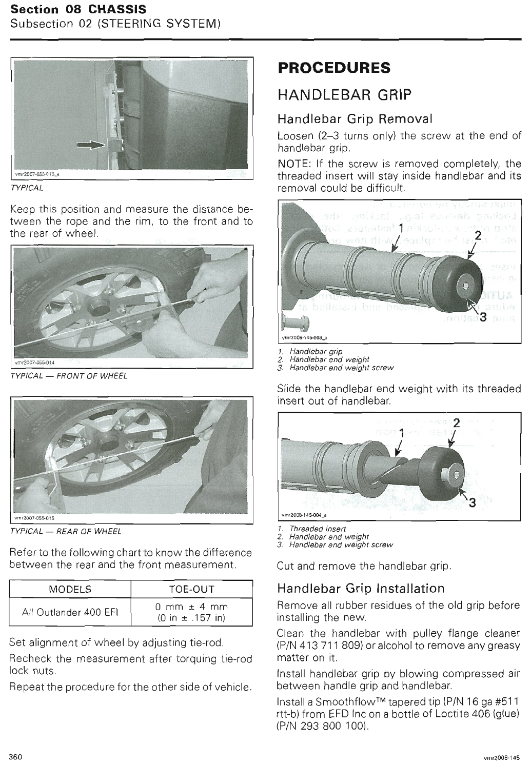
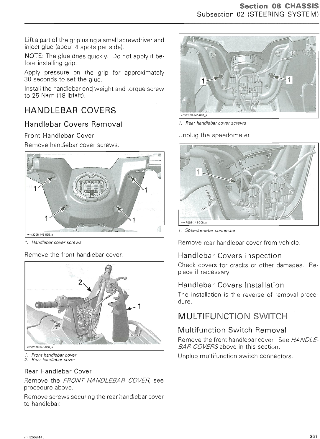
Tires Pressure
NOTICE For transportation purpose, tires are
deflated at the factory, make sure to inflate
them at the recommended air pressure before
riding the vehicle.
NOTICE Always check pressure when tires are
cold.
PREDELIVERY 2009-2 17 / 34
sales@midwestmanuals.com
sales@midwestmanuals.com
ADJUSTMENTS
WARNING
Low pressure may cause tire to deflate and
rotate on wheel. Overpressure may burst the
tire. Always follow recommended pressure.
Since tires are low-pressure type, a manual
pump should be used.
NOTE: Tire pressure varies with temperature and
altitude.
NOTE: A pressure gauge is supplied in the tool kit.
1. Inflate tires to the specified air pressure. Refer
to the following table.
RECOMMENDED AIR PRESSURE
FRONT REAR
Maximum 34.5 kPa (5 PSI) 34.5 kPa (5 PSI)Outlander
400 Series Minimum 31 kPa (4.5 PSI) 31 kPa (4.5 PSI)
Maximum 34.5 kPa (5 PSI) 34.5 kPa (5 PSI)Outlander
MAX 400
Series Minimum 31 kPa (4.5 PSI) 31 kPa (4.5 PSI)
Maximum 34.5 kPa (5 PSI) 34.5 kPa (5 PSI)Outlander
500 Series Minimum 31 kPa (4.5 PSI) 31 kPa (4.5 PSI)
Maximum 34.5 kPa (5 PSI) 34.5 kPa (5 PSI)Outlander
MAX 500
Series Minimum 31 kPa (4.5 PSI) 31 kPa (4.5PSI)
Maximum 48.3 kPa (7 PSI) 48.3 kPa (7 PSI)Outlander
650 / 800R
Series Minimum 31 kPa (4.5 PSI) 31 kPa (4.5 PSI)
Maximum 48.3 kPa (7 PSI) 48.3 kPa (7 PSI)Outlander
MAX 650 /
800R Series Minimum 31 kPa (4.5 PSI) 34.5 kPa (5 PSI)
Maximum 48.3 kPa (7 PSI) 48.3 kPa (7 PSI)
Renegade
Series Minimum 34.5 kPa (5 PSI) 37.9 kPa (5.5 PSI)
BrakeDiskCleanup
1. Clean front and rear brake discs using pulley
flange cleaner (P/N 413 711 809).
NOTICE A thin layer of anticorrosion product
can be present on the brake disc and must be
removed before using the vehicle. Not con-
forming to this procedure may lead to a brake
chattering and the brake pads replacement
would be necessary to solve the problem.
Protective Materials
1. Ensure that all protective materials are re-
moved from vehicle.
ADJUSTMENTS
General Guidelines
All adjustments have already been performed
at factory, it is only necessary to validate them.
However, if readjustment is needed, refer to the
appropriate
ATVSHOPMANUAL
for the proper
procedure.
Transmission Lever
1. Verify that transmission lever works properly
and adjust if required.
vmo2006-007-007
TYPICAL - TRANSMISSION LEVER
Suspension
WARNING
Left and right adjusting cams must always
be set at the same position. Never adjust
one adjusting cam only. Uneven adjustment
can cause poor handling and loss of stability,
which couldleadtoanaccident.
NOTE: The front suspension of Outlander 400 se-
ries and Outlander 500 series are not adjustable.
Front and Rear Suspension
1. Adjust the spring preload as per the owner’s
preference.
2. Refer to the following table for proper adjust-
ment.
18 / 34 2009-2 PREDELIVERY
sales@midwestmanuals.com
sales@midwestmanuals.com
ADJUSTMENTS
ACTION SPRING
LENGTH RIDE
TYPE ROAD
CONDITION
Turn adjusting
cam clockwise Shorten
the spring Firmer
ride Rough road
condition
Turn
adjusting cam
counterclockwise
Lengthen
the spring Softer
ride Smooth
road
condition
It is recommended to shorten the spring length
when carrying cargo or pulling a trailer.
213
TYPICAL
1. Adjusting cam
2. Lengthen the spring
3. Shorten thespring
X Package Model
3. Adjust the suspension as per the owner’s pref-
erence.
4. Refer to the following table for proper adjust-
ment.
ADJUSTMENT ACTION RIDE TYPE
Shorten the
spring Firmer ride
Spring Preload Lengthen the
spring Softer ride
Turning it
clockwise
(H)
Stiffer (increases
shock damping
action)
Low Speed
Compression Turning it
counterclockwise
(S)
Softer (decreases
shock damping
action)
Turning it
clockwise
(H)
Stiffer (increases
shock damping
action)
High Speed
Compression Turning it
counterclockwise
(S)
Softer (decreases
shock damping
action)
Turning it
clockwise
(H)
Stiffer (increases
shock damping
action)
Rebound Turning it
counterclockwise
(S)
Softer (decreases
shock damping
action)
vmo2008-021-003_a
PRELOAD ADJUSTMENT
Step 1: Loosen top locking ring
Step 2: Turn adjusting ring accordingly
Step 3: Tighten top locking ring
vmo2008-021-004_a
COMPRESSION - LOW SPEED
1. Compression adjuster (flat screwdriver)
PREDELIVERY 2009-2 19 / 34
sales@midwestmanuals.com
sales@midwestmanuals.com
ADJUSTMENTS
vmo2008-021-004_b
COMPRESSION - HIGH SPEED
1. Compression adjuster (17 mm wrench)
vmo2008-021-005_a
REBOUND
1. Rebound adjuster (flat screwdriver)
Brake Pedal and Lever
1. Ensure that brake pedal and brake lever (s) are
not spongy.
B.U.D.S. Programming
Connecting a PC to Vehicle
1. Connect the PC to vehicle. Refer to the latest
edition of
CAN-AM ATV B.U.D.S. SOFTWARE
AND COMMUNICATION TOOLS
for the prop-
er connecting procedure.
2. Ensure that the status bar shows the proper
protocol and the number 2 is displayed.
3. Press the READ DATA button from the tool bar
to initiate communication with the vehicle.
Entering Customer's Name
NOTE: When starting the vehicle, the multifunc-
tion display will show the name of the customer;
for example: “HI JOHN SMITH”. If the cus-
tomer's name is not programmed, only “HI” will
be visible when turning the vehicle ON.
1. Click on the VEHICLE tab to open the vehicle
information page.
vbl2006-007-001
VEHICLE TAB
2. Type the name of the customer.
vbl2006-007-002
3. Click on WRITE DATA to save the information
in the vehicle’s ECM.
NOTE: After you are finished typing the name,
B.U.D.S. automatically updates the Delivery Date
on the screen.
ResettingTripHoursandTripDistance
1. Ensure that the VEHICLE tab is selected.
2. Click on the RESET TRIP buttons to reset the
information.
20 / 34 2009-2 PREDELIVERY
sales@midwestmanuals.com
sales@midwestmanuals.com
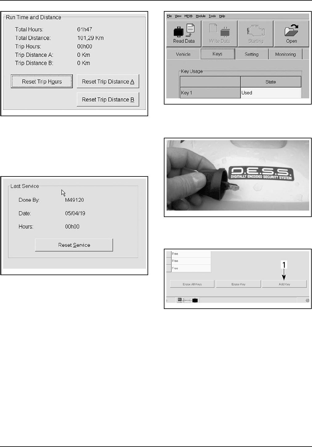
ADJUSTMENTS
vbl2008-007-001
RESET TRIP BUTTONS
NOTE: It can also be done directly on the info-cen-
ter, using the selector button.
Resetting Last Service
1. Click on the RESET SERVICE button to reset
the informations.
vbl2006-007-004
RESET SERVICE BUTTON
After each maintenance service, last service
should be reset to keep a good tracking of the
vehicle service history.
Programing Keys with B.U.D.S.
Outlander 400 series
The Outlander 400 HO EFI does not have DESS,
therefore the key does not have to be pro-
grammed.
All except Outlander 400 series
1. Click on KEYS tab.
smr2005-072-001_en
KEYS TAB
2. Click on ERASE ALL KEYS button.
3. Insert ignition key in the ignition switch.
vdd2006-001-041_a
D.E.S.S IGNITION KEY
4. Turn ignition switch to any ON position.
5. Click on ADD KEY button.
smr2005-072-003_Aen
1. Add Key Button
6. Repeat to program more keys.
7. Click on WRITE DATA to save the information
in the vehicle’s ECM.
Speedometer Reading
The speedometer is factory preset in miles but it
is possible to change it to kilometer reading. Any
unit modification is applied to the speedometer,
odometer and trip meter.
1. Select SETTING tab in B.U.D.S.
2. Select Miles or Kilometers from the CLUSTER
SCALE section.
NOTE: No data will be lost when changing this set-
ting.
PREDELIVERY 2009-2 21 / 34
sales@midwestmanuals.com
sales@midwestmanuals.com
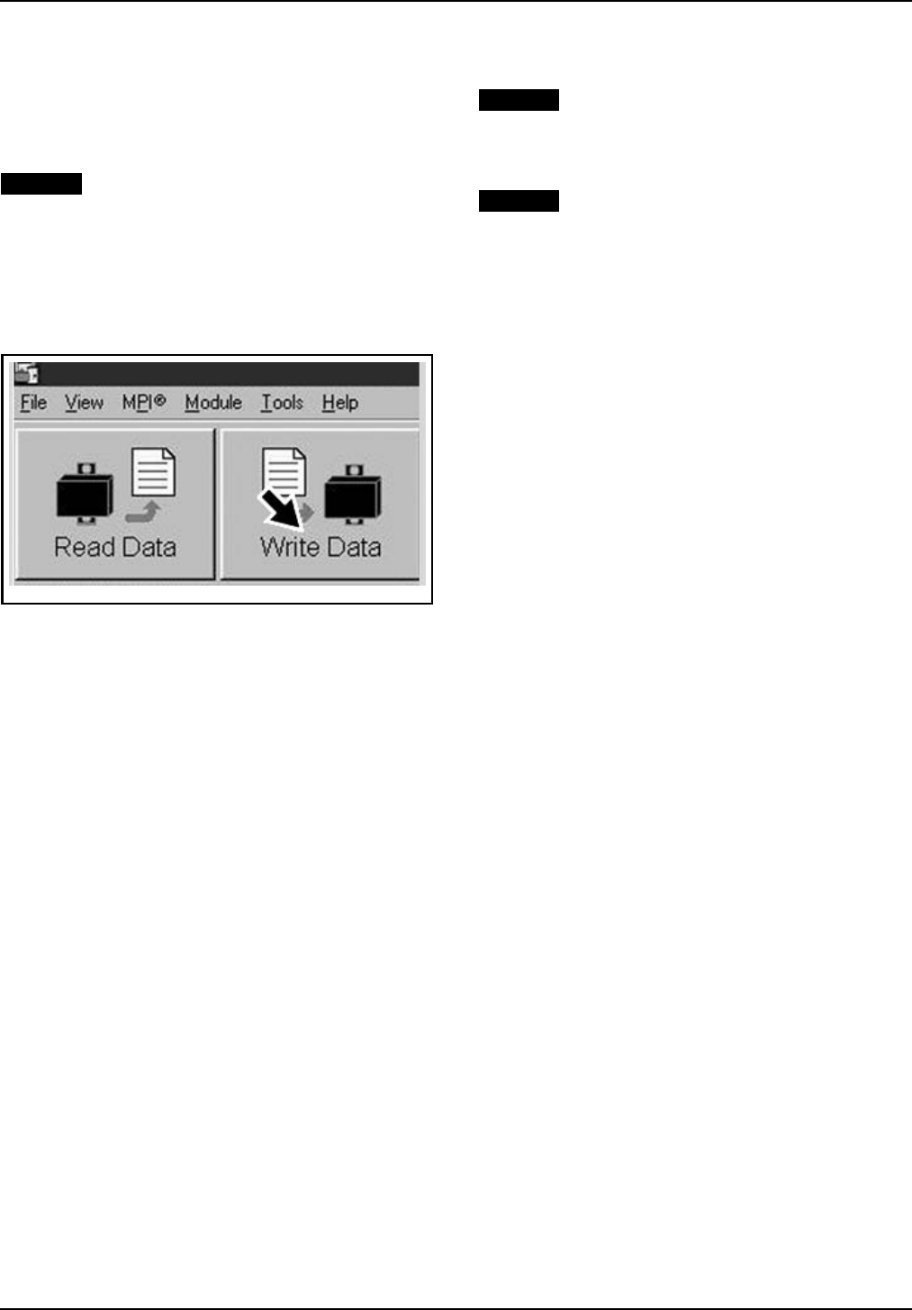
FINAL INSPECTION
Ending a B.U.D.S. Session
1. Click on FAULT tab and check if there are active
faults.
– If so, service vehicle then clear the faults in
B.U.D.S.
NOTICE After a problem has been solved, en-
sure to clear the fault(s) in the ECM. This will
properly reset the appropriate counter(s). This
will also records that the problem has been
fixed in the MPEM memory.
2. Click on WRITE DATA button to transfer new
settings and information to the ECM.
vmr2006-012-100_ben
WRITE DATABUTTON
3. Click on EXIT button to end session.
4. Disconnect all cables and hardware from vehi-
cle.
5. Ensure to reinstall the cap over the vehicle’s
communication connector.
ASSEMBLY INSPECTION
Inspect the following parts to make sure that the
vehicle is properly assembled.
1. Handlebar tightness
2. Wheel nut torque
3. Tubes/hoses routing and condition
4. Steering column cotter pin
5. Suspension arm ball joint cotter pins
6. Tie rod end nuts and cotter pins
7. Wheel nuts and cotter pins
8. Complete applicable recall or factory-directed
modification.
FINAL INSPECTION
Vehicle Test Run
1. Ride the vehicle to ensure proper operation of
all systems and components.
Vehicle Cleaning
NOTICE Never use a high pressure washer to
clean the vehicle. USE LOW PRESSURE ONLY
(like a garden hose). The high pressure can
cause electrical or mechanical damages.
NOTICE It is necessary to use flannel clothes
on plastic parts to avoid damaging surfaces.
Never clean plastic parts with strong detergent,
degreasing agent, paint thinner, acetone, prod-
ucts containing chlorine, etc.
1. Wash and dry the vehicle.
2. Remove any dirt.
3. Clean vinyl and / or plastic parts, using flan-
nel clothes with BRP Vinyl & Plastic Cleaner
(P/N 413 711 200).
4. Clean the entire vehicle, including metallic
parts, with BRP Cleaner (P/N 293 110 001) (400
g).
Delivery To Customer
1. Complete the
PREDELIVERY CHECK LIST
.
2. Give
OPERATOR’S GUIDE
and
SAFETY DVD
to customer.
NOTE: The customer must read and sign the
PRE-
DELIVERY CHECK LIST
.
NOTE: Hang tag is to be removed by the owner
only.
NOTE: Any person who rides this vehicle should
read and understand all the information given on
hang tag and safety labels before riding.
22 / 34 2009-2 PREDELIVERY
sales@midwestmanuals.com
sales@midwestmanuals.com
TECHNICAL DATA
TECHNICAL DATA
Outlander 400 series
MODEL OUTLANDER 400 EFI
ENGINE
Engine type ROTAX 400, 4-stroke, Single Over
Head Camshaft (SOHC), liquid cooled
Number of cylinder 1
Number of valves 4 valves (mechanical adjustment)
Bore mm (in) 91 (3.58)
Stroke mm (in) 61.5 (2.42)
Displacement 400 cm³ (24.41 in³)
Compression ratio 10.3:1
Decompressor type Automatic
Maximum HP RPM RPM 7500
Type Wet sump with replaceable oil filter
Oil filter BRP ROTAX paper type, replaceable
Capacity
(oil change with filter) 3 L (3.17 quarts)
(engine/transmission)
Lubrication
Engine oil
Recommended SAE 5W 30 API
classification SM, SL or SJ
see
RECOMMENDED ENGINE OIL
Exhaust system Spark arrestor approved by USDA
Forest Service
Air filter Synthetic paper filter with foam
COOLING SYSTEM
Type
Ethyl glycol/water mix
(50% coolant, 50% water).
Use premixed coolant sold
by BRP (P/N 219 700 362) or
coolant specifically designed for
aluminum engines
Coolant
Capacity 2.5 L (2.65 quarts)
PREDELIVERY 2009-2 23 / 34
sales@midwestmanuals.com
sales@midwestmanuals.com
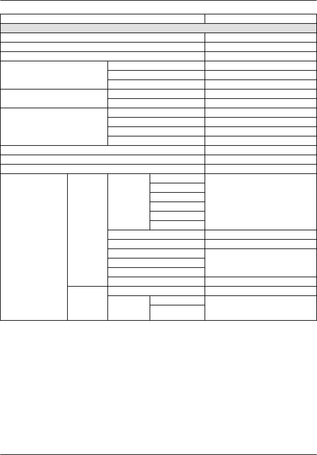
TECHNICAL DATA
MODEL OUTLANDER 400 EFI
ELECTRICAL SYSTEM
Magneto generator output 400 W @ 6000 RPM
Ignition system type CDI (Capacity Discharge ignition)
Ignition timing Not adjustable
Quantity 1
Make and type NGK DCPR8E
Spark plug
Gap 0.6to0.7mm(.024to.027in)
Forward RPM 8000
Engine RPM limiter setting Reverse RPM 4000 ± 100
Type Dry battery type
Voltage 12 volts
Nominal rating 18 A•h
Battery
Power starter output 0.7 KW
Headlight W 2 x 35
Taillight/Brake light W 8/27
Turn signal lights W 10
Aux. supply
Diagnostic
Headlight
Power outlet
Winch (XT)
Access.
4x4
20 A (F6)
ECM 5A(F1)and7.5A(F3)
Fuel pump 7.5 A (F5)
Gauge
Tail light
Diagnostic
7.5 A (F4)
Fuse box
Fan 20 A (F2)
Main 30 A
Fan
Fuses
Rear
fuse holder Access. Acc. items in fuse
box
30 A
24 / 34 2009-2 PREDELIVERY
sales@midwestmanuals.com
sales@midwestmanuals.com
TECHNICAL DATA
MODEL OUTLANDER 400 EFI
FUEL SYSTEM
Fuel delivery Type Electronic Fuel Injection (EFI), Del' Orto
46 mm throttle body, 1 injector
Fuel pump Type Electrical (in fuel tank)
Idle speed RPM ± 50 1300 (Not adjustable)
Type Unleaded gasoline
Inside North
America (R+M)/2 87 or higher
Fuel Octane no. Outside
North
America RON 92 or higher
Fuel tank capacity 20 L (5.3 U.S. gal)
Fuel tank reserve ±6L(1.6U.S
.gal)
CVT TRANSMISSION
Type CVT (Continuously Variable
Transmission)
Engagement RPM ± 100 RPM 1450
GEARBOX
Type Dual range (HI-LO) with park,
neutral and reverse
DRIVE SYSTEM
Front differential Shaft driven/auto-lock differential
(Visco-Lok)
Front differential ratio 3.6:1
Rear axle Shaft driven/
locked differential
Rear axle ratio 3.6:1
Front 500 mL (17 U.S. oz)
Capacity Rear 250mL(8.5U.S.oz)
Differential oil
Recommended BRP differential oil (P/N 293 600 043) or
synthetic oil 75W 90 (API GL5)
CV joint grease CV joint grease
(P/N 293 550 019)
Propeller shaft grease XP-S synthetic grease
(P/N 293 550 010)
STEERING SYSTEM
Turning radius m (ft) 1.83 (6)
Turning radius (MAX) m (ft) 2.0 (6.6)
Total toe (vehicle on ground) mm (in) 0 ± 4 (0 ± .157)
FRONT SUSPENSION
Suspension type MacPherson
Suspension travel mm (in) 178 (7)
Front preload adjustment N.A.
PREDELIVERY 2009-2 25 / 34
sales@midwestmanuals.com
sales@midwestmanuals.com
TECHNICAL DATA
MODEL OUTLANDER 400 EFI
REAR SUSPENSION
Suspension type TTI™ independent
Suspension travel mm (in) 203 (8)
Qty 2
Shock absorber Type Oil
Rear preload adjustment 5 settings
BRAKES
Front brake Type Hydraulic, 2 discs
Rear brake Type Hydraulic, 1 disc
Capacity 125mL(4.3U.S.oz)
Brake fluid Type DOT 4
Parking brake Hydraulic lock-4 wheels
Front Organic
Brake pad material Rear Metallic
Minimum pad thickness mm (in) 1 (.04)
Front mm (in) 3.5 (.138)
Minimum brake disc thickness Rear mm (in) 4.3 (.17)
Maximum brake disc warpage mm (in) 0.2 (.01)
TIRES
Max. 34.5 kPa (5 PSI)
Front Min. 31 kPa (4.5 PSI)
Max. 34.5 kPa (5 PSI)
Pressure
Rear Min. 31 kPa (4.5 PSI)
Minimum tire thread depth mm (in) 3 (1/8)
Front 25 x 8 x 12
Size Rear 25 x 10 x 12
XT: 25 x 11 x 12
WHEELS
Front 12 x 6
Size Rear 12 x 7.5
Standard 70 N•m (52 lbf•ft)
Wheel nuts torque XT 100N•m(74lbf•ft)
DIMENSION
Overall length m (in) 2.18 (86)
Overall length (MAX) m (in) 2.39 (94)
Overall width m (in) 1.17 (46)
Overall height m (in) 1.14 (45)
Wheelbase m (in) 1.24 (49)
Wheelbase (MAX) m (in) 1.45 (57)
Front mm (in) 965 (38)
Wheel track Rear mm (in) 914 (36)
Ground clearance mm (in) 236 (9.3)
26 / 34 2009-2 PREDELIVERY
sales@midwestmanuals.com
sales@midwestmanuals.com
TECHNICAL DATA
MODEL OUTLANDER 400 EFI
LOADING CAPACITY
Weight distribution Front/rear % 49/51
Weight distribution (MAX) Front/rear % 46/54
Rear storage box
(included with rear rack weight) kg (lb) 10 (22)
Front kg (lb) 45 (100)
Rack
Rear
(including rear
storage box
and tongue
weight)
kg (lb) 90 (200)
kg (lb) 227 (500)
Total vehicle load allowed (including
driver, all other loads and added
accessories) (MAX) kg (lb) 235 (517)
kg (lb) 460 (1014)
Gross vehicle weight rating (MAX) kg (lb) 554 (1219)
Towing capacity kg (lb) 500 (1100)
Tongue capacity
(included with rear rack weight) kg (lb) 14 (30)
Outlander 500-650-800R series
MODEL OUTLANDER 500
EFI OUTLANDER
650 EFI OUTLANDER
800R EFI
ENGINE
ROTAX®V490 ROTAX V660 ROTAX V810
Engine type 4-stroke, Single Over Head Camshaft (SOHC), liquid cooled
Number of cylinders 2
Number of valves 8 valves (mechanical adjustment)
Bore mm (in) 82.03 (3.23) 91 (3.58)
Stroke mm (in) 47.3 (1.86) 61.5 (2.42)
Displacement 500 cm³
(30.51 in³)
650 cm³
(39.67 in³)
800 cm³
(48.82 in³)
Compression ratio 10.7:1 10.3:1 10.3:1
Maximum HP RPM RPM 7250 6750
Type Wet sump. Replaceable oil filter
Oil filter BRP Rotax paper type, replaceable
Capacity
(oil change with filter) 2 L (2.11 quarts)
Lubrication
Engine oil
Recommended SAE 5W30 API classification SM, SL or SJ
See
OIL VISCOSITY CHART
Exhaust system Spark arrestor approved by USDA Forest Service
Air filter Synthetic paper filter with foam
COOLING SYSTEM
Type
Ethyl glycol/water mix (50% coolant, 50% water).
Use premixed coolant sold by BRP
(P/N 219 700 362) or coolant specifically designed
for aluminum engines
Coolant
Capacity 2.5 L (2.65 quarts)
PREDELIVERY 2009-2 27 / 34
sales@midwestmanuals.com
sales@midwestmanuals.com

TECHNICAL DATA
MODEL OUTLANDER 500
EFI OUTLANDER
650 EFI OUTLANDER
800R EFI
ELECTRICAL SYSTEM
Magneto generator output 400 W @ 6000 RPM
Ignition system type IDI (Inductive Discharge Ignition)
Ignition timing Not adjustable
Quantity 2
Make and type NGK DCPR8ESpark plug
Gap 0.6 to 0.7 mm (.024 to .027 in)
Forward RPM 8000
Engine RPM limiter setting Reverse RPM 3200
Type Dry battery type
Voltage 12 volts
Nominal rating 18 A•h
Battery
Power starter output 0.7 KW
Headlight W 2x35
Taillight W 7/29
Director indicator
(European models only) W10
Indicator lights LEDS, 0.7 V approximately (each)
Accessories 20 A
Fan 20 A
Main (rear) 30 A
Ignition coils 5 A
Fuel injectors 5 A
Speedometer/speed sensor/tail
light 7.5 A
Fuel pump 7.5 A
Engine control module (ECM) 5 A
Fuses
Main accessories (rear) 30 A
28 / 34 2009-2 PREDELIVERY
sales@midwestmanuals.com
sales@midwestmanuals.com
TECHNICAL DATA
MODEL OUTLANDER 500
EFI OUTLANDER
650 EFI OUTLANDER
800R EFI
FUEL SYSTEM
Fuel delivery Type Electronic Fuel Injection (EFI), DeLorto 46 mm throttle
body, 1 injector per cylinder
Type Electrical (in fuel tank)
Fuel pump Model Bosch
Idle speed RPM ± 50 1250 (not adjustable)
Type Regular unleaded gasoline
Inside North
America (R+M)/2 87 or higher
Fuel Octane no. Outside North
America RON 92 or higher
Fuel tank capacity 20 L (5.3 U.S. gal)
Remaining fuel in fuel tank when display light turns ON ± 6 L (1.6 U.S. gal)
TRANSMISSION
Type CVT (Continuously Variable Transmission)
Engagement RPM ± 100 RPM 1750
GEARBOX
Type Dual range (HI-LO) with park, neutral and reverse
Capacity 400 ml (14 U.S. oz)
Gearbox oil Recommended XP-S chaincase oil
DRIVE SYSTEM
Front drive Shaft driven/Auto-lock differential (shear pump)
Front drive ratio 3.6:1
Rear drive Shaft driven/locked differential
Rear drive ratio 3.6:1
Front 500 ml (17 U.S. oz)
Capacity Rear 250 ml (8.5 U.S. oz)
Differential oil
Recommended BRP differential oil (P/N 293 600 043) or
synthetic oil 75W90 (API GL5)
CV joint grease CV joint grease (P/N 293 550 019)
Propeller shaft grease Suspension synthetic grease (P/N 293 550 033)
STEERING
Turning radius 2.16 m (7 ft)
Turning radius (MAX) 2.4 m (7 ft 9 in)
Total toe (vehicle on ground) mm (in) 0 (0)
FRONT SUSPENSION
Suspension type MacPherson Double A-Arm
Suspension travel mm (in) 178 (7) 203 (8)
Qty 2
Shock absorber Type Oil
Preload adjustment N.A. 5 settings
PREDELIVERY 2009-2 29 / 34
sales@midwestmanuals.com
sales@midwestmanuals.com
TECHNICAL DATA
MODEL OUTLANDER 500
EFI OUTLANDER
650 EFI OUTLANDER
800R EFI
REAR SUSPENSION
Suspension type TTI™ independent
Suspension travel mm (in) 229 (9)
Qty 2
Shock absorber Type Oil
Preload adjustment 5 settings
BRAKES
Qty 2
Front brake Type Hydraulic, 2 discs
Qty 1
Rear brake Type Hydraulic, single disc
Capacity 180 ml (6.1 U.S. oz)
Brake fluid Type DOT 4
Parking brake Hydraulic lock-4 wheels
Caliper Floating
Front Organic
Brake pad material Rear Metallic
Minimum brake pad thickness mm (in) 1 (.04)
Front mm (in) 3.5 (.138)
Minimum brake disc thickness Rear mm (in) 4.3 (.17)
Maximum brake disc warpage mm (in) 0.2 (.01)
TIRES
Maximum 34.5 kPa (5 PSI) 48 kPa (7 PSI)
Front Minimum 31 kPa (4.5 PSI) 31 kPa (4.5 PSI)
Maximum 34.5 kPa (5 PSI) 48 kPa (7 PSI)
Rear Minimum 31 kPa (4.5 PSI) 31 kPa (4.5 PSI)
Maximum 34.5 kPa (5 PSI) 48 kPa (7 PSI)
Front (MAX) Minimum 31 kPa (4.5 PSI) 31 kPa (4.5 PSI)
Maximum 34.5 kPa (5 PSI) 48 kPa (7 PSI)
Pressure
Rear (MAX) Minimum 31 kPa (4.5 PSI) 34.5 kPa (5 PSI)
Minimum tire thread depth mm (in) 3 (0.118)
Front 25x8x12 26x8x12
Size Rear
25 x 10 x 12
XT:25x
11 x 12
26 x 10 x 12
WHEELS
Front 12 x 6
Size Rear 12 x 7.5
Standard 70 N•m (52 lbf•ft)
XT 100 N•m (74 lbf•ft)
CAMO XT 70 N•m (52 lbf•ft)
Wheel nuts torque
LTD 70N•m(52lbf•ft)
30 / 34 2009-2 PREDELIVERY
sales@midwestmanuals.com
sales@midwestmanuals.com

TECHNICAL DATA
MODEL OUTLANDER 500
EFI OUTLANDER
650 EFI OUTLANDER
800R EFI
DIMENSION
Overall length m (in) 2.18 (86)
Overall length (MAX) m (in) 2.39 (94)
Overall width m (in) 1.17 (46)
Overall height m (in) 1.14 (45)
Wheelbase m (in) 1.30 (51)
Wheelbase (MAX) m (in) 1.50 (59)
Front mm (in) 965 (38)
Wheel track Rear mm (in) 914 (36)
Ground clearance mm (in) 279 (11)
LOADING CAPACITY
Weight distribution Front/rear % 51/49
Weight distribution (MAX) Front/rear % 48/52
Rear storage box
(included with rear rack weight) kg (lb) 10 (22)
Front kg (lb) 45 (100)
Rack Rear (including rear storage box
and tongue weight) 90 kg (200 lb)
kg (lb) 227 (500) 235 (517)
Total vehicle load allowed (including
driver, all other loads and added
accessories) MAX kg (lb) 235 (517) 272 (600)
kg (lb) 553 (1220)
XT: 584 (1287) 584 (1287)
Gross vehicle weight rating
MAX kg (lb) 558 (1228) 649 (1430)
Towing capacity kg (lb) 591 (1300)
Tongue capacity
(included with rear rack weight) kg (lb) 23 (50)
Renegade series
MODEL RENEGADE 500 RENEGADE 800R/800R X
ENGINE
Engine type 4-stroke, Single Over Head Camshaft (SOHC), liquid cooled
Number of cylinders 2
Number of valves 8 valves (mechanical adjustment)
Bore mm (in) 82 (3.23) 91 (3.58)
Stroke mm (in) 47 (1.85) 61.5 (2.42)
Displacement 500 cm³ (30.51 in³) 800 cm³ (48.82 in³)
Compression ratio 10.3:1
Maximum Horsepower RPM RPM 7250 6750
Type Wet sump. Replaceable oil filter
Oil filter BRP Rotax paper type, replaceable
Capacity
(oil change with filter) 2L(
2.11 quarts)
Lubrication
Engine oil
Recommended SAE 5W 30 API classification SM, SL or SJ
see OIL VISCOSITY CHART
Exhaust system Spark arrestor approved by USDA Forest Service
Air filter Synthetic paper filter with foam
PREDELIVERY 2009-2 31 / 34
sales@midwestmanuals.com
sales@midwestmanuals.com

TECHNICAL DATA
MODEL RENEGADE 500 RENEGADE 800R/800R X
COOLING SYSTEM
Type
Ethyl glycol/water mix (50% coolant, 50% water).
Use premixed coolant sold by BRP (P/N 219 700 362) or
coolant specifically designed for aluminum engines
Coolant
Capacity 2.5 L (2.65 quarts)
ELECTRICAL SYSTEM
Magneto generator output 400 W @ 6000 RPM
Ignition system type IDI (Inductive Discharge Ignition)
Ignition timing Not adjustable
Quantity 2
Make and type NGK DCPR8ESpark plug
Gap 0.6 to 0.7 mm (.024 to .027 in)
Forward RPM 8000
Engine RPM limiter setting Reverse RPM 3200
Type Dry battery type
Voltage 12 volts
Nominal rating 18 A•h
Battery
Power starter output 0.7 KW
headlights W 4x60
taillight W 8/26
Director indicator
(European models only) W10
Accessories 20 A
Fan 20 A
Main 30 A
Ignition coils 5A
Fuel injectors 5A
Speedometer/speed
sensor/taillight 7.5 A
Fuel pump 7.5 A
Engine control module (ECM) 5 A
Fuses
Main accessories 30 A
FUEL SYSTEM
Fuel delivery Type Electronic Fuel Injection (EFI), Dell'Orto 46 mm throttle body,
1 injector per cylinder
Type Bosch
Fuel pump Model Electrical (in fuel tank)
Idle speed ± 50 RPM 1250 (not adjustable)
Type Regular unleaded gasoline
Inside
North
America
(R+M)/2 87 or higher
Fuel Octane
no. Outside
North
America
RON 92 or higher
Fuel tank capacity 20 L (5.3 U.S. gal)
Remaining fuel in fuel tank when display light turns ON ±6L(1.6 U.S. gal)
32 / 34 2009-2 PREDELIVERY
sales@midwestmanuals.com
sales@midwestmanuals.com

TECHNICAL DATA
MODEL RENEGADE 500 RENEGADE 800R/800R X
CVT TRANSMISSION
Type CVT (Continuously Variable Transmission)
Engagement RPM± 100 RPM 1600
GEARBOX
Type Dual range (HI-LO) with park, neutral and reverse
Capacity 400 ml (14 U.S.oz)
Gearbox oil Recommended XP-S chaincase oil (P/N 413 801 900)
DRIVE SYSTEM
Front 500 ml (17 U.S. oz)
Capacity Rear 250 ml (8.5 U.S. oz)
Differential oil
Recommended BRP differential oil (P/N 293 600 043) or
synthetic oil 75W 90 (API GL5)
Front drive Shaft driven/single Auto-lock differential (pump driven)
Front drive ratio 3.6:1
Rear drive Shaft driven/single differential
Rear drive ratio 3.6:1
CV joint grease CV joint grease (P/N 293 550 019)
Propeller shaft grease XP-S synthetic grease (P/N 293 550 010)
STEERING
Turning radius 2.16 m (7 ft)
Total toe (vehicle on ground) 0 mm (0 in)
Camber angle 0°
SUSPENSION
FRONT
Suspension type Double A-Arm
Suspension travel mm (in) 216 (8.5)
Qty 2
Shock absorber Type Oil
5 settings
HPG
X: HPG Clicker
REAR
Suspension type TTI™ independent
Suspension travel mm (in) 229 (9)
Qty 2
Shock absorber Type Oil
5 settings
HPG
X: HPG Clicker
PREDELIVERY 2009-2 33 / 34
sales@midwestmanuals.com
sales@midwestmanuals.com

TECHNICAL DATA
MODEL RENEGADE 500 RENEGADE 800R/800R X
BRAKES
Front brake Type Hydraulic, 2 discs
Rear brake Type Hydraulic, single disc
Capacity 125 ml (4.3 U.S.oz)
Brake fluid Type DOT 4
Parking brakeLH brake lever includes a lock on rear wheels
Caliper Floating
Front Organic
Brake pad material Rear Metallic
Minimum bake pad thickness mm (in) 1 (.04)
Front mm (in) 3.5 (.138)
Minimum brake disc thickness Rear mm (in) 4.3 (.17)
Maximum brake disc warpage mm (in) 0.2 (.01)
TIRES AND WHEELS
TIRES
Front Maximum: 48 kPa (7 PSI)
Minimum: 34.5 kPa (5 PSI)
Pressure
Rear Maximum: 48 kPa (7 PSI)
Minimum: 38 kPa (5.5 PSI)
Minimum tire thread depth mm (in) 3 (0.118)
Front 25x8x12
Size Rear 25 x 10 x 12
WHEELS
Front 12 x 6
Size Rear 12 x 7.5
Wheel nuts torque 100 N•m (74 lbf•ft)
WEIGHT AND DIMENSION
Overall length m (in) 2.18 (86)
Overall width m (in) 1.17 (46)
Overall height m (in) 1.14 (45)
Dry weight kg (lb) 275 (607)
Wheel base m (in) 1.30 (51)
Front mm (in) 965 (38)
Wheel track Rear mm (in) 914 (36)
Ground clearance mm (in) 305 (12)
LOADING CAPACITY
Weight distribution Front/rear % 51/49
Rear storage box L ( U.S. gal) 3.7 (1)
Rack Rear kg (lb) 16 (35)
Total vehicle load allowed (including driver,
all other loads and added accessories) kg (lb) 141 (310)
Gross vehicle weight rating kg (lb) 476 (1050)
Towing capacity kg (lb) 591 (1300)
34 / 34 2009-2 PREDELIVERY
sales@midwestmanuals.com
sales@midwestmanuals.com

August 19, 2008 Subject:High Altitude Use No. 2009-6
YEAR MODEL NAME MODEL NUMBER SERIAL NUMBER
2009 All All All
Standard carburetor and drive pulley calibration
on above-listed models were set at factory for sea
level riding. Refer to appropriate
Shop Manual
for
detailed specifications.
When an ATV is used at 1200 m (4000 ft) or more
above sea level, modifications to carburetor and/or
drive pulley settings must be performed as per
tables contained in this document.
IMPORTANT: Should vehicle return to lower al-
titudes, carburetor and drive pulley calibration
must be set back accordingly.
ATV HIGH ALTITUDE
PARTS RETURN
NOTE: Do not use a warranty claim form; in-
stead, use the
Parts Return Authorization Request
form at the end of this bulletin (of which you will
make photocopies).
Purchase from BRP the necessary parts for high al-
titude application. Anything other than a BRP part
will not be accepted.
Fax the request to the parts department using an
authorization request form that has been complet-
ed.
Return the original UNUSED centrifugal levers
(complete with bolts and nuts), with the
Return
Authorization
and the
Parts Return Authorization
Request
. Attach proof that replacement parts
were purchased from BRP (invoice or packing
slip).
NOTE: Centrifugal levers are sold by package with
the required quantity to update a model to high
altitude. The same quantity of levers must be re-
turned for each specific model.
Credit for the original parts will be issued to deal-
er's account through the regular parts system,
credited at 100% of parts cost (current dealer
cost), no handling.
Levers will be inspected when received and, if
found used, will be returned to the dealer without
credit.
NOTE: Only centrifugal levers (complete with
bolts and nuts) are allowed to be returned with this
program; no other parts can be returned. No labor
credit.
More than one ATV can be submitted on the same
form; simply use one line for each vehicle.
Be sure to match and ship all centrifugal levers
with the same form.
NOTE: This program is also applicable for previous
model year ATVs; refer to appropriate model year
High Altitude Service Bulletin.
Return to:
U.S. Dealers
Bombardier Recreational Products Inc.,
c/o Affiliated,
60 Maple Street
Derby Line, VT
05830
ATTN: HIGH ALTITUDE PARTS RETURN
Canadian Dealers
Bombardier Recreational Products Inc.,
75 J.-A.-Bombardier,
Sherbrooke, Qc
J1L 1W3
ATTN: HIGH ALTITUDE PARTS RETURN
International Dealers
All parts must be returned to the distributor or BRP
regional office. Contact them for complete ad-
dress and shipping information.
vbs2009-001 en MD
©2008 Bombardier Recreational Products Inc. and BRP US Inc. All rights reserved. 1/6
®™ and the BRP logo are trademarks of Bombardier Recreational Products Inc. or its affiliates.
sales@midwestmanuals.com
sales@midwestmanuals.com
HIGH ALTITUDE
SPECIFICATIONS
In the tables throughout this document,
– Shaded column gives factory setting,
– (*) Single asterisk refers to Centrifugal Levers
Reference Chart on page 5 of this document.
Renegade™ 800 EFI
No high altitude calibration settings have to be
done through B.U.D.S. The calibration features an
automatic electronic fuel injection compensation
allowing fuel injection mapping to be optimized at
all altitudes.
DRIVE PULLEY
Sea Level 1200 m
(4000 ft) 2400 m
(8000 ft) Qty
Centrifugal
Lever 420 248 495
(set of 6)
(qty 1)
10.2
mm* 9 mm* 6
Remove all 6 standard levers and replace them
with 6 high altitude levers.
WARNING
Failure to perform proper installation can
cause damage to the vehicle and serious per-
sonal injuries to the rider.
Outlander™ 800 EFI
No high altitude calibration settings have to be
done through B.U.D.S. The calibration features an
automatic electronic fuel injection compensation
allowing fuel injection mapping to be optimized at
all altitudes.
DRIVE PULLEY
Sea Level 1200 m
(4000 ft) 2400 m
(8000 ft) Qty
Centrifugal
Lever 420 248 495
(set of 6)
(qty 1)
10.2
mm* 9 mm* 6
Remove all 6 standard levers and replace them
with 6 high altitude levers.
WARNING
Failure to perform proper installation can
cause damage to the vehicle and serious per-
sonal injuries to the rider.
Outlander 650 EFI
No high altitude calibration settings have to be
done through B.U.D.S. The calibration features an
automatic electronic fuel injection compensation
allowing fuel injection mapping to be optimized at
all altitudes.
DRIVE PULLEY
Sea
Level 1200 m
(4000 ft) 2400 m
(8000 ft) Qty
Centrifugal
Lever 420 248 558
(set of 6)(qty1) 8.7 mm* 6
Remove all 6 standard levers and replace them
with 6 high altitude levers.
WARNING
Failure to perform proper installation can
cause damage to the vehicle and serious per-
sonal injuries to the rider.
Renegade 500 EFI
No high altitude calibration settings have to be
done through B.U.D.S. The calibration features an
automatic electronic fuel injection compensation
allowing fuel injection mapping to be optimized at
all altitudes.
DRIVE PULLEY
Sea Level 1200 m
(4000 ft) 2400 m
(8000 ft) Qty
Centrifugal
Lever 420 248 555
(set of 4)
(qty1)
10.75
mm* 9.75
mm* 4
2 / 6 2009-6 SERVICE
sales@midwestmanuals.com
sales@midwestmanuals.com
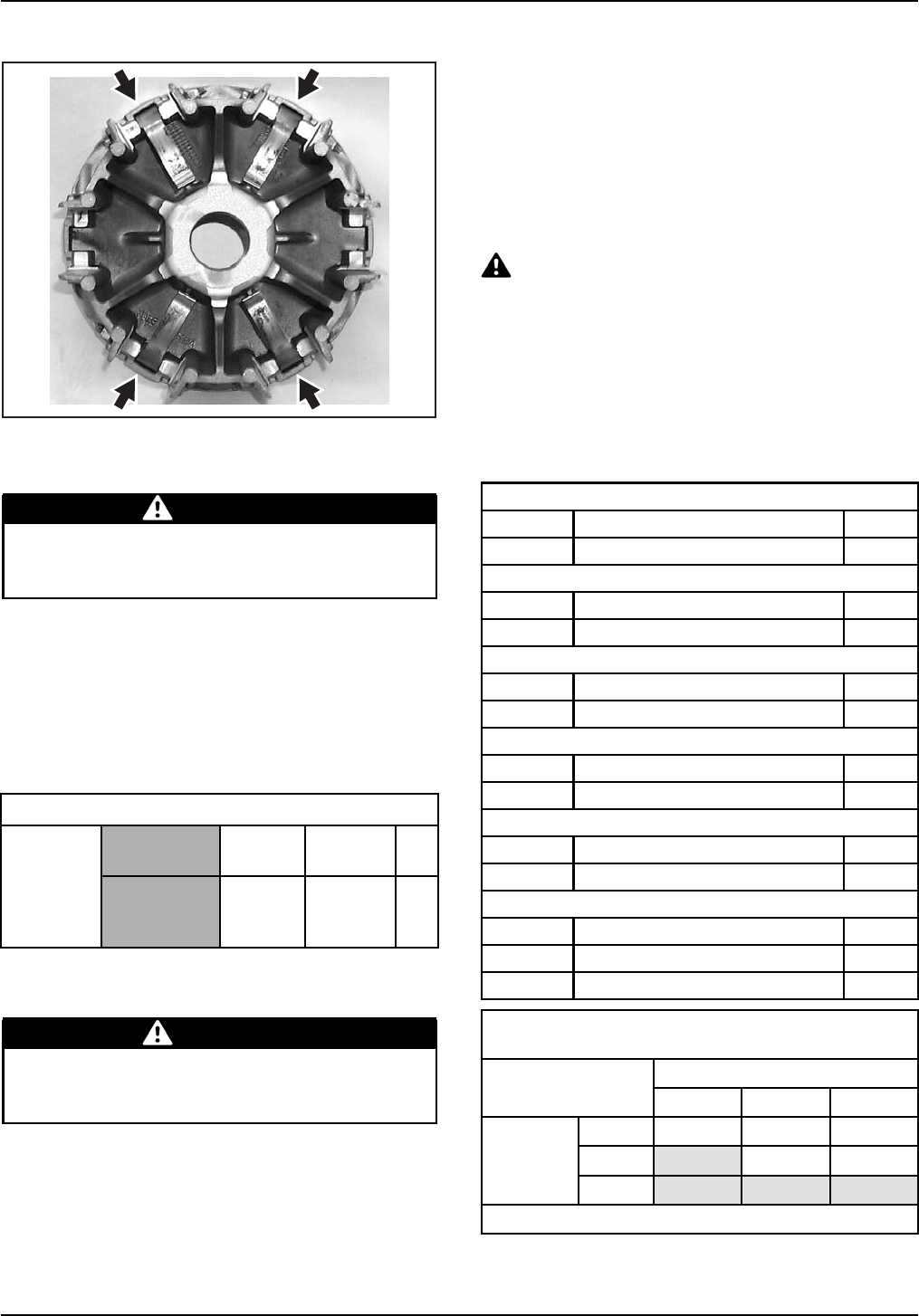
Remove all 4 standard levers and replace them
with 4 high altitude levers.
WARNING
Failure to perform proper installation can
cause damage to the vehicle and serious per-
sonal injuries to the rider.
Outlander500EFI
No high altitude calibration settings have to be
done through B.U.D.S. The calibration features an
automatic electronic fuel injection compensation
allowing fuel injection mapping to be optimized at
all altitudes.
DRIVE PULLEY
Sea Level 1200 m
(4000 ft) 2400 m
(8000 ft) Qty
Centrifugal
Lever 420 248 555
(set of 4)
(qty 1)
10.75
mm* 9.75
mm* 4
Remove all 4 standard levers and replace them
with 4 high altitude levers.
WARNING
Failure to perform proper installation can
cause damage to the vehicle and serious per-
sonal injuries to the rider.
DS 450™ EFI
No high altitude calibration settings have to be
done through B.U.D.S. The calibration features an
automatic electronic fuel injection compensation
allowing fuel injection mapping to be optimized at
all altitudes.
There are different sprocket calibration available to
fine tune vehicle.
CAUTION Changing sprocket ratio may
affect performance, including maximum ve-
hicle speed. If the vehicle is equipped with
a speedometer, the speed indicated by the
speedometer may be different than actual ve-
hicle speed. Please refer to chart below. Any
sprocket combination highlighted (shaded
areas) in the chart below will result in a ve-
hicle speed higher than speed indicated on
speedometer.
13-tooth Sprocket Kit (P/N 715 000 519)
707 000 612 Sprocket 1
420 245 650 Retaining Ring 1
14-tooth Sprocket Kit (P/N 715 000 591)
420 236 061 Sprocket 1
420 245 650 Retaining Ring 1
15-tooth Sprocket Kit (P/N 715 000 518)
420 236 062 Sprocket 1
420 245 650 Retaining Ring 1
39-tooth Sprocket Kit (P/N 715 000 527)
705 500 872 Sprocket 1
233 201 414 Flanged Elastic Nut 4
42-tooth Sprocket Kit (P/N 715 000 592)
705 500 930 Sprocket 1
233 201 414 Flanged Elastic Nut 4
44-tooth Sprocket Kit (P/N 715 000 515)
705 500 946 Sprocket 1
233 201 414 Flanged Elastic Nut 4
293 900 028 Bushing 2
CORRECTION FACTOR DUE TO CHANGE OF
SPROCKET RATIO
Rear sprocket
39 42 44
13 100% 93% 89%
14 108% 100% (1) 95%
Front
sprocket
15 115% 107% 102%
(1) Factory Ratio
SERVICE 2009-6 3 / 6
sales@midwestmanuals.com
sales@midwestmanuals.com
CAUTION Chain length might need to be
adjusted with new sprocket sizes. See
ACCES-
SORY CATALOG
for replacement chain that can
be installed with these kits. DO NOT ride the
vehicle with a chain tension different than rec-
ommended.
WARNING
The use of any sprocket combination high-
lighted (shaded areas) in the previous chart
leads to a change of the maximum vehicle
load allowed. To avoid exceeding the OEM
tire manufacturer's recommendations, the
new maximum load will be 91 kg (200 lb). The
omission to comply with this request could
cause tire bursting and severe injury or death
could occur.
Outlander 400 EFI
No high altitude calibration settings have to be
done through B.U.D.S. The calibration features an
automatic electronic fuel injection compensation
allowing fuel injection mapping to be optimized at
all altitudes.
DRIVE PULLEY
Sea Level 1200 m
(4000 ft) 2400 m
(8000 ft) Qty
Centrifugal
Lever 420 248 424
(set of 4)
(qty 1)
10.5
mm* 9.5
mm* 4
Remove all 4 standard levers and replace them
with 4 high altitude levers as per illustration.
WARNING
Failure to perform proper installation can
cause damage to the vehicle and serious per-
sonal injuries to the rider.
4 / 6 2009-6 SERVICE
sales@midwestmanuals.com
sales@midwestmanuals.com
DS 250
CALIBRATION SEA LEVEL 1200 M (4000 FT) 2400 M (8000 FT)
Country North
America Europe North
America Europe North
America Europe
Main Jet 105 110 100 105 95 100
Needle Position 423 1
Mixture Screw 21.5
Idle RPM ±100 1700 1800
Mini DS 90 / Mini DS 70
NOTE: There is no specific high altitude calibration
for the DS 90 or the DS 70.
Parts to optimize vehicle performance at high alti-
tudes have though been made available.
Refer to table beside.
MAIN JET TYPE P/N
68 V16104DGF000
70 V16105DGF000
72 V16106DGF000
78 V16107DGF000
80 V16108DGF000
82 V16109DGF000
85 V16110DGF000
PILOT JET TYPE
35 V16101DGF000
Reference Chart
CENTRIFUGAL LEVER ‡
Identification
Size Vehicle Model KIT P/N
8.7 mm Outlander 650 EFI 715 500 285
9.0 mm Outlander 800 EFI / Renegade 800 EFI 715 500 248
9.5 mm Outlander 400 EFI 707 000 325
9.75 mm Outlander 500 EFI / Renegade 500 EFI 715 500 295
10.2 mm Outlander 800 EFI / Renegade 800 EFI 715 500 249
10.5 mm Outlander 400 EFI 707 000 324
10.75 mm Outlander 500 EFI/ Renegade 500 EFI 715 500 294
‡ Levers are sold by package. Each package contains the required quantity of levers to update a unit to
high altitude.
SERVICE 2009-6 5 / 6
sales@midwestmanuals.com
sales@midwestmanuals.com
ATV—HIGHALTITUDE
PARTSRETURN
AUTHORIZATIONREQUEST
PARTSFORUSEATHIGHALTITUDE
DEALER NUMBER:_________________
DEALER NAME:
________________________________________ State/Province:__________________
✓Please submit only one request per week. Country:_______________________
BRP USE ONLY
PART NO. MODEL
NO. SERIAL NO. QTY REASON CODE RECEPTION
DATE
Please complete this form and fax it to obtain a RETURN AUTHORIZATION.
Fax Number (U.S.A.): 1-800-366-3880
Fax Number (Canada): 1-800-361-7143
Return parts with RETURN AUTHORIZATION and this form.
6 / 6 2009-6 SERVICE
sales@midwestmanuals.com
sales@midwestmanuals.com
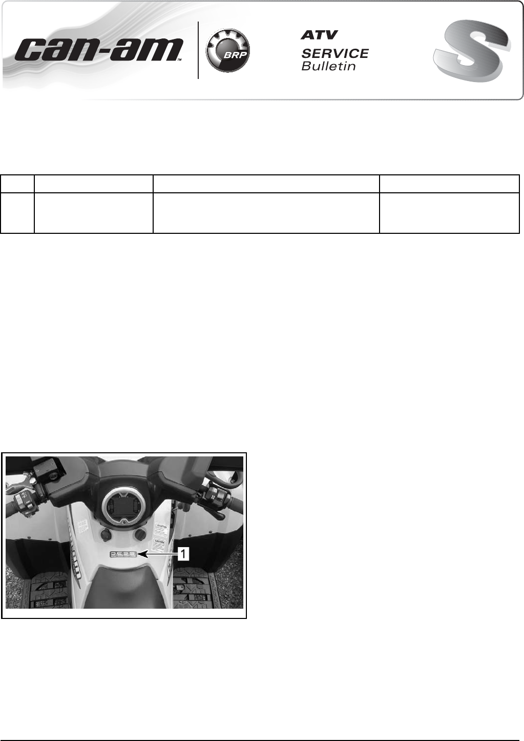
August 11, 2008 Subject:CAN-AM™Outlander 400 EFI Inappropriate
D.E.S.S.™Decal No. 2009-5
YEAR MODEL MODEL NUMBERSERIAL NUMBER
2009 Outlander 400 EFI 5A9A – 5A9B – 5A9C – 5A9D - 5B9A – 5B9B
– 5B9C – 5B9F – 5C9A – 5C9B - 5C9C - 5D9A
– 5D9B – 5D9C – 5D9D - 5D9F
All
D.E.S.S. DECAL
On a limited quantity of the above described ve-
hicle, an inappropriate D.E.S.S. decal has been
installed. As described in BRP documentation,
there is no D.E.S.S. on the MY 2009 Outlander 400
EFI. To avoid any confusion in the network, you
may want to remove the inappropriate D.E.S.S.
decal.
Also, some of our Operator's Guides may incor-
rectly talk about D.E.S.S., so please make sure to
inform your customers.
Refer to the following illustration to locate the in-
appropriate D.E.S.S. decal.
vbs2009-008-001_a
1. Inappropriate D.E.S.S. decal
Printed in Canada (vbs2009-008 en DM)
©2008 Bombardier Recreational Products Inc. and BRP US Inc. All rights reserved. 1/ 1
®™ and the BRP logo are trademarks of Bombardier Recreational Products Inc. or its affiliates.
sales@midwestmanuals.com
sales@midwestmanuals.com
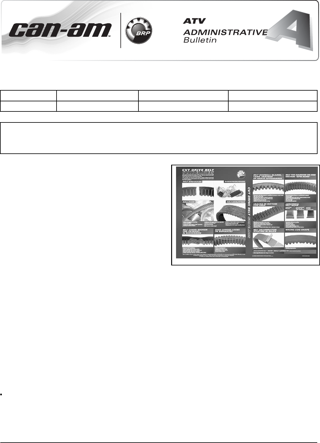
Date: August 6, 2007 Subject: CVT Drive Belt Guidelines No. 2008-1
YEAR MODEL MODEL NUMBER SERIAL NUMBER
2008 All All All
All BRP CVT belts are covered by the BRP Limited
Warranty against any manufacturing defect.
mba2007-002-001 en
BRP OEM CVT belts are premium belts that
are especially designed and calibrated for BRP
recreative vehicles. Non-OEM CVT belts can be
the cause of poor performance, poor acceleration,
over-revving, clutch slipping, high fuel consumption,
etc. BRP CVT belts are the only belts covered
by the BRP Limited Warranty against any
manufacturing defects. This warranty also
covers contributory damages caused by a belt
manufacturing defect; aftermarket belts do not.
Beyond manufacturing defects, damage can still
occur if the system is abused, adjusted incorrectly
or neglected. Therefore, BRP has created a new
“CVT DRIVE BELT GUIDELINES” document you
can consult to determine the cause of a damaged
CVT belt.
This is a two-page color document that can be
inserted in your dealer binder (English on one side,
French on the other).
Some conditions shown on these pages are not
related to a manufacturing defect, and therefore are
not covered under BRP Limited Warranty.
In case of doubt, do not hesitate to send CVT
belts to the Warranty Department to confirm
your diagnostic.
CVT belts are considered wear items; normal
wear is not warrantable.
English / French (P/N 484 800 456)
Do not hesitate to order more if required.
Printed in Canada. (vba2008-002 DL) 1/ 1
©2007 Bombardier Recreational Products Inc. and BRP US Inc. All rights reserved.
®™ and the BRP logo are trademarks of Bombardier Recreational Products Inc. or its affiliates.
sales@midwestmanuals.com
sales@midwestmanuals.com
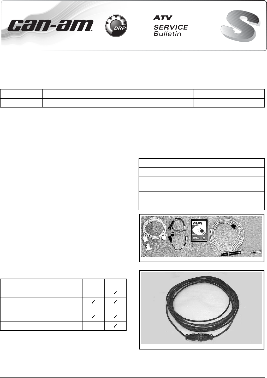
June 01, 2008 Subject:CAN-AM™ATV B.U.D.S. Software and
Communication Tools No. 2009-2
YEAR MODEL MODEL NUMBERSERIAL NUMBER
2009 EFI equipped vehicles All All
GENERAL INFORMATION
As a reference to predelivery inspection bulletin,
this service publication provides instructions about
B.U.D.S. software and B.U.D.S. communication
tools. It contains general practices to connect
B.U.D.S.toavehicleandcanbeusedasaref-
erence for preparing vehicles before delivery to
customers.
For additional information, refer to the following:
– Use B.U.D.S. software help menu which con-
tains detailed information on its functions.
–BRP'sGu
ide to Service Fundamentals and Prin-
ciples, Chapter 9, (P/N 484 800 168).
– 2006 ATV Technical Update Book, Section 4B,
(P/N 219 100 226).
As a reminder, always use the latest version of
B.U.D.S. that can be downloaded from BOSSWeb
(www.bossweb.brp.com).
Note that two different MPI (Multi-Purpose Inter-
face) can be used with B.U.D.S. software: MPI-1
and MPI-2. Refer to the following table for proper
vehicles compatibility.
MODELS MPI-1 MPI-2
Outlander™ 400 EFI Series
Outlander 500-650-800R
EFI Series
Renegade™ 500-800R EFI Series
DS 450™ EFI Series
For MY2008 and previous, refer to the appropri-
ate
PREDELIVERY INSPECTION BULLETIN
for
B.U.D.S software and communication tools infor-
mation.
MPI-1 COMMUNICATION
TOOLS
Multi-Purpose Interface (MPI-1)
PART REQUIRED
PC computer
B.U.D.S. software
Use latest version available on BOSSWeb
Communication kit (P/N 529 035 981)
Optional extension cable (P/N 529 035 703)
5290359812
COMMUNICATION KIT
529035703
OPTIONAL EXTENSION CABLE
Printed in Canada (vbs2009-006 en DM)
©2008 Bombardier Recreational Products Inc. and BRP US Inc. All rights reserved. 1/ 7
®™ and the BRP logo are trademarks of Bombardier Recreational Products Inc. or its affiliates.
sales@midwestmanuals.com
sales@midwestmanuals.com
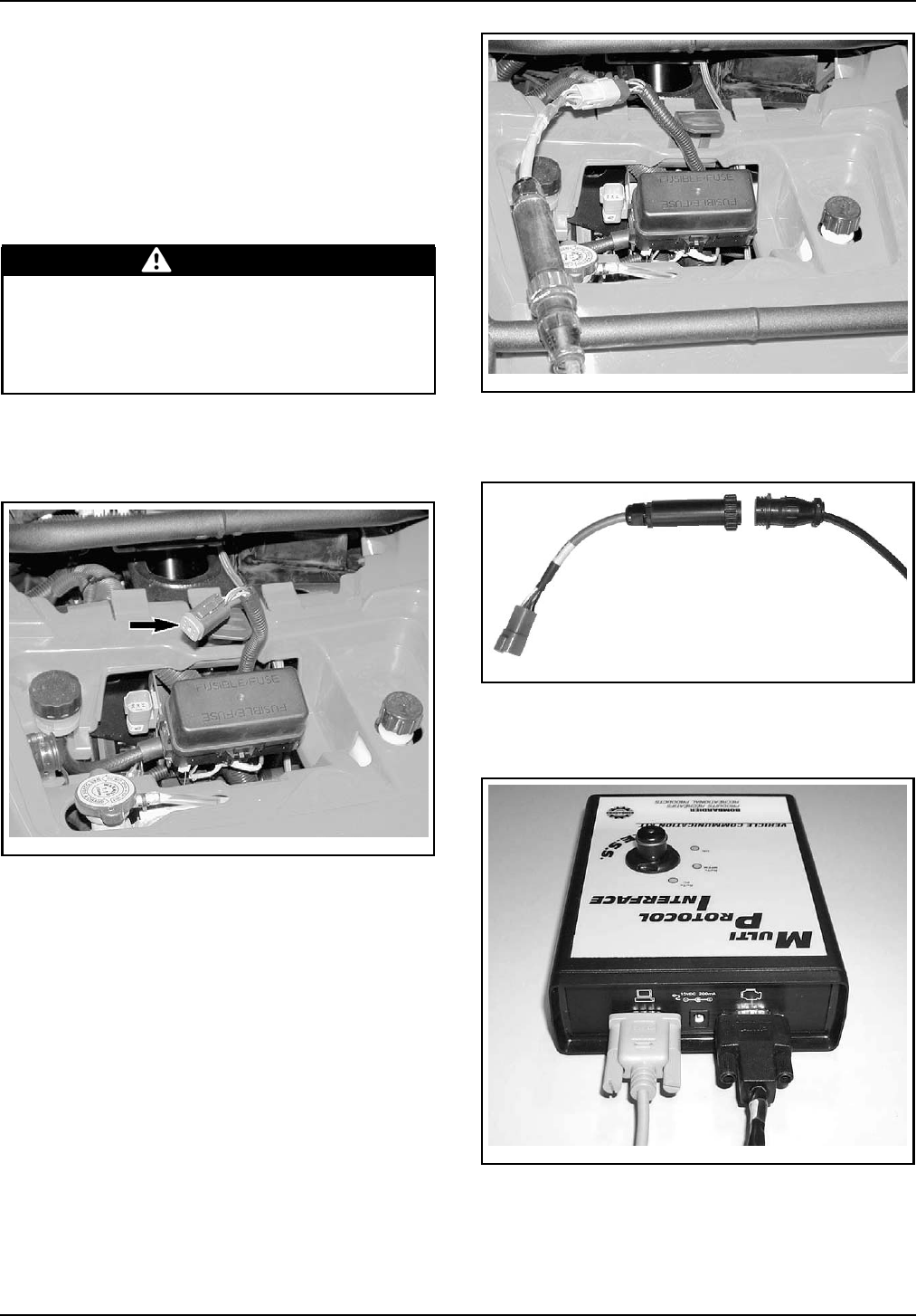
MPI-1 Supply
The MPI can use the vehicle power for its supply.
Four AA batteries or an AC/DC power supply can
also be used. Make sure to respect MPI specifica-
tion if a power supply is used.
Connections with Vehicle Using
MPI-1
WARNING
If the computer you are using is connected to
the power outlet, there is a potential risk of
electrocution when working in contact with
water. Be careful not to touch water while
working with the computer.
1. Remove service compartment cover and lo-
cate communication connector.
2. Unplug communication connector.
vmr2007-042-001_a
TYPICAL
3. Connect the 6-pin adapter to the vehicle con-
nector.
vmr2007-042-002
TYPICAL
4. Connect the diagnostic cable to the 6-pin
adapter.
vdd2006-001-105
5. Connect the other diagnostic cable connector
to MPI connector.
6. Connect serial cable to MPI connector.
vdd2006-001-102
7. Connect remaining serial cable connector to
the serial port of a PC (personal computer).
2 / 7 2009-2 SERVICE
sales@midwestmanuals.com
sales@midwestmanuals.com
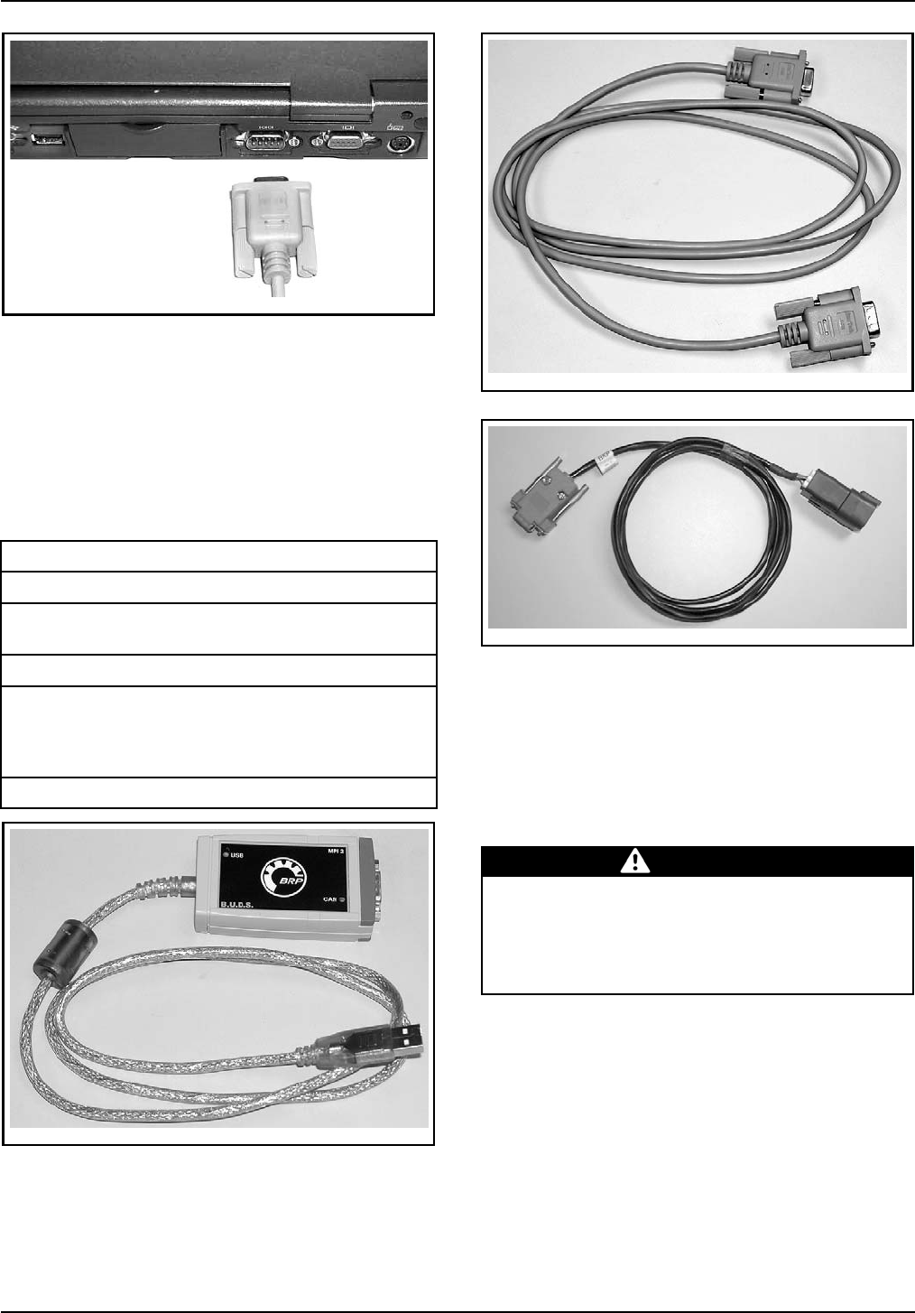
vdd2006-001-103
8. Use B.U.D.S. software as described further in
B.U.D.S. SOFTWARE
.
MPI-2 COMMUNICATION
TOOLS
Multi-Purpose Interface-2
(MPI-2)
PART REQUIRED
PC computer
B.U.D.S. software
Use latest version available on BOSSWeb
MPI-2 (P/N 529 036 018)
Optional extension cable
Use DB9 male to DB9 female connector
purchased at any PC store. Do not exceed 7.6 meter
(25 FT) in length.
Diagnostic cable (P/N 710 000 851)
529036018
MPI-2
529035697
OPTIONAL EXTENSION CABLE
710000851
DIAGNOSTIC CABLE
MPI-2 Supply
The MPI-2 uses the USB power of the PC comput-
er for its supply.
Connections with Vehicle Using
MPI-2
WARNING
If the computer you are using is connected to
the power outlet, there is a potential risk of
electrocution when working in contact with
water. Be careful not to touch water while
working with the computer.
1. Remove service compartment cover and lo-
cate communication connector.
2. Unplug communication connector.
SERVICE 2009-2 3 / 7
sales@midwestmanuals.com
sales@midwestmanuals.com
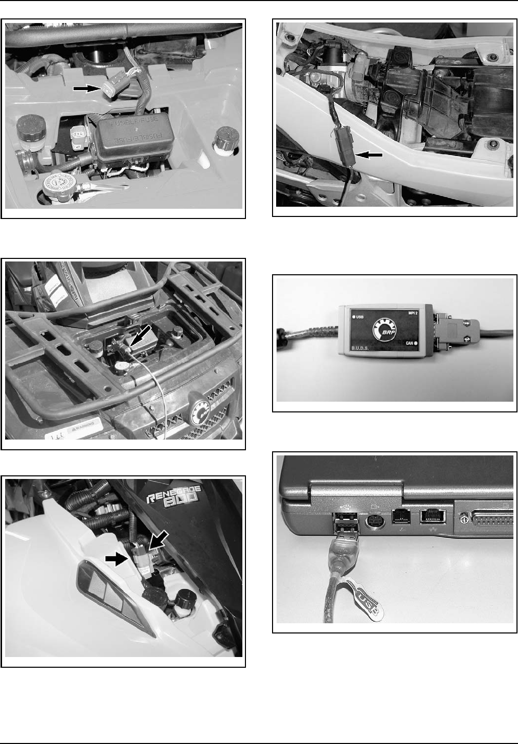
vmr2007-042-001_a
OUTLANDER SERIES (TYPICAL)
3. Connect diagnostic cable to vehicle connector.
vdd2006-001-152
OUTLANDER SERIES (TYPICAL)
Step 1: Remove front service compartment panel
vbl2007-008-008_a
RENEGADE SERIES (TYPICAL)
Step 1: Remove seat
Step 2: Remove central panel
vmr2008-020-002_a
DS 450 EFI SERIES (TYPICAL)
Step 1: Remove seat
4. Connect remaining connector to MPI-2 con-
nector.
vdd2006-001-151
5. Connect remaining MPI-2 connector to the
USB port of a PC (personnal computer).
mmr2006-079-200
6. Use B.U.D.S. software as described further in
B.U.D.S. SOFTWARE
.
4 / 7 2009-2 SERVICE
sales@midwestmanuals.com
sales@midwestmanuals.com
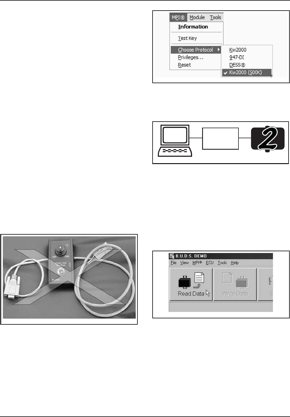
B.U.D.S. SOFTWARE
B.U.D.S. (Bombardier Utility and Diagnostic Soft-
ware) is designed to program key(s), to allow elec-
trical component inspection, diagnostic options
and adjustments such as the closed throttle.
The type of MPI that is being used does not have
any effect on the interface and the features of
B.U.D.S.
Ensure to use the latest B.U.D.S. version available
on BOSSWeb.
IfyouareusinganoldPCcomputerwiththe
MPI-1, it may be necessary to use a slower speed
so that the communication works.
Ensure to turn ignition switch ON and set engine
switch to RUN to activate the communication.
On the MPI-1, the RX/TX MPEM LED on the mid-
dle of the enclosure will blink to indicate that data
is being exchanged with the vehicle.
On the MPI-2, LEDs on enclosure will blink to indi-
cate that data is being exchanged with the vehicle.
Outlander 400 EFI series
NOTE: MPI-1 will not allow communication with
these vehicles. Only the MPI-2 must be used.
NOTE: Do not use DESS Post Interface (P/N 529
036 019) with the KW2000 (500K) protocol. DESS
Post Interface will not allow communication with
these vehicles.
529036019_a
DO NOT USE DESS POST INTERFACE
1. Select MPI from the top menu and then
CHOOSE PROTOCOL.
2. Click on KW2000 (500K)
vbs2009-006-001
3. Ensure the status bar shows KW2000 (500K)
with the number 2 to its right.
NOTE: Number 2 means that 2 “ECU” are con-
nected (ECM and multifunction gauge).
kW2000
500K
vbl2008-007-100
CONNECTION SUCCESSFUL — ECM AND MULTIFUNCTION
GAUGE ARE CONNECTED
4. If an “X” is shown, this means that no commu-
nication between MPI and ECM/multifunction
gauge takes place. Possible causes are:
– ECM is not powered-up
– Multifunction gauge is not powered-up
– Wrong protocol is used
– Bad connection between MPI and module.
5. Press the READ DATA button from the tool bar
to initiate communication with vehicle.
vdd2006-001-101
Outlander 500-650-800R EFI
series and Renegade 500-800R
EFI series
NOTE: It is recommended to use MPI-2 with these
vehicles but both (MPI-1 and MPI-2) will work.
NOTE:The following procedure is for MPI-2, how-
ever, if MPI-1 protocol is used, the procedure will
be the same except that it will be necessary to set
the speed in the CHOOSE SPEED menu. In this
case, the speed is not automatically adjusted.
SERVICE 2009-2 5 / 7
sales@midwestmanuals.com
sales@midwestmanuals.com
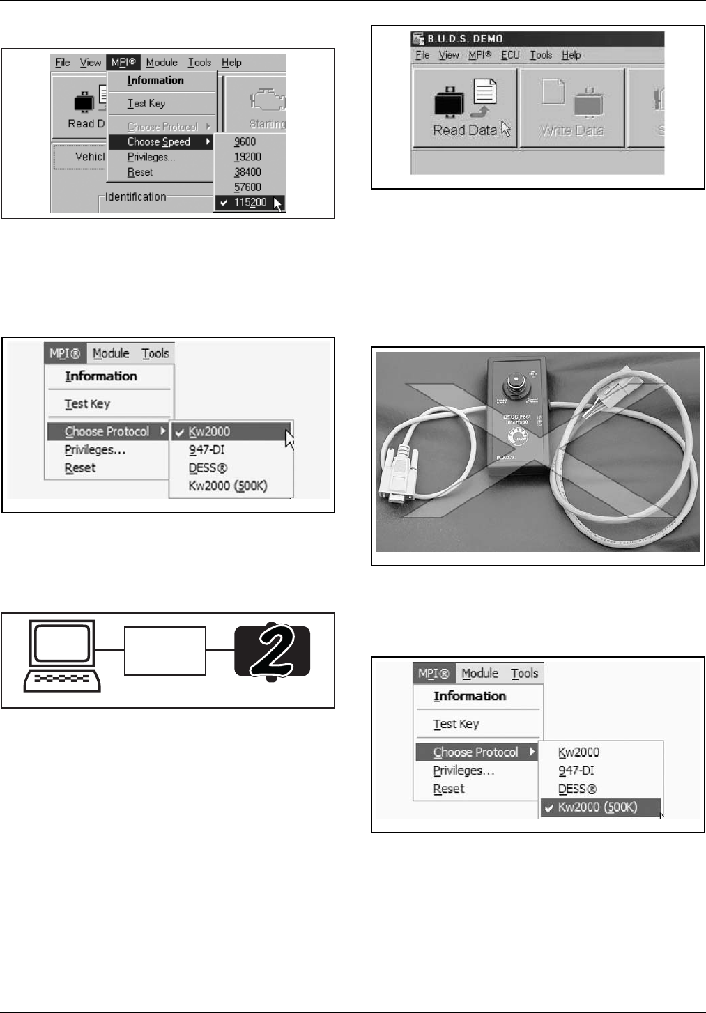
A33C5KA
MPI-1PROTOCOLONLY
Step 1: Select MPI from the top menu and then CHOOSE SPEED.
Step 2: Click on 115200.
1. Select MPI from the top menu and then
CHOOSE PROTOCOL.
2. Click on KW2000
vbs2009-006-002
3. Ensure the status bar shows KW2000 with the
number 2 to its right.
NOTE: Number 2 means that 2 “ECU” are con-
nected (ECM and multifunction gauge).
F18H0XA
kW2000
CONNECTION SUCCESSFUL — ECM AND MULTIFUNCTION
GAUGE ARE CONNECTED
4. If an “X” is shown, this means that no commu-
nication between MPI and ECM/multifunction
gauge takes place. Possible causes are:
– ECM is not powered-up
– Multifunction gauge is not powered-up
– Wrong protocol is used
– Bad connection between MPI and module.
5. Press the READ DATA button from the tool bar
to initiate communication with vehicle.
vdd2006-001-101
DS 450 EFI series
NOTE: MPI-1 will not allow communication with
these vehicles. Only the MPI-2 must be used.
NOTE: Do not use DESS Post Interface (P/N 529
036 019) with the KW2000 (500K) protocol. DESS
Post Interface will not allow communication with
these vehicles.
529036019_a
DO NOT USE DESS POST INTERFACE
1. Select MPI from the top menu and then
CHOOSE PROTOCOL.
2. Click on KW2000 (500K)
vbs2009-006-001
3. Ensure the status bar shows KW2000 (500K)
with the number 1 to its right.
NOTE: Number 1 means that 1 “ECU” is connect-
ed (ECMonly)
NOTE: If the vehicle is equipped with a multifunc-
tion gauge, the number 2 will appear instead of
number 1.
6 / 7 2009-2 SERVICE
sales@midwestmanuals.com
sales@midwestmanuals.com
vmr2008-020-004
CONNECTION SUCCESSFUL — ECM IS CONNECTED
4. If an “X” is shown, this means that no commu-
nication between MPI and ECM/multifunction
gauge takes place. Possible causes are:
– ECM is not powered-up
– Wrong protocol is used
– Bad connection between MPI and module.
5. Press the READ DATA button from the tool bar
to initiate communication with vehicle.
vdd2006-001-101
SERVICE 2009-2 7 / 7
sales@midwestmanuals.com
sales@midwestmanuals.com
June 01, 2008 Subject:CAN-AM™ATV Batteries Activation,
Charging and Maintenance No. 2009-1
YEAR MODEL MODEL NUMBERSERIAL NUMBER
2009 All All All
GENERAL INFORMATION
As a reference to predelivery inspection bulletin,
this service publication provides instructions for
the activation, charging and maintenance of new
ATV batteries. It contains standard practices and
can be used as a reference for preparing vehicles
before delivery to customers.
For complete battery information and detailed pro-
cedures, refer to appropriate
ATV SHOP MANUAL
and manufacturer's instructions.
For MY2008 and previous, refer to the appropri-
ate
PREDELIVERY INSPECTION BULLETIN
for
batteries activation, charging and maintenance
information.
Guidelines for MY2009
All MY2009 vehicles are equipped with facto-
ry activated VRLA batteries (Valve Regulated
Lead Acid). They are a maintenance free and
non-spillable type batteries.
These WET type batteries are factory filled and
activated. They never need electrolyte check and
readjustment.
The permanently sealed VRLA battery never
needs refilling; however, it still needs periodic
charging.
BATTERY ACTIVATION
Since all the MY2009 batteries are WET (factory
activated), they never need to be activated using
acid packs. The electrolytes are already in the bat-
teries.
BATTERY CHARGING
Initial Charging
Sealed VRLA batteries require an initial charge.
If you are using a constant current charger, refer to
the standard (STD) charging method printed on the
battery.
vbl2006-004-007
TYPICAL
Some batteries may differ
If you are using an automatic type taper charg-
er, check to make sure that the charger current
(amps) is equal to or greater than the standard
(STD) charging method listed on the battery.
These batteries are a sealed VRLA construction;
never remove the sealing strip after charging
is completed. If the battery gets very hot to the
touch, cease charging and allow battery to cool
down. Check voltage using a voltmeter. Reading
for a charged, newly-activated battery should be
Printed in Canada (vbs2009-005 en DM)
©2008 Bombardier Recreational Products Inc. and BRP US Inc. All rights reserved. 1/4
®™ and the BRP logo are trademarks of Bombardier Recreational Products Inc. or its affiliates.
sales@midwestmanuals.com
sales@midwestmanuals.com

12.8 volts or higher after the battery is charged and
sits for at least 1 – 2 hours. If less, it needs addi-
tional charge.
Routine Charging
NOTICE Overcharging can harm the battery
beyond recovery.
The single most important thing to maintaining a
VRLA battery is to not let it sit discharged: keep
it fully charged. A sealed VRLA battery should be
kept to near fully charged for peak performance.
In fact, it can need charging more often than a car
battery because it is probably not used routinely
and, therefore, not “automatically” charged.
Use the following guidelines for boost charge. Al-
ways verify battery condition before charging, and
30 minutes after charging.
A fully charged battery should read 12.8 V or higher
after battery has been off the charger 1 hour.
It is not recommended to overcharge sealed VR-
LA batteries. Because of their characteristics, too
much of a boost charge will decrease the volume
of electrolyte. The longer the overcharge time, the
greater the drop in electrolyte – and starting pow-
er.
Refer to the following tables for charging routine.
Note that charging times can vary depending on
type of charger. Follow the charger's instructions
for details.
STATE OF CHARGE : 100%
VOLTAGE ACTION CHARGE
TIME *
12.8 – 13.0 None
Check at 3 months from
date of manufacture
None required
* Using a constant current charger at standard
amps specified on the battery
STATE OF CHARGE : 75% - 100%
VOLTAGE ACTION CHARGE
TIME *
12.5 – 12.8 May need slight charge,
if no charge given, check
in3months
3–6hours
* Using a constant current charger at standard
amps specified on the battery
STATE OF CHARGE :50%-75%
VOLTAGE ACTION CHARGE
TIME *
12.0 – 12.5 Need charge 5 – 11 hours
* Using a constant current charger at standard
amps specified on the battery
STATE OF CHARGE : 25% - 50%
VOLTAGE ACTION CHARGE TIME *
11.5 – 12.0 Need charge At least 13 hours
verify state of charge
* Using a constant current charger at standard
amps specified on the battery
STATE OF CHARGE : 0% - 25%
VOLTAGE ACTION CHARGE
TIME *
11.5 or less
(see instructions below)
Need charge 20 hours
* Using a constant current charger at standard
amps specified on the battery
Charging for Voltage of 11.5 or
Less
Batteries with voltage below 11.5 V may require
special equipment and procedures to recharge.
In charging an over discharged battery having a
terminal voltage of 11.5 V or lower, its internal re-
sistance may be too high to charge at a normal
charge voltage.
Therefore, it may be necessary to raise the voltage
of the battery initially (25 V as a maximum), and
charge for approximately 5 minutes. If the amme-
ter shows no change in current after 5 minutes,
you need a new battery.
Current flowing into the battery at high voltage
can become excessive. Monitor amperage and
adjust voltage as necessary to keep current at the
battery’s standard amp rating. Charge for approxi-
mately 20 hours.
BATTERY
MAINTENANCE
A battery requires little maintenance to perform
perfectly. Follow this simple check list for opti-
mum battery performance:
– Check voltage every 3 months using a volt-
meter.
– Keep a battery fully charged to 100% (12.8 V -
13.0 V after standing 1 - 2 hours).
2 / 4 2009-1 SERVICE
sales@midwestmanuals.com
sales@midwestmanuals.com
– Check and charge battery if the voltage drops
below 12.5 V.
– Keep the battery top free of grime.
– Clean terminals and connectors if necessary.
– For storage, pull battery or disconnect battery
cables.
BATTERY STORAGE
Battery storage is critical for battery life, it is im-
portant to follow the above battery maintenance
check list to keep an optimal condition.
Always remove battery from vehicle for storage.
Keeping the battery in vehicle for storage may lead
to contacts degradation/corrosion and case dam-
age if freezing occurs. A discharged battery will
freeze and break in area where freezing point is
experienced. Electrolyte leakage will damage sur-
rounding parts.
Regularly charging the battery during storage will
prevent cell sulfation.
Keep in mind that higher storage temperatures
cause faster self-discharge and require checking
more often.
BATTERY CARE
REMINDER
Through proper maintenance and care, today’s
modern batteries can survive long storage peri-
ods, however one must adhere to the proper main-
tenance procedures as specified in this bulletin.
It is a good practice to strictly follow all activated
batteries and apply the maintenance procedure to
keep them at a high level of performance.
All batteries which did not receive proper periodic
maintenance will not be covered by the warranty.
SAFETY WARNINGS
Here are important safety things to keep in mind
before working with batteries. Any person who
intends to work with batteries should read and
understand the information contained on the fol-
lowing safety warnings before doing so.
WARNING
Store the battery in a cool, dry place out of di-
rect sunlight.
WARNING
Absolutely no smoking, sparks or open
flames around batteries. Batteries can pro-
duce hydrogen and oxygen; if they ignite the
battery can rupture.
WARNING
Properly connect charger to battery: positive
to positive, negative to negative. Unplug the
charger or turn it off before you disconnect
the leads; that cuts down on the chance of
sparks.
WARNING
Always wear eye protection, protective
gloves and protective clothing.
WARNING
Clean up acid spills immediately, using a wa-
ter and baking soda solution to neutralize.
WARNING
If sulfuricacidisswallowedorsplashedinthe
eyes, take immediate action. While the dilut-
ed sulfuric acid used as electrolyte can burn
the skin, this type of injury is generally less
serious. Sulfuric acid in the eyes can cause
blindness. Serious internal injuries or death
can result from ingesting sulfuric acid.
WARNING
The sealed VRLA battery will not be topped
off during its life. Never pry off sealing caps:
it is dangerous and damaging. Water cannot
be added to the sealed VRLA battery.
WARNING
Always ventilate battery charging area.
WARNING
Always stop charging if the battery becomes
really warm to the touch. Let it cool down
for 6 - 12 hours and resume charging. Over-
charging can warp plates, making future
charging difficult or impossible. Watch
charging times carefully, or ideally, use a
Yuasa†Automatic Charger. A battery that
is too hot can rupture.
† Yuasa is a registered trademark of Yuasa Battery Inc.
SERVICE 2009-1 3 / 4
sales@midwestmanuals.com
sales@midwestmanuals.com

WARNING
Never charge or boost battery while installed
on vehicle.
WARNING
Always connect battery cables exactly in the
specified order. Connect RED positive cable
first, then BLACK negative ground cable.
4 / 4 2009-1 SERVICE
sales@midwestmanuals.com
sales@midwestmanuals.com
1Volume 1 - Can-Am 2009
INTRODUCTION
This publication governs all warranty labor allowances for 2009 Can-Am ATV OUTLANDER/RENEGADE models.
1. HOW DOES IT WORK
We follow the procedures detailed in the Can-Am ATV Shop Manual. The flat rate time is the maximum time allowed
for a repair involving any given part. FLAT RATE TIME IS NOT CUMULATIVE. You must use the flat rate time given
for the longest lasting operation.
NOTE: The Flat Rate Time Schedule was prepared by skilled mechanics using the hand tool usually found in work-
shops and all the special tools mentioned in the Shop Manual.
2. COMPILATION
The Flat Rate Time Schedule is compiled as follows:
The actual required time to perform the repair plus (+) 30% correction factor up to 3.0 hours or (+) 15% over 3.0
hours time to take into account, among others:
– vehicle handling
– obtaining the parts
– diagnosis
– cleaning
– special compensation (rusted bolts)
3. HOW TO USE IT
Refer to the system you need, locate part of series of parts replaced. List JOB CODE in the appropriate column on
claim.
NOTE: Unless otherwise specified, dismantling order is: top to bottom, exterior to interior, front to rear.
All fractions of hours are in tenths:
LEGEND:
IMPORTANT: Always use the longuest flat rate time applicable to the repair performed.
4. JOB REQUIREMENTS
All the flat rate times mentioned in the following pages include the required operations such as: engine timing (piston
clearance/ring end gap measurement, crankshaft to crankcase measurement, cylinder honing, engine leak test.
5. ILLUSTRATIONS
The illustrations contained in this manual do not necessarily show every components of a given system as Parts
Catalog do. Their purpose is to facilitate recognition of parts related to a flat rate time. Item numbers on illustrations
correspond to the four or five digit Job Code.
6. SUGGESTION (FORM REQUEST)
SYSTEM PAGE
01 ENGINE 4
02 CARBURETOR AND FUEL SYSTEM 21
03 IGNITION 28
04 STARTER 31
05 TRANSMISSION AND LINKAGE 33
06 BRAKE SYSTEM 38
SYSTEM PAGE
07 STEERING/FRONT DRIVE SYSTEM AND
SUSPENSION 40
08 REAR DRIVE SYSTEM AND
SUSPENSION 48
09 BODY AND ACCESSORIES 52
10 ELECTRICAL SYSTEM 58
11 CLAIM TYPE 02 62
0.1 = 6 minutes
0.2 = 12 minutes, and so on
* REQUIRES PRIOR AUTHORIZATION BY DISTRIBUTOR.
** INDICATE LABOUR TIME ON LINE “LABOUR ONLY“ OF CLAIM.
*** INDICATE $$$ AMOUNT ON “SUB-CONTRACTED LABOUR“ OF CLAIM.
VTF2009-001.FM
sales@midwestmanuals.com
sales@midwestmanuals.com

2Can-Am - Volume 1
2009
INTRODUCTION
Cette publication détermine le temps de MAIN-D’OEUVRE couvert par la garantie pour les VTT Can-Am 2009 modèle
OUTLANDER/RENEGADE.
1. UTILISATION DU MANUEL
En procédant de la façon indiquée dans le Manuel de réparation Can-Am VTT, chaque temps donné représente le
maximum permis pour une réparation portant sur cette pièce. LES TEMPS NE SONT PAS CUMULATIFS. On doit
inscrire le temps donné pour l’opération qui prend le plus de temps.
REMARQUE: Le Barème de temps à taux fixe a été préparé par des mécaniciens compétents utilisant les outils
que l’on retrouve normalement dans les ateliers de réparation, en plus de tous les outils spéciaux mentionnés dans
le Manuel de réparation.
2. COMPILATION
Le Barème de temps à taux fixe a été établi en compilant le temps nécessaire pour faire la réparation plus (+) un
facteur de correction de 30% lorsqu’un travail dure 3.0 heures et moins, ou (+) 15% lorsqu’un travail dure plus de
3.0 heures. Cette compilation comprends, entre autres les étapes suivantes:
– manutention du véhicule
– nettoyage
– aller chercher les pièces, essais physique
– compensation spéciale (boulons rouillés)
– diagnostic
3. UTILISATION DU BARÈME
Se reporter à la section désirée, repérer la pièce ou l’ensemble de pièces remplacées et inscrire le CODE DE
TRAVAIL dans la colonne appropriée sur la formule de réclamation.
REMARQUE: Sauf indication contraire, le démontage doit s’effectuer de haut en bas, de l’extérieur vers l’intérieur,
de l’avant vers l’arrière.
Toutes les fractions d’heures sont exprimées en dixièmes:
LÉGENDE:
IMPORTANT: Toujours utiliser le temps donné à l’opération qui nécessite le plus de temps.
4. TRAVAUX REQUIS
Tous les temps mentionnés dans les pages suivantes incluent les opérations telles que: réglage du moteur (mesure
du jet des pistons/jeu en bout des segments, mesure de l’écart entre le vilebrequin et le carter, rectification du
cylindre, vérification de fuite du moteur.
5. ILLUSTRATIONS
Contrairement aux Catalogues de pièces, les illustrations de ce manuel ne montrent pas nécessairement chacune
des pièces qu’elles représentent, leur raison d’être étant plutôt de faciliter la reconnaissance des pièces reliées à
un barème de temps à taux fixe. Les numéros d’items sur les illustrations correspondent aux quatre ou cinq
derniers chiffres du code de travail.
6. SUGGESTION (FORMULAIRE)
SYSTÈME PAGE
01 MOTEUR 4
02 CARBURATEUR ET SYSTÈME
D’ALIMENTATION D’ESSENCE 21
03 ALLUMAGE 28
04 DÉMARREUR 31
05 TRANSMISSION ET TRINGLERIE 33
06 SYSTÈME DE FREIN 38
SYSTÈME PAGE
07 DIRECTION/SYSTÈME
D’ENTRAÎNEMENT AVANT ET
SUSPENSION 40
08 YSTÈME D’ENTRAÎNEMENT ARRIÈRE
ET SUSPENSION 48
09 CARROSSERIE ET ACCESSOIRES 52
10 SYSTÈME ÉLECTRIQUE 58
11 RÉCLAMATION DE TYPE 02 62
0.1 = 6 minutes
0.2 = 12 minutes, et ainsi de suite
* AUTORISATION REQUISE AVANT LE REMPLACEMENT.
** INSCRIRE LE TEMPS À LA LIGNE «MAIN-D’OEUVRE SEULEMENT».
*** INSCRIRE LE MONTANT $$$ À LA LIGNE «OUVRAGE SOUS-CONTRACTÉE».
sales@midwestmanuals.com
sales@midwestmanuals.com

3Volume 1 - Can-Am 2009
2008
ATV / VTT
TABLE DESCRIPTION MODEL/MODÈLE ENGINE TYPE/
TYPE DE MOTEUR CARBURETOR/
CARBURATEUR
COOLING SYSTEM/
SYSTEME DE
REFROIDISSEMENT
1
OUTLANDER 4X4 400 5A9A/5A9B
5A9C/5A9D 400 CVT Dell’Orto
46 mm Liquid cooled/
Refroidi par liquide
OUTLANDER XT 4X4 400 5B9A/5B9B
5B9C/5B9F
2
OUTLANDER MAX 4X4 400 5C9A/5C9B
5C9C 400 CVT Dell’Orto
46 mm Liquid cooled/
Refroidi par liquide
OUTLANDER MAX XT 4X4 400 5D9A/5D9B/5D9C
5D9D/5D9F
3
OUTLANDER 4X4 500 2T9A/2T9B
500 CVT Dell’Orto
46 mm Liquid cooled/
Refroidi par liquide
OUTLANDER XT 4X4 500 2U9A/2U9B/2U9C
2U9D/2U9E/2U9F
2U9G
4
OUTLANDER MAX 4X4 500 2W9A
500 CVT Dell’Orto
46 mm Liquid cooled/
Refroidi par liquide
OUTLANDER MAX XT 4X4 500 2X9A/2X9B/2X9C
2X9D/2X9E/2X9F
2X9G/2X9H
5
OUTLANDER 4X4 650 2N9A/2N9B
2N9C/2N9D
650 CVT
Dell’Orto
46 mm Liquid cooled/
Refroidi par liquide
OUTLANDER XT 4X4 650 2P9A/2P9B/2P9C
2P9D/2P9E/2P9F
2P9G/2P9H/2P9J
OUTLANDER 4X4 800 2H9E/2H9F/2H9G
800 CVT
OUTLANDER XT 4X4 800 2J9J/2J9K/2J9L
2J9M/2J9N/2J9P
6
OUTLANDER MAX 4X4 650 2R9A/2R9B
2R9C/2R9D
650 CVT
Dell’Orto
46 mm Liquid cooled/
Refroidi par liquide
OUTLANDER MAX XT 4X4 650 2S9A/2S9B/2S9C
2S9D/2S9E/2S9F
2S9G/2S9H/2S9J
OUTLANDER MAX 4X4 800 2K9A/2K9B
2K9C/2K9D
800 CVTOUTLANDER MAX XT 4X4 800 2L9A/2L9B/2L9C
2L9D/2L9E/2L9F
2L9G/2L9H/2L9J
OUTLANDER MAX LTD 4X4 800 2M9A/2M9B/2M9C
2M9D/2M9E/2M9F
7
RENEGADE 500 4X4 4E9A/4E9B/4E9C
4E9D/4E9E/4E9F 500 CVT
Dell’Orto
46 mm Liquid cooled/
Refroidi par liquide
RENEGADE 800 4X4 4B9A/4B9B/4B9C
4B9D/4B9E/4B9F 800 CVT
RENEGADE X 800 4X4 4C9A/4C9B/4C9C
sales@midwestmanuals.com
sales@midwestmanuals.com
ENGINE
MOTEUR
01
SYSTEM/SYSTÈME
4Can-Am - Volume 1
2009
SYSTEM
SYSTÈME
CODE
DESCRIPTION
OUTLANDER
400
OUTLANDER
MAX 400
OUTLANDER
500
OUTLANDER
MAX 500
OUTLANDER
650/800
OUTLANDER
MAX 650/800
RENEGADE
500/800
1234567
01 00 NO LABOR INVOLVED
AUCUNE MAIN D’OEUVRE 0000000
01
*01 REMOVE AND REPLACE ENGINE (ASS’Y)
REMPLACEMENT DU MOTEUR (COMPLET) 3.3 3.3 4.0 4.0 4.0 4.0 4.0
01 03 OIL PRESSURE SWITCH
INTERRUPTEUR DE PRESSION D’HUILE 0.3 0.3 0.3 0.3 0.3 0.3 0.3
01 04 HEAT SHIELD AND/OR RUBBER MOUNT
DÉFLECTEUR DE CHALEUR ET/OU BUTÉE DE CAOUTCHOUC 0.4 0.4
01 08 FAN AND/OR FAN SUPPORT
VENTILATEUR ET/OU SUPPORT DE VENTILATEUR 0.6 0.6 0.6 0.6 0.6 0.6 0.6
01 18 SENDER TEMPERATURE (ENGINE)
CAPTEUR DE TEMPÉRATURE (MOTEUR) 0.3 0.3 0.3 0.3 0.3 0.3 0.3
01 19 THERMOSTAT
THERMOSTAT 0.4 0.4 0.4 0.4 0.4 0.4 0.4
01 34 DECOMPESSOR (ANY PARTS)
DÉCOMPRESSEUR (TOUTES LES PIÈCES) 0.7 0.7
01 37 RADIATOR INLET HOSE
BOYAU D’ENTRÉ DU RADIATEUR 0.5 0.5 0.5 0.5 0.5 0.5 0.5
01 38 WATER PUMP SHAFT (ALL PARTS)
ARBRE DE POMPE À L'EAU (TOUTES LES PIÈCES) 3.9 3.9 4.8 4.8 4.8 4.8 4.8
01 44 ENGINE RUBBER MOUNTS (3 OR 4)
TAMPONS D’ANCRAGE DE CAOUTCHOUC DU MOTEUR (3 OU 4) 1.4 1.4
01 45 ENGINE RUBBER MOUNT
TAMPONS D'ANCRAGE DU MOTEUR 0.3 0.3 1.0 1.0 1.0 1.0 1.0
01 46 RADIATOR AND/OR GROMMMET
RADIATEUR ET/OU PASSE-FILS 1.5 1.5 1.5 1.5 1.5 1.5 1.5
01 50 CRANKSHAFT AND/OR BEARINGS (FRONT/REAR)
VILEBREQUIN ET/OU ROULEMENTS (AVANT/ARRIÈRE) 6.0 6.0 6.0 6.0 6.0
01 56 CRANKCASE COVER GASKET
JOINT DE COUVERCLE DE CARTER 1.3 1.3 1.3 1.3 1.3
01 57 PTO CRANKCASE COVER
COUVERCLE DE CARTER PDM 1.4 1.4 1.4 1.4 1.4
01 58 INTAKE OR EXHAUST VALVE GUIDE (1)
GUIDE DE SOUPAPE D'ADMISSION OU D'ÉCHAPPEMENT (1) 2.0 2.0 2.5 2.5 2.5 2.5 2.5
01 59 INTAKE OR EXHAUST VALVE GUIDE (2)
GUIDE DE SOUPAPE D'ADMISSION OU D'ÉCHAPPEMENT (2) 2.1 2.1 2.6 2.6 2.6 2.6 2.6
01 70 MUFFLER AND/OR EXHAUST GASKET AND/OR CLAMP
SILENCIEUX D’ÉCHAPPEMENT ET/OU JOINT D’ÉCHAPPEMENT
ET/OU BRIDE DE SERRAGE 0.3 0.3 0.3 0.3 0.3 0.3 0.3
01 72 TUNE PIPE AND/OR GASKET
TUYAU D’ÉCHAPPEMENT CALIBRÉ ET/OU JOINT D’ÉTANCHÉITÉ 0.3 0.3
sales@midwestmanuals.com
sales@midwestmanuals.com
ENGINE
MOTEUR
5
2009
01
SYSTEM/SYSTÈME
Volume 1 - Can-Am
01 73 EXHAUST MANIFOLD (REAR)
CONNECTEUR D'ÉCHAPPEMENT (ARRIÈRE) 0.5 0.5 0.5 0.5 0.5
01 77 ANTI-VIBRATION RUBBER MOUNT (1 OR 2) (TOP)
TAMPON D’ANCRAGE ANTI-VIBRATION (1 OU 2) (HAUT) 1.0 1.0 1.0 1.0 1.0 1.0 1.0
01 79 COOLANT HOSE (RADIATOR TO TANK)
BOYAU DU SYSTÈME DE REFROIDISSEMENT
(RÉSERVOIR AU RADIATEUR) 0.4 0.4 0.4 0.4 0.4 0.4 0.4
01 83 EXHAUST MANIFOLD (FRONT)
CONNECTEUR D'ÉCHAPPEMENT (AVANT) 0.5 0.5 0.5 0.5 0.5
01 84 TUNE PIPE HEAT SHIELD (1)
DÉFLECTEUR DE CHALEUR TUYAU D'ÉCHAPPEMENT (1) 0.3 0.3 0.3 0.3 0.3
01 85 TUNE PIPE HEAT SHIELD (2)
DÉFLECTEUR DE CHALEUR TUYAU D'ÉCHAPPEMENT (2) 0.3 0.3 0.3 0.3 0.3
01 86 TUNE PIPE HEAT SHIELD (3)
DÉFLECTEUR DE CHALEUR TUYAU D'ÉCHAPPEMENT (3) 0.5 0.5 0.5 0.5 0.5
01 87 MUFFLER SUPPORT
SUPPORT DU SILENCIEUX 0.3 0.3 0.3 0.3 0.3 0.3 0.3
01 88 RUBBER MOUNT (MUFFLER)
TAMPON D'ANCRAGE (SILENCIEUX) 0.3 0.3 0.3 0.3 0.3
01 90 ENGINE OIL FILTER
FILTRE À HUILE DU MOTEUR 0.3 0.3 0.3 0.3 0.3 0.3 0.3
01 96
OIL SIEVE AND/OR O-RING AND/OR COLLECTOR AND/OR RUBBER
RING AND/OR COVER
CRIBLE D’HUILE ET/OU JOINT TORIQUE ET/OU COLLECTEUR
ET/OU ANNEAU DE CAOUTCHOUC ET/OU COUVERCLE
2.0 2.0 6.0 6.0 6.0 6.0 6.0
01 98 COOLING RESERVOIR
RÉSERVOIR D’ANTIGEL 0.4 0.4 0.4 0.4 0.4 0.4 0.4
01 100 RADIATOR OUTLET HOSE
BOYAU DE SORTIE DU RADIATEUR 0.4 0.4 0.4 0.4 0.4 0.4 0.4
01 101 PISTON, PIN, CIRCLIP, RINGS (1)
PISTON, GOUPILLE, CIRCLIP, SEGMENTS (1) 2.7 2.7 2.7 2.7 2.7
01 102 PISTONS, PINS, CIRCLIPS, RINGS (2)
PISTONS, GOUPILLES, CIRCLIPS, SEGMENTS (2) 4.5 4.5 4.5 4.5 4.5
01 109 VALVE COVER AND/OR GASKET
COUVERCLE DE SOUPAPE ET/OU JOINT D’ÉTANCHÉITÉ 0.3 0.3 0.3 0.3 0.3 0.3 0.3
01 111 TIMING GEAR
PIGNON DE DISTRIBUTION 0.9 0.9 1.0 1.0 1.0 1.0 1.0
01 113 ROCKER ARM AND/OR PUSH ROD AND/OR ROCKER ARM SHAFT
CULBUTEUR ET/OU TIGE POUSSOIR ET/OU ARBRE DE
CULBUTEUR 1.0 1.0 1.1 1.1 1.1 1.1 1.1
01 114 CYLINDER HEAD AND/OR GASKET
CULASSE ET/OU JOINT D’ÉTANCHÉITÉ 2.6 2.6 3.2 3.2 3.2 3.2 3.2
SYSTEM
SYSTÈME
CODE
DESCRIPTION
OUTLANDER
400
OUTLANDER
MAX 400
OUTLANDER
500
OUTLANDER
MAX 500
OUTLANDER
650/800
OUTLANDER
MAX 650/800
RENEGADE
500/800
1234567
sales@midwestmanuals.com
sales@midwestmanuals.com

ENGINE
MOTEUR
01
SYSTEM/SYSTÈME
6Can-Am - Volume 1
2009
01 116 EXHAUST AND/OR INLET VALVE AND/OR SPRING AND/OR SEAL
VALVE ADMISSION ET/OU ÉCHAPPEMENT ET/OU RESSORT
ET/OU ANNEAU D’ÉTANCHÉITÉ 1.9 1.9 2.4 2.4 2.4 2.4 2.4
01 117 CYLINDER AND/OR GASKET
CYLINDRE ET/OU JOINT D’ÉTANCHÉITÉ 2.0 2.0 2.5 2.5 2.5 2.5 2.5
01 118 PISTON AND/OR PISTON PIN AND/OR CIRCLIP
PISTON ET/OU GOUPILLE DE PISTON ET/OU CIRCLIP 2.1 2.1
01 119 WATER PUMP HOUSING AND/OR IMPELLER
CARTER DE LA POMPE À EAU ET/OU ROUE À AILETTES 0.4 0.4 0.4 0.4 0.4 0.4 0.4
01 122 SHIFT SHAFT (ASS’Y)
ARBRE D’EMBRAYAGE (COMPLET) 4.1 4.1
01 132 OIL PUMP GEAR
ENGRENAGE DE LA POMPE À HUILE 4.0 4.0 1.4 1.4 1.4 1.4 1.4
01 134 CAMSHAFT
ARBRE À CAME 1.0 1.0 2.0 2.0 2.0 2.0 2.0
01 137 OIL PUMP COVER AND/OR SHAFT AND/OR ROTOR
COUVERCLE DE LA POMPE À HUILE ET/OU ARBRE ET/OU ROTOR 4.0 4.0 1.4 1.4 1.4 1.4 1.4
01 138 CRANKCASE RESEAL OR GASKET
RECELLEMENT DU CARTER ET/OU JOINT D’ÉTANCHÉITÉ 4.9 4.9 5.9 5.9 5.9 5.9 5.9
01 139 CRANKCASE REPLACEMENT
REMPLACEMENT DU CARTER 5.4 5.4 6.5 6.5 6.5 6.5 6.5
01 140 CRANKSHAFT AND/OR BALANCE SHAFT
VILEBREQUIN ET/OU ARBRE D’ÉQUILIBRAGE 4.9 4.9
01 152 DRIVE SHAFT AND/OR BEARINGS AND/OR SEALS
ARBRE D’ENTRAÎNEMENT ET/OU ROULEMENT À BILLES ET/OU
ANNEAUX D’ÉTANCHÉITÉ 5.1 5.1 5.1 5.1 5.1
01 153 GEARBOX (ALL PARTS)/MAIN SHAFT
BOÎTE DE VITESSE (TOUTES LES PIÈCES)/ARBRE PRINCIPAL 5.1 5.1
01 154 TIMING CHAIN
CHAÎNE D’ENGRENAGE 4.5 4.5 2.8 2.8 2.8 2.8 2.8
01 155 OUTPUT SHAFT
ARBRE DE SORTIE 5.1 5.1
01 172 SHIFT DRUM
TAMBOUR D’EMBRAYAGE 5.2 5.2
01 173 INDEX LEVER (ASS’Y)
LEVIER D’INDEXATION (COMPLET) 5.2 5.2
01 179 CHAIN GUIDE
GUIDE DE CHAÎNE 0.8 0.8 0.8 0.8 0.8 0.8 0.8
01 191 CHAIN TENSION GUIDE
GUIDE DE TENSION DE CHAÎNE 1.9 1.9 2.8 2.8 2.8 2.8 2.8
01 192 CHAIN TENSIONER (ASS’Y)
TENDEUR DE CHAÎNE (COMPLET) 0.3 0.3 0.3 0.3 0.3 0.3 0.3
SYSTEM
SYSTÈME
CODE
DESCRIPTION
OUTLANDER
400
OUTLANDER
MAX 400
OUTLANDER
500
OUTLANDER
MAX 500
OUTLANDER
650/800
OUTLANDER
MAX 650/800
RENEGADE
500/800
1234567
sales@midwestmanuals.com
sales@midwestmanuals.com

ENGINE
MOTEUR
7
2009
01
SYSTEM/SYSTÈME
Volume 1 - Can-Am
01 200 WATER PUMP GEAR
ENGRENAGE DE LA POMPE À EAU 3.9 3.9 1.4 1.4 1.4 1.4 1.4
01 205 REAR OUTPUT SHAFT SEAL
ANNEAU D’ÉTANCHÉITÉ DE L’ARBRE DE SORTIE ARRIÈRE 1.5 1.5 4.5 4.5 4.5 4.5 4.5
01 209 OUTPUT CRANKSHAFT SEAL (REWIND SIDE)
ANNEAU D’ÉTANCHÉITÉ DE L’ARBRE DE SORTIE DU
VILEBREQUIN (CÔTÉ DÉMARREUR À RAPPEL) 0.6 0.6
01 210 MAIN SHAFT SEAL
JOINT D'ÉTANCHÉITÉ DE L'ARBRE PRINCIPAL 0.6 0.6
01 215 OIL DIPSTICK
JAUGE À HUILE 0.3 0.3 0.3 0.3 0.3 0.3 0.3
01 216 PRESSURE CAP
BOUCHON À PRESSION 0.3 0.3 0.3 0.3 0.3 0.3 0.3
01 217 ENGINE BRACKET AND/OR RUBBER MOUNT
ATTACHE MOTEUR ET/OU TAMPON D'ANCRAGE 0.3 0.3 0.3 0.3 0.3 0.3 0.3
01 220 MAIN DRIVE GEAR AND/OR PIN
ROUAGE D'ENTRAÎNEMENT PRINCIPALE ET/OU GOUPILLE 4.0 4.0 1.4 1.4 1.4 1.4 1.4
01 221 INTERMEDIATE GEAR AND/OR PIN AND/OR THRUST WASHER
ROUAGE INTERMEDIAIRE ET/OU GOUPILLE ET/OU RONDELLE
D'APPUI 4.0 4.0 1.4 1.4 1.4 1.4 1.4
01 223 FRONT OUTPUT SHAFT SEAL
ANNEAU ÉTANCHÉITÉ ARBRE SORTIE AVANT 2.1 2.1 2.1 2.1 2.1
01 245 OUTPUT CRANKSHAFT SEAL (PTO SIDE)
ANNEAU ÉTANCHÉITÉ SORTIE VILBREQUIN (CÔTÉ PDM) 0.6 0.6 0.6 0.6 0.6 0.6 0.6
01 246 WATER PUMP GEAR AND/OR SEAL
ARBRE POMPE À EAU ET/OU JOINT ÉTANCHÉITÉ 4.8 4.8 4.8 4.8 4.8
01 247 REED VALVE AND/OR STOPPER
SOUPAPE À CLAPET ET/OU BUTOIR 1.4 1.4 1.4 1.4 1.4
01 248 BREATHER GEAR AND/OR V-RING
RENIFLARD ET/OU ANNEAU ÉTANCHÉITÉ EN «V» 1.3 1.3 1.3 1.3 1.3
01 249 CAMSHAFT POSITION SENSOR
CAPTEUR DE POSITION DE L’ARBRE À CAME 0.3 0.3 0.3 0.3 0.3
01 255
EXHAUST AND/OR INLET VALVES AND/OR SPRINGS AND/OR
SEALS (4)
ÉCHAPPEMENT ET/OU VALVES ADMISSION ET/OU RESSORTS
ET/OU ANNEAUX D’ÉTANCHÉITÉ (4)
2.5 2.5 3.0 3.0 3.0 3.0 3.0
01 256
EXHAUST AND/OR INLET VALVES AND/OR SPRINGS AND/OR
SEALS (8)
ÉCHAPPEMENT ET/OU VALVES ADMISSION ET/OU RESSORTS
ET/OU ANNEAUX D’ÉTANCHÉITÉ (8)
5.7 5.7 5.7 5.7 5.7
01 258 TEMPERATURE SENSOR (RADIATOR)
CAPTEUR DE TEMPÉRATURE (RADIATEUR) 0.4 0.4 0.4 0.4 0.4 0.4 0.4
01 261 TIMING CHAIN (MAG SIDE)
CHAÎNE D’ENGRENAGE (CÔTÉ MAG) 2.5 2.5 2.5 2.5 2.5
SYSTEM
SYSTÈME
CODE
DESCRIPTION
OUTLANDER
400
OUTLANDER
MAX 400
OUTLANDER
500
OUTLANDER
MAX 500
OUTLANDER
650/800
OUTLANDER
MAX 650/800
RENEGADE
500/800
1234567
sales@midwestmanuals.com
sales@midwestmanuals.com

ENGINE
MOTEUR
01
SYSTEM/SYSTÈME
8Can-Am - Volume 1
2009
01 301 WATER PUMP DYNAMIC SEAL AND/OR OIL SEAL
ANNEAU D’ÉTANCHÉITÉ DYNAMIQUE DE LA POMPE À EAU 1.9 1.9 1.9 1.9 1.9
01 303 TIMING CHAINS (ALL)
CHAÎNES D’ENGRENAGE (TOUTES) 4.8 4.8 4.8 4.8 4.8
01 304 CHAINS TENSION GUIDE (ALL)
GUIDE DE TENSION DE CHAÎNES (TOUS) 4.8 4.8 4.8 4.8 4.8
01 305 CHAINS GUIDE (ALL)
GUIDE DE CHAÎNES (TOUS) 1.5 1.5 1.5 1.5 1.5
01 308 CYLINDER HEAD GASKET (1)
JOINT D’ÉTANCHÉITÉ DE LA CULASSE (1) 1.1 1.1 1.2 1.2 1.2 1.2 1.2
01 309 CYLINDER HEAD GASKETS (2)
JOINTS D’ÉTANCHÉITÉ DE LA CULASSE (2) 2.0 2.0 2.0 2.0 2.0
SYSTEM
SYSTÈME
CODE
DESCRIPTION
OUTLANDER
400
OUTLANDER
MAX 400
OUTLANDER
500
OUTLANDER
MAX 500
OUTLANDER
650/800
OUTLANDER
MAX 650/800
RENEGADE
500/800
1234567
sales@midwestmanuals.com
sales@midwestmanuals.com
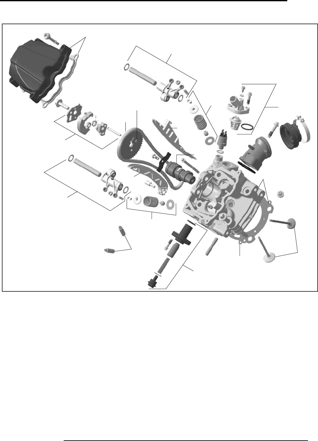
ENGINE
MOTEUR
9
2009
01
SYSTEM/SYSTÈME
Volume 1 - Can-Am
Outlander 400
V07C1WV
0134
01154
01111
01179
01134
01192
0119
01113
01116
01191
01113
01116
01255
0158
0159
01109
01116
01255
01114
01308
sales@midwestmanuals.com
sales@midwestmanuals.com
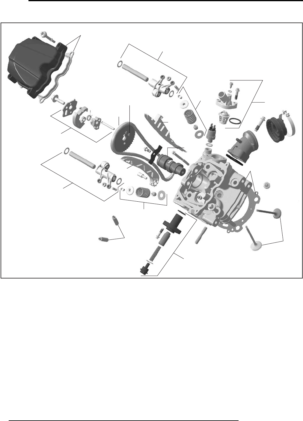
ENGINE
MOTEUR
01
SYSTEM/SYSTÈME
10 Can-Am - Volume 1
2009
Outlander 400
V07C1WU
0134
01154
01111
01179
01134
01192
0119
01113
01116
01191
01113
01116
01255
0158
0159
01109
01116
01255
01114
sales@midwestmanuals.com
sales@midwestmanuals.com
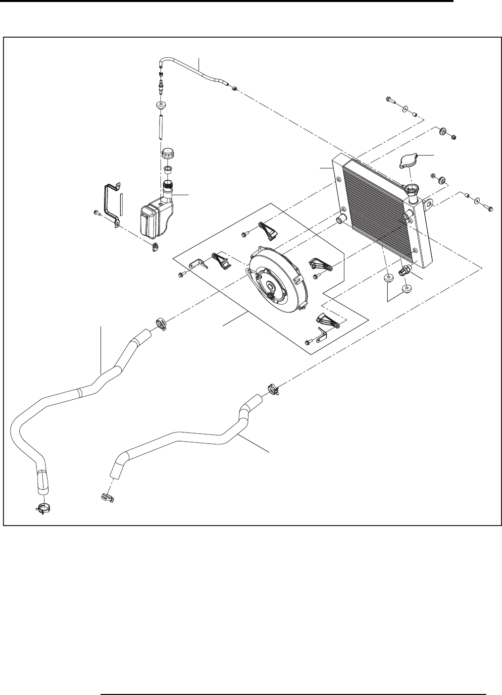
ENGINE
MOTEUR
11
2009
01
SYSTEM/SYSTÈME
Volume 1 - Can-Am
Renagade
V07C1XU
0108
0146
0179
0198
0137
01100
0146
01258
01216
sales@midwestmanuals.com
sales@midwestmanuals.com
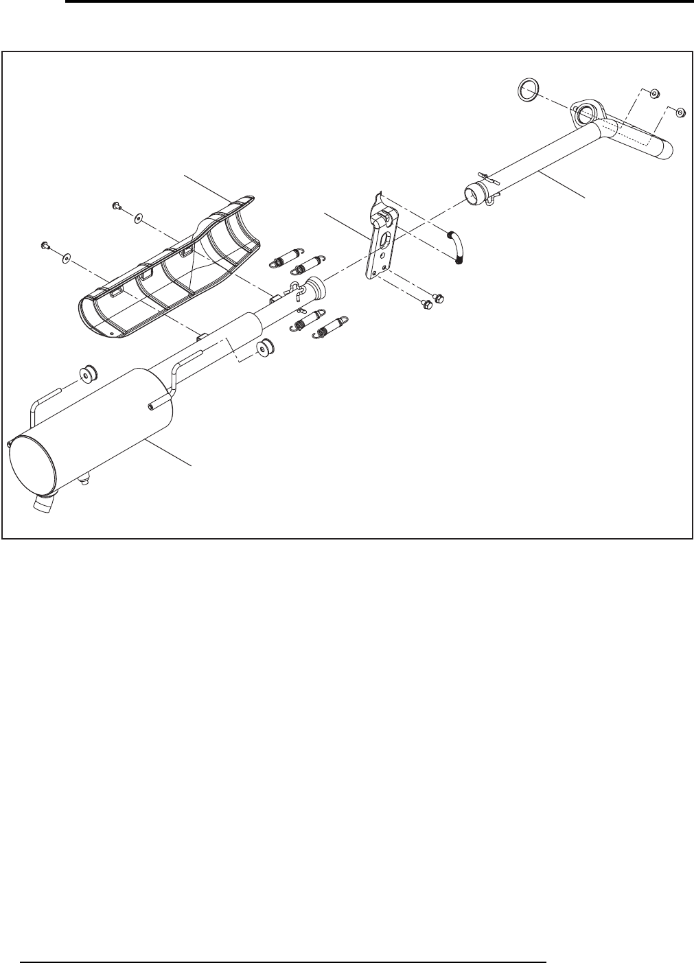
ENGINE
MOTEUR
01
SYSTEM/SYSTÈME
12 Can-Am - Volume 1
2009
Outlander 400
0170
V07C1YT
0104
0172
0187
sales@midwestmanuals.com
sales@midwestmanuals.com
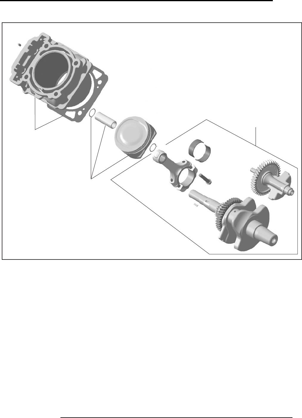
ENGINE
MOTEUR
13
2009
01
SYSTEM/SYSTÈME
Volume 1 - Can-Am
Outlander 400
V07C20S
01117
01118
01140
sales@midwestmanuals.com
sales@midwestmanuals.com
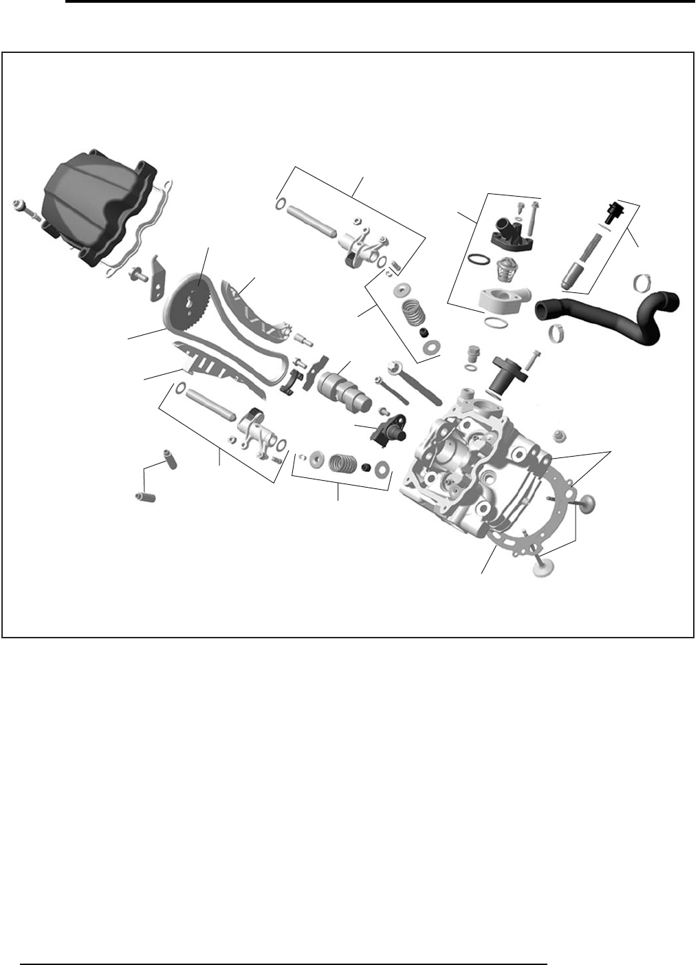
ENGINE
MOTEUR
01
SYSTEM/SYSTÈME
14 Can-Am - Volume 1
2009
V500/650/800
V07C2RU
01113
01116
01255
01256
0119
01192
01114
01113
0158
0159
01179
01304
01154
01261
01303
01111
01191
01305
01134
FRONT/REAR
AVANT/ARRIÈRE
01116
01255
01256 01116
01255
01256
01249
01308
01309
sales@midwestmanuals.com
sales@midwestmanuals.com
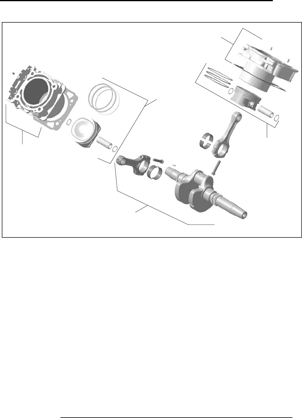
ENGINE
MOTEUR
15
2009
01
SYSTEM/SYSTÈME
Volume 1 - Can-Am
V500/650/800
V07C2SS
01117
01101
01102
01101
01102
0150
01117
sales@midwestmanuals.com
sales@midwestmanuals.com
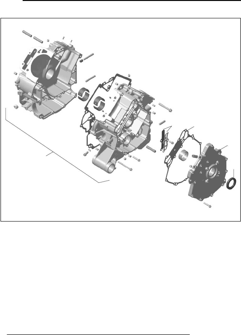
ENGINE
MOTEUR
01
SYSTEM/SYSTÈME
16 Can-Am - Volume 1
2009
V500/650/800
V07C2TS
01247 0156
0157
01245
01139
sales@midwestmanuals.com
sales@midwestmanuals.com
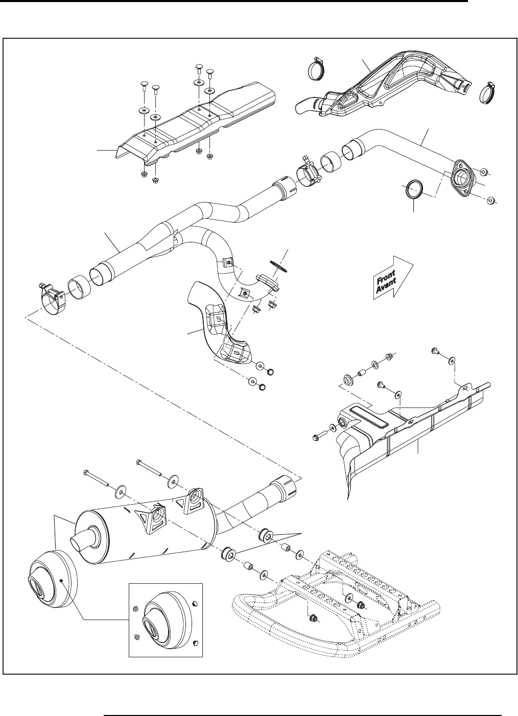
ENGINE
MOTEUR
17
2009
01
SYSTEM/SYSTÈME
Volume 1 - Can-Am
V500/650/800
Engine /
Moteur
V07C2YS
0184
0173
0104
0185
0183
0183
0186
0188
0170
sales@midwestmanuals.com
sales@midwestmanuals.com
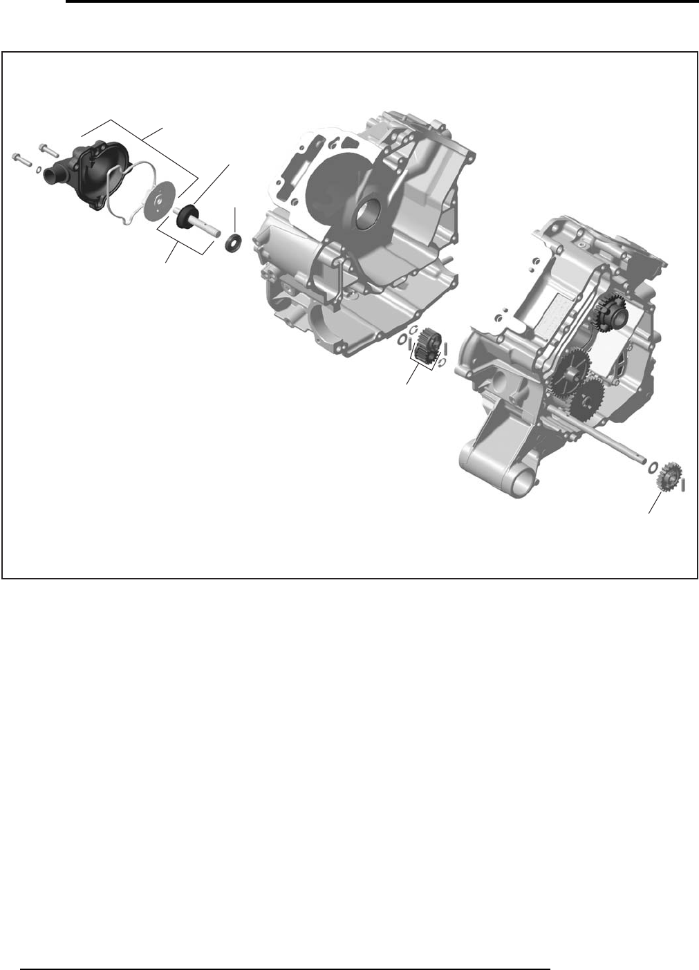
ENGINE
MOTEUR
01
SYSTEM/SYSTÈME
18 Can-Am - Volume 1
2009
V500/650/800
V07C2VT
01119
01246
0138
01246
01200
01301
sales@midwestmanuals.com
sales@midwestmanuals.com
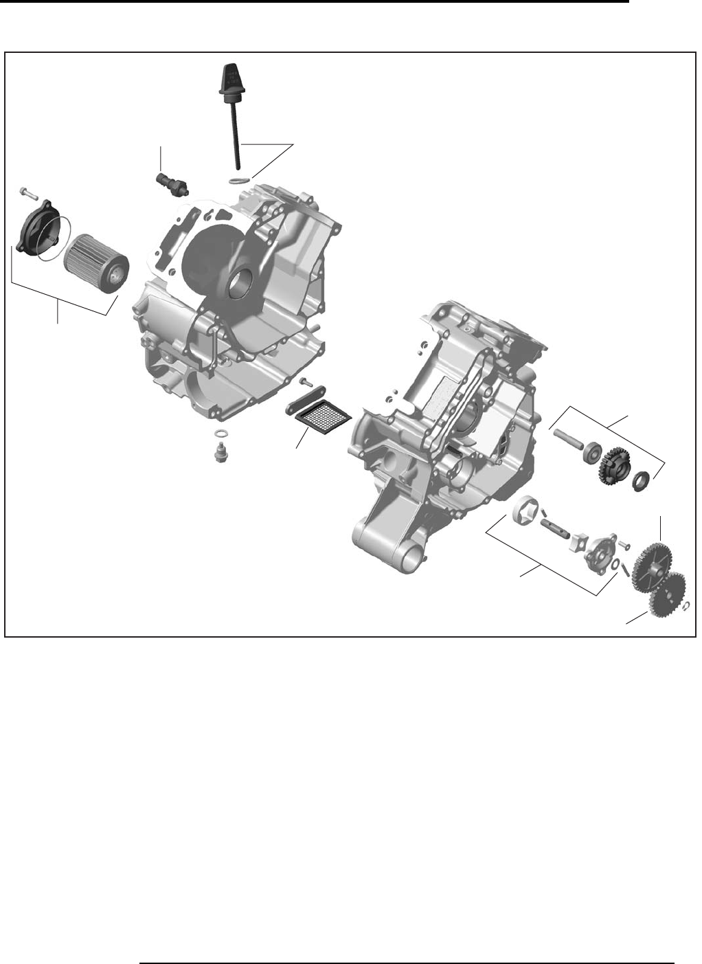
ENGINE
MOTEUR
19
2009
01
SYSTEM/SYSTÈME
Volume 1 - Can-Am
V500/650/800
V07C2WS
01215
0103
0190
0196
01132
01137
01220
01248
sales@midwestmanuals.com
sales@midwestmanuals.com
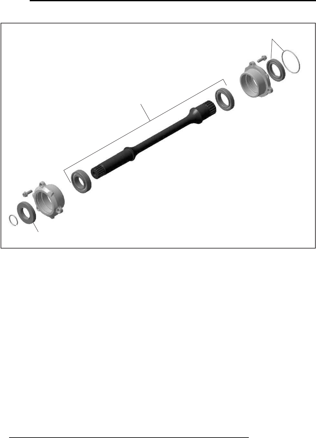
ENGINE
MOTEUR
01
SYSTEM/SYSTÈME
20 Can-Am - Volume 1
2009
V500/650/800
vtf2009-001-001_a
01205
01152
01223
sales@midwestmanuals.com
sales@midwestmanuals.com

CARBURETOR AND FUEL SYSTEM
CARBURATEUR ET SYSTÈME D’ALIMENTATION D’ESSENCE
21
2009
02
SYSTEM/SYSTÈME
Volume 1 - Can-Am
SYSTEM
SYSTÈME
CODE
DESCRIPTION
OUTLANDER
400
OUTLANDER
MAX 400
OUTLANDER
500
OUTLANDER
MAX 500
OUTLANDER
650/800
OUTLANDER
MAX 650/800
RENEGADE
500/800
1234567
02 00 NO LABOR INVOLVED
AUCUNE MAIN D’OEUVRE 0000000
02 01 AIR INTAKE SILENCER (ASS’Y)
SILENCIEUX D’ADMISSION D’AIR (COMPLET) 0.4 0.4 0.4 0.4 0.4 0.4 0.4
02 06 THROTTLE CABLE
CÂBLE D’ACCÉLÉRATEUR 0.6 0.6 0.6 0.6 0.6 0.6 0.6
02 16 INTAKE ADAPTOR
ADAPTATEUR D’ADMISSION 0.4 0.4 0.4 0.4 0.4 0.4 0.4
02 19 AIR INTAKE TUBE
TUYAU D’ADMISSION D’AIR 0.4 0.4 0.4 0.4 0.4 0.4 0.4
02 23 REAR AIR INTAKE TUBE AND/OR SLEEVE
TUYAU D’ADMISSION D’AIR ARRIÈRE ET/OU DOUILLE 0.4 0.4 0.4 0.4 0.4 0.4 0.4
02 46 AIR TEMPERATURE SENSOR
CAPTEUR DE TEMPÉRATURE D’AIR 0.3 0.3 0.3 0.3 0.3 0.3 0.3
02 57 FUEL FILTER
FILTRE À ESSENCE 0.4 0.4 0.4 0.4 0.4
02 58 FUEL TANK
RÉSERVOIR D’ESSENCE 1.5 1.5 1.5 1.5 1.5 1.5 1.5
02 59 INTAKE COVER AND/OR SEAL
COUVERCLE D’ADMISSION ET/OU JOINT D’ÉTANCHÉITÉ 0.3 0.3 0.3 0.3 0.3 0.3 0.3
02 60 FUEL CAP
BOUCHON DU RÉSERVOIR À ESSENCE 0.3 0.3 0.3 0.3 0.3 0.3 0.3
02 69 AIR FILTER
FILTRE À AIR 0.3 0.3 0.3 0.3 0.3 0.3 0.3
02 72 INTAKE MANIFOLD
CONNECTEUR D’ADMISSION 0.7 0.7 0.6 0.6 0.6 0.6 0.6
02 79 FUEL RAIL (1 OR 2)
RAMPE D’ESSENCE (1 OU 2) 0.5 0.5 0.3 0.3 0.3 0.3 0.3
02 80 INJECTOR (ALL)
INJECTEUR (TOUS) 0.6 0.6 0.4 0.4 0.4 0.4 0.4
02 81 THROTTLE BODY (ASS’Y)
CARTER ACCÉLÉRATEUR (COMPLET) 0.5 0.5 0.5 0.5 0.5 0.5 0.5
02 82 THROTTLE SENSOR
CAPTEUR POSITION D’ACCÉLÉRATEUR 0.3 0.3 0.3 0.3 0.3 0.3 0.3
02 84 IDLE BY-PASS VALVE
VALVE DU RALENTI 0.4 0.4 0.3 0.3 0.3 0.3 0.3
02 89 FUEL PUMP MODULE
MODULE POMPE À ESSENCE 0.5 0.5 0.5 0.5 0.5 0.5 0.5
02 94 FEMALE QUICK FITTING
CONNECTEUR RAPIDE FEMELLE 0.4 0.4 0.4 0.4 0.4 0.4 0.4
sales@midwestmanuals.com
sales@midwestmanuals.com

CARBURETOR AND FUEL SYSTEM
CARBURATEUR ET SYSTÈME D’ALIMENTATION D’ESSENCE
02
SYSTEM/SYSTÈME
22 Can-Am - Volume 1
2009
02 99 FUEL INJECTION HOSE (ASS’Y)
BOYAU À INJECTION D’ESSENCE (COMPLET) 0.4 0.4 0.3 0.3 0.3 0.3 0.3
02 101 FUEL TANK PROTECTOR
PROTECTEUR DU RÉSERVOIR À ESSENCE 1.2 1.2 1.2 1.2 1.2 1.2 1.2
SYSTEM
SYSTÈME
CODE
DESCRIPTION
OUTLANDER
400
OUTLANDER
MAX 400
OUTLANDER
500
OUTLANDER
MAX 500
OUTLANDER
650/800
OUTLANDER
MAX 650/800
RENEGADE
500/800
1234567
sales@midwestmanuals.com
sales@midwestmanuals.com
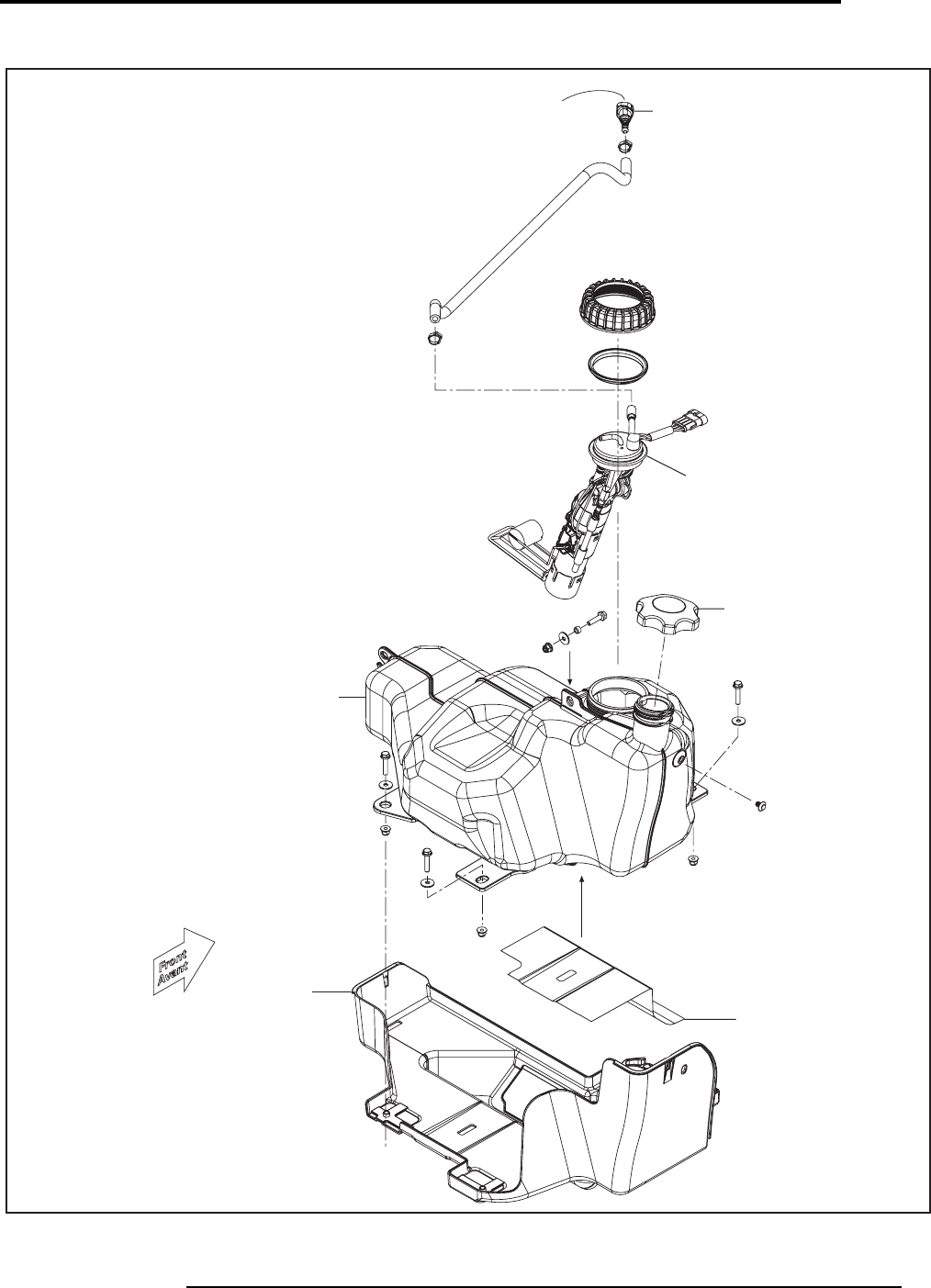
CARBURETOR AND FUEL SYSTEM
CARBURATEUR ET SYSTÈME D’ALIMENTATION D’ESSENCE
23
2009
02
SYSTEM/SYSTÈME
Volume 1 - Can-Am
Outlander Renegade
vtf2009-001-002_a
0294
0289
0262
02101
02101
0258
sales@midwestmanuals.com
sales@midwestmanuals.com
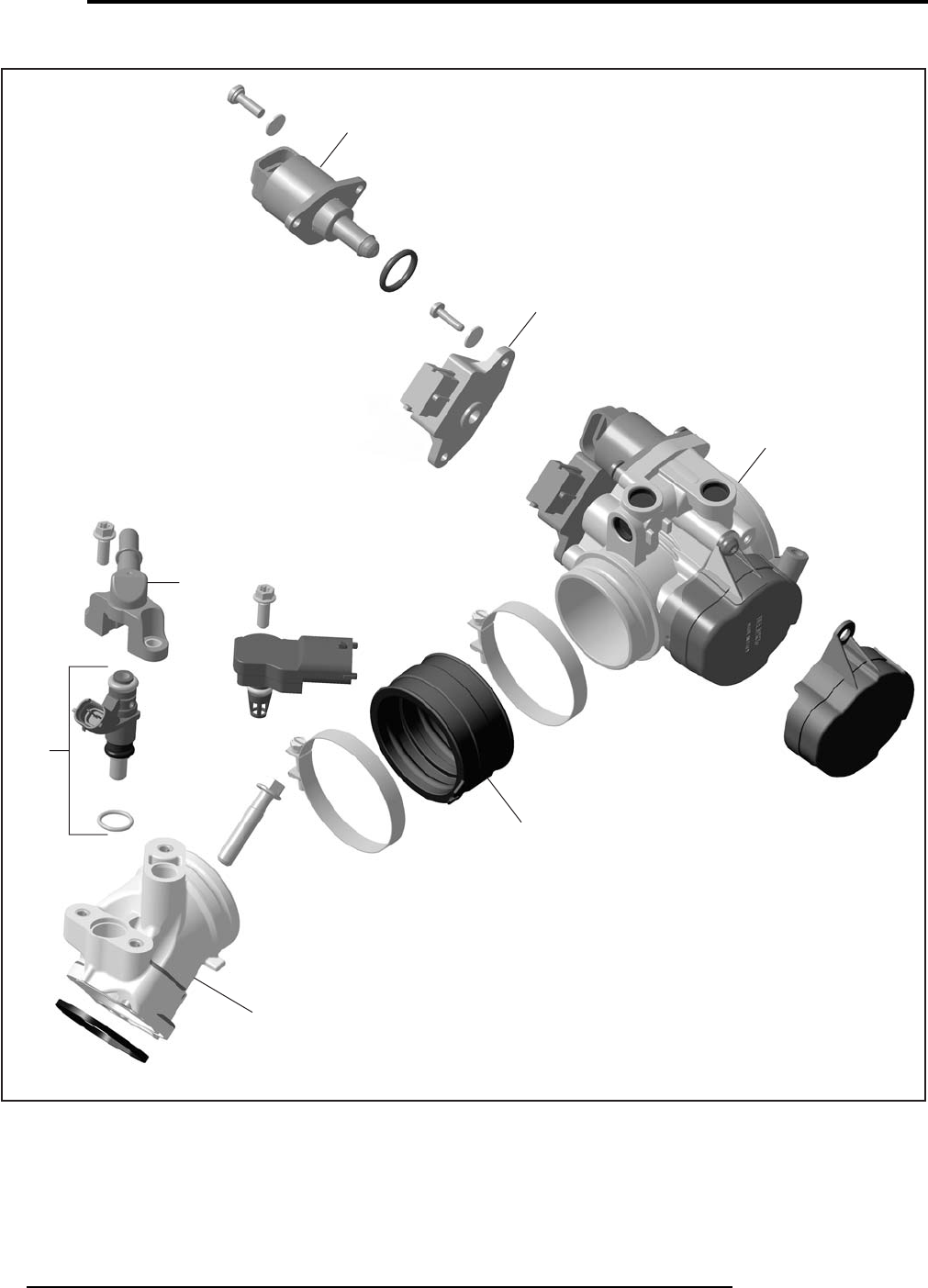
CARBURETOR AND FUEL SYSTEM
CARBURATEUR ET SYSTÈME D’ALIMENTATION D’ESSENCE
02
SYSTEM/SYSTÈME
24 Can-Am - Volume 1
2009
400 EFI
vtf2009-001-003_a
0284
0282
0281
0216
0272
0279
0280
sales@midwestmanuals.com
sales@midwestmanuals.com
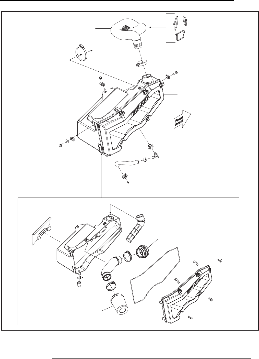
CARBURETOR AND FUEL SYSTEM
CARBURATEUR ET SYSTÈME D’ALIMENTATION D’ESSENCE
25
2009
02
SYSTEM/SYSTÈME
Volume 1 - Can-Am
Engine /
Moteur
Throttle Body /
Corps du Papillon
vtf2009-001-004_a
0219
0201
0223
0269
sales@midwestmanuals.com
sales@midwestmanuals.com
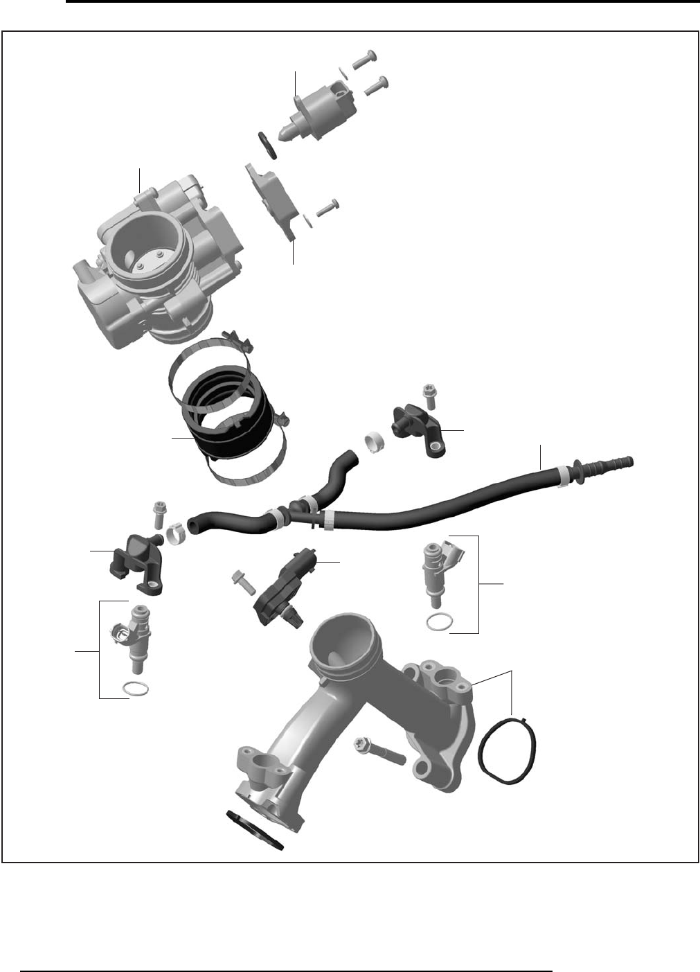
CARBURETOR AND FUEL SYSTEM
CARBURATEUR ET SYSTÈME D’ALIMENTATION D’ESSENCE
02
SYSTEM/SYSTÈME
26 Can-Am - Volume 1
2009
0284
0282
0281
0216
0279 0246
0280
0280
0272
0279 0299
V07F18T
sales@midwestmanuals.com
sales@midwestmanuals.com
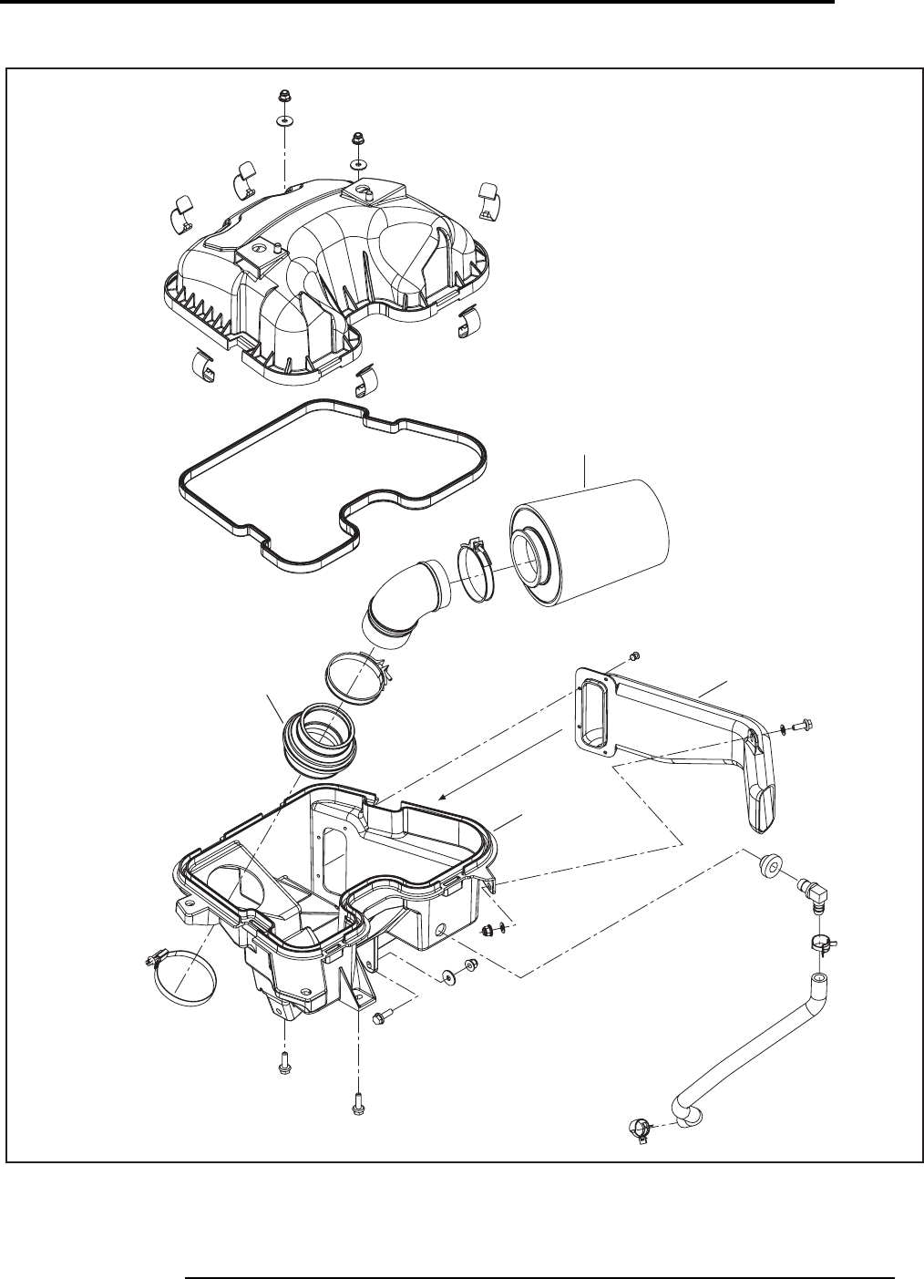
CARBURETOR AND FUEL SYSTEM
CARBURATEUR ET SYSTÈME D’ALIMENTATION D’ESSENCE
27
2009
02
SYSTEM/SYSTÈME
Volume 1 - Can-Am
V500/650/800
V07F0AS
0269
0223
0201
0219
sales@midwestmanuals.com
sales@midwestmanuals.com
IGNITION
ALLUMAGE
03
SYSTEM/SYSTÈME
28 Can-Am - Volume 1
2009
SYSTEM
SYSTÈME
CODE
DESCRIPTION
OUTLANDER
400
OUTLANDER
MAX 400
OUTLANDER
500
OUTLANDER
MAX 500
OUTLANDER
650/800
OUTLANDER
MAX 650/800
RENEGADE
500/800
1234567
03 00 NO LABOR INVOLVED
AUCUNE MAIN D’OEUVRE 0000000
03 02 MAGNETO (ASS’Y)
MAGNÉTO (COMPLET) 3.9 3.9 1.6 1.6 1.6 1.6 1.6
03 08 IGNITION COIL (EACH)
BOBINE D’ALLUMAGE (CHAQUE) 0.3 0.3 0.3 0.3 0.3 0.3 0.3
03 10 IGNITION CABLE
CÂBLE D’ALLUMAGE 0.3 0.3 0.3 0.3 0.3 0.3 0.3
03 27 STATOR (ASS’Y)
STATOR (COMPLET) 3.7 3.7 1.5 1.5 1.5 1.5 1.5
sales@midwestmanuals.com
sales@midwestmanuals.com
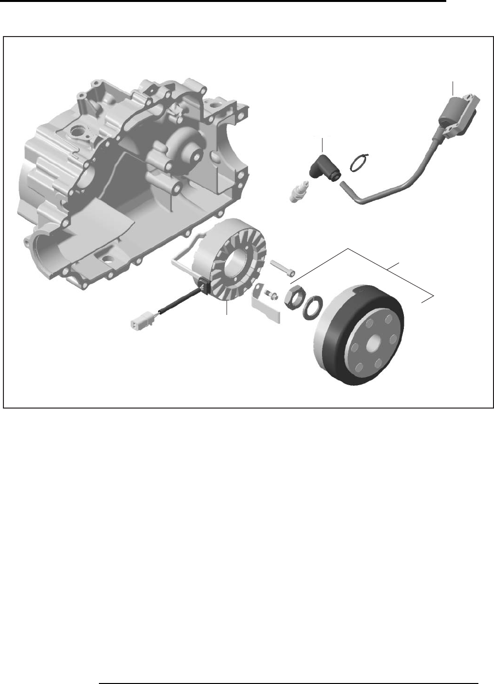
IGNITION
ALLUMAGE
29
2009
03
SYSTEM/SYSTÈME
Volume 1 - Can-Am
Outlander 400
V07G0ET
0310
0308
0302
0327
sales@midwestmanuals.com
sales@midwestmanuals.com
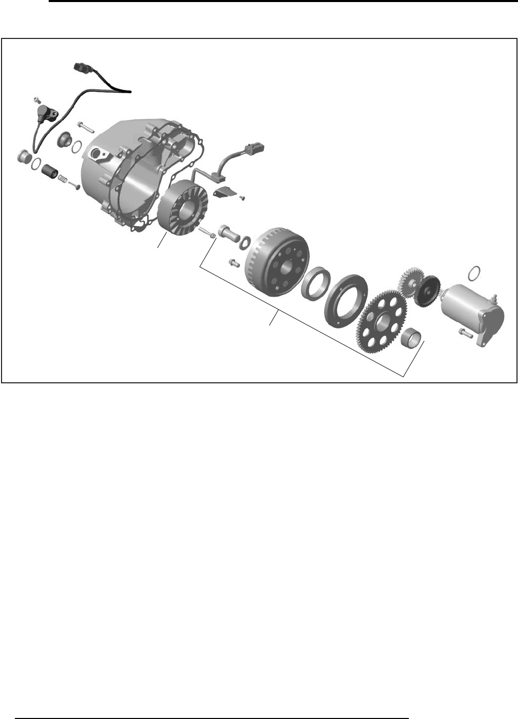
IGNITION
ALLUMAGE
03
SYSTEM/SYSTÈME
30 Can-Am - Volume 1
2009
V500/650/800
V07G29S
0327
0302
sales@midwestmanuals.com
sales@midwestmanuals.com
STARTER
DÉMARREUR
31
2009
04
SYSTEM/SYSTÈME
Volume 1 - Can-Am
SYSTEM
SYSTÈME
CODE
DESCRIPTION
OUTLANDER
400
OUTLANDER
MAX 400
OUTLANDER
500
OUTLANDER
MAX 500
OUTLANDER
650/800
OUTLANDER
MAX 650/800
RENEGADE
500/800
1234567
04 00 NO LABOUR INVOLVED
AUCUNE MAIN-D’OEUVRE 0000000
04 01 REWIND STARTER (ALL PARTS EXCEPT HANDLE)
DÉMARREUR À RAPPEL (TOUTES LES PIÈCES SAUF POIGNÉE) 0.3 0.3
04 02 ELECTRIC STARTER (ASS’Y)
DÉMARREUR (COMPLET) 0.3 0.3 0.3 0.3 0.3 0.3 0.3
04 03 STARTER RELAY
SOLÉNOÏDE DE DÉMARRAGE 0.3 0.3 0.3 0.3 0.3 0.3 0.3
04 09 REWIND STARTER HANDLE
POIGNÉE DU DÉMARREUR 0.3 0.3
04 19 STARTER DRIVE
LANCEUR DÉMARREUR 0.7 0.7 1.4 1.4 1.4 1.4 1.4
sales@midwestmanuals.com
sales@midwestmanuals.com
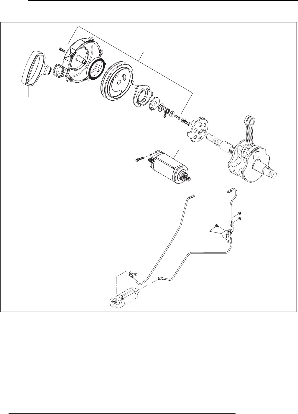
STARTER
DÉMARREUR
04
SYSTEM/SYSTÈME
32 Can-Am - Volume 1
2009
Outlander
V01C36S
0402
0409
0401
0403
sales@midwestmanuals.com
sales@midwestmanuals.com
TRANSMISSION AND LINKAGE
TRANSMISSION ET TRINGLERIE
33
2009
05
SYSTEM/SYSTÈME
Volume 1 - Can-Am
SYSTEM
SYSTÈME
CODE
DESCRIPTION
OUTLANDER
400
OUTLANDER
MAX 400
OUTLANDER
500
OUTLANDER
MAX 500
OUTLANDER
650/800
OUTLANDER
MAX 650/800
RENEGADE
500/800
1234567
05 00 NO LABOR INVOLVED
AUCUNE MAIN-D’OEUVRE IMPLIQUÉE 0000000
05 12 DRIVEN PULLEY SLIDING HALF
DEMI-POULIE MENÉE COULISSANTE 0.5 0.5 0.5 0.5 0.5 0.5 0.5
05 19 BELT
COURROIE 0.4 0.4 0.4 0.4 0.4 0.4 0.4
05 55 LEVER BUTTON
BOUTON DE LEVIER 0.3 0.3 0.3 0.3 0.3 0.3 0.3
05 56 LEVER (ASS’Y) AND/OR LEVER SPRING
LEVIER (COMPLET) ET/OU RESSORT DE LEVIER 0.3 0.3 0.3 0.3 0.3 0.3 0.3
05 59 SPEED SENSOR
CAPTEUR DE VITESSE 0.3 0.3 0.3 0.3 0.3 0.3 0.3
05 78 CVT COVER
COUVERCLE CVC 0.3 0.3 0.3 0.3 0.3 0.3 0.3
05 79 GASKET
JOINT D’ÉTANCHÉITÉ 0.3 0.3 0.3 0.3 0.3 0.3 0.3
05 80 GOVERNOR CUP
COUPOLE RÉGULATEUR 0.6 0.6 0.6 0.6 0.6 0.6 0.6
05 81 ONE WAY CLUTCH, FLANGE, RING, SPRING
EMBRAYAGE À ROUE LIBRE, FLASQUE, ANNEAU, RESSORT 0.6 0.6 0.6 0.6 0.6 0.6 0.6
05 82 DRIVE PULLEY (ASS’Y)
POULIE MOTRICE (COMPLET) 0.7 0.7 0.7 0.7 0.7 0.7 0.7
05 83 DRIVE PULLEY FIXED HALF
POULIE MOTRICE FIXE 0.7 0.7 0.7 0.7 0.7 0.7 0.7
05 84 DRIVEN PULLEY OUTER CAM AND/OR SPRING
CAME DE POULIE MENÉE EXTERNE ET/OU RESSORT 0.5 0.5 0.5 0.5 0.5 0.5 0.5
05 85 CENTRIFUGAL LEVER
LEVIER CENTRIFUGE 0.8 0.8 0.8 0.8 0.8 0.8 0.8
05 86 SLIDER SHOES
GLISSIÈRES 0.7 0.7 0.7 0.7 0.7 0.7 0.7
05 87 LEVER SPRING
LEVIER À RESSORT 0.3 0.3 0.3 0.3 0.3 0.3 0.3
05 91 MAIN SHAFT (ASS'Y)
ARBRE DE RENVOI (COMPLET) 5.1 5.1 5.1 5.1 5.1
05 95 AIR INTAKE (CVT)
ENTRÉE D'AIR (CVT) 0.3 0.3 0.3 0.3 0.3 0.3 0.3
05 96 AIR OUTLET (CVT)
SORTIE D'AIR (CVT) 0.3 0.3 0.3 0.3 0.3 0.3 0.3
05 97 FLEXIBLE ADAPTOR
ADAPTATEUR FLEXIBLE 0.3 0.3 0.3 0.3 0.3 0.3 0.3
05 98 CAM, PLATE, DRIVEN SHAFT, SPRING
CAME, PLAQUE, ARBRE POULIE MENÉE, RESSORT 0.5 0.5 0.5 0.5 0.5 0.5 0.5
sales@midwestmanuals.com
sales@midwestmanuals.com
TRANSMISSION AND LINKAGE
TRANSMISSION ET TRINGLERIE
05
SYSTEM/SYSTÈME
34 Can-Am - Volume 1
2009
05 99 OUTPUT SHAFT
ARBRE DE SORTIE 5.0 5.0 5.0 5.0 5.0
05 100 REAR OUTPUT SHAFT SEALS
ANNEAUX ÉTANCHÉITÉ DE L’ARBRE DE SORTIE ARRIÈRE 3.1 3.1 3.1 3.1 3.1
05 101 GEARS BOX (ASS'Y)/MAIN SHAFT
BOÎTE D'ENGRENAGE (COMPLET)/ARBRE PRINCIPAL 5.1 5.1 5.1 5.1 5.1
05 102 SHIFT SHAFT (ASS'Y )
ARBRE D'EMBRAYAGE (COMPLET) 5.1 5.1 5.1 5.1 5.1
05 103 SHIFT DRUM
TAMBOUR D'EMBRAYAGE 5.1 5.1 5.1 5.1 5.1
05 104 INDEX LEVER (ASS'Y)
LEVIER D'INDEXATION (COMPLET) 5.1 5.1 5.1 5.1 5.1
05 105 MAIN SHAFT SEAL
JOINT D'ÉTANCHÉITÉ DE L'ARBRE PRINCIPAL 0.7 0.7 0.7 0.7 0.7
05 106 LH HOUSING GEAR AND/OR BEARINGS AND/OR GEAR
LOGEMENT DE TRANSMISSION GAUCHE ET/OU ROULEMENT À
BILLE ET/OU ENGRENAGE 5.1 5.1 5.1 5.1 5.1
05 107 SPACER AND/OR O-RING
ENTRETOISE ET/OU JOINT TORIQUE 0.5 0.5 0.5 0.5 0.5
05 108 ACTUATOR AND/OR FORK AND/OR SEAL
ACTUATEUR ET/OU FOURCHETTE ET/OU JOINT D'ÉTANCHÉITÉ 0.5 0.5 0.5 0.5 0.5
05 109 FORK AND/OR PIN
FOURCHETTE ET/OU GOUPILLE 0.7 0.7 0.7 0.7 0.7
05 110 CENTER HOUSING GEAR AND/OR BEARING
LOGEMENT DE TRANSMISSION CENTRE ET/OU ROULEMENT 5.1 5.1 5.1 5.1 5.1
05 111 RH HOUSING GEAR AND/OR BEARING
LOGEMENT DE TRANSMISSION DROIT ET/OU ROULEMENT 5.0 5.0 5.0 5.0 5.0
05 112 TRANSMISSION SWITCHES
INTERRUPTEUR DE TRANSMISSION 0.6 0.6 0.3 0.3 0.3 0.3 0.3
05 113 SHIFTING SWITCH
INTERRUPTEUR D'EMBRAYAGE 0.3 0.3 0.3 0.3 0.3
05 114 SHIFT SHAFT SEAL
ANNEAU D’ÉTANCHÉITÉ DE L'ARBRE D'EMBRAYAGE 0.3 0.3 0.3 0.3 0.3
05 115 CVT AIR GUIDE AND/OR O-RINGS
GUIDE D'AÉRATION ET/OU JOINT D'ÉTANCHÉITÉ 0.8 0.8 0.8 0.8 0.8
SYSTEM
SYSTÈME
CODE
DESCRIPTION
OUTLANDER
400
OUTLANDER
MAX 400
OUTLANDER
500
OUTLANDER
MAX 500
OUTLANDER
650/800
OUTLANDER
MAX 650/800
RENEGADE
500/800
1234567
sales@midwestmanuals.com
sales@midwestmanuals.com
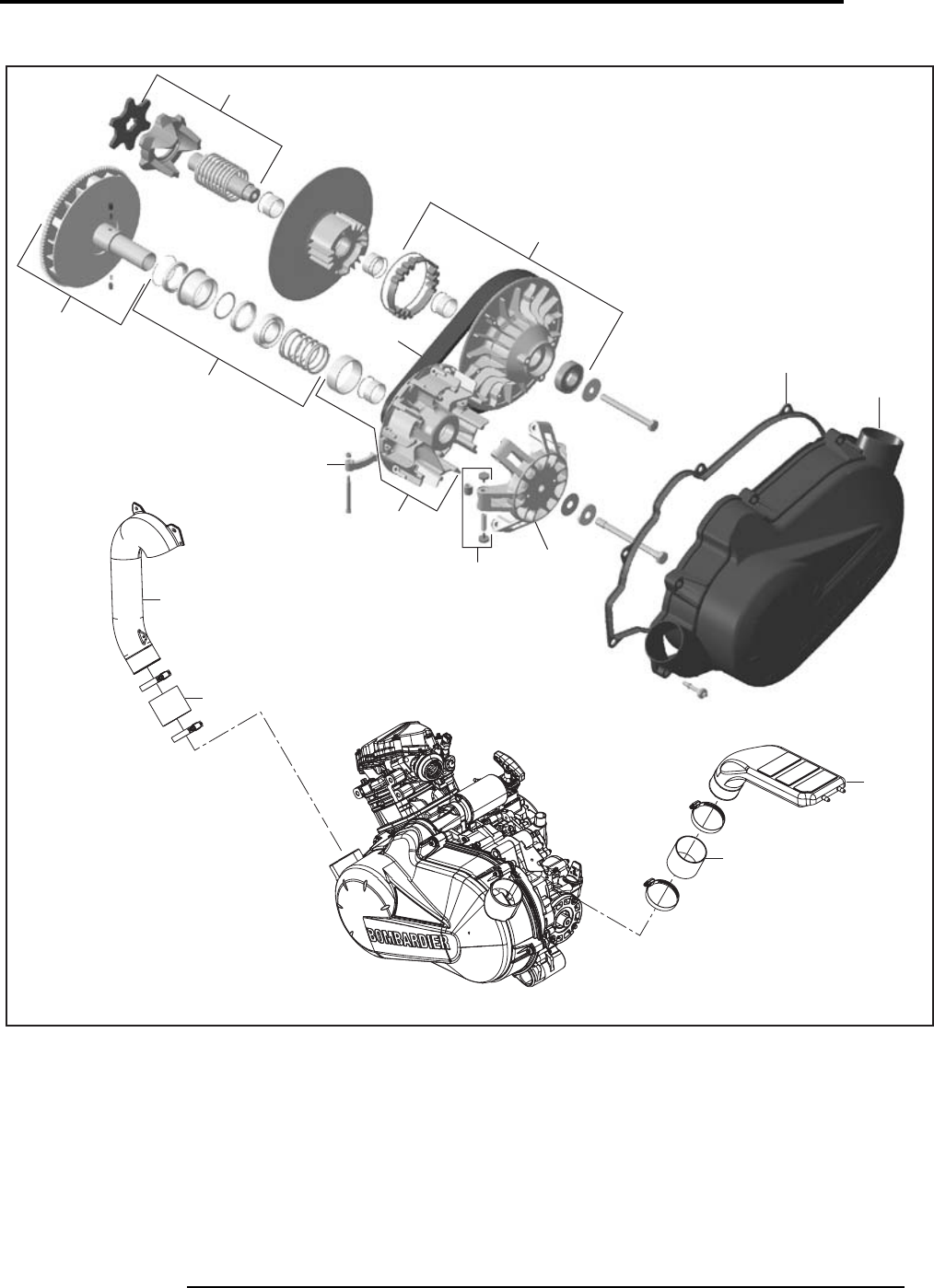
TRANSMISSION AND LINKAGE
TRANSMISSION ET TRINGLERIE
35
2009
05
SYSTEM/SYSTÈME
Volume 1 - Can-Am
Outlander 400
V07K13S
0512
0584
0579
0578
0519
0580
0586
0582
0581
0583
0585
0598
0595
0597
0596
0597
sales@midwestmanuals.com
sales@midwestmanuals.com
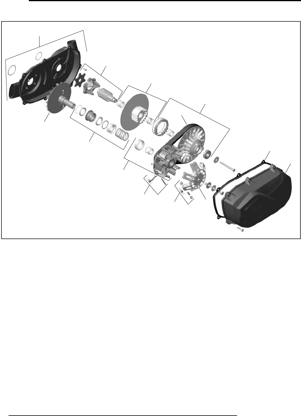
TRANSMISSION AND LINKAGE
TRANSMISSION ET TRINGLERIE
05
SYSTEM/SYSTÈME
36 Can-Am - Volume 1
2009
V500/650/800
V07K15S
05115
0598
0512
0584
0519
0579
0578
0585
0586 0580
0582
0581
0583
sales@midwestmanuals.com
sales@midwestmanuals.com
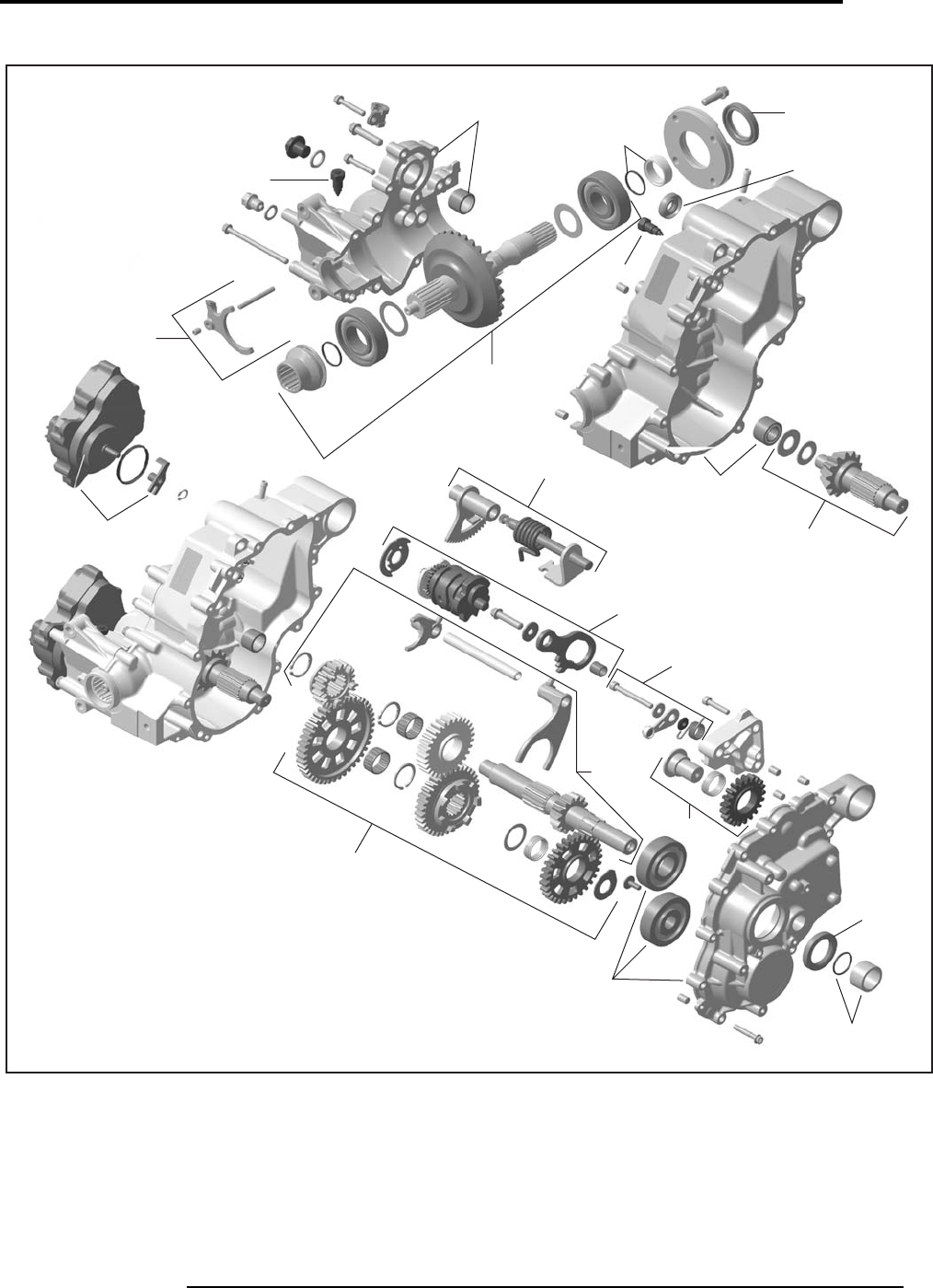
TRANSMISSION AND LINKAGE
TRANSMISSION ET TRINGLERIE
37
2009
05
SYSTEM/SYSTÈME
Volume 1 - Can-Am
V500/650/800
V07K16S
05113
05109
0599
05100
05100
05114
05112
05110
05101
05102
05103
05104
05106
0591
05101
05106
05107
05105
05108
05111
sales@midwestmanuals.com
sales@midwestmanuals.com
BRAKE SYSTEM
SYSTÈME DE FREIN
06
SYSTEM/SYSTÈME
38 Can-Am - Volume 1
2009
SYSTEM
SYSTÈME
CODE
DESCRIPTION
OUTLANDER
400
OUTLANDER
MAX 400
OUTLANDER
500
OUTLANDER
MAX 500
OUTLANDER
650/800
OUTLANDER
MAX 650/800
RENEGADE
500/800
1234567
06 00 NO LABOR INVOLVED
AUCUNE MAIN-D’OEUVRE 0 0 0 0 0 0 0
06 09 FRONT CALIPER (RH OR LH)
ÉTRIER AVANT (DROIT OU GAUCHE) 0.4 0.4 0.4 0.4 0.4 0.4 0.4
06 10 FRONT BRAKE PAD (RH OR LH)
PLAQUETTE DE FREIN AVANT (DROIT OU GAUCHE) 0.3 0.3 0.3 0.3 0.3 0.3 0.3
06 11 FRONT BRAKE DISC (RH OR LH)
DISQUE DE FREIN AVANT (DROIT OU GAUCHE) 0.7 0.7 0.7 0.7 0.9 0.9 0.5
06 12 FRONT FLEXIBLE BRAKE HOSE
BOYAU FLEXIBLE DE FREIN AVANT 0.9 0.9 0.9 0.9 0.9 0.9 0.9
06 16 FRONT MASTER CYLINDER
MAÎTRE-CYLINDRE AVANT 0.4 0.4 0.4 0.4 0.4 0.4 0.4
06 17 REAR BRAKE PEDAL
PÉDALE DE FREIN ARRIÈRE 0.4 0.4 0.4 0.4 0.4 0.4 0.4
06 18 REAR BRAKE PEDAL SPRING
RESSORT DE LA PÉDALE DE FREIN ARRIÈRE 0.3 0.3 0.3 0.3 0.3 0.3 0.3
06 19 BRAKE SWITCH
INTERRUPTEUR DE FREIN 0.3 0.3 0.3 0.3 0.3 0.3 0.3
06 22 REAR MASTER CYLINDER
MAÎTRE-CYLINDRE ARRIÈRE 0.8 0.8 0.8 0.8 0.8 0.8 0.8
06 23 REAR OIL HOUSING HOSE
BOYAU CARTER D’HUILE ARRIÈRE 0.6 0.6 0.6 0.6 0.6 0.6 0.6
06 24 REAR OIL HOUSING
CARTER D’HUILE ARRIÈRE 0.3 0.3 0.3 0.3 0.3 0.3 0.3
06 25 REAR BRAKE HOSE
BOYAU DE FREIN ARRIÈRE 0.6 0.6 0.6 0.6 0.6 0.6 0.6
06 26 REAR CALIPER
ÉTRIER ARRIÈRE 0.4 0.4 0.4 0.4 0.4 0.4 0.4
06 27 REAR BRAKE PAD
PLAQUETTE DE FREIN ARRIÈRE 0.3 0.3 0.3 0.3 0.3 0.3 0.3
06 28 REAR BRAKE DISC AND/OR HUB
DISQUE DE FREIN ARRIÈRE ET/OU MOYEU 0.9 0.9 0.9 0.9 0.9 0.9 0.9
sales@midwestmanuals.com
sales@midwestmanuals.com
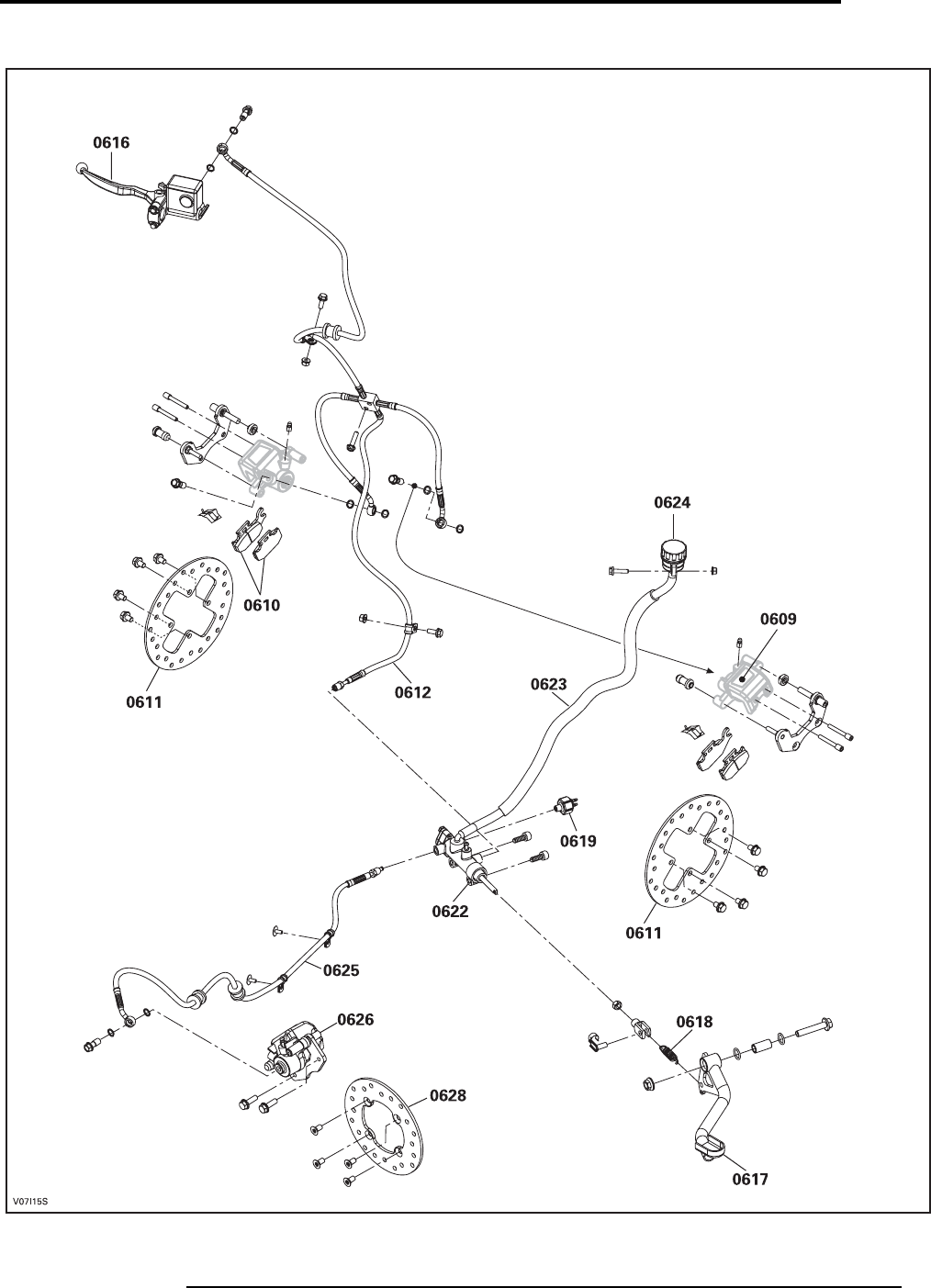
BRAKE SYSTEM
SYSTÈME DE FREIN
39
2009
06
SYSTEM/SYSTÈME
Volume 1 - Can-Am
Outlander/Renegade
sales@midwestmanuals.com
sales@midwestmanuals.com

STEERING/FRONT DRIVE SYSTEM AND SUSPENSION
DIRECTION/SYSTÈEME D’ENTRAÎNEMENT AVANT ET SUSPENSION
07
SYSTEM/SYSTÈME
40 Can-Am - Volume 1
2009
SYSTEM
SYSTÈME
CODE
DESCRIPTION
OUTLANDER
400
OUTLANDER
MAX 400
OUTLANDER
500
OUTLANDER
MAX 500
OUTLANDER
650/800
OUTLANDER
MAX 650/800
RENEGADE
500/800
1234567
07 00 NO LABOR INVOLVED
AUCUNE MAIN-D’OEUVRE 0000000
07 04 ARM PROTECTOR (RH OR LH)
PROTECTEUR DE BRAS (DROIT OU GAUCHE) 0.3 0.3 0.3 0.3 0.3 0.3 0.3
07 05 STEERING CLAMP AND/OR STEERING COVER SUPPORT
BRIDE DE DIRECTION ET/OU SUPPORT DU COUVRE-GUIDON 0.40.40.40.40.40.40.4
07 07 THRUST BEARING
PALIER DE BUTÉE 1.6 1.6 1.6 1.6 1.6 1.6 1.6
07 12 INTERNAL BALL JOINT (RH OR LH)
JOINT À ROTULE INTERNE (DROIT AU GAUCHE) 0.90.90.90.90.90.90.9
07 13 EXTERNAL BALL JOINT (RH OR LH)
JOINT À ROTULE EXTERNE (DROIT OU GAUCHE) 0.8 0.8 0.8 0.8 0.8 0.8 0.8
07 19 TIE ROD (RH OR LH)
BARRE D’ACCOUPLEMENT (DROIT OU GAUCHE) 0.90.90.90.90.90.90.9
07 24 MAIN TUBE
TUBE PRINCIPAL 2.0 2.0 2.0 2.0 2.0 2.0 2.0
07 25 HANDLEBAR
GUIDON 1.11.11.11.11.11.11.1
07 26 HANDLEBAR GRIP KIT (RH AND/OR LH)
ENSEMBLE DE GAINE DE GUIDON (DROIT ET/OU GAUCHE) 0.3 0.3 0.3 0.3 0.3 0.3 0.3
07 27 STEERING COVER
COUVRE-GUIDON 0.40.40.30.30.30.3
07 28 HALF HOUSING AND HOUSING BUSHING
DEMI-LOGEMENT ET DOUILLE DE LOGEMENT 0.7 0.7 0.7 0.7 0.7 0.7 0.7
07 32 LOWER ARM AND/OR BALL JOINT (RH OR LH)
BRAS INFÉRIEUR ET/OU JOINT À ROTULE (DROIT OU GAUCHE) 0.70.70.70.70.70.70.7
07 33 UPPER ARM (RH OR LH)
BRAS DE SUSPENSION SUPÉRIEUR (DROIT OU GAUCHE) 0.8 0.8 0.8
07 37
FRONT SHOCK AND/OR SPRING AND/OR STOPPER AND/OR
PROTECTOR AND/OR SEAT (RH OR LH)
AMORTISSEUR AVANT ET/OU RESSORT ET/OU BUTÉE ET/OU
SIÈGE ET/OU PROTECTEUR (DROIT OU GAUCHE)
0.70.70.70.70.70.70.7
07 40 FRONT DIFFERENTIEL (ASS’Y)
DIFFÉRENTIEL AVANT (COMPLET) 2.3 2.3 2.3 2.3 2.6 2.6 2.6
07 42 FRONT PROPELLER SHAFT (ASS’Y)
ARBRE DE PROPULSION AVANT (COMPLET) 1.41.41.71.72.02.02.0
07 45 CV JOINT (RH OR LH)
JOINT HOMOCINÉTIQUE (DROIT OU GAUCHE) 0.7 0.7 0.7 0.7 0.7 0.7 0.7
07 46 FRONT WHEEL HUB (SEAL AND/OR BEARING) (RH OR LH)
MOYEU DE ROUE AVANT (JOINT ET/OU ROULEMENT)
(DROIT OU GAUCHE) 0.30.30.30.30.30.30.4
07 47 KNUCKLE (RH OR LH)
PORTE-FUSÉE (DROIT OU GAUCHE) 0.4 0.4 0.4 0.4 0.4 0.4 0.4
sales@midwestmanuals.com
sales@midwestmanuals.com

STEERING/FRONT DRIVE SYSTEM AND SUSPENSION
DIRECTION/SYSTÈEME D’ENTRAÎNEMENT AVANT ET SUSPENSION
41
2009
07
SYSTEM/SYSTÈME
Volume 1 - Can-Am
07 50 FRONT RIM AND/OR TIRE
JANTE AVANT ET/OU PNEU 0.4 0.4 0.4 0.4 0.4 0.4 0.4
07 56 THROTTLE HANDLE
MANETTE D’ACCÉLÉRATEUR 0.30.30.30.30.30.30.3
07 72
INTERNAL BUSHING AND/OR CUSHION
(LOWER AND/OR UPPER ARM) (RH OR LH)
DOUILLE INTERNE ET/OU COUSSIN (BRAS INFÉRIEUR ET/OU
SUPÉRIEUR) (DROIT OU GAUCHE)
0.4 0.4 0.4 0.4 0.4 0.4 0.4
07 80 FRONT RIM
JANTE AVANT 0.40.40.40.40.40.40.4
07 82 RADIAL BALL BEARINGS
ROULEMENTS À BILLE RADIALES 0.5 0.5 0.5 0.5 0.5 0.5 0.5
07 85 RING GEAR AND/OR CARRIER AND/OR SHIM
COURONNE DE LANCEMENT ET/OU SUPPORT ET/OU CALE 2.72.72.72.72.72.72.7
07 86 DISCONNECT UNIT AND/OR ALL PARTS
UNITÉ D’EMBRAYAGE ET/OU TOUTES LES PIÈCES 2.0 2.0
07 87 ACTUATOR AND/OR SHIFTING AND/OR FORK AND/OR SLIDDING
ACTUATEUR ET/OU EMBRAYAGE ET/OU FOURCHETTE ET/OU
GLISSIÈRE 0.9 0.9
07 88 RING GEAR DRIVE GEAR AND/OR BEARING AND/OR SHIM
PIGNON DE COMMANDE DE LA COURONNE ET/OU ROULEMENT
À BILLE ET/OU CALE 2.7 2.7 2.7 2.7 2.9 2.9 2.9
07 89 COVER AND/OR PINION COVER AND/OR SEAL AND/OR BEARING
COUVERCLE ET/OU COUVERCLE DE PIGNON ET/OU JOINT
D’ÉTANCHÉITÉ ET/OU ROULEMENT À BILLE 3.03.03.03.03.23.23.2
07 90 BOOT WHEEL KIT AND/OR CV JOINT (RH OR LH)
ENSEMBLE DE SOUFFLET DE ROUE ET/OU JOINT CV
(DROIT OU GAUCHE) 0.8 0.8 0.8 0.8 0.8 0.8 0.8
07 91
BOOT DIFFERENTIAL KIT AND/OR PLUNGING JOINT
(RH OR LH)
ENSEMBLE DE SOUFFLET DE DIFFÉRENCIEL ET/OU JOINT
PLONGEANT (DROIT OU GAUCHE)
0.80.80.80.80.80.80.8
07 92 SLEEVE AND/OR WEARRING
MANCHON ET/OU BAGUE D'USURE 1.6 1.6 1.6 1.6 1.6 1.6 1.6
07 93 O-RING (DISCONNECT UNIT)
JOINT TORIQUE (UNITÉ D’EMBRAYAGE) 1.8 1.8
07 94 UNIT PACK KIT
ENSEMBLE JOINT CARDAN 2.3 2.3 2.3 2.3 2.3 2.3 2.3
07 96 UPPER ARM BRACKET
ATTACHE BRAS SUPÉRIEUR 2.2
07 103 DIFFERENTIAL SEAL (1)
JOINT D’ÉTANCHÉITÉ DU DIFFÉRENTIEL (1) 0.7 0.7 0.7 0.7 0.7 0.7 0.7
07 104 DIFFERENTIAL SEALS (2)
JOINTS D’ÉTANCHÉITÉ DU DIFFÉRENTIEL (2) 1.41.41.41.41.41.41.4
SYSTEM
SYSTÈME
CODE
DESCRIPTION
OUTLANDER
400
OUTLANDER
MAX 400
OUTLANDER
500
OUTLANDER
MAX 500
OUTLANDER
650/800
OUTLANDER
MAX 650/800
RENEGADE
500/800
1234567
sales@midwestmanuals.com
sales@midwestmanuals.com
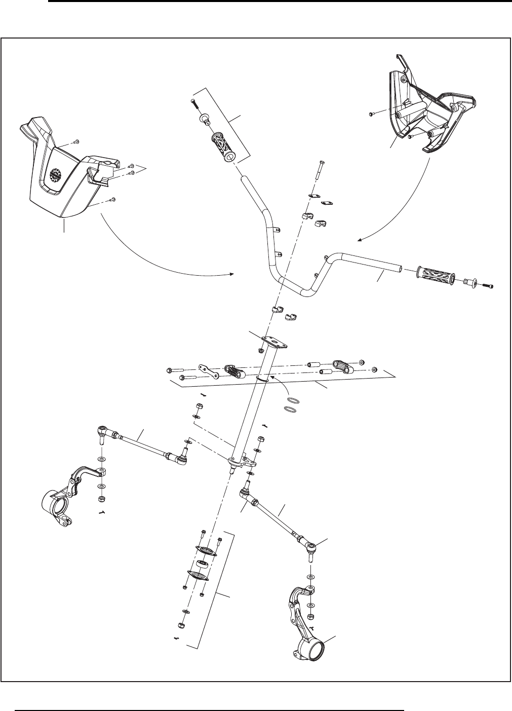
STEERING/FRONT DRIVE SYSTEM AND SUSPENSION
DIRECTION/SYSTÈEME D’ENTRAÎNEMENT AVANT ET SUSPENSION
07
SYSTEM/SYSTÈME
42 Can-Am - Volume 1
2009
Outlander 400
V07i0XS
0726
0727
0727
0725
0724
0728
0719
0719
0713
0747
0707
0712
sales@midwestmanuals.com
sales@midwestmanuals.com
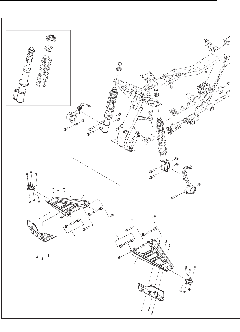
STEERING/FRONT DRIVE SYSTEM AND SUSPENSION
DIRECTION/SYSTÈEME D’ENTRAÎNEMENT AVANT ET SUSPENSION
43
2009
07
SYSTEM/SYSTÈME
Volume 1 - Can-Am
Outlander 400
V07i0YS
0737
0732 0732
0772
0772
0732
0704 0732
sales@midwestmanuals.com
sales@midwestmanuals.com
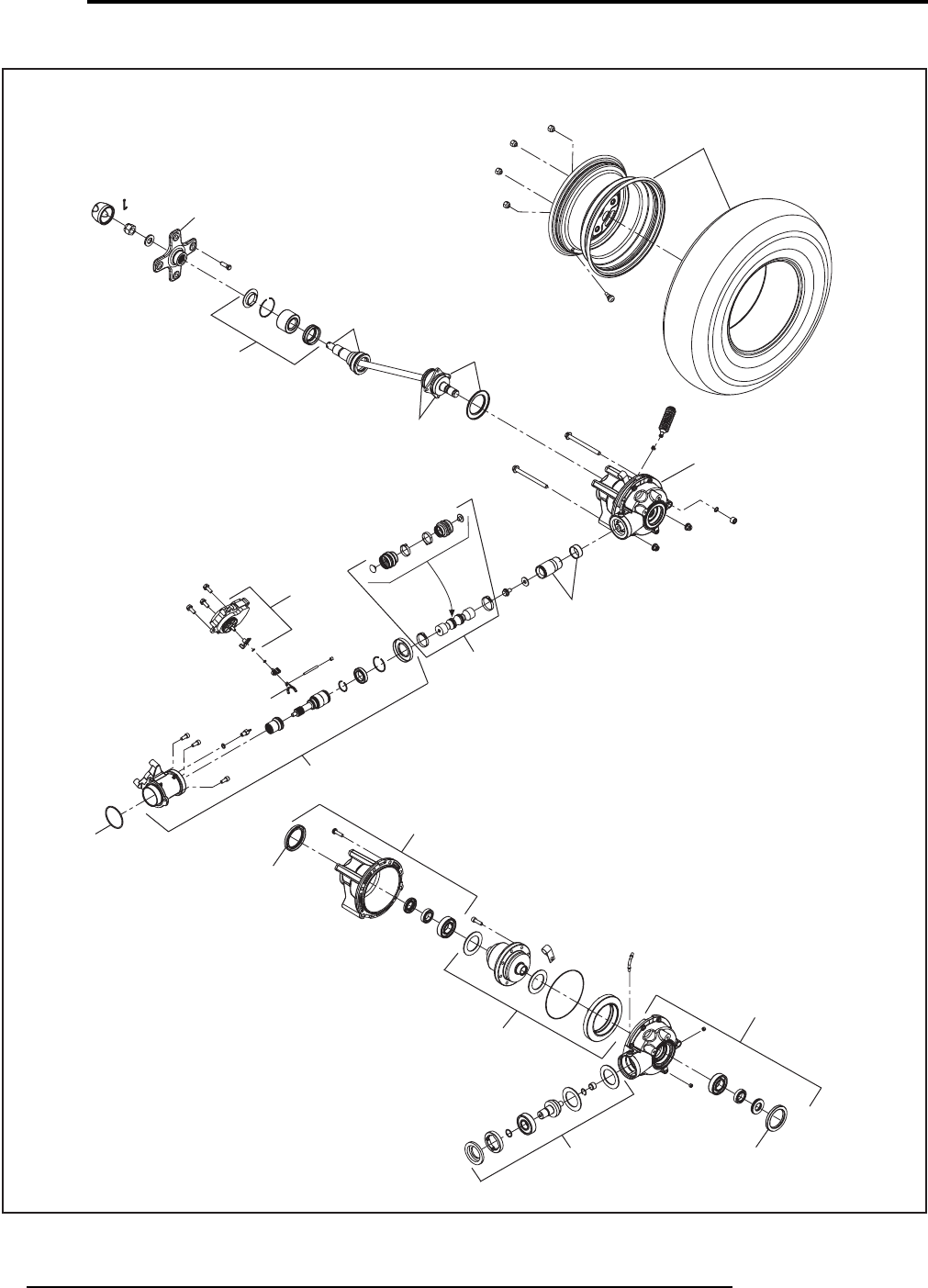
STEERING/FRONT DRIVE SYSTEM AND SUSPENSION
DIRECTION/SYSTÈEME D’ENTRAÎNEMENT AVANT ET SUSPENSION
07
SYSTEM/SYSTÈME
44 Can-Am - Volume 1
2009
Outlander 400
V07I16U
0750
0745
0746
0740
0742
0787
0786
0789
0785
0788
0789
0786
0782
0790
0791
0793
0792
07103
07104
07103
07104
sales@midwestmanuals.com
sales@midwestmanuals.com
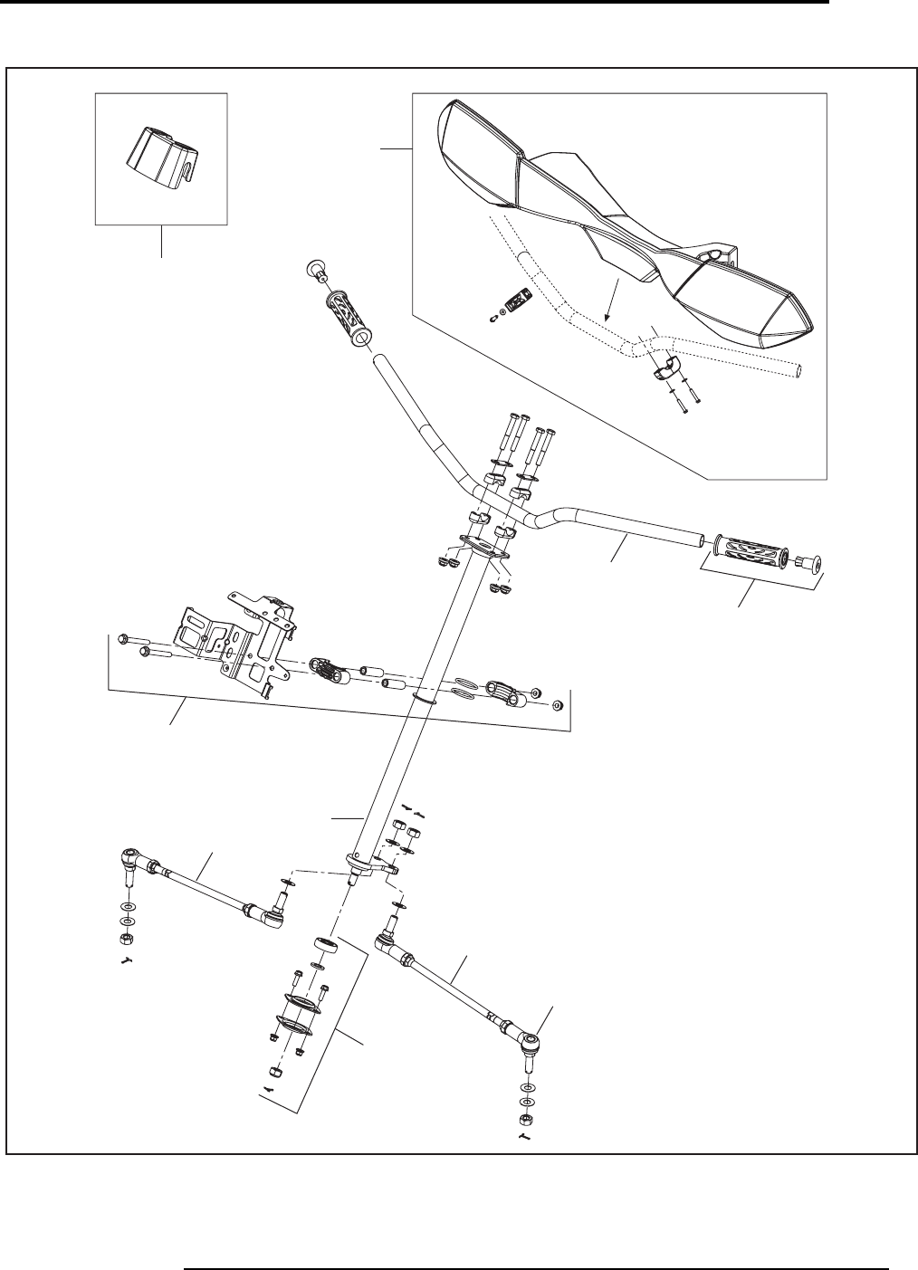
STEERING/FRONT DRIVE SYSTEM AND SUSPENSION
DIRECTION/SYSTÈEME D’ENTRAÎNEMENT AVANT ET SUSPENSION
45
2009
07
SYSTEM/SYSTÈME
Volume 1 - Can-Am
Outlander/Renegade
V07I1CS
0727
0727
0725
0726
0724
0728
0719
0719
0713
0707
sales@midwestmanuals.com
sales@midwestmanuals.com
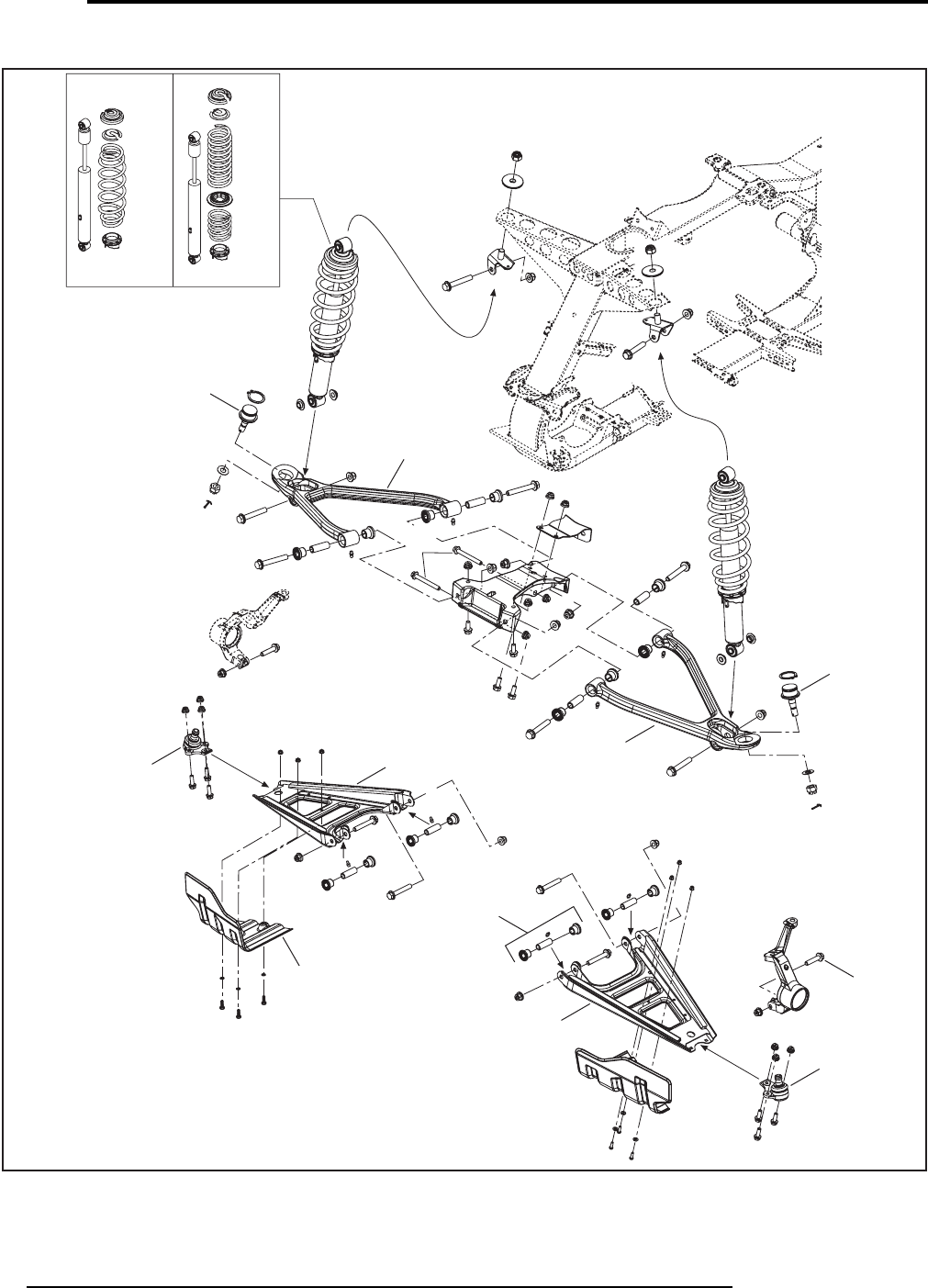
STEERING/FRONT DRIVE SYSTEM AND SUSPENSION
DIRECTION/SYSTÈEME D’ENTRAÎNEMENT AVANT ET SUSPENSION
07
SYSTEM/SYSTÈME
46 Can-Am - Volume 1
2009
Outlander/Renegade
STD XT
V07I1DS
0737
0733
0733
0732
0704
0732
0772
0732
0732
0747
0733
0733
sales@midwestmanuals.com
sales@midwestmanuals.com
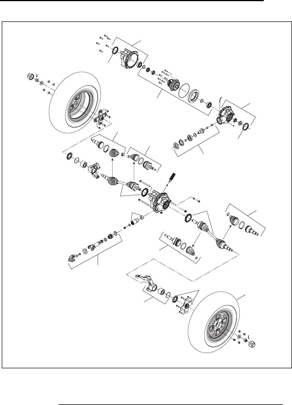
STEERING/FRONT DRIVE SYSTEM AND SUSPENSION
DIRECTION/SYSTÈEME D’ENTRAÎNEMENT AVANT ET SUSPENSION
47
2009
07
SYSTEM/SYSTÈME
Volume 1 - Can-Am
Outlander/Renegade
V07I1ET
0789
0785 0789
0788
0790
0745
0791
0747
0746 0750
0742
0792
0745
0791
0790
07103
07104
07103
07104
sales@midwestmanuals.com
sales@midwestmanuals.com
REAR DRIVE SYSTEM AND SUSPENSION
SYSTÈME D’ENTRAINEMENT ARRIÈRE ET SUSPENSION
08
SYSTEM/SYSTÈME
48 Can-Am - Volume 1
2009
SYSTEM
SYSTÈME
CODE
DESCRIPTION
OUTLANDER
400
OUTLANDER
MAX 400
OUTLANDER
500
OUTLANDER
MAX 500
OUTLANDER
650/800
OUTLANDER
MAX 650/800
RENEGADE
500/800
1234567
08 00 NO LABOR INVOLVED
AUCUNE MAIN D’OEUVRE 0000000
08 05 REAR WHEEL HUB (RH)
MOYEU DE ROUE ARRIÈRE (DROIT) 0.3 0.3 0.3 0.3 0.3 0.3 0.3
08 07 REAR DIFFERENTIAL (ASS’Y)
DIFFÉRENTIEL ARRIÈRE (COMPLET) 0.90.90.90.90.90.90.9
08 25 PROTECTOR REAR DIFFERENTIAL
PROTECTEUR DE DIFFÉRENTIEL ARRIÈRE 0.3 0.3 0.3 0.3 0.3 0.3 0.3
08 26 REAR PROPELLER SHAFT (ASS’Y)
ARBRE DE PROPULSION ARRIÈRE (COMPLET) 0.90.90.70.70.70.70.7
08 62 SWING ARM
BRAS OSCILLANT 0.7 1.0 0.7 1.0 0.7 1.0 1.0
08 101 LH PROTECTOR
PROTECTEUR GAUCHE 0.30.30.30.30.30.30.3
08 102 RH PROTECTOR
PROTECTEUR DROIT 0.3 0.3 0.3 0.3 0.3 0.3 0.3
08 109 REAR WHEEL HUB (LH)
MOYEU DE ROUE ARRIÈRE (GAUCHE) 0.30.30.30.30.30.30.3
08 111 REAR SHOCK (RH OR LH)
AMORTISSEUR ARRIÈRE (DROIT OU GAUCHE) 0.3 0.3 0.3 0.3 0.3 0.3 0.3
08 114 REAR RIM AND/OR TIRE
JANTE ARRIÈRE ET/OU PNEU 0.40.40.40.40.40.40.4
08 120 CV JOINT (RH OR LH)
JOINT HOMOCINÉTIQUE (DROIT OU GAUCHE) 0.5 0.5 0.5 0.5 0.5 0.5 0.5
08 121 STABILIZER BAR
BARRE STABILISATRICE 0.40.70.40.70.40.70.7
08 122 RING GEAR AND/OR SHIM
COURONNE DE LANCEMENT ET/OU CALE 2.0 2.0 2.0 2.0 2.0 2.0 2.0
08 123 RING GEAR DRIVE GEAR AND/OR BEARING AND/OR SHIM
PIGNON DE COMMANDE DE LA COURONNE ET/OU ROULEMENT
À BILLE ET/OU CALE 2.02.02.02.02.02.02.0
08 124 COVER AND/OR PINION COVER AND/OR SEAL AND/OR BEARING
COUVERCLE ET/OU COUVERCLE DE PIGNON ET/OU JOINT
D’ÉTANCHÉITÉ ET/OU ROULEMENT À BILLE 2.2 2.2 2.2 2.2 2.2 2.2 2.2
08 125 BOOT WHEEL KIT AND/OR CV JOINT (RH OR LH)
ENSEMBLE DE SOUFFLET DE ROUE ET/OU JOINT CV
(DROIT OU GAUCHE) 0.60.60.60.60.60.60.6
08 126
BOOT DIFFERENTIAL KIT AND/OR PLUNGING JOINT
(RH OR LH)
ENSEMBLE DE SOUFFLET DE DIFFÉRENTIEL ET/OU JOINT
PLONGENT (DROIT OU GAUCHE)
0.6 0.6 0.6 0.6 0.6 0.6 0.6
08 127 RADIAL BALL BEARINGS
ROULEMENTS À BILLE RADIALES 0.70.70.70.70.70.70.7
sales@midwestmanuals.com
sales@midwestmanuals.com

REAR DRIVE SYSTEM AND SUSPENSION
SYSTÈME D’ENTRAINEMENT ARRIÈRE ET SUSPENSION
49
2009
08
SYSTEM/SYSTÈME
Volume 1 - Can-Am
08 128 UNIT PACK KIT
ENSEMBLE DE JOINT CARDAN 1.2 1.2 1.2 1.2 1.2 1.2 1.2
08 129 UNIT PACK KIT (2)
ENSEMBLE DE JOINT CARDAN (2) 1.5 1.5 1.5 1.5 1.5 1.5 1.5
08 134 DIFFERENTIAL SEAL (1)
JOINT D’ÉTANCHÉITÉ DU DIFFÉRENTIEL (1) 0.5 0.5 0.5 0.5 0.5 0.5 0.5
08 135 DIFFERENTIAL SEALS (2)
JOINTS D’ÉTANCHÉITÉ DU DIFFÉRENTIEL (2) 1.0 1.0 1.0 1.0 1.0 1.0 1.0
SYSTEM
SYSTÈME
CODE
DESCRIPTION
OUTLANDER
400
OUTLANDER
MAX 400
OUTLANDER
500
OUTLANDER
MAX 500
OUTLANDER
650/800
OUTLANDER
MAX 650/800
RENEGADE
500/800
1234567
sales@midwestmanuals.com
sales@midwestmanuals.com
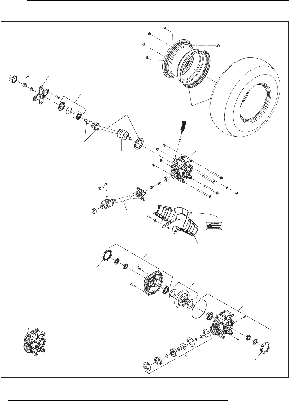
REAR DRIVE SYSTEM AND SUSPENSION
SYSTÈME D’ENTRAINEMENT ARRIÈRE ET SUSPENSION
08
SYSTEM/SYSTÈME
50 Can-Am - Volume 1
2009
Outlander/Renegade
V07H1XV
08114
08120
0805
08109
0807
0825
0826
08124
08122
08124
08123
08125
08126
08127
08134
08135
08134
08135
sales@midwestmanuals.com
sales@midwestmanuals.com
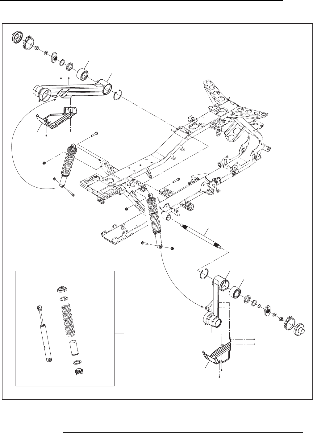
REAR DRIVE SYSTEM AND SUSPENSION
SYSTÈME D’ENTRAINEMENT ARRIÈRE ET SUSPENSION
51
2009
08
SYSTEM/SYSTÈME
Volume 1 - Can-Am
Outlander/Renegade
0862
08101
08121
0862
08102
08111
V07H1WT
08127
08127
sales@midwestmanuals.com
sales@midwestmanuals.com

BODY AND ACCESSORIS
CARROSSERIE ET ACCESSOIRES
09
SYSTEM/SYSTÈME
52 Can-Am - Volume 1
2009
SYSTEM
SYSTÈME
CODE
DESCRIPTION
OUTLANDER
400
OUTLANDER
MAX 400
OUTLANDER
500
OUTLANDER
MAX 500
OUTLANDER
650/800
OUTLANDER
MAX 650/800
RENEGADE
500/800
1234567
09 00 NO LABOR INVOLVED
AUCUNE MAIN D’OEUVRE IMPLIQUÉE 0000000
09 13 LUGGAGE RACK KIT (FRONT OR REAR)
ENSEMBLE DE PORTE-BAGAGES (AVANT OU ARRIÈRE) 0.3 0.3 0.3 0.3 0.3 0.3
09 17 CONSOLE
CONSOLE 0.3 0.3 0.3 0.3 0.3 0.3 0.3
09 21 SEAT AND/OR SUPPORT
SIÈGE ET/OU SUPPORT 0.3 0.3 0.3 0.3 0.3 0.3 0.3
09 22 SEAT COVER
HOUSSE DE SIÈGE 1.5 1.5 1.5 1.5 1.5 1.5 1.5
09 26 FRONT BUMPER
PARE-CHOCS AVANT 0.6 0.6 0.6 0.6 0.6 0.6 0.3
09 27 WINCH LATCH
ATTACHE DE TREUIL 0.3 0.3 0.3 0.3 0.3 0.3
09 28 FRONT FASCIA
FASCIA AVANT 0.7 0.7 0.7 0.7 0.7 0.7 0.7
09 29 REAR FASCIA
FASCIA ARRIÈRE 0.3 0.3 0.3 0.3 0.3 0.3
09 34 REAR BUMPER
PARE-CHOCS ARRIÈRE 0.8 0.8 0.8 0.8 0.8 0.8 0.8
09 39 FRONT OR REAR MUDGUARD KIT (RH OR LH)
ENSEMBLE DE GARDE-BOUE AVANT OU ARRIÈRE
(DROIT OU GAUCHE) 0.3 0.3 0.3 0.3 0.3 0.3 0.3
09 45 REAR HANDLE (RH OR LH)
POIGNÉE ARRIÈRE (DROIT OU GAUCHE) 0.3 0.3 0.3
09 48 FOOTREST (RH OR LH)
MARCHEPIED (DROIT OU GAUCHE) 0.4 0.4 0.4 0.4 0.4 0.4 0.5
09
*49 FRAME
CHÂSSIS 12.3 12.9 12.8 13.5 12.8 13.5 13.5
09 56 REAR FENDER
AILE ARRIÈRE 0.7 0.7 0.7 0.7 0.7 0.7 0.8
09 57 FRONT FENDER AND/OR SUPPORT (RH OR LH)
AILE AVANT ET/OU SUPPORT (DROIT OU GAUCHE) 1.5 1.5 1.5 1.5 1.5 1.5 1.5
09 80 FRONT GRILLS
GRILLES AVANT 0.3 0.3 0.3 0.3 0.3 0.3 0.3
09 91 FOOTWELL (RH OR LH)
REPOSE-PIED (DROIT OU GAUCHE) 0.3 0.3 0.3 0.3 0.3 0.3 0.3
09 93 PROTECTION PLATE
PLAQUE DE PROTECTION 0.3 0.3 0.3 0.3 0.3 0.3 0.3
09 95 EACH DECAL (1)
CHAQUE AUTOCOLLANT (1) 0.3 0.3 0.3 0.3 0.3 0.3 0.3
sales@midwestmanuals.com
sales@midwestmanuals.com

BODY AND ACCESSORIS
CARROSSERIE ET ACCESSOIRES
53
2009
09
SYSTEM/SYSTÈME
Volume 1 - Can-Am
09 108 REAR SEAT
SIÈGE ARRIÈRE 0.3 0.3 0.3
09 120 FRONT LIGHT FASCIA
FASCIA DE LUMIÈRE AVANT 0.4 0.4 0.4 0.4
09 136 BACKREST (ASS’Y)
DOSSIER (COMPLET) 0.3 0.3 0.3
09 138 HAND PROTECTOR
PROTÈGE MAIN 0.3 0.3 0.3 0.3
09 149 ENGINE SIDE PANELS (2)
PANNEAUX MOTEUR (2) 0.3 0.3 0.3 0.3 0.3 0.3 0.3
09 157 UPPER CONSOLE
CONSOLE SUPÉRIEURE 0.4 0.4 0.4 0.4 0.6
09 158 FRONT FENDER SUPPORT
SUPPORT D’AILE AVANT 1.6 1.6 1.6 1.6 1.6 1.6 1.6
09 161 REAR BUMPER (XT)
PARE-CHOC ARRIÈRE (XT) 0.3 0.3 0.3 0.3 0.3 0.3
09 162 FRONT BUMPER (XT)
PARE-CHOC AVANT (XT) 0.3 0.3 0.3 0.3 0.3 0.3
09 200 REAR FENDER SUPPORT
SUPPORT D’AILE ARRIÈRE 0.9 0.9 0.9 0.9 0.9 0.9
09 210 FRONT FASCIA (RH OR LH)
FASCIA AVANT (DROIT OU GAUCHE) 0.3 0.3 0.3 0.3 0.4
SYSTEM
SYSTÈME
CODE
DESCRIPTION
OUTLANDER
400
OUTLANDER
MAX 400
OUTLANDER
500
OUTLANDER
MAX 500
OUTLANDER
650/800
OUTLANDER
MAX 650/800
RENEGADE
500/800
1234567
sales@midwestmanuals.com
sales@midwestmanuals.com
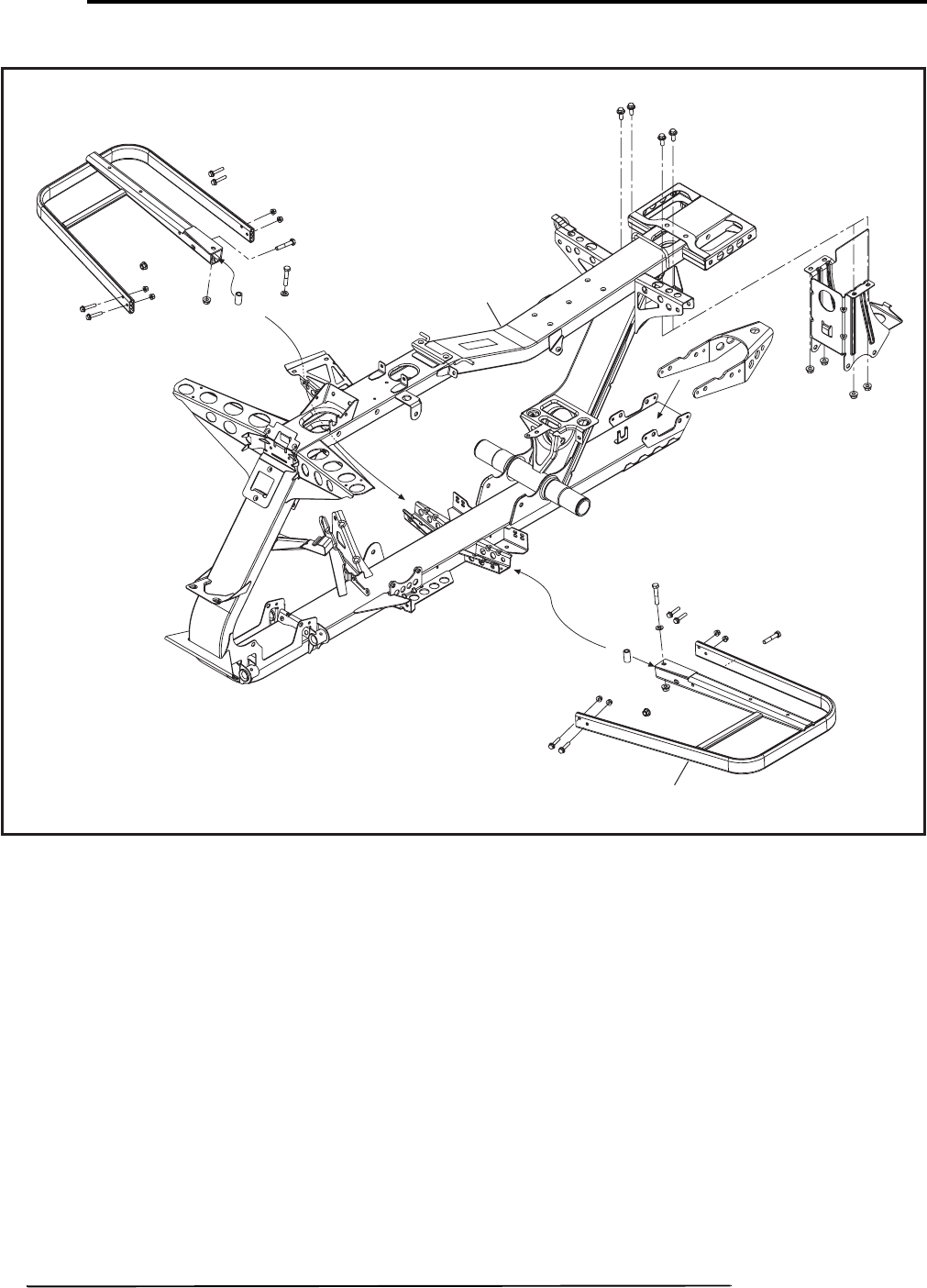
BODY AND ACCESSORIS
CARROSSERIE ET ACCESSOIRES
09
SYSTEM/SYSTÈME
54 Can-Am - Volume 1
2009
Outlander/Renegade
0949
0948
V07L19S
sales@midwestmanuals.com
sales@midwestmanuals.com
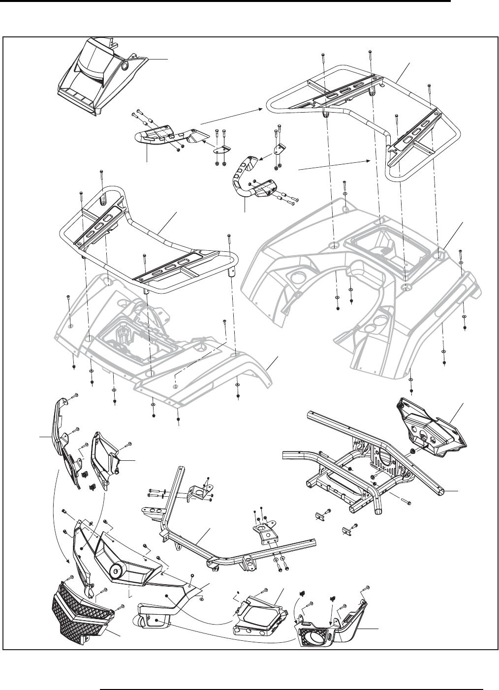
REAR DRIVE SYSTEM AND SUSPENSION
SYSTÈME D’ENTRAINEMENT ARRIÈRE ET SUSPENSION
55
2009
08
SYSTEM/SYSTÈME
Volume 1 - Can-Am
Outlander
vtf2009-001-005_a
09157 0913
0956
0929
09200
0945
0945
0913
0957
0957
09120
09158
09158
09210
09120
0980
sales@midwestmanuals.com
sales@midwestmanuals.com
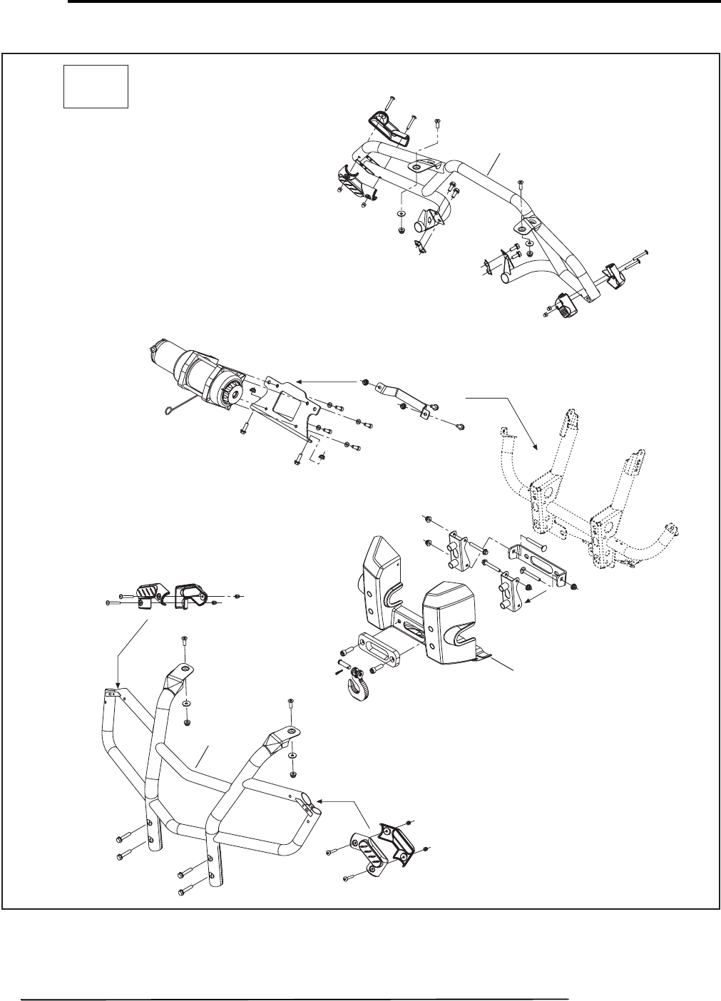
BODY AND ACCESSORIS
CARROSSERIE ET ACCESSOIRES
09
SYSTEM/SYSTÈME
56 Can-Am - Volume 1
2009
Outlander XT
XT
V07L4AS
09161
0993
09162
sales@midwestmanuals.com
sales@midwestmanuals.com
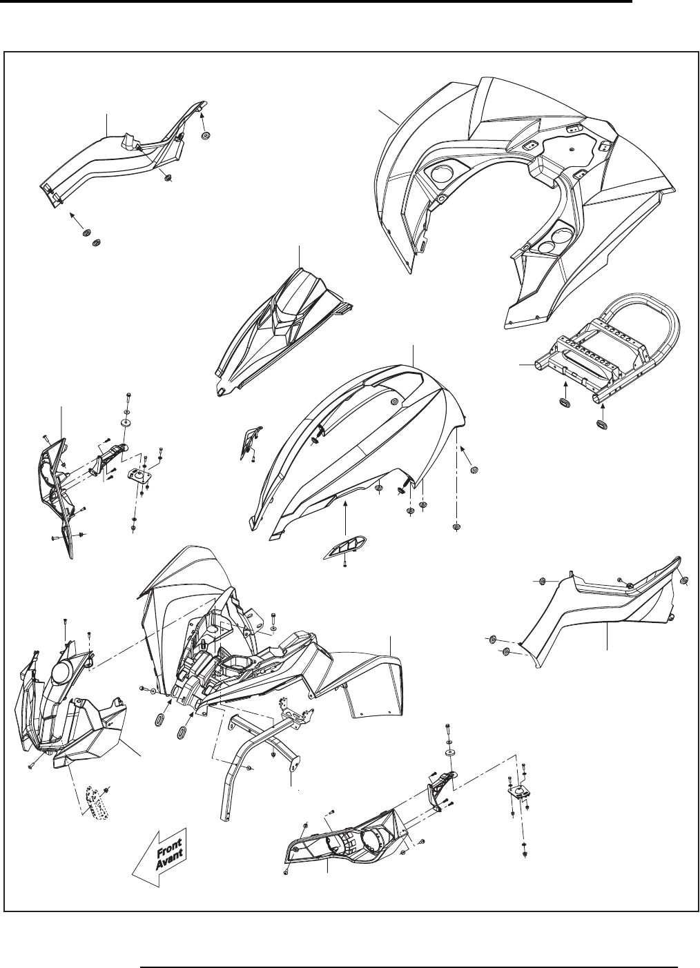
BODY AND ACCESSORIS
CARROSSERIE ET ACCESSOIRES
57
2009
09
SYSTEM/SYSTÈME
Volume 1 - Can-Am
Renegade
V07L4CS
09149
09157
0917
0934
09149
09158
0928
09210
09210
0956
0957
sales@midwestmanuals.com
sales@midwestmanuals.com
ELECTRICAL SYSTEM
SYSTÈME ÉLECTRIQUE
10
SYSTEM/SYSTÈME
58 Can-Am - Volume 1
2009
SYSTEM
SYSTÈME
CODE
DESCRIPTION
OUTLANDER
400
OUTLANDER
MAX 400
OUTLANDER
500
OUTLANDER
MAX 500
OUTLANDER
650/800
OUTLANDER
MAX 650/800
RENEGADE
500/800
1234567
10 00 NO LABOR INVOLVED
AUCUNE MAIN-D’OEUVRE 0000000
10 01 IGNITION SWITCH
INTERRUPTEUR D’ALLUMAGE 0.3 0.3 0.3 0.3 0.3 0.3 0.3
10 09 HEADLAMP AND/OR HEADLAMP SUPPORT (ASS’Y) (RH OR LH)
PHARE AVANT ET/OU SUPPORT (COMPLET) (DROIT OU GAUCHE) 0.3 0.3 0.3 0.3 0.3 0.3 0.3
10 10 VOLTAGE REGULATOR
RÉGULATEUR DE TENSION 0.3 0.3 0.3 0.3 0.3 0.3 0.3
10 13 BATTERY
BATTERIE 0.3 0.3 0.3 0.3 0.3 0.3 0.3
10 14 FUSE BOX
BOÎTE-FUSIBLE 0.3 0.3 0.4 0.4 0.4 0.4 0.4
10 21 MULTIFUNCTION SWITCH
INTERRUPTEUR MULTIFONCTION 0.3 0.3 0.3 0.3 0.3 0.3 0.3
10 28 SPEEDOMETER/TACHOMETER
INDICATEUR DE VITESSE/COMPTE-TOURS 0.3 0.3 0.3 0.3 0.3 0.3 0.3
10 29 TAIL LAMP HOUSING (ASS’Y)
BOÎTIER DE FEU ARRIÈRE (COMPLET) 0.3 0.3 0.3 0.3 0.3 0.3 0.3
10 31 DC OUTLET PLUG
PRISE D’ACCESSOIRE DC 0.3 0.3 0.3 0.3 0.3 0.3 0.3
10 34 ELECTRONIC MODULE
MODULE ÉLECTRONIQUE 1.3 1.3 0.4 0.4 0.4 0.4 0.4
10 45 WINCH (ASS’Y) (XT)
TREUIL (COMPLET) (XT) 0.4 0.4 0.4 0.4 0.4 0.4
10 46 WINCH SOLENOID (XT)
SOLÉNOÏDE DE TREUIL (XT) 0.4 0.4 0.4 0.4 0.4 0.4
10 47 WINCH SWITCH (XT)
INTERRUPTEUR DE TREUIL (XT) 0.5 0.5 0.5 0.5 0.5 0.5
10 51 MAIN WIRE HARNESS
CÂBLAGE PRINCIPAL 3.1 3.1 2.9 2.9 2.9 2.9 2.9
10 61 FRONT FLASHERS 1 OR 2 (CE ONLY)
CLIGNOTANTS AVANT 1 OU 2 (CE SEULEMENT) 0.3 0.3 0.3 0.3 0.3 0.3 0.3
10 62 REAR FLASHERS 1 OR 2 (CE ONLY)
CLIGNOTANTS ARRIÈRE 1 OU 2 (CE SEULEMENT) 0.3 0.3 0.3 0.3 0.3 0.3 0.3
10 63 HAZARD WARNING BUTTON (CE ONLY)
COMMUTATEUR D’URGENCE (CE SEULEMENT) 0.3 0.3 0.3 0.3 0.3 0.3 0.3
10 64 DIRECTION INDICATOR SWITCH (CE ONLY)
INTERRUPTEUR CLIGNOTANTS (CE SEULEMENT) 0.3 0.3 0.3 0.3 0.3 0.3 0.3
10 65 12 VOLT RELAY (CE ONLY)
RELAIS 12 VOLT (CE SEULEMENT) 0.3 0.3 0.3 0.3 0.3 0.3 0.3
10 66 HORN
AVERTISSEUR 0.3 0.3 0.3 0.3 0.3 0.3 0.3
sales@midwestmanuals.com
sales@midwestmanuals.com

ELECTRICAL SYSTEM
SYSTÈME ÉLECTRIQUE
59
2009
10
SYSTEM/SYSTÈME
Volume 1 - Can-Am
10 67 RELAY
RELAIS 0.3 0.3 0.3 0.3 0.3
10 68 ANY BULBS
TOUTES LES AMPOULES 0.4 0.4 0.4 0.4 0.4 0.4 0.4
SYSTEM
SYSTÈME
CODE
DESCRIPTION
OUTLANDER
400
OUTLANDER
MAX 400
OUTLANDER
500
OUTLANDER
MAX 500
OUTLANDER
650/800
OUTLANDER
MAX 650/800
RENEGADE
500/800
1234567
sales@midwestmanuals.com
sales@midwestmanuals.com
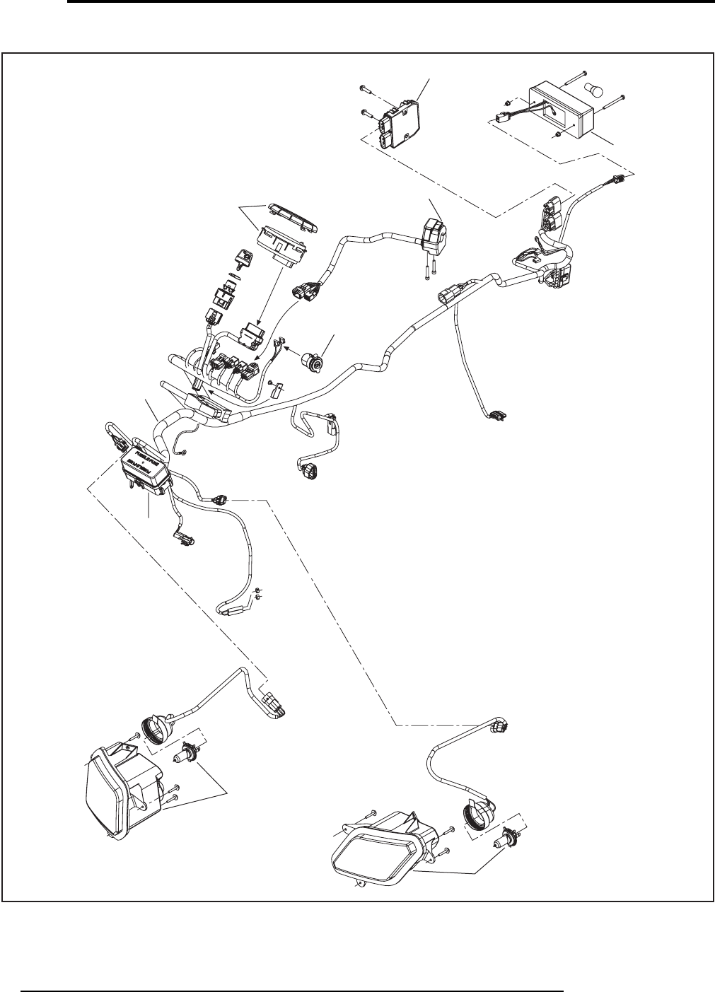
ELECTRICAL SYSTEM
SYSTÈME ÉLECTRIQUE
10
SYSTEM/SYSTÈME
60 Can-Am - Volume 1
2009
Outlander
V07G2AS
1010
1029
1021
1031
1028
1051
1014
1009
1009
sales@midwestmanuals.com
sales@midwestmanuals.com
ELECTRICAL SYSTEM
SYSTÈME ÉLECTRIQUE
61
2009
10
SYSTEM/SYSTÈME
Volume 1 - Can-Am
Outlander
ACCESSORIES FOR EUROPE ONLY / ACCESSOIRES POUR EUROPE SEULEMENT
10
Front Flasher/
Clignotant Avant
Right Side/
Côté Droit
Left Side/
Côté Gauche
Rear Flasher/
Clignotant Arrière
Right Side/
Côté Droit
Left Side/
Côté Gauche
Tail Light/
Feu Arrière
Headlamp/
Phare Avant
V07G2BS
1065
1064 1063
1061
1062
1066
1062
1009
1009
1029
sales@midwestmanuals.com
sales@midwestmanuals.com

CLAIM TYPE 02
RÉCLAMATION DE TYPE 02
11
SYSTEM/SYSTÈME
62 Can-Am - Volume 1
2009
SYSTEM
SYSTÈME
CODE
DESCRIPTION
OUTLANDER
400
OUTLANDER
MAX 400
OUTLANDER
500
OUTLANDER
MAX 500
OUTLANDER
650/800
OUTLANDER
MAX 650/800
RENEGADE
500/800
1234567
11 00 NO LABOR INVOLVED
AUCUNE MAIN-D’OEUVRE 0000000
11 MT1 SCHEDULED MAINTENANCE TRACKING
SUIVI DES ENTRETIENS PLANIFIÉS 0000000
sales@midwestmanuals.com
sales@midwestmanuals.com

63
2009
FLAT RATE TIME
SUGGESTION
DEALER’S NO.: ________________________________________________ DATE: ____________
DEALER’S NAME: _______________________________________________________________
FILE IDENTIFICATION NO.: ________________________________________________________
ADDRESS: ____________________________________________________________________
ADDRESS: ____________________________________________________________________
ADDRESS: ____________________________________________________________________
Detailed procedure used:
Signature: _____________________________________________________________________
BOMBARDIER RECREATIONAL PRODUCTS INC.
WARRANTY DEPARTMENT
75, J.A. BOMBARDIER ST.
SHERBROOKE (QUEBEC)
CANADA, J1L 1W3
FAX NUMBER: 819 566-3590
YEAR MODEL DESCRIPTION OPERATION JOB
CODE PRESENT
FLAT RATE SUGGESTED
FLAT RATE
Volume 1 - Can-Am
sales@midwestmanuals.com
sales@midwestmanuals.com

64
BARÈME DE TEMPS À TAUX FIXE
SUGGESTION
N° DU CONCESSIONNAIRE: _____________________________________ DATE: ____________
NOM DU CONCESSIONNAIRE: _____________________________________________________
N° D’IDENTIFICATION DU DOSSIER: _________________________________________________
ADRESSE: _____________________________________________________________________
ADDRESS: ____________________________________________________________________
ADDRESS: ____________________________________________________________________
Détails de la marche à suivre:
Signature: _____________________________________________________________________
Retournez par
BOMBARDIER PRODUITS RÉCRÉATIFS INC.
SERVICE DE GARANTIE
75, RUE J.-A. BOMBARDIER
SHERBROOKE (QUÉBEC)
CANADA, J1L 1W3
N° DU TÉLÉCOPIEUR: 819 566-3590
ANNÉE DESCRIPTION DU MODÈLE OPÉRATION CODE DE
TRAVAUX TTP
ACTUEL TTP
SUGGÉRÉ
Can-Am - Volume 1
2009
sales@midwestmanuals.com
sales@midwestmanuals.com
