IEEE Std 1800™ 2012 (Revision Of 1800 2009) Standard For SystemVerilog—Unified Hardware Design, Specification, And System Verilog Language Reference Manual
User Manual:
Open the PDF directly: View PDF ![]() .
.
Page Count: 1315 [warning: Documents this large are best viewed by clicking the View PDF Link!]
- IEEE Std 1800-2012 Front cover
- Title page
- Notice to users
- Participants
- Introduction
- Contents
- Part One: Design and Verification Constructs
- Important notice
- 1. Overview
- 2. Normative references
- 3. Design and verification building blocks
- 4. Scheduling semantics
- 4.1 General
- 4.2 Execution of a hardware model and its verification environment
- 4.3 Event simulation
- 4.4 Stratified event scheduler
- 4.5 SystemVerilog simulation reference algorithm
- 4.6 Determinism
- 4.7 Nondeterminism
- 4.8 Race conditions
- 4.9 Scheduling implication of assignments
- 4.10 PLI callback control points
- 5. Lexical conventions
- 6. Data types
- 6.1 General
- 6.2 Data types and data objects
- 6.3 Value set
- 6.4 Singular and aggregate types
- 6.5 Nets and variables
- 6.6 Net types
- 6.7 Net declarations
- 6.8 Variable declarations
- 6.9 Vector declarations
- 6.10 Implicit declarations
- 6.11 Integer data types
- 6.12 Real, shortreal, and realtime data types
- 6.13 Void data type
- 6.14 Chandle data type
- 6.15 Class
- 6.16 String data type
- 6.17 Event data type
- 6.18 User-defined types
- 6.19 Enumerations
- 6.20 Constants
- 6.21 Scope and lifetime
- 6.22 Type compatibility
- 6.23 Type operator
- 6.24 Casting
- 6.25 Parameterized data types
- 7. Aggregate data types
- 8. Classes
- 8.1 General
- 8.2 Overview
- 8.3 Syntax
- 8.4 Objects (class instance)
- 8.5 Object properties and object parameter data
- 8.6 Object methods
- 8.7 Constructors
- 8.8 Typed constructor calls
- 8.9 Static class properties
- 8.10 Static methods
- 8.11 This
- 8.12 Assignment, renaming, and copying
- 8.13 Inheritance and subclasses
- 8.14 Overridden members
- 8.15 Super
- 8.16 Casting
- 8.17 Chaining constructors
- 8.18 Data hiding and encapsulation
- 8.19 Constant class properties
- 8.20 Virtual methods
- 8.21 Abstract classes and pure virtual methods
- 8.22 Polymorphism: dynamic method lookup
- 8.23 Class scope resolution operator ::
- 8.24 Out-of-block declarations
- 8.25 Parameterized classes
- 8.26 Interface classes
- 8.27 Typedef class
- 8.28 Classes and structures
- 8.29 Memory management
- 9. Processes
- 10. Assignment statements
- 10.1 General
- 10.2 Overview
- 10.3 Continuous assignments
- 10.4 Procedural assignments
- 10.5 Variable declaration assignment (variable initialization)
- 10.6 Procedural continuous assignments
- 10.7 Assignment extension and truncation
- 10.8 Assignment-like contexts
- 10.9 Assignment patterns
- 10.10 Unpacked array concatenation
- 10.11 Net aliasing
- 11. Operators and expressions
- 11.1 General
- 11.2 Overview
- 11.3 Operators
- 11.4 Operator descriptions
- 11.5 Operands
- 11.6 Expression bit lengths
- 11.7 Signed expressions
- 11.8 Expression evaluation rules
- 11.9 Tagged union expressions and member access
- 11.10 String literal expressions
- 11.11 Operator overloading
- 11.12 Minimum, typical, and maximum delay expressions
- 11.13 Let construct
- 12. Procedural programming statements
- 13. Tasks and functions (subroutines)
- 14. Clocking blocks
- 14.1 General
- 14.2 Overview
- 14.3 Clocking block declaration
- 14.4 Input and output skews
- 14.5 Hierarchical expressions
- 14.6 Signals in multiple clocking blocks
- 14.7 Clocking block scope and lifetime
- 14.8 Multiple clocking blocks example
- 14.9 Interfaces and clocking blocks
- 14.10 Clocking block events
- 14.11 Cycle delay: ##
- 14.12 Default clocking
- 14.13 Input sampling
- 14.14 Global clocking
- 14.15 Synchronous events
- 14.16 Synchronous drives
- 15. Interprocess synchronization and communication
- 16. Assertions
- 16.1 General
- 16.2 Overview
- 16.3 Immediate assertions
- 16.4 Deferred assertions
- 16.5 Concurrent assertions overview
- 16.6 Boolean expressions
- 16.7 Sequences
- 16.8 Declaring sequences
- 16.9 Sequence operations
- 16.10 Local variables
- 16.11 Calling subroutines on match of a sequence
- 16.12 Declaring properties
- 16.13 Multiclock support
- 16.14 Concurrent assertions
- 16.15 Disable iff resolution
- 16.16 Clock resolution
- 16.17 Expect statement
- 16.18 Clocking blocks and concurrent assertions
- 17. Checkers
- 18. Constrained random value generation
- 18.1 General
- 18.2 Overview
- 18.3 Concepts and usage
- 18.4 Random variables
- 18.5 Constraint blocks
- 18.6 Randomization methods
- 18.7 In-line constraints—randomize() with
- 18.8 Disabling random variables with rand_mode()
- 18.9 Controlling constraints with constraint_mode()
- 18.10 Dynamic constraint modification
- 18.11 In-line random variable control
- 18.12 Randomization of scope variables—std::randomize()
- 18.13 Random number system functions and methods
- 18.14 Random stability
- 18.15 Manually seeding randomize
- 18.16 Random weighted case—randcase
- 18.17 Random sequence generation—randsequence
- 19. Functional coverage
- 19.1 General
- 19.2 Overview
- 19.3 Defining the coverage model: covergroup
- 19.4 Using covergroup in classes
- 19.5 Defining coverage points
- 19.6 Defining cross coverage
- 19.7 Specifying coverage options
- 19.8 Predefined coverage methods
- 19.9 Predefined coverage system tasks and system functions
- 19.10 Organization of option and type_option members
- 19.11 Coverage computation
- 20. Utility system tasks and system functions
- 20.1 General
- 20.2 Simulation control system tasks
- 20.3 Simulation time system functions
- 20.4 Timescale system tasks
- 20.5 Conversion functions
- 20.6 Data query functions
- 20.7 Array querying functions
- 20.8 Math functions
- 20.9 Bit vector system functions
- 20.10 Severity tasks
- 20.11 Elaboration system tasks
- 20.12 Assertion control system tasks
- 20.13 Sampled value system functions
- 20.14 Coverage system functions
- 20.15 Probabilistic distribution functions
- 20.16 Stochastic analysis tasks and functions
- 20.17 Programmable logic array modeling system tasks
- 20.18 Miscellaneous tasks and functions
- 21. Input/output system tasks and system functions
- 22. Compiler directives
- 22.1 General
- 22.2 Overview
- 22.3 `resetall
- 22.4 `include
- 22.5 `define, `undef, and `undefineall
- 22.6 `ifdef, `else, `elsif, `endif, `ifndef
- 22.7 `timescale
- 22.8 `default_nettype
- 22.9 `unconnected_drive and `nounconnected_drive
- 22.10 `celldefine and `endcelldefine
- 22.11 `pragma
- 22.12 `line
- 22.13 `__FILE__ and `__LINE__
- 22.14 `begin_keywords, `end_keywords
- Part Two: Hierarchy Constructs
- 23. Modules and hierarchy
- 23.1 General
- 23.2 Module definitions
- 23.3 Module instances (hierarchy)
- 23.4 Nested modules
- 23.5 Extern modules
- 23.6 Hierarchical names
- 23.7 Member selects and hierarchical names
- 23.8 Upwards name referencing
- 23.9 Scope rules
- 23.10 Overriding module parameters
- 23.11 Binding auxiliary code to scopes or instances
- 24. Programs
- 25. Interfaces
- 26. Packages
- 27. Generate constructs
- 28. Gate-level and switch-level modeling
- 28.1 General
- 28.2 Overview
- 28.3 Gate and switch declaration syntax
- 28.4 and, nand, nor, or, xor, and xnor gates
- 28.5 buf and not gates
- 28.6 bufif1, bufif0, notif1, and notif0 gates
- 28.7 MOS switches
- 28.8 Bidirectional pass switches
- 28.9 CMOS switches
- 28.10 pullup and pulldown sources
- 28.11 Logic strength modeling
- 28.12 Strengths and values of combined signals
- 28.13 Strength reduction by nonresistive devices
- 28.14 Strength reduction by resistive devices
- 28.15 Strengths of net types
- 28.16 Gate and net delays
- 29. User-defined primitives
- 30. Specify blocks
- 31. Timing checks
- 31.1 General
- 31.2 Overview
- 31.3 Timing checks using a stability window
- 31.4 Timing checks for clock and control signals
- 31.5 Edge-control specifiers
- 31.6 Notifiers: user-defined responses to timing violations
- 31.7 Enabling timing checks with conditioned events
- 31.8 Vector signals in timing checks
- 31.9 Negative timing checks
- 32. Backannotation using the standard delay format
- 33. Configuring the contents of a design
- 34. Protected envelopes
- Part Three: Application Programming Interfaces
- 35. Direct programming interface
- 36. Programming language interface (PLI/VPI) overview
- 36.1 General
- 36.2 PLI purpose and history
- 36.3 User-defined system task and system function names
- 36.4 User-defined system task and system function arguments
- 36.5 User-defined system task and system function types
- 36.6 User-supplied PLI applications
- 36.7 PLI include files
- 36.8 VPI sizetf, compiletf, and calltf routines
- 36.9 PLI mechanism
- 36.10 VPI access to SystemVerilog objects and simulation objects
- 36.11 List of VPI routines by functional category
- 36.12 VPI backwards compatibility features and limitations
- 37. VPI object model diagrams
- 37.1 General
- 37.2 VPI Handles
- 37.3 VPI object classifications
- 37.4 Key to data model diagrams
- 37.5 Module
- 37.6 Interface
- 37.7 Modport
- 37.8 Interface task or function declaration
- 37.9 Program
- 37.10 Instance
- 37.11 Instance arrays
- 37.12 Scope
- 37.13 IO declaration
- 37.14 Ports
- 37.15 Reference objects
- 37.16 Nets
- 37.17 Variables
- 37.18 Packed array variables
- 37.19 Variable select
- 37.20 Memory
- 37.21 Variable drivers and loads
- 37.22 Object Range
- 37.23 Typespec
- 37.24 Structures and unions
- 37.25 Named events
- 37.26 Parameter, spec param, def param, param assign
- 37.27 Virtual interface
- 37.28 Interface typespec
- 37.29 Class definition
- 37.30 Class typespec
- 37.31 Class variables and class objects
- 37.32 Constraint, constraint ordering, distribution
- 37.33 Primitive, prim term
- 37.34 UDP
- 37.35 Intermodule path
- 37.36 Constraint expression
- 37.37 Module path, path term
- 37.38 Timing check
- 37.39 Task and function declaration
- 37.40 Task and function call
- 37.41 Frames
- 37.42 Threads
- 37.43 Delay terminals
- 37.44 Net drivers and loads
- 37.45 Continuous assignment
- 37.46 Clocking block
- 37.47 Assertion
- 37.48 Concurrent assertions
- 37.49 Property declaration
- 37.50 Property specification
- 37.51 Sequence declaration
- 37.52 Sequence expression
- 37.53 Immediate assertions
- 37.54 Multiclock sequence expression
- 37.55 Let
- 37.56 Simple expressions
- 37.57 Expressions
- 37.58 Atomic statement
- 37.59 Dynamic prefixing
- 37.60 Event statement
- 37.61 Process
- 37.62 Assignment
- 37.63 Event control
- 37.64 While, repeat
- 37.65 Waits
- 37.66 Delay control
- 37.67 Repeat control
- 37.68 Forever
- 37.69 If, if–else
- 37.70 Case, pattern
- 37.71 Expect
- 37.72 For
- 37.73 Do-while, foreach
- 37.74 Alias statement
- 37.75 Disables
- 37.76 Return statement
- 37.77 Assign statement, deassign, force, release
- 37.78 Callback
- 37.79 Time queue
- 37.80 Active time format
- 37.81 Attribute
- 37.82 Iterator
- 37.83 Generates
- 38. VPI routine definitions
- 38.1 General
- 38.2 vpi_chk_error()
- 38.3 vpi_compare_objects()
- 38.4 vpi_control()
- 38.5 vpi_flush()
- 38.6 vpi_get()
- 38.7 vpi_get64()
- 38.8 vpi_get_cb_info()
- 38.9 vpi_get_data()
- 38.10 vpi_get_delays()
- 38.11 vpi_get_str()
- 38.12 vpi_get_systf_info()
- 38.13 vpi_get_time()
- 38.14 vpi_get_userdata()
- 38.15 vpi_get_value()
- 38.16 vpi_get_value_array()
- 38.17 vpi_get_vlog_info()
- 38.18 vpi_handle()
- 38.19 vpi_handle_by_index()
- 38.20 vpi_handle_by_multi_index()
- 38.21 vpi_handle_by_name()
- 38.22 vpi_handle_multi()
- 38.23 vpi_iterate()
- 38.24 vpi_mcd_close()
- 38.25 vpi_mcd_flush()
- 38.26 vpi_mcd_name()
- 38.27 vpi_mcd_open()
- 38.28 vpi_mcd_printf()
- 38.29 vpi_mcd_vprintf()
- 38.30 vpi_printf()
- 38.31 vpi_put_data()
- 38.32 vpi_put_delays()
- 38.33 vpi_put_userdata()
- 38.34 vpi_put_value()
- 38.35 vpi_put_value_array()
- 38.36 vpi_register_cb()
- 38.37 vpi_register_systf()
- 38.38 vpi_release_handle()
- 38.39 vpi_remove_cb()
- 38.40 vpi_scan()
- 38.41 vpi_vprintf()
- 39. Assertion API
- 40. Code coverage control and API
- 41. Data read API
- Part Four: Annexes
- Annex A (normative) Formal syntax
- Annex B (normative) Keywords
- Annex C (normative) Deprecation
- Annex D (informative) Optional system tasks and system functions
- Annex E (informative) Optional compiler directives
- Annex F (normative) Formal semantics of concurrent assertions
- Annex G (normative) Std package
- Annex H (normative) DPI C layer
- Annex I (normative) svdpi.h
- Annex J (normative) Inclusion of foreign language code
- Annex K (normative) vpi_user.h
- Annex L (normative) vpi_compatibility.h
- Annex M (normative) sv_vpi_user.h
- Annex N (normative) Algorithm for probabilistic distribution functions
- Annex O (informative) Encryption/decryption flow
- Annex P (informative) Glossary
- Annex Q (informative) Bibliography

IEEE Standard for SystemVerilog—
Unified Hardware Design, Specification, and
Verification Language
Sponsored by the
Design Automation Standards Committee
IEEE
3 Park Avenue
New York, NY 10016-5997
USA
21 February 2013
IEEE Computer Society
and the
IEEE Standards Association Corporate Advisory Group
IEEE Std 1800™-2012
(Revision of
IEEE Std 1800-2009)
IEEE Std 1800™-2012
(Revision of
IEEE Std 1800-2009)
IEEE Standard for SystemVerilog—
Unified Hardware Design, Specification, and
Verification Language
Sponsor
Design Automation Standards Committee
of the
IEEE Computer Society
and the
IEEE Standards Association Corporate Advisory Group
Approved 5 December 2012
IEEE-SA Standards Board

The Institute of Electrical and Electronics Engineers, Inc.
3 Park Avenue, New York, NY 10016-5997, USA
Copyright © 2013 by The Institute of Electrical and Electronics Engineers, Inc.
All rights reserved. Published 21 February 2013. Printed in the United States of America.
IEEE, 802, and POSIX are registered trademarks in the U.S. Patent & Trademark Office, owned by The Institute of
Electrical and Electronics Engineers, Incorporated.
Verilog is a registered trademark of Cadence Design Systems, Inc.
P'): ISBN 978-0-7381-811-67'GT
PULQW:ISBN 978-0-7381-811-STDPD98078
IEEE prohibits discrimination, harassment and bullying. For more information, visit http://www.ieee.org/web/aboutus/whatis/policies/p9-26.html.
No part of this publication may be reproduced in any form, in an electronic retrieval system or otherwise, without the prior written permission of the
publisher.
Abstract: The definition of the language syntax and semantics for SystemVerilog, which is a unified
hardware design, specification, and verification language, is provided. This standard includes
support for modeling hardware at the behavioral, register transfer level (RTL), and gate-level
abstraction levels, and for writing testbenches using coverage, assertions, object-oriented
programming, and constrained random verification. The standard also provides application
programming interfaces (APIs) to foreign programming languages.
Keywords: assertions, design automation, design verification, hardware description language,
HDL, HDVL, IEEE 1800™, PLI, programming language interface, SystemVerilog, Verilog®, VPI

Notice and Disclaimer of Liability Concerning the Use of IEEE Documents: IEEE Standards documents are developed
within the IEEE Societies and the Standards Coordinating Committees of the IEEE Standards Association (IEEE-SA)
Standards Board. IEEE develops its standards through a consensus development process, approved by the American National
Standards Institute, which brings together volunteers representing varied viewpoints and interests to achieve the final product.
Volunteers are not necessarily members of the Institute and serve without compensation. While IEEE administers the process
and establishes rules to promote fairness in the consensus development process, IEEE does not independently evaluate, test, or
verify the accuracy of any of the information or the soundness of any judgments contained in its standards.
Use of an IEEE Standard is wholly voluntary. IEEE disclaims liability for any personal injury, property or other damage, of any
nature whatsoever, whether special, indirect, consequential, or compensatory, directly or indirectly resulting from the
publication, use of, or reliance upon any IEEE Standard document.
IEEE does not warrant or represent the accuracy or content of the material contained in its standards, and expressly disclaims
any express or implied warranty, including any implied warranty of merchantability or fitness for a specific purpose, or that the
use of the material contained in its standards is free from patent infringement. IEEE Standards documents are supplied “AS IS.”
The existence of an IEEE Standard does not imply that there are no other ways to produce, test, measure, purchase, market, or
provide other goods and services related to the scope of the IEEE standard. Furthermore, the viewpoint expressed at the time a
standard is approved and issued is subject to change brought about through developments in the state of the art and comments
received from users of the standard. Every IEEE standard is subjected to review at least every ten years. When a document is
more than ten years old and has not undergone a revision process, it is reasonable to conclude that its contents, although still of
some value, do not wholly reflect the present state of the art. Users are cautioned to check to determine that they have the latest
edition of any IEEE standard.
In publishing and making its standards available, IEEE is not suggesting or rendering professional or other services for, or on
behalf of, any person or entity. Nor is IEEE undertaking to perform any duty owed by any other person or entity to another. Any
person utilizing any IEEE Standards document, should rely upon his or her own independent judgment in the exercise of
reasonable care in any given circumstances or, as appropriate, seek the advice of a competent professional in determining the
appropriateness of a given IEEE standard.
Translations: The IEEE consensus development process involves the review of documents in English only. In the event that an
IEEE standard is translated, only the English version published by IEEE should be considered the approved IEEE standard.
Official Statements: A statement, written or oral, that is not processed in accordance with the IEEE-SA Standards Board
Operations Manual shall not be considered the official position of IEEE or any of its committees and shall not be considered to
be, nor be relied upon as, a formal position of IEEE. At lectures, symposia, seminars, or educational courses, an individual
presenting information on IEEE standards shall make it clear that his or her views should be considered the personal views of
that individual rather than the formal position of IEEE.
Comments on Standards: Comments for revision of IEEE Standards documents are welcome from any interested party,
regardless of membership affiliation with IEEE. However, IEEE does not provide consulting information or advice pertaining
to IEEE Standards documents. Suggestions for changes in documents should be in the form of a proposed change of text,
together with appropriate supporting comments. Since IEEE standards represent a consensus of concerned interests, it is
important to ensure that any responses to comments and questions also receive the concurrence of a balance of interests. For
this reason, IEEE and the members of its societies and Standards Coordinating Committees are not able to provide an instant
response to comments or questions except in those cases where the matter has previously been addressed. Any person who
would like to participate in evaluating comments or revisions to an IEEE standard is welcome to join the relevant IEEE working
group at http://standards.ieee.org/develop/wg/.
Comments on standards should be submitted to the following address:
Secretary, IEEE-SA Standards Board
445 Hoes Lane
Piscataway, NJ 08854
USA
Photocopies: Authorization to photocopy portions of any individual standard for internal or personal use is granted by The
Institute of Electrical and Electronics Engineers, Inc., provided that the appropriate fee is paid to Copyright Clearance Center.
To arrange for payment of licensing fee, please contact Copyright Clearance Center, Customer Service, 222 Rosewood Drive,
Danvers, MA 01923 USA; +1 978 750 8400. Permission to photocopy portions of any individual standard for educational
classroom use can also be obtained through the Copyright Clearance Center.

iv
Copyright © 2013 IEEE. All rights reserved.
Notice to users
Laws and regulations
Users of IEEE Standards documents should consult all applicable laws and regulations. Compliance with the
provisions of any IEEE Standards document does not imply compliance to any applicable regulatory
requirements. Implementers of the standard are responsible for observing or referring to the applicable
regulatory requirements. IEEE does not, by the publication of its standards, intend to urge action that is not
in compliance with applicable laws, and these documents may not be construed as doing so.
Copyrights
This document is copyrighted by the IEEE. It is made available for a wide variety of both public and private
uses. These include both use, by reference, in laws and regulations, and use in private self-regulation,
standardization, and the promotion of engineering practices and methods. By making this document
available for use and adoption by public authorities and private users, the IEEE does not waive any rights in
copyright to this document.
Updating of IEEE documents
Users of IEEE Standards documents should be aware that these documents may be superseded at any time
by the issuance of new editions or may be amended from time to time through the issuance of amendments,
corrigenda, or errata. An official IEEE document at any point in time consists of the current edition of the
document together with any amendments, corrigenda, or errata then in effect. In order to determine whether
a given document is the current edition and whether it has been amended through the issuance of
amendments, corrigenda, or errata, visit the IEEE-SA Website at http://standards.ieee.org/index.html or
contact the IEEE at the address listed previously. For more information about the IEEE Standards
Association or the IEEE standards development process, visit IEEE-SA Website at http://standards.ieee.org/
index.html.
Errata
Errata, if any, for this and all other standards can be accessed at the following URL: http://
standards.ieee.org/findstds/errata/index.html. Users are encouraged to check this URL for errata
periodically.
Patents
Attention is called to the possibility that implementation of this standard may require use of subject matter
covered by patent rights. By publication of this standard, no position is taken by the IEEE with respect to the
existence or validity of any patent rights in connection therewith. If a patent holder or patent applicant has
filed a statement of assurance via an Accepted Letter of Assurance, then the statement is listed on the IEEE-
SA Website at http://standards.ieee.org/about/sasb/patcom/patents.html. Letters of Assurance may indicate
whether the Submitter is willing or unwilling to grant licenses under patent rights without compensation or
under reasonable rates, with reasonable terms and conditions that are demonstrably free of any unfair
discrimination to applicants desiring to obtain such licenses.
v
Copyright © 2013 IEEE. All rights reserved.
Essential Patent Claims may exist for which a Letter of Assurance has not been received. The IEEE is not
responsible for identifying Essential Patent Claims for which a license may be required, for conducting
inquiries into the legal validity or scope of Patents Claims, or determining whether any licensing terms or
conditions provided in connection with submission of a Letter of Assurance, if any, or in any licensing
agreements are reasonable or non-discriminatory. Users of this standard are expressly advised that
determination of the validity of any patent rights, and the risk of infringement of such rights, is entirely their
own responsibility. Further information may be obtained from the IEEE Standards Association.
vi
Copyright © 2013 IEEE. All rights reserved.
Participants
The SystemVerilog Language Working Group is entity based. At the time this standard was completed,
the SystemVerilog Working Group had the following membership:
Karen Pieper, Accellera Representative, Tabula, Inc., Chair
Neil Korpusik, Oracle Corporation, Vice Chair, Technical Chair
Dennis Brophy, Mentor Graphics Corporation, Secretary
Stuart Sutherland, Sutherland HDL, Inc., Technical Editor
Work on this standard was divided among primary committees.
The Champions Committee was responsible for ensuring consistency in the work done by each committee.
Neil Korpusik, Oracle Corporation, Chair
Dave Rich, Mentor Graphics Corporation, Co-Chair
The Basic/Design Committee (SV-BC) was responsible for the specification of the design features of
SystemVerilog.
Matt Maidment, Intel Corporation, Chair
Brad Pierce, Synopsys, Inc., Co-Chair
Shalom Bresticker, Intel Corporation
Charles Dawson, Cadence Design Systems, Inc.
Josef Derner, Mentor Graphics Corporation
John Goodenough, ARM, Ltd.
Kaiming Ho, Fraunhofer IIS
Haim Kerem, Intel Corporation
Dmitry Korchemny, Intel Corporation
Dave Rich, Mentor Graphics Corporation
Neil Sensarkar, Marvell Technology Group Ltd.
Yatin Trivedi, Synopsys, Inc.
Tony Tsai, Cisco Systems, Inc.
Shalom Bresticker, Intel Corporation
Surrendra Dudani, Synopsys, Inc.
Francoise Martinolle, Cadence Design Systems, Inc.
Brad Pierce, Synopsys, Inc.
Stuart Sutherland, Sutherland HDL, Inc.
Tom Alsop, Intel Corporation
Shalom Bresticker, Intel Corporation
Eric Coffin, Mentor Graphics Corporation
Peter Flake, Accellera Systems Initiative
Alex Gran, Mentor Graphics Corporation
Mark Hartoog, Synopsys, Inc.
Kaiming Ho, Fraunhofer IIS
Francoise Martinolle, Cadence Design Systems, Inc.
Dave Rich, Mentor Graphics Corporation
Arnab Saha, Mentor Graphics Corporation
Daniel Schostak, ARM, Ltd.
Steven Sharp, Cadence Design Systems, Inc.
Stuart Sutherland, Sutherland HDL, Inc.
Gordon Vreugdenhil, Mentor Graphics Corporation
vii
Copyright © 2013 IEEE. All rights reserved.
The Enhancement Committee (SV-EC) was responsible for the specification of the testbench features of
SystemVerilog.
Mehdi Mohtashemi, Synopsys, Inc., Chair
Neil Korpusik, Oracle Corporation, Co-Chair
The Assertions Committee (SV-AC) was responsible for the specification of the assertion features of
SystemVerilog.
Dmitry Korchemny, Intel Corporation, Chair
Tom Thatcher, Oracle Corporation, Co-Chair
The C API Committee (SV-CC) was responsible for on the specification of the DPI, the SystemVerilog
Verification Procedural Interface (VPI), and the additional coverage API.
Charles Dawson, Cadence Design Systems, Inc., Chair
Ghassan Khoory, Synopsys, Inc., Co-Chair
The Discrete Committee (SV-DC) was responsible for defining features to support modeling of analog/
mixed-signal circuit components in the discrete domain.
Scott Little, Intel Corporation, Chair
Abhijeet Kolpekwar, Cadence Design Systems, Inc., Co-Chair
Tom Alsop, Intel Corporation
Jonathan Bromley, Accellera Systems Initiative
Dhiraj Goswami, Synopsys, Inc.
Alex Gran, Mentor Graphics Corporation
Mark Hartoog, Synopsys, Inc.
Scott Little, Intel Corporation
Francoise Martinolle, Cadence Design Systems, Inc.
Dave Rich, Mentor Graphics Corporation
Ray Ryan, Mentor Graphics Corporation
Arturo Salz, Synopsys, Inc.
Daniel Schostak, ARM Ltd.
Nilotpal Sensarkar, Marvell Technology Group, Ltd.
Steven Sharp, Cadence Design Systems, Inc.
Brandon Tipp, Intel Corporation
Tony Tsai, Cisco Systems, Inc.
Gordon Vreugdenhil, Mentor Graphics Corporation
Ashok Bhatt, Cadence Design Systems, Inc.
Laurence Bisht, Intel Corporation
Eduard Cerny, Synopsys, Inc.
Ben Cohen, Accellera Systems Initiative
Dana Fisman, Synopsys, Inc.
John Havlicek, Freescale, Inc.
Tapan Kapoor, Cadence Design Systems, Inc.
Jacob Katz, Intel Corporation
Manisha Kulshrestha, Mentor Graphics Corporation
Scott Little, Intel Corporation
Anupam Prabhakar, Mentor Graphics Corporation
Erik Seligman, Intel Corporation
Samik Sengupta, Synopsys, Inc.
Chuck Berking, Cadence Design Systems, Inc.
Steve Dovich, Cadence Design Systems, Inc.
Amit Kohli, Cadence Design Systems, Inc.
Francoise Martinolle, Cadence Design Systems, Inc.
Abigail Moorhouse, Mentor Graphics Corporation
Michael Rohleder, Freescale, Inc.
Arnab Saha, Mentor Graphics Corporation
Arturo Salz, Synopsys, Inc.
George Scott, Mentor Graphics Corporation
Bassam Tabbara, Synopsys, Inc.
Jim Vellenga, Cadence Design Systems, Inc.
Vitaly Yankelevich, Cadence Design Systems, Inc.
Shekar Chetput, Cadence Design Systems, Inc.
Scott Cranston, Cadence Design Systems, Inc.
Dave Cronauer, Synopsys, Inc.
Mark Hartoog, Synopsys, Inc.
John Havlicek, Freescale, Inc.
Ghassan Khoory, Synopsys, Inc.
Francoise Martinolle, Cadence Design Systems, Inc.
Arturo Salz, Synopsys, Inc.
Sundaram Sangameswaran, Texas Instruments, Inc.
Steven Sharp, Cadence Design Systems, Inc.
Gordon Vreugdenhil, Mentor Graphics Corporation
Ian Wilson, Accellera Systems Initiative
viii
Copyright © 2013 IEEE. All rights reserved.
The following members of the entity balloting committee voted on this standard. Balloters may have voted
for approval, disapproval, or abstention.
When the IEEE-SA Standards Board approved this standard on 5 December 2012, it had the following
membership:
Richard H. Hulett, Chair
John Kulick, Vice Chair
Robert M. Grow, Past Chair
Konstantinos Karachalios, Secretary
*Member Emeritus
Also included are the following nonvoting IEEE-SA Standards Board liaisons:
Richard DeBlasio, DOE Representative
Michael Janezic, NIST Representative
Matthew J. Ceglia
IEEE Manager, Professional Services
Michelle Turner
IEEE Standards Program Manager, Document Development
Joan Woolery
IEEE Standards Program Manager, Technical Program Development
Accellera Systems Initiative
Cadence Design Systems, Inc.
Fraunhofer IIS
Freescale, Inc.
Intel Corporation
Japan Electronics and Information Technology
Industries Association (JEITA)
Marvell Technology Group Ltd.
Mentor Graphics Corporation
Oracle Corporation
Synopsys, Inc.
Satish Aggarwal
Masayuki Ariyoshi
Peter Balma
William Bartley
Ted Burse
Clint Chaplin
Wael Diab
Jean-Philippe Faure
Alexander Gelman
Paul Houzé
Jim Hughes
Young Kyun Kim
Joseph L. Koepfinger*
David J. Law
Thomas Lee
Hung Ling
Oleg Logvinov
Ted Olsen
Gary Robinson
Jon Walter Rosdahl
Mike Seavy
Yatin Trivedi
Phil Winston
Yu Yuan

ix
Copyright © 2013 IEEE. All rights reserved.
Introduction
The purpose of this standard is to provide the electronic design automation (EDA), semiconductor, and
system design communities with a well-defined and official IEEE unified hardware design, specification,
and verification standard language. The language is designed to coexist and enhance the hardware
description and verification languages (HDVLs) presently used by designers while providing the capabilities
lacking in those languages.
SystemVerilog is a unified hardware design, specification, and verification language based on the Accellera
SystemVerilog 3.1a extensions to the Verilog hardware description language (HDL) [B3], published in
2004.a Accellera is a consortium of EDA, semiconductor, and system companies. IEEE Std 1800 enables a
productivity boost in design and validation and covers design, simulation, validation, and formal assertion-
based verification flows.
SystemVerilog enables the use of a unified language for abstract and detailed specification of the design,
specification of assertions, coverage, and testbench verification based on manual or automatic
methodologies. SystemVerilog offers application programming interfaces (APIs) for coverage and
assertions, and a direct programming interface (DPI) to access proprietary functionality. SystemVerilog
offers methods that allow designers to continue to use present design languages when necessary to leverage
existing designs and intellectual property (IP). This standardization project will provide the VLSI design
engineers with a well-defined IEEE standard, which meets their requirements in design and validation, and
which enables a step function increase in their productivity. This standardization project will also provide
the EDA industry with a standard to which they can adhere and that they can support in order to deliver their
solutions in this area.
aThe numbers in brackets correspond to those of the bibliography in Annex Q.
This introduction is not part of IEEE Std 1800-2012, IEEE Standard for SystemVerilog—Unified Hardware Design,
Specification, and Verification Language.
x
Copyright © 2013 IEEE. All rights reserved.
xi
Copyright © 2013 IEEE. All rights reserved.
Contents
Part One: Design and Verification Constructs
1. Overview.............................................................................................................................................. 2
1.1 Scope........................................................................................................................................ 2
1.2 Purpose..................................................................................................................................... 2
1.3 Content summary..................................................................................................................... 2
1.4 Special terms............................................................................................................................ 3
1.5 Conventions used in this standard ........................................................................................... 3
1.6 Syntactic description................................................................................................................ 4
1.7 Use of color in this standard .................................................................................................... 5
1.8 Contents of this standard.......................................................................................................... 5
1.9 Deprecated clauses................................................................................................................... 8
1.10 Examples.................................................................................................................................. 8
1.11 Prerequisites............................................................................................................................. 8
2. Normative references........................................................................................................................... 9
3. Design and verification building blocks ............................................................................................ 11
3.1 General................................................................................................................................... 11
3.2 Design elements..................................................................................................................... 11
3.3 Modules ................................................................................................................................. 11
3.4 Programs ................................................................................................................................ 12
3.5 Interfaces................................................................................................................................ 13
3.6 Checkers................................................................................................................................. 14
3.7 Primitives ............................................................................................................................... 14
3.8 Subroutines ............................................................................................................................ 14
3.9 Packages................................................................................................................................. 14
3.10 Configurations ....................................................................................................................... 15
3.11 Overview of hierarchy ........................................................................................................... 15
3.12 Compilation and elaboration.................................................................................................. 16
3.13 Name spaces .......................................................................................................................... 18
3.14 Simulation time units and precision....................................................................................... 19
4. Scheduling semantics......................................................................................................................... 23
4.1 General................................................................................................................................... 23
4.2 Execution of a hardware model and its verification environment ......................................... 23
4.3 Event simulation .................................................................................................................... 23
4.4 Stratified event scheduler....................................................................................................... 24
4.5 SystemVerilog simulation reference algorithm ..................................................................... 29
4.6 Determinism........................................................................................................................... 29
4.7 Nondeterminism..................................................................................................................... 30
4.8 Race conditions...................................................................................................................... 30
4.9 Scheduling implication of assignments ................................................................................. 30
4.10 PLI callback control points .................................................................................................... 32
5. Lexical conventions ........................................................................................................................... 33
5.1 General................................................................................................................................... 33
5.2 Lexical tokens ........................................................................................................................ 33
5.3 White space............................................................................................................................ 33
xii
Copyright © 2013 IEEE. All rights reserved.
5.4 Comments .............................................................................................................................. 33
5.5 Operators................................................................................................................................ 33
5.6 Identifiers, keywords, and system names .............................................................................. 34
5.7 Numbers................................................................................................................................. 35
5.8 Time literals ........................................................................................................................... 40
5.9 String literals.......................................................................................................................... 40
5.10 Structure literals..................................................................................................................... 42
5.11 Array literals .......................................................................................................................... 43
5.12 Attributes ............................................................................................................................... 43
5.13 Built-in methods .................................................................................................................... 45
6. Data types .......................................................................................................................................... 47
6.1 General................................................................................................................................... 47
6.2 Data types and data objects.................................................................................................... 47
6.3 Value set ................................................................................................................................ 47
6.4 Singular and aggregate types .................................................................................................48
6.5 Nets and variables.................................................................................................................. 49
6.6 Net types ................................................................................................................................ 50
6.7 Net declarations ..................................................................................................................... 61
6.8 Variable declarations ............................................................................................................. 64
6.9 Vector declarations ................................................................................................................ 66
6.10 Implicit declarations .............................................................................................................. 67
6.11 Integer data types ................................................................................................................... 68
6.12 Real, shortreal, and realtime data types ................................................................................. 69
6.13 Void data type........................................................................................................................ 69
6.14 Chandle data type................................................................................................................... 69
6.15 Class....................................................................................................................................... 70
6.16 String data type ...................................................................................................................... 70
6.17 Event data type....................................................................................................................... 75
6.18 User-defined types ................................................................................................................. 76
6.19 Enumerations ......................................................................................................................... 77
6.20 Constants................................................................................................................................ 83
6.21 Scope and lifetime ................................................................................................................. 90
6.22 Type compatibility................................................................................................................. 92
6.23 Type operator......................................................................................................................... 95
6.24 Casting ................................................................................................................................... 96
6.25 Parameterized data types ..................................................................................................... 101
7. Aggregate data types........................................................................................................................ 103
7.1 General................................................................................................................................. 103
7.2 Structures ............................................................................................................................. 103
7.3 Unions.................................................................................................................................. 105
7.4 Packed and unpacked arrays ................................................................................................ 109
7.5 Dynamic arrays .................................................................................................................... 113
7.6 Array assignments................................................................................................................ 116
7.7 Arrays as arguments to subroutines ..................................................................................... 117
7.8 Associative arrays ................................................................................................................ 118
7.9 Associative array methods ................................................................................................... 121
7.10 Queues ................................................................................................................................. 124
7.11 Array querying functions ..................................................................................................... 129
7.12 Array manipulation methods ............................................................................................... 129
xiii
Copyright © 2013 IEEE. All rights reserved.
8. Classes ............................................................................................................................................. 134
8.1 General................................................................................................................................. 134
8.2 Overview.............................................................................................................................. 134
8.3 Syntax .................................................................................................................................. 135
8.4 Objects (class instance)........................................................................................................ 136
8.5 Object properties and object parameter data........................................................................ 137
8.6 Object methods .................................................................................................................... 138
8.7 Constructors ......................................................................................................................... 138
8.8 Typed constructor calls........................................................................................................ 140
8.9 Static class properties........................................................................................................... 141
8.10 Static methods...................................................................................................................... 141
8.11 This ...................................................................................................................................... 141
8.12 Assignment, renaming, and copying.................................................................................... 142
8.13 Inheritance and subclasses ................................................................................................... 144
8.14 Overridden members............................................................................................................ 144
8.15 Super .................................................................................................................................... 145
8.16 Casting ................................................................................................................................. 146
8.17 Chaining constructors .......................................................................................................... 146
8.18 Data hiding and encapsulation............................................................................................. 147
8.19 Constant class properties ..................................................................................................... 147
8.20 Virtual methods.................................................................................................................... 148
8.21 Abstract classes and pure virtual methods........................................................................... 150
8.22 Polymorphism: dynamic method lookup............................................................................. 150
8.23 Class scope resolution operator :: ........................................................................................ 151
8.24 Out-of-block declarations .................................................................................................... 153
8.25 Parameterized classes .......................................................................................................... 154
8.26 Interface classes ................................................................................................................... 157
8.27 Typedef class ....................................................................................................................... 167
8.28 Classes and structures .......................................................................................................... 167
8.29 Memory management .......................................................................................................... 168
9. Processes.......................................................................................................................................... 169
9.1 General................................................................................................................................. 169
9.2 Structured procedures .......................................................................................................... 169
9.3 Block statements .................................................................................................................. 173
9.4 Procedural timing controls...................................................................................................179
9.5 Process execution threads ....................................................................................................189
9.6 Process control..................................................................................................................... 189
9.7 Fine-grain process control ...................................................................................................193
10. Assignment statements .................................................................................................................... 196
10.1 General................................................................................................................................. 196
10.2 Overview.............................................................................................................................. 196
10.3 Continuous assignments ......................................................................................................197
10.4 Procedural assignments........................................................................................................ 200
10.5 Variable declaration assignment (variable initialization) .................................................... 205
10.6 Procedural continuous assignments ..................................................................................... 205
10.7 Assignment extension and truncation .................................................................................. 207
10.8 Assignment-like contexts..................................................................................................... 208
10.9 Assignment patterns............................................................................................................. 209
10.10 Unpacked array concatenation............................................................................................. 213
10.11 Net aliasing .......................................................................................................................... 216
xiv
Copyright © 2013 IEEE. All rights reserved.
11. Operators and expressions ............................................................................................................... 218
11.1 General................................................................................................................................. 218
11.2 Overview.............................................................................................................................. 218
11.3 Operators.............................................................................................................................. 219
11.4 Operator descriptions........................................................................................................... 223
11.5 Operands .............................................................................................................................. 243
11.6 Expression bit lengths.......................................................................................................... 247
11.7 Signed expressions............................................................................................................... 249
11.8 Expression evaluation rules .................................................................................................250
11.9 Tagged union expressions and member access.................................................................... 251
11.10 String literal expressions...................................................................................................... 253
11.11 Operator overloading ........................................................................................................... 254
11.12 Minimum, typical, and maximum delay expressions .......................................................... 256
11.13 Let construct ........................................................................................................................ 258
12. Procedural programming statements ............................................................................................... 264
12.1 General................................................................................................................................. 264
12.2 Overview.............................................................................................................................. 264
12.3 Syntax .................................................................................................................................. 264
12.4 Conditional if–else statement...............................................................................................265
12.5 Case statement ..................................................................................................................... 270
12.6 Pattern matching conditional statements ............................................................................. 275
12.7 Loop statements ................................................................................................................... 279
12.8 Jump statements................................................................................................................... 283
13. Tasks and functions (subroutines) ................................................................................................... 285
13.1 General................................................................................................................................. 285
13.2 Overview.............................................................................................................................. 285
13.3 Tasks .................................................................................................................................... 285
13.4 Functions.............................................................................................................................. 289
13.5 Subroutine calls and argument passing................................................................................ 295
13.6 Import and export functions.................................................................................................300
13.7 Task and function names .....................................................................................................300
13.8 Parameterized tasks and functions....................................................................................... 300
14. Clocking blocks ............................................................................................................................... 302
14.1 General................................................................................................................................. 302
14.2 Overview.............................................................................................................................. 302
14.3 Clocking block declaration ..................................................................................................302
14.4 Input and output skews ........................................................................................................ 304
14.5 Hierarchical expressions ...................................................................................................... 305
14.6 Signals in multiple clocking blocks ..................................................................................... 306
14.7 Clocking block scope and lifetime....................................................................................... 306
14.8 Multiple clocking blocks example....................................................................................... 306
14.9 Interfaces and clocking blocks............................................................................................. 307
14.10 Clocking block events.......................................................................................................... 308
14.11 Cycle delay: ## .................................................................................................................... 308
14.12 Default clocking................................................................................................................... 309
14.13 Input sampling ..................................................................................................................... 310
14.14 Global clocking.................................................................................................................... 311
xv
Copyright © 2013 IEEE. All rights reserved.
14.15 Synchronous events ............................................................................................................. 315
14.16 Synchronous drives.............................................................................................................. 315
15. Interprocess synchronization and communication........................................................................... 320
15.1 General................................................................................................................................. 320
15.2 Overview.............................................................................................................................. 320
15.3 Semaphores.......................................................................................................................... 320
15.4 Mailboxes............................................................................................................................. 322
15.5 Named events....................................................................................................................... 325
16. Assertions......................................................................................................................................... 330
16.1 General................................................................................................................................. 330
16.2 Overview.............................................................................................................................. 330
16.3 Immediate assertions............................................................................................................ 330
16.4 Deferred assertions .............................................................................................................. 333
16.5 Concurrent assertions overview........................................................................................... 340
16.6 Boolean expressions ............................................................................................................ 343
16.7 Sequences............................................................................................................................. 344
16.8 Declaring sequences ............................................................................................................ 348
16.9 Sequence operations ............................................................................................................ 356
16.10 Local variables..................................................................................................................... 378
16.11 Calling subroutines on match of a sequence........................................................................ 384
16.12 Declaring properties............................................................................................................. 385
16.13 Multiclock support............................................................................................................... 411
16.14 Concurrent assertions........................................................................................................... 421
16.15 Disable iff resolution ........................................................................................................... 438
16.16 Clock resolution................................................................................................................... 440
16.17 Expect statement .................................................................................................................. 445
16.18 Clocking blocks and concurrent assertions.......................................................................... 446
17. Checkers........................................................................................................................................... 448
17.1 Overview.............................................................................................................................. 448
17.2 Checker declaration ............................................................................................................. 448
17.3 Checker instantiation ........................................................................................................... 451
17.4 Context inference................................................................................................................. 454
17.5 Checker procedures.............................................................................................................. 455
17.6 Covergroups in checkers...................................................................................................... 457
17.7 Checker variables................................................................................................................. 458
17.8 Functions in checkers........................................................................................................... 464
17.9 Complex checker example................................................................................................... 464
18. Constrained random value generation ............................................................................................. 467
18.1 General................................................................................................................................. 467
18.2 Overview.............................................................................................................................. 467
18.3 Concepts and usage.............................................................................................................. 467
18.4 Random variables ................................................................................................................ 470
18.5 Constraint blocks ................................................................................................................. 472
18.6 Randomization methods ...................................................................................................... 492
18.7 In-line constraints—randomize() with................................................................................. 493
18.8 Disabling random variables with rand_mode() ................................................................... 496
18.9 Controlling constraints with constraint_mode() .................................................................. 497
xvi
Copyright © 2013 IEEE. All rights reserved.
18.10 Dynamic constraint modification......................................................................................... 498
18.11 In-line random variable control ........................................................................................... 499
18.12 Randomization of scope variables—std::randomize()......................................................... 500
18.13 Random number system functions and methods ................................................................. 501
18.14 Random stability .................................................................................................................. 503
18.15 Manually seeding randomize ............................................................................................... 505
18.16 Random weighted case—randcase ...................................................................................... 506
18.17 Random sequence generation—randsequence..................................................................... 507
19. Functional coverage......................................................................................................................... 517
19.1 General................................................................................................................................. 517
19.2 Overview.............................................................................................................................. 517
19.3 Defining the coverage model: covergroup........................................................................... 518
19.4 Using covergroup in classes ................................................................................................ 520
19.5 Defining coverage points ..................................................................................................... 522
19.6 Defining cross coverage....................................................................................................... 533
19.7 Specifying coverage options................................................................................................ 542
19.8 Predefined coverage methods .............................................................................................. 547
19.9 Predefined coverage system tasks and system functions..................................................... 549
19.10 Organization of option and type_option members .............................................................. 549
19.11 Coverage computation ......................................................................................................... 550
20. Utility system tasks and system functions ....................................................................................... 555
20.1 General................................................................................................................................. 555
20.2 Simulation control system tasks .......................................................................................... 556
20.3 Simulation time system functions........................................................................................ 556
20.4 Timescale system tasks........................................................................................................ 558
20.5 Conversion functions ........................................................................................................... 561
20.6 Data query functions............................................................................................................ 562
20.7 Array querying functions ..................................................................................................... 564
20.8 Math functions ..................................................................................................................... 566
20.9 Bit vector system functions.................................................................................................. 568
20.10 Severity tasks ....................................................................................................................... 569
20.11 Elaboration system tasks...................................................................................................... 570
20.12 Assertion control system tasks.............................................................................................571
20.13 Sampled value system functions.......................................................................................... 578
20.14 Coverage system functions ..................................................................................................579
20.15 Probabilistic distribution functions...................................................................................... 579
20.16 Stochastic analysis tasks and functions ............................................................................... 581
20.17 Programmable logic array modeling system tasks .............................................................. 583
20.18 Miscellaneous tasks and functions....................................................................................... 586
21. Input/output system tasks and system functions.............................................................................. 588
21.1 General................................................................................................................................. 588
21.2 Display system tasks............................................................................................................ 588
21.3 File input/output system tasks and system functions........................................................... 599
21.4 Loading memory array data from a file ............................................................................... 609
21.5 Writing memory array data to a file..................................................................................... 613
21.6 Command line input............................................................................................................. 614
21.7 Value change dump (VCD) files ......................................................................................... 617
xvii
Copyright © 2013 IEEE. All rights reserved.
22. Compiler directives.......................................................................................................................... 638
22.1 General................................................................................................................................. 638
22.2 Overview ............................................................................................................................. 638
22.3 `resetall................................................................................................................................. 638
22.4 `include ................................................................................................................................ 639
22.5 `define, `undef, and `undefineall ......................................................................................... 639
22.6 `ifdef, `else, `elsif, `endif, `ifndef ........................................................................................ 645
22.7 `timescale ............................................................................................................................. 648
22.8 `default_nettype ................................................................................................................... 649
22.9 `unconnected_drive and `nounconnected_drive .................................................................. 650
22.10 `celldefine and `endcelldefine.............................................................................................. 650
22.11 `pragma ................................................................................................................................ 650
22.12 `line ...................................................................................................................................... 651
22.13 `__FILE__ and `__LINE__ ................................................................................................. 652
22.14 `begin_keywords, `end_keywords ....................................................................................... 653
Part Two: Hierarchy Constructs
23. Modules and hierarchy..................................................................................................................... 660
23.1 General................................................................................................................................. 660
23.2 Module definitions............................................................................................................... 660
23.3 Module instances (hierarchy)............................................................................................... 672
23.4 Nested modules.................................................................................................................... 683
23.5 Extern modules .................................................................................................................... 684
23.6 Hierarchical names .............................................................................................................. 685
23.7 Member selects and hierarchical names .............................................................................. 688
23.8 Upwards name referencing .................................................................................................. 689
23.9 Scope rules .......................................................................................................................... 692
23.10 Overriding module parameters ............................................................................................ 694
23.11 Binding auxiliary code to scopes or instances ..................................................................... 701
24. Programs .......................................................................................................................................... 705
24.1 General................................................................................................................................. 705
24.2 Overview.............................................................................................................................. 705
24.3 The program construct ......................................................................................................... 705
24.4 Eliminating testbench races .................................................................................................709
24.5 Blocking tasks in cycle/event mode..................................................................................... 709
24.6 Programwide space and anonymous programs.................................................................... 710
24.7 Program control tasks .......................................................................................................... 710
25. Interfaces.......................................................................................................................................... 711
25.1 General................................................................................................................................. 711
25.2 Overview.............................................................................................................................. 711
25.3 Interface syntax.................................................................................................................... 712
25.4 Ports in interfaces................................................................................................................. 716
25.5 Modports.............................................................................................................................. 717
25.6 Interfaces and specify blocks...............................................................................................723
25.7 Tasks and functions in interfaces......................................................................................... 724
25.8 Parameterized interfaces ...................................................................................................... 730
25.9 Virtual interfaces.................................................................................................................. 732
25.10 Access to interface objects................................................................................................... 737
xviii
Copyright © 2013 IEEE. All rights reserved.
26. Packages........................................................................................................................................... 738
26.1 General................................................................................................................................. 738
26.2 Package declarations............................................................................................................ 738
26.3 Referencing data in packages .............................................................................................. 739
26.4 Using packages in module headers...................................................................................... 743
26.5 Search order rules ................................................................................................................ 744
26.6 Exporting imported names from packages .......................................................................... 746
26.7 The std built-in package....................................................................................................... 747
27. Generate constructs.......................................................................................................................... 749
27.1 General................................................................................................................................. 749
27.2 Overview.............................................................................................................................. 749
27.3 Generate construct syntax.................................................................................................... 749
27.4 Loop generate constructs ..................................................................................................... 751
27.5 Conditional generate constructs........................................................................................... 755
27.6 External names for unnamed generate blocks ..................................................................... 758
28. Gate-level and switch-level modeling ............................................................................................. 760
28.1 General................................................................................................................................. 760
28.2 Overview.............................................................................................................................. 760
28.3 Gate and switch declaration syntax ..................................................................................... 760
28.4 and, nand, nor, or, xor, and xnor gates................................................................................. 766
28.5 buf and not gates .................................................................................................................. 767
28.6 bufif1, bufif0, notif1, and notif0 gates................................................................................. 768
28.7 MOS switches ...................................................................................................................... 769
28.8 Bidirectional pass switches.................................................................................................. 770
28.9 CMOS switches ................................................................................................................... 771
28.10 pullup and pulldown sources ............................................................................................... 772
28.11 Logic strength modeling ...................................................................................................... 772
28.12 Strengths and values of combined signals ........................................................................... 774
28.13 Strength reduction by nonresistive devices ......................................................................... 786
28.14 Strength reduction by resistive devices ............................................................................... 786
28.15 Strengths of net types........................................................................................................... 786
28.16 Gate and net delays .............................................................................................................. 787
29. User-defined primitives ................................................................................................................... 791
29.1 General................................................................................................................................. 791
29.2 Overview.............................................................................................................................. 791
29.3 UDP definition..................................................................................................................... 791
29.4 Combinational UDPs ........................................................................................................... 795
29.5 Level-sensitive sequential UDPs ......................................................................................... 796
29.6 Edge-sensitive sequential UDPs .......................................................................................... 796
29.7 Sequential UDP initialization .............................................................................................. 797
29.8 UDP instances...................................................................................................................... 799
29.9 Mixing level-sensitive and edge-sensitive descriptions....................................................... 800
29.10 Level-sensitive dominance ..................................................................................................801
30. Specify blocks.................................................................................................................................. 802
30.1 General................................................................................................................................. 802
30.2 Overview.............................................................................................................................. 802
xix
Copyright © 2013 IEEE. All rights reserved.
30.3 Specify block declaration..................................................................................................... 802
30.4 Module path declarations..................................................................................................... 803
30.5 Assigning delays to module paths ....................................................................................... 812
30.6 Mixing module path delays and distributed delays ............................................................. 816
30.7 Detailed control of pulse filtering behavior......................................................................... 817
31. Timing checks.................................................................................................................................. 826
31.1 General................................................................................................................................. 826
31.2 Overview.............................................................................................................................. 826
31.3 Timing checks using a stability window.............................................................................. 829
31.4 Timing checks for clock and control signals ....................................................................... 836
31.5 Edge-control specifiers ........................................................................................................ 845
31.6 Notifiers: user-defined responses to timing violations ........................................................ 846
31.7 Enabling timing checks with conditioned events ................................................................ 848
31.8 Vector signals in timing checks ........................................................................................... 849
31.9 Negative timing checks........................................................................................................ 850
32. Backannotation using the standard delay format............................................................................. 855
32.1 General................................................................................................................................. 855
32.2 Overview.............................................................................................................................. 855
32.3 The SDF annotator............................................................................................................... 855
32.4 Mapping of SDF constructs to SystemVerilog .................................................................... 855
32.5 Multiple annotations ............................................................................................................ 860
32.6 Multiple SDF files ............................................................................................................... 861
32.7 Pulse limit annotation .......................................................................................................... 861
32.8 SDF to SystemVerilog delay value mapping....................................................................... 862
32.9 Loading timing data from an SDF file................................................................................. 863
33. Configuring the contents of a design ............................................................................................... 865
33.1 General................................................................................................................................. 865
33.2 Overview.............................................................................................................................. 865
33.3 Libraries ............................................................................................................................... 866
33.4 Configurations ..................................................................................................................... 868
33.5 Using libraries and configs .................................................................................................. 874
33.6 Configuration examples....................................................................................................... 875
33.7 Displaying library binding information ............................................................................... 877
33.8 Library mapping examples .................................................................................................. 877
34. Protected envelopes ......................................................................................................................... 880
34.1 General................................................................................................................................. 880
34.2 Overview.............................................................................................................................. 880
34.3 Processing protected envelopes ........................................................................................... 880
34.4 Protect pragma directives..................................................................................................... 882
34.5 Protect pragma keywords.....................................................................................................884
Part Three: Application Programming Interfaces
35. Direct programming interface.......................................................................................................... 901
35.1 General................................................................................................................................. 901
35.2 Overview.............................................................................................................................. 901
xx
Copyright © 2013 IEEE. All rights reserved.
35.3 Two layers of DPI................................................................................................................ 902
35.4 Global name space of imported and exported functions...................................................... 903
35.5 Imported tasks and functions ............................................................................................... 904
35.6 Calling imported functions ..................................................................................................911
35.7 Exported functions............................................................................................................... 913
35.8 Exported tasks...................................................................................................................... 914
35.9 Disabling DPI tasks and functions....................................................................................... 914
36. Programming language interface (PLI/VPI) overview.................................................................... 916
36.1 General................................................................................................................................. 916
36.2 PLI purpose and history....................................................................................................... 916
36.3 User-defined system task and system function names......................................................... 917
36.4 User-defined system task and system function arguments .................................................. 918
36.5 User-defined system task and system function types .......................................................... 918
36.6 User-supplied PLI applications............................................................................................ 918
36.7 PLI include files................................................................................................................... 918
36.8 VPI sizetf, compiletf, and calltf routines ............................................................................. 918
36.9 PLI mechanism .................................................................................................................... 919
36.10 VPI access to SystemVerilog objects and simulation objects ............................................. 921
36.11 List of VPI routines by functional category......................................................................... 922
36.12 VPI backwards compatibility features and limitations ........................................................ 924
37. VPI object model diagrams.............................................................................................................. 929
37.1 General................................................................................................................................. 929
37.2 VPI Handles......................................................................................................................... 929
37.3 VPI object classifications..................................................................................................... 930
37.4 Key to data model diagrams ................................................................................................ 936
37.5 Module ............................................................................................................................... 939
37.6 Interface ............................................................................................................................ 940
37.7 Modport .............................................................................................................................. 940
37.8 Interface task or function declaration ................................................................................. 940
37.9 Program ............................................................................................................................. 941
37.10 Instance ............................................................................................................................... 942
37.11 Instance arrays .................................................................................................................... 944
37.12 Scope ................................................................................................................................... 945
37.13 IO declaration ..................................................................................................................... 946
37.14 Ports .................................................................................................................................... 947
37.15 Reference objects ................................................................................................................ 948
37.16 Nets ...................................................................................................................................... 950
37.17 Variables ............................................................................................................................ 954
37.18 Packed array variables ........................................................................................................ 957
37.19 Variable select ..................................................................................................................... 958
37.20 Memory................................................................................................................................ 959
37.21 Variable drivers and loads .................................................................................................. 959
37.22 Object Range........................................................................................................................ 960
37.23 Typespec ............................................................................................................................ 961
37.24 Structures and unions........................................................................................................... 963
37.25 Named events ...................................................................................................................... 964
37.26 Parameter, spec param, def param, param assign .............................................................. 965
37.27 Virtual interface ................................................................................................................... 966
37.28 Interface typespec ................................................................................................................ 968
37.29 Class definition ................................................................................................................... 969
xxi
Copyright © 2013 IEEE. All rights reserved.
37.30 Class typespec ..................................................................................................................... 970
37.31 Class variables and class objects ......................................................................................... 972
37.32 Constraint, constraint ordering, distribution ....................................................................... 974
37.33 Primitive, prim term............................................................................................................. 975
37.34 UDP ..................................................................................................................................... 976
37.35 Intermodule path .................................................................................................................. 976
37.36 Constraint expression .......................................................................................................... 977
37.37 Module path, path term ....................................................................................................... 978
37.38 Timing check ....................................................................................................................... 979
37.39 Task and function declaration .............................................................................................980
37.40 Task and function call ......................................................................................................... 981
37.41 Frames ................................................................................................................................. 983
37.42 Threads ................................................................................................................................ 984
37.43 Delay terminals .................................................................................................................... 984
37.44 Net drivers and loads ........................................................................................................... 985
37.45 Continuous assignment ........................................................................................................ 986
37.46 Clocking block .................................................................................................................... 987
37.47 Assertion ............................................................................................................................. 988
37.48 Concurrent assertions ........................................................................................................ 989
37.49 Property declaration ............................................................................................................ 990
37.50 Property specification ....................................................................................................... 991
37.51 Sequence declaration .......................................................................................................... 992
37.52 Sequence expression ........................................................................................................... 993
37.53 Immediate assertions ........................................................................................................... 994
37.54 Multiclock sequence expression ....................................................................................... 995
37.55 Let ....................................................................................................................................... 995
37.56 Simple expressions ............................................................................................................. 996
37.57 Expressions ....................................................................................................................... 997
37.58 Atomic statement .............................................................................................................. 1000
37.59 Dynamic prefixing ............................................................................................................. 1001
37.60 Event statement ................................................................................................................. 1002
37.61 Process .............................................................................................................................. 1002
37.62 Assignment ....................................................................................................................... 1003
37.63 Event control ..................................................................................................................... 1003
37.64 While, repeat...................................................................................................................... 1004
37.65 Waits ................................................................................................................................. 1004
37.66 Delay control...................................................................................................................... 1004
37.67 Repeat control .................................................................................................................... 1005
37.68 Forever ............................................................................................................................... 1005
37.69 If, if–else ............................................................................................................................ 1005
37.70 Case, pattern ...................................................................................................................... 1006
37.71 Expect ............................................................................................................................... 1007
37.72 For ..................................................................................................................................... 1007
37.73 Do-while, foreach .............................................................................................................. 1007
37.74 Alias statement .................................................................................................................. 1008
37.75 Disables.............................................................................................................................. 1008
37.76 Return statement ............................................................................................................... 1008
37.77 Assign statement, deassign, force, release ......................................................................... 1009
37.78 Callback ............................................................................................................................. 1009
37.79 Time queue ........................................................................................................................ 1010
37.80 Active time format ............................................................................................................. 1010
37.81 Attribute ............................................................................................................................ 1011
37.82 Iterator................................................................................................................................ 1012
37.83 Generates .......................................................................................................................... 1013
xxii
Copyright © 2013 IEEE. All rights reserved.
38. VPI routine definitions................................................................................................................... 1015
38.1 General............................................................................................................................... 1015
38.2 vpi_chk_error() .................................................................................................................. 1015
38.3 vpi_compare_objects().......................................................................................................1016
38.4 vpi_control() ...................................................................................................................... 1018
38.5 vpi_flush().......................................................................................................................... 1019
38.6 vpi_get()............................................................................................................................. 1019
38.7 vpi_get64()......................................................................................................................... 1020
38.8 vpi_get_cb_info()............................................................................................................... 1020
38.9 vpi_get_data() .................................................................................................................... 1021
38.10 vpi_get_delays()................................................................................................................. 1022
38.11 vpi_get_str()....................................................................................................................... 1024
38.12 vpi_get_systf_info()........................................................................................................... 1025
38.13 vpi_get_time().................................................................................................................... 1026
38.14 vpi_get_userdata() ............................................................................................................. 1027
38.15 vpi_get_value() .................................................................................................................. 1027
38.16 vpi_get_value_array() ....................................................................................................... 1033
38.17 vpi_get_vlog_info() ........................................................................................................... 1037
38.18 vpi_handle() ....................................................................................................................... 1038
38.19 vpi_handle_by_index() ......................................................................................................1039
38.20 vpi_handle_by_multi_index()............................................................................................ 1039
38.21 vpi_handle_by_name() ...................................................................................................... 1040
38.22 vpi_handle_multi()............................................................................................................. 1041
38.23 vpi_iterate()........................................................................................................................ 1041
38.24 vpi_mcd_close()................................................................................................................. 1042
38.25 vpi_mcd_flush()................................................................................................................. 1043
38.26 vpi_mcd_name() ................................................................................................................ 1043
38.27 vpi_mcd_open() ................................................................................................................. 1044
38.28 vpi_mcd_printf() ................................................................................................................ 1045
38.29 vpi_mcd_vprintf() .............................................................................................................. 1046
38.30 vpi_printf()......................................................................................................................... 1046
38.31 vpi_put_data().................................................................................................................... 1047
38.32 vpi_put_delays() ................................................................................................................ 1049
38.33 vpi_put_userdata() ............................................................................................................. 1052
38.34 vpi_put_value().................................................................................................................. 1052
38.35 vpi_put_value_array() ...................................................................................................... 1055
38.36 vpi_register_cb()................................................................................................................ 1059
38.37 vpi_register_systf() ............................................................................................................ 1067
38.38 vpi_release_handle().......................................................................................................... 1071
38.39 vpi_remove_cb()................................................................................................................ 1071
38.40 vpi_scan()........................................................................................................................... 1072
38.41 vpi_vprintf()....................................................................................................................... 1073
39. Assertion API................................................................................................................................. 1074
39.1 General............................................................................................................................... 1074
39.2 Overview............................................................................................................................ 1074
39.3 Static information .............................................................................................................. 1074
39.4 Dynamic information.........................................................................................................1075
39.5 Control functions ............................................................................................................... 1079
xxiii
Copyright © 2013 IEEE. All rights reserved.
40. Code coverage control and API ..................................................................................................... 1083
40.1 General............................................................................................................................... 1083
40.2 Overview............................................................................................................................ 1083
40.3 SystemVerilog real-time coverage access ......................................................................... 1084
40.4 FSM recognition ................................................................................................................ 1089
40.5 VPI coverage extensions.................................................................................................... 1092
41. Data read API................................................................................................................................. 1097
Part Four: Annexes
Annex A (normative) Formal syntax ......................................................................................................... 1099
A.1 Source text ......................................................................................................................... 1099
A.2 Declarations ....................................................................................................................... 1108
A.3 Primitive instances............................................................................................................. 1119
A.4 Instantiations...................................................................................................................... 1120
A.5 UDP declaration and instantiation ..................................................................................... 1122
A.6 Behavioral statements ........................................................................................................1123
A.7 Specify section................................................................................................................... 1130
A.8 Expressions ........................................................................................................................ 1134
A.9 General............................................................................................................................... 1139
A.10 Footnotes (normative)........................................................................................................ 1142
Annex B (normative) Keywords................................................................................................................ 1145
Annex C (normative) Deprecation............................................................................................................. 1147
C.1 General............................................................................................................................... 1147
C.2 Constructs that have been deprecated................................................................................ 1147
C.3 Accellera SystemVerilog 3.1a-compatible access to packed data..................................... 1148
C.4 Constructs identified for deprecation................................................................................. 1148
Annex D (informative) Optional system tasks and system functions........................................................ 1151
D.1 General............................................................................................................................... 1151
D.2 $countdrivers ..................................................................................................................... 1151
D.3 $getpattern ......................................................................................................................... 1152
D.4 $input ................................................................................................................................. 1153
D.5 $key and $nokey ................................................................................................................ 1153
D.6 $list..................................................................................................................................... 1153
D.7 $log and $nolog ................................................................................................................. 1153
D.8 $reset, $reset_count, and $reset_value .............................................................................. 1154
D.9 $save, $restart, and $incsave.............................................................................................. 1155
D.10 $scale ................................................................................................................................. 1156
D.11 $scope ................................................................................................................................ 1156
D.12 $showscopes ...................................................................................................................... 1156
D.13 $showvars .......................................................................................................................... 1156
D.14 $sreadmemb and $sreadmemh........................................................................................... 1156
xxiv
Copyright © 2013 IEEE. All rights reserved.
Annex E (informative) Optional compiler directives ................................................................................ 1158
E.1 General............................................................................................................................... 1158
E.2 `default_decay_time........................................................................................................... 1158
E.3 `default_trireg_strength .....................................................................................................1158
E.4 `delay_mode_distributed ................................................................................................... 1159
E.5 `delay_mode_path.............................................................................................................. 1159
E.6 `delay_mode_unit .............................................................................................................. 1159
E.7 `delay_mode_zero.............................................................................................................. 1159
Annex F (normative) Formal semantics of concurrent assertions ............................................................. 1160
F.1 General............................................................................................................................... 1160
F.2 Overview............................................................................................................................ 1160
F.3 Abstract syntax .................................................................................................................. 1161
F.4 Rewriting algorithms .........................................................................................................1167
F.5 Semantics ........................................................................................................................... 1171
F.6 Extended expressions.........................................................................................................1180
F.7 Recursive properties .......................................................................................................... 1180
Annex G (normative) Std package............................................................................................................. 1182
G.1 General............................................................................................................................... 1182
G.2 Overview............................................................................................................................ 1182
G.3 Semaphore ......................................................................................................................... 1182
G.4 Mailbox.............................................................................................................................. 1182
G.5 Randomize ......................................................................................................................... 1183
G.6 Process ............................................................................................................................... 1183
Annex H (normative) DPI C layer............................................................................................................. 1184
H.1 General............................................................................................................................... 1184
H.2 Overview............................................................................................................................ 1184
H.3 Naming conventions .......................................................................................................... 1185
H.4 Portability........................................................................................................................... 1185
H.5 svdpi.h include file............................................................................................................. 1185
H.6 Semantic constraints .......................................................................................................... 1186
H.7 Data types .......................................................................................................................... 1188
H.8 Argument passing modes................................................................................................... 1192
H.9 Context tasks and functions ............................................................................................... 1195
H.10 Include files........................................................................................................................ 1199
H.11 Arrays................................................................................................................................. 1202
H.12 Open arrays ........................................................................................................................ 1205
H.13 SV3.1a-compatible access to packed data (deprecated functionality)............................... 1211
Annex I (normative) svdpi.h...................................................................................................................... 1217
I.1 General............................................................................................................................... 1217
I.2 Overview............................................................................................................................ 1217
I.3 Source code........................................................................................................................ 1217
xxv
Copyright © 2013 IEEE. All rights reserved.
Annex J (normative) Inclusion of foreign language code..........................................................................1226
J.1 General............................................................................................................................... 1226
J.2 Overview............................................................................................................................ 1226
J.3 Location independence ...................................................................................................... 1227
J.4 Object code inclusion......................................................................................................... 1227
Annex K (normative) vpi_user.h ............................................................................................................... 1230
K.1 General............................................................................................................................... 1230
K.2 Source code........................................................................................................................ 1230
Annex L (normative) vpi_compatibility.h ................................................................................................. 1247
L.1 General............................................................................................................................... 1247
L.2 Source code........................................................................................................................ 1247
Annex M (normative) sv_vpi_user.h ......................................................................................................... 1250
M.1 General............................................................................................................................... 1250
M.2 Source code........................................................................................................................ 1250
Annex N (normative) Algorithm for probabilistic distribution functions ................................................. 1260
N.1 General............................................................................................................................... 1260
N.2 Source code........................................................................................................................ 1260
Annex O (informative) Encryption/decryption flow ................................................................................. 1268
O.1 General............................................................................................................................... 1268
O.2 Overview............................................................................................................................ 1268
O.3 Tool vendor secret key encryption system ........................................................................ 1268
O.4 IP author secret key encryption system ............................................................................. 1269
O.5 Digital envelopes ............................................................................................................... 1270
Annex P (informative) Glossary ................................................................................................................ 1272
Annex Q (informative) Bibliography ........................................................................................................ 1275
xxvi
Copyright © 2013 IEEE. All rights reserved.
List of figures
Figure 4-1—Event scheduling regions .......................................................................................................... 28
Figure 6-1—Simulation values of a trireg and its driver ............................................................................... 53
Figure 6-2—Simulation results of a capacitive network ............................................................................... 54
Figure 6-3—Simulation results of charge sharing ......................................................................................... 55
Figure 7-1—VInt type with packed qualifier .............................................................................................. 108
Figure 7-2—Instr type with packed qualifier .............................................................................................. 108
Figure 9-1—Intra-assignment repeat event control utilizing a clock edge.................................................. 188
Figure 14-1—Sample and drive times including skew with respect to the positive edge of the clock ....... 305
Figure 16-1—Sampling a variable in a simulation time step ...................................................................... 342
Figure 16-2—Concatenation of sequences .................................................................................................. 347
Figure 16-3—Value change expressions ..................................................................................................... 362
Figure 16-4—Future value change .............................................................................................................. 366
Figure 16-5—ANDing (and) two sequences ............................................................................................... 368
Figure 16-6—ANDing (and) two sequences, including a time range ......................................................... 369
Figure 16-7—ANDing (and) two Boolean expressions .............................................................................. 369
Figure 16-8—Intersecting two sequences.................................................................................................... 370
Figure 16-9—ORing (or) two Boolean expressions .................................................................................... 371
Figure 16-10—ORing (or) two sequences................................................................................................... 372
Figure 16-11—ORing (or) two sequences, including a time range ............................................................. 373
Figure 16-12—Match with throughout restriction fails............................................................................... 375
Figure 16-13—Match with throughout restriction succeeds ....................................................................... 376
Figure 16-14—Conditional sequence matching .......................................................................................... 392
Figure 16-15—Conditional sequences......................................................................................................... 393
Figure 16-16—Results without the condition.............................................................................................. 393
Figure 16-17—Clocking blocks and concurrent assertion .......................................................................... 447
Figure 17-1—Nondeterministic free checker variable ................................................................................ 459
Figure 18-1—Example of randc .................................................................................................................. 472
Figure 18-2—Global constraints ................................................................................................................. 481
Figure 18-3—Truth tables for conjunction, disjunction, and negation rules............................................... 487
Figure 21-1—Creating the 4-state VCD file................................................................................................ 617
Figure 21-2—Creating the extended VCD file............................................................................................ 627
Figure 23-1—Hierarchy in a model............................................................................................................. 687
Figure 23-1—Scopes available to upward name referencing ...................................................................... 693
Figure 28-1—Schematic diagram of interconnections in array of instances............................................... 766
Figure 28-2—Scale of strengths .................................................................................................................. 774
Figure 28-3—Combining unequal strengths................................................................................................ 774
Figure 28-4—Combination of signals of equal strength and opposite values ............................................. 775
Figure 28-5—Weak x signal strength .......................................................................................................... 775
Figure 28-6—Bufifs with control inputs of x .............................................................................................. 776
xxvii
Copyright © 2013 IEEE. All rights reserved.
Figure 28-7—Strong H range of values....................................................................................................... 776
Figure 28-8—Strong L range of values ....................................................................................................... 776
Figure 28-9—Combined signals of ambiguous strength ............................................................................. 777
Figure 28-10—Range of strengths for an unknown signal.......................................................................... 777
Figure 28-11—Ambiguous strengths from switch networks....................................................................... 777
Figure 28-12—Range of two strengths of a defined value .......................................................................... 778
Figure 28-13—Range of three strengths of a defined value ........................................................................ 778
Figure 28-14—Unknown value with a range of strengths........................................................................... 778
Figure 28-15—Strong X range .................................................................................................................... 779
Figure 28-16—Ambiguous strength from gates .......................................................................................... 779
Figure 28-17—Ambiguous strength signal from a gate .............................................................................. 779
Figure 28-18—Weak 0 ................................................................................................................................ 780
Figure 28-19—Ambiguous strength in combined gate signals ................................................................... 780
Figure 28-20—Elimination of strength levels ............................................................................................. 781
Figure 28-21—Result showing a range and the elimination of strength levels of two values .................... 782
Figure 28-22—Result showing a range and the elimination of strength levels of one value ...................... 783
Figure 28-23—A range of both values ........................................................................................................ 783
Figure 28-24—Wired logic with unambiguous strength signals ................................................................. 784
Figure 28-25—Wired logic and ambiguous strengths.................................................................................785
Figure 28-26—Trireg net with capacitance ................................................................................................. 790
Figure 29-1—Module schematic and simulation times of initial value propagation .................................. 799
Figure 30-1—Module path delays ............................................................................................................... 804
Figure 30-2—Difference between parallel and full connection paths......................................................... 810
Figure 30-3—Module path delays longer than distributed delays............................................................... 816
Figure 30-4—Module path delays shorter than distributed delays.............................................................. 817
Figure 30-5—Example of pulse filtering..................................................................................................... 817
Figure 30-6—On-detect versus on-event..................................................................................................... 820
Figure 30-7—Current event cancellation problem and correction .............................................................. 822
Figure 30-8—NAND gate with nearly simultaneous input switching where one event
is scheduled prior to another that has not matured ...................................................................................... 823
Figure 30-9—NAND gate with nearly simultaneous input switching with output event
scheduled at same time ................................................................................................................................ 824
Figure 31-1—Sample $timeskew ................................................................................................................ 838
Figure 31-2—Sample $timeskew with remain_active_flag set ................................................................... 839
Figure 31-3—Sample $fullskew.................................................................................................................. 841
Figure 31-4—Data constraint interval, positive setup/hold......................................................................... 850
Figure 31-5—Data constraint interval, negative setup/hold ........................................................................851
Figure 31-6—Timing check violation windows.......................................................................................... 854
Figure 37-1—Example of object relationships diagram..............................................................................931
Figure 37-2—Accessing a class of objects using tags................................................................................. 932
Figure 38-1—s_vpi_error_info structure definition .................................................................................. 1016
xxviii
Copyright © 2013 IEEE. All rights reserved.
Figure 38-2—s_cb_data structure definition ............................................................................................. 1021
Figure 38-3—s_vpi_delay structure definition.......................................................................................... 1022
Figure 38-4—s_vpi_time structure definition ........................................................................................... 1022
Figure 38-5—s_vpi_systf_data structure definition .................................................................................. 1025
Figure 38-6—s_vpi_time structure definition ........................................................................................... 1026
Figure 38-7—s_vpi_value structure definition.......................................................................................... 1028
Figure 38-8—s_vpi_vecval structure definition ........................................................................................ 1028
Figure 38-9—s_vpi_strengthval structure definition................................................................................. 1028
Figure 38-10—s_vpi_vlog_info structure definition ................................................................................. 1037
Figure 38-11—s_vpi_delay structure definition........................................................................................ 1050
Figure 38-12—s_vpi_time structure definition ......................................................................................... 1050
Figure 38-13—s_vpi_value structure definition........................................................................................ 1054
Figure 38-14—s_vpi_time structure definition ......................................................................................... 1054
Figure 38-15—s_vpi_vecval structure definition ...................................................................................... 1055
Figure 38-16—s_vpi_strengthval structure definition............................................................................... 1055
Figure 38-17—s_cb_data structure definition ........................................................................................... 1059
Figure 38-18—s_vpi_systf_data structure definition ................................................................................ 1068
Figure 39-1—Assertions with global clocking future sampled value functions ....................................... 1079
Figure 40-1—Hierarchical instance example ............................................................................................ 1087
Figure 40-2—FSM specified with pragmas............................................................................................... 1092
xxix
Copyright © 2013 IEEE. All rights reserved.
List of tables
Table 3-1—Time unit strings......................................................................................................................... 19
Table 4-1—PLI callbacks .............................................................................................................................. 32
Table 5-1—Specifying special characters in string literals ........................................................................... 41
Table 6-1—Built-in net types ........................................................................................................................ 51
Table 6-2—Truth table for wire and tri nets ................................................................................................. 51
Table 6-3—Truth table for wand and triand nets .......................................................................................... 52
Table 6-4—Truth table for wor and trior nets ............................................................................................... 52
Table 6-5—Truth table for tri0 net ............................................................................................................... 56
Table 6-6—Truth table for tri1 net ................................................................................................................ 56
Table 6-7—Default values............................................................................................................................. 66
Table 6-8—Integer data types........................................................................................................................ 68
Table 6-9—String operators .......................................................................................................................... 72
Table 6-10—Enumeration element ranges .................................................................................................... 80
Table 6-11—Differences between specparams and parameters .................................................................... 89
Table 7-1—Value read from a nonexistent array entry ............................................................................... 112
Table 8-1—Comparison of pointer and handle types.................................................................................. 137
Table 9-1—fork-join control options........................................................................................................... 175
Table 9-2—Detecting posedge and negedge ............................................................................................... 181
Table 9-3—Intra-assignment timing control equivalence ........................................................................... 187
Table 10-1—Legal left-hand forms in assignment statements .................................................................... 196
Table 11-1—Operators and data types ........................................................................................................ 220
Table 11-2—Operator precedence and associativity ................................................................................... 221
Table 11-3—Arithmetic operators defined ................................................................................................. 224
Table 11-4—Power operator rules............................................................................................................... 225
Table 11-5—Unary operators defined ........................................................................................................ 225
Table 11-6—Examples of modulus and power operators ........................................................................... 225
Table 11-7—Data type interpretation by arithmetic operators.................................................................... 226
Table 11-8—Definitions of relational operators ......................................................................................... 227
Table 11-9—Definitions of equality operators............................................................................................ 228
Table 11-10—Wildcard equality and wildcard inequality operators........................................................... 228
Table 11-11—Bitwise binary AND operator............................................................................................... 230
Table 11-12—Bitwise binary OR operator.................................................................................................. 230
Table 11-13—Bitwise binary exclusive OR operator.................................................................................. 231
Table 11-14—Bitwise binary exclusive NOR operator............................................................................... 231
Table 11-15—Bitwise unary negation operator........................................................................................... 231
Table 11-16—Reduction unary AND operator ........................................................................................... 232
Table 11-17—Reduction unary OR operator............................................................................................... 232
Table 11-18—Reduction unary exclusive OR operator .............................................................................. 232
Table 11-19—Results of unary reduction operations .................................................................................. 233
xxx
Copyright © 2013 IEEE. All rights reserved.
Table 11-20—Ambiguous condition results for conditional operator ........................................................ 234
Table 11-21—Bit lengths resulting from self-determined expressions ....................................................... 248
Table 16-1—Operator precedence and associativity ................................................................................... 356
Table 16-2—Global clocking future sampled value functions.................................................................... 366
Table 16-3—Sequence and property operator precedence and associativity .............................................. 388
Table 18-1—Unordered constraint c legal value probability ...................................................................... 482
Table 18-2—Ordered constraint c legal value probability ..........................................................................483
Table 18-3—rand_mode argument.............................................................................................................. 496
Table 18-4—constraint_mode argument ..................................................................................................... 498
Table 19-1—Instance-specific coverage options......................................................................................... 542
Table 19-2—Coverage options per syntactic level...................................................................................... 544
Table 19-3—Coverage group type (static) options...................................................................................... 545
Table 19-4—Coverage type options ............................................................................................................ 546
Table 19-5—Predefined coverage methods................................................................................................. 547
Table 20-1—Diagnostics for $finish ........................................................................................................... 556
Table 20-2—$timeformat units_number arguments....................................................................................559
Table 20-3—$timeformat default value for arguments ...............................................................................560
Table 20-4—SystemVerilog to C real math function cross-listing ............................................................. 567
Table 20-5—Values for control_type for assertion control tasks................................................................ 573
Table 20-6—Values for assertion_type for assertion control tasks............................................................. 573
Table 20-7—Values for directive_type for assertion control tasks ............................................................. 573
Table 20-8—VPI callbacks for assertion control tasks ............................................................................... 577
Table 20-9—Types of queues of $q_type values ....................................................................................... 581
Table 20-10—Argument values for $q_exam system task.......................................................................... 582
Table 20-11—Status code values ............................................................................................................... 582
Table 20-12—PLA modeling system tasks ................................................................................................ 583
Table 21-1—Escape sequences for printing special characters................................................................... 589
Table 21-2—Escape sequences for format specifications ........................................................................... 590
Table 21-3—Format specifications for real numbers .................................................................................. 592
Table 21-4—Logic value component of strength format ............................................................................ 595
Table 21-5—Mnemonics for strength levels ............................................................................................... 595
Table 21-6—Explanation of strength formats ............................................................................................. 596
Table 21-7—Types for file descriptors........................................................................................................ 600
Table 21-8—$fscanf input field characters.................................................................................................. 605
Table 21-9—Rules for left-extending vector values.................................................................................... 623
Table 21-10—How the VCD can shorten values ........................................................................................ 623
Table 21-11—Keyword commands............................................................................................................. 624
Table 21-12—VCD type mapping............................................................................................................... 636
Table 22-1—IEEE 1364-1995 reserved keywords......................................................................................655
Table 22-2—IEEE 1364-2001 additional reserved keywords ................................................................... 656
xxxi
Copyright © 2013 IEEE. All rights reserved.
Table 22-3—IEEE 1364-2005 additional reserved keywords .................................................................... 656
Table 22-4—IEEE 1800-2005 additional reserved keywords .................................................................... 657
Table 22-5—IEEE 1800-2009 additional reserved keywords ................................................................... 657
Table 22-6—IEEE 1800-2012 additional reserved keywords .................................................................... 658
Table 23-1—Net types resulting from dissimilar port connections............................................................. 682
Table 26-1—Scoping rules for package importation................................................................................... 745
Table 28-1—Built-in gates and switches..................................................................................................... 762
Table 28-2—Valid gate types for strength specifications ........................................................................... 762
Table 28-3—Truth tables for multiple input logic gates ............................................................................ 767
Table 28-4—Truth tables for multiple output logic gates .......................................................................... 768
Table 28-5—Truth tables for three-state logic gates ................................................................................... 769
Table 28-6—Truth tables for MOS switches .............................................................................................. 770
Table 28-7—Strength levels for scalar net signal values ............................................................................ 773
Table 28-8—Strength reduction rules.......................................................................................................... 786
Table 28-9—Rules for propagation delays.................................................................................................. 787
Table 29-1—UDP table symbols................................................................................................................. 794
Table 29-2—Initial statements in UDPs and modules................................................................................. 797
Table 29-3—Mixing of level-sensitive and edge-sensitive entries ............................................................. 801
Table 30-1—List of valid operators in state-dependent path delay expression........................................... 807
Table 30-2—Associating path delay expressions with transitions .............................................................. 813
Table 30-3—Calculating delays for x transitions ....................................................................................... 815
Table 31-1—$setup arguments ................................................................................................................... 829
Table 31-2—$hold arguments .................................................................................................................... 830
Table 31-3—$setuphold arguments ............................................................................................................ 831
Table 31-4—$removal arguments ............................................................................................................... 833
Table 31-5—$recovery arguments .............................................................................................................. 834
Table 31-6—$recrem arguments ................................................................................................................. 835
Table 31-7—$skew arguments ................................................................................................................... 837
Table 31-8—$timeskew arguments ............................................................................................................. 838
Table 31-9—$fullskew arguments............................................................................................................... 840
Table 31-10—$width arguments ................................................................................................................. 842
Table 31-11—$period arguments ................................................................................................................ 843
Table 31-12—$nochange arguments ........................................................................................................... 844
Table 31-13—Notifier value responses to timing violations ...................................................................... 846
Table 32-1—Mapping of SDF delay constructs to SystemVerilog declarations......................................... 856
Table 32-2—Mapping of SDF timing check constructs to SystemVerilog................................................. 857
Table 32-3—SDF annotation of interconnect delays .................................................................................. 859
Table 32-4—SDF to SystemVerilog delay value mapping ......................................................................... 862
Table 32-5—mtm_spec argument ............................................................................................................... 863
Table 32-6—scale_type argument ............................................................................................................... 864
xxxii
Copyright © 2013 IEEE. All rights reserved.
Table 34-1—protect pragma keywords ....................................................................................................... 883
Table 34-2—Encoding algorithm identifiers............................................................................................... 887
Table 34-3—Encryption algorithm identifiers ............................................................................................ 889
Table 34-4—Message digest algorithm identifiers...................................................................................... 894
Table 36-1—VPI routines for simulation-related callbacks ........................................................................ 922
Table 36-2—VPI routines for system task or system function callbacks.................................................... 923
Table 36-3—VPI routines for traversing SystemVerilog hierarchy............................................................ 923
Table 36-4—VPI routines for accessing properties of objects .................................................................... 923
Table 36-5—VPI routines for accessing objects from properties................................................................ 923
Table 36-6—VPI routines for delay processing .......................................................................................... 923
Table 36-7—VPI routines for logic and strength value processing............................................................. 923
Table 36-8—VPI routines for simulation time processing.......................................................................... 924
Table 36-9—VPI routines for miscellaneous utilities ................................................................................. 924
Table 36-10—Summary of VPI incompatibilities across versions ............................................................. 925
Table 37-1—Part-select parent expressions ................................................................................................ 999
Table 38-1—Return error constants for vpi_chk_error()........................................................................... 1016
Table 38-2—Size of the s_vpi_delay->da array ........................................................................................ 1023
Table 38-3—Return value field of the s_vpi_value structure union ......................................................... 1029
Table 38-4—Size of the s_vpi_delay->da array ........................................................................................ 1050
Table 38-5—Value format field of cb_data_p->value->format ................................................................ 1061
Table 38-6—cbStmt callbacks................................................................................................................... 1063
Table 40-1—Coverage control return values............................................................................................. 1085
Table 40-2—Instance coverage permutations ........................................................................................... 1086
Table 40-3—Assertion coverage results.................................................................................................... 1094
Table B.1—Reserved keywords ................................................................................................................ 1145
Table D.1—Argument return value for $countdriver function.................................................................. 1152
Table H.1—Mapping data types................................................................................................................ 1189
Table N.1—SystemVerilog to C function cross-listing.............................................................................1260
xxxiii
Copyright © 2013 IEEE. All rights reserved.
List of syntax excerpts
Syntax 5-1—Syntax for system tasks and system functions (excerpt from Annex A) ................................. 35
Syntax 5-2—Syntax for integer and real numbers (excerpt from Annex A) ................................................ 36
Syntax 5-3—Syntax for attributes (excerpt from Annex A) ......................................................................... 44
Syntax 6-1—Syntax for net type declarations (excerpt from Annex A) ...................................................... 56
Syntax 6-2—Syntax for net declarations (excerpt from Annex A) .............................................................. 61
Syntax 6-3—Syntax for variable declarations (excerpt from Annex A) ...................................................... 65
Syntax 6-4—User-defined types (excerpt from Annex A) ........................................................................... 76
Syntax 6-5—Enumerated types (excerpt from Annex A) ............................................................................. 78
Syntax 6-6—Parameter declaration syntax (excerpt from Annex A) ........................................................... 84
Syntax 6-7—Casting (excerpt from Annex A) ............................................................................................. 96
Syntax 7-1—Structure declaration syntax (excerpt from Annex A) .......................................................... 103
Syntax 7-2—Union declaration syntax (excerpt from Annex A) ............................................................... 106
Syntax 7-3—Dynamic array new constructor syntax (excerpt from Annex A) ......................................... 114
Syntax 7-4—Declaration of queue dimension (excerpt from Annex A) .................................................... 125
Syntax 7-5—Array method call syntax (not in Annex A) .......................................................................... 129
Syntax 8-1—Class syntax (excerpt from Annex A) ................................................................................... 136
Syntax 8-2—Calling a constructor (excerpt from Annex A) ...................................................................... 140
Syntax 8-3—Class syntax (excerpt from Annex A) ................................................................................... 159
Syntax 9-1—Syntax for structured procedures (excerpt from Annex A) ................................................... 169
Syntax 9-2—Syntax for sequential block (excerpt from Annex A) ........................................................... 174
Syntax 9-3—Syntax for parallel block (excerpt from Annex A) ................................................................ 175
Syntax 9-4—Delay and event control syntax (excerpt from Annex A) ...................................................... 180
Syntax 9-5—Syntax for wait statement (excerpt from Annex A) .............................................................. 185
Syntax 9-6—Syntax for intra-assignment delay and event control (excerpt from Annex A) .................... 186
Syntax 9-7—Syntax for process control statements (excerpt from Annex A) ........................................... 189
Syntax 10-1—Syntax for continuous assignment (excerpt from Annex A) ............................................... 197
Syntax 10-2—Blocking assignment syntax (excerpt from Annex A) ........................................................ 201
Syntax 10-3—Nonblocking assignment syntax (excerpt from Annex A) .................................................. 202
Syntax 10-4—Syntax for procedural continuous assignments (excerpt from Annex A) ........................... 205
Syntax 10-5—Assignment patterns syntax (excerpt from Annex A) ......................................................... 210
Syntax 10-6—Syntax for net aliasing (excerpt from Annex A) ................................................................. 216
Syntax 11-1—Operator syntax (excerpt from Annex A) ............................................................................ 219
Syntax 11-2—Conditional operator syntax (excerpt from Annex A) ......................................................... 234
Syntax 11-3—Inside expression syntax (excerpt from Annex A) .............................................................. 237
Syntax 11-4—Streaming concatenation syntax (excerpt from Annex A) .................................................. 239
Syntax 11-5—With expression syntax (excerpt from Annex A) ................................................................ 241
Syntax 11-6—Tagged union syntax (excerpt from Annex A) .................................................................... 251
Syntax 11-7—Operator overloading syntax (excerpt from Annex A) ........................................................ 255
Syntax 11-8—Syntax for min:typ:max expression (excerpt from Annex A) ............................................. 257

xxxiv
Copyright © 2013 IEEE. All rights reserved.
Syntax 11-9—Let syntax (excerpt from Annex A) .................................................................................... 258
Syntax 12-1—Procedural statement syntax (excerpt from Annex A) ........................................................ 265
Syntax 12-2—Syntax for if–else statement (excerpt from Annex A) ......................................................... 265
Syntax 12-3—Syntax for case statements (excerpt from Annex A) ........................................................... 270
Syntax 12-4—Pattern syntax (excerpt from Annex A) .............................................................................. 275
Syntax 12-5—Loop statement syntax (excerpt from Annex A) ................................................................. 279
Syntax 12-6—Jump statement syntax (excerpt from Annex A)................................................................. 283
Syntax 13-1—Task syntax (excerpt from Annex A) .................................................................................. 286
Syntax 13-2—Function syntax (excerpt from Annex A) ............................................................................ 290
Syntax 13-3—Task or function call syntax (excerpt from Annex A) ......................................................... 296
Syntax 14-1—Clocking block syntax (excerpt from Annex A) ................................................................. 303
Syntax 14-2—Cycle delay syntax (excerpt from Annex A) ....................................................................... 309
Syntax 14-3—Default clocking syntax (excerpt from Annex A) ............................................................... 310
Syntax 14-4—Global clocking syntax (excerpt from Annex A) ................................................................ 311
Syntax 14-5—Synchronous drive syntax (excerpt from Annex A) ............................................................ 316
Syntax 15-1—Event trigger syntax (excerpt from Annex A) ..................................................................... 326
Syntax 15-2—Wait_order event sequencing syntax (excerpt from Annex A) ........................................... 327
Syntax 16-1—Immediate assertion syntax (excerpt from Annex A) .......................................................... 331
Syntax 16-2—Deferred immediate assertion syntax (excerpt from Annex A)........................................... 334
Syntax 16-3—Sequence syntax (excerpt from Annex A) ........................................................................... 345
Syntax 16-4—Sequence concatenation syntax (excerpt from Annex A) ................................................... 346
Syntax 16-5—Declaring sequence syntax (excerpt from Annex A) .......................................................... 349
Syntax 16-6—Sequence repetition syntax (excerpt from Annex A) .......................................................... 357
Syntax 16-7—And operator syntax (excerpt from Annex A) ..................................................................... 367
Syntax 16-8—Intersect operator syntax (excerpt from Annex A) .............................................................. 370
Syntax 16-9—Or operator syntax (excerpt from Annex A) ....................................................................... 371
Syntax 16-10—First_match operator syntax (excerpt from Annex A) ...................................................... 373
Syntax 16-11—Throughout construct syntax (excerpt from Annex A) ..................................................... 375
Syntax 16-12—Within construct syntax (excerpt from Annex A) ............................................................. 376
Syntax 16-13—Assertion variable declaration syntax (excerpt from Annex A) ........................................ 378
Syntax 16-14—Variable assignment syntax (excerpt from Annex A) ....................................................... 379
Syntax 16-15—Subroutine call in sequence syntax (excerpt from Annex A) ............................................ 384
Syntax 16-16—Property construct syntax (excerpt from Annex A) .......................................................... 387
Syntax 16-17—Implication syntax (excerpt from Annex A) ..................................................................... 390
Syntax 16-18—Followed-by syntax (excerpt from Annex A) ................................................................... 395
Syntax 16-19—Property statement case syntax (excerpt from Annex A) .................................................. 404
Syntax 16-20—Concurrent assert construct syntax (excerpt from Annex A) ............................................ 422
Syntax 16-21—Default clocking and default disable syntax (excerpt from Annex A) .............................. 438
Syntax 16-22—Expect statement syntax (excerpt from Annex A) ............................................................ 445
Syntax 17-1—Checker declaration syntax (excerpt from Annex A).......................................................... 449

xxxv
Copyright © 2013 IEEE. All rights reserved.
Syntax 17-2—Checker instantiation syntax (excerpt from Annex A)........................................................ 452
Syntax 18-1—Random variable declaration syntax (excerpt from Annex A)............................................ 470
Syntax 18-2—Constraint syntax (excerpt from Annex A) ......................................................................... 473
Syntax 18-3—Constraint distribution syntax (excerpt from Annex A) ...................................................... 476
Syntax 18-4—Uniqueness constraint syntax (excerpt from Annex A) ...................................................... 477
Syntax 18-5—Constraint implication syntax (excerpt from Annex A) ...................................................... 478
Syntax 18-6—If–else constraint syntax (excerpt from Annex A) .............................................................. 478
Syntax 18-7—Foreach iterative constraint syntax (excerpt from Annex A) .............................................. 479
Syntax 18-8—Solve...before constraint ordering syntax (excerpt from Annex A) .................................... 483
Syntax 18-9—Static constraint syntax (excerpt from Annex A) ................................................................ 484
Syntax 18-10—Inline constraint syntax (excerpt from Annex A) .............................................................. 493
Syntax 18-11—Scope randomize function syntax (not in Annex A) ......................................................... 500
Syntax 18-12—Randcase syntax (excerpt from Annex A)......................................................................... 506
Syntax 18-13—Randsequence syntax (excerpt from Annex A).................................................................. 508
Syntax 18-14—Random production weights syntax (excerpt from Annex A) .......................................... 509
Syntax 18-15—If–else conditional random production syntax (excerpt from Annex A) .......................... 509
Syntax 18-16—Case random production syntax (excerpt from Annex A) ................................................. 510
Syntax 18-17—Repeat random production syntax (excerpt from Annex A) ............................................. 510
Syntax 18-18—Rand join random production syntax (excerpt from Annex A) ......................................... 511
Syntax 18-19—Random production syntax (excerpt from Annex A) ........................................................ 513
Syntax 19-1—Covergroup syntax (excerpt from Annex A) ....................................................................... 518
Syntax 19-2—Coverage point syntax (excerpt from Annex A) ................................................................. 523
Syntax 19-3—Transition bin syntax (excerpt from Annex A) ................................................................... 527
Syntax 19-4—Cross coverage syntax (excerpt from Annex A) ................................................................. 534
Syntax 20-1—Syntax for simulation control tasks (not in Annex A) ......................................................... 556
Syntax 20-2—Syntax for time system functions (not in Annex A) ............................................................ 556
Syntax 20-3—Syntax for $printtimescale (not in Annex A) ...................................................................... 558
Syntax 20-4—Syntax for $timeformat (not in Annex A) ........................................................................... 559
Syntax 20-5—Type name function syntax (not in Annex A) ..................................................................... 562
Syntax 20-6—Size function syntax (not in Annex A) ................................................................................ 563
Syntax 20-7—Range function syntax (not in Annex A) ............................................................................. 564
Syntax 20-8—Array querying function syntax (not in Annex A) .............................................................. 564
Syntax 20-9—Bit vector system function syntax (not in Annex A) ........................................................... 568
Syntax 20-10—Severity system task syntax (not in Annex A) .................................................................. 569
Syntax 20-11—Elaboration system task syntax (excerpt from Annex A) .................................................. 570
Syntax 20-12—Assertion control syntax (not in Annex A) ........................................................................ 572
Syntax 20-13—Sampled value system function syntax (not in Annex A) ................................................. 578
Syntax 20-14—Syntax for $random (not in Annex A) ............................................................................... 579
Syntax 20-15—Syntax for probabilistic distribution functions (not in Annex A) ..................................... 580
Syntax 20-16—Syntax for PLA modeling system task (not in Annex A) .................................................. 583

xxxvi
Copyright © 2013 IEEE. All rights reserved.
Syntax 20-17—$system function syntax (not in Annex A)........................................................................ 587
Syntax 21-1—Syntax for $display and $write system tasks (not in Annex A) .......................................... 589
Syntax 21-2—Syntax for $strobe system tasks (not in Annex A) .............................................................. 598
Syntax 21-3—Syntax for $monitor system tasks (not in Annex A) ........................................................... 598
Syntax 21-4—Syntax for $fopen and $fclose system tasks (not in Annex A) ........................................... 599
Syntax 21-5—Syntax for file output system tasks (not in Annex A) ......................................................... 601
Syntax 21-6—Syntax for formatting data tasks (not in Annex A) ............................................................. 602
Syntax 21-7—Syntax for file read system functions (not in Annex A)....................................................... 603
Syntax 21-8—Syntax for file positioning system functions (not in Annex A) .......................................... 607
Syntax 21-9—Syntax for file flush system task (not in Annex A) ............................................................. 608
Syntax 21-10—Syntax for file I/O error detection system function (not in Annex A) .............................. 609
Syntax 21-11—Syntax for end-of-file file detection system function (not in Annex A) ........................... 609
Syntax 21-12—Syntax for memory load system tasks (not in Annex A) .................................................. 609
Syntax 21-13—$writemem system task syntax (not in Annex A) ............................................................. 613
Syntax 21-14—Syntax for $dumpfile task (not in Annex A) ..................................................................... 617
Syntax 21-15—Syntax for $dumpvars task (not in Annex A).................................................................... 618
Syntax 21-16—Syntax for $dumpoff and $dumpon tasks (not in Annex A) ............................................. 619
Syntax 21-17—Syntax for $dumpall task (not in Annex A) ...................................................................... 619
Syntax 21-18—Syntax for $dumplimit task (not in Annex A) ................................................................... 620
Syntax 21-19—Syntax for $dumpflush task (not in Annex A) ................................................................... 620
Syntax 21-20—Syntax for output 4-state VCD file (not in Annex A) ....................................................... 622
Syntax 21-21—Syntax for $dumpports task (not in Annex A) .................................................................. 627
Syntax 21-22—Syntax for $dumpportsoff and $dumpportson system tasks (not in Annex A) ................. 628
Syntax 21-23—Syntax for $dumpportsall system task (not in Annex A) .................................................. 629
Syntax 21-24—Syntax for $dumpportslimit system task (not in Annex A) ............................................... 629
Syntax 21-25—Syntax for $dumpportsflush system task (not in Annex A) .............................................. 629
Syntax 21-26—Syntax for $vcdclose keyword (not in Annex A) .............................................................. 630
Syntax 21-27—Syntax for output extended VCD file (not in Annex A) ................................................... 631
Syntax 21-28—Syntax for extended VCD node information (not in Annex A) ........................................ 632
Syntax 21-29—Syntax for value change section (not in Annex A) ........................................................... 633
Syntax 22-1—Syntax for include compiler directive (not in Annex A) ..................................................... 639
Syntax 22-2—Syntax for text macro definition (not in Annex A) ............................................................. 640
Syntax 22-3—Syntax for text macro usage (not in Annex A) .................................................................... 641
Syntax 22-4—Syntax for undef compiler directive (not in Annex A) ....................................................... 645
Syntax 22-5—Syntax for conditional compilation directives (not in Annex A) ......................................... 645
Syntax 22-6—Syntax for timescale compiler directive (not in Annex A) ................................................. 648
Syntax 22-7—Syntax for default_nettype compiler directive (not in Annex A) ........................................ 650
Syntax 22-8—Syntax for pragma compiler directive (not in Annex A) ..................................................... 651
Syntax 22-9—Syntax for line compiler directive (not in Annex A) ........................................................... 652
Syntax 22-10—Syntax for begin_keywords and end_keywords compiler directives (not in Annex A) .... 653

xxxvii
Copyright © 2013 IEEE. All rights reserved.
Syntax 23-1—Module declaration syntax (excerpt from Annex A) ........................................................... 661
Syntax 23-2—Non-ANSI style module header declaration syntax (excerpt from Annex A) .................... 662
Syntax 23-3—Non-ANSI style port declaration syntax (excerpt from Annex A) ...................................... 663
Syntax 23-4—ANSI style list_of_port_declarations syntax (excerpt from Annex A) ............................... 666
Syntax 23-5—Module item syntax (excerpt from Annex A) ..................................................................... 672
Syntax 23-6—Module instance syntax (excerpt from Annex A) ............................................................... 673
Syntax 23-7—Syntax for hierarchical path names (excerpt from Annex A) .............................................. 686
Syntax 23-8—Syntax for upward name referencing (not in Annex A)...................................................... 690
Syntax 23-9—Bind construct syntax (excerpt from Annex A) .................................................................. 702
Syntax 24-1—Program declaration syntax (excerpt from Annex A) ......................................................... 706
Syntax 25-1—Interface syntax (excerpt from Annex A) ............................................................................ 712
Syntax 25-2—Modport clocking declaration syntax (excerpt from Annex A) .......................................... 722
Syntax 25-3—Virtual interface declaration syntax (excerpt from Annex A) ............................................. 732
Syntax 26-1—Package declaration syntax (excerpt from Annex A) .......................................................... 739
Syntax 26-2—Package import syntax (excerpt from Annex A) ................................................................. 740
Syntax 26-3—Package import in header syntax (excerpt from Annex A) ................................................. 744
Syntax 26-4—Package export syntax (excerpt from Annex A) ................................................................. 746
Syntax 26-5—Std package import syntax (not in Annex A) ...................................................................... 748
Syntax 27-1—Syntax for generate constructs (excerpt from Annex A)..................................................... 751
Syntax 28-1—Syntax for gate instantiation (excerpt from Annex A) ........................................................ 761
Syntax 29-1—Syntax for UDPs (excerpt from Annex A) ........................................................................... 792
Syntax 29-2—Syntax for UDP instances (excerpt from Annex A) ............................................................ 799
Syntax 30-1—Syntax for specify block (excerpt from Annex A) .............................................................. 802
Syntax 30-2—Syntax for module path declaration (excerpt from Annex A) ............................................. 803
Syntax 30-3—Syntax for simple module path (excerpt from Annex A).................................................... 804
Syntax 30-4—Syntax for edge-sensitive path declaration (excerpt from Annex A) .................................. 805
Syntax 30-5—Syntax for state-dependent paths (excerpt from Annex A) .................................................. 806
Syntax 30-6—Syntax for path delay value (excerpt from Annex A) ......................................................... 813
Syntax 30-7—Syntax for PATHPULSE$ pulse control (excerpt from Annex A) ...................................... 818
Syntax 30-8—Syntax for pulse style declarations (excerpt from Annex A) .............................................. 820
Syntax 30-9—Syntax for showcancelled declarations (excerpt from Annex A)........................................ 821
Syntax 31-1—Syntax for system timing checks (excerpt from Annex A) ................................................. 827
Syntax 31-2—Syntax for time check conditions and timing check events (excerpt from Annex A).......... 828
Syntax 31-3—Syntax for $setup (excerpt from Annex A) ......................................................................... 829
Syntax 31-4—Syntax for $hold (excerpt from Annex A) .......................................................................... 830
Syntax 31-5—Syntax for $setuphold (excerpt from Annex A) .................................................................. 831
Syntax 31-6—Syntax for $removal (excerpt from Annex A) .................................................................... 833
Syntax 31-7—Syntax for $recovery (excerpt from Annex A).................................................................... 833
Syntax 31-8—Syntax for $recrem (excerpt from Annex A) ...................................................................... 834
Syntax 31-9—Syntax for $skew (excerpt from Annex A) ......................................................................... 836

xxxviii
Copyright © 2013 IEEE. All rights reserved.
Syntax 31-10—Syntax for $timeskew (excerpt from Annex A) ................................................................ 837
Syntax 31-11—Syntax for $fullskew (excerpt from Annex A) .................................................................. 840
Syntax 31-12—Syntax for $width (excerpt from Annex A) ...................................................................... 842
Syntax 31-13—Syntax for $period (excerpt from Annex A) ..................................................................... 843
Syntax 31-14—Syntax for $nochange (excerpt from Annex A) ................................................................ 844
Syntax 31-15—Syntax for edge-control specifier (excerpt from Annex A) ............................................... 845
Syntax 31-16—Syntax for controlled timing check events (excerpt from Annex A) ................................ 848
Syntax 32-1—Syntax for $sdf_annotate system task (not in Annex A) ..................................................... 863
Syntax 33-1—Syntax for cell (excerpt from Annex A) .............................................................................. 866
Syntax 33-2—Syntax for declaring library in library map file (excerpt from Annex A) ........................... 867
Syntax 33-3—Syntax for include command (excerpt from Annex A) ....................................................... 868
Syntax 33-4—Syntax for configurations (excerpt from Annex A) ............................................................ 869
Syntax 35-1—DPI import declaration syntax (excerpt from Annex A) ..................................................... 908
Syntax 35-2—DPI export declaration syntax (excerpt from Annex A) ..................................................... 913
1
Copyright © 2013 IEEE. All rights reserved.
Part One:
Design and Verification Constructs

2
Copyright © 2012 IEEE. All rights reserved.
IEEE Standard for SystemVerilog—
Unified Hardware Design, Specification, and
Verification Language
IMPORTANT NOTICE: IEEE Standards documents are not intended to ensure safety, health, or
environmental protection, or ensure against interference with or from other devices or networks.
Implementers of IEEE Standards documents are responsible for determining and complying with all
appropriate safety, security, environmental, health, and interference protection practices and all
applicable laws and regulations.
This IEEE document is made available for use subject to important notices and legal disclaimers. These
notices and disclaimers appear in all publications containing this document and may be found under the
heading “Important Notice” or “Important Notices and Disclaimers Concerning IEEE Documents.”
They can also be obtained on request from IEEE or viewed at http://standards.ieee.org/IPR/
disclaimers.html.
1. Overview
1.1 Scope
This standard provides the definition of the language syntax and semantics for the IEEE 1800™
SystemVerilog language, which is a unified hardware design, specification, and verification language. The
standard includes support for behavioral, register transfer level (RTL), and gate-level hardware descriptions;
testbench, coverage, assertion, object-oriented, and constrained random constructs; and also provides
application programming interfaces (APIs) to foreign programming languages.
1.2 Purpose
This standard develops the IEEE 1800 SystemVerilog language in order to meet the increasing usage of the
language in specification, design, and verification of hardware. This revision corrects errors and clarifies
aspects of the language definition in IEEE Std 1800-2009.1 This revision also provides enhanced features
that ease design, improve verification, and enhance cross-language interactions.
1.3 Content summary
This standard serves as a complete specification of the SystemVerilog language. This standard contains the
following:
— The formal syntax and semantics of all SystemVerilog constructs
1Information on references can be found in Clause 2.

IEEE Std 1800-2012
IEEE STANDARD FOR SYSTEMVERILOG—UNIFIED HARDWARE DESIGN, SPECIFICATION, AND
VERIFICATION LANGUAGE
3
Copyright © 2013 IEEE. All rights reserved.
— Simulation system tasks and system functions, such as text output display commands
— Compiler directives, such as text substitution macros and simulation time scaling
— The Programming Language Interface (PLI) mechanism
— The formal syntax and semantics of the SystemVerilog Verification Procedural Interface (VPI)
— An Application Programming Interface (API) for coverage access not included in VPI
— Direct programming interface (DPI) for interoperation with the C programming language
— VPI, API, and DPI header files
— Concurrent assertion formal semantics
— The formal syntax and semantics of standard delay format (SDF) constructs
— Informative usage examples
NOTE—The earlier standard, IEEE Std 1800-2009, represented a merger of two previous standards: IEEE Std 1364™-
2005 and IEEE Std 1800™-2005. In these previous standards, Verilog® was the base language and defined a completely
self-contained standard. SystemVerilog defined a number of significant extensions to Verilog, but IEEE Std 1800-2005
was not a self-contained standard; IEEE Std 1800-2005 referred to, and relied on, IEEE Std 1364-2005. These two
standards were designed to be used as one language. Merging the base Verilog language into the SystemVerilog standard
enabled users to have all information regarding syntax and semantics in a single document.2, 3
1.4 Special terms
Throughout this standard, the following terms apply:
—SystemVerilog 3.1a refers to the Accellera SystemVerilog 3.1a Language Reference Manual [B3],
a precursor to IEEE Std 1800-2005.4
—Verilog refers to IEEE Std 1364-2005 for the Verilog hardware description language (HDL).
—Language Reference Manual (LRM) refers to the document describing a Verilog or SystemVerilog
standard.
—Tool refers to a software implementation that reads SystemVerilog source code, such as a logic
simulator.
NOTE—In IEEE Std 1800-2005, SystemVerilog referred to just the extensions to the IEEE 1364-2005 Verilog language
and did not include the Verilog base language.
1.5 Conventions used in this standard
This standard is organized into clauses, each of which focuses on a specific area of the language. There are
subclauses within each clause to discuss individual constructs and concepts. The discussion begins with an
introduction and an optional rationale for the construct or the concept, followed by syntax and semantic
descriptions, followed by examples and notes.
The terminology conventions used throughout this standard are as follows:
— The word shall is used to indicate mandatory requirements strictly to be followed in order to
conform to the standard and from which no deviation is permitted (shall equals is required to).
— The word should is used to indicate that among several possibilities one is recommended as
particularly suitable, without mentioning or excluding others; or that a certain course of action is
preferred but not necessarily required; or that (in the negative form) a certain course of action is
deprecated but not prohibited (should equals is recommended that).
2Notes in text, tables, and figures are given for information only and do not contain requirements needed to implement the standard.
3Verilog is a registered trademark of Cadence Design Systems, Inc.
4The numbers in brackets correspond to those of the bibliography in Annex Q.
IEEE Std 1800-2012
IEEE STANDARD FOR SYSTEMVERILOG—UNIFIED HARDWARE DESIGN, SPECIFICATION, AND
VERIFICATION LANGUAGE
4
Copyright © 2013 IEEE. All rights reserved.
— The word may is used to indicate a course of action permissible within the limits of the standard
(may equals is permitted to).
— The word can is used for statements of possibility and capability, whether material, physical, or
causal (can equals is able to).
1.6 Syntactic description
The main text uses the following conventions:
—Italicized font when a term is being defined
—Constant-width font for examples, file names, and references to constants, especially 0, 1, x, and
z values
—Boldface constant-width font for SystemVerilog keywords, when referring to the actual
keyword
The formal syntax of SystemVerilog is described using Backus-Naur Form (BNF). The following
conventions are used:
— Lowercase words, some containing embedded underscores, denote syntactic categories. For
example:
—Boldface-red characters denote reserved keywords, operators, and punctuation marks as a required
part of the syntax. For example:
— A vertical bar ( | ) that is not in boldface-red separates alternative items. For example:
— Square brackets ([]) that are not in boldface-red enclose optional items. For example:
— Braces ( { } ) that are not in boldface-red enclose a repeated item. The item may appear zero or more
times; the repetitions occur from left to right as with an equivalent left-recursive rule. Thus, the
following two rules are equivalent:
A qualified term in the syntax is a term such as array_identifier for which the “array” portion represents
some semantic intent and the “identifier” term indicates that the qualified term reduces to the “identifier”
term in the syntax. The syntax does not completely define the semantics of such qualified terms; for example
while an identifier that would qualify semantically as an array_identifier is created by a declaration, such
declaration forms are not explicitly described using array_identifier in the syntax.
module_declaration
module => ;
unary_operator ::=
+ | - | ! | ~ | & | ~& | | | ~| | ^ | ~^ | ^~
function_declaration ::= function [ lifetime ] function_body_declaration
list_of_param_assignments ::= param_assignment { , param_assignment }
list_of_param_assignments ::=
param_assignment
| list_of_param_assignments , param_assignment

IEEE Std 1800-2012
IEEE STANDARD FOR SYSTEMVERILOG—UNIFIED HARDWARE DESIGN, SPECIFICATION, AND
VERIFICATION LANGUAGE
5
Copyright © 2013 IEEE. All rights reserved.
1.7 Use of color in this standard
This standard uses a minimal amount of color to enhance readability. The coloring is not essential and does
not affect the accuracy of this standard when viewed in pure black and white. The places where color is used
are the following:
— Cross references that are hyperlinked to other portions of this standard are shown in underlined-blue
text (hyperlinking works when this standard is viewed interactively as a PDF file).
— Syntactic keywords and tokens in the formal language definitions are shown in boldface-red
text.
— Some figures use a minimal amount of color to enhance readability.
1.8 Contents of this standard
A synopsis of the clauses and annexes is presented as a quick reference. All clauses and several of the
annexes are normative parts of this standard. Some annexes are included for informative purposes only.
Part One: Design and Verification Constructs
Clause 1 describes the contents of this standard and the conventions used in this standard.
Clause 2 lists references to other standards that are required in order to implement this standard.
Clause 3 introduces the major building blocks that make up a SystemVerilog design and verification
environment: modules, programs, interfaces, checkers, packages, and configurations. This clause also
discusses primitives, name spaces, the $unit compilation space, and the concept of simulation time.
Clause 4 describes the SystemVerilog simulation scheduling semantics.
Clause 5 describes the lexical tokens used in SystemVerilog source text and their conventions.
Clause 6 describes SystemVerilog data objects and types, including nets and variables, their declaration
syntax and usage rules, and charge strength of the values on nets. This clause also discusses strings and
string methods, enumerated types, user-defined types, constants, data scope and lifetime, and type
compatibility.
Clause 7 describes SystemVerilog compound data types: structures, unions, arrays, including packed and
unpacked arrays, dynamic arrays, associative arrays, and queues. This clause also describes various array
methods.
Clause 8 describes the object-oriented programming capabilities in SystemVerilog. Topics include defining
classes, interface classes, dynamically constructing objects, inheritance and subclasses, data hiding and
encapsulation, polymorphism, and parameterized classes.
Clause 9 describes the SystemVerilog procedural blocks: initial, always, always_comb, always_ff,
always_latch, and final. Sequential and parallel statement grouping, block names, statement labels, and
process control are also described.
Clause 10 describes continuous assignments, blocking and nonblocking procedural assignments, and
procedural continuous assignments.
Clause 11 describes the operators and operands that can be used in expressions. This clause also discusses
operations on arrays, operator methods, and operator overloading.

IEEE Std 1800-2012
IEEE STANDARD FOR SYSTEMVERILOG—UNIFIED HARDWARE DESIGN, SPECIFICATION, AND
VERIFICATION LANGUAGE
6
Copyright © 2013 IEEE. All rights reserved.
Clause 12 describes SystemVerilog procedural programming statements, such as decision statements and
looping constructs.
Clause 13 describes tasks and functions, which are subroutines that can be called from more than one place
in a behavioral model.
Clause 14 defines clocking blocks, input and output skews, cycle delays, and default clocking.
Clause 15 describes interprocess communications using event types and event controls, and built-in
semaphore and mailbox classes.
Clause 16 describes immediate and concurrent assertions, properties, sequences, sequence operations,
multiclock sequences, and clock resolution.
Clause 17 describes checkers. Checkers allow the encapsulation of assertions and modeling code to create a
single verification entity.
Clause 18 describes generating random numbers, constraining random number generation, dynamically
changing constraints, seeding random number generators (RNGs), and randomized case statement
execution.
Clause 19 describes coverage groups, coverage points, cross coverage, coverage options, and coverage
methods.
Clause 20 describes most of the built-in system tasks and system functions.
Clause 21 describes additional system tasks and system functions that are specific to input/output (I/O)
operations.
Clause 22 describes various compiler directives, including a directive for controlling reserved keyword
compatibility between versions of previous Verilog and SystemVerilog standards.
Part Two: Hierarchy Constructs
Clause 23 describes how hierarchies are created in SystemVerilog using module instances and interface
instances, and port connection rules. This clause also discusses the $root top-level instances, nested
modules, extern modules, identifier search rules, how parameter values can be overridden, and binding
auxiliary code to scopes or instances.
Clause 24 describes the testbench program construct, the elimination of testbench race conditions, and
program control tasks.
Clause 25 describes interface syntax, interface ports, modports, interface subroutines, parameterized
interfaces, virtual interfaces, and accessing objects within interfaces.
Clause 26 describes user-defined packages and the std built-in package.
Clause 27 describes the generate construct and how generated constructs can be used to do conditional or
multiple instantiations of procedural code or hierarchy.
Clause 28 describes the gate- and switch-level primitives and logic strength modeling.
Clause 29 describes how a user-defined primitive (UDP) can be defined and how these primitives are
included in SystemVerilog models.

IEEE Std 1800-2012
IEEE STANDARD FOR SYSTEMVERILOG—UNIFIED HARDWARE DESIGN, SPECIFICATION, AND
VERIFICATION LANGUAGE
7
Copyright © 2013 IEEE. All rights reserved.
Clause 30 describes how to specify timing relationships between input and output ports of a module.
Clause 31 describes how timing checks are used in specify blocks to determine whether signals obey the
timing constraints.
Clause 32 describes the syntax and semantics of SDF constructs.
Clause 33 describes how to configure the contents of a design.
Clause 34 describes encryption and decryption of source text regions.
Part Three: Application Programming Interfaces
Clause 35 describes SystemVerilog’s direct programming interface (DPI), a direct interface to foreign
languages and the syntax for importing functions from a foreign language and exporting subroutines to a
foreign language.
Clause 36 provides an overview of the programming language interface (PLI and VPI).
Clause 37 presents the VPI data model diagrams, which document the VPI object relationships and access
methods.
Clause 38 describes the VPI routines.
Clause 39 describes the assertion API in SystemVerilog.
Clause 40 describes the coverage API in SystemVerilog.
Part Four: Annexes
Annex A (normative) defines the formal syntax of SystemVerilog, using BNF.
Annex B (normative) lists the SystemVerilog keywords.
Annex C (informative) lists constructs that have been deprecated from SystemVerilog. The annex also
discusses the possible deprecation of the defparam statement and the procedural assign/deassign
statements.
Annex D (informative) describes system tasks and system functions that are frequently used, but that are not
required in this standard.
Annex E (informative) describes compiler directives that are frequently used, but that are not required in this
standard.
Annex F (normative) describes a formal semantics for SystemVerilog concurrent assertions.
Annex G (normative) describes the SystemVerilog standard package, containing type definitions for
mailbox, semaphore, randomize, and process.
Annex H (normative) defines the C language layer for the SystemVerilog DPI.
Annex I (normative) defines the standard svdpi.h include file for use with SystemVerilog DPI
applications.

IEEE Std 1800-2012
IEEE STANDARD FOR SYSTEMVERILOG—UNIFIED HARDWARE DESIGN, SPECIFICATION, AND
VERIFICATION LANGUAGE
8
Copyright © 2013 IEEE. All rights reserved.
Annex J (normative) describes common guidelines for the inclusion of foreign language code into a
SystemVerilog application.
Annex K (normative) provides a listing of the contents of the vpi_user.h file.
Annex L (normative) provides a listing of the contents of the vpi_compatibility.h file, which extends
the vpi_user.h include file.
Annex M (normative) provides a listing of the contents of the sv_vpi_user.h file, which extends the
vpi_user.h include file.
Annex N (normative) provides the C source code for the SystemVerilog random distribution system
functions.
Annex O (informative) describes various scenarios that can be used for intellectual property (IP) protection,
and it also shows how the relevant pragmas can be used to achieve the desired effect of securely protecting,
distributing, and decrypting the model.
Annex P (informative) defines terms that are used in this standard.
Annex Q (informative) lists reference documents that are related to this standard.
1.9 Deprecated clauses
Annex C lists constructs that appeared in previous versions of either IEEE Std 1364 or IEEE Std 1800, but
that have been deprecated and do not appear in this standard. This annex also lists constructs that appear in
this standard, but that are under consideration for deprecation in a future version of this standard.
1.10 Examples
Small SystemVerilog code examples are shown throughout this standard. These examples are informative.
They are intended to illustrate the usage of SystemVerilog constructs in a simple context and do not define
the full syntax.
1.11 Prerequisites
Some clauses of this standard presuppose a working knowledge of the C programming language.

IEEE Std 1800-2012
IEEE STANDARD FOR SYSTEMVERILOG—UNIFIED HARDWARE DESIGN, SPECIFICATION, AND
VERIFICATION LANGUAGE
9
Copyright © 2013 IEEE. All rights reserved.
2. Normative references
The following referenced documents are indispensable for the application of this standard (i.e., they must be
understood and used, so each referenced document is cited in the text and its relationship to this document is
explained). For dated references, only the edition cited applies. For undated references, the latest edition of
the referenced document (including any amendments or corrigenda) applies.
Anderson, R., Biham, E., and Knudsen, L. “Serpent: A Proposal for the Advanced Encryption Standard,”
NIST AES Proposal, 1998.5
ANSI X9.52-1998, American National Standard for Financial Services—Triple Data Encryption Algorithm
Modes of Operation.6
ElGamal, T., “A Public-Key Cryptosystem and a Signature Scheme Based on Discrete Logarithms,” IEEE
Transactions on Information Theory, vol. IT-31, no. 4, pp. 469–472, July 1985.
FIPS 46-3 (October 1999), Data Encryption Standard (DES).7
FIPS 180-2 (August 2002), Secure Hash Standard (SHS).
FIPS 197 (November 2001), Advanced Encryption Standard (AES).
IEEE Std 754™, IEEE Standard for Floating-Point Arithmetic.8, 9
IEEE Std 1003.1™, IEEE Standard for Information Technology—Portable Operating System Interface
(POSIX®).
IEEE Std 1364™-1995, IEEE Standard Hardware Description Language Based on the Verilog® Hardware
Description Language.
IEEE Std 1364™-2001, IEEE Standard Verilog Hardware Description Language.
IEEE Std 1364™-2005, IEEE Standard for Verilog Hardware Description Language.
IEEE Std 1800™-2005, IEEE Standard for SystemVerilog—Unified Hardware Design, Specification, and
Verification Language.
IEEE Std 1800™-2009, IEEE Standard for SystemVerilog—Unified Hardware Design, Specification, and
Verification Language.
IETF RFC 1319 (April 1992), The MD2 Message-Digest Algorithm.10
IETF RFC 1321 (April 1992), The MD5 Message-Digest Algorithm.
IETF RFC 2045 (November 1996), Multipurpose Internet Mail Extensions (MIME), Part One: Format of
Internet Message Bodies.
IETF RFC 2144 (May 1997), The CAST-128 Encryption Algorithm.
IETF RFC 2437 (October 1998), PKCS #1: RSA Cryptography Specifications, Version 2.0.
5This document is available at http://www.cl.cam.ac.uk/~rja14/Papers/serpent.tar.gz.
6ANSI publications are available from the American National Standards Institute (http://www.ansi.org/).
7FIPS publications are available from the National Technical Information Service (http://www.ntis.gov/).
8IEEE publications are available from The Institute of Electrical and Electronics Engineers (http://standards.ieee.org/).
9The IEEE standards or products referred to in this clause are trademarks of The Institute of Electrical and Electronics Engineers, Inc.
10IETF documents (i.e., RFCs) are available for download at http://www.rfc-archive.org/.

IEEE Std 1800-2012
IEEE STANDARD FOR SYSTEMVERILOG—UNIFIED HARDWARE DESIGN, SPECIFICATION, AND
VERIFICATION LANGUAGE
10
Copyright © 2013 IEEE. All rights reserved.
IETF RFC 2440 (November 1998), OpenPGP Message Format.
ISO/IEC 10118-3:2004, Information technology—Security techniques—Hash-functions—Part 3: Dedicated
hash-functions.11
Schneier, B., “Description of a New Variable-Length Key, 64-Bit Block Cipher (Blowfish),” Fast Software
Encryption, Cambridge Security Workshop Proceedings (December 1993), Springer-Verlag, 1994, pp. 191–
204.
Schneier, B., et al., The Twofish Encryption Algorithm: A 128-Bit Block Cipher, 1st ed., Wiley, 1999.
11ISO/IEC publications are available from the ISO Central Secretariat (http://www.iso.org/). ISO publications are also available in the
United States from the American National Standards Institute (http://www.ansi.org/).

IEEE Std 1800-2012
IEEE STANDARD FOR SYSTEMVERILOG—UNIFIED HARDWARE DESIGN, SPECIFICATION, AND
VERIFICATION LANGUAGE
11
Copyright © 2013 IEEE. All rights reserved.
3. Design and verification building blocks
3.1 General
This clause describes the following:
— The purpose of modules, programs, interfaces, checkers, and primitives
— An overview of subroutines
— An overview of packages
— An overview of configurations
— An overview of design hierarchy
— Definition of compilation and elaboration
— Declaration name spaces
— Simulation time, time units, and time precision
This clause defines several important SystemVerilog terms and concepts that are used throughout this
document. The clause also provides an overview of the purpose and usage of the modeling blocks used to
represent a hardware design and its verification environment.
3.2 Design elements
A design element is a SystemVerilog module (see Clause 23), program (see Clause 24), interface (see
Clause 25), checker (see Clause 17), package (see Clause 26), primitive (see Clause 28) or configuration
(see Clause 33). These constructs are introduced by the keywords module, program, interface,
checker, package, primitive, and config, respectively.
Design elements are the primary building blocks used to model and build up a design and verification
environment. These building blocks are the containers for the declarations and procedural code that are
discussed in subsequent clauses of this document.
This clause describes the purpose of these building blocks. Full details on the syntax and semantics of these
blocks are defined in later clauses of this standard.
3.3 Modules
The basic building block in SystemVerilog is the module, enclosed between the keywords module and
endmodule. Modules are primarily used to represent design blocks, but can also serve as containers for
verification code and interconnections between verification blocks and design blocks. Some of the
constructs that modules can contain include the following:
— Ports, with port declarations
— Data declarations, such as nets, variables, structures, and unions
— Constant declarations
— User-defined type definitions
— Class definitions
— Imports of declarations from packages
— Subroutine definitions
— Instantiations of other modules, programs, interfaces, checkers, and primitives
— Instantiations of class objects
— Continuous assignments

IEEE Std 1800-2012
IEEE STANDARD FOR SYSTEMVERILOG—UNIFIED HARDWARE DESIGN, SPECIFICATION, AND
VERIFICATION LANGUAGE
12
Copyright © 2013 IEEE. All rights reserved.
— Procedural blocks
— Generate blocks
— Specify blocks
Each of the constructs in the preceding list is discussed in detail in subsequent clauses of this standard.
NOTE—The preceding list is not all inclusive. Modules can contain additional constructs, which are also discussed in
subsequent clauses of this standard.
Following is a simple example of a module that represents a 2-to-1 multiplexer:
module mux2to1 (input wire a, b, sel, // combined port and type declaration
output logic y);
always_comb begin // procedural block
if (sel) y = a; // procedural statement
else y = b;
end
endmodule: mux2to1
Modules are presented in more detail in Clause 23. See also 3.11 on creating design hierarchy with modules.
3.4 Programs
The program building block is enclosed between the keywords program...endprogram. This construct is
provided for modeling the testbench environment. The module construct works well for the description of
hardware. However, for the testbench, the emphasis is not on the hardware-level details such as wires,
structural hierarchy, and interconnects, but in modeling the complete environment in which a design is
verified.
The program block serves the following three basic purposes:
— It provides an entry point to the execution of testbenches.
— It creates a scope that encapsulates program-wide data, tasks, and functions.
— It provides a syntactic context that specifies scheduling in the Reactive region.
The program construct serves as a clear separator between design and testbench, and, more importantly, it
specifies specialized simulation execution semantics. Together with clocking blocks (see Clause 14), the
program construct provides for race-free interaction between the design and the testbench and enables cycle-
and transaction-level abstractions.
A program block can contain data declarations, class definitions, subroutine definitions, object instances,
and one or more initial or final procedures. It cannot contain always procedures, primitive instances, module
instances, interface instances, or other program instances.
The abstraction and modeling constructs of SystemVerilog simplify the creation and maintenance of
testbenches. The ability to instantiate and individually connect each program instance enables their use as
generalized models.
A sample program declaration is as follows:
program test (input clk, input [16:1] addr, inout [7:0] data);
initial begin
...
endprogram

IEEE Std 1800-2012
IEEE STANDARD FOR SYSTEMVERILOG—UNIFIED HARDWARE DESIGN, SPECIFICATION, AND
VERIFICATION LANGUAGE
13
Copyright © 2013 IEEE. All rights reserved.
The program construct is discussed more fully in Clause 24.
3.5 Interfaces
The interface construct, enclosed between the keywords interface...endinterface, encapsulates the
communication between design blocks, and between design and verification blocks, allowing a smooth
migration from abstract system-level design through successive refinement down to lower level register-
transfer and structural views of the design. By encapsulating the communication between blocks, the
interface construct also facilitates design reuse.
At its lowest level, an interface is a named bundle of nets or variables. The interface is instantiated in a
design and can be connected to interface ports of other instantiated modules, interfaces and programs. An
interface can be accessed through a port as a single item, and the component nets or variables referenced
where needed. A significant proportion of a design often consists of port lists and port connection lists,
which are just repetitions of names. The ability to replace a group of names by a single name can
significantly reduce the size of a description and improve its maintainability.
Additional power of the interface comes from its ability to encapsulate functionality as well as connectivity,
making an interface, at its highest level, more like a class template. An interface can have parameters,
constants, variables, functions, and tasks. The types of elements in an interface can be declared, or the types
can be passed in as parameters. The member variables and functions are referenced relative to the instance
name of the interface as instance members. Thus, modules that are connected via an interface can simply call
the subroutine members of that interface to drive the communication. With the functionality thus
encapsulated in the interface and isolated from the module, the abstraction level and/or granularity of the
communication protocol can be easily changed by replacing the interface with a different interface
containing the same members, but implemented at a different level of abstraction. The modules connected
via the interface do not need to change at all.
To provide direction information for module ports and to control the use of subroutines within particular
modules, the modport construct is provided. As the name indicates, the directions are those seen from the
module.
In addition to subroutine methods, an interface can also contain processes (i.e., initial or always procedures)
and continuous assignments, which are useful for system-level modeling and testbench applications. This
allows the interface to include, for example, its own protocol checker, which automatically verifies that all
modules connected via the interface conform to the specified protocol. Other applications, such as functional
coverage recording and reporting, protocol checking, and assertions can also be built into the interface.
A simple example of an interface definition and usage is as follows:
interface simple_bus(input logic clk); // Define the interface
logic req, gnt;
logic [7:0] addr, data;
logic [1:0] mode;
logic start, rdy;
endinterface: simple_bus
module memMod(simple_bus a); // simple_bus interface port
logic avail;
// When memMod is instantiated in module top, a.req is the req
// signal in the sb_intf instance of the 'simple_bus' interface
always @(posedge clk) a.gnt <= a.req & avail;
endmodule

IEEE Std 1800-2012
IEEE STANDARD FOR SYSTEMVERILOG—UNIFIED HARDWARE DESIGN, SPECIFICATION, AND
VERIFICATION LANGUAGE
14
Copyright © 2013 IEEE. All rights reserved.
module cpuMod(simple_bus b); // simple_bus interface port
...
endmodule
module top;
logic clk = 0;
simple_bus sb_intf(.clk(clk)); // Instantiate the interface
memMod mem(.a(sb_intf)); // Connect interface to module instance
cpuMod cpu(.b(sb_intf)); // Connect interface to module instance
endmodule
See Clause 25 for a full description of interfaces.
3.6 Checkers
The checker construct, enclosed by the keywords checker...endchecker, represents a verification block
encapsulating assertions along with the modeling code. The intended use of checkers is to serve as
verification library units or as building blocks for creating abstract auxiliary models used in formal
verification. The checker construct is discussed in detail in Clause 17.
3.7 Primitives
The primitive building block is used to represent low-level logic gates and switches. SystemVerilog includes
a number of built-in primitive types. Designers can supplement the built-in primitives with user-defined
primitives (UDPs). A UDP is enclosed between the keywords primitive...endprimitive. The built-in
and UDP constructs allow modeling timing-accurate digital circuits, commonly referred to as gate-level
models. Gate-level modeling is discussed more fully in Clause 28 through Clause 31.
3.8 Subroutines
Subroutines provide a mechanism to encapsulate executable code that can be invoked from one or more
places. There are two forms of subroutines, tasks (13.3) and functions (13.4).
A task is called as a statement. A task can have any number of input, output, inout, and ref arguments, but
does not return a value. Tasks can block simulation time during execution. That is, the task exit can occur at
a later simulation time than when the task was called.
A function can return a value or can be defined as a void function, which does not return a value. A nonvoid
function call is used as an operand within an expression. A void function is called as a statement. A function
can have input, output, inout, and ref arguments. Functions must execute without blocking simulation time,
but can fork off processes that do block time.
3.9 Packages
Modules, interfaces, programs, and checkers provide a local name space for declarations. Identifiers
declared within a module, interface, program, or checker are local to that scope, and do not affect or conflict
with declarations in other building blocks.

IEEE Std 1800-2012
IEEE STANDARD FOR SYSTEMVERILOG—UNIFIED HARDWARE DESIGN, SPECIFICATION, AND
VERIFICATION LANGUAGE
15
Copyright © 2013 IEEE. All rights reserved.
Packages provide a declaration space, which can be shared by other building blocks. Package declarations
can be imported into other building blocks, including other packages.
A package is defined between the keywords package...endpackage. For example:
package ComplexPkg;
typedef struct {
shortreal i, r;
} Complex;
function Complex add(Complex a, b);
add.r = a.r + b.r;
add.i = a.i + b.i;
endfunction
function Complex mul(Complex a, b);
mul.r = (a.r * b.r) - (a.i * b.i);
mul.i = (a.r * b.i) + (a.i * b.r);
endfunction
endpackage : ComplexPkg
The full syntax and semantics of packages are described in Clause 26.
3.10 Configurations
SystemVerilog provides the ability to specify design configurations, which specify the binding information
of module instances to specific SystemVerilog source code. Configurations utilize libraries. A library is a
collection of modules, interfaces, programs, checkers, primitives, packages, and other configurations.
Separate library map files specify the source code location for the cells contained within the libraries. The
names of the library map files are typically specified as invocation options to simulators or other software
tools reading in SystemVerilog source code.
See Clause 33 for details of configurations.
3.11 Overview of hierarchy
The basic building blocks of modules, programs, interfaces, checkers, and primitives are used to build up a
design hierarchy. Hierarchy is created by one building block instantiating another building block. When a
module contains an instance of another module, interface, program, or checker, a new level of hierarchy is
created. Communication through levels of hierarchy is primarily through connections to the ports of the
instantiated module, interface, program, or checker.
Following is a simple example of two module declarations that utilize some simple declarations. Module
top contains an instance of module mux2to1, creating a design with two levels of hierarchy.
module top; // module with no ports
logic in1, in2, select; // variable declarations
wire out1; // net declaration
mux2to1 m1 (.a(in1), .b(in2), .sel(select), .y(out1)); // module instance
endmodule: top
module mux2to1 (input wire a, b, sel, // combined port and type declaration
output logic y);

IEEE Std 1800-2012
IEEE STANDARD FOR SYSTEMVERILOG—UNIFIED HARDWARE DESIGN, SPECIFICATION, AND
VERIFICATION LANGUAGE
16
Copyright © 2013 IEEE. All rights reserved.
// netlist using built-in primitive instances
not g1 (sel_n, sel);
and g2 (a_s, a, sel_n);
and g3 (b_s, b, sel);
or g4 (y, a_s, b_s);
endmodule: mux2to1
Modules can instantiate other modules, programs, interfaces, checkers, and primitives, creating a hierarchy
tree. Interfaces can also instantiate other building blocks and create a hierarchy tree. Programs and checkers
can instantiate other checkers. Primitives cannot instantiate other building blocks; they are leaves in a
hierarchy tree.
Normally, a module or program that is elaborated but not explicitly instantiated is implicitly instantiated
once at the top of the hierarchy tree and becomes a top-level hierarchy block (see 23.3 and 24.3).
SystemVerilog permits multiple top-level blocks.
Identifiers within any level of hierarchy can be referenced from any other level of hierarchy using
hierarchical path names (see 23.6).
Instantiation syntax and design hierarchy are presented in more detail in Clause 23.
3.12 Compilation and elaboration
Compilation is the process of reading in SystemVerilog source code, decrypting encrypted code, and
analyzing the source code for syntax and semantic errors. Implementations may execute compilation in one
or more passes. Implementations may save compiled results in a proprietary intermediate format, or may
pass the compiled results directly to an elaboration phase. Not all syntax and semantics can be checked
during the compilation process. Some checking can only be done during or at the completion of elaboration.
SystemVerilog supports both single file and multiple file compilation through the use of compilation units
(see 3.12.1).
Elaboration is the process of binding together the components that make up a design. These components can
include module instances, program instances, interface instances, checker instances, primitive instances, and
the top level of the design hierarchy. Elaboration occurs after parsing the source code and before simulation;
and it involves expanding instantiations, computing parameter values, resolving hierarchical names,
establishing net connectivity and in general preparing the design for simulation. See 23.10.4 for additional
details on the elaboration process.
Although this standard defines the results of compilation and elaboration, the compilation and elaboration
steps are not required to be distinct phases in an implementation. Throughout this standard the terms
compilation, compile, and compiler normally refer to the combined compilation and elaboration process. So
for example, when the standard refers to a “compile time error,” an implementation is permitted to report the
error at any time prior to the start of simulation.
This standard does not normally specify requirements regarding the order of compilation for design
elements. The two exceptions are the rules regarding “compilation units” (see 3.12.1) where actual file
boundaries during compilation are significant, and the rules regarding references to package items (see 26.3)
where the compilation of a package is required to precede references to it.
3.12.1 Compilation units
SystemVerilog supports separate compilation using compiled units. The following terms and definitions are
provided:

IEEE Std 1800-2012
IEEE STANDARD FOR SYSTEMVERILOG—UNIFIED HARDWARE DESIGN, SPECIFICATION, AND
VERIFICATION LANGUAGE
17
Copyright © 2013 IEEE. All rights reserved.
—compilation unit: A collection of one or more SystemVerilog source files compiled together.
—compilation-unit scope: A scope that is local to the compilation unit. It contains all declarations
that lie outside any other scope.
—$unit: The name used to explicitly access the identifiers in the compilation-unit scope.
The exact mechanism for defining which files constitute a compilation unit is tool-specific. However,
compliant tools shall provide use models that allow both of the following cases:
a) All files on a given compilation command line make a single compilation unit (in which case the
declarations within those files are accessible following normal visibility rules throughout the entire
set of files).
b) Each file is a separate compilation unit (in which case the declarations in each compilation-unit
scope are accessible only within its corresponding file).
The contents of files included using one or more `include directives become part of the compilation unit
of the file within which they are included.
If there is a declaration that is incomplete at the end of a file, then the compilation unit including that file
will extend through each successive file until there are no incomplete declarations at the end of the group of
files.
There are other possible mappings of files to compilation units, and the mechanisms for defining them are
tool-specific and may not be portable.
Although the compilation-unit scope is not a package, it can contain any item that can be defined within a
package (see 26.2) and bind constructs as well (see 23.11). These items are in the compilation-unit scope
name space (see 3.13).
The following items are visible in all compilation units: modules, primitives, programs, interfaces, and
packages. Items defined in the compilation-unit scope cannot be accessed by name from outside the
compilation unit. The items in a compilation-unit scope can be accessed using the PLI, which must provide
an iterator to traverse all the compilation units.
Items in a compilation-unit scope can have hierarchical references to identifiers. For upwards name
referencing (see 23.8), the compilation-unit scope is treated like a top-level design unit. This means that if
these are not references to identifiers created within the compilation-unit scope or made visible by import of
a package into the compilation unit scope, they are treated as full path names starting at the top of the design
($root, described in 23.3.1).
Within a separately compiled unit, compiler directives once seen by a tool apply to all subsequent source
text. However, compiler directives from one separately compiled unit shall not affect other compilation
units. This may result in a difference of behavior between compiling the units separately or as a single
compilation unit containing the entire source.
When an identifier is referenced within a scope
— First, the nested scope is searched (see 23.9) (including nested module declarations), including any
identifiers made available through package import declarations.
— Next, the portion of the compilation-unit scope defined prior to the reference is searched (including
any identifiers made available through package import declarations).
— Finally, if the identifier follows hierarchical name resolution rules, the instance hierarchy is
searched (see 23.8 and 23.9).

IEEE Std 1800-2012
IEEE STANDARD FOR SYSTEMVERILOG—UNIFIED HARDWARE DESIGN, SPECIFICATION, AND
VERIFICATION LANGUAGE
18
Copyright © 2013 IEEE. All rights reserved.
$unit is the name of the scope that encompasses a compilation unit. Its purpose is to allow the
unambiguous reference to declarations at the outermost level of a compilation unit (i.e., those in the
compilation-unit scope). This is done via the same scope resolution operator used to access package items
(see 26.3).
For example:
bit b;
task t;
int b;
b = 5 + $unit::b; // $unit::b is the one outside
endtask
Other than for task and function names (see 23.8.1), references shall only be made to names already defined
in the compilation unit. The use of an explicit $unit:: prefix only provides for name disambiguation and
does not add the ability to refer to later compilation unit items.
For example:
task t;
int x;
x = 5 + b; // illegal - "b" is defined later
x = 5 + $unit::b; // illegal - $unit adds no special forward referencing
endtask
bit b;
The compilation-unit scope allows users to easily share declarations (e.g., types) across the unit of
compilation, but without having to declare a package from which the declarations are subsequently
imported. Because it has no name, the compilation-unit scope cannot be used with an import declaration,
and the identifiers declared within the scope are not accessible via hierarchical references. Within a
particular compilation unit, however, the special name $unit can be used to explicitly access the
declarations of its compilation-unit scope.
3.13 Name spaces
SystemVerilog has eight name spaces for identifiers: two are global (definitions name space and package
name space), two are global to the compilation unit (compilation unit name space and text macro name
space), and four are local. The eight name spaces are described as follows:
a) The definitions name space unifies all the non-nested module, primitive, program, and
interface identifiers defined outside all other declarations. Once a name is used to define a
module, primitive, program, or interface within one compilation unit, the name shall not be used
again (in any compilation unit) to declare another non-nested module, primitive, program, or
interface outside all other declarations.
b) The package name space unifies all the package identifiers defined among all compilation units.
Once a name is used to define a package within one compilation unit, the name shall not be used
again to declare another package within any compilation unit.
c) The compilation-unit scope name space exists outside the module, interface, package,
checker, program, and primitive constructs. It unifies the definitions of the functions, tasks,
checkers, parameters, named events, net declarations, variable declarations, and user-defined types
within the compilation-unit scope.
d) The text macro name space is global within the compilation unit. Because text macro names are
introduced and used with a leading ‘ character, they remain unambiguous with any other name
space. The text macro names are defined in the linear order of appearance in the set of input files that
IEEE Std 1800-2012
IEEE STANDARD FOR SYSTEMVERILOG—UNIFIED HARDWARE DESIGN, SPECIFICATION, AND
VERIFICATION LANGUAGE
19
Copyright © 2013 IEEE. All rights reserved.
make up the compilation unit. Subsequent definitions of the same name override the previous
definitions for the balance of the input files.
e) The module name space is introduced by the module, interface, package, program, checker,
and primitive constructs. It unifies the definition of modules, interfaces, programs, checkers,
functions, tasks, named blocks, instance names, parameters, named events, net declarations, variable
declarations, and user-defined types within the enclosing construct.
f) The block name space is introduced by named or unnamed blocks, the specify, function, and
task constructs. It unifies the definitions of the named blocks, functions, tasks, parameters, named
events, variable type of declaration, and user-defined types within the enclosing construct.
g) The port name space is introduced by the module, interface, primitive, and program
constructs. It provides a means of structurally defining connections between two objects that are in
two different name spaces. The connection can be unidirectional (either input or output) or
bidirectional (inout or ref). The port name space overlaps the module and the block name spaces.
Essentially, the port name space specifies the type of connection between names in different name
spaces. The port type of declarations includes input, output, inout, and ref. A port name
introduced in the port name space can be reintroduced in the module name space by declaring a
variable or a net with the same name as the port name.
h) The attribute name space is enclosed by the (* and *) constructs attached to a language element
(see 5.12). An attribute name can be defined and used only in the attribute name space. Any other
type of name cannot be defined in this name space.
Within a name space, it shall be illegal to redeclare a name already declared by a prior declaration.
3.14 Simulation time units and precision
An important aspect of simulation is time. The term simulation time is used to refer to the time value
maintained by the simulator to model the actual time it would take for the system description being
simulated. The term time is used interchangeably with simulation time.
Time values are used in design elements to represent propagation delays and the amount of simulation time
between when procedural statements execute. Time values have two components, a time unit and a time
precision.
— The time unit represents the unit of measurement for times and delays, and can be specified in units
ranging from 100 second units down to 1 femtosecond units.
— The time precision specifies the degree of accuracy for delays.
Both the time units and time precision are represented using one of the character strings: s, ms, us, ns, ps,
and fs with an order of magnitude of 1, 10, or 100. The definition of these character strings is given in
Table 3-1.
Table 3-1—Time unit strings
Character string Unit of measurement
sseconds
ms milliseconds
us microseconds
ns nanoseconds
ps picoseconds
fs femtoseconds

IEEE Std 1800-2012
IEEE STANDARD FOR SYSTEMVERILOG—UNIFIED HARDWARE DESIGN, SPECIFICATION, AND
VERIFICATION LANGUAGE
20
Copyright © 2013 IEEE. All rights reserved.
NOTE—While s, ms, ns, ps, and fs are the usual SI unit symbols for second, millisecond, nanosecond, picosecond, and
femtosecond, due to lack of the Greek letter (mu) in coding character sets, “us” represents the SI unit symbol for
microsecond, properly .
The time precision of a design element shall be at least as precise as the time unit; it cannot be a longer unit
of time than the time unit.
3.14.1 Time value rounding
Within a design element, such as a module, program or interface, the time precision specifies how delay
values are rounded before being used in simulation.
The time precision is relative to the time units. If the precision is the same as the time units, then delay
values are rounded off to whole numbers (integers). If the precision is one order of magnitude smaller than
the time units, then delay values are rounded off to one decimal place. For example, if the time unit specified
is 1ns and the precision is 100ps, then delay values are rounded off to one decimal place (100ps is
equivalent to 0.1ns). Thus, a delay of 2.75ns would be rounded off to 2.8ns.
The time values in a design element are accurate to within the unit of time precision specified for that design
element, even if there is a smaller time precision specified elsewhere in the design.
3.14.2 Specifying time units and precision
The time unit and time precision can be specified in the following two ways:
— Using the compiler directive `timescale
— Using the keywords timeunit and timeprecision
3.14.2.1 The `timescale compiler directive
The `timescale compiler directive specifies the default time unit and precision for all design elements that
follow this directive and that do not have timeunit and timeprecision constructs specified within the
design element. The `timescale directive remains in effect from when it is encountered in the source code
until another `timescale compiler directive is read. The `timescale directive only affects the current
compilation unit; it does not span multiple compilation units (see 3.12.1).
The general syntax for the `timescale directive is (see 22.7 for more details):
`timescale time_unit / time_precision
The following example specifies a time unit of 1 ns with a precision of 10 ps (2 decimal places of accuracy).
The compiler directive affects both module A and B. A second `timescale directive replaces the first
directive, specifying a time unit of 1 ps and precision of 1 ps (zero decimal places of accuracy) for module
C.
`timescale 1ns / 10ps
module A (...);
...
endmodule
module B (...);
...
endmodule
`timescale 1ps/1ps
module C (...);
μ
μs

IEEE Std 1800-2012
IEEE STANDARD FOR SYSTEMVERILOG—UNIFIED HARDWARE DESIGN, SPECIFICATION, AND
VERIFICATION LANGUAGE
21
Copyright © 2013 IEEE. All rights reserved.
...
endmodule
The `timescale directive can result in file order dependency problems. If the three modules above were
compiled in the order of A, B, C (as shown) then module B would simulate with time units in nanoseconds. If
the same three files were compiled in the order of C, B, A then module would simulate with time units in
picoseconds. This could cause very different simulation results, depending on the time values specified in
module B.
3.14.2.2 The timeunit and timeprecision keywords
The time unit and precision can be declared by the timeunit and timeprecision keywords, respectively,
and set to a time literal (see 5.8). The time precision may also be declared using an optional second argument
to the timeunit keyword using the slash separator. For example:
module D (...);
timeunit 100ps;
timeprecision 10fs;
...
endmodule
module E (...);
timeunit 100ps / 10fs; // timeunit with optional second argument
...
endmodule
Defining the timeunit and timeprecision constructs within the design element removes the file order
dependency problems with compiler directives.
There shall be at most one time unit and one time precision for any module, program, package, or interface
definition or in any compilation-unit scope. This shall define a time scope. If specified, the timeunit and
timeprecision declarations shall precede any other items in the current time scope. The timeunit and
timeprecision declarations can be repeated as later items, but must match the previous declaration within
the current time scope.
3.14.2.3 Precedence of timeunit, timeprecision, and `timescale
If a timeunit is not specified within a module, program, package, or interface definition, then the time unit
shall be determined using the following rules of precedence:
a) If the module or interface definition is nested, then the time unit shall be inherited from the
enclosing module or interface (programs and packages cannot be nested).
b) Else, if a `timescale directive has been previously specified (within the compilation unit), then
the time unit shall be set to the units of the last `timescale directive.
c) Else, if the compilation-unit scope specifies a time unit (outside all other declarations), then the time
unit shall be set to the time units of the compilation unit.
d) Else, the default time unit shall be used.
The time unit of the compilation-unit scope can only be set by a timeunit declaration, not a `timescale
directive. If it is not specified, then the default time unit shall be used.
If a timeprecision is not specified in the current time scope, then the time precision shall be determined
following the same precedence as with time units.
The default time unit and precision are implementation-specific.
IEEE Std 1800-2012
IEEE STANDARD FOR SYSTEMVERILOG—UNIFIED HARDWARE DESIGN, SPECIFICATION, AND
VERIFICATION LANGUAGE
22
Copyright © 2013 IEEE. All rights reserved.
It shall be an error if some design elements have a time unit and precision specified and others do not.
3.14.3 Simulation time unit
The global time precision, also called the simulation time unit, is the minimum of all the timeprecision
statements, all the time precision arguments to timeunit declarations, and the smallest time precision
argument of all the `timescale compiler directives in the design.
The step time unit is equal to the global time precision. Unlike other time units, which represent physical
units, a step cannot be used to set or modify either the precision or the time unit.
IEEE Std 1800-2012
IEEE STANDARD FOR SYSTEMVERILOG—UNIFIED HARDWARE DESIGN, SPECIFICATION, AND
VERIFICATION LANGUAGE
23
Copyright © 2013 IEEE. All rights reserved.
4. Scheduling semantics
4.1 General
This clause describes the following:
— Event-based simulation scheduling semantics
— SystemVerilog’s stratified event scheduling algorithm
— Determinism and nondeterminism of event ordering
— Possible sources of race conditions
— PLI callback control points
4.2 Execution of a hardware model and its verification environment
The balance of the clauses of this standard describe the behavior of each of the elements of the language.
This clause gives an overview of the interactions between these elements, especially with respect to the
scheduling and execution of events.
The elements that make up the SystemVerilog language can be used to describe the behavior, at varying
levels of abstraction, of electronic hardware. SystemVerilog is a parallel programming language. The
execution of certain language constructs is defined by parallel execution of blocks or processes. It is
important to understand what execution order is guaranteed to the user and what execution order is
indeterminate.
Although SystemVerilog is used for more than simulation, the semantics of the language is defined for
simulation, and everything else is abstracted from this base definition.
4.3 Event simulation
The SystemVerilog language is defined in terms of a discrete event execution model. The discrete event
simulation is described in more detail in this clause to provide a context to describe the meaning and valid
interpretation of SystemVerilog constructs. These resulting definitions provide the standard SystemVerilog
reference algorithm for simulation, which all compliant simulators shall implement. Within the following
event execution model definitions, there is a great deal of choice, and differences in some details of
execution are to be expected between different simulators. In addition, SystemVerilog simulators are free to
use different algorithms from those described in this clause, provided the user-visible effect is consistent
with the reference algorithm.
A SystemVerilog description consists of connected threads of execution or processes. Processes are objects
that can be evaluated, that can have state, and that can respond to changes on their inputs to produce outputs.
Processes are concurrently scheduled elements, such as initial procedures. Example of processes include,
but are not limited to, primitives; initial, always, always_comb, always_latch, and always_ff
procedures; continuous assignments; asynchronous tasks; and procedural assignment statements.
Every change in state of a net or variable in the system description being simulated is considered an update
event.
Processes are sensitive to update events. When an update event is executed, all the processes that are
sensitive to that event are considered for evaluation in an arbitrary order. The evaluation of a process is also
an event, known as an evaluation event.
IEEE Std 1800-2012
IEEE STANDARD FOR SYSTEMVERILOG—UNIFIED HARDWARE DESIGN, SPECIFICATION, AND
VERIFICATION LANGUAGE
24
Copyright © 2013 IEEE. All rights reserved.
Evaluation events also include PLI callbacks, which are points in the execution model where PLI application
routines can be called from the simulation kernel.
In addition to events, another key aspect of a simulator is time. The term simulation time is used to refer to
the time value maintained by the simulator to model the actual time it would take for the system description
being simulated. The term time is used interchangeably with simulation time in this clause.
To fully support clear and predictable interactions, a single time slot is divided into multiple regions where
events can be scheduled that provide for an ordering of particular types of execution. This allows properties
and checkers to sample data when the design under test is in a stable state. Property expressions can be
safely evaluated, and testbenches can react to both properties and checkers with zero delay, all in a
predictable manner. This same mechanism also allows for nonzero delays in the design, clock propagation,
and/or stimulus and response code to be mixed freely and consistently with cycle-accurate descriptions.
4.4 Stratified event scheduler
A compliant SystemVerilog simulator shall maintain some form of data structure that allows events to be
dynamically scheduled, executed, and removed as the simulator advances through time. The data structure is
normally implemented as a time-ordered set of linked lists, which are divided and subdivided in a well-
defined manner.
The first division is by time. Every event has one and only one simulation execution time, which at any
given point during simulation can be the current time or some future time. All scheduled events at a specific
time define a time slot. Simulation proceeds by executing and removing all events in the current simulation
time slot before moving on to the next nonempty time slot, in time order. This procedure guarantees that the
simulator never goes backwards in time.
A time slot is divided into a set of ordered regions, as follows:
a) Preponed
b) Pre-Active
c) Active
d) Inactive
e) Pre-NBA
f) NBA
g) Post-NBA
h) Pre-Observed
i) Observed
j) Post-Observed
k) Reactive
l) Re-Inactive
m) Pre-Re-NBA
n) Re-NBA
o) Post-Re-NBA
p) Pre-Postponed
q) Postponed
The purpose of dividing a time slot into these ordered regions is to provide predictable interactions between
the design and testbench code.

IEEE Std 1800-2012
IEEE STANDARD FOR SYSTEMVERILOG—UNIFIED HARDWARE DESIGN, SPECIFICATION, AND
VERIFICATION LANGUAGE
25
Copyright © 2013 IEEE. All rights reserved.
NOTE—These regions essentially encompass the IEEE 1364-2005 reference model for simulation, with exactly the
same level of determinism. In other words, legacy Verilog code should continue to run correctly without modification
within the SystemVerilog mechanism.
4.4.1 Active region sets and reactive region sets
There are two important groupings of event regions that are used to help define the scheduling of
SystemVerilog activity, the active region set and the reactive region set. Events scheduled in the Active,
Inactive, Pre-NBA, NBA, and Post-NBA regions are active region set events. Events scheduled in the
Reactive, Re-Inactive, Pre- Re-NBA, Re-NBA, and Post-Re-NBA regions are reactive region set events.
The Active, Inactive, Pre-NBA, NBA, Post-NBA, Pre-Observed, Observed, Post- Observed, Reactive, Re-
Inactive, Pre-Re-NBA, Re-NBA, Post-Re-NBA, and Pre-Postponed regions are known as the iterative
regions.
In addition to the active region set and reactive region set, all of the event regions of each time slot can be
categorized as simulation regions (see 4.4.2) or PLI regions (see 4.4.3).
4.4.2 Simulation regions
The simulation regions of a time slot are the Preponed, Active, Inactive, NBA, Observed, Reactive, Re-
Inactive, Re-NBA and Postponed regions. The flow of execution of the event regions is specified in
Figure 4-1.
4.4.2.1 Preponed events region
The #1step sampling delay provides the ability to sample data immediately before entering the current time
slot. #1step sampling is identical to taking the data samples in the Preponed region of the current time slot.
Sampling in the Preponed region is equivalent to sampling in the previous Postponed region.
Preponed region PLI events are also scheduled in this region (see 4.4.3.1).
4.4.2.2 Active events region
The Active region holds the current active region set events being evaluated and can be processed in any
order.
4.4.2.3 Inactive events region
The Inactive region holds the events to be evaluated after all the Active events are processed.
If events are being executed in the active region set, an explicit #0 delay control requires the process to be
suspended and an event to be scheduled into the Inactive region of the current time slot so that the process
can be resumed in the next Inactive to Active iteration.
4.4.2.4 NBA events region
The NBA (nonblocking assignment update) region holds the events to be evaluated after all the Inactive
events are processed.
If events are being executed in the active region set, a nonblocking assignment creates an event in the NBA
region scheduled for the current or a later simulation time.

IEEE Std 1800-2012
IEEE STANDARD FOR SYSTEMVERILOG—UNIFIED HARDWARE DESIGN, SPECIFICATION, AND
VERIFICATION LANGUAGE
26
Copyright © 2013 IEEE. All rights reserved.
4.4.2.5 Observed events region
The Observed region is for evaluation of property expressions when they are triggered. During property
evaluation, pass/fail code shall be scheduled in the Reactive region of the current time slot. PLI callbacks are
not allowed in the Observed region.
4.4.2.6 Reactive events region
The Reactive region holds the current reactive region set events being evaluated and can be processed in any
order.
The code specified by blocking assignments in program blocks and the code in action blocks of concurrent
assertions are scheduled in the Reactive region. The Reactive region is the reactive region set dual of the
Active region (see 4.4.2.2).
4.4.2.7 Re-Inactive events region
The Re-Inactive region holds the events to be evaluated after all the Reactive events are processed.
If events are being executed in the reactive region set, an explicit #0 delay control requires the process to be
suspended and an event to be scheduled into the Re-Inactive region of the current time slot so that the
process can be resumed in the next Re-Inactive to Reactive iteration. The Re-Inactive region is the reactive
region set dual of the Inactive region (see 4.4.2.3).
4.4.2.8 Re-NBA events region
The Re-NBA region holds the events to be evaluated after all the Re-Inactive events are processed.
If events are being executed in the reactive region set, a nonblocking assignment creates an event in the Re-
NBA update region scheduled for the current or a later simulation time. The Re-NBA region is the reactive
region set dual of the NBA region (see 4.4.2.4).
4.4.2.9 Postponed events region
$monitor, $strobe, and other similar events are scheduled in the Postponed region.
No new value changes are allowed to happen in the current time slot once the Postponed region is reached.
Within this region, it is illegal to write values to any net or variable or to schedule an event in any previous
region within the current time slot.
Postponed region PLI events are also scheduled in this region (see 4.4.3.10).
4.4.3 PLI regions
In addition to the simulation regions, where PLI callbacks can be scheduled, there are additional PLI-
specific regions. The PLI regions of a time slot are the Preponed, Pre-Active, Pre-NBA, Post-NBA,
Pre-Observed, Post-Observed, Pre-Re-NBA, Post-Re-NBA and Pre-Postponed regions. The flow of
execution of the PLI regions is specified in Figure 4-1.
4.4.3.1 Preponed PLI region
The Preponed region provides for a PLI callback control point that allows PLI application routines to access
data at the current time slot before any net or variable has changed state. Within this region, it is illegal to
write values to any net or variable or to schedule an event in any other region within the current time slot.

IEEE Std 1800-2012
IEEE STANDARD FOR SYSTEMVERILOG—UNIFIED HARDWARE DESIGN, SPECIFICATION, AND
VERIFICATION LANGUAGE
27
Copyright © 2013 IEEE. All rights reserved.
NOTE—The PLI currently does not schedule callbacks in the Preponed region.
4.4.3.2 Pre-Active PLI region
The Pre-Active region provides for a PLI callback control point that allows PLI application routines to read
and write values and create events before events in the Active region are evaluated (see 4.5).
4.4.3.3 Pre-NBA PLI region
The Pre-NBA region provides for a PLI callback control point that allows PLI application routines to read
and write values and create events before the events in the NBA region are evaluated (see 4.5).
4.4.3.4 Post-NBA PLI region
The Post-NBA region provides for a PLI callback control point that allows PLI application routines to read
and write values and create events after the events in the NBA region are evaluated (see 4.5).
4.4.3.5 Pre-Observed PLI region
The Pre-Observed region provides for a PLI callback control point that allows PLI application routines to
read values after the active region set has stabilized. Within this region, it is illegal to write values to any net
or variable or to schedule an event within the current time slot.
4.4.3.6 Post-Observed PLI region
The Post-Observed region provides for a PLI callback control point that allows PLI application routines to
read values after properties are evaluated (in the Observed or an earlier region).
NOTE—The PLI currently does not schedule callbacks in the Post-Observed region.
4.4.3.7 Pre-Re-NBA PLI region
The Pre-Re-NBA region provides for a PLI callback control point that allows PLI application routines to
read and write values and create events before the events in the Re-NBA region are evaluated (see 4.5).
4.4.3.8 Post-Re-NBA PLI region
The Post-Re-NBA region provides for a PLI callback control point that allows PLI application routines to
read and write values and create events after the events in the Re- NBA region are evaluated (see 4.5).
4.4.3.9 Pre-Postponed PLI region
The Pre-Postponed region provides a PLI callback control point that allows PLI application routines to read
and write values and create events after processing all other regions except the Postponed region.
4.4.3.10 Postponed PLI region
The Postponed region provides a PLI callback control point that allows PLI application routines to create
read-only events after processing all other regions. PLI cbReadOnlySynch and other similar events are
scheduled in the Postponed region.
The SystemVerilog flow of time slots and event regions is shown in Figure 4-1.
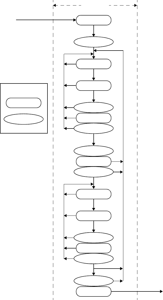
IEEE Std 1800-2012
IEEE STANDARD FOR SYSTEMVERILOG—UNIFIED HARDWARE DESIGN, SPECIFICATION, AND
VERIFICATION LANGUAGE
28
Copyright © 2013 IEEE. All rights reserved.
Figure 4-1—Event scheduling regions
Preponed
Pre-Active
Active
Inactive
Pre-NBA
NBA
Post-NBA
Postponed
time slot
from previous
time slot
to next
time slot
region
PLI region
Legend:
Pre-Postponed
Reactive
Re-Inactive
Pre-Re-NBA
Re-NBA
Post-Re-NBA
Pre-Observed
Observed
Post-Observed
IEEE Std 1800-2012
IEEE STANDARD FOR SYSTEMVERILOG—UNIFIED HARDWARE DESIGN, SPECIFICATION, AND
VERIFICATION LANGUAGE
29
Copyright © 2013 IEEE. All rights reserved.
4.5 SystemVerilog simulation reference algorithm
execute_simulation {
T = 0;
initialize the values of all nets and variables;
schedule all initialization events into time 0 slot;
while (some time slot is nonempty) {
move to the first nonempty time slot and set T;
execute_time_slot (T);
}
}
execute_time_slot {
execute_region (Preponed);
execute_region (Pre-Active);
while (any region in [Active ... Pre-Postponed] is nonempty) {
while (any region in [Active ... Post-Observed] is nonempty) {
execute_region (Active);
R = first nonempty region in [Active ... Post-Observed];
if (R is nonempty)
move events in R to the Active region;
}
while (any region in [Reactive ... Post-Re-NBA] is nonempty) {
execute_region (Reactive);
R = first nonempty region in [Reactive ... Post-Re-NBA];
if (R is nonempty)
move events in R to the Reactive region;
}
if (all regions in [Active ... Post-Re-NBA] are empty)
execute_region (Pre-Postponed);
}
execute_region (Postponed);
}
execute_region {
while (region is nonempty) {
E = any event from region;
remove E from the region;
if (E is an update event) {
update the modified object;
schedule evaluation event for any process sensitive to the object;
} else { /* E is an evaluation event */
evaluate the process associated with the event and possibly
schedule further events for execution;
}
}
}
The Iterative regions and their order are Active, Inactive, Pre-NBA, NBA, Post-NBA, Pre-Observed,
Observed, Post-Observed, Reactive, Re-Inactive, Pre-Re-NBA, Re-NBA, Post-Re-NBA, and Pre-
Postponed. As shown in the algorithm, once the Reactive, Re-Inactive, Pre-Re-NBA, Re-NBA, or Post-Re-
NBA regions are processed, iteration over the other regions does not resume until these five regions are
empty.
4.6 Determinism
This standard guarantees a certain scheduling order:

IEEE Std 1800-2012
IEEE STANDARD FOR SYSTEMVERILOG—UNIFIED HARDWARE DESIGN, SPECIFICATION, AND
VERIFICATION LANGUAGE
30
Copyright © 2013 IEEE. All rights reserved.
a) Statements within a begin-end block shall be executed in the order in which they appear in that
begin-end block. Execution of statements in a particular begin-end block can be suspended in favor
of other processes in the model; however, in no case shall the statements in a begin-end block be
executed in any order other than that in which they appear in the source.
b) NBAs shall be performed in the order the statements were executed (see 10.4.2).
Consider the following example:
module test;
logic a;
initial begin
a <= 0;
a <= 1;
end
endmodule
When this block is executed, there will be two events added to the NBA region. The previous rule requires
that they be entered in the event region in execution order, which, in a sequential begin-end block, is source
order. This rule requires that they be taken from the NBA region and performed in execution order as well.
Hence, at the end of simulation time 0, the variable a will be assigned 0 and then 1.
4.7 Nondeterminism
One source of nondeterminism is the fact that active events can be taken off the Active or Reactive event
region and processed in any order. Another source of nondeterminism is that statements without time-
control constructs in procedural blocks do not have to be executed as one event. Time control statements are
the # expression and @ expression constructs (see 9.4). At any time while evaluating a procedural statement,
the simulator may suspend execution and place the partially completed event as a pending event in the event
region. The effect of this is to allow the interleaving of process execution, although the order of interleaved
execution is nondeterministic and not under control of the user.
4.8 Race conditions
Because the execution of expression evaluation and net update events may be intermingled, race conditions
are possible: For example:
assign p = q;
initial begin
q = 1;
#1 q = 0;
$display(p);
end
The simulator is correct in displaying either a 1 or a 0. The assignment of 0 to q enables an update event for
p. The simulator may either continue and execute the $display task or execute the update for p, followed
by the $display task.
4.9 Scheduling implication of assignments
Assignments are translated into processes and events as detailed in 4.9.1 through 4.9.7.

IEEE Std 1800-2012
IEEE STANDARD FOR SYSTEMVERILOG—UNIFIED HARDWARE DESIGN, SPECIFICATION, AND
VERIFICATION LANGUAGE
31
Copyright © 2013 IEEE. All rights reserved.
4.9.1 Continuous assignment
A continuous assignment statement (see 10.3) corresponds to a process, sensitive to the source elements in
the expression. When the value of the expression changes, it causes an active update event to be added to the
event region, using current values to determine the target. A continuous assignment process is also evaluated
at time 0 in order to propagate constant values. This includes implicit continuous assignments inferred from
port connections (see 4.9.6).
4.9.2 Procedural continuous assignment
A procedural continuous assignment (which is the assign or force statement; see 10.6) corresponds to a
process that is sensitive to the source elements in the expression. When the value of the expression changes,
it causes an active update event to be added to the event region, using current values to determine the target.
A deassign or a release statement deactivates any corresponding assign or force statement(s).
4.9.3 Blocking assignment
A blocking assignment statement (see 10.4.1) with an intra-assignment delay computes the right-hand side
value using the current values, then causes the executing process to be suspended and scheduled as a future
event. If the delay is 0, the process is scheduled as an Inactive event for the current time. If a blocking
assignment with zero delay is executed from a Reactive region, the process is scheduled as a Re-Inactive
event.
When the process is returned (or if it returns immediately if no delay is specified), the process performs the
assignment to the left-hand side and enables any events based upon the update of the left-hand side. The
values at the time the process resumes are used to determine the target(s). Execution may then continue with
the next sequential statement or with other Active or Reactive events.
4.9.4 Nonblocking assignment
A nonblocking assignment statement (see 10.4.2) always computes the updated value and schedules the
update as an NBA update event, either in the current time step if the delay is zero or as a future event if the
delay is nonzero. The values in effect when the update is placed in the event region are used to compute both
the right-hand value and the left-hand target.
4.9.5 Switch (transistor) processing
The event-driven simulation algorithm described in 4.5 depends on unidirectional signal flow and can
process each event independently. The inputs are read, the result is computed, and the update is scheduled.
SystemVerilog provides switch-level modeling in addition to behavioral and gate-level modeling. Switches
provide bidirectional signal flow and require coordinated processing of nodes connected by switches.
The source elements that model switches are various forms of transistors, called tran, tranif0, tranif1,
rtran, rtranif0, and rtranif1.
Switch processing shall consider all the devices in a bidirectional switch-connected net before it can
determine the appropriate value for any node on the net because the inputs and outputs interact. A simulator
can do this using a relaxation technique. The simulator can process tran at any time. It can process a subset
of tran-connected events at a particular time, intermingled with the execution of other active events.
Further refinement is required when some transistors have gate value x. A conceptually simple technique is
to solve the network repeatedly with these transistors set to all possible combinations of fully conducting
IEEE Std 1800-2012
IEEE STANDARD FOR SYSTEMVERILOG—UNIFIED HARDWARE DESIGN, SPECIFICATION, AND
VERIFICATION LANGUAGE
32
Copyright © 2013 IEEE. All rights reserved.
and nonconducting transistors. Any node that has a unique logic level in all cases has steady-state response
equal to this level. All other nodes have steady-state response x.
4.9.6 Port connections
Ports connect processes through implicit continuous assignment statements or implicit bidirectional
connections. Bidirectional connections are analogous to an always-enabled tran connection between the
two nets, but without any strength reduction.
Ports can always be represented as declared objects connected, as follows:
— If an input port, then a continuous assignment from an outside expression to a local (input) net or
variable
— If an output port, then a continuous assignment from a local output expression to an outside net or
variable
— If an inout port, then a non-strength-reducing transistor connecting the local net to an outside net
Primitive terminals, including UDP terminals, are different from module ports. Primitive output and inout
terminals shall be connected directly to 1-bit nets or 1-bit structural net expressions (see 23.3.3), with no
intervening process that could alter the strength. Changes from primitive evaluations are scheduled as active
update events in the connected nets. Input terminals connected to 1-bit nets or 1-bit structural net
expressions are also connected directly, with no intervening process that could affect the strength. Input
terminals connected to other kinds of expressions are represented as implicit continuous assignments from
the expression to an implicit net that is connected to the input terminal.
4.9.7 Subroutines
Subroutine argument passing is by value, and it copies in on invocation and copies out on return. The copy-
out-on-the-return function behaves in the same manner as does any blocking assignment.
4.10 PLI callback control points
There are two kinds of PLI callbacks: those that are executed immediately when some specific activity
occurs, and those that are explicitly registered as a one-shot evaluation event.
Table 4-1 provides the mapping from the various PLI callbacks.
Table 4-1—PLI callbacks
Callback Event region
cbAfterDelay Pre-Active
cbNextSimTime Pre-Active
cbReadWriteSynch Pre-NBA or Post-NBA
cbAtStartOfSimTime Pre-Active
cbNBASynch Pre-NBA
cbAtEndOfSimTime Pre-Postponed
cbReadOnlySynch Postponed

IEEE Std 1800-2012
IEEE STANDARD FOR SYSTEMVERILOG—UNIFIED HARDWARE DESIGN, SPECIFICATION, AND
VERIFICATION LANGUAGE
33
Copyright © 2013 IEEE. All rights reserved.
5. Lexical conventions
5.1 General
This clause describes the following:
— Lexical tokens (white space, comments, operators)
— Integer, real, string, array, structure, and time literals
— Built-in method calls
— Attributes
5.2 Lexical tokens
SystemVerilog source text files shall be a stream of lexical tokens. A lexical token shall consist of one or
more characters. The layout of tokens in a source file shall be free format; that is, spaces and newlines shall
not be syntactically significant other than being token separators, except for escaped identifiers (see 5.6.1).
The types of lexical tokens in the language are as follows:
— White space
— Comment
—Operator
— Number
— String literal
— Identifier
—Keyword
5.3 White space
White space shall contain the characters for spaces, tabs, newlines, and formfeeds. These characters shall be
ignored except when they serve to separate other lexical tokens. However, blanks and tabs shall be
considered significant characters in string literals (see 5.9).
5.4 Comments
SystemVerilog has two forms to introduce comments. A one-line comment shall start with the two
characters // and end with a newline. A block comment shall start with /* and end with */. Block
comments shall not be nested. The one-line comment token // shall not have any special meaning in a block
comment.
5.5 Operators
Operators are single-, double-, or triple-character sequences and are used in expressions. Clause 11
discusses the use of operators in expressions.
Unary operators shall appear to the left of their operand. Binary operators shall appear between their
operands. A conditional operator shall have two operator characters that separate three operands.

IEEE Std 1800-2012
IEEE STANDARD FOR SYSTEMVERILOG—UNIFIED HARDWARE DESIGN, SPECIFICATION, AND
VERIFICATION LANGUAGE
34
Copyright © 2013 IEEE. All rights reserved.
5.6 Identifiers, keywords, and system names
An identifier is used to give an object a unique name so it can be referenced. An identifier is either a simple
identifier or an escaped identifier (see 5.6.1). A simple identifier shall be any sequence of letters, digits,
dollar signs ($), and underscore characters (_).
The first character of a simple identifier shall not be a digit or $; it can be a letter or an underscore.
Identifiers shall be case sensitive.
For example:
shiftreg_a
busa_index
error_condition
merge_ab
_bus3
n$657
Implementations may set a limit on the maximum length of identifiers, but the limit shall be at least
1024 characters. If an identifier exceeds the implementation-specific length limit, an error shall be reported.
5.6.1 Escaped identifiers
Escaped identifiers shall start with the backslash character (\) and end with white space (space, tab,
newline). They provide a means of including any of the printable ASCII characters in an identifier (the
decimal values 33 through 126, or 21 through 7E in hexadecimal).
Neither the leading backslash character nor the terminating white space is considered to be part of the
identifier. Therefore, an escaped identifier \cpu3 is treated the same as a nonescaped identifier cpu3.
For example:
\busa+index
\-clock
\***error-condition***
\net1/\net2
\{a,b}
\a*(b+c)
5.6.2 Keywords
Keywords are predefined nonescaped identifiers that are used to define the language constructs. A
SystemVerilog keyword preceded by an escape character is not interpreted as a keyword.
All keywords are defined in lowercase only. Annex B gives a list of all defined keywords. Subclause 22.14
discusses compatibility of reserved keywords with previous versions of IEEE Std 1364 and IEEE Std 1800.
5.6.3 System tasks and system functions
The dollar sign ($) introduces a language construct that enables development of user-defined system tasks
and system functions. System constructs are not design semantics, but refer to simulator functionality. A
name following the $ is interpreted as a system task or a system function.
The syntax for system tasks and system functions is given in Syntax 5-1.

IEEE Std 1800-2012
IEEE STANDARD FOR SYSTEMVERILOG—UNIFIED HARDWARE DESIGN, SPECIFICATION, AND
VERIFICATION LANGUAGE
35
Copyright © 2013 IEEE. All rights reserved.
system_tf_call ::= // from A.8.2
system_tf_identifier [ ( list_of_arguments ) ]
| system_tf_identifier ( data_type [ , expression ] )
system_tf_identifier50 ::= $[ a-zA-Z0-9_$ ]{ [ a-zA-Z0-9_$ ] } // from A.9.3
50) The $ character in a system_tf_identifier shall not be followed by white_space. A system_tf_identifier shall not be
escaped.
Syntax 5-1—Syntax for system tasks and system functions (excerpt from Annex A)
SystemVerilog defines a standard set of system tasks and system functions in this document (see Clause 20
and Clause 21). Additional user-defined system tasks and system functions can be defined using the PLI, as
described in Clause 36. Software implementations can also specify additional system tasks and system
functions, which may be tool-specific (see Annex D for some common additional system tasks and system
functions). Additional system tasks and system functions are not part of this standard.
For example:
$display ("display a message");
$finish;
5.6.4 Compiler directives
The ` character (the ASCII value 0x60, called grave accent) introduces a language construct used to
implement compiler directives. The compiler behavior dictated by a compiler directive shall take effect as
soon as the compiler reads the directive. The directive shall remain in effect for the rest of the compilation
unless a different compiler directive specifies otherwise. A compiler directive in one description file can,
therefore, control compilation behavior in multiple description files. The effects of a compiler directive are
limited to a compilation unit (see 3.12.1) and shall not affect other compilation units.
For example:
`define wordsize
SystemVerilog defines a standard set of compiler directives in this document (see Clause 22). Software
implementations can also specify additional compiler directives, which may be tool-specific (see Annex E
for some common additional compiler directives). Additional compiler directives are not part of this
standard.
5.7 Numbers
Constant numbers can be specified as integer constants (see 5.7.1) or real constants (see 5.7.2). The formal
syntax for numbers is listed in Syntax 5-2.
primary_literal ::= number | time_literal | unbased_unsized_literal | string_literal // from A.8.4
time_literal44 ::=
unsigned_number time_unit
| fixed_point_number time_unit
time_unit ::= s | ms | us | ns | ps | fs

IEEE Std 1800-2012
IEEE STANDARD FOR SYSTEMVERILOG—UNIFIED HARDWARE DESIGN, SPECIFICATION, AND
VERIFICATION LANGUAGE
36
Copyright © 2013 IEEE. All rights reserved.
number ::= // from A.8.7
integral_number
| real_number
integral_number ::=
decimal_number
| octal_number
| binary_number
| hex_number
decimal_number ::=
unsigned_number
| [ size ] decimal_base unsigned_number
| [ size ] decimal_base x_digit { _ }
| [ size ] decimal_base z_digit { _ }
binary_number ::= [ size ] binary_base binary_value
octal_number ::= [ size ] octal_base octal_value
hex_number ::= [ size ] hex_base hex_value
sign ::= + | -
size ::= non_zero_unsigned_number
non_zero_unsigned_number33 ::= non_zero_decimal_digit { _ | decimal_digit}
real_number33 ::=
fixed_point_number
| unsigned_number [ . unsigned_number ] exp [ sign ] unsigned_number
fixed_point_number33 ::= unsigned_number . unsigned_number
exp ::= e | E
unsigned_number33 ::= decimal_digit { _ | decimal_digit }
binary_value33 ::= binary_digit { _ | binary_digit }
octal_value33 ::= octal_digit { _ | octal_digit }
hex_value33 ::= hex_digit { _ | hex_digit }
decimal_base33 ::= '[s|S]d | '[s|S]D
binary_base33 ::= '[s|S]b | '[s|S]B
octal_base33 ::= '[s|S]o | '[s|S]O
hex_base33 ::= '[s|S]h | '[s|S]H
non_zero_decimal_digit ::= 1 | 2 | 3 | 4 | 5 | 6 | 7 | 8 | 9
decimal_digit ::= 0 | 1 | 2 | 3 | 4 | 5 | 6 | 7 | 8 | 9
binary_digit ::= x_digit | z_digit | 0 | 1
octal_digit ::= x_digit | z_digit | 0 | 1 | 2 | 3 | 4 | 5 | 6 | 7
hex_digit ::= x_digit | z_digit | 0 | 1 | 2 | 3 | 4 | 5 | 6 | 7 | 8 | 9 | a | b | c | d | e | f | A | B | C | D | E | F
x_digit ::= x | X
z_digit ::= z | Z | ?
unbased_unsized_literal ::= '0 | '1 | 'z_or_x 48
string_literal ::= " { Any_ASCII_Characters } " // from A.8.8
33) Embedded spaces are illegal.
44) The unsigned number or fixed-point number in time_literal shall not be followed by a white_space.
48) The apostrophe ( ' ) in unbased_unsized_literal shall not be followed by white_space.
Syntax 5-2—Syntax for integer and real numbers (excerpt from Annex A)

IEEE Std 1800-2012
IEEE STANDARD FOR SYSTEMVERILOG—UNIFIED HARDWARE DESIGN, SPECIFICATION, AND
VERIFICATION LANGUAGE
37
Copyright © 2013 IEEE. All rights reserved.
5.7.1 Integer literal constants
Integer literal constants can be specified in decimal, hexadecimal, octal, or binary format.
There are two forms to express integer literal constants. The first form is a simple decimal number, which
shall be specified as a sequence of digits 0 through 9, optionally starting with a plus or minus unary
operator. The second form specifies a based literal constant, which shall be composed of up to three
tokens—an optional size constant, an apostrophe character (', ASCII 0x27) followed by a base format
character, and the digits representing the value of the number. It shall be legal to macro-substitute these three
tokens.
The first token, a size constant, shall specify the size of the integer literal constant in terms of its exact
number of bits. It shall be specified as a nonzero unsigned decimal number. For example, the size
specification for two hexadecimal digits is eight because one hexadecimal digit requires 4 bits.
The second token, a base_format, shall consist of a case insensitive letter specifying the base for the
number, optionally preceded by the single character s (or S) to indicate a signed quantity, preceded by the
apostrophe character. Legal base specifications are d, D, h, H, o, O, b, or B for the bases decimal,
hexadecimal, octal, and binary, respectively.
The apostrophe character and the base format character shall not be separated by any white space.
The third token, an unsigned number, shall consist of digits that are legal for the specified base format. The
unsigned number token shall immediately follow the base format, optionally preceded by white space. The
hexadecimal digits a to f shall be case insensitive.
Simple decimal numbers without the size and the base format shall be treated as signed integers, whereas the
numbers specified with the base format shall be treated as signed integers if the s designator is included or
as unsigned integers if the base format only is used. The s designator does not affect the bit pattern
specified, only its interpretation.
A plus or minus operator preceding the size constant is a unary plus or minus operator. A plus or minus
operator between the base format and the number is an illegal syntax.
Negative numbers shall be represented in twos-complement form.
An x represents the unknown value in hexadecimal, octal, and binary literal constants. A z represents the
high-impedance value. See 6.3 for a discussion of the SystemVerilog value set. An x shall set 4 bits to
unknown in the hexadecimal base, 3 bits in the octal base, and 1 bit in the binary base. Similarly, a z shall set
4 bits, 3 bits, and 1 bit, respectively, to the high-impedance value.
If the size of the unsigned number is smaller than the size specified for the literal constant, the unsigned
number shall be padded to the left with zeros. If the leftmost bit in the unsigned number is an x or a z, then
an x or a z shall be used to pad to the left, respectively. If the size of the unsigned number is larger than the
size specified for the literal constant, the unsigned number shall be truncated from the left.
The number of bits that make up an unsized number (which is a simple decimal number or a number with a
base specifier but no size specification) shall be at least 32. Unsized unsigned literal constants where the
high-order bit is unknown (X or x) or three-state (Z or z) shall be extended to the size of the expression
containing the literal constant.
NOTE—In IEEE Std 1364-1995, in unsized literal constants where the high-order bit is unknown or three-state, the x or
z was only extended to 32 bits.

IEEE Std 1800-2012
IEEE STANDARD FOR SYSTEMVERILOG—UNIFIED HARDWARE DESIGN, SPECIFICATION, AND
VERIFICATION LANGUAGE
38
Copyright © 2013 IEEE. All rights reserved.
An unsized single-bit value can be specified by preceding the single-bit value with an apostrophe ( ' ), but
without the base specifier. All bits of the unsized value shall be set to the value of the specified bit. In a
self-determined context, an unsized single-bit value shall have a width of 1 bit, and the value shall be treated
as unsigned.
'0, '1, 'X, 'x, 'Z, 'z // sets all bits to specified value
The use of x and z in defining the value of a number is case insensitive.
When used in a number, the question mark (?) character is a SystemVerilog alternative for the z character.
It sets 4 bits to the high-impedance value in hexadecimal numbers, 3 bits in octal, and 1 bit in binary. The
question mark can be used to enhance readability in cases where the high-impedance value is a do-not-care
condition. See the discussion of casez and casex in 12.5.1. The question mark character is also used in
UDP state tables. See Table 29-1 in 29.3.6.
In a decimal literal constant, the unsigned number token shall not contain any x, z, or ? digits, unless there is
exactly one digit in the token, indicating that every bit in the decimal literal constant is x or z.
The underscore character (_) shall be legal anywhere in a number except as the first character. The
underscore character is ignored. This feature can be used to break up long numbers for readability purposes.
Several examples of specifying literal integer numbers are as follows:
Example 1: Unsized literal constant numbers
659 // is a decimal number
'h 837FF // is a hexadecimal number
'o7460 // is an octal number
4af // is illegal (hexadecimal format requires 'h)
Example 2: Sized literal constant numbers
4'b1001 // is a 4-bit binary number
5 'D 3 // is a 5-bit decimal number
3'b01x // is a 3-bit number with the least
// significant bit unknown
12'hx // is a 12-bit unknown number
16'hz // is a 16-bit high-impedance number
Example 3: Using sign with literal constant numbers
8 'd -6 // this is illegal syntax
-8 'd 6 // this defines the two's complement of 6,
// held in 8 bits—equivalent to -(8'd 6)
4 'shf // this denotes the 4-bit number '1111', to
// be interpreted as a 2's complement number,
// or '-1'. This is equivalent to -4'h 1
-4 'sd15 // this is equivalent to -(-4'd 1), or '0001'
16'sd? // the same as 16'sbz
Example 4: Automatic left padding of literal constant numbers
logic [11:0] a, b, c, d;
logic [84:0] e, f, g;
initial begin
a = 'h x; // yields xxx
IEEE Std 1800-2012
IEEE STANDARD FOR SYSTEMVERILOG—UNIFIED HARDWARE DESIGN, SPECIFICATION, AND
VERIFICATION LANGUAGE
39
Copyright © 2013 IEEE. All rights reserved.
b = 'h 3x; // yields 03x
c = 'h z3; // yields zz3
d = 'h 0z3; // yields 0z3
e = 'h5; // yields {82{1'b0},3'b101}
f = 'hx; // yields {85{1'hx}}
g = 'hz; // yields {85{1'hz}}
end
Example 5: Automatic left padding of constant literal numbers using a single-bit value
logic [15:0] a, b, c, d;
a = '0; // sets all 16 bits to 0
b = '1; // sets all 16 bits to 1
c = 'x; // sets all 16 bits to x
d = 'z; // sets all 16 bits to z
Example 6: Underscores in literal constant numbers
27_195_000 // unsized decimal 27195000
16'b0011_0101_0001_1111 // 16-bit binary number
32 'h 12ab_f001 // 32-bit hexadecimal number
Sized negative literal constant numbers and sized signed literal constant numbers are sign-extended when
assigned to a data object of type logic, regardless of whether the type itself is signed.
The default length of x and z is the same as the default length of an integer.
5.7.2 Real literal constants
The real literal constant numbers shall be represented as described by IEEE Std 754, an IEEE standard for
double-precision floating-point numbers.
Real numbers can be specified in either decimal notation (for example, 14.72) or in scientific notation (for
example, 39e8, which indicates 39 multiplied by 10 to the eighth power). Real numbers expressed with a
decimal point shall have at least one digit on each side of the decimal point.
For example:
1.2
0.1
2394.26331
1.2E12 (the exponent symbol can be e or E)
1.30e-2
0.1e-0
23E10
29E-2
236.123_763_e-12 (underscores are ignored)
The following are invalid forms of real numbers because they do not have at least one digit on each side of
the decimal point:
.12
9.
4.E3
.2e-7

IEEE Std 1800-2012
IEEE STANDARD FOR SYSTEMVERILOG—UNIFIED HARDWARE DESIGN, SPECIFICATION, AND
VERIFICATION LANGUAGE
40
Copyright © 2013 IEEE. All rights reserved.
The default type for fixed-point format (e.g., 1.2), and exponent format (e.g., 2.0e10) shall be real.
A cast can be used to convert literal real values to the shortreal type (e.g., shortreal'(1.2)). Casting
is described in 6.24.
Real numbers shall be converted to integers by rounding the real number to the nearest integer, rather than
by truncating it. Implicit conversion shall take place when a real number is assigned to an integer. The ties
shall be rounded away from zero. For example:
— The real numbers 35.7 and 35.5 both become 36 when converted to an integer and 35.2 becomes 35.
— Converting –1.5 to integer yields –2, converting 1.5 to integer yields 2.
5.8 Time literals
Time is written in integer or fixed-point format, followed without a space by a time unit (fs ps ns us ms s).
For example:
2.1ns
40ps
The time literal is interpreted as a realtime value scaled to the current time unit and rounded to the current
time precision.
5.9 String literals
A string literal is a sequence of characters enclosed by double quotes ("").
Nonprinting and other special characters are preceded with a backslash.
A string literal shall be contained in a single line unless the new line is immediately preceded by a \
(backslash). In this case, the backslash and the newline are ignored. There is no predefined limit to the
length of a string literal.
Example 1:
$display("Humpty Dumpty sat on a wall. \
Humpty Dumpty had a great fall.");
prints
Humpty Dumpty sat on a wall. Humpty Dumpty had a great fall.
Example 2:
$display("Humpty Dumpty sat on a wall.\n\
Humpty Dumpty had a great fall.");
prints
Humpty Dumpty sat on a wall.
Humpty Dumpty had a great fall.
String literals used as operands in expressions and assignments shall be treated as unsigned integer constants
represented by a sequence of 8-bit ASCII values, with one 8-bit ASCII value representing one character.
IEEE Std 1800-2012
IEEE STANDARD FOR SYSTEMVERILOG—UNIFIED HARDWARE DESIGN, SPECIFICATION, AND
VERIFICATION LANGUAGE
41
Copyright © 2013 IEEE. All rights reserved.
A string literal can be assigned to an integral type, such as a packed array. If the size differs, it is right
justified. To fully store a string literal, the integral type should be declared with a width equal to the number
of characters in the string multiplied by 8. For example:
byte c1 = "A" ;
bit [7:0] d = "\n" ;
The rules of SystemVerilog assignments shall be followed if the packed array width does not match the
number of characters multiplied by 8. When an integral type is larger than required to hold the string literal
value being assigned, the value is right-justified, and the leftmost bits are padded with zeros, as is done with
nonstring values. If a string literal is larger than the destination integral type, the string is right-justified, and
the leftmost characters are truncated.
For example, to store the 12-character string "Hello world\n" requires a variable 8 × 12, or 96 bits wide.
bit [8*12:1] stringvar = "Hello world\n";
Alternatively, a multidimensional packed array can be used, with 8-bit subfields, as in:
bit [0:11] [7:0] stringvar = "Hello world\n" ;
A string literal can be assigned to an unpacked array of bytes. If the size differs, it is left justified.
byte c3 [0:12] = "hello world\n" ;
Packed and unpacked arrays are discussed in 7.4.
String literals can also be cast to a packed or unpacked array type, which shall follow the same rules as
assigning a string literal to a packed or unpacked array. Casting is discussed in 6.24.
SystemVerilog also includes a string data type to which a string literal can be assigned. Variables of type
string have arbitrary length; they are dynamically resized to hold any string. String literals are packed
arrays (of a width that is a multiple of 8 bits), and they are implicitly converted to the string type when
assigned to a string type or used in an expression involving string type operands (see 6.16).
String literals stored in vectors can be manipulated using the SystemVerilog operators. The value being
manipulated by the operator is the sequence of 8-bit ASCII values. See 11.10 for operations on string
literals.
5.9.1 Special characters in strings
Certain characters can only be used in string literals when preceded by an introductory character called an
escape character. Table 5-1 lists these characters in the right-hand column, with the escape sequence that
represents the character in the left-hand column.
Table 5-1—Specifying special characters in string literals
Escape string Character produced by escape string
\n Newline character
\t Tab character
\\ \ character
\" " character
IEEE Std 1800-2012
IEEE STANDARD FOR SYSTEMVERILOG—UNIFIED HARDWARE DESIGN, SPECIFICATION, AND
VERIFICATION LANGUAGE
42
Copyright © 2013 IEEE. All rights reserved.
5.10 Structure literals
Structure literals are structure assignment patterns or pattern expressions with constant member expressions
(see 10.9.2). A structure literal must have a type, which may be either explicitly indicated with a prefix or
implicitly indicated by an assignment-like context (see 10.8).
typedef struct {int a; shortreal b;} ab;
ab c;
c = '{0, 0.0}; // structure literal type determined from
// the left-hand context (c)
Nested braces shall reflect the structure. For example:
ab abarr[1:0] = '{'{1, 1.0}, '{2, 2.0}};
The C-like alternative '{1, 1.0, 2, 2.0} for the preceding example is not allowed.
Structure literals can also use member name and value or use data type and default value (see 10.9.2):
c = '{a:0, b:0.0}; // member name and value for that member
c = '{default:0}; // all elements of structure c are set to 0
d = ab'{int:1, shortreal:1.0}; // data type and default value for all
// members of that type
When an array of structures is initialized, the nested braces shall reflect the array and the structure. For
example:
ab abarr[1:0] = '{'{1, 1.0}, '{2, 2.0}};
Replication operators can be used to set the values for the exact number of members. The inner pair of
braces in a replication is removed.
struct {int X,Y,Z;} XYZ = '{3{1}};
typedef struct {int a,b[4];} ab_t;
int a,b,c;
ab_t v1[1:0] [2:0];
v1 = '{2{'{3{'{a,'{2{b,c}}}}}}};
/* expands to '{ '{3{ '{ a, '{2{ b, c }} } }},
\v vertical tab
\f form feed
\a bell
\ddd A character specified in 1 to 3 octal_digits (see Syntax 5-2). If fewer than three charac-
ters are used, the following character shall not be an octal_digit. Implementations may
issue an error if the character represented is greater than \377. It shall be illegal for an
octal_digit in an escape sequence to be an x_digit or a z_digit (see Syntax 5-2).
\xdd A character specified in 1 to 2 hex_digits (see Syntax 5-2). If only one digit is used, the
following character shall not be a hex_digit. It shall be illegal for a hex_digit in an
escape sequence to be an x_digit or a z_digit (see Syntax 5-2).
Table 5-1—Specifying special characters in string literals (continued)
Escape string Character produced by escape string

IEEE Std 1800-2012
IEEE STANDARD FOR SYSTEMVERILOG—UNIFIED HARDWARE DESIGN, SPECIFICATION, AND
VERIFICATION LANGUAGE
43
Copyright © 2013 IEEE. All rights reserved.
'{3{ '{ a, '{2{ b, c }} } }}
} */
/* expands to '{ '{ '{ a, '{2{ b, c }} },
'{ a, '{2{ b, c }} },
'{ a, '{2{ b, c }} }
},
'{ '{ a, '{2{ b, c }} },
'{ a, '{2{ b, c }} },
'{ a, '{2{ b, c }} }
}
} */
/* expands to '{ '{ '{ a, '{ b, c, b, c } },
'{ a, '{ b, c, b, c } },
'{ a, '{ b, c, b, c } }
},
'{ '{ a, '{ b, c, b, c } },
'{ a, '{ b, c, b, c } },
'{ a, '{ b, c, b, c } }
}
} */
5.11 Array literals
Array literals are syntactically similar to C initializers, but with the replication operator ( {{}} ) allowed.
int n[1:2][1:3] = '{'{0,1,2},'{3{4}}};
The nesting of braces shall follow the number of dimensions, unlike in C. However, replication operators
can be nested. The inner pair of braces in a replication is removed. A replication expression only operates
within one dimension.
int n[1:2][1:6] = '{2{'{3{4, 5}}}}; // same as
'{'{4,5,4,5,4,5},'{4,5,4,5,4,5}}
Array literals are array assignment patterns or pattern expressions with constant member expressions (see
10.9.1). An array literal must have a type, which may be either explicitly indicated with a prefix or implicitly
indicated by an assignment-like context (see 10.8).
typedef int triple [1:3];
$mydisplay(triple'{0,1,2});
Array literals can also use their index or type as a key and use a default key value (see 10.9.1).
triple b = '{1:1, default:0}; // indices 2 and 3 assigned 0
5.12 Attributes
A mechanism is included for specifying properties about objects, statements, and groups of statements in the
SystemVerilog source that can be used by various tools, including simulators, to control the operation or
behavior of the tool. These properties are referred to as attributes. This subclause specifies the syntactic
mechanism used for specifying attributes, without standardizing on any particular attributes.
The syntax for specifying an attribute is shown in Syntax 5-3.

IEEE Std 1800-2012
IEEE STANDARD FOR SYSTEMVERILOG—UNIFIED HARDWARE DESIGN, SPECIFICATION, AND
VERIFICATION LANGUAGE
44
Copyright © 2013 IEEE. All rights reserved.
attribute_instance ::= (* attr_spec { , attr_spec } *) // from A.9.1
attr_spec ::= attr_name [ = constant_expression ]
attr_name ::= identifier
Syntax 5-3—Syntax for attributes (excerpt from Annex A)
An attribute_instance can appear in the SystemVerilog description as a prefix attached to a declaration, a
module item, a statement, or a port connection. It can appear as a suffix to an operator or a function name in
an expression.
The default type of an attribute with no value is bit, with a value of 1. Otherwise, the attribute takes the
type of the expression.
If the same attribute name is defined more than once for the same language element, the last attribute value
shall be used, and a tool can issue a warning that a duplicate attribute specification has occurred.
Nesting of attribute instances is disallowed. It shall be illegal to specify the value of an attribute with a
constant expression that contains an attribute instance.
Refer to Annex A for the syntax of specifying an attribute instance on specific language elements. Several
examples are illustrated below.
Example 1: The following example shows how to attach attributes to a case statement:
(* full_case, parallel_case *)
case (a)
<rest_of_case_statement>
or
(* full_case=1 *)
(* parallel_case=1 *) // Multiple attribute instances also OK
case (a)
<rest_of_case_statement>
or
(* full_case, // no value assigned
parallel_case=1 *)
case (a)
<rest_of_case_statement>
Example 2: To attach the full_case attribute, but not the parallel_case attribute:
(* full_case *) // parallel_case not specified
case (a)
<rest_of_case_statement>
or
(* full_case=1, parallel_case = 0 *)
case (a)
<rest_of_case_statement>
IEEE Std 1800-2012
IEEE STANDARD FOR SYSTEMVERILOG—UNIFIED HARDWARE DESIGN, SPECIFICATION, AND
VERIFICATION LANGUAGE
45
Copyright © 2013 IEEE. All rights reserved.
Example 3: To attach an attribute to a module definition:
(* optimize_power *)
module mod1 (<port_list>);
or
(* optimize_power=1 *)
module mod1 (<port_list>);
Example 4: To attach an attribute to a module instantiation:
(* optimize_power=0 *)
mod1 synth1 (<port_list>);
Example 5: To attach an attribute to a variable declaration:
(* fsm_state *) logic [7:0] state1;
(* fsm_state=1 *) logic [3:0] state2, state3;
logic [3:0] reg1; // reg1 does NOT have fsm_state set
(* fsm_state=0 *) logic [3:0] reg2; // nor does reg2
Example 6: To attach an attribute to an operator:
a = b + (* mode = "cla" *) c; // sets the value for the attribute mode
// to be the string cla.
Example 7: To attach an attribute to a function call:
a = add (* mode = "cla" *) (b, c);
Example 8: To attach an attribute to a conditional operator:
a = b ? (* no_glitch *) c : d;
5.13 Built-in methods
SystemVerilog uses a C++ -like class method calling syntax, in which a subroutine is called using the dot
notation (.):
object.task_or_function()
The object uniquely identifies the data on which the subroutine operates. Hence, the method concept is
naturally extended to built-in types in order to add functionality, which traditionally was done via system
tasks or system functions. Unlike system tasks, built-in methods are not prefixed with a $ because they
require no special prefix to avoid collisions with user-defined identifiers. Thus, the method syntax allows
extending the language without the addition of new keywords or the cluttering of the global name space with
system tasks.
Built-in methods, unlike system tasks, cannot be redefined by users via PLI tasks. Thus, only functions that
users should not be allowed to redefine are good candidates for built-in method calls.
In general, a built-in method is preferred over a system task when a particular functionality applies to all
data types or when it applies to a specific data type. For example:

IEEE Std 1800-2012
IEEE STANDARD FOR SYSTEMVERILOG—UNIFIED HARDWARE DESIGN, SPECIFICATION, AND
VERIFICATION LANGUAGE
46
Copyright © 2013 IEEE. All rights reserved.
dynamic_array.size, associative_array.num, and string.len
These are all similar concepts, but they represent different things. A dynamic array has a size, an associative
array contains a given number of items, and a string has a given length. Using the same system task, such as
$size, for all of them would be less clear and intuitive.
A built-in method can only be associated with a particular data type. Therefore, if some functionality is a
simple side effect (i.e., $stop or $reset) or it operates on no specific data (i.e., $random), then a system
task must be used.
When a subroutine built-in method call specifies no arguments, the empty parenthesis, (), following the
subroutine name is optional. This is also true for subroutines that require arguments, when all arguments
have defaults specified. For a method, this rule allows simple calls to appear as properties of the object or
built-in type. Similar rules are defined for subroutines in 13.5.5.

IEEE Std 1800-2012
IEEE STANDARD FOR SYSTEMVERILOG—UNIFIED HARDWARE DESIGN, SPECIFICATION, AND
VERIFICATION LANGUAGE
47
Copyright © 2013 IEEE. All rights reserved.
6. Data types
6.1 General
This clause describes the following:
— SystemVerilog logic value and strength set
— Net declarations
— Singular variable declarations
—Constants
— Scope and lifetime of data
— Type compatibility
— Type operator and type casting
6.2 Data types and data objects
SystemVerilog makes a distinction between an object and its data type. A data type is a set of values and a
set of operations that can be performed on those values. Data types can be used to declare data objects or to
define user-defined data types that are constructed from other data types. A data object is a named entity that
has a data value and a data type associated with it, such as a parameter, a variable, or a net.
6.3 Value set
6.3.1 Logic values
The SystemVerilog value set consists of the following four basic values:
0—represents a logic zero or a false condition
1—represents a logic one or a true condition
x—represents an unknown logic value
z—represents a high-impedance state
The values 0 and 1 are logical complements of one another.
When the z value is present at the input of a gate or when it is encountered in an expression, the effect is
usually the same as an x value. Notable exceptions are the metal-oxide semiconductor (MOS) primitives,
which can pass the z value.
The name of this primitive data type is logic. This name can be used to declare objects and to construct
other data types from the 4-state data type.
Several SystemVerilog data types are 4-state types, which can store all four logic values. All bits of 4-state
vectors can be independently set to one of the four basic values. Some SystemVerilog data types are 2-state,
and only store 0 or 1 values in each bit of a vector. Other exceptions are the event type (see 6.17), which has
no storage, and the real types (see 6.12).
6.3.2 Strengths
The language includes strength information in addition to the basic value information for nets. This is
described in detail in Clause 28. The additional strength information associated with bits of a net is not
considered part of the data type.

IEEE Std 1800-2012
IEEE STANDARD FOR SYSTEMVERILOG—UNIFIED HARDWARE DESIGN, SPECIFICATION, AND
VERIFICATION LANGUAGE
48
Copyright © 2013 IEEE. All rights reserved.
Two types of strengths can be specified in a net declaration, as follows:
—Charge strength shall only be used when declaring a net of type trireg.
—Drive strength shall only be used when placing a continuous assignment on a net in the same state-
ment that declares the net.
Gate declarations can also specify a drive strength. See Clause 28 for more information on gates and for
information on strengths.
6.3.2.1 Charge strength
The charge strength specification shall be used only with trireg nets. A trireg net shall be used to model
charge storage; charge strength shall specify the relative size of the capacitance indicated by one of the
following keywords:
—small
—medium
—large
The default charge strength of a trireg net shall be medium.
A trireg net can model a charge storage node whose charge decays over time. The simulation time of a
charge decay shall be specified in the delay specification for the trireg net (see 28.16.2).
For example:
trireg a; // trireg net of charge strength medium
trireg (large) #(0,0,50) cap1; // trireg net of charge strength large
// with charge decay time 50 time units
trireg (small) signed [3:0] cap2; // signed 4-bit trireg vector of
// charge strength small
6.3.2.2 Drive strength
The drive strength specification allows a continuous assignment to be placed on a net in the same statement
that declares that net. See Clause 10 for more details. Net drive strength properties are described in detail in
Clause 28.
6.4 Singular and aggregate types
Data types are categorized as either singular or aggregate. A singular type shall be any data type except an
unpacked structure, unpacked union, or unpacked array (see 7.4 on arrays). An aggregate type shall be any
unpacked structure, unpacked union, or unpacked array data type. A singular variable or expression
represents a single value, symbol, or handle. Aggregate expressions and variables represent a set or
collection of singular values. Integral types (see 6.11.1) are always singular even though they can be sliced
into multiple singular values. The string data type is singular even though a string can be indexed in a
similar way to an unpacked array of bytes.
These categories are defined so that operators and functions can simply refer to these data types as a
collective group. For example, some functions recursively descend into an aggregate variable until reaching
a singular value and then perform an operation on each singular value.
Although a class is a type, there are no variables or expressions of class type directly, only class object
handles that are singular. Therefore, classes need not be categorized in this manner (see Clause 8 on classes).

IEEE Std 1800-2012
IEEE STANDARD FOR SYSTEMVERILOG—UNIFIED HARDWARE DESIGN, SPECIFICATION, AND
VERIFICATION LANGUAGE
49
Copyright © 2013 IEEE. All rights reserved.
6.5 Nets and variables
There are two main groups of data objects: variables and nets. These two groups differ in the way in which
they are assigned and hold values.
A net can be written by one or more continuous assignments, by primitive outputs, or through module ports.
The resultant value of multiple drivers is determined by the resolution function of the net type. A net cannot
be procedurally assigned. If a net on one side of a port is driven by a variable on the other side, a continuous
assignment is implied. A force statement can override the value of a net. When released, the net returns to
the resolved value.
Variables can be written by one or more procedural statements, including procedural continuous
assignments. The last write determines the value. Alternatively, variables can be written by one continuous
assignment or one port.
Variables can be packed or unpacked aggregates of other types (see 7.4 for packed and unpacked types).
Multiple assignments made to independent elements of a variable are examined individually. Independent
elements include different members of a structure or different elements of an array. Each bit in a packed type
is also an independent element. Thus, in an aggregate of packed types, each bit in the aggregate is an
independent element.
An assignment where the left-hand side contains a slice is treated as a single assignment to the entire slice.
Thus, a structure or array can have one element assigned procedurally and another element assigned
continuously. And elements of a structure or array can be assigned with multiple continuous assignments,
provided that each element is covered by no more than a single continuous assignment.
The precise rule is that it shall be an error to have multiple continuous assignments or a mixture of
procedural and continuous assignments writing to any term in the expansion of a written longest static prefix
of a variable (see 11.5.3 for the definition of a longest static prefix).
For example, assume the following structure declaration:
struct {
bit [7:0] A;
bit [7:0] B;
byte C;
} abc;
The following statements are legal assignments to struct abc:
assign abc.C = sel ? 8'hBE : 8'hEF;
not (abc.A[0],abc.B[0]),
(abc.A[1],abc.B[1]),
(abc.A[2],abc.B[2]),
(abc.A[3],abc.B[3]);
always @(posedge clk) abc.B <= abc.B + 1;
The following additional statements are illegal assignments to struct abc:
// Multiple continuous assignments to abc.C
assign abc.C = sel ? 8'hDE : 8'hED;
// Mixing continuous and procedural assignments to abc.A[3]
always @(posedge clk) abc.A[7:3] <= !abc.B[7:3];

IEEE Std 1800-2012
IEEE STANDARD FOR SYSTEMVERILOG—UNIFIED HARDWARE DESIGN, SPECIFICATION, AND
VERIFICATION LANGUAGE
50
Copyright © 2013 IEEE. All rights reserved.
For the purposes of the preceding rule, a declared variable initialization or a procedural continuous
assignment is considered a procedural assignment. The force statement overrides the procedural assign
statement, which in turn overrides the normal assignments. A force statement is neither a continuous nor a
procedural assignment.
A continuous assignment shall be implied when a variable is connected to an input port declaration. This
makes assignments to a variable declared as an input port illegal. A continuous assignment shall be implied
when a variable is connected to the output port of an instance. This makes additional procedural or
continuous assignments to a variable connected to the output port of an instance illegal.
Variables cannot be connected to either side of an inout port. Variables can be shared across ports with the
ref port type. See 23.3.3 for more information about ports and port connection rules.
The compiler can issue a warning if a continuous assignment could drive strengths other than St0, St1,
StX, or HiZ to a variable. In any case, automatic type conversion shall be applied to the assignment, and the
strength is lost.
Unlike nets, a variable cannot have an implicit continuous assignment as part of its declaration. An
assignment as part of the declaration of a variable is a variable initialization, not a continuous assignment.
For example:
wire w = vara & varb; // net with a continuous assignment
logic v = consta & constb; // variable with initialization
logic vw; // no initial assignment
assign vw = vara & varb; // continuous assignment to a variable
real circ;
assign circ = 2.0 * PI * R; // continuous assignment to a variable
Data shall be declared before they are used, apart from implicit nets (see 6.10).
Within a name space (see 3.13), it shall be illegal to redeclare a name already declared by a net, variable, or
other declaration.
6.6 Net types
There are two different kinds of net types: built-in and user-defined. The net types can represent physical
connections between structural entities, such as gates. A net shall not store a value (except for the trireg
net). Instead, its value shall be determined by the values of its drivers, such as a continuous assignment or a
gate. See Clause 10 and Clause 28 for definitions of these constructs. If no driver is connected to a net, its
value shall be high-impedance (z) unless the net is a trireg, in which case it shall hold the previously
driven value.
There are several distinct types of built-in net types, as shown in Table 6-1.
IEEE Std 1800-2012
IEEE STANDARD FOR SYSTEMVERILOG—UNIFIED HARDWARE DESIGN, SPECIFICATION, AND
VERIFICATION LANGUAGE
51
Copyright © 2013 IEEE. All rights reserved.
6.6.1 Wire and tri nets
The wire and tri nets connect elements. The net types wire and tri shall be identical in their syntax and
functions; two names are provided so that the name of a net can indicate the purpose of the net in that model.
A wire net can be used for nets that are driven by a single gate or continuous assignment. The tri net type
can be used where multiple drivers drive a net.
Logical conflicts from multiple sources of the same strength on a wire or a tri net result in x (unknown)
values.
Table 6-2 is a truth table for resolving multiple drivers on wire and tri nets. It assumes equal strengths for
both drivers. See 28.11 for a discussion of logic strength modeling.
6.6.2 Unresolved nets
The uwire net is an unresolved or unidriver wire and is used to model nets that allow only a single driver.
The uwire type can be used to enforce this restriction. It shall be an error to connect any bit of a uwire net
to more than one driver. It shall be an error to connect a uwire net to a bidirectional terminal of a
bidirectional pass switch.
The port connection rule in 23.3.3.6 enforces this restriction across the net hierarchy or shall issue a warning
if not.
6.6.3 Wired nets
Wired nets are of type wor, wand, trior, and triand and are used to model wired logic configurations.
Wired nets use different truth tables to resolve the conflicts that result when multiple drivers drive the same
net. The wor and trior nets shall create wired or configurations so that when any of the drivers is 1, the
resulting value of the net is 1. The wand and triand nets shall create wired and configurations so that if any
driver is 0, the value of the net is 0.
Table 6-1—Built-in net types
wire tri tri0 supply0
wand triand tri1 supply1
wor trior trireg uwire
Table 6-2—Truth table for wire and tri nets
wire/tri 01xz
00xx0
1x1x1
xxxxx
z01xz
IEEE Std 1800-2012
IEEE STANDARD FOR SYSTEMVERILOG—UNIFIED HARDWARE DESIGN, SPECIFICATION, AND
VERIFICATION LANGUAGE
52
Copyright © 2013 IEEE. All rights reserved.
The net types wor and trior shall be identical in their syntax and functionality. The net types wand and
triand shall be identical in their syntax and functionality. Table 6-3 and Table 6-4 give the truth tables for
wired nets, assuming equal strengths for both drivers. See 28.11 for a discussion of logic strength modeling.
6.6.4 Trireg net
The trireg net stores a value and is used to model charge storage nodes. A trireg net can be in one of two
states, as follows:
Driven state When at least one driver of a trireg net has a value of 1, 0, or x, the resolved
value propagates into the trireg net and is the driven value of the trireg net.
Capacitive state When all the drivers of a trireg net are at the high-impedance value (z), the
trireg net retains its last driven value; the high-impedance value does not prop-
agate from the driver to the trireg.
The strength of the value on the trireg net in the capacitive state can be small, medium, or large,
depending on the size specified in the declaration of the trireg net. The strength of a trireg net in the
driven state can be supply, strong, pull, or weak, depending on the strength of the driver.
For example, Figure 6-1 shows a schematic that includes a trireg net whose size is medium, its driver, and
the simulation results.
Table 6-3—Truth table for wand and triand nets
wand/triand 01xz
00000
101x1
x0xxx
z01xz
Table 6-4—Truth table for wor and trior nets
wor/trior 01xz
001x0
11111
xx1xx
z01xz
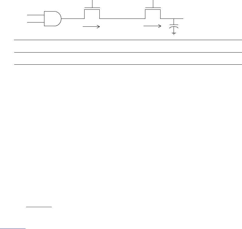
IEEE Std 1800-2012
IEEE STANDARD FOR SYSTEMVERILOG—UNIFIED HARDWARE DESIGN, SPECIFICATION, AND
VERIFICATION LANGUAGE
53
Copyright © 2013 IEEE. All rights reserved.
Figure 6-1—Simulation values of a trireg and its driver
a) At simulation time 0, wire a and wire b have a value of 1. A value of 1 with a strong strength
propagates from the and gate through the nmos switches connected to each other by wire c into
trireg net d.
b) At simulation time 10, wire a changes value to 0, disconnecting wire c from the and gate. When
wire c is no longer connected to the and gate, the value of wire c changes to HiZ. The value of wire
b remains 1 so wire c remains connected to trireg net d through the nmos2 switch. The HiZ value
does not propagate from wire c into trireg net d. Instead, trireg net d enters the capacitive state,
storing its last driven value of 1. It stores the 1 with a medium strength.
6.6.4.1 Capacitive networks
A capacitive network is a connection between two or more trireg nets. In a capacitive network whose trireg
nets are in the capacitive state, logic and strength values can propagate between trireg nets.
For example, Figure 6-2 shows a capacitive network in which the logic value of some trireg nets change the
logic value of other trireg nets of equal or smaller size.
In Figure 6-2, the capacitive strength of trireg_la net is large, trireg_me1 and trireg_me2 are
medium, and trireg_sm is small. Simulation reports the following sequence of events:
a) At simulation time 0, wire a and wire b have a value of 1. The wire c drives a value of 1 into
trireg_la and trireg_sm; wire d drives a value of 1 into trireg_me1 and trireg_me2.
b) At simulation time 10, the value of wire b changes to 0, disconnecting trireg_sm and
trireg_me2 from their drivers. These trireg nets enter the capacitive state and store the value 1,
their last driven value.
c) At simulation time 20, wire c drives a value of 0 into trireg_la.
d) At simulation time 30, wire d drives a value of 0 into trireg_me1.
e) At simulation time 40, the value of wire a changes to 0, disconnecting trireg_la and
trireg_me1 from their drivers. These trireg nets enter the capacitive state and store the value 0.
f) At simulation time 50, the value of wire b changes to 1.
g) This change of value in wire b connects trireg_sm to trireg_la; these trireg nets have different
sizes and stored different values. This connection causes the smaller trireg net to store the value of
the larger trireg net, and trireg_sm now stores a value of 0.
This change of value in wire b also connects trireg_me1 to trireg_me2; these trireg nets have
the same size and stored different values. The connection causes both trireg_me1 and
trireg_me2 to change value to x.
nmos1 nmos2
wire c
trireg d
wire a wire b
simulation time wire a wire b wire c trireg d
1 1 strong 1 strong 1
0 1 HiZ medium 110
0
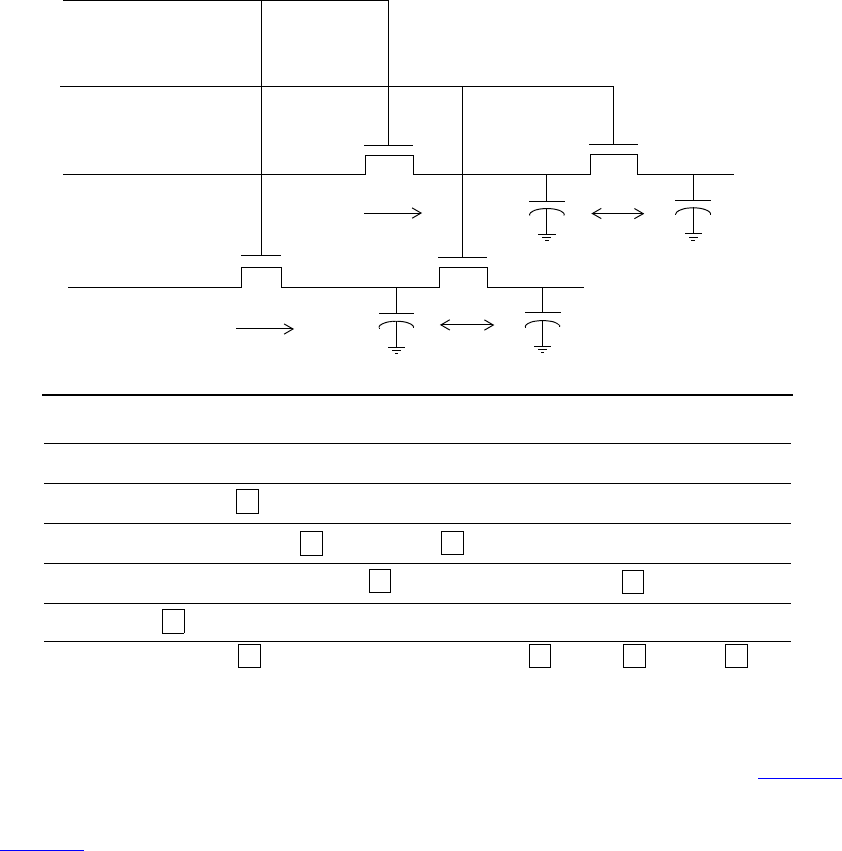
IEEE Std 1800-2012
IEEE STANDARD FOR SYSTEMVERILOG—UNIFIED HARDWARE DESIGN, SPECIFICATION, AND
VERIFICATION LANGUAGE
54
Copyright © 2013 IEEE. All rights reserved.
Figure 6-2—Simulation results of a capacitive network
In a capacitive network, charge strengths propagate from a larger trireg net to a smaller trireg net. Figure 6-3
shows a capacitive network and its simulation results.
In Figure 6-3, the capacitive strength of trireg_la is large, and the capacitive strength of trireg_sm is
small. Simulation reports the following results:
a) At simulation time 0, the values of wire a, wire b, and wire c are 1, and wire a drives a strong 1
into trireg_la and trireg_sm.
b) At simulation time 10, the value of wire b changes to 0, disconnecting trireg_la and trireg_sm
from wire a. The trireg_la and trireg_sm nets enter the capacitive state. Both trireg nets share
the large charge of trireg_la because they remain connected through tranif1_2.
c) At simulation time 20, the value of wire c changes to 0, disconnecting trireg_sm from
trireg_la. The trireg_sm no longer shares large charge of trireg_la and now stores a
small charge.
d) At simulation time 30, the value of wire c changes to 1, connecting the two trireg nets. These trireg
nets now share the same charge.
e) At simulation time 40, the value of wire c changes again to 0, disconnecting trireg_sm from
trireg_la. Once again, trireg_sm no longer shares the large charge of trireg_la and now
stores a small charge.
40 000 0 0 1 0 1
trireg_sm
trireg_la
trireg_me2
trireg_me1
wire a
wire b
wire c
wire d
simulation
time wire a wire b wire c wire d trireg_la trireg_sm trireg_me1 trireg_me2
01111 1 1 1 1
10 011111 11
20 101110 01
30 100
001 01
nmos_1
nmos_2 tranif1_2
50 0100 0 0xx
tranif1_1
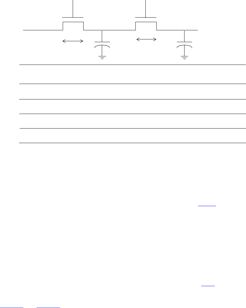
IEEE Std 1800-2012
IEEE STANDARD FOR SYSTEMVERILOG—UNIFIED HARDWARE DESIGN, SPECIFICATION, AND
VERIFICATION LANGUAGE
55
Copyright © 2013 IEEE. All rights reserved.
Figure 6-3—Simulation results of charge sharing
6.6.4.2 Ideal capacitive state and charge decay
A trireg net can retain its value indefinitely, or its charge can decay over time. The simulation time of
charge decay is specified in the delay specification of the trireg net. See 28.16.2 for charge decay
explanation.
6.6.5 Tri0 and tri1 nets
The tri0 and tri1 nets model nets with resistive pulldown and resistive pullup devices on them. A tri0
net is equivalent to a wire net with a continuous 0 value of pull strength driving it. A tri1 net is equivalent
to a wire net with a continuous 1 value of pull strength driving it.
When no driver drives a tri0 net, its value is 0 with strength pull. When no driver drives a tri1 net, its
value is 1 with strength pull. When there are drivers on a tri0 or tri1 net, the drivers combine with the
strength pull value implicitly driven on the net to determine the net’s value. See 28.11 for a discussion of
logic strength modeling.
Table 6-5 and Table 6-6 are truth tables for modeling multiple drivers of strength strong on tri0 and
tri1 nets. The resulting value on the net has strength strong, unless both drivers are z, in which case the
net has strength pull.
tranif1_2
trireg_sm
simulation
time
wire a
wire b wire c
tranif1_1
wire a wire b trireg_la trireg_sm
0strong 1
wire c
strong 1 strong 111
0 1 large 1 large 1strong 110
20 00 small 1large 1strong 1
30 1 large 1large 1strong 1 0
40 00 small 1large 1strong 1
trireg_la
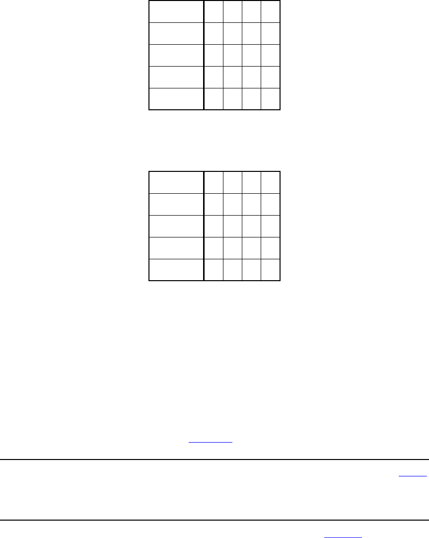
IEEE Std 1800-2012
IEEE STANDARD FOR SYSTEMVERILOG—UNIFIED HARDWARE DESIGN, SPECIFICATION, AND
VERIFICATION LANGUAGE
56
Copyright © 2013 IEEE. All rights reserved.
6.6.6 Supply nets
The supply0 and supply1 nets can be used to model the power supplies in a circuit. These nets shall have
supply strengths.
6.6.7 User-defined nettypes
A user-defined nettype allows users to describe more general abstract values for a wire, including its
resolution function. This nettype is similar to a typedef in some ways, but shall only be used in declaring
a net. It provides a name for a particular data type and optionally an associated resolution function.
The syntax for net type declarations is given in Syntax 6-1.
net_type_declaration ::= // from A.2.1.3
nettype data_type net_type_identifier
[ with [ package_scope | class_scope ] tf_identifier ] ;
|nettype [ package_scope | class_scope ] net_type_identifier net_type_identifier ;
Syntax 6-1—Syntax for net type declarations (excerpt from Annex A)
A net declared with a nettype therefore uses that data type and, if specified, the associated resolution
function. An explicit data type is required for a user-defined nettype.
Table 6-5—Truth table for tri0 net
tri0 01xz
00xx0
1x1x1
xxxxx
z01x0
Table 6-6—Truth table for tri1 net
tri1 01xz
00xx0
1x1x1
xxxxx
z01x1

IEEE Std 1800-2012
IEEE STANDARD FOR SYSTEMVERILOG—UNIFIED HARDWARE DESIGN, SPECIFICATION, AND
VERIFICATION LANGUAGE
57
Copyright © 2013 IEEE. All rights reserved.
Certain restrictions apply to the data type of a net with a user-defined nettype. A valid data type shall be
one of the following:
a) A 4-state integral type, including a packed array, packed structure or union.
b) A 2-state integral type, including a packed array, packed structure or union with 2-state data type
members.
c) A real or shortreal type.
d) A fixed-size unpacked array, unpacked structure or union, where each element has a valid data type
for a net of a user-defined nettype.
A second form of a nettype declaration is to create another name for an existing nettype.
An atomic net is a net whose value is updated and resolved as a whole. A net declared with a user-defined
nettype is an atomic net. Similarly, a logic net is an atomic net, but a logic vector net is not an atomic
net as each logic element is resolved and updated independently. While an atomic net may have a singular
or aggregate value, each atomic net is intended to describe a single connection point in the design.
The resolution for a user-defined nettype is specified using a SystemVerilog function declaration. If a
resolution function is specified, then when a driver of the net changes value, an update event is scheduled on
the net in the Active (or Reactive) region. When the update event matures, the simulator calls the resolution
function to compute the value of the net from the values of the drivers. The return type of the function shall
match the data type of the nettype. The function shall accept an arbitrary number of drivers, since different
instances of the net could be connected to different numbers of drivers. Any change in the value of one or
more of the drivers shall trigger the evaluation of the resolution function associated with that nettype.
A user-defined resolution function for a net of a user-defined nettype with a data type T shall be a function
with a return type of T and a single input argument whose type is a dynamic array of elements of type T. A
resolution function shall be automatic (or preserve no state information) and have no side effects. A
resolution function shall not resize the dynamic array input argument nor shall it write to any part of the
dynamic array input argument. While a class function method may be used for a resolution function, such
functions shall be class static methods as the method call occurs in a context where no class object is
involved in the call. Parameterized variants of such methods can be created through the use of parameterized
class methods as described in 13.8.
Two different nettypes can use the same data type, but have different resolution functions A nettype may
be declared without a resolution function, in which case it shall be an error for a net of that nettype to have
multiple drivers.
Due to nondeterminism within scheduling regions, if there are multiple driver updates within a scheduling
region, there may be multiple evaluations of the resolution function.
A force statement can override the value of a net of a user-defined nettype. When released, the net
returns to the resolved value.
// user-defined data type T
typedef struct {
real field1;
bit field2;
} T;
// user-defined resolution function Tsum
function automatic T Tsum (input T driver[]);
Tsum.field1 = 0.0;
foreach (driver[i])
Tsum.field1 += driver[i].field1;
IEEE Std 1800-2012
IEEE STANDARD FOR SYSTEMVERILOG—UNIFIED HARDWARE DESIGN, SPECIFICATION, AND
VERIFICATION LANGUAGE
58
Copyright © 2013 IEEE. All rights reserved.
endfunction
nettype T wT; // an unresolved nettype wT whose data type is T
// a nettype wTsum whose data type is T and
// resolution function is Tsum
nettype T wTsum with Tsum;
// user-defined data type TR
typedef real TR[5];
// an unresolved nettype wTR whose data type
// is an array of real
nettype TR wTR;
// declare another name nettypeid2 for nettype wTsum
nettype wTsum nettypeid2;
The following example shows how to use a combination of a parameterized class definition with class static
methods to parameterize the data type of a user-defined nettype.
class Base #(parameter p = 1);
typedef struct {
real r;
bit[p-1:0] data;
} T;
static function T Tsum (input T driver[]);
Tsum.r = 0.0;
Tsum.data = 0;
foreach (driver[i])
Tsum.data += driver[i].data;
Tsum.r = $itor(Tsum.data);
endfunction
endclass
typedef Base#(32) MyBaseT;
nettype MyBaseT::T narrowTsum with MyBaseT::Tsum;
typedef Base#(64) MyBaseType;
nettype MyBaseType::T wideTsum with MyBaseType::Tsum;
narrowTsum net1; // data is 32 bits wide
wideTsum net2; // data is 64 bits wide
6.6.8 Generic interconnect
In SystemVerilog it is possible to use net types and configurations to create design models with varying
levels of abstraction. In order to support netlist designs, which primarily specify design element instances
and the net connections between the design elements, SystemVerilog defines a generic form of nets. Such
generic nets allow the separation of the specification of the net connections from the types of the
connections.
A net or port declared as interconnect (an interconnect net or port) indicates a typeless or generic net.
Such nets or ports are only able to express net port and terminal connections and shall not be used in any
procedural context nor in any continuous or procedural continuous assignments. An interconnect net or
port shall not be used in any expression other than a net_lvalue expression in which all nets or ports in the
expression are also interconnect nets. An interconnect array shall be considered valid even if
different bits in the array are resolved to different net types as demonstrated in the following example. It

IEEE Std 1800-2012
IEEE STANDARD FOR SYSTEMVERILOG—UNIFIED HARDWARE DESIGN, SPECIFICATION, AND
VERIFICATION LANGUAGE
59
Copyright © 2013 IEEE. All rights reserved.
shall be legal to specify a net_alias statement with an interconnect net_lvalue. See 23.3.3.7.1 and
23.3.3.7.2 for port and terminal connection rules for interconnect nets.
package NetsPkg;
nettype real realNet;
endpackage : NetsPkg
module top();
interconnect [0:1] iBus;
lDriver l1(iBus[0]);
rDriver r1(iBus[1]);
rlMod m1(iBus);
endmodule : top
module lDriver(output wire logic out);
endmodule : lDriver
module rDriver
import NetsPkg::*;
(output realNet out);
endmodule : rDriver
module rlMod(input interconnect [0:1] iBus);
lMod l1(iBus[0]);
rMod r1(iBus[1]);
endmodule : rlMod
The following simple example serves to illustrate the usefulness of an interconnect net. The example
contains a top level module (top) that instantiates a stimulus module (driver) and a comparator module
(cmp). This configuration is intended to compare two elements and determine if they are equal. There are
two different versions of the configuration, as described by the two different config blocks: one that works
on real values and one that works on logic values. By using the typeless interconnect net, we can use
the same testbench with both configurations, without having to change anything in the testbench itself. The
interconnect net aBus takes its data type from the type of its connections.
<file lib.map>
library realLib *.svr;
library logicLib *.sv;
config cfgReal;
design logicLib.top;
default liblist realLib logicLib;
endconfig
config cfgLogic;
design logicLib.top;
default liblist logicLib realLib;
endconfig
<file top.sv>
module top();
interconnect [0:3] [0:1] aBus;
logic [0:3] dBus;
driver driverArray[0:3](aBus);
cmp cmpArray[0:3](aBus,rst,dBus);
endmodule : top
<file nets.pkg>
package NetsPkg;
IEEE Std 1800-2012
IEEE STANDARD FOR SYSTEMVERILOG—UNIFIED HARDWARE DESIGN, SPECIFICATION, AND
VERIFICATION LANGUAGE
60
Copyright © 2013 IEEE. All rights reserved.
nettype real realNet;
endpackage : NetsPkg
<file driver.svr>
module driver
import NetsPkg::*;
#(parameter int delay = 30,
int iterations = 256)
(output realNet [0:1] out);
timeunit 1ns / 1ps;
real outR[1:0];
assign out = outR;
initial begin
outR[0] = 0.0;
outR[1] = 3.3;
for (int i = 0; i < iterations; i++) begin
#delay outR[0] += 0.2;
outR[1] -= 0.2;
end
end
endmodule : driver
<file driver.sv>
module driver #(parameter int delay = 30,
int iterations = 256)
(output wire logic [0:1] out);
timeunit 1ns / 1ps;
logic [0:1] outvar;
assign out = outvar;
initial begin
outvar = '0;
for (int i = 0; i < iterations; i++)
#delay outvar++;
end
endmodule : driver
<file cmp.svr>
module cmp
import NetsPkg::*;
#(parameter real hyst = 0.65)
(input realNet [0:1] inA,
input logic rst,
output logic out);
timeunit 1ns / 1ps;
real updatePeriod = 100.0;
initial out = 1’b0;
always #updatePeriod begin
if (rst) out <= 1’b0;
else if (inA[0] > inA[1]) out <= 1’b1;
else if (inA[0] < inA[1] - hyst) out <= 1’b0;
end
endmodule : cmp
<file cmp.sv>
module cmp #(parameter real hyst = 0.65)
IEEE Std 1800-2012
IEEE STANDARD FOR SYSTEMVERILOG—UNIFIED HARDWARE DESIGN, SPECIFICATION, AND
VERIFICATION LANGUAGE
61
Copyright © 2013 IEEE. All rights reserved.
(input wire logic [0:1] inA,
input logic rst,
output logic out);
initial out = 1’b0;
always @(inA, rst) begin
if (rst) out <= 1'b0;
else if (inA[0] & ~inA[1]) out <= 1'b1;
else out <= 1'b0;
end
endmodule : cmp
6.7 Net declarations
The syntax for net declarations is given in Syntax 6-2.
net_declaration12 ::= // from A.2.1.3
net_type [ drive_strength | charge_strength ] [ vectored | scalared ]
data_type_or_implicit [ delay3 ] list_of_net_decl_assignments ;
| net_type_identifier [ delay_control ]
list_of_net_decl_assignments ;
|interconnect implicit_data_type [ # delay_value ]
net_identifier { unpacked_dimension }
[ , net_identifier { unpacked_dimension }] ;
net_type ::= // from A.2.2.1
supply0 | supply1 | tri | triand | trior | trireg | tri0 | tri1 | uwire | wire | wand | wor
drive_strength ::= // from A.2.2.2
( strength0 , strength1 )
|( strength1 , strength0 )
|( strength0 , highz1 )
|( strength1 , highz0 )
|( highz0 , strength1 )
|( highz1 , strength0 )
strength0 ::= supply0 | strong0 | pull0 | weak0
strength1 ::= supply1 | strong1 | pull1 | weak1
charge_strength ::= ( small ) | ( medium ) | ( large )
delay3 ::= // from A.2.2.3
# delay_value | # ( mintypmax_expression [ , mintypmax_expression [ , mintypmax_expression ] ] )
delay2 ::= # delay_value | # ( mintypmax_expression [ , mintypmax_expression ] )
delay_value ::=
unsigned_number
| real_number
| ps_identifier
| time_literal
|1step
list_of_net_decl_assignments ::= net_decl_assignment { , net_decl_assignment } // from A.2.3
net_decl_assignment ::= net_identifier { unpacked_dimension } [ = expression ] // from A.2.4
12) A charge strength shall only be used with the trireg keyword. When the vectored or scalared keyword is
used, there shall be at least one packed dimension.
Syntax 6-2—Syntax for net declarations (excerpt from Annex A)

IEEE Std 1800-2012
IEEE STANDARD FOR SYSTEMVERILOG—UNIFIED HARDWARE DESIGN, SPECIFICATION, AND
VERIFICATION LANGUAGE
62
Copyright © 2013 IEEE. All rights reserved.
6.7.1 Net declarations with built-in net types
Net declarations without assignments and whose nettype is not a user-defined nettype are described in
this subclause. Net declarations with assignments are described in Clause 10.
A net declaration begins with a net type that determines how the values of the nets in the declaration are
resolved. The declaration can include optional information such as delay values, drive or charge strength,
and a data type.
If a set of nets share the same characteristics, they can be declared in the same declaration statement.
Any 4-state data type can be used to declare a net. For example:
trireg (large) logic #(0,0,0) cap1;
typedef logic [31:0] addressT;
wire addressT w1;
wire struct packed { logic ecc; logic [7:0] data; } memsig;
If a data type is not specified in the net declaration or if only a range and/or signing is specified, then the data
type of the net is implicitly declared as logic. For example:
wire w; // equivalent to "wire logic w;"
wire [15:0] ww; // equivalent to "wire logic [15:0] ww;"
A net declared as an interconnect net shall:
— have no data type but may have optional packed or unpacked dimensions;
— not specify drive_strength or charge_strength;
— not have assignment expressions;
— specify at most one delay value.
Certain restrictions apply to the data type of a net. A valid data type for a net shall be one of the following:
a) A 4-state integral type, including a packed array or packed structure.
b) A fixed-size unpacked array or unpacked structure, where each element has a valid data type for a
net.
The effect of this recursive definition is that a net is composed entirely of 4-state bits and is treated
accordingly. In addition to a signal value, each bit of a net shall have additional strength information. When
bits of signals combine, the strength and value of the resulting signal shall be determined as described in
28.12.
A lexical restriction applies to the use of the reg keyword in a net or port declaration. A net type keyword
shall not be followed directly by the reg keyword. Thus, the following declarations are in error:
tri reg r;
inout wire reg p;
The reg keyword can be used in a net or port declaration if there are lexical elements between the net type
keyword and the reg keyword.
The default initialization value for a net shall be the value z. Nets with drivers shall assume the output value
of their drivers. The trireg net is an exception. The trireg net shall default to the value x, with the
strength specified in the net declaration (small, medium, or large).

IEEE Std 1800-2012
IEEE STANDARD FOR SYSTEMVERILOG—UNIFIED HARDWARE DESIGN, SPECIFICATION, AND
VERIFICATION LANGUAGE
63
Copyright © 2013 IEEE. All rights reserved.
As described in 6.6.8, an interconnect net is restricted in terms of its declaration and use. The following
are some examples of legal and illegal interconnect net declarations:
interconnect w1; // legal
interconnect [3:0] w2; // legal
interconnect [3:0] w3 [1:0]; // legal
interconnect logic [3:0] w4; // illegal – data type specified
interconnect #(1,2,3) w5; // illegal – only one delay permitted
assign w1 = 1; // illegal – not allowed in a
// continuous assign
initial $display(w1); // illegal – not allowed in a
// procedural context
6.7.2 Net declarations with user-defined nettypes
A net with a user-defined nettype allows users to describe more general abstract values for a wire. A net
declared with a nettype uses the data type and any associated resolution function for that nettype.
// an unresolved nettype wT whose data type is T
// Refer to example in 6.6.7 for declaration of the data type T
nettype T wT;
// a nettype wTsum whose data type is T and
// resolution function is Tsum
// Refer to example in 6.6.7 for the declaration of Tsum
nettype T wTsum with Tsum;
// a net of unresolved nettype wT
wT w1;
// an array of nets, each net element is of unresolved nettype wT
wT w2[8];
// a net of resolved nettype wTsum and resolution function Tsum
wTsum w3;
// an array of nets, each net is of resolved nettype wTsum
wTsum w4[8];
// user-defined data type TR which is an array of reals
typedef real TR[5];
// an unresolved nettype wTR with data type TR
nettype TR wTR;
// a net with unresolved nettype wTR and data type TR
wTR w5;
// an array of nets, each net has an unresolved nettype wTR
// and data type TR
wTR w6[8];
6.7.3 Initialization of nets with user-defined nettypes
The resolution function for any net of a user-defined nettype shall be activated at time zero at least once.
This activation occurs even for such nets with no drivers or no value changes on drivers at time zero. Since
the actual evaluation of the resolution function is subject to scheduling nondeterminism, no assumptions can
IEEE Std 1800-2012
IEEE STANDARD FOR SYSTEMVERILOG—UNIFIED HARDWARE DESIGN, SPECIFICATION, AND
VERIFICATION LANGUAGE
64
Copyright © 2013 IEEE. All rights reserved.
be made regarding the state of driven values during the guaranteed call, which may precede or follow any
driver changes at time zero.
The initial value of a net with a user-defined nettype shall be set before any initial or always procedures
are started and before the activation of the guaranteed time zero resolution call. The default initialization
value for a net with a user-defined nettype shall be the default value defined by the data type. Table 6-7
defines the default value for data types of variables if no initializer is provided; those default values shall
also apply to nets of user-defined nettypes for valid data types of a net. For a net with a user-defined
nettype whose data type is a struct type, any initialization expressions for the members within the
struct shall be applied.
NOTE— The default value for a logic net of a user-defined nettype is X. This default means that a bit of a logic
data type in an unresolved user-defined nettype will be X if it has no drivers, not Z. For a net with a resolved net-
type, the value would be determined by the resolution function executed with an empty array of driver values.
6.8 Variable declarations
A variable is an abstraction of a data storage element. A variable shall store a value from one assignment to
the next. An assignment statement in a procedure acts as a trigger that changes the value in the data storage
element.
The syntax for variable declarations is given in Syntax 6-3.
data_declaration10 ::= // from A.2.1.3
[ const ] [ var ] [ lifetime ] data_type_or_implicit list_of_variable_decl_assignments ;
| type_declaration
...
data_type ::= // from A.2.2.1
integer_vector_type [ signing ] { packed_dimension }
| integer_atom_type [ signing ]
| non_integer_type
| struct_union [ packed [ signing ] ] { struct_union_member { struct_union_member } }
{ packed_dimension }13
|enum [ enum_base_type ] { enum_name_declaration { , enum_name_declaration } }
{ packed_dimension }
|string
|chandle
|virtual [ interface ] interface_identifier [ parameter_value_assignment ] [ . modport_identifier ]
| [ class_scope | package_scope ] type_identifier { packed_dimension }
| class_type
|event
| ps_covergroup_identifier
| type_reference14
integer_type ::= integer_vector_type | integer_atom_type
integer_atom_type ::= byte | shortint | int | longint | integer | time
integer_vector_type ::= bit | logic | reg
non_integer_type ::= shortreal | real | realtime
signing ::= signed | unsigned
simple_type ::= integer_type | non_integer_type | ps_type_identifier | ps_parameter_identifier
data_type_or_void ::= data_type | void

IEEE Std 1800-2012
IEEE STANDARD FOR SYSTEMVERILOG—UNIFIED HARDWARE DESIGN, SPECIFICATION, AND
VERIFICATION LANGUAGE
65
Copyright © 2013 IEEE. All rights reserved.
variable_decl_assignment ::= // from A.2.4
variable_identifier { variable_dimension } [ = expression ]
| dynamic_array_variable_identifier unsized_dimension { variable_dimension }
[ = dynamic_array_new ]
| class_variable_identifier [ = class_new ]
10) In a data_declaration that is not within a procedural context, it shall be illegal to use the automatic keyword. In
a data_declaration, it shall be illegal to omit the explicit data_type before a list_of_variable_decl_assignments
unless the var keyword is used.
13) When a packed dimension is used with the struct or union keyword, the packed keyword shall also be used.
14) When a type_reference is used in a net declaration, it shall be preceded by a net type keyword; and when it is used
in a variable declaration, it shall be preceded by the var keyword.
Syntax 6-3—Syntax for variable declarations (excerpt from Annex A)
One form of variable declaration consists of a data type followed by one or more instances.
shortint s1, s2[0:9];
Another form of variable declaration begins with the keyword var. The data type is optional in this case. If
a data type is not specified or if only a range and/or signing is specified, then the data type is implicitly
declared as logic.
var byte my_byte; // equivalent to "byte my_byte;"
var v; // equivalent to "var logic v;"
var [15:0] vw; // equivalent to "var logic [15:0] vw;"
var enum bit { clear, error } status;
input var logic data_in;
var reg r;
If a set of variables share the same characteristics, they can be declared in the same declaration statement.
A variable can be declared with an initializer, for example:
int i = 0;
Setting the initial value of a static variable as part of the variable declaration (including static class
members) shall occur before any initial or always procedures are started (also see 6.21 and 10.5 on variable
initialization with static and automatic lifetimes).
NOTE—In IEEE Std 1364-2005, an initialization value specified as part of the declaration was executed as if the
assignment were made from an initial procedure, after simulation has started.
Initial values are not constrained to simple constants; they can include run-time expressions, including
dynamic memory allocation. For example, a static class handle or a mailbox can be created and initialized by
calling its new method (see 15.4.1), or static variables can be initialized to random values by calling the
$urandom system task. This may require a special pre-initial pass at run time.
Table 6-7 contains the default values for variables if no initializer is specified.

IEEE Std 1800-2012
IEEE STANDARD FOR SYSTEMVERILOG—UNIFIED HARDWARE DESIGN, SPECIFICATION, AND
VERIFICATION LANGUAGE
66
Copyright © 2013 IEEE. All rights reserved.
Nets and variables can be assigned negative values, but only signed types shall retain the significance of the
sign. The byte, shortint, int, integer, and longint types are signed types by default. Other net and
variable types can be explicitly declared as signed. See 11.4.3.1 for a description of how signed and
unsigned nets and variables are treated by certain operators.
6.9 Vector declarations
A data object declared as reg, logic, or bit (or as a matching user-defined type or implicitly as logic)
without a range specification shall be considered 1-bit wide and is known as a scalar. A multibit data object
of one of these types shall be declared by specifying a range and is known as a vector. Vectors are packed
arrays of scalars (see 7.4).
6.9.1 Specifying vectors
The range specification ([msb_constant_expression : lsb_constant_expression]) gives addresses to the
individual bits in a multibit reg, logic, or bit vector. The most significant bit, specified by the msb
constant expression, is the left-hand value in the range, and the least significant bit, specified by the lsb
constant expression, is the right-hand value in the range.
Both the msb constant expression and the lsb constant expression shall be constant integer expressions. The
msb and lsb constant expressions (see 11.2.1) may be any integer value—positive, negative, or zero. It shall
be illegal for them to contain any unknown (x) or high-impedance bits. The lsb value may be greater than,
equal to, or less than the msb value.
Vectors shall obey laws of arithmetic modulo-2 to the power n (2n), where n is the number of bits in the
vector. Vectors of reg, logic, and bit types shall be treated as unsigned quantities, unless declared to be
signed or connected to a port that is declared to be signed (see 23.2.2.1 and 23.3.3.8).
Examples:
wand w; // a scalar "wand" net
tri [15:0] busa; // a 16-bit bus
trireg (small) storeit; // a charge storage node of strength small
logic a; // a scalar variable
logic[3:0] v; // a 4-bit vector made up of (from most to
Table 6-7—Default values
Type Default initial value
4-state integral 'X
2-state integral '0
real, shortreal 0.0
Enumeration Base type default initial value
string "" (empty string)
event New event
class null
chandle (Opaque handle) null

IEEE Std 1800-2012
IEEE STANDARD FOR SYSTEMVERILOG—UNIFIED HARDWARE DESIGN, SPECIFICATION, AND
VERIFICATION LANGUAGE
67
Copyright © 2013 IEEE. All rights reserved.
// least significant)v[3], v[2], v[1], and v[0]
logic signed [3:0] signed_reg; // a 4-bit vector in range -8 to 7
logic [-1:4] b; // a 6-bit vector
wire w1, w2; // declares two nets
logic [4:0] x, y, z; // declares three 5-bit variables
Implementations may set a limit on the maximum length of a vector, but the limit shall be at least
65536 (216) bits.
Implementations are not required to detect overflow of integer operations.
6.9.2 Vector net accessibility
Vectored and scalared shall be optional advisory keywords to be used in vector net declarations. If these
keywords are implemented, certain operations on vector nets may be restricted. If the keyword vectored is
used, bit-selects and part-selects and strength specifications may not be permitted, and the PLI may consider
the net unexpanded. If the keyword scalared is used, bit-selects and part-selects of the net shall be
permitted, and the PLI shall consider the net expanded.
For example:
tri1 scalared [63:0] bus64; //a bus that will be expanded
tri vectored [31:0] data; //a bus that may or may not be expanded
6.10 Implicit declarations
The syntax shown in 6.7 and 6.8 shall be used to declare nets and variables explicitly. In the absence of an
explicit declaration, an implicit net of default net type shall be assumed in the following circumstances:
— If an identifier is used in a port expression declaration, then an implicit net of default net type shall
be assumed, with the vector width of the port expression declaration. See 23.2.2.1 for a discussion of
port expression declarations.
— If an identifier is used in the terminal list of a primitive instance or in the port connection list of a
module, interface, program, or static checker instance (but not a procedural checker instance, see
17.3), and that identifier has not been declared previously in the scope where the instantiation
appears or in any scope whose declarations can be directly referenced from the scope where the
instantiation appears (see 23.9), then an implicit scalar net of default net type shall be assumed.
— If an identifier appears on the left-hand side of a continuous assignment statement, and that identifier
has not been declared previously in the scope where the continuous assignment statement appears or
in any scope whose declarations can be directly referenced from the scope where the continuous
assignment statement appears (see 23.9), then an implicit scalar net of default net type shall be
assumed. See 10.3 for a discussion of continuous assignment statements.
The implicit net declaration shall belong to the scope in which the net reference appears. For example, if the
implicit net is declared by a reference in a generate block, then the net is implicitly declared only in that
generate block. Subsequent references to the net from outside the generate block or in another generate
block within the same module either would be illegal or would create another implicit declaration of a
different net (depending on whether the reference meets the above criteria). See Clause 27 for information
about generate blocks.
See 22.8 for a discussion of control of the type for implicitly declared nets with the `default_nettype
compiler directive.

IEEE Std 1800-2012
IEEE STANDARD FOR SYSTEMVERILOG—UNIFIED HARDWARE DESIGN, SPECIFICATION, AND
VERIFICATION LANGUAGE
68
Copyright © 2013 IEEE. All rights reserved.
6.11 Integer data types
SystemVerilog provides several integer data types, as shown in Table 6-8.
6.11.1 Integral types
The term integral is used throughout this standard to refer to the data types that can represent a single basic
integer data type, packed array, packed structure, packed union, enum variable, or time variable.
The term simple bit vector type is used throughout this standard to refer to the data types that can directly
represent a one-dimensional packed array of bits. The integer types listed in Table 6-8 are simple bit vector
types with predefined widths. The packed structure types (see 7.2) and multidimensional packed array types
(see 7.4) are not simple bit vector types, but each is equivalent (see 6.22.2) to some simple bit vector type, to
and from which it can be easily converted.
6.11.2 2-state (two-value) and 4-state (four-value) data types
Types that can have unknown and high-impedance values are called 4-state types. These are logic, reg,
integer, and time. The other types do not have unknown values and are called 2-state types, for example,
bit and int.
The difference between int and integer is that int is a 2-state type and integer is a 4-state type. The 4-
state values have additional bits, which encode the X and Z states. The 2-state data types can simulate faster,
take less memory, and are preferred in some design styles.
The keyword reg does not always accurately describe user intent, as it could be perceived to imply a
hardware register. The keyword logic is a more descriptive term. logic and reg denote the same type.
Automatic type conversions from a smaller number of bits to a larger number of bits involve zero extensions
if unsigned or sign extensions if signed. Automatic type conversions from a larger number of bits to a
smaller number of bits involve truncations of the most significant bits (MSBs). When a 4-state value is
automatically converted to a 2-state value, any unknown or high-impedance bits shall be converted to zeros.
6.11.3 Signed and unsigned integer types
Integer types use integer arithmetic and can be signed or unsigned. This affects the meaning of certain
operators (see Clause 11 on operators and expressions).
Table 6-8—Integer data types
shortint 2-state data type, 16-bit signed integer
int 2-state data type, 32-bit signed integer
longint 2-state data type, 64-bit signed integer
byte 2-state data type, 8-bit signed integer or ASCII character
bit 2-state data type, user-defined vector size, unsigned
logic 4-state data type, user-defined vector size, unsigned
reg 4-state data type, user-defined vector size, unsigned
integer 4-state data type, 32-bit signed integer
time 4-state data type, 64-bit unsigned integer

IEEE Std 1800-2012
IEEE STANDARD FOR SYSTEMVERILOG—UNIFIED HARDWARE DESIGN, SPECIFICATION, AND
VERIFICATION LANGUAGE
69
Copyright © 2013 IEEE. All rights reserved.
The data types byte, shortint, int, integer, and longint default to signed. The data types time, bit,
reg, and logic default to unsigned, as do arrays of these types. The signedness can be explicitly defined
using the keywords signed and unsigned.
int unsigned ui;
int signed si;
6.12 Real, shortreal, and realtime data types
The real12 data type is the same as a C double. The shortreal data type is the same as a C float. The
realtime declarations shall be treated synonymously with real declarations and can be used
interchangeably. Variables of these three types are collectively referred to as real variables.
6.12.1 Operators and real numbers
The result of using logical or relational operators on real numbers and real variables is a single-bit scalar
value. Not all operators can be used with expressions involving real numbers and real variables (see 11.3.1).
Real number constants and real variables are also prohibited in the following cases:
— Edge event controls (posedge, negedge, edge) applied to real variables
— Bit-select or part-select references of variables declared as real
— Real number index expressions of bit-select or part-select references of vectors
6.12.2 Conversion
Real numbers shall be converted to integers by rounding the real number to the nearest integer, rather than
by truncating it. Implicit conversion shall take place when a real number is assigned to an integer. If the
fractional part of the real number is exactly 0.5, it shall be rounded away from zero.
Implicit conversion shall also take place when an expression is assigned to a real. Individual bits that are x
or z in the net or the variable shall be treated as zero upon conversion.
Explicit conversion can be specified using casting (see 6.24) or using system tasks (see 20.5).
6.13 Void data type
The void data type represents nonexistent data. This type can be specified as the return type of functions to
indicate no return value. This type can also be used for members of tagged unions (see 7.3.2).
6.14 Chandle data type
The chandle data type represents storage for pointers passed using the DPI (see Clause 35). The size of a
value of this data type is platform dependent, but shall be at least large enough to hold a pointer on the
machine on which the tool is running.
The syntax to declare a handle is as follows:
chandle variable_name ;
12The real and shortreal types are represented as described by IEEE Std 754.

IEEE Std 1800-2012
IEEE STANDARD FOR SYSTEMVERILOG—UNIFIED HARDWARE DESIGN, SPECIFICATION, AND
VERIFICATION LANGUAGE
70
Copyright © 2013 IEEE. All rights reserved.
where variable_name is a valid identifier. Chandles shall always be initialized to the value null, which
has a value of 0 on the C side. Chandles are restricted in their usage, with the only legal uses being as
follows:
— Only the following operators are valid on chandle variables:
— Equality (==), inequality (!=) with another chandle or with null
— Case equality (===), case inequality (!==) with another chandle or with null (same
semantics as == and !=)
— Chandles can be tested for a Boolean value, which shall be 0 if the chandle is null and
1otherwise.
— Only the following assignments can be made to a chandle:
— Assignment from another chandle
— Assignment to null
— Chandles can be inserted into associative arrays (refer to 7.8), but the relative ordering of any two
entries in such an associative array can vary, even between successive runs of the same tool.
— Chandles can be used within a class.
— Chandles can be passed as arguments to subroutines.
— Chandles can be returned from functions.
The use of chandles is restricted as follows:
— Ports shall not have the chandle data type.
— Chandles shall not be assigned to variables of any other type.
— Chandles shall not be used as follows:
— In any expression other than as permitted in this subclause
— As ports
— In sensitivity lists or event expressions
— In continuous assignments
— In untagged unions
— In packed types
6.15 Class
A class variable can hold a handle to a class object. Defining classes and creating objects is discussed in
Clause 8.
6.16 String data type
The string data type is an ordered collection of characters. The length of a string variable is the number
of characters in the collection. Variables of type string are dynamic as their length may vary during
simulation. A single character of a string variable may be selected for reading or writing by indexing the
variable. A single character of a string variable is of type byte.
SystemVerilog also includes a number of special methods to work with strings, which are defined in this
subclause.
A string variable does not represent a string in the same way as a string literal (see 5.9). String literals
behave like packed arrays of a width that is a multiple of 8 bits. A string literal assigned to a packed array of
an integral variable of a different size is either truncated to the size of the variable or padded with zeros to
the left as necessary. When using the string data type instead of an integral variable, strings can be of

IEEE Std 1800-2012
IEEE STANDARD FOR SYSTEMVERILOG—UNIFIED HARDWARE DESIGN, SPECIFICATION, AND
VERIFICATION LANGUAGE
71
Copyright © 2013 IEEE. All rights reserved.
arbitrary length and no truncation occurs. String literals are implicitly converted to the string type when
assigned to a string type or used in an expression involving string type operands.
The indices of string variables shall be numbered from 0 to N–1 (where N is the length of the string) so that
index 0 corresponds to the first (leftmost) character of the string and index N–1 corresponds to the last
(rightmost) character of the string. The string variables can take on the special value "", which is the empty
string. Indexing an empty string variable shall be an out-of-bounds access.
A string variable shall not contain the special character "\0". Assigning the value 0 to a string character
shall be ignored.
The syntax to declare a string variable is as follows:
string variable_name [= initial_value];
where variable_name is a valid identifier and the optional initial_value can be a string literal, the
value "" for an empty string, or a string data type expression. For example:
parameter string default_name = "John Smith";
string myName = default_name;
If an initial value is not specified in the declaration, the variable is initialized to “ ”, the empty string. An
empty string has zero length.
SystemVerilog provides a set of operators that can be used to manipulate combinations of string variables
and string literals. The basic operators defined on the string data type are listed in Table 6-9.
A string literal can be assigned to a variable of a string or an integral data type. When assigning to a
variable of integral data type, if the number of bits of the data object is not equal to the number of characters
in the string literal multiplied by 8, the literal is right justified and either truncated on the left or zero-filled
on the left, as necessary. For example:
byte c = "A"; // assigns to c "A"
bit [10:0] b = "\x41"; // assigns to b 'b000_0100_0001
bit [1:4][7:0] h = "hello" ; // assigns to h "ello"
A string literal or an expression of string type can be assigned directly to a variable of string type (a
string variable). Values of integral type can be assigned to a string variable, but require a cast. When casting
an integral value to a string variable, that variable shall grow or shrink to accommodate the integral value. If
the size of the integral value is not a multiple of 8 bits, then the value shall be zero-filled on the left so that its
size is a multiple of 8 bits.
A string literal assigned to a string variable is converted according to the following steps:
—All
"\0" characters in the string literal are ignored (i.e., removed from the string).
— If the result of the first step is an empty string literal, the string is assigned the empty string.
— Otherwise, the string is assigned the remaining characters in the string literal.
Casting an integral value to a string variable proceeds in the following steps:
— If the size (in bits) of the integral value is not a multiple of 8, the integral value is left extended and
filled with zeros until its bit size is a multiple of 8. The extended value is then treated the same as a
string literal, where each successive 8 bits represent a character.
— The steps described above for string literal conversion are then applied to the extended value.

IEEE Std 1800-2012
IEEE STANDARD FOR SYSTEMVERILOG—UNIFIED HARDWARE DESIGN, SPECIFICATION, AND
VERIFICATION LANGUAGE
72
Copyright © 2013 IEEE. All rights reserved.
For example:
string s0 = "String literal assign";// sets s0 to "String literal assign"
string s1 = "hello\0world"; // sets s1 to "helloworld"
bit [11:0] b = 12'ha41;
string s2 = string'(b); // sets s2 to 16'h0a41
As a second example:
typedef logic [15:0] r_t;
r_t r;
integer i = 1;
string b = "";
string a = {"Hi", b};
r = r_t'(a); // OK
b = string'(r); // OK
b = "Hi"; // OK
b = {5{"Hi"}}; // OK
a = {i{"Hi"}}; // OK (non-constant replication)
r = {i{"Hi"}}; // invalid (non-constant replication)
a = {i{b}}; // OK
a = {a,b}; // OK
a = {"Hi",b}; // OK
r = {"H",""}; // yields "H\0". "" is converted to 8'b0
b = {"H",""}; // yields "H". "" is the empty string
a[0] = "h"; // OK, same as a[0] = "cough"
a[0] = b; // invalid, requires a cast
a[1] = "\0"; // ignored, a is unchanged
Table 6-9—String operators
Operator Semantics
Str1 == Str2 Equality. Checks whether the two string operands are equal. Result is 1 if they
are equal and 0 if they are not. Both operands can be expressions of string
type, or one can be an expression of string type and the other can be a string
literal, which shall be implicitly converted to string type for the comparison.
If both operands are string literals, the operator is the same equality operator as
for integral types.
Str1 != Str2 Inequality. Logical negation of ==
Str1 < Str2
Str1 <= Str2
Str1 > Str2
Str1 >= Str2
Comparison: Relational operators return 1 if the corresponding condition is true
using the lexicographic ordering of the two strings Str1 and Str2. The com-
parison uses the compare string method. Both operands can be expressions of
string type, or one can be an expression of string type and the other can be
a string literal, which shall be implicitly converted to string type for the com-
parison. If both operands are string literals, the operator is the same comparison
operator as for integral types.
{Str1,Str2,...,Strn} Concatenation: Each operand can be a string literal or an expression of string
type. If all the operands are string literals the expression shall behave as a con-
catenation of integral values; if the result of such a concatenation is used in an
expression involving string types then it shall be implicitly converted to
string type. If at least one operand is an expression of string type, then
any operands that are string literals shall be converted to string type before
the concatenation is performed, and the result of the concatenation shall be of
string type.
IEEE Std 1800-2012
IEEE STANDARD FOR SYSTEMVERILOG—UNIFIED HARDWARE DESIGN, SPECIFICATION, AND
VERIFICATION LANGUAGE
73
Copyright © 2013 IEEE. All rights reserved.
SystemVerilog also includes a number of special methods to work with strings, which use the built-in
method notation. These methods are described in 6.16.1 through 6.16.15.
6.16.1 Len()
function int len();
—str.len() returns the length of the string, i.e., the number of characters in the string.
—If
str is " ", then str.len() returns 0.
6.16.2 Putc()
function void putc(int i, byte c);
—str.putc(i, c) replaces the ith character in str with the given integral value.
—putc does not change the size of str: If i < 0 or i >= str.len(), then str is unchanged.
— If the second argument to putc is zero, the string is unaffected.
The putc method assignment str.putc(j, x) is semantically equivalent to str[j] = x.
6.16.3 Getc()
function byte getc(int i);
—str.getc(i) returns the ASCII code of the ith character in str.
—If
i < 0 or i >= str.len(), then str.getc(i) returns 0.
The getc method assignment x = str.getc(j) is semantically equivalent to x = str[j].
6.16.4 Toupper()
function string toupper();
—str.toupper() returns a string with characters in str converted to uppercase.
—str is unchanged.
{multiplier{Str}} Replication: Str can be a string literal or an expression of string type.
multiplier shall be an expression of integral type and is not required to be a
constant expression. If multiplier is non-constant or Str is an expression
of string type, the result is a string containing N concatenated copies of Str,
where N is specified by the multiplier. If Str is a literal and the
multiplier is constant, the expression behaves like numeric replication (if
the result is used in another expression involving string types, it is implicitly
converted to the string type).
Str[index] Indexing. Returns a byte, the ASCII code at the given index. Indices range from
0 to N–1, where N is the number of characters in the string. If given an index out
of range, returns 0. Semantically equivalent to Str.getc(index) in 6.16.3.
Str.method(...) The dot (.) operator is used to invoke a specified method on strings.
Table 6-9—String operators (continued)
Operator Semantics

IEEE Std 1800-2012
IEEE STANDARD FOR SYSTEMVERILOG—UNIFIED HARDWARE DESIGN, SPECIFICATION, AND
VERIFICATION LANGUAGE
74
Copyright © 2013 IEEE. All rights reserved.
6.16.5 Tolower()
function string tolower();
—str.tolower() returns a string with characters in str converted to lowercase.
—str is unchanged.
6.16.6 Compare()
function int compare(string s);
—str.compare(s) compares str and s, as in the ANSI C strcmp function with regard to lexical
ordering and return value.
See the relational string operators in Table 6-9.
6.16.7 Icompare()
function int icompare(string s);
—str.icompare(s) compares str and s, like the ANSI C strcmp function with regard to lexical
ordering and return value, but the comparison is case insensitive.
6.16.8 Substr()
function string substr(int i, int j);
—str.substr(i, j) returns a new string that is a substring formed by characters in position i
through j of str.
—If
i < 0, j < i, or j >= str.len(), substr() returns "" (the empty string).
6.16.9 Atoi(), atohex(), atooct(), atobin()
function integer atoi();
function integer atohex();
function integer atooct();
function integer atobin();
—str.atoi() returns the integer corresponding to the ASCII decimal representation in str. For
example:
str = "123";
int i = str.atoi(); // assigns 123 to i.
The conversion scans all leading digits and underscore characters ( _ ) and stops as soon as it encounters any
other character or the end of the string. It returns zero if no digits were encountered. It does not parse the full
syntax for integer literals (sign, size, apostrophe, base).
—atohex interprets the string as hexadecimal.
—atooct interprets the string as octal.
—atobin interprets the string as binary.
NOTE—These ASCII conversion functions return a 32-bit integer value. Truncation is possible without warning. For
converting integer values greater than 32 bits, see $sscanf in 21.3.4.

IEEE Std 1800-2012
IEEE STANDARD FOR SYSTEMVERILOG—UNIFIED HARDWARE DESIGN, SPECIFICATION, AND
VERIFICATION LANGUAGE
75
Copyright © 2013 IEEE. All rights reserved.
6.16.10 Atoreal()
function real atoreal();
—str.atoreal() returns the real number corresponding to the ASCII decimal representation in
str.
The conversion parses for real constants. The scan stops as soon as it encounters any character that does not
conform to this syntax or the end of the string. It returns zero if no digits were encountered.
6.16.11 Itoa()
function void itoa(integer i);
—str.itoa(i) stores the ASCII decimal representation of i into str (inverse of atoi).
6.16.12 Hextoa()
function void hextoa(integer i);
—str.hextoa(i) stores the ASCII hexadecimal representation of i into str (inverse of atohex).
6.16.13 Octtoa()
function void octtoa(integer i);
—str.octtoa(i) stores the ASCII octal representation of i into str (inverse of atooct).
6.16.14 Bintoa()
function void bintoa(integer i);
—str.bintoa(i) stores the ASCII binary representation of i into str (inverse of atobin).
6.16.15 Realtoa()
function void realtoa(real r);
—str.realtoa(r) stores the ASCII real representation of r into str (inverse of atoreal).
6.17 Event data type
An event object gives a powerful and efficient means of describing the communication between, and
synchronization of, two or more concurrently active processes. A basic example of this is a small waveform
clock generator that synchronizes control of a synchronous circuit by signaling the occurrence of an explicit
event periodically while the circuit waits for the event to occur.
The event data type provides a handle to a synchronization object. The object referenced by an event
variable can be explicitly triggered and waited for. Furthermore, event variables have a persistent triggered
state that lasts for the duration of the entire time step. Its occurrence can be recognized by using the event
control syntax described in 9.4.2.
IEEE Std 1800-2012
IEEE STANDARD FOR SYSTEMVERILOG—UNIFIED HARDWARE DESIGN, SPECIFICATION, AND
VERIFICATION LANGUAGE
76
Copyright © 2013 IEEE. All rights reserved.
An event variable can be assigned or compared to another event variable or assigned the special value null.
When assigned another event variable, both event variables refer to the same synchronization object. When
assigned null, the association between the synchronization object and the event variable is broken.
If an initial value is not specified in the declaration of an event variable, then the variable is initialized to a
new synchronization object.
Examples:
event done; // declare a new event called done
event done_too = done; // declare done_too as alias to done
event empty = null; // event variable with no synchronization object
Event operations and semantics are discussed in detail in 15.5.
6.18 User-defined types
SystemVerilog’s data types can be extended with user-defined types using typedef. The syntax for
declaring user-defined types is shown in Syntax 6-4.
type_declaration ::= // from A.2.1.3
typedef data_type type_identifier { variable_dimension } ;
|typedef interface_instance_identifier constant_bit_select . type_identifier type_identifier ;
|typedef [ enum | struct | union | class | interface class ] type_identifier ;
Syntax 6-4—User-defined types (excerpt from Annex A)
A typedef may be used to give a user-defined name to an existing data type. For example:
typedef int intP;
The named data type can then be used as follows:
intP a, b;
User-defined data type names must be used for complex data types in casting (see 6.24), which only allows
simple data type names, and as type parameter values (see 6.20.3) when unpacked array types are used.
A type parameter may also be used to declare a type_identifier. The declaration of a user-defined data type
shall precede any reference to its type_identifier. User-defined data type identifiers have the same scoping
rules as data identifiers, except that hierarchical references to type_identifier shall not be allowed.
References to type identifiers defined within an interface through ports are not considered hierarchical
references and are allowed provided they are locally redefined before being used. Such a typedef is called
an interface based typedef.
interface intf_i;
typedef int data_t;
endinterface
module sub(intf_i p);
typedef p.data_t my_data_t;
my_data_t data;
// type of 'data' will be int when connected to interface above
endmodule
IEEE Std 1800-2012
IEEE STANDARD FOR SYSTEMVERILOG—UNIFIED HARDWARE DESIGN, SPECIFICATION, AND
VERIFICATION LANGUAGE
77
Copyright © 2013 IEEE. All rights reserved.
Sometimes a user-defined type needs to be declared before the contents of the type have been defined. This
is of use with user-defined types derived from the basic data types: enum, struct, union,
interface class, and class. Support for this is provided by the following forms for a forward typedef:
typedef enum type_identifier;
typedef struct type_identifier;
typedef union type_identifier;
typedef class type_identifier;
typedef interface class type_identifier;
typedef type_identifier;
NOTE—While an empty user-defined type declaration is useful for coupled definitions of classes as shown in 8.27, it
cannot be used for coupled definitions of structures because structures are statically declared and there is no support for
handles to structures.
The last form shows that the basic data type of the user-defined type does not have to be defined in the
forward declaration.
The actual data type definition of a forward typedef declaration shall be resolved within the same local
scope or generate block. It shall be an error if the type_identifier does not resolve to a data type. It shall be
an error if a basic data type was specified by the forward type declaration and the actual type definition does
not conform to the specified basic data type. It shall be legal to have a forward type declaration in the same
scope, either before or after the final type definition. It shall be legal to have multiple forward type
declarations for the same type identifier in the same scope. The use of the term forward type declaration
does not require the forward type declaration to precede the final type definition.
A forward typedef shall be considered incomplete prior to the final type definition. While incomplete
forward types, type parameters, and types defined by an interface based typedef may resolve to class types,
use of the class scope resolution operator (see 8.23) to select a type with such a prefix shall be restricted to a
typedef declaration. It shall be an error if the prefix does not resolve to a class.
Example:
typedef C;
C::T x; // illegal; C is an incomplete forward type
typedef C::T c_t; // legal; reference to C::T is made by a typedef
c_t y;
class C;
typedef int T;
endclass
6.19 Enumerations
Enumerated types shall be defined using the syntax shown in Syntax 6-5.
data_type ::= // from A.2.2.1
...
|enum [ enum_base_type ] { enum_name_declaration { , enum_name_declaration } }
{ packed_dimension }
...
enum_base_type ::=
integer_atom_type [ signing ]
| integer_vector_type [ signing ] [ packed_dimension ]
| type_identifier [ packed_dimension ] 15

IEEE Std 1800-2012
IEEE STANDARD FOR SYSTEMVERILOG—UNIFIED HARDWARE DESIGN, SPECIFICATION, AND
VERIFICATION LANGUAGE
78
Copyright © 2013 IEEE. All rights reserved.
enum_name_declaration ::=
enum_identifier [ [ integral_number [ : integral_number ] ] ] [ = constant_expression ]
15) A type_identifier shall be legal as an enum_base_type if it denotes an integer_atom_type, with which an additional
packed dimension is not permitted, or an integer_vector_type.
Syntax 6-5—Enumerated types (excerpt from Annex A)
An enumerated type declares a set of integral named constants. Enumerated data types provide the capability
to abstractly declare strongly typed variables without either a data type or data value(s) and later add the
required data type and value(s) for designs that require more definition. Enumerated data types also can be
easily referenced or displayed using the enumerated names as opposed to the enumerated values.
In the absence of a data type declaration, the default data type shall be int. Any other data type used with
enumerated types shall require an explicit data type declaration.
An enumerated type defines a set of named values. In the following example, light1 and light2 are
defined to be variables of the anonymous (unnamed) enumerated int type that includes the three members:
red, yellow, and green.
enum {red, yellow, green} light1, light2; // anonymous int type
An enumerated name with x or z assignments assigned to an enum with no explicit data type or an explicit
2-state declaration shall be a syntax error.
// Syntax error: IDLE=2'b00, XX=2'bx <ERROR>, S1=2'b01, S2=2'b10
enum bit [1:0] {IDLE, XX='x, S1=2'b01, S2=2'b10} state, next;
An enum declaration of a 4-state type, such as integer, that includes one or more names with x or z
assignments shall be permitted.
// Correct: IDLE=0, XX='x, S1=1, S2=2
enum integer {IDLE, XX='x, S1='b01, S2='b10} state, next;
An unassigned enumerated name that follows an enum name with x or z assignments shall be a syntax error.
// Syntax error: IDLE=0, XX='x, S1=??, S2=??
enum integer {IDLE, XX='x, S1, S2} state, next;
The values can be cast to integer types and increment from an initial value of 0. This can be overridden.
enum {bronze=3, silver, gold} medal; // silver=4, gold=5
The values can be set for some of the names and not set for other names. The optional value of an enum
named constant is an elaboration time constant expression (see 6.20) and can include references to
parameters, local parameters, genvars, other enum named constants, and constant functions of these.
Hierarchical names and const variables are not allowed. A name without a value is automatically assigned
an increment of the value of the previous name. It shall be an error to automatically increment the maximum
representable value of the enum.
// c is automatically assigned the increment-value of 8
enum {a=3, b=7, c} alphabet;

IEEE Std 1800-2012
IEEE STANDARD FOR SYSTEMVERILOG—UNIFIED HARDWARE DESIGN, SPECIFICATION, AND
VERIFICATION LANGUAGE
79
Copyright © 2013 IEEE. All rights reserved.
Both the enumeration names and their integer values shall be unique. It shall be an error to set two values to
the same name or to set the same value to two names, regardless of whether the values are set explicitly or
by automatic incrementing.
// Error: c and d are both assigned 8
enum {a=0, b=7, c, d=8} alphabet;
If the first name is not assigned a value, it is given the initial value of 0.
// a=0, b=7, c=8
enum {a, b=7, c} alphabet;
The integer value expressions are evaluated in the context of a cast to the enum base type. Any enumeration
encoding value that is outside the representable range of the enum base type shall be an error. For an
unsigned base type, this occurs if the cast truncates the value and any of the discarded bits are nonzero. For a
signed base type, this occurs if the cast truncates the value and any of the discarded bits are not equal to the
sign bit of the result. If the integer value expression is a sized literal constant, it shall be an error if the size is
different from the enum base type, even if the value is within the representable range. The value after the
cast is the value used for the name, including in the uniqueness check and automatic incrementing to get a
value for the next name.
// Correct declaration - bronze and gold are unsized
enum bit [3:0] {bronze='h3, silver, gold='h5} medal2;
// Correct declaration - bronze and gold sizes are redundant
enum bit [3:0] {bronze=4'h3, silver, gold=4'h5} medal3;
// Error in the bronze and gold member declarations
enum bit [3:0] {bronze=5'h13, silver, gold=3'h5} medal4;
// Error in c declaration, requires at least 2 bits
enum bit [0:0] {a,b,c} alphabet;
Type checking of enumerated types used in assignments, as arguments, and with operators is covered in
6.19.3. As in C, there is no overloading of literals; therefore, medal2 and medal3 cannot be defined in the
same scope because they contain the same names.
6.19.1 Defining new data types as enumerated types
A type name can be given so that the same type can be used in many places.
typedef enum {NO, YES} boolean;
boolean myvar; // named type
6.19.2 Enumerated type ranges
A range of enumeration elements can be specified automatically, via the syntax shown in Table 6-10.
IEEE Std 1800-2012
IEEE STANDARD FOR SYSTEMVERILOG—UNIFIED HARDWARE DESIGN, SPECIFICATION, AND
VERIFICATION LANGUAGE
80
Copyright © 2013 IEEE. All rights reserved.
For example:
typedef enum { add=10, sub[5], jmp[6:8] } E1;
This example defines the enumerated type E1, which assigns the number 10 to the enumerated named
constant add. It also creates the enumerated named constants sub0, sub1, sub2, sub3, and sub4 and
assigns them the values 11...15, respectively. Finally, the example creates the enumerated named constants
jmp6, jmp7, and jmp8 and assigns them the values 16 through 18, respectively.
enum { register[2] = 1, register[2:4] = 10 } vr;
The preceding example declares enumerated variable vr, which creates the enumerated named constants
register0 and register1, which are assigned the values 1 and 2, respectively. Next, it creates the
enumerated named constants register2, register3, and register4 and assigns them the values 10, 11,
and 12.
6.19.3 Type checking
Enumerated types are strongly typed; thus, a variable of type enum cannot be directly assigned a value that
lies outside the enumeration set unless an explicit cast is used or unless the enum variable is a member of a
union. This is a powerful type-checking aid, which prevents users from accidentally assigning nonexistent
values to variables of an enumerated type. The enumeration values can still be used as constants in
expressions, and the results can be assigned to any variable of a compatible integral type.
Enumerated variables are type-checked in assignments, arguments, and relational operators. Enumerated
variables are auto-cast into integral values, but assignment of arbitrary expressions to an enumerated
variable requires an explicit cast.
For example:
typedef enum { red, green, blue, yellow, white, black } Colors;
Table 6-10—Enumeration element ranges
name Associates the next consecutive number with name.
name = C Associates the constant C to name.
name[N] Generates N named constants in the sequence: name0, name1,..., nameN–1. N shall be a
positive integral number.
name[N] = C Optionally, a constant can be assigned to the generated named constants to associate that
constant to the first generated named constant; subsequent generated named constants are
associated consecutive values.
N shall be a positive integral number.
name[N:M] Creates a sequence of named constants starting with nameN and incrementing or decre-
menting until reaching named constant nameM.
N and M shall be nonnegative integral numbers.
name[N:M] = C Optionally, a constant can be assigned to the generated named constants to associate that
constant to the first generated named constants; subsequent generated named constants are
associated consecutive values.
N and M shall be nonnegative integral numbers.

IEEE Std 1800-2012
IEEE STANDARD FOR SYSTEMVERILOG—UNIFIED HARDWARE DESIGN, SPECIFICATION, AND
VERIFICATION LANGUAGE
81
Copyright © 2013 IEEE. All rights reserved.
This operation assigns a unique number to each of the color identifiers and creates the new data type
Colors. This type can then be used to create variables of that type.
Colors c;
c = green;
c = 1; // Invalid assignment
if ( 1 == c ) // OK. c is auto-cast to integer
In the preceding example, the value green is assigned to the variable c of type Colors. The second
assignment is invalid because of the strict typing rules enforced by enumerated types.
Casting can be used to perform an assignment of a different data type, or an out-of-range value, to an
enumerated type. Casting is discussed in 6.19.4, 6.24.1, and 6.24.2.
6.19.4 Enumerated types in numerical expressions
Elements of enumerated type variables can be used in numerical expressions. The value used in the
expression is the numerical value associated with the enumerated value. For example:
typedef enum { red, green, blue, yellow, white, black } Colors;
Colors col;
integer a, b;
a = blue * 3;
col = yellow;
b = col + green;
From the previous declaration, blue has the numerical value 2. This example assigns a the value of 6 (2*3),
and it assigns b a value of 4 (3+1).
An enum variable or identifier used as part of an expression is automatically cast to the base type of the
enum declaration (either explicitly or using int as the default). A cast shall be required for an expression
that is assigned to an enum variable where the type of the expression is not equivalent to the enumeration
type of the variable.
Casting to an enum type shall cause a conversion of the expression to its base type without checking the
validity of the value (unless a dynamic cast is used as described in 6.24.2).
typedef enum {Red, Green, Blue} Colors;
typedef enum {Mo,Tu,We,Th,Fr,Sa,Su} Week;
Colors C;
Week W;
int I;
C = Colors'(C+1); // C is converted to an integer, then added to
// one, then converted back to a Colors type
C = C + 1; C++; C+=2; C = I; // Illegal because they would all be
// assignments of expressions without a cast
C = Colors'(Su); // Legal; puts an out of range value into C
I = C + W; // Legal; C and W are automatically cast to int

IEEE Std 1800-2012
IEEE STANDARD FOR SYSTEMVERILOG—UNIFIED HARDWARE DESIGN, SPECIFICATION, AND
VERIFICATION LANGUAGE
82
Copyright © 2013 IEEE. All rights reserved.
6.19.5 Enumerated type methods
SystemVerilog includes a set of specialized methods to enable iterating over the values of enumerated types,
which are defined in 6.19.5.1 through 6.19.5.6.
6.19.5.1 First()
The prototype for the first() method is as follows:
function enum first();
The first() method returns the value of the first member of the enumeration.
6.19.5.2 Last()
The prototype for the last() method is as follows:
function enum last();
The last() method returns the value of the last member of the enumeration.
6.19.5.3 Next()
The prototype for the next() method is as follows:
function enum next( int unsigned N = 1 );
The next() method returns the Nth next enumeration value (default is the next one) starting from the
current value of the given variable. A wrap to the start of the enumeration occurs when the end of the
enumeration is reached. If the given value is not a member of the enumeration, the next() method returns
the default initial value for the enumeration (see Table 6-7).
6.19.5.4 Prev()
The prototype for the prev() method is as follows:
function enum prev( int unsigned N = 1 );
The prev() method returns the Nth previous enumeration value (default is the previous one) starting from
the current value of the given variable. A wrap to the end of the enumeration occurs when the start of the
enumeration is reached. If the given value is not a member of the enumeration, the prev() method returns
the default initial value for the enumeration (see Table 6-7).
6.19.5.5 Num()
The prototype for the num() method is as follows:
function int num();
The num() method returns the number of elements in the given enumeration.
6.19.5.6 Name()
The prototype for the name() method is as follows:
function string name();
IEEE Std 1800-2012
IEEE STANDARD FOR SYSTEMVERILOG—UNIFIED HARDWARE DESIGN, SPECIFICATION, AND
VERIFICATION LANGUAGE
83
Copyright © 2013 IEEE. All rights reserved.
The name() method returns the string representation of the given enumeration value. If the given value is
not a member of the enumeration, the name() method returns the empty string.
6.19.5.7 Using enumerated type methods
The following code fragment shows how to display the name and value of all the members of an
enumeration:
typedef enum { red, green, blue, yellow } Colors;
Colors c = c.first;
forever begin
$display( "%s : %d\n", c.name, c );
if( c == c.last ) break;
c = c.next;
end
6.20 Constants
Constants are named data objects that never change. SystemVerilog provides three elaboration-time
constants: parameter, localparam, and specparam. SystemVerilog also provides a run-time constant,
const (see 6.20.6).
The parameter, localparam, and specparam constants are collectively referred to as parameter
constants.
Parameter constants can be initialized with a literal.
localparam byte colon1 = ":" ;
specparam delay = 10 ; // specparams are used for specify blocks
parameter logic flag = 1 ;
SystemVerilog provides several methods for setting the value of parameter constants. Each parameter may
be assigned a default value when declared. The value of a parameter of an instantiated module, interface, or
program can be overridden in each instance using one of the following:
— Assignment by ordered list (e.g., m #(value, value) u1 (...); ) (see 23.10.2.1)
— Assignment by name
(e.g., m #(.param1(value), .param2(value)) u1 (...); ) (see 23.10.2.2)
—defparam statements, using hierarchical path names to redefine each parameter (see 23.10.1)
NOTE—The defparam statement might be removed from future versions of the language. See C.4.1.
6.20.1 Parameter declaration syntax
local_parameter_declaration ::= // from A.2.1.1
localparam data_type_or_implicit list_of_param_assignments
|localparam type list_of_type_assignments
parameter_declaration ::=
parameter data_type_or_implicit list_of_param_assignments
|parameter type list_of_type_assignments
specparam_declaration ::=
specparam [ packed_dimension ] list_of_specparam_assignments ;
data_type_or_implicit ::= // from A.2.2.1
IEEE Std 1800-2012
IEEE STANDARD FOR SYSTEMVERILOG—UNIFIED HARDWARE DESIGN, SPECIFICATION, AND
VERIFICATION LANGUAGE
84
Copyright © 2013 IEEE. All rights reserved.
data_type
| implicit_data_type
implicit_data_type ::= [ signing ] { packed_dimension }
list_of_param_assignments ::= param_assignment { , param_assignment } // from A.2.3
list_of_specparam_assignments ::= specparam_assignment { , specparam_assignment }
list_of_type_assignments ::= type_assignment { , type_assignment }
param_assignment ::= // from A.2.4
parameter_identifier { unpacked_dimension } [ = constant_param_expression ]18
specparam_assignment ::=
specparam_identifier = constant_mintypmax_expression
| pulse_control_specparam
type_assignment ::=
type_identifier [ = data_type ]18
parameter_port_list ::= // from A.1.3
# ( list_of_param_assignments { , parameter_port_declaration } )
|# ( parameter_port_declaration { , parameter_port_declaration } )
|#( )
parameter_port_declaration ::=
parameter_declaration
| local_parameter_declaration
| data_type list_of_param_assignments
|type list_of_type_assignments
18) It shall be legal to omit the constant_param_expression from a param_assignment or the data_type from a
type_assignment only within a parameter_port_list. However, it shall not be legal to omit them from localparam
declarations in a parameter_port_list.
Syntax 6-6—Parameter declaration syntax (excerpt from Annex A)
The list_of_param_assignments can appear in a module, interface, program, class, or package or in the
parameter_port_list of a module (see 23.2), interface, program, or class. If the declaration of a design
element uses a parameter_port_list (even an empty one), then in any parameter_declaration directly
contained within the declaration, the parameter keyword shall be a synonym for the localparam
keyword (see 6.20.4). All param_assignments appearing within a class body shall become localparam
declarations regardless of the presence or absence of a parameter_port_list. All param_assignments
appearing within a generate block, package, or compilation-unit scope shall become localparam
declarations.
The parameter keyword can be omitted in a parameter port list. For example:
class vector #(size = 1); // size is a parameter in a parameter port list
logic [size-1:0] v;
endclass
interface simple_bus #(AWIDTH = 64, type T = word) // parameter port list
(input logic clk) ; // port list
...
endinterface

IEEE Std 1800-2012
IEEE STANDARD FOR SYSTEMVERILOG—UNIFIED HARDWARE DESIGN, SPECIFICATION, AND
VERIFICATION LANGUAGE
85
Copyright © 2013 IEEE. All rights reserved.
In a list of parameter constants, a parameter can depend on earlier parameters. In the following declaration,
the default value of the second parameter depends on the value of the first parameter. The third parameter is
a type, and the fourth parameter is a value of that type.
module mc #(int N = 5, M = N*16, type T = int, T x = 0)
( ... );
...
endmodule
In the declaration of a parameter in a parameter port list, the specification for its default value may be
omitted, in which case the parameter shall have no default value. If no default value is specified for a
parameter of a design element, then an overriding parameter value shall be specified in every instantiation of
that design element (see 23.10). Also, if no default value is specified for a parameter of a design element,
then a tool shall not implicitly instantiate that design element (see 23.3, 23.4, and 24.3). If no default value is
specified for a parameter of a class, then an overriding parameter value shall be specified in every
specialization of that class (see 8.25).
class Mem #(type T, int size);
T words[size];
...
endclass
typedef Mem#(byte, 1024) Kbyte;
6.20.2 Value parameters
A parameter constant can have a type specification and a range specification. The type and range of
parameters shall be in accordance with the following rules:
— A parameter declaration with no type or range specification shall default to the type and range of the
final value assigned to the parameter, after any value overrides have been applied. If the expression
is real, the parameter is real. If the expression is integral, the parameter is a logic vector of the
same size with range [size-1:0].
— A parameter with a range specification, but with no type specification, shall have the range of the
parameter declaration and shall be unsigned. The sign and range shall not be affected by value
overrides.
— A parameter with a type specification, but with no range specification, shall be of the type specified.
A signed parameter shall default to the range of the final value assigned to the parameter, after any
value overrides have been applied.
— A parameter with a signed type specification and with a range specification shall be signed and shall
have the range of its declaration. The sign and range shall not be affected by value overrides.
— A parameter with no range specification and with either a signed type specification or no type speci-
fication shall have an implied range with an lsb equal to 0 and an msb equal to one less than the size
of the final value assigned to the parameter.
— A parameter with no range specification, with either a signed type specification or no type specifica-
tion, and for which the final value assigned to it is unsized shall have an implied range with an lsb
equal to 0 and an msb equal to an implementation-dependent value of at least 31.
In an assignment to, or override of, a parameter with an explicit type declaration, the type of the right-hand
expression shall be assignment compatible with the declared type (see 6.22.3).
The conversion rules between real and integer values described in 6.12.2 apply to parameters as well.
Bit-selects and part-selects of parameters that are of integral types shall be allowed (see 6.11.1).
IEEE Std 1800-2012
IEEE STANDARD FOR SYSTEMVERILOG—UNIFIED HARDWARE DESIGN, SPECIFICATION, AND
VERIFICATION LANGUAGE
86
Copyright © 2013 IEEE. All rights reserved.
A value parameter (parameter, localparam, or specparam) can only be set to an expression of literals,
value parameters or local parameters, genvars, enumerated names, or a constant function of these. Package
references are allowed. Hierarchical names are not allowed. A specparam can also be set to an expression
containing one or more specparams.
Examples:
parameter msb = 7; // defines msb as a constant value 7
parameter e = 25, f = 9; // defines two constant numbers
parameter r = 5.7; // declares r as a real parameter
parameter byte_size = 8,
byte_mask = byte_size - 1;
parameter average_delay = (r + f) / 2;
parameter signed [3:0] mux_selector = 0;
parameter real r1 = 3.5e17;
parameter p1 = 13'h7e;
parameter [31:0] dec_const = 1'b1; // value converted to 32 bits
parameter newconst = 3'h4; // implied range of [2:0]
parameter newconst = 4; // implied range of at least [31:0]
A parameter can also be declared as an aggregate type, such as an unpacked array or an unpacked structure.
An aggregate parameter must be assigned to or overridden as a whole; individual members of an aggregate
parameter may not be assigned or overridden separately. However, an individual member of an aggregate
parameter may be used in an expression. For example:
parameter logic [31:0] P1 [3:0] = '{ 1, 2, 3, 4 } ; // unpacked array
// parameter declaration
initial begin
if ( P1[2][7:0] ) ... // use part-select of individual element of the array
6.20.2.1 $ as a parameter value
The value $ can be assigned to parameters of integer types. A parameter to which $ is assigned shall only be
used wherever $ can be specified as a literal constant.
For example, $ represents unbounded range specification, where the upper index can be any integer.
parameter r2 = $;
property inq1(r1,r2);
@(posedge clk) a ##[r1:r2] b ##1 c |=> d;
endproperty
assert inq1(3);
A system function is provided to test whether a constant is a $. The syntax of the system function is
$isunbounded(constant_expression);
$isunbounded returns true if constant_expression is unbounded. Typically, $isunbounded would be
used as a condition in the generate statement.
The following example illustrates the benefit of using $ in writing properties concisely where the range is
parameterized. The checker in the example verifies that a bus driven by signal en remains 0, i.e, quiet for the
specified minimum (min_quiet) and maximum (max_quiet) quiet time.
NOTE—The function $isunbounded is used for checking the validity of the actual arguments.
IEEE Std 1800-2012
IEEE STANDARD FOR SYSTEMVERILOG—UNIFIED HARDWARE DESIGN, SPECIFICATION, AND
VERIFICATION LANGUAGE
87
Copyright © 2013 IEEE. All rights reserved.
interface quiet_time_checker #(parameter min_quiet = 0,
parameter max_quiet = 0)
(input logic clk, reset_n, logic [1:0]en);
generate
if ( max_quiet == 0) begin
property quiet_time;
@(posedge clk) reset_n |-> ($countones(en) == 1);
endproperty
a1: assert property (quiet_time);
end
else begin
property quiet_time;
@(posedge clk)
(reset_n && ($past(en) != 0) && en == 0)
|->(en == 0)[*min_quiet:max_quiet]
##1 ($countones(en) == 1);
endproperty
a1: assert property (quiet_time);
end
if ((min_quiet == 0) && ($isunbounded(max_quiet))
$display(warning_msg);
endgenerate
endinterface
quiet_time_checker #(0, 0) quiet_never (clk,1,enables);
quiet_time_checker #(2, 4) quiet_in_window (clk,1,enables);
quiet_time_checker #(0, $) quiet_any (clk,1,enables);
Another example below illustrates that by testing for $, a property can be configured according to the
requirements. When parameter max_cks is unbounded, it is not required to test for expr to become false.
interface width_checker #(parameter min_cks = 1, parameter max_cks = 1)
(input logic clk, reset_n, expr);
generate
if ($isunbounded(max_cks)) begin
property width;
@(posedge clk)
(reset_n && $rose(expr)) |-> (expr [* min_cks]);
endproperty
a2: assert property (width);
end
else begin
property assert_width_p;
@(posedge clk)
(reset_n && $rose(expr)) |-> (expr[* min_cks:max_cks])
##1 (!expr);
endproperty
a2: assert property (width);
end
endgenerate
endinterface
width_checker #(3, $) max_width_unspecified (clk,1,enables);
width_checker #(2, 4) width_specified (clk,1,enables);

IEEE Std 1800-2012
IEEE STANDARD FOR SYSTEMVERILOG—UNIFIED HARDWARE DESIGN, SPECIFICATION, AND
VERIFICATION LANGUAGE
88
Copyright © 2013 IEEE. All rights reserved.
6.20.3 Type parameters
A parameter constant can also specify a data type, allowing modules, interfaces, or programs to have ports
and data objects whose type is set for each instance.
module ma #( parameter p1 = 1, parameter type p2 = shortint )
(input logic [p1:0] i, output logic [p1:0] o);
p2 j = 0; // type of j is set by a parameter, (shortint unless redefined)
always @(i) begin
o = i;
j++;
end
endmodule
module mb;
logic [3:0] i,o;
ma #(.p1(3), .p2(int)) u1(i,o); //redefines p2 to a type of int
endmodule
In an assignment to, or override of, a type parameter, the right-hand expression shall represent a data type.
A data-type parameter (parameter type) can only be set to a data type. Package references are allowed.
Hierarchical names are not allowed.
It shall be illegal to override a type parameter with a defparam statement.
6.20.4 Local parameters (localparam)
Local parameters are identical to parameters except that they cannot directly be modified by defparam
statements (see 23.10.1) or instance parameter value assignments (see 23.10.2). Local parameters can be
assigned constant expressions (see 11.2.1) containing parameters, which in turn can be modified with
defparam statements or instance parameter value assignments.
Unlike nonlocal parameters, local parameters can be declared in a generate block, package, class body, or
compilation-unit scope. In these contexts, the parameter keyword shall be a synonym for the localparam
keyword.
Local parameters may be declared in a module’s parameter_port_list. Any parameter declaration appearing
in such a list between a localparam keyword and the next parameter keyword (or the end of the list, if
there is no next parameter keyword) shall be a local parameter. Any other parameter declaration in such a
list shall be a nonlocal parameter that may be overridden as described in 23.10.
6.20.5 Specify parameters
The keyword specparam declares a special type of parameter that is intended only for providing timing and
delay values, but can appear in any expression that is not assigned to a parameter and is not part of the range
specification of a declaration. Specify parameters (also called specparams) are permitted both within the
specify block (see Clause 30) and in the main module body.
A specify parameter declared outside a specify block shall be declared before it is referenced. The value
assigned to a specify parameter can be any constant expression. A specify parameter can be used as part of a
constant expression for a subsequent specify parameter declaration. Unlike the parameter constant, a
specify parameter cannot be modified from within the language, but it can be modified through SDF
annotation (see Clause 32).
IEEE Std 1800-2012
IEEE STANDARD FOR SYSTEMVERILOG—UNIFIED HARDWARE DESIGN, SPECIFICATION, AND
VERIFICATION LANGUAGE
89
Copyright © 2013 IEEE. All rights reserved.
Specify parameters and parameter constants are not interchangeable. In addition, parameter and
localparam shall not be assigned a constant expression that includes any specify parameters. Table 6-11
summarizes the differences between the two types of parameter declarations.
A specify parameter can have a range specification. The range of specify parameters shall be in accordance
with the following rules:
—A
specparam declaration with no range specification shall default to the range of the final value
assigned to the parameter, after any value overrides have been applied.
—A
specparam with a range specification shall have the range of the parameter declaration. The
range shall not be affected by value overrides.
Examples:
specify
specparam tRise_clk_q = 150, tFall_clk_q = 200;
specparam tRise_control = 40, tFall_control = 50;
endspecify
The lines between the keywords specify and endspecify declare four specify parameters. The first line
declares specify parameters called tRise_clk_q and tFall_clk_q with values 150 and 200, respectively;
the second line declares tRise_control and tFall_control specify parameters with values 40 and 50,
respectively.
module RAM16GEN ( output [7:0] DOUT,
input [7:0] DIN,
input [5:0] ADR,
input WE, CE);
specparam dhold = 1.0;
specparam ddly = 1.0;
parameter width = 1;
parameter regsize = dhold + 1.0; // Illegal - cannot assign
// specparams to parameters
endmodule
6.20.6 Const constants
A const form of constant differs from a localparam constant in that the localparam shall be set during
elaboration, whereas a const can be set during simulation, such as in an automatic task.
Table 6-11—Differences between specparams and parameters
Specparams (specify parameter) Parameters
Use keyword specparam Use keyword parameter
Shall be declared inside a module or specify block Shall be declared outside specify blocks
May only be used inside a module or specify block May not be used inside specify blocks
May be assigned specparams and parameters May not be assigned specparams
Use SDF annotation to override values Use defparam or instance declaration
parameter value passing to override values

IEEE Std 1800-2012
IEEE STANDARD FOR SYSTEMVERILOG—UNIFIED HARDWARE DESIGN, SPECIFICATION, AND
VERIFICATION LANGUAGE
90
Copyright © 2013 IEEE. All rights reserved.
A static constant declared with the const keyword can be set to an expression of literals, parameters, local
parameters, genvars, enumerated names, a constant function of these, or other constants. Hierarchical names
are allowed because constants declared with the const keyword are calculated after elaboration.
const logic option = a.b.c ;
An automatic constant declared with the const keyword can be set to any expression that would be legal
without the const keyword.
An instance of a class (an object handle) can also be declared with the const keyword.
const class_name object = new(5,3);
In other words, the object acts like a variable that cannot be written. The arguments to the new method shall
be constant expressions (see 11.2.1). The members of the object can be written (except for those members
that are declared const).
6.21 Scope and lifetime
Variables declared outside a module, program, interface, checker, task, or function are local to the
compilation unit and have a static lifetime (exist for the whole simulation). This is roughly equivalent to C
static variables declared outside a function, which are local to a file. Variables declared inside a module,
interface, program, or checker, but outside a task, process, or function, are local in scope and have a static
lifetime.
Variables declared inside a static task, function, or block are local in scope and default to a static lifetime.
Specific variables within a static task, function, or block can be explicitly declared as automatic. Such
variables have the lifetime of the call or block and are initialized on each entry to the call or block (also see
6.8 on variable initialization). This is roughly equivalent to a C automatic variable.
Tasks and functions may be declared as automatic. Variables declared in an automatic task, function, or
block are local in scope, default to the lifetime of the call or block, and are initialized on each entry to the
call or block (also see 6.8 on variable initialization). An automatic block is one in which declarations are
automatic by default. Specific variables within an automatic task, function, or block can be explicitly
declared as static. Such variables have a static lifetime. This is roughly equivalent to C static variables
declared within a function.
The lifetime of a fork-join block (see 9.3.2) shall encompass the execution of all processes spawned by the
block. The lifetime of a scope enclosing any fork-join block includes the lifetime of the fork-join block.
A variable declaration shall precede any simple reference (non-hierarchical) to that variable. Variable
declarations shall precede any statements within a procedural block. Variables may also be declared in
unnamed blocks. These variables are visible to the unnamed block and any nested blocks below it.
Hierarchical references shall not be used to access these variables by name.
module msl;
int st0; // static
initial begin
int st1; // static
static int st2; // static
automatic int auto1; // automatic
end
task automatic t1();
int auto2; // automatic
IEEE Std 1800-2012
IEEE STANDARD FOR SYSTEMVERILOG—UNIFIED HARDWARE DESIGN, SPECIFICATION, AND
VERIFICATION LANGUAGE
91
Copyright © 2013 IEEE. All rights reserved.
static int st3; // static
automatic int auto3; // automatic
endtask
endmodule
Variables declared in a static task, function, or procedural block default to a static lifetime and a local scope.
However, an explicit static keyword shall be required when an initialization value is specified as part of a
static variable’s declaration to indicate the user’s intent of executing that initialization only once at the
beginning of simulation. The static keyword shall be optional where it would not be legal to declare the
variables as automatic. For example:
module top_legal;
int svar1 = 1; // static keyword optional
initial begin
for (int i=0; i<3; i++) begin
automatic int loop3 = 0; // executes every loop
for (int j=0; j<3; j++) begin
loop3++;
$display(loop3);
end
end // prints 1 2 3 1 2 3 1 2 3
for (int i=0; i<3; i++) begin
static int loop2 = 0; // executes once before time 0
for (int j=0; j<3; j++) begin
loop2++;
$display(loop2);
end
end // prints 1 2 3 4 5 6 7 8 9
end
endmodule : top_legal
module top_illegal; // should not compile
initial begin
int svar2 = 2; // static/automatic needed to show intent
for (int i=0; i<3; i++) begin
int loop3 = 0; // illegal statement
for (int i=0; i<3; i++) begin
loop3++;
$display(loop3);
end
end
end
endmodule : top_illegal
An optional qualifier can be used to specify the default lifetime of all variables declared in a task, function,
or block defined within a module, interface, package, or program. The lifetime qualifier is automatic or
static. The default lifetime is static.
program automatic test ;
int i; // not within a procedural block - static
task t ( int a ); // arguments and variables in t are automatic
... // unless explicitly declared static
endtask
endprogram
It is permissible to hierarchically reference any static variable unless the variable is declared inside an
unnamed block. This includes static variables declared inside automatic tasks and functions.

IEEE Std 1800-2012
IEEE STANDARD FOR SYSTEMVERILOG—UNIFIED HARDWARE DESIGN, SPECIFICATION, AND
VERIFICATION LANGUAGE
92
Copyright © 2013 IEEE. All rights reserved.
Class methods (see Clause 8) and declared for loop variables (see 12.7.1) are by default automatic,
regardless of the lifetime attribute of the scope in which they are declared.
Automatic variables and elements of dynamically sized array variables shall not be written with
nonblocking, continuous, or procedural continuous assignments. Non-static class properties shall not be
written with continuous or procedural continuous assignments. References to automatic variables and
elements or members of dynamic variables shall be limited to procedural blocks.
See also Clause 13 on tasks and functions.
6.22 Type compatibility
Some constructs and operations require a certain level of type compatibility for their operands to be legal.
There are five levels of type compatibility, formally defined here: matching, equivalent, assignment
compatible, cast compatible, and nonequivalent.
SystemVerilog does not require a category for identical types to be defined here because there is no
construct in the SystemVerilog language that requires it. For example, as defined below, int can be
interchanged with bit signed [31:0] wherever it is syntactically legal to do so. Users can define their
own level of type identity by using the $typename system function (see 20.6.1) or through use of the PLI.
The scope of a data type identifier shall include the hierarchical instance scope. In other words, each
instance with a user-defined type declared inside the instance creates a unique type. To have type matching
or equivalence among multiple instances of the same module, interface, program, or checker, a class, enum,
unpacked structure, or unpacked union type must be declared at a higher level in the compilation-unit scope
than the declaration of the module, interface, program, or checker, or imported from a package. For type
matching, this is true even for packed structure and packed union types.
6.22.1 Matching types
Two data types shall be defined as matching data types using the following inductive definition. If two data
types do not match using the following definition, then they shall be defined to be nonmatching.
a) Any built-in type matches every other occurrence of itself, in every scope.
b) A simple typedef or type parameter override that renames a built-in or user-defined type matches
that built-in or user-defined type within the scope of the type identifier.
typedef bit node; // 'bit' and 'node' are matching types
typedef type1 type2; // 'type1' and 'type2' are matching types
c) An anonymous enum, struct, or union type matches itself among data objects declared within the
same declaration statement and no other data types.
struct packed {int A; int B;} AB1, AB2; // AB1, AB2 have matching types
struct packed {int A; int B;} AB3; // the type of AB3 does not match
// the type of AB1
d) A typedef for an enum, struct, union, or class matches itself and the type of data objects
declared using that data type within the scope of the data type identifier.
typedef struct packed {int A; int B;} AB_t;
AB_t AB1; AB_t AB2; // AB1 and AB2 have matching types
IEEE Std 1800-2012
IEEE STANDARD FOR SYSTEMVERILOG—UNIFIED HARDWARE DESIGN, SPECIFICATION, AND
VERIFICATION LANGUAGE
93
Copyright © 2013 IEEE. All rights reserved.
typedef struct packed {int A; int B;} otherAB_t;
otherAB_t AB3; // the type of AB3 does not match the type of AB1 or AB2
e) A simple bit vector type that does not have a predefined width and one that does have a predefined
width match if both are 2-state or both are 4-state, both are signed or both are unsigned, both have
the same width, and the range of the simple bit vector type without a predefined width is [width–
1:0].
typedef bit signed [7:0] BYTE; // matches the byte type
typedef bit signed [0:7] ETYB; // does not match the byte type
f) Two array types match if they are both packed or both unpacked, are the same kind of array (fixed-
size, dynamic, associative, or queue), have matching index types (for associative arrays), and have
matching element types. Fixed-size arrays shall also have the same left and right range bounds. Note
that the element type of a multidimensional array is itself an array type.
typedef byte MEM_BYTES [256];
typedef bit signed [7:0] MY_MEM_BYTES [256]; // MY_MEM_BYTES matches
// MEM_BYTES
typedef logic [1:0] [3:0] NIBBLES;
typedef logic [7:0] MY_BYTE; // MY_BYTE and NIBBLES are not matching types
typedef logic MD_ARY [][2:0];
typedef logic MD_ARY_TOO [][0:2]; // Does not match MD_ARY
g) Explicitly adding signed or unsigned modifiers to a type that does not change its default signing
creates a type that matches the type without the explicit signing specification.
typedef byte signed MY_CHAR; // MY_CHAR matches the byte type
h) A typedef for an enum, struct, union, or class type declared in a package always matches
itself, regardless of the scope into which the type is imported.
6.22.2 Equivalent types
Two data types shall be defined as equivalent data types using the following inductive definition. If the two
data types are not defined as equivalent using the following definition, then they shall be defined to be
nonequivalent.
a) If two types match, they are equivalent.
b) An anonymous enum, unpacked struct, or unpacked union type is equivalent to itself among data
objects declared within the same declaration statement and no other data types.
struct {int A; int B;} AB1, AB2; // AB1, AB2 have equivalent types
struct {int A; int B;} AB3; // AB3 is not type equivalent to AB1
c) Packed arrays, packed structures, packed unions, and built-in integral types are equivalent if they
contain the same number of total bits, are either all 2-state or all 4-state, and are either all signed or
all unsigned.
NOTE—If any bit of a packed structure or union is 4-state, the entire structure or union is considered 4-state.
typedef bit signed [7:0] BYTE; // equivalent to the byte type
typedef struct packed signed {bit[3:0] a, b;} uint8;
// equivalent to the byte type

IEEE Std 1800-2012
IEEE STANDARD FOR SYSTEMVERILOG—UNIFIED HARDWARE DESIGN, SPECIFICATION, AND
VERIFICATION LANGUAGE
94
Copyright © 2013 IEEE. All rights reserved.
d) Unpacked fixed-size array types are equivalent if they have equivalent element types and equal size;
the actual range bounds may differ. Note that the element type of a multidimensional array is itself
an array type.
bit [9:0] A [0:5];
bit [1:10] B [6];
typedef bit [10:1] uint10;
uint10 C [6:1]; // A, B and C have equivalent types
typedef int anint [0:0]; // anint is not type equivalent to int
e) Dynamic array, associative array, and queue types are equivalent if they are the same kind of array
(dynamic, associative, or queue), have equivalent index types (for associative arrays), and have
equivalent element types.
The following example is assumed to be within one compilation unit, although the package declaration need
not be in the same unit:
package p1;
typedef struct {int A;} t_1;
endpackage
typedef struct {int A;} t_2;
module sub();
import p1::t_1;
parameter type t_3 = int;
parameter type t_4 = int;
typedef struct {int A;} t_5;
t_1 v1; t_2 v2; t_3 v3; t_4 v4; t_5 v5;
endmodule
module top();
typedef struct {int A;} t_6;
sub #(.t_3(t_6)) s1 ();
sub #(.t_3(t_6)) s2 ();
initial begin
s1.v1 = s2.v1; // legal - both types from package p1 (rule 8)
s1.v2 = s2.v2; // legal - both types from $unit (rule 4)
s1.v3 = s2.v3; // legal - both types from top (rule 2)
s1.v4 = s2.v4; // legal - both types are int (rule 1)
s1.v5 = s2.v5; // illegal - types from s1 and s2 (rule 4)
end
endmodule
6.22.3 Assignment compatible
All equivalent types, and all nonequivalent types that have implicit casting rules defined between them, are
assignment-compatible types. For example, all integral types are assignment compatible. Conversion
between assignment-compatible types can involve loss of data by truncation or rounding.
Unpacked arrays are assignment compatible with certain other arrays that are not of equivalent type.
Assignment compatibility of unpacked arrays is discussed in detail in 7.6.

IEEE Std 1800-2012
IEEE STANDARD FOR SYSTEMVERILOG—UNIFIED HARDWARE DESIGN, SPECIFICATION, AND
VERIFICATION LANGUAGE
95
Copyright © 2013 IEEE. All rights reserved.
Compatibility can be in one direction only. For example, an enum can be converted to an integral type
without a cast, but not the other way around. Implicit casting rules are defined in 6.24.
6.22.4 Cast compatible
All assignment-compatible types, plus all nonequivalent types that have defined explicit casting rules, are
cast-compatible types. For example, an integral type requires a cast to be assigned to an enum.
Explicit casting rules are defined in 6.24.
6.22.5 Type incompatible
Type incompatible includes all the remaining nonequivalent types that have no defined implicit or explicit
casting rules. Class handles, interface class handles, and chandles are type incompatible with all other types.
6.22.6 Matching nettypes
a) A nettype matches itself and the nettype of nets declared using that nettype within the scope of
the nettype type identifier.
b) A simple nettype that renames a user-defined nettype matches that user-defined nettype
within the scope of the nettype identifier.
// declare another name nettypeid2 for nettype nettypeid1
nettype nettypeid1 nettypeid2;
6.23 Type operator
The type operator provides a way to refer to the data type of an expression. A type reference can be used
like a type name or local type parameter, for example, in casts, data object declarations, and type parameter
assignments and overrides. It can also be used in equality/inequality and case equality/inequality
comparisons with other type references, and such comparisons are considered to be constant expressions
(see 11.2.1). When a type reference is used in a net declaration, it shall be preceded by a net type keyword;
and when it is used in a variable declaration, it shall be preceded by the var keyword.
var type(a+b) c, d;
c = type(i+3)'(v[15:0]);
The type operator applied to an expression shall represent the self-determined result type of that expression.
The expression shall not be evaluated and shall not contain any hierarchical references or references to
elements of dynamic objects.
The type operator can also be applied to a data type.
localparam type T = type(bit[12:0]);
When a type reference is used in an equality/inequality or case equality/inequality comparison, it shall only
be compared with another type reference. Two type references shall be considered equal in such
comparisons if, and only if, the types to which they refer match (see 6.22.1).
bit [12:0] A_bus, B_bus;
parameter type bus_t = type(A_bus);
generate
case (type(bus_t))
IEEE Std 1800-2012
IEEE STANDARD FOR SYSTEMVERILOG—UNIFIED HARDWARE DESIGN, SPECIFICATION, AND
VERIFICATION LANGUAGE
96
Copyright © 2013 IEEE. All rights reserved.
type(bit[12:0]): addfixed_int #(bus_t) (A_bus,B_bus);
type(real): add_float #(type(A_bus)) (A_bus,B_bus);
endcase
endgenerate
6.24 Casting
6.24.1 Cast operator
A data type can be changed by using a cast ( ') operation. The syntax for cast operations is shown in
Syntax 6-7.
constant_cast ::= // from A.8.4
casting_type ' ( constant_expression )
cast ::=
casting_type ' ( expression )
casting_type ::= simple_type | constant_primary | signing | string | const // from A.2.2.1
simple_type ::= integer_type | non_integer_type | ps_type_identifier | ps_parameter_identifier
Syntax 6-7—Casting (excerpt from Annex A)
In a static cast, the expression to be cast shall be enclosed in parentheses that are prefixed with the casting
type and an apostrophe. If the expression is assignment compatible with the casting type, then the cast shall
return the value that a variable of the casting type would hold after being assigned the expression. If the
expression is not assignment compatible with the casting type, then if the casting type is an enumerated type,
the behavior shall be as described as in 6.19.4, and if the casting type is a bit-stream type, the behavior shall
be as described in 6.24.3.
int'(2.0 * 3.0)
shortint'({8'hFA,8'hCE})
Thus, in the following example, if expressions expr_1 and expr_2 are assignment compatible with data
types cast_t1 and cast_t2, respectively, then
A = cast_t1'(expr_1) + cast_t2'(expr_2);
is the same as
cast_t1 temp1;
cast_t2 temp2;
temp1 = expr_1;
temp2 = expr_2;
A = temp1 + temp2;
Thus, an implicit cast (e.g., temp1 = expr1), if defined, gives the same results as the corresponding
explicit cast (cast_t1'(expr1)).
If the casting type is a constant expression with a positive integral value, the expression in parentheses shall
be padded or truncated to the size specified. It shall be an error if the size specified is zero or negative.

IEEE Std 1800-2012
IEEE STANDARD FOR SYSTEMVERILOG—UNIFIED HARDWARE DESIGN, SPECIFICATION, AND
VERIFICATION LANGUAGE
97
Copyright © 2013 IEEE. All rights reserved.
Examples:
17'(x - 2)
parameter P = 16;
(P+1)'(x – 2)
The signedness can also be changed.
signed'(x)
The expression inside the cast shall be an integral value when changing the size or signing.
When changing the size, the cast shall return the value that a packed array type with a single [n-1:0]
dimension would hold after being assigned the expression, where n is the cast size. The signedness shall
pass through unchanged, i.e., the signedness of the result shall be the self-determined signedness of the
expression inside the cast. The array elements shall be of type bit if the expression inside the cast is 2-state,
otherwise they shall be of type logic.
When changing the signing, the cast shall return the value that a packed array type with a single [n-1:0]
dimension would hold after being assigned the expression, where n is the number of bits in the expression to
be cast ($bits(expression)). The signedness of the result shall be the signedness specified by the cast
type. The array elements shall be of type bit if the expression inside the cast is 2-state; otherwise, they shall
be of type logic.
NOTE—The $signed() and $unsigned() system functions (see 11.7) return the same results as signed'() and
unsigned'(), respectively.
Examples:
logic [7:0] regA;
logic signed [7:0] regS;
regA = unsigned'(-4); // regA = 8'b11111100
regS = signed'(4'b1100); // regS = -4
An expression may be changed to a constant with a const cast.
const'(x)
When casting an expression as a constant, the type of the expression to be cast shall pass through unchanged.
The only effect is to treat the value as though it had been used to define a const variable of the type of the
expression.
When casting to a predefined type, the prefix of the cast shall be the predefined type keyword. When casting
to a user-defined type, the prefix of the cast shall be the user-defined type identifier.
When a shortreal is converted to an int or to 32 bits using either casting or assignment, its value is
rounded (see 6.12). Therefore, the conversion can lose information. To convert a shortreal to its
underlying bit representation without a loss of information, use $shortrealtobits as defined in 20.5. To
convert from the bit representation of a shortreal value into a shortreal, use $bitstoshortreal as
defined in 20.5.
Structures can be converted to bits preserving the bit pattern. In other words, they can be converted back to
the same value without any loss of information. When unpacked data are converted to the packed
representation, the order of the data in the packed representation is such that the first field in the structure

IEEE Std 1800-2012
IEEE STANDARD FOR SYSTEMVERILOG—UNIFIED HARDWARE DESIGN, SPECIFICATION, AND
VERIFICATION LANGUAGE
98
Copyright © 2013 IEEE. All rights reserved.
occupies the MSBs. The effect is the same as a concatenation of the data items (struct fields or array
elements) in order. The type of the elements in an unpacked structure or array shall be valid for a packed
representation in order to be cast to any other type, whether packed or unpacked.
An explicit cast between packed types is not required because they are implicitly cast as integral values, but
a cast can be used by tools to perform stronger type checking.
The following example demonstrates how $bits can be used to obtain the size of a structure in bits (the
$bits system function is discussed in 20.6.2), which facilitates conversion of the structure into a packed
array:
typedef struct {
bit isfloat;
union { int i; shortreal f; } n; // anonymous type
} tagged_st; // named structure
typedef bit [$bits(tagged_st) - 1 : 0] tagbits; // tagged_st defined above
tagged_st a [7:0]; // unpacked array of structures
tagbits t = tagbits'(a[3]); // convert structure to array of bits
a[4] = tagged_st'(t); // convert array of bits back to structure
Note that the bit data type loses X values. If these are to be preserved, the logic type should be used
instead.
The size of a union in bits is the size of its largest member. The size of a logic in bits is 1.
The functions $itor, $rtoi, $bitstoreal, $realtobits, $signed, and $unsigned can also be used
to perform type conversions (see Clause 20).
6.24.2 $cast dynamic casting
The $cast system task can be used to assign values to variables that might not ordinarily be valid because
of differing data type. $cast can be called as either a task or a function.
The syntax for $cast is as follows:
function int $cast( singular dest_var, singular source_exp );
or
task $cast( singular dest_var, singular source_exp );
The dest_var is the variable to which the assignment is made.
The source_exp is the expression that is to be assigned to the destination variable.
Use of $cast as either a task or a function determines how invalid assignments are handled.
When called as a task, $cast attempts to assign the source expression to the destination variable. If the
assignment is invalid, a run-time error occurs, and the destination variable is left unchanged.
When called as a function, $cast attempts to assign the source expression to the destination variable and
returns 1 if the cast is legal. If the cast fails, the function does not make the assignment and returns 0. When
called as a function, no run-time error occurs, and the destination variable is left unchanged.

IEEE Std 1800-2012
IEEE STANDARD FOR SYSTEMVERILOG—UNIFIED HARDWARE DESIGN, SPECIFICATION, AND
VERIFICATION LANGUAGE
99
Copyright © 2013 IEEE. All rights reserved.
It is important to note that $cast performs a run-time check. No type checking is done by the compiler,
except to check that the destination variable and source expression are singulars. The $cast behavior when
applied to class handles is described in 8.16.
For example:
typedef enum { red, green, blue, yellow, white, black } Colors;
Colors col;
$cast( col, 2 + 3 );
This example assigns the expression (5 => black) to the enumerated type. Without $cast or a static
compile-time cast operation, this type of assignment is illegal.
The following example shows how to use the $cast to check whether an assignment will succeed:
if ( ! $cast( col, 2 + 8 ) ) // 10: invalid cast
$display( "Error in cast" );
Alternatively, the preceding examples can be cast using a static cast operation. For example:
col = Colors'(2 + 3);
However, this is a compile-time cast, i.e, a coercion that always succeeds at run time and does not provide
for error checking or warn if the expression lies outside the enumeration values.
Allowing both types of casts gives full control to the user. If users know that certain expressions assigned to
an enumerated variable lie within the enumeration values, the faster static compile-time cast can be used. If
users need to check if an expression lies within the enumeration values, it is not necessary to write a lengthy
case statement manually. The compiler automatically provides that functionality via the $cast function. By
providing both types of casts, SystemVerilog enables users to balance the trade-offs of performance and
checking associated with each cast type.
NOTE—$cast is similar to the dynamic_cast function available in C++. However, $cast allows users to check whether
the operation will succeed, whereas dynamic_cast always raises a C++ exception.
6.24.3 Bit-stream casting
Type casting can also be applied to unpacked arrays and structs. It is thus possible to convert freely between
bit-stream types using explicit casts. Types that can be packed into a stream of bits are called bit-stream
types. A bit-stream type is a type consisting of the following:
— Any integral, packed, or string type
— Unpacked arrays, structures, or classes of the above types
— Dynamically sized arrays (dynamic, associative, or queues) of any of the above types
This definition is recursive so that, for example, a structure containing a queue of int is a bit-stream type.
Assuming A is of bit-stream type source_t and B is of bit-stream type dest_t, it is legal to convert A into
B by an explicit cast:
B = dest_t'(A);
The conversion from A of type source_t to B of type dest_t proceeds in two steps:

IEEE Std 1800-2012
IEEE STANDARD FOR SYSTEMVERILOG—UNIFIED HARDWARE DESIGN, SPECIFICATION, AND
VERIFICATION LANGUAGE
100
Copyright © 2013 IEEE. All rights reserved.
a) Conversion from source_t to a generic packed value containing the same number of bits as
source_t. If source_t contains any 4-state data, the entire packed value is 4-state; otherwise, it is
2-state.
b) Conversion from the generic packed value to dest_t. If the generic packed value is a 4-state type
and parts of dest_t designate 2-state types, then those parts in dest_t are assigned as if cast to a
2-state.
When a dynamic array, queue, or string type is converted to the packed representation, the item at index
0 occupies the MSBs. When an associative array is converted to the packed representation, items are packed
in index-sorted order with the first indexed element occupying the MSBs. An associative array type or class
shall be illegal as a destination type. A class handle with local or protected members shall be illegal as a
source type except when the handle is the current instance this (see 8.11 and 8.18).
Both source_t and dest_t can include one or more dynamically sized data in any position (for example, a
structure containing a dynamic array followed by a queue of bytes). If the source type, source_t, includes
dynamically sized variables, they are all included in the bit stream. If the destination type, dest_t, includes
unbounded dynamically sized types, the conversion process is greedy: compute the size of the source_t,
subtract the size of the fixed-size data items in the destination, and then adjust the size of the first
dynamically sized item in the destination to the remaining size; any remaining dynamically sized items are
left empty.
For the purposes of a bit-stream cast, a string type is considered a dynamic array of bytes.
Regardless of whether the destination type contains only fixed-size items or dynamically sized items, data
are extracted into the destination in left-to-right order. It is thus legal to fill a dynamically sized item with
data extracted from the middle of the packed representation.
If both source_t and dest_t are fixed-size types of different sizes and either type is unpacked, then a cast
generates a compile-time error. If source_t or dest_t contain dynamically sized types, then a difference
in their sizes will issue an error either at compile time or at run time, as soon as it is possible to determine the
size mismatch. For example:
// Illegal conversion from 24-bit struct to 32 bit int - compile time error
struct {bit[7:0] a; shortint b;} a;
int b = int'(a);
// Illegal conversion from 20-bit struct to int (32 bits) - run time error
struct {bit a[$]; shortint b;} a = {{1,2,3,4}, 67};
int b = int'(a);
// Illegal conversion from int (32 bits) to struct dest_t (25 or 33 bits),
// compile time error
typedef struct {byte a[$]; bit b;} dest_t;
int a;
dest_t b = dest_t'(a);
Bit-stream casting can be used to convert between different aggregate types, such as two structure types, or
a structure and an array or queue type. This conversion can be useful to model packet data transmission over
serial communication streams. For example, the following code uses bit-stream casting to model a control
packet transfer over a data stream:
typedef struct {
shortint address;
logic [3:0] code;
byte command [2];
IEEE Std 1800-2012
IEEE STANDARD FOR SYSTEMVERILOG—UNIFIED HARDWARE DESIGN, SPECIFICATION, AND
VERIFICATION LANGUAGE
101
Copyright © 2013 IEEE. All rights reserved.
} Control;
typedef bit Bits [36:1];
Control p;
Bits stream[$];
p = ... // initialize control packet
stream.push_back(Bits'(p)); // append packet to unpacked queue of Bits
Bits b;
Control q;
b = stream.pop_front(); // get packet (as Bits) from stream
q = Control'(b); // convert packet bits back to a Control packet
The following example uses bit-stream casting to model a data packet transfer over a byte stream:
typedef struct {
byte length;
shortint address;
byte payload[];
byte chksum;
} Packet;
The preceding type defines a generic data packet in which the size of the payload field is stored in the length
field. Following is a function that randomly initializes the packet and computes the checksum.
function Packet genPkt();
Packet p;
void'( randomize( p.address, p.length, p.payload )
with { p.length > 1 && p.payload.size == p.length; } );
p.chksum = p.payload.xor();
return p;
endfunction
The byte stream is modeled using a queue, and a bit-stream cast is used to send the packet over the stream.
typedef byte channel_type[$];
channel_type channel;
channel = {channel, channel_type'(genPkt())};
And the code to receive the packet:
Packet p;
int size;
size = channel[0] + 4;
p = Packet'( channel[0 : size - 1] ); // convert stream to Packet
channel = channel[ size : $ ]; // update the stream so it now
// lacks that packet
6.25 Parameterized data types
SystemVerilog provides a way to create parameterized data types. A parameterized data type allows the user
to generically define a data type and then conveniently create many varieties of that data type. When using

IEEE Std 1800-2012
IEEE STANDARD FOR SYSTEMVERILOG—UNIFIED HARDWARE DESIGN, SPECIFICATION, AND
VERIFICATION LANGUAGE
102
Copyright © 2013 IEEE. All rights reserved.
such a data type one may provide the parameters that fully define its sets of values and operations. This
allows for only one definition to be written and maintained instead of multiple definitions.
Parameterized data types are implemented through the use of type definitions in parameterized classes (see
8.25). The following example shows how to use type definitions and class parameterization to implement
parameterized data types. The example has one class with three data types. The class may be declared
virtual in order to prevent object construction and enforce its usage only for data type definition.
virtual class C#(parameter type T = logic, parameter SIZE = 1);
typedef logic [SIZE-1:0] t_vector;
typedef T t_array [SIZE-1:0];
typedef struct {
t_vector m0 [2*SIZE-1:0];
t_array m1;
} t_struct;
endclass
Class C contains three data types: t_vector, t_array, and t_struct. Each data type is parameterized by
reusing the class parameters T and SIZE.
module top ();
typedef logic [7:0] t_t0;
C#(t_t0,3)::t_vector v0; C#(t_t0,3)::t_array a0;
C#(bit,4)::t_struct s0;
endmodule
The top level module first defines a data type t_t0. Data type t_t0 and the constant 3 are then used to
declare variable v0. The number of bits in variable t_vector is determined by the specialized class
parameter value of 3. Data type t_vector is referenced inside class C using the static class scope resolution
operator “::” (see 8.23). Similarly for variable a0, the specialized class parameter values of t_t0 and 3,
declare a0 as an unpacked array of 3 elements of type t_t0. Finally, variable s0 is declared as an unpacked
struct whose member data types are defined through the values of specialized class parameter values bit
and 4.
IEEE Std 1800-2012
IEEE STANDARD FOR SYSTEMVERILOG—UNIFIED HARDWARE DESIGN, SPECIFICATION, AND
VERIFICATION LANGUAGE
103
Copyright © 2013 IEEE. All rights reserved.
7. Aggregate data types
7.1 General
This clause describes the following:
— Structure definitions and usage
— Union definitions and usage
— Packed arrays, unpacked arrays, dynamic arrays, associative arrays, and queues
— Array query and manipulation methods
7.2 Structures
A structure represents a collection of data types that can be referenced as a whole, or the individual data
types that make up the structure can be referenced by name. By default, structures are unpacked, meaning
that there is an implementation-dependent packing of the data types. Unpacked structures can contain any
data type.
Structure declarations follow the C syntax, but without the optional structure tags before the “{”. The syntax
for structure declarations is shown in Syntax 7-1.
data_type ::= // from A.2.2.1
...
| struct_union [ packed [ signing ] ] { struct_union_member { struct_union_member } }
{ packed_dimension }13
struct_union_member16 ::=
{ attribute_instance } [random_qualifier] data_type_or_void list_of_variable_decl_assignments ;
data_type_or_void ::= data_type | void
struct_union ::= struct | union [ tagged ]
13) When a packed dimension is used with the struct or union keyword, the packed keyword shall also be used.
16)It shall be legal to declare a void struct_union_member only within tagged unions.
Syntax 7-1—Structure declaration syntax (excerpt from Annex A)
Examples of declaring structures are as follows:
struct { bit [7:0] opcode; bit [23:0] addr; }IR; // anonymous structure
// defines variable IR
IR.opcode = 1; // set field in IR.
typedef struct {
bit [7:0] opcode;
bit [23:0] addr;
} instruction; // named structure type
instruction IR; // define variable

IEEE Std 1800-2012
IEEE STANDARD FOR SYSTEMVERILOG—UNIFIED HARDWARE DESIGN, SPECIFICATION, AND
VERIFICATION LANGUAGE
104
Copyright © 2013 IEEE. All rights reserved.
7.2.1 Packed structures
A packed structure is a mechanism for subdividing a vector into subfields, which can be conveniently
accessed as members. Consequently, a packed structure consists of bit fields, which are packed together in
memory without gaps. An unpacked structure has an implementation-dependent packing, normally
matching the C compiler. A packed structure differs from an unpacked structure in that, when a packed
structure appears as a primary, it shall be treated as a single vector.
A packed structure can be used as a whole with arithmetic and logical operators. The first member specified
is the most significant and subsequent members follow in decreasing significance. The structures are
declared using the packed keyword, which can be followed by the signed or unsigned keyword,
according to the desired arithmetic behavior. The default is unsigned.
struct packed signed {
int a;
shortint b;
byte c;
bit [7:0] d;
} pack1; // signed, 2-state
struct packed unsigned {
time a;
integer b;
logic [31:0] c;
} pack2; // unsigned, 4-state
The signing of unpacked structures is not allowed. The following declaration would be considered illegal:
typedef struct signed {
int f1 ;
logic f2 ;
} sIllegalSignedUnpackedStructType; // illegal declaration
If all data types within a packed structure are 2-state, the structure as a whole is treated as a 2-state vector.
If any data type within a packed structure is 4-state, the structure as a whole is treated as a 4-state vector. If
there are also 2-state members in the structure, there is an implicit conversion from 4-state to 2-state when
reading those members and from 2-state to 4-state when writing them.
One or more bits of a packed structure can be selected as if it were a packed array with the range [n-1:0]:
pack1 [15:8] // c
Only packed data types and the integer data types summarized in Table 6-8 (see 6.11) shall be legal in
packed structures.
A packed structure can be used with a typedef.
typedef struct packed { // default unsigned
bit [3:0] GFC;
bit [7:0] VPI;
bit [11:0] VCI;
bit CLP;
bit [3:0] PT ;
bit [7:0] HEC;
bit [47:0] [7:0] Payload;
IEEE Std 1800-2012
IEEE STANDARD FOR SYSTEMVERILOG—UNIFIED HARDWARE DESIGN, SPECIFICATION, AND
VERIFICATION LANGUAGE
105
Copyright © 2013 IEEE. All rights reserved.
bit [2:0] filler;
} s_atmcell;
7.2.2 Assigning to structures
A structure can be assigned as a whole and passed to or from a subroutine as a whole.
Members of a structure data type can be assigned individual default member values by using an initial
assignment with the declaration of each member. The assigned expression shall be a constant expression.
An example of initializing members of a structure type is as follows:
typedef struct {
int addr = 1 + constant;
int crc;
byte data [4] = '{4{1}};
} packet1;
The structure can then be instantiated.
packet1 p1; // initialization defined by the typedef.
// p1.crc will use the default value for an int
If an explicit initial value expression is used with the declaration of a variable, the initial assignment
expression within the structure data type shall be ignored. Subclause 5.10 discusses assigning initial values
to a structure. For example:
packet1 pi = '{1,2,'{2,3,4,5}}; //suppresses the typedef initialization
Members of unpacked structures containing a union as well as members of packed structures shall not be
assigned individual default member values.
The initial assignment expression within a data type shall be ignored when using a data type to declare a net
that does not have a user-defined nettype (see 6.7.1).
7.3 Unions
A union is a data type that represents a single piece of storage that can be accessed using one of the named
member data types. Only one of the data types in the union can be used at a time. By default, a union is
unpacked, meaning there is no required representation for how members of the union are stored. Dynamic
types and chandle types can only be used in tagged unions.
The syntax for union declarations is shown in Syntax 7-2.
data_type ::= // from A.2.2.1
...
| struct_union [ packed [ signing ] ] { struct_union_member { struct_union_member } }
{ packed_dimension }13
struct_union_member16 ::=
{ attribute_instance } [random_qualifier] data_type_or_void list_of_variable_decl_assignments ;
data_type_or_void ::= data_type | void

IEEE Std 1800-2012
IEEE STANDARD FOR SYSTEMVERILOG—UNIFIED HARDWARE DESIGN, SPECIFICATION, AND
VERIFICATION LANGUAGE
106
Copyright © 2013 IEEE. All rights reserved.
struct_union ::= struct | union [ tagged ]
13) When a packed dimension is used with the struct or union keyword, the packed keyword shall also be used.
16)It shall be legal to declare a void struct_union_member only within tagged unions.
Syntax 7-2—Union declaration syntax (excerpt from Annex A)
Examples:
typedef union { int i; shortreal f; } num; // named union type
num n;
n.f = 0.0; // set n in floating point format
typedef struct {
bit isfloat;
union { int i; shortreal f; } n; // anonymous union type
} tagged_st; // named structure
If no initial value is specified in the declaration of a variable of an unpacked union type, then the variable
shall be initialized to the default initial value for variables of the type of the first member in declaration order
of the union type.
One special provision exists in order to simplify the use of unpacked unions: if an unpacked union contains
several unpacked structures that share a common initial sequence and if the unpacked union object currently
contains one of these structures, it is permitted to inspect the common initial part of any of them anywhere
that a declaration of the complete type of the union is visible. Two structures share a common initial
sequence if corresponding members have equivalent types for a sequence of one or more initial members.
7.3.1 Packed unions
Packed unions shall only contain members that are of integral data types. The members of a packed,
untagged union shall all be the same size (in contrast to an unpacked union or a packed, tagged union, where
the members can be different sizes). Thus, a union member that was written as another member can be read
back. A packed union can also be used as a whole with arithmetic and logical operators, and its behavior is
determined by the signed or unsigned keyword, the latter being the default. One or more bits of a
packed union can be selected as if it were a packed array with the range [n-1:0].
Only packed data types and the integer data types summarized in Table 6-8 (see 6.11) shall be legal in
packed unions.
If a packed union contains a 2-state member and a 4-state member, the entire union is 4-state. There is an
implicit conversion from 4-state to 2-state when reading and from 2-state to 4-state when writing the 2-state
member.
For example, a union can be accessible with different access widths:
typedef union packed { // default unsigned
s_atmcell acell;
bit [423:0] bit_slice;
bit [52:0][7:0] byte_slice;
} u_atmcell;
u_atmcell u1;
byte b; bit [3:0] nib;

IEEE Std 1800-2012
IEEE STANDARD FOR SYSTEMVERILOG—UNIFIED HARDWARE DESIGN, SPECIFICATION, AND
VERIFICATION LANGUAGE
107
Copyright © 2013 IEEE. All rights reserved.
b = u1.bit_slice[415:408]; // same as b = u1.byte_slice[51];
nib = u1.bit_slice [423:420]; // same as nib = u1.acell.GFC;
With packed unions, writing one member and reading another is independent of the byte ordering of the
machine, unlike an unpacked union of unpacked structures, which are C-compatible and have members in
ascending address order.
7.3.2 Tagged unions
The qualifier tagged in a union declares it as a tagged union, which is a type-checked union. An ordinary
(untagged) union can be updated using a value of one member type and read as a value of another member
type, which is a potential type loophole. A tagged union stores both the member value and a tag, i.e.,
additional bits representing the current member name. The tag and value can only be updated together
consistently using a statically type-checked tagged union expression (see 11.9). The member value can only
be read with a type that is consistent with the current tag value (i.e., member name). Thus, it is impossible to
store a value of one type and (mis)interpret the bits as another type.
Dynamic types and chandle types shall not be used in untagged unions, but may be used in tagged unions.
Members of tagged unions can be referenced as tagged expressions. See 11.9.
In addition to type safety, the use of member names as tags also makes code simpler and smaller than code
that has to track unions with explicit tags. Tagged unions can also be used with pattern matching (see 12.6),
which improves readability even further.
In tagged unions, members can be declared with type void, when all the information is in the tag itself, as in
the following example of an integer together with a valid bit:
typedef union tagged {
void Invalid;
int Valid;
} VInt;
A value of VInt type is either Invalid (and contains nothing) or Valid (and contains an int). Subclause
11.9 describes how to construct values of this type and also describes how it is impossible to read an integer
out of a VInt value that currently has the Invalid tag.
For example:
typedef union tagged {
struct {
bit [4:0] reg1, reg2, regd;
} Add;
union tagged {
bit [9:0] JmpU;
struct {
bit [1:0] cc;
bit [9:0] addr;
} JmpC;
} Jmp;
} Instr;
A value of Instr type is either an Add instruction, in which case it contains three 5-bit register fields, or it is
a Jmp instruction. In the latter case, it is either an unconditional jump, in which case it contains a 10-bit
destination address, or it is a conditional jump, in which case it contains a 2-bit condition-code register field
IEEE Std 1800-2012
IEEE STANDARD FOR SYSTEMVERILOG—UNIFIED HARDWARE DESIGN, SPECIFICATION, AND
VERIFICATION LANGUAGE
108
Copyright © 2013 IEEE. All rights reserved.
and a 10-bit destination address. Subclause 11.9 describes how to construct values of Instr type and
describes how, in order to read the cc field, for example, the instruction must have opcode Jmp and sub-
opcode JmpC.
When the packed qualifier is used on a tagged union, all the members shall have packed types, but they do
not have to be of the same size. The (standard) representation for a packed tagged union is the following:
— The size is always equal to the number of bits needed to represent the tag plus the maximum of the
sizes of the members.
— The size of the tag is the minimum number of bits needed to code for all the member names (e.g.,
five to eight members would need 3 tag bits).
— The tag bits are always left-justified (i.e., towards the MSBs).
— For each member, the member bits are always right-justified [i.e., towards the least significant bits
(LSBs)].
— The bits between the tag bits and the member bits are undefined. In the extreme case of a void mem-
ber, only the tag is significant and all the remaining bits are undefined.
The representation scheme is applied recursively to any nested tagged unions.
For example, if the VInt type definition had the packed qualifier, Invalid and Valid values will have the
layouts shown in Figure 7-1, respectively.
Figure 7-1—VInt type with packed qualifier
For example, if the Instr type had the packed qualifier, its values will have the layouts shown in
Figure 7-2.
Figure 7-2—Instr type with packed qualifier
321
0x x x x x x x ... ... ... x x x x x x x x x
321
1... an int value ...
tag is 0 for Invalid, 1 for Valid
11
1
0
10
Add Instructions
51
0
reg1
55
reg2 regd
22
xx xx Jmp/JmpU Instructions
11
1
1
10
addr
22
xx cc Jmp/JmpC Instructions
Outer tag is 0 for Add, 1 for Jmp
Inner tag is 0 for JmpU, 1 for JmpC

IEEE Std 1800-2012
IEEE STANDARD FOR SYSTEMVERILOG—UNIFIED HARDWARE DESIGN, SPECIFICATION, AND
VERIFICATION LANGUAGE
109
Copyright © 2013 IEEE. All rights reserved.
7.4 Packed and unpacked arrays
SystemVerilog supports both packed arrays and unpacked arrays of data. The term packed array is used to
refer to the dimensions declared before the data identifier name. The term unpacked array is used to refer to
the dimensions declared after the data identifier name.
bit [7:0] c1; // packed array of scalar bit types
real u [7:0]; // unpacked array of real types
A one-dimensional packed array is often referred to as a vector (see 6.9). Multidimensional packed arrays
are also allowed.
Unpacked arrays may be fixed-size arrays (see 7.4.2), dynamic arrays (see 7.5), associative arrays (see 7.8),
or queues (see 7.10). Unpacked arrays are formed from any data type, including other packed or unpacked
arrays (see 7.4.5).
7.4.1 Packed arrays
A packed array is a mechanism for subdividing a vector into subfields, which can be conveniently accessed
as array elements. Consequently, a packed array is guaranteed to be represented as a contiguous set of bits.
An unpacked array may or may not be so represented. A packed array differs from an unpacked array in that,
when a packed array appears as a primary, it is treated as a single vector.
If a packed array is declared as signed, then the array viewed as a single vector shall be signed. The
individual elements of the array are unsigned unless they are of a named type declared as signed. A part-
select of a packed array shall be unsigned.
Packed arrays allow arbitrary length integer types; therefore, a 48-bit integer can be made up of 48 bits.
These integers can then be used for 48-bit arithmetic. The maximum size of a packed array can be limited,
but shall be at least 65 536 (216) bits.
Packed arrays can be made of only the single bit data types (bit, logic, reg), enumerated types, and
recursively other packed arrays and packed structures.
Integer types with predefined widths shall not have packed array dimensions declared. These types are
byte, shortint, int, longint, integer, and time. Although an integer type with a predefined width n
is not a packed array, it matches (see 6.22), and can be selected from as if it were, a packed array type with a
single [n-1:0] dimension.
byte c2; // same as bit signed [7:0] c2;
integer i1; // same as logic signed [31:0] i1;
7.4.2 Unpacked arrays
Unpacked arrays can be made of any data type. Arrays whose elements are themselves arrays are declared as
multidimensional arrays (see 7.4.5). Unpacked arrays shall be declared by specifying the element address
range(s) after the declared identifier.
Elements of net arrays can be used in the same fashion as a scalar or vector net. Net arrays are useful for
connecting to ports of module instances inside loop generate constructs (see 27.4).
Each fixed-size dimension shall be represented by an address range, such as [1:1024], or a single positive
number to specify the size of a fixed-size unpacked array, as in C. In other words, [size] becomes the
same as [0:size-1].

IEEE Std 1800-2012
IEEE STANDARD FOR SYSTEMVERILOG—UNIFIED HARDWARE DESIGN, SPECIFICATION, AND
VERIFICATION LANGUAGE
110
Copyright © 2013 IEEE. All rights reserved.
The following examples declare equivalent size two-dimensional fixed-size arrays of int variables:
int Array[0:7][0:31]; // array declaration using ranges
int Array[8][32]; // array declaration using sizes
The expressions that specify an address range shall be constant integer expressions. The value of the
constant expression can be a positive integer, a negative integer, or zero. It shall be illegal for them to
contain any unknown (x) or high-impedance bits.
Implementations may limit the maximum size of an array, but they shall allow at least
16 777 216 (224) elements.
7.4.3 Operations on arrays
The following operations can be performed on all arrays, packed or unpacked. The examples provided with
these rules assume that A and B are arrays of the same shape and type.
— Reading and writing the array, e.g., A = B
— Reading and writing a slice of the array, e.g., A[i:j] = B[i:j]
— Reading and writing a variable slice of the array, e.g., A[x+:c] = B[y+:c]
— Reading and writing an element of the array, e.g., A[i] = B[i]
— Equality operations on the array or slice of the array, e.g., A==B, A[i:j] != B[i:j]
The following operations can be performed on packed arrays, but not on unpacked arrays. The examples
provided with these rules assume that A is an array.
— Assignment from an integer, e.g., A = 8'b11111111;
— Treatment as an integer in an expression, e.g., (A + 3)
If an unpacked array is declared as signed, then this applies to the individual elements of the array because
the whole array cannot be viewed as a single vector.
See 7.6 for rules for assigning to packed and unpacked arrays.
7.4.4 Memories
A one-dimensional array with elements of types reg, logic, or bit is also called a memory. Memory
arrays can be used to model read-only memories (ROMs), random access memories (RAMs), and register
files. An element of the packed dimension in the array is known as a memory element or word.
logic [7:0] mema [0:255]; // declares a memory array of 256 8-bit
// elements. The array indices are 0 to 255
mema[5] = 0; // Write to word at address 5
data = mema[addr]; // Read word at address indexed by addr
7.4.5 Multidimensional arrays
A multidimensional array is an array of arrays. Multidimensional arrays can be declared by including
multiple dimensions in a single declaration. The dimensions preceding the identifier set the packed
dimensions. The dimensions following the identifier set the unpacked dimensions.
IEEE Std 1800-2012
IEEE STANDARD FOR SYSTEMVERILOG—UNIFIED HARDWARE DESIGN, SPECIFICATION, AND
VERIFICATION LANGUAGE
111
Copyright © 2013 IEEE. All rights reserved.
bit [3:0] [7:0] joe [1:10]; // 10 elements of 4 8-bit bytes
// (each element packed into 32 bits)
can be used as follows:
joe[9] = joe[8] + 1; // 4 byte add
joe[7][3:2] = joe[6][1:0]; // 2 byte copy
In a multidimensional declaration, the dimensions declared following the type and before the name
([3:0][7:0] in the preceding declaration) vary more rapidly than the dimensions following the name
([1:10] in the preceding declaration). When referenced, the packed dimensions ([3:0], [7:0]) follow
the unpacked dimensions ([1:10]).
In a list of dimensions, the rightmost one varies most rapidly, as in C. However, a packed dimension varies
more rapidly than an unpacked one.
bit [1:10] v1 [1:5]; // 1 to 10 varies most rapidly; compatible with
memory arrays
bit v2 [1:5] [1:10]; // 1 to 10 varies most rapidly, compatible with C
bit [1:5] [1:10] v3 ; // 1 to 10 varies most rapidly
bit [1:5] [1:6] v4 [1:7] [1:8]; // 1 to 6 varies most rapidly, followed by
// 1 to 5, then 1 to 8 and then 1 to 7
Multiple packed dimensions can also be defined in stages with typedef.
typedef bit [1:5] bsix;
bsix [1:10] v5; // 1 to 5 varies most rapidly
Multiple unpacked dimensions can also be defined in stages with typedef.
typedef bsix mem_type [0:3]; // array of four 'bsix' elements
mem_type ba [0:7]; // array of eight 'mem_type' elements
A subarray is an array that is an element of another array. As in the C language, subarrays are referenced by
omitting indices for one or more array dimensions, always omitting the ones that vary most rapidly.
Omitting indices for all the dimensions references the entire array.
int A[2][3][4], B[2][3][4], C[5][4];
...
A[0][2] = B[1][1]; // assign a subarray composed of four ints
A[1] = B[0]; // assign a subarray composed of three arrays of
// four ints each
A = B; // assign an entire array
A[0][1] = C[4]; // assign compatible subarray of four ints
A comma-separated list of array declarations can be specified. All arrays in the list shall have the same data
type and the same packed array dimensions.
bit [7:0] [31:0] v7 [1:5] [1:10], v8 [0:255]; // two arrays declared
IEEE Std 1800-2012
IEEE STANDARD FOR SYSTEMVERILOG—UNIFIED HARDWARE DESIGN, SPECIFICATION, AND
VERIFICATION LANGUAGE
112
Copyright © 2013 IEEE. All rights reserved.
7.4.6 Indexing and slicing of arrays
An expression can select part of a packed array, or any integer type, which is assumed to be numbered down
to 0.
The term part-select refers to a selection of one or more contiguous bits of a single-dimension packed array.
logic [63:0] data;
logic [7:0] byte2;
byte2 = data[23:16]; // an 8-bit part-select from data
The term slice refers to a selection of one or more contiguous elements of an array.
NOTE—IEEE Std 1364-2005 only permitted a single element of an array to be selected.
A single element of a packed or unpacked array can be selected using an indexed name.
bit [3:0] [7:0] j; // j is a packed array
byte k;
k = j[2]; // select a single 8-bit element from j
One or more contiguous elements can be selected using a slice name. A slice name of a packed array is a
packed array. A slice name of an unpacked array is an unpacked array.
bit signed [31:0] busA [7:0] ; // unpacked array of 8 32-bit vectors
int busB [1:0]; // unpacked array of 2 integers
busB = busA[7:6]; // select a 2-vector slice from busA
The size of the part-select or slice shall be constant, but the position can be variable.
int i = bitvec[j +: k]; // k must be constant.
int a[x:y], b[y:z], e;
a = {b[c -: d], e}; // d must be constant
Slices of an array can only apply to one dimension, but other dimensions can have single index values in an
expression.
If an index expression is out of bounds or if any bit in the index expression is x or z, then the index shall be
invalid. Reading from an unpacked array of any kind with an invalid index shall return the value specified in
Table 7-1. Writing to an array with an invalid index shall perform no operation, with the exceptions of
writing to element [$+1] of a queue (described in 7.10.1) and creating a new element of an associative array
(described in 7.8.6). Implementations may issue a warning if an invalid index occurs for a read or write
operation on an array.
Access to a packed array with an invalid index is described in 11.5.1.
See 11.5.1 and 11.5.2 for more information on vector and array element selecting and slicing.
Table 7-1—Value read from a nonexistent array entry
Type of array Value read
4-state integral type 'X
2-state integral type '0
IEEE Std 1800-2012
IEEE STANDARD FOR SYSTEMVERILOG—UNIFIED HARDWARE DESIGN, SPECIFICATION, AND
VERIFICATION LANGUAGE
113
Copyright © 2013 IEEE. All rights reserved.
7.5 Dynamic arrays
A dynamic array is an unpacked array whose size can be set or changed at run time. The default size of an
uninitialized dynamic array is zero. The size of a dynamic array is set by the new constructor or array
assignment, described in 7.5.1 and 7.6, respectively. Dynamic arrays support all variable data types as
element types, including arrays.
Dynamic array dimensions are denoted in the array declaration by []. Any unpacked dimension in an array
declaration may be a dynamic array dimension.
For example:
bit [3:0] nibble[]; // Dynamic array of 4-bit vectors
integer mem[2][]; // Fixed-size unpacked array composed
// of 2 dynamic subarrays of integers
Note that in order for an identifier to represent a dynamic array, it must be declared with a dynamic array
dimension as the leftmost unpacked dimension.
The new[] constructor is used to set or change the size of the array and initialize its elements (see 7.5.1).
The size() built-in method returns the current size of the array (see 7.5.2).
The delete() built-in method clears all the elements yielding an empty array (zero size) (see 7.5.3).
Enumeration Value specified in this table for the enumeration’s
base type
real, shortreal 0.0
string ""
class null
event null
chandle null
virtual interface null
Variable-size unpacked array
(dynamic, queue or associative)
Array of size zero (no elements)
Fixed-size unpacked array Array, all of whose elements have the value speci-
fied in this table for that array’s element type
Unpacked struct struct, each of whose members has the value
specified in this table for that member’s type, unless
the member has an initial assignment as part of its
declaration (see 7.2.2), in which case the member’s
value shall be as given by its initial assignment
Unpacked union Value specified in this table for the type of the first
member of the union
Table 7-1—Value read from a nonexistent array entry (continued)
Type of array Value read
IEEE Std 1800-2012
IEEE STANDARD FOR SYSTEMVERILOG—UNIFIED HARDWARE DESIGN, SPECIFICATION, AND
VERIFICATION LANGUAGE
114
Copyright © 2013 IEEE. All rights reserved.
7.5.1 New[ ]
The new constructor sets the size of a dynamic array and initializes its elements. It may appear in place of
the right-hand side expression of variable declaration assignments and blocking procedural assignments
when the left-hand side indicates a dynamic array.
blocking_assignment ::= // from A.6.2
...
| nonrange_variable_lvalue = dynamic_array_new
...
dynamic_array_new ::= new [ expression ] [ ( expression ) ] // from A.2.4
Syntax 7-3—Dynamic array new constructor syntax (excerpt from Annex A)
[ expression ]:
The desired size of the dynamic array. The type of this operand is longint. It shall be an error if the
value of this operand is negative. If this operand is zero, the array shall become empty.
( expression ):
Optional. An array with which to initialize the dynamic array.
The new constructor follows the SystemVerilog precedence rules. Because both the square brackets [] and
the parenthesis () have the same precedence, the arguments to the new constructor are evaluated left to
right: [expression ] first, and ( expression ) second.
Dynamic array declarations may include a declaration assignment with the new constructor as the right-hand
side:
int arr1 [][2][3] = new [4]; // arr1 sized to length 4; elements are
// fixed-size arrays and so do not require
// initializing
int arr2 [][] = new [4]; // arr2 sized to length 4; dynamic subarrays
// remain unsized and uninitialized
int arr3 [1][2][] = new [4]; // Error – arr3 is not a dynamic array, though
// it contains dynamic subarrays
Dynamic arrays may be initialized in procedural contexts using the new constructor in blocking
assignments:
int arr[2][][];
arr[0] = new [4]; // dynamic subarray arr[0] sized to length 4
arr[0][0] = new [2]; // legal, arr[0][n] created above for n = 0..3
arr[1][0] = new [2]; // illegal, arr[1] not initialized so arr[1][0] does
// not exist
arr[0][] = new [2]; // illegal, syntax error - dimension without
// subscript on left hand side
arr[0][1][1] = new[2]; // illegal, arr[0][1][1] is an int, not a dynamic
// array

IEEE Std 1800-2012
IEEE STANDARD FOR SYSTEMVERILOG—UNIFIED HARDWARE DESIGN, SPECIFICATION, AND
VERIFICATION LANGUAGE
115
Copyright © 2013 IEEE. All rights reserved.
In either case, if the new constructor call does not specify an initialization expression, the elements are
initialized to the default value for their type.
The optional initialization expression is used to initialize the dynamic array. When present, it shall be an
array that is assignment compatible with the left-hand-side dynamic array.
int idest[], isrc[3] = '{5, 6, 7};
idest = new [3] (isrc); // set size and array element data values (5, 6, 7)
The size argument need not match the size of the initialization array. When the initialization array’s size is
greater, it is truncated to match the size argument; when it is smaller, the initialized array is padded with
default values to attain the specified size.
int src[3], dest1[], dest2[];
src = '{2, 3, 4};
dest1 = new[2] (src); // dest1's elements are {2, 3}.
dest2 = new[4] (src); // dest2's elements are {2, 3, 4, 0}.
This behavior provides a mechanism for resizing a dynamic array while preserving its contents. An existing
dynamic array can be resized by using it both as the left-hand side term and the initialization expression.
integer addr[]; // Declare the dynamic array.
addr = new[100]; // Create a 100-element array.
...
// Double the array size, preserving previous values.
// Preexisting references to elements of addr are outdated.
addr = new[200](addr);
Resizing or reinitializing a previously initialized dynamic array using new is destructive; no preexisting
array data is preserved (unless reinitialized with its old contents—see above), and all preexisting references
to array elements become outdated.
7.5.2 Size()
The prototype for the size() method is as follows:
function int size();
The size() method returns the current size of a dynamic array or returns zero if the array has not been
created.
int j = addr.size;
addr = new[ addr.size() * 4 ] (addr); // quadruple addr array
The size dynamic array method is equivalent to $size( addr, 1 ) array query system function (see
20.7).
7.5.3 Delete()
The prototype for the delete() method is as follows:
function void delete();
The delete() method empties the array, resulting in a zero-sized array.
int ab [] = new[ N ]; // create a temporary array of size N

IEEE Std 1800-2012
IEEE STANDARD FOR SYSTEMVERILOG—UNIFIED HARDWARE DESIGN, SPECIFICATION, AND
VERIFICATION LANGUAGE
116
Copyright © 2013 IEEE. All rights reserved.
// use ab
ab.delete; // delete the array contents
$display( "%d", ab.size ); // prints 0
7.6 Array assignments
For the purposes of assignment, a packed array is treated as a vector. Any vector expression can be assigned
to any packed array. The packed array bounds of the target packed array do not affect the assignment. A
packed array cannot be directly assigned to an unpacked array without an explicit cast.
Associative arrays are assignment compatible only with associative arrays, as described in 7.9.9. A fixed-
size unpacked array, dynamic array, or queue, or a slice of such an array, shall be assignment compatible
with any other such array or slice if all the following conditions are satisfied:
— The element types of source and target shall be equivalent.
— If the target is a fixed-size array or a slice, the source array shall have the same number of elements
as the target.
Here element refers to elements of the slowest-varying array dimension. These elements may themselves be
of some unpacked array type. Consequently, for two arrays to be assignment compatible it is necessary (but
not sufficient) that they have the same number of unpacked dimensions. Assignment compatibility of
unpacked arrays is a weaker condition than type equivalence because it does not require their slowest-
varying dimensions to be of the same unpacked array kind (queue, dynamic, or fixed-size). This weaker
condition applies only to the slowest-varying dimension. Any faster-varying dimensions must meet the
requirements for equivalence (see 6.22.2) for the entire arrays to be assignment compatible.
Assignment shall be done by assigning each element of the source array to the corresponding element of the
target array. Correspondence between elements is determined by the left-to-right order of elements in each
array. For example, if array A is declared as int A[7:0] and array B is declared as int B[1:8], the
assignment A=B; will assign element B[1] to element A[7], and so on. If the target of the assignment is
a queue or dynamic array, it shall be resized to have the same number of elements as the source expression
and assignment shall then follow the same left-to-right element correspondence as previously described.
int A[10:1]; // fixed-size array of 10 elements
int B[0:9]; // fixed-size array of 10 elements
int C[24:1]; // fixed-size array of 24 elements
A = B; // ok. Compatible type and same size
A = C; // type check error: different sizes
An array of wires can be assigned to an array of variables, and vice versa, if the source and target arrays’
data types are assignment compatible.
logic [7:0] V1[10:1];
logic [7:0] V2[10];
wire [7:0] W[9:0]; // data type is logic [7:0] W[9:0]
assign W = V1;
initial #10 V2 = W;
When a dynamic array or queue is assigned to a fixed-size array, the size of the source array cannot be
determined until run time. An attempt to copy a dynamic array or queue into a fixed-size array target having
a different number of elements shall result in a run-time error and no operation shall be performed. Example
code showing assignment of a dynamic array to a fixed-size array follows.
int A[2][100:1];
int B[] = new[100]; // dynamic array of 100 elements

IEEE Std 1800-2012
IEEE STANDARD FOR SYSTEMVERILOG—UNIFIED HARDWARE DESIGN, SPECIFICATION, AND
VERIFICATION LANGUAGE
117
Copyright © 2013 IEEE. All rights reserved.
int C[] = new[8]; // dynamic array of 8 elements
int D [3][][]; // multidimensional array with dynamic subarrays
D[2] = new [2]; // initialize one of D's dynamic subarrays
D[2][0] = new [100];
A[1] = B; // OK. Both are arrays of 100 ints
A[1] = C; // type check error: different sizes (100 vs. 8 ints)
A = D[2]; // A[0:1][100:1] and subarray D[2][0:1][0:99] both
// comprise 2 subarrays of 100 ints
Examples showing assignment to a dynamic array follow. (See 7.5.1 for additional assignment examples
involving the dynamic array new constructor).
int A[100:1]; // fixed-size array of 100 elements
int B[]; // empty dynamic array
int C[] = new[8]; // dynamic array of size 8
B = A; // ok. B has 100 elements
B = C; // ok. B has 8 elements
The last statement above is equivalent to:
B = new[ C.size ] (C);
Similarly, the source of an assignment can be a complex expression involving array slices or concatenations.
For example:
string d[1:5] = '{ "a", "b", "c", "d", "e" };
string p[];
p = { d[1:3], "hello", d[4:5] };
The preceding example creates the dynamic array p with contents "a", "b", "c", "hello", "d", "e".
7.7 Arrays as arguments to subroutines
Arrays can be passed as arguments to subroutines. The rules that govern array argument passing by value are
the same as for array assignment (see 7.6). When an array argument is passed by value, a copy of the array is
passed to the called subroutine. This is true for all array types: fixed-size, dynamic, queue, or associative.
The rules that govern whether an array actual argument can be associated with a given formal argument are
the same as the rules for whether a source array’s values can be assigned to a destination array (see 7.6). If a
dimension of a formal is unsized (unsized dimensions can occur in dynamic arrays, queues, and formal
arguments of import DPI functions), then it matches any size of the actual argument’s corresponding
dimension.
For example, the declaration
task fun(int a[3:1][3:1]);
declares task fun that takes one argument, a two-dimensional array with each dimension of size 3. A call to
fun must pass a two-dimensional array and with the same dimension size 3 for all the dimensions. For
example, given the above description for fun, consider the following actuals:
int b[3:1][3:1]; // OK: same type, dimension, and size

IEEE Std 1800-2012
IEEE STANDARD FOR SYSTEMVERILOG—UNIFIED HARDWARE DESIGN, SPECIFICATION, AND
VERIFICATION LANGUAGE
118
Copyright © 2013 IEEE. All rights reserved.
int b[1:3][0:2]; // OK: same type, dimension, & size (different ranges)
logic b[3:1][3:1]; // error: incompatible element type
event b[3:1][3:1]; // error: incompatible type
int b[3:1]; // error: incompatible number of dimensions
int b[3:1][4:1]; // error: incompatible size (3 vs. 4)
A subroutine that accepts a fixed-size array can also be passed a dynamic array or queue with compatible
type and equal size.
For example, the declaration
task t( string arr[4:1] );
declares a task that accepts one argument, an array of 4 strings. This task can accept the following actual
arguments:
string b[4:1]; // OK: same type and size
string b[5:2]; // OK: same type and size (different range)
string b[] = new[4]; // OK: same type, number of dimensions, and
// dimension size; requires run-time check
A subroutine that accepts a dynamic array or queue can be passed a dynamic array, queue, or fixed-size
array of a compatible type.
For example, the declaration
task t ( string arr[] );
declares a task that accepts one argument, a dynamic array of strings. This task can accept any one-
dimensional unpacked array of strings or any one-dimensional dynamic array or queue of strings.
The rules that govern dynamic array and queue formal arguments also govern the behavior of unpacked
dimensions of DPI open array formal arguments (see 7.6). DPI open arrays can also have a solitary unsized,
packed dimension (see 34.5.6.1). A dynamic array or queue shall not be passed as an actual argument if the
DPI formal argument has unsized dimensions and an output direction mode.
7.8 Associative arrays
Dynamic arrays are useful for dealing with contiguous collections of variables whose number changes
dynamically. When the size of the collection is unknown or the data space is sparse, an associative array is a
better option. Associative arrays do not have any storage allocated until it is used, and the index expression
is not restricted to integral expressions, but can be of any type.
An associative array implements a lookup table of the elements of its declared type. The data type to be used
as an index serves as the lookup key and imposes an ordering.
The syntax to declare an associative array is as follows:
data_type array_id [ index_type ];
where

IEEE Std 1800-2012
IEEE STANDARD FOR SYSTEMVERILOG—UNIFIED HARDWARE DESIGN, SPECIFICATION, AND
VERIFICATION LANGUAGE
119
Copyright © 2013 IEEE. All rights reserved.
data_type is the data type of the array elements. Can be any type allowed for fixed-size arrays.
array_id is the name of the array being declared.
index_type is the data-type to be used as an index or is *. If * is specified, then the array is indexed by
any integral expression of arbitrary size. An index type restricts the indexing expressions to a
particular type. It shall be illegal for index_type to declare a type.
Examples of associative array declarations are as follows:
integer i_array[*]; // associative array of integer (unspecified
// index)
bit [20:0] array_b[string]; // associative array of 21-bit vector,
// indexed by string
event ev_array[myClass]; // associative array of event indexed by class
// myClass
Array elements in associative arrays are allocated dynamically. An entry for a nonexistent associative array
element shall be allocated when it is used as the target of an assignment or actual to an argument passed by
reference. The associative array maintains the entries that have been assigned values and their relative order
according to the index data type. Associative array elements are unpacked. In other words, other than for
copying or comparing arrays, an individual element must be selected out of the array before it can be used in
most expressions.
7.8.1 Wildcard index type
For example:
int array_name [*];
Associative arrays that specify a wildcard index type have the following properties:
— The array may be indexed by any integral expression. Because the index expressions may be of dif-
ferent sizes, the same numerical value can have multiple representations, each of a different size.
SystemVerilog resolves this ambiguity by removing the leading zeros and computing the minimal
length and using that representation for the value.
— Nonintegral index values are illegal and result in an error.
— A 4-state index value containing X or Z is invalid.
— Indexing expressions are self-determined and treated as unsigned.
— A string literal index is automatically cast to a bit vector of equivalent size.
— The ordering is numerical (smallest to largest).
— Associative arrays that specify a wildcard index type shall not be used in a foreach loop (see
12.7.3) or with an array manipulation method (see 7.12) that returns an index value or array of
values.
7.8.2 String index
For example:
int array_name [ string ];
Associative arrays that specify a string index have the following properties:
— Indices can be strings or string literals of any length. Other types are illegal and shall result in a type
check error.
IEEE Std 1800-2012
IEEE STANDARD FOR SYSTEMVERILOG—UNIFIED HARDWARE DESIGN, SPECIFICATION, AND
VERIFICATION LANGUAGE
120
Copyright © 2013 IEEE. All rights reserved.
— An empty string “ ” index is valid.
— The ordering is lexicographical (lesser to greater).
7.8.3 Class index
For example:
int array_name [ some_Class ];
Associative arrays that specify a class index have the following properties:
— Indices can be objects of that particular type or derived from that type. Any other type is illegal and
shall result in a type check error.
— A null index is valid.
— The ordering is deterministic but arbitrary.
7.8.4 Integral index
For example:
int array_name1 [ integer ];
typedef bit signed [4:1] SNibble;
int array_name2 [ SNibble ];
typedef bit [4:1] UNibble;
int array_name3 [ UNibble ];
Associative arrays that specify an index of integral data type shall have the following properties:
— The index expression shall be evaluated in terms of a cast to the index type, except that an implicit
cast from a real or shortreal data type shall be illegal.
— A 4-state index expression containing X or Z is invalid.
— The ordering is signed or unsigned numerical, depending on the signedness of the index type.
7.8.5 Other user-defined types
For example:
typedef struct {byte B; int I[*];} Unpkt;
int array_name [ Unpkt ];
In general, associative arrays that specify an index of any type have the following properties:
— Declared indices shall have the equality operator defined for its type to be legal. This includes all of
the dynamically sized types as legal index types. However, real or shortreal data types, or a
type containing a real or shortreal, shall be an illegal index type.
— An index expression that is or contains X or Z in any of its elements is invalid.
— An index expression that is or contains an empty value or null for any of its elements does not make
the index invalid.
— If the relational operator is defined for the index type, the ordering is as defined in the preceding
clauses. If not, the relative ordering of any two entries in such an associative array can vary, even
between successive runs of the same tool. However, the relative ordering shall remain the same
within the same simulation run while no indices have been added or deleted.

IEEE Std 1800-2012
IEEE STANDARD FOR SYSTEMVERILOG—UNIFIED HARDWARE DESIGN, SPECIFICATION, AND
VERIFICATION LANGUAGE
121
Copyright © 2013 IEEE. All rights reserved.
7.8.6 Accessing invalid indices
If a read operation uses an index that is a 4-state expression with one or more x or z bits, or an attempt is
made to read a nonexistent entry, then a warning shall be issued and the nonexistent entry value for the array
type shall be returned, as shown in Table 7-1 (see 7.4.6). A user-specified default shall not issue a warning
and returns the value specified in 7.9.11.
If an invalid index is used during a write operation, the write shall be ignored, and a warning shall be issued.
7.8.7 Allocating associative array elements
An entry for a nonexistent associative array element shall be allocated when it is used as the target of an
assignment or actual to an argument passed by reference. Some constructs perform both a read and write
operation as part of a single statement, such as with an increment operation. In those cases, the nonexistent
element shall be allocated with its default or user-specified initial value before any reference to that element.
For example:
int a[int] = '{default:1};
typedef struct { int x=1,y=2; } xy_t;
xy_t b[int];
begin
a[1]++;
b[2].x = 5;
end
Assume the references to a[1] and b[2] are nonexistent elements before these statements execute. Upon
executing a[1]++, a[1] will be allocated and initialized to 1. After the increment, a[1] will be 2. Upon
executing b[2].x = 5, b[2] will be allocated and b[2].x will be 1 and b[2].y will be 2. After executing
the assignment, b[2].x will be updated to 5.
7.9 Associative array methods
In addition to the indexing operators, several built-in methods are provided, which allow users to analyze
and manipulate associative arrays, as well as iterate over its indices or keys.
7.9.1 Num() and size()
The syntax for the num() and size() methods is as follows:
function int num();
function int size();
The num() and size() methods return the number of entries in the associative array. If the array is empty,
they return 0.
int imem[int];
imem[ 2'b3 ] = 1;
imem[ 16'hffff ] = 2;
imem[ 4b'1000 ] = 3;
$display( "%0d entries\n", imem.num ); // prints "3 entries"
7.9.2 Delete()
The syntax for the delete() method is as follows:
IEEE Std 1800-2012
IEEE STANDARD FOR SYSTEMVERILOG—UNIFIED HARDWARE DESIGN, SPECIFICATION, AND
VERIFICATION LANGUAGE
122
Copyright © 2013 IEEE. All rights reserved.
function void delete( [input index] );
where index is an optional index of the appropriate type for the array in question.
If the index is specified, then the delete() method removes the entry at the specified index. If the entry to
be deleted does not exist, the method issues no warning.
If the index is not specified, then the delete() method removes all the elements in the array.
int map[ string ];
map[ "hello" ] = 1;
map[ "sad" ] = 2;
map[ "world" ] = 3;
map.delete( "sad" ); // remove entry whose index is "sad" from "map"
map.delete; // remove all entries from the associative array "map"
7.9.3 Exists()
The syntax for the exists() method is as follows:
function int exists( input index );
where index is an index of the appropriate type for the array in question.
The exists() function checks whether an element exists at the specified index within the given array. It
returns 1 if the element exists; otherwise, it returns 0.
if ( map.exists( "hello" ))
map[ "hello" ] += 1;
else
map[ "hello" ] = 0;
7.9.4 First()
The syntax for the first() method is as follows:
function int first( ref index );
where index is an index of the appropriate type for the array in question. Associative arrays that specify a
wildcard index type shall not be allowed.
The first() method assigns to the given index variable the value of the first (smallest) index in the
associative array. It returns 0 if the array is empty; otherwise, it returns 1.
string s;
if ( map.first( s ) )
$display( "First entry is : map[ %s ] = %0d\n", s, map[s] );
7.9.5 Last()
The syntax for the last() method is as follows:
function int last( ref index );
IEEE Std 1800-2012
IEEE STANDARD FOR SYSTEMVERILOG—UNIFIED HARDWARE DESIGN, SPECIFICATION, AND
VERIFICATION LANGUAGE
123
Copyright © 2013 IEEE. All rights reserved.
where index is an index of the appropriate type for the array in question. Associative arrays that specify a
wildcard index type shall not be allowed.
The last() method assigns to the given index variable the value of the last (largest) index in the associative
array. It returns 0 if the array is empty; otherwise, it returns 1.
string s;
if ( map.last( s ) )
$display( "Last entry is : map[ %s ] = %0d\n", s, map[s] );
7.9.6 Next()
The syntax for the next() method is as follows:
function int next( ref index );
where index is an index of the appropriate type for the array in question. Associative arrays that specify a
wildcard index type shall not be allowed.
The next() method finds the smallest index whose value is greater than the given index argument.
If there is a next entry, the index variable is assigned the index of the next entry, and the function returns 1.
Otherwise, the index is unchanged, and the function returns 0.
string s;
if ( map.first( s ) )
do
$display( "%s : %d\n", s, map[ s ] );
while ( map.next( s ) );
7.9.7 Prev()
The syntax for the prev() method is as follows:
function int prev( ref index );
where index is an index of the appropriate type for the array in question. Associative arrays that specify a
wildcard index type shall not be allowed.
The prev() function finds the largest index whose value is smaller than the given index argument. If there
is a previous entry, the index variable is assigned the index of the previous entry, and the function returns 1.
Otherwise, the index is unchanged, and the function returns 0.
string s;
if ( map.last( s ) )
do
$display( "%s : %d\n", s, map[ s ] );
while ( map.prev( s ) );
7.9.8 Arguments to traversal methods
The argument that is passed to any of the four associative array traversal methods first(), last(),
next(), and prev() shall be assignment compatible with the index type of the array. If the argument has
an integral type that is smaller than the size of the corresponding array index type, then the function returns
–1 and shall truncate in order to fit into the argument. For example:

IEEE Std 1800-2012
IEEE STANDARD FOR SYSTEMVERILOG—UNIFIED HARDWARE DESIGN, SPECIFICATION, AND
VERIFICATION LANGUAGE
124
Copyright © 2013 IEEE. All rights reserved.
string aa[int];
byte ix;
int status;
aa[ 1000 ] = "a";
status = aa.first( ix );
// status is –1
// ix is 232 (least significant 8 bits of 1000)
7.9.9 Associative array assignment
Associative arrays can be assigned only to another associative array of a compatible type and with the same
index type. Other types of arrays cannot be assigned to an associative array, nor can associative arrays be
assigned to other types of arrays, whether fixed-size or dynamic.
Assigning an associative array to another associative array causes the target array to be cleared of any
existing entries, and then each entry in the source array is copied into the target array.
7.9.10 Associative array arguments
Associative arrays can be passed as arguments only to associative arrays of a compatible type and with the
same index type. Other types of arrays, whether fixed-size or dynamic, cannot be passed to subroutines that
accept an associative array as an argument. Likewise, associative arrays cannot be passed to subroutines that
accept other types of arrays.
Passing an associative array by value causes a local copy of the associative array to be created.
7.9.11 Associative array literals
Associative array literals use the '{index:value} syntax with an optional default index. Like all other
arrays, an associative array can be written one entry at a time, or the whole array contents can be replaced
using an array literal.
For example:
// an associative array of strings indexed by 2-state integers,
// default is "hello".
string words [int] = '{default: "hello"};
// an associative array of 4-state integers indexed by strings, default is –1
integer tab [string] = '{"Peter":20, "Paul":22, "Mary":23, default:-1 };
If a default value is specified, then reading a nonexistent element shall yield the specified default value, and
no warning shall be issued. Otherwise, the value specified by Table 7-1 (see 7.4.6) shall be returned.
Defining a default value shall not affect the operation of the associative array methods (see 7.9).
7.10 Queues
A queue is a variable-size, ordered collection of homogeneous elements. A queue supports constant-time
access to all its elements as well as constant-time insertion and removal at the beginning or the end of the
queue. Each element in a queue is identified by an ordinal number that represents its position within the
queue, with 0 representing the first, and $ representing the last. A queue is analogous to a one-dimensional

IEEE Std 1800-2012
IEEE STANDARD FOR SYSTEMVERILOG—UNIFIED HARDWARE DESIGN, SPECIFICATION, AND
VERIFICATION LANGUAGE
125
Copyright © 2013 IEEE. All rights reserved.
unpacked array that grows and shrinks automatically. Thus, like arrays, queues can be manipulated using the
indexing, concatenation, slicing operator syntax, and equality operators.
Queues are declared using the same syntax as unpacked arrays, but specifying $ as the array size. The
maximum size of a queue can be limited by specifying its optional right bound (last index).
Queue values may be written using assignment patterns or unpacked array concatenations (see 10.9, 10.10).
The syntax for declaring queues is shown in Syntax 7-4.
variable_dimension ::= // from A.2.5
unsized_dimension
| unpacked_dimension
| associative_dimension
| queue_dimension
queue_dimension ::= [ $ [ : constant_expression ] ]
Syntax 7-4—Declaration of queue dimension (excerpt from Annex A)
constant_expression shall evaluate to a positive integer value.
For example:
byte q1[$]; // A queue of bytes
string names[$] = { "Bob" }; // A queue of strings with one element
integer Q[$] = { 3, 2, 7 }; // An initialized queue of integers
bit q2[$:255]; // A queue whose maximum size is 256 bits
The empty array literal {} is used to denote an empty queue. If an initial value is not provided in the
declaration, the queue variable is initialized to the empty queue.
7.10.1 Queue operators
Queues shall support the same operations that can be performed on unpacked arrays. In addition, queues
shall support the following operations:
— A queue shall resize itself to accommodate any queue value that is written to it, except that its maxi-
mum size may be bounded as described in 7.10.
— In a queue slice expression such as Q[a:b], the slice bounds may be arbitrary integral expressions
and, in particular, are not required to be constant expressions.
— Queues shall support methods as described in 7.10.2.
Unlike arrays, the empty queue, {}, is a valid queue and the result of some queue operations. The following
rules govern queue operators:
—Q[ a : b ] yields a queue with b - a + 1 elements.
—If
a > b, then Q[a:b] yields the empty queue {}.
—Q[ n : n ] yields a queue with one item, the one at position n. Thus, Q[ n : n ] === {
Q[n] }.
—If
n lies outside Q’s range (n < 0 or n > $), then Q[n:n] yields the empty queue {}.
— If either a or b are 4-state expressions containing X or Z values, it yields the empty queue {}.
—Q[ a : b ] where a < 0 is the same as Q[ 0 : b ].

IEEE Std 1800-2012
IEEE STANDARD FOR SYSTEMVERILOG—UNIFIED HARDWARE DESIGN, SPECIFICATION, AND
VERIFICATION LANGUAGE
126
Copyright © 2013 IEEE. All rights reserved.
—Q[ a : b ] where b > $ is the same as Q[ a : $ ].
— An invalid index value (i.e., a 4-state expression whose value has one or more x or z bits, or a value
that lies outside 0...$) shall cause a read operation to return the value appropriate for a nonexistent
array entry of the queue’s element type (as described in Table 7-1 in 7.4.6).
— An invalid index (i.e., a 4-state expression with X’s or Z’s, or a value that lies outside 0...$+1) shall
cause a write operation to be ignored and a run-time warning to be issued; however, writing to
Q[$+1] is legal.
— A queue declared with a right bound using the syntax [$:N] is known as a bounded queue and shall
be limited to have indices not greater than N (its size shall not exceed N+1). The additional rules
governing bounded queues are described in 7.10.5.
7.10.2 Queue methods
In addition to the array operators, queues provide several built-in methods. Assume these declarations for
the examples that follow:
typedef mytype element_t; // mytype is any legal type for a queue
typedef element_t queue_t[$];
element_t e;
queue_t Q;
int i;
7.10.2.1 Size()
The prototype for the size() method is as follows:
function int size();
The size() method returns the number of items in the queue. If the queue is empty, it returns 0.
for ( int j = 0; j < Q.size; j++ ) $display( Q[j] );
7.10.2.2 Insert()
The prototype of the insert() method is as follows:
function void insert(input integer index, input element_t item);
The insert() method inserts the given item at the specified index position.
If the index argument has any bits with unknown (x/z) value, or is negative, or is greater than the current
size of the queue, then the method call shall have no effect on the queue and may cause a warning to be
issued.
NOTE—The index argument is of type integer rather than int so that x/z values in the caller’s actual argument
value can be detected.
7.10.2.3 Delete()
The prototype for the delete() method is as follows:
function void delete( [input integer index] );
where index is an optional index.

IEEE Std 1800-2012
IEEE STANDARD FOR SYSTEMVERILOG—UNIFIED HARDWARE DESIGN, SPECIFICATION, AND
VERIFICATION LANGUAGE
127
Copyright © 2013 IEEE. All rights reserved.
If the index is not specified, then the delete() method deletes all the elements in the queue, leaving the
queue empty.
If the index is specified, then the delete() method deletes the item at the specified index position. If the
index argument has any bits with unknown (x/z) value, or is negative, or is greater than or equal to the
current size of the queue, then the method call shall have no effect on the queue and may cause a warning to
be issued.
7.10.2.4 Pop_front()
The prototype of the pop_front() method is as follows:
function element_t pop_front();
The pop_front() method removes and returns the first element of the queue.
If this method is called on an empty queue:
— Its return value shall be the same as that obtained by attempting to read a nonexistent array element
of the same type as the queue's elements (as described in Table 7-1, in 7.4.6);
— It shall have no effect on the queue and may cause a warning to be issued.
7.10.2.5 Pop_back()
The prototype of the pop_back() method is as follows:
function element_t pop_back();
The pop_back() method removes and returns the last element of the queue.
If this method is called on an empty queue:
— Its return value shall be the same as that obtained by attempting to read a nonexistent array element
of the same type as the queue's elements (as described in Table 7-1 in 7.4.6);
— It shall have no effect on the queue and may cause a warning to be issued.
7.10.2.6 Push_front()
The prototype of the push_front() method is as follows:
function void push_front(input element_t item);
The push_front() method inserts the given element at the front of the queue.
7.10.2.7 Push_back()
The prototype of the push_back() method is as follows:
function void push_back(input element_t item);
The push_back() method inserts the given element at the end of the queue.

IEEE Std 1800-2012
IEEE STANDARD FOR SYSTEMVERILOG—UNIFIED HARDWARE DESIGN, SPECIFICATION, AND
VERIFICATION LANGUAGE
128
Copyright © 2013 IEEE. All rights reserved.
7.10.3 Persistence of references to elements of a queue
As described in 13.5.2, it is possible for an element of a queue to be passed by reference to a task that
continues to hold the reference while other operations are performed on the queue. Some operations on the
queue shall cause any such reference to become outdated (as defined in 13.5.2). This subclause defines the
situations in which a reference to a queue element shall become outdated.
When any of the queue methods described in 7.10.2 updates a queue, a reference to any existing element that
is not deleted by the method shall not become outdated. All elements that are removed from the queue by the
method shall become outdated references.
When the target of an assignment is an entire queue, references to any element of the original queue shall
become outdated.
As a consequence of this clause, inserting elements in a queue using unpacked array concatenation syntax,
as illustrated in the examples in 7.10.4, will cause all references to any element of the existing queue to
become outdated. Use of the delete, pop_front, and pop_back methods will outdate any reference to the
popped or deleted element, but will leave references to all other elements of the queue unaffected. By
contrast, use of the insert, push_back, and push_front methods on a queue can never give rise to
outdated references (except that insert or push_front on a bounded queue would cause the highest-
numbered element of the queue to be deleted if the new size of the queue were to exceed the queue’s bound).
7.10.4 Updating a queue using assignment and unpacked array concatenation
As described in 7.10, a queue variable may be updated by assignment. Together with unpacked array
concatenation, this offers a flexible alternative to the queue methods described in 7.10.2 when performing
operations on a queue variable.
The following examples show queue assignment operations that exhibit behaviors similar to those of queue
methods. In each case the resulting value of the queue variable shall be the same as if the queue method had
been applied, but any reference to elements of the queue will become outdated by the assignment operation
(see 7.10.3):
int q[$] = { 2, 4, 8 };
int e, pos;
// assignment // method call yielding the
// // same value in variable q
// ----------------------------- // -------------------------
q = { q, 6 }; // q.push_back(6)
q = { e, q }; // q.push_front(e)
q = q[1:$]; // void'(q.pop_front()) or q.delete(0)
q = q[0:$-1]; // void'(q.pop_back()) or
// q.delete(q.size-1)
q = { q[0:pos-1], e, q[pos:$] }; // q.insert(pos, e)
q = { q[0:pos], e, q[pos+1:$] }; // q.insert(pos+1, e)
q = {}; // q.delete()
Some useful operations that cannot be implemented as a single queue method call are illustrated in the
following examples. As in the preceding examples, assignment to the queue variable outdates any reference
to its elements.
q = q[2:$]; // a new queue lacking the first two items
q = q[1:$-1]; // a new queue lacking the first and last items

IEEE Std 1800-2012
IEEE STANDARD FOR SYSTEMVERILOG—UNIFIED HARDWARE DESIGN, SPECIFICATION, AND
VERIFICATION LANGUAGE
129
Copyright © 2013 IEEE. All rights reserved.
7.10.5 Bounded queues
A bounded queue shall not have an element whose index is higher than the queue’s declared upper bound.
Operations on bounded queues shall behave exactly as if the queue were unbounded except that if, after any
operation that writes to a bounded queue variable, that variable has any elements beyond its bound, then all
such out-of-bounds elements shall be discarded and a warning shall be issued.
NOTE—Implementations may meet this requirement in any way that achieves the same result. In particular, they are not
required to write the out-of-bounds elements before discarding them.
7.11 Array querying functions
SystemVerilog provides new system functions to return information about an array. These are $left,
$right, $low, $high, $increment, $size, $dimensions, and $unpacked_dimensions. These
functions are described in 20.7.
7.12 Array manipulation methods
SystemVerilog provides several built-in methods to facilitate array searching, ordering, and reduction.
The general syntax to call these array methods is as follows:
array_method_call ::=
expression . array_method_name { attribute_instance } [ ( iterator_argument ) ]
[ with ( expression ) ]
Syntax 7-5—Array method call syntax (not in Annex A)
The optional with clause accepts an expression enclosed in parentheses. In contrast, the with clause used
by the randomize method (see 18.7) accepts a set of constraints enclosed in braces.
If the expression contained in the with clause includes any side effects, the results may be unpredictable.
Array manipulation methods iterate over the array elements, which are then used to evaluate the expression
specified by the with clause. The iterator_argument optionally specifies the name of the variable used by
the with expression to designate the element of the array at each iteration. If it is not specified, the name
item is used by default. The scope for the iterator_argument is the with expression. Specifying an
iterator_argument without also specifying a with clause shall be illegal.
7.12.1 Array locator methods
Array locator methods operate on any unpacked array, including queues, but their return type is a queue.
These locator methods allow searching an array for elements (or their indices) that satisfy a given
expression. Array locator methods traverse the array in an unspecified order.
Index locator methods return a queue of int for all arrays except associative arrays, which return a queue of
the same type as the associative index type. Associative arrays that specify a wildcard index type shall not be
allowed.
If no elements satisfy the given expression or the array is empty (in the case of a queue or dynamic array),
then an empty queue is returned. Otherwise, these methods return a queue containing all items that satisfy
IEEE Std 1800-2012
IEEE STANDARD FOR SYSTEMVERILOG—UNIFIED HARDWARE DESIGN, SPECIFICATION, AND
VERIFICATION LANGUAGE
130
Copyright © 2013 IEEE. All rights reserved.
the expression. Index locator methods return a queue with the indices of all items that satisfy the expression.
The optional expression specified by the with clause shall evaluate to a Boolean value.
The following locator methods are supported (the with clause is mandatory):
—find() returns all the elements satisfying the given expression.
—find_index() returns the indices of all the elements satisfying the given expression.
—find_first() returns the first element satisfying the given expression.
—find_first_index() returns the index of the first element satisfying the given expression.
—find_last() returns the last element satisfying the given expression.
—find_last_index() returns the index of the last element satisfying the given expression.
The first or last element is defined as being closest to the leftmost or rightmost indexed element,
respectively, except for an associative array, which shall use the element closest to the index returned by the
first or last method for the associative array index type.
For the following locator methods, the with clause (and its expression) may be omitted if the relational
operators (<, >, ==) are defined for the element type of the given array. If a with clause is specified, the
relational operators (<, >, ==) shall be defined for the type of the expression.
—min() returns the element with the minimum value or whose expression evaluates to a minimum.
—max() returns the element with the maximum value or whose expression evaluates to a maximum.
—unique() returns all elements with unique values or whose expression evaluates to a unique value.
The queue returned contains one and only one entry for each of the values found in the array. The
ordering of the returned elements is unrelated to the ordering of the original array.
—unique_index() returns the indices of all elements with unique values or whose expression evalu-
ates to a unique value. The queue returned contains one and only one entry for each of the values
found in the array. The ordering of the returned elements is unrelated to the ordering of the original
array. The index returned for duplicate valued entries may be the index for one of the duplicates.
Examples:
string SA[10], qs[$];
int IA[int], qi[$];
// Find all items greater than 5
qi = IA.find( x ) with ( x > 5 );
qi = IA.find( x ); // shall be an error
// Find indices of all items equal to 3
qi = IA.find_index with ( item == 3 );
// Find first item equal to Bob
qs = SA.find_first with ( item == "Bob" );
// Find last item equal to Henry
qs = SA.find_last( y ) with ( y == "Henry" );
// Find index of last item greater than Z
qi = SA.find_last_index( s ) with ( s > "Z" );
// Find smallest item
qi = IA.min;
// Find string with largest numerical value

IEEE Std 1800-2012
IEEE STANDARD FOR SYSTEMVERILOG—UNIFIED HARDWARE DESIGN, SPECIFICATION, AND
VERIFICATION LANGUAGE
131
Copyright © 2013 IEEE. All rights reserved.
qs = SA.max with ( item.atoi );
// Find all unique string elements
qs = SA.unique;
// Find all unique strings in lowercase
qs = SA.unique( s ) with ( s.tolower );
7.12.2 Array ordering methods
Array ordering methods reorder the elements of any unpacked array (fixed or dynamically sized) except for
associative arrays.
The prototype for the ordering methods is as follows:
function void ordering_method ( array_type iterator = item );
The following ordering methods are supported:
—reverse() reverses the order of the elements in the array. Specifying a with clause shall be a com-
piler error.
—sort() sorts the array in ascending order, optionally using the expression in the with clause. The
with clause (and its expression) is optional when the relational operators (<, >, ==) are defined for
the array element type. If a with clause is specified, the relational operators (<, >, ==) shall be
defined for the type of the expression.
—rsort() sorts the array in descending order, optionally using the expression in the with clause.
The with clause (and its expression) is optional when the relational operators (<, >, ==) are defined
for the array element type. If a with clause is specified, the relational operators (<, >, ==) shall be
defined for the type of the expression.
—shuffle() randomizes the order of the elements in the array. Specifying a with clause shall be a
compiler error.
Examples:
string s[] = { "hello", "sad", "world" };
s.reverse; // s becomes { "world", "sad", "hello" };
int q[$] = { 4, 5, 3, 1 };
q.sort; // q becomes { 1, 3, 4, 5 }
struct { byte red, green, blue; } c [512];
c.sort with ( item.red ); // sort c using the red field only
c.sort( x ) with ( {x.blue, x.green} ); // sort by blue then green
7.12.3 Array reduction methods
Array reduction methods may be applied to any unpacked array of integral values to reduce the array to a
single value. The expression within the optional with clause is used to specify the values to use in the
reduction. The values produced by evaluating this expression for each array element are used by the
reduction method. This is in contrast to the array locator methods (see 7.12.1) where the with clause is used
as a selection criteria.
The prototype for these methods is as follows:
function expression_or_array_type reduction_method (array_type iterator = item);

IEEE Std 1800-2012
IEEE STANDARD FOR SYSTEMVERILOG—UNIFIED HARDWARE DESIGN, SPECIFICATION, AND
VERIFICATION LANGUAGE
132
Copyright © 2013 IEEE. All rights reserved.
The method returns a single value of the same type as the array element type or, if specified, the type of the
expression in the with clause. The with clause may be omitted if the corresponding arithmetic or Boolean
reduction operation is defined for the array element type. If a with clause is specified, the corresponding
arithmetic or Boolean reduction operation shall be defined for the type of the expression.
The following reduction methods are supported:
—sum() returns the sum of all the array elements or, if a with clause is specified, returns the sum of
the values yielded by evaluating the expression for each array element.
—product() returns the product of all the array elements or, if a with clause is specified, returns the
product of the values yielded by evaluating the expression for each array element.
—and() returns the bitwise AND ( & ) of all the array elements or, if a with clause is specified,
returns the bitwise AND of the values yielded by evaluating the expression for each array element.
—or() returns the bitwise OR ( | ) of all the array elements or, if a with clause is specified, returns the
bitwise OR of the values yielded by evaluating the expression for each array element.
—xor() returns the bitwise XOR ( ^ ) of all the array elements or, if a with clause is specified,
returns the bitwise XOR of the values yielded by evaluating the expression for each array element.
Examples:
byte b[] = { 1, 2, 3, 4 };
int y;
y = b.sum ; // y becomes 10 => 1 + 2 + 3 + 4
y = b.product ; // y becomes 24 => 1 * 2 * 3 * 4
y = b.xor with ( item + 4 ); // y becomes 12 => 5 ^ 6 ^ 7 ^ 8
logic [7:0] m [2][2] = '{ '{5, 10}, '{15, 20} };
int y;
y = m.sum with (item.sum with (item)); // y becomes 50 => 5+10+15+20
logic bit_arr [1024];
int y;
y = bit_arr.sum with ( int'(item) ); // forces result to be 32-bit
The last example shows how the result of calling sum on a bit array can be forced to be a 32-bit quantity. By
default, the result of calling sum would be of type logic in this example. Summing the values of 1024 bits
could overflow the result. This overflow can be avoided by using a with clause. When specified, the with
clause is used to determine the type of the result. Casting item to an int in the with clause causes the
array elements to be extended to 32 bits before being summed. The result of calling sum in this example is
32 bits since the width of the reduction method result shall be the same as the width of the expression in the
with clause.
7.12.4 Iterator index querying
The expressions used by array manipulation methods sometimes need the actual array indices at each
iteration, not just the array element. The index method of an iterator returns the index value of the specified
dimension. The prototype of the index method is as follows:
function int_or_index_type index ( int dimension = 1 );
The array dimensions are numbered as defined in 20.7. The slowest varying is dimension 1. Successively
faster varying dimensions have sequentially higher dimension numbers. If the dimension is not specified, the
first dimension is used by default.
IEEE Std 1800-2012
IEEE STANDARD FOR SYSTEMVERILOG—UNIFIED HARDWARE DESIGN, SPECIFICATION, AND
VERIFICATION LANGUAGE
133
Copyright © 2013 IEEE. All rights reserved.
The return type of the index method is an int for all array iterator items except associative arrays, which
return an index of the same type as the associative index type. Associative arrays that specify a wildcard
index type shall not be allowed.
For example:
int arr[];
int q[$];
...
// find all items equal to their position (index)
q = arr.find with ( item == item.index );
IEEE Std 1800-2012
IEEE STANDARD FOR SYSTEMVERILOG—UNIFIED HARDWARE DESIGN, SPECIFICATION, AND
VERIFICATION LANGUAGE
134
Copyright © 2013 IEEE. All rights reserved.
8. Classes
8.1 General
This clause describes the following:
— Class definitions
— Virtual classes and methods
— Polymorphism
— Parameterized classes
— Interface classes
— Memory management
8.2 Overview
A class is a type that includes data and subroutines (functions and tasks) that operate on those data. A class’s
data are referred to as class properties, and its subroutines are called methods; both are members of the class.
The class properties and methods, taken together, define the contents and capabilities of some kind of object.
For example, a packet might be an object. It might have a command field, an address, a sequence number, a
time stamp, and a packet payload. In addition, there are various things than can be done with a packet:
initialize the packet, set the command, read the packet’s status, or check the sequence number. Each packet
is different, but as a class, packets have certain intrinsic properties that can be captured in a definition.
class Packet ;
//data or class properties
bit [3:0] command;
bit [40:0] address;
bit [4:0] master_id;
integer time_requested;
integer time_issued;
integer status;
typedef enum { ERR_OVERFLOW= 10, ERR_UNDERFLOW = 1123} PCKT_TYPE;
const integer buffer_size = 100;
const integer header_size;
// initialization
function new();
command = 4'd0;
address = 41'b0;
master_id = 5'bx;
header_size = 10;
endfunction
// methods
// public access entry points
task clean();
command = 0; address = 0; master_id = 5'bx;
endtask
task issue_request( int delay );
// send request to bus
endtask
function integer current_status();

IEEE Std 1800-2012
IEEE STANDARD FOR SYSTEMVERILOG—UNIFIED HARDWARE DESIGN, SPECIFICATION, AND
VERIFICATION LANGUAGE
135
Copyright © 2013 IEEE. All rights reserved.
current_status = status;
endfunction
endclass
The object-oriented class extension allows objects to be created and destroyed dynamically. Class instances,
or objects, can be passed around via object handles, which provides a safe-pointer capability. An object can
be declared as an argument with direction input, output, inout, or ref. In each case, the argument
copied is the object handle, not the contents of the object.
8.3 Syntax
class_declaration ::= // from A.1.2
[virtual ] class [ lifetime ] class_identifier [ parameter_port_list ]
[ extends class_type [ ( list_of_arguments ) ] ]
[ implements interface_class_type { , interface_class_type } ] ;
{ class_item }
endclass [ : class_identifier]
interface_class_type ::= ps_class_identifier [ parameter_value_assignment ]
class_item ::= // from A.1.9
{ attribute_instance } class_property
| { attribute_instance } class_method
| { attribute_instance } class_constraint
| { attribute_instance } class_declaration
| { attribute_instance } covergroup_declaration
| local_parameter_declaration ;
| parameter_declaration7 ;
|;
class_property ::=
{ property_qualifier } data_declaration
|const { class_item_qualifier } data_type const_identifier [ = constant_expression ] ;
class_method ::=
{ method_qualifier } task_declaration
| { method_qualifier } function_declaration
|pure virtual { class_item_qualifier } method_prototype ;
|extern { method_qualifier } method_prototype ;
| { method_qualifier } class_constructor_declaration
|extern { method_qualifier } class_constructor_prototype
class_constructor_prototype ::=
function new [ ( [ tf_port_list ] ) ] ;
class_constraint ::=
constraint_prototype
| constraint_declaration
class_item_qualifier8 ::=
static
|protected
|local
property_qualifier8 ::=
random_qualifier
| class_item_qualifier

IEEE Std 1800-2012
IEEE STANDARD FOR SYSTEMVERILOG—UNIFIED HARDWARE DESIGN, SPECIFICATION, AND
VERIFICATION LANGUAGE
136
Copyright © 2013 IEEE. All rights reserved.
random_qualifier8 ::=
rand
|randc
method_qualifier8 ::=
[ pure ] virtual
| class_item_qualifier
method_prototype ::=
task_prototype
| function_prototype
7) In a parameter_declaration that is a class_item, the parameter keyword shall be a synonym for the local-
param keyword.
8) In any one declaration, only one of protected or local is allowed, only one of rand or randc is allowed,
and static and/or virtual can appear only once.
Syntax 8-1—Class syntax (excerpt from Annex A)
8.4 Objects (class instance)
A class defines a data type. An object is an instance of that class. An object is used by first declaring a
variable of that class type (that holds an object handle) and then creating an object of that class (using the
new function) and assigning it to the variable.
Packet p; // declare a variable of class Packet
p = new; // initialize variable to a new allocated object
// of the class Packet
The variable p is said to hold an object handle to an object of class Packet.
Uninitialized object handles are set by default to the special value null. An uninitialized object can be
detected by comparing its handle with null.
For example: The following task task1 checks whether the object is initialized. If it is not, it creates a new
object via the new command.
class obj_example;
...
endclass
task task1(integer a, obj_example myexample);
if (myexample == null) myexample = new;
endtask
Accessing non-static members (see 8.9) or virtual methods (see 8.20) via a null object handle is illegal. The
result of an illegal access via a null object is indeterminate, and implementations may issue an error.
SystemVerilog objects are referenced using an object handle. There are some differences between a C
pointer and a SystemVerilog object handle (see Table 8-1). C pointers give programmers a lot of latitude in
how a pointer can be used. The rules governing the usage of SystemVerilog object handles are much more
restrictive. A C pointer can be incremented, for example, but a SystemVerilog object handle cannot. In
addition to object handles, 6.14 introduces the chandle data type for use with the DPI (see Clause 35).
IEEE Std 1800-2012
IEEE STANDARD FOR SYSTEMVERILOG—UNIFIED HARDWARE DESIGN, SPECIFICATION, AND
VERIFICATION LANGUAGE
137
Copyright © 2013 IEEE. All rights reserved.
Only the following operators are valid on object handles:
— Equality (==), inequality (!=) with another class object or with null. One of the objects being com-
pared must be assignment compatible with the other.
— Case equality (===), case inequality (!==) with another class object or with null (same semantics
as == and !=).
— Conditional operator (see 11.4.11).
— Assignment of a class object whose class data type is assignment compatible with the target class
object.
— Assignment of null.
8.5 Object properties and object parameter data
There are no restrictions on the data type of a class property. The class properties of an object can be used by
qualifying class property names with an instance name. Using the earlier example (see 8.2), the properties
for the Packet object p can be used as follows:
Packet p = new;
int var1;
p.command = INIT;
p.address = $random;
packet_time = p.time_requested;
var1 = p.buffer_size;
Class enum names, in addition to being accessed using a class scope resolution operator, can also be
accessed by qualifying the class enum name with an instance name.
initial $display (p.ERR_OVERFLOW);
The parameter data values of an object can also be accessed by qualifying the class value parameter or local
value parameter name with an instance name. Such an expression is not a constant expression. Accessing
data types using a class handle is not allowed. For example:
Table 8-1—Comparison of pointer and handle types
Operation C pointer SV object
handle SV chandle
Arithmetic operations (such as incrementing) Allowed Not allowed Not allowed
For arbitrary data types Allowed Not allowed Not allowed
Dereference when null Error Error, see
text above
Not allowed
Casting Allowed Limited Not allowed
Assignment to an address of a data type Allowed Not allowed Not allowed
Unreferenced objects are garbage collected No Yes No
Default value Undefined null null
For classes (C++) Allowed Not allowed
IEEE Std 1800-2012
IEEE STANDARD FOR SYSTEMVERILOG—UNIFIED HARDWARE DESIGN, SPECIFICATION, AND
VERIFICATION LANGUAGE
138
Copyright © 2013 IEEE. All rights reserved.
class vector #(parameter width = 7, type T = int);
endclass
vector #(3) v = new;
initial $display (vector #(3)::T'(3.45)); // Typecasting
initial $display ((v.T)'(3.45)); //ILLEGAL
initial $display (v.width);
8.6 Object methods
An object’s methods can be accessed using the same syntax used to access class properties:
Packet p = new;
status = p.current_status();
The preceding assignment to status cannot be written as follows:
status = current_status(p);
The focus in object-oriented programming is the object, in this case the packet, not the function call. Also,
objects are self-contained, with their own methods for manipulating their own properties. Therefore, the
object does not have to be passed as an argument to current_status(). A class’s properties are freely
and broadly available to the methods of the class, but each method only accesses the properties associated
with its object, i.e., its instance.
The lifetime of methods declared as part of a class type shall be automatic. It shall be illegal to declare a
class method with a static lifetime.
8.7 Constructors
SystemVerilog does not require the complex memory allocation and deallocation of C++. Construction of an
object is straightforward; and garbage collection, as in Java, is implicit and automatic. There can be no
memory leaks or other subtle behaviors, which are so often the bane of C++ programmers.
SystemVerilog provides a mechanism for initializing an instance at the time the object is created. When an
object is created, for example,
Packet p = new;
the system executes the new function associated with the class:
class Packet;
integer command;
function new();
command = IDLE;
endfunction
endclass
As shown above, new is now being used in two very different contexts with very different semantics. The
variable declaration creates an object of class Packet. In the course of creating this instance, the new
function is invoked, in which any specialized initialization required can be done. The new function is also
called the class constructor.

IEEE Std 1800-2012
IEEE STANDARD FOR SYSTEMVERILOG—UNIFIED HARDWARE DESIGN, SPECIFICATION, AND
VERIFICATION LANGUAGE
139
Copyright © 2013 IEEE. All rights reserved.
The new operation is defined as a function with no return type, and like any other function, it shall be
nonblocking. Even though new does not specify a return type, the left-hand side of the assignment
determines the return type.
If a class does not provide an explicit user-defined new method, an implicit new method shall be provided
automatically. The new method of a derived class shall first call its base class constructor [super.new() as
described in 8.15]. After the base class constructor call (if any) has completed, each property defined in the
class shall be initialized to its explicit default value or its uninitialized value if no default is provided. After
the properties are initialized, the remaining code in a user-defined constructor shall be evaluated. The default
constructor has no additional effect after the property initialization. The value of a property prior to its
initialization shall be undefined.
Example:
class C;
int c1 = 1;
int c2 = 1;
int c3 = 1;
function new(int a);
c2 = 2;
c3 = a;
endfunction
endclass
class D extends C;
int d1 = 4;
int d2 = c2;
int d3 = 6;
function new;
super.new(d3);
endfunction
endclass
After the construction of an object of type D is complete, the properties are as follows:
—c1 has the value 1
—c2 has the value 2 since the constructor assignment happens after the property initialization
—c3 has an undefined value since the constructor call from D passes in the value of d3 which is unde-
fined when the super.new(d3) call is made
—d1 has the value 4
—d2 has the value 2 since the super.new call is complete when d2 is initialized
—d3 has the value 6
It is also possible to pass arguments to the constructor, which allows run-time customization of an object:
Packet p = new(STARTUP, $random, $time);
where the new initialization task in Packet might now look like the following:
function new(int cmd = IDLE, bit[12:0] adrs = 0, int cmd_time );
command = cmd;
address = adrs;
time_requested = cmd_time;
endfunction

IEEE Std 1800-2012
IEEE STANDARD FOR SYSTEMVERILOG—UNIFIED HARDWARE DESIGN, SPECIFICATION, AND
VERIFICATION LANGUAGE
140
Copyright © 2013 IEEE. All rights reserved.
The conventions for arguments are the same as for any other procedural subroutine calls, such as the use of
default arguments.
A constructor may be declared as a local or protected method (see 8.18). A constructor shall not be
declared as a static (see 8.10) or virtual method (see 8.20).
8.8 Typed constructor calls
class_new19 ::= // from A.2.4
[ class_scope ] new [ ( list_of_arguments ) ]
|new expression
19) In a shallow copy, the expression shall evaluate to an object handle.
Syntax 8-2—Calling a constructor (excerpt from Annex A)
Uses of new described in earlier parts of this clause require that the type of the object to be constructed
matches the assignment target’s type. An alternative form of constructor invocation, the typed constructor
call, adds class_scope immediately before the new keyword, specifying the constructed object’s type
independently of the assignment target. The specified type shall be assignment compatible with the target.
The following example illustrates a typed constructor call. The extends keyword is described in 8.13. The
concept of a superclass type is described in 8.15.
class C; . . . endclass
class D extends C; . . . endclass
C c = D::new; // variable c of superclass type C now references
// a newly constructed object of type D
NOTE—The effect of this typed constructor call is as if a temporary variable of type D had been declared, constructed,
and then copied to variable c, as in this example fragment:
D d = new;
C c = d;
A typed constructor call shall create and initialize a new object of the specified type. Creation and
initialization of the new object shall proceed exactly as it would for an ordinary constructor as described in
8.7. Arguments may be passed to a typed constructor call if appropriate, just as for an ordinary constructor.
If the type of object to be constructed is a parameterized class, as described in 8.25, the specified type may
have parameter specializations. The following example, continuing the previous example, illustrates a typed
constructor call for a parameterized class and also illustrates how arguments may be passed to the
constructor as described in 8.7.
class E #(type T = int) extends C;
T x;
function new(T x_init);
super.new();
x = x_init;
endfunction
endclass
initial begin
IEEE Std 1800-2012
IEEE STANDARD FOR SYSTEMVERILOG—UNIFIED HARDWARE DESIGN, SPECIFICATION, AND
VERIFICATION LANGUAGE
141
Copyright © 2013 IEEE. All rights reserved.
c = E #(.T(byte))::new(.x_init(5));
end
8.9 Static class properties
The previous examples have only declared instance class properties. Each instance of the class (i.e., each
object of type Packet) has its own copy of each of its six variables. Sometimes only one version of a
variable is required to be shared by all instances. These class properties are created using the keyword
static. Thus, for example, in the following case, all instances of a class need access to a common file
descriptor:
class Packet ;
static integer fileID = $fopen( "data", "r" );
Now, fileID shall be created and initialized once. Thereafter, every Packet object can access the file
descriptor in the usual way:
Packet p;
c = $fgetc( p.fileID );
The static class properties can be used without creating an object of that type.
8.10 Static methods
Methods can be declared as static. A static method is subject to all the class scoping and access rules, but
behaves like a regular subroutine that can be called outside the class, even with no class instantiation. A
static method has no access to non-static members (class properties or methods), but it can directly access
static class properties or call static methods of the same class. Access to non-static members or to the special
this handle within the body of a static method is illegal and results in a compiler error. Static methods
cannot be virtual.
class id;
static int current = 0;
static function int next_id();
next_id = ++current; // OK to access static class property
endfunction
endclass
A static method is different from a task with static lifetime. The former refers to the lifetime of the method
within the class, while the latter refers to the lifetime of the arguments and variables within the task.
class TwoTasks;
static task t1(); ... endtask // static class method with
// automatic variable lifetime
task static t2(); ... endtask // ILLEGAL: non-static class method with
// static variable lifetime
endclass
8.11 This
The this keyword is used to unambiguously refer to class properties, value parameters, local value
parameters, or methods of the current instance. The this keyword denotes a predefined object handle that
refers to the object that was used to invoke the subroutine that this is used within. The this keyword shall

IEEE Std 1800-2012
IEEE STANDARD FOR SYSTEMVERILOG—UNIFIED HARDWARE DESIGN, SPECIFICATION, AND
VERIFICATION LANGUAGE
142
Copyright © 2013 IEEE. All rights reserved.
only be used within non-static class methods, constraints, inlined constraint methods, or covergroups
embedded within classes (see 19.4); otherwise, an error shall be issued. For example, the following
declaration is a common way to write an initialization task:
class Demo ;
integer x;
function new (integer x);
this.x = x;
endfunction
endclass
The x is now both a property of the class and an argument to the function new. In the function new, an
unqualified reference to x shall be resolved by looking at the innermost scope, in this case, the subroutine
argument declaration. To access the instance class property, it is qualified with the this keyword, to refer to
the current instance.
NOTE—In writing methods, members can be qualified with this to refer to the current instance, but it is usually
unnecessary.
8.12 Assignment, renaming, and copying
Declaring a class variable only creates the name by which the object is known. Thus,
Packet p1;
creates a variable, p1, that can hold the handle of an object of class Packet, but the initial value of p1 is
null. The object does not exist, and p1 does not contain an actual handle, until an instance of type Packet
is created:
p1 = new;
Thus, if another variable is declared and assigned the old handle, p1, to the new one, as in
Packet p2;
p2 = p1;
then there is still only one object, which can be referred to with either the name p1 or p2. In this example,
new was executed only once; therefore, only one object has been created.
If, however, the preceding example is rewritten as follows, a copy of p1 shall be made:
Packet p1;
Packet p2;
p1 = new;
p2 = new p1;
The last statement has new executing a second time, thus creating a new object p2, whose class properties
are copied from p1. This is known as a shallow copy. All of the variables are copied across integers, strings,
instance handles, etc. Objects, however, are not copied, only their handles; as before, two names for the
same object have been created. This is true even if the class declaration includes the instantiation operator
new.
It shall be illegal to use a typed constructor call for a shallow copy (see 8.8).
A shallow copy executes in the following manner:

IEEE Std 1800-2012
IEEE STANDARD FOR SYSTEMVERILOG—UNIFIED HARDWARE DESIGN, SPECIFICATION, AND
VERIFICATION LANGUAGE
143
Copyright © 2013 IEEE. All rights reserved.
1) An object of the class type being copied is allocated. This allocation shall not call the object’s con-
structor or execute any variable declaration initialization assignments.
2) All class properties, including the internal states used for randomization and coverage, are copied to
the new object. Object handles are copied; this includes the object handles for covergroup objects
(see Clause 19). An exception is made for embedded covergroups (see 19.4). The object handle of
an embedded covergroup shall be set to null in the new object. The internal states for randomization
include the random number generator (RNG) state, the constraint_mode status of constraints, the
rand_mode status of random variables, and the cyclic state of randc variables (see Clause 18).
3) A handle to the newly created object is assigned to the variable on the left-hand side.
NOTE—A shallow copy does not create new coverage objects (covergroup instances). As a result, the properties of the
new object are not covered.
class baseA ;
integer j = 5;
endclass
class B ;
integer i = 1;
baseA a = new;
endclass
class xtndA extends baseA;
rand int x;
constraint cst1 { x < 10; }
endclass
function integer test;
xtndA xtnd1;
baseA base2, base3;
B b1 = new; // Create an object of class B
B b2 = new b1; // Create an object that is a copy of b1
b2.i = 10; // i is changed in b2, but not in b1
b2.a.j = 50; // change a.j, shared by both b1 and b2
test = b1.i; // test is set to 1 (b1.i has not changed)
test = b1.a.j; // test is set to 50 (a.j has changed)
xtnd1 = new; // create a new instance of class xtndA
xtnd1.x = 3;
base2 = xtnd1; // base2 refers to the same object as xtnd1
base3 = new base2; // Creates a shallow copy of xtnd1
endfunction
In the last statement base3 is assigned a shallow copy of base2. The type of the variable base3 is a handle
to the base class baseA. When the shallow copy is invoked, this variable contains a handle to an instance of
the extended class xtndA. The shallow copy creates a duplicate of the referenced object, resulting in a
duplicate instance of the extended class xntdA. The handle to this instance is then assigned to the variable
base3.
Several things are noteworthy. First, class properties and instantiated objects can be initialized directly in a
class declaration. Second, the shallow copy does not copy objects. Third, instance qualifications can be
chained as needed to reach into objects or to reach through objects:
b1.a.j // reaches into a, which is a property of b1
p.next.next.next.val // chain through a sequence of handles to get to val
To do a full (deep) copy, where everything (including nested objects) is copied, custom code is typically
needed. For example:
Packet p1 = new;
IEEE Std 1800-2012
IEEE STANDARD FOR SYSTEMVERILOG—UNIFIED HARDWARE DESIGN, SPECIFICATION, AND
VERIFICATION LANGUAGE
144
Copyright © 2013 IEEE. All rights reserved.
Packet p2 = new;
p2.copy(p1);
where copy(Packet p) is a custom method written to copy the object specified as its argument into its
instance.
8.13 Inheritance and subclasses
The previous subclauses defined a class called Packet. This class can be extended so that the packets can be
chained together into a list. One solution would be to create a new class called LinkedPacket that contains
a variable of type Packet called packet_c.
To refer to a class property of Packet, the variable packet_c needs to be referenced.
class LinkedPacket;
Packet packet_c;
LinkedPacket next;
function LinkedPacket get_next();
get_next = next;
endfunction
endclass
Because LinkedPacket is a special form of Packet, a more elegant solution is to extend the class creating
a new subclass that inherits the members of the base class. Thus, for example:
class LinkedPacket extends Packet;
LinkedPacket next;
function LinkedPacket get_next();
get_next = next;
endfunction
endclass
Now, all of the methods and class properties of Packet are part of LinkedPacket (as if they were defined
in LinkedPacket), and LinkedPacket has additional class properties and methods.
The methods of the base class can also be overridden to change their definitions.
The mechanism provided by SystemVerilog is called single inheritance, that is, each class is derived from a
single base class.
8.14 Overridden members
Subclass objects are also legal representative objects of their base classes. For example, every
LinkedPacket object is a perfectly legal Packet object.
The handle of a LinkedPacket object can be assigned to a Packet variable:
LinkedPacket lp = new;
Packet p = lp;
In this case, references to p access the methods and class properties of the Packet class. So, for example, if
class properties and methods in LinkedPacket are overridden, these overridden members referred to

IEEE Std 1800-2012
IEEE STANDARD FOR SYSTEMVERILOG—UNIFIED HARDWARE DESIGN, SPECIFICATION, AND
VERIFICATION LANGUAGE
145
Copyright © 2013 IEEE. All rights reserved.
through p get the original members in the Packet class. From p, new and all overridden members in
LinkedPacket are now hidden.
class Packet;
integer i = 1;
function integer get();
get = i;
endfunction
endclass
class LinkedPacket extends Packet;
integer i = 2;
function integer get();
get = -i;
endfunction
endclass
LinkedPacket lp = new;
Packet p = lp;
j = p.i; // j = 1, not 2
j = p.get(); // j = 1, not -1 or –2
To call the overridden method via a base class object (p in the example), the method needs to be declared
virtual (see 8.20).
8.15 Super
The super keyword is used from within a derived class to refer to members, class value parameters, or local
value parameters of the base class. It is necessary to use super to access members, value parameters, or
local value parameters of a base class when those are overridden by the derived class. An expression using
super to access the value parameter or local value parameter is not a constant expression.
class Packet; // base class
integer value;
function integer delay();
delay = value * value;
endfunction
endclass
class LinkedPacket extends Packet; // derived class
integer value;
function integer delay();
delay = super.delay()+ value * super.value;
endfunction
endclass
The member, value parameter, or local value parameter can be declared a level up or be inherited by the
class one level up. There is no way to reach higher (for example, super.super.count is not allowed).
Subclasses (or derived classes) are classes that are extensions of the current class whereas superclasses (base
classes) are classes from which the current class is extended, beginning with the original base class.
A super.new call shall be the first statement executed in the constructor. This is because the superclass
shall be initialized before the current class and, if the user code does not provide an initialization, the
compiler shall insert a call to super.new automatically.

IEEE Std 1800-2012
IEEE STANDARD FOR SYSTEMVERILOG—UNIFIED HARDWARE DESIGN, SPECIFICATION, AND
VERIFICATION LANGUAGE
146
Copyright © 2013 IEEE. All rights reserved.
8.16 Casting
It is always legal to assign an expression of subclass type to a variable of a class type higher in the
inheritance tree (a superclass or ancestor of the expression type). It shall be illegal to directly assign a
variable of a superclass type to a variable of one of its subclass types. However, $cast may be used to
assign a superclass handle to a variable of a subclass type provided the superclass handle refers to an object
that is assignment compatible with the subclass variable.
To check whether the assignment is legal, the dynamic cast function $cast is used (see 6.24.2).
The prototype for $cast is as follows:
function int $cast( singular dest_var, singular source_exp );
or
task $cast( singular dest_var, singular source_exp );
When $cast is applied to class handles, it succeeds in only three cases:
1) The source expression and the destination type are assignment compatible, that is, the destination is
the same type or a superclass of the source expression.
2) The type of the source expression is cast compatible with the destination type, that is, either:
— the type of the source expression is a superclass of the destination type, or
— the type of the source expression is an interface class (see 8.26)
and the source is an object that is assignment compatible with the destination type. This type of
assignment requires a run-time check as provided by $cast.
3) The source expression is the literal constant null.
In all other situations $cast shall fail, particularly when the source and destination types are not cast
compatible, even if the source expression evaluates to null.
When $cast succeeds, it performs the assignment. Otherwise, the error handling is as described in 6.24.2.
8.17 Chaining constructors
When a subclass is instantiated, the class method new() is invoked. The first action that new() takes, before
any code defined in the function is evaluated, is to invoke the new() method of its superclass and so on up
the inheritance hierarchy. Thus, all the constructors are called, in the proper order, beginning with the root
base class and ending with the current class. Class property initialization occurs during this sequence as
described in 8.7.
If the initialization method of the superclass requires arguments, there are two choices: to always supply the
same arguments or to use the super keyword. If the arguments are always the same, then they can be
specified at the time the class is extended:
class EtherPacket extends Packet(5);
This passes 5 to the new routine associated with Packet.
A more general approach is to use the super keyword, to call the superclass constructor:
function new();
super.new(5);
endfunction

IEEE Std 1800-2012
IEEE STANDARD FOR SYSTEMVERILOG—UNIFIED HARDWARE DESIGN, SPECIFICATION, AND
VERIFICATION LANGUAGE
147
Copyright © 2013 IEEE. All rights reserved.
To use this approach, super.new(...) shall be the first executable statement in the function new.
If the arguments are specified at the time the class is extended, the subclass constructor shall not contain a
super.new() call. The compiler shall insert a call to super.new() automatically, as whenever the
subclass constructor does not contain a super.new() call (see 8.15).
NOTE—Declaring a class constructor as a local method makes that class inextensible since the reference to
super.new() in a subclass would be illegal.
8.18 Data hiding and encapsulation
In SystemVerilog, unqualified class properties and methods are public, available to anyone who has access
to the object’s name. Often, it is desirable to restrict access to class properties and methods from outside the
class by hiding their names. This keeps other programmers from relying on a specific implementation, and it
also protects against accidental modifications to class properties that are internal to the class. When all data
become hidden (i.e., being accessed only by public methods), testing and maintenance of the code become
much easier.
Class parameters and class local parameters are also public.
A member identified as local is available only to methods inside the class. Further, these local members
are not visible within subclasses. Of course, nonlocal methods that access local class properties or methods
can be inherited and work properly as methods of the subclass.
A protected class property or method has all of the characteristics of a local member, except that it can
be inherited; it is visible to subclasses.
Within a class, a local method or class property of the same class can be referenced, even if it is in a different
instance of the same class. For example:
class Packet;
local integer i;
function integer compare (Packet other);
compare = (this.i == other.i);
endfunction
endclass
A strict interpretation of encapsulation might say that other.i should not be visible inside this packet
because it is a local class property being referenced from outside its instance. Within the same class,
however, these references are allowed. In this case, this.i shall be compared to other.i, and the result of
the logical comparison returned.
Class members can be identified as either local or protected; class properties can be further defined as
const, and methods can be defined as virtual. There is no predefined ordering for specifying these
modifiers; however, they can only appear once per member. It shall be an error to define members to be both
local and protected or to duplicate any of the other modifiers.
8.19 Constant class properties
Class properties can be made read-only by a const declaration like any other SystemVerilog variable.
However, because class objects are dynamic objects, class properties allow two forms of read-only
variables: global constants and instance constants.

IEEE Std 1800-2012
IEEE STANDARD FOR SYSTEMVERILOG—UNIFIED HARDWARE DESIGN, SPECIFICATION, AND
VERIFICATION LANGUAGE
148
Copyright © 2013 IEEE. All rights reserved.
Global constant class properties include an initial value as part of their declaration. They are similar to other
const variables in that they cannot be assigned a value anywhere other than in the declaration.
class Jumbo_Packet;
const int max_size = 9 * 1024; // global constant
byte payload [];
function new( int size );
payload = new[ size > max_size ? max_size : size ];
endfunction
endclass
Instance constants do not include an initial value in their declaration, only the const qualifier. This type of
constant can be assigned a value at run time, but the assignment can only be done once in the corresponding
class constructor.
class Big_Packet;
const int size; // instance constant
byte payload [];
function new();
size = $urandom % 4096; //one assignment in new -> ok
payload = new[ size ];
endfunction
endclass
Typically, global constants are also declared static because they are the same for all instances of the class.
However, an instance constant cannot be declared static because doing so would disallow all assignments
in the constructor.
8.20 Virtual methods
A method of a class may be identified with the keyword virtual. Virtual methods are a basic polymorphic
construct. A virtual method shall override a method in all of its base classes, whereas a non-virtual method
shall only override a method in that class and its descendants. One way to view this is that there is only one
implementation of a virtual method per class hierarchy, and it is always the one in the latest derived class.
Virtual methods provide prototypes for the methods that later override them, i.e., all of the information
generally found on the first line of a method declaration: the encapsulation criteria, the type and number of
arguments, and the return type if it is needed.
Virtual method overrides in subclasses shall have matching argument types, identical argument names,
identical qualifiers, and identical directions to the prototype. The virtual qualifier is optional in the
derived class method declarations. The return type of a virtual function shall be either:
— a matching type (see 6.22.1)
— or a derived class type
of the return type of the virtual function in the superclass. It is not necessary to have matching default
expressions, but the presence of a default shall match.
Example 1 illustrates virtual method override.
Example 1:
class BasePacket;
int A = 1;
IEEE Std 1800-2012
IEEE STANDARD FOR SYSTEMVERILOG—UNIFIED HARDWARE DESIGN, SPECIFICATION, AND
VERIFICATION LANGUAGE
149
Copyright © 2013 IEEE. All rights reserved.
int B = 2;
function void printA;
$display("BasePacket::A is %d", A);
endfunction : printA
virtual function void printB;
$display("BasePacket::B is %d", B);
endfunction : printB
endclass : BasePacket
class My_Packet extends BasePacket;
int A = 3;
int B = 4;
function void printA;
$display("My_Packet::A is %d", A);
endfunction: printA
virtual function void printB;
$display("My_Packet::B is %d", B);
endfunction : printB
endclass : My_Packet
BasePacket P1 = new;
My_Packet P2 = new;
initial begin
P1.printA; // displays 'BasePacket::A is 1'
P1.printB; // displays 'BasePacket::B is 2'
P1 = P2; // P1 has a handle to a My_packet object
P1.printA; // displays 'BasePacket::A is 1'
P1.printB; // displays 'My_Packet::B is 4' – latest derived method
P2.printA; // displays 'My_Packet::A is 3'
P2.printB; // displays 'My_Packet::B is 4'
end
Example 2 illustrates the use of a derived class type for a virtual function return type and of matching formal
argument types. In the derived class D, the virtual function return type is D, a derived class type of C. The
formal argument data type is T, which is a matching data type of the predefined type int.
Example 2:
typedef int T; // T and int are matching data types.
class C;
virtual function C some_method(int a); endfunction
endclass
class D extends C;
virtual function D some_method(T a); endfunction
endclass
class E (type Y = logic) extends C;
virtual function D some_method(Y a); endfunction
endclass
E #() v1; // Illegal: type parameter Y resolves to logic, which is not
// a matching type for argument a
E #(int) v2; // Legal: type parameter Y resolves to int
IEEE Std 1800-2012
IEEE STANDARD FOR SYSTEMVERILOG—UNIFIED HARDWARE DESIGN, SPECIFICATION, AND
VERIFICATION LANGUAGE
150
Copyright © 2013 IEEE. All rights reserved.
A virtual method may override a non-virtual method, but once a method has been identified as virtual, it
shall remain virtual in any subclass that overrides it. In that case, the virtual keyword may be used in later
declarations, but is not required.
8.21 Abstract classes and pure virtual methods
A set of classes may be created that can be viewed as all being derived from a common base class. For
example, a common base class of type BasePacket that sets out the structure of packets, but is incomplete,
would never be constructed. This is characterized as an abstract class. From this abstract base class,
however, a number of useful subclasses may be derived, such as Ethernet packets, token ring packets, GPS
packets, and satellite packets. Each of these packets might look very similar, all needing the same set of
methods, but they could vary significantly in terms of their internal details.
A base class may be characterized as being abstract by identifying it with the keyword virtual:
virtual class BasePacket;
...
endclass
An object of an abstract class shall not be constructed directly. Its constructor may only be called indirectly
through the chaining of constructor calls originating in an extended non-abstract object.
A virtual method in an abstract class may be declared as a prototype without providing an implementation.
This is called a pure virtual method and shall be indicated with the keyword pure together with not
providing a method body. An extended subclass may provide an implementation by overriding the pure
virtual method with a virtual method having a method body.
Abstract classes may be extended to further abstract classes, but all pure virtual methods shall have
overridden implementations in order to be extended by a non-abstract class. By having implementations for
all its methods, the class is complete and may now be constructed. Any class may be extended into an
abstract class, and may provide additional or overridden pure virtual methods.
virtual class BasePacket;
pure virtual function integer send(bit[31:0] data); // No implementation
endclass
class EtherPacket extends BasePacket;
virtual function integer send(bit[31:0] data);
// body of the function
...
endfunction
endclass
EtherPacket is now a class that can have an object of its type constructed.
NOTE—A method without a statement body is still a legal, callable method. For example, if the function send was
declared as follows, it would have an implementation:
virtual function integer send(bit[31:0] data); // Will return 'x
endfunction
8.22 Polymorphism: dynamic method lookup
Polymorphism allows the use of a variable of the superclass type to hold subclass objects and to reference
the methods of those subclasses directly from the superclass variable. As an example, assume the base class

IEEE Std 1800-2012
IEEE STANDARD FOR SYSTEMVERILOG—UNIFIED HARDWARE DESIGN, SPECIFICATION, AND
VERIFICATION LANGUAGE
151
Copyright © 2013 IEEE. All rights reserved.
for the Packet objects, BasePacket, defines, as virtual functions, all of the public methods that are to be
generally used by its subclasses. Such methods include send, receive, and print. Even though
BasePacket is abstract, it can still be used to declare a variable:
BasePacket packets[100];
Now, instances of various packet objects can be created and put into the array:
EtherPacket ep = new; // extends BasePacket
TokenPacket tp = new; // extends BasePacket
GPSPacket gp = new; // extends EtherPacket
packets[0] = ep;
packets[1] = tp;
packets[2] = gp;
If the data types were, for example, integers, bits, and strings, all of these types could not be stored into a
single array, but with polymorphism, it can be done. In this example, because the methods were declared as
virtual, the appropriate subclass methods can be accessed from the superclass variable, even though the
compiler did not know—at compile time—what was going to be loaded into it.
For example, packets[1]
packets[1].send();
shall invoke the send method associated with the TokenPacket class. At run time, the system correctly
binds the method from the appropriate class.
This is a typical example of polymorphism at work, providing capabilities that are far more powerful than
what is found in a nonobject-oriented framework.
8.23 Class scope resolution operator ::
The class scope resolution operator :: is used to specify an identifier defined within the scope of a class. It
has the following form:
class_type :: { class_type :: } identifier
The left operand of the scope resolution operator :: shall be a class type name, package name (see 26.2),
covergroup type name, coverpoint name, cross name (see 19.5, 19.6), typedef name, or type
parameter. When a type name is used, the name shall resolve to a class or covergroup type after elaboration.
Because classes and other scopes can have the same identifiers, the class scope resolution operator uniquely
identifies a member, a parameter or local parameter of a particular class. In addition to disambiguating class
scope identifiers, the :: operator also allows access to static members (class properties and methods), class
parameters, and class local parameters from outside the class, as well as access to public or protected
elements of a superclass from within the derived classes. A class parameter or local parameter is a public
element of a class. A class scoped parameter or local parameter is a constant expression.
class Base;
typedef enum {bin,oct,dec,hex} radix;
static task print( radix r, integer n ); ... endtask
endclass
...
Base b = new;
int bin = 123;
IEEE Std 1800-2012
IEEE STANDARD FOR SYSTEMVERILOG—UNIFIED HARDWARE DESIGN, SPECIFICATION, AND
VERIFICATION LANGUAGE
152
Copyright © 2013 IEEE. All rights reserved.
b.print( Base::bin, bin ); // Base::bin and bin are different
Base::print( Base::hex, 66 );
In SystemVerilog, the class scope resolution operator applies to all static elements of a class: static class
properties, static methods, typedefs, enumerations, parameters, local parameters, constraints, structures,
unions, and nested class declarations. Class scope resolved expressions can be read (in expressions), written
(in assignments or subroutines calls), or triggered off (in event expressions). A class scope can also be used
as the prefix of a type or a method call.
Like modules, classes are scopes and can nest. Nesting allows hiding of local names and local allocation of
resources. This is often desirable when a new type is needed as part of the implementation of a class.
Declaring types within a class helps prevent name collisions and the cluttering of the outer scope with
symbols that are used only by that class. Type declarations nested inside a class scope are public and can be
accessed outside the class.
class StringList;
class Node; // Nested class for a node in a linked list.
string name;
Node link;
endclass
endclass
class StringTree;
class Node; // Nested class for a node in a binary tree.
string name;
Node left, right;
endclass
endclass
// StringList::Node is different from StringTree::Node
The class scope resolution operator enables the following:
— Access to static public members (methods and class properties) from outside the class hierarchy.
— Access to public or protected class members of a superclass from within the derived classes.
— Access to constraints, type declarations, and enumeration named constants declared inside the class
from outside the class hierarchy or from within derived classes.
— Access to parameters and local parameters declared inside the class from outside the class hierarchy
or from within derived classes.
Nested classes shall have the same access rights as methods do in the containing class. They have full access
rights to local and protected methods and properties of the containing class. Nested classes have
lexically scoped, unqualified access to the static properties and methods, parameters, and local
parameters of the containing class. They shall not have implicit access to non-static properties and methods
except through a handle either passed to it or otherwise accessible by it. There is no implicit this handle to
the outer class. For example:
class Outer;
int outerProp;
local int outerLocalProp;
static int outerStaticProp;
static local int outerLocalStaticProp;
class Inner;
function void innerMethod(Outer h);
outerStaticProp = 0;
// Legal, same as Outer::outerStaticProp
outerLocalStaticProp = 0;

IEEE Std 1800-2012
IEEE STANDARD FOR SYSTEMVERILOG—UNIFIED HARDWARE DESIGN, SPECIFICATION, AND
VERIFICATION LANGUAGE
153
Copyright © 2013 IEEE. All rights reserved.
// Legal, nested classes may access local's in outer class
outerProp = 0;
// Illegal, unqualified access to non-static outer
h.outerProp = 0;
// Legal, qualified access.
h.outerLocalProp = 0;
// Legal, qualified access and locals to outer class allowed.
endfunction
endclass
endclass
The class resolution operator has special rules when used with a prefix that is the name of a parameterized
class; see 8.25.1 for details.
8.24 Out-of-block declarations
It is convenient to be able to move method definitions out of the body of the class declaration. This is done
in two steps. First, within the class body, declare the method prototypes, i.e., whether it is a function or task,
any qualifiers (local, protected, or virtual), and the full argument specification plus the extern
qualifier. The extern qualifier indicates that the body of the method (its implementation) is to be found
outside the declaration. Second, outside the class declaration, declare the full method (e.g., the prototype but
without the qualifiers), and, to tie the method back to its class, qualify the method name with the class name
and a pair of colons, as follows:
class Packet;
Packet next;
function Packet get_next();// single line
get_next = next;
endfunction
// out-of-body (extern) declaration
extern protected virtual function int send(int value);
endclass
function int Packet::send(int value);
// dropped protected virtual, added Packet::
// body of method
...
endfunction
The out-of-block method declaration shall match the prototype declaration exactly, with the following
exceptions:
— The method name is preceded by the class name and the class scope resolution operator.
— A function return type may also require the addition of a class scope in the out-of-block declaration,
as described below.
— A default argument value specified in the prototype may be omitted in the out-of-block declaration.
If a default argument value is specified in the out-of-block declaration, then there shall be a syntacti-
cally identical default argument value specified in the prototype.
An out-of-block declaration shall be declared in the same scope as the class declaration and shall follow the
class declaration. It shall be an error if more than one out-of-block declaration is provided for a particular
extern method.
IEEE Std 1800-2012
IEEE STANDARD FOR SYSTEMVERILOG—UNIFIED HARDWARE DESIGN, SPECIFICATION, AND
VERIFICATION LANGUAGE
154
Copyright © 2013 IEEE. All rights reserved.
The class resolution operator is required in some situations in order to name the return type of a method with
an out-of-block declaration. When the return type of the out-of-block declaration is defined within the class,
the scope resolution operator shall be used to indicate the internal return type.
Example:
typedef real T;
class C;
typedef int T;
extern function T f();
extern function real f2();
endclass
function C::T C::f(); // the return must use the scope resolution
// since the type is defined within the class
return 1;
endfunction
function real C::f2();
return 1.0;
endfunction
An out-of-block method declaration shall be able to access all declarations of the class in which the
corresponding prototype is declared. Following normal resolution rules, the prototype has access to class
types only if they are declared prior to the prototype. It shall be an error if an identifier referenced in the
prototype does not resolve to the same declaration as the declaration resolved for the corresponding
identifier in the out-of-block method declaration’s header.
Example:
typedef int T;
class C;
extern function void f(T x);
typedef real T;
endclass
function void C::f(T x);
endfunction
In this example, identifier T in the prototype for method f resolves to the declaration of T in the outer scope.
In the out-of-block declaration for method f the identifier T resolves to C::T since the out-of-block
declaration has visibility to all types in class C. Since the resolution of T in the out-of-block declaration does
not match the resolution in the prototype, an error shall be reported.
8.25 Parameterized classes
It is often useful to define a generic class whose objects can be instantiated to have different array sizes or
data types. This avoids writing similar code for each size or type and allows a single specification to be used
for objects that are fundamentally different and (like a templated class in C++) not interchangeable.
The SystemVerilog parameter mechanism is used to parameterize a class:
IEEE Std 1800-2012
IEEE STANDARD FOR SYSTEMVERILOG—UNIFIED HARDWARE DESIGN, SPECIFICATION, AND
VERIFICATION LANGUAGE
155
Copyright © 2013 IEEE. All rights reserved.
class vector #(int size = 1);
bit [size-1:0] a;
endclass
Instances of this class can then be instantiated like modules or interfaces:
vector #(10) vten; // object with vector of size 10
vector #(.size(2)) vtwo; // object with vector of size 2
typedef vector#(4) Vfour; // Class with vector of size 4
This feature is particularly useful when using types as parameters:
class stack #(type T = int);
local T items[];
task push( T a ); ... endtask
task pop( ref T a ); ... endtask
endclass
The preceding class defines a generic stack class, which can be instantiated with any arbitrary type:
stack is; // default: a stack of ints
stack#(bit[1:10]) bs; // a stack of 10-bit vector
stack#(real) rs; // a stack of real numbers
Any type can be supplied as a parameter, including a user-defined type such as a class or struct.
The combination of a generic class and the actual parameter values is called a specialization. Each
specialization of a class has a separate set of static member variables (this is consistent with C++
templated classes). To share static member variables among several class specializations, they shall be
placed in a nonparameterized base class.
class vector #(int size = 1);
bit [size-1:0] a;
static int count = 0;
function void disp_count();
$display( "count: %d of size %d", count, size );
endfunction
endclass
The variable count in the preceding example can only be accessed by the corresponding disp_count
method. Each specialization of the class vector has its own unique copy of count.
A specialization is the combination of a specific generic class with a unique set of parameters. Two sets of
parameters shall be unique unless all parameters are the same, as defined by the following rules:
a) A parameter is a type parameter and the two types are matching types.
b) A parameter is a value parameter and both their type and their value are the same.
All matching specializations of a particular generic class shall represent the same type. The set of matching
specializations of a generic class is defined by the context of the class declaration. Because generic classes
in a package are visible throughout the system, all matching specializations of a package generic class are
the same type. In other contexts, such as modules or programs, each instance of the scope containing the
generic class declaration creates a unique generic class, thus defining a new set of matching specializations.
A generic class is not a type; only a concrete specialization represents a type. In the preceding example, the
class vector becomes a concrete type only when it has had parameters applied to it, for example:

IEEE Std 1800-2012
IEEE STANDARD FOR SYSTEMVERILOG—UNIFIED HARDWARE DESIGN, SPECIFICATION, AND
VERIFICATION LANGUAGE
156
Copyright © 2013 IEEE. All rights reserved.
typedef vector my_vector; // use default size of 1
vector#(6) vx; // use size 6
To avoid having to repeat the specialization either in the declaration or to create parameters of that type, a
typedef should be used:
typedef vector#(4) Vfour;
typedef stack#(Vfour) Stack4;
Stack4 s1, s2; // declare objects of type Stack4
A parameterized class can extend another parameterized class. For example:
class C #(type T = bit); ... endclass // base class
class D1 #(type P = real) extends C; // T is bit (the default)
class D2 #(type P = real) extends C #(integer); // T is integer
class D3 #(type P = real) extends C #(P); // T is P
class D4 #(type P = C#(real)) extends P; // for default T is real
Class D1 extends the base class C using the base class’s default type (bit) parameter. Class D2 extends the
base class C using an integer parameter. Class D3 extends the base class C using the parameterized type (P)
with which the extended class is parameterized. Class D4 extends the base class specified by the type
parameter P.
When a type parameter or typedef name is used as a base class, as in class D4 above, the name shall resolve
to a class type after elaboration.
The default specialization of a parameterized class is the specialization of the parameterized class with an
empty parameter override list. For a parameterized class C, the default specialization is C#(). Other than as
the prefix of the scope resolution operator, use of the unadorned name of a parameterized class shall denote
the default specialization of the class. Not all parameterized classes have a default specialization since it is
legal for a class to not provide parameter defaults. In that case all specializations shall override at least those
parameters with no defaults.
Example:
class C #(int p = 1);
...
endclass
class D #(int p);
...
endclass
C obj; // legal; equivalent to "C#() obj";
D obj; // illegal; D has no default specialization
8.25.1 Class resolution operator for parameterized classes
Use of the class resolution operator with a prefix that is the unadorned name of a parameterized class (see
8.25) shall be restricted to use within the scope of the named parameterized class and within its out-of-block
declarations (see 8.24). In such cases, the unadorned name of the parameterized class does not denote the
default specialization but is used to unambiguously refer to members of the parameterized class. When
referring to the default specialization as the prefix to the class resolution operator, the explicit default
specialization form of #() shall be used.

IEEE Std 1800-2012
IEEE STANDARD FOR SYSTEMVERILOG—UNIFIED HARDWARE DESIGN, SPECIFICATION, AND
VERIFICATION LANGUAGE
157
Copyright © 2013 IEEE. All rights reserved.
Outside the context of a parameterized class or its out-of-block declarations, the class resolution operator
may be used to access any of the class parameters. In such a context, the explicit specialization form shall be
used; the unadorned name of the parameterized class shall be illegal. The explicit specialization form may
denote a specific parameter or the default specialization form. The class resolution operator may access
value as well as type parameters that are either local or parameters to the class.
Example:
class C #(int p = 1);
parameter int q = 5; // local parameter
static task t;
int p;
int x = C::p; // C::p disambiguates p
// C::p is not p in the default specialization
endtask
endclass
int x = C::p; // illegal; C:: is not permitted in this context
int y = C#()::p; // legal; refers to parameter p in the default
// specialization of C
typedef C T; // T is a default specialization, not an alias to
// the name "C"
int z = T::p; // legal; T::p refers to p in the default specialization
int v = C#(3)::p; // legal; parameter p in the specialization of C#(3)
int w = C#()::q; // legal; refers to the local parameter
T obj = new();
int u = obj.q; // legal; refers to the local parameter
bit arr[obj.q]; // illegal: local parameter is not a constant expression
In the context of a parameterized class method out-of-block declaration, use of the class scope resolution
operator shall be a reference to the name as though it was made inside the parameterized class; no
specialization is implied.
Example:
class C #(int p = 1, type T = int);
extern static function T f();
endclass
function C::T C::f();
return p + C::p;
endfunction
initial $display(“%0d %0d”, C#()::f(),C#(5)::f()); // output is "2 10"
8.26 Interface classes
A set of classes may be created that can be viewed as all having a common set of behaviors. Such a common
set of behaviors may be created using interface classes. An interface class makes it unnecessary for related
classes to share a common abstract superclass or for that superclass to contain all method definitions needed
by all subclasses. A non-interface class can be declared as implementing one or more interface classes. This
creates a requirement for the non-interface class to provide implementations for a set of methods that shall
satisfy the requirements of a virtual method override (see 8.20).
An interface class shall only contain pure virtual methods (see 8.21), type declarations (see 6.18), and
parameter declarations (see 6.20, 8.25). Constraint blocks, covergroups, and nested classes (see 8.23) shall

IEEE Std 1800-2012
IEEE STANDARD FOR SYSTEMVERILOG—UNIFIED HARDWARE DESIGN, SPECIFICATION, AND
VERIFICATION LANGUAGE
158
Copyright © 2013 IEEE. All rights reserved.
not be allowed in an interface class. An interface class shall not be nested within another class. An interface
class can inherit from one or more interface classes through the extends keyword, meaning that it inherits
all the member types, pure virtual methods and parameters of the interface classes it extends, except for any
member types and parameters that it may hide. In the case of multiple inheritance, name conflicts may occur
that must be resolved (see 8.26.6).
Classes can implement one or more interface classes through the implements keyword. No member types
or parameters are inherited through the implements keyword. A subclass implicitly implements all of the
interface classes implemented by its superclass. In the following example, class C implicitly implements
interface class A and has all of the requirements and capabilities as if it explicitly implemented interface
class A:
interface class A;
endclass
class B implements A;
endclass
class C extends B;
endclass
Each pure virtual method from an interface class shall have a virtual method implementation in order to be
implemented by a non-abstract class. When an interface class is implemented by a class, the required
implementations of interface class methods may be provided by inherited virtual method implementations.
A virtual class shall define or inherit a pure virtual method prototype or virtual method
implementation for each pure virtual method prototype in each implemented interface class. The
keyword virtual shall be used unless the virtual method is inherited.
A variable whose declared type is an interface class type may have as its value a reference to any instance of
a class that implements the specified interface class (see 8.22). It is not sufficient that a class provides
implementations for all the pure virtual methods of an interface class; the class or one of its superclasses
shall be declared to implement the interface class through the implements keyword, or else the class does
not implement the interface class.
The following is a simple example of interface classes.
interface class PutImp#(type PUT_T = logic);
pure virtual function void put(PUT_T a);
endclass
interface class GetImp#(type GET_T = logic);
pure virtual function GET_T get();
endclass
class Fifo#(type T = logic, int DEPTH=1) implements PutImp#(T), GetImp#(T);
T myFifo [$:DEPTH-1];
virtual function void put(T a);
myFifo.push_back(a);
endfunction
virtual function T get();
get = myFifo.pop_front();
endfunction
endclass
class Stack#(type T = logic, int DEPTH=1) implements PutImp#(T), GetImp#(T);
T myFifo [$:DEPTH-1];
IEEE Std 1800-2012
IEEE STANDARD FOR SYSTEMVERILOG—UNIFIED HARDWARE DESIGN, SPECIFICATION, AND
VERIFICATION LANGUAGE
159
Copyright © 2013 IEEE. All rights reserved.
virtual function void put(T a);
myFifo.push_front(a);
endfunction
virtual function T get();
get = myFifo.pop_front();
endfunction
endclass
The example has two interface classes, PutImp and GetImp, which contain prototype pure virtual methods
put and get. The Fifo and Stack classes use the keyword implements to implement the PutImp and
GetImp interface classes and they provide implementations for put and get. These classes therefore share
common behaviors without sharing a common implementation.
8.26.1 Interface class syntax
interface_class_declaration ::= // from A.1.2
interface class class_identifier [ parameter_port_list ]
[ extends interface_class_type { , interface_class_type } ] ;
{ interface_class_item }
endclass [ : class_identifier]
interface_class_item ::=
type_declaration
| { attribute_instance } interface_class_method
| local_parameter_declaration ;
| parameter_declaration7 ;
|;
interface_class_method ::=
pure virtual method_prototype ;
7) In a parameter_declaration that is a class_item, the parameter keyword shall be a synonym for the
localparam keyword.
Syntax 8-3—Class syntax (excerpt from Annex A)
8.26.2 Extends versus implements
Conceptually extends is a mechanism to add to or modify the behavior of a superclass while implements
is a requirement to provide implementations for the pure virtual methods in an interface class. When a class
is extended, all members of the class are inherited into the subclass. When an interface class is implemented,
nothing is inherited.
An interface class may extend, but not implement, one or more interface classes, meaning that the interface
subclass inherits members from multiple interface classes and may add additional member types, pure
virtual method prototypes, and parameters. A class or virtual class may implement, but not extend, one or
more interface classes. Because virtual classes are abstract, they are not required to fully define the methods
from their implemented classes (see 8.26.7). The following highlights these differences:
— An interface class
— may extend zero or more interface classes
— may not implement an interface class
— may not extend a class or virtual class
— may not implement a class or virtual class
IEEE Std 1800-2012
IEEE STANDARD FOR SYSTEMVERILOG—UNIFIED HARDWARE DESIGN, SPECIFICATION, AND
VERIFICATION LANGUAGE
160
Copyright © 2013 IEEE. All rights reserved.
— A class or virtual class
— may not extend an interface class
— may implement zero or more interface classes
— may extend at most one other class or virtual class
— may not implement a class or virtual class
— may simultaneously extend a class and implement interface classes
In the following example, a class is both extending a base class and implementing two interface classes:
interface class PutImp#(type PUT_T = logic);
pure virtual function void put(PUT_T a);
endclass
interface class GetImp#(type GET_T = logic);
pure virtual function GET_T get();
endclass
class MyQueue #(type T = logic, int DEPTH = 1);
T PipeQueue[$:DEPTH-1];
virtual function void deleteQ();
PipeQueue.delete();
endfunction
endclass
class Fifo #(type T = logic, int DEPTH = 1)
extends MyQueue#(T, DEPTH)
implements PutImp#(T), GetImp#(T);
virtual function void put(T a);
PipeQueue.push_back(a);
endfunction
virtual function T get();
get = PipeQueue.pop_front();
endfunction
endclass
In this example, the PipeQueue property and deleteQ method are inherited in the Fifo class. In addition
the Fifo class is also implementing the PutImp and GetImp interface classes so it shall provide
implementations for the put and get methods, respectively.
The following example demonstrates that multiple types can be parameterized in the class definition and the
resolved types used in the implemented classes PutImp and GetImp.
virtual class XFifo#(type T_in = logic, type T_out = logic, int DEPTH = 1)
extends MyQueue#(T_out)
implements PutImp#(T_in), GetImp#(T_out);
pure virtual function T_out translate(T_in a);
virtual function void put(T_in a);
PipeQueue.push_back(translate(a));
endfunction
virtual function T_out get();
get = PipeQueue.pop_front();
endfunction
endclass
An inherited virtual method can provide the implementation for a method of an implemented interface class.
Here is an example:

IEEE Std 1800-2012
IEEE STANDARD FOR SYSTEMVERILOG—UNIFIED HARDWARE DESIGN, SPECIFICATION, AND
VERIFICATION LANGUAGE
161
Copyright © 2013 IEEE. All rights reserved.
interface class IntfClass;
pure virtual function bit funcBase();
pure virtual function bit funcExt();
endclass
class BaseClass;
virtual function bit funcBase();
return (1);
endfunction
endclass
class ExtClass extends BaseClass implements IntfClass;
virtual function bit funcExt();
return (0);
endfunction
endclass
ExtClass fulfills its requirement to implement IntfClass by providing an implementation of funcExt
and by inheriting an implementation of funcBase from BaseClass.
An inherited non-virtual method does not provide an implementation for a method of an implemented
interface class.
interface class IntfClass;
pure virtual function void f();
endclass
class BaseClass;
function void f();
$display("Called BaseClass::f()");
endfunction
endclass
class ExtClass extends BaseClass implements IntfClass;
virtual function void f();
$display("Called ExtClass::f()");
endfunction
endclass
The non-virtual function f() in BaseClass does not fulfill the requirement to implement IntfClass. The
implementation of f() in ExtClass simultaneously hides the f() of BaseClass and fulfills the
requirement to implement IntfClass.
8.26.3 Type access
Parameters and typedefs within an interface class are inherited by extending interface classes, but are not
inherited by implementing interface classes. All parameters and typedefs within an interface class are static
and can be accessed through the class scope resolution operator :: (see 8.23). It shall be illegal to access
interface class parameters through an interface class select (a dotted reference).
Example 1: Types and parameter declarations are inherited by extends
interface class IntfA #(type T1 = logic);
typedef T1[1:0] T2;
pure virtual function T2 funcA();
endclass : IntfA
IEEE Std 1800-2012
IEEE STANDARD FOR SYSTEMVERILOG—UNIFIED HARDWARE DESIGN, SPECIFICATION, AND
VERIFICATION LANGUAGE
162
Copyright © 2013 IEEE. All rights reserved.
interface class IntfB #(type T = bit) extends IntfA #(T);
pure virtual function T2 funcB(); // legal, type T2 is inherited
endclass : IntfB
Example 2: Type and parameter declarations are not inherited by implements and must be specified with
the scope resolution operator
interface class IntfC;
typedef enum {ONE, TWO, THREE} t1_t;
pure virtual function t1_t funcC();
endclass : IntfC
class ClassA implements IntfC;
t1_t t1_i; // error, t1_t is not inherited from IntfC
virtual function IntfC::t1_t funcC(); // correct
return (IntfC::ONE); // correct
endfunction : funcC
endclass : ClassA
8.26.4 Type usage restrictions
A class shall not implement a type parameter, nor shall an interface class extend a type parameter, even if the
type parameter resolves to an interface class. The following examples illustrate this restriction and are
illegal:
class Fifo #(type T = PutImp) implements T;
virtual class Fifo #(type T = PutImp) implements T;
interface class Fifo #(type T = PutImp) extends T;
A class shall not implement a forward typedef for an interface class. An interface class shall not extend from
a forward typedef of an interface class. An interface class shall be declared before it is implemented or
extended.
typedef interface class IntfD;
class ClassB implements IntfD #(bit); // illegal
virtual function bit[1:0] funcD();
endclass : ClassB
// This interface class declaration must be declared before ClassB
interface class IntfD #(type T1 = logic);
typedef T1[1:0] T2;
pure virtual function T2 funcD();
endclass : IntfD
8.26.5 Casting and object reference assignment
It shall be legal to assign an object handle to a variable of an interface class type that the object implements.
class Fifo #(type T = int) implements PutImp#(T), GetImp#(T);
endclass
Fifo#(int) fifo_obj = new;
PutImp#(int) put_ref = fifo_obj;
It shall be legal to dynamically cast between interface class variables if the actual class handle is valid to
assign to the destination.

IEEE Std 1800-2012
IEEE STANDARD FOR SYSTEMVERILOG—UNIFIED HARDWARE DESIGN, SPECIFICATION, AND
VERIFICATION LANGUAGE
163
Copyright © 2013 IEEE. All rights reserved.
GetImp#(int) get_ref;
Fifo#(int) fifo_obj = new;
PutImp#(int) put_ref = fifo_obj;
$cast(get_ref, put_ref);
In the above, put_ref is an instance of Fifo#(int) that implements GetImp#(int). It shall also be legal
to cast from an object handle to an interface class type handle if the actual object implements the interface
class type.
$cast(fifo_obj, put_ref); // legal
$cast(put_ref, fifo_obj); // legal, but casting is not required
Like abstract classes, an object of an interface class type shall not be constructed.
put_ref = new(); // illegal
Casting from a source interface class handle that is null is handled in the same manner as casting from a
source class handle that is null (see 8.16).
8.26.6 Name conflicts and resolution
When a class implements multiple interface classes, or when an interface class extends multiple
interface classes, identifiers are merged from different name spaces into a single name space. When this
occurs, it is possible that the same identifier name from multiple name spaces may be simultaneously visible
in a single name space creating a name conflict that must be resolved.
8.26.6.1 Method name conflict resolution
It is possible that an interface class may inherit multiple methods, or a class may be required through
implements to provide an implementation of multiple methods, where these methods have the same name.
This is a method name conflict. A method name conflict shall be resolved with a single method prototype or
implementation that simultaneously provides an implementation for all pure virtual methods of the same
name of any implemented interface class. That method prototype or implementation must also be a valid
virtual method override (see 8.20) for any inherited method of the same name.
Example:
interface class IntfBase1;
pure virtual function bit funcBase();
endclass
interface class IntfBase2;
pure virtual function bit funcBase();
endclass
virtual class ClassBase;
pure virtual function bit funcBase();
endclass
class ClassExt extends ClassBase implements IntfBase1, IntfBase2;
virtual function bit funcBase();
return (0);
endfunction
endclass
IEEE Std 1800-2012
IEEE STANDARD FOR SYSTEMVERILOG—UNIFIED HARDWARE DESIGN, SPECIFICATION, AND
VERIFICATION LANGUAGE
164
Copyright © 2013 IEEE. All rights reserved.
Class ClassExt provides an implementation of funcBase that overrides the pure virtual method prototype
from ClassBase and simultaneously provides an implementation for funcBase from both IntfBase1 and
IntfBase2.
There are cases in which a method name conflict cannot be resolved.
Example:
interface class IntfBaseA;
pure virtual function bit funcBase();
endclass
interface class IntfBaseB;
pure virtual function string funcBase();
endclass
class ClassA implements IntfBaseA, IntfBaseB;
virtual function bit funcBase();
return (0);
endfunction
endclass
In this case, funcBase is prototyped in both IntfBaseA and IntfBaseB but with different return types,
bit and string respectively. Although the implementation of funcBase is a valid override of
IntfBaseA::funcBase, it is not simultaneously a valid override of the prototype of IntfBaseB::
funcBase, so an error shall occur.
8.26.6.2 Parameter and type declaration inheritance conflicts and resolution
Interface classes may inherit parameters and type declarations from multiple interface classes. A name
collision will occur if the same name is inherited from different interface classes. The subclass shall provide
parameter and/or type declarations that override all such name collisions.
Example:
interface class PutImp#(type T = logic);
pure virtual function void put(T a);
endclass
interface class GetImp#(type T = logic);
pure virtual function T get();
endclass
interface class PutGetIntf#(type TYPE = logic)
extends PutImp#(TYPE), GetImp#(TYPE);
typedef TYPE T;
endclass
In the preceding example, the parameter T is inherited from both PutImp and GetImp. A conflict occurs
despite the fact that PutImp::T matches GetImp::T and is never used by PutGetIntf. PutGetIntf
overrides T with a type definition to resolve the conflict.

IEEE Std 1800-2012
IEEE STANDARD FOR SYSTEMVERILOG—UNIFIED HARDWARE DESIGN, SPECIFICATION, AND
VERIFICATION LANGUAGE
165
Copyright © 2013 IEEE. All rights reserved.
8.26.6.3 Diamond relationship
A diamond relationship occurs if an interface class is implemented by the same class or inherited by the
same interface class in multiple ways. In the case of a diamond relationship, only one copy of the symbols
from any single interface class will be merged so as to avoid a name conflict. For example:
interface class IntfBase;
parameter SIZE = 64;
endclass
interface class IntfExt1 extends IntfBase;
pure virtual function bit funcExt1();
endclass
interface class IntfExt2 extends IntfBase;
pure virtual function bit funcExt2();
endclass
interface class IntfExt3 extends IntfExt1, IntfExt2;
endclass
In the preceding example, the class IntfExt3 inherits the parameter SIZE from IntfExt1 and IntfExt2.
Since these parameters originate from the same interface class, IntfBase, only one copy of SIZE shall be
inherited into IntfExt3 so it shall not be considered a conflict.
Each unique parameterization of a parameterized interface class is an interface class specialization. Each
interface class specialization is considered as though it is a unique interface class type. Therefore, there is no
diamond relationship if different specializations of the same parameterized interface class are inherited by
the same interface class or implemented by the same class. As a result, method name conflicts as described
in 8.26.6.1 and parameter and type declaration name conflicts as described in 8.26.6.2 may occur. For
example:
interface class IntfBase #(type T = int);
pure virtual function bit funcBase();
endclass
interface class IntfExt1 extends IntfBase#(bit);
pure virtual function bit funcExt1();
endclass
interface class IntfExt2 extends IntfBase#(logic);
pure virtual function bit funcExt2();
endclass
interface class IntfFinal extends IntfExt1, IntfExt2;
typedef bit T; // Override the conflicting identifier name
pure virtual function bit funcBase();
endclass
In the preceding example, there are two different parameterizations of the interface class IntfBase. Each of
these parameterizations of IntfBase is a specialization; therefore there is no diamond relationship and
there are conflicts of the parameter T and method funcBase that must be resolved.

IEEE Std 1800-2012
IEEE STANDARD FOR SYSTEMVERILOG—UNIFIED HARDWARE DESIGN, SPECIFICATION, AND
VERIFICATION LANGUAGE
166
Copyright © 2013 IEEE. All rights reserved.
8.26.7 Partial implementation
It is possible to create classes that are not fully defined and that take advantage of interface classes through
the use of virtual classes (see 8.21). Because virtual classes do not have to fully define their implementation,
they are free to partially define their methods. The following is an example of a partially implemented
virtual class.
interface class IntfClass;
pure virtual function bit funcA();
pure virtual function bit funcB();
endclass
// Partial implementation of IntfClass
virtual class ClassA implements IntfClass;
virtual function bit funcA();
return (1);
endfunction
pure virtual function bit funcB();
endclass
// Complete implementation of IntfClass
class ClassB extends ClassA;
virtual function bit funcB();
return (1);
endfunction
endclass
It shall be illegal to use an interface class to partially define a virtual class without fulfilling the interface
class prototype requirements. In other words, when an interface class is implemented by a virtual class, the
virtual class must do one of the following for each interface class method prototype:
— Provide a method implementation
— Re-declare the method prototype with the pure qualifier
In the preceding example ClassA fully defines funcA, but re-declares the prototype funcB.
8.26.8 Method default argument values
Method declarations within interface classes may have default argument values. The default expression shall
be a constant expression and is evaluated in the scope containing the subroutine declaration. The value of the
constant expression shall be the same for all the classes that implement the method. See 13.5.3 for more
information.
8.26.9 Constraint blocks, covergroups, and randomization
Constraint blocks and covergroups shall not be declared in interface classes.
A randomize method call shall be legal with interface class handles. While in-line constraints shall also be
legal, interface classes cannot contain any data meaning that in-line constraints will only be able to express
conditions related to state variables and are therefore of very limited utility. Use of rand_mode and
constraint_mode shall not be legal as a consequence of the name resolution rules and the fact that
interface classes are not permitted to contain data members.
Interface classes contain two built-in empty virtual methods pre_randomize() and post_randomize()
that are automatically called before and after randomization. These methods can be overridden. As a special
case, pre_randomize() and post_randomize() shall not cause method name conflicts.

IEEE Std 1800-2012
IEEE STANDARD FOR SYSTEMVERILOG—UNIFIED HARDWARE DESIGN, SPECIFICATION, AND
VERIFICATION LANGUAGE
167
Copyright © 2013 IEEE. All rights reserved.
8.27 Typedef class
Sometimes a class variable needs to be declared before the class itself has been declared; for example, if two
classes each need a handle to the other. When, in the course of processing the declaration for the first class,
the compiler encounters the reference to the second class, that reference is undefined and the compiler flags
it as an error.
This is resolved using typedef to provide a forward declaration for the second class:
typedef class C2; // C2 is declared to be of type class
class C1;
C2 c;
endclass
class C2;
C1 c;
endclass
In this example, C2 is declared to be of type class, a fact that is reinforced later in the source code. The
class construct always creates a type and does not require a typedef declaration for that purpose (as in
typedef class …).
In the preceding example, the class keyword in the statement typedef class C2; is not necessary and
is used only for documentation purposes. The statement typedef C2; is equivalent and shall work the
same way.
As with other forward typedefs as described in 6.18, the actual class definition of a forward class declaration
shall be resolved within the same local scope or generate block.
A forward typedef to a class may refer to a class with a parameter port list.
Example:
typedef class C ;
module top ;
C#(1, real) v2 ; // positional parameter override
C#(.p(2), .T(real)) v3 ; // named parameter override
endmodule
class C #(parameter p = 2, type T = int);
endclass
8.28 Classes and structures
On the surface, it might appear that class and struct provide equivalent functionality, and only one of
them is needed. However, that is not true; class differs from struct in the following three fundamental
ways:
a) SystemVerilog structs are strictly static objects; they are created either in a static memory location
(global or module scope) or on the stack of an automatic task. Conversely, SystemVerilog objects
(i.e., class instances) are exclusively dynamic; their declaration does not create the object. Creating
an object is done by calling new.
b) SystemVerilog objects are implemented using handles, thereby providing C-like pointer
functionality. But SystemVerilog disallows casting handles onto other data types; thus,
SystemVerilog handles do not have the risks associated with C pointers.
IEEE Std 1800-2012
IEEE STANDARD FOR SYSTEMVERILOG—UNIFIED HARDWARE DESIGN, SPECIFICATION, AND
VERIFICATION LANGUAGE
168
Copyright © 2013 IEEE. All rights reserved.
c) SystemVerilog objects form the basis of an Object-Oriented data abstraction that provides true
polymorphism. Class inheritance, abstract classes, and dynamic casting are powerful mechanisms,
which go way beyond the mere encapsulation mechanism provided by structs.
8.29 Memory management
Memory for objects, strings, and dynamic and associative arrays is allocated dynamically. When objects are
created, SystemVerilog allocates more memory. When an object is no longer needed, SystemVerilog
automatically reclaims the memory, making it available for reuse. The automatic memory management
system is an integral part of SystemVerilog. Without automatic memory management, SystemVerilog’s
multithreaded, reentrant environment creates many opportunities for users to run into problems. A manual
memory management system, such as the one provided by C’s malloc and free, would not be sufficient.
Consider the following example:
myClass obj = new;
fork
task1( obj );
task2( obj );
join_none
In this example, the main process (the one that forks off the two tasks) does not know when the two
processes might be done using the object obj. Similarly, neither task1 nor task2 knows when any of the
other two processes will no longer be using the object obj. It is evident from this simple example that no
single process has enough information to determine when it is safe to free the object. The only two options
available to the user are as follows:
— Play it safe and never reclaim the object, or
— Add some form of reference count that can be used to determine when it might be safe to reclaim the
object.
Adopting the first option can cause the system to quickly run out of memory. The second option places a
large burden on users, who, in addition to managing their testbench, must also manage the memory using
less than ideal schemes. To avoid these shortcomings, SystemVerilog manages all dynamic memory
automatically.
Users do not need to worry about dangling references, premature deallocation, or memory leaks. The system
shall automatically reclaim any object that is no longer being used. In the preceding example, all that users
do is assign null to all the variables referencing handle obj when they no longer need it. An object shall
not be reclaimed while there are outstanding references to that object in any active scope, or pending
nonblocking assignments to non-static members of that object.
IEEE Std 1800-2012
IEEE STANDARD FOR SYSTEMVERILOG—UNIFIED HARDWARE DESIGN, SPECIFICATION, AND
VERIFICATION LANGUAGE
169
Copyright © 2013 IEEE. All rights reserved.
9. Processes
9.1 General
This clause describes the following:
— Structured procedures (initial procedures, always procedures, final procedures)
— Block statements (begin-end sequential blocks, fork-join parallel blocks)
— Timing control (delays, events, waits, intra-assignment)
— Process threads and process control
9.2 Structured procedures
All structured procedures in SystemVerilog are specified within one of the following constructs:
—initial procedure, denoted with the keyword initial (see 9.2.1)
—always procedure, denoted with the keywords:
—always (see 9.2.2.1)
—always_comb (see 9.2.2.2)
—always_latch (see 9.2.2.3)
—always_ff (see 9.2.2.4)
—final procedure, denoted with the keyword final (see 9.2.3)
—Task
— Function
The syntax for these structured procedures is shown in Syntax 9-1.
initial_construct ::= initial statement_or_null // from A.6.2
always_construct ::= always_keyword statement
always_keyword ::= always | always_comb | always_latch | always_ff
final_construct ::= final function_statement
function_declaration ::= function [ lifetime ] function_body_declaration // from A.2.6
task_declaration ::= task [ lifetime ] task_body_declaration // from A.2.7
Syntax 9-1—Syntax for structured procedures (excerpt from Annex A)
The initial and always procedures are enabled at the beginning of a simulation. The initial procedure shall
execute only once, and its activity shall cease when the statement has finished. In contrast, an always
procedure shall execute repeatedly, and its activity shall cease only when the simulation is terminated.
There shall be no implied order of execution between initial and always procedures. The initial procedures
need not be scheduled and executed before the always procedures. There shall be no limit to the number of
initial and always procedures that can be defined in a module. See 6.8 for the order of variable initialization
relative to the execution of procedures.
The final procedures are enabled at the end of simulation time and execute only once.
Tasks and functions are procedures that are enabled from one or more places in other procedures. Tasks and
functions are described in Clause 13.

IEEE Std 1800-2012
IEEE STANDARD FOR SYSTEMVERILOG—UNIFIED HARDWARE DESIGN, SPECIFICATION, AND
VERIFICATION LANGUAGE
170
Copyright © 2013 IEEE. All rights reserved.
In addition to these structured procedures, SystemVerilog contains other procedural contexts, such as
coverage point expressions (19.5), assertion sequence match items (16.10, 16.11), and action blocks (16.14).
SystemVerilog has the following types of control flow within a procedure:
— Selection, loops, and jumps (see Clause 12)
— Subroutine calls (see Clause 13)
— Sequential and parallel blocks (see 9.3)
— Timing control (see 9.4)
— Process control (see 9.5 through 9.7)
9.2.1 Initial procedures
An initial procedure shall execute only once, and its activity shall cease when the statement has finished.
The following example illustrates use of an initial procedure for initialization of variables at the start of
simulation.
initial begin
a = 0; // initialize a
for (int index = 0; index < size; index++)
memory[index] = 0; // initialize memory word
end
Another typical usage of the initial procedure is specification of waveform descriptions that execute once to
provide stimulus to the main part of the circuit being simulated.
initial begin
inputs = 'b000000; // initialize at time zero
#10 inputs = 'b011001; // first pattern
#10 inputs = 'b011011; // second pattern
#10 inputs = 'b011000; // third pattern
#10 inputs = 'b001000; // last pattern
end
9.2.2 Always procedures
There are four forms of always procedures: always, always_comb, always_latch, and always_ff. All
forms of always procedures repeat continuously throughout the duration of the simulation.
9.2.2.1 General purpose always procedure
The always keyword represents a general purpose always procedure, which can be used to represent
repetitive behavior such as clock oscillators. The construct can also be used with proper timing controls to
represent combinational, latched, and sequential hardware behavior.
The general purpose always procedure, because of its looping nature, is only useful when used in
conjunction with some form of timing control. If an always procedure has no control for simulation time to
advance, it will create a simulation deadlock condition.
The following code, for example, creates a zero-delay infinite loop:
always areg = ~areg;

IEEE Std 1800-2012
IEEE STANDARD FOR SYSTEMVERILOG—UNIFIED HARDWARE DESIGN, SPECIFICATION, AND
VERIFICATION LANGUAGE
171
Copyright © 2013 IEEE. All rights reserved.
Providing a timing control to the preceding code creates a potentially useful description as shown in the
following:
always #half_period areg = ~areg;
9.2.2.2 Combinational logic always_comb procedure
SystemVerilog provides a special always_comb procedure for modeling combinational logic behavior. For
example:
always_comb
a = b & c;
always_comb
d <= #1ns b & c;
The always_comb procedure provides functionality that is different from the general purpose always
procedure, as follows:
— There is an inferred sensitivity list that includes the expressions defined in 9.2.2.2.1.
— The variables written on the left-hand side of assignments shall not be written to by any other
process. However, multiple assignments made to independent elements of a variable are allowed as
long as their longest static prefixes do not overlap (see 11.5.3). For example, an unpacked structure
or array can have one bit assigned by an always_comb procedure and another bit assigned
continuously or by another always_comb procedure, etc. See 6.5 for more details.
— The procedure is automatically triggered once at time zero, after all initial and always
procedures have been started so that the outputs of the procedure are consistent with the inputs.
Software tools should perform additional checks to warn if the behavior within an always_comb procedure
does not represent combinational logic, such as if latched behavior can be inferred.
9.2.2.2.1 Implicit always_comb sensitivities
The implicit sensitivity list of an always_comb includes the expansions of the longest static prefix of each
variable or select expression that is read within the block or within any function called within the block with
the following exceptions:
a) Any expansion of a variable declared within the block or within any function called within the block
b) Any expression that is also written within the block or within any function called within the block
For the definition of the longest static prefix, see 11.5.3.
Hierarchical function calls and function calls from packages are analyzed as normal functions, as are calls to
static method functions referenced with the class scope resolution operator (see 8.23). References to class
objects and method calls of class objects do not add anything to the sensitivity list of an always_comb,
except for any contributions from argument expressions passed to these method calls.
Task calls are allowed in an always_comb, but the contents of the tasks do not add anything to the
sensitivity list.
NOTE—A task that does not consume time may be replaced by a void function so that the contents will be analyzed for
sensitivity.
An expression used in an immediate assertion (see 16.3) within the procedure, or in any function called
within the procedure, contributes to the implicit sensitivity list of an always_comb as if that expression
were used as a condition of an if statement. Expressions used in assertion action blocks do not contribute to

IEEE Std 1800-2012
IEEE STANDARD FOR SYSTEMVERILOG—UNIFIED HARDWARE DESIGN, SPECIFICATION, AND
VERIFICATION LANGUAGE
172
Copyright © 2013 IEEE. All rights reserved.
the implicit sensitivity list of an always_comb. In the following example, the always_comb shall trigger
whenever b, c or e change.
always_comb
begin
a = b & c;
A1:assert (a != e) else if (!disable_error) $error("failed");
end
9.2.2.2.2 always_comb compared to always @*
The SystemVerilog always_comb procedure differs from always @* (see 9.4.2.2) in the following ways:
—always_comb automatically executes once at time zero, whereas always @* waits until a change
occurs on a signal in the inferred sensitivity list.
—always_comb is sensitive to changes within the contents of a function, whereas always @* is only
sensitive to changes to the arguments of a function.
— Variables on the left-hand side of assignments within an always_comb procedure, including vari-
ables from the contents of a called function, shall not be written to by any other processes, whereas
always @* permits multiple processes to write to the same variable.
— Statements in an always_comb shall not include those that block, have blocking timing or event
controls, or fork-join statements.
—always_comb is sensitive to expressions in immediate assertions within the procedure and within
the contents of a function called in the procedure, whereas always @* is sensitive to expressions in
immediate assertions within the procedure only.
9.2.2.3 Latched logic always_latch procedure
SystemVerilog also provides a special always_latch procedure for modeling latched logic behavior. For
example:
always_latch
if(ck) q <= d;
The always_latch construct is identical to the always_comb construct except that software tools should
perform additional checks and warn if the behavior in an always_latch construct does not represent
latched logic, whereas in an always_comb construct, tools should check and warn if the behavior does not
represent combinational logic. All statements in 9.2.2.2 shall apply to always_latch.
9.2.2.4 Sequential logic always_ff procedure
The always_ff procedure can be used to model synthesizable sequential logic behavior. For example:
always_ff @(posedge clock iff reset == 0 or posedge reset) begin
r1 <= reset ? 0 : r2 + 1;
...
end
The always_ff procedure imposes the restriction that it contains one and only one event control and no
blocking timing controls. Variables on the left-hand side of assignments within an always_ff procedure,
including variables from the contents of a called function, shall not be written to by any other process.
Software tools should perform additional checks to warn if the behavior within an always_ff procedure
does not represent sequential logic.
IEEE Std 1800-2012
IEEE STANDARD FOR SYSTEMVERILOG—UNIFIED HARDWARE DESIGN, SPECIFICATION, AND
VERIFICATION LANGUAGE
173
Copyright © 2013 IEEE. All rights reserved.
9.2.3 Final procedures
The final procedure is like an initial procedure, defining a procedural block of statements, except that
it occurs at the end of simulation time and executes without delays. A final procedure is typically used to
display statistical information about the simulation.
The only statements allowed inside a final procedure are those permitted inside a function declaration, so
that they execute within a single simulation cycle. Unlike an initial procedure, the final procedure does
not execute as a separate process; instead, it executes in zero time, as a series of function calls from a single
process. All final procedures shall execute in an arbitrary order. No remaining scheduled events shall
execute after all final procedures have executed.
A final procedure executes when simulation ends due to an explicit or implicit call to $finish.
final
begin
$display("Number of cycles executed %d",$time/period);
$display("Final PC = %h",PC);
end
Execution of $finish, tf_dofinish(), or vpi_control(vpiFinish,...) from within a final
procedure shall cause the simulation to end immediately. A final procedure can only trigger once in a
simulation.
A final procedure shall execute before any PLI callbacks that indicate the end of simulation.
SystemVerilog final procedures execute in an arbitrary but deterministic sequential order. This is possible
because final procedures are limited to the legal set of statements allowed for functions.
NOTE—SystemVerilog does not specify the ordering in which final procedures are executed, but implementations
should define rules that preserve the ordering between runs. This helps keep the output log file stable because final
procedures are mainly used for displaying statistics.
9.3 Block statements
Block statements are a means of grouping statements together so that they act syntactically like a single
statement. There are two types of blocks, as follows:
—Sequential block, also called begin-end block
—Parallel block, also called fork-join block
The sequential block shall be delimited by the keywords begin and end. The procedural statements in a
sequential block shall be executed sequentially in the given order.
The parallel block shall be delimited by the keywords fork and join, join_any, or join_none. The
procedural statements in a parallel block shall be executed concurrently.
9.3.1 Sequential blocks
A sequential block shall have the following characteristics:
— Statements shall be executed in sequence, one after another.
— Delay values for each statement shall be treated relative to the simulation time of the execution of
the previous statement.
— Control shall pass out of the block after the last statement executes.
IEEE Std 1800-2012
IEEE STANDARD FOR SYSTEMVERILOG—UNIFIED HARDWARE DESIGN, SPECIFICATION, AND
VERIFICATION LANGUAGE
174
Copyright © 2013 IEEE. All rights reserved.
Syntax 9-2 gives the formal syntax for a sequential block.
seq_block ::= // from A.6.3
begin [ : block_identifier ] { block_item_declaration } { statement_or_null }
end [ : block_identifier ]
block_item_declaration ::= // from A.2.8
{ attribute_instance } data_declaration
| { attribute_instance } local_parameter_declaration ;
| { attribute_instance } parameter_declaration ;
| { attribute_instance } overload_declaration
| { attribute_instance } let_declaration
Syntax 9-2—Syntax for sequential block (excerpt from Annex A)
Example 1: A sequential block enables the following two assignments to have a deterministic result:
begin
areg = breg;
creg = areg; // creg stores the value of breg
end
The first assignment is performed, and areg is updated before control passes to the second assignment.
Example 2: An event control (see 9.4.2) can be used in a sequential block to separate the two assignments in
time.
begin
areg = breg;
@(posedge clock) creg = areg; // assignment delayed until
end // posedge on clock
Example 3: The following example shows how the combination of the sequential block and delay control
can be used to specify a time-sequenced waveform:
parameter d = 50; // d declared as a parameter and
logic [7:0] r; // r declared as an 8-bit variable
begin // a waveform controlled by sequential delays
#d r = 'h35;
#d r = 'hE2;
#d r = 'h00;
#d r = 'hF7;
end
9.3.2 Parallel blocks
The fork-join parallel block construct enables the creation of concurrent processes from each of its parallel
statements. A parallel block shall have the following characteristics:
— Statements shall execute concurrently.
— Delay values for each statement shall be considered relative to the simulation time of entering the
block.
— Delay control can be used to provide time-ordering for assignments.
IEEE Std 1800-2012
IEEE STANDARD FOR SYSTEMVERILOG—UNIFIED HARDWARE DESIGN, SPECIFICATION, AND
VERIFICATION LANGUAGE
175
Copyright © 2013 IEEE. All rights reserved.
— Control shall pass out of the block when the last time-ordered statement executes based on the type
of join keyword.
— Has restricted usage inside function calls (see 13.4).
Syntax 9-3 gives the formal syntax for a parallel block.
par_block ::= // from A.6.3
fork [ : block_identifier ] { block_item_declaration } { statement_or_null }
join_keyword [ : block_identifier ]
join_keyword ::= join | join_any | join_none
block_item_declaration ::= // from A.2.8
{ attribute_instance } data_declaration
| { attribute_instance } local_parameter_declaration ;
| { attribute_instance } parameter_declaration ;
| { attribute_instance } overload_declaration
| { attribute_instance } let_declaration
Syntax 9-3—Syntax for parallel block (excerpt from Annex A)
One or more statements can be specified; each statement shall execute as a concurrent process. The timing
controls in a fork-join block do not have to be ordered sequentially in time.
The following example codes the waveform description shown in Example 3 of 9.3.1 by using a parallel
block instead of a sequential block. The waveform produced on the variable is exactly the same for both
implementations.
fork
#50 r = 'h35;
#100 r = 'hE2;
#150 r = 'h00;
#200 r = 'hF7;
join
SystemVerilog provides three choices for specifying when the parent (forking) process resumes execution,
which are summarized in Table 9-1.
When defining a fork-join block, encapsulating the entire fork within a begin-end block causes the entire
block to execute as a single process, with each statement executing sequentially.
fork
begin
Table 9-1—fork-join control options
Option Description
join The parent process blocks until all the processes spawned by this fork complete.
join_any The parent process blocks until any one of the processes spawned by this fork completes.
join_none The parent process continues to execute concurrently with all the processes spawned by the
fork. The spawned processes do not start executing until the parent thread executes a blocking
statement or terminates.

IEEE Std 1800-2012
IEEE STANDARD FOR SYSTEMVERILOG—UNIFIED HARDWARE DESIGN, SPECIFICATION, AND
VERIFICATION LANGUAGE
176
Copyright © 2013 IEEE. All rights reserved.
statement1; // one process with 2 statements
statement2;
end
join
In the following example, two processes are forked. The first one waits for 20 ns and the second one waits
for the named event eventA to be triggered. Because the join keyword is specified, the parent process shall
block until the two processes complete, i.e., until 20 ns have elapsed and eventA has been triggered.
fork
begin
$display( "First Block\n" );
# 20ns;
end
begin
$display( "Second Block\n" );
@eventA;
end
join
A return statement within the context of a fork-join block is illegal and shall result in a compilation error.
For example:
task wait_20;
fork
# 20;
return ; // Illegal: cannot return; task lives in another process
join_none
endtask
Variables declared in the block_item_declaration of a fork-join block shall be initialized to their
initialization value expression whenever execution enters their scope and before any processes are spawned.
Within a fork-join_any or fork-join_none block, it shall be illegal to refer to formal arguments
passed by reference other than in the initialization value expressions of variables declared in a
block_item_declaration of the fork. These variables are useful in processes spawned by looping constructs
to store unique, per-iteration data. For example:
initial
for( int j = 1; j <= 3; ++j )
fork
automatic int k = j; // local copy, k, for each value of j
#k $write( "%0d", k );
begin
automatic int m = j; // the value of m is undetermined
...
end
join_none
The example above generates the output 123.
9.3.3 Statement block start and finish times
Both sequential and parallel blocks have the notion of a start and finish time. For sequential blocks, the start
time is when the first statement is executed, and the finish time is when the last statement has been executed.
For parallel blocks, the start time is the same for all the statements, and the finish time is controlled by the
type of join construct used (see 9.3.2, Table 9-1).

IEEE Std 1800-2012
IEEE STANDARD FOR SYSTEMVERILOG—UNIFIED HARDWARE DESIGN, SPECIFICATION, AND
VERIFICATION LANGUAGE
177
Copyright © 2013 IEEE. All rights reserved.
Sequential and parallel blocks can be embedded within each other, allowing complex control structures to be
expressed easily and with a high degree of structure. When blocks are embedded within each other, the
timing of when a block starts and finishes is important. Execution shall not continue to the statement
following a block until the finish time for the block has been reached, that is, until the block has completely
finished executing.
Example 1: The following example shows the statements from the example in 9.3.2 written in the reverse
order and still producing the same waveform.
fork
#200 r = 'hF7;
#150 r = 'h00;
#100 r = 'hE2;
#50 r = 'h35;
join
Example 2: When an assignment is to be made after two separate events have occurred, known as the joining
of events, a fork-join block can be useful.
begin
fork
@Aevent;
@Bevent;
join
areg = breg;
end
The two events can occur in any order (or even at the same simulation time), the fork-join block will
complete once both events have occurred, and the assignment will be made. In contrast, if the fork-join
block was a begin-end block and the Bevent occurred before the Aevent, then the block would be
waiting for the next Bevent.
Example 3: This example shows two sequential blocks, each of which will execute when its controlling
event occurs. Because the event controls are within a fork-join block, they execute in parallel, and the
sequential blocks can, therefore, also execute in parallel.
fork
@enable_a
begin
#ta wa = 0;
#ta wa = 1;
#ta wa = 0;
end
@enable_b
begin
#tb wb = 1;
#tb wb = 0;
#tb wb = 1;
end
join
9.3.4 Block names
Both sequential and parallel blocks can be named by adding : name_of_block after the keywords begin
or fork. A named block creates a new hierarchy scope. The naming of blocks serves the following
purposes:

IEEE Std 1800-2012
IEEE STANDARD FOR SYSTEMVERILOG—UNIFIED HARDWARE DESIGN, SPECIFICATION, AND
VERIFICATION LANGUAGE
178
Copyright © 2013 IEEE. All rights reserved.
— It allows local variables, parameters, and named events to be referenced hierarchically, using the
block name.
— It allows the block to be referenced in statements such as the disable statement (see 9.6.2).
An unnamed block creates a new hierarchy scope only if it directly contains a block item declaration, such
as a variable declaration or a type declaration. This hierarchy scope is unnamed and the items declared in it
cannot be hierarchically referenced (see 6.21).
All variables shall be static; that is, a unique location exists for all variables, and leaving or entering blocks
shall not affect the values stored in them.
The block names give a means of uniquely identifying all variables at any simulation time.
A matching block name may be specified after the block end, join, join_any, or join_none keyword,
preceded by a colon. This can help document which end or join, join_any, or join_none is associated
with which begin or fork when there are nested blocks. A name at the end of the block is not required. It
shall be an error if the name at the end is different from the block name at the beginning.
begin: blockB // block name after the begin or fork
...
end: blockB
Similarly, a matching block name may be specified after the following block end keywords, preceded by a
colon:
—endchecker (see 17.2)
—endclass (see 8.3)
—endclocking (see 14.3)
—endconfig (see 33.4)
—endfunction (see 13.4)
—endgroup (see 19.2)
—endinterface (see 25.3)
—endmodule (see 23.2.1)
—endpackage (see 26.2)
—endprimitive (see 29.3)
—endprogram (see 24.3)
—endproperty (see 16.2)
—endsequence (see 16.8)
—endtask (see 13.3)
A matching block name may also follow the keyword end at the end of a generate block (see 27.3). A name
at the end of the block is not required. It shall be an error if the name at the end is different from the block
name at the beginning.
9.3.5 Statement labels
A label can be specified before any procedural statement (any non-declaration statement that can appear
inside a begin-end block), as in C. A statement label is used to identify a single statement. The label name is
specified before the statement, followed by a colon.
labelA: statement

IEEE Std 1800-2012
IEEE STANDARD FOR SYSTEMVERILOG—UNIFIED HARDWARE DESIGN, SPECIFICATION, AND
VERIFICATION LANGUAGE
179
Copyright © 2013 IEEE. All rights reserved.
A begin-end or fork-join block is considered a statement and can have a statement label before the block.
Specifying a statement label before a begin or fork keyword is equivalent to specifying a block name after
the keyword, and a matching block name may be specified after the block end, join, join_any, or
join_none keyword. For example:
labelB: fork // label before the begin or fork
...
join_none : labelB
It shall be illegal to have both a label before a begin or fork and a block name after the begin or fork. A
label cannot appear before the end, join, join_any, or join_none, as these keywords do not form a
statement.
A statement label on a foreach loop, or on a for loop with variables declared as part of the
for_initialization, names the implicit block created by the loop. For other types of statements, a statement
label creates a named begin-end block around the statement and creates a new hierarchy scope.
A label may also be specified before a generate begin-end block (see 27.3).
A label may also be specified before a concurrent assertion (see 16.5).
A statement with a label can be disabled using a disable statement. Disabling a statement shall have the
same behavior as disabling a named block. See 9.6.2 on disable statements and process control.
9.4 Procedural timing controls
SystemVerilog has two types of explicit timing control over when procedural statements can occur. The first
type is a delay control, in which an expression specifies the time duration between initially encountering the
statement and when the statement actually executes. The delay expression can be a dynamic function of the
state of the circuit, or it can be a simple number that separates statement executions in time. The delay
control is an important feature when specifying stimulus waveform descriptions. It is described in 9.4.1 and
9.4.5.
The second type of timing control is the event expression, which allows statement execution to be delayed
until the occurrence of some simulation event occurring in a procedure executing concurrently with this
procedure. A simulation event can be a change of value on a net or variable (an implicit event) or the
occurrence of an explicitly named event that is triggered from other procedures (an explicit event). Most
often, an event control is a positive or negative edge on a clock signal. Event control is discussed in 9.4.2
through 9.4.5.
The procedural statements encountered so far all execute without advancing simulation time. Simulation
time can advance by one of the following three methods:
—A delay control, which is introduced by the symbol #
—An event control, which is introduced by the symbol @
— The wait statement, which operates like a combination of the event control and the while loop
The three procedural timing control methods are discussed in 9.4.1 through 9.4.5. Syntax 9-4 shows the
syntax of timing control in procedural statements.
procedural_timing_control_statement ::= // from A.6.5
procedural_timing_control statement_or_null
delay_or_event_control ::=
IEEE Std 1800-2012
IEEE STANDARD FOR SYSTEMVERILOG—UNIFIED HARDWARE DESIGN, SPECIFICATION, AND
VERIFICATION LANGUAGE
180
Copyright © 2013 IEEE. All rights reserved.
delay_control
| event_control
|repeat ( expression ) event_control
delay_control ::=
# delay_value
|# ( mintypmax_expression )
event_control ::=
@ hierarchical_event_identifier
|@ ( event_expression )
|@*
|@ (*)
|@ ps_or_hierarchical_sequence_identifier
event_expression31 ::=
[ edge_identifier ] expression [ iff expression ]
| sequence_instance [ iff expression ]
| event_expression or event_expression
| event_expression , event_expression
|( event_expression )
procedural_timing_control ::=
delay_control
| event_control
| cycle_delay
...
wait_statement ::=
wait ( expression ) statement_or_null
|wait fork ;
|wait_order ( hierarchical_identifier { , hierarchical_identifier } ) action_block
edge_identifier ::= posedge | negedge | edge // from A.7.4
31) Parentheses are required when an event expression that contains comma-separated event expressions is passed as an
actual argument using positional binding.
Syntax 9-4—Delay and event control syntax (excerpt from Annex A)
The gate and net delays also advance simulation time, as discussed in Clause 28.
9.4.1 Delay control
A procedural statement following the delay control shall be delayed in its execution with respect to the
procedural statement preceding the delay control by the specified delay. If the delay expression evaluates to
an unknown or high-impedance value, it shall be interpreted as zero delay. If the delay expression evaluates
to a negative value, it shall be interpreted as a twos-complement unsigned integer of the same size as a time
variable. Specify parameters are permitted in the delay expression. They can be overridden by SDF
annotation, in which case the expression is reevaluated.
Example 1: The following example delays the execution of the assignment by 10 time units:
#10 rega = regb;
Example 2: The next three examples provide an expression following the number sign (#). Execution of the
assignment is delayed by the amount of simulation time specified by the value of the expression.
IEEE Std 1800-2012
IEEE STANDARD FOR SYSTEMVERILOG—UNIFIED HARDWARE DESIGN, SPECIFICATION, AND
VERIFICATION LANGUAGE
181
Copyright © 2013 IEEE. All rights reserved.
#d rega = regb; // d is defined as a parameter
#((d+e)/2) rega = regb; // delay is average of d and e
#regr regr = regr + 1; // delay is the value in regr
9.4.2 Event control
The execution of a procedural statement can be synchronized with a value change on a net or variable or the
occurrence of a declared event. The value changes on nets and variables can be used as events to trigger
the execution of a statement. This is known as detecting an implicit event. The event can also be based on
the direction of the change, that is, toward the value 1 (posedge) or toward the value 0 (negedge). The
behavior of posedge and negedge events is shown in Table 9-2 and can be described as follows:
—A negedge shall be detected on the transition from 1 to x, z, or 0, and from x or z to 0
—A posedge shall be detected on the transition from 0 to x, z, or 1, and from x or z to 1
In addition to posedge and negedge, a third edge event, edge, indicates a change towards either 1 or 0.
More precisely, the behavior of an edge event can be described as:
—An edge shall be detected whenever negedge or posedge is detected.
An implicit event shall be detected on any change in the value of the expression. An edge event shall be
detected only on the LSB of the expression. A change of value in any operand of the expression without a
change in the result of the expression shall not be detected as an event.
The following example shows illustrations of edge-controlled statements:
@r rega = regb; // controlled by any value change in the reg r
@(posedge clock) rega = regb; // controlled by posedge on clock
forever @(negedge clock) rega = regb; // controlled by negedge on clock
forever @(edge clock) rega = regb; // controlled by edge on clock
If the expression denotes a clocking block input or inout (see Clause 14), the event control operator
uses the synchronous values, that is, the values sampled by the clocking event. The expression can also
denote a clocking block name (with no edge qualifier) to be triggered by the clocking event.
A variable used with the event control can be any one of the integral data types (see 6.11.1) or string. The
variable can be either a simple variable or a ref argument (variable passed by reference); it can be a
member of an array, associative array, or object (class instance) of the aforementioned types.
Table 9-2—Detecting posedge and negedge
From
To
01xz
0No edge posedge posedge posedge
1negedge No edge negedge negedge
xnegedge posedge No edge No edge
znegedge posedge No edge No edge

IEEE Std 1800-2012
IEEE STANDARD FOR SYSTEMVERILOG—UNIFIED HARDWARE DESIGN, SPECIFICATION, AND
VERIFICATION LANGUAGE
182
Copyright © 2013 IEEE. All rights reserved.
Event expressions shall return singular values. Aggregate types can be used in an expression provided the
expression reduces to a singular value. The object members or aggregate elements can be any type as long as
the result of the expression is a singular value.
If the event expression is a reference to a simple object handle or chandle variable, an event is created when
a write to that variable is not equal to its previous value.
Nonvirtual methods of an object and built-in methods or system functions for an aggregate type are allowed
in event control expressions as long as the type of the return value is singular and the method is defined as a
function, not a task.
Changing the value of object data members, aggregate elements, or the size of a dynamically sized array
referenced by a method or function shall cause the event expression to be reevaluated. An implementation
can cause the event expression to be reevaluated when changing the value or size even if the members are
not referenced by the method or function.
real AOR[]; // dynamic array of reals
byte stream[$]; // queue of bytes
initial wait(AOR.size() > 0) ....; // waits for array to be allocated
initial wait($bits(stream) > 60)...; // waits for total number of bits
// in stream greater than 60
Packet p = new; // Packet 1 -- Packet is defined in 8.2
Packet q = new; // Packet 2
initial fork
@(p.status); // Wait for status in Packet 1 to change
@p; // Wait for a change to handle p
# 10 p = q; // triggers @p.
// @(p.status) now waits for status in Packet 2 to change,
// if not already different from Packet 1
join
9.4.2.1 Event OR operator
The logical OR of any number of events can be expressed so that the occurrence of any one of the events
triggers the execution of the procedural statement that follows it. The keyword or or a comma character (,)
is used as an event logical OR operator. A combination of these can be used in the same event expression.
Comma-separated sensitivity lists shall be synonymous to or-separated sensitivity lists.
The next two examples show the logical or of two and three events, respectively:
@(trig or enable) rega = regb; // controlled by trig or enable
@(posedge clk_a or posedge clk_b or trig) rega = regb;
The following examples show the use of the comma (,) as an event logical or operator:
always @(a, b, c, d, e)
always @(posedge clk, negedge rstn)
always @(a or b, c, d or e)

IEEE Std 1800-2012
IEEE STANDARD FOR SYSTEMVERILOG—UNIFIED HARDWARE DESIGN, SPECIFICATION, AND
VERIFICATION LANGUAGE
183
Copyright © 2013 IEEE. All rights reserved.
9.4.2.2 Implicit event_expression list
An incomplete event_expression list of an event control is a common source of bugs in register transfer level
(RTL) simulations. The implicit event_expression, @*, is a convenient shorthand that eliminates these
problems by adding all nets and variables that are read by the statement (which can be a statement group) of
a procedural_timing_ control_statement to the event_expression.
NOTE—The always_comb procedure (see 9.2.2.2) is preferred over using the @* implicit event_expression list when
used at the beginning of an always procedure as a sensitivity list. See 9.2.2.2.2 for a comparison of always_comb and
@*.
All net and variable identifiers that appear in the statement will be automatically added to the event
expression with the following exceptions:
— Identifiers that only appear in wait or event expressions.
— Identifiers that only appear as a hierarchical_variable_identifier in the variable_lvalue of the left-
hand side of assignments.
Nets and variables that appear on the right-hand side of assignments, in subroutine calls, in case and
conditional expressions, as an index variable on the left-hand side of assignments, or as variables in case
item expressions shall all be included by these rules.
Example 1:
always @(*) // equivalent to @(a or b or c or d or f)
y = (a & b) | (c & d) | myfunction(f);
Example 2:
always @* begin // equivalent to @(a or b or c or d or tmp1 or tmp2)
tmp1 = a & b;
tmp2 = c & d;
y = tmp1 | tmp2;
end
Example 3:
always @* begin // equivalent to @(b)
@(i) kid = b; // i is not added to @*
end
Example 4:
always @* begin // equivalent to @(a or b or c or d)
x = a ^ b;
@* // equivalent to @(c or d)
x = c ^ d;
end
Example 5:
always @* begin // same as @(a or en)
y = 8'hff;
y[a] = !en;
end

IEEE Std 1800-2012
IEEE STANDARD FOR SYSTEMVERILOG—UNIFIED HARDWARE DESIGN, SPECIFICATION, AND
VERIFICATION LANGUAGE
184
Copyright © 2013 IEEE. All rights reserved.
Example 6:
always @* begin // same as @(state or go or ws)
next = 4'b0;
case (1'b1)
state[IDLE]: if (go) next[READ] = 1'b1;
else next[IDLE] = 1'b1;
state[READ]: next[DLY ] = 1'b1;
state[DLY ]: if (!ws) next[DONE] = 1'b1;
else next[READ] = 1'b1;
state[DONE]: next[IDLE] = 1'b1;
endcase
end
9.4.2.3 Conditional event controls
The @ event control can have an iff qualifier.
module latch (output logic [31:0] y, input [31:0] a, input enable);
always @(a iff enable == 1)
y <= a; //latch is in transparent mode
endmodule
The event expression only triggers if the expression after the iff is true (as defined in 12.4), in this case
when enable is equal to 1. This type of expression is evaluated when a changes and not when enable
changes. Also, in similar event expressions of this type, iff has precedence over or. This can be made
clearer by the use of parentheses.
9.4.2.4 Sequence events
A sequence instance can be used in event expressions to control the execution of procedural statements
based on the successful match of the sequence. This allows the end point of a named sequence to trigger
multiple actions in other processes. Syntax 16-3 and Syntax 16-5 describe the syntax for declaring named
sequences and sequence instances. A sequence instance can be used directly in an event expression, as
shown in Syntax 9-4.
When a sequence instance is specified in an event expression, the process executing the event control shall
block until the specified sequence reaches its end point. A sequence reaches its end point whenever there is
a match for the entire sequence. A process resumes execution following the Observed region in which the
end point is detected.
An example of using a sequence as an event control follows:
sequence abc;
@(posedge clk) a ##1 b ##1 c;
endsequence
program test;
initial begin
@ abc $display( "Saw a-b-c" );
L1 : ...
end
endprogram
IEEE Std 1800-2012
IEEE STANDARD FOR SYSTEMVERILOG—UNIFIED HARDWARE DESIGN, SPECIFICATION, AND
VERIFICATION LANGUAGE
185
Copyright © 2013 IEEE. All rights reserved.
In the preceding example, when the named sequence abc reaches its end point, the initial procedure in
the program block test is unblocked, then displays the string "Saw a-b-c", and continues execution with
the statement labeled L1. In this case, the end of the sequence acts as the trigger to unblock the event.
A sequence used in an event control is instantiated (as if by an assert property statement); the event control is
used to synchronize to the end of the sequence, regardless of its start time. Arguments to these sequences
shall be static; automatic variables used as sequence arguments shall result in an error.
9.4.3 Level-sensitive event control
The execution of a procedural statement can also be delayed until a condition becomes true. This is
accomplished using the wait statement, which is a special form of event control. The nature of the wait
statement is level-sensitive, as opposed to basic event control (specified by the @ character), which is edge-
sensitive.
The wait statement shall evaluate a condition; and, if it is not true (as defined in 12.4), the procedural
statements following the wait statement shall remain blocked until that condition becomes true before
continuing. The wait statement has the form given in Syntax 9-5.
wait_statement ::= // from A.6.5
wait ( expression ) statement_or_null
|wait fork ;
|wait_order ( hierarchical_identifier { , hierarchical_identifier } ) action_block
Syntax 9-5—Syntax for wait statement (excerpt from Annex A)
The following example shows the use of the wait statement to accomplish level-sensitive event control:
begin
wait (!enable) #10 a = b;
#10 c = d;
end
If the value of enable is 1 when the block is entered, the wait statement will delay the evaluation of the next
statement (#10 a = b;) until the value of enable changes to 0. If enable is already 0 when the begin-end
block is entered, then the assignment “a = b;” is evaluated after a delay of 10 and no additional delay
occurs.
See also 9.6 on process control.
9.4.4 Level-sensitive sequence controls
The execution of procedural code can be delayed until a sequence termination status is true. This is
accomplished using the level-sensitive wait statement in conjunction with the built-in method that returns
the current end status of a named sequence: triggered.
The triggered sequence method evaluates to true (1'b1) if the given sequence has reached its end point at
that particular point in time (in the current time step) and false (1'b0) otherwise. The triggered status of a
sequence is set during the Observed region and persists through the remainder of the time step (i.e., until
simulation time advances).
IEEE Std 1800-2012
IEEE STANDARD FOR SYSTEMVERILOG—UNIFIED HARDWARE DESIGN, SPECIFICATION, AND
VERIFICATION LANGUAGE
186
Copyright © 2013 IEEE. All rights reserved.
For example:
sequence abc;
@(posedge clk) a ##1 b ##1 c;
endsequence
sequence de;
@(negedge clk) d ##[2:5] e;
endsequence
program check;
initial begin
wait( abc.triggered || de.triggered );
if( abc.triggered )
$display( "abc succeeded" );
if( de.triggered )
$display( "de succeeded" );
L2 : ...
end
endprogram
In the preceding example, the initial procedure in program check waits for the end point (success) of
either sequence abc or sequence de. When either condition evaluates to true, the wait statement unblocks
the process, displays the sequences that caused the process to unblock, and then continues to execute the
statement labeled L2.
See 16.9.11, 16.13.6 for a definition of sequence methods.
9.4.5 Intra-assignment timing controls
The delay and event control constructs previously described precede a statement and delay its execution. In
contrast, intra-assignment delay and event controls are contained within an assignment statement and
modify the flow of activity in a different way. This subclause describes the purpose of intra-assignment
timing controls and the repeat timing control that can be used in intra-assignment delays.
An intra-assignment delay or event control shall delay the assignment of the new value to the left-hand side,
but the right-hand expression shall be evaluated before the delay, instead of after the delay. The syntax for
intra-assignment delay and event control is given in Syntax 9-6.
blocking_assignment ::= // from A.6.2
variable_lvalue = delay_or_event_control expression
| ...
nonblocking_assignment ::=
variable_lvalue <= [ delay_or_event_control ] expression
Syntax 9-6—Syntax for intra-assignment delay and event control (excerpt from Annex A)
The delay_or_event_control syntax is shown in Syntax 9-4 in 9.4.
The intra-assignment delay and event control can be applied to both blocking assignments and nonblocking
assignments. The repeat event control shall specify an intra-assignment delay of a specified number of
occurrences of an event. If the repeat count literal, or signed variable holding the repeat count, is less than or
equal to 0 at the time of evaluation, the assignment occurs as if there is no repeat construct.
IEEE Std 1800-2012
IEEE STANDARD FOR SYSTEMVERILOG—UNIFIED HARDWARE DESIGN, SPECIFICATION, AND
VERIFICATION LANGUAGE
187
Copyright © 2013 IEEE. All rights reserved.
For example:
repeat (3) @ (event_expression)
// will execute event_expression three times
repeat (-3) @ (event_expression)
// will not execute event_expression.
repeat (a) @ (event_expression)
// if a is assigned -3, it will execute the event_expression if a is
// declared as an unsigned variable, but not if a is signed
This construct is convenient when events have to be synchronized with counts of clock signals.
Table 9-3 illustrates the philosophy of intra-assignment timing controls by showing the code that could
accomplish the same timing effect without using intra-assignment timing.
The next three examples use the fork-join behavioral construct. All statements between the keywords fork
and join execute concurrently. This construct is described in more detail in 9.3.2.
The following example shows a race condition that could be prevented by using intra-assignment timing
control:
fork
#5 a = b;
#5 b = a;
join
The code in this example samples and sets the values of both a and b at the same simulation time, thereby
creating a race condition. The intra-assignment form of timing control used in the next example prevents this
race condition.
fork // data swap
a = #5 b;
Table 9-3—Intra-assignment timing control equivalence
Intra-assignment timing control
With intra-assignment construct Without intra-assignment construct
a = #5 b;
begin
temp = b;
#5 a = temp;
end
a = @(posedge clk) b;
begin
temp = b;
@(posedge clk) a = temp;
end
a = repeat(3) @(posedge clk) b;
begin
temp = b;
@(posedge clk);
@(posedge clk);
@(posedge clk) a = temp;
end
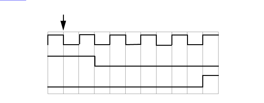
IEEE Std 1800-2012
IEEE STANDARD FOR SYSTEMVERILOG—UNIFIED HARDWARE DESIGN, SPECIFICATION, AND
VERIFICATION LANGUAGE
188
Copyright © 2013 IEEE. All rights reserved.
b = #5 a;
join
Intra-assignment timing control works because the intra-assignment delay causes the values of a and b to be
evaluated before the delay and causes the assignments to be made after the delay.
Intra-assignment waiting for events is also effective. In the following example, the right-hand expressions
are evaluated when the assignment statements are encountered, but the assignments are delayed until the
rising edge of the clock signal:
fork // data shift
a = @(posedge clk) b;
b = @(posedge clk) c;
join
The following is an example of a repeat event control as the intra-assignment delay of a nonblocking
assignment:
a <= repeat(5) @(posedge clk) data;
Figure 9-1 illustrates the activities that result from this repeat event control.
Figure 9-1—Intra-assignment repeat event control utilizing a clock edge
In this example, the value of data is evaluated when the assignment is encountered. After five occurrences
of posedge clk, a is assigned the value of data.
The following is an example of a repeat event control as the intra-assignment delay of a procedural
assignment:
a = repeat(num) @(clk) data;
In this example, the value of data is evaluated when the assignment is encountered. After the number of
transitions of clk equals the value of num, a is assigned the value of data.
The following is an example of a repeat event control with expressions containing operations to specify both
the number of event occurrences and the event that is counted:
a <= repeat(a+b) @(posedge phi1 or negedge phi2) data;
In this example, the value of data is evaluated when the assignment is encountered. After the sum of the
positive edges of phi1 and the negative edges of phi2 equals the sum of a and b, a is assigned the value of
clk
data
a
data is evaluated

IEEE Std 1800-2012
IEEE STANDARD FOR SYSTEMVERILOG—UNIFIED HARDWARE DESIGN, SPECIFICATION, AND
VERIFICATION LANGUAGE
189
Copyright © 2013 IEEE. All rights reserved.
data. Even if posedge phi1 and negedge phi2 occurred at the same simulation time, each will be
detected and counted separately.
If phi1 and phi2 refer to the same signal, then the assignment above can be simplified as:
a <= repeat(a+b) @(edge phi1) data;
9.5 Process execution threads
SystemVerilog creates a thread of execution for the following:
— Each initial procedure
— Each final procedure
— Each always, always_comb, always_latch, and always_ff procedure
— Each parallel statement in a fork-join (or join_any or join_none) statement group
— Each dynamic process
Each continuous assignment can also be considered its own thread (see 10.3).
9.6 Process control
SystemVerilog provides constructs that allow one process to terminate or wait for the completion of other
processes. The wait fork construct waits for the completion of processes. The disable construct stops the
execution of all activity within a named block or task, without regard to parent-child relationship (a child
process can terminate execution of a parent or one process can terminate execution of an unrelated process).
The disable fork construct stops the execution of processes, but with consideration of parent-child
relationships.
The process control statements have the syntax form shown in Syntax 9-7.
wait_statement ::= // from A.6.5
wait ( expression ) statement_or_null
|wait fork ;
|wait_order ( hierarchical_identifier { , hierarchical_identifier } ) action_block
disable_statement ::=
disable hierarchical_task_identifier ;
|disable hierarchical_block_identifier ;
|disable fork ;
Syntax 9-7—Syntax for process control statements (excerpt from Annex A)
9.6.1 Wait fork statement
The wait fork statement blocks process execution flow until all immediate child subprocesses (processes
created by the current process, excluding their descendants) have completed their execution.
The syntax for wait fork is as follows:
wait fork ; // from A.6.5
Specifying wait fork causes the calling process to block until all its immediate child subprocesses have
completed.

IEEE Std 1800-2012
IEEE STANDARD FOR SYSTEMVERILOG—UNIFIED HARDWARE DESIGN, SPECIFICATION, AND
VERIFICATION LANGUAGE
190
Copyright © 2013 IEEE. All rights reserved.
Simulation automatically terminates when there is no further activity of any kind. Simulation also
automatically terminates when all its program blocks finish executing (i.e, they reach the end of their
execute block), regardless of the status of any child processes (see 24.7). The wait fork statement allows a
program block to wait for the completion of all its concurrent threads before exiting.
In the following example, in the task do_test, the first two processes are spawned, and the task blocks until
one of the two processes completes (either exec1 or exec2). Next, two more processes are spawned in the
background. The wait fork statement shall block the execution flow of the task do_test until all four
spawned processes complete before returning to its caller.
task do_test;
fork
exec1();
exec2();
join_any
fork
exec3();
exec4();
join_none
wait fork; // block until exec1 ... exec4 complete
endtask
9.6.2 Disable statement
The disable statement provides the ability to terminate the activity associated with concurrently active
processes, while maintaining the structured nature of procedural descriptions. The disable statement gives a
mechanism for terminating a task before it executes all its statements, breaking from a looping statement, or
skipping statements in order to continue with another iteration of a looping statement. It is useful for
handling exception conditions such as hardware interrupts and global resets. The disable statement can also
be used to terminate execution of a labeled statement, including a deferred assertion (see 16.4) or a
procedural concurrent assertion (see 16.14.6).
The disable statement shall terminate the activity of a task or a named block. Execution shall resume at the
statement following the block or following the task-enabling statement. All activities enabled within the
named block or task shall be terminated as well. If task enable statements are nested (that is, one task enables
another, and that one enables yet another), then disabling a task within the chain shall disable all tasks
downward on the chain. If a task is enabled more than once, then disabling such a task shall disable all
activations of the task.
The results of the following activities that can be initiated by a task are not specified if the task is disabled:
— Results of output and inout arguments
— Scheduled, but not executed, nonblocking assignments
— Procedural continuous assignments (assign and force statements)
The disable statement can be used within blocks and tasks to disable the particular block or task containing
the disable statement. The disable statement can be used to disable named blocks within a function, but
cannot be used to disable functions. In cases where a disable statement within a function disables a block or
a task that called the function, the behavior is undefined. Disabling an automatic task or a block inside an
automatic task proceeds as for regular tasks for all concurrent executions of the task.
Example 1: This example illustrates how a block disables itself.
begin : block_name
rega = regb;
disable block_name;

IEEE Std 1800-2012
IEEE STANDARD FOR SYSTEMVERILOG—UNIFIED HARDWARE DESIGN, SPECIFICATION, AND
VERIFICATION LANGUAGE
191
Copyright © 2013 IEEE. All rights reserved.
regc = rega; // this assignment will never execute
end
Example 2: This example shows the disable statement being used within a named block in a manner similar
to a forward goto. The next statement executed after the disable statement is the one following the named
block.
begin : block_name
...
...
if (a == 0)
disable block_name;
...
end // end of named block
// continue with code following named block
...
Example 3: This example illustrates using the disable construct to terminate execution of a named block that
does not contain the disable statement. If the block is currently executing, this causes control to jump to the
statement immediately after the block. If the block is a loop body, it acts like a continue (see 12.8). If the
block is not currently executing, the disable has no effect.
module m (...);
always
begin : always1
...
t1: task1( ); // task call
...
end
...
always
begin
...
disable m.always1; // exit always1, which will exit task1,
// if it was currently executing
end
endmodule
Example 4: This example shows the disable statement being used as an early return from a task. However, a
task disabling itself using a disable statement is not a shorthand for the return statement (see 12.8).
SystemVerilog has return from a task, which shall terminate execution of the process in which the return is
executed. If disable is applied to a task, all currently active executions of the task are disabled.
task proc_a;
begin
...
...
if (a == 0)
disable proc_a; // return if true
...
...
end
endtask

IEEE Std 1800-2012
IEEE STANDARD FOR SYSTEMVERILOG—UNIFIED HARDWARE DESIGN, SPECIFICATION, AND
VERIFICATION LANGUAGE
192
Copyright © 2013 IEEE. All rights reserved.
Example 5: This example shows the disable statement being used in an equivalent way to the two statements
continue and break (see 12.8). The example illustrates control code that would allow a named block to
execute until a loop counter reaches n iterations or until the variable a is set to the value of b. The named
block outer_block contains the code that executes until a==b, at which point the disable
outer_block; statement terminates execution of that block. The named block inner_block contains the
code that executes for each iteration of the for loop. Each time this code executes the
disable inner_block; statement, the inner_block block terminates, and execution passes to the next
iteration of the for loop. For each iteration of the inner_block block, a set of statements executes
if (a != 0). Another set of statements executes if (a! = b).
begin : outer_block
for (i = 0; i < n; i = i+1) begin : inner_block
@clk
if (a == 0) // "continue" loop
disable inner_block ;
... // statements
... // statements
@clk
if (a == b) // "break" from loop
disable outer_block;
... // statements
... // statements
end
end
NOTE—The C-like break and continue statements (see 12.8) may be a more intuitive way to code the preceding
example.
Example 6: This example shows the disable statement being used to disable concurrently a sequence of
timing controls and the task named action when the reset event occurs. The example shows a fork-join
block within which are a named sequential block (event_expr) and a disable statement that waits for
occurrence of the event reset. The sequential block and the wait for reset execute in parallel. The
event_expr block waits for one occurrence of event ev1 and three occurrences of event trig. When these
four events have happened, plus a delay of d time units, the task action executes. When the event reset
occurs, regardless of events within the sequential block, the fork-join block terminates—including the task
action.
fork
begin : event_expr
@ev1;
repeat (3) @trig;
#d action (areg, breg);
end
@reset disable event_expr;
join
Example 7: The next example is a behavioral description of a retriggerable monostable. The named event
retrig restarts the monostable time period. If retrig continues to occur within 250 time units, then q
will remain at 1.
always begin : monostable
#250 q = 0;
end
always @retrig begin
disable monostable;
q = 1;
end

IEEE Std 1800-2012
IEEE STANDARD FOR SYSTEMVERILOG—UNIFIED HARDWARE DESIGN, SPECIFICATION, AND
VERIFICATION LANGUAGE
193
Copyright © 2013 IEEE. All rights reserved.
9.6.3 Disable fork statement
The disable fork statement terminates all active descendants (subprocesses) of the calling process.
The syntax for disable fork is as follows:
disable fork ; // from A.6.5
The disable fork statement terminates all descendants of the calling process as well as the descendants of
the process’s descendants. In other words, if any of the child processes have descendants of their own, the
disable fork statement shall terminate them as well.
In the following example, the task get_first spawns three versions of a task that wait for a particular
device (1, 7, or 13). The task wait_device waits for a particular device to become ready and then returns
the device’s address. When the first device becomes available, the get_first task shall resume execution
and proceed to kill the outstanding wait_device processes.
task get_first( output int adr );
fork
wait_device( 1, adr );
wait_device( 7, adr );
wait_device( 13, adr );
join_any
disable fork;
endtask
The disable construct terminates a process when applied to the named block or statement being executed
by the process. The disable fork statement differs from disable in that disable fork considers the
dynamic parent-child relationship of the processes, whereas disable uses the static, syntactical information
of the disabled block. Thus, disable shall end all processes executing a particular block, whether the
processes were forked by the calling thread or not, while disable fork shall end only the processes that
were spawned by the calling thread.
9.7 Fine-grain process control
A process is a built-in class that allows one process to access and control another process once it has started.
Users can declare variables of type process and safely pass them through tasks or incorporate them into other
objects. The prototype for the process class is as follows:
class process;
typedef enum { FINISHED, RUNNING, WAITING, SUSPENDED, KILLED } state;
static function process self();
function state status();
function void kill();
task await();
function void suspend();
function void resume();
function void srandom( int seed );
function string get_randstate();
function void set_randstate( string state );
endclass
Objects of type process are created internally when processes are spawned. Users cannot create objects of
type process; attempts to call new shall not create a new process and shall instead result in an error. The
process class cannot be extended. Attempts to extend it shall result in a compilation error. Objects of type
IEEE Std 1800-2012
IEEE STANDARD FOR SYSTEMVERILOG—UNIFIED HARDWARE DESIGN, SPECIFICATION, AND
VERIFICATION LANGUAGE
194
Copyright © 2013 IEEE. All rights reserved.
process are unique; they become available for reuse once the underlying process terminates and all
references to the object are discarded.
The self() function returns a handle to the current process, that is, a handle to the process making the call.
The status() function returns the process status, as defined by the state enumeration:
—FINISHED means the process terminated normally.
—RUNNING means the process is currently running (not in a blocking statement).
—WAITING means the process is waiting in a blocking statement.
—SUSPENDED means the process is stopped awaiting a resume.
—KILLED means the process was forcibly killed (via kill or disable).
The kill() function terminates the given process and all its subprocesses, that is, processes spawned using
fork statements by the process being killed. If the process to be terminated is not blocked waiting on some
other condition, such as an event, wait expression, or a delay, then the process shall be terminated at some
unspecified time in the current time step.
The await() task allows one process to wait for the completion of another process. It shall be an error to
call this task on the current process, i.e., a process cannot wait for its own completion.
The suspend() function allows a process to suspend either its own execution or that of another process. If
the process to be suspended is not blocked waiting on some other condition, such as an event, wait
expression, or a delay, then the process shall be suspended at some unspecified time in the current time step.
Calling this method more than once, on the same (suspended) process, has no effect.
The resume() function restarts a previously suspended process. Calling resume on a process that was
suspended while blocked on another condition shall resensitize the process to the event expression or to wait
for the wait condition to become true or for the delay to expire. If the wait condition is now true or the
original delay has transpired, the process is scheduled onto the Active or Reactive region to continue its
execution in the current time step. Calling resume on a process that suspends itself causes the process to
continue to execute at the statement following the call to suspend.
The methods kill(), await(), suspend(), and resume() shall be restricted to a process created by an
initial procedure, always procedure, or fork block from one of those procedures.
The following example starts an arbitrary number of processes, as specified by the task argument N. Next,
the task waits for the last process to start executing and then waits for the first process to terminate. At that
point, the parent process forcibly terminates all forked processes that have not yet completed.
task automatic do_n_way( int N );
process job[] = new [N];
foreach (job[j])
fork
automatic int k = j;
begin job[k] = process::self(); ... ; end
join_none
foreach (job[j]) // wait for all processes to start
wait( job[j] != null );
job[1].await(); // wait for first process to finish
foreach (job[j]) begin
IEEE Std 1800-2012
IEEE STANDARD FOR SYSTEMVERILOG—UNIFIED HARDWARE DESIGN, SPECIFICATION, AND
VERIFICATION LANGUAGE
195
Copyright © 2013 IEEE. All rights reserved.
if ( job[j].status != process::FINISHED )
job[j].kill();
end
endtask
IEEE Std 1800-2012
IEEE STANDARD FOR SYSTEMVERILOG—UNIFIED HARDWARE DESIGN, SPECIFICATION, AND
VERIFICATION LANGUAGE
196
Copyright © 2013 IEEE. All rights reserved.
10. Assignment statements
10.1 General
This clause describes the following:
— Continuous assignments
— Procedural blocking and nonblocking assignments
— Procedural continuous assignments (assign, deassign, force, release)
— Net aliasing
10.2 Overview
The assignment is the basic mechanism for placing values into nets and variables. There are two basic forms
of assignments, as follows:
— The continuous assignment, which assigns values to nets or variables
— The procedural assignment, which assigns values to variables
Continuous assignments drive nets or variables in a manner similar to the way gates drive nets or variables.
The expression on the right-hand side can be thought of as a combinational circuit that drives the net or
variable continuously. In contrast, procedural assignments put values in variables. The assignment does not
have duration; instead, the variable holds the value of the assignment until the next procedural assignment to
that variable.
There are two additional forms of assignments, assign/deassign and force/release, which are called
procedural continuous assignments, described in 10.6.
An assignment consists of two parts, a left-hand side and a right-hand side, separated by the equals ( = )
character; or, in the case of nonblocking procedural assignment, the less-than-equals ( <= ) character pair.
The right-hand side can be any expression that evaluates to a value. The left-hand side indicates the net or
variable to which the right-hand side value is to be assigned. The left-hand side can take one of the forms
given in Table 10-1, depending on whether the assignment is a continuous assignment or a procedural
assignment.
Table 10-1—Legal left-hand forms in assignment statements
Statement type Left-hand side
Continuous assignment Net or variable (vector or scalar)
Constant bit-select of a vector net or packed variable
Constant part-select of a vector net or packed variable
Concatenation or nested concatenation of any of the above left-hand sides
Procedural assignment Variable (vector or scalar)
Bit-select of a packed variable
Part-select of a packed variable
Memory word
Array
Array element select
Array slice
Concatenation or nested concatenation of any of the above left-hand sides
IEEE Std 1800-2012
IEEE STANDARD FOR SYSTEMVERILOG—UNIFIED HARDWARE DESIGN, SPECIFICATION, AND
VERIFICATION LANGUAGE
197
Copyright © 2013 IEEE. All rights reserved.
SystemVerilog also allows a time unit to be specified in the assignment statement, as follows:
#1ns r = a;
r = #1ns a;
r <= #1ns a;
assign #2.5ns sum = a + b;
10.3 Continuous assignments
Continuous assignments shall drive values onto nets or variables, both vector (packed) and scalar. This
assignment shall occur whenever the value of the right-hand side changes. Continuous assignments provide
a way to model combinational logic without specifying an interconnection of gates. Instead, the model
specifies the logical expression that drives the net or variable.
There are two forms of continuous assignments: net declaration assignments (see 10.3.1) and continuous
assign statements (see 10.3.2).
The syntax for continuous assignments is given in Syntax 10-1.
net_declaration12 ::= // from A.2.1.3
net_type [ drive_strength | charge_strength ] [ vectored | scalared ]
data_type_or_implicit [ delay3 ] list_of_net_decl_assignments ;
| net_type_identifier [ delay_control ]
list_of_net_decl_assignments ;
|interconnect implicit_data_type [ # delay_value ]
net_identifier { unpacked_dimension }
[ , net_identifier { unpacked_dimension }] ;
list_of_net_decl_assignments ::= net_decl_assignment { , net_decl_assignment } // from A.2.3
net_decl_assignment ::= net_identifier { unpacked_dimension } [ = expression ] // from A.2.4
continuous_assign ::= // from A.6.1
assign [ drive_strength ] [ delay3 ] list_of_net_assignments ;
|assign [ delay_control ] list_of_variable_assignments ;
list_of_net_assignments ::= net_assignment { , net_assignment }
list_of_variable_assignments ::= variable_assignment { , variable_assignment }
net_assignment ::= net_lvalue = expression
12) A charge strength shall only be used with the trireg keyword. When the vectored or scalared keyword is
used, there shall be at least one packed dimension.
Syntax 10-1—Syntax for continuous assignment (excerpt from Annex A)
10.3.1 The net declaration assignment
The net declaration assignment allows a continuous assignment to be placed on a net in the same statement
that declares the net.
The following is an example of the net declaration form of a continuous assignment:
wire (strong1, pull0) mynet = enable;

IEEE Std 1800-2012
IEEE STANDARD FOR SYSTEMVERILOG—UNIFIED HARDWARE DESIGN, SPECIFICATION, AND
VERIFICATION LANGUAGE
198
Copyright © 2013 IEEE. All rights reserved.
Because a net can be declared only once, only one net declaration assignment can be made for a particular
net. This contrasts with the continuous assignment statement; one net can receive multiple assignments of
the continuous assignment form.
An interconnect net (see 6.6.8) shall not have a net declaration assignment.
10.3.2 The continuous assignment statement
The continuous assignment statement shall place a continuous assignment on a net or variable data type. The
net may be explicitly declared or may inherit an implicit declaration in accordance with the implicit
declaration rules defined in 6.10. Variables shall be explicitly declared prior to the continuous assignment
statement.
Assignments on nets or variables shall be continuous and automatic. In other words, whenever an operand in
the right-hand expression changes value, the whole right-hand side shall be evaluated. If the new value is
different from the previous value, then the new value shall be assigned to the left-hand side.
Nets can be driven by multiple continuous assignments or by a mixture of primitive outputs, module outputs,
and continuous assignments. Variables can only be driven by one continuous assignment or by one primitive
output or module output. It shall be an error for a variable driven by a continuous assignment or output to
have an initializer in the declaration or any procedural assignment. See also 6.5.
A continuous assignment to an atomic net shall not drive part of the net; the entire nettype value shall be
driven. Thus the left-hand side of a continuous assignment to a net of a user-defined nettype shall not
contain any indexing or select operations into the data type of the nettype.
Example 1: The following is an example of a continuous assignment to a net that has been previously
declared:
wire mynet ;
assign (strong1, pull0) mynet = enable;
Example 2: The following is an example of the use of a continuous assignment to model a 4-bit adder with
carry. The assignment could not be specified directly in the declaration of the nets because it requires a
concatenation on the left-hand side.
module adder (sum_out, carry_out, carry_in, ina, inb);
output [3:0] sum_out;
output carry_out;
input [3:0] ina, inb;
input carry_in;
wire carry_out, carry_in;
wire [3:0] sum_out, ina, inb;
assign {carry_out, sum_out} = ina + inb + carry_in;
endmodule
Example 3: The following example describes a module with one 16-bit output bus. It selects between one of
four input busses and connects the selected bus to the output bus.
module select_bus(busout, bus0, bus1, bus2, bus3, enable, s);
parameter n = 16;
parameter Zee = 16'bz;
output [1:n] busout;

IEEE Std 1800-2012
IEEE STANDARD FOR SYSTEMVERILOG—UNIFIED HARDWARE DESIGN, SPECIFICATION, AND
VERIFICATION LANGUAGE
199
Copyright © 2013 IEEE. All rights reserved.
input [1:n] bus0, bus1, bus2, bus3;
input enable;
input [1:2] s;
tri [1:n] data; // net declaration
// net declaration with continuous assignment
tri [1:n] busout = enable ? data : Zee;
// assignment statement with four continuous assignments
assign
data = (s == 0) ? bus0 : Zee,
data = (s == 1) ? bus1 : Zee,
data = (s == 2) ? bus2 : Zee,
data = (s == 3) ? bus3 : Zee;
endmodule
The following sequence of events is experienced during simulation of this example:
a) The value of s, a bus selector input variable, is checked in the assign statement. Based on the value
of s, the net data receives the data from one of the four input buses.
b) The setting of net data triggers the continuous assignment in the net declaration for busout. If
enable is set, the contents of data are assigned to busout; if enable is 0, the contents of Zee are
assigned to busout.
10.3.3 Continuous assignment delays
A delay given to a continuous assignment shall specify the time duration between a right-hand operand
value change and the assignment made to the left-hand side. If the left-hand references a scalar net, then the
delay shall be treated in the same way as for gate delays; that is, different delays can be given for the output
rising, falling, and changing to high impedance (see 28.16).
If the left-hand references a vector net, then up to three delays can be applied. The following rules determine
which delay controls the assignment:
— If the right-hand side makes a transition from nonzero to zero, then the falling delay shall be used.
— If the right-hand side makes a transition to z, then the turn-off delay shall be used.
— For all other cases, the rising delay shall be used.
If the left-hand side references a net of a user-defined nettype or an array of such nets, then only a single
delay may be applied. The specific delay is used when any change occurs to the value of the net.
Specifying the delay in a continuous assignment that is part of the net declaration shall be treated differently
from specifying a net delay and then making a continuous assignment to the net. A delay value can be
applied to a net in a net declaration, as in the following example:
wire #10 wireA;
This syntax, called a net delay, means that any value change that is to be applied to wireA by some other
statement shall be delayed for ten time units before it takes effect. When there is a continuous assignment in
a declaration, the delay is part of the continuous assignment and is not a net delay. Thus, it shall not be added
to the delay of other drivers on the net. Furthermore, if the assignment is to a vector net, then the rising and
falling delays shall not be applied to the individual bits if the assignment is included in the declaration.
In situations where a right-hand operand changes before a previous change has had time to propagate to the
left-hand side, then the following steps are taken:

IEEE Std 1800-2012
IEEE STANDARD FOR SYSTEMVERILOG—UNIFIED HARDWARE DESIGN, SPECIFICATION, AND
VERIFICATION LANGUAGE
200
Copyright © 2013 IEEE. All rights reserved.
a) The value of the right-hand expression is evaluated.
b) If this right-hand side value differs from the value currently scheduled to propagate to the left-hand
side, then the currently scheduled propagation event is descheduled.
c) If the new right-hand side value equals the current left-hand side value, no event is scheduled.
d) If the new right-hand side value differs from the current left-hand side value, a delay is calculated in
the standard way using the current value of the left-hand side, the newly calculated value of the
right-hand side, and the delays indicated on the statement; a new propagation event is then sched-
uled to occur delay time units in the future.
10.3.4 Continuous assignment strengths
The driving strength of a continuous assignment can be specified by the user. This applies only to
assignments to scalar nets, except for nets of types supply0 and supply1.
Continuous assignments driving strengths can be specified either in a net declaration or in a stand-alone
assignment, using the assign keyword. The strength specification, if provided, shall immediately follow
the keyword (either the keyword for the net type or assign) and precede any delay specified. Whenever the
continuous assignment drives the net, the strength of the value shall be simulated as specified.
A drive strength specification shall contain one strength value that applies when the value being assigned to
the net is 1 and a second strength value that applies when the assigned value is 0. The following keywords
shall specify the strength value for an assignment of 1:
supply1 strong1 pull1 weak1 highz1
The following keywords shall specify the strength value for an assignment of 0:
supply0 strong0 pull0 weak0 highz0
The order of the two strength specifications shall be arbitrary. The following two rules shall constrain the
use of drive strength specifications:
— The strength specifications (highz1, highz0) and (highz0, highz1) shall be treated as illegal
constructs.
— If drive strength is not specified, it shall default to (strong1, strong0).
10.4 Procedural assignments
Procedural assignments occur within procedures such as always, initial (see 9.2), task, and function
(see Clause 13) and can be thought of as “triggered” assignments. The trigger occurs when the flow of
execution in the simulation reaches an assignment within a procedure. Reaching the assignment can be
controlled by conditional statements. Event controls, delay controls, if statements, case statements, and
looping statements can all be used to control whether assignments are evaluated. Clause 12 gives details and
examples.
The right-hand side of a procedural assignment can be any expression that evaluates to a value, however the
variable type on the left-hand side may restrict what is a legal expression on the right-hand side. The left-
hand side shall be a variable that receives the assignment from the right-hand side. The left-hand side of a
procedural assignment can take one of the following forms:
— Singular variables, as described in 6.4
— Aggregate variables, as described in Clause 7
— Bit-selects, part-selects, and slices of packed arrays
— Slices of unpacked arrays
IEEE Std 1800-2012
IEEE STANDARD FOR SYSTEMVERILOG—UNIFIED HARDWARE DESIGN, SPECIFICATION, AND
VERIFICATION LANGUAGE
201
Copyright © 2013 IEEE. All rights reserved.
SystemVerilog contains the following three types of procedural assignment statements:
— Blocking procedural assignment statements (see 10.4.1)
— Nonblocking procedural assignment statements (see 10.4.2)
— Assignment operators (see 11.4.1)
Blocking and nonblocking procedural assignment statements specify different procedural flows in
sequential blocks.
10.4.1 Blocking procedural assignments
A blocking procedural assignment statement shall be executed before the execution of the statements that
follow it in a sequential block (see 9.3.1). A blocking procedural assignment statement shall not prevent the
execution of statements that follow it in a parallel block (see 9.3.2).
The syntax for a blocking procedural assignment is given in Syntax 10-2.
blocking_assignment ::= // from A.6.3
variable_lvalue = delay_or_event_control expression
| nonrange_variable_lvalue = dynamic_array_new
| [ implicit_class_handle . | class_scope | package_scope ] hierarchical_variable_identifier
select = class_new
| operator_assignment
operator_assignment ::= variable_lvalue assignment_operator expression
assignment_operator ::=
= | += | -= | *= | /= | %= | &= | |= | ^= | <<= | >>= | <<<= | >>>=
Syntax 10-2—Blocking assignment syntax (excerpt from Annex A)
In this syntax, variable_lvalue is a data type that is valid for a procedural assignment statement, = is the
assignment operator, and delay_or_event_control is the optional intra-assignment timing control (see 9.4.5).
The expression is the right-hand side value that shall be assigned to the left-hand side. If variable_lvalue
requires an evaluation, it shall be evaluated at the time specified by the intra-assignment timing control. The
order of evaluation of the variable_lvalue and the expression on the right-hand side is undefined if a timing
control is not specified. See 4.9.3.
The = assignment operator used by blocking procedural assignments is also used by procedural continuous
assignments and continuous assignments.
The following examples show blocking procedural assignments:
rega = 0;
rega[3] = 1; // a bit-select
rega[3:5] = 7; // a part-select
mema[address] = 8'hff; // assignment to a mem element
{carry, acc} = rega + regb; // a concatenation
Additional assignment operators, such as +=, are described in 11.4.1.

IEEE Std 1800-2012
IEEE STANDARD FOR SYSTEMVERILOG—UNIFIED HARDWARE DESIGN, SPECIFICATION, AND
VERIFICATION LANGUAGE
202
Copyright © 2013 IEEE. All rights reserved.
10.4.2 Nonblocking procedural assignments
The nonblocking procedural assignment allows assignment scheduling without blocking the procedural
flow. The nonblocking procedural assignment statement can be used whenever several variable assignments
within the same time step can be made without regard to order or dependence upon each other.
It shall be illegal to make nonblocking assignments to automatic variables.
The syntax for a nonblocking procedural assignment is given in Syntax 10-3.
nonblocking_assignment ::= variable_lvalue <= [ delay_or_event_control ] expression // from A.6.3
Syntax 10-3—Nonblocking assignment syntax (excerpt from Annex A)
In this syntax, variable_lvalue is a data type that is valid for a procedural assignment statement, <= is the
nonblocking assignment operator, and delay_or_event_control is the optional intra-assignment timing
control (see 9.4.5). If variable_lvalue requires an evaluation, such as an index expression, class handle, or
virtual interface reference, it shall be evaluated at the same time as the expression on the right-hand side.
The order of evaluation of the variable_lvalue and the expression on the right-hand side is undefined (see
4.9.4).
The nonblocking assignment operator is the same operator as the less-than-or-equal-to relational operator.
The interpretation shall be decided from the context in which <= appears. When <= is used in an expression,
it shall be interpreted as a relational operator; and when it is used in a nonblocking procedural assignment, it
shall be interpreted as an assignment operator.
The nonblocking procedural assignments shall be evaluated in two steps as discussed in Clause 4. These two
steps are shown in the following example:
Example 1:
At the end of the time step means that the nonblocking assignments are the last assignments executed in a
time step—with one exception. Nonblocking assignment events can create blocking assignment events.
These blocking assignment events shall be processed after the scheduled nonblocking events.
module evaluates (out);
output out;
logic a, b, c;
initial begin
a = 0;
b = 1;
c = 0;
end
always c = #5 ~c;
always @(posedge c) begin
a <= b; // evaluates, schedules,
b <= a; // and executes in two steps
end
endmodule
Step 1:
Step 2:
a = 0
b = 1
a = 1
b = 0
At posedge c, the simulator
evaluates the right-hand sides of
the nonblocking assignments and
schedules the assignments of the
new values at the end of the
nonblocking assign update events
NBA region (see 4.5).
When the simulator activates the
nonblocking assign update events,
the simulator updates the left-hand
side of each nonblocking
assignment statement.
Nonblocking
assignment
schedules
change at
time 5
assignment
values

IEEE Std 1800-2012
IEEE STANDARD FOR SYSTEMVERILOG—UNIFIED HARDWARE DESIGN, SPECIFICATION, AND
VERIFICATION LANGUAGE
203
Copyright © 2013 IEEE. All rights reserved.
Unlike an event or delay control for blocking assignments, the nonblocking assignment does not block the
procedural flow. The nonblocking assignment evaluates and schedules the assignment, but it does not block
the execution of subsequent statements in a begin-end block.
Example 2:
As shown in the previous example, the simulator evaluates and schedules assignments for the end of the
current time step and can perform swapping operations with the nonblocking procedural assignments.
Example 3:
The order of the execution of distinct nonblocking assignments to a given variable shall be preserved. In
other words, if there is clear ordering of the execution of a set of nonblocking assignments, then the order of
the resulting updates of the destination of the nonblocking assignments shall be the same as the ordering of
the execution (see 4.6).
Example 4:
module multiple;
logic a;
module nonblock1;
logic a, b, c, d, e, f;
// blocking assignments
initial begin
a = #10 1; // a will be assigned 1 at time 10
b = #2 0; // b will be assigned 0 at time 12
c = #4 1; // c will be assigned 1 at time 16
end
// nonblocking assignments
initial begin
d <= #10 1; // d will be assigned 1 at time 10
e <= #2 0; // e will be assigned 0 at time 2
f <= #4 1; // f will be assigned 1 at time 4
end
endmodule
scheduled
changes at
time 2
e = 0
f = 1
d = 1
scheduled
changes at
time 4
scheduled
changes at
time 10
module nonblock2;
logic a, b;
initial begin
a = 0;
b = 1;
a <= b; // evaluates, schedules,
b <= a; // and executes in two steps
end
initial begin
$monitor ($time, ,"a = %b b = %b", a, b);
#100 $finish;
end
endmodule
assignment
values
The simulator evaluates the right-hand
side of the nonblocking assignments
and schedules the assignments for the
end of the current time step.
At the end of the current time step, the
simulator updates the left-hand side of
each nonblocking assignment
statement.
Step 1:
Step 2:
a = 1
b = 0
IEEE Std 1800-2012
IEEE STANDARD FOR SYSTEMVERILOG—UNIFIED HARDWARE DESIGN, SPECIFICATION, AND
VERIFICATION LANGUAGE
204
Copyright © 2013 IEEE. All rights reserved.
initial a = 1;
// The assigned value of the variable is determinate
initial begin
a <= #4 0; // schedules a = 0 at time 4
a <= #4 1; // schedules a = 1 at time 4
end // At time 4, a = 1
endmodule
If the simulator executes two procedural blocks concurrently and if these procedural blocks contain
nonblocking assignment operators to the same variable, the final value of that variable is indeterminate. For
example, the value of variable a is indeterminate in the following example:
Example 5:
module multiple2;
logic a;
initial a = 1;
initial a <= #4 0; // schedules 0 at time 4
initial a <= #4 1; // schedules 1 at time 4
// At time 4, a = ??
// The assigned value of the variable is indeterminate
endmodule
The fact that two nonblocking assignments targeting the same variable are in different blocks is not by itself
sufficient to make the order of assignments to a variable indeterminate. For example, the value of variable a
at the end of time cycle 16 is determinate in the following example:
Example 6:
module multiple3;
logic a;
initial #8 a <= #8 1; // executed at time 8;
// schedules an update of 1 at time 16
initial #12 a <= #4 0; // executed at time 12;
// schedules an update of 0 at time 16
// Because it is determinate that the update of a to the value 1
// is scheduled before the update of a to the value 0,
// then it is determinate that a will have the value 0
// at the end of time slot 16.
endmodule
The following example shows how the value of i[0] is assigned to r1 and how the assignments are
scheduled to occur after each time delay:
Example 7:
module multiple4;
logic r1;
logic [2:0] i;
initial begin
// makes assignments to r1 without cancelling previous assignments
IEEE Std 1800-2012
IEEE STANDARD FOR SYSTEMVERILOG—UNIFIED HARDWARE DESIGN, SPECIFICATION, AND
VERIFICATION LANGUAGE
205
Copyright © 2013 IEEE. All rights reserved.
for (i = 0; i <= 5; i++)
r1 <= # (i*10) i[0];
end
endmodule
10.5 Variable declaration assignment (variable initialization)
Unlike nets, a variable cannot have an implicit continuous assignment as part of its declaration. An
assignment as part of the declaration of a variable is a variable initialization, not a continuous assignment.
The variable declaration assignment is a special case of procedural assignment as it assigns a value to a
variable. It allows an initial value to be placed in a variable in the same statement that declares the variable
(see 6.8). The assignment does not have duration; instead, the variable holds the value until the next
assignment to that variable.
For example:
wire w = vara & varb; // net with a continuous assignment
logic v = consta & constb; // variable with initialization
Setting the initial value of a static variable as part of the variable declaration (including static class
members) shall occur before any initial or always procedures are started. See also 6.21.
10.6 Procedural continuous assignments
The procedural continuous assignments (using keywords assign and force) are procedural statements
that allow expressions to be driven continuously onto variables or nets. The syntax for these statements is
given in Syntax 10-4.
procedural_continuous_assignment ::= // from A.6.2
assign variable_assignment
|deassign variable_lvalue
|force variable_assignment
|force net_assignment
|release variable_lvalue
|release net_lvalue
variable_assignment ::= variable_lvalue = expression
net_assignment ::= net_lvalue = expression // from A.6.1
Syntax 10-4—Syntax for procedural continuous assignments (excerpt from Annex A)
r1
10 20 30 40 500

IEEE Std 1800-2012
IEEE STANDARD FOR SYSTEMVERILOG—UNIFIED HARDWARE DESIGN, SPECIFICATION, AND
VERIFICATION LANGUAGE
206
Copyright © 2013 IEEE. All rights reserved.
The right-hand side of an assign procedural continuous assignment or a force statement can be an
expression. This shall be treated just as a continuous assignment; that is, if any variable on the right-hand
side of the assignment changes, the assignment shall be reevaluated while the assign or force is in effect. For
example:
force a = b + f(c) ;
Here, if b changes or c changes, a will be forced to the new value of the expression b+f(c).
10.6.1 The assign and deassign procedural statements
The assign procedural continuous assignment statement shall override all procedural assignments to a
variable. The deassign procedural statement shall end a procedural continuous assignment to a variable.
The value of the variable shall remain the same until the variable is assigned a new value through a
procedural assignment or a procedural continuous assignment. The assign and deassign procedural
statements allow, for example, modeling of asynchronous clear/preset on a D-type edge-triggered flip-flop,
where the clock is inhibited when the clear or preset is active.
The left-hand side of the assignment in the assign statement shall be a singular variable reference or a
concatenation of variables. It shall not be a bit-select or a part-select of a variable.
If the keyword assign is applied to a variable for which there is already a procedural continuous
assignment, then this new procedural continuous assignment shall deassign the variable before making the
new procedural continuous assignment.
The following example shows a use of the assign and deassign procedural statements in a behavioral
description of a D-type flip-flop with preset and clear inputs:
module dff (q, d, clear, preset, clock);
output q;
input d, clear, preset, clock;
logic q;
always @(clear or preset)
if (!clear)
assign q = 0;
else if (!preset)
assign q = 1;
else
deassign q;
always @(posedge clock)
q = d;
endmodule
If either clear or preset is low, then the output q will be held continuously to the appropriate constant
value, and a positive edge on the clock will not affect q. When both the clear and preset are high, then
q is deassigned.
NOTE—The procedural assign and deassign constructs are under consideration for deprecation. See Annex C.
10.6.2 The force and release procedural statements
Another form of procedural continuous assignment is provided by the force and release procedural
statements. These statements have a similar effect to the assign-deassign pair, but a force can be applied
to nets as well as to variables. The left-hand side of the assignment can be a reference to a singular variable,
IEEE Std 1800-2012
IEEE STANDARD FOR SYSTEMVERILOG—UNIFIED HARDWARE DESIGN, SPECIFICATION, AND
VERIFICATION LANGUAGE
207
Copyright © 2013 IEEE. All rights reserved.
a net, a constant bit-select of a vector net, a constant part-select of a vector net, or a concatenation of these. It
shall not be a bit-select or a part-select of a variable or of a net with a user-defined nettype. A force or
release statement shall not be applied to a variable that is being assigned by a mixture of continuous and
procedural assignments.
A force statement to a variable shall override a procedural assignment, continuous assignment or an
assign procedural continuous assignment to the variable until a release procedural statement is executed
on the variable. When released, then if the variable is not driven by a continuous assignment and does not
currently have an active assign procedural continuous assignment, the variable shall not immediately
change value and shall maintain its current value until the next procedural assignment to the variable is
executed. Releasing a variable that is driven by a continuous assignment or currently has an active assign
procedural continuous assignment shall reestablish that assignment and schedule a reevaluation in the
continuous assignment’s scheduling region.
A force procedural statement on a net shall override all drivers of the net—gate outputs, module outputs,
and continuous assignments—until a release procedural statement is executed on the net. When released,
the net shall immediately be assigned the value determined by the drivers of the net.
For example:
module test;
logic a, b, c, d;
wire e;
and and1 (e, a, b, c);
initial begin
$monitor("%d d=%b,e=%b", $stime, d, e);
assign d = a & b & c;
a = 1;
b = 0;
c = 1;
#10;
force d = (a | b | c);
force e = (a | b | c);
#10;
release d;
release e;
#10 $finish;
end
endmodule
Results:
0 d=0,e=0
10 d=1,e=1
20 d=0,e=0
In this example, an and gate instance, and1, is “patched” to act like an or gate by a force procedural
statement that forces its output to the value of its ORed inputs, and an assign procedural statement of
ANDed values is “patched” to act like an assign statement of ORed values.
10.7 Assignment extension and truncation
The size of the left-hand side of an assignment forms the context for the right-hand expression.

IEEE Std 1800-2012
IEEE STANDARD FOR SYSTEMVERILOG—UNIFIED HARDWARE DESIGN, SPECIFICATION, AND
VERIFICATION LANGUAGE
208
Copyright © 2013 IEEE. All rights reserved.
The following are the steps for evaluating an assignment:
— Determine the size of the left-hand side and right-hand side by the standard expression size determi-
nation rules (see 11.8.1).
— When the right-hand side evaluates to fewer bits than the left-hand side, the right-hand side value is
padded to the size of the left-hand side. If the right-hand side is unsigned, it is padded according to
the rules specified in 11.6.1. If the right-hand side is signed, it is sign-extended.
— If the left-hand side is smaller than the right-hand side, truncation shall occur, as described in the
following paragraphs.
If the width of the right-hand expression is larger than the width of the left-hand side in an assignment, the
MSBs of the right-hand expression shall be discarded to match the size of the left-hand side.
Implementations can, but are not required to, warn or report any errors related to assignment size mismatch
or truncation. Size casting can be used to indicate explicit intent to change the size (see 6.24.1). Truncating
the sign bit of a signed expression may change the sign of the result.
Some examples of assignment truncation follow.
Example 1:
logic [5:0] a;
logic signed [4:0] b;
initial begin
a = 8'hff; // After the assignment, a = 6'h3f
b = 8'hff; // After the assignment, b = 5'h1f
end
Example 2:
logic [0:5] a;
logic signed [0:4] b, c;
initial begin
a = 8'sh8f; // After the assignment, a = 6'h0f
b = 8'sh8f; // After the assignment, b = 5'h0f
c = -113; // After the assignment, c = 15
// 1000_1111 = (-'h71 = -113) truncates to ('h0F = 15)
end
Example 3:
logic [7:0] a;
logic signed [7:0] b;
logic signed [5:0] c, d;
initial begin
a = 8'hff;
c = a; // After the assignment, c = 6'h3f
b = -113;
d = b; // After the assignment, d = 6'h0f
end
10.8 Assignment-like contexts
An assignment-like context is as follows:

IEEE Std 1800-2012
IEEE STANDARD FOR SYSTEMVERILOG—UNIFIED HARDWARE DESIGN, SPECIFICATION, AND
VERIFICATION LANGUAGE
209
Copyright © 2013 IEEE. All rights reserved.
— A continuous or procedural assignment
— For a parameter with an explicit type declaration:
— A parameter value assignment in a module, interface, program, or class
— A parameter value override in the instantiation of a module, interface, or program
— A parameter value override in the instantiation of a class or in the left-hand side of a class
scope operator
— A port connection to an input or output port of a module, interface, or program
— The passing of a value to a subroutine input, output, or inout port
— A return statement in a function
— A tagged union expression
— For an expression that is used as the right-hand value in an assignment-like context:
— If a parenthesized expression, then the expression within the parentheses
— If a mintypmax expression, then the colon-separated expressions
— If a conditional operator expression, then the second and third operand
— A nondefault correspondence between an expression in an assignment pattern and a field or element
in a data object or data value
No other contexts shall be considered assignment-like contexts. In particular, none of the following shall be
considered assignment-like contexts:
— A static cast
— A default correspondence between an expression in an assignment pattern and a field or element in a
data object or data value
— A port expression in a module, interface, or program declaration
— The passing of a value to a subroutine ref port
— A port connection to an inout or ref port of a module, interface, or program
10.9 Assignment patterns
Assignment patterns are used for assignments to describe patterns of assignments to structure fields and
array elements.
An assignment pattern specifies a correspondence between a collection of expressions and the fields and
elements in a data object or data value. An assignment pattern has no self-determined data type, but can be
used as one of the sides in an assignment-like context (see 10.8) when the other side has a self-determined
data type. An assignment pattern is built from braces, keys, and expressions and is prefixed with an
apostrophe. For example:
var int A[N] = '{default:1};
var integer i = '{31:1, 23:1, 15:1, 8:1, default:0};
typedef struct {real r, th;} C;
var C x = '{th:PI/2.0, r:1.0};
var real y [0:1] = '{0.0, 1.1}, z [0:9] = '{default: 3.1416};
A positional notation without keys can also be used. For example:
var int B[4] = '{a, b, c, d};
var C y = '{1.0, PI/2.0};
'{a, b, c, d} = B;
IEEE Std 1800-2012
IEEE STANDARD FOR SYSTEMVERILOG—UNIFIED HARDWARE DESIGN, SPECIFICATION, AND
VERIFICATION LANGUAGE
210
Copyright © 2013 IEEE. All rights reserved.
When an assignment pattern is used as the left-hand side of an assignment-like context, the positional
notation shall be required; and each member expression shall have a bit-stream data type that is assignment
compatible with and has the same number of bits as the data type of the corresponding element on the right-
hand side.
The assignment pattern syntax is listed in Syntax 10-5.
assignment_pattern ::= // from A.6.7.1
'{ expression { , expression } }
|'{ structure_pattern_key : expression { , structure_pattern_key : expression } }
|'{ array_pattern_key : expression { , array_pattern_key : expression } }
|'{ constant_expression { expression { , expression } } }
structure_pattern_key ::= member_identifier | assignment_pattern_key
array_pattern_key ::= constant_expression | assignment_pattern_key
assignment_pattern_key ::= simple_type | default
assignment_pattern_expression ::=
[ assignment_pattern_expression_type ] assignment_pattern
assignment_pattern_expression_type ::=
ps_type_identifier
| ps_parameter_identifier
| integer_atom_type
| type_reference
constant_assignment_pattern_expression32 ::= assignment_pattern_expression
32) In a constant_assignment_pattern_expression, all member expressions shall be constant expressions.
Syntax 10-5—Assignment patterns syntax (excerpt from Annex A)
An assignment pattern can be used to construct or deconstruct a structure or array by prefixing the pattern
with the name of a data type to form an assignment pattern expression. Unlike an assignment pattern, an
assignment pattern expression has a self-determined data type and is not restricted to being one of the sides
in an assignment-like context. When an assignment pattern expression is used in a right-hand expression, it
shall yield the value that a variable of the data type would hold if it were initialized using the assignment
pattern.
typedef logic [1:0] [3:0] T;
shortint'({T'{1,2}, T'{3,4}}) // yields 16'sh1234
When an assignment pattern expression is used in a left-hand expression, the positional notation shall be
required; and each member expression shall have a bit-stream data type that is assignment compatible with
and has the same number of bits as the corresponding element in the data type of the assignment pattern
expression. If the right-hand expression has a self-determined data type, then it shall be assignment
compatible with and have the same number of bits as the data type of the assignment pattern expression.
typedef byte U[3];
var U A = '{1, 2, 3};
var byte a, b, c;
U'{a, b, c} = A;
U'{c, a, b} = '{a+1, b+1, c+1};

IEEE Std 1800-2012
IEEE STANDARD FOR SYSTEMVERILOG—UNIFIED HARDWARE DESIGN, SPECIFICATION, AND
VERIFICATION LANGUAGE
211
Copyright © 2013 IEEE. All rights reserved.
An assignment pattern expression shall not be used in a port expression in a module, interface, or program
declaration.
10.9.1 Array assignment patterns
Concatenation braces are used to construct and deconstruct simple bit vectors. A similar syntax is used to
support the construction and deconstruction of arrays. The expressions shall match element for element, and
the braces shall match the array dimensions. Each expression item shall be evaluated in the context of an
assignment to the type of the corresponding element in the array. In other words, the following examples are
not required to cause size warnings:
bit unpackedbits [1:0] = '{1,1}; // no size warning required as
// bit can be set to 1
int unpackedints [1:0] = '{1'b1, 1'b1}; // no size warning required as
// int can be set to 1'b1
A syntax resembling replications (see 11.4.12.1) can be used in array assignment patterns as well. Each
replication shall represent an entire single dimension.
unpackedbits = '{2 {y}} ; // same as '{y, y}
int n[1:2][1:3] = '{2{'{3{y}}}}; // same as '{'{y,y,y},'{y,y,y}}
SystemVerilog determines the context of the braces when used in the context of an assignment.
It can sometimes be useful to set array elements to a value without having to keep track of how many
members there are. This can be done with the default keyword:
initial unpackedints = '{default:2}; // sets elements to 2
For arrays of structures, it is useful to specify one or more matching type keys, as described under structure
assignment patterns following in 10.9.2.
struct {int a; time b;} abkey[1:0];
abkey = '{'{a:1, b:2ns}, '{int:5, time:$time}};
The matching rules are as follows:
—An
index:value specifies an explicit value for a keyed element index. The value is evaluated in
the context of an assignment to the indexed element and shall be castable to its type. It shall be an
error to specify the same index more than once in a single array pattern expression.
— For type:value, if the element or subarray type of the array matches this type, then each element
or subarray that has not already been set by an index key above shall be set to the value. The value
shall be castable to the array element or subarray type. Otherwise, if the array is multidimensional,
then there is a recursive descent into each subarray of the array using the rules in this subclause and
the type and default keys. Otherwise, if the array is an array of structures, there is a recursive descent
into each element of the array using the rules for structure assignment patterns and the type and
default keys. If more than one type matches the same element, the last value shall be used.
— The default:value applies to elements or subarrays that are not matched by either index or type
key. If the type of the element or subarray is a simple bit vector type, matches the self-determined
type of the value, or is not an array or structure type, then the value is evaluated in the context of
each assignment to an element or subarray by the default and shall be castable to the type of the
element or subarray; otherwise, an error is generated. For unmatched subarrays, the type and default
specifiers are applied recursively according to the rules in this subclause to each of its elements or
subarrays. For unmatched structure elements, the type and default keys are applied to the element
according to the rules for structures.
IEEE Std 1800-2012
IEEE STANDARD FOR SYSTEMVERILOG—UNIFIED HARDWARE DESIGN, SPECIFICATION, AND
VERIFICATION LANGUAGE
212
Copyright © 2013 IEEE. All rights reserved.
Every element shall be covered by one of these rules.
If the type key, default key, or replication operator is used on an expression with side effects, the number of
times that expression evaluates is undefined.
10.9.2 Structure assignment patterns
A structure can be constructed and deconstructed with a structure assignment pattern built from member
expressions using braces and commas, with the members in declaration order. Replication operators can be
used to set the values for the exact number of members. Each member expression shall be evaluated in the
context of an assignment to the type of the corresponding member in the structure. It can also be built with
the names of the members.
module mod1;
typedef struct {
int x;
int y;
} st;
st s1;
int k = 1;
initial begin
#1 s1 = '{1, 2+k}; // by position
#1 $display( s1.x, s1.y);
#1 s1 = '{x:2, y:3+k}; // by name
#1 $display( s1.x, s1.y);
#1 $finish;
end
endmodule
It can sometimes be useful to set structure members to a value without having to keep track of how many
members there are or what the names are. This can be done with the default keyword:
initial s1 = '{default:2}; // sets x and y to 2
The '{member:value} or '{data_type: default_value} syntax can also be used:
ab abkey[1:0] = '{'{a:1, b:1.0}, '{int:2, shortreal:2.0}};
Use of the default keyword applies to members in nested structures or elements in unpacked arrays in
structures.
struct {
int A;
struct {
int B, C;
} BC1, BC2;
} ABC, DEF;
ABC = '{A:1, BC1:'{B:2, C:3}, BC2:'{B:4,C:5}};
DEF = '{default:10};
To deal with the problem of members of different types, a type can be used as the key. This overrides the
default for members of that type:

IEEE Std 1800-2012
IEEE STANDARD FOR SYSTEMVERILOG—UNIFIED HARDWARE DESIGN, SPECIFICATION, AND
VERIFICATION LANGUAGE
213
Copyright © 2013 IEEE. All rights reserved.
typedef struct {
logic [7:0] a;
bit b;
bit signed [31:0] c;
string s;
} sa;
sa s2;
initial s2 = '{int:1, default:0, string:""}; // set all to 0 except the
// array of bits to 1 and
// string to ""
Similarly, an individual member can be set to override the general default and the type default:
initial #10 s2 = '{default:'1, s : ""}; // set all to 1 except s to ""
SystemVerilog determines the context of the braces when used in the context of an assignment.
The matching rules are as follows:
—A
member:value specifies an explicit value for a named member of the structure. The named
member shall be at the top level of the structure; a member with the same name in some level of
substructure shall not be set. The value shall be castable to the member type and is evaluated in the
context of an assignment to the named member; otherwise, an error is generated.
— The type:value specifies an explicit value for each field in the structure whose type matches the
type (see 6.22.1) and has not been set by a field name key above. If the same type key is mentioned
more than once, the last value is used. The value is evaluated in the context of an assignment to the
matching type.
— The default:value applies to members that are not matched by either member name or type key.
If the member type is a simple bit vector type, matches the self-determined type of the value, or is
not an array or structure type, then the value is evaluated in the context of each assignment to a
member by the default and shall be castable to the member type; otherwise, an error is generated.
For unmatched structure members, the type and default specifiers are applied recursively according
to the rules in this subclause to each member of the substructure. For unmatched array members, the
type and default keys are applied to the array according to the rules for arrays.
Every member shall be covered by one of these rules.
If the type key, default key, or replication operator is used on an expression with side effects, the number of
times that expression evaluates is undefined.
10.10 Unpacked array concatenation
Unpacked array concatenation provides a flexible way to compose an unpacked array value from a
collection of elements and arrays. An unpacked array concatenation may appear as the source expression in
an assignment-like context and shall not appear in any other context. The target of such assignment-like
context shall be an array whose slowest-varying dimension is an unpacked fixed-size, queue, or dynamic
dimension. A target of any other type (including associative array) shall be illegal.
An unpacked array concatenation shall be written as a comma-separated list, enclosed in braces, of zero or
more items. If the list has zero items, then the concatenation shall denote an array value with no elements.
Otherwise, each item shall represent one or more elements of the resulting array value, interpreted as
follows:

IEEE Std 1800-2012
IEEE STANDARD FOR SYSTEMVERILOG—UNIFIED HARDWARE DESIGN, SPECIFICATION, AND
VERIFICATION LANGUAGE
214
Copyright © 2013 IEEE. All rights reserved.
— An item whose self-determined type is assignment compatible with the element type of the target
array shall represent a single element
— An item whose self-determined type is an unpacked array whose slowest-varying dimension’s ele-
ment type is assignment compatible with the element type of the target array shall represent as many
elements as exist in that item, arranged in the same left-to-right order as they would appear in the
array item itself
— An item of any other type, or an item that has no self-determined type, shall be illegal except that the
literal value null shall be legal if the target array’s elements are of class or interface class type
The elements thus represented shall be arranged in left-to-right order to form the resulting array. It shall be
an error if the size of the resulting array differs from the number of elements in a fixed-size target. If the size
exceeds the maximum number of elements of a bounded queue, then elements beyond the upper bound of
the target shall be ignored and a warning shall be issued.
10.10.1 Unpacked array concatenations compared with array assignment patterns
Array assignment patterns have the advantage that they can be used to create assignment pattern expressions
of self-determined type by prefixing the pattern with a type name. Furthermore, items in an assignment
pattern can be replicated using syntax, such as '{ n{element} }, and can be defaulted using the
default: syntax. However, every element item in an array assignment pattern must be of the same type as
the element type of the target array. By contrast, unpacked array concatenations forbid replication,
defaulting, and explicit typing, but they offer the additional flexibility of composing an array value from an
arbitrary mix of elements and arrays. In some simple cases both forms can have the same effect, as in the
following example:
int A3[1:3];
A3 = {1, 2, 3}; // unpacked array concatenation: A3[1]=1, A3[2]=2, A3[3]=3
A3 = '{1, 2, 3}; // array assignment pattern: A3[1]=1, A3[2]=2, A3[3]=3
The next examples illustrate some differences between the two forms:
typedef int AI3[1:3];
AI3 A3;
int A9[1:9];
A3 = '{1, 2, 3};
A9 = '{3{A3}}; // illegal, A3 is wrong element type
A9 = '{A3, 4, 5, 6, 7, 8, 9}; // illegal, A3 is wrong element type
A9 = {A3, 4, 5, A3, 6}; // legal, gives A9='{1,2,3,4,5,1,2,3,6}
A9 = '{9{1}}; // legal, gives A9='{1,1,1,1,1,1,1,1,1}
A9 = {9{1}}; // illegal, no replication in unpacked
// array concatenation
A9 = {A3, {4,5,6,7,8,9} }; // illegal, {...} is not self-determined here
A9 = {A3, '{4,5,6,7,8,9} }; // illegal, '{...} is not self-determined
A9 = {A3, 4, AI3'{5, 6, 7}, 8, 9}; // legal, A9='{1,2,3,4,5,6,7,8,9}
Unpacked array concatenation is especially useful for writing values of queue type, as shown in the
examples in 7.10.4.
10.10.2 Relationship with other constructs that use concatenation syntax
Concatenation syntax with braces can be used in other SystemVerilog constructs, including vector
concatenation and string concatenation. These forms of concatenation are expressions of self-determined
type, unlike unpacked array concatenation that does not have a self-determined type and that must appear as
the source expression in an assignment-like context. If concatenation braces appear in an assignment-like

IEEE Std 1800-2012
IEEE STANDARD FOR SYSTEMVERILOG—UNIFIED HARDWARE DESIGN, SPECIFICATION, AND
VERIFICATION LANGUAGE
215
Copyright © 2013 IEEE. All rights reserved.
context with an unpacked array target, they unambiguously act as unpacked array concatenation and must
conform to the rules given in 10.10. Otherwise, they form a vector or string concatenation according to the
rules given in 11.4.12. The following examples illustrate how the same expression can have different
meanings in different contexts without ambiguity.
string S, hello;
string SA[2];
byte B;
byte BA[2];
hello = "hello";
S = {hello, " world"}; // string concatenation: "hello world"
SA = {hello, " world"}; // array concatenation:
// SA[0]="hello", SA[1]=" world"
B = {4'h6, 4'hf}; // vector concatenation: B=8'h6f
BA = {4'h6, 4'hf}; // array concatenation: BA[0]=8'h06, BA[1]=8'h0f
10.10.3 Nesting of unpacked array concatenations
Each item of an unpacked array concatenation shall have a self-determined type (see 10.10), but a complete
unpacked array concatenation has no self-determined type. Consequently it shall be illegal for an unpacked
array concatenation to appear as an item in another unpacked array concatenation. This rule makes it
possible for a vector or string concatenation to appear as an item in an unpacked array concatenation without
ambiguity, as illustrated in the following example.
string S1, S2;
typedef string T_SQ[$];
T_SQ SQ;
S1 = "S1";
S2 = "S2";
SQ = '{"element 0", "element 1"}; // assignment pattern, two strings
SQ = {S1, SQ, {"element 3 is ", S2} };
In the last line of the preceding example, the outer pair of braces encloses an unpacked array concatenation
whereas the inner pair of braces encloses a string concatenation, so that the resulting queue of strings is
'{"S1", "element 0", "element 1", "element 3 is S2"}
Alternatively the third item in the unpacked array concatenation could instead represent an array of strings,
if it were written as an assignment pattern expression. The unpacked array concatenation would still be valid
in this case, but now it would treat its third item as an array of two strings, each forming one element of the
resulting array:
SQ = {S1, SQ, T_SQ'{"element 3 is ", S2} };
// result: '{"S1", "element 0", "element 1", "element 3 is ", "S2"}
With the exception of default: items, each item of an assignment pattern or an assignment pattern
expression is in an assignment-like context (see 10.9). Consequently an unpacked array concatenation may
appear as a non-default item in an assignment pattern. The following example uses a two-dimensional queue
to build a jagged array of arrays of int, using both an assignment pattern expression and unpacked array
concatenations to represent the subarrays:
IEEE Std 1800-2012
IEEE STANDARD FOR SYSTEMVERILOG—UNIFIED HARDWARE DESIGN, SPECIFICATION, AND
VERIFICATION LANGUAGE
216
Copyright © 2013 IEEE. All rights reserved.
typedef int T_QI[$];
T_QI jagged_array[$] = '{ {1}, T_QI'{2,3,4}, {5,6} };
// jagged_array[0][0] = 1 -- jagged_array[0] is a queue of 1 int
// jagged_array[1][0] = 2 -- jagged_array[1] is a queue of 3 ints
// jagged_array[1][1] = 3
// jagged_array[1][2] = 4
// jagged_array[2][0] = 5 -- jagged_array[2] is a queue of 2 ints
// jagged_array[2][1] = 6
10.11 Net aliasing
An alias statement declares multiple names for the same physical net, or bits within a net. The syntax for an
alias statement is as follows:
net_alias ::= alias net_lvalue = net_lvalue { = net_lvalue } ; // from A.6.1
net_lvalue ::= // from A.8.5
ps_or_hierarchical_net_identifier constant_select
|{ net_lvalue { , net_lvalue } }
| [ assignment_pattern_expression_type ] assignment_pattern_net_lvalue
Syntax 10-6—Syntax for net aliasing (excerpt from Annex A)
The continuous assign statement is a unidirectional assignment and can incorporate a delay and strength
change. To model a bidirectional short-circuit connection, it is necessary to use the alias statement. The
members of an alias list are signals whose bits share the same physical nets. The following example
implements a byte order swapping between bus A and bus B:
module byte_swap (inout wire [31:0] A, inout wire [31:0] B);
alias {A[7:0],A[15:8],A[23:16],A[31:24]} = B;
endmodule
This example strips out the LSB and MSB from a 4-byte bus:
module byte_rip (inout wire [31:0] W, inout wire [7:0] LSB, MSB);
alias W[7:0] = LSB;
alias W[31:24] = MSB;
endmodule
The bit overlay rules are the same as for a packed union with the same member types: each member shall be
the same size, and connectivity is independent of the simulation host. The nets connected with an alias
statement shall be type compatible, that is, they have to be of the same net type. For example, it is illegal to
connect a wand net to a wor net with an alias statement. This rule is stricter than the rule applied to nets
joining at ports because the scope of an alias is limited and such connections are more likely to be a design
error. Variables and hierarchical references cannot be used in alias statements. Any violation of these rules
shall be considered a fatal error.
The same nets can appear in multiple alias statements. The effects are cumulative. The following two
examples are equivalent. In either case, low12[11:4] and high12[7:0] share the same wires.
IEEE Std 1800-2012
IEEE STANDARD FOR SYSTEMVERILOG—UNIFIED HARDWARE DESIGN, SPECIFICATION, AND
VERIFICATION LANGUAGE
217
Copyright © 2013 IEEE. All rights reserved.
module overlap(inout wire [15:0] bus16, inout wire [11:0] low12, high12);
alias bus16[11:0] = low12;
alias bus16[15:4] = high12;
endmodule
module overlap(inout wire [15:0] bus16, inout wire [11:0] low12, high12);
alias bus16 = {high12, low12[3:0]};
alias high12[7:0] = low12[11:4];
endmodule
To avoid errors in specification, it is not allowed to specify an alias from an individual signal to itself or to
specify a given alias more than once. The following version of the code above would be illegal because the
top 4 bits and bottom 4 bits are the same in both statements:
alias bus16 = {high12[11:8], low12};
alias bus16 = {high12, low12[3:0]};
This alternative is also illegal because the bits of bus16 are being aliased to itself:
alias bus16 = {high12, bus16[3:0]} = {bus16[15:12], low12};
alias statements can appear anywhere module instance statements can appear. If an identifier that has not
been declared as a data type appears in an alias statement, then an implicit net is assumed, following the
same rules as implicit nets for a module instance. The following example uses alias along with the
automatic name binding to connect pins on cells from different libraries to create a standard macro:
module lib1_dff(Reset, Clk, Data, Q, Q_Bar);
...
endmodule
module lib2_dff(reset, clock, data, q, qbar);
...
endmodule
module lib3_dff(RST, CLK, D, Q, Q_);
...
endmodule
module my_dff(rst, clk, d, q, q_bar); // wrapper cell
input rst, clk, d;
output q, q_bar;
alias rst = Reset = reset = RST;
alias clk = Clk = clock = CLK;
alias d = Data = data = D;
alias q = Q;
alias Q_ = q_bar = Q_Bar = qbar;
`LIB_DFF my_dff (.*); // LIB_DFF is any of lib1_dff, lib2_dff or lib3_dff
endmodule
Using a net in an alias statement does not modify its syntactic behavior in other statements. Aliasing is
performed at elaboration time and cannot be undone.

IEEE Std 1800-2012
IEEE STANDARD FOR SYSTEMVERILOG—UNIFIED HARDWARE DESIGN, SPECIFICATION, AND
VERIFICATION LANGUAGE
218
Copyright © 2013 IEEE. All rights reserved.
11. Operators and expressions
11.1 General
This clause describes the following:
— Expression semantics
— Operations on expressions
— Operator precedence
— Operand size extension rules
— Signed and unsigned operation rules
— Bit and part-select operations and longest static prefix
— Bit-stream operations
— Operator overloading
11.2 Overview
This clause describes the operators and operands available in SystemVerilog and how to use them to form
expressions.
An expression is a construct that combines operands with operators to produce a result that is a function of
the values of the operands and the semantic meaning of the operator. Any legal operand, such as a net bit-
select, without any operator is considered an expression. Wherever a value is needed in a SystemVerilog
statement, an expression can be used.
An operand can be one of the following:
— Constant literal number, including real literals
— String literal
— Parameter, including local and specify parameters
— Parameter bit-select or part-select, including local and specify parameters
— Net (see 6.7)
— Net bit-select or part-select
— Variable (see 6.8)
— Variable bit-select or part-select
— Structure, either packed or unpacked
— Structure member
— Packed structure bit-select or part-select
— Union, packed, unpacked, or tagged
—Union member
— Packed union bit-select or part-select
— Array, either packed or unpacked
— Packed array bit-select, part-select, element, or slice
— Unpacked array element bit-select or part-select, element, or slice
— A call to a user-defined function, system-defined function, or method that returns any of the above
IEEE Std 1800-2012
IEEE STANDARD FOR SYSTEMVERILOG—UNIFIED HARDWARE DESIGN, SPECIFICATION, AND
VERIFICATION LANGUAGE
219
Copyright © 2013 IEEE. All rights reserved.
11.2.1 Constant expressions
Some statement constructs require an expression to be a constant expression. The operands of a constant
expression consist of constant numbers, strings, parameters, constant bit-selects and part-selects of
parameters, constant function calls (see 13.4.3), and constant system function calls only. Constant
expressions can use any of the operators defined in Table 11-1.
Constant system function calls are calls to certain built-in system functions where the arguments meet
conditions outlined in this subclause. When used in constant expressions, these function calls shall be
evaluated at elaboration time. The system functions that may be used in constant system function calls are
pure functions, i.e., those whose value depends only on their input arguments and that have no side effects.
Certain built-in system functions where the arguments are constant expressions are constant system function
calls. Specifically, these are the conversion system functions listed in 20.5, the mathematical system
functions listed in 20.8, and the bit vector system functions listed in 20.9.
The data query system functions listed in 20.6 and the array query system functions listed in 20.7 are
normally also constant system function calls even when their arguments are not constant. See those
subclauses for the conditions under which these query system function calls are considered to be constant
expressions.
11.2.2 Aggregate expressions
Unpacked structure and array data objects, as well as unpacked structure and array constructors, can all be
used as aggregate expressions. A multi-element slice of an unpacked array can also be used as an aggregate
expression.
Aggregate expressions can be copied in an assignment, through a port, or as an argument to a subroutine.
Aggregate expressions can also be compared with equality or inequality operators.
If the two operands of a comparison operator are aggregate expressions, they shall be of equivalent type as
defined in 6.22.2. Assignment compatibility of aggregate expressions is defined in 6.22.3 and, for arrays, in
7.6.
11.3 Operators
The symbols for the SystemVerilog operators are similar to those in the C programming language.
Syntax 11-1 and Table 11-1 list these operators.
assignment_operator ::= // from A.6.2
= | += | -= | *= | /= | %= | &= | |= | ^= | <<= | >>= | <<<= | >>>=
conditional_expression ::= // from A.8.3
cond_predicate ? { attribute_instance } expression : expression
unary_operator ::= // from A.8.6
+ | - | ! | ~ | & | ~& | | | ~| | ^ | ~^ | ^~
binary_operator ::=
+ | - | * | / | % | == | != | === | !== | ==? | !=? | && | || | **
|< | <= | > | >= | & | | | ^ | ^~ | ~^ | >> | << | >>> | <<<
|-> | <->
inc_or_dec_operator ::= ++ | --
stream_operator ::= >> | << // from A.8.1
Syntax 11-1—Operator syntax (excerpt from Annex A)

IEEE Std 1800-2012
IEEE STANDARD FOR SYSTEMVERILOG—UNIFIED HARDWARE DESIGN, SPECIFICATION, AND
VERIFICATION LANGUAGE
220
Copyright © 2013 IEEE. All rights reserved.
11.3.1 Operators with real operands
Table 11-1 shows what operators may be applied to real operands.
The result of using logical or relational operators or the inside operator on real operands shall be a single-
bit scalar value.
Table 11-1—Operators and data types
Operator token Name Operand data types
=Binary assignment operator Any
+= -= /= *= Binary arithmetic assignment operators Integral, real, shortreal
%= Binary arithmetic modulus assignment operator Integral
&= |= ^= Binary bitwise assignment operators Integral
>>= <<= Binary logical shift assignment operators Integral
>>>= <<<= Binary arithmetic shift assignment operators Integral
?: Conditional operator Any
+- Unary arithmetic operators Integral, real, shortreal
! Unary logical negation operator Integral, real, shortreal
~&~&|~|^
~^ ^~
Unary logical reduction operators Integral
+-*/** Binary arithmetic operators Integral, real, shortreal
% Binary arithmetic modulus operator Integral
&|^^~~^ Binary bitwise operators Integral
>> << Binary logical shift operators Integral
>>> <<< Binary arithmetic shift operators Integral
&& ||
–><–>
Binary logical operators Integral, real, shortreal
<<=>>= Binary relational operators Integral, real, shortreal
=== !== Binary case equality operators Any except real and
shortreal
== != Binary logical equality operators Any
==? !=? Binary wildcard equality operators Integral
++ -- Unary increment, decrement operators Integral, real, shortreal
inside Binary set membership operator Singular for the left operand
dista
aThe dist operator is described in 16.14.2 and 18.5.4.
Binary distribution operator Integral
{} {{}} Concatenation, replication operators Integral
{<<{}} {>>{}} Stream operators Integral
IEEE Std 1800-2012
IEEE STANDARD FOR SYSTEMVERILOG—UNIFIED HARDWARE DESIGN, SPECIFICATION, AND
VERIFICATION LANGUAGE
221
Copyright © 2013 IEEE. All rights reserved.
For other operators, if any operand, except before the ? in the conditional operator, is real, the result is
real. Otherwise, if any operand, except before the ? in the conditional operator, is shortreal, the result is
shortreal.
Real operands can also be used in the following expressions:
str.realval // structure or union member
realarray[intval] // array element
See 6.12.1 for more information on use of real numbers.
11.3.2 Operator precedence
Operator precedence and associativity are listed in Table 11-2. The highest precedence is listed first.
Operators shown on the same row in Table 11-2 shall have the same precedence. Rows are arranged in order
of decreasing precedence for the operators. For example, *, /, and % all have the same precedence, which is
higher than that of the binary + and – operators.
All operators shall associate left to right with the exception of the conditional (?:), implication (->), and
equivalence (<->) operators, which shall associate right to left. Associativity refers to the order in which the
operators having the same precedence are evaluated. Thus, in the following example, B is added to A, and
then C is subtracted from the result of A+B.
Table 11-2—Operator precedence and associativity
Operator Associativity Precedence
() [] :: . Left Highest
+-!~&~&|~|^~^^~++-- (unary)
** Left
*/% Left
+- (binary) Left
<< >> <<< >>> Left
<<=>>=inside dist Left
== != === !== ==? !=? Left
& (binary) Left
^ ~^ ^~ (binary) Left
| (binary) Left
&& Left
|| Left
?: (conditional operator) Right
–> <–> Right
=+=-=*=/=%=&=^=|=
<<= >>= <<<= >>>= := :/ <=
None
{} {{}} Concatenation Lowest

IEEE Std 1800-2012
IEEE STANDARD FOR SYSTEMVERILOG—UNIFIED HARDWARE DESIGN, SPECIFICATION, AND
VERIFICATION LANGUAGE
222
Copyright © 2013 IEEE. All rights reserved.
A + B - C
When operators differ in precedence, the operators with higher precedence shall associate first. In the
following example, B is divided by C (division has higher precedence than addition), and then the result is
added to A.
A + B / C
Parentheses can be used to change the operator precedence.
(A + B) / C // not the same as A + B / C
11.3.3 Using integer literals in expressions
Integer literals can be used as operands in expressions. An integer literal can be expressed as the following:
— An unsized, unbased integer (e.g., 12)
— An unsized, based integer (e.g., 'd12, 'sd12)
— A sized, based integer (e.g., 16'd12, 16'sd12)
See 5.7.1 for integer literal syntax.
A negative value for an integer with no base specifier shall be interpreted differently from an integer with a
base specifier. An integer with no base specifier shall be interpreted as a signed value in twos-complement
form. An integer with an unsigned base specifier shall be interpreted as an unsigned value.
The following example shows four ways to write the expression “minus 12 divided by 3.” Note that -12 and
-'d12 both evaluate to the same twos-complement bit pattern, but, in an expression, the -'d12 loses its
identity as a signed negative number.
int IntA;
IntA = -12 / 3; // The result is -4
IntA = -'d 12 / 3; // The result is 1431655761
IntA = -'sd 12 / 3; // The result is -4
IntA = -4'sd 12 / 3; // -4'sd12 is the negative of the 4-bit
// quantity 1100, which is -4. -(-4) = 4
// The result is 1
11.3.4 Operations on logic (4-state) and bit (2-state) types
Operators may be applied to 2-state values or to a mixture of 2-state and 4-state values. The result is the
same as if all values were treated as 4-state values. In most cases, if all operands are 2-state, the result is in
the 2-state value set. The only exceptions involve operators that produce an x result for operands in the 2-
state value set (e.g., division by zero).
int n = 8, zero = 0;
int res = 'b01xz | n; // res gets 'b11xz coerced to int, or 'b1100
int sum = n + n; // sum gets 16 coerced to int, or 16
int sumx = 'x + n; // sumx gets 'x coerced to int, or 0
int div2 = n/zero + n; // div2 gets 'x coerced to int, or 0
integer div4 = n/zero + n; // div4 gets 'x

IEEE Std 1800-2012
IEEE STANDARD FOR SYSTEMVERILOG—UNIFIED HARDWARE DESIGN, SPECIFICATION, AND
VERIFICATION LANGUAGE
223
Copyright © 2013 IEEE. All rights reserved.
11.3.5 Operator expression short circuiting
The operators shall follow the associativity rules while evaluating an expression as described in 11.3.2.
Some operators (&&, ||, ->, and ?:) shall use short-circuit evaluation; in other words, some of their
operand expressions shall not be evaluated if their value is not required to determine the final value of the
operation. The detailed short-circuiting behavior of each of these operators is described in its corresponding
subclause (11.4.7 and 11.4.11). All other operators shall not use short-circuit evaluation—all of their
operand expressions are always evaluated. When short circuiting occurs, any side effects or runtime errors
that would have occurred due to evaluation of the short-circuited operand expression shall not occur.
For example:
logic regA, regB, regC, result ;
function logic myFunc(logic x);
...
endfunction
result = regA & (regB | myFunc(regC)) ;
Even if regA is known to be zero, the subexpression (regB | myFunc(regC)) will be evaluated and any
side effects caused by calling myFunc(regC) will occur.
Note that implementations are free to optimize by omitting evaluation of subexpressions as long as the
simulation behavior (including side effects) is as if the standard rules were followed.
11.3.6 Assignment within an expression
An expression can include a blocking assignment, provided it does not have a timing control. These
blocking assignments shall be enclosed in parentheses to avoid common mistakes such as using a=b for
a==b or using a|=b for a!=b.
if ((a=b)) b = (a+=1);
a = (b = (c = 5));
The semantics of such an assignment expression is that of a function that evaluates the right-hand side, casts
the right-hand side to the left-hand data type, stacks it, updates the left-hand side, and returns the stacked
value. The data type of the value that is returned is the data type of the left-hand side. If the left-hand side is
a concatenation, then the data type of the value that is returned shall be an unsigned integral data type whose
bit length is the sum of the length of its operands.
It shall be illegal to include an assignment operator in an event expression, in an expression within a
procedural continuous assignment, or in an expression that is not within a procedural statement.
11.4 Operator descriptions
11.4.1 Assignment operators
In addition to the simple assignment operator, =, SystemVerilog includes the C assignment operators and
special bitwise assignment operators: +=, -=, *=, /=, %=, &=, |=, ^=, <<=, >>=, <<<=, and >>>=. An
assignment operator is semantically equivalent to a blocking assignment, with the exception that any left-
hand index expression is only evaluated once. For example:
a[i]+=2; // same as a[i] = a[i] +2;
IEEE Std 1800-2012
IEEE STANDARD FOR SYSTEMVERILOG—UNIFIED HARDWARE DESIGN, SPECIFICATION, AND
VERIFICATION LANGUAGE
224
Copyright © 2013 IEEE. All rights reserved.
11.4.2 Increment and decrement operators
SystemVerilog includes the C increment and decrement assignment operators ++i, --i, i++, and i--.
These do not need parentheses when used in expressions. These increment and decrement assignment
operators behave as blocking assignments.
The ordering of assignment operations relative to any other operation within an expression is undefined. An
implementation can warn whenever a variable is both written and read-or-written within an integral
expression or in other contexts where an implementation cannot guarantee order of evaluation. For example:
i = 10;
j = i++ + (i = i - 1);
After execution, the value of j can be 18, 19, or 20 depending upon the relative ordering of the increment
and the assignment statements.
The increment and decrement operators, when applied to real operands, increment or decrement the operand
by 1.0.
11.4.3 Arithmetic operators
The binary arithmetic operators are given in Table 11-3.
The integer division shall truncate any fractional part toward zero. For the division or modulus operators, if
the second operand is a zero, then the entire result value shall be x. The modulus operator (for example,
a%b) gives the remainder when the first operand is divided by the second and thus is zero when b divides
a exactly. The result of a modulus operation shall take the sign of the first operand.
If either operand of the power operator is real, then the result type shall be real (see 11.3.1). The result of the
power operator is unspecified if the first operand is zero and the second operand is nonpositive or if the first
operand is negative and the second operand is not an integral value.
If neither operand of the power operator is real, then the result type shall be determined as outlined in 11.6.1
and 11.8.1. The result value is 'x if the first operand is zero and the second operand is negative. The result
value is 1 if the second operand is zero.
In all cases, the second operand of the power operator shall be treated as self-determined.
Table 11-3—Arithmetic operators defined
a + b a plus b
a - b a minus b
a * b a multiplied by b (or a times b)
a / b a divided by b
a % b a modulo b
a ** b a to the power of b
IEEE Std 1800-2012
IEEE STANDARD FOR SYSTEMVERILOG—UNIFIED HARDWARE DESIGN, SPECIFICATION, AND
VERIFICATION LANGUAGE
225
Copyright © 2013 IEEE. All rights reserved.
These statements are illustrated in Table 11-4.
The unary arithmetic operators shall take precedence over the binary operators. The unary operators are
given in Table 11-5.
For the arithmetic operators, if any operand bit value is the unknown value x or the high-impedance value z,
then the entire result value shall be x.
Table 11-6 gives examples of some modulus and power operations.
Table 11-4—Power operator rules
op1 is
negative < -1
op1 is
-1
op1 is
zero
op1 is
1
op1 is
positive > 1
op2 is positive op1 ** op2 op2 is odd -> -1
op2 is even -> 1
0 1 op1 ** op2
op2 is zero 11 111
op2 is negative 0 op2 is odd -> -1
op2 is even -> 1
'x 1 0
Table 11-5—Unary operators defined
+m Unary plus m (same as m)
-m Unary minus m
Table 11-6—Examples of modulus and power operators
Expression Result Comments
10 % 3 1 10/3 yields a remainder of 1.
11 % 3 2 11/3 yields a remainder of 2.
12 % 3 0 12/3 yields no remainder.
–10 % 3 –1 The result takes the sign of the first operand.
11 % –3 2 The result takes the sign of the first operand.
–4'd12 % 3 1 –4'd12 is seen as a large positive number that leaves a remainder of 1 when divided by 3.
3 ** 2 9 3 × 3
2 ** 3 8 2 × 2 × 2
2 ** 0 1 Anything to the zero exponent is 1.
0 ** 0 1 Zero to the zero exponent is also 1.
2.0 ** –3'sb1 0.5 2.0 is real, giving real reciprocal.
2 ** –3 'sb1 0 2 ** –1 = 1/2. Integer division truncates to zero.
0 ** –1 'x 0 ** –1 = 1/0. Integer division by zero is 'x.
9 ** 0.5 3.0 Real square root.
IEEE Std 1800-2012
IEEE STANDARD FOR SYSTEMVERILOG—UNIFIED HARDWARE DESIGN, SPECIFICATION, AND
VERIFICATION LANGUAGE
226
Copyright © 2013 IEEE. All rights reserved.
11.4.3.1 Arithmetic expressions with unsigned and signed types
Nets and variables can be explicitly declared as unsigned or signed. The byte, shortint, int, integer,
and longint data types are signed by default. Other data types are unsigned by default.
A value assigned to an unsigned variable or net shall be treated as an unsigned value. A value assigned to a
signed variable or net shall be treated as signed. Signed values, except for those assigned to real variables,
shall use a twos-complement representation. Values assigned to real variables shall use a floating-point
representation. Conversions between signed and unsigned values shall keep the same bit representation;
only the interpretation changes.
Table 11-7 lists how arithmetic operators interpret each data type.
The following example shows various ways to divide “minus twelve by three”—using integer and logic
variables in expressions.
integer intS;
var logic [15:0] U;
var logic signed [15:0] S;
intS = -4'd12;
U = intS / 3; // expression result is -4,
// intS is an integer data type, U is 65532
U = -4'd12; // U is 65524
intS = U / 3; // expression result is 21841,
// U is a logic data type
intS = -4'd12 / 3; // expression result is 1431655761.
// -4'd12 is effectively a 32-bit logic data type
U = -12 / 3; // expression result is -4, -12 is effectively
// an integer data type. U is 65532
S = -12 / 3; // expression result is -4. S is a signed logic
9.0 ** (1/2) 1.0 Integer division truncates exponent to zero.
–3.0 ** 2.0 9.0 Defined because real 2.0 is still integral value.
Table 11-7—Data type interpretation by arithmetic operators
Data type Interpretation
Unsigned net Unsigned
Signed net Signed, twos complement
Unsigned variable Unsigned
Signed variable Signed, twos complement
Real variable Signed, floating point
Table 11-6—Examples of modulus and power operators (continued)
Expression Result Comments
IEEE Std 1800-2012
IEEE STANDARD FOR SYSTEMVERILOG—UNIFIED HARDWARE DESIGN, SPECIFICATION, AND
VERIFICATION LANGUAGE
227
Copyright © 2013 IEEE. All rights reserved.
S = -4'sd12 / 3; // expression result is 1. -4'sd12 is actually 4.
// The rules for integer division yield 4/3==1
11.4.4 Relational operators
Table 11-8 lists and defines the relational operators.
An expression using these relational operators shall yield the scalar value 0 if the specified relation is false
or the value 1 if it is true. If either operand of a relational operator contains an unknown (x) or high-
impedance (z) value, then the result shall be a 1-bit unknown value (x).
When one or both operands of a relational expression are unsigned, the expression shall be interpreted as a
comparison between unsigned values. If the operands are of unequal bit lengths, the smaller operand shall be
zero-extended to the size of the larger operand.
When both operands are signed, the expression shall be interpreted as a comparison between signed values.
If the operands are of unequal bit lengths, the smaller operand shall be sign-extended to the size of the larger
operand. See 11.8.2 for more information.
If either operand is a real operand, then the other operand shall be converted to an equivalent real value and
the expression shall be interpreted as a comparison between real values.
All the relational operators shall have the same precedence. Relational operators shall have lower
precedence than arithmetic operators.
The following examples illustrate the implications of this precedence rule:
a < b - 1 // this expression is the same as
a < (b - 1) // this expression, but . . .
b - (1 < a) // this one is not the same as
b - 1 < a // this expression
When b-(1<a) evaluates, the relational expression evaluates first, and then either zero or one is
subtracted from b. When b-1<a evaluates, the value of b operand is reduced by one and then
compared with a.
Table 11-8—Definitions of relational operators
a < b a less than b
a > b a greater than b
a <= b a less than or equal to b
a>=b agreaterthanorequaltob
IEEE Std 1800-2012
IEEE STANDARD FOR SYSTEMVERILOG—UNIFIED HARDWARE DESIGN, SPECIFICATION, AND
VERIFICATION LANGUAGE
228
Copyright © 2013 IEEE. All rights reserved.
11.4.5 Equality operators
The equality operators shall rank lower in precedence than the relational operators. Table 11-9 lists and
defines the equality operators.
All four equality operators shall have the same precedence. These four operators compare operands bit for
bit. As with the relational operators, the result shall be 0 if comparison fails and 1 if it succeeds.
When one or both operands are unsigned, the expression shall be interpreted as a comparison between
unsigned values. If the operands are of unequal bit lengths, the smaller operand shall be zero-extended to the
size of the larger operand.
When both operands are signed, the expression shall be interpreted as a comparison between signed values.
If the operands are of unequal bit lengths, the smaller operand shall be sign-extended to the size of the larger
operand. See 11.8.2 for more information.
If either operand is a real operand, then the other operand shall be converted to an equivalent real value, and
the expression shall be interpreted as a comparison between real values.
The logical equality (or case equality) operator is a legal operation if either operand is a class handle or the
literal null, and one of the operands is assignment compatible with the other. The logical equality (or case
equality) operator is a legal operation if either operand is a chandle or the literal null. In both cases, the
operator compares the values of the class handles, interface class handles, or chandles.
For the logical equality and logical inequality operators (== and !=), if, due to unknown or high-impedance
bits in the operands, the relation is ambiguous, then the result shall be a 1-bit unknown value (x).
For the case equality and case inequality operators (=== and !==), the comparison shall be done just as it is
in the procedural case statement (see 12.5). Bits that are x or z shall be included in the comparison and shall
match for the result to be considered equal. The result of these operators shall always be a known value,
either 1 or 0.
11.4.6 Wildcard equality operators
The wildcard equality operators shall have the same precedence as the equality operators. Table 11-10 lists
and defines the wildcard equality operators.
Table 11-9—Definitions of equality operators
a === b a equal to b, including xand z
a !== b a not equal to b, including xand z
a == b a equal to b, result can be unknown
a != b a not equal to b, result can be unknown
Table 11-10—Wildcard equality and wildcard inequality operators
Operator Usage Description
==? a ==? b a equals b, X and Z values in b act as wildcards
!=? a !=? b a does not equal b, X and Z values in b act as wildcards
IEEE Std 1800-2012
IEEE STANDARD FOR SYSTEMVERILOG—UNIFIED HARDWARE DESIGN, SPECIFICATION, AND
VERIFICATION LANGUAGE
229
Copyright © 2013 IEEE. All rights reserved.
The wildcard equality operator (==?) and inequality operator (!=?) treat X and Z values in a given bit
position of their right operand as a wildcard. X and Z values in the left operand are not treated as wildcards.
A wildcard bit matches any bit value (0, 1, Z, or X) in the corresponding bit of the left operand being
compared against it. Any other bits are compared as for the logical equality and logical inequality operators.
These operators compare operands bit for bit and return a 1-bit self-determined result. If the operands to the
wildcard equality/inequality are of unequal bit length, the operands are extended in the same manner as for
the logical equality/inequality operators. If the relation is true, the operator yields a 1. If the relation is false,
it yields a 0. If the relation is unknown, it yields X.
The different types of equality (and inequality) operators in SystemVerilog behave differently when their
operands contain unknown values (X or Z). The == and != operators may result in x if any of their operands
contains an X or Z. The === and !== operators explicitly check for 4-state values; therefore, X and Z values
shall either match or mismatch, never resulting in X. The ==? and !=? operators may result in X if the left
operand contains an x or Z that is not being compared with a wildcard in the right operand.
The wildcard equality operator is equivalent to the logical equality operator if its operands are class handles,
interface class handles, chandles or the literal null.
11.4.7 Logical operators
The operators logical AND (&&), logical OR (||), logical implication (->), and logical equivalence (<->)
are logical connectives. The result of the evaluation of a logical operation shall be 1 (defined as true), 0
(defined as false), or, if the result is ambiguous, the unknown value (x). The precedence of && is greater than
that of ||, and both are lower than relational and equality operators. The precedence of -> and <-> is at the
same level, the binding of operands between the two operations is governed by associativity (right), both are
lower than other logical operators and the conditional operator.
The logical implication expression1 –> expression2 is logically equivalent to
(!expression1 || expression2), and the logical equivalence expression1 <–> expression2 is
logically equivalent to ((expression1 –> expression2) && (expression2 –> expression1)).
Each of the two operands of the logical equivalence operator shall be evaluated exactly once.
The unary logical negation operator (!) converts a nonzero or true operand into 0 and a zero or false
operand into 1. An ambiguous truth value remains as x.
Example 1: If variable alpha holds the integer value 237 and beta holds the value zero, then the following
examples perform as described:
regA = alpha && beta; // regA is set to 0
regB = alpha || beta; // regB is set to 1
Example 2: The following expression performs a logical and of three subexpressions without needing any
parentheses:
a < size-1 && b != c && index != lastone
However, it is recommended for readability purposes that parentheses be used to show very clearly the
precedence intended, as in the following rewrite of this example:
(a < size-1) && (b != c) && (index != lastone)
IEEE Std 1800-2012
IEEE STANDARD FOR SYSTEMVERILOG—UNIFIED HARDWARE DESIGN, SPECIFICATION, AND
VERIFICATION LANGUAGE
230
Copyright © 2013 IEEE. All rights reserved.
Example 3: A common use of ! is in constructions like the following:
if (!inword)
In some cases, the preceding construct makes more sense to someone reading the code than this equivalent
construct:
if (inword == 0)
The && and || operators shall use short circuit evaluation as follows:
— The first operand expression shall always be evaluated.
— For &&, if the first operand value is logically false then the second operand shall not be evaluated.
— For ||, if the first operand value is logically true then the second operand shall not be evaluated.
11.4.8 Bitwise operators
The bitwise operators shall perform bitwise manipulations on the operands; that is, the operator shall
combine a bit in one operand with its corresponding bit in the other operand to calculate 1 bit for the result.
Table 11-11 through Table 11-15 show the results for each possible calculation.
Table 11-11—Bitwise binary AND operator
& 01xz
00000
101xx
x0xxx
z0xxx
Table 11-12—Bitwise binary OR operator
| 01xz
001xx
11111
xx1xx
zx1xx
IEEE Std 1800-2012
IEEE STANDARD FOR SYSTEMVERILOG—UNIFIED HARDWARE DESIGN, SPECIFICATION, AND
VERIFICATION LANGUAGE
231
Copyright © 2013 IEEE. All rights reserved.
11.4.9 Reduction operators
The unary reduction operators shall perform a bitwise operation on a single operand to produce a single-bit
result. For reduction AND, reduction OR, and reduction XOR operators, the first step of the operation shall
apply the operator between the first bit of the operand and the second using Table 11-16 through
Table 11-18. The second and subsequent steps shall apply the operator between the 1-bit result of the prior
step and the next bit of the operand using the same logic table. For reduction NAND, reduction NOR, and
reduction XNOR operators, the result shall be computed by inverting the result of the reduction AND,
reduction OR, and reduction XOR operation, respectively.
Table 11-13—Bitwise binary exclusive OR operator
^ 01xz
001xx
110xx
xxxxx
zxxxx
Table 11-14—Bitwise binary exclusive NOR operator
^~
~^ 01xz
010xx
101xx
xxxxx
zxxxx
Table 11-15—Bitwise unary negation operator
~
01
10
xx
zx

IEEE Std 1800-2012
IEEE STANDARD FOR SYSTEMVERILOG—UNIFIED HARDWARE DESIGN, SPECIFICATION, AND
VERIFICATION LANGUAGE
232
Copyright © 2013 IEEE. All rights reserved.
Table 11-16—Reduction unary AND operator
& 01xz
00000
101xx
x0xxx
z0xxx
Table 11-17—Reduction unary OR operator
| 01xz
001xx
11111
xx1xx
zx1xx
Table 11-18—Reduction unary exclusive OR operator
^ 01xz
001xx
110xx
xxxxx
zxxxx
IEEE Std 1800-2012
IEEE STANDARD FOR SYSTEMVERILOG—UNIFIED HARDWARE DESIGN, SPECIFICATION, AND
VERIFICATION LANGUAGE
233
Copyright © 2013 IEEE. All rights reserved.
For example, Table 11-19 shows the results of applying reduction operators on different operands.
11.4.10 Shift operators
There are two types of shift operators: the logical shift operators, << and >>, and the arithmetic shift
operators, <<< and >>>. The left shift operators, << and <<<, shall shift their left operand to the left by the
number of bit positions given by the right operand. In both cases, the vacated bit positions shall be filled
with zeros. The right shift operators, >> and >>>, shall shift their left operand to the right by the number of
bit positions given by the right operand. The logical right shift shall fill the vacated bit positions with zeros.
The arithmetic right shift shall fill the vacated bit positions with zeros if the result type is unsigned. It shall
fill the vacated bit positions with the value of the most significant (i.e., sign) bit of the left operand if the
result type is signed. If the right operand has an x or z value, then the result shall be unknown. The right
operand is always treated as an unsigned number and has no effect on the signedness of the result. The result
signedness is determined by the left-hand operand and the remainder of the expression, as outlined in 11.8.1.
Example 1: In this example, the variable result is assigned the binary value 0100, which is 0001 shifted to
the left two positions and zero-filled.
module shift;
logic [3:0] start, result;
initial begin
start = 1;
result = (start << 2);
end
endmodule
Example 2: In this example, the variable result is assigned the binary value 1110, which is 1000 shifted to
the right two positions and sign-filled.
module ashift;
logic signed [3:0] start, result;
initial begin
start = 4'b1000;
result = (start >>> 2);
end
endmodule
11.4.11 Conditional operator
The conditional operator shall be right associative and shall be constructed using three operands separated
by two operators in the format given in Syntax 11-2.
Table 11-19—Results of unary reduction operations
Operand & ~& | ~| ^ ~^ Comments
4'b0000 010101No bits set
4'b1111101001All bits set
4'b0110011001Even number of bits set
4'b1000 011010Odd number of bits set
IEEE Std 1800-2012
IEEE STANDARD FOR SYSTEMVERILOG—UNIFIED HARDWARE DESIGN, SPECIFICATION, AND
VERIFICATION LANGUAGE
234
Copyright © 2013 IEEE. All rights reserved.
conditional_expression ::= // from A.8.3
cond_predicate ? { attribute_instance } expression : expression
cond_predicate ::= // from A.6.6
expression_or_cond_pattern { &&& expression_or_cond_pattern }
expression_or_cond_pattern ::=
expression | cond_pattern
cond_pattern ::= expression matches pattern
Syntax 11-2—Conditional operator syntax (excerpt from Annex A)
This subclause describes the traditional notation where cond_predicate is just a single expression.
SystemVerilog also allows cond_predicate to perform pattern matching, which is described in 12.6.
If cond_predicate is true, the operator returns the value of the first expression without evaluating the second
expression; if false, it returns the value of the second expression without evaluating the first expression. If
cond_predicate evaluates to an ambiguous value (x or z), then both the first expression and the second
expression shall be evaluated, and compared for logical equivalence as described in 11.4.5. If that
comparison is true (1), the operator shall return either the first or second expression. Otherwise the operator
returns a result based on the data types of the expressions.
When both the first and second expressions are of integral types, if the cond_predicate evaluates to an
ambiguous value and the expressions are not logically equivalent, their results shall be combined bit by bit
using Table 11-20 to calculate the final result. The first and second expressions are extended to the same
width, as described in 11.6.1 and 11.8.2. .
The following example of a three-state output bus illustrates a common use of the conditional operator:
wire [15:0] busa = drive_busa ? data : 16'bz;
The bus called data is driven onto busa when drive_busa is 1. If drive_busa is unknown, then an
unknown value is driven onto busa. Otherwise, busa is not driven.
The conditional operator can be used with nonintegral types (see 6.11.1) and aggregate expressions (see
11.2.2) using the following rules:
— If both the first expression and second expression are of integral types, the operation proceeds as
defined.
— If both expressions are real, then the resulting type is real. If one expression is real and the other
expression is shortreal or integral, the other expression is cast to real, and the resulting type is
Table 11-20—Ambiguous condition results for conditional operator
?: 01xz
00xxx
1x1xx
xxxxx
zxxxx

IEEE Std 1800-2012
IEEE STANDARD FOR SYSTEMVERILOG—UNIFIED HARDWARE DESIGN, SPECIFICATION, AND
VERIFICATION LANGUAGE
235
Copyright © 2013 IEEE. All rights reserved.
real. If one expression is shortreal and the other expression is integral, the integral expression is
cast to shortreal, and the resulting type is shortreal.
— Otherwise, if the first expression or second expression is an integral type and the opposing expres-
sion can be implicitly cast to an integral type, the cast is made and proceeds as defined.
— If the first expression or second expression is a class or interface class data type, the condition
expression is legal in the following cases:
a) If both first expression and second expression are the literal value null, the result of the entire
conditional expression is as if the expression were the literal null.
b) Else, if either first expression or second expression is the literal null, the resulting type is the
type of the non-null expression.
c) Else, if the first expression is assignment compatible with the second expression, the resulting
type is the type of the second expression,
d) Else, if the second expression is assignment compatible with the first expression, the resulting
type is the type of the first expression,
e) Else, if the first expression and second expression are of a class type deriving from a common
base class type, the resulting type is the closest common inherited class type.
In the preceding cases, the resulting value is the value of the first expression if the condition evalu-
ates to TRUE or the value of the second expression if the condition evaluates to FALSE.
— For all other cases, the type of the first expression and second expression shall be equivalent (see
6.22.2).
For nonintegral and aggregate expressions, if cond_predicate evaluates to an ambiguous value and the
expressions are not logically equivalent, then:
— For aggregate array data types, except associative arrays, where both expressions contain the same
number of elements their results shall be combined element by element. If the elements match, the
element shall be returned. If they do not match, then the value specified in Table 7-1 for that ele-
ment’s type shall be returned.
— For all other data types, the value specified in Table 7-1 for the resulting type as defined above shall
be returned.
11.4.12 Concatenation operators
A concatenation is the result of the joining together of bits resulting from one or more expressions. The
concatenation shall be expressed using the brace characters { and }, with commas separating the expressions
within.
Unsized constant numbers shall not be allowed in concatenations. This is because the size of each operand in
the concatenation is needed to calculate the complete size of the concatenation.
The following example concatenates four expressions:
{a, b[3:0], w, 3'b101}
The example above is equivalent to the following example:
{a, b[3], b[2], b[1], b[0], w, 1'b1, 1'b0, 1'b1}
The concatenation is treated as a packed vector of bits. It can be used on the left-hand side of an assignment
or in an expression.
logic log1, log2, log3;
{log1, log2, log3} = 3'b111;
{log1, log2, log3} = {1'b1, 1'b1, 1'b1}; // same effect as 3'b111

IEEE Std 1800-2012
IEEE STANDARD FOR SYSTEMVERILOG—UNIFIED HARDWARE DESIGN, SPECIFICATION, AND
VERIFICATION LANGUAGE
236
Copyright © 2013 IEEE. All rights reserved.
One or more bits of a concatenation can be selected as if the concatenation were a packed array with the
range [n-1:0]. Such a select shall not be legal as a net_lvalue, variable_lvalue, or in any equivalent use,
such as on the left-hand side of an assignment. For example:
byte a, b ;
bit [1:0] c ;
c = {a + b}[1:0]; // 2 lsb's of sum of a and b
A concatenation is not the same as a structure literal (see 5.10) or an array literal (see 5.11). Concatenations
are enclosed in just braces ( {} ), whereas structure and array literals are enclosed in braces that begin with
an apostrophe ( '{ } ).
11.4.12.1 Replication operator
A replication operator (also called a multiple concatenation) is expressed by a concatenation preceded by a
non-negative, non-x, and non-z constant expression, called a replication constant, enclosed together within
brace characters. A replication indicates a joining together of that many copies of the concatenation. Unlike
regular concatenations, expressions containing replications shall not appear on the left-hand side of an
assignment and shall not be connected to output or inout ports.
This example replicates w four times.
{4{w}} // yields the same value as {w, w, w, w}
The following examples show illegal replications:
{1'bz{1'b0}} // illegal
{1'bx{1'b0}} // illegal
The next example illustrates a replication nested within a concatenation:
{b, {3{a, b}}} // yields the same value as {b, a, b, a, b, a, b}
A replication operation may have a replication constant with a value of zero. This is useful in parameterized
code. A replication with a zero replication constant is considered to have a size of zero and is ignored. Such
a replication shall appear only within a concatenation in which at least one of the operands of the
concatenation has a positive size.
For example:
parameter P = 32;
// The following is legal for all P from 1 to 32
assign b[31:0] = { {32-P{1'b1}}, a[P-1:0] } ;
// The following is illegal for P=32 because the zero
// replication appears alone within a concatenation
assign c[31:0] = { {{32-P{1'b1}}}, a[P-1:0] }
// The following is illegal for P=32
initial
$displayb({32-P{1'b1}}, a[P-1:0]);
IEEE Std 1800-2012
IEEE STANDARD FOR SYSTEMVERILOG—UNIFIED HARDWARE DESIGN, SPECIFICATION, AND
VERIFICATION LANGUAGE
237
Copyright © 2013 IEEE. All rights reserved.
When a replication expression is evaluated, the operands shall be evaluated exactly once, even if the
replication constant is zero. For example:
result = {4{func(w)}} ;
would be computed as
y = func(w) ;
result = {y, y, y, y} ;
11.4.12.2 String concatenation
A concatenation of data objects of type string is allowed. In general, if any of the operands is of the data
type string, the concatenation is treated as a string, and all other arguments are implicitly converted to the
string data type (as described in 6.16). String concatenation is not allowed on the left-hand side of an
assignment, only as an expression.
string hello = "hello";
string s;
s = { hello, " ", "world" };
$display( "%s\n", s ); // displays 'hello world'
s = { s, " and goodbye" };
$display( "%s\n", s ); // displays 'hello world and goodbye'
The replication operator form of braces can also be used with data objects of type string. In the case of
string replication, a non-constant multiplier is allowed.
int n = 3;
string s = {n { "boo " }};
$display( "%s\n", s ); // displays 'boo boo boo '
Unlike bit concatenation, the result of a string concatenation or replication is not truncated. Instead, the
destination variable (of type string) is resized to accommodate the resulting string.
11.4.13 Set membership operator
SystemVerilog supports singular value sets and set membership operators.
The syntax for the set membership operator is as follows:
inside_expression ::= expression inside { open_range_list } // from A.8.3
Syntax 11-3—Inside expression syntax (excerpt from Annex A)
The expression on the left-hand side of the inside operator is any singular expression.
The set-membership open_range_list on the right-hand side of the inside operator is a comma-separated list
of expressions or ranges. If an expression in the list is an unpacked array, its elements are traversed by
descending into the array until reaching a singular value. The members of the set are scanned until a match is
found and the operation returns 1'b1. Values can be repeated; therefore, values and value ranges can
overlap. The order of evaluation of the expressions and ranges is nondeterministic.
int a, b, c;
if ( a inside {b, c} ) ...

IEEE Std 1800-2012
IEEE STANDARD FOR SYSTEMVERILOG—UNIFIED HARDWARE DESIGN, SPECIFICATION, AND
VERIFICATION LANGUAGE
238
Copyright © 2013 IEEE. All rights reserved.
int array [$] = '{3,4,5};
if ( ex inside {1, 2, array} ) ... // same as { 1, 2, 3, 4, 5}
The inside operator uses the equality ( == ) operator on nonintegral expressions to perform the
comparison. If no match is found, the inside operator returns 1'b0. Integral expressions use the wildcard
equality (==?) operator so that an x or z bit in a value in the set is treated as a do-not-care in that bit position
(see 11.4.6). As with wildcard equality, an x or z in the expression on the left-hand side of the inside
operator is not treated as a do-not-care.
logic [2:0] val;
while ( val inside {3'b1?1} ) ... // matches 3'b101, 3'b111, 3'b1x1, 3'b1z1
If no match is found, but some of the comparisons result in x, the inside operator shall return 1'bx. The
return value is effectively the or reduction of all the comparisons in the set with the expression on the left-
hand side.
wire r;
assign r=3'bz11 inside {3'b1?1, 3'b011}; // r = 1'bx
A range can be specified with a low and high bound enclosed by square braces [ ] and separated by a colon
( : ), as in [low_bound:high_bound]. A bound specified by $ shall represent the lowest or highest value
for the type of the expression on the left-hand side. A match is found if the expression on the left-hand side
is inclusively within the range. When specifying a range, the expressions shall be of a singular type for
which the relation operators ( <=, >= ) are defined. If the bound to the left of the colon is greater than the
bound to the right, the range is empty and contains no values.
For example:
bit ba = a inside { [16:23], [32:47] };
string I;
if (I inside {["a rock":"hard place"]}) ...
// I between "a rock" and a "hard place"
11.4.14 Streaming operators (pack/unpack)
The bit-stream casting described in 6.24.3 is most useful when the conversion operation can be easily
expressed using only a type cast and the specific ordering of the bit stream is not important. Sometimes,
however, a stream that matches a particular machine organization is required. The streaming operators
perform packing of bit-stream types (see 6.24.3) into a sequence of bits in a user-specified order. When used
in the left-hand side, the streaming operators perform the reverse operation, i.e., unpack a stream of bits into
one or more variables.
If the data being packed contains any 4-state types, the result of a pack operation is a 4-state stream;
otherwise, the result of a pack is a 2-state stream. In the remainder of this subclause, the word bit, without
other qualification, denotes either a 2-state or a 4-state bit as required by this paragraph.
The syntax of the bit-stream concatenation is as follows:
streaming_concatenation ::= { stream_operator [ slice_size ] stream_concatenation } // from A.8.1
stream_operator ::= >> | <<
slice_size ::= simple_type | constant_expression
stream_concatenation ::= { stream_expression { , stream_expression } }
stream_expression ::= expression [ with [ array_range_expression ] ]

IEEE Std 1800-2012
IEEE STANDARD FOR SYSTEMVERILOG—UNIFIED HARDWARE DESIGN, SPECIFICATION, AND
VERIFICATION LANGUAGE
239
Copyright © 2013 IEEE. All rights reserved.
array_range_expression ::=
expression
| expression : expression
| expression +: expression
| expression -: expression
primary ::= // from A.8.4
...
| streaming_concatenation
Syntax 11-4—Streaming concatenation syntax (excerpt from Annex A)
A streaming_concatenation (as specified in Syntax 11-4) shall be used either as the target of an assignment,
or as the source of an assignment, or as the operand of a bit-stream cast, or as a stream_expression in another
streaming_concatenation. Use of streaming_concatenation as the target of an assignment, and the
associated unpack operation, is described in 11.4.14.3.
It shall be an error to use a streaming_concatenation as an operand in an expression without first casting it to
a bit-stream type. When a streaming_concatenation is used as the source of an assignment, the target of that
assignment shall be either a data object of bit-stream type or a streaming_concatenation.
If the target is a data object of bit-stream type, the stream created by the source streaming_concatenation
shall be implicitly cast to the type of the target. If this target represents a fixed-size variable and the stream is
larger than the variable, an error will be generated. If the target variable is larger than the stream, the stream
is left-aligned and zero-filled on the right. If the target represents a dynamically sized variable, such as a
queue or dynamic array, the variable is resized to accommodate the entire stream. If, after resizing, the
variable is larger than the stream, the stream is left-aligned and zero-filled on the right.
The pack operation performed by a streaming_concatenation is described in two steps for convenience, but
the intermediate result between the two steps is never visible and therefore tools are free to implement it in
any way that yields the same overall result. First, all integral data in the stream_expressions are
concatenated into a single stream of bits, similarly to bit-stream casting (as described in 6.24.3) but with
fewer restrictions. Second, the resulting stream may be re-ordered in a manner specified by the
stream_operator and slice_size. These two steps are described in more detail in 11.4.14.1 and 11.4.14.2.
11.4.14.1 Concatenation of stream_expressions
Each stream_expression within the stream_concatenation, starting with the leftmost and proceeding from
left to right through the comma-separated list of stream_expressions, is converted to a bit-stream and
appended to a packed array (stream) of bits, the generic stream, by recursively applying the following
procedure:
if the expression is a streaming_concatenation or it is of any bit-stream type,
it shall be cast to a packed array of bit using a bit-stream cast, including casting 2-state to 4-
state if necessary, and that packed array shall then be appended to the right-hand end of the
generic stream;
else if the expression is an unpacked array (i.e., a queue, dynamic array, associative array, or fixed-size
unpacked array)
this procedure shall be applied in turn to each element of the array. An associative array is
processed in index-sorted order. Other unpacked arrays are processed in the order in which
they would be traversed by a foreach loop (see 12.7.3) having exactly one index variable;

IEEE Std 1800-2012
IEEE STANDARD FOR SYSTEMVERILOG—UNIFIED HARDWARE DESIGN, SPECIFICATION, AND
VERIFICATION LANGUAGE
240
Copyright © 2013 IEEE. All rights reserved.
else if the expression is of a struct type
this procedure shall be applied in turn to each element of the struct, in declaration order;
else if the expression is of an untagged union type
this procedure shall be applied to the first-declared member of the union;
else if the expression is a null class handle
the expression shall be skipped (not streamed), and a warning may be issued;
else if the expression is a non-null class handle
this procedure shall be applied in turn to each data member of the referenced object, and not
the handle itself. Class members shall be streamed in declaration order. Extended class
members shall be streamed after members of their base class. The result of streaming an
object hierarchy that contains cycles shall be undefined, and an error may be issued. It shall
be illegal to stream a class handle with local or protected members if those members would
not be accessible at the point of the streaming operator;
else
the expression shall be skipped (not streamed), and an error shall be issued.
In the preceding description, the phrase skipped (not streamed) means that the expression in question is not
appended to the stream, and operation of the procedure then proceeds with the next item in turn.
Implementations are not required to continue the procedure after issuing an error.
11.4.14.2 Re-ordering of the generic stream
The stream resulting from the operation described in 11.4.14.1 is then re-ordered by slicing it into blocks
and then re-ordering those blocks.
The slice_size determines the size of each block, measured in bits. If a slice_size is not specified, the default
is 1. If specified, it may be a constant integral expression or a simple type. If a type is used, the block size
shall be the number of bits in that type. If a constant integral expression is used, it shall be an error for the
value of the expression to be zero or negative.
The stream_operator << or >> determines the order in which blocks of data are streamed: >> causes blocks
of data to be streamed in left-to-right order, while << causes blocks of data to be streamed in right-to-left
order. Left-to-right streaming using >> shall cause the slice_size to be ignored and no re-ordering performed.
Right-to-left streaming using << shall reverse the order of blocks in the stream, preserving the order of bits
within each block. For right-to-left streaming using <<, the stream is sliced into blocks with the specified
number of bits, starting with the right-most bit. If as a result of slicing the last (left-most) block has fewer
bits than the block size, the last block has the size of the remaining bits; there is no padding or truncation.
For example:
int j = { "A", "B", "C", "D" };
{ >> {j}} // generates stream "A" "B" "C" "D"
{ << byte {j}} // generates stream "D" "C" "B" "A" (little endian)
{ << 16 {j}} // generates stream "C" "D" "A" "B"
{ << { 8'b0011_0101 }} // generates stream 'b1010_1100 (bit reverse)
{ << 4 { 6'b11_0101 }} // generates stream 'b0101_11
{ >> 4 { 6'b11_0101 }} // generates stream 'b1101_01 (same)
{ << 2 { { << { 4'b1101 }} }} // generates stream 'b1110
IEEE Std 1800-2012
IEEE STANDARD FOR SYSTEMVERILOG—UNIFIED HARDWARE DESIGN, SPECIFICATION, AND
VERIFICATION LANGUAGE
241
Copyright © 2013 IEEE. All rights reserved.
11.4.14.3 Streaming concatenation as an assignment target (unpack)
When a streaming_concatenation appears as the target of an assignment, the streaming operators perform
the reverse operation; i.e., to unpack a stream of bits into one or more variables. The source expression shall
be of bit-stream type, or the result of another streaming_concatenation. If the source expression contains
more bits than are needed, the appropriate number of bits shall be consumed from its left (most significant)
end. However, if more bits are needed than are provided by the source expression, an error shall be
generated.
Unpacking a 4-state stream into a 2-state target is done by casting to a 2-state type, and vice versa. Null
handles are skipped by both the pack and unpack operations; therefore, the unpack operation shall not create
class objects. If a particular object hierarchy is to be reconstructed from a stream, the object hierarchy into
which the stream is to be unpacked must be created before the streaming operator is applied. The unpack
operation shall only modify explicitly declared properties; it will not modify implicitly declared properties
such as random modes (see Clause 18).
For example:
int a, b, c;
logic [10:0] up [3:0];
logic [11:1] p1, p2, p3, p4;
bit [96:1] y = {>>{ a, b, c }}; // OK: pack a, b, c
int j = {>>{ a, b, c }}; // error: j is 32 bits < 96 bits
bit [99:0] d = {>>{ a, b, c }}; // OK: d is padded with 4 bits
{>>{ a, b, c }} = 23'b1; // error: too few bits in stream
{>>{ a, b, c }} = 96'b1; // OK: unpack a = 0, b = 0, c = 1
{>>{ a, b, c }} = 100'b1; // OK: unpack as above (4 bits unread)
{ >> {p1, p2, p3, p4}} = up; // OK: unpack p1 = up[3], p2 = up[2],
// p3 = up[1], p4 = up[0]
11.4.14.4 Streaming dynamically sized data
If the unpack operation includes unbounded dynamically sized types, the process is greedy (as in a cast): the
first dynamically sized item is resized to accept all the available data (excluding subsequent fixed-size
items) in the stream; any remaining dynamically sized items are left empty. This mechanism is sufficient to
unpack a packet-sized stream that contains only one dynamically sized data item. However, when the stream
contains multiple variable-size data packets, or each data packet contains more than one variable-size data
item, or the size of the data to be unpacked is stored in the middle of the stream, this mechanism can become
cumbersome and error-prone. To overcome these problems, the unpack operation allows a with expression
to explicitly specify the extent of a variable-size field within the unpack operation.
The syntax of the with expression is as follows:
stream_expression ::= expression [ with [ array_range_expression ] ] // from A.8.1
array_range_expression ::=
expression
| expression : expression
| expression +: expression
| expression -: expression
Syntax 11-5—With expression syntax (excerpt from Annex A)

IEEE Std 1800-2012
IEEE STANDARD FOR SYSTEMVERILOG—UNIFIED HARDWARE DESIGN, SPECIFICATION, AND
VERIFICATION LANGUAGE
242
Copyright © 2013 IEEE. All rights reserved.
The array range expression within the with construct shall be of integral type and evaluate to values that lie
within the bounds of a fixed-size array or to positive values for dynamic arrays or queues. The expression
before the with can be any one-dimensional unpacked array (including a queue). The expression within the
with is evaluated immediately before its corresponding array is streamed (i.e., packed or unpacked). Thus,
the expression can refer to data that are unpacked by the same operator but before the array. If the expression
refers to variables that are unpacked after the corresponding array (to the right of the array), then the
expression is evaluated using the previous values of the variables.
When used within the context of an unpack operation and the array is a variable-size array, it shall be resized
to accommodate the range expression. If the array is a fixed-size array and the range expression evaluates to
a range outside the extent of the array, only the range that lies within the array is unpacked and an error is
generated. If the range expression evaluates to a range smaller than the extent of the array (fixed or variable
size), only the specified items are unpacked into the designated array locations; the remainder of the array is
unmodified.
When used within the context of a pack (on the right-hand side), it behaves the same as an array slice. The
specified number of array items are packed into the stream. If the range expression evaluates to a range
smaller than the extent of the array, only the specified array items are streamed. If the range expression
evaluates to a range greater than the extent of the array size, the entire array is streamed, and the remaining
items are generated using the nonexistent array entry value (as described in Table 7-1 in 7.4.6) for the given
array.
For example, the following code uses streaming operators to model a packet transfer over a byte stream that
uses little-endian encoding:
byte stream[$]; // byte stream
class Packet;
rand int header;
rand int len;
rand byte payload[];
int crc;
constraint G { len > 1; payload.size == len ; }
function void post_randomize; crc = payload.sum; endfunction
endclass
...
send: begin // Create random packet and transmit
byte q[$];
Packet p = new;
void'(p.randomize());
q = {<< byte{p.header, p.len, p.payload, p.crc}}; // pack
stream = {stream, q}; // append to stream
end
...
receive: begin // Receive packet, unpack, and remove
byte q[$];
Packet p = new;
{<< byte{ p.header, p.len, p.payload with [0 +: p.len], p.crc }} = stream;
stream = stream[ $bits(p) / 8 : $ ]; // remove packet
end

IEEE Std 1800-2012
IEEE STANDARD FOR SYSTEMVERILOG—UNIFIED HARDWARE DESIGN, SPECIFICATION, AND
VERIFICATION LANGUAGE
243
Copyright © 2013 IEEE. All rights reserved.
In the preceding example, the pack operation could have been written as either:
q = {<<byte{p.header, p.len, p.payload with [0 +: p.len], p.crc}};
or
q = {<<byte{p.header, p.len, p.payload with [0 : p.len-1], p.crc}};
or
q = {<<byte{p}};
The result in this case would be the same because p.len is the size of p.payload as specified by the
constraint.
11.5 Operands
There are several types of operands that can be specified in expressions. The simplest type is a reference to a
net, variable, or parameter in its complete form; that is, just the name of the net, variable, or parameter is
given. In this case, all of the bits making up the net, variable, or parameter value shall be used as the
operand.
If a single bit of a vector net, vector variable, packed array, packed structure or parameter is required, then a
bit-select operand shall be used. A part-select operand shall be used to reference a group of adjacent bits in a
vector net, vector variable, packed array, packed structure, or parameter.
An unpacked array element can be referenced as an operand.
A concatenation of other operands (including nested concatenations) can be specified as an operand.
A function call is an operand.
Each of the types of operands mentioned above is an example of a simple operand. An operand is simple if
it is not parenthesized and is a primary as defined in A.8.4. In the following example, the expressions
1'b1 - 2'b00 and (1'b1 + 1'b1) are operands, but are not simple operands.
1'b1 - 2'b00 + (1'b1 + 1'b1)
11.5.1 Vector bit-select and part-select addressing
Bit-selects extract a particular bit from a vector, packed array, packed structure, parameter, or concatenation.
The bit can be addressed using an expression that shall be evaluated in a self-determined context. If the bit-
select address is invalid (it is out of bounds or has one or more x or z bits), then the value returned by the
reference shall be x for 4-state and 0 for 2-state values. A bit-select or part-select of a scalar, or of a real
variable or real parameter, shall be illegal.
Several contiguous bits can be addressed and are known as part-selects. There are two types of part-selects:
a non-indexed part-select and an indexed part-select. A non-indexed part-select is given with the following
syntax:
vect[msb_expr:lsb_expr]
IEEE Std 1800-2012
IEEE STANDARD FOR SYSTEMVERILOG—UNIFIED HARDWARE DESIGN, SPECIFICATION, AND
VERIFICATION LANGUAGE
244
Copyright © 2013 IEEE. All rights reserved.
Both msb_expr and lsb_expr shall be constant integer expressions. Each of these expressions shall be
evaluated in a self-determined context. The first expression shall address a more significant bit than the
second expression.
An indexed part-select is given with the following syntax:
logic [15:0] down_vect;
logic [0:15] up_vect;
down_vect[lsb_base_expr +: width_expr]
up_vect[msb_base_expr +: width_expr]
down_vect[msb_base_expr -: width_expr]
up_vect[lsb_base_expr -: width_expr]
The msb_base_expr and lsb_base_expr shall be integer expressions, and the width_expr shall be a positive
constant integer expression. Each of these expressions shall be evaluated in a self-determined context. The
lsb_base_expr and msb_base_expr can vary at run time. The first two examples select bits starting at the
base and ascending the bit range. The number of bits selected is equal to the width expression. The second
two examples select bits starting at the base and descending the bit range.
A constant bit-select is a bit-select whose position is constant. A constant part-select is a part-select whose
position and width are both constant. The width of a part-select is always constant. Thus, a non-indexed
part-select is always a constant part-select, and an indexed part-select is a constant part-select if its base is a
constant value as well as its width.
A part-select that addresses a range of bits that are completely out of the address bounds of the vector,
packed array, packed structure, parameter or concatenation, or a part-select that is x or z shall yield the value
x when read and shall have no effect on the data stored when written. Part-selects that are partially out of
range shall, when read, return x for the bits that are out of range and shall, when written, only affect the bits
that are in range.
For example:
logic [31: 0] a_vect;
logic [0 :31] b_vect;
logic [63: 0] dword;
integer sel;
a_vect[ 0 +: 8] // == a_vect[ 7 : 0]
a_vect[15 -: 8] // == a_vect[15 : 8]
b_vect[ 0 +: 8] // == b_vect[0 : 7]
b_vect[15 -: 8] // == b_vect[8 :15]
dword[8*sel +: 8] // variable part-select with fixed width
The following example specifies the single bit of vector acc that is addressed by the operand index:
acc[index]
The actual bit that is accessed by an address is, in part, determined by the declaration of acc. For instance,
each of the declarations of acc shown in the next example causes a particular value of index to access a
different bit:

IEEE Std 1800-2012
IEEE STANDARD FOR SYSTEMVERILOG—UNIFIED HARDWARE DESIGN, SPECIFICATION, AND
VERIFICATION LANGUAGE
245
Copyright © 2013 IEEE. All rights reserved.
logic [15:0] acc;
logic [2:17] acc;
The next example and the bullet items that follow it illustrate the principles of bit addressing. The code
declares an 8-bit variable called vect and initializes it to a value of 4. The list describes how the separate
bits of that vector can be addressed.
logic [7:0] vect;
vect = 4; // fills vect with the pattern 00000100
// msb is bit 7, lsb is bit 0
— If the value of addr is 2, then vect[addr] returns 1.
— If the value of addr is out of bounds, then vect[addr] returns x.
—If addr is 0, 1, or 3 through 7, vect[addr] returns 0.
—vect[3:0] returns the bits 0100.
—vect[5:1] returns the bits 00010.
—vect[expression that returns x] returns x.
—vect[expression that returns z] returns x.
— If any bit of addr is x or z, then the value of addr is x.
NOTE 1—Part-select indices that evaluate to x or z may be flagged as a compile time error.
NOTE 2—Bit-select or part-select indices that are outside the declared range may be flagged as a compile time error.
11.5.2 Array and memory addressing
Declaration of arrays and memories (one-dimensional arrays of reg, logic, or bit) are discussed in 7.4.
This subclause discusses array addressing.
The following example declares a memory of 1024 8-bit words:
logic [7:0] mem_name[0:1023];
The syntax for a memory address shall consist of the name of the memory and an expression for the address,
specified with the following format:
mem_name[addr_expr]
The addr_expr can be any integer expression; therefore, memory indirections can be specified in a single
expression. The next example illustrates memory indirection:
mem_name[mem_name[3]]
In this example, mem_name[3] addresses word three of the memory called mem_name. The value at word
three is the index into mem_name that is used by the memory address mem_name[mem_name[3]]. As with
bit-selects, the address bounds given in the declaration of the memory determine the effect of the address
expression. If the address is invalid (it is out of bounds or has one or more x or z bits), then the value of the
reference shall be as described in 7.4.6.
The next example declares an array of 256-by-256 8-bit elements and an array 256-by-256-by-8 1-bit
elements:
logic [7:0] twod_array[0:255][0:255];
wire threed_array[0:255][0:255][0:7];

IEEE Std 1800-2012
IEEE STANDARD FOR SYSTEMVERILOG—UNIFIED HARDWARE DESIGN, SPECIFICATION, AND
VERIFICATION LANGUAGE
246
Copyright © 2013 IEEE. All rights reserved.
The syntax for access to the array shall consist of the name of the memory or array and an integer expression
for each addressed dimension:
twod_array[addr_expr][addr_expr]
threed_array[addr_expr][addr_expr][addr_expr]
As before, the addr_expr can be any integer expression. The array twod_array accesses a whole 8-bit
vector, while the array threed_array accesses a single bit of the three-dimensional array.
To express bit-selects or part-selects of array elements, the desired word shall first be selected by supplying
an address for each dimension. Once selected, bit-selects and part-selects shall be addressed in the same
manner as net and variable bit-selects and part-selects (see 11.5.1).
For example:
twod_array[14][1][3:0] // access lower 4 bits of word
twod_array[1][3][6] // access bit 6 of word
twod_array[1][3][sel] // use variable bit-select
threed_array[14][1][3:0] // Illegal
11.5.3 Longest static prefix
Informally, the longest static prefix of a select is the longest part of the select for which an analysis tool has
known values following elaboration. This concept is used when describing implicit sensitivity lists (see
9.2.2.2) and when describing error conditions for drivers of logic ports (see 6.5). The remainder of this
subclause defines what constitutes the “longest static prefix” of a select.
A field select is defined as a hierarchical name where the right-hand side of the last “.” hierarchy separator
identifies a field of a variable whose type is a struct or union declaration. The field select prefix is
defined to be the left-hand side of the final “.” hierarchy separator in a field select.
An indexing select is a single indexing operation. The indexing select prefix is either an identifier or, in the
case of a multidimensional select, another indexing select. Array selects, bit-selects, part-selects, and
indexed part-selects are examples of indexing selects.
The definition of a static prefix is recursive and is defined as follows:
— An identifier is a static prefix.
— A hierarchical reference to an object is a static prefix.
— A package reference to net or variable is a static prefix.
— A field select is a static prefix if the field select prefix is a static prefix.
— An indexing select is a static prefix if the indexing select prefix is a static prefix and the select
expression is a constant expression.
The definition of the longest static prefix is defined as follows:
— An identifier that is not the field select prefix or indexing select prefix of an expression that is a
static prefix.
— A field select that is not the field select prefix or indexing select prefix of an expression that is a
static prefix.
— An indexing select that is not the field select prefix or indexing select prefix of an expression that is
a static prefix.

IEEE Std 1800-2012
IEEE STANDARD FOR SYSTEMVERILOG—UNIFIED HARDWARE DESIGN, SPECIFICATION, AND
VERIFICATION LANGUAGE
247
Copyright © 2013 IEEE. All rights reserved.
Examples:
localparam p = 7;
reg [7:0] m [5:1][5:1];
integer i;
m[1][i] // longest static prefix is m[1]
m[p][1] // longest static prefix is m[p][1]
m[i][1] // longest static prefix is m
11.6 Expression bit lengths
The number of bits of an expression is determined by the operands and the context. Casting can be used to
set the size context of an intermediate value (see 6.24).
Controlling the number of bits that are used in expression evaluations is important if consistent results are to
be achieved. Some situations have a simple solution; for example, if a bitwise AND operation is specified on
two 16-bit variables, then the result is a 16-bit value. However, in some situations, it is not obvious how
many bits are used to evaluate an expression or what size the result should be.
For example, should an arithmetic add of two 16-bit values perform the evaluation using 16 bits, or should
the evaluation use 17 bits in order to allow for a possible carry overflow? The answer depends on the type of
device being modeled and whether that device handles carry overflow.
SystemVerilog uses the bit length of the operands to determine how many bits to use while evaluating an
expression. The bit length rules are given in 11.6.1. In the case of the addition operator, the bit length of the
largest operand, including the left-hand side of an assignment, shall be used.
For example:
logic [15:0] a, b; // 16-bit variables
logic [15:0] sumA; // 16-bit variable
logic [16:0] sumB; // 17-bit variable
sumA = a + b; // expression evaluates using 16 bits
sumB = a + b; // expression evaluates using 17 bits
11.6.1 Rules for expression bit lengths
The rules governing the expression bit lengths have been formulated so that most practical situations have a
natural solution.
The number of bits of an expression (known as the size of the expression) shall be determined by the
operands involved in the expression and the context in which the expression is given.
A self-determined expression is one where the bit length of the expression is solely determined by the
expression itself—for example, an expression representing a delay value.
A context-determined expression is one where the bit length of the expression is determined by the bit length
of the expression and by the fact that it is part of another expression. For example, the bit size of the right-
hand expression of an assignment depends on itself and the size of the left-hand side.
IEEE Std 1800-2012
IEEE STANDARD FOR SYSTEMVERILOG—UNIFIED HARDWARE DESIGN, SPECIFICATION, AND
VERIFICATION LANGUAGE
248
Copyright © 2013 IEEE. All rights reserved.
Table 11-21 shows how the form of an expression shall determine the bit lengths of the results of the
expression. In Table 11-21, i, j, and k represent expressions of an operand, and L(i) represents the bit
length of the operand represented by i.
Multiplication may be performed without losing any overflow bits by assigning the result to something wide
enough to hold it.
11.6.2 Example of expression bit-length problem
During the evaluation of an expression, interim results shall take the size of the largest operand (in case of an
assignment, this also includes the left-hand side). Care has to be taken to prevent loss of a significant bit
during expression evaluation. The following example describes how the bit lengths of the operands could
result in the loss of a significant bit.
Given the following declarations:
logic [15:0] a, b, answer; // 16-bit variables
the intent is to evaluate the expression
answer = (a + b) >> 1; // will not work properly
where a and b are to be added, which can result in an overflow, and then shifted right by 1 bit to preserve
the carry bit in the 16-bit answer.
A problem arises, however, because all operands in the expression are of a 16-bit width. Therefore, the
expression (a + b) produces an interim result that is only 16 bits wide, thus losing the carry bit before the
evaluation performs the 1-bit right shift operation.
Table 11-21—Bit lengths resulting from self-determined expressions
Expression Bit length Comments
Unsized constant number Same as integer
Sized constant number As given
i op j, where op is:
+ - * / % & | ^ ^~ ~^
max(L(i),L(j))
op i, where op is:
+ - ~
L(i)
i op j, where op is:
=== !== == != > >= < <=
1 bit Operands are sized to max(L(i),L(j))
i op j, where op is:
&& || –> <->
1 bit All operands are self-determined
op i, where op is:
& ~& | ~| ^ ~^ ^~ !
1 bit All operands are self-determined
i op j, where op is:
>> << ** >>> <<<
L(i) j is self-determined
i ? j : k max(L(j),L(k)) i is self-determined
{i,...,j}L(i)+..+L(j) All operands are self-determined
{i{j,..,k}} i × (L(j)+..+L(k)) All operands are self-determined

IEEE Std 1800-2012
IEEE STANDARD FOR SYSTEMVERILOG—UNIFIED HARDWARE DESIGN, SPECIFICATION, AND
VERIFICATION LANGUAGE
249
Copyright © 2013 IEEE. All rights reserved.
The solution is to force the expression (a+b) to evaluate using at least 17 bits. For example, adding an
integer value of 0 to the expression will cause the evaluation to be performed using the bit size of integers.
The following example will produce the intended result:
answer = (a + b + 0) >> 1; // will work correctly
In the following example:
module bitlength();
logic [3:0] a, b, c;
logic [4:0] d;
initial begin
a = 9;
b = 8;
c = 1;
$display("answer = %b", c ? (a&b) : d);
end
endmodule
the $display statement will display
answer = 01000
By itself, the expression a&b would have the bit length 4, but because it is in the context of the conditional
expression, which uses the maximum bit length, the expression a&b actually has length 5, the length of d.
11.6.3 Example of self-determined expressions
logic [3:0] a;
logic [5:0] b;
logic [15:0] c;
initial begin
a = 4'hF;
b = 6'hA;
$display("a*b=%h", a*b); // expression size is self-determined
c = {a**b}; // expression a**b is self-determined
// due to concatenation operator {}
$display("a**b=%h", c);
c = a**b; // expression size is determined by c
$display("c=%h", c);
end
Simulator output for this example:
a*b=16 // 'h96 was truncated to 'h16 since expression size is 6
a**b=1 // expression size is 4 bits (size of a)
c=ac61 // expression size is 16 bits (size of c)
11.7 Signed expressions
Controlling the sign of an expression is important if consistent results are to be achieved. 11.8.1 outlines the
rules that determine if an expression is signed or unsigned.

IEEE Std 1800-2012
IEEE STANDARD FOR SYSTEMVERILOG—UNIFIED HARDWARE DESIGN, SPECIFICATION, AND
VERIFICATION LANGUAGE
250
Copyright © 2013 IEEE. All rights reserved.
The cast operator can be used to change either the signedness or type of an expression (see 6.24.1). In
addition to the cast operator, the $signed and $unsigned system functions are available for casting the
signedness of expressions. These functions shall evaluate the input expression and return a one-dimensional
packed array with the same number of bits and value of the input expression and the signedness defined by
the function.
$signed—returned value is signed
$unsigned—returned value is unsigned
For example:
logic [7:0] regA, regB;
logic signed [7:0] regS;
regA = $unsigned(-4); // regA = 8'b11111100
regB = $unsigned(-4'sd4); // regB = 8'b00001100
regS = $signed (4'b1100); // regS = -4
regA = unsigned'(-4); // regA = 8'b11111100
regS = signed'(4'b1100); // regS = -4
regS = regA + regB; // will do unsigned addition
regS = byte'(regA) + byte'(regB); // will do signed addition
regS = signed'(regA) + signed'(regB); // will do signed addition
regS = $signed(regA) + $signed(regB); // will do signed addition
11.8 Expression evaluation rules
11.8.1 Rules for expression types
The following are the rules for determining the resulting type of an expression:
— Expression type depends only on the operands. It does not depend on the left-hand side (if any).
— Decimal numbers are signed.
— Based numbers are unsigned, except where the s notation is used in the base specifier (as in
4'sd12).
— Bit-select results are unsigned, regardless of the operands.
— Part-select results are unsigned, regardless of the operands even if the part-select specifies the entire
vector.
logic [15:0] a;
logic signed [7:0] b;
initial
a = b[7:0]; // b[7:0] is unsigned and therefore zero-extended
— Concatenate results are unsigned, regardless of the operands.
— Comparison and reduction operator results are unsigned, regardless of the operands.
— Reals converted to integers by type coercion are signed
— The sign and size of any self-determined operand are determined by the operand itself and indepen-
dent of the remainder of the expression.
— For non-self-determined operands, the following rules apply:
— If any operand is real, the result is real.

IEEE Std 1800-2012
IEEE STANDARD FOR SYSTEMVERILOG—UNIFIED HARDWARE DESIGN, SPECIFICATION, AND
VERIFICATION LANGUAGE
251
Copyright © 2013 IEEE. All rights reserved.
— If any operand is unsigned, the result is unsigned, regardless of the operator.
— If all operands are signed, the result will be signed, regardless of operator, except when
specified otherwise.
11.8.2 Steps for evaluating an expression
The following are the steps for evaluating an expression:
— Determine the expression size based upon the standard rules of expression size determination.
— Determine the sign of the expression using the rules outlined in 11.8.1.
— Propagate the type and size of the expression (or self-determined subexpression) back down to the
context-determined operands of the expression. In general, any context-determined operand of an
operator shall be the same type and size as the result of the operator. However, there are two
exceptions:
— If the result type of the operator is real and if it has a context-determined operand that is not
real, that operand shall be treated as if it were self-determined and then converted to real just
before the operator is applied.
— The relational and equality operators have operands that are neither fully self-determined nor
fully context-determined. The operands shall affect each other as if they were context-
determined operands with a result type and size (maximum of the two operand sizes)
determined from them. However, the actual result type shall always be 1 bit unsigned. The
type and size of the operand shall be independent of the rest of the expression and vice versa.
— When propagation reaches a simple operand as defined in 11.5, then that operand shall be converted
to the propagated type and size. If the operand shall be extended, then it shall be sign-extended only
if the propagated type is signed.
11.8.3 Steps for evaluating an assignment
The following are the steps for evaluating an assignment:
— Determine the size of the right-hand side by the standard assignment size determination rules (see
11.6).
— If needed, extend the size of the right-hand side, performing sign extension if, and only if, the type
of the right-hand side is signed.
11.8.4 Handling X and Z in signed expressions
If a signed operand is to be resized to a larger signed width and the value of the sign bit is x, the resulting
value shall be bit-filled with x. If the sign bit of the value is z, then the resulting value shall be bit-filled
with z. If any bit of a signed value is x or z, then any nonlogical operation involving the value shall result
in the entire resultant value being an x and the type consistent with the expression’s type.
11.9 Tagged union expressions and member access
expression ::= // from A.8.3
...
| tagged_union_expression
tagged_union_expression ::=
tagged member_identifier [ expression ]
Syntax 11-6—Tagged union syntax (excerpt from Annex A)

IEEE Std 1800-2012
IEEE STANDARD FOR SYSTEMVERILOG—UNIFIED HARDWARE DESIGN, SPECIFICATION, AND
VERIFICATION LANGUAGE
252
Copyright © 2013 IEEE. All rights reserved.
A tagged union expression (packed or unpacked) is expressed using the keyword tagged followed by a
tagged union member identifier, followed by an expression representing the corresponding member value.
For void members the member value expression is omitted.
Example:
typedef union tagged {
void Invalid;
int Valid;
} VInt;
VInt vi1, vi2;
vi1 = tagged Valid (23+34); // Create Valid int
vi2 = tagged Invalid; // Create an Invalid value
In the following tagged union expressions, the expressions in braces are structure assignment patterns (see
10.9.2).
typedef union tagged {
struct {
bit [4:0] reg1, reg2, regd;
} Add;
union tagged {
bit [9:0] JmpU;
struct {
bit [1:0] cc;
bit [9:0] addr;
} JmpC;
} Jmp;
} Instr;
Instr i1, i2;
// Create an Add instruction with its 3 register fields
i1 = ( e
? tagged Add '{ e1, 4, ed }; // struct members by position
: tagged Add '{ reg2:e2, regd:3, reg1:19 }); // by name (order irrelevant)
// Create a Jump instruction, with "unconditional" sub-opcode
i1 = tagged Jmp (tagged JmpU 239);
// Create a Jump instruction, with "conditional" sub-opcode
i2 = tagged Jmp (tagged JmpC '{ 2, 83 }); // inner struct by position
i2 = tagged Jmp (tagged JmpC '{ cc:2, addr:83 }); // by name
The type of a tagged union expression shall be known from its context (e.g., it is used in the right-hand side
of an assignment to a variable whose type is known, or it has a cast, or it is used inside another expression
from which its type is known). The expression evaluates to a tagged union value of that type. The tagged
union expression can be completely type-checked statically; the only member names allowed after the
tagged keyword are the member names for the expression type, and the member expression shall have the
corresponding member type.
An uninitialized variable of tagged union type shall be undefined. This includes the tag bits. A variable of
tagged union type can be initialized with a tagged union expression provided the member value expression is
a legal initializer for the member type.

IEEE Std 1800-2012
IEEE STANDARD FOR SYSTEMVERILOG—UNIFIED HARDWARE DESIGN, SPECIFICATION, AND
VERIFICATION LANGUAGE
253
Copyright © 2013 IEEE. All rights reserved.
Members of tagged unions can be read or assigned using the usual dot notation. Such accesses are
completely type-checked, i.e., the value read or assigned shall be consistent with the current tag. In general,
this can require a run-time check. An attempt to read or assign a value whose type is inconsistent with the
tag results in a run-time error.
All of the following examples are legal only if the instruction variable i1 currently has tag Add:
x = i1.Add.reg1;
i1.Add = '{19, 4, 3};
i1.Add.reg2 = 4;
11.10 String literal expressions
This subclause discusses operations on string literals (see 5.9) and string literals stored in bit vectors and
other packed types. SystemVerilog also has string variables, which store strings differently than vectors. The
string data type has several special built-in methods for manipulating strings. See 6.16 for a discussion of
the string data type and associated methods.
String literal operands shall be treated as constant numbers consisting of a sequence of 8-bit ASCII codes,
one per character. Any SystemVerilog operator can manipulate string literal operands. The operator shall
behave as though the entire string were a single numeric value.
When a vector is larger than required to hold the string literal value being assigned, the contents after the
assignment shall be padded on the left with zeros. This is consistent with the padding that occurs during
assignment of nonstring unsigned values.
The following example declares a vector variable large enough to hold 14 characters and assigns a value to
it. The example then manipulates the stored value using the concatenation operator.
module string_test;
bit [8*14:1] stringvar;
initial begin
stringvar = "Hello world";
$display("%s is stored as %h", stringvar, stringvar);
stringvar = {stringvar,"!!!"};
$display("%s is stored as %h", stringvar, stringvar);
end
endmodule
The result of simulating the above description is as follows:
Hello world is stored as 00000048656c6c6f20776f726c64
Hello world!!! is stored as 48656c6c6f20776f726c64212121
11.10.1 String literal operations
SystemVerilog operators support the common string operations copy, concatenate, and compare for string
literals and string literals stored in vectors. Copy is provided by simple assignment. Concatenation is
provided by the concatenation operator. Comparison is provided by the equality operators.
When manipulating string literal values in vectors, the vectors should be at least 8*n bits (where n is the
number of ASCII characters) in order to preserve the 8-bit ASCII code.
IEEE Std 1800-2012
IEEE STANDARD FOR SYSTEMVERILOG—UNIFIED HARDWARE DESIGN, SPECIFICATION, AND
VERIFICATION LANGUAGE
254
Copyright © 2013 IEEE. All rights reserved.
11.10.2 String literal value padding and potential problems
When string literals are assigned to vectors, the values stored shall be padded on the left with zeros. Padding
can affect the results of comparison and concatenation operations. The comparison and concatenation
operators shall not distinguish between zeros resulting from padding and the original string characters (\0,
ASCII NUL).
The following example illustrates the potential problem:
bit [8*10:1] s1, s2;
initial begin
s1 = "Hello";
s2 = " world!";
if ({s1,s2} == "Hello world!")
$display("strings are equal");
end
The comparison in this example fails because during the assignment the variables s1 and s2 are padded as
illustrated in the next example:
s1 = 000000000048656c6c6f
s2 = 00000020776f726c6421
The concatenation of s1 and s2 includes the zero padding, resulting in the following value:
000000000048656c6c6f00000020776f726c6421
Because the string literal “Hello world!” contains no zero padding, the comparison fails, as shown in the
following example:
This comparison yields a result of zero, which represents false.
11.10.3 Null string literal handling
The null string literal ("") shall be considered equivalent to the ASCII NUL ("\0"), which has a value zero
(0), which is different from a string "0".
11.11 Operator overloading
There are various kinds of arithmetic that can be useful: saturating, arbitrary size floating point, carry save,
etc. It is convenient to use the normal arithmetic operators for readability, rather than relying on function
calls.
000000000048656c6c6f00000020776f726c6421
48656c6c6f20776f726c6421
"Hello" " world!"
s1 s2
IEEE Std 1800-2012
IEEE STANDARD FOR SYSTEMVERILOG—UNIFIED HARDWARE DESIGN, SPECIFICATION, AND
VERIFICATION LANGUAGE
255
Copyright © 2013 IEEE. All rights reserved.
overload_declaration ::= // from A.2.8
bind overload_operator function data_type function_identifier ( overload_proto_formals ) ;
overload_operator ::= + | ++ | – | – – | * | ** | / | % | == | != | < | <= | > | >= | =
overload_proto_formals ::= data_type {, data_type}
Syntax 11-7—Operator overloading syntax (excerpt from Annex A)
The overload declaration allows the arithmetic operators to be applied to data types that are normally illegal
for them, such as unpacked structures. It does not change the meaning of the operators for data types where
it is legal to apply them. In other words, such code does not change behavior when operator overloading is
used.
The overload declaration links an operator to a function prototype. The arguments are matched, and the data
type of the result is then checked. Multiple functions can have the same arguments and different return data
types. If no expected data type exists because the operator is in a self-determined context, then a cast shall be
used to select the correct function. Similarly if more than one expected data type is possible, due to nested
operators, and could match more than one function, a cast shall be used to select the correct function.
An expected result data type exists in any of the following contexts:
— Right-hand side of an assignment or assignment expression
— Actual input argument of a subroutine call
— Input port connection of a module, interface, or program
— Actual parameter to a module, interface, program, or class
— Relational operator with unambiguous comparison
— Inside a cast
For example, suppose there is a structure type float:
typedef struct {
bit sign;
bit [3:0] exponent;
bit [10:0] mantissa;
} float;
The + operator can be applied to this structure by invoking a function as indicated in the following
overloading declarations:
bind + function float faddif(int, float);
bind + function float faddfi(float, int);
bind + function float faddrf(real, float);
bind + function float faddrf(shortreal, float);
bind + function float faddfr(float, real);
bind + function float faddfr(float, shortreal);
bind + function float faddff(float, float);
bind + function float fcopyf(float); // unary +
bind + function float fcopyi(int); // unary +
bind + function float fcopyr(real); // unary +
bind + function float fcopyr(shortreal); // unary +
float A, B, C, D;
assign A = B + C; //equivalent to A = faddff(B, C);
assign D = A + 1.0; //equivalent to A = faddfr(A, 1.0);

IEEE Std 1800-2012
IEEE STANDARD FOR SYSTEMVERILOG—UNIFIED HARDWARE DESIGN, SPECIFICATION, AND
VERIFICATION LANGUAGE
256
Copyright © 2013 IEEE. All rights reserved.
The overloading declaration links the + operator to each function prototype according to the corresponding
argument data types in the overloaded expression, which normally shall match exactly. The exception is if
the actual argument is an integral type and there is only one prototype with a corresponding integral
argument, in which case the normal implicit casting rules apply when calling the function. For example, the
fcopyi function can be defined with an int argument:
function float fcopyi (int i);
float o;
o.sign = i[31];
o.exponent = 0;
o.mantissa = 0;
…
return o;
endfunction
Overloading the assignment operator also serves to overload implicit assignments or casting. Here these are
using the same functions as the unary +.
bind = function float fcopyi(int); // cast int to float
bind = function float fcopyr(real); // cast real to float
bind = function float fcopyr(shortreal); // cast shortreal to float
The operators that can be overloaded are the arithmetic operators, the relational operators, and assignment.
The assignment operator from a float to a float cannot be overloaded above because it is already legal in the
three preceding bind statements. Similarly, equality and inequality between floats cannot be overloaded.
No format can be assumed for 0 or 1; therefore, the user cannot rely on subtraction to give equality or on
addition to give increment. Similarly, no format can be assumed for positive or negative; therefore,
comparison shall be explicitly coded.
An assignment operator such as += is automatically built from both the + and = operators successively,
where the = has its normal meaning. For example:
float A, B;
bind + function float faddff(float, float);
always @(posedge clock) A += B; // equivalent to A = A + B
The scope and visibility of the overload declaration follows the same search rules as a data declaration. The
overload declaration shall be defined before use in a scope that is visible. The function bound by the
overload declaration uses the same scope search rules as a function call from the scope where the operator is
invoked.
11.12 Minimum, typical, and maximum delay expressions
SystemVerilog delay expressions can be specified as three expressions separated by colons and enclosed by
parentheses. This is intended to represent minimum, typical, and maximum values—in that order. The
syntax is given in Syntax 11-8.
mintypmax_expression ::= // from A.8.3
expression
| expression : expression : expression
constant_mintypmax_expression ::=
constant_expression
IEEE Std 1800-2012
IEEE STANDARD FOR SYSTEMVERILOG—UNIFIED HARDWARE DESIGN, SPECIFICATION, AND
VERIFICATION LANGUAGE
257
Copyright © 2013 IEEE. All rights reserved.
| constant_expression : constant_expression : constant_expression
expression ::=
primary
| unary_operator { attribute_instance } primary
| inc_or_dec_expression
|( operator_assignment )
| expression binary_operator { attribute_instance } expression
| conditional_expression
| inside_expression
| tagged_union_expression
constant_expression ::=
constant_primary
| unary_operator { attribute_instance } constant_primary
| constant_expression binary_operator { attribute_instance } constant_expression
| constant_expression ? { attribute_instance } constant_expression : constant_expression
constant_primary ::= // from A.8.4
primary_literal
| ps_parameter_identifier constant_select
| specparam_identifier [ [ constant_range_expression ] ]
| genvar_identifier39
| formal_port_identifier constant_select
| [ package_scope | class_scope ] enum_identifier
| constant_concatenation [ [ constant_range_expression ] ]
| constant_multiple_concatenation [ [ constant_range_expression ] ]
| constant_function_call
| constant_let_expression
|( constant_mintypmax_expression )
| constant_cast
| constant_assignment_pattern_expression
| type_reference40
primary_literal ::= number | time_literal | unbased_unsized_literal | string_literal
39) A genvar_identifier shall be legal in a constant_primary only within a genvar_expression.
40) It shall be legal to use a type_reference constant_primary as the casting_type in a static cast. It shall be illegal for a
type_reference constant_primary to be used with any operators except the equality/inequality and case equality/
inequality operators.
Syntax 11-8—Syntax for min:typ:max expression (excerpt from Annex A)
SystemVerilog models typically specify three values for delay expressions. The three values allow a design
to be tested with minimum, typical, or maximum delay values, known as a min:typ:max expression.
Values expressed in min:typ:max format can be used in expressions. The min:typ:max format can be used
wherever expressions can appear.
Example 1: This example shows an expression that defines a single triplet of delay values. The minimum
value is the sum of a+d; the typical value is b+e; the maximum value is c+f, as follows:
(a:b:c) + (d:e:f)
Example 2: The next example shows a typical expression that is used to specify min:typ:max format values:
val - (32'd 50: 32'd 75: 32'd 100)
IEEE Std 1800-2012
IEEE STANDARD FOR SYSTEMVERILOG—UNIFIED HARDWARE DESIGN, SPECIFICATION, AND
VERIFICATION LANGUAGE
258
Copyright © 2013 IEEE. All rights reserved.
11.13 Let construct
assertion_item_declaration ::= // from A.2.10
…
| let_declaration
let_declaration ::=
let let_identifier [ ( [ let_port_list ] ) ] = expression ;
let_identifier ::=
identifier
let_port_list ::=
let_port_item {, let_port_item}
let_port_item ::=
{ attribute_instance } let_formal_type formal_port_identifier { variable_dimension } [ = expression ]
let_formal_type ::=
data_type_or_implicit
|untyped
let_expression ::=
[ package_scope ] let_identifier [ ( [ let_list_of_arguments ] ) ]
let_list_of_arguments ::=
[ let_actual_arg ] {, [ let_actual_arg ] } {, . identifier ( [ let_actual_arg ] ) }
|. identifier ( [ let_actual_arg ] ) { , . identifier ( [ let_actual_arg ] ) }
let_actual_arg ::=
expression
primary ::= // from A.8.4
…
| let_expression
…
Syntax 11-9—Let syntax (excerpt from Annex A)
A let declaration defines a template expression (a let body), customized by its ports. A let construct may
be instantiated in other expressions.
let declarations can be used for customization and can replace the text macros in many cases. The let
construct is safer because it has a local scope, while the scope of compiler directives is global within the
compilation unit. Including let declarations in packages (see Clause 26) is a natural way to implement a
well-structured customization for the design code.
Example 1:
package pex_gen9_common_expressions;
let valid_arb(request, valid, override) = |(request & valid) || override;
...
endpackage
module my_checker;
import pex_gen9_common_expressions::*;
logic a, b;
wire [1:0] req;
wire [1:0] vld;

IEEE Std 1800-2012
IEEE STANDARD FOR SYSTEMVERILOG—UNIFIED HARDWARE DESIGN, SPECIFICATION, AND
VERIFICATION LANGUAGE
259
Copyright © 2013 IEEE. All rights reserved.
logic ovr;
...
if (valid_arb(.request(req), .valid(vld), .override(ovr))) begin
...
end
...
endmodule
Example 2:
let mult(x, y) = ($bits(x) + $bits(y))'(x * y);
Just as properties and sequences serve as templates for concurrent assertions (see 16.5), the let construct
can serve this purpose for immediate assertions. For example:
let at_least_two(sig, rst = 1'b0) = rst || ($countones(sig) >= 2);
logic [15:0] sig1;
logic [3:0] sig2;
always_comb begin
q1: assert (at_least_two(sig1));
q2: assert (at_least_two(~sig2));
end
Another intended use of let is to provide shortcuts for identifiers or subexpressions. For example:
task write_value;
input logic [31:0] addr;
input logic [31:0] value;
...
endtask
...
let addr = top.block1.unit1.base + top.block1.unit2.displ;
...
write_value(addr, 0);
The formal arguments may optionally be typed and also may have optional default values. If a formal
argument of a let is typed, then the type shall be event or one of the types allowed in 16.6. The following
rules apply to typed formal arguments and their corresponding actual arguments, including default actual
arguments declared in a let:
1) If the formal argument is of type event, then the actual argument shall be an event_expression and
each reference to the formal argument shall be in a place where an event_expression may be written.
2) Otherwise, the self-determined result type of the actual argument shall be cast compatible (see
6.22.4) with the type of the formal argument. The actual argument shall be cast to the type of the
formal argument before being substituted for a reference to the formal argument in the rewriting
algorithm (see F.4.1).
Variables used in a let that are not formal arguments to the let are resolved according to the scoping rules
from the scope in which the let is declared. In the scope of declaration, a let body shall be defined before
it is used. No hierarchical references to let declarations are allowed.
The let body gets expanded with the actual arguments by replacing the formal arguments with the actual
arguments. Semantic checks are performed to verify that the expanded let body with the actual arguments
is legal. The result of the substitution is enclosed in parentheses (...) so as to preserve the priority of
evaluation of the let body. Recursive let instantiations are not permitted.

IEEE Std 1800-2012
IEEE STANDARD FOR SYSTEMVERILOG—UNIFIED HARDWARE DESIGN, SPECIFICATION, AND
VERIFICATION LANGUAGE
260
Copyright © 2013 IEEE. All rights reserved.
A let body may contain sampled value function calls (see 16.9.3 and 16.9.4). Their clock, if not explicitly
specified, is inferred in the instantiation context in the same way as if the functions were used directly in the
instantiation context. It shall be an error if the clock is required, but cannot be inferred in the instantiation
context.
A let may be declared in any of the following:
— A module
— An interface
— A program
— A checker
— A clocking block
— A package
— A compilation-unit scope
— A generate block
— A sequential or parallel block
— A subroutine
Examples:
a) let with arguments and without arguments.
module m;
logic clk, a, b;
logic p, q, r;
// let with formal arguments and default value on y
let eq(x, y = b) = x == y;
// without parameters, binds to a, b above
let tmp = a && b;
...
a1: assert property (@(posedge clk) eq(p,q));
always_comb begin
a2: assert (eq(r)); // use default for y
a3: assert (tmp);
end
endmodule : m
The effective code after expanding let expressions:
module m;
bit clk, a, b;
logic p, q, r;
// let eq(x, y = b) = x == y;
// let tmp = a && b;
...
a1: assert property (@(posedge clk) (m.p == m.q));
always_comb begin
a2: assert ((m.r == m.b)); // use default for y
a3: assert ((m.a && m.b));
end
endmodule : m

IEEE Std 1800-2012
IEEE STANDARD FOR SYSTEMVERILOG—UNIFIED HARDWARE DESIGN, SPECIFICATION, AND
VERIFICATION LANGUAGE
261
Copyright © 2013 IEEE. All rights reserved.
b) Declarative context binding of let arguments
module top;
logic x = 1'b1;
logic a, b;
let y = x;
...
always_comb begin
// y binds to preceding definition of x
// in the declarative context of let
bit x = 1'b0;
b = a | y;
end
endmodule : top
The effective code after expanding let expressions:
module top;
bit x = 1'b1;
bit a;
// let y = x;
...
always_comb begin
// y binds to preceding definition of x
// in the declarative context of let
bit x = 1'b0;
b = a | (top.x);
end
endmodule : top
c) Sequences (and properties) with let in structural context (see 16.8):
module top;
logic a, b;
let x = a || b;
sequence s;
x ##1 b;
endsequence : s
...
endmodule : top
The effective code after expanding let expressions:
module top;
logic a, b;
// let x = a || b;
sequence s;
(top.a || top.b) ##1 b;
endsequence : s
...
endmodule : top
d) let declared in a generate block
module m(...);
wire a, b;
wire [2:0] c;
wire [2:0] d;
wire e;

IEEE Std 1800-2012
IEEE STANDARD FOR SYSTEMVERILOG—UNIFIED HARDWARE DESIGN, SPECIFICATION, AND
VERIFICATION LANGUAGE
262
Copyright © 2013 IEEE. All rights reserved.
...
for (genvar i = 0; i < 3; i++) begin : L0
if (i !=1) begin : L1
let my_let(x) = !x || b && c[i];
s1: assign d[2 – i] = my_let(a)); // OK
end : L1
end : L0
s2: assign e = L0[0].L1.my_let(a)); // Illegal
endmodule : m
Statement s1 becomes two statements L0[0].L1.s1 and L0[2].L1.s1, the first of them being
assign d[2] = (!m.a || m.b && m.c[0]);
and the second one being
assign d[0] = (!m.a || m.b && m.c[2]);
Statement s2 is illegal since it references the let expression hierarchically, while hierarchical refer-
ences to let expressions are not allowed.
e) let with typed arguments
module m(input clock);
logic [15:0] a, b;
logic c, d;
typedef bit [15:0] bits;
...
let ones_match(bits x, y) = x == y;
let same(logic x, y) = x === y;
always_comb
a1: assert(ones_match(a, b));
property toggles(bit x, y);
same(x, y) |=> !same(x, y);
endproperty
a2: assert property (@(posedge clock) toggles(c, d));
endmodule : m
In this example the let expression ones_match checks that both arguments have bits set to 1 at the
same position. Because of the explicit specification of the formal arguments to be of the 2-state type bit
in the let declaration, all argument bits having unknown logic value or a high-impedance value become
0, and therefore the comparison captures the match of the bits set to 1. The let expression same tests for
the case equality (see 11.4.6) of its operands. When instantiated in the property toggles its actual argu-
ments will be of type bit. The effective code after expanding let expressions:
module m(input clock);
logic [15:0] a, b;
logic c, d;
typedef bit [15:0] bits;
...
// let ones_match(bits x, y) = x == y;
// let same(logic x, y) = x === y;
always_comb
a1:assert((bits'(a) == bits'(b)));
property toggles(bit x, y);
IEEE Std 1800-2012
IEEE STANDARD FOR SYSTEMVERILOG—UNIFIED HARDWARE DESIGN, SPECIFICATION, AND
VERIFICATION LANGUAGE
263
Copyright © 2013 IEEE. All rights reserved.
(logic'(x) === logic'(y)) |=> ! (logic'(x) === logic'(y));
endproperty
a2: assert property (@(posedge clock) toggles(c, d));
endmodule : m
f) Sampled value functions in let
module m(input clock);
logic a;
let p1(x) = $past(x);
let p2(x) = $past(x,,,@(posedge clock));
let s(x) = $sampled(x);
always_comb begin
a1: assert(p1(a));
a2: assert(p2(a));
a3: assert(s(a));
end
a4: assert property(@(posedge clock) p1(a));
...
endmodule : m
The effective code after expanding let expressions:
module m(input clock);
logic a;
// let p1(x) = $past(x);
// let p2(x) = $past(x,,,@(posedge clock));
// let s(x) = $sampled(x);
always_comb begin
a1: assert(($past(a))); // Illegal: no clock can be inferred
a2: assert(($past(a,,,@(posedge clock))));
a3: assert(($sampled (a)));
end
a4: assert property(@(posedge clock)($past(a))); // @(posedge clock)
// is inferred
...
endmodule : m
IEEE Std 1800-2012
IEEE STANDARD FOR SYSTEMVERILOG—UNIFIED HARDWARE DESIGN, SPECIFICATION, AND
VERIFICATION LANGUAGE
264
Copyright © 2013 IEEE. All rights reserved.
12. Procedural programming statements
12.1 General
This clause describes the following:
— Selection statements (if–else, case, casez, casex, unique, unique0, priority)
— Loop statements (for, repeat, foreach, while, do...while, forever)
— Jump statements (break, continue, return)
12.2 Overview
Procedural programming statements shall be contained within any of the following constructs:
— Procedural blocks that automatically activate, introduced with one of the keywords:
— initial
— always
— always_comb
— always_latch
— always_ff
— final
See Clause 9 for a description of each type of procedural block.
— Procedural blocks that activate when called, introduced with one of the keywords:
— task
— function
See Clause 13 for a description of tasks and functions.
Procedural programming statements include the following:
— Selection statements (see 12.4 and 12.5)
— Loop statements (see 12.7)
— Jump statements (see 12.8)
— Sequential and parallel blocks (see 9.3)
— Timing controls (see 9.4)
— Process control (see 9.5 through 9.7)
— Procedural assignments (see 10.4 through 10.9)
— Subroutine calls (see Clause 13)
12.3 Syntax
The syntax for procedural statements is as follows in Syntax 12-1:
statement_or_null ::= // from A.6.4
statement
| { attribute_instance } ;
statement ::= [ block_identifier : ] { attribute_instance } statement_item
statement_item ::=
blocking_assignment ;
| nonblocking_assignment ;
| procedural_continuous_assignment ;
IEEE Std 1800-2012
IEEE STANDARD FOR SYSTEMVERILOG—UNIFIED HARDWARE DESIGN, SPECIFICATION, AND
VERIFICATION LANGUAGE
265
Copyright © 2013 IEEE. All rights reserved.
| case_statement
| conditional_statement
| inc_or_dec_expression ;
| subroutine_call_statement
| disable_statement
| event_trigger
| loop_statement
| jump_statement
| par_block
| procedural_timing_control_statement
| seq_block
| wait_statement
| procedural_assertion_statement
| clocking_drive ;
| randsequence_statement
| randcase_statement
| expect_property_statement
Syntax 12-1—Procedural statement syntax (excerpt from Annex A)
12.4 Conditional if–else statement
The conditional statement (or if–else statement) is used to make a decision about whether a statement is
executed. Formally, the syntax is given in Syntax 12-2.
conditional_statement ::= // from A.6.6
[ unique_priority ] if ( cond_predicate ) statement_or_null
{ else if ( cond_predicate ) statement_or_null }
[ else statement_or_null ]
unique_priority ::= unique | unique0 | priority
cond_predicate ::=
expression_or_cond_pattern { &&& expression_or_cond_pattern }
expression_or_cond_pattern ::=
expression | cond_pattern
cond_pattern ::= expression matches pattern
Syntax 12-2—Syntax for if–else statement (excerpt from Annex A)
If the cond_predicate expression evaluates to true (that is, has a nonzero known value), the first statement
shall be executed. If it evaluates to false (that is, has a zero value or the value is x or z), the first
statement shall not execute. If there is an else statement and the cond_predicate expression is false, the else
statement shall be executed.
Because the numeric value of the if expression is tested for being zero, certain shortcuts are possible. For
example, the following two statements express the same logic:
if (expression)
if (expression != 0)
IEEE Std 1800-2012
IEEE STANDARD FOR SYSTEMVERILOG—UNIFIED HARDWARE DESIGN, SPECIFICATION, AND
VERIFICATION LANGUAGE
266
Copyright © 2013 IEEE. All rights reserved.
Because the else part of an if–else is optional, there can be confusion when an else is omitted from a
nested if sequence. This is resolved by always associating the else with the closest previous if that lacks an
else. In the following example, the else goes with the inner if, as shown by indentation.
if (index > 0)
if (rega > regb)
result = rega;
else // else applies to preceding if
result = regb;
If that association is not desired, a begin-end block statement shall be used to force the proper association, as
in the following example:
if (index > 0)
begin
if (rega > regb)
result = rega;
end
else result = regb;
12.4.1 if–else–if construct
The if–else construct can be chained.
if (expression) statement;
else if (expression) statement;
else if (expression) statement;
else statement;
This sequence of if–else statements (known as an if–else–if construct) is the most general way of writing a
multiway decision. The expressions shall be evaluated in order. If any expression is true, the statement
associated with it shall be executed, and this shall terminate the whole chain. Each statement is either a
single statement or a block of statements.
The last else of the if–else–if construct handles the none-of-the-above or default case where none of the
other conditions were satisfied. Sometimes there is no explicit action for the default. In that case, the trailing
else statement can be omitted, or it can be used for error checking to catch an unexpected condition.
The following module fragment uses the if–else statement to test the variable index to decide whether one
of three modify_segn variables has to be added to the memory address and which increment is to be added
to the index variable.
// declare variables and parameters
logic [31:0] instruction,
segment_area[255:0];
logic [7:0] index;
logic [5:0] modify_seg1,
modify_seg2,
modify_seg3;
parameter
segment1 = 0, inc_seg1 = 1,
segment2 = 20, inc_seg2 = 2,
segment3 = 64, inc_seg3 = 4,
data=128;
// test the index variable
if (index < segment2) begin
IEEE Std 1800-2012
IEEE STANDARD FOR SYSTEMVERILOG—UNIFIED HARDWARE DESIGN, SPECIFICATION, AND
VERIFICATION LANGUAGE
267
Copyright © 2013 IEEE. All rights reserved.
instruction = segment_area [index + modify_seg1];
index = index + inc_seg1;
end
else if (index < segment3) begin
instruction = segment_area [index + modify_seg2];
index = index + inc_seg2;
end
else if (index < data) begin
instruction = segment_area [index + modify_seg3];
index = index + inc_seg3;
end
else
instruction = segment_area [index];
12.4.2 unique-if, unique0-if, and priority-if
The keywords unique, unique0, and priority can be used before an if to perform certain violation
checks.
If the keywords unique or priority are used, a violation report shall be issued if no condition matches
unless there is an explicit else. For example:
unique if ((a==0) || (a==1)) $display("0 or 1");
else if (a == 2) $display("2");
else if (a == 4) $display("4"); // values 3,5,6,7 cause a violation report
priority if (a[2:1]==0) $display("0 or 1");
else if (a[2] == 0) $display("2 or 3");
else $display("4 to 7"); // covers all other possible values,
// so no violation report
If the keyword unique0 is used, there shall be no violation if no condition is matched. For example:
unique0 if ((a==0) || (a==1)) $display("0 or 1");
else if (a == 2) $display("2");
else if (a == 4) $display("4"); // values 3,5,6,7
// cause no violation report
Unique-if and unique0-if assert that there is no overlap in a series of if–else–if conditions, i.e., they are
mutually exclusive and hence it is safe for the conditions to be evaluated in parallel.
In unique-if and unique0-if, the conditions may be evaluated and compared in any order. The
implementation shall continue the evaluations and comparisons after finding a true condition. A unique-if or
unique0-if is violated if more than one condition is found true. The implementation shall issue a violation
report and execute the statement associated with the true condition that appears first in the if statement, but
not the statements associated with other true conditions.
After finding a uniqueness violation, the implementation is not required to continue evaluating and
comparing additional conditions. The implementation is not required to try more than one order of
evaluations and comparisons of conditions. The presence of side effects in conditions may cause
nondeterministic results.
A priority-if indicates that a series of if–else–if conditions shall be evaluated in the order listed. In the
preceding example, if the variable a had a value of 0, it would satisfy both the first and second conditions,
requiring priority logic.

IEEE Std 1800-2012
IEEE STANDARD FOR SYSTEMVERILOG—UNIFIED HARDWARE DESIGN, SPECIFICATION, AND
VERIFICATION LANGUAGE
268
Copyright © 2013 IEEE. All rights reserved.
The unique, unique0, and priority keywords apply to the entire series of if–else–if conditions. In the
preceding examples, it would have been illegal to insert any of these keywords after any of the occurrences
of else. To nest another if statement within such a series of conditions, a begin-end block should be used.
12.4.2.1 Violation reports generated by unique-if, unique0-if, and priority-if constructs
The descriptions in 12.4.2 mention several cases in which a violation report shall be generated by unique-if,
unique0-if, or priority-if statements. These violation checks shall be immune to false violation reports due to
zero-delay glitches in the active region set (see 4.4.1).
A unique, unique0, or priority violation check is evaluated at the time the statement is executed, but
violation reporting is deferred until the Observed region of the current time step (see 4.4). The violation
reporting can be controlled by using assertion control system tasks (see 20.12).
Once a violation is detected, a pending violation report is scheduled in the Observed region of the current
time step. It is scheduled on a violation report queue associated with the currently executing process. A
violation report flush point is said to be reached if any of the following conditions are met:
— The procedure, having been suspended earlier due to reaching an event control or wait statement,
resumes execution.
— The procedure was declared by an always_comb or always_latch statement, and its execution is
resumed due to a transition on one of its dependent signals.
If a violation report flush point is reached in a process, its violation report queue is cleared. Any pending
violation reports are discarded.
In the Observed region of each simulation time step, each pending violation report shall mature or be
confirmed for reporting. Once a report matures, it shall no longer be flushed. A tool-specific violation report
mechanism is then used to report each violation, and the pending violation report is cleared from the
appropriate process violation report queue.
The following is an example of a unique-if that is immune to zero-delay glitches in the active region set:
always_comb begin
not_a = !a;
end
always_comb begin : a1
u1: unique if (a)
z = a | b;
else if (not_a)
z = a | c;
end
In this example, unique if u1 is checking for overlap in the two conditional expressions. When a and
not_a are in a state of 0 and 1, respectively, and a transitions to 1, this unique if could be executed while
a and not_a are both true, so the violation check for uniqueness will fail. Since this check is in the active
region set, the failure is not immediately reported. After the update to not_a, process a1 will be
rescheduled, which results in a flush of the original violation report. The violation check will now pass, and
no violation will be reported.
Another example shows how looping constructs are likewise immune to zero-delay glitches in the active
region set:
always_comb begin
for (int j = 0; j < 3; j++)

IEEE Std 1800-2012
IEEE STANDARD FOR SYSTEMVERILOG—UNIFIED HARDWARE DESIGN, SPECIFICATION, AND
VERIFICATION LANGUAGE
269
Copyright © 2013 IEEE. All rights reserved.
not_a[j] = !a[j];
end
always_comb begin : a1
for (int j = 0; j < 3; j++)
unique if (a[j])
z[j] = a[j] | b[j];
else if (not_a[j])
z[j] = a[j] | c[j];
end
This example is identical to the previous example but adds loop statements. Each loop iteration
independently checks for a uniqueness violation in the exact same manner as the previous example. Any
iteration in the loop can report a uniqueness violation. If the process a1 is rescheduled, all violations in the
loop are flushed and the entire loop is reevaluated.
12.4.2.2 If statement violation reports and multiple processes
As described in the previous subclauses (see 12.4.2 and 12.4.2.1), violation reports are inherently associated
with the process in which they are executed. This means that a violation check within a task or function may
be executed several times due to the task or function being called by several different processes, and each of
these different process executions is independent. The following example illustrates this situation:
module fsm(...);
function bit f1(bit a, bit not_a, ...)
...
a1: unique if (a)
...
else if (not_a)
...
endfunction
...
always_comb begin : b1
some_stuff = f1(c, d, ...);
...
end
always_comb begin : b2
other_stuff = f1(e, f, ...);
...
end
endmodule
In this case, there are two different processes that may call process a1: b1 and b2. Suppose simulation
executes the following scenario in the first passage through the Active region of each time step. Note that
this example refers to three distinct points in simulation time and how glitch resolution is handled for each
specific time step:
a) In time step 1, b1 executes with c=1 and d=1, and b2 executes with e=1 and f=1.
In this first time step, since a1 fails independently for processes b1 and b2, its failure is reported
twice.
b) In time step 2, b1 executes with c=1 and d=1, then again with c=1 and d=0.
In this second time step, the failure of a1 in process b1 is flushed when the process is re-triggered,
and since the final execution passes, no failure is reported.
IEEE Std 1800-2012
IEEE STANDARD FOR SYSTEMVERILOG—UNIFIED HARDWARE DESIGN, SPECIFICATION, AND
VERIFICATION LANGUAGE
270
Copyright © 2013 IEEE. All rights reserved.
c) In time step 3, b1 executes with c=1 and d=1, then b2 executes with e=1 and f=0.
In this third time step, the failure in process b1 does not see a flush point, so that failure is reported.
In process b2, the violation check passes, so no failure is reported from that process.
12.5 Case statement
The case statement is a multiway decision statement that tests whether an expression matches one of a
number of other expressions and branches accordingly. The case statement has the syntax shown in
Syntax 12-3.
case_statement ::= // from A.6.7
[ unique_priority ] case_keyword ( case_expression )
case_item { case_item } endcase
| [ unique_priority ] case_keyword (case_expression )matches
case_pattern_item { case_pattern_item } endcase
| [ unique_priority ] case ( case_expression ) inside
case_inside_item { case_inside_item } endcase
case_keyword ::= case | casez | casex
case_expression ::= expression
case_item ::=
case_item_expression { , case_item_expression } : statement_or_null
|default [ : ] statement_or_null
case_pattern_item ::=
pattern [ &&& expression ] : statement_or_null
|default [ : ] statement_or_null
case_inside_item ::=
open_range_list : statement_or_null
|default [ : ] statement_or_null
case_item_expression ::= expression
Syntax 12-3—Syntax for case statements (excerpt from Annex A)
The default statement shall be optional. Use of multiple default statements in one case statement shall be
illegal.
The case_expression and case_item_expressions are not required to be constant expressions.
A simple example of the use of the case statement is the decoding of variable data to produce a value for
result as follows:
logic [15:0] data;
logic [9:0] result;
case (data)
16'd0: result = 10'b0111111111;
16'd1: result = 10'b1011111111;
16'd2: result = 10'b1101111111;
16'd3: result = 10'b1110111111;
16'd4: result = 10'b1111011111;
16'd5: result = 10'b1111101111;
IEEE Std 1800-2012
IEEE STANDARD FOR SYSTEMVERILOG—UNIFIED HARDWARE DESIGN, SPECIFICATION, AND
VERIFICATION LANGUAGE
271
Copyright © 2013 IEEE. All rights reserved.
16'd6: result = 10'b1111110111;
16'd7: result = 10'b1111111011;
16'd8: result = 10'b1111111101;
16'd9: result = 10'b1111111110;
default result = 'x;
endcase
The case_expression shall be evaluated exactly once and before any of the case_item_expressions. The
case_item_expressions shall be evaluated and then compared in the exact order in which they appear. If
there is a default case_item, it is ignored during this linear search. During the linear search, if one of the
case_item_expressions matches the case_expression, then the statement associated with that case_item shall
be executed, and the linear search shall terminate. If all comparisons fail and the default item is given, then
the default item statement shall be executed. If the default statement is not given and all of the comparisons
fail, then none of the case_item statements shall be executed.
Apart from syntax, the case statement differs from the multiway if–else–if construct in two important ways:
a) The conditional expressions in the if–else–if construct are more general than comparing one expres-
sion with several others, as in the case statement.
b) The case statement provides a definitive result when there are x and z values in an expression.
In a case_expression comparison, the comparison only succeeds when each bit matches exactly with respect
to the values 0, 1, x, and z. As a consequence, care is needed in specifying the expressions in the case
statement. The bit length of all the expressions needs to be equal, so that exact bitwise matching can be
performed. Therefore, the length of all the case_item_expressions, as well as the case_expression, shall be
made equal to the length of the longest case_expression and case_item_expressions. If any of these
expressions is unsigned, then all of them shall be treated as unsigned. If all of these expressions are signed,
then they shall be treated as signed.
The reason for providing a case_expression comparison that handles the x and z values is that it provides
a mechanism for detecting such values and reducing the pessimism that can be generated by their presence.
Example 1: The following example illustrates the use of a case statement to handle x and z values
properly:
case (select[1:2])
2'b00: result = 0;
2'b01: result = flaga;
2'b0x,
2'b0z: result = flaga ? 'x : 0;
2'b10: result = flagb;
2'bx0,
2'bz0: result = flagb ? 'x : 0;
default result = 'x;
endcase
In this example, if select[1] is 0 and flaga is 0, then even if the value of select[2] is x or z, result
should be 0—which is resolved by the third case_item.
Example 2: The following example shows another way to use a case statement to detect x and z values:
case (sig)
1'bz: $display("signal is floating");
1'bx: $display("signal is unknown");
default: $display("signal is %b", sig);
endcase
IEEE Std 1800-2012
IEEE STANDARD FOR SYSTEMVERILOG—UNIFIED HARDWARE DESIGN, SPECIFICATION, AND
VERIFICATION LANGUAGE
272
Copyright © 2013 IEEE. All rights reserved.
12.5.1 Case statement with do-not-cares
Two other types of case statements are provided to allow handling of do-not-care conditions in the case
comparisons. One of these treats high-impedance values (z) as do-not-cares, and the other treats both
high-impedance and unknown (x) values as do-not-cares. These case statements can be used in the same
way as the traditional case statement, but they begin with keywords casez and casex, respectively.
Do-not-care values (z values for casez, z and x values for casex) in any bit of either the
case_expression or the case_items shall be treated as do-not-care conditions during the comparison, and that
bit position shall not be considered.
The syntax of literal numbers allows the use of the question mark (?) in place of z in these case
statements. This provides a convenient format for specification of do-not-care bits in case statements.
Example 1: The following is an example of the casez statement. It demonstrates an instruction decode,
where values of the MSBs select which task should be called. If the MSB of ir is a 1, then the task
instruction1 is called, regardless of the values of the other bits of ir.
logic [7:0] ir;
casez (ir)
8'b1???????: instruction1(ir);
8'b01??????: instruction2(ir);
8'b00010???: instruction3(ir);
8'b000001??: instruction4(ir);
endcase
Example 2: The following is an example of the casex statement. It demonstrates an extreme case of how do-
not-care conditions can be dynamically controlled during simulation. In this example, if
r = 8'b01100110, then the task stat2 is called.
logic [7:0] r, mask;
mask = 8'bx0x0x0x0;
casex (r ^ mask)
8'b001100xx: stat1;
8'b1100xx00: stat2;
8'b00xx0011: stat3;
8'bxx010100: stat4;
endcase
12.5.2 Constant expression in case statement
A constant expression can be used for the case_expression. The value of the constant expression shall be
compared against the case_item_expressions.
The following example demonstrates the usage by modeling a 3-bit priority encoder:
logic [2:0] encode ;
case (1)
encode[2] : $display("Select Line 2") ;
encode[1] : $display("Select Line 1") ;
encode[0] : $display("Select Line 0") ;
default $display("Error: One of the bits expected ON");
endcase
IEEE Std 1800-2012
IEEE STANDARD FOR SYSTEMVERILOG—UNIFIED HARDWARE DESIGN, SPECIFICATION, AND
VERIFICATION LANGUAGE
273
Copyright © 2013 IEEE. All rights reserved.
In this example, the case_expression is a constant expression (1). The case_items are expressions (bit-
selects) and are compared against the constant expression for a match.
12.5.3 unique-case, unique0-case, and priority-case
The case, casez, and casex keywords can be qualified by priority, unique, or unique0 keywords to
perform certain violation checks. These are collectively referred to as a priority-case, unique-case, or
unique0-case. A priority-case shall act on the first match only. Unique-case and unique0-case assert that
there are no overlapping case_items and hence that it is safe for the case_items to be evaluated in parallel.
In unique-case and unique0-case, the case_expression shall be evaluated exactly once and before any of the
case_item_expressions. The case_item_expressions may be evaluated in any order and compared in any
order. The implementation shall continue the evaluations and comparisons after finding a matching
case_item. Unique-case and unique0-case are violated if more than one case_item is found to match the
case_expression. The implementation shall issue a violation report and execute the statement associated
with the matching case_item that appears first in the case statement, but not the statements associated with
other matching case_items.
After finding a uniqueness violation, the implementation is not required to continue evaluating and
comparing additional case_items. It is not a violation of uniqueness for a single case_item to contain more
than one case_item_expression that matches the case_expression. If a case_item_expression matches the
case_expression, the implementation is not required to evaluate additional case_item_expressions in the
same case_item. The implementation is not required to try more than one order of evaluations and
comparisons of case_item_expressions. The presence of side-effects in case_item_expressions may cause
nondeterministic results.
If the case is qualified as priority or unique, the simulator shall issue a violation report if no case_item
matches. A violation report may be issued at compile time if it is possible then to determine the violation. If
it is not possible to determine the violation at compile time, a violation report shall be issued during run
time. If the case is qualified as unique0, the implementation shall not issue a violation report if no
case_item matches.
NOTE—By specifying unique or priority, it is not necessary to code a default case to trap unexpected case
values.
Consider the following example:
bit [2:0] a;
unique case(a) // values 3,5,6,7 cause a violation report
0,1: $display("0 or 1");
2: $display("2");
4: $display("4");
endcase
priority casez(a) // values 4,5,6,7 cause a violation report
3'b00?: $display("0 or 1");
3'b0??: $display("2 or 3");
endcase
unique0 case(a) // values 3,5,6,7 do not cause a violation report
0,1: $display("0 or 1");
2: $display("2");
4: $display("4");
endcase

IEEE Std 1800-2012
IEEE STANDARD FOR SYSTEMVERILOG—UNIFIED HARDWARE DESIGN, SPECIFICATION, AND
VERIFICATION LANGUAGE
274
Copyright © 2013 IEEE. All rights reserved.
12.5.3.1 Violation reports generated by unique-case, unique0-case, and priority-case
constructs
The descriptions in 12.5.3 mention several cases in which a violation report shall be generated by unique-
case, unique0-case, or priority-case statements. These violation checks shall be immune to false violation
reports due to zero-delay glitches in the active region set (see 4.4.1). The violation reporting can be
controlled by using assertion control system tasks (see 20.12).
The mechanics of handling zero-delay glitches shall be identical to those used when processing zero-delay
glitches for unique-if, unique0-if, and priority-if constructs (see 12.4.2.1).
The following is an example of a unique-case that is immune to zero-delay glitches in the active region set:
always_comb begin
not_a = !a;
end
always_comb begin : a1
unique case (1'b1)
a : z = b;
not_a : z = c;
endcase
end
In this example the unique case is checking for overlap in the two case_item selects. When a and not_a
are in state 0 and 1, respectively, and a transitions to 1, this unique case could be executed while a and
not_a are both true, so the violation check for uniqueness will fail. But since this violation check is in the
active region set, the failure is not reported immediately. After the update to not_a, process a1 will be
rescheduled, which results in a flush of the original violation report. The violation check will now pass, and
no violation will be reported.
12.5.3.2 Case statement violation reports and multiple processes
Case violation reports shall behave in the same manner as if violation reports when dealing with multiple
processes (see 12.4.2.2).
12.5.4 Set membership case statement
The keyword inside can be used after the parenthesized expression to indicate a set membership (see
11.4.13). In a case-inside statement, the case_expression shall be compared with each case_item_expression
(open_range_list) using the set membership inside operator. The inside operator uses asymmetric
wildcard matching (see 11.4.6). Accordingly, the case_expression shall be the left operand, and each
case_item_expression shall be the right operand. The case_expression and each case_item_expression in
braces shall be evaluated in the order specified by a normal case, unique-case, or priority-case statement. A
case_item shall be matched when the inside operation compares the case_expression to the
case_item_expressions and returns 1'b1 and no match when the operation returns 1'b0 or 1'bx. If all
comparisons do not match and the default item is given, the default item statement shall be executed.
For example:
logic [2:0] status;
always @(posedge clock)
priority case (status) inside
1, 3 : task1; // matches 'b001 and 'b011
3'b0?0, [4:7]: task2; // matches 'b000 'b010 'b0x0 'b0z0
IEEE Std 1800-2012
IEEE STANDARD FOR SYSTEMVERILOG—UNIFIED HARDWARE DESIGN, SPECIFICATION, AND
VERIFICATION LANGUAGE
275
Copyright © 2013 IEEE. All rights reserved.
// 'b100 'b101 'b110 'b111
endcase // priority case fails all other values including
// 'b00x 'b01x 'bxxx
12.6 Pattern matching conditional statements
Pattern matching provides a visual and succinct notation to compare a value against structures, tagged
unions, and constants and to access their members. Pattern matching can be used with case and if–else
statements and with conditional expressions. Before describing pattern matching in those contexts, the
general concepts are described first.
A pattern is a nesting of tagged union and structure expressions with identifiers, constant expressions (see
11.2.1), and the wildcard pattern “.*” at the leaves. For tagged union patterns, the identifier following the
tagged keyword is a union member name. For void members, the nested member pattern is omitted.
pattern ::= // from A.6.7.1
. variable_identifier
|.*
| constant_expression
|tagged member_identifier [ pattern ]
|'{ pattern { , pattern } }
|'{ member_identifier : pattern { , member_identifier : pattern } }
Syntax 12-4—Pattern syntax (excerpt from Annex A)
A pattern always occurs in a context of known type because it is matched against an expression of known
type. Recursively, its nested patterns also have known type. A constant expression pattern shall be of
integral type. Thus a pattern can always be statically type-checked.
Each pattern introduces a new scope; the extent of this scope is described separately below for case
statements, if–else statements, and conditional expressions. Each pattern identifier is implicitly declared as a
new variable within the pattern’s scope, with the unique type that it shall have based on its position in the
pattern. Pattern identifiers shall be unique in the pattern, i.e., the same identifier cannot be used in more than
one position in a single pattern.
In pattern-matching, the value V of an expression is always matched against a pattern, and static type
checking verifies that V and the pattern have the same type. The result of a pattern match is as follows:
— A 1-bit determined value: 0 (false, or fail) or 1 (true, or succeed). The result cannot be x or z even if
the value and pattern contain such bits.
— If the match succeeds, the pattern identifiers are bound to the corresponding members from V, using
ordinary procedural assignment.
— Each pattern is matched using the following simple recursive rule:
— An identifier pattern always succeeds (matches any value), and the identifier is bound to that
value (using ordinary procedural assignment).
— The wildcard pattern “.*” always succeeds.
— A constant expression pattern succeeds if V is equal to its value.
— A tagged union pattern succeeds if the value has the same tag and, recursively, if the nested
pattern matches the member value of the tagged union.
— A structure pattern succeeds if, recursively, each of the nested member patterns matches the
corresponding member values in V. In structure patterns with named members, the textual
order of members does not matter, and members can be omitted. Omitted members are
ignored.
IEEE Std 1800-2012
IEEE STANDARD FOR SYSTEMVERILOG—UNIFIED HARDWARE DESIGN, SPECIFICATION, AND
VERIFICATION LANGUAGE
276
Copyright © 2013 IEEE. All rights reserved.
Conceptually, if the value V is seen as a flattened vector of bits, the pattern specifies which bits to match,
with what values they should be matched, and, if the match is successful, which bits to extract and bind to
the pattern identifiers. Matching can be insensitive to x and z values, as described in the following
individual constructs.
12.6.1 Pattern matching in case statements
In a pattern-matching case statement, the expression in parentheses is followed by the keyword matches,
and the statement contains a series of case_pattern_items. The left-hand side of a case item, before the colon
( : ), consists of a pattern and, optionally, the operator &&& followed by a Boolean filter expression. The
right-hand side of a case item is a statement. Each pattern introduces a new scope, in which its pattern
identifiers are implicitly declared; this scope extends to the optional filter expression and the statement in the
right-hand side of the same case item. Thus different case items can reuse pattern identifiers.
All the patterns are completely statically type-checked. The expression being tested in the pattern-matching
case statement shall have a known type, which is the same as the type of the pattern in each case item.
The expression in parentheses in a pattern-matching case statement shall be evaluated exactly once. Its value
V shall be matched against the left-hand sides of the case items, one at a time, in the exact order given,
ignoring the default case item if any. During this linear search, if a case item is selected, its statement is
executed and the linear search is terminated. If no case item is selected and a default case item is given, then
its statement is executed. If no case item is selected and no default case item is given, no statement is
executed.
For a case item to be selected, the value V shall match the pattern (and the pattern identifiers are assigned the
corresponding member values in V), and then the Boolean filter expression shall evaluate to true (a
determined value other than 0).
Example 1:
typedef union tagged {
void Invalid;
int Valid;
} VInt;
...
VInt v;
...
case (v) matches
tagged Invalid : $display ("v is Invalid");
tagged Valid .n : $display ("v is Valid with value %d", n);
endcase
In the case statement, if v currently has the Invalid tag, the first pattern is matched. Otherwise, it must
have the Valid tag, and the second pattern is matched. The identifier n is bound to the value of the Valid
member, and this value is displayed. It is impossible to access the integer member value (n) when the tag is
Invalid.
Example 2:
typedef union tagged {
struct {
bit [4:0] reg1, reg2, regd;
} Add;
union tagged {
bit [9:0] JmpU;
IEEE Std 1800-2012
IEEE STANDARD FOR SYSTEMVERILOG—UNIFIED HARDWARE DESIGN, SPECIFICATION, AND
VERIFICATION LANGUAGE
277
Copyright © 2013 IEEE. All rights reserved.
struct {
bit [1:0] cc;
bit [9:0] addr;
} JmpC;
} Jmp;
} Instr;
...
Instr instr;
...
case (instr) matches
tagged Add '{.r1, .r2, .rd} &&& (rd != 0) : rf[rd] = rf[r1] + rf[r2];
tagged Jmp .j : case (j) matches
tagged JmpU .a : pc = pc + a;
tagged JmpC '{.c, .a}: if (rf[c]) pc = a;
endcase
endcase
If instr holds an Add instruction, the first pattern is matched, and the identifiers r1, r2, and rd are bound
to the three register fields in the nested structure value. The right-hand statement executes the instruction on
the register file rf. It is impossible to access these register fields if the tag is Jmp. If instr holds a Jmp
instruction, the second pattern is matched, and the identifier j is bound to the nested tagged union value. The
inner case statement, in turn, matches this value against JmpU and JmpC patterns and so on.
Example 3 (same as previous example, but using wildcard and constant patterns to eliminate the rd = 0
case; in some processors, register 0 is a special “discard” register):
case (instr) matches
tagged Add '{.*, .*, 0} : ; // no op
tagged Add '{.r1, .r2, .rd} : rf[rd] = rf[r1] + rf[r2];
tagged Jmp .j : case (j) matches
tagged JmpU .a : pc = pc + a;
tagged JmpC '{.c, .a} : if (rf[c]) pc = a;
endcase
endcase
Example 4 (same as previous example except that the first inner case statement involves only structures and
constants but no tagged unions):
case (instr) matches
tagged Add s: case (s) matches
'{.*, .*, 0} : ; // no op
'{.r1, .r2, .rd} : rf[rd] = rf[r1] + rf[r2];
endcase
tagged Jmp .j: case (j) matches
tagged JmpU .a : pc = pc + a;
tagged JmpC '{.c, .a} : if (rf[c]) pc = a;
endcase
endcase
Example 5 (same as previous example, but using nested tagged union patterns):
case (instr) matches
tagged Add '{.r1, .r2, .rd} &&& (rd != 0) : rf[rd] = rf[r1] + rf[r2];
tagged Jmp (tagged JmpU .a) : pc = pc + a;
tagged Jmp (tagged JmpC '{.c, .a}) : if (rf[c]) pc = a;
endcase
IEEE Std 1800-2012
IEEE STANDARD FOR SYSTEMVERILOG—UNIFIED HARDWARE DESIGN, SPECIFICATION, AND
VERIFICATION LANGUAGE
278
Copyright © 2013 IEEE. All rights reserved.
Example 6 (same as previous example, with named structure components):
case (instr) matches
tagged Add '{reg2:.r2,regd:.rd,reg1:.r1} &&& (rd != 0):
rf[rd] = rf[r1] + rf[r2];
tagged Jmp (tagged JmpU .a) : pc = pc + a;
tagged Jmp (tagged JmpC '{addr:.a,cc:.c}) : if (rf[c]) pc = a;
endcase
The casez and casex keywords can be used instead of case, with the same semantics. In other words,
during pattern matching, wherever 2 bits are compared (whether they are tag bits or members), the casez
form ignores z bits, and the casex form ignores both z and x bits.
The priority and unique qualifiers can also be used. priority implies that some case item must be
selected. unique implies that some case item must be selected and also implies that exactly one case item
will be selected so that they can be evaluated in parallel.
12.6.2 Pattern matching in if statements
The predicate in an if–else statement can be a series of clauses separated with the &&& operator. Each clause
is either an expression (used as a Boolean filter) or has the form: expression matches pattern. The clauses
represent a sequential conjunction from left to right (i.e., if any clause fails, the remaining clauses are not
evaluated) and all of them shall succeed for the predicate to be true. Boolean expression clauses are
evaluated as usual. Each pattern introduces a new scope, in which its pattern identifiers are implicitly
declared; this scope extends to the remaining clauses in the predicate and to the corresponding “true” arm of
the if–else statement.
In each e matches p clause, e and p shall have the same known statically known type. The value of e is
matched against the pattern p as previously described.
Even though the pattern matching clauses always return a defined 1-bit result, the overall result can be
ambiguous because of the Boolean filter expressions in the predicate. The standard semantics of if–else
statements holds, i.e., the first statement is executed if, and only if, the result is a determined value other
than 0.
Example 1:
if (e matches (tagged Jmp (tagged JmpC '{cc:.c,addr:.a})))
... // c and a can be used here
else
...
Example 2 (same as previous example, illustrating a sequence of two pattern matches with identifiers bound
in the first pattern used in the second pattern):
if (e matches (tagged Jmp .j) &&&
j matches (tagged JmpC '{cc:.c,addr:.a}))
... // c and a can be used here
else
...
Example 3 (same as first example, but adding a Boolean expression to the sequence of clauses). The idea
expressed is “if e is a conditional jump instruction and the condition register is not equal to zero ...”.
if (e matches (tagged Jmp (tagged JmpC '{cc:.c,addr:.a}))
IEEE Std 1800-2012
IEEE STANDARD FOR SYSTEMVERILOG—UNIFIED HARDWARE DESIGN, SPECIFICATION, AND
VERIFICATION LANGUAGE
279
Copyright © 2013 IEEE. All rights reserved.
&&& (rf[c] != 0))
... // c and a can be used here
else
...
The priority and unique qualifiers can be used even if they use pattern matching.
12.6.3 Pattern matching in conditional expressions
A conditional expression (e1?e2:e3) can also use pattern matching, i.e., the predicate e1 can be a
sequence of expressions and “expression matches pattern” clauses separated with the &&& operator, just
like the predicate of an if–else statement. The clauses represent a sequential conjunction from left to right,
(i.e., if any clause fails, the remaining clauses are not evaluated) and all of them shall succeed for the
predicate to be true. Boolean expression clauses are evaluated as usual. Each pattern introduces a new scope,
in which its pattern identifiers are implicitly declared; this scope extends to the remaining clauses in the
predicate and to the consequent expression e2.
As described in the previous subclause, e1 can evaluate to true, false, or an ambiguous value. The semantics
of the overall conditional expression is described in 11.4.11, based on these three possible outcomes for e1.
12.7 Loop statements
SystemVerilog provides six types of looping constructs, as shown in Syntax 12-5.
loop_statement ::= // from A.6.8
forever statement_or_null
|repeat ( expression ) statement_or_null
|while ( expression ) statement_or_null
|for ( [ for_initialization ] ; [ expression ] ; [ for_step ] )
statement_or_null
|do statement_or_null while ( expression ) ;
|foreach ( ps_or_hierarchical_array_identifier [ loop_variables ] ) statement
for_initialization ::=
list_of_variable_assignments
| for_variable_declaration { , for_variable_declaration }
for_variable_declaration ::=
[ var ] data_type variable_identifier = expression { , variable_identifier = expression }14
for_step ::= for_step_assignment { , for_step_assignment }
for_step_assignment ::=
operator_assignment
| inc_or_dec_expression
| function_subroutine_call
loop_variables ::= [ index_variable_identifier ] { , [ index_variable_identifier ] }
14) When a type_reference is used in a net declaration, it shall be preceded by a net type keyword; and when it is used
in a variable declaration, it shall be preceded by the var keyword.
Syntax 12-5—Loop statement syntax (excerpt from Annex A)

IEEE Std 1800-2012
IEEE STANDARD FOR SYSTEMVERILOG—UNIFIED HARDWARE DESIGN, SPECIFICATION, AND
VERIFICATION LANGUAGE
280
Copyright © 2013 IEEE. All rights reserved.
12.7.1 The for-loop
The for-loop controls execution of its associated statement(s) by a three-step process, as follows:
a) Unless the optional for_initialization is omitted, executes one or more for_initialization assign-
ments, which are normally used to initialize a variable that controls the number of times the loop is
executed.
b) Unless the optional expression is omitted, evaluates the expression. If the result is false (as defined
in 12.4), the for-loop shall exit. Otherwise, or if the expression is omitted, the for-loop shall execute
its associated statement(s) and then perform step c). If the expression evaluates to an unknown or
high-impedance value, it shall be treated as zero.
c) Unless the optional for_step is omitted, executes one or more for_step assignments, normally used
to modify the value of the loop-control variable, then repeats step b).
The variables used to control a for-loop can be declared prior to the loop. If loops in two or more parallel
processes use the same loop control variable, there is a potential of one loop modifying the variable while
other loops are still using it.
The variables used to control a for-loop can also be declared within the loop, as part of the for_initialization
assignments. This creates an implicit begin-end block around the loop, containing declarations of the loop
variables with automatic lifetime. This block creates a new hierarchical scope, making the variables local to
the loop scope. The block is unnamed by default, but can be named by adding a statement label (9.3.5) to the
for-loop statement. Thus, other parallel loops cannot inadvertently affect the loop control variable. For
example:
module m;
initial begin
for (int i = 0; i <= 255; i++)
...
end
initial begin
loop2: for (int i = 15; i >= 0; i--)
...
end
endmodule
This is equivalent to the following:
module m;
initial begin
begin
automatic int i;
for (i = 0; i <= 255; i++)
...
end
end
initial begin
begin : loop2
automatic int i;
for (i = 15; i >= 0; i--)
...
end
end
endmodule
IEEE Std 1800-2012
IEEE STANDARD FOR SYSTEMVERILOG—UNIFIED HARDWARE DESIGN, SPECIFICATION, AND
VERIFICATION LANGUAGE
281
Copyright © 2013 IEEE. All rights reserved.
Only for-loop statements containing variable declarations as part of the for-initialization assignments create
implicit begin-end blocks around them.
The initial declaration or assignment statement can be one or more comma-separated statements. The step
assignment can also be one or more comma-separated assignment statements, increment or decrement
expressions, or function calls.
for ( int count = 0; count < 3; count++ )
value = value +((a[count]) * (count+1));
for ( int count = 0, done = 0, j = 0; j * count < 125; j++, count++)
$display("Value j = %d\n", j );
In a for-loop initialization, either all or none of the control variables shall be locally declared. In the second
loop of the example above, count, done, and j are all locally declared. The following would be illegal
because it attempts to locally declare y whereas x was not locally declared:
for (x = 0, int y = 0; ...)
...
In a for-loop initialization that declares multiple local variables, the initialization expression of a local
variable can use earlier local variables.
for (int i = 0, j = i+offset; i < N; i++,j++)
...
12.7.2 The repeat loop
The repeat-loop executes a statement a fixed number of times. If the expression evaluates to unknown or
high impedance, it shall be treated as zero, and no statement shall be executed.
In the following example of a repeat-loop, add and shift operators implement a multiplier:
parameter size = 8, longsize = 16;
logic [size:1] opa, opb;
logic [longsize:1] result;
begin : mult
logic [longsize:1] shift_opa, shift_opb;
shift_opa = opa;
shift_opb = opb;
result = 0;
repeat (size) begin
if (shift_opb[1])
result = result + shift_opa;
shift_opa = shift_opa << 1;
shift_opb = shift_opb >> 1;
end
end
12.7.3 The foreach-loop
The foreach-loop construct specifies iteration over the elements of an array. Its argument is an identifier that
designates any type of array followed by a comma-separated list of loop variables enclosed in square
brackets. Each loop variable corresponds to one of the dimensions of the array. The foreach-loop is similar
to a repeat-loop that uses the array bounds to specify the repeat count instead of an expression.

IEEE Std 1800-2012
IEEE STANDARD FOR SYSTEMVERILOG—UNIFIED HARDWARE DESIGN, SPECIFICATION, AND
VERIFICATION LANGUAGE
282
Copyright © 2013 IEEE. All rights reserved.
Examples:
string words [2] = '{ "hello", "world" };
int prod [1:8] [1:3];
foreach( words [ j ] )
$display( j , words[j] ); // print each index and value
foreach( prod[ k, m ] )
prod[k][m] = k * m; // initialize
The number of loop variables shall not be greater than the number of dimensions of the array variable. Loop
variables may be omitted to indicate no iteration over that dimension of the array, and trailing commas in the
list may also be omitted. As in a for-loop (12.7.1), a foreach-loop creates an implicit begin-end block around
the loop statement, containing declarations of the loop variables with automatic lifetime. This block creates
a new hierarchical scope, making the variables local to the loop scope. The block is unnamed by default, but
can be named by adding a statement label (9.3.5) to the foreach statement. foreach-loop variables are read-
only. The type of each loop variable is implicitly declared to be consistent with the type of array index. It
shall be an error for any loop variable to have the same identifier as the array.
The mapping of loop variables to array indices is determined by the dimension cardinality, as described in
20.7. The foreach-loop arranges for higher cardinality indices to change more rapidly.
// 1 2 3 3 4 1 2 -> Dimension numbers
int A [2][3][4]; bit [3:0][2:1] B [5:1][4];
foreach( A [ i, j, k ] ) ...
foreach( B [ q, r, , s ] ) ...
The first foreach-loop causes i to iterate from 0 to 1, j from 0 to 2, and k from 0 to 3. The second foreach-
loop causes q to iterate from 5 to 1, r from 0 to 3, and s from 2 to 1 (iteration over the third index is
skipped).
If the dimensions of a dynamically sized array are changed while iterating over a foreach-loop construct, the
results are undefined and may cause invalid index values to be generated.
Multiple loop variables correspond to nested loops that iterate over the given indices. The nesting of the
loops is determined by the dimension cardinality; outer loops correspond to lower cardinality indices. In the
first example above, the outermost loop iterates over i, and the innermost loop iterates over k.
When loop variables are used in expressions other than as indices to the designated array, they are auto-cast
into a type consistent with the type of index. For fixed-size and dynamic arrays, the auto-cast type is int.
For associative arrays indexed by a specific index type, the auto-cast type is the same as the index type. To
use different types, an explicit cast can be used.
12.7.4 The while-loop
The while-loop repeatedly executes a statement as long as a control expression is true (as defined in 12.4). If
the expression is not true at the beginning of the execution of the while-loop, the statement shall not be
executed at all.
The following example counts the number of logic 1 values in data:
begin : count1s
logic [7:0] tempreg;
IEEE Std 1800-2012
IEEE STANDARD FOR SYSTEMVERILOG—UNIFIED HARDWARE DESIGN, SPECIFICATION, AND
VERIFICATION LANGUAGE
283
Copyright © 2013 IEEE. All rights reserved.
count = 0;
tempreg = data;
while (tempreg) begin
if (tempreg[0])
count++;
tempreg >>= 1;
end
end
12.7.5 The do...while-loop
The do...while-loop differs from the while-loop in that a do...while-loop tests its control expression at the
end of the loop. Loops with a test at the end are sometimes useful to save duplication of the loop body.
string s;
if ( map.first( s ) )
do
$display( "%s : %d\n", s, map[ s ] );
while ( map.next( s ) );
The condition can be any expression that can be treated as a Boolean. It is evaluated after the statement.
12.7.6 The forever-loop
The forever-loop repeatedly executes a statement. To avoid a zero-delay infinite loop, which could hang the
simulation event scheduler, the forever loop should only be used in conjunction with the timing controls or
the disable statement. For example:
initial begin
clock1 <= 0;
clock2 <= 0;
fork
forever #10 clock1 = ~clock1;
#5 forever #10 clock2 = ~clock2;
join
end
12.8 Jump statements
jump_statement ::= // from A.6.5
return [ expression ] ;
|break ;
|continue ;
Syntax 12-6—Jump statement syntax (excerpt from Annex A)
SystemVerilog provides the C-like jump statements break, continue, and return.
break // break out of loop, as in C
continue // skip to end of loop, as in C
return expression // exit from a function
return // exit from a task or void function
IEEE Std 1800-2012
IEEE STANDARD FOR SYSTEMVERILOG—UNIFIED HARDWARE DESIGN, SPECIFICATION, AND
VERIFICATION LANGUAGE
284
Copyright © 2013 IEEE. All rights reserved.
The continue and break statements can only be used in a loop. The continue statement jumps to the end
of the loop and executes the loop control if present. The break statement jumps out of the loop.
The continue and break statements cannot be used inside a fork-join block to control a loop outside the
fork-join block.
The return statement can only be used in a subroutine. In a function returning a value, the return statement
shall have an expression of the correct type.
NOTE—SystemVerilog does not include the C goto statement.

IEEE Std 1800-2012
IEEE STANDARD FOR SYSTEMVERILOG—UNIFIED HARDWARE DESIGN, SPECIFICATION, AND
VERIFICATION LANGUAGE
285
Copyright © 2013 IEEE. All rights reserved.
13. Tasks and functions (subroutines)
13.1 General
This clause describes the following:
— Task declarations
— Function declarations
— Calling tasks and functions
13.2 Overview
Tasks and functions provide the ability to execute common procedures from several different places in a
description. They also provide a means of breaking up large procedures into smaller ones to make it easier to
read and debug the source descriptions. This clause discusses the differences between tasks and functions,
describes how to define and invoke tasks and functions, and presents examples of each.
Tasks and functions are collectively referred to as subroutines.
The following rules distinguish tasks from functions, with exceptions noted in 13.4.4:
— The statements in the body of a function shall execute in one simulation time unit; a task may con-
tain time-controlling statements.
— A function cannot enable a task; a task can enable other tasks and functions.
— A nonvoid function shall return a single value; a task or void function shall not return a value.
— A nonvoid function can be used as an operand in an expression; the value of that operand is the
value returned by the function.
For example:
Either a task or a function can be defined to switch bytes in a 16-bit word. The task would return the
switched word in an output argument; therefore, the source code to enable a task called switch_bytes
could look like the following example:
switch_bytes (old_word, new_word);
The task switch_bytes would take the bytes in old_word, reverse their order, and place the reversed
bytes in new_word.
A word-switching function would return the switched word as the return value of the function. Thus, the
function call for the function switch_bytes could look like the following example:
new_word = switch_bytes (old_word);
13.3 Tasks
A task shall be enabled from a statement that defines the argument values to be passed to the task and the
variables that receive the results. Control shall be passed back to the enabling process after the task has
completed. Thus, if a task has timing controls inside it, then the time of enabling a task can be different from
the time at which the control is returned. A task can enable other tasks, which in turn can enable still other
tasks—with no limit on the number of tasks enabled. Regardless of how many tasks have been enabled,
control shall not return until all enabled tasks have completed.
IEEE Std 1800-2012
IEEE STANDARD FOR SYSTEMVERILOG—UNIFIED HARDWARE DESIGN, SPECIFICATION, AND
VERIFICATION LANGUAGE
286
Copyright © 2013 IEEE. All rights reserved.
The syntax for task declarations is as follows in Syntax 13-1.
task_declaration ::= task [ lifetime ] task_body_declaration // from A.2.7
task_body_declaration ::=
[ interface_identifier . | class_scope ] task_identifier ;
{ tf_item_declaration }
{ statement_or_null }
endtask [ : task_identifier ]
| [ interface_identifier . | class_scope ] task_identifier ( [ tf_port_list ] ) ;
{ block_item_declaration }
{ statement_or_null }
endtask [ : task_identifier ]
tf_item_declaration ::=
block_item_declaration
| tf_port_declaration
tf_port_list ::=
tf_port_item { , tf_port_item }
tf_port_item23 ::=
{ attribute_instance }
[ tf_port_direction ] [ var ] data_type_or_implicit
[ port_identifier { variable_dimension } [ = expression ] ]
tf_port_direction ::= port_direction | const ref
tf_port_declaration ::=
{ attribute_instance } tf_port_direction [ var ] data_type_or_implicit list_of_tf_variable_identifiers ;
lifetime ::= static | automatic // from A.2.1
signing ::= signed | unsigned // from A.2.2.1
data_type_or_implicit ::=
data_type
| implicit_data_type
implicit_data_type ::= [ signing ] { packed_dimension }
23) In a tf_port_item, it shall be illegal to omit the explicit port_identifier except within a function_prototype or
task_prototype.
Syntax 13-1—Task syntax (excerpt from Annex A)
A task declaration has the formal arguments either in parentheses (like ANSI C) or in declarations and
directions.
task mytask1 (output int x, input logic y);
...
endtask
task mytask2;
output x;
input y;
int x;
logic y;
...
endtask

IEEE Std 1800-2012
IEEE STANDARD FOR SYSTEMVERILOG—UNIFIED HARDWARE DESIGN, SPECIFICATION, AND
VERIFICATION LANGUAGE
287
Copyright © 2013 IEEE. All rights reserved.
Each formal argument has one of the following directions:
input // copy value in at beginning
output // copy value out at end
inout // copy in at beginning and out at end
ref // pass reference (see 13.5.2)
There is a default direction of input if no direction has been specified. Once a direction is given,
subsequent formals default to the same direction. In the following example, the formal arguments a and b
default to inputs, and u and v are both outputs:
task mytask3(a, b, output logic [15:0] u, v);
...
endtask
Each formal argument has a data type that can be explicitly declared or inherited from the previous
argument. If the data type is not explicitly declared, then the default data type is logic if it is the first
argument or if the argument direction is explicitly specified. Otherwise, the data type is inherited from the
previous argument.
An array can be specified as a formal argument to a task. For example:
// the resultant declaration of b is input [3:0][7:0] b[3:0]
task mytask4(input [3:0][7:0] a, b[3:0], output [3:0][7:0] y[1:0]);
...
endtask
Multiple statements can be written between the task declaration and endtask. Statements are executed
sequentially, the same as if they were enclosed in a begin .... end group. It shall also be legal to have no
statements at all.
A task exits when the endtask is reached. The return statement can be used to exit the task before the
endtask keyword.
A call to a task is also referred to as a task enable (see 13.5 for more details on calling tasks).
Example 1: The following example illustrates the basic structure of a task definition with five arguments:
task my_task;
input a, b;
inout c;
output d, e;
. . . // statements that perform the work of the task
. . .
c = a; // the assignments that initialize result outputs
d = b;
e = c;
endtask
Or using the second form of a task declaration, the task could be defined as follows:
task my_task (input a, b, inout c, output d, e);
. . . // statements that perform the work of the task
. . .
c = a; // the assignments that initialize result variables
d = b;
IEEE Std 1800-2012
IEEE STANDARD FOR SYSTEMVERILOG—UNIFIED HARDWARE DESIGN, SPECIFICATION, AND
VERIFICATION LANGUAGE
288
Copyright © 2013 IEEE. All rights reserved.
e = c;
endtask
The following statement calls the task:
initial
my_task (v, w, x, y, z);
The task call arguments (v, w, x, y, and z) correspond to the arguments (a, b, c, d, and e) defined by the
task. At the time of the call, the input and inout type arguments (a, b, and c) receive the values passed in v,
w, and x. Thus, execution of the call effectively causes the following assignments:
a = v;
b = w;
c = x;
As part of the processing of the task, the task definition for my_task places the computed result values into
c, d, and e. When the task completes, the following assignments to return the computed values to the calling
process are performed:
x = c;
y = d;
z = e;
Example 2: The following example illustrates the use of tasks by describing a traffic light sequencer:
module traffic_lights;
logic clock, red, amber, green;
parameter on = 1, off = 0, red_tics = 350,
amber_tics = 30, green_tics = 200;
// initialize colors
initial red = off;
initial amber = off;
initial green = off;
always begin // sequence to control the lights
red = on; // turn red light on
light(red, red_tics); // and wait.
green = on; // turn green light on
light(green, green_tics); // and wait.
amber = on; // turn amber light on
light(amber, amber_tics); // and wait.
end
// task to wait for 'tics' positive edge clocks
// before turning 'color' light off
task light (output color, input [31:0] tics);
repeat (tics) @ (posedge clock);
color = off; // turn light off.
endtask: light
always begin // waveform for the clock
#100 clock = 0;
#100 clock = 1;
end
endmodule: traffic_lights

IEEE Std 1800-2012
IEEE STANDARD FOR SYSTEMVERILOG—UNIFIED HARDWARE DESIGN, SPECIFICATION, AND
VERIFICATION LANGUAGE
289
Copyright © 2013 IEEE. All rights reserved.
13.3.1 Static and automatic tasks
Tasks defined within a module, interface, program, or package default to being static, with all declared items
being statically allocated. These items shall be shared across all uses of the task executing concurrently.
Tasks can be defined to use automatic storage in the following two ways:
— Explicitly declared using the optional automatic keyword as part of the task declaration.
— Implicitly declared by defining the task within a module, interface, program, or package that is
defined as automatic.
Tasks defined within a class are always automatic (see 8.6).
All items declared inside automatic tasks are allocated dynamically for each invocation. All formal
arguments and local variables are stored on the stack.
Automatic task items cannot be accessed by hierarchical references. Automatic tasks can be invoked through
use of their hierarchical name.
Specific local variables can be declared as automatic within a static task or as static within an automatic
task.
13.3.2 Task memory usage and concurrent activation
A task may be enabled more than once concurrently. All variables of an automatic task shall be replicated on
each concurrent task invocation to store state specific to that invocation. All variables of a static task shall be
static in that there shall be a single variable corresponding to each declared local variable in a module
instance, regardless of the number of concurrent activations of the task. However, static tasks in different
instances of a module shall have separate storage from each other.
Variables declared in static tasks, including input, output, and inout type arguments, shall retain their
values between invocations. They shall be initialized to the default initialization value as described in 6.8.
Variables declared in automatic tasks, including output type arguments, shall be initialized to the default
initialization value whenever execution enters their scope. input and inout type arguments shall be
initialized to the values passed from the expressions corresponding to these arguments listed in the task-
enabling statements.
Because variables declared in automatic tasks are deallocated at the end of the task invocation, they shall not
be used in certain constructs that might refer to them after that point:
— They shall not be assigned values using nonblocking assignments or procedural continuous
assignments.
— They shall not be referenced by procedural continuous assignments or procedural force statements.
— They shall not be referenced in intra-assignment event controls of nonblocking assignments.
— They shall not be traced with system tasks such as $monitor and $dumpvars.
13.4 Functions
The primary purpose of a function is to return a value that is to be used in an expression. A void function can
also be used instead of a task to define a subroutine that executes and returns within a single time step. The
rest of this clause explains how to define and use functions.
IEEE Std 1800-2012
IEEE STANDARD FOR SYSTEMVERILOG—UNIFIED HARDWARE DESIGN, SPECIFICATION, AND
VERIFICATION LANGUAGE
290
Copyright © 2013 IEEE. All rights reserved.
Functions have restrictions that make certain they return without suspending the process that enables them.
The following rules shall govern their usage, with exceptions noted in 13.4.4:
a) A function shall not contain any time-controlled statements. That is, any statements containing #,
##, @, fork-join, fork-join_any, wait, wait_order, or expect.
b) A function shall not enable tasks regardless of whether those tasks contain time-controlling
statements.
c) Functions may enable fine-grain process control methods to suspend its own or another process (see
9.7).
The syntax for defining a function is given in Syntax 13-2.
function_declaration ::= function [ lifetime ] function_body_declaration // from A.2.6
function_body_declaration ::=
function_data_type_or_implicit
[ interface_identifier . | class_scope ] function_identifier ;
{ tf_item_declaration }
{ function_statement_or_null }
endfunction [ : function_identifier ]
| function_data_type_or_implicit
[ interface_identifier . | class_scope ] function_identifier ( [ tf_port_list ] ) ;
{ block_item_declaration }
{ function_statement_or_null }
endfunction [ : function_identifier ]
function_data_type_or_implicit ::=
data_type_or_void
| implicit_data_type
data_type ::= // from A.2.2.1
integer_vector_type [ signing ] { packed_dimension }
| integer_atom_type [ signing ]
| non_integer_type
| struct_union [ packed [ signing ] ] { struct_union_member { struct_union_member } }
{ packed_dimension }13
|enum [ enum_base_type ] { enum_name_declaration { , enum_name_declaration } }
{ packed_dimension }
|string
|chandle
|virtual [ interface ] interface_identifier [ parameter_value_assignment ] [ . modport_identifier ]
| [ class_scope | package_scope ] type_identifier { packed_dimension }
| class_type
|event
| ps_covergroup_identifier
| type_reference14
signing ::= signed | unsigned
lifetime ::= static | automatic // from A.2.1.3
13) When a packed dimension is used with the struct or union keyword, the packed keyword shall also be used.
14) When a type_reference is used in a net declaration, it shall be preceded by a net type keyword; and when it is used
in a variable declaration, it shall be preceded by the var keyword.
Syntax 13-2—Function syntax (excerpt from Annex A)

IEEE Std 1800-2012
IEEE STANDARD FOR SYSTEMVERILOG—UNIFIED HARDWARE DESIGN, SPECIFICATION, AND
VERIFICATION LANGUAGE
291
Copyright © 2013 IEEE. All rights reserved.
To indicate the return type of a function, its declaration can either include an explicit data_type_or_void or
use an implicit syntax that indicates only the ranges of the packed dimensions and, optionally, the
signedness. When the implicit syntax is used, the return type is the same as if the implicit syntax had been
immediately preceded by the logic keyword. In particular, the implicit syntax can be empty, in which case
the return type is a logic scalar. A function can also be void, without a return value (see 13.4.1).
A function declaration has the formal arguments either in parentheses (like ANSI C) or in declarations and
directions, as follows:
function logic [15:0] myfunc1(int x, int y);
...
endfunction
function logic [15:0] myfunc2;
input int x;
input int y;
...
endfunction
Functions can have the same formal arguments as tasks. Function argument directions are as follows:
input // copy value in at beginning
output // copy value out at end
inout // copy in at beginning and out at end
ref // pass reference (see 13.5.2)
Function declarations default to the formal direction input if no direction has been specified. Once a
direction is given, subsequent formals default to the same direction. In the following example, the formal
arguments a and b default to inputs, and u and v are both outputs:
function logic [15:0] myfunc3(int a, int b, output logic [15:0] u, v);
...
endfunction
Each formal argument has a data type that can be explicitly declared or inherited from the previous
argument. If the data type is not explicitly declared, then the default data type is logic if it is the first
argument or if the argument direction is explicitly specified. Otherwise the data type is inherited from the
previous argument. An array can be specified as a formal argument to a function, for example:
function [3:0][7:0] myfunc4(input [3:0][7:0] a, b[3:0]);
...
endfunction
It shall be illegal to call a function with output, inout, or ref arguments in an event expression, in an
expression within a procedural continuous assignment, or in an expression that is not within a procedural
statement. However, a const ref function argument shall be legal in this context (see 13.5.2).
Multiple statements can be written between the function header and endfunction. Statements are executed
sequentially, as if they were enclosed in a begin-end group. It is also legal to have no statements at all, in
which case the function returns the current value of the implicit variable that has the same name as the
function.
IEEE Std 1800-2012
IEEE STANDARD FOR SYSTEMVERILOG—UNIFIED HARDWARE DESIGN, SPECIFICATION, AND
VERIFICATION LANGUAGE
292
Copyright © 2013 IEEE. All rights reserved.
13.4.1 Return values and void functions
The function definition shall implicitly declare a variable, internal to the function, with the same name as the
function. This variable has the same type as the function return value. Function return values can be
specified in two ways, either by using a return statement or by assigning a value to the internal variable
with the same name as the function. For example:
function [15:0] myfunc1 (input [7:0] x,y);
myfunc1 = x * y - 1; // return value assigned to function name
endfunction
function [15:0] myfunc2 (input [7:0] x,y);
return x * y - 1; //return value is specified using return statement
endfunction
The return statement shall override any value assigned to the function name. When the return statement is
used, nonvoid functions shall specify an expression with the return.
A function return can be a structure or union. In this case, a hierarchical name used inside the function and
beginning with the function name is interpreted as a member of the return value. If the function name is used
outside the function, the name indicates the scope of the whole function. If the function name is used within
a hierarchical name, it also indicates the scope of the whole function.
Functions can be declared as type void, which do not have a return value. Function calls may be used as
expressions unless of type void, which are statements:
a = b + myfunc1(c, d); // call myfunc1 (defined above) as an expression
myprint(a); // call myprint (defined below) as a statement
function void myprint (int a);
...
endfunction
Functions that return a value may be used in an assignment or an expression. Calling a nonvoid function as
if it has no return value shall be legal, but shall issue a warning. The function can be used as a statement and
the return value discarded without a warning by casting the function call to the void type.
void'(some_function());
It shall be illegal to declare another object with the same name as the function in the scope where the
function is declared or explicitly imported. It shall also be illegal to declare another object with the same
name as the function inside the function scope.
13.4.2 Static and automatic functions
Functions defined within a module, interface, program, or package default to being static, with all declared
items being statically allocated. These items shall be shared across all uses of the function executing
concurrently.
Functions can be defined to use automatic storage in the following two ways:
— Explicitly declared using the optional automatic keyword as part of the function declaration.
— Implicitly declared by defining the function within a module, interface, program, or package that is
defined as automatic.

IEEE Std 1800-2012
IEEE STANDARD FOR SYSTEMVERILOG—UNIFIED HARDWARE DESIGN, SPECIFICATION, AND
VERIFICATION LANGUAGE
293
Copyright © 2013 IEEE. All rights reserved.
Functions defined within a class are always automatic (see 8.6).
An automatic function is reentrant, with all the function declarations allocated dynamically for each
concurrent function call. Automatic function items cannot be accessed by hierarchical references. Automatic
functions can be invoked through the use of their hierarchical name.
Specific local variables can be declared as automatic within a static function or as static within an
automatic function.
The following example defines a function called factorial that returns an integer value. The factorial
function is called iteratively and the results are printed.
module tryfact;
// define the function
function automatic integer factorial (input [31:0] operand);
if (operand >= 2)
factorial = factorial (operand - 1) * operand;
else
factorial = 1;
endfunction: factorial
// test the function
integer result;
initial begin
for (int n = 0; n <= 7; n++) begin
result = factorial(n);
$display("%0d factorial=%0d", n, result);
end
end
endmodule: tryfact
The simulation results are as follows:
0 factorial=1
1 factorial=1
2 factorial=2
3 factorial=6
4 factorial=24
5 factorial=120
6 factorial=720
7 factorial=5040
13.4.3 Constant functions
Constant functions are a subset of normal functions that shall meet the following constraints:
— A constant function shall not have output, inout, or ref arguments.
— A void function shall not be a constant function.
— A DPI import function (see 35.2.1) shall not be a constant function.
— A constant function shall not contain a statement that directly schedules an event to execute after the
function has returned.
— A constant function shall not contain any fork constructs.
— Constant functions shall contain no hierarchical references.

IEEE Std 1800-2012
IEEE STANDARD FOR SYSTEMVERILOG—UNIFIED HARDWARE DESIGN, SPECIFICATION, AND
VERIFICATION LANGUAGE
294
Copyright © 2013 IEEE. All rights reserved.
— Any function invoked within a constant function shall be a constant function local to the current
module.
— It shall be legal to call any system function that is allowed in a constant_expression (see 11.2.1).
This includes $bits and the array query functions. Calls to other system functions shall be illegal.
— All system task calls within a constant function shall be ignored.
— All parameter values used within the function shall be defined before the use of the invoking
constant function call (i.e., any parameter use in the evaluation of a constant function call constitutes
a use of that parameter at the site of the original constant function call). A constant function may
reference parameters defined in packages or $unit.
— All identifiers that are not parameters or functions shall be declared locally to the current function.
— If constant functions use any parameter value that is affected directly or indirectly by a defparam
statement (see 23.10.1), the result shall be undefined. This can produce an error or the constant
function can return an indeterminate value.
— Constant functions shall not be declared inside a generate block (see Clause 27).
— Constant functions shall not themselves use constant functions in any context requiring a constant
expression.
— A constant function may have default argument values (see 13.5.3), but any such default argument
value shall be a constant expression.
Constant function calls are used to support the building of complex calculations of values at elaboration time
(see 3.12). A constant function call is a function call of a constant function local to the calling module or
from a package or $unit where the arguments to the function are all constant expressions (see 11.2.1).
Constant function calls are evaluated at elaboration time. Their execution has no effect on the initial values
of the variables used either at simulation time or among multiple invocations of a function at elaboration
time. In each of these cases, the variables are initialized as they would be for normal simulation.
The following example defines a function called clogb2 that returns an integer with the value of the ceiling
of the log base 2.
module ram_model (address, write, chip_select, data);
parameter data_width = 8;
parameter ram_depth = 256;
localparam addr_width = clogb2(ram_depth);
input [addr_width - 1:0] address;
input write, chip_select;
inout [data_width - 1:0] data;
//define the clogb2 function
function integer clogb2 (input [31:0] value);
value = value - 1;
for (clogb2 = 0; value > 0; clogb2 = clogb2 + 1)
value = value >> 1;
endfunction
logic [data_width - 1:0] data_store[0:ram_depth - 1];
//the rest of the ram model
endmodule: ram_model
An instance of this ram_model with parameters assigned is as follows:
ram_model #(32,421) ram_a0(a_addr,a_wr,a_cs,a_data);
IEEE Std 1800-2012
IEEE STANDARD FOR SYSTEMVERILOG—UNIFIED HARDWARE DESIGN, SPECIFICATION, AND
VERIFICATION LANGUAGE
295
Copyright © 2013 IEEE. All rights reserved.
13.4.4 Background processes spawned by function calls
Functions shall execute with no delay. Thus, a process calling a function shall return immediately.
Statements that do not block shall be allowed inside a function; specifically, nonblocking assignments, event
triggers, clocking drives, and fork-join_none constructs shall be allowed inside a function.
Calling a function that tries to schedule an event that cannot become active until after that function returns
shall be allowed provided that the thread calling the function is created by an initial procedure, always
procedure, or fork block from one of those procedures and in a context in which a side effect is allowed.
Implementations shall issue an error either at compile time or run time when these provisions have not been
met.
Within a function, a fork-join_none construct may contain any statements that are legal within a task.
Examples of a legal and illegal usage of fork-join_none in a function are shown as follows:
class IntClass;
int a;
endclass
IntClass address=new(), stack=new();
function automatic bit watch_for_zero( IntClass p );
fork
forever @p.a begin
if ( p.a == 0 ) $display (“Unexpected zero”);
end
join_none
return ( p.a == 0 );
endfunction
function bit start_check();
return ( watch_for_zero( address ) | watch_for_zero( stack ) );
endfunction
bit y = watch_for_zero( stack ); // illegal
initial if ( start_check() ) $display ( “OK”); // legal
initial fork
if (start_check() ) $display( “OK too”); // legal
join_none
13.5 Subroutine calls and argument passing
Tasks and void functions are called as statements within procedural blocks (see 9.2). A nonvoid function call
may be an operand within an expression.
The syntax for calling a subroutine as a statement is shown in Syntax 13-3:
subroutine_call_statement ::= // from A.6.9
subroutine_call ;
|void ' ( function_subroutine_call ) ;
subroutine_call ::= // from A.8.2
tf_call
IEEE Std 1800-2012
IEEE STANDARD FOR SYSTEMVERILOG—UNIFIED HARDWARE DESIGN, SPECIFICATION, AND
VERIFICATION LANGUAGE
296
Copyright © 2013 IEEE. All rights reserved.
| system_tf_call
| method_call
|[
std:: ] randomize_call
tf_call37 ::= ps_or_hierarchical_tf_identifier { attribute_instance } [ ( list_of_arguments ) ]
list_of_arguments ::=
[ expression ] { , [ expression ] } { , . identifier ( [ expression ] ) }
|. identifier ( [ expression ] ) { , . identifier ( [ expression ] ) }
ps_or_hierarchical_tf_identifier ::= // from A.9.3
[ package_scope ] tf_identifier
| hierarchical_tf_identifier
37) It shall be illegal to omit the parentheses in a tf_call unless the subroutine is a task, void function, or class method.
If the subroutine is a nonvoid class function method, it shall be illegal to omit the parentheses if the call is directly
recursive.
Syntax 13-3—Task or function call syntax (excerpt from Annex A)
If an argument in the subroutine is declared as an input, then the corresponding expression in the
subroutine call can be any expression. The order of evaluation of the expressions in the argument list is
undefined.
If the argument in the subroutine is declared as an output or an inout, then the corresponding expression
in the subroutine call shall be restricted to an expression that is valid on the left-hand side of a procedural
assignment (see 10.4).
The execution of the subroutine call shall pass input values from the expressions listed in the arguments of
the call. Execution of the return from the subroutine shall pass values from the output and inout type
arguments to the corresponding variables in the subroutine call.
SystemVerilog provides two means for passing arguments to tasks and functions: by value and by reference.
Arguments can also be bound by name as well as by position. Subroutine arguments can also be given
default values, allowing the call to the subroutine to not pass arguments.
13.5.1 Pass by value
Pass by value is the default mechanism for passing arguments to subroutines. This argument passing
mechanism works by copying each argument into the subroutine area. If the subroutine is automatic, then
the subroutine retains a local copy of the arguments in its stack. If the arguments are changed within the
subroutine, the changes are not visible outside the subroutine. When the arguments are large, it can be
undesirable to copy the arguments. Also, programs sometimes need to share a common piece of data that is
not declared global.
For example, calling the following function copies 1000 bytes each time the call is made.
function automatic int crc( byte packet [1000:1] );
for( int j= 1; j <= 1000; j++ ) begin
crc ^= packet[j];
end
endfunction

IEEE Std 1800-2012
IEEE STANDARD FOR SYSTEMVERILOG—UNIFIED HARDWARE DESIGN, SPECIFICATION, AND
VERIFICATION LANGUAGE
297
Copyright © 2013 IEEE. All rights reserved.
13.5.2 Pass by reference
Arguments passed by reference are not copied into the subroutine area, rather, a reference to the original
argument is passed to the subroutine. The subroutine can then access the argument data via the reference.
Arguments passed by reference shall be matched with equivalent data types (see 6.22.2). No casting shall be
permitted. To indicate argument passing by reference, the argument declaration is preceded by the ref
keyword. It shall be illegal to use argument passing by reference for subroutines with a lifetime of static.
The general syntax is as follows:
subroutine( ref type argument );
For example, the example above can be written as follows:
function automatic int crc( ref byte packet [1000:1] );
for( int j= 1; j <= 1000; j++ ) begin
crc ^= packet[j];
end
endfunction
As shown in the preceding example, no change other than addition of the ref keyword is needed. The
compiler knows that packet is now addressed via a reference, but users do not need to make these
references explicit either in the callee or at the point of the call. In other words, the call to either version of
the crc function remains the same:
byte packet1[1000:1];
int k = crc( packet1 ); // pass by value or by reference: call is the same
When the argument is passed by reference, both the caller and the subroutine share the same representation
of the argument; therefore, any changes made to the argument, within either the caller or the subroutine,
shall be visible to each other. The semantics of assignments to variables passed by reference is that changes
are seen outside the subroutine immediately (before the subroutine returns).
Only the following shall be legal to pass by reference:
— A variable,
— A class property,
— A member of an unpacked structure, or
— An element of an unpacked array.
Nets and selects into nets shall not be passed by reference.
Because a variable passed by reference may be an automatic variable, a ref argument shall not be used in
any context forbidden for automatic variables.
Elements of dynamic arrays, queues, and associative arrays that are passed by reference may get removed
from the array or the array may get resized before the called subroutine completes. The specific array
element passed by reference shall continue to exist within the scope of the called subroutines until they
complete. Changes made to the values of array elements by the called subroutine shall not be visible outside
the scope of those subroutines if those array elements were removed from the array before the changes were
made. These references shall be called outdated references.
The following operations on a variable-size array shall cause existing references to elements of that array to
become outdated references:
— A dynamic array is resized with an implicit or explicit new[].
— A dynamic array is deleted with the delete() method.
IEEE Std 1800-2012
IEEE STANDARD FOR SYSTEMVERILOG—UNIFIED HARDWARE DESIGN, SPECIFICATION, AND
VERIFICATION LANGUAGE
298
Copyright © 2013 IEEE. All rights reserved.
— The element of an associative array being referenced is deleted with the delete() method.
— The queue or dynamic array containing the referenced element is updated by assignment.
— The element of a queue being referenced is deleted by a queue method.
Passing an argument by reference is a unique argument-passing qualifier, different from input, output, or
inout. Combining ref with any other directional qualifier shall be illegal. For example, the following
declaration results in a compiler error:
task automatic incr( ref input int a );// incorrect: ref cannot be qualified
A ref argument is similar to an inout argument except that an inout argument is copied twice: once from
the actual into the argument when the subroutine is called and once from the argument into the actual when
the subroutine returns. Passing object handles is no exception and has similar semantics when passed as ref
or inout arguments. Thus, a ref of an object handle allows changes to the object handle (for example,
assigning a new object) in addition to modification of the contents of the object.
To protect arguments passed by reference from being modified by a subroutine, the const qualifier can be
used together with ref to indicate that the argument, although passed by reference, is a read-only variable.
task automatic show ( const ref byte data [] );
for ( int j = 0; j < data.size ; j++ )
$display( data[j] ); // data can be read but not written
endtask
When the formal argument is declared as a const ref, the subroutine cannot alter the variable, and an
attempt to do so shall generate a compiler error.
13.5.3 Default argument values
To handle common cases or allow for unused arguments, SystemVerilog allows a subroutine declaration to
specify a default value for each singular argument.
The syntax to declare a default argument in a subroutine is as follows:
subroutine( [ direction ] [ type ] argument = default_expression);
The optional direction can be input, inout, output, or ref.
The default_expression is evaluated in the scope containing the subroutine declaration each time a call using
the default is made. If the default is not used, the default expression is not evaluated. The use of defaults
shall only be allowed with the ANSI style declarations.
When the subroutine is called, arguments with defaults can be omitted from the call, and the compiler shall
insert their corresponding values. Unspecified (or empty) arguments can be used as placeholders for default
arguments. If an unspecified argument is used for an argument that does not have a default, a compiler error
shall be issued.
task read(int j = 0, int k, int data = 1 );
...
endtask
This example declares a task read() with two default arguments, j and data. The task can then be called
using various default arguments:
IEEE Std 1800-2012
IEEE STANDARD FOR SYSTEMVERILOG—UNIFIED HARDWARE DESIGN, SPECIFICATION, AND
VERIFICATION LANGUAGE
299
Copyright © 2013 IEEE. All rights reserved.
read( , 5 ); // is equivalent to read( 0, 5, 1 );
read( 2, 5 ); // is equivalent to read( 2, 5, 1 );
read( , 5, ); // is equivalent to read( 0, 5, 1 );
read( , 5, 7 ); // is equivalent to read( 0, 5, 7 );
read( 1, 5, 2 ); // is equivalent to read( 1, 5, 2 );
read( ); // error; k has no default value
read( 1, , 7 ); // error; k has no default value
The following example shows an output argument with a default expression:
module m;
logic a, w;
task t1 (output o = a) ; // default binds to m.a
...
endtask :t1
task t2 (output o = b) ; // illegal, b cannot be resolved
...
endtask :t2
task t3 (inout io = w) ; // default binds to m.w
...
endtask :t1
endmodule :m
module n;
logic a;
initial begin
m.t1(); // same as m.t1(m.a), not m.t1(n.a);
// at end of task, value of t1.o is copied to m.a
m.t3(); // same as m.t3(m.w)
// value of m.w is copied to t3.io at start of task and
// value of t3.io is copied to m.w at end of task
end
endmodule :n
13.5.4 Argument binding by name
SystemVerilog allows arguments to tasks and functions to be bound by name as well as by position. This
allows specifying nonconsecutive default arguments and easily specifying the argument to be passed at the
call. For example:
function int fun( int j = 1, string s = "no" );
...
endfunction
The fun function can be called as follows:
fun( .j(2), .s("yes") ); // fun( 2, "yes" );
fun( .s("yes") ); // fun( 1, "yes" );
fun( , "yes" ); // fun( 1, "yes" );
fun( .j(2) ); // fun( 2, "no" );
fun( .s("yes"), .j(2) ); // fun( 2, "yes" );
fun( .s(), .j() ); // fun( 1, "no" );
fun( 2 ); // fun( 2, "no" );
fun( ); // fun( 1, "no" );

IEEE Std 1800-2012
IEEE STANDARD FOR SYSTEMVERILOG—UNIFIED HARDWARE DESIGN, SPECIFICATION, AND
VERIFICATION LANGUAGE
300
Copyright © 2013 IEEE. All rights reserved.
If the arguments have default values, they are treated like parameters to module instances. If the arguments
do not have a default, then they shall be given, or the compiler shall issue an error.
If both positional and named arguments are specified in a single subroutine call, then all the positional
arguments shall come before the named arguments. Then, using the same example as above:
fun( .s("yes"), 2 ); // illegal
fun( 2, .s("yes") ); // OK
13.5.5 Optional argument list
When a void function or class function method specifies no arguments, the empty parenthesis, (), following
the subroutine name shall be optional. This is also true for tasks, void functions, and class methods that
require arguments, when all arguments have defaults specified. It shall be illegal to omit the parenthesis in a
directly recursive nonvoid class function method call that is not hierarchically qualified.
13.6 Import and export functions
SystemVerilog provides a direct programming interface (DPI) that allows importing foreign language
subroutines, such as C functions, into SystemVerilog. An imported subroutine is called in the same way as a
SystemVerilog subroutine. SystemVerilog tasks and functions can also be exported to a foreign language.
See Clause 35 for details on the DPI.
13.7 Task and function names
Task and function names are resolved following slightly different rules than other references. Even when
used as a simple name, a task or function name follows a modified form of the upwards hierarchical name
resolution rules. This means that “forward” references to a task or function defined later in the same or an
enclosing scope can be resolved. See 23.8.1 for the rules that govern task and function name resolution.
13.8 Parameterized tasks and functions
SystemVerilog provides a way to create parameterized tasks and functions, also known as parameterized
subroutines. A parameterized subroutine allows the user to generically specify or define an implementation.
When using that subroutine one may provide the parameters that fully define its behavior. This allows for
only one definition to be written and maintained instead of multiple subroutines with different array sizes,
data types, and variable widths.
The way to implement parameterized subroutines is through the use of static methods in parameterized
classes (see 8.10 and 8.25). The following generic encoder and decoder example shows how to use static
class methods along with class parameterization to implement parameterized subroutines. The example has
one class with two subroutines that, in this case, share parameterization. The class may be declared virtual in
order to prevent object construction and enforce the strict static usage of the method.
virtual class C#(parameter DECODE_W, parameter ENCODE_W = $clog2(DECODE_W));
static function logic [ENCODE_W-1:0] ENCODER_f
(input logic [DECODE_W-1:0] DecodeIn);
ENCODER_f = '0;
for (int i=0; i<DECODE_W; i++) begin
if(DecodeIn[i]) begin
ENCODER_f = i[ENCODE_W-1:0];
break;
end

IEEE Std 1800-2012
IEEE STANDARD FOR SYSTEMVERILOG—UNIFIED HARDWARE DESIGN, SPECIFICATION, AND
VERIFICATION LANGUAGE
301
Copyright © 2013 IEEE. All rights reserved.
end
endfunction
static function logic [DECODE_W-1:0] DECODER_f
(input logic [ENCODE_W-1:0] EncodeIn);
DECODER_f = '0;
DECODER_f[EncodeIn] = 1'b1;
endfunction
endclass
Class C contains two static subroutines, ENCODER_f and DECODER_f. Each subroutine is parameterized by
reusing the class parameters DECODE_W and ENCODE_W. The default value of parameter ENCODE_W is
determined by using the system function $clog2 (see 20.8.1). These parameters are used within the
subroutines to specify the size of the encoder and the size of the decoder.
module top ();
logic [7:0] encoder_in;
logic [2:0] encoder_out;
logic [1:0] decoder_in;
logic [3:0] decoder_out;
// Encoder and Decoder Input Assignments
assign encoder_in = 8'b0100_0000;
assign decoder_in = 2'b11;
// Encoder and Decoder Function calls
assign encoder_out = C#(8)::ENCODER_f(encoder_in);
assign decoder_out = C#(4)::DECODER_f(decoder_in);
initial begin
#50;
$display("Encoder input = %b Encoder output = %b\n",
encoder_in, encoder_out );
$display("Decoder input = %b Decoder output = %b\n",
decoder_in, decoder_out );
end
endmodule
The top level module first defines some intermediate variables used in this example, and then assigns
constant values to the encoder and decoder inputs. The subroutine call of the generic encoder, ENCODER_f,
uses the specialized class parameter value of 8 that represents the decoder width value for that specific
instance of the encoder while at the same time passing the input encoded value, encoder_in. This
expression uses the static class scope resolution operator “::” (see 8.23) to access the encoder subroutine.
The expression is assigned to an output variable to hold the result of the operation. The subroutine call for
the generic decoder, DECODER_f, is similar, using the parameter value of 4.

IEEE Std 1800-2012
IEEE STANDARD FOR SYSTEMVERILOG—UNIFIED HARDWARE DESIGN, SPECIFICATION, AND
VERIFICATION LANGUAGE
302
Copyright © 2013 IEEE. All rights reserved.
14. Clocking blocks
14.1 General
This clause describes the following:
— Clocking block declarations
— Input and output skews
— Clocking block signal events
— Cycle delays
— Synchronous events
— Synchronous drives
14.2 Overview
Module port connections and interfaces can specify the signals or nets through which a testbench
communicates with a device under test (DUT). However, such specification does not explicitly denote any
timing disciplines, synchronization requirements, or clocking paradigms.
The clocking block construct identifies clock signals and captures the timing and synchronization
requirements of the blocks being modeled. A clocking block is defined between the keywords clocking
and endclocking.
A clocking block assembles signals that are synchronous to a particular clock and makes their timing
explicit. The clocking block is a key element in a cycle-based methodology, which enables users to write
testbenches at a higher level of abstraction. Rather than focusing on signals and transitions in time, the test
can be defined in terms of cycles and transactions. Depending on the environment, a testbench can contain
one or more clocking blocks, each containing its own clock plus an arbitrary number of signals.
The clocking block separates the timing and synchronization details from the structural, functional, and
procedural elements of a testbench. Thus, the timing for sampling and driving clocking block signals is
implicit and relative to the clocking block’s clock. This enables a set of key operations to be written very
succinctly, without explicitly using clocks or specifying timing. These operations are as follows:
— Synchronous events
— Input sampling
— Synchronous drives
14.3 Clocking block declaration
The syntax for the clocking block is as follows in Syntax 14-1.
clocking_declaration ::= // from A.6.11
[ default ] clocking [ clocking_identifier ] clocking_event ;
{ clocking_item }
endclocking [ : clocking_identifier ]
|global clocking [ clocking_identifier ] clocking_event ; endclocking [ : clocking_identifier ]
clocking_event ::=
@ identifier
|@ ( event_expression )
IEEE Std 1800-2012
IEEE STANDARD FOR SYSTEMVERILOG—UNIFIED HARDWARE DESIGN, SPECIFICATION, AND
VERIFICATION LANGUAGE
303
Copyright © 2013 IEEE. All rights reserved.
clocking_item ::=
default default_skew ;
| clocking_direction list_of_clocking_decl_assign ;
| { attribute_instance } assertion_item_declaration
default_skew ::=
input clocking_skew
|output clocking_skew
|input clocking_skew output clocking_skew
clocking_direction ::=
input [ clocking_skew ]
|output [ clocking_skew ]
|input [ clocking_skew ] output [ clocking_skew ]
|inout
list_of_clocking_decl_assign ::= clocking_decl_assign { , clocking_decl_assign }
clocking_decl_assign ::= signal_identifier [ = expression ]
clocking_skew ::=
edge_identifier [ delay_control ]
| delay_control
edge_identifier ::= posedge | negedge | edge // from A.7.4
delay_control ::= // from A.6.5
# delay_value
|# ( mintypmax_expression )
Syntax 14-1—Clocking block syntax (excerpt from Annex A)
The delay_control shall be either a time literal or a constant expression that evaluates to a positive integer
value.
The clocking_identifier specifies the name of the clocking block being declared. Only default clocking
blocks may be unnamed. Declarations in unnamed clocking blocks may not be referenced.
The signal_identifier specifies a signal (a net or variable) in the scope enclosing the clocking block
declaration, and defines a clockvar in the clocking block. The specified signal is called a clocking signal.
Unless a hierarchical expression is used (see 14.5), both the clocking signal and the clockvar names shall be
the same. It shall be illegal for a clocking signal to designate a variable restricted to a procedural block (see
6.21).
The clocking_event designates a particular event to act as the clock for the clocking block. The timing used
to drive and sample all other signals specified in a given clocking block is governed by its clocking event.
See 14.13 and 14.16 for details on the precise timing semantics of sampling and driving clocking signals.
It shall be illegal to write to any clockvar whose clocking_direction is input.
It shall be illegal to read the value of any clockvar whose clocking_direction is output.
A clockvar whose clocking_direction is inout shall behave as if it were two clockvars, one input and one
output, having the same name and the same clocking_signal. Reading the value of such an inout clockvar
shall be equivalent to reading the corresponding input clockvar. Writing to such an inout clockvar shall
be equivalent to writing to the corresponding output clockvar.

IEEE Std 1800-2012
IEEE STANDARD FOR SYSTEMVERILOG—UNIFIED HARDWARE DESIGN, SPECIFICATION, AND
VERIFICATION LANGUAGE
304
Copyright © 2013 IEEE. All rights reserved.
The clocking_skew determines how many time units away from the clock event a signal is to be sampled or
driven. Input skews are implicitly negative, that is, they always refer to a time before the clock, whereas
output skews always refer to a time after the clock (see 14.4). When the clocking event specifies a simple
edge, instead of a number, the skew can be specified as the specific edge of the signal. A single skew can be
specified for the entire block by using a default clocking item.
clocking ck1 @(posedge clk);
default input #1step output negedge; // legal
// outputs driven on the negedge clk
input ... ;
output ... ;
endclocking
clocking ck2 @(clk); // no edge specified!
default input #1step output negedge; // legal
input ... ;
output ... ;
endclocking
The expression assigned to the clockvar specifies that the signal to be associated with the clocking block is
associated with the specified hierarchical expression. For example, a cross-module reference can be used
instead of a local port. See 14.5 for more information.
Example:
clocking bus @(posedge clock1);
default input #10ns output #2ns;
input data, ready, enable = top.mem1.enable;
output negedge ack;
input #1step addr;
endclocking
In the preceding example, the first line declares a clocking block called bus that is to be clocked on the
positive edge of the signal clock1. The second line specifies that by default all signals in the clocking block
shall use a 10ns input skew and a 2ns output skew. The next line adds three input signals to the clocking
block: data, ready, and enable; the last signal refers to the hierarchical signal top.mem1.enable. The
fourth line adds the signal ack to the clocking block and overrides the default output skew so that ack is
driven on the negative edge of the clock. The last line adds the signal addr and overrides the default input
skew so that addr is sampled one step before the positive edge of the clock.
Unless otherwise specified, the default input skew is 1step and the default output skew is 0. A step is a
special time unit whose value is defined in 3.14.3. A 1step input skew allows input signals to sample their
steady-state values in the time step immediately before the clock event (i.e., in the preceding Postponed
region).
14.4 Input and output skews
Input (or inout) signals are sampled at the designated clock event. If an input skew is specified, then the
signal is sampled at skew time units before the clock event. Similarly, output (or inout) signals are driven
skew simulation time units after the corresponding clock event. Figure 14-1 shows the basic sample and
drive timing for a positive edge clock.
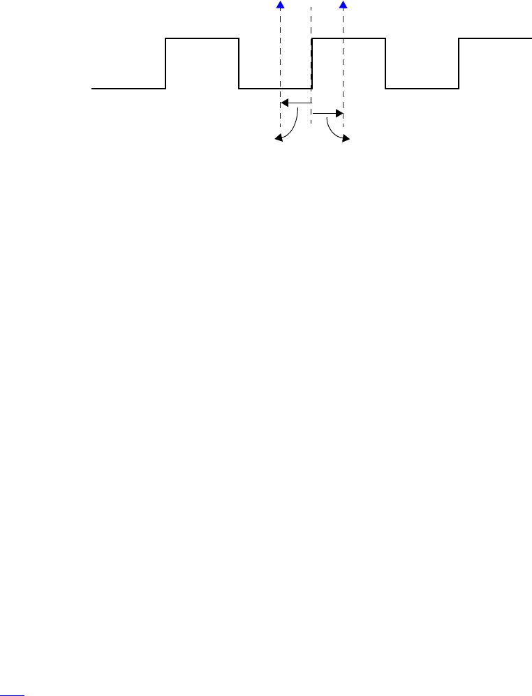
IEEE Std 1800-2012
IEEE STANDARD FOR SYSTEMVERILOG—UNIFIED HARDWARE DESIGN, SPECIFICATION, AND
VERIFICATION LANGUAGE
305
Copyright © 2013 IEEE. All rights reserved.
A skew shall be a constant expression and can be specified as a parameter. If the skew does not specify a
time unit, the current time unit is used. If a number is used, the skew is interpreted using the timescale of the
current scope.
clocking dram @(clk);
input #1ps address;
input #5 output #6 data;
endclocking
An input skew of 1step indicates that the signal is to be sampled at the end of the previous time step. In
other words, the value sampled is always the signal’s last value immediately before the corresponding clock
edge.
NOTE—A clocking block does not eliminate potential races when an event control outside a program block is sensitive
to the same clock as the clocking block and a statement after the event control attempts to read a member of the clocking
block. The race is between reading the old sampled value and the new sampled value.
Inputs with explicit #0 skew shall be sampled at the same time as their corresponding clocking event, but to
avoid races, they are sampled in the Observed region. Likewise, clocking block outputs with no skew (or
explicit #0 skew) shall be driven at the same time as their specified clocking event, in the Re-NBA region.
Skews are declarative constructs; thus, they are semantically very different from the syntactically similar
procedural delay statement. In particular, an explicit #0 skew does not suspend any process, nor does it
execute or sample values in the Inactive region.
14.5 Hierarchical expressions
Any signal in a clocking block can be associated with an arbitrary hierarchical expression. As described in
14.3, a hierarchical expression is introduced by appending an equal sign (=) followed by the hierarchical
expression:
clocking cd1 @(posedge phi1);
input #1step state = top.cpu1.state;
endclocking
However, hierarchical expressions are not limited to simple names or signals in other scopes. They can be
used to declare slices and concatenations (or combinations thereof) of signals in other scopes or in the
current scope.
clocking mem @(clock);
output skew
input skew
clock
signal sampled here signal driven here
Figure 14-1—Sample and drive times including skew
with respect to the positive edge of the clock

IEEE Std 1800-2012
IEEE STANDARD FOR SYSTEMVERILOG—UNIFIED HARDWARE DESIGN, SPECIFICATION, AND
VERIFICATION LANGUAGE
306
Copyright © 2013 IEEE. All rights reserved.
input instruction = { opcode, regA, regB[3:1] };
endclocking
In a clocking block, any expression assigned to a signal in its declaration shall be an expression that would
be legal in a port connection to a port of appropriate direction. Any expression assigned to a signal in a
clocking input or inout declaration shall be an expression that would be legal for connection to a
module’s input port. Any expression assigned to a signal in a clocking output or inout declaration shall
be an expression that would be legal for connection to a module’s output port.
A clocking inout declaration is not an inout port; it is shorthand for two clocking declarations, one input
and one output, with the same signal. Consequently, such a signal must meet the requirements for both a
clocking input and a clocking output, but it is not required to meet the stricter requirements for connection to
a module’s inout port. In particular, it is acceptable to specify a variable as a clocking inout signal.
14.6 Signals in multiple clocking blocks
The same signals—clock, inputs, inouts, or outputs—can appear in more than one clocking block. When
clocking blocks use the same clock (or clocking expression), they shall share the same synchronization
event, in the same manner as several latches can be controlled by the same clock. Input semantics is
described in 14.13, and output semantics is described in 14.16.
14.7 Clocking block scope and lifetime
A clocking block is both a declaration and an instance of that declaration. A separate instantiation step is not
necessary. Instead, one copy is created for each instance of the block containing the declaration (like an
always procedure). Once declared, the clocking signals are available via the clocking block name and the dot
(.) operator:
dom.sig // signal sig in clocking dom
Multiple clocking blocks cannot be nested. They cannot be declared inside functions, tasks, or packages or
outside all declarations in a compilation unit. A clocking block can only be declared inside a module,
interface, checker, or program (see Clause 24).
A clocking block has static lifetime and scope local to its enclosing module, interface, or program.
14.8 Multiple clocking blocks example
In this example, a simple test program includes two clocking blocks. The program construct used in this
example is discussed in Clause 24.
program test( input phi1, input [15:0] data, output logic write,
input phi2, inout [8:1] cmd, input enable
);
reg [8:1] cmd_reg;
clocking cd1 @(posedge phi1);
input data;
output write;
input state = top.cpu1.state;
endclocking
clocking cd2 @(posedge phi2);

IEEE Std 1800-2012
IEEE STANDARD FOR SYSTEMVERILOG—UNIFIED HARDWARE DESIGN, SPECIFICATION, AND
VERIFICATION LANGUAGE
307
Copyright © 2013 IEEE. All rights reserved.
input #2 output #4ps cmd;
input enable;
endclocking
initial begin
// program begins here
...
// user can access cd1.data , cd2.cmd , etc…
end
assign cmd = enable ? cmd_reg: 'x;
endprogram
The test program can be instantiated and connected to a DUT (cpu and mem).
module top;
logic phi1, phi2;
wire [8:1] cmd; // cannot be logic (two bidirectional drivers)
logic [15:0] data;
test main (phi1, data, write, phi2, cmd, enable);
cpu cpu1 (phi1, data, write);
mem mem1 (phi2, cmd, enable);
endmodule
14.9 Interfaces and clocking blocks
A clocking block encapsulates a set of signals that share a common clock; therefore, specifying a clocking
block using a SystemVerilog interface (see Clause 25) can significantly reduce the amount of code
needed to connect the testbench. Furthermore, because the signal directions in the clocking block within the
testbench are with respect to the testbench and not the design under test, a modport declaration (see 25.5)
can appropriately describe either direction. A testbench program can be contained within a program, and its
ports can be interfaces that correspond to the signals declared in each clocking block. The interface’s wires
shall have the same direction as specified in the clocking block when viewed from the testbench side (i.e.,
modport test) and reversed when viewed from the DUT (i.e., modport dut).
For example, the previous example could be rewritten using interfaces as follows:
interface bus_A (input clk);
logic [15:0] data;
logic write;
modport test (input data, output write);
modport dut (output data, input write);
endinterface
interface bus_B (input clk);
logic [8:1] cmd;
logic enable;
modport test (input enable);
modport dut (output enable);
endinterface
program test( bus_A.test a, bus_B.test b );
clocking cd1 @(posedge a.clk);
input data = a.data;
output write = a.write;
inout state = top.cpu.state;

IEEE Std 1800-2012
IEEE STANDARD FOR SYSTEMVERILOG—UNIFIED HARDWARE DESIGN, SPECIFICATION, AND
VERIFICATION LANGUAGE
308
Copyright © 2013 IEEE. All rights reserved.
endclocking
clocking cd2 @(posedge b.clk);
input #2 output #4ps cmd = b.cmd;
input en = b.enable;
endclocking
initial begin
// program begins here
...
// user can access cd1.data, cd1.write, cd1.state,
// cd2.cmd, and cd2.en
end
endprogram
The test module can be instantiated and connected as before:
module top;
logic phi1, phi2;
bus_A a (phi1);
bus_B b (phi2);
test main (a, b);
cpu cpu1 (a);
mem mem1 (b);
endmodule
14.10 Clocking block events
The clocking event of a clocking block is available directly by using the clocking block name, regardless of
the actual clocking event used to declare the clocking block.
For example:
clocking dram @(posedge phi1);
inout data;
output negedge #1 address;
endclocking
The clocking event of the dram clocking block can be used to wait for that particular event:
@(dram);
The preceding statement is equivalent to @(posedge phi1).
14.11 Cycle delay: ##
The ## operator can be used to delay execution by a specified number of clocking events or clock cycles.
The syntax for the cycle delay statement is as follows in Syntax 14-2.
IEEE Std 1800-2012
IEEE STANDARD FOR SYSTEMVERILOG—UNIFIED HARDWARE DESIGN, SPECIFICATION, AND
VERIFICATION LANGUAGE
309
Copyright © 2013 IEEE. All rights reserved.
procedural_timing_control_statement ::= // from A.6.5
procedural_timing_control statement_or_null
procedural_timing_control ::=
...
| cycle_delay
cycle_delay ::= // from A.6.11
## integral_number
|## identifier
|## ( expression )
Syntax 14-2—Cycle delay syntax (excerpt from Annex A)
The expression can be any SystemVerilog expression that evaluates to a positive integer value.
What constitutes a cycle is determined by the default clocking in effect (see 14.12). If no default clocking
has been specified for the current module, interface, checker, or program, then the compiler shall issue an
error.
Example:
##5; // wait 5 cycles (clocking events) using the default clocking
##(j + 1); // wait j+1 cycles (clocking events) using the default clocking
The cycle delay timing control shall wait for the specified number of clocking events. This implies that for a
##1 statement that is executed at a simulation time that is not coincident with the associated clocking event,
the calling process shall be delayed a fraction of the associated clock cycle.
Cycle delays of ##0 are treated specially. If a clocking event has not yet occurred in the current time step, a
##0 cycle delay shall suspend the calling process until the clocking event occurs. When a process executes a
##0 cycle delay and the associated clocking event has already occurred in the current time step, the process
shall continue execution without suspension. When used on the right-hand side of a synchronous drive, a
##0 cycle delay shall have no effect, as if it were not present.
Cycle delay timing controls shall not be legal for use in intra-assignment delays in either blocking or
nonblocking assignment statements.
14.12 Default clocking
One clocking block can be specified as the default for all cycle delay operations within a given module,
interface, program, or checker.
The syntax for default clocking specification statement is as follows in Syntax 14-3.
module_or_generate_item_declaration ::= // from A.1.4
...
|default clocking clocking_identifier ;
...
checker_or_generate_item_declaration ::= // from A.1.8
...

IEEE Std 1800-2012
IEEE STANDARD FOR SYSTEMVERILOG—UNIFIED HARDWARE DESIGN, SPECIFICATION, AND
VERIFICATION LANGUAGE
310
Copyright © 2013 IEEE. All rights reserved.
|default clocking clocking_identifier ;
...
clocking_declaration ::= // from A.6.11
[ default ] clocking [ clocking_identifier ] clocking_event ;
{ clocking_item }
endclocking [ : clocking_identifier ]
...
Syntax 14-3—Default clocking syntax (excerpt from Annex A)
The clocking_identifier shall be the name of a clocking block.
Only one default clocking can be specified in a module, interface, program, or checker. Specifying a default
clocking more than once in the same module, interface, program, or checker shall result in a compiler error.
A default clocking is valid only within the scope containing the default clocking specification statement.
This scope includes the module, interface, program, or checker that contains the declaration as well as any
nested modules, interfaces, or checkers. It does not include instantiated modules, interfaces, or checkers.
Example 1: Declaring a clocking as the default:
program test(input logic clk, input logic [15:0] data);
default clocking bus @(posedge clk);
inout data;
endclocking
initial begin
## 5;
if (bus.data == 10)
## 1;
else
...
end
endprogram
Example 2: Assigning an existing clocking to be the default:
module processor ...
clocking busA @(posedge clk1); ... endclocking
clocking busB @(negedge clk2); ... endclocking
module cpu( interface y );
default clocking busA ;
initial begin
## 5; // use busA => (posedge clk1)
...
end
endmodule
endmodule
14.13 Input sampling
All clocking block inputs (input or inout) are sampled at the corresponding clocking event. If the input skew
is not an explicit #0, then the value sampled corresponds to the signal value at the Postponed region of the
time step skew time units prior to the clocking event (see Figure 14-1 in 14.4). If the input skew is an
explicit #0, then the value sampled corresponds to the signal value in the Observed region. In this case, the
IEEE Std 1800-2012
IEEE STANDARD FOR SYSTEMVERILOG—UNIFIED HARDWARE DESIGN, SPECIFICATION, AND
VERIFICATION LANGUAGE
311
Copyright © 2013 IEEE. All rights reserved.
newly sampled values shall be available for reading at the end of the Observed region processing. If upon
processing the Reactive region, the simulation must process Active events without advancing time (thereby
executing the Observed region more than once), clocking inputs sampled with #0 skew shall not be
resampled unless a new clocking event occurs in the active region set.
NOTE—When the clocking event is triggered by the execution of a program, there is a potential race between the update
of a clocking block input value and programs that read that value without synchronizing with the corresponding clocking
event. This race does not exist when the clocking block event is triggered from within a module.
Upon processing its specified clocking event, a clocking block shall update its sampled values before
triggering the event associated with the clocking block name. This event shall be triggered in the Observed
region. Thus, a process that waits for the clocking block itself is guaranteed to read the updated sampled
values, regardless of the scheduling region in which either the waiting or the triggering processes execute.
For example:
clocking cb @(negedge clk);
input v;
endclocking
always @(cb) $display(cb.v);
always @(negedge clk) $display(cb.v);
The first always procedure above is guaranteed to display the updated sampled value of signal v. In
contrast, the second always exhibits a potential race and may display the old or the newly updated sampled
value.
When an input or inout clockvar appears in any expression its value is the signal’s sampled value; that is,
the value that the clocking block sampled at the most recent clocking event.
When the same signal is an input to multiple clocking blocks, the semantics is straightforward; each
clocking block samples the corresponding signal with its own clocking event.
14.14 Global clocking
A clocking block may be declared as the global clocking for all or part of the design hierarchy. The main
purpose of global clocking is to specify which clocking event in simulation corresponds to the primary
system clock used in formal verification (see F.3.1). Such a specification may be done for a whole design, or
separately for different subsystems in a design, when there are multiple clocks and building a single global
clocking event is challenging.
The syntax for the global clocking declaration is as follows in Syntax 14-4.
clocking_declaration ::= // from A.6.11
...
|global clocking [ clocking_identifier ] clocking_event ; endclocking [ : clocking_identifier ]
Syntax 14-4—Global clocking syntax (excerpt from Annex A)
Global clocking may be declared in a module, an interface, a checker, or a program. A given module,
interface, checker, or program shall contain at most one global clocking declaration. Global clocking shall
not be declared in a generate block.

IEEE Std 1800-2012
IEEE STANDARD FOR SYSTEMVERILOG—UNIFIED HARDWARE DESIGN, SPECIFICATION, AND
VERIFICATION LANGUAGE
312
Copyright © 2013 IEEE. All rights reserved.
Although more than one global clocking declaration may appear in different parts of the design hierarchy, at
most one global clocking declaration is effective at each point in the elaborated design hierarchy. The
$global_clock system function shall be used to explicitly refer to the event expression in the effective
global clocking declaration. The effective global clocking declaration for a specific reference is determined
using the following hierarchical lookup rules, which iteratively check the design hierarchy to find the global
clocking declaration closest to the point of reference.
a) Look for a global clocking declaration in the enclosing module, interface, checker, or program
instance scope. If found, the lookup terminates with the result being the event expression of that
global clocking declaration. If not found and the current scope is a top-level hierarchy block (see
3.11), the lookup terminates and shall result in an error. Otherwise, proceed to step b).
b) Look for a global clocking declaration in the parent module, interface, or checker instance scope of
the enclosing instantiation. If found, the lookup terminates with the result being the event expression
of that global clocking declaration. Otherwise, continue up the hierarchy until a global clocking dec-
laration is found or a top-level hierarchy block is reached. If no global clocking declaration is found
and a top-level hierarchy block is reached, the lookup terminates and shall result in an error.
When global clocking is referenced in a sequence declaration, a property declaration, or as an actual
argument to a named sequence instance, a named property instance, or a checker instance, the point of
reference shall be considered after the application of the rewriting algorithm defined in F.4.1. As a result,
when a property or a sequence declaration is instantiated in an assertion statement, the hierarchical lookup
rules described above shall be applied from the point of the assertion statement appearance in the source
description, not from the point of the sequence or the property declaration. Similarly, the lookup rules shall
be applied after the substitution of the actual argument in place of the corresponding formal argument inside
the checker body.
The following is an example of a global clocking declaration:
module top;
logic clk1, clk2;
global clocking sys @(clk1 or clk2); endclocking
// ...
endmodule
In this example, sys is declared as the global clocking event and is defined to occur if, and only if, there is a
change of either of two signals, clk1 and clk2. Specification of the name sys in the global clocking
declaration is optional since the global clocking event may be referenced by $global_clock .
In the following example the design hierarchy contains two global clocking declarations. The call to
$global_clock in top.sub1.common resolves to the clocking event top.sub1.sub_sys1. The call to
$global_clock in top.sub2.common resolves to the clocking event top.sub2.sub_sys2.
module top;
subsystem1 sub1();
subsystem2 sub2();
endmodule
module subsystem1;
logic subclk1;
global clocking sub_sys1 @(subclk1); endclocking
// ...
common_sub common();
endmodule
module subsystem2;
logic subclk2;
IEEE Std 1800-2012
IEEE STANDARD FOR SYSTEMVERILOG—UNIFIED HARDWARE DESIGN, SPECIFICATION, AND
VERIFICATION LANGUAGE
313
Copyright © 2013 IEEE. All rights reserved.
global clocking sub_sys2 @(subclk2); endclocking
// ...
common_sub common();
endmodule
module common_sub;
always @($global_clock) begin
// ...
end
endmodule
In the following example the property p is declared in a module containing a global clocking declaration.
However, that global clocking declaration is not effective where the property p is instantiated. Similar to the
previous example, the call to $global_clock in top.sub1.checks resolves to the clocking event
top.sub1.sub_sys1, and the call to $global_clock in top.sub2.checks resolves to the clocking
event top.sub2.sub_sys2.
module top;
subsystem1 sub1();
subsystem2 sub2();
endmodule
module subsystem1;
logic subclk1, req, ack;
global clocking sub_sys1 @(subclk1); endclocking
// ...
common_checks checks(req, ack);
endmodule
module subsystem2;
logic subclk2, req, ack;
global clocking sub_sys2 @(subclk2); endclocking
// ...
common_checks checks(req, ack);
endmodule
module another_module;
logic another_clk;
global clocking another_clocking @(another_clock); endclocking
// ...
property p(req, ack);
@($global_clock) req |=> ack;
endproperty
endmodule
checker common_checks(logic req, logic ack);
assert property another_module.p(req, ack);
endchecker
In the following example, $global_clock is used in a task. The call to $global_clock in the task
another_module.t resolves to the clocking event another_module.another_clocking.
module top;
subsystem1 sub1();
subsystem2 sub2();
endmodule
module subsystem1;
IEEE Std 1800-2012
IEEE STANDARD FOR SYSTEMVERILOG—UNIFIED HARDWARE DESIGN, SPECIFICATION, AND
VERIFICATION LANGUAGE
314
Copyright © 2013 IEEE. All rights reserved.
logic subclk1, req, ack;
global clocking sub_sys1 @(subclk1); endclocking
// ...
always another_module.t(req, ack);
endmodule
module subsystem2;
logic subclk2, req, ack;
global clocking sub_sys2 @(subclk2); endclocking
// ...
always another_module.t(req, ack);
endmodule
module another_module;
logic another_clk;
global clocking another_clocking @(another_clk); endclocking
task t(input req, input ack);
@($global_clock);
// ...
endtask
endmodule
The following example demonstrates the usage of $global_clock in checker arguments. The resolution of
the calls to $global_clock is performed after the substitution of the actual checker arguments in place of
the corresponding formal arguments, and flattening of the properties in the assertion statements. All calls to
$global_clock in this example refer to the clocking event top.check.checker_clocking.
module top;
logic a, b, c, clk;
global clocking top_clocking @(clk); endclocking
// ...
property p1(req, ack);
@($global_clock) req |=> ack;
endproperty
property p2(req, ack, interrupt);
@($global_clock) accept_on(interrupt) p1(req, ack);
endproperty
my_checker check(
p2(a, b, c),
@$global_clock a[*1:$] ##1 b);
endmodule
checker my_checker(property p, sequence s);
logic checker_clk;
global clocking checker_clocking @(checker_clk); endclocking
// ...
assert property (p);
cover property (s);
endchecker
NOTE—This is an area of backward incompatibility between this standard and 14.14 of IEEE Std 1800-2009. In the
2009 definition, only one global clocking declaration was allowed in the elaborated design description; it could be
specified in any module, interface, or checker and referenced everywhere in the description. A design conforming to
IEEE Std 1800-2009 could have a global clocking declaration defined in a non-top-level module and use
$global_clock outside the subhierarchy of that module. Such a design shall not conform to this standard.

IEEE Std 1800-2012
IEEE STANDARD FOR SYSTEMVERILOG—UNIFIED HARDWARE DESIGN, SPECIFICATION, AND
VERIFICATION LANGUAGE
315
Copyright © 2013 IEEE. All rights reserved.
14.15 Synchronous events
Explicit synchronization is done via the event control operator, @, which allows a process to wait for a
particular signal value change or a clocking event (see 14.10).
The syntax for the synchronization operator is given in 9.4.2.
The expression used with the event control can denote clocking block input (input or inout) or a slice
thereof. Slices can include dynamic indices, which are evaluated once when the @ expression executes.
Following are some examples of synchronization statements:
— Wait for the next change of signal ack_1 of clocking block ram_bus
@(ram_bus.ack_l);
— Wait for the next clocking event in clocking block ram_bus
@(ram_bus);
— Wait for the positive edge of the signal ram_bus.enable
@(posedge ram_bus.enable);
— Wait for the falling edge of the specified 1-bit slice dom.sign[a]
@(negedge dom.sign[a]);
NOTE—The index a is evaluated at run time.
— Wait for either the next positive edge of dom.sig1 or the next change of dom.sig2, whichever
happens first
@(posedge dom.sig1 or dom.sig2);
— Wait for either the negative edge of dom.sig1 or the positive edge of dom.sig2, whichever hap-
pens first
@(negedge dom.sig1 or posedge dom.sig2);
— Wait for the edge (either the negative edge or the positive edge, whichever happens first) of
dom.sig1.
@(edge dom.sig1);
Or equivalently
@(negedge dom.sig1 or posedge dom.sig1);
The values used by the synchronization event control are the synchronous values, that is, the values sampled
at the corresponding clocking event.
14.16 Synchronous drives
Clocking block outputs (output or inout) are used to drive values onto their corresponding signals, but at
a specified time. In other words, the corresponding signal changes value at the indicated clocking event as
modified by the output skew.
For zero skew clocking block outputs with no cycle delay, synchronous drives shall schedule new values in
the Re-NBA region of the time step corresponding to the clocking event. For clocking block outputs with
IEEE Std 1800-2012
IEEE STANDARD FOR SYSTEMVERILOG—UNIFIED HARDWARE DESIGN, SPECIFICATION, AND
VERIFICATION LANGUAGE
316
Copyright © 2013 IEEE. All rights reserved.
nonzero skew, or drives with nonzero cycle delay, the corresponding signal shall be scheduled to change
value in the Re-NBA region of a future time step.
For each clocking block output whose target is a net, a driver on that net shall be created. The driver so
created shall have (strong1, strong0) drive strength and shall be updated as if by a continuous
assignment from a variable inside the clocking block. This implicit variable, which is invisible to user code,
shall be updated in the Re-NBA region by the execution of a synchronous drive to the corresponding
clockvar. The created driver shall be initialized to 'z; hence, the driver has no influence on its target net
until a synchronous drive is performed to the corresponding clockvar.
The syntax to specify a synchronous drive is similar to an assignment and is shown in Syntax 14-5.
statement ::= [ block_identifier : ] { attribute_instance } statement_item // from A.6.4
statement_item ::=
...
| clocking_drive ;
clocking_drive ::= // from A.6.11
clockvar_expression <= [ cycle_delay ] expression
cycle_delay ::= ## expression
clockvar ::= hierarchical_identifier
clockvar_expression ::= clockvar select
Syntax 14-5—Synchronous drive syntax (excerpt from Annex A)
The clockvar_expression is a bit-select, slice, or the entire clocking block output whose corresponding
signal is to be driven (concatenation is not allowed):
dom.sig // entire clockvar
dom.sig[2] // bit-select
dom.sig[8:2] // slice
The expression (in the clocking_drive production) can be any valid expression that is assignment compatible
with the type of the corresponding signal.
The optional cycle_delay construct, appearing on the right-hand side of a clocking_drive statement, is
syntactically similar to an intra-assignment delay in a nonblocking assignment. Like a nonblocking intra-
assignment delay, it shall not cause execution of the statement to block. The right-hand side expression shall
be evaluated immediately even when a cycle_delay is present. However, updating of the target signal shall
be postponed for the specified number of cycles of the target clockvar’s clocking block, plus any clocking
output skew specified for that clockvar.
No other form of intra-assignment delay syntax shall be legal in a synchronous drive to a clockvar.
A procedural cycle delay, as described in 14.11, can be used as a prefix to any procedural statement. If a
procedural cycle delay is used as a prefix to a synchronous drive, it shall block for its specified number of
cycles of the default clocking exactly as it would if used as a prefix to any other procedural statement.
IEEE Std 1800-2012
IEEE STANDARD FOR SYSTEMVERILOG—UNIFIED HARDWARE DESIGN, SPECIFICATION, AND
VERIFICATION LANGUAGE
317
Copyright © 2013 IEEE. All rights reserved.
Examples:
bus.data[3:0] <= 4'h5; // drive data in Re-NBA region of the current cycle
##1 bus.data <= 8'hz; // wait 1 default clocking cycle, then drive data
##2; bus.data <= 2; // wait 2 default clocking cycles, then drive data
bus.data <= ##2 r; // remember the value of r and then drive
// data 2 (bus) cycles later
bus.data <= #4 r; // error: regular intra-assignment delay not allowed
// in synchronous drives
Regardless of whether the synchronous drive takes effect on the current clocking event or at some future
clocking event as a result of a cycle_delay, the corresponding signal shall be updated at a time after that
clocking event as specified by the output skew.
It is possible for a drive statement to execute at a time that is not coincident with its clocking event. Such
drive statements shall execute without blocking, but shall perform their drive action as if they had executed
at the time of the next clocking event. The expression on the right-hand side of the drive statement shall be
evaluated immediately, but the processing of the drive is delayed until the time of the next clocking event.
For example:
default clocking cb @(posedge clk); // Assume clk has a period of #10 units
output v;
endclocking
initial begin
#3 cb.v <= expr1; // Matures in cycle 1; equivalent to ##1 cb.v <= expr1
end
It shall be an error to write to a clockvar except by using the synchronous drive syntax described in this
subclause. Thus, it is illegal to use any continuous assignment, force statement, or procedural continuous
assignment to write to a clockvar.
14.16.1 Drives and nonblocking assignments
Although synchronous drives use the same operator syntax as nonblocking variable assignments, they are
not the same. One difference is that synchronous drives do not support intra-assignment delay syntax. A key
feature of synchronous drives to inout clockvars is that a drive does not change the clocking block input.
This is because reading the input always yields the last sampled value, and not the driven value.
For example, consider the following code:
clocking cb @(posedge clk);
inout a;
output b;
endclocking
initial begin
cb.a <= c; // The value of a will change in the Re-NBA region
cb.b <= cb.a; // b is assigned the value of a before the change
end

IEEE Std 1800-2012
IEEE STANDARD FOR SYSTEMVERILOG—UNIFIED HARDWARE DESIGN, SPECIFICATION, AND
VERIFICATION LANGUAGE
318
Copyright © 2013 IEEE. All rights reserved.
14.16.2 Driving clocking output signals
When more than one synchronous drive on the same clocking block output (or inout) is scheduled to mature
in the same Re-NBA region of the same time step, the last value is the only value driven onto the output
signal. This is true whether the synchronous drives execute at times coincident with clocking events, or at
times in between clocking events (within the same clock cycle).
For example:
default clocking pe @(posedge clk);
output nibble; // four bit output
endclocking
initial begin
##2;
pe.nibble <= 4'b0101;
pe.nibble <= 4'b0011;
end
The driven value of nibble is 4'b0011, regardless of whether nibble is a variable or a net.
It is possible for the scheduling loop described in 4.4 to iterate through the Re-NBA region more than once
in a given time step. If this happens, synchronous drives will cause their associated clocking signal to glitch
(i.e., change value more than once in a time step) if they assign different values to their associated clockvar
in different iterations of the scheduling loop.
In the following example, variable a will glitch 1 –> 0 –> 1 at the first posedge of clk.
module m;
bit a = 1'b1;
default clocking cb @(posedge clk);
output a;
endclocking
initial begin
## 1;
cb.a <= 1'b0;
@(x); // x is triggered by reactive stimulus running in same time step
cb.a <= 1'b1;
end
endmodule
If a given clocking output is driven by multiple synchronous drives that are scheduled to mature at different
future times due to the use of cycle delay, the drives shall each mature in their corresponding future cycles.
For example:
bit v;
default clocking cb @(posedge clk);
output v;
endclocking
initial begin
##1; // Wait until cycle 1
cb.v <= expr1; // Matures in cycle 1, v is assigned expr1
cb.v <= ##2 expr2; // Matures in cycle 3
#1 cb.v <= ##2 expr3; // Matures in cycle 3

IEEE Std 1800-2012
IEEE STANDARD FOR SYSTEMVERILOG—UNIFIED HARDWARE DESIGN, SPECIFICATION, AND
VERIFICATION LANGUAGE
319
Copyright © 2013 IEEE. All rights reserved.
##1 cb.v <= ##1 expr4; // Matures in cycle 3, v is assigned expr4
end
When the same variable is an output from multiple clocking blocks, the last drive determines the value of the
variable. This allows a single module to model multirate devices, such as a DDR memory, using a different
clocking block to model each active edge. For example:
reg j;
clocking pe @(posedge clk);
output j;
endclocking
clocking ne @(negedge clk);
output j;
endclocking
The variable j is an output from two clocking blocks using different clocking events, @(posedge clk)
versus @(negedge clk). When driven, the variable j shall take on the value most recently assigned by
either clocking block. A clocking block output only assigns a value to its associated signal in clock cycles
where a synchronous drive occurs.
With the edge event, this is equivalent to the following simplified declaration:
reg j;
clocking e @(edge clk);
output j;
endclocking
Multiple clocking block outputs driving a net cause the net to be driven to its resolved signal value. As
described in 14.16, when a clocking block output corresponds to a net, a driver on that net is created. This
semantic model applies to each clocking block output that drives the net. The driving values of all these
driver(s), together with any other drivers on the net, shall be resolved as determined by the net’s type.
It is possible to use a procedural assignment to assign to a signal associated with an output clockvar. When
the associated signal is a variable, the procedural assignment assigns a new value to the variable, and the
variable shall hold that value until another assignment occurs (either from a drive to a clocking block output
or another procedural assignment).
If a synchronous drive and a procedural nonblocking assignment write to the same variable in the same time
step, the writes shall take place in an arbitrary order.
It shall be illegal to write to a variable with a continuous assignment, a procedural continuous assignment, or
a primitive when that variable is associated with an output clockvar.

IEEE Std 1800-2012
IEEE STANDARD FOR SYSTEMVERILOG—UNIFIED HARDWARE DESIGN, SPECIFICATION, AND
VERIFICATION LANGUAGE
320
Copyright © 2013 IEEE. All rights reserved.
15. Interprocess synchronization and communication
15.1 General
This clause describes the following:
— Semaphores
— Mailboxes
— Named events
15.2 Overview
High-level and easy-to-use synchronization and communication mechanisms are essential to control the
kinds of interactions that occur between dynamic processes used to model a complex system or a highly
reactive testbench.
The basic synchronization mechanism is the named event type, along with the event trigger and event
control constructs (i.e., -> and @). This type of control is limited to static objects. It is adequate for
synchronization at the hardware level and simple system level, but falls short of the needs of a highly
dynamic, reactive testbench.
SystemVerilog also provides a powerful and easy-to-use set of synchronization and communication
mechanisms that can be created and reclaimed dynamically. This set comprises of a semaphore built-in
class, which can be used for synchronization and mutual exclusion to shared resources, and a mailbox built-
in class, which can be used as a communication channel between processes.
Semaphores and mailboxes are built-in types; nonetheless, they are classes and can be used as base classes
for deriving additional higher level classes. These built-in classes reside in the built-in std package (see
26.7); thus, they can be redefined by user code in any other scope.
15.3 Semaphores
Conceptually, a semaphore is a bucket. When a semaphore is allocated, a bucket that contains a fixed
number of keys is created. Processes using semaphores must first procure a key from the bucket before they
can continue to execute. If a specific process requires a key, only a fixed number of occurrences of that
process can be in progress simultaneously. All others must wait until a sufficient number of keys is returned
to the bucket. Semaphores are typically used for mutual exclusion, access control to shared resources, and
basic synchronization.
An example of creating a semaphore is as follows:
semaphore smTx;
Semaphore is a built-in class that provides the following methods:
— Create a semaphore with a specified number of keys: new()
— Obtain one or more keys from the bucket: get()
— Return one or more keys into the bucket: put()
— Try to obtain one or more keys without blocking: try_get()
IEEE Std 1800-2012
IEEE STANDARD FOR SYSTEMVERILOG—UNIFIED HARDWARE DESIGN, SPECIFICATION, AND
VERIFICATION LANGUAGE
321
Copyright © 2013 IEEE. All rights reserved.
15.3.1 New()
Semaphores are created with the new() method.
The prototype for new() is as follows:
function new(int keyCount = 0 );
The keyCount specifies the number of keys initially allocated to the semaphore bucket. The number of keys
in the bucket can increase beyond keyCount when more keys are put into the semaphore than are removed.
The default value for keyCount is 0.
The new() function returns the semaphore handle.
15.3.2 Put()
The semaphore put() method is used to return keys to a semaphore.
The prototype for put() is as follows:
function void put(int keyCount = 1);
The keyCount specifies the number of keys being returned to the semaphore. The default is 1.
When the semaphore.put() function is called, the specified number of keys is returned to the semaphore.
If a process has been suspended waiting for a key, that process shall execute if enough keys have been
returned.
15.3.3 Get()
The semaphore get() method is used to procure a specified number of keys from a semaphore.
The prototype for get() is as follows:
task get(int keyCount = 1);
The keyCount specifies the required number of keys to obtain from the semaphore. The default is 1.
If the specified number of keys is available, the method returns and execution continues. If the specified
number of keys is not available, the process blocks until the keys become available.
The semaphore waiting queue is first-in first-out (FIFO). This does not guarantee the order in which
processes arrive at the queue, only that their arrival order shall be preserved by the semaphore.
15.3.4 Try_get()
The semaphore try_get() method is used to procure a specified number of keys from a semaphore, but
without blocking.
The prototype for try_get() is as follows:
function int try_get(int keyCount = 1);
The keyCount specifies the required number of keys to obtain from the semaphore. The default is 1.
IEEE Std 1800-2012
IEEE STANDARD FOR SYSTEMVERILOG—UNIFIED HARDWARE DESIGN, SPECIFICATION, AND
VERIFICATION LANGUAGE
322
Copyright © 2013 IEEE. All rights reserved.
If the specified number of keys is available, the method returns a positive integer and execution continues. If
the specified number of keys is not available, the method returns 0.
15.4 Mailboxes
A mailbox is a communication mechanism that allows messages to be exchanged between processes. Data
can be sent to a mailbox by one process and retrieved by another.
Conceptually, mailboxes behave like real mailboxes. When a letter is delivered and put into the mailbox, a
person can retrieve the letter (and any data stored within). However, if the letter has not been delivered when
the mailbox is checked, the person must choose whether to wait for the letter or to retrieve the letter on a
subsequent trip to the mailbox. Similarly, SystemVerilog’s mailboxes provide processes to transfer and
retrieve data in a controlled manner. Mailboxes are created as having either a bounded or unbounded queue
size. A bounded mailbox becomes full when it contains the bounded number of messages. A process that
attempts to place a message into a full mailbox shall be suspended until enough room becomes available in
the mailbox queue. Unbounded mailboxes never suspend a thread in a send operation.
An example of creating a mailbox is as follows:
mailbox mbxRcv;
Mailbox is a built-in class that provides the following methods:
— Create a mailbox: new()
— Place a message in a mailbox: put()
— Try to place a message in a mailbox without blocking: try_put()
— Retrieve a message from a mailbox: get() or peek()
— Try to retrieve a message from a mailbox without blocking: try_get() or try_peek()
— Retrieve the number of messages in the mailbox: num()
15.4.1 New()
Mailboxes are created with the new() method.
The prototype for mailbox new() is as follows:
function new(int bound = 0);
The new() function returns the mailbox handle. If the bound argument is 0, then the mailbox is unbounded
(the default) and a put() operation shall never block. If bound is nonzero, it represents the size of the
mailbox queue.
The bound shall be positive. Negative bounds are illegal and can result in indeterminate behavior, but
implementations can issue a warning.
15.4.2 Num()
The number of messages in a mailbox can be obtained via the num() method.
The prototype for num() is as follows:
function int num();

IEEE Std 1800-2012
IEEE STANDARD FOR SYSTEMVERILOG—UNIFIED HARDWARE DESIGN, SPECIFICATION, AND
VERIFICATION LANGUAGE
323
Copyright © 2013 IEEE. All rights reserved.
The num() method returns the number of messages currently in the mailbox.
The returned value should be used with care because it is valid only until the next get() or put() is
executed on the mailbox. These mailbox operations can be from different processes from the one executing
the num() method. Therefore, the validity of the returned value depends on the time that the other methods
start and finish.
15.4.3 Put()
The put() method places a message in a mailbox.
The prototype for put() is as follows:
task put( singular message);
The message is any singular expression, including object handles.
The put() method stores a message in the mailbox in strict FIFO order. If the mailbox was created with a
bounded queue, the process shall be suspended until there is enough room in the queue.
15.4.4 Try_put()
The try_put() method attempts to place a message in a mailbox.
The prototype for try_put() is as follows:
function int try_put( singular message);
The message is any singular expression, including object handles.
The try_put() method stores a message in the mailbox in strict FIFO order. This method is meaningful
only for bounded mailboxes. If the mailbox is not full, then the specified message is placed in the mailbox,
and the function returns a positive integer. If the mailbox is full, the method returns 0.
15.4.5 Get()
The get() method retrieves a message from a mailbox.
The prototype for get() is as follows:
task get( ref singular message );
The message can be any singular expression, and it shall be a valid left-hand expression.
The get() method retrieves one message from the mailbox, that is, removes one message from the mailbox
queue. If the mailbox is empty, then the current process blocks until a message is placed in the mailbox. If
the type of the message variable is not equivalent to the type of the message in the mailbox, a run-time error
is generated.
Nonparameterized mailboxes are typeless (see 15.4.9), that is, a single mailbox can send and receive
different types of data. Thus, in addition to the data being sent (i.e., the message queue), a mailbox
implementation shall maintain the message data type placed by put(). This is required in order to enable
the run-time type checking.
IEEE Std 1800-2012
IEEE STANDARD FOR SYSTEMVERILOG—UNIFIED HARDWARE DESIGN, SPECIFICATION, AND
VERIFICATION LANGUAGE
324
Copyright © 2013 IEEE. All rights reserved.
The mailbox waiting queue is FIFO. This does not guarantee the order in which processes arrive at the
queue, only that their arrival order shall be preserved by the mailbox.
15.4.6 Try_get()
The try_get() method attempts to retrieves a message from a mailbox without blocking.
The prototype for try_get() is as follows:
function int try_get( ref singular message );
The message can be any singular expression, and it shall be a valid left-hand expression.
The try_get() method tries to retrieve one message from the mailbox. If the mailbox is empty, then the
method returns 0. If the type of the message variable is not equivalent to the type of the message in the
mailbox, the method returns a negative integer. If a message is available and the message type is equivalent
to the type of the message variable, the message is retrieved, and the method returns a positive integer.
15.4.7 Peek()
The peek() method copies a message from a mailbox without removing the message from the queue.
The prototype for peek() is as follows:
task peek( ref singular message );
The message can be any singular expression, and it shall be a valid left-hand expression.
The peek() method copies one message from the mailbox without removing the message from the mailbox
queue. If the mailbox is empty, then the current process blocks until a message is placed in the mailbox. If
the type of the message variable is not equivalent to the type of the message in the mailbox, a run-time error
is generated.
Calling the peek() method can also cause one message to unblock more than one process. As long as a
message remains in the mailbox queue, any process blocked in either a peek() or get() operation shall
become unblocked.
15.4.8 Try_peek()
The try_peek() method attempts to copy a message from a mailbox without blocking.
The prototype for try_peek() is as follows:
function int try_peek( ref singular message );
The message can be any singular expression, and it shall be a valid left-hand expression.
The try_peek() method tries to copy one message from the mailbox without removing the message from
the mailbox queue. If the mailbox is empty, then the method returns 0. If the type of the message variable is
not equivalent to the type of the message in the mailbox, the method returns a negative integer. If a message
is available and its type is equivalent to the type of the message variable, the message is copied, and the
method returns a positive integer.

IEEE Std 1800-2012
IEEE STANDARD FOR SYSTEMVERILOG—UNIFIED HARDWARE DESIGN, SPECIFICATION, AND
VERIFICATION LANGUAGE
325
Copyright © 2013 IEEE. All rights reserved.
15.4.9 Parameterized mailboxes
The default mailbox is typeless, that is, a single mailbox can send and receive any type of data. This is a very
powerful mechanism, which, unfortunately, can also result in run-time errors due to type mismatches (types
not equivalent) between a message and the type of the variable used to retrieve the message. Frequently, a
mailbox is used to transfer a particular message type, and, in that case, it is useful to detect type mismatches
at compile time.
Parameterized mailboxes use the same parameter mechanism as parameterized classes (see 8.25), modules,
and interfaces:
mailbox #(type = dynamic_type)
where dynamic_type represents a special type that enables run-time type checking (the default).
A parameterized mailbox of a specific type is declared by specifying the type:
typedef mailbox #(string) s_mbox;
s_mbox sm = new;
string s;
sm.put( "hello" );
...
sm.get( s ); // s <- "hello"
Parameterized mailboxes provide all the same standard methods as dynamic mailboxes: num(), new(),
get(), peek(), put(), try_get(), try_peek(), try_put().
The only difference between a generic (dynamic) mailbox and a parameterized mailbox is that for a
parameterized mailbox, the compiler verifies that the calls to put, try_put, peek, try_peek, get, and
try_get methods use argument types equivalent to the mailbox type so that all type mismatches are caught
by the compiler and not at run time.
15.5 Named events
An identifier declared as an event data type is called a named event. A named event can be triggered
explicitly. It can be used in an event expression to control the execution of procedural statements in the same
manner as event controls described in 9.4.2. A named event may also be used as a handle assigned from
another named event.
A named event provides a handle to an underlying synchronization object. When a process waits for an
event to be triggered, the process is put on a queue maintained within the synchronization object. Processes
can wait for a named event to be triggered either via the @ operator or by the use of the wait() construct to
examine their triggered state.
15.5.1 Triggering an event
An event is made to occur by the activation of an event triggering statement with the syntax given in
Syntax 15-1.
IEEE Std 1800-2012
IEEE STANDARD FOR SYSTEMVERILOG—UNIFIED HARDWARE DESIGN, SPECIFICATION, AND
VERIFICATION LANGUAGE
326
Copyright © 2013 IEEE. All rights reserved.
event_trigger ::= // from A.6.5
-> hierarchical_event_identifier ;
|->> [ delay_or_event_control ] hierarchical_event_identifier ;
Syntax 15-1—Event trigger syntax (excerpt from Annex A)
An event is not made to occur by changing the index of a named event array in an event control expression.
Named events triggered via the -> operator unblock all processes currently waiting on that event. When
triggered, named events behave like a one shot, i.e., the trigger state itself is not observable, only its effect.
This is similar to the way in which an edge can trigger a flip-flop, but the state of the edge cannot be
ascertained, i.e., if (posedge clock) is illegal.
Nonblocking events are triggered using the ->> operator. The effect of the ->> operator is that the statement
executes without blocking, and it creates a nonblocking assign update event in the time in which the delay
control expires or the event control occurs. The effect of this update event shall be to trigger the referenced
event in the nonblocking assignment region of the simulation cycle.
15.5.2 Waiting for an event
The basic mechanism to wait for an event to be triggered is via the event control operator, @.
@ hierarchical_event_identifier;
The @ operator blocks the calling process until the given event is triggered.
For a trigger to unblock a process waiting on an event, the waiting process shall execute the @ statement
before the triggering process executes the trigger operator, ->. If the trigger executes first, then the waiting
process remains blocked.
15.5.3 Persistent trigger: triggered property
SystemVerilog can distinguish the event trigger itself, which is instantaneous, from the event’s triggered
state, which persists throughout the time step (i.e., until simulation time advances). The triggered event
property allows users to examine this state.
The triggered property is invoked using a method-like syntax:
hierarchical_event_identifier.triggered
The triggered event property evaluates to true (1'b1) if the given event has been triggered in the current
time step and false (1'b0) otherwise. If event_identifier is null, then the triggered event property
evaluates to false.
The triggered event property is most useful when used in the context of a wait construct:
wait ( hierarchical_event_identifier.triggered )
Using this mechanism, an event trigger shall unblock the waiting process whether the wait executes before
or at the same simulation time as the trigger operation. The triggered event property, thus, helps eliminate
a common race condition that occurs when both the trigger and the wait happen at the same time. A process
that blocks waiting for an event might or might not unblock, depending on the execution order of the waiting
IEEE Std 1800-2012
IEEE STANDARD FOR SYSTEMVERILOG—UNIFIED HARDWARE DESIGN, SPECIFICATION, AND
VERIFICATION LANGUAGE
327
Copyright © 2013 IEEE. All rights reserved.
and triggering processes. However, a process that waits on the triggered state always unblocks, regardless of
the order of execution of the wait and trigger operations.
Example:
event done, blast; // declare two new events
event done_too = done; // declare done_too as alias to done
task trigger( event ev );
-> ev;
endtask
...
fork
@ done_too; // wait for done through done_too
#1 trigger( done ); // trigger done through task trigger
join
fork
-> blast;
wait ( blast.triggered );
join
The first fork in the example shows how two event identifiers, done and done_too, refer to the same
synchronization object and also how an event can be passed to a generic task that triggers the event. In the
example, one process waits for the event via done_too, while the actual triggering is done via the trigger
task that is passed done as an argument.
In the second fork, one process can trigger the event blast before the other process (if the processes in the
fork…join execute in source order) has a chance to execute, and wait for the event. Nonetheless, the
second process unblocks and the fork terminates. This is because the process waits for the event’s triggered
state, which remains in its triggered state for the duration of the time step.
15.5.4 Event sequencing: wait_order()
The wait_order construct suspends the calling process until all of the specified events are triggered in the
given order (left to right) or any of the untriggered events are triggered out of order and thus causes the
operation to fail.
The syntax for the wait_order construct is as follows in Syntax 15-2.
wait_statement ::= // from A.6.5
...
|wait_order ( hierarchical_identifier { , hierarchical_identifier } ) action_block
action_block ::=
statement _or_null
| [ statement ] else statement
Syntax 15-2—Wait_order event sequencing syntax (excerpt from Annex A)
For wait_order to succeed, at any point in the sequence, the subsequent events, which shall all be
untriggered at this point or the sequence would have already failed, shall be triggered in the prescribed order.
IEEE Std 1800-2012
IEEE STANDARD FOR SYSTEMVERILOG—UNIFIED HARDWARE DESIGN, SPECIFICATION, AND
VERIFICATION LANGUAGE
328
Copyright © 2013 IEEE. All rights reserved.
Preceding events are not limited to occur only once. In other words, once an event occurs in the prescribed
order, it can be triggered again without causing the construct to fail.
Only the first event in the list can wait for the persistent triggered property.
The action taken when the construct fails depends on whether the optional action_block else statement (the
fail statement) is specified. If it is specified, then the given statement is executed upon failure of the
construct. If the fail statement is not specified, a failure generates a run-time error.
For example:
wait_order( a, b, c);
suspends the current process until events a, b, and c trigger in the order a –> b –> c. If the events trigger
out of order, a run-time error is generated.
For example:
wait_order( a, b, c ) else $display( "Error: events out of order" );
In this example, the fail statement specifies that, upon failure of the construct, a user message be displayed,
but without an error being generated.
For example:
bit success;
wait_order( a, b, c ) success = 1; else success = 0;
In this example, the completion status is stored in the variable success, without an error being generated.
15.5.5 Operations on named event variables
An event is a unique data type with several important properties. Named events can be assigned to one
another. When one event is assigned to another, the synchronization queue of the source event is shared by
both the source and the destination event. In this sense, events act as full-fledged variables and not merely as
labels.
15.5.5.1 Merging events
When one event variable is assigned to another, the two become merged. Thus, executing -> on either event
variable affects processes waiting on either event variable.
For example:
event a, b, c;
a = b;
-> c;
-> a; // also triggers b
-> b; // also triggers a
a = c;
b = a;
-> a; // also triggers b and c
-> b; // also triggers a and c
-> c; // also triggers a and b
IEEE Std 1800-2012
IEEE STANDARD FOR SYSTEMVERILOG—UNIFIED HARDWARE DESIGN, SPECIFICATION, AND
VERIFICATION LANGUAGE
329
Copyright © 2013 IEEE. All rights reserved.
When events are merged, the assignment only affects the execution of subsequent event control or wait
operations. If a process is blocked waiting for event1 when another event is assigned to event1, the
currently waiting process shall never unblock. For example:
fork
T1: forever @ E2;
T2: forever @ E1;
T3: begin
E2 = E1;
forever -> E2;
end
join
This example forks off three concurrent processes. Each process starts at the same time. Thus, at the same
time that processes T1 and T2 are blocked, process T3 assigns event E1 to E2. As a result, process T1 shall
never unblock because the event E2 is now E1. To unblock both threads T1 and T2, the merger of E2 and E1
must take place before the fork.
15.5.5.2 Reclaiming events
When an event variable is assigned the special null value, the association between the event variable and
the underlying synchronization queue is broken. When no event variable is associated with an underlying
synchronization queue, the resources of the queue itself become available for reuse.
Triggering a null event shall have no effect. The outcome of waiting on a null event is undefined, and
implementations can issue a run-time warning.
For example:
event E1 = null;
@ E1; // undefined: might block forever or not at all
wait( E1.triggered ); // undefined
-> E1; // no effect
15.5.5.3 Events comparison
Event variables can be compared against other event variables or the special value null. Only the following
operators are allowed for comparing event variables:
— Equality (==) with another event or with null
— Inequality (!=) with another event or with null
— Case equality (===) with another event or with null (same semantics as ==)
— Case inequality (!==) with another event or with null (same semantics as !=)
— Test for a Boolean value that shall be 0 if the event is null and 1 otherwise
Example:
event E1, E2;
if ( E1 ) // same as if ( E1 != null )
E1 = E2;
if ( E1 == E2 )
$display( "E1 and E2 are the same event" );

IEEE Std 1800-2012
IEEE STANDARD FOR SYSTEMVERILOG—UNIFIED HARDWARE DESIGN, SPECIFICATION, AND
VERIFICATION LANGUAGE
330
Copyright © 2013 IEEE. All rights reserved.
16. Assertions
16.1 General
This clause describes the following:
— Immediate assertions
— Concurrent assertions
— Sequence specifications
— Property specifications
16.2 Overview
An assertion specifies a behavior of the system. Assertions are primarily used to validate the behavior of a
design. In addition, assertions can be used to provide functional coverage and to flag that input stimulus,
which is used for validation, does not conform to assumed requirements.
An assertion appears as an assertion statement that states the verification function to be performed. The
statement shall be of one of the following kinds:
—assert, to specify the property as an obligation for the design that is to be checked to verify that the
property holds.
—assume, to specify the property as an assumption for the environment. Simulators check that the
property holds, while formal tools use the information to generate input stimulus.
—cover, to monitor the property evaluation for coverage.
—restrict, to specify the property as a constraint on formal verification computations. Simulators
do not check the property.
There are two kinds of assertions: concurrent and immediate.
— Immediate assertions follow simulation event semantics for their execution and are executed like a
statement in a procedural block. Immediate assertions are primarily intended to be used with
simulation. There is no immediate restrict assertion statement.
— Concurrent assertions are based on clock semantics and use sampled values of their expressions (see
16.5.1). One of the goals of SystemVerilog assertions is to provide a common semantic meaning for
assertions so that they can be used to drive various design and verification tools. Many tools, such as
formal verification tools, evaluate circuit descriptions using cycle-based semantics, which typically
rely on a clock signal or signals to drive the evaluation of the circuit. Any timing or event behavior
between clock edges is abstracted away. Concurrent assertions incorporate this clock semantics.
While this approach generally simplifies the evaluation of a circuit description, there are a number
of scenarios under which this cycle-based evaluation provides different behavior from the standard
event-based evaluation of SystemVerilog.
This clause describes both types of assertions.
16.3 Immediate assertions
The immediate assertion statement is a test of an expression performed when the statement is executed in the
procedural code. The expression is nontemporal and is interpreted the same way as an expression in the
condition of a procedural if statement. In other words, if the expression evaluates to X, Z, or 0, then it is
interpreted as being false, and the assertion statement is said to fail. Otherwise, the expression is interpreted
as being true, and the assertion statement is said to pass or, equivalently, to succeed.

IEEE Std 1800-2012
IEEE STANDARD FOR SYSTEMVERILOG—UNIFIED HARDWARE DESIGN, SPECIFICATION, AND
VERIFICATION LANGUAGE
331
Copyright © 2013 IEEE. All rights reserved.
There are two modes of immediate assertions, simple immediate assertions and deferred immediate
assertions. In a simple immediate assertion, pass and fail actions take place immediately upon assertion
evaluation. In a deferred immediate assertion, the actions are delayed until later in the time step, providing
some level of protection against unintended multiple executions on transient or “glitch” values. Deferred
immediate assertions are described in detail in 16.4.
The immediate_assertion_statement is a statement_item and can be specified anywhere a procedural
statement is specified. The execution of immediate assertions can be controlled by using assertion control
system tasks (see 20.12).
procedural_assertion_statement ::= // from A.6.10
...
| immediate_assertion_statement
...
immediate_assertion_statement ::=
simple_immediate_assertion_statement
| deferred_immediate_assertion_statement
simple_immediate_assertion_statement ::=
simple_immediate_assert_statement
| simple_immediate_assume_statement
| simple_immediate_cover_statement
simple_immediate_assert_statement ::=
assert ( expression ) action_block
simple_immediate_assume_statement ::=
assume ( expression ) action_block
simple_immediate_cover_statement ::=
cover ( expression ) statement_or_null
deferred_immediate_assertion_item ::= [ block_identifier : ] deferred_immediate_assertion_statement
deferred_immediate_assertion_statement ::=
deferred_immediate_assert_statement
| deferred_immediate_assume_statement
| deferred_immediate_cover_statement
deferred_immediate_assert_statement ::=
assert #0 ( expression ) action_block
|assert final ( expression ) action_block
deferred_immediate_assume_statement ::=
assume #0 ( expression ) action_block
|assume final ( expression ) action_block
deferred_immediate_cover_statement ::=
cover #0 ( expression ) statement_or_null
|cover final ( expression ) statement_or_null
action_block ::= // from A.6.3
statement _or_null
| [ statement ] else statement_or_null
Syntax 16-1—Immediate assertion syntax (excerpt from Annex A)
An immediate assertion statement may be an immediate assert, an immediate assume, or an immediate
cover.

IEEE Std 1800-2012
IEEE STANDARD FOR SYSTEMVERILOG—UNIFIED HARDWARE DESIGN, SPECIFICATION, AND
VERIFICATION LANGUAGE
332
Copyright © 2013 IEEE. All rights reserved.
The immediate assert statement specifies that its expression is required to hold. Failure of an immediate
assert statement indicates a violation of the requirement and thus a potential error in the design. If an
assert statement fails and no else clause is specified, the tool shall, by default, call $error, unless
$assertcontrol with control_type 9 (FailOff) is used to suppress the failure.
The immediate assume statement specifies that its expression is assumed to hold. For example, immediate
assume statements can be used with formal verification tools to specify assumptions on design inputs that
constrain the verification computation. When used in this way, they specify the expected behavior of the
environment of the design as opposed to that of the design itself. In simulation, an immediate assume may
behave as an immediate assert to verify that the environment behaves as assumed. A simulation tool shall
provide the capability to check the immediate assume statement in this way.
The action_block of an immediate assert or assume statement specifies what actions are taken upon
success or failure of the assertion. The statement associated with success is the first statement. It is called the
pass statement and shall be executed if the expression evaluates to true. The pass statement can, for
example, record the number of successes for a coverage log, but can be omitted altogether. If the pass
statement is omitted, then no user-specified action is taken when the assert expression of the immediate
assert or assume statement is true. The statement associated with else is called the fail statement and
shall be executed if the expression evaluates to false. The else statement can also be omitted. The action
block shall be enabled to execute immediately after the evaluation of the assert expression of the immediate
assert or assume statement. The execution of pass and fail statements can be controlled by using assertion
action control tasks. The assertion action control tasks are described in 20.12.
The immediate cover statement specifies that successful evaluation of its expression is a coverage goal.
Tools shall collect coverage information and report the results at the end of simulation or on demand via an
assertion API (see Clause 39). The results of coverage for an immediate cover statement shall contain the
following:
— Number of times evaluated
— Number of times succeeded
A pass statement for an immediate cover may be specified in statement_or_null. The pass statement shall
be executed if the expression evaluates to true. The pass statement shall be enabled to execute immediately
after the evaluation of the expression of the immediate cover.
The optional statement label (identifier and colon) creates a named block around the assertion statement (or
any other statement), and the hierarchical name of the scope can be displayed using the %m format
specification.
The information about assertion failure can be printed using one of the following severity system tasks in the
action block:
—$fatal is a run-time fatal.
—$error is a run-time error.
—$warning is a run-time warning.
—$info indicates that the assertion failure carries no specific severity.
The syntax for these severity system tasks is shown in 20.10.
The severity system tasks can be used in assertion pass or fail statements. These tasks shall print the same
tool-specific message when used either in a pass or a fail statement. For example:
assert_f: assert(f) $info("passed"); else $error("failed");
assume_inputs: assume (in_a || in_b) $info("assumption holds");

IEEE Std 1800-2012
IEEE STANDARD FOR SYSTEMVERILOG—UNIFIED HARDWARE DESIGN, SPECIFICATION, AND
VERIFICATION LANGUAGE
333
Copyright © 2013 IEEE. All rights reserved.
else $error("assumption does not hold");
cover_a_and_b: cover (in_a && in_b) $info("in_a && in_b == 1 covered");
For example, a formal verification tool might prove assert_f under the assumption assume_inputs
expressing the condition that in_a and in_b are not both 0 at the same time. The cover statement detects
whether in_a and in_b are both simultaneously 1.
If more than one of these system tasks is included in the action block, then each shall be executed as
specified.
If the severity system task is executed at a time other than when the immediate assert or assume fails, the
actual failure time of the immediate assert or assume can be recorded and displayed programmatically.
For example:
time t;
always @(posedge clk)
if (state == REQ)
assert (req1 || req2)
else begin
t = $time;
#5 $error("assert failed at time %0t",t);
end
If the immediate assert fails at time 10, the error message shall be printed at time 15, but the user-defined
string printed will be “assert failed at time 10.”
Because the fail statement, like the pass statement, is any legal SystemVerilog procedural statement, it can
also be used to signal a failure to another part of the testbench.
assert (myfunc(a,b)) count1 = count + 1; else ->event1;
assert (y == 0) else flag = 1;
16.4 Deferred assertions
immediate_assertion_statement ::= // from A.6.10
...
| deferred_immediate_assertion_statement
deferred_immediate_assertion_item ::= [ block_identifier : ] deferred_immediate_assertion_statement
deferred_immediate_assertion_statement ::=
deferred_immediate_assert_statement
| deferred_immediate_assume_statement
| deferred_immediate_cover_statement
deferred_immediate_assert_statement ::=
assert #0 ( expression ) action_block
|assert final ( expression ) action_block
deferred_immediate_assume_statement ::=
assume #0 ( expression ) action_block
|assume final ( expression ) action_block

IEEE Std 1800-2012
IEEE STANDARD FOR SYSTEMVERILOG—UNIFIED HARDWARE DESIGN, SPECIFICATION, AND
VERIFICATION LANGUAGE
334
Copyright © 2013 IEEE. All rights reserved.
deferred_immediate_cover_statement ::=
cover #0 ( expression ) statement_or_null
|cover final ( expression ) statement_or_null
Syntax 16-2—Deferred immediate assertion syntax (excerpt from Annex A)
Deferred assertions are a kind of immediate assertion. They can be used to suppress false reports that occur
due to glitching activity on combinational inputs to immediate assertions. Since deferred assertions are a
subset of immediate assertions, the term deferred assertion (often used for brevity) is equivalent to the term
deferred immediate assertion. The term simple immediate assertion refers to an immediate assertion that is
not deferred. In addition, there are two different kinds of deferred assertions: observed deferred immediate
assertions and final deferred immediate assertions.
A deferred assertion is similar to a simple immediate assertion, but with the following key differences:
— Syntax: Deferred assertions use #0 (for an observed deferred assertion) or final (for a final
deferred assertion) after the verification directive.
— Deferral: Reporting is delayed rather than being reported immediately.
— Action block limitations: Action blocks may only contain a single subroutine call.
— Use outside procedures: A deferred assertion may be used as a module_common_item.
Deferred assertion syntax is similar to simple immediate assertion syntax, with the difference being the
specification of a #0 or final after the assert, assume, or cover:
assert #0 (expression) action_block
assert final (expression) action_block
As with all immediate assertions, a deferred assertion’s expression is evaluated at the time the deferred
assertion statement is processed. However, in order to facilitate glitch avoidance, the reporting or action
blocks are scheduled at a later point in the current time step.
The pass and fail statements in a deferred assertion’s action_block, if present, shall each consist of a single
subroutine call. The subroutine can be a task, task method, void function, void function method, or system
task. The requirement of a single subroutine call implies that no begin-end block shall surround the pass or
fail statements, as begin is itself a statement that is not a subroutine call. In the case of a final deferred
assertion, the subroutine shall be one that may be legally called in the Postponed region (see 4.4.2.9). A
subroutine argument may be passed by value as an input or passed by reference as a ref or const ref.
Actual argument expressions that are passed by value, including function calls, shall be fully evaluated at the
instant the deferred assertion expression is evaluated. It shall be an error to pass automatic or dynamic
variables as actuals to a ref or const ref formal. The processing of the action block differs between
observed and final deferred assertions as follows:
— For an observed deferred assertion, the subroutine shall be scheduled in the Reactive region. Actual
argument expressions that are passed by reference use or assign the current values of the underlying
variables in the Reactive region.
— For a final deferred assertion, the subroutine shall be scheduled in the Postponed region. Actual
argument expressions that are passed by reference use the current values of the underlying variables
in the Postponed region.
Deferred assertions may also be used outside procedural code, as a module_common_item. This is explained
in more detail in 16.4.3.
In addition to deferred assert statements, deferred assume and cover statements are also defined. Other
than the deferred evaluation as described in this subclause, these assume and cover statements behave the

IEEE Std 1800-2012
IEEE STANDARD FOR SYSTEMVERILOG—UNIFIED HARDWARE DESIGN, SPECIFICATION, AND
VERIFICATION LANGUAGE
335
Copyright © 2013 IEEE. All rights reserved.
same way as the simple immediate assume and cover statements described in 16.3. A deferred assume
will often be useful in cases where a combinational condition is checked in a function, but needs to be used
as an assumption rather than a proof target by formal tools. A deferred cover is useful to avoid crediting tests
for covering a condition that is only met in passing by glitched values.
16.4.1 Deferred assertion reporting
When a deferred assertion passes or fails, the action block is not executed immediately. Instead, the action
block subroutine call (or $error, if an assert or assume fails and no action_block is present) and the
current values of its input arguments are placed in a deferred assertion report queue associated with the
currently executing process. Such a call is said to be a pending assertion report.
If a deferred assertion flush point (see 16.4.2) is reached in a process, its deferred assertion report queue is
cleared. Any pending assertion reports will not be executed.
In the Observed region of each simulation time step, each pending observed deferred assertion report that
has not been flushed from its queue shall mature, or be confirmed for reporting. Once a report matures, it
may no longer be flushed. Then the associated subroutine call (or $error, if the assertion fails and no action
block is present) is executed in the Reactive region, and the pending assertion report is cleared from the
appropriate process’s deferred assertion report queue.
Note that if code in the Reactive region modifies signals and causes another pass to the Active region to
occur, this still may create glitching behavior in observed deferred assertions, as the new passage in the
Active region may re-execute some of the deferred assertions with different reported results. In general,
observed deferred assertions prevent glitches due to order of procedural execution, but do not prevent
glitches caused by execution loops between regions that the assignments from the Reactive region may
cause.
In the Postponed region of each simulation time step, each pending final deferred assertion report that has
not been flushed from its queue shall mature. Then the associated subroutine call (or $error, if the assertion
fails and no action block is present) is scheduled in the same Postponed region, and the pending assertion
report is cleared from the appropriate process’s deferred assertion report queue. Due to their execution in the
non-iterative Postponed region, final deferred assertions are not vulnerable to the potential glitch behavior
previously described for observed deferred assertions.
16.4.2 Deferred assertion flush points
A process is defined to have reached a deferred assertion flush point if any of the following occur:
— The process, having been suspended earlier due to reaching an event control or wait statement,
resumes execution.
— The process was declared by an always_comb or always_latch, and its execution is resumed due
to a transition on one of its dependent signals.
— The outermost scope of the process is disabled by a disable statement (see 16.4.4)
The following example shows how deferred assertions might be used to avoid undesired reports of a failure
due to transitional combinational values in a single simulation time step:
assign not_a = !a;
always_comb begin : b1
a1: assert (not_a != a);
a2: assert #0 (not_a != a); // Should pass once values have settled
end

IEEE Std 1800-2012
IEEE STANDARD FOR SYSTEMVERILOG—UNIFIED HARDWARE DESIGN, SPECIFICATION, AND
VERIFICATION LANGUAGE
336
Copyright © 2013 IEEE. All rights reserved.
When a changes, a simulator could evaluate assertions a1 and a2 twice—once for the change in a and once
for the change in not_a after the evaluation of the continuous assignment. A failure could thus be reported
during the first execution of a1. The failure during the first execution of a2 will be scheduled on the
process’s deferred assertion report queue. When not_a changes, the deferred assertion queue is flushed due
to the activation of b1, so no failure of a2 will be reported.
This example illustrates the behavior of deferred assertions in the presence of time delays:
always @(a or b) begin : b1
a3: assert #0 (a == b) rptobj.success(0); else rptobj.error(0, a, b);
#1;
a4: assert #0 (a == b) rptobj.success(1); else rptobj.error(1, a, b);
end
In this case, due to the time delay in the middle of the procedure, an Observed region will always be reached
after the execution of a3 and before a flush point. Thus any passes or failures of a3 will always be reported.
For a4, during cycles where either a or b changes after it has been executed, failures will be flushed and
never reported. In general, deferred assertions must be used carefully when mixed with time delays.
The following example illustrates a typical use of a deferred cover statement:
assign a = ...;
assign b = ...;
always_comb begin : b1
c1: cover (b != a);
c2: cover #0 (b != a);
end
In this example, it is important to make sure some test is covering the case where a and b have different
values. Due to the arbitrary order of the assignments in the simulator, it might be the case that in a cycle
where both variables are being assigned the same value, b1 executes while a has been assigned but b still
holds its previous value. Thus c1 will be triggered, but this is actually a glitch, and probably not a useful
piece of coverage information. In the case of c2, this coverage will get added to the deferred report queue,
but when b1 is executed the next time (after b has also been assigned its new value), that coverage point will
be flushed, and c2 will correctly not get reported as having been covered during that time step.
The next example illustrates a case where, due to short-circuiting (see 11.3.5), the result of a deferred
assertion may not appear at first glance to be consistent with the signal values at the end of a time step.
function f(bit v);
p: assert #0 (v);
...
endfunction
always_comb begin: myblk
a = b || f(c);
end
Suppose, during some time step, the following sequence of events occurs:
—b is set to 0 while c==1, and myblk is entered. When f is called, assertion p has a passing value.
— Later in the time step b settles at a value of 1, while c becomes 0. When the procedure resumes, the
previous execution is flushed. This time, due to short-circuiting, f is never evaluated—so the new
failing value of assertion p is never seen.
— In the Reactive region, no passing or failing execution is reported by the simulator on p.
NOTE—If the bitwise | operator, which does not allow short-circuiting, were used instead of || in the assignment to a,
then f would be evaluated each time the assignment was reached.
IEEE Std 1800-2012
IEEE STANDARD FOR SYSTEMVERILOG—UNIFIED HARDWARE DESIGN, SPECIFICATION, AND
VERIFICATION LANGUAGE
337
Copyright © 2013 IEEE. All rights reserved.
The following example illustrates the evaluation of subroutine arguments to deferred assertion action
blocks.
function int error_type (int opcode);
func_assert: assert (opcode < 64) else $display("Opcode error.");
if (opcode < 32)
return (0);
else
return (1);
endfunction
always_comb begin : b1
a1: assert #0 (my_cond) else
$error("Error on operation of type %d\n", error_type(opcode));
a2: assert #0 (my_cond) else
error_type(opcode);
...
end
Suppose block b1 is executed twice in the Active region of a single time step, with my_cond == 0, so it
fails assertions a1 and a2 both times. Also suppose opcode is 64 the first time it is executed, and 0 the
second time. The following will occur during simulation:
— Upon each deferred assertion failure, the subroutine arguments of the action block are evaluated,
even though the action block itself is not executed.
— Upon the first failure of a1, the arguments of $error are examined. Since the second argument
contains a function call, that function (error_type(opcode), with opcode=64) is evaluated.
During this function call, func_assert fails and displays the message “Opcode error.”
— Upon the first failure of a2, the arguments of error_type are examined. Since its only argu-
ment is the expression opcode, its value 64 is used and no further evaluation is needed at this
time.
— The pending reports with opcode=64 are placed on the deferred assertion report queue.
— When block b1 is executed again, the pending reports are flushed from the deferred assertion report
queue.
— Upon the second failure of a1, function error_type is called with opcode==0, so assertion
func_assert passes.
— Upon the second failure of a2, the value of 0 is used for the expression opcode, and no further
evaluation is needed at this time.
— When the assertions later mature, the $error task will be called for a1, and the function
error_type will be called for a2.
The deferral and flushing prevented a report from the first failure of a1 as expected. But the evaluation of
action block subroutine arguments, which happens every time a pending assertion report is queued, caused a
function to be called upon each failure. In general, users must be cautious about the contents of action blocks
for deferred assertions, since the evaluation of their subroutine arguments on every failure may seem
inconsistent with the deferral in some usages.
The following example illustrates the differences between observed deferred assertions and final deferred
assertions.
module dut(input logic clk, input logic a, input logic b);
logic c;
always_ff @(posedge clk)
c <= b;
a1: assert #0 (!(a & c)) $display("Pass"); else $display("Fail");
IEEE Std 1800-2012
IEEE STANDARD FOR SYSTEMVERILOG—UNIFIED HARDWARE DESIGN, SPECIFICATION, AND
VERIFICATION LANGUAGE
338
Copyright © 2013 IEEE. All rights reserved.
a2: assert final (!(a & c)) $display("Pass"); else $display("Fail");
endmodule
program tb(input logic clk, output logic a, output logic b);
default clocking m @(posedge clk);
default input #0;
default output #0;
output a;
output b;
endclocking
initial begin
a = 1;
b = 0;
##10;
b = 1;
##1;
a = 0;
end
endprogram
module sva_svtb;
bit clk;
logic a, b;
...
dut dut (.*);
tb tb (.*);
endmodule
In the 11th clock cycle, observed deferred assertion a1 will first execute in the Active region, and it will fail
since at this point a and c are both 1. This pending assertion report will mature in the Observed region, and
the failure report will be scheduled in the Reactive region. However, in the Reactive region of the same time
step, the testbench will set a to 0, triggering another execution of the implied always_comb block
containing assertion a1. This time a1 will pass. So both a pass and a fail message will be displayed for a1
during this time step.
For final deferred assertion a2, the behavior will be different. As with a1, a pending assertion report will be
generated when the assertion fails in the Active region. However, when the value of a changes in the
Reactive region and the assertion's implicit always_comb is resumed, this creates a flush point, so this
pending report will be flushed. a2 will be executed again with the new value, and the new result will be put
on the deferred assertion report queue. In the Postponed region, this will mature, and the final passing result
of this assertion will be the only one reported.
16.4.3 Deferred assertions outside procedural code
A deferred assertion statement may also appear outside procedural code, in which case it is referred to as a
static deferred assertion. In such cases, it is treated as if it were contained in an always_comb procedure.
For example:
module m (input a, b);
a1: assert #0 (a == b);
endmodule
This is equivalent to the following:
module m (input a, b);
always_comb begin

IEEE Std 1800-2012
IEEE STANDARD FOR SYSTEMVERILOG—UNIFIED HARDWARE DESIGN, SPECIFICATION, AND
VERIFICATION LANGUAGE
339
Copyright © 2013 IEEE. All rights reserved.
a1: assert #0 (a == b);
end
endmodule
Static deferred assertions in checkers are described in 17.3.
16.4.4 Disabling deferred assertions
The disable statement shall interact with deferred assertions as follows:
— A specific deferred assertion may be disabled. Any pending assertion reports for that assertion are
cancelled.
—When a disable is applied to the outermost scope of a procedure that has an active deferred
assertion queue, in addition to normal disable activities (see 9.6.2), the deferred assertion report
queue is flushed and all pending assertion reports on the queue are cleared.
Disabling a task or a non-outermost scope of a procedure does not cause flushing of any pending reports.
The following example illustrates how user code can explicitly flush a pending assertion report. In this case,
failures of a1 are only reported in time steps where bad_val_ok does not settle at a value of 1.
always @(bad_val or bad_val_ok) begin : b1
a1: assert #0 (bad_val) else $fatal(1, "Sorry");
if (bad_val_ok) begin
disable a1;
end
end
The following example illustrates how user code can explicitly flush all pending assertion reports on the
deferred assertion queue of process b2:
always @(a or b or c) begin : b2
if (c == 8'hff) begin
a2: assert #0 (a && b);
end else begin
a3: assert #0 (a || b);
end
end
always @(clear_b2) begin : b3
disable b2;
end
16.4.5 Deferred assertions and multiple processes
As described in the previous subclauses, deferred assertions are inherently associated with the process in
which they are executed. This means that a deferred assertion within a function may be executed several
times due to the function being called by several different processes, and each of these different process
executions is independent. The following example illustrates this situation:
module fsm(...);
function bit f (int a, int b)
...
a1: assert #0 (a == b);
...
endfunction
...

IEEE Std 1800-2012
IEEE STANDARD FOR SYSTEMVERILOG—UNIFIED HARDWARE DESIGN, SPECIFICATION, AND
VERIFICATION LANGUAGE
340
Copyright © 2013 IEEE. All rights reserved.
always_comb begin : b1
some_stuff = f(x,y) ? ...
...
end
always_comb begin : b2
other_stuff = f(z,w) ? ...
...
end
endmodule
In this case, there are two different processes that may call assertion a1: b1 and b2. Suppose simulation
executes the following scenario in the first passage through the Active region of each time step:
— In time step 1, b1 executes with x!=y, and b2 executes with z!=w.
— In time step 2, b1 executes with x!=y, then again with x==y.
— In time step 3, b1 executes with x!=y, then b2 executes with z==w.
In the first time step, since a1 fails independently for processes b1 and b2, its failure is reported twice.
In the second time step, the failure of a1 in process b1 is flushed when the process is re-triggered, and since
the final execution passes, no failure is reported.
In the third time step, the failure in process b1 does not see a flush point, so that failure is reported. In
process b2, the assertion passes, so no failure is reported from that process.
16.5 Concurrent assertions overview
Concurrent assertions describe behavior that spans over time. Unlike immediate assertions, the evaluation
model is based on a clock so that a concurrent assertion is evaluated only at the occurrence of a clock tick.
Concurrent assertions use the sampled values of their expressions except for disable conditions (see 16.15)
and clocking events. Expression sampling is explained in 16.5.1. Concurrent assertions are evaluated in the
Observed region.
16.5.1 Sampling
Concurrent assertions and several other constructs (such as variables referenced in an always_ff procedure
in a checker, see 17.5) have special rules for sampling values of their expressions. The value of an
expression sampled in one of these constructs is called a sampled value. In most cases the sampled value of
an expression is its value in the Preponed region. This rule has, however, several important exceptions. The
rest of this subclause provides the formal definition of sampling.
The default sampled value of an expression is defined as follows:
— The default sampled value of a static variable is the value assigned in its declaration, or, in the
absence of such an assignment, it is the default (or uninitialized) value of the corresponding type
(see 6.8, Table 6-7).
— The default sampled value of any other variable or net is the default value of the corresponding type
(see 6.8, Table 6-7). For example, the default sampled value of variable y of type logic is 1'bx.
— The default sampled value of the triggered event property (see 15.5.3) and the sequence methods
triggered and matched is false (1'b0) .
— The default sampled value of an expression is defined recursively by evaluating the expression using
the default sampled values of its component subexpressions and variables.

IEEE Std 1800-2012
IEEE STANDARD FOR SYSTEMVERILOG—UNIFIED HARDWARE DESIGN, SPECIFICATION, AND
VERIFICATION LANGUAGE
341
Copyright © 2013 IEEE. All rights reserved.
A default sampled value is used in the definition of a sampled value of an expression as explained below,
and in the definition of sampled value functions when there is a need to reference a sampled value of an
expression before time 0 (see 16.9.3).
The definition of a sampled value of an expression is based on the definition of a sampled value of a
variable. The general rule for variable sampling is as follows:
— The sampled value of a variable in a time slot corresponding to time greater than 0 is the value of
this variable in the Preponed region of this time slot.
— The sampled value of a variable in a time slot corresponding to time 0 is its default sampled value.
This rule has the following exceptions:
— Sampled values of automatic variables (see 16.14.6), local variables (see 16.10), and active free
checker variables (see 17.7.2) are their current values. However,
— When a past or a future value of an active free checker variable is referenced by a sampled
value function (see 16.9.3 and 16.9.4), this value is sampled in the Postponed region of the
corresponding past or future clock tick;
— When a past or a future value of an automatic variable is referenced by a sampled value
function, the current value of the automatic variable is taken instead.
— If a variable is an input variable of a clocking block, the variable shall be sampled by the clocking
block with #1step sampling. Any other type of sampling for the clocking block variable shall result
in an error. The sampled value of a such variable is the sampled value produced by the clocking
block. This is explained in Clause 14.
The sampled value of an expression is defined as follows:
— The sampled value of an expression consisting of a single variable is the sampled value of this
variable.
— The sampled value of a const cast expression (see 6.24.1 and 16.14.6) is defined as the current
value of its argument. For example, if a is a variable, then the sampled value of const'(a) is the
current value of a. When a past or a future value of a const cast expression is referenced by a
sampled value function, the current value of this expression is taken instead.
— The sampled value of the triggered event property and the sequence methods triggered and
matched (see 16.13.6) is defined as the current value returned by the event property or sequence
method. When a past or a future value of an event property or sequence method is referenced by a
sampled value function (see 16.9.3 and 16.9.4), this value is sampled in the Postponed region of the
corresponding past or future clock tick.
— The sampled value of any other expression is defined recursively using the values of its arguments.
For example, the sampled value of an expression e1 & e2, where e1 and e2 are expressions, is the
bitwise AND of the sampled values of e1 and e2. In particular, if an expression contains a function
call, to evaluate the sampled value of this expression, the function is called on the sampled values of
its arguments at the time of the expression evaluation. For example, if a is a static module variable,
s is a sequence, and f is a function, the sampled value of f(a, s.triggered) is the result of the
application of f to the sampled values of a and s.triggered, i.e., to the value of a taken from the
Preponed region and to the current value of s.triggered.
16.5.2 Assertion clock
The timing model employed in a concurrent assertion specification is based on clock ticks and uses a
generalized notion of clock cycles. The definition of a clock is explicitly specified by the user and can vary
from one expression to another.
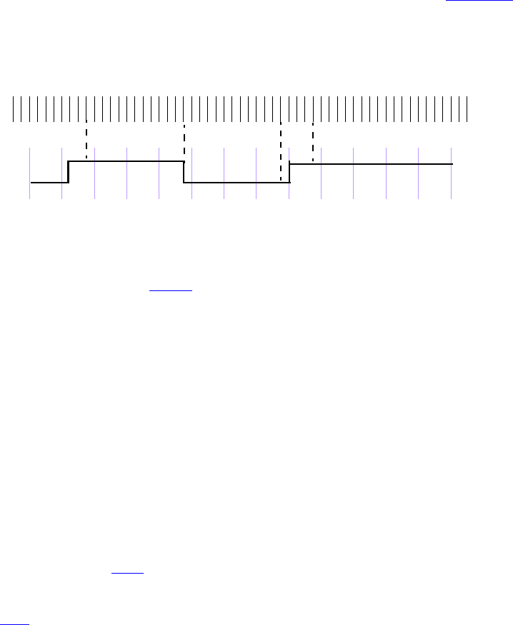
IEEE Std 1800-2012
IEEE STANDARD FOR SYSTEMVERILOG—UNIFIED HARDWARE DESIGN, SPECIFICATION, AND
VERIFICATION LANGUAGE
342
Copyright © 2013 IEEE. All rights reserved.
A clock tick is an atomic moment in time that itself spans no duration of time. A clock shall tick only once at
any simulation time, and the sampled values for that simulation time are used for evaluation of concurrent
assertions. In an assertion, the sampled value is the only valid value of a variable at a clock tick. Figure 16-1
shows the values of a variable as the clock progresses. The value of signal req is low at clock ticks 1 and 2.
At clock tick 3, the value is sampled as high and remains high until clock tick 6. The sampled value of
variable req at clock tick 6 is low and remains low up to and including clock tick 9. Notice that the
simulation value transitions to high at clock tick 9. However, the sampled value at clock tick 9 is low.
Figure 16-1—Sampling a variable in a simulation time step
An expression used in an assertion is always tied to a clock definition, except for the use of constant or
automatic values from procedural code (see 16.14.6). The sampled values are used to evaluate value change
expressions or Boolean subexpressions that are required to determine a match of a sequence.
For concurrent assertions, the following statements apply:
— It is important that the defined clock behavior be glitch free. Otherwise, wrong values can be
sampled.
— If a variable that appears in the expression for clock also appears in an expression with an assertion,
the values of the two usages of the variable can be different. The current value of the variable is used
in the clock expression, while the sampled value of the variable is used within the assertion.
The clock expression that controls evaluation of a sequence can be more complex than just a single signal
name. Expressions such as (clk && gating_signal) and (clk iff gating_signal) can be used to
represent a gated clock. Other more complex expressions are possible. However, in order to verify proper
behavior of the system and conform as closely as possible to truly cycle-based semantics, the user should
ensure that the clock expression is glitch-free and only transitions once at any simulation time.
A reference to $global_clock (see 14.14) is understood to be a reference to a clocking_event defined in a
global clocking declaration. A global clock behaves just as any other clocking event. In formal
verification, however, $global_clock has additional significance, as it is considered to be the primary
system clock (see F.3.1 ). Thus, in the following example:
global clocking @clk; endclocking
...
assert property(@$global_clock a);
the assertion states that a is true at each tick of the global clock. This assertion is logically equivalent to:
assert property(@clk a);
An example of a concurrent assertion is as follows:
base_rule1: assert property (cont_prop(rst,in1,in2)) $display("%m, passing");
else $display("%m, failed");
1234567891011121314clock ticks
req
simulation
time steps

IEEE Std 1800-2012
IEEE STANDARD FOR SYSTEMVERILOG—UNIFIED HARDWARE DESIGN, SPECIFICATION, AND
VERIFICATION LANGUAGE
343
Copyright © 2013 IEEE. All rights reserved.
The keyword property distinguishes a concurrent assertion from an immediate assertion. The syntax of
concurrent assertions is discussed in 16.14.
16.6 Boolean expressions
The outcome of the evaluation of an expression is Boolean and is interpreted the same way as an expression
is interpreted in the condition of a procedural if statement. In other words, if the expression evaluates to X,
Z, or 0, then it is interpreted as being false. Otherwise, it is true.
Expressions that appear in concurrent assertions shall satisfy the following requirements:
— An expression shall result in a type that is cast compatible with an integral type. Subexpressions
need not meet this requirement as long as the overall expression is cast compatible with an integral
type.
— Elements of dynamic arrays, queues, and associative arrays that are sampled for assertion expression
evaluation may get removed from the array or the array may get resized before the assertion
expression is evaluated. These specific array elements sampled for assertion expression evaluation
shall continue to exist within the scope of the assertion until the assertion expression evaluation
completes.
—Expressions that appear in procedural concurrent assertions may reference automatic variables as
described in 16.14.6.1. Otherwise, expressions in concurrent assertions shall not reference automatic
variables.
— Expressions shall not reference non-static class properties or methods.
— Expressions shall not reference variables of the chandle data type.
— Sequence match items with a local variable as the variable_lvalue may use the C assignment,
increment, and decrement operators. Otherwise, evaluation of an expression shall not have any side
effects (e.g., the increment and decrement operators are not allowed).
— Functions that appear in expressions shall not contain output or ref arguments (const ref is
allowed).
— Functions shall be automatic (or preserve no state information) and have no side effects.
Care should be taken when accessing large data structures, especially large dynamic data structures, in
concurrent assertions. Some types of access may require creating a copy of the entire data structure, which
could incur a significant performance penalty. The following example illustrates how the need to copy an
entire data structure may arise. In p1 only a single byte of q must be sampled by the assertion, and the
location of that byte is constant. However, in p2 there will be multiple active threads with potentially
different values of l_b. This increases the difficulty of determining which bytes of q to sample and likely
results in sampling all of q.
bit a;
integer b;
byte q[$];
property p1;
$rose(a) |-> q[0];
endproperty
property p2;
integer l_b;
($rose(a), l_b = b) |-> ##[3:10] q[l_b];
endproperty

IEEE Std 1800-2012
IEEE STANDARD FOR SYSTEMVERILOG—UNIFIED HARDWARE DESIGN, SPECIFICATION, AND
VERIFICATION LANGUAGE
344
Copyright © 2013 IEEE. All rights reserved.
There are two places where Boolean expressions occur in concurrent assertions. They are as follows:
— In a sequence or property expression
— In the disable condition inferred for an assertion, specified either in a top-level disable iff clause
(see 16.12) or in a default disable iff declaration (see 16.15)
The Boolean expressions used in defining a sequence or property expression shall be evaluated over the
sampled values of all variables. The preceding rule shall not, however, apply to expressions in a clocking
event (see 16.5).
The expressions in a disable condition are evaluated using the current values of variables (not sampled) and
may contain the sequence Boolean method triggered. They shall not contain any reference to local
variables or to the sequence method matched.
Assertions that perform checks based on time values should capture these values in the same context. It is
not recommended to capture time outside of the assertion. Time should be captured within the assertion
using local variables. The following example illustrates how a problem may arise when capturing time in
different contexts. In property p1, a time value, t, is captured in a procedural context based on the current
value of count. Within the assertion, a comparison is made between the time value t and the time value
returned by $realtime in the assertion context based on the sampled value of count. In both contexts,
$realtime returns the current time value. As a result, the comparison between values of time captured in
the different contexts yields an inconsistent result. The inconsistency results in the computation for p1
checking the amount of time that elapses between 8 periods of clk instead of the intended 7. In property p2,
both time values are captured within the assertion context. This strategy yields a consistent result.
bit count[2:0];
realtime t;
initial count = 0;
always @(posedge clk) begin
if (count == 0) t = $realtime; //capture t in a procedural context
count++;
end
property p1;
@(posedge clk)
count == 7 |-> $realtime – t < 50.5;
endproperty
property p2;
realtime l_t;
@(posedge clk)
(count == 0, l_t = $realtime) ##1 (count == 7)[->1] |->
$realtime – l_t < 50.5;
endproperty
16.7 Sequences
sequence_expr ::= // from A.2.10
cycle_delay_range sequence_expr { cycle_delay_range sequence_expr }
| sequence_expr cycle_delay_range sequence_expr { cycle_delay_range sequence_expr }
| expression_or_dist [ boolean_abbrev ]
| sequence_instance [ sequence_abbrev ]
|( sequence_expr {, sequence_match_item } ) [ sequence_abbrev ]

IEEE Std 1800-2012
IEEE STANDARD FOR SYSTEMVERILOG—UNIFIED HARDWARE DESIGN, SPECIFICATION, AND
VERIFICATION LANGUAGE
345
Copyright © 2013 IEEE. All rights reserved.
| sequence_expr and sequence_expr
| sequence_expr intersect sequence_expr
| sequence_expr or sequence_expr
|first_match ( sequence_expr {, sequence_match_item} )
| expression_or_dist throughout sequence_expr
| sequence_expr within sequence_expr
| clocking_event sequence_expr
cycle_delay_range ::=
## constant_primary
|## [ cycle_delay_const_range_expression ]
|##[*]
|##[+]
sequence_match_item ::=
operator_assignment
| inc_or_dec_expression
| subroutine_call
sequence_instance ::=
ps_or_hierarchical_sequence_identifier [ ( [ sequence_list_of_arguments ] ) ]
sequence_list_of_arguments ::=
[sequence_actual_arg] { , [sequence_actual_arg] } { , . identifier ( [sequence_actual_arg] ) }
|. identifier ( [sequence_actual_arg] ) { , . identifier ( [sequence_actual_arg] ) }
sequence_actual_arg ::=
event_expression
| sequence_expr
boolean_abbrev ::=
consecutive_repetition
| non_consecutive_repetition
| goto_repetition
sequence_abbrev ::= consecutive_repetition
consecutive_repetition ::=
[* const_or_range_expression ]
|[*]
|[+]
non_consecutive_repetition ::= [= const_or_range_expression ]
goto_repetition ::= [-> const_or_range_expression ]
const_or_range_expression ::=
constant_expression
| cycle_delay_const_range_expression
cycle_delay_const_range_expression ::=
constant_expression : constant_expression
| constant_expression : $
expression_or_dist ::= expression [ dist { dist_list } ]
Syntax 16-3—Sequence syntax (excerpt from Annex A)
Properties are often constructed out of sequential behaviors. The sequence feature provides the capability
to build and manipulate sequential behaviors. The simplest sequential behaviors are linear. A linear
sequence is a finite list of SystemVerilog Boolean expressions in a linear order of increasing time. The linear
sequence is said to match along a finite interval of consecutive clock ticks provided the first Boolean
expression evaluates to true at the first clock tick, the second Boolean expression evaluates to true at the
second clock tick, and so forth, up to and including the last Boolean expression evaluating to true at the last
IEEE Std 1800-2012
IEEE STANDARD FOR SYSTEMVERILOG—UNIFIED HARDWARE DESIGN, SPECIFICATION, AND
VERIFICATION LANGUAGE
346
Copyright © 2013 IEEE. All rights reserved.
clock tick. A single Boolean expression is an example of a simple linear sequence, and it matches at a single
clock tick provided the Boolean expression evaluates to true at that clock tick.
More complex sequential behaviors are described by SystemVerilog sequences. A sequence is a regular
expression over the SystemVerilog Boolean expressions that concisely specifies a set of zero, finitely many,
or infinitely many linear sequences. If at least one of the linear sequences from this set matches along a finite
interval of consecutive clock ticks, then the sequence is said to match along that interval.
A property may involve checking of one or more sequential behaviors beginning at various times. An
attempted evaluation of a sequence is a search for a match of the sequence beginning at a particular clock
tick. To determine whether such a match exists, appropriate Boolean expressions are evaluated beginning at
the particular clock tick and continuing at each successive clock tick until either a match is found or it is
deduced that no match can exist.
Sequences can be composed by concatenation, analogous to a concatenation of lists. The concatenation
specifies a delay, using ##, from the end of the first sequence until the beginning of the second sequence.
The syntax for sequence concatenation is shown in Syntax 16-4.
sequence_expr ::= // from A.2.10
cycle_delay_range sequence_expr { cycle_delay_range sequence_expr }
| sequence_expr cycle_delay_range sequence_expr { cycle_delay_range sequence_expr }
...
cycle_delay_range ::=
## constant_primary
|## [ cycle_delay_const_range_expression ]
|##[*]
|##[+]
cycle_delay_const_range_expression ::=
constant_expression : constant_expression
| constant_expression : $
Syntax 16-4—Sequence concatenation syntax (excerpt from Annex A)
In this syntax, the following statements apply:
—constant_primary is a constant_expression, which is computed at compile time and shall result in an
integer value. Furthermore, constant_expression and the bounds in
cycle_delay_const_range_expression can only be 0 or greater.
— The $ token is used to indicate the end of simulation. For formal verification tools, $ is used to
indicate a finite, but unbounded, range.
—##[*] is used as an equivalent representation of ##[0:$].
—##[+] is used as an equivalent representation of ##[1:$].
— When a range is specified with two expressions, the second expression shall be greater than or equal
to the first expression.
—In a cycle_delay_range, it shall be illegal for a constant_primary to contain a
constant_mintypmax_expression that is not also a constant_expression.
The context in which a sequence occurs determines when the sequence is evaluated. The first expression in a
sequence is checked at the first occurrence of the clock tick at or after the expression that triggered
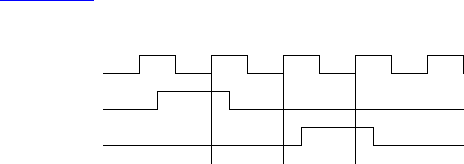
IEEE Std 1800-2012
IEEE STANDARD FOR SYSTEMVERILOG—UNIFIED HARDWARE DESIGN, SPECIFICATION, AND
VERIFICATION LANGUAGE
347
Copyright © 2013 IEEE. All rights reserved.
evaluation of the sequence. Each successive element (if any) in the sequence is checked at the next
subsequent occurrence of the clock.
A ## followed by a number or range specifies the delay from the current clock tick to the beginning of the
sequence that follows. The delay ##1 indicates that the beginning of the sequence that follows is one clock
tick later than the current clock tick. The delay ##0 indicates that the beginning of the sequence that follows
is at the same clock tick as the current clock tick.
When used as a concatenation between two sequences, the delay is from the end of the first sequence to the
beginning of the second sequence. The delay ##1 indicates that the beginning of the second sequence is one
clock tick later than the end of the first sequence. The delay ##0 indicates that the beginning of the second
sequence is at the same clock tick as the end of the first sequence.
The following are examples of delay expressions. `true is a Boolean expression that always evaluates to
true and is used for visual clarity. It can be defined as follows:
`define true 1
##0 a // means a
##1 a // means `true ##1 a
##2 a // means `true ##1 `true ##1 a
##[0:3]a // means (a) or (`true ##1 a) or (`true ##1 `true ##1 a) or
(`true ##1 `true ##1 `true ##1 a)
a ##2 b // means a ##1 `true ##1 b
The sequence
req ##1 gnt ##1 !req
specifies that req be true on the current clock tick, gnt shall be true on the first subsequent tick, and req
shall be false on the next clock tick after that. The ##1 operator specifies one clock tick separation. A delay
of more than one clock tick can be specified, as in the following:
req ##2 gnt
This specifies that req shall be true on the current clock tick, and gnt shall be true on the second subsequent
clock tick, as shown in Figure 16-2.
Figure 16-2—Concatenation of sequences
The following specifies that signal b shall be true on the Nth clock tick after signal a:
a ##N b // check b on the Nth sample
To specify a concatenation of overlapped sequences, where the end point of one sequence coincides with the
start of the next sequence, a value of 0 is used, as follows:
a ##1 b ##1 c // first sequence seq1
clk
req
gnt
s0 s1 s2

IEEE Std 1800-2012
IEEE STANDARD FOR SYSTEMVERILOG—UNIFIED HARDWARE DESIGN, SPECIFICATION, AND
VERIFICATION LANGUAGE
348
Copyright © 2013 IEEE. All rights reserved.
d ##1 e ##1 f // second sequence seq2
(a ##1 b ##1 c) ##0 (d ##1 e ##1 f) // overlapped concatenation
In the preceding example, c must be true at the end point of sequence seq1, and d must be true at the start of
sequence seq2. When concatenated with 0 clock tick delay, c and d must be true at the same time, resulting
in a concatenated sequence equivalent to the following:
a ##1 b ##1 c&&d ##1 e ##1 f
It should be noted that no other form of overlapping between the sequences can be expressed using the
concatenation operation.
In cases where the delay can be any value in a range, a time window can be specified as follows:
req ##[4:32] gnt
In the preceding case, signal req must be true at the current clock tick, and signal gnt must be true at some
clock tick between the 4th and the 32nd clock tick after the current clock tick.
The time window can extend to a finite, but unbounded, range by using $ as in the following example:
req ##[4:$] gnt
A sequence can be unconditionally extended by concatenation with `true.
a ##1 b ##1 c ##3 `true
After satisfying signal c, the sequence length is extended by three clock ticks. Such adjustments in the
length of sequences can be required when complex sequences are constructed by combining simpler
sequences.
16.8 Declaring sequences
A named sequence may be declared in the following:
— A module
— An interface
— A program
—A
clocking block
— A package
— A compilation-unit scope
— A checker
— A generate block
Named sequences are declared using Syntax 16-5.
assertion_item_declaration ::= // from A.2.10
...
| sequence_declaration
sequence_declaration ::=
sequence sequence_identifier [ ( [ sequence_port_list ] ) ] ;
{ assertion_variable_declaration }

IEEE Std 1800-2012
IEEE STANDARD FOR SYSTEMVERILOG—UNIFIED HARDWARE DESIGN, SPECIFICATION, AND
VERIFICATION LANGUAGE
349
Copyright © 2013 IEEE. All rights reserved.
sequence_expr [ ; ]
endsequence [ : sequence_identifier ]
sequence_port_list ::=
sequence_port_item {, sequence_port_item}
sequence_port_item ::=
{ attribute_instance } [ local [ sequence_lvar_port_direction ] ] sequence_formal_type
formal_port_identifier {variable_dimension} [ = sequence_actual_arg ]
sequence_lvar_port_direction ::= input | inout | output
sequence_formal_type ::=
data_type_or_implicit
|sequence
|untyped
formal_port_identifier ::= identifier // from A.9.3
sequence_instance ::= // from A.2.10
ps_or_hierarchical_sequence_identifier [ ( [ sequence_list_of_arguments ] ) ]
sequence_list_of_arguments ::=
[sequence_actual_arg] { , [sequence_actual_arg] } { , . identifier ( [sequence_actual_arg] ) }
|. identifier ( [sequence_actual_arg] ) { , . identifier ( [sequence_actual_arg] ) }
sequence_actual_arg ::=
event_expression
| sequence_expr
assertion_variable_declaration ::=
var_data_type list_of_variable_decl_assignments ;
Syntax 16-5—Declaring sequence syntax (excerpt from Annex A)
A named sequence may be declared with formal arguments in the optional sequence_port_list.
A formal argument may be typed by specifying the type prior to the formal_port_identifier of the formal
argument. A type shall apply to all formal arguments whose identifiers both follow the type and precede the
next type, if any, specified in the port list. Rules particular to the specification and use of typed formal
arguments are discussed in 16.8.1.
Rules particular to the specification and use of local variable formal arguments are discussed in 16.8.2.
A formal argument is said to be untyped if there is no type specified prior to its formal_port_identifier in the
port list. There is no default type for a formal argument.
The supported data types for sequence formal arguments are the types that are allowed for operands in
assertion expressions (see 16.6) and the keyword untyped.
A default actual argument may be specified for a formal argument in the optional associated declaration
assignment. The default_expression is resolved in the scope containing the sequence declaration.
Requirements for the type of the default actual argument of a typed formal argument are described in 16.8.1.
The default actual argument of an untyped formal argument may be of any type provided its substitution
results in a valid sequence as described in the rewriting algorithm (see F.4.1).
A formal argument may be referenced in the body of the declaration of the named sequence. A reference to
a formal argument may be written in place of various syntactic entities, such as the following:
— identifier
— expression

IEEE Std 1800-2012
IEEE STANDARD FOR SYSTEMVERILOG—UNIFIED HARDWARE DESIGN, SPECIFICATION, AND
VERIFICATION LANGUAGE
350
Copyright © 2013 IEEE. All rights reserved.
— sequence_expr
— event_expression
— terminal $ in a cycle_delay_const_range_expression
A named sequence may be instantiated by referencing its name. The reference may be a hierarchical name
(see 23.6). A named sequence may be instantiated anywhere that a sequence_expr may be written, including
prior to its declaration. A named sequence may also be instantiated as part of a sequence_method_call (see
16.9.11, 16.13.5) or as an event_expression (see 9.4.2.4). It shall be an error if a cyclic dependency among
named sequences results from their instantiations. A cyclic dependency among named sequences results if,
and only if, there is a cycle in the directed graph whose nodes are the named sequences and whose edges are
defined by the following rule: there is a directed edge from one named sequence to a second named
sequence if, and only if, either the first named sequence instantiates the second named sequence within its
declaration, including an instance within the declaration of a default actual argument, or there is an instance
of the first named sequence that instantiates the second named sequence within an actual argument.
In an instance of a named sequence, actual arguments may be passed to formal arguments. The instance shall
provide an actual argument in the list of arguments for each formal argument that does not have a default
actual argument declared. The instance may provide an actual argument for a formal argument that has a
default actual argument, thereby overriding the default. Actual arguments in the list of arguments may be
bound to formal arguments by name or by position.
The terminal $ may be an actual argument in an instance of a named sequence, either declared as a default
actual argument or passed in the list of arguments of the instance. If $ is an actual argument, then the
corresponding formal argument shall be untyped and each of its references either shall be an upper bound in
a cycle_delay_const_range_expression or shall itself be an actual argument in an instance of a named
sequence.
If an instance of a named sequence is within the scope of a local variable (see 16.10), then an actual
argument in the list of arguments of the instance may reference the local variable.
Names other than formal arguments that appear in the declaration of a named sequence, including those that
appear in default actual arguments, shall be resolved according to the scoping rules from the scope of the
declaration of the named sequence. Names appearing in actual arguments in the list of arguments of the
instance shall be resolved according to the scoping rules from the scope of the instance of the named
sequence.
The sequential behavior and matching semantics of an instance of a named sequence are the same as those of
the flattened sequence that is obtained from the body of the declaration of the named sequence by the
rewriting algorithm defined in F.4.1. The rewriting algorithm substitutes actual arguments for references to
the corresponding formal arguments in the body of the declaration of the named sequence. The rewriting
algorithm does not itself account for name resolution and assumes that names have been resolved prior to the
substitution of actual arguments. If the flattened sequence is not legal, then the instance is not legal and there
shall be an error.
The substitution of an actual argument for a reference to the corresponding untyped formal argument in the
rewriting algorithm retains the actual as an expression term. An actual argument shall be enclosed in
parentheses and shall be cast to its self-determined type before being substituted for a reference to the
corresponding formal argument unless one of the following conditions holds:
— The actual argument is $.
— The actual argument is a variable_lvalue.
If the result of the rewriting algorithm is an invalid sequence, an error shall occur.

IEEE Std 1800-2012
IEEE STANDARD FOR SYSTEMVERILOG—UNIFIED HARDWARE DESIGN, SPECIFICATION, AND
VERIFICATION LANGUAGE
351
Copyright © 2013 IEEE. All rights reserved.
For example, a reference to an untyped formal argument may appear in the specification of a
cycle_delay_range, a boolean_abbrev, or a sequence_abbrev (see 16.9.2) only if the actual argument is an
elaboration-time constant. The following example illustrates such usage of formal arguments:
sequence delay_example(x, y, min, max, delay1);
x ##delay1 y[*min:max];
endsequence
// Legal
a1: assert property (@(posedge clk) delay_example(x, y, 3, $, 2));
int z, d;
// Illegal: z and d are not elaboration-time constants
a2_illegal: assert property (@(posedge clk) delay_example(x, y, z, $, d));
In the following example, named sequences s1 and s2 are evaluated on successive posedge events of clk.
The named sequence s3 is evaluated on successive negedge events of clk. The named sequence s4 is
evaluated on successive alternating posedge and negedge events of clk.
sequence s1;
@(posedge clk) a ##1 b ##1 c;
endsequence
sequence s2;
@(posedge clk) d ##1 e ##1 f;
endsequence
sequence s3;
@(negedge clk) g ##1 h ##1 i;
endsequence
sequence s4;
@(edge clk) j ##1 k ##1 l;
endsequence
Another example of named sequence declaration, which includes arguments, follows:
sequence s20_1(data,en);
(!frame && (data==data_bus)) ##1 (c_be[0:3] == en);
endsequence
Named sequence s20_1 does not specify a clock. In this case, a clock would be inherited from some
external source, such as a property or an assert statement. An example of instantiating a named
sequence is shown as follows:
sequence s;
a ##1 b ##1 c;
endsequence
sequence rule;
@(posedge sysclk)
trans ##1 start_trans ##1 s ##1 end_trans;
endsequence
Named sequence rule in the preceding example is equivalent to the following:
sequence rule;
@(posedge sysclk)
trans ##1 start_trans ##1 (a ##1 b ##1 c) ##1 end_trans ;
endsequence

IEEE Std 1800-2012
IEEE STANDARD FOR SYSTEMVERILOG—UNIFIED HARDWARE DESIGN, SPECIFICATION, AND
VERIFICATION LANGUAGE
352
Copyright © 2013 IEEE. All rights reserved.
The following example illustrates an illegal cyclic dependency among the named sequences s1 and s2:
sequence s1;
@(posedge sysclk) (x ##1 s2);
endsequence
sequence s2;
@(posedge sysclk) (y ##1 s1);
endsequence
16.8.1 Typed formal arguments in sequence declarations
The data type specified for a formal argument of a sequence may be the keyword untyped. A formal
argument shall be untyped (see 16.8) if its data type is untyped. The semantics of binding an actual
argument expression to a formal with a data type of untyped shall be the same as the semantics for an
untyped formal. The keyword untyped shall be used if an untyped formal argument follows a data type in
the formal argument list.
If a formal argument of a named sequence is typed, then the type shall be sequence or one of the types
allowed in 16.6. The following rules apply to typed formal arguments and their corresponding actual
arguments, including default actual arguments declared in a named sequence:
a) If the formal argument is of type sequence, then the actual argument shall be a sequence_expr. A
reference to the formal argument of type sequence shall either be in a place where a sequence_expr
is legal, or as an operand of sequence methods triggered and matched.
b) If the formal argument is of type event, then the actual argument shall be an event_expression and
each reference to the formal argument shall be in a place where an event_expression may be written.
c) Otherwise, the self-determined result type of the actual argument shall be cast compatible (see
6.22.4) with the type of the formal argument. If the actual argument is a variable_lvalue, references
to the formal shall be considered as having the formal’s type with any assignment to the formal
being treated as though there was a subsequent assignment from the formal to the actual argument. If
the actual argument is not a variable_lvalue, the actual argument shall be cast to the type of the
formal argument before being substituted for a reference to the formal argument in the rewriting
algorithm (see F.4.1).
For example, a Boolean expression may be passed as an actual argument to a formal argument of type
sequence because a Boolean expression is a sequence_expr. A formal argument of type sequence may
not be referenced as the expression_or_dist operand of a goto_repetition (see 16.9.2), regardless of the
corresponding actual argument, because a sequence_expr may not be written in that position.
A reference to a typed formal argument within a sequence_match_item (see 16.10) shall not stand as the
variable_lvalue in either an operator_assignment or an inc_or_dec_expression unless the formal argument
is a local variable argument (see 16.8.2, 16.12.19).
Two examples of declaring formal arguments follow. All of the formal arguments of s1 are untyped. The
formal arguments w and y of s2 are untyped, while the formal argument x has type bit.
sequence s1(w, x, y);
w ##1 x ##[2:10] y;
endsequence
sequence s2(w, y, bit x);
w ##1 x ##[2:10] y;
endsequence
The following instances of s1 and s2 are equivalent:

IEEE Std 1800-2012
IEEE STANDARD FOR SYSTEMVERILOG—UNIFIED HARDWARE DESIGN, SPECIFICATION, AND
VERIFICATION LANGUAGE
353
Copyright © 2013 IEEE. All rights reserved.
s1(.w(a), .x(bit'(b)), .y(c))
s2(.w(a), .x(b), .y(c))
In the instance of s2 above, if b happens to be 8 bits wide then it will be cast to bit by truncation since it is
being passed to a formal argument of type bit. Similarly, if an expression of type bit is passed as actual
argument to a formal argument of type byte, then the expression is extended to a byte.
If a reference to a typed formal argument appears in the specification of a cycle_delay_range, a
boolean_abbrev, or a sequence_abbrev (see 16.9.2), then the type of the formal argument shall be
shortint, int, or longint. The following example illustrates such usage of formal arguments:
sequence delay_arg_example (max, shortint delay1, delay2, min);
x ##delay1 y[*min:max] ##delay2 z;
endsequence
parameter my_delay=2;
cover property (delay_arg_example($, my_delay, my_delay-1, 3));
The cover property in the preceding example is equivalent to the following:
cover property (x ##2 y[*3:$] ##1 z);
The following shows an example of a formal argument with event type:
sequence event_arg_example (event ev);
@(ev) x ##1 y;
endsequence
cover property (event_arg_example(posedge clk));
The cover property in the preceding example is equivalent to the following:
cover property (@(posedge clk) x ##1 y));
If the intent is to pass as actual argument an expression that will be combined with an edge_identifier to
create an event_expression, then the formal argument shall not be typed with type event. The following
example illustrates such usage:
sequence event_arg_example2 (reg sig);
@(posedge sig) x ##1 y;
endsequence
cover property (event_arg_example2(clk));
The cover property in the preceding example is equivalent to the following:
cover property (@(posedge clk) x ##1 y));
Another example, in which a local variable is used to sample a formal argument, shows how to get the effect
of “pass by value.” Pass by value is not currently supported as a mode of argument passing.
sequence s(bit a, bit b);
bit loc_a;
(1'b1, loc_a = a) ##0
(t == loc_a) [*0:$] ##1 b;
endsequence

IEEE Std 1800-2012
IEEE STANDARD FOR SYSTEMVERILOG—UNIFIED HARDWARE DESIGN, SPECIFICATION, AND
VERIFICATION LANGUAGE
354
Copyright © 2013 IEEE. All rights reserved.
16.8.2 Local variable formal arguments in sequence declarations
This subclause describes mechanisms for declaring local variable formal arguments and rules specific to
their use. Local variable formal arguments are special cases of local variables (see 16.10).
A formal argument of a named sequence may be designated as a local variable argument by specifying the
keyword local in the port item, followed optionally by one of the directions input, inout, or output. If
no direction is specified explicitly, then the direction input shall be inferred. If the keyword local is
specified in a port item, then the type of that argument shall be specified explicitly in that port item and shall
not be inferred from a previous argument. The type of a local variable argument shall be one of the types
allowed in 16.6. If one of the directions input, inout, or output is specified in a port item, then the
keyword local shall be specified in that port item.
The designation of a formal argument as a local variable argument of a given direction and type shall apply
to subsequent identifiers in the port list as long as none of the subsequent port items specifies the keyword
local or an explicit type. In other words, if a port item consists only of an identifier and if the nearest
preceding argument with an explicitly specified type also specifies the keyword local, then the port item is
a local variable argument with the same direction and type as that preceding argument.
If a local variable formal argument has direction input, then a default actual argument may be specified for
that argument in the optional declaration assignment in the port item, subject to the rules for default actual
arguments described in 16.8. It shall be illegal to specify a default actual argument for a local variable
argument of direction inout or output.
An example showing legal declaration of a named sequence using local variable formal arguments is as
follows:
logic b_d, d_d;
sequence legal_loc_var_formal (
local inout logic a,
local logic b = b_d, // input inferred, default actual argument b_d
c, // local input logic inferred, no default
// actual argument
d = d_d, // local input logic inferred, default actual
// argument d_d
logic e, f // e and f are not local variable formal arguments
);
logic g = c, h = g || d;
...
endsequence
An example showing illegal declaration of a named sequence using local variable formal arguments is
shown as follows:
sequence illegal_loc_var_formal (
output logic a, // illegal: local must be specified with
// direction
local inout logic b,
c = 1'b0,// default actual argument illegal for inout
local d = expr,// illegal: type must be specified explicitly
local event e, // illegal: event is a type disallowed in
// 16.6
local logic f = g // g shall not refer to the local variable
// below and must be resolved upward from
// this declaration
);

IEEE Std 1800-2012
IEEE STANDARD FOR SYSTEMVERILOG—UNIFIED HARDWARE DESIGN, SPECIFICATION, AND
VERIFICATION LANGUAGE
355
Copyright © 2013 IEEE. All rights reserved.
logic g = b;
...
endsequence
In general, a local variable formal argument behaves in the same way as a local variable declared in an
assertion_variable_declaration. The rules in 16.10 for assigning to and referencing local variables,
including the rules of local variable flow, apply to local variable formal arguments with the following
provisions:
— Without further specification, the term local variable shall mean either a local variable formal
argument or a local variable declared in an assertion_variable_declaration.
— At the beginning of each evaluation attempt of an instance of a named sequence, a new copy of each
of its local variable formal arguments shall be created.
— A local variable formal argument with direction input or inout shall be treated like a local
variable declared in an assertion_variable_declaration with a declaration assignment. The initial
value for the local variable formal argument is provided by the associated actual argument for the
instance. The self-determined result type of the actual argument shall be cast compatible (see 6.22.4)
with the type of the local variable formal argument. The value of the actual argument shall be cast to
the type of the local variable formal argument before being assigned as initial value to the local
variable formal argument. This assignment is referred to as the initialization assignment of the local
variable formal argument. Initialization of all input and inout local variable formal arguments shall
be performed before initialization of any local variable declared in an
assertion_variable_declaration. The expression of a declaration assignment to a local variable
declared in an assertion_variable_declaration may refer to a local variable formal argument of
direction input or inout.
— If a local variable formal argument of direction input or inout is bound to an actual argument in
the argument list of an instance and if the actual argument references a local variable, then it shall be
an error if that local variable is unassigned at the point of the reference in the context of the instance.
— A local variable formal argument of direction output shall be unassigned at the beginning of the
evaluation attempt of the instance.
— The entire actual argument expression bound to an inout or output local variable formal argument
shall itself be a reference to a local variable whose scope includes the instance and with whose type
the type of the local variable formal argument is cast compatible. It shall be an error if references to
the same local variable are bound as actual arguments to two or more local variable formal
arguments of direction inout or output. It shall be an error if there exists a match of the named
sequence for which an inout or output local variable formal argument is unassigned at the
completion of the match. At the completion of a match of the instance of the named sequence, the
value of the inout or output local variable formal argument shall be cast to the type of and assigned
to the local variable whose reference is the associated actual argument. If multiple threads of
evaluation of the instance of the named sequence match, then multiple threads of evaluation shall
continue in the instantiation context, each with its own copy of the actual argument local variable.
For each matching thread of the instance of the named sequence, at the completion of the match of
that thread the value of the local variable formal argument in that thread shall be cast to the type of
and assigned to the associated copy of the actual argument local variable.
— It shall be an error for an instance of a named sequence with an inout or output local variable
formal argument to admit an empty match.
— It shall be an error to apply any of the sequence methods triggered (see 16.9.11, 16.13.6) or
matched (see 16.13.5) to an instance of a named sequence with an input or inout local variable
formal argument.
The following example illustrates legal usage of a local variable formal argument:
sequence sub_seq2(local inout int lv);
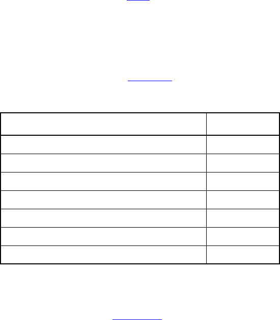
IEEE Std 1800-2012
IEEE STANDARD FOR SYSTEMVERILOG—UNIFIED HARDWARE DESIGN, SPECIFICATION, AND
VERIFICATION LANGUAGE
356
Copyright © 2013 IEEE. All rights reserved.
(a ##1 !a, lv += data_in)
##1 !b[*0:$] ##1 b && (data_out == lv);
endsequence
sequence seq2;
int v1;
(c, v1 = data)
##1 sub_seq2(v1) // lv is initialized by assigning it the value of v1;
// when the instance sub_seq2(v1) matches, v1 is
// assigned the value of lv
##1 (do1 == v1);
endsequence
The matching behavior of seq2 is equivalent to that of seq2_inlined as follows:
sequence seq2_inlined;
int v1, lv;
(c, v1 = data) ##1
(
(1, lv = v1) ##0
(a ##1 !a, lv += data_in)
##1 (!b[*0:$] ##1 b && (data_out == lv), v1 = lv)
)
##1 (do1 == v1);
endsequence
Untyped arguments provide an alternative mechanism for passing local variables to an instance of a
subsequence, including the capability to assign to the local variable in the subsequence and later reference
the value assigned in the instantiation context (see 16.10).
16.9 Sequence operations
16.9.1 Operator precedence
Operator precedence and associativity are listed in Table 16-1. The highest precedence is listed first.
16.9.2 Repetition in sequences
The syntax for sequence repetition is shown in Syntax 16-6.
Table 16-1—Operator precedence and associativity
SystemVerilog expression operators Associativity
[* ] [= ] [-> ] —
## Left
throughout Right
within Left
intersect Left
and Left
or Left
IEEE Std 1800-2012
IEEE STANDARD FOR SYSTEMVERILOG—UNIFIED HARDWARE DESIGN, SPECIFICATION, AND
VERIFICATION LANGUAGE
357
Copyright © 2013 IEEE. All rights reserved.
sequence_expr ::= // from A.2.10
...
| expression_or_dist [ boolean_abbrev ]
| sequence_instance [ sequence_abbrev ]
|( sequence_expr {, sequence_match_item} ) [ sequence_abbrev ]
...
boolean_abbrev ::=
consecutive_repetition
| non_consecutive_repetition
| goto_repetition
sequence_abbrev ::= consecutive_repetition
consecutive_repetition ::=
[* const_or_range_expression ]
|[*]
|[+]
non_consecutive_repetition ::= [= const_or_range_expression ]
goto_repetition ::= [-> const_or_range_expression ]
const_or_range_expression ::=
constant_expression
| cycle_delay_const_range_expression
cycle_delay_const_range_expression ::=
constant_expression : constant_expression
| constant_expression : $
Syntax 16-6—Sequence repetition syntax (excerpt from Annex A)
The number of iterations of a repetition can either be specified by exact count or be required to fall within a
finite range. If specified by exact count, then the number of iterations is defined by a non-negative integer
constant expression. If required to fall within a finite range, then the minimum number of iterations is
defined by a non-negative integer constant expression; and the maximum number of iterations either is
defined by a non-negative integer constant expression or is $, indicating a finite, but unbounded, maximum.
If both the minimum and maximum numbers of iterations are defined by non-negative integer constant
expressions (see 11.2.1), then the minimum number shall be less than or equal to the maximum number.
The following three kinds of repetition are provided:
—Consecutive repetition ( [*const_or_range_expression]): Consecutive repetition specifies finitely
many iterative matches of the operand sequence, with a delay of one clock tick from the end of one
match to the beginning of the next. The overall repetition sequence matches at the end of the last
iterative match of the operand. [*] is an equivalent representation of [*0:$] and [+] is an
equivalent representation of [*1:$].
—Goto repetition ( [->const_or_range_expression]): Goto repetition specifies finitely many
iterative matches of the operand Boolean expression, with a delay of one or more clock ticks from
one match of the operand to the next successive match and no match of the operand strictly in
between. The overall repetition sequence matches at the last iterative match of the operand.
—Nonconsecutive repetition ( [=const_or_range_expression]): Nonconsecutive repetition specifies
finitely many iterative matches of the operand Boolean expression, with a delay of one or more
clock ticks from one match of the operand to the next successive match and no match of the operand
strictly in between. The overall repetition sequence matches at or after the last iterative match of the
operand, but before any later match of the operand.
IEEE Std 1800-2012
IEEE STANDARD FOR SYSTEMVERILOG—UNIFIED HARDWARE DESIGN, SPECIFICATION, AND
VERIFICATION LANGUAGE
358
Copyright © 2013 IEEE. All rights reserved.
The effect of consecutive repetition of a subsequence within a sequence can be achieved by explicitly
iterating the subsequence, as follows:
a ##1 b ##1 b ##1 b ##1 c
Using the consecutive repetition operator [*3], which indicates three iterations, this sequential behavior is
specified more succinctly:
a ##1 b [*3] ##1 c
A consecutive repetition specifies that the operand sequence shall match a specified number of times. The
consecutive repetition operator [*N] specifies that the operand sequence must match N times in succession.
For example:
a [*3] means a ##1 a ##1 a
Using 0 as the repetition number, an empty sequence results, as follows:
a [*0]
An empty sequence is one that matches over zero clock ticks and does not match over any positive number
of clock ticks. The following rules apply for concatenating sequences with empty sequences. An empty
sequence is denoted as empty, and a sequence is denoted as seq.
—(empty ##0 seq) does not result in a match.
—(seq ##0 empty) does not result in a match.
—(empty ##n seq), where n is greater than 0, is equivalent to (##(n-1) seq).
—(seq ##n empty), where n is greater than 0, is equivalent to (seq ##(n-1) `true).
For example:
b ##1 ( a[*0] ##0 c)
produces no match of the sequence. The example
b ##1 a[*0:1] ##2 c
is equivalent to
(b ##2 c) or (b ##1 a ##2 c)
The syntax allows the combination of a delay and repetition in the same sequence. The following are both
allowed:
`true ##3 (a [*3]) // means `true ##1 `true ##1 `true ##1 a ##1 a ##1 a
(`true ##2 a) [*3] // means (`true ##2 a) ##1 (`true ##2 a) ##1
// (`true ##2 a), which in turn means `true ##1 `true
##1
// a ##1 `true ##1 `true ##1 a ##1 `true ##1 `true ##1 a
A sequence can be repeated as follows:
(a ##2 b) [*5]
This is the same as the following:
(a ##2 b ##1 a ##2 b ##1 a ##2 b ##1 a ##2 b ##1 a ##2 b)
IEEE Std 1800-2012
IEEE STANDARD FOR SYSTEMVERILOG—UNIFIED HARDWARE DESIGN, SPECIFICATION, AND
VERIFICATION LANGUAGE
359
Copyright © 2013 IEEE. All rights reserved.
A repetition with a range of minimum min and maximum max number of iterations can be expressed with
the consecutive repetition operator [* min:max].
For example:
(a ##2 b)[*1:5]
is equivalent to
(a ##2 b)
or (a ##2 b ##1 a ##2 b)
or (a ##2 b ##1 a ##2 b ##1 a ##2 b)
or (a ##2 b ##1 a ##2 b ##1 a ##2 b ##1 a ##2 b)
or (a ##2 b ##1 a ##2 b ##1 a ##2 b ##1 a ##2 b ##1 a ##2 b)
Similarly,
(a[*0:3] ##1 b ##1 c)
is equivalent to
(b ##1 c)
or (a ##1 b ##1 c)
or (a ##1 a ##1 b ##1 c)
or (a ##1 a ##1 a ##1 b ##1 c)
To specify a finite, but unbounded, number of iterations, the dollar sign ( $ ) is used. For example, the
repetition
a ##1 b [*1:$] ##1 c
matches over an interval of three or more consecutive clock ticks if a is true on the first clock tick, c is true
on the last clock tick, and b is true at every clock tick strictly in between the first and the last.
Specifying the number of iterations of a repetition by exact count is equivalent to specifying a range in
which the minimum number of repetitions is equal to the maximum number of repetitions. In other words,
seq[*n] is equivalent to seq[*n:n].
The goto repetition (nonconsecutive exact repetition) takes a Boolean expression rather than a sequence as
operand. It specifies the iterative matching of the Boolean expression at clock ticks that are not necessarily
consecutive and ends at the last iterative match. For example:
a ##1 b [->2:10] ##1 c
matches over an interval of consecutive clock ticks provided a is true on the first clock tick, c is true on the
last clock tick, b is true on the penultimate clock tick, and, including the penultimate, there are at least 2 and
at most 10 not necessarily consecutive clock ticks strictly in between the first and last on which b is true.
This sequence is equivalent to the following:
a ##1 ((!b[*0:$] ##1 b) [*2:10]) ##1 c
The nonconsecutive repetition is like the goto repetition except that a match does not have to end at the last
iterative match of the operand Boolean expression. The use of nonconsecutive repetition instead of goto
repetition allows the match to be extended by arbitrarily many clock ticks provided the Boolean expression
is false on all of the extra clock ticks. For example:

IEEE Std 1800-2012
IEEE STANDARD FOR SYSTEMVERILOG—UNIFIED HARDWARE DESIGN, SPECIFICATION, AND
VERIFICATION LANGUAGE
360
Copyright © 2013 IEEE. All rights reserved.
a ##1 b [=2:10] ##1 c
matches over an interval of consecutive clock ticks provided a is true on the first clock tick, c is true on the
last clock tick, and there are at least 2 and at most 10 not necessarily consecutive clock ticks strictly in
between the first and last on which b is true. This sequence is equivalent to the following:
a ##1 ((!b [*0:$] ##1 b) [*2:10]) ##1 !b[*0:$] ##1 c
The consecutive repetition operator can be applied to general sequence expressions, but the goto repetition
and nonconsecutive repetition operators can be applied only to Boolean expressions. In particular, goto
repetition and nonconsecutive repetition cannot be applied to a Boolean expression to which a sequence
match item (see 16.10, 16.11) has been attached. For example, the following is a legal sequence expression:
(b[->1], v = e)[*2]
but the following is illegal:
(b, v = e)[->2]
16.9.3 Sampled value functions
This subclause describes the system functions available for accessing sampled values of an expression.
These functions include the capability to access current sampled value, access sampled value in the past, or
detect changes in sampled value of an expression. Sampling of an expression is explained in 16.5.1. Local
variables (see 16.10) and the sequence method matched are not allowed in the argument expressions passed
to these functions. The following functions are provided:
$sampled ( expression )
$rose ( expression [, [clocking_event] ] )
$fell ( expression [, [clocking_event] ] )
$stable ( expression [, [clocking_event] ] )
$changed ( expression [ , [ clocking_event ] ] )
$past ( expression1 [, [number_of_ticks ] [, [expression2 ] [, [clocking_event]]] ] )
The use of these functions is not limited to assertion features; they may be used as expressions in procedural
code as well. The clocking event, although optional as an explicit argument to the functions $past, $rose,
$stable, $changed, and $fell, is required for their semantics. The clocking event is used to sample
the value of the argument expression.
The function $sampled does not use a clocking event.
For a sampled value function other than $sampled, the clocking event shall be explicitly specified as an
argument or inferred from the code where the function is called. The following rules are used to infer the
clocking event:
— If called in an assertion, the appropriate clocking event as determined by clock flow rules (see
16.13.3) is used.
— Otherwise, if called in a disable condition or a clock expression in an assertion, it shall be explicitly
clocked.
— Otherwise, if called in an action block of an assertion, the leading clock of the assertion is used.
— Otherwise, if called in a procedure, the inferred clock, if any, from the procedural context (see
16.14.6) is used.
—Otherwise, if called outside an assertion, default clocking (see 14.12) is used.

IEEE Std 1800-2012
IEEE STANDARD FOR SYSTEMVERILOG—UNIFIED HARDWARE DESIGN, SPECIFICATION, AND
VERIFICATION LANGUAGE
361
Copyright © 2013 IEEE. All rights reserved.
The function $sampled returns the sampled value of its argument (see 16.5.1). The use of $sampled in
concurrent assertions, although allowed, is redundant, as the result of the function is identical to the sampled
value of the expression itself used in the assertion. The use of $sampled in a disable iff clause is
meaningful since the disable condition by default is not sampled (see 16.12).
The function $sampled is useful to access the value of expressions used in concurrent assertions in their
action blocks. Consider the following example:
logic a, b, clk;
// ...
a1_bad: assert property (@clk a == b)
else $error("Different values: a = %b, b = %b", a, b);
a2_ok: assert property (@clk a == b)
else $error("Different values: a = %b, b = %b",
$sampled(a), $sampled(b));
If in some clock tick the sampled value of a is 0 and of b is 1, but their current values in the Reactive region
of this tick are 0, then assertion a1_bad will report Different values:a=0,b=0. This is because
action blocks are evaluated in the Reactive region (see 16.14.1). Assertion a2_ok reports the intended
message Different values: a = 0, b = 1 because the values of a and b in its action block are
evaluated in the same context as in the assertion.
The following functions are called value change functions and are provided to detect changes in sampled
values: $rose, $fell, $stable, and $changed.
A value change function detects a change (or, in the case of $stable, lack of change) in the sampled value
of an expression. The change (or lack of change) is determined by comparing the sampled value of the
expression with the sampled value of the expression from the most recent strictly prior time step in which
the clocking event occurred (see 16.5.1 for the definition of sampling in past clock ticks and the following
description of $past for how past values are evaluated). The result of a value change function is true or
false and a call to a value change function may be used as a Boolean expression. The results of value change
functions shall be determined as follows:
—$rose returns true if the LSB of the expression changed to 1. Otherwise, it returns false.
—$fell returns true if the LSB of the expression changed to 0. Otherwise, it returns false.
—$stable returns true if the value of the expression did not change. Otherwise, it returns false.
—$changed returns true if the value of the expression changed. Otherwise, it returns false.
When these functions are called at or before the simulation time step in which the first clocking event
occurs, the results are computed by comparing the sampled value of the expression with its default sampled
value (see 16.5.1).
Figure 16-3 illustrates two examples of value changes:
— Value change expression e1 is defined as $rose(req).
— Value change expression e2 is defined as $fell(ack).
The clock ticks used for sampling the variables are derived from the clock for the property, which is
different from the simulation time steps. Assume, for now, that this clock is defined elsewhere. At clock tick
3, e1 occurs because the value of req at clock tick 2 was low and the value at clock tick 3 is high. Similarly,
e2 occurs at clock tick 6 because the value of ack was sampled as high at clock tick 5 and sampled as low at
clock tick 6.
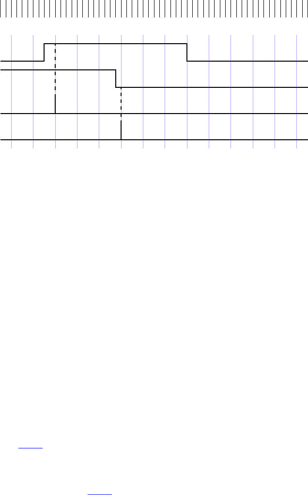
IEEE Std 1800-2012
IEEE STANDARD FOR SYSTEMVERILOG—UNIFIED HARDWARE DESIGN, SPECIFICATION, AND
VERIFICATION LANGUAGE
362
Copyright © 2013 IEEE. All rights reserved.
Figure 16-3—Value change expressions
The following example illustrates the use of $rose in SystemVerilog code outside assertions:
always @(posedge clk)
reg1 <= a & $rose(b);
In this example, the clocking event @(posedge clk) is applied to $rose. $rose is true whenever the
sampled value of b changed to 1 from its sampled value at the previous tick of the clocking event.
Past sampled values can be accessed with the $past function. The following three optional arguments are
provided:
—expression2 is used as a gating expression for the clocking event.
—number_of_ticks specifies the number of clock ticks in the past.
—clocking_event specifies the clocking event for sampling expression1.
expression1 and expression2 may be any expression allowed in assertions. If expression2 is not specified,
then it defaults to 1'b1.
number_of_ticks shall be 1 or greater and shall be an elaboration-time constant expression. If
number_of_ticks is not specified, then it defaults to 1.
$past returns the sampled value of expression1 in a particular time step strictly prior to the one in which
$past is evaluated (see 16.5.1 for the definition of sampling in past clock ticks). If number_of_ticks equals
k and if ev is the event expression underlying clocking_event, then the particular time step is the kth strictly
prior time step in which the event ev iff expression2 occurred. If there do not exist k strictly prior time
steps in which the event ev iff expression2 occurred, then the value returned from the $past function is the
default sampled value of expression1 (see 16.5.1).
The clocking event for $past shall be explicitly specified through the clocking_event argument or inferred
from the code where $past is called. The rules for inferring the clocking event are described previously.
When intermediate optional arguments between two arguments are not needed, a comma shall be placed for
each omitted argument. For example:
$past(in1, , enable);
1234567891011121314clock ticks
req
ack
e1
simulation
e2
time steps

IEEE Std 1800-2012
IEEE STANDARD FOR SYSTEMVERILOG—UNIFIED HARDWARE DESIGN, SPECIFICATION, AND
VERIFICATION LANGUAGE
363
Copyright © 2013 IEEE. All rights reserved.
Here, a comma is specified to omit number_of_ticks. The default of 1 is used for the empty number_of_ticks
argument. There is no need to include a comma for the omitted clocking_event argument, as it does not fall
within the specified arguments.
$past can be used in any SystemVerilog expression. An example follows.
always @(posedge clk)
reg1 <= a & $past(b);
In this example, the inferred clocking event @(posedge clk) is applied to $past. $past is evaluated in
the current occurrence of (posedge clk) and returns the value of b sampled at the previous occurrence of
(posedge clk).
The function $past may refer to automatic variables, e.g., to procedural loop variables, as follows:
always @(posedge clk)
for (int i = 0; i < 4; i ++)
if (cond[i])
reg1[i] <= $past(b[i]);
According to the definition of the past sampled value (see 16.5.1), $past returns at each loop iteration the
past value of the i-th bit of b.
When expression2 is specified, the sampling of expression1 is performed based on its clock gated with
expression2. For example:
always @(posedge clk)
if (enable) q <= d;
always @(posedge clk)
assert property (done |=> (out == $past(q, 2,enable)) );
In this example, the sampling of q for evaluating $past is based on the following clocking expression:
posedge clk iff enable
The clocking event argument of a sampled value function may be different from the clocking event of the
context in which it is called, as determined by the clock resolution (see 16.16).
Consider the following assertions:
bit clk, fclk, req, gnt, en;
...
a1: assert property
(@(posedge clk) en && $rose(req) |=> gnt);
a2: assert property
(@(posedge clk) en && $rose(req, @(posedge fclk)) |=> gnt);
Both assertions a1 and a2 read: “whenever en is high and req rises, at the next cycle gnt must be asserted.”
In both assertions, the rise of req occurs if and only if the sampled value of req at the current posedge of
clk is 1'b1 and the sampled value of req at a particular prior point is distinct from 1'b1. The assertions
differ in the specification of the prior point. In a1 the prior point is the preceding posedge of clk, while in
a2 the prior point is the most recent prior posedge of fclk.
IEEE Std 1800-2012
IEEE STANDARD FOR SYSTEMVERILOG—UNIFIED HARDWARE DESIGN, SPECIFICATION, AND
VERIFICATION LANGUAGE
364
Copyright © 2013 IEEE. All rights reserved.
As another example,
always_ff @(posedge clk1)
reg1 <= $rose(b, @(posedge clk2));
Here, reg1 is updated in each time step in which posedge clk1 occurs, using the value returned from the
$rose sampled value function in that time step. $rose compares the sampled value of the LSB of b from
the current time step (one in which posedge clk1 occurs) with the sampled value of the LSB of b in the
strictly prior time step in which posedge clk2 occurs.
The following example is illegal if it is not within the scope of a default clocking because no clock can be
inferred:
always @(posedge clk) begin
...
@(negedge clk2);
x = $past(y, 5); // illegal if not within default clocking
end
This example is legal if it is within the scope of a default clocking.
16.9.4 Global clocking past and future sampled value functions
This subclause describes the system functions available for accessing the nearest past and future values of an
expression as sampled by the global clock. They may be used only if global clocking is defined (see 14.14).
These functions include the capability to access the sampled value at the global clock tick that immediately
precedes or follows the time step at which the function is called. Sampled value is explained in 16.5.1. The
following functions are provided.
Global clocking past sampled value functions are as follows:
$past_gclk ( expression )
$rose_gclk ( expression )
$fell_gclk ( expression )
$stable_gclk ( expression )
$changed_gclk ( expression )
Global clocking future sampled value functions are as follows:
$future_gclk ( expression )
$rising_gclk ( expression )
$falling_gclk ( expression )
$steady_gclk ( expression )
$changing_gclk ( expression )
The behavior of the global clocking past sampled value functions can be defined using the sampled value
functions as follows (the symbol means here “is equivalent by definition”):
$past_gclk(v) $past(v,,, @$global_clock)
$rose_gclk(v) $rose(v, @$global_clock)
$fell_gclk(v) $fell(v, @$global_clock)
$stable_gclk(v) $stable(v, @$global_clock)
$changed_gclk(v) $changed(v, @$global_clock)

IEEE Std 1800-2012
IEEE STANDARD FOR SYSTEMVERILOG—UNIFIED HARDWARE DESIGN, SPECIFICATION, AND
VERIFICATION LANGUAGE
365
Copyright © 2013 IEEE. All rights reserved.
The global clocking future sampled value functions are similar except that they use the subsequent value of
the expression.
$future_gclk(v) is the sampled value of v at the next global clock tick (see 16.5.1 for the definition of
sampling in future clock ticks).
The other functions are defined as follows:
—$rising_gclk(expression) returns true if the sampled value of the LSB of the expression is
changing to 1 at the next global clocking tick. Otherwise, it returns false.
—$falling_gclk(expression) returns true if the sampled value of the LSB of the expression is
changing to 0 at the next global clocking tick. Otherwise, it returns false.
—$steady_gclk(expression) returns true if the sampled value of the expression does not change
at the next global clock tick. Otherwise, it returns false.
—$changing_gclk(expression) is the complement of $steady_gclk, i.e.,
!$steady_gclk(expression).
The global clocking future sampled value functions may be invoked only in property_expr or in
sequence_expr; this implies that they shall not be used in assertion action blocks. The global clocking past
sampled value functions are a special case of the sampled value functions, and therefore the regular
restrictions imposed on the sampled value functions and their arguments apply (see 16.9.3). In particular, the
global clocking past sampled value functions are usable in general procedural code and action blocks.
Additional restrictions are imposed on the usage of the global clocking future sampled value functions: they
shall not be nested and they shall not be used in assertions containing sequence match items (see 16.10,
16.11).
The following example illustrates the illegal usage of the global clocking future sampled value functions:
// Illegal: global clocking future sampled value functions
// shall not be nested
a1: assert property (@clk $future_gclk(a || $rising_gclk(b));
sequence s;
bit v;
(a, v = a) ##1 (b == v)[->1];
endsequence : s
// Illegal: a global clocking future sampled value function shall not
// be used in an assertion containing sequence match items
a2: assert property (@clk s |=> $future_gclk(c));
Even though global clocking future sampled value functions depend on future values of their arguments, the
interval of simulation time steps for an evaluation attempt of an assertion containing global clocking future
sampled value functions is defined as though the future sampled values were known in advance. The end of
the evaluation attempt is defined to be the last tick of the assertion clock and is not delayed any additional
time steps up to the next global clocking tick.
The behavior of disable iff and other asynchronous assertion related controls such as $assertcontrol
(see 20.12) is with respect to the interval of the evaluation attempt previously defined. If, for example,
$assertcontrol with control_type 5 (Kill) is executed in a time step strictly after the last tick of the
assertion clock for the evaluation attempt, then it shall not affect that attempt, even if $assertcontrol is
executed no later than the next global clocking tick.
Execution of the action block of an assertion containing global clocking future sampled value functions shall
be delayed until the global clocking tick that follows the last tick of the assertion clock for the attempt. If the
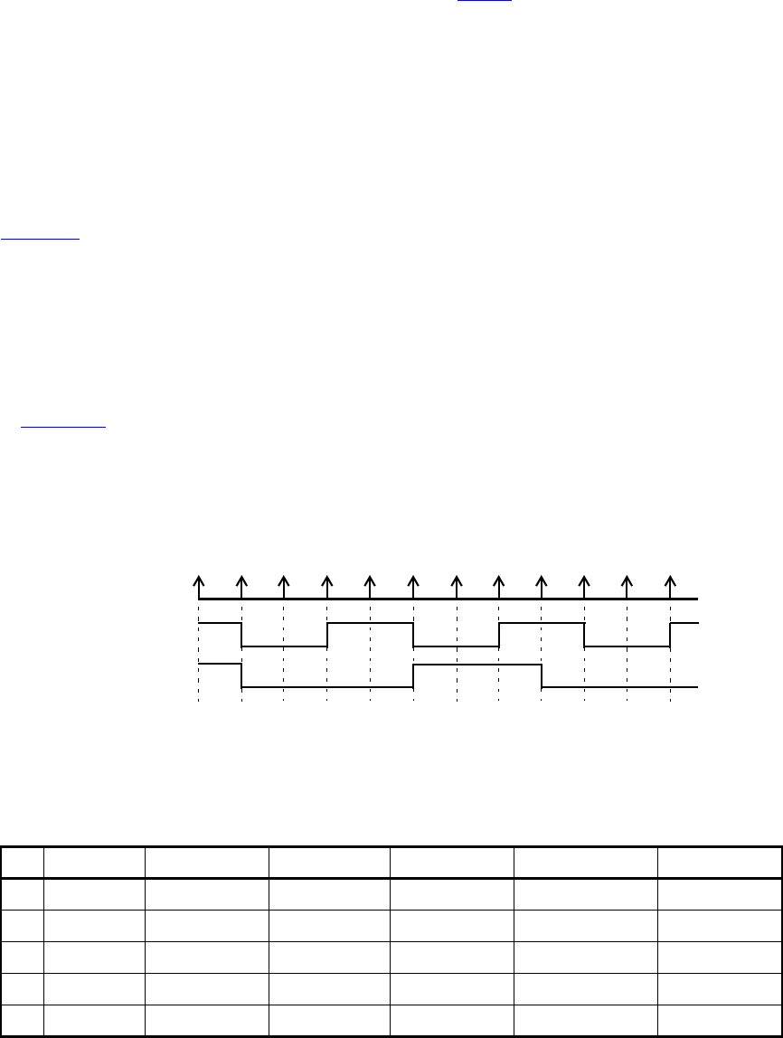
IEEE Std 1800-2012
IEEE STANDARD FOR SYSTEMVERILOG—UNIFIED HARDWARE DESIGN, SPECIFICATION, AND
VERIFICATION LANGUAGE
366
Copyright © 2013 IEEE. All rights reserved.
evaluation attempt fails and $error is called by default (see 16.14.1), then $error shall be called at the
global clocking tick that follows the last tick of the assertion clock.
A tool specific message that reports the starting or ending time step of an evaluation attempt of an assertion
containing global clocking future sampled functions shall be consistent with the preceding definition of the
interval of simulation time steps for the evaluation attempt. The message may also report the time step in
which it is written, which may be that of the global clocking tick that follows the last tick of the assertion
clock.
Example 1:
Table 16-2 shows the values returned by the global clocking future sampled value functions for sig at
different time moments.
The following assertion states that the signal may change only on falling clock:
a1: assert property (@$global_clock $changing_gclk(sig)
|-> $falling_gclk(clk))
else $error(”sig is not stable”);
In Figure 16-4, the vertical arrows indicate the ticks of the global clock. The assertion a1 is violated at time
80 because $changing_gclk(sig) is true and $falling_gclk(clk) is false. Because the assertion
contains global clocking future sampled value functions, the error task $error("sig is not stable")
in the action block is executed at time 90. If, as part of the tool-specific message printed by $error, a tool
reports the ending or failing time of this evaluation attempt, the time reported is 80.
Figure 16-4—Future value change
Table 16-2—Global clocking future sampled value functions
Time $sampled(sig) $future_gclk(sig) $rising_gclk(sig) $falling_gclk(sig) $changing_gclk(sig) $steady_gclk(sig)
10 1'b1 1'b0 1'b0 1'b1 1'b1 1'b0
30 1'b0 1'b0 1'b0 1'b0 1'b0 1'b1
40 1'b0 1'b0 1'b0 1'b0 1'b0 1'b1
50 1'b0 1'b1 1'b1 1'b0 1'b1 1'b0
80 1'b1 1'b0 1'b0 1'b1 1'b1 1'b0
10 20 30 40 50 60 70 80 90 100 1100
$global_clock
clk
sig
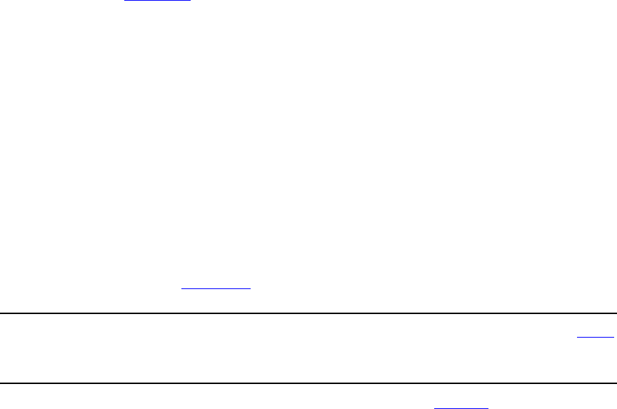
IEEE Std 1800-2012
IEEE STANDARD FOR SYSTEMVERILOG—UNIFIED HARDWARE DESIGN, SPECIFICATION, AND
VERIFICATION LANGUAGE
367
Copyright © 2013 IEEE. All rights reserved.
Example 2:
The following assumption states that a signal sig must remain stable between two falling edges of a clock
clk as sampled by global clocking. This differs from the property in Example 1 in the case where the first
falling edge of clk has not yet occurred. In Example 1, sig is not allowed to change in that case, but in this
example sig can toggle freely while waiting for clk to begin.
a2: assume property(@$global_clock
$falling_gclk(clk) ##1 (!$falling_gclk(clk)[*1:$]) |->
$steady_gclk(sig));
Example 3:
Assume that the signal rst is high between times 82 and 84, and is low at all other time moments. Then the
following assertion:
a3: assert property (@$global_clock disable iff (rst) $changing_gclk(sig)
|-> $falling_gclk(clk))
else $error(”sig is not stable”);
fails at time 80 (see Figure 16-4) since rst is inactive at time 80. The interval of the failing evaluation
attempt starts and ends at time 80. Although rst is active prior to the execution of the action block at time
90, the attempt is not disabled.
Example 4:
In some cases, the global clocking future value functions provide a more natural expression of a property
than the past value functions. For example, the following two assertions are equivalent:
// A ##1 is needed in a4 due to the corner case at cycle 0
a4: assert property (##1 $stable_gclk(sig));
// In a5, there is no issue at cycle 0
a5: assert property ($steady_gclk(sig));
16.9.5 AND operation
The binary operator and is used when both operands are expected to match, but the end times of the operand
sequences can be different (see Syntax 16-7).
sequence_expr ::= // from A.2.10
...
| sequence_expr and sequence_expr
Syntax 16-7—And operator syntax (excerpt from Annex A)
The two operands of and are sequences. The requirement for the match of the and operation is that both the
operands shall match. The operand sequences start at the same time. When one of the operand sequences
matches, it waits for the other to match. The end time of the composite sequence is the end time of the
operand sequence that completes last.
When te1 and te2 are sequences, then the composite sequence
te1 and te2
matches if te1 and te2 match. The end time is the end time of either te1 or te2, whichever matches last.
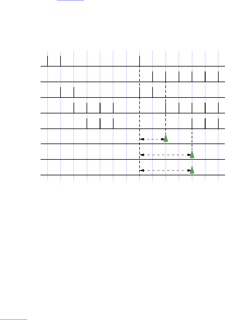
IEEE Std 1800-2012
IEEE STANDARD FOR SYSTEMVERILOG—UNIFIED HARDWARE DESIGN, SPECIFICATION, AND
VERIFICATION LANGUAGE
368
Copyright © 2013 IEEE. All rights reserved.
The following example is a sequence with operator and, where the two operands are sequences:
(te1 ##2 te2) and (te3 ##2 te4 ##2 te5)
The operation as illustrated in Figure 16-5 shows the evaluation attempt at clock tick 8. Here, the two
operand sequences are (te1 ##2 te2) and (te3 ##2 te4 ##2 te5). The first operand sequence
requires that first te1 evaluates to true followed by te2 two clock ticks later. The second sequence requires
that first te3 evaluates to true followed by te4 two clock ticks later, followed by te5 two clock ticks later.
Figure 16-5—ANDing (and) two sequences
This attempt results in a match because both operand sequences match. The end times of matches for the
individual sequences are clock ticks 10 and 12. The end time for the composite sequence is the later of the
two end times; therefore, a match is recognized for the composite sequence at clock tick 12.
In the following example, the first operand sequence has a concatenation operator with range from 1 to 5:
(te1 ##[1:5] te2) and (te3 ##2 te4 ##2 te5)
The first operand sequence requires that te1 evaluate to true and that te2 evaluate to true 1, 2, 3, 4, or 5
clock ticks later. The second operand sequence is the same as in the previous example. To consider all
possibilities of a match of the composite sequence, the following steps can be taken:
a) Five threads of evaluation are started for the five possible linear sequences associated with the first
sequence operand.
b) The second operand sequence has only one associated linear sequence; therefore, only one thread of
evaluation is started for it.
c) Figure 16-6 shows the evaluation attempt beginning at clock tick 8. All five linear sequences for the
first operand sequence match, as shown in a time window; therefore, there are five matches of the
first operand sequence, ending at clock ticks 9, 10, 11, 12, and 13, respectively. The second operand
sequence matches at clock tick 12.
1234567891011121314clk
te1
te2
te3
te1 ##2 te2
te3 ##2 te4 ##2 te5
te4
te5
(te1 ##2 te2) and
(te3 ##2 te4 ##2 te5)
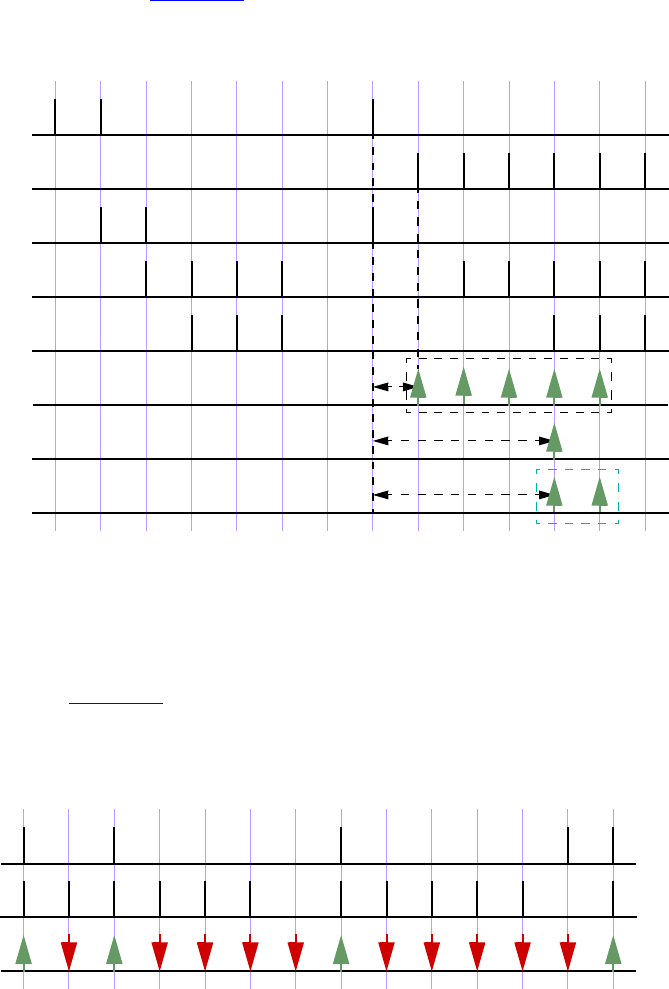
IEEE Std 1800-2012
IEEE STANDARD FOR SYSTEMVERILOG—UNIFIED HARDWARE DESIGN, SPECIFICATION, AND
VERIFICATION LANGUAGE
369
Copyright © 2013 IEEE. All rights reserved.
d) Each match of the first operand sequence is combined with the single match of the second operand
sequence, and the rules of the AND operation determine the end time of the resulting match of the
composite sequence.
The result of this computation is five matches of the composite sequence, four of them ending at clock tick
12, and the fifth ending at clock tick 13. Figure 16-6 shows the matches of the composite sequence ending at
clock ticks 12 and 13.
Figure 16-6—ANDing (and) two sequences, including a time range
If te1 and te2 are sampled expressions (not sequences), the sequence (te1 and te2) matches if te1 and
te2 both evaluate to true.
An example is illustrated in Figure 16-7, which shows the results for attempts at every clock tick. The
sequence matches at clock tick 1, 3, 8, and 14 because both te1 and te2 are simultaneously true. At all
other clock ticks, match of the AND operation fails because either te1 or te2 is false.
Figure 16-7—ANDing (and) two Boolean expressions
1234567891011121314clk
te1
te2
te3
te1 ##[1:5] te2
te3 ##2 te4 ##2 te5
te4
te5
(te1 ##[1:5] te2) and
(te3 ##2 te4 ##2 te5)
1234567891011121314clock
te1
te2
te1 and te2
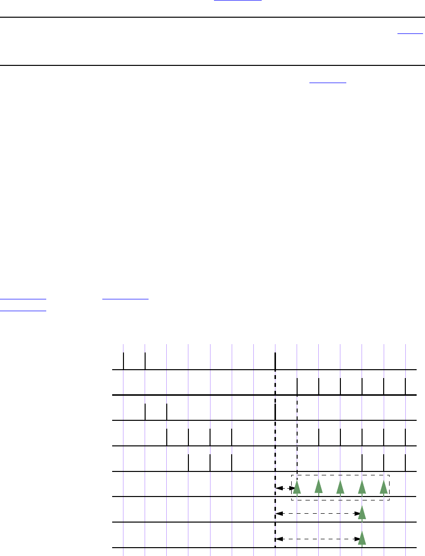
IEEE Std 1800-2012
IEEE STANDARD FOR SYSTEMVERILOG—UNIFIED HARDWARE DESIGN, SPECIFICATION, AND
VERIFICATION LANGUAGE
370
Copyright © 2013 IEEE. All rights reserved.
16.9.6 Intersection (AND with length restriction)
The binary operator intersect is used when both operand sequences are expected to match, and the end
times of the operand sequences must be the same (see Syntax 16-8).
sequence_expr ::= // from A.2.10
...
| sequence_expr intersect sequence_expr
Syntax 16-8—Intersect operator syntax (excerpt from Annex A)
The two operands of intersect are sequences. The requirements for match of the intersect operation
are as follows:
— Both the operands shall match.
— The lengths of the two matches of the operand sequences shall be the same.
The additional requirement on the length of the sequences is the basic difference between and and
intersect.
An attempted evaluation of an intersect sequence can result in multiple matches. The results of such an
attempt can be computed as follows:
— Matches of the first and second operands that are of the same length are paired. Each such pair
results in a match of the composite sequence, with length and end point equal to the shared length
and end point of the paired matches of the operand sequences.
— If no such pair is found, then there is no match of the composite sequence.
Figure 16-8 is similar to Figure 16-6, except that and is replaced by intersect. In this case, unlike in
Figure 16-6, there is only a single match at clock tick 12.
Figure 16-8—Intersecting two sequences
1234567891011121314clk
te1
te2
te3
te1 ##[1:5] te2
te3 ##2 te4 ##2 te5
te4
te5
(te1 ##[1:5] te2)
intersect
(te3 ##2 te4 ##2 te5)
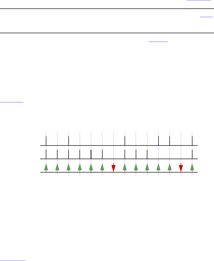
IEEE Std 1800-2012
IEEE STANDARD FOR SYSTEMVERILOG—UNIFIED HARDWARE DESIGN, SPECIFICATION, AND
VERIFICATION LANGUAGE
371
Copyright © 2013 IEEE. All rights reserved.
16.9.7 OR operation
The operator or is used when at least one of the two operand sequences is expected to match (Syntax 16-9).
sequence_expr ::= // from A.2.10
...
| sequence_expr or sequence_expr
Syntax 16-9—Or operator syntax (excerpt from Annex A)
The two operands of or are sequences.
If the operands te1 and te2 are expressions, then
te1 or te2
matches at any clock tick on which at least one of te1 and te2 evaluates to true.
Figure 16-9 illustrates an OR operation for which the operands te1 and te2 are expressions. The composite
sequence does not match at clock ticks 7 and 13 because te1 and te2 are both false at those times. At all
other clock ticks, the composite sequence matches, as at least one of the two operands evaluates to true.
Figure 16-9—ORing (or) two Boolean expressions
When te1 and te2 are sequences, then the sequence
te1 or te2
matches if at least one of the two operand sequences te1 and te2 matches. Each match of either te1 or te2
constitutes a match of the composite sequence, and its end time as a match of the composite sequence is the
same as its end time as a match of te1 or of te2. In other words, the set of matches of te1 or te2 is the
union of the set of matches of te1 with the set of matches of te2.
The following example shows a sequence with operator or where the two operands are sequences.
Figure 16-10 illustrates this example.
(te1 ##2 te2) or (te3 ##2 te4 ##2 te5)
1234567891011121314clock
te1
te2
te1 or te2
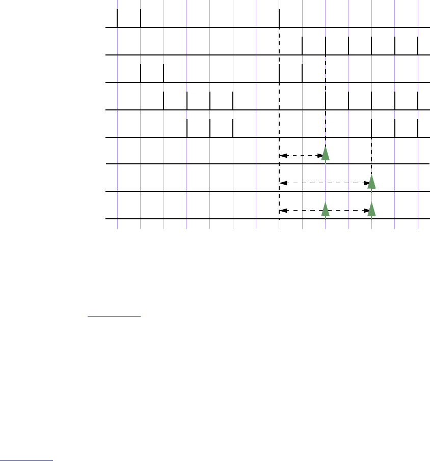
IEEE Std 1800-2012
IEEE STANDARD FOR SYSTEMVERILOG—UNIFIED HARDWARE DESIGN, SPECIFICATION, AND
VERIFICATION LANGUAGE
372
Copyright © 2013 IEEE. All rights reserved.
Figure 16-10—ORing (or) two sequences
The two operand sequences in the preceding example are (te1 ##2 te2) and (te3 ##2 te4 ##2 te5).
The first sequence requires that te1 first evaluates to true, followed by te2 two clock ticks later. The second
sequence requires that te3 evaluates to true, followed by te4 two clock ticks later, followed by te5 two
clock ticks later. In Figure 16-10, the evaluation attempt for clock tick 8 is shown. The first sequence
matches at clock tick 10, and the second sequence matches at clock tick 12. Therefore, two matches for the
composite sequence are recognized.
In the following example, the first operand sequence has a concatenation operator with range from 1 to 5:
(te1 ##[1:5] te2) or (te3 ##2 te4 ##2 te5)
The first operand sequence requires that te1 evaluate to true and that te2 evaluate to true 1, 2, 3, 4, or 5
clock ticks later. The second operand sequence requires that te3 evaluate to true, that te4 evaluate to true
two clock ticks later, and that te5 evaluate to true another two clock ticks later. The composite sequence
matches at any clock tick on which at least one of the operand sequences matches. As shown in
Figure 16-11, for the attempt at clock tick 8, the first operand sequence matches at clock ticks 9, 10, 11, 12,
and 13, while the second operand matches at clock tick 12. The composite sequence, therefore, has one
match at each of clock ticks 9, 10, 11, and 13 and has two matches at clock tick 12.
1234567891011121314clk
te1
te2
te3
te1 ##2 te2
te3 ##2 te4 ##2 te5
te4
te5
(te1 ##2 te2) or
(te3 ##2 te4 ##2 te5)
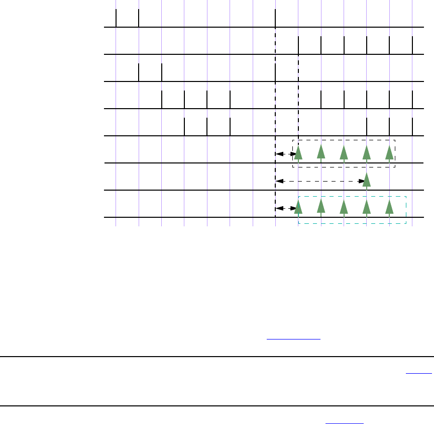
IEEE Std 1800-2012
IEEE STANDARD FOR SYSTEMVERILOG—UNIFIED HARDWARE DESIGN, SPECIFICATION, AND
VERIFICATION LANGUAGE
373
Copyright © 2013 IEEE. All rights reserved.
Figure 16-11—ORing (or) two sequences, including a time range
16.9.8 First_match operation
The first_match operator matches only the first of possibly multiple matches for an evaluation attempt of
its operand sequence. This allows all subsequent matches to be discarded from consideration. In particular,
when a sequence is a subsequence of a larger sequence, then applying the first_match operator has
significant effect on the evaluation of the enclosing sequence (see Syntax 16-10).
sequence_expr ::= // from A.2.10
...
|first_match ( sequence_expr {, sequence_match_item} )
Syntax 16-10—First_match operator syntax (excerpt from Annex A)
An evaluation attempt of first_match (seq) results in an evaluation attempt for the operand seq beginning
at the same clock tick. If the evaluation attempt for seq produces no match, then the evaluation attempt for
first_match (seq) produces no match. Otherwise, the match of seq with the earliest ending clock tick is a
match of first_match (seq). If there are multiple matches of seq with the same ending clock tick as the
earliest one, then all those matches are matches of first_match (seq).
The following example shows a variable delay specification:
sequence t1;
te1 ## [2:5] te2;
endsequence
sequence ts1;
first_match(te1 ## [2:5] te2);
endsequence
1234567891011121314clk
te1
te2
te3
te1 ##[1:5] te2
te3 ##2 te4 ##2 te5
te4
te5
(te1 ##[1:5] te2) or
(te3 ##2 te4 ##2 te5)

IEEE Std 1800-2012
IEEE STANDARD FOR SYSTEMVERILOG—UNIFIED HARDWARE DESIGN, SPECIFICATION, AND
VERIFICATION LANGUAGE
374
Copyright © 2013 IEEE. All rights reserved.
Here, te1 and te2 are expressions. Each attempt of sequence t1 can result in matches for up to four of the
following sequences:
te1 ##2 te2
te1 ##3 te2
te1 ##4 te2
te1 ##5 te2
However, sequence ts1 can result in a match for only one of the preceding four sequences. Whichever
match of the preceding four sequences ends first is a match of sequence ts1.
For example:
sequence t2;
(a ##[2:3] b) or (c ##[1:2] d);
endsequence
sequence ts2;
first_match(t2);
endsequence
Each attempt of sequence t2 can result in matches for up to four of the following sequences:
a ##2 b
a ##3 b
c ##1 d
c ##2 d
Sequence ts2 matches only the earliest ending match of these sequences. If a, b, c, and d are expressions,
then it is possible to have matches ending at the same time for both.
a ##2 b
c ##2 d
If both of these sequences match and (c ##1 d) does not match, then evaluation of ts2 results in these two
matches.
Sequence match items can be attached to the operand sequence of the first_match operator. The sequence
match items are placed within the same set of parentheses that enclose the operand. Thus, for example, the
local variable assignment x = e can be attached to the first match of seq via
first_match(seq, x = e)
which is equivalent to the following:
first_match((seq, x = e))
See 16.10 and 16.11 for discussion of sequence match items.
16.9.9 Conditions over sequences
Sequences often occur under the assumptions of some conditions for correct behavior. A logical condition
must hold true, for instance, while processing a transaction. Also, occurrence of certain values is prohibited
while processing a transaction. Such situations can be expressed directly using the construct shown in
Syntax 16-11.
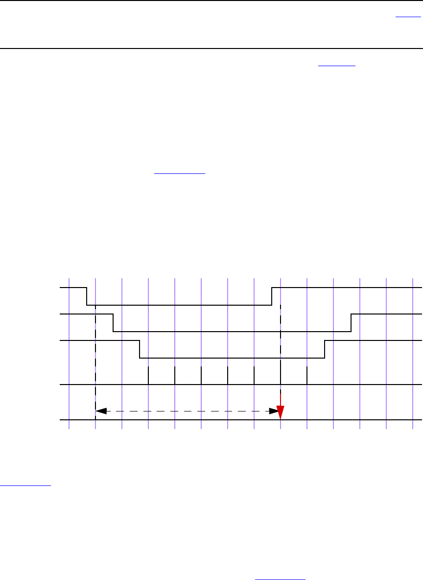
IEEE Std 1800-2012
IEEE STANDARD FOR SYSTEMVERILOG—UNIFIED HARDWARE DESIGN, SPECIFICATION, AND
VERIFICATION LANGUAGE
375
Copyright © 2013 IEEE. All rights reserved.
sequence_expr ::= // from A.2.10
...
| expression_or_dist throughout sequence_expr
Syntax 16-11—Throughout construct syntax (excerpt from Annex A)
The construct exp throughout seq is an abbreviation for the following:
(exp) [*0:$] intersect seq
The composite sequence, exp throughout seq, matches along a finite interval of consecutive clock ticks
provided seq matches along the interval and exp evaluates to true at each clock tick of the interval.
The following example is illustrated in Figure 16-12.
sequence burst_rule1;
@(posedge mclk)
$fell(burst_mode) ##0
((!burst_mode) throughout (##2 ((trdy==0)&&(irdy==0)) [*7]));
endsequence
Figure 16-12—Match with throughout restriction fails
Figure 16-13 illustrates the evaluation attempt for sequence burst_rule1 beginning at clock tick 2.
Because signal burst_mode is high at clock tick 1 and low at clock tick 2, $fell(burst_mode) is true at
clock tick 2. To complete the match of burst_rule1, the value of burst_mode is required to be low
throughout a match of the subsequence (##2 ((trdy==0)&&(irdy==0)) [*7]) beginning at clock tick 2.
This subsequence matches from clock tick 2 to clock tick 10. However, at clock tick 9 burst_mode
becomes high, thereby failing to match according to the rules for throughout.
If signal burst_mode were instead to remain low through at least clock tick 10, then there would be a match
of burst_rule1 from clock tick 2 to clock tick 10, as shown in Figure 16-13.
1 2 3 4 5 6 7 8 9 10 11 12 13 14
burst_mode
irdy
trdy
(trdy==0) &&
(irdy==0)
burst_rule1
1 2 3 4 5 6 7
mclk
IEEE Std 1800-2012
IEEE STANDARD FOR SYSTEMVERILOG—UNIFIED HARDWARE DESIGN, SPECIFICATION, AND
VERIFICATION LANGUAGE
376
Copyright © 2013 IEEE. All rights reserved.
Figure 16-13—Match with throughout restriction succeeds
16.9.10 Sequence contained within another sequence
The containment of a sequence within another sequence is expressed as follows in Syntax 16-12.
sequence_expr ::= // from A.2.10
...
| sequence_expr within sequence_expr
Syntax 16-12—Within construct syntax (excerpt from Annex A)
The construct seq1 within seq2 is an abbreviation for the following:
(1[*0:$] ##1 seq1 ##1 1[*0:$]) intersect seq2
The composite sequence seq1 within seq2 matches along a finite interval of consecutive clock ticks
provided seq2 matches along the interval and seq1 matches along some subinterval of consecutive clock
ticks. In other words, the matches of seq1 and seq2 must satisfy the following:
— The start point of the match of seq1 shall be no earlier than the start point of the match of seq2.
— The end point of the match of seq1 shall be no later than the end point of the match of seq2.
For example, the sequence
!trdy[*7] within ($fell(irdy) ##1 !irdy[*8])
matches from clock tick 3 to clock tick 11 on the trace shown in Figure 16-13.
16.9.11 Composing sequences from simpler subsequences
There are two ways in which a complex sequence can be composed using simpler subsequences.
One is to instantiate a named sequence by referencing its name. Evaluation of such a reference requires the
named sequence to match starting from the clock tick at which the reference is reached during the evaluation
of the enclosing sequence. For example:
1 2 3 4 5 6 7 8 9 10 11 12 13 14
burst_mode
trdy
(trdy==0) &&
(irdy==0)
burst_rule1
1 2 3 4 5 6 7
mclk
irdy
IEEE Std 1800-2012
IEEE STANDARD FOR SYSTEMVERILOG—UNIFIED HARDWARE DESIGN, SPECIFICATION, AND
VERIFICATION LANGUAGE
377
Copyright © 2013 IEEE. All rights reserved.
sequence s;
a ##1 b ##1 c;
endsequence
sequence rule;
@(posedge sysclk)
trans ##1 start_trans ##1 s ##1 end_trans;
endsequence
Sequence s is evaluated beginning one tick after the evaluation of start_trans in the sequence rule.
Another way to use a sequence is to detect its end point in another sequence. The end point of a sequence is
reached whenever the ending clock tick of a match of the sequence is reached, regardless of the starting
clock tick of the match. The reaching of the end point can be tested by using the method triggered.
To detect the end point, the triggered method may be applied to a named sequence instance, with or
without arguments, an untyped formal argument, or a formal argument of type sequence, where such is
allowed, as follows:
sequence_instance.triggered
or
formal_argument_sequence.triggered
triggered is a method on a sequence. The result of its operation is true (1'b1) or false (1'b0) . When
method triggered is evaluated in an expression, it tests whether its operand sequence has reached its end
point at that particular point in time. The result of triggered does not depend upon the starting point of the
match of its operand sequence. An example is shown as follows:
sequence e1;
@(posedge sysclk) $rose(ready) ##1 proc1 ##1 proc2 ;
endsequence
sequence rule;
@(posedge sysclk) reset ##1 inst ##1 e1.triggered ##1 branch_back;
endsequence
In this example, sequence e1 must match one clock tick after inst. If the method triggered is replaced
with an instance of sequence e1, a match of e1 must start one clock tick after inst. Notice that method
triggered only tests for the end point of e1 and has no bearing on the starting point of e1.
The following example demonstrates an application of the method triggered on a named sequence
instance with arguments:
sequence e2(a,b,c);
@(posedge sysclk) $rose(a) ##1 b ##1 c;
endsequence
sequence rule2;
@(posedge sysclk) reset ##1 inst ##1 e2(ready,proc1,proc2).triggered
##1 branch_back;
endsequence
rule2 is equivalent to rule2a as follows:
sequence e2_instantiated;
e2(ready,proc1,proc2);
endsequence
sequence rule2a;
IEEE Std 1800-2012
IEEE STANDARD FOR SYSTEMVERILOG—UNIFIED HARDWARE DESIGN, SPECIFICATION, AND
VERIFICATION LANGUAGE
378
Copyright © 2013 IEEE. All rights reserved.
@(posedge sysclk) reset ##1 inst ##1 e2_instantiated.triggered ##1
branch_back;
endsequence
The following example demonstrates an application of method triggered on a formal argument of type
sequence:
sequence e3(sequence a, untyped b);
@(posedge sysclk) a.triggered ##1 b;
endsequence
sequence rule3;
@(posedge sysclk) reset ##1 e3(ready ##1 proc1, proc2) ##1 branch_back;
endsequence
There are additional restrictions on passing local variables into an instance of a sequence to which
triggered is applied (see 16.10).
The method triggered can be used in the presence of multiple clocks. However, the ending clock of the
sequence instance to which triggered is applied shall always be the same as the clock in the context where
the application of method triggered appears (see 16.13.5).
16.10 Local variables
Data can be manipulated within named sequences (see 16.8) and properties (see 16.12) using dynamically
created local variables. The use of a static SystemVerilog variable implies that only one copy exists. If data
values need to be checked in pipelined designs, then for each quantum of data entering the pipeline, a
separate variable can be used to store the predicted output of the pipeline for later comparison when the
result actually exits the pipe. This storage can be built by using an array of variables arranged in a shift
register to mimic the data propagating through the pipeline. However, in more complex situations where the
latency of the pipe is variable and out of order, this construction could become very complex and error
prone. Therefore, variables are needed that are local to and are used within a particular transaction check that
can span an arbitrary interval of time and can overlap with other transaction checks. Such a variable will
thus be dynamically created when needed within an instance of a sequence and removed when the end of the
sequence is reached.
The dynamic creation of a local variable and its assignment is achieved by either using a local variable
formal argument declaration (see 16.8.2, 16.12.18) or using an assertion variable declaration within the
declaration of a named sequence or property (see 16.12). Without further specification, the term local
variable shall mean either a local variable formal argument or a local variable declared in an
assertion_variable_declaration. Without further specification, the term local variable initialization
assignment shall mean either an initialization assignment to a local variable formal argument of direction
input or inout of the value of the corresponding actual argument or a declaration assignment to a local
variable declared in an assertion_variable_declaration (see Syntax 16-13).
assertion_variable_declaration ::= // from A.2.10
var_data_type list_of_variable_decl_assignments ;
Syntax 16-13—Assertion variable declaration syntax (excerpt from Annex A)
The data type of an assertion variable declaration shall be specified explicitly. The data type shall be one of
the types allowed within assertions as defined in 16.6. The data type shall be followed by a comma-
separated list of one or more identifiers with optional declaration assignments. A declaration assignment, if

IEEE Std 1800-2012
IEEE STANDARD FOR SYSTEMVERILOG—UNIFIED HARDWARE DESIGN, SPECIFICATION, AND
VERIFICATION LANGUAGE
379
Copyright © 2013 IEEE. All rights reserved.
present, defines the initial value to be placed in the corresponding local variable. The initial value is defined
by an expression, which need not be constant.
The sampled value of a local variable is defined as the current value (see 16.5.1).
At the beginning of each evaluation attempt of an instance of a named sequence or property, a new copy of
each of its local variables shall be created and, if present, the corresponding initialization assignment shall
be performed. Initialization assignments shall be performed in the Observed region in the order that they
appear in the sequence or property declaration. For the purposes of this rule, all initialization assignments to
local variable formal arguments shall be performed before any initialization assignment to a local variable
declared in an assertion_variable_declaration. An initialization assignment to a local variable uses the
sampled value of its expression in the time slot in which the evaluation attempt begins. The expression of an
initialization assignment to a given local variable may refer to a previously declared local variable. In this
case the previously declared local variable shall itself have an initialization assignment, and the initial value
assigned to the previously declared local variable shall be used in the evaluation of the expression assigned
to the given local variable. Local variables do not have default initial values. A local variable without an
initialization assignment shall be unassigned at the beginning of the evaluation attempt.
For example, at the beginning of an evaluation attempt of an instance of
sequence s;
logic u, v = a, w = v || b;
...
endsequence
the assignment of a to v is performed first, and the assignment of v||b to w is performed second. The
value assigned to w is the same as would result from the declaration assignment w=a||b. The local
variable u is unassigned at the beginning of the evaluation attempt.
Local variables may be assigned and reassigned within the body of the sequence or property in which they
are declared.
sequence_expr ::= // from A.2.10
...
|( sequence_expr {, sequence_match_item} ) [ sequence_abbrev ]
...
sequence_match_item ::=
operator_assignment
| inc_or_dec_expression
...
Syntax 16-14—Variable assignment syntax (excerpt from Annex A)
One or more local variables may be assigned at the end point of a syntactic subsequence by placing the
subsequence, comma-separated from the list of local variable assignments, in parentheses. At the end of any
non-empty match of the subsequence, the local variable assignments are performed in the order that they
appear in the list. For example, if in
a ##1 b[->1] ##1 c[*2]
it is desired to assign x = e and then y=x&&f at the match of b[->1], the sequence can be rewritten as
a ##1 (b[->1], x = e, y = x && f) ##1 c[*2]

IEEE Std 1800-2012
IEEE STANDARD FOR SYSTEMVERILOG—UNIFIED HARDWARE DESIGN, SPECIFICATION, AND
VERIFICATION LANGUAGE
380
Copyright © 2013 IEEE. All rights reserved.
A local variable may be reassigned later in the sequence or property, as in
a ##1 (b[->1], x = e, y = x && f) ##1 (c[*2], x &= g)
The subsequence to which a local variable assignment is attached shall not admit an empty match. For
example, the sequence
a ##1 (b[*0:1], x = e) ##1 c[*2] // illegal
is illegal because the subsequence b[*0:1] can match the empty word. The sequence
(a ##1 b[*0:1], x = e) ##1 c[*2] // legal
is legal because the concatenated subsequence a ##1 b[*0:1] cannot match the empty word.
A local variable may be referenced within the sequence or property in which it is declared. The sequence or
property shall assign a value to the local variable prior to the point at which the reference is made. The prior
assignment may be an initialization assignment or an assignment attached to a subsequence. There is an
implicit reference associated with the use of an inc_or_dec_operator or an assignment operator other than
“=”. Therefore, a local variable shall be assigned a value prior to being updated with an
inc_or_dec_operator or with an assignment operator other than “=”.
Under certain circumstances, a local variable that is assigned later becomes unassigned. If a local variable
does not flow out of a subsequence (see the following), then the local variable shall become unassigned at
the end of that subsequence, regardless of whether it was assigned a value prior to that point. The local
variable shall not be referenced after the point from which it does not flow until after it has again been
assigned a value. See F.5.4 for precise conditions defining local variable flow.
Hierarchical references to a local variable are not allowed.
As an example of local variable usage, assume a pipeline that has a fixed latency of five clock cycles. The
data enter the pipe on pipe_in when valid_in is true, and the value computed by the pipeline appears five
clock cycles later on the signal pipe_out1. The data as transformed by the pipe are predicted by a function
that increments the data. The following property verifies this behavior:
property e;
int x;
(valid_in, x = pipe_in) |-> ##5 (pipe_out1 == (x+1));
endproperty
Property e is evaluated as follows:
—When
valid_in is true, x is assigned the value of pipe_in. If five cycles later, pipe_out1 is
equal to x+1, then property e is true. Otherwise, property e is false.
—When
valid_in is false, property e evaluates to true.
A local variable can be used to form expressions in the same way that a static variable of the same type can
be used. This includes the use of local variables in expressions for bit-selects and part-selects of vectors or
for indices of arrays. A local variable shall not be used in a clocking event expression.
Local variables may be used in sequences or properties.
sequence data_check;
int x;
a ##1 (!a, x = data_in) ##1 !b[*0:$] ##1 b && (data_out == x);
endsequence
IEEE Std 1800-2012
IEEE STANDARD FOR SYSTEMVERILOG—UNIFIED HARDWARE DESIGN, SPECIFICATION, AND
VERIFICATION LANGUAGE
381
Copyright © 2013 IEEE. All rights reserved.
property data_check_p
int x;
a ##1 (!a, x = data_in) |=> !b[*0:$] ##1 b && (data_out == x);
endproperty
Local variable assignments may be attached to the operand sequence of a repetition and accomplish
accumulation of values.
sequence rep_v;
int x = 0;
(a[->1], x += data)[*4] ##1 b ##1 c && (data_out == x);
endsequence
An accumulating local variable may be used to count the number of times a condition is repeated, as in the
following example:
sequence count_a_cycles;
int x;
($rose(a), x = 1)
##1 (a, x++)[*0:$]
##1 !a && (x <= MAX);
endsequence
The local variables declared within a sequence or property are not visible in the context where the sequence
or property is instantiated. The following example illustrates an illegal access to local variable v1 of
sequence sub_seq1 in sequence seq1.
sequence sub_seq1;
int v1;
(a ##1 !a, v1 = data_in) ##1 !b[*0:$] ##1 b && (data_out == v1);
endsequence
sequence seq1;
c ##1 sub_seq1 ##1 (do1 == v1); // error because v1 is not visible
endsequence
It can be useful to assign a value to a local variable within an instance of a named sequence and reference the
local variable in the instantiating context at or after the completion of a match of the instance. This
capability is supported under the following conditions:
— The local variable shall be declared outside the named sequence, and its scope shall include both the
instance of the named sequence and the desired reference in the instantiating context.
— The local variable shall be passed as an entire actual argument in the list of arguments of the
instance of the named sequence.
— The corresponding formal argument shall be untyped.
The named sequence may specify assignments to the formal argument in one or more
sequence_match_items.
The following example illustrates this usage:
sequence sub_seq2(lv);
(a ##1 !a, lv = data_in) ##1 !b[*0:$] ##1 b && (data_out == lv);
endsequence
sequence seq2;
int v1;
c ##1 sub_seq2(v1) // v1 is bound to lv

IEEE Std 1800-2012
IEEE STANDARD FOR SYSTEMVERILOG—UNIFIED HARDWARE DESIGN, SPECIFICATION, AND
VERIFICATION LANGUAGE
382
Copyright © 2013 IEEE. All rights reserved.
##1 (do1 == v1); // v1 holds the value that was assigned to lv
endsequence
An alternative way to achieve a similar capability is by using local variable formal arguments (see 16.8.2).
Local variables can be passed into an instance of a named sequence to which triggered is applied and
accessed in a similar manner. For example:
sequence seq2a;
int v1; c ##1 sub_seq2(v1).triggered ##1 (do1 == v1);
// v1 is now bound to lv
endsequence
There are additional restrictions when passing local variables into an instance of a named sequence to which
triggered is applied:
— Local variables can be passed in only as entire actual arguments, not as proper subexpressions of
actual arguments.
— In the declaration of the named sequence, the formal argument to which the local variable is bound
shall not be referenced before it is assigned.
The second restriction is met by sub_seq2 because the assignment lv = data_in occurs before the
reference to lv in data_out == lv.
If a local variable is assigned before being passed into an instance of a named sequence to which
triggered is applied, then the restrictions prevent this assigned value from being visible within the named
sequence. The restrictions are important because the use of triggered means that there is no guaranteed
relationship between the point in time at which the local variable is assigned outside the named sequence
and the beginning of the match of the instance.
A local variable that is passed in as actual argument to an instance of a named sequence to which
triggered is applied will flow out of the application of triggered to that instance provided both of the
following conditions are met:
— The local variable flows out of the end of the named sequence instance, as defined by the local
variable flow rules for sequences. (See the following and F.5.4.)
— The application of triggered to this instance is a maximal Boolean expression. In other words, the
application of triggered cannot have negation or any other expression operator applied to it.
Both conditions are satisfied by sub_seq2 and seq2a. Thus, in seq2a, the value in v1 in the comparison
do1 == v1 is the value assigned to lv in sub_seq2 by the assignment lv = data_in. However, in
sequence seq2b;
int v1; c ##1 !sub_seq2(v1).triggered ##1 (do1 == v1); // v1 unassigned
endsequence
the second condition is violated because of the negation applied to sub_seq2(v1).triggered. Therefore,
v1 does not flow out of the application of triggered to this instance, and the reference to v1 in do1 ==
v1 is to an unassigned variable.
In a single cycle, there can be multiple matches of a sequence instance to which triggered is applied, and
these matches can have different valuations of the local variables. The multiple matches are treated
semantically the same way as matching both disjuncts of an or (see the following). In other words, the
thread evaluating the instance to which triggered is applied will fork to account for such distinct local
variable valuations.

IEEE Std 1800-2012
IEEE STANDARD FOR SYSTEMVERILOG—UNIFIED HARDWARE DESIGN, SPECIFICATION, AND
VERIFICATION LANGUAGE
383
Copyright © 2013 IEEE. All rights reserved.
When a local variable is a formal argument of a sequence declaration, it is illegal to declare the variable, as
shown in the following example:
sequence sub_seq3(lv);
int lv; // illegal because lv is a formal argument
(a ##1 !a, lv = data_in) ##1 !b[*0:$] ##1 b && (data_out == lv);
endsequence
There are special considerations when using local variables in sequences involving the branching operators
or, and, and intersect. The evaluation of a composite sequence constructed from one of these operators
can be thought of as forking two threads to evaluate the operand sequences in parallel. A local variable may
have been assigned a value before the start of the evaluation of the composite sequence, either from an
initialization assignment or from an assignment attached to a preceding subsequence. Such a local variable
is said to flow in to each of the operand sequences. The local variable may be assigned or reassigned in one
or both of the operand sequences. In general, there is no guarantee that evaluation of the two threads results
in consistent values for the local variable, or even that there is a consistent view of whether the local variable
has been assigned a value. Therefore, the values assigned to the local variable before and during the
evaluation of the composite sequence are not always allowed to be visible after the evaluation of the
composite sequence.
In some cases, inconsistency in the view of the local variable’s value does not matter, while in others it does.
Precise conditions are given in F.5.4 to define static (i.e., compile-time computable) conditions under which
a sufficiently consistent view of the local variable’s value after the evaluation of the composite sequence is
provided. If these conditions are satisfied, then the local variable is said to flow out of the composite
sequence. Otherwise, the local variable shall become unassigned at the end of the composite sequence. An
intuitive description of the conditions for local variable flow follows:
a) Variables assigned on parallel threads cannot be accessed in sibling threads. For example:
sequence s4;
int x;
(a ##1 (b, x = data) ##1 c) or (d ##1 (e==x)); // illegal
endsequence
b) In the case of or, a local variable flows out of the composite sequence if, and only if, it flows out of
each of the operand sequences. If the local variable is not assigned before the start of the composite
sequence and it is assigned in only one of the operand sequences, then it does not flow out of the
composite sequence.
c) Each thread for an operand of an or that matches its operand sequence continues as a separate
thread, carrying with it its own latest assignments to the local variables that flow out of the
composite sequence. These threads do not have to have consistent valuations for the local variables.
For example:
sequence s5;
int x,y;
((a ##1 (b, x = data, y = data1) ##1 c)
or (d ##1 (`true, x = data) ##0 (e==x))) ##1 (y==data2);
// illegal because y is not in the intersection
endsequence
sequence s6;
int x,y;
((a ##1 (b, x = data, y = data1) ##1 c)
or (d ##1 (`true, x = data) ##0 (e==x))) ##1 (x==data2);
// legal because x is in the intersection
endsequence
d) In the case of and and intersect, a local variable that flows out of at least one operand shall flow
out of the composite sequence unless it is blocked. A local variable is blocked from flowing out of
the composite sequence if either of the following statements applies:
IEEE Std 1800-2012
IEEE STANDARD FOR SYSTEMVERILOG—UNIFIED HARDWARE DESIGN, SPECIFICATION, AND
VERIFICATION LANGUAGE
384
Copyright © 2013 IEEE. All rights reserved.
1) The local variable is assigned in and flows out of each operand of the composite sequence, or
2) The local variable is blocked from flowing out of at least one of the operand sequences.
The value of a local variable that flows out of the composite sequence is the latest assigned value.
The threads for the two operands are merged into one at completion of evaluation of the composite
sequence.
sequence s7;
int x,y;
((a ##1 (b, x = data, y = data1) ##1 c)
and (d ##1 (`true, x = data) ##0 (e==x))) ##1 (x==data2);
// illegal because x is common to both threads
endsequence
sequence s8;
int x,y;
(a ##1 (b, x = data, y = data1) ##1 c)
and (d ##1 (`true, x = data) ##0 (e==x))) ##1 (y==data2);
// legal because y is in the difference
endsequence
16.11 Calling subroutines on match of a sequence
Tasks, task methods, void functions, void function methods, and system tasks can be called at the end of a
successful non-empty match of a sequence. The subroutine calls, like local variable assignments, appear in
the comma-separated list that follows the sequence. The subroutine calls are said to be attached to the
sequence. It shall be an error to attach a subroutine call or any sequence_match_item to a sequence that
admits an empty match. The sequence and the list that follows are enclosed in parentheses (see
Syntax 16-15).
sequence_expr ::= // from A.2.10
...
|( sequence_expr {, sequence_match_item} ) [ sequence_abbrev ]
...
sequence_match_item ::=
operator_assignment
| inc_or_dec_expression
| subroutine_call
Syntax 16-15—Subroutine call in sequence syntax (excerpt from Annex A)
For example:
sequence s1;
logic v, w;
(a, v = e) ##1
(b[->1], w = f, $display("b after a with v = %h, w = %h\n", v, w));
endsequence
defines a sequence s1 that matches at the first occurrence of b strictly after an occurrence of a. At the match,
the system task $display is executed to write a message that announces the match and shows the values
assigned to the local variables v and w.
IEEE Std 1800-2012
IEEE STANDARD FOR SYSTEMVERILOG—UNIFIED HARDWARE DESIGN, SPECIFICATION, AND
VERIFICATION LANGUAGE
385
Copyright © 2013 IEEE. All rights reserved.
All subroutine calls attached to a sequence are executed at every successful match of the sequence. For each
successful match, the attached calls are executed in the order they appear in the list. Assertion evaluation
does not wait on or receive data back from any attached subroutine. The subroutines are scheduled in the
Reactive region, like an action block.
Each argument of a subroutine call attached to a sequence shall either be passed by value as an input or be
passed by reference (either ref or const ref; see 13.5.2). Actual argument expressions that are passed by
value use sampled values of the underlying variables and are consistent with the variable values used to
evaluate the sequence match. The variable passed by value as an input shall be of a type allowed in 16.6. An
automatic variable may be passed as a constant input for a subroutine call from an assertion statement in
procedural code (see 16.14.6.1). An automatic variable shall not be passed by reference nor passed as a non-
constant input to a subroutine call from an assertion statement in procedural code. The rules for passing
elements of dynamic arrays, queues, and associative arrays as ref arguments are described in 13.5.2.
Local variables can be passed into subroutine calls attached to a sequence. Any local variable that flows out
of the sequence or that is assigned in the list following the sequence, but before the subroutine call, can be
used in an actual argument expression for the call. If a local variable appears in an actual argument
expression, then that argument shall be passed by value.
16.12 Declaring properties
A property defines a behavior of the design. A named property may be used for verification as an
assumption, an obligation, or a coverage specification. In order to use the behavior for verification, an
assert, assume, or cover statement must be used. A property declaration by itself does not produce any
result.
A named property may be declared in any of the following:
— A module
— An interface
— A program
—A
clocking block
— A package
— A compilation-unit scope
— A generate block
— A checker
To declare a named property, the property construct is used as shown in Syntax 16-16.
assertion_item_declaration ::= // from A.2.10
property_declaration
...
property_declaration ::=
property property_identifier [ ( [ property_port_list ] ) ] ;
{ assertion_variable_declaration }
property_spec [ ; ]
endproperty [ : property_identifier ]
property_port_list ::=
property_port_item {, property_port_item}
property_port_item ::=
{ attribute_instance } [ local [ property_lvar_port_direction ] ] property_formal_type
IEEE Std 1800-2012
IEEE STANDARD FOR SYSTEMVERILOG—UNIFIED HARDWARE DESIGN, SPECIFICATION, AND
VERIFICATION LANGUAGE
386
Copyright © 2013 IEEE. All rights reserved.
formal_port_identifier {variable_dimension} [ = property_actual_arg ]
property_lvar_port_direction ::= input
property_formal_type ::=
sequence_formal_type
|property
property_spec ::=
[clocking_event ] [ disable iff ( expression_or_dist ) ] property_expr
property_expr ::=
sequence_expr
| strong ( sequence_expr )
| weak ( sequence_expr )
|( property_expr )
|not property_expr
| property_expr or property_expr
| property_expr and property_expr
| sequence_expr |-> property_expr
| sequence_expr |=> property_expr
|if ( expression_or_dist ) property_expr [ else property_expr ]
|case ( expression_or_dist ) property_case_item { property_case_item } endcase
| sequence_expr #-# property_expr
| sequence_expr #=# property_expr
|nexttime property_expr
|nexttime [ constant _expression ] property_expr
|s_nexttime property_expr
|s_nexttime [ constant_expression ] property_expr
|always property_expr
|always [ cycle_delay_const_range_expression ] property_expr
|s_always [ constant_range ] property_expr
|s_eventually property_expr
|eventually [ constant_range ] property_expr
|s_eventually [ cycle_delay_const_range_expression ] property_expr
| property_expr until property_expr
| property_expr s_until property_expr
| property_expr until_with property_expr
| property_expr s_until_with property_expr
| property_expr implies property_expr
| property_expr iff property_expr
|accept_on ( expression_or_dist ) property_expr
|reject_on ( expression_or_dist ) property_expr
|sync_accept_on ( expression_or_dist ) property_expr
|sync_reject_on ( expression_or_dist ) property_expr
| property_instance
| clocking_event property_expr
property_case_item::=
expression_or_dist { , expression_or_dist } : property_expr [ ; ]
|default [ : ] property_expr [ ; ]
assertion_variable_declaration ::=
var_data_type list_of_variable_decl_assignments ;
property_instance ::=
ps_or_hierarchical_property_identifier [ ( [ property_list_of_arguments ] ) ]
property_list_of_arguments ::=
[property_actual_arg] { , [property_actual_arg] } { , . identifier ( [property_actual_arg] ) }

IEEE Std 1800-2012
IEEE STANDARD FOR SYSTEMVERILOG—UNIFIED HARDWARE DESIGN, SPECIFICATION, AND
VERIFICATION LANGUAGE
387
Copyright © 2013 IEEE. All rights reserved.
|. identifier ( [property_actual_arg] ) { , . identifier ( [property_actual_arg] ) }
property_actual_arg ::=
property_expr
| sequence_actual_arg
Syntax 16-16—Property construct syntax (excerpt from Annex A)
A named property may be declared with formal arguments in the optional property_port_list.
Except as described in 16.12.18, 16.12.19, and 16.12.17, the rules for declaring formal arguments and
default actual arguments in named properties and for instantiating named properties with actual arguments
are the same as those for named sequences as described in 16.8, 16.8.1, and 16.8.2.
Rules particular to the specification and use of typed formal arguments in named properties are discussed in
16.12.18.
Rules particular to the specification and use of local variable formal arguments in named properties are
discussed in 16.12.19.
A formal argument may be referenced in the body property_spec of the declaration of the named property. A
reference to a formal argument may be written in place of various syntactic entities, including, in addition to
those listed in 16.8, the following:
—property_expr
—property_spec
A named property may be instantiated prior to its declaration. A named property may be instantiated
anywhere a property_spec may be written. A named property may be instantiated in a place where a
property_expr may be written provided the instance does not produce an illegal disable iff clause (see
the following). There may be cyclic dependencies among named properties resulting from their
instantiations. A cyclic dependency among named properties results if, and only if, there is a cycle in the
directed graph whose nodes are the named properties and whose edges are defined by the following rule:
there is a directed edge from one named property to a second named property if, and only if, either the first
named property instantiates the second named property within its declaration, including an instance within
the declaration of a default actual argument, or there is an instance of the first named property that
instantiates the second named property within an actual argument. Named properties with such cyclic
dependencies are called recursive and are discussed in 16.12.17.
If $ is an actual argument to an instance of a named property, then the corresponding formal argument shall
be untyped and each of its references either shall be an upper bound in a
cycle_delay_const_range_expression or shall itself be an actual argument in an instance of a named
sequence or property.
The behavior and semantics of an instance of a nonrecursive named property are the same as those of the
flattened property that is obtained from the body of the declaration of the named property by the rewriting
algorithm defined in F.4.1. The rewriting algorithm substitutes actual arguments for references to the
corresponding formal arguments in the body of the declaration of the named property. The rewriting
algorithm does not itself account for name resolution and assumes that names have been resolved prior to the
substitution of actual arguments. If the flattened property is not legal, then the instance is not legal and there
shall be an error.
The result of property evaluation is either true or false. Properties may be built from other properties or
sequences using instantiation and the operators described in the following subclauses.
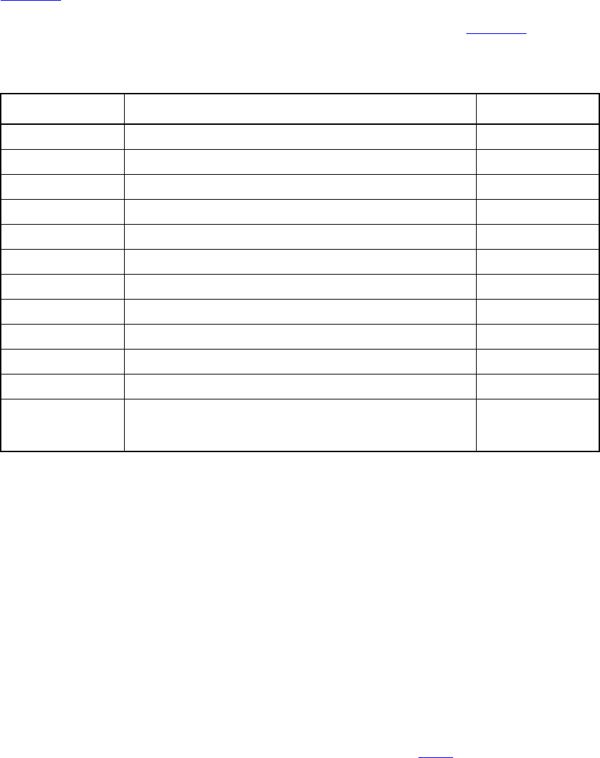
IEEE Std 1800-2012
IEEE STANDARD FOR SYSTEMVERILOG—UNIFIED HARDWARE DESIGN, SPECIFICATION, AND
VERIFICATION LANGUAGE
388
Copyright © 2013 IEEE. All rights reserved.
Table 16-3 lists the sequence and property operators from highest to lowest precedence and shows the
associativity of the non-unary operators. The precedence for the strong and weak sequence operators is not
defined because these operators require parentheses. The operators described in Table 11-2 have higher
precedence than the sequence and property operators.
A disable iff clause can be attached to a property_expr to yield a property_spec.
disable iff (expression_or_dist) property_expr
The expression of the disable iff is called the disable condition. The disable iff clause allows
preemptive resets to be specified. For an evaluation of the property_spec, there is an evaluation of the
underlying property_expr. If the disable condition is true at anytime between the start of the attempt in the
Observed region, inclusive, and the end of the evaluation attempt, inclusive, then the overall evaluation of
the property results in disabled. A property has disabled evaluation if it was preempted due to a
disable iff condition. A disabled evaluation of a property does not result in success or failure.
Otherwise, the evaluation of the property_spec is the same as that of the property_expr. The disable
condition is tested independently for different evaluation attempts of the property_spec. The values of
variables used in the disable condition are those in the current simulation cycle, i.e., not sampled. The
expression may contain a reference to an end point of a sequence by using the method triggered of that
sequence. The disable conditions shall not contain any reference to local variables or the sequence method
matched. If a sampled value function other than $sampled is used in the disable condition, the sampling
clock shall be explicitly specified in its actual argument list as described in 16.9.3. Nesting of disable iff
clauses, explicitly or through property instantiations, is not allowed.
16.12.1 Sequence property
Sequence properties have three forms: sequence_expr, weak(sequence_expr), and
strong(sequence_expr). The strong and weak operators are called sequence operators.
strong(sequence_expr) evaluates to true if, and only if, there is a nonempty match of the sequence_expr.
Table 16-3—Sequence and property operator precedence and associativity
Sequence operators Property operators Associativity
[*], [=], [->] —
## Left
throughout Right
within Left
intersect Left
not, nexttime, s_nexttime —
and and Left
or or Left
iff Right
until, s_until, until_with, s_until_with, implies Right
|->,|=>, #-#, #=# Right
always, s_always, eventually, s_eventually,
if-else, case , accept_on, reject_on,
sync_accept_on, sync_reject_on
—
IEEE Std 1800-2012
IEEE STANDARD FOR SYSTEMVERILOG—UNIFIED HARDWARE DESIGN, SPECIFICATION, AND
VERIFICATION LANGUAGE
389
Copyright © 2013 IEEE. All rights reserved.
weak(sequence_expr) evaluates to true if, and only if, there is no finite prefix that witnesses inability to
match the sequence_expr. The sequence_expr of a sequential property shall not admit an empty match.
If the strong or weak operator is omitted, then the evaluation of the sequence_expr depends on the
assertion statement in which it is used. If the assertion statement is assert property or
assume property, then the sequence_expr is evaluated as weak(sequence_expr). Otherwise, the
sequence_expr is evaluated as strong(sequence_expr).
NOTE—The IEEE 1800-2009 and IEEE 1800-2012 semantics for a sequence_expr definition is not backward
compatible with IEEE Std 1800-2005. The IEEE 1800-2009 and IEEE 1800-2012 equivalent to a sequence_expr as
defined in IEEE Std 1800-2005 is strong(sequence_expr).
Since only one match of a sequence_expr is needed for strong(sequence_expr) to hold, a property of the
form strong(sequence_expr) evaluates to true if, and only if, the property
strong(first_match(sequence_expr)) evaluates to true.
Similarly, a property of the form weak(sequence_expr) evaluates to true if, and only if, the property
weak(first_match(sequence_expr)) evaluates to true. This is because a prefix witnesses inability to
match sequence_expr if, and only if, it witnesses inability to match first_match(sequence_expr).
The following examples illustrate the sequential property forms:
property p3;
b ##1 c;
endproperty
c1: cover property (@(posedge clk) a #-# p3);
a1: assert property (@(posedge clk) a |-> p3);
The sequential property p3 is interpreted as strong in the cover property c1. An evaluation attempt of c1
returns true if, and only if, a is true at the tick of posedge clk at which the attempt begins and both of the
following conditions are satisfied:
—b is true at the tick of posedge clk at which the attempt begins.
— There exists a subsequent tick of posedge clk and c is true at the first such tick.
The sequential property p3 is interpreted as weak in the assert property a1. An evaluation attempt of a1
returns true if, and only if, either a is false at the tick of posedge clk at which the attempt begins or both of
the following conditions are satisfied:
—b is true at the tick of posedge clk at which the attempt begins.
— If there exists a subsequent tick of posedge clk, then c is true at the first such tick.
16.12.2 Negation property
A property is a negation if it has the form not property_expr. For each evaluation attempt of the property,
there is an evaluation attempt of property_expr. The keyword not states that the evaluation of the property
returns the opposite of the evaluation of the underlying property_expr. Thus, if property_expr evaluates to
true, then not property_expr evaluates to false; and if property_expr evaluates to false, then not
property_expr evaluates to true.
The not operator switches the strength of a property. In particular, one should be careful when negating a
sequence. For example, consider the following assertion:
a1: assert property (@clk not a ##1 b);
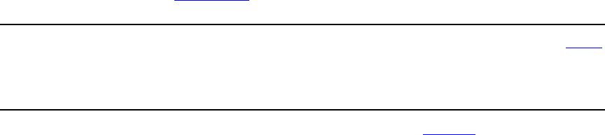
IEEE Std 1800-2012
IEEE STANDARD FOR SYSTEMVERILOG—UNIFIED HARDWARE DESIGN, SPECIFICATION, AND
VERIFICATION LANGUAGE
390
Copyright © 2013 IEEE. All rights reserved.
Since the sequential property a ##1 b is used in an assertion, it is weak. This means that if clk stops
ticking and a holds at the last tick of clk, the weak sequential property a ##1 b will also hold beginning at
that tick, and so the assertion a1 will fail. In this case it is more reasonable to use:
a2: assert property (@clk not strong(a ##1 b));
16.12.3 Disjunction property
A property is a disjunction if it has the following form:
property_expr or property_expr
The property evaluates to true if, and only if, at least one of property_expr1 and property_expr2 evaluates to
true.
16.12.4 Conjunction property
A property is a conjunction if it has the following form:
property_expr and property_expr
The property evaluates to true if, and only if, both property_expr1 and property_expr2 evaluate to true.
16.12.5 If-else property
A property is an if–else if it has either the following form:
if ( expression_or_dist ) property_expr
or the following form:
if ( expression_or_dist ) property_expr else property_expr
A property of the first form evaluates to true if, and only if, either expression_or_dist evaluates to false or
property_expr evaluates to true. A property of the second form evaluates to true if, and only if, either
expression_or_dist evaluates to true and property_expr1 evaluates to true or expression_or_dist evaluates to
false and property_expr2 evaluates to true.
16.12.6 Implication
The implication construct specifies that the checking of a property is performed conditionally on the match
of a sequential antecedent (see Syntax 16-17).
property_expr ::= // from A.2.10
...
| sequence_expr |-> property_expr
| sequence_expr |=> property_expr
Syntax 16-17—Implication syntax (excerpt from Annex A)
This construct is used to precondition monitoring of a property expression and is allowed at the property
level. The result of the implication is either true or false. The left-hand operand sequence_expr is called the
antecedent, while the right-hand operand property_expr is called the consequent.

IEEE Std 1800-2012
IEEE STANDARD FOR SYSTEMVERILOG—UNIFIED HARDWARE DESIGN, SPECIFICATION, AND
VERIFICATION LANGUAGE
391
Copyright © 2013 IEEE. All rights reserved.
The following points should be noted for |-> implication:
— From a given start point, the antecedent sequence_expr can have zero, one, or more than one
successful match.
— If there is no match of the antecedent sequence_expr from a given start point, then evaluation of the
implication from that start point succeeds and returns true.
— For each successful match of the antecedent sequence_expr, the consequent property_expr is
separately evaluated. The end point of the match of the antecedent sequence_expr is the start point
of the evaluation of the consequent property_expr.
— From a given start point, evaluation of the implication succeeds and returns true if, and only if, for
every match of the antecedent sequence_expr beginning at the start point, the evaluation of the
consequent property_expr beginning at the end point of the match succeeds and returns true.
Two forms of implication are provided: overlapped using operator |-> and nonoverlapped using operator
|=>. For overlapped implication, if there is a match for the antecedent sequence_expr, then the end point of
the match is the start point of the evaluation of the consequent property_expr. For nonoverlapped
implication, the start point of the evaluation of the consequent property_expr is the clock tick after the end
point of the match. Therefore,
sequence_expr |=> property_expr
is equivalent to the following:
sequence_expr ##1 `true |-> property_expr
The use of implication when multiclock sequences and properties are involved is explained in 16.13.
The following example illustrates a bus operation for data transfer from a master to a target device. When
the bus enters a data transfer phase, multiple data phases can occur to transfer a block of data. During the
data transfer phase, a data phase completes on any rising clock edge on which irdy is asserted and either
trdy or stop is asserted. In this example, an asserted signal implies a value of low. The requirement for the
end of a data phase can be expressed as follows:
property data_end;
@(posedge mclk)
$rose(data_phase) |-> ##[1,5] ((irdy==0) && ($fell(trdy) || $fell(stop)));
endproperty
Each time the sequence $rose(data_phase) matches, an evaluation of the consequent property begins. In
Figure 16-14, a match for $rose(data_phase) occurs at clock tick 2. This begins the evaluation of the
consequent property. Then, at clock tick 6, data_end evaluates to true because $fell(stop) and
irdy==0 both evaluate to true.
In another example, data_end_exp is used to verify that frame is deasserted (value high) within two clock
ticks after data_end_exp occurs. Further, it is also required that irdy is deasserted (value high) one clock
tick after frame is deasserted.
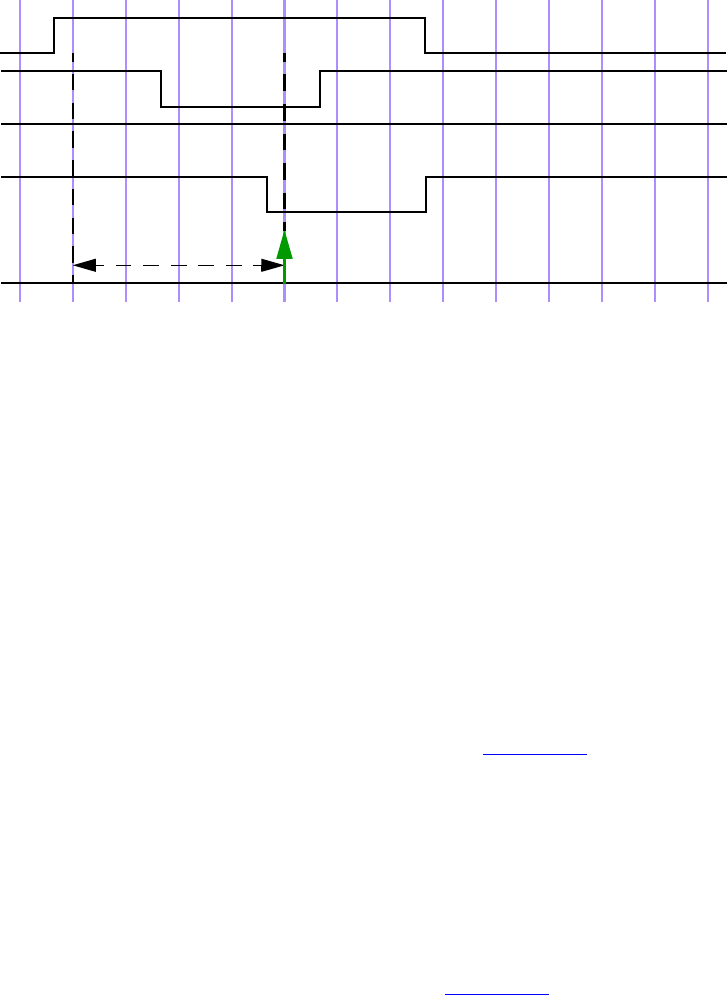
IEEE Std 1800-2012
IEEE STANDARD FOR SYSTEMVERILOG—UNIFIED HARDWARE DESIGN, SPECIFICATION, AND
VERIFICATION LANGUAGE
392
Copyright © 2013 IEEE. All rights reserved.
Figure 16-14—Conditional sequence matching
A property written to express this condition is as follows:
`define data_end_exp (data_phase && ((irdy==0)&&($fell(trdy)||$fell(stop))))
property data_end_rule1;
@(posedge mclk)
`data_end_exp |-> ##[1:2] $rose(frame) ##1 $rose(irdy);
endproperty
Property data_end_rule1 first evaluates data_end_exp at every clock tick to test if its value is true. If
the value is false, then that particular attempt to evaluate data_end_rule1 is considered true. Otherwise,
the following sequence is evaluated:
##[1:2] $rose(frame) ##1 $rose(irdy)
that specifies looking for the rising edge of frame within two clock ticks in the future. After frame toggles
high, irdy must also toggle high after one clock tick. This is illustrated in Figure 16-15 for the evaluation
attempt at clock tick 6. `data_end_exp is acknowledged at clock tick 6. Next, frame toggles high at clock
tick 7. Because this falls within the timing constraint imposed by [1:2], it satisfies the sequence and
continues to evaluate further. At clock tick 8, irdy is evaluated. Signal irdy transitions to high at clock tick
8, matching the sequence specification completely for the attempt that began at clock tick 6.
Generally, assertions are associated with preconditions so that the checking is performed only under certain
specified conditions. As seen from the previous example, the |-> operator provides this capability to specify
preconditions with sequences that must be satisfied before evaluating their consequent properties. The next
example modifies the preceding example to see the effect on the results of the assertion by removing the
precondition for the consequent. This is shown below and illustrated in Figure 16-16.
property data_end_rule2;
@(posedge mclk) ##[1:2] $rose(frame) ##1 $rose(irdy);
endproperty
1 2 3 4 5 6 7 8 9 10 11 12 13 14
data_phase
irdy
trdy
stop
data_end
mclk
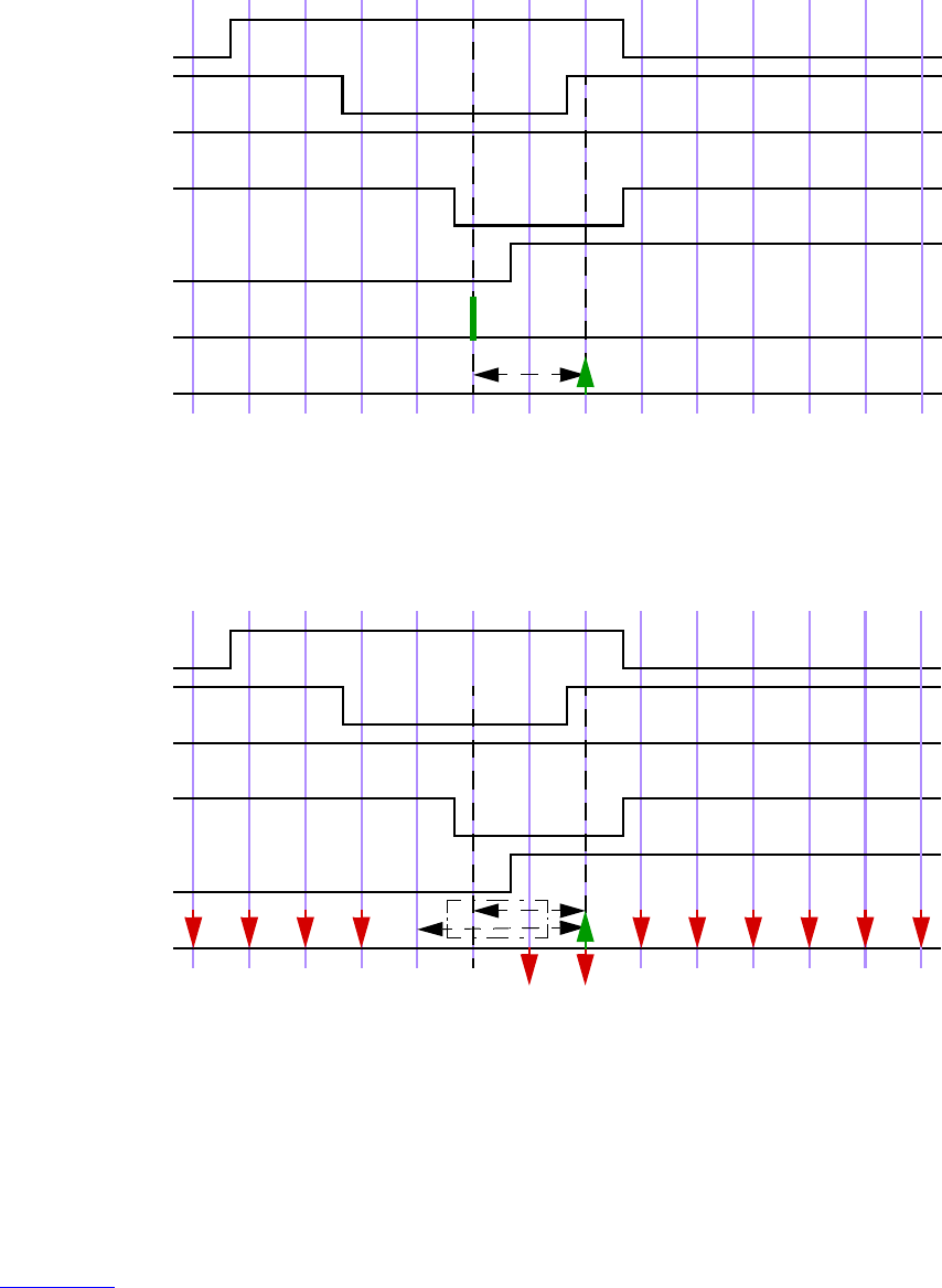
IEEE Std 1800-2012
IEEE STANDARD FOR SYSTEMVERILOG—UNIFIED HARDWARE DESIGN, SPECIFICATION, AND
VERIFICATION LANGUAGE
393
Copyright © 2013 IEEE. All rights reserved.
Figure 16-15—Conditional sequences
Figure 16-16—Results without the condition
The property is evaluated at every clock tick. For the evaluation at clock tick 1, the rising edge of signal
frame does not occur at clock tick 2 or 3; therefore, the property fails at clock tick 1. Similarly, there is a
failure at clock ticks 2, 3, and 4. For attempts starting at clock ticks 5 and 6, the rising edge of signal frame
at clock tick 7 allows checking further. At clock tick 8, the sequences complete according to the
specification, resulting in a match for attempts starting at clock ticks 5 and 6. All later attempts to match the
sequence fail because $rose(frame) does not occur again.
Figure 16-16 shows that removing the precondition of checking `data_end_exp from the assertion causes
failures that are not relevant to the verification objective. It is important from the validation standpoint to
determine these preconditions and use them to filter out inappropriate or extraneous situations.
1 2 3 4 5 6 7 8 9 10 11 12 13 14
data_phase
irdy
trdy (high)
stop
frame
mclk
`data_end_exp
data_end_rule1
1 2 3 4 5 6 7 8 9 10 11 12 13 14
data_phase
irdy
trdy (high)
stop
frame
mclk
data_end_rule2 [1:2]

IEEE Std 1800-2012
IEEE STANDARD FOR SYSTEMVERILOG—UNIFIED HARDWARE DESIGN, SPECIFICATION, AND
VERIFICATION LANGUAGE
394
Copyright © 2013 IEEE. All rights reserved.
An example of implication where the antecedent is a sequence follows:
(a ##1 b ##1 c) |-> (d ##1 e)
If the sequence (a ##1 b ##1 c) matches, then the sequence (d ##1 e) must also match. On the other
hand, if the sequence (a ##1 b ##1 c) does not match, then the result is true.
Another example of implication is as follows:
property p16;
(write_en & data_valid) ##0
(write_en && (retire_address[0:4]==addr)) [*2] |->
##[3:8] write_en && !data_valid &&(write_address[0:4]==addr);
endproperty
This property can be coded alternatively as a nested implication:
property p16_nested;
(write_en & data_valid) |->
(write_en && (retire_address[0:4]==addr)) [*2] |->
##[3:8] write_en && !data_valid && (write_address[0:4]==addr);
endproperty
Multiclock sequence implication is explained in 16.13.
16.12.7 Implies and iff properties
A property is an implies if it has the following form:
property_expr1 implies property_expr2
A property of this form evaluates to true if, and only if, either property_expr1 evaluates to false or
property_expr2 evaluates to true.
A property is an iff if it has the following form:
property_expr1 iff property_expr2
A property of this form evaluates to true if, and only if, either both property_expr1 evaluates to false and
property_expr2 evaluates to false or both property_expr1 evaluates to true and property_expr2 evaluates to
true.
16.12.8 Property instantiation
An instance of a named property can be used as a property_expr or property_spec. In general, the instance is
legal provided the body property_spec of the named property can be substituted in place of the instance,
with actual arguments substituted for formal arguments, and result in a legal property_expr or
property_spec. For example, if an instance of a named property is used as a property_expr operand for any
property-building operator, then the named property must not have a disable iff clause.
16.12.9 Followed-by property
A property is a followed-by if it has one of the following forms that use the followed-by operators shown in
Syntax 16-18.
IEEE Std 1800-2012
IEEE STANDARD FOR SYSTEMVERILOG—UNIFIED HARDWARE DESIGN, SPECIFICATION, AND
VERIFICATION LANGUAGE
395
Copyright © 2013 IEEE. All rights reserved.
property_expr ::= // from A.2.10
...
| sequence_expr #-# property_expr
| sequence_expr #=# property_expr
Syntax 16-18—Followed-by syntax (excerpt from Annex A)
This clause is used to trigger monitoring of a property expression and is allowed at the property level.
The result of the followed-by is either true or false. The left-hand operand sequence_expr is called the
antecedent, while the right-hand operand property_expr is called the consequent. For the followed-by
property to succeed, the following must hold:
— From a given start point sequence_expr shall have at least one successful match.
—property_expr shall be successfully evaluated starting from the end point of some successful match
of sequence_expr.
From a given start point, evaluation of the followed-by succeeds and returns true if, and only if, there exists
a match of the antecedent sequence_expr beginning at the start point, and the evaluation of the consequent
property_expr beginning at the end point of the match succeeds and returns true.
Two forms of followed-by are provided: overlapped using operator #-# and nonoverlapped using operator
#=#. For overlapped followed-by, there shall be a match for the antecedent sequence_expr, where the end
point of this match is the start point of the evaluation of the consequent property_expr. For nonoverlapped
followed-by, the start point of the evaluation of the consequent property_expr is the clock tick after the end
point of the match.
The followed-by operators are the duals of the implication operators. Therefore, sequence_expr #-#
property_expr is equivalent to the following:
not (sequence_expr |-> not property_expr)
and sequence_expr #=# property_expr is equivalent to the following:
not (sequence_expr |=> not property_expr)
Examples:
property p1;
##[0:5] done #-# always !rst;
endproperty
property p2;
##[0:5] done #=# always !rst;
endproperty
Property p1 says that done shall be asserted at some clock tick during the first 6 clock ticks, and starting
from one of the clock ticks when done is asserted, rst shall always be low. Property p2 says that done
shall be asserted at some clock tick during the first 6 clock ticks, and starting the clock tick after one of the
clock ticks when done is asserted, rst shall always be low.
IEEE Std 1800-2012
IEEE STANDARD FOR SYSTEMVERILOG—UNIFIED HARDWARE DESIGN, SPECIFICATION, AND
VERIFICATION LANGUAGE
396
Copyright © 2013 IEEE. All rights reserved.
sequence_expr #-# strong(sequence_expr1) is semantically equivalent to strong(sequence_expr ##0
sequence_expr1), and sequence_expr #=# strong(sequence_expr1) is semantically equivalent to
strong(sequence_expr ##1 sequence_expr1).
A followed-by operator is especially convenient for specifying a cover property directive over a
sequence followed by a property.
16.12.10 Nexttime property
A property is a nexttime if it has one of the following forms that use the nexttime operators:
— Weak nexttime
nexttime property_expr
The weak nexttime property nexttime property_expr evaluates to true if, and only if, either the
property_expr evaluates to true beginning at the next clock tick or there is no further clock tick.
— Indexed form of weak nexttime
nexttime [ constant_expression ] property_expr
The indexed weak nexttime property nexttime [constant_expression]property_expr evaluates to
true if, and only if, either there are not constant_expression clock ticks or property_expr evaluates to
true beginning at the last of the next constant_expression clock ticks.
— Strong nexttime
s_nexttime property_expr
The strong nexttime property s_nexttime property_expr evaluates to true if, and only if, there
exists a next clock tick and property_expr evaluates to true beginning at that clock tick.
— Indexed form of strong nexttime
s_nexttime [ constant_expression ] property_expr
The indexed strong nexttime property s_nexttime [constant_expression]property_expr
evaluates to true if, and only if, there exist constant_expression clock ticks and property_expr
evaluates to true beginning at the last of the next constant_expression clock ticks.
The number of clock ticks given by constant_expression shall be a non-negative integer constant expression.
The preceding explanations refer to the case where the nexttime property is evaluated in a time step that is a
tick of the clock of the nexttime property. When the nexttime property is evaluated in a time step that is not
a tick of the clock of the nexttime property, an alignment to the tick of the clock of the nexttime property
should be applied before the above description. Thus, it is more precise to say that s_nexttime[n]
property_expr evaluates to true if, and only if, there exist n+1 ticks of the clock of the nexttime property,
including the current time step, and property_expr evaluates to true on the n+1 clock tick, where counting
starts at the current time step. In particular nexttime[0] and s_nexttime[0] act as alignment operators.
The comments in the following examples describe the conditions for the properties to be evaluated to true:
// if the clock ticks once more, then a shall be true at the next clock tick
property p1;
nexttime a;
endproperty
// the clock shall tick once more and a shall be true at the next clock tick.
property p2;
IEEE Std 1800-2012
IEEE STANDARD FOR SYSTEMVERILOG—UNIFIED HARDWARE DESIGN, SPECIFICATION, AND
VERIFICATION LANGUAGE
397
Copyright © 2013 IEEE. All rights reserved.
s_nexttime a;
endproperty
// as long as the clock ticks, a shall be true at each future clock tick
// starting from the next clock tick
property p3;
nexttime always a;
endproperty
// the clock shall tick at least once more and as long as it ticks, a shall
// be true at every clock tick starting from the next one
property p4;
s_nexttime always a;
endproperty
// if the clock ticks at least once more, it shall tick enough times for a to
// be true at some point in the future starting from the next clock tick
property p5;
nexttime s_eventually a;
endproperty
// a shall be true sometime in the strict future
property p6;
s_nexttime s_eventually a;
endproperty
// if there are at least two more clock ticks, a shall be true at the second
// future clock tick
property p7;
nexttime[2] a;
endproperty
// there shall be at least two more clock ticks, and a shall be true at the
// second future clock tick
property p8;
s_nexttime[2] a;
endproperty
16.12.11 Always property
A property is an always if it has one of the following forms that use the always operators:
— Weak always
always property_expr
A property always property_expr evaluates to true if, and only if, property_expr holds at every
current or future clock tick.
— Ranged form of weak always
always [ cycle_delay_const_range_expression ] property_expr
A property always [cycle_delay_const_range_expression]property_expr evaluates to true if, and
only if, property_expr holds at every current or future clock tick that is within the range of clock
ticks specified by cycle_delay_const_range_expression. It is not required that all clock ticks within
this range exist. The range for a weak always may be unbounded.
— Ranged form of strong always
s_always [ constant_range ] property_expr

IEEE Std 1800-2012
IEEE STANDARD FOR SYSTEMVERILOG—UNIFIED HARDWARE DESIGN, SPECIFICATION, AND
VERIFICATION LANGUAGE
398
Copyright © 2013 IEEE. All rights reserved.
A property s_always [constant_range]property_expr evaluates to true if, and only if, all current
or future clock ticks specified by constant_range exist and property_expr holds at each of these
clock ticks. The range for a strong always shall be bounded.
The range of clock ticks given by constant_range shall adhere to the following restrictions. The minimum
number of clock ticks is defined by a non-negative integer constant expression; and the maximum number of
clock ticks either is defined by a non-negative integer constant expression or is $, indicating a finite, but
unbounded, maximum. If both the minimum and maximum numbers of clock ticks are defined by non-
negative integer constant expressions (see 11.2.1), then the minimum number shall be less than or equal to
the maximum number.
The preceding explanations refer to the case where the always property is evaluated in a time step that is a
tick of the clock of the always property. When the always property is evaluated in a time step that is not a
tick of the clock of the always property, an alignment to the tick of the clock of the always property should
be applied before the above description. Thus, it is more precise to say that s_always[n:m] property_expr
evaluates to true if, and only if, there exist m+1 ticks of the clock of the always property, including the
current time step, and property_expr evaluates to true beginning in all of the n+1 to m+1 clock ticks, where
counting starts at the current time step.
There is also the implicit always that is associated with concurrent assertions (see 16.5). A verification
statement that is not placed inside an initial block specifies that an evaluation attempt of its top-level
property shall begin at each occurrence of its leading clocking event. In the following two examples, there is
a one-to-one correspondence between the evaluation attempts of p specified by the implicit always from the
verification statement implicit_always and the evaluation attempts of p specified by the explicit always
operator in explicit_always:
Implicit form:
implicit_always: assert property(p);
Explicit form:
initial explicit_always: assert property(always p);
This is not shown as a practical example, but only for illustration of the meaning of always.
Examples:
initial a1: assume property( @(posedge clk) reset[*5] #=# always !reset);
property p1;
a ##1 b |=> always c;
endproperty
property p2;
always [2:5] a;
endproperty
property p3;
s_always [2:5] a;
endproperty
property p4;
always [2:$] a;
endproperty
IEEE Std 1800-2012
IEEE STANDARD FOR SYSTEMVERILOG—UNIFIED HARDWARE DESIGN, SPECIFICATION, AND
VERIFICATION LANGUAGE
399
Copyright © 2013 IEEE. All rights reserved.
property p5;
s_always [2:$] a; // Illegal
endproperty
The assertion a1 says that reset shall be true for the first 5 clock ticks and then remain 0 for the rest of the
computation. The assumption is being evaluated once starting at the first clock tick. The property p1
evaluates to true provided that if a is true at the first clock tick and b is true at the second clock tick, then c
shall be true at every clock tick that follows the second. The properties p2 and p3 evaluate to true provided
that a is true at each of the second through fifth clock ticks after the starting clock tick of the evaluation
attempt. Property p3 evaluates to true provided that these clock ticks exist, while property p2 does not
require that. The property p4 evaluates to true if, and only if, a is true at every clock tick that is at least two
clock ticks after the starting clock tick of the evaluation attempt. These clock ticks are not required to exist.
The property p5 is illegal since specifying an unbounded range is not permitted with the strong form of an
always property.
16.12.12 Until property
A property is an until if it has one of the following forms that use the until operators:
— Weak non-overlapping form
property_expr1 until property_expr2
— Strong non-overlapping form
property_expr1 s_until property_expr2
— Weak overlapping form
property_expr1 until_with property_expr2
— Strong overlapping form
property_expr1 s_until_with property_expr2
An until property of the non-overlapping form evaluates to true if property_expr1 evaluates to true at every
clock tick beginning with the starting clock tick of the evaluation attempt and continuing until at least one
tick before a clock tick where property_expr2 evaluates to true. An until property of one of the overlapping
forms evaluates to true if property_expr1 evaluates to true at every clock tick beginning with the starting
clock tick of the evaluation attempt and continuing until and including a clock tick at which property_expr2
evaluates to true. An until property of one of the strong forms requires a current or future clock tick exist at
which property_expr2 evaluates to true, while an until property of one of the weak forms does not make this
requirement. An until property of one of the weak forms evaluates to true if property_expr1 evaluates to true
at each clock tick, even if property_expr2 never holds.
Examples:
property p1;
a until b;
endproperty
property p2;
a s_until b;
endproperty
property p3;
a until_with b;
endproperty
IEEE Std 1800-2012
IEEE STANDARD FOR SYSTEMVERILOG—UNIFIED HARDWARE DESIGN, SPECIFICATION, AND
VERIFICATION LANGUAGE
400
Copyright © 2013 IEEE. All rights reserved.
property p4;
a s_until_with b;
endproperty
Property p1 evaluates to true if, and only if, a is true at every clock tick beginning with the starting clock
tick of the evaluation attempt and continuing until, but not necessarily including, a clock tick at which b is
true. If there is no current or future clock tick at which b is true, than a shall be true at every current or future
clock tick. If b is true at the starting clock tick of the evaluation attempt, then a need not be true at that clock
tick. The property p2 evaluates to true provided that there exists a current or future clock tick at which b is
true and that a is true at every clock tick beginning with the starting clock tick of the evaluation attempt and
continuing until, but not necessarily including, the clock tick at which b is true. If b is true at the starting
clock tick of the evaluation attempt, then a need not be true at that clock tick. The property p3 evaluates to
true provided that a is true at every clock tick beginning with the starting clock tick of the evaluation attempt
and continuing until and including a clock tick at which b is true. If there is no current or future clock tick at
which b is true, than a shall be true at every current or future clock tick. The property p4 evaluates to true
provided there exists a current or future clock tick at which b is true and that a is true at every clock tick
beginning with the starting clock tick of the evaluation attempt and continuing until and including the clock
tick at which b is true. The property p4 is equivalent to strong(a[*1:$] ##0 b) (here a and b are
Boolean expressions).
16.12.13 Eventually property
A property is an eventually if it has one of the following forms that use the eventually operators:
— Strong eventually
s_eventually property_expr
A property s_eventually property_expr evaluates to true if, and only if, there exists a current or
future clock tick at which property_expr evaluates to true.
— Ranged form of weak eventually
eventually [ constant_range ] property_expr
A property eventually [constant_range] property_expr evaluates to true if, and only if, either there
exists a current or future clock tick within the range specified by constant_range at which
property_expr evaluates to true or not all the current or future clock ticks within the range specified
by constant_range exist. The range for a weak eventually shall be bounded.
— Ranged form of strong eventually
s_eventually [ cycle_delay_const_range_expression ] property_expr
A property s_eventually [cycle_delay_const_range_expression] property_expr evaluates to true if,
and only if, there exists a current or future clock tick within the range specified by
cycle_delay_const_range_expression at which property_expr evaluates to true. The range for a
strong eventually may be unbounded.
In the following examples, a and b are Boolean expressions:
property p1;
s_eventually a;
endproperty
property p2;
s_eventually always a;
endproperty
property p3;
IEEE Std 1800-2012
IEEE STANDARD FOR SYSTEMVERILOG—UNIFIED HARDWARE DESIGN, SPECIFICATION, AND
VERIFICATION LANGUAGE
401
Copyright © 2013 IEEE. All rights reserved.
always s_eventually a;
endproperty
property p4;
eventually [2:5] a;
endproperty
property p5;
s_eventually [2:5] a;
endproperty
property p6;
eventually [2:$] a; // Illegal
endproperty
property p7;
s_eventually [2:$] a;
endproperty
The property p1 evaluates to true if, and only if, there exists a current or future clock tick at which a is true.
It is equivalent to strong(##[*0:$] a). The property p2 evaluates to true if, and only if, there exists a
current or future clock tick such that a is true both at that clock tick and also at every subsequent clock tick.
On a computation with infinitely many clock ticks, the property p3 evaluates to true if, and only if, a is true
at infinitely many of those clock ticks. On a computation with finitely many clock ticks, the property p3
evaluates to true provided that if there is at least one clock tick, then a holds at the last clock tick. The
property p4 evaluates to true provided that if the second through fifth clock ticks from the starting clock tick
of the evaluation attempt all exist, then a is true at one of these clock ticks. p4 is equivalent to
weak(##[2:5] a). The property p5 evaluates to true if, and only if, there exists a clock tick at which a is
true and that it is between the second and fifth clock ticks, inclusive, from the starting clock tick of the
evaluation attempt. p5 is equivalent to strong(##[2:5] a). The property p7 evaluates to true if, and only
if, there exists a clock tick at which a is true and that it is no earlier than the second clock tick after the
starting clock tick of the evaluation attempt.
The preceding explanations refer to the case where the eventually property is evaluated in a time step that is
a tick of the clock of the eventually property. When the eventually property is evaluated in a time step that is
not a tick of the clock of the eventually property, an alignment to the tick of the clock of the eventually
property should be applied before the above description. Thus, it is more precise to say that
s_eventually[n:m] property_expr evaluates to true if, and only if, there exist at least n+1 ticks of the
clock of the eventually property, including the current time step, and property_expr evaluates to true
beginning in one of the n+1 to m+1 clock ticks, where counting starts at the current time step.
16.12.14 Abort properties
A property is an abort if it has one of the following forms:
accept_on ( expression_or_dist ) property_expr
reject_on ( expression_or_dist ) property_expr
sync_accept_on ( expression_or_dist ) property_expr
sync_reject_on ( expression_or_dist ) property_expr
where the expression_or_dist is called the abort condition. The properties accept_on and reject_on are
called asynchronous abort properties, and the properties sync_accept_on and sync_reject_on are
called synchronous abort properties.
IEEE Std 1800-2012
IEEE STANDARD FOR SYSTEMVERILOG—UNIFIED HARDWARE DESIGN, SPECIFICATION, AND
VERIFICATION LANGUAGE
402
Copyright © 2013 IEEE. All rights reserved.
For an evaluation of accept_on (expression_or_dist)property_expr and of
sync_accept_on (expression_or_dist)property_expr, there is an evaluation of the underlying
property_expr. If during the evaluation, the abort condition becomes true, then the overall evaluation of the
property results in true. Otherwise, the overall evaluation of the property is equal to the evaluation of the
property_expr.
For an evaluation of reject_on (expression_or_dist)property_expr and of
sync_reject_on (expression_or_dist)property_expr, there is an evaluation of the underlying
property_expr. If during the evaluation, the abort condition becomes true, then the overall evaluation of the
property results in false. Otherwise, the overall evaluation of the property is equal to the evaluation of the
property_expr.
The operators accept_on and reject_on are evaluated at the granularity of the simulation time step like
disable iff, but their abort condition is evaluated using sampled value as a regular Boolean expression in
assertions. The operators accept_on and reject_on represent asynchronous resets.
The operators sync_accept_on and sync_reject_on are evaluated at the simulation time step when the
clocking event happens, unlike disable iff, accept_on, and reject_on. Their abort condition is
evaluated using sampled value as for accept_on and reject_on. The operators sync_accept_on and
sync_reject_on represent synchronous resets.
The semantics of accept_on is similar to disable iff, except for the following differences:
—accept_on operates at the property level rather than the concurrent assertion level.
—accept_on uses sampled values.
— While a disable condition of a disable iff in a property_spec may cause an evaluation of the
property_spec to be disabled, an abort condition of accept_on in a property_expr may cause the
evaluation of the property_expr to be true.
The semantics of reject_on(expression_or_dist) property_expr is the same as
not(accept_on(expression_or_dist) not(property_expr)).
The semantics of sync_accept_on is similar to accept_on, except that it evaluates only at the time steps
when the clocking event happens.
The semantics of sync_reject_on(expression_or_dist)property_expr is the same as
not(sync_accept_on(expression_or_dist) not(property_expr)).
Any nesting of abort operators accept_on, reject_on, sync_accept_on, and sync_reject_on is
allowed.
For example, whenever go is high, followed by two occurrences of get being high, then stop cannot be
high until after put is asserted twice (not necessarily consecutive).
assert property (@(clk) go ##1 get[*2] |-> reject_on(stop) put[->2]);
In this example the stop is an asynchronous abort, its value is checked even between ticks of clk. The
following is the synchronous version of the same example:
assert property (@(clk) go ##1 get[*2] |-> sync_reject_on(stop) put[->2]);
Here stop is checked only at the clk ticks. The latter assertion can also be written as follows:
assert property (@(clk) go ##1 get[*2] |-> !stop throughout put[->2]);

IEEE Std 1800-2012
IEEE STANDARD FOR SYSTEMVERILOG—UNIFIED HARDWARE DESIGN, SPECIFICATION, AND
VERIFICATION LANGUAGE
403
Copyright © 2013 IEEE. All rights reserved.
When the abort condition occurs at the same time step where the evaluation of the property_expr ends, the
abort condition takes precedence. For example:
property p; (accept_on(a) p1) and (reject_on(b) p2); endproperty
If a becomes true during the evaluation of p1, the first term is ignored in deciding the truth of p. On the other
hand, if b becomes true during the evaluation of p2 then p evaluates to false.
property p; (accept_on(a) p1) or (reject_on(b) p2); endproperty
If a becomes true during the evaluation of p1 then p evaluates to true. On the other hand, if b becomes true
during the evaluation of p2, then the second term is ignored in deciding the truth of p.
property p; not (accept_on(a) p1); endproperty
not inverts the effect of the abort operator. Therefore, if a becomes true while evaluating p1, property p
evaluates to false.
Nested accept_on, reject_on, sync_accept_on, and sync_reject_on operators are evaluated in the
lexical order (left to right). Therefore, if two nested operator conditions become true in the same time step
during the evaluation of the argument property, then the outermost operator takes precedence. For example:
property p; accept_on(a) reject_on(b) p1; endproperty
If a becomes true in the same time step as b and during the evaluation of p1, then p succeeds in that time
step. If b becomes true before a and during the evaluation of p1, then p fails.
The abort conditions may contain sampled value functions (see 16.9.3). When sampled value functions other
than $sampled are used in the abort condition, the clock argument shall be explicitly specified. Abort
conditions shall not contain any reference to local variables and the sequence methods triggered and
matched.
16.12.15 Weak and strong operators
The property operators s_nexttime, s_always, s_eventually, s_until, s_until_with, and
sequence operator strong are strong: they require that some terminating condition happen in the future, and
this includes the requirement that the property clock ticks enough time to enable the condition to happen.
The property operators nexttime, always, until, eventually, until_with, and sequence operator
weak are weak: they do not impose any requirement on the terminating condition, and do not require the
clock to tick.
The concept of weak and strong operators is closely related to an important notion of safety properties.
Safety properties have the characteristic that all their failures happen at a finite time. For example, the
property always a is a safety property since it is violated only if after finitely many clock ticks there is a
clock tick at which a is false, even if there are infinitely many clock ticks in the computation. To the
contrary, a failure of the property s_eventually a on a computation with infinitely many clock ticks
cannot be identified at a finite time; if it is violated, the value of a must be false at each of the infinitely
many clock ticks.
16.12.16 Case
The case property statement is a multiway decision that tests whether a Boolean expression matches one of
a number of other Boolean expressions and branches accordingly (see Syntax 16-19).

IEEE Std 1800-2012
IEEE STANDARD FOR SYSTEMVERILOG—UNIFIED HARDWARE DESIGN, SPECIFICATION, AND
VERIFICATION LANGUAGE
404
Copyright © 2013 IEEE. All rights reserved.
property_expr ::= // from A.2.10
...
|case ( expression_or_dist ) property_case_item { property_case_item } endcase
...
property_case_item::=
expression_or_dist { , expression_or_dist } : property_expr [ ; ]
|default [ : ] property_expr [ ; ]
Syntax 16-19—Property statement case syntax (excerpt from Annex A)
The default statement shall be optional. Use of multiple default statements in one property case statement
shall be illegal.
A simple example of the use of the case property statement is the decoding of variable delay to produce a
delay between the check of two signals as follows:
property p_delay(logic [1:0] delay);
case (delay)
2'd0 : a && b;
2'd1 : a ##2 b;
2'd2 : a ##4 b;
2'd3 : a ##8 b;
default: 0; // cause a failure if delay has x or z values
endcase
endproperty
During the linear search, if one of the case item expressions matches the case expression given in
parentheses, then the property statement associated with that case item shall be evaluated, and the linear
search shall terminate. If there is a default case item, it is ignored during this linear search. If all comparisons
fail and the default item is given, then the default item property statement shall be executed. If the default
property statement is not given and all of the comparisons fail, then none of the case item property
statements shall be evaluated and the evaluation of the case property statement from that start point succeeds
and returns true (vacuously).
The rules for comparing the case expression to the case item expressions are described in 12.5.
16.12.17 Recursive properties
SystemVerilog allows recursive properties. A named property is recursive if its declaration involves an
instantiation of itself. Recursion provides a flexible framework for coding properties to serve as ongoing
assumptions, obligations, or coverage monitors.
For example:
property prop_always(p);
p and (1'b1 |=> prop_always(p));
endproperty
is a recursive property that says that the formal argument property p must hold at every cycle. This example
is useful if the ongoing requirement that property p hold applies after a complicated triggering condition
encoded in sequence s:
property p1(s,p);

IEEE Std 1800-2012
IEEE STANDARD FOR SYSTEMVERILOG—UNIFIED HARDWARE DESIGN, SPECIFICATION, AND
VERIFICATION LANGUAGE
405
Copyright © 2013 IEEE. All rights reserved.
s |=> prop_always(p);
endproperty
As another example, the recursive property
property prop_weak_until(p,q);
q or (p and (1'b1 |=> prop_weak_until(p,q)));
endproperty
says that formal argument property p must hold at every cycle up to, but not including, the first cycle at
which formal argument property q holds. Formal argument property q is not required ever to hold, however.
This example is useful if p must hold at every cycle after a complicated triggering condition encoded in
sequence s, but the requirement on p is lifted by q:
property p2(s,p,q);
s |=> prop_weak_until(p,q);
endproperty
More generally, several properties can be mutually recursive. For example:
property check_phase1;
s1 |-> (phase1_prop and (1'b1 |=> check_phase2));
endproperty
property check_phase2;
s2 |-> (phase2_prop and (1'b1 |=> check_phase1));
endproperty
There are four restrictions on recursive property declarations, as follows:
—Restriction 1: The negation operator not and strong operators s_nexttime, s_eventually,
s_always, s_until, and s_until_with cannot be applied to any property expression that
instantiates a recursive property. In particular, the negation of a recursive property cannot be
asserted or used in defining another property.
The following are examples of illegal property declarations that violate Restriction 1:
property illegal_recursion_1(p);
not prop_always(not p);
endproperty
property illegal_recursion_2(p);
p and (1'b1 |=> not illegal_recursion_2(p));
endproperty
Furthermore, not cannot be applied to any property expression that instantiates a property that
depends on a recursive property. The precise definition of dependency is given in F.7.
—Restriction 2: The operator disable iff cannot be used in the declaration of a recursive property.
This restriction is consistent with the restriction that disable iff cannot be nested.
The following is an example of an illegal property declaration that violates Restriction 2:
property illegal_recursion_3(p);
disable iff (b)
p and (1'b1 |=> illegal_recursion_3(p));
endproperty
The intent of illegal_recursion_3 can be written legally as follows:
IEEE Std 1800-2012
IEEE STANDARD FOR SYSTEMVERILOG—UNIFIED HARDWARE DESIGN, SPECIFICATION, AND
VERIFICATION LANGUAGE
406
Copyright © 2013 IEEE. All rights reserved.
property legal_3(p);
disable iff (b) prop_always(p);
endproperty
because legal_3 is not a recursive property.
—Restriction 3: If p is a recursive property, then, in the declaration of p, every instance of p must
occur after a positive advance in time. In the case of mutually recursive properties, all recursive
instances must occur after positive advances in time.
The following is an example of an illegal property declaration that violates Restriction 3:
property illegal_recursion_4(p);
p and (1'b1 |-> illegal_recursion_4(p));
endproperty
If this form were legal, the recursion would be stuck in time, checking p over and over again at the
same cycle.
—Restriction 4: For every recursive instance of property q in the declaration of property p, each actual
argument expression e of the instance satisfies at least one of the following conditions:
—e is itself a formal argument of p.
— No formal argument of p appears in e.
—e is bound to a local variable formal argument of q.
For example:
property fibonacci1 (local input int a, b, n, int fib_sig);
(n > 0)
|->
(
(fib_sig == a)
and
(1'b1 |=> fibonacci1(b, a + b, n - 1, fib_sig))
);
endproperty
is a legal declaration, but
property fibonacci2 (int a, b, n, fib_sig);
(n > 0)
|->
(
(fib_sig == a)
and
(1'b1 |=> fibonacci2(b, a + b, n - 1, fib_sig))
);
endproperty
is not legal because, in the recursive instance fibonacci2(b, a+b, n-1, fib_sig), the actual
argument expressions a+b, n-1 are not themselves formal arguments of fibonacci2, are not bound to
local variable formal arguments, and yet formal arguments of fibonacci2 appear in these expressions.
The operators accept_on, reject_on, sync_accept_on, and sync_reject_on may be used inside a
recursive property. For example, the following uses of accept_on and reject_on in a property are legal:
IEEE Std 1800-2012
IEEE STANDARD FOR SYSTEMVERILOG—UNIFIED HARDWARE DESIGN, SPECIFICATION, AND
VERIFICATION LANGUAGE
407
Copyright © 2013 IEEE. All rights reserved.
property p3(p, bit b, abort);
(p and (1'b1 |=> p4(p, b, abort)));
endproperty
property p4(p, bit b, abort);
accept_on(b) reject_on(abort) p3(p, b, abort);
endproperty
Recursive properties can represent complicated requirements, such as those associated with varying
numbers of data beats, out-of-order completions, retries, etc. Following is an example of using a recursive
property to check complicated conditions of this kind.
Suppose that write data must be checked according to the following conditions:
— Acknowledgment of a write request is indicated by the signal write_request together with
write_request_ack. When a write request is acknowledged, it gets a 4-bit tag, indicated by
signal write_reqest_ack_tag. The tag is used to distinguish data beats for multiple write
transactions in flight at the same time.
— It is understood that distinct write transactions in flight at the same time must be given distinct tags.
For simplicity, this condition is not a part of what is checked in this example.
— Each write transaction can have between 1 data beat and 16 data beats, and each data beat is 8 bits.
There is a model of the expected write data that is available at acknowledgment of a write request.
The model is a 128-bit vector. The most significant group of 8 bits represents the expected data for
the first beat, the next group of 8 bits represents the expected data for the second beat (if there is a
second beat), and so forth.
— Data transfer for a write transaction occurs after acknowledgment of the write request and, barring
retry, ends with the last data beat. The data beats for a single write transaction occur in order.
— A data beat is indicated by the data_valid signal together with the signal data_valid_tag to
determine the relevant write transaction. The signal data are valid with data_valid and carry the
data for that beat. The data for each beat must be correct according to the model of the expected
write data.
— The last data beat is indicated by signal last_data_valid together with data_valid and
data_valid_tag. For simplicity, this example does not represent the number of data beats and
does not check that last_data_valid is signaled at the correct beat.
— At any time after acknowledgment of the write request, but not later than the cycle after the last data
beat, a write transaction can be forced to retry. Retry is indicated by the signal retry together with
signal retry_tag to identify the relevant write transaction. If a write transaction is forced to retry,
then its current data transfer is aborted, and the entire data transfer must be repeated. The transaction
does not re-request, and its tag does not change.
— There is no limit on the number of times a write transaction can be forced to retry.
— A write transaction completes the cycle after the last data beat provided it is not forced to retry in
that cycle.
The following is code to check these conditions:
property check_write;
logic [0:127] expected_data; // local variable to sample model data
logic [3:0] tag; // local variable to sample tag
disable iff (reset)
(
write_request && write_request_ack,
expected_data = model_data,

IEEE Std 1800-2012
IEEE STANDARD FOR SYSTEMVERILOG—UNIFIED HARDWARE DESIGN, SPECIFICATION, AND
VERIFICATION LANGUAGE
408
Copyright © 2013 IEEE. All rights reserved.
tag = write_request_ack_tag
)
|=>
check_write_data_beat(expected_data, tag, 4'h0);
endproperty
property check_write_data_beat
(
local input logic [0:127] expected_data,
local input logic [3:0] tag, i
);
(
(data_valid && (data_valid_tag == tag))
||
(retry && (retry_tag == tag))
)[->1]
|->
(
(
(data_valid && (data_valid_tag == tag))
|->
(data == expected_data[i*8+:8])
)
and
(
if (retry && (retry_tag == tag))
(
1'b1 |=> check_write_data_beat(expected_data, tag, 4'h0)
)
else if (!last_data_valid)
(
1'b1 |=> check_write_data_beat(expected_data, tag, i+4'h1)
)
else
(
##1 (retry && (retry_tag == tag))
|=>
check_write_data_beat(expected_data, tag, 4'h0)
)
)
);
endproperty
16.12.18 Typed formal arguments in property declarations
The rules in 16.8.1 for typed formal arguments and their corresponding actual arguments apply to named
properties, except as described next.
If a formal argument of a named property is typed, then the type shall be property, sequence, event, or
one of the types allowed in 16.6. If the formal argument is of type property, then the corresponding actual
argument shall be a property_expr, and each reference to the formal argument shall be in a place where a
property_expr may be written.
For example, a Boolean expression or a sequence_expr may be passed as actual argument to a formal
argument of type property because each is a property_expr. A formal argument of type property may

IEEE Std 1800-2012
IEEE STANDARD FOR SYSTEMVERILOG—UNIFIED HARDWARE DESIGN, SPECIFICATION, AND
VERIFICATION LANGUAGE
409
Copyright © 2013 IEEE. All rights reserved.
not be referenced as the antecedent of |-> or |=> (see 16.12.6), regardless of the corresponding actual
argument, because a property_expr may not be written in that position.
16.12.19 Local variable formal arguments in property declarations
The rules in 16.8.2 for local variable formal arguments and their corresponding actual arguments apply to
named properties, except as described next.
A local variable formal argument of a named property shall have direction input, either specified explicitly
or inferred. It shall be illegal to declare a local variable formal argument of a named property with direction
inout or output.
16.12.20 Property examples
The following examples illustrate the property forms:
property rule1;
@(posedge clk) a |-> b ##1 c ##1 d;
endproperty
property rule2;
@(clkev) disable iff (e) a |-> not(b ##1 c ##1 d);
endproperty
Property rule2 negates the sequence (b ##1 c ##1 d) in the consequent of the implication. clkev
specifies the clock for the property.
property rule3;
@(posedge clk) a[*2] |-> ((##[1:3] c) or (d |=> e));
endproperty
Property rule3 says that if a holds and a also held last cycle, then either c must hold at some point one to
three cycles after the current cycle or, if d holds in the current cycle, then e must hold one cycle later.
property rule4;
@(posedge clk) a[*2] |-> ((##[1:3] c) and (d |=> e));
endproperty
Property rule4 says that if a holds and a also held last cycle, then c must hold at some point one to three
cycles after the current cycle and, if d holds in the current cycle, then e must hold one cycle later.
property rule5;
@(posedge clk)
a ##1 (b || c)[->1] |->
if (b)
(##1 d |-> e)
else // c
f ;
endproperty
Property rule5 has a followed by the next occurrence of either b or c as its antecedent. The consequent
uses if–else to split cases on which of b or c is matched first.
property rule6(x,y);
##1 x |-> y;
endproperty
property rule5a;

IEEE Std 1800-2012
IEEE STANDARD FOR SYSTEMVERILOG—UNIFIED HARDWARE DESIGN, SPECIFICATION, AND
VERIFICATION LANGUAGE
410
Copyright © 2013 IEEE. All rights reserved.
@(posedge clk)
a ##1 (b || c)[->1] |->
if (b)
rule6(d,e)
else // c
f ;
endproperty
Property rule5a is equivalent to rule5, but it uses an instance of rule6 as a property expression.
A property can optionally specify an event control for the clock. The clock derivation and resolution rules
are described in 16.16.
A named property can be instantiated by referencing its name. A hierarchical name can be used, consistent
with the SystemVerilog naming conventions. Like sequence declarations, variables used within a property
that are not formal arguments to the property are resolved hierarchically from the scope in which the
property is declared.
Properties that use more than one clock are described in 16.13.
16.12.21 Finite-length versus infinite-length behavior
The formal semantics in F.5 defines whether a given property holds on a given behavior. How the outcome
of this evaluation relates to the design depends on the behavior that was analyzed. In dynamic verification,
only behaviors that are finite in length are considered. In such a case, SystemVerilog defines the following
four levels of satisfaction of a property:
— Holds strongly
— No bad states have been seen.
— All future obligations have been met.
— The property will hold on any extension of the path.
— Holds (but does not hold strongly)
— No bad states have been seen.
— All future obligations have been met.
— The property may or may not hold on a given extension of the path.
— Pending
— No bad states have been seen.
— Future obligations have not been met.
— The property may or may not hold on a given extension of the path.
— Fails
— A bad state has been seen.
— Future obligations may or may not have been met.
— The property will not hold on any extension of the path.
16.12.22 Nondegeneracy
It is possible to define sequences that can never be matched. For example:
(1'b1) intersect(1'b1 ##1 1'b1)
It is also possible to define sequences that admit only empty matches. For example:
1'b1[*0]

IEEE Std 1800-2012
IEEE STANDARD FOR SYSTEMVERILOG—UNIFIED HARDWARE DESIGN, SPECIFICATION, AND
VERIFICATION LANGUAGE
411
Copyright © 2013 IEEE. All rights reserved.
A sequence that admits no match or that admits only empty matches is called degenerate. A sequence that
admits at least one nonempty match is called nondegenerate. A more precise definition of nondegeneracy is
given in F.5.2 and F.5.5.
The following restrictions apply:
a) Any sequence that is used as a property shall be nondegenerate and shall not admit any empty
match.
b) Any sequence that is used as the antecedent of an overlapping implication (|->) shall be
nondegenerate.
c) Any sequence that is used as the antecedent of a nonoverlapping implication (|=>) shall admit at
least one match. Such a sequence can admit only empty matches.
The reason for these restrictions is because the use of degenerate sequences in forbidden ways results in
counterintuitive property semantics, especially when the property is combined with a disable iff clause.
16.13 Multiclock support
Multiclock sequences and properties can be specified as described in the following subclauses.
16.13.1 Multiclocked sequences
Multiclocked sequences are built by concatenating singly clocked subsequences using the single-delay
concatenation operator ##1 or the zero-delay concatenation operator ##0. The single delay indicated by ##1
is understood to be from the end point of the first sequence, which occurs at a tick of the first clock, to the
nearest strictly subsequent tick of the second clock, where the second sequence begins. The zero delay
indicated by ##0 is understood to be from the end point of the first sequence, which occurs at a tick of the
first clock, to the nearest possibly overlapping tick of the second clock, where the second sequence begins.
Example 1:
@(posedge clk0) sig0 ##1 @(posedge clk1) sig1
A match of this sequence starts with a match of sig0 at posedge clk0. Then ##1 moves the time to the
nearest strictly subsequent posedge clk1, and the match of the sequence ends at that point with a match of
sig1. If clk0 and clk1 are not identical, then the clocking event for the sequence changes after ##1. If
clk0 and clk1 are identical, then the clocking event does not change after ##1, and the above sequence is
equivalent to the singly clocked sequence
@(posedge clk0) sig0 ##1 sig1
Example 2:
@(posedge clk0) sig0 ##0 @(posedge clk1) sig1
A match of this sequence starts with a match of sig0 at posedge clk0. Then ##0 moves the time to the
nearest possibly overlapping posedge clk1, and the match of the sequence ends at that point with a match
of sig1: if posedge clk0 and posedge clk1 happen simultaneously then the time does not move at ##0,
otherwise, it behaves as ##1. If clk0 and clk1 are not identical, then the clocking event for the sequence
changes after ##0. If clk0 and clk1 are identical, then the clocking event does not change after ##0, and the
above sequence is equivalent to the following singly clocked sequence:
@(posedge clk0) sig0 ##0 sig1

IEEE Std 1800-2012
IEEE STANDARD FOR SYSTEMVERILOG—UNIFIED HARDWARE DESIGN, SPECIFICATION, AND
VERIFICATION LANGUAGE
412
Copyright © 2013 IEEE. All rights reserved.
which is equivalent to the following:
@(posedge clk0) sig0 && sig1
When concatenating differently clocked sequences, the maximal singly clocked subsequences are required
to admit only nonempty matches. The term maximal singly clocked subsequence refers to the largest singly
clocked sequence appearing in a multiclock sequence resulting from the application of the rewriting
algorithm in F.4. Such a sequence cannot be enlarged by absorbing any surrounding operators and their
arguments without changing the singly clocked sequence into a multiclock sequence or to a property.
Thus, if s1, s2 are sequence expressions with no clocking events, then the multiclocked sequence
@(posedge clk1) s1 ##1 @(posedge clk2) s2
is legal only if neither s1 nor s2 can match the empty word. The clocking event @(posedge clk1) applies
throughout the match of s1, while the clocking event @(posedge clk2) applies throughout the match of
s2. Because the match of s1 is nonempty, there is an end point of this match at posedge clk1. The ##1
synchronizes between this end point and the first occurrence of posedge clk2 strictly after it. That
occurrence of posedge clk2 is the start point of the match of s2.
A multiclocked sequence has well-defined starting and ending clocking events and well-defined clock
changes because of the restriction that maximal singly clocked subsequences not match the empty word. If
clk1 and clk2 are not identical, then the sequence
@(posedge clk0) sig0 ##1 @(posedge clk1) sig1[*0:1]
is illegal because of the possibility of an empty match of sig1[*0:1], which would make ambiguous
whether the ending clocking event is @(posedge clk0) or @(posedge clk1).
Differently clocked or multiclocked sequence operands cannot be combined with any sequence operators
other than ##1 and ##0. For example, if clk1 and clk2 are not identical, then the following are illegal:
@(posedge clk1) s1 ##2 @(posedge clk2) s2
@(posedge clk1) s1 intersect @(posedge clk2) s2
16.13.2 Multiclocked properties
A clock may be explicitly specified with any property. The property is multiclocked if some of its
subproperties have a clock different from the property clock, or some of its subproperties are multiclocked
sequences.
As in the case of singly clocked properties, the result of evaluating a multiclocked property is either true or
false. Multiclocked sequences are themselves multiclocked properties. For example:
@(posedge clk0) sig0 ##1 @(posedge clk1) sig1
is a multiclocked property. If a multiclocked sequence is evaluated as a property starting at some point, the
evaluation returns true if, and only if, there is a match of the multiclocked sequence beginning at that point.
The following example shows how to form a multiclocked property using Boolean property operators:
(@(posedge clk0) sig0) and (@(posedge clk1) sig1)
IEEE Std 1800-2012
IEEE STANDARD FOR SYSTEMVERILOG—UNIFIED HARDWARE DESIGN, SPECIFICATION, AND
VERIFICATION LANGUAGE
413
Copyright © 2013 IEEE. All rights reserved.
This is a multiclocked property, but it is not a multiclocked sequence. This property evaluates to true at a
point if, and only if, the two sequences
@(posedge clk0) sig0
and
@(posedge clk1) sig1
both have matches beginning at the point.
The meaning of multiclocked nonoverlapping implication is similar to that of singly clocked nonoverlapping
implication. For example, if s0 and s1 are sequences with no clocking event, then in
@(posedge clk0) s0 |=> @(posedge clk1) s1
|=> synchronizes between posedge clk0 and posedge clk1. Starting at the point at which the implication
is being evaluated, for each match of s0 clocked by clk0, time is advanced from the end point of the match
to the nearest strictly future occurrence of posedge clk1, and from that point there must exist a match of
s1 clocked by clk1.
The following example shows a combination of differently clocked properties using both implication and
Boolean property operators:
@(posedge clk0) s0 |=> (@(posedge clk1) s1) and (@(posedge clk2) s2)
The multiclocked overlapping implication |-> has the following meaning: at the end of the antecedent the
nearest tick of the consequent clock is awaited. If the consequent clock happens at the end of the antecedent,
the consequent is started checking immediately. Otherwise, the meaning of the multiclocked overlapping
implication is the same as the meaning of the multiclock nonoverlapping implication.
For example, if s0 and s1 are sequences with no clocking events, then
@(posedge clk0) s0 |-> @(posedge clk1) s1
means the following: at each match of s0 the nearest posedge clk1 is awaited. If it happens immediately
then s1 is checked without delay, otherwise its check starts at the next posedge clk1 as in case with |=>.
In both cases the evaluation of s1 is controlled by posedge clk1.
The semantics of multiclocked if/if-else operators is similar to the semantics of the overlapping
implication. For example, if s1 and s2 are sequences with no clocking events, then
@(posedge clk0) if (b) @(posedge clk1) s1 else @(posedge clk2) s2
has the following meaning: the condition b is checked at posedge clk0. If b is true then s1 is checked at
the nearest, possibly overlapping posedge clk1, else s2 is checked at the nearest non-strictly subsequent
posedge clk2.
16.13.3 Clock flow
Throughout this subclause, c and d denote clocking event expressions and v, w, x, y, and z denote sequences
with no clocking events.
IEEE Std 1800-2012
IEEE STANDARD FOR SYSTEMVERILOG—UNIFIED HARDWARE DESIGN, SPECIFICATION, AND
VERIFICATION LANGUAGE
414
Copyright © 2013 IEEE. All rights reserved.
Clock flow allows the scope of a clocking event to extend in a natural way through various parts of
multiclocked sequences and properties and reduces the number of places at which the same clocking event
must be specified.
Intuitively, clock flow provides that in a multiclocked sequence or property, the scope of a clocking event
flows left to right across linear operators (e.g., repetition, concatenation, negation, implication, followed-by,
and the nexttime, always, eventually operators) and distributes to the operands of branching operators
(e.g., conjunction, disjunction, intersection, if–else, and the until operators) until it is replaced by a new
clocking event.
For example:
@(c) x |=> @(c) y ##1 @(d) z
can be written more simply as
@(c) x |=> y ##1 @(d) z
because clock c is understood to flow across |=>.
Clock flow also makes the adjointness relationships between concatenation and implication clean for
multiclocked properties:
@(c) x ##1 y |=> @(d) z
is equivalent to
@(c) x |=> y |=> @(d) z
and
@(c) x ##0 y |=> @(d) z
is equivalent to
@(c) x |-> y |=> @(d) z
The scope of a clocking event flows into parenthesized subexpressions and, if the subexpression is a
sequence, also flows left to right across the parenthesized subexpression. However, the scope of a clocking
event does not flow out of enclosing parentheses.
For example, in the following:
@(c) w ##1 (x ##1 @(d) y) |=> z
w, x, and z are clocked at c, and y is clocked at d. Clock c flows across ##1, across the parenthesized
subsequence (x ##1 @(d) y), and across |=>. Clock c also flows into the parenthesized subsequence, but
it does not flow through @(d). Clock d does not flow out of its enclosing parentheses.
As another example, in the following:
@(c) v |=> (w ##1 @(d) x) and (y ##1 z)
v, w, y, and z are clocked at c, and x is clocked at d. Clock c flows across |=>, distributes to both operands of
the and (which is a property conjunction due to the multiple clocking), and flows into each of the
IEEE Std 1800-2012
IEEE STANDARD FOR SYSTEMVERILOG—UNIFIED HARDWARE DESIGN, SPECIFICATION, AND
VERIFICATION LANGUAGE
415
Copyright © 2013 IEEE. All rights reserved.
parenthesized subexpressions. Within (w ##1 @(d) x), c flows across ##1 but does not flow through
@(d). Clock d does not flow out of its enclosing parentheses. Within (y ##1 z), c flows across ##1.
Similarly, the scope of a clocking event flows into an instance of a named property or sequence, regardless
of whether method triggered or method matched is applied to the instance of the sequence. The scope of
a clocking event flows left to right across an instance of a property or sequence. A clocking event in the
declaration of a property or sequence does not flow out of an instance of that property or sequence.
The scope of a clocking event does not flow into the disable condition of disable iff.
Juxtaposing two clocking events nullifies the first of them; therefore, the following two-clocking-event
statement:
@(d) @(c) x
is equivalent to the following:
@(c) x
because the flow of clock d is immediately overridden by clock c.
16.13.4 Examples
The following are examples of multiclock specifications:
sequence s1;
a ##1 b; // unclocked sequence
endsequence
sequence s2;
c ##1 d; // unclocked sequence
endsequence
a) Multiclock sequence
sequence mult_s;
@(posedge clk) a ##1 @(posedge clk1) s1 ##1 @(posedge clk2) s2;
endsequence
b) Property with a multiclock sequence
property mult_p1;
@(posedge clk) a ##1 @(posedge clk1) s1 ##1 @(posedge clk2) s2;
endproperty
c) Property with a named multiclock sequence
property mult_p2;
mult_s;
endproperty
d) Property with multiclock implication
property mult_p3;
@(posedge clk) a ##1 @(posedge clk1) s1 |=> @(posedge clk2) s2;
endproperty
IEEE Std 1800-2012
IEEE STANDARD FOR SYSTEMVERILOG—UNIFIED HARDWARE DESIGN, SPECIFICATION, AND
VERIFICATION LANGUAGE
416
Copyright © 2013 IEEE. All rights reserved.
e) Property with implication, where antecedent and consequent are named multiclocked sequences
property mult_p6;
mult_s |=> mult_s;
endproperty
f) Property using clock flow and overlapped implication
property mult_p7;
@(posedge clk) a ##1 b |-> c ##1 @(posedge clk1) d;
endproperty
Here, a, b, and c are clocked at posedge clk.
g) Property using clock flow and if–else
property mult_p8;
@(posedge clk) a ##1 b |->
if (c)
(1 |=> @(posedge clk1) d)
else
e ##1 @(posedge clk2) f ;
endproperty
Here, a, b, c, e, and constant 1 are clocked at posedge clk.
16.13.5 Detecting and using end point of a sequence in multiclock context
Method triggered can be applied to detect the end point of a multiclocked sequence. Method triggered
can also be applied to detect the end point of a sequence from within a multiclocked sequence. In both cases,
the ending clock of the sequence instance to which triggered is applied shall be the same as the clock in
the context where the application of method triggered appears.
To detect the end point of a sequence when the clock of the source sequence is different from the destination
sequence, method matched on the source sequence is used. The end point of a sequence is reached
whenever there is a match on its expression.
To detect the end point, the matched method may be applied to a named sequence instance, with or without
arguments, an untyped formal argument, or a formal argument of type sequence, where such is allowed, as
follows:
sequence_instance.matched
or
formal_argument_sequence.matched
matched is a method on a sequence that returns true (1'b1) or false (1'b0) . Unlike triggered, matched
uses synchronization between the two clocks, by storing the result of the source sequence match until the
arrival of the first destination clock tick after the match. The result of matched does not depend upon the
starting point of the source sequence.
Like triggered, matched can be used on sequences that have formal arguments. An example is shown as
follows:
sequence e1(a,b,c);
@(posedge clk) $rose(a) ##1 b ##1 c ;

IEEE Std 1800-2012
IEEE STANDARD FOR SYSTEMVERILOG—UNIFIED HARDWARE DESIGN, SPECIFICATION, AND
VERIFICATION LANGUAGE
417
Copyright © 2013 IEEE. All rights reserved.
endsequence
sequence e2;
@(posedge sysclk) reset ##1 inst ##1 e1(ready,proc1,proc2).matched [->1]
##1 branch_back;
endsequence
In this example, source sequence e1 is evaluated at clock clk, while the destination sequence e2 is
evaluated at clock sysclk. In e2, the end point of the instance e1(ready,proc1,proc2) is tested to
occur sometime after the occurrence of inst. Notice that method matched only tests for the end point of
e1(ready,proc1,proc2) and has no bearing on the starting point of e1(ready,proc1,proc2).
Local variables can be passed into an instance of a named sequence to which matched is applied. The same
restrictions apply as in the case of triggered. Values of local variables sampled in an instance of a named
sequence to which matched is applied will flow out under the same conditions as for triggered. See
16.10.
As with triggered, a sequence instance to which matched is applied can have multiple matches in a
single cycle of the destination sequence clock. The multiple matches are treated semantically the same way
as matching both disjuncts of an or. In other words, the thread evaluating the destination sequence will fork
to account for such distinct local variable valuations.
16.13.6 Sequence methods
Methods triggered and matched are available to identify the end point of a sequence. The operand
sequence shall be a named sequence instance, with or without arguments, an untyped formal argument, or
a formal argument of type sequence, in the contexts where such arguments are legal. These methods are
invoked using the following syntax:
sequence_instance.sequence_method
or
formal_argument_sequence.sequence_method
The results of these operations are true (1'b1) or false (1'b0) and do not depend upon the starting point of
the match of their operand sequence. These methods can be invoked on sequences with formal arguments.
The sampled values of these methods are defined as the current values (see 16.5.1).
The value of method triggered evaluates to true (1'b1) if the operand sequence has reached its end point
at that particular point in time and false (1'b0) otherwise. The triggered status of the sequence is set in the
Observed region and persists through the remainder of the time step. In addition to using this method in
assertion statements, it may be used in wait statements (see 9.4.4) or Boolean expressions outside a
sequence context. It shall be considered an error to invoke this method outside a sequence context on
sequences that treat their formal arguments as local variables. A sequence treats its formal argument as a
local variable if the formal argument is used as an lvalue in operator_assignment or inc_or_dec_expression
in sequence_match_item. There shall be no circular dependencies between sequences induced by the use of
triggered.
The method matched is used to detect the end point of one sequence (the source sequence) referenced in a
multiclocked sequence (the destination sequence). It can only be used in sequence expressions. Unlike
triggered, matched provides synchronization between two clocks by storing the result of the source
sequence until the arrival of the first clock tick of the destination sequence after the match. The matched
status of the sequence is set in the Observed region and persists until the Observed region following the
arrival of the first clock tick of the destination sequence after the match.
It shall be considered an error to use the sequence method matched in sampled value functions (see 16.9.3).

IEEE Std 1800-2012
IEEE STANDARD FOR SYSTEMVERILOG—UNIFIED HARDWARE DESIGN, SPECIFICATION, AND
VERIFICATION LANGUAGE
418
Copyright © 2013 IEEE. All rights reserved.
An example of using the above methods on a sequence is shown as follows:
sequence e1;
@(posedge sysclk) $rose(a) ##1 b ##1 c;
endsequence
sequence e2;
@(posedge sysclk) reset ##1 inst ##1 e1.triggered ##1 branch_back;
endsequence
sequence e3;
@(posedge clk) reset1 ##1 e1.matched ##1 branch_back1;
endsequence
sequence e2_with_arg(sequence subseq);
@(posedge sysclk) reset ##1 inst ##1 subseq.triggered ##1 branch_back;
endsequence
sequence e4;
e2_with_arg(@(posedge sysclk) $rose(a) ##1 b ##1 c);
endsequence
program check;
initial begin
wait (e1.triggered || e2.triggered);
if (e1.triggered)
$display("e1 passed");
if (e2.triggered)
$display("e2 passed");
L2: ...
end
endprogram
In the preceding example, sequence e2 tests for the end point of sequence e1 using method triggered
because both sequences use the same clock. The sequence e3 tests for the end point of sequence e1 using
method matched because e1 and e3 use different clocks. The sequence e4 is semantically equivalent to e2
and shows an application of the sequence method triggered on a formal argument of type sequence. The
initial procedure in the program waits for the end point of either e1 or e2. When either e1 or e2
evaluates to true, the wait statement unblocks the initial process. The process then displays the sequence that
caused it to unblock, and then continues to execute at the statement labeled L2.
The sequence on which a method is applied shall either be clocked or infer the clock from the context where
it is used. The same rules are used to infer the clocking event as specified in 16.9.3 for sampled value
functions.
If the default actual argument $inferred_clock is specified for a formal argument of a sequence, and an
actual argument is not provided to the sequence instance to which a method is applied, the same rules as
specified in 16.9.3 for sampled value functions are used to determine the inferred clocking event expression
that is bound to that formal argument.
If a sequence with a method is passed as an actual argument to a checker instantiation, it is substituted in
place of the corresponding formal argument. Such a sequence shall be clocked as if it were instantiated
inside the checker.
If a sequence with a method is connected to a port of a module instantiation, it shall be clocked as if it were
instantiated at the place of module instantiation. The same rule shall apply if a sequence with a method is

IEEE Std 1800-2012
IEEE STANDARD FOR SYSTEMVERILOG—UNIFIED HARDWARE DESIGN, SPECIFICATION, AND
VERIFICATION LANGUAGE
419
Copyright © 2013 IEEE. All rights reserved.
connected to a port of an interface or program instantiation or passed as an actual argument to a function or
task call.
The preceding rules for inferring the clocking event also apply to a sequence instantiated in an event
expression.
The following examples illustrate how a clock is inferred by a sequence when a method is applied to it.
module mod_sva_checks;
logic a, b, c, d;
logic clk_a, clk_d, clk_e1, clk_e2;
logic clk_c, clk_p;
clocking cb_prog @(posedge clk_p); endclocking
clocking cb_checker @(posedge clk_c); endclocking
default clocking cb @(posedge clk_d); endclocking
sequence e4;
$rose(b) ##1 c;
endsequence
// e4 infers posedge clk_a as per clock flow rules
a1: assert property (@(posedge clk_a) a |=> e4.triggered);
sequence e5;
// e4 will infer posedge clk_e1 as per clock flow rules
// wherever e5 is instantiated (with/without a method)
@(posedge clk_e1) a ##[1:3] e4.triggered ##1 c;
endsequence
// e4, used in e5, infers posedge clk_e1 from e5
a2: assert property (@(posedge clk_a) a |=> e5.matched);
sequence e6(f);
@(posedge clk_e2) f;
endsequence
// e4 infers posedge clk_e2 as per clock flow rules
a3: assert property (@(posedge clk_a) a |=> e6(e4.triggered));
sequence e7;
e4 ##1 e6(d);
endsequence
// Leading clock of e7 is posedge clk_a as per clock flow rules
a4: assert property (@(posedge clk_a) a |=> e7.triggered);
// Illegal use in a disable condition, e4 is not explicitly clocked
a5_illegal: assert property (
@(posedge clk_a) disable iff (e4.triggered) a |=> b);
always @(posedge clk_a) begin
// e4 infers default clocking cb and not posedge clk_a as there is
// more than one event control in this procedure (16.14.6)
@(e4);
d = a;
end

IEEE Std 1800-2012
IEEE STANDARD FOR SYSTEMVERILOG—UNIFIED HARDWARE DESIGN, SPECIFICATION, AND
VERIFICATION LANGUAGE
420
Copyright © 2013 IEEE. All rights reserved.
program prog_e4;
default clocking cb_prog;
initial begin
// e4 infers default clocking cb_prog
wait (e4.triggered);
$display("e4 passed");
end
endprogram : prog_e4
checker check(input in1, input sequence s_f);
default clocking cb_checker;
always @(s_f)
$display("sequence triggered");
a4: assert property (a |=> in1);
endchecker : check
// e4 infers checker's default clocking cb_checker
check c1(e4.triggered, e4);
// e4 connected to port of a module instance infers default clocking cb
mod_adder ai1(e4.triggered);
endmodule : mod_sva_checks
More details about sequence methods can be found in 9.4.4, 16.9.11, and 16.13.5.
16.13.7 Local variable initialization assignments
For singly clocked sequences and properties, a local variable initialization assignment for an evaluation
attempt of an instance of a named sequence or property is performed when the evaluation attempt begins.
Such an evaluation attempt always begins in a time step in which there is a tick of the single governing
clock.
For multiclock sequences and properties, a local variable initialization assignment for an evaluation attempt
of an instance of a named sequence or property with a single semantic leading clock (see 16.16.1) shall be
performed at the earliest tick of the semantic leading clock that is at or after the beginning of the evaluation
attempt. If there are two or more distinct semantic leading clocks for an instance of a named property, then a
separate copy of the local variable shall be created for each semantic leading clock. For each copy of the
local variable, the initialization assignment shall be performed at the earliest tick of the corresponding
semantic leading clock that is at or after the beginning of the evaluation attempt, and that copy of the local
variable shall be used in the evaluation of the subproperty associated with the corresponding semantic
leading clock.
For example, let
property p;
logic v = e;
(@(posedge clk1) (a == v)[*1:$] |-> b)
and
(@(posedge clk2) c[*1:$] |-> d == v)
;
endproperty
a1: assert property (@(posedge clk) f |=> p);
IEEE Std 1800-2012
IEEE STANDARD FOR SYSTEMVERILOG—UNIFIED HARDWARE DESIGN, SPECIFICATION, AND
VERIFICATION LANGUAGE
421
Copyright © 2013 IEEE. All rights reserved.
where f is of type logic. The instance of p in assertion a1 has two semantic leading clocks, posedge clk1
and posedge clk2. Separate copies of the local variable v are created for the two subproperties governed
by these clocks. Let t0 be a time step in which posedge clk occurs and in which the sampled value of f is
true. According to the structure of a1, an evaluation attempt of the instance of p starts strictly after t0. Let
t1 be the earliest time step after t0 in which posedge clk1 occurs, and let t2 be the earliest time step after
t0 in which posedge clk2 occurs. Then a declaration assignment v=e is performed in t1, and the value
is assigned to the copy of v associated with posedge clk1. This value is used in the evaluation of the
subproperty (a == v)[*1:$] |-> b. Similarly, a declaration assignment v=e is performed in t2, and
the value is assigned to the copy of v associated with posedge clk2. This value is used in the evaluation of
the subproperty c[*1:$] |-> d == v.
An equivalent declaration of p that does not use local variable declaration assignments is as follows:
property p;
logic v;
(@(posedge clk1) (1, v = e) ##0 (a == v)[*1:$] |-> b)
and
(@(posedge clk2) (1, v = e) ##0 c[*1:$] |-> d == v)
;
endproperty
16.14 Concurrent assertions
A property on its own is never evaluated for checking an expression. It shall be used within an assertion
statement (see 16.2) for this to occur.
A concurrent assertion statement may be specified in any of the following:
— An always procedure or initial procedure as a statement, wherever these procedures may appear (see
9.2)
— A module
— An interface
— A program
— A generate block
— A checker
concurrent_assertion_item ::= // from A.2.10
[ block_identifier : ] concurrent_assertion_statement
...
procedural_assertion_statement ::= // from A.6.10
concurrent_assertion_statement
...
concurrent_assertion_statement ::=
assert_property_statement
| assume_property_statement
| cover_property_statement
| cover_sequence_statement
| restrict_property_statement
assert_property_statement::=
assert property ( property_spec ) action_block
assume_property_statement::=

IEEE Std 1800-2012
IEEE STANDARD FOR SYSTEMVERILOG—UNIFIED HARDWARE DESIGN, SPECIFICATION, AND
VERIFICATION LANGUAGE
422
Copyright © 2013 IEEE. All rights reserved.
assume property ( property_spec ) action_block
cover_property_statement::=
cover property ( property_spec ) statement_or_null
cover_sequence_statement::=
cover sequence ( [clocking_event ] [ disable iff ( expression_or_dist ) ]
sequence_expr ) statement_or_null
restrict_property_statement::=
restrict property ( property_spec ) ;
Syntax 16-20—Concurrent assert construct syntax (excerpt from Annex A)
The execution of assertion statements can be controlled using assertion control system tasks (see 20.12).
A concurrent assertion statement can be referenced by its optional name. A hierarchical name can be used
consistent with the SystemVerilog naming conventions. When a name is not provided, a tool shall assign a
name to the statement for the purpose of reporting.
16.14.1 Assert statement
The assert statement is used to enforce a property. When the property for the assert statement is
evaluated to be true, the pass statements of the action block are executed. When the property for the assert
statement is evaluated to be false, the fail statements of the action_block are executed. When the property for
the assert statement is evaluated to be disabled, no action_block statement is executed. The execution of
pass and fail statements can be controlled by using assertion action control tasks. The assertion action
control tasks are described in 20.12.
For example:
property abc(a, b, c);
disable iff (a==2) @(posedge clk) not (b ##1 c);
endproperty
env_prop: assert property (abc(rst, in1, in2))
$display("env_prop passed."); else $display("env_prop failed.");
When no action is needed, a null statement (i.e., ; ) is specified. If no statement is specified for else, then
$error is used as the statement when the assertion fails.
The action_block shall not include any concurrent assert, assume, or cover statement. The action_block,
however, can contain immediate assertion statements.
The conventions regarding default severity (error) and the use of severity system tasks in concurrent
assertion action blocks shall be the same as those specified for immediate assertions in 16.3.
The pass and fail statements of an assert statement are executed in the Reactive region. The regions of
execution are explained in the scheduling semantics in Clause 4.
16.14.2 Assume statement
The purpose of the assume statement is to allow properties to be considered as assumptions for formal
analysis as well as for dynamic simulation tools. When a property is assumed, the tools constrain the
environment so that the property holds.
IEEE Std 1800-2012
IEEE STANDARD FOR SYSTEMVERILOG—UNIFIED HARDWARE DESIGN, SPECIFICATION, AND
VERIFICATION LANGUAGE
423
Copyright © 2013 IEEE. All rights reserved.
For formal analysis, there is no obligation to verify that the assumed properties hold. An assumed property
can be considered as a hypothesis to prove the asserted properties.
For simulation, the environment must be constrained so that the properties that are assumed shall hold. Like
an asserted property, an assumed property must be checked and reported if it fails to hold. When the
property for the assume statement is evaluated to be true, the pass statements of the action_block are
executed. If it evaluates to false, the fail statements of the action_block are executed. For example:
property abc(a, b, c);
disable iff (c) @(posedge clk) a |=> b;
endproperty
env_prop:
assume property (abc(req, gnt, rst)) else $error(”Assumption failed.”);
If the property has a disabled evaluation, neither the pass nor fail statements of the action_block are
executed. The execution of pass and fail statements can be controlled by using assertion action control tasks.
The assertion action control tasks are described in 20.12.
Additionally, for random simulation, biasing on the inputs provides a way to make random choices. An
expression can be associated with biasing as follows:
expression dist { dist_list } ; // from A.2.10
Distribution sets and the dist operator are explained in 18.5.4.
The biasing feature is useful when properties are considered as assumptions to drive random simulation.
When a property with biasing is used within an assert or cover assertion statement, the dist operator is
equivalent to inside operator, and the weight specification is ignored. For example:
a1:assume property ( @(posedge clk) req dist {0:=40, 1:=60} ) ;
property proto ;
@(posedge clk) req |-> req[*1:$] ##0 ack;
endproperty
This is equivalent to the following:
a1_assertion:assert property ( @(posedge clk) req inside {0, 1} ) ;
property proto_assertion ;
@(posedge clk) req |-> req[*1:$] ##0 ack;
endproperty
In the preceding example, signal req is specified with distribution in assumption a1 and is converted to an
equivalent assertion a1_assertion.
It should be noted that the properties that are assumed must hold in the same way with or without biasing.
When using an assume statement for random simulation, the biasing simply provides a means to select
values of free variables, according to the specified weights, when there is a choice of selection at a particular
time.
Consider an example specifying a simple synchronous request and acknowledge protocol, where variable
req can be raised at any time and must stay asserted until ack is asserted. In the next clock cycle, both req
and ack must be deasserted.
Properties governing req are as follows:

IEEE Std 1800-2012
IEEE STANDARD FOR SYSTEMVERILOG—UNIFIED HARDWARE DESIGN, SPECIFICATION, AND
VERIFICATION LANGUAGE
424
Copyright © 2013 IEEE. All rights reserved.
property pr1;
@(posedge clk) !reset_n |-> !req; // when reset_n is asserted (0),
// keep req 0
endproperty
property pr2;
@(posedge clk) ack |=> !req; // one cycle after ack, req
// must be deasserted
endproperty
property pr3;
@(posedge clk) req |-> req[*1:$] ##0 ack; // hold req asserted until
// and including ack asserted
endproperty
Properties governing ack are as follows:
property pa1;
@(posedge clk) !reset_n || !req |-> !ack;
endproperty
property pa2;
@(posedge clk) ack |=> !ack;
endproperty
When verifying the behavior of a protocol controller that has to respond to requests on req, assertions
assert_ack1 and assert_ack2 should be proven while assuming that statements a1, assume_req1,
assume_req2, and assume_req3 hold at all times.
a1:assume property (@(posedge clk) req dist {0:=40, 1:=60} );
assume_req1:assume property (pr1);
assume_req2:assume property (pr2);
assume_req3:assume property (pr3);
assert_ack1:assert property (pa1)
else $display("\n ack asserted while req is still deasserted");
assert_ack2:assert property (pa2)
else $display("\n ack is extended over more than one cycle");
16.14.3 Cover statement
There exist two categories of cover statements: cover sequence and cover property. The
cover sequence statement specifies sequence coverage, while the cover property statement specifies
property coverage. Both monitor behavioral aspects of the design for coverage. Tools shall collect coverage
information and report the results at the end of simulation or on demand via an assertion API (refer to
Clause 39). The difference between the two categories is that for sequence coverage, all matches per
evaluation attempt are reported, whereas for property coverage the coverage count is incremented at most
once per evaluation attempt. A cover statement may have an optional pass statement. The pass statement
shall not include any concurrent assert, assume, or cover statement.
For property coverage, the statement appears as follows:
cover property ( property_spec ) statement_or_null
The results of this coverage statement for a property shall contain the following:
— Number of times attempted
— Number of times succeeded (maximum of one per attempt)
— Number of times succeeded because of vacuity

IEEE Std 1800-2012
IEEE STANDARD FOR SYSTEMVERILOG—UNIFIED HARDWARE DESIGN, SPECIFICATION, AND
VERIFICATION LANGUAGE
425
Copyright © 2013 IEEE. All rights reserved.
The pass statement specified in statement_or_null shall be executed once for each successful evaluation
attempt of the underlying property_spec. The pass statement shall be executed in the Reactive region of the
time step in which the corresponding evaluation attempt succeeds. The execution of statement_or_null can
be controlled by using assertion action control tasks. The assertion action control tasks are described in
20.12.
The preceding coverage counters for success or vacuous success do not include disabled evaluations. The
attempt counter includes the attempts that result in disabled evaluation. See 40.5.3 for details on obtaining
assertion coverage results.
For sequence coverage, the statement appears as follows:
cover sequence (
[clocking_event ] [ disable iff ( expression_or_dist ) ] sequence_expr )
statement_or_null
Results of coverage for a sequence shall include the following:
— Number of times attempted
— Number of times matched (each attempt can generate multiple matches)
For a given attempt of the cover sequence statement, all matches of the sequence_expr that complete
without the occurrence of the disable iff condition shall be counted, with multiplicity, toward the total
number of times matched for the attempt. No other match shall be counted towards the total for the attempt.
The pass statement specified in statement_or_null shall be executed, with multiplicity, for each match that is
counted toward the total for the attempt. The pass statement shall be executed in the Reactive region of the
time step in which the corresponding match completes. The execution of statement_or_null can be
controlled by using assertion action control tasks. The assertion action control tasks are described in 20.12.
For a given attempt of the cover sequence statement, the total number of times matched for the attempt is
equal to the number of times increment_match_coverage() is executed in the corresponding attempt of
assert property (
[clocking_event] [ disable iff ( expression_or_dist ) ]
sequence_expr |-> ( 1'b1, increment_match_coverage() ) );
For each execution of increment_match_coverage(), the pass statement of the cover sequence
statement is executed in the Reactive region of the same time step.
16.14.4 Restrict statement
In formal verification, for the tool to converge on a proof of a property or to initialize the design to a specific
state, it is often necessary to constrain the state space. For this purpose, the assertion statement restrict
property is introduced. It has the same semantics as assume property, however, in contrast to that
statement, the restrict property statement is not verified in simulation and has no action block.
The statement has the following form:
restrict property ( property_spec ) ;
There is no action block associated with the statement.
IEEE Std 1800-2012
IEEE STANDARD FOR SYSTEMVERILOG—UNIFIED HARDWARE DESIGN, SPECIFICATION, AND
VERIFICATION LANGUAGE
426
Copyright © 2013 IEEE. All rights reserved.
Example:
Suppose that when a control bit ctr has a value 0, an ALU performs an addition, and when it is 1, it
performs a subtraction. It is required to formally verify that some behavior is correct when ALU does an
addition (in another verification session it is possible to do the same for subtraction by changing the
restriction). The behavior can thus be constrained using the statement:
restrict property (@(posedge clk) ctr == '0);
It does not mean that ctr cannot be 1 in any test case in the simulation; that is not an error.
16.14.5 Using concurrent assertion statements outside procedural code
A concurrent assertion statement can be used outside a procedural context. It can be used within a module,
an interface, or a program. A concurrent assertion statement is an assert, an assume, a cover, or a
restrict statement. Such a concurrent assertion statement uses the always semantics, meaning that it
specifies that a new evaluation attempt of the underlying property_spec begins at every occurrence of its
leading clock event.
The following two forms are equivalent:
assert property ( property_spec ) action_block
always assert property ( property_spec ) action_block ;
Similarly, the following two forms are equivalent:
cover property ( property_spec ) statement_or_null
always cover property ( property_spec ) statement_or_null
For example:
module top(input logic clk);
logic a,b,c;
property rule3;
@(posedge clk) a |-> b ##1 c;
endproperty
a1: assert property (rule3);
...
endmodule
rule3 is a property declared in module top. The assert statement a1 starts checking the property from the
beginning to the end of simulation. The property is always checked. Similarly,
module top(input logic clk);
logic a,b,c;
sequence seq3;
@(posedge clk) b ##1 c;
endsequence
c1: cover property (seq3);
...
endmodule
The cover statement c1 starts coverage of the sequence seq3 from beginning to the end of simulation. The
sequence is always monitored for coverage.

IEEE Std 1800-2012
IEEE STANDARD FOR SYSTEMVERILOG—UNIFIED HARDWARE DESIGN, SPECIFICATION, AND
VERIFICATION LANGUAGE
427
Copyright © 2013 IEEE. All rights reserved.
16.14.6 Embedding concurrent assertions in procedural code
A concurrent assertion statement can also be embedded in a procedural block. For example:
property rule;
a ##1 b ##1 c;
endproperty
always @(posedge clk) begin
<statements>
assert property (rule);
end
The term procedural concurrent assertion is used to refer to any concurrent assertion statement (see 16.2)
that appears in procedural code. Unlike an immediate assertion, a procedural concurrent assertion is not
immediately evaluated when reached in procedural code. Instead, the assertion and the current values of all
constant and automatic expressions appearing in its assertion arguments (see 16.14.6.1) are placed in a
procedural assertion queue associated with the currently executing process. Each of the entries in this queue
is said to be a pending procedural assertion instance. Since any given statement in a procedure may be
executed multiple times (as in a loop for example), a particular procedural concurrent assertion may result in
many pending procedural assertion instances within a single time step. A concurrent assertion statement that
appears outside procedural code is referred to as a static concurrent assertion statement.
In the Observed region of each simulation time step, each pending procedural assertion instance that is
currently present in a procedural assertion queue shall mature, which means it is confirmed for execution.
When a pending procedural assertion instance matures, if the current time step is one that corresponds to that
assertion instance’s leading clocking event, an evaluation attempt of the assertion begins immediately within
the Observed region. If the assertion’s leading clocking event has not occurred in this time step, the matured
instance shall be placed on the matured assertion queue, which will cause the assertion to begin an
evaluation attempt upon the next clocking event that corresponds to the leading clocking event of the
assertion.
If a procedural assertion flush point (see 16.14.6.2) is reached in a process, its procedural assertion queue is
cleared. Any currently pending procedural assertion instances will not mature, unless again placed on the
queue in the course of procedural execution.
If no clocking event is specified in a procedural concurrent assertion, the leading clocking event of the
assertion shall be inferred from the procedural context, if possible. If no clock can be inferred from the
procedural context, then the clocks shall be inferred from the default clocking (14.12), as if the assertion
were instantiated immediately before the procedure.
A clock shall be inferred for the context of an always or initial procedure that satisfies the following
requirements:
a) There is no blocking timing control in the procedure.
b) There is exactly one event control in the procedure.
c) One and only one event expression within the event control of the procedure satisfies both of the fol-
lowing conditions:
1) The event expression consists solely of an event variable, solely of a clocking block event, or is
of the form edge_identifier expression1 [ iff expression2 ] and is not a proper subexpression of
an event expression of this form.
2) If the event expression consists solely of an event variable or clocking block event, it does not
appear anywhere else in the body of the procedure other than as a clocking event or within asser-
tion statements. If the event expression is of the form edge_identifier expression1 [ iff
expression2 ], no term in expression1 appears anywhere else in the body of the procedure other
than as a clocking event or within assertion statements.

IEEE Std 1800-2012
IEEE STANDARD FOR SYSTEMVERILOG—UNIFIED HARDWARE DESIGN, SPECIFICATION, AND
VERIFICATION LANGUAGE
428
Copyright © 2013 IEEE. All rights reserved.
If these requirements are satisfied, then the unique event expression from the third requirement shall be the
clock inferred for the context of the procedure.
For example, in the following code fragment, the clocking event @(posedge mclk) is inferred as the
clocking event of r1_p1, while r1_p2 is clocked by @(posedge scanclk) as written:
property r1;
q != d;
endproperty
always @(posedge mclk) begin
q <= d1;
r1_p1: assert property (r1);
r1_p2: assert property (@(posedge scanclk)r1);
end
The resulting behavior of the above assertion r1_p2 depends on the relative frequencies of mclk and
scanclk. For example:
—If
scanclk runs at twice the frequency of mclk, only every other posedge of scanclk will result in
an evaluation of r1_p2. It is only queued when reached during procedural execution, which happens
on a rising edge of mclk.
—If
mclk runs at twice the frequency of scanclk, then by every posedge of scanclk, two pending
procedural instances of r1_p2 will mature. Thus every posedge of scanclk will see r1_p2
evaluated and results reported twice.
Also see 17.4 for the context clock inference in checkers, and 17.5 for examples of clock inference in
checker procedures.
Another, more complex example that is legal is as follows:
property r2;
q != d;
endproperty
always_ff @(posedge clock iff reset == 0 or posedge reset) begin
cnt <= reset ? 0 : cnt + 1;
q <= $past(d1);
r2_p: assert property (r2);
end
In the preceding example, the inferred clock is posedge clock iff reset == 0. The inferred clock is
not posedge clock because posedge clock is a proper subexpression of posedge clock iff
reset == 0.
In contrast, no clock is inferred for the context of the always_ff in the following:
property r3;
q != d;
endproperty
always_ff @(clock iff reset == 0 or posedge reset) begin
cnt <= reset ? 0 : cnt + 1;
q <= $past(d1); // no inferred clock
r3_p: assert property (r3); // no inferred clock
end

IEEE Std 1800-2012
IEEE STANDARD FOR SYSTEMVERILOG—UNIFIED HARDWARE DESIGN, SPECIFICATION, AND
VERIFICATION LANGUAGE
429
Copyright © 2013 IEEE. All rights reserved.
The edge expression posedge reset cannot be inferred because reset is referenced within the procedure,
and the expression clock iff reset == 0 cannot be inferred because it does not have an edge identifier.
In the absence of default clocking, the code above results in an error.
In the following example, no clock is inferred due to multiple event controls and delays in the always
procedure.
property r4;
q != d;
endproperty
always @(posedge mclk) begin
#10 q <= d1; // delay prevents clock inference
@(negedge mclk) // event control prevents clock inference
#10 q1 <= !d1;
r4_p: assert property (r4); // no inferred clock
end
16.14.6.1 Arguments to procedural concurrent assertions
A procedural concurrent assertion saves the value of its const expressions and automatic variables at the
time the assertion evaluation attempt is added to the procedural assertion queue. This assertion evaluation
attempt uses these saved values for the evaluation. For example:
// Assume for this example that (posedge clk) will not occur at time 0
always @(posedge clk) begin
int i = 10;
for (i=0; i<10; i++) begin
a1: assert property (foo[i] && bar[i]);
a2: assert property (foo[const'(i)] && bar[i]);
a3: assert property (foo[const'(i)] && bar[const'(i)]);
end
end
In any given clock cycle, each of these assertions will result in 10 queued executions. Every execution of
assertion a1, however, will be checking the value of (foo[10] && bar[10]), since the sampled value of
i will always be 10, its final value from the previous execution of the procedure. In the case of a2, its
executions will be checking (foo[0] && bar[10]), (foo[1] && bar[10]), ...
(foo[9] && bar[10]). Assertion a3, since it has const casts on both uses of i, will be checking
(foo[0] && bar[0]), (foo[1] && bar[1]), ... (foo[9] && bar[9]). So the above code fragment
is logically equivalent (aside from instance names) to the following:
default clocking @(posedge clk); endclocking
generate for (genvar i=0; i<10; i++) begin
a1: assert property (foo[10] && bar[10]);
a2: assert property (foo[i] && bar[10]);
a3: assert property (foo[i] && bar[i]);
end
endgenerate
Since automatic variables also have their immediate values preserved, in the following example, all three
properties a4, a5, and a6 are logically equivalent:
always @(posedge clk) begin
// variable declared in for statement is automatic (see 12.7.1)
for (int i=0; i<10; i++) begin
a4: assert property (foo[i] && bar[i]);

IEEE Std 1800-2012
IEEE STANDARD FOR SYSTEMVERILOG—UNIFIED HARDWARE DESIGN, SPECIFICATION, AND
VERIFICATION LANGUAGE
430
Copyright © 2013 IEEE. All rights reserved.
a5: assert property (foo[const'(i)] && bar[i]);
a6: assert property (foo[const'(i)] && bar[const'(i)]);
end
end
When a procedural concurrent assertion contains temporal expressions and has matured, the execution flow
of the procedure no longer directly affects the matured instance in future time steps. In other words, the
procedural execution only affects the activation of the assertion instance, not the completion of temporal
expressions in the future. However, any constant values that were passed into the assertion instance due to
constant or automatic variables will remain constant for the duration of that instance’s evaluation. The
following example illustrates this behavior:
wire w;
always @(posedge clk) begin : procedural_block_1
if (my_activation_condition == 1) begin
for (int i=0; i<2; i++) begin
a7: assume property (foo[i] |=> bar[i] ##1 (w==1'b1));
end
end
end
During the time step when my_activation_condition is 1, two pending instances of a7 will be placed
on the procedural assertion queue, one for each value of i. Assume that they successfully mature, and
foo[0] is true in the current time step. This means that on the next posedge of clk, regardless of the
execution of procedural_block_1 or the value of my_activation_condition, that matured instance
of a7 will be checking that bar[0] is true. The constant value of the automatic i from when the assertion
was queued is still in effect, for this and any future clock cycles of this assertion evaluation. Then, one cycle
later, the assertion will also be checking that the sampled value of w is 1'b1.
The same rules that apply to procedural concurrent assertion arguments also apply to variables appearing in
their action blocks. Thus, constant or automatic values may be used in action blocks as well as the assertion
statements themselves, where they behave as inputs to the action block that shall not be modified. The
following example illustrates this behavior:
// Assume for this example that (posedge clk) will not occur at time 0
always @(posedge clk) begin
int i = 10;
for (i=0; i<10; i++) begin
a8: assert property (foo[const'(i)] && bar[i]) else
$error("a8 failed for const i=%d and i=%d",
const'(i), $sampled(i));
end
end
Upon a failure, any instance of the preceding assertion will show the constant value of i (may be from 0 to
9) that was used in that instance for “const i=”, while the string printed will always end in “i=10”, since
10 will be the sampled value captured from the Preponed region.
When embedding procedural concurrent assertions in code using conditionals, it is important to remember
that the current values of the conditionals in the procedure are used, rather than the sampled values. This
contrasts with the assertion’s expressions, where sampled values are used (see 16.5.1). The following
example illustrates this situation:
// Assume a, b, c, and en are not automatic
always @(posedge clk) begin
en = ...;

IEEE Std 1800-2012
IEEE STANDARD FOR SYSTEMVERILOG—UNIFIED HARDWARE DESIGN, SPECIFICATION, AND
VERIFICATION LANGUAGE
431
Copyright © 2013 IEEE. All rights reserved.
if (en) begin
a9: assert property p1(a,b,c);
end
if ($sampled(en)) begin
a10: assert property p1(a,b,c);
end
end
Assertion a9 is queued on any time step when en becomes true, while a10 is queued on any time step when
the sampled value of en was true. Thus, assuming nothing else in the code modifies en, checks of a10 will
happen a time step later than checks on a9, even though both use the sampled values of a, b, and c on their
respective time steps.
NOTE—This is an area of backwards-incompatibility between this standard and 17.13 of IEEE Std 1800-2005. In the
2005 definition, en would have been detected as the inferred enabling condition (a definition that no longer exists in this
standard) of a9 and always sampled, so a9 and a10 would have identical behavior.
16.14.6.2 Procedural assertion flush points
A process is defined to have reached a procedural assertion flush point if any of the following occur:
— The process, having been suspended earlier due to reaching an event control or wait statement,
resumes execution.
— The process was declared by an always_comb or always_latch, and its execution is resumed due
to a transition on one of its dependent signals.
— The outermost scope of the process is disabled by a disable statement (see 16.14.6.4).
The following example shows how procedural concurrent assertions inherently avoid multiple evaluations
due to transitional combinational values in a single simulation time step:
assign not_a = !a;
default clocking @(posedge clk); endclocking
always_comb begin : b1
// Probably better to not use consts in this example
// ...but using them to illustrate effects of flushing method
a1: assert property (const'(not_a) != const'(a));
end
When a changes in a time step during which a positive clock edge occurs, a simulator could evaluate
assertion a1 twice—once for the change in a and once for the change in not_a after the evaluation of the
continuous assignment. The first execution of a1, which would have ended up reporting a failure, will be
scheduled on the process’s procedural assertion queue. When not_a changes, the procedural assertion
queue is flushed due to the activation of b1, and a new pending instance of the procedural concurrent
assertion will now be queued with the correct values, so no failure of a1 will be reported.
The following example illustrates the behavior of procedural concurrent assertions in the presence of time
delays:
default clocking @(posedge clk); endclocking
always @(a or b) begin : b1
a2: assert property (a == b) r.success(0) else r.error(0, a, b);
#1;
a3: assert property (a == b) r.success(1) else r.error(1, a, b);
end
In this case, due to the time delay in the middle of the procedure, an Observed region will always be reached
after the queueing of a2 and before a flush point. Thus a2 will always mature. For a3, during time steps
IEEE Std 1800-2012
IEEE STANDARD FOR SYSTEMVERILOG—UNIFIED HARDWARE DESIGN, SPECIFICATION, AND
VERIFICATION LANGUAGE
432
Copyright © 2013 IEEE. All rights reserved.
where either a or b changes after it has been queued, the assertion will always be flushed from the queue and
never mature. In general, procedural concurrent assertions must be used carefully when mixed with time
delays.
The following example illustrates a typical use of a procedural concurrent assertion statement with a cover
rather than an assert:
assign a = ...;
assign b = ...;
default clocking @(posedge clk); endclocking
always_comb begin : b1
...
c1: cover property (const'(b) != const'(a));
end
In this example, the goal is to make sure some test is covering the case where a and b have different values
at that point in the procedural code. Due to the arbitrary order of the assignments in the simulator, it might be
the case that in a cycle where there is a positive clock edge and both variables are being assigned the same
value, b1 executes while a has been assigned but b still holds its previous value. Thus c1 will be queued, but
this is actually a glitch, and probably not a useful piece of coverage information. But, when b1 is executed
the next time (after b has also been assigned its new value), that coverage point will be flushed, and when
the coverage point matures, c2 will correctly not get reported as having been covered during that time step.
16.14.6.3 Procedural concurrent assertions and glitches
One common concern with assertion execution is glitches, where the same assertion executes multiple times
in a time step and reports undesired failures on temporary values that have not yet received their final values
for the step. In general, procedural concurrent assertions are immune to glitches due to order of procedural
execution due to the flushing mechanism, but are still subject to glitches caused by execution loops between
regions.
For example, if code in the Reactive region modifies signals and causes another pass to the Active region to
occur, this may create some glitching behavior, as the new passage in the Active region may requeue
procedural concurrent assertions, and a second evaluation attempt may be added to the matured assertion
queue. The following code illustrates this situation.
always_comb begin : procedural_block_1
if (en)
foo = bar;
end
always_comb begin : procedural_block_2
p1: assert property ( @(posedge clk) (const'(foo) == const'(bar)) );
end
Suppose bar is assigned a new value elsewhere in the code at the posedge of the clock, and en is 1 so the
assignment in procedural_block_1 takes place. Block procedural_block_2 may be executed twice in
the Active region: once upon the initial change to bar, and once after the assignment that updates foo.
Upon the first execution of procedural_block_2, a pending instance of p1 will be queued and would
result in failure of the assertion if it matured. But this instance will be flushed upon the second execution of
the procedural block before maturing, and thus there will be no glitch.
However, now suppose that in the same example, en is 0, and the assignment of the bar value to foo
happens through VPI code in the Reactive region. In this case, the Observed region has already occurred, so
p1 has matured and executed, and reported the assertion failure due to foo and bar having different values.

IEEE Std 1800-2012
IEEE STANDARD FOR SYSTEMVERILOG—UNIFIED HARDWARE DESIGN, SPECIFICATION, AND
VERIFICATION LANGUAGE
433
Copyright © 2013 IEEE. All rights reserved.
After the Reactive region, there will be another Active region in which procedural_block_2 will be
executed, and this time a newly queued instance of p1 will pass. But this is too late to prevent the report of
the failure earlier in the time step.
16.14.6.4 Disabling procedural concurrent assertions
The disable statement shall interact with procedural concurrent assertions as follows:
— A specific procedural concurrent assertion may be disabled. Any pending procedural instances of
that assertion are cleared from the queue. Any pending procedural instances of other assertions
remain in the queue.
—When a disable is applied to the outermost scope of a procedure that has a pending procedural
assertion queue, in addition to normal disable activities (see 9.6.2), the pending procedural assertion
queue is flushed and all pending assertion instances on the queue are cleared.
Once a procedural concurrent assertion evaluation attempt has matured, it shall not be impacted by any
disable.
Disabling a task or a non-outermost scope of a procedure does not cause flushing of any pending procedural
assertion instances.
The following example illustrates how user code can explicitly flush a pending procedural assertion
instance. In this case, instances of a1 only mature in time steps where bad_val_ok does not settle at a value
of 1.
default clocking @(posedge clk); endclocking
always @(bad_val or bad_val_ok) begin : b1
a1: assert property (bad_val) else $fatal(1, "Sorry");
if (bad_val_ok) begin
disable a1;
end
end
The following example illustrates how user code can explicitly flush all pending procedural assertion
instances on the procedural assertion queue of process b2:
default clocking @(posedge clk); endclocking
always @(a or b or c) begin : b2
if (c == 8'hff) begin
a2: assert property (a && b);
end else begin
a3: assert property (a || b);
end
end
always @(clear_b2) begin : b3
disable b2;
end
16.14.7 Inferred value functions
The following elaboration time system functions are available to query the inferred clocking event
expression and disable expression:
—$inferred_clock returns the expression of the inferred clocking event.
—$inferred_disable returns the inferred disable expression.

IEEE Std 1800-2012
IEEE STANDARD FOR SYSTEMVERILOG—UNIFIED HARDWARE DESIGN, SPECIFICATION, AND
VERIFICATION LANGUAGE
434
Copyright © 2013 IEEE. All rights reserved.
The inferred clocking event expression is the current resolved event expression that can be used in a
clocking event definition. It is obtained by applying clock flow rules to the point where $inferred_clock
is called. If there is no current resolved event expression when $inferred_clock is encountered then an
error shall be issued.
The inferred disable expression is the disable condition from the default disable declaration whose scope
includes the call to $inferred_disable (see 16.15). If the call to $inferred_disable is not within the
scope of any default disable declaration, then the call to $inferred_disable returns 1'b0 (false).
A call to an inferred expression function may only be used as the entire default value expression for a formal
argument to a property or sequence declaration. A call to an inferred expression function shall not appear
within the body expression of a property or sequence declaration. If a call to an inferred expression function
is used as the entire default value expression for a formal argument to a property or sequence declaration,
then it is replaced by the inferred expression as determined at the point where the property or sequence is
instantiated. Therefore, if the property or sequence instance is the top-level property expression in an
assertion statement, the event expression that is used to replace the default argument $inferred_clock is
that as determined at the location of the assertion statement. If the property or sequence instance is not the
top-level property expression in the assertion statement, then the event expression determined by clock flow
rules up to the instance location in the property expression is used as the default value of the argument.
Consider the following example:
module m(logic a, b, c, d, rst1, clk1, clk2);
logic rst;
default clocking @(negedge clk1); endclocking
default disable iff rst1;
property p_triggers(start_event, end_event, form, clk = $inferred_clock,
rst = $inferred_disable);
@clk disable iff (rst)
(start_event ##0 end_event[->1]) |=> form;
endproperty
property p_multiclock(clkw, clkx = $inferred_clock, clky, w, x, y, z);
@clkw w ##1 @clkx x |=> @clky y ##1 z;
endproperty
a1: assert property (p_triggers(a, b, c));
a2: assert property (p_triggers(a, b, c, posedge clk1, 1'b0) );
always @(posedge clk2 or posedge rst) begin
if (rst) ... ;
else begin
a3: assert property (p_triggers(a, b, c));
...
end
end
a4: assert property(p_multiclock(negedge clk2, , posedge clk1,
a, b, c, d) );
endmodule
IEEE Std 1800-2012
IEEE STANDARD FOR SYSTEMVERILOG—UNIFIED HARDWARE DESIGN, SPECIFICATION, AND
VERIFICATION LANGUAGE
435
Copyright © 2013 IEEE. All rights reserved.
The preceding code is logically equivalent to the following:
module m(logic a, b, c, d, rst1, clk1, clk2);
logic rst;
a1: assert property (@(negedge clk1) disable iff (rst1)
a ##0 b[->1] |=> c);
a2: assert property (@(posedge clk1) disable iff (1'b0)
a ##0 b[->1] |=> c);
always @(posedge clk2 or posedge rst) begin
if (rst) ... ;
else begin
...
end
end
a3: assert property
(
@(posedge clk2) disable iff (rst1)
(a ##0 b[->1]) |=> c
);
a4: assert property (@(negedge clk2) a ##1 @(negedge clk1) b |=>
@(posedge clk1) c ##1 d);
endmodule
In assertion a1 the clock event is inferred from the default clocking, therefore $inferred_clock is
negedge clk1 for a1. In assertion a2 the event expression posedge clk1 is passed to the formal
argument clk in the instance of property p_triggers. Therefore, the $inferred_clock is not used for
clk in that instance. In assertion a3 the clocking event is inferred from the event control of the always
procedure, therefore $inferred_clock is posedge clk2 for a3.
In assertion a4, as the property p_multiclock is instantiated in the assert property statement, clkw is
replaced by the actual argument (negedge clk2), clkx by the default argument value
$inferred_clock, which is the default clocking clock (negedge clk1) at the location of the property
instance in the assertion. The third clock, clky, is replaced by the actual argument (posedge clk1)
because it is explicitly specified.
The disable condition rst1 is inferred for assertions a1 and a3 from the default disable statement. Assertion
a2 uses explicit reset value 1'b0 in which case the disable iff statement could be omitted altogether in
the equivalent assertion.
16.14.8 Nonvacuous evaluations
An evaluation attempt of a property is either vacuous or nonvacuous, as follows:
a) An evaluation attempt of a property that is a sequence is always nonvacuous.
b) An evaluation attempt of a property of the form strong(sequence_expr) is always nonvacuous.
c) An evaluation attempt of a property of the form weak(sequence_expr) is always nonvacuous.
d) An evaluation attempt of a property of the form not property_expr is nonvacuous if, and only if, the
underlying evaluation attempt of property_expr is nonvacuous.
IEEE Std 1800-2012
IEEE STANDARD FOR SYSTEMVERILOG—UNIFIED HARDWARE DESIGN, SPECIFICATION, AND
VERIFICATION LANGUAGE
436
Copyright © 2013 IEEE. All rights reserved.
e) An evaluation attempt of a property of the form property_expr1 or property_expr2 is nonvacuous
if, and only if, either the underlying evaluation attempt of property_expr1 is nonvacuous or the
underlying evaluation attempt of property_expr2 is nonvacuous.
f) An evaluation attempt of a property of the form property_expr1 and property_expr2 is nonvacuous
if, and only if, either the underlying evaluation attempt of property_expr1 is nonvacuous or the
underlying evaluation attempt of property_expr2 is nonvacuous.
g) An evaluation attempt of a property of the form if ( expression_or_dist ) property_expr1 is non-
vacuous if, and only if, expression_or_dist evaluates to true and the underlying evaluation attempt
of property_expr1 is nonvacuous.
An evaluation attempt of a property of the form if (expression_or_dist ) property_expr1 else
property_expr2 is nonvacuous if, and only if, either expression_or_dist evaluates to true and the
underlying evaluation attempt of property_expr1 is nonvacuous, or expression_or_dist evaluates to
false and the underlying evaluation attempt of property_expr2 is nonvacuous.
h) An evaluation attempt of a property of the form sequence_expression |-> property_expr is
nonvacuous if, and only if, there is a successful match of the antecedent sequence_expression and
the evaluation attempt of property_expr that starts at the end point of the match is nonvacuous.
An evaluation attempt of a property of the form sequence_expression |=> property_expr is
nonvacuous if, and only if, there is a successful match of the antecedent sequence_expression and
the evaluation attempt of property_expr that starts at the clock event following the end point of the
match is nonvacuous.
i) An evaluation attempt of an instance of a property is nonvacuous if, and only if, the underlying
evaluation attempt of the property_expr that results from substituting actual arguments for formal
arguments is nonvacuous.
j) An evaluation attempt of a property of the form sequence_expression #-# property_expr is
nonvacuous if, and only if, there is a successful match of the antecedent sequence_expression and
the evaluation attempt of property_expr that starts at the end point of the match is nonvacuous.
k) An evaluation attempt of a property of the form sequence_expression #=# property_expr is
nonvacuous if, and only if, there is a successful match of the antecedent sequence_expression and
the evaluation attempt of property_expr that starts at the clock event following the end point of the
match is nonvacuous.
l) An evaluation attempt of a property of the form nexttime property_expr is nonvacuous if, and only
if, there is at least one more clock event, and in the evaluation attempt that starts in the next clock
event, property_expr is nonvacuous.
m) An evaluation attempt of a property of the form nexttime[constant_expression]property_expr is
nonvacuous if, and only if, there is at least constant_expression more clock events, and
property_expr is nonvacuous in the evaluation attempt beginning at the last of the next
constant_expression clock events.
n) An evaluation attempt of a property of the form s_nexttime property_expr is nonvacuous if, and
only if, there is at least one more clock event, and in the evaluation attempt starting at the next clock
event, property_expr is nonvacuous.
o) An evaluation attempt of a property of the form s_nexttime[constant_expression]property_expr
is nonvacuous if, and only if, there is at least constant_expression more clock events, and
property_expr is nonvacuous in the evaluation attempt beginning at the last of the next
constant_expression clock events.
p) An evaluation attempt of a property of the form always property_expr is nonvacuous if, and only
if, there is a clock event where the evaluation attempt of property_expr is nonvacuous, and
property_expr does not fail in prior clock events.
IEEE Std 1800-2012
IEEE STANDARD FOR SYSTEMVERILOG—UNIFIED HARDWARE DESIGN, SPECIFICATION, AND
VERIFICATION LANGUAGE
437
Copyright © 2013 IEEE. All rights reserved.
q) An evaluation attempt of a property of the form always[cycle_delay_const_range_expression]
property_expr is nonvacuous if, and only if, there is a clock event within the range specified by
cycle_delay_const_range_expression, in which the evaluation attempt of property_expr is
nonvacuous, and the property_expr does not fail in prior clock events within the range specified by
cycle_delay_const_range_expression.
r) An evaluation attempt of a property of the form s_always[constant_range]property_expr is
nonvacuous if, and only if, there is a clock event within the range specified by constant_range, in
which the evaluation attempt of property_expr is nonvacuous, and property_expr does not fail in
prior clock events within the range specified by constant_range.
s) An evaluation attempt of a property of the form s_eventually property_expr is nonvacuous if,
and only if, there is a clock event in which the evaluation attempt of property_expr is nonvacuous,
and the property_expr does not hold in prior clock events.
t) An evaluation attempt of a property of the form
s_eventually[cycle_delay_const_range_expression]property_expr is nonvacuous if, and only
if, there is a clock event within the range specified by cycle_delay_const_range_expression, in
which the evaluation attempt of property_expr is nonvacuous, and property_expr does not hold in
prior clock events within the range specified by cycle_delay_const_range_expression.
u) An evaluation attempt of a property of the form eventually[constant_range]property_expr is
nonvacuous if, and only if, there is a clock event within the range specified by constant_range, in
which the evaluation attempt of property_expr is nonvacuous, and property_expr does not hold in
prior clock events within the range specified by constant_range.
v) An evaluation attempt of a property of the form property_expr1 until property_expr2 is
nonvacuous if, and only if, there is a clock event in which either the evaluation attempt of
property_expr1 or the evaluation attempt of property_expr2 is nonvacuous, property_expr2 does not
hold in prior clock events, and property_expr1 holds in all prior clock events.
w) An evaluation attempt of a property of the form property_expr1 s_until property_expr2 is
nonvacuous if, and only if, there is a clock event in which either the evaluation attempt of
property_expr1 or the evaluation attempt of property_expr2 is nonvacuous, property_expr2 does not
hold in prior clock events, and property_expr1 holds in all prior clock events.
x) An evaluation attempt of a property of the form property_expr1 until_with property_expr2 is
nonvacuous if, and only if, there is a clock event in which the evaluation attempt of property_expr1
is nonvacuous, property_expr2 does not hold in prior clock events, and property_expr1 holds in all
prior clock events.
y) An evaluation attempt of a property of the form property_expr1 s_until_with property_expr2 is
nonvacuous if, and only if, there is a clock event in which the evaluation attempt of property_expr1
is nonvacuous, property_expr2 does not hold in prior clock events, and property_expr1 holds in all
prior clock events.
z) An evaluation attempt of a property of the form property_expr1 implies property_expr2 is
nonvacuous if, and only if, the underlying evaluation attempt of property_expr1 is true and
nonvacuous, and the underlying evaluation attempt of property_expr2 is nonvacuous.
aa) An evaluation attempt of a property of the form property_expr1 iff property_expr2 is nonvacuous
if, and only if, either the evaluation attempt of property_expr1 is nonvacuous or the evaluation
attempt of property_expr2 is nonvacuous.
ab) An evaluation attempt of a property of the form accept_on(expression_or_dist)property_expr is
nonvacuous if, and only if, the underlying evaluation attempt of property_expr is nonvacuous and
expression_or_dist does not hold in any time step of that evaluation attempt.
ac) An evaluation attempt of a property of the form reject_on(expression_or_dist)property_expr is
nonvacuous if, and only if, the underlying evaluation attempt of property_expr is nonvacuous and
expression_or_dist does not hold in any time step of that evaluation attempt.
IEEE Std 1800-2012
IEEE STANDARD FOR SYSTEMVERILOG—UNIFIED HARDWARE DESIGN, SPECIFICATION, AND
VERIFICATION LANGUAGE
438
Copyright © 2013 IEEE. All rights reserved.
ad) An evaluation attempt of a property of the form sync_accept_on(expression_or_dist)
property_expr is nonvacuous if, and only if, the underlying evaluation attempt of property_expr is
nonvacuous and expression_or_dist does not hold in any clock event of that evaluation attempt.
ae) An evaluation attempt of a property of the form sync_reject_on(expression_or_dist)
property_expr is nonvacuous if, and only if, the underlying evaluation attempt of property_expr is
nonvacuous and expression_or_dist does not hold in any clock event of that evaluation attempt.
af) An evaluation attempt of a property of the form
case (expression_or_dist)
expression_or_dist1 : property_stmt1
...
expression_or_distn : property_stmtn
[ default : property_stmtd ]
endcase
is nonvacuous if, and only if:
— For some index i such that 1 <= i <= n, (expression_or_dist === expression_or_disti), and
— For each index j such that 1 <= j < i, (expression_or_dist !== expression_or_distj), and
— The underlying evaluation attempt of property_stmti is nonvacuous
or
— The default is present, and
— For each index i such that 1 <= i <= n, (expression_or_dist !== expression_or_disti), and
— The underlying evaluation attempt of property_stmtd is nonvacuous.
ag) An evaluation attempt of a property of the form disable iff (expression_or_dist) property_expr
is nonvacuous if, and only if, the underlying evaluation attempt of property_expr is nonvacuous and
expression_or_dist does not hold in any time step of that evaluation attempt.
An evaluation attempt of a property succeeds nonvacuously if, and only if, the property evaluates to true and
the evaluation attempt is nonvacuous.
16.15 Disable iff resolution
module_or_generate_item_declaration ::= // from A.1.4
...
|default clocking clocking_identifier ;
|default disable iff expression_or_dist ;
Syntax 16-21—Default clocking and default disable syntax (excerpt from Annex A)
A default disable iff may be declared within a generate block or within a module, interface, or program
declaration. It provides a default disable condition to all concurrent assertions in the scope and subscopes of
the default disable iff declaration. Furthermore, the default extends to any nested module, interface, or
program declarations, and to nested generate blocks. However, if a nested module, interface, or program
declaration, or a generate block itself has a default disable iff declaration, then that default
disable iff applies within the nested declaration or generate block and overrides any default
disable iff from outside. Any signals referenced in the disable iff declaration that are resolved
using scopes will be resolved from the scope of the declaration.
The effect of a default disable iff declaration is independent of the position of the declaration within
that scope. More than one default disable iff declaration within the same module, interface, program
IEEE Std 1800-2012
IEEE STANDARD FOR SYSTEMVERILOG—UNIFIED HARDWARE DESIGN, SPECIFICATION, AND
VERIFICATION LANGUAGE
439
Copyright © 2013 IEEE. All rights reserved.
declaration, or generate block shall be an error. The scope does not extend into any instances of modules,
interfaces, or programs.
In the following example, module m1 declares rst1 to be the default disable condition, and there is no
default disable iff declaration in the nested module m2. The default disable condition rst1 applies
throughout the declaration of m1 and the nested declaration of m2. Therefore, the inferred disable condition
of both assertions a1 and a2 is rst1.
module m1;
bit clk, rst1;
default disable iff rst1;
a1: assert property (@(posedge clk) p1); // property p1 is
// defined elsewhere
...
module m2;
bit rst2;
...
a2: assert property (@(posedge clk) p2); // property p2 is
// defined elsewhere
endmodule
...
endmodule
If there is a default disable iff declaration in the nested module m2, then within m2 this default disable
condition overrides the default disable condition declared in m1. Therefore, in the following example the
inferred disable condition of a1 is rst1, but the inferred disable condition of a2 is rst2.
module m1;
bit clk, rst1;
default disable iff rst1;
a1: assert property (@(posedge clk) p1); // property p1 is
// defined elsewhere
...
module m2;
bit rst2;
default disable iff rst2;
...
a2: assert property (@(posedge clk) p2); // property p2 is
// defined elsewhere
endmodule
...
endmodule
The following rules apply for resolution of the disable condition:
a) If an assertion has a disable iff clause, then the disable condition specified in this clause shall be
used and any default disable iff declaration ignored for this assertion.
b) If an assertion does not contain a disable iff clause, but the assertion is within the scope of a
default disable iff declaration, then the disable condition for the assertion is inferred from the
default disable iff declaration.
c) Otherwise, no inference is performed (this is equivalent to the inference of a 1'b0 disable
condition).
Following are two example modules illustrating the application of these rules:
module examples_with_default (input logic a, b, clk, rst, rst1);
default disable iff rst;
IEEE Std 1800-2012
IEEE STANDARD FOR SYSTEMVERILOG—UNIFIED HARDWARE DESIGN, SPECIFICATION, AND
VERIFICATION LANGUAGE
440
Copyright © 2013 IEEE. All rights reserved.
property p1;
disable iff (rst1) a |=> b;
endproperty
// Disable condition is rst1 - explicitly specified within a1
a1 : assert property (@(posedge clk) disable iff (rst1) a |=> b);
// Disable condition is rst1 - explicitly specified within p1
a2 : assert property (@(posedge clk) p1);
// Disable condition is rst - no explicit specification, inferred from
// default disable iff declaration
a3 : assert property (@(posedge clk) a |=> b);
// Disable condition is 1'b0. This is the only way to
// cancel the effect of default disable.
a4 : assert property (@(posedge clk) disable iff (1'b0) a |=> b);
endmodule
module examples_without_default (input logic a, b, clk, rst);
property p2;
disable iff (rst) a |=> b;
endproperty
// Disable condition is rst - explicitly specified within a5
a5 : assert property (@(posedge clk) disable iff (rst) a |=> b);
// Disable condition is rst - explicitly specified within p2
a6 : assert property (@ (posedge clk) p2);
// No disable condition
a7 : assert property (@ (posedge clk) a |=> b);
endmodule
16.16 Clock resolution
There are a number of ways to specify a clock for a property. They are as follows:
— Sequence instance with a clock, for example:
sequence s2; @(posedge clk) a ##2 b; endsequence
property p2; not s2; endproperty
assert property (p2);
— Property, for example:
property p3; @(posedge clk) not (a ##2 b); endproperty
assert property (p3);
— Contextually inferred clock from a procedural block, for example:
always @(posedge clk) assert property (not (a ##2 b));

IEEE Std 1800-2012
IEEE STANDARD FOR SYSTEMVERILOG—UNIFIED HARDWARE DESIGN, SPECIFICATION, AND
VERIFICATION LANGUAGE
441
Copyright © 2013 IEEE. All rights reserved.
—A clocking block, for example:
clocking master_clk @(posedge clk);
property p3; not (a ##2 b); endproperty
endclocking
assert property (master_clk.p3);
— Default clock, for example:
default clocking master_clk ; // master clock as defined above
property p4; (a ##2 b); endproperty
assert property (p4);
In general, a clocking event applies throughout its scope except where superseded by an inner clocking
event, as with clock flow in multiclocked sequences and properties. The following rules apply (the term
maximal property, used in the rules below, is defined as the unique flattened property contained in the
assertion statement and obtained by applying the rewriting algorithm in F.4):
a) In a module, interface, program, or checker with a default clocking event, a concurrent assertion
statement that has no otherwise specified leading clocking event is treated as though the default
clocking event had been written explicitly as the leading clocking event. The default clocking event
does not apply to a sequence or property declaration except in the case that the declaration appears
in a clocking block whose clocking event is the default.
b) The following rules apply within a clocking block:
1) No explicit clocking event is allowed in any property or sequence declaration within the
clocking block. All sequence and property declarations within the clocking block are
treated as though the clocking event of the clocking block had been written explicitly as the
leading clocking event.
2) Multiclocked sequences and properties are not allowed within the clocking block.
3) If a named sequence or property that is declared outside the clocking block is instantiated
within the clocking block, the instance shall be singly clocked and its clocking event shall be
identical to that of the clocking block.
c) A contextually inferred clocking event from a procedural block supersedes a default clocking event.
The contextually inferred clocking event is treated as though it had been written as the leading
clocking event of any concurrent assertion statement to which the inferred clock applies. The
maximal property of such a concurrent assertion statement shall be singly clocked.
d) An explicitly specified leading clocking event in a concurrent assertion statement supersedes a
default clocking event.
e) A multiclocked sequence or property can inherit the default clocking event as its leading clocking
event. If a multiclocked property is the maximal property of a concurrent assertion statement, then
the property shall have a unique semantic leading clock (see 16.16.1).
f) If a concurrent assertion statement has no explicit leading clocking event, there is no default
clocking event, and no contextually inferred clocking event applies to the assertion statement, then
the maximal property of the assertion statement shall be an instance of a sequence or property for
which a unique leading clocking event is determined.
The following are two example modules illustrating the application of these rules with some legal and some
illegal declarations, as indicated by the comments:
module examples_with_default (input logic a, b, c, clk);
property q1;
$rose(a) |-> ##[1:5] b;

IEEE Std 1800-2012
IEEE STANDARD FOR SYSTEMVERILOG—UNIFIED HARDWARE DESIGN, SPECIFICATION, AND
VERIFICATION LANGUAGE
442
Copyright © 2013 IEEE. All rights reserved.
endproperty
property q2;
@(posedge clk) q1;
endproperty
default clocking posedge_clk @(posedge clk);
property q3;
$fell(c) |=> q1;
// legal: q1 has no clocking event
endproperty
property q4;
$fell(c) |=> q2;
// legal: q2 has clocking event identical to that of
// the clocking block
endproperty
sequence s1;
@(posedge clk) b[*3];
// illegal: explicit clocking event in clocking block
endsequence
endclocking
property q5;
@(negedge clk) b[*3] |=> !b;
endproperty
always @(negedge clk)
begin
a1: assert property ($fell(c) |=> q1);
// legal: contextually inferred leading clocking event,
// @(negedge clk)
a2: assert property (posedge_clk.q4);
// legal: will be queued (pending) on negedge clk, then
// (if matured) checked at next posedge clk (see 16.14.6)
a3: assert property ($fell(c) |=> q2);
// illegal: multiclocked property with contextually
// inferred leading clocking event
a4: assert property (q5);
// legal: contextually inferred leading clocking event,
// @(negedge clk)
end
property q6;
q1 and q5;
endproperty
a5: assert property (q6);
// illegal: default leading clocking event, @(posedge clk),
// but semantic leading clock is not unique
a6: assert property ($fell(c) |=> q6);
// legal: default leading clocking event, @(posedge clk),
// is the unique semantic leading clock
sequence s2;
$rose(a) ##[1:5] b;
endsequence
IEEE Std 1800-2012
IEEE STANDARD FOR SYSTEMVERILOG—UNIFIED HARDWARE DESIGN, SPECIFICATION, AND
VERIFICATION LANGUAGE
443
Copyright © 2013 IEEE. All rights reserved.
c1: cover property (s2);
// legal: default leading clocking event, @(posedge clk)
c2: cover property (@(negedge clk) s2);
// legal: explicit leading clocking event, @(negedge clk)
endmodule
module examples_without_default (input logic a, b, c, clk);
property q1;
$rose(a) |-> ##[1:5] b;
endproperty
property q5;
@(negedge clk) b[*3] |=> !b;
endproperty
property q6;
q1 and q5;
endproperty
a5: assert property (q6);
// illegal: no leading clocking event
a6: assert property ($fell(c) |=> q6);
// illegal: no leading clocking event
sequence s2;
$rose(a) ##[1:5] b;
endsequence
c1: cover property (s2);
// illegal: no leading clocking event
c2: cover property (@(negedge clk) s2);
// legal: explicit leading clocking event, @(negedge clk)
sequence s3;
@(negedge clk) s2;
endsequence
c3: cover property (s3);
// legal: leading clocking event, @(negedge clk),
// determined from declaration of s3
c4: cover property (s3 ##1 b);
// illegal: no default, inferred, or explicit leading
// clocking event and maximal property is not an instance
endmodule
16.16.1 Semantic leading clocks for multiclocked sequences and properties
Throughout this subclause, s, s1, and s2 denote sequences without clocking events; p, p1, and p2 denote
properties without clocking events; m, m1, and m2 denote multiclocked sequences, q, q1, and q2 denote
multiclocked properties; and c, c1, and c2 denote nonidentical clocking event expressions.
This subclause defines a notion of the set of semantic leading clocks for a multiclocked sequence or
property.
IEEE Std 1800-2012
IEEE STANDARD FOR SYSTEMVERILOG—UNIFIED HARDWARE DESIGN, SPECIFICATION, AND
VERIFICATION LANGUAGE
444
Copyright © 2013 IEEE. All rights reserved.
Some sequences and properties have no explicit leading clock event. Their initial clocking event is inherited
from an outer clocking event according to the flow of clocking event scope. In this case, the semantic
leading clock is said to be inherited. For example, in the property
@(c) s |=> p and @(c1) p1
the semantic leading clock of the subproperty p is inherited because the initial clock of p is the clock that
flows across |=>.
A multiclocked sequence has a unique semantic leading clock, defined inductively as follows:
— The semantic leading clock of s is inherited.
— The semantic leading clock of @(c) s is c.
—If inherited is the semantic leading clock of m, then the semantic leading clock of @(c) m is c.
Otherwise, the semantic leading clock of @(c) m is equal to the semantic leading clock of m.
— The semantic leading clock of (m) is equal to the semantic leading clock of m.
— The semantic leading clock of m1 ##1 m2 is equal to the semantic leading clock of m1.
— The semantic leading clock of m1 ##0 m2 is equal to the semantic leading clock of m1.
The set of semantic leading clocks of a multiclocked property is defined inductively as follows:
— The set of semantic leading clocks of strong(m) is {c}, where c is the unique semantic leading
clock of m.
— The set of semantic leading clocks of weak(m) is {c}, where c is the unique semantic leading clock
of m.
— The set of semantic leading clocks of p is {inherited}.
—If inherited is an element of the set of semantic leading clocks of q, then the set of semantic leading
clocks of @(c) q is obtained from the set of semantic leading clocks of q by replacing inherited by c.
Otherwise, the set of semantic leading clocks of @(c) q is equal to the set of semantic leading clocks
of q.
— The set of semantic leading clocks of (q) is equal to the set of semantic leading clocks of q.
— The set of semantic leading clocks of not q is equal to the set of semantic leading clocks of q.
— The set of semantic leading clocks of q1 and q2 is the union of the set of semantic leading clocks of
q1 with the set of semantic leading clocks of q2.
— The set of semantic leading clocks of q1 or q2 is the union of the set of semantic leading clocks of q1
with the set of semantic leading clocks of q2.
— The set of semantic leading clocks of m |-> p is equal to the set of semantic leading clocks of m.
— The set of semantic leading clocks of m |=> p is equal to the set of semantic leading clocks of m.
— The set of semantic leading clocks of if (b) q is {inherited}.
— The set of semantic leading clocks of if (b) q1 else q2 is {inherited}.
— The set of semantic leading clocks of case (b) b1: q1 … bn: qn [default: qd] endcase is
{inherited}.
— The set of semantic leading clocks of nexttime q is {inherited}.
— The set of semantic leading clocks of always q is {inherited}.
— The set of semantic leading clocks of s_eventually q is {inherited}.
— The set of semantic leading clocks of q1 until q2 is {inherited}.
— The set of semantic leading clocks of q1 until_with q2 is {inherited}.
— The set of semantic leading clocks of accept_on(b) q is the set of semantic leading clocks of q.
— The set of semantic leading clocks of reject_on(b) q is the set of semantic leading clocks of q.
IEEE Std 1800-2012
IEEE STANDARD FOR SYSTEMVERILOG—UNIFIED HARDWARE DESIGN, SPECIFICATION, AND
VERIFICATION LANGUAGE
445
Copyright © 2013 IEEE. All rights reserved.
— The set of semantic leading clocks of sync_accept_on(b) q is {inherited}.
— The set of semantic leading clocks of sync_reject_on(b) q is {inherited}.
— The set of semantic leading clocks of a property instance is equal to the set of semantic leading
clocks of the multiclocked property obtained from the body of its declaration by substituting in
actual arguments.
For example, the multiclocked sequence
@(c1) s1 ##1 @(c2) s2
has c1 as its unique semantic leading clock, while the multiclocked property
not (p1 and (@(c2) p2)
has {inherited, c2} as its set of semantic leading clocks.
In the presence of an incoming outer clock, the inherited semantic leading clock is always understood to
refer to the incoming outer clock. Therefore, the clocking of a property q in the presence of incoming outer
clock c is equivalent to the clocking of the property @(c) q.
A multiclocked property has a unique semantic leading clock in cases where all its leading clocks are
identical. Consider the following example:
wire clk1, clk2;
logic a, b;
...
assign clk2 = clk1;
a1: assert property (@(clk1) a and @(clk2) b); // Illegal
a2: assert property (@(clk1) a and @(clk1) b); // OK
always @(posedge clk1) begin
a3: assert property(a and @(posedge clk2)); //Illegal
a4: assert property(a and @(posedge clk1)); // OK
end
The assertions a2 and a4 are legal, while the assertions a1 and a3 are not. Though both clocks of a1 have
the same value, they are not identical. Therefore, a1 does not have a unique semantic leading clock. The
assertions a3 and a4 have @(posedge clk1) as their inferred clock. This clock is not identical to
@(posedge clk2) therefore a3 does not have a unique semantic leading clock.
16.17 Expect statement
The expect statement is a procedural blocking statement that allows waiting on a property evaluation. The
syntax of the expect statement accepts a named property or a property declaration and is given in
Syntax 16-22.
expect_property_statement ::= // from A.2.10
expect ( property_spec ) action_block
Syntax 16-22—Expect statement syntax (excerpt from Annex A)
The expect statement accepts the same syntax used to assert a property. An expect statement causes the
executing process to block until the given property succeeds or fails. The statement following the expect is
scheduled to execute after processing the Observed region in which the property completes its evaluation.

IEEE Std 1800-2012
IEEE STANDARD FOR SYSTEMVERILOG—UNIFIED HARDWARE DESIGN, SPECIFICATION, AND
VERIFICATION LANGUAGE
446
Copyright © 2013 IEEE. All rights reserved.
When the property succeeds or fails, the process unblocks, and the property stops being evaluated (i.e., no
property evaluation is started until that expect statement is executed again).
When executed, the expect statement starts a single thread of evaluation for the given property on the
subsequent clocking event, that is, the first evaluation shall take place on the next clocking event. If the
property fails at its clocking event, the optional else clause of the action block is executed. If the property
succeeds, the optional pass statement of the action block is executed. The execution of pass and fail
statements can be controlled by using assertion action control tasks. The assertion action control tasks are
described in 20.12.
program tst;
initial begin
# 200ms;
expect( @(posedge clk) a ##1 b ##1 c ) else $error( "expect failed" );
ABC: ...
end
endprogram
In the preceding example, the expect statement specifies a property that consists of the sequence a ##1 b
##1 c. The expect statement (second statement in the initial procedure of program tst) blocks until
the sequence a ##1 b ##1 c is matched or is determined not to match. The property evaluation starts on
the occurrence of the posedge clk event following the 200 ms delay. If the sequence is matched, the
process is unblocked and continues to execute on the statement labeled ABC. If the sequence fails to match,
then the else clause is executed, which in this case generates a run-time error. For the expect statement
above to succeed, the sequence a ##1 b ##1 c must match starting on the occurrence of the
posedge clk event immediately after time 200ms. The sequence will not match if a, b, or c is evaluated to
be false at the first, second, or third clocking event occurrence, respectively.
The expect statement can appear anywhere a wait statement (see 9.4.3) can appear. Because it is a
blocking statement, the property can refer to automatic variables as well as static variables. For example, the
task below waits between 1 and 10 clock ticks for the variable data to equal a particular value, which is
specified by the automatic argument value. The second argument, success, is used to return the result of
the expect statement: 1 for success and 0 for failure.
integer data;
...
task automatic wait_for( integer value, output bit success );
expect( @(posedge clk) ##[1:10] data == value ) success = 1;
else success = 0;
endtask
initial begin
bit ok;
wait_for( 23, ok ); // wait for the value 23
...
end
16.18 Clocking blocks and concurrent assertions
If a variable used in a concurrent assertion is a clocking block variable, it will be sampled only in the
clocking block.
Examples:
module A;
logic a, clk;
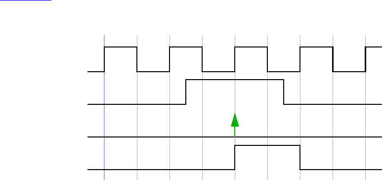
IEEE Std 1800-2012
IEEE STANDARD FOR SYSTEMVERILOG—UNIFIED HARDWARE DESIGN, SPECIFICATION, AND
VERIFICATION LANGUAGE
447
Copyright © 2013 IEEE. All rights reserved.
clocking cb_with_input @(posedge clk);
input a;
property p1;
a;
endproperty
endclocking
clocking cb_without_input @(posedge clk);
property p1;
a;
endproperty
endclocking
property p1;
@(posedge clk) a;
endproperty
property p2;
@(posedge clk) cb_with_input.a;
endproperty
a1: assert property (p1);
a2: assert property (cb_with_input.p1);
a3: assert property (p2);
a4: assert property (cb_without_input.p1);
endmodule
Figure 16-17 explains the behavior of all the assertions. In the above example, a1, a2, a3, and a4 are
equivalent.
Figure 16-17—Clocking blocks and concurrent assertion
clk
a
a1/a2/a3/a4
cb.a
IEEE Std 1800-2012
IEEE STANDARD FOR SYSTEMVERILOG—UNIFIED HARDWARE DESIGN, SPECIFICATION, AND
VERIFICATION LANGUAGE
448
Copyright © 2013 IEEE. All rights reserved.
17. Checkers
17.1 Overview
Assertions provide building blocks to validate the behavior of the design. In many cases there is a need to
group several assertions together into bigger blocks having a well-defined functionality. These verification
blocks may also need to contain modeling code to compute values of auxiliary variables used in assertions or
covergroup instances to be integrated with cover statements. The checker construct in SystemVerilog was
specifically created to represent such verification blocks encapsulating assertions along with the modeling
code. The intended use of checkers is to serve as verification library units, or as building blocks for creating
abstract auxiliary models used in formal verification.
The modeling mechanism in checkers is similar to the modeling mechanism in modules and interfaces,
though several limitations apply. For example, no nets can be declared and assigned in checkers. On the
other hand, checkers allow nondeterministic modeling, which does not exist in modules and interfaces. Each
variable declared in a checker may be either deterministic or random. Checker modeling is explained in
17.7. Random variables are useful to build abstract nondeterministic models for formal verification.
Reasoning about nondeterministic models is sometimes much easier than reasoning about deterministic RTL
models.
Deterministic variables allow a conventional (deterministic) modeling for assertions. Using random
variables instead of regular variables in checkers has the advantage that the same checker may be used for
both deterministic and nondeterministic cases.
17.2 Checker declaration
checker_declaration ::= // from A.1.2
checker checker_identifier [ ( [ checker_port_list ] ) ] ;
{ { attribute_instance } checker_or_generate_item }
endchecker [ : checker_identifier ]
checker_port_list ::= // from A.1.8
checker_port_item {, checker_port_item}
checker_port_item ::=
{ attribute_instance } [ checker_port_direction ] property_formal_type formal_port_identifier
{variable_dimension} [ = property_actual_arg ]
checker_port_direction ::=
input | output
checker_or_generate_item ::=
checker_or_generate_item_declaration
| initial_construct
| always_construct
| final_construct
| assertion_item
| continuous_assign
| checker_generate_item
checker_or_generate_item_declaration ::=
[ rand ] data_declaration
| function_declaration
| checker_declaration
| assertion_item_declaration

IEEE Std 1800-2012
IEEE STANDARD FOR SYSTEMVERILOG—UNIFIED HARDWARE DESIGN, SPECIFICATION, AND
VERIFICATION LANGUAGE
449
Copyright © 2013 IEEE. All rights reserved.
| covergroup_declaration
| overload_declaration
| genvar_declaration
| clocking_declaration
|default clocking clocking_identifier ;
|default disable iff expression_or_dist ;
|;
checker_generate_item6 ::=
loop_generate_construct
| conditional_generate_construct
| generate_region
| elaboration_system_task
checker_identifier ::= // from A.9.3
identifier
6) It shall be illegal for a checker_generate_item to include any item that would be illegal in a checker_declaration
outside a checker_generate_item.
Syntax 17-1—Checker declaration syntax (excerpt from Annex A)
A checker may be declared in one of the following:
— A module
— An interface
— A program
— A checker
— A package
— A generate block
— A compilation unit scope
A checker is declared using the keyword checker followed by a name and optional formal argument list,
and ending with the keyword endchecker.
The following elements from the scope enclosing the checker declaration shall not be referenced in a
checker:
— Automatic variables and members or elements of dynamic variables (see 6.21).
— Elements of fork...join, fork...join_any, or fork...join_none blocks.
Action blocks of assertions within a checker will be referred to as checker action blocks, and the rest of the
checker will be referred to as a checker body.
A checker body may contain the following elements:
— Declarations of let constructs, sequences, properties, and functions
— Deferred assertions (see 16.4)
— Concurrent assertions (see 16.14)
— Checker declarations
— Other checker instantiations
— Covergroup declarations and instances
— Checker variable declarations and assignments (see 17.7)

IEEE Std 1800-2012
IEEE STANDARD FOR SYSTEMVERILOG—UNIFIED HARDWARE DESIGN, SPECIFICATION, AND
VERIFICATION LANGUAGE
450
Copyright © 2013 IEEE. All rights reserved.
—default clocking and default disable iff declarations
—initial, always_comb, always_latch, always_ff, and final procedures (see 9.2)
— Generate blocks, containing any of the above elements
Modules, interfaces, programs, and packages shall not be declared inside checkers. Modules, interfaces, and
programs shall not be instantiated inside checkers.
A formal argument of a checker may be optionally preceded by a direction qualifier: input or output. If
no direction is specified explicitly then the direction of the previous argument shall be inferred. If the
direction of the first checker argument is omitted, it shall default to input. An input checker formal
argument shall not be modified by a checker.
The legal data types for checker formal arguments are those legal for a property (see 16.12). The type of an
output argument shall not be of untyped, sequence, or property. If the type of a checker formal
argument is omitted, it is inferred according to the following rules:
— If the argument has an explicit direction qualifier, it shall be an error to omit its type.
— Otherwise, if the argument is the first argument of the checker, it is assumed to be input untyped.
—Otherwise, the type of the previous formal argument is inferred as described for sequences and
properties (see 16.8 and 16.12).
In a similar manner to sequences and properties, a checker declaration may specify a default value for each
singular input port, as described in 16.8. A checker declaration may also specify an initial value for each
singular output port using the same syntax as the default value specification for input arguments. Checker
output port initialization has the same semantics as a variable initialization (see 6.8).
Following are examples of simple checkers:
Example 1:
// Simple checker containing concurrent assertions
checker my_check1 (logic test_sig, event clock);
default clocking @clock; endclocking
property p(logic sig);
...
endproperty
a1: assert property (p (test_sig));
c1: cover property (!test_sig ##1 test_sig);
endchecker : my_check1
Example 2:
// Simple checker containing deferred assertions
checker my_check2 (logic a, b);
a1: assert #0 ($onehot0({a, b});
c1: cover #0 (a == 0 && b == 0);
c2: cover #0 (a == 1);
c3: cover #0 (b == 1);
endchecker : my_check2
Example 3:
// Simple checker with output arguments
checker my_check3 (logic a, b, event clock, output bit failure, undef);
default clocking @clock; endclocking
IEEE Std 1800-2012
IEEE STANDARD FOR SYSTEMVERILOG—UNIFIED HARDWARE DESIGN, SPECIFICATION, AND
VERIFICATION LANGUAGE
451
Copyright © 2013 IEEE. All rights reserved.
a1: assert property ($onehot0({a, b}) failure = 1’b0; else failure = 1’b1;
a2: assert property ($isunknown({a, b}) undef = 1’b0; else undef = 1’b1;
endchecker : my_check3
Example 4:
// Checker with default input and initialized output arguments
checker my_check4 (input logic in,
en = 1’b1, // default value
event clock,
output int ctr = 0); // initial value
default clocking @clock; endclocking
always_ff @clock
if (en && in) ctr <= ctr + 1;
a1: assert property (ctr < 5);
endchecker : my_check4
Type and data declarations within the checker are local to the checker scope and are static. Clock and
disable iff contexts are inherited from the scope of the checker declaration (but see 17.4 for usage of
context value functions for passing the instantiation context to the checker). For example:
module m;
default clocking @clk1; endclocking
default disable iff rst1;
checker c1;
// Inherits @clk1 and rst1
...
endchecker : c1
checker c2;
// Explicitly redefines its default values
default clocking @clk2; endclocking
default disable iff rst2;
...
endchecker : c2
...
endmodule : m
Variables used in a checker that are neither formal arguments to the checker nor internal variables of the
checker are resolved according to the scoping rules from the scope in which the checker is declared.
17.3 Checker instantiation
concurrent_assertion_item ::= // from A.2.10
...
| checker_instantiation
checker_instantiation ::= // from A.4.1.4
ps_checker_identifier name_of_instance ( [list_of_checker_port_connections] ) ;
list_of_checker_port_connections29 ::=
ordered_checker_port_connection { , ordered_checker_port_connection }
| named_checker_port_connection { , named_checker_port_connection }
ordered_checker_port_connection ::= { attribute_instance } [ property_actual_arg ]
named_checker_port_connection ::=
{ attribute_instance } . formal_port_identifier [ ( [ property_actual_arg ] ) ]
IEEE Std 1800-2012
IEEE STANDARD FOR SYSTEMVERILOG—UNIFIED HARDWARE DESIGN, SPECIFICATION, AND
VERIFICATION LANGUAGE
452
Copyright © 2013 IEEE. All rights reserved.
| { attribute_instance } .*
ps_checker_identifier ::= // from A.9.3
[ package_scope ] checker_identifier
29) The .* token shall appear at most once in a list of port connections.
Syntax 17-2—Checker instantiation syntax (excerpt from Annex A)
A checker may be instantiated wherever a concurrent assertion may appear (see 16.14) with the following
exceptions:
— It shall be illegal to instantiate checkers in fork...join, fork...join_any, or fork...join_none
blocks.
— It shall be illegal to instantiate a checker in a procedure of another checker.
A checker has different behavior depending on whether it is instantiated inside or outside procedural code. A
checker instantiation in procedural code is referred to as a procedural checker instance. A checker
instantiation outside procedural code is referred to as a static checker instance. See 16.14.6 for the
corresponding definitions of procedural and static assertion statements.
When a checker is instantiated, actual arguments are passed to the checker. The mechanism for passing input
arguments to a checker is similar to the mechanism for passing arguments to a property (see 16.12). The
following restrictions apply:
— As in the case of sequences and properties, if $ is an actual input argument to a checker instance,
then the corresponding formal argument shall be untyped and each of its references either shall be an
upper bound in a cycle_delay_const_range_expression or shall itself be an actual argument in an
instance of a named sequence or property, or in a checker instance.
— If an actual input argument contains any subexpression that is a const cast or automatic value from
procedural code, then the corresponding formal argument shall not be used in a continuous
assignment or in the procedural code within the checker.
Checker actual output arguments shall be variable_lvalue or net_lvalue. The checker instantiation should be
treated as if there were continuous assignments, executed in the Reactive region, of the checker’s output
formal arguments to their corresponding actual arguments.
Checker formal arguments may be connected to their actual arguments in ways similar to module ports (see
23.3.2):
— Positional connections by port order.
— Named port connections using fully explicit connections.
— Named port connections using implicit connections.
— Named port connections using a wildcard port name.
The following example illustrates a checker instantiation:
checker mutex (logic sig, event clock, output bit failure);
assert property (@clock $onehot0(sig))
failure = 1’b0; else failure = 1’b1;
endchecker : mutex
module m(wire [31:0] bus, logic clk);
logic res, scan;
// ...
mutex check_bus(bus, posedge clk, res);

IEEE Std 1800-2012
IEEE STANDARD FOR SYSTEMVERILOG—UNIFIED HARDWARE DESIGN, SPECIFICATION, AND
VERIFICATION LANGUAGE
453
Copyright © 2013 IEEE. All rights reserved.
always @(posedge clk) scan <= res;
endmodule : m
On each rising edge of clk the bits of bus are checked for mutual exclusion and the result is assigned to res
in the Reactive region. If clk is changed in the Active region, scan will capture the value of res generated
on the previous rising edge of clk.
All contents of a checker instance other than static assertion statements are considered to exist during every
time step, regardless of whether the checker is static or procedural. One copy of these contents exists for
each instantiation. Procedural concurrent assertion statements in a checker shall be treated just like other
procedural assertion statements as described in 16.14.6. However, static assertion statements within a
checker are treated as if they appear at the checker’s instantiation point. If the checker is instantiated inside
some scope, any of its static assertions, both concurrent and deferred, are treated as if instantiated in this
scope. Therefore, the following applies for static assertions within a checker:
— If the checker is static, the concurrent assertions are continually monitored, and begin execution on
any time step matching their initial clock event. The deferred assertions are monitored whenever
their expressions change.
— If the checker is procedural, all static concurrent assertions in the checker are added to the pending
procedural assertion queue when the checker instantiation is reached in process execution, and then
may mature or be flushed like any procedural concurrent assertion (see 16.14.6.2). Similarly all
static deferred assertions in the checker are added to the pending deferred assertion report when the
checker instantiation is reached in its process execution, and may mature or be flushed like any
procedural deferred assertion (see 16.4.1).
— If the checker is statically instantiated inside another checker, any of its static assertions, concurrent
or deferred, are treated as if instantiated in the parent checker, and thus will be treated as procedural
assertions when an instantiation of its top-level ancestor in the checker hierarchy is visited in
procedural code.
The following example illustrates this behavior:
checker c1(event clk, logic[7:0] a, b);
logic [7:0] sum;
always_ff @(clk) begin
sum <= a + 1'b1;
p0: assert property (sum < `MAX_SUM);
end
p1: assert property (@clk sum < `MAX_SUM);
p2: assert property (@clk a != b);
p3: assert #0 ($onehot(a));
endchecker
module m(input logic rst, clk, logic en, logic[7:0] in1, in2,
in_array [20:0]);
c1 check_outside(posedge clk, in1, in2);
always @(posedge clk) begin
automatic logic [7:0] v1=0;
if (en) begin
// v1 is automatic, so current procedural value is used
c1 check_inside(posedge clk, in1, v1);
end
for (int i = 0; i < 4; i++) begin
v1 = v1+5;
if (i != 2) begin
// v1 is automatic, so current procedural value is used
c1 check_loop(posedge clk, in1, in_array[v1]);

IEEE Std 1800-2012
IEEE STANDARD FOR SYSTEMVERILOG—UNIFIED HARDWARE DESIGN, SPECIFICATION, AND
VERIFICATION LANGUAGE
454
Copyright © 2013 IEEE. All rights reserved.
end
end
end
endmodule : m
In this example, there are three instantiations of c1: check_outside, check_inside, and check_loop.
They have the following characteristics:
—check_outside is a static instantiation, while check_inside and check_loop are procedural.
— Each of the three instantiations has its own version of sum, which is updated at every positive clock
edge, regardless of whether that instance was visited in procedural code. Even in the case of
check_loop, there is only one instance of sum, and it will be updated using the sampled value of
in1.
— Each of the three instantiations will queue an evaluation of p0 at every posedge of the clock
(according to the rules in 16.14.6), which will mature and report a violation during any time step
when sum is not less than MAX_SUM, regardless of the behavior of the procedural code in module m.
— For checker instance check_outside, p1 and p2 are checked at every positive clock edge. For
checker instance check_inside, p1 and p2 are queued to mature and be checked on any positive
clock edge when en is true. For check_loop, three procedural instances of p1 and p2 are queued to
mature on any positive clock edge. For p1, all three instances are identical, using the sampled value
of sum; but for p2, the three instances compare the sampled value of in1 to the sampled value of
in_array indexed by constant v1 values of 5, 10, and 20, respectively.
— For checker instance check_outside, p3 is checked whenever a changes. In checker instances
check_inside and check_loop, deferred assertion p3 behaves as a procedural deferred assertion
placed at the instantiation point of its checker.
17.4 Context inference
Context value functions (see 16.14.7) may be used as default values of formal arguments in a checker
declaration. These functions enable adjusting the checker behavior depending on its instantiation context.
For example:
// Context inference in a checker
checker check_in_context (logic test_sig,
event clock = $inferred_clock,
logic reset = $inferred_disable);
property p(logic sig);
...
endproperty
a1: assert property (@clock disable iff (reset) p(test_sig));
c1: cover property (@clock !reset throughout !test_sig ##1 test_sig);
endchecker : check_in_context
module m(logic rst);
wire clk;
logic a, en;
wire b = a && en;
// No context inference
check_in_context my_check1(.test_sig(b), .clock(clk), .reset(rst));
always @(posedge clk) begin
a <= ...;
if (en) begin
...
// inferred from context:
// .clock(posedge clk)

IEEE Std 1800-2012
IEEE STANDARD FOR SYSTEMVERILOG—UNIFIED HARDWARE DESIGN, SPECIFICATION, AND
VERIFICATION LANGUAGE
455
Copyright © 2013 IEEE. All rights reserved.
// .reset(1'b0)
check_in_context my_check2(a);
end
en <= ...;
end
endmodule : m
In the preceding example the default values of clock and reset in check_in_context are taken from the
instantiation context. In the instantiation my_check1 all formal arguments are provided explicitly. In the
instantiation my_check2 all optional arguments are passed their default value: the clock is inferred from the
clock of the always procedure of the module m, the disable condition is inferred to be 1'b0.
17.5 Checker procedures
The following procedures are allowed inside a checker body:
—initial procedure
—always procedure
—final procedure
An initial procedure in a checker body may contain let declarations, immediate, deferred, and
concurrent assertions, and a procedural timing control statement using an event control only.
The following forms of always procedures are allowed in checkers: always_comb, always_latch, and
always_ff. Checker always procedures may contain the following statements:
—Blocking assignments (see 10.4.1; always_comb and always_latch procedures only)
—Nonblocking assignments (see 10.4.2)
—Selection statements (see 12.4 and 12.5)
—Loop statements (see 12.7)
—Timing event control (see 9.4.2; always_ff procedure only)
—Subroutine calls (see Clause 13)
—let declarations
Except for the variables used in the event control, all other expressions in always_ff procedures are
sampled (see 16.5.1). It follows from this rule that the expressions in immediate and deferred assertions
instantiated in this procedure are also sampled. Expressions in always_comb and always_latch
procedures are not implicitly sampled and the assignments appearing in these procedures use the current
values of their expressions. For example:
checker check(logic a, b, c, clk, rst);
logic x, y, z, v, t;
assign x = a; // current value of a
always_ff @(posedge clk or negedge rst) // current values of clk and rst
begin
a1: assert (b); // sampled value of b
if (rst) // current value of rst
z <= b; // sampled value of b
else z <= !c; // sampled value of c
end
always_comb begin

IEEE Std 1800-2012
IEEE STANDARD FOR SYSTEMVERILOG—UNIFIED HARDWARE DESIGN, SPECIFICATION, AND
VERIFICATION LANGUAGE
456
Copyright © 2013 IEEE. All rights reserved.
a2: assert (b); // current value of b
if (a) // current value of a
v = b; // current value of b
else v = !b; // current value of b
end
always_latch begin
a3: assert (b); // current value of b
if (clk) // current value of clk
t <= b; // current value of b
end
// ...
endchecker : check
The following example illustrates clock inference for checker procedures, following the rules in 16.14.6.
checker clocking_example (logic sig1, sig2, default_clk, rst,
event e1, e2, e3 );
bit local_sig;
default clocking @(posedge default_clk); endclocking
always_ff @(e1) begin: p1_block
p1a: assert property (sig1 == sig2);
p1b: assert property (@(e1) (sig1 == sig2));
end
always_ff @(e2 or e3) begin: p2_block
local_sig <= rst;
p2a: assert property (sig1 == sig2);
p2b: assert property (@(e2) (sig1 == sig2));
end
always_ff @(rst or e3) begin: p3_block
local_sig <= rst;
p3a: assert property (sig1 == sig2);
p3b: assert property (@(e3) (sig1 == sig2));
end
...
endchecker
...
clocking_example c1 (s1, s2, default_clk, rst,
posedge clk1 or posedge clk2,
posedge clk1,
negedge rst);
In instance c1 of clocking_example, the assertions will be clocked as follows:
—Assertion p1a will be clocked by posedge default_clk. This is because after the substitution of
the actual argument posedge clk1 or posedge clk2 for the formal argument e1, it does not
satisfy the clock inference conditions in 16.14.6, particularly condition (b). If clocking based on e1
is desired, it must be done explicitly as in property p1b.
—Assertion p2a will be clocked by posedge clk1. This is because the event control of p2_block
satisfies the conditions in 16.14.6, including condition (c 2), after the formal arguments are
substituted with the actual arguments. Thus assertions p2a and p2b are equivalent.
—Assertion p3a will be clocked by posedge default_clk. This is because the event control of
p3_block does not satisfy the conditions in 16.14.6, particularly condition (c 2). If clocking based
on e3 is desired, it must be done explicitly as in property p3b.

IEEE Std 1800-2012
IEEE STANDARD FOR SYSTEMVERILOG—UNIFIED HARDWARE DESIGN, SPECIFICATION, AND
VERIFICATION LANGUAGE
457
Copyright © 2013 IEEE. All rights reserved.
A final procedure may be specified within a checker in the same manner as in a module (see 9.2.3). This
allows for the checker to check conditions with immediate assertions or print out statistics at the end of
simulation. The operation of the final procedure is independent of the instantiation context of the checker
that contains it. It will be executed once at the end of simulation for every instantiation of that checker.
There is no implied ordering in the execution of multiple final procedures. A final procedure within a
checker may include any construct allowed in a non-checker final procedure.
17.6 Covergroups in checkers
One or more covergroup declarations or instances (see 19.3) are permitted within a checker. These
declarations and instances shall not appear in any procedural block in the checker. A covergroup may
reference any variable visible in its scope, including checker formal arguments and checker variables.
However, it shall be an error if a formal argument referenced by a covergroup has a const actual
argument. For example:
checker my_check(logic clk, active);
bit active_d1 = 1'b0;
always_ff @(posedge clk) begin
active_d1 <= active;
end
covergroup cg_active @(posedge clk);
cp_active : coverpoint active
{
bins idle = { 1'b0 };
bins active = { 1'b1 };
}
cp_active_d1 : coverpoint active_d1
{
bins idle = { 1'b0 };
bins active = { 1'b1 };
}
option.per_instance = 1;
endgroup
cg_active cg_active_1 = new();
endchecker : my_check
A covergroup may also be triggered by a procedural call to its sample() method (see 19.8). The following
examples show how the sample() method may be called from a sequence match item to trigger a
covergroup.
checker op_test (logic clk, vld_1, vld_2, logic [3:0] opcode);
bit [3:0] opcode_d1;
always_ff @(posedge clk) opcode_d1 <= opcode;
covergroup cg_op;
cp_op : coverpoint opcode_d1;
endgroup: cg_op
cg_op cg_op_1 = new();
sequence op_accept;
@(posedge clk) vld_1 ##1 (vld_2, cg_op_1.sample());
endsequence
cover property (op_accept);
endchecker

IEEE Std 1800-2012
IEEE STANDARD FOR SYSTEMVERILOG—UNIFIED HARDWARE DESIGN, SPECIFICATION, AND
VERIFICATION LANGUAGE
458
Copyright © 2013 IEEE. All rights reserved.
In this example, the coverpoint cp_op refers to the checker variable opcode_d1 directly. It is triggered by a
call to the default sample() method from a sequence match item. This function call occurs in the Reactive
region, while nonblocking assignments to checker variables will occur in the Re-NBA region. As a result,
the covergroup will sample the old value of the checker variable opcode_d1.
It is also possible to define a custom sample() method for a covergroup (see 19.8.1). The following is an
example of this:
checker op_test (logic clk, vld_1, vld_2, logic [3:0] opcode);
bit [3:0] opcode_d1;
always_ff @(posedge clk) opcode_d1 <= opcode;
covergroup cg_op with function sample(bit [3:0] opcode_d1);
cp_op : coverpoint opcode_d1;
endgroup: cg_op
cg_op cg_op_1 = new();
sequence op_accept;
@(posedge clk) vld_1 ##1 (vld2, cg_op_1.sample(opcode_d1));
endsequence
cover property (op_accept);
endchecker
In this example, a custom sample() method has been defined for the covergroup cg_op, and the coverpoint
cp_op references the formal argument of the custom sample() method. This custom method will be called
in the Reactive region upon a sequence match, but the sampled value of the sequential checker variable
opcode_d1 will be passed to the sample() function. As a result, the covergroup will sample the value
from the Preponed region.
17.7 Checker variables
Variables may be defined in checkers, but defining nets in the checker body shall be illegal. All variables
defined in a checker body shall have static lifetimes (see 17.2). The variables defined in the checker body are
referred to as checker variables. The following example illustrates checker variable usage:
checker counter_model(logic flag);
bit [2:0] counter = '0;
always_ff @$global_clock
counter <= counter + 1'b1;
assert property (@$global_clock counter == 0 |-> flag);
endchecker : counter_model
Checker variables may have an optional rand qualifier. In this case, they are called free variables; free
variables may behave nondeterministically.
Formal analysis tools shall take into account all possible values of the free checker variables imposed by the
assumptions and assignments (see 17.7.1). Simulators shall assign random values to the free variables as
explained in 17.7.2.
The following example shows how free variables can be used for modeling for formal verification:
checker observer_model(bit valid, reset);
default clocking @$global_clock; endclocking
rand bit flag;
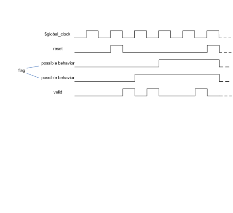
IEEE Std 1800-2012
IEEE STANDARD FOR SYSTEMVERILOG—UNIFIED HARDWARE DESIGN, SPECIFICATION, AND
VERIFICATION LANGUAGE
459
Copyright © 2013 IEEE. All rights reserved.
m1: assume property (reset |=> !flag);
m2: assume property (!reset && flag |=> flag);
m3: assume property ($rising_gclk(flag) |-> valid);
endchecker : observer_model
In this example, the following constraints are imposed on the free variable flag:
— If it is high, it remains high as long as there is no reset.
— If there is a reset, it becomes low at the next tick of the clock.
— It may rise only when valid is high.
Although the behavior of the free variable flag has been restricted by the assumptions m1, m2, and m3, it is
still nondeterministic because it does not have to rise when valid is high. Figure 17-1 shows two possible
legal behaviors of this variable given the same behaviors of reset and valid. Formal analysis tools shall
take all possible legal behaviors of flag into account. Simulators shall assign random values to the variable
flag as explained in 17.7.2.
Figure 17-1—Nondeterministic free checker variable
The following example shows how free variables may be used to implement a nondeterministic choice:
// a may assume values 3 and 5 only
rand bit r;
let a = r ? 3'd3 : 3'd5;
A free variable declaration may have a const qualifier. If a constant free variable is initialized, it retains its
initial value forever. An uninitialized constant free variable has a nondeterministic value at the initialization,
and this value does not change. The following examples demonstrate the usage of constant free checker
variables.
Formal analysis tools shall take into account any possible values of a constant free checker variable
consistent with the imposed assumptions. Simulators shall assign a random constant value to a constant free
variable as explained in 17.7.2.
Examples:
Reasoning about a representative bit:
checker reason_about_one_bit(bit [63:0] data1, bit [63:0] data2,
event clock);
rand const bit [5:0] idx;
a1: assert property (@clock data1[idx] == data2[idx]);
endchecker : reason_about_one_bit

IEEE Std 1800-2012
IEEE STANDARD FOR SYSTEMVERILOG—UNIFIED HARDWARE DESIGN, SPECIFICATION, AND
VERIFICATION LANGUAGE
460
Copyright © 2013 IEEE. All rights reserved.
In this example the assertion a1 states that any fixed bit of data1 has the same value as the corresponding
bit of data2. Therefore, the checker reason_about_one_bit is equivalent in formal verification to the
following checker (these two checkers are not equivalent in simulation):
checker reason_about_all_bit(bit [63:0] data1, bit [63:0] data2,
event clock);
a1: assert property (@clock data1 == data2);
endchecker : reason_about_all_bit
The second realization of the checker compares two 64-bit values while the first one compares only 1-bit
values, for every possible index. The first version may be more efficient for some formal tools.
Data integrity checking:
// If start_ev is asserted then the value of out_data at the next assertion
// of end_ev has to be equal to the current value of in_data at start_ev.
//
// It is assumed that in_data and out_data have the same size
checker data_legal(start_ev, end_ev, in_data, out_data);
rand const bit [$bits(in_data)-1:0] mem_data;
sequence transaction;
start_ev && (in_data == mem_data) ##1 end_ev[->1];
endsequence
a1: assert property (@clock transaction |-> out_data == mem_data);
endchecker : data_legal
Since mem_data is a constant free variable, if in_data is equal to mem_data at the beginning of the
transaction, then mem_data records that value and keeps it throughout the trace. In particular, at the end of
the transaction, mem_data still holds that value and the assertion checks that it is equal to out_data.
Moreover, mem_data was initialized with a nondeterministic value; it follows that for every value of
in_data, there exists a computation in which mem_data is equal to that value of in_data, which in turn
implies that the corresponding legality of data transfer through that transaction is being checked for formal
verification. In simulation mem_data will be randomly initialized (see 17.7.2), and it will only be checked
that if at the transaction beginning in_data equals to mem_data then at the transaction end out_data will
have the same value as in_data at the beginning of the transaction.
The latter example may be rewritten for formal verification using local variables instead of constant free
variables (see 16.10; these implementations are not equivalent in simulation):
// If start_ev is asserted then the value of in_data has to be
// equal to the value of out_data at the next assertion of end_ev
//
// It is assumed that in_data and out_data have the same size
checker data_legal_with_loc(start_ev, end_ev, in_data, out_data);
sequence transaction (loc_var);
(start_ev, loc_var = in_data) ##1 end_ev[->1];
endsequence
property data_legal;
bit [$bits(in_data)-1:0] mem_data;
transaction(mem_data) |-> out_data == mem_data;
endproperty
a1: assert property (@clock data_legal);
endchecker : data_legal_with_loc
There is a difference between a constant and a non-constant free variable: a constant free variable does not
change its value, while a non-constant free variable can assume a new value any time. If a non-constant free

IEEE Std 1800-2012
IEEE STANDARD FOR SYSTEMVERILOG—UNIFIED HARDWARE DESIGN, SPECIFICATION, AND
VERIFICATION LANGUAGE
461
Copyright © 2013 IEEE. All rights reserved.
variable has been initialized but is never assigned then it can assume any value at any time step in formal
verification, or be randomized in subsequent time steps in simulation (see 17.7.2), except the first one where
its value is defined by the initialization. Consider the following declaration:
rand bit a = 1'b0, b;
The free variable a has initial value 0, but in other time steps its value may change. The free checker variable
b may assume any value 0 or 1 at any time (in formal verification or randomized in simulation), as opposed
to an uninitialized constant free checker variable, which keeps one specific value.
17.7.1 Checker variable assignments
Checker variables may be assigned using blocking and nonblocking procedural assignments, or non-
procedural continuous assignments.
The following rules and restrictions apply:
—In
always_ff procedures only nonblocking assignments are allowed.
—Referencing a checker variable using its hierarchical name in assignments (see 23.6) shall be illegal.
For example:
checker check(...)
bit a;
...
endchecker
module m(...)
...
check my_check(...);
...
wire x = my_check.a; // Illegal
bit y;
...
always @(posedge clk) begin
my_check.a = y; // Illegal
...
end
...
endmodule
— Continuous assignments and blocking procedural assignments to free checker variables shall be
illegal.
checker check1(bit a, b, event clk, ...);
rand bit x, y, z, v;
...
assign x = a & b; // Illegal
always_comb
y = a & b; // Illegal
always_ff @clk
z <= a & b; // OK
endchecker : check1

IEEE Std 1800-2012
IEEE STANDARD FOR SYSTEMVERILOG—UNIFIED HARDWARE DESIGN, SPECIFICATION, AND
VERIFICATION LANGUAGE
462
Copyright © 2013 IEEE. All rights reserved.
— A checker variable may not be assigned in an initial procedure, but may be initialized in its
declaration. For example:
bit v;
initial v = 1'b0; // Illegal
bit w = 1'b0; // OK
—The right-hand side of a checker variable assignment may contain the sequence method triggered
(see 16.13.6).
— The left hand side of a nonblocking assignment may contain a free checker variable. The following
example illustrates usage of free variable assignments.
// Toggling variable:
// a may have either 0101... or 1010... pattern
rand bit a;
always_ff @clk a <= !a;
17.7.2 Checker variable randomization with assumptions
Checker assume statements are used to describe assumptions that may be made about the values of
variables. They may be used by simulators to constrain the random generation of free checker variable
values or by formal tools to constrain the formal computation. As with normal assume statements, checker
assume statements shall also be checked for violation during simulation.
Assume-based checker variable randomization is the process of periodically solving a set of properties
appearing in assume statements (called an assume set) to find satisfying values for the free checker
variables, and updating those variables with the newfound values. Unlike class-based constrained random
generation, solving is triggered by any of the clock events of the properties in the assume set (called an
assume set clock event) rather than by an explicit procedural call [e.g., there is no randomize() for
checkers]. Once updated with solution values, free checker variables shall remain constant until the next
assume set clock event or the end of the time step, whichever comes first.
All non-const free checker variables are treated as either active or inactive for assume-based
randomization, in the same way as rand variables for class-based constrained random generation (see 17.9),
but without an explicit control facility [such as rand_mode()]. All other variables (such as non-free
checker variables and checker formals) are always treated as inactive. Any free checker variables that appear
on the left-hand side of a checker variable assignment (see 17.7.1) are inactive; all other free checker
variables are active. Free checker variables are active or inactive for each singular element of the variable.
For example, a packed array or structure is active or inactive monolithically, whereas the elements of an
unpacked array or structure are separately active or inactive.
All free checker variables, both const and non-const, active and inactive, are initialized with
unconstrained random values unless explicitly initialized in their declaration.
Each checker instance has one and only one assume set, which may be empty. Like checker procedures and
variables, checker assume sets are considered to exist at every time step, regardless of whether the checker
instance is static or procedural (see 17.3).
The assume set of a checker instance is formed from the checker assume statements and child checker
assume statements. Any of these assume statements that references a formal whose actual argument
contains any subexpression that is a const cast or automatic value (see 17.3) is excluded from the assume
set. This restriction allows a single copy of the assume set to exist for each instantiation that is valid for the
entire simulation, as described in 17.3. Among the remaining assume statements, those that reference active
free variables of the checker are included in the assume set. For example:

IEEE Std 1800-2012
IEEE STANDARD FOR SYSTEMVERILOG—UNIFIED HARDWARE DESIGN, SPECIFICATION, AND
VERIFICATION LANGUAGE
463
Copyright © 2013 IEEE. All rights reserved.
module my_mod();
bit mclk, v1, v2;
checker c1(bit fclk, bit a, bit b);
default clocking @ (posedge fclk); endclocking
checker c2(bit bclk, bit x, bit y);
default clocking @ (posedge bclk); endclocking
rand bit m, n;
u1: assume property (f1(x,m));
u2: assume property (f2(y,n));
endchecker
rand bit q, r;
c2 B1(fclk, q+r, r);
always_ff @ (posedge fclk)
r <= a || q; // assignment makes r inactive
u3: assume property (f3(a, q));
u4: assume property (f4(b, r));
endchecker
...
c1 F1(mclk, v1, const'(v2));
endmodule
The assume set of F1 consists of F1.u3 and F1.B1.u1. The property F1.B1.u1 is included because it
references the formal x, whose actual expression q+r involves an active free checker variable. F1.u4 is
excluded because it references the formal b, which is associated with the const cast actual v2. F1.B1.u2
is excluded because the only formal referenced is y, which is not associated with an active free variable
actual (the actual r is inactive). However, checker instance F1.B1 has its own assume set, which includes
u2 as well as u1; neither of those assume statements involve formals with const cast or automatic actuals.
When a solution attempt is made on an assume set, values shall be sought for all active checker variables
such that, together with the inactive variables and state, none of the assumptions will fail in that time step. If
a set of such values is found, the solution attempt is successful. Otherwise, any values may be chosen for the
active variables and the solution attempt is unsuccessful. There is no requirement that a solution be found if
it exists or that “dead end” states (states where no solution exists) be avoided. For example,
u_deadend: assume property (@(posedge clk) x |=> ##5 1'b0);
If the value 1 is chosen for x, the property would not fail in the current time step; however, it would
inevitably fail six clock cycles later. Such an inevitable future failure is called a dead end. Despite the dead
end, selecting 1 for x is considered a successful solution attempt.
Empty assume sets shall be considered to have an implicit assume set clock event in every time step before
the Observed region. Active variables in checkers with empty assume sets are called implicitly clocked
active free variables; those with non-empty assume sets are explicitly clocked. Implicitly clocked active
variables may be updated with unconstrained random values at every time step. Once updated, the variables
stay constant until the end of the time step.
Active variables that do not appear in any property in a non-empty assume set are unconstrained but
explicitly clocked. They may be updated with random values at every assume set clock event.
When an implementation is about to begin the Observed region, it shall solve for all the active free checker
variables using sampled values of all other variables. A sampled value of an active checker variable is
defined as its current value (see 16.5.1). Note that checker procedures and properties execute in the Reactive
and Observed regions (see 17.7.3), and so have the new values available.

IEEE Std 1800-2012
IEEE STANDARD FOR SYSTEMVERILOG—UNIFIED HARDWARE DESIGN, SPECIFICATION, AND
VERIFICATION LANGUAGE
464
Copyright © 2013 IEEE. All rights reserved.
When a solution attempt is unsuccessful, any resulting assumption failure(s) do not occur until an
unsatisfied property is clocked and checked in the Observed region.
17.7.3 Scheduling semantics
Statements and constructs within a checker that are sensitive to changes (e.g., clocking events, continuous
assignments) and all blocking statements are scheduled in the Reactive region (similarly to programs, see
24.3.1). The nonblocking assignments of checker variables schedule their updates is the Re-NBA region.
The Re-NBA region is processed after the Reactive and Re-Inactive regions have been emptied of events
(see 4.2). These scheduling rules make possible assignment of sequence endpoint values to checker
variables. For example:
checker my_check(...);
...
sequence s; ...; endsequence
always_ff @clk a <= s.triggered;
endchecker
For every transition of signal clk, the simulator will update the variable a in the Re-NBA region with the
value of s.triggered captured in the Reactive region. Had the checker captured the value of
s.triggered in the Active region, a would always be assigned 1'b0, since s.triggered is evaluated in
the Observed region, and the above code would be meaningless.
Concurrent assertions have invariant scheduling semantics, whether present in checker code or design code.
17.8 Functions in checkers
The formal arguments and internal variables of functions used in checkers shall not be declared as free
variables. However, free variables are allowed to be passed in as actual arguments to a function.
Expressions at the right-hand side of checker variable assignments are allowed to include function calls with
the same restrictions that are imposed on function calls in concurrent assertions (see 16.6):
— Functions that appear in expressions shall not contain output or ref arguments (const ref is
allowed).
— Functions shall be automatic (or preserve no state information) and have no side effects.
See an example of a function used in a checker in 17.9.
17.9 Complex checker example
The checkers in the following examples make sure that the expression is true in a window delimited by
start_event and end_event. When start_event and end_event are Boolean, the checker may be
implemented as shown in Example 1.
Example 1:
typedef enum { cover_none, cover_all } coverage_level;
checker assert_window1 (
logic test_expr, // Expression to be true in the window
untyped start_event, // Window opens at the completion of the start_event
untyped end_event, // Window closes at the completion of the end_event
event clock = $inferred_clock,
logic reset = $inferred_disable,

IEEE Std 1800-2012
IEEE STANDARD FOR SYSTEMVERILOG—UNIFIED HARDWARE DESIGN, SPECIFICATION, AND
VERIFICATION LANGUAGE
465
Copyright © 2013 IEEE. All rights reserved.
string error_msg = "violation",
coverage_level clevel = cover_all // This argument should be bound to an
// elaboration time constant expression
);
default clocking @clock; endclocking
default disable iff reset;
bit window = 1’b0, next_window = 1’b1;
// Compute next value of window
always_comb begin
if (reset || window && end_event)
next_window = 1'b0;
else if (!window && start_event)
next_window = 1'b1;
else
next_window = window;
end
always_ff @clock
window <= next_window;
property p_window;
start_event && !window |=> test_expr[+] ##0 end_event;
endproperty
a_window: assert property (p_window) else $error(error_msg);
generate if (clevel != cover_none) begin : cover_b
cover_window_open: cover property (start_event && !window)
$display("window_open covered");
cover_window: cover property (
start_event && !window
##1 (!end_event && window) [*]
##1 end_event && window
) $display("window covered");
end : cover_b
endgenerate
endchecker : assert_window1
If start_event and end_event may be arbitrary sequences, and not necessary Boolean values, the
checker needs to be implemented differently, as shown in Example 2. This case requires a different
implementation because the reset of the triggered status of a sequence does not create an event (see 9.4.4),
and therefore a sequence triggered method should not be used in the right-hand side of a continuous
assignment or of an assignment in an always_comb procedure.
Example 2:
typedef enum { cover_none, cover_all } coverage_level;
checker assert_window2 (
logic test_expr, // Expression to be true in the window
sequence start_event, // Window opens at the completion of the start_event
sequence end_event, // Window closes at the completion of the end_event
event clock = $inferred_clock,
logic reset = $inferred_disable,
string error_msg = "violation",
coverage_level clevel = cover_all // This argument should be bound to an
// elaboration time constant expression
);
IEEE Std 1800-2012
IEEE STANDARD FOR SYSTEMVERILOG—UNIFIED HARDWARE DESIGN, SPECIFICATION, AND
VERIFICATION LANGUAGE
466
Copyright © 2013 IEEE. All rights reserved.
default clocking @clock; endclocking
default disable iff reset;
bit window = 0;
let start_flag = start_event.triggered;
let end_flag = end_event.triggered;
// Compute next value of window
function bit next_window (bit win);
if (reset || win && end_flag)
return 1'b0;
if (!win && start_flag)
return 1'b1;
return win;
endfunction
always_ff @clock
window <= next_window(window);
property p_window;
start_flag && !window |=> test_expr[+] ##0 end_flag;
endproperty
a_window: assert property (p_window) else $error(error_msg);
generate if (clevel != cover_none) begin : cover_b
cover_window_open: cover property (start_flag && !window)
$display("window_open covered");
cover_window: cover property (
start_flag && !window
##1 (!end_flag && window) [*]
##1 end_flag && window
) $display("window covered");
end : cover_b
endgenerate
endchecker : assert_window2

IEEE Std 1800-2012
IEEE STANDARD FOR SYSTEMVERILOG—UNIFIED HARDWARE DESIGN, SPECIFICATION, AND
VERIFICATION LANGUAGE
467
Copyright © 2013 IEEE. All rights reserved.
18. Constrained random value generation
18.1 General
This clause describes the following:
— Random variables
— Constraint blocks
— Randomization methods
— Disabling randomization
— Controlling constraints
— Scope variable randomization
— Seeding the random number generator (RNG)
— Random weighted case statements
— Random sequence generation
18.2 Overview
Constraint-driven test generation allows users to automatically generate tests for functional verification.
Random testing can be more effective than a traditional, directed testing approach. By specifying
constraints, one can easily create tests that can find hard-to-reach corner cases. SystemVerilog allows users
to specify constraints in a compact, declarative way. The constraints are then processed by a solver that
generates random values that meet the constraints.
The random constraints are typically specified on top of an object-oriented data abstraction that models the
data to be randomized as objects that contain random variables and user-defined constraints. The constraints
determine the legal values that can be assigned to the random variables. Objects are ideal for representing
complex aggregate data types and protocols such as Ethernet packets.
Subclause 18.3 provides an overview of object-based randomization and constraint programming. The rest
of this clause provides detailed information on random variables, constraint blocks, and the mechanisms
used to manipulate them.
18.3 Concepts and usage
This subclause introduces the basic concepts and uses for generating random stimulus within objects.
SystemVerilog uses an object-oriented method for assigning random values to the member variables of an
object, subject to user-defined constraints. For example:
class Bus;
rand bit[15:0] addr;
rand bit[31:0] data;
constraint word_align {addr[1:0] == 2'b0;}
endclass
The Bus class models a simplified bus with two random variables, addr and data, representing the address
and data values on a bus. The word_align constraint declares that the random values for addr must be
such that addr is word-aligned (the low-order 2 bits are 0).
The randomize() method is called to generate new random values for a bus object:
IEEE Std 1800-2012
IEEE STANDARD FOR SYSTEMVERILOG—UNIFIED HARDWARE DESIGN, SPECIFICATION, AND
VERIFICATION LANGUAGE
468
Copyright © 2013 IEEE. All rights reserved.
Bus bus = new;
repeat (50) begin
if ( bus.randomize() == 1 )
$display ("addr = %16h data = %h\n", bus.addr, bus.data);
else
$display ("Randomization failed.\n");
end
Calling randomize() causes new values to be selected for all of the random variables in an object so that
all of the constraints are true (satisfied). In the preceding program test, a bus object is created and then
randomized 50 times. The result of each randomization is checked for success. If the randomization
succeeds, the new random values for addr and data are printed; if the randomization fails, an error
message is printed. In this example, only the addr value is constrained, while the data value is
unconstrained. Unconstrained variables are assigned any value in their declared range.
Constraint programming is a powerful method that lets users build generic, reusable objects that can later be
extended or constrained to perform specific functions. The approach differs from both traditional procedural
and object-oriented programming, as illustrated in this example that extends the Bus class:
typedef enum {low, mid, high} AddrType;
class MyBus extends Bus;
rand AddrType atype;
constraint addr_range
{
(atype == low ) -> addr inside { [0 : 15] };
(atype == mid ) -> addr inside { [16 : 127]};
(atype == high) -> addr inside {[128 : 255]};
}
endclass
The MyBus class inherits all of the random variables and constraints of the Bus class and adds a random
variable called atype that is used to control the address range using another constraint. The addr_range
constraint uses implication to select one of three range constraints depending on the random value of atype.
When a MyBus object is randomized, values for addr, data, and atype are computed so that all of the
constraints are satisfied. Using inheritance to build layered constraint systems enables the development of
general-purpose models that can be constrained to perform application-specific functions.
Objects can be further constrained using the randomize() with construct, which declares additional
constraints in-line with the call to randomize():
task exercise_bus (MyBus bus);
int res;
// EXAMPLE 1: restrict to low addresses
res = bus.randomize() with {atype == low;};
// EXAMPLE 2: restrict to address between 10 and 20
res = bus.randomize() with {10 <= addr && addr <= 20;};
// EXAMPLE 3: restrict data values to powers-of-two
res = bus.randomize() with {(data & (data - 1)) == 0;};
endtask
IEEE Std 1800-2012
IEEE STANDARD FOR SYSTEMVERILOG—UNIFIED HARDWARE DESIGN, SPECIFICATION, AND
VERIFICATION LANGUAGE
469
Copyright © 2013 IEEE. All rights reserved.
This example illustrates several important properties of constraints, as follows:
— Constraints can be any SystemVerilog expression with variables and constants of integral type (e.g.,
bit, reg, logic, integer, enum, packed struct).
— The constraint solver shall be able to handle a wide spectrum of equations, such as algebraic
factoring, complex Boolean expressions, and mixed integer and bit expressions. In the previous
example, the power-of-two constraint was expressed arithmetically. It could have also been defined
with expressions using a shift operator; for example, 1 << n, where n is a 5-bit random variable.
— If a solution exists, the constraint solver shall find it. The solver can fail only when the problem is
over-constrained and there is no combination of random values that satisfy the constraints.
— Constraints interact bidirectionally. In this example, the value chosen for addr depends on atype
and how it is constrained, and the value chosen for atype depends on addr and how it is
constrained. All expression operators are treated bidirectionally, including the implication operator
(->).
— Constraints support only 2-state values. The 4-state values (X or Z) or 4-state operators (e.g., ===,
!== ) are illegal and shall result in an error.
Sometimes it is desirable to disable constraints on random variables. For example, to deliberately generate
an illegal address (nonword-aligned):
task exercise_illegal(MyBus bus, int cycles);
int res;
// Disable word alignment constraint.
bus.word_align.constraint_mode(0);
repeat (cycles) begin
// CASE 1: restrict to small addresses.
res = bus.randomize() with {addr[0] || addr[1];};
...
end
// Reenable word alignment constraint
bus.word_align.constraint_mode(1);
endtask
The constraint_mode() method can be used to enable or disable any named constraint block in an
object. In this example, the word-alignment constraint is disabled, and the object is then randomized with
additional constraints forcing the low-order address bits to be nonzero (and thus unaligned).
The ability to enable or disable constraints allows users to design constraint hierarchies. In these hierarchies,
the lowest level constraints can represent physical limits grouped by common properties into named
constraint blocks, which can be independently enabled or disabled.
Similarly, the rand_mode() method can be used to enable or disable any random variable. When a random
variable is disabled, it behaves in exactly the same way as other nonrandom variables.
Occasionally, it is desirable to perform operations immediately before or after randomization. That is
accomplished via two built-in methods, pre_randomize() and post_randomize(), which are
automatically called before and after randomization. These methods can be overridden with the desired
functionality:
class XYPair;
rand integer x, y;
IEEE Std 1800-2012
IEEE STANDARD FOR SYSTEMVERILOG—UNIFIED HARDWARE DESIGN, SPECIFICATION, AND
VERIFICATION LANGUAGE
470
Copyright © 2013 IEEE. All rights reserved.
endclass
class MyXYPair extends XYPair
function void pre_randomize();
super.pre_randomize();
$display("Before randomize x=%0d, y=%0d", x, y);
endfunction
function void post_randomize();
super.post_randomize();
$display("After randomize x=%0d, y=%0d", x, y);
endfunction
endclass
By default, pre_randomize() and post_randomize() call their overridden base class methods. When
pre_randomize() or post_randomize() are overridden, care must be taken to invoke the base class’s
methods, unless the class is a base class (has no base class). Otherwise, the base class methods shall not be
called.
The random stimulus generation capabilities and the object-oriented constraint-based verification
methodology enable users to quickly develop tests that cover complex functionality and better assure design
correctness.
18.4 Random variables
Class variables can be declared random using the rand and randc type-modifier keywords.
The syntax to declare a random variable in a class is as follows in Syntax 18-1.
class_property ::= // from A.1.9
{ property_qualifier } data_declaration
property_qualifier8 ::=
random_qualifier
| class_item_qualifier
random_qualifier8 ::=
rand
|randc
8) In any one declaration, only one of protected or local is allowed, only one of rand or randc is allowed,
and static and/or virtual can appear only once.
Syntax 18-1—Random variable declaration syntax (excerpt from Annex A)
— The solver can randomize singular variables of any integral type.
— Arrays can be declared rand or randc, in which case all of their member elements are treated as
rand or randc.
— Individual array elements can be constrained, in which case the index expression may include itera-
tive constraint loop variables, constants, and state variables.
— Dynamic arrays, associative arrays and queues can be declared rand or randc. All of the elements
in the array are randomized, overwriting any previous data.

IEEE Std 1800-2012
IEEE STANDARD FOR SYSTEMVERILOG—UNIFIED HARDWARE DESIGN, SPECIFICATION, AND
VERIFICATION LANGUAGE
471
Copyright © 2013 IEEE. All rights reserved.
— The size of a dynamic array or queue declared as rand or randc can also be constrained. In that
case, the array shall be resized according to the size constraint, and then all the array elements shall
be randomized. The array size constraint is declared using the size method. For example:
rand bit [7:0] len;
rand integer data[];
constraint db { data.size == len; }
The variable len is declared to be 8 bits wide. The randomizer computes a random value for the len
variable in the 8-bit range of 0 to 255 and then randomizes the first len elements of the data array.
When a dynamic array is resized by randomize, the resized array is initialized (see 7.5.1) with the
original array. When a queue is resized by randomize, elements are inserted or deleted (see 7.10.2.2
and 7.10.2.3) at the back (i.e., right side) of the queue as necessary to produce the new queue size;
any new elements inserted take on the default value of the element type. That is, the resize grows or
shrinks the array. This is significant for a dynamic array or queue of class handles. Randomize does
not allocate any class objects. Up to the new size, existing class objects are retained and their content
randomized. If the new size is greater than the original size, each of the additional elements has a
null value requiring no randomization.
In resizing a dynamic array or queue by randomize or new, the rand_mode of each retained element
is preserved and the rand_mode of each new element is set to active.
If a dynamic array’s size is not constrained, then the array shall not be resized and all the array
elements shall be randomized.
— An object handle can be declared rand, in which case all of that object’s variables and constraints
are solved concurrently with the variables and constraints of the object that contains the handle.
Randomization shall not modify the actual object handle. Object handles shall not be declared
randc.
— An unpacked structure can be declared rand, in which case all of that structure’s random members
are solved concurrently using one of the rules listed in this subclause. Unpacked structures shall not
be declared randc. A member of a unpacked structure can be made random by having a rand or
randc modifier in the declaration of its type. Members of unpacked structures containing a union as
well as members of packed structures shall not be allowed to have a random modifier.
For example:
class packet;
typedef struct {
randc int addr = 1 + constant;
int crc;
rand byte data [] = {1,2,3,4};
} header;
rand header h1;
endclass
packet p1=new;
18.4.1 Rand modifier
Variables declared with the rand keyword are standard random variables. Their values are uniformly
distributed over their range. For example:
rand bit [7:0] y;
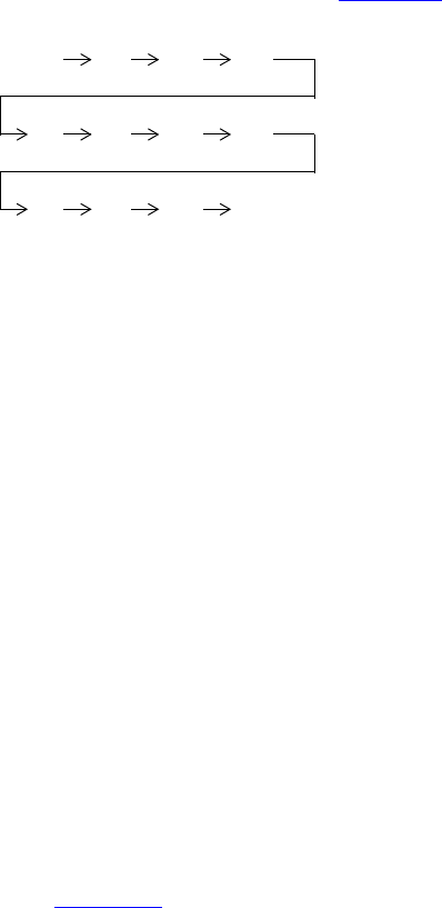
IEEE Std 1800-2012
IEEE STANDARD FOR SYSTEMVERILOG—UNIFIED HARDWARE DESIGN, SPECIFICATION, AND
VERIFICATION LANGUAGE
472
Copyright © 2013 IEEE. All rights reserved.
This is an 8-bit unsigned integer with a range of 0 to 255. If unconstrained, this variable shall be assigned
any value in the range of 0 to 255 with equal probability. In this example, the probability of the same value
repeating on successive calls to randomize is 1/256.
18.4.2 Randc modifier
Variables declared with the randc keyword are random-cyclic variables that cycle through all the values in
a random permutation of their declared range.
To understand randc, consider a 2-bit random variable y:
randc bit [1:0] y;
The variable y can take on the values 0, 1, 2, and 3 (range of 0 to 3). Randomize computes an initial random
permutation of the range values of y and then returns those values in order on successive calls. After it
returns the last element of a permutation, it repeats the process by computing a new random permutation.
The basic idea is that randc randomly iterates over all the values in the range and that no value is repeated
within an iteration. When the iteration finishes, a new iteration automatically starts (see Figure 18-1).
Figure 18-1—Example of randc
The permutation sequence for any given randc variable is recomputed whenever the constraints change on
that variable or when none of the remaining values in the permutation can satisfy the constraints. The
permutation sequence shall contain only 2-state values.
To reduce memory requirements, implementations may impose a limit on the maximum size of a randc
variable, but it shall be no less than 8 bits.
The semantics of random-cyclical variables requires that they be solved before other random variables. A set
of constraints that includes both rand and randc variables shall be solved so that the randc variables are
solved first, and this can sometimes cause randomize() to fail.
If a random variable is declared as static, the randc state of the variable shall also be static. Thus
randomize chooses the next cyclic value (from a single sequence) when the variable is randomized through
any instance of the base class.
18.5 Constraint blocks
The values of random variables are determined using constraint expressions that are declared using
constraint blocks. Constraint blocks are class members, like tasks, functions, and variables. Constraint block
names shall be unique within a class.
The syntax to declare a constraint block is as follows in Syntax 18-2.
initial permutation: 0 3 2 1
next permutation: 21 3 0
next permutation: 20 1 3
.
.
.
IEEE Std 1800-2012
IEEE STANDARD FOR SYSTEMVERILOG—UNIFIED HARDWARE DESIGN, SPECIFICATION, AND
VERIFICATION LANGUAGE
473
Copyright © 2013 IEEE. All rights reserved.
constraint_declaration ::= // from A.1.10
[ static ] constraint constraint_identifier constraint_block
constraint_block ::= { { constraint_block_item } }
constraint_block_item ::=
solve solve_before_list before solve_before_list ;
| constraint_expression
solve_before_list ::= constraint_primary { , constraint_primary }
constraint_primary ::= [ implicit_class_handle . | class_scope ] hierarchical_identifier select
constraint_expression ::=
[ soft ] expression_or_dist ;
| expression –> constraint_set
|if ( expression ) constraint_set [ else constraint_set ]
|foreach ( ps_or_hierarchical_array_identifier [ loop_variables ] ) constraint_set
|disable soft constraint_primary ;
constraint_set ::=
constraint_expression
|{ { constraint_expression } }
dist_list ::= dist_item { , dist_item }
dist_item ::= value_range [ dist_weight ]
dist_weight ::=
:= expression
|:/ expression
constraint_prototype ::= [constraint_prototype_qualifier] [ static ] constraint constraint_identifier ;
constraint_prototype_qualifier ::= extern | pure
extern_constraint_declaration ::=
[ static ] constraint class_scope constraint_identifier constraint_block
identifier_list ::= identifier { , identifier }
expression_or_dist ::= expression [ dist { dist_list } ] // from A.2.10
loop_variables ::= [ index_variable_identifier ] { , [ index_variable_identifier ] } // from A.6.8
Syntax 18-2—Constraint syntax (excerpt from Annex A)
The constraint_identifier is the name of the constraint block. This name can be used to enable or disable a
constraint using the constraint_mode() method (see 18.9).
The constraint_block is a list of expression statements that restrict the range of a variable or define relations
between variables. A constraint_expression is any SystemVerilog expression or one of the constraint-
specific operators, dist and -> (see 18.5.4 and 18.5.6, respectively).
The declarative nature of constraints imposes the following restrictions on constraint expressions:
— Functions are allowed with certain limitations (see 18.5.12).
— Operators with side effects, such as ++ and --, are not allowed.
—randc variables cannot be specified in ordering constraints (see solve...before in 18.5.10).
—dist expressions cannot appear in other expressions.

IEEE Std 1800-2012
IEEE STANDARD FOR SYSTEMVERILOG—UNIFIED HARDWARE DESIGN, SPECIFICATION, AND
VERIFICATION LANGUAGE
474
Copyright © 2013 IEEE. All rights reserved.
18.5.1 External constraint blocks
Constraint blocks can be declared outside their enclosing class declaration if a constraint prototype appears
in the enclosing class declaration. A constraint prototype specifies that the class shall have a constraint of the
specified name, but does not specify a constraint block to implement that constraint. A constraint prototype
can take either of two forms, as shown in the following example:
class C;
rand int x;
constraint proto1; // implicit form
extern constraint proto2; // explicit form
endclass
For both forms the constraint can be completed by providing an external constraint block using the class
scope resolution operator, as in the following example:
constraint C::proto1 { x inside {-4, 5, 7}; }
constraint C::proto2 { x >= 0; }
An external constraint block shall appear in the same scope as the corresponding class declaration and shall
appear after the class declaration in that scope. If the explicit form of constraint prototype is used, it shall be
an error if no corresponding external constraint block is provided. If the implicit form of prototype is used
and there is no corresponding external constraint block, the constraint shall be treated as an empty constraint
and a warning may be issued. An empty constraint is one that has no effect on randomization, equivalent to
a constraint block containing the constant expression 1.
For either form, it shall be an error if more than one external constraint block is provided for any given
prototype, and it shall be an error if a constraint block of the same name as a prototype appears in the same
class declaration.
18.5.2 Constraint inheritance
Constraints follow the same general rules for inheritance as other class members. The randomize()
method is virtual and therefore honors constraints of the object on which it was called, regardless of the data
type of the object handle through which the method was called.
A derived class shall inherit all constraints from its superclass. Any constraint in a derived class having the
same name as a constraint in its superclass shall replace the inherited constraint of that name. Any constraint
in a derived class that does not have the same name as a constraint in the superclass shall be an additional
constraint.
If a derived class has a constraint prototype with the same name as a constraint in its superclass, that
constraint prototype shall replace the inherited constraint. Completion of the derived class’s constraint
prototype shall then follow the rules described in 18.5.1.
An abstract class (i.e., a class declared using the syntax virtual class, as described in 8.21) may contain
pure constraints. A pure constraint is syntactically similar to a constraint prototype but uses the pure
keyword, as in the following example:
virtual class D;
pure constraint Test;
endclass
A pure constraint represents an obligation on any non-abstract derived class (i.e., a derived class that is not
virtual) to provide a constraint of the same name. It shall be an error if a non-abstract class does not have

IEEE Std 1800-2012
IEEE STANDARD FOR SYSTEMVERILOG—UNIFIED HARDWARE DESIGN, SPECIFICATION, AND
VERIFICATION LANGUAGE
475
Copyright © 2013 IEEE. All rights reserved.
an implementation of every pure constraint that it inherits. It shall be an error to declare a pure constraint in
a non-abstract class.
It shall be an error if a class containing a pure constraint also has a constraint block, constraint prototype or
external constraint block of the same name. However, any class (whether abstract or not) may contain a
constraint block or constraint prototype of the same name as a pure constraint that the class inherits; such a
constraint shall override the pure constraint, and shall be a non-pure constraint for the class and any class
derived from it.
An abstract class that inherits a constraint from its superclass may have a pure constraint of the same name.
In this case, the pure constraint in the derived virtual class shall replace the inherited constraint.
A constraint that overrides a pure constraint may be declared using a constraint block in the body of the
overriding class, or may be declared using a constraint prototype and external constraint as described in
18.5.1.
18.5.3 Set membership
Constraints support integer value sets and the set membership operator (as defined in 11.4.13).
Absent any other constraints, all values (either single values or value ranges) have an equal probability of
being chosen by the inside operator.
The negated form of the inside operator denotes that expression lies outside the set: !(expression
inside { set }).
For example:
rand integer x, y, z;
constraint c1 {x inside {3, 5, [9:15], [24:32], [y:2*y], z};}
rand integer a, b, c;
constraint c2 {a inside {b, c};}
integer fives[4] = '{ 5, 10, 15, 20 };
rand integer v;
constraint c3 { v inside {fives}; }
In SystemVerilog, the inside operator is bidirectional; thus, the second example above is equivalent to a
== b || a == c.
18.5.4 Distribution
In addition to set membership, constraints support sets of weighted values called distributions. Distributions
have two properties: they are a relational test for set membership, and they specify a statistical distribution
function for the results.
The syntax to define a distribution expression is as follows in Syntax 18-3.
constraint_expression ::= // from A.1.10
expression_or_dist ;
...
dist_list ::= dist_item { , dist_item }

IEEE Std 1800-2012
IEEE STANDARD FOR SYSTEMVERILOG—UNIFIED HARDWARE DESIGN, SPECIFICATION, AND
VERIFICATION LANGUAGE
476
Copyright © 2013 IEEE. All rights reserved.
dist_item ::= value_range [ dist_weight ]
dist_weight ::=
:= expression
|:/ expression
expression_or_dist ::= expression [ dist { dist_list } ] // from A.2.10
Syntax 18-3—Constraint distribution syntax (excerpt from Annex A)
The expression can be any integral SystemVerilog expression.
The distribution operator dist evaluates to true if the value of the expression is contained in the set;
otherwise, it evaluates to false.
Absent any other constraints, the probability that the expression matches any value in the list is proportional
to its specified weight. If there are constraints on some expressions that cause the distribution weights on
these expressions to be not satisfiable, implementations are only required to satisfy the constraints. An
exception to this rule is a weight of zero, which is treated as a constraint.
The distribution set is a comma-separated list of integral expressions and ranges. Optionally, each term in
the list can have a weight, which is specified using the := or :/ operators. If no weight is specified for an
item, the default weight is := 1. The weight can be any integral SystemVerilog expression.
The := operator assigns the specified weight to the item or, if the item is a range, to every value in the range.
The :/ operator assigns the specified weight to the item or, if the item is a range, to the range as a whole. If
there are n values in the range, the weight of each value is range_weight / n. For example:
x dist {100 := 1, 200 := 2, 300 := 5}
means x is equal to 100, 200, or 300 with weighted ratio of 1-2-5. If an additional constraint is added that
specifies that x cannot be 200,
x != 200;
x dist {100 := 1, 200 := 2, 300 := 5}
then x is equal to 100 or 300 with weighted ratio of 1-5.
It is easier to think about mixing ratios, such as 1-2-5, than the actual probabilities, because mixing ratios do
not have to be normalized to 100%. Converting probabilities to mixing ratios is straightforward.
When weights are applied to ranges, they can be applied to each value in the range, or they can be applied to
the range as a whole. For example:
x dist { [100:102] := 1, 200 := 2, 300 := 5}
means x is equal to 100, 101, 102, 200, or 300 with a weighted ratio of 1-1-1-2-5, and
x dist { [100:102] :/ 1, 200 := 2, 300 := 5}
means x is equal to one of 100, 101, 102, 200, or 300 with a weighted ratio of 1/3-1/3-1/3-2-5.
In general, distributions guarantee two properties: set membership and monotonic weighting. In other
words, increasing a weight increases the likelihood of choosing those values.

IEEE Std 1800-2012
IEEE STANDARD FOR SYSTEMVERILOG—UNIFIED HARDWARE DESIGN, SPECIFICATION, AND
VERIFICATION LANGUAGE
477
Copyright © 2013 IEEE. All rights reserved.
Limitations are as follows:
—A
dist operation shall not be applied to randc variables.
—A
dist expression requires that expression contain at least one rand variable.
18.5.5 Uniqueness constraints
A group of variables can be constrained using the unique constraint so that no two members of the group
have the same value after randomization. The group of variables to be constrained shall be specified using a
restricted form of the open_range_list syntax in which each item in the comma-separated list shall be one of
the following:
— A scalar variable of integral type
— An unpacked array variable whose leaf element type is integral, or a slice of such a variable
constraint_expression ::= // from A.1.10
...
| uniqueness_constraint ;
uniqueness_constraint ::=
unique { open_range_list9 }
9) The open_range_list in a uniqueness_constraint shall contain only expressions that denote scalar or array variables, as
described in 18.5.5.
Syntax 18-4—Uniqueness constraint syntax (excerpt from Annex A)
A leaf element of an unpacked array is found by descending through the array until an element is reached
that is not of unpacked array type.
All members of the group of variables so specified (that is, any scalar variables, and all leaf elements of any
arrays or slices) shall be of equivalent type. No randc variable shall appear in the group.
If the group of variables so specified contains fewer than two members, the constraint shall have no effect
and shall not cause a constraint contradiction.
In the following example, variables a[2], a[3], b, and excluded will all contain different values after
randomization. Because of the constraint exclusion, none of the variables a[2], a[3], and b will contain
the value 5.
rand byte a[5];
rand byte b;
rand byte excluded;
constraint u { unique {b, a[2:3], excluded}; }
constraint exclusion { excluded == 5; }
18.5.6 Implication
Constraints provide two constructs for declaring conditional (predicated) relations: implication and if–
else.
The implication operator ( –> ) can be used to declare an expression that implies a constraint.
The syntax to define an implication constraint is as follows in Syntax 18-5.
IEEE Std 1800-2012
IEEE STANDARD FOR SYSTEMVERILOG—UNIFIED HARDWARE DESIGN, SPECIFICATION, AND
VERIFICATION LANGUAGE
478
Copyright © 2013 IEEE. All rights reserved.
constraint_expression ::= // from A.1.10
...
| expression –> constraint_set
Syntax 18-5—Constraint implication syntax (excerpt from Annex A)
The expression can be any integral SystemVerilog expression.
The Boolean equivalent of the implication operator a -> b is (!a || b). This states that if the expression
is true, then random numbers generated are constrained by the constraint (or constraint set). Otherwise, the
random numbers generated are unconstrained.
The constraint_set represents any valid constraint or an unnamed constraint set. If the expression is true, all
of the constraints in the constraint set shall also be satisfied.
For example:
mode == little -> len < 10;
mode == big -> len > 100;
In this example, the value of mode implies that the value of len shall be constrained to less than 10 (mode
== little), greater than 100 (mode == big), or unconstrained (mode != little and mode !=
big).
In the example
bit [3:0] a, b;
constraint c { (a == 0) -> (b == 1); }
both a and b are 4 bits; therefore, there are 256 combinations of a and b. Constraint c says that a == 0
implies that b==1, thereby eliminating 15 combinations: {0,0}, {0,2}, … {0,15}. Therefore, the
probability that a==0 is thus 1/(256-15) or 1/241.
18.5.7 if–else constraints
The if–else style constraints are also supported.
The syntax to define an if–else constraint is as follows in Syntax 18-6.
constraint_expression ::= // from A.1.10
...
|if ( expression ) constraint_set [ else constraint_set ]
Syntax 18-6—If–else constraint syntax (excerpt from Annex A)
The expression can be any integral SystemVerilog expression.
The constraint_set represents any valid constraint or an unnamed constraint set. If the expression is true, all
of the constraints in the first constraint or constraint set shall be satisfied; otherwise, all of the constraints in
the optional else constraint or constraint set shall be satisfied. Constraint sets can be used to group multiple
constraints.
IEEE Std 1800-2012
IEEE STANDARD FOR SYSTEMVERILOG—UNIFIED HARDWARE DESIGN, SPECIFICATION, AND
VERIFICATION LANGUAGE
479
Copyright © 2013 IEEE. All rights reserved.
The if–else style constraint declarations are equivalent to implications
if (mode == little)
len < 10;
else if (mode == big)
len > 100;
which is equivalent to
mode == little -> len < 10 ;
mode == big -> len > 100 ;
In this example, the value of mode implies that the value of len is less than 10, greater than 100, or
unconstrained.
Just like implication, if–else style constraints are bidirectional. In the preceding declaration, the value of
mode constrains the value of len, and the value of len constrains the value of mode.
Because the else part of an if–else style constraint declaration is optional, there can be confusion when
an else is omitted from a nested if sequence. This is resolved by always associating the else with the
closest previous if that lacks an else. In the following example, the else goes with the inner if, as shown
by indentation:
if (mode != big)
if (mode == little)
len < 10;
else // the else applies to preceding if
len > 100;
18.5.8 Iterative constraints
Iterative constraints allow arrayed variables to be constrained using loop variables and indexing expressions,
or by using array reduction methods.
18.5.8.1 foreach iterative constraints
The syntax to define a foreach iterative constraint is as follows in Syntax 18-7.
constraint_expression ::= // from A.1.10
...
|foreach ( ps_or_hierarchical_array_identifier [ loop_variables ] ) constraint_set
loop_variables ::= [ index_variable_identifier ] { , [ index_variable_identifier ] } // from A.6.8
Syntax 18-7—Foreach iterative constraint syntax (excerpt from Annex A)
The foreach construct specifies iteration over the elements of an array. Its argument is an identifier that
designates any type of array (fixed-size, dynamic, associative, or queue) followed by a list of loop variables
enclosed in square brackets. Each loop variable corresponds to one of the dimensions of the array.
For example:
class C;
rand byte A[] ;
constraint C1 { foreach ( A [ i ] ) A[i] inside {2,4,8,16}; }

IEEE Std 1800-2012
IEEE STANDARD FOR SYSTEMVERILOG—UNIFIED HARDWARE DESIGN, SPECIFICATION, AND
VERIFICATION LANGUAGE
480
Copyright © 2013 IEEE. All rights reserved.
constraint C2 { foreach ( A [ j ] ) A[j] > 2 * j; }
endclass
C1 constrains each element of the array A to be in the set [2,4,8,16]. C2 constrains each element of the array
A to be greater than twice its index.
The number of loop variables shall not exceed the number of dimensions of the array variable. The scope of
each loop variable is the foreach constraint construct, including its constraint_set. The type of each loop
variable is implicitly declared to be consistent with the type of array index. An empty loop variable indicates
no iteration over that dimension of the array. As with default arguments, a list of commas at the end can be
omitted; thus, foreach( arr [ j ] ) is a shorthand for foreach( arr [ j, , , , ] ). It shall be
an error for any loop variable to have the same identifier as the array.
The mapping of loop variables to array indices is determined by the dimension cardinality, as described in
20.7.
// 1 2 3 3 4 1 2 -> Dimension numbers
int A [2][3][4]; bit [3:0][2:1] B [5:1][4];
foreach( A [ i, j, k ] ) ...
foreach( B [ q, r, , s ] ) ...
The first foreach causes i to iterate from 0 to 1, j from 0 to 2, and k from 0 to 3. The second foreach
causes q to iterate from 5 to 1, r from 0 to 3, and s from 2 to 1.
foreach iterative constraints can include predicates. For example:
class C;
rand int A[] ;
constraint c1 { A.size inside {[1:10]}; }
constraint c2 { foreach ( A[ k ] ) (k < A.size - 1) -> A[k + 1] > A[k]; }
endclass
The first constraint, c1, constrains the size of the array A to be between 1 and 10. The second constraint, c2,
constrains each array value to be greater than the preceding one, i.e., an array sorted in ascending order.
Within a foreach, predicate expressions involving only constants, state variables, object handle
comparisons, loop variables, or the size of the array being iterated behave as guards against the creation of
constraints, and not as logical relations. For example, the implication in constraint c2 above involves only a
loop variable and the size of the array being iterated; thus, it allows the creation of a constraint only when k
< A.size() - 1, which in this case prevents an out-of-bounds access in the constraint. Guards are
described in more detail in 18.5.13.
Index expressions can include loop variables, constants, and state variables. Invalid or out-of-bounds array
indices are not automatically eliminated; users must explicitly exclude these indices using predicates.
The size method of a dynamic array or queue can be used to constrain the size of the array (see constraint c1
above). If an array is constrained by both size constraints and iterative constraints, the size constraints are
solved first and the iterative constraints next. As a result of this implicit ordering between size constraints
and iterative constraints, the size method shall be treated as a state variable within the foreach block of the
corresponding array. For example, the expression A.size is treated as a random variable in constraint c1
and as a state variable in constraint c2. This implicit ordering can cause the solver to fail in some situations.
IEEE Std 1800-2012
IEEE STANDARD FOR SYSTEMVERILOG—UNIFIED HARDWARE DESIGN, SPECIFICATION, AND
VERIFICATION LANGUAGE
481
Copyright © 2013 IEEE. All rights reserved.
18.5.8.2 Array reduction iterative constraints
The array reduction methods can produce a single integral value from an unpacked array of integral values
(see 7.12.3). In the context of a constraint, an array reduction method is treated as an expression iterated over
each element of the array, joined by the relevant operand for each method. The result returns a single value
of the same type as the array element type or, if specified, the type of the expression in the with clause. For
example:
class C;
rand bit [7:0] A[] ;
constraint c1 { A.size == 5; }
constraint c2 { A.sum() with (int'(item)) < 1000; }
endclass
The constraint c2 will be interpreted as
( int'(A[0])+int'(A[1])+int'(A[2])+int'(A[3])+int'(A[4]) ) < 1000
18.5.9 Global constraints
When an object member of a class is declared rand, all of its constraints and random variables are
randomized simultaneously along with the other class variables and constraints. Constraint expressions
involving random variables from other objects are called global constraints (see Figure 18-2).
class A; // leaf node
rand bit [7:0] v;
endclass
class B extends A; // heap node
rand A left;
rand A right;
constraint heapcond {left.v <= v; right.v > v;}
endclass
Figure 18-2—Global constraints
This example uses global constraints to define the legal values of an ordered binary tree. Class A represents a
leaf node with an 8-bit value v. Class B extends class A and represents a heap node with value v, a left
subtree, and a right subtree. Both subtrees are declared as rand in order to randomize them at the same time
as other class variables. The constraint block named heapcond has two global constraints relating the left
and right subtree values to the heap node value. When an instance of class B is randomized, the solver
simultaneously solves for B and its left and right children, which in turn can be leaf nodes or more heap
nodes.
.left
.right
.v
.v
.v
B
A
A
IEEE Std 1800-2012
IEEE STANDARD FOR SYSTEMVERILOG—UNIFIED HARDWARE DESIGN, SPECIFICATION, AND
VERIFICATION LANGUAGE
482
Copyright © 2013 IEEE. All rights reserved.
The following rules determine which objects, variables, and constraints are to be randomized:
a) First, determine the set of objects that are to be randomized as a whole. Starting with the object that
invoked the randomize() method, add all objects that are contained within it, are declared rand,
and are active (see rand_mode in 18.8). The definition is recursive and includes all of the active
random objects that can be reached from the starting object. The objects selected in this step are
referred to as the active random objects.
b) Second, select all of the active constraints from the set of active random objects. These are the con-
straints that are applied to the problem.
c) Third, select all of the active random variables from the set of active random objects. These are the
variables that are to be randomized. All other variable references are treated as state variables,
whose current value is used as a constant.
18.5.10 Variable ordering
The solver shall assure that the random values are selected to give a uniform value distribution over legal
value combinations (that is, all combinations of legal values have the same probability of being the
solution). This important property guarantees that all legal value combinations are equally probable, which
allows randomization to better explore the whole design space.
Sometimes, however, it is desirable to force certain combinations to occur more frequently. Consider the
case where a 1-bit control variable s constrains a 32-bit data value d:
class B;
rand bit s;
rand bit [31:0] d;
constraint c { s -> d == 0; }
endclass
The constraint c says “s implies d equals zero.” Although this reads as if s determines d, in fact s and d are
determined together. There are 1 + 232 legal value combinations of {s,d}, but s is true only for one of
them. Table 18-1 lists each of the legal value combinations and the probability of occurrence of each:
The constraints provide a mechanism for ordering variables so that s can be chosen independently of d. This
mechanism defines a partial ordering on the evaluation of variables and is specified using the solve
keyword.
class B;
rand bit s;
Table 18-1—Unordered constraint c legal value probability
s d Probability
1 'h00000000 1/(1 + 232)
0 'h00000000 1/(1 + 232)
0 'h00000001 1/(1 + 232)
0 'h00000002 1/(1 + 232)
0 ...
0 'hfffffffe 1/(1 + 232)
0 'hffffffff 1/(1 + 232)
IEEE Std 1800-2012
IEEE STANDARD FOR SYSTEMVERILOG—UNIFIED HARDWARE DESIGN, SPECIFICATION, AND
VERIFICATION LANGUAGE
483
Copyright © 2013 IEEE. All rights reserved.
rand bit [31:0] d;
constraint c { s -> d == 0; }
constraint order { solve s before d; }
endclass
In this case, the order constraint instructs the solver to solve for s before solving for d. The effect is that s is
now chosen 0 or 1 with 50/50% probability, and then d is chosen subject to the value of s. Adding this order
constraint does not change the set of legal value combinations, but alters their probability of occurrence, as
shown in Table 18-2:
Note that the probability of d==0 is 1/(1 + 232), near 0%, without the order constraint, and is 1/2 × 1/232,
slightly over 50%, with the order constraint.
Variable ordering can be used to force selected corner cases to occur more frequently than they would
otherwise. However, a “solve...before...” constraint does not change the solution space and, therefore,
cannot cause the solver to fail.
The syntax to define variable order in a constraint block is as follows in Syntax 18-8.
constraint_block_item ::= // from A.1.10
solve solve_before_list before solve_before_list ;
| constraint_expression
solve_before_list ::= solve_before_primary { , solve_before_primary }
solve_before_primary ::= [ implicit_class_handle . | class_scope ] hierarchical_identifier select
Syntax 18-8—Solve...before constraint ordering syntax (excerpt from Annex A)
The following restrictions apply to variable ordering:
— Only random variables are allowed, that is, they shall be rand.
—randc variables are not allowed. randc variables are always solved before any other.
— The variables shall be integral values.
— A constraint block can contain both regular value constraints and ordering constraints.
— There shall be no circular dependencies in the ordering, such as “solve a before b” combined with
“solve b before a.”
Table 18-2—Ordered constraint c legal value probability
s d Probability
1 'h00000000 1/2
0 'h00000000 1/2 × 1/232
0 'h00000001 1/2 × 1/232
0 'h00000002 1/2 × 1/232
0 ...
0 'hfffffffe 1/2 × 1/232
0 'hffffffff 1/2 × 1/232
IEEE Std 1800-2012
IEEE STANDARD FOR SYSTEMVERILOG—UNIFIED HARDWARE DESIGN, SPECIFICATION, AND
VERIFICATION LANGUAGE
484
Copyright © 2013 IEEE. All rights reserved.
— Variables that are not explicitly ordered shall be solved with the last set of ordered variables. These
values are deferred until as late as possible to assure a good distribution of values.
— Variables that are partially ordered shall be solved with the latest set of ordered variables so that all
ordering constraints are met. These values are deferred until as late as possible to assure a good dis-
tribution of values.
— Variables can be solved in an order that is not consistent with the ordering constraints, provided that
the outcome is the same. An example situation where this might occur is as follows:
x == 0;
x < y;
solve y before x;
In this case, because x has only one possible assignment (0), x can be solved for before y. The con-
straint solver can use this flexibility to speed up the solving process.
18.5.11 Static constraint blocks
A constraint block can be defined as static by including the static keyword in its definition.
The syntax to declare a static constraint block is as follows in Syntax 18-9.
constraint_declaration ::= // from A.1.10
[ static ] constraint constraint_identifier constraint_block
Syntax 18-9—Static constraint syntax (excerpt from Annex A)
If a constraint block is declared as static, then calls to constraint_mode() shall affect all instances of
the specified constraint in all objects. Thus, if a static constraint is set to OFF, it is off for all instances of that
particular class.
When a constraint is declared using a constraint prototype and an external constraint block, the static
keyword shall be applied to both the constraint prototype and the external constraint block, or to neither. It
shall be an error if one but not the other is qualified static. Similarly, a pure constraint may be qualified
static but any overriding constraint must match the pure constraint’s qualification or absence thereof.
18.5.12 Functions in constraints
Some properties are unwieldy or impossible to express in a single expression. For example, the natural way
to compute the number of ones in a packed array uses a loop:
function int count_ones ( bit [9:0] w );
for( count_ones = 0; w != 0; w = w >> 1 )
count_ones += w & 1'b1;
endfunction
Such a function could be used to constrain other random variables to the number of 1 bits:
constraint C1 { length == count_ones( v ) ; }
Without the ability to call a function, this constraint requires the loop to be unrolled and expressed as a sum
of the individual bits:
constraint C2
{
IEEE Std 1800-2012
IEEE STANDARD FOR SYSTEMVERILOG—UNIFIED HARDWARE DESIGN, SPECIFICATION, AND
VERIFICATION LANGUAGE
485
Copyright © 2013 IEEE. All rights reserved.
length == ((v>>9)&1) + ((v>>8)&1) + ((v>>7)&1) + ((v>>6)&1) + ((v>>5)&1) +
((v>>4)&1) + ((v>>3)&1) + ((v>>2)&1) + ((v>>1)&1) + ((v>>0)&1);
}
Unlike the count_ones function, more complex properties, which require temporary state or unbounded
loops, may be impossible to convert into a single expression. The ability to call functions, thus, enhances the
expressive power of the constraint language and reduces the likelihood of errors. The two constraints, C1
and C2, from above are not completely equivalent; C2 is bidirectional (length can constrain v and vice
versa), whereas C1 is not.
To handle these common cases, SystemVerilog allows constraint expressions to include function calls, but it
imposes certain semantic restrictions, as follows:
— Functions that appear in constraint expressions cannot contain output or ref arguments (const
ref is allowed).
— Functions that appear in constraint expressions should be automatic (or preserve no state informa-
tion) and have no side effects.
— Functions that appear in constraints cannot modify the constraints, for example, calling rand_mode
or constraint_mode methods.
— Functions shall be called before constraints are solved, and their return values shall be treated as
state variables.
— Random variables used as function arguments shall establish an implicit variable ordering or
priority. Constraints that include only variables with higher priority are solved before other, lower
priority constraints. Random variables solved as part of a higher priority set of constraints become
state variables to the remaining set of constraints. For example:
class B;
rand int x, y;
constraint C { x <= F(y); }
constraint D { y inside { 2, 4, 8 } ; }
endclass
forces y to be solved before x. Thus, constraint D is solved separately before constraint C, which uses
the values of y and F(y) as state variables. In SystemVerilog, the behavior for variable ordering
implied by function arguments differs from the behavior for ordering specified using the
“solve...before...” constraint; function argument variable ordering subdivides the solution space
thereby changing it. Because constraints on higher priority variables are solved without considering
lower priority constraints at all, this subdivision can cause the overall constraints to fail. Within each
prioritized set of constraints, cyclical (randc) variables are solved first.
— Circular dependencies created by the implicit variable ordering shall result in an error.
— Function calls in active constraints are executed an unspecified number of times (at least once) in an
unspecified order.
18.5.13 Constraint guards
Constraint guards are predicate expressions that function as guards against the creation of constraints and
not as logical relations to be satisfied by the solver. These predicate expressions are evaluated before the
constraints are solved and are characterized by involving only the following items:
—Constants
— State variables
— Object handle comparisons (comparisons between two handles or a handle and the constant null)

IEEE Std 1800-2012
IEEE STANDARD FOR SYSTEMVERILOG—UNIFIED HARDWARE DESIGN, SPECIFICATION, AND
VERIFICATION LANGUAGE
486
Copyright © 2013 IEEE. All rights reserved.
In addition to these, iterative constraints (see 18.5.8) also consider loop variables and the size of the array
being iterated as state variables.
Treating these predicate expressions as constraint guards prevents the solver from generating evaluation
errors, thereby failing on some seemingly correct constraints. This enables users to write constraints that
avoid errors due to nonexistent object handles or array indices out of bounds. For example, the sort
constraint of the singly linked list, SList, shown below is intended to assign a random sequence of numbers
that is sorted in ascending order. However, the constraint expression will fail on the last element when
next.n results in an evaluation error due to a nonexistent handle.
class SList;
rand int n;
rand Slist next;
constraint sort { n < next.n; }
endclass
This error condition can be avoided by writing a predicate expression to guard against that condition:
constraint sort { if( next != null ) n < next.n; }
In the preceding sort constraint, the if prevents the creation of a constraint when next == null, which in
this case avoids accessing a nonexistent object. Both implication ( –>) and if…else can be used as guards.
Guard expressions can themselves include subexpressions that result in evaluation errors (e.g., null
references), and they are also guarded from generating errors. This logical sifting is accomplished by
evaluating predicate subexpressions using the following 4-state representation:
—0 FALSE Subexpression evaluates to FALSE.
—1 TRUE Subexpression evaluates to TRUE.
—E ERROR Subexpression causes an evaluation error.
—R RANDOM Expression includes random variables and cannot be evaluated.
Every subexpression within a predicate expression is evaluated to yield one of the above four values. The
subexpressions are evaluated in an arbitrary order, and the result of that evaluation plus the logical operation
define the outcome in the alternate 4-state representation. A conjunction ( && ), disjunction ( || ), or
negation ( ! ) of subexpressions can include some (perhaps all) guard subexpressions. The following rules
specify the resulting value for the guard:
— Conjunction ( && ): If any one of the subexpressions evaluates to FALSE, then the guard evaluates to
FALSE. If any one subexpression evaluates to ERROR, then the guard evaluates to ERROR. Otherwise,
the guard evaluates to TRUE.
— If the guard evaluates to FALSE, then the constraint is eliminated.
— If the guard evaluates to TRUE, then a (possibly conditional) constraint is generated.
— If the guard evaluates to ERROR, then an error is generated and randomize fails.
— Disjunction ( || ): If any one of the subexpressions evaluates to TRUE, then the guard evaluates to
TRUE. If any one subexpression evaluates to ERROR, then the guard evaluates to ERROR. Otherwise,
the guard evaluates to FALSE.
— If the guard evaluates to FALSE, then a (possibly conditional) constraint is generated.
— If the guard evaluates to TRUE, then an unconditional constraint is generated.
— If the guard evaluates to ERROR, then an error is generated and randomize fails.
IEEE Std 1800-2012
IEEE STANDARD FOR SYSTEMVERILOG—UNIFIED HARDWARE DESIGN, SPECIFICATION, AND
VERIFICATION LANGUAGE
487
Copyright © 2013 IEEE. All rights reserved.
— Negation ( ! ): If the subexpression evaluates to ERROR, then the guard evaluates to ERROR. Other-
wise, if the subexpression evaluates to TRUE or FALSE, then the guard evaluates to FALSE or TRUE,
respectively.
These rules are codified by the truth tables shown in Figure 18-3.
Figure 18-3—Truth tables for conjunction, disjunction, and negation rules
These rules are applied recursively until all subexpressions are evaluated. The final value of the evaluated
predicate expression determines the outcome as follows:
— If the result is TRUE, then an unconditional constraint is generated.
— If the result is FALSE, then the constraint is eliminated and can generate no error.
— If the result is ERROR, then an unconditional error is generated and the constraint fails.
— If the final result of the evaluation is RANDOM, then a conditional constraint is generated.
When the final value is RANDOM, a traversal of the predicate expression tree is needed to collect all
conditional guards that evaluate to RANDOM. When the final value is ERROR, a subsequent traversal of the
expression tree is not required, allowing implementations to issue only one error.
Example 1:
class D;
int x;
endclass
class C;
rand int x, y;
D a, b;
constraint c1 { (x < y || a.x > b.x || a.x == 5 ) -> x+y == 10; }
endclass
In Example 1, the predicate subexpressions are (x < y), (a.x > b.x), and (a.x == 5), which are all
connected by disjunction. Some possible cases are as follows:
— Case 1: a is non-null, b is null, a.x is 5.
Because (a.x==5) is true, the fact that b.x generates an error does not result in an error.
The unconditional constraint (x+y == 10) is generated.
— Case 2: a is null.
This always results in error, irrespective of the other conditions.
— Case 3: a is non-null, b is non-null, a.x is 10, b.x is 20.
All the guard subexpressions evaluate to FALSE.
The conditional constraint (x<y) -> (x+y == 10) is generated.
&& 0 1 E R
00000
101ER
E0EEE
R0RER
|| 0 1 E R
001ER
11111
EE1EE
RR1ER
!
01
10
EE
RR
Conjunction Disjunction Negation
IEEE Std 1800-2012
IEEE STANDARD FOR SYSTEMVERILOG—UNIFIED HARDWARE DESIGN, SPECIFICATION, AND
VERIFICATION LANGUAGE
488
Copyright © 2013 IEEE. All rights reserved.
Example 2:
class D;
int x;
endclass
class C;
rand int x, y;
D a, b;
constraint c1 { (x < y && a.x > b.x && a.x == 5 ) -> x+y == 10; }
endclass
In Example 2, the predicate subexpressions are (x < y), (a.x > b.x), and (a.x == 5), which are all
connected by conjunction. Some possible cases are as follows:
— Case 1: a is non-null, b is null, a.x is 6.
Because (a.x==5) is false, the fact that b.x generates an error does not result in an error.
The constraint is eliminated.
— Case 2: a is null
This always results in error, irrespective of the other conditions.
— Case 3: a is non-null, b is non-null, a.x is 5, b.x is 2.
All the guard subexpressions evaluate to TRUE, producing constraint (x<y) -> (x+y == 10).
Example 3:
class D;
int x;
endclass
class C;
rand int x, y;
D a, b;
constraint c1 { (x < y && (a.x > b.x || a.x ==5)) -> x+y == 10; }
endclass
In Example 3, the predicate subexpressions are (x < y) and (a.x > b.x || a.x == 5), which are
connected by disjunction. Some possible cases are as follows:
— Case 1: a is non-null, b is null, a.x is 5.
The guard expression evaluates to (ERROR || a.x==5), which evaluates to (ERROR || TRUE)
The guard subexpression evaluates to TRUE.
The conditional constraint (x<y) -> (x+y == 10) is generated.
— Case 2: a is non-null, b is null, a.x is 8.
The guard expression evaluates to (ERROR || FALSE) and generates an error.
— Case 3: a is null
This always results in error, irrespective of the other conditions.
— Case 4: a is non-null, b is non-null, a.x is 5, b.x is 2.
All the guard subexpressions evaluate to TRUE.
The conditional constraint (x<y) -> (x+y == 10) is generated.
18.5.14 Soft constraints
The (normal) constraints described up to this point can be denoted as hard constraints because the solver
must always satisfy them, or result in a solver failure. In contrast, a constraint expression defined as soft
IEEE Std 1800-2012
IEEE STANDARD FOR SYSTEMVERILOG—UNIFIED HARDWARE DESIGN, SPECIFICATION, AND
VERIFICATION LANGUAGE
489
Copyright © 2013 IEEE. All rights reserved.
designates a constraint that is to be satisfied unless contradicted by another constraint—either by a hard
constraint or by a soft constraint with higher priority.
Soft constraints enable authors of generic verification blocks to provide complete working environments
that are more easily extended because the constraint solver automatically disregards generic soft constraints
overridden by subsequent, more specialized constraints. Soft constraints are often used to specify default
values and distributions for random variables. For example, the author of a generic packet class might add a
constraint to ensure packets of legal size are generated by default (absent any other constraints):
class Packet;
rand int length;
constraint deflt { soft length inside {32,1024}; }
endclass
Packet p = new();
p.randomize() with { length == 1512; }
If the generic constraint, deflt, is not defined as soft, the call to randomize will fail and require special
attention. The failure might be resolved by explicitly turning off the constraint, which requires additional
procedural code, or by using a new class to extend the base class and override the constraint with a new one,
which significantly complicates the test. In contrast, a default value specified by a soft constraint is
automatically overridden, which result in a simpler layered test.
18.5.14.1 Soft constraint priorities
Soft constraints only express a preference for one solution over another; they are discarded when they are
contradicted by other more important constraints. Regular (hard) constraints must always be satisfied; they
are never discarded and are thus considered to be of the same highest priority. Conversely, soft constraints
may be overridden by hard constraints or other higher-priority soft constraints, therefore, a specific priority
shall be associated with every soft constraint. The soft priorities are designed such that the last constraint
specified by the user will prevail. Hence, constraints specified in subsequent layers of the verification
environment are assigned higher priorities than those in the preceding layers.
The following rules determine the priorities of soft constraints:
— Constraints within the scope of the same construct—constraint block, class, or struct—are assigned
a priority relative to their syntactic declaration order. Constraint expressions that appear later in the
construct have higher priority.
— Constraints within external constraint blocks are assigned a priority relative to the declaration order
of the constraint prototype (extern declaration) in the class. The priority depends on the prototype
declaration and not on the out-of-body declaration. Constraint expressions in out-of-body constraint
blocks whose prototypes appear later in the class have higher priority.
— Constraints in contained objects (rand class handles) have lower priority than all constraints in the
container object (class or struct).
— Constraints in each contained object (rand class handle) are assigned a priority relative to the decla-
ration order of their class handle. Constraints in objects whose handles appear later in the container
object (class or struct) have higher priority. If the same object is contained multiple times, the
constraints in the contained object shall have the priority of the highest priority object—the object
whose handle is declared last.
— Constraints in derived classes shall have higher priority than all constraints in their super classes.
IEEE Std 1800-2012
IEEE STANDARD FOR SYSTEMVERILOG—UNIFIED HARDWARE DESIGN, SPECIFICATION, AND
VERIFICATION LANGUAGE
490
Copyright © 2013 IEEE. All rights reserved.
— Constraints within in-line constraint blocks shall have higher priority than constraints in the class
being randomized.
— Soft constraints within a foreach shall have a priority that is defined by iteration order; latter
iterations shall have higher priority. If the relational operator is not defined for an index type of an
associative array, the priority is implementation dependent.
The following example illustrates the preceding rules:
class B1;
rand int x;
constraint a { soft x > 10 ; soft x < 100 ; }
endclass /* a1 */ /* a2 */
class D1 extends B1;
constraint b { soft x inside {[5:9]} ; }
endclass /* b1 */
class B2;
rand int y;
constraint c { soft y > 10 ; }
endclass /* c1 */
class D2 extends B2;
constraint d { soft y inside {[5:9]} ; }
constraint e ; /* d1 */
rand D1 p1;
rand B1 p2;
rand D1 p3;
constraint f { soft p1.x < p2.x ; }
endclass /* f1 */
constraint D2::e { soft y > 100 ; }
/* e1 */
D2 d = new();
initial begin
d.randomize() with { soft y inside {10,20,30} ; soft y < p1.x ; };
end /* i1 */ /* i2 */
The relative priority of the soft constraints (highest to lowest) in the above example is:
i2 i1 f1 e1 d1 c1 p3.b1 p3.a2 p3.a1 p2.a2->p2.a1->p1.b1->p1.a2 p1.a1
If handles p1 and p3 refer to the same object, the relative priority is:
i2 i1 f1 e1 d1 c1 p3.b1 p3.a2 p3.a1 p2.a2 p2.a1
Soft constraints can only be specified on random variables; they may not be specified for randc variables.
The constraint solver implements the following conceptual model:
— Consider two soft constraints c1 and c2, such that c1 has higher priority than c2.
1) The constraint solver will first try to produce a solution satisfying both c1 and c2.
2) If it fails in (1) then it will try to produce a solution satisfying only c1.
3) If it fails in (2) then it will try to produce a solution satisfying only c2.
4) If it fails in (3) then it will discard both c1 and c2.
IEEE Std 1800-2012
IEEE STANDARD FOR SYSTEMVERILOG—UNIFIED HARDWARE DESIGN, SPECIFICATION, AND
VERIFICATION LANGUAGE
491
Copyright © 2013 IEEE. All rights reserved.
— The constraint solver shall satisfy the following properties:
— If a call to randomize only involves soft constraints, the call can never fail.
— If the soft constraints do not exhibit any contradictions, then the result is the same as if all con-
straints were declared hard.
18.5.14.2 Discarding soft constraints
A disable soft constraint on a random variable specifies that all lower priority soft constraints that
reference the given random variable shall be discarded. For example:
class A;
rand int x;
constraint A1 { soft x == 3; }
constraint A2 { disable soft x; } // discard soft constraints
constraint A3 { soft x inside { 1, 2 }; }
endclass
initial begin
A a = new();
a.randomize();
end
The constraint A2 instructs the solver to discard all soft constraints of lower priority on random variable x,
resulting in constraint A1 being discarded. Thus, the solver only has to satisfy the last constraint A3. As a
result the above example will result in random variable x taking on the values 1 and 2. Note that if the
constraint A3 was omitted, then the variable would be unconstrained.
A disable soft constraint causes lower priority soft constraints to be discarded regardless of whether
those constraints create a contradiction. This feature is very useful to extend the solution space beyond the
default values specified by any preceding soft constraints. The following example illustrates this behavior:
class B;
rand int x;
constraint B1 { soft x == 5; }
constraint B2 { disable soft x; soft x dist {5, 8};}
endclass
initial begin
B b = new();
b.randomize();
end
In this example, the disable soft constraint preceding the soft distribution in block B2 causes the lower
priority constraint on variable x in block B1 to be discarded. Hence, the solver will assign to x the values 5
and 8 with equal distribution—the result of solving constraint: x dist {5,8}.
Contrast the behavior of the above example when the disable soft constraint is omitted:
class B;
rand int x;
constraint B1 { soft x == 5; }
constraint B3 { soft x dist {5, 8}; }
endclass
initial begin
B b = new();
b.randomize();
end
IEEE Std 1800-2012
IEEE STANDARD FOR SYSTEMVERILOG—UNIFIED HARDWARE DESIGN, SPECIFICATION, AND
VERIFICATION LANGUAGE
492
Copyright © 2013 IEEE. All rights reserved.
In this preceding, the soft distribution constraint in block B3 can be satisfied for the value of 5. Hence, the
solver will assign x the value 5. In general, if it is desired for the distribution weights of a soft dist
constraint to be satisfied regardless of the presence of lower priority soft constraints then those soft
constraints should be discarded first.
18.6 Randomization methods
18.6.1 Randomize()
Variables in an object are randomized using the randomize() class method. Every class has a built-in
randomize() virtual method, declared as follows:
virtual function int randomize();
The randomize() method is a virtual function that generates random values for all the active random
variables in the object, subject to the active constraints.
The randomize() method returns 1 if it successfully sets all the random variables and objects to valid
values; otherwise, it returns 0.
Example:
class SimpleSum;
rand bit [7:0] x, y, z;
constraint c {z == x + y;}
endclass
This class definition declares three random variables, x, y, and z. Calling the randomize() method shall
randomize an instance of class SimpleSum:
SimpleSum p = new;
int success = p.randomize();
if (success == 1 ) ...
Checking the return status can be necessary because the actual value of state variables or addition of
constraints in derived classes can render seemingly simple constraints unsatisfiable.
18.6.2 Pre_randomize() and post_randomize()
Every class contains pre_randomize() and post_randomize() methods, which are automatically called
by randomize() before and after computing new random values.
The prototype for the pre_randomize() method is as follows:
function void pre_randomize();
The prototype for the post_randomize() method is as follows:
function void post_randomize();
When obj.randomize() is invoked, it first invokes pre_randomize() on obj and also all of its random
object members that are enabled. After the new random values are computed and assigned, randomize()
invokes post_randomize() on obj and also all of its random object members that are enabled.
IEEE Std 1800-2012
IEEE STANDARD FOR SYSTEMVERILOG—UNIFIED HARDWARE DESIGN, SPECIFICATION, AND
VERIFICATION LANGUAGE
493
Copyright © 2013 IEEE. All rights reserved.
Users can override the pre_randomize() in any class to perform initialization and set preconditions
before the object is randomized. If the class is a derived class and no user-defined implementation
of pre_randomize() exists, then pre_randomize() will automatically invoke
super.pre_randomize().
Users can override the post_randomize() in any class to perform cleanup, print diagnostics, and check
post-conditions after the object is randomized. If the class is a derived class and no user-defined
implementation of post_randomize() exists, then post_randomize() will automatically invoke
super.post_randomize().
If these methods are overridden, they shall call their associated base class methods; otherwise, their pre- and
post-randomization processing steps shall be skipped.
The pre_randomize() and post_randomize() methods are not virtual. However, because they are
automatically called by the randomize() method, which is virtual, they appear to behave as virtual
methods.
18.6.3 Behavior of randomization methods
— Random variables declared as static are shared by all instances of the class in which they are
declared. Each time the randomize() method is called, the variable is changed in every class
instance.
—If
randomize() fails, the constraints are infeasible, and the random variables retain their previous
values.
—If
randomize() fails, post_randomize() is not called.
— The randomize() method is built-in and cannot be overridden.
— The randomize() method implements object random stability. An object can be seeded by calling
its srandom() method (see 18.13.3).
— The built-in methods pre_randomize() and post_randomize() are functions and cannot block.
18.7 In-line constraints—randomize() with
By using the randomize() with construct, users can declare in-line constraints at the point where the
randomize() method is called. These additional constraints are applied along with the object constraints.
The syntax for randomize() with is as follows in Syntax 18-10.
inline_constraint _declaration ::= // not in Annex A
class_variable_identifier . randomize [ ( [ variable_identifier_list | null ] ) ]
with [ ( [ identifier_list ] ) ] constraint_block
randomize_call ::= // from A.1.10
randomize { attribute_instance }
[ ( [ variable_identifier_list | null ] ) ]
[ with [ ( [ identifier_list ] ) ] constraint_block ]38
38) In a randomize_call that is not a method call of an object of class type (i.e., a scope randomize), the optional
parenthesized identifier_list after the keyword with shall be illegal, and the use of null shall be illegal.
Syntax 18-10—Inline constraint syntax (excerpt from Annex A)

IEEE Std 1800-2012
IEEE STANDARD FOR SYSTEMVERILOG—UNIFIED HARDWARE DESIGN, SPECIFICATION, AND
VERIFICATION LANGUAGE
494
Copyright © 2013 IEEE. All rights reserved.
The class_variable_identifier is the name of an instantiated object.
The unnamed constraint_block contains additional in-line constraints to be applied along with the object
constraints declared in the class.
For example:
class SimpleSum;
rand bit [7:0] x, y, z;
constraint c {z == x + y;}
endclass
task InlineConstraintDemo(SimpleSum p);
int success;
success = p.randomize() with {x < y;};
endtask
This is the same example used before; however, randomize() with is used to introduce an additional
constraint that x < y.
The randomize() with construct can be used anywhere an expression can appear. The constraint block
following with can define all of the same constraint types and forms as would otherwise be declared in a
class.
The randomize() with constraint block can also reference local variables and subroutine arguments,
eliminating the need for mirroring a local state as member variables in the object class. When the constraint
block is not preceded by the optional parenthesized identifier_list, the constraint block is considered to be
unrestricted. The scope for resolution of variable names referenced in an unrestricted constraint block
begins with the randomize() with object class; that is, the class of the object handle used in the method
call to randomize. Then, if a name fails to resolve within the randomize() with object class, the name is
resolved normally starting in the scope containing the in-line constraint. Names qualified by this or super
shall bind to the class of the object handle used in the call to the randomize() with method. Hence, it shall
be an error if the qualified name fails to resolve within the randomize() with object class. Dotted names
other than those qualified by this or super shall first be resolved in a downwards manner (see 23.3)
starting in the scope of the randomize() with object class. If the dotted name does not resolve in the
scope of the randomize() with object class, it shall be resolved following normal resolution rules in the
scope containing the in-line constraint.
The local:: qualifier (see 18.7.1) is used to bypass the scope of the (randomize() with object) class and
begin the name resolution procedure in the (local) scope that contains the randomize method call.
When the constraint_block is preceded by the optional parenthesized identifier_list, the constraint block is
considered to be restricted. In a restricted constraint block, only variables whose name resolution begins
with identifiers in the identifier_list shall resolve into the randomize() with object class; all other names
shall resolve starting in the scope containing the randomize method call. When the parenthesized
identifier_list is present and the local:: qualifier is used, the qualified name shall resolve starting in the
scope containing the randomize method call independent of whether the name is present in the
identifier_list.
In the following example, the randomize() with class is C1.
class C1;
rand integer x;
endclass
IEEE Std 1800-2012
IEEE STANDARD FOR SYSTEMVERILOG—UNIFIED HARDWARE DESIGN, SPECIFICATION, AND
VERIFICATION LANGUAGE
495
Copyright © 2013 IEEE. All rights reserved.
class C2;
integer x;
integer y;
task doit(C1 f, integer x, integer z);
int result;
result = f.randomize() with {x < y + z;};
endtask
endclass
In the f.randomize() with constraint block, x is a member of class C1 and hides the x in class C2. It also
hides the x argument in the doit() task. y is a member of C2.z is a local argument.
A restricted constraint block can be used to guarantee that local variable references will resolve into a local
scope.
class C;
rand integer x;
endclass
function int F(C obj, integer y);
F = obj.randomize() with (x) { x < y; };
endfunction
In this example, only x is resolved into the object obj since only x is listed in the identifier_list. The
reference to y will never bind into obj even if a later change adds a property named y into class C.
18.7.1 local:: Scope resolution
The randomize() with constraint block can reference both class properties and variables local to the
method call. Unqualified names in an unrestricted in-lined constraint block are then resolved by searching
first in the scope of the randomize() with object class followed by a search of the scope containing the
method call—the local scope. The local:: qualifier modifies the resolution search order. When applied to
an identifier within an in-line constraint, the local:: qualifier bypasses the scope of the
[randomize() with object] class and resolves the identifier in the local scope.
In the following example, the randomize() with class is C, and the local scope is the function F():
class C;
rand integer x;
endclass
function int F(C obj, integer x);
F = obj.randomize() with { x < local::x; };
endfunction
In the unrestricted in-line constraint block of the obj.randomize() call, the unqualified name, x, binds to
the property of class C (the scope of the object being randomized) while the qualified name local::x binds
to the argument of the function F() (the local scope).
As a result of the preceding rules, the following apply:
— Names qualified only by this or super shall bind to the class of the object handle used in the
randomize() with method call.
— Names qualified by local:: shall bind to the scope containing the randomize method call,
including the special names this or super (i.e., local::this).
IEEE Std 1800-2012
IEEE STANDARD FOR SYSTEMVERILOG—UNIFIED HARDWARE DESIGN, SPECIFICATION, AND
VERIFICATION LANGUAGE
496
Copyright © 2013 IEEE. All rights reserved.
— The local:: prefix may be used to qualify class scopes and type names.
— As it pertains to wildcard package imports, the syntactic form local::a shall be semantically iden-
tical to the unqualified name a declared in the local scope.
— Given a method call obj.randomize() with, the name local::obj shall bind to the scope of the
randomize() with object class.
18.8 Disabling random variables with rand_mode()
The rand_mode() method can be used to control whether a random variable is active or inactive. When a
random variable is inactive, it is treated the same as if it had not been declared rand or randc. Inactive
variables are not randomized by the randomize() method, and their values are treated as state variables by
the solver. All random variables are initially active.
The syntax for the rand_mode() method is as follows:
task object[.random_variable]::rand_mode( bit on_off );
or
function int object.random_variable::rand_mode();
The object is any expression that yields the object handle in which the random variable is defined.
The random_variable is the name of the random variable to which the operation is applied. If it is not
specified (only allowed when called as a task), the action is applied to all random variables within the
specified object.
When called as a task, the argument to the rand_mode method determines the operation to be performed as
shown in Table 18-3.
For unpacked array variables, random_variable can specify individual elements using the corresponding
index. Omitting the index results in all the elements of the array being affected by the call.
For unpacked structure variables, random_variable can specify individual members using the
corresponding member. Omitting the member results in all the members of the structure being affected by
the call.
If the random variable is an object handle, only the mode of the variable is changed, not the mode of random
variables within that object (see global constraints in 18.5.9).
A compiler error shall be issued if the specified variable does not exist within the class hierarchy or it exists
but is not declared as rand or randc.
Table 18-3—rand_mode argument
Value Meaning Description
0 OFF Sets the specified variables to inactive so that they are not randomized
on subsequent calls to the randomize() method.
1 ON Sets the specified variables to active so that they are randomized on
subsequent calls to the randomize() method.

IEEE Std 1800-2012
IEEE STANDARD FOR SYSTEMVERILOG—UNIFIED HARDWARE DESIGN, SPECIFICATION, AND
VERIFICATION LANGUAGE
497
Copyright © 2013 IEEE. All rights reserved.
When called as a function, rand_mode() returns the current active state of the specified random variable. It
returns 1 if the variable is active (ON) and 0 if the variable is inactive (OFF).
The function form of rand_mode() only accepts singular variables; thus, if the specified variable is an
unpacked array, a single element shall be selected via its index.
Example:
class Packet;
rand integer source_value, dest_value;
... other declarations
endclass
int ret;
Packet packet_a = new;
// Turn off all variables in object
packet_a.rand_mode(0);
// ... other code
// Enable source_value
packet_a.source_value.rand_mode(1);
ret = packet_a.dest_value.rand_mode();
This example first disables all random variables in the object packet_a and then enables only the
source_value variable. Finally, it sets the ret variable to the active status of variable dest_value.
The rand_mode() method is built-in and cannot be overridden.
If a random variable is declared as static, the rand_mode state of the variable shall also be static. For
example, if rand_mode() is set to inactive, the random variable is inactive in all instances of the base class.
18.9 Controlling constraints with constraint_mode()
The constraint_mode() method can be used to control whether a constraint is active or inactive. When a
constraint is inactive, it is not considered by the randomize() method. All constraints are initially active.
The syntax for the constraint_mode() method is as follows:
task object[.constraint_identifier]::constraint_mode( bit on_off );
or
function int object.constraint_identifier::constraint_mode();
The object is any expression that yields the object handle in which the constraint is defined.
The constraint_identifier is the name of the constraint block to which the operation is applied. The
constraint name can be the name of any constraint block in the class hierarchy. If no constraint name is
specified (only allowed when called as a task), the operation is applied to all constraints within the specified
object.
When called as a task, the argument to the constraint_mode task method determines the operation to be
performed as shown in Table 18-4.

IEEE Std 1800-2012
IEEE STANDARD FOR SYSTEMVERILOG—UNIFIED HARDWARE DESIGN, SPECIFICATION, AND
VERIFICATION LANGUAGE
498
Copyright © 2013 IEEE. All rights reserved.
A compiler error shall be issued if the specified constraint block does not exist within the class hierarchy.
When called as a function, constraint_mode() returns the current active state of the specified constraint
block. It returns 1 if the constraint is active (ON) and 0 if the constraint is inactive (OFF).
Example:
class Packet;
rand integer source_value;
constraint filter1 { source_value > 2 * m; }
endclass
function integer toggle_rand( Packet p );
if ( p.filter1.constraint_mode() )
p.filter1.constraint_mode(0);
else
p.filter1.constraint_mode(1);
toggle_rand = p.randomize();
endfunction
In this example, the toggle_rand function first checks the current active state of the constraint filter1 in
the specified Packet object p. If the constraint is active, the function deactivates it; if it is inactive, the
function activates it. Finally, the function calls the randomize method to generate a new random value for
variable source_value.
The constraint_mode() method is built-in and cannot be overridden.
18.10 Dynamic constraint modification
There are several ways to dynamically modify randomization constraints, as follows:
— Implication and if–else style constraints allow declaration of predicated constraints.
— Constraint blocks can be made active or inactive using the constraint_mode() built-in method.
Initially, all constraint blocks are active. Inactive constraints are ignored by the randomize()
function.
— Random variables can be made active or inactive using the rand_mode() built-in method. Initially,
all rand and randc variables are active. Inactive variables are not randomized by the
randomize() method, and their values are treated as state variables by the solver.
— The weights in a dist constraint can be changed, affecting the probability that particular values in
the set are chosen.
Table 18-4—constraint_mode argument
Value Meaning Description
0 OFF Sets the specified constraint block to inactive so that it is not
enforced by subsequent calls to the randomize() method.
1 ON Sets the specified constraint block to active so that it is considered
on subsequent calls to the randomize() method.
IEEE Std 1800-2012
IEEE STANDARD FOR SYSTEMVERILOG—UNIFIED HARDWARE DESIGN, SPECIFICATION, AND
VERIFICATION LANGUAGE
499
Copyright © 2013 IEEE. All rights reserved.
18.11 In-line random variable control
The randomize() method can be used to temporarily control the set of random and state variables within a
class instance or object. When the randomize method is called with no arguments, it behaves as described in
the previous subclauses, that is, it assigns new values to all random variables in an object—those declared as
rand or randc—so that all of the constraints are satisfied. When randomize is called with arguments, those
arguments designate the complete set of random variables within that object; all other variables in the object
are considered state variables. For example, consider the following class and calls to randomize:
class CA;
rand byte x, y;
byte v, w;
constraint c1 { x < v && y > w );
endclass
CA a = new;
a.randomize(); // random variables: x, y state variables: v, w
a.randomize( x ); // random variables: x state variables: y, v, w
a.randomize( v, w ); // random variables: v, w state variables: x, y
a.randomize( w, x ); // random variables: w, x state variables: y, v
This mechanism controls the set of active random variables for the duration of the call to randomize, which
is conceptually equivalent to making a set of calls to the rand_mode() method to disable or enable the
corresponding random variables. Calling randomize() with arguments allows changing the random mode
of any class property, even those not declared as rand or randc. This mechanism, however, does not affect
the cyclical random mode; it cannot change a nonrandom variable into a cyclical random variable (randc)
and cannot change a cyclical random variable into a noncyclical random variable (change from randc to
rand).
The scope of the arguments to the randomize method is the object class. Arguments are limited to the names
of properties of the calling object; expressions are not allowed. The random mode of local class members
can only be changed when the call to randomize has access to those properties, that is, within the scope of
the class in which the local members are declared.
18.11.1 In-line constraint checker
Normally, calling the randomize method of a class that has no random variables causes the method to
behave as a checker. In other words, it assigns no random values and only returns a status: 1 if all constraints
are satisfied and 0 otherwise. The in-line random variable control mechanism can also be used to force the
randomize() method to behave as a checker.
The randomize method accepts the special argument null to indicate no random variables for the duration
of the call. In other words, all class members behave as state variables. This causes the randomize method to
behave as a checker instead of a generator. A checker evaluates all constraints and simply returns 1 if all
constraints are satisfied and 0 otherwise. For example, if class CA defined previously executes the following
call:
success = a.randomize( null ); // no random variables
then the solver considers all variables as state variables and only checks whether the constraint is satisfied,
namely, that the relation (x < v && y > w) is true using the current values of x, y, v, and w.

IEEE Std 1800-2012
IEEE STANDARD FOR SYSTEMVERILOG—UNIFIED HARDWARE DESIGN, SPECIFICATION, AND
VERIFICATION LANGUAGE
500
Copyright © 2013 IEEE. All rights reserved.
18.12 Randomization of scope variables—std::randomize()
The built-in class randomize method operates exclusively on class member variables. Using classes to
model the data to be randomized is a powerful mechanism that enables the creation of generic, reusable
objects containing random variables and constraints that can be later extended, inherited, constrained,
overridden, enabled, disabled, and merged with or separated from other objects. The ease with which classes
and their associated random variables and constraints can be manipulated makes classes an ideal vehicle for
describing and manipulating random data and constraints. However, some less-demanding problems that do
not require the full flexibility of classes can use a simpler mechanism to randomize data that do not belong to
a class. The scope randomize function, std::randomize(), enables users to randomize data in the current
scope without the need to define a class or instantiate a class object.
The syntax of the scope randomize function is as follows in Syntax 18-11.
scope_randomize ::=
[ std:: ] randomize ( [ variable_identifier_list ] ) [ with constraint_block ]
Syntax 18-11—Scope randomize function syntax (not in Annex A)
The scope randomize function behaves exactly the same as a class randomize method, except that it operates
on the variables of the current scope instead of class member variables. Arguments to this function specify
the variables that are to be assigned random values, i.e., the random variables.
For example:
module stim;
bit [15:0] addr;
bit [31:0] data;
function bit gen_stim();
bit success, rd_wr;
success = randomize( addr, data, rd_wr ); // call std::randomize
return rd_wr ;
endfunction
...
endmodule
The function gen_stim calls std::randomize() with three variables as arguments: addr, data, and
rd_wr. Thus, std::randomize() assigns new random variables to the variables that are visible in the
scope of the gen_stim function. In the preceding example, addr and data have module scope, whereas
rd_wr has scope local to the function. The preceding example can also be written using a class:
class stimc;
rand bit [15:0] addr;
rand bit [31:0] data;
rand bit rd_wr;
endclass
function bit gen_stim( stimc p );
bit [15:0] addr;
bit [31:0] data;
bit success;
IEEE Std 1800-2012
IEEE STANDARD FOR SYSTEMVERILOG—UNIFIED HARDWARE DESIGN, SPECIFICATION, AND
VERIFICATION LANGUAGE
501
Copyright © 2013 IEEE. All rights reserved.
success = p.randomize();
addr = p.addr;
data = p.data;
return p.rd_wr;
endfunction
However, for this simple application, the scope randomize function leads to a straightforward
implementation.
The scope randomize function returns 1 if it successfully sets all the random variables to valid values;
otherwise, it returns 0. If the scope randomize function is called with no argument, it shall not change the
value of any variable but instead it shall check its constraints. All constraint expressions in its
constraint_block shall be evaluated, and if one or more of those expressions evaluates to false (0) then the
randomize call shall return 0; otherwise it shall return 1.
18.12.1 Adding constraints to scope variables—std::randomize() with
The std::randomize() with form of the scope randomize function allows users to specify random
constraints to be applied to the local scope variables. When specifying constraints, the arguments to the
scope randomize function become random variables; all other variables are considered state variables.
task stimulus( int length );
int a, b, c, success;
success = std::randomize( a, b, c ) with { a < b ; a + b < length ; };
...
success = std::randomize( a, b ) with { b - a > length ; };
...
endtask
The task stimulus above calls std::randomize twice resulting in two sets of random values for its local
variables a, b, and c. In the first call, variables a and b are constrained so that variable a is less than b and
their sum is less than the task argument length, which is designated as a state variable. In the second call,
variables a and b are constrained so that their difference is greater than the state variable length.
18.13 Random number system functions and methods
18.13.1 $urandom
The system function $urandom provides a mechanism for generating pseudo-random numbers. The
function returns a new 32-bit random number each time it is called. The number shall be unsigned.
The syntax for $urandom is as follows:
function int unsigned $urandom [ (int seed ) ] ;
The seed is an optional argument that determines the sequence of random numbers generated. The seed can
be any integral expression. The random number generator (RNG) shall generate the same sequence of
random numbers every time the same seed is used.
The RNG is deterministic. Each time the program executes, it cycles through the same random sequence.
This sequence can be made nondeterministic by seeding the $urandom function with an extrinsic random
variable, such as the time of day.

IEEE Std 1800-2012
IEEE STANDARD FOR SYSTEMVERILOG—UNIFIED HARDWARE DESIGN, SPECIFICATION, AND
VERIFICATION LANGUAGE
502
Copyright © 2013 IEEE. All rights reserved.
For example:
bit [64:1] addr;
bit [ 3:0] number;
addr[32:1] = $urandom( 254 ); // Initialize the generator,
// get 32-bit random number
addr = {$urandom, $urandom }; // 64-bit random number
number = $urandom & 15; // 4-bit random number
18.13.2 $urandom_range()
The $urandom_range() function returns an unsigned integer within a specified range.
The syntax for $urandom_range() is as follows:
function int unsigned $urandom_range( int unsigned maxval,
int unsigned minval = 0 );
The function shall return an unsigned integer in the range of maxval ... minval.
Example 1:
val = $urandom_range(7,0);
If minval is omitted, the function shall return a value in the range of maxval ... 0.
Example 2:
val = $urandom_range(7);
If maxval is less than minval, the arguments are automatically reversed so that the first argument is larger
than the second argument.
Example 3:
val = $urandom_range(0,7);
All of the three previous examples produce a value in the range of 0 to 7, inclusive.
$urandom_range() is automatically thread stable (see 18.14.2).
18.13.3 srandom()
The srandom() method allows manually seeding the RNG of objects or threads. The RNG of a process can
be seeded using the srandom() method of the process (see 9.7).
The prototype of the srandom() method is as follows:
function void srandom( int seed );
The srandom() method initializes an object’s RNG using the value of the given seed.

IEEE Std 1800-2012
IEEE STANDARD FOR SYSTEMVERILOG—UNIFIED HARDWARE DESIGN, SPECIFICATION, AND
VERIFICATION LANGUAGE
503
Copyright © 2013 IEEE. All rights reserved.
18.13.4 get_randstate()
The get_randstate() method retrieves the current state of an object’s RNG. The state of the RNG
associated with a process is retrieved using the get_randstate() method of the process (see 9.7).
The prototype of the get_randstate() method is as follows:
function string get_randstate();
The get_randstate() method returns a copy of the internal state of the RNG associated with the given
object.
The RNG state is a string of unspecified length and format. The length and contents of the string are
implementation dependent.
18.13.5 set_randstate()
The set_randstate() method sets the state of an object’s RNG. The state of the RNG associated with a
process is set using the set_randstate() method of the process (see 9.7).
The prototype of the set_randstate() method is as follows:
function void set_randstate( string state );
The set_randstate() method copies the given state into the internal state of an object’s RNG.
The RNG state is a string of unspecified length and format. Calling set_randstate() with a string value
that was not obtained from get_randstate(), or from a different implementation of get_randstate(),
is undefined.
18.14 Random stability
The RNG is localized to threads and objects. Because the sequence of random values returned by a thread or
object is independent of the RNG in other threads or objects, this property is called random stability.
Random stability applies to the following:
— The system randomization calls, $urandom() and $urandom_range()
— The object and process random seeding method, srandom()
— The object randomization method, randomize()
Testbenches with this feature exhibit more stable RNG behavior in the face of small changes to the user
code. Additionally, it enables more precise control over the generation of random values by manually
seeding threads and objects.
18.14.1 Random stability properties
Random stability encompasses the following properties:
—Initialization RNG. Each module instance, interface instance, program instance, and package has an
initialization RNG. Each initialization RNG is seeded with the default seed. The default seed is an
implementation-dependent value. An initialization RNG shall be used in the creation of static pro-
cesses and static initializers (see the following list items). Static processes are defined in Annex P.
—Thread stability. Each thread has an independent RNG for all randomization system calls invoked
from that thread. When a new dynamic thread is created, its RNG is seeded with the next random
IEEE Std 1800-2012
IEEE STANDARD FOR SYSTEMVERILOG—UNIFIED HARDWARE DESIGN, SPECIFICATION, AND
VERIFICATION LANGUAGE
504
Copyright © 2013 IEEE. All rights reserved.
value from its parent thread. This property is called hierarchical seeding. When a static process is
created, its RNG is seeded with the next value from the initialization RNG of the module instance,
interface instance, program instance, or package containing the thread declaration.
Program and thread stability can be achieved as long as thread creation and random number genera-
tion are done in the same order as before. When adding new threads to an existing test, they can be
added at the end of a code block in order to maintain random number stability of previously created
work.
—Object stability. Each class instance (object) has an independent RNG for all randomization methods
in the class. When an object is created using new, its RNG is seeded with the next random value
from the thread that creates the object. When a class object is created by a static declaration
initializer, there is no active thread; thus, the RNG of the created object is seeded with the next ran-
dom value of the initialization RNG of the module instance, interface instance, program instance, or
package in which the declaration occurred.
Object stability shall be preserved when object and thread creation and random number generation
are done in the same order as before. In order to maintain random number stability, new objects,
threads, and random numbers can be created after existing objects are created.
—Manual seeding. All noninitialization RNGs can be manually seeded. Combined with hierarchical
seeding, this facility allows users to define the operation of a subsystem (hierarchy subtree) com-
pletely with a single seed at the root thread of the subsystem.
18.14.2 Thread stability
Random values returned from the $urandom system call are independent of thread execution order. For
example:
integer x, y, z;
fork //set a seed at the start of a thread
begin process::self.srandom(100); x = $urandom; end
//set a seed during a thread
begin y = $urandom; process::self.srandom(200); end
// draw 2 values from the thread RNG
begin z = $urandom + $urandom ; end
join
The preceding program fragment illustrates the following several properties:
—Thread locality. The values returned for x, y, and z are independent of the order of thread execution.
This is an important property because it allows development of subsystems that are independent,
controllable, and predictable.
—Hierarchical seeding. When a thread is created, its random state is initialized using the next random
value from the parent thread as a seed. The three forked threads are all seeded from the parent
thread.
Each thread is seeded with a unique value, determined solely by its parent. The root of a thread execution
subtree determines the random seeding of its children. This allows entire subtrees to be moved and preserves
their behavior by manually seeding their root thread.
18.14.3 Object stability
The randomize() method built into every class exhibits object stability. This is the property that calls to
randomize() in one instance are independent of calls to randomize() in other instances and are
independent of calls to other randomize functions.
IEEE Std 1800-2012
IEEE STANDARD FOR SYSTEMVERILOG—UNIFIED HARDWARE DESIGN, SPECIFICATION, AND
VERIFICATION LANGUAGE
505
Copyright © 2013 IEEE. All rights reserved.
For example:
class C1;
rand integer x;
endclass
class C2;
rand integer y;
endclass
initial begin
C1 c1 = new();
C2 c2 = new();
integer z;
void'(c1.randomize());
// z = $random;
void'(c2.randomize());
end
— The values returned for c1.x and c2.y are independent of each other.
— The calls to randomize() are independent of the $random system call. If one uncomments the line
z = $random above, there is no change in the values assigned to c1.x and c2.y.
— Each instance has a unique source of random values that can be seeded independently. That random
seed is taken from the parent thread when the instance is created.
— Objects can be seeded at any time using the srandom() method.
class C3
function new (integer seed);
//set a new seed for this instance
this.srandom(seed);
endfunction
endclass
Once an object is created, there is no guarantee that the creating thread can change the object’s random state
before another thread accesses the object. Therefore, it is best that objects self-seed within their new method
rather than externally.
An object’s seed can be set from any thread. However, a thread’s seed can only be set from within the thread
itself.
18.15 Manually seeding randomize
Each object maintains its own internal RNG, which is used exclusively by its randomize() method. This
allows objects to be randomized independently of each other and of calls to other system randomization
functions. When an object is created, its RNG is seeded using the next value from the RNG of the thread that
creates the object. This process is called hierarchical object seeding.
Sometimes it is desirable to manually seed an object’s RNG using the srandom() method. This can be done
either in a class method or external to the class definition:
An example of seeding the RNG internally, as a class method, is as follows:
class Packet;
rand bit[15:0] header;
IEEE Std 1800-2012
IEEE STANDARD FOR SYSTEMVERILOG—UNIFIED HARDWARE DESIGN, SPECIFICATION, AND
VERIFICATION LANGUAGE
506
Copyright © 2013 IEEE. All rights reserved.
...
function new (int seed);
this.srandom(seed);
...
endfunction
endclass
An example of seeding the RNG externally is as follows:
Packet p = new(200); // Create p with seed 200.
p.srandom(300); // Re-seed p with seed 300.
Calling srandom() in an object’s new() function assures the object’s RNG is set with the new seed before
any class member values are randomized.
18.16 Random weighted case—randcase
statement_item ::= // from A.6.4
...
| randcase_statement
randcase_statement ::= // from A.6.7
randcase randcase_item { randcase_item } endcase
randcase_item ::= expression : statement_or_null
Syntax 18-12—Randcase syntax (excerpt from Annex A)
The keyword randcase introduces a case statement that randomly selects one of its branches. The
randcase_item expressions are non-negative integral values that constitute the branch weights. An item’s
weight divided by the sum of all weights gives the probability of taking that branch. For example:
randcase
3 : x = 1;
1 : x = 2;
4 : x = 3;
endcase
The sum of all weights is 8; therefore, the probability of taking the first branch is 0.375, the probability of
taking the second is 0.125, and the probability of taking the third is 0.5.
If a branch specifies a zero weight, then that branch is not taken. If all randcase_items specify zero weights,
then no branch is taken and a warning can be issued.
The randcase weights can be arbitrary expressions, not just constants. For example:
byte a, b;
randcase
a + b : x = 1;
a - b : x = 2;
a ^ ~b : x = 3;
12'b800 : x = 4;
endcase
IEEE Std 1800-2012
IEEE STANDARD FOR SYSTEMVERILOG—UNIFIED HARDWARE DESIGN, SPECIFICATION, AND
VERIFICATION LANGUAGE
507
Copyright © 2013 IEEE. All rights reserved.
The precision of each weight expression is self-determined. The sum of the weights is computed using
standard addition semantics (maximum precision of all weights), where each summand is unsigned. Each
weight expression is evaluated at most once (implementations can cache identical expressions) in an
unspecified order. In the preceding example, the first three weight expressions are computed using 8-bit
precision, and the fourth expression is computed using 12-bit precision. The resulting weights are added as
unsigned values using 12-bit precision. The weight selection then uses unsigned 12-bit comparison.
Each call to randcase retrieves one random number in the range of 0 to the sum of the weights. The
weights are then selected in declaration order: smaller random numbers correspond to the first (top) weight
statements.
Randcase statements exhibit thread stability. The random numbers are obtained from $urandom_
range(); thus, random values drawn are independent of thread execution order. This can result in multiple
calls to $urandom_range() to handle greater than 32 bits.
18.17 Random sequence generation—randsequence
Parser generators, such as yacc, use a BNF or similar notation to describe the grammar of the language to be
parsed. The grammar is thus used to generate a program that is able to check whether a stream of tokens
represents a syntactically correct utterance in that language. SystemVerilog’s sequence generator reverses
this process. It uses the grammar to randomly create a correct utterance (i.e., a stream of tokens) of the
language described by the grammar. The random sequence generator is useful for randomly generating
structured sequences of stimulus such as instructions or network traffic patterns.
The sequence generator uses a set of rules and productions within a randsequence block. The syntax of the
randsequence block is as follows in Syntax 18-13.
statement_item ::= // from A.6.4
...
| randsequence_statement
randsequence_statement ::= randsequence ( [ production_ identifier ] ) // from A.6.12
production { production }
endsequence
production ::= [ data_type_or_void ] production_identifier [ ( tf_port_list ) ] : rs_rule { | rs_rule } ;
rs_rule ::= rs_production_list [ := weight_specification [ rs_code_block ] ]
rs_production_list ::=
rs_prod { rs_prod }
|rand join [ ( expression ) ] production_item production_item { production_item }
weight_specification ::=
integral_number
| ps_identifier
|
( expression )
rs_code_block ::= { { data_declaration } { statement_or_null } }
rs_prod ::=
production_item
| rs_code_block
| rs_if_else
| rs_repeat
| rs_case
production_item ::= production_identifier [ ( list_of_arguments ) ]

IEEE Std 1800-2012
IEEE STANDARD FOR SYSTEMVERILOG—UNIFIED HARDWARE DESIGN, SPECIFICATION, AND
VERIFICATION LANGUAGE
508
Copyright © 2013 IEEE. All rights reserved.
rs_if_else ::= if ( expression ) production_item [ else production_item ]
rs_repeat ::= repeat ( expression ) production_item
rs_case ::= case ( case_expression ) rs_case_item { rs_case_item } endcase
rs_case_item ::=
case_item_expression { , case_item_expression } : production_item ;
|default [ : ] production_item ;
case_expression ::= expression // from A.6.7
case_item_expression ::= expression
Syntax 18-13—Randsequence syntax (excerpt from Annex A)
A randsequence grammar is composed of one or more productions. Each production contains a name and
a list of production items. Production items are further classified into terminals and nonterminals.
Nonterminals are defined in terms of terminals and other nonterminals. A terminal is an indivisible item that
needs no further definition than its associated code block. Ultimately, every nonterminal is decomposed into
its terminals. A production list contains a succession of production items, indicating that the items must be
streamed in sequence. A single production can contain multiple production lists separated by the | symbol.
Production lists separated by a | imply a set of choices, which the generator will make at random.
A simple example illustrates the basic concepts:
randsequence( main )
main : first second done ;
first : add | dec ;
second : pop | push ;
done : { $display("done"); } ;
add : { $display("add"); } ;
dec : { $display("dec"); } ;
pop : { $display("pop"); } ;
push : { $display("push"); } ;
endsequence
The production main is defined in terms of three nonterminals: first, second, and done. When main is
chosen, it generates the sequence, first, second, and done. When the first production is generated, it is
decomposed into its productions, which specify a random choice between add and dec. Similarly, the
second production specifies a choice between pop and push. All other productions are terminals; they are
completely specified by their code block, which in the example displays the production name. Thus, the
grammar leads to the following possible outcomes:
add pop done
add push done
dec pop done
dec push done
When the randsequence statement is executed, it generates a grammar-driven stream of random
productions. As each production is generated, the side effects of executing its associated code blocks
produce the desired stimulus. In addition to the basic grammar, the sequence generator provides for random
weights, interleaving, and other control mechanisms. Although the randsequence statement does not
intrinsically create a loop, a recursive production will cause looping.
The randsequence statement creates an automatic scope. All production identifiers are local to the scope.
In addition, each code block within the randsequence block creates an anonymous automatic scope.
Hierarchical references to the variables declared within the code blocks are not allowed. To declare a static
IEEE Std 1800-2012
IEEE STANDARD FOR SYSTEMVERILOG—UNIFIED HARDWARE DESIGN, SPECIFICATION, AND
VERIFICATION LANGUAGE
509
Copyright © 2013 IEEE. All rights reserved.
variable, the static prefix shall be used. The randsequence keyword can be followed by an optional
production name (inside the parentheses) that designates the name of the top-level production. If
unspecified, the first production becomes the top-level production.
18.17.1 Random production weights
The probability that a production list is generated can be changed by assigning weights to production lists.
The probability that a particular production list is generated is proportional to its specified weight.
production ::= // from A.6.12
[ data_type_or_void ] production_identifier [ ( tf_port_list ) ] : rs_rule { | rs_rule } ;
rs_rule ::= rs_production_list [ := weight_specification [ rs_code_block ] ]
Syntax 18-14—Random production weights syntax (excerpt from Annex A)
The := operator assigns the weight specified by the weight_specification to its production list. A
weight_specification shall evaluate to an integral non-negative value. A weight is only meaningful when
assigned to alternative productions, that is, production lists separated by a |. Weight expressions are
evaluated when their enclosing production is selected, thus allowing weights to change dynamically. For
example, the first production of the previous example can be rewritten as follows:
first : add := 3
| dec := (1 + 1) // 2
;
This defines the production first in terms of two weighted production lists, add and dec. The production
add will be generated with 60% probability, and the production dec will be generated with 40% probability.
If no weight is specified, a production shall use a weight of 1. If only some weights are specified, the
unspecified weights shall use a weight of 1.
18.17.2 if–else production statements
A production can be made conditionally by means of an if–else production statement. The syntax of the
if–else production statement is as follows in Syntax 18-15.
rs_if_else ::= if ( expression ) production_item [ else production_item ] // from A.6.12
Syntax 18-15—If–else conditional random production syntax (excerpt from Annex A)
The expression can be any expression that evaluates to a Boolean value. If the expression evaluates to true,
the production following the expression is generated; otherwise, the production following the optional else
statement is generated. For example:
randsequence()
...
PP_PO : if ( depth < 2 ) PUSH else POP ;
PUSH : { ++depth; do_push(); };
POP : { --depth; do_pop(); };
endsequence
IEEE Std 1800-2012
IEEE STANDARD FOR SYSTEMVERILOG—UNIFIED HARDWARE DESIGN, SPECIFICATION, AND
VERIFICATION LANGUAGE
510
Copyright © 2013 IEEE. All rights reserved.
This example defines the production PP_OP. If the variable depth is less than 2, then production PUSH is
generated. Otherwise, production POP is generated. The variable depth is updated by the code blocks of both
the PUSH and POP productions.
18.17.3 Case production statements
A production can be selected from a set of alternatives using a case production statement. The syntax of the
case production statement is as follows in Syntax 18-16.
rs_case ::= case ( case_expression ) rs_case_item { rs_case_item } endcase // from A.6.12
rs_case_item ::=
case_item_expression { , case_item_expression } : production_item ;
|default [ : ] production_item ;
case_expression ::= expression // from A.6.7
case_item_expression ::= expression
Syntax 18-16—Case random production syntax (excerpt from Annex A)
The case production statement is analogous to the procedural case statement except as noted below. The
case expression is evaluated, and its value is compared against the value of each case_item expression, all of
which are evaluated and compared in the order in which they are given. The production generated is the one
associated with the first case_item expression matching the case expression. If no matching case_item
expression is found, then the production associated with the optional default item is generated, or nothing if
there is no default item. Multiple default statements in one case production statement shall be illegal. The
case_item expressions separated by commas allow multiple expressions to share the production. For
example:
randsequence()
SELECT : case ( device & 7 )
0 : NETWORK ;
1, 2 : DISK ;
default : MEMORY ;
endcase ;
...
endsequence
This example defines the production SELECT with a case statement. The case_expression (device & 7) is
evaluated and compared against the two case_item_expressions. If the expression matches 0, the production
NETWORK is generated; if it matches 1 or 2, the production DISK is generated. Otherwise, the production
MEMORY is generated.
18.17.4 Repeat production statements
The repeat production statement is used to iterate over a production a specified number of times. The
syntax of the repeat production statement is as follows in Syntax 18-17.
rs_repeat ::= repeat ( expression ) production_item // from A.6.12
Syntax 18-17—Repeat random production syntax (excerpt from Annex A)
IEEE Std 1800-2012
IEEE STANDARD FOR SYSTEMVERILOG—UNIFIED HARDWARE DESIGN, SPECIFICATION, AND
VERIFICATION LANGUAGE
511
Copyright © 2013 IEEE. All rights reserved.
The repeat expression shall evaluate to a non-negative integral value. That value specifies the number of
times that the corresponding production is generated. For example:
randsequence()
...
PUSH_OPER : repeat( $urandom_range( 2, 6 ) ) PUSH ;
PUSH : ...
endsequence
In this example, the PUSH_OPER production specifies that the PUSH production be repeated a random
number of times (between 2 and 6) depending on the value returned by $urandom_range().
The repeat production statement itself cannot be terminated prematurely. A break statement will
terminate the entire randsequence block (see 18.17.6).
18.17.5 Interleaving productions—rand join
The rand join production control is used to randomly interleave two or more production sequences while
maintaining the relative order of each sequence. The syntax of the rand join production control is as
follows in Syntax 18-18.
rs_production_list ::= // from A.6.12
rs_prod { rs_prod }
|rand join [ ( expression ) ] production_item production_item { production_item }
Syntax 18-18—Rand join random production syntax (excerpt from Annex A)
For example:
randsequence( TOP )
TOP : rand join S1 S2 ;
S1 : A B ;
S2 : C D ;
endsequence
The generator will randomly produce the following sequences:
A B C D
A C B D
A C D B
C D A B
C A B D
C A D B
The optional expression following the rand join keywords shall be a real number in the range of 0.0 to 1.0.
The value of this expression represents the degree to which the length of the sequences to be interleaved
affects the probability of selecting a sequence. A sequence’s length is the number of productions not yet
interleaved at a given time. If the expression is 0.0, the shortest sequences are given higher priority. If the
expression is 1.0, the longest sequences are given priority. For instance, using the previous example,
TOP : rand join (0.0) S1 S2 ;
gives higher priority to the sequences: A B C D C D A B, and
TOP : rand join (1.0) S1 S2 ;
gives higher priority to the sequences: A C B D A C D B C A B D C A D B.

IEEE Std 1800-2012
IEEE STANDARD FOR SYSTEMVERILOG—UNIFIED HARDWARE DESIGN, SPECIFICATION, AND
VERIFICATION LANGUAGE
512
Copyright © 2013 IEEE. All rights reserved.
If unspecified, the generator used the default value of 0.5, which does not prioritize any sequence length.
At each step, the generator interleaves nonterminal symbols to depth of 1.
18.17.6 Aborting productions—break and return
Two procedural statements can be used to terminate a production prematurely: break and return. These
two statements can appear in any code block; they differ in what they consider the scope from which to exit.
The break statement terminates the sequence generation. When a break statement is executed from within
a production code block, it forces a jump out of the randsequence block. For example:
randsequence()
WRITE : SETUP DATA ;
SETUP : { if( fifo_length >= max_length ) break; } COMMAND ;
DATA : ...
endsequence
next_statement : ...
When the preceding example executes the break statement within the SETUP production, the COMMAND
production is not generated, and execution continues on the line labeled next_statement. Use of the
break statement within a loop statement behaves as defined in 12.8. Thus, the break statement terminates
the smallest enclosing looping statement; otherwise, it terminates the randsequence block.
The return statement aborts the generation of the current production. When a return statement is
executed from within a production code block, the current production is aborted. Sequence generation
continues with the next production following the aborted production. For example:
randsequence()
TOP : P1 P2 ;
P1 : A B C ;
P2 : A { if( flag == 1 ) return; } B C ;
A : { $display( "A" ); } ;
B : { if( flag == 2 ) return; $display( "B" ); } ;
C : { $display( "C" ); } ;
endsequence
Depending on the value of variable flag, the example above displays the following:
flag == 0 ==> A B C A B C
flag == 1 ==> A B C A
flag == 2 ==> A C A C
When flag == 1, production P2 is aborted in the middle, after generating A. When flag == 2,
production B is aborted twice (once as part of P1 and once as part of P2); however, each time, generation
continues with the next production, C.
18.17.7 Value passing between productions
Data can be passed down to a production about to be generated, and generated productions can return data to
the nonterminals that triggered their generation. Passing data to a production is similar to a task call and uses
the same syntax. Returning data from a production requires that a type be declared for the production, which
uses syntax similar to a function declaration.
IEEE Std 1800-2012
IEEE STANDARD FOR SYSTEMVERILOG—UNIFIED HARDWARE DESIGN, SPECIFICATION, AND
VERIFICATION LANGUAGE
513
Copyright © 2013 IEEE. All rights reserved.
Productions that accept data include a formal argument list. The syntax for declaring the arguments to a
production is similar to a task prototype; the syntax for passing data to the production is the same as a task
call (see Syntax 18-19).
production ::=
[ data_type_or_void ] production_identifier [ ( tf_port_list ) ] : rs_rule { | rs_rule } ; // from A.6.12
Syntax 18-19—Random production syntax (excerpt from Annex A)
For example, the first example above could be written as follows:
randsequence( main )
main : first second gen ;
first : add | dec ;
second : pop | push ;
add : gen("add") ;
dec : gen("dec") ;
pop : gen("pop") ;
push : gen("push") ;
gen( string s = "done" ) : { $display( s ); } ;
endsequence
In this example, the production gen accepts a string argument whose default is "done". Five other
productions generate this production, each with a different argument (the one in main uses the default).
A production creates a scope, which encompasses all its rules and code blocks. Thus, arguments passed
down to a production are available throughout the production.
Productions that return data require a type declaration. The optional return type precedes the production.
Productions that do not specify a return type shall assume a void return type.
A value is returned from a production by using the return with an expression. When the return statement
is used with a production that returns a value, it shall specify an expression of the correct type, just like
nonvoid functions. The return statement assigns the given expression to the corresponding production.
The return value can be read in the code blocks of the production that triggered the generation of the
production returning a value. Within these code blocks, return values are accessed using the production
name plus an optional indexing expression.
Within a rule, a variable is implicitly declared for each production (of the rule) that returns a value. The type
of the variable is determined by the return type of the production and the number of times the production
syntactically appears with the rule. If a production appears only once in a rule, the type of the implicit
variable is the return type of the production. If a production appears multiple times, the type is an array
where the element type is the return type of the production. The array is indexed from 1 to the number of
times the production appears within the rule. The elements of the array are assigned the values returned by
the instances of the production according to the syntactic order of appearance.
Example 1:
randsequence( bin_op )
void bin_op : value operator value // void type is optional
{ $display("%s %b %b", operator, value[1], value[2]); }
;
bit [7:0] value : { return $urandom; } ;
string operator : add := 5 { return "+" ; }
IEEE Std 1800-2012
IEEE STANDARD FOR SYSTEMVERILOG—UNIFIED HARDWARE DESIGN, SPECIFICATION, AND
VERIFICATION LANGUAGE
514
Copyright © 2013 IEEE. All rights reserved.
| dec := 2 { return "-" ; }
| mult := 1 { return "*" ; }
;
endsequence
In the preceding example, the operator and value productions return a string and an 8-bit value,
respectively. The production bin_op includes these two value-returning productions. Therefore, the code
block associated with production bin_op has access to the following implicit variable declarations:
bit [7:0] value [1:2];
string operator;
Example 2:
int cnt;
...
randsequence( A )
void A : A1 A2;
void A1 : { cnt = 1; } B repeat(5) C B
{ $display("c=%d, b1=%d, b2=%d", C, B[1], B[2]); }
;
void A2 : if (cond) D(5) else D(20)
{ $display("d1=%d, d2=%d", D[1], D[2]); }
;
int B : C { return C;}
| C C { return C[2]; }
| C C C { return C[3]; }
;
int C : { cnt = cnt + 1; return cnt; };
int D (int prm) : { return prm; };
endsequence
In Example 2, the code block in production A1 has access to the implicit variable declarations:
int B[1:2];
int C;
The code block in production A2 has access to the implicit variable declaration:
int D[1:2];
If cond is true, the first element is assigned the value returned by D(5). If cond is false, the second element
is assigned the value returned by D(20).
The code block in the first rule of production B has access to the implicit variable declaration:
int C;
The code block in the third rule of production B has access to the implicit variable declaration:
int C[1:3];
Accessing these implicit variables yields the values returned from the corresponding productions. When
executed, Example 1, above, displays a simple three-item random sequence: an operator followed by two
8-bit values. The operators +, -, and * are chosen with a distribution of 5/8, 2/8, and 1/8, respectively.
IEEE Std 1800-2012
IEEE STANDARD FOR SYSTEMVERILOG—UNIFIED HARDWARE DESIGN, SPECIFICATION, AND
VERIFICATION LANGUAGE
515
Copyright © 2013 IEEE. All rights reserved.
Only the return values of productions already generated (i.e., to the left of the code block accessing them)
can be retrieved. Attempting to read the return value of a production that has not been generated results in an
undefined value. For example:
X : A {int y = B;} B ; // invalid use of B
X : A {int y = A[2];} B A ; // invalid use of A[2]
X : A {int y = A;} B {int j = A + B;} ; // valid
The sequences produced by randsequence can be driven directly into a system, as a side effect of
production generation, or the entire sequence can be generated for future processing. For example, the
following function generates and returns a queue of random numbers in the range given by its arguments.
The first and last queue items correspond to the lower and upper bounds, respectively. Also, the size of the
queue is randomly selected based on the production weights.
function int[$] GenQueue(int low, int high);
int[$] q;
randsequence()
TOP : BOUND(low) LIST BOUND(high) ;
LIST : LIST ITEM := 8 { q = { q, ITEM }; }
| ITEM := 2 { q = { q, ITEM }; }
;
int ITEM : { return $urandom_range( low, high ); } ;
BOUND(int b) : { q = { q, b }; } ;
endsequence
GenQueue = q;
endfunction
When the randsequence in function GenQueue executes, it generates the TOP production, which causes
three productions to be generated: BOUND with argument low, LIST, and BOUND with argument high. The
BOUND production simply appends its argument to the queue. The LIST production consists of a weighted
LIST ITEM production and an ITEM production. The LIST ITEM production is generated with 80%
probability, which causes the LIST production to be generated recursively, thereby postponing the
generation of the ITEM production. The selection between LIST ITEM and ITEM is repeated until the ITEM
production is selected, which terminates the LIST production. Each time the ITEM production is generated,
it produces a random number in the indicated range, which is later appended to the queue.
The following example uses a randsequence block to produce random traffic for a DSL packet network:
class DSL; ... endclass // class that creates valid DSL packets
randsequence (STREAM)
STREAM : GAP DATA := 80
| DATA := 20 ;
DATA : PACKET(0) := 94 { transmit( PACKET ); }
| PACKET(1) := 6 { transmit( PACKET ); } ;
DSL PACKET (bit bad) : { DSL d = new;
if( bad ) d.crc ^= 23; // mangle crc
return d;
);
GAP: { ## {$urandom_range( 1, 20 )}; };
endsequence
IEEE Std 1800-2012
IEEE STANDARD FOR SYSTEMVERILOG—UNIFIED HARDWARE DESIGN, SPECIFICATION, AND
VERIFICATION LANGUAGE
516
Copyright © 2013 IEEE. All rights reserved.
In this example, the traffic consists of a stream of (good and bad) data packets and gaps. The first
production, STREAM, specifies that 80% of the time the traffic consists of a GAP followed by some DATA and
20% of the time it consists of just DATA (no GAP). The second production, DATA, specifies that 94% of all
data packets are good packets and the remaining 6% are bad packets. The PACKET production implements
the DSL packet creation; if the production argument is 1, then a bad packet is produced by mangling the crc
of a valid DSL packet. Finally, the GAP production implements the transmission gaps by waiting a random
number of cycles between 1 and 20.
IEEE Std 1800-2012
IEEE STANDARD FOR SYSTEMVERILOG—UNIFIED HARDWARE DESIGN, SPECIFICATION, AND
VERIFICATION LANGUAGE
517
Copyright © 2013 IEEE. All rights reserved.
19. Functional coverage
19.1 General
This clause describes the following:
— Defining coverage groups
— Defining coverage points
— Defining cross coverage
— Coverage options
— Coverage system tasks and system functions
— Coverage computation
19.2 Overview
Functional verification comprises a large portion of the resources required to design and validate a complex
system. Often, the validation must be comprehensive without redundant effort. To minimize wasted effort,
coverage is used as a guide for directing verification resources by identifying tested and untested portions of
the design.
Coverage is defined as the percentage of verification objectives that have been met. It is used as a metric for
evaluating the progress of a verification project in order to reduce the number of simulation cycles spent in
verifying a design.
Broadly speaking, there are two types of coverage metrics: those that can be automatically extracted from
the design code, such as code coverage, and those that are user-specified in order to tie the verification
environment to the design intent or functionality. The latter form is referred to as functional coverage and is
the topic of this clause.
Functional coverage is a user-defined metric that measures how much of the design specification, as
enumerated by features in the test plan, has been exercised. It can be used to measure whether interesting
scenarios, corner cases, specification invariants, or other applicable design conditions—captured as features
of the test plan—have been observed, validated, and tested.
The key aspects of functional coverage are as follows:
— It is user-specified and is not automatically inferred from the design.
— It is based on the design specification (i.e., its intent) and is thus independent of the actual design
code or its structure.
Because it is fully specified by the user, functional coverage requires more up-front effort (someone has to
write the coverage model). Functional coverage also requires a more structured approach to verification.
Although functional coverage can shorten the overall verification effort and yield higher quality designs, its
shortcomings can impede its adoption.
The SystemVerilog functional coverage extensions address these shortcomings by providing language
constructs for easy specification of functional coverage models. This specification can be efficiently
executed by the SystemVerilog simulation engine, thus enabling coverage data manipulation and analysis
tools that speed up the development of high-quality tests. The improved set of tests can exercise more corner
cases and required scenarios, without redundant work.
The SystemVerilog functional coverage constructs enable the following:
— Coverage of variables and expressions, as well as cross coverage between them
— Automatic as well as user-defined coverage bins
IEEE Std 1800-2012
IEEE STANDARD FOR SYSTEMVERILOG—UNIFIED HARDWARE DESIGN, SPECIFICATION, AND
VERIFICATION LANGUAGE
518
Copyright © 2013 IEEE. All rights reserved.
— Associate bins with sets of values, transitions, or cross products
— Filtering conditions at multiple levels
— Events and sequences to automatically trigger coverage sampling
— Procedural activation and query of coverage
— Optional directives to control and regulate coverage
19.3 Defining the coverage model: covergroup
The covergroup construct encapsulates the specification of a coverage model. Each covergroup
specification can include the following components:
— A clocking event that synchronizes the sampling of coverage points
— A set of coverage points
— Cross coverage between coverage points
— Optional formal arguments
— Coverage options
The covergroup construct is a user-defined type. The type definition is written once, and multiple
instances of that type can be created in different contexts. Similar to a class, once defined, a covergroup
instance can be created via the new() operator. A covergroup can be defined in a package, module,
program, interface, checker, or class (see Syntax 19-1).
covergroup_declaration ::= // from A.2.11
covergroup covergroup_identifier [ ( [ tf_port_list ] ) ] [ coverage_event ] ;
{ coverage_spec_or_option }
endgroup [ : covergroup_identifier ]
coverage_spec_or_option ::=
{attribute_instance} coverage_spec
| {attribute_instance} coverage_option ;
coverage_option ::=
option.member_identifier = expression
|type_option.member_identifier = constant_expression
coverage_spec ::=
cover_point
| cover_cross
coverage_event ::=
clocking_event
|with function sample ( [ tf_port_list ] )
|@@( block_event_expression )
block_event_expression ::=
block_event_expression or block_event_expression
|begin hierarchical_btf_identifier
|end hierarchical_btf_identifier
hierarchical_btf_identifier ::=
hierarchical_tf_identifier
| hierarchical_block_identifier
| [ hierarchical_identifier. | class_scope ] method_identifier
Syntax 19-1—Covergroup syntax (excerpt from Annex A)

IEEE Std 1800-2012
IEEE STANDARD FOR SYSTEMVERILOG—UNIFIED HARDWARE DESIGN, SPECIFICATION, AND
VERIFICATION LANGUAGE
519
Copyright © 2013 IEEE. All rights reserved.
The identifier associated with the covergroup declaration defines the name of the coverage model. Using
this name, an arbitrary number of coverage model instances can be created. For example:
covergroup cg; ... endgroup
cg cg_inst = new;
The preceding example defines a covergroup named cg. An instance of cg is declared as cg_inst and
created using the new operator.
A covergroup can specify an optional list of arguments as described in 13.5. When the covergroup specifies
a list of formal arguments, its instances shall provide to the new operator all the actual arguments that are not
defaulted. Actual arguments are evaluated when the new operator is executed. A ref argument allows a
different variable to be sampled by each instance of a covergroup. Input arguments will not track the value
of their arguments; they will use the value passed to the new operator.
An output or inout shall be illegal as a formal argument. Since a covergroup cannot modify any argument
to the new operator, a ref argument will be treated the same as a read-only const ref argument. The
formal arguments of a covergroup cannot be accessed using a hierarchical name (the formals cannot be
accessed outside the covergroup declaration).
If a clocking event is specified, it defines the event at which coverage points are sampled. Because it is in the
scope of the covergroup, the clocking event can be based on ref arguments of the covergroup. If an
automatic variable is passed by reference, behavior is undefined. If a clocking event is not specified, users
must procedurally trigger the coverage sampling via the built-in sample() method (see 19.8). The
predefined sample() method accepts no arguments; however, users may override this by specifying as the
triggering function a sample method with an argument list (see 19.8.1). If the overridden sample() method
specifies a list of formal arguments then each call to the sample() method must provide all the actual
arguments that are not defaulted. If the coverage_event is omitted, the coverage group shall specify the
predefined sample() method.
Optionally, the strobe option can be used to modify the sampling behavior. When the strobe option is not
set (the default), a coverage point is sampled the instant the clocking event takes place, as if the process
triggering the event were to call the built-in sample() method. If the clocking event occurs multiple times
in a time step, the coverage point will also be sampled multiple times. The strobe option (see 19.7.1) can be
used to specify that coverage points are sampled in the Postponed region, thereby filtering multiple clocking
events so that only one sample per time slot is taken. The strobe option only applies to the scheduling of
samples triggered by a clocking event. It shall have no effect on procedural calls to the built-in sample()
method.
As an alternative to a clocking event or a sample method, a coverage group accepts a block event expression
to indicate that the coverage sample is to be triggered by the start or the end of execution of a given named
block, task, function, or class method. Block event expressions that specify the begin keyword followed by
a hierarchical identifier denoting a named block, task, function, or class method shall be triggered
immediately before the corresponding block, task, function, or method begins executing its first statement.
Block event expressions that specify the end keyword followed by a hierarchical identifier denoting a
named block, task, function, or class method shall be triggered immediately after the corresponding block,
task, function, or method executes its last statement. Block event expressions that specify the end of
execution shall not be triggered if the block, task, function, or method is disabled.
A covergroup can contain one or more coverage points. A coverage point can cover a variable or an
expression.
Each coverage point includes a set of bins associated with its sampled values or its value transitions. Bins
associated with value sets are referred to as state bins while bins associated with value transitions are
referred to as transition bins. The bins can be explicitly defined by the user or automatically created by the
tool. Coverage points are discussed in detail in 19.5.

IEEE Std 1800-2012
IEEE STANDARD FOR SYSTEMVERILOG—UNIFIED HARDWARE DESIGN, SPECIFICATION, AND
VERIFICATION LANGUAGE
520
Copyright © 2013 IEEE. All rights reserved.
enum { red, green, blue } color;
covergroup g1 @(posedge clk);
c: coverpoint color;
endgroup
The preceding example defines coverage group g1 with a single coverage point associated with variable
color. The value of the variable color is sampled at the indicated clocking event: the positive edge of signal
clk. Because the coverage point does not explicitly define any bins, the tool automatically creates three
bins, one for each possible value of the enumerated type. Automatic bins are described in 19.5.3.
A coverage group can also specify cross coverage between two or more coverage points or variables. Any
combination of more than two variables or previously declared coverage points is allowed. For example:
enum { red, green, blue } color;
bit [3:0] pixel_adr, pixel_offset, pixel_hue;
covergroup g2 @(posedge clk);
Hue: coverpoint pixel_hue;
Offset: coverpoint pixel_offset;
AxC: cross color, pixel_adr; // cross 2 variables (implicitly declared
// coverpoints)
all: cross color, Hue, Offset; // cross 1 variable and 2 coverpoints
endgroup
This example creates coverage group g2 that includes two coverage points and two cross coverage items.
Explicit coverage points labeled Offset and Hue are defined for variables pixel_offset and
pixel_hue. SystemVerilog implicitly declares coverage points for variables color and pixel_adr in
order to track their cross coverage. Implicitly declared coverage points are described in 19.6.
A coverage group can also specify one or more options to control and regulate how coverage data are
structured and collected. Coverage options can be specified for the coverage group as a whole or for specific
items within the coverage group, that is, any of its coverage points or crosses. In general, a coverage option
specified at the covergroup level applies to all of its items unless overridden by them. Coverage options are
described in 19.7.
19.4 Using covergroup in classes
By embedding a coverage group within a class definition, the covergroup provides a simple way to cover a
subset of the class properties. This integration of coverage with classes provides an intuitive and expressive
mechanism for defining the coverage model associated with a class. For example:
In class xyz, defined as follows, members m_x and m_y are covered using an embedded covergroup:
class xyz;
bit [3:0] m_x;
int m_y;
bit m_z;
covergroup cov1 @m_z; // embedded covergroup
coverpoint m_x;
coverpoint m_y;
endgroup
IEEE Std 1800-2012
IEEE STANDARD FOR SYSTEMVERILOG—UNIFIED HARDWARE DESIGN, SPECIFICATION, AND
VERIFICATION LANGUAGE
521
Copyright © 2013 IEEE. All rights reserved.
function new(); cov1 = new; endfunction
endclass
In this example, data members m_x and m_y of class xyz are sampled on every change of data member m_z.
A covergroup declaration within a class is an embedded covergroup declaration. An embedded
covergroup declaration declares an anonymous covergroup type and an instance variable of the
anonymous type. The covergroup_identifier defines the name of the instance variable. In the above
example, a variable cov1 (of the anonymous coverage group) is implicitly declared.
An embedded covergroup can define a coverage model for protected and local class properties without any
changes to the class data encapsulation. Class members can be used in coverpoint expressions or can be used
in other coverage constructs, such as conditional guards or option initialization.
A class can have more than one covergroup. The following example shows two coverage groups in class MC.
class MC;
logic [3:0] m_x;
local logic m_z;
bit m_e;
covergroup cv1 @(posedge clk); coverpoint m_x; endgroup
covergroup cv2 @m_e ; coverpoint m_z; endgroup
endclass
In covergroup cv1, public class member variable m_x is sampled at every positive edge of signal clk.
Local class member m_z is covered by another covergroup cv2. Each coverage group is sampled by a
different clocking event.
An embedded covergroup variable may only be assigned in the new method. An embedded coverage group
can be explicitly instantiated in the new method. If it is not, then the coverage group is not created and no
data will be sampled.
Following is an example of an embedded coverage group that does not have any passed-in arguments and
uses explicit instantiation to synchronize with another object:
class Helper;
int m_ev;
endclass
class MyClass;
Helper m_obj;
int m_a;
covergroup Cov @(m_obj.m_ev);
coverpoint m_a;
endgroup
function new();
m_obj = new;
Cov = new; // Create embedded covergroup after creating m_obj
endfunction
endclass
In this example, covergroup Cov is embedded within class MyClass, which contains an object of type
Helper class, called m_obj. The clocking event for the embedded coverage group refers to data member
m_ev of m_obj. Because the coverage group Cov uses m_obj, m_obj must be instantiated before Cov.
Therefore, the coverage group Cov is instantiated after instantiating m_obj in the class constructor. As
IEEE Std 1800-2012
IEEE STANDARD FOR SYSTEMVERILOG—UNIFIED HARDWARE DESIGN, SPECIFICATION, AND
VERIFICATION LANGUAGE
522
Copyright © 2013 IEEE. All rights reserved.
shown above, the instantiation of an embedded coverage group is done by assigning the result of the new
operator to the coverage group identifier.
The following example shows how arguments passed in to an embedded coverage group can be used to set a
coverage option of the coverage group:
class C1;
bit [7:0] x;
covergroup cv (int arg) @(posedge clk);
option.at_least = arg;
coverpoint x;
endgroup
function new(int p1);
cv = new(p1);
endfunction
endclass
initial begin
C1 obj = new(4);
end
19.5 Defining coverage points
A covergroup can contain one or more coverage points. A coverage point specifies an integral expression
that is to be covered. Each coverage point includes a set of bins associated with the sampled values or value
transitions of the covered expression. The bins can be explicitly defined by the user or automatically created
by SystemVerilog. The syntax for specifying coverage points is given in Syntax 19-2. Evaluation of the
coverage point expression (and of its enabling iff condition, if any) takes place when the covergroup is
sampled. The expression shall be evaluated in a procedural context, and therefore it shall be legal for the
expression to make access through a virtual interface (see 25.9).
cover_point ::= // from A.2.11
[ [ data_type_or_implicit ] cover_point_identifier : ] coverpoint expression [ iff ( expression ) ]
bins_or_empty
bins_or_empty ::=
{ {attribute_instance} { bins_or_options ; } }
|
;
bins_or_options ::=
coverage_option
|[
wildcard ] bins_keyword bin_identifier [ [ [ covergroup_expression ] ] ] =
{ covergroup_range_list } [ with ( with_covergroup_expression ) ]
[ iff ( expression ) ]
|[
wildcard ] bins_keyword bin_identifier [ [ [ covergroup_expression ] ] ] =
cover_point_identifier with ( with_covergroup_expression ) ] [ iff ( expression ) ]
|[
wildcard ] bins_keyword bin_identifier [ [ [ covergroup_expression ] ] ] =
set_covergroup_expression [ iff ( expression ) ]
|[
wildcard] bins_keyword bin_identifier [ [ ] ] = trans_list [ iff ( expression ) ]
| bins_keyword bin_identifier [
[ [ covergroup_expression ] ] ] = default [ iff ( expression ) ]
| bins_keyword bin_identifier
= default sequence [ iff ( expression ) ]
bins_keyword::= bins | illegal_bins | ignore_bins
covergroup_range_list ::= covergroup_value_range { , covergroup_value_range }

IEEE Std 1800-2012
IEEE STANDARD FOR SYSTEMVERILOG—UNIFIED HARDWARE DESIGN, SPECIFICATION, AND
VERIFICATION LANGUAGE
523
Copyright © 2013 IEEE. All rights reserved.
covergroup_value_range ::=
covergroup_expression
|[ covergroup_expression : covergroup_expression ]25
with_covergroup_expression ::= covergroup_expression26
set_covergroup_expression ::= covergroup_expression27
covergroup_expression ::= expression28
25) It shall be legal to use the $ primary in an open_value_range or covergroup_value_range of the form [ expression :
$ ] or [$:expression ].
26) The result of this expression shall be assignment compatible with an integral type.
27) This expression is restricted as described in 19.5.1.2.
28) This expression is restricted as described in 19.5.
Syntax 19-2—Coverage point syntax (excerpt from Annex A)
A coverpoint coverage point creates a hierarchical scope and can be optionally labeled. If the label is
specified, then it designates the name of the coverage point. This name can be used to add this coverage
point to a cross coverage specification or to access the methods of the coverage point. If the label is omitted
and the coverage point is associated with a single variable, then the variable name becomes the name of the
coverage point. Otherwise, an implementation can generate a name for the coverage point only for the
purposes of coverage reporting, that is, generated names cannot be used within the language.
A data type for the coverpoint may be specified explicitly or implicitly in data_type_or_implicit. In either
case, it shall be understood that a data type is specified for the coverpoint. The data type shall be an integral
type. If a data type is specified, then a cover_point_identifier shall also be specified.
If a data type is specified, then the coverpoint expression shall be assignment compatible with the data type.
Values for the coverpoint shall be of the specified data type and shall be determined as though the
coverpoint expression were assigned to a variable of the specified data type.
If no data type is specified, then the inferred data type for the coverpoint shall be the self-determined type of
the coverpoint expression.
A coverpoint name has limited visibility. An identifier can only refer to a coverpoint in the following
contexts:
— In the coverpoint list of a cross declaration (see 19.6),
— In a hierarchical name where the prefix specifies the name of a covergroup variable. For example,
cov1.cp.option.weight where cov1 is the name of a covergroup variable and cp is the name of
a coverpoint declared within the covergroup.
— Following ::, where the left operand of the scope resolution operator refers to a covergroup. For
example, covtype :: cp :: type_option.weight.
Only constant expressions (see 11.2.1), global and instance constants (for an embedded covergroup, see 19.4
and 8.19), or non-ref arguments to the covergroup are allowed to be used as variables in a
covergroup_expression.
Global and instance constants referenced from a covergroup_expression shall be members of the enclosing
class. The initializers for such instance constants shall appear before the referring covergroup constructor
call in the class constructor. These initializers shall not appear with the covergroup constructor call in the
body of any looping statement (see 12.7) or fork—join_none, either before or after.

IEEE Std 1800-2012
IEEE STANDARD FOR SYSTEMVERILOG—UNIFIED HARDWARE DESIGN, SPECIFICATION, AND
VERIFICATION LANGUAGE
524
Copyright © 2013 IEEE. All rights reserved.
Function calls may participate in a covergroup_expression, but the following semantic restrictions are
imposed:
— Functions shall not contain output or non-const ref arguments (const ref is allowed).
— Functions shall be automatic (or preserve no state information) and have no side effects.
— Functions shall not reference non-constant variables outside the local scope of the function.
— System function calls are restricted to constant system function calls (see 11.2.1).
For example:
covergroup cg ( ref int x , ref int y, input int c);
coverpoint x; // creates coverpoint "x" covering the formal "x"
x: coverpoint y; // INVALID: coverpoint label "x" already exists
b: coverpoint y; // creates coverpoint "b" covering the formal "y"
cx: coverpoint x; // creates coverpoint "cx" covering the formal "x"
option.weight = c; // set weight of "cg" to value of formal "c"
bit [7:0] d: coverpoint y[31:24]; // creates coverpoint "d" covering the
// high order 8 bits of the formal "y"
e: coverpoint x {
option.weight = 2; // set the weight of coverpoint "e"
}
e.option.weight = 2; // INVALID use of "e", also syntax error
cross x, y { // Creates implicit coverpoint "y" covering
// the formal "y". Then creates a cross of
// coverpoints "x", "y"
option.weight = c; // set weight of cross to value of formal "c"
}
b: cross y, x; // INVALID: coverpoint label "b" already exists
endgroup
A coverage point can sample the values that correspond to a particular scheduling region (see Clause 4) by
specifying a clocking block signal. Thus, a coverage point that denotes a clocking block signal will sample
the values made available by the clocking block. If the clocking block specifies a skew of #1step, the
coverage point will sample the signal values from the Preponed region. If the clocking block specifies a
skew of #0, the coverage point will sample the signal values from the Observed region.
The expression within the iff construct specifies an optional condition that disables coverage for that
coverpoint. If the guard expression evaluates to false at a sampling point, the coverage point is ignored.
For example:
covergroup g4;
coverpoint s0 iff(!reset);
endgroup
In the preceding example, coverage point s0 is covered only if the value reset is false.
A coverage point bin associates a name and a count with a set of values or a sequence of value transitions. If
the bin designates a set of values, the count is incremented every time the coverage point matches one of the
values in the set. If the bin designates a sequence of value transitions, the count is incremented every time
the coverage point matches the entire sequence of value transitions.

IEEE Std 1800-2012
IEEE STANDARD FOR SYSTEMVERILOG—UNIFIED HARDWARE DESIGN, SPECIFICATION, AND
VERIFICATION LANGUAGE
525
Copyright © 2013 IEEE. All rights reserved.
The bins for a coverage point can be automatically created by SystemVerilog or explicitly defined using the
bins construct to name each bin. If the bins are not explicitly defined, they are automatically created by
SystemVerilog. The number of automatically created bins can be controlled using the auto_bin_max
coverage option. Coverage options are described in 19.7.
The default specification defines a bin that is associated with none of the defined value bins. The default
bin catches the values of the coverage point that do not lie within any of the defined bins. However, the
coverage calculation for a coverage point shall not take into account the coverage captured by the default
bin. The default bin is also excluded from cross coverage (see 19.6). The default is useful for catching
unplanned or invalid values. The default sequence form can be used to catch all transitions (or
sequences) that do not lie within any of the defined transition bins (see 19.5.2). The default sequence
specification does not accept multiple transition bins (i.e., the [] notation is not allowed). A default or
default sequence bin specification cannot be explicitly ignored (see 19.5.5). It shall be an error for bins
designated as ignore_bins to also specify a default or default sequence.
19.5.1 Specifying bins for values
The bins construct allows creating a separate bin for each value in the given range list or a single bin for the
entire range of values. To create a separate bin for each value (an array of bins), the square brackets, [],
shall follow the bin name. To create a fixed number of bins for a set of values, a single positive integral
expression can be specified inside the square brackets. The bin name and optional square brackets are
followed by a covergroup_range_list that specifies the set of values associated with the bin. It shall be legal
to use the $ primary in a covergroup_value_range of the form [ expression : $ ] or [$ : expression ].
If a fixed number of bins is specified and that number is smaller than the specified number of values, then
the possible bin values are uniformly distributed among the specified bins. The first N specified values are
assigned to the first bin, the next N specified values are assigned to the next bin, etc. Duplicate values are
retained; thus the same value can be assigned to multiple bins. If the number of values is not divisible by the
number of bins, then the last bin will include the remaining items. For example:
bins fixed [4] = { [1:10], 1, 4, 7 };
The 13 possible values are distributed as follows: <1,2,3>, <4,5,6>, <7,8,9>, <10,1,4,7>. If the number of
bins exceeds the number of values, then some of the bins will be empty.
The expression within the iff construct at the end of a bin definition provides a per-bin guard condition. If
the expression is false at a sampling point, the count for the bin is not incremented.
bit [9:0] v_a;
covergroup cg @(posedge clk);
coverpoint v_a
{
bins a = { [0:63],65 };
bins b[] = { [127:150],[148:191] }; // note overlapping values
bins c[] = { 200,201,202 };
bins d = { [1000:$] };
bins others[] = default;
}
endgroup
In the preceding example, the first bins construct associates bin a with the values of variable v_a between
0 and 63 and the value 65. The second bins construct creates a set of 65 bins b[127], b[128],...b[191].
Likewise, the third bins construct creates 3 bins: c[200], c[201], and c[202]. The fourth bins construct

IEEE Std 1800-2012
IEEE STANDARD FOR SYSTEMVERILOG—UNIFIED HARDWARE DESIGN, SPECIFICATION, AND
VERIFICATION LANGUAGE
526
Copyright © 2013 IEEE. All rights reserved.
associates bin d with the values between 1000 and 1023 ($ represents the maximum value of v_a). Every
value that does not match bins a, b[], c[], or d is added into its own distinct bin.
Generic coverage groups can be written by passing their traits as arguments to the constructor. For example:
covergroup cg (ref int ra, input int low, int high ) @(posedge clk);
coverpoint ra // sample variable passed by reference
{
bins good = { [low : high] };
bins bad[] = default;
}
endgroup
...
int va, vb;
cg c1 = new( va, 0, 50 ); // cover variable va in the range 0 to 50
cg c2 = new( vb, 120, 600 ); // cover variable vb in the range 120 to 600
This example defines a coverage group, cg, in which the signal to be sampled and the extent of the coverage
bins are specified as arguments. Later, two instances of the coverage group are created; each instance
samples a different signal and covers a different range of values.
19.5.1.1 Coverpoint bin with covergroup expressions
The with clause specifies that only those values in the covergroup_range_list that satisfy the given
expression (i.e., for which the expression evaluates to true, as described in 12.4) are included in the bin. In
the expression, the name item shall be used to represent the candidate value. The candidate value is of the
same type as the coverpoint.
The name of the coverpoint itself may be used in place of the covergroup_range_list to denote all values of
the coverpoint. Only the name of the coverpoint containing the bin being defined shall be allowed; no other
coverpoint names shall be permitted.
Consider the following example:
a: coverpoint x
{
bins mod3[] = {[0:255]} with (item % 3 == 0);
}
This bin definition selects all values from 0 to 255 that are evenly divisible by 3.
coverpoint b
{
bins func[] = b with (myfunc(item));
}
Note the use of the coverpoint name b to denote that the with_covergroup_expression will be applied to all
values of the coverpoint.
As with array manipulation methods involving with (see 7.12), if the expression has side effects, the results
are unpredictable.
The with clause behaves as if the expression were evaluated for every value in the covergroup_range_list at
the time the covergroup instance is constructed. By default, the with_covergroup_expression is applied to
IEEE Std 1800-2012
IEEE STANDARD FOR SYSTEMVERILOG—UNIFIED HARDWARE DESIGN, SPECIFICATION, AND
VERIFICATION LANGUAGE
527
Copyright © 2013 IEEE. All rights reserved.
the set of values in the covergroup_range_list prior to distribution of values to the bins. If the distribution of
values is desired before with_covergroup_expression application, the distribute_first covergroup
option (see 19.7.1) can be used to achieve this ordering. The result of applying a
with_covergroup_expression shall preserve multiple, equivalent bin items as well as bin order. The intent of
these rules is to allow the use of non-simulation analysis techniques to calculate the bin (for example, formal
symbolic analysis) or for caching of previously calculated results.
19.5.1.2 Coverpoint bin set covergroup expressions
The set_covergroup_expression syntax allows specifying an expression yielding an array of values that
define the bin. Any array whose element type is assignment compatible with the coverpoint type is
permitted, with the exception that associative arrays are not permitted. Identifiers declared within the
covergroup (such as coverpoint identifiers and bin identifiers) are not visible. The expression is evaluated
when the covergroup instance is constructed.
19.5.2 Specifying bins for transitions
The syntax for specifying transition bins (Syntax 19-3) accepts a subset of the sequence syntax described in
16.9:
bins_or_options ::= // from A.2.11
coverage_option
|[
wildcard ] bins_keyword bin_identifier [ [ [ covergroup_expression ] ] ] =
{ covergroup_range_list } [ with ( with_covergroup_expression ) ]
[ iff ( expression ) ]
|[
wildcard ] bins_keyword bin_identifier [ [ [ covergroup_expression ] ] ] =
cover_point_identifier with ( with_covergroup_expression ) ] [ iff ( expression ) ]
|[
wildcard ] bins_keyword bin_identifier [ [ [ covergroup_expression ] ] ] =
set_covergroup_expression [ iff ( expression ) ]
|[
wildcard] bins_keyword bin_identifier [ [ ] ] = trans_list [ iff ( expression ) ]
...
bins_keyword::= bins | illegal_bins | ignore_bins
covergroup_range_list ::= covergroup_value_range { , covergroup_value_range }
trans_list ::= ( trans_set ) { , ( trans_set ) }
trans_set ::= trans_range_list { => trans_range_list }
trans_range_list ::=
trans_item
| trans_item [* repeat_range ]
| trans_item [–> repeat_range ]
| trans_item [= repeat_range ]
trans_item ::= covergroup_range_list
repeat_range ::=
covergroup_expression
| covergroup_expression : covergroup_expression
Syntax 19-3—Transition bin syntax (excerpt from Annex A)
A trans_list specifies one or more sets of ordered value transitions of the coverage point. A single value
transition is thus specified as follows:
value1 => value2
IEEE Std 1800-2012
IEEE STANDARD FOR SYSTEMVERILOG—UNIFIED HARDWARE DESIGN, SPECIFICATION, AND
VERIFICATION LANGUAGE
528
Copyright © 2013 IEEE. All rights reserved.
It represents the value of coverage point at two successive sample points, that is, value1 followed by
value2 at the next sample point.
A sequence of transitions is represented as follows:
value1 => value3 => value4 => value5
In this case, value1 is followed by value3, followed by value4, and followed by value5. A sequence
can be of any arbitrary length.
A set of transitions can be specified as follows:
range_list1 => range_list2
This specification expands to transitions between each value in range_list1 and each value in
range_list2. For example:
1,5 => 6, 7
specifies the following four transitions:
( 1=>6 ), ( 1=>7 ), ( 5=>6 ), ( 5=>7 )
Consecutive repetitions of transitions are specified using:
trans_item [* repeat_range ]
Here, trans_item is repeated for repeat_range times. For example:
3 [* 5]
is the same as
3=>3=>3=>3=>3
An example of a range of repetitions is as follows:
3 [* 3:5]
which is the same as
( 3=>3=>3 ), ( 3=>3=>3=>3 ), ( 3=>3=>3=>3=>3 )
The goto repetition is specified using: trans_item [-> repeat_range]. The required number of occurrences
of a particular value is specified by the repeat_range. Any number of sample points can occur before the first
occurrence of the specified value and any number of sample points can occur between each occurrence of
the specified value. The transition following the goto repetition must immediately follow the last occurrence
of the repetition. For example:
3 [-> 3]
is the same as
...=>3...=>3...=>3
where the dots (...) represent any transition that does not contain the value 3.
IEEE Std 1800-2012
IEEE STANDARD FOR SYSTEMVERILOG—UNIFIED HARDWARE DESIGN, SPECIFICATION, AND
VERIFICATION LANGUAGE
529
Copyright © 2013 IEEE. All rights reserved.
A goto repetition followed by an additional value is represented as follows:
1 => 3 [ -> 3] => 5
is the same as
1...=>3...=>3...=>3 =>5
The nonconsecutive repetition is specified using: trans_item [= repeat_range]. The required number of
occurrences of a particular value is specified by the repeat_range. Any number of sample points can occur
before the first occurrence of the specified value and any number of sample points can occur between each
occurrence of the specified value. The transition following the nonconsecutive repetition may occur after
any number of sample points so long as the repetition value does not occur again.
For example:
3 [= 2]
is the same as
...=>3...=>3
A nonconsecutive repetition followed by an additional value is represented as follows:
1 => 3 [=2] => 6
is the same as
1...=>3...=>3...=>6
A trans_list specifies one or more sets of ordered value transitions of the coverage point. If the sequence of
value transitions of the coverage point matches any complete sequence in the trans_list, the coverage count
of the corresponding bin is incremented. For example:
bit [4:1] v_a;
covergroup cg @(posedge clk);
coverpoint v_a
{
bins sa = (4 => 5 => 6), ([7:9],10=>11,12);
bins sb[] = (4=> 5 => 6), ([7:9],10=>11,12);
bins sc = (12 => 3 [-> 1]);
bins allother = default sequence ;
}
endgroup
The preceding example defines three transition coverage bins. The first bins construct associates the
following sequences with bin sa: 4=>5=>6, or 7=>11, 8=>11, 9=>11, 10=>11, 7=>12, 8=>12, 9=>12,
10=>12. The second bins construct associates an individual bin with each of the above sequences:
sb[4=>5=>6], ..., sb[10=>12]. The third bins construct associates the unbounded sequence
12=>...=>3 with bin sc. The bin allother is incremented when none of the coverpoint’s other
nondefault sequence transition bins increments, and none of the coverpoint’s previously pending transition
bins remains pending. For example, consider the following sequence of sampled values:
4 5 7 11 8 12 2 2 3
IEEE Std 1800-2012
IEEE STANDARD FOR SYSTEMVERILOG—UNIFIED HARDWARE DESIGN, SPECIFICATION, AND
VERIFICATION LANGUAGE
530
Copyright © 2013 IEEE. All rights reserved.
The bin allother increments twice. The bin allother increments on the sample of 7 because 5=>7
causes the matching of the pending sequence 4=>5=>6 to fail for bins sa and sb[4=>5=>6], and there were
no other previously pending sequences or incremented bins. The bin allother increments on the sample of
8 since no other bin increments on the transition 11=>8 and no other sequences were previously pending.
The bin allother does not increment during the transitions 12=>2=>2 because the bin sc remains pending
throughout.
Transitions that specify sequences of unbounded or undetermined varying length cannot be used with the
multiple bins construct (the [] notation). For example, the length of the transition 3[=2], which uses
nonconsecutive repetition, is unbounded and can vary during simulation. An attempt to specify multiple bins
with such sequences shall result in an error.
A transition bin is incremented every time the sequence of value transitions of its corresponding coverage
point matches a complete sequence, even when the sequences overlap. For example, given the definition
covergroup sg @(posedge clk);
coverpoint v
{
bins b2 = ( 2 [-> 3:5] ); // 3 to 5 nonconsecutive 2's
bins b3 = ( 3 [-> 3:5] ); // 3 to 5 nonconsecutive 3's
bins b5 = ( 5 [* 3] ); // 3 consecutive 5's
bins b6 = ( 1 => 3 [-> 4:6] => 1); // 1 followed by
// 4 to 6 goto nonconsecutive 3's
// followed immediately by a 1
bins b7 = ( 1 => 2 [= 3:6] => 5); // 1 followed by
// 3 to 6 non consecutive 2's
// followed sometime later by a 5
}
endgroup
and the sequence of sampled values for coverpoint variable v
1st Sample
| 5th 10th 15th
||||
1 4 3 2 3 3 2 2 3 2 3 1 5 5 5 5 5 5
the above sequence causes transition bin b2 to be incremented on the 8th sample (3 nonconsecutive twos),
and transition bin b3 to be incremented on the 6th sample (3 nonconsecutive threes). Likewise, transition bin
b2 is incremented on the 10th sample, and transition bin b3 is incremented on the 9th and 11th samples.
Transition bin b5 is incremented on the 15th, 16th, 17th, and 18th samples. Transition bin b6 is incremented
on the 12th sample. Transition bin b7 is incremented on the 13th sample.
A transition bin is incremented at most once per sample. In the preceding example, on the 10th sample, the
transition bin b2 is incremented only once (1 is added to the bin count).
Transition bin specifications of length 0 shall be illegal. These are transition bin specifications containing a
trans_set production of a single covergroup_value_range, e.g., (0) or ([0:1]), or a single
covergroup_value_range with a repeat_range evaluating to 1, e.g., (0[*1]) or ([0:1][*1]).
19.5.3 Automatic bin creation for coverage points
If a coverage point does not define any bins, SystemVerilog automatically creates state bins. This provides
an easy-to-use mechanism for binning different values of a coverage point. Users can either let the tool
automatically create state bins for coverage points or explicitly define named bins for each coverage point.

IEEE Std 1800-2012
IEEE STANDARD FOR SYSTEMVERILOG—UNIFIED HARDWARE DESIGN, SPECIFICATION, AND
VERIFICATION LANGUAGE
531
Copyright © 2013 IEEE. All rights reserved.
When the automatic bin creation mechanism is used, SystemVerilog creates N bins to collect the sampled
values of a coverage point. The value N is determined as follows:
— For an enum coverage point, N is the cardinality of the enumeration.
— For any other integral coverage point, N is the minimum of 2M and the value of the auto_bin_max
option, where M is the number of bits needed to represent the coverage point.
If the number of automatic bins is smaller than the number of possible values (N < 2M ), then the 2M values
are uniformly distributed in the N bins. If the number of values, 2M, is not divisible by N, then the last bin
will include the additional remaining items. For example, if M is 3 and N is 3, then the eight possible values
are distributed as follows: <0:1>, <2:3>, <4,5,6,7>.
Automatically created bins only consider 2-state values; sampled values containing X or Z are excluded.
SystemVerilog implementations can impose a limit on the number of automatic bins. See the 19.7 for the
default value of auto_bin_max.
Each automatically created bin will have a name of the form of auto[value] where value is either a
single coverage point value or the range of coverage point values included in the bin—in the form low:high.
For enumerated types, value is the named constant associated with a particular enumerated value.
19.5.4 Wildcard specification of coverage point bins
By default, a value or transition bin definition can specify 4-state values. When a bin definition includes an
X or Z, it indicates that the bin count should only be incremented when the sampled value has an X or Z in the
same bit positions, i.e., the comparison is done using ===. A wildcard bin definition causes all X, Z, or ? to
be treated as wildcards for 0 or 1. For example:
wildcard bins g12_15 = { 4'b11?? };
The count of bin g12_15 is incremented when the sampled variable is between 12 and 15:
1100 1101 1110 1111
In the following example a separate bin is created for each of the four values shown above:
wildcard bins g12_15_array[] = { 4'b11?? };
Similarly, transition bins can define wildcard bins. For example:
wildcard bins T0_3 = (2'b0x => 2'b1x);
The count of transition bin T0_3 is incremented for the following transitions (as if by (0,1=>2,3)):
00 => 10 00 => 11 01 => 10 01 => 11
In the following example a separate bin is created for each of the four transition sequences shown above:
wildcard bins T0_3_array[] = (2'b0x => 2'b1x);
A wildcard bin definition only considers 2-state values; sampled values containing X or Z are excluded.
19.5.5 Excluding coverage point values or transitions
A set of values or transitions associated with a coverage point can be explicitly excluded from coverage by
specifying them as ignore_bins. For example:

IEEE Std 1800-2012
IEEE STANDARD FOR SYSTEMVERILOG—UNIFIED HARDWARE DESIGN, SPECIFICATION, AND
VERIFICATION LANGUAGE
532
Copyright © 2013 IEEE. All rights reserved.
covergroup cg23;
coverpoint a
{
ignore_bins ignore_vals = {7,8};
ignore_bins ignore_trans = (1=>3=>5);
}
endgroup
All values or transitions associated with ignored bins are excluded from coverage. For state bins, each
ignored value is removed from the set of values associated with any coverage bin. For transition bins, any
covered sequence is removed when it cannot be matched without also matching an ignored sequence. (For
example, the ignored sequence 2=>3 would remove the covered sequence 1=>2=>3=>4.) The removal of
ignored values shall occur after the distribution of values to the specified bins. An ignored value has no
effect on a transition that includes the value. Ignored transition bins cannot specify a sequence of unbounded
or undetermined varying length.
The above may result in a bin that is associated with no values or sequences. Such empty bins are excluded
from coverage (see 19.11).
19.5.6 Specifying Illegal coverage point values or transitions
A set of values or transitions associated with a coverage point can be marked as illegal by specifying them as
illegal_bins. For example:
covergroup cg3;
coverpoint b
{
illegal_bins bad_vals = {1,2,3};
illegal_bins bad_trans = (4=>5=>6);
}
endgroup
All values or transitions associated with illegal bins are excluded from coverage. For state bins, each illegal
value is removed from the set of values associated with any coverage bin. For transition bins, any covered
sequence is removed when it cannot be matched without also matching an illegal sequence. (For example,
the illegal sequence 2=>3 would remove the covered sequence 1=>2=>3=>4.) The removal of illegal values
shall occur after the distribution of values to the specified bins. If an illegal value or transition occurs, a run-
time error is issued. Illegal bins take precedence over any other bins, that is, they will result in a run-time
error even if they are also included in another bin. Specifying an illegal value has no effect on a transition
that includes the value. Illegal transition bins cannot specify a sequence of unbounded or undetermined
varying length.
The above may result in a bin that is associated with no values or sequences. Such empty bins are excluded
from coverage (see 19.11).
19.5.7 Value resolution
A coverpoint expression, the expressions in a bins construct, and the coverpoint type, if present, are
involved in comparison operations in order to determine into which bins a particular value falls. Let e be the
coverpoint expression and b be an expression in a bins coverpoint_range_list or
set_covergroup_expression. The following rules shall apply when evaluating e and b: For wildcard bins, x
and z values in b shall be treated as all possible 0 and 1 values prior to applying these rules.
a) If there is no coverpoint type, the effective type of e shall be self-determined. In the presence of a
coverpoint type, the effective type of e shall be the coverpoint type.
IEEE Std 1800-2012
IEEE STANDARD FOR SYSTEMVERILOG—UNIFIED HARDWARE DESIGN, SPECIFICATION, AND
VERIFICATION LANGUAGE
533
Copyright © 2013 IEEE. All rights reserved.
b) b shall be statically cast to the effective type of e. Enumeration values in expressions b and e shall
first be treated as being in an expression context. This implies that the type of an enumeration value
is the base type of the enumeration and not the enumeration type itself. An implementation shall
issue a warning under the following conditions:
1) If the effective type of e is unsigned and b is signed with a negative value.
2) If assigning b to a variable of the effective type of e would yield a value that is not equal to b
under normal comparison rules for ==.
3) If b yields a value with any x or z bits. This rule does not apply to wildcard bins because x
and z shall be treated as 0 and 1 as described above.
If a warning is issued for a bins element, the following rules shall apply:
— If an element of a bins covergroup_range_list or set_covergroup_expression is a singleton value b,
the element shall not participate in the bins values.
— If an element of a bins covergroup_range_list is a range [b1 : b2] and either b1 or b2 contains
any x or z bits or every value in the range would generate a warning, then the element shall not
participate in the bins values.
— If an element of a bins covergroup_range_list is a range [b1 : b2] and there exists at least one
value in the range for which a warning would not be issued, then the range shall be treated as
containing the intersection of the values in the range and the values expressible by the effective type
of e.
Examples:
bit [2:0] p1; // type expresses values in the range 0 to 7
bit signed [2:0] p2; // type expresses values in the range –4 to 3
covergroup g1 @(posedge clk);
coverpoint p1 {
bins b1 = { 1, [2:5], [6:10] };
bins b2 = { -1, [1:10], 15 };
}
coverpoint p2 {
bins b3 = {1, [2:5], [6:10] };
bins b4 = { -1, [1:10], 15 };
}
endgroup
— For b1, a warning is issued for the range [6:10]. b1 is treated as though it had the specification
{1, [2:5], [6:7]}.
— For b2, a warning is issued for the range [1:10] and for the values –1 and 15. b2 is treated as
though it had the specification { [1:7] }.
— For b3, a warning is issued for the ranges [2:5] and [6:10]. b3 is treated as though it had the
specification { 1, [2:3] }.
— For b4, a warning is issued for the range [1:10] and for the value 15. b2 is treated as though it had
the specification { -1, [1:3] }.
19.6 Defining cross coverage
A coverage group can specify cross coverage between two or more coverage points or variables. Cross
coverage is specified using the cross construct. When a variable V is part of a cross coverage,
SystemVerilog implicitly creates a coverage point for the variable, as if it had been created by the statement
coverpoint V;. Thus, a cross involves only coverage points. Expressions cannot be used directly in a
cross; a coverage point must be explicitly defined first.
IEEE Std 1800-2012
IEEE STANDARD FOR SYSTEMVERILOG—UNIFIED HARDWARE DESIGN, SPECIFICATION, AND
VERIFICATION LANGUAGE
534
Copyright © 2013 IEEE. All rights reserved.
The syntax for specifying cross coverage is given in Syntax 19-4.
cover_cross ::= // from A.2.11
[ cross_identifier : ] cross list_of_cross_items [ iff ( expression ) ] cross_body
list_of_cross_items ::= cross_item , cross_item { , cross_item }
cross_item ::=
cover_point_identifier
| variable_identifier
cross_body ::=
{ { cross_body_item ; } }
|;
cross_body_item ::=
function_declaraton
| bins_selection_or_option ;
bins_selection_or_option ::=
{ attribute_instance } coverage_option
| { attribute_instance } bins_selection
bins_selection ::= bins_keyword bin_identifier = select_expression [ iff ( expression ) ]
select_expression24 ::=
select_condition
|! select_condition
| select_expression && select_expression
| select_expression || select_expression
|( select_expression )
| select_expression with ( with_covergroup_expression ) [ matches integer_covergroup_expression ]
| cross_identifier
| cross_set_expression [ matches integer_covergroup_expression ]
select_condition ::= binsof ( bins_expression ) [ intersect { covergroup_range_list } ]
bins_expression ::=
variable_identifier
| cover_point_identifier [ . bin_identifier ]
covergroup_range_list ::= covergroup_value_range { , covergroup_value_range }
covergroup_value_range ::=
covergroup_expression
|[ covergroup_expression : covergroup_expression ]25
with_covergroup_expression ::= covergroup_expression26
integer_covergroup_expression ::= covergroup_expression
cross_set_expression ::= covergroup_expression
24) The matches operator shall have higher precedence than the && and || operators.
25) It shall be legal to use the $ primary in an open_value_range or covergroup_value_range of the form [ expression :
$ ] or [$:expression ].
26) The result of this expression shall be assignment compatible with an integral type.
Syntax 19-4—Cross coverage syntax (excerpt from Annex A)

IEEE Std 1800-2012
IEEE STANDARD FOR SYSTEMVERILOG—UNIFIED HARDWARE DESIGN, SPECIFICATION, AND
VERIFICATION LANGUAGE
535
Copyright © 2013 IEEE. All rights reserved.
The label for a cross declaration provides an optional name. The label also creates a hierarchical scope for
the bins defined within the cross.
A cross name has limited visibility. An identifier can only refer to a cross in the following contexts:
— In a hierarchical name where the prefix specifies the name of a covergroup variable. For example,
cov1.crs.option.weight where cov1 is the name of a covergroup variable and crs is the name
of a cross declared within the covergroup.
— Following :: where the left operand of the scope resolution operator refers to a covergroup. For
example, covtype :: crs :: type_option.weight.
Identifiers and function calls within the cross are restricted in the same way as identifiers and function calls
within coverpoints (see 19.5). Functions declared within the cross shall not be visible outside of that scope.
The expression within the optional iff provides a conditional guard for the cross coverage. If at any sample
point, the condition evaluates to false, the cross coverage is ignored. The expression within the optional iff
construct at the end of a cross bin definition provides a per-bin guard condition. If the expression is false, the
cross bin is ignored.
Cross coverage of a set of N coverage points is defined as the coverage of all combinations of all bins
associated with the N coverage points, that is, the Cartesian product of the N sets of coverage point bins. For
example:
bit [3:0] a, b;
covergroup cov @(posedge clk);
aXb : cross a, b;
endgroup
The coverage group cov in the preceding example specifies the cross coverage of two 4-bit variables, a and
b. SystemVerilog implicitly creates a coverage point for each variable. Each coverage point has 16 bins,
namely auto[0]...auto[15]. The cross of a and b (labeled aXb), therefore, has 256 cross products, and
each cross product is a bin of aXb.
Cross coverage between expressions previously defined as coverage points is also allowed. For example:
bit [3:0] a, b, c;
covergroup cov2 @(posedge clk);
BC: coverpoint b+c;
aXb : cross a, BC;
endgroup
The coverage group cov2 has the same number of cross products as the previous example, but in this case,
one of the coverage points is the expression b+c, which is labeled BC.
bit [31:0] a_var;
bit [3:0] b_var;
covergroup cov3 @(posedge clk);
A: coverpoint a_var { bins yy[] = { [0:9] }; }
CC: cross b_var, A;
endgroup
The coverage group cov3 crosses variable b_var with coverage point A (labeled CC). Variable b_var
automatically creates 16 bins (auto[0]...auto[15]). Coverage point A explicitly creates 10 bins

IEEE Std 1800-2012
IEEE STANDARD FOR SYSTEMVERILOG—UNIFIED HARDWARE DESIGN, SPECIFICATION, AND
VERIFICATION LANGUAGE
536
Copyright © 2013 IEEE. All rights reserved.
(yy[0]...yy[9]). The cross of two coverage points creates 16 × 10 = 160 cross product bins, namely the
following pairs:
<auto[0], yy[0]>
<auto[0], yy[1]>
...
<auto[0], yy[9]>
<auto[1], yy[0]>
...
<auto[15], yy[9]>
No cross coverage bins shall be created for coverpoint bins that are specified as default, ignored, or illegal
bins.
Cross coverage is allowed only between coverage points defined within the same coverage group. Coverage
points defined in a coverage group other than the one enclosing the cross cannot participate in a cross.
Attempts to cross items from different coverage groups shall result in a compiler error.
19.6.1 Defining cross coverage bins
In addition to specifying the coverage points that are crossed, SystemVerilog includes a powerful set of
operators that allow defining cross coverage bins. Cross coverage bins can be specified in order to group
together a set of cross products. A cross coverage bin associates a name and a count with a set of cross
products. The count of the bin is incremented every time any of the cross products match, i.e., every
coverage point in the cross matches its corresponding bin in the cross product.
User-defined bins for cross coverage are defined using bin select expressions. The syntax for defining these
bin select expressions is given in Syntax 19-4.
User-defined cross bins and automatically generated bins can coexist in the same cross. Automatically
generated bins are retained for those cross products that do not intersect cross products specified by any
user-defined cross bin.
Consider the following example code:
int i,j;
covergroup ct;
coverpoint i { bins i[] = { [0:1] }; }
coverpoint j { bins j[] = { [0:1] }; }
x1: cross i,j;
x2: cross i,j {
bins i_zero = binsof(i) intersect { 0 };
}
endgroup
Cross x1 has the following bins:
<i[0],j[0]>
<i[1],j[0]>
<i[0],j[1]>
<i[1],j[1]>
Cross x2 has the following bins:
i_zero // user-specified bin for <i[0],j[0]> and <i[0],j[1]>
<i[1],j[0]> // an automatically generated bin that is retained
<i[1],j[1]> // an automatically generated bin that is retained

IEEE Std 1800-2012
IEEE STANDARD FOR SYSTEMVERILOG—UNIFIED HARDWARE DESIGN, SPECIFICATION, AND
VERIFICATION LANGUAGE
537
Copyright © 2013 IEEE. All rights reserved.
The automatically generated cross bins (which are the same as the set given above for cross x1) are retained
for those bins that do not overlap the explicitly declared cross bins. In this particular case, since the
explicitly declared bin covers all cases for which i==0, the cross will have the explicitly declared bin
(i_zero) plus automatically generated bins for cases where i!=0.
The binsof construct yields the bins of its expression, which can be either a coverage point (explicitly
defined or implicitly defined for a single variable) or a coverage point bin. The resulting bins can be further
selected by including (or excluding) only the bins whose associated values intersect a desired set of values.
The desired set of values can be specified using a comma-separated list of covergroup_value_range as
shown in Syntax 19-4. For example, the select expression
binsof( x ) intersect { y }
denotes the bins of coverage point x whose values intersect the range given by y. Its negated form
! binsof( x ) intersect { y }
denotes the bins of coverage point x whose values do not intersect the range given by y.
The covergroup_value_range syntax can specify a single value, a range of values, or an open range, which
denotes the following:
[ $ : value ] => The set of values less than or equal to value
[ value : $ ] => The set of values greater or equal to value
The bins selected can be combined with other selected bins using the logical operators && and || .
19.6.1.1 Example of user-defined cross coverage and select expressions
bit [7:0] v_a, v_b;
covergroup cg @(posedge clk);
a: coverpoint v_a
{
bins a1 = { [0:63] };
bins a2 = { [64:127] };
bins a3 = { [128:191] };
bins a4 = { [192:255] };
}
b: coverpoint v_b
{
bins b1 = {0};
bins b2 = { [1:84] };
bins b3 = { [85:169] };
bins b4 = { [170:255] };
}
c : cross a, b
{
bins c1 = ! binsof(a) intersect {[100:200]};// 4 cross products
bins c2 = binsof(a.a2) || binsof(b.b2);// 7 cross products
bins c3 = binsof(a.a1) && binsof(b.b4);// 1 cross product
}
endgroup

IEEE Std 1800-2012
IEEE STANDARD FOR SYSTEMVERILOG—UNIFIED HARDWARE DESIGN, SPECIFICATION, AND
VERIFICATION LANGUAGE
538
Copyright © 2013 IEEE. All rights reserved.
The preceding example defines a coverage group named cg that samples its coverage points on the positive
edge of signal clk (not shown). The coverage group includes two coverage points, one for each of the two
8-bit variables, v_a and v_b. Coverage point a associated with variable v_a defines four equal-sized bins
for each possible value of variable v_a. Likewise, coverage point b associated with variable v_b defines
four bins for each possible value of variable v_b. Cross definition c specifies the cross coverage of the two
coverage points a and b. If the cross coverage of coverage points a and b were defined without any
additional cross bins (select expressions), then cross coverage of a and b would include 16 cross products
corresponding to all combinations of bins a1 through a4 with bins b1 through b4, that is, cross products
<a1,b1>, <a1,b2>, <a1,b3>, <a1,b4>...<a4,b1>, <a4,b2>, <a4,b3>, <a4,b4>.
The first user-defined cross bin, c1, specifies that c1 should include only cross products of coverage point a
that do not intersect the value range of 100 to 200. This select expression excludes bins a2, a3, and a4.
Thus, c1 will cover only four cross products of <a1,b1>, <a1,b2>, <a1,b3>, and <a1,b4>.
The second user-defined cross bin, c2, specifies that bin c2 should include only cross products whose values
are covered by bin a2 of coverage point a or cross products whose values are covered by bin b2 of coverage
point b. This select expression includes the following seven cross products: <a2,b1>, <a2,b2>,
<a2,b3>, <a2,b4>, <a1,b2>, <a3,b2>, and <a4,b2>.
The final user-defined cross bin, c3, specifies that c3 should include only cross products whose values are
covered by bin a1 of coverage point a and cross products whose values are covered by bin b4 of coverage
point b. This select expression includes only one cross product: <a1,b4>.
Additionally, the cross retains those automatically generated bins that represent cross products not
intersecting any of the user-defined bins. There are 6 of these: <a3,b1>, <a4,b1>, <a3,b3>, <a4,b3>,
<a3,b4>, and <a4,b4>.
When select expressions are specified on transition bins, the binsof operator uses the last value of the
transition.
19.6.1.2 Cross bin with covergroup expressions
The with clause in a select_expression specifies that only those bin tuples in the subordinate
select_expression for which sufficiently many value tuples satisfy the given with_covergroup_expression
(i.e., for which the expression evaluates to true, as described in 12.4) are selected.
In the with_covergroup_expression, occurrences of cross_items (i.e., those cover_point_identifiers or
variable_identifiers occurring in the list_of_cross_items for the cross) represent corresponding values in the
value tuples of the candidate bin tuples.
When a cross_identifier is used as a select_expression, it selects all possible bin tuples. When used with a
with clause, the cross bin can be completely described using a with_covergroup_expression. Only the
cross_identifier of the enclosing cross may be used; other cross_identifiers shall be disallowed.
The optional matches clause specifies the selection policy. The integer_covergroup_expression shall
evaluate to a positive integer or $, representing the minimum number of satisfying value tuples required to
select the candidate bin tuple. The $ symbol specifies that all value tuples must satisfy the expression to
select the candidate bin tuple. When the matches clause is omitted, the selection policy defaults to one.
Consider the following example:
logic [0:7] a, b;
parameter [0:7] mask;
...
covergroup cg;
coverpoint a

IEEE Std 1800-2012
IEEE STANDARD FOR SYSTEMVERILOG—UNIFIED HARDWARE DESIGN, SPECIFICATION, AND
VERIFICATION LANGUAGE
539
Copyright © 2013 IEEE. All rights reserved.
{
bins low[] = {[0:127]};
bins high = {[128:255]};
}
coverpoint b
{
bins two[] = b with (item % 2 == 0)
bins three[] = b with (item % 3 == 0)
}
X: cross a,b
{
bins apple = X with (a+b < 257) matches 127;
bins cherry = ( binsof(b) intersect {[0:50]}
&& binsof(a.low) intersect {[0:50]}) with (a==b) );
bins plum = binsof(b.two) with (b > 12)
|| binsof(a.low) with (a & b & mask);
}
endgroup
The bin structure for coverpoint a is straightforward—bin array low contains 128 single-element bins for
each value between 0 and 127, and bin high contains all values from 128 to 255. The bins of coverpoint b
are specified using the with clause; bin array two contains a bin for each even value, and three contains a
bin for each value divisible by 3.
The cross X crosses coverpoints a and b. Three cross bins are defined, apple, cherry, and plum. apple
consists of all bin tuples for which a+b < 257 for at least 127 value tuples. In this example, apple would
consist of three coverpoint bin tuples: <high, two[0]>, <high, two[2]>, and <high, three[0]>.
The cross bin cherry demonstrates using the with clause on a complex select_expression. First, those bin
tuples consisting of a bin from b containing a value between 0 and 50 are selected; then, the && operator
selects from those bin tuples the bin tuples with a bin from a.low containing a value between 0 and 50. The
with clause then selects from those only the bin tuples containing at least one value tuple where a==b.
The cross bin plum demonstrates a select_expression composed of with covergroup expressions. The first
with covergroup expression selects those bin tuples containing bins in the b.two bin array whose values
are greater than 12. The || operator then adds the bin tuples selected by the second with covergroup
expression—namely those containing a bin from a.low and for which the bitwise-AND of the a-value, b-
value and a mask is non-zero for some values a and b in the bins of the bin tuple.
As with array manipulation methods involving with (see 7.12), if the expression has side effects, the results
are unpredictable.
The with clause behaves as if the expression were evaluated for every value tuple of every bin tuple
selected by the subordinate select_expression at the time the covergroup instance is constructed. However,
implementations are not required to schedule the evaluation events when calculating the bin tuples in the
cross bin; all, some, or none of the events may be scheduled. The intent of these rules is to allow the use of
non-simulation analysis techniques to calculate the cross bin (for example, formal symbolic analysis), or for
caching of previously calculated results.
19.6.1.3 Cross bin automatically defined types
A cross defines a coverage space composed of tuples of values. To aid in describing the structure of that
space, SystemVerilog provides automatically defined types for these tuples and queues of tuples in each
cross. The types are named CrossValType and CrossQueueType. The scope of the type names is the
cross itself and the types are not accessible outside of this scope.

IEEE Std 1800-2012
IEEE STANDARD FOR SYSTEMVERILOG—UNIFIED HARDWARE DESIGN, SPECIFICATION, AND
VERIFICATION LANGUAGE
540
Copyright © 2013 IEEE. All rights reserved.
The definition of CrossValType is a SystemVerilog struct consisting of one member for each coverpoint in
the cross. The name and type of each field are the name and type of the corresponding coverpoint. If range
bounds for the coverpoint type are not evident (e.g., the coverpoint expression is a concatenation and no
other type is specified), the bounds are assumed to be [$bits(coverpoint_expression)-1:0]. The
definition of CrossQueueType is an unbounded queue of CrossValType elements.
The cross types shall be considered as implicit typedefs in the body of the cross, even though the syntax does
not allow typedefs to appear there explicitly. Consider the following example:
covergroup cg (ref logic [0:3] x, ref logic [0:7] y, ref logic [0:2] a);
xy: coverpoint {x,y};
coverpoint y;
XYA: cross xy, a
{
// the cross types are as if defined here as follows:
// typedef struct {logic [11:0] xy;logic [0:2] a;} CrossValType;
// typedef CrossValType CrossQueueType[$];
};
endgroup
Subclause 19.6.1.4 shows how CrossValType and CrossQueueType can be used to compute explicit
enumerations of cross bins.
19.6.1.4 Cross bin set expression
The cross_set_expression syntax allows specifying an expression yielding a queue of elements that define
the cross bin, similarly to the set_covergroup_expression for coverpoint bins. However, for cross bins the
type of the queue shall be the cross’s CrossQueueType, whose elements are of type CrossValType (see
19.6.1.3).
The selection of bin tuples for the cross bin by the elements of the cross_set_expression is subject to the
same policy specification as the cross bin with covergroup expression (see 19.6.1.2). The optional
matches expression specifies the number of value tuples in a bin tuple that must be present in the
cross_set_expression for that bin tuple to be selected. The default policy is one, denoting the policy where a
single value tuple from a bin tuple must exist in the cross_set_expression to select the bin tuple.
For example:
int a;
logic [7:0] b;
covergroup cg;
coverpoint a { bins x[] = {[0:10]}; }
coverpoint b { bins y[] = {[0:20]}; }
aXb : cross a, b
{
bins one = '{ '{1,2}, '{3,4}, '{5,6} };
}
endgroup
The cross bin definition uses an array literal to define the bin tuples in cross bin one as <a.x[1],
b.y[2]>, <a.x[3], b.y[4]>, and <a.x[5], b.y[6]>. Here, the cross bin provides the context
required to determine the type of the literal (in this case, the cross's CrossQueueType). In general, literal
arrays are not required; any expression may be used as long as it evaluates to the cross’s CrossQueueType.
A cast is required if the type is assignment-incompatible with the cross type.
IEEE Std 1800-2012
IEEE STANDARD FOR SYSTEMVERILOG—UNIFIED HARDWARE DESIGN, SPECIFICATION, AND
VERIFICATION LANGUAGE
541
Copyright © 2013 IEEE. All rights reserved.
Following is a more involved example:
module mod_m;
logic [31:0] a, b;
covergroup cg(int cg_lim);
coverpoint a;
coverpoint b;
aXb : cross a, b
{
function CrossQueueType myFunc1(int f_lim);
for (int i = 0; i < f_lim; ++i)
myFunc1.push_back('{i,i});
endfunction
bins one = myFunc1(cg_lim);
bins two = myFunc2(cg_lim);
function CrossQueueType myFunc2(logic [31:0] f_lim);
for (logic [31:0] i = 0; i < f_lim; ++i)
myFunc2.push_back('{2*i,2*i});
endfunction
}
endgroup
cg cg_inst = new(3);
endmodule
Here functions are used to create the queues that define the cross bins. Note that the coverpoints a and b are
32 bits wide; iterating over all value tuples using a with expression would be computationally expensive.
By using functions, the user is able to restrict the bin computation to a reasonable subset of value tuples; the
entire cross space need not be considered.
As shown, the bins for cg_inst are as follows:
cg_inst.aXb.one = <0,0>, <1,1>, <2,2>
cg_inst.aXb.two = <0,0>, <2,2>, <4,4>
19.6.2 Excluding cross products
A group of bins can be excluded from coverage by specifying a select expression using ignore_bins. For
example:
covergroup yy;
cross a, b
{
ignore_bins ignore = binsof(a) intersect { 5, [1:3] };
}
endgroup
All cross products that satisfy the select expression are excluded from coverage. Ignored cross products are
excluded even if they are included in other cross coverage bins of the enclosing cross.
IEEE Std 1800-2012
IEEE STANDARD FOR SYSTEMVERILOG—UNIFIED HARDWARE DESIGN, SPECIFICATION, AND
VERIFICATION LANGUAGE
542
Copyright © 2013 IEEE. All rights reserved.
19.6.3 Specifying illegal cross products
A group of bins can be marked as illegal by specifying a select expression using illegal_bins. For
example:
covergroup zz(int bad);
cross x, y
{
illegal_bins illegal = binsof(y) intersect {bad};
}
endgroup
All cross products that satisfy the select expression are excluded from coverage, and a run-time error is
issued. Illegal cross products take precedence over any other cross products, that is, they will result in a run-
time error even if they are also explicitly ignored (using an ignore_bins) or included in another cross bin.
19.7 Specifying coverage options
Options control the behavior of the covergroup, coverpoint, and cross. There are two types of options:
those that are specific to an instance of a covergroup and those that specify an option for the covergroup type
as a whole.
Specifying a value for the same option more than once within the same covergroup definition shall be an
error.
Table 19-1 lists instance-specific covergroup options and their description. Each instance of a covergroup
can initialize an instance-specific option to a different value. The initialized option value affects only that
instance.
Table 19-1—Instance-specific coverage options
Option name Default Description
weight= number 1 If set at the covergroup syntactic level, it specifies the weight
of this covergroup instance for computing the overall instance
coverage of the simulation. If set at the coverpoint (or
cross) syntactic level, it specifies the weight of a coverpoint
(or cross) for computing the instance coverage of the enclosing
covergroup. The specified weight shall be a non-negative
integral value.
goal=number 100 Specifies the target goal for a covergroup instance or for a
coverpoint or a cross of an instance.
name=string unique
name
Specifies a name for the covergroup instance. If unspecified, a
unique name for each instance is automatically generated by the
tool.
comment=string “ ” A comment that appears with a covergroup instance or with a
coverpoint or cross of the covergroup instance. The comment is
saved in the coverage database and included in the coverage
report.
at_least=number 1 Minimum number of hits for each bin. A bin with a hit count that
is less than number is not considered covered.
detect_overlap=boolean 0 When true, a warning is issued if there is an overlap between the
range list (or transition list) of two bins of a coverpoint.
IEEE Std 1800-2012
IEEE STANDARD FOR SYSTEMVERILOG—UNIFIED HARDWARE DESIGN, SPECIFICATION, AND
VERIFICATION LANGUAGE
543
Copyright © 2013 IEEE. All rights reserved.
The instance-specific options mentioned in Table 19-1 can be set in the covergroup definition. The syntax
for setting these options in the covergroup definition is as follows:
option.member_name = expression ;
The identifier option is a built-in member of every covergroup, coverpoint and cross (see 19.10 for a
description).
For example:
covergroup g1 (int w, string instComment) @(posedge clk) ;
// track coverage information for each instance of g1 in addition
// to the cumulative coverage information for covergroup type g1
option.per_instance = 1;
// comment for each instance of this covergroup
option.comment = instComment;
a : coverpoint a_var
{
// Create 128 automatic bins for coverpoint “a” of each instance of g1
option.auto_bin_max = 128;
}
b : coverpoint b_var
{
// This coverpoint contributes w times as much to the coverage of an
// instance of g1 as coverpoints "a" and "c1"
option.weight = w;
}
c1 : cross a_var, b_var ;
endgroup
Option assignment statements in the covergroup definition are evaluated at the time that the covergroup is
instantiated. The per_instance and get_inst_coverage options can only be set in the covergroup
definition. The auto_bin_max and detect_overlap options can only be set in the covergroup or
coverpoint definition. Other instance-specific options can be assigned procedurally after a covergroup has
been instantiated.
auto_bin_max=number 64 Maximum number of automatically created bins when no bins are
explicitly defined for a coverpoint.
cross_num_print_missing=
number
0 Number of missing (not covered) cross product bins that shall be
saved to the coverage database and printed in the coverage report.
per_instance=boolean 0 Each instance contributes to the overall coverage information for
the covergroup type. When true, coverage information for this
covergroup instance shall be saved in the coverage database and
included in the coverage report. When false, implementations are
not required to save instance-specific information.
get_inst_coverage=boolean 0 Only applies when the merge_instances type option is set.
Enables the tracking of per instance coverage with the
get_inst_coverage built-in method. When false, the value
returned by get_inst_coverage shall equal the value
returned by get_coverage.
Table 19-1—Instance-specific coverage options (continued)
Option name Default Description
IEEE Std 1800-2012
IEEE STANDARD FOR SYSTEMVERILOG—UNIFIED HARDWARE DESIGN, SPECIFICATION, AND
VERIFICATION LANGUAGE
544
Copyright © 2013 IEEE. All rights reserved.
For example:
covergroup gc (int maxA, int maxB) @(posedge clk) ;
a : coverpoint a_var;
b : coverpoint b_var;
endgroup
...
gc g1 = new (10,20);
g1.option.comment = "Here is a comment set for the instance g1";
g1.a.option.weight = 3; // Set weight for coverpoint "a" of instance g1
Table 19-2 summarizes the syntactical level (covergroup, coverpoint, or cross) at which instance
options can be specified. All instance options can be specified at the covergroup level. Except for the
weight, goal, comment, and per_instance options, all other options set at the covergroup syntactic
level act as a default value for the corresponding option of all coverpoints and crosses in the covergroup.
Individual coverpoints or crosses can overwrite these default values. When set at the covergroup level, the
weight, goal, comment, and per_instance options do not act as default values to the lower syntactic
levels.
19.7.1 Covergroup type options
Table 19-3 lists options that describe particular features (or properties) of the covergroup type as a whole.
They are analogous to static data members of classes.
Table 19-2—Coverage options per syntactic level
Option name
Allowed in syntactic level
covergroup coverpoint cross
name Yes No No
weight Yes Yes Yes
goal Yes Yes Yes
comment Yes Yes Yes
at_least Yes (default for coverpoints & crosses) Yes Yes
detect_overlap Yes (default for coverpoints) Yes No
auto_bin_max Yes (default for coverpoints) Yes No
cross_num_print_missing Yes (default for crosses) No Yes
per_instance Yes No No
IEEE Std 1800-2012
IEEE STANDARD FOR SYSTEMVERILOG—UNIFIED HARDWARE DESIGN, SPECIFICATION, AND
VERIFICATION LANGUAGE
545
Copyright © 2013 IEEE. All rights reserved.
The covergroup type options mentioned in Table 19-3 can be set in the covergroup definition. The
syntax for setting these options in the covergroup definition is as follows:
type_option.member_name = constant_expression ;
The identifier type_option is a built-in static member of every covergroup, coverpoint, and cross (see
19.10 for a description).
Different instances of a covergroup cannot assign different values to type options. This is syntactically
disallowed because these options can only be initialized via constant expressions (see 11.2.1). For example:
covergroup g1 (int w, string instComment) @(posedge clk) ;
// track coverage information for each instance of g1 in addition
// to the cumulative coverage information for covergroup type g1
option.per_instance = 1;
type_option.comment = "Coverage model for features x and y";
type_option.strobe = 1; // sample at the end of the time slot
// compute type coverage as the merge of all instances
type_option.merge_instances = 1;
// comment for each instance of this covergroup
option.comment = instComment;
a : coverpoint a_var
Table 19-3—Coverage group type (static) options
Option name Default Description
weight=constant_number 1 If set at the covergroup syntactic level, it specifies the weight of
this covergroup for computing the overall cumulative (or type)
coverage of the saved database. If set at the coverpoint (or
cross) syntactic level, it specifies the weight of a coverpoint (or
cross) for computing the cumulative (or type) coverage of the
enclosing covergroup. The specified weight shall be a non-
negative integral value.
goal=constant_number 100 Specifies the target goal for a covergroup type or for a coverpoint
or cross of a covergroup type.
comment=string_literal “ ” A comment that appears with the covergroup type or with a
coverpoint or cross of the covergroup type. The comment is saved in
the coverage database and included in the coverage report.
strobe=boolean 0 When true, all samples happen at the end of the time slot, like the
$strobe system task.
merge_instances=boolean 0 When true, cumulative (or type) coverage is computed by merging
instances together as the union of coverage of all instances. When
false, type coverage is computed as the weighted average of
instances.
distribute_first=boolean 0 When true, instructs the tool to perform value distribution to the bins
prior to application of the with_covergroup_expression.
IEEE Std 1800-2012
IEEE STANDARD FOR SYSTEMVERILOG—UNIFIED HARDWARE DESIGN, SPECIFICATION, AND
VERIFICATION LANGUAGE
546
Copyright © 2013 IEEE. All rights reserved.
{
// Use weight 2 to compute the coverage of each instance
option.weight = 2;
// Use weight 3 to compute the cumulative (type) coverage for g1
type_option.weight = 3;
// NOTE: type_option.weight = w would cause syntax error.
}
b : coverpoint b_var
{
// Use weight w to compute the coverage of each instance
option.weight = w;
// Use weight 5 to compute the cumulative (type) coverage of g1
type_option.weight = 5;
}
endgroup
In the preceding example, the coverage for each instance of g1 is computed as follows:
(((instance coverage of a) × 2) + ((instance coverage of b) × w)) / ( 2 + w)
On the other hand, the coverage for covergroup type g1 is computed as follows:
( ((merge of coverage of a from all instances) × 3)
+ ((merge of coverage of b from all instances) × 5) ) / (3 + 5)
The strobe type option can only be set in the covergroup definition. Other type options can be assigned
procedurally at any time during simulation.
For example:
covergroup gc @(posedge clk) ;
a : coverpoint a_var;
b : coverpoint b_var;
endgroup
...
// Set the comment for all covergroups of type "gc"
gc::type_option.comment = "Here is a comment for covergroup g1";
// Set the weight for coverpoint "a" of all covergroups of type gc
gc::a::type_option.weight = 3;
gc g1 = new;
Table 19-4 summarizes the syntactical level (covergroup, coverpoint, or cross) in which type options
can be specified. When set at the covergroup level, the type options do not act as defaults for lower syntactic
levels.
Table 19-4—Coverage type options
Option name
Allowed syntactic level
covergroup coverpoint cross
weight Yes Yes Yes
goal Yes Yes Yes
comment Yes Yes Yes
strobe Yes No No
IEEE Std 1800-2012
IEEE STANDARD FOR SYSTEMVERILOG—UNIFIED HARDWARE DESIGN, SPECIFICATION, AND
VERIFICATION LANGUAGE
547
Copyright © 2013 IEEE. All rights reserved.
19.8 Predefined coverage methods
The coverage methods in Table 19-5 are provided for the covergroup. These methods can be invoked
procedurally at any time.
The get_coverage() method returns the cumulative (or type) coverage, which considers the contribution
of all instances of a particular coverage item; and it is a static method that is available on both types (via the
:: operator) and instances (using the . operator). In contrast, the get_inst_coverage() method returns
the coverage of the specific instance on which it is invoked; thus, it can only be invoked via the . operator.
The get_coverage() and get_inst_coverage() methods both accept an optional set of arguments, a
pair of int values passed by reference. When the optional arguments are specified, the get_coverage()
and get_inst_coverage() methods assign to the first argument the number of covered bins and to the
second argument the number of coverage bins defined for the given coverage item. When
get_inst_coverage() is called on a coverpoint or cross, these two values correspond to the
numerator and the denominator used for calculating the particular coverage number (i.e., the return value
before scaling by 100); in other cases, these two values do not necessarily correspond to the numerator and
denominator. When get_inst_coverage() is called on a covergroup, these values are aggregated
numbers of bins from all constituent coverpoints and crosses of the same instance. When get_coverage()
is called on a coverpoint or cross, these values are aggregated numbers of bins from the same
coverpoint or cross in all instances. When get_coverage() is called on a covergroup, these values
are aggregated numbers of bins from all coverpoints and crosses in all instances.
For example:
covergroup cg (int xb, yb, ref int x, y) ;
coverpoint x {bins xbins[] = { [0:xb] }; }
coverpoint y {bins ybins[] = { [0:yb] }; }
endgroup
cg cv1 = new (1,2,a,b); // cv1.x has 2 bins, cv1.y has 3 bins
cg cv2 = new (3,6,c,d); // cv2.x has 4 bins, cv2.y has 7 bins
initial begin
cv1.x.get_inst_coverage(covered,total); // total = 2
cv1.get_inst_coverage(covered,total); // total = 5
Table 19-5—Predefined coverage methods
Method
(function)
Can be called on
Description
covergroup coverpoint cross
void sample() Yes No No Triggers sampling of the
covergroup
real get_coverage()
real get_coverage(ref int, ref int)
Yes Yes Yes Calculates type coverage number
(0...100)
real get_inst_coverage()
real get_inst_coverage(ref int, ref int)
Yes Yes Yes Calculates the coverage number
(0...100)
void set_inst_name(string) Yes No No Sets the instance name to the
given string
void start() Yes Yes Yes Starts collecting coverage
information
void stop() Yes Yes Yes Stops collecting coverage
information
IEEE Std 1800-2012
IEEE STANDARD FOR SYSTEMVERILOG—UNIFIED HARDWARE DESIGN, SPECIFICATION, AND
VERIFICATION LANGUAGE
548
Copyright © 2013 IEEE. All rights reserved.
cg::x::get_coverage(covered,total); // total = 6
cg::get_coverage(covered,total); // total = 16
end
19.8.1 Overriding the built-in sample method
Overriding the predefined sample() method with a triggering function that accepts arguments facilitates
sampling coverage data from contexts other than the scope enclosing the covergroup declaration. For
example, an overridden sample method can be called with different arguments to pass directly to a
covergroup the data to be sampled from within an automatic task or function, or from within a particular
instance of a process, or from within a sequence or property of a concurrent assertion. Since concurrent
assertions have special sampling semantics (values are sampled in the Preponed region), passing their values
as arguments to an overridden sample method facilitates managing various aspects of assertion coverage,
such as sampling of multiple covergroups by one property, sampling of multiple properties by the same
covergroup, or sampling different branches of a sequence or property (including local variables) by any
arbitrary covergroup.
For example:
covergroup p_cg with function sample(bit a, int x);
coverpoint x;
cross x, a;
endgroup : p_cg
p_cg cg1 = new;
property p1;
int x;
@(posedge clk)(a, x = b) ##1 (c, cg1.sample(a, x));
endproperty : p1
c1: cover property (p1);
function automatic void F(int j);
bit d;
...
cg1.sample( d, j );
endfunction
The preceding example declares covergroup p_cg whose sample method is overridden to accept two
arguments: a and x. The sample method of an instance of this covergroup (cg1) is then called directly from
within property p1 and from the automatic function F().
The formal arguments of an overridden sample method shall be searched before the enclosing scope; each
such argument may only designate a coverpoint or conditional guard expression. It shall be an error to use a
sample formal argument in any context other than a coverpoint or conditional guard expression. Formal
sample arguments shall not designate an output direction. The formal arguments of an overridden sample
method belong to the same lexical scope as the formal arguments to the covergroup (consumed by the
covergroup new operator). Hence, it shall be an error for the same argument name to be specified in both
argument lists.
For example:
covergroup C1 (int v) with function sample (int v, bit b); // error (v)
coverpoint v;
option.per_instance = b;// error: b may only designate a coverpoint
option.weight = v; // error: v is ambiguous
endgroup
IEEE Std 1800-2012
IEEE STANDARD FOR SYSTEMVERILOG—UNIFIED HARDWARE DESIGN, SPECIFICATION, AND
VERIFICATION LANGUAGE
549
Copyright © 2013 IEEE. All rights reserved.
19.9 Predefined coverage system tasks and system functions
SystemVerilog provides the following system tasks and system functions to help manage coverage data
collection.
—$set_coverage_db_name ( filename ) sets the file name of the coverage database into which
coverage information is saved at the end of a simulation run.
—$load_coverage_db ( filename ) loads from the given file name the cumulative coverage
information for all coverage group types.
—$get_coverage ( ) returns as a real number in the range of 0 to 100 the overall coverage of all
coverage group types. This number is computed as previously described.
19.10 Organization of option and type_option members
The option and type_option members of a covergroup, coverpoint, and cross are implicitly declared
structures with the following composition:
struct // covergroup option declaration
{
string name ;
int weight ;
int goal ;
string comment ;
int at_least ;
int auto_bin_max ;
int cross_num_print_missing ;
bit detect_overlap ;
bit per_instance ;
bit get_inst_coverage ;
} option;
struct // coverpoint option declaration
{
int weight ;
int goal ;
string comment ;
int at_least ;
int auto_bin_max ;
bit detect_overlap ;
} option;
struct // cross option declaration
{
int weight ;
int goal ;
string comment ;
int at_least ;
int cross_num_print_missing ;
} option;
struct // covergroup type_option declaration
{
int weight ;
int goal ;
string comment ;
bit strobe ;
bit merge_instances ;

IEEE Std 1800-2012
IEEE STANDARD FOR SYSTEMVERILOG—UNIFIED HARDWARE DESIGN, SPECIFICATION, AND
VERIFICATION LANGUAGE
550
Copyright © 2013 IEEE. All rights reserved.
} type_option;
struct // coverpoint and cross type_option declaration
{
int weight ;
int goal ;
string comment ;
} type_option;
19.11 Coverage computation
This subclause describes how SystemVerilog computes functional coverage numbers. The cumulative (or
type) coverage considers the contribution of all instances of a particular coverage item, and it is the value
returned by the get_coverage() method. Thus, when applied to a covergroup, the get_coverage()
method returns the contribution of all instances of that particular covergroup. In contrast, the
get_inst_coverage() method returns the coverage of the specific coverage instance on which it is
invoked. Because get_coverage() is a static method, it is available for both types (via the :: operator)
and instances (using the . operator). There are two different ways in which type coverage can be computed,
selected with type_option.merge_instances. See 19.11.3.
The coverage of a coverage group, Cg, is the weighted average of the coverage of all items defined in the
coverage group, and it is computed according to the following equation:
where
i set of coverage items (coverage points and crosses) defined in the coverage group
Wi is the weight associated with item i
Ci is the coverage of item i
The coverage of each item, Ci, is a measure of how much the item has been covered, and its computation
depends on the type of coverage item: coverpoint or cross. Each of these is described in 19.11.1 and
19.11.2, respectively.
The rules for computation of the coverage Ci of an item may indicate that the item is to be excluded from the
coverage computation. In this case, the contribution of the item is excluded from both the numerator and the
denominator.
There are several circumstances that can result in the denominator of the covergroup calculation equation
being zero, as follows:
— All items in a covergroup are excluded from coverage due to the rules for computation of Ci
—All weights Wi are zero
— A covergroup contains no coverpoints or crosses
Any zero denominator in the coverage calculation shall result in the following:
a) The covergroup does not contribute to the overall coverage score.
b) If the covergroup’s weight is nonzero, a value of 0.0 is returned by get_coverage and
get_inst_coverage.
Cg
Wi Ci
×
i
∑
Wi
i
∑
----------------------------=
∈

IEEE Std 1800-2012
IEEE STANDARD FOR SYSTEMVERILOG—UNIFIED HARDWARE DESIGN, SPECIFICATION, AND
VERIFICATION LANGUAGE
551
Copyright © 2013 IEEE. All rights reserved.
c) If the covergroup’s weight is zero, a value of 100.0 is returned by get_coverage and
get_inst_coverage.
d) If get_coverage or get_inst_coverage is called with two arguments, zero is assigned to both
arguments—the numerator and denominator.
Consistent with the above behavior, $get_coverage shall return a value of 100.0 if called on a design that
has no covergroup instances, or if called on a design in which all covergroups have a weight of 0.
19.11.1 Coverpoint coverage computation
Coverage of a coverpoint item is computed differently depending on whether the bins of the coverage point
are explicitly defined by the user (see 19.5.1, 19.5.2) or automatically created by the tool (see 19.5.3). For
user-defined bins, the coverage of a coverpoint is computed as follows:
where
|bins| is the cardinality of the set of bins defined
|binscovered| is the cardinality of the covered bins—the subset of all (defined) bins that are covered
For automatically generated bins, the coverage of a coverpoint is computed as follows:
where
|binscovered| is the cardinality of the covered bins—the subset of all (auto-defined) bins that are
covered
M is the minimum number of bits needed to represent the coverpoint
auto_bin_max is the value of the auto_bin_max option in effect (see 19.7)
If there is no value or transition associated with a bin, the bin is ignored and shall not contribute to the
coverage computation; that is, the bin is excluded from both the numerator and the denominator of the
coverage equation.
If none of the bins have an associated value or transition, the denominator of the coverage calculation is
zero. In this case:
a) The coverpoint does not contribute to the coverage computation (of the parent covergroup).
b) If the coverpoint’s weight is nonzero, a value of 0.0 is returned by get_coverage and
get_inst_coverage.
c) If the coverpoint’s weight is zero, a value of 100.0 is returned by get_coverage and
get_inst_coverage.
d) If get_coverage or get_inst_coverage is called with two arguments, zero is assigned to both
arguments—the numerator and denominator.
For example:
bit [2:0] a, b;
covergroup ct;
coverpoint b {
option.auto_bin_max = 4;
ignore_bins ig = { [0:1], [5:6] };
Ci
binscovered
bins
---------------------------=
Ci
binscovered
MIN(auto_bin_max, 2M)
------------------------------------------------------------=

IEEE Std 1800-2012
IEEE STANDARD FOR SYSTEMVERILOG—UNIFIED HARDWARE DESIGN, SPECIFICATION, AND
VERIFICATION LANGUAGE
552
Copyright © 2013 IEEE. All rights reserved.
}
endgroup
In this case, coverpoint b will have 4 auto bins: auto[0,1], auto[2,3], auto[4,5], auto[6,7]. The
ignore_bins declaration specifies that the values 0,1,5,6 are ignored. After applying the ignore_bins,
the bins are: auto[], auto[2,3], auto[4], auto[7]. Since it no longer is associated with any value,
auto[] does not contribute to coverage.
To determine whether a particular bin of a coverage group is covered, the cumulative coverage computation
considers the value of the at_least option of all instances being accumulated. Consequently, a bin is not
considered covered unless its hit count equals or exceeds the maximum of all the at_least values of all
instances. Use of the maximum represents the more conservative choice.
19.11.2 Cross coverage computation
The coverage of a cross item is computed according to the following equation:
where
j set of coverpoints being crossed
Bj is the cardinality (number of bins) of the jth coverpoint being crossed
Bc is the number of auto-cross bins
Bu is the number of significant user-defined cross bins—excluding ignore_bins and
illegal_bins
Bb is the number of cross products that comprise all user-defined cross bins
The term Bu represents user-defined bins that contribute towards coverage.
If the denominator of the cross coverage calculation equation has a value of zero:
a) The cross does not contribute to the coverage computation (of the parent covergroup).
b) If the cross’s weight is nonzero, a value of 0.0 is returned by get_coverage and
get_inst_coverage.
c) If the cross’s weight is zero, a value of 100.0 is returned by get_coverage and
get_inst_coverage.
d) If get_coverage or get_inst_coverage is called with two arguments, zero is assigned to both
arguments—the numerator and denominator.
19.11.3 Type coverage computation
Cumulative (or type) coverage is computed in two ways. When type_option.merge_instances is false,
type coverage is computed as the weighted average of all instances. When
type_option.merge_instances is true, type coverage is computed as if instances were merged together
into the type, as a union of coverage of all instances.
When type coverage is computed as the weighted average of all instances, the covergroup type coverage
depends on the instances only, not its coverpoints or crosses, as follows:
Ci
binscovered
BcBu
+
---------------------------=
BcBj
j
∏
⎝⎠
⎛⎞
Bb
–=
∈

IEEE Std 1800-2012
IEEE STANDARD FOR SYSTEMVERILOG—UNIFIED HARDWARE DESIGN, SPECIFICATION, AND
VERIFICATION LANGUAGE
553
Copyright © 2013 IEEE. All rights reserved.
where
Wi is the option.weight of a covergroup instance
Ii is the coverage of a covergroup instance
Likewise, the type coverage of a coverpoint or cross is computed from the coverage of that coverpoint or
cross in each instance, weighted by option.weight in the coverpoint or cross scope for each instance.
The values returned by get_coverage(ref int,ref int) are consistent with the weighted sum above
when type_option.merge_instances is false.
When type coverage is computed as the merge of coverage from all instances, the union of all bins from all
instances must be computed. To determine when bins overlap among instances, the bin name is used as
described in detail as follows. When bins overlap among instances, the cumulative coverage count of an
overlapping bin is the sum of counts of that bin in all instances containing it. For example:
covergroup gt ( int l, h);
coverpoint a { bins b[] = { [l:h] }; }
endgroup
gt gv1 = new (0,1);
gt gv2 = new (1,2);
In this case, bin “b[1]” overlaps between instances referenced by gv1 and gv2. The covergroup gt has bins
“b[0],” “b[1],” and “b[2].” If a==0 were sampled by gv1 and a==1 sampled by both gv1 and gv2, the
gt::get_coverage() value would be 66.6667 because 2 out of 3 type bins were covered; the cumulative
count for the bin “b[1]” would be 2. If instance coverage were enabled with option.get_inst_coverage
equal to 1 for both instances, gv1.get_inst_coverage() would return 100.0 and
gv2.get_inst_coverage() would return 50.0.
To compute the union of all bins in all instances, bins are compared by name, so that bins with the same
name are overlapping among instances. For state or transition bins declared as “binname,” all instances
share the same name, so the bin overlaps in all instances. For state bins declared as “binname[],” bin names
are “binname[value]” (as specified in 19.5.1) for a set of scalar values. Instances sharing the same value
have overlapping bins. For state bins declared as “binname[N],” bin names range “binname[0]” through
“binname[N-1].” Instances sharing the same indices have overlapping bins. For automatically created bins,
bin names are of the form “auto[value]” or “auto[low:high]” (as specified in 19.5.3), and these names are
unaffected by ignored or illegal values in the coverpoint except inasmuch as they may empty an
automatically created bin. Instances sharing the same value or low:high range have overlapping bins. For
transition bins declared as “binname[ ],” bin names are “binname[transition]” for some bounded transition
(as specified in 19.5.2). Instances sharing the same transition have overlapping bins. For automatically
created cross bins, bin names are of the form “<binname1,...,binnameN>” where the bin names are derived
from the crossed coverpoint bins (as specified in 19.6). Instances sharing exactly the same cross product bin
name have overlapping bins.
The following example shows automatically created bins:
bit [7:0] a;
covergroup ga ( int abm);
option.auto_bin_max = abm;
coverpoint a { ignore_bins i = {3}; }
endgroup
Wi Ii
×
∑
Wi
∑
IEEE Std 1800-2012
IEEE STANDARD FOR SYSTEMVERILOG—UNIFIED HARDWARE DESIGN, SPECIFICATION, AND
VERIFICATION LANGUAGE
554
Copyright © 2013 IEEE. All rights reserved.
ga gv1 = new (64);
ga gv2 = new (32);
In this case, the bins of the instance referenced by gv1 are “auto[0:3]” through “auto[252:255],” while the
bins of the instance referenced by gv2 are “auto[0:7]” through “auto[248:255].” Note how the ignored value
3 does not have an effect on the bin names. Because none of the bin names overlap between the two
instances, the covergroup type ga has 96 cumulative bins.

IEEE Std 1800-2012
IEEE STANDARD FOR SYSTEMVERILOG—UNIFIED HARDWARE DESIGN, SPECIFICATION, AND
VERIFICATION LANGUAGE
555
Copyright © 2013 IEEE. All rights reserved.
20. Utility system tasks and system functions
20.1 General
This clause describes the utility system tasks and system functions that are part of SystemVerilog. Clause 21
presents additional system tasks and system functions that are specific to I/O operations. The system tasks
and system functions described in this clause are divided into several categories, as follows:
Simulation control tasks (20.2)
$finish $stop
$exit
Simulation time functions (20.3)
$realtime $stime
$time
Timescale tasks (20.4)
$printtimescale $timeformat
Conversion functions (20.5)
$bitstoreal $realtobits
$bitstoshortreal $shortrealtobits
$itor $rtoi
$signed $unsigned
$cast
Data query functions (20.6)
$bits $isunbounded
$typename
Array query functions (20.7)
$unpacked_dimensions $dimensions
$left $right
$low $high
$increment $size
Math functions (20.8)
$clog2 $asin
$ln $acos
$log10 $atan
$exp $atan2
$sqrt $hypot
$pow $sinh
$floor $cosh
$ceil $tanh
$sin $asinh
$cos $acosh
$tan $atanh
Bit vector system functions (20.9)
$countbits $countones
$onehot $onehot0
$isunknown
Severity tasks (20.10)
$fatal $error
$warning $info
Elaboration tasks (20.11)
$fatal $error
$warning $info
Assertion control tasks (20.12)
$asserton $assertoff
$assertkill $assertcontrol
$assertpasson $assertpassoff
$assertfailon $assertfailoff
$assertnonvacuouson $assertvacuousoff
Sampled value system functions (20.13)
$sampled $rose
$fell $stable
$changed $past
$past_gclk $rose_gclk
$fell_gclk $stable_gclk
$changed_gclk $future_gclk
$rising_gclk $falling_gclk
$steady_gclk $changing_gclk
Coverage control functions (20.14)
$coverage_control $coverage_get_max
$coverage_get $coverage_merge
$coverage_save $get_coverage
$set_coverage_db_name $load_coverage_db
Probabilistic distribution functions (20.15)
$random $dist_chi_square
$dist_erlang $dist_exponential
$dist_normal $dist_poisson
$dist_t $dist_uniform
Stochastic analysis tasks and functions (20.16)
$q_initialize $q_add
$q_remove $q_full
$q_exam
PLA modeling tasks (20.17)
$async$and$array $async$and$plane
$async$nand$array $async$nand$plane
$async$or$array $async$or$plane
$async$nor$array $async$nor$plane
$sync$and$array $sync$and$plane
$sync$nand$array $sync$nand$plane
$sync$or$array $sync$or$plane
$sync$nor$array $sync$nor$plane
Miscellaneous tasks and functions (20.18)
$system
IEEE Std 1800-2012
IEEE STANDARD FOR SYSTEMVERILOG—UNIFIED HARDWARE DESIGN, SPECIFICATION, AND
VERIFICATION LANGUAGE
556
Copyright © 2013 IEEE. All rights reserved.
20.2 Simulation control system tasks
This subclause defines the following three simulation control system tasks:
a) $finish
b) $stop
c) $exit
simulation_control_task ::=
$stop [ ( n ) ] ;
$finish [ ( n ) ] ;
$exit [ ( ) ] ;
Syntax 20-1—Syntax for simulation control tasks (not in Annex A)
The $stop system task causes simulation to be suspended.
The $finish system task causes the simulator to exit and pass control back to the host operating system.
The $exit control task waits for all program blocks to complete, and then makes an implicit call to
$finish. The usage of $exit is presented in 24.7 on program blocks.
The $stop and $finish system tasks take an optional expression argument (0, 1, or 2) that determines
what type of diagnostic message is printed, as shown in Table 20-1. If no argument is supplied, then a value
of 1 is taken as the default.
20.3 Simulation time system functions
The following system functions provide access to current simulation time:
$time $stime $realtime
The syntax for time system functions is shown in Syntax 20-2.
time_function ::=
$time
|$stime
|$realtime
Syntax 20-2—Syntax for time system functions (not in Annex A)
Table 20-1—Diagnostics for $finish
Argument value Diagnostic message
0 Prints nothing
1 Prints simulation time and location
2 Prints simulation time, location, and statistics about the memory
and central processing unit (CPU) time used in simulation
IEEE Std 1800-2012
IEEE STANDARD FOR SYSTEMVERILOG—UNIFIED HARDWARE DESIGN, SPECIFICATION, AND
VERIFICATION LANGUAGE
557
Copyright © 2013 IEEE. All rights reserved.
20.3.1 $time
The $time system function returns an integer that is a 64-bit time, scaled to the time unit of the module that
invoked it.
For example:
`timescale 10 ns / 1 ns
module test;
logic set;
parameter p = 1.55;
initial begin
$monitor($time,,"set=", set);
#p set = 0;
#p set = 1;
end
endmodule
The output from this example is as follows:
0 set=x
2 set=0
3 set=1
In this example, the variable set is assigned the value 0 at simulation time 16 ns, and the value 1 at
simulation time 32 ns. The time values returned by the $time system function are determined by the
following steps:
a) The simulation times 16 ns and 32 ns are scaled to 1.6 and 3.2 because the time unit for the module
is 10 ns; therefore, time values reported by this module are multiples of 10 ns.
b) The value 1.6 is rounded to 2, and 3.2 is rounded to 3 because the $time system function returns
an integer. The time precision does not cause rounding of these values.
NOTE—The times at which the assignments take place in this example do not match the times reported by $time.
20.3.2 $stime
The $stime system function returns an unsigned integer that is a 32-bit time, scaled to the time unit of the
module that invoked it. If the actual simulation time does not fit in 32 bits, the low order 32 bits of the
current simulation time are returned.
20.3.3 $realtime
The $realtime system function returns a real number time that, like $time, is scaled to the time unit of the
module that invoked it.
For example:
`timescale 10 ns / 1 ns
module test;
logic set;
parameter p = 1.55;
initial begin
$monitor($realtime,,"set=", set);
#p set = 0;
#p set = 1;
end
endmodule
IEEE Std 1800-2012
IEEE STANDARD FOR SYSTEMVERILOG—UNIFIED HARDWARE DESIGN, SPECIFICATION, AND
VERIFICATION LANGUAGE
558
Copyright © 2013 IEEE. All rights reserved.
The output from this example is as follows:
0 set=x
1.6 set=0
3.2 set=1
In this example, the event times in the variable set are multiples of 10 ns because 10 ns is the time unit of
the module. They are real numbers because $realtime returns a real number.
20.4 Timescale system tasks
This subclause defines the system tasks that display and set timescale printing information:
a) $printtimescale
b) $timeformat
See 22.7 for a discussion of timescale and time units.
20.4.1 $printtimescale
The $printtimescale system task displays the time unit and precision for a particular module. The syntax
for the system task is shown in Syntax 20-3.
printtimescale_task ::=
$printtimescale [ ( hierarchical_identifier ) ] ;
Syntax 20-3—Syntax for $printtimescale (not in Annex A)
This system task can be specified with or without an argument.
— When no argument is specified, $printtimescale displays the time unit and precision of the
module that is the current scope.
— When an argument is specified, $printtimescale displays the time unit and precision of the
module passed to it.
The timescale information shall appear in the following format:
Time scale of (module_name) is unit / precision
For example:
`timescale 1 ms / 1 us
module a_dat;
initial
$printtimescale(b_dat.c1);
endmodule
`timescale 10 fs / 1 fs
module b_dat;
c_dat c1 ();
endmodule
`timescale 1 ns / 1 ns
module c_dat;
.
IEEE Std 1800-2012
IEEE STANDARD FOR SYSTEMVERILOG—UNIFIED HARDWARE DESIGN, SPECIFICATION, AND
VERIFICATION LANGUAGE
559
Copyright © 2013 IEEE. All rights reserved.
.
.
endmodule
In this example, module a_dat invokes the $printtimescale system task to display timescale
information about another module c_dat, which is instantiated in module b_dat.
The information about c_dat shall be displayed in the following format:
Time scale of (b_dat.c1) is 1ns / 1ns
20.4.2 $timeformat
The syntax for the $timeformat system task is shown in Syntax 20-4.
timeformat_task ::=
$timeformat [ ( units_number , precision_number , suffix_string , minimum_field_width ) ] ;
Syntax 20-4—Syntax for $timeformat (not in Annex A)
The $timeformat system task performs the following two functions:
— It specifies how the %t format specification reports time information for the $write, $display,
$strobe, $monitor, $fwrite, $fdisplay, $fstrobe, and $fmonitor group of system tasks.
— It specifies the time unit for delays entered interactively.
The units number argument shall be an integer in the range from 0 to -15. This argument represents the time
unit as shown in Table 20-2.
NOTE—While s, ms, ns, ps, and fs are the usual SI unit symbols for second, millisecond, nanosecond, picosecond, and
femtosecond, due to lack of the Greek letter (mu) in coding character sets, “us” represents the SI unit symbol for
microsecond, properly .
The $timeformat system task performs the following two operations:
— It sets the time unit for all later-entered delays entered interactively.
Table 20-2—$timeformat units_number arguments
Unit number Time unit Unit number Time unit
01 s –8 10 ns
–1 100 ms –9 1 ns
–2 10 ms –10 100 ps
–3 1 ms –11 10 ps
–4 100 us –12 1 ps
–5 10 us –13 100 fs
–6 1 us –14 10 fs
–7 100 ns –15 1 fs
μ
μs
IEEE Std 1800-2012
IEEE STANDARD FOR SYSTEMVERILOG—UNIFIED HARDWARE DESIGN, SPECIFICATION, AND
VERIFICATION LANGUAGE
560
Copyright © 2013 IEEE. All rights reserved.
— It sets the time unit, precision number, suffix string, and minimum field width for all %t formats
specified in all modules that follow in the source description until another $timeformat system
task is invoked.
The default $timeformat system task arguments are given in Table 20-3.
The following example shows the use of %t with the $timeformat system task to specify a uniform time
unit, time precision, and format for timing information.
`timescale 1 ms / 1 ns
module cntrl;
initial
$timeformat(-9, 5, " ns", 10);
endmodule
`timescale 1 fs / 1 fs
module a1_dat;
logic in1;
integer file;
buf #10000000 (o1,in1);
initial begin
file = $fopen("a1.dat");
#00000000 $fmonitor(file,"%m: %t in1=%d o1=%h", $realtime,in1,o1);
#10000000 in1 = 0;
#10000000 in1 = 1;
end
endmodule
`timescale 1 ps / 1 ps
module a2_dat;
logic in2;
integer file2;
buf #10000 (o2,in2);
initial begin
file2=$fopen("a2.dat");
#00000 $fmonitor(file2,"%m: %t in2=%d o2=%h",$realtime,in2,o2);
#10000 in2 = 0;
#10000 in2 = 1;
end
endmodule
The contents of file a1.dat are as follows:
a1_dat: 0.00000 ns in1=x o1=x
a1_dat: 10.00000 ns in1=0 o1=x
Table 20-3—$timeformat default value for arguments
Argument Default
units_number The smallest time precision argument of all the `timescale
compiler directives in the source description
precision_number 0
suffix_string A null character string
minimum_field_width 20

IEEE Std 1800-2012
IEEE STANDARD FOR SYSTEMVERILOG—UNIFIED HARDWARE DESIGN, SPECIFICATION, AND
VERIFICATION LANGUAGE
561
Copyright © 2013 IEEE. All rights reserved.
a1_dat: 20.00000 ns in1=1 o1=0
a1_dat: 30.00000 ns in1=1 o1=1
The contents of file a2.dat are as follows:
a2_dat: 0.00000 ns in2=x o2=x
a2_dat: 10.00000 ns in2=0 o2=x
a2_dat: 20.00000 ns in2=1 o2=0
a2_dat: 30.00000 ns in2=1 o2=1
In this example, the times of events written to the files by the $fmonitor system task in modules a1_dat
and a2_dat are reported as multiples of 1ns—even though the time units for these modules are 1fs and
1ps, respectively—because the first argument of the $timeformat system task is -9 and the %t format
specification is included in the arguments to $fmonitor. This time information is reported after the
module names with five fractional digits, followed by an ns character string in a space wide enough for 10
ASCII characters.
20.5 Conversion functions
System functions are provided to convert values to and from real number values, and to convert values to
signed or unsigned values.
The following system functions handle real number values (the real and shortreal types).
integer $rtoi ( real_val )
real $itor ( int_val )
[63:0] $realtobits ( real_val )
real $bitstoreal ( bit_val )
[31:0] $shortrealtobits ( shortreal_val )
shortreal $bitstoshortreal ( bit_val )
These conversion system functions may be used in constant expressions, as specified in 11.2.1.
$rtoi converts real values to an integer type by truncating the real value (for example, 123.45 becomes
123). $rtoi differs from casting a real value to an integer or other integral type in that casting will
perform rounding instead of truncation. Directly assigning a real value to an integral type will also round
instead of truncate.
$itor converts integer values to real values (for example, 123 becomes 123.0).
$realtobits converts values from a real type to a 64-bit vector representation of the real number.
$bitstoreal converts a bit pattern created by $realtobits to a value of the real type.
$shortrealtobits converts values from a shortreal type to the 32-bit vector representation of the real
number.
$bitstoshortreal converts a bit pattern created by $shortrealtobits to a value of the shortreal
type.
NOTE 1—The real numbers accepted or generated by these functions shall conform to the IEEE 754 representation of
the single precision and double precision floating-point numbers. The conversion shall round the result to the nearest
valid representation.
IEEE Std 1800-2012
IEEE STANDARD FOR SYSTEMVERILOG—UNIFIED HARDWARE DESIGN, SPECIFICATION, AND
VERIFICATION LANGUAGE
562
Copyright © 2013 IEEE. All rights reserved.
The following example shows how the $realtobits and $bitstoreal functions can be used in port
connections:
module driver (net_r);
output [64:1] net_r;
real r;
wire [64:1] net_r = $realtobits(r);
endmodule
module receiver (net_r);
input [64:1] net_r;
wire [64:1] net_r;
real r;
initial assign r = $bitstoreal(net_r);
endmodule
NOTE 2—SystemVerilog allows directly passing real values across module, interface, and program ports; it is not
necessary to use the $realtobits and $bitstoreal conversion functions as shown in this example. IEEE Std 1364-2005 did
not allow directly passing real values across module ports, and therefore utilized these system functions.
The $signed and $unsigned system functions can be used to cast the signedness (but not the type) of
expressions. These functions shall evaluate the input expression and return a value with the same size and
value of the input expression and the type defined by the function.
$signed—returned value is signed
$unsigned—returned value is unsigned
See 11.7 for examples of using $signed and $unsigned. The cast operator can also be used to change the
signedness of an expression (see 6.24.1).
The $cast system function performs a dynamic cast of an expression type. $cast is described in 6.24.2 and
8.16.
20.6 Data query functions
SystemVerilog provides system functions to query information about expressions $typename, $bits, and
$isunbounded.
20.6.1 Type name function
The $typename system function returns a string that represents the resolved type of its argument.
typename_function ::=
$typename ( expression )
|$typename ( data_type )
Syntax 20-5—Type name function syntax (not in Annex A)
The return string is constructed in the following steps:
a) A typedef that creates an equivalent type is resolved back to built-in or user-defined types.
b) The default signing is removed, even if present explicitly in the source.
c) System-generated names are created for anonymous structs, unions, and enums.
d) A “$” is used as the placeholder for the name of an anonymous unpacked array.
IEEE Std 1800-2012
IEEE STANDARD FOR SYSTEMVERILOG—UNIFIED HARDWARE DESIGN, SPECIFICATION, AND
VERIFICATION LANGUAGE
563
Copyright © 2013 IEEE. All rights reserved.
e) Actual encoded values are appended with enumeration named constants.
f) User-defined type names are prefixed with their defining package or scope name space.
g) Array ranges are represented as unsized decimal numbers.
h) White space in the source is removed and a single space is added to separate identifiers and
keywords from each other.
This process is similar to the way that type matching (see 6.22.1) is computed, except that simple bit vector
types with predefined widths are distinguished from those with user-defined widths. Thus $typename can
be used in string comparisons for stricter type comparison of arrays than with type references.
When called with an expression as its argument, $typename returns a string that represents the self-
determined type result of the expression. The expression’s return type is determined during elaboration, but
never evaluated. When used as an elaboration time constant, the expression shall not contain any
hierarchical references or references to elements of dynamic objects.
// source code // $typename would return
typedef bit node; // "bit"
node [2:0] X; // "bit [2:0]"
int signed Y; // "int"
package A;
enum {A,B,C=99} X; // "enum{A=32'sd0,B=32'sd1,C=32'sd99}A::e$1"
typedef bit [9:1'b1] word; // "A::bit[9:1]"
endpackage : A
import A::*;
module top;
typedef struct {node A,B;} AB_t;
AB_t AB[10]; // "struct{bit A;bit B;}top.AB_t$[0:9]"
...
endmodule
20.6.2 Expression size system function
The $bits system function returns the number of bits required to hold an expression as a bit stream. The
return type is integer. See 6.24.3 for a definition of legal types. A 4-state value counts as 1 bit.
size_function ::=
$bits ( expression )
|$bits ( data_type )
Syntax 20-6—Size function syntax (not in Annex A)
Given the declaration
logic [31:0] v;
then $bits(v) shall return 32, even if the implementation uses more than 32 bits of storage to represent the
4-state values. Given the declaration:
typedef struct {
logic valid;
bit [8:1] data;
} MyType;
the expression $bits(MyType) shall return 9, the number of data bits needed by a variable of type MyType.
IEEE Std 1800-2012
IEEE STANDARD FOR SYSTEMVERILOG—UNIFIED HARDWARE DESIGN, SPECIFICATION, AND
VERIFICATION LANGUAGE
564
Copyright © 2013 IEEE. All rights reserved.
The $bits function can be used as an elaboration time constant when used on fixed-size data types; hence,
it can be used in the declaration of other data types, variables, or nets.
typedef bit[$bits(MyType):1] MyBits; //same as typedef bit [9:1] MyBits;
MyBits b;
Variable b can be used to hold the bit pattern of a variable of type MyType without loss of information.
The value returned by $bits shall be determined without actual evaluation of the expression it encloses. It
shall be an error to enclose a function that returns a dynamically sized data type. The $bits return value
shall be valid at elaboration only if the expression contains fixed-size data types.
The $bits system function returns 0 when called with a dynamically sized expression that is currently
empty. It shall be an error to:
—Use the $bits system function directly with a dynamically sized data type identifier.
—Use the $bits system function on an object of an interface class type (see 8.26).
20.6.3 Range system function
The $isunbounded system function returns true if the argument is $.
range_function ::=
$isunbounded ( constant_expression )
Syntax 20-7—Range function syntax (not in Annex A)
Given the declaration
parameter int i = $;
then $isunbounded(i) shall return true. Otherwise, it shall return false.
20.7 Array querying functions
array_query_function ::=
array_dimension_function ( array_identifier [ , dimension_expression ] )
| array_dimension_function ( data_type [ , dimension_expression ] )
| array_dimensions_function ( array_identifier )
| array_dimensions_function ( data_type )
array_dimensions_function ::=
$dimensions
|$unpacked_dimensions
array_dimension_function ::=
$left
|$right
|$low
|$high
|$increment
|$size
dimension_expression ::= expression
Syntax 20-8—Array querying function syntax (not in Annex A)

IEEE Std 1800-2012
IEEE STANDARD FOR SYSTEMVERILOG—UNIFIED HARDWARE DESIGN, SPECIFICATION, AND
VERIFICATION LANGUAGE
565
Copyright © 2013 IEEE. All rights reserved.
SystemVerilog provides system functions to return information about a particular dimension of an array (see
Clause 7) or integral (see 6.11.1) data type or of data objects of such a data type.
The return type is integer, and the default for the optional dimension expression is 1. The dimension
expression can specify any fixed-size dimension (packed or unpacked) or any dynamically sized dimension
(dynamic, associative, or queue). When used on a dynamic array or queue dimension, these functions return
information about the current state of the array. For any dimension other than an associative array
dimension:
—$left shall return the left bound of the dimension. For a packed dimension, this is the index of the
most significant element. For a queue or dynamic array dimension, $left shall return 0.
—$right shall return the right bound of the dimension. For a packed dimension, this is the index of
the least significant element. For a queue or dynamic array dimension whose current size is zero,
$right shall return –1.
— For a fixed-size dimension, $increment shall return 1 if $left is greater than or equal to $right
and –1 if $left is less than $right. For a queue or dynamic array dimension, $increment shall
return –1.
—$low shall return the same value as $left if $increment returns –1, and the same value as
$right if $increment returns 1.
—$high shall return the same value as $right if $increment returns –1, and the same value as
$left if $increment returns 1.
—$size shall return the number of elements in the dimension, which is equivalent to:
$high – $low + 1.
—$dimensions shall return the following:
— The total number of dimensions in the array (packed and unpacked, static or dynamic)
—1 for the string data type or any other nonarray type that is equivalent to a simple bit vector
type (see 6.11.1)
— 0 for any other type
—$unpacked_dimensions shall return the following:
— The total number of unpacked dimensions for an array (static or dynamic)
— 0 for any other type
The dimensions of an array shall be numbered as follows: the slowest varying dimension (packed or
unpacked) is dimension 1. Successively faster varying dimensions have sequentially higher dimension
numbers. Intermediate type definitions are expanded first before numbering the dimensions.
For example:
// Dimension numbers
// 3 4 1 2
logic [3:0][2:1] n [1:5][2:8];
typedef logic [3:0][2:1] packed_reg;
packed_reg n[1:5][2:8]; // same dimensions as in the lines above
For a fixed-size integer type (integer, shortint, longint, and byte), dimension 1 is predefined. For an
integer N declared without a range specifier, its bounds are assumed to be [$bits(N)-1:0].
If the first argument to an array query function would cause $dimensions to return 0 or if the second
argument is out of range, then 'x shall be returned.
It is an error to use these functions directly on a dynamically sized type identifier.

IEEE Std 1800-2012
IEEE STANDARD FOR SYSTEMVERILOG—UNIFIED HARDWARE DESIGN, SPECIFICATION, AND
VERIFICATION LANGUAGE
566
Copyright © 2013 IEEE. All rights reserved.
Use on associative array dimensions is restricted to index types with integral values. With integral indices,
these functions shall return the following:
—$left shall return 0.
—$right shall return the highest possible index value.
—$low shall return the lowest currently allocated index value, but shall return 'x if there are no
elements currently allocated.
—$high shall return the largest currently allocated index value, but shall return 'x if there are no
elements currently allocated.
—$increment shall return –1.
—$size shall return the number of elements currently allocated.
It shall be legal to call any of these query functions within a constant expression if all three of the following
conditions are true: (1) the call would be legal in an expression, (2) the first argument is a fixed-size type or
is an expression of some fixed-size type, and (3) any optional dimension expression is a constant expression.
Given the declaration
typedef logic [16:1] Word;
Word Ram[0:9];
the following system functions return 16:
$size(Word)
$size(Ram,2)
20.7.1 Queries over multiple variable dimensions
If any of the functions described in 20.7 are called with arguments (v, n) where v denotes some array
variable and n is greater than 1, then it shall be an error if the dimension indicated by n is a variable-sized
dimension. The following examples illustrate this restriction. This restriction does not affect the
$dimensions or $unpacked_dimensions functions, since they cannot accept a second argument.
int a[3][][5]; // array dimension 2 has variable size
$display( $unpacked_dimensions(a) ); // displays 3
a[2] = new[4];
a[2][2][0] = 220; // OK, a[2][2] is a 5-element array
$display( $size(a, 1) ); // OK, displays 3
$display( $size(a, 2) ); // ERROR, dimension 2 is dynamic
$display( $size(a[2], 1) ); // OK, displays 4 (a[2] is
// a 4-element dynamic array)
$display( $size(a[1], 1) ); // OK, displays 0 (a[1] is
// an empty dynamic array)
$display( $size(a, 3) ); // OK, displays 5 (fixed-size dimension)
20.8 Math functions
There are integer and real math functions. The math system functions may be used in constant expressions,
as specified in 11.2.1.

IEEE Std 1800-2012
IEEE STANDARD FOR SYSTEMVERILOG—UNIFIED HARDWARE DESIGN, SPECIFICATION, AND
VERIFICATION LANGUAGE
567
Copyright © 2013 IEEE. All rights reserved.
20.8.1 Integer math functions
The system function $clog2 shall return the ceiling of the log base 2 of the argument (the log rounded up to
an integer value). The argument can be an integer or an arbitrary sized vector value. The argument shall be
treated as an unsigned value, and an argument value of 0 shall produce a result of 0.
This system function can be used to compute the minimum address width necessary to address a memory of
a given size or the minimum vector width necessary to represent a given number of states.
For example:
integer result;
result = $clog2(n);
20.8.2 Real math functions
The system functions in Table 20-4 shall accept real value arguments and return a real result type. Their
behavior shall match the equivalent C language standard math library function indicated.
Table 20-4—SystemVerilog to C real math function cross-listing
SystemVerilog
function Equivalent C function Description
$ln(x) log(x) Natural logarithm
$log10(x) log10(x) Decimal logarithm
$exp(x) exp(x) Exponential
$sqrt(x) sqrt(x) Square root
$pow(x,y) pow(x,y) x**y
$floor(x) floor(x) Floor
$ceil(x) ceil(x) Ceiling
$sin(x) sin(x) Sine
$cos(x) cos(x) Cosine
$tan(x) tan(x) Tangent
$asin(x) asin(x) Arc-sine
$acos(x) acos(x) Arc-cosine
$atan(x) atan(x) Arc-tangent
$atan2(y,x) atan2(y,x)Arc-tangent of y/x
$hypot(x,y) hypot(x,y) sqrt(x*x+y*y)
$sinh(x) sinh(x) Hyperbolic sine
$cosh(x) cosh(x) Hyperbolic cosine
$tanh(x) tanh(x) Hyperbolic tangent
$asinh(x) asinh(x) Arc-hyperbolic sine
IEEE Std 1800-2012
IEEE STANDARD FOR SYSTEMVERILOG—UNIFIED HARDWARE DESIGN, SPECIFICATION, AND
VERIFICATION LANGUAGE
568
Copyright © 2013 IEEE. All rights reserved.
20.9 Bit vector system functions
bit_vector_function ::=
$countbits ( expression , list_of_control_bits )
|$countones ( expression )
|$onehot ( expression )
|$onehot0 ( expression )
|$isunknown ( expression )
list_of_control_bits ::= control_bit { , control_bit }
Syntax 20-9—Bit vector system function syntax (not in Annex A)
The function $countbits counts the number of bits that have a specific set of values (e.g., 0, 1, X, Z) in a
bit vector.
—$countbits ( expression , control_bit { , control_bit } )
This function returns an int equal to the number of bits in expression whose values match one of the
control_bit entries. For example:
—$countbits (expression, '1) returns the number of bits in expression having value 1.
—$countbits (expression, '1, '0) returns the number of bits in expression having values 1
or 0.
—$countbits (expression, 'x, 'z) returns the number of bits in expression having values X
or Z.
The argument type for the control_bit argument is 1-bit logic and represents one of the values being counted
in the vector. If a value with a width greater than 1 is passed in, only the LSB is used. If any individual value
appears more than once in the control bits, it is treated exactly as if it had appeared once.
The expression argument to $countbits shall be of a bit-stream type. For the purpose of calculating the
return value, the argument is treated as a vector of equal size assigned from {>>{expression}} (see
11.4.14).
For convenience, the following related functions are also provided:
—$countones ( expression ) is equivalent to $countbits(expression,'1).
—$onehot ( expression ) returns true if $countbits(expression,'1)==1, otherwise it returns
false.
—$onehot0 ( expression ) returns true if $countbits(expression,'1)<=1, otherwise it returns
false.
—$isunknown ( expression ) returns true if $countbits(expression,'x,'z)!=0, otherwise it
returns false.
$acosh(x) acosh(x) Arc-hyperbolic cosine
$atanh(x) atanh(x) Arc-hyperbolic tangent
Table 20-4—SystemVerilog to C real math function cross-listing (continued)
SystemVerilog
function Equivalent C function Description

IEEE Std 1800-2012
IEEE STANDARD FOR SYSTEMVERILOG—UNIFIED HARDWARE DESIGN, SPECIFICATION, AND
VERIFICATION LANGUAGE
569
Copyright © 2013 IEEE. All rights reserved.
The expression argument to each of the preceding functions follows the same rules as the expression
argument to $countbits. The return type of $countones is int. The return type of $onehot, $onehot0,
and $isunknown is bit. The functions $countbits, $countones, $onehot, $onehot0, and
$isunknown may be used in any context where a value of their return type is legal. These functions may be
used as constant expressions as specified in 11.2.1 as long as all their arguments are also constant
expressions.
The following example shows how $countbits can be used to replicate common one-hot and related
checks, with special handling possible for 4-valued logic:
// Custom one-hot that, unlike $onehot, fails on any X or Z
let my_one_hot_known(myvec) = (
($countones(myvec) == 1) &&
($countbits(myvec,'x,'z) == 0) );
The control bit arguments to $countbits may be variables, as shown in the following example:
logic [1:0] bad_bits;
logic [31:0] myvec;
logic design_initialization_done;
...
always_comb begin
if (!design_initialization_done) begin
bad_bits[0] = 'x;
bad_bits[1] = 'x; // Repeated control_bit same as single occurrence
end else begin
bad_bits[0] = 'x;
bad_bits[1] = 'z;
end
// Z allowed during initialization, but no Z or X allowed afterwards
a1: assert ($countbits(myvec,bad_bits[0],bad_bits[1]) == 0);
end
20.10 Severity tasks
severity_message_task ::=
fatal_message_task
| nonfatal_message_task
fatal_message_task ::= $fatal [ ( finish_number [ , list_of_arguments ] ) ] ;
nonfatal_message_task ::= severity_task [ ( [ list_of_arguments ] ) ] ;
severity_task ::= $error | $warning | $info
finish_number ::= 0 | 1 | 2
Syntax 20-10—Severity system task syntax (not in Annex A)
SystemVerilog provides special text messaging system tasks that can be used to flag various exception
conditions. The tasks are defined as follows:
—$fatal shall generate a run-time fatal error, which terminates the simulation with an error code.
The first argument passed to $fatal shall be consistent with the corresponding argument to the
$finish system task (see 20.2), which sets the level of diagnostic information reported by the tool.
Calling $fatal results in an implicit call to $finish.

IEEE Std 1800-2012
IEEE STANDARD FOR SYSTEMVERILOG—UNIFIED HARDWARE DESIGN, SPECIFICATION, AND
VERIFICATION LANGUAGE
570
Copyright © 2013 IEEE. All rights reserved.
—$error shall be a run-time error.
—$warning shall be a run-time warning.
—$info shall indicate that the message carries no specific severity.
Each of the severity system tasks can include optional user-defined information to be reported. The user-
defined message shall use the same syntax as the $display system task (see 21.2.1) and thus can include
any number of arguments.
All of the severity system tasks shall print a tool-specific message, indicating the severity of the exception
condition and specific information about the condition, which shall include the following information:
— The file name and line number of the severity system task call. The file name and line number shall
be the same as `__FILE__ and `__LINE__ compiler directives, respectively.
— The hierarchical name of the scope in which the severity system task call is made.
— For simulation tools, the simulation run time at which the severity system task is called.
The tool-specific message shall include the user-defined message if specified.
20.11 Elaboration system tasks
It is often necessary to validate the actual parameter values used in a SystemVerilog model and report any
error without generating the executable simulation model. This is achieved by using elaboration system
tasks. These tasks have the same names as the severity system tasks (see 20.10) that can be used during
simulation. However, the elaboration system tasks shall be called outside procedural code and their
activation can be controlled by conditional generate constructs. If such a task is called from within a
procedure, then it becomes a simulation-time severity system task.
elaboration_system_task ::= // from A.1.4
$fatal [ ( finish_number [, list_of_arguments ] ) ] ;
|$error [ ( [ list_of_arguments ] ) ] ;
|$warning [ ( [ list_of_arguments ] ) ] ;
|$info [ ( [ list_of_arguments ] ) ] ;
finish_number ::= 0 | 1 | 2
Syntax 20-11—Elaboration system task syntax (excerpt from Annex A)
list_of_arguments may only contain a formatting string and constant expressions, including constant
function calls. If a call to such a task remains in the elaborated model after any generate construct expansion,
the task is executed. Depending on the severity of the task, the elaboration may be aborted or continue to
successful completion. If more than one elaboration system task call is present, they may be executed in any
order.
If $fatal is executed then after outputting the message the elaboration may be aborted, and in no case shall
simulation be executed. Some of the elaboration system task calls may not be executed either. The
finish_number may be used in an implementation-specific manner.
If $error is executed then the message is issued and the elaboration continues. However, no simulation
shall be executed.
The other two tasks, $warning and $info, only output their text message but do not affect the rest of the
elaboration and the simulation.

IEEE Std 1800-2012
IEEE STANDARD FOR SYSTEMVERILOG—UNIFIED HARDWARE DESIGN, SPECIFICATION, AND
VERIFICATION LANGUAGE
571
Copyright © 2013 IEEE. All rights reserved.
All of the elaboration system tasks shall print a tool-specific message, indicating the severity of the
exception condition and specific information about the condition, which shall include the following
information:
— The file name and line number of the elaboration system task call. The file name and line number
shall be the same as `__FILE__ and `__LINE__ compiler directives, respectively.
— The hierarchical name of the scope in which the elaboration system task call is made.
The tool-specific message shall include the user-defined message if specified.
Example 1: Sometimes it is desirable to validate elaboration-time constants, such as bounds on a parameter,
in a way that can be enforced during model elaboration. In this example, if the module parameter value is
outside the range 1 to 8, an error is issued and the model elaboration is aborted.
module test #(N = 1) (input [N-1:0] in, output [N-1:0] out);
if ((N < 1) || (N > 8)) // conditional generate construct
$error("Parameter N has an invalid value of %0d", N);
assign out = in;
endmodule
Example 2: In this simple example, the generate construct builds a concatenation (##1) of subsequences,
each of length 1, over a bit from a vector passed as argument to the top sequence definition. Elaboration
system tasks are used to indicate if the vector is only a 1-bit vector, otherwise informational messages are
issued that indicate which conditional branches were generated.
generate
if ($bits(vect) == 1) begin : err $error("Only a 1-bit vector"); end
for (genvar i = 0; i < $bits(vect); i++) begin : Loop
if (i==0) begin : Cond
sequence t; vect[0]; endsequence
$info("i=0 branch generated");
end : Cond
else begin : Cond
sequence t; vect[i] ##1 Loop[i-1].Cond.t; endsequence
$info("i = %0d branch generated", i);
end : Cond
end : Loop
endgenerate
// instantiate the last generated sequence in a property
property p;
@(posedge clk) trig |-> Loop[$bits(vect)-1].Cond.t;
endproperty
20.12 Assertion control system tasks
assert_control_task ::=
assert_task [ ( levels [ , list_of_scopes_or_assertions ] ) ] ;
| assert_action_task [ ( levels [ , list_of_scopes_or_assertions ] ) ] ;
|$assertcontrol ( control_type [ , [ assertion_type ] [ , [ directive_type ] [ , [ levels ]
[ , list_of_scopes_or_assertions ] ] ] ] ) ;
assert_task ::=
$asserton

IEEE Std 1800-2012
IEEE STANDARD FOR SYSTEMVERILOG—UNIFIED HARDWARE DESIGN, SPECIFICATION, AND
VERIFICATION LANGUAGE
572
Copyright © 2013 IEEE. All rights reserved.
|$assertoff
|$assertkill
assert_action_task ::=
$assertpasson
|$assertpassoff
|$assertfailon
|$assertfailoff
|$assertnonvacuouson
|$assertvacuousoff
list_of_scopes_or_assertions ::=
scope_or_assertion { , scope_or_assertion }
scope_or_assertion ::=
hierarchical_identifier
Syntax 20-12—Assertion control syntax (not in Annex A)
SystemVerilog provides the $assertcontrol system task to control the evaluation of assertions (see
16.2). The $assertcontrol system task can also be used to control the execution of assertion action
blocks associated with assertions and expect statements. This system task provides the capability to enable/
disable/kill the assertions based on assertion type or directive type. Similarly, this task also provides the
capability to enable/disable action block execution of assertions and expect statements based on assertion
type or directive type. The violation reporting for unique, unique0 and priority if and case constructs
(see 12.4.2 and 12.5.3) can also be controlled using these tasks. The arguments for the $assertcontrol
system task are described as follows:
—control_type: This argument controls the effect of the $assertcontrol system task. This
argument shall be an integer expression. The valid values for this argument are described in
Table 20-5.
—assertion_type: This argument selects the assertion types and violation report types that are
affected by the $assertcontrol system task. This argument shall be an integer expression. The
valid values for this argument are described in Table 20-6. Multiple assertion_type values can
be specified at a time by OR-ing different values. For example, a task with assertion_type value
of 3 (which is the same as Concurrent|SimpleImmediate) shall apply to concurrent and simple
immediate assertions. Similarly, a task with assertion_type value of 96 (which is same as
Unique|Unique0) shall apply to unique and unique0 if and case constructs. If assertion_type
is not specified, then it defaults to 255 and the system task applies to all types of assertions, expect
statements, and violation reports.
—directive_type: This argument selects the directive types that are affected by the
$assertcontrol system task. This argument shall be an integer expression. The valid values for
this argument are described in Table 20-7. This argument is checked only for assertions. Multiple
directive_type values can be specified at a time by OR-ing different values. For example, a task
with directive_type value of 3 (which is same as Assert|Cover) shall apply to assert and cover
directives. If directive_type is not specified, then it defaults to 7 (Assert|Cover|Assume) and the
system task applies to all types of directives.
—levels: This argument specifies the levels of hierarchy, consistent with the corresponding
argument to the $dumpvars system task (see 21.7.1.2). If this argument is not specified, it defaults
to 0. This argument shall be an integer expression.
—list_of_scopes_or_assertions: This argument specifies which scopes of the model to
control. These arguments can specify any scopes or individual assertions.

IEEE Std 1800-2012
IEEE STANDARD FOR SYSTEMVERILOG—UNIFIED HARDWARE DESIGN, SPECIFICATION, AND
VERIFICATION LANGUAGE
573
Copyright © 2013 IEEE. All rights reserved.
Table 20-5—Values for control_type for assertion control tasks
control_type values Effect
1 Lock
2 Unlock
3On
4Off
5Kill
6 PassOn
7 PassOff
8FailOn
9FailOff
10 NonvacuousOn
11 VacuousOff
Table 20-6—Values for assertion_type for assertion control tasks
assertion_type values Types of assertions affected
1 Concurrent
2 Simple Immediate
4 Observed Deferred Immediate
8 Final Deferred Immediate
16 Expect
32 Unique
64 Unique0
128 Priority
Table 20-7—Values for directive_type for assertion control tasks
directive_type values Types of directives affected
1 Assert directives
2 Cover directives
4 Assume directives

IEEE Std 1800-2012
IEEE STANDARD FOR SYSTEMVERILOG—UNIFIED HARDWARE DESIGN, SPECIFICATION, AND
VERIFICATION LANGUAGE
574
Copyright © 2013 IEEE. All rights reserved.
The effect of the $assertcontrol system task is determined by the value of its first argument
control_type, which shall be an integer expression. The effect of the system task based on the value of
control_type is described as follows:
— Lock: A value of 1 for this argument prevents status change of all specified assertions, expect
statements, and violation reports until they are unlocked. Once an $assertcontrol with
control_type of value 1 (Lock) is applied to an assertion, expect statement, or violation report,
it becomes locked and no $assertcontrol shall affect it until the locked state is removed by a
subsequent $assertcontrol with a control_type value of 2 (Unlock).
— Unlock: A value of 2 for this argument shall remove the locked status of all specified assertions,
expect statements, and violation reports.
— On: A value of 3 for this argument shall re-enable the execution of all specified assertions. A value
of 3 for this argument shall also re-enable violation reporting from all the specified violation report
types. This control_type value does not affect expect statements.
— Off: A value of 4 for this argument shall stop the checking of all specified assertions until a
subsequent $assertcontrol with a control_type of 3 (On). No new attempts will be started.
Attempts that are already executing for the assertions, and their pass or fail statements, are not
affected. In the case of a deferred assertion (see 16.4), currently queued reports are not flushed and
may still mature, though further checking is prevented until a subsequent $assertcontrol with a
control_type of 3 (On). In the case of a pending procedural assertion instance (see 16.14.6),
currently queued instances are not flushed and may still mature, though no new instances may be
queued until a subsequent $assertcontrol with a control_type of 3 (On). A value of 4 for this
argument shall also disable the violation reporting from all the specified violation report types.
Currently queued violation reports are not flushed and may still mature, though no new violation
reports shall be added to the pending violation report queue until a subsequent $assertcontrol
with a control_type value of 3 (On). The violation reporting can be re-enabled subsequently by
$assertcontrol with a control_type value of 3 (On). This control_type value does not
affect expect statements.
— Kill: A value of 5 for this argument shall abort execution of any currently executing attempts for the
specified assertions and then stop the checking of all specified assertions until a subsequent
$assertcontrol with a control_type of 3 (On). This also flushes any queued pending reports
of deferred assertions (see 16.4) or pending procedural assertion instances (see 16.14.6) that have
not yet matured. A value of 5 for this argument shall also abort violation reporting from all the
specified violation report types. Currently queued violation reports that have not yet matured are
also flushed, and no new violation reports shall be added to the pending violation report queue until
a subsequent $assertcontrol with a control_type value of 3 (On). This control_type value
does not affect expect statements.
— PassOn: A value of 6 for this argument shall enable execution of the pass action for vacuous and
nonvacuous success of all the specified assertions and expect statements. An assertion that is
already executing, including execution of the pass or fail action, is not affected. This
control_type value does not affect violation report types.
— PassOff: A value of 7 for this argument shall stop execution of the pass action for vacuous and
nonvacuous success of all the specified assertions and expect statements. Execution of the pass
action for both vacuous and nonvacuous successes can be re-enabled subsequently by
$assertcontrol with a control_type value of 6 (PassOn), while the execution of the pass
action for only nonvacuous successes can be enabled subsequently by $assertcontrol with a
control_type value of 10 (NonvacuousOn). An assertion that is already executing, including
execution of the pass or fail action, is not affected. By default, the pass action is executed. This
control_type value does not affect violation report types.
— FailOn: A value of 8 for this argument shall enable execution of the fail action of all the specified
assertions and expect statements. An assertion that is already executing, including execution of the
pass or fail action, is not affected. This task also affects the execution of the default fail action block.
This control_type value does not affect violation report types.

IEEE Std 1800-2012
IEEE STANDARD FOR SYSTEMVERILOG—UNIFIED HARDWARE DESIGN, SPECIFICATION, AND
VERIFICATION LANGUAGE
575
Copyright © 2013 IEEE. All rights reserved.
— FailOff: A value of 9 for this argument shall stop execution of the fail action of all the specified
assertions and expect statements until a subsequent $assertcontrol with a control_type
value of 8 (FailOn). An assertion that is already executing, including execution of the pass or fail
action, is not affected. By default, the fail action is executed. This task also affects the execution of
default fail action block, i.e., $error, which is called in case no else clause is specified for the
assertion. This control_type value does not affect violation report types.
—NonvacuousOn: A value of 10 for this argument shall enable execution of the pass action of all the
specified assertions and expect statements on nonvacuous success. An assertion that is already
executing, including execution of the pass or fail action, is not affected. Refer to 16.14.8 for the
definition of vacuous success. This control_type value does not affect violation report types.
—VacuousOff: A value of 11 for this argument shall stop execution of the pass action of all the
specified assertions and expect statements on vacuous success until a subsequent
$assertcontrol with a control_type value of 6 (PassOn). An assertion that is already
executing, including execution of the pass or fail action, is not affected. By default, the pass action is
executed on vacuous success. Refer to 16.14.8 for the definition of vacuous success. This
control_type value does not affect violation report types.
The assertion action control tasks or $assertcontrol with control_type values of 6 (PassOn) to 11
(VacuousOff) do not affect statistics counters for the assertions.
The details related to the behavior of $assertcontrol for assertions referring to global clocking future
sampled value functions are explained in 16.9.4.
The $assertcontrol system task provides finer grain assertion selection controls than the $asserton,
$assertoff, and $assertkill system tasks. The $asserton, $assertoff, and $assertkill system
tasks are provided for convenience and backward compatibility. They can be defined as follows:
—$asserton[(levels[, list])] is equivalent to $assertcontrol(3, 15, 7, levels [,list])
—$assertoff[(levels[, list])] is equivalent to $assertcontrol(4, 15, 7, levels [,list])
—$assertkill[(levels[, list])] is equivalent to $assertcontrol(5, 15, 7, levels [,list])
Similarly, assertion action control tasks $assertpasson, $assertpassoff, $assertfailon,
$assertfailoff, $assertvacuousoff, and $assertnonvacuouson are provided for convenience and
backward compatibility. These tasks can be defined as follows:
—$assertpasson[(levels[, list])] is equivalent to $assertcontrol(6, 31, 7, levels [,list])
—$assertpassoff[(levels[, list])] is equivalent to $assertcontrol(7, 31, 7, levels [,list])
—$assertfailon[(levels[, list])] is equivalent to $assertcontrol(8, 31, 7, levels [,list])
—$assertfailoff[(levels[, list])] is equivalent to $assertcontrol(9, 31, 7, levels [,list])
—$assertnonvacuouson[(levels[, list])] is equivalent to $assertcontrol(10, 31, 7, levels [,list])
—$assertvacuousoff[(levels[, list])] is equivalent to $assertcontrol(11, 31, 7, levels [,list])
In the following example, assertion control tasks are used to control the directive behavior.
module test;
logic clk;
logic a, b;
logic c, d;
// Define lets to make the code more readable.
let LOCK = 1;
let UNLOCK = 2;
let ON = 3;
let OFF = 4;
IEEE Std 1800-2012
IEEE STANDARD FOR SYSTEMVERILOG—UNIFIED HARDWARE DESIGN, SPECIFICATION, AND
VERIFICATION LANGUAGE
576
Copyright © 2013 IEEE. All rights reserved.
let KILL = 5;
let CONCURRENT = 1;
let S_IMMEDIATE = 2; // simple immediate
let D_IMMEDIATE = 12; // Final and Observed deferred immediate
let EXPECT = 16;
let UNIQUE = 32; // unique if and case violation
let UNIQUE0 = 64; // unique0 if and case violation
let PRIORITY = 128; // priority if and case violation
let ASSERT = 1;
let COVER = 2;
let ASSUME = 4;
let ALL_DIRECTIVES = (ASSERT|COVER|ASSUME);
let ALL_ASSERTS = (CONCURRENT|S_IMMEDIATE|D_IMMEDIATE|EXPECT);
let VACUOUSOFF = 11;
a1: assert property (@(posedge clk) a |=> b) $info("assert passed");
else $error("assert failed");
c1: cover property (@(posedge clk) a ##1 b);
always @(posedge clk) begin
ia1: assert (a);
end
always_comb begin
if (c)
df1: assert #0 (d);
unique if ((a==0) || (a==1)) $display("0 or 1");
else if (a == 2) $display("2");
else if (a == 4) $display("4"); // values 3,5,6,7 cause a violation
// report
end
initial begin
// The following systasks affect the whole design so no modules
// are specified
// Disable vacuous pass action for all the concurrent asserts,
// covers and assumes in the design. Also disable vacuous pass
// action for expect statements.
$assertcontrol(VACUOUSOFF, CONCURRENT | EXPECT);
// Disable concurrent and immediate asserts and covers.
// This will also disable violation reporting.
// The following systask does not affect expect
// statements as control type is Off.
$assertcontrol(OFF); // using default values of all the
// arguments after first argument
// After 20 time units, enable assertions,
// This will not enable violation reporting.
// explicitly specifying second, third and fourth arguments
// in the following task call
#20 $assertcontrol(ON, CONCURRENT|S_IMMEDIATE|D_IMMEDIATE,
ASSERT|COVER|ASSUME, 0);
// Enable violation reporting after 20 time units.
IEEE Std 1800-2012
IEEE STANDARD FOR SYSTEMVERILOG—UNIFIED HARDWARE DESIGN, SPECIFICATION, AND
VERIFICATION LANGUAGE
577
Copyright © 2013 IEEE. All rights reserved.
#20 $assertcontrol(ON, UNIQUE|UNIQUE0|PRIORITY);
// Kill currently executing concurrent assertions after
// 100 time units but do not kill concurrent covers/assumes
// and immediate/deferred asserts/covers/assumes
// using appropriate values of second and third arguments.
#100 $assertcontrol(KILL, CONCURRENT, ASSERT, 0);
// The following assertion control task does not have any effect as
// directive_type is assert but it has selected cover directive c1.
#10 $assertcontrol(ON, CONCURRENT|S_IMMEDIATE|D_IMMEDIATE, ASSERT, 0,
c1);
// Now, after 10 time units, enable all the assertions except a1.
// To accomplish this, first we’ll lock a1 and then we’ll enable all
// the assertions and then unlock a1 as we want future assertion
// control tasks to affect a1.
#10 $assertcontrol(LOCK, ALL_ASSERTS, ALL_DIRECTIVES, 0, a1);
$assertcontrol(ON); // enable all the assertions except a1
$assertcontrol(UNLOCK, ALL_ASSERTS, ALL_DIRECTIVES, 0, a1);
end
endmodule
Table 20-8 lists the VPI callbacks (see 36.9.2 and 39.4) corresponding to the assertion control system task’s
invocation.
Table 20-8—VPI callbacks for assertion control tasks
Task No arguments—assertion system
callback (see 39.4.1)
With arguments—assertion callback
(see 39.4.2)
$asserton cbAssertionSysOn cbAssertionEnable
$assertoff cbAssertionSysOff cbAssertionDisable
$assertkill cbAssertionSysKill cbAssertionReset +
cbAssertionDisable
$assertpasson cbAssertionSysEnablePassAction cbAssertionEnablePassAction
$assertfailon cbAssertionSysEnableFailAction cbAssertionEnableFailAction
$assertpassoff cbAssertionSysDisablePassAction cbAssertionDisablePassAction
$assertfailoff cbAssertionSysDisableFailAction cbAssertionDisableFailAction
$assertnonvacuouson cbAssertionSysEnableNonvacuousAction cbAssertionEnableNonvacuousAction
$assertvacuousoff cbAssertionSysDisableVacuousAction cbAssertionDisableVacuousAction
$assertcontrol with
control_type 1 (lock)
cbAssertionSysLock cbAssertionLock
$assertcontrol with
control_type 2
(unlock)
cbAssertionSysUnlock cbAssertionUnlock
$assertcontrol with
control_type 3 (On)
cbAssertionSysOn cbAssertionEnable
$assertcontrol with
control_type 4 (Off)
cbAssertionSysOff cbAssertionDisable
IEEE Std 1800-2012
IEEE STANDARD FOR SYSTEMVERILOG—UNIFIED HARDWARE DESIGN, SPECIFICATION, AND
VERIFICATION LANGUAGE
578
Copyright © 2013 IEEE. All rights reserved.
20.13 Sampled value system functions
sampled_value_function ::=
$sampled ( expression )
|$rose ( expression [ , [ clocking_event ] ] )
|$fell ( expression [ , [ clocking_event ] ] )
|$stable ( expression [ , [ clocking_event ] ] )
|$changed ( expression [ , [ clocking_event ] ] )
|$past ( expression1 [ , [ number_of_ticks ] [ , [ expression2 ] [ , [ clocking_event ] ] ] ] )
global_clocking_past_function ::=
$past_gclk ( expression )
|$rose_gclk ( expression )
|$fell_gclk ( expression )
|$stable_gclk ( expression )
|$changed_gclk ( expression )
global_clocking_future_function ::=
$future_gclk ( expression )
|$rising_gclk ( expression )
|$falling_gclk ( expression )
|$steady_gclk ( expression )
|$changing_gclk ( expression )
Syntax 20-13—Sampled value system function syntax (not in Annex A)
$assertcontrol with
control_type 5 (Kill)
cbAssertionSysKill cbAssertionReset + cbAssertionDisable
$assertcontrol with
control_type 6
(PassOn)
cbAssertionSysEnablePassAction cbAssertionEnablePassAction
$assertcontrol with
control_type 8
(FailOn)
cbAssertionSysEnableFailAction cbAssertionEnableFailAction
$assertcontrol with
control_type 7
(PassOff)
cbAssertionSysDisablePassAction cbAssertionDisablePassAction
$assertcontrol with
control_type 9
(FailOff)
cbAssertionSysDisableFailAction cbAssertionDisableFailAction
$assertcontrol with
control_type 10
(NonvacuousOn)
cbAssertionSysEnableNonvacuousAction cbAssertionEnableNonvacuousAction
$assertcontrol with
control_type 11
(VacuousOff)
cbAssertionSysDisableVacuousAction cbAssertionDisableVacuousAction
Table 20-8—VPI callbacks for assertion control tasks (continued)
Task No arguments—assertion system
callback (see 39.4.1)
With arguments—assertion callback
(see 39.4.2)

IEEE Std 1800-2012
IEEE STANDARD FOR SYSTEMVERILOG—UNIFIED HARDWARE DESIGN, SPECIFICATION, AND
VERIFICATION LANGUAGE
579
Copyright © 2013 IEEE. All rights reserved.
System functions based on sampled values (16.5) and global clocking (14.14) are provided to perform
various temporal calculations. These functions are fully described in other clauses as follows:
Sampled value functions $sampled, $rose, $fell, $stable, $changed, and $past are described in
16.9.3.
Global clocking functions $past_gclk, $rose_gclk, $fell_gclk, $stable_gclk, $changed_gclk,
$future_gclk, $rising_gclk, $falling_gclk, $steady_gclk, and $changing_gclk are described
in 16.9.4.
20.14 Coverage system functions
SystemVerilog has several built-in system functions for obtaining test coverage information: $coverage_
control, $coverage_get_max, $coverage_get, $coverage_merge, and $coverage_save. The
coverage system functions are described in 40.3.2.
System tasks and system functions are also provided to help manage coverage data collection and reporting:
$set_coverage_db_name, $load_coverage_db, and $get_coverage. The coverage data system tasks
and system functions are described in 19.9.
20.15 Probabilistic distribution functions
Constrained pseudo-random value generation (see Clause 18) uses the .randomize method and two special
system functions, $urandom and $urandom_range (see 18.13).
In addition to the constrained random value generation discussed in Clause 18, SystemVerilog provides a set
of RNGs that return integer values distributed according to standard probabilistic functions. These are:
$random, $dist_uniform, $dist_normal, $dist_exponential, $dist_poisson,
$dist_chi_square, $dist_t, and $dist_erlang.
The value generation algorithm for these system functions is part of this standard, ensuring repeatable
random value sets across different implementations. The C source code for this algorithm is included in
Annex N.
20.15.1 $random function
The syntax for the system function $random is shown in Syntax 20-14.
random_function ::=
$random [ ( seed ) ]
Syntax 20-14—Syntax for $random (not in Annex A)
The system function $random provides a mechanism for generating random numbers. The function returns
a new 32-bit random number each time it is called. The random number is a signed integer; it can be positive
or negative. For further information on probabilistic RNGs, see 20.15.2.
The seed argument controls the numbers that $random returns so that different seeds generate different
random streams. The seed argument shall be an integral variable. The seed value should be assigned to this
variable prior to calling $random.

IEEE Std 1800-2012
IEEE STANDARD FOR SYSTEMVERILOG—UNIFIED HARDWARE DESIGN, SPECIFICATION, AND
VERIFICATION LANGUAGE
580
Copyright © 2013 IEEE. All rights reserved.
Example 1: Where b is greater than 0, the expression ($random % b) gives a number in the following
range: [(-b+1):(b-1)].
The following code fragment shows an example of random number generation between –59 and 59:
int randvar;
randvar = $random % 60;
Example 2: The following example shows how adding the concatenation operator to the preceding example
gives randvar a positive value from 0 to 59:
int randvar;
randvar = {$random} % 60;
20.15.2 Distribution functions
The syntax for the probabilistic distribution functions is shown in Syntax 20-15.
dist_functions ::=
$dist_uniform ( seed , start , end )
|$dist_normal ( seed , mean , standard_deviation )
|$dist_exponential ( seed , mean )
|$dist_poisson ( seed , mean )
|$dist_chi_square ( seed , degree_of_freedom )
|$dist_t ( seed , degree_of_freedom )
|$dist_erlang ( seed , k_stage , mean )
Syntax 20-15—Syntax for probabilistic distribution functions (not in Annex A)
All arguments to the system functions are integer values. For the exponential, poisson, chi-square, t, and
erlang functions, the arguments mean, degree_of_freedom, and k_stage shall be greater than 0.
Each of these functions returns a pseudo-random number whose characteristics are described by the function
name. In other words, $dist_uniform returns random numbers uniformly distributed in the interval
specified by its arguments.
For each system function, the seed argument is an inout argument; that is, a value is passed to the
function, and a different value is returned. The system functions shall always return the same value given the
same seed. This facilitates debugging by making the operation of the system repeatable. The seed
argument should be an integral variable that is initialized by the user and only updated by the system
function so that the desired distribution is achieved.
In the $dist_uniform function, the start and end arguments are integer inputs that bound the values
returned. The start value should be smaller than the end value.
The mean argument, used by $dist_normal, $dist_exponential, $dist_poisson, and
$dist_erlang, is an integer input that causes the average value returned by the function to approach the
value specified.
The standard_deviation argument used with the $dist_normal function is an integer input that helps
determine the shape of the density function. Larger numbers for standard_deviation spread the returned
values over a wider range.
IEEE Std 1800-2012
IEEE STANDARD FOR SYSTEMVERILOG—UNIFIED HARDWARE DESIGN, SPECIFICATION, AND
VERIFICATION LANGUAGE
581
Copyright © 2013 IEEE. All rights reserved.
The degree_of_freedom argument used with the $dist_chi_square and $dist_t functions is an
integer input that helps determine the shape of the density function. Larger numbers spread the returned
values over a wider range.
20.16 Stochastic analysis tasks and functions
This subclause describes a set of system tasks and system functions that manage queues. These tasks
facilitate implementation of stochastic queueing models.
The set of system tasks and system functions that create and manage queues follows:
$q_initialize ( q_id , q_type , max_length , status ) ;
$q_add ( q_id , job_id , inform_id , status ) ;
$q_remove ( q_id , job_id , inform_id , status ) ;
$q_full (q_id , status )
$q_exam (q_id , q_stat_code , q_stat_value , status ) ;
20.16.1 $q_initialize
The $q_initialize system task creates new queues. The q_id argument is an integer input that shall
uniquely identify the new queue. The q_type argument is an integer input. The value of the q_type
argument specifies the type of the queue as shown in Table 20-9.
The max_length argument is an integer input that specifies the maximum number of entries allowed on the
queue. The success or failure of the creation of the queue is returned as an integer value in status. The error
conditions and corresponding values of status are described in Table 20-11 in 20.16.6.
20.16.2 $q_add
The $q_add system task places an entry on a queue. The q_id argument is an integer input that indicates to
which queue to add the entry. The job_id argument is an integer input that identifies the job.
The inform_id argument is an integer input that is associated with the queue entry. Its meaning is user-
defined. For example, the inform_id argument can represent execution time for an entry in a CPU model.
The status code reports on the success of the operation or error conditions as described in Table 20-11.
20.16.3 $q_remove
The $q_remove system task receives an entry from a queue. The q_id argument is an integer input that
indicates from which queue to remove. The job_id argument is an integer output that identifies the entry
being removed. The inform_id argument is an integer output that the queue manager stored during
$q_add. Its meaning is user-defined. The status code reports on the success of the operation or error
conditions as described in Table 20-11.
Table 20-9—Types of queues of $q_type values
q_type value Type of queue
1 First-in, first-out
2 Last-in, first-out
IEEE Std 1800-2012
IEEE STANDARD FOR SYSTEMVERILOG—UNIFIED HARDWARE DESIGN, SPECIFICATION, AND
VERIFICATION LANGUAGE
582
Copyright © 2013 IEEE. All rights reserved.
20.16.4 $q_full
The $q_full system function checks whether there is room for another entry on a queue. It returns 0 when
the queue is not full and 1 when the queue is full. The status code reports on the success of the operation
or error conditions as described in Table 20-11.
20.16.5 $q_exam
The $q_exam system task provides statistical information about activity at the queue q_id. It returns a
value in q_stat_value depending on the information requested in q_stat_code. The values of
q_stat_code and the corresponding information returned in q_stat_value are described in Table 20-10.
The status code reports on the success of the operation or error conditions as described in Table 20-11.
20.16.6 Status codes
All of the queue management tasks and functions return an output status code. The status code values and
corresponding information are described in Table 20-11.
Table 20-10—Argument values for $q_exam system task
Value requested in
q_stat_code
Information received back
from q_stat_value
1 Current queue length
2 Mean interarrival time
3 Maximum queue length
4 Shortest wait time ever
5 Longest wait time for jobs still in the queue
6 Average wait time in the queue
Table 20-11—Status code values
Status code values What it means
0OK
1 Queue full, cannot add
2 Undefined q_id
3 Queue empty, cannot remove
4 Unsupported queue type, cannot create queue
5 Specified length <= 0, cannot create queue
6 Duplicate q_id, cannot create queue
7 Not enough memory, cannot create queue
IEEE Std 1800-2012
IEEE STANDARD FOR SYSTEMVERILOG—UNIFIED HARDWARE DESIGN, SPECIFICATION, AND
VERIFICATION LANGUAGE
583
Copyright © 2013 IEEE. All rights reserved.
20.17 Programmable logic array modeling system tasks
The modeling of programmable logic array (PLA) devices is provided by a group of system tasks. This
subclause describes the syntax and use of these system tasks and the formats of the logic array personality
file. The syntax for PLA modeling system task is shown in Syntax 20-16.
pla_system_task ::=
$array_type$logic$format ( memory_identifier , input_terms , output_terms ) ;
array_type ::=
sync | async
logic ::=
and | or | nand | nor
format ::=
array | plane
memory_identifier ::=
identifier
input_terms ::=
expression
output_terms ::=
variable_lvalue
Syntax 20-16—Syntax for PLA modeling system task (not in Annex A)
The input terms can be nets or variables whereas the output terms shall only be variables.
The PLA syntax allows for the system tasks as shown in Table 20-12.
20.17.1 Array types
The modeling of both synchronous and asynchronous arrays is provided by the PLA system tasks. The
synchronous forms control the time at which the logic array shall be evaluated and the outputs shall be
updated. For the asynchronous forms, the evaluations are automatically performed whenever an input term
changes value or any word in the personality memory is changed.
For both the synchronous and asynchronous forms, the output terms are updated without any delay.
An example of an asynchronous system call is as follows:
wire a1, a2, a3, a4, a5, a6, a7;
logic b1, b2, b3;
wire [1:7] awire;
logic [1:3] breg;
Table 20-12—PLA modeling system tasks
$async$and$array $sync$and$array $async$and$plane $sync$and$plane
$async$nand$array $sync$nand$array $async$nand$plane $sync$nand$plane
$async$or$array $sync$or$array $async$or$plane $sync$or$plane
$async$nor$array $sync$nor$array $async$nor$plane $sync$nor$plane

IEEE Std 1800-2012
IEEE STANDARD FOR SYSTEMVERILOG—UNIFIED HARDWARE DESIGN, SPECIFICATION, AND
VERIFICATION LANGUAGE
584
Copyright © 2013 IEEE. All rights reserved.
$async$and$array(mem,{a1,a2,a3,a4,a5,a6,a7},{b1,b2,b3});
or
$async$and$array(mem,awire, breg);
An example of a synchronous system call is as follows:
$sync$or$plane(mem,{a1,a2,a3,a4,a5,a6,a7}, {b1,b2,b3});
20.17.2 Array logic types
The logic arrays are modeled with and, or, nand, and nor logic planes. This applies to all array types and
formats.
An example of a nor plane system call is as follows:
$async$nor$plane(mem,{a1,a2,a3,a4,a5,a6,a7},{b1,b2,b3});
An example of a nand plane system call is as follows:
$sync$nand$plane(mem,{a1,a2,a3,a4,a5,a6,a7}, {b1,b2,b3});
20.17.3 Logic array personality declaration and loading
The logic array personality is declared as an array of variables that is as wide as the number of input terms
and as deep as the number of output terms.
The personality of the logic array is normally loaded into the memory from a text data file using the system
tasks $readmemb or $readmemh (see 21.4). Alternatively, the personality data can be written directly into
the memory using the procedural assignment statements. PLA personalities can be changed dynamically at
any time during simulation simply by changing the contents of the memory. The new personality shall be
reflected on the outputs of the logic array at the next evaluation.
The following example shows a logic array with n input terms and m output terms:
logic [1:n] mem[1:m];
As shown in the examples in 20.17, PLA input terms, output terms, and memory shall be specified in
ascending order.
20.17.4 Logic array personality formats
Two separate personality formats are supported and are differentiated by using either an array system call or
a plane system call. The array system call allows for a 1 or 0 in the memory that has been declared. A 1
means take the input value, and a 0 means do not take the input value.
The plane system call complies with the University of California at Berkeley format for Espresso.13 Each bit
of the data stored in the array has the following meaning:
— 0 Take the complemented input value.
— 1 Take the true input value.
13Information on Espresso can be found at http://embedded.eecs.berkeley.edu/pubs/downloads/espresso/index.htm.
IEEE Std 1800-2012
IEEE STANDARD FOR SYSTEMVERILOG—UNIFIED HARDWARE DESIGN, SPECIFICATION, AND
VERIFICATION LANGUAGE
585
Copyright © 2013 IEEE. All rights reserved.
— x Take the “worst case” of the input value.
— z Do-not-care; the input value is of no significance.
— ? Same as z.
Example 1: The following example illustrates an array with logic equations:
b1 = a1 & a2
b2 = a3 & a4 & a5
b3 = a5 & a6 & a7
The PLA personality is as follows:
1100000 in mem[1]
0011100 in mem[2]
0000111 in mem[3]
The module for the PLA is as follows:
module async_array(a1,a2,a3,a4,a5,a6,a7,b1,b2,b3);
input a1, a2, a3, a4, a5, a6, a7 ;
output b1, b2, b3;
logic [1:7] mem[1:3]; // memory declaration for array personality
logic b1, b2, b3;
initial begin
// set up the personality from the file array.dat
$readmemb("array.dat", mem);
// set up an asynchronous logic array with the input
// and output terms expressed as concatenations
$async$and$array(mem,{a1,a2,a3,a4,a5,a6,a7},{b1,b2,b3});
end
endmodule
Where the file array.dat contains the binary data for the PLA personality:
1100000
0011100
0000111
A synchronous version of this example has the following description:
module sync_array(a1,a2,a3,a4,a5,a6,a7,b1,b2,b3,clk);
input a1, a2, a3, a4, a5, a6, a7, clk;
output b1, b2, b3;
logic [1:7] mem[1:3]; // memory declaration
logic b1, b2, b3;
initial begin
// set up the personality
$readmemb("array.dat", mem);
// set up a synchronous logic array to be evaluated
// when a positive edge on the clock occurs
forever @(posedge clk)
$async$and$array(mem,{a1,a2,a3,a4,a5,a6,a7},{b1,b2,b3});
end
endmodule

IEEE Std 1800-2012
IEEE STANDARD FOR SYSTEMVERILOG—UNIFIED HARDWARE DESIGN, SPECIFICATION, AND
VERIFICATION LANGUAGE
586
Copyright © 2013 IEEE. All rights reserved.
Example 2: An example of the usage of the plane format tasks follows. The logical function of this PLA is
shown first, followed by the PLA personality in the new format, the SystemVerilog description using the
$async$and$plane system task, and finally the result of running the simulation.
The logical function of the PLA is as follows:
b[1] = a[1] & ~a[2];
b[2] = a[3];
b[3] = ~a[1] & ~a[3];
b[4] = 1;
The PLA personality is as follows:
3'b10?
3'b??1
3'b0?0
3'b???
An example of using the $async$and$plane system task is as follows:
module pla;
`define rows 4
`define cols 3
logic [1:`cols] a, mem[1:`rows];
logic [1:`rows] b;
initial begin
// PLA system call
$async$and$plane(mem,a[1:3],b[1:4]);
mem[1] = 3'b10?;
mem[2] = 3'b??1;
mem[3] = 3'b0?0;
mem[4] = 3'b???;
// stimulus and display
#10 a = 3'b111;
#10 $displayb(a, " -> ", b);
#10 a = 3'b000;
#10 $displayb(a, " -> ", b);
#10 a = 3'bxxx;
#10 $displayb(a, " -> ", b);
#10 a = 3'b101;
#10 $displayb(a, " -> ", b);
end
endmodule
The output is as follows:
111 -> 0101
000 -> 0011
xxx -> xxx1
101 -> 1101
20.18 Miscellaneous tasks and functions
20.18.1 $system
The syntax for $system is shown in Syntax 20-17.

IEEE Std 1800-2012
IEEE STANDARD FOR SYSTEMVERILOG—UNIFIED HARDWARE DESIGN, SPECIFICATION, AND
VERIFICATION LANGUAGE
587
Copyright © 2013 IEEE. All rights reserved.
system_call ::=
$system ( [ " terminal_command_line " ] )
Syntax 20-17—$system function syntax (not in Annex A)
$system makes a call to the C function system(). The C function executes the argument passed to it as if the
argument was executed from the terminal. $system can be called as either a task or a function. When called
as a function, it returns the return value of the call to system() with data type int. If $system is called with
no string argument, the C function system() will be called with the NULL string.
The following example calls $system as a task to rename a file.
module top;
initial $system("mv design.v adder.v");
endmodule

IEEE Std 1800-2012
IEEE STANDARD FOR SYSTEMVERILOG—UNIFIED HARDWARE DESIGN, SPECIFICATION, AND
VERIFICATION LANGUAGE
588
Copyright © 2013 IEEE. All rights reserved.
21. Input/output system tasks and system functions
21.1 General
This clause describes input/output (I/O) system tasks and system functions. These system tasks and system
functions are divided into several categories as follows:
21.2 Display system tasks
The display group of system tasks is divided into three categories: the display and write tasks, strobed
monitoring tasks, and continuous monitoring tasks.
21.2.1 The display and write tasks
The syntax for $display and $write system tasks is shown in Syntax 21-1.
Display tasks (21.2)
$display $write
$displayb $writeb
$displayh $writeh
$displayo $writeo
$strobe $monitor
$strobeb $monitorb
$strobeh $monitorh
$strobeo $monitoro
$monitoroff
$monitoron
File I/O tasks and functions (21.3)
$fclose $fopen
$fdisplay $fwrite
$fdisplayb $fwriteb
$fdisplayh $fwriteh
$fdisplayo $fwriteo
$fstrobe $fmonitor
$fstrobeb $fmonitorb
$fstrobeh $fmonitorh
$fstrobeo $fmonitoro
$swrite $sformat
$swriteb $sformatf
$swriteh $fgetc
$swriteo $ungetc
$fscanf $fgets
$fread $sscanf
$fseek $rewind
$fflush $ftell
$feof $ferror
Memory load tasks (21.4)
$readmemb $readmemh
Memory dump tasks (21.5)
$writememb $writememh
Command line input (21.6)
$test$plusargs $value$plusargs
VCD tasks (21.7)
$dumpfile $dumpvars
$dumpoff $dumpon
$dumpall $dumplimit
$dumpflush $dumpports
$dumpportsoff $dumpportson
$dumpportsall $dumpportslimit
$dumpportsflush
IEEE Std 1800-2012
IEEE STANDARD FOR SYSTEMVERILOG—UNIFIED HARDWARE DESIGN, SPECIFICATION, AND
VERIFICATION LANGUAGE
589
Copyright © 2013 IEEE. All rights reserved.
display_tasks ::=
display_task_name [ ( list_of_arguments ) ] ;
display_task_name ::=
$display | $displayb | $displayo | $displayh
|$write | $writeb | $writeo | $writeh
Syntax 21-1—Syntax for $display and $write system tasks (not in Annex A)
These are the main system task routines for displaying information. The two sets of tasks are identical
except that $display automatically adds a newline character to the end of its output, whereas the $write
task does not.
The $display and $write tasks display their arguments in the same order as they appear in the argument
list. Each argument can be a quoted string literal, an expression that returns a value, or an empty argument.
(An empty argument is characterized by two adjacent commas in the argument list.) Any argument
expression of either a string data type or an unpacked array of byte data type that has no corresponding
format specification shall be formatted as a character string. Any expression argument of any other
unpacked data type that has no corresponding format specification shall be illegal.
The contents of string literal arguments are output literally except when certain escape sequences are
inserted to display special characters or to specify the display format for a subsequent expression.
Escape sequences are inserted into a string in the following three ways:
— The special character \ indicates that the character to follow is a literal or nonprintable character
(see Table 21-1).
— The special character % indicates that the next character should be interpreted as a format
specification that establishes the display format for a subsequent expression argument (see
Table 21-2). For each % character (except %m, %l, and %%) that appears in a string, a corresponding
expression argument shall be supplied after the string.
— The special character string %% indicates the display of the percent sign character % (see Table 21-1).
An empty argument produces a single space character in the display.
The $display task, when invoked without arguments, simply prints a newline character. A $write task
supplied without arguments prints nothing at all.
21.2.1.1 Escape sequences for special characters
The escape sequences given in Table 21-1, when included in a string argument, cause special characters to
be displayed.
Table 21-1—Escape sequences for printing special characters
Escape string Character produced by escape string
\n Newline character
\t Tab character
\\ \ character
\" " character
IEEE Std 1800-2012
IEEE STANDARD FOR SYSTEMVERILOG—UNIFIED HARDWARE DESIGN, SPECIFICATION, AND
VERIFICATION LANGUAGE
590
Copyright © 2013 IEEE. All rights reserved.
For example:
module disp;
initial begin
$display("\\\t\\\n\"\123");
end
endmodule
Simulating this example shall display the following:
\ \
"S
An escaped character not appearing in Table 21-1 shall cause the character to be printed by itself. For
example, a string argument “\b” shall print simply “b”.
21.2.1.2 Format specifications
Table 21-2 shows the escape sequences used for format specifications. Each escape sequence, when
included in a string literal argument, specifies the display format for a subsequent expression. For each %
character (except %m, %l, and %%) that appears in a string literal, a corresponding expression shall follow the
string in the argument list. The value of the expression replaces the format specification when the string is
displayed. It shall be an error if an undefined format specifier appears in a string literal argument.
Any expression argument that has no corresponding format specification is displayed using the default
decimal format in $display and $write, binary format in $displayb and $writeb, octal format in
$displayo and $writeo, and hexadecimal format in $displayh and $writeh.
\v Vertical tab
\f Form feed
\a Bell
%% % character
\ddd A character specified in 1 to 3 octal digits, where 0 ≤ d ≤ 7.
If fewer than three characters are used, the following character shall not be an octal digit.
Implementations may issue an error if the character represented is greater than \377.
\xdd A character specified in 2 hexadecimal digits, where 0 ≤ d ≤ F
Table 21-2—Escape sequences for format specifications
Argument Description
%h or %H
%x or %X
Display in hexadecimal format
%d or %D Display in decimal format
%o or %O Display in octal format
%b or %B Display in binary format
Table 21-1—Escape sequences for printing special characters (continued)
Escape string Character produced by escape string
IEEE Std 1800-2012
IEEE STANDARD FOR SYSTEMVERILOG—UNIFIED HARDWARE DESIGN, SPECIFICATION, AND
VERIFICATION LANGUAGE
591
Copyright © 2013 IEEE. All rights reserved.
The integer format specifiers, %h, %x, %d, %o, %b, %c, %u, and %z (uppercase or lowercase), may be used with
any of the SystemVerilog integral data types, including enumerated types and packed aggregate data types.
These format specifiers can also be used with user-defined types that have been defined (using typedef) to
be represented using one of these basic types. They shall not be used with any unpacked aggregate type.
The formatting specification %l (or %L) is defined for displaying the library information of the specific
module. This information shall be displayed as "library.cell" corresponding to the library name from
which the current module instance was extracted and the cell name of the current module instance. See
Clause 33 for information on libraries and configuring designs.
The formatting specification %u (or %U) is defined for writing data without formatting (binary values). The
application shall transfer the 2 value binary representation of the specified data to the output stream. This
escape sequence can be used with any of the existing display system tasks, although $fwrite (see 21.3.2)
should be the preferred one to use. Any unknown or high-impedance bits in the source shall be treated as
zero. This formatting specifier is intended to be used to support transferring data to and from external
programs that have no concept of x and z. Applications that require preservation of x and z are encouraged
to use the %z I/O format specification.
— For packed data, %u and %z are defined to operate as though the operation were applied to the equiv-
alent vector.
— For unpacked struct data, %u and %z are defined to apply as though the operation were performed on
each member in declaration order.
— For unpacked union data, %u and %z are defined to apply as though the operation were performed on
the first member in declaration order.
—%u and %z are not defined on unpacked arrays.
— The count of data items read by a %u or %z for an aggregate type is always either 1 or 0; the individ-
ual members are not counted separately.
The data shall be written to the file in the native endian format of the underlying system [i.e., in the same
endian order as if the PLI was used and the C language write(2) system call was used]. The data shall be
written in units of 32 bits with the word containing the LSB written first.
NOTE 1—For POSIX applications, it might be necessary to open files for unformatted I/O with the wb, wb+, or w+b
specifiers to avoid the systems implementation of I/O altering patterns in the unformatted stream that match special
characters.
%c or %C Display in ASCII character format
%l or %L Display library binding information
%v or %V Display net signal strength
%m or %M Display hierarchical name
%p or %P Display as an assignment pattern
%s or %S Display as a string
%t or %T Display in current time format
%u or %U Unformatted 2 value data
%z or %Z Unformatted 4 value data
Table 21-2—Escape sequences for format specifications (continued)
Argument Description
IEEE Std 1800-2012
IEEE STANDARD FOR SYSTEMVERILOG—UNIFIED HARDWARE DESIGN, SPECIFICATION, AND
VERIFICATION LANGUAGE
592
Copyright © 2013 IEEE. All rights reserved.
The formatting specification %z (or %Z) is defined for writing data without formatting (binary values). The
application shall transfer the 4 value binary representation of the specified data to the output stream. This
escape sequence can be used with any of the existing display system tasks, although $fwrite (see 21.3.2)
should be the preferred one to use.
This formatting specifier is intended to be used to support transferring data to and from external programs
that recognize and support the concept of x and z. Applications that do not require the preservation of x and
z are encouraged to use the %u I/O format specification.
The data shall be written to the file in the native endian format of the underlying system [i.e., in the same
endian order as if the PLI was used, the data were in a s_vpi_vecval structure (see Figure 38-8 in 38.15),
and the C language write(2) system call was used to write the structure to disk]. The data shall be written
in units of 32 bits with the structure containing the LSB written first.
NOTE 2—For POSIX applications, it might be necessary to open files for unformatted I/O with the wb, wb+, or w+b
specifiers to avoid the systems implementation of I/O altering patterns in the unformatted stream that match special
characters.
The format specifications in Table 21-3 are used with real numbers (i.e., real and shortreal types) and
have the full formatting capabilities available in the C language. For example, the format specification
%10.3g specifies a minimum field width of 10 with 3 fractional digits.
The net signal strength, hierarchical name, assignment pattern, and string format specifications are described
in 21.2.1.5 through 21.2.1.8.
The %t format specification works with the $timeformat system task to specify a uniform time unit, time
precision, and format for reporting timing information from various modules that use different time units
and precisions. The $timeformat task is described in 20.4.2.
For example:
module disp;
logic [31:0] rval;
pulldown (pd);
initial begin
rval = 101;
$display("rval = %h hex %d decimal",rval,rval);
$display("rval = %o octal\nrval = %b bin",rval,rval);
$display("rval has %c ascii character value",rval);
$display("pd strength value is %v",pd);
$display("current scope is %m");
$display("%s is ascii value for 101",101);
$display("simulation time is %t", $time);
end
endmodule
Table 21-3—Format specifications for real numbers
Argument Description
%e or %E Display real numbers in an exponential format
%f or %F Display real numbers in a decimal format
%g or %G Display real numbers in exponential or decimal format,
whichever format results in the shorter printed output
IEEE Std 1800-2012
IEEE STANDARD FOR SYSTEMVERILOG—UNIFIED HARDWARE DESIGN, SPECIFICATION, AND
VERIFICATION LANGUAGE
593
Copyright © 2013 IEEE. All rights reserved.
Simulating this example shall display the following:
rval = 00000065 hex 101 decimal
rval = 00000000145 octal
rval = 00000000000000000000000001100101 bin
rval has e ascii character value
pd strength value is StX
current scope is disp
e is ascii value for 101
simulation time is 0
21.2.1.3 Size of displayed data
For expression arguments, the values written to the output file (or terminal) are sized automatically.
For example, the result of a 12-bit expression would be allocated three characters when displayed in
hexadecimal format and four characters when displayed in decimal format because the largest possible value
for the expression is FFF (hexadecimal) and 4095 (decimal).
When displaying decimal values, leading zeros are suppressed and replaced by spaces. In other radices,
leading zeros are always displayed.
The automatic sizing of displayed data can be overridden by inserting a field width between the % character
and the letter that indicates the radix. The field width shall be a non-negative decimal integer constant. If the
field width is 0, the result is displayed in the minimum width, with no leading spaces or zeros, as shown in
the following example:
$display("d=%0h a=%0h", data, addr);
For example:
module printval;
logic [11:0] r1;
initial begin
r1 = 10;
$display( "Printing with maximum size - :%d: :%h:", r1,r1 );
$display( "Printing with minimum size - :%0d: :%0h:", r1,r1 );
end
endmodule
This example will print:
Printing with maximum size - : 10: :00a:
Printing with minimum size - :10: :a:
In this example, the result of a 12-bit expression is displayed. The first call to $display uses the standard
format specifier syntax and produces results requiring four and three columns for the decimal and
hexadecimal radices, respectively. The second $display call uses the %0 form of the format specifier
syntax and produces results requiring two columns and one column, respectively.
If the value to be displayed has fewer characters than the field width, the field is padded on the left to the
length specified by the field width. If the value is wider than the field width, the field is expanded to contain
the converted result. Decimal and string values are expanded with leading spaces while hexadecimal, octal,
and binary values use leading zeros. No truncation occurs.
IEEE Std 1800-2012
IEEE STANDARD FOR SYSTEMVERILOG—UNIFIED HARDWARE DESIGN, SPECIFICATION, AND
VERIFICATION LANGUAGE
594
Copyright © 2013 IEEE. All rights reserved.
Examples:
Format Value Displays
%d 32'd10 : 10:
%0d 32'd10 :10:
%h 32'd10 :0000000a:
%0h 32'd10 :a:
%3d 32'd5 : 5:
%3d 32'd100 :100:
%3d 32'd1234 :1234:
%3h 32'h5 :005:
%3h 32'h100 :100:
%3h 32'h1234 :1234:
%s "abc" :abc:
%3s "a" : a:
%3s "abc" :abc:
%3s "abcdef" :abcdef:
21.2.1.4 Unknown and high-impedance values
When the result of an expression contains an unknown or high-impedance value, certain rules apply to
displaying that value.
In decimal (%d) format, the rules are as follows:
— If all bits are at the unknown value, a single lowercase x character is displayed.
— If all bits are at the high-impedance value, a single lowercase z character is displayed.
— If some, but not all, bits are at the unknown value, the uppercase X character is displayed.
— If some, but not all, bits are at the high-impedance value, the uppercase Z character is displayed,
unless there are also some bits at the unknown value, in which case the uppercase X character is
displayed.
— Decimal numerals always appear right-justified in a fixed-width field.
In hexadecimal (%h, %x) and octal (%o) formats, the rules are as follows:
— Each group of 4 bits is represented as a single hexadecimal digit; each group of 3 bits is represented
as a single octal digit.
— If all bits in a group are at the unknown value, a lowercase x is displayed for that digit.
— If all bits in a group are at a high-impedance state, a lowercase z is printed for that digit.
— If some, but not all, bits in a group are unknown, an uppercase X is displayed for that digit.
— If some, but not all, bits in a group are at a high-impedance state, then an uppercase Z is displayed
for that digit, unless there are also some bits at the unknown value, in which case an uppercase X is
displayed for that digit.
In binary (%b) format, each bit is printed separately using the characters 0, 1, x, and z.
For example:
STATEMENT RESULT
$display("%d", 1'bx); x
$display("%h", 14'bx01010); xxXa
$display("%h %o", 12'b001xxx101x01,
12'b001xxx101x01); XXX 1x5X
IEEE Std 1800-2012
IEEE STANDARD FOR SYSTEMVERILOG—UNIFIED HARDWARE DESIGN, SPECIFICATION, AND
VERIFICATION LANGUAGE
595
Copyright © 2013 IEEE. All rights reserved.
21.2.1.5 Strength format
The %v format specification is used to display the strength of scalar nets. For each %v specification that
appears in a string, a corresponding scalar reference shall follow the string in the argument list.
The strength of a scalar net is reported in a three-character format. The first two characters indicate the
strength. The third character indicates the current logic value of the scalar and can be any one of the values
given in Table 21-4.
The first two characters—the strength characters—are either a two-letter mnemonic or a pair of decimal
digits. Usually, a mnemonic is used to indicate strength information; however, in less typical cases, a pair of
decimal digits can be used to indicate a range of strength levels. Table 21-5 shows the mnemonics used to
represent the various strength levels.
There are four driving strengths and three charge storage strengths. The driving strengths are associated with
gate outputs and continuous assignment outputs. The charge storage strengths are associated with the
trireg type net. (See Clause 28 for strength modeling.)
For the logic values 0 and 1, a mnemonic is used when there is no range of strengths in the signal.
Otherwise, the logic value is preceded by two decimal digits, which indicate the maximum and minimum
strength levels.
Table 21-4—Logic value component of strength format
Argument Description
0 For a logic 0 value
1 For a logic 1 value
X For an unknown value
Z For a high-impedance value
L For a logic 0 or high-impedance value
H For a logic 1 or high-impedance value
Table 21-5—Mnemonics for strength levels
Mnemonic Strength name Strength level
Su Supply drive 7
St Strong drive 6
Pu Pull drive 5
La Large capacitor 4
We Weak drive 3
Me Medium capacitor 2
Sm Small capacitor 1
Hi High impedance 0
IEEE Std 1800-2012
IEEE STANDARD FOR SYSTEMVERILOG—UNIFIED HARDWARE DESIGN, SPECIFICATION, AND
VERIFICATION LANGUAGE
596
Copyright © 2013 IEEE. All rights reserved.
For the unknown value, a mnemonic is used when both the 0 and 1 strength components are at the same
strength level. Otherwise, the unknown value X is preceded by two decimal digits, which indicate the 0 and
1 strength levels, respectively.
The high-impedance strength cannot have a known logic value; the only logic value allowed for this level is
Z.
For the values L and H, a mnemonic is always used to indicate the strength level.
For example:
always
#15 $display($time,,"group=%b signals=%v %v %v",{s1,s2,s3},s1,s2,s3);
The following example shows the output that might result from such a call, while Table 21-6 explains the
various strength formats that appear in the output.
0 group=111 signals=St1 Pu1 St1
15 group=011 signals=Pu0 Pu1 St1
30 group=0xz signals=520 PuH HiZ
45 group=0xx signals=Pu0 65X StX
60 group=000 signals=Me0 St0 St0
21.2.1.6 Hierarchical name format
The %m format specifier does not accept an argument. Instead, it causes the display task to print the
hierarchical name of the design element, subroutine, named block, or labeled statement that invokes the
system task containing the format specifier. This is useful when there are many instances of the module that
calls the system task. One obvious application is timing check messages in a flip-flop or latch module; the
%m format specifier pinpoints the module instance responsible for generating the timing check message.
21.2.1.7 Assignment pattern format
The %p format specifier may be used to print aggregate expressions such as unpacked structures, arrays, and
unions. For unpacked structure data types, it shall print the value as an assignment pattern with named
elements. For unions, only the first declared elements shall be printed. In the case of a tagged union, it shall
print “tag:value” along with the currently valid element. For unpacked array data types, it shall print the
Table 21-6—Explanation of strength formats
Argument Description
St1 A strong driving 1 value
Pu0 A pull driving 0 value
HiZ The high-impedance state
Me0 A 0 charge storage of medium capacitor strength
StX A strong driving unknown value
PuH A pull driving strength of 1 or high-impedance value
65X An unknown value with a strong driving 0 component and a pull driving 1 component
520 An 0 value with a range of possible strength from pull driving to medium capacitor

IEEE Std 1800-2012
IEEE STANDARD FOR SYSTEMVERILOG—UNIFIED HARDWARE DESIGN, SPECIFICATION, AND
VERIFICATION LANGUAGE
597
Copyright © 2013 IEEE. All rights reserved.
value as an assignment pattern, which may include the use of index labels. The use of white space is
implementation dependent; however the output shall be a legal interpretation of the assignment pattern
syntax (see 10.8).
An unpacked data type is traversed until reaching a singular data type. Each element that is a singular type
shall print its value as follows:
— A packed structure data type shall print its value as an assignment pattern with named elements.
Each element shall be printed under one of these rules.
— An enumerated data type shall print its value as an enumeration name if the value is valid for that
type. Otherwise the value shall print according to the base type of the enumeration.
— A string data type or string literal shall print its value as a string enclosed in quotes.
— A chandle, class handle, interface class handle, event, or virtual interface shall print its value in an
implementation-dependent format, except that a null handle value shall print the word null.
— All other singular data types shall print their values as they would unformatted.
An implementation may use a “default” element to reduce its output and may set a limit on the maximum
length of characters output, but that limit shall be at least 1024 characters. If that limit is reached, the output
shall be truncated and a warning issued.
The %0p format specifier may be used to print aggregate expressions such as unpacked structures, arrays,
and unions in a shorter, implementation-specific form. An implementation may set a limit on the maximum
length of characters output as with %p.
The %p and %0p format specifiers can also be used to print singular expressions, in which case the
expression is formatted as an element of an aggregate expression previously described.
For example:
module top;
typedef enum {ON, OFF} switch_e;
typedef struct {switch_e sw; string s;} pair_t;
pair_t va[int] = '{10:'{OFF, "switch10"}, 20:'{ON, "switch20"}};
initial begin
$display("va[int] = %p;",va);
$display("va[int] = %0p;",va);
$display("va[10].s = %p;", va[10].s);
end
endmodule : top
This example may print:
va[int] = '{10:'{sw:OFF, s:"switch10"}, 20:'{sw:ON, s:"switch20"}} ;
va[int] = '{10:'{OFF, "switch10"}, 20:'{ON, "switch20"}} ;
va[10].s = "switch10";
21.2.1.8 String format
The %s format specifier is used to print ASCII codes as characters. For each %s specification that appears in
a string, a corresponding argument shall follow the string in the argument list. The associated argument is
interpreted as a sequence of 8-bit hexadecimal ASCII codes, with each 8 bits representing a single character.
If the argument is a variable, its value should be right-justified so that the rightmost bit of the value is the
LSB of the last character in the string. No termination character or value is required at the end of a string,
and leading zeros are never printed.
IEEE Std 1800-2012
IEEE STANDARD FOR SYSTEMVERILOG—UNIFIED HARDWARE DESIGN, SPECIFICATION, AND
VERIFICATION LANGUAGE
598
Copyright © 2013 IEEE. All rights reserved.
The argument corresponding to a %s format specifier may also have a string type or unpacked array of
byte data types. Character ordering of the unpacked array is from left bound to right bound.
21.2.2 Strobed monitoring
The syntax for $strobe system task is shown in Syntax 21-2.
strobe_tasks ::=
strobe_task_name [ ( list_of_arguments ) ] ;
strobe_task_name ::=
$strobe | $strobeb | $strobeo | $strobeh
Syntax 21-2—Syntax for $strobe system tasks (not in Annex A)
The system task $strobe provides the ability to display simulation data at a selected time. That time is the
end of the current simulation time, when all the simulation events have occurred for that simulation time,
just before simulation time is advanced. The arguments for this task are specified in exactly the same
manner as for the $display system task—including the use of escape sequences for special characters and
format specifications (see 21.2.1).
For example:
forever @(negedge clock)
$strobe ("At time %d, data is %h",$time,data);
In this example, $strobe writes the time and data information to the standard output and the log file at each
negative edge of the clock. The action shall occur just before simulation time is advanced and after all other
events at that time have occurred so that the data written are sure to be the correct data for that simulation
time.
21.2.3 Continuous monitoring
The syntax for $monitor system task is shown in Syntax 21-3.
monitor_tasks ::=
monitor_task_name [ ( list_of_arguments ) ] ;
|$monitoron ;
|$monitoroff ;
monitor_task_name ::=
$monitor | $monitorb | $monitoro | $monitorh
Syntax 21-3—Syntax for $monitor system tasks (not in Annex A)
The $monitor task provides the ability to monitor and display the values of any variables or expressions
specified as arguments to the task. The arguments for this task are specified in exactly the same manner as
for the $display system task—including the use of escape sequences for special characters and format
specifications (see 21.2.1).
When a $monitor task is invoked with one or more arguments, the simulator sets up a mechanism whereby
each time a variable or an expression in the argument list changes value—with the exception of the $time,
$stime, or $realtime system functions—the entire argument list is displayed at the end of the time step as

IEEE Std 1800-2012
IEEE STANDARD FOR SYSTEMVERILOG—UNIFIED HARDWARE DESIGN, SPECIFICATION, AND
VERIFICATION LANGUAGE
599
Copyright © 2013 IEEE. All rights reserved.
if reported by the $display task. If two or more arguments change value at the same time, only one display
is produced that shows the new values.
Only one $monitor display list can be active at any one time; however, a new $monitor task with a new
display list can be issued any number of times during simulation.
The $monitoron and $monitoroff tasks control a monitor flag that enables and disables the monitoring.
Use $monitoroff to turn off the flag and disable monitoring. The $monitoron system task can be used to
turn on the flag so that monitoring is enabled and the most recent call to $monitor can resume its display.
A call to $monitoron shall produce a display immediately after it is invoked, regardless of whether a value
change has taken place; this is used to establish the initial values at the beginning of a monitoring session.
By default, the monitor flag is turned on at the beginning of simulation.
21.3 File input/output system tasks and system functions
The system tasks and system functions for file-based operations are divided into the following categories:
— System tasks and system functions that open and close files
— System tasks that output values into files
— System tasks that output values into variables
— System tasks and system functions that read values from files and load into variables or memories
21.3.1 Opening and closing files
The syntax for $fopen and $fclose system tasks is shown in Syntax 21-4.
file_open_function ::=
multi_channel_descriptor = $fopen ( filename ) ;
|fd = $fopen ( filename , type ) ;
file_close_task ::=
$fclose ( multi_channel_descriptor ) ;
|$fclose ( fd ) ;
Syntax 21-4—Syntax for $fopen and $fclose system tasks (not in Annex A)
The function $fopen opens the file specified as the filename argument and returns either a 32-bit
multichannel descriptor or a 32-bit file descriptor, determined by the absence or presence of the type
argument.
filename is an expression that is a string literal, string data type, or an integral data type containing a
character string that names the file to be opened.
type is an expression that is a string literal, string data type, or an integral data type containing a character
string of one of the forms in Table 21-7 that indicates how the file should be opened. If type is omitted, the
file is opened for writing, and a multichannel descriptor mcd is returned. If type is supplied, the file is
opened as specified by the value of type, and a file descriptor fd is returned.

IEEE Std 1800-2012
IEEE STANDARD FOR SYSTEMVERILOG—UNIFIED HARDWARE DESIGN, SPECIFICATION, AND
VERIFICATION LANGUAGE
600
Copyright © 2013 IEEE. All rights reserved.
The multichannel descriptor mcd is a 32-bit packed array value in which a single bit is set indicating which
file is opened. The LSB (bit 0) of an mcd always refers to the standard output. Output is directed to two or
more files opened with multichannel descriptors by bitwise OR-ing together their mcds and writing to the
resultant value.
The MSB (bit 31) of a multichannel descriptor is reserved and shall always be cleared, limiting an
implementation to at most 31 files opened for output via multichannel descriptors.
The file descriptor fd is a 32-bit packed array value. The MSB (bit 31) of a fd is reserved and shall always
be set; this allows implementations of the file input and output functions to determine how the file was
opened. The remaining bits hold a small number indicating what file is opened. Three file descriptors are
pre-opened; they are STDIN, STDOUT, and STDERR, which have the values 32'h8000_0000,
32'h8000_0001, and 32'h8000_0002, respectively. STDIN is pre-opened for reading, and STDOUT and
STDERR are pre-opened for append.
Unlike multichannel descriptors, file descriptors cannot be combined via bitwise OR in order to direct
output to multiple files. Instead, files are opened via file descriptor for input, output, and both input and
output, as well as for append operations, based on the value of type, according to Table 21-7.
If a file cannot be opened (either the file does not exist and the type specified is "r", "rb", "r+", "r+b", or
"rb+", or the permissions do not allow the file to be opened at that path), a zero is returned for the mcd or
fd. Applications can call $ferror to determine the cause of the most recent error (see 21.3.7).
The "b" in the preceding types exists to distinguish binary files from text files. Many systems make no
distinction between binary and text files, and on these systems the "b" is ignored. However, some systems
perform data mappings on certain binary values written to and read from files that are opened for text access.
The $fclose system task closes the file specified by fd or closes the file(s) specified by the multichannel
descriptor mcd. No further output to or input from any file descriptor(s) closed by $fclose is allowed.
Active $fmonitor and/or $fstrobe operations on a file descriptor or multichannel descriptor are
implicitly cancelled by an $fclose operation. The $fopen function shall reuse channels that have been
closed.
NOTE—The number of simultaneous input and output channels that can be open at any one time is dependent on the
operating system. Some operating systems do not support opening files for update.
21.3.2 File output system tasks
The syntax for $fdisplay, $fwrite, $fmonitor, and $fstrobe system tasks is shown in Syntax 21-5.
Table 21-7—Types for file descriptors
Argument Description
"r" or "rb" Open for reading
"w" or "wb" Truncate to zero length or create for writing
"a" or "ab" Append; open for writing at end of file (EOF), or create for writing
"r+", "r+b", or "rb+" Open for update (reading and writing)
"w+", "w+b", or "wb+" Truncate or create for update
"a+", "a+b", or "ab+" Append; open or create for update at EOF
IEEE Std 1800-2012
IEEE STANDARD FOR SYSTEMVERILOG—UNIFIED HARDWARE DESIGN, SPECIFICATION, AND
VERIFICATION LANGUAGE
601
Copyright © 2013 IEEE. All rights reserved.
file_output_tasks ::=
file_output_task_name ( multi_channel_descriptor [ , list_of_arguments ] ) ;
| file_output_task_name ( fd [ , list_of_arguments ] ) ;
file_output_task_name ::=
$fdisplay | $fdisplayb | $fdisplayh | $fdisplayo
|$fwrite | $fwriteb | $fwriteh | $fwriteo
|$fstrobe | $fstrobeb | $fstrobeh | $fstrobeo
|$fmonitor | $fmonitorb | $fmonitorh | $fmonitoro
Syntax 21-5—Syntax for file output system tasks (not in Annex A)
Each of the four formatted display tasks—$display, $write, $monitor, and $strobe—has a
counterpart that writes to specific files as opposed to the standard output. These counterpart tasks—
$fdisplay, $fwrite, $fmonitor, and $fstrobe—accept the same type of arguments as the tasks upon
which they are based, with one exception: The first argument shall be either a multichannel descriptor or a
file descriptor, which indicates where to direct the file output. Multichannel descriptors are described in
detail in 21.3.1. A multichannel descriptor is either a variable or the result of an expression that takes the
form of a 32-bit unsigned integer value.
The $fstrobe and $fmonitor system tasks work just like their counterparts, $strobe and $monitor,
except that they write to files using the multichannel descriptor for control. Unlike $monitor, any number
of $fmonitor tasks can be set up to be simultaneously active. However, there is no counterpart to
$monitoron and $monitoroff tasks. The task $fclose is used to cancel an active $fstrobe or
$fmonitor task.
The following example shows how to set up multichannel descriptors. In this example, three different
channels are opened using the $fopen function. The three multichannel descriptors that are returned by the
function are then combined in a bitwise OR operation and assigned to the integer variable messages. The
messages variable can then be used as the first argument in a file output task to direct output to all three
channels at once. To create a descriptor that directs output to the standard output as well, the messages
variable is a bitwise OR with the constant 1, which effectively enables channel 0.
integer
messages, broadcast,
cpu_chann, alu_chann, mem_chann;
initial begin
cpu_chann = $fopen("cpu.dat");
if (cpu_chann == 0) $finish;
alu_chann = $fopen("alu.dat");
if (alu_chann == 0) $finish;
mem_chann = $fopen("mem.dat");
if (mem_chann == 0) $finish;
messages = cpu_chann | alu_chann | mem_chann;
// broadcast includes standard output
broadcast = 1 | messages;
end
endmodule
The following file output tasks show how the channels opened in the preceding example might be used:
$fdisplay( broadcast, "system reset at time %d", $time );
$fdisplay( messages, "Error occurred on address bus",

IEEE Std 1800-2012
IEEE STANDARD FOR SYSTEMVERILOG—UNIFIED HARDWARE DESIGN, SPECIFICATION, AND
VERIFICATION LANGUAGE
602
Copyright © 2013 IEEE. All rights reserved.
" at time %d, address = %h", $time, address );
forever @(posedge clock)
$fdisplay( alu_chann, "acc= %h f=%h a=%h b=%h", acc, f, a, b );
21.3.3 Formatting data to a string
The syntax for the $swrite family of tasks and for $sformat system task is shown in Syntax 21-6.
string_output_tasks ::=
string_output_task_name ( output_var [ , list_of_arguments ] ) ;
string_output_task_name ::=
$swrite | $swriteb | $swriteh | $swriteo
variable_format_string_output_task ::=
$sformat ( output_var , format_string [ , list_of_arguments ] ) ;
variable_format_string_output_function ::=
$sformatf ( format_string [ , list_of_arguments ] )
Syntax 21-6—Syntax for formatting data tasks (not in Annex A)
The $swrite family of tasks is based on the $fwrite family of tasks and accepts the same type of
arguments as the tasks upon which it is based, with one exception: The first argument to $swrite shall be a
variable of integral, unpacked array of byte, or string data types to which the resulting string shall be
written, instead of a variable specifying the file to which to write the resulting string. Character ordering of
the unpacked array is from left bound to right bound.
The system task $sformat is similar to the system task $swrite, with one major difference. Unlike the
display and write family of output system tasks, $sformat always interprets its second argument, and only
its second argument, as a format string. This format argument can be a string literal, such as
"data is %d", or may be an expression of integral, unpacked array of byte, or string data types whose
content is interpreted as the formatting string. No other arguments are interpreted as format strings.
$sformat supports all the format specifiers supported by $display, as documented in 21.2.1.2.
The remaining arguments to $sformat, if any, are processed using any format specifiers in the
format_string, until all such format specifiers are used up. If not enough arguments are supplied for the
format specifiers or too many are supplied, then the application shall issue a warning and continue
execution. The application, if possible, can statically determine a mismatch in format specifiers and number
of arguments and issue a compile time error message.
NOTE—If the format_string is a not a constant expression, it might not be possible to determine its value at compile
time.
The variable output_var is assigned using the string literal assignment to variable rules, as specified in
11.10.
The system function $sformatf behaves like $sformat except that the string result is passed back as the
function result value for $sformatf, not placed in the first argument as for $sformat. Thus $sformatf
can be used where a string value would be valid.
IEEE Std 1800-2012
IEEE STANDARD FOR SYSTEMVERILOG—UNIFIED HARDWARE DESIGN, SPECIFICATION, AND
VERIFICATION LANGUAGE
603
Copyright © 2013 IEEE. All rights reserved.
21.3.4 Reading data from a file
file_read_functions ::=
$fgetc ( fd )
|$ungetc ( c , fd )
|$fgets ( str , fd )
|$fscanf ( fd , format , args )
|$sscanf ( str , format , args )
|$fread ( integral_var , fd )
|$fread ( mem , fd [ , [ start ] [ , count ] ] )
Syntax 21-7—Syntax for file read system functions (not in Annex A)
Files opened using file descriptors (fd) can be read from only if they were opened with either the r or r+ type
values. See 21.3.1 for more information about opening files.
21.3.4.1 Reading a character at a time
A single character can be read from a file using $fgetc. For example:
Example 1:
integer c;
c = $fgetc ( fd );
reads a byte from the file specified by fd. If an error occurs reading from the file, then c is set to EOF (-1).
The code defines the width of variable c to be wider than 8 bits so that a return value from $fgetc of EOF
(-1) can be differentiated from the character code 0xFF. Applications can call $ferror to determine the
cause of the most recent error (see 21.3.7).
Example 2:
integer code;
code = $ungetc ( c, fd );
inserts the character specified by c into the buffer specified by file descriptor fd. The character c shall be
returned by the next $fgetc call on that file descriptor. The file itself is unchanged. If an error occurs
pushing a character onto a file descriptor, then code is set to EOF. Otherwise, code is set to zero.
Applications can call $ferror to determine the cause of the most recent error (see 21.3.7).
NOTE—The features of the underlying implementation of file I/O on the host system limit the number of characters that
can be pushed back onto a stream. Operations like $fseek might erase any pushed back characters.
21.3.4.2 Reading a line at a time
One line can be read from a file using $fgets. For example:
integer code;
code = $fgets ( str, fd );
reads characters from the file specified by fd into the variable str until str is filled, or a newline character
is read and transferred to str, or an EOF condition is encountered. If str is not an integral number of bytes
in length, the most significant partial byte is not used in order to determine the size.

IEEE Std 1800-2012
IEEE STANDARD FOR SYSTEMVERILOG—UNIFIED HARDWARE DESIGN, SPECIFICATION, AND
VERIFICATION LANGUAGE
604
Copyright © 2013 IEEE. All rights reserved.
If an error occurs reading from the file, then code is set to zero. Otherwise, the number of characters read is
returned in code. Applications can call $ferror to determine the cause of the most recent error (see
21.3.7).
21.3.4.3 Reading formatted data
The $fscanf system function can be used to format data as it is read from a file. For example:
integer code ;
code = $fscanf ( fd, format, args );
code = $sscanf ( str, format, args );
$fscanf reads from the files specified by the file descriptor fd.
$sscanf reads from the argument str, which may be an expression of integral, unpacked array of byte, or
string data type.
Both functions read characters, interpret them according to a format, and store the results. Both expect as
arguments a control string, format, and a set of arguments specifying where to place the results. If there are
insufficient arguments for the format, the behavior is undefined. If the format is exhausted while arguments
remain, the excess arguments are ignored.
If an argument is too small to hold the converted input, then, in general, the LSBs are transferred. Arguments
of any length that are supported by SystemVerilog can be used. However, if the destination is real,
shortreal, or realtime, then the value +Inf (or -Inf) is transferred. The format can be an expression
containing a string, string data type, or an integral data type. The string contains conversion specifications,
which direct the conversion of input into the arguments. The control string can contain the following:
a) White space characters (blanks, tabs, newlines, or formfeeds) that, except in one case described
below, cause input to be read up to the next nonwhite space character. For $sscanf, null characters
shall also be considered white space.
b) An ordinary character (not %) that shall match the next character of the input stream.
c) Conversion specifications consisting of the character %, an optional assignment suppression
character *, a decimal digit string that specifies an optional numerical maximum field width, and a
conversion code.
A conversion specification directs the conversion of the next input field; the result is placed in the variable
specified in the corresponding argument unless assignment suppression was indicated by the character *. In
this case, no argument shall be supplied.
The suppression of assignment provides a way of describing an input field that is to be skipped. An input
field is defined as a string of nonspace characters; it extends to the next inappropriate character or until the
maximum field width, if one is specified, is exhausted. For all descriptors except the character c, white
space leading an input field is ignored. Table 21-8 describes the input field characters for $fscanf.
The integer format specifiers, %h (or %H), %d (or %D), %o (or %O), %b (or %B), %c (or %C), %u (or %U), and %z
(or %Z), may be used to read into any of the integral data types, including enumerated data types and packed
aggregate data types. These format specifiers can also be used with user-defined data types that have been
defined (using typedef) to be represented using one of these basic types. They shall not be used with any
unpacked aggregate data type.

IEEE Std 1800-2012
IEEE STANDARD FOR SYSTEMVERILOG—UNIFIED HARDWARE DESIGN, SPECIFICATION, AND
VERIFICATION LANGUAGE
605
Copyright © 2013 IEEE. All rights reserved.
Table 21-8—$fscanf input field characters
Input
field Description
%A single % is expected in the input at this point; no assignment is done.
bMatches a binary number, consisting of a sequence from the set 0,1,X,x,Z,z,?, and _.
o Matches a octal number, consisting of a sequence of characters from the set 0,1,2,3,4,5,6,7,X,x,Z,z,?,
and _.
d Matches an optionally signed decimal number, consisting of the optional sign from the set + or –,
followed by a sequence of characters from the set 0,1,2,3,4,5,6,7,8,9, and _, or a single value from the
set x,X,z,Z,?.
h or x Matches a hexadecimal number, consisting of a sequence of characters from the set
0,1,2,3,4,5,6,7,8,9,a,A,b,B,c,C,d,D,e,E,f,F,x,X,z,Z,?, and _.
f, e, or
g
Matches a floating-point number. The format of a floating-point number is an optional sign (either + or
–), followed by a string of digits from the set 0,1,2,3,4,5,6,7,8,9 optionally containing a decimal point
character (.), followed by an optional exponent part including e or E, followed by an optional sign,
followed by a string of digits from the set 0,1,2,3,4,5,6,7,8,9.
vMatches a net signal strength, consisting of a three-character sequence as specified in 21.2.1.5. This
conversion is not extremely useful, as strength values are really only usefully assigned to nets and
$fscanf can only assign values to integral variables (if assigned to integral variables, the values are
converted to the 4 value equivalent).
t Matches a floating-point number. The format of a floating-point number is an optional sign (either + or
–), followed by a string of digits from the set 0,1,2,3,4,5,6,7,8,9 optionally containing a decimal point
character (.), followed by an optional exponent part including e or E, followed by an optional sign,
followed by a string of digits from the set 0,1,2,3,4,5,6,7,8,9. The value matched is then scaled and
rounded according to the current timescale as set by $timeformat. For example, if the timescale is
`timescale 1ns/100ps and the time format is $timeformat(–3,2," ms",10);, then a
value read with $sscanf("10.345", "%t", t) would return 10350000.0.
c Matches a single character, whose 8-bit ASCII value is returned.
s Matches a string, which is a sequence of nonwhite space characters.
uMatches unformatted (binary) data. The application shall transfer sufficient data from the input to fill
the target variable. Typically, the data are obtained from a matching $fwrite ("%u",data) or
from an external application written in another programming language such as C, Perl, or FORTRAN.
The application shall transfer the 2 value binary data from the input stream to the destination variable,
expanding the data to the 4 value format. This escape sequence can be used with any of the existing
input system tasks, although $fscanf should be the preferred one to use. As the input data cannot
represent x or z, it is not possible to obtain an x or z in the result variable. This formatting specifier is
intended to be used to support transferring data to and from external programs that have no concept of
x and z.
Applications that require preservation of x and z are encouraged to use the %z I/O format
specification.
The data shall be read from the file in the native endian format of the underlying system [i.e., in the
same endian order as if the PLI was used and the C language read(2) system call was used].
For POSIX applications, it might be necessary to open files for unformatted I/O with the "rb",
"rb+", or "r+b" specifiers to avoid the systems implementation of I/O altering patterns in the
unformatted stream that match special characters.
IEEE Std 1800-2012
IEEE STANDARD FOR SYSTEMVERILOG—UNIFIED HARDWARE DESIGN, SPECIFICATION, AND
VERIFICATION LANGUAGE
606
Copyright © 2013 IEEE. All rights reserved.
The string format specifier %s (or %S) may be used to read into a variable of integral, unpacked array of
byte, or string data types.
If an invalid conversion character follows the %, the results of the operation are implementation dependent.
If the format string or the str argument to $sscanf contains unknown bits (x or z), then the system
function shall return EOF (-1).
If EOF is encountered during input, conversion is terminated. If EOF occurs before any characters matching
the current directive have been read (other than leading white space, where permitted), execution of the
current directive terminates with an input failure. Otherwise, unless execution of the current directive is
terminated with a matching failure, execution of the following directive (if any) is terminated with an input
failure.
If conversion terminates on a conflicting input character, the offending input character is left unread in the
input stream. Trailing white space (including newline characters) is left unread unless matched by a
directive. The success of literal matches and suppressed assignments is not directly determinable.
The number of successfully matched and assigned input items is returned in code; this number can be 0 in
the event of an early matching failure between an input character and the control string. If the input ends
before the first matching failure or conversion, EOF (-1) is returned. Applications can call $ferror to
determine the cause of the most recent error (see 21.3.7).
21.3.4.4 Reading binary data
$fread can be used to read binary data from a file. For example:
integer code ;
code = $fread( integral_var, fd);
code = $fread( mem, fd);
code = $fread( mem, fd, start);
code = $fread( mem, fd, start, count);
code = $fread( mem, fd, , count);
zThe formatting specification %z (or %Z) is defined for reading data without formatting (binary values).
The application shall transfer the 4 value binary representation of the specified data from the input
stream to the destination variable. This escape sequence can be used with any of the existing input
system tasks, although $fscanf should be the preferred one to use.
This formatting specifier is intended to be used to support transferring data to and from external
programs that recognize and support the concept of x and z. Applications that do not require the
preservation of x and z are encouraged to use the %u I/O format specification.
The data shall be read from the file in the native endian format of the underlying system [i.e., in the
same endian order as if the PLI was used, the data were in a s_vpi_vecval structure (see
Figure 38-8 in 38.15), and the C language read(2) system call was used to read the data from disk].
For POSIX applications, it might be necessary to open files for unformatted I/O with the "rb",
"rb+", or "r+b" specifiers to avoid the systems implementation of I/O altering patterns in the unfor-
matted stream that match special characters.
mReturns the current hierarchical path as a string. Does not read data from the input file or str
argument.
Table 21-8—$fscanf input field characters (continued)
Input
field Description

IEEE Std 1800-2012
IEEE STANDARD FOR SYSTEMVERILOG—UNIFIED HARDWARE DESIGN, SPECIFICATION, AND
VERIFICATION LANGUAGE
607
Copyright © 2013 IEEE. All rights reserved.
read binary data from the file specified by fd into the variable integral_var or the memory mem.
The integral variable variant,
$fread(integral_var, fd);
is defined to be the one applied for all packed data.
start is an optional argument. If present, start shall be used as the address of the first element in the
memory to be loaded. If not present, the lowest numbered location in the memory shall be used.
count is an optional argument. If present, count shall be the maximum number of locations in mem that
shall be loaded. If not supplied, the memory shall be filled with what data are available.
start and count are ignored if $fread is loading an integral variable.
If no addressing information is specified within the system task and no address specifications appear within
the data file, then the default start address is the lowest address given in the declaration of the memory.
Consecutive words are loaded toward the highest address until either the memory is full or the data file is
completely read. If the start address is specified in the task without the finish address, then loading starts at
the specified start address and continues toward the highest address given in the declaration of the memory.
start is the address in the memory. For start = 12 and the memory up[10:20], the first data would be
loaded at up[12]. For the memory down[20:10], the first location loaded would be down[12], then
down[13].
The data in the file shall be read byte by byte to fulfill the request. An 8-bit wide memory is loaded using
1 byte per memory word, while a 9-bit wide memory is loaded using 2 bytes per memory word. The data are
read from the file in a big endian manner; the first byte read is used to fill the most significant location in the
memory element. If the memory width is not evenly divisible by 8 (8, 16, 24, 32), not all data in the file are
loaded into memory because of truncation.
For unpacked struct data, $fread is defined to apply as though the operation were performed on each
member in declaration order.
For unpacked union data, $fread is defined to apply as though the operation were performed on the first
member in declaration order.
The data loaded from the file are taken as 2 value data. A bit set in the data is interpreted as a 1, and bit not
set is interpreted as a 0. It is not possible to read a value of x or z using $fread.
If an error occurs reading from the file, then code is set to zero. Otherwise, the number of characters read is
returned in code. Applications can call $ferror to determine the cause of the most recent error (see 21.3.7).
NOTE—There is not a “binary” mode and an “ASCII” mode; one can freely intermingle binary and formatted read com-
mands from the same file.
21.3.5 File positioning
file_positioning_functions ::=
$ftell ( fd )
|$fseek ( fd , offset , operation )
|$rewind ( fd )
Syntax 21-8—Syntax for file positioning system functions (not in Annex A)
IEEE Std 1800-2012
IEEE STANDARD FOR SYSTEMVERILOG—UNIFIED HARDWARE DESIGN, SPECIFICATION, AND
VERIFICATION LANGUAGE
608
Copyright © 2013 IEEE. All rights reserved.
$ftell is used to determine the current read or write position within a file. For example:
integer pos ;
pos = $ftell ( fd );
returns in pos the offset from the beginning of the file of the current byte of the file fd, which shall be read
or written by a subsequent operation on that file descriptor.
This value can be used by subsequent $fseek calls to reposition the file to this point. Any repositioning
shall cancel any $ungetc operations. If an error occurs, EOF (-1) is returned. Applications can call
$ferror to determine the cause of the most recent error (see 21.3.7).
$fseek and $rewind can be used to change the current read or write position within a file. For example:
integer code ;
code = $fseek ( fd, offset, operation );
code = $rewind ( fd );
sets the position of the next input or output operation on the file specified by fd. The new position is at the
signed distance offset bytes from the beginning, from the current position, or from the end of the file,
according to an operation value of 0, 1, and 2, as follows:
—
0 sets position equal to offset bytes
—
1 sets position to current location plus offset
—
2 sets position to EOF plus offset
$rewind is equivalent to $fseek (fd,0,0);
Repositioning the current file position with $fseek or $rewind shall cancel any $ungetc operations.
$fseek() allows the file position indicator to be set beyond the end of the existing data in the file. If data
are later written at this point, subsequent reads of data in the gap shall return zero until data are actually
written into the gap. $fseek, by itself, does not extend the size of the file.
When a file is opened for append (that is, when type is "a" or "a+"), it is impossible to overwrite
information already in the file. $fseek can be used to reposition the file pointer to any position in the file,
but when output is written to the file, the current file pointer is disregarded. All output is written at the end of
the file and causes the file pointer to be repositioned at the end of the output.
If an error occurs repositioning the file, then code is set to –1. Otherwise, code is set to 0. Applications can
call $ferror to determine the cause of the most recent error (see 21.3.7).
21.3.6 Flushing output
file_flush_task ::=
$fflush ( [ mcd | fd ] ) ;
Syntax 21-9—Syntax for file flush system task (not in Annex A)
The file I/O buffer can be flushed used $fflush. For example:
$fflush ( mcd );
$fflush ( fd );
$fflush ( );
IEEE Std 1800-2012
IEEE STANDARD FOR SYSTEMVERILOG—UNIFIED HARDWARE DESIGN, SPECIFICATION, AND
VERIFICATION LANGUAGE
609
Copyright © 2013 IEEE. All rights reserved.
writes any buffered output to the file(s) specified by mcd, to the file specified by fd, or if $fflush is
invoked with no arguments, to all open files.
21.3.7 I/O error status
file_error_detect_function ::=
$ferror ( fd , str )
Syntax 21-10—Syntax for file I/O error detection system function (not in Annex A)
Should any error be detected by one of the file I/O routines, an error code is returned. Often this is sufficient
for normal operation (i.e., if the opening of an optional configuration file fails, the application typically
would simply continue using default values). However, sometimes it is useful to obtain more information
about the error for correct application operation. In this case, the $ferror function can be used, as follows:
integer errno ;
errno = $ferror ( fd, str );
A string description of the type of error encountered by the most recent file I/O operation is written into the
variable str, which should be a packed array of at least 640 bits wide or a string type. The integral value
of the error code is returned in errno. If the most recent operation did not result in an error, then the value
returned shall be zero, and the str variable shall be cleared.
21.3.8 Detecting EOF
file_eof_detect_function ::=
$feof ( fd )
Syntax 21-11—Syntax for end-of-file file detection system function (not in Annex A)
EOF can be tested for using $feof. For example:
integer code;
code = $feof ( fd );
returns a nonzero value when EOF has previously been detected reading the input file fd. It returns zero
otherwise.
21.4 Loading memory array data from a file
Two system tasks—$readmemb and $readmemh—read and load data from a specified text file into a
specified memory array (see 7.4.4). The syntax for $readmemb and $readmemh system tasks is shown in
Syntax 21-12.
load_memory_tasks ::=
$readmemb ( filename , memory_name [ , start_addr [ , finish_addr ] ] ) ;
|$readmemh ( filename , memory_name [ , start_addr [ , finish_addr ] ] ) ;
Syntax 21-12—Syntax for memory load system tasks (not in Annex A)

IEEE Std 1800-2012
IEEE STANDARD FOR SYSTEMVERILOG—UNIFIED HARDWARE DESIGN, SPECIFICATION, AND
VERIFICATION LANGUAGE
610
Copyright © 2013 IEEE. All rights reserved.
The filename is an expression that is a string literal, string data type, or an integral data type containing a
character string that names the file to be opened.
The memory_name can be an unpacked array or a partially indexed multidimensional unpacked array that
resolves to a lesser dimensioned unpacked array (see 21.4.3). Higher order dimensions shall be specified
with an index, rather than a complete or partial dimension range. The lowest dimension (i.e., the rightmost
specified dimension in the identifier) can be specified with slice syntax. See 7.4.6 for details on legal array
indexing in SystemVerilog.
The start_addr and finish_addr arguments apply to the addresses of the unpacked array selected by
memory_name. This address range represents the highest dimension of data in the filename.
When slice syntax is used in the memory_name argument, any start_addr and finish_addr arguments shall
fall within the bounds of the slice’s range.
The direction of the highest dimension’s file entries is given by the relative magnitudes of start_addr and
finish_addr.
These tasks can be executed at any time during simulation.
The text file to be read shall contain only the following:
— White space (spaces, newlines, tabs, and formfeeds)
— Comments (both types of comment are allowed)
— Binary or hexadecimal numbers
The numbers shall have neither the length nor the base format specified. For $readmemb, each number shall
be binary. For $readmemh, the numbers shall be hexadecimal. The unknown value (x or X), the high-
impedance value (z or Z), and the underscore ( _ ) can be used in specifying a number as in a SystemVerilog
source description. White space and/or comments shall be used to separate the numbers.
In the following discussion, the term address refers to an index into the array that models the memory.
As the file is read, each number encountered is assigned to a successive word element of the memory.
Addressing is controlled both by specifying start and/or finish addresses in the system task invocation and
by specifying addresses in the data file.
When addresses appear in the data file, the format is an at character (@) followed by a hexadecimal number,
as follows:
@hh...h
Both uppercase and lowercase digits are allowed in the number. No white space is allowed between the @
and the number. As many address specifications as needed within the data file can be used. When the system
task encounters an address specification, it loads subsequent data starting at that memory address.
If no addressing information is specified within the system task and no address specifications appear within
the data file, then the default start address shall be the lowest address in the memory. Consecutive words
shall be loaded until either the highest address in the memory is reached or the data file is completely read. If
the start address is specified in the task without the finish address, then loading shall start at the specified
start address and shall continue upward toward the highest address in the memory. In both cases, loading
shall continue upward even after an address specification in the data file.

IEEE Std 1800-2012
IEEE STANDARD FOR SYSTEMVERILOG—UNIFIED HARDWARE DESIGN, SPECIFICATION, AND
VERIFICATION LANGUAGE
611
Copyright © 2013 IEEE. All rights reserved.
If both start and finish addresses are specified as arguments to the task, then loading shall begin at the start
address and shall continue toward the finish address. If the start address is greater than the finish address,
then the address will be decremented between consecutive loads rather than being incremented. Loading
shall continue to follow this direction even after an address specification in the data file.
When addressing information is specified both in the system task and in the data file, the addresses in the
data file shall be within the address range specified by the system task arguments; otherwise, an error
message is issued, and the load operation is terminated.
A warning shall be issued if the number of data words in the file differs from the number of words in the
range implied by the start through finish addresses and no address specifications appear within the data file.
In this case, the data words that are contained in the file shall be loaded into the memory beginning at the
start address, and memory addresses for which the file does not contain data words are not modified by the
operation.
For example:
logic [7:0] mem[1:256];
Given this declaration, each of the following statements load data into mem in a different manner:
initial $readmemh("mem.data", mem);
initial $readmemh("mem.data", mem, 16);
initial $readmemh("mem.data", mem, 128, 1);
The first statement loads up the memory at simulation time 0 starting at the memory address 1. The second
statement begins loading at address 16 and continues on toward address 256. For the third and final
statement, loading begins at address 128 and continues down toward address 1.
In the third case, when loading is complete, a final check is performed to verify that exactly 128 numbers are
contained in the file. If the check fails, a warning is issued.
21.4.1 Reading packed data
$readmemb and $readmemh support unpacked arrays of packed data. In such cases, the system tasks treat
each packed element as the vector equivalent and perform the normal operation.
When loading dynamic arrays and queues, the current size of the array is fixed; the array shall not be resized.
When loading associative arrays, indices shall be of integral types. Loading an address creates an element of
that index, if it does not already exist. When an associative array’s index is of an enumerated type, address
entries in the pattern file are in numeric format and correspond to the numeric values associated with the
elements of the enumerated type.
21.4.2 Reading 2-state types
$readmemb and $readmemh support packed data of 2-state types, such as int or enumerated types. For 2-
state integer types, reading proceeds the same as for 4-state variable types (e.g., integer), with the exception
that X or Z data are converted to 0. For enumerated types, the file data represents the numeric values
associated with each element of the enumerated type (see 6.19). If a numeric value is out of range for a given
type, then an error shall be issued and no further reading shall take place.
IEEE Std 1800-2012
IEEE STANDARD FOR SYSTEMVERILOG—UNIFIED HARDWARE DESIGN, SPECIFICATION, AND
VERIFICATION LANGUAGE
612
Copyright © 2013 IEEE. All rights reserved.
21.4.3 File format considerations for multidimensional unpacked arrays
The $readmemb and $readmemh system tasks (and the $writememb and $writememh tasks) can work
with multidimensional unpacked arrays.
The file contents are organized in row-major order, with each dimension’s entries ranging from low to high
address. This is backward compatible with one-dimensional memory arrays.
In this organization, the lowest dimension (i.e., the rightmost dimension in the array declaration) varies the
most rapidly. There is a hierarchical sense to the file data. The higher dimensions contain words of lower
dimension data, sorted in row-major order. Each successive lower dimension is entirely enclosed as part of
higher dimension words.
As an example of file format organization, here is the layout of a file representing words for a memory
declared:
logic [31:0] mem [0:2][0:4][5:8];
In the example word contents, wzyx,
—z corresponds to words of the [0:2] dimension.
—y corresponds to words of the [0:4] dimension.
—x corresponds to words of the [5:8] dimension.
w005 w006 w007 w008
w015 w016 w017 w018
w025 w026 w027 w028
w035 w036 w037 w038
w045 w046 w047 w048
w105 w106 w107 w108
w115 w116 w117 w118
w125 w126 w127 w128
w135 w136 w137 w138
w145 w146 w147 w148
w205 w206 w207 w208
w215 w216 w217 w218
w225 w226 w227 w228
w235 w236 w237 w238
w245 w246 w247 w248
The preceding diagram would be identical if one or more of the unpacked dimension declarations were
reversed, as in the following:
logic [31:0] mem [2:0][0:4][8:5]
Address entries in the file exclusively address the highest dimension’s words. In the above case, address
entries in the file could look something as follows:
@0 w005 w006 w007 w008
w015 w016 w017 w018
w025 w026 w027 w028
w035 w036 w037 w038
w045 w046 w047 w048
@1 w105 w106 w107 w108
w115 w116 w117 w118
w125 w126 w127 w128
IEEE Std 1800-2012
IEEE STANDARD FOR SYSTEMVERILOG—UNIFIED HARDWARE DESIGN, SPECIFICATION, AND
VERIFICATION LANGUAGE
613
Copyright © 2013 IEEE. All rights reserved.
w135 w136 w137 w138
w145 w146 w147 w148
@2 w205 w206 w207 w208
w215 w216 w217 w218
w225 w226 w227 w228
w235 w236 w237 w238
w245 w246 w247 w248
When $readmemh or $readmemb is given a file without address entries, all data are read assuming that each
dimension has complete data. i.e., each word in each dimension will be initialized with the appropriate value
from the file. If the file contains incomplete data, the read operation will stop at the last initialized word, and
any remaining array words or subwords will be left unchanged.
When $readmemh or $readmemb is given a file with address entries, initialization of the specified highest
dimension words is done. If the file contains insufficient words to completely fill a highest dimension word,
then the remaining subwords are left unchanged.
When a memory contains multiple packed dimensions, the memory words in the pattern file are composed
of the sum total of all bits in the packed dimensions. The layout of packed bits in packed dimensions is
defined in 7.4.5.
21.5 Writing memory array data to a file
The $writememb and $writememh system tasks can be used to dump memory array (see 7.4.4) contents to
files that are readable by $readmemb and $readmemh, respectively.
writemem_tasks ::=
$writememb ( filename , memory_name [ , start_addr [ , finish_addr ] ] ) ;
|$writememh ( filename , memory_name [ , start_addr [ , finish_addr ] ] ) ;
Syntax 21-13—$writemem system task syntax (not in Annex A)
If filename exists at the time $writememb or $writememh is called, the file will be overwritten (i.e., there
is no append mode).
21.5.1 Writing packed data
$writememb and $writememh treat packed data identically to $readmemb and $readmemh. See 21.4.1.
21.5.2 Writing 2-state types
$writememb and $writememh can write out data corresponding to unpacked arrays of 2-state types, such
as int or enumerated types. For enumerated types, values in the file correspond to the ordinal values of the
enumerated type (see 6.19).
21.5.3 Writing addresses to output file
When $writememb and $writememh write out data corresponding to unpacked or dynamic arrays, address
specifiers (@-words) shall not be written to the output file.

IEEE Std 1800-2012
IEEE STANDARD FOR SYSTEMVERILOG—UNIFIED HARDWARE DESIGN, SPECIFICATION, AND
VERIFICATION LANGUAGE
614
Copyright © 2013 IEEE. All rights reserved.
When $writememb and $writememh write out data corresponding to associative arrays, address specifiers
shall be written to the output file. As specified in 21.4.1, associative arrays shall have indices of integral
types in order to be legal arguments to the $writememb and $writememh calls.
21.6 Command line input
An alternative to reading a file to obtain information for use in the simulation is specifying information with
the command to invoke the simulator. This information is in the form of an optional argument provided to
the simulation. These arguments are visually distinguished from other simulator arguments by their starting
with the plus (+) character.
These arguments, referred to below as plusargs, are accessible through the following system functions:
$test$plusargs ( string )
$value$plusargs ( user_string, variable )
The $test$plusargs system function searches the list of plusargs for a user-specified plusarg_string. The
string is specified in the argument to the system function as either a string or an integral variable that is
interpreted as a string. If a variable is used to specify the string, leading nulls in the variable shall be ignored
and shall not be considered as part of the matching string. This string shall not include the leading plus sign
of the command line argument. The plusargs present on the command line are searched in the order
provided. If the prefix of one of the supplied plusargs matches all characters in the provided string, the
function returns a nonzero integer. If no plusarg from the command line matches the string provided, the
function returns the integer value zero.
For example:
Run simulator with command: +HELLO
initial begin
if ($test$plusargs("HELLO")) $display("Hello argument found.");
if ($test$plusargs("HE")) $display("The HE subset string is detected.");
if ($test$plusargs("H")) $display("Argument starting with H found.");
if ($test$plusargs("HELLO_HERE")) $display("Long argument.");
if ($test$plusargs("HI")) $display("Simple greeting.");
if ($test$plusargs("LO")) $display("Does not match.");
end
This code would produce the following output:
Hello argument found.
The HE subset string is detected.
Argument starting with H found.
The $value$plusargs system function searches the list of plusargs (like the $test$plusargs system
function) for a user-specified plusarg_string. The string is specified in the first argument to the system
function as either a string or an integral variable that is interpreted as a string. If a variable is used to specify
the string, leading nulls in the variable shall be ignored and shall not be considered as part of the matching
string. This string shall not include the leading plus sign of the command line argument. The plusargs
present on the command line are searched in the order provided. If the prefix of one of the supplied plusargs
matches all characters in the provided string, the function returns a nonzero integer, the remainder of the
string is converted to the type specified in the user_string, and the resulting value is stored in the variable
provided. If no string is found matching, the function returns the integer value zero, and the variable
provided is not modified. No warnings shall be generated when the function returns zero (0).
IEEE Std 1800-2012
IEEE STANDARD FOR SYSTEMVERILOG—UNIFIED HARDWARE DESIGN, SPECIFICATION, AND
VERIFICATION LANGUAGE
615
Copyright © 2013 IEEE. All rights reserved.
The user_string shall be of the following form: "plusarg_string format_string". The format strings are the
same as the $display system tasks. The following are the only valid format strings (uppercase and
lowercase as well as leading 0 forms are valid):
%d decimal conversion
%o octal conversion
%h, %x hexadecimal conversion
%b binary conversion
%e real exponential conversion
%f real decimal conversion
%g real decimal or exponential conversion
%s string (no conversion)
The first string from the list of plusargs provided to the simulator, which matches the plusarg_string portion
of the user_string specified, shall be the plusarg string available for conversion. The remainder string of the
matching plusarg (the remainder is the part of the plusarg string after the portion that matches the user’s
plusarg_string) shall be converted from a string into the format indicated by the format string and stored in
the variable provided. If there is no remaining string, the value stored into the variable shall be either a zero
or an empty string value.
If the size of the variable is larger than the value after conversion, the value stored is zero-padded to the
width of the variable. If the variable cannot contain the value after conversion, the value shall be truncated.
If the value is negative, the value shall be considered larger than the variable provided. If characters exist in
the string available for conversion that are illegal for the specified conversion, the variable shall be written
with the value 'bx.
Given the SystemVerilog code:
`define STRING logic [1024 * 8:1]
module goodtasks;
`STRING str;
integer i1;
logic [31:0] vect;
real realvar;
initial
begin
if ($value$plusargs("TEST=%d", i1))
$display("value was %d", i1);
else
$display("+TEST= not found");
#100 $finish;
end
endmodule
module ieee1364_example;
real frequency;
logic [8*32:1] testname;
logic [64*8:1] pstring;
logic clk;
initial
begin
if ($value$plusargs("TESTNAME=%s",testname))
begin
IEEE Std 1800-2012
IEEE STANDARD FOR SYSTEMVERILOG—UNIFIED HARDWARE DESIGN, SPECIFICATION, AND
VERIFICATION LANGUAGE
616
Copyright © 2013 IEEE. All rights reserved.
$display(" TESTNAME= %s.",testname);
$finish;
end
if (!($value$plusargs("FREQ+%0F",frequency)))
frequency = 8.33333; // 166 MHz
$display("frequency = %f",frequency);
pstring = "TEST%d";
if ($value$plusargs(pstring, testname))
$display("Running test number %0d.",testname);
end
endmodule
and adding to the tool’s command line the plusarg
+TEST=5
will result in the following output:
value was 5
frequency = 8.333330
Running text number x.
Adding to the tool’s command line the plusarg
+TESTNAME=t1
will result in the following output:
+TEST= not found
TESTNAME= t1.
Adding to the tool’s command line the plusarg
+FREQ+9.234
will result in the following output:
+TEST= not found
frequency = 9.234000
Adding to the tool’s command line the plusarg
+TEST23
will result in the following output:
+TEST= not found
frequency = 8.333330
Running test number 23.
IEEE Std 1800-2012
IEEE STANDARD FOR SYSTEMVERILOG—UNIFIED HARDWARE DESIGN, SPECIFICATION, AND
VERIFICATION LANGUAGE
617
Copyright © 2013 IEEE. All rights reserved.
21.7 Value change dump (VCD) files
A VCD file contains information about value changes on selected variables in the design stored by VCD
system tasks. The following two types of VCD files exist:
a) 4-state: to represent variable changes in 0, 1, x, and z with no strength information.
b) Extended: to represent variable changes in all states and strength information.
This subclause describes how to generate both types of VCD files and their format.
21.7.1 Creating 4-state VCD file
The steps involved in creating the 4-state VCD file are listed as follows and illustrated in Figure 21-1.
a) Insert the VCD system tasks in the SystemVerilog source file to define the dump file name and to
specify the variables to be dumped.
b) Run the simulation.
Figure 21-1—Creating the 4-state VCD file
A VCD file is an ASCII file that contains header information, variable definitions, and the value changes for
all variables specified in the task calls.
Several system tasks can be inserted in the source description to create and control the VCD file.
21.7.1.1 Specifying name of dump file ($dumpfile)
The $dumpfile task shall be used to specify the name of the VCD file. The syntax for the task is given in
Syntax 21-14.
dumpfile_task ::=
$dumpfile ( filename ) ;
Syntax 21-14—Syntax for $dumpfile task (not in Annex A)
The filename is an expression that is a string literal, string data type, or an integral data type containing a
character string that names the file to be opened. The filename is optional and defaults to the string literal
"dump.vcd" if not specified.
initial
$dumpfile("dump1.dump");
.
.
.
$dumpvars(...);
.
.
.
simulation
SystemVerilog Source File 4-State VCD File
dump1.dump
(Header
Information)
(Node
Information)
(Value
Changes)
User
Postprocessing

IEEE Std 1800-2012
IEEE STANDARD FOR SYSTEMVERILOG—UNIFIED HARDWARE DESIGN, SPECIFICATION, AND
VERIFICATION LANGUAGE
618
Copyright © 2013 IEEE. All rights reserved.
For example:
initial $dumpfile ("module1.dump") ;
21.7.1.2 Specifying variables to be dumped ($dumpvars)
The $dumpvars task shall be used to list which variables to dump into the file specified by $dumpfile.
The $dumpvars task can be invoked as often as desired throughout the model (for example, within various
blocks), but the execution of all the $dumpvars tasks shall be at the same simulation time.
The $dumpvars task can be used with or without arguments. The syntax for the $dumpvars task is given
in Syntax 21-15.
dumpvars_task ::=
$dumpvars ;
|$dumpvars ( levels [ , list_of_modules_or_variables ] ) ;
list_of_modules_or_variables ::=
module_or_variable { , module_or_variable }
module_or_variable ::=
module_identifier
| variable_identifier
Syntax 21-15—Syntax for $dumpvars task (not in Annex A)
When invoked with no arguments, $dumpvars dumps all the variables in the model to the VCD file.
When the $dumpvars task is specified with arguments, the first argument indicates how many levels of the
hierarchy below each specified module instance to dump to the VCD file. Subsequent arguments specify
which scopes of the model to dump to the VCD file. These arguments can specify entire modules or
individual variables within a module.
Setting the first argument to 0 causes a dump of all variables in the specified module and in all module
instances below the specified module. The argument 0 applies only to subsequent arguments that specify
module instances, and not to individual variables.
Example 1:
$dumpvars (1, top);
Because the first argument is a 1, this invocation dumps all variables within the module top; it does not
dump variables in any of the modules instantiated by module top.
Example 2:
$dumpvars (0, top);
In this example, the $dumpvars task shall dump all variables in the module top and in all module instances
below module top in the hierarchy.
Example 3: This example shows how the $dumpvars task can specify both modules and individual
variables.
$dumpvars (0, top.mod1, top.mod2.net1);
IEEE Std 1800-2012
IEEE STANDARD FOR SYSTEMVERILOG—UNIFIED HARDWARE DESIGN, SPECIFICATION, AND
VERIFICATION LANGUAGE
619
Copyright © 2013 IEEE. All rights reserved.
This call shall dump all variables in module mod1 and in all module instances below mod1, along with
variable net1 in module mod2. The argument 0 applies only to the module instance top.mod1 and not to
the individual variable top.mod2.net1.
21.7.1.3 Stopping and resuming the dump ($dumpoff/$dumpon)
Executing the $dumpvars task causes the value change dumping to start at the end of the current simulation
time unit. To suspend the dump, the $dumpoff task can be invoked. To resume the dump, the $dumpon task
can be invoked. The syntax of these two tasks is given in Syntax 21-16.
dumpoff_task ::=
$dumpoff ;
dumpon_task ::=
$dumpon ;
Syntax 21-16—Syntax for $dumpoff and $dumpon tasks (not in Annex A)
When the $dumpoff task is executed, a checkpoint is made in which every selected variable is dumped as
an x value. When the $dumpon task is later executed, each variable is dumped with its value at that time. In
the interval between $dumpoff and $dumpon, no value changes are dumped.
The $dumpoff and $dumpon tasks provide the mechanism to control the simulation period during which the
dump shall take place.
For example:
initial begin
#10 $dumpvars( . . . );
#200 $dumpoff;
#800 $dumpon;
#900 $dumpoff;
end
This example starts the VCD after 10 time units, stops it 200 time units later (at time 210), restarts it again
800 time units later (at time 1010), and stops it 900 time units later (at time 1910).
21.7.1.4 Generating a checkpoint ($dumpall)
The $dumpall task creates a checkpoint in the VCD file that shows the current value of all selected
variables. The syntax is given in Syntax 21-17.
dumpall_task ::=
$dumpall ;
Syntax 21-17—Syntax for $dumpall task (not in Annex A)
When dumping is enabled, the value change dumper records the values of the variables that change during
each time increment. Values of variables that do not change during a time increment are not dumped.
IEEE Std 1800-2012
IEEE STANDARD FOR SYSTEMVERILOG—UNIFIED HARDWARE DESIGN, SPECIFICATION, AND
VERIFICATION LANGUAGE
620
Copyright © 2013 IEEE. All rights reserved.
21.7.1.5 Limiting size of dump file ($dumplimit)
The $dumplimit task can be used to set the size of the VCD file. The syntax for this task is given in
Syntax 21-18.
dumplimit_task ::=
$dumplimit ( filesize ) ;
Syntax 21-18—Syntax for $dumplimit task (not in Annex A)
The filesize argument specifies the maximum size of the VCD file in bytes. When the size of the VCD file
reaches this number of bytes, the dumping stops, and a comment is inserted in the VCD file indicating the
dump limit was reached.
21.7.1.6 Reading dump file during simulation ($dumpflush)
The $dumpflush task can be used to empty the VCD file buffer of the operating system to verify all the
data in that buffer are stored in the VCD file. After executing a $dumpflush task, dumping is resumed as
before so no value changes are lost. The syntax for the task is given in Syntax 21-19.
dumpflush_task ::=
$dumpflush ;
Syntax 21-19—Syntax for $dumpflush task (not in Annex A)
A common application is to call $dumpflush to update the dump file so an application program can read
the VCD file during a simulation.
Example 1: This example shows how the $dumpflush task can be used in a SystemVerilog source file.
initial begin
$dumpvars ;
.
.
.
$dumpflush ;
$(applications program) ;
end
Example 2: The following is a simple source description example to produce a VCD file:
In this example, the name of the dump file is verilog.dump. It dumps value changes for all variables in the
model. Dumping begins when an event do_dump occurs. The dumping continues for 500 clock cycles and
then stops and waits for the event do_dump to be triggered again. At every 10 000 time steps, the current
values of all VCD variables are dumped.
module dump;
event do_dump;

IEEE Std 1800-2012
IEEE STANDARD FOR SYSTEMVERILOG—UNIFIED HARDWARE DESIGN, SPECIFICATION, AND
VERIFICATION LANGUAGE
621
Copyright © 2013 IEEE. All rights reserved.
initial $dumpfile("verilog.dump");
initial @do_dump
$dumpvars; //dump variables in the design
always @do_dump //to begin the dump at event do_dump
begin
$dumpon; //no effect the first time through
repeat (500) @(posedge clock); //dump for 500 cycles
$dumpoff; //stop the dump
end
initial @(do_dump)
forever #10000 $dumpall; // checkpoint all variables
endmodule
21.7.2 Format of 4-state VCD file
The dump file is structured in a free format. White space is used to separate commands and to make the file
easily readable by a text editor.
21.7.2.1 Syntax of 4-state VCD file
The syntax of the 4-state VCD file is given in Syntax 21-20.
value_change_dump_definitions ::=
{ declaration_command }{ simulation_command }
declaration_command ::=
$comment [ comment_text ] $end
|$date [ date_text ] $end
|$enddefinitions $end
|$scope [ scope_type scope_identifier ] $end
|$timescale [ time_number time_unit ] $end
|$upscope $end
|$var [ var_type size identifier_code reference ] $end
|$version [ version_text system_task ] $end
simulation_command ::=
$dumpall { value_change } $end
|$dumpoff { value_change } $end
|$dumpon { value_change } $end
|$dumpvars { value_change } $end
|$comment [ comment_text ] $end
| simulation_time
| value_change
scope_type ::=
begin
|fork
|function
|module
|task
time_number ::= 1 | 10 | 100
time_unit ::= s | ms | us | ns | ps | fs
var_type ::=
event | integer | parameter | real | realtime | reg | supply0 | supply1 | time

IEEE Std 1800-2012
IEEE STANDARD FOR SYSTEMVERILOG—UNIFIED HARDWARE DESIGN, SPECIFICATION, AND
VERIFICATION LANGUAGE
622
Copyright © 2013 IEEE. All rights reserved.
|tri | triand | trior | trireg | tri0 | tri1 | wand | wire | wor
simulation_time ::= # decimal_number
value_change ::=
scalar_value_change
| vector_value_change
scalar_value_change ::= value identifier_code
value ::= 0 | 1 | x | X | z | Z
vector_value_change ::=
b binary_number identifier_code
|B binary_number identifier_code
|r real_number identifier_code
|R real_number identifier_code
identifier_code ::= { ASCII character }
size ::= decimal_number
reference ::=
identifier
|identifier
[ bit_select_index ]
|identifier
[ msb_index : lsb_index ]
index ::= decimal_number
scope_identifier ::= { ASCII character }
comment_text ::= { ASCII character }
date_text ::= { ASCII character }
version_text ::= { ASCII character }
system_task ::= ${ASCII character}
Syntax 21-20—Syntax for output 4-state VCD file (not in Annex A)
The VCD file starts with header information giving the date, the version number of the simulator used for
the simulation, and the timescale used. Next, the file contains definitions of the scope and type of variables
being dumped, followed by the actual value changes at each simulation time increment. Only the variables
that change value during a time increment are listed.
The simulation time recorded in the VCD file is the absolute value of the simulation time for the changes in
variable values that follow.
Value changes for real variables are specified by real numbers. Value changes for all other variables are
specified in binary format by 0, 1, x, or z values. Strength information and memories are not dumped.
A real number is dumped using a %.16g printf() format. This preserves the precision of that number by
outputting all 53 bits in the mantissa of a 64-bit IEEE 754 double-precision number. Application programs
can read a real number using a %g format to scanf().
The value change dumper generates character identifier codes to represent variables. The identifier code is a
code composed of the printable characters, which are in the ASCII character set from ! to ~ (decimal 33 to
126).
The VCD format does not support a mechanism to dump part of a vector. For example, bits 8 to 15
([8:15]) of a 16-bit vector cannot be dumped in VCD file; instead, the entire vector ([0:15]) has to be
dumped. In addition, expressions, such as a + b, cannot be dumped in the VCD file.
IEEE Std 1800-2012
IEEE STANDARD FOR SYSTEMVERILOG—UNIFIED HARDWARE DESIGN, SPECIFICATION, AND
VERIFICATION LANGUAGE
623
Copyright © 2013 IEEE. All rights reserved.
Data in the VCD file are case sensitive.
21.7.2.2 Formats of variable values
Variables can be either scalars or vectors. Each type is dumped in its own format. Dumps of value changes
to scalar variables shall not have any white space between the value and the identifier code.
Dumps of value changes to vectors shall not have any white space between the base letter and the value
digits, but they shall have one white space between the value digits and the identifier code.
The output format for each value is right-justified. Vector values appear in the shortest form possible:
redundant bit values that result from left-extending values to fill a particular vector size are eliminated.
The rules for left-extending vector values are given in Table 21-9.
Table 21-10 shows how the VCD can shorten values.
Events are dumped in the same format as scalars; for example, 1*%. For events, however, the value (1 in this
example) is irrelevant. Only the identifier code (*% in this example) is significant. It appears in the VCD file
as a marker to indicate the event was triggered during the time step.
For example:
1*@ No space between the value 1 and the identifier code *@
b1100x01z (k No space between the b and 1100x01z,
but a space between b1100x01z and (k
Table 21-9—Rules for left-extending vector values
When the value is VCD left-extends with
10
00
ZZ
XX
Table 21-10—How the VCD can shorten values
Binary value Extends to fill a
4-bit reg as
Appears in the
VCD file as
10 0010 b10
X10 XX10 bX10
ZX0 ZZX0 bZX0
0X10 0X10 b0X10
IEEE Std 1800-2012
IEEE STANDARD FOR SYSTEMVERILOG—UNIFIED HARDWARE DESIGN, SPECIFICATION, AND
VERIFICATION LANGUAGE
624
Copyright © 2013 IEEE. All rights reserved.
21.7.2.3 Description of keyword commands
The general information in the VCD file is presented as a series of sections surrounded by keywords.
Keyword commands provide a means of inserting information in the VCD file. Keyword commands can be
inserted either by the dumper or manually.
This subclause deals with the keyword commands given in Table 21-11.
The $comment section provides a means of inserting a comment in the VCD file. For example:
$comment This is a single-line comment $end
$comment This is a
multiple-line comment
$end
The $date section indicates the date on which the VCD file was generated. For example:
$date
June 25, 1989 09:24:35
$end
The $enddefinitions section marks the end of the header information and definitions.
The $scope section defines the scope of the variables being dumped. The scope type indicates one of the
following scopes:
module Top-level module and module instances
task Tasks
function Functions
begin Named sequential blocks
fork Named parallel blocks
For example:
$scope
module top
$end
The $timescale keyword specifies what timescale was used for the simulation. For example:
$timescale 10 ns $end
The $upscope section indicates a change of scope to the next higher level in the design hierarchy.
Table 21-11—Keyword commands
Declaration keywords Simulation keywords
$comment $timescale $dumpall
$date $upscope $dumpoff
$enddefinitions $var $dumpon
$scope $version $dumpvars
IEEE Std 1800-2012
IEEE STANDARD FOR SYSTEMVERILOG—UNIFIED HARDWARE DESIGN, SPECIFICATION, AND
VERIFICATION LANGUAGE
625
Copyright © 2013 IEEE. All rights reserved.
The $var section prints the names and identifier codes of the variables being dumped. The size specifies
how many bits are in the variable. The identifier code specifies the name of the variable using printable
ASCII characters, as previously described.
a) The msb index indicates the most significant index; the lsb index indicates the least significant
index.
b) More than one reference name can be mapped to the same identifier code. For example, net10 and
net15 can be interconnected in the circuit and, therefore, have the same identifier code.
c) The individual bits of vector nets can be dumped individually.
d) The identifier is the name of the variable being dumped in the model.
In the $var section, a net of net type uwire shall have a var_type of wire.
For example:
$var
integer 32 (2 index
$end
The $version section indicates which version of the VCD writer was used to produce the VCD file and the
$dumpfile system task used to create the file. If a variable or an expression was used to specify the
filename within $dumpfile, the unevaluated variable or expression literal shall appear in the $version
string. For example:
$version
VERILOG-SIMULATOR 1.0a
$dumpfile("dump1.dump")
$end
The $dumpall keyword specifies current values of all variables dumped. For example:
$dumpall 1*@ x*# 0*$ bx (k $end
The $dumpoff keyword indicates all variables dumped with X values. For example:
$dumpoff x*@ x*# x*$ bx (k $end
The $dumpon keyword indicates resumption of dumping and lists current values of all variables dumped.
For example:
$dumpon x*@ 0*# x*$ b1 (k $end
The section beginning with $dumpvars keyword lists initial values of all variables dumped. For example:
$dumpvars x*@ z*$ b0 (k $end
21.7.2.4 4-state VCD file format example
The following example illustrates the format of the 4-state VCD file:
$date June 26, 1989 10:05:41
$end
$version VERILOG-SIMULATOR 1.0a
$end
$timescale 1 ns
$end
IEEE Std 1800-2012
IEEE STANDARD FOR SYSTEMVERILOG—UNIFIED HARDWARE DESIGN, SPECIFICATION, AND
VERIFICATION LANGUAGE
626
Copyright © 2013 IEEE. All rights reserved.
$scope module top $end
$scope module m1 $end
$var trireg 1 *@ net1 $end
$var trireg 1 *# net2 $end
$var trireg 1 *$ net3 $end
$upscope $end
$scope task t1 $end
$var reg 32 (k accumulator[31:0] $end
$var integer 32 {2 index $end
$upscope $end
$upscope $end
$enddefinitions $end
$comment
$dumpvars was executed at time '#500'.
All initial values are dumped at this time.
$end
#500
$dumpvars
x*@
x*#
x*$
bx (k
bx {2
$end
#505
0*@
1*#
1*$
b10zx1110x11100 (k
b1111000101z01x {2
#510
0*$
#520
1*$
#530
0*$
bz (k
#535
$dumpall 0*@ 1*# 0*$
bz (k
b1111000101z01x {2
$end
#540
1*$
#1000
$dumpoff
x*@
x*#
x*$
bx (k
bx {2
$end
#2000
$dumpon
z*@
1*#
0*$
b0 (k
bx {2
IEEE Std 1800-2012
IEEE STANDARD FOR SYSTEMVERILOG—UNIFIED HARDWARE DESIGN, SPECIFICATION, AND
VERIFICATION LANGUAGE
627
Copyright © 2013 IEEE. All rights reserved.
$end
#2010
1*$
21.7.3 Creating extended VCD file
The steps involved in creating the extended VCD file are listed as follows and illustrated in Figure 21-2.
a) Insert the extended VCD system tasks in the SystemVerilog source file to define the dump file name
and to specify the variables to be dumped.
b) Run the simulation.
The 4-state VCD file rules and syntax apply to the extended VCD file unless otherwise stated in this
subclause.
21.7.3.1 Specifying dump file name and ports to be dumped ($dumpports)
The $dumpports task shall be used to specify the name of the VCD file and the ports to be dumped. The
syntax for the task is given in Syntax 21-21.
dumpports_task ::=
$dumpports ( scope_list , filename ) ;
scope_list ::=
module_identifier { , module_identfier }
Syntax 21-21—Syntax for $dumpports task (not in Annex A)
The arguments are optional and are defined as follows:
The scope_list is one or more module_identifiers. Only modules are allowed (not variables). If more than
one module_identifier is specified, they shall be separated by a comma. Path names to modules are allowed,
using the period hierarchy separator. String literals are not allowed for the module_identifier. If no
scope_list value is provided, the scope shall be the module from which $dumpports is called.
The filename is an expression that is a string literal, string data type, or an integral data type containing a
character string that denotes the file that shall contain the port VCD information. If no filename is provided,
initial
$dumpports(,"dump2.dump");
.
.
.
.
.
.
simulation
SystemVerilog Source File Extended VCD File
dump2.dump
(Header
Information)
(Node
Information)
(Value
Changes)
User
Postprocessing
Figure 21-2—Creating the extended VCD file

IEEE Std 1800-2012
IEEE STANDARD FOR SYSTEMVERILOG—UNIFIED HARDWARE DESIGN, SPECIFICATION, AND
VERIFICATION LANGUAGE
628
Copyright © 2013 IEEE. All rights reserved.
the file shall be written to the current working directory with the name dumpports.vcd. If that file already
exists, it shall be silently overwritten. All file-writing checks shall be made by the simulator (e.g., write
rights, correct path name) and appropriate errors or warnings issued.
The following rules apply to the use of the $dumpports system task:
— All the ports in the model from the point of the $dumpports call are considered primary I/O pins
and shall be included in the VCD file. However, any ports that exist in instantiations below
scope_list are not dumped.
— If no arguments are specified for the task, $dumpports; and $dumpports(); are allowed. In both
of these cases, the default values for the arguments shall be used.
— If the first argument is null, a comma shall be used before specifying the second argument in the
argument list.
— Each scope specified in the scope_list shall be unique. If multiple calls to $dumpports are
specified, the scope_list values in these calls shall also be unique.
— The $dumpports task can be used in source code that also contains the $dumpvars task.
—When
$dumpports executes, the associated value change dumping shall start at the end of the
current simulation time unit.
— The $dumpports task can be invoked multiple times throughout the model, but the execution of all
$dumpports tasks shall be at the same simulation time. Specifying the same filename multiple
times is not allowed.
21.7.3.2 Stopping and resuming the dump ($dumpportsoff/$dumpportson)
The $dumpportsoff and $dumpportson system tasks provide a means to control the simulation period
for dumping port values. The syntax for these system tasks is given in Syntax 21-22.
dumpportsoff_task ::=
$dumpportsoff ( filename ) ;
dumpportson_task ::=
$dumpportson ( filename ) ;
Syntax 21-22—Syntax for $dumpportsoff and $dumpportson system tasks (not in Annex A)
The filename is an expression that is a string literal, string data type, or an integral data type containing a
character string that denotes the filename specified in the $dumpports system task.
When the $dumpportsoff task is executed, a checkpoint is made in the filename where each specified port
is dumped with an X value. Port values are no longer dumped from that simulation time forward. If filename
is not specified, all dumping to files opened by $dumpports calls shall be suspended.
When the $dumpportson task is executed, all ports specified by the associated $dumpports call shall have
their values dumped. This system task is typically used to resume dumping after the execution of
$dumpportsoff. If filename is not specified, dumping shall resume for all files specified by $dumpports
calls, if dumping to those files was stopped.
If $dumpportson is executed while ports are already being dumped to filename, the system task is ignored.
If $dumpportsoff is executed while port dumping is already suspended for filename, the system task is
ignored.
IEEE Std 1800-2012
IEEE STANDARD FOR SYSTEMVERILOG—UNIFIED HARDWARE DESIGN, SPECIFICATION, AND
VERIFICATION LANGUAGE
629
Copyright © 2013 IEEE. All rights reserved.
21.7.3.3 Generating a checkpoint ($dumpportsall)
The $dumpportsall system task creates a checkpoint in the VCD file that shows the value of all selected
ports at that time in the simulation, regardless of whether the port values have changed since the last time
step. The syntax for this system task is given in Syntax 21-23.
dumpportsall_task ::=
$dumpportsall ( filename ) ;
Syntax 21-23—Syntax for $dumpportsall system task (not in Annex A)
The filename is an expression that is a string literal, string data type, or an integral data type containing a
character string that denotes the filename specified in the $dumpports system task.
If the filename is not specified, checkpointing occurs for all files opened by calls to $dumpports.
21.7.3.4 Limiting size of dump file ($dumpportslimit)
The $dumpportslimit system task allows control of the VCD file size. The syntax for this system task is
given in Syntax 21-24.
dumpportslimit_task ::=
$dumpportslimit ( filesize , filename ) ;
Syntax 21-24—Syntax for $dumpportslimit system task (not in Annex A)
The filesize integer argument is required, and it specifies the maximum size in bytes for the associated
filename. When this filesize is reached, the dumping stops, and a comment is inserted into filename
indicating the size limit was attained.
The filename is an expression that is a string literal, string data type, or an integral data type containing a
character string that denotes the filename specified in the $dumpports system task.
If the filename is not specified, the filesize limit applies to all files opened for dumping due to calls to
$dumpports.
21.7.3.5 Reading dump file during simulation ($dumpportsflush)
To facilitate performance, simulators often buffer VCD output and write to the file at intervals, instead of
line by line. The $dumpportsflush system task writes all port values to the associated file, clearing a
simulator’s VCD buffer.
The syntax for this system task is given in Syntax 21-25.
dumpportsflush_task ::=
$dumpportsflush ( filename ) ;
Syntax 21-25—Syntax for $dumpportsflush system task (not in Annex A)
IEEE Std 1800-2012
IEEE STANDARD FOR SYSTEMVERILOG—UNIFIED HARDWARE DESIGN, SPECIFICATION, AND
VERIFICATION LANGUAGE
630
Copyright © 2013 IEEE. All rights reserved.
The filename is an expression that is a string literal, string data type, or an integral data type containing a
character string that denotes the filename specified in the $dumpports system task.
If the filename is not specified, the VCD buffers shall be flushed for all files opened by calls to
$dumpports.
21.7.3.6 Description of keyword commands
The general information in the extended VCD file is presented as a series of sections surrounded by
keywords. Keyword commands provide a means of inserting information in the extended VCD file.
Keyword commands can be inserted either by the dumper or manually. Extended VCD provides one
additional keyword command to that of the 4-state VCD.
21.7.3.6.1 $vcdclose
The $vcdclose keyword indicates the final simulation time at the time the extended VCD file is closed.
This allows accurate recording of the end simulation time, regardless of the state of signal changes, in order
to assist parsers that require this information. The syntax for the keyword is given in Syntax 21-26.
vcdclose_task ::=
$vcdclose final_simulation_time $end
Syntax 21-26—Syntax for $vcdclose keyword (not in Annex A)
For example:
$vcdclose #13000 $end
21.7.3.7 General rules for extended VCD system tasks
For each extended VCD system task, the following rules apply:
—If a filename is specified that does not match a filename specified in a $dumpports call, the control
task shall be ignored.
— If no arguments are specified for the tasks that have only optional arguments, the system task name
can be used with no arguments or the name followed by ( ) can be specified, for example,
$dumpportsflush or $dumpportsflush(). In both of these cases, the default actions for the
arguments shall be executed.
21.7.4 Format of extended VCD file
The format of the extended VCD file is similar to that of the 4-state VCD file, as it is also structured in a free
format. White space is used to separate commands and to make the file easily readable by a text editor.
21.7.4.1 Syntax of extended VCD file
The syntax of the extended VCD file is given in Syntax 21-27. A 4-state VCD construct name that matches
an extended VCD construct shall be considered equivalent, except if preceded by an *.
value_change_dump_definitions ::= {declaration_command} {simulation_command}
declaration_command ::= declaration_keyword [command_text] $end
simulation_command ::=

IEEE Std 1800-2012
IEEE STANDARD FOR SYSTEMVERILOG—UNIFIED HARDWARE DESIGN, SPECIFICATION, AND
VERIFICATION LANGUAGE
631
Copyright © 2013 IEEE. All rights reserved.
simulation_keyword { value_change } $end
|$comment [comment_text] $end
| simulation_time
| value_change
declaration_keyword ::=
$comment | $date | $enddefinitions | $scope | $timescale | $upscope | $var | $vcdclose
| $version
command_text ::=
comment_text | close_text | date_section | scope_section | timescale_section | var_section
| version_section
simulation_keyword ::= $dumpports | $dumpportsoff | $dumpportson | $dumpportsall
simulation_time ::= #decimal_number
final_simulation_time ::= simulation_time
value_change ::= value identifier_code
value ::= pport_value 0_strength_component 1_strength_component
port_value ::= input_value | output_value | unknown_direction_value
input_value ::= D | U | N | Z | d | u
output_value ::= L | H | X | T | l | h
unknown_direction_value ::= 0 | 1 | ? | F | A | a | B | b | C | c | f
strength_component ::= 0 | 1 | 2 | 3 | 4 | 5 | 6 | 7
identifier_code ::= <{integer}
comment_text ::= {ASCII_character}
close_text ::= final_simulation_time
date_section ::= date_text
date_text :: = day month date time year
scope_section ::= scope_type scope_identifier
scope_type ::= module
timescale_section ::= number time_unit
number ::= 1 | 10 | 100
time_unit ::= fs | ps | ns | us | ms | s
var_section ::= var_type size identifier_code reference
var_type ::= port
size ::= 1 | vector_index
vector_index ::= [ msb_index : lsb_index ]
index ::= decimal_number
msb_index ::= index
lsb_index ::= index
reference ::= port_identifier
identifier ::= {printable_ASCII_character}
version_section ::= version_text
version_text ::= version_identifier {dumpports_command}
dumpports_command ::=
$dumpports (scope_identifier , string_literal | variable | expression )
Syntax 21-27—Syntax for output extended VCD file (not in Annex A)

IEEE Std 1800-2012
IEEE STANDARD FOR SYSTEMVERILOG—UNIFIED HARDWARE DESIGN, SPECIFICATION, AND
VERIFICATION LANGUAGE
632
Copyright © 2013 IEEE. All rights reserved.
The extended VCD file starts with header information giving the date, the version number of the simulator
used for the simulation, and the timescale used. Next, the file contains definitions of the scope of the ports
being dumped, followed by the actual value changes at each simulation time increment. Only the ports that
change value during a time increment are listed.
The simulation time recorded in the extended VCD file is the absolute value of the simulation time for the
changes in port values that follow.
Value changes for all ports are specified in binary format by 0, 1, x, or z values and include strength
information.
A real number is dumped using a %.16g printf() format. This preserves the precision of that number by
outputting all 53 bits in the mantissa of a 64-bit IEEE 754 double-precision number. Application programs
can read a real number using a %g format to scanf().
The extended VCD format does not support a mechanism to dump part of a vector. For example, bits 8 to 15
([8:15]) of a 16-bit vector cannot be dumped in VCD file; instead, the entire vector ([0:15]) has to be
dumped. In addition, expressions, such as a+b, cannot be dumped in the VCD file.
Data in the extended VCD file are case sensitive.
21.7.4.2 Extended VCD node information
The node information section (also referred to as the variable definitions section) is affected by the
$dumpports task as Syntax 21-28 shows.
$var var_type size < identifier_code reference $end
var_type ::= port
size ::= 1 | vector_index
vector_index ::= [ msb_index : lsb_index ]
index ::= decimal_number
identifier_code ::= integer
reference ::= port_identifier
Syntax 21-28—Syntax for extended VCD node information (not in Annex A)
The constructs are defined as follows:
var_type The keyword port. No other keyword is allowed.
size A decimal number indicating the number of bits in the port. If the port is a single
bit, the value shall be 1. If the port is a bus, the actual index is printed. The msb
indicates the most significant index; lsb, the least significant index.
identifier_code An integer preceded by <, which starts at zero and ascends in one-unit increments
for each port, in the order found in the module declaration.
reference Identifier indicating the port name.
For example:
module test_device(count_out, carry, data, reset)
output count_out, carry ;
input [0:3] data;
input reset;

IEEE Std 1800-2012
IEEE STANDARD FOR SYSTEMVERILOG—UNIFIED HARDWARE DESIGN, SPECIFICATION, AND
VERIFICATION LANGUAGE
633
Copyright © 2013 IEEE. All rights reserved.
. . .
initial
begin
$dumpports(testbench.DUT, "testoutput.vcd");
. . .
end
endmodule
This example produces the following node information in the VCD file:
$scope module testbench.DUT $end
$var port 1 <0 count_out $end
$var port 1 <1 carry $end
$var port [0:3] <2 data $end
$var port 1 <3 reset $end
$upscope $end
At least one space shall separate each syntactical element. However, the formatting of the information is the
choice of the simulator vendor. All 4-state VCD syntax rules for the vector_index apply.
If the vector_index appears in the port declaration, this shall be the index dumped. If the vector_index is not
in the port declaration, the vector_index in the net or variable declaration matching the port name shall be
dumped. If no vector_index is found, the port is considered scalar (1-bit wide).
Concatenated ports shall appear in the extended VCD file as separate entries.
For example:
module addbit ({A, b}, ci, sum, co);
input A, b, ci;
output sum, co;
. . .
The VCD file output looks like the following:
$scope module addbit $end
$var port 1 <0 A $end
$var port 1 <1 b $end
$var port 1 <2 ci $end
$enddefinitions $end
. . .
21.7.4.3 Value changes
The value change section of the VCD file is also affected by $dumpports, as Syntax 21-29 shows.
value ::= pport_value 0_strength_component 1_strength_component
Syntax 21-29—Syntax for value change section (not in Annex A)
The constructs are defined as follows:
pKey character that indicates a port. There is no space between the p and the
port_value.
port_value State character (described as follows).
IEEE Std 1800-2012
IEEE STANDARD FOR SYSTEMVERILOG—UNIFIED HARDWARE DESIGN, SPECIFICATION, AND
VERIFICATION LANGUAGE
634
Copyright © 2013 IEEE. All rights reserved.
0_strength_component One of the eight SystemVerilog strengths that indicates the strength0
specification for the port.
1_strength_component One of the eight SystemVerilog strengths that indicates the strength1
specification for the port.
The SystemVerilog strength values are as follows (append keyword with 0 or 1 as appropriate for the
strength component):
0highz
1small
2medium
3weak
4large
5pull
6strong
7supply
identifier_code the integer preceded by the < character as defined in the $var construct for the
port.
21.7.4.3.1 State characters
The following state information is listed in terms of input values from a test fixture, the output values of the
device under test (DUT), and the states representing unknown direction:
INPUT (TESTFIXTURE):
Dlow
Uhigh
Nunknown
Zthree-state
dlow (two or more drivers active)
uhigh (two or more drivers active)
OUTPUT (DUT):
Llow
Hhigh
Xunknown (do not care)
Tthree-state
llow (two or more drivers active)
hhigh (two or more drivers active)
UNKNOWN DIRECTION:
0low (both input and output are active with 0 value)
1high (both input and output are active with 1 value)
?unknown
Fthree-state (input and output unconnected)
Aunknown (input 0 and output 1)
aunknown (input 0 and output X)
IEEE Std 1800-2012
IEEE STANDARD FOR SYSTEMVERILOG—UNIFIED HARDWARE DESIGN, SPECIFICATION, AND
VERIFICATION LANGUAGE
635
Copyright © 2013 IEEE. All rights reserved.
Bunknown (input 1 and output 0)
bunknown (input 1 and output X)
Cunknown (input X and output 0)
cunknown (input X and output 1)
funknown (input and output three-stated)
21.7.4.3.2 Drivers
Drivers are considered only in terms of primitives, continuous assignments, and procedural continuous
assignments. Value 0/1 means both input and output are active with value 0/1. 0 and 1 are conflict states.
The following rules apply to conflicts:
— If both input and output are driving the same value with the same range of strength, then this is a
conflict. The resolved value is 0/1, and the strength is the stronger of the two.
— If the input is driving a strong strength (range) and the output is driving a weak strength (range), the
resolved value is d/u, and the strength is the strength of the input.
— If the input is driving a weak strength (range) and the output is driving a strong strength (range), then
the resolved value is l/h, and the strength is the strength of the output.
Range is as follows:
— Strength 7 to 5 : strong strength
— Strength 4 to 1: weak strength
21.7.4.4 Extended VCD file format example
The following example illustrates the format of the extended VCD file.
A module declaration:
module adder(data0, data1, data2, data3, carry, as, rdn, reset,
test, write);
inout data0, data1, data2, data3;
output carry;
input as, rdn, reset, test, write;
. . .
and the resulting VCD fragment:
$scope module testbench.adder_instance $end
$var port 1 <0 data0 $end
$var port 1 <1 data1 $end
$var port 1 <2 data2 $end
$var port 1 <3 data3 $end
$var port 1 <4 carry $end
$var port 1 <5 as $end
$var port 1 <6 rdn $end
$var port 1 <7 reset $end
$var port 1 <8 test $end
$var port 1 <9 write $end
$upscope $end
$enddefinitions $end
#0
$dumpports
pX 6 6 <0
IEEE Std 1800-2012
IEEE STANDARD FOR SYSTEMVERILOG—UNIFIED HARDWARE DESIGN, SPECIFICATION, AND
VERIFICATION LANGUAGE
636
Copyright © 2013 IEEE. All rights reserved.
pX 6 6 <1
pX 6 6 <2
pX 6 6 <3
pX 6 6 <4
pN 6 6 <5
pN 6 6 <6
pU 0 6 <7
pD 6 0 <8
pN 6 6 <9
$end
#180
pH 0 6 <4
#200000
pD 6 0 <5
pU 0 6 <6
pD 6 0 <9
#200500
pf 0 0 <0
pf 0 0 <1
pf 0 0 <2
pf 0 0 <3
21.7.5 VCD SystemVerilog type mappings
SystemVerilog does not extend the IEEE 1364-2005 VCD format. Some SystemVerilog types can be
dumped into a standard VCD file by masquerading as an IEEE 1364-2005 type. Table 21-12 lists the basic
SystemVerilog types and their mapping to an IEEE 1364-2005 type for VCD dumping.
Packed arrays and structures are dumped as a single vector of reg. Multiple packed array dimensions are
collapsed into a single dimension.
If an enum declaration specified a type, it is dumped as that type rather than the default shown above.
Unpacked structures appear as named fork-join blocks, and their member elements of the structure appear as
the types above. Because named fork-join blocks with variable declarations are seldom used in testbenches
and hardware models, this makes structures easy to distinguish from variables declared in begin-end blocks,
which are more frequently used in testbenches and models.
Table 21-12—VCD type mapping
SystemVerilog IEEE 1364-2005
Verilog Size
bit reg Total size of packed dimension
logic reg Total size of packed dimension
int integer 32
shortint reg 16
longint reg 64
byte reg 8
enum integer 32
shortreal real —
IEEE Std 1800-2012
IEEE STANDARD FOR SYSTEMVERILOG—UNIFIED HARDWARE DESIGN, SPECIFICATION, AND
VERIFICATION LANGUAGE
637
Copyright © 2013 IEEE. All rights reserved.
Unpacked arrays and automatic variables are not dumped.
NOTE—The current VCD format does not indicate whether a variable has been declared as signed or unsigned.

IEEE Std 1800-2012
IEEE STANDARD FOR SYSTEMVERILOG—UNIFIED HARDWARE DESIGN, SPECIFICATION, AND
VERIFICATION LANGUAGE
638
Copyright © 2013 IEEE. All rights reserved.
22. Compiler directives
22.1 General
This clause describes the following compiler directives (listed alphabetically):
`__FILE__ [22.13]
`__LINE__ [22.13]
`begin_keywords [22.14]
`celldefine [22.10]
`default_nettype [22.8]
`define [22.5.1]
`else [22.6]
`elsif [22.6]
`end_keywords [22.14]
`endcelldefine [22.10]
`endif [22.6]
`ifdef [22.6]
`ifndef [22.6]
`include [22.4]
`line [22.12]
`nounconnected_drive [22.9]
`pragma [22.11]
`resetall [22.3]
`timescale [22.7]
`unconnected_drive [22.9]
`undef [22.5.2]
`undefineall [22.5.3]
22.2 Overview
All compiler directives are preceded by the (`) character. This character is called grave accent (ASCII
0x60). It is different from the character ('), which is the apostrophe character (ASCII 0x27). The scope of a
compiler directive extends from the point where it is processed, across all files processed in the current
compilation unit, to the point where another compiler directive supersedes it or the processing of the
compilation unit completes. The semantics of compiler directives is defined in 3.12.1 and 5.6.4.
22.3 `resetall
When `resetall compiler directive is encountered during compilation, all compiler directives are set to
the default values. This is useful for ensuring that only directives that are desired in compiling a particular
source file are active.
The recommended usage is to place `resetall at the beginning of each source text file, followed
immediately by the directives desired in the file.
It shall be illegal for the `resetall directive to be specified within a design element.
Not all compiler directives have a default value (e.g., `define and `include). Directives that do not have
a default are not affected by `resetall.

IEEE Std 1800-2012
IEEE STANDARD FOR SYSTEMVERILOG—UNIFIED HARDWARE DESIGN, SPECIFICATION, AND
VERIFICATION LANGUAGE
639
Copyright © 2013 IEEE. All rights reserved.
22.4 `include
The file inclusion (`include) compiler directive is used to insert the entire contents of a source file in
another file during compilation. The result is as though the contents of the included source file appear in
place of the `include compiler directive.
The syntax of the `include compiler directive is given in Syntax 22-1.
include_compiler_directive ::=
`include " filename "
|`include < filename >
Syntax 22-1—Syntax for include compiler directive (not in Annex A)
The compiler directive `include can be specified anywhere within the SystemVerilog source description.
Only white space or a comment may appear on the same line as the `include compiler directive.
The filename is the name of the file to be included in the source file. The filename can be a full or relative
path name.
The filename can be enclosed in either quotes or angle brackets, which affects how a tool searches for the
file, as follows:
—When the filename is enclosed in double quotes ("filename"), for a relative path the compiler’s
current working directory, and optionally user-specified locations are searched.
—When the filename is enclosed in angle brackets (<filename>), then only an implementation-
dependent location containing files defined by the language standard is searched. Relative path
names are interpreted relative to that location.
When the filename is an absolute path, only that filename is included and only the double quote form of the
`include can be used.
A file included in the source using the `include compiler directive may contain other `include compiler
directives. The number of nesting levels for include files shall be finite. Implementations may limit the
maximum number of levels to which include files can be nested, but the limit shall be at least 15.
Examples of `include compiler directives are as follows:
`include "parts/count.v"
`include "fileB" // including fileB
`include <List.vh>
22.5 `define, `undef, and `undefineall
A text macro substitution facility has been provided so that meaningful names can be used to represent
commonly used pieces of text. For example, in the situation where a constant number is repetitively used
throughout a description, a text macro would be useful in that only one place in the source description would
need to be altered if the value of the constant needed to be changed.
The text macro facility is not affected by the compiler directive `resetall.

IEEE Std 1800-2012
IEEE STANDARD FOR SYSTEMVERILOG—UNIFIED HARDWARE DESIGN, SPECIFICATION, AND
VERIFICATION LANGUAGE
640
Copyright © 2013 IEEE. All rights reserved.
22.5.1 `define
The directive `define creates a macro for text substitution. This directive can be used both inside and
outside design elements. After a text macro is defined, it can be used in the source description by using the
(`) character, followed by the macro name. The compiler shall substitute the text of the macro for the string
`text_macro_name and any actual arguments that follow it. All compiler directives shall be considered
predefined macro names; it shall be illegal to redefine a compiler directive as a macro name.
A text macro can be defined with arguments. This allows the macro to be customized for each use
individually.
The syntax for text macro definitions is given in Syntax 22-2.
text_macro_definition ::=
`define text_macro_name macro_text
text_macro_name ::=
text_macro_identifier [ ( list_of_formal_arguments ) ]
list_of_formal_arguments ::=
formal_argument { , formal_argument }
formal_argument ::=
simple_identifier [ = default_text ]
text_macro_identifier ::=
identifier
Syntax 22-2—Syntax for text macro definition (not in Annex A)
The macro text can be any arbitrary text specified on the same line as the text macro name. If more than one
line is necessary to specify the text, the newline shall be preceded by a backslash ( \ ). The first newline not
preceded by a backslash shall end the macro text. The newline preceded by a backslash shall be replaced in
the expanded macro with a newline (but without the preceding backslash character).
When formal arguments are used to define a text macro, the scope of the formal argument shall extend up to
the end of the macro text. A formal argument can be used in the macro text in the same manner as an
identifier.
If formal arguments are used, the list of formal argument names shall be enclosed in parentheses following
the name of the macro. The formal argument names shall be simple_identifiers, separated by commas and
optionally white space. The left parenthesis shall follow the text macro name immediately, with no space in
between.
A formal macro argument may have a default. A default is specified by appending an = token after the
formal argument name, followed by the default text. The default text is substituted for the formal argument
if no corresponding actual argument is specified.
The default text may be explicitly specified to be empty by adding an = token after the formal argument
name, followed by a comma (or a right parenthesis if it is the last argument in the argument list).
If a one-line comment (that is, a comment specified with the characters //) is included in the text, then the
comment shall not become part of the substituted text. The macro text can be blank, in which case the text
macro is defined to be empty and no text is substituted when the macro is used.

IEEE Std 1800-2012
IEEE STANDARD FOR SYSTEMVERILOG—UNIFIED HARDWARE DESIGN, SPECIFICATION, AND
VERIFICATION LANGUAGE
641
Copyright © 2013 IEEE. All rights reserved.
The syntax for using a text macro is given in Syntax 22-3.
text_macro_usage ::=
`text_macro_identifier [ ( list_of_actual_arguments ) ]
list_of_actual_arguments ::=
actual_argument { , actual_argument }
actual_argument ::=
expression
Syntax 22-3—Syntax for text macro usage (not in Annex A)
For a macro without arguments, the text shall be substituted as is for every occurrence of
`text_macro_identifier. However, a text macro with one or more arguments shall be expanded by
substituting each formal argument with the expression used as the actual argument in the macro usage.
To use a macro defined with arguments, the name of the text macro shall be followed by a list of actual
arguments in parentheses, separated by commas. Actual arguments and defaults shall not contain comma or
right parenthesis characters outside matched pairs of left and right parentheses (), square brackets [],
braces {}, double quotes "", or an escaped identifier.
White space shall be allowed between the text macro name and the left parenthesis in the macro usage.
An actual argument may be empty or white space only, in which case the formal argument is substituted by
the argument default if one is specified or by nothing if no default is specified.
If fewer actual arguments are specified than the number of formal arguments and all the remaining formal
arguments have defaults, then the defaults are substituted for the additional formal arguments. It shall be an
error if any of the remaining formal arguments does not have a default specified. For a macro with
arguments, the parentheses are always required in the macro call, even if all the arguments have defaults. It
shall be an error to specify more actual arguments than the number of formal arguments.
Example macro without defaults:
`define D(x,y) initial $display("start", x , y, "end");
`D( "msg1" , "msg2" )
// expands to 'initial $display("start", "msg1" , "msg2", "end");'
`D( " msg1", )
// expands to 'initial $display("start", " msg1" , , "end");'
`D(, "msg2 ")
// expands to 'initial $display("start", , "msg2 ", "end");'
`D(,)
// expands to 'initial $display("start", , , "end");'
`D( , )
// expands to 'initial $display("start", , , "end");'
`D("msg1")
// illegal, only one argument
`D()
// illegal, only one empty argument
`D(,,)
// illegal, more actual than formal arguments
Example macros with defaults:
IEEE Std 1800-2012
IEEE STANDARD FOR SYSTEMVERILOG—UNIFIED HARDWARE DESIGN, SPECIFICATION, AND
VERIFICATION LANGUAGE
642
Copyright © 2013 IEEE. All rights reserved.
`define MACRO1(a=5,b="B",c) $display(a,,b,,c);
`MACRO1 ( , 2, 3 ) // argument a omitted, replaced by default
// expands to '$display(5,,2,,3);'
`MACRO1 ( 1 , , 3 ) // argument b omitted, replaced by default
// expands to '$display(1,,"B",,3);'
`MACRO1 ( , 2, ) // argument c omitted, replaced by nothing
// expands to '$display(5,,2,,);'
`MACRO1 ( 1 ) // ILLEGAL: b and c omitted, no default for c
`define MACRO2(a=5, b, c="C") $display(a,,b,,c);
`MACRO2 (1, , 3) // argument b omitted, replaced by nothing
// expands to '$display(1,,,,3);'
`MACRO2 (, 2, ) // a and c omitted, replaced by defaults
// expands to '$display(5,,2,,"C");'
`MACRO2 (, 2) // a and c omitted, replaced by defaults
// expands to '$display(5,,2,,"C");'
`define MACRO3(a=5, b=0, c="C") $display(a,,b,,c);
`MACRO3 ( 1 ) // b and c omitted, replaced by defaults
// expands to '$display(1,,0,,"C");'
`MACRO3 ( ) // all arguments replaced by defaults
// expands to '$display(5,,0,,"C");'
`MACRO3 // ILLEGAL: parentheses required
Once a text macro name has been defined, it can be used anywhere in the compilation unit where it is
defined. There are no other scope restrictions once inside the compilation unit. Implementations may also
allow text macros to be defined and used interactively.
The text specified for macro text shall not be split across the following lexical tokens:
— Comments
— Numbers
— String literals
— Identifiers
—Keywords
— Operators
For example:
`define wordsize 8
logic [1:`wordsize] data;
//define a nand with variable delay
`define var_nand(dly) nand #dly
`var_nand(2) g121 (q21, n10, n11);
`var_nand(5) g122 (q22, n10, n11);
The following is illegal syntax because it is split across a string:
`define first_half "start of string
$display(`first_half end of string");
IEEE Std 1800-2012
IEEE STANDARD FOR SYSTEMVERILOG—UNIFIED HARDWARE DESIGN, SPECIFICATION, AND
VERIFICATION LANGUAGE
643
Copyright © 2013 IEEE. All rights reserved.
Each actual argument is substituted for the corresponding formal argument literally. Therefore, when an
expression is used as an actual argument, the expression will be substituted in its entirety. This may cause an
expression to be evaluated more than once if the formal argument was used more than once in the macro
text. For example:
`define max(a,b)((a) > (b) ? (a) : (b))
n = `max(p+q, r+s) ;
will expand as
n = ((p+q) > (r+s)) ? (p+q) : (r+s) ;
Here, the larger of the two expressions p+q and r+s will be evaluated twice.
The word define is known as a compiler directive keyword, and it is not part of the normal set of keywords.
Thus, normal identifiers in a SystemVerilog source description can be the same as compiler directive
keywords. The following problems should be considered:
a) Text macro names shall not be the same as compiler directive keywords.
b) Text macro names can reuse names being used as ordinary identifiers. For example, signal_name
and `signal_name are different.
c) Redefinition of text macros is allowed; the latest definition of a particular text macro read by the
compiler prevails when the macro name is encountered in the source text.
The macro text and argument defaults may contain usages of other text macros. Such usages shall be
substituted after the outer macro is substituted, not when it is defined. If an actual argument or an argument
default contains a macro usage, the macro usage shall be expanded only after substitution into the outer
macro text.
If a formal argument has a non-empty default and one wants to replace the formal argument with an empty
actual argument, one cannot simply omit the actual argument, as then the default will be used. However, one
can define an empty text macro, say `EMPTY, and use that as the actual argument. This will be substituted in
place of the formal argument and will be replaced by empty text after expansion of the empty text macro.
When a macro usage is passed as an actual argument or a default to another macro, the argument expansion
does not introduce new uses of the formal arguments to the top-level macro.
Example:
`define TOP(a,b) a + b
`TOP( `TOP(b,1), `TOP(42,a) )
expands to: b + 1 + 42 + a
not into: 42 + a + 1 + 42 + a
nor into: b + 1 + 42 + b + 1
It shall be an error for a macro to expand directly or indirectly to text containing another usage of itself (a
recursive macro). However, an actual argument to a macro or a default may contain a usage of itself, as in
the previous example.
Macro substitution and argument substitution shall not occur within string literals. For example,
module main;
`define HI Hello
`define LO "`HI, world"
IEEE Std 1800-2012
IEEE STANDARD FOR SYSTEMVERILOG—UNIFIED HARDWARE DESIGN, SPECIFICATION, AND
VERIFICATION LANGUAGE
644
Copyright © 2013 IEEE. All rights reserved.
`define H(x) "Hello, x"
initial begin
$display("`HI, world");
$display(`LO);
$display(`H(world));
end
endmodule
will print:
`HI, world
`HI, world
Hello, x
The `define macro text can also include `", `\`", and ``.
An `" overrides the usual lexical meaning of " and indicates that the expansion shall include the quotation
mark, substitution of actual arguments, and expansions of embedded macros. This allows string literals to be
constructed from macro arguments.
A mixture of `" and " is allowed in the macro text, however the use of " always starts a string literal and
must have a terminating ". Any characters embedded inside this string literal, including `", become part of
the string in the replaced macro text. Thus, if " is followed by `", the " starts a string literal whose last
character is ` and is terminated by the " of `".
A `\`" indicates that the expansion should include the escape sequence \". For example:
`define msg(x,y) `"x: `\`"y`\`"`"
An example of using this `msg macro is:
$display(`msg(left side,right side));
The preceding example expands to:
$display("left side: \"right side\"");
A `` delimits lexical tokens without introducing white space, allowing identifiers to be constructed from
arguments. For example:
`define append(f) f``_master
An example of using this `append macro is:
`append(clock)
This example expands to:
clock_master
The `include directive can be followed by a macro, instead of a string literal:
`define home(filename) `"/home/mydir/filename`"
`include `home(myfile)
IEEE Std 1800-2012
IEEE STANDARD FOR SYSTEMVERILOG—UNIFIED HARDWARE DESIGN, SPECIFICATION, AND
VERIFICATION LANGUAGE
645
Copyright © 2013 IEEE. All rights reserved.
22.5.2 `undef
The directive `undef shall undefine the specified text macro if previously defined by a `define compiler
directive within the compilation unit. An attempt to undefine a text macro that was not previously defined
using a `define compiler directive can issue a warning. The syntax for the `undef compiler directive is
given in Syntax 22-4.
undefine_compiler_directive ::=
`undef text_macro_identifier
Syntax 22-4—Syntax for undef compiler directive (not in Annex A)
An undefined text macro has no value, just as if it had never been defined.
22.5.3 `undefineall
The `undefineall directive shall undefine all text macros previously defined by `define compiler
directives within the compilation unit. This directive takes no arguments and may appear anywhere in the
source description.
22.6 `ifdef, `else, `elsif, `endif, `ifndef
These conditional compilation compiler directives are used to include optionally lines of SystemVerilog
source description during compilation.
These directives may appear anywhere in the source description.
Situations where the `ifdef, `else, `elsif, `endif, and `ifndef compiler directives may be useful
include the following:
— Selecting different representations of a design element such as behavioral, structural, or switch level
— Choosing different timing or structural information
— Selecting different stimulus for a given run
The `ifdef, `else, `elsif, `endif, and `ifndef compiler directives have the syntax shown in
Syntax 22-5.
conditional_compilation_directive ::=
ifdef_directive
| ifndef_directive
ifdef_directive ::=
`ifdef text_macro_identifier ifdef_group_of_lines
{ `elsif text_macro_identifier elsif_group_of_lines }
[ `else else_group_of_lines ]
`endif
ifndef_directive ::=
`ifndef text_macro_identifier ifndef_group_of_lines
{ `elsif text_macro_identifier elsif_group_of_lines }
[ `else else_group_of_lines ]
`endif
Syntax 22-5—Syntax for conditional compilation directives (not in Annex A)
IEEE Std 1800-2012
IEEE STANDARD FOR SYSTEMVERILOG—UNIFIED HARDWARE DESIGN, SPECIFICATION, AND
VERIFICATION LANGUAGE
646
Copyright © 2013 IEEE. All rights reserved.
The text_macro_identifier is a SystemVerilog identifier. The ifdef_group_of_lines, ifndef_group_of_lines,
elsif_group_of_lines, and the else_group_of_lines are parts of a SystemVerilog source description. The
`else and `elsif compiler directives and all of the groups of lines are optional.
The `ifdef, `else, `elsif, and `endif compiler directives work together in the following manner:
— When an `ifdef is encountered, the `ifdef text_macro_identifier is tested to see whether it is
defined as a text macro name using `define within the SystemVerilog source description.
—If the `ifdef text_macro_identifier is defined, the `ifdef group of lines is compiled as part of the
description; and if there are `else or `elsif compiler directives, these compiler directives and
corresponding groups of lines are ignored.
—If the `ifdef text_macro_identifier has not been defined, the `ifdef group of lines is ignored.
— If there is an `elsif compiler directive, the `elsif text macro identifier is tested to see whether it
is defined as a text macro name using `define within the SystemVerilog source description.
—If the `elsif text macro identifier is defined, the `elsif group of lines is compiled as part of the
description; and if there are other `elsif or `else compiler directives, the other `elsif or `else
directives and corresponding groups of lines are ignored.
— If the first `elsif text_macro_identifier has not been defined, the first `elsif group of lines is
ignored.
— If there are multiple `elsif compiler directives, they are evaluated like the first `elsif compiler
directive in the order they are written in the SystemVerilog source description.
— If there is an `else compiler directive, the `else group of lines is compiled as part of the
description.
The `ifndef, `else, `elsif, and `endif compiler directives work together in the following manner:
— When an `ifndef is encountered, the `ifndef text_macro_identifier is tested to see whether it is
defined as a text macro name using `define within the SystemVerilog source description.
—If the `ifndef text_macro_identifier is not defined, the `ifndef group of lines is compiled as part
of the description; and if there are `else or `elsif compiler directives, these compiler directives
and corresponding groups of lines are ignored.
—If the `ifndef text_macro_identifier is defined, the `ifndef group of lines is ignored.
— If there is an `elsif compiler directive, the `elsif text_macro_identifier is tested to see whether
it is defined as a text macro name using `define within the SystemVerilog source description.
—If the `elsif text_macro_identifier is defined, the `elsif group of lines is compiled as part of the
description; and if there are other `elsif or `else compiler directives, the other `elsif or `else
directives and corresponding groups of lines are ignored.
— If the first `elsif text_macro_identifier has not been defined, the first `elsif group of lines is
ignored.
— If there are multiple `elsif compiler directives, they are evaluated like the first `elsif compiler
directive in the order they are written in the SystemVerilog source description.
— If there is an `else compiler directive, the `else group of lines is compiled as part of the
description.
Although the names of compiler directives are contained in the same name space as text macro names, the
names of compiler directives are considered not to be defined by `ifdef, `ifndef, and `elseif.
Nesting of `ifdef, `ifndef, `else, `elsif, and `endif compiler directives shall be permitted.
Any group of lines that the compiler ignores shall still follow the SystemVerilog lexical conventions for
white space, comments, numbers, strings, identifiers, keywords, and operators.
IEEE Std 1800-2012
IEEE STANDARD FOR SYSTEMVERILOG—UNIFIED HARDWARE DESIGN, SPECIFICATION, AND
VERIFICATION LANGUAGE
647
Copyright © 2013 IEEE. All rights reserved.
Example 1: The following example shows a simple usage of an `ifdef directive for conditional
compilation. If the identifier behavioral is defined, a continuous net assignment will be compiled in;
otherwise, an and gate will be instantiated.
module and_op (a, b, c);
output a;
input b, c;
`ifdef behavioral
wire a = b & c;
`else
and a1 (a,b,c);
`endif
endmodule
Example 2: The following example shows usage of nested conditional compilation directives:
module test(out);
output out;
`define wow
`define nest_one
`define second_nest
`define nest_two
`ifdef wow
initial $display("wow is defined");
`ifdef nest_one
initial $display("nest_one is defined");
`ifdef nest_two
initial $display("nest_two is defined");
`else
initial $display("nest_two is not defined");
`endif
`else
initial $display("nest_one is not defined");
`endif
`else
initial $display("wow is not defined");
`ifdef second_nest
initial $display("second_nest is defined");
`else
initial $display("second_nest is not defined");
`endif
`endif
endmodule
Example 3: The following example shows usage of chained nested conditional compilation directives:
module test;
`ifdef first_block
`ifndef second_nest
initial $display("first_block is defined");
`else
initial $display("first_block and second_nest defined");
`endif
`elsif second_block
initial $display("second_block defined, first_block is not");
`else
`ifndef last_result
IEEE Std 1800-2012
IEEE STANDARD FOR SYSTEMVERILOG—UNIFIED HARDWARE DESIGN, SPECIFICATION, AND
VERIFICATION LANGUAGE
648
Copyright © 2013 IEEE. All rights reserved.
initial $display("first_block, second_block,",
" last_result not defined.");
`elsif real_last
initial $display("first_block, second_block not defined,",
" last_result and real_last defined.");
`else
initial $display("Only last_result defined!");
`endif
`endif
endmodule
22.7 `timescale
This directive specifies the time unit and time precision of the design elements that follow it. The time unit is
the unit of measurement for time values such as the simulation time and delay values.
To use design elements with different time units in the same design, the following timescale constructs are
useful:
— The timeunit and timeprecision keywords to specify the unit of measurement for time and
precision of time in specific design elements (see 3.14.2.2)
— The `timescale compiler directive to specify the unit of measurement for time and precision of
time in the design elements that follow the directive
— The $printtimescale system task to display the time unit and precision of a design element
— The $time and $realtime system functions, the $timeformat system task, and the %t format
specification to specify how time information is reported
The `timescale compiler directive specifies the default unit of measurement for time and delay values and
the degree of accuracy for delays in all design elements that follow this directive, and that do not have
timeunit and timeprecision constructs specified within the design element, until another `timescale
compiler directive is read.
See 3.14.2.3 for the precedence rules of the timeunit and timeprecision constructs versus the
`timescale directive.
If there is no `timescale specified or it has been reset by a `resetall directive, the default time unit and
precision are tool-specific.
The syntax for the `timescale directive is given in Syntax 22-6.
timescale_compiler_directive ::=
`timescale time_unit / time_precision
Syntax 22-6—Syntax for timescale compiler directive (not in Annex A)
The time_unit argument specifies the unit of measurement for times and delays.
The time_precision argument specifies how delay values are rounded before being used in simulation.
The time_precision argument shall be at least as precise as the time_unit argument; it cannot specify a longer
unit of time than time_unit.

IEEE Std 1800-2012
IEEE STANDARD FOR SYSTEMVERILOG—UNIFIED HARDWARE DESIGN, SPECIFICATION, AND
VERIFICATION LANGUAGE
649
Copyright © 2013 IEEE. All rights reserved.
The integers in these arguments specify an order of magnitude for the size of the value; the valid integers are
1, 10, and 100. The character strings represent units of measurement; the valid character strings are s, ms,
us, ns, ps, and fs.
See 3.14 for the semantics and effects of time_unit and time_precision.
The following example shows how this directive is used:
`timescale 1 ns / 1 ps
Here, all time values in the design elements that follow the directive are multiples of 1 ns because the
time_unit argument is “1 ns.” Delays are rounded to real numbers with three decimal places—or precise
to within one thousandth of a nanosecond—because the time_precision argument is “1 ps,” or one
thousandth of a nanosecond.
Consider the following example:
`timescale 10 us / 100 ns
The time values in the design elements that follow this directive are multiples of 10 us because the
time_unit argument is “10 us.” Delays are rounded to within one tenth of a microsecond because the
time_precision argument is “100 ns,” or one tenth of a microsecond.
The following example shows a `timescale directive in the context of a module:
`timescale 10 ns / 1 ns
module test;
logic set;
parameter d = 1.55;
initial begin
#d set = 0;
#d set = 1;
end
endmodule
The `timescale 10 ns / 1 ns compiler directive specifies that the time unit for module test is 10 ns.
As a result, the time values in the module are multiples of 10 ns, rounded to the nearest 1 ns; therefore, the
value stored in parameter d is scaled to a delay of 16 ns. In other words, the value 0 is assigned to variable
set at simulation time 16 ns (1.6 × 10 ns), and the value 1 at simulation time 32 ns.
Parameter d retains its value no matter what timescale is in effect.
These simulation times are determined as follows:
a) The value of parameter d is rounded from 1.55 to 1.6 according to the time precision.
b) The time unit of the module is 10 ns, and the precision is 1 ns; therefore, the delay of parameter d is
scaled from 1.6 to 16.
c) The assignment of 0 to variable set is scheduled at simulation time 16 ns, and the assignment of 1
at simulation time 32 ns. The time values are not rounded when the assignments are scheduled.
22.8 `default_nettype
The directive `default_nettype controls the net type created for implicit net declarations (see 6.10). It
can be used only outside design elements. Multiple `default_nettype directives are allowed. The latest

IEEE Std 1800-2012
IEEE STANDARD FOR SYSTEMVERILOG—UNIFIED HARDWARE DESIGN, SPECIFICATION, AND
VERIFICATION LANGUAGE
650
Copyright © 2013 IEEE. All rights reserved.
occurrence of this directive in the source controls the type of nets that will be implicitly declared.
Syntax 22-7 contains the syntax of the directive.
default_nettype_compiler_directive ::=
`default_nettype default_nettype_value
default_nettype_value ::= wire | tri | tri0 | tri1 | wand | triand | wor | trior | trireg | uwire | none
Syntax 22-7—Syntax for default_nettype compiler directive (not in Annex A)
When no `default_nettype directive is present or if the `resetall directive is specified, implicit nets
are of type wire. When the `default_nettype is set to none, all nets shall be explicitly declared. If a net
is not explicitly declared, an error is generated.
22.9 `unconnected_drive and `nounconnected_drive
All unconnected input ports of a module, program or interface appearing between the directives
`unconnected_drive and `nounconnected_drive are pulled up or pulled down instead of the normal
default.
The directive `unconnected_drive takes one of two arguments—pull1 or pull0. When pull1 is
specified, all unconnected input ports are automatically pulled up. When pull0 is specified, unconnected
ports are pulled down. It is advisable to pair each `unconnected_drive with a
`nounconnected_drive, but it is not required. The latest occurrence of either directive in the source
controls what happens to unconnected ports. These directives shall be specified outside the design element
declarations.
The `resetall directive includes the effects of a `nounconnected_drive directive.
22.10 `celldefine and `endcelldefine
The directives `celldefine and `endcelldefine tag modules as cell modules. Cells are used by certain
PLI routines and may be useful for applications such as delay calculations. It is advisable to pair each
`celldefine with an `endcelldefine, but it is not required. The latest occurrence of either directive in
the source controls whether modules are tagged as cell modules. More than one of these pairs may appear in
a single source description.
These directives may appear anywhere in the source description, but it is recommended that the directives be
specified outside any design elements.
The `resetall directive includes the effects of a `endcelldefine directive.
22.11 `pragma
The `pragma directive is a structured specification that alters interpretation of the SystemVerilog source.
The specification introduced by this directive is referred to as a pragma. The effect of pragmas other than
those specified in this standard is implementation-specific. The syntax for the `pragma directive is given in
Syntax 22-8.
pragma ::=
`pragma pragma_name [ pragma_expression { , pragma_expression } ]
pragma_name ::= simple_identifier

IEEE Std 1800-2012
IEEE STANDARD FOR SYSTEMVERILOG—UNIFIED HARDWARE DESIGN, SPECIFICATION, AND
VERIFICATION LANGUAGE
651
Copyright © 2013 IEEE. All rights reserved.
pragma_expression ::=
pragma_keyword
| pragma_keyword = pragma_value
| pragma_value
pragma_value ::=
( pragma_expression { , pragma_expression } )
| number
| string
|identifier
pragma_keyword ::= simple_identifier
Syntax 22-8—Syntax for pragma compiler directive (not in Annex A)
The pragma specification is identified by the pragma_name, which follows the `pragma directive. The
pragma_name is followed by an optional list of pragma_expressions, which qualify the altered
interpretation indicated by the pragma_name. Unless otherwise specified, pragma directives for
pragma_names that are not recognized by an implementation shall have no effect on interpretation of the
SystemVerilog source text.
22.11.1 Standard pragmas
The reset and resetall pragmas shall restore the default values and state of pragma_keywords
associated with the affected pragmas. These default values shall be the values that the tool defines before
any SystemVerilog text has been processed. The reset pragma shall reset the state for all pragma_names
that appear as pragma_keywords in the directive. The resetall pragma shall reset the state of all
pragma_names recognized by the implementation.
The protect pragma is used to specify protected envelopes, as described in Clause 34.
22.12 `line
It is important for SystemVerilog tools to keep track of the file names of the SystemVerilog source files and
the line numbers in the files. This information can be used for error messages or source code debugging and
can be accessed by the Programming Language Interface (PLI) (see Clause 36).
In many cases, however, the SystemVerilog source is preprocessed by some other tool, and the line and file
information of the original source file can be lost because the preprocessor might add additional lines to the
source code file, combine multiple source code lines into one line, concatenate multiple source files, and so
on.
The `line compiler directive can be used to specify the original source code line number and file name.
This allows the location in the original file to be maintained if another process modifies the source. After the
newline number and file name are specified, the compiler can correctly refer to the original source location.
However, a tool is not required to produce `line directives. These directives are not intended to be inserted
manually into the code, although they can be.
The compiler shall maintain the current line number and file name of the file being compiled. The `line
directive shall set the line number and file name of the following line to those specified in the directive. The
directive can be specified anywhere within the SystemVerilog source description. However, only white
space may appear on the same line as the `line directive. Comments are not allowed on the same line as a
`line directive. All parameters in the `line directive are required. The results of this directive are not
affected by the `resetall directive.

IEEE Std 1800-2012
IEEE STANDARD FOR SYSTEMVERILOG—UNIFIED HARDWARE DESIGN, SPECIFICATION, AND
VERIFICATION LANGUAGE
652
Copyright © 2013 IEEE. All rights reserved.
The syntax for the `line compiler directive is given in Syntax 22-9.
line_compiler_directive ::=
`line number " filename " level
Syntax 22-9—Syntax for line compiler directive (not in Annex A)
The number parameter shall be a positive integer that specifies the new line number of the following text
line. The filename parameter shall be a string literal that is treated as the new name of the file. The filename
can also be a full or relative path name. The level parameter shall be 0, 1, or 2. The value 1 indicates that the
following line is the first line after an include file has been entered. The value 2 indicates that the following
line is the first line after an include file has been exited. The value 0 indicates any other line.
For example:
`line 3 "orig.v" 2
// This line is line 3 of orig.v after exiting include file
As the compiler processes the remainder of the file and new files, the line number shall be incremented as
each line is read, and the name shall be updated to the new current file being processed. The line number
shall be reset to 1 at the beginning of each file. When beginning to read include files, the current line and file
name shall be stored for restoration at the termination of the include file. The updated line number and file
name information shall be available for PLI access. The mechanism of library searching is not affected by
the effects of the `line compiler directive.
22.13 `__FILE__ and `__LINE__
`__FILE__ expands to the name of the current input file, in the form of a string literal. This is the path by
which a tool opened the file, not the short name specified in `include or as a tool’s input file name
argument. The format of this path name may be implementation dependent.
`__LINE__ expands to the current input line number, in the form of a simple decimal number.
`__FILE__ and `__LINE__ are useful in generating an error message to report a problem; the message can
state the source line at which the problem was detected.
For example:
$display("Internal error: null handle at %s, line %d.",
`__FILE__, `__LINE__);
An `include directive changes the expansions of `__FILE__ and `__LINE__ to correspond to the
included file. At the end of that file, when processing resumes on the input file that contained the `include
directive, the expansions of `__FILE__ and `__LINE__ revert to the values they had before the `include
(but `__LINE__ is then incremented by one as processing moves to the line after the `include).
A `line directive changes `__LINE__ and may change `__FILE__ as well.

IEEE Std 1800-2012
IEEE STANDARD FOR SYSTEMVERILOG—UNIFIED HARDWARE DESIGN, SPECIFICATION, AND
VERIFICATION LANGUAGE
653
Copyright © 2013 IEEE. All rights reserved.
22.14 `begin_keywords, `end_keywords
A pair of directives, `begin_keywords and `end_keywords, can be used to specify what identifiers are
reserved as keywords within a block of source code, based on a specific version of IEEE Std 1364 or
IEEE Std 1800.
The syntax of the `begin_keywords and `end_keywords directives is given in Syntax 22-10.
keywords_directive ::= `begin_keywords "version_specifier"
version_specifier ::=
1800-2012
| 1800-2009
| 1800-2005
| 1364-2005
| 1364-2001
| 1364-2001-noconfig
| 1364-1995
endkeywords_directive ::= `end_keywords
Syntax 22-10—Syntax for begin_keywords and end_keywords compiler directives (not in Annex A)
The version_specifier specifies that only the identifiers listed as reserved keywords in the specified version
are considered to be reserved words. The `begin_keywords and `end_keywords directives only specify
the set of identifiers that are reserved as keywords. The directives do not affect the semantics, tokens, and
other aspects of the SystemVerilog language.
Implementations and other standards are permitted to extend the `begin_keywords directive with custom
version specifiers. It shall be an error if an implementation does not recognize the version_specifier used
with the `begin_keywords directive.
The `begin_keywords and `end_keywords directives can only be specified outside a design element
(see 3.2). The `begin_keywords directive affects all source code that follows the directive, even across
source code file boundaries, until the matching `end_keywords directive or the end of the compilation
unit. The results of these directives are not affected by the `resetall directive.
The `begin_keywords...`end_keywords directive pair can be nested. Each nested pair is stacked so that
when an `end_keywords directive is encountered, the implementation returns to using the version_
specifier that was in effect prior to the matching `begin_keywords directive.
If no `begin_keywords directive is specified, then the reserved keyword list shall be the implementation’s
default set of keywords. The default set of reserved keywords used by an implementation shall be
implementation dependent. For example, an implementation based on IEEE Std 1800-2005 would most
likely use the IEEE 1800-2005 set of reserved keywords as its default, whereas an implementation based on
IEEE Std 1364-2001 would most likely use the IEEE 1364-2001 set of reserved keywords as its default.
Implementations may provide other mechanisms for specifying the set of reserved keywords to be used as
the default. One possible use model might be for an implementation to use invocation options to specify its
default set of reserved keywords. Another possible use model might be the use of source file name
extensions for determining a default set of reserved keywords to be used for each source file.
IEEE Std 1800-2012
IEEE STANDARD FOR SYSTEMVERILOG—UNIFIED HARDWARE DESIGN, SPECIFICATION, AND
VERIFICATION LANGUAGE
654
Copyright © 2013 IEEE. All rights reserved.
22.14.1 Examples
In the following example, it is assumed that the definition of module m1 does not have a `begin_keywords
directive specified prior to the module definition. Without this directive, the set of reserved keywords in
effect for this module shall be the implementation’s default set of reserved keywords.
module m1; // module definition with no `begin_keywords directive
...
endmodule
The following example specifies a `begin_keywords "1364-2001" directive. The source code within
the module uses the identifier logic as a variable name. The `begin_keywords directive would be
necessary in this example if an implementation uses IEEE Std 1800-2005 as its default set of keywords
because logic is a reserved keyword in SystemVerilog. Specifying that the "1364-1995" or "1364-
2005" Verilog keyword lists should be used would also work with this example.
`begin_keywords "1364-2001" // use IEEE Std 1364-2001 Verilog keywords
module m2 (...);
reg [63:0] logic; // OK: "logic" is not a keyword in 1364-2001
...
endmodule
`end_keywords
The next example is the same code as the previous example, except that it explicitly specifies that the
IEEE 1800-2005 SystemVerilog keywords should be used. This example shall result in an error because
logic is reserved as a keyword in this standard.
`begin_keywords "1800-2005" // use IEEE Std 1800-2005 SystemVerilog keywords
module m2 (...);
reg [63:0] logic; // ERROR: "logic" is a keyword in 1800-2005
...
endmodule
`end_keywords
The following example specifies a `begin_keywords directive on an interface declaration. The
directive specifies that an implementation shall use the set of reserved keywords specified in this standard.
`begin_keywords "1800-2005" // use IEEE Std 1800-2005 SystemVerilog keywords
interface if1 (...);
...
endinterface
`end_keywords
The next example is nearly identical to the one above, except that the `begin_keywords directive specifies
that the IEEE 1364-2005 Verilog set of keywords are to be used. This example shall result in errors because
the identifiers interface and endinterface are not reserved keywords in IEEE Std 1364-2005.
`begin_keywords "1364-2005" // use IEEE Std 1364-2005 Verilog keywords
interface if2 (...); // ERROR: "interface" is not a keyword in 1364-2005
...
endinterface // ERROR: "endinterface" is not a keyword in 1364-2005
`end_keywords

IEEE Std 1800-2012
IEEE STANDARD FOR SYSTEMVERILOG—UNIFIED HARDWARE DESIGN, SPECIFICATION, AND
VERIFICATION LANGUAGE
655
Copyright © 2013 IEEE. All rights reserved.
22.14.2 IEEE 1364-1995 keywords
The version_specifier "1364-1995" specifies that the identifiers listed as reserved keywords in
IEEE Std 1364-1995 are considered to be reserved words. These identifiers are listed in Table 22-1.
Table 22-1—IEEE 1364-1995 reserved keywords
22.14.3 IEEE 1364-2001 keywords
The version_specifier "1364-2001" specifies that the identifiers listed as reserved keywords in
IEEE Std 1364-2001 are considered to be reserved words. This version includes the identifiers listed in
version "1364-1995" (see Table 22-1) plus all identifiers in listed in Table 22-2.
always
and
assign
begin
buf
bufif0
bufif1
case
casex
casez
cmos
deassign
default
defparam
disable
edge
else
end
endcase
endmodule
endfunction
endprimitive
endspecify
endtable
endtask
event
for
force
forever
fork
function
highz0
highz1
if
ifnone
initial
inout
input
integer
join
large
macromodule
medium
module
nand
negedge
nmos
nor
not
notif0
notif1
or
output
parameter
pmos
posedge
primitive
pull0
pull1
pullup
pulldown
rcmos
real
realtime
reg
release
repeat
rnmos
rpmos
rtran
rtranif0
rtranif1
scalared
small
specify
specparam
strong0
strong1
supply0
supply1
table
task
time
tran
tranif0
tranif1
tri
tri0
tri1
triand
trior
trireg
vectored
wait
wand
weak0
weak1
while
wire
wor
xnor
xor
IEEE Std 1800-2012
IEEE STANDARD FOR SYSTEMVERILOG—UNIFIED HARDWARE DESIGN, SPECIFICATION, AND
VERIFICATION LANGUAGE
656
Copyright © 2013 IEEE. All rights reserved.
Table 22-2—IEEE 1364-2001 additional reserved keywords
22.14.4 IEEE 1364-2001-noconfig keywords
The version_specifier "1364-2001-noconfig" behaves similarly to the "1364-2001" version_specifier,
with the exception that the following identifiers are excluded from the reserved list in Table 22-2:
cell
config
design
endconfig
incdir
include
instance
liblist
library
use
22.14.5 IEEE 1364-2005 keywords
The version_specifier "1364-2005" specifies that the identifiers listed as reserved keywords in
IEEE Std 1364-2005 are considered to be reserved words. This version includes the identifiers listed in
versions "1364-1995" (see Table 22-1) and "1364-2001" (see Table 22-2) plus the additional identifiers
listed in Table 22-3.
Table 22-3—IEEE 1364-2005 additional reserved keywords
22.14.6 IEEE 1800-2005 keywords
The version_specifier "1800-2005" specifies that the identifiers listed as reserved keywords in the
IEEE Std 1800-2005 are considered to be reserved words. This version includes the identifiers listed in
versions "1364-1995" (see Table 22-1), "1364-2001" (see Table 22-2), and "1364-2005" (see
Table 22-3) plus the additional identifiers listed in Table 22-4.
automatic
cell
config
design
endconfig
endgenerate
generate
genvar
ifnone
incdir
include
liblist
library
localparam
noshowcancelled
pulsestyle_ondetect
pulsestyle_onevent
showcancelled
signed
unsigned
use
uwire

IEEE Std 1800-2012
IEEE STANDARD FOR SYSTEMVERILOG—UNIFIED HARDWARE DESIGN, SPECIFICATION, AND
VERIFICATION LANGUAGE
657
Copyright © 2013 IEEE. All rights reserved.
Table 22-4—IEEE 1800-2005 additional reserved keywords
22.14.7 IEEE 1800-2009 keywords
The version_specifier "1800-2009" specifies that the identifiers listed as reserved keywords in
IEEE Std 1800-2009 are considered to be reserved words. This version includes the identifiers listed in all
previous versions, plus the additional identifiers listed in Table 22-5.
Table 22-5—IEEE 1800-2009 additional reserved keywords
alias
always_comb
always_ff
always_latch
assert
assume
before
bind
bins
binsof
bit
break
byte
chandle
class
clocking
const
constraint
context
continue
cover
covergroup
coverpoint
cross
dist
do
endclass
endclocking
endgroup
endinterface
endpackage
endprogram
endproperty
endsequence
enum
expect
export
extends
extern
final
first_match
foreach
forkjoin
iff
ignore_bins
illegal_bins
import
inside
int
interface
intersect
join_any
join_none
local
logic
longint
matches
modport
new
null
package
packed
priority
program
property
protected
pure
rand
randc
randcase
randsequence
ref
return
sequence
shortint
shortreal
solve
static
string
struct
super
tagged
this
throughout
timeprecision
timeunit
type
typedef
union
unique
var
virtual
void
wait_order
wildcard
with
within
accept_on
checker
endchecker
eventually
global
implies
let
nexttime
reject_on
restrict
s_always
s_eventually
s_nexttime
s_until
s_until_with
strong
sync_accept_on
sync_reject_on
unique0
until
until_with
untyped
weak
IEEE Std 1800-2012
IEEE STANDARD FOR SYSTEMVERILOG—UNIFIED HARDWARE DESIGN, SPECIFICATION, AND
VERIFICATION LANGUAGE
658
Copyright © 2013 IEEE. All rights reserved.
22.14.8 IEEE 1800-2012 keywords
The version_specifier "1800-2012" specifies that the identifiers listed as reserved keywords in
IEEE Std 1800-2012 are considered to be reserved words. This version includes the identifiers listed in all
previous versions, plus the additional identifiers listed in Table 22-6.
Table 22-6—IEEE 1800-2012 additional reserved keywords
The full set of reserved identifiers for the current version of this standard is listed in Annex B, which reflects
the combination of all version tables.
implements
interconnect
nettype
soft
IEEE Std 1800-2012
IEEE STANDARD FOR SYSTEMVERILOG—UNIFIED HARDWARE DESIGN, SPECIFICATION, AND
VERIFICATION LANGUAGE
659
Copyright © 2013 IEEE. All rights reserved.
Part Two:
Hierarchy Constructs
IEEE Std 1800-2012
IEEE STANDARD FOR SYSTEMVERILOG—UNIFIED HARDWARE DESIGN, SPECIFICATION, AND
VERIFICATION LANGUAGE
660
Copyright © 2013 IEEE. All rights reserved.
23. Modules and hierarchy
23.1 General
This clause describes the following:
— Formal syntax for module definitions
— Formal syntax for module instantiations
— Nested modules
— Extern modules
— Hierarchical name referencing
— Scope rules
— Parameter redefinition
— Elaboration considerations
— Binding
23.2 Module definitions
The module construct is the basic building block of a SystemVerilog design. The primary purpose of a
module is to encapsulate the data, functionality, and timing of digital hardware objects. A module can
represent low-level digital components, such as a simple AND gate, or an entire complex digital system. A
module can represent function and timing at a very detailed level, at a very abstract level, or as a mix of
abstract and detail levels. Modules can instantiate other design elements, thereby creating a design
hierarchy.
A module definition shall be enclosed between the keywords module and endmodule. The identifier
following the keyword module shall be the name of the module being defined. The keyword macromodule
can be used interchangeably with the keyword module to define a module. An implementation may choose
to treat module definitions beginning with the macromodule keyword differently.
23.2.1 Module header definition
The module header defines the following:
— The name of the module
— The port list of the module
— The direction and size of each port
— The type of data passed through each port
— The parameter constants of the module
— A package import list of the module
— The default lifetime (static or automatic) of subroutines defined within the module
There are two styles of module header definitions, the non-ANSI header and the ANSI header.
The non-ANSI header style separates the definition of the module header from the declarations of the
module ports and internal data. The informal syntax of a non-ANSI style module header is as follows:
module_name ( port_list ) ;
parameter_declaration_list
port_direction_and_size_declarations
port_type_declarations
IEEE Std 1800-2012
IEEE STANDARD FOR SYSTEMVERILOG—UNIFIED HARDWARE DESIGN, SPECIFICATION, AND
VERIFICATION LANGUAGE
661
Copyright © 2013 IEEE. All rights reserved.
The module header definition is syntactically completed by the semicolon after the closing parenthesis of the
port list. Declarations that define the characteristics of the ports (direction, size, data type, signedness, etc.)
are local definitions within the module.
The ANSI header style makes the declarations of the port characteristics part of the module header (which is
still terminated by a semicolon). The informal general syntax of an ANSI style module header is as follows:
module_name #( parameter_port_list )
( port_direction_and_type_list ) ;
The formal syntax for module declarations is shown in Syntax 23-1.
module_declaration ::= // from A.1.2
module_nonansi_header [ timeunits_declaration ] { module_item }
endmodule [ : module_identifier ]
| module_ansi_header [ timeunits_declaration ] { non_port_module_item }
endmodule [ : module_identifier ]
| { attribute_instance } module_keyword [ lifetime ] module_identifier ( .* ) ;
[ timeunits_declaration ] { module_item } endmodule [ : module_identifier ]
|extern module_nonansi_header
|extern module_ansi_header
module_nonansi_header ::=
{ attribute_instance } module_keyword [ lifetime ] module_identifier
{ package_import_declaration } [ parameter_port_list ] list_of_ports ;
module_ansi_header ::=
{ attribute_instance } module_keyword [ lifetime ] module_identifier
{ package_import_declaration }1 [ parameter_port_list ] [ list_of_port_declarations ] ;
module_keyword ::= module | macromodule
timeunits_declaration ::=
timeunit time_literal [ / time_literal ] ;
|timeprecision time_literal ;
|timeunit time_literal ; timeprecision time_literal ;
|timeprecision time_literal ; timeunit time_literal ;
parameter_port_list ::= // from A.1.3
# ( list_of_param_assignments { , parameter_port_declaration } )
|# ( parameter_port_declaration { , parameter_port_declaration } )
|#( )
parameter_port_declaration ::=
parameter_declaration
| local_parameter_declaration
| data_type list_of_param_assignments
|type list_of_type_assignments
1) A package_import_declaration in a module_ansi_header, interface_ansi_header, or program_ansi_header shall be
followed by a parameter_port_list or list_of_port_declarations, or both.
Syntax 23-1—Module declaration syntax (excerpt from Annex A)
IEEE Std 1800-2012
IEEE STANDARD FOR SYSTEMVERILOG—UNIFIED HARDWARE DESIGN, SPECIFICATION, AND
VERIFICATION LANGUAGE
662
Copyright © 2013 IEEE. All rights reserved.
23.2.2 Port declarations
Ports provide a means of interconnecting a hardware description consisting of modules and primitives. For
example, module A can instantiate module B, using port connections appropriate to module A. These port
names can differ from the names of the internal nets and variables specified in the definition of module B.
A port can be a declaration of an interface, an event, or a variable or net of any allowed data type, including
an array, a structure, or a union.
typedef struct {
bit isfloat;
union { int i; shortreal f; } n;
} tagged_st; // named structure
module mh1 (input var int in1,
input var shortreal in2,
output tagged_st out);
...
endmodule
Implementations may limit the maximum number of ports in a module definition, but the limit shall be at
least 256.
23.2.2.1 Non-ANSI style port declarations
In the non-ANSI style of module header, separate declarations are used for the module list_of_ports and the
declarations of the port characteristics (direction, size, signedness) and the type of data passed through the
ports.
The syntax for the non-ANSI style list_of_ports module header declaration is given in Syntax 23-2.
module_nonansi_header ::= // from A.1.2
{ attribute_instance } module_keyword [ lifetime ] module_identifier
{ package_import_declaration } [ parameter_port_list ] list_of_ports ;
list_of_ports ::= ( port { , port } )
port ::=
[ port_expression ]
|. port_identifier ( [ port_expression ] )
port_expression ::=
port_reference
|{ port_reference { , port_reference } }
port_reference ::=
port_identifier constant_select
Syntax 23-2—Non-ANSI style module header declaration syntax (excerpt from Annex A)
The port reference for each port in the list_of_ports in the module header can be one of the following:
— A simple identifier or escaped identifier
— A bit-select of a vector declared within the module
— A part-select of a vector declared within the module
— A concatenation of any of the above
IEEE Std 1800-2012
IEEE STANDARD FOR SYSTEMVERILOG—UNIFIED HARDWARE DESIGN, SPECIFICATION, AND
VERIFICATION LANGUAGE
663
Copyright © 2013 IEEE. All rights reserved.
The port expression is optional because ports can be defined that do not connect to anything internal to the
module. Once a port has been defined, there shall not be another port definition with this same name.
The first type of module port, with only a port_expression, is an implicit port.
The second type is the explicit port. This explicitly specifies the port_identifier used for connecting module
instance ports by name (see 23.3.2.2) and the port_expression that contains identifiers declared inside the
module as described below. Named port connections shall not be used for implicit ports unless the
port_expression is a simple identifier or escaped identifier, which shall be used as the port name.
Each port_identifier in a port_expression in the list of ports for the module declaration shall also be declared
in the body of the module as one of the following port declarations: input, output, inout (bidirectional),
ref, or as an interface port (see Clause 25). This is in addition to any net or variable declaration for a
particular port_identifier.
The syntax for non-ANSI style module port_declarations is given in Syntax 23-3.
port_declaration ::= // from A.1.3
{ attribute_instance } inout_declaration
| { attribute_instance } input_declaration
| { attribute_instance } output_declaration
| { attribute_instance } ref_declaration
| { attribute_instance } interface_port_declaration
inout_declaration ::= // from A.2.1.2
inout net_port_type list_of_port_identifiers
input_declaration ::=
input net_port_type list_of_port_identifiers
|input variable_port_type list_of_variable_identifiers
output_declaration ::=
output net_port_type list_of_port_identifiers
|output variable_port_type list_of_variable_port_identifiers
ref_declaration ::= ref variable_port_type list_of_variable_identifiers
interface_port_declaration ::=
interface_identifier list_of_interface_identifiers
| interface_identifier . modport_identifier list_of_interface_identifiers
Syntax 23-3—Non-ANSI style port declaration syntax (excerpt from Annex A)
If a port declaration includes a net or variable type, then the port is considered completely declared, and it is
an error for the port to be declared again in a variable or net data type declaration. Because of this, all other
aspects of the port shall be declared in such a port declaration, including the signed and range definitions if
needed.
If a port declaration does not include a net or variable type, then the port can be again declared in a net or
variable declaration. If the net or variable is declared as a vector, the range specification between the two
declarations of a port shall be identical. Once a name is used in a port declaration, it shall not be declared
again in another port declaration or in a data type declaration.
For example:
input aport; // First declaration - okay

IEEE Std 1800-2012
IEEE STANDARD FOR SYSTEMVERILOG—UNIFIED HARDWARE DESIGN, SPECIFICATION, AND
VERIFICATION LANGUAGE
664
Copyright © 2013 IEEE. All rights reserved.
input aport; // Error - multiple declaration, port declaration
output aport; // Error - multiple declaration, port declaration
The signed attribute can be attached either to a port declaration or the corresponding net or variable
declaration or to both. If either the port or the net/variable is declared as signed, then the other shall also be
considered signed. It shall be illegal to specify signed for a port declared as an interconnect port.
Nets connected to ports without an explicit net declaration shall be considered unsigned, unless the port is
declared as signed. Other implicit nets (see 6.10) shall be considered unsigned.
Using the non-ANSI header style with a port list followed by separate declarations for each port allows
flexibility on the internal data to be passed through ports.
Example 1: Implicitly named ports connected to internal nets or variables of the same name (non-ANSI style
module header)
module test(a,b,c,d,e,f,g,h);
input [7:0] a; // no explicit net declaration - net is unsigned
input [7:0] b;
input signed [7:0] c;
input signed [7:0] d; // no explicit net declaration - net is signed
output [7:0] e; // no explicit net declaration - net is unsigned
output [7:0] f;
output signed [7:0] g;
output signed [7:0] h; // no explicit net declaration - net is signed
wire signed [7:0] b; // port b inherits signed attribute from net decl.
wire [7:0] c; // net c inherits signed attribute from port
logic signed [7:0] f;// port f inherits signed attribute from logic decl.
logic [7:0] g; // logic g inherits signed attribute from port
endmodule
Example 2: Ports connected to internal nets of a different name (non-ANSI style module header)
module complex_ports ( {c,d}, .e(f) );
// Nets {c,d} receive the first port bits.
// Name 'f' is declared inside the module.
// Name 'e' is defined outside the module.
// Cannot use named port connections of first port.
Example 3: Ports connected to split of internal vector (non-ANSI style module header)
module split_ports (a[7:4], a[3:0]);
// First port is upper 4 bits of 'a'.
// Second port is lower 4 bits of 'a'.
// Cannot use named port connections because
// of part-select port 'a'.
Example 4: Two ports with different names connected to same internal net (non-ANSI style module header)
module same_port (.a(i), .b(i));
// Name 'i' is declared inside the module as an inout port.
// Names 'a' and 'b' are defined for port connections.
IEEE Std 1800-2012
IEEE STANDARD FOR SYSTEMVERILOG—UNIFIED HARDWARE DESIGN, SPECIFICATION, AND
VERIFICATION LANGUAGE
665
Copyright © 2013 IEEE. All rights reserved.
Example 5: Explicitly named port connected to concatenation of internal nets or variables (non-ANSI style
module header)
module renamed_concat (.a({b,c}), f, .g(h[1]));
// Names 'b', 'c', 'f', 'h' are defined inside the module.
// Names 'a', 'f', 'g' are defined for port connections.
// Can use named port connections.
Example 6: Two implicitly named ports connected to same internal net (non-ANSI style module header)
module same_input (a,a);
input a; // This is legal. The inputs are tied together.
Example 7: Explicitly named port with mix of input and output directions (non-ANSI style module header)
module mixed_direction (.p({a, e}));
input a; // p contains both input and output directions.
output e;
23.2.2.2 ANSI style list of port declarations
An alternate syntax that minimizes the duplication of data can be used to specify the ports of a module. Each
module shall be declared either entirely with the list_of_ports syntax as described in 23.2.2.1 or entirely with
the list_of_port_declarations syntax as described in this subclause.
The syntax for ANSI style list_of_port_declarations module header is given in Syntax 23-4.
module_ansi_header ::= // from A.1.2
{ attribute_instance } module_keyword [ lifetime ] module_identifier
{ package_import_declaration }1 [ parameter_port_list ] [ list_of_port_declarations ] ;
list_of_port_declarations2 ::= // from A.1.3
( [ { attribute_instance} ansi_port_declaration { , { attribute_instance} ansi_port_declaration } ] )
ansi_port_declaration ::=
[ net_port_header | interface_port_header ] port_identifier { unpacked_dimension }
[ = constant_expression ]
| [ variable_port_header ] port_identifier { variable_dimension } [ = constant_expression ]
| [ port_direction ] . port_identifier ( [ expression ] )
net_port_header ::= [ port_direction ] net_port_type
variable_port_header ::= [ port_direction ] variable_port_type
interface_port_header ::=
interface_identifier [ . modport_identifier ]
|interface [ . modport_identifier ]
port_direction ::= input | output | inout | ref
net_port_type ::= // from A.2.2.1
[ net_type ] data_type_or_implicit
| net_type_identifier
|interconnect implicit_data_type

IEEE Std 1800-2012
IEEE STANDARD FOR SYSTEMVERILOG—UNIFIED HARDWARE DESIGN, SPECIFICATION, AND
VERIFICATION LANGUAGE
666
Copyright © 2013 IEEE. All rights reserved.
variable_port_type ::= var_data_type
var_data_type ::= data_type | var data_type_or_implicit
1) A package_import_declaration in a module_ansi_header, interface_ansi_header, or program_ansi_header shall be
followed by a parameter_port_list or list_of_port_declarations, or both.
2) The list_of_port_declarations syntax is explained in 23.2.2, which also imposes various semantic restrictions, e.g., a
ref port shall be of a variable type and an inout port shall not be. It shall be illegal to initialize a port that is not
a variable output port or to specify a default value for a port that is not an input port.
Syntax 23-4—ANSI style list_of_port_declarations syntax (excerpt from Annex A)
Each port declaration provides the complete information about the port. The port’s direction, width, net or
variable type, and signedness are completely described. The port identifier shall not be redeclared, in part or
in full, inside the module body.
The same syntax for input, inout, and output declarations is used in the module header as would be used for
the list of port style declaration, except that the list_of_port_declarations is included in the module header
rather than separately (after the ; that terminates the module header).
As an example, the module named test listed in 23.2.2.1 Example 1 could alternatively be declared as
follows:
module test (
input [7:0] a,
input signed [7:0] b, c, d, // Multiple ports that share all
// attributes can be declared together.
output [7:0] e, // Every attribute of the declaration
// must be in the one declaration.
output var signed [7:0] f, g,
output signed [7:0] h) ;
// It is illegal to redeclare any ports of
// the module in the body of the module.
endmodule
Generic interface ports (see 25.3.3) cannot be declared using the non-ANSI style list_of_ports syntax (see
23.2.2.1). Generic interface ports can only be declared using the ANSI style list_of_port_declarations
syntax.
module cpuMod(interface d, interface j);
...
endmodule
ANSI style port declarations can be explicitly named, allowing elements of arrays and structures,
concatenations of elements, and assignment pattern expressions of elements declared in a module, interface,
or program to be specified on the port list.
Like explicitly named ports in a module port declaration, port identifiers exist in their own name space for
each port list. When a port item is just a simple port identifier, that identifier is used as both a reference to an
interface item and a port identifier. Once a port identifier has been defined, there shall not be another port
definition with this same name.

IEEE Std 1800-2012
IEEE STANDARD FOR SYSTEMVERILOG—UNIFIED HARDWARE DESIGN, SPECIFICATION, AND
VERIFICATION LANGUAGE
667
Copyright © 2013 IEEE. All rights reserved.
For example:
module mymod (
output .P1(r[3:0]),
output .P2(r[7:4]),
ref .Y(x),
input R );
logic [7:0] r;
int x;
...
endmodule
The self-determined type of the port expression becomes the type for the port. The port expression shall not
be considered an assignment-like context. The port expression shall resolve to a legal expression for type of
module port (see 23.3.3). The port expression is optional because ports can be defined that do not connect to
anything internal to the port.
23.2.2.3 Rules for determining port kind, data type, and direction
Within this subclause, the term port kind is used to mean any of the net type keywords, or the keyword var,
which are used to explicitly declare a port of one of these kinds. If these keywords are omitted in a port
declaration, there are default rules for determining the port kind, specified as follows.
Within this subclause, the term data type means both explicit and implicit data type declarations and does
not include unpacked dimensions. An explicit data type declaration uses the data_type syntax. An implicit
data type declaration uses the implicit_data_type syntax and includes only a signedness keyword and/or
packed dimensions. An implicit data type declaration implies a net unless the var keyword is used.
Unpacked dimensions shall not be inherited from the previous port declaration and must be repeated for
each port with the same dimensions.
For the first port in the port list:
— If the direction, port kind, and data type are all omitted, then the port shall be assumed to be a
member of a non-ANSI style list_of_ports, and port direction and type declarations shall be declared
after the port list.
Otherwise:
— If the direction is omitted, it shall default to inout.
— If the port kind is omitted, it shall be determined as specified below.
— If the data type is omitted, it shall default to logic except for interconnect ports which have no
data type.
If the port kind is omitted:
— For input and inout ports, the port shall default to a net of default net type. The default net type
can be changed using the `default_nettype compiler directive (see 22.8).
— For output ports, the default port kind depends on how the data type is specified:
— If the data type is omitted or declared with the implicit_data_type syntax, the port kind shall
default to a net of default net type.
— If the data type is declared with the explicit data_type syntax, the port kind shall default to
variable.
—A
ref port is always a variable.
IEEE Std 1800-2012
IEEE STANDARD FOR SYSTEMVERILOG—UNIFIED HARDWARE DESIGN, SPECIFICATION, AND
VERIFICATION LANGUAGE
668
Copyright © 2013 IEEE. All rights reserved.
Examples:
// Declarations must follow the port list because the first port
// does not have a direction, kind, or type specified
module mh_nonansi(x, y);
input wire x;
output tri0 y;
...
endmodule
module mh0 (wire x); // inout wire logic x
module mh1 (integer x); // inout wire integer x
module mh2 (inout integer x); // inout wire integer x
module mh3 ([5:0] x); // inout wire logic [5:0] x
module mh4 (var x); // ERROR: direction defaults to inout,
// which cannot be var
module mh5 (input x); // input wire logic x
module mh6 (input var x); // input var logic x
module mh7 (input var integer x); // input var integer x
module mh8 (output x); // output wire logic x
module mh9 (output var x); // output var logic x
module mh10(output signed [5:0] x); // output wire logic signed [5:0] x
module mh11(output integer x); // output var integer x
module mh12(ref [5:0] x); // ref var logic [5:0] x
module mh13(ref x [5:0]); // ref var logic x [5:0]
For subsequent ports in the port list:
— If the direction, port kind and data type are all omitted, then they shall be inherited from the previous
port. If the previous port was an interconnect port, this port shall also be an interconnect port.
Otherwise:
— If the direction is omitted, it shall be inherited from the previous port.
— If the port kind is omitted, it shall be determined as specified above.
— If the data type is omitted, it shall default to logic except for interconnect ports that have no
data type.
Examples:
module mh14(wire x, y[7:0]); // inout wire logic x
// inout wire logic y[7:0]
module mh15(integer x, signed [5:0] y); // inout wire integer x
// inout wire logic signed [5:0] y

IEEE Std 1800-2012
IEEE STANDARD FOR SYSTEMVERILOG—UNIFIED HARDWARE DESIGN, SPECIFICATION, AND
VERIFICATION LANGUAGE
669
Copyright © 2013 IEEE. All rights reserved.
module mh16([5:0] x, wire y); // inout wire logic [5:0] x
// inout wire logic y
module mh17(input var integer x, wire y); // input var integer x
// input wire logic y
module mh18(output var x, input y); // output var logic x
// input wire logic y
module mh19(output signed [5:0] x, integer y);
// output wire logic signed [5:0] x
// output var integer y
module mh20(ref [5:0] x, y); // ref var logic [5:0] x
// ref var logic [5:0] y
module mh21(ref x [5:0], y); // ref var logic x [5:0]
// ref var logic y
The preceding rules do not apply to explicit port declarations (i.e., of the form .port_identifier(expression),
see 23.2.2.2). Explicit port declarations shall inherit only the port direction from the preceding port (if not
explicitly specified), but not other properties. The data type of the port is the self-determined data type of the
expression.
A port declaration that immediately follows an explicit port declaration shall inherit only the port direction
(if not explicitly specified) from the explicit port declaration, but not other properties. The port kind and data
type of such a port shall be determined using the same rules as for the first port in the port list.
Example:
module mh22 (input wire integer p_a, .p_b(s_b), p_c);
logic [5:0] s_b;
In this example, port p_a is fully declared. p_b is an explicitly named port that inherits only the direction
input from port p_a. Its data type is that of s_b. Port p_c inherits only the direction from p_b, and defaults
to the net port kind and to the logic data type.
23.2.2.4 Default port values
A module declaration may specify a default value for each singular input port. These default values shall be
constant expressions evaluated in the scope of the module where they are defined, not in the scope of the
instantiating module.
The informal syntax to declare a default input port value in a module is as follows:
module module_name (
...,
[ input ] [ type ] port_identifier = constant_expression,
... ) ;
Defaults can be specified only for input ports and only in ANSI style declarations. A default shall not be
specified for a port declared as interconnect (an interconnect port).
When the module is instantiated, input ports with default values can be omitted from the instantiation, and
the compiler shall insert the corresponding default values. If a connection is not specified for an input port

IEEE Std 1800-2012
IEEE STANDARD FOR SYSTEMVERILOG—UNIFIED HARDWARE DESIGN, SPECIFICATION, AND
VERIFICATION LANGUAGE
670
Copyright © 2013 IEEE. All rights reserved.
and the port does not have a default value, then, depending on the connection style (ordered list, named
connections, implicit named connections, or implicit .* connections), the port shall either be left
unconnected or result in an error, as discussed in 23.3.2.1 through 23.3.2.4.
The following example illustrates default port semantics and parameter scope resolution:
parameter logic [7:0] My_DataIn = 8'hFF;
module bus_conn (
output logic [7:0] dataout,
input [7:0] datain = My_DataIn);
assign dataout = datain;
endmodule
module bus_connect1 (
output logic [31:0] dataout,
input [ 7:0] datain);
parameter logic [7:0] My_DataIn = 8'h00;
bus_conn bconn0 (dataout[31:24], 8'h0F);
// Constant literal overrides default in bus_conn definition
bus_conn bconn1 (dataout[23:16]);
// Omitted port for datain, default parameter value 8'hFF in
// bus_conn used
bus_conn bconn2 (dataout[15:8], My_DataIn);
// The parameter value 8'h00 from the instantiating scope is used
bus_conn bconn3 (dataout[7:0]);
endmodule
23.2.3 Parameterized modules
Port declarations can be based on parameter declarations. Parameter types can be redefined for each instance
of a module, providing a means of customizing the characteristics of each instance of a module.
Example 1: Parameterized module declaration using non-ANSI style module header:
module generic_fifo (clk, read, write, reset, out, full, empty );
parameter MSB=3, LSB=0, DEPTH=4; // these parameters can be redefined
input [MSB:LSB] in;
input clk, read, write, reset;
output [MSB:LSB] out;
output full, empty;
wire [MSB:LSB] in;
wire clk, read, write, reset;
logic [MSB:LSB] out;
logic full, empty;
...
endmodule
Example 2: Parameterized module declaration using ANSI style module header:
module generic_fifo
#(parameter MSB=3, LSB=0, DEPTH=4) // these parameters can be redefined
IEEE Std 1800-2012
IEEE STANDARD FOR SYSTEMVERILOG—UNIFIED HARDWARE DESIGN, SPECIFICATION, AND
VERIFICATION LANGUAGE
671
Copyright © 2013 IEEE. All rights reserved.
(input wire [MSB:LSB] in,
input wire clk, read, write, reset,
output logic [MSB:LSB] out,
output logic full, empty );
...
endmodule
Parameter redefinition is discussed in 23.10.
The order used in defining the list of parameters can be significant when instantiating the module (see
23.10.2.1).
Example 3: Parameterized module header with local parameters using ANSI style header:
module generic_decoder
#(num_code_bits = 3, localparam num_out_bits = 1 << num_code_bits)
(input [num_code_bits-1:0] A, output reg [num_out_bits-1:0] Y);
23.2.4 Module contents
The module definition can contain zero or more module items. The syntax is shown in Syntax 23-5.
module_common_item ::= // from A.1.4
module_or_generate_item_declaration
| interface_instantiation
| program_instantiation
| assertion_item
| bind_directive
| continuous_assign
| net_alias
| initial_construct
| final_construct
| always_construct
| loop_generate_construct
| conditional_generate_construct
module_item ::=
port_declaration ;
| non_port_module_item
module_or_generate_item ::=
{ attribute_instance } parameter_override
| { attribute_instance } gate_instantiation
| { attribute_instance } udp_instantiation
| { attribute_instance } module_instantiation
| { attribute_instance } module_common_item
module_or_generate_item_declaration ::=
package_or_generate_item_declaration
| genvar_declaration
| clocking_declaration
|default clocking clocking_identifier ;
non_port_module_item ::=
generate_region
| module_or_generate_item

IEEE Std 1800-2012
IEEE STANDARD FOR SYSTEMVERILOG—UNIFIED HARDWARE DESIGN, SPECIFICATION, AND
VERIFICATION LANGUAGE
672
Copyright © 2013 IEEE. All rights reserved.
| specify_block
| { attribute_instance } specparam_declaration
| program_declaration
| module_declaration
| interface_declaration
| timeunits_declaration3
parameter_override ::= defparam list_of_defparam_assignments ;
bind_directive4 ::=
bind bind_target_scope [: bind_target_instance_list] bind_instantiation ;
|bind bind_target_instance bind_instantiation ;
bind_target_scope ::=
module_identifier
| interface_identifier
bind_target_instance ::=
hierarchical_identifier constant_bit_select
bind_target_instance_list ::=
bind_target_instance { , bind_target_instance }
bind_instantiation ::=
program_instantiation
| module_instantiation
| interface_instantiation
| checker_instantiation
3) A timeunits_declaration shall be legal as a non_port_module_item, non_port_interface_item,
non_port_program_item, or package_item only if it repeats and matches a previous timeunits_declaration within
the same time scope.
4) If the bind_target_scope is an interface_identifier or the bind_target_instance is an interface_instance_identifier,
then the bind_instantiation shall be an interface_instantiation or a checker_instantiation.
Syntax 23-5—Module item syntax (excerpt from Annex A)
The module items define what constitutes a module and can include many different types of declarations and
definitions, which are described in various clauses throughout this document.
23.3 Module instances (hierarchy)
A module can be instantiated in two ways, hierarchical or top level. Top-level modules are implicitly
instantiated (see 23.3.1). Hierarchical modules can be instantiated explicitly (see 23.3.2) or implicitly as a
nested module (see 23.4).
23.3.1 Top-level modules and $root
Top-level modules are modules that are included in the SystemVerilog source text, but do not appear in any
module instantiation statement, as described in 23.3.2. This applies even if the module instantiation appears
in a generate block that is not itself instantiated (see 27.3). A design shall contain at least one top-level
module. A top-level module is implicitly instantiated once, and its instance name is the same as the module
name. Such an instance is called a top-level instance.
The name $root is used to unambiguously refer to a top-level instance or to an instance path starting from
the root of the instantiation tree. $root is the root of the instantiation tree.
IEEE Std 1800-2012
IEEE STANDARD FOR SYSTEMVERILOG—UNIFIED HARDWARE DESIGN, SPECIFICATION, AND
VERIFICATION LANGUAGE
673
Copyright © 2013 IEEE. All rights reserved.
For example:
$root.A.B // item B within top instance A
$root.A.B.C // item C within instance B within instance A
$root allows explicit access to the top of the instantiation tree. This is useful to disambiguate a local path
(which takes precedence) from the rooted path. If $root is not specified, a hierarchical path is ambiguous.
For example, A.B.C can mean the local A.B.C or the top-level A.B.C (assuming there is an instance A that
contains an instance B at both the top level and in the current module). The ambiguity is resolved by giving
priority to the local scope and thereby preventing access to the top-level path. $root allows explicit access
to the top level in those cases in which the name of the top-level module is insufficient to uniquely identify
the path.
23.3.2 Module instantiation syntax
Explicit module instantiation creates a hierarchical instance of a module. The syntax for explicit module
instantiation is as follows in Syntax 23-6.
module_instantiation ::= // from A.4.1.1
module_identifier [ parameter_value_assignment ] hierarchical_instance { , hierarchical_instance };
parameter_value_assignment ::= # ( [ list_of_parameter_assignments ] )
list_of_parameter_assignments ::=
ordered_parameter_assignment { , ordered_parameter_assignment }
| named_parameter_assignment { , named_parameter_assignment }
ordered_parameter_assignment ::= param_expression
named_parameter_assignment ::= . parameter_identifier ( [ param_expression ] )
hierarchical_instance ::= name_of_instance ( [ list_of_port_connections ] )
name_of_instance ::= instance_identifier { unpacked_dimension }
list_of_port_connections29 ::=
ordered_port_connection { , ordered_port_connection }
| named_port_connection { , named_port_connection }
ordered_port_connection ::= { attribute_instance } [ expression ]
named_port_connection ::=
{ attribute_instance } . port_identifier [ ( [ expression ] ) ]
| { attribute_instance } .*
param_expression ::= mintypmax_expression | data_type | $ // from A.8.3
29) The .* token shall appear at most once in a list of port connections.
Syntax 23-6—Module instance syntax (excerpt from Annex A)
Hierarchical instantiation allows more than one instance of the same module. The module name can be a
module previously declared or one declared later. Parameter assignments can be named or ordered. Port
connections can be named, ordered, or implicitly connected. They can be nets, variables, or other kinds of
interfaces, events, or expressions. See 23.3.3 for the connection rules.
The instantiations of modules can contain a range specification. This allows an array of instances to be
created. The array of instances is described in 28.3.5 (also see 23.3.3.5). The syntax and semantics of arrays
of instances defined for gates and primitives apply for modules as well.

IEEE Std 1800-2012
IEEE STANDARD FOR SYSTEMVERILOG—UNIFIED HARDWARE DESIGN, SPECIFICATION, AND
VERIFICATION LANGUAGE
674
Copyright © 2013 IEEE. All rights reserved.
The list of port connections shall be provided only for modules defined with ports. The parentheses shall be
required on all module instantiations, even when the instantiated module does not have ports.
One or more module instances (identical copies of a module) can be specified in a single module
instantiation statement. For example, three instances of a module called ffnand can be instantiated as:
ffnand ff1 (.q(), .qbar(out1), .clear(in1), .preset(in2)),
ff2 (.q(), .qbar(out2), .clear(in2), .preset(in1), .q());
ff3 (.q(out3), .qbar(), .clear(in1), .preset(in2));
Connections can be made to module instances in the following four ways:
— Positional connections by port order (see 23.3.2.1)
— Named port connections using fully explicit connections (see 23.3.2.2)
— Named port connections using implicit connections (see 23.3.2.3)
— Named port connections using a wildcard port name (see 23.3.2.4)
Positional and named module port connections shall not be mixed in the same module instantiation;
connections to the ports of a particular module instance shall be all by order or all by name. The three forms
of named port connections can be mixed.
An ALU accumulator (alu_accum) example module is used to illustrate these four forms of port
connections. The ALU accumulator includes instantiations of an ALU module, an accumulator register
(accum) module, and a sign-extension (xtend) module. The module headers for the three instantiated
modules are shown in the following example code:
parameter logic [7:0] My_DataIn = 8'hFF;
module alu (
output reg [7:0] alu_out,
output reg zero,
input [7:0] ain, bin,
input [2:0] opcode);
// RTL code for the alu module
endmodule
module accum (
output reg [7:0] dataout,
input [7:0] datain = My_DataIn,
input clk, rst_n = 1'b1);
// RTL code for the accumulator module
endmodule
module xtend (
output reg [7:0] dout,
input din,
input clk, rst = 1'b0 );
// RTL code for the sign-extension module
endmodule
23.3.2.1 Connecting module instance ports by ordered list
One method of making the connection between the port expressions listed in a module instantiation and the
ports declared within the instantiated module is the ordered list; that is, the port expressions listed for the
module instance shall be in the same order as the ports listed in the module declaration.

IEEE Std 1800-2012
IEEE STANDARD FOR SYSTEMVERILOG—UNIFIED HARDWARE DESIGN, SPECIFICATION, AND
VERIFICATION LANGUAGE
675
Copyright © 2013 IEEE. All rights reserved.
A connection can be a simple reference to a variable or a net identifier, an expression, or a blank. An
expression can be used for supplying a value to a module input port. A blank port connection shall represent
the situation where the port is not to be connected. However, if a port connection is omitted (indicated by a
missing argument in the comma-separated list) to an input port with a default value, the default value shall
be used.
Examples of module instantiations with positional port connections and default values are shown in the
follwoing alu_accum1 module example:
module alu_accum1 (
output [15:0] dataout,
input [7:0] ain, bin,
input [2:0] opcode,
input clk, rst_n, rst);
wire [7:0] alu_out;
alu alu (alu_out, , ain, bin, opcode); // zero output is unconnected
accum accum (dataout[7:0], alu_out, clk, rst_n);
xtend xtend (dataout[15:8], alu_out[7], clk); // rst gets default
// value 1'b0
endmodule
Refer to 23.3.3 for additional port connection rules.
23.3.2.2 Connecting module instance ports by name
The second way to connect module ports consists of explicitly linking the two names for each side of the
connection: the port declaration name from the module declaration to the expression, i.e., the name used in
the module declaration, followed by the name used in the instantiating module. This compound name is then
placed in the list of module connections. The informal syntax for named port connections of a module with
two ports is as follows:
module_name instance_name (.port_name(expression),.port_name(expression) );
The port_name shall be the name specified in the module declaration. The port name cannot be a bit-select,
a part-select, or a concatenation of ports.
The port expression can be any valid expression. The port expression is optional so that the instantiating
module can document the existence of the port without connecting it to anything. The parentheses are
required.
If an input port with a specified default value has an explicit empty named port connection [i.e.,
.port_name()], then the port shall be left unconnected and the default value shall not be used. When
connecting ports by name, an unconnected port can also be indicated by omitting it in the port list providing
there is no default value.
Examples of module instantiations with named port connections and default values are shown in the
following alu_accum2 module example:
module alu_accum2 (
output [15:0] dataout,
input [7:0] ain, bin,
input [2:0] opcode,
input clk, rst_n, rst);
wire [7:0] alu_out;

IEEE Std 1800-2012
IEEE STANDARD FOR SYSTEMVERILOG—UNIFIED HARDWARE DESIGN, SPECIFICATION, AND
VERIFICATION LANGUAGE
676
Copyright © 2013 IEEE. All rights reserved.
alu alu (.alu_out(alu_out), .zero(),
.ain(ain), .bin(bin), .opcode(opcode));
// zero output is unconnected
accum accum (.dataout(dataout[7:0]), .datain(alu_out),
.clk(clk));
// rst_n is not in the port list and so gets default value 1'b1
xtend xtend (.dout(dataout[15:8]), .din(alu_out[7]),
.clk(clk), .rst() );
// rst has a default value, but has an empty port connection,
// therefore it is left unconnected
endmodule
Because the connections in the preceding example are made by name, the order in which they appear is
irrelevant.
Multiple module instance port connections are not allowed. The following example instantiation is illegal:
module test;
A ia ( .i (a), .i (b), // illegal connection of input port twice
.o (c), .o (d), // illegal connection of output port twice
.e (e), .e (f)); // illegal connection of inout port twice
endmodule
module A (input i, output o, inout e);
...
endmodule
Refer to 23.3.3 for additional port connection rules.
23.3.2.3 Connecting module instance using implicit named port connections (.name)
SystemVerilog can implicitly instantiate ports using a .name syntax if the instance port name matches the
connecting port name and their data types are equivalent.
This eliminates the requirement to list an identifier name twice when the port name and expression name are
the same, while still listing all of the ports of the instantiated module for documentation purposes.
If a signal of the same name does not exist in the instantiating module, the port connection shall not create an
implicit net declaration and an error shall be issued, even if the port has a specified default value. The
purpose of using default values is to implicitly assign constant expressions to otherwise unconnected input
ports. If an implicit .name port connection is used, it is assumed that the coder’s intent is to connect this port
value and not use the default value. To leave a port with a default value unconnected, empty parentheses
must be used after .name, i.e., .name().
In the following alu_accum3 example, all of the ports of the instantiated alu module match the names of
the declarations connected to the ports, except for the unconnected zero port, which is listed using a named
port connection, showing that the port is unconnected. Implicit .name port connections are made for all
name and equivalent type matching connections on the instantiated module.
In the same alu_accum3 example, the accum module has an 8-bit port called dataout that is connected to
a 16-bit bus called dataout. Because the internal and external sizes of dataout do not match, the port
must be connected by name, showing which bits of the 16-bit bus are connected to the 8-bit port. The
datain port on the accum is connected to a bus by a different name (alu_out); therefore, this port is also

IEEE Std 1800-2012
IEEE STANDARD FOR SYSTEMVERILOG—UNIFIED HARDWARE DESIGN, SPECIFICATION, AND
VERIFICATION LANGUAGE
677
Copyright © 2013 IEEE. All rights reserved.
connected by name. clk is connected using an implicit .name port connection while the rst_n port is left
unconnected because it uses empty parentheses. Also in the same alu_accum3 example, the xtend module
has an 8-bit output port called dout and a 1-bit input port called din. Because neither of these port names
matches the names (or sizes) of the connecting declarations, both are connected by name. clk is connected
using an implicit .name port connection, but the rst signal does not exist in the instantiation module and
hence will result in an error even though a default port value exists.
module alu_accum3 (
output [15:0] dataout,
input [7:0] ain, bin,
input [2:0] opcode,
input clk, rst_n);
wire [7:0] alu_out;
alu alu (.alu_out, .zero(), .ain, .bin, .opcode);
accum accum (.dataout(dataout[7:0]), .datain(alu_out), .clk, .rst_n());
xtend xtend (.dout(dataout[15:8]), .din(alu_out[7]), .clk, .rst);
// Error: rst does not exist in the instantiation module
endmodule
A .port_identifier port connection is semantically equivalent to the named port connection
.port_identifier(port_identifier) with the following exceptions:
— The port connection shall not create an implicit net declaration.
— The declarations on each side of the port connection shall have equivalent data types.
— An implicit .port_identifier port connection between nets of two dissimilar net types shall issue an
error when it is a warning in an explicit named port connection as required by 23.3.3.7.
It shall be an error if the name port_identifier has not been declared (explicitly or implicitly) or
imported from a package (by explicit or wildcard import) prior to the .port_identifier implicit port
connection.
23.3.2.4 Connecting module instances using wildcard named port connections ( .*)
SystemVerilog can implicitly instantiate ports using a .* wildcard syntax for all ports where the instance
port name matches the connecting port name and their data types are equivalent. This eliminates the
requirement to list any port where the name and type of the connecting declaration match the name and
equivalent type of the instance port. This implicit port connection style is used to indicate that all port names
and types match the connections where emphasis is placed only on the exception ports. A named port
connection can be mixed with a .* connection to override a port connection to a different expression or to
leave a port unconnected. The implicit .* port connection syntax can greatly facilitate rapid block-level
testbench generation where all of the testbench declarations are chosen to match the instantiated module port
names and types.
An implicit .* port connection is semantically equivalent to an implicit .name port connection for every
port declared in the instantiated module, with the following two exceptions:
1) If an instantiation uses a .name port connection, the default value to that port shall not be used. If the
name does not exist in the instantiating scope, an error shall occur. When using .*, however, the
default value shall be used if the name does not exist in the instantiating scope. In this case, if an
unconnected port is truly needed for a specific instantiation, then .name() can be used in addition to
.*.
2) Using .* does not create a sufficient reference for a wildcard import of a name from a package. A
named or implicit .name connection can be mixed with a .* connection to create a sufficient
reference for a wildcard import of a name from a package.
IEEE Std 1800-2012
IEEE STANDARD FOR SYSTEMVERILOG—UNIFIED HARDWARE DESIGN, SPECIFICATION, AND
VERIFICATION LANGUAGE
678
Copyright © 2013 IEEE. All rights reserved.
In the following alu_accum4 example, all of the ports of the instantiated alu module match the names of
the variables connected to the ports, except for the unconnected zero port, which is listed using a named
port connection, showing that the port is unconnected. The implicit .* port connection syntax connects all
other ports on the instantiated module.
In the same alu_accum4 example, the accum module has an 8-bit port called dataout that is connected to
a 16-bit bus called dataout. Because the internal and external sizes of dataout do not match, the port
must be connected by name, showing which bits of the 16-bit bus are connected to the 8-bit port. The
datain port on the accum is connected to a bus by a different name (alu_out); therefore, this port is also
connected by name. The clk port is connected using an implicit .* port connection while rst_n does not
exist at the instantiation level, and therefore the default rst_n value is used. Also in the same alu_accum4
example, the xtend module has an 8-bit output port called dout and a 1-bit input port called din. Because
neither of these port names matches the names (or sizes) of the connecting declarations, both are connected
by name. The clk port is connected using an implicit .* port connection while again rst does not exist at
the instantiation level, and therefore the default rst value is used.
module alu_accum4 (
output [15:0] dataout,
input [7:0] ain, bin,
input [2:0] opcode,
input clk);
wire [7:0] alu_out;
alu alu (.*, .zero());
accum accum (.*, .dataout(dataout[7:0]), .datain(alu_out));
xtend xtend (.*, .dout(dataout[15:8]), .din(alu_out[7]));
endmodule
When the implicit .* port connection is mixed in the same instantiation with named port connections, the
implicit .* port connection token can be placed anywhere in the port list. The .* token can only appear at
most once in the port list.
Modules can be instantiated into the same parent module using any combination of legal positional, named,
implicit .name connected and implicit .* connected instances, as shown in the follwoing alu_accum5
example:
module alu_accum5 (
output [15:0] dataout,
input [7:0] ain, bin,
input [2:0] opcode,
input clk, rst_n);
wire [7:0] alu_out;
// mixture of named port connections and
// implicit .name port connections
alu alu (.ain(ain), .bin(bin), .alu_out, .zero(), .opcode);
// positional port connections
accum accum (dataout[7:0], alu_out, clk, rst_n);
// mixture of named port connections and implicit .* port connections
xtend xtend (.dout(dataout[15:8]), .*, .din(alu_out[7]));
endmodule

IEEE Std 1800-2012
IEEE STANDARD FOR SYSTEMVERILOG—UNIFIED HARDWARE DESIGN, SPECIFICATION, AND
VERIFICATION LANGUAGE
679
Copyright © 2013 IEEE. All rights reserved.
23.3.3 Port connection rules
Values of all data types on variables and nets can be passed through ports. This is accomplished by allowing
both sides of a port connection to have assignment-compatible data types and by allowing continuous
assignments to variables. The ref port type allows shared variable behavior across a port by passing a
hierarchical reference.
Each port connection shall be a continuous assignment of source to sink, where one connected item shall be
a signal source and the other shall be a signal sink. The assignment shall be a continuous assignment from
source to sink for input or output ports. The assignment is a non-strength-reducing transistor connection for
inout ports.
The same rules are used for compatible port types as for assignment compatibility (see 6.22.3).
If the internal and external connections to a port are of user-defined nettypes, they shall be of matching
nettypes and shall be merged into a single simulated net. If only one of the two connections is of a user-
defined nettype then the connections shall have matching data types, the port shall be of mode input or
output and the connection shall be treated as a continuous assignment from source to sink.
23.3.3.1 Port coercion
A port that is declared as input (output) but used as an output (input) or inout may be coerced to inout. If not
coerced to inout, a warning shall be issued.
23.3.3.2 Port connection rules for variables
If a port declaration has a variable data type, then its direction controls how it can be connected when
instantiated, as follows:
—An
input port can be connected to any expression of a compatible data type. A continuous
assignment shall be implied when a variable is connected to an input port declaration. Assignments
to variables declared as input ports shall be illegal. If left unconnected, the port shall have the default
initial value corresponding to the data type.
—An
output port can be connected to a variable (or a concatenation) of a compatible data type. A
continuous assignment shall be implied when a variable is connected to the output port of an
instance. Procedural or continuous assignments to a variable connected to the output port of an
instance shall be illegal.
—An
output port can be connected to a net (or a concatenation) of a compatible data type. In this
case, multiple drivers shall be permitted on the net.
— A variable data type is not permitted on either side of an inout port.
—A
ref port shall be connected to an equivalent variable data type. References to the port variable
shall be treated as hierarchical references to the variable to which it is connected in its instantiation.
This kind of port cannot be left unconnected. See 6.22.2.
— It shall be illegal to connect a port variable to an interconnect port or interconnect net.
23.3.3.3 Port connection rules for nets with built-in net types
If a port declaration has a net type, such as wire, then its direction controls how it can be connected, as
follows:
—An
input can be connected to any expression of a compatible data type. If left unconnected, it shall
have the value 'z.
—An
output can be connected to a net or variable (or a concatenation of nets or variables) of a
compatible data type.

IEEE Std 1800-2012
IEEE STANDARD FOR SYSTEMVERILOG—UNIFIED HARDWARE DESIGN, SPECIFICATION, AND
VERIFICATION LANGUAGE
680
Copyright © 2013 IEEE. All rights reserved.
—An inout can be connected to a net (or a concatenation of nets) of a compatible data type or left
unconnected, but cannot be connected to a variable.
If there is a data type difference between the port declaration and connection, an initial value change event
can be caused at time zero.
See 23.3.3.7 for additional rules when net types or interconnect nets are used on both sides of a port
connection.
23.3.3.4 Port connection rules for interfaces
A port declaration can be a generic interface or named interface type. An interface port instance shall always
be connected to an interface instance or a higher level interface port. An interface port cannot be left
unconnected.
If a port declaration has a generic interface type, then it can be connected to an interface instance of any
type. If a port declaration has a named interface type, then it shall be connected to an interface instance of
the identical type.
23.3.3.5 Unpacked array ports and arrays of instances
For an unpacked array port, the port and the array connected to the port shall have the same number of
unpacked dimensions, and each dimension of the port shall have the same size as the corresponding
dimension of the array being connected.
If the size and type of the port connection match the size and type of a single instance port, the connection
shall be made to each instance in an array of instances.
If the port connection is an unpacked array, the slowest varying unpacked array dimensions of each port
connection shall be compared with the dimensions of the instance array. If they match exactly in size, each
element of the port connection shall be matched to the port left index to left index, right index to right index.
If they do not match it shall be considered an error.
For example:
module child(output o, input i[5]);
//...
endmodule : child
module parent(output o[8][4],
input i[8][4][5] );
child c[8][4](o,i);
//...
endmodule : parent
If the port connection is a packed array, each instance shall get a part-select of the port connection, starting
with all right-hand indices to match the rightmost part-select and iterating through the rightmost dimension
first. Too many or too few bits to connect all the instances shall be considered an error.
In the following example, a two-dimensional array of DFF instances is connected to form M pipelines with
N stages.
module MxN_pipeline #(M=3,N=4)
(input [M-1:0] in, output [M-1:0] out, input clk);

IEEE Std 1800-2012
IEEE STANDARD FOR SYSTEMVERILOG—UNIFIED HARDWARE DESIGN, SPECIFICATION, AND
VERIFICATION LANGUAGE
681
Copyright © 2013 IEEE. All rights reserved.
typedef logic T [M-1:0][1:N];
T Ins, Outs;
DFF dff[M-1:0][1:N](Outs, Ins, clk);
for (genvar I = M-1; I >= 0; I--) begin
for (genvar J = 1; J <= N; J++) begin
case (J)
1: begin
assign out[I] = Outs[I][1];
assign Ins[I][J] = Outs[I][2];
end
default: assign Ins[I][J] = Outs[I][J+1];
N: assign Ins[I][N] = in[I];
endcase
end
end
endmodule : MxN_pipeline
23.3.3.6 Single source nets (uwire)
If the net on either side of a port has the net type uwire, a warning shall be issued if the nets are not merged
into a single net, as described in 23.3.3.7.
23.3.3.7 Port connections with dissimilar net types (net and port collapsing)
When different net types are connected through a module port, the nets on both sides of the port can take on
the same type. The resulting net type can be determined as shown in Table 23-1. In the table, external net
means the net specified in the module instantiation, and internal net means the net specified in the module
definition. The net whose type is used is said to be the dominating net. The net whose type is changed is said
to be the dominated net. It is permissible to merge the dominating and dominated nets into a single net,
whose type shall be that of the dominating net. The resulting net is called the simulated net, and the
dominated net is called a collapsed net.
The simulated net shall take the delay specified for the dominating net. If the dominating net is of the type
trireg, any strength value specified for the trireg net shall apply to the simulated net.
When the two nets connected by a port are of different net types, the resulting single net can be assigned one
of the following:
— The dominating net type if one of the two nets is dominating, or
— The net type external to the module
When a dominating net type does not exist, the external net type shall be used.
The simulated net shall take the net type specified in the table and the delay specified for that net. If the
simulated net selected is a trireg, any strength value specified for the trireg net applies to the simulated
net.
IEEE Std 1800-2012
IEEE STANDARD FOR SYSTEMVERILOG—UNIFIED HARDWARE DESIGN, SPECIFICATION, AND
VERIFICATION LANGUAGE
682
Copyright © 2013 IEEE. All rights reserved.
23.3.3.7.1 Port connections with interconnect net types
Any port connection with an interconnect net shall merge the dominating and dominated nets into a
single net.
If the internal and external nets are both interconnect nets, the merged net shall be an interconnect
net. If only one net is an interconnect net, the merged net shall be the type of the other net.
It shall be illegal for the type of a simulated net (see 23.3.3.7) at the end of elaboration to be an
interconnect net.
Example:
module netlist;
interconnect iwire;
dut1 child1(iwire);
dut2 child2(iwire);
endmodule
module dut1(inout wire w);
assign w = 1;
Table 23-1—Net types resulting from dissimilar port connections
Internal
net
External net
wire,
tri
wand,
triand
wor,
trior trireg tri0 tri1 uwire supply0 supply1
wire, tri external external external external external external external external external
wand, triand internal external external
warn
external
warn
external
warn
external
warn
external
warn
external external
wor, trior internal external
warn
external external
warn
external
warn
external
warn
external
warn
external external
trireg internal external
warn
external
warn
external external external external
warn
external external
tri0 internal external
warn
external
warn
internal external external
warn
external
warn
external external
tri1 internal external
warn
external
warn
internal external
warn
external external
warn
external external
uwire internal internal
warn
internal
warn
internal
warn
internal
warn
internal
warn
external external external
supply0 internal internal internal internal internal internal internal external external
warn
supply1 internal internal internal internal internal internal internal external
warn
external
KEY:
external = The external net type shall be used.
internal = The internal net type shall be used.
warn = A warning shall be issued.
IEEE Std 1800-2012
IEEE STANDARD FOR SYSTEMVERILOG—UNIFIED HARDWARE DESIGN, SPECIFICATION, AND
VERIFICATION LANGUAGE
683
Copyright © 2013 IEEE. All rights reserved.
endmodule
module dut2(inout wand w);
assign w = 0;
endmodule
The interconnect net iwire will merge with the nets from each of the children resulting in a simulation
net with net_type wand.
23.3.3.7.2 Terminal connections with interconnect net types
When connected to a primitive or user-defined primitive (UDP) terminal, an interconnect net shall be
treated as though connecting to a scalar wire.
23.3.3.8 Connecting signed values via ports
The sign attribute shall not cross hierarchy. In order to have the signed type cross hierarchy, the signed
keyword shall be used in the object’s declaration at the different levels of hierarchy. Any expressions on a
port shall be treated as any other expression in an assignment. It shall be typed, sized, and evaluated, and the
resulting value assigned to the object on the other side of the port using the same rules as an assignment.
23.4 Nested modules
A module can be declared within another module. The outer name space is visible to the inner module so
that any name declared there can be used, unless hidden by a local name, provided the module is declared
and instantiated in the same scope.
One purpose of nesting modules is to show the logical partitioning of a module without using ports. Names
that are global are in the outermost scope, and names that are only used locally can be limited to local
modules.
// This example shows a D-type flip-flop made of NAND gates
module dff_flat(input d, ck, pr, clr, output q, nq);
wire q1, nq1, q2, nq2;
nand g1b (nq1, d, clr, q1);
nand g1a (q1, ck, nq2, nq1);
nand g2b (nq2, ck, clr, q2);
nand g2a (q2, nq1, pr, nq2);
nand g3a (q, nq2, clr, nq);
nand g3b (nq, q1, pr, q);
endmodule
// This example shows how the flip-flop can be structured into 3 RS latches.
module dff_nested(input d, ck, pr, clr, output q, nq);
wire q1, nq1, nq2;
module ff1;
nand g1b (nq1, d, clr, q1);
nand g1a (q1, ck, nq2, nq1);
endmodule
ff1 i1();
IEEE Std 1800-2012
IEEE STANDARD FOR SYSTEMVERILOG—UNIFIED HARDWARE DESIGN, SPECIFICATION, AND
VERIFICATION LANGUAGE
684
Copyright © 2013 IEEE. All rights reserved.
module ff2;
wire q2; // This wire can be encapsulated in ff2
nand g2b (nq2, ck, clr, q2);
nand g2a (q2, nq1, pr, nq2);
endmodule
ff2 i2();
module ff3;
nand g3a (q, nq2, clr, nq);
nand g3b (nq, q1, pr, q);
endmodule
ff3 i3();
endmodule
The nested module declarations can also be used to create a library of modules that is local to part of a
design.
module part1(....);
module and2(input a, b, output z);
....
endmodule
module or2(input a, b, output z);
....
endmodule
....
and2 u1(....), u2(....), u3(....);
.....
endmodule
This allows the same module name, e.g., and2, to occur in different parts of the design and represent
different modules. An alternative way of handling this problem is to use configurations.
Nested modules with no ports that are not explicitly instantiated shall be implicitly instantiated once with an
instance name identical to the module name. Otherwise, if they have ports and are not explicitly instantiated,
they are ignored.
23.5 Extern modules
To support separate compilation, extern declarations of a module can be used to declare the ports on a
module without defining the module itself. An extern module declaration consists of the keywords extern
module followed by the module name and the list of ports for the module. Both the ANSI style
list_of_port_declarations syntax (possibly with parameters) and the non-ANSI style list_of_ports syntax
may be used.
NOTE—The potential existence of defparams precludes the checking of the port connection information prior to
elaboration time even for the ANSI style list_of_port_declarations syntax.
The following example demonstrates the usage of extern module declarations:
extern module m (a,b,c,d);
extern module a #(parameter size= 8, parameter type TP = logic [7:0])
(input [size:0] a, output TP b);
module top ();
wire [8:0] a;
logic [7:0] b;
wire c, d;
IEEE Std 1800-2012
IEEE STANDARD FOR SYSTEMVERILOG—UNIFIED HARDWARE DESIGN, SPECIFICATION, AND
VERIFICATION LANGUAGE
685
Copyright © 2013 IEEE. All rights reserved.
m mm (.*);
a aa (.*);
endmodule
Modules m and a are then assumed to be instantiated as follows:
module top ();
wire [8:0] a;
logic [7:0] b;
wire c, d;
m mm (a,b,c,d);
a aa (a,b);
endmodule
If an extern declaration exists for a module, it is possible to use .* as the ports of the module. This usage
shall be equivalent to placing the ports (and possibly parameters) of the extern declaration on the module.
For example:
extern module m (a,b,c,d);
extern module a #(parameter size = 8, parameter type TP = logic [7:0])
(input [size:0] a, output TP b);
module m (.*);
input a,b,c;
output d;
endmodule
module a (.*);
...
endmodule
is equivalent to writing
module m (a,b,c,d);
input a,b,c;
output d;
endmodule
module a #(parameter size = 8, parameter type TP = logic [7:0])
(input [size:0] a, output TP b);
...
endmodule
Extern module declarations can appear at any level of the instantiation hierarchy, but are visible only within
the level of hierarchy in which they are declared. An extern module declaration shall match the actual
module declaration’s port and parameter lists in correspondence of names, positions, and their equivalent
types.
23.6 Hierarchical names
Every identifier in a SystemVerilog description shall have a unique hierarchical path name. The hierarchy
of modules and the definition of items such as tasks and named blocks within the modules shall define these
names. The hierarchy of names can be viewed as a tree structure, where each module instance, generate
IEEE Std 1800-2012
IEEE STANDARD FOR SYSTEMVERILOG—UNIFIED HARDWARE DESIGN, SPECIFICATION, AND
VERIFICATION LANGUAGE
686
Copyright © 2013 IEEE. All rights reserved.
block instance, task, function, or named begin-end or fork-join block defines a new hierarchical level, or
scope, in a particular branch of the tree.
A design description contains one or more top-level modules (see 23.3.1). Each such module forms the top
of a name hierarchy. This root or these parallel root modules make up one or more hierarchies in a design
description or description. Inside any module, each module instance (including an arrayed instance),
generate block instance, task definition, function definition, and named begin-end or fork-join block shall
define a new branch of the hierarchy. Named blocks within named blocks and within tasks and functions
shall create new branches. Unnamed generate blocks are exceptions. They create branches that are visible
only from within the block and within any hierarchy instantiated by the block. See Clause 27 for a
discussion of unnamed generate blocks.
Each node in the hierarchical name tree shall be a separate scope with respect to identifiers. A particular
identifier can be declared at most once in any scope. See 23.9 for a discussion of scope rules and 3.13 for a
discussion of name spaces.
Any named SystemVerilog object or hierarchical name reference can be referenced uniquely in its full form
by concatenating the names of the modules, module instance names, generate blocks, tasks, functions, or
named blocks that contain it. The period character shall be used to separate each of the names in the
hierarchy, except for escaped identifiers embedded in the hierarchical name reference, which are followed
by separators composed of white space and a period-character.
The syntax for hierarchical path names is given in Syntax 23-7.
hierarchical_identifier ::= [ $root . ] { identifier constant_bit_select . } identifier // from A.9.3
Syntax 23-7—Syntax for hierarchical path names (excerpt from Annex A)
Hierarchical names consist of instance names separated by periods, where an instance name can be an array
element. The instance name $root refers to the top of the instantiated design and is used to unambiguously
gain access to the top of the design.
$root.mymodule.u1 // absolute name
u1.struct1.field1 // u1 must be visible locally or above, including globally
adder1[5].sum
The complete path name to any object shall start at a top-level (root) module. This path name can be used
from any level in the hierarchy or from a parallel hierarchy.
The first node name in a path name can also be the top of a hierarchy that starts at the level where the path is
being used (which allows and enables downward referencing of items).
Objects declared in automatic tasks and functions are exceptions and cannot be accessed by hierarchical
name references. Objects declared in unnamed generate blocks are also exceptions. They can be referenced
by hierarchical names only from within the block and within any hierarchy instantiated by the block.
Names in a hierarchical path name that refer to instance arrays or loop generate blocks may be followed
immediately by a constant expression in square brackets. This expression selects a particular instance of the
array and is, therefore, called an instance select. The expression shall evaluate to one of the legal index
values of the array. If the array name is not the last path element in the hierarchical name, the instance select
expression is required.
IEEE Std 1800-2012
IEEE STANDARD FOR SYSTEMVERILOG—UNIFIED HARDWARE DESIGN, SPECIFICATION, AND
VERIFICATION LANGUAGE
687
Copyright © 2013 IEEE. All rights reserved.
Hierarchical name referencing allows free data access to any object from any level in the hierarchy. If the
unique hierarchical path name of an item is known, its value can be sampled or changed from anywhere
within the description.
Hierarchical names can be read (in expressions), written (in assignments or in subroutine calls) or triggered
off (in event expressions). They can also be used to reference subroutine names.
Example 1: The code in this example defines a hierarchy of module instances and named blocks.
module cct (stim1, stim2);
input stim1, stim2;
// instantiate mod
mod amod(stim1),
bmod(stim2);
endmodule
module mod (in);
input in;
always @(posedge in) begin : keep
logic hold;
hold = in;
end
endmodule
module wave;
logic stim1, stim2;
cct a(stim1, stim2); // instantiate cct
initial begin :wave1
#100 fork :innerwave
reg hold;
join
#150 begin
stim1 = 0;
end
end
endmodule
Figure 23-1 illustrates the hierarchy implicit in this code.
wave1
a
amod bmod
keep keep
innerwave
wave
Figure 23-1—Hierarchy in a model

IEEE Std 1800-2012
IEEE STANDARD FOR SYSTEMVERILOG—UNIFIED HARDWARE DESIGN, SPECIFICATION, AND
VERIFICATION LANGUAGE
688
Copyright © 2013 IEEE. All rights reserved.
Following is a list of the hierarchical forms of the names of all the objects defined in the code.
wave
wave.stim1
wave.stim2
wave.a
wave.a.stim1
wave.a.stim2
wave.a.amod
wave.a.amod.in
wave.a.amod.keep
wave.a.amod.keep.hold
wave.a.bmod
wave.a.bmod.in
wave.a.bmod.keep
wave.a.bmod.keep.hold
wave.wave1
wave.wave1.innerwave
wave.wave1.innerwave.hold
Any of the hierarchical names above can also be preceded with $root.
Example 2: The following example shows how a pair of named blocks can refer to items declared within
each other.
begin
fork : mod_1
reg x;
mod_2.x = 1;
join
fork : mod_2
reg x;
mod_1.x = 0;
join
end
Hierarchical references into checkers (see Clause 17) shall not be permitted.
23.7 Member selects and hierarchical names
A hierarchical name and a member select into a structure, union, class or covergroup object share the same
syntactic form of a sequence of name components separated by periods. Such names are called dotted names
prior to the determination of whether the name is a hierarchical name or member select. The distinguishing
aspect of a hierarchical name is that the first component of the name must match a scope name while the first
name component of a member select must match a data object or interface port name. The general approach
used is to attempt to resolve the first name component immediately and to use the results of that resolution
attempt to determine how to treat the overall name.
When a dotted name is encountered at its point of appearance, the first name in the sequence is resolved as
though it were a simple identifier. The following are the possible results:
a) The name resolves to a data object or interface port. The dotted name shall be considered to be a
select of that data object or interface port.
b) The name resolves to a directly visible scope name. The dotted name shall be considered to be a
hierarchical name.

IEEE Std 1800-2012
IEEE STANDARD FOR SYSTEMVERILOG—UNIFIED HARDWARE DESIGN, SPECIFICATION, AND
VERIFICATION LANGUAGE
689
Copyright © 2013 IEEE. All rights reserved.
c) The name resolves to an imported scope name. The dotted name shall be resolved in the same
manner as a hierarchical name prefixed by the package name from which the name was imported.
d) The name is not found. The dotted name shall be considered to be a hierarchical name.
It is important to note that resolution to an imported scope name is different than resolution to a directly
visible scope name (see 23.7.1).
Example:
package p;
struct { int x; } s1;
struct { int x; } s2;
function void f();
int x;
endfunction
endpackage
module m;
import p::*;
if (1) begin : s1
initial begin
s1.x = 1; // dotted name 1
s2.x = 1; // dotted name 2
f.x = 1; // dotted name 3
f2.x = 1; // dotted name 4
end
int x;
some_module s2();
end
endmodule
The following describes the resolution of each of the dotted names:
— Dotted name 1: The first name component is s1. Since s1 is a directly visible scope name, rule b)
applies and the name s1.x is considered to be a hierarchical name.
— Dotted name 2: The first name component is s2. Since at the time of analysis the module
instantiation scope s2 (from some_module s2();) is not yet visible, the name s2 binds to the
visible name s2 from package p and rule a) applies. This causes s2 to be imported into module m as
would occur with a normal variable reference.
— Dotted name 3: The first name component is f. Since f is an imported scope name, rule c) applies
and the name f.x is considered to be a hierarchical name equivalent to p::f.x.
— Dotted name 4: The first name component is f2. Since f2 has no visible definition, rule d) applies
and the name f2.x is considered to be a hierarchical name.
23.7.1 Names with package or class scope resolution operator prefixes
A name with a package or class scope resolution prefix (::) shall always resolve in a downwards manner
and shall never be subject to the upwards resolution rules in 23.8. If the prefix name can be resolved using
the normal scope resolution rules, the “::” shall denote the class resolution operator. Otherwise the “::”
shall denote the package resolution operator.
23.8 Upwards name referencing
The name of a module or module instance is sufficient to identify the module and its location in the
hierarchy. A lower level module can reference items in a module above it in the hierarchy. Variables can be

IEEE Std 1800-2012
IEEE STANDARD FOR SYSTEMVERILOG—UNIFIED HARDWARE DESIGN, SPECIFICATION, AND
VERIFICATION LANGUAGE
690
Copyright © 2013 IEEE. All rights reserved.
referenced if the name of the higher level module or its instance name is known. For tasks, functions, named
blocks, and generate blocks, SystemVerilog shall look in the enclosing module for the name until it is found
or until the root of the hierarchy is reached. It shall only search in higher enclosing modules for the name,
not instances.
The syntax for an upward reference is given in Syntax 23-8.
upward_name_reference ::=
module_identifier.item_name
item_name ::=
function_identifier
| block_identifier
| net_identifier
| parameter_identifier
| port_identifier
| task_identifier
| variable_identifier
Syntax 23-8—Syntax for upward name referencing (not in Annex A)
Upward name references can also be done with names of the form
scope_name.item_name
where scope_name is either a subroutine name, a module, program, or interface instance name or a
generate block name. A name of this form shall be resolved as follows:
a) Look in the current scope for a scope named scope_name. If not found and the current scope is not
the design element scope, look for the name in the enclosing scope, repeating as necessary until the
name is found or the design element scope is reached. If still not found, proceed to step b).
Otherwise, this name reference shall be treated as a downward reference from the scope in which the
name is found.
b) Look in the instantiation’s parent scope for a scope named scope_name. If found, the item name
shall be resolved in a downwards manner from that scope. If all name components of the item name
are matched, the search terminates with the final matching item. If any component of the item name
matches the name of a structure, union, class, or covergroup object, no further upwards steps shall
occur even if the item name does not find a match. Continue upwards through the enclosing scopes,
repeating as necessary until the name is found or the design element scope is reached.
c) Repeat step b), going up the hierarchy.
There is an exception to these rules for hierarchical names on the left-hand side of defparam statements.
See 23.10.4 for details.
In the following example, there are four modules, a, b, c, and d. Each module contains an integer i. The
highest level modules in this segment of a model hierarchy are a and d. There are two copies of module b
because module a and d instantiate b. There are four copies of c.i because each of the two copies of b
instantiates c twice.
module a;
integer i;
b a_b1();
endmodule
IEEE Std 1800-2012
IEEE STANDARD FOR SYSTEMVERILOG—UNIFIED HARDWARE DESIGN, SPECIFICATION, AND
VERIFICATION LANGUAGE
691
Copyright © 2013 IEEE. All rights reserved.
module b;
integer i;
c b_c1(),
b_c2();
initial // downward path references two copies of i:
#10 b_c1.i = 2; // a.a_b1.b_c1.i, d.d_b1.b_c1.i
endmodule
module c;
integer i;
initial begin // local name references four copies of i:
i = 1; // a.a_b1.b_c1.i, a.a_b1.b_c2.i,
// d.d_b1.b_c1.i, d.d_b1.b_c2.i
b.i = 1; // upward path references two copies of i:
// a.a_b1.i, d.d_b1.i
end
endmodule
module d;
integer i;
b d_b1();
initial begin // full path name references each copy of i
a.i = 1; d.i = 5;
a.a_b1.i = 2; d.d_b1.i = 6;
a.a_b1.b_c1.i = 3; d.d_b1.b_c1.i = 7;
a.a_b1.b_c2.i = 4; d.d_b1.b_c2.i = 8;
end
endmodule
23.8.1 Task and function name resolution
Task and function names are resolved following slightly different rules than other references. Task and
function name resolution follows the rules for upwards hierarchical name resolution as described in 23.8,
step a). Then, before proceeding with step b), an implementation shall look in the complete compilation unit
of the reference. If a task or function with a matching name is found there, the name resolves to that task or
function. Only then does the resolution proceed with step b) and iterate as normal. The special matching
within the compilation unit shall only take place the first time through the iteration through steps a) – c); a
task or function name shall never match a task or function in a compilation unit other than the compilation
unit enclosing the reference.
Example 1:
task t;
int x;
x = f(1); // valid reference to function f in $unit scope
endtask
function int f(int y);
return y+1;
endfunction
Example 2:
package p;
function void f();
$display("p::f");
endfunction

IEEE Std 1800-2012
IEEE STANDARD FOR SYSTEMVERILOG—UNIFIED HARDWARE DESIGN, SPECIFICATION, AND
VERIFICATION LANGUAGE
692
Copyright © 2013 IEEE. All rights reserved.
endpackage
module top;
import p::*;
if (1) begin : b // generate block
initial f(); // reference to “f”
function void f();
$display("top.b.f");
endfunction
end
endmodule
The resolution of the name f follows the hierarchical rules and therefore is resolved to the function
top.b.f. The output of the example would be the output of the string "top.b.f".
23.9 Scope rules
The following elements define a new scope in SystemVerilog:
— Modules
— Interfaces
— Programs
—Checkers
— Packages
—Classes
—Tasks
— Functions
— begin-end blocks (named or unnamed)
— fork-join blocks (named or unnamed)
— Generate blocks
An identifier shall be used to declare only one item within a scope. This rule means it is illegal to declare
two or more variables that have the same name, or to name a task the same as a variable within the same
module, or to give a gate instance the same name as the name of the net connected to its output. For generate
blocks, this rule applies regardless of whether the generate block is instantiated. An exception to this is made
for generate blocks in a conditional generate construct. See 27.6 for a discussion of naming conditional
generate blocks.
If an identifier is referenced directly (without a hierarchical path) within a task, function, named block, or
generate block, it shall be declared either within the task, function, named block, or generate block locally or
within a module, interface, program, checker, task, function, named block, or generate block that is higher in
the same branch of the name tree that contains the task, function, named block, or generate block. If it is
declared locally, then the local item shall be used; if not, the search shall continue upward until an item by
that name is found or until a module, interface, program, or checker boundary is encountered. If the item is a
variable, it shall stop at a module boundary; if the item is a task, function, named block, or generate block, it
continues to search higher level modules until found. This fact means that tasks and functions can use and
modify the variables within the containing module by name, without going through their formal arguments.
If an identifier is referenced with a hierarchical name, the path can start with a module name, interface name,
program name, checker name, instance name, task, function, named block, or named generate block. The
names shall be searched first at the current level and then in higher level modules until found. Because both
IEEE Std 1800-2012
IEEE STANDARD FOR SYSTEMVERILOG—UNIFIED HARDWARE DESIGN, SPECIFICATION, AND
VERIFICATION LANGUAGE
693
Copyright © 2013 IEEE. All rights reserved.
module, interface, program, or checker names as well as instance names can be used, precedence is given to
instance names if there is a module, interface, program, or checker named the same as an instance name.
Because of the upward searching, path names that are not strictly on a downward path can be used.
For example:
Example 1: In Figure 23-1, each rectangle represents a local scope. The scope available to upward searching
extends outward to all containing rectangles—with the boundary of the module A as the outer limit. Thus
block G can directly reference identifiers in F, E, and A; it cannot directly reference identifiers in H, B, C,
and D.
Figure 23-1—Scopes available to upward name referencing
Example 2: The following example shows how variables can be accessed directly or with hierarchical
names:
task t;
logic s;
begin : b
logic r;
t.b.r = 0;// These three lines access the same variable r
b.r = 0;
r = 0;
t.s = 0;// These two lines access the same variable s
s = 0;
end
endtask
block B
task C
func D
task E
block F
block G
block H
module A
Scopes available
to block G
Scopes not
available to
block G

IEEE Std 1800-2012
IEEE STANDARD FOR SYSTEMVERILOG—UNIFIED HARDWARE DESIGN, SPECIFICATION, AND
VERIFICATION LANGUAGE
694
Copyright © 2013 IEEE. All rights reserved.
23.10 Overriding module parameters
SystemVerilog provides two types of parameter constants that can be overridden, value parameters (see
6.20.2) and type parameters (see 6.20.3).
There are two different places parameters can be defined within a module (or interface or program). The first
is the module’s parameter_port_list (see 23.2), and the second is as a module_item (see 6.20). A module
declaration can contain parameter definitions of either or both types or can contain no parameter definitions.
For example:
module generic_fifo
#(MSB=3, LSB=0) // parameter port list parameters
(input wire [MSB:LSB] in,
input wire clk, read, write, reset,
output logic [MSB:LSB] out,
output logic full, empty );
parameter DEPTH=4; // module item parameter
localparam FIFO_MSB = DEPTH*MSB;
localparam FIFO_LSB = LSB;
// These constants are local, and cannot be overridden.
// They can be affected by altering the value parameters above
logic [FIFO_MSB:FIFO_LSB] fifo;
logic [LOG2(DEPTH):0] depth;
always @(posedge clk or posedge reset) begin
casez ({read,write,reset})
// implementation of fifo
endcase
end
endmodule
There are two ways to alter nonlocal parameters: the defparam statement, which allows assignment to
parameters using their hierarchical names, and the module instance parameter value assignment, which
allows values to be assigned in-line during module instantiation. The module instance parameter value
assignment comes in two forms, by ordered list or by name. The next two subclauses describe these two
methods. If a defparam assignment conflicts with a module instance parameter, the parameter in the
module will take the value specified by the defparam.
A value parameter (see 6.20.2) can have a type specification and a range specification. The effect of
parameter overrides on a value parameter’s type and range shall be in accordance with the following rules:
— A value parameter declaration with no type or range specification shall default to the type and range
of the final override value assigned to the parameter.
— A value parameter with a range specification, but with no type specification, shall have the range of
the parameter declaration and shall be unsigned. An override value shall be converted to the type
and range of the parameter.
— A value parameter with a type specification, but with no range specification, shall be of the type
specified. An override value shall be converted to the type of the parameter. A signed parameter
shall default to the range of the final override value assigned to the parameter.
— A value parameter with a signed type specification and with a range specification shall be signed
and shall have the range of its declaration. An override value shall be converted to the type and
range of the parameter.

IEEE Std 1800-2012
IEEE STANDARD FOR SYSTEMVERILOG—UNIFIED HARDWARE DESIGN, SPECIFICATION, AND
VERIFICATION LANGUAGE
695
Copyright © 2013 IEEE. All rights reserved.
For example:
module m1 (a,b);
real r1,r2;
parameter [2:0] A = 3'h2;
parameter B = 3'h2;
initial begin
r1 = A;
r2 = B;
$display("r1 is %f r2 is %f",r1,r2);
end
endmodule: m1
module m2;
wire a,b;
defparam f1.A = 3.1415;
defparam f1.B = 3.1415;
m1 f1(a,b);
endmodule: m2
Parameter A is a typed and/or ranged parameter; when its value is redefined, the parameter retains its original
type and sign. Therefore, the defparam of f1.A with the value 3.1415 is performed by converting the
floating-point number 3.1415 into a fixed-point number 3, and then the low 3 bits of 3 are assigned to A.
Parameter B is not a typed and/or ranged parameter; when its value is redefined, the parameter type and
range take on the type and range of the new value. Therefore, the defparam of f1.B with the value 3.1415
replaces B’s current value of 3'h2 with the floating-point number 3.1415.
23.10.1 defparam statement
Using the defparam statement, parameter values can be changed in any module, interface, or program
instance throughout the design using the hierarchical name of the parameter. See 23.6 for hierarchical
names.
However, a defparam statement in a hierarchy in or under a generate block instance (see Clause 27) or an
array of instances (see 28.3.5 and 23.3.2) shall not change a parameter value outside that hierarchy.
Each instantiation of a generate block is considered to be a separate hierarchy scope. Therefore, a defparam
statement in a generate block may not target a parameter in another instantiation of the same generate block,
even when the other instantiation is created by the same loop generate construct. For example, the following
code is not allowed:
genvar i;
generate
for (i = 0; i < 8; i = i + 1) begin : somename
flop my_flop(in[i], in1[i], out1[i]);
defparam somename[i+1].my_flop.xyz = i ;
end
endgenerate
Similarly, a defparam statement in one instance of an array of instances may not target a parameter in
another instance of the array.

IEEE Std 1800-2012
IEEE STANDARD FOR SYSTEMVERILOG—UNIFIED HARDWARE DESIGN, SPECIFICATION, AND
VERIFICATION LANGUAGE
696
Copyright © 2013 IEEE. All rights reserved.
The expression on the right-hand side of defparam assignments shall be a constant expression involving
only numbers and references to parameters. The referenced parameters (on the right-hand side of the
defparam) shall be declared in the same module as the defparam statement.
The defparam statement is particularly useful for grouping all of the parameter value override assignments
together in one module.
In the case of multiple defparams for a single parameter, the parameter takes the value of the last defparam
statement encountered in the source text. When defparams are encountered in multiple source files, e.g.,
found by library searching, the defparam from which the parameter takes its value is undefined.
For example:
module top;
logic clk;
logic [0:4] in1;
logic [0:9] in2;
wire [0:4] o1;
wire [0:9] o2;
vdff m1 (o1, in1, clk);
vdff m2 (o2, in2, clk);
endmodule
module vdff (out, in, clk);
parameter size = 1, delay = 1;
input [0:size-1] in;
input clk;
output [0:size-1] out;
logic [0:size-1] out;
always @(posedge clk)
# delay out = in;
endmodule
module annotate;
defparam
top.m1.size = 5,
top.m1.delay = 10,
top.m2.size = 10,
top.m2.delay = 20;
endmodule
The module annotate has the defparam statement, which overrides size and delay parameter values for
instances m1 and m2 in the top-level module top. The modules top and annotate would both be
considered top-level modules.
NOTE—The defparam statement might be removed from future versions of the language. See C.4.1.
23.10.2 Module instance parameter value assignment
An alternative method for assigning values to parameters within module instances is to use one of the two
forms of module instance parameter value assignment: assignment by ordered list and assignment by name.
The two types of module instance parameter value assignment shall not be mixed; parameter assignments to
a particular module instance shall be entirely by order or entirely by name.

IEEE Std 1800-2012
IEEE STANDARD FOR SYSTEMVERILOG—UNIFIED HARDWARE DESIGN, SPECIFICATION, AND
VERIFICATION LANGUAGE
697
Copyright © 2013 IEEE. All rights reserved.
Module instance parameter value assignment by ordered list is similar in appearance to the assignment of
delay values to gate instances, and assignment by name is similar to connecting module ports by name. It
supplies values for particular instances of a module to any parameters that have been specified in the
definition of that module.
A parameter declared in a named block, task, or function can only be directly redefined using a defparam
statement. However, if the parameter value is dependent on a second parameter, then redefining the second
parameter will update the value of the first parameter as well (see 23.10.3).
23.10.2.1 Parameter value assignment by ordered list
The order of the assignments in the module instance parameter assignment by ordered list shall follow the
order of declaration of the parameters within the module. It is not necessary to assign values/types to all of
the parameters within a module when using this method. However, it is not possible to skip over a
parameter. Therefore, to assign values to a subset of the parameters declared within a module, the
declarations of the parameters that make up this subset shall precede the declarations of the remaining
parameters. An alternative is to assign values to all of the parameters, but to use the default value (the same
value assigned in the declaration of the parameter within the module definition) for those parameters that do
not need new values.
Consider the following example, where the parameters within module instances mod_a, mod_c, and mod_d
are changed during instantiation:
module tb1;
wire [9:0] out_a, out_d;
wire [4:0] out_b, out_c;
logic [9:0] in_a, in_d;
logic [4:0] in_b, in_c;
logic clk;
// testbench clock & stimulus generation code ...
// Four instances of vdff with parameter value assignment by ordered list
// mod_a has new parameter values size=10 and delay=15
// mod_b has default parameters (size=5, delay=1)
// mod_c has one default size=5 and one new delay=12
// In order to change the value of delay,
// it is necessary to specify the (default) value of size as well.
// mod_d has a new parameter value size=10.
// delay retains its default value
vdff #(10,15) mod_a (.out(out_a), .in(in_a), .clk(clk));
vdff mod_b (.out(out_b), .in(in_b), .clk(clk));
vdff #( 5,12) mod_c (.out(out_c), .in(in_c), .clk(clk));
vdff #(10) mod_d (.out(out_d), .in(in_d), .clk(clk));
endmodule
module vdff (out, in, clk);
parameter size=5, delay=1;
output [size-1:0] out;
input [size-1:0] in;
input clk;
logic [size-1:0] out;
always @(posedge clk)
IEEE Std 1800-2012
IEEE STANDARD FOR SYSTEMVERILOG—UNIFIED HARDWARE DESIGN, SPECIFICATION, AND
VERIFICATION LANGUAGE
698
Copyright © 2013 IEEE. All rights reserved.
#delay out = in;
endmodule
Local parameters cannot be overridden; therefore, they are not considered part of the ordered list for
parameter value assignment, even if the local parameter appears in a module’s parameter_port_list. In the
following example, addr_width will be assigned the value 12, and data_width will be assigned the value
16. mem_size will not be explicitly assigned a value due to the ordered list, but will have the value 4096 due
to its declaration expression.
module my_mem (addr, data);
parameter addr_width = 16;
localparam mem_size = 1 << addr_width;
parameter data_width = 8;
...
endmodule
module top;
...
my_mem #(12, 16) m(addr,data);
endmodule
23.10.2.2 Parameter value assignment by name
Parameter assignment by name consists of explicitly linking the parameter name and its new value. The
name of the parameter shall be the name specified in the instantiated module.
It is not necessary to assign values to all of the parameters within a module when using this method. Only
parameters that are assigned new values need to be specified.
The parameter expression is optional so that the instantiating module can document the existence of a
parameter without assigning anything to it. The parentheses are required, and in this case the parameter
retains its default value. Once a parameter is assigned a value, there shall not be another assignment to this
parameter name.
Consider the following example, where both parameters of mod_a and only one parameter of mod_c and
mod_d are changed during instantiation:
module tb2;
wire [9:0] out_a, out_d;
wire [4:0] out_b, out_c;
logic [9:0] in_a, in_d;
logic [4:0] in_b, in_c;
logic clk;
// testbench clock & stimulus generation code ...
// Four instances of vdff with parameter value assignment by name
// mod_a has new parameter values size=10 and delay=15
// mod_b has default parameters (size=5, delay=1)
// mod_c has one default size=5 and one new delay=12
// mod_d has a new parameter value size=10.
// delay retains its default value
vdff #(.size(10),.delay(15)) mod_a (.out(out_a),.in(in_a),.clk(clk));
vdff mod_b (.out(out_b),.in(in_b),.clk(clk));
vdff #(.delay(12)) mod_c (.out(out_c),.in(in_c),.clk(clk));
IEEE Std 1800-2012
IEEE STANDARD FOR SYSTEMVERILOG—UNIFIED HARDWARE DESIGN, SPECIFICATION, AND
VERIFICATION LANGUAGE
699
Copyright © 2013 IEEE. All rights reserved.
vdff #(.delay( ),.size(10) ) mod_d (.out(out_d),.in(in_d),.clk(clk));
endmodule
module vdff (out, in, clk);
parameter size=5, delay=1;
output [size-1:0] out;
input [size-1:0] in;
input clk;
logic [size-1:0] out;
always @(posedge clk)
#delay out = in;
endmodule
It shall be legal to instantiate modules using different types of parameter redefinition in the same top-level
module. Consider the following example, where the parameters of mod_a are changed using parameter
redefinition by ordered list and the second parameter of mod_c is changed using parameter redefinition by
name during instantiation:
module tb3;
// declarations & code
// legal mixture of instance with positional parameters and
// another instance with named parameters
vdff #(10, 15) mod_a (.out(out_a), .in(in_a), .clk(clk));
vdff mod_b (.out(out_b), .in(in_b), .clk(clk));
vdff #(.delay(12)) mod_c (.out(out_c), .in(in_c), .clk(clk));
endmodule
It shall be illegal to instantiate any module using a mixture of parameter redefinitions by order and by name
as shown in the instantiation of mod_a below:
// mod_a instance with ILLEGAL mixture of parameter assignments
vdff #(10, .delay(15)) mod_a (.out(out_a), .in(in_a), .clk(clk));
23.10.3 Parameter dependence
A parameter (for example, memory_size) can be defined with an expression containing another parameter
(for example, word_size). However, overriding a parameter, whether by a defparam statement or in a
module instantiation statement, effectively replaces the parameter definition with the new expression.
Because memory_size depends on the value of word_size, a modification of word_size changes the
value of memory_size. For example, in the following parameter declaration, an update of word_size,
whether by defparam statement or in an instantiation statement for the module that defined these
parameters, automatically updates memory_size. If memory_size is updated due to either a defparam or
an instantiation statement, then it will take on that value, regardless of the value of word_size.
parameter
word_size = 32,
memory_size = word_size * 4096;
Parameters can also have type dependencies on other parameters, including type parameters. Examples of
such dependencies are as follows:
IEEE Std 1800-2012
IEEE STANDARD FOR SYSTEMVERILOG—UNIFIED HARDWARE DESIGN, SPECIFICATION, AND
VERIFICATION LANGUAGE
700
Copyright © 2013 IEEE. All rights reserved.
parameter p = 1;
parameter [p:0] p2 = 4;
parameter type T = int;
parameter T p3 = 7;
If parameter p changes, the value of p2 is recomputed based on the new size of the type. If the type
parameter T changes, the value of p3 is recomputed. It is possible for an override of a parameter to result in
an illegal parameter assignment. For example, if T in the preceding example was overridden to a class type,
the evaluation of p3 would be illegal and would cause elaboration to fail.
If a module instance overrides a type parameter, assignments to parameters that depend on the type
parameter shall not occur with the default type.
class C ;
endclass
module M #( type T = C, T p = 4,
type T2, T2 p2 = 4
) () ;
endmodule
In the preceding example, if the type parameter T is not overridden to an integral type, the evaluation of the
default value for parameter p is illegal. If T is overridden to an integral type, the default initialization of p
shall occur only with the overridden type resulting in a legal initialization. Similarly, since T2 requires an
instantiation override, the evaluation of p2 shall only occur with the type defined by the parameter override.
23.10.4 Elaboration considerations
Elaboration is the process that occurs between parsing and simulation. It binds modules to module
instances, builds the model hierarchy, computes parameter values, resolves hierarchical names, establishes
net connectivity, and prepares all of this for simulation.
23.10.4.1 Order of elaboration
Because of generate constructs, the model hierarchy can depend on parameter values. Because defparam
statements can alter parameter values from almost anywhere in the hierarchy, the result of elaboration can be
ambiguous when generate constructs are involved. The final model hierarchy can depend on the order in
which defparams and generate constructs are evaluated.
The following algorithm defines an order that produces the correct hierarchy:
a) A list of starting points is initialized with the list of top-level modules.
b) The hierarchy below each starting point is expanded as much as possible without elaborating
generate constructs. All parameters encountered during this expansion are given their final values by
applying initial values, parameter overrides, and defparam statements.
In other words, any defparam statement whose target can be resolved within the hierarchy
elaborated so far shall have its target resolved and its value applied. defparam statements whose
target cannot be resolved are deferred until the next iteration of this step. Because no defparam
inside the hierarchy below a generate construct is allowed to refer to a parameter outside the
generate construct, it is possible for parameters to get their final values before going to step c).
c) Each generate construct encountered in step b) is revisited, and the generate scheme is evaluated.
The resulting generate block instantiations make up the new list of starting points. If the new list of
starting points is not empty, go to step b).
IEEE Std 1800-2012
IEEE STANDARD FOR SYSTEMVERILOG—UNIFIED HARDWARE DESIGN, SPECIFICATION, AND
VERIFICATION LANGUAGE
701
Copyright © 2013 IEEE. All rights reserved.
23.10.4.2 Early resolution of hierarchical names
In order to comply with this algorithm, hierarchical names in some defparam statements will need to be
resolved prior to the full elaboration of the hierarchy. It is possible that when elaboration is complete, rules
for name resolution would dictate that a hierarchical name in a defparam statement would have resolved
differently had early resolution not been required. This could result in a situation where an identical
hierarchical name in some other statement in the same scope would resolve differently from the one in the
defparam statement. Following is an example of a design that has this problem:
module m;
m1 n();
endmodule
module m1;
parameter p = 2;
defparam m.n.p = 1;
initial $display(m.n.p);
generate
if (p == 1) begin : m
m2 n();
end
endgenerate
endmodule
module m2;
parameter p = 3;
endmodule
In this example, the defparam must be evaluated before the conditional generate is elaborated. At this point
in elaboration, the name resolves to parameter p in module m1, and this parameter is used in the generate
scheme. The result of the defparam is to set that parameter to 1; therefore, the generate condition is true.
After the hierarchy below the generate construct is elaborated, the rules for hierarchical name resolution
would dictate that the name should have resolved to parameter p in module m2. In fact, the identical name
in the $display statement will resolve to that other parameter.
It shall be an error if a hierarchical name in a defparam is resolved before the hierarchy is completely
elaborated and that name would resolve differently once the model is completely elaborated.
This situation will occur very rarely. In order to cause the error, there has to be a named generate block that
has the same name as one of the scopes in its full hierarchical name. Furthermore, there have to be two
instances with the same name, one in the generate block and one in the other scope with the same name as
the generate block. Then, inside these instances there have to be parameters with the same name. If this
problem occurs, it can be easily fixed by changing the name of the generate block.
23.11 Binding auxiliary code to scopes or instances
It is often desired to keep verification code separate from the design code. SystemVerilog provides a bind
construct that is used to specify one or more instantiations of a module, interface, program, or checker
without modifying the code of the target. So, for example, instrumentation code or assertions that are
encapsulated in a module, interface, program, or checker can be instantiated in a target module or a module
instance in a non-intrusive manner. Similarly, instrumentation code that is encapsulated in an interface can
be bound to a target interface or interface instance.
IEEE Std 1800-2012
IEEE STANDARD FOR SYSTEMVERILOG—UNIFIED HARDWARE DESIGN, SPECIFICATION, AND
VERIFICATION LANGUAGE
702
Copyright © 2013 IEEE. All rights reserved.
The syntax of the bind construct is as follows in Syntax 23-9.
bind_directive4 ::= // from A.1.4
bind bind_target_scope [: bind_target_instance_list] bind_instantiation ;
|bind bind_target_instance bind_instantiation ;
bind_target_scope ::=
module_identifier
| interface_identifier
bind_target_instance ::=
hierarchical_identifier constant_bit_select
bind_target_instance_list ::=
bind_target_instance { , bind_target_instance }
bind_instantiation ::=
program_instantiation
| module_instantiation
| interface_instantiation
| checker_instantiation
4) If the bind_target_scope is an interface_identifier or the bind_target_instance is an interface_instance_identifier,
then the bind_instantiation shall be an interface_instantiation or a checker_instantiation.
Syntax 23-9—Bind construct syntax (excerpt from Annex A)
The bind directive can be specified in any of the following:
— A module
— An interface
— A compilation-unit scope
There are two forms of bind syntax. In the first form, bind_target_scope specifies a target scope into which
the bind_instantiation should be inserted. A bind target scope shall be a module or an interface. A bind
target instance shall be an instance of a module or an interface. In the absence of a bind_target_instance_list,
the bind_instantiation is inserted into all instances of the specified target scope, designwide. If a
bind_target_instance_list is present, the bind_instantiation is only inserted into the specified instances of
the target scope. The bind_instantiation is effectively a complete module, interface, program, or checker
instantiation statement.
The second form of bind syntax can be used to specify a single instance into which the bind_instantiation
should be inserted. If the second form of bind syntax is used and the bind_target_instance identifier resolves
to both an instance name and a module name, binding shall only occur to the specified instance.
Example of binding a program instance to a module:
bind cpu fpu_props fpu_rules_1(a,b,c);
where
—cpu is the name of the target module.
—fpu_props is the name of the program to be instantiated.
—fpu_rules_1 is the program instance name to be created in the target scope.
— An instance named fpu_rules_1 is instantiated in every instance of module cpu.
IEEE Std 1800-2012
IEEE STANDARD FOR SYSTEMVERILOG—UNIFIED HARDWARE DESIGN, SPECIFICATION, AND
VERIFICATION LANGUAGE
703
Copyright © 2013 IEEE. All rights reserved.
— The first three ports of program fpu_props get bound to objects a, b, and c in module cpu (these
objects are viewed from module cpu’s point of view, and they are completely distinct from any
objects named a, b, and c that are visible in the scope that contains the bind directive).
Example of binding a program instance to a specific instance of a module:
bind cpu: cpu1 fpu_props fpu_rules_1(a, b, c);
In the preceding example, the fpu_rules_1 instance is bound into the cpu1 instance of module cpu.
Example of binding a program instance to multiple instances of a module:
bind cpu: cpu1, cpu2, cpu3 fpu_props fpu_rules_1(a, b, c);
In the preceding example, the fpu_rules_1 instance is bound into instances cpu1, cpu2, and cpu3 of
module cpu.
By binding a program to a module or an instance, the program becomes part of the bound object. The names
of assertion-related declarations can be referenced using the SystemVerilog hierarchical naming
conventions.
Binding of a module instance or an interface instance works the same way as described for the previous
programs.
interface range (input clk, enable, input var int minval, expr);
property crange_en;
@(posedge clk) enable |-> (minval <= expr);
endproperty
range_chk: assert property (crange_en);
endinterface
bind cr_unit range r1(c_clk,c_en,v_low,(in1&&in2));
In this example, interface range is instantiated in the module cr_unit. Effectively, every instance of
module cr_unit shall contain the interface instance r1.
The bind_instantiation portion of the bind statement allows the complete range of SystemVerilog
instantiation syntax. In other words, both parameter and port associations may appear in the
bind_instantiation. All actual ports and parameters in the bind_instantiation refer to objects from the
viewpoint of the bind_target_instance.
When an instance is bound into a target scope, the effect will be as if the instance was present at the very end
of the target scope. In other words, all declarations present in the target scope or imported into the target
scope are visible to the bound instance. Wildcard import candidates that have been imported into the scope
are visible, but a bind statement cannot cause the import of a wildcard candidate. Declarations present or
imported into $unit are not visible in the bind statement.
User-defined type names that are used to override type parameters must be visible and matching in both the
scope containing the bind statement and in the target scope.
If multiple bind statements are present in a given scope, the order of those statements is not important. An
implementation is free to elaborate bind statements in any order it chooses.

IEEE Std 1800-2012
IEEE STANDARD FOR SYSTEMVERILOG—UNIFIED HARDWARE DESIGN, SPECIFICATION, AND
VERIFICATION LANGUAGE
704
Copyright © 2013 IEEE. All rights reserved.
The following is an example of a module containing a bind statement with complex instantiation syntax.
All identifiers in the bind instantiation are referenced from the bind target’s point of view in the overall
design hierarchy.
bind targetmod
mycheck #(.param1(const4), .param2(8'h44))
i_mycheck(.*, .p1(f1({v1, 1'b0, b1.c}, v2 & v3)), .p2(top.v4));
If any controlling configuration library mapping is in effect at the time a bind statement is encountered, the
mapping associated with the bind statement shall influence the elaboration of the bind_instantiation
statement. In all cases, library mapping associated with the bind_target_instance shall be ignored during
elaboration of the bind_instantiation.
It shall be an error to use noninstance-based binding for a given target if the design contains more than one
module or interface with the target name. This can occur in the presence of configuration library mapping. In
such cases, instance-based binding syntax can be used to target individual instances of the design elements
with the ambiguous name.
Any defparam statement located at a lower level of the bind_instantiation’s hierarchy shall not extend
influence outside the scope of that local hierarchy. This is similar to the rules for use of defparam inside the
scope of generated hierarchy.
Hierarchical references to a bind_instantiation’s parameters may not be used outside the instantiation in any
context that requires a constant expression. Examples of such contexts include type descriptions and
generate conditions.
It is legal for more than one bind statement to bind a bind_instantiation into the same target scope.
However, it shall be an error for a bind_instantiation to introduce an instance name that clashes with another
name in the module name space of the target scope (see 3.13). This applies to both preexisting names as well
as instance names introduced by other bind statements. The latter situation will occur if the design contains
more than one instance of a module containing a bind statement.
It shall be an error for a bind statement to bind a bind_instantiation underneath the scope of another
bind_instantiation.
IEEE Std 1800-2012
IEEE STANDARD FOR SYSTEMVERILOG—UNIFIED HARDWARE DESIGN, SPECIFICATION, AND
VERIFICATION LANGUAGE
705
Copyright © 2013 IEEE. All rights reserved.
24. Programs
24.1 General
This clause describes the following:
— Program declarations
— Program scheduling semantics
— Programs in conjunction with clocking blocks
— Anonymous programs
24.2 Overview
The module is the basic building block for designs. Modules can contain hierarchies of other modules, nets,
variables, subroutine declarations, and procedural statements within always and initial procedures. This
construct works extremely well for the description of hardware. However, for the testbench, the emphasis is
not in the hardware-level details such as wires, structural hierarchy, and interconnects, but in modeling the
complete environment in which a design is verified. The environment must be properly initialized and
synchronized, avoiding races between the design and the testbench, automating the generation of input
stimuli, and reusing existing models and other infrastructure.
The program block serves the following three basic purposes:
— It provides an entry point to the execution of testbenches.
— It creates a scope that encapsulates programwide data, tasks, and functions.
— It provides a syntactic context that specifies scheduling in the reactive region set.
The program construct serves as a clear separator between design and testbench, and, more importantly, it
specifies specialized execution semantics in the reactive region set for all elements declared within the
program. Together with clocking blocks, the program construct provides for race-free interaction between
the design and the testbench and enables cycle- and transaction-level abstractions.
The abstraction and modeling constructs of SystemVerilog simplify the creation and maintenance of
testbenches. The ability to instantiate and individually connect each program instance enables their use as
generalized models.
24.3 The program construct
A typical program contains type and data declarations, subroutines, connections to the design, and one or
more procedural code streams. The connection between design and testbench uses the same interconnect
mechanism used to specify port connections, including interfaces. Program port declaration syntax and
semantics are the same as those of modules (see 23.2.2).
The syntax for the program block is as follows:
program_nonansi_header ::= // from A.1.2
{ attribute_instance } program [ lifetime ] program_identifier
{ package_import_declaration } [ parameter_port_list ] list_of_ports ;
program_ansi_header ::=
{attribute_instance } program [ lifetime ] program_identifier
{ package_import_declaration }1 [ parameter_port_list ] [ list_of_port_declarations ] ;

IEEE Std 1800-2012
IEEE STANDARD FOR SYSTEMVERILOG—UNIFIED HARDWARE DESIGN, SPECIFICATION, AND
VERIFICATION LANGUAGE
706
Copyright © 2013 IEEE. All rights reserved.
program_declaration ::=
program_nonansi_header [ timeunits_declaration ] { program_item }
endprogram [ : program_identifier ]
| program_ansi_header [ timeunits_declaration ] { non_port_program_item }
endprogram [ : program_identifier ]
| { attribute_instance } program program_identifier ( .* ) ;
[ timeunits_declaration ] { program_item }
endprogram [ : program_identifier ]
|extern program_nonansi_header
|extern program_ansi_header
program_item ::= // from A.1.7
port_declaration ;
| non_port_program_item
non_port_program_item ::=
{ attribute_instance } continuous_assign
| { attribute_instance } module_or_generate_item_declaration
| { attribute_instance } initial_construct
| { attribute_instance } final_construct
| { attribute_instance } concurrent_assertion_item
| timeunits_declaration3
| program_generate_item
program_generate_item5 ::=
loop_generate_construct
| conditional_generate_construct
| generate_region
lifetime ::= static | automatic // from A.2.1.3
anonymous_program ::= program ; { anonymous_program_item } endprogram // from A.1.11
anonymous_program_item ::=
task_declaration
| function_declaration
| class_declaration
| covergroup_declaration
| class_constructor_declaration
|;
1) A package_import_declaration in a module_ansi_header, interface_ansi_header, or program_ansi_header shall be
followed by a parameter_port_list or list_of_port_declarations, or both.
3) A timeunits_declaration shall be legal as a non_port_module_item, non_port_interface_item,
non_port_program_item, or package_item only if it repeats and matches a previous timeunits_declaration within
the same time scope.
5) It shall be illegal for a program_generate_item to include any item that would be illegal in a program_declaration
outside a program_generate_item.
Syntax 24-1—Program declaration syntax (excerpt from Annex A)
For example:
program test (input clk, input [16:1] addr, inout [7:0] data);
initial ...
endprogram

IEEE Std 1800-2012
IEEE STANDARD FOR SYSTEMVERILOG—UNIFIED HARDWARE DESIGN, SPECIFICATION, AND
VERIFICATION LANGUAGE
707
Copyright © 2013 IEEE. All rights reserved.
or
program test ( interface device_ifc );
initial ...
endprogram
A more complete example is included in 14.8 and 14.9.
The program construct can be considered a leaf module with special execution semantics. Once declared, a
program block can be instantiated in the required hierarchical location (typically at the top level), and its
ports can be connected in the same manner as any other module.
Program blocks can be nested within modules or interfaces. This allows multiple cooperating programs to
share variables local to the scope. Nested programs with no ports or top-level programs that are not
explicitly instantiated are implicitly instantiated once. Implicitly instantiated programs have the same
instance and declaration name. For example:
module test(...);
int shared; // variable shared by programs p1 and p1
program p1;
...
endprogram
program p2;
...
endprogram // p1 and p2 are implicitly instantiated once in module test
endmodule
A program block may contain one or more initial or final procedures. It shall not contain always procedures,
primitives, UDPs, or declarations or instances of modules, interfaces, or other programs.
When all initial procedures within a program have reached their end, that program shall immediately
terminate all descendent threads of initial procedures within that program. If there is at least one initial
procedure within at least one program block, the entire simulation shall terminate by means of an implicit
call to the $finish system task immediately after all the threads and all their descendent threads originating
from all initial procedures within all programs have ended.
Type and data declarations within the program are local to the program scope and have static lifetime.
Variables declared within the scope of a program, including variables declared as ports, are called program
variables. Similarly, nets declared within the scope of a program are called program nets. Program variables
and nets are collectively termed program signals.
The dual of a program signal is a design signal. Any net or variable declared within a module, interface,
package, or $unit is considered to be a design signal.
References to program signals from outside any program block shall be an error. It shall be legal for
hierarchical references to extend from one program scope to another program scope. However, anonymous
programs shall not contain hierarchical references to other program scopes.
24.3.1 Scheduling semantics of code in program constructs
Statements and constructs within a program block that are sensitive to changes (e.g., update events) on
design signals are scheduled in the Reactive region. Consider a program that contains the statement

IEEE Std 1800-2012
IEEE STANDARD FOR SYSTEMVERILOG—UNIFIED HARDWARE DESIGN, SPECIFICATION, AND
VERIFICATION LANGUAGE
708
Copyright © 2013 IEEE. All rights reserved.
@(clk) S1; where clk is a design signal. Every transition of signal clk will cause the statement S1 to be
scheduled into the Reactive region. The continuous assignment assign tclk = clk; would also be
scheduled in the Reactive region. Likewise, initial procedures within program blocks are scheduled in the
Reactive region. The standard # delay operator within program blocks schedules process resumption in the
Reactive region.
Nonblocking assignments in program code schedule their updates in the Re-NBA region. The Re-NBA
region is processed after the Reactive and Re-Inactive regions have been emptied of events. See 4.2.
Concurrent assertions are allowed in program blocks. Concurrent assertions have invariant scheduling
semantics—whether present in program code or design code. Assertions always sample the values available
while processing the Preponed region, and they are always evaluated when processing the Observed region.
If an assertion is clocked by activity on a program object (not recommended), the scheduler will iterate from
the reactive region set back around the outer loop in Figure 4-1, through the Observed region, where the
assertion is evaluated.
Once a program process starts a thread of execution, all subsequent blocking statements in that thread are
scheduled in the Reactive region. This includes subroutine code called by the thread, even if the subroutine
code is declared in a module, package, or interface. Effectively, a section of sequential code anywhere in the
design or testbench inherits the scheduling region of the thread that calls it. Since program code can never be
called by module code, program code always executes as part of the reactive set processing. Code in a
module, interface, or package scope may execute as part of either the Active region set or the reactive set
processing.
24.3.2 Operation of program port connections in the absence of clocking blocks
The interaction of clocking blocks with program ports is described in Clause 14. Clocking blocks are an
important component in establishing race-free behavior between designs and testbenches. However, it is
possible to construct a program that contains no clocking blocks. Such programs are more prone to races
when interacting with design code. This subclause defines the interaction of program ports with design code
in the absence of clocking blocks.
Program ports are program-scope objects. They are always connected to design objects (nets and variables),
since programs can only be instantiated in design scopes.
Sequential code declared in programs always executes in the reactive region set. Thus, variables on the other
side of a program port connection are updated in the reactive region set. Similarly, the driving and resolution
of nets on the other side of a program port connection also occurs in the reactive region set. Such driving and
resolution occurs immediately after an event causes a change to a driver on a program net. Design processes
sensitive to those cross-region variables and nets are scheduled for wake up in the active region set.
Consider the following example design, which contains both design constructs and program constructs:
module m;
logic r;
wire dw1, dw2;
initial begin
r = 0;
#10 r = 1;
end
assign dw1 = r;
p p_i(dw2, dw1);

IEEE Std 1800-2012
IEEE STANDARD FOR SYSTEMVERILOG—UNIFIED HARDWARE DESIGN, SPECIFICATION, AND
VERIFICATION LANGUAGE
709
Copyright © 2013 IEEE. All rights reserved.
always @(dw2)
$display("dw2 is %b", dw2);
endmodule
program p(output pw2, input pw1);
assign pw2 = pw1;
endprogram
In this design, the flow of data originates in logic r and terminates in the execution of the always
procedure. Due to the presence of program p, it is necessary for simulators to perform multiple iterations
over the entire loop in Figure 4-1. This is because the assign statement in program p shall not be
executed until the Reactive region. And when it executes and triggers activity on the always procedure in
module m, that always procedure is not executed until the Active region in the next iteration of the overall
scheduling loop.
24.4 Eliminating testbench races
There are two major sources of nondeterminism in SystemVerilog. The first one is that active events are
processed in an arbitrary order. The second one is that statements without time control constructs in
behavioral blocks do not execute as one event. However, from the testbench perspective, these effects are all
unimportant details. The primary task of a testbench is to generate valid input stimulus for the design under
test and to verify that the device operates correctly. Furthermore, testbenches that use cycle abstractions are
only concerned with the stable or steady state of the system for both checking the current outputs and for
computing stimuli for the next cycle. Formal tools also work in this fashion.
Because the program schedules events in the reactive region set, the clocking block construct is very useful
to automatically sample the steady-state values of previous time steps or clock cycles. Programs that read
design values exclusively through clocking blocks with clocks that are design signals are insensitive to read-
write races. It is important to understand that simply sampling input signals (or setting nonzero skews on
clocking block inputs) does not eliminate the potential for races. Proper input sampling only addresses a
single clocking block. With multiple clocks, the arbitrary order in which overlapping or simultaneous clocks
are processed is still a potential source for races. The program construct addresses this issue by scheduling
its execution in the Reactive region, after all design events have been processed, including clocks driven by
nonblocking assignments.
24.5 Blocking tasks in cycle/event mode
Calling program subroutines from within design modules is illegal and shall result in an error. This is
because the design should not be aware of the testbench. Programs are allowed to call subroutines in other
programs or within design modules. Functions within design modules can be called from a program and
require no special handling. When a task within a design module is called from a program, it shall use the
reactive region set for its scheduling activities. See 24.3.1.
module ...
task T;
S1: a = b; // executes in reactive region set if called from a program
#5;
S2: b <= 1'b1; // executes in reactive region set if called from a program
endtask
endmodule
If task T, above, is called from within a module, then the statement S1 can execute immediately when the
Active region is processed, before variable b is updated by the nonblocking assignment. If the same task is

IEEE Std 1800-2012
IEEE STANDARD FOR SYSTEMVERILOG—UNIFIED HARDWARE DESIGN, SPECIFICATION, AND
VERIFICATION LANGUAGE
710
Copyright © 2013 IEEE. All rights reserved.
called from within a program, then the statement S1 shall execute when the Reactive region is processed.
Statement S2 shall also execute in the Reactive region, and variable b’s update shall be scheduled in the Re-
NBA region.
24.6 Programwide space and anonymous programs
The set of program definitions and instances define a space of programwide data, tasks, and functions that is
accessible only to programs.
Anonymous programs can be used inside packages (see Clause 26) or compilation-unit scopes (see 3.12.1)
to declare items that are part of the programwide space without declaring a new scope. Items declared in an
anonymous program share the same name space as the package or compilation-unit scope in which they are
declared.
NOTE—Although identifiers declared inside an anonymous program cannot be referenced outside any program block,
attempting to declare another identifier with the same name outside the anonymous program block will generate an error.
This occurs because the identifier shares the same name space within the scope of the surrounding package or
compilation unit.
24.7 Program control tasks
In addition to the normal simulation control tasks ($stop and $finish), a program can use the $exit
control task.
A program block may terminate the threads of all its initial procedures as well as all of their descendents
explicitly by calling the $exit system task. The syntax for the $exit system task is as follows:
$exit();
Calling $exit from a thread or its descendent thread originating in an initial procedure of a program
block shall terminate all initial procedures and their descendent threads within that originating program
block. Calling $exit from a thread or its descendent thread that does not originate in an initial procedure
in a program shall be ignored, and a warning may be issued to indicate that the call to $exit has been
ignored.
IEEE Std 1800-2012
IEEE STANDARD FOR SYSTEMVERILOG—UNIFIED HARDWARE DESIGN, SPECIFICATION, AND
VERIFICATION LANGUAGE
711
Copyright © 2013 IEEE. All rights reserved.
25. Interfaces
25.1 General
This clause describes the following:
— Purpose of interfaces
— Interface syntax
— Interface modports
— Interface methods
— Parameterized interfaces
— Virtual interfaces
— Accessing interface objects
25.2 Overview
The communication between blocks of a digital system is a critical area that can affect everything from ease
of RTL coding to hardware-software partitioning to performance analysis to bus implementation choices
and protocol checking. The interface construct in SystemVerilog was specifically created to encapsulate the
communication between blocks, allowing a smooth migration from abstract system-level design through
successive refinement down to lower level register-transfer and structural views of the design. By
encapsulating the communication between blocks, the interface construct also facilitates design reuse. The
inclusion of interface capabilities is an important advantage of SystemVerilog.
At its lowest level, an interface is a named bundle of nets or variables. The interface is instantiated in a
design and can be accessed through a port as a single item, and the component nets or variables referenced
where needed. A significant proportion of a design often consists of port lists and port connection lists,
which are just repetitions of names. The ability to replace a group of names by a single name can
significantly reduce the size of a description and improve its maintainability.
Additional power of the interface comes from its ability to encapsulate functionality as well as connectivity,
making an interface, at its highest level, more like a class template. An interface can have parameters,
constants, variables, functions, and tasks. The types of elements in an interface can be declared, or the types
can be passed in as parameters. The member variables and functions are referenced relative to the instance
name of the interface as instance members. Thus, modules that are connected via an interface can simply call
the subroutine members of that interface to drive the communication. With the functionality thus
encapsulated in the interface and isolated from the module, the abstraction level and/or granularity of the
communication protocol can be easily changed by replacing the interface with a different interface
containing the same members, but implemented at a different level of abstraction. The modules connected
via the interface do not need to change at all.
To provide direction information for module ports and to control the use of tasks and functions within
particular modules, the modport construct is provided. As the name indicates, the directions are those seen
from the module.
In addition to subroutine methods, an interface can also contain processes (i.e., initial or always
procedures) and continuous assignments, which are useful for system-level modeling and testbench
applications. This allows the interface to include, for example, its own protocol checker that automatically
verifies that all modules connected via the interface conform to the specified protocol. Other applications,
such as functional coverage recording and reporting, protocol checking, and assertions, can also be built into
the interface.

IEEE Std 1800-2012
IEEE STANDARD FOR SYSTEMVERILOG—UNIFIED HARDWARE DESIGN, SPECIFICATION, AND
VERIFICATION LANGUAGE
712
Copyright © 2013 IEEE. All rights reserved.
The methods can be abstract, i.e., defined in one module and called in another, using the export and
import constructs. This could be coded using hierarchical path names, but this would impede reuse because
the names would be design-specific. A better way is to declare the subroutine names in the interface and to
use local hierarchical names from the interface instance for both definition and call. Broadcast
communication is modeled by forkjoin tasks, which can be defined in more than one module and
executed concurrently.
25.3 Interface syntax
interface_declaration ::= // from A.1.2
interface_nonansi_header [ timeunits_declaration ] { interface_item }
endinterface [ : interface_identifier ]
| interface_ansi_header [ timeunits_declaration ] { non_port_interface_item }
endinterface [ : interface_identifier ]
| { attribute_instance } interface interface_identifier ( .* ) ;
[ timeunits_declaration ] { interface_item }
endinterface [ : interface_identifier ]
|extern interface_nonansi_header
|extern interface_ansi_header
interface_nonansi_header ::=
{ attribute_instance } interface [ lifetime ] interface_identifier
{ package_import_declaration } [ parameter_port_list ] list_of_ports ;
interface_ansi_header ::=
{attribute_instance } interface [ lifetime ] interface_identifier
{ package_import_declaration }1 [ parameter_port_list ] [ list_of_port_declarations ] ;
modport_declaration ::= modport modport_item { , modport_item } ; // from A.2.9
modport_item ::= modport_identifier ( modport_ports_declaration { , modport_ports_declaration } )
modport_ports_declaration ::=
{ attribute_instance } modport_simple_ports_declaration
| { attribute_instance } modport_tf_ports_declaration
| { attribute_instance } modport_clocking_declaration
modport_clocking_declaration ::= clocking clocking_identifier
modport_simple_ports_declaration ::=
port_direction modport_simple_port { , modport_simple_port }
modport_simple_port ::=
port_identifier
|. port_identifier ( [ expression ] )
modport_tf_ports_declaration ::=
import_export modport_tf_port { , modport_tf_port }
modport_tf_port ::=
method_prototype
| tf_identifier
import_export ::= import | export
interface_instantiation ::= // from A.4.1.2
interface_identifier [ parameter_value_assignment ] hierarchical_instance { , hierarchical_instance } ;
1) A package_import_declaration in a module_ansi_header, interface_ansi_header, or program_ansi_header shall be
followed by a parameter_port_list or list_of_port_declarations, or both.
Syntax 25-1—Interface syntax (excerpt from Annex A)

IEEE Std 1800-2012
IEEE STANDARD FOR SYSTEMVERILOG—UNIFIED HARDWARE DESIGN, SPECIFICATION, AND
VERIFICATION LANGUAGE
713
Copyright © 2013 IEEE. All rights reserved.
The interface construct provides a new hierarchical structure. It can contain smaller interfaces and can be
passed through ports.
The aim of interfaces is to encapsulate communication. At the lower level, this means bundling variables
and nets in interfaces and can impose access restrictions with port directions in modports. The modules can
be made generic so that the interfaces can be changed. The following examples show these features. At a
higher level of abstraction, communication can be done by tasks and functions. Interfaces can include
subroutine definitions or just subroutine prototypes, with the definition in one module and the call in another
(see 25.7 and 25.7.3).
A simple interface declaration is as follows (see Syntax 25-1 for the complete syntax):
interface identifier;
...
interface_items
...
endinterface [ : identifier ]
An interface can be instantiated hierarchically like a module, with or without ports. For example:
myinterface #(100) scalar1(), vector[9:0]();
In this example, 11 instances of the interface of type myinterface have been instantiated, and the first
parameter within each interface is changed to 100. One myinterface instance is instantiated with the name
scalar1, and an array of 10 myinterface interfaces are instantiated with instance names vector[9] to
vector[0].
Interfaces can be declared and instantiated in modules (either flat or hierarchical), but modules can neither
be declared nor instantiated in interfaces. In contrast to modules (see 23.3) and programs (see 24.3),
interfaces are never implicitly instantiated.
A defparam within an instance whose port actuals refer to an arrayed interface shall not modify a parameter
outside the hierarchy of such an instance. If the actual of an interface port connection is a hierarchical
reference to an interface or a modport of a hierarchically referenced interface, the hierarchical reference
shall refer to an interface instance and shall not resolve through an arrayed instance or a generate block.
The simplest use of an interface is to bundle wires, as illustrated in the following examples.
25.3.1 Example without using interfaces
This example shows a simple bus implemented without interfaces.
module memMod( input logic req,
logic clk,
logic start,
logic [1:0] mode,
logic [7:0] addr,
inout wire [7:0] data,
output bit gnt,
bit rdy );
logic avail;
...
endmodule
module cpuMod(
IEEE Std 1800-2012
IEEE STANDARD FOR SYSTEMVERILOG—UNIFIED HARDWARE DESIGN, SPECIFICATION, AND
VERIFICATION LANGUAGE
714
Copyright © 2013 IEEE. All rights reserved.
input logic clk,
logic gnt,
logic rdy,
inout wire [7:0] data,
output logic req,
logic start,
logic [7:0] addr,
logic [1:0] mode );
...
endmodule
module top;
logic req, gnt, start, rdy;
logic clk = 0;
logic [1:0] mode;
logic [7:0] addr;
wire [7:0] data;
memMod mem(req, clk, start, mode, addr, data, gnt, rdy);
cpuMod cpu(clk, gnt, rdy, data, req, start, addr, mode);
endmodule
25.3.2 Interface example using a named bundle
The simplest form of a SystemVerilog interface is a bundled collection of variables or nets. When an
interface is referenced as a port, the variables and nets in it are assumed to have ref and inout access,
respectively. The following interface example shows the basic syntax for defining, instantiating, and
connecting an interface. Usage of the SystemVerilog interface capability can significantly reduce the
amount of code required to model port connections.
interface simple_bus; // Define the interface
logic req, gnt;
logic [7:0] addr, data;
logic [1:0] mode;
logic start, rdy;
endinterface: simple_bus
module memMod(simple_bus a, // Access the simple_bus interface
input logic clk);
logic avail;
// When memMod is instantiated in module top, a.req is the req
// signal in the sb_intf instance of the 'simple_bus' interface
always @(posedge clk) a.gnt <= a.req & avail;
endmodule
module cpuMod(simple_bus b, input logic clk);
...
endmodule
module top;
logic clk = 0;
simple_bus sb_intf(); // Instantiate the interface
memMod mem(sb_intf, clk); // Connect the interface to the module instance
cpuMod cpu(.b(sb_intf), .clk(clk)); // Either by position or by name
endmodule

IEEE Std 1800-2012
IEEE STANDARD FOR SYSTEMVERILOG—UNIFIED HARDWARE DESIGN, SPECIFICATION, AND
VERIFICATION LANGUAGE
715
Copyright © 2013 IEEE. All rights reserved.
In the preceding example, if the same identifier, sb_intf, had been used to name the simple_bus
interface in the memMod and cpuMod module headers, then implicit port connections also could have been
used to instantiate the memMod and cpuMod modules into the top module, as follows:
module memMod (simple_bus sb_intf, input logic clk);
...
endmodule
module cpuMod (simple_bus sb_intf, input logic clk);
...
endmodule
module top;
logic clk = 0;
simple_bus sb_intf();
memMod mem (.*); // implicit port connections
cpuMod cpu (.*); // implicit port connections
endmodule
25.3.3 Interface example using a generic bundle
A module header can be created with an unspecified interface reference as a placeholder for an interface to
be selected when the module itself is instantiated. The unspecified interface is referred to as a generic
interface reference.
This generic interface reference can only be declared using the ANSI style list_of_port_declarations syntax
(see 23.2.2.2). It shall be illegal to declare such a generic interface reference using the non-ANSI style
list_of_ports syntax (see 23.2.2.1).
The following interface example shows how to specify a generic interface reference in a module definition:
// memMod and cpuMod can use any interface
module memMod (interface a, input logic clk);
...
endmodule
module cpuMod(interface b, input logic clk);
...
endmodule
interface simple_bus; // Define the interface
logic req, gnt;
logic [7:0] addr, data;
logic [1:0] mode;
logic start, rdy;
endinterface: simple_bus
module top;
logic clk = 0;
simple_bus sb_intf(); // Instantiate the interface
// Reference the sb_intf instance of the simple_bus
// interface from the generic interfaces of the

IEEE Std 1800-2012
IEEE STANDARD FOR SYSTEMVERILOG—UNIFIED HARDWARE DESIGN, SPECIFICATION, AND
VERIFICATION LANGUAGE
716
Copyright © 2013 IEEE. All rights reserved.
// memMod and cpuMod modules
memMod mem (.a(sb_intf), .clk(clk));
cpuMod cpu (.b(sb_intf), .clk(clk));
endmodule
An implicit port cannot be used to reference a generic interface. A named port shall be used to reference a
generic interface, as follows:
module memMod (interface a, input logic clk);
...
endmodule
module cpuMod (interface b, input logic clk);
...
endmodule
module top;
logic clk = 0;
simple_bus sb_intf();
memMod mem (.*, .a(sb_intf)); // partial implicit port connections
cpuMod cpu (.*, .b(sb_intf)); // partial implicit port connections
endmodule
25.4 Ports in interfaces
One limitation of simple interfaces is that the nets and variables declared within the interface are only used
to connect to a port with the same nets and variables. To share an external net or variable, one that makes a
connection from outside the interface as well as forming a common connection to all module ports that
instantiate the interface, an interface port declaration is required. The difference between nets or variables in
the interface port list and other nets or variables within the interface is that only those in the port list can be
connected externally by name or position when the interface is instantiated. Interface port declaration syntax
and semantics are the same as those of modules (see 23.2.2).
interface i1 (input a, output b, inout c);
wire d;
endinterface
The wires a, b, and c can be individually connected to the interface and thus shared with other interfaces.
The following example shows how to specify an interface with inputs, allowing a wire to be shared between
two instances of the interface:
interface simple_bus (input logic clk); // Define the interface
logic req, gnt;
logic [7:0] addr, data;
logic [1:0] mode;
logic start, rdy;
endinterface: simple_bus
module memMod(simple_bus a); // Uses just the interface
logic avail;
IEEE Std 1800-2012
IEEE STANDARD FOR SYSTEMVERILOG—UNIFIED HARDWARE DESIGN, SPECIFICATION, AND
VERIFICATION LANGUAGE
717
Copyright © 2013 IEEE. All rights reserved.
always @(posedge a.clk) // the clk signal from the interface
a.gnt <= a.req & avail; // a.req is in the 'simple_bus' interface
endmodule
module cpuMod(simple_bus b);
...
endmodule
module top;
logic clk = 0;
simple_bus sb_intf1(clk); // Instantiate the interface
simple_bus sb_intf2(clk); // Instantiate the interface
memMod mem1(.a(sb_intf1)); // Reference simple_bus 1 to memory 1
cpuMod cpu1(.b(sb_intf1));
memMod mem2(.a(sb_intf2)); // Reference simple_bus 2 to memory 2
cpuMod cpu2(.b(sb_intf2));
endmodule
In the preceding example, the instantiated interface names do not match the interface names used in the
memMod and cpuMod modules; therefore, implicit port connections cannot be used for this example.
25.5 Modports
To restrict interface access within a module, there are modport lists with directions declared within the
interface. The keyword modport indicates that the directions are declared as if inside the module.
interface i2;
wire a, b, c, d;
modport master (input a, b, output c, d);
modport slave (output a, b, input c, d);
endinterface
In this example, the modport list name (master or slave) can be specified in the module header, where
the interface name selects an interface and the modport name selects the appropriate directional information
for the interface signals accessed in the module header.
module m (i2.master i);
...
endmodule
module s (i2.slave i);
...
endmodule
module top;
i2 i();
m u1(.i(i));
s u2(.i(i));
endmodule
The syntax of interface_name.modport_name reference_name gives a local name for a hierarchical
reference. This technique can be generalized to any interface with a given modport name by writing
interface.modport_name reference_name.
IEEE Std 1800-2012
IEEE STANDARD FOR SYSTEMVERILOG—UNIFIED HARDWARE DESIGN, SPECIFICATION, AND
VERIFICATION LANGUAGE
718
Copyright © 2013 IEEE. All rights reserved.
The modport list name (master or slave) can also be specified in the port connection with the module
instance, where the modport name is hierarchical from the interface instance.
module m (i2 i);
...
endmodule
module s (i2 i);
...
endmodule
module top;
i2 i();
m u1(.i(i.master));
s u2(.i(i.slave));
endmodule
If a port connection specifies a modport list name in both the module instance and module header
declaration, then the two modport list names shall be identical.
All of the names used in a modport declaration shall be declared by the same interface as the modport itself.
In particular, the names used shall not be those declared by another enclosing interface, and a modport
declaration shall not implicitly declare new ports.
The following interface declarations would be illegal:
interface i;
wire x, y;
interface illegal_i;
wire a, b, c, d;
// x, y not declared by this interface
modport master(input a, b, x, output c, d, y);
modport slave(output a, b, x, input c, d, y);
endinterface : illegal_i
endinterface : i
interface illegal_i;
// a, b, c, d not declared by this interface
modport master(input a, b, output c, d);
modport slave(output a, b, input c, d);
endinterface : illegal_i
Adding modports to an interface does not require that any of the modports be used when the interface is
used. If no modport is specified in the module header or in the port connection, then all the nets and
variables in the interface are accessible with direction inout or ref, as in the preceding examples.
25.5.1 Example of named port bundle
This interface example shows how to use modports to control signal directions as in port declarations. It uses
the modport name in the module definition.
interface simple_bus (input logic clk); // Define the interface
logic req, gnt;
logic [7:0] addr, data;
IEEE Std 1800-2012
IEEE STANDARD FOR SYSTEMVERILOG—UNIFIED HARDWARE DESIGN, SPECIFICATION, AND
VERIFICATION LANGUAGE
719
Copyright © 2013 IEEE. All rights reserved.
logic [1:0] mode;
logic start, rdy;
modport slave (input req, addr, mode, start, clk,
output gnt, rdy,
ref data);
modport master(input gnt, rdy, clk,
output req, addr, mode, start,
ref data);
endinterface: simple_bus
module memMod (simple_bus.slave a); // interface name and modport name
logic avail;
always @(posedge a.clk) // the clk signal from the interface
a.gnt <= a.req & avail; // the gnt and req signal in the interface
endmodule
module cpuMod (simple_bus.master b);
...
endmodule
module top;
logic clk = 0;
simple_bus sb_intf(clk); // Instantiate the interface
initial repeat(10) #10 clk++;
memMod mem(.a(sb_intf)); // Connect the interface to the module instance
cpuMod cpu(.b(sb_intf));
endmodule
25.5.2 Example of connecting port bundle
This interface example shows how to use modports to restrict interface signal access and control their
direction. It uses the modport name in the module instantiation.
interface simple_bus (input logic clk); // Define the interface
logic req, gnt;
logic [7:0] addr, data;
logic [1:0] mode;
logic start, rdy;
modport slave (input req, addr, mode, start, clk,
output gnt, rdy,
ref data);
modport master(input gnt, rdy, clk,
output req, addr, mode, start,
ref data);
endinterface: simple_bus
module memMod(simple_bus a); // Uses just the interface name
logic avail;
IEEE Std 1800-2012
IEEE STANDARD FOR SYSTEMVERILOG—UNIFIED HARDWARE DESIGN, SPECIFICATION, AND
VERIFICATION LANGUAGE
720
Copyright © 2013 IEEE. All rights reserved.
always @(posedge a.clk) // the clk signal from the interface
a.gnt <= a.req & avail; // the gnt and req signal in the interface
endmodule
module cpuMod(simple_bus b);
...
endmodule
module top;
logic clk = 0;
simple_bus sb_intf(clk); // Instantiate the interface
initial repeat(10) #10 clk++;
memMod mem(sb_intf.slave); // Connect the modport to the module instance
cpuMod cpu(sb_intf.master);
endmodule
25.5.3 Example of connecting port bundle to generic interface
This interface example shows how to use modports to control signal directions. It shows the use of the
interface keyword in the module definition. The actual interface and modport are specified in the module
instantiation.
interface simple_bus (input logic clk); // Define the interface
logic req, gnt;
logic [7:0] addr, data;
logic [1:0] mode;
logic start, rdy;
modport slave (input req, addr, mode, start, clk,
output gnt, rdy,
ref data);
modport master(input gnt, rdy, clk,
output req, addr, mode, start,
ref data);
endinterface: simple_bus
module memMod(interface a); // Uses just the interface
logic avail;
always @(posedge a.clk) // the clk signal from the interface
a.gnt <= a.req & avail; // the gnt and req signal in the interface
endmodule
module cpuMod(interface b);
...
endmodule
module top;
logic clk = 0;
simple_bus sb_intf(clk); // Instantiate the interface

IEEE Std 1800-2012
IEEE STANDARD FOR SYSTEMVERILOG—UNIFIED HARDWARE DESIGN, SPECIFICATION, AND
VERIFICATION LANGUAGE
721
Copyright © 2013 IEEE. All rights reserved.
memMod mem(sb_intf.slave); // Connect the modport to the module instance
cpuMod cpu(sb_intf.master);
endmodule
25.5.4 Modport expressions
A modport expression allows elements of arrays and structures, concatenations of elements, and assignment
pattern expressions of elements declared in an interface to be included in a modport list. This modport
expression is explicitly named with a port identifier, visible only through the modport connection.
Like explicitly named ports in a module port declaration, port identifiers exist in their own name space for
each modport list. When a modport item is just a simple port identifier, that identifier is used as both a
reference to an interface item and a port identifier. Once a port identifier has been defined, there shall not be
another port definition with this same name.
For example:
interface I;
logic [7:0] r;
const int x=1;
bit R;
modport A (output .P(r[3:0]), input .Q(x), R);
modport B (output .P(r[7:4]), input .Q(2), R);
endinterface
module M ( interface i);
initial i.P = i.Q;
endmodule
module top;
I i1 ();
M u1 (i1.A);
M u2 (i1.B);
initial #1 $display("%b", i1.r); // displays 00100001
endmodule
The self-determined type of the port expression becomes the type for the port. The port expression shall not
be considered an assignment-like context. The port expression shall resolve to a legal expression for the type
of module port (see 23.3.3). In the example above, the Q port could not be an output or inout because the port
expression is a constant. The port expression is optional because ports can be defined that do not connect to
anything internal to the port.
The following example illustrates how a bus with a parameterizable number of clients can be described:
// Bus interface with parameterized number of client modports
interface intf_t #(num_clients = 0);
bit [num_clients-1:0] req;
for (genvar i=0; i< num_clients; i++) begin: mps
modport client_mp (output .client_req( req[i] ));
end
endinterface
// A generic client that attaches to the bus
module client_m (interface client_ifc);
// ... code will drive client_ifc.client_req
endmodule

IEEE Std 1800-2012
IEEE STANDARD FOR SYSTEMVERILOG—UNIFIED HARDWARE DESIGN, SPECIFICATION, AND
VERIFICATION LANGUAGE
722
Copyright © 2013 IEEE. All rights reserved.
// The bus system with N clients
module bus #(N = 0);
intf_t #(.num_clients(N)) intf();
for (genvar j=0; j < N; j++) begin: clients
client_m client (.client_ifc (intf.mps[j].client_mp));
end
endmodule
25.5.5 Clocking blocks and modports
The modport construct can also be used to specify the direction of clocking blocks declared within an
interface. As with other modport declarations, the directions of the clocking block are those seen from the
module in which the interface becomes a port. The syntax for this is shown in Syntax 25-2.
modport_declaration ::= modport modport_item { , modport_item } ; // from A.2.9
modport_item ::= modport_identifier ( modport_ports_declaration { , modport_ports_declaration } )
modport_ports_declaration ::=
{ attribute_instance } modport_simple_ports_declaration
| { attribute_instance } modport_tf_ports_declaration
| { attribute_instance } modport_clocking_declaration
modport_clocking_declaration ::= clocking clocking_identifier
Syntax 25-2—Modport clocking declaration syntax (excerpt from Annex A)
All of the clocking blocks used in a modport declaration shall be declared by the same interface as the
modport itself. Like all modport declarations, the direction of the clocking signals are those seen from the
module in which the interface becomes a port. The following example shows how modports can be used to
create both synchronous as well as asynchronous ports. When used in conjunction with virtual interfaces
(see 25.9.2), these constructs facilitate the creation of abstract synchronous models.
interface A_Bus( input logic clk );
wire req, gnt;
wire [7:0] addr, data;
clocking sb @(posedge clk);
input gnt;
output req, addr;
inout data;
property p1; req ##[1:3] gnt; endproperty
endclocking
modport DUT ( input clk, req, addr, // Device under test modport
output gnt,
inout data );
modport STB ( clocking sb ); // synchronous testbench modport
modport TB ( input gnt, // asynchronous testbench modport
output req, addr,
inout data );
endinterface
IEEE Std 1800-2012
IEEE STANDARD FOR SYSTEMVERILOG—UNIFIED HARDWARE DESIGN, SPECIFICATION, AND
VERIFICATION LANGUAGE
723
Copyright © 2013 IEEE. All rights reserved.
The above interface A_Bus can then be instantiated as follows:
module dev1(A_Bus.DUT b); // Some device: Part of the design
...
endmodule
module dev2(A_Bus.DUT b); // Some device: Part of the design
...
endmodule
module top;
logic clk;
A_Bus b1( clk );
A_Bus b2( clk );
dev1 d1( b1 );
dev2 d2( b2 );
T tb( b1, b2 );
endmodule
program T (A_Bus.STB b1, A_Bus.STB b2 ); // testbench: 2 synchronous ports
assert property (b1.sb.p1); // assert property from within program
initial begin
b1.sb.req <= 1;
wait( b1.sb.gnt == 1 );
...
b1.sb.req <= 0;
b2.sb.req <= 1;
wait( b2.sb.gnt == 1 );
...
b2.sb.req <= 0;
end
endprogram
This example shows the program block using the synchronous interface designated by the clocking modport
of interface ports b1 and b2. In addition to the procedural drives and samples of the clocking block
signals, the program asserts the property p1 of one of its interfaces b1.
25.6 Interfaces and specify blocks
The specify block is used to describe various paths across a module and perform timing checks to verify
that events occurring at the module inputs satisfy the timing constraints of the device described by the
module. The module paths are from module input ports to output ports, and the timing checks are relative to
the module inputs. The specify block refers to these ports as terminal descriptor. Module inout ports can
function as either an input or output terminal. When one of the port instances is an interface, each signal in
the interface becomes an available terminal, with the default direction as defined for an interface or as
restricted by a modport. A ref port cannot be used as a terminal in a specify block.
The following shows an example of using interfaces together with a specify block:
interface itf;
logic c,q,d;

IEEE Std 1800-2012
IEEE STANDARD FOR SYSTEMVERILOG—UNIFIED HARDWARE DESIGN, SPECIFICATION, AND
VERIFICATION LANGUAGE
724
Copyright © 2013 IEEE. All rights reserved.
modport flop (input c,d, output q);
endinterface
module dtype (itf.flop ch);
always_ff @(posedge ch.c) ch.q <= ch.d;
specify
( posedge ch.c => (ch.q+:ch.d)) = (5,6);
$setup( ch.d, posedge ch.c, 1 );
endspecify
endmodule
25.7 Tasks and functions in interfaces
Subroutines (tasks and functions) can be defined within an interface, or they can be defined within one or
more of the modules connected. This allows a more abstract level of modeling. For example, “read” and
“write” can be defined as tasks, without reference to any wires, and the master module can merely call these
tasks. In a modport, these tasks are declared as import tasks.
A function prototype specifies the types and directions of the arguments and the return value of a function
that is defined elsewhere. Similarly, a task prototype specifies the types and directions of the arguments of a
task that is defined elsewhere. In a modport, the import and export constructs can either use subroutine
prototypes or use just the identifiers. The only exceptions are when a modport is used to import a subroutine
from another module and when default argument values or argument binding by name is used, in which
cases a full prototype shall be used.
The number and types of arguments in a prototype shall match the argument types in the subroutine
declaration. The rules for type matching are described in 6.22.1. If a default argument value is needed in a
subroutine call, it shall be specified in the prototype. If an argument has default values specified in both the
prototype and the declaration, the specified values need not be the same, but the default value used shall be
the one specified in the prototype. Formal argument names in a prototype shall be optional unless default
argument values or argument binding by name is used or additional unpacked dimensions are declared. The
formal argument names in the prototype shall be the same as the formal argument names in a declaration.
If a module is connected to a modport containing an exported subroutine and the module does not define that
subroutine, then an elaboration error shall occur. Similarly, if the modport contains an exported subroutine
prototype and the subroutine defined in the module does not exactly match that prototype, then an
elaboration error shall occur.
If the subroutines are defined in a module using a hierarchical name, they shall also be declared as extern
in the interface or as export in a modport.
Tasks (not functions) can be defined in a module that is instantiated twice, e.g., two memories driven from
the same CPU. Such multiple task definitions are allowed by an extern forkjoin declaration in the
interface.
25.7.1 Example of using tasks in interface
interface simple_bus (input logic clk); // Define the interface
logic req, gnt;
logic [7:0] addr, data;
logic [1:0] mode;
logic start, rdy;
task masterRead(input logic [7:0] raddr); // masterRead method
IEEE Std 1800-2012
IEEE STANDARD FOR SYSTEMVERILOG—UNIFIED HARDWARE DESIGN, SPECIFICATION, AND
VERIFICATION LANGUAGE
725
Copyright © 2013 IEEE. All rights reserved.
// ...
endtask: masterRead
task slaveRead; // slaveRead method
// ...
endtask: slaveRead
endinterface: simple_bus
module memMod(interface a); // Uses any interface
logic avail;
always @(posedge a.clk) // the clk signal from the interface
a.gnt <= a.req & avail // the gnt and req signals in the interface
always @(a.start)
a.slaveRead;
endmodule
module cpuMod(interface b);
enum {read, write} instr;
logic [7:0] raddr;
always @(posedge b.clk)
if (instr == read)
b.masterRead(raddr); // call the Interface method
...
endmodule
module top;
logic clk = 0;
simple_bus sb_intf(clk); // Instantiate the interface
memMod mem(sb_intf);
cpuMod cpu(sb_intf);
endmodule
25.7.2 Example of using tasks in modports
This interface example shows how to use modports to control signal directions and task access in a full read/
write interface.
interface simple_bus (input logic clk); // Define the interface
logic req, gnt;
logic [7:0] addr, data;
logic [1:0] mode;
logic start, rdy;
modport slave (input req, addr, mode, start, clk,
output gnt, rdy,
ref data,
import slaveRead,
slaveWrite);
// import into module that uses the modport
modport master(input gnt, rdy, clk,
output req, addr, mode, start,
IEEE Std 1800-2012
IEEE STANDARD FOR SYSTEMVERILOG—UNIFIED HARDWARE DESIGN, SPECIFICATION, AND
VERIFICATION LANGUAGE
726
Copyright © 2013 IEEE. All rights reserved.
ref data,
import masterRead,
masterWrite);
// import into module that uses the modport
task masterRead(input logic [7:0] raddr); // masterRead method
// ...
endtask
task slaveRead; // slaveRead method
// ...
endtask
task masterWrite(input logic [7:0] waddr);
//...
endtask
task slaveWrite;
//...
endtask
endinterface: simple_bus
module memMod(interface a); // Uses just the interface
logic avail;
always @(posedge a.clk) // the clk signal from the interface
a.gnt <= a.req & avail; // the gnt and req signals in the interface
always @(a.start)
if (a.mode[0] == 1'b0)
a.slaveRead;
else
a.slaveWrite;
endmodule
module cpuMod(interface b);
enum {read, write} instr;
logic [7:0] raddr = $random();
always @(posedge b.clk)
if (instr == read)
b.masterRead(raddr); // call the Interface method
// ...
else
b.masterWrite(raddr);
endmodule
module omniMod( interface b);
//...
endmodule: omniMod
module top;
logic clk = 0;
simple_bus sb_intf(clk); // Instantiate the interface
memMod mem(sb_intf.slave); // only has access to the slave tasks
cpuMod cpu(sb_intf.master); // only has access to the master tasks
IEEE Std 1800-2012
IEEE STANDARD FOR SYSTEMVERILOG—UNIFIED HARDWARE DESIGN, SPECIFICATION, AND
VERIFICATION LANGUAGE
727
Copyright © 2013 IEEE. All rights reserved.
omniMod omni(sb_intf); // has access to all master and slave tasks
endmodule
25.7.3 Example of exporting tasks and functions
This interface example shows how to define tasks in one module and call them in another, using modports to
control task access.
interface simple_bus (input logic clk); // Define the interface
logic req, gnt;
logic [7:0] addr, data;
logic [1:0] mode;
logic start, rdy;
modport slave( input req, addr, mode, start, clk,
output gnt, rdy,
ref data,
export Read,
Write);
// export from module that uses the modport
modport master(input gnt, rdy, clk,
output req, addr, mode, start,
ref data,
import task Read(input logic [7:0] raddr),
task Write(input logic [7:0] waddr));
// import requires the full task prototype
endinterface: simple_bus
module memMod(interface a); // Uses just the interface keyword
logic avail;
task a.Read; // Read method
avail = 0;
...
avail = 1;
endtask
task a.Write;
avail = 0;
...
avail = 1;
endtask
endmodule
module cpuMod(interface b);
enum {read, write} instr;
logic [7:0] raddr;
always @(posedge b.clk)
if (instr == read)
b.Read(raddr); // call the slave method via the interface
...
else
b.Write(raddr);
endmodule
IEEE Std 1800-2012
IEEE STANDARD FOR SYSTEMVERILOG—UNIFIED HARDWARE DESIGN, SPECIFICATION, AND
VERIFICATION LANGUAGE
728
Copyright © 2013 IEEE. All rights reserved.
module top;
logic clk = 0;
simple_bus sb_intf(clk); // Instantiate the interface
memMod mem(sb_intf.slave); // exports the Read and Write tasks
cpuMod cpu(sb_intf.master); // imports the Read and Write tasks
endmodule
25.7.4 Example of multiple task exports
It is normally an error for more than one module to export the same task name. However, several instances
of the same modport type can be connected to an interface, such as memory modules in the previous
example. So that these can still export their read and write tasks, the tasks shall be declared in the interface
using the extern forkjoin keywords.
The call to extern forkjoin task countslaves( ); in the following example behaves as follows:
fork
top.mem1.a.countslaves;
top.mem2.a.countslaves;
join
For a read task, only one module should actively respond to the task call, e.g., the one containing the
appropriate address. The tasks in the other modules should return with no effect. Only then should the active
task write to the result variables.
Unlike tasks, multiple export of functions is not allowed because they always write to the result.
The effect of a disable on an extern forkjoin task is as follows:
— If the task is referenced via the interface instance, all task calls shall be disabled.
— If the task is referenced via the module instance, only the task call to that module instance shall be
disabled.
— If an interface contains an extern forkjoin task and no module connected to that interface defines the
task, then any call to that task shall report a run-time error and return immediately with no effect.
This interface example shows how to define tasks in more than one module and call them in another using
extern forkjoin. The multiple task export mechanism can also be used to count the instances of a
particular modport that are connected to each interface instance.
interface simple_bus (input logic clk); // Define the interface
logic req, gnt;
logic [7:0] addr, data;
logic [1:0] mode;
logic start, rdy;
int slaves = 0;
// tasks executed concurrently as a fork-join block
extern forkjoin task countSlaves();
extern forkjoin task Read (input logic [7:0] raddr);
extern forkjoin task Write (input logic [7:0] waddr);
modport slave (input req,addr, mode, start, clk,
output gnt, rdy,
ref data, slaves,
IEEE Std 1800-2012
IEEE STANDARD FOR SYSTEMVERILOG—UNIFIED HARDWARE DESIGN, SPECIFICATION, AND
VERIFICATION LANGUAGE
729
Copyright © 2013 IEEE. All rights reserved.
export Read, Write, countSlaves);
// export from module that uses the modport
modport master ( input gnt, rdy, clk,
output req, addr, mode, start,
ref data,
import task Read(input logic [7:0] raddr),
task Write(input logic [7:0] waddr));
// import requires the full task prototype
initial begin
slaves = 0;
countSlaves;
$display ("number of slaves = %d", slaves);
end
endinterface: simple_bus
module memMod #(parameter int minaddr=0, maxaddr=0;) (interface a);
logic avail = 1;
logic [7:0] mem[255:0];
task a.countSlaves();
a.slaves++;
endtask
task a.Read(input logic [7:0] raddr); // Read method
if (raddr >= minaddr && raddr <= maxaddr) begin
avail = 0;
#10 a.data = mem[raddr];
avail = 1;
end
endtask
task a.Write(input logic [7:0] waddr); // Write method
if (waddr >= minaddr && waddr <= maxaddr) begin
avail = 0;
#10 mem[waddr] = a.data;
avail = 1;
end
endtask
endmodule
module cpuMod(interface b);
typedef enum {read, write} instr;
instr inst;
logic [7:0] raddr;
integer seed;
always @(posedge b.clk) begin
inst = instr'($dist_uniform(seed, 0, 1));
raddr = $dist_uniform(seed, 0, 3);
if (inst == read) begin
$display("%t begin read %h @ %h", $time, b.data, raddr);
callr:b.Read(raddr);
$display("%t end read %h @ %h", $time, b.data, raddr);
end
else begin
$display("%t begin write %h @ %h", $time, b.data, raddr);
IEEE Std 1800-2012
IEEE STANDARD FOR SYSTEMVERILOG—UNIFIED HARDWARE DESIGN, SPECIFICATION, AND
VERIFICATION LANGUAGE
730
Copyright © 2013 IEEE. All rights reserved.
b.data = raddr;
callw:b.Write(raddr);
$display("%t end write %h @ %h", $time, b.data, raddr);
end
end
endmodule
module top;
logic clk = 0;
function void interrupt();
disable mem1.a.Read; // task via module instance
disable sb_intf.Write; // task via interface instance
if (mem1.avail == 0) $display ("mem1 was interrupted");
if (mem2.avail == 0) $display ("mem2 was interrupted");
endfunction
always #5 clk++;
initial begin
#28 interrupt();
#10 interrupt();
#100 $finish;
end
simple_bus sb_intf(clk);
memMod #(0, 127) mem1(sb_intf.slave);
memMod #(128, 255) mem2(sb_intf.slave);
cpuMod cpu(sb_intf.master);
endmodule
25.8 Parameterized interfaces
Interface definitions can take advantage of parameters and parameter redefinition in the same manner as
module definitions. The following example shows how to use parameters in interface definitions.
interface simple_bus #(AWIDTH = 8, DWIDTH = 8)
(input logic clk); // Define the interface
logic req, gnt;
logic [AWIDTH-1:0] addr;
logic [DWIDTH-1:0] data;
logic [1:0] mode;
logic start, rdy;
modport slave( input req, addr, mode, start, clk,
output gnt, rdy,
ref data,
import task slaveRead,
task slaveWrite);
// import into module that uses the modport
modport master(input gnt, rdy, clk,
output req, addr, mode, start,
ref data,
import task masterRead(input logic [AWIDTH-1:0] raddr),
task masterWrite(input logic [AWIDTH-1:0] waddr));
// import requires the full task prototype
IEEE Std 1800-2012
IEEE STANDARD FOR SYSTEMVERILOG—UNIFIED HARDWARE DESIGN, SPECIFICATION, AND
VERIFICATION LANGUAGE
731
Copyright © 2013 IEEE. All rights reserved.
task masterRead(input logic [AWIDTH-1:0] raddr); // masterRead method
...
endtask
task slaveRead; // slaveRead method
...
endtask
task masterWrite(input logic [AWIDTH-1:0] waddr);
...
endtask
task slaveWrite;
...
endtask
endinterface: simple_bus
module memMod(interface a); // Uses just the interface keyword
logic avail;
always @(posedge a.clk) // the clk signal from the interface
a.gnt <= a.req & avail; //the gnt and req signals in the interface
always @(a.start)
if (a.mode[0] == 1'b0)
a.slaveRead;
else
a.slaveWrite;
endmodule
module cpuMod(interface b);
enum {read, write} instr;
logic [7:0] raddr;
always @(posedge b.clk)
if (instr == read)
b.masterRead(raddr); // call the Interface method
// ...
else
b.masterWrite(raddr);
endmodule
module top;
logic clk = 0;
simple_bus sb_intf(clk); // Instantiate default interface
simple_bus #(.DWIDTH(16)) wide_intf(clk); // Interface with 16-bit data
initial repeat(10) #10 clk++;
memMod mem(sb_intf.slave); // only has access to the slaveRead task
cpuMod cpu(sb_intf.master); // only has access to the masterRead task
memMod memW(wide_intf.slave); // 16-bit wide memory
cpuMod cpuW(wide_intf.master); // 16-bit wide cpu
endmodule
IEEE Std 1800-2012
IEEE STANDARD FOR SYSTEMVERILOG—UNIFIED HARDWARE DESIGN, SPECIFICATION, AND
VERIFICATION LANGUAGE
732
Copyright © 2013 IEEE. All rights reserved.
25.9 Virtual interfaces
Virtual interfaces provide a mechanism for separating abstract models and test programs from the actual
signals that make up the design. A virtual interface allows the same subprogram to operate on different
portions of a design and to dynamically control the set of signals associated with the subprogram. Instead of
referring to the actual set of signals directly, users are able to manipulate a set of virtual signals. Changes to
the underlying design do not require the code using virtual interfaces to be rewritten. By abstracting the
connectivity and functionality of a set of blocks, virtual interfaces promote code reuse.
A virtual interface is a variable that represents an interface instance. The syntax to declare a virtual interface
variable is given in Syntax 25-3.
data_declaration10 ::= // from A.2.1.3
[ const ] [ var ] [ lifetime ] data_type_or_implicit
list_of_variable_decl_assignments ;
|...
data_type ::= // from A.2.2.1
...
|virtual [ interface ] interface_identifier [ parameter_value_assignment ] [ . modport_identifier ]
10) In a data_declaration that is not within a procedural context, it shall be illegal to use the automatic keyword. In
a data_declaration, it shall be illegal to omit the explicit data_type before a list_of_variable_decl_assignments
unless the var keyword is used.
Syntax 25-3—Virtual interface declaration syntax (excerpt from Annex A)
Virtual interface variables may be passed as arguments to tasks, functions, or methods. A single virtual
interface variable can thus represent different interface instances at different times throughout the
simulation. A virtual interface shall be initialized before referencing a component of the virtual interface; it
has the value null before it is initialized. Attempting to use a null virtual interface shall result in a fatal
run-time error.
The type of an interface shall include actual parameters, default or overridden, used in the instantiation of an
interface or the declaration of a virtual interface variable. The actual values and types of those parameters
shall match for an interface and virtual interface to be of the same type and to be assignment compatible (see
6.22.3). A virtual interface declaration may select a modport of an interface in which case the modport is
also part of its type. An interface instance or virtual interface with no modport selected may be assigned to a
virtual interface with a modport selected.
It shall be illegal to assign an interface instance to a virtual interface if there is a defparam to a parameter of
that interface instance or interface hierarchy and that defparam statement is declared outside the interface.
Although an interface may contain hierarchical references to objects outside its body or ports that reference
other interfaces, it shall be illegal to use an interface containing those references in the declaration of a
virtual interface.
Only the following operations are directly allowed on virtual interface variables:
— Assignment ( = ) to the following:
— Another virtual interface of the same type
— An interface instance of the same type
— The special constant null
IEEE Std 1800-2012
IEEE STANDARD FOR SYSTEMVERILOG—UNIFIED HARDWARE DESIGN, SPECIFICATION, AND
VERIFICATION LANGUAGE
733
Copyright © 2013 IEEE. All rights reserved.
— Equality ( == ) and inequality ( != ) with the following:
— Another virtual interface of the same type
— An interface instance of the same type
— The special constant null
Virtual interfaces shall not be used as ports, interface items, or as members of unions.
Once a virtual interface has been initialized, all the components of the underlying interface instance are
directly available to the virtual interface via the dot notation. These components can only be used in
procedural statements; they cannot be used in continuous assignments or sensitivity lists. In order for a net to
be driven via a virtual interface, the interface itself must provide a procedural means to do so. This can be
accomplished either via a clocking block or by including a driver that is updated by a continuous
assignment from a variable within the interface.
Virtual interfaces can be declared as class properties, which can be initialized procedurally or by an
argument to new(). This allows the same virtual interface to be used in different classes. The following
example shows how the same transactor class can be used to interact with various different devices:
interface SBus; // A Simple bus interface
logic req, grant;
logic [7:0] addr, data;
endinterface
class SBusTransactor; // SBus transactor class
virtual SBus bus; // virtual interface of type SBus
function new( virtual SBus s );
bus = s; // initialize the virtual interface
endfunction
task request(); // request the bus
bus.req <= 1'b1;
endtask
task wait_for_bus(); // wait for the bus to be granted
@(posedge bus.grant);
endtask
endclass
module devA( SBus s ) ... endmodule // devices that use SBus
module devB( SBus s ) ... endmodule
module top;
SBus s[1:4] (); // instantiate 4 interfaces
devA a1( s[1] ); // instantiate 4 devices
devB b1( s[2] );
devA a2( s[3] );
devB b2( s[4] );
initial begin
SBusTransactor t[1:4]; // create 4 bus-transactors and bind
t[1] = new( s[1] );
t[2] = new( s[2] );
IEEE Std 1800-2012
IEEE STANDARD FOR SYSTEMVERILOG—UNIFIED HARDWARE DESIGN, SPECIFICATION, AND
VERIFICATION LANGUAGE
734
Copyright © 2013 IEEE. All rights reserved.
t[3] = new( s[3] );
t[4] = new( s[4] );
// test t[1:4]
end
endmodule
In the preceding example, the transaction class SbusTransctor is a simple reusable component. It is
written without any global or hierarchical references and is unaware of the particular device with which it
will interact. Nevertheless, the class can interact with any number of devices (four in the example) that
adhere to the interface’s protocol.
An interface instance, or virtual interface, with no modport selected may be assigned to a virtual interface
with a modport selected.
interface PBus #(parameter WIDTH=8); // A parameterized bus interface
logic req, grant;
logic [WIDTH-1:0] addr, data;
modport phy(input addr, ref data);
endinterface
module top;
PBus #(16) p16();
PBus #(32) p32();
virtual PBus v8; // legal declaration, but no legal assignments
virtual PBus #(35) v35; // legal declaration, but no legal assignments
virtual PBus #(16) v16;
virtual PBus #(16).phy v16_phy;
virtual PBus #(32) v32;
virtual PBus #(32).phy v32_phy;
initial begin
v16 = p16; // legal – parameter values match
v32 = p32; // legal – parameter values match
v16 = p32; // illegal – parameter values don't match
v16 = v32; // illegal – parameter values don't match
v16_phy = v16; // legal assignment from no selected modport to
// selected modport
v16 = v16_phy; // illegal assignment from selected modport to
// no selected modport
v32_phy = p32; // legal assignment from no selected modport to
// selected modport
v32 = p32.phy; // illegal assignment from selected modport to
// no selected modport
end
endmodule
25.9.1 Virtual interfaces and clocking blocks
Interfaces and clocking blocks can be combined to represent the interconnect between synchronous
blocks. Moreover, because clocking blocks provide a procedural mechanism to assign values to both nets
and variables, they are ideally suited to be used by virtual interfaces. For example:
interface SyncBus( input logic clk );
wire a, b, c;
clocking sb @(posedge clk);
input a;
output b;
inout c;

IEEE Std 1800-2012
IEEE STANDARD FOR SYSTEMVERILOG—UNIFIED HARDWARE DESIGN, SPECIFICATION, AND
VERIFICATION LANGUAGE
735
Copyright © 2013 IEEE. All rights reserved.
endclocking
endinterface
typedef virtual SyncBus VI; // A virtual interface type
task do_it( VI v ); // handles any SyncBus via clocking sb
if( v.sb.a == 1 )
v.sb.b <= 0;
else
v.sb.c <= ##1 1;
endtask
In the preceding example, interface SyncBus includes a clocking block, which is used by task do_it to
provide synchronous access to the interface’s signals: a, b, and c. A change to the storage type of the
interface signals (from net to variable and vice versa) requires no changes to the task. The interfaces can be
instantiated as follows:
module top;
logic clk;
SyncBus b1( clk );
SyncBus b2( clk );
initial begin
VI v[2] = '{ b1, b2 };
repeat( 20 )
do_it( v[ $urandom_range( 0, 1 ) ] );
end
endmodule
This top module shows how a virtual interface can be used to randomly select among a set of interfaces to be
manipulated, in this case by the do_it task.
25.9.2 Virtual interface modports and clocking blocks
As shown in the previous example, once a virtual interface is declared, its clocking block can be
referenced using dot notation. However, this only works for interfaces with no modports. Typically, a DUT
and its testbench exhibit modport direction. This common case can be handled by including the clocking in
the corresponding modport as described in 25.5.5.
The following example shows how modports used in conjunction with virtual interfaces facilitate the
creation of abstract synchronous models.
interface A_Bus( input logic clk );
wire req, gnt;
wire [7:0] addr, data;
clocking sb @(posedge clk);
input gnt;
output req, addr;
inout data;
property p1; req ##[1:3] gnt; endproperty
endclocking
IEEE Std 1800-2012
IEEE STANDARD FOR SYSTEMVERILOG—UNIFIED HARDWARE DESIGN, SPECIFICATION, AND
VERIFICATION LANGUAGE
736
Copyright © 2013 IEEE. All rights reserved.
modport DUT ( input clk, req, addr, // Device under test modport
output gnt,
inout data );
modport STB ( clocking sb ); // synchronous testbench modport
modport TB ( input gnt, // asynchronous testbench modport
output req, addr,
inout data );
endinterface
The above interface A_Bus can then be instantiated as follows:
module dev1(A_Bus.DUT b); // Some device: Part of the design
...
endmodule
module dev2(A_Bus.DUT b); // Some device: Part of the design
...
endmodule
program T (A_Bus.STB b1, A_Bus.STB b2 ); // Testbench: 2 synchronous ports
...
endprogram
module top;
logic clk;
A_Bus b1( clk );
A_Bus b2( clk );
dev1 d1( b1 );
dev2 d2( b2 );
T tb( b1, b2 );
endmodule
And, within the testbench program, the virtual interface can refer directly to the clocking block.
program T (A_Bus.STB b1, A_Bus.STB b2 ); // Testbench: 2 synchronous ports
typedef virtual A_Bus.STB SYNCTB;
task request( SYNCTB s );
s.sb.req <= 1;
endtask
task wait_grant( SYNCTB s );
wait( s.sb.gnt == 1 );
endtask
task drive(SYNCTB s, logic [7:0] adr, data );
if( s.sb.gnt == 0 ) begin
request(s); // acquire bus if needed
wait_grant(s);
end
IEEE Std 1800-2012
IEEE STANDARD FOR SYSTEMVERILOG—UNIFIED HARDWARE DESIGN, SPECIFICATION, AND
VERIFICATION LANGUAGE
737
Copyright © 2013 IEEE. All rights reserved.
s.sb.addr = adr;
s.sb.data = data;
repeat(2) @s.sb;
s.sb.req = 0; //release bus
endtask
assert property (b1.sb.p1); // assert property from within program
initial begin
drive( b1, $random, $random );
drive( b2, $random, $random );
end
endprogram
This example shows how the clocking block is referenced via the virtual interface by the tasks within the
program block.
25.10 Access to interface objects
Access to objects declared in an interface shall be available by hierarchical name reference, regardless of
whether the interface is also accessed through a port connection or through a virtual interface, and regardless
of the existence of any declared modports in that interface. A modport may be used to restrict access to
objects declared in an interface that are referenced through a port connection or virtual interface by
explicitly listing the accessible objects in the modport. However, objects that are not permissible to be listed
in a modport shall remain accessible. For example:
interface ebus_i;
integer I; // reference to I not allowed through modport mp
typedef enum {Y,N} choice;
choice Q;
localparam True = 1;
modport mp(input Q);
endinterface
module Top;
ebus_i ebus ();
sub s1 (ebus.mp);
endmodule
module sub(interface.mp i);
typedef i.choice yes_no; // import type from interface
yes_no P;
assign P = i.Q; // refer to Q with a port reference
initial
Top.ebus.Q = i.True; // refer to Q with a hierarchical reference
initial
Top.ebus.I = 0; // referring to i.I would not be legal because
// is not in modport mp
endmodule

IEEE Std 1800-2012
IEEE STANDARD FOR SYSTEMVERILOG—UNIFIED HARDWARE DESIGN, SPECIFICATION, AND
VERIFICATION LANGUAGE
738
Copyright © 2013 IEEE. All rights reserved.
26. Packages
26.1 General
This clause describes the following:
— Package declarations
— Referencing data within packages
— Package search order rules
— Exporting imported names from packages
— The std built-in package
26.2 Package declarations
SystemVerilog packages provide an additional mechanism for sharing parameters, data, type, task, function,
sequence, property, and checker declarations among multiple SystemVerilog modules, interfaces, programs,
and checkers.
Packages are explicitly named scopes appearing at the outermost level of the source text (at the same level as
top-level modules and primitives). Types, nets, variables, tasks, functions, sequences, properties, and
checkers may be declared within a package. Such declarations may be referenced within modules,
interfaces, programs, checkers, and other packages by either import or fully resolved name.
Packages may contain processes inside checkers only. Therefore, net declarations with implicit continuous
assignments are not allowed.
package_declaration ::= // from A.1.2
{ attribute_instance } package [ lifetime ] package_identifier ;
[ timeunits_declaration ] { { attribute_instance } package_item }
endpackage [ : package_identifier ]
package_item ::= // from A.1.11
package_or_generate_item_declaration
| anonymous_program
| package_export_declaration
| timeunits_declaration3
package_or_generate_item_declaration ::=
net_declaration
| data_declaration
| task_declaration
| function_declaration
| checker_declaration
| dpi_import_export
| extern_constraint_declaration
| class_declaration
| class_constructor_declaration
| local_parameter_declaration ;
| parameter_declaration ;
| covergroup_declaration
| overload_declaration
| assertion_item_declaration
|;

IEEE Std 1800-2012
IEEE STANDARD FOR SYSTEMVERILOG—UNIFIED HARDWARE DESIGN, SPECIFICATION, AND
VERIFICATION LANGUAGE
739
Copyright © 2013 IEEE. All rights reserved.
anonymous_program ::= program ; { anonymous_program_item } endprogram
anonymous_program_item ::=
task_declaration
| function_declaration
| class_declaration
| covergroup_declaration
| class_constructor_declaration
|;
3) A timeunits_declaration shall be legal as a non_port_module_item, non_port_interface_item,
non_port_program_item, or package_item only if it repeats and matches a previous timeunits_declaration within
the same time scope.
Syntax 26-1—Package declaration syntax (excerpt from Annex A)
The package declaration creates a scope that contains declarations intended to be shared among one or
more compilation units, modules, interfaces, or programs. Items within packages are generally type
definitions, tasks, and functions. Items within packages shall not have hierarchical references to identifiers
except those created within the package or made visible by import of another package. A package shall not
refer to items defined in the compilation unit scope. (See 3.12.1.) It is also possible to populate packages
with parameters, variables, and nets. This may be useful for global items that are not conveniently passed
down through the hierarchy. Variable declaration assignments within the package shall occur before any
initial or always procedures are started, in the same way as variables declared in a compilation unit or
module.
The following is an example of a package:
package ComplexPkg;
typedef struct {
shortreal i, r;
} Complex;
function Complex add(Complex a, b);
add.r = a.r + b.r;
add.i = a.i + b.i;
endfunction
function Complex mul(Complex a, b);
mul.r = (a.r * b.r) - (a.i * b.i);
mul.i = (a.r * b.i) + (a.i * b.r);
endfunction
endpackage : ComplexPkg
26.3 Referencing data in packages
The compilation of a package shall precede the compilation of scopes in which the package is imported.
One way to use declarations made in a package is to reference them using the class scope resolution
operator ::.
ComplexPkg::Complex cout = ComplexPkg::mul(a, b);
An alternate method for utilizing package declarations is via the import declaration (see Syntax 26-2).
IEEE Std 1800-2012
IEEE STANDARD FOR SYSTEMVERILOG—UNIFIED HARDWARE DESIGN, SPECIFICATION, AND
VERIFICATION LANGUAGE
740
Copyright © 2013 IEEE. All rights reserved.
data_declaration ::= // from A.2.1.3
...
| package_import_declaration11
...
package_import_declaration ::=
import package_import_item { , package_import_item } ;
package_import_item ::=
package_identifier :: identifier
| package_identifier :: *
11) It shall be illegal to have an import statement directly within a class scope.
Syntax 26-2—Package import syntax (excerpt from Annex A)
The import declaration provides direct visibility of identifiers within packages. It allows identifiers
declared within packages to be visible within the current scope without a package name qualifier. Two
forms of the import declaration are provided: explicit import and wildcard import. Explicit import allows
control over precisely which symbols are imported:
import ComplexPkg::Complex;
import ComplexPkg::add;
An explicit import only imports the symbols specifically referenced by the import.
In the following example, the import of the enumeration type teeth_t does not import the enumeration
literals ORIGINAL and FALSE. In order to refer to the enumeration literal FALSE from package q, either add
import q::FALSE or use a full package reference as in teeth = q::FALSE;.
package p;
typedef enum { FALSE, TRUE } bool_t;
endpackage
package q;
typedef enum { ORIGINAL, FALSE } teeth_t;
endpackage
module top1 ;
import p::*;
import q::teeth_t;
teeth_t myteeth;
initial begin
myteeth = q:: FALSE; // OK:
myteeth = FALSE; // ERROR: Direct reference to FALSE refers to the
end // FALSE enumeration literal imported from p
endmodule
module top2 ;
import p::*;
import q::teeth_t, q::ORIGINAL, q::FALSE;
teeth_t myteeth;

IEEE Std 1800-2012
IEEE STANDARD FOR SYSTEMVERILOG—UNIFIED HARDWARE DESIGN, SPECIFICATION, AND
VERIFICATION LANGUAGE
741
Copyright © 2013 IEEE. All rights reserved.
initial begin
myteeth = FALSE; // OK: Direct reference to FALSE refers to the
end // FALSE enumeration literal imported from q
endmodule
An explicit import shall be illegal if the imported identifier is declared in the same scope or explicitly
imported from another package. Importing an identifier from the same package multiple times is allowed.
A wildcard import allows all identifiers declared within a package to be imported provided the identifier is
not otherwise defined in the importing scope: A wildcard import is of the following form:
import ComplexPkg::*;
An identifier is potentially locally visible at some point within a scope if there is a wildcard import of a
package before that point within the current scope and the package contains a declaration of that identifier.
An identifier is locally visible at some point within a scope if
a) The identifier denotes a nested scope within the current scope, or
b) The identifier is declared as an identifier prior to that point within the current scope, or
c) The identifier is visible from an explicit import prior to that point within the current scope.
A potentially locally visible identifier from a wildcard import may become locally visible if the resolution of
a reference to an identifier finds no other matching locally visible identifiers.
For a reference to an identifier other than function or task call, the locally visible identifiers defined at the
point of the reference in the current scope shall be searched. If the reference is a function or task call, all of
the locally visible identifiers to the end of the current scope shall be searched. If a match is found, the
reference shall be bound to that locally visible identifier.
If no locally visible identifiers match, then the potentially locally visible identifiers defined prior to the point
of the reference in the current scope shall be searched. If a match is found, that identifier from the package
shall be imported into the current scope, becoming a locally visible identifier within the current scope, and
the reference shall be bound to that identifier.
If the reference is not bound within the current scope, the next outer lexical scope shall be searched; first
from among the locally visible identifiers in that scope and then from among the potentially locally visible
identifiers defined prior to the point of the reference. If a match is found among the potentially locally
visible identifiers, that identifier from the package shall be imported into the outer scope, becoming a locally
visible identifier within the outer scope.
If a wildcard imported symbol is made locally visible in a scope, any later locally visible declaration of the
same name in that scope shall be illegal.
The search algorithm shall be repeated for each outer lexical scope until an identifier is found that matches
the reference or there are no more outer lexical scopes, the compilation unit scope being the final scope
searched. For a reference to an identifier other than function or task call, it shall be illegal if no identifier can
be found that matches the reference. If the reference is a function or task call, the search continues using
upwards hierarchical identifier resolution (see 23.8.1).
It shall be illegal if the wildcard import of more than one package within the same scope defines the same
potentially locally visible identifier and a search for a reference matches that identifier.
IEEE Std 1800-2012
IEEE STANDARD FOR SYSTEMVERILOG—UNIFIED HARDWARE DESIGN, SPECIFICATION, AND
VERIFICATION LANGUAGE
742
Copyright © 2013 IEEE. All rights reserved.
Example 1:
package p;
int x;
endpackage
module top;
import p::*; // line 1
if (1) begin : b
initial x = 1; // line 2
int x; // line 3
initial x = 1; // line 4
end
int x; // line 5
endmodule
The reference in line 2 causes the potentially locally visible x from wildcard import p::* ( p::x ) to
become locally visible in scope top, and line 2 initializes p::x. Line 4 initializes top.b.x. Line 5 is illegal
since it is a local declaration in scope top, which conflicts with the name x imported from p, which had
already become a locally visible declaration.
Example 2:
package p;
int x;
endpackage
package p2;
int x;
endpackage
module top;
import p::*; // line 1
if (1) begin : b
initial x = 1; // line 2
import p2::*; // line 3
end
endmodule
Line 2 causes the import of p::x in scope top because the wildcard import p::* is in the outer scope top
and precedes the occurrence of x. The declaration x from package p becomes locally visible in scope top.
Example 3:
package p;
function int f();
return 1;
endfunction
endpackage
module top;
int x;
if (1) begin : b
initial x = f(); // line 2
import p::*; // line 3
end
IEEE Std 1800-2012
IEEE STANDARD FOR SYSTEMVERILOG—UNIFIED HARDWARE DESIGN, SPECIFICATION, AND
VERIFICATION LANGUAGE
743
Copyright © 2013 IEEE. All rights reserved.
function int f();
return 1;
endfunction
endmodule
f() on line 2 binds to top.f and not to p::f since the import is after the function call reference.
Example 4:
package p;
function int f();
return 1;
endfunction
endpackage
package p2;
function int f();
return 1;
endfunction
endpackage
module top;
import p::*;
int x;
if (1) begin : b
initial x = f(); // line 1
end
import p2::*;
endmodule
Since f is not found in scope b, the rules require inspection of all wildcard imports in the parent scope.
There are two wildcard imports, but only the wildcard import p::* that is lexically preceding the occurrence
of f() is considered. In this case, f binds to p::f.
The effect of importing an identifier into a scope makes that identifier visible without requiring access using
the scope resolution operator. Importing does not copy the declaration of that identifier into the importing
scope. The imported identifier shall not be visible outside that importing scope by hierarchical reference into
that scope or by interface port reference into that scope.
It shall be illegal to have an import statement directly within a class scope.
26.4 Using packages in module headers
Package items can be referenced in module, interface or program parameter and port declarations by
importing the package as part of the header to the module, interface, or program declaration. The syntax is
shown in Syntax 26-3.
module_nonansi_header ::= // from A.1.2
{ attribute_instance } module_keyword [ lifetime ] module_identifier
{ package_import_declaration } [ parameter_port_list ] list_of_ports ;
module_ansi_header ::=
{ attribute_instance } module_keyword [ lifetime ] module_identifier
{ package_import_declaration }1 [ parameter_port_list ] [ list_of_port_declarations ] ;

IEEE Std 1800-2012
IEEE STANDARD FOR SYSTEMVERILOG—UNIFIED HARDWARE DESIGN, SPECIFICATION, AND
VERIFICATION LANGUAGE
744
Copyright © 2013 IEEE. All rights reserved.
interface_nonansi_header ::=
{ attribute_instance } interface [ lifetime ] interface_identifier
{ package_import_declaration } [ parameter_port_list ] list_of_ports ;
interface_ansi_header ::=
{attribute_instance } interface [ lifetime ] interface_identifier
{ package_import_declaration }1 [ parameter_port_list ] [ list_of_port_declarations ] ;
program_nonansi_header ::=
{ attribute_instance } program [ lifetime ] program_identifier
{ package_import_declaration } [ parameter_port_list ] list_of_ports ;
program_ansi_header ::=
{attribute_instance } program [ lifetime ] program_identifier
{ package_import_declaration }1 [ parameter_port_list ] [ list_of_port_declarations ] ;
1) A package_import_declaration in a module_ansi_header, interface_ansi_header, or program_ansi_header shall be
followed by a parameter_port_list or list_of_port_declarations, or both.
Syntax 26-3—Package import in header syntax (excerpt from Annex A)
Package items that are imported as part of a module, interface, or program header are visible throughout the
module, interface, or program, including in parameter and port declarations.
For example:
package A;
typedef struct {
bit [ 7:0] opcode;
bit [23:0] addr;
} instruction_t;
endpackage: A
package B;
typedef enum bit {FALSE, TRUE} boolean_t;
endpackage: B
module M import A::instruction_t, B::*;
#(WIDTH = 32)
(input [WIDTH-1:0] data,
input instruction_t a,
output [WIDTH-1:0] result,
output boolean_t OK
);
...
endmodule: M
26.5 Search order rules
Table 26-1 describes the search order rules for the declarations imported from a package. For the purposes
of the discussion that follows, consider the following package declarations:
package p;
typedef enum { FALSE, TRUE } BOOL;
const BOOL c = FALSE;
endpackage

IEEE Std 1800-2012
IEEE STANDARD FOR SYSTEMVERILOG—UNIFIED HARDWARE DESIGN, SPECIFICATION, AND
VERIFICATION LANGUAGE
745
Copyright © 2013 IEEE. All rights reserved.
package q;
const int c = 0;
endpackage
When using a wildcard import, a reference to an undefined identifier that is declared within the package
causes that identifier to be imported into the scope of the import statement. However, an error results if the
same identifier is later declared or explicitly imported in the same scope. This is shown in the following
example:
module m;
import q::*;
Table 26-1—Scoping rules for package importation
Example Description
In a scope
containing a
local
declaration of
c
In a scope not
containing a
local
declaration of
c
In a scope
containing an
explicit import
of c (import
q::c)
In a scope
containing a
wildcard
import of c
(import q::*)
u = p::c;
y = p::TRUE;
A qualified
package identi-
fier is visible in
any scope
(without the
need for an
import clause).
OK
Direct reference
to c refers to
the locally
declared c.
p::c refers to
the c in pack-
age p.
OK
Direct reference
to c is illegal
because it is
undefined.
p::c refers to
the c in
package p.
OK
Direct reference
to c refers to the
c imported from
q.
p::c refers to
the c in package
p.
OK
Direct reference
to c refers to the
c imported from
q.
p::c refers to
the c in package
p.
import p::*;
. . .
y = FALSE;
All declara-
tions inside
package p
become poten-
tially directly
visible in the
importing
scope:
– c
– BOOL
– FALSE
– TRUE
OK
Direct reference
to c refers to
the locally
declared c.
Direct reference
to other identi-
fiers (e.g.,
FALSE) refers
to those implic-
itly imported
from package
p.
OK
Direct reference
to c refers to
the c imported
from package
p.
OK
Direct reference
to c refers to the
c imported from
package q.
OK / ERROR
c is undefined in
the importing
scope. Thus, a
direct reference
to c is illegal
and results in an
error.
The import
clause is other-
wise allowed.
import p::c;
. . .
if( ! c ) ...
The imported
identifier c
becomes
directly visible
in the import-
ing scope.
ERROR
It is illegal to
import an iden-
tifier defined in
the importing
scope.
OK
Direct reference
to c refers to
the c imported
from package
p.
ERROR
It is illegal to
import the same
identifier from
different
packages.
OK / ERROR
The import of
p::c makes
any prior
reference to c
illegal.
Otherwise,
direct reference
to c refers to the
c imported from
package p.
IEEE Std 1800-2012
IEEE STANDARD FOR SYSTEMVERILOG—UNIFIED HARDWARE DESIGN, SPECIFICATION, AND
VERIFICATION LANGUAGE
746
Copyright © 2013 IEEE. All rights reserved.
wire a = c; // This statement forces the import of q::c;
import p::c; // The conflict with q::c and p::c creates an error.
endmodule
26.6 Exporting imported names from packages
By default, declarations imported into a package are not visible by way of subsequent imports of that
package. Package export declarations allow a package to specify that imported declarations are to be made
visible in subsequent imports. A package export may precede a corresponding package import.
The syntax for package exports is shown in Syntax 26-4.
package_export_declaration ::= // from A.2.1.3
export *::* ;
|export package_import_item { , package_import_item } ;
Syntax 26-4—Package export syntax (excerpt from Annex A)
An export of the form package_name::* exports all declarations that were actually imported from
package_name within the context of the exporting package. All names from package_name, whether
imported directly or through wildcard imports, are made available. Symbols that are candidates for import
but not actually imported are not made available. The special wildcard export form, export *::*; ,
exports all imported declarations from all packages from which imports occur.
An export of the form package_name::name makes the given declaration available. It shall be an error if
the given declaration is not a candidate for import or if the declaration is not actually imported in the
package. The declaration being exported shall be imported from the same package_name used in the
export. If the declaration is an unreferenced candidate for import, the export shall be considered to be a
reference and shall import the declaration into the package following the same rules as for a direct import of
the name.
An import of a declaration made visible through an export is equivalent to an import of the original
declaration. Thus direct or wildcard import of a declaration by way of multiple exported paths does not
cause conflicts.
It is valid to specify multiple exports that export the same actual declaration.
Examples:
package p1;
int x, y;
endpackage
package p2;
import p1::x;
export p1::*; // exports p1::x as the name "x";
// p1::x and p2::x are the same declaration
endpackage
package p3;
import p1::*;
import p2::*;
export p2::*;

IEEE Std 1800-2012
IEEE STANDARD FOR SYSTEMVERILOG—UNIFIED HARDWARE DESIGN, SPECIFICATION, AND
VERIFICATION LANGUAGE
747
Copyright © 2013 IEEE. All rights reserved.
int q = x;
// p1::x and q are made available from p3. Although p1::y
// is a candidate for import, it is not actually imported
// since it is not referenced. Since p1::y is not imported,
// it is not made available by the export.
endpackage
package p4;
import p1::*;
export p1::*;
int y = x; // y is available as a direct declaration;
// p1::x is made available by the export
endpackage
package p5;
import p4::*;
import p1::*;
export p1::x;
export p4::x; // p4::x refers to the same declaration
// as p1::x so this is legal.
endpackage
package p6;
import p1::*;
export p1::x;
int x; // Error. export p1::x is considered to
// be a reference to "x" so a subsequent
// declaration of x is illegal.
endpackage
package p7;
int y;
endpackage
package p8;
export *::*; // Exports both p7::y and p1::x.
import p7::y;
import p1::x;
endpackage
module top;
import p2::*;
import p4::*;
int y = x; // x is p1::x
endmodule
26.7 The std built-in package
SystemVerilog provides a built-in package that can contain system types (e.g., classes), variables, tasks, and
functions. Users cannot insert additional declarations into the built-in package.
The contents of the standard built-in package are defined in Annex G.

IEEE Std 1800-2012
IEEE STANDARD FOR SYSTEMVERILOG—UNIFIED HARDWARE DESIGN, SPECIFICATION, AND
VERIFICATION LANGUAGE
748
Copyright © 2013 IEEE. All rights reserved.
The built-in package is implicitly wildcard imported into the compilation-unit scope of every compilation
unit (see 3.12.1). Thus, declarations in the built-in package are directly available in any other scope (like
system tasks and system functions) unless they are redefined by user code.
Declarations in the standard built-in package can also be directly referenced using the syntax shown in
Syntax 26-5.
built_in_data_type ::= [ std:: ] data_type_identifier
built_in_function_call ::= [ std:: ] function_subroutine_call
Syntax 26-5—Std package import syntax (not in Annex A)
The package name std followed by the class scope resolution operator :: can be used to unambiguously
access names in the built-in package. For example:
std::sys_task(); // unambiguously call the system provided sys_task
Unlike system tasks and system functions, tasks and functions in the built-in package need not be prefixed
with a $ to avoid collisions with user-defined identifiers. This mechanism allows functional extensions to
the language in a backward compatible manner, without the addition of new keywords or polluting local
name spaces.

IEEE Std 1800-2012
IEEE STANDARD FOR SYSTEMVERILOG—UNIFIED HARDWARE DESIGN, SPECIFICATION, AND
VERIFICATION LANGUAGE
749
Copyright © 2013 IEEE. All rights reserved.
27. Generate constructs
27.1 General
This clause describes the following:
— Loop generate constructs
— Conditional generate constructs
— External names in unnamed generate constructs
27.2 Overview
Generate constructs are used to either conditionally or multiply instantiate generate blocks into a model. A
generate block is a collection of one or more module items. A generate block may not contain port
declarations, specify blocks, or specparam declarations. Parameters declared in generate blocks shall be
treated as localparams (see 6.20.4). All other module items, including other generate constructs, are allowed
in a generate block. Generate constructs provide the ability for parameter values to affect the structure of the
design. They also allow for modules with repetitive structure to be described more concisely, and they make
recursive module instantiation possible.
27.3 Generate construct syntax
There are two kinds of generate constructs: loops and conditionals. Loop generate constructs allow a single
generate block to be instantiated into a model multiple times. Conditional generate constructs, which
include if-generate and case-generate constructs, instantiate at most one generate block from a set of
alternative generate blocks. The term generate scheme refers to the method for determining which or how
many generate blocks are instantiated. It includes the conditional expressions, case alternatives, and loop
control statements that appear in a generate construct.
Generate schemes are evaluated during elaboration of the design. Although generate schemes use syntax that
is similar to behavioral statements, it is important to recognize that they do not execute at simulation time.
They are evaluated at elaboration time, and the result is determined before simulation begins. Therefore, all
expressions in generate schemes shall be constant expressions, deterministic at elaboration time. For more
details on elaboration, see 3.12.
The elaboration of a generate construct results in zero or more instances of a generate block. An instance of
a generate block is similar in some ways to an instance of a module. It creates a new level of hierarchy. It
brings the objects, behavioral constructs, and module instances within the block into existence. These
constructs act the same as they would if they were in a module brought into existence with a module
instantiation, except that object declarations from the enclosing scope can be referenced directly (see 23.9).
Names in instantiated named generate blocks can be referenced hierarchically as described in 23.6.
The keywords generate and endgenerate may be used in a module to define a generate region. A
generate region is a textual span in the module description where generate constructs may appear. Use of
generate regions is optional. There is no semantic difference in the module when a generate region is used. A
parser may choose to recognize the generate region to produce different error messages for misused generate
construct keywords. Generate regions do not nest, and they may only occur directly within a module. If the
generate keyword is used, it shall be matched by an endgenerate keyword.
The syntax for generate constructs is given in Syntax 27-1.

IEEE Std 1800-2012
IEEE STANDARD FOR SYSTEMVERILOG—UNIFIED HARDWARE DESIGN, SPECIFICATION, AND
VERIFICATION LANGUAGE
750
Copyright © 2013 IEEE. All rights reserved.
generate_region ::= // from A.4.2
generate { generate_item } endgenerate
loop_generate_construct ::=
for ( genvar_initialization ; genvar_expression ; genvar_iteration )
generate_block
genvar_initialization ::=
[ genvar ] genvar_identifier = constant_expression
genvar_iteration ::=
genvar_identifier assignment_operator genvar_expression
| inc_or_dec_operator genvar_identifier
| genvar_identifier inc_or_dec_operator
conditional_generate_construct ::=
if_generate_construct
| case_generate_construct
if_generate_construct ::=
if ( constant_expression ) generate_block [ else generate_block ]
case_generate_construct ::=
case ( constant_expression ) case_generate_item { case_generate_item } endcase
case_generate_item ::=
constant_expression { , constant_expression } : generate_block
|default [ : ] generate_block
generate_block ::=
generate_item
| [ generate_block_identifier : ] begin [ : generate_block_identifier ]
{ generate_item }
end [ : generate_block_identifier ]
generate_item30 ::=
module_or_generate_item
| interface_or_generate_item
| checker_or_generate_item
module_or_generate_item ::= // from A.1.4
{ attribute_instance } parameter_override
| { attribute_instance } gate_instantiation
| { attribute_instance } udp_instantiation
| { attribute_instance } module_instantiation
| { attribute_instance } module_common_item
module_or_generate_item_declaration ::=
package_or_generate_item_declaration
| genvar_declaration
| clocking_declaration
|default clocking clocking_identifier ;
module_common_item ::=
module_or_generate_item_declaration
| interface_instantiation
| program_instantiation
| assertion_item
| bind_directive
| continuous_assign
| net_alias
IEEE Std 1800-2012
IEEE STANDARD FOR SYSTEMVERILOG—UNIFIED HARDWARE DESIGN, SPECIFICATION, AND
VERIFICATION LANGUAGE
751
Copyright © 2013 IEEE. All rights reserved.
| initial_construct
| final_construct
| always_construct
| loop_generate_construct
| conditional_generate_construct
interface_or_generate_item ::= // from A.1.6
{ attribute_instance } module_common_item
| { attribute_instance } modport_declaration
| { attribute_instance } extern_tf_declaration
package_or_generate_item_declaration ::= // from A.1.11
net_declaration
| data_declaration
| task_declaration
| function_declaration
| checker_declaration
| dpi_import_export
| extern_constraint_declaration
| class_declaration
| class_constructor_declaration
| local_parameter_declaration ;
| parameter_declaration ;
| covergroup_declaration
| overload_declaration
| assertion_item_declaration
|;
30) Within an interface_declaration, it shall only be legal for a generate_item to be an interface_or_generate_item.
Within a module_declaration, except when also within an interface_declaration, it shall only be legal for a
generate_item to be a module_or_generate_item. Within a checker_declaration, it shall only be legal for a
generate_item to be a checker_or_generate_item.
Syntax 27-1—Syntax for generate constructs (excerpt from Annex A)
27.4 Loop generate constructs
A loop generate construct permits a generate block to be instantiated multiple times using syntax that is
similar to a for loop statement. The loop index variable shall be declared in a genvar declaration prior to its
use in a loop generate scheme.
The genvar is used as an integer during elaboration to evaluate the generate loop and create instances of the
generate block, but it does not exist at simulation time. A genvar shall not be referenced anywhere other
than in a loop generate scheme.
Both the initialization and iteration assignments in the loop generate scheme shall assign to the same
genvar. The initialization assignment shall not reference the loop index variable on the right-hand side.
Within the generate block of a loop generate construct, there is an implicit localparam declaration. This is
an integer parameter that has the same name and type as the loop index variable, and its value within each
instance of the generate block is the value of the index variable at the time the instance was elaborated. This
parameter can be used anywhere within the generate block that a normal parameter with an integer value can
be used. It can be referenced with a hierarchical name.
IEEE Std 1800-2012
IEEE STANDARD FOR SYSTEMVERILOG—UNIFIED HARDWARE DESIGN, SPECIFICATION, AND
VERIFICATION LANGUAGE
752
Copyright © 2013 IEEE. All rights reserved.
Because this implicit localparam has the same name as the genvar, any reference to this name inside the
loop generate block will be a reference to the localparam, not to the genvar. As a consequence, it is not
possible to have two nested loop generate constructs that use the same genvar.
Generate blocks in loop generate constructs can be named or unnamed, and they can consist of only one
item, which need not be surrounded by begin-end keywords. Even if the begin-end keywords are absent,
it is still a generate block, which, like all generate blocks, comprises a separate scope and a new level of
hierarchy when it is instantiated.
If the generate block is named, it is a declaration of an array of generate block instances. The index values in
this array are the values assumed by the genvar during elaboration. This can be a sparse array because the
genvar values do not have to form a contiguous range of integers. The array is considered to be declared
even if the loop generate scheme resulted in no instances of the generate block. If the generate block is not
named, the declarations within it cannot be referenced using hierarchical names other than from within the
hierarchy instantiated by the generate block itself.
It shall be an error if the name of a generate block instance array conflicts with any other declaration,
including any other generate block instance array. It shall be an error if the loop generate scheme does not
terminate. It shall be an error if a genvar value is repeated during the evaluation of the loop generate
scheme. It shall be an error if any bit of the genvar is set to x or z during the evaluation of the loop
generate scheme.
Example 1: Examples of legal and illegal generate loops
module mod_a;
genvar i;
// "generate", "endgenerate" keywords are not required
for (i=0; i<5; i=i+1) begin:a
for (i=0; i<5; i=i+1) begin:b
... // error -- using "i" as loop index for
... // two nested generate loops
end
end
endmodule
module mod_b;
genvar i;
logic a;
for (i=1; i<0; i=i+1) begin: a
... // error -- "a" conflicts with name of variable "a"
end
endmodule
module mod_c;
genvar i;
for (i=1; i<5; i=i+1) begin: a
...
end
for (i=10; i<15; i=i+1) begin: a
... // error -- "a" conflicts with name of previous
IEEE Std 1800-2012
IEEE STANDARD FOR SYSTEMVERILOG—UNIFIED HARDWARE DESIGN, SPECIFICATION, AND
VERIFICATION LANGUAGE
753
Copyright © 2013 IEEE. All rights reserved.
... // loop even though indices are unique
end
endmodule
Example 2: A parameterized gray-code–to–binary-code converter module using a loop to generate
continuous assignments
module gray2bin1 (bin, gray);
parameter SIZE = 8; // this module is parameterizable
output [SIZE-1:0] bin;
input [SIZE-1:0] gray;
genvar i;
generate
for (i=0; i<SIZE; i=i+1) begin:bitnum
assign bin[i] = ^gray[SIZE-1:i];
// i refers to the implicitly defined localparam whose
// value in each instance of the generate block is
// the value of the genvar when it was elaborated.
end
endgenerate
endmodule
The models in Example 3 and Example 4 are parameterized modules of ripple adders using a loop to
generate SystemVerilog gate primitives. Example 3 uses a two-dimensional net declaration outside the
generate loop to make the connections between the gate primitives while Example 4 makes the net
declaration inside the generate loop to generate the wires needed to connect the gate primitives for each
iteration of the loop.
Example 3: Generated ripple adder with two-dimensional net declaration outside the generate loop
module addergen1 (co, sum, a, b, ci);
parameter SIZE = 4;
output [SIZE-1:0] sum;
output co;
input [SIZE-1:0] a, b;
input ci;
wire [SIZE :0] c;
wire [SIZE-1:0] t [1:3];
genvar i;
assign c[0] = ci;
// Hierarchical gate instance names are:
// xor gates: bitnum[0].g1 bitnum[1].g1 bitnum[2].g1 bitnum[3].g1
// bitnum[0].g2 bitnum[1].g2 bitnum[2].g2 bitnum[3].g2
// and gates: bitnum[0].g3 bitnum[1].g3 bitnum[2].g3 bitnum[3].g3
// bitnum[0].g4 bitnum[1].g4 bitnum[2].g4 bitnum[3].g4
// or gates: bitnum[0].g5 bitnum[1].g5 bitnum[2].g5 bitnum[3].g5
// Generated instances are connected with
// multidimensional nets t[1][3:0] t[2][3:0] t[3][3:0]
// (12 nets total)
for(i=0; i<SIZE; i=i+1) begin:bitnum
xor g1 ( t[1][i], a[i], b[i]);
xor g2 ( sum[i], t[1][i], c[i]);
and g3 ( t[2][i], a[i], b[i]);
and g4 ( t[3][i], t[1][i], c[i]);

IEEE Std 1800-2012
IEEE STANDARD FOR SYSTEMVERILOG—UNIFIED HARDWARE DESIGN, SPECIFICATION, AND
VERIFICATION LANGUAGE
754
Copyright © 2013 IEEE. All rights reserved.
or g5 ( c[i+1], t[2][i], t[3][i]);
end
assign co = c[SIZE];
endmodule
Example 4: Generated ripple adder with net declaration inside the generate loop
module addergen1 (co, sum, a, b, ci);
parameter SIZE = 4;
output [SIZE-1:0] sum;
output co;
input [SIZE-1:0] a, b;
input ci;
wire [SIZE :0] c;
genvar i;
assign c[0] = ci;
// Hierarchical gate instance names are:
// xor gates: bitnum[0].g1 bitnum[1].g1 bitnum[2].g1 bitnum[3].g1
// bitnum[0].g2 bitnum[1].g2 bitnum[2].g2 bitnum[3].g2
// and gates: bitnum[0].g3 bitnum[1].g3 bitnum[2].g3 bitnum[3].g3
// bitnum[0].g4 bitnum[1].g4 bitnum[2].g4 bitnum[3].g4
// or gates: bitnum[0].g5 bitnum[1].g5 bitnum[2].g5 bitnum[3].g5
// Gate instances are connected with nets named:
// bitnum[0].t1 bitnum[1].t1 bitnum[2].t1 bitnum[3].t1
// bitnum[0].t2 bitnum[1].t2 bitnum[2].t2 bitnum[3].t2
// bitnum[0].t3 bitnum[1].t3 bitnum[2].t3 bitnum[3].t3
for(i=0; i<SIZE; i=i+1) begin:bitnum
wire t1, t2, t3;
xor g1 ( t1, a[i], b[i]);
xor g2 ( sum[i], t1, c[i]);
and g3 ( t2, a[i], b[i]);
and g4 ( t3, t1, c[i]);
or g5 ( c[i+1], t2, t3);
end
assign co = c[SIZE];
endmodule
The hierarchical generate block instance names in a multilevel generate loop are shown in Example 5. For
each block instance created by the generate loop, the generate block identifier for the loop is indexed by
adding the “[genvar value]” to the end of the generate block identifier. These names can be used in
hierarchical path names (see 23.6).
Example 5: A multilevel generate loop
parameter SIZE = 2;
genvar i, j, k, m;
generate
for (i=0; i<SIZE; i=i+1) begin:B1 // scope B1[i]
M1 N1(); // instantiates B1[i].N1
for (j=0; j<SIZE; j=j+1) begin:B2 // scope B1[i].B2[j]
M2 N2(); // instantiates B1[i].B2[j].N2
IEEE Std 1800-2012
IEEE STANDARD FOR SYSTEMVERILOG—UNIFIED HARDWARE DESIGN, SPECIFICATION, AND
VERIFICATION LANGUAGE
755
Copyright © 2013 IEEE. All rights reserved.
for (k=0; k<SIZE; k=k+1) begin:B3 // scope B1[i].B2[j].B3[k]
M3 N3(); // instantiates
end // B1[i].B2[j].B3[k].N3
end
if (i>0) begin:B4 // scope B1[i].B4
for (m=0; m<SIZE; m=m+1) begin:B5 // scope B1[i].B4.B5[m]
M4 N4(); // instantiates
end // B1[i].B4.B5[m].N4
end
end
endgenerate
// Some examples of hierarchical names for the module instances:
// B1[0].N1 B1[1].N1
// B1[0].B2[0].N2 B1[0].B2[1].N2
// B1[0].B2[0].B3[0].N3 B1[0].B2[0].B3[1].N3
// B1[0].B2[1].B3[0].N3
// B1[1].B4.B5[0].N4 B1[1].B4.B5[1].N4
27.5 Conditional generate constructs
The conditional generate constructs, if-generate and case-generate, select at most one generate block from a
set of alternative generate blocks based on constant expressions evaluated during elaboration. The selected
generate block, if any, is instantiated into the model.
Generate blocks in conditional generate constructs can be named or unnamed, and they may consist of only
one item, which need not be surrounded by begin-end keywords. Even if the begin-end keywords are
absent, it is still a generate block, which, like all generate blocks, comprises a separate scope and a new level
of hierarchy when it is instantiated.
Because at most one of the alternative generate blocks is instantiated, it is permissible for there to be more
than one block with the same name within a single conditional generate construct. It is not permissible for
any of the named generate blocks to have the same name as generate blocks in any other conditional or loop
generate construct in the same scope, even if the blocks with the same name are not selected for
instantiation. It is not permissible for any of the named generate blocks to have the same name as any other
declaration in the same scope, even if that block is not selected for instantiation.
If the generate block selected for instantiation is named, then this name declares a generate block instance
and is the name for the scope it creates. Normal rules for hierarchical naming apply. If the generate block
selected for instantiation is not named, it still creates a scope; but the declarations within it cannot be
referenced using hierarchical names other than from within the hierarchy instantiated by the generate block
itself.
If a generate block in a conditional generate construct consists of only one item that is itself a conditional
generate construct and if that item is not surrounded by begin-end keywords, then this generate block is
not treated as a separate scope. The generate construct within this block is said to be directly nested. The
generate blocks of the directly nested construct are treated as if they belong to the outer construct. Therefore,
they can have the same name as the generate blocks of the outer construct, and they cannot have the same
name as any declaration in the scope enclosing the outer construct (including other generate blocks in other
generate constructs in that scope). This allows complex conditional generate schemes to be expressed
without creating unnecessary levels of generate block hierarchy.
The most common use of this would be to create an if–else–if generate scheme with any number of
else–if clauses, all of which can have generate blocks with the same name because only one will be
selected for instantiation. It is permissible to combine if-generate and case-generate constructs in the same
IEEE Std 1800-2012
IEEE STANDARD FOR SYSTEMVERILOG—UNIFIED HARDWARE DESIGN, SPECIFICATION, AND
VERIFICATION LANGUAGE
756
Copyright © 2013 IEEE. All rights reserved.
complex generate scheme. Direct nesting applies only to conditional generate constructs nested in
conditional generate constructs. It does not apply in any way to loop generate constructs.
Example 1:
module test;
parameter p = 0, q = 0;
wire a, b, c;
//---------------------------------------------------------
// Code to either generate a u1.g1 instance or no instance.
// The u1.g1 instance of one of the following gates:
// (and, or, xor, xnor) is generated if
// {p,q} == {1,0}, {1,2}, {2,0}, {2,1}, {2,2}, {2, default}
//---------------------------------------------------------
if (p == 1)
if (q == 0)
begin : u1 // If p==1 and q==0, then instantiate
and g1(a, b, c); // AND with hierarchical name test.u1.g1
end
else if (q == 2)
begin : u1 // If p==1 and q==2, then instantiate
or g1(a, b, c); // OR with hierarchical name test.u1.g1
end
// "else" added to end "if (q == 2)" statement
else ; // If p==1 and q!=0 or 2, then no instantiation
else if (p == 2)
case (q)
0, 1, 2:
begin : u1 // If p==2 and q==0,1, or 2, then instantiate
xor g1(a, b, c); // XOR with hierarchical name test.u1.g1
end
default:
begin : u1 // If p==2 and q!=0,1, or 2, then instantiate
xnor g1(a, b, c); // XNOR with hierarchical name test.u1.g1
end
endcase
endmodule
This generate construct will select at most one of the generate blocks named u1. The hierarchical name of
the gate instantiation in that block would be test.u1.g1. When nesting if-generate constructs, the else
always belongs to the nearest if construct.
NOTE—As in the preceding example, an else with a null generate block can be inserted to make a subsequent else
belong to an outer if construct. begin-end keywords can also be used to disambiguate. However, this would violate
the criteria for direct nesting, and an extra level of generate block hierarchy would be created.
Conditional generate constructs make it possible for a module to contain an instantiation of itself. The same
can be said of loop generate constructs, but it is more easily done with conditional generates. With proper
use of parameters, the resulting recursion can be made to terminate, resulting in a legitimate model
hierarchy. Because of the rules for determining top-level modules, a module containing an instantiation of
itself will not be a top-level module.
Example 2: An implementation of a parameterized multiplier module
module multiplier(a,b,product);
parameter a_width = 8, b_width = 8;
IEEE Std 1800-2012
IEEE STANDARD FOR SYSTEMVERILOG—UNIFIED HARDWARE DESIGN, SPECIFICATION, AND
VERIFICATION LANGUAGE
757
Copyright © 2013 IEEE. All rights reserved.
localparam product_width = a_width+b_width;
// cannot be modified directly with the defparam
// statement or the module instance statement #
input [a_width-1:0] a;
input [b_width-1:0] b;
output [product_width-1:0] product;
generate
if((a_width < 8) || (b_width < 8)) begin: mult
CLA_multiplier #(a_width,b_width) u1(a, b, product);
// instantiate a CLA multiplier
end
else begin: mult
WALLACE_multiplier #(a_width,b_width) u1(a, b, product);
// instantiate a Wallace-tree multiplier
end
endgenerate
// The hierarchical instance name is mult.u1
endmodule
Example 3: Generate with a case to handle widths less than 3
generate
case (WIDTH)
1: begin: adder // 1-bit adder implementation
adder_1bit x1(co, sum, a, b, ci);
end
2: begin: adder // 2-bit adder implementation
adder_2bit x1(co, sum, a, b, ci);
end
default:
begin: adder // others - carry look-ahead adder
adder_cla #(WIDTH) x1(co, sum, a, b, ci);
end
endcase
// The hierarchical instance name is adder.x1
endgenerate
Example 4: A module of memory dimm
module dimm(addr, ba, rasx, casx, csx, wex, cke, clk, dqm, data, dev_id);
parameter [31:0] MEM_WIDTH = 16, MEM_SIZE = 8; // in mbytes
input [10:0] addr;
input ba, rasx, casx, csx, wex, cke, clk;
input [ 7:0] dqm;
inout [63:0] data;
input [ 4:0] dev_id;
genvar i;
case ({MEM_SIZE, MEM_WIDTH})
{32'd8, 32'd16}: // 8Meg x 16 bits wide
begin: memory
for (i=0; i<4; i=i+1) begin:word16
sms_08b216t0 p(.clk(clk), .csb(csx), .cke(cke),.ba(ba),
.addr(addr), .rasb(rasx), .casb(casx),
IEEE Std 1800-2012
IEEE STANDARD FOR SYSTEMVERILOG—UNIFIED HARDWARE DESIGN, SPECIFICATION, AND
VERIFICATION LANGUAGE
758
Copyright © 2013 IEEE. All rights reserved.
.web(wex), .udqm(dqm[2*i+1]), .ldqm(dqm[2*i]),
.dqi(data[15+16*i:16*i]), .dev_id(dev_id));
// The hierarchical instance names are:
// memory.word16[3].p, memory.word16[2].p,
// memory.word16[1].p, memory.word16[0].p,
// and the task memory.read_mem
end
task read_mem;
input [31:0] address;
output [63:0] data;
begin // call read_mem in sms module
word[3].p.read_mem(address, data[63:48]);
word[2].p.read_mem(address, data[47:32]);
word[1].p.read_mem(address, data[31:16]);
word[0].p.read_mem(address, data[15: 0]);
end
endtask
end
{32'd16, 32'd8}: // 16Meg x 8 bits wide
begin: memory
for (i=0; i<8; i=i+1) begin:word8
sms_16b208t0 p(.clk(clk), .csb(csx), .cke(cke),.ba(ba),
.addr(addr), .rasb(rasx), .casb(casx),
.web(wex), .dqm(dqm[i]),
.dqi(data[7+8*i:8*i]), .dev_id(dev_id));
// The hierarchical instance names are
// memory.word8[7].p, memory.word8[6].p,
// ...
// memory.word8[1].p, memory.word8[0].p,
// and the task memory.read_mem
end
task read_mem;
input [31:0] address;
output [63:0] data;
begin // call read_mem in sms module
byte[7].p.read_mem(address, data[63:56]);
byte[6].p.read_mem(address, data[55:48]);
byte[5].p.read_mem(address, data[47:40]);
byte[4].p.read_mem(address, data[39:32]);
byte[3].p.read_mem(address, data[31:24]);
byte[2].p.read_mem(address, data[23:16]);
byte[1].p.read_mem(address, data[15: 8]);
byte[0].p.read_mem(address, data[ 7: 0]);
end
endtask
end
// Other memory cases ...
endcase
endmodule
27.6 External names for unnamed generate blocks
Although an unnamed generate block has no name that can be used in a hierarchical name, it needs to have a
name by which external interfaces can refer to it. A name will be assigned for this purpose to each unnamed
generate block as described in the next paragraph.
IEEE Std 1800-2012
IEEE STANDARD FOR SYSTEMVERILOG—UNIFIED HARDWARE DESIGN, SPECIFICATION, AND
VERIFICATION LANGUAGE
759
Copyright © 2013 IEEE. All rights reserved.
Each generate construct in a given scope is assigned a number. The number will be 1 for the construct that
appears textually first in that scope and will increase by 1 for each subsequent generate construct in that
scope. All unnamed generate blocks will be given the name “genblk<n>” where <n> is the number
assigned to its enclosing generate construct. If such a name would conflict with an explicitly declared name,
then leading zeros are added in front of the number until the name does not conflict.
NOTE—Each generate construct is assigned its number as described in the previous paragraph even if it does not
contain any unnamed generate blocks.
For example:
module top;
parameter genblk2 = 0;
genvar i;
// The following generate block is implicitly named genblk1
if (genblk2) logic a; // top.genblk1.a
else logic b; // top.genblk1.b
// The following generate block is implicitly named genblk02
// as genblk2 is already a declared identifier
if (genblk2) logic a; // top.genblk02.a
else logic b; // top.genblk02.b
// The following generate block would have been named genblk3
// but is explicitly named g1
for (i = 0; i < 1; i = i + 1) begin : g1 // block name
// The following generate block is implicitly named genblk1
// as the first nested scope inside g1
if (1) logic a; // top.g1[0].genblk1.a
end
// The following generate block is implicitly named genblk4 since
// it belongs to the fourth generate construct in scope "top".
// The previous generate block would have been
// named genblk3 if it had not been explicitly named g1
for (i = 0; i < 1; i = i + 1)
// The following generate block is implicitly named genblk1
// as the first nested generate block in genblk4
if (1) logic a; // top.genblk4[0].genblk1.a
// The following generate block is implicitly named genblk5
if (1) logic a; // top.genblk5.a
endmodule
IEEE Std 1800-2012
IEEE STANDARD FOR SYSTEMVERILOG—UNIFIED HARDWARE DESIGN, SPECIFICATION, AND
VERIFICATION LANGUAGE
760
Copyright © 2013 IEEE. All rights reserved.
28. Gate-level and switch-level modeling
28.1 General
This clause describes the following:
— Gate and switch primitives
— Logic strength modeling
— Gate and net delays
28.2 Overview
This clause describes the syntax and semantics of the built-in primitives of gate- and switch-level modeling
and how a hardware design can be described using these primitives.
There are 14 logic gates and 12 switches predefined in the SystemVerilog to provide the gate- and switch-
level modeling facility. Modeling with logic gates and switches has the following advantages:
— Gates provide a much closer one-to-one mapping between the actual circuit and the model.
— There is no continuous assignment equivalent to the bidirectional transfer gate.
28.3 Gate and switch declaration syntax
Syntax 28-1 shows the gate and switch declaration syntax.
A gate or a switch instance declaration shall have the following specifications:
— The keyword that names the type of gate or switch primitive
— An optional drive strength
— An optional propagation delay
— An optional identifier that names each gate or switch instance
— An optional range for array of instances
— The terminal connection list
Multiple instances of the one type of gate or switch primitive can be declared as a comma-separated list. All
such instances shall have the same drive strength and delay specification.
gate_instantiation ::= // from A.3.1
cmos_switchtype [delay3] cmos_switch_instance { , cmos_switch_instance } ;
| enable_gatetype [drive_strength] [delay3] enable_gate_instance { , enable_gate_instance } ;
| mos_switchtype [delay3] mos_switch_instance { , mos_switch_instance } ;
| n_input_gatetype [drive_strength] [delay2] n_input_gate_instance { , n_input_gate_instance } ;
| n_output_gatetype [drive_strength] [delay2] n_output_gate_instance
{ , n_output_gate_instance } ;
| pass_en_switchtype [delay2] pass_enable_switch_instance { , pass_enable_switch_instance } ;
| pass_switchtype pass_switch_instance { , pass_switch_instance } ;
|pulldown [pulldown_strength] pull_gate_instance { , pull_gate_instance } ;
|pullup [pullup_strength] pull_gate_instance { , pull_gate_instance } ;
cmos_switch_instance ::= [ name_of_instance ] ( output_terminal , input_terminal ,
ncontrol_terminal , pcontrol_terminal )
IEEE Std 1800-2012
IEEE STANDARD FOR SYSTEMVERILOG—UNIFIED HARDWARE DESIGN, SPECIFICATION, AND
VERIFICATION LANGUAGE
761
Copyright © 2013 IEEE. All rights reserved.
enable_gate_instance ::= [ name_of_instance ] ( output_terminal , input_terminal , enable_terminal )
mos_switch_instance ::= [ name_of_instance ] ( output_terminal , input_terminal , enable_terminal )
n_input_gate_instance ::= [ name_of_instance ] ( output_terminal , input_terminal { , input_terminal } )
n_output_gate_instance ::= [ name_of_instance ] ( output_terminal { , output_terminal } ,
input_terminal )
pass_switch_instance ::= [ name_of_instance ] ( inout_terminal , inout_terminal )
pass_enable_switch_instance ::= [ name_of_instance ] ( inout_terminal , inout_terminal ,
enable_terminal )
pull_gate_instance ::= [ name_of_instance ] ( output_terminal )
pulldown_strength ::= // from A.3.2
( strength0 , strength1 )
|( strength1 , strength0 )
|( strength0 )
pullup_strength ::=
( strength0 , strength1 )
|( strength1 , strength0 )
|( strength1 )
enable_terminal ::= expression // from A.3.3
inout_terminal ::= net_lvalue
input_terminal ::= expression
ncontrol_terminal ::= expression
output_terminal ::= net_lvalue
pcontrol_terminal ::= expression
cmos_switchtype ::= cmos | rcmos // from A.3.4
enable_gatetype ::= bufif0 | bufif1 | notif0 | notif1
mos_switchtype ::= nmos | pmos | rnmos | rpmos
n_input_gatetype ::= and | nand | or | nor | xor | xnor
n_output_gatetype ::= buf | not
pass_en_switchtype ::= tranif0 | tranif1 | rtranif1 | rtranif0
pass_switchtype ::= tran | rtran
name_of_instance ::= instance_identifier { unpacked_dimension } // from A.4.1.1
Syntax 28-1—Syntax for gate instantiation (excerpt from Annex A)
28.3.1 The gate type specification
A gate or switch instance declaration shall begin with the keyword that specifies the gate or switch primitive
being used by the instances that follow in the declaration. Table 28-1 lists the keywords that shall begin a
gate or a switch instance declaration.
Explanations of the built-in gates and switches shown in Table 28-1 begin in 28.4.
IEEE Std 1800-2012
IEEE STANDARD FOR SYSTEMVERILOG—UNIFIED HARDWARE DESIGN, SPECIFICATION, AND
VERIFICATION LANGUAGE
762
Copyright © 2013 IEEE. All rights reserved.
28.3.2 The drive strength specification
An optional drive strength specification shall specify the strength of the logic values on the output terminals
of the gate instance. Only the instances of the gate primitives shown in Table 28-2 can have the drive
strength specification.
The drive strength specification for a gate instance, with the exception of pullup and pulldown, shall have
a strength1 specification and a strength0 specification. The strength1 specification shall specify the strength
of signals with a logic value 1, and the strength0 specification shall specify the strength of signals with a
logic value 0. The strength specification shall follow the gate type keyword and precede any delay
specification. The strength0 specification can precede or follow the strength1 specification. The strength1
and strength0 specifications shall be separated by a comma and enclosed within a pair of parentheses.
The pullup gate shall have one of the following: no strength specification, only a strength1 specification,
or both strength1 and strength0 specifications. The pulldown gate shall have one of the following: no
strength specification, only a strength0 specification, or both strength1 and strength0 specifications. See
28.10 for more details.
The strength1 specification shall be one of the following keywords:
supply1 strong1 pull1 weak1
The strength0 specification shall be one of the following keywords:
supply0 strong0 pull0 weak0
Specifying highz1 as strength1 shall cause the gate or switch to output a logic value z in place of a 1.
Specifying highz0 shall cause the gate to output a logic value z in place of a 0. The strength specifications
(highz0, highz1) and (highz1, highz0) shall be considered invalid.
Table 28-1—Built-in gates and switches
n_input gates n_output gates Three-state
gates Pull gates MOS switches Bidirectional
switches
and buf bufif0 pulldown cmos rtran
nand not bufif1 pullup nmos rtranif0
nor notif0 pmos rtranif1
or notif1 rcmos tran
xnor rnmos tranif0
xor rpmos tranif1
Table 28-2—Valid gate types for strength specifications
and nand buf not pulldown
or nor bufif0 notif0 pullup
xor xnor bufif1 notif1 —

IEEE Std 1800-2012
IEEE STANDARD FOR SYSTEMVERILOG—UNIFIED HARDWARE DESIGN, SPECIFICATION, AND
VERIFICATION LANGUAGE
763
Copyright © 2013 IEEE. All rights reserved.
In the absence of a strength specification, the instances shall have the default strengths strong1 and
strong0.
The following example shows a drive strength specification in a declaration of an open collector nor gate:
nor (highz1,strong0) n1(out1,in1,in2);
In this example, the nor gate outputs a z in place of a 1.
Logic strength modeling is discussed in more detail in 28.11 through 28.15.
28.3.3 The delay specification
An optional delay specification shall specify the propagation delay through the gates and switches in a
declaration. Gates and switches in declarations with no delay specification shall have no propagation delay.
A delay specification can contain up to three delay values, depending on the gate type. The pullup and
pulldown instance declarations shall not include delay specifications. Delays are discussed in more detail
in 28.16.
28.3.4 The primitive instance identifier
An optional name can be given to a gate or switch instance. If multiple instances are declared as an array of
instances, an identifier shall be used to name the instances.
28.3.5 The range specification
There are many situations when repetitive instances are required. These instances shall differ from each
other only by the index of the vector to which they are connected.
In order to specify an array of instances, the instance name shall be followed by the range specification. The
range shall be specified by two constant expressions, left-hand index (lhi) and right-hand index (rhi),
separated by a colon and enclosed within a pair of square brackets. A [lhi:rhi] range specification shall
represent an array of abs(lhi-rhi)+1 instances. Neither of the two constant expressions are required to be
zero, and lhi is not required to be larger than rhi. If both constant expressions are equal, only one instance
shall be generated.
An array of instances shall have a continuous range. One instance identifier shall be associated with only
one range to declare an array of instances.
The range specification shall be optional. If no range specification is given, a single instance shall be
created.
For example:
The following declaration is illegal:
nand #2 t_nand[0:3] ( ... ), t_nand[4:7] ( ... );
It could be declared correctly as one array of eight instances or as two arrays with unique names of four
elements each, as follows:
nand #2 t_nand[0:7]( ... );
nand #2 x_nand[0:3] ( ... ), y_nand[4:7] ( ... );
IEEE Std 1800-2012
IEEE STANDARD FOR SYSTEMVERILOG—UNIFIED HARDWARE DESIGN, SPECIFICATION, AND
VERIFICATION LANGUAGE
764
Copyright © 2013 IEEE. All rights reserved.
28.3.6 Primitive instance connection list
The terminal list describes how the gate or switch connects to the rest of the model. The gate or switch type
can limit these expressions. The connection list shall be enclosed in a pair of parentheses, and the terminals
shall be separated by commas. The output or bidirectional terminals shall always come first in the terminal
list, followed by the input terminals.
The terminal connections for an array of instances shall follow these rules:
— The bit length of each port expression in the declared instance-array shall be compared with the bit
length of each single-instance port or terminal in the instantiated module or primitive.
— For each port or terminal where the bit length of the instance-array port expression is the same as the
bit length of the single-instance port, the instance-array port expression shall be connected to each
single-instance port.
— If the instance-array port expression is an interconnect port or interconnect net expression,
the bit-length of the port expression shall be the same as the instance array length.
— If bit lengths are different, each instance shall get a part-select of the port expression as specified in
the range, starting with the right-hand index.
— If bit lengths are different, each instance shall get a part-select of the port expression, of a bit length
equal to the instance port bit length. The LSB of the port expression shall be connected to the
instance corresponding to the right-hand index of the array range.
— Too many or too few bits to connect to all the instances shall be considered an error.
An individual instance from an array of instances shall be referenced in the same manner as referencing an
element of an array of logic types.
For example:
Example 1: The following declaration of nand_array declares four instances that can be referenced by
nand_array[1], nand_array[2], nand_array[3], and nand_array[4], respectively.
nand #2 nand_array[1:4]( ... ) ;
Example 2: The two module descriptions that follow are equivalent except for indexed instance names, and
they demonstrate the range specification and connection rules for declaring an array of instances:
module driver (in, out, en);
input [3:0] in;
output [3:0] out;
input en;
bufif0 ar[3:0] (out, in, en); // array of three-state buffers
endmodule
module driver_equiv (in, out, en);
input [3:0] in;
output [3:0] out;
input en;
bufif0 ar3 (out[3], in[3], en); // each buffer declared separately
bufif0 ar2 (out[2], in[2], en);
bufif0 ar1 (out[1], in[1], en);
bufif0 ar0 (out[0], in[0], en);

IEEE Std 1800-2012
IEEE STANDARD FOR SYSTEMVERILOG—UNIFIED HARDWARE DESIGN, SPECIFICATION, AND
VERIFICATION LANGUAGE
765
Copyright © 2013 IEEE. All rights reserved.
endmodule
Example 3: The two module descriptions that follow are equivalent except for indexed instance names, and
they demonstrate how different instances within an array of instances are connected when the port sizes do
not match:
module busdriver (busin, bushigh, buslow, enh, enl);
input [15:0] busin;
output [ 7:0] bushigh, buslow;
input enh, enl;
driver busar3 (busin[15:12], bushigh[7:4], enh);
driver busar2 (busin[11:8], bushigh[3:0], enh);
driver busar1 (busin[7:4], buslow[7:4], enl);
driver busar0 (busin[3:0], buslow[3:0], enl);
endmodule
module busdriver_equiv (busin, bushigh, buslow, enh, enl);
input [15:0] busin;
output [ 7:0] bushigh, buslow;
input enh, enl;
driver busar[3:0] (.out({bushigh, buslow}), .in(busin),
.en({enh, enh, enl, enl}));
endmodule
Example 4: This example demonstrates how a series of modules can be chained together. Figure 28-1 shows
an equivalent schematic interconnection of DFF instances.
module dffn (q, d, clk);
parameter bits = 1;
input [bits-1:0] d;
output [bits-1:0] q;
input clk ;
DFF dff[bits-1:0] (q, d, clk); // create a row of D flip-flops
endmodule
module MxN_pipeline (in, out, clk);
parameter M = 3, N = 4; // M=width,N=depth
input [M-1:0] in;
output [M-1:0] out;
input clk;
wire [M*(N-1):1] t;
// #(M) redefines the bits parameter for dffn
// create p[1:N] columns of dffn rows (pipeline)
dffn #(M) p[1:N] ({out, t}, {t, in}, clk);
endmodule
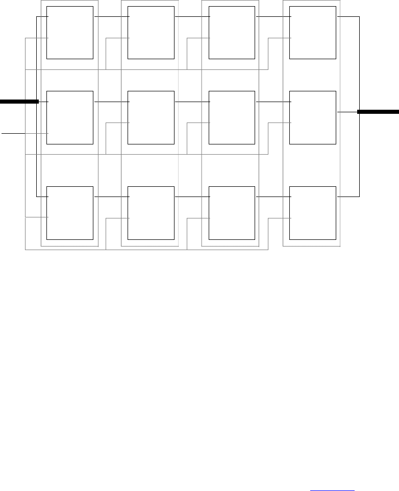
IEEE Std 1800-2012
IEEE STANDARD FOR SYSTEMVERILOG—UNIFIED HARDWARE DESIGN, SPECIFICATION, AND
VERIFICATION LANGUAGE
766
Copyright © 2013 IEEE. All rights reserved.
Figure 28-1—Schematic diagram of interconnections in array of instances
28.4 and, nand, nor, or, xor, and xnor gates
The instance declaration of a multiple input logic gate shall begin with one of the following keywords:
and nand nor or xor xnor
The delay specification shall be zero, one, or two delays. If the specification contains two delays, the first
delay shall determine the output rise delay, the second delay shall determine the output fall delay, and the
smaller of the two delays shall apply to output transitions to x. If only one delay is specified, it shall specify
both the rise delay and the fall delay. If there is no delay specification, there shall be no propagation delay
through the gate.
These six logic gates shall have one output and one or more inputs. The first terminal in the terminal list
shall connect to the output of the gate and all other terminals connect to its inputs.
The truth tables for these gates, showing the result of two input values, appear in Table 28-3.
in[2:0]
clk
out[2:0]
p[4] p[3] p[2] p[1]
dff[2] dff[2]
dff[2]dff[2]
dff[1] dff[1]
dff[1]
dff[1]
dff[0] dff[0] dff[0] dff[0]
t[3] t[6] t[9]
t[2] t[5] t[8]
t[1] t[4] t[7]
out[2]
out[1]
out[0]
in[2]
in[1]
in[0]
IEEE Std 1800-2012
IEEE STANDARD FOR SYSTEMVERILOG—UNIFIED HARDWARE DESIGN, SPECIFICATION, AND
VERIFICATION LANGUAGE
767
Copyright © 2013 IEEE. All rights reserved.
Table 28-3—Truth tables for multiple input logic gates
Versions of these six logic gates having more than two inputs shall have a natural extension, but the number
of inputs shall not alter propagation delays.
The following example declares a two-input and gate:
and a1 (out, in1, in2);
The inputs are in1 and in2. The output is out. The instance name is a1.
28.5 buf and not gates
The instance declaration of a multiple output logic gate shall begin with one of the following keywords:
buf not
The delay specification shall be zero, one, or two delays. If the specification contains two delays, the first
delay shall determine the output rise delay, the second delay shall determine the output fall delay, and the
smaller of the two delays shall apply to output transitions to x. If only one delay is specified, it shall specify
both the rise delay and the fall delay. If there is no delay specification, there shall be no propagation delay
through the gate.
These two logic gates shall have one input and one or more outputs. The last terminal in the terminal list
shall connect to the input of the logic gate, and the other terminals shall connect to the outputs of the logic
gate.
Truth tables for these logic gates with one input and one output are shown in Table 28-4.
and01xz
00000
101xx
x0xxx
z0xxx
nand 0 1 x z
01111
110xx
x1xxx
z1xxx
nor 0 1 x z
010xx
10000
xx0xx
zx0xx
xor 0 1 x z
001xx
110xx
xxxxx
zxxxx
xnor 0 1 x z
010xx
101xx
xxxxx
zxxxx
or 01xz
001xx
11111
xx1xx
zx1xx
IEEE Std 1800-2012
IEEE STANDARD FOR SYSTEMVERILOG—UNIFIED HARDWARE DESIGN, SPECIFICATION, AND
VERIFICATION LANGUAGE
768
Copyright © 2013 IEEE. All rights reserved.
Table 28-4—Truth tables for multiple output logic gates
The following example declares a two-output buf:
buf b1 (out1, out2, in);
The input is in. The outputs are out1 and out2. The instance name is b1.
28.6 bufif1, bufif0, notif1, and notif0 gates
The instance declaration of these three-state logic gates shall begin with one of the following keywords:
bufif0 bufif1 notif1 notif0
These four logic gates model three-state drivers. In addition to logic values 1 and 0, these gates can output z.
The delay specification shall be zero, one, two, or three delays. If the delay specification contains three
delays, the first delay shall determine the rise delay, the second delay shall determine the fall delay, the third
delay shall determine the delay of transitions to z, and the smallest of the three delays shall determine the
delay of transitions to x. If the specification contains two delays, the first delay shall determine the output
rise delay, the second delay shall determine the output fall delay, and the smaller of the two delays shall
apply to output transitions to x and z. If only one delay is specified, it shall specify the delay for all output
transitions. If there is no delay specification, there shall be no propagation delay through the gate.
Some combinations of data input values and control input values can cause these gates to output either of
two values, without a preference for either value (see ). The logic tables for these gates include two symbols
representing such unknown results. The symbol L shall represent a result that has a value 0 or z. The symbol
H shall represent a result that has a value 1 or z. Delays on transitions to H or L shall be treated the same as
delays on transitions to x.
These four logic gates shall have one output, one data input, and one control input. The first terminal in the
terminal list shall connect to the output, the second terminal shall connect to the data input, and the third
terminal shall connect to the control input.
Table 28-5 presents the logic tables for these gates.
buf
input output
00
11
xx
zx
not
input output
01
10
xx
zx
IEEE Std 1800-2012
IEEE STANDARD FOR SYSTEMVERILOG—UNIFIED HARDWARE DESIGN, SPECIFICATION, AND
VERIFICATION LANGUAGE
769
Copyright © 2013 IEEE. All rights reserved.
Table 28-5—Truth tables for three-state logic gates
The following example declares an instance of bufif1:
bufif1 bf1 (outw, inw, controlw);
The output is outw, the input is inw, and the control is controlw. The instance name is bf1.
28.7 MOS switches
The instance declaration of a metal-oxide semiconductor (MOS) switch shall begin with one of the
following keywords:
cmos nmos pmos rcmos rnmos rpmos
The cmos and rcmos switches are described in 28.9.
The pmos keyword stands for the P-type metal-oxide semiconductor (PMOS) transistor and the nmos
keyword stands for the N-type metal-oxide semiconductor (NMOS) transistor. PMOS and NMOS transistors
have relatively low impedance between their sources and drains when they conduct. The rpmos keyword
stands for resistive PMOS transistor and the rnmos keyword stands for resistive NMOS transistor. Resistive
PMOS and resistive NMOS transistors have significantly higher impedance between their sources and
drains when they conduct than PMOS and NMOS transistors have. The load devices in static MOS networks
are examples of rpmos and rnmos transistors. These four switches are unidirectional channels for data
similar to the bufif gates.
The delay specification shall be zero, one, two, or three delays. If the delay specification contains three
delays, the first delay shall determine the rise delay, the second delay shall determine the fall delay, the third
delay shall determine the delay of transitions to z, and the smallest of the three delays shall determine the
bufif0
CONTROL
01xz
D 00zLL
A 11zHH
T xxzxx
A zxzxx
bufif1
CONTROL
01xz
D0z0LL
A1z1HH
T xzxxx
A zzxxx
notif0
CONTROL
01xz
D 01zHH
A 10zLL
T xxzxx
A zxzxx
notif1
CONTROL
01xz
D0z1HH
A1z0LL
T xzxxx
A zzxxx
IEEE Std 1800-2012
IEEE STANDARD FOR SYSTEMVERILOG—UNIFIED HARDWARE DESIGN, SPECIFICATION, AND
VERIFICATION LANGUAGE
770
Copyright © 2013 IEEE. All rights reserved.
delay of transitions to x. If the specification contains two delays, the first delay shall determine the output
rise delay, the second delay shall determine the output fall delay, and the smaller of the two delays shall
apply to output transitions to x and z. If only one delay is specified, it shall specify the delay for all output
transitions. If there is no delay specification, there shall be no propagation delay through the switch.
Some combinations of data input values and control input values can cause these switches to output either of
two values, without a preference for either value. The logic tables for these switches include two symbols
representing such unknown results. The symbol L represents a result that has a value 0 or z. The symbol H
represents a result that has a value 1 or z. Delays on transitions to H and L shall be the same as delays on
transitions to x.
These four switches shall have one output, one data input, and one control input. The first terminal in the
terminal list shall connect to the output, the second terminal shall connect to the data input, and the third
terminal shall connect to the control input.
The nmos and pmos switches shall pass signals from their inputs and through their outputs with a change in
the strength of the signal in only one case, as discussed in 28.15.1. The rnmos and rpmos switches shall
reduce the strength of signals that propagate through them, as discussed in 28.14.
Table 28-6 presents the logic tables for these switches.
Table 28-6—Truth tables for MOS switches
The following example declares a pmos switch:
pmos p1 (out, data, control);
The output is out, the data input is data, and the control input is control. The instance name is p1.
28.8 Bidirectional pass switches
The instance declaration of a bidirectional pass switch shall begin with one of the following keywords:
tran tranif1 tranif0
rtran rtranif1 rtranif0
The bidirectional pass switches shall not delay signals propagating through them. When tranif0,
tranif1, rtranif0, or rtranif1 devices are turned off, they shall block signals; and when they are
turned on, they shall pass signals. The tran and rtran devices cannot be turned off; they shall always pass
signals.
pmos
rpmos
CONTROL
01xz
D 00zLL
A 11zHH
T xxzxx
A zzzzz
nmos
rnmos
CONTROL
01xz
D0z0LL
A1z1HH
T xzxxx
A zzzzz

IEEE Std 1800-2012
IEEE STANDARD FOR SYSTEMVERILOG—UNIFIED HARDWARE DESIGN, SPECIFICATION, AND
VERIFICATION LANGUAGE
771
Copyright © 2013 IEEE. All rights reserved.
The delay specifications for tranif1, tranif0, rtranif1, and rtranif0 devices shall be zero, one, or
two delays. If the specification contains two delays, the first delay shall determine the turn-on delay, the
second delay shall determine the turn-off delay, and the smaller of the two delays shall apply to output
transitions to x and z. If only one delay is specified, it shall specify both the turn-on and the turn-off delays.
If there is no delay specification, there shall be no turn-on or turn-off delay for the bidirectional pass switch.
The bidirectional pass switches tran and rtran shall not accept delay specification.
The tranif1, tranif0, rtranif1, and rtranif0 devices shall have three items in their terminal lists.
The first two shall be bidirectional terminals that conduct signals to and from the devices, and the third
terminal shall connect to a control input. The tran and rtran devices shall have terminal lists containing
two bidirectional terminals. Both bidirectional terminals shall unconditionally conduct signals to and from
the devices, allowing signals to pass in either direction through the devices. The bidirectional terminals of all
six devices shall be connected only to scalar nets or bit-selects of vector nets.
The tran, tranif0, and tranif1 devices shall pass signals with an alteration in their strength in only one
case, as discussed in 28.15.1. The rtran, rtranif0, and rtranif1 devices shall reduce the strength of the
signals passing through them according to rules discussed in 28.14.
The following example declares an instance of tranif1:
tranif1 t1 (inout1,inout2,control);
The bidirectional terminals are inout1 and inout2. The control input is control. The instance name is
t1.
28.9 CMOS switches
The instance declaration of a CMOS switch shall begin with one of the following keywords:
cmos rcmos
The delay specification shall be zero, one, two, or three delays. If the delay specification contains three
delays, the first delay shall determine the rise delay, the second delay shall determine the fall delay, the third
delay shall determine the delay of transitions to z, and the smallest of the three delays shall determine the
delay of transitions to x. Delays in transitions to H or L are the same as delays in transitions to x. If the
specification contains two delays, the first delay shall determine the output rise delay, the second delay shall
determine the output fall delay, and the smaller of the two delays shall apply to output transitions to x and z.
If only one delay is specified, it shall specify the delay for all output transitions. If there is no delay
specification, there shall be no propagation delay through the switch.
The cmos and rcmos switches shall have a data input, a data output, and two control inputs. In the terminal
list, the first terminal shall connect to the data output, the second terminal shall connect to the data input, the
third terminal shall connect to the n-channel control input, and the last terminal shall connect to the p-
channel control input.
The cmos gate shall pass signals with an alteration in their strength in only one case, as discussed in 28.15.1.
The rcmos gate shall reduce the strength of signals passing through it according to rules described in 28.14.
The cmos switch shall be treated as the combination of a pmos switch and an nmos switch. The rcmos
switch shall be treated as the combination of an rpmos switch and an rnmos switch. The combined switches
in these configurations shall share data input and data output terminals, but they shall have separate control
inputs.
IEEE Std 1800-2012
IEEE STANDARD FOR SYSTEMVERILOG—UNIFIED HARDWARE DESIGN, SPECIFICATION, AND
VERIFICATION LANGUAGE
772
Copyright © 2013 IEEE. All rights reserved.
The equivalence of the cmos gate to the pairing of an nmos gate and a pmos gate is shown in the following
example:
28.10 pullup and pulldown sources
The instance declaration of a pullup or a pulldown source shall begin with one of the following keywords:
pullup pulldown
A pullup source shall place a logic value 1 on the nets connected in its terminal list. A pulldown source
shall place a logic value 0 on the nets connected in its terminal list.
The signals that these sources place on nets shall have pull strength in the absence of a strength
specification. If there is a strength1 specification on a pullup source or a strength0 specification on a
pulldown source, the signals shall have the strength specified. A strength0 specification on a pullup
source and a strength1 specification on a pulldown source shall be ignored.
There shall be no delay specifications for these sources.
The following example declares two pullup instances:
pullup (strong1) p1 (neta), p2 (netb);
In this example, the p1 instance drives neta and the p2 instance drives netb with strong strength.
28.11 Logic strength modeling
SystemVerilog provides for accurate modeling of signal contention, bidirectional pass gates, resistive MOS
devices, dynamic MOS, charge sharing, and other technology-dependent network configurations by
allowing scalar net signal values to have a full range of unknown values and different levels of strength or
combinations of levels of strength. This multiple-level logic strength modeling resolves combinations of
signals into known or unknown values to represent the behavior of hardware with improved accuracy.
A strength specification shall have the following two components:
a) The strength of the 0 portion of the net value, called strength0, designated as one of the following:
supply0 strong0 pull0 weak0 highz0
b) The strength of the 1 portion of the net value, called strength1, designated as one of the following:
supply1 strong1 pull1 weak1 highz1
cmos (w, datain, ncontrol, pcontrol);
is equivalent to:
nmos (w, datain, ncontrol);
pmos (w, datain, pcontrol);
nmos
pmos
ncontrol
pcontrol
wdatain
IEEE Std 1800-2012
IEEE STANDARD FOR SYSTEMVERILOG—UNIFIED HARDWARE DESIGN, SPECIFICATION, AND
VERIFICATION LANGUAGE
773
Copyright © 2013 IEEE. All rights reserved.
The combinations (highz0, highz1) and (highz1, highz0) shall be considered illegal.
Despite this division of the strength specification, it is helpful to consider strength as a property occupying
regions of a continuum in order to predict the results of combinations of signals.
Table 28-7 demonstrates the continuum of strengths. The left column lists the keywords used in specifying
strengths. The right column gives correlated strength levels.
In Table 28-7, there are four driving strengths:
supply strong pull weak
Signals with driving strengths shall propagate from gate outputs and continuous assignment outputs.
In Table 28-7, there are three charge storage strengths:
large medium small
Signals with the charge storage strengths shall originate in the trireg net type.
It is possible to think of the strengths of signals in Table 28-7 as locations on the scale in Figure 28-2.
Table 28-7—Strength levels for scalar net signal values
Strength name Strength level
supply0 7
strong0 6
pull0 5
large0 4
weak0 3
medium0 2
small0 1
highz0 0
highz1 0
small1 1
medium1 2
weak1 3
large1 4
pull1 5
strong1 6
supply1 7
IEEE Std 1800-2012
IEEE STANDARD FOR SYSTEMVERILOG—UNIFIED HARDWARE DESIGN, SPECIFICATION, AND
VERIFICATION LANGUAGE
774
Copyright © 2013 IEEE. All rights reserved.
Figure 28-2—Scale of strengths
Discussions of signal combinations later in this clause employ graphics similar to those used in Figure 28-2.
If the signal value of a net is known, all of its strength levels shall be in either the strength0 part of the scale
represented by Figure 28-2, or all strength levels shall be in its strength1 part. If the signal value of a net is
unknown, it shall have strength levels in both the strength0 and the strength1 parts. A net with a signal value
z shall have a strength level only in one of the 0 subdivisions of the parts of the scale.
28.12 Strengths and values of combined signals
In addition to a signal value, a net shall have either a single unambiguous strength level or an ambiguous
strength consisting of more than one level. When signals combine, their strengths and values shall determine
the strength and value of the resulting signal in accordance with the principles in 28.12.1 through 28.12.4.
Nets with user-defined nettypes shall not have strength levels.
Combining signal values for nets with user-defined nettypes shall follow the rules in 6.6.7. Any strength
associated with any drivers of a net with a user-defined nettype shall be ignored.
28.12.1 Combined signals of unambiguous strength
This subclause deals with combinations of signals in which each signal has a known value and a single
strength level.
If two or more signals of unequal strength combine in a wired net configuration, the stronger signal shall
dominate all the weaker drivers and determine the result. The combination of two or more signals of like
value shall result in the same value with the greater of all the strengths. The combination of signals identical
in strength and value shall result in the same signal.
The combination of signals with unlike values and the same strength can have three possible results. Two of
the results occur in the presence of wired logic, and the third occurs in its absence. Wired logic is discussed
in 28.12.4. The result in the absence of wired logic is the subject of Figure 28-4 (in 28.12.2).
In Figure 28-3, the numbers in parentheses indicate the relative strengths of the signals. The combination of
a pull1 and a strong0 results in a strong0, which is the stronger of the two signals.
76543210 76543210
strength0 strength1
HiZ0Sm0Me0We0La0Pu0St0Su0 HiZ1 Sm1 Me1 We1 La1 Pu1 St1 Su1
Pu1(5)
St0(6)
St0(6)
Su1(7)
La1(4)
Su1(7)
Figure 28-3—Combining unequal strengths
IEEE Std 1800-2012
IEEE STANDARD FOR SYSTEMVERILOG—UNIFIED HARDWARE DESIGN, SPECIFICATION, AND
VERIFICATION LANGUAGE
775
Copyright © 2013 IEEE. All rights reserved.
28.12.2 Ambiguous strengths: sources and combinations
There are several classifications of signals possessing ambiguous strengths, as follows:
— Signals with known values and multiple strength levels
— Signals with a value x, which have strength levels consisting of subdivisions of both the strength1
and the strength0 parts of the scale of strengths in Figure 28-2
— Signals with a value L, which have strength levels that consist of high impedance joined with
strength levels in the strength0 part of the scale of strengths in Figure 28-2
— Signals with a value H, which have strength levels that consist of high impedance joined with
strength levels in the strength1 part of the scale of strengths in Figure 28-2
Many configurations can produce signals of ambiguous strength. When two signals of equal strength and
opposite value combine, the result shall be a value x, along with the strength levels of both signals and all
the smaller strength levels.
Figure 28-4 shows the combination of a weak signal with a value 1 and a weak signal with a value 0
yielding a signal with weak strength and a value x.
Figure 28-4—Combination of signals of equal strength and opposite values
This output signal is described in Figure 28-5.
Figure 28-5—Weak x signal strength
An ambiguous signal strength can be a range of possible values. An example is the strength of the output
from the three-state drivers with unknown control inputs as shown in Figure 28-6.
We1
We0
WeX
76543210 76543210
strength0 strength1
HiZ0Sm0Me0We0La0Pu0St0Su0 HiZ1 Sm1 Me1 We1 La1 Pu1 St1 Su1
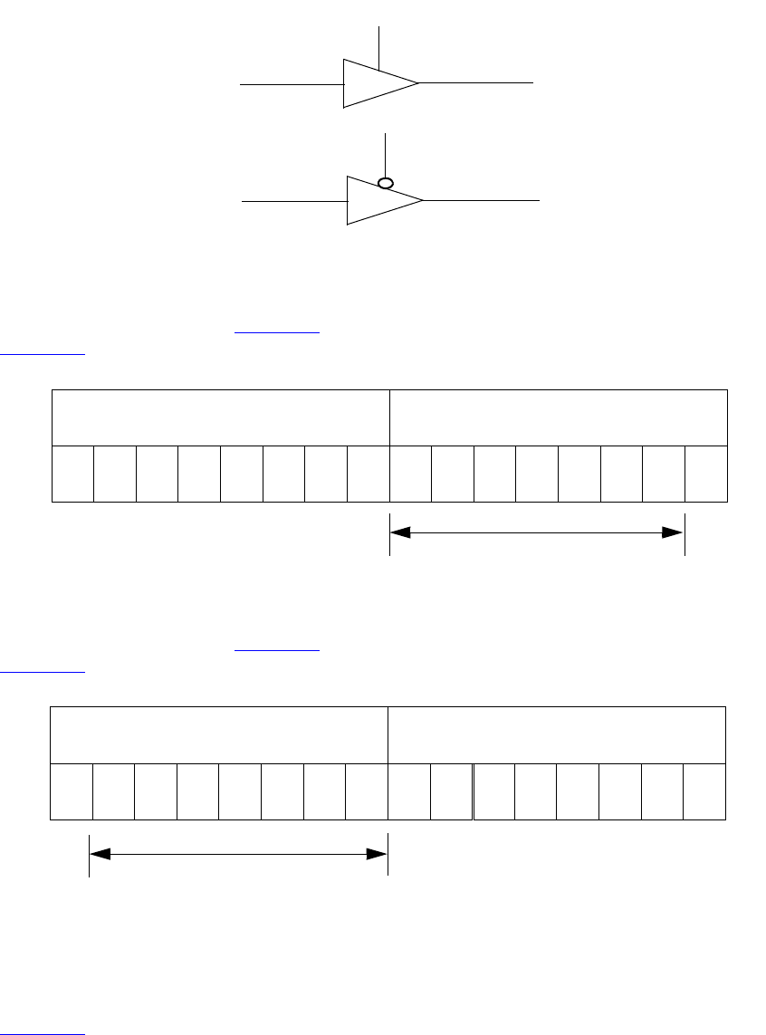
IEEE Std 1800-2012
IEEE STANDARD FOR SYSTEMVERILOG—UNIFIED HARDWARE DESIGN, SPECIFICATION, AND
VERIFICATION LANGUAGE
776
Copyright © 2013 IEEE. All rights reserved.
Figure 28-6—Bufifs with control inputs of x
The output of the bufif1 in Figure 28-6 is a strong H, composed of the range of values described in
Figure 28-7.
Figure 28-7—Strong H range of values
The output of the bufif0 in Figure 28-6 is a strong L, composed of the range of values described in
Figure 28-8.
Figure 28-8—Strong L range of values
The combination of two signals of ambiguous strength shall result in a signal of ambiguous strength. The
resulting signal shall have a range of strength levels that includes the strength levels in its component
signals. The combination of outputs from two three-state drivers with unknown control inputs, shown in
Figure 28-9, is an example.
X
St1
X
We0
StH
StL
bufif1
bufif0
76543210 76543210
strength0 strength1
HiZ0Sm0Me0We0La0Pu0St0Su0 HiZ1 Sm1 Me1 We1 La1 Pu1 St1 Su1
76543210 76543210
strength0 strength1
HiZ0Sm0Me0We0La0Pu0St0Su0 HiZ1 Sm1 Me1 We1 La1 Pu1 St1 Su1
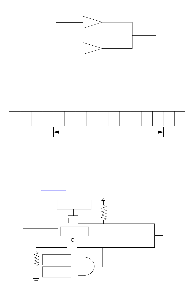
IEEE Std 1800-2012
IEEE STANDARD FOR SYSTEMVERILOG—UNIFIED HARDWARE DESIGN, SPECIFICATION, AND
VERIFICATION LANGUAGE
777
Copyright © 2013 IEEE. All rights reserved.
Figure 28-9—Combined signals of ambiguous strength
In Figure 28-9, the combination of signals of ambiguous strengths produces a range that includes the
extremes of the signals and all the strengths between them, as described in Figure 28-10.
Figure 28-10—Range of strengths for an unknown signal
The result is a value x because its range includes the values 1 and 0. The number 35, which precedes the x,
is a concatenation of two digits. The first is the digit 3, which corresponds to the highest strength0 level for
the result. The second digit, 5, corresponds to the highest strength1 level for the result.
Switch networks can produce a ranges of strengths of the same value, such as the signals from the upper and
lower configurations in Figure 28-11.
Figure 28-11—Ambiguous strengths from switch networks
X
X
Pu1
We0
PuH
WeL
35X
76543210 76543210
strength0 strength1
HiZ0Sm0Me0We0La0Pu0St0Su0 HiZ1 Sm1 Me1 We1 La1 Pu1 St1 Su1
logic b = x Vcc
651
530
56X
pullup
pulldown ground
and We0 (3)
Pu0 (5)
Pu1 (5)
logic a = 1 (6)
logic d = 0
logic d = 0
logic g = x
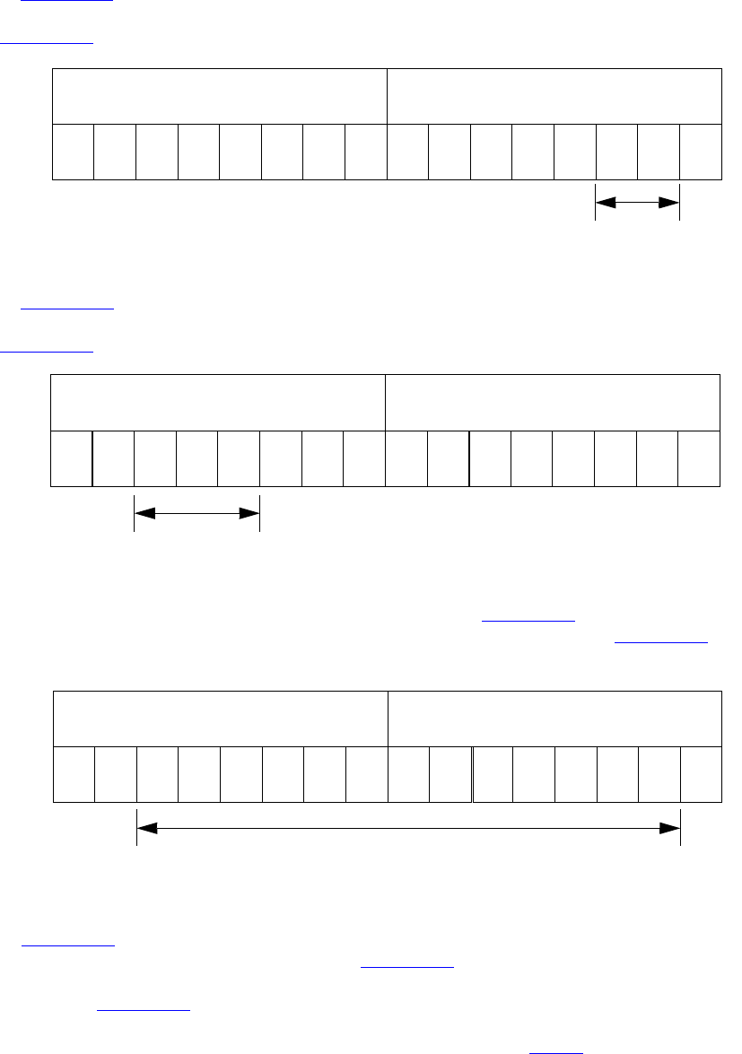
IEEE Std 1800-2012
IEEE STANDARD FOR SYSTEMVERILOG—UNIFIED HARDWARE DESIGN, SPECIFICATION, AND
VERIFICATION LANGUAGE
778
Copyright © 2013 IEEE. All rights reserved.
In Figure 28-11, the upper combination of a logic type, a gate controlled by a logic type of unspecified
value, and a pullup produces a signal with a value of 1 and a range of strengths (651) described in
Figure 28-12.
Figure 28-12—Range of two strengths of a defined value
In Figure 28-11, the lower combination of a pulldown, a gate controlled by a logic type of unspecified
value, and an and gate produces a signal with a value 0 and a range of strengths (530) described in
Figure 28-13.
Figure 28-13—Range of three strengths of a defined value
When the signals from the upper and lower configurations in Figure 28-11 combine, the result is an
unknown with a range (56x) determined by the extremes of the two signals shown in Figure 28-14.
Figure 28-14—Unknown value with a range of strengths
In Figure 28-11, replacing the pulldown in the lower configuration with a supply0 would change the
range of the result to the range (StX) described in Figure 28-15.
The range in Figure 28-15 is strong x because it is unknown and the extremes of both its components are
strong. The extreme of the output of the lower configuration is strong because the lower pmos reduces
the strength of the supply0 signal. This modeling feature is discussed in 28.15.1.
76543210 76543210
strength0 strength1
HiZ0Sm0Me0We0La0Pu0St0Su0 HiZ1 Sm1 Me1 We1 La1 Pu1 St1 Su1
76543210 76543210
strength0 strength1
HiZ0Sm0Me0We0La0Pu0St0Su0 HiZ1 Sm1 Me1 We1 La1 Pu1 St1 Su1
76543210 76543210
strength0 strength1
HiZ0Sm0Me0We0La0Pu0St0Su0 HiZ1 Sm1 Me1 We1 La1 Pu1 St1 Su1
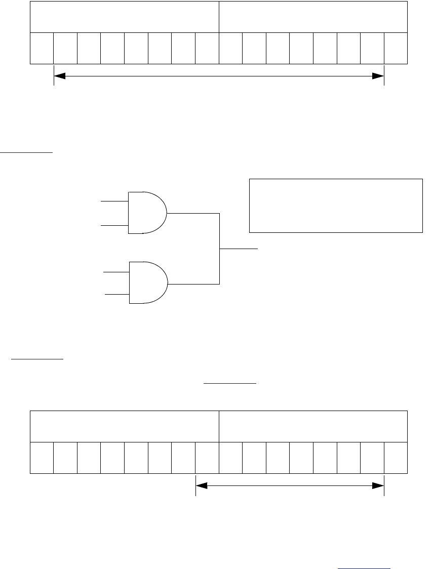
IEEE Std 1800-2012
IEEE STANDARD FOR SYSTEMVERILOG—UNIFIED HARDWARE DESIGN, SPECIFICATION, AND
VERIFICATION LANGUAGE
779
Copyright © 2013 IEEE. All rights reserved.
Figure 28-15—Strong X range
Logic gates produce results with ambiguous strengths as well as three-state drivers. Such a case appears in
Figure 28-16. The and gate N1 is declared with highz0 strength, and N2 is declared with weak0 strength.
Figure 28-16—Ambiguous strength from gates
In Figure 28-16, logic type b has an unspecified value; therefore, input to the upper and gate is strong x.
The upper and gate has a strength specification including highz0. The signal from the upper and gate is a
strong H composed of the values as described in Figure 28-17.
Figure 28-17—Ambiguous strength signal from a gate
HiZ0 is part of the result because the strength specification for the gate in question specified that strength for
an output with a value 0. A strength specification other than high impedance for the 0 value output results in
a gate output value x. The output of the lower and gate is a weak 0 as described in Figure 28-18.
76543210 76543210
strength0 strength1
HiZ0Sm0Me0We0La0Pu0St0Su0 HiZ1 Sm1 Me1 We1 La1 Pu1 St1 Su1
StH
36X
We0
a=1
b=X
c=0
d=0
N1
N2
and (strong1,highz0) N1(a,b);
and (strong1, weak0) N2(c,d);
76543210 76543210
strength0 strength1
HiZ0Sm0Me0We0La0Pu0St0Su0 HiZ1 Sm1 Me1 We1 La1 Pu1 St1 Su1
IEEE Std 1800-2012
IEEE STANDARD FOR SYSTEMVERILOG—UNIFIED HARDWARE DESIGN, SPECIFICATION, AND
VERIFICATION LANGUAGE
780
Copyright © 2013 IEEE. All rights reserved.
Figure 28-18—Weak 0
When the signals combine, the result is the range (36x) as described in Figure 28-19.
Figure 28-19—Ambiguous strength in combined gate signals
Figure 28-19 presents the combination of an ambiguous signal and an unambiguous signal. Such
combinations are the topic of 28.12.3.
28.12.3 Ambiguous strength signals and unambiguous signals
The combination of a signal with unambiguous strength and known value with another signal of ambiguous
strength presents several possible cases. To understand a set of rules governing this type of combination, it is
necessary to consider the strength levels of the ambiguous strength signal separately from each other and
relative to the unambiguous strength signal. When a signal of known value and unambiguous strength
combines with a component of a signal of ambiguous strength, the rules shall be as follows:
a) The strength levels of the ambiguous strength signal that are greater than the strength level of the
unambiguous signal shall remain in the result.
b) The strength levels of the ambiguous strength signal that are smaller than or equal to the strength
level of the unambiguous signal shall disappear from the result, subject to rule c).
c) If the operation of rule a) and rule b) results in a gap in strength levels because the signals are of
opposite value, the signals in the gap shall be part of the result.
The following figures show some applications of the rules.
In Figure 28-20, the strength levels in the ambiguous strength signal that are smaller than or equal to the
strength level of the unambiguous strength signal disappear from the result, demonstrating rule b).
76543210 76543210
strength0 strength1
HiZ0Sm0Me0We0La0Pu0St0Su0 HiZ1 Sm1 Me1 We1 La1 Pu1 St1 Su1
76543210 76543210
strength0 strength1
HiZ0Sm0Me0We0La0Pu0St0Su0 HiZ1 Sm1 Me1 We1 La1 Pu1 St1 Su1
IEEE Std 1800-2012
IEEE STANDARD FOR SYSTEMVERILOG—UNIFIED HARDWARE DESIGN, SPECIFICATION, AND
VERIFICATION LANGUAGE
781
Copyright © 2013 IEEE. All rights reserved.
Figure 28-20—Elimination of strength levels
In Figure 28-21, rule a), rule b), and rule c) apply. The strength levels of the ambiguous strength signal that
are of opposite value and lesser strength than the unambiguous strength signal disappear from the result. The
strength levels in the ambiguous strength signal that are less than the strength level of the unambiguous
strength signal, and of the same value, disappear from the result. The strength level of the unambiguous
strength signal and the greater extreme of the ambiguous strength signal define a range in the result.
In Figure 28-22, rule a) and rule b) apply. The strength levels in the ambiguous strength signal that are less
than the strength level of the unambiguous strength signal disappear from the result. The strength level of
the unambiguous strength signal and the strength level at the greater extreme of the ambiguous strength
signal define a range in the result.
In Figure 28-23, rule a), rule b), and rule c) apply. The greater extreme of the range of strengths for the
ambiguous strength signal is larger than the strength level of the unambiguous strength signal. The result is a
range defined by the greatest strength in the range of the ambiguous strength signal and by the strength level
of the unambiguous strength signal.
76543210 76543210
strength0 strength1
HiZ0Sm0Me0We0La0Pu0St0Su0 HiZ1 Sm1 Me1 We1 La1 Pu1 St1 Su1
76543210 76543210
strength0 strength1
HiZ0Sm0Me0We0La0Pu0St0Su0 HiZ1 Sm1 Me1 We1 La1 Pu1 St1 Su1
76543210 76543210
strength0 strength1
HiZ0Sm0Me0We0La0Pu0St0Su0 HiZ1 Sm1 Me1 We1 La1 Pu1 St1 Su1
Combining the two signals above results in the following signal:
IEEE Std 1800-2012
IEEE STANDARD FOR SYSTEMVERILOG—UNIFIED HARDWARE DESIGN, SPECIFICATION, AND
VERIFICATION LANGUAGE
782
Copyright © 2013 IEEE. All rights reserved.
Figure 28-21—Result showing a range and the elimination of strength levels of two values
76543210 76543210
strength0 strength1
HiZ0Sm0Me0We0La0Pu0St0Su0 HiZ1 Sm1 Me1 We1 La1 Pu1 St1 Su1
76543210 76543210
strength0 strength1
HiZ0Sm0Me0We0La0Pu0St0Su0 HiZ1 Sm1 Me1 We1 La1 Pu1 St1 Su1
76543210 76543210
strength0 strength1
HiZ0Sm0Me0We0La0Pu0St0Su0 HiZ1 Sm1 Me1 We1 La1 Pu1 St1 Su1
Combining the two signals above results in the following signal:
IEEE Std 1800-2012
IEEE STANDARD FOR SYSTEMVERILOG—UNIFIED HARDWARE DESIGN, SPECIFICATION, AND
VERIFICATION LANGUAGE
783
Copyright © 2013 IEEE. All rights reserved.
Figure 28-22—Result showing a range and the elimination of strength levels of one value
Figure 28-23—A range of both values
76543210 76543210
strength0 strength1
HiZ0Sm0Me0We0La0Pu0St0Su0 HiZ1 Sm1 Me1 We1 La1 Pu1 St1 Su1
76543210 76543210
strength0 strength1
HiZ0Sm0Me0We0La0Pu0St0Su0 HiZ1 Sm1 Me1 We1 La1 Pu1 St1 Su1
76543210 76543210
strength0 strength1
HiZ0Sm0Me0We0La0Pu0St0Su0 HiZ1 Sm1 Me1 We1 La1 Pu1 St1 Su1
Combining the two signals above results in the following signal:
76543210 76543210
strength0 strength1
HiZ0Sm0Me0We0La0Pu0St0Su0 HiZ1 Sm1 Me1 We1 La1 Pu1 St1 Su1
76543210 76543210
strength0 strength1
HiZ0Sm0Me0We0La0Pu0St0Su0 HiZ1 Sm1 Me1 We1 La1 Pu1 St1 Su1
76543210 76543210
strength0 strength1
HiZ0Sm0Me0We0La0Pu0St0Su0 HiZ1 Sm1 Me1 We1 La1 Pu1 St1 Su1
Combining the two signals above results in the following signal:
IEEE Std 1800-2012
IEEE STANDARD FOR SYSTEMVERILOG—UNIFIED HARDWARE DESIGN, SPECIFICATION, AND
VERIFICATION LANGUAGE
784
Copyright © 2013 IEEE. All rights reserved.
28.12.4 Wired logic net types
The net types triand, wand, trior, and wor shall resolve conflicts when multiple drivers have the same
strength. These net types shall resolve signal values by treating signals as inputs of logic functions.
Consider the combination of two signals of unambiguous strength in Figure 28-24.
Figure 28-24—Wired logic with unambiguous strength signals
The combination of the signals in Figure 28-24, using wired and logic, produces a result with the same value
as the result produced by an and gate with the value of the two signals as its inputs. The combination of
signals using wired or logic produces a result with the same value as the result produced by an or gate with
the values of the two signals as its inputs. The strength of the result is the same as the strength of the
combined signals in both cases. If the value of the upper signal changes so that both signals in Figure 28-24
possess a value 1, then the results of both types of logic have a value 1.
When ambiguous strength signals combine in wired logic, it is necessary to consider the results of all
combinations of each of the strength levels in the first signal with each of the strength levels in the second
signal, as shown in Figure 28-25.
wired AND logic value result: 0
wired OR logic value result: 1
76543210 76543210
strength0 strength1
HiZ0Sm0Me0We0La0Pu0St0Su0 HiZ1 Sm1 Me1 We1 La1 Pu1 St1 Su1
76543210 76543210
strength0 strength1
HiZ0Sm0Me0We0La0Pu0St0Su0 HiZ1 Sm1 Me1 We1 La1 Pu1 St1 Su1
IEEE Std 1800-2012
IEEE STANDARD FOR SYSTEMVERILOG—UNIFIED HARDWARE DESIGN, SPECIFICATION, AND
VERIFICATION LANGUAGE
785
Copyright © 2013 IEEE. All rights reserved.
signal1 signal2 result
strength value strength value strength value
505 15 1
605 16 0
signal1 signal2 result
strength value strength value strength value
505 15 0
605 16 0
Signal 1
Signal 2
The result is the following signal:
76543210 76543210
strength0 strength1
HiZ0Sm0Me0We0La0Pu0St0Su0 HiZ1 Sm1 Me1 We1 La1 Pu1 St1 Su1
76543210 76543210
strength0 strength1
HiZ0Sm0Me0We0La0Pu0St0Su0 HiZ1 Sm1 Me1 We1 La1 Pu1 St1 Su1
76543210 76543210
strength0 strength1
HiZ0Sm0Me0We0La0Pu0St0Su0 HiZ1 Sm1 Me1 We1 La1 Pu1 St1 Su1
76543210 76543210
strength0 strength1
HiZ0Sm0Me0We0La0Pu0St0Su0 HiZ1 Sm1 Me1 We1 La1 Pu1 St1 Su1
The combinations of strength levels for or logic appear in the following chart:
The result is the following signal:
The combinations of strength levels for and logic appear in the following chart:
Figure 28-25—Wired logic and ambiguous strengths

IEEE Std 1800-2012
IEEE STANDARD FOR SYSTEMVERILOG—UNIFIED HARDWARE DESIGN, SPECIFICATION, AND
VERIFICATION LANGUAGE
786
Copyright © 2013 IEEE. All rights reserved.
28.13 Strength reduction by nonresistive devices
The nmos, pmos, and cmos switches shall pass the strength from the data input to the output, except that a
supply strength shall be reduced to a strong strength.
The tran, tranif0, and tranif1 switches shall not affect signal strength across the bidirectional
terminals, except that a supply strength shall be reduced to a strong strength.
28.14 Strength reduction by resistive devices
The rnmos, rpmos, rcmos, rtran, rtranif1, and rtranif0 devices shall reduce the strength of signals
that pass through them according to Table 28-8.
28.15 Strengths of net types
The tri0, tri1, supply0, and supply1 net types shall generate signals with specific strength levels. The
trireg declaration can specify either of two signal strength levels other than a default strength level.
28.15.1 tri0 and tri1 net strengths
The tri0 net type models a net connected to a resistive pulldown device. In the absence of an overriding
source, such a signal shall have a value 0 and a pull strength. The tri1 net type models a net connected to
a resistive pullup device. In the absence of an overriding source, such a signal shall have a value 1 and a
pull strength.
28.15.2 trireg strength
The trireg net type models charge storage nodes. The strength of the drive resulting from a trireg net
that is in the charge storage state (that is, a driver charged the net and then went to high impedance) shall be
one of these three strengths: large, medium, or small. The specific strength associated with a particular
trireg net shall be specified by the user in the net declaration. The default shall be medium. The syntax of
this specification is described in 6.7.
Table 28-8—Strength reduction rules
Input strength Reduced strength
Supply drive Pull drive
Strong drive Pull drive
Pull drive Weak drive
Large capacitor Medium capacitor
Weak drive Medium capacitor
Medium capacitor Small capacitor
Small capacitor Small capacitor
High impedance High impedance
IEEE Std 1800-2012
IEEE STANDARD FOR SYSTEMVERILOG—UNIFIED HARDWARE DESIGN, SPECIFICATION, AND
VERIFICATION LANGUAGE
787
Copyright © 2013 IEEE. All rights reserved.
28.15.3 supply0 and supply1 net strengths
The supply0 net type models ground connections. The supply1 net type models connections to power
supplies. The supply0 and supply1 net types shall have supply driving strengths.
28.16 Gate and net delays
Gate and net delays provide a means of more accurately describing delays through a circuit. The gate delays
specify the signal propagation delay from any gate input to the gate output. Up to three values per output
representing rise, fall, and turn-off delays can be specified (see 28.4 through 28.9).
Net delays refer to the time it takes from any driver on the net changing value to the time when the net value
is updated and propagated further. Up to three delay values per net can be specified.
For both gates and nets, the default delay shall be zero when no delay specification is given. When one delay
value is given, then this value shall be used for all propagation delays associated with the gate or the net.
When two delays are given, the first delay shall specify the rise delay, and the second delay shall specify the
fall delay. The delay when the signal changes to high impedance or to unknown shall be the lesser of the two
delay values.
For a three-delay specification
— The first delay refers to the transition to the 1 value (rise delay).
— The second delay refers to the transition to the 0 value (fall delay).
— The third delay refers to the transition to the high-impedance value.
When a value changes to the unknown (x) value, the delay is the smallest of the three delays. The strength of
the input signal shall not affect the propagation delay from an input to an output.
Table 28-9 summarizes the from-to propagation delay choice for the two- and three-delay specifications.
Table 28-9—Rules for propagation delays
From value:To value:
Delay used if there are
2 delays 3 delays
01d1d1
0 x min(d1, d2) min(d1, d2, d3)
0 z min(d1, d2) d3
10d2d2
1 x min(d1, d2) min(d1, d2, d3)
1 z min(d1, d2) d3
x0d2d2
x1d1d1
x z min(d1, d2) d3
z 0 d2 d2

IEEE Std 1800-2012
IEEE STANDARD FOR SYSTEMVERILOG—UNIFIED HARDWARE DESIGN, SPECIFICATION, AND
VERIFICATION LANGUAGE
788
Copyright © 2013 IEEE. All rights reserved.
Example 1: The following is an example of a delay specification with one, two, and three delays:
and #(10) a1 (out, in1, in2); // only one delay
and #(10,12) a2 (out, in1, in2); // rise and fall delays
bufif0 #(10,12,11) b3 (out, in, ctrl); // rise, fall, and turn-off delays
Example 2: The following example specifies a simple latch module with three-state outputs, where
individual delays are given to the gates. The propagation delay from the inputs to the outputs of the module
will be cumulative, and it depends on the signal path through the network.
module tri_latch (qout, nqout, clock, data, enable);
output qout, nqout;
input clock, data, enable;
tri qout, nqout;
not #5 n1 (ndata, data);
nand #(3,5) n2 (wa, data, clock),
n3 (wb, ndata, clock);
nand #(12,15) n4 (q, nq, wa),
n5 (nq, q, wb);
bufif1 #(3,7,13) q_drive (qout, q, enable),
nq_drive (nqout, nq, enable);
endmodule
28.16.1 min:typ:max delays
The syntax for delays on gate primitives (including UDPs; see Clause 29), nets, and continuous assignments
shall allow three values each for the rising, falling, and turn-off delays. The minimum, typical, and
maximum values for each delay shall be specified as expressions separated by colons. There shall be no
required relation (e.g., min ≤ typ ≤ max) between the expressions for minimum, typical, and maximum
delays. These can be any three expressions.
The following example shows min:typ:max values for rising, falling, and turn-off delays:
module iobuf (io1, io2, dir);
. . .
bufif0 #(5:7:9, 8:10:12, 15:18:21) b1 (io1, io2, dir);
bufif1 #(6:8:10, 5:7:9, 13:17:19) b2 (io2, io1, dir);
. . .
endmodule
The syntax for delay controls in procedural statements (see 9.4) also allows minimum, typical, and
maximum values. These are specified by expressions separated by colons. The following example illustrates
this concept:
z 1 d1 d1
z x min(d1, d2) min(d1, d2, d3)
Table 28-9—Rules for propagation delays (continued)
From value:To value:
Delay used if there are
2 delays 3 delays

IEEE Std 1800-2012
IEEE STANDARD FOR SYSTEMVERILOG—UNIFIED HARDWARE DESIGN, SPECIFICATION, AND
VERIFICATION LANGUAGE
789
Copyright © 2013 IEEE. All rights reserved.
parameter min_hi = 97, typ_hi = 100, max_hi = 107;
logic clk;
always begin
#(95:100:105) clk = 1;
#(min_hi:typ_hi:max_hi) clk = 0;
end
28.16.2 trireg net charge decay
Like all nets, the delay specification in a trireg net declaration can contain up to three delays. The first two
delays shall specify the delay for transition to the 1 and 0 logic states when the trireg net is driven to these
states by a driver. The third delay shall specify the charge decay time instead of the delay in a transition to
the z logic state. The charge decay time specifies the delay between when the drivers of a trireg net turn
off and when its stored charge can no longer be determined.
A trireg net does not need a turn-off delay specification because a trireg net never makes a transition to
the z logic state. When the drivers of a trireg net make transitions from the 1, 0, or x logic states to off,
the trireg net shall retain the previous 1, 0, or x logic state that was on its drivers. The z value shall not
propagate from the drivers of a trireg net to a trireg net. A trireg net can only hold a z logic state
when z is the initial logic state of the trireg net or when the trireg net is forced to the z state with a force
statement (see 10.6.2).
A delay specification for charge decay models a charge storage node that is not ideal, i.e., a charge storage
node whose charge leaks out through its surrounding devices and connections.
The charge decay process and the delay specification for charge decay are described in 28.16.2.1 and
28.16.2.2, respectively.
28.16.2.1 Charge decay process
Charge decay is the cause of transition of a 1 or 0 that is stored in a trireg net to an unknown value (x)
after a specified delay. The charge decay process shall begin when the drivers of the trireg net turn off and
the trireg net starts to hold charge. The charge decay process shall end under the following two
conditions:
a) The delay specified by charge decay time elapses, and the trireg net makes a transition from 1 or
0 to x.
b) The drivers of trireg net turn on and propagate a 1, 0, or x into the trireg net.
28.16.2.2 Delay specification for charge decay time
The third delay in a trireg net declaration shall specify the charge decay time. A three-valued delay
specification in a trireg net declaration shall have the following form:
#(d1, d2, d3) // (rise_delay, fall_delay, charge_decay_time)
The charge decay time specification in a trireg net declaration shall be preceded by a rise and a fall delay
specification.
Example 1: The following example shows a specification of the charge decay time in a trireg net
declaration:
trireg (large) #(0,0,50) cap1;
IEEE Std 1800-2012
IEEE STANDARD FOR SYSTEMVERILOG—UNIFIED HARDWARE DESIGN, SPECIFICATION, AND
VERIFICATION LANGUAGE
790
Copyright © 2013 IEEE. All rights reserved.
This example declares a trireg net named cap1. This trireg net stores a large charge. The delay
specifications for the rise delay is 0, the fall delay is 0, and the charge decay time specification is 50 time
units.
Example 2: The next example presents a source description file that contains a trireg net declaration with
a charge decay time specification. Figure 28-26 shows an equivalent schematic for the source description.
module capacitor;
logic data, gate;
// trireg declaration with a charge decay time of 50 time units
trireg (large) #(0,0,50) cap1;
nmos nmos1 (cap1, data, gate); // nmos that drives the trireg
initial begin
$monitor("%0d data=%v gate=%v cap1=%v", $time, data, gate, cap1);
data = 1;
// Toggle the driver of the control input to the nmos switch
gate = 1;
#10 gate = 0;
#30 gate = 1;
#10 gate = 0;
#100 $finish;
end
endmodule
Figure 28-26—Trireg net with capacitance
data
gate
nmos1 trireg

IEEE Std 1800-2012
IEEE STANDARD FOR SYSTEMVERILOG—UNIFIED HARDWARE DESIGN, SPECIFICATION, AND
VERIFICATION LANGUAGE
791
Copyright © 2013 IEEE. All rights reserved.
29. User-defined primitives
29.1 General
This clause describes the following:
— User-defined primitive (UDP) definitions
— Combinational UDPs
— Level-sensitive sequential UDPs
— Edge-sensitive sequential UDPs
— Sequential UDP initialization
— UDP instantiation
29.2 Overview
This clause describes a modeling technique to augment the set of predefined gate primitives by designing
and specifying new primitive elements called UDPs. Instances of these new UDPs can be used in exactly the
same manner as the gate primitives to represent the circuit being modeled.
The following two types of behavior can be represented in a UDP:
a) Combinational—modeled by a combinational UDP
b) Sequential—modeled by a sequential UDP
A combinational UDP uses the value of its inputs to determine the next value of its output. A sequential
UDP uses the value of its inputs and the current value of its output to determine the value of its output.
Sequential UDPs provide a way to model sequential circuits such as flip-flops and latches. A sequential
UDP can model both level-sensitive and edge-sensitive behavior.
Each UDP has exactly one output, which can be in one of three states: 0, 1, or x. The three-state value z is
not supported. In sequential UDPs, the output always has the same value as the internal state.
The z values passed to UDP inputs shall be treated the same as x values.
29.3 UDP definition
UDP definitions are independent of modules; they are at the same level as module definitions in the syntax
hierarchy. They can appear anywhere in the source text, either before or after they are instantiated inside a
module. They shall not appear between the keywords module...endmodule, program...endprogram,
interface...endinterface, or package...endpackage.
Implementations may limit the maximum number of UDP definitions in a model, but they shall allow at
least 256.
The formal syntax of the UDP definition is given in Syntax 29-1.
udp_nonansi_declaration ::= // from A.5.1
{ attribute_instance } primitive udp_identifier ( udp_port_list ) ;
udp_ansi_declaration ::=
{ attribute_instance } primitive udp_identifier ( udp_declaration_port_list ) ;
IEEE Std 1800-2012
IEEE STANDARD FOR SYSTEMVERILOG—UNIFIED HARDWARE DESIGN, SPECIFICATION, AND
VERIFICATION LANGUAGE
792
Copyright © 2013 IEEE. All rights reserved.
udp_declaration ::=
udp_nonansi_declaration udp_port_declaration { udp_port_declaration }
udp_body
endprimitive [ : udp_identifier ]
| udp_ansi_declaration
udp_body
endprimitive [ : udp_identifier ]
|extern udp_nonansi_declaration
|extern udp_ansi_declaration
| { attribute_instance } primitive udp_identifier ( .* ) ;
{ udp_port_declaration }
udp_body
endprimitive [ : udp_identifier ]
udp_port_list ::= output_port_identifier , input_port_identifier { , input_port_identifier } // from A.5.2
udp_declaration_port_list ::= udp_output_declaration , udp_input_declaration { , udp_input_declaration }
udp_port_declaration ::=
udp_output_declaration ;
| udp_input_declaration ;
| udp_reg_declaration ;
udp_output_declaration ::=
{ attribute_instance } output port_identifier
| { attribute_instance } output reg port_identifier [ = constant_expression ]
udp_input_declaration ::= { attribute_instance } input list_of_udp_port_identifiers
udp_reg_declaration ::= { attribute_instance } reg variable_identifier
udp_body ::= combinational_body | sequential_body // from A.5.3
combinational_body ::= table combinational_entry { combinational_entry } endtable
combinational_entry ::= level_input_list : output_symbol ;
sequential_body ::= [ udp_initial_statement ] table sequential_entry { sequential_entry } endtable
udp_initial_statement ::= initial output_port_identifier = init_val ;
init_val ::= 1'b0 | 1'b1 | 1'bx | 1'bX | 1'B0 | 1'B1 | 1'Bx | 1'BX | 1 | 0
sequential_entry ::= seq_input_list : current_state : next_state ;
seq_input_list ::= level_input_list | edge_input_list
level_input_list ::= level_symbol { level_symbol }
edge_input_list ::= { level_symbol } edge_indicator { level_symbol }
edge_indicator ::= ( level_symbol level_symbol ) | edge_symbol
current_state ::= level_symbol
next_state ::= output_symbol | -
output_symbol ::= 0 | 1 | x | X
level_symbol ::= 0 | 1 | x | X | ? | b | B
edge_symbol ::= r | R | f | F | p | P | n | N | *
udp_instantiation ::=
udp_identifier [ drive_strength ] [ delay2 ] udp_instance { , udp_instance } ; // from A.5.4
udp_instance ::= [ name_of_instance ] ( output_terminal , input_terminal { , input_terminal } )
Syntax 29-1—Syntax for UDPs (excerpt from Annex A)

IEEE Std 1800-2012
IEEE STANDARD FOR SYSTEMVERILOG—UNIFIED HARDWARE DESIGN, SPECIFICATION, AND
VERIFICATION LANGUAGE
793
Copyright © 2013 IEEE. All rights reserved.
29.3.1 UDP header
A UDP definition shall have one of two alternate forms. The first form, udp_nonansi_declaration, shall
begin with the keyword primitive, followed by an identifier, which shall be the name of the UDP. This in
turn shall be followed by a comma-separated list of port names enclosed in parentheses, which shall be
followed by a semicolon. The UDP definition header shall be followed by port declarations and a state table.
The UDP definition shall be terminated by the keyword endprimitive.
The second form, udp_ansi_declaration, shall begin with the keyword primitive, followed by an
identifier, which shall be the name of the UDP. This in turn shall be followed by a comma-separated list of
port declarations enclosed in parentheses, followed by a semicolon. The UDP definition header shall be
followed by a state table. The UDP definition shall be terminated by the keyword endprimitive.
UDPs have multiple input ports and exactly one output port; bidirectional inout ports are not permitted on
UDPs. All ports of a UDP shall be scalar; vector ports are not permitted.
The output port shall be the first port in the port list.
29.3.2 UDP port declarations
UDPs shall contain input and output port declarations. The output port declaration begins with the keyword
output, followed by one output port name. The input port declaration begins with the keyword input,
followed by one or more input port names.
Sequential UDPs shall contain a reg declaration for the output port, either in addition to the output
declaration, when the UDP is declared using the first form of a UDP header, or as part of the
output_declaration. Combinational UDPs cannot contain a reg declaration. The initial value of the output
port can be specified in an initial statement in a sequential UDP (see 29.3.3).
Implementations may limit the maximum number of inputs to a UDP, but they shall allow at least nine
inputs for sequential UDPs and 10 inputs for combinational UDPs.
When UDPs are discussed from the instantiation point of view, UDP ports are referred to as terminals. This
is because they are consistent with terminals of other primitives, rather than module ports. Wherever
primitive terminals are mentioned, the text shall also apply to UDP terminals.
29.3.3 Sequential UDP initial statement
The sequential UDP initial statement specifies the value of the output port when simulation begins. This
statement begins with the keyword initial. The statement that follows shall be an assignment statement
that assigns a single-bit literal value to the output port.
29.3.4 UDP state table
The state table defines the behavior of a UDP. It begins with the keyword table and is terminated with the
keyword endtable. Each row of the table is terminated by a semicolon.
Each row of the table is created using a variety of characters (see Table 29-1), which indicate input values
and output state. Three states—0, 1, and x—are supported. The z state is explicitly excluded from
consideration in UDPs. A number of special characters are defined to represent certain combinations of state
possibilities. These are described in Table 29-1.
The order of the input state fields of each row of the state table is taken directly from the port list in the UDP
definition header. It is not related to the order of the input port declarations.
IEEE Std 1800-2012
IEEE STANDARD FOR SYSTEMVERILOG—UNIFIED HARDWARE DESIGN, SPECIFICATION, AND
VERIFICATION LANGUAGE
794
Copyright © 2013 IEEE. All rights reserved.
Combinational UDPs have one field per input and one field for the output. The input fields are separated
from the output field by a colon (:). Each row defines the output for a particular combination of the input
values (see 29.4).
Sequential UDPs have an additional field inserted between the input fields and the output field. This
additional field represents the current state of the UDP and is considered equivalent to the current output
value. It is delimited by colons. Each row defines the output based on the current state, particular
combinations of input values, and at most one input transition (see 29.6). A row such as the following one is
illegal:
(01) (10) 0 : 0 : 1 ;
If all input values are specified as x, then the output state shall be specified as x.
It is not necessary to explicitly specify every possible input combination. All combinations of input values
that are not explicitly specified result in a default output state of x.
It shall be illegal to have the same combination of inputs, including edges, specify different output values.
29.3.5 Z values in UDP
The z value in a table entry is not supported, and it is considered illegal. The z values passed to UDP inputs
shall be treated the same as x values.
29.3.6 Summary of symbols
To improve the readability and to ease writing of the state table, several special symbols are provided.
Table 29-1 summarizes the meaning of all the value symbols that are valid in the table part of a UDP
definition.
Table 29-1—UDP table symbols
Symbol Interpretation Comments
0Logic 0—
1Logic 1—
xUnknown Permitted in the input and output fields of all
UDPs and in the current state field of
sequential UDPs.
?Iteration of 0,1,andx Not permitted in output field.
bIteration of 0 and 1 Permitted in the input fields of all UDPs and
in the current state field of sequential UDPs.
Not permitted in the output field.
-No change Permitted only in the output field of a
sequential UDP.
(vw) Value change from vto w vand wcan be any one of 0, 1,x,?,orb,
and are only permitted in the input field.
*Same as (??) Any value change on input.
rSame as (01) Rising edge on input.
fSame as (10) Falling edge on input.
IEEE Std 1800-2012
IEEE STANDARD FOR SYSTEMVERILOG—UNIFIED HARDWARE DESIGN, SPECIFICATION, AND
VERIFICATION LANGUAGE
795
Copyright © 2013 IEEE. All rights reserved.
29.4 Combinational UDPs
In combinational UDPs, the output state is determined solely as a function of the current input states.
Whenever an input state changes, the UDP is evaluated and the output state is set to the value indicated by
the row in the state table that matches all the input states. All combinations of the inputs that are not
explicitly specified will drive the output state to the unknown value x.
The following example defines a multiplexer with two data inputs and a control input:
primitive multiplexer (mux, control, dataA, dataB);
output mux;
input control, dataA, dataB;
table
// control dataA dataB mux
010:1 ;
011:1 ;
01x:1 ;
000:0 ;
001:0 ;
00x:0 ;
101:1 ;
111:1 ;
1x1:1 ;
100:0 ;
110:0 ;
1x0:0 ;
x00:0 ;
x11:1 ;
endtable
endprimitive
The first entry in this example can be explained as follows: when control equals 0, dataA equals 1, and
dataB equals 0, then output mux equals 1.
The input combination 0xx (control=0, dataA=x, dataB=x) is not specified. If this combination occurs
during simulation, the value of output port mux will become x.
Using ?, the description of a multiplexer can be abbreviated as follows:
primitive multiplexer (mux, control, dataA, dataB);
output mux;
input control, dataA, dataB;
table
// control dataA dataB mux
0 1 ? : 1 ; // ? = 0 1 x
00?:0 ;
1?1:1 ;
1?0:0 ;
pIteration of (01),(0x), and (x1) Potential positive edge on the input.
nIteration of (10), (1x), and
(x0)
Potential negative edge on the input.
Table 29-1—UDP table symbols (continued)
Symbol Interpretation Comments
IEEE Std 1800-2012
IEEE STANDARD FOR SYSTEMVERILOG—UNIFIED HARDWARE DESIGN, SPECIFICATION, AND
VERIFICATION LANGUAGE
796
Copyright © 2013 IEEE. All rights reserved.
x00:0 ;
x11:1 ;
endtable
endprimitive
29.5 Level-sensitive sequential UDPs
Level-sensitive sequential behavior is represented the same way as combinational behavior, except that the
output is declared to be of type reg and there is an additional field in each table entry. This new field
represents the current state of the UDP. The output field in a sequential UDP represents the next state.
Consider the following example of a latch:
primitive latch (q, ena_, data);
output q; reg q;
input ena_, data;
table
// ena_ data : q : q+
0 1 : ? : 1 ;
0 0 : ? : 0 ;
1 ? : ? : - ; // - = no change
endtable
endprimitive
This description differs from a combinational UDP model in two ways. First, the output identifier q has an
additional reg declaration to indicate that there is an internal state q. The output value of the UDP is always
the same as the internal state. Second, a field for the current state, which is separated by colons from the
inputs and the output, has been added.
29.6 Edge-sensitive sequential UDPs
In level-sensitive behavior, the values of the inputs and the current state are sufficient to determine the
output value. Edge-sensitive behavior differs in that changes in the output are triggered by specific
transitions of the inputs. This makes the state table a transition table.
Each table entry can have a transition specification on at most one input. A transition is specified by a pair of
values in parentheses such as (01) or a transition symbol such as r. Entries such as the following are illegal:
(01)(01)0 : 0 : 1 ;
All transitions that do not affect the output shall be explicitly specified. Otherwise, such transitions cause the
value of the output to change to x. All unspecified transitions default to the output value x.
If the behavior of the UDP is sensitive to edges of any input, the desired output state shall be specified for all
edges of all inputs.
The following example describes a rising edge D flip-flop:
primitive d_edge_ff (q, clock, data);
output q; reg q;
input clock, data;
table
// clock data q q+
IEEE Std 1800-2012
IEEE STANDARD FOR SYSTEMVERILOG—UNIFIED HARDWARE DESIGN, SPECIFICATION, AND
VERIFICATION LANGUAGE
797
Copyright © 2013 IEEE. All rights reserved.
// obtain output on rising edge of clock
(01) 0 :?:0;
(01) 1 :?:1;
(0?) 1 :1:1;
(0?) 0 :0:0;
// ignore negative edge of clock
(?0) ? :?:-;
// ignore data changes on steady clock
? (??) : ? : - ;
endtable
endprimitive
The terms such as (01) represent transitions of the input values. Specifically, (01) represents a transition
from 0 to 1. The first line in the table of the preceding UDP definition is interpreted as follows: when clock
changes value from 0 to 1 and data equals 0, the output goes to 0 no matter what the current state.
The transition of clock from 0 to x with data equal to 0 and current state equal to 1 will result in the output
q going to x.
29.7 Sequential UDP initialization
The initial value on the output port of a sequential UDP can be specified with an initial statement that
provides a procedural assignment. The initial statement is optional.
Like initial statements in modules, the initial statement in UDPs begins with the keyword initial. The
valid contents of initial statements in UDPs and the valid left-hand and right-hand sides of their procedural
assignment statements differ from initial statements in modules. A partial list of differences between these
two types of initial statements is described in Table 29-2.
Example 1: The following example shows a sequential UDP that contains an initial statement.
primitive srff (q, s, r);
output q; reg q;
input s, r;
initial q = 1'b1;
table
// s r q q+
1 0 : ? : 1 ;
f 0 : 1 : - ;
0 r : ? : 0 ;
0 f : 0 : - ;
Table 29-2—Initial statements in UDPs and modules
Initial statements in UDPs Initial statements in modules
Contents limited to one procedural assignment
statement
Contents can be one procedural statement of any type
or a block statement that contains more than one
procedural statement
The procedural assignment statement shall assign a
value to a reg whose identifier matches the identifier
of the output port
Procedural assignment statements in initial statements
can assign values to a variable whose identifier does
not match the identifier of an output port
The procedural assignment statement shall assign one
of the following values: 1'b1, 1'b0, 1'bx, 1, 0
Procedural assignment statements can assign values of
any size, radix, and value

IEEE Std 1800-2012
IEEE STANDARD FOR SYSTEMVERILOG—UNIFIED HARDWARE DESIGN, SPECIFICATION, AND
VERIFICATION LANGUAGE
798
Copyright © 2013 IEEE. All rights reserved.
1 1 : ? : 0 ;
endtable
endprimitive
The output q has an initial value of 1 at the start of the simulation; a delay specification on an instantiated
UDP does not delay the simulation time of the assignment of this initial value to the output. When
simulation starts, this value is the current state in the state table. Delays are not permitted in a UDP initial
statement.
Example 2: The following example and Figure 29-1 show how values are applied in a module that
instantiates a sequential UDP with an initial statement:
primitive dff1 (q, clk, d);
input clk, d;
output q; reg q;
initial q = 1'b1;
table
// clk d q q+
r 0:?:0;
r 1:?:1;
f ?:?:-;
? *:?:-;
endtable
endprimitive
module dff (q, qb, clk, d);
input clk, d;
output q, qb;
dff1 g1 (qi, clk, d);
buf #3 g2 (q, qi);
not #5 g3 (qb, qi);
endmodule
The UDP dff1 contains an initial statement that sets the initial value of its output to 1. The module dff
contains an instance of UDP dff1.
Figure 29-1 shows the schematic of the preceding module and the simulation propagation times of the initial
value of the UDP output.
In Figure 29-1, the fanout from the UDP output qi includes nets q and qb. At simulation time 0, qi changes
value to 1. That initial value of qi does not propagate to net q until simulation time 3, and it does not
propagate to net qb until simulation time 5.
IEEE Std 1800-2012
IEEE STANDARD FOR SYSTEMVERILOG—UNIFIED HARDWARE DESIGN, SPECIFICATION, AND
VERIFICATION LANGUAGE
799
Copyright © 2013 IEEE. All rights reserved.
Figure 29-1—Module schematic and simulation times of initial value propagation
29.8 UDP instances
The syntax for creating a UDP instance is shown in Syntax 29-2.
udp_instantiation ::= // from A.5.4
udp_identifier [ drive_strength ] [ delay2 ] udp_instance { , udp_instance } ;
udp_instance ::= [ name_of_instance ] ( output_terminal , input_terminal { , input_terminal } )
name_of_instance ::= instance_identifier { unpacked_dimension } // from A.4.1.1
Syntax 29-2—Syntax for UDP instances (excerpt from Annex A)
Instances of UDPs are specified inside modules in the same manner as gates (see 28.3). The instance name is
optional, just as for gates. The terminal connection order is as specified in the UDP definition. Only two
delays may be specified because z is not supported for UDPs. An optional range may be specified for an
array of UDP instances. The terminal connection rules remain the same as outlined in 28.3.6.
The following example creates an instance of the D-type flip-flop d_edge_ff (defined in 29.6).
module flip;
reg clock, data;
parameter p1 = 10;
parameter p2 = 33;
qi
UDP dff1 g1
buf g2
not g3
d
clk
q
qb
module dff
#3
#5
0
1
0
1
0
1
035
qi
q
qb
simulation time

IEEE Std 1800-2012
IEEE STANDARD FOR SYSTEMVERILOG—UNIFIED HARDWARE DESIGN, SPECIFICATION, AND
VERIFICATION LANGUAGE
800
Copyright © 2013 IEEE. All rights reserved.
parameter p3 = 12;
d_edge_ff #p3 d_inst (q, clock, data);
initial begin
data = 1;
clock = 1;
#(20 * p1) $finish;
end
always #p1 clock = ~clock;
always #p2 data = ~data;
endmodule
29.9 Mixing level-sensitive and edge-sensitive descriptions
UDP definitions allow a mixing of the level-sensitive and the edge-sensitive constructs in the same table.
When the input changes, the edge-sensitive cases are processed first, followed by level-sensitive cases.
Thus, when level-sensitive and edge-sensitive cases specify different output values, the result is specified by
the level-sensitive case.
For example:
primitive jk_edge_ff (q, clock, j, k, preset, clear);
output q; reg q;
input clock, j, k, preset, clear;
table
// clock jk pc state output/next state
? ?? 01 : ? : 1 ; // preset logic
? ??*1: 1 :1 ;
? ?? 10 : ? : 0 ; // clear logic
? ??1*: 0 :0 ;
r 00 00 : 0 : 1 ; // normal clocking cases
r 0011: ? :- ;
r 0111: ? :0 ;
r 1011: ? :1 ;
r 1111: 0 :1 ;
r 1111: 1 :0 ;
f ????: ? :- ;
b *? ?? : ? : - ; // j and k transition cases
b ?*??: ? :- ;
endtable
endprimitive
In this example, the preset and clear logic is level-sensitive. Whenever the preset and clear combination
is 01, the output has value 1. Similarly, whenever the preset and clear combination has value 10, the output
has value 0.
The remaining logic is sensitive to edges of the clock. In the normal clocking cases, the flip-flop is sensitive
to the rising clock edge, as indicated by an r in the clock field in those entries. The insensitivity to the falling
edge of clock is indicated by a hyphen (-) in the output field (see Table 29-1) for the entry with an f as the
value of clock. Remember that the desired output for this input transition shall be specified to avoid
unwanted x values at the output. The last two entries show that the transitions in j and k inputs do not
change the output on a steady low or high clock.
IEEE Std 1800-2012
IEEE STANDARD FOR SYSTEMVERILOG—UNIFIED HARDWARE DESIGN, SPECIFICATION, AND
VERIFICATION LANGUAGE
801
Copyright © 2013 IEEE. All rights reserved.
29.10 Level-sensitive dominance
Table 29-3 shows level-sensitive and edge-sensitive entries in the example from 29.9, their level-sensitive or
edge-sensitive behavior, and a case of input values that each includes.
The included cases specify opposite next state values for the same input and current state combination. The
level-sensitive included case specifies that when the inputs clock, jk, and pc values are 0, 00, and 01 and
the current state is 0, the output changes to 1. The edge-sensitive included case specifies that when clock
falls from 1 to 0, the other inputs jk and pc are 00 and 01, and the current state is 0, then the output changes
to 0.
When the edge-sensitive case is processed first, followed by the level-sensitive case, the output changes to 1.
Table 29-3—Mixing of level-sensitive and edge-sensitive entries
Entry Included case Behavior
? ?? 01: ?: 1; 0 00 01: 0: 1; Level-sensitive
f ?? ??: ?: -; f 00 01: 0: 0; Edge-sensitive

IEEE Std 1800-2012
IEEE STANDARD FOR SYSTEMVERILOG—UNIFIED HARDWARE DESIGN, SPECIFICATION, AND
VERIFICATION LANGUAGE
802
Copyright © 2013 IEEE. All rights reserved.
30. Specify blocks
30.1 General
This clause describes the following:
— Module path declarations
— Module path delays
— Mixed path and distributed delays
— Pulse control filtering
30.2 Overview
Two types of constructs are often used to describe delays for structural models such as ASIC cells. They are
as follows:
—Distributed delays, which specify the time it takes events to propagate through gates and nets inside
the module (see 28.16)
—Module path delays, which describe the time it takes an event at a source (input port or inout port) to
propagate to a destination (output port or inout port)
This clause describes how paths are specified in a module and how delays are assigned to these paths.
30.3 Specify block declaration
A block statement called the specify block is the vehicle for describing paths between a source and a
destination and for assigning delays to these paths. The syntax for specify blocks is shown in Syntax 30-1.
specify_block ::= specify { specify_item } endspecify // from A.7.1
specify_item ::=
specparam_declaration
| pulsestyle_declaration
| showcancelled_declaration
| path_declaration
| system_timing_check
Syntax 30-1—Syntax for specify block (excerpt from Annex A)
The specify block shall be bounded by the keywords specify and endspecify, and it shall appear inside a
module declaration. The specify block can be used to perform the following tasks:
— Describe various paths across the module.
— Assign delays to those paths.
— Perform timing checks to verify that events occurring at the module inputs satisfy the timing
constraints of the device described by the module (see Clause 31).
The paths described in the specify block, called module paths, pair a signal source with a signal destination.
The source may be unidirectional (an input port) or bidirectional (an inout port) and is referred to as the
module path source. Similarly, the destination may be unidirectional (an output port) or bidirectional (an
inout port) and is referred to as the module path destination.
IEEE Std 1800-2012
IEEE STANDARD FOR SYSTEMVERILOG—UNIFIED HARDWARE DESIGN, SPECIFICATION, AND
VERIFICATION LANGUAGE
803
Copyright © 2013 IEEE. All rights reserved.
For example:
specify
specparam tRise_clk_q = 150, tFall_clk_q = 200;
specparam tSetup = 70;
(clk => q) = (tRise_clk_q, tFall_clk_q);
$setup(d, posedge clk, tSetup);
endspecify
The first two lines following the keyword specify declare specify parameters, which are discussed in
6.20.5. The line following the declarations of specify parameters describes a module path and assigns delays
to that module path. The specify parameters determine the delay assigned to the module path. Specifying
module paths is presented in 30.4. Assigning delays to module paths is discussed in 30.5. The line preceding
the keyword endspecify instantiates one of the system timing checks, which are discussed further in
Clause 31.
30.4 Module path declarations
There are two steps required to set up module path delays in a specify block:
a) Describe the module paths.
b) Assign delays to those paths (see 30.5).
The syntax of the module path declaration is described in Syntax 30-2.
path_declaration ::= // from A.7.2
simple_path_declaration ;
| edge_sensitive_path_declaration ;
| state_dependent_path_declaration ;
Syntax 30-2—Syntax for module path declaration (excerpt from Annex A)
A module path may be described as a simple path, an edge-sensitive path, or a state-dependent path. A
module path shall be defined inside a specify block as a connection between a source signal and a
destination signal. Module paths can connect any combination of vectors and scalars.
Figure 30-1 illustrates an example circuit with module path delays. More than one source (A, B, C, and D)
may have a module path to the same destination (Q), and different delays may be specified for each input to
output path.
30.4.1 Module path restrictions
Module paths have the following restrictions:
— The module path source shall be a net that is connected to a module input port or inout port.
— The module path destination shall be a net or variable that is connected to a module output port or
inout port.
IEEE Std 1800-2012
IEEE STANDARD FOR SYSTEMVERILOG—UNIFIED HARDWARE DESIGN, SPECIFICATION, AND
VERIFICATION LANGUAGE
804
Copyright © 2013 IEEE. All rights reserved.
Figure 30-1—Module path delays
30.4.2 Simple module paths
The syntax for specifying a simple module path is given in Syntax 30-3.
simple_path_declaration ::= // from A.7.2
parallel_path_description = path_delay_value
| full_path_description = path_delay_value
parallel_path_description ::=
( specify_input_terminal_descriptor [ polarity_operator ] => specify_output_terminal_descriptor )
full_path_description ::=
( list_of_path_inputs [ polarity_operator ] *> list_of_path_outputs )
list_of_path_inputs ::=
specify_input_terminal_descriptor { , specify_input_terminal_descriptor }
list_of_path_outputs ::=
specify_output_terminal_descriptor { , specify_output_terminal_descriptor }
specify_input_terminal_descriptor ::= // from A.7.3
input_identifier [ [ constant_range_expression ] ]
specify_output_terminal_descriptor ::=
output_identifier [ [ constant_range_expression ] ]
input_identifier ::= input_port_identifier | inout_port_identifier | interface_identifier.port_identifier
output_identifier ::= output_port_identifier | inout_port_identifier | interface_identifier.port_identifier
polarity_operator ::= + | - // from A.7.4
Syntax 30-3—Syntax for simple module path (excerpt from Annex A)
Simple paths can be declared in one of two forms:
— source *> destination
— source => destination
The symbols *> and => each represent a different kind of connection between the module path source and
the module path destination. The operator *> establishes a full connection between source and destination.
MODULE PATHS:
from A to Q
from B to Q
from C to Q
from D to Q
= module path delay
n
A
B
C
D
Q
22
10
12
18
IEEE Std 1800-2012
IEEE STANDARD FOR SYSTEMVERILOG—UNIFIED HARDWARE DESIGN, SPECIFICATION, AND
VERIFICATION LANGUAGE
805
Copyright © 2013 IEEE. All rights reserved.
The operator => establishes a parallel connection between source and destination. See 30.4.5 for a
description of full connection and parallel connection paths.
The following three examples illustrate valid simple module path declarations:
(A => Q) = 10;
(B => Q) = (12);
(C, D *> Q) = 18;
30.4.3 Edge-sensitive paths
When a module path is described using an edge transition at the source, it is called an edge-sensitive path.
The edge-sensitive path construct is used to model the timing of input-to-output delays, which only occur
when a specified edge occurs at the source signal.
The syntax of the edge-sensitive path declaration is shown in Syntax 30-4.
edge_sensitive_path_declaration ::= // from A.7.4
parallel_edge_sensitive_path_description = path_delay_value
| full_edge_sensitive_path_description = path_delay_value
parallel_edge_sensitive_path_description ::=
( [ edge_identifier ] specify_input_terminal_descriptor [ polarity_operator ] =>
( specify_output_terminal_descriptor [ polarity_operator ] : data_source_expression ) )
full_edge_sensitive_path_description ::=
( [ edge_identifier ] list_of_path_inputs [ polarity_operator ] *>
( list_of_path_outputs [ polarity_operator ] : data_source_expression ) )
data_source_expression ::= expression
edge_identifier ::= posedge | negedge | edge
polarity_operator ::= + | -
Syntax 30-4—Syntax for edge-sensitive path declaration (excerpt from Annex A)
The edge identifier may be one of the keywords posedge, negedge, or edge, associated with an input
terminal descriptor, which may be any input port or inout port. If a vector port is specified as the input
terminal descriptor, the edge transition shall be detected on the LSB. If the edge transition is not specified,
the path shall be considered active on any transition at the input terminal.
An edge-sensitive path may be specified with full connections (*>) or parallel connections (=>). For parallel
connections (=>), the destination shall be any scalar output or inout port or the bit-select of a vector output or
inout port. For full connections (*>), the destination shall be a list of one or more of the vector or scalar
output and inout ports, and bit-selects or part-selects of vector output and inout ports. See 30.4.5 for a
description of parallel paths and full connection paths.
The data source expression is an arbitrary expression, which serves as a description of the flow of data to the
path destination. This arbitrary data path description does not affect the actual propagation of data or events
through the model; how an event at the data path source propagates to the destination depends on the internal
logic of the module.
The polarity operator is optional. It describes whether the data path is inverting or noninverting. The polarity
operator has no effect on simulation results. It can be used by timing analysis tools to propagate the timing
of rising or falling edges in the absence of simulation data.

IEEE Std 1800-2012
IEEE STANDARD FOR SYSTEMVERILOG—UNIFIED HARDWARE DESIGN, SPECIFICATION, AND
VERIFICATION LANGUAGE
806
Copyright © 2013 IEEE. All rights reserved.
Example 1: The following example demonstrates an edge-sensitive path declaration with a positive polarity
operator:
( posedge clock => ( out +: in ) ) = (10, 8);
In this example, at the positive edge of clock, a module path extends from clock to out using a rise delay
of 10 and a fall delay of 8. The data path is from in to out, and in is not inverted as it propagates to out.
Example 2: The following example demonstrates an edge-sensitive path declaration with a negative polarity
operator:
( negedge clock[0] => ( out -: in ) ) = (10, 8);
In this example, at the negative edge of clock[0], a module path extends from clock[0] to out using a
rise delay of 10 and a fall delay of 8. The data path is from in to out, and in is inverted as it propagates to
out.
Example 3: The following example demonstrates an edge-sensitive path declaration with no edge identifier:
( clock => ( out : in ) ) = (10, 8);
In this example, at any change in clock, a module path extends from clock to out.
30.4.4 State-dependent paths
A state-dependent path makes it possible to assign a delay to a module path that affects signal propagation
delay through the path only if specified conditions are true.
A state-dependent path description includes the following items:
— A conditional expression that, when evaluated true, enables the module path
— A module path description
— A delay expression that applies to the module path
The syntax for the state-dependent path declaration is shown in Syntax 30-5.
state_dependent_path_declaration ::= // from A.7.4
if ( module_path_expression ) simple_path_declaration
|if ( module_path_expression ) edge_sensitive_path_declaration
|ifnone simple_path_declaration
Syntax 30-5—Syntax for state-dependent paths (excerpt from Annex A)
30.4.4.1 Conditional expression
The operands in the conditional expression shall be constructed from the following:
— Scalar or vector module input ports or inout ports or their bit-selects or part-selects
— Locally defined variables or nets or their bit-selects or part-selects
— Compile time constants (constant numbers and specify parameters)
Table 30-1 contains a list of valid operators that may be used in conditional expressions.

IEEE Std 1800-2012
IEEE STANDARD FOR SYSTEMVERILOG—UNIFIED HARDWARE DESIGN, SPECIFICATION, AND
VERIFICATION LANGUAGE
807
Copyright © 2013 IEEE. All rights reserved.
A conditional expression shall evaluate to true (1) for the state-dependent path to be assigned a delay value.
If the conditional expression evaluates to x or z, it shall be treated as true. If the conditional expression
evaluates to multiple bits, the LSB shall represent the result. The conditional expression can have any
number of operands and operators.
30.4.4.2 Simple state-dependent paths
If the path description of a state-dependent path is a simple path, then it is called a simple state-dependent
path. The simple path description is discussed in 30.4.2.
Example 1: The following example uses state-dependent paths to describe the timing of an XOR gate:
module XORgate (a, b, out);
input a, b;
output out;
xor x1 (out, a, b);
specify
specparam noninvrise = 1, noninvfall = 2;
specparam invertrise = 3, invertfall = 4;
if (a) (b => out) = (invertrise, invertfall);
if (b) (a => out) = (invertrise, invertfall);
if (~a)(b => out) = (noninvrise, noninvfall);
if (~b)(a => out) = (noninvrise, noninvfall);
endspecify
endmodule
In this example, the first two state-dependent paths describe a pair of output rise and fall delay times when
the XOR gate (x1) inverts a changing input. The last two state-dependent paths describe another pair of
output rise and fall delay times when the XOR gate buffers a changing input.
Table 30-1—List of valid operators in state-dependent path delay expression
Operator Description Operator Description
~bitwise negation & reduction AND
& bitwise AND | reduction OR
| bitwise OR ^ reduction XOR
^ bitwise XOR ~& reduction NAND
^~ ~^ bitwise XNOR ~| reduction NOR
== logical equality ^~ ~^ reduction XNOR
!= logical inequality {} concatenation
&& logical AND { {} } replication
|| logical OR ?: conditional
! logical NOT

IEEE Std 1800-2012
IEEE STANDARD FOR SYSTEMVERILOG—UNIFIED HARDWARE DESIGN, SPECIFICATION, AND
VERIFICATION LANGUAGE
808
Copyright © 2013 IEEE. All rights reserved.
Example 2: The following example models a partial ALU. The state-dependent paths specify different
delays for different ALU operations:
module ALU (o1, i1, i2, opcode);
input [7:0] i1, i2;
input [2:1] opcode;
output [7:0] o1;
//functional description omitted
specify
// add operation
if (opcode == 2'b00) (i1,i2 *> o1) = (25.0, 25.0);
// pass-through i1 operation
if (opcode == 2'b01) (i1 => o1) = (5.6, 8.0);
// pass-through i2 operation
if (opcode == 2'b10) (i2 => o1) = (5.6, 8.0);
// delays on opcode changes
(opcode *> o1) = (6.1, 6.5);
endspecify
endmodule
In the preceding example, the first three path declarations declare paths extending from operand inputs i1
and i2 to the o1 output. The delays on these paths are assigned to operations on the basis of the operation
specified by the inputs on opcode. The last path declaration declares a path from the opcode input to the o1
output.
30.4.4.3 Edge-sensitive state-dependent paths
If the path description of a state-dependent path describes an edge-sensitive path, then the state-dependent
path is called an edge-sensitive state-dependent path. The edge-sensitive paths are discussed in 30.4.3.
Different delays can be assigned to the same edge-sensitive path as long as the following criteria are met:
— The edge, condition, or both make each declaration unique.
— The port is referenced in the same way in all path declarations (entire port, bit-select, or part-select).
Example 1:
if ( !reset && !clear )
( posedge clock => ( out +: in ) ) = (10, 8) ;
In this example, if the positive edge of clock occurs when reset and clear are low, a module path
extends from clock to out using a rise delay of 10 and a fall delay of 8.
Example 2: The following example shows two edge-sensitive path declarations, each of which has a unique
edge:
specify
( posedge clk => ( q[0] : data ) ) = (10, 5);
( negedge clk => ( q[0] : data ) ) = (20, 12);
endspecify
Example 3: The following example shows two edge-sensitive path declarations, each of which has a unique
condition:
specify
if (reset)
IEEE Std 1800-2012
IEEE STANDARD FOR SYSTEMVERILOG—UNIFIED HARDWARE DESIGN, SPECIFICATION, AND
VERIFICATION LANGUAGE
809
Copyright © 2013 IEEE. All rights reserved.
(posedge clk => ( q[0] : data ) ) = (15, 8);
if (!reset && cntrl)
(posedge clk => ( q[0] : data ) ) = (6, 2);
endspecify
Example 4: The following two state-dependent path declarations are not legal because even though they
have different conditions, the destinations are not specified in the same way: the first destination is a part-
select, the second is a bit-select.
specify
if (reset)
(posedge clk => (q[3:0]:data)) = (10,5);
if (!reset)
(posedge clk => (q[0]:data)) = (15,8);
endspecify
30.4.4.4 The ifnone condition
The ifnone keyword is used to specify a default state-dependent path delay when all other conditions for
the path are false. The ifnone condition shall specify the same module path source and destination as the
state-dependent module paths. The following rules apply to module paths specified with the ifnone
condition:
— Only simple module paths may be described with an ifnone condition.
— The state-dependent paths that correspond to the ifnone path may be either simple module paths or
edge-sensitive paths.
— If there are no corresponding state-dependent module paths to the ifnone module path, then the
ifnone module path shall be treated the same as an unconditional simple module path.
— It is illegal to specify both an ifnone condition for a module path and an unconditional simple
module path for the same module path.
Example 1: The following are valid state-dependent path combinations:
if (C1) (IN => OUT) = (1,1);
ifnone (IN => OUT) = (2,2);
// add operation
if (opcode == 2'b00) (i1,i2 *> o1) = (25.0, 25.0);
// pass-through i1 operation
if (opcode == 2'b01) (i1 => o1) = (5.6, 8.0);
// pass-through i2 operation
if (opcode == 2'b10) (i2 => o1) = (5.6, 8.0);
// all other operations
ifnone (i2 => o1) = (15.0, 15.0);
if (C1) (posedge CLK => (Q +: D)) = (1,1);
ifnone (CLK => Q) = (2,2);
Example 2: The following module path description combination is illegal because it combines a state-
dependent path using an ifnone condition and an unconditional path for the same module path:
if (a) (b => out) = (2,2);
if (b) (a => out) = (2,2);
ifnone (a => out) = (1,1);
(a => out) = (1,1);
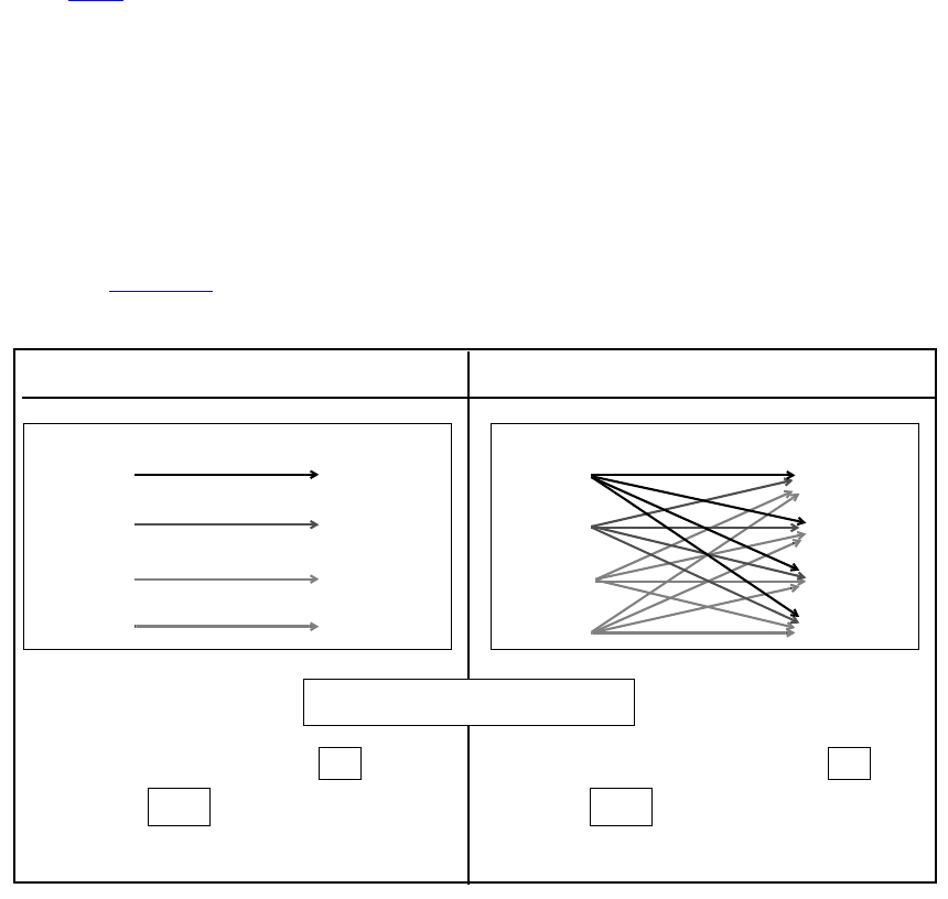
IEEE Std 1800-2012
IEEE STANDARD FOR SYSTEMVERILOG—UNIFIED HARDWARE DESIGN, SPECIFICATION, AND
VERIFICATION LANGUAGE
810
Copyright © 2013 IEEE. All rights reserved.
30.4.5 Full connection and parallel connection paths
The operator *> shall be used to establish a full connection between source and destination. In a full
connection, every bit in the source shall connect to every bit in the destination. The module path source need
not have the same number of bits as the module path destination.
The full connection can handle most types of module paths because it does not restrict the size or number of
source signals and destination signals. The following situations require the use of full connections:
— To describe a module path between a vector and a scalar
— To describe a module path between vectors of different sizes
— To describe a module path with multiple sources or multiple destinations in a single statement (see
30.4.6)
The operator => shall be used to establish a parallel connection between source and destination. In a parallel
connection, each bit in the source shall connect to one corresponding bit in the destination. Parallel module
paths can be created only between sources and destinations that contain the same number of bits.
Parallel connections are more restrictive than full connections. They only connect one source to one
destination, where each signal contains the same number of bits. Therefore, a parallel connection may only
be used to describe a module path between two vectors of the same size. Because scalars are 1-bit wide,
either *> or => may be used to set up bit-to-bit connections between two scalars.
Example 1: Figure 30-2 illustrates how a parallel connection differs from a full connection between two
4-bit vectors.
Figure 30-2—Difference between parallel and full connection paths
Example 2: The following example shows module paths for a 2:1 multiplexer with two 8-bit inputs and one
8-bit output:
module mux8 (in1, in2, s, q) ;
output [7:0] q;
Parallel module path
0
1
2
3
0
1
2
3
Input bits Output bits
0
1
2
3
0
1
2
3
Input bits Output bits
N = number of bits = 4
Number of paths = N =
Use => to define path
4
bit-to-bit connections
Full module path
Number of paths = N * N =
Use to define path
16
bit-to-vector connections
*>
IEEE Std 1800-2012
IEEE STANDARD FOR SYSTEMVERILOG—UNIFIED HARDWARE DESIGN, SPECIFICATION, AND
VERIFICATION LANGUAGE
811
Copyright © 2013 IEEE. All rights reserved.
input [7:0] in1, in2;
input s;
// Functional description omitted ...
specify
(in1 => q) = (3, 4) ;
(in2 => q) = (2, 3) ;
(s *> q) = 1;
endspecify
endmodule
The module path from s to q uses a full connection (*>) because it connects a scalar source—the 1-bit
select line—to a vector destination—the 8-bit output bus. The module paths from both input lines in1 and
in2 to q use a parallel connection (=>) because they set up parallel connections between two 8-bit buses.
30.4.6 Declaring multiple module paths in a single statement
Multiple module paths may be described in a single statement by using the symbol *> to connect a comma-
separated list of sources to a comma-separated list of destinations. When describing multiple module paths
in one statement, the lists of sources and destinations may contain a mix of scalars and vectors of any size.
The connection in a multiple module path declaration is always a full connection.
For example:
(a, b, c *> q1, q2) = 10;
is equivalent to the following six individual module path assignments:
(a *> q1) = 10 ;
(b *> q1) = 10 ;
(c *> q1) = 10 ;
(a *> q2) = 10 ;
(b *> q2) = 10 ;
(c *> q2) = 10 ;
30.4.7 Module path polarity
The polarity of a module path is an arbitrary specification indicating whether the direction of a signal
transition is inverted as it propagates from the input to the output. This arbitrary polarity description does not
affect the actual propagation of data or events through the model; how a rise or a fall at the source
propagates to the destination depends on the internal logic of the module.
Module paths may specify any of three polarities:
— Unknown polarity
— Positive polarity
— Negative polarity
30.4.7.1 Unknown polarity
By default, module paths shall have unknown polarity; that is, a transition at the path source may propagate
to the destination in an unpredictable way, as follows:
— A rise at the source may cause a rise transition, a fall transition, or no transition at the destination.
— A fall at the source may cause a rise transition, a fall transition, or no transition at the destination.

IEEE Std 1800-2012
IEEE STANDARD FOR SYSTEMVERILOG—UNIFIED HARDWARE DESIGN, SPECIFICATION, AND
VERIFICATION LANGUAGE
812
Copyright © 2013 IEEE. All rights reserved.
A module path specified either as a full connection or as a parallel connection, but without a polarity
operator + or -, shall be treated as a module path with unknown polarity.
For example:
// Unknown polarity
(In1 => q) = In_to_q ;
(s *> q) = s_to_q ;
30.4.7.2 Positive polarity
For module paths with positive polarity, any transition at the source may cause the same transition at the
destination, as follows:
— A rise at the source may cause either a rise transition or no transition at the destination.
— A fall at the source may cause either a fall transition or no transition at the destination.
A module path with positive polarity shall be specified by prefixing the + polarity operator to => or *>.
For example:
// Positive polarity
(In1 +=> q) = In_to_q ;
(s +*> q) = s_to_q ;
30.4.7.3 Negative polarity
For module paths with negative polarity, any transition at the source may cause the opposite transition at the
destination, as follows:
— A rise at the source may cause either a fall transition or no transition at the destination.
— A fall at the source may cause either a rise transition or no transition at the destination.
A module path with negative polarity shall be specified by prefixing the - polarity operator to => or *>.
For example:
// Negative polarity
(In1 -=> q) = In_to_q ;
(s -*> q) = s_to_q ;
30.5 Assigning delays to module paths
The delays that occur at the module outputs where paths terminate shall be specified by assigning delay
values to the module path descriptions. The syntax for specifying delay values is shown in Syntax 30-6.
path_delay_value ::= // from A.7.4
list_of_path_delay_expressions
|( list_of_path_delay_expressions )
list_of_path_delay_expressions ::=
t_path_delay_expression
| trise_path_delay_expression , tfall_path_delay_expression
| trise_path_delay_expression , tfall_path_delay_expression , tz_path_delay_expression
| t01_path_delay_expression , t10_path_delay_expression , t0z_path_delay_expression ,
IEEE Std 1800-2012
IEEE STANDARD FOR SYSTEMVERILOG—UNIFIED HARDWARE DESIGN, SPECIFICATION, AND
VERIFICATION LANGUAGE
813
Copyright © 2013 IEEE. All rights reserved.
tz1_path_delay_expression , t1z_path_delay_expression , tz0_path_delay_expression
| t01_path_delay_expression , t10_path_delay_expression , t0z_path_delay_expression ,
tz1_path_delay_expression , t1z_path_delay_expression , tz0_path_delay_expression ,
t0x_path_delay_expression , tx1_path_delay_expression , t1x_path_delay_expression ,
tx0_path_delay_expression , txz_path_delay_expression , tzx_path_delay_expression
t_path_delay_expression ::= path_delay_expression
path_delay_expression ::= constant_mintypmax_expression
Syntax 30-6—Syntax for path delay value (excerpt from Annex A)
In module path delay assignments, a module path description (see 30.4) is specified on the left-hand side,
and one or more delay values are specified on the right-hand side. The delay values may be optionally
enclosed in a pair of parentheses. There may be one, two, three, six, or twelve delay values assigned to a
module path, as described in 30.5.1. The delay values shall be constant expressions containing literals or
specparams, and there may be a delay expression of the form min:typ:max.
For example:
specify
// Specify Parameters
specparam tRise_clk_q = 45:150:270, tFall_clk_q=60:200:350;
specparam tRise_Control = 35:40:45, tFall_control=40:50:65;
// Module Path Assignments
(clk => q) = (tRise_clk_q, tFall_clk_q);
(clr, pre *> q) = (tRise_control, tFall_control);
endspecify
In the preceding example, the specify parameters declared following the specparam keyword specify
values for the module path delays. The module path assignments assign those module path delays to the
module paths.
30.5.1 Specifying transition delays on module paths
Each path delay expression may be a single value—representing the typical delay—or a colon-separated list
of three values—representing a minimum, typical, and maximum delay, in that order. If the path delay
expression results in a negative value, it shall be treated as zero. Table 30-2 describes how different path
delay values shall be associated with various transitions. The path delay expression names refer to the names
used in Syntax 30-6.
Table 30-2—Associating path delay expressions with transitions
Number of path delay expressions specified
Transitions 1 2 3 6 12
0 -> 1 t trise trise t01 t01
1 -> 0 t tfall tfall t10 t10
0 -> z t trise tz t0z t0z
z -> 1 t trise trise tz1 tz1
1 -> z t tfall tz t1z t1z
IEEE Std 1800-2012
IEEE STANDARD FOR SYSTEMVERILOG—UNIFIED HARDWARE DESIGN, SPECIFICATION, AND
VERIFICATION LANGUAGE
814
Copyright © 2013 IEEE. All rights reserved.
For example:
// one expression specifies all transitions
(C => Q) = 20;
(C => Q) = 10:14:20;
// two expressions specify rise and fall delays
specparam tPLH1 = 12, tPHL1 = 25;
specparam tPLH2 = 12:16:22, tPHL2 = 16:22:25;
(C => Q) = ( tPLH1, tPHL1 ) ;
(C => Q) = ( tPLH2, tPHL2 ) ;
// three expressions specify rise, fall, and z transition delays
specparam tPLH1 = 12, tPHL1 = 22, tPz1 = 34;
specparam tPLH2 = 12:14:30, tPHL2 = 16:22:40, tPz2 = 22:30:34;
(C => Q) = (tPLH1, tPHL1, tPz1);
(C => Q) = (tPLH2, tPHL2, tPz2);
// six expressions specify transitions to/from 0, 1, and z
specparam t01 = 12, t10 = 16, t0z = 13,
tz1 = 10, t1z = 14, tz0 = 34 ;
(C => Q) = ( t01, t10, t0z, tz1, t1z, tz0) ;
specparam T01 = 12:14:24, T10 = 16:18:20, T0z = 13:16:30 ;
specparam Tz1 = 10:12:16, T1z = 14:23:36, Tz0 = 15:19:34 ;
(C => Q) = ( T01, T10, T0z, Tz1, T1z, Tz0) ;
// twelve expressions specify all transition delays explicitly
specparam t01=10, t10=12, t0z=14, tz1=15, t1z=29, tz0=36,
t0x=14, tx1=15, t1x=15, tx0=14, txz=20, tzx=30 ;
(C => Q) = (t01, t10, t0z, tz1, t1z, tz0,
t0x, tx1, t1x, tx0, txz, tzx) ;
30.5.2 Specifying x transition delays
If the x transition delays are not explicitly specified, the calculation of delay values for x transitions is based
on the following two pessimistic rules:
z -> 0 t tfall tfall tz0 tz0
0 -> x aaaat0x
x -> 1 aaaatx1
1 -> x aaaat1x
x -> 0 aaaatx0
x -> z aaaatxz
z -> x aaaatzx
a See 30.5.2.
Table 30-2—Associating path delay expressions with transitions (continued)
Number of path delay expressions specified
Transitions 1 2 3 6 12
IEEE Std 1800-2012
IEEE STANDARD FOR SYSTEMVERILOG—UNIFIED HARDWARE DESIGN, SPECIFICATION, AND
VERIFICATION LANGUAGE
815
Copyright © 2013 IEEE. All rights reserved.
— Transitions from a known state to x shall occur as quickly as possible; that is, the shortest possible
delay shall be used for any transition to x.
— Transitions from x to a known state shall take as long as possible; that is, the longest possible delay
shall be used for any transition from x.
Table 30-3 presents the general algorithm for calculating delay values for x transitions along with specific
examples. The following two groups of x transitions are represented in the table:
a) Transition from a known state s to x: s -> x
b) Transition from x to a known state s: x -> s
30.5.3 Delay selection
The simulator shall determine the proper delay to use when a specify path output is to be scheduled to
transition. There may be specify paths to the output from more than one input, and the simulator must decide
which specify path to use.
The simulator shall do this by first determining which specify paths to the output are active. Active specify
paths are those whose input has transitioned most recently in time, and either they have no condition or their
conditions are true. In the presence of simultaneous input transitions, it is possible for many specify paths to
an output to be simultaneously active.
Table 30-3—Calculating delays for x transitions
X transition Delay value
General algorithm
s -> x minimum (s -> other known signals)
x -> s maximum (other known signals -> s)
Specific transitions
0 -> x minimum (0 -> z delay, 0 -> 1 delay)
1 -> x minimum (1 -> z delay, 1 -> 0 delay)
z -> x minimum (z -> 1 delay, z -> 0 delay)
x -> 0 maximum (z -> 0 delay, 1 -> 0 delay)
x -> 1 maximum (z -> 1 delay, 0 -> 1 delay)
x -> zmaximum (1-> z delay, 0 -> z delay)
Usage: (C => Q) = (5, 12, 17, 10, 6, 22) ;
0 -> x minimum (17, 5) = 5
1 -> x minimum (6, 12) = 6
z -> x minimum (10, 22) = 10
x -> 0 maximum (22, 12) = 22
x -> 1 maximum (10, 5) = 10
x -> z maximum (6, 17) = 17
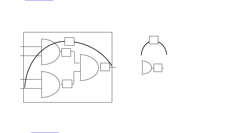
IEEE Std 1800-2012
IEEE STANDARD FOR SYSTEMVERILOG—UNIFIED HARDWARE DESIGN, SPECIFICATION, AND
VERIFICATION LANGUAGE
816
Copyright © 2013 IEEE. All rights reserved.
Once the active specify paths are identified, a delay shall be selected from among them. This is done by
comparing the correct delay for the specific transition being scheduled from each specify path and choosing
the smallest.
Example 1:
(A => Y) = (6, 9);
(B => Y) = (5, 11);
For a Y transition from 0 to 1, if A transitioned more recently than B, a delay of 6 will be chosen. But if B
transitioned more recently than A, a delay of 5 will be chosen. And if, the last time they transitioned, A and B
did so simultaneously, then the smallest of the two rise delays would be chosen, which is the rise delay from
B of 5. The fall delay from A of 9 would be chosen if Y was instead to transition from 1 to 0.
Example 2:
if (MODE < 5) (A => Y) = (5, 9);
if (MODE < 4) (A => Y) = (4, 8);
if (MODE < 3) (A => Y) = (6, 5);
if (MODE < 2) (A => Y) = (3, 2);
if (MODE < 1) (A => Y) = (7, 7);
Anywhere from zero to five of these specify paths might be active depending upon the value of MODE. For
instance, when MODE is 2, the first three specify paths are active. A rise transition would select a delay of 4
because that is the smallest rise delay among the first three. A fall transition would select a delay of 5
because that is the smallest fall delay among the first three.
30.6 Mixing module path delays and distributed delays
If a module contains module path delays and distributed delays (delays on primitive instances within the
module), the larger of the two delays for each path shall be used.
Example 1: Figure 30-3 illustrates a simple circuit modeled with a combination of distributed delays and
path delays (only the D input to Q output path is illustrated). Here, the delay on the module path from input
D to output Q is 22, while the sum of the distributed delays is 0 + 1 = 1. Therefore, a transition on Q caused
by a transition on D will occur 22 time units after the transition on D.
Figure 30-3—Module path delays longer than distributed delays
Example 2: In Figure 30-4, the delay on the module path from D to Q is 22, but the distributed delays along
that module path now add up to 10 + 20 = 30. Therefore, an event on Q caused by an event on D will occur
30 time units after the event on D.
A
B
C
D
Q
1
0
0
22
= distributed delay
n
= module path delay
n
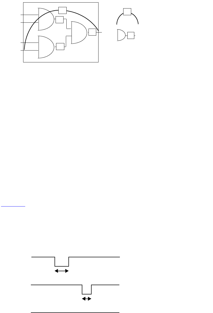
IEEE Std 1800-2012
IEEE STANDARD FOR SYSTEMVERILOG—UNIFIED HARDWARE DESIGN, SPECIFICATION, AND
VERIFICATION LANGUAGE
817
Copyright © 2013 IEEE. All rights reserved.
30.7 Detailed control of pulse filtering behavior
Two consecutive scheduled transitions closer together in time than the module path delay are deemed a
pulse. By default, pulses on a module path output are rejected. Consecutive transitions cannot be closer
together than the module path delay, and this is known as the inertial delay model of pulse propagation.
Pulse width ranges control how to handle a pulse presented at a module path output. They are as follows:
— A pulse width range for which a pulse shall be rejected
— A pulse width range for which a pulse shall be allowed to propagate to the path destination
— A pulse width range for which a pulse shall generate a logic x on the path destination
Two pulse limit values define the pulse width ranges associated with each module path transition delay. The
pulse limit values are called the error limit and the reject limit. The error limit shall always be at least as
large as the reject limit. Pulses greater than or equal to the error limit pass unfiltered. Pulses less than the
error limit but greater than or equal to the reject limit are filtered to X. Pulses less than the reject limit are
rejected, and no pulse emerges. By default, both the error limit and the reject limit are set equal to the delay.
These default values yield full inertial pulse behavior, rejecting all pulses smaller than the delay.
In Figure 30-5, the rise delay from input A to output Y is 7, and the fall delay is 9. By default, the error limit
and the reject limit for the rise delay are both 7. The error limit and the reject limit for the fall delay are both
9. The pulse limits associated with the delay forming the trailing edge of the pulse determine whether and
how the pulse should be filtered. Waveform Y' shows the waveform resulting from no pulse filtering. The
width of the pulse is 2, which is less than the reject limit for the rise delay of 7; therefore, the pulse is filtered
as shown in waveform Y.
Figure 30-5—Example of pulse filtering
A
B
C
D
Q = distributed delay
20
10
10
n
22
= module path delay
n
Figure 30-4—Module path delays shorter than distributed delays
(A =>Y ) = 7, 9;
pulse width = 4
// Pulse considered
// at module path output
pulse width = 2
Y
Y‚
A
// Pulse is filtered
// Module path
// delay for a buffer
IEEE Std 1800-2012
IEEE STANDARD FOR SYSTEMVERILOG—UNIFIED HARDWARE DESIGN, SPECIFICATION, AND
VERIFICATION LANGUAGE
818
Copyright © 2013 IEEE. All rights reserved.
There are three ways to modify the pulse limits from their default values. First, SystemVerilog provides the
PATHPULSE$ specparam to modify the pulse limits from their default values. Second, invocation options can
specify percentages applying to all module path delays to form the corresponding error limits and reject
limits. Third, SDF annotation can individually annotate the error limit and reject limit of each module path
transition delay.
30.7.1 Specify block control of pulse limit values
Pulse limit values may be set from within the specify block with the PATHPULSE$ specparam. The syntax
for using PATHPULSE$ to specify the reject limit and error limit values is given in Syntax 30-7.
pulse_control_specparam ::=
PATHPULSE$ = ( reject_limit_value [ , error_limit_value ] )
|PATHPULSE$specify_input_terminal_descriptor$specify_output_terminal_descriptor
= ( reject_limit_value [ , error_limit_value ] )
error_limit_value ::= limit_value
reject_limit_value ::= limit_value
limit_value ::= constant_mintypmax_expression
Syntax 30-7—Syntax for PATHPULSE$ pulse control (excerpt from Annex A)
If only the reject limit value is specified, it shall apply to both the reject limit and the error limit.
The reject limit and error limit may be specified for a specific module path. When no module path is
specified, the reject limit and error limit shall apply to all module paths defined in a module. If both
path-specific PATHPULSE$ specparams and a nonpath-specific PATHPULSE$ specparam appear in the same
module, then the path-specific specparams shall take precedence for the specified paths.
The module path input terminals and output terminals shall conform to the rules for module path inputs and
outputs, with the following restriction: the terminals may not be a bit-select or part-select of a vector.
When a module path declaration declares multiple paths, the PATHPULSE$ specparam shall only be
specified for the first path input terminal and the first path output terminal. The reject limit and error limit
specified shall apply to all other paths in the multiple path declaration. A PATHPULSE$ specparam that
specifies anything other than the first path input and path output terminals shall be ignored.
In the following example, the path (clk=>q) acquires a reject limit of 2 and an error limit of 9, as defined
by the first PATHPULSE$ declaration. The paths (clr*>q) and (pre*>q) receive a reject limit of 0 and an
error limit of 4, as specified by the second PATHPULSE$ declaration. The path (data=>q) is not explicitly
defined in any of the PATHPULSE$ declarations; therefore, it acquires reject and error limit of 3, as defined
by the last PATHPULSE$ declaration.
specify
(clk => q) = 12;
(data => q) = 10;
(clr, pre *> q) = 4;
specparam
PATHPULSE$clk$q = (2,9),
PATHPULSE$clr$q = (0,4),
PATHPULSE$ = 3;
endspecify

IEEE Std 1800-2012
IEEE STANDARD FOR SYSTEMVERILOG—UNIFIED HARDWARE DESIGN, SPECIFICATION, AND
VERIFICATION LANGUAGE
819
Copyright © 2013 IEEE. All rights reserved.
30.7.2 Global control of pulse limit values
Two invocation options can specify percentages applying globally to all module path transition delays. The
error limit invocation option specifies the percentage of each module path transition delay used for its error
limit value. The reject limit invocation option specifies the percentage of each module path transition delay
used for its reject limit value. The percentage values shall be an integer between 0 and 100.
The default values for both the reject and error limit invocation options are 100%. When neither option is
present, then 100% of each module transition delay is used as the reject and error limits.
It is an error if the error limit percentage is smaller than the reject limit percentage. In such cases, the error
limit percentage is set equal to the reject limit percentage.
When both PATHPULSE$ and global pulse limit invocation options are present, the PATHPULSE$ values
shall take precedence.
30.7.3 SDF annotation of pulse limit values
SDF annotation can be used to specify the pulse limit values of module path transition delays. Clause 32
describes this in greater detail.
When PATHPULSE$, global pulse limit invocation options, and SDF annotation of pulse limit values are
present, SDF annotation values shall take precedence.
30.7.4 Detailed pulse control capabilities
The default style of pulse filtering behavior has two drawbacks. First, pulse filtering to the X state may be
insufficiently pessimistic with an X state duration too short to be useful. Second, unequal delays can result in
pulse rejection whenever the trailing edge precedes the leading edge, leaving no indication that a pulse was
rejected. This subclause introduces more detailed pulse control capabilities.
30.7.4.1 On-event versus on-detect pulse filtering
When an output pulse is to be filtered to X, greater pessimism can be expressed if the module path output
transitions immediately to X (on-detect) instead of at the already scheduled transition time of the leading
edge of the pulse (on-event).
The on-event method of pulse filtering to X is the default. When an output pulse is to be filtered to X, the
leading edge of the pulse becomes a transition to X, and the trailing edge becomes a transition from X. The
times of transition of the edges do not change.
Just like on-event, the on-detect method of pulse filtering changes the leading edge of the pulse into a
transition to X and the trailing edge to a transition from X, but the time of the leading edge is changed to
occur immediately upon detection of the pulse.
Figure 30-6 illustrates this behavior using a simple buffer with asymmetric rise/fall times and both the reject
limits and error limits equal to 0. An output waveform is shown for both on-detect and on-event approaches.
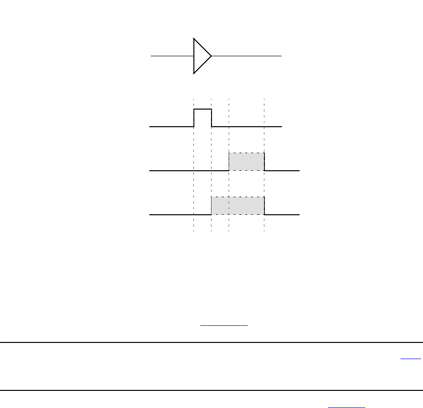
IEEE Std 1800-2012
IEEE STANDARD FOR SYSTEMVERILOG—UNIFIED HARDWARE DESIGN, SPECIFICATION, AND
VERIFICATION LANGUAGE
820
Copyright © 2013 IEEE. All rights reserved.
Figure 30-6—On-detect versus on-event
On-detect versus on-event behavior can be selected in two different ways. First, one may be selected
globally for all module path outputs through use of the on-detect or on-event invocation option. Second, one
may be selected locally through use of specify block pulse style declarations.
The syntax for pulse style declarations is shown in Syntax 30-8.
pulsestyle_declaration ::= // from A.7.1
pulsestyle_onevent list_of_path_outputs ;
|pulsestyle_ondetect list_of_path_outputs ;
Syntax 30-8—Syntax for pulse style declarations (excerpt from Annex A)
It is an error if a module path output appears in a pulse style declaration after it has already appeared in a
module path declaration.
The pulse style invocation options take precedence over pulse style specify block declarations.
30.7.4.2 Negative pulse detection
When the delays to a module path output are unequal, it is possible for the trailing edge of a pulse to be
scheduled for a time earlier than the schedule time of the leading edge, yielding a pulse with a negative
width. Under normal operation, if the schedule for a trailing pulse edge is earlier than the schedule for a
leading pulse edge, then the leading edge is cancelled. No transition takes place when the initial and final
states of the pulse are the same, leaving no indication a schedule was ever present.
Negative pulses can be indicated with the X state by use of the showcancelled style of behavior. When the
trailing edge of a pulse would be scheduled before the leading edge, this style causes the leading edge to be
scheduled to X and the trailing edge to be scheduled from X. With on-event pulse style, the schedule to X
in
rise/fall
4/6
outin
12 14 1810
out (on-event)
(default)
out (on-detect)
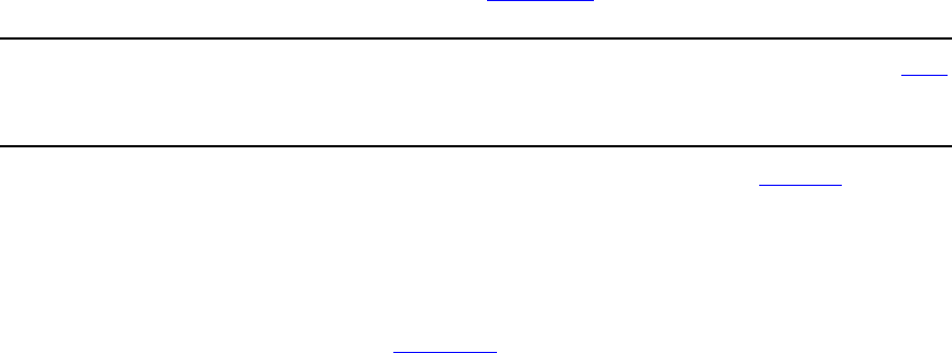
IEEE Std 1800-2012
IEEE STANDARD FOR SYSTEMVERILOG—UNIFIED HARDWARE DESIGN, SPECIFICATION, AND
VERIFICATION LANGUAGE
821
Copyright © 2013 IEEE. All rights reserved.
replaces the leading edge schedule. With on-detect pulse style, the schedule to X is made immediately upon
detection of the negative pulse.
Showcancelled behavior can be enabled in two different ways. First, it may be enabled globally for all
module path outputs through use of the showcancelled and noshowcancelled invocation options.
Second, it may be enabled locally through use of specify block showcancelled declarations.
The syntax for showcancelled declarations is shown in Syntax 30-9.
showcancelled_declaration ::= // from A.7.1
showcancelled list_of_path_outputs ;
|noshowcancelled list_of_path_outputs ;
Syntax 30-9—Syntax for showcancelled declarations (excerpt from Annex A)
It is an error if a module path output appears in a showcancelled declaration after it has already appeared in
a module path declaration. The showcancelled invocation options take precedence over the showcancelled
specify block declarations.
The showcancelled behavior is illustrated in Figure 30-7, which shows a narrow pulse presented at the input
to a buffer with unequal rise/fall delays. This causes the trailing edge of the pulse to be scheduled earlier
than leading edge. The leading edge of the input pulse schedules an output event 6 units later at the point
marked by A. The pulse trailing edge occurs one time unit later, which schedules an output event 4 units later
marked by point B. This second schedule on the output is for a time prior to the already existing schedule for
the leading output pulse edge.
The output waveform is shown for three different operating modes. The first waveform shows the default
behavior with showcancelled behavior not enabled and with the default on-event style. The second
waveform shows showcancelled behavior in conjunction with on-event. The last waveform shows
showcancelled behavior in conjunction with on-detect.
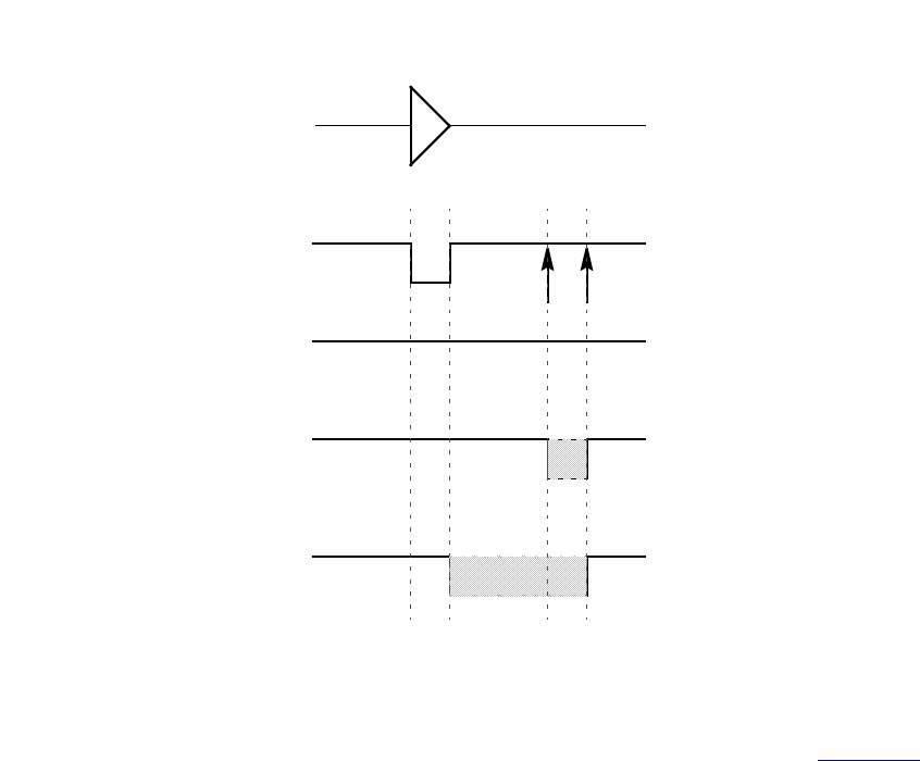
IEEE Std 1800-2012
IEEE STANDARD FOR SYSTEMVERILOG—UNIFIED HARDWARE DESIGN, SPECIFICATION, AND
VERIFICATION LANGUAGE
822
Copyright © 2013 IEEE. All rights reserved.
Figure 30-7—Current event cancellation problem and correction
This same situation can also arise with nearly simultaneous input transitions, which is defined as two inputs
transitioning closer together in time than the difference in their respective delays to the output. Figure 30-8
shows waveforms for a two-input NAND gate where initially A is high and B is low. B transitions 0->1 at
time 10, causing a 1->0 output schedule at time 24. A transitions 1->0 at time 12, causing a 0->1 schedule
at time 22. Arrows mark the output transitions caused by the transitions on inputs A and B.
The output waveform is shown for three different operating modes. The first waveform shows the default
behavior with showcancelled behavior not enabled and with the default on-event style. The second shows
showcancelled behavior in conjunction with on-event. The third shows showcancelled behavior in
conjunction with on-detect.
in
(in=>out)=(4,6);
out
in
out (default)
15 16
10 11
BA
out (showcancelled with on-event)
out (showcancelled with on-detect)
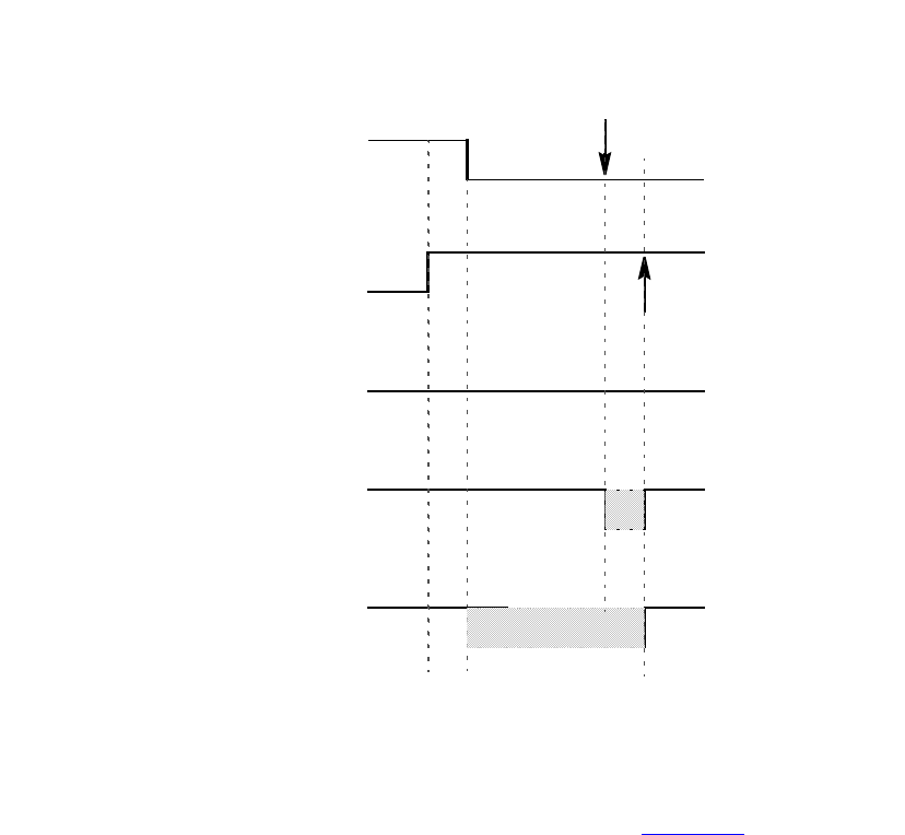
IEEE Std 1800-2012
IEEE STANDARD FOR SYSTEMVERILOG—UNIFIED HARDWARE DESIGN, SPECIFICATION, AND
VERIFICATION LANGUAGE
823
Copyright © 2013 IEEE. All rights reserved.
Figure 30-8—NAND gate with nearly simultaneous input switching where
one event is scheduled prior to another that has not matured
One drawback of the on-event style with showcancelled behavior is that as the output pulse edges draw
closer together, the duration of the resulting X state becomes smaller. Figure 30-9 illustrates how the
on-detect style solves this problem.
out (default)
24
.
10 2212
A
B
(A=>Q) = 10;
(B=>Q) = 14;
out (showcancelled with on-event)
out (showcancelled with on-detect)
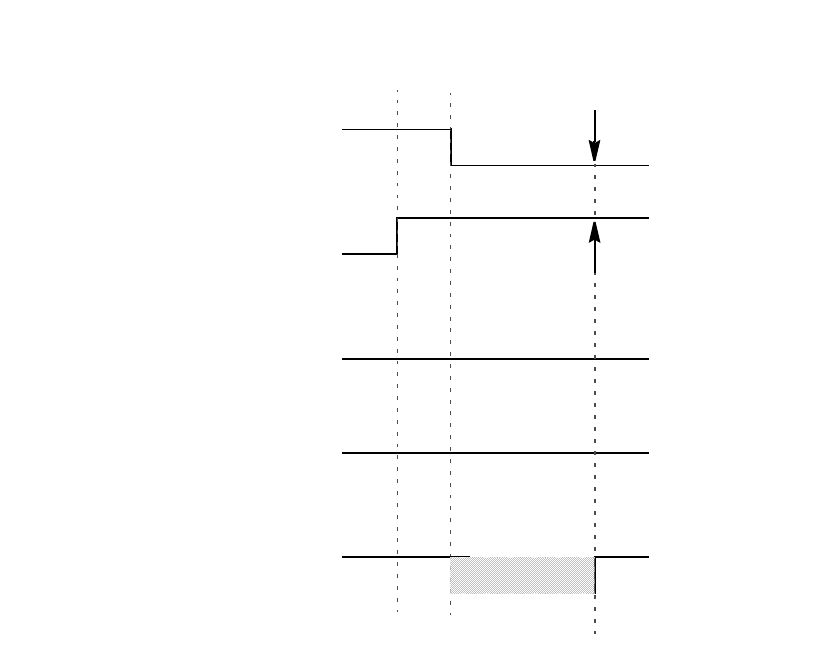
IEEE Std 1800-2012
IEEE STANDARD FOR SYSTEMVERILOG—UNIFIED HARDWARE DESIGN, SPECIFICATION, AND
VERIFICATION LANGUAGE
824
Copyright © 2013 IEEE. All rights reserved.
Figure 30-9—NAND gate with nearly simultaneous input switching with
output event scheduled at same time
Example 1:
specify
(a=>out)=(2,3);
(b =>out)=(3,4);
endspecify
Because no pulse style or showcancelled declarations appear within the specify block, the compiler applies
the default modes of on-event and noshowcancelled.
Example 2:
specify
(a=>out)=(2,3);
showcancelled out;
(b =>out)=(3,4);
endspecify
This showcancelled declaration is in error because it follows use of out in a module path declaration. It
would be contradictory for out to have noshowcancelled behavior from input a, but showcancelled behavior
from input b.
out (default)
10
A
B
(A=>Q) = 10
(B=>Q) = 14
14 24
out (showcancelled with on-event)
out (showcancelled with on-detect)
IEEE Std 1800-2012
IEEE STANDARD FOR SYSTEMVERILOG—UNIFIED HARDWARE DESIGN, SPECIFICATION, AND
VERIFICATION LANGUAGE
825
Copyright © 2013 IEEE. All rights reserved.
Example 3: Both these specify blocks produce the same result. Outputs out and out_b are both declared
showcancelled and on-detect.
specify
showcancelled out;
pulsestyle_ondetect out;
(a => out) = (2,3);
(b => out) = (4,5);
showcancelled out_b;
pulsestyle_ondetect out_b;
(a => out_b) = (3,4);
(b => out_b) = (5,6);
endspecify
specify
showcancelled out,out_b;
pulsestyle_ondetect out,out_b;
(a => out) = (2,3);
(b => out) = (4,5);
(a => out_b) = (3,4);
(b => out_b) = (5,6);
endspecify

IEEE Std 1800-2012
IEEE STANDARD FOR SYSTEMVERILOG—UNIFIED HARDWARE DESIGN, SPECIFICATION, AND
VERIFICATION LANGUAGE
826
Copyright © 2013 IEEE. All rights reserved.
31. Timing checks
31.1 General
This clause describes the following:
— Stability timing checks
— Clock and control timing checks
— Edge control specifiers
— Notifiers
— Enabling timing checks
— Vectors in timing checks
— Negative timing checks
31.2 Overview
Timing checks can be placed in specify blocks to verify the timing performance of a design by making sure
critical events occur within given time limits. The syntax for system timing checks is given in Syntax 31-1.
system_timing_check ::= // from A.7.5.1
$setup_timing_check
| $hold_timing_check
| $setuphold_timing_check
| $recovery_timing_check
| $removal_timing_check
| $recrem_timing_check
| $skew_timing_check
| $timeskew_timing_check
| $fullskew_timing_check
| $period_timing_check
| $width_timing_check
| $nochange_timing_check
$setup_timing_check ::= // from A.7.5.1
$setup ( data_event , reference_event , timing_check_limit [ , [ notifier ] ] ) ;
$hold_timing_check ::=
$hold ( reference_event , data_event , timing_check_limit [ , [ notifier ] ] ) ;
$setuphold_timing_check ::=
$setuphold ( reference_event , data_event , timing_check_limit , timing_check_limit
[ , [ notifier ] [ , [ timestamp_condition ] [ , [ timecheck_condition ]
[ , [ delayed_reference ] [ , [ delayed_data ] ] ] ] ] ] ) ;
$recovery_timing_check ::=
$recovery ( reference_event , data_event , timing_check_limit [ , [ notifier ] ] ) ;
$removal_timing_check ::=
$removal ( reference_event , data_event , timing_check_limit [ , [ notifier ] ] ) ;
$recrem_timing_check ::=
$recrem ( reference_event , data_event , timing_check_limit , timing_check_limit
[ , [ notifier ] [ , [ timestamp_condition ] [ , [ timecheck_condition ]
[ , [ delayed_reference ] [ , [ delayed_data ] ] ] ] ] ] ) ;
$skew_timing_check ::=

IEEE Std 1800-2012
IEEE STANDARD FOR SYSTEMVERILOG—UNIFIED HARDWARE DESIGN, SPECIFICATION, AND
VERIFICATION LANGUAGE
827
Copyright © 2013 IEEE. All rights reserved.
$skew ( reference_event , data_event , timing_check_limit [ , [ notifier ] ] ) ;
$timeskew_timing_check ::=
$timeskew ( reference_event , data_event , timing_check_limit
[ , [ notifier ] [ , [ event_based_flag ] [ , [ remain_active_flag ] ] ] ] ) ;
$fullskew_timing_check ::=
$fullskew ( reference_event , data_event , timing_check_limit , timing_check_limit
[ , [ notifier ] [ , [ event_based_flag ] [ , [ remain_active_flag ] ] ] ] ) ;
$period_timing_check ::=
$period ( controlled_reference_event , timing_check_limit [ , [ notifier ] ] ) ;
$width_timing_check ::=
$width ( controlled_reference_event , timing_check_limit , threshold [ , [ notifier ] ] ) ;
$nochange_timing_check ::=
$nochange ( reference_event , data_event , start_edge_offset , end_edge_offset [ , [ notifier ] ] ) ;
Syntax 31-1—Syntax for system timing checks (excerpt from Annex A)
The syntax for time check conditions and timing check events is given in Syntax 31-2.
timecheck_condition ::= mintypmax_expression // from A.7.5.2
controlled_reference_event ::= controlled_timing_check_event
data_event ::= timing_check_event
delayed_data ::=
terminal_identifier
| terminal_identifier [ constant_mintypmax_expression ]
delayed_reference ::=
terminal_identifier
| terminal_identifier [ constant_mintypmax_expression ]
end_edge_offset ::= mintypmax_expression
event_based_flag ::= constant_expression
notifier ::= variable_identifier
reference_event ::= timing_check_event
remain_active_flag ::= constant_mintypmax_expression
timestamp_condition ::= mintypmax_expression
start_edge_offset ::= mintypmax_expression
threshold ::= constant_expression
timing_check_limit ::= expression
timing_check_event ::= // from A.7.5.3
[timing_check_event_control] specify_terminal_descriptor [ &&& timing_check_condition ]
controlled_timing_check_event ::=
timing_check_event_control specify_terminal_descriptor [ &&& timing_check_condition ]
timing_check_event_control ::=
posedge
|negedge
|edge
| edge_control_specifier
specify_terminal_descriptor ::=
specify_input_terminal_descriptor

IEEE Std 1800-2012
IEEE STANDARD FOR SYSTEMVERILOG—UNIFIED HARDWARE DESIGN, SPECIFICATION, AND
VERIFICATION LANGUAGE
828
Copyright © 2013 IEEE. All rights reserved.
| specify_output_terminal_descriptor
edge_control_specifier ::= edge [ edge_descriptor { , edge_descriptor } ]
edge_descriptor33 ::= 01 | 10 | z_or_x zero_or_one | zero_or_one z_or_x
zero_or_one ::= 0 | 1
z_or_x ::= x | X | z | Z
timing_check_condition ::=
scalar_timing_check_condition
|( scalar_timing_check_condition )
scalar_timing_check_condition ::=
expression
|~ expression
| expression == scalar_constant
| expression === scalar_constant
| expression != scalar_constant
| expression !== scalar_constant
scalar_constant ::= 1'b0 | 1'b1 | 1'B0 | 1'B1 | 'b0 | 'b1 | 'B0 | 'B1 | 1 | 0
33) Embedded spaces are illegal.
Syntax 31-2—Syntax for time check conditions and timing check events (excerpt from Annex A)
For ease of presentation, the timing checks are divided into two groups. The first group of timing checks are
described in terms of stability time windows:
$setup $hold $setuphold
$recovery $removal $recrem
The timing checks in the second group check clock and control signals and are described in terms of the
difference in time between two events (the $nochange check involves three events):
$skew $timeskew $fullskew
$width $period $nochange
Although they begin with a $, timing checks are not system tasks. The leading $ is present because of
historical reasons, and timing checks shall not be confused with system tasks. In particular, no system task
can appear in a specify block, and no timing check can appear in procedural code.
Some timing checks can accept negative limit values. This topic is discussed in detail in 31.9.
All timing checks have both a reference event and a data event, and Boolean conditions can be associated
with each. Some of the checks have two signal arguments, one of which is the reference event and the other
is the data event. Other checks have only one signal argument, and the reference and data events are derived
from it. Reference events and data events shall only be detected by timing checks when their associated
conditions are true. See 31.7 for more information about conditions in timing checks.
Timing check evaluation is based upon the times of two events, called the timestamp event and the
timecheck event. A transition on the timestamp event signal causes the simulator to record (stamp) the time
of transition for future use in evaluating the timing check. A transition on the timecheck event signal causes
the simulator to actually evaluate the timing check to determine whether a violation has taken place.
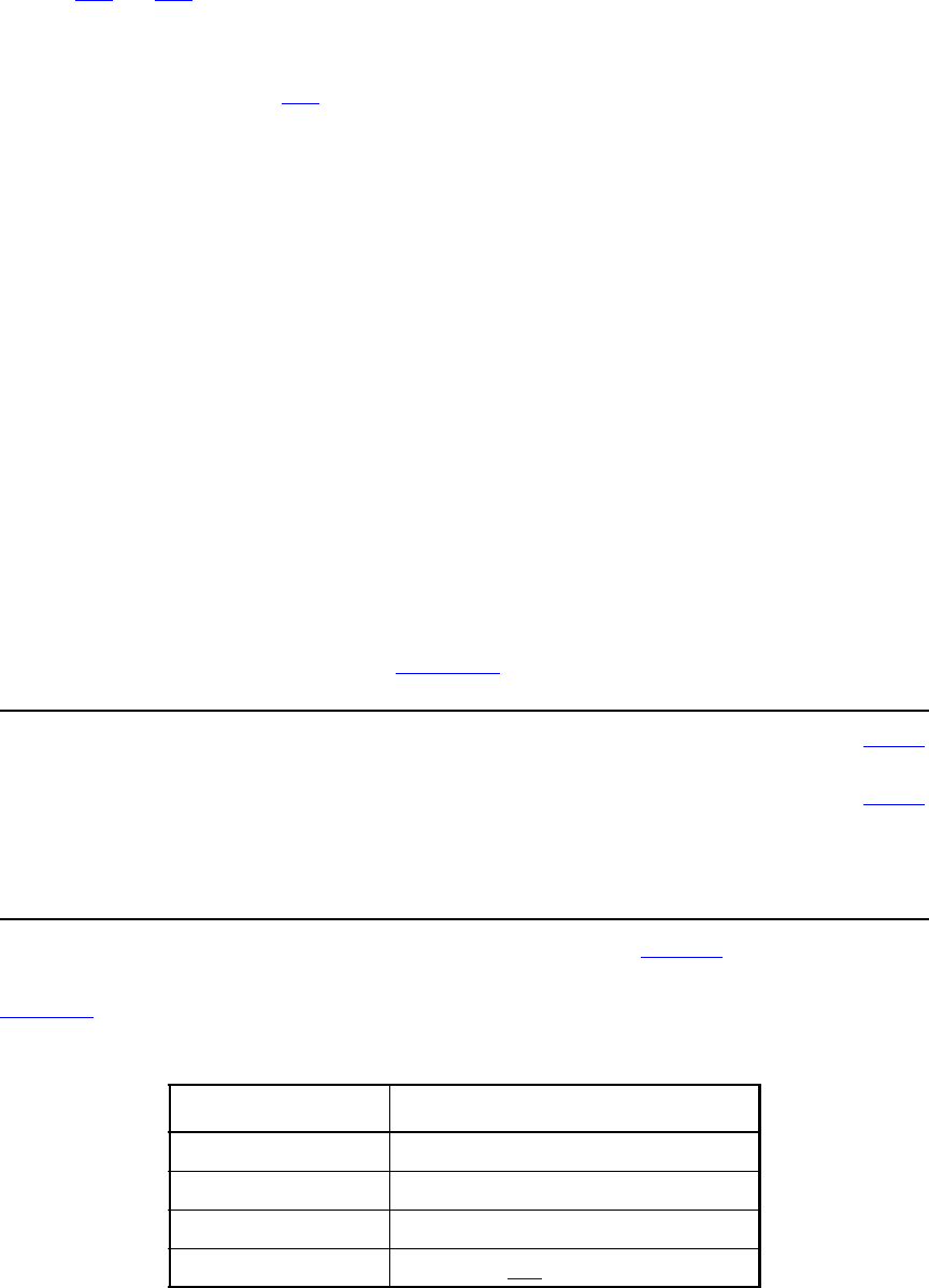
IEEE Std 1800-2012
IEEE STANDARD FOR SYSTEMVERILOG—UNIFIED HARDWARE DESIGN, SPECIFICATION, AND
VERIFICATION LANGUAGE
829
Copyright © 2013 IEEE. All rights reserved.
For some checks, the reference event is always the timestamp event, and the data event is always the
timecheck event; while for other checks the reverse is true. And for yet other checks, the decision about
which is the timestamp and which is the timecheck event is based upon factors that are discussed in greater
detail in 31.3 and 31.4.
Every timing check can include an optional notifier that toggles whenever the timing check detects a
violation. The model can use the notifier to make behavior a function of timing check violations. Notifiers
are discussed in greater detail in 31.6.
Like expressions for module path delays, timing check limit values are constant expressions that can include
specparams.
31.3 Timing checks using a stability window
The following timing checks are discussed in this subclause:
$setup $hold $setuphold
$recovery $removal $recrem
These checks accept two signals, the reference event and the data event, and define a time window with
respect to one signal while checking the time of transition of the other signal with respect to the window. In
general, they all perform the following steps:
a) Define a time window with respect to the reference signal using the specified limit or limits.
b) Check the time of transition of the data signal with respect to the time window.
c) Report a timing violation if the data signal transitions within the time window.
31.3.1 $setup
The $setup timing check syntax is shown in Syntax 31-3.
$setup_timing_check ::= // from A.7.5.1
$setup ( data_event , reference_event , timing_check_limit [ , [ notifier ] ] ) ;
data_event ::= timing_check_event // from A.7.5.2
notifier ::= variable_identifier
reference_event ::= timing_check_event
timing_check_limit ::= expression
Syntax 31-3—Syntax for $setup (excerpt from Annex A)
Table 31-1 defines the $setup timing check.
Table 31-1—$setup arguments
Argument Description
data_event Timestamp event
reference_event Timecheck event
limit Non-negative constant expression
notifier (optional) Variable (see 31.6)
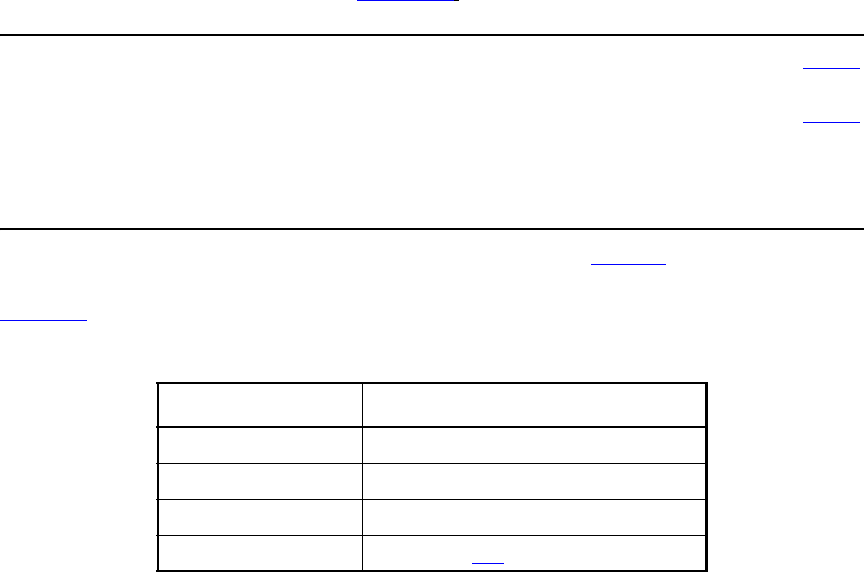
IEEE Std 1800-2012
IEEE STANDARD FOR SYSTEMVERILOG—UNIFIED HARDWARE DESIGN, SPECIFICATION, AND
VERIFICATION LANGUAGE
830
Copyright © 2013 IEEE. All rights reserved.
The data event is usually a data signal, while the reference event is usually a clock signal.
The end points of the time window are determined as follows:
(beginning of time window) = (timecheck time) - limit
(end of time window) = (timecheck time)
The $setup timing check reports a timing violation in the following case:
(beginning of time window) < (timestamp time) < (end of time window)
The end points of the time window are not part of the violation region. When the limit is zero, the $setup
check shall never issue a violation.
31.3.2 $hold
The $hold timing check syntax is shown in Syntax 31-4.
$hold_timing_check ::= // from A.7.5.1
$hold ( reference_event , data_event , timing_check_limit [ , [ notifier ] ] ) ;
data_event ::= timing_check_event // from A.7.5.2
notifier ::= variable_identifier
reference_event ::= timing_check_event
timing_check_limit ::= expression
Syntax 31-4—Syntax for $hold (excerpt from Annex A)
Table 31-2 defines the $hold timing check.
The data event is usually a data signal, while the reference event is usually a clock signal.
The end points of the time window are determined as follows:
(beginning of time window) = (timestamp time)
(end of time window) = (timestamp time) + limit
The $hold timing check reports a timing violation in the following case:
(beginning of time window) <= (timecheck time) < (end of time window)
Table 31-2—$hold arguments
Argument Description
reference_event Timestamp event
data_event Timecheck event
limit Non-negative constant expression
notifier (optional) Variable (see 31.6)
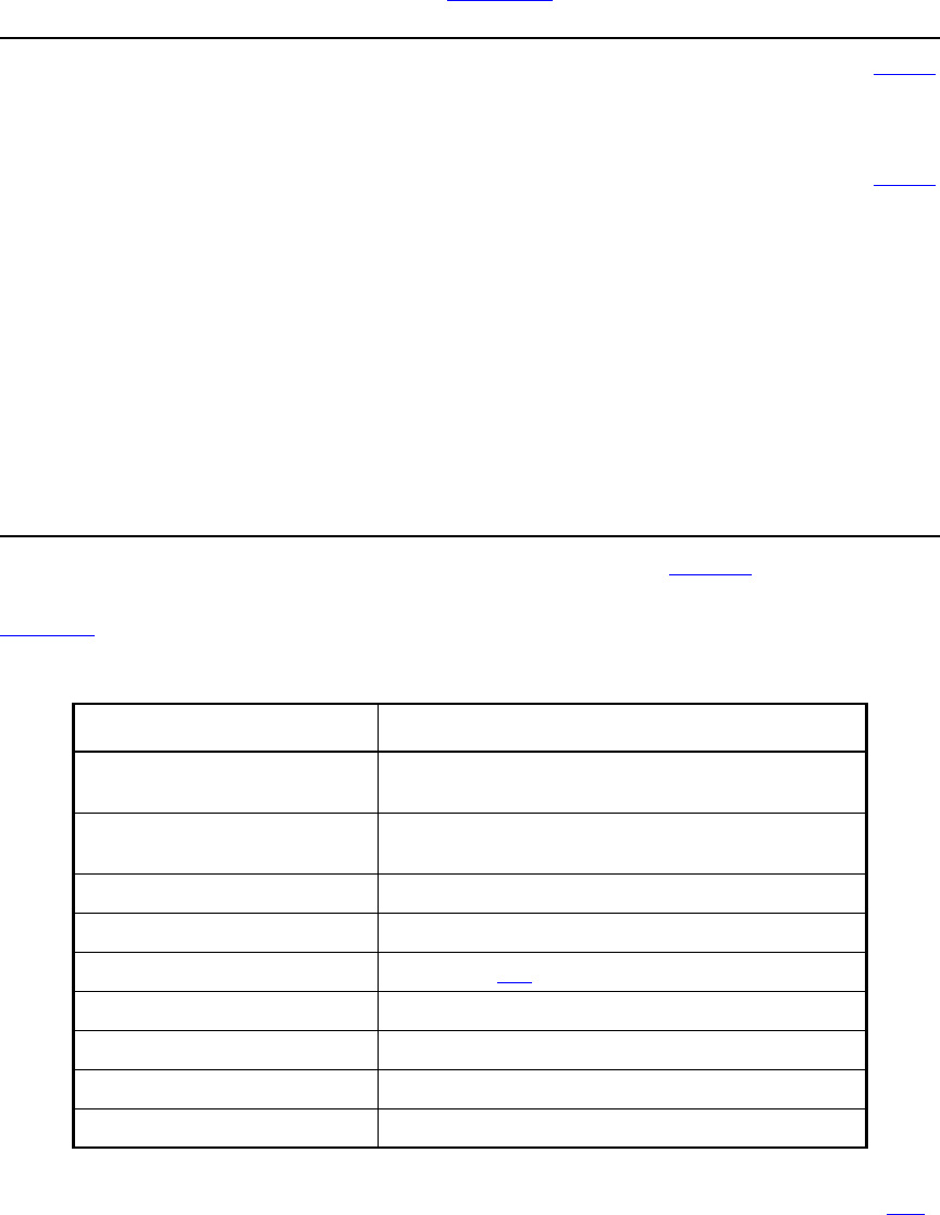
IEEE Std 1800-2012
IEEE STANDARD FOR SYSTEMVERILOG—UNIFIED HARDWARE DESIGN, SPECIFICATION, AND
VERIFICATION LANGUAGE
831
Copyright © 2013 IEEE. All rights reserved.
Only the end of the time window is not part of the violation region. When the limit is zero, the $hold check
shall never issue a violation.
31.3.3 $setuphold
The $setuphold timing check syntax is shown in Syntax 31-5.
$setuphold_timing_check ::= // from A.7.5.1
$setuphold ( reference_event , data_event , timing_check_limit , timing_check_limit
[ , [ notifier ] [ , [ timestamp_condition ] [ , [ timecheck_condition ]
[ , [ delayed_reference ] [ , [ delayed_data ] ] ] ] ] ] ) ;
timecheck_condition ::= mintypmax_expression // from A.7.5.2
data_event ::= timing_check_event
delayed_data ::=
terminal_identifier
| terminal_identifier [ constant_mintypmax_expression ]
delayed_reference ::=
terminal_identifier
| terminal_identifier [ constant_mintypmax_expression ]
notifier ::= variable_identifier
reference_event ::= timing_check_event
timestamp_condition ::= mintypmax_expression
timing_check_limit ::= expression
Syntax 31-5—Syntax for $setuphold (excerpt from Annex A)
Table 31-3 defines the $setuphold timing check.
The $setuphold timing check can accept negative limit values. This is discussed in greater detail in 31.9.
Table 31-3—$setuphold arguments
Argument Description
reference_event Timecheck or timestamp event when setup limit is positive
Timestamp event when setup limit is negative
data_event Timecheck or timestamp event when hold limit is positive
Timestamp event when hold limit is negative
setup_limit Constant expression
hold_limit Constant expression
notifier (optional) Variable (see 31.6)
timestamp_condition (optional) Timestamp condition for negative timing checks
timecheck_condition (optional) Timecheck condition for negative timing checks
delayed_reference (optional) Delayed reference signal for negative timing checks
delayed_data (optional) Delayed data signal for negative timing checks
IEEE Std 1800-2012
IEEE STANDARD FOR SYSTEMVERILOG—UNIFIED HARDWARE DESIGN, SPECIFICATION, AND
VERIFICATION LANGUAGE
832
Copyright © 2013 IEEE. All rights reserved.
The data event is usually a data signal, while the reference event is usually a clock signal.
When both the setup limit and the hold limit are positive, either the reference event or the data event can be
the timecheck event. It shall depend upon which occurs first in the simulation.
When either the setup limit or the hold limit is negative, the restriction becomes as follows:
setup_limit + hold_limit > (simulation unit of precision)
The $setuphold timing check combines the functionality of the $setup and $hold timing checks into a
single timing check. Therefore, the invocation
$setuphold( posedge clk, data, tSU, tHLD );
is equivalent in functionality to the following, if tSU and tHLD are not negative:
$setup( data, posedge clk, tSU );
$hold( posedge clk, data, tHLD );
When both setup and hold limits are positive and the data event occurs first, the end points of the time
window are determined as follows:
(beginning of time window) = (timecheck time) - limit
(end of time window) = (timecheck time)
And the $setuphold timing check reports a timing violation in the following case:
(beginning of time window) < (timestamp time) <= (end of time window)
Only the beginning of the time window is not part of the violation region. The $setuphold check shall
report a timing violation when the reference and data events occur simultaneously.
When both setup and hold limits are positive and the data event occurs second, the end points of the time
window are determined as follows:
beginning of time window) = (timestamp time)
(end of time window) = (timestamp time) + limit
And the $setuphold timing check reports a timing violation in the following case:
(beginning of time window) <= (timecheck time) < (end of time window)
Only the end of the time window is not part of the violation region. The $setuphold check shall report a
timing violation when the reference and data events occur simultaneously.
When both limits are zero, the $setuphold check shall never issue a violation.
31.3.4 $removal
The $removal timing check syntax is shown in Syntax 31-6.
$removal_timing_check ::= // from A.7.5.1
$removal ( reference_event , data_event , timing_check_limit [ , [ notifier ] ] ) ;
data_event ::= timing_check_event // from A.7.5.2
IEEE Std 1800-2012
IEEE STANDARD FOR SYSTEMVERILOG—UNIFIED HARDWARE DESIGN, SPECIFICATION, AND
VERIFICATION LANGUAGE
833
Copyright © 2013 IEEE. All rights reserved.
notifier ::= variable_identifier
reference_event ::= timing_check_event
timing_check_limit ::= expression
Syntax 31-6—Syntax for $removal (excerpt from Annex A)
Table 31-4 defines the $removal timing check.
The reference event is usually a control signal like clear, reset, or set, while the data event is usually a clock
signal.
The end points of the time window are determined as follows:
(beginning of time window) = (timecheck time) - limit
(end of time window) = (timecheck time)
The $removal timing check reports a timing violation in the following case:
(beginning of time window) < (timestamp time) < (end of time window)
The end points of the time window are not part of the violation region. When the limit is zero, the $removal
check shall never issue a violation.
31.3.5 $recovery
The $recovery timing check syntax is shown in Syntax 31-7.
$recovery_timing_check ::= // from A.7.5.1
$recovery ( reference_event , data_event , timing_check_limit [ , [ notifier ] ] ) ;
data_event ::= timing_check_event // from A.7.5.2
notifier ::= variable_identifier
reference_event ::= timing_check_event
timing_check_limit ::= expression
Syntax 31-7—Syntax for $recovery (excerpt from Annex A)
Table 31-4—$removal arguments
Argument Description
reference_event Timecheck event
data_event Timestamp event
limit Non-negative constant expression
notifier (optional) Variable (see 31.6)
IEEE Std 1800-2012
IEEE STANDARD FOR SYSTEMVERILOG—UNIFIED HARDWARE DESIGN, SPECIFICATION, AND
VERIFICATION LANGUAGE
834
Copyright © 2013 IEEE. All rights reserved.
Table 31-5 defines the $recovery timing check.
The reference event is usually a control signal like clear, reset, or set, while the data event is usually a clock
signal.
The end points of the time window are determined as follows:
(beginning of time window) = (timestamp time)
(end of time window) = (timestamp time) + limit
The $recovery timing check reports a timing violation in the following case:
(beginning of time window) <= (timecheck time) < (end of time window)
Only the end of the time window is not part of the violation region. When the limit is zero, the $recovery
check shall never issue a violation.
31.3.6 $recrem
The $recrem timing check syntax is shown in Syntax 31-8.
$recrem_timing_check ::= // from A.7.5.1
$recrem ( reference_event , data_event , timing_check_limit , timing_check_limit
[ , [ notifier ] [ , [ timestamp_condition ] [ , [ timecheck_condition ]
[ , [ delayed_reference ] [ , [ delayed_data ] ] ] ] ] ] ) ;
timecheck_condition ::= mintypmax_expression // from A.7.5.2
data_event ::= timing_check_event
delayed_data ::=
terminal_identifier
| terminal_identifier [ constant_mintypmax_expression ]
delayed_reference ::=
terminal_identifier
| terminal_identifier [ constant_mintypmax_expression ]
notifier ::= variable_identifier
reference_event ::= timing_check_event
timestamp_condition ::= mintypmax_expression
timing_check_limit ::= expression
Syntax 31-8—Syntax for $recrem (excerpt from Annex A)
Table 31-5—$recovery arguments
Argument Description
reference_event Timestamp event
data_event Timecheck event
limit Non-negative constant expression
notifier (optional) Variable (see 31.6)
IEEE Std 1800-2012
IEEE STANDARD FOR SYSTEMVERILOG—UNIFIED HARDWARE DESIGN, SPECIFICATION, AND
VERIFICATION LANGUAGE
835
Copyright © 2013 IEEE. All rights reserved.
Table 31-6 defines the $recrem timing check.
The $recrem timing check can accept negative limit values. This is discussed in greater detail in 31.9.
When both the removal limit and the recovery limit are positive, either the reference event or the data event
can be the timecheck event. It shall depend upon which occurs first in the simulation.
When either the removal limit or the recovery limit is negative, the restriction becomes as follows:
removal_limit + recovery_limit > (simulation unit of precision)
The $recrem timing check combines the functionality of the $removal and $recovery timing checks into
a single timing check. Therefore, the invocation
$recrem( posedge clear, posedge clk, tREC, tREM );
is equivalent in functionality to the following, if tREC and tREM are not negative:
$removal( posedge clear, posedge clk, tREM );
$recovery( posedge clear, posedge clk, tREC );
When both removal and recovery limits are positive and the data event occurs first, the end points of the
time window are determined as follows:
(beginning of time window) = (timecheck time) - limit
(end of time window) = (timecheck time)
And the $recrem timing check reports a timing violation in the following case:
(beginning of time window) < (timestamp time) <= (end of time window)
Only the beginning of the time window is not part of the violation region. The $recrem check shall report a
timing violation when the reference and data events occur simultaneously.
Table 31-6—$recrem arguments
Argument Description
reference_event Timecheck or timestamp event when removal limit is positive
Timestamp event when removal limit is negative
data_event Timecheck or timestamp event when recovery limit is positive
Timestamp event when recovery limit is negative
recovery_limit Constant expression
removal_limit Constant expression
notifier (optional) Variable (see 31.6)
timestamp_condition (optional) Timestamp condition for negative timing checks
timecheck_condition (optional) Timecheck condition for negative timing checks
delayed_reference (optional) Delayed reference signal for negative timing checks
delayed_data (optional) Delayed data signal for negative timing checks
IEEE Std 1800-2012
IEEE STANDARD FOR SYSTEMVERILOG—UNIFIED HARDWARE DESIGN, SPECIFICATION, AND
VERIFICATION LANGUAGE
836
Copyright © 2013 IEEE. All rights reserved.
When both removal and recovery limits are positive and the data event occurs second, the end points of the
time window are determined as follows:
(beginning of time window) = (timestamp time)
(end of time window) = (timestamp time) + limit
And the $recrem timing check reports a timing violation in the following case:
(beginning of time window) <= (timecheck time) < (end of time window)
Only the end of the time window is not part of the violation region. The $recrem check shall report a timing
violation when the reference and data events occur simultaneously.
When both limits are zero, the $recrem check shall never issue a violation.
31.4 Timing checks for clock and control signals
The following timing checks are discussed in this subclause:
$skew $timeskew $fullskew $period $width $nochange
These checks accept one or two signals and verify that transitions on them are never separated by more than
the limit. For checks specifying only one signal, the reference event and data event are derived from that one
signal. In general, these checks all perform the following steps:
a) Determine the elapsed time between two events.
b) Compare the elapsed time to the specified limit.
c) Report a timing violation if the elapsed time violates the limit.
The skew checks have two different violation detection mechanisms, event-based and timer-based. Event-
based skew checking is performed only when a signal transitions, while timer-based skew checking takes
place as soon as the simulation time equal to the skew limit has elapsed.
The $nochange check involves three events rather than two.
31.4.1 $skew
The $skew timing check syntax is shown in Syntax 31-9.
$skew_timing_check ::= // from A.7.5.1
$skew ( reference_event , data_event , timing_check_limit [ , [ notifier ] ] ) ;
data_event ::= timing_check_event // from A.7.5.2
notifier ::= variable_identifier
reference_event ::= timing_check_event
timing_check_limit ::= expression
Syntax 31-9—Syntax for $skew (excerpt from Annex A)
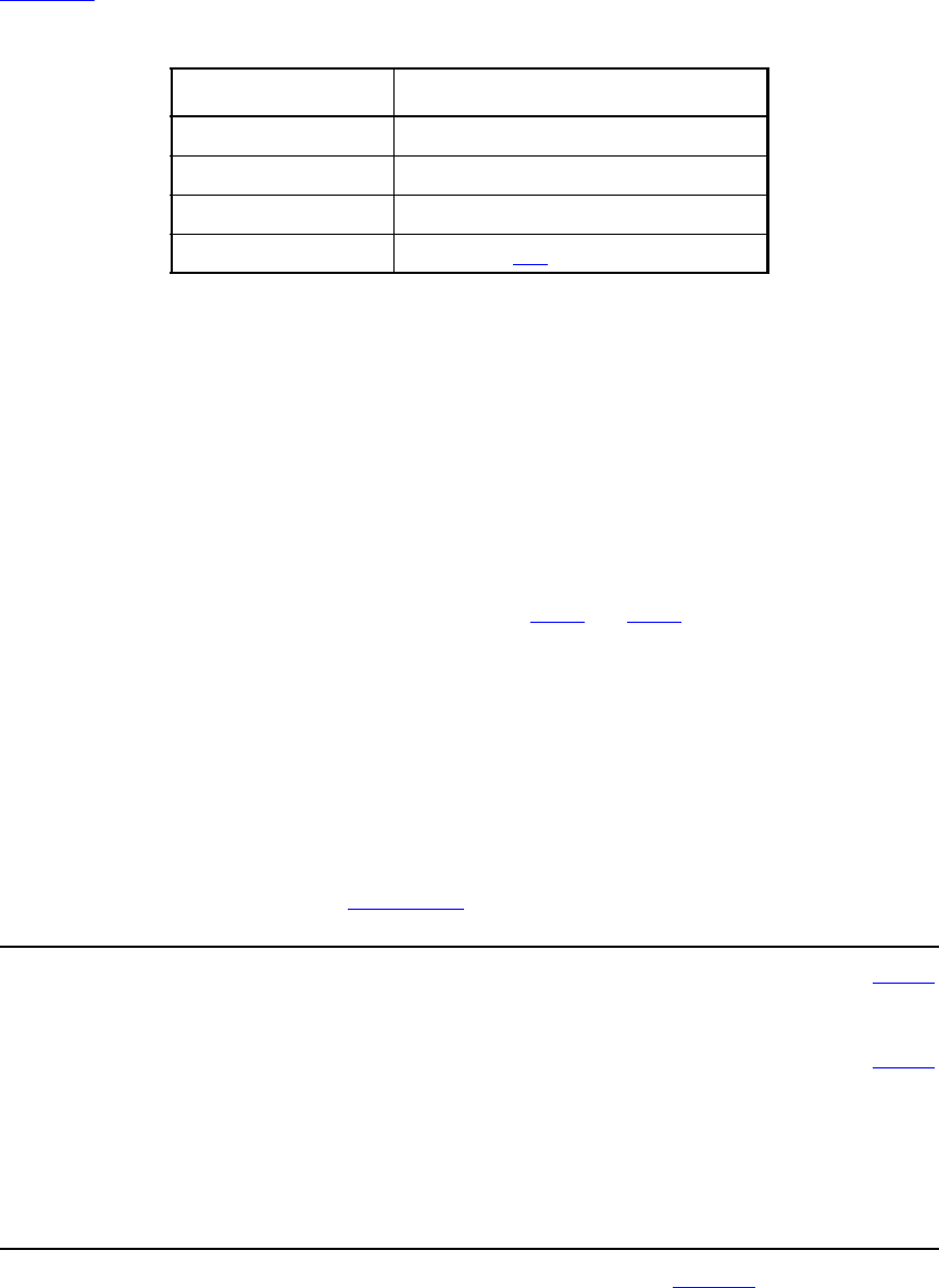
IEEE Std 1800-2012
IEEE STANDARD FOR SYSTEMVERILOG—UNIFIED HARDWARE DESIGN, SPECIFICATION, AND
VERIFICATION LANGUAGE
837
Copyright © 2013 IEEE. All rights reserved.
Table 31-7 defines the $skew timing check.
The $skew timing check reports a violation in the following case:
(timecheck time) - (timestamp time) > limit
Simultaneous transitions on the reference and data signals shall not cause $skew to report a timing violation,
even when the skew limit value is zero.
The $skew timing check is event-based; it is evaluated only after a data event. If there is never a data event
(i.e., the data event is infinitely late), the $skew timing check shall never be evaluated, and no timing
violation shall ever be reported. In contrast, the $timeskew and $fullskew checks are timer-based by
default, and they should be used if violation reports are absolutely required and the data event can be very
late or even absent altogether. These checks are discussed in 31.4.2 and 31.4.3.
$skew shall wait indefinitely for the data event once it has detected a reference event, and it shall not report
a timing violation until the data event takes place. A second consecutive reference event shall cancel the old
wait for the data event and begin a new one.
After a reference event, the $skew timing check shall never stop checking data events for a timing violation.
$skew shall report timing violations for all data events occurring beyond the limit after a reference event.
31.4.2 $timeskew
The syntax for $timeskew is shown in Syntax 31-10.
$timeskew_timing_check ::= // from A.7.5.1
$timeskew ( reference_event , data_event , timing_check_limit
[ , [ notifier ] [ , [ event_based_flag ] [ , [ remain_active_flag ] ] ] ] ) ;
data_event ::= timing_check_event // from A.7.5.2
event_based_flag ::= constant_expression
notifier ::= variable_identifier
reference_event ::= timing_check_event
remain_active_flag ::= constant_mintypmax_expression
timing_check_limit ::= expression
Syntax 31-10—Syntax for $timeskew (excerpt from Annex A)
Table 31-7—$skew arguments
Argument Description
reference_event Timestamp event
data_event Timecheck event
limit Non-negative constant expression
notifier (optional) Variable (see 31.6)
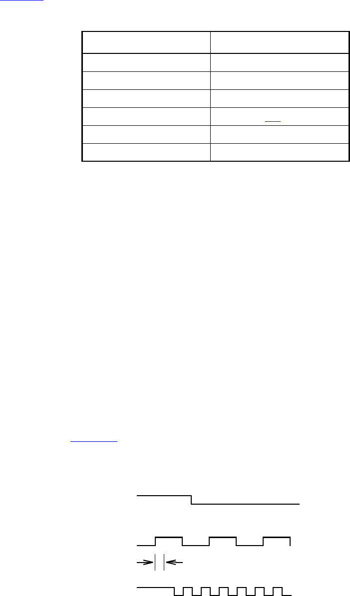
IEEE Std 1800-2012
IEEE STANDARD FOR SYSTEMVERILOG—UNIFIED HARDWARE DESIGN, SPECIFICATION, AND
VERIFICATION LANGUAGE
838
Copyright © 2013 IEEE. All rights reserved.
Table 31-8 defines the $timeskew timing check arguments.
The $timeskew timing check reports a violation only in the following case:
(timecheck time) - (timestamp time) > limit
Simultaneous transitions on the reference and data signals shall not cause $timeskew to report a timing
violation, even when the skew limit value is zero. $timeskew shall also not report a violation if a new
timestamp event occurs exactly at the expiration of the time limit.
The default behavior for $timeskew is timer-based. A violation shall be reported immediately upon an
elapse of time after the reference event equal to the limit, and the check shall become dormant and report no
more violations (even in response to data events) until after the next reference event. However, if a data
event occurs within the limit, then a violation shall not be reported, and the check shall become dormant
immediately. This check shall also become dormant if it detects a conditioned reference event when its
condition is false and the remain_active_flag is not set.
The $timeskew check’s default timer-based behavior can be altered to event-based using the
event_based_flag. It behaves like the $skew check when both the event_based_flag and the
remain_active_flag are set. The $timeskew check behaves like the $skew check when only the
event_based_flag is set, except that it becomes dormant after reporting the first violation or if it detects a
conditioned reference event when its condition is false.
For example, see Figure 31-1.
$timeskew (posedge CP &&& MODE, negedge CPN, 50, , event_based_flag,
remain_active_flag);
Table 31-8—$timeskew arguments
Argument Description
reference_event Timestamp event
data_event Timecheck event
limit Non-negative constant expression
notifier (optional) Variable (see 31.6)
event_based_flag (optional) Constant expression
remain_active_flag (optional) Constant expression
MODE
CP
A
50
F
CPN
CDE
B
GH I J
Figure 31-1—Sample $timeskew
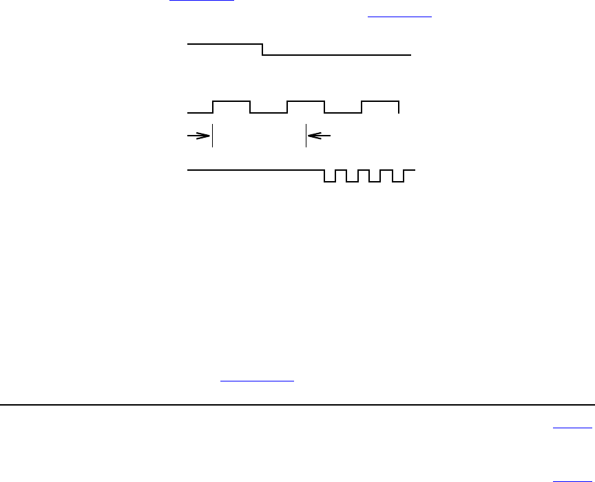
IEEE Std 1800-2012
IEEE STANDARD FOR SYSTEMVERILOG—UNIFIED HARDWARE DESIGN, SPECIFICATION, AND
VERIFICATION LANGUAGE
839
Copyright © 2013 IEEE. All rights reserved.
Case 1: event_based_flag not set, remain_active_flag not set.
After the first reference event on CP at A, a violation is reported at B as soon as 50 time units have passed,
turning the $timeskew check dormant, and no further violations are reported.
Case 2: event_based_flag set, remain_active_flag not set.
After the first reference event on CP at A, the negative transition on CPN at point C causes a timing violation,
turning the $timeskew check dormant, and no further violations are reported. The second reference event at
F occurs while MODE is false; therefore, the $timeskew check remains dormant.
Case 3: event_based_flag set, remain_active_flag set.
After the first reference event on CP at A, the first three negative transitions on CPN at points C, D, and E
cause timing violations. The second reference event at F occurs while MODE is false, but because the
remain_active_flag is set, the $timeskew check remains active. Therefore, additional violations are
reported at G, H, I, and J. In other words, all negative transitions on CPN cause violations, which is identical
to $skew behavior.
Case 4: event_based_flag not set, remain_active_flag set.
For the waveform depicted in Figure 31-1, $timeskew has the same behavior in Case 4 as in Case 1. The
difference between the two cases is illustrated by the waveform in Figure 31-2.
Although the reference event on CP at F occurs while MODE is false, it does not turn the $timeskew check
dormant because the remain_active_flag is set. A violation will hence be reported at time B, whereas for
Case 1, where the remain_active_flag is not set, the $timeskew check would turn dormant at F, and no
violation would be reported.
31.4.3 $fullskew
The syntax for $fullskew is shown in Syntax 31-11.
$fullskew_timing_check ::= // from A.7.5.1
$fullskew ( reference_event , data_event , timing_check_limit , timing_check_limit
[ , [ notifier ] [ , [ event_based_flag ] [ , [ remain_active_flag ] ] ] ] ) ;
data_event ::= timing_check_event // from A.7.5.2
event_based_flag ::= constant_expression
notifier ::= variable_identifier
MODE
CP
A
50
F
CPN
CDE
B
G
Figure 31-2—Sample $timeskew with remain_active_flag set
IEEE Std 1800-2012
IEEE STANDARD FOR SYSTEMVERILOG—UNIFIED HARDWARE DESIGN, SPECIFICATION, AND
VERIFICATION LANGUAGE
840
Copyright © 2013 IEEE. All rights reserved.
reference_event ::= timing_check_event
remain_active_flag ::= constant_mintypmax_expression
timing_check_limit ::= expression
Syntax 31-11—Syntax for $fullskew (excerpt from Annex A)
Table 31-9 defines the $fullskew timing check arguments.
$fullskew is similar to $timeskew except that the reference and data events can transition in either order.
The first limit is the maximum time by which the data event should follow the reference event. The second
limit is the maximum time by which the reference event should follow the data event.
The reference event is the timestamp event, and the data event is the timecheck event when the reference
event precedes the data event. The data event is the timestamp event, and the reference event is the
timecheck event when the data event precedes the reference event.
The $fullskew timing check reports a violation only in the following case, where limit is set to limit1
when the reference event transitions first and set to limit2 when the data event transitions first:
(timecheck time) - (timestamp time) > limit
Simultaneous transitions on the reference and data signals shall not cause $fullskew to report a timing
violation, even when the skew limit value is zero. $fullskew shall also not report a violation if a new
timestamp event occurs exactly at the expiration of the time limit.
The default behavior for $fullskew is timer-based (event_based_flag not set). A violation shall be reported
immediately upon elapse of the time limit after the timestamp event if a timecheck event does not occur in
this time, turning the timing check dormant. However, if a timecheck event does occur within the time limit,
then no violation is reported, and the timing check turns dormant immediately.
A reference event or data event is a timestamp event and starts a new timing window, unless it is a
timecheck event occurring within the time limit after a preceding timestamp event, in which case it turns the
timing check dormant, as previously stated.
In the timer-based mode, a second timestamp event that occurs within the time limit starts a new timing
window that replaces the first one, unless the second timestamp event has an associated condition whose
value is false. In such a case, the behavior of $fullskew depends on the remain_active_flag. If the flag is
Table 31-9—$fullskew arguments
Argument Description
reference_event Timestamp or timecheck event
data_event Timestamp or timecheck event
limit 1 Non-negative constant expression
limit 2 Non-negative constant expression
notifier (optional) Variable (see 31.6)
event_based_flag (optional) Constant expression
remain_active_flag (optional) Constant expression
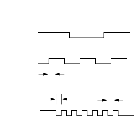
IEEE Std 1800-2012
IEEE STANDARD FOR SYSTEMVERILOG—UNIFIED HARDWARE DESIGN, SPECIFICATION, AND
VERIFICATION LANGUAGE
841
Copyright © 2013 IEEE. All rights reserved.
set, then the second timestamp event is simply ignored. If the flag is not set and if the timing check is active,
then the timing check turns dormant.
The $fullskew check’s default timer-based behavior can be altered to event-based using the
event_based_flag. In this mode, $fullskew is similar to $skew in that a violation is reported not upon
elapse of the time limit after the timestamp event (as in timer-based mode), but rather if a timecheck event
occurs after the time limit. Such an event ends the first timing window and immediately begins a new timing
window, where it acts as the timestamp event of the new window. A timecheck event within the time limit
ends the timing window and turns the timing check dormant, and no violation is reported.
In the event-based mode, a second timestamp event that occurs before a timecheck event has occurred starts
a new timing window that replaces the first one, unless the second timestamp event has an associated
condition whose value is false. In such a case, the behavior of $fullskew depends on the
remain_active_flag. If the flag is set, then the second timestamp event is simply ignored. If the flag is not set
and if the timing check is active, then the timing check turns dormant.
In both the timer-based and event-based modes, if the timestamp event has no condition or has a true
condition and if the timing check is dormant, then the timing check is activated.
For example, see Figure 31-3.
$fullskew (posedge CP &&& MODE, negedge CPN, 50, 70,, event_based_flag,
remain_active_flag);
Case 1: event_based_flag not set.
The transition at A of CP while MODE is true begins a wait for a negative transition on CPN, and a violation is
reported at B as soon as a period of time equal to 50 time units has passed. This resets the check and readies
it for the next active transition.
A negative transition on CPN occurs next at C, beginning a wait for a positive transition on CP while MODE is
true. At D, a time equal to 70 time units has passed without a positive edge on CP while MODE is true;
therefore, a violation is reported, and the check is again reset to await the next active transition.
A transition on CPN at E also results in a timing violation, as does the transition at F, because even though CP
transitions, MODE is no longer true. Transitions at G and H also result in timing violations, but not the
transition at I because it is followed by a positive transition on CP while MODE is true.
MODE
CP
50
J
70
D
70
CEFGH
I
CPN
AB
Figure 31-3—Sample $fullskew
IEEE Std 1800-2012
IEEE STANDARD FOR SYSTEMVERILOG—UNIFIED HARDWARE DESIGN, SPECIFICATION, AND
VERIFICATION LANGUAGE
842
Copyright © 2013 IEEE. All rights reserved.
Case 2: event_based_flag set.
The transition at A of CP while MODE is true begins a wait for a negative transition on CPN, and a violation is
reported at C on CPN because it occurs beyond the 50 time unit limit. This transition at C also begins a wait
of 70 time units for a positive transition on CP while MODE is true. But for transitions on CPN at C through H,
there is no positive transition on CP while MODE is true; therefore, no timing violations are reported. The
transition at I on CPN begins a wait of 70 time units, and this is satisfied by the positive transition on CP at J
while MODE is true.
Although the waveform in this particular example does not show the role of the remain_active_flag, it
should be recognized that this flag has a vital role in determining the behavior of the $fullskew timing
check, just as it does for the $timeskew timing check.
31.4.4 $width
The $width timing check syntax is shown in Syntax 31-12.
$width_timing_check ::= // from A.7.5.1
$width ( controlled_reference_event , timing_check_limit , threshold [ , [ notifier ] ] ) ;
controlled_reference_event ::= controlled_timing_check_event // from A.7.5.2
notifier ::= variable_identifier
threshold ::= constant_expression
timing_check_limit ::= expression
Syntax 31-12—Syntax for $width (excerpt from Annex A)
Table 31-10 defines the $width timing check.
The $width timing check monitors the width of signal pulses by measuring the time from the timestamp
event to the timecheck event. Because a data event is not passed to $width, it is derived from the reference
event, as follows:
data event = reference event signal with opposite edge
Because of the way the data event is derived for $width, an edge triggered event has to be passed as the
reference event. A compilation error shall occur if the reference event is not an edge specification.
Table 31-10—$width arguments
Argument Description
reference_event Timestamp edge triggered event
data_event (implicit) Timecheck edge triggered event
limit Non-negative constant expression
threshold (optional) Non-negative constant expression
notifier (optional) Variable (see 31.6)
IEEE Std 1800-2012
IEEE STANDARD FOR SYSTEMVERILOG—UNIFIED HARDWARE DESIGN, SPECIFICATION, AND
VERIFICATION LANGUAGE
843
Copyright © 2013 IEEE. All rights reserved.
While the $width timing check can be defined in terms of a time window, it is simpler to express it as the
difference between the timecheck and timestamp times. The $width timing check reports a violation in the
following case:
threshold < (timecheck time) - (timestamp time) < limit
The pulse width has to be greater than or equal to limit in order to avoid a timing violation, but no violation
is reported for glitches smaller than the threshold.
The threshold argument shall be included if the notifier argument is required. It is permissible to not specify
both the threshold and notifier arguments, making the default value for the threshold zero. If the notifier is
present, a non-null value for the threshold shall also be present. Here is a legal $width check when the
notifier is required and the threshold is not:
$width (posedge clk, 6, 0, ntfr_reg);
The data event and the reference event shall never occur at the same simulation time because these events
are triggered by opposite transitions.
The following example demonstrates some examples of legal and illegal calls:
// Legal Calls
$width ( negedge clr, lim );
$width ( negedge clr, lim, thresh, notif );
$width ( negedge clr, lim, 0, notif );
// Illegal Calls
$width ( negedge clr, lim, , notif );
$width ( negedge clr, lim, notif );
31.4.5 $period
The $period timing check syntax is shown in Syntax 31-13.
$period_timing_check ::= // from A.7.5.1
$period ( controlled_reference_event , timing_check_limit [ , [ notifier ] ] ) ;
controlled_reference_event ::= controlled_timing_check_event // from A.7.5.2
notifier ::= variable_identifier
timing_check_limit ::= expression
Syntax 31-13—Syntax for $period (excerpt from Annex A)
Table 31-11 defines the $period timing check.
Table 31-11—$period arguments
Argument Description
reference_event Timestamp edge triggered event
data_event (implicit) Timecheck edge triggered event
limit Non-negative constant expression
notifier (optional) Variable (see 31.6)
IEEE Std 1800-2012
IEEE STANDARD FOR SYSTEMVERILOG—UNIFIED HARDWARE DESIGN, SPECIFICATION, AND
VERIFICATION LANGUAGE
844
Copyright © 2013 IEEE. All rights reserved.
Because the data event is not passed as an argument to $period, it is derived from the reference event, as
follows:
data event = reference event signal with the same edge
Because of the way the data event is derived for $period, an edge triggered event shall be passed as the
reference event. A compilation error shall occur if the reference event is not an edge specification.
While the $period timing check can be defined in terms of a time window, it is simpler to express it as the
difference between the timecheck and timestamp times. The $period timing check reports a violation in the
following case:
(timecheck time) - (timestamp time) < limit
31.4.6 $nochange
The $nochange syntax is shown in Syntax 31-14.
$nochange_timing_check ::= // from A.7.5.1
$nochange ( reference_event , data_event , start_edge_offset , end_edge_offset [ , [ notifier ] ] );
data_event ::= timing_check_event // from A.7.5.2
end_edge_offset ::= mintypmax_expression
notifier ::= variable_identifier
reference_event ::= timing_check_event
start_edge_offset ::= mintypmax_expression
Syntax 31-14—Syntax for $nochange (excerpt from Annex A)
Table 31-12 defines the $nochange timing check arguments.
The $nochange timing check reports a timing violation if the data event occurs during the specified level of
the control signal (the reference event). The reference event can be specified with the posedge or the
negedge keyword, but the edge-control specifiers (see 31.5) cannot be used.
The start edge and end edge offsets can expand or shrink the timing violation region, which is defined by the
duration of the reference event signal after the edge. For example, if the reference event is a posedge, then
the duration is the period during which the reference signal is high. A positive offset for start edge extends
the region by starting the timing violation region earlier; a negative offset for start edge shrinks the region by
starting the region later. Similarly, a positive offset for the end edge extends the timing violation region by
Table 31-12—$nochange arguments
Argument Description
reference_event Edge triggered timestamp and/or timecheck event
data_event Timestamp or timecheck event
start_edge_offset Constant expression
end_edge_offset Constant expression
notifier (optional) Variable (see 31.6)
IEEE Std 1800-2012
IEEE STANDARD FOR SYSTEMVERILOG—UNIFIED HARDWARE DESIGN, SPECIFICATION, AND
VERIFICATION LANGUAGE
845
Copyright © 2013 IEEE. All rights reserved.
ending it later, while a negative offset for the end edge shrinks the region by ending it earlier. If both the
offsets are zero, the size of the region shall not change.
Unlike other timing checks, $nochange involves three, rather than two, transitions. The leading edge of the
reference event defines the beginning of the time window, while the trailing edge of the reference event
defines the end of the time window. A violation results if the data event occurs anytime within the time
window.
The end points of the time window are determined as follows:
(beginning of time window) = (leading reference edge time) - start_edge_offset
(end of time window) = (trailing reference edge time) + end_edge_offset
The $nochange timing check reports a timing violation in the following case:
(beginning of time window) < (data event time) < (end of time window)
The end points of the time window are not included. The values of start_edge_offset and
end_edge_offset play a significant role in determining which signal, the reference event or the data
event, is the timestamp or timecheck event.
For example:
$nochange( posedge clk, data, 0, 0) ;
In this example, the $nochange timing check shall report a violation if the data signal changes while clk
is high. It shall not be a violation if posedge clk and a transition on data occur simultaneously.
31.5 Edge-control specifiers
The edge-control specifiers can be used to control events in timing checks based on specific edge transitions
between 0, 1, and x. Syntax 31-15 shows the syntax for edge-control specifiers.
edge_control_specifier ::= edge [ edge_descriptor { , edge_descriptor } ] // from A.7.5.3
edge_descriptor33 ::= 01 | 10 | z_or_x zero_or_one | zero_or_one z_or_x
zero_or_one ::= 0 | 1
z_or_x ::= x | X | z | Z
33) Embedded spaces are illegal.
Syntax 31-15—Syntax for edge-control specifier (excerpt from Annex A)
Edge-control specifiers contain the keyword edge followed by a square-bracketed list of from one to six
pairs of edge transitions between 0, 1, and x, as follows:
01 Transition from 0 to 1
0x Transition from 0 to x
10 Transition from 1 to 0
1x Transition from 1 to x
x0 Transition from x to 0
x1 Transition from x to 1

IEEE Std 1800-2012
IEEE STANDARD FOR SYSTEMVERILOG—UNIFIED HARDWARE DESIGN, SPECIFICATION, AND
VERIFICATION LANGUAGE
846
Copyright © 2013 IEEE. All rights reserved.
Edge transitions involving z are treated the same way as edge transitions involving x.
The posedge and negedge keywords can be used as a shorthand for certain edge-control specifiers. For
example, the construct
posedge clr
is equivalent to the following:
edge[01, 0x, x1] clr
Similarly, the construct
negedge clr
is the same as the following:
edge[10, x0, 1x] clr
However, edge-control specifiers offer the flexibility to declare edge transitions other than posedge and
negedge.
31.6 Notifiers: user-defined responses to timing violations
Timing check notifiers detect timing check violations behaviorally and, therefore, take an action as soon as a
violation occurs. Such notifiers can be used to print an informative error message describing the violation or
to propagate an x value at the output of the device that reported the violation.
The notifier is a variable, declared in the module where timing check tasks are invoked, that is passed as the
last argument to a system timing check. Whenever a timing violation occurs, the timing check updates the
value of the notifier.
The notifier is an optional argument to all system timing checks and can be omitted from the timing check
call without adversely affecting its operation.
Table 31-13 shows how the notifier values are toggled when timing violations occur.
Example 1:
$setup( data, posedge clk, 10, notifier ) ;
$width( posedge clk, 16, 0, notifier ) ;
Table 31-13—Notifier value responses to timing violations
BEFORE violation AFTER violation
x Either 0 or 1
01
10
zz
IEEE Std 1800-2012
IEEE STANDARD FOR SYSTEMVERILOG—UNIFIED HARDWARE DESIGN, SPECIFICATION, AND
VERIFICATION LANGUAGE
847
Copyright © 2013 IEEE. All rights reserved.
Example 2: Consider a more complex example of how to use notifiers in a behavioral model. The following
example uses a notifier to set the D flip-flop output to x when a timing violation occurs in an edge-sensitive
UDP:
primitive posdff_udp(q, clock, data, preset, clear, notifier);
output q; reg q;
input clock, data, preset, clear, notifier;
table
//clock data p c notifier state q
//-------------------------------------
r 0 1 1 ? : ? : 0 ;
r 1 1 1 ? : ? : 1 ;
p 1 ? 1 ? : 1 : 1 ;
p 0 1 ? ? : 0 : 0 ;
n ? ? ? ? : ? : - ;
? * ? ? ? : ? : - ;
? ? 0 1 ? : ? : 1 ;
? ? * 1 ? : 1 : 1 ;
? ? 1 0 ? : ? : 0 ;
? ? 1 * ? : 0 : 0 ;
? ? ? ? * : ? : x ;// At any notifier event
// output x
endtable
endprimitive
module dff(q, qbar, clock, data, preset, clear);
output q, qbar;
input clock, data, preset, clear;
reg notifier;
and (enable, preset, clear);
not (qbar, ffout);
buf (q, ffout);
posdff_udp (ffout, clock, data, preset, clear, notifier);
specify
// Define timing check specparam values
specparam tSU = 10, tHD = 1, tPW = 25, tWPC = 10, tREC = 5;
// Define module path delay rise and fall min:typ:max values
specparam tPLHc = 4:6:9 , tPHLc = 5:8:11;
specparam tPLHpc = 3:5:6 , tPHLpc = 4:7:9;
// Specify module path delays
(clock *> q,qbar) = (tPLHc, tPHLc);
(preset,clear *> q,qbar) = (tPLHpc, tPHLpc);
// Setup time : data to clock, only when preset and clear are 1
$setup(data, posedge clock &&& enable, tSU, notifier);
// Hold time: clock to data, only when preset and clear are 1
$hold(posedge clock, data &&& enable, tHD, notifier);
// Clock period check
IEEE Std 1800-2012
IEEE STANDARD FOR SYSTEMVERILOG—UNIFIED HARDWARE DESIGN, SPECIFICATION, AND
VERIFICATION LANGUAGE
848
Copyright © 2013 IEEE. All rights reserved.
$period(posedge clock, tPW, notifier);
// Pulse width : preset, clear
$width(negedge preset, tWPC, 0, notifier);
$width(negedge clear, tWPC, 0, notifier);
// Recovery time: clear or preset to clock
$recovery(posedge preset, posedge clock, tREC, notifier);
$recovery(posedge clear, posedge clock, tREC, notifier);
endspecify
endmodule
NOTE—This model applies to edge-sensitive UDPs only; for level-sensitive models, an additional UDP for x
propagation has to be generated.
31.7 Enabling timing checks with conditioned events
A construct called a conditioned event ties the occurrence of timing checks to the value of a conditioning
signal. Syntax 31-16 shows the syntax for controlled timing check events.
timing_check_event ::= // from A.7.5.3
[timing_check_event_control] specify_terminal_descriptor [ &&& timing_check_condition ]
controlled_timing_check_event ::=
timing_check_event_control specify_terminal_descriptor [ &&& timing_check_condition ]
timing_check_event_control ::=
posedge
|negedge
|edge
| edge_control_specifier
specify_terminal_descriptor ::=
specify_input_terminal_descriptor
| specify_output_terminal_descriptor
timing_check_condition ::=
scalar_timing_check_condition
|( scalar_timing_check_condition )
scalar_timing_check_condition ::=
expression
|~ expression
| expression == scalar_constant
| expression === scalar_constant
| expression != scalar_constant
| expression !== scalar_constant
scalar_constant ::= 1'b0 | 1'b1 | 1'B0 | 1'B1 | 'b0 | 'b1 | 'B0 | 'B1 | 1 | 0
Syntax 31-16—Syntax for controlled timing check events (excerpt from Annex A)
The comparisons used in the condition can be deterministic, as in ===, !==, ~, or no operation, or
nondeterministic, as in == or !=. When comparisons are deterministic, an x value on the conditioning signal
shall not enable the timing check. For nondeterministic comparisons, an x on the conditioning signal shall
enable the timing check.
The conditioning signal shall be a scalar net; if a vector net or an expression resulting in a multibit value is
used, then the LSB of the vector net or the expression value is used.
IEEE Std 1800-2012
IEEE STANDARD FOR SYSTEMVERILOG—UNIFIED HARDWARE DESIGN, SPECIFICATION, AND
VERIFICATION LANGUAGE
849
Copyright © 2013 IEEE. All rights reserved.
If more than one conditioning signal is required for conditioning timing checks, appropriate logic shall be
combined in a separate signal outside the specify block, which can be used as the conditioning signal.
Example 1:To illustrate the difference between conditioned and unconditioned timing check events,
consider the following example with unconditioned timing check:
$setup( data, posedge clk, 10 );
Here, a setup timing check shall occur every time there is a positive edge on the signal clk.
To trigger the setup check on the positive edge on the signal clk only when the signal clr is high, rewrite
the command as
$setup( data, posedge clk &&& clr, 10 ) ;
Example 2: This example shows two ways to trigger the same timing check as in Example 1 (on the positive
clk edge) only when clr is low. The second method uses the === operator, which makes the comparison
deterministic.
$setup( data, posedge clk &&& (~clr), 10 ) ;
$setup( data, posedge clk &&& (clr===0), 10 );
Example 3: To perform the previous sample setup check on the positive clk edge only when clr and set
are high, add the following statement outside the specify block:
and new_gate( clr_and_set, clr, set );
Then add the condition to the timing check using the signal clr_and_set as follows:
$setup( data, posedge clk &&& clr_and_set, 10 );
31.8 Vector signals in timing checks
Either or both signals in a timing check can be a vector. This shall be interpreted as a single timing check
where the transition of one or more bits of a vector is considered a single transition of that vector.
For example:
module DFF (Q, CLK, DAT);
input CLK;
input [7:0] DAT;
output [7:0] Q;
always @(posedge clk)
Q = DAT;
specify
$setup (DAT, posedge CLK, 10);
endspecify
endmodule
If DAT transitions from 'b00101110 to 'b01010011 at time 100 and if CLK transitions from 0 to 1 at time
105, then the $setup timing check shall still only report a single timing violation.
Simulators may provide an option causing vectors in timing checks to result in the creation of multiple
single-bit timing checks. For timing checks with only a single signal, such as $period or $width, a vector
of width N results in N unique timing checks. For timing checks with two signals, such as $setup, $hold,
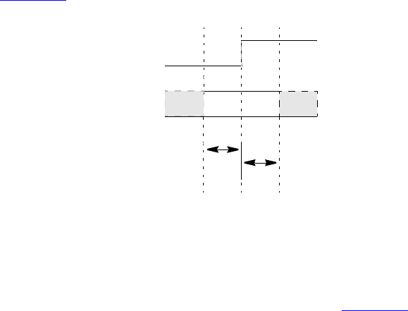
IEEE Std 1800-2012
IEEE STANDARD FOR SYSTEMVERILOG—UNIFIED HARDWARE DESIGN, SPECIFICATION, AND
VERIFICATION LANGUAGE
850
Copyright © 2013 IEEE. All rights reserved.
$setuphold, $skew, $timeskew, $fullskew, $recovery, $removal, $recrem, and $nochange,
where M and N are the widths of the signals, the result is M*N unique timing checks. If there is a notifier, all
the timing checks trigger that notifier.
With such an option enabled, the preceding example yields six timing violation because 6 bits of DAT
transitioned.
31.9 Negative timing checks
Both the $setuphold and $recrem timing checks can accept negative values when the negative timing
check option is enabled. The behavior of these two timing checks is identical with respect to negative values.
The descriptions in this subclause are for the $setuphold timing check, but apply equally to the $recrem
timing check.
The setup and hold timing check values define a timing violation window with respect to the reference
signal edge during which the data shall remain constant. Any change of the data during the specified
window causes a timing violation. The timing violation is reported, and through the notifier variable, other
actions can take place in the model, such as forcing the output of a flip-flop to X when it detects a timing
violation.
A positive value for both setup and hold times implies this violation window straddles the reference signal
shown in Figure 31-4.
A negative hold or setup time means the violation window is shifted to either before or after the reference
edge. This can happen in a real device because of disparate internal device delays between the internal clock
and data signal paths. These internal device delays are illustrated in Figure 31-5 showing how significant
differences in these delays can cause negative setup or hold values.
clock
data
..........Setup time (+)
..........Hold Time (+)
Figure 31-4—Data constraint interval, positive setup/hold
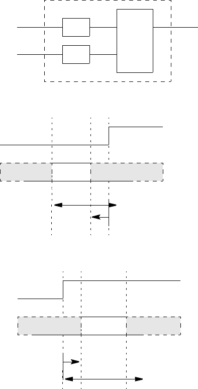
IEEE Std 1800-2012
IEEE STANDARD FOR SYSTEMVERILOG—UNIFIED HARDWARE DESIGN, SPECIFICATION, AND
VERIFICATION LANGUAGE
851
Copyright © 2013 IEEE. All rights reserved.
31.9.1 Requirements for accurate simulation
In order to accurately model negative value timing checks, the following requirements apply:
a) A timing violation shall be triggered if the signal changes in the violation window, exclusive of the
end points. Violation windows smaller than two units of simulation precision cannot yield timing
violations.
b) The value of the latched data shall be the one that is stable during the violation window, again,
exclusive of the end points.
To facilitate these modeling requirements, delayed copies of the data and reference signals are generated in
the timing checks, and these are used internally for timing check evaluation at run time. The setup and hold
times used internally are adjusted to shift the violation window and make it overlap the reference signal.
Delayed data and reference signals can be declared within the timing check so they can be used in the
model’s functional implementation for more accurate simulation. If no delayed signals are declared in the
D1
D2
Seq.
Elem.
data
clock
output
ASIC Cell
clock
data
..........Setup time (+)
..........Hold Time (-)
Negative Setup time (D2>D1)
clock
data
..........Setup time (-)
..........Hold Time (+)
Negative Hold time (D1>D2)
Figure 31-5—Data constraint interval, negative setup/hold
IEEE Std 1800-2012
IEEE STANDARD FOR SYSTEMVERILOG—UNIFIED HARDWARE DESIGN, SPECIFICATION, AND
VERIFICATION LANGUAGE
852
Copyright © 2013 IEEE. All rights reserved.
timing check and if a negative setup or hold value is present, then implicit delayed signals are created.
Because implicit delayed signals cannot be used in defining model behavior, such a model can possibly
behave incorrectly.
Example 1:
$setuphold(posedge CLK, DATA, -10, 20);
Implicit delayed signals shall be created for CLK and DATA, but it shall not be possible to access them. The
$setuphold check shall be properly evaluated, but functional behavior shall not always be accurate. The
old DATA value shall be incorrectly clocked in if DATA transitions between posedge CLK and 10 time units
later.
Example 2:
$setuphold(posedge CLK, DATA1, -10, 20);
$setuphold(posedge CLK, DATA2, -15, 18);
Implicit delayed signals shall be created for CLK, DATA1, and DATA2, one for each. Even though CLK is
referenced in two different timing checks, only one implicit delayed signal is created, and it is used for both
timing checks.
Example 3: If a given signal has a delayed signal in some timing checks but not in others, the delayed signal
shall be used in both cases:
$setuphold(posedge CLK, DATA1, -10, 20,,,, del_CLK, del_DATA1);
$setuphold(posedge CLK, DATA2, -15, 18);
Explicit delayed signals of del_CLK and del_DATA1 are created for CLK and DATA1, while an implicit
delayed signal is created for DATA2. In other words, CLK has only one delayed signal created for it,
del_CLK, rather than one explicit delayed signal for the first check and another implicit delayed signal for
the second check.
The delayed versions of the signals, whether implicit or explicit, shall be used in the $setup, $hold,
$setuphold, $recovery, $removal, $recrem, $width, $period, and $nochange timing checks; and
these checks shall have their limits adjusted accordingly so that the notifier shall be toggled at the proper
moment. If the adjusted limit becomes less than or equal to 0, the limit shall be set to 0, and the simulator
shall issue a warning.
The delayed versions of the signals shall not be used for the $skew, $fullskew, and $timeskew timing
checks because it can possibly result in the reversal of the order of signal transitions. This causes the
notifiers for these timing checks to toggle at the wrong time relative to the rest of the model, perhaps
resulting in transitions to X due to a timing check violation being cancelled. This issue shall be addressed in
the model, possibly by using separate notifiers for these checks.
It is possible for a set of negative timing check values to be mutually inconsistent and produce no solution
for the delay values of delayed signals. In these situations, the simulator shall issue a warning. The
inconsistency shall be resolved by changing the smallest negative limit value to 0 and recalculating the
delays for the delayed signals, and this shall be repeated until a solution is reached. This procedure shall
always produce a solution because in the worst case all negative limit values become 0 and no delayed
signals are needed.
The delayed timing check signals are only actually delayed when negative limit values are present. If a
timing check signal becomes delayed by more than the propagation delay from that signal to an output, that

IEEE Std 1800-2012
IEEE STANDARD FOR SYSTEMVERILOG—UNIFIED HARDWARE DESIGN, SPECIFICATION, AND
VERIFICATION LANGUAGE
853
Copyright © 2013 IEEE. All rights reserved.
output shall take longer than its propagation delay to change. It shall instead transition at the same time that
the delayed timing check signal changes. Thus, the output shall behave as if its specify path delay were equal
to the delay applied to the timing check signal. This situation can only arise when unique setup/hold or
removal/recovery times are given for each edge of the data signal.
For example:
(CLK = Q) = 6;
$setuphold (posedge CLK, posedge D, -3, 8, , , , dCLK, dD);
$setuphold (posedge CLK, negedge D, -7, 13, , , , dCLK, dD);
The setup time of -7 (the larger in absolute value of -3 and -7) creates a delay of 7 for dCLK; therefore,
output Q shall not change until 7 time units after a positive edge on CLK, rather than the 6 time units given in
the specify path.
31.9.2 Conditions in negative timing checks
Conditions can be associated with both the reference and data signals by using the &&& operator; but when
either the setup or hold time is negative, the conditions need to be paired with reference and data signals in a
more flexible way. This example illustrates why.
This pair of $setup and $hold checks works together to provide the same check as a single $setuphold:
$setup (data, clk &&& cond1, tsetup, ntfr);
$hold (clk, data &&& cond1, thold, ntfr);
clk is the timecheck event for the $setup check, while data is the timecheck event for the $hold check.
This cannot be represented in a single $setuphold check; therefore, additional arguments are provided to
make this possible. These arguments are timestamp_condition and timecheck_condition, and they
immediately follow the notifier (see 31.3.3). The following $setuphold check is equivalent to the separate
$setup and $hold checks shown above:
$setuphold( clk, data, tsetup, thold, ntfr, , cond1);
The timestamp_condition argument is null, while the timecheck_condition argument is cond1.
The timestamp_condition and timecheck_condition arguments are associated with either the reference or
data signals based on which delayed version of these signals occurs first. timestamp_condition is associated
with the delayed signal that transitions first, while timecheck_condition is associated with the delayed signal
that transitions second.
Delayed signals are only created for the reference and data signals and not for any condition signals
associated with them. Therefore, timestamp_condition and timecheck_condition are not implicitly delayed
by the simulator. Delayed condition signals for the timestamp_condition and timecheck_condition fields can
be created by making them a function of the delayed signals.
For example:
assign TE_cond_D = (dTE !== 1'b1);
assign TE_cond_TI = (dTE !== 1'b0);
assign DXTI_cond = (dTI !== dD);
specify
$setuphold(posedge CP, D, -10, 20, notifier, ,TE_cond_D, dCP, dD);
$setuphold(posedge CP, TI, 20, -10, notifier, ,TE_cond_TI, dCP, dTI);
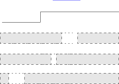
IEEE Std 1800-2012
IEEE STANDARD FOR SYSTEMVERILOG—UNIFIED HARDWARE DESIGN, SPECIFICATION, AND
VERIFICATION LANGUAGE
854
Copyright © 2013 IEEE. All rights reserved.
$setuphold(posedge CP, TE, -4, 8, notifier, ,DXTI_cond, dCP, dTE);
endspecify
The assign statements create condition signals that are functions of the delayed signals. Creating delayed
signal conditions synchronizes the conditions with the delayed versions of the reference and data signals
used to perform the checks.
The first $setuphold has a negative setup time; therefore, the timecheck condition TE_cond_D is
associated with data signal D. The second $setuphold has a negative hold time; therefore, the timecheck
condition TE_cond_TI is associated with reference signals CP. The third $setuphold has a negative setup
time; therefore, the timecheck condition DXTI_cond is associated with data signal TE.
The violation windows for the example are shown in Figure 31-6.
These are the delay values calculated for the delayed signals:
dCP 10.01
dD 0.00
dTI 20.02
dTE 2.02
Use of delayed signals in creating the signals for the timestamp_condition and timecheck_condition
arguments is not required, but it is usually closer to actual device behavior.
31.9.3 Notifiers in negative timing checks
Because the reference and data signals are delayed internally, the detection of the timing violation is also
delayed. Notifier variables in negative timing checks shall be toggled when the timing check detects a
timing violation, which occurs when the delayed signals as measured by the adjusted timing check values
are in violation, not when the undelayed signals at the model inputs as measured by the original timing
check values are in violation.
31.9.4 Option behavior
As already mentioned, the ability of simulators to handle negative values in $setuphold and $recrem
timing checks shall be enabled with an invocation option. It is possible models written to accept negative
timing check values with delayed reference and/or delayed data signals can be run without this invocation
option enabled. In this circumstance, the delayed reference and data signals become copies of the original
reference and data signals. The same occurs if an invocation option turning off all timing checks is used.
D
TE
TI
480
CP
508
490
520510
500
504
Figure 31-6—Timing check violation windows

IEEE Std 1800-2012
IEEE STANDARD FOR SYSTEMVERILOG—UNIFIED HARDWARE DESIGN, SPECIFICATION, AND
VERIFICATION LANGUAGE
855
Copyright © 2013 IEEE. All rights reserved.
32. Backannotation using the standard delay format
32.1 General
This clause describes the following:
— Standard delay format (SDF) annotator
— Mapping SDF constructs to SystemVerilog
— Multiple annotations
— Multiple SDF files
— Pulse limit annotation
— SDF to SystemVerilog value mapping
— The $sdf_annotate SDF file reader
32.2 Overview
SDF files contain timing values for specify path delays, specparam values, timing check constraints, and
interconnect delays. SDF files can also contain other information in addition to simulation timing, but these
need not concern SystemVerilog simulation. The timing values in SDF files usually come from application-
specific integrated circuit (ASIC) delay calculation tools that take advantage of connectivity, technology,
and layout geometry information.
SystemVerilog backannotation is the process by which timing values from the SDF file update specify path
delays, specparam values, timing constraint values, and interconnect delays.
All this information is covered further in IEEE Std 1497™-2001 [B1].
32.3 The SDF annotator
The term SDF annotator refers to any tool capable of backannotating SDF data to a SystemVerilog
simulator. It shall issue a warning for any data it is unable to annotate.
An SDF file can contain many constructs that are not related to specify path delays, specparam values,
timing check constraint values, or interconnect delays. An example is any construct in the TIMINGENV
section of the SDF file. All constructs unrelated to SystemVerilog timing shall be ignored without any
warnings issued.
Any SystemVerilog timing value for which the SDF file does not provide a value shall not be modified
during the backannotation process, and its prebackannotation value shall be unchanged.
32.4 Mapping of SDF constructs to SystemVerilog
SDF timing values appear within a CELL declaration, which can contain one or more of DELAY,
TIMINGCHECK, and LABEL sections. The DELAY section contains propagation delay values for specify paths
and interconnect delays. The TIMINGCHECK section contains timing check constraint values. The LABEL
section contains new values for specparams. Backannotation into SystemVerilog is done by matching SDF
constructs to the corresponding SystemVerilog declarations and then replacing the existing SystemVerilog
timing values with those from the SDF file.
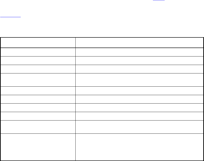
IEEE Std 1800-2012
IEEE STANDARD FOR SYSTEMVERILOG—UNIFIED HARDWARE DESIGN, SPECIFICATION, AND
VERIFICATION LANGUAGE
856
Copyright © 2013 IEEE. All rights reserved.
32.4.1 Mapping of SDF delay constructs to SystemVerilog declarations
When annotating DELAY constructs that are not interconnect delays (covered in 32.4.4), the SDF annotator
looks for specify paths where the names and conditions match. When annotating TIMINGCHECK constructs,
the SDF annotator looks for timing checks of the same type where the names and conditions match.
Table 32-1 shows which SystemVerilog structures can be annotated by each SDF construct in the DELAY
section.
In the following example, the source SDF signal sel matches the source SystemVerilog signal, and the
destination SDF signal zout also matches the destination SystemVerilog signal. Therefore, the rise/fall
times of 1.3 and 1.7 are annotated to the specify path.
SDF file:
(IOPATH sel zout (1.3) (1.7))
SystemVerilog specify path:
(sel => zout) = 0;
A conditional IOPATH delay between two ports shall annotate only to SystemVerilog specify paths between
those same two ports with the same condition. In the following example, the rise/fall times of 1.3 and 1.7
are annotated only to the second specify path:
SDF file:
(COND mode (IOPATH sel zout (1.3) (1.7)))
Table 32-1—Mapping of SDF delay constructs to SystemVerilog declarations
SDF construct SystemVerilog annotated structure
(PATHPULSE... Conditional and nonconditional specify path pulse limits
(PATHPULSEPERCENT... Conditional and nonconditional specify path pulse limits
(IOPATH... Conditional and nonconditional specify path delays/pulse limits
(IOPATH (RETAIN... Conditional and nonconditional specify path delays/pulse limits,
RETAIN may be ignored
(COND (IOPATH... Conditional specify path delays/pulse limits
(COND (IOPATH (RETAIN... Conditional specify path delays/pulse limits, RETAIN may be ignored
(CONDELSE (IOPATH... ifnone
(CONDELSE (IOPATH (RETAIN... ifnone, RETAIN may be ignored
(DEVICE... All specify paths to module outputs. If no specify paths, all primitives
driving module outputs.
(DEVICE port_instance... If port_instance is a module instance, all specify paths to module
outputs. If no specify paths, all primitives driving module outputs. If
port_instance is a module instance output, all specify paths to that
module output. If no specify path, all primitives driving that module
output.
IEEE Std 1800-2012
IEEE STANDARD FOR SYSTEMVERILOG—UNIFIED HARDWARE DESIGN, SPECIFICATION, AND
VERIFICATION LANGUAGE
857
Copyright © 2013 IEEE. All rights reserved.
SystemVerilog specify paths:
if (!mode) (sel => zout) = 0;
if (mode) (sel => zout) = 0;
A nonconditional IOPATH delay between two ports shall annotate to all SystemVerilog specify paths
between those same two ports. In the following example, the rise/fall times of 1.3 and 1.7 are annotated
to both specify paths:
SDF file:
(IOPATH sel zout (1.3) (1.7))
SystemVerilog specify paths:
if (!mode) (sel => zout) = 0;
if (mode) (sel => zout) = 0;
32.4.2 Mapping of SDF timing check constructs to SystemVerilog
Table 32-2 shows which SystemVerilog timing checks are annotated to by each type of SDF timing check.
v1 is the first value of a timing check, v2 is the second value, while x indicates no value is annotated.
The reference and data signals of timing checks can have logical condition expressions and edges associated
with them. An SDF timing check with no conditions or edges on any of its signals shall match all
corresponding SystemVerilog timing checks regardless of whether conditions are present. In the following
example, the SDF timing check shall annotate to all the SystemVerilog timing checks:
SDF file:
(SETUPHOLD data clk (3) (4))
Table 32-2—Mapping of SDF timing check constructs to SystemVerilog
SDF timing check Annotated SystemVerilog timing checks
(SETUP v1... $setup(v1), $setuphold(v1,x)
(HOLD v1... $hold(v1), $setuphold(x,v1)
(SETUPHOLD v1 v2... $setup(v1), $hold(v2), $setuphold(v1,v2)
(RECOVERY v1... $recovery(v1), $recrem(v1,x)
(REMOVAL v1... $removal(v1), $recrem(x,v1)
(RECREM v1 v2... $recovery(v1), $removal(v2), $recrem(v1,v2)
(SKEW v1... $skew(v1), $timeskew(v1)
(BIDIRECTSKEW v1 v2... $fullskew(v1,v2)
(WIDTH v1... $width(v1,x)
(PERIOD v1... $period(v1)
(NOCHANGE v1 v2... $nochange(v1,v2)
IEEE Std 1800-2012
IEEE STANDARD FOR SYSTEMVERILOG—UNIFIED HARDWARE DESIGN, SPECIFICATION, AND
VERIFICATION LANGUAGE
858
Copyright © 2013 IEEE. All rights reserved.
SystemVerilog timing checks:
$setuphold (posedge clk &&& mode, data, 1, 1, ntfr);
$setuphold (negedge clk &&& !mode, data, 1, 1, ntfr);
$setuphold (edge clk, data, 1, 1, ntfr);
When conditions and/or edges are associated with the signals in an SDF timing check, then they shall match
those in any corresponding SystemVerilog timing check before annotation shall happen. In the following
example, the SDF timing check shall annotate to the first SystemVerilog timing check, but not the second
and the third:
SDF file:
(SETUPHOLD data (posedge clk) (3) (4))
SystemVerilog timing checks:
$setuphold (posedge clk &&& mode, data, 1, 1, ntfr); // Annotated
$setuphold (negedge clk &&& !mode, data, 1, 1, ntfr); // Not annotated
$setuphold (edge clk, data, 1, 1, ntfr); // Not annotated
Here, the SDF timing check shall not annotate to any of the SystemVerilog timing checks.
SDF file:
(SETUPHOLD data (COND !mode (posedge clk)) (3) (4))
SystemVerilog timing checks:
$setuphold (posedge clk &&& mode, data, 1, 1, ntfr); // Not annotated
$setuphold (negedge clk &&& !mode, data, 1, 1, ntfr); // Not annotated
$setuphold (edge clk, data, 1, 1, ntfr); // Not annotated
32.4.3 SDF annotation of specparams
The SDF LABEL construct annotates to specparams. Any expression containing one or more specparams is
reevaluated when annotated to from an SDF file.
The following example shows SDF LABEL constructs annotating to specparams in a SystemVerilog module.
The specparams are used in procedural delays to control when the clock transitions. The SDF LABEL
construct annotates the values of dhigh and dlow, thereby setting the period and duty cycle of the clock.
SDF file:
(LABEL
(ABSOLUTE
(dhigh 60)
(dlow 40)))
SystemVerilog file:
module clock(clk);
output clk;
reg clk;
specparam dhigh=0, dlow=0;
initial clk = 0;
IEEE Std 1800-2012
IEEE STANDARD FOR SYSTEMVERILOG—UNIFIED HARDWARE DESIGN, SPECIFICATION, AND
VERIFICATION LANGUAGE
859
Copyright © 2013 IEEE. All rights reserved.
always
begin
#dhigh clk = 1; // Clock remains low for time dlow
// before transitioning to 1
#dlow clk = 0; // Clock remains high for time dhigh
// before transitioning to 0
end
endmodule
The following example shows a specparam in an expression of a specify path. The SDF LABEL construct can
be used to change the value of the specparam and cause reevaluation of the expression.
specparam cap = 0;
...
specify
(A => Z) = 1.4 * cap + 0.7;
endspecify
32.4.4 SDF annotation of interconnect delays
SDF interconnect delay annotation differs from annotation of other constructs previously described in that
there exists no corresponding SystemVerilog declaration to which to annotate. In SystemVerilog simulation,
interconnect delays are an abstraction that represents the signal propagation delay from an output or inout
module port to an input or inout module port. The INTERCONNECT construct includes a source, a load, and
delay values, while the PORT and NETDELAY constructs include only a load and delay values. Interconnect
delays can only be annotated between module ports, never between primitive pins. Table 32-3 shows how
the SDF interconnect constructs in the DELAY section are annotated.
Interconnect delays can be annotated to both single source and multisource nets.
When annotating a PORT construct, the SDF annotator shall search for the port and, if it exists, shall annotate
an interconnect delay to that port that shall represent the delay from all sources on the net to that port.
When annotating a NETDELAY construct, the SDF annotator shall check to see if it is annotating to a port or a
net. If it is a port, then the SDF annotator shall annotate an interconnect delay to that port. If it is a net, then
it shall annotate an interconnect delay to all load ports connected to that net. If the port or net has more than
one source, then the delay shall represent the delay from all sources. NETDELAY delays can only be
annotated to input or inout module ports or to nets.
In the case of multisource nets, unique delays can be annotated between each source/load pair using the
INTERCONNECT construct. When annotating this construct, the SDF annotator shall find the source port and
the load port; and if both exist, it shall annotate an interconnect delay between the two. If the source port is
not found or if the source port and the load port are not actually on the same net, then a warning is issued,
but the delay to the load port is annotated anyway. If this happens for a load port that is part of a multisource
Table 32-3—SDF annotation of interconnect delays
SDF construct SystemVerilog annotated structure
(PORT... Interconnect delay
(NETDELAY a
aOnly OVI SDF version 1.0, 2.0, and 2.1 and IEEE SDF version 4.0
Interconnect delay
(INTERCONNECT... Interconnect delay
IEEE Std 1800-2012
IEEE STANDARD FOR SYSTEMVERILOG—UNIFIED HARDWARE DESIGN, SPECIFICATION, AND
VERIFICATION LANGUAGE
860
Copyright © 2013 IEEE. All rights reserved.
net, then the delay is treated as if it were the delay from all source ports, which is the same as the annotation
behavior for a PORT delay. Source ports shall be output or inout ports, while load ports shall be input or inout
ports.
Interconnect delays share many of the characteristics of specify path delays. The same rules for specify path
delays for filling in missing delays and pulse limits also apply for interconnect delays. Interconnect delays
have 12 transition delays, and unique reject and error pulse limits are associated with each of the 12. An
unlimited number of future schedules are permitted.
In a SystemVerilog module, a reference to an annotated port, wherever it occurs, whether in $monitor and
$display statements or in expressions, shall provide the delayed signal value. A reference to the source
shall yield the undelayed signal value, while a reference to the load shall yield the delayed signal value. In
general, references to the signal value hierarchically before the load shall yield the undelayed signal value,
while references to the signal at or hierarchically after the load shall yield the delayed signal value. An
annotation to a hierarchical port shall affect all connected ports at higher or lower hierarchical levels,
depending on the direction of annotation. An annotation from a source port shall be interpreted as being
from all sources hierarchically higher or lower than that source port.
Up-hierarchy annotations shall be properly handled. This situation arises when the load is hierarchically
above the source. The delay to all ports that are hierarchically above the load or that connect to the net at
points hierarchically above the load is the same as the delay to that load.
Down-hierarchy annotation shall also be properly handled. This situation arises when the source is
hierarchically above the load. The delay to the load is interpreted as being from all ports that are at or above
the source or that connect to the net at points hierarchically above the source.
Hierarchically overlapping annotations are permitted. This occurs when annotations to or from the same port
take place at different hierarchical levels and, therefore, do not correspond to the same hierarchical subset of
ports. In the following example, the first INTERCONNECT statement annotates to all ports of the net that are
at or hierarchically within i53/selmode, while the second annotates to a smaller subset of ports, only those
at or hierarchically within i53/u21/in:
(INTERCONNECT i14/u5/out i53/selmode (1.43) (2.17))
(INTERCONNECT i14/u5/out i53/u21/in (1.58) (1.92))
Overlapping annotations can occur in many different ways, particularly on multisource/multiload nets, and
SDF annotation shall properly resolve all the interactions.
32.5 Multiple annotations
SDF annotation is an ordered process. The constructs from the SDF file are annotated in their order of
occurrence. In other words, annotation of an SDF construct can be changed by annotation of a subsequent
construct that either modifies (INCREMENT) or overwrites (ABSOLUTE) it. These do not have to be the
same construct. The following example first annotates pulse limits to an IOPATH and then annotates the
entire IOPATH, thereby overwriting the pulse limits that were just annotated:
(DELAY
(ABSOLUTE
(PATHPULSE A Z (2.1) (3.4))
(IOPATH A Z (3.5) (6.1))
Overwriting the pulse limits can be avoided by using empty parentheses to hold the current values of the
pulse limits:
IEEE Std 1800-2012
IEEE STANDARD FOR SYSTEMVERILOG—UNIFIED HARDWARE DESIGN, SPECIFICATION, AND
VERIFICATION LANGUAGE
861
Copyright © 2013 IEEE. All rights reserved.
(DELAY
(ABSOLUTE
(PATHPULSE A Z (2.1) (3.4))
(IOPATH A Z ((3.5) () ()) ((6.1) () ()) )
The preceding annotation can be simplified into a single statement as follows:
(DELAY
(ABSOLUTE
(IOPATH A Z ((3.5) (2.1) (3.4)) ((6.1) (2.1) (3.4)) )
A PORT annotation followed by an INTERCONNECT annotation to the same load shall cause only the delay
from the INTERCONNECT source to be affected. For the following net with three sources and a single load,
the delay from all sources except i13/out remains 6:
(DELAY
(ABSOLUTE
(PORT i15/in (6))
(INTERCONNECT i13/out i15/in (5))
An INTERCONNECT annotation followed by a PORT annotation shall cause the INTERCONNECT annotation to
be overwritten. Here, the delays from all sources to the load shall become 6:
(DELAY
(ABSOLUTE
(INTERCONNECT i13/out i15/in (5))
(PORT i15/in (6))
32.6 Multiple SDF files
More than one SDF file can be annotated. Each call to the $sdf_annotate task annotates the design with
timing information from an SDF file. Annotated values either modify (INCREMENT) or overwrite
(ABSOLUTE) values from earlier SDF files. Different regions of a design can be annotated from different
SDF files by specifying the region’s hierarchy scope as the second argument to $sdf_annotate.
32.7 Pulse limit annotation
For SDF annotation of delays (not timing constraints), the default values annotated for pulse limits shall be
calculated using the percentage settings for the reject and error limits. By default, these limits are 100%, but
they can be modified through invocation options. For example, assuming invocation options have set the
reject limit to 40% and the error limit to 80%, the following SDF construct shall annotate a delay of 5, a reject
limit of 2, and an error limit of 4:
(DELAY
(ABSOLUTE
(IOPATH A Z (5))
Given that the specify path delay was originally 0, the following annotation results in a delay of 5 and pulse
limits of 0:
(DELAY
(ABSOLUTE
(IOPATH A Z ((5) () ()) )
IEEE Std 1800-2012
IEEE STANDARD FOR SYSTEMVERILOG—UNIFIED HARDWARE DESIGN, SPECIFICATION, AND
VERIFICATION LANGUAGE
862
Copyright © 2013 IEEE. All rights reserved.
Annotations in INCREMENT mode can result in pulse limits less than 0, in which case they shall be adjusted
to 0. For example, if the specify path pulse limits were both 3, the following annotation results in a 0 value
for both pulse limits:
(DELAY
(INCREMENT
(IOPATH A Z (() (-4) (-5)) )
There are two SDF constructs that annotate only to pulse limits, PATHPULSE and PATHPULSEPERCENT.
They do not affect the delay. When PATHPULSE sets the pulse limits to values greater than the delay,
SystemVerilog shall exhibit the same behavior as if the pulse limits had been set equal to the delay.
32.8 SDF to SystemVerilog delay value mapping
SystemVerilog specify paths and interconnects can have unique delays for up to 12 state transitions (see
30.5.1). All other constructs, such as gate primitives and continuous assignments, can have only three state
transition delays (see 28.16).
For SystemVerilog specify path and interconnect delays, the number of transition delay values provided by
SDF might be less than 12.
Table 32-4 shows how fewer than 12 SDF delays are extended to be 12 delays. The SystemVerilog
transition types are shown down the left-hand side, while the number of SDF delays provided is shown
across the top. The SDF values are given the names v1 through v12.
For other delays that can have at most three values, the expansion of less than three SDF delays into three
SystemVerilog delays is covered in Table 28-9. More than three SDF delays are reduced to three
SystemVerilog delays by simply ignoring the extra delays. The delay to the X-state is created from the
minimum of the other three delays.
Table 32-4—SDF to SystemVerilog delay value mapping
SystemVerilog
transition
Number of SDF delay values provided
1 value 2 values 3 values 6 values 12 values
0 –> 1 v1 v1 v1 v1 v1
1 –> 0 v1 v2 v2 v2 v2
0 –> z v1 v1 v3 v3 v3
z –> 1 v1 v1 v1 v4 v4
1 –> z v1 v2 v3 v5 v5
z –> 0 v1 v2 v2 v6 v6
0 –> x v1 v1 min(v1,v3) min(v1,v3) v7
x –> 1 v1 v1 v1 max(v1,v4) v8
1 –> x v1 v2 min(v2,v3) min(v2,v5) v9
x –> 0 v1 v2 v2 max(v2,v6) v10
x –> z v1 max(v1,v2) v3 max(v3,v5) v11
z –> x v1 min(v1,v2) min(v1,v2) min(v4,v6) v12
IEEE Std 1800-2012
IEEE STANDARD FOR SYSTEMVERILOG—UNIFIED HARDWARE DESIGN, SPECIFICATION, AND
VERIFICATION LANGUAGE
863
Copyright © 2013 IEEE. All rights reserved.
32.9 Loading timing data from an SDF file
The syntax for the $sdf_annotate system task is shown in Syntax 32-1.
sdf_annotate_task ::=
$sdf_annotate ( sdf_file [ , [ module_instance ] [ , [ "config_file" ]
[ , [ "log_file" ] [ , [ "mtm_spec" ] [ , [ "scale_factors" ] [ , [ "scale_type" ] ] ] ] ] ] ] ) ;
Syntax 32-1—Syntax for $sdf_annotate system task (not in Annex A)
The $sdf_annotate system task reads timing data from an SDF file into a specified region of the design.
sdf_file—is an expression that is a string literal, string data type, or an integral data type containing a
character string that names the file to be opened.
module_instance—is an optional argument specifying the scope to which to annotate the information in the
SDF file. The SDF annotator uses the hierarchy level of the specified instance for running the annotation.
Array indices are permitted. If the module_instance is not specified, the SDF annotator uses the module
containing the call to the $sdf_annotate system task as the module_instance for annotation.
config_file—is an optional character string argument providing the name of a configuration file. Information
in this file can be used to provide detailed control over many aspects of annotation.
log_file—is an optional character string argument providing the name of the log file used during SDF
annotation. Each individual annotation of timing data from the SDF file results in an entry in the log file.
mtm_spec—is an optional character string argument specifying which member of the min/typ/max triples
shall be annotated. The legal values for this string are described in Table 32-5. This overrides any MTM_SPEC
keywords in the configuration file.
scale_factors—is an optional character string argument specifying the scale factors to be used while
annotating timing values. For example, "1.6:1.4:1.2" causes minimum values to be multiplied by 1.6,
typical values by 1.4, and maximum values by 1.2. The default values are 1.0:1.0:1.0. The
scale_factors argument overrides any SCALE_FACTORS keywords in the configuration file.
scale_type—is an optional character string argument specifying how the scale factors should be applied to
the min/typ/max triples. The legal values for this string are shown in Table 32-6. This overrides any
SCALE_TYPE keywords in the configuration file.
Table 32-5—mtm_spec argument
Keyword Description
MAXIMUM Annotates the maximum value
MINIMUM Annotates the minimum value
TOOL_CONTROL (default) Annotates the value as selected by the simulator
TYPICAL Annotates the typical value
IEEE Std 1800-2012
IEEE STANDARD FOR SYSTEMVERILOG—UNIFIED HARDWARE DESIGN, SPECIFICATION, AND
VERIFICATION LANGUAGE
864
Copyright © 2013 IEEE. All rights reserved.
Table 32-6—scale_type argument
Keyword Description
FROM_MAXIMUM Applies scale factors to maximum value
FROM_MINIMUM Applies scale factors to minimum value
FROM_MTM (default) Applies scale factors to min/typ/max values
FROM_TYPICAL Applies scale factors to typical value

IEEE Std 1800-2012
IEEE STANDARD FOR SYSTEMVERILOG—UNIFIED HARDWARE DESIGN, SPECIFICATION, AND
VERIFICATION LANGUAGE
865
Copyright © 2013 IEEE. All rights reserved.
33. Configuring the contents of a design
33.1 General
This clause describes the following:
— Configuration libraries
— Configuration syntax
— Using libraries and configurations
33.2 Overview
To facilitate both the sharing of SystemVerilog designs between designers and/or design groups and the
repeatability of the exact contents of a given simulation (or other tool) session, the concept of configurations
is used in the SystemVerilog language. A configuration is simply an explicit set of rules to specify the exact
source description to be used to represent each instance in a design. The operation of selecting a source
representation for an instance is referred to as binding the instance.
The following example shows a simple configuration problem:
file top.v file adder.v file adder.vg
module top(); module adder(...); module adder(...);
adder a1(...); // rtl adder // gate-level adder
adder a2(...); // description // description
endmodule ... ...
endmodule endmodule
Consider using the rtl adder description in adder.v for instance a1 in module top and the gate-level
adder description in adder.vg for instance a2. In order to specify this particular set of instance bindings
and to avoid having to change the source description to specify a new set, a configuration can be used.
config cfg1; // specify rtl adder for top.a1, gate-level adder for top.a2
design rtlLib.top;
default liblist rtlLib;
instance top.a2 liblist gateLib;
endconfig
The elements of a config are explained in subsequent subclauses, but this simple example illustrates some
important points about configs. As evidenced by the config–endconfig syntax, the config is a design
element, similar to a module, which exists in the SystemVerilog name space. The config contains a set of
rules that are applied when searching for a source description to bind to a particular instance of the design.
A design description starts with a top-level module (or modules) (see 23.3.1). From this module’s source
description, the instantiated modules (or children) are found, then the source descriptions for the module
definitions of these subinstances shall be located, and so on until every instance in the design is mapped to a
source description.
33.2.1 Library notation
A library is a named collection of cells. A cell is a design element (see 3.2), such as a module, primitive,
interface, program, package, or configuration. The cell name shall be the same as the name of the design
element being processed.
IEEE Std 1800-2012
IEEE STANDARD FOR SYSTEMVERILOG—UNIFIED HARDWARE DESIGN, SPECIFICATION, AND
VERIFICATION LANGUAGE
866
Copyright © 2013 IEEE. All rights reserved.
In order to map a design element instance to a source description, the concept of a symbolic library, which is
simply a logical collection of design elements, can be used. Syntax 33-1 specifies a cell from a given library.
cell_clause ::= cell [ library_identifier . ] cell_identifier // from A.1.5
Syntax 33-1—Syntax for cell (excerpt from Annex A)
This notation gives a symbolic method of referring to source descriptions; the method of mapping source
descriptions into libraries is shown in greater detail in 33.3.1. The optional :config extension shall be used
explicitly to refer to a config in the case where a config has the same name as a module/primitive.
For the purposes of this example, suppose the files top.v and adder.v (i.e., the RTL descriptions) have
been mapped into the library rtlLib and the file adder.vg (i.e., the gate-level description of the adder)
has been mapped into the library gateLib. The actual mechanism for mapping source descriptions to
libraries is detailed in 33.3.
33.2.2 Basic configuration elements
The design statement in config cfg1 of the first example of 33.2 specifies the top-level module in the
design and what source description is to be used. In this example, the rtlLib.top notation indicates the
top-level module description shall be taken from rtlLib. Because top.v and adder.v were mapped to
this library, the actual description for the module is known to come from top.v.
The default statement coupled with the liblist clause specifies, by default, all subinstances of top (i.e.,
top.a1 and top.a2) shall be taken from rtlLib, which means the descriptions in top.v and adder.v,
which were mapped to this library, shall be used. For a basic design, which can be completely rtl, this can
be sufficient to specify completely the binding for the entire design. However, here the top.a2 instance of
adder to the gate-level description shall be bound.
The instance statement specifies, for the particular instance top.a2, the source description shall be taken
from gateLib. The instance statement overrides the default rule for this particular instance. Because
adder.vg was mapped to gateLib, this statement dictates the gate-level description in adder.vg be used
for instance top.a2.
33.3 Libraries
As mentioned in the previous subclause, a library is a logical collection of cells that are mapped to particular
source description files. The symbolic lib.cell[:config] notation supports the separate compilation of
source files by providing a file-system-independent name to refer to source descriptions when instances in a
design are bound. It also allows multiple tools, which can have different invocation use models, to share the
same configuration.
33.3.1 Specifying libraries—the library map file
When parsing a source description file (or files), the parser shall first read the library mapping information
from a predefined file prior to reading any source files. The name of this file and the mechanism for reading
it shall be tool-specific, but all compliant tools shall provide a mechanism to specify one or more library
map files to be used for a particular invocation of the tool. If multiple map files are specified, then they shall
be read in the order in which they are specified.

IEEE Std 1800-2012
IEEE STANDARD FOR SYSTEMVERILOG—UNIFIED HARDWARE DESIGN, SPECIFICATION, AND
VERIFICATION LANGUAGE
867
Copyright © 2013 IEEE. All rights reserved.
For the purposes of this discussion, assume the existence of a file named lib.map in the current working
directory, which is automatically read by the parser prior to parsing any source files specified on the
command line. The syntax for declaring a library in the library map file is shown in Syntax 33-2.
library_text ::= { library_description } // from A.1.1
library_description ::=
library_declaration
| include_statement
| config_declaration
|;
library_declaration ::=
library library_identifier file_path_spec { , file_path_spec }
[ -incdir file_path_spec { , file_path_spec } ] ;
include_statement ::= include file_path_spec ;
Syntax 33-2—Syntax for declaring library in library map file (excerpt from Annex A)
Library map file details
1) file_path_spec uses file-system-specific notation to specify an absolute or relative path to a
particular file or set of files. The following shortcuts/wildcards can be used:
? single character wildcard (matches any single character)
* multiple character wildcard (matches any number of characters in a directory/file name)
... hierarchical wildcard (matches any number of hierarchical directories)
.. specifies the parent directory
. specifies the directory containing the lib.map
Paths that end in / shall include all files in the specified directory. Identical to /*.
Paths that do not begin with / are relative to the directory in which the current lib.map file
is located.
2) The paths ./*.v and *.v are identical, and both specify all files with a .v suffix in the current
directory.
Any file encountered by the compiler that does not match any library’s file_path_spec shall by default be
compiled into a library named work.
To perform the library mapping discussed in the example in 33.2, use the following library definitions in the
lib.map file:
library rtlLib *.v; // matches all files in the current directory with
// a .v suffix
library gateLib ./*.vg; // matches all files in the current directory with
// a .vg suffix
33.3.1.1 File path resolution
If a file name potentially matches multiple file path specifications, the path specifications shall be resolved
in the following order:
a) File path specifications that end with an explicit file name
b) File path specifications that end with a wildcarded file name
c) File path specifications that end with a directory

IEEE Std 1800-2012
IEEE STANDARD FOR SYSTEMVERILOG—UNIFIED HARDWARE DESIGN, SPECIFICATION, AND
VERIFICATION LANGUAGE
868
Copyright © 2013 IEEE. All rights reserved.
If a file name matches path specifications in multiple library definitions (after the above resolution rules
have been applied), it shall be an error.
Using these rules with the library definitions in the lib.map file, all source files encountered by the parser/
compiler can be mapped to a unique library. Once the source descriptions have been mapped to libraries, the
cells defined in those libraries are available for binding.
NOTE—Tool implementers may find it convenient to provide a command-line argument to explicitly specify the library
into which the file being parsed is to be mapped, which shall override any library definitions in the lib.map file. If
these libraries do not exist in the lib.map file, they can only be accessed via an explicit config.
If multiple cells with the same name map to the same library, then the last cell encountered shall be written
to the library. This is to support a “separate-compile” use model (see 33.5.3), where it is assumed that
encountering a cell after it has previously been compiled is intended to be a recompiling of the cell. In the
case where multiple modules with the same name are mapped to the same library in a single invocation of
the compiler, then a warning shall be issued.
33.3.2 Using multiple library map files
In addition to specifying library mapping information, a lib.map file can also include references to other
lib.map files. The include command is used to insert the entire contents of a library map file in another
file during parsing. The result is as though the contents of the included map file appear in place of the
include command.
The syntax of a lib.map file is limited to library specifications, include statements, and standard
SystemVerilog comment syntax. Syntax 33-3 shows the syntax for the include command.
include_statement ::= include file_path_spec ; // from A.1.1
Syntax 33-3—Syntax for include command (excerpt from Annex A)
If the file path specification, whether in an include or library statement, describes a relative path, it shall be
relative to the location of the file that contains the file path. Library providers shall include a local library
map file in addition to the source contents of the library. Individual users can then simply include the
provider’s library map file in their own map file to gain access to the contents of the provided library.
33.3.3 Mapping source files to libraries
For each cell definition encountered during parsing/compiling, the name of the source file being parsed is
compared to the file path specifications of the library declarations in all of the library map files being used.
The cell is mapped into the library whose file path specification matches the source file name.
33.4 Configurations
As mentioned in the introduction of this clause, a configuration is simply a set of rules to apply when
searching for library cells to which to bind instances.
A configuration may change the binding of a module, primitive, interface, or program instance, but shall not
change the binding of a package.
The syntax for configurations is shown in 33.4.1.
IEEE Std 1800-2012
IEEE STANDARD FOR SYSTEMVERILOG—UNIFIED HARDWARE DESIGN, SPECIFICATION, AND
VERIFICATION LANGUAGE
869
Copyright © 2013 IEEE. All rights reserved.
33.4.1 Basic configuration syntax
The configuration syntax is shown in Syntax 33-4.
config_declaration ::= // from A.1.5
config config_identifier ;
{ local_parameter_declaration ; }
design_statement
{ config_rule_statement }
endconfig [ : config_identifier ]
design_statement ::= design { [ library_identifier . ] cell_identifier } ;
config_rule_statement ::=
default_clause liblist_clause ;
| inst_clause liblist_clause ;
| inst_clause use_clause ;
| cell_clause liblist_clause ;
| cell_clause use_clause ;
default_clause ::= default
inst_clause ::= instance inst_name
inst_name ::= topmodule_identifier { . instance_identifier }
cell_clause ::= cell [ library_identifier . ] cell_identifier
liblist_clause ::= liblist {library_identifier}
use_clause ::= use [ library_identifier . ] cell_identifier [ : config ]
|use named_parameter_assignment { , named_parameter_assignment } [ : config ]
|use [ library_identifier . ] cell_identifier named_parameter_assignment
{ , named_parameter_assignment } [ : config ]
Syntax 33-4—Syntax for configurations (excerpt from Annex A)
33.4.1.1 Design statement
The design statement names the library and cell of the top-level module or modules in the design hierarchy
configured by the config. There shall be one and only one design statement, but multiple top-level modules
can be listed in the design statement. The cell or cells identified cannot be configurations themselves. It is
possible the design identified can have the same name as configs, however.
The design statement shall appear before any config rule statements in the config.
If the library identifier is omitted, then the library that contains the config shall be used to search for the cell.
33.4.1.2 The default clause
The default clause selects all instances that do not match a more specific selection clause. The use
expansion clause (see 33.4.1.6) cannot be used with a default selection clause. For other expansion
clauses, there cannot be more than one default clause that specifies the expansion clause.
For simple design configurations, it might be sufficient to specify a default liblist (see 33.4.1.5).
IEEE Std 1800-2012
IEEE STANDARD FOR SYSTEMVERILOG—UNIFIED HARDWARE DESIGN, SPECIFICATION, AND
VERIFICATION LANGUAGE
870
Copyright © 2013 IEEE. All rights reserved.
33.4.1.3 The instance clause
The instance clause is used to specify the specific instance to which the expansion clause shall apply. The
instance name associated with the instance clause is a SystemVerilog hierarchical name, starting at the
top-level module of the config (i.e., the name of the cell in the design statement).
33.4.1.4 The cell clause
The cell selection clause names the cell to which it applies. If the optional library name is specified, then
the selection rule applies to any instance that is bound or is under consideration for being bound to the
selected library and cell. It is an error if a library name is included in a cell selection clause and the
corresponding expansion clause is a library list expansion clause.
33.4.1.5 The liblist clause
The liblist clause defines an ordered set of libraries to be searched to find the current instance. liblists are
inherited hierarchically downward as instances are bound. When searching for a cell to bind to the current
unbound instance, and in the absence of an applicable binding expansion clause, the specified library list is
searched in the specified order.
The current library list is selected by the selection clauses. If no library list clause is selected or if the
selected library list is empty, then the library list contains the single name that is the library in which the cell
containing the unbound instance is found (i.e., the parent cell’s library).
33.4.1.6 The use clause
The use clause specifies a specific binding for the selected cell. A use clause can only be used in
conjunction with an instance or cell selection clause. It specifies the exact library and cell to which a
selected cell or instance is bound.
The use clause has no effect on the current value of the library list. It can be common in practice to specify
multiple config rule statements, one of which specifies a binding and the other of which specifies a library
list.
If the lib.cell to which the use clause refers is a config that has the same name as a module/primitive in the
same library, then the optional :config suffix can be added to the lib.cell to specify the config
explicitly.
If the library name is omitted, the library shall be inherited from the parent cell.
NOTE—The binding statement can create situations where the unbound instance’s module name and the cell name to
which it is bound are different.
33.4.2 Hierarchical configurations
For situations where it is desirable to specify a special set of configuration rules for a subsection of a design,
it is possible to bind a particular instance directly to a configuration using the binding clause:
instance top.a1.c use lib1.c:config;
// bind to the config c in library lib1
that specifies the instance top.a1.c is to be replaced with the design hierarchy specified by the
configuration lib1.c:config. The design statement in lib1.c:config shall specify the actual binding
for the instance top.a1.c, and the rules specified in the config shall determine the configuration of all other
subinstances under top.a1.c.
IEEE Std 1800-2012
IEEE STANDARD FOR SYSTEMVERILOG—UNIFIED HARDWARE DESIGN, SPECIFICATION, AND
VERIFICATION LANGUAGE
871
Copyright © 2013 IEEE. All rights reserved.
It shall be an error for an instance clause to specify a hierarchical path to an instance that occurs within a
hierarchy specified by another config.
config bot;
design lib1.bot;
default liblist lib1 lib2;
instance bot.a1 liblist lib3;
endconfig
config top;
design lib1.top;
default liblist lib2 lib1;
instance top.bot use lib1.bot:config;
instance top.bot.a1 liblist lib4;
// ERROR - cannot set liblist for top.bot.a1 from this config
endconfig
33.4.3 Setting parameters in configurations
Configurations can be used to override parameters declared within a design, or to apply or override
parameter values for specific instantiations of a design. When a common value is desired for overriding a
number of parameters in a configuration, a localparam can be declared in the configuration.
The following is a list of detailed restrictions regarding setting parameters from a configuration:
— A localparam declared in a configuration must be assigned a value and shall only be set to a literal
value.
— Index expressions in a hierarchical name shall only refer to literals or localparams of the
configuration.
— Parameters identifiers shall be resolved starting in the parent scope of the instance. If a hierarchical
identifier is used, it must be the only term in the expression, e.g., a.b.c + 7 is invalid.
— Parameter identifiers that bind into the parent of the configured instance shall be identifiers that are
legal in a bind statement.
— Hierarchical references cannot include scopes of generate or array of instances.
— A parameter override in a configuration shall not refer to a constant function other than a built-in
constant system function.
— A parameter override from a configuration shall take precedence over a defparam statement when
both are referencing the same parameter at the same level of hierarchy. In all other conditions,
defparam statements work as defined.
— Configurations may not use positional parameter notation to override parameters.
The following two code sample modules are used by examples in this subclause. Note that module top
includes an instantiation of adder and does not include any direct parameter modifications.
module adder #(parameter ID = "id",
W= 8,
D = 512)
(...);
...
$display("ID = %s, W = %d, D = %d", ID, W, D);
...
endmodule: adder
IEEE Std 1800-2012
IEEE STANDARD FOR SYSTEMVERILOG—UNIFIED HARDWARE DESIGN, SPECIFICATION, AND
VERIFICATION LANGUAGE
872
Copyright © 2013 IEEE. All rights reserved.
Example 1:
module top (...);
parameter WIDTH = 16;
adder a1 (...);
endmodule
Example 2:
The preceding code, without any parameter overrides on adder a1, will print the following:
ID = id, W=8, D = 512
A configuration can be used to override a parameter in a module and apply that overridden parameter to
instantiations within that module. The configuration in Example 3 overrides the default value of parameter
WIDTH in module top shown in Example 2. Example 3 then uses parameter WIDTH to override the parameter
for the instantiation of adder. (The code for adder is found in Example 1.)
config cfgl;
design rtlLib.top;
instance top use #(.WIDTH(32));
instance top.a1 use #(.W(top.WIDTH));
endconfig
Example 3:
Using configuration cfg1 above, the $display in adder will print the following:
ID = id, W=32, D = 512
A localparam can be used in a configuration to represent a value sent to multiple instances.
module top4 ();
parameter S = 16;
adder a1 #(.ID("a1"))(...);
adder a2 #(.ID("a2"))(...);
adder a3 #(.ID("a3"))(...);
adder a4 #(.ID("a4"))(...);
endmodule
config cfg2;
localparam S = 24;
design rtlLib.top4;
instance top4.a1 use #(.W(top4.S));
instance top4.a2 use #(.W(S));
endconfig
Example 4:
With cfg2 configuring module top4.a1, the $display in adder will print the following:
ID = a1, W=16, D = 512
ID = a2, W=24, D = 512
ID = a3, W=8, D = 512
ID = a4, W=8, D = 512
IEEE Std 1800-2012
IEEE STANDARD FOR SYSTEMVERILOG—UNIFIED HARDWARE DESIGN, SPECIFICATION, AND
VERIFICATION LANGUAGE
873
Copyright © 2013 IEEE. All rights reserved.
In Example 4, the override of adder port ID in top4 is maintained. This example also used the same
parameter identifier and localparam identifier in both module top4 and config cfg2. There is no conflict in
the configuration since the localparam in config cfg2 is directly accessed in the configuration. When config
cfg2 needs to use parameter S in module top, parameter S has to be referenced via the design name in the
configuration.
A parameter override with empty parentheses will set the parameter back to its default as defined in its
module.
module top5 (...);
parameter WIDTH = 64, DEPTH = 1024, ID = "A1";
adder a1 #(.ID(ID), .W(WIDTH), .D(DEPTH))(...);
endmodule
Example 5:
Using the preceding code, the $display in adder will print the following:
ID = A1, W=64, D = 1024
config cfg3;
design rtlLib.top5;
instance top5.a1 use #(.W()); // set only parameter W back to its default
endconfig
Example 6:
When the preceding configuration cfg3 configures module top5.a1, the $display in adder will print the
following:
ID = A1, W=8, D = 1024
Only parameter W is configured to use its default value.
All the parameters can be reset to their default values, meaning their initial values prior to any parameter
overrides. This is shown in the following configuration, which uses the module top from Example 2.
config cfg4;
design rtlLib.top;
instance top.a1 use #(); // set all parameters in instance a1
// back to their defaults
endconfig
Example 7:
This configuration of top.a1 will print the following:
ID = id, W=8, D = 512
When both a configuration and a defparam statement are modifying the same parameter at the same
hierarchal level, the configuration shall take precedence. The following code adds a level of hierarchy,
which includes defparam statements:
module test;
...
top8 t(...);

IEEE Std 1800-2012
IEEE STANDARD FOR SYSTEMVERILOG—UNIFIED HARDWARE DESIGN, SPECIFICATION, AND
VERIFICATION LANGUAGE
874
Copyright © 2013 IEEE. All rights reserved.
defparam t.WIDTH = 64;
defparam t.a1.W = 16;
...
endmodule
module top8 (...);
parameter WIDTH = 32;
adder a1 #(.ID("a1")) (...);
adder a2 #(.ID("a2"),.W(WIDTH))(...);
endmodule
module adder #(parameter ID = "id",
W= 8,
D = 512)
(...);
...
$display("ID = %s, W = %d, D = %d", ID, W, D);
...
endmodule
config cfg6;
design rtlLib.test;
instance test.t use #(.WIDTH(48));
endconfig
Example 8:
With cfg6 configuring module top8.a1, the $display in adder will print the following:
ID = a1, W=16, D = 512
ID = a2, W=48, D = 512
33.5 Using libraries and configs
This subclause describes potential use models for referencing configs on the command line. It is included for
clarification purposes.
The traditional SystemVerilog simulation use model takes a file-based approach, where the source
descriptions for all cells in the design are specified on the command line for each invocation of the tool.
With the advent of compiled-code simulators, the configuration mechanism shall also support a use model
that allows for the source files to be precompiled and then for the precompiled design objects to be
referenced on the command line. This subclause explains how configurations can be used in both of these
scenarios.
33.5.1 Precompiling in a single-pass use model
The single-pass use model is the traditional use model with which most users are familiar. In this use model,
all of the source description files shall be provided to the simulator via the command line, and only these
source descriptions can be used to bind cell instances in the current design. A precompiling strategy in this
scenario actually parses every cell description provided on the command line and maps it into the library
without regard to whether the cell actually is used in the design. The tool can optionally check to see
whether the cell already exists in the library and, if it is up-to-date (i.e., the source description has not
changed since the last time the cell was compiled), can skip recompiling the cell. After all cells on the
command line have been compiled, then the tool can locate the top-level cell (discussed in 23.3.1) and
proceed down the hierarchy, binding each instance as it is encountered in the hierarchy.
NOTE—With this use model, it is not necessary for library objects to persist from one tool invocation to another
(although for performance considerations it is recommended they do).
IEEE Std 1800-2012
IEEE STANDARD FOR SYSTEMVERILOG—UNIFIED HARDWARE DESIGN, SPECIFICATION, AND
VERIFICATION LANGUAGE
875
Copyright © 2013 IEEE. All rights reserved.
33.5.2 Elaboration-time compiling in a single-pass use model
An alternate strategy that can be used with a single-pass tool is to parse the source files only to find the top-
level module(s), without actually compiling anything into the library during this scanning process. Once the
top-level module(s) has been found, then it can be compiled into the library, and the tool can proceed down
the hierarchy, only compiling the source descriptions necessary to bind the design successfully. Based on the
binding rules in place, only the source files that match the current library specification need to be parsed to
find the current cell’s source description to compile. As with the precompiled single-pass use model, it is not
necessary for library cells to persist from one invocation to another using this strategy.
33.5.3 Precompiling using a separate compilation tool
When using a separate compilation tool, it is essential that library cells persist, and the compiled forms shall,
therefore, exist somewhere in the file system. The exact format and location for holding these compiled
forms shall be vendor- or tool-specific. Using this separate compiler strategy, the source descriptions shall
be parsed and compiled into the library using one or more invocations of the compiler tool. The only
restriction is that all cells in a design shall be precompiled prior to binding the design (typically via an
invocation of a separate tool). Using this strategy, the tool that actually does the binding only needs to be
told the top-level module(s) of the design to be bound, and then it shall use the precompiled form of the cell
description(s) from the library to determine the subinstances and descend hierarchically down the design,
binding each cell as it is located.
33.5.4 Command line considerations
In each of the three preceding strategies, either the binding rules can be specified via a config, or the default
rules (from the library map file) can be used. In the single-pass use models, the config can be specified by
including its source description file on the command line. In the case where the config includes a design
statement, then the specified cell shall be the top-level module, regardless of the presence of any
uninstantiated cells in the rest of the source files. When using a separate compilation tool, the tool that
actually does the binding only needs to be given the lib.cell specification for the top-level cell(s) and/or the
config to be used. In this strategy, the config itself shall also be precompiled.
33.6 Configuration examples
Consider the following set of source descriptions:
All of the examples in this subclause shall assume the top.v, adder.v and adder.vg files get compiled
with the given lib.map file. This yields the following library structure:
rtlLib.top // from top.v
rtlLib.m // from top.v
aLib.adder // from adder.v
aLib.m // rtl from adder.v
gateLib.adder // from adder.vg
gateLib.m // from adder.vg
file top.v
module top(...);
...
adder a1(...);
adder a2(...);
endmodule
module m(...);
... // rtl
endmodule
file adder.v
module adder(...);
... // rtl
m f1(...);
m f2(...);
endmodule
module m(...);
... // rtl
endmodule
file adder.vg
module adder(...);
... // gate-level
m f1(...);
m f2(...);
endmodule
module m(...);
... // gate-level
endmodule
file lib.map
library rtlLib top.v;
library aLib adder.*;
library gateLib
adder.vg;
IEEE Std 1800-2012
IEEE STANDARD FOR SYSTEMVERILOG—UNIFIED HARDWARE DESIGN, SPECIFICATION, AND
VERIFICATION LANGUAGE
876
Copyright © 2013 IEEE. All rights reserved.
33.6.1 Default configuration from library map file
With no configuration, the libraries are searched according to the library declaration order in the library map
file. In other words, all instances of module adder shall use aLib.adder (because aLib is the first library
specified that contains a cell named adder), and all instances of module m shall use rtlLib.m (because
rtlLib is the first library that contains m).
33.6.2 Using default clause
To always use the m definition from file adder.v, use the following simple configuration:
config cfg1;
design rtlLib.top ;
default liblist aLib rtlLib;
endconfig
The default liblist statement overrides the library search order in the lib.map file; therefore, aLib is
always searched before rtlLib. Because the gateLib library is not included in the liblist, the gate-
level descriptions of adder and m shall not be used.
To use the gate-level representations of adder and m, add to the config as follows:
config cfg2;
design rtlLib.top ;
default liblist gateLib aLib rtlLib;
endconfig
This shall cause the gate representation always to be taken before the rtl representation, using the module
definitions for adder and m from adder.vg. The rtl view of top shall be taken because there is no gate
representation available.
33.6.3 Using cell clause
To modify the config to use the rtl view of adder and the gate-level representation of m from gateLib,
use the following:
config cfg3;
design rtlLib.top ;
default liblist aLib rtlLib;
cell m use gateLib.m ;
endconfig
The cell clause selects all cells named m and explicitly binds them to the gate representation in gateLib.
33.6.4 Using instance clause
To modify the config so the top.a1 adder (and its descendants) use the gate representation and the
top.a2 adder (and its descendants), use the rtl representation from aLib:
config cfg4
design rtlLib.top ;
default liblist gateLib rtlLib;
instance top.a2 liblist aLib;
endconfig
IEEE Std 1800-2012
IEEE STANDARD FOR SYSTEMVERILOG—UNIFIED HARDWARE DESIGN, SPECIFICATION, AND
VERIFICATION LANGUAGE
877
Copyright © 2013 IEEE. All rights reserved.
Because the liblist is inherited, all of the descendants of top.a2 inherit its liblist from the instance
selection clause.
33.6.5 Using hierarchical config
Now suppose all this work has only been on the adder module by itself and a config that uses the rtlLib.m
cell for f1, and the gateLib.m cell for f2 has already been developed. Then, use the following:
config cfg5;
design aLib.adder;
default liblist gateLib aLib;
instance adder.f1 liblist rtlLib;
endconfig
To use this configuration cfg5 for the top.a2 instance of adder and take the full default aLib adder for
the top.a1 instance, use the following config:
config cfg6;
design rtlLib.top;
default liblist aLib rtlLib;
instance top.a2 use work.cfg5:config ;
endconfig
The binding clause specifies the work.cfg5:config configuration is to be used to resolve the bindings of
instance top.a2 and its descendants. It is the design statement in config cfg5 that defines the exact binding
for the top.a2 instance itself. The rest of cfg5 defines the rules to bind the descendants of top.a2. Notice
the instance clause in cfg5 is relative to its own top-level module, adder.
33.7 Displaying library binding information
It shall be possible to display the actual library binding information for module instances during simulation.
The format specifier %l or %L shall print out the library.cell binding information for the module
instance containing the display (or other textual output) command. This is similar to the %m format specifier,
which prints out the hierarchical path name of the module containing it.
It shall also be able to use VPI to display the binding information. The following VPI properties shall exist
for objects of type vpiModule:
—vpiLibrary—the library name into which the module was compiled
—vpiCell—the name of the cell bound to the module instance
—vpiConfig—the library.cell name of the config controlling the binding of the module
instance
These properties shall be of string type, similar to the vpiName and vpiFullName properties.
33.8 Library mapping examples
In the absence of a configuration, it is possible to perform basic control of the library searching order when
binding a design.
When a config is used, the config overrides the rules specified in this subclause.

IEEE Std 1800-2012
IEEE STANDARD FOR SYSTEMVERILOG—UNIFIED HARDWARE DESIGN, SPECIFICATION, AND
VERIFICATION LANGUAGE
878
Copyright © 2013 IEEE. All rights reserved.
33.8.1 Using the command line to control library searching
In the absence of a configuration, it shall be necessary for all compliant tools to provide a mechanism of
specifying a library search order on the command line that overrides the default order from the library map
file. This mechanism shall include specification of library names only, with the definitions of these libraries
to be taken from the library map file.
NOTE—It is recommended all compliant tools use “-L <library_name>” to specify this search order.
33.8.2 File path specification examples
For example, given the following set of files:
/proj/lib1/rtl/a.v
/proj/lib2/gates/a.v
/proj/lib1/rtl/b.v
/proj/lib2/gates/b.v
From the /proj library, the following absolute file_path_specs are resolved as follows:
/proj/lib*/*/a.v = /proj/lib1/rtl/a.v, /proj/lib2/gates/a.v
.../a.v = /proj/lib1/rtl/a.v, /proj/lib2/gates/a.v
/proj/.../b.v = /proj/lib1/rtl/b.v, /proj/lib2/gates/b.v
.../rtl/*.v = /proj/lib1/rtl/a.v, /proj/lib1/rtl/b.v
From the /proj/lib1 directory, the following relative file_path_specs are resolved as follows:
../lib2/gates/*.v = /proj/lib2/gates/a.v, /proj/lib2/gates/b.v
./rtl/?.v = /proj/lib1/rtl/a.v, /proj/lib1/rtl/b.v
./rtl/ = /proj/lib1/rtl/a.v, /proj/lib1/rtl/b.v
33.8.3 Resolving multiple path specifications
For example:
library lib1 "/proj/lib/foo*.v";
library lib2 "/proj/lib/foo.v";
library lib3 "../lib/";
library lib4 "/proj/lib/*ver.v";
When evaluated from the directory /proj/tb directory, the following source files shall map into the
specified library:
../lib/foobar.v // Maps to library lib1. Potentially matches lib1 and
// lib3. Because lib1 includes a filename and lib3 only
// specifies a directory, lib1 takes precedence
// (see 33.3.1.1 b)
/proj/lib/foo.v // Maps to library lib2. Takes precedence over lib1 and
// lib3 path specifications (see 33.3.1.1 a)
/proj/lib/bar.v // Maps to library lib3. (see 33.3.1.1 c)
/proj/lib/barver.v // Maps to library lib4. Takes precedence over lib3 path
// specification (see 33.3.1.1 b)

IEEE Std 1800-2012
IEEE STANDARD FOR SYSTEMVERILOG—UNIFIED HARDWARE DESIGN, SPECIFICATION, AND
VERIFICATION LANGUAGE
879
Copyright © 2013 IEEE. All rights reserved.
/proj/lib/foover.v // ERROR, matches lib1 and lib4 (see 33.3.1.1)
/test/tb/tb.v // Maps to library work. Does not match any library
// specification (see 33.3.1)

IEEE Std 1800-2012
IEEE STANDARD FOR SYSTEMVERILOG—UNIFIED HARDWARE DESIGN, SPECIFICATION, AND
VERIFICATION LANGUAGE
880
Copyright © 2013 IEEE. All rights reserved.
34. Protected envelopes
34.1 General
This clause describes the following:
— Processing protected envelopes
— Protect pragma directives
— Protect pragma keywords
34.2 Overview
Protected envelopes specify a region of text that shall be transformed prior to analysis by the source
language processor. These regions of text are structured to provide the source language processor with the
specification of the cryptographic algorithm, key, envelope attributes, and textual design data.
All information that identifies a protected envelope is introduced by the protect pragma (see 22.11). This
pragma is reserved by this standard for the description of protected envelopes and is the prefix for specifying
the regions and processing specifications for each protected envelope. Additional information is associated
with the pragma by appending pragma expressions. The pragma expressions of the protect pragma are
evaluated in sequence from left to right. Interpretation of protected envelopes shall not be altered based on
whether the sequence of pragma expressions occurs in a single protect pragma directive or in a sequence
of protect pragma directives. In this clause, unless otherwise specified, pragma directives, pragma
keywords, and pragma expressions shall refer to occurrences of protect pragma directives and their
associated pragma keywords and pragma expressions.
Envelopes may be defined for either of two modes of processing. Encryption envelopes specify the pragma
expressions for encrypting source text regions. An encryption envelope begins in the source text when a
begin pragma expression is encountered. The end of the encryption envelope occurs at the point where an
end pragma expression is encountered. The end pragma expression is said to close the envelope and shall be
associated with the most recent begin pragma expression.
Decryption envelopes specify the pragma expressions for decrypting encrypted text regions. A decryption
envelope begins in the source text when a begin_protected pragma expression is encountered. The end
of the decryption envelope occurs at the point where an end_protected pragma expression is encountered.
The end_protected pragma expression is said to close the envelope and shall be associated with the most
recent begin_protected that has not already been closed. Decryption envelopes may contain other
envelopes within their enclosed data block. The number of nested decryption envelopes that can be
processed is implementation-specific; however, that number shall be no less than 8. Code that is contained
within a decryption envelope is said to be protected.
Pragma expressions that precede begin or begin_protected are designated as envelope keywords.
Pragma expressions that follow the begin/begin_protected keywords and precede the associated end/
end_protected keywords are designated as content keywords. Content keywords are pragma expressions
that are within the region of text that is processed during encryption or decryption of a protected envelope.
34.3 Processing protected envelopes
Two modes of processing are defined for protected envelopes. Envelope encryption is the process of
recognizing encryption envelopes in the source text and transforming them into decryption envelopes.
Envelope decryption is the process of recognizing decryption envelopes in the input text and transforming
them into the corresponding cleartext for the compilation step that follows.
IEEE Std 1800-2012
IEEE STANDARD FOR SYSTEMVERILOG—UNIFIED HARDWARE DESIGN, SPECIFICATION, AND
VERIFICATION LANGUAGE
881
Copyright © 2013 IEEE. All rights reserved.
Tools that process SystemVerilog source code shall perform envelope decryption for all decryption
envelopes contained in the source text, where the proper key is supplied by the user. Tools that perform
envelope encryption shall only be required to process the protect pragma directives and shall apply no other
interpretation to text that is not part of a protect pragma directive.
34.3.1 Encryption
SystemVerilog tools that provide encryption services shall transform source text containing encryption
envelopes by replacing each encryption envelope with a decryption envelope formed by encrypting the
source text of the encryption envelope according to the specified pragma expressions.
Source text that is not contained in an encryption envelope shall not be modified by the encrypting language
processor, unless otherwise specified.
Decryption envelopes are formed from encryption envelopes by transforming the specified encryption
envelope pragma expressions into decryption envelope pragma expressions and decryption content pragma
expressions. The body of the encryption envelope is encrypted using the specified key, referred to as the
exchange key, and is recorded in the decryption envelope as a data_block.
Encryption algorithms that use the same key to encrypt cleartext and decrypt the corresponding ciphertext
are said to be symmetric. Algorithms that require different keys to encrypt and decrypt are said to be
asymmetric. This description may be applied to both the algorithm and the key.
Tools that provide encryption services may support session keys to limit exposure to the exchange key that is
specified by the IP author using the encryption envelope pragma expressions. A session key is created in an
unspecified manner to encrypt the data from the encryption envelope. A copy of the session key is encrypted
using the exchange key and is recorded in a key_block in the decryption envelope. Next, the body of the
encryption envelope is encrypted using the session key and is recorded in the decryption envelope as a
data_block.
The following example shows the use of the protect pragma to specify encryption of design data. The
encryption method is a simple substitution cipher where each alphabetic character is replaced with the 13th
character in alphabetic sequence, commonly referred to as “rot13.” Nonalphabetic characters are not
substituted. The following design data contain an encryption envelope that specifies the desired protection.
module secret (a, b);
input a;
output b;
`pragma protect encoding=(enctype="raw")
`pragma protect data_method="x-caesar", data_keyname="rot13", begin
`pragma protect
runtime_license=(library="lic.so",feature="runSecret",entry="chk", match=42)
logic b;
initial
begin
b = 0;
end
always
begin
#5 b = a;
end
`pragma protect end
endmodule // secret

IEEE Std 1800-2012
IEEE STANDARD FOR SYSTEMVERILOG—UNIFIED HARDWARE DESIGN, SPECIFICATION, AND
VERIFICATION LANGUAGE
882
Copyright © 2013 IEEE. All rights reserved.
After encryption processing, the following design data are produced. The decryption envelope is written
with a “raw” encoding to make the substitution encryption directly visible.
NOTE 1—The encoded line beginning `centzn is actually one long line, but it wraps over to the following line on the
printed page.
module secret (a, b);
input a;
output b;
`pragma protect encoding=(enctype="raw")
`pragma protect data_method="x-caesar", data_keyname="rot13",
begin_protected
`pragma protect encoding=(enctype="raw", bytes=190), data_block
`centzn cebgrpg ehagvzr_yvprafr=(yvoenel="yvp.fb",srngher="ehaFrperg",
ragel="pux",zngpu=42)
ert o;
vavgvny
ortva
o = 0;
raq
nyjnlf
ortva
#5 o = n;
raq
`pragma protect end_protected
`pragma reset protect
endmodule // secret
NOTE 2—Products that include cryptographic algorithms may be subject to government laws and regulations, including
possible restrictions or limitations on transfer or use in many jurisdictions. Users of this standard are advised to seek the
advice of competent counsel to determine all applicable legal and regulatory obligations.
34.3.2 Decryption
SystemVerilog tools that support decrypting compilation shall transform source text containing decryption
envelopes by replacing each decryption envelope with the decrypted source text from the data_block,
according to the specified pragma expressions. The substituted text may contain usages of text macros,
which shall be substituted after replacement of the decryption envelope. The substituted text may also
contain decryption envelopes, which shall be decrypted and substituted after replacement of their enclosing
decryption envelope.
34.4 Protect pragma directives
Protected envelopes are lexical regions delimited by protect pragma directives. The effect of a particular
protect pragma directive is specified by its pragma expressions. This standard defines the pragma
keyword names listed in Table 34-1 for use with the protect pragma. These pragma keywords are defined
in 34.5 with a specification of how each participates in the encryption and decryption processing modes.

IEEE Std 1800-2012
IEEE STANDARD FOR SYSTEMVERILOG—UNIFIED HARDWARE DESIGN, SPECIFICATION, AND
VERIFICATION LANGUAGE
883
Copyright © 2013 IEEE. All rights reserved.
Table 34-1—protect pragma keywords
Pragma keyword Description
begin Opens a new encryption envelope
end Closes an encryption envelope
begin_protected Opens a new decryption envelope
end_protected Closes a decryption envelope
author Identifies the author of an envelope
author_info Specifies additional author information
encrypt_agent Identifies the encryption service
encrypt_agent_info Specifies additional encryption service information
encoding Specifies the coding scheme for encrypted data
data_keyowner Identifies the owner of the data encryption key
data_method Identifies the data encryption algorithm
data_keyname Specifies the name of the data encryption key
data_public_key Specifies the public key for data encryption
data_decrypt_key Specifies the data session key
data_block Begins an encoded block of encrypted data
digest_keyowner Identifies the owner of the digest encryption key
digest_key_method Identifies the digest encryption algorithm
digest_keyname Specifies the name of the digest encryption key
digest_public_key Specifies the public key for digest encryption
digest_decrypt_key Specifies the digest session key
digest_method Specifies the digest computation algorithm
digest_block Specifies a message digest for data integrity
key_keyowner Identifies the owner of the key encryption key
key_method Specifies the key encryption algorithm
key_keyname Specifies the name of the key encryption key
key_public_key Specifies the public key for key encryption
key_block Begins an encoded block of key data
decrypt_license Specifies licensing constraints on decryption
runtime_license Specifies licensing constraints on simulation
comment Uninterpreted documentation string
reset Resets pragma keyword values to default
viewport Modifies scope of access into decryption envelope
IEEE Std 1800-2012
IEEE STANDARD FOR SYSTEMVERILOG—UNIFIED HARDWARE DESIGN, SPECIFICATION, AND
VERIFICATION LANGUAGE
884
Copyright © 2013 IEEE. All rights reserved.
The scope of protect pragma directives is completely lexical and not associated with any declarative
region or declaration in the source text itself. This lexical scope may cross file boundaries and included files.
In protected envelopes where a specific pragma keyword is absent, the SystemVerilog tool shall use the
default value. SystemVerilog tools that perform encryption should explicitly output all relevant pragma
keywords for each envelope in order to avoid unintended interpretations during decryption. Further
robustness can be achieved by appending a reset pragma keyword after each envelope.
34.5 Protect pragma keywords
34.5.1 begin
34.5.1.1 Syntax
begin
34.5.1.2 Description
ENCRYPTION INPUT: The begin pragma expression is used in the input text to indicate to an encrypting
tool the point at which encryption shall begin.
Nesting of pragma begin-end blocks shall be an error. There may be begin_protected-
end_protected blocks containing previously encrypted content inside such a block. They are simply
treated as a byte stream and encrypted as if they were text.
ENCRYPTION OUTPUT: The begin pragma expression is replaced in the encryption output stream by the
begin_protected pragma expression. Following begin_protected, all pragma expressions required as
encryption output shall be generated prior to the end_protected pragma expression. Protected envelopes
should be completely self-contained to avoid any undesired interaction when multiple encrypted models
exist in the decryption input stream. The data_block and key_block pragma expressions introduce the
encrypted data or keys and will always be found within a begin_protected-end_protected envelope.
All text, including comments and other protect pragmas, occurring between the begin pragma expression
and the corresponding end pragma expression shall, unless otherwise specified, be encrypted and placed in
the encryption output stream using the data_block pragma expression. An unspecified length of arbitrary
comment text may be added by the encrypting tool to the beginning and end of the input text in order to
prevent known text attacks on the encrypted content of the data_block.
DECRYPTION INPUT: none
34.5.2 end
34.5.2.1 Syntax
end
34.5.2.2 Description
ENCRYPTION INPUT: The end pragma expression is used in the input cleartext to indicate the end of the
region that shall be encrypted.
ENCRYPTION OUTPUT: The end pragma expression is replaced in the encryption output stream by the
end_protected pragma expression.
IEEE Std 1800-2012
IEEE STANDARD FOR SYSTEMVERILOG—UNIFIED HARDWARE DESIGN, SPECIFICATION, AND
VERIFICATION LANGUAGE
885
Copyright © 2013 IEEE. All rights reserved.
DECRYPTION INPUT: none
34.5.3 begin_protected
34.5.3.1 Syntax
begin_protected
34.5.3.2 Description
ENCRYPTION INPUT: When a begin_protected-end_protected block is found in an input file
during encryption, its contents are treated as input cleartext. This allows a previously encrypted model to be
reencrypted as a portion of a larger model. Any other protect pragmas inside the begin_protected-
end_protected block shall not be interpreted and shall not override pragmas in effect. Nested encryption
shall not corrupt pragma values in the current encryption in process.
ENCRYPTION OUTPUT: The begin_protected pragma expression, and the entire content of the
protected envelope up to the corresponding end_protect pragma expression, shall be encrypted into the
current data_block as specified by the current method and keys.
DECRYPTION INPUT: The begin_protected pragma expression begins a previously encrypted region.
A decrypting tool shall accumulate all the pragma expressions in the block for use in decryption of the
block.
34.5.4 end_protected
34.5.4.1 Syntax
end_protected
34.5.4.2 Description
ENCRYPTION INPUT: This pragma expression indicates the end of a previous begin_protected block.
This indicates that the block is complete, and subsequent pragma expression values will be accumulated for
the next envelope.
ENCRYPTION OUTPUT: The end_protected pragma expression following the corresponding
begin_protected pragma expression shall be encrypted into the current data_block as specified by the
current method and keys.
DECRYPTION INPUT: The end_protected pragma expression indicates the end of a set of pragmas that
are sufficient to decrypt the current block.
34.5.5 author
34.5.5.1 Syntax
author = <string>
34.5.5.2 Description
ENCRYPTION INPUT: The author pragma expression specifies a string that identifies the name of the IP
author. It is distinct from the comment pragma expression so that this information can be recognized without
need for parsing of a comment string value.
IEEE Std 1800-2012
IEEE STANDARD FOR SYSTEMVERILOG—UNIFIED HARDWARE DESIGN, SPECIFICATION, AND
VERIFICATION LANGUAGE
886
Copyright © 2013 IEEE. All rights reserved.
ENCRYPTION OUTPUT: If present in the encryption envelope, the author pragma expression shall be
placed in a pragma directive enclosed within the protected envelope, but shall not be encrypted into the
data_block. Otherwise, it is copied without change into the output stream.
DECRYPTION INPUT: none
34.5.6 author_info
34.5.6.1 Syntax
author_info = <string>
34.5.6.2 Description
ENCRYPTION INPUT: The author_info pragma expression specifies a string that contains additional
information provided by the IP author. It is distinct from the comment pragma expression so that this
information can be recognized without need for parsing of a comment string value.
ENCRYPTION OUTPUT: If present in the encryption envelope, the author_info pragma expression
shall be placed in a pragma directive enclosed within the protected envelope, but shall not be encrypted into
the data_block. Otherwise, it is copied without change into the output stream.
DECRYPTION INPUT: none
34.5.7 encrypt_agent
34.5.7.1 Syntax
encrypt_agent = <string>
34.5.7.2 Description
ENCRYPTION INPUT: none
ENCRYPTION OUTPUT: The encrypt_agent pragma expression specifies a string that identifies the
name of the encrypting tool. The encrypting tool shall generate this pragma expression and place it in a
pragma directive enclosed within the protected envelope, but shall not encrypt it into the data_block.
DECRYPTION INPUT: none
34.5.8 encrypt_agent_info
34.5.8.1 Syntax
encrypt_agent_info = <string>
34.5.8.2 Description
ENCRYPTION INPUT: none
ENCRYPTION OUTPUT: The encrypt_agent_info pragma expression specifies a string that contains
additional information provided by the encrypting tool. If provided, the encrypt_agent_info pragma
expression shall be placed within a pragma directive enclosed within the protected envelope, but shall not be
encrypted into the data_block.
IEEE Std 1800-2012
IEEE STANDARD FOR SYSTEMVERILOG—UNIFIED HARDWARE DESIGN, SPECIFICATION, AND
VERIFICATION LANGUAGE
887
Copyright © 2013 IEEE. All rights reserved.
DECRYPTION INPUT: none
34.5.9 encoding
34.5.9.1 Syntax
encoding = ( enctype = <string> , line_length = <number> , bytes = <number> )
34.5.9.2 Description
ENCRYPTION INPUT: The encoding pragma expression specifies how the data_block,
digest_block, and key_block content shall be encoded. This encoding allows all binary data produced
in the encryption process to be treated as text. If an encoding pragma expression is present in the input
stream, it specifies how the output shall be encoded.
The encoding pragma expression shall be a pragma_expression value containing encoding subkeywords
separated by white space. The following subkeywords are defined for the value of the encoding pragma
expression:
enctype=<string> The method for calculating the encoding. This standard specifies the identifiers
in Table 34-2 as string values for the enctype subkeyword. These identifiers are
associated with their respective encoding algorithms. The required methods are
standard in every implementation. Optional identifiers are implementation-
specific, but are required to use these identifiers for the corresponding encoding
algorithm. Additional identifier values and their corresponding encoding
algorithms are implementation-defined.
line_length=<number>
The maximum number of characters (after any encoding) in a single line of the
data_block. Insertion of line breaks in the data_block after encryption and
encoding allows the generated text files to be usable by commonly available text
tools.
bytes=<number> The number of bytes in the original block of data before any encoding or the
addition of line breaks. This encoding keyword shall be ignored in the encryption
input.
ENCRYPTION OUTPUT: The encoding directive shall be output in each begin_protected–
end_protected block to explicitly specify the encoding used by the encrypt_agent. A tool may choose to
encode the data even if no encoding pragma expression was found in the input stream and shall output the
corresponding encoding pragma expression. The tool shall generate an encoding descriptor that specifies in
the bytes keyword the number of bytes in the original block of data.
Table 34-2—Encoding algorithm identifiers
enctype Required/
optional Encoding algorithm
uuencode Required IEEE Std 1003.1 (uuencode historical algorithm)
base64 Required IETF RFC 2045 [also IEEE Std 1003.1 (uuencode -m)]
quoted-printable Optional IETF RFC 2045
raw Optional Identity transformation; no encoding shall be performed,
and the data may contain nonprintable characters.

IEEE Std 1800-2012
IEEE STANDARD FOR SYSTEMVERILOG—UNIFIED HARDWARE DESIGN, SPECIFICATION, AND
VERIFICATION LANGUAGE
888
Copyright © 2013 IEEE. All rights reserved.
The data_block, data_public_key, data_decrypt_key, digest_block, key_block, and
key_public_key are all encoded using this encoding. If separate encoding is desired for each of these
fields, then multiple encoding pragma expressions can be given in the input stream prior to each of the
above pragma expressions. The bytes value is added by the encrypting tool for each block that it encrypts.
DECRYPTION INPUT: During decryption, the encoding directive is used to find the encoding algorithm
used and the size of actual data.
34.5.10 data_keyowner
34.5.10.1 Syntax
data_keyowner = <string>
34.5.10.2 Description
ENCRYPTION INPUT: The data_keyowner specifies the legal entity or tool that provided the keys used
for encryption and decryption of the data. This pragma keyword permits use of a third-party key, distinct
from one associated with either author or encrypt_agent. The data_keyowner value is used by the
encrypting tool to select the key used to encrypt the data_block. The values for data_keyname,
data_decrypt_key, and data_public_key shall be unique for the specified data_keyowner.
ENCRYPTION OUTPUT: The data_keyowner shall be unchanged in the output file, except where a
digital signature is used, in which case it is encrypted with the key_method and placed in a key_block.
DECRYPTION INPUT: During decryption, the data_keyowner is combined with the data_keyname or
data_public_key to determine the appropriate secret/private key to use during decryption of the
data_block.
34.5.11 data_method
34.5.11.1 Syntax
data_method = <string>
34.5.11.2 Description
ENCRYPTION INPUT: The data_method pragma expression specifies the encryption algorithm that shall
be used to encrypt subsequent begin-end blocks. The encryption method is an identifier that is commonly
associated with a specific encryption algorithm. If the specified encryption algorithm uses a cipher-block
chaining (CBC) technique that requires an Initialization Vector (IV), it is recommended that the IV be
randomly generated for each use of the cipher.
This standard specifies the identifiers in Table 34-3 as string values for the data_method pragma
expression. These identifiers are associated with their respective encryption types. The required methods are
standard in every implementation. Optional identifiers are implementation-specific, but are required to use
these identifiers for the corresponding cipher. Additional identifier values and their corresponding ciphers
are implementation-defined.

IEEE Std 1800-2012
IEEE STANDARD FOR SYSTEMVERILOG—UNIFIED HARDWARE DESIGN, SPECIFICATION, AND
VERIFICATION LANGUAGE
889
Copyright © 2013 IEEE. All rights reserved.
ENCRYPTION OUTPUT: The data_method shall be unchanged in the output file, except where a digital
signature is used, in which case it is encrypted with the key_method and placed in a key_block.
DECRYPTION INPUT: The data_method specifies the algorithm that should be used to decrypt the
data_block.
34.5.12 data_keyname
34.5.12.1 Syntax
data_keyname = <string>
34.5.12.2 Description
ENCRYPTION INPUT: The data_keyname pragma expression specifies the name of the key, or key pair,
for an asymmetric encryption algorithm, that should be used to decrypt the data_block. It shall be an error
to specify a data_keyname that is not a member of the list of keys known for the given data_keyowner.
ENCRYPTION OUTPUT: When a data_keyname is provided in the input, it indicates the key that should
be used for encrypting the data. The encrypting tool shall combine this pragma expression with the
data_keyname and determine the key to use. The data_keyname itself shall be output as cleartext in the
Table 34-3—Encryption algorithm identifiers
Identifier Required/
optional Encryption algorithm
des-cbc Required Data Encryption Standard (DES) in CBC mode, see FIPS 46-3.
3des-cbc Optional Triple DES in CBC mode, see FIPS 46-3; ANSI X9.52-1998.
aes128-cbc Optional Advanced Encryption Standard (AES) with 128-bit key, see FIPS 197.
aes256-cbc Optional AES in CBC mode, with 256-bit key.
aes192-cbc Optional AES with 192-bit key.
blowfish-cbc Optional Blowfish in CBC mode, see Schneier (Blowfish).
twofish256-cbc Optional Twofish in CBC mode, with 256-bit key, see Schneier (Twofish).
twofish192-cbc Optional Twofish with 192-bit key.
twofish128-cbc Optional Twofish with 128-bit key.
serpent256-cbc Optional Serpent in CBC mode, with 256-bit key, see Anderson, et al.
serpent192-cbc Optional Serpent with 192-bit key.
serpent128-cbc Optional Serpent with 128-bit key.
cast128-cbc Optional CAST-128 in CBC mode, see IETF RFC 2144.
rsa Optional RSA, see IETF RFC 2437.
elgamal Optional ElGamal, see ElGamal.
pgp-rsa Optional OpenPGP RSA key, see IETF RFC 2440.
IEEE Std 1800-2012
IEEE STANDARD FOR SYSTEMVERILOG—UNIFIED HARDWARE DESIGN, SPECIFICATION, AND
VERIFICATION LANGUAGE
890
Copyright © 2013 IEEE. All rights reserved.
output file except where a digital envelope is used. For a digital envelope mechanism, the data_keyname is
encrypted using key_method and key_keyname/key_public_key and encoded in the key_block.
DECRYPTION INPUT: The data_keyname value is combined with the data_keyowner to select a single
key that shall be used to decrypt the data_block from the protected envelope.
34.5.13 data_public_key
34.5.13.1 Syntax
data_public_key
34.5.13.2 Description
ENCRYPTION INPUT: The data_public_key pragma expression specifies that the next line of the file
contains the encoded value of the public key to be used to encrypt the data. The encoding is specified by the
encoding pragma expression that is currently in effect. If both data_public_key and data_keyname
are present, then they shall refer to the same key.
ENCRYPTION OUTPUT: The data_public_key pragma expression shall be output in each protected
block for which it is used, followed by the encoded value. The data_method and data_public_key can
be combined to fully specify the required encryption.
DECRYPTION INPUT: The data_keyowner and data_method can be combined with the
data_public_key to determine whether the decrypting tool knows the corresponding private key to
decrypt a given data_block. If the decrypting tool can compute the required key, the model can be
decrypted (if licensing allows it).
34.5.14 data_decrypt_key
34.5.14.1 Syntax
data_decrypt_key
34.5.14.2 Description
ENCRYPTION INPUT: The data_decrypt_key indicates that the next line contains the encoded value of
the key that will decrypt the data_block. This pragma expression should only be used when digital
signatures are used. An IP author can generate a key and use it to encrypt the cleartext. This encrypted text is
then stored in the output file as the data_block. Then the data_method and data_decrypt_key are
encrypted using the key_method and stored in the output file as the contents of the key_block. The
data_block itself is not reencrypted; only the information about the data key is.
ENCRYPTION OUTPUT: The data_decrypt_key is output as part of the encrypted content of the
key_block. The value is encoded as specified by the encoding pragma expression.
DECRYPTION INPUT: Upon determining that a digital signature was in use for a given protected region,
the decrypting tool shall decrypt the key_block to find the data_decrypt_key and data_method that in
turn can be used to decrypt the data_block.
IEEE Std 1800-2012
IEEE STANDARD FOR SYSTEMVERILOG—UNIFIED HARDWARE DESIGN, SPECIFICATION, AND
VERIFICATION LANGUAGE
891
Copyright © 2013 IEEE. All rights reserved.
34.5.15 data_block
34.5.15.1 Syntax
data_block
34.5.15.2 Description
ENCRYPTION INPUT: It shall be an error if a data_block is found in an input file unless it is contained
within a previously generated begin_protected–end_protected block, in which case it is ignored.
ENCRYPTION OUTPUT: The data_block pragma expression indicates that a data block begins on the
next line in the file. The encrypting tool shall take each begin-end block, encrypt the contents as specified
by the data_block pragma expression, and then encode the block as specified by the encoding pragma
expression. The resultant text shall be output. If the data_method specifies a CBC encryption algorithm
that requires an IV, then the IV cipher-block shall be prepended to the encrypted data before encoding is
performed.
DECRYPTION INPUT: The data_block is first read in the encoded form. The encoding shall be reversed,
and then the block shall be internally decrypted. If the data_method specifies a CBC encryption algorithm
that requires an IV, then the first cipher-block of the decoded data_block shall be removed for use as the
IV. The remainder of the data_block shall be internally decrypted.
34.5.16 digest_keyowner
34.5.16.1 Syntax
digest_keyowner = <string>
34.5.16.2 Description
ENCRYPTION INPUT: The digest_keyowner specifies the legal entity or tool that provided the keys
used for encryption and decryption of the data. This pragma keyword permits use of a third-party key,
distinct from one associated with either author or encrypt_agent. The digest_keyowner value is used
by the encrypting tool to select the key used to encrypt the digest_block. The values for digest_keyname,
digest_decrypt_key, and digest_public_key shall be unique for the specified digest_keyowner.
If no digest_keyowner is specified in the input, then the default value of digest_keyowner shall be the
current value of data_keyowner.
ENCRYPTION OUTPUT: The digest_keyowner shall be unchanged in the output file, except where a
digital signature is used, in which case it is encrypted with the digest_key_method and placed in a
digest_key_block.
DECRYPTION INPUT: During decryption, the digest_keyowner is combined with the
digest_keyname or digest_public_key to determine the appropriate secret/private key to use during
decryption of the digest_block.
34.5.17 digest_key_method
34.5.17.1 Syntax
digest_key_method = <string>
IEEE Std 1800-2012
IEEE STANDARD FOR SYSTEMVERILOG—UNIFIED HARDWARE DESIGN, SPECIFICATION, AND
VERIFICATION LANGUAGE
892
Copyright © 2013 IEEE. All rights reserved.
34.5.17.2 Description
ENCRYPTION INPUT: The digest_key_method pragma expression indicates the encryption algorithm
that shall be used to encrypt subsequent digest_block contents. The values specified for
digest_key_method to identify encryption algorithms are the same as those specified for data_method.
If no digest_key_method is specified in the input, then the default value of digest_key_method shall
be the current value of data_method.
ENCRYPTION OUTPUT: The digest_key_method shall be unchanged in the output file, except where a
digital signature is used, in which case it is encrypted with the key_method algorithm and uses the key
found in the key_block.
DECRYPTION INPUT: The digest_key_method indicates the algorithm that shall be used to decrypt the
digest_block.
34.5.18 digest_keyname
34.5.18.1 Syntax
digest_keyname = <string>
34.5.18.2 Description
ENCRYPTION INPUT: The digest_keyname pragma expression provides the name of the key, or key
pair for an asymmetric encryption algorithm, that shall be used to decrypt the digest_block. It shall be an
error to specify a digest_keyname that is not a member of the list of keys known for the given
digest_keyowner. If no digest_keyname is specified in the input, then the default value of
digest_keyname shall be the current value of data_keyname.
ENCRYPTION OUTPUT: When a digest_keyname is provided in the input, it indicates the key that shall
be used for encrypting the data. The encrypting tool shall combine this pragma expression with the
digest_keyowner and determine the key to use. The digest_keyname itself shall be output as cleartext
in the output file except where a digital envelope is used. For a digital envelope mechanism, the
digest_keyname is encrypted using key_method and key_keyname/key_public_key and encoded in
the key_block.
DECRYPTION INPUT: The digest_keyname value is combined with the digest_keyowner to select a
single key that shall be used to decrypt the digest_block from the protected envelope.
34.5.19 digest_public_key
34.5.19.1 Syntax
digest_public_key
34.5.19.2 Description
ENCRYPTION INPUT: The digest_public_key pragma expression indicates that the next line of the
file contains the encoded value of the public key used to encrypt the digest. The encoding is specified by the
encoding pragma expression that is currently in effect. If both digest_public_key and
digest_keyname are present, then they shall refer to the same key. If no digest_public_key is
specified in the input, then the default value of digest_public_key shall be the current value of
data_public_key.

IEEE Std 1800-2012
IEEE STANDARD FOR SYSTEMVERILOG—UNIFIED HARDWARE DESIGN, SPECIFICATION, AND
VERIFICATION LANGUAGE
893
Copyright © 2013 IEEE. All rights reserved.
ENCRYPTION OUTPUT: The digest_public_key pragma expression shall be output in each protected
block for which it is used, followed by the encoded value. The digest_key_method and
digest_public_key can be combined to fully specify the required encryption.
DECRYPTION INPUT: The digest_keyowner and digest_key_method can be combined with the
digest_public_key to determine whether the decrypting tool knows the corresponding private key to
decrypt a given digest_block. If the decrypting tool can compute the required key, the model can be
decrypted (if licensing allows it).
34.5.20 digest_decrypt_key
34.5.20.1 Syntax
digest_decrypt_key
34.5.20.2 Description
ENCRYPTION INPUT: The digest_decrypt_key indicates that the next line contains the encoded value
of the key that will decrypt the digest_block. This pragma expression should only be used when digital
signatures are used. An IP author can generate a key and use it to encrypt the digest. This encrypted text is
then stored in the output file as the digest_block. Then the digest_key_method and
digest_decrypt_key are encrypted using the key_method and stored in the output file as the contents of
the key_block. The digest_block itself is not reencrypted; only the information about the digest key is.
If no digest_decrypt_key is specified in the input, then the default value of digest_decrypt_key
shall be the current value of data_decrypt_key.
ENCRYPTION OUTPUT: The digest_decrypt_key is output as part of the encrypted content of the
key_block. The value is encoded as specified by the encoding pragma expression.
DECRYPTION INPUT: Upon determining that a digital signature was in use for a given protected region,
the decrypting tool shall decrypt the key_block to find the digest_decrypt_key and
digest_key_method that in turn can be used to decrypt the digest block.
34.5.21 digest_method
34.5.21.1 Syntax
digest_method = <string>
34.5.21.2 Description
ENCRYPTION INPUT: The digest_method pragma expression specifies the message digest algorithm
that shall be used to generate message digests for subsequent data_block and key_block output. The
string value is an identifier commonly associated with a specific message digest algorithm.
This standard specifies the values Table 34-4 for the digest_method pragma expression. Additional
identifier values are implementation-defined.
IEEE Std 1800-2012
IEEE STANDARD FOR SYSTEMVERILOG—UNIFIED HARDWARE DESIGN, SPECIFICATION, AND
VERIFICATION LANGUAGE
894
Copyright © 2013 IEEE. All rights reserved.
ENCRYPTION OUTPUT: The digest_method shall be unchanged in the output file, except where a
digital signature is used, in which case it is encrypted with the key_method and placed in a key_block.
DECRYPTION INPUT: The digest_method indicates the algorithm that shall be used to generate the
digest from the data_block.
34.5.22 digest_block
34.5.22.1 Syntax
digest_block
34.5.22.2 Description
ENCRYPTION INPUT: If a digest_block pragma expression is found in an input file (other than in a
begin_protected–end_protected block), it shall be treated by the encrypting tool as a request to
generate a message digest in the output file.
ENCRYPTION OUTPUT: A message digest is used to verify that the encrypted data have not been
modified. The encrypting tool generates the message digest (a fixed-length, computationally unique
identifier corresponding to a set of data) using the algorithm specified by the digest_method pragma
expression and encrypts the message digest as specified by the digest_key_method pragma keyword
using the key specified by digest_keyname, digest_key_keyowner, digest_public_key, and
digest_decrypt_key. If digest_key_method is not specified for the encryption envelope, then the
current data_method encryption key shall be used. If the digest_key_method, or in its absence the
current data_method, specifies a CBC encryption algorithm that requires an IV, then the IV cipher-block
shall be prepended to the encrypted digest before encoding is performed.
This digest shall then be encoded using the current encoding pragma expression and output on the next line
of the output file following the digest_block pragma expression. A digest_block shall be generated for
each key_block and data_block that are generated in the encryption process and shall immediately
follow the key_block or data_block to which it refers.
DECRYPTION INPUT: In order to authenticate the message, the consuming tool will decrypt the encrypted
data, generate a message digest from the decrypted data, decrypt the message digest in the digest_block
with the specified key, and compare the two message digests. If the two digests do not match, then either the
digest_block or the encrypted data has been altered since the input data was encrypted. The message
digest for a key_block or data_block shall be contained in a digest_block immediately following the
key_block or data_block. If the digest_key_method, or in its absence the current data_method,
specifies a CBC encryption algorithm that requires an IV, then the first cipher-block of the decoded
Table 34-4—Message digest algorithm identifiers
Identifier Required/
optional Message digest algorithm
sha1 Required Secure Hash Algorithm 1 (SHA-1), see FIPS 180-2.
md5 Required Message Digest Algorithm 5, see IETF RFC 1321.
md2 Optional Message Digest Algorithm 2, see IETF RFC 1319.
ripemd-160 Optional RIPEMD-160, see ISO/IEC 10118-3:2004.
IEEE Std 1800-2012
IEEE STANDARD FOR SYSTEMVERILOG—UNIFIED HARDWARE DESIGN, SPECIFICATION, AND
VERIFICATION LANGUAGE
895
Copyright © 2013 IEEE. All rights reserved.
digest_block shall be removed for use as the IV. The remainder of the digest_block shall be internally
decrypted.
34.5.23 key_keyowner
34.5.23.1 Syntax
key_keyowner = <string>
34.5.23.2 Description
ENCRYPTION INPUT: The key_keyowner specifies the legal entity or tool that provided the keys used
for encryption and decryption of the key information. The value of the key_keyowner also has the same
constraints specified for the data_keyowner values.
ENCRYPTION OUTPUT: The key_keyowner shall be unchanged in the output file.
DECRYPTION INPUT: During decryption, the key_keyowner can be combined with the key_keyname
or key_public_key to determine the appropriate secret/private key to use during decryption of the
key_block.
34.5.24 key_method
34.5.24.1 Syntax
key_method = <string>
34.5.24.2 Description
ENCRYPTION INPUT: The key_method pragma expression indicates the encryption algorithm that shall
be used to encrypt the keys used to encrypt the data_block. The values specified for key_method to
identify encryption algorithms are the same as those specified for data_method.
ENCRYPTION OUTPUT: The key_method shall be unchanged in the output file.
DECRYPTION INPUT: The key_method indicates the algorithm that shall be used to decrypt the
key_block.
34.5.25 key_keyname
34.5.25.1 Syntax
key_keyname = <string>
34.5.25.2 Description
ENCRYPTION INPUT: The key_keyname pragma expression provides the name of the key, or key pair
for an asymmetric encryption algorithm, that shall be used to decrypt the key_block. It shall be an error to
specify a key_keyname that is not a member of the list of keys known for the given key_keyowner.
ENCRYPTION OUTPUT: When a key_keyname is provided in the input, it indicates the key that shall be
used for encrypting the data encryption keys. The encrypting tool shall combine this pragma expression with
the key_keyowner and determine the key to use. The key_keyname itself shall be output as cleartext in the
output file.
IEEE Std 1800-2012
IEEE STANDARD FOR SYSTEMVERILOG—UNIFIED HARDWARE DESIGN, SPECIFICATION, AND
VERIFICATION LANGUAGE
896
Copyright © 2013 IEEE. All rights reserved.
DECRYPTION INPUT: The key_keyname value is combined with the key_keyowner to select a single
key that shall be used to decrypt the data_block from the protected envelope.
34.5.26 key_public_key
34.5.26.1 Syntax
key_public_key
34.5.26.2 Description
ENCRYPTION INPUT: The key_public_key pragma expression indicates that the next line of the file
contains the encoded value of the public key to be used to encrypt the key data. The encoding is specified by
the encoding pragma expression that is currently in effect. If both a key_public_key and key_keyname
are present, then they shall refer to the same key.
ENCRYPTION OUTPUT: The key_public_key pragma expression shall be output in each protected
block for which it is used, followed by the encoded value. The key_method and key_public_key can be
combined to fully specify the required encryption of data keys.
DECRYPTION INPUT: The key_keyowner and key_method can be combined with the
key_public_key to determine whether the decryption tool knows the corresponding private key to decrypt
a given key_block. If the decrypting tool can compute the required key, the data keys can be decrypted.
34.5.27 key_block
34.5.27.1 Syntax
key_block
34.5.27.2 Description
ENCRYPTION INPUT: It shall be an error if a key_block is found in an input file unless it is contained
within a previously generated begin_protected–end_protected block, in which case it is ignored.
ENCRYPTION OUTPUT: The key_block pragma expression indicates that a key block begins on the next
line in the file. When requested to use a digital signature, the encrypting tool shall take any of the
data_method, data_public_key, data_keyname, data_decrypt_key, and digest_block to form a
text buffer. This buffer shall then be encrypted with the appropriate key_public_key, and then the
encrypted region shall be encoded using the encoding pragma expression in effect. The output of this
encoding shall be generated as the contents of the key_block. If the key_method specifies a CBC
encryption algorithm that requires an IV, then the IV cipher-block shall be prepended to the encrypted key
before encoding is performed. Note that encrypting keys with a symmetric cipher is not a common use case.
Where more than one key_block pragma expression occurs within a single begin-end block, the
generated key blocks shall all encode the same data decryption key data. It shall be an error if the data
decryption pragma expressions change value between key_block pragma expressions of a single
encryption envelope. Multiple key blocks are specified for the purpose of providing alternative decryption
keys for a single decryption envelope.
DECRYPTION INPUT: The key_block is first read in the encoded form, the encoding is reversed, and
then the block is internally decrypted. The resulting text is then parsed to determine the keys required to
decrypt the data_block. If the key_method specifies a CBC encryption algorithm that requires an IV,
IEEE Std 1800-2012
IEEE STANDARD FOR SYSTEMVERILOG—UNIFIED HARDWARE DESIGN, SPECIFICATION, AND
VERIFICATION LANGUAGE
897
Copyright © 2013 IEEE. All rights reserved.
then the first cipher-block of the decoded key_block shall be removed for use as the IV. The remainder of
the decoded key_block shall be internally decrypted.
34.5.28 decrypt_license
34.5.28.1 Syntax
decrypt_license = ( library = <string> , entry = <string> ,
feature = <string> , [ exit = <string> , ] [ match = <number> ] )
34.5.28.2 Description
ENCRYPTION INPUT: The decrypt_license pragma expression will typically be found inside a
begin-end pair in the original cleartext. This is necessary so that it is encrypted in the output IP that is
shipped to the end user.
ENCRYPTION OUTPUT: The decrypt_license is output unchanged in the output description except
for encryption and encoding of the pragma exactly as other cleartext in the begin-end pair. Typically, it
will be output in the data_block.
DECRYPTION INPUT: After encountering a decrypt_license pragma expression in an encrypted
model, prior to processing the decrypted text, the application shall load the specified library and call the
entry function, passing it the feature specified string. The return value of the entry function shall be
compared to the match value. If the application is licensed to decrypt the model, the returned value shall
compare equal to the match value and shall compare nonequal otherwise. If the application is not licensed to
decrypt the model, no decryption shall be performed, and the application shall produce an error message that
includes the return value of the entry function. If an exit function is specified, then it shall be called prior
to exiting the decrypting application to allow for releasing the license.
NOTE—This mechanism only provides limited security because the end users of the model have the shared library and
could use readily available debuggers to debug the calling sequence of the licensing mechanism. They could then
produce an equivalent library that returns a 0, but avoids the license check.
34.5.29 runtime_license
34.5.29.1 Syntax
runtime_license = ( library = <string> , entry = <string> ,
feature = <string> [ , exit = <string> ] [ , match = <number> ] )
34.5.29.2 Description
ENCRYPTION INPUT: The runtime_license pragma expression will typically be found inside a
begin-end pair in the original cleartext. This is necessary so that it is encrypted in the output IP shipped to
the end user.
ENCRYPTION OUTPUT: The runtime_license is output unchanged in the output description except
for encryption and encoding of the pragma exactly as other cleartext in the begin-end pair.
DECRYPTION INPUT: After encountering a runtime_license pragma expression in an encrypted
model, prior to executing, the application shall load the specified library and call the entry function, passing
it the feature specified string. The return value of the entry function shall be compared to the match value.
If the application is licensed to execute the model, the returned value shall compare equal to the match value
and shall compare nonequal otherwise. If the application is not licensed to execute the model, execution
shall not begin, and the application shall produce an error message that includes the return value of the entry
IEEE Std 1800-2012
IEEE STANDARD FOR SYSTEMVERILOG—UNIFIED HARDWARE DESIGN, SPECIFICATION, AND
VERIFICATION LANGUAGE
898
Copyright © 2013 IEEE. All rights reserved.
function. If an exit is specified, then it shall be called prior to exiting the executing application to allow for
releasing the license.
NOTE 1—Execution could mean any evaluation of the model, including simulation, layout, or synthesis.
NOTE 2—This mechanism only provides limited security because the end users of the model have the shared library and
could use readily available debuggers to debug the calling sequence of the licensing mechanism. They could then
produce an equivalent library that returns a 0, but avoids the license check. IP authors may wish to implement their own
licensing scheme embedded within the behavior of the model, possibly using PLI and/or system tasks.
34.5.30 comment
34.5.30.1 Syntax
comment = <string>
34.5.30.2 Description
ENCRYPTION INPUT: The comment pragma expression can be found anywhere in an input file and
indicates that even if this is found inside a begin-end block, the value shall be output as a comment in
cleartext in the output immediately prior to the data_block.
This is provided so that comments that may end up being included in other files inside a begin-end block
can protect themselves from being encrypted. This is important so that critical information such as copyright
notices can be explicitly excluded from encryption.
Because this constitutes known cleartext that would be found inside the data_block, the pragma itself and
the value should not be included in the encrypted text.
ENCRYPTION OUTPUT: The entire comment including the beginning pragma shall be output in cleartext
immediately prior to the data_block corresponding to the begin-end in which the comment was found.
DECRYPTION INPUT: none
34.5.31 reset
34.5.31.1 Syntax
reset
34.5.31.2 Description
ENCRYPTION INPUT: The reset pragma expression is a synonym for a reset pragma directive that
contains protect in the pragma keyword list. Following the reset, all protect pragma keywords are
restored to their default values.
Because the scope of pragma definitions is lexical and extends from the point of the directive until the end of
the compilation input, if an IP author chooses to put common pragmas such as author and author_info
at the beginning of a list of files, they should include a reset pragma at the end of the list of files so that this
information is not unintentionally visible in other files.
ENCRYPTION OUTPUT: none
DECRYPTION INPUT: none
IEEE Std 1800-2012
IEEE STANDARD FOR SYSTEMVERILOG—UNIFIED HARDWARE DESIGN, SPECIFICATION, AND
VERIFICATION LANGUAGE
899
Copyright © 2013 IEEE. All rights reserved.
34.5.32 viewport
34.5.32.1 Syntax
viewport = ( object = <string> , access = <string> )
34.5.32.2 Description
The viewport pragma expression describes objects within the current protected envelope for which access
shall be permitted by the SystemVerilog tool. The specified object name shall be contained within the
current envelope. The access value is an implementation-specific relaxation of protection.
IEEE Std 1800-2012
IEEE STANDARD FOR SYSTEMVERILOG—UNIFIED HARDWARE DESIGN, SPECIFICATION, AND
VERIFICATION LANGUAGE
900
Copyright © 2013 IEEE. All rights reserved.
Part Three:
Application Programming Interfaces

IEEE Std 1800-2012
IEEE STANDARD FOR SYSTEMVERILOG—UNIFIED HARDWARE DESIGN, SPECIFICATION, AND
VERIFICATION LANGUAGE
901
Copyright © 2013 IEEE. All rights reserved.
35. Direct programming interface
35.1 General
This clause describes the following:
— Direct programming interface (DPI) tasks and functions
—DPI layers
— Importing and exporting functions
— Importing and exporting tasks
— Disabling DPI tasks and functions
35.2 Overview
This clause highlights the DPI and provides a detailed description of the SystemVerilog layer of the
interface. The C layer is defined in Annex H.
DPI is an interface between SystemVerilog and a foreign programming language. It consists of two separate
layers: the SystemVerilog layer and a foreign language layer. Both sides of DPI are fully isolated. Which
programming language is actually used as the foreign language is transparent and irrelevant for the
SystemVerilog side of this interface. Neither the SystemVerilog compiler nor the foreign language compiler
is required to analyze the source code in the other’s language. Different programming languages can be used
and supported with the same intact SystemVerilog layer. For now, however, SystemVerilog defines a
foreign language layer only for the C programming language. See Annex H for more details.
The motivation for this interface is two-fold. The methodological requirement is that the interface should
allow a heterogeneous system to be built (a design or a testbench) in which some components can be written
in a language (or more languages) other than SystemVerilog, hereinafter called the foreign language. On the
other hand, there is also a practical need for an easy and efficient way to connect existing code, usually
written in C or C++, without the knowledge and the overhead of VPI.
DPI follows the principle of a black box: the specification and the implementation of a component are
clearly separated, and the actual implementation is transparent to the rest of the system. Therefore, the actual
programming language of the implementation is also transparent, although this standard defines only C
linkage semantics. The separation between SystemVerilog code and the foreign language is based on using
functions as the natural encapsulation unit in SystemVerilog. By and large, any function can be treated as a
black box and implemented either in SystemVerilog or in the foreign language in a transparent way, without
changing its calls.
35.2.1 Tasks and functions
DPI allows direct inter-language function calls between the languages on either side of the interface.
Specifically, functions implemented in a foreign language can be called from SystemVerilog; such functions
are referred to as imported functions. SystemVerilog functions that are to be called from a foreign code shall
be specified in export declarations (see 35.7 for more details). DPI allows for passing SystemVerilog data
between the two domains through function arguments and results. There is no intrinsic overhead in this
interface.
It is also possible to perform task enables across the language boundary. Foreign code can call
SystemVerilog tasks, and native SystemVerilog code can call imported tasks. An imported task has the same
semantics as a native SystemVerilog task: it never returns a value, and it can consume simulation time.

IEEE Std 1800-2012
IEEE STANDARD FOR SYSTEMVERILOG—UNIFIED HARDWARE DESIGN, SPECIFICATION, AND
VERIFICATION LANGUAGE
902
Copyright © 2013 IEEE. All rights reserved.
All functions used in DPI are assumed to complete their execution instantly and consume zero simulation
time, just as normal SystemVerilog functions. DPI provides no means of synchronization other than by data
exchange and explicit transfer of control.
Every imported subroutine needs to be declared. A declaration of an imported subroutine is referred to as an
import declaration. Import declarations are very similar to SystemVerilog subroutine declarations. Import
declarations can occur anywhere where SystemVerilog subroutine definitions are permitted. An import
declaration is considered to be a definition of a SystemVerilog subroutine with a foreign language
implementation. The same foreign subroutine can be used to implement multiple SystemVerilog tasks and
functions (this can be a useful way of providing differing default argument values for the same basic
subroutine), but a given SystemVerilog name can only be defined once per scope. Imported subroutines can
have zero or more formal input, output, and inout arguments. Imported tasks always return a void value
and thus can only be used in statement context. Imported functions can return a result or be defined as void
functions.
DPI is based entirely upon SystemVerilog constructs. The usage of imported functions is identical to the
usage of native SystemVerilog functions. With few exceptions, imported functions and native functions are
mutually exchangeable. Calls of imported functions are indistinguishable from calls of SystemVerilog
functions. This facilitates ease of use and minimizes the learning curve. Similar interchangeable semantics
exist between native SystemVerilog tasks and imported tasks.
35.2.2 Data types
SystemVerilog data types are the sole data types that can cross the boundary between SystemVerilog and a
foreign language in either direction (i.e., when an imported function is called from SystemVerilog code or
an exported SystemVerilog function is called from a foreign code). It is not possible to import the data types
or directly use the type syntax from another language. A rich subset of SystemVerilog data types is allowed
for formal arguments of import and export functions, although with some restrictions and with some
notational extensions. Function result types are restricted to small values, however (see 35.5.5).
Formal arguments of an imported function can be declared as open arrays as specified in 35.5.6.1.
35.2.2.1 Data representation
DPI does not add any constraints on how SystemVerilog-specific data types are actually implemented.
Optimal representation can be platform dependent. The layout of 2- or 4-state packed structures and arrays is
implementation and platform dependent.
The implementation (representation and layout) of 4-state values, structures, and arrays is irrelevant for
SystemVerilog semantics and can only impact the foreign side of the interface.
35.3 Two layers of DPI
DPI consists of two separate layers: the SystemVerilog layer and a foreign language layer. The
SystemVerilog layer does not depend on which programming language is actually used as the foreign
language. Although different programming languages can be supported and used with the intact
SystemVerilog layer, SystemVerilog defines a foreign language layer only for the C programming language.
Nevertheless, SystemVerilog code shall look identical and its semantics shall be unchanged for any foreign
language layer. Different foreign languages can require that the SystemVerilog implementation shall use the
appropriate function call protocol and argument passing and linking mechanisms. This shall be, however,
transparent to SystemVerilog users. SystemVerilog requires only that its implementation shall support C
protocols and linkage.

IEEE Std 1800-2012
IEEE STANDARD FOR SYSTEMVERILOG—UNIFIED HARDWARE DESIGN, SPECIFICATION, AND
VERIFICATION LANGUAGE
903
Copyright © 2013 IEEE. All rights reserved.
35.3.1 DPI SystemVerilog layer
The SystemVerilog side of DPI does not depend on the foreign programming language. In particular, the
actual function call protocol and argument passing mechanisms used in the foreign language are transparent
and irrelevant to SystemVerilog. SystemVerilog code shall look identical regardless of what code the
foreign side of the interface is using. The semantics of the SystemVerilog side of the interface is
independent from the foreign side of the interface.
This clause does not constitute a complete interface specification. It only describes the functionality,
semantics, and syntax of the SystemVerilog layer of the interface. The other half of the interface, the foreign
language layer, defines the actual argument passing mechanism and the methods to access (read/write)
formal arguments from the foreign code. See Annex H for more details.
35.3.2 DPI foreign language layer
The foreign language layer of the interface (which is transparent to SystemVerilog) shall specify how actual
arguments are passed, how they can be accessed from the foreign code, how SystemVerilog-specific data
types (such as logic and packed) are represented, and how they are translated to and from some
predefined C-like types.
The data types allowed for formal arguments and results of imported functions or exported functions are
generally SystemVerilog types (with some restrictions and with notational extensions for open arrays).
Users are responsible for specifying in their foreign code the native types equivalent to the SystemVerilog
types used in imported declarations or export declarations. Software tools, like a SystemVerilog compiler,
can facilitate the mapping of SystemVerilog types onto foreign native types by generating the appropriate
function headers.
The SystemVerilog compiler or simulator shall generate and/or use the function call protocol and argument
passing mechanisms required for the intended foreign language layer. The same SystemVerilog code
(compiled accordingly) shall be usable with different foreign language layers, regardless of the data access
method assumed in a specific layer. Annex H defines the DPI foreign language layer for the C programming
language.
35.4 Global name space of imported and exported functions
Every subroutine imported to SystemVerilog shall eventually resolve to a global symbol. Similarly, every
subroutine exported from SystemVerilog defines a global symbol. Thus the tasks and functions imported to
and exported from SystemVerilog have their own global name space of linkage names, different from
compilation-unit scope name space. Global names of imported and exported tasks and functions shall be
unique (no overloading is allowed) and shall follow C conventions for naming; specifically, such names
shall start with a letter or underscore, and they can be followed by alphanumeric characters or underscores.
Exported and imported tasks and functions, however, can be declared with local SystemVerilog names.
Import and export declarations allow users to specify a global name for a function in addition to its declared
name. Should a global name clash with a SystemVerilog keyword or a reserved name, it shall take the form
of an escaped identifier. The leading backslash ( \ ) character and the trailing white space shall be stripped
off by the SystemVerilog tool to create the linkage identifier. After this stripping, the linkage identifier so
formed shall comply with the normal rules for C identifier construction. If a global name is not explicitly
given, it shall be the same as the SystemVerilog subroutine name. For example:
export "DPI-C" f_plus = function \f+ ; // "f+" exported as "f_plus"
export "DPI-C" function f; // "f" exported under its own name
import "DPI-C" init_1 = function void \init[1] (); // "init_1" is a linkage name
import "DPI-C" \begin = function void \init[2] (); // "begin" is a linkage name

IEEE Std 1800-2012
IEEE STANDARD FOR SYSTEMVERILOG—UNIFIED HARDWARE DESIGN, SPECIFICATION, AND
VERIFICATION LANGUAGE
904
Copyright © 2013 IEEE. All rights reserved.
The same global subroutine can be referred to in multiple import declarations in different scopes or/and with
different SystemVerilog names (see 35.5.4).
Multiple export declarations are allowed with the same c_identifier, explicit or implicit, as long as they are
in different scopes and have the equivalent type signature (as defined in 35.5.4 for imported tasks and
functions). Multiple export declarations with the same c_identifier in the same scope are forbidden.
It is possible to use the deprecated "DPI" version string syntax in an import or export declaration. This
syntax indicates that the SystemVerilog 2-state and 4-state packed array argument passing convention is to
be used (see H.13). In such cases, all declarations using the same c_identifier shall be declared with the same
DPI version string syntax.
35.5 Imported tasks and functions
The usage of imported functions is similar as for native SystemVerilog functions.
35.5.1 Required properties of imported tasks and functions—semantic constraints
This subclause defines the semantic constraints imposed on imported subroutines. Some semantic
restrictions are shared by all imported subroutines. Other restrictions depend on whether the special
properties pure (see 35.5.2) or context (see 35.5.3) are specified for an imported subroutine. A
SystemVerilog compiler is not able to verify that those restrictions are observed; and if those restrictions are
not satisfied, the effects of such imported subroutine calls can be unpredictable.
35.5.1.1 Instant completion of imported functions
Imported functions shall complete their execution instantly and consume zero simulation time, similarly to
native functions.
NOTE—Imported tasks can consume time, similar to native SystemVerilog tasks.
35.5.1.2 input, output, and inout arguments
Imported functions can have input, output, and inout arguments. The formal input arguments shall not
be modified. If such arguments are changed within a function, the changes shall not be visible outside the
function; the actual arguments shall not be changed.
The imported function shall not assume anything about the initial values of formal output arguments. The
initial values of output arguments are undetermined and implementation dependent.
The imported function can access the initial value of a formal inout argument. Changes that the imported
function makes to a formal inout argument shall be visible outside the function.
35.5.1.3 Special properties pure and context
Special properties can be specified for an imported subroutine as pure or as context (see also 35.5.2 or
35.5.3).
A function whose result depends solely on the values of its input arguments and with no side effects can be
specified as pure. This can usually allow for more optimizations and thus can result in improved simulation
performance. Subclause 35.5.2 details the rules that shall be obeyed by pure functions. An imported task can
never be declared pure.

IEEE Std 1800-2012
IEEE STANDARD FOR SYSTEMVERILOG—UNIFIED HARDWARE DESIGN, SPECIFICATION, AND
VERIFICATION LANGUAGE
905
Copyright © 2013 IEEE. All rights reserved.
An imported subroutine that is intended to call exported subroutines or to access SystemVerilog data objects
other than its actual arguments (e.g., via VPI calls) shall be specified as context. Calls of context tasks and
functions are specially instrumented and can impair SystemVerilog compiler optimizations; therefore,
simulation performance can decrease if the context property is specified when not necessary. A subroutine
not specified as context shall not read or write any data objects from SystemVerilog other than its actual
arguments. For subroutines not specified as context, the effects of calling VPI or exported SystemVerilog
subroutines can be unpredictable and can lead to unexpected behavior; such calls can even crash. Subclause
35.5.3 details the restrictions that shall be obeyed by noncontext subroutines.
If neither the pure nor the context attribute is used on an imported subroutine, the subroutine shall not access
SystemVerilog data objects; however, it can perform side effects such as writing to a file or manipulating a
global variable.
35.5.1.4 Memory management
The memory spaces owned and allocated by the foreign code and SystemVerilog code are disjoined. Each
side is responsible for its own allocated memory. Specifically, an imported function shall not free the
memory allocated by SystemVerilog code (or the SystemVerilog compiler) nor expect SystemVerilog code
to free the memory allocated by the foreign code (or the foreign compiler). This does not exclude scenarios
where foreign code allocates a block of memory and then passes a handle (i.e., a pointer) to that block to
SystemVerilog code, which in turn calls an imported function (e.g., C standard function free) that directly
or indirectly frees that block.
NOTE—In this last scenario, a block of memory is allocated and freed in the foreign code, even when the standard
functions malloc and free are called directly from SystemVerilog code.
35.5.1.5 Reentrancy of imported tasks
A call to an imported task can result in the suspension of the currently executing thread. This occurs when an
imported task calls an exported task, and the exported task executes a delay control, event control, or wait
statement. Thus it is possible for an imported task’s C code to be simultaneously active in multiple execution
threads. Standard reentrancy considerations must be made by the C programmer. Some examples of such
considerations include the use of static variables and ensuring that only thread-safe C standard library calls
(multi-thread safe) are used.
35.5.1.6 C++ exceptions
It is possible to implement DPI imported tasks and functions using C++, as long as C linkage conventions
are observed at the language boundary. If C++ is used, exceptions shall not propagate out of any imported
subroutine. Undefined behavior can result if an exception crosses the language boundary from C++ into
SystemVerilog.
35.5.2 Pure functions
A pure function call can be eliminated if its result is not needed or if the previous result for the same values
of input arguments is available somehow and can be reused without needing to recalculate. Only nonvoid
functions with no output or inout arguments can be specified as pure. Functions specified as pure shall
have no side effects whatsoever; their results need to depend solely on the values of their input arguments.
Calls to such functions can be removed by SystemVerilog compiler optimizations or replaced with the
values previously computed for the same values of the input arguments.
Specifically, a pure function is assumed not to directly or indirectly (i.e., by calling other functions) perform
the following:
— Perform any file operations.
IEEE Std 1800-2012
IEEE STANDARD FOR SYSTEMVERILOG—UNIFIED HARDWARE DESIGN, SPECIFICATION, AND
VERIFICATION LANGUAGE
906
Copyright © 2013 IEEE. All rights reserved.
— Read or write anything in the broadest possible meaning, including input/output (I/O), environment
variables, objects from the operating system or from the program or other processes, shared
memory, sockets, etc.
— Access any persistent data, like global or static variables.
If a pure function does not obey the preceding restrictions, SystemVerilog compiler optimizations can lead
to unexpected behavior, due to eliminated calls or incorrect results being used.
35.5.3 Context tasks and functions
Some DPI imported subroutines require that the context of their call be known. It takes special
instrumentation of their call instances to provide such context; for example, an internal variable referring to
the “current instance” might need to be set. To avoid any unnecessary overhead, imported subroutine calls in
SystemVerilog code are not instrumented unless the imported subroutine is specified as context.
The SystemVerilog context of DPI export tasks and functions must be known when they are called,
including when they are called by imports. When an import invokes the svSetScope utility prior to calling
the export, it sets the context explicitly. Otherwise, the context will be the context of the instantiated scope
where the import declaration is located. Because imports with diverse instantiated scopes can export the
same subroutine, multiple instances of such an export can exist after elaboration. Prior to any invocations of
svSetScope, these export instances would have different contexts, which would reflect their imported
caller’s instantiated scope.
A foreign language subroutine supported through some other interface (a VPI callback for example), can
also make a call to svSetScope or to other DPI scope-related APIs. This foreign language subroutine can
also call an export subroutine declared in a specific instantiated scope by first making a call to svSetScope.
The behavior of the DPI scope-related APIs and invocation of DPI export subroutines will be simulator
defined and is beyond the scope of the DPI specification.
The concept of call chains is useful for understanding how context works as control weaves in and out of
SystemVerilog and another language through a DPI interface. For the purpose of this description, an inter-
language call is between SystemVerilog and a DPI supported language, or vice versa. An intra-language
call is between SystemVerilog subroutines themselves, or between subroutines in the DPI support language,
i.e., the call does not cross the language boundary.
A DPI import call chain is an inter-language call chain starting from SystemVerilog into a subroutine that is
defined in a DPI supported language. The starting point of the call chain from SystemVerilog is called the
root of the call chain.This call chain can comprise multiple intra-language and inter-language calls between
SystemVerilog and DPI supported language before it unwinds and returns to the calling SystemVerilog
subroutine at the root of the import call chain.
The subroutine in the DPI supported language could make intra-language calls within the language and then
could unwind and return back to the calling SystemVerilog subroutine. Alternatively, the called import
subroutine could make an inter-language call to an export DPI subroutine in the imported caller’s
instantiated scope, or by setting another instantiated scope and calling the export DPI routine in that scope.
The called export DPI subroutine can make intra-language calls in SystemVerilog, or make an inter-
language call to yet another import subroutine or simply return to the calling import subroutine. This nested
invocation of inter-language and intra-language calls is considered a part of a single import call chain.
Another key point to note is that the context property applies to each import subroutine call that is made
from SystemVerilog. This implies that the context property at the root of the DPI import call chain or any
intermediate import call in the call chain is not transitively promoted to subsequent import calls in the DPI
IEEE Std 1800-2012
IEEE STANDARD FOR SYSTEMVERILOG—UNIFIED HARDWARE DESIGN, SPECIFICATION, AND
VERIFICATION LANGUAGE
907
Copyright © 2013 IEEE. All rights reserved.
import call chain. Since a noncontext imported DPI subroutine cannot make a call to a SystemVerilog export
subroutine, the behavior of making any such calls in the DPI import call chain is an error.
The following behavior characterizes context mechanics for imported call chains:
— The following actions determine an import call chain’s context value:
— When a SystemVerilog subroutine calls a DPI context import, a context for the import call
chain is created that is equal to the instantiated scope of the import declaration.
— When a routine in an import call chain invokes svSetScope with a legal argument, the call
chain’s context is set to the indicated scope.
— When a call from an import call chain to an exported SystemVerilog subroutine finishes and
returns to the chain, the call chain’s context is set equal to its value when the call to the export
was made.
— Detecting when control moves across the language boundary between SystemVerilog and an
imported language is critical for simulators managing DPI context. Therefore, if user code
circumvents unwinding an export call chain back to its import chain caller (e.g., by using C setjmp/
longjmp constructs), the results are undefined.
— Whether a specific import subroutine call in the DPI import call chain is context or not is governed
by the context property of the import subroutine to which the call was made. The context property of
a previous import subroutine call in the DPI import call chain is not transitively promoted to all
subsequent import function calls in the call chain.
— The context characteristic of a DPI import call cannot be dynamically changed after the initial call to
the import subroutine in the DPI supported language.
— The context characteristic adheres to the calling chain, not to an individual imported subroutine;
thus, the same imported subroutine can appear in both context and non-context call chains.
For the sake of simulation performance, an imported subroutine call shall not block SystemVerilog compiler
optimizations. An imported subroutine not specified as context shall not access any data objects from
SystemVerilog other than its actual arguments. Only the actual arguments can be affected (read or written)
by its call. Therefore, a call of a noncontext subroutine is not a barrier for optimizations. A context imported
subroutine, however, can access (read or write) any SystemVerilog data objects by calling VPI or by calling
an export subroutine. Therefore, a call to a context subroutine is a barrier for SystemVerilog compiler
optimizations.
Only calls of context imported subroutines are properly instrumented and cause conservative optimizations;
therefore, only those subroutines can safely call all subroutines from other APIs, including VPI functions or
exported SystemVerilog subroutines. For imported subroutines not specified as context, the effects of
calling VPI functions or SystemVerilog subroutines can be unpredictable; and such calls can crash if the
callee requires a context that has not been properly set. However, declaring an import context subroutine
does not automatically make any other simulator interface automatically available. For VPI access (or any
other interface access) to be possible, the appropriate implementation-defined mechanism shall still be used
to enable these interface(s). Realize also that DPI calls do not automatically create or provide any handles or
any special environment that can be needed by those other interfaces. It is the user’s responsibility to create,
manage, or otherwise manipulate the required handles or environment(s) needed by the other interfaces.
Context imported subroutines are always implicitly supplied a scope representing the fully qualified instance
name within which the import declaration was present. This scope defines which exported SystemVerilog
subroutines can be called directly from the imported subroutine; only subroutines defined and exported from
the same scope as the import can be called directly. To call any other exported SystemVerilog subroutines,
the imported subroutine shall first have to modify its current scope, in essence performing the foreign
language equivalent of a SystemVerilog hierarchical subroutine call.
IEEE Std 1800-2012
IEEE STANDARD FOR SYSTEMVERILOG—UNIFIED HARDWARE DESIGN, SPECIFICATION, AND
VERIFICATION LANGUAGE
908
Copyright © 2013 IEEE. All rights reserved.
Special DPI utility functions exist that allow imported subroutines to retrieve and operate on their scope. See
Annex H for more details.
35.5.4 Import declarations
Each imported subroutine shall be declared. Such declaration are referred to as import declarations.
Imported subroutines are similar to SystemVerilog subroutines. Imported subroutines can have zero or more
formal input, output, and inout arguments. Imported functions can return a result or be defined as void
functions. Imported tasks always return an int result as part of the DPI disable protocol and, thus, are
declared in foreign code as int functions (see 35.8 and 35.9).
dpi_import_export ::= // from A.2.6
import dpi_spec_string [ dpi_function_import_property ] [ c_identifier = ] dpi_function_proto ;
|import dpi_spec_string [ dpi_task_import_property ] [ c_identifier = ] dpi_task_proto ;
|export dpi_spec_string [ c_identifier = ] function function_identifier ;
|export dpi_spec_string [ c_identifier = ] task task_identifier ;
dpi_spec_string ::= "DPI-C" | "DPI"
dpi_function_import_property ::= context | pure
dpi_task_import_property ::= context
dpi_function_proto21,22 ::= function_prototype
dpi_task_proto22 ::= task_prototype
function_prototype ::= function data_type_or_void function_identifier [ ( [ tf_port_list ] ) ]
task_prototype ::= task task_identifier [ ( [ tf_port_list ] ) ] // from A.2.7
21) dpi_function_proto return types are restricted to small values, per 35.5.5.
22) Formals of dpi_function_proto and dpi_task_proto cannot use pass by reference mode and class types cannot be
passed at all; see 35.5.6 for a description of allowed types for DPI formal arguments.
Syntax 35-1—DPI import declaration syntax (excerpt from Annex A)
An import declaration specifies the subroutine name, function result type, and types and directions of formal
arguments. It can also provide optional default values for formal arguments. Formal argument names are
optional unless argument binding by name is needed. An import declaration can also specify an optional
subroutine property. Imported functions can have the properties context or pure; imported tasks can have the
property context.
Because an import declaration is equivalent to defining a subroutine of that name in the SystemVerilog
scope in which the import declaration occurs, and multiple imports of the same subroutine name into the
same scope are forbidden.
NOTE—This declaration scope is particularly important in the case of imported context subroutines (see 35.5.3); for
noncontext imported subroutines the declaration scope has no other implications other than defining the visibility of the
subroutine.
The dpi_spec_string can take values "DPI-C" and "DPI". "DPI" is used to indicate that the deprecated
SystemVerilog packed array argument passing semantics is to be used. In this semantics, arguments are
passed in actual simulator representation format rather than in canonical format, as is the case with
"DPI-C".
Use of the string "DPI" shall generate a compile-time warning or error. The tool generated message shall
contain the following information:

IEEE Std 1800-2012
IEEE STANDARD FOR SYSTEMVERILOG—UNIFIED HARDWARE DESIGN, SPECIFICATION, AND
VERIFICATION LANGUAGE
909
Copyright © 2013 IEEE. All rights reserved.
—"DPI" is deprecated and should be replaced with "DPI-C".
—Use of the "DPI-C" string may require changes in the DPI application’s C code.
For more information on using deprecated "DPI" access to packed data, see H.13.
The c_identifier provides the linkage name for this subroutine in the foreign language. If not provided, this
defaults to the same identifier as the SystemVerilog subroutine name. In either case, this linkage name shall
conform to C identifier syntax. An error shall occur if the c_identifier, either directly or indirectly, does not
conform to these rules.
For any given c_identifier (whether explicitly defined with c_identifier= or automatically determined from
the subroutine name), all declarations, regardless of scope, shall have exactly the same type signature. The
signature includes the return type and the number, order, direction, and types of each and every argument.
The type includes dimensions and bounds of any arrays or array dimensions. The signature also includes the
pure/context qualifiers that can be associated with an import definition, and it includes the value of the
dpi_spec_string.
It is permitted to have multiple declarations of the same imported or exported subroutine in different scopes;
therefore, argument names and default values can vary, provided the type compatibility constraints are met.
A formal argument name is required to separate the packed and the unpacked dimensions of an array.
The qualifier ref cannot be used in import declarations. The actual implementation of argument passing
depends solely on the foreign language layer and its implementation and shall be transparent to the
SystemVerilog side of the interface.
The following are examples of external declarations:
import "DPI-C" function void myInit();
// from standard math library
import "DPI-C" pure function real sin(real);
// from standard C library: memory management
import "DPI-C" function chandle malloc(int size); // standard C function
import "DPI-C" function void free(chandle ptr); // standard C function
// abstract data structure: queue
import "DPI-C" function chandle newQueue(input string name_of_queue);
// Note the following import uses the same foreign function for
// implementation as the prior import, but has different SystemVerilog name
// and provides a default value for the argument.
import "DPI-C" newQueue=function chandle newAnonQueue(input string s=null);
import "DPI-C" function chandle newElem(bit [15:0]);
import "DPI-C" function void enqueue(chandle queue, chandle elem);
import "DPI-C" function chandle dequeue(chandle queue);
// miscellanea
import "DPI-C" function bit [15:0] getStimulus();
import "DPI-C” context function void processTransaction(chandle elem,
output logic [64:1] arr [0:63]);
import "DPI-C" task checkResults(input string s, bit [511:0] packet);
IEEE Std 1800-2012
IEEE STANDARD FOR SYSTEMVERILOG—UNIFIED HARDWARE DESIGN, SPECIFICATION, AND
VERIFICATION LANGUAGE
910
Copyright © 2013 IEEE. All rights reserved.
35.5.5 Function result
An imported function declaration shall explicitly specify a data type or void for the type of the function’s
return result. Function result types are restricted to small values. The following SystemVerilog data types
are allowed for imported function results:
—void, byte, shortint, int, longint, real, shortreal, chandle, and string
— Scalar values of type bit and logic
The same restrictions apply for the result types of exported functions.
35.5.6 Types of formal arguments
A rich subset of SystemVerilog data types is allowed for formal arguments of import and export subroutines.
Generally, C-compatible types, packed types, and user-defined types built of types from these two
categories can be used for formal arguments of DPI subroutines. The set of permitted types is defined
inductively.
The following SystemVerilog types are the only permitted types for formal arguments of import and export
subroutines:
—void, byte, shortint, int, longint, real, shortreal, chandle, time, integer, and
string
— Scalar values of type bit and logic
— Packed arrays, structs, and unions composed of types bit and logic. Every packed type is
eventually equivalent to a packed one-dimensional array. On the foreign language side of the DPI,
all packed types are perceived as packed one-dimensional arrays regardless of their declaration in
the SystemVerilog code.
— Enumeration types interpreted as the type associated with that enumeration
— Types constructed from the supported types with the help of the following constructs:
—struct
—union (packed forms only)
— Unpacked array
—typedef
The following caveats apply for the types permitted in DPI:
— Enumerated data types are not supported directly. Instead, an enumerated data type is interpreted as
the type associated with that enumerated type.
— SystemVerilog does not specify the actual memory representation of packed structures or any
arrays, packed or unpacked. Unpacked structures have an implementation-dependent packing,
normally matching the C compiler.
— In exported DPI subroutines, it is erroneous to declare formal arguments of dynamic array types.
— The actual memory representation of SystemVerilog data types is transparent for SystemVerilog
semantics and irrelevant for SystemVerilog code. It can be relevant for the foreign language code on
the other side of the interface, however; a particular representation of the SystemVerilog data types
can be assumed. This shall not restrict the types of formal arguments of imported subroutines, with
the exception of unpacked arrays. SystemVerilog implementation can restrict which SystemVerilog
unpacked arrays are passed as actual arguments for a formal argument that is a sized array, although
they can be always passed for an unsized (i.e., open) array. Therefore, the correctness of an actual
argument might be implementation dependent. Nevertheless, an open array provides an
implementation-independent solution.

IEEE Std 1800-2012
IEEE STANDARD FOR SYSTEMVERILOG—UNIFIED HARDWARE DESIGN, SPECIFICATION, AND
VERIFICATION LANGUAGE
911
Copyright © 2013 IEEE. All rights reserved.
35.5.6.1 Open arrays
The size of the packed dimension, the unpacked dimension, or both dimensions can remain unspecified;
such cases are referred to as open arrays (or unsized arrays). Open arrays allow the use of generic code to
handle different sizes.
Formal arguments of imported functions can be specified as open arrays. (Exported SystemVerilog
functions cannot have formal arguments specified as open arrays.) A formal argument is an open array when
a range of one or more of its dimensions is unspecified (denoted by using square brackets, []). This is solely
a relaxation of the argument-matching rules. An actual argument shall match the formal one regardless of
the range(s) for its corresponding dimension(s), which facilitates writing generalized code that can handle
SystemVerilog arrays of different sizes.
Although the packed part of an array can have an arbitrary number of sized dimensions, an unsized
dimension shall be the sole packed dimension of a formal argument. This is not very restrictive, because any
packed type is essentially equivalent to a one-dimensional packed array. The number of unpacked
dimensions is not restricted.
If a formal argument has an unsized, packed dimension, it will match any collection of actual argument
packed dimensions. Formal argument unpacked dimensions are matched on a dimension-by-dimension basis
(see 7.7) with each unsized formal dimension matching a corresponding actual dimension of any size.
The following are examples of types of formal arguments (empty square brackets [] denote open array):
logic
bit [8:1]
bit[]
bit [7:0] array8x10 [1:10] // array8x10 is a formal arg name
logic [31:0] array32xN [] // array32xN is a formal arg name
logic [] arrayNx3 [3:1] // arrayNx3 is a formal arg name
bit [] arrayNxN [] // arrayNxN is a formal arg name
The following is an example of complete import declarations:
import "DPI-C" function void f1(input logic [127:0]);
import "DPI-C" function void f2(logic [127:0] i []); //open array of 128-bit
The following is an example of the use of open arrays for different sizes of actual arguments:
typedef struct {int i; ... } MyType;
import "DPI-C" function void f3(input MyType i [][]);
/* 2-dimensional unsized unpacked array of MyType */
MyType a_10x5 [11:20][6:2];
MyType a_64x8 [64:1][-1:-8];
f3(a_10x5);
f3(a_64x8);
35.6 Calling imported functions
The usage of imported functions is identical to the usage of native SystemVerilog functions. Hence the
usage and syntax for calling imported functions is identical to the usage and syntax of native SystemVerilog

IEEE Std 1800-2012
IEEE STANDARD FOR SYSTEMVERILOG—UNIFIED HARDWARE DESIGN, SPECIFICATION, AND
VERIFICATION LANGUAGE
912
Copyright © 2013 IEEE. All rights reserved.
functions. Specifically, arguments with default values can be omitted from the call; arguments can be bound
by name if all formal arguments are named.
35.6.1 Argument passing
Argument passing for imported functions is ruled by the WYSIWYG principle: What You Specify Is What
You Get (see 35.6.1.1). The evaluation order of formal arguments follows general SystemVerilog rules.
Argument compatibility and coercion rules are the same as for native SystemVerilog functions. If a coercion
is needed, a temporary variable is created and passed as the actual argument. For input and inout
arguments, the temporary variable is initialized with the value of the actual argument with the appropriate
coercion. For output or inout arguments, the value of the temporary variable is assigned to the actual
argument with the appropriate conversion. The assignments between a temporary and the actual argument
follow general SystemVerilog rules for assignments and automatic coercion.
On the SystemVerilog side of the interface, the values of actual arguments for formal input arguments of
imported functions shall not be affected by the callee. The initial values of formal output arguments of
imported functions are unspecified (and can be implementation dependent), and the necessary coercions, if
any, are applied as for assignments. Imported functions shall not modify the values of their input arguments.
For the SystemVerilog side of the interface, the semantics of arguments passing is as if input arguments are
passed by copy-in, output arguments are passed by copy-out, and inout arguments are passed by copy-in,
copy-out. The terms copy-in and copy-out do not impose the actual implementation; they refer only to
“hypothetical assignment.”
The actual implementation of argument passing is transparent to the SystemVerilog side of the interface. In
particular, it is transparent to SystemVerilog whether an argument is actually passed by value or by
reference. The actual argument passing mechanism is defined in the foreign language layer. See Annex H
for more details.
35.6.1.1 WYSIWYG principle
The WYSIWYG principle guarantees the types of formal arguments of imported functions: an actual
argument is guaranteed to be of the type specified for the formal argument, with the exception of open arrays
(for which unspecified ranges are statically unknown). Formal arguments, other than open arrays, are fully
defined by import declaration; they shall have ranges of packed or unpacked arrays exactly as specified in
the import declaration. Only the declaration site of the imported function is relevant for such formal
arguments.
Another way to state this is that no compiler (either C or SystemVerilog) can make argument coercions
between a caller’s declared formal and the callee’s declared formals. This is because the callee’s formal
arguments are declared in a different language from the caller’s formal arguments; hence there is no visible
relationship between the two sets of formals. Users are expected to understand all argument relationships
and provide properly matched types on both sides of the interface.
The unsized dimensions of open array formal arguments have the size of the corresponding actual argument
dimensions. A formal’s unsized, unpacked dimensions take on the ranges of the corresponding actual
dimension. A solitary, unsized, packed dimension assumes the linearized, normalized range of the actual’s
packed dimensions (see H.7.6). The unsized ranges of open arrays are determined at a call site; the rest of
the type information is specified at the import declaration.
Therefore, if a formal argument is declared as bit [15:8] b [], then the import declaration specifies that
the formal argument is an unpacked array of packed bit array with bounds 15 to 8, while the actual argument
used at a particular call site defines the bounds for the unpacked part for that call.

IEEE Std 1800-2012
IEEE STANDARD FOR SYSTEMVERILOG—UNIFIED HARDWARE DESIGN, SPECIFICATION, AND
VERIFICATION LANGUAGE
913
Copyright © 2013 IEEE. All rights reserved.
It is sometimes permissible to pass a dynamic array as an actual argument to an imported DPI subroutine.
The rules for passing dynamic array actual arguments to imported DPI tasks and functions are identical to
the rules for native SystemVerilog tasks and functions. Refer to 7.7 for details on such use of dynamic
arrays.
35.6.2 Value changes for output and inout arguments
The SystemVerilog simulator is responsible for handling value changes for output and inout arguments.
Such changes shall be detected and handled after control returns from imported functions to SystemVerilog
code.
For output and inout arguments, the value propagation (i.e., value change events) happens as if an actual
argument was assigned a formal argument immediately after control returns from imported functions. If
there is more than one argument, the order of such assignments and the related value change propagation
follows general SystemVerilog rules.
35.7 Exported functions
DPI allows calling SystemVerilog functions from another language. However, such functions shall adhere to
the same restrictions on argument types and results as imposed on imported functions. It is an error to export
a function that does not satisfy such constraints. Declaring a SystemVerilog function to be exported does not
change its semantics or behavior from the SystemVerilog perspective; there is no effect on SystemVerilog
usage other than making it possible for foreign language tasks and functions in a DPI call-chain to call the
exported function.
SystemVerilog functions that can be called from foreign code need to be specified in export declarations.
Export declarations are allowed to occur only in the scope in which the function being exported is defined.
Only one export declaration per function is allowed in a given scope.
One important restriction exists. Class member functions cannot be exported, but all other SystemVerilog
functions can be exported.
Similar to import declarations, export declarations can define an optional c_identifier to be used in the
foreign language when calling an exported function.
dpi_import_export ::= // from A.2.6
...
|export dpi_spec_string [ c_identifier = ] function function_identifier ;
...
dpi_spec_string ::= "DPI-C" | "DPI"
Syntax 35-2—DPI export declaration syntax (excerpt from Annex A)
The c_identifier is optional here. It defaults to function_identifier. For rules describing c_identifier, see 35.4.
No two functions in the same SystemVerilog scope can be exported with the same explicit or implicit
c_identifier. The export declaration and the definition of the corresponding SystemVerilog function can
occur in any order. Only one export declaration is permitted per SystemVerilog function, and all export
functions are always context functions.

IEEE Std 1800-2012
IEEE STANDARD FOR SYSTEMVERILOG—UNIFIED HARDWARE DESIGN, SPECIFICATION, AND
VERIFICATION LANGUAGE
914
Copyright © 2013 IEEE. All rights reserved.
35.8 Exported tasks
SystemVerilog allows tasks to be called from a foreign language, similar to functions. Such tasks are termed
exported tasks.
All aspects of exported functions described above in 35.7 apply to exported tasks. This includes legal
declaration scopes as well as usage of the optional c_identifier.
It is never legal to call an exported task from within an imported function. This semantics is identical to
native SystemVerilog semantics, in which it is illegal for a function to perform a task enable.
It is legal for an imported task to call an exported task only if the imported task is declared with the context
property. See 35.5.3 for more details.
One difference between exported tasks and exported functions is that SystemVerilog tasks do not have
return value types. The return value of an exported task is an int value that indicates if a disable is active or
not on the current execution thread.
Similarly, imported tasks return an int value that is used to indicate that the imported task has
acknowledged a disable. See 35.9 for more detail on disables in DPI.
35.9 Disabling DPI tasks and functions
It is possible for a disable statement to disable a block that is currently executing a mixed language call
chain. When a DPI import subroutine is disabled, the C code is required to follow a simple disable protocol.
The protocol gives the C code the opportunity to perform any necessary resource cleanup, such as closing
open file handles, closing open VPI handles, or freeing heap memory.
An imported subroutine is said to be in the disabled state when a disable statement somewhere in the
design targets either it or a parent for disabling. An imported subroutine can only enter the disabled state
immediately after the return of a call to an exported subroutine. An important aspect of the protocol is that
disabled import tasks and functions shall programmatically acknowledge that they have been disabled. A
subroutine can determine that it is in the disabled state by calling the API function
svIsDisabledState().
The protocol is composed of the following items:
a) When an exported task returns due to a disable, it shall return a value of 1. Otherwise, it shall
return 0.
b) When an imported task returns due to a disable, it shall return a value of 1. Otherwise, it shall
return 0.
c) Before an imported function returns due to a disable, it shall call the API function
svAckDisabledState().
d) Once an imported subroutine enters the disabled state, it is illegal for the current function call to
make any further calls to exported subroutines.
Item b), item c), and item d) are mandatory behavior for imported DPI tasks and functions. It is the
responsibility of the DPI programmer to correctly implement the behavior.
Item a) is guaranteed by SystemVerilog simulators. In addition, simulators shall implement checks to verify
that item b), item c), and item d) are correctly followed by imported tasks and functions. If any protocol item
is not correctly followed, a fatal simulation error is issued.
IEEE Std 1800-2012
IEEE STANDARD FOR SYSTEMVERILOG—UNIFIED HARDWARE DESIGN, SPECIFICATION, AND
VERIFICATION LANGUAGE
915
Copyright © 2013 IEEE. All rights reserved.
The foreign language side of the DPI contains a disable protocol that is realized by user code working
together with a simulator. The disable protocol allows for foreign models to participate in SystemVerilog
disable processing. The participation is done through special return values for DPI tasks and special API
calls for DPI functions.
The special return values do not require a change in call syntax of either import or export DPI tasks in the
SystemVerilog code. While the return value for an export task is guaranteed by the simulator, for the import
task the return value has to be ensured by the DPI application.
Calls to import tasks in SystemVerilog code are indistinguishable from calls to native SystemVerilog tasks.
Likewise, calls to DPI export tasks in SystemVerilog code are indistinguishable from calls to non DPI
SystemVerilog tasks.
If an exported task itself is the target of a disable, its parent imported task is not considered to be in the
disabled state when the exported task returns. In such cases, the exported task shall return value 0, and calls
to svIsDisabledState() shall return 0 as well.
When a DPI imported subroutine returns due to a disable, the values of its output and inout parameters
are undefined. Similarly, function return values are undefined when an imported function returns due to a
disable. C programmers can return values from disabled functions, and C programmers can write values into
the locations of output and inout parameters of imported subroutines. However, SystemVerilog
simulators are not obligated to propagate any such values to the calling SystemVerilog code if a disable is in
effect.
IEEE Std 1800-2012
IEEE STANDARD FOR SYSTEMVERILOG—UNIFIED HARDWARE DESIGN, SPECIFICATION, AND
VERIFICATION LANGUAGE
916
Copyright © 2013 IEEE. All rights reserved.
36. Programming language interface (PLI/VPI) overview
36.1 General
This clause describes the following:
— Definition and history of PLI and VPI
— User-defined system tasks and system functions
— VPI sizetf, compiletf, and calltf routines
— PLI mechanism
— Access to SystemVerilog and simulation objects
— List of VPI routines by functional category
36.2 PLI purpose and history
The Programming Language Interface (PLI) is a procedural interface that allows foreign language functions
to access the internal data structures of a SystemVerilog simulation. The SystemVerilog Verification
Procedural Interface (VPI) is part of the PLI. VPI provides a library of C language functions and a
mechanism for associating foreign language functions with SystemVerilog user-defined system task and
system function names.
The PLI provides a means for SystemVerilog users to dynamically access and modify data in an instantiated
SystemVerilog data structure. An instantiated SystemVerilog data structure is the result of compiling and
elaborating SystemVerilog source descriptions and generating the hierarchy modeled by module instances,
primitive instances, and other SystemVerilog constructs that represent scope. The PLI procedural interface
provides a library of C language functions that can directly access data within an instantiated SystemVerilog
data structure.
A few of the many possible applications for the PLI procedural interface are as follows:
— C language delay calculators for SystemVerilog model libraries that can dynamically scan the data
structure of a SystemVerilog tool and then dynamically modify the delays of each instance of
models from the library
— C language applications that dynamically read test vectors or other data from a file and pass the data
into a SystemVerilog tool
— Custom graphical waveform and debugging environments for SystemVerilog software products
— Source code decompilers that can generate SystemVerilog source code from the compiled data
structure of a SystemVerilog tool
— Simulation models written in the C language and dynamically linked into SystemVerilog
simulations
— Interfaces to actual hardware, such as a hardware modeler, that dynamically interact with
simulations
The following are the three primary generations of the SystemVerilog PLI:
a) Task/function routines, called TF routines, made up the first generation of the PLI. These routines,
most of which started with the characters tf_, were primarily used for operations involving user-
defined system task and system function arguments, along with utility functions, such as setting up
call-back mechanisms and writing data to output devices. The TF routines were sometimes referred
to as utility routines
b) Access routines, called ACC routines, formed the second generation of the PLI. These routines,
which all started with the characters acc_, provided an object-oriented access directly into a

IEEE Std 1800-2012
IEEE STANDARD FOR SYSTEMVERILOG—UNIFIED HARDWARE DESIGN, SPECIFICATION, AND
VERIFICATION LANGUAGE
917
Copyright © 2013 IEEE. All rights reserved.
SystemVerilog structural description. ACC routines were used to access and modify information,
such as delay values and logic values, on a wide variety of objects that exist in a SystemVerilog
description. There was some overlap in functionality between ACC routines and TF routines.
c) The SystemVerilog Verification Procedural Interface routines, called VPI routines, are the third
generation of the PLI. These routines, most of which start with the characters vpi_, provide an
object-oriented access for SystemVerilog structural, behavioral, assertion, and coverage objects. The
VPI routines are a superset of the functionality of the TF routines and ACC routines.
NOTE—IEEE Std 1364-2005 deprecated the task/function (TF) and access (ACC) routines These deprecated routines
are not included in this standard. See Clause 21 through Clause 25, Annex E, and Annex F of IEEE Std 1364-2001 for
the deprecated text.
This clause, along with Clause 38, Annex K, and Annex M, describes the VPI procedural interface standard
and interface mechanisms.
36.3 User-defined system task and system function names
A user-defined system task or system function name is the name that will be used within a SystemVerilog
source file to invoke specific PLI applications. The name shall adhere to the following rules:
— The first character of the name shall be the dollar sign ($).
— The remaining characters shall be letters, digits, the underscore character ( _ ), or the dollar sign ($).
— Uppercase and lowercase letters shall be considered to be unique—the name is case sensitive.
— The name can be any size, and all characters are significant.
36.3.1 Defining system task and system function names
User-defined system task and system function names are defined using a system task and system function
callback registry, which is part of the PLI mechanism. Registering system tasks and system functions is
described in 36.9.1.
36.3.2 Overriding built-in system task and system function names
Clause 20 and Clause 21 define a number of built-in system tasks and system functions that are part of the
SystemVerilog language. In addition, SystemVerilog tools can include other built-in system tasks and
system functions specific to the tool. These built-in system task and system function names begin with the
dollar sign ($) just as user-defined system task and system function names.
If a user-provided PLI application is associated with the same name as a built-in system task or system
function (using the PLI mechanism), the user-provided C application shall override the built-in system task
or system function, replacing its functionality with that of the user-provided C application. For example, a
user could write an RNG as a PLI application and then associate the application with the name $random,
thereby overriding the built-in $random function with the user’s application.
SystemVerilog timing checks, such as $setup, are not system tasks and cannot be overridden.
The built-in system functions $signed and $unsigned can be overridden. These system functions are
unique in that the return width is based on the width of their argument. If overridden, the PLI version shall
have the same return width for all instances of the system function. The PLI return width is defined by the
PLI sizetf routine.

IEEE Std 1800-2012
IEEE STANDARD FOR SYSTEMVERILOG—UNIFIED HARDWARE DESIGN, SPECIFICATION, AND
VERIFICATION LANGUAGE
918
Copyright © 2013 IEEE. All rights reserved.
36.4 User-defined system task and system function arguments
When a user-defined system task or system function is used in a SystemVerilog source file, it can have
arguments that can be used by the PLI applications associated with the system task or system function. In the
following example, the user-defined system task $get_vector has two arguments:
$get_vector("test_vector.pat", input_bus);
The arguments to a system task or system function are referred to as task/function arguments (often
abbreviated as tfargs). These arguments are not the same as C language arguments. When the PLI
applications associated with a user-defined system task or system function are called, the task/function
arguments are not passed to the PLI application. Instead, a number of PLI routines are provided that allow
the PLI applications to read and write to the task/function arguments. See Clause 38 for information on
specific routines that work with task/function arguments.
36.5 User-defined system task and system function types
The type of a user-defined system task or system function determines how a PLI application is called from
the SystemVerilog source code. The types are as follows:
— A user task can be used in the same places a SystemVerilog task can be used (see 13.3). A user-
defined system task can read and modify the arguments of the task, but does not return any value.
— A user function can be used in the same places a SystemVerilog function can be used (see 13.4). A
user-defined system function can read and modify the arguments of the function, and it returns a
value. The bit width of a vector shall be determined by a user-supplied sizetf application (see
36.8.1).
36.6 User-supplied PLI applications
User-supplied PLI applications are C language functions that utilize the library of PLI C functions to access
and interact dynamically with SystemVerilog software implementations as the SystemVerilog source code is
executed.
These PLI applications are not independent C programs. They are C functions that are linked into a tool and
become part of the tool. This allows the PLI application to be called when the user-defined system task or
system function $ name is compiled or executed in the SystemVerilog source code (see 36.8).
36.7 PLI include files
The libraries of PLI functions are defined in C include files, which are a normative part of this standard.
These files also define constants, structures, and other data used by the library of PLI routines and the
interface mechanisms. These files are vpi_user.h (listed in Annex K) and sv_vpi_user.h (listed in
Annex M). PLI applications that use the VPI routines shall include these files.
36.8 VPI sizetf, compiletf, and calltf routines
VPI-based system tasks have sizetf, compiletf, and calltf routines, which perform specific actions for the task
or system function. The sizetf, compiletf, and calltf routines are called during specific periods during
processing. The purpose of each of these routines is explained in 36.8.1 through 36.8.4.

IEEE Std 1800-2012
IEEE STANDARD FOR SYSTEMVERILOG—UNIFIED HARDWARE DESIGN, SPECIFICATION, AND
VERIFICATION LANGUAGE
919
Copyright © 2013 IEEE. All rights reserved.
36.8.1 sizetf VPI application routine
A sizetf VPI application routine can be used in conjunction with user-defined system functions. A function
shall return a value, and tools that execute the system function need to determine how many bits wide that
return value shall be. When sizetf shall be called is described in 36.10.2 and 38.37.1. Each sizetf routine shall
be called at most once. It shall be called if its associated system function appears in the design. The value
returned by the sizetf routine shall be the number of bits that the calltf routine shall provide as the return
value for the system function. If no sizetf routine is specified, a user-defined system function shall return
32 bits. The sizetf routine shall not be called for user-defined system tasks or for functions whose
sysfunctype is set to vpiRealFunc.
36.8.2 compiletf VPI application routine
A compiletf VPI application routine shall be called when the user-defined system task or system function
name is encountered during parsing or compiling the SystemVerilog source code. This routine is typically
used to check the correctness of any arguments passed to the user-defined system task or system function in
the SystemVerilog source code. The compiletf routine shall be called one time for each instance of a system
task or system function in the source description. Providing a compiletf routine is optional, but it is
recommended that any arguments used with the system task or system function be checked for correctness to
avoid problems when the calltf or other PLI routines read and perform operations on the arguments. When
the compiletf is called is described in 36.10.2 and 38.37.1.
36.8.3 calltf VPI application routine
A calltf VPI application routine shall be called each time the associated user-defined system task or system
function is executed within the SystemVerilog source code. For example, the following SystemVerilog loop
would call the calltf routine that is associated with the $get_vector user-defined system task name
1024 times:
for (i = 1; i <= 1024; i = i + 1)
@(posedge clk) $get_vector("test_vector.pat", input_bus);
In this example, the calltf might read a test vector from a file called test_vector.pat (the first task/
function argument), perhaps manipulate the vector to put it in a proper format for SystemVerilog, and then
assign the vector value to the second task/function argument called input_bus.
36.8.4 Arguments to sizetf, compiletf, and calltf application routines
The sizetf, compiletf, and calltf routines all take one argument. When the tool calls these routines, it will pass
to them the value supplied in the s_vpi_systf_data structure’s user_data field when the user-defined
system task or system function was registered. See 38.37.
36.9 PLI mechanism
The PLI mechanism provides a means to have PLI applications called for various reasons when the
associated system task and system function $ name is encountered in the SystemVerilog source description.
For example, when a SystemVerilog simulator first compiles the SystemVerilog source description, a
specific compiletf PLI routine can be called that performs syntax checking to verify the user-defined system
task or system function is being used correctly. Then, as simulation is executing, a specific calltf PLI routine
can be called to perform the operations required by the PLI application. User-defined system tasks and
system functions, and their associated routines and data, are defined by registering system task and system
function callbacks (see 36.9.1).

IEEE Std 1800-2012
IEEE STANDARD FOR SYSTEMVERILOG—UNIFIED HARDWARE DESIGN, SPECIFICATION, AND
VERIFICATION LANGUAGE
920
Copyright © 2013 IEEE. All rights reserved.
The PLI mechanism also enables having specific PLI applications automatically called by the simulator for
miscellaneous reasons, such as the end of a simulation time step or a logic value change on a specific signal.
This dynamic interaction with simulation is accomplished by registering simulation callbacks (see 36.9.2).
36.9.1 Registering user-defined system tasks and system functions
User-defined system tasks and system functions are created using the routine vpi_register_systf() (see
38.37). The registration of system tasks shall occur prior to elaboration or the resolution of references.
The intended use model would be to place a reference to a routine within the vlog_startup_routines[]
array. This routine would register all user-defined system tasks and system functions when it is called.
Through the VPI, an application can perform the following:
— Specify a user-defined system task or system function name that can be included in SystemVerilog
source descriptions; the user-defined system task and system function name shall begin with a dollar
sign ($), such as $get_vector.
— Provide one or more PLI C applications to be called by a tool (such as a logic simulator).
— Define which PLI C applications are to be called—and when the applications should be called—
when the user-defined system task and system function name is encountered in the SystemVerilog
source description.
— Define whether the PLI applications should be treated as functions (which return a value) or tasks
(analogous to subroutines in other programming languages).
— Define a data argument to be passed to the PLI applications each time they are called.
36.9.2 Registering simulation callbacks
Dynamic tool interaction shall be accomplished with a registered callback mechanism. VPI callbacks allow
an application to request that a SystemVerilog tool, such as a logic simulator, call a user-defined application
when a specific activity occurs. For example, the application can request that the application routine
my_monitor() be called when a particular net changes value or that my_cleanup() be called when the
tool execution has completed.
The VPI simulation callback facility shall provide the application with the means to interact dynamically
with a tool, detecting the occurrence of value changes, advancement of time, end of simulation, etc. This
feature allows integration with other simulation systems, specialized timing checks, complex debugging
features, etc.
The reasons for which callbacks shall be provided can be separated into the following four categories:
—Simulation event (e.g., a value change on a net or a behavioral statement execution)
—Simulation time (e.g., the end of a time queue or after certain amount of time)
—Simulator action or feature (e.g., the end of compile, end of simulation, restart, or enter interactive
mode)
—User-defined system task or system function execution
VPI simulation callbacks shall be registered by the application with the function vpi_register_cb() (see
38.36). This routine indicates the specific reason for the callback, the application routine to be called, and
what system and user_data shall be passed to the callback application when the callback occurs. A facility is
also provided to call the callback functions when a SystemVerilog tool is first invoked. A primary use of this
facility shall be for registration of user-defined system tasks and system functions.

IEEE Std 1800-2012
IEEE STANDARD FOR SYSTEMVERILOG—UNIFIED HARDWARE DESIGN, SPECIFICATION, AND
VERIFICATION LANGUAGE
921
Copyright © 2013 IEEE. All rights reserved.
36.10 VPI access to SystemVerilog objects and simulation objects
Accessible SystemVerilog objects and simulation objects and their relationships and properties are
described using data model diagrams. These diagrams are presented in Clause 37. The data model diagrams
indicate the routines and constants that are required to access and manipulate objects within an application
environment. An associated set of routines to access these objects is defined in Clause 38.
VPI also includes a set of utility routines for functions such as handle comparison, file handling, and
redirected printing, which are described in Table 36-9 (in 36.11).
VPI routines provide access to objects in an instantiated SystemVerilog design. An instantiated design is
one where each instance of an object is uniquely accessible. For instance, if a module m contains wire w and
is instantiated twice as m1 and m2, then m1.w and m2.w are two distinct objects, each with its own set of
related objects and properties.
VPI is designed as a simulation interface, with access to both SystemVerilog objects and specific simulation
objects. This simulation interface is different from a hierarchical language interface, which would provide
access to source code information, but would not provide information about simulation objects.
36.10.1 Error handling
To determine whether an error occurred, the routine vpi_chk_error() (see 38.2) shall be provided. The
vpi_chk_ error() routine shall return a nonzero value if an error occurred in the previously called VPI
routine. Callbacks can be set up for when an error occurs as well. The vpi_chk_error() routine can provide
detailed information about the error.
36.10.2 Function availability
Certain features of VPI shall occur early in the execution of a tool. In order to allow this process to occur in
an orderly manner, some functionality shall be restricted in these early stages. Specifically, when the
routines within the vlog_startup_routines[ ] array are executed, there is very little functionality
available. Only the following two routines can be called at this time:
—vpi_register_systf() (see 38.37)
—vpi_register_cb() (see 38.36)
In addition, the vpi_register_cb() routine can only be called for the following reasons:
—cbEndOfCompile
—cbStartOfSimulation
—cbEndOfSimulation
—cbUnresolvedSystf
—cbError
—cbPLIError
See 38.37 for a further explanation of the use of the vlog_startup_routines[ ] array.
The next earliest phase is when the sizetf routines are called for the user-defined system functions. At this
phase, no additional access is permitted. After the sizetf routines are called, the routines registered for reason
cbEndOfCompile are called. At this point, and continuing until the tool has finished execution, all
functionality is available.
IEEE Std 1800-2012
IEEE STANDARD FOR SYSTEMVERILOG—UNIFIED HARDWARE DESIGN, SPECIFICATION, AND
VERIFICATION LANGUAGE
922
Copyright © 2013 IEEE. All rights reserved.
36.10.3 Traversing expressions
The VPI routines provide access to any expression that can be written in the source code. Dealing with these
expressions can be complex because very complex expressions can be written in the source code.
Expressions with multiple operands will result in a handle of type vpiOperation. To determine how many
operands, access the property vpiOpType. This operation will be evaluated after its subexpressions.
Therefore, it has the least precedence in the expression.
An example of a routine that traverses an entire complex expression is listed as follows:
void traverseExpr(vpiHandle expr)
{
vpiHandle subExprI, subExprH;
switch (vpi_get(vpiType,expr))
{
case vpiOperation:
subExprI = vpi_iterate(vpiOperand, expr);
if (subExprI)
while (subExprH = vpi_scan(subExprI))
traverseExpr(subExprH);
/* else it is of op type vpiNullOp */
break;
default:
/* Do whatever to the leaf object. */
break;
}
}
36.11 List of VPI routines by functional category
The VPI routines can be divided into the following groups based on primary functionality:
— Simulation-related callbacks
— System task and system function callbacks
— Traversing SystemVerilog hierarchy
— Accessing properties of objects
— Accessing objects from properties
— Delay processing
— Logic and strength value processing
— Simulation time processing
— Miscellaneous utilities
Table 36-1 through Table 36-9 list the VPI routines by major category. Clause 38 defines each of the VPI
routines, listed in alphabetical order.
Table 36-1—VPI routines for simulation-related callbacks
To Use
Register a simulation-related callback vpi_register_cb()
Remove a simulation-related callback vpi_remove_cb()
Get information about a simulation-related callback vpi_get_cb_info()

IEEE Std 1800-2012
IEEE STANDARD FOR SYSTEMVERILOG—UNIFIED HARDWARE DESIGN, SPECIFICATION, AND
VERIFICATION LANGUAGE
923
Copyright © 2013 IEEE. All rights reserved.
Table 36-2—VPI routines for system task or system function callbacks
To Use
Register a system task or system function callback vpi_register_systf()
Get information about a system task or system function callback vpi_get_systf_info()
Table 36-3—VPI routines for traversing SystemVerilog hierarchy
To Use
Obtain a handle for an object with a one-to-one relationship vpi_handle()
Obtain handles for objects in a one-to-many relationship vpi_iterate()
vpi_scan()
Obtain a handle for an object in a many-to-one relationship vpi_handle_multi()
Table 36-4—VPI routines for accessing properties of objects
To Use
Get the value of objects with types of int or bool vpi_get()
Get the value of a 64-bit integer property of an object vpi_get64()
Get the value of objects with types of string vpi_get_str()
Table 36-5—VPI routines for accessing objects from properties
To Use
Obtain a handle for a named object vpi_handle_by_name()
Obtain a handle for an indexed object vpi_handle_by_index()
Obtain a handle to a word or bit in an array vpi_handle_by_multi_index()
Table 36-6—VPI routines for delay processing
To Use
Retrieve delays or timing limits of an object vpi_get_delays()
Write delays or timing limits to an object vpi_put_delays()
Table 36-7—VPI routines for logic and strength value processing
To Use
Retrieve logic value or strength value of an object vpi_get_value()
Write logic value or strength value to an object vpi_put_value()

IEEE Std 1800-2012
IEEE STANDARD FOR SYSTEMVERILOG—UNIFIED HARDWARE DESIGN, SPECIFICATION, AND
VERIFICATION LANGUAGE
924
Copyright © 2013 IEEE. All rights reserved.
36.12 VPI backwards compatibility features and limitations
The VPI data model has evolved over many previous versions in order to keep up with corresponding
features of the Verilog language. Substantial efforts have been made to maintain backwards compatibility
with prior versions whenever possible. However, some critical incompatible changes were needed that could
not be avoided. This subclause identifies those incompatibilities and provides a way for older affected
applications to continue to run in newer VPI environments, with some important restrictions.
Table 36-8—VPI routines for simulation time processing
To Use
Find the current simulation time or the scheduled time of future events vpi_get_time()
Table 36-9—VPI routines for miscellaneous utilities
To Use
Write to the output channel of the tool that invoked the PLI application
and the current log file
vpi_printf()
Write to the output channel of the tool that invoked the PLI application
and the current log file using varargs
vpi_vprintf()
Flush data from the current simulator output buffers vpi_flush()
Open a file for writing vpi_mcd_open()
Close one or more files vpi_mcd_close()
Write to one or more files vpi_mcd_printf()
Write to one or more open files using varargs vpi_mcd_vprintf()
Flush data from a given mcd output buffer vpi_mcd_flush()
Retrieve the name of an open file vpi_mcd_name()
Retrieve data about tool invocation options vpi_get_vlog_info()
See whether two handles refer to the same object vpi_compare_objects()
Obtain error status and error information about the previous call to a
VPI routine
vpi_chk_error()
Add application-allocated storage to application saved data vpi_put_data()
Retrieve application-allocated storage from application saved data vpi_get_data()
Store user data in VPI work area vpi_put_userdata()
Retrieve user data from VPI work area vpi_get_userdata()
Release handle and its associated resources allocated by VPI routines vpi_release_handle()
Control simulation execution (e.g., stop, finish) vpi_control()
IEEE Std 1800-2012
IEEE STANDARD FOR SYSTEMVERILOG—UNIFIED HARDWARE DESIGN, SPECIFICATION, AND
VERIFICATION LANGUAGE
925
Copyright © 2013 IEEE. All rights reserved.
36.12.1 VPI Incompatibilities with other standard versions
Table 36-10 summarizes the VPI incompatibilities between this version and prior versions of IEEE
standards.
Table key:
Y = Behavior, function, or object present in that version
D = Behavior, function, or object deprecated (present, but use discouraged) in that version
N = Behavior, function, or object not applicable or no longer present in that version
For Table 36-10 and the following details, the types vpiReg and vpiRegArray are the same as vpiLogicVar
and vpiArrayVar, respectively, as shown in the IEEE 1800 VPI data model (see 37.16, detail 19).
Incompatibility details:
1) vpiMemory exists as an object:
Unpacked unidimensional reg arrays were exclusively characterized as vpiMemory objects in
IEEE Std 1364-1995, and later deprecated in IEEE Std 1364-2001. This object type was replaced by
vpiRegArray in IEEE Std 1364-2005, leaving vpiMemory allowed as only a one-to-many
transition for IEEE Std 1364-2005 and IEEE 1800 standards (see 37.19). IEEE Std 1364-2001
allowed either vpiMemory or vpiRegArray types to represent unpacked unidimensional arrays of
vpiReg objects.
2) vpiMemoryWord exists as an object
Elements of unpacked unidimensional reg arrays were exclusively characterized as
vpiMemoryWord objects in IEEE Std 1364-1995, and later deprecated in IEEE Std 1364-2001.
This object type was replaced by vpiReg in IEEE Std 1364-2005, leaving vpiMemoryWord
allowed only as an iterator for IEEE Std 1364-2005 and IEEE 1800 standards (see 37.19).
IEEE Std 1364-2001 allowed either vpiMemoryWord or vpiReg types to represent elements of
unpacked unidimensional arrays of vpiReg objects.
3) vpiIntegerVar and vpiTimeVar can be arrays
vpiIntegerVar and vpiTimeVar objects could represent unpacked arrays instead of simple
variables in all IEEE 1364 standards. In IEEE 1800 standards, these array types are always
Table 36-10—Summary of VPI incompatibilities across versions
Incompatibility IEEE Std 1364 IEEE Std 1800
See following detailed descriptions 1995 2001 2005 2005 2009 2012
1) vpiMemory exists as an object Y D N N N N
2) vpiMemoryWord exists as an object Y D N N N N
3) vpiIntegerVar and vpiTimeVar can be arrays Y Y Y N N N
4) vpiRealVar can be an array N Y Y N N N
5) vpiVariables iterations include vpiReg and vpiRegArray NNNYYY
6) vpiReg iterations on vpiRegArray include other objects N N N Y Y Y
7) vpiRegArray iterations include variable arrays N N N Y Y Y
8) vpiInterfaceDecl iterations allowed on vpiClassDefn objectsNNNYYN
9) vpiInterfaceDecl iterations produce vpiRefObj objects NNNYYN

IEEE Std 1800-2012
IEEE STANDARD FOR SYSTEMVERILOG—UNIFIED HARDWARE DESIGN, SPECIFICATION, AND
VERIFICATION LANGUAGE
926
Copyright © 2013 IEEE. All rights reserved.
represented as vpiRegArray objects, and vpiIntegerVar and vpiTimeVar objects are always non-
array variables (see 37.16).
4) vpiRealVar can be an array
This object type was allowed to represent an unpacked array of such variables in IEEE Std 1364-
2001 and IEEE Std 1364-2005 (vpiRealVar arrays were not yet allowed in IEEE Std 1364-1995). In
IEEE 1800 standards, these are now exclusively represented as vpiRegArray objects (see 37.16).
5) vpiVariables iterations include vpiReg and vpiRegArray
In all IEEE 1364 standards, vpiReg and vpiRegArray objects were excluded from vpiVariables
iterations, and only accessed instead by iterations on vpiReg (from a scope or vpiRegArray) or
vpiRegArray (from a scope), respectively. In IEEE 1800 standards, they are both included in
vpiVariables iterations (see 37.16).
6) vpiReg iterations on vpiRegArray include other objects
This is a consequence of vpiRegArray objects being used to represent unpacked arrays of non-
vpiReg elements in IEEE 1800 standards (see 37.16). vpiReg iterations on these array objects can
retrieve array elements that are of type vpiIntegerVar or vpiTimeVar for example, which is not
expected in IEEE Std 1364-2001 and IEEE Std 1364-2005.
7) vpiRegArray iterations include variable array objects
This is another consequence of vpiRegArray objects being used to represent unpacked arrays of
non-vpiReg elements in IEEE 1800 standards (see 37.16). In IEEE Std 1364-2001 and
IEEE Std 1364-2005, vpiRegArray iterations only included arrays of vpiReg objects, but in
IEEE 1800 standards, this iteration includes arrays of vpiIntegerVar, vpiTimeVar, and
vpiRealVar.
8) vpiInterfaceDecl iterations allowed on vpiClassDefn objects
The vpiInterfaceDecl iteration (aliased to vpiVirtualInterfaceVar in IEEE Std 1800-2012) was
allowed on vpiClassDefn objects in IEEE Std 1800-2005 and IEEE Std 1800-2009, but this has
been disallowed in IEEE Std 1800-2012. It was deemed to be misleading since vpiClassDefn
objects are lexical-only scopes. This iteration remains allowed for vpiClassTypespec objects, which
can represent active scopes.
9) vpiInterfaceDecl iterations produce vpiRefObj objects
The vpiInterfaceDecl iteration (aliased to vpiVirtualInterfaceVar in IEEE Std 1800-2012)
returned vpiRefObj objects in IEEE Std 1800-2005 and IEEE Std 1800-2009. This behavior has
been changed to produce vpiVirtualInterfaceVar objects in IEEE Std 1800-2012 in order to match
the aliased iteration type.
36.12.2 VPI Mechanisms to deal with incompatibilities
In order to ease the transition to the latest VPI standard for older applications, capability shall be provided to
emulate the incompatible VPI behaviors where they conflict with the current standard. This allows older
VPI applications dependent on these behaviors to be run unmodified, as long as they are applied only to
designs (or portions of designs) with which they are compatible. This capability is intended only as an
interim measure to allow extra time for applications to be upgraded; it does not provide general emulation of
older behaviors for newer design constructs. For example, it does not allow IEEE 1364 applications to run
on portions of designs requiring IEEE 1800-level simulation capability.
As described in 36.12.2.1 and 36.12.2.2, two mechanisms to support this shall be provided, which can be
used in combination.
36.12.2.1 Mechanism 1: Compile-based binding to a compatibility mode
This mechanism requires recompilation of the VPI application source code and is based on defining a
compiler symbol that binds a particular application to a particular compatibility mode. To use this scheme,
IEEE Std 1800-2012
IEEE STANDARD FOR SYSTEMVERILOG—UNIFIED HARDWARE DESIGN, SPECIFICATION, AND
VERIFICATION LANGUAGE
927
Copyright © 2013 IEEE. All rights reserved.
one of the following compiler symbols shall be defined prior to compilation of any of the standard VPI
include files in the application source code—either using a “#define” in the source code itself (setting it to
the numeric constant “1”), or defined on the C-compiler command-line:
VPI_COMPATIBILITY_VERSION_1364v1995
VPI_COMPATIBILITY_VERSION_1364v2001
VPI_COMPATIBILITY_VERSION_1364v2005
VPI_COMPATIBILITY_VERSION_1800v2005
VPI_COMPATIBILITY_VERSION_1800v2009
VPI_COMPATIBILITY_VERSION_1800v2012
No more than one of these symbols shall be defined for a given application, and it shall be consistently
defined for all of its source code that can access any portion of VPI, including callback functions. This
allows all design information to be handled in the same way for a given mode across the entire application.
A compilation error will occur during the processing of vpi_user.h if more than one of the preceding
symbols is defined.
Example:
VPI source code file with a compatibility mode selected:
/* VPI application mytask */
#include <stdio.h>
#include <stdlib.h>
#include <string.h>
#define VPI_COMPATIBILITY_VERSION_1364v2001 1
#include “vpi_user.h”
#include “sv_vpi_user.h”
#include “my_appl_header.h”
...
...
Alternatively, the same mode selection could be performed by defining the following option on the C-
compiler command line:
-DVPI_COMPATIBILITY_VERSION_1364v2001
When a mode is selected by one of the means above, C-preprocessor constructs in vpi_user.h cause the
following VPI functions to be redefined to mode-specific versions:
vpi_compare_objects
vpi_control
vpi_get
vpi_get_str
vpi_get_value
vpi_handle
vpi_handle_by_index
vpi_handle_by_multi_index
vpi_handle_by_name
vpi_handle_multi
vpi_iterate
vpi_put_value
vpi_register_cb
vpi_scan

IEEE Std 1800-2012
IEEE STANDARD FOR SYSTEMVERILOG—UNIFIED HARDWARE DESIGN, SPECIFICATION, AND
VERIFICATION LANGUAGE
928
Copyright © 2013 IEEE. All rights reserved.
For example, defining the mode symbol “VPI_COMPATIBILITY_VERSION_1364v2001” as shown above
will cause “vpi_handle” to be redefined as:
vpi_handle_1364v2001
This retargets all calls to “vpi_handle” in the recompiled application to this mode-specific variant,
achieving mode-compatible behavior. See “vpi_compatibility.h” (Annex L) for the complete set of
definitions.
36.12.2.2 Mechanism 2: Selection of default VPI compatibility mode run by host simulator
A means to set the default VPI compatibility mode shall be made available by the simulation provider. This
shall determine the compatibility mode VPI behavior for all applications not using the compile-based
scheme detailed in Mechanism 1. Although VPI applications choosing this mechanism can be run without
modification or recompilation, only one such default mode shall be selectable for a given simulation run.
Additional applications requiring different modes in the same run-time simulation environment shall use the
compile-based mechanism to do so.
36.12.3 Limitations of VPI compatibility mechanisms
When a VPI application uses the compatibility mode mechanism, the application user and application
provider should verify that the design or design partition to which the application is applied is consistent
with the mode, and does not include constructs that are only supported in other modes. If the design contains
unsupported constructs, the behavior of the VPI implementation is undefined. The extent of checking for
consistency between constructs and mode is left to the discretion of the VPI implementation.
In general, VPI users and application developers are strongly encouraged to update their applications to the
latest VPI version as soon as possible. The compatibility mode feature should be used only as a temporary
solution until such upgrades can be completed or become available. It should be expected that older modes
will be phased out as new versions of the standard become available.

IEEE Std 1800-2012
IEEE STANDARD FOR SYSTEMVERILOG—UNIFIED HARDWARE DESIGN, SPECIFICATION, AND
VERIFICATION LANGUAGE
929
Copyright © 2013 IEEE. All rights reserved.
37. VPI object model diagrams
37.1 General
This clause describes the following:
— Using VPI data models
— VPI data model diagrams
37.2 VPI Handles
A handle is an opaque reference to an object in the VPI information model. It is represented as a value of the
data type vpiHandle (see Annex K); however, the interpretation of the representation is implementation
defined. A handle allows a VPI program to refer to an object without assuming details of the representation
of the object. The VPI provides functions that operate on objects referred to by handles. The particular
operations that are legal for an object referred to by a handle depend on the type of the object.
37.2.1 Handle creation
A handle is created by a tool as the result of one of the following functions called by a VPI application
program:
a) vpi_handle(), which returns a handle that refers to an object in a one-to-one relationship
b) vpi_handle_by_index(), which returns a handle that refers to an object in an ordered, one-to-many
relationship using an index
c) vpi_handle_by_multi_index(), which returns a handle that refers to an indexed subobject of a
multidimensional parent object using an array of indices
d) vpi_handle_by_name(), which returns a handle that refers to an object identified by a specific name
e) vpi_handle_multi(), which returns a handle to an object in a many-to-one relationship
f) vpi_iterate(), which returns a handle to an iterator object for scanning a one-to-many relationship
g) vpi_put_value(), which returns a handle to a scheduled event object
h) vpi_register_cb(), which returns a handle to the callback object being registered.
i) vpi_register_systf(), which returns a handle to the callback object for a user-defined system task or
function
j) vpi_scan(), which returns a handle to objects in a one-to-many relationship, using their iterator
object
A tool shall support multiple VPI programs, each of which acquires handles. The way in which a tool
implements handles shall allow a VPI program to function correctly independently of other VPI programs
executing concurrently. A tool may share between VPI programs resources associated with the
implementation of handles and the objects to which they refer. However, the occurrence of such sharing
shall not alter the effect of the VPI programs. If a tool creates two handles that refer to the same object, the
tool may create two distinct handles or may provide the same handle in both cases. Two distinct handles that
refer to the same object are equivalent.
NOTE—The number of handles that an implementation can create may be constrained by the capacity of the host
system.
37.2.2 Handle release
The function vpi_release_handle() called by a VPI program causes a tool to release a handle. If a tool
shares resources associated with handles and one VPI program releases a handle, other VPI programs shall

IEEE Std 1800-2012
IEEE STANDARD FOR SYSTEMVERILOG—UNIFIED HARDWARE DESIGN, SPECIFICATION, AND
VERIFICATION LANGUAGE
930
Copyright © 2013 IEEE. All rights reserved.
be able to continue to refer to objects using handles that they have not released. The tool may reclaim
resources associated with the representation of a released handle.Handles may also be released as part of the
action of other VPI function calls, in particular:
a) vpi_remove_callback() releases the associated callback handle.
b) vpi_scan() releases the iterator handle after its last object has been scanned.
Simulation events or actions may also cause certain handles to be released, in particular:
1) A simulation restart shall release all handles except for cbStartOfRestart and cbEndOfRestart
callback handles.
2) Whenever the simulator frees objects belonging to a frame or thread, it shall release all handles to
those objects, and to any subelement of these objects. Handles to callbacks placed on these objects
will also be released.
3) Whenever the simulator reclaims the memory of a class object, it shall release all handles to the class
object, to any of its automatic data members, and to any subelement of its automatic data members.
Handles to callbacks placed on these objects will also be released.
NOTE 1—It is recommended that a VPI program release handles when they are no longer needed.
NOTE 2—A tool may reclaim resources associated with a handle when the handle is released by a VPI program,
provided the requirements of 37.2 are met. As a consequence, resources might not be reclaimed immediately upon
release of a handle by a VPI program, as the resources may be associated with handles in use by other VPI programs.
NOTE 3—A static local variable declared in a task/function does not belong to a frame or thread, and handles to such a
variable or callbacks associated with the variable are not released automatically when the frame or thread ends.
37.2.3 Handle comparison
Handle equivalence cannot be determined with a C “==” comparison. The function vpi_compare_objects()
compares the objects they refer to. It returns the value 1 if the objects they refer to are the same object);
otherwise it returns the value 0. See 38.3.
37.2.4 Validity of handles
The lifetime of an object is the duration of existence of the object in the VPI information model. Lifetime of
objects is discussed in 37.3.7. A tool can create a handle that refers to an object only during the lifetime of
the object. A handle is said to be valid from the time of its creation until the time at which it is released, or
until the object that it refers to ceases to exist, or until termination of the tool; at other times it is invalid. A
VPI program shall not refer to an object using an invalid handle, nor shall a VPI program attempt to release
an invalid handle.
37.3 VPI object classifications
VPI objects are classified using data model diagrams. These diagrams provide a graphical representation of
those objects within a SystemVerilog design to which the VPI routines shall provide access. The diagrams
shall show the relationships between objects and the properties of each object. Objects with sufficient
commonality are placed in groups. Group relationships and properties apply to all the objects in the group.
As an example, the simplified diagram in Figure 37-1 shows that there is a one-to-many relationship from
objects of type module to objects of type net and a one-to-one relationship from objects of type net
to objects of type module. Objects of type net have properties vpiName, vpiVector, and vpiSize with data
types string, Boolean, and integer, respectively.
IEEE Std 1800-2012
IEEE STANDARD FOR SYSTEMVERILOG—UNIFIED HARDWARE DESIGN, SPECIFICATION, AND
VERIFICATION LANGUAGE
931
Copyright © 2013 IEEE. All rights reserved.
For object relationships (unless a special tag is shown in the diagram), the type used for access is determined
by adding “vpi” to the beginning of the word within the enclosure with each word’s first letter being a
capital. Using the above example, if an application has a handle to a net and wants to go to the module
instance where the net is defined, the call would be as follows:
modH = vpi_handle(vpiModule,netH);
where netH is a handle to the net. As another example, to access a “named event” object, use the type
vpiNamedEvent.
37.3.1 Accessing object relationships and properties
VPI defines the C data type of vpiHandle. All objects are manipulated via a vpiHandle variable. Object
handles can be accessed from a relationship with another object or from a hierarchical name as the following
example demonstrates:
vpiHandle net;
net = vpi_handle_by_name("top.m1.w1", NULL);
This example call retrieves a handle to wire top.m1.w1 and assigns it to the vpiHandle variable net. The
NULL second argument directs the routine to search for the name from the top level of the design.
VPI provides generic functions for tasks, such as traversing relationships and determining property values.
One-to-one relationships are traversed with routine vpi_handle(). In the following example, the module that
contains net is derived from a handle to that net:
vpiHandle net, mod;
net = vpi_handle_by_name("top.m1.w1", NULL);
mod = vpi_handle(vpiModule, net);
The call to vpi_handle() in the preceding example shall return a handle to module top.m1.
Sometimes it is necessary to access a class of objects that do not have a name or whose name is ambiguous
with another class of objects that can be accessed from the reference handle. Tags are used in this situation,
as shown in Figure 37-2.
module net
-> name
str: vpiName
str: vpiFullName
-> vector
bool: vpiVector
-> size
int: vpiSize
Figure 37-1—Example of object relationships diagram
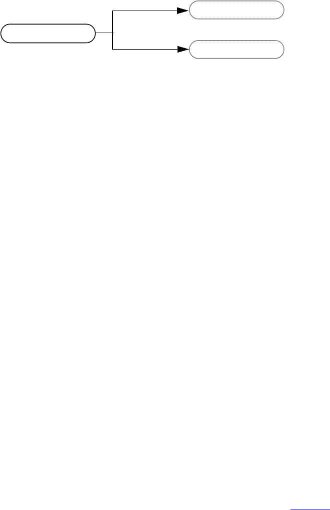
IEEE Std 1800-2012
IEEE STANDARD FOR SYSTEMVERILOG—UNIFIED HARDWARE DESIGN, SPECIFICATION, AND
VERIFICATION LANGUAGE
932
Copyright © 2013 IEEE. All rights reserved.
In this example, the tags vpiLeftRange and vpiRightRange are used to access the expressions that make up
the range of the part-select. These tags are used instead of vpiExpr to get to the expressions. Without the
tags, VPI would not know which expression should be accessed. For example:
vpi_handle(vpiExpr, part_select_handle)
would be illegal when the reference handle (part_select_handle) is a handle to a part-select because the part-
select can refer to two expressions, a left-range and a right-range.
Properties of objects shall be derived with routines in the vpi_get family. The routine vpi_get() returns
integer and Boolean properties. Integer and Boolean properties shall be defined to be of type PLI_INT32.
For Boolean properties, a value of 1 shall represent TRUE and a value of 0 shall represent FALSE. The
routine vpi_get64() returns 64-bit integer properties as type PLI_INT64. The routine vpi_get_str() accesses
string properties. String properties shall be defined to be of type PLI_BYTE8 *. For example, to retrieve a
pointer to the full hierarchical name of the object referenced by handle mod, the following call would be
made:
PLI_BYTE8 *name = vpi_get_str(vpiFullName, mod);
In the preceding example, the pointer name shall now point to the string “top.m1”.
One-to-many relationships are traversed with an iteration mechanism. The routine vpi_iterate() creates an
object of type vpiIterator, which is then passed to the routine vpi_scan() to traverse the desired objects. In
the following example, each net in module top.m1 is displayed:
vpiHandle itr;
itr = vpi_iterate(vpiNet,mod);
while (net = vpi_scan(itr) )
vpi_printf("\t%s\n", vpi_get_str(vpiFullName, net) );
As the preceding examples illustrate, the routine naming convention is a “vpi” prefix with “_” word
delimiters (with the exception of callback-related defined values, which use the “cb” prefix). Macro-defined
types and properties have the “vpi” prefix, and they use capitalization for word delimiters.
The routines for traversing SystemVerilog structures and accessing objects are described in Clause 38.
37.3.2 Object type properties
All objects have a vpiType property, which is not shown in the data model diagrams.
-> type
int: vpiType
Using vpi_get(vpiType, <object_handle>) returns an integer constant that represents the type of the
object.
part select
expr
expr
vpiLeftRange
vpiRightRange
Figure 37-2—Accessing a class of objects using tags

IEEE Std 1800-2012
IEEE STANDARD FOR SYSTEMVERILOG—UNIFIED HARDWARE DESIGN, SPECIFICATION, AND
VERIFICATION LANGUAGE
933
Copyright © 2013 IEEE. All rights reserved.
Using vpi_get_str(vpiType, <object_handle>) returns a pointer to a string containing the name of
the type constant. The name of the type constant is derived from the name of the object as it is shown in the
data model diagram (see 37.3 for a description of how type constant names are derived from object names).
Some objects have additional type properties that are shown in the data model diagrams vpiDelayType,
vpiNetType, vpiOpType, vpiPrimType, vpiResolvedNetType, and vpiTchkType. Using
vpi_get(<type_property>, <object_handle>) returns an integer constant that represents the
additional type of the object. See vpi_user.h in Annex K and sv_vpi_user.h in Annex M for the types
that can be returned for these additional type properties. The constant names of the types returned for these
additional type properties can be accessed using vpi_get_str().
37.3.3 Object file and line properties
Most objects have the following two location properties, which are not shown in the data model diagrams:
-> location
int: vpiLineNo
str: vpiFile
The properties vpiLineNo and vpiFile can be affected by the `line compiler directive. See 22.12 for more
details on the `line compiler directive. These properties are applicable to every object that corresponds to
some object within the source code. The exceptions are objects of the following types:
— vpiCallback
— vpiDelayTerm
— vpiDelayDevice
— vpiInterModPath
— vpiIterator
—vpiTimeQueue
— vpiGenScopeArray
— vpiGenScope
37.3.4 Delays and values
Most properties are of type integer, Boolean, or string. Delay and logic value properties, however, are more
complex and require specialized routines and associated structures. The routines vpi_get_delays() and
vpi_put_delays() use structure pointers, where the structure contains the pertinent information about delays.
Similarly, simulation values are also handled with the routines vpi_get_value() and vpi_put_value(), along
with an associated set of structures.
The routines, C structures, and some examples for handling delays and logic values are presented in
Clause 38. See 38.15 for vpi_get_value(), 38.34 for vpi_put_value(), 38.10 for vpi_get_delays(), and
38.32 for vpi_put_delays().
Nets, primitives, module paths, timing checks, and continuous assignments can have delays specified within
the SystemVerilog source code. Additional delays may exist, such as module input port delays or inter-
module path delays, that do not appear within the SystemVerilog source code. To access the delay
expressions that are specified within the SystemVerilog source code, use the method vpiDelay. These
expressions shall be either an expression that evaluates to a constant if there is only one delay specified or an
operation if there are more than one delay specified. If multiple delays are specified, then the operation’s
vpiOpType shall be vpiListOp. To access the actual delays being used by the tool, use the routine
vpi_get_delays() on any of these objects.

IEEE Std 1800-2012
IEEE STANDARD FOR SYSTEMVERILOG—UNIFIED HARDWARE DESIGN, SPECIFICATION, AND
VERIFICATION LANGUAGE
934
Copyright © 2013 IEEE. All rights reserved.
37.3.5 Expressions with side effects
VPI gives applications access to arbitrarily complex expressions from the SystemVerilog source, either as
arguments to system tasks or functions (see 36.4) or by traversing the design hierarchy. Expressions may
have side effects when evaluated; such expressions include the following:
— Assignment operators (11.4.1)
— Increment and decrement operators (11.4.2)
— Function calls, including built-in methods and system function calls, that change the state of the
simulation other than via their return values
— Expressions in which other expressions with side effects appear as operands, arguments, or index
expressions
Applying the function vpi_get_value() (38.15) to an expression with side effects shall fully evaluate the
expression together with its side effects. However, it shall be an error for an application to ask for a VPI
property or relation of an expression if the VPI implementation cannot determine the value or handle
without also evaluating an expression with side effects. Since implementations may differ in their ability to
determine whether an expression has side effects, this result may result in an error with some
implementations but not with others. It shall be an error for an application to apply vpi_put_value() (38.34)
to an object if any of its index expressions is an expression with side effects.
To provide the greatest flexibility for VPI applications, it is recommended that expressions with side effects
not be used as index expressions or as arguments to system tasks or functions or to SystemVerilog function
calls.
Example 1:
function string ename(my_enum_type e);
static first_time = 1;
begin
if (first_time == 1) first_time = 0;
ename = e.name();
end
endfunction
...
foo = ename(e);
For most implementations, asking for the vpiSize property of the function call ename(e) shall be an error
because the implementation cannot determine the size of the function call without evaluating it, and
evaluating it may have the side effect of changing the value of first_time.
In the unusual case in which all the names of the enumeration type have the same length, an implementation
could in principle determine the vpiSize by analyzing the function without evaluating it. However, this is not
required by the standard, and an implementation may issue an error in this case as well.
Example 2:
j = my_array[i++];
k = my_array[--i];
It shall be an error for a VPI application to apply vpi_put_value() to either my_array[i++] or my_array
[--i], since both expressions have side effects.

IEEE Std 1800-2012
IEEE STANDARD FOR SYSTEMVERILOG—UNIFIED HARDWARE DESIGN, SPECIFICATION, AND
VERIFICATION LANGUAGE
935
Copyright © 2013 IEEE. All rights reserved.
37.3.6 Object protection properties
All objects have a vpiIsProtected property, which is not shown in the data model diagrams.
-> IsProtected
bool: vpiIsProtected
Using vpi_get(vpiIsProtected, object_handle) returns a Boolean constant that indicates whether
the object represents code contained in a decryption envelope. The vpiIsProtected property shall be TRUE
if the object_handle represents code that is protected; otherwise, it shall be FALSE. Unless otherwise
specified, access to relationships and properties of a protected object shall be an error. Restrictions on access
to complex properties are specified in the function reference descriptions for the corresponding VPI
functions. Access to the vpiType property and the vpiIsProtected property of a protected object shall be
permitted for all objects.
NOTE—Handles to protected objects can be returned through object relationships or by direct lookup using VPI
functions that return handles.
37.3.7 Lifetimes of objects
The lifetime of an object is the duration of existence of the object in the VPI information model. A source
code object comes into existence during analysis and persists, independent of elaboration and runtime, until
the tool terminates. It has a lifetime that is independent of simulation. Static objects rooted in the static
design hierarchy are alive from the point at which they are created during elaboration and for the entire
simulation. Objects that may have a lifetime shorter than the duration of the simulation are called transient
objects. Class objects and automatic variables are transient objects.
A class object (see 37.30) is alive from the time it is created by a call to new() until the time its memory is
reclaimed by the simulator’s automatic memory management (see 8.29); data members and methods that
belong to the class object have the same object lifetime as the class object. An automatic variable that
belongs to a frame (see 37.40) has the same object lifetime as that of the frame, which is alive from the point
of the call that establishes the stack frame until the stack frame is destroyed.
Other transient objects include the following:
a) Threads (see 37.42)
b) Outdated and out-of-scope references made within a thread
c) Iterators (objects of type vpiIterator), which are created by calls to vpi_iterate() (see 38.23)
d) A vpiSchedEvent created by vpi_put_value() (see 38.34)
e) Callbacks (see 38.36)
There are two properties relevant to understanding the lifetimes of objects. As a property of an object,
vpiAutomatic is a Boolean property that, when false, means the object is static. When true, it means the
object is non-static and may be an automatic variable or dynamic object. The property name vpiAutomatic
and its interpretation reflect the keywords in the language, static and automatic, used to declare the object.
Those keywords may be applied to the object declaration or to the scope of the object, the latter indicating
the default for all objects of that scope. vpiAutomatic is also a property of an instance of a module, program,
interface, or package, indicating the default lifetime for variables of any of its declared tasks/functions.
vpiAutomatic is also a property of a class defn or class typespec, indicating the default lifetime for variables
of any of its declared tasks/functions. Other exceptions to this general description of vpiAutomatic are noted
in the object diagram details.
The property vpiAllocScheme indicates how an object’s memory was allocated and thus supports
understanding its lifetime. It is useful for determining whether and how to manage a transient object. It is an
enumeration of three possible values: vpiAutomaticScheme, vpiDynamicScheme, and vpiOtherScheme.
IEEE Std 1800-2012
IEEE STANDARD FOR SYSTEMVERILOG—UNIFIED HARDWARE DESIGN, SPECIFICATION, AND
VERIFICATION LANGUAGE
936
Copyright © 2013 IEEE. All rights reserved.
vpiAutomaticScheme indicates the object is allocated as part of a frame or thread and has the lifetime of
that frame or thread. vpiDynamicScheme indicates the object was allocated in dynamic memory and may
be a class object or part thereof. For all other objects, vpiAllocScheme shall return vpiOtherScheme.
37.3.8 Managing transient objects
One may obtain a handle to an object during its lifetime, and it remains valid only as long as the object
exists. For a static object, one may therefore keep its handle indefinitely. For a transient object, one may
release its handle after use or expect that handle to be released and become invalid when the object ceases to
exist.
The life of a transient object may be tracked through various callbacks, depending on the specific type of
object. The callbacks are described on the object model diagrams and/or the function reference for
vpi_register_cb(), as appropriate. The relevant callbacks are as follows:
cbCreateObj, cbReclaimObj, cbStartofFrame, cbEndOfFrame, cbStartOfThread, cbEndOfThread, and
cbEndOfObject.
37.4 Key to data model diagrams
This subclause contains the keys to the symbols used in the data model diagrams. Keys are provided for
objects and classes, traversing relationships, and accessing properties.
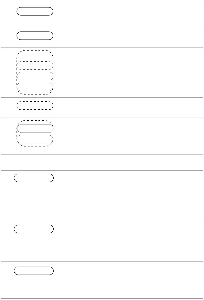
IEEE Std 1800-2012
IEEE STANDARD FOR SYSTEMVERILOG—UNIFIED HARDWARE DESIGN, SPECIFICATION, AND
VERIFICATION LANGUAGE
937
Copyright © 2013 IEEE. All rights reserved.
37.4.1 Diagram key for objects and classes
37.4.2 Diagram key for accessing properties
class defn
obj defn
class
object
obj defn
object
class
obj1
obj2
Object definition:
Bold letters in a solid enclosure indicate an object definition. The
properties of the object are defined in this location.
Unnamed class:
A dotted enclosure with no name is an unnamed class. It is sometimes
convenient to group objects although they shall not be referenced as a
group elsewhere; therefore, a name is not indicated.
Object reference:
Normal letters in a solid enclosure indicate an object reference.
Class definition:
Bold italic letters in a dotted enclosure indicate a class definition,
where the class groups other objects and classes. Properties of the
class are defined in this location. The class definition can contain an
object definition.
Class reference:
Italic letters in a dotted enclosure indicate a class reference.
obj
obj
object
String properties are accessed with routine vpi_get_str(). String
properties are of type PLI_BYTE8 *.
For example:
PLI_BYTE8 *name = vpi_get_str(vpiName, obj_h);
Integer and Boolean properties are accessed with the routine vpi_get().
These properties are of type PLI_INT32.
For example: Given handle obj_h to an object of type vpiObj, test if
the object is a vector, and get the size of the object.
PLI_INT32 vect_flag = vpi_get(vpiVector, obj_h);
PLI_INT32 size = vpi_get(vpiSize, obj_h);
Complex properties for time and logic value are accessed with the
indicated routines. See the descriptions of the routines for usage.
-> vector
bool: vpiVector
-> size
int: vpiSize
-> complex
func1()
func2()
-> name
str: vpiName
str: vpiFullName
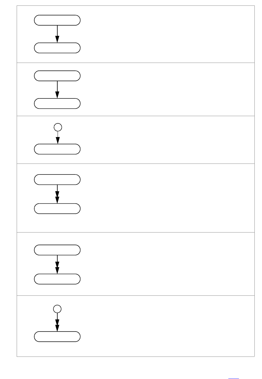
IEEE Std 1800-2012
IEEE STANDARD FOR SYSTEMVERILOG—UNIFIED HARDWARE DESIGN, SPECIFICATION, AND
VERIFICATION LANGUAGE
938
Copyright © 2013 IEEE. All rights reserved.
37.4.3 Diagram key for traversing relationships
For relationships that do not have a tag, the type used for access is determined by adding “vpi” to the
beginning of the word within the enclosure, with each word’s first letter being a capital. See 37.3 for more
details on VPI access to constant names.
ref
obj
ref
obj
Tag
ref
obj
ref
obj
Tag
obj
obj
A single arrow indicates a one-to-one relationship accessed
with the routine vpi_handle().
For example: Given vpiHandle variable ref_h of type ref,
access obj_h of type Obj:
obj_h = vpi_handle(Obj, ref_h);
A tagged one-to-one relationship is traversed similarly, using
Tag instead of Obj.
For example:
obj_h = vpi_handle(Tag, ref_h);
A one-to-one relationship that originates from a circle is
traversed using NULL for the ref_h.
For example:
obj_h = vpi_handle(Obj, NULL);
A double arrow indicates a one-to-many relationship accessed
with the routine vpi_scan().
For example: Given vpiHandle variable ref_h of type ref,
scan objects of type Obj:
itr = vpi_iterate(Obj, ref_h);
while (obj_h = vpi_scan(itr) )
/* process 'obj_h' */
A tagged one-to-many relationship is traversed similarly, using
Tag instead of Obj.
For example:
itr = vpi_iterate(Tag, ref_h);
while (obj_h = vpi_scan(itr) )
/* process 'obj_h' */
A one-to-many relationship that originates from a circle is
traversed using NULL for the ref_h.
For example:
itr = vpi_iterate(Obj, NULL);
while (obj_h = vpi_scan(itr) )
/* process 'obj_h' */
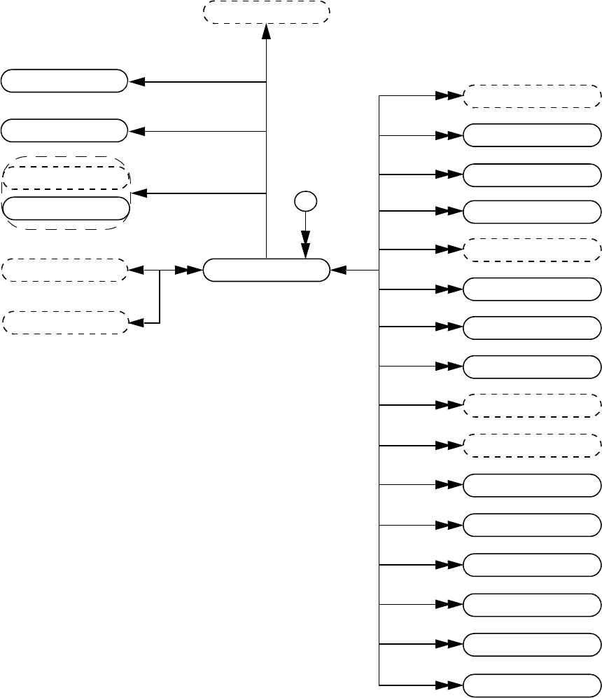
IEEE Std 1800-2012
IEEE STANDARD FOR SYSTEMVERILOG—UNIFIED HARDWARE DESIGN, SPECIFICATION, AND
VERIFICATION LANGUAGE
939
Copyright © 2013 IEEE. All rights reserved.
37.5 Module
Details:
1) Top-level modules shall be accessed using vpi_iterate() with a NULL reference object.
2) If a module is an element within a module array, the vpiIndex transition is used to access the index within the array.
If a module is not part of a module array, this transition shall return NULL.
module
clocking block
expr
instance array
vpiDefaultClocking
vpiIndex
port
interface
interface array
process
module
module array
mod path
tchk
def param
io decl
vpiInternalScope
cont assign
scope
primitive
primitive array
alias stmt
clocking block
-> top module
bool: vpiTopModule
-> decay time
int: vpiDefDecayTime
module array
expr
distribution
vpiDefaultDisableIff
clocking block
vpiGlobalClocking
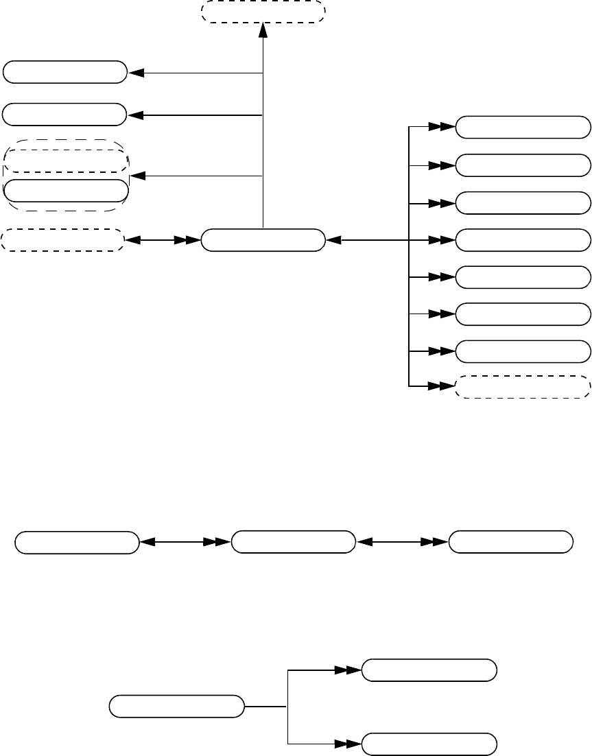
IEEE Std 1800-2012
IEEE STANDARD FOR SYSTEMVERILOG—UNIFIED HARDWARE DESIGN, SPECIFICATION, AND
VERIFICATION LANGUAGE
940
Copyright © 2013 IEEE. All rights reserved.
37.6 Interface
Details:
1) If an interface is an element within an instance array, the vpiIndex transition is used to access the index within the
array. If an interface is not part of an instance array, this transition shall return NULL.
37.7 Modport
37.8 Interface task or function declaration
Details:
1) vpi_iterate() can return more than one task or function declaration for modport tasks or functions with an access
type of vpiForkJoinAcc, because the task or function can be imported from multiple module instances.
2) Possible return values for the vpiAccessType property for an interface tf decl are vpiForkJoinAcc and
vpiExternAcc.
interface
interface tf decl
modport
mod path
cont assign
clocking block
interface
interface array
vpiInstance
expr
instance array
vpiIndex
process
clocking block
vpiDefaultClocking
expr
distribution
vpiDefaultDisableIff
clocking block
vpiGlobalClocking
modport
interface io decl
-> name
str: vpiName
task
function
interface tf decl
-> access type
int: vpiAccessType
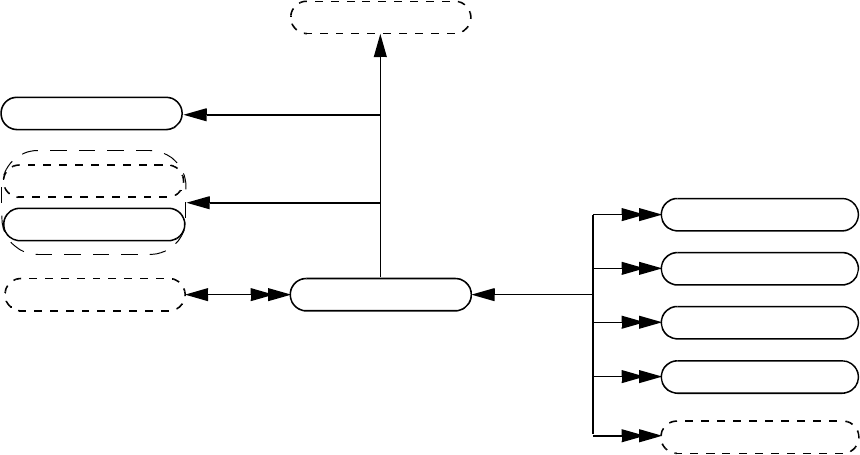
IEEE Std 1800-2012
IEEE STANDARD FOR SYSTEMVERILOG—UNIFIED HARDWARE DESIGN, SPECIFICATION, AND
VERIFICATION LANGUAGE
941
Copyright © 2013 IEEE. All rights reserved.
37.9 Program
Details:
1) If a program is an element within an instance array, the vpiIndex transition is used to access the index within the
array. If a program is not part of an instance array, this transition shall return NULL.
program
cont assign
clocking block
interface
interface array
vpiInstance
expr
instance array
vpiIndex
process
clocking block
vpiDefaultClocking
expr
distribution
vpiDefaultDisableIff
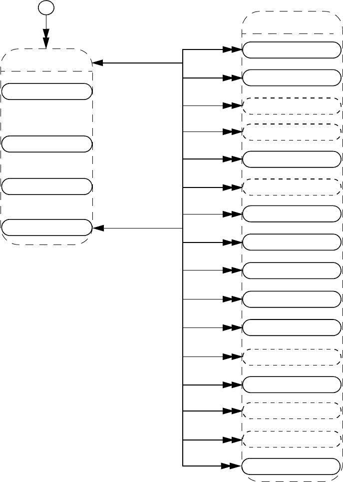
IEEE Std 1800-2012
IEEE STANDARD FOR SYSTEMVERILOG—UNIFIED HARDWARE DESIGN, SPECIFICATION, AND
VERIFICATION LANGUAGE
942
Copyright © 2013 IEEE. All rights reserved.
37.10 Instance
Details:
1) The vpiTypedef iteration shall return the user-defined typespecs that have typedefs explicitly declared in the
instance.
2) vpiModule shall return a module if the object is inside a module instance, otherwise it shall return NULL.
3) vpiInstance shall always return the immediate instance (package, module, interface, or program) in which the
object is instantiated.
4) vpiMemory shall return array variable objects rather than vpiMemory objects.
-> array member
bool: vpiArray (deprecated)
bool: vpiArrayMember
-> cell
bool: vpiCellInstance
-> default net type
int: vpiDefNetType
-> definition location
int: vpiDefLineNo
str: vpiDefFile
-> definition name
str: vpiDefName
-> delay mode
int: vpiDefDelayMode
-> name
str: vpiName
str: vpiFullName
-> protected
bool: vpiProtected
-> timeprecision
int: vpiTimePrecision
-> timeunit
int: vpiTimeUnit
-> unconnected drive
int: vpiUnconnDrive
-> configuration
str: vpiLibrary
str: vpiCell
str: vpiConfig
-> default lifetime
bool: vpiAutomatic
-> top
bool: vpiTop
vpiTypedef
vpiRegArray
module
program
interface
instance
-> compile unit
bool: vpiUnit
package
program
program array
array net
variables
array var
array var
named event
named event array
spec param
assertion
typespec
vpiMemory
vpiReg
logic var
task func
instance item
net
class defn
parameters
vpiParameter

IEEE Std 1800-2012
IEEE STANDARD FOR SYSTEMVERILOG—UNIFIED HARDWARE DESIGN, SPECIFICATION, AND
VERIFICATION LANGUAGE
943
Copyright © 2013 IEEE. All rights reserved.
5) vpiFullName for objects that exist within a compilation unit shall begin with “$unit::”. As a result, the full
name for objects within a compilation unit may be ambiguous. vpiFullName for a package shall be the name of the
package and should end with “::”; this syntax disambiguates between a module and a package of the same name.
vpiFullName for objects that exist in a package shall begin with the name of the package followed by “::”. The
separator :: shall appear between the package name and the immediately following name component. The
“.” separator shall be used in all cases except package and class defn.
6) The following items shall not be accessible via vpi_handle_by_name():
— Imported items
— Objects that exist within a compilation unit
7) Passing a NULL handle to vpi_get() with properties vpiTimePrecision or vpiTimeUnit shall return the smallest
time precision of all modules in the instantiated design.
8) The properties vpiDefLineNo and vpiDefFile can be affected by the `line compiler directive. See 22.12 for more
details on the `line directive.
9) For details on lifetime and memory allocation properties, see 37.3.7.
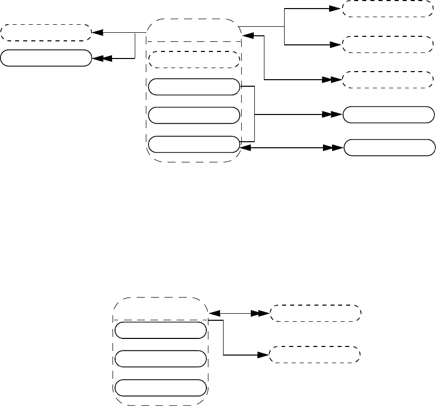
IEEE Std 1800-2012
IEEE STANDARD FOR SYSTEMVERILOG—UNIFIED HARDWARE DESIGN, SPECIFICATION, AND
VERIFICATION LANGUAGE
944
Copyright © 2013 IEEE. All rights reserved.
37.11 Instance arrays
Details:
1) Traversing from the instance array to expr shall return a simple expression object of type vpiOperation with a
vpiOpType of vpiListOp. This expression can be used to access the actual list of connections to the instance array
in the SystemVerilog source code
2) vpi_iterate(vpiRange, instance_array_handle) shall return the set of instance array ranges beginning with the
leftmost range of the array declaration and iterating through the rightmost range. Using the vpiLeftRange/
vpiRightRange properties returns the bounds of the leftmost dimension of a multidimensional array.
interface array
expr
expr
vpiLeftRange
range
instance array
instance
vpiRightRange
primitive array
program array
module array
expr
-> access by index
vpi_handle_by_index()
vpi_handle_by_multi_index()
-> name
str: vpiName
str: vpiFullName
->size
int; vpiSize
param assign
primitive
expr
vpiDelay
gate array
primitive array
switch array
udp array
module
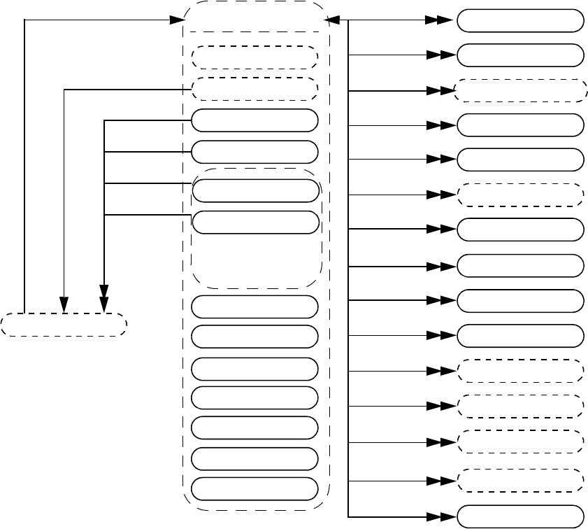
IEEE Std 1800-2012
IEEE STANDARD FOR SYSTEMVERILOG—UNIFIED HARDWARE DESIGN, SPECIFICATION, AND
VERIFICATION LANGUAGE
945
Copyright © 2013 IEEE. All rights reserved.
37.12 Scope
Details:
1) An unnamed begin or unnamed fork shall be a scope if, and only if, it directly contains a block item declaration
such as a variable declaration or type declaration. A named begin or named fork shall always be a scope.
Example:
begin
begin : BLK
var logic v; // This declaration is not local to the unnamed begin
v = 1'b1;
end
end
In this example, the block BLK is a scope, but the unnamed begin is not a scope because it does not directly contain
a block item declaration.
2) A for statement shall be a scope if, and only if, the vpiLocalVarDecls property returns TRUE. In this case, the
scope of each loop control variable shall be the for statement.
concurrent assertion
stmt
named event
scope
variables
instance
named begin
vpiReg
task func
begin
named fork
fork
class defn
class obj
named event array
logic var
array var
scope
instance item
vpiRegArray
vpiInternalScope
vpiImport
array var
vpiMemory
-> name
str: vpiName
str: vpiFullName
typespec
vpiTypedef
clocking block
gen scope
for
foreach stmt
class typespec
vpiParameter
parameters
property decl
sequence decl
let decl
-> join type
int: vpiJoinType
virtual interface var
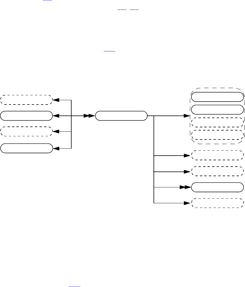
IEEE Std 1800-2012
IEEE STANDARD FOR SYSTEMVERILOG—UNIFIED HARDWARE DESIGN, SPECIFICATION, AND
VERIFICATION LANGUAGE
946
Copyright © 2013 IEEE. All rights reserved.
3) The scope of each loop control variable in a foreach stmt shall be the foreach stmt.
4) The vpiImport iterator shall return all objects imported into the current scope via import declarations. Only objects
actually referenced through the import shall be returned, rather than items potentially made visible as a result of the
import. Refer to 26.3 for more details.
5) A task func can have zero or more statements (see 13.3, 13.4). If the number of statements is greater than 1, the
vpiStmt relation shall return an unnamed begin that contains the statements of the task or function. If the number
of statements is zero, the vpiStmt relation shall return NULL.
6) The vpiJoinType property indicates what type of join statement terminates the fork-join block. It shall return one
of the values vpiJoin, vpiJoinNone, or vpiJoinAny.
7) The vpiVirtualInterfaceVar iteration is supported only within elaborated contexts and is not supported within
lexical contexts such as class defns (see 37.29). If the scope declares an array of virtual interfaces, the
vpiVirtualInterfaceVar iteration shall return each element of the array separately. However, the vpiVariables
iteration shall return the array declaration as a single vpiArrayVar.
37.13 IO declaration
Details:
1) vpiDirection returns vpiRef for pass by ref ports or arguments.
2) A ref obj type handle shall be returned for the vpiExpr of an io decl if it is passed by reference or if the io decl is an
interface or a modport. If the io decl is a virtual interface, vpiExpr shall return a vpiVirtualInterfaceVar.
3) If the vpiExpr of an io decl is a ref obj and if the vpiActual of the ref obj is an interface or modport declaration,
then the vpiDirection of the io decl shall be undefined. The vpiDirection shall also be undefined if the vpiExpr is
a virtual interface var.
4) The vpiRange, vpiLeftRange, and vpiRightRange relations for an io decl shall be the same as for the
corresponding typespec (see 37.23).
instance
udp defn
vpiExpr
io decl
interface tf decl
vpiLeftRange
ref obj
task func
nets
variables
expr
expr
range
typespec
-> direction
int: vpiDirection
-> name
str: vpiName
-> scalar
bool: vpiScalar
-> sign
bool: vpiSigned
-> size
int: vpiSize
-> vector
bool: vpiVector
vpiRightRange
module
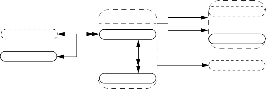
IEEE Std 1800-2012
IEEE STANDARD FOR SYSTEMVERILOG—UNIFIED HARDWARE DESIGN, SPECIFICATION, AND
VERIFICATION LANGUAGE
947
Copyright © 2013 IEEE. All rights reserved.
37.14 Ports
Details:
1) vpiPortType shall be one of the following three types: vpiPort, vpiInterfacePort, or vpiModportPort. Port type
depends on the formal, not on the actual.
2) vpi_get_delays() and vpi_put_delays() delays shall not be applicable for vpiInterfacePort.
3) vpiHighConn shall indicate the hierarchically higher (closer to the top module) port connection.
4) vpiLowConn shall indicate the lower (further from the top module) port connection.
5) vpiLowConn of a vpiInterfacePort shall always be vpiRefObj.
6) Properties vpiScalar and vpiVector shall indicate if the port is 1 bit or more than 1 bit. They shall not indicate
anything about what is connected to the port.
7) Properties vpiIndex and vpiName shall not apply for port bits.
8) If a port is explicitly named, then the explicit name shall be returned. If not, and a name exists, then that name shall
be returned. Otherwise, NULL shall be returned.
9) vpiPortIndex can be used to determine the port order. The first port has a port index of zero.
10) vpiLowConn shall return NULL if the module or interface or program port is a null port (e.g., “module M();”).
vpiHighConn shall return NULL if the instance of the module, interface, or program does not have a connection to
the port.
11) vpiSize for a null port shall return 0.
port
expr
instance
vpiHighConn
-> index
int: vpiPortIndex
-> name
str: vpiName
-> port type
int: vpiPortType
-> scalar
bool: vpiScalar
-> size
int: vpiSize
-> vector
bool: vpiVector
port bit
vpiParent
vpiBit
ref obj
ports
typespec
vpiLowConn
-> access by index
vpi_handle_by_index()
vpi_handle_by_multi_index()
->connected by name
bool: vpiConnByName
-> delay (mipd)
vpi_get_delays()
vpi_put_delays()
-> direction
int: vpiDirection
-> explicitly named
bool: vpiExplicitName
module
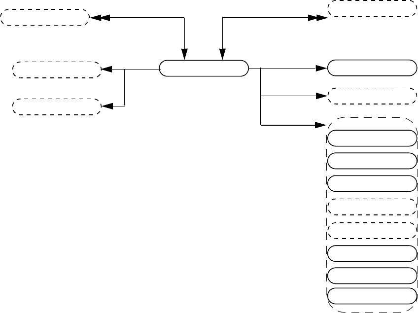
IEEE Std 1800-2012
IEEE STANDARD FOR SYSTEMVERILOG—UNIFIED HARDWARE DESIGN, SPECIFICATION, AND
VERIFICATION LANGUAGE
948
Copyright © 2013 IEEE. All rights reserved.
37.15 Reference objects
Details:
1) A ref obj represents a declared object or subelement of that object that is a reference to an actual instantiated object.
A ref obj exists for ports with ref direction, for an interface port, a modport port, or for formal task function ref
arguments. The specific cases for a ref obj are as follows:
— A variable, named event, named event array that is the lowconn of a ref port
— Any subelement expression of the above
— A local declaration of an interface or modport passed through a port or any net, variable, named event, named
event array of those
— A ref formal argument of a task or function, or subelement expression of it
2) A ref obj may be obtained when walking port connections (lowConn, highConn), when traversing an expression
that is a use of such ref obj, or when accessing the io decl of an instance or task or function.
3) The name of ref obj can be different at every instance level it is being declared. The vpiActual relationship always
returns the actual instantiated object if the ref obj is bound to an actual object at the time of the query.
4) The vpiParent relationship allows the traversal of a ref obj that is a subelement of a ref obj. In the following
example, r[0] is a ref obj whose parent is the ref obj r. The vpiActual for the ref obj r[0] would return the var
bit a[0], and the vpiActual of the ref obj r would return the variable a.
module top;
logic [2:0] a;
m u1 (a);
endmodule
module m (ref [2:0] r);
initial
r[0] = 1'b0;
endmodule
ref obj
variables
ports
vpiHighConn
-> name
str: vpiName
str: vpiFullName
-> generic
bool: vpiGeneric
-> definition name
str: vpiDefName
vpiLowConn
ref obj
typespec
vpiParent
vpiPortInst
ports
interface
interface array
modport
nets
named event
named event array
vpiActual
part select
instance
task func
IEEE Std 1800-2012
IEEE STANDARD FOR SYSTEMVERILOG—UNIFIED HARDWARE DESIGN, SPECIFICATION, AND
VERIFICATION LANGUAGE
949
Copyright © 2013 IEEE. All rights reserved.
5) The vpiGeneric property shall return TRUE if the ref obj is a reference to a generic interface and FALSE if the ref
obj is a reference to an interface that is not a generic interface. The vpiGeneric property shall return vpiUndefined
for all other kinds of ref obj.
6) The vpiDefName property when applied to a ref obj that is an actual of an interface or modport shall return the
interface definition name or modport name.
7) The vpiTypespec relation returns NULL for a ref obj that vpiActual is a not a net, variable, or part select.
Example: Passing an interface or modport through a port:
interface simple ();
logic req, gnt;
modport slave (input req, output gnt);
modport master (input gnt, output req);
endinterface
module top();
interface simple i;
child1 i1(i);
child2 i2(i.master);
endmodule
/***********************************
for the port of i1,
the vpiHighConn relationship returns a handle of type vpiRefObj. The
vpiActual relationship applied to the ref obj returns a handle of type
vpiInterface.
for the port of i2 ,
the vpiHighConn relationship returns a handle of type vpiRefObj. The
vpiActual relationship applied to the ref obj returns a handle of type
vpiModport.
****************************************/
module child1(interface simple s);
c1 c_1(s);
c1 c_2(s.master);
endmodule
/****************************
for the port of module child1,
the vpiLowConn relationship returns a handle of type vpiRefObj. The
vpiActual relationship applied to the ref obj returns a handle of type
vpiInterface.
for that refObj,
the vpiPort relationship returns the port of child1.
the vpiPortInst iteration returns handles to s, s.master.
the vpiActual relationship returns a handle to i.
for the port of instance c_1 :
vpiHighConn returns a handle of type vpiRefObj. The vpiActual relationship
applied to the ref obj handle returns a handle of type vpiInterface.
for the port of instance c_2 :
vpiHighConn returns a handle of type vpiRefObj. The vpiActual relationship
applied to the ref obj handle returns a handle of type vpiModport.
****************************************/
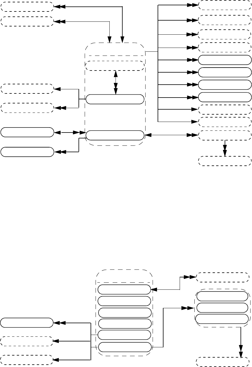
IEEE Std 1800-2012
IEEE STANDARD FOR SYSTEMVERILOG—UNIFIED HARDWARE DESIGN, SPECIFICATION, AND
VERIFICATION LANGUAGE
950
Copyright © 2013 IEEE. All rights reserved.
37.16 Nets
ports
vpiHighConnvpiLowConn
prim term
path term
tchk term
net bit
array net
nets
net drivers
cont assign
range
expr
expr
vpiParent
expr
net
vpiIndex
-> access by index
vpi_handle_by_index()
vpi_handle_by_multi_index()
-> array member
bool: vpiArray (deprecated)
bool: vpiArrayMember
-> constant selection
bool: vpiConstantSelect
-> delay
vpi_get_delays()
-> expanded
bool: vpiExpanded
-> implicitly declared
bool: vpiImplicitDecl
-> name
str: vpiName
str: vpiFullName
-> net decl assign
bool: vpiNetDeclAssign
-> net type
int: vpiNetType
int: vpiResolvedNetType
-> scalar
bool: vpiScalar
-> scalared declaration
bool: vpiExplicitScalared
-> sign
bool: vpiSigned
-> size
int: vpiSize
-> strength
int: vpiStrength0
int: vpiStrength1
int: vpiChargeStrength
-> value
vpi_get_value()
vpi_put_value()
-> vector
bool: vpiVector
-> vectored declaration
bool: vpiExplicitVectored
->member
bool: vpiStructUnionMember
nets
net
typespec
ports
vpiPortInst
vpiLoad
net loads
vpiLocalLoad
vpiSimNet
module
vpiIndex
vpiIndex
vpiParent
vpiBit
net loads
vpiLocalDriver
net drivers
vpiDriver
net
expr
expr
range
vpiRightRange
vpiLeftRange
struct net
enum net
integer net
time net
logic net
packed array net
struct net
packed array net
vpiElement
nets
vpiParent
vpiMember
expr
vpiIndex
-> packed array member
bool:
vpiPackedArrayMember
enum net

IEEE Std 1800-2012
IEEE STANDARD FOR SYSTEMVERILOG—UNIFIED HARDWARE DESIGN, SPECIFICATION, AND
VERIFICATION LANGUAGE
951
Copyright © 2013 IEEE. All rights reserved.
Details:
1) Any net declared as an array with one or more unpacked ranges is an array net. Any packed struct net or enum net
declared with one or more explicit packed ranges is a packed array net. The range iterator for a packed array net
returns only the explicit packed ranges for such a net. It shall not return the implicit range of packed struct net
elements themselves, nor shall it return the range (explicit or implicit) for the base type of enum net elements. For
example:
// a 34-bit-wide struct net (range iteration not allowed)
wire struct packed { logic [1:0]vec1; integer i1; } psnet;
// a packed array net (ranges [3:0] and [2:1] returned by range iteration)
wire struct packed { logic [1:0]vec1; integer i1; } [3:0][2:1] panet;
// an array net (ranges [5:4] and [6:8] returned by range iteration)
wire struct packed { logic [1:0]vec1; integer i1; } [3:0][2:1] anet
[5:4][6:8];
2) The Boolean property vpiArray is deprecated in this standard. The vpiArrayMember property shall be TRUE for
a net that is an element of an array net. It shall be FALSE otherwise. The vpiPackedArrayMember property shall
be TRUE for a packed struct net, an enum net, or a packed array net that is an element of a packed array net.
3) For logic nets, net bits shall be available regardless of vector expansion.
4) Continuous assignments and primitive terminals shall be accessed regardless of hierarchical boundaries.
5) Continuous assignments and primitive terminals shall only be accessed from scalar nets or bit-selects.
6) For vpiPorts, if the reference handle is a net bit, then port bits shall be returned. If it is an entire net or array net,
then a handle to the entire port shall be returned.
7) For vpiPortInst, if the reference handle is a bit or scalar, then port bits or scalar ports shall be returned, unless the
highconn for the port is a complex expression where the bit index cannot be determined. If this is the case, then the
entire port shall be returned. If the reference handle is an entire net or array net, then the entire port shall be
returned.
8) For vpiPortInst, it is possible for the reference handle to be part of the highconn expression, but not connected to
any of the bits of the port. This may occur if there is a size mismatch. In this situation, the port shall not qualify as a
member for that iteration.
9) For implicit nets, vpiLineNo shall return 0, and vpiFile shall return the file name where the implicit net is first
referenced.
10) vpi_handle(vpiIndex, net_bit_handle) shall return the bit index for the net bit. vpi_iterate(vpiIndex,
net_bit_handle) shall return the set of indices for a multidimensional net array bit-select, starting with the index for
the net bit and working outward.
11) Only active forces and assign statements shall be returned for vpiLoad.
12) Only active forces shall be returned for vpiDriver.
13) vpiDriver shall also return ports that are driven by objects other than nets and net bits.
14) vpiLocalLoad and vpiLocalDriver return only the loads or drivers that are local, i.e., contained by the module
instance that contains the net, including any ports connected to the net (output and inout ports are loads, input and
inout ports are drivers).
15) For vpiLoad, vpiLocalLoad, vpiDriver, and vpiLocalDriver iterators, if the object is a vector net (an enum net,
integer net, time net, packed array net, or a logic net or struct net for which vpiVector is TRUE), then all loads or
drivers are returned exactly once as the loading or driving object. That is, if a part-select loads or drives only some
bits, the load or driver returned is the part-select. If a driver is repeated, it is only returned once. To trace exact bit-
by-bit connectivity, pass a vpiNetBit object to vpi_iterate.
16) An iteration on loads or drivers for a variable bit-select shall return the set of loads or drivers for whatever bit to
which the bit-select is referring to at the beginning of the iteration.
17) vpiSimNet shall return a unique net if an implementation collapses nets across hierarchy (refer to 23.3.3.7 for the
definition of simulated net and collapsed net).
18) The property vpiExpanded on an object of type vpiNetBit shall return the property’s value for the parent.

IEEE Std 1800-2012
IEEE STANDARD FOR SYSTEMVERILOG—UNIFIED HARDWARE DESIGN, SPECIFICATION, AND
VERIFICATION LANGUAGE
952
Copyright © 2013 IEEE. All rights reserved.
19) The loads and drivers returned from (vpiLoad, obj_handle) and vpi_iterate(vpiDriver, obj_handle) may not be
the same in different implementations, due to allowable net collapsing 23.3.3.7. The loads and drivers returned
from vpi_iterate(vpiLocalLoad, obj_handle) and vpi_iterate(vpiLocalDriver, obj_handle) shall be the same for
all implementations.
20) The Boolean property vpiConstantSelect shall return TRUE for a net or net bit if it has no parent (the vpiParent
relation returns NULL) or if both of the following are true of the “select” part of the equivalent primary expression
(see A.8.4):
— Every index expression in the select is an elaboration time constant expression.
— Every element within the select denotes either a member of a struct net or a member of a packed or unpacked
array with static bounds.
Otherwise, vpiConstantSelect shall return FALSE.
NOTE—If vpiConstantSelect is TRUE, then if the handle refers to a valid underlying simulation object at the
beginning of simulation (or at any point in the simulation), it refers to the same object at all points in the simulation.
Moreover, if any index expression is in or out of bounds at the beginning of simulation, it is in or out of bounds at
all subsequent simulation times as well.
21) vpiSize for an array net shall return the number of nets in the array. For unpacked structures, the size returned
indicates the number of members in the structure. For an enum net, integer net, logic net, time net, packed struct
net, or packed array net, vpiSize shall return the size of the net in bits. For a net bit, vpiSize shall return 1.
22) vpi_iterate(vpiIndex, net_handle) shall return the set of indices for a net within an array net, starting with the
index for the net and working outward. If the net is not part of an array (the vpiArrayMember property is FALSE),
a NULL shall be returned. The vpiIndex iterator shall work similarly for packed array net elements (packed struct
nets, enum nets, or packed array nets whose vpiPackedArrayMember property is TRUE). The indices returned
shall start with the index of the element and work outward until the vpiParent packed array net is reached (see
detail 28). The indices retrieved for packed array net elements shall be the same as those shown in the example for
detail 29 for each of the subelements returned by vpiElement. The indices will be retrieved in right-to-left order as
they appear in the text.
23) For an array net, vpi_iterate(vpiRange, handle) shall return the set of array range declarations beginning with the
leftmost unpacked range of the array declaration and iterating through the rightmost unpacked range. For a packed
array (logic net), the iteration shall return the set of ranges beginning with the leftmost packed range and iterating
through the rightmost packed range. For a logic net, the vpiLeftRange and vpiRightRange relations shall return
the bounds of the leftmost packed dimension.
24) vpiArrayNet is #defined the same as vpiNetArray for backward compatibility. A call to vpi_get_str(vpiType,
<array_net_handle>) may return either “vpiArrayNet” or “vpiNetArray”.
25) A logic net without a packed dimension defined is a scalar; and for that object, the property vpiScalar shall return
TRUE and the property vpiVector shall return FALSE. A logic net with one or more packed dimensions defined is
a vector, and the property vpiVector shall return TRUE (vpiScalar shall return FALSE). Packed struct nets and
packed array nets are vectors, and the property vpiVector shall return TRUE (vpiScalar shall return FALSE). A net
bit is a scalar, and the property vpiScalar shall return TRUE (vpiVector shall return FALSE). The properties
vpiScalar and vpiVector when queried on a handle to an enum net shall return the value of the respective property
for an object for which the typespec is the same as the base typespec of the typespec of the enum net. For an integer
net or a time net, the property vpiVector shall return TRUE (vpiScalar shall return FALSE). For an array net, the
vpiScalar and vpiVector properties shall return the values of the respective properties for an array element. The
vpiScalar and vpiVector properties shall return FALSE for all other net objects.
26) vpiLogicNet is #defined the same as vpiNet for backward compatibility. A call to vpi_get_str(vpiType,
<logic_net_handle>) may return either “vpiLogicNet” or “vpiNet”.
27) Neither an array net nor an unpacked struct net has a value property.
28) The vpiParent transition shall be allowed on all net objects. It shall return one of the following types of objects
listed, representing one of its prefix objects (field select prefix or indexing select prefix as described in 11.5.3), or
NULL, depending on whether certain criteria are met. For purposes of defining vpiParent, a prefix object is the
object obtained from successively removing the rightmost index or identifier from a compound or indexed/
multidimensional object name.
Consider the following vpiArrayNet objects:
wire logic [1:0][2:3] mda [4:6][6:8];
wire struct { int i1; logic[1:0][2:3]bvec[4:5]; } spa [9:11][12:13];

IEEE Std 1800-2012
IEEE STANDARD FOR SYSTEMVERILOG—UNIFIED HARDWARE DESIGN, SPECIFICATION, AND
VERIFICATION LANGUAGE
953
Copyright © 2013 IEEE. All rights reserved.
mda[6][8][1][3] is a vpiLogicNet, mda[6][8][1] is its first prefix object (a 2-bit vpiLogicNet vector),
and mda[6][8] is its second prefix object (a 2 ×2 packed array vpiLogicNet), etc. The
spa[9][12].bvec[4] object is a vpiLogicNet (a 2 ×2 packed array vpiLogicNet), and
spa[9][12].bvec is its first prefix object (a vpiArrayNet struct member), and spa[9][12] is the second
prefix object (the vpiStructNet containing the bvec member), etc.
For a net object with prefix objects, the vpiParent transition shall return one of the following prefix objects,
whichever comes first in prefix order (rightmost to leftmost):
— Struct or union net
— Struct or union member net
— The largest containing packed array net object
— The largest containing unpacked array net object
If there is no prefix object, or no prefix object meets at least one of the above criteria, vpiParent shall return
NULL.
Using the preceding declarations, the vpiParent of mda[6][8][1][3] is mda[6][8], the vpiLogicNet
representing the largest containing packed array prefix; the vpiParent of mda[6][8] is mda, the vpiArrayNet
representing the largest containing unpacked array net prefix. Likewise, the vpiParent of
spa[9][12].bvec[4][0] is spa[9][12].bvec[4] (the largest containing packed array net); the
vpiParent of spa[9][12].bvec[4] is spa[9][12].bvec (struct member), and applying vpiParent again
yields spa[9][12], the struct net for member bvec. The vpiParent of spa[9][12] is spa, the largest
containing unpacked array of the struct net; vpiParent of spa (or mda) would return NULL.
29) The vpiElement transition shall be used to iterate over the subelements of packed array nets. Unlike vpiNet
iterations for vpiArrayNet objects, vpiElement shall retrieve elements for only one dimension level at a time. This
means that for multidimensioned packed array nets, vpiElement shall retrieve elements that are themselves also
vpiPackedArrayNet objects. vpiElement can then be used to iterate over the subelements of these objects and so
on, until the leaf level struct nets or enum nets are returned. In other words, the data type of each element retrieved
by vpiElement is equivalent to the original vpiPackedArrayNet object’s data type with one leftmost packed range
removed. For example, consider the following vpiPackedArrayNet object:
typedef struct packed { integer i1; logic [1:0][2:3]bvec; } pavartype;
wire pavartype [0:2][6:3] panet1;
The vpiElement transition applied to panet1 shall return 3 vpiPackedArrayNet objects: panet1[0],
panet1[1], and panet1[2]. The vpiElement transition applied to vpiPackedArrayNet panet1[0] in turn
shall retrieve vpiStructNet objects panet1[0][6], panet1[0][5], panet1[0][4], and
panet1[0][3], respectively. Also, the vpiParent transition for all the above-mentioned subelements of
panet1 shall return panet1 (as per detail 28), since panet1 is “the largest containing packed array net object.”
30) The vpiStructUnionMember property shall be TRUE for any enum net, integer net, time net, struct net, packed
array net, or array net that is a direct member of a struct net, i.e., whose vpiParent is a struct net (see detail 28).
This property shall be FALSE for any net, array net, or net bit whose vpiParent is not a struct net.
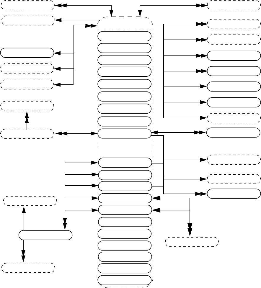
IEEE Std 1800-2012
IEEE STANDARD FOR SYSTEMVERILOG—UNIFIED HARDWARE DESIGN, SPECIFICATION, AND
VERIFICATION LANGUAGE
954
Copyright © 2013 IEEE. All rights reserved.
37.17 Variables
expr
ports
vpiHighConn
-> array type
int: vpiArrayType
vpiLowConn
variable loads
vpiDriver
vpiPortInst
ports
prim term
path term
tchk term
expr
var select
vpiParent
short int var
int var
long int var
integer var
variables
byte var
string var
class var
time var
enum var
bit var
logic var
array var
real var
virtual interface var
struct var
union var
variable drivers
vpiLoad
cont assign
short real var
range
vpiLeftRange
vpiRightRange
expr
module
instance
scope
var bit
vpiIndex
expr
vpiIndex
vpiParent
vpiParent
vpiParent
vpiParent
vpiParent
variables
expr
vpiReg
vpiIndex
-> access by index
vpi_handle_by_index()
vpi_handle_by_multi_index()
-> array member
bool: vpiArray (deprecated)
bool: vpiArrayMember
-> name
str: vpiName
str: vpiFullName
-> sign
bool: vpiSigned
-> size
int: vpiSize
-> lifetime
bool: vpiAutomatic
-> memory allocation
int: vpiAllocScheme
-> constant variable
bool: vpiConstantVariable
-> determine random availability
bool: vpiIsRandomized
-> randomization type
int: vpiRandType
-> member
bool: vpiStructUnionMember
->value
vpi_get_value()
vpi_put_value()
-> scalar
bool: vpiScalar
-> visibility
int: vpiVisibility
-> vector
bool: vpiVector
typespec
vpiBit
variables
vpiParent
vpiParent
vpiMember
-> constant selection
bool: vpiConstantSelect
expr
packed array var
vpiParent
chandle var
var bit

IEEE Std 1800-2012
IEEE STANDARD FOR SYSTEMVERILOG—UNIFIED HARDWARE DESIGN, SPECIFICATION, AND
VERIFICATION LANGUAGE
955
Copyright © 2013 IEEE. All rights reserved.
Details:
1) Any variable declared as an array with one or more unpacked ranges is an array var.
2) The Boolean property vpiArray is deprecated in this standard. The Boolean property vpiArrayMember shall be
TRUE if the referenced variable is a member of an array variable. It shall be FALSE otherwise.
3) To obtain the members of a union and structure, see the relations in 37.24.
4) For an array var, vpi_iterate(vpiRange, handle) shall return the set of array range declarations beginning with the
leftmost unpacked range and iterating through the rightmost unpacked range. If any dimension of the unpacked
array other than the first dimension is a dynamic array, associative array, or queue dimension, the iteration shall
return an empty range (see 37.22) for that dimension. For a packed array, the iteration shall return the set of ranges
beginning with the leftmost packed range and iterating through the rightmost packed range. The ranges returned for
a packed array shall not include the implicit range for packed struct or union var elements themselves, or the range
(explicit or implicit) for the base type of enum var elements.
5) vpi_handle (vpiIndex, var_select_handle) shall return the index of a var select in a one-dimensional array.
vpi_iterate (vpiIndex, var_select_handle) shall return the set of indices for a var select in a multidimensional
array, starting with the index for the var select and working outward.
6) The vpiLeftRange and vpiRightRange relations shall return the bounds of the leftmost packed dimension for a
packed array and of the leftmost unpacked dimension for an unpacked array. If the unpacked array has no members,
vpiLeftRange and vpiRightRange shall return NULL.
7) A var select is an element selected from an array var.
8) If the variable has an initialization expression, the expression can be obtained from vpi_handle(vpiExpr,
var_handle).
9) vpiSize for a variable array shall return the number of variables in the array. For variables belonging to an integer
data type (see 6.11), for enum vars, and for packed struct and union variables, vpiSize shall return the size of the
variable in bits. For a string var, it shall return the number of characters that the variable currently contains. For
unpacked structures and unions, the size returned indicates the number of fields in the structure or union. For a var
bit, vpiSize shall return 1. For all other variables, the behavior of the vpiSize property is not defined.
10) vpiSize for a var select shall return the number of bits in the var select. This applies only for packed var select.
11) Variables of type vpiArrayVar, vpiClassVar or vpiVirtualInterfaceVar do not have a value property. Struct var
and union var variables for which the vpiVector property is FALSE do not have a value property.
12) vpiBit iterator applies only for logic, bit, packed struct, packed union, and packed array variables.
13) vpi_handle(vpiIndex, var_bit_handle) shall return the bit index for the variable bit. vpi_iterate(vpiIndex,
var_bit_handle) shall return the set of indices for a multidimensional variable bit select, starting with the index for
the bit and working outwards.
14) cbSizeChange shall be applicable only for dynamic and associative arrays, for queues, and for string vars. If both
value and size change, the size change callback shall be invoked first. This callback fires after the size change
occurs and before any value changes for that variable. The value in the callback is the new size of the array.
15) The property vpiRandType returns the current randomization type for the variable, which can be one of vpiRand,
vpiRandC, or vpiNotRand.
16) vpiIsRandomized is a property to determine whether a random variable is currently active for randomization.
17) When the vpiStructUnionMember property is TRUE, it indicates that the variable is a member of a parent struct or
union variable. See also the relations in 37.24 and 37.18 detail 5.
18) If a variable is an element of an array (the vpiArrayMember property is TRUE), the vpiIndex iterator shall return
the indexing expressions that select that specific variable out of the array. See 37.18 (and detail 6) for similar
functionality available for elements of packed array vars.
19) In the preceding diagram:
logic var == reg
var bit == reg bit
array var == reg array
vpiVarBit is #defined the same as vpiRegBit for backward compatibility. However, a vpiVarBit can be an
element of a vpiBitVar (2-state) or a vpiLogicVar (4-state), whereas vpiRegBit could only be an element of a
vpiReg (4-state).

IEEE Std 1800-2012
IEEE STANDARD FOR SYSTEMVERILOG—UNIFIED HARDWARE DESIGN, SPECIFICATION, AND
VERIFICATION LANGUAGE
956
Copyright © 2013 IEEE. All rights reserved.
SystemVerilog treats reg and logic variables as equivalent in all respects. To allow for backward compatibility,
a call to vpi_get_str(vpiType, <logic_var_handle>) may return either “vpiLogicVar” or “vpiReg”. Similarly,
vpi_get_str(vpiType, <var_bit_handle>) may return either “vpiVarBit” or “vpiRegBit”, while
vpi_get_str(vpiType, <array_var_handle>) may return either “vpiArrayVar” or “vpiRegArray”.
20) A bit var or logic var, without a packed dimension defined, is a scalar and for those objects, the property vpiScalar
shall return TRUE, and the property vpiVector shall return FALSE. A bit var or logic var, with one or more packed
dimensions defined, is a vector, and the property vpiVector shall return TRUE (vpiScalar shall return FALSE). A
packed struct var, a packed union var, and packed array var are vectors, and the property vpiVector shall return
TRUE (vpiScalar shall return FALSE). A var bit is a scalar, and the property vpiScalar shall return TRUE
(vpiVector shall return FALSE). The properties vpiScalar and vpiVector when queried on a handle to an enum var
shall return the value of the respective property for an object for which the typespec is the same as the base typespec
of the typespec of the enum var. For an integer var, time var, short int var, int var, long int var, and byte var, the
property vpiVector shall return TRUE (vpiScalar shall return FALSE). For an array var, the vpiScalar and
vpiVector properties shall return the values of the respective properties for an array element. The vpiScalar and
vpiVector properties shall return FALSE for all other var objects.
21) vpiArrayType can be one of vpiStaticArray, vpiDynamicArray, vpiAssocArray, or vpiQueue.
22) vpiRandType can be one of vpiRand, vpiRandC, or vpiNotRand.
23) For details on lifetime and memory allocation properties, see 37.3.7.
24) vpiVisibility denotes the visibility (local, protected, or default) of a variable that is a class member.
vpiVisibility shall return vpiPublicVis for a class member that is not local or protected, or for a variable that
is not a class member.
25) A non-static data member of a class var does not have a vpiFullName property. The static data member of a class,
referenced either via a class var or a class defn, has the vpiFullName property. It shall return a full name string
representing the hierarchical path of the static variable through “class defn”. For example:
module top;
class Packet ;
static integer Id ;
....
endclass
Packet p;
c = p.Id;
....
The vpiFullName for p.Id is “top.Packet::Id”.
26) The vpiParent transition shall be allowed on all variable objects. It shall return one of the following types of
objects, representing one of its prefix objects (similar to the field select prefix or indexing select prefix as described
in 11.5.3), or NULL, depending on whether certain criteria are met. For purposes of defining vpiParent, a prefix
object is the object obtained from successively removing the rightmost index or identifier from a compound or
indexed/multidimensional object name (excluding scope identifiers).
Consider the following vpiArrayVar objects:
logic [1:0][2:3] mda [4:6][6:8];
struct { int i1; bit [1:0][2:3]bvec[4:5]; } spa [9:11][12:13];
mda[6][8][1][3] is a vpiVarBit, mda[6][8][1] is its first prefix object (a 2-bit vpiLogicVar vector), and
mda[6][8] is its second prefix object (a 2 x 2 vpiLogicVar packed array), etc. The spa[9][12].bvec[4]
object is a vpiBitVar (a 2 x 2 vpiBitVar packed array), and spa[9][12].bvec is its first prefix object (a
vpiArrayVar struct member), and spa[9][12] is the second prefix object (the vpiStructVar containing the
bvec member). etc.
For a variable object with prefix objects, the vpiParent transition shall return one of the following prefix objects,
whichever comes first in prefix order (rightmost to leftmost):
— Struct, union, or class variable
— Struct or union member variable, or class variable data member
— The largest containing packed array object
— The largest containing unpacked array object
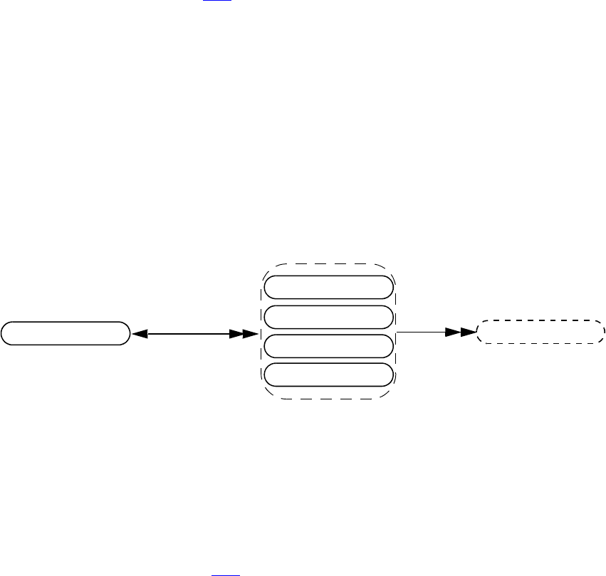
IEEE Std 1800-2012
IEEE STANDARD FOR SYSTEMVERILOG—UNIFIED HARDWARE DESIGN, SPECIFICATION, AND
VERIFICATION LANGUAGE
957
Copyright © 2013 IEEE. All rights reserved.
If there is no prefix object, or no prefix object meets at least one of the above criteria, vpiParent shall return
NULL.
Using the preceding declarations, the vpiParent of mda[6][8][1][3] is mda[6][8], the vpiLogicVar
representing the largest containing packed array prefix; the vpiParent of mda[6][8] is mda, the vpiArrayVar
representing the largest containing unpacked array prefix. Likewise, the vpiParent of
spa[9][12].bvec[4][0] is spa[9][12].bvec[4] (the largest containing packed array); the vpiParent
of spa[9][12].bvec[4] is spa[9][12].bvec (struct member), and applying vpiParent again yields
spa[9][12], the struct variable for member bvec. The vpiParent of spa[9][12] is spa, the largest
containing unpacked array of the struct variable; vpiParent of spa (or mda) would return NULL.
Class variables (as previously mentioned in the prefix object types) shall be returned as parent objects only when
they are explicitly used to reference corresponding class data members in the design. A VPI handle to a data
member that does not correspond to such an explicit reference in the design (e.g., a VPI handle to a data member
derived from iterations on its vpiClassObj or vpiClassDefn) shall have a NULL parent.
27) The property vpiConstantSelect shall return TRUE for a var bit or other variable if it has a static lifetime and has
no parent (the vpiParent relation returns NULL) or if both of the following are true of the “select” part of the
equivalent primary expression (see A.8.4):
— Every index expression in the select is an elaboration time constant expression.
— Every element within the select denotes either a member of a struct or union variable or a member of a packed
or unpacked array with static bounds.
Otherwise, vpiConstantSelect shall return FALSE.
NOTE 1—The final (non-prefix) element of the select may be an unindexed member identifier belonging to any
VPI variable type. It may, for example, be the name of a class variable or dynamic array. However, it must not be a
member of a class variable if the member has an automatic lifetime, and it must not be an element of a dynamically
allocated array.
NOTE 2—If vpiConstantSelect is TRUE, then if the handle refers to a valid underlying simulation object at the
beginning of simulation (or at any point in the simulation), it refers to the same object at all points in the simulation.
Moreover, if any index expression is in or out of bounds at the beginning of simulation, it is in or out of bounds at
all subsequent simulation times as well.
37.18 Packed array variables
Details:
1) vpiPackedArrayVar objects shall represent packed arrays of packed struct var, union var, or enum var objects.
The properties vpiVector and vpiPacked for these objects and their underlying struct var, union var, or enum var
elements shall always be TRUE (see 37.17).
2) For consistency with other variable-width vector objects, the vpiSize property for vpiPackedArrayVar objects
shall be the number of bits in the packed array, not the number of struct, enum, or union var elements. The total
number of struct var, enum var, or union var elements for a packed array var can be obtained by computing the
product of the vpiSize property for all of its packed ranges.
vpiElement
struct var
union var
vpiParent
-> packed array member
bool: vpiPackedArrayMember
-> constant selection
bool: vpiConstantSelect
packed array var
packed array var
vpiIndex
expr
-> packed
bool: vpiPacked
enum var
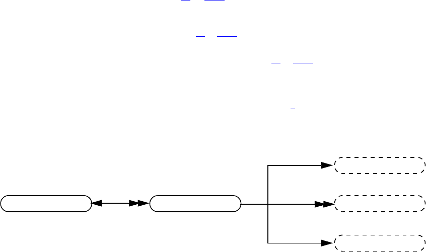
IEEE Std 1800-2012
IEEE STANDARD FOR SYSTEMVERILOG—UNIFIED HARDWARE DESIGN, SPECIFICATION, AND
VERIFICATION LANGUAGE
958
Copyright © 2013 IEEE. All rights reserved.
3) The vpiElement transition shall be used to iterate over the subelements of packed array variables. Unlike
vpiVarSelect or vpiReg transitions for vpiArrayVar objects, vpiElement shall retrieve elements for only one
dimension level at a time. This means that for multi-dimensioned packed arrays, vpiElement shall retrieve
elements that are themselves also vpiPackedArrayVar objects. vpiElement can then be used to iterate over the
subelements of these objects and so on, until the leaf level struct, enum, or union vars are returned. In other words,
the data type of each element retrieved by vpiElement is equivalent to the original vpiPackedArrayVar object’s
data type with the leftmost packed range removed. For example, consider the following vpiPackedArrayVar
object:
typedef struct packed { int i1; bit [1:0][2:3]bvec; } pavartype;
pavartype [0:2][6:3] pavar1;
The vpiElement transition applied to pavar1 shall return 3 vpiPackedArrayVar objects: pavar1[0],
pavar1[1], and pavar1[2]. The vpiElement transition applied to vpiPackedArrayVar pavar1[0] in turn
shall retrieve vpiStructVar objects pavar1[0][6], pavar1[0][5], pavar1[0][4], and
pavar1[0][3], respectively. Also, the vpiParent transition for all the above-mentioned subelements of
pavar1 shall return pavar1 (as per detail 26 of 37.17, since pavar1 is “the largest containing packed array
object”).
4) The vpiPackedArrayMember property shall be TRUE for any struct var, union var, enum var, or packed array var
whose vpiParent is a packed array var (see detail 26 of 37.17).
5) The vpiStructUnionMember property shall be TRUE only for packed array vars that are direct members of struct
or union vars, i.e., whose vpiParent is a struct or union var (see detail 26 of 37.17). This property shall be FALSE
for all subelements (as returned by the vpiElement iterator) of such packed array vars.
6) vpi_iterate(vpiIndex, packed_array_var_handle) shall return the set of indices for a subelement of a packed
array variable (relative to its vpiParent), starting with the index for the subelement and working outwards. The
indices retrieved shall be the same as those shown in the example for detail 3 for each of the subelements returned
by vpiElement. The indices will be retrieved in right-to-left order as they appear in the text.
37.19 Variable select
Details:
1) The property vpiConstantSelect shall return TRUE for a var select if
— every associated index expression is an elaboration time constant expression, and
— the parent of the var select is an unpacked array with static bounds, and
—vpiConstantSelect returns TRUE for the parent of the var select.
Otherwise, vpiConstantSelect shall return FALSE.
NOTE—If vpiConstantSelect is TRUE, then if the handle refers to a valid underlying simulation object at the
beginning of simulation (or at any point in the simulation), it refers to the same object at all points in the simulation.
Moreover, if an index expression of the var select or of any of its parents is in or out of bounds at the beginning of
simulation, it is in or out of bounds at all subsequent simulation times as well.
var select
expr
vpiIndex
-> constant selection
bool: vpiConstantSelect
-> name
str: vpiName
str: vpiFullName
-> size
int: vpiSize
-> value
vpi_get_value()
vpi_put_value()
vpiParent vpiIndex
expr
array var
typespec
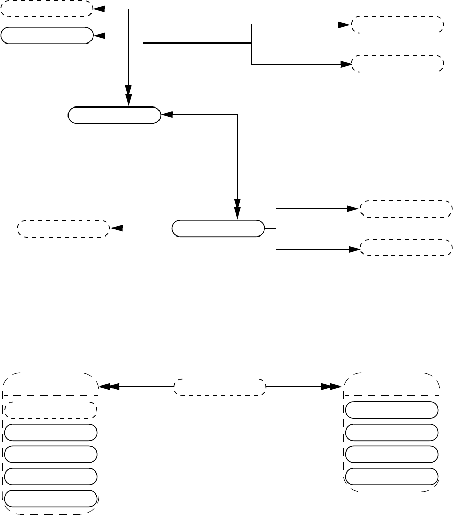
IEEE Std 1800-2012
IEEE STANDARD FOR SYSTEMVERILOG—UNIFIED HARDWARE DESIGN, SPECIFICATION, AND
VERIFICATION LANGUAGE
959
Copyright © 2013 IEEE. All rights reserved.
37.20 Memory
Details:
1) The objects vpiMemory and vpiMemoryWord have been generalized with the addition of arrays of variables. To
preserve backwards compatibility, they have been converted into methods that will return objects of type
vpiRegArray and vpiReg, respectively. See 37.17 for the definitions of variables and variable arrays.
37.21 Variable drivers and loads
Details:
1) vpiDrivers/Loads for a structure, union, or class variable shall include the following:
— Driver/Load for the whole variable
— Driver/Load for any bit-select or part-select of that variable
— Driver/Load of any member nested inside that variable
2) vpiDrivers/Loads for any variable array should include driver/load for entire array/vector or any portion of an
array/vector to which a handle can be obtained.
reg array
expr
vpiLeftRange
-> access by index
vpi_handle_by_index()
vpi_handle_by_multi_index()
-> is a memory
bool: vpiIsMemory
vpiMemory
vpiRightRange
expr
scope
module
reg
expr
vpiLeftRange
vpiRightRange
expr
vpiMemoryWord
expr
vpiIndex
vpiParent
ports
force
assign stmt
vpiDriver
variable drivers
cont assign
cont assign bit
variables
force
variable loads
cont assign
cont assign bit
vpiLoad
assign stmt
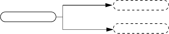
IEEE Std 1800-2012
IEEE STANDARD FOR SYSTEMVERILOG—UNIFIED HARDWARE DESIGN, SPECIFICATION, AND
VERIFICATION LANGUAGE
960
Copyright © 2013 IEEE. All rights reserved.
37.22 Object Range
Details:
1) An empty range is a range that has no elements. A range corresponding to an empty dynamic array, associative
array, or queue is an empty range. A range of a typespec for a dynamic array, associative array, or queue is also an
empty range.
2) For an empty range, vpiSize shall return 0, while the vpiLeftRange and vpiRightRange relations shall each return
NULL.
range
expr
vpiLeftRange
vpiRightRange
expr
-> size
int: vpiSize
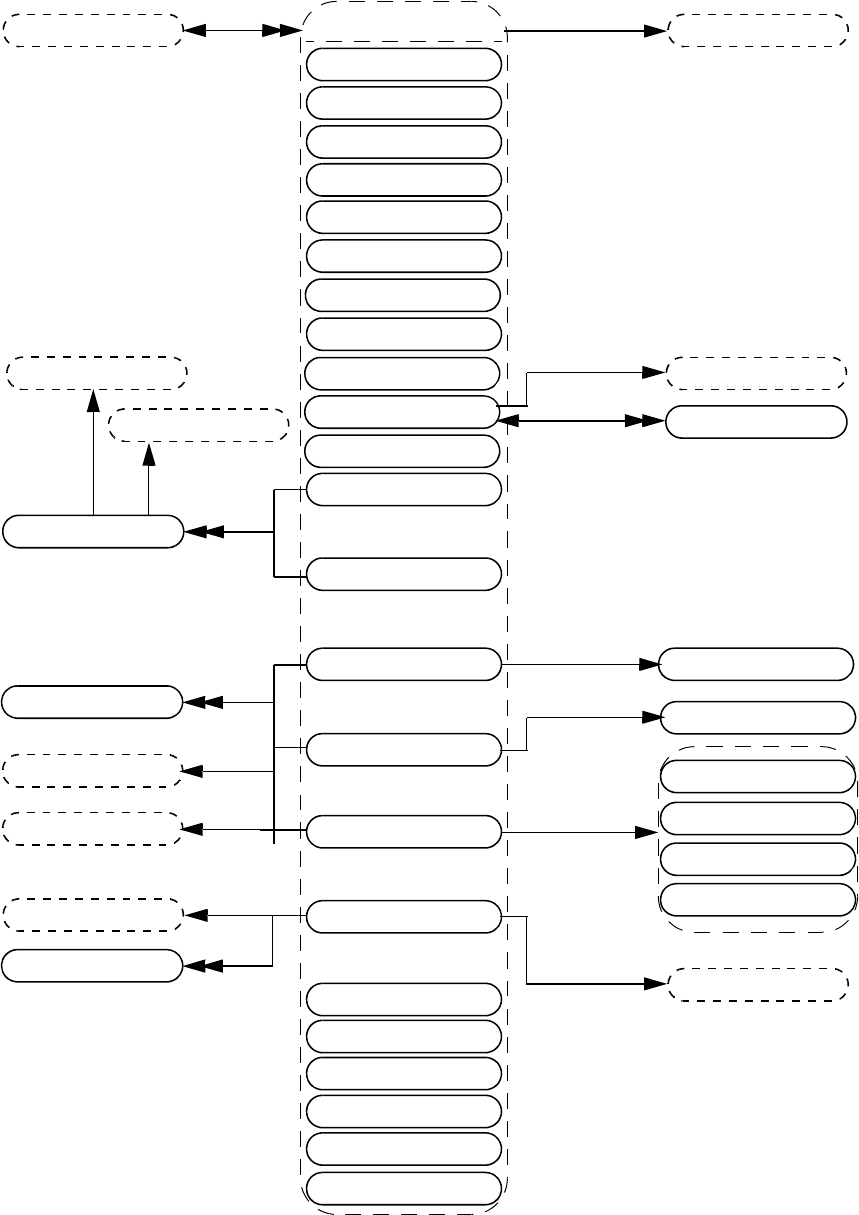
IEEE Std 1800-2012
IEEE STANDARD FOR SYSTEMVERILOG—UNIFIED HARDWARE DESIGN, SPECIFICATION, AND
VERIFICATION LANGUAGE
961
Copyright © 2013 IEEE. All rights reserved.
37.23 Typespec
-> packed
bool: vpiPacked
vpiTypedefAlias
enum const
short int typespec
int typespec
long int typespec
typespec
byte typespec
string typespec
class typespec
time typespec
enum typespec
bit typespec
logic typespec
array typespec
real typespec
struct typespec
union typespec
typespec
short real typespec
instance
typespec member
typespec
vpiIndexTypespec
typespec
typespec
integer typespec
-> tagged
bool: vpiTagged
-> vector
bool: vpiVector
-> vector
bool: vpiVector
-> array type
int: vpiArrayType
vpiBaseTypespec
-> name
str: vpiName
-> value
vpi_get_value()
typespec
vpiElemTypespec
-> name
str: vpiName
range
range
-> name
str: vpiName
-> randomization type
int: vpiRandType
expr
packed array typespec
-> vector
bool: vpiVector
struct typespec
union typespec
packed array typespec
vpiElemTypespec
bit typespec
logic typespec
vpiElemTypespec
vpiElemTypespec
expr
expr
vpiRightRange
vpiLeftRange
sequence typespec
property typespec
event typespec
type parameter
void typespec
enum typespec
interface typespec

IEEE Std 1800-2012
IEEE STANDARD FOR SYSTEMVERILOG—UNIFIED HARDWARE DESIGN, SPECIFICATION, AND
VERIFICATION LANGUAGE
962
Copyright © 2013 IEEE. All rights reserved.
Details:
1) If a typespec denotes a type that has a user-defined typedef, the vpiName property shall return the name of that
type; otherwise, except in the case of a class typespec (see 37.30), the vpiName property shall return NULL.
Consequently the vpiName property returns NULL for any SystemVerilog built-in type. If the typespec denotes a
type with a typedef that creates an alias of another typedef, then the vpiTypedefAlias of the typespec shall return a
non-null handle, which represents the handle to the aliased typedef. For example:
typedef enum bit [0:2] {red, yellow, blue} primary_colors;
typedef primary_colors colors;
If “h1” is a handle to the typespec colors, its vpiType shall return vpiEnumTypespec, the vpiName property
shall return “colors,” vpiTypedefAlias shall return a handle “h2” to the typespec “primary_colors” of
vpiType vpiEnumTypespec. The vpiName property for “h2” shall return “primary_colors”, and its
vpiTypedefAlias shall return NULL.
2) vpiIndexTypespec relation is present only on associative array typespecs and returns the type that is used as the
key into the associative array. For the wildcard index type (see 7.8.1), vpiIndexTypespec shall return NULL.
3) If the value of the property vpiType of a typespec is vpiStructTypesec or vpiUnionTypespec, then it is possible to
iterate over vpiTypespecMember to obtain the structure of the user-defined type. For each typespec member, the
typespec relation indicates the type of the member.
4) The property vpiName of a typespec member returns the name of the corresponding member, rather than the name
(if any) of the associated typespec.
5) The name of a typedef may be the empty string if the typespec denotes typedef field defined in-line rather than via
a typedef declaration. For example:
typedef struct {
struct
int a;
} B
} C;
The typespec representing the typedef C is a struct typespec; it has a single typespec member named B. The
typespec relation for B returns another struct typespec that has no name and has a single typespec member named
“a”. The typespec relation for “a” returns an int typespec.
6) If a type is defined as an alias of another type, it inherits the vpiType of this other type. For example:
typedef time my_time;
my_time t;
The vpiTypespec of the variable named “t” shall return a handle h1 to the typespec “my_time” whose vpiType
shall be a vpiTimeTypespec. The vpiTypedefAlias applied to handle h1 shall return a typespec handle h2 to the
predefined type “time”.
7) The expr associated with a typespec member shall represent the explicit default member value, if any, of the
corresponding member of an unpacked structure data type (See 7.2).
8) The vpiElemTypespec transition shall be used to unwind the typespec of an unpacked array (array typespec) or a
packed array (packed array typespec, or a bit or logic typespec with one or more dimensions), one dimension level
at a time. This means that for a multidimensional array typespec (a typespec with more than one unpacked range),
vpi_handle(vpiElemTypespec, array_typespec_handle) shall initially retrieve a vpiArrayTypespec equivalent
to the original typespec with its leftmost unpacked range removed. Subsequent calls to the vpiElemTypespec
method continue the unwinding until a typespec object is retrieved that has no unpacked ranges remaining.
Similarly, when the vpiElemTypespec is applied to a typespec of a multidimensional packed array object, a
vpiPackedArrayTypespec (or vpiBitTypespec or vpiLogicTypespec) is retrieved that is equivalent to the
original typespec with its leftmost packed range removed, and so on, until a typespec without an explicit packed
range is retrieved. When the vpiElemTypespec relation is applied to a vpiStructTypespec, vpiUnionTypespec,
vpiEnumTypespec, or a vpiBitTypespec or vpiLogicTypespec with no ranges present, it shall return NULL. This
allows packed or unpacked array typespecs constructed with multiple typedefs to be unwound without losing name
information. Consider the complex array typespec defined below for arr:
typedef struct packed { int i1; bit bvec; } [1:3] parrtype;
typedef parrtype [2:1] parrtype2;
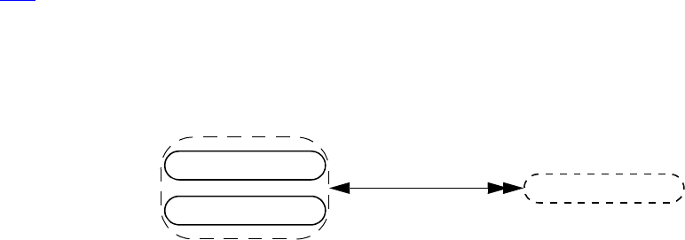
IEEE Std 1800-2012
IEEE STANDARD FOR SYSTEMVERILOG—UNIFIED HARDWARE DESIGN, SPECIFICATION, AND
VERIFICATION LANGUAGE
963
Copyright © 2013 IEEE. All rights reserved.
typedef parrtype2 unparrtype [6:4];
unparrtype arr [3:0];
The typespec of the object arr is an unpacked 4 ×3 array typespec with a NULL vpiName property. The typespec
retrieved by applying vpiElemTypespec to this is a 3-element unpacked array typespec with a vpiName property
of “unparrtype”. The typespec retrieved by using vpiElemTypespec on this in turn yields a 2 ×3 packed array
typespec (of packed struct objects) with a vpiName property of “parrtype2”. Using vpiElemTypespec again in
turn yields another packed array typespec (of 3 packed struct objects) with a vpiName property of “parrtype”.
One more application of vpiElemTypespec to this result yields a struct typespec, a non-array typespec for which
no further array subelements exist (the unwinding is done).
9) If a logic typespec, bit typespec, or packed array typespec has more than one packed dimension, vpiLeftRange and
vpiRightRange shall return the bounds of the leftmost packed dimension. If an array typespec has more than one
unpacked dimension, vpiLeftRange and vpiRightRange shall return the bounds of the leftmost unpacked
dimension.
10) For an array typespec, vpi_iterate(vpiRange, handle) shall return the set of array range declarations beginning
with the leftmost unpacked range and iterating through the rightmost unpacked range. If any dimension of the array
typespec corresponds to a dynamic array, associative array, or queue, the iteration shall return an empty range (see
37.22) for that dimension. For a logic typespec or bit typespec that has an associated range, the iteration shall return
the set of ranges beginning with the leftmost packed range and iterating through the rightmost packed range.
11) In a context (such as a class defn) in which a type parameter has not been resolved, the type parameter itself shall
act as a typespec.
37.24 Structures and unions
Details:
1) vpi_get_value()/vpi_put_value() cannot be used to access values of entire unpacked structures and unpacked
unions.
vpiMember
struct var
union var
variables
vpiParent
-> packed
bool: vpiPacked
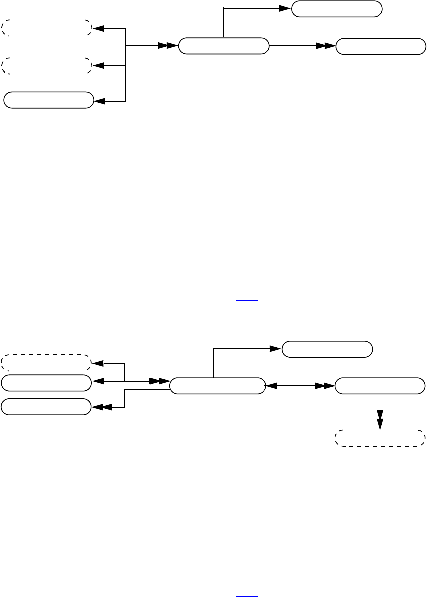
IEEE Std 1800-2012
IEEE STANDARD FOR SYSTEMVERILOG—UNIFIED HARDWARE DESIGN, SPECIFICATION, AND
VERIFICATION LANGUAGE
964
Copyright © 2013 IEEE. All rights reserved.
37.25 Named events
Details:
1) The vpiWaitingProcesses iterator returns all waiting processes, static or dynamic, identified by their thread, for
that named event.
2) vpi_iterate(vpiRange, named_event_array_handle) shall return the set of array range declarations beginning
with the leftmost unpacked range and iterating through the rightmost unpacked range.
3) For details on lifetime and memory allocation properties, see 37.3.7.
Details:
1) vpi_iterate(vpiIndex, named_event_handle) shall return the set of indices for a named event within an array,
starting with the index for the named event and working outward. If the named event is not part of an array, a NULL
shall be returned.
2) For details on lifetime and memory allocation properties, see 37.3.7.
named event thread
vpiWaitingProcesses
-> array member
bool: vpiArray (deprecated)
bool: vpiArrayMember
-> name
str: vpiName
str: vpiFullName
-> value
vpi_put_value()
-> lifetime
bool: vpiAutomatic
-> memory allocation
int: vpiAllocScheme
instance
scope
module
event typespec
vpiTypespec
named event array named event
vpiParent
-> name
str: vpiName
str: vpiFullName
-> access by index
vpi_handle_by_index()
vpi_handle_by_multi_index()
-> lifetime
bool: vpiAutomatic
-> memory allocation
int: vpiAllocScheme
instance
range
expr
vpiIndex
module
array typespec
vpiTypespec
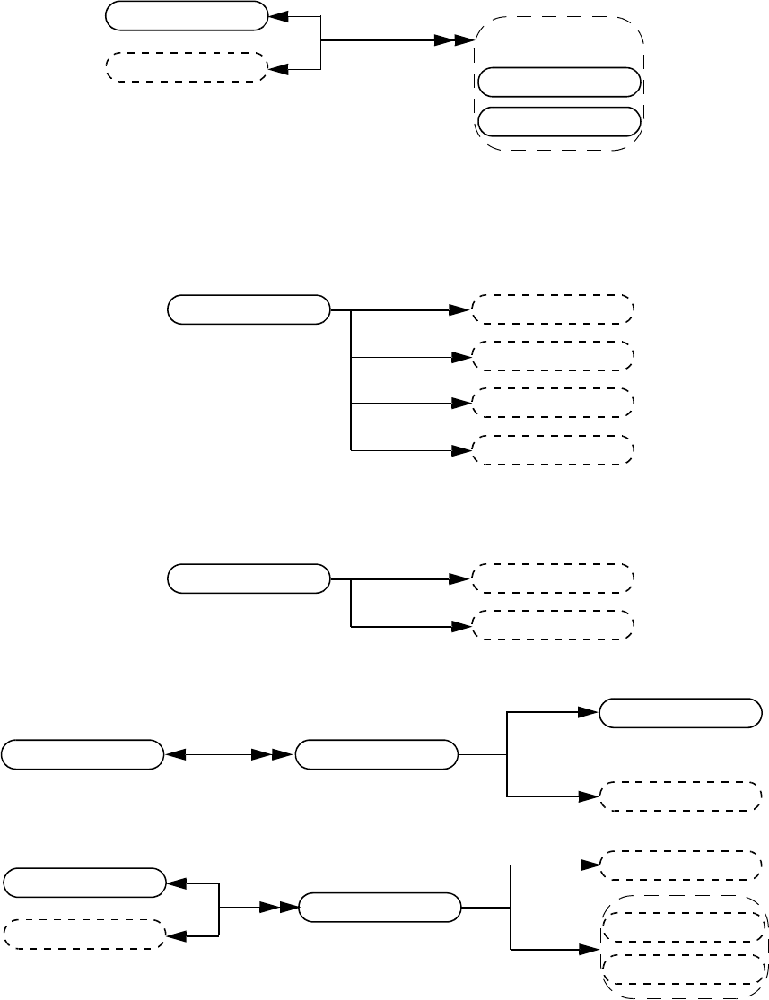
IEEE Std 1800-2012
IEEE STANDARD FOR SYSTEMVERILOG—UNIFIED HARDWARE DESIGN, SPECIFICATION, AND
VERIFICATION LANGUAGE
965
Copyright © 2013 IEEE. All rights reserved.
37.26 Parameter, spec param, def param, param assign
Details:
1) For a value parameter, vpi_get_value() shall return the value that the parameter has at the end of elaboration.
2) The vpiTypespec of a type parameter shall return the typespec that the type parameter has at the end of elaboration,
but without resolving typedef aliases.
vpiRightRange
parameter typespec
expr
expr
expr
vpiLeftRange
-> constant type
int: vpiConstType
-> sign
bool: vpiSigned
-> size
int: vpiSize
-> value
vpi_get_value()
-> connection by name
bool: vpiConnByName
expr
parameter
vpiRhs
vpiLhs
def parammodule
typespec
vpiRhs
vpiLhs
param assign
scope
module
type parameter
parameters
parameter
-> local
bool: vpiLocalParam
-> name
str: vpiName
str: vpiFullName
type parameter typespec
typespec
vpiExpr
scope
module parameters
expr
vpiParameter
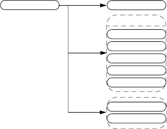
IEEE Std 1800-2012
IEEE STANDARD FOR SYSTEMVERILOG—UNIFIED HARDWARE DESIGN, SPECIFICATION, AND
VERIFICATION LANGUAGE
966
Copyright © 2013 IEEE. All rights reserved.
3) The vpiExpr relation of a value parameter shall return the default expr, while the vpiExpr relation of a type
parameter shall return the default typespec.
4) vpiLhs from a param assign object shall return a handle to the overridden value parameter or type parameter.
5) If a value parameter does not have an explicitly defined range, vpiLeftRange and vpiRightRange shall return a
NULL handle.
37.27 Virtual interface
Details:
1) The vpiExpr relation shall return the interface instance assigned to the virtual interface in its declaration, if any;
otherwise, vpiExpr shall return NULL.
2) A ref obj may be an interface expr only if it is a local declaration of an interface or modport passed through a port.
A constant may be an interface expr only if it has a vpiConstType of vpiNullConst.
Example 1: Passing an interface or modport through a port:
interface SBus #(parameter WIDTH=8);
logic req, grant;
logic [WIDTH-1:0] addr, data;
modport phy(input addr, inout data);
endinterface
module top;
parameter SIZE = 4;
virtual SBus#(16) V16;
virtual SBus#(32).phy V32_Array [1:SIZE];
...
endmodule
-> name
str: vpiName
str: vpiFullName
-> is modport
bool: vpiIsModPort
interface typespec
vpiTypespec
interface expr
interface
modport
ref obj
interface
vpiActual
modport
virtual interface var
constant
vpiExpr
virtual interface var
IEEE Std 1800-2012
IEEE STANDARD FOR SYSTEMVERILOG—UNIFIED HARDWARE DESIGN, SPECIFICATION, AND
VERIFICATION LANGUAGE
967
Copyright © 2013 IEEE. All rights reserved.
In this example, V16 is a virtual interface, while V32_Array is an array var. The vpiVariables iteration from
module top includes both V16 and V32_Array, while the vpiVirtualInterfaceVar iteration returns V16
together with the individual elements of V32_Array, that is, V32_Array[1] through V32_Array[4].
Example 2: Virtual interface declaration in a class definition:
interface SBus; // A Simple bus interface
logic req, grant;
logic [7:0] addr, data;
endinterface
class SBusTransactor; // SBus transactor class
virtual SBus bus; // virtual interface of type SBus
function new( virtual SBus s );
bus = s; // initialize the virtual interface
endfunction
task request(); // request the bus
bus.req <= 1'b1;
endtask
task wait_for_bus(); // wait for the bus to be granted
@(posedge bus.grant);
endtask
endclass
module devA( SBus s ); ... endmodule // devices that use SBus
module devB( SBus s ); ... endmodule
module top;
SBus s[1:4] (); // instantiate 4 interfaces
devA a1( s[1] ); // instantiate 4 devices
devB b1( s[2] );
devA a2( s[3] );
devB b2( s[4] );
initial begin
SbusTransactor t[1:4]; // create 4 bus-transactors and bind
t[1] = new( s[1] );
t[2] = new( s[2] );
t[3] = new( s[3] );
t[4] = new( s[4] );
end
endmodule
A virtual interface var is returned for the left-hand side expression of the statement “bus = s” in the constructor
of the class definition SBusTransactor. The vpiName of the virtual interface var is “bus”, and it has a
vpiInterfaceTypespec for which the vpiDefName is “SBus”. The vpiActual relationship returns the interface
instance associated with that particular call to new after the assignment has executed. For example if it was
“new(s[1])”, vpiActual would return the interface s[1]. If vpiActual is queried before the assignment is
executed, the method shall return NULL if the virtual interface is uninitialized. In addition, the right-hand side
expression of “bus = s” returns a virtual interface var for which vpiActual is the interface instance passed to the
call to new.
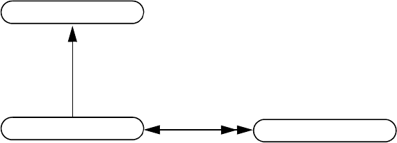
IEEE Std 1800-2012
IEEE STANDARD FOR SYSTEMVERILOG—UNIFIED HARDWARE DESIGN, SPECIFICATION, AND
VERIFICATION LANGUAGE
968
Copyright © 2013 IEEE. All rights reserved.
37.28 Interface typespec
Details:
1) The vpiDefName of an interface typespec that represents a modport shall be the mod port identifier. The
vpiDefName of an interface typespec that represents an interface shall be the identifier of the interface declaration.
2) For an interface typespec that represents a modport, vpiParent shall return an interface typespec of the
corresponding interface. For an interface typespec that represents an interface, vpiParent shall return NULL.
3) In the following example, the first typedef defines an interface typespec corresponding to “virtual
SBus#(16)” whose vpiName is SB16. The vpiDefname of this typespec shall be SBus, and the assigned
parameter value of 16 shall be derived by iterating on vpiParamAssign. The typedef SBphy, however, is an array
typespec for which the vpiElemTypespec returns an interface typespec corresponding to “virtual
SBus#(32).phy”.
The vpiTypedef iteration from the module top returns handles to both SB16 and SBphy interface typespecs.
interface SBus #(parameter WIDTH=8);
logic req, grant;
logic [WIDTH-1:0] addr, data;
modport phy(input addr, inout data);
endinterface
module top;
parameter SIZE = 4;
typedef virtual SBus#(16) SB16;
typedef virtual SBus#(32).phy SBphy [1:SIZE];
...
endmodule
-> name
str: vpiName
-> def name
str: vpiDefName
-> is modport
bool: vpiIsModPort
param assign
interface typespec
vpiParent
interface typespec
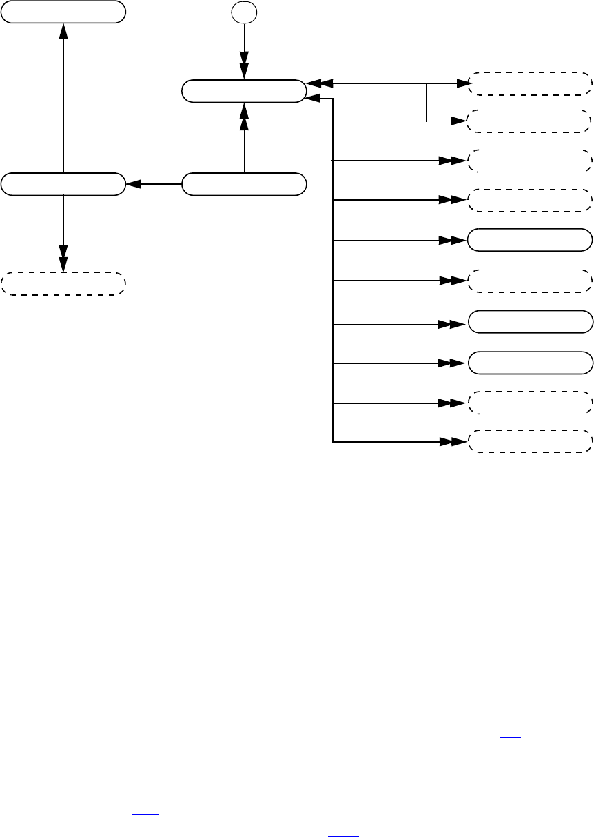
IEEE Std 1800-2012
IEEE STANDARD FOR SYSTEMVERILOG—UNIFIED HARDWARE DESIGN, SPECIFICATION, AND
VERIFICATION LANGUAGE
969
Copyright © 2013 IEEE. All rights reserved.
37.29 Class definition
Details:
1) The iterations over vpiVariables, vpiMethods, vpiNamedEvent, and vpiNamedEventArray shall return both
static and automatic properties or methods. However, the iteration over vpiMethods shall not include built-in
methods for which there is no explicit declaration.
2) vpi_get_value() and vpi_put_value() are not allowed for variable and event handles obtained from class defn
handles.
3) The iterator to constraints returns only normal constraints and not inline constraints.
4) The vpiConstraint iteration shall return the constraints in syntactic declaration order. The position within this
order of a constraint declared as extern shall be determined by the position of its prototype. To get constraints
inherited from base classes, it is necessary to traverse the extends relation to obtain the base class typespec.
5) The vpiDerivedClasses iterator shall return all the class defns derived from the given class defn.
6) The relation to vpiExtends exists whenever one class is derived from another class (refer to 8.13). The relation
from extends to class typespec provides the base class. The vpiArgument iterator from extends shall provide the
arguments used in constructor chaining (refer to 8.17).
7) The vpiParameter iteration shall return both the parameters declared in the parameter port list of the class
declaration and the parameters declared within the body of the class declaration as class items. The property
vpiLocalParam (see 37.26) shall return TRUE for parameters declared within the body.
8) For details on lifetime and memory allocation properties, see 37.3.7.
class defn instance
extends
constraint
vpiMethods
-> name
str: vpiName
-> virtual
bool: vpiVirtual
-> declared lifetime
bool: vpiAutomatic
expr
variables
task func
class defn
vpiArgument
vpiDerivedClasses
scope
named event
named event array
type spec
scope
vpiTypedef
vpiInternalScope
class typespec
vpiParameter
parameters
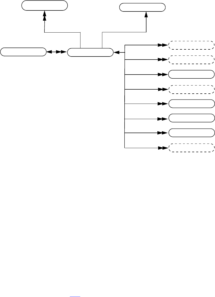
IEEE Std 1800-2012
IEEE STANDARD FOR SYSTEMVERILOG—UNIFIED HARDWARE DESIGN, SPECIFICATION, AND
VERIFICATION LANGUAGE
970
Copyright © 2013 IEEE. All rights reserved.
37.30 Class typespec
Details:
1) According to how it is obtained, a class typespec may represent either a lexical construct or a class specialization.
If the class typespec is obtained as part of a class defn, it represents a lexical construct from the SystemVerilog
source code. In particular, it shall represent a lexical construct under the following conditions:
— It is obtained from a class defn via the vpiTypedef iteration. In this case it represents a user-defined typedef.
— It is part of the declaration of a class item (variable or method) obtained from the class defn.
— It is obtained from the extends object associated with the class defn.
A class typespec object that has all parameter values resolved shall represent a class specialization. In particular, it
shall represent a class specialization under the following conditions:
— It is obtained from a class defn by iterating over vpiClassTypespec.
— It is the type of a variable or method for which no containing scope is a class defn. If the variable or method is
declared using the name of a typedef, the class typespec shall be the corresponding class instantiation rather
than the class typespec for the typedef itself.
A class typespec derived from a class defn for which the parameter port list is empty may represent both a lexical
construct and a class specialization.
2) For a class typespec that represents only a lexical construct, the one-to-many relations vpiVariables, vpiMethods,
vpiConstraint, vpiNamedEvent, vpiNamedEventArray, vpiTypedef, and vpiInternalScope are not supported.
3) In the case of a class typespec that represents a lexical construct, if the class type construct includes an explicit
parameter expression or type, the object for that parameter or type shall constitute the vpiRhs part of the
corresponding param assign (see 37.26); otherwise the vpiRhs part shall reference the default expression or type
with which the parameter was declared. However, if the class typespec represents a class specialization, the vpiRhs
of each param assignment may be any object that has the correct value (in the case of a non-type parameter) or type
(in the case of a type parameter).
constraint
vpiMethods
-> name
str: vpiName
-> class type
int: vpiClassType
-> declared lifetime
bool: vpiAutomatic
variables
task func
class typespec
virtual interface var
named event
named event array
scope
vpiInternalScope
class typespec
class defn
vpiExtends
param assign
vpiParameter
parameters

IEEE Std 1800-2012
IEEE STANDARD FOR SYSTEMVERILOG—UNIFIED HARDWARE DESIGN, SPECIFICATION, AND
VERIFICATION LANGUAGE
971
Copyright © 2013 IEEE. All rights reserved.
4) A class typespec that represents a class specialization shall have a valid, though tool-dependent, name.
5) From a class typespec that represents a class specialization, the iterations over vpiVariables, vpiMethods,
vpiNamedEvent, and vpiNamedEventArray shall return both static and automatic properties or methods.
However, the iteration over vpiMethods shall not include built-in methods for which there is no explicit
declaration.
6) vpi_get_value() and vpi_put_value() are not allowed for non-static variable and event handles obtained from class
typespec handles.
7) The iterator to constraints returns only normal constraints and not inline constraints.
8) The vpiConstraint iteration shall return the constraints in syntactic declaration order. The position within this
order of a constraint declared as extern shall be determined by the position of its prototype. To get constraints
inherited from a base class typespec, it is necessary to traverse the extends relation to obtain the base class typespec.
9) The vpiExtends relation shall return the base class typespec, if any, from which a given class typespec is derived.
The base class typespec of a class specialization shall also be a specialization.
10) The vpiClassTypespec iteration from a class defn shall return the class specializations derived directly (and not by
inheritance) from that class defn.
11) The vpiVirtualInterfaceVar iteration (formerly vpiInterfaceDecl—now deprecated in this standard—see C.4.3,
item 5) shall return the virtual interface var declarations in the class specialization (see 37.12 detail 7). If an array of
virtual interfaces is declared, the vpiVirtualInterfaceVar iteration shall return each element of the array
separately. However, the vpiVariables iteration shall return the array declaration as a single vpiArrayVar.
12) The vpiParameter iteration shall return parameters corresponding both to those declared in the parameter port list
of the class declaration and to those declared within the body of the class declaration as class items. The property
vpiLocalParam (see 37.26) shall return TRUE for parameters declared within the body.
13) The vpiClassDefn relation shall return NULL for built-in classes.
14) For details on lifetime and memory allocation properties, see 37.3.7.

IEEE Std 1800-2012
IEEE STANDARD FOR SYSTEMVERILOG—UNIFIED HARDWARE DESIGN, SPECIFICATION, AND
VERIFICATION LANGUAGE
972
Copyright © 2013 IEEE. All rights reserved.
37.31 Class variables and class objects
Details:
1) The property vpiObjId is a class object’s identifier. It is a property of a live object and guaranteed to be unique
with respect to all other dynamic objects that support this property for as long as the object is alive. After the object
is destroyed by garbage collection, its particular vpiObjId value may be reused.
2) For a class var, its vpiObjId is the identifier of the object it references or 0, indicating it is not referencing any
object.
3) The vpiWaitingProcesses iterator on a mailbox or semaphore shall return the threads waiting on the class object or
object resource. A waiting process is a static or dynamic process represented by its suspended thread. A process
may be waiting to retrieve a message from a mailbox or waiting for a semaphore resource key.
4) A vpiMessages iteration shall return all the messages in a mailbox.
5) For a class var, vpiClassTypespec shall return the class typespec with which the class var was declared in the
SystemVerilog source text. If the class var has the value of NULL, the vpiClassObj relationship applied to the class
var shall return a null handle. vpiClassTypespec when applied to a class obj handle shall return the class typespec
with which the class obj was created. The difference between the two usages of vpiClassTypespec can be seen in
the following example:
class Packet;
...
endclass : Packet
class LinkedPacket extends Packet;
...
endclass : LinkedPacket
LinkedPacket l = new;
Packet p = l;
In this example, the vpiClassTypespec of variable p is Packet, but the vpiClassTypespec of the class obj
associated with variable p is “LinkedPacket”.
NOTE—When a class var is obtained as a data member of a class typespec, the application must use vpiScope (see
37.12) rather than vpiClassTypespec to obtain the enclosing scope.
class var
vpiWaitingProcesses
variables
expr
class typespec
-> referenced identity
int64: vpiObjId
vpiMessages
thread
constraint
vpiMethods
class obj
class typespec
task func
virtual interface var
named event
named event array
scope
vpiInternalScope
-> my identity
int64: vpiObjId
vpiParameter
parameters

IEEE Std 1800-2012
IEEE STANDARD FOR SYSTEMVERILOG—UNIFIED HARDWARE DESIGN, SPECIFICATION, AND
VERIFICATION LANGUAGE
973
Copyright © 2013 IEEE. All rights reserved.
6) From a class obj, the iterations over vpiVariables, vpiMethods, vpiNamedEvent, and vpiNamedEventArray
shall return both static and automatic properties or methods. However, the iteration over vpiMethods shall not
include built-in methods for which there is no explicit declaration.
7) The vpiVirtualInterfaceVar iteration (formerly vpiInterfaceDecl—now deprecated in this standard—see C.4.3,
item 5) shall return the virtual interface var declarations in the class object. If an array of virtual interfaces is
declared, the vpiVirtualInterfaceVar iteration shall return each element of the array separately. However, the
vpiVariables iteration shall return the array declaration as a single vpiArrayVar.
8) The vpiParameter iteration shall return parameters corresponding both to those declared in the parameter port list
of the class declaration and to those declared within the body of the class declaration as class items. The property
vpiLocalParam (see 37.26) shall return TRUE for parameters declared with the body. The value of a parameter
derived from a class obj shall be the same as that of the same parameter derived from the corresponding class
typespec.
9) vpi_handle_by_name() shall accept a full name to a non-static data member, even though it does not have a
vpiFullName property. For example:
module top;
class Packet ;
integer Id ;
....
endclass
Packet p;
c = p.Id;
....
vpi_handle_by_name() accepts “top.p.Id”.
10) For details on class object specific callbacks, see 38.36.1.
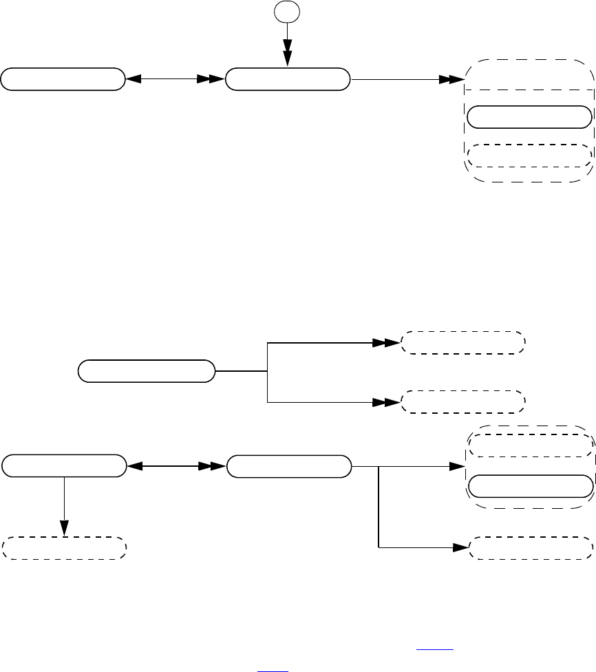
IEEE Std 1800-2012
IEEE STANDARD FOR SYSTEMVERILOG—UNIFIED HARDWARE DESIGN, SPECIFICATION, AND
VERIFICATION LANGUAGE
974
Copyright © 2013 IEEE. All rights reserved.
37.32 Constraint, constraint ordering, distribution
Details:
1) For a constraint, vpiAutomatic property does not mean lifetime, but reflects the keyword used in the constraint
declaration. vpiAutomatic == 0 implies the constraint was declared static. See 18.5.11 for meaning.
2) For details on memory allocation property, see 37.3.7.
3) The vpiConstraint iteration shall return the constraints in syntactic declaration order. The position within this
order of a constraint declared as extern shall be determined by the position of its prototype.
4) The vpiConstraintItem iteration shall return the constraint items in the order in which they occur within the
constraint.
expr
constraint item
constraint expr
constraint ordering
class obj
-> virtual
bool: vpiVirtual
-> lifetime (static/automatic)
bool: vpiAutomatic
-> memory allocation
int: vpiAllocScheme
-> extern
bool: vpiExtern
-> name
str: vpiName
str: vpiFullName
-> active
bool: vpiIsConstraintEnabled
distribution
constraint
vpiParent
expr
expr
constraint ordering
vpiSolveBefore
vpiSolveAfter
dist item
expr
range
expr
vpiValueRange
vpiWeight
-> distribution type
int: vpiDistType
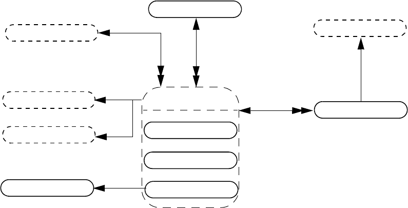
IEEE Std 1800-2012
IEEE STANDARD FOR SYSTEMVERILOG—UNIFIED HARDWARE DESIGN, SPECIFICATION, AND
VERIFICATION LANGUAGE
975
Copyright © 2013 IEEE. All rights reserved.
37.33 Primitive, prim term
Details:
1) vpiSize shall return the number of inputs.
2) For primitives, vpi_put_value() shall only be used with sequential UDP primitives.
3) vpiTermIndex can be used to determine the terminal order. The first terminal has a term index of zero.
4) If a primitive is an element within a primitive array, the vpiIndex transition is used to access the index within the
array. If a primitive is not part of a primitive array, this transition shall return NULL.
expr
primitive
gate
udp defn
-> array member
bool: vpiArray (deprecated)
bool: vpiArrayMember
-> definition name
str: vpiDefName
-> delay
vpi_get_delays()
vpi_put_delays()
-> name
str: vpiName
str: vpiFullName
-> primitive type
int: vpiPrimType
-> number of inputs
int: vpiSize
-> strength
int: vpiStrength0
int: vpiStrength1
-> value
vpi_get_value()
vpi_put_value()
switch
prim term
vpiDelay
expr
expr -> direction
int: vpiDirection
-> index
vpiTermIndex
-> value
vpi_get_value()
udp
vpiIndex
primitive array
module
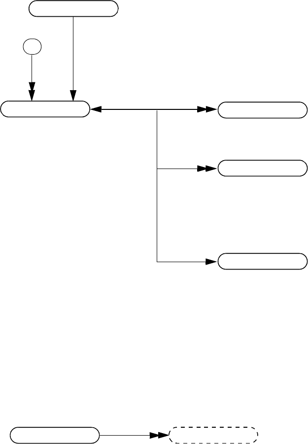
IEEE Std 1800-2012
IEEE STANDARD FOR SYSTEMVERILOG—UNIFIED HARDWARE DESIGN, SPECIFICATION, AND
VERIFICATION LANGUAGE
976
Copyright © 2013 IEEE. All rights reserved.
37.34 UDP
Details:
1) Only string (decompilation) and vector (ASCII values) shall be obtained for table entry objects using
vpi_get_value(). Refer to the definition of vpi_get_value() for additional details.
2) vpiPrimType returns vpiSeqPrim for sequential UDPs and vpiCombPrim for combinational UDPs.
37.35 Intermodule path
Details:
1) To get to an intermodule path, vpi_handle_multi(vpiInterModPath, port1, port2) can be used.
io decl
initial
udp
udp defn
-> definition name
str: vpiDefName
-> number of inputs
int: vpiSize
-> protected
bool: vpiProtected
-> type
int: vpiPrimType
-> number of symbol entries
int: vpiSize
-> value
vpi_get_value()
table entry
inter mod path ports
-> delay
vpi_get_delays()
vpi_put_delays()
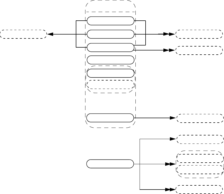
IEEE Std 1800-2012
IEEE STANDARD FOR SYSTEMVERILOG—UNIFIED HARDWARE DESIGN, SPECIFICATION, AND
VERIFICATION LANGUAGE
977
Copyright © 2013 IEEE. All rights reserved.
37.36 Constraint expression
Details:
1) The variable obtained via the vpiVariables relation from a vpiConstrForeach shall represent the array being
indexed.
2) The vpiLoopVars iteration shall return the index variables of the foreach constraint in left-to-right order. If an
index variable is skipped, its place shall be represented as a vpiOperation for which the vpiOpType is vpiNullOp.
3) Each vpiConstraintExpr iteration shall return the expressions in the order in which they occur in the containing
implication, if, if-else, or foreach constraint.
constraint expr
constraint expr
implication
vpiElseConst
expr
constr if
constr if else constraint expr
expr
vpiCondition
constr foreach
distribution
constr foreach variables
variables
vpiLoopVars
constraint expr
operation
-> soft constraint
bool: vpiSoft
soft disable expr
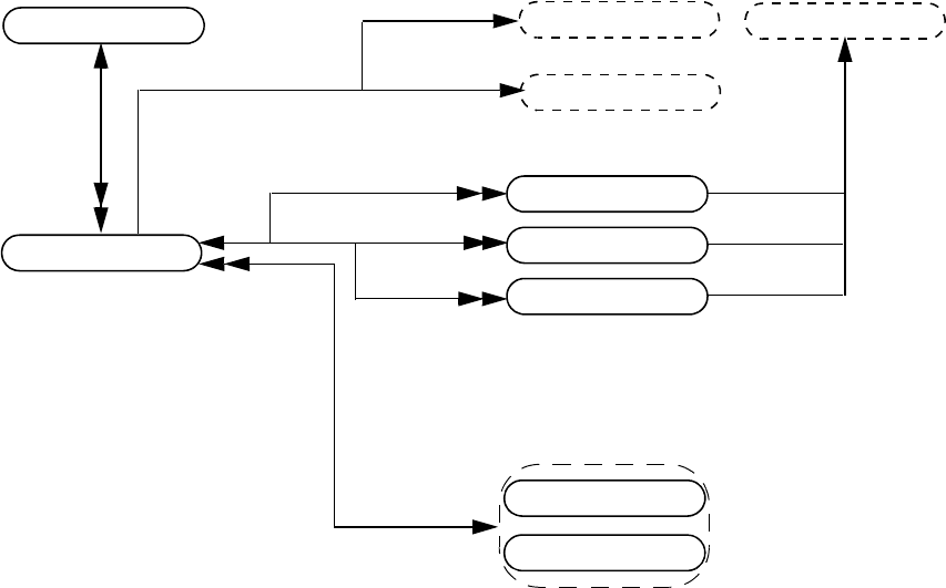
IEEE Std 1800-2012
IEEE STANDARD FOR SYSTEMVERILOG—UNIFIED HARDWARE DESIGN, SPECIFICATION, AND
VERIFICATION LANGUAGE
978
Copyright © 2013 IEEE. All rights reserved.
37.37 Module path, path term
Details:
1) Specify blocks can occur in both modules and interfaces. For backwards compatibility the vpiModule relation has
been preserved; however this relation shall return NULL for specify blocks in interfaces. For new code, it is
recommended that the vpiInstance relation be used instead.
vpiModPathin
interface
expr
path term
mod path
module
module
vpiDelay
expr
expr
vpiCondition
-> direction
int: vpiDirection
-> edge
int: vpiEdge
-> delay
vpi_get_delays()
vpi_put_delays()
-> path type
int: vpiPathType
-> polarity
int: vpiPolarity
int: vpiDataPolarity
-> hasIfNone
bool: vpiModPathHasIfNone
vpiModPathout
vpiModDataPathin
vpiInstance
path term
path term
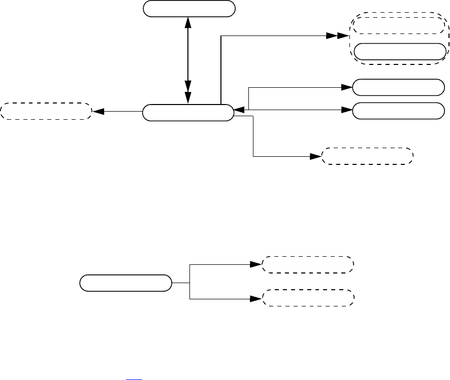
IEEE Std 1800-2012
IEEE STANDARD FOR SYSTEMVERILOG—UNIFIED HARDWARE DESIGN, SPECIFICATION, AND
VERIFICATION LANGUAGE
979
Copyright © 2013 IEEE. All rights reserved.
37.38 Timing check
Details:
1) For the timing checks in 31.2 the relationship vpiTchkRefTerm shall denote the reference_event or
controlled_reference_event, while vpiTchkDataTerm shall denote the data_event, if any.
2) When iterating over vpiExpr from a tchk, the handles returned for a reference_event, a controlled_reference_event,
or a data_event shall have the type vpiTchkTerm. All other arguments shall have types matching the expression.
vpiTchkNotifier
tchk term
tchk
module
vpiExpr
expr
expr
-> edge
int: vpiEdge
-> limit
vpi_get_delays()
vpi_put_delays()
-> tchk type
int: vpiTchkType
vpiTchkDataTerm
vpiTchkRefTerm
tchk term
tchk term
vpiCondition
regs
expr
tchk term
expr
vpiDelay
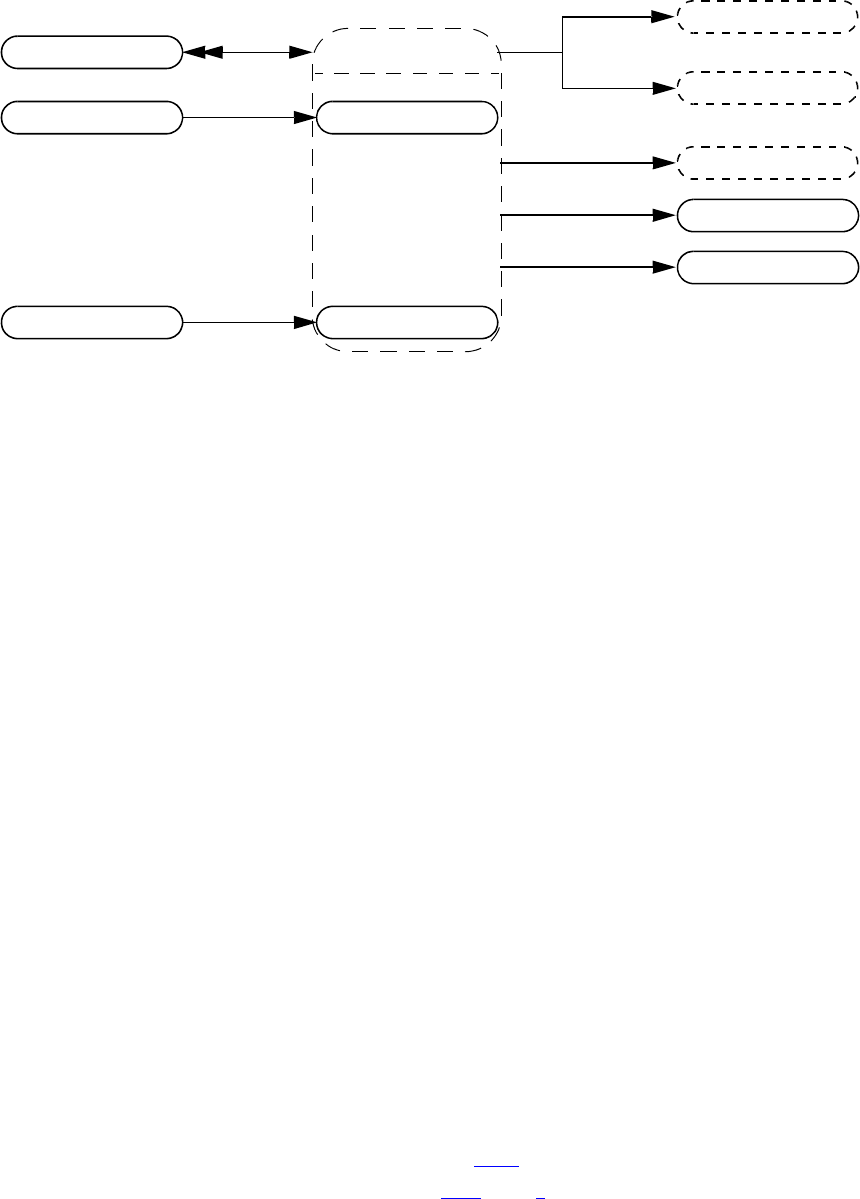
IEEE Std 1800-2012
IEEE STANDARD FOR SYSTEMVERILOG—UNIFIED HARDWARE DESIGN, SPECIFICATION, AND
VERIFICATION LANGUAGE
980
Copyright © 2013 IEEE. All rights reserved.
37.39 Task and function declaration
Details:
1) A SystemVerilog function shall contain an object with the same name, size, and type as the function. This object
shall be used to capture the return value for this function.
2) For a function where the return type is a user-defined type, vpi_handle(vpiReturn, function_handle) shall return
the implicit variable handle representing the return of the function from which the user can get the details of that
user-defined type.
3) vpiReturn shall always return a var object, even for simple returns.
4) vpiVisibility denotes the visibility (local, protected, or default) of a task or function that is a class member (a
method). vpiVisibility shall return vpiPublicVis for a class member that is not local or protected, or for a task or
function that is not a class member.
5) vpiFullName of a task or function declared inside a package or class defn shall begin with the full name of the
package or class defn followed by “::” and immediately followed with the name of the task or function.
6) vpiAccessType shall return vpiDPIExportAcc for "DPI" and "DPI-C" export functions/tasks, and shall return
vpiDPIImportAcc for "DPI" and "DPI-C" import functions/tasks.
7) vpiDPIPure shall return TRUE for pure "DPI" and "DPI-C" import functions.
8) vpiDPIContext shall return TRUE for context import "DPI" and "DPI-C", functions/tasks.
9) vpiDPICStr shall return vpiDPI for a "DPI" function/task, and vpiDPIC for a "DPI-C" function/task.
10) vpiDPICIdentifier shall return a string corresponding to the C linkage name for the "DPI"/"DPI-C" function/task.
11) For details on lifetime and memory allocation properties, see 37.3.7.
12) If the vpiSize of the vpiReturn variable is defined (see 37.17, detail 9) and can be determined without evaluating
the function, vpiSize for the function shall return the same value as vpiSize for the vpiReturn variable. For a void
function, vpiSize shall return 0. For all other cases the behavior of vpiSize is undefined.
function
expr
vpiLeftRange
io decl
task func
variables
vpiRightRange
task
expr
vpiReturn
-> method
bool: vpiMethod
-> access
int: vpiAccessType
-> visibility
int: vpiVisibility
-> virtual
bool: vpiVirtual
-> default lifetime
bool: vpiAutomatic
-> sign
bool: vpiSigned
-> size
int: vpiSize
-> type
int: vpiFuncType
class defn
ref obj
vpiParent
func call
task call
-> pure DPI
bool: vpiDPIPure
-> context
bool: vpiDPIContext
-> DPI qualifier
int: vpiDPICStr
-> identifier
str: vpiDPICIdentifier
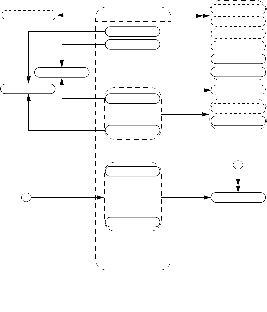
IEEE Std 1800-2012
IEEE STANDARD FOR SYSTEMVERILOG—UNIFIED HARDWARE DESIGN, SPECIFICATION, AND
VERIFICATION LANGUAGE
981
Copyright © 2013 IEEE. All rights reserved.
37.40 Task and function call
Details:
1) The vpiWith relation is only available for randomize methods (see 18.7) and for array locator methods (see 7.12.1).
2) For methods (method func call, method task call), the vpiPrefix relation shall return the object to which the method
is being applied. For example, for the class method invocation
packet.send();
the prefix for the “send” method is the class var “packet”.
3) The system task or function that invoked an application shall be accessed with vpi_handle(vpiSysTfCall, NULL).
4) vpi_get_value() shall return the current value of the system function.
task
vpiPrefix
named event
expr
expr
user systf
-> type
int: vpiFuncType
-> value
vpi_get_value()
function
task call
func call
named event array
vpiSysTfCall
scope
tf call
method func call
method task call
-> is built in
bool: vpiUserDefn
-> value
vpi_get_value()
sys func call
sys task call
-> user-defined
bool: vpiUserDefn
-> decompile
bool: vpiDecompile
-> type
int: vpiFuncType
-> value
vpi_get_value()
vpi_put_value()
-> name
str: vpiName
-> systf info
p_vpi_systf_data:
vpi_get_systf_info()
scope
primitive
vpiArgument
expr
vpiWith
constraint
interface expr

IEEE Std 1800-2012
IEEE STANDARD FOR SYSTEMVERILOG—UNIFIED HARDWARE DESIGN, SPECIFICATION, AND
VERIFICATION LANGUAGE
982
Copyright © 2013 IEEE. All rights reserved.
5) If the vpiUserDefn property of a system task or function call is true, then the properties of the corresponding systf
object shall be obtained via vpi_get_systf_info().
6) All user-defined system tasks or functions shall be retrieved using vpi_iterate(), with vpiUserSystf as the type
argument, and a NULL reference argument.
7) The simulator shall not evaluate arguments to system tasks or functions when calling those tasks or functions
(36.4). Effectively, the value of any argument expression, or of any operand or argument of the expression, is not
known until an application asks for it using vpi_get_value() (38.15), a cbValueChange callback (38.36.1), or other
equivalent operation. If no application asks for the value of the argument, it is never evaluated.
8) An empty (omitted) argument (see 21.2.1) shall be represented as an expression with a vpiType of vpiOperation
and a vpiOpType of vpiNullOp. An argument consisting of the special value null shall be represented as an
expression with a vpiType of vpiConstant and a vpiConstType of vpiNullConst.
Example:
logic my_var;
$my_task(my_var, ””, , null, );
In the call to the user-defined system task $my_task(), my_var is an ordinary argument of type vpiLogicVar.
The second argument, an empty string (but not an empty argument), is a vpiConstant for which the vpiConstType
is vpiStringConst. The third and fifth arguments are empty arguments, while the fourth argument is a vpiConstant
with a vpiConstType of vpiNullConst. VPI shall represent the third and fifth arguments as vpiOperations with a
vpiOpType of vpiNullOp.
9) The property vpiDecompile shall return a string with a functionally equivalent system task or function call to what
was in the original source code. The arguments shall be decompiled using the same manner as any expression is
decompiled. See 37.57 for a description of expression decompilation.
10) System task and function calls that are protected shall allow iteration over the vpiArgument relationship.
11) For a built-in method func call, vpiFunction shall return NULL, while vpiTask shall return NULL for a built-in
method task call.
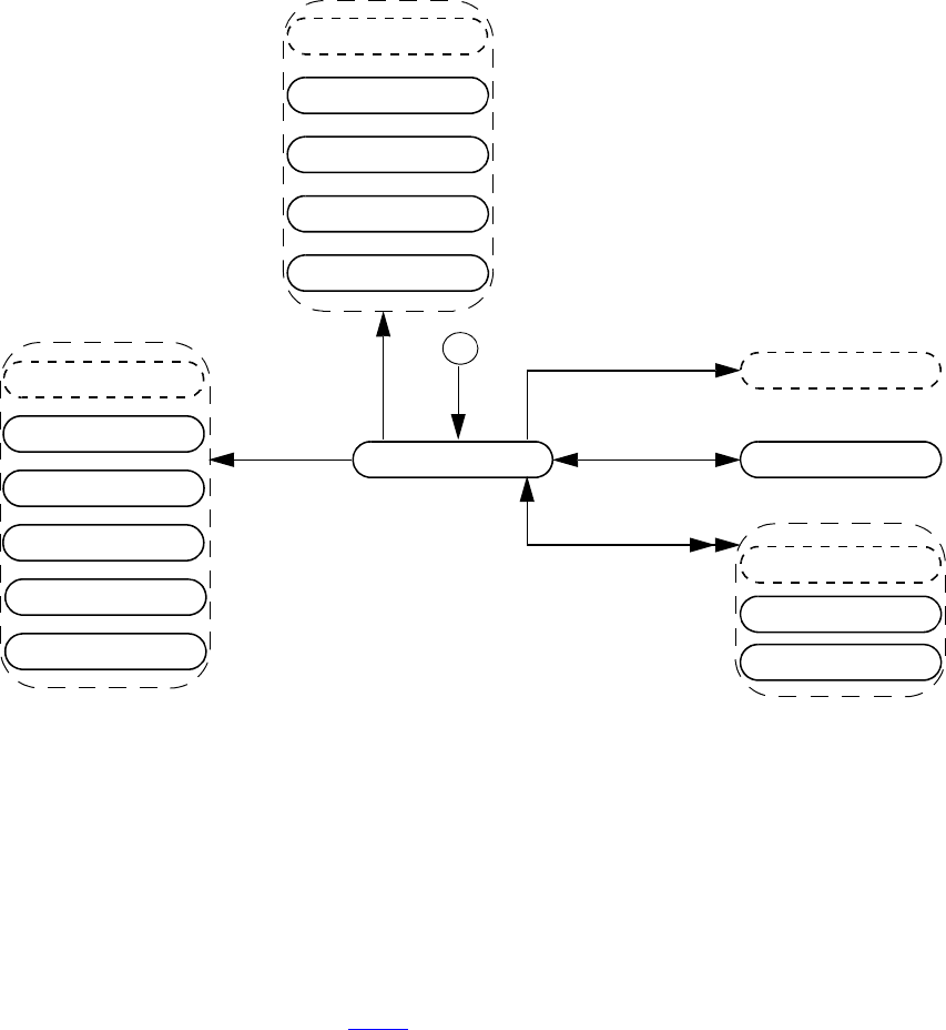
IEEE Std 1800-2012
IEEE STANDARD FOR SYSTEMVERILOG—UNIFIED HARDWARE DESIGN, SPECIFICATION, AND
VERIFICATION LANGUAGE
983
Copyright © 2013 IEEE. All rights reserved.
37.41 Frames
Details:
1) Frames correspond to the set of automatic variables declared in a given task or function.
2) It shall be illegal to place value change callbacks on automatic variables.
3) It shall be illegal to put a value with a delay on automatic variables.
4) There is at most only one active frame at any time in a given thread. To get a handle to the currently active frame,
use vpi_handle(vpiFrame, NULL). The frame to stmt transition shall return the currently active statement within
the frame.
5) The frame object model is not backwards compatible with IEEE Std 1364-2005.
6) For details on frame specific callbacks, see 38.36.1.
vpiAutomatics
named event
variables
stmt
thread
-> active
bool: vpiActive
frame
task call
func call
scope
frame
named event array
vpiOrigin
vpiParent
task call
func call
scope
method task call
method task call
method func call
method func call
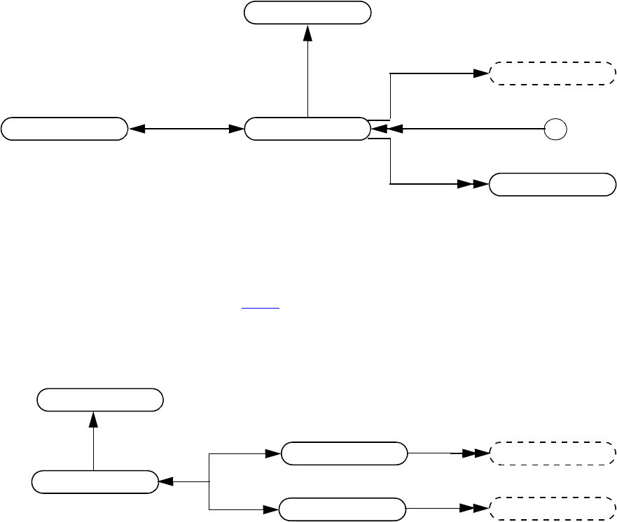
IEEE Std 1800-2012
IEEE STANDARD FOR SYSTEMVERILOG—UNIFIED HARDWARE DESIGN, SPECIFICATION, AND
VERIFICATION LANGUAGE
984
Copyright © 2013 IEEE. All rights reserved.
37.42 Threads
Details:
1) A thread is a SystemVerilog process such as an always procedure or a branch of a fork construct. As a thread
works its way down a call chain of tasks and/or functions, a new frame is activated as each new task or function is
entered.
2) For details on thread specific callbacks, see 38.36.1.
37.43 Delay terminals
Details:
1) The value of the input delay term shall change before the delay associated with the delay device.
2) The value of the output delay term shall not change until after the delay has occurred.
stmt
-> active
bool: vpiActive
thread
thread
frame
vpiParent
vpiOrigin
thread
delay term
-> delay type
int: vpiDelayType
-> value
vpi_get_value()
module
delay term
delay device
net drivers
net loads
vpiLoad
vpiDriver
vpiOutTerm
vpiInTerm
-> delay type
int: vpiDelayType
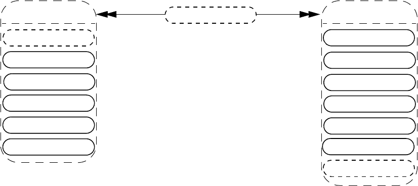
IEEE Std 1800-2012
IEEE STANDARD FOR SYSTEMVERILOG—UNIFIED HARDWARE DESIGN, SPECIFICATION, AND
VERIFICATION LANGUAGE
985
Copyright © 2013 IEEE. All rights reserved.
37.44 Net drivers and loads
Details:
1) Complex expressions on input ports that are not concatenations shall be considered a load for a net. Iterating on
loads for trinet in the following example will cause the fourth port of ram to be a load:
module my_module;
tri trinet;
ram r0 (a, write, read, !trinet);
endmodule
Access to the complex expression shall be available using vpi_handle(vpiHighConn, portH) where portH is the
handle to the port returned when iterating on loads.
ports
force
prim term
vpiDriver
net drivers
cont assign
cont assign bit
nets
force
net loads
cont assign
cont assign bit
vpiLoad
assign stmt
delay term
delay term
prim term
ports
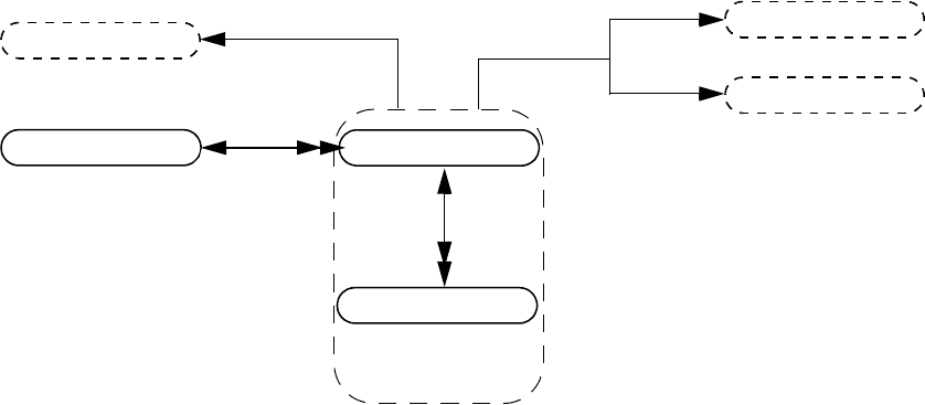
IEEE Std 1800-2012
IEEE STANDARD FOR SYSTEMVERILOG—UNIFIED HARDWARE DESIGN, SPECIFICATION, AND
VERIFICATION LANGUAGE
986
Copyright © 2013 IEEE. All rights reserved.
37.45 Continuous assignment
Details:
1) The size of a cont assign bit is always scalar.
2) Callbacks for value changes can be placed onto cont assign or a cont assign bit.
3) vpiOffset shall return zero for the LSB.
expr
-> delay
vpi_get_delays()
-> net decl assign
bool: vpiNetDeclAssign
-> strength
int: vpiStrength0
int: vpiStrength1
-> value
vpi_get_value()
module cont assign
cont assign bit
expr
vpiBit
-> offset from LSB
int: vpiOffset
expr
vpiParent
vpiDelay
vpiLhs
vpiRhs
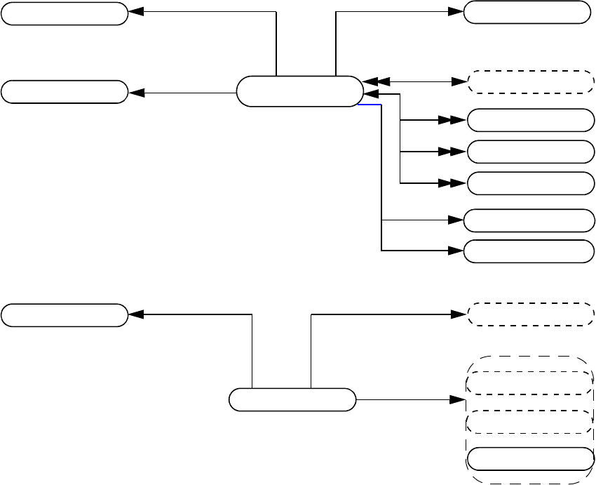
IEEE Std 1800-2012
IEEE STANDARD FOR SYSTEMVERILOG—UNIFIED HARDWARE DESIGN, SPECIFICATION, AND
VERIFICATION LANGUAGE
987
Copyright © 2013 IEEE. All rights reserved.
37.46 Clocking block
Details:
1) The methods, vpiInputSkew and vpiOutputSkew, and properties vpiInputEdge and vpiOutputEdge, on the
clocking block apply to the default constructs. The same methods and properties on the clocking io decl apply to
the clocking io decl itself.
2) The vpiPrefix relation shall be non-NULL when the clocking block represents an expression in the SystemVerilog
source code immediately prefixed by a virtual interface.
3) If a prefix of a clocking block is a virtual interface that has no value at the current simulation time, the vpiActual
relation shall return NULL.
4) vpiExpr shall return the expression or ref obj referenced by the clocking io decl. Consider input
enable = top.mem1.enable. Here, “enable” is represented by a clocking io decl, and the vpiExpr
relation returns a handle to “top.mem1.enable”.
clocking block
vpiInputSkew
instance
vpiClockingEvent
clocking io decl
expr
delay control
event control
delay control
clocking io decl
vpiInputSkew vpiOutputSkew
-> name
str: vpiName
str: vpiFullName
-> edge
int: vpiInputEdge
int: vpiOutputEdge
-> direction
int: vpiDirection
-> name
str: vpiName
-> edge
int: vpiInputEdge
int: vpiOutputEdge
delay control
vpiOutputSkew
vpiExpr
nets
variables
property decl
sequence decl
ref obj
virtual interface var
vpiPrefix
clocking block
vpiActual
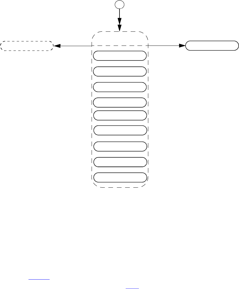
IEEE Std 1800-2012
IEEE STANDARD FOR SYSTEMVERILOG—UNIFIED HARDWARE DESIGN, SPECIFICATION, AND
VERIFICATION LANGUAGE
988
Copyright © 2013 IEEE. All rights reserved.
37.47 Assertion
Details:
1) For details on using VPI to obtain static and dynamic assertion information as well as assertion callbacks and
control, see Clause 39.
2) For details on using VPI to obtain assertion coverage, see 40.5.3.
sequence inst
assume
assertion
cover
property inst
assert
immediate assert
instance clocking block
-> location
str: vpiFile
int: vpiStartLine
int: vpiColumn
int: vpiEndLine
int: vpiEndColumn
-> assertion name
str: vpiName
immediate assume
immediate cover
restrict
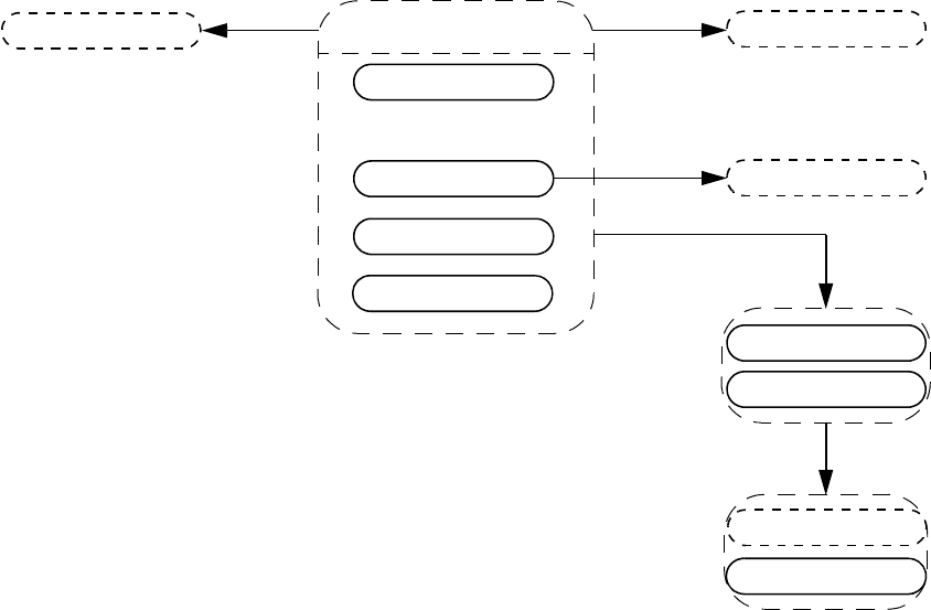
IEEE Std 1800-2012
IEEE STANDARD FOR SYSTEMVERILOG—UNIFIED HARDWARE DESIGN, SPECIFICATION, AND
VERIFICATION LANGUAGE
989
Copyright © 2013 IEEE. All rights reserved.
37.48 Concurrent assertions
Details:
1) Clocking event is always the actual clocking event on which the assertion is being evaluated, regardless of whether
this is explicit or implicit (inferred).
2) The restrict property statement has no pass and no fail action statement. Also, it is not simulated and hence
generates no run-time information.
vpiElseStmt
stmt
expr
-> name
str: vpiName
str: vpiFullName
-> is clock inferred
bool:vpiIsClockInferred
assert
assume
expr
concurrent
assertions
stmt
vpiClockingEvent
property inst
property spec
vpiProperty
cover
vpiDisableCondition
distribution
-> is cover sequence
bool:vpiIsCoverSequence
restrict
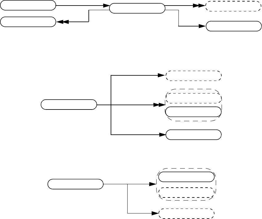
IEEE Std 1800-2012
IEEE STANDARD FOR SYSTEMVERILOG—UNIFIED HARDWARE DESIGN, SPECIFICATION, AND
VERIFICATION LANGUAGE
990
Copyright © 2013 IEEE. All rights reserved.
37.49 Property declaration
Details:
1) The vpiPropFormalDecl iterator shall return the property declaration arguments in the order that the formals for
the property are declared.
2) The vpiArgument iterator shall return the property instance arguments in the order that the formals for the property
are declared, so that the correspondence between each argument and its respective formal can be made. If a formal
has a default value, that value shall appear as the argument should the instantiation not provide a value for that
argument.
3) The vpiTypespec relation shall return NULL if the formal is untyped.
4) If the formal has an initialization expression, the expression can be obtained using the vpiExpr relation.
5) vpiDirection returns vpiNoDirection if the formal argument is not a local variable argument. Otherwise,
vpiDirection returns vpiInput.
property decl
property spec
-> name
str: vpiName
str: vpiFullName
property inst
prop formal decl
variables
prop formal decl
property expr
-> name
str: vpiName
-> direction
int: vpiDirection
named event
typespec
vpiExpr
property decl
property inst
vpiDisableCondition
property expr
named event
expr
vpiArgument
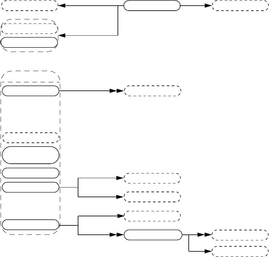
IEEE Std 1800-2012
IEEE STANDARD FOR SYSTEMVERILOG—UNIFIED HARDWARE DESIGN, SPECIFICATION, AND
VERIFICATION LANGUAGE
991
Copyright © 2013 IEEE. All rights reserved.
37.50 Property specification
Details:
1) Variables are declarations of property variables. The value of these variables cannot be accessed.
2) Within the context of a property expr, vpiOpType can be any one of vpiAcceptOnOp, vpiAlwaysOp, vpiCom-
pAndOp, vpiCompOrOp, vpiEventuallyOp, vpiIfElseOp, vpiIfOp, vpiIffOp, vpiImpliesOp, vpiNexttimeOp,
vpiNonOverlapFollowedByOp, vpiNonOverlapImplyOp, vpiNotOp, vpiOverlapFollowedByOp, vpiOver-
lapImplyOp, vpiRejectOnOp, vpiSyncAcceptOnOp, vpiSyncRejectOnOp, vpiUntilOp, or vpiUntilWithOp.
Operands to these operations shall be provided in the same order as shown in the BNF, with the following excep-
tions:
—vpiNexttimeOp: Arguments shall be: property, constant. constant shall only be given if different from 1.
—vpiAlwaysOp and vpiEventuallyOp: Arguments shall be: property, left range, right range.
3) vpiOpStrong is valid only for operations vpiNexttimeOp, vpiAlwaysOp, vpiEventuallyOp, vpiUntilOp,
vpiUntilWithOp, and for sequence expression. vpiOpStrong shall return TRUE to indicate the strong version of
the corresponding operator.
4) The case property item shall group all case conditions that branch to the same property statement.
5) vpi_iterate() shall return NULL for the default case item because there is no expression with the default case.
property spec
vpiClockingEvent
expr
vpiDisableCondition
property expr
operation
property expr
property inst
-> operation type
int: vpiOpType
-> operator strength
bool: vpiOpStrong
sequence expr
multiclock
sequence expr
clocked property
property expr
expr
property expr
vpiClockingEvent
vpiOperand
expr
distribution
case property
case property item
expr
expr
property expr
vpiCondition
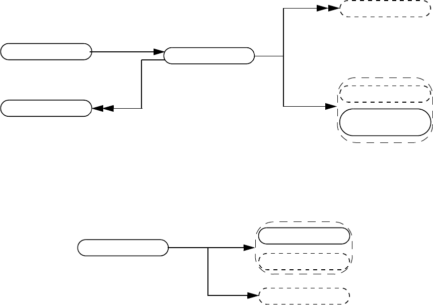
IEEE Std 1800-2012
IEEE STANDARD FOR SYSTEMVERILOG—UNIFIED HARDWARE DESIGN, SPECIFICATION, AND
VERIFICATION LANGUAGE
992
Copyright © 2013 IEEE. All rights reserved.
37.51 Sequence declaration
Details:
1) The vpiSeqFormalDecl iterator shall return the sequence declaration arguments in the order that the formals for the
sequence are declared.
2) The vpiTypespec relation shall return NULL if the formal is untyped.
3) If the formal has an initialization expression, the expression can be obtained using the vpiExpr relation.
4) vpiDirection returns vpiNoDirection if the formal argument is not a local variable argument. Otherwise,
vpiDirection returns either vpiInput, vpiOutput, or vpiInout.
variables
sequence decl
multiclock
-> name
str: vpiName
str: vpiFullName
vpiExpr
sequence inst
sequence expr
sequence expr
seq formal decl
seq formal decl
sequence expr
named event
typespec
vpiExpr
-> name
str: vpiName
-> direction
int: vpiDirection
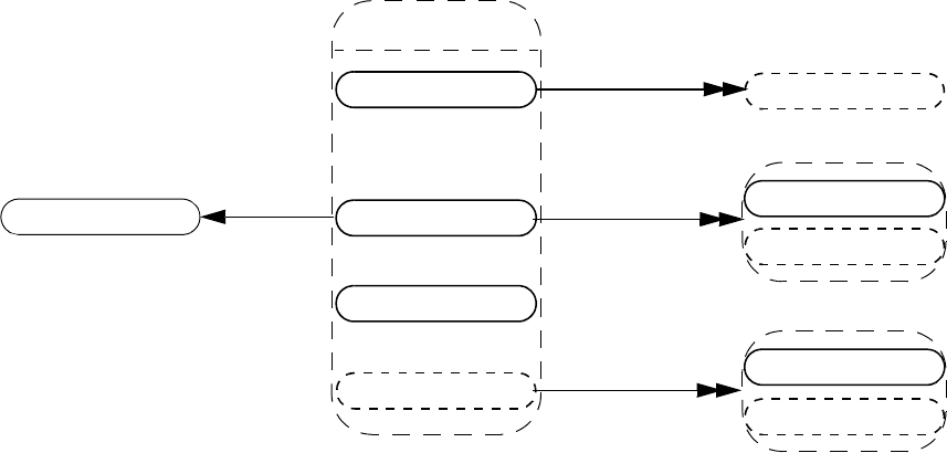
IEEE Std 1800-2012
IEEE STANDARD FOR SYSTEMVERILOG—UNIFIED HARDWARE DESIGN, SPECIFICATION, AND
VERIFICATION LANGUAGE
993
Copyright © 2013 IEEE. All rights reserved.
37.52 Sequence expression
Details:
1) The vpiArgument iterator shall return the sequence instance arguments in the order that the formals for the
sequence are declared, so that the correspondence between each argument and its respective formal can be made. If
a formal has a default value, that value shall appear as the argument should the instantiation not provide a value for
that argument.
2) Within a sequence expression, vpiOpType can be any one of vpiCompAndOp, vpiIntersectOp, vpiCompOr,
vpiFirstMatchOp, vpiThroughoutOp, vpiWithinOp, vpiUnaryCycleDelayOp, vpiCycleDelayOp, vpiRepe-
atOp, vpiConsecutiveRepeatOp, or vpiGotoRepeatOp.
3) For operations, the operands shall be provided in the same order as the operands appear in BNF, with the following
exceptions:
—vpiUnaryCycleDelayOp: Arguments shall be: sequence, left range, right range. Right range shall only be
given if different from left range.
—vpiCycleDelayOp: Arguments shall be: left-hand side sequence, right-hand side sequence, left range, right
range. Right range shall only be provided if different than left range.
— All the repeat operators: The first argument shall be the sequence being repeated, and the next argument shall be
the left repeat bound, followed by the right repeat bound. The right repeat bound shall only be provided if
different from left repeat bound.
and, intersect, or,
first_match,
throughout, within,
##,
[*], [=], [->]
operation
tf call
sequence decl
vpiMatchItem
sequence inst
assignment
sequence expr
sequence expr
distribution
vpiOperand
-> operation type
int: vpiOpType
vpiArgument
sequence expr
expr
named event
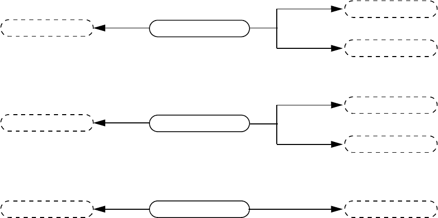
IEEE Std 1800-2012
IEEE STANDARD FOR SYSTEMVERILOG—UNIFIED HARDWARE DESIGN, SPECIFICATION, AND
VERIFICATION LANGUAGE
994
Copyright © 2013 IEEE. All rights reserved.
37.53 Immediate assertions
stmt
vpiElseStmt
stmt
immediate assume
stmt
vpiElseStmt
stmt
expr
immediate assert
expr
immediate cover
expr stmt
-> is deferred
int: vpiIsDeferred
-> is final
int: vpiIsFinal
-> is deferred
int: vpiIsDeferred
-> is final
int: vpiIsFinal
-> is deferred
int: vpiIsDeferred
-> is final
int: vpiIsFinal
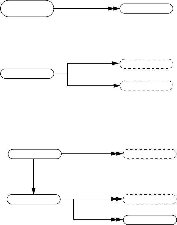
IEEE Std 1800-2012
IEEE STANDARD FOR SYSTEMVERILOG—UNIFIED HARDWARE DESIGN, SPECIFICATION, AND
VERIFICATION LANGUAGE
995
Copyright © 2013 IEEE. All rights reserved.
37.54 Multiclock sequence expression
37.55 Let
Details:
1) The vpiArgument iterator shall return the let expression arguments in the order that the formals for the let are
declared, so that the correspondence between each argument and its respective formal can be made. If a formal has
a default value, that value shall appear as the argument should the instantiation not provide a value for that
argument.
multiclock clocked seq
sequence expr
clocked seq
vpiClockingEvent
expr
sequence expr
let decl
vpiArgument
expr
-> name
str: vpiName
let expr expr
seq formal decl
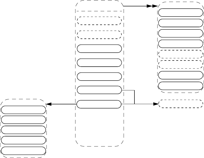
IEEE Std 1800-2012
IEEE STANDARD FOR SYSTEMVERILOG—UNIFIED HARDWARE DESIGN, SPECIFICATION, AND
VERIFICATION LANGUAGE
996
Copyright © 2013 IEEE. All rights reserved.
37.56 Simple expressions
Details:
1) For vectors, the vpiUse relationship shall access any use of the vector or of the part-selects or bit-selects of the
vector.
2) For bit-selects, the vpiUse relationship shall access any specific use of that bit, any use of the parent vector, and any
part-select that contains that bit.
3) The property vpiConstantSelect shall return TRUE for a bit-select if
— every associated index expression is an elaboration time constant expression, and
—vpiConstantSelect returns TRUE for the parent of the bit-select.
Otherwise, vpiConstantSelect shall return FALSE.
NOTE—If vpiConstantSelect is TRUE, then if the handle refers to a valid underlying simulation object at the
beginning of simulation (or at any point in the simulation), it refers to the same object at all points in the simulation.
Moreover, if an index expression of the bit-select or of any of its parents is in or out of bounds at the beginning of
simulation, it is in or out of bounds at all subsequent simulation times as well.
simple expr
nets
ref obj
vpiIndex
variables
parameter
spec param
var select
bit select
-> name
str: vpiName
str: vpiFullName
-> constant select
bool:
vpiConstantSelect
integer var
time var
parameter
spec param
var select
expr
vpiParent
tchk term
delay term
cont assign
cont assign bit
prim term
path term
ports
stmt
vpiUse
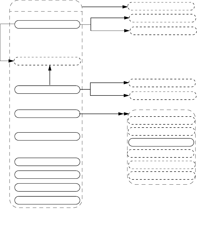
IEEE Std 1800-2012
IEEE STANDARD FOR SYSTEMVERILOG—UNIFIED HARDWARE DESIGN, SPECIFICATION, AND
VERIFICATION LANGUAGE
997
Copyright © 2013 IEEE. All rights reserved.
37.57 Expressions
Details:
1) For an operator whose type is vpiMultiConcatOp, the first operand shall be the multiplier expression. The
remaining operands shall be the expressions within the concatenation.
2) The property vpiDecompile shall return a string with a functionally equivalent expression to the original expression
within the source code. Parentheses shall be added only to preserve precedence. Each operand and operator shall be
separated by a single space character. No additional white space shall be added due to parentheses.
expr
simple expr
vpiOperand
vpiParent
vpiLeftRange
vpiRightRange
-> constant selection
bool: vpiConstantSelect
-> operation type
int: vpiOpType
-> constant type
int: vpiConstType
-> decompile
str: vpiDecompile
-> size
int: vpiSize
-> value
vpi_get_value()
indexed part select
part select
operation
func call
constant
method func call
sys func call
-> constant selection
bool: vpiConstantSelect
-> index part select type
int: vpiIndexedPartSelectType
expr
expr
expr
typespec
pattern
sequence inst
range
vpiWidthExpr
expr
expr
vpiBaseExpr
vpiParent
property inst
let expr
interface expr
IEEE Std 1800-2012
IEEE STANDARD FOR SYSTEMVERILOG—UNIFIED HARDWARE DESIGN, SPECIFICATION, AND
VERIFICATION LANGUAGE
998
Copyright © 2013 IEEE. All rights reserved.
3) The cast operation, for which vpiOpType returns vpiCastOp, is represented as a unary operation, with its sole
argument being the expression being cast, and the typespec of the cast expression being the type to which the argu-
ment is being cast.
4) The constant type vpiUnboundedConst represents the $ value used in assertion ranges.
5) The one-to-one relation to typespec shall always be available for vpiCastOp operations, for simple expressions,
and for vpiAssignmentPatternOp and vpiMultiAssignmentPatternOp expressions when the curly braces of the
assignment pattern are prefixed by a data type name to form an assignment pattern expression. For other expres-
sions, it is implementation dependent as to whether or not there is any associated typespec.
6) For an operation of type vpiAssignmentPatternOp, the operand iteration shall return the expressions as if the
assignment pattern were written with the positional notation. Nesting of assignment patterns shall be preserved.
Example 1:
struct {
int A;
struct {
logic B;
real C;
} BC1, BC2;
} ABC = '{BC1: '{1'b1, 1.0}, int: 0, BC2: '{default: 0}};
The assignment pattern that initializes the struct variable ABC uses member, type, and default keys. The
vpiOperand traversal would represent this assignment pattern expression as:
'{0, '{1'b1, 1.0}, '{0, 0}}
or some other equivalent positional assignment pattern.
Example 2:
logic [2:0] varr [0:3] = '{3: 3'b1, default: 3'b0};
The assignment pattern that initializes the array variable varr uses index and default keys. The vpiOperand
traversal would represent this assignment pattern as:
'{3'b0, 3'b0, 3'b0, 3'b1}
7) For an operator whose type is vpiMultiAssignmentPatternOp, the first operand shall be the multiplier expression.
The remaining operands shall be the expressions within the assignment pattern.
Example:
bit unpackedbits [1:0];
initial unpackedbits = '{2 {y}} ; // same as '{y, y}
For the assignment pattern '{2{y}}, the vpiOpType property shall return vpiMultiAssignmentPatternOp, and
the first operand shall be the constant 2. The next operand shall represent the expression y.
8) Expressions that are protected shall permit access to the vpiSize property.
9) The property vpiConstantSelect shall return TRUE for a part-select or indexed part-select if
—vpiConstantSelect returns TRUE for its parent, and
— the parent is a packed or unpacked array with static bounds, and
— each range expression in the part-select or indexed part-select is an elaboration time constant expression.
Otherwise, vpiConstantSelect shall return FALSE.
NOTE—If vpiConstantSelect is TRUE, then if the handle refers to a valid underlying simulation object at the
beginning of simulation (or at any point in the simulation), it refers to the same object at all points in the simulation.
Moreover, if any index expression of the part-select or indexed part-select or of any of its parents is in or out of
bounds at the beginning of simulation, it is in or out of bounds at all subsequent simulation times as well.
IEEE Std 1800-2012
IEEE STANDARD FOR SYSTEMVERILOG—UNIFIED HARDWARE DESIGN, SPECIFICATION, AND
VERIFICATION LANGUAGE
999
Copyright © 2013 IEEE. All rights reserved.
10) For a part-select or indexed part-select, the vpiParent object shall correspond to the expression formed by
removing the part-select range from the expression represented by the part-select or indexed part-select itself. For
example, given the declaration
logic [0:3][7:0] r [1:4];
then the parents of various part-selects or indexed part-selects shall be as shown in Table 37-1:
Table 37-1—Part-select parent expressions
Part-select or indexed
part-select expression Parent expression
r[4][3][1:0] r[4][3]
r[i+1][3][j+:2] r[i+1][3]
r[0][j-:4] r[0]
r[0:2] r
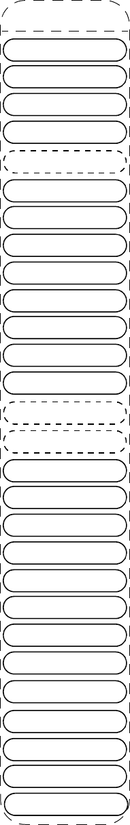
IEEE Std 1800-2012
IEEE STANDARD FOR SYSTEMVERILOG—UNIFIED HARDWARE DESIGN, SPECIFICATION, AND
VERIFICATION LANGUAGE
1000
Copyright © 2013 IEEE. All rights reserved.
37.58 Atomic statement
if
atomic stmt
-> label
str: vpiName
if else
while
repeat
waits
case
for
delay control
event control
event stmt
assignment
assign stmt
deassign
disables
tf call
forever
force
release
do while
expect stmt
foreach stmt
return stmt
break
continue
immediate assert
null stmt
immediate assume
immediate cover
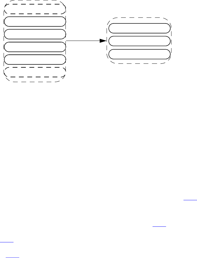
IEEE Std 1800-2012
IEEE STANDARD FOR SYSTEMVERILOG—UNIFIED HARDWARE DESIGN, SPECIFICATION, AND
VERIFICATION LANGUAGE
1001
Copyright © 2013 IEEE. All rights reserved.
Details:
1) The vpiName property shall provide the statement label if one was given; otherwise, the name is NULL.
37.59 Dynamic prefixing
Details:
1) The vpiPrefix relation shall be non-NULL when the object represents an expression or task call in the
SystemVerilog source code prefixed by a virtual interface or a clocking block, or when the object is all or part of a
non-static class property prefix ed by a class var.
2) The memory allocation scheme value for an object for which a class var or virtual interface var vpiPrefix is non-
NULL shall be the same as for the prefix.
3) The property vpiHasActual shall return TRUE:
— whenever the prefix object has a corresponding actual at the current simulation time.
— if the object is all or part of a statically declared object in an elaborated context.
—if the object is part or all of an automatically allocated variable obtained from a frame (see 37.41).
The property vpiHasActual shall return FALSE:
— whenever the prefix object has no corresponding actual at the current simulation time.
—if the object is obtained from a lexical context, such as from a class defn (see 37.29).
—if the object is part or all of a non-static class property variable referenced relative to its class
typespec (see 37.30).
—if the object is part or all of an automatically allocated variable obtained from a task or function
declaration (see 37.39).
-> has actual
bool: vpiHasActual
class var
clocking block
virtual interface var
vpiPrefix
indexed part select
part select
named event array
named event
tf call
simple expr
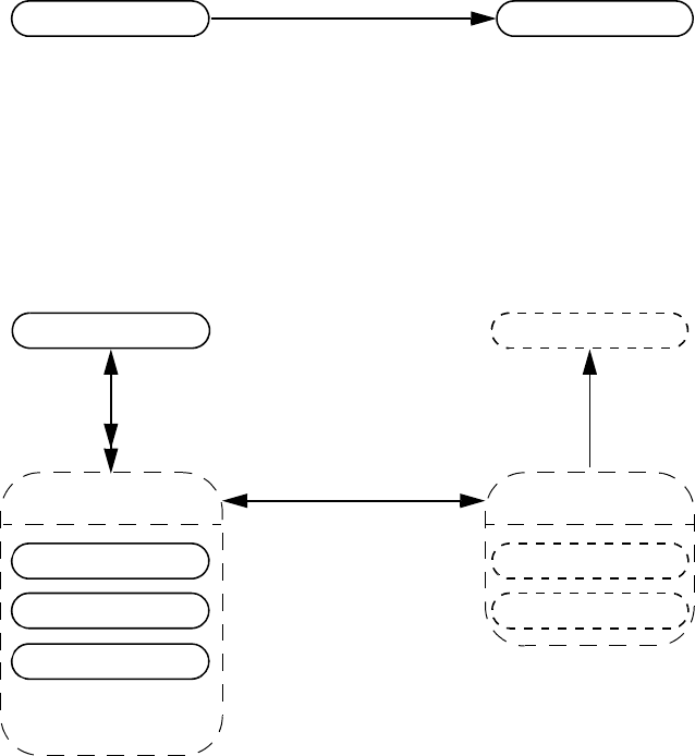
IEEE Std 1800-2012
IEEE STANDARD FOR SYSTEMVERILOG—UNIFIED HARDWARE DESIGN, SPECIFICATION, AND
VERIFICATION LANGUAGE
1002
Copyright © 2013 IEEE. All rights reserved.
37.60 Event statement
37.61 Process
Details:
1) vpiAlwaysType can be one of vpiAlways, vpiAlwaysComb, vpiAlwaysFF, or vpiAlwaysLatch.
event stmt named event
-> blocking
bool: vpiBlocking
initial
process
final
always
scope
module
stmt
scope
atomic stmt
-> always type
int: vpiAlwaysType
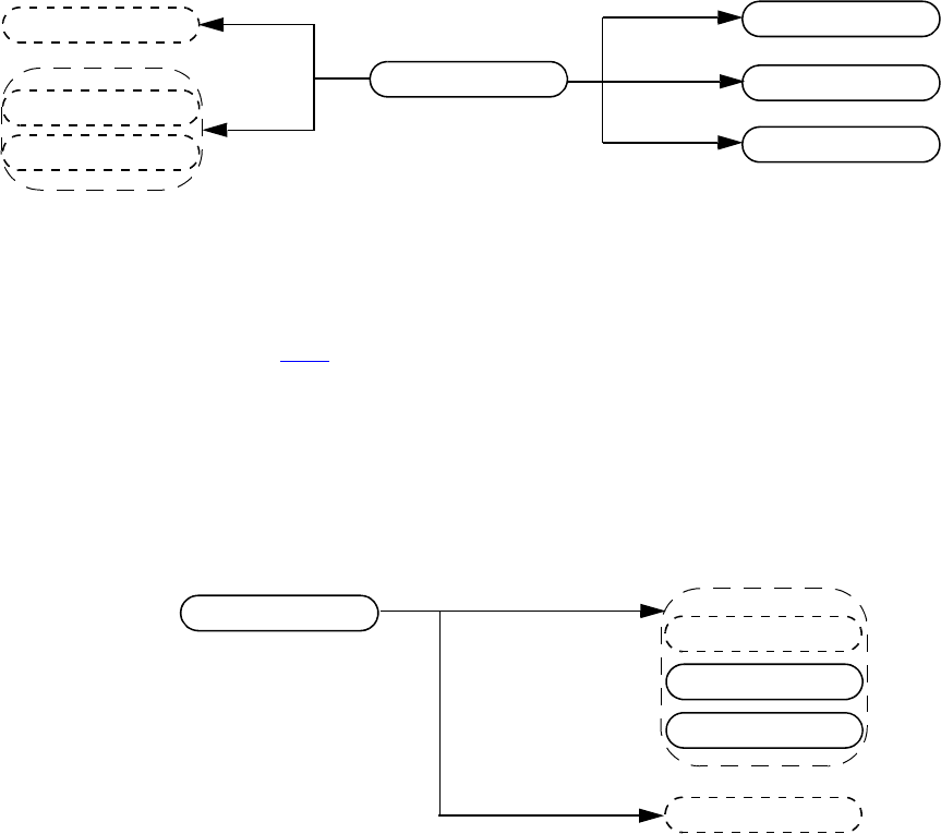
IEEE Std 1800-2012
IEEE STANDARD FOR SYSTEMVERILOG—UNIFIED HARDWARE DESIGN, SPECIFICATION, AND
VERIFICATION LANGUAGE
1003
Copyright © 2013 IEEE. All rights reserved.
37.62 Assignment
Details:
1) vpiOpType shall return vpiAssignmentOp for normal assignments (both blocking “=” and nonblocking “<=”).
For assignment operators, vpiOpType shall return a value that corresponds to the operator that is combined with
the assignment as described in 11.4.1.
For example, the assignment
a += 2;
shall return vpiAddOp for the vpiOpType property.
37.63 Event control
Details:
1) For event control associated with assignment, the statement shall always be NULL.
assignment
vpiLhs
expr
expr
vpiRhs
event control
delay control
repeat control
-> operator
int: vpiOpType
-> blocking
bool: vpiBlocking
interface expr
expr
event control “@”
sequence inst
vpiCondition
stmt
named event
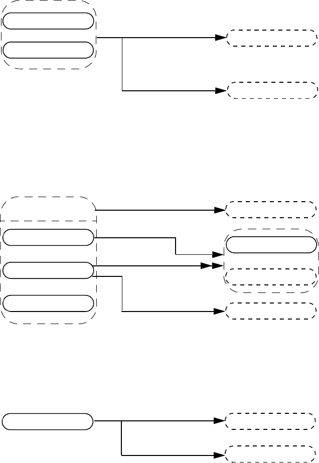
IEEE Std 1800-2012
IEEE STANDARD FOR SYSTEMVERILOG—UNIFIED HARDWARE DESIGN, SPECIFICATION, AND
VERIFICATION LANGUAGE
1004
Copyright © 2013 IEEE. All rights reserved.
37.64 While, repeat
37.65 Waits
37.66 Delay control
Details:
1) For delay control associated with assignment, the statement shall always be NULL.
expr
while
repeat
vpiCondition
stmt
stmt
wait
ordered wait
waits
sequence inst
vpiCondition
wait fork stmt
expr
vpiCondition
vpiElseStmt
expr
delay control “#”
vpiDelay
stmt
-> delay
vpi_get_delays()
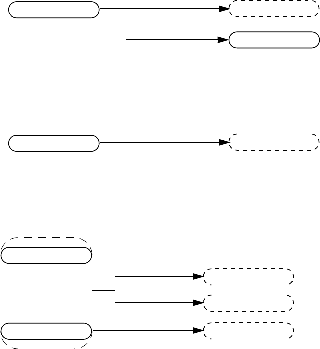
IEEE Std 1800-2012
IEEE STANDARD FOR SYSTEMVERILOG—UNIFIED HARDWARE DESIGN, SPECIFICATION, AND
VERIFICATION LANGUAGE
1005
Copyright © 2013 IEEE. All rights reserved.
37.67 Repeat control
37.68 Forever
37.69 If, if–else
expr
repeat control
event control
stmt
forever
expr
stmt
vpiCondition
if
if else
vpiElseStmt
stmt
-> qualifier
int: vpiQualifer
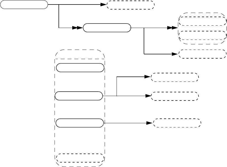
IEEE Std 1800-2012
IEEE STANDARD FOR SYSTEMVERILOG—UNIFIED HARDWARE DESIGN, SPECIFICATION, AND
VERIFICATION LANGUAGE
1006
Copyright © 2013 IEEE. All rights reserved.
37.70 Case, pattern
Details:
1) The case item shall group all case conditions that branch to the same statement.
2) vpi_iterate() shall return NULL for the default case item because there is no expression with the default case.
any pattern
tagged pattern
pattern
case item
expr
stmt
case
-> type
int: vpiCaseType
-> qualifier
int: vpiQualifier expr
vpiExpr
pattern
pattern
typespec
struct pattern pattern
-> name
str: vpiName
vpiCondition
-> name
str: vpiName
expr
-> name
str: vpiName
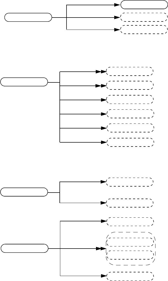
IEEE Std 1800-2012
IEEE STANDARD FOR SYSTEMVERILOG—UNIFIED HARDWARE DESIGN, SPECIFICATION, AND
VERIFICATION LANGUAGE
1007
Copyright © 2013 IEEE. All rights reserved.
37.71 Expect
37.72 For
37.73 Do-while, foreach
Details:
1) The variable obtained via the vpiVariables relation from a foreach stmt shall represent the packed array, unpacked
array, or string var being indexed.
2) The vpiLoopVars iteration shall return the index variables of the foreach statement in left-to-right order. If an
index variable is skipped, its place shall be represented as a vpiOperation for which the vpiOpType is vpiNullOp.
expect stmt
property spec
stmt
stmt
vpiElseStmt
for
expr
stmt
vpiCondition
stmt
stmt
stmt
vpiForIncStmt
stmt
vpiForInitStmt
vpiForIncStmt
vpiForInitStmt
-> has local variables
int: vpiLocalVarDecls
do while
expr
stmt
vpiCondition
foreach stmt
variables
variables
vpiLoopVars
stmt
operation
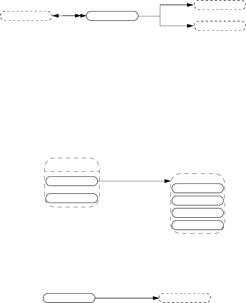
IEEE Std 1800-2012
IEEE STANDARD FOR SYSTEMVERILOG—UNIFIED HARDWARE DESIGN, SPECIFICATION, AND
VERIFICATION LANGUAGE
1008
Copyright © 2013 IEEE. All rights reserved.
37.74 Alias statement
Example:
alias a=b=c=d;
results in 3 aliases:
alias a=d;
alias b=d;
alias c=d;
d is the right-hand side for all.
37.75 Disables
37.76 Return statement
instance
expr
vpiLhs
alias stmt
expr
vpiRhs
disable
disables
task
disable fork
vpiExpr
function
named begin
named fork
return stmt expr
vpiCondition

IEEE Std 1800-2012
IEEE STANDARD FOR SYSTEMVERILOG—UNIFIED HARDWARE DESIGN, SPECIFICATION, AND
VERIFICATION LANGUAGE
1009
Copyright © 2013 IEEE. All rights reserved.
37.77 Assign statement, deassign, force, release
37.78 Callback
Details:
1) To get information about the callback object, the routine vpi_get_cb_info() can be used..
2) To get callback objects not related to the above objects, the second argument to vpi_iterate() shall be NULL.
force
assign stmt
vpiLhs
deassign
release
vpiRhs
vpiLhs
expr
expr
expr
callback
-> cb info
p_cb_data: vpi_get_cb_info()
prim term
expr
time queue
stmt
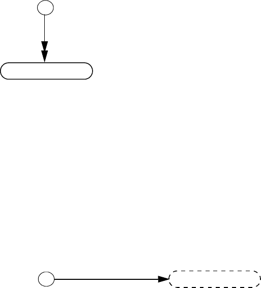
IEEE Std 1800-2012
IEEE STANDARD FOR SYSTEMVERILOG—UNIFIED HARDWARE DESIGN, SPECIFICATION, AND
VERIFICATION LANGUAGE
1010
Copyright © 2013 IEEE. All rights reserved.
37.79 Time queue
Details:
1) The time queue objects shall be returned in increasing order of simulation time.
2) vpi_iterate() shall return NULL if there is nothing left in the simulation time queue.
3) The current time queue shall only be returned as part of the iteration if there are events that precede read only sync.
37.80 Active time format
Details:
1) If $timeformat() has not been called, vpi_handle(vpiActiveFormat, NULL) shall return NULL.
time queue
-> time
vpi_get_time()
tf call
vpiActiveTimeFormat
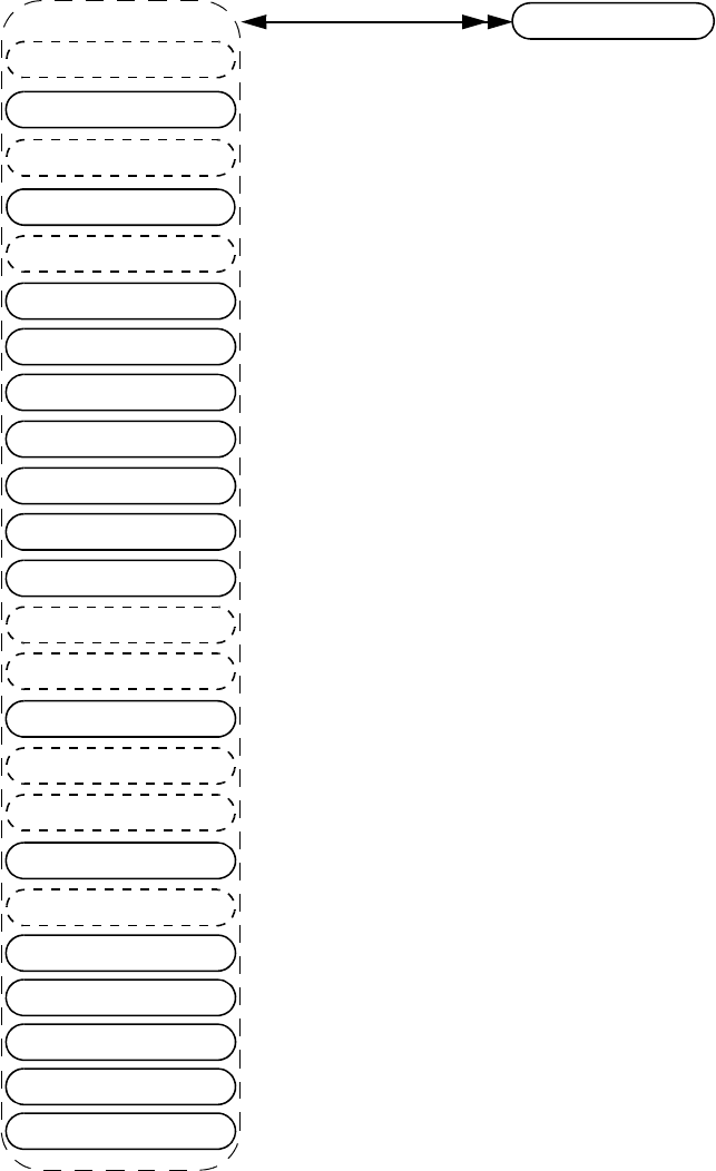
IEEE Std 1800-2012
IEEE STANDARD FOR SYSTEMVERILOG—UNIFIED HARDWARE DESIGN, SPECIFICATION, AND
VERIFICATION LANGUAGE
1011
Copyright © 2013 IEEE. All rights reserved.
37.81 Attribute
net
attribute
-> name
str: vpiName
-> On definition
bool: vpiDefAttribute
-> value:
vpi_get_value()
-> definition location
str: vpiDefFile
int: vpiDefLineNo
port
array net
variables
named event
prim term
path term
mod path
tchk
param assign
spec param
task func
table entry
stmt
process
primitive
operation
concurrent assertions
sequence decl
property decl
clocking block
class defn
constraint
instances
vpiParent
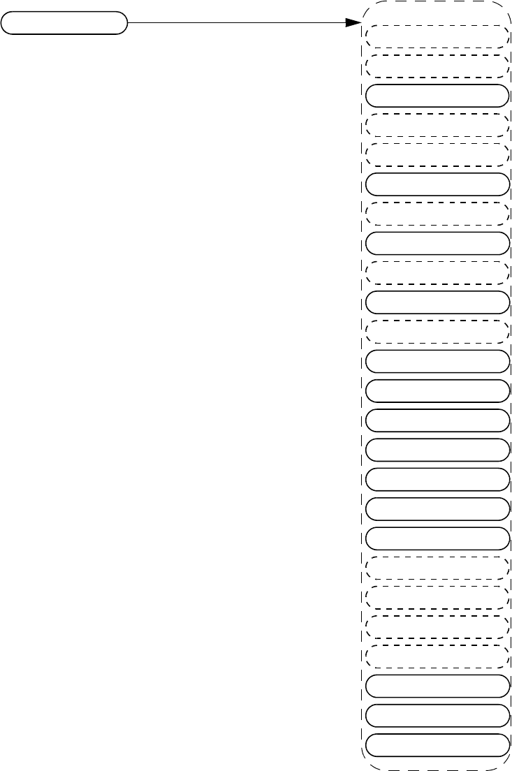
IEEE Std 1800-2012
IEEE STANDARD FOR SYSTEMVERILOG—UNIFIED HARDWARE DESIGN, SPECIFICATION, AND
VERIFICATION LANGUAGE
1012
Copyright © 2013 IEEE. All rights reserved.
37.82 Iterator
Details:
1) vpi_handle(vpiUse, iterator_handle) shall return the reference handle used to create the iterator.
2) It is possible to have a NULL reference handle, in which case vpi_handle(vpiUse, iterator_handle) shall return
NULL.
ports
iterator
-> type
int: vpiIteratorType
udp defn
regs
net array
named event array
inter mod path
mod path
tchk
param assign
case item
tf call
frame
stmt
process
primitive
time queue
expr
vpiUse
instance array
scope
nets
variables
reg array
prim term
path term
delay term
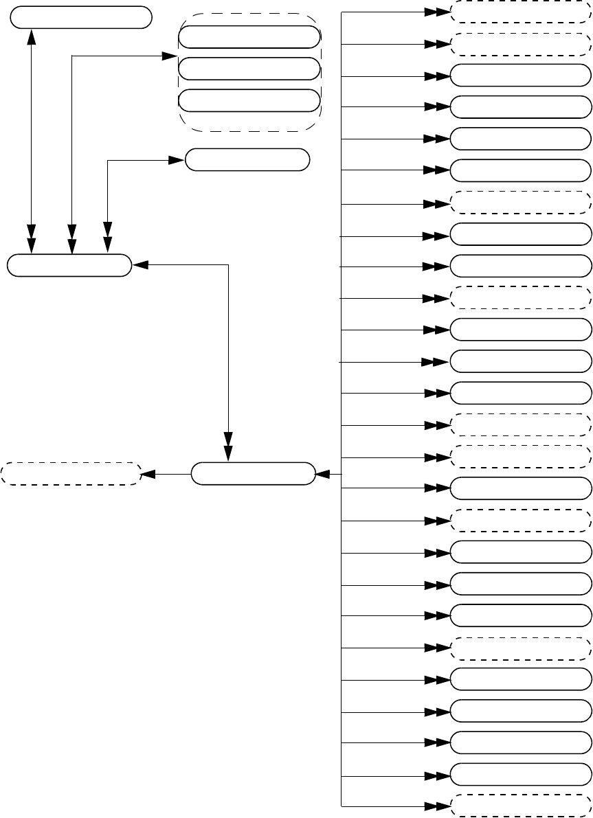
IEEE Std 1800-2012
IEEE STANDARD FOR SYSTEMVERILOG—UNIFIED HARDWARE DESIGN, SPECIFICATION, AND
VERIFICATION LANGUAGE
1013
Copyright © 2013 IEEE. All rights reserved.
37.83 Generates
expr
gen scope array
-> size
int: vpiSize
-> name
str: vpiName
str: vpiFullName
-> access by index
vpi_handle_by_index()
vpi_handle_by_multi_index()
array net
variables
named event
named event array
module
module array
gen scope array
def param
program
process
primitive
cont assign
clocking block
alias stmt
interface
vpiInstance
scope
vpiIndex
logic var
array var
array var
primitive array
program array
interface array
module
interface
program
module
gen var
gen scope
-> name
str: vpiName
str: vpiFullName
vpiTypedef
vpiInternalScope
vpiMemory
-> array member
bool: vpiArray (deprecated)
bool: vpiArrayMember
-> name
str: vpiName
str: vpiFullName
-> protected
bool: vpiProtected
-> is implicitly declared
bool: vpiImplicitDecl
typespec
assertion
net
parameters
vpiParameter
IEEE Std 1800-2012
IEEE STANDARD FOR SYSTEMVERILOG—UNIFIED HARDWARE DESIGN, SPECIFICATION, AND
VERIFICATION LANGUAGE
1014
Copyright © 2013 IEEE. All rights reserved.
Details:
1) The size for a gen scope array shall be the number of elements in the array.
2) For an unnamed generate, an implicit scope shall be created. Its vpiImplicitDecl property shall return TRUE.
3) References to gen vars within the gen scope shall be treated as local parameters.
4) Parameters within the gen scope must be local parameters.
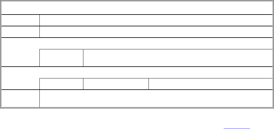
IEEE Std 1800-2012
IEEE STANDARD FOR SYSTEMVERILOG—UNIFIED HARDWARE DESIGN, SPECIFICATION, AND
VERIFICATION LANGUAGE
1015
Copyright © 2013 IEEE. All rights reserved.
38. VPI routine definitions
38.1 General
This clause describes the VPI routines and explains their function, syntax, and usage. The routines are listed
in alphabetical order.
The following conventions are used in the definitions of the PLI routines described in this clause:
—Synopsis: A brief description of the PLI routine functionality, intended to be used as a quick
reference when searching for PLI routines to perform specific tasks.
—Syntax: The exact name of the PLI routine and the order of the arguments passed to the routine.
—Returns: The definition of the value returned when the PLI routine is called, along with a brief
description of what the value represents. The return definition contains the following fields:
—Type: The data type of the C value that is returned. The data type is either a standard ANSI C
type or a special type defined within the PLI.
—Description: A brief description of what the value represents.
—Arguments: The definition of the arguments passed with a call to the PLI routine. The argument
definition contains the following fields:
—Type: The data type of the C values that are passed as arguments. The data type is either a
standard ANSI C type or a special type defined within the PLI.
—Name: The name of the argument used in the syntax definition.
—Description: A brief description of what the value represents.
All arguments shall be considered mandatory unless specifically noted in the definition of the PLI
routine.
—Related routines: A list of PLI routines that are typically used with, or provide similar functionality
to, the PLI routine being defined. This list is provided as a convenience to facilitate finding
information in this standard. It is not intended to be all-inclusive, and it does not imply that the
related routines have to be used.
38.2 vpi_chk_error()
The VPI routine vpi_chk_error() shall return an integer constant representing an error severity level if the
previous call to a VPI routine resulted in an error. The error constants are shown in Table 38-1. If the
previous call to a VPI routine did not result in an error, then vpi_chk_error() shall return 0 (false). The error
vpi_chk_error()
Synopsis: Retrieve information about VPI routine errors.
Syntax: vpi_chk_error(error_info_p)
Type Description
Returns: PLI_INT32 The error severity level if the previous VPI routine call resulted in an error; 0 (false)
if no error occurred.
Type Name Description
Arguments: p_vpi_error_info error_info_p Pointer to a structure containing error information.
Related
routines:
IEEE Std 1800-2012
IEEE STANDARD FOR SYSTEMVERILOG—UNIFIED HARDWARE DESIGN, SPECIFICATION, AND
VERIFICATION LANGUAGE
1016
Copyright © 2013 IEEE. All rights reserved.
status shall be reset by any VPI routine call except vpi_chk_error(). Calling vpi_chk_error() shall have no
effect on the error status.
If an error occurred, the s_vpi_error_info structure shall contain information about the error. If the error
information is not needed, a NULL can be passed to the routine. The s_vpi_error_info structure used by
vpi_chk_error() is defined in vpi_user.h and is listed in Figure 38-1.
38.3 vpi_compare_objects()
The VPI routine vpi_compare_objects() shall return 1 (TRUE) if the two handles refer to the same
underlying simulation object at the time the function is called, provided that the simulation object exists.
Table 38-1—Return error constants for vpi_chk_error()
Error constant Severity level
vpiNotice Lowest severity
vpiWarning
vpiError
vpiSystem
vpiInternal Highest severity
vpi_compare_objects()
Synopsis: Compare two handles to determine whether they reference the same object.
Syntax: vpi_compare_objects(obj1, obj2)
Type Description
Returns: PLI_INT32 1 (true) if the two handles refer to the same object; 0 (false) otherwise.
Type Name Description
Arguments: vpiHandle obj1 Handle to an object.
vpiHandle obj2 Handle to an object.
Related
routines:
typedef struct t_vpi_error_info
{
PLI_INT32 state; /* vpi[Compile,PLI,Run] */
PLI_INT32 level; /* vpi[Notice,Warning,Error,System,Internal] */
PLI_BYTE8 *message;
PLI_BYTE8 *product;
PLI_BYTE8 *code;
PLI_BYTE8 *file;
PLI_INT32 line;
} s_vpi_error_info, *p_vpi_error_info;
Figure 38-1—s_vpi_error_info structure definition
IEEE Std 1800-2012
IEEE STANDARD FOR SYSTEMVERILOG—UNIFIED HARDWARE DESIGN, SPECIFICATION, AND
VERIFICATION LANGUAGE
1017
Copyright © 2013 IEEE. All rights reserved.
Otherwise, 0 (FALSE) shall be returned. Object equivalence cannot be determined with a C “==”
comparison.
The following examples illustrate the use of vpi_compare_objects().
Example 1:
struct packed {
int a;
reg [0:7] b;
} ps;
...
initial begin
ps[0] = ...;
ps.b[7] = ...;
end
The expression ps[0] is another way of referring to bit 7 of ps.b, so if a handle obj1 refers to ps[0] and
a handle obj2 refers to ps.b[7], then vpi_compare_objects(obj1, obj2) shall return TRUE.
Example 2:
integer i [0:3];
int j;
...
initial begin
j = 0;
i[j] = ...;
#(1)
j = 1;
i[j] = ...;
end
Let obj1 be a handle to an occurrence of the expression i[j], and let obj2 be a handle to the object i[0]
derived by iteration from the integer array i. Then
vpi_compare_objects(obj1, obj2)
shall return TRUE when j has the value 0 and FALSE when j has the value 1.
Example 3:
class MyClass;
int a;
endclass
...
MyClass c, d;
...
initial begin
c = null;
d = null;
#(1)
c = new;
c.a = 5;
#(1)
d = c;
d.a = 6;
IEEE Std 1800-2012
IEEE STANDARD FOR SYSTEMVERILOG—UNIFIED HARDWARE DESIGN, SPECIFICATION, AND
VERIFICATION LANGUAGE
1018
Copyright © 2013 IEEE. All rights reserved.
#(1)
c = new;
c.a = 7;
end
If obj1 represents the expression c.a, while obj2 represents d.a, then initially neither object exists, and
vpi_compare_objects(obj1, obj2) shall return FALSE. After one time step, c.a exists, but d.a does
not, and vpi_compare_objects(obj1, obj2) shall still return FALSE. After the second time step, c.a
and d.a point to the same int data member of the same class object, and vpi_compare_objects(obj1,
obj2) shall return TRUE. Finally, c gets a new class object assigned to it, but d does not, and
vpi_compare_objects(obj1, obj2) shall once again return FALSE.
38.4 vpi_control()
The VPI routine vpi_control() shall pass information from a user PLI application to a SystemVerilog
software tool, such as a simulator. The following control constants are defined as part of the VPI standard:
vpiStop Causes the $stop built-in SystemVerilog system task to be executed upon return
of the application routine. This operation shall be passed one additional integer
argument, which is the same as the diagnostic message level argument passed to
$stop (see 20.2).
vpiFinish Causes the $finish built-in SystemVerilog system task to be executed upon
return of the application routine. This operation shall be passed one additional
integer argument, which is the same as the diagnostic message level argument
passed to $finish (see 20.2).
vpiReset Causes the $reset built-in SystemVerilog system task to be executed upon
return of the application routine. This operation shall be passed three additional
integer arguments: stop_value, reset_value, and diagnostics_value,
which are the same values passed to the $reset system task (see D.8).
vpiSetInteractiveScope
Causes a tool’s interactive scope to be immediately changed to a new scope. This
operation shall be passed one additional argument, which is a vpiHandle object
within the vpiScope class.
vpi_control()
Synopsis: Pass information from the application code to the simulator.
Syntax: vpi_control(operation, varargs)
Type Description
Returns: PLI_INT32 1 (true) if successful; 0 (false) on a failure.
Type Name Description
Arguments: PLI_INT32 operation Select type of operation.
varargs Variable number of operation-specific arguments.
Related
routines:
IEEE Std 1800-2012
IEEE STANDARD FOR SYSTEMVERILOG—UNIFIED HARDWARE DESIGN, SPECIFICATION, AND
VERIFICATION LANGUAGE
1019
Copyright © 2013 IEEE. All rights reserved.
38.5 vpi_flush()
The routine vpi_flush() shall flush the output buffers for the simulator’s output channel and current log file.
38.6 vpi_get()
The VPI routine vpi_get() shall return the value of integer and Boolean object properties. These properties
shall be of type PLI_INT32. Boolean properties shall have a value of 1 for TRUE and 0 for FALSE. For
integer object properties such as vpiSize, any integer shall be returned. For integer object properties that
return a defined value, see Annex K and Annex M for the value that shall be returned. For object property
vpiTimeUnit or vpiTimePrecision, if the object is NULL, then the simulation time unit shall be returned.
Unless otherwise specified, calling vpi_get() for a protected object shall be an error. Should an error occur,
vpi_get() shall return vpiUndefined.
vpi_flush()
Synopsis: Flushes the data from the simulator output channel and log file output buffers.
Syntax: vpi_flush()
Type Description
Returns: PLI_INT32 0 if successful; nonzero if unsuccessful.
Type Name Description
Arguments: None
Related
routines:
Use vpi_printf() to write a finite number of arguments to the simulator output channel and log file.
Use vpi_vprintf() to write a variable number of arguments to the simulator output channel and log file.
Use vpi_mcd_printf() to write one or more opened files.
vpi_get()
Synopsis: Get the value of an integer or Boolean property of an object.
Syntax: vpi_get(prop, obj)
Type Description
Returns: PLI_INT32 Value of an integer or Boolean property.
Type Name Description
Arguments: PLI_INT32 prop An integer constant representing the property of an
object for which to obtain a value.
vpiHandle obj Handle to an object.
Related
routines:
Use vpi_get_str() to get string properties.
Use vpi_get64() to get 64-bit integer properties.
IEEE Std 1800-2012
IEEE STANDARD FOR SYSTEMVERILOG—UNIFIED HARDWARE DESIGN, SPECIFICATION, AND
VERIFICATION LANGUAGE
1020
Copyright © 2013 IEEE. All rights reserved.
38.7 vpi_get64()
The VPI routine vpi_get64() shall return the value of 64-bit integer object properties. These properties shall
be of type PLI_INT64. For 64-bit integer object properties that return a defined value, see Annex K and
Annex M for the value that shall be returned. Unless otherwise specified, calling vpi_get64() for a protected
object shall be an error. Should an error occur, vpi_get64() shall return vpiUndefined.
38.8 vpi_get_cb_info()
The VPI routine vpi_get_cb_info() shall return information about a simulation-related callback in an
s_cb_data structure. The memory for this structure shall be allocated by the application.
The s_cb_data structure used by vpi_get_cb_info() is defined in vpi_user.h and is listed in Figure 38-2.
vpi_get64()
Synopsis: Get the value of a 64-bit integer property of an object.
Syntax: vpi_get64(prop, obj)
Type Description
Returns: PLI_INT64 Value of a 64-bit integer property.
Type Name Description
Arguments: PLI_INT32 prop An integer constant representing the property of an
object for which to obtain a value.
vpiHandle obj Handle to an object.
Related
routines:
Use vpi_get_str() to get string properties.
Use vpi_get() to get integer or Boolean properties.
vpi_get_cb_info()
Synopsis: Retrieve information about a simulation-related callback.
Syntax: vpi_get_cb_info(obj, cb_data_p)
Type Description
Returns: void
Type Name Description
Arguments: vpiHandle obj Handle to a simulation-related callback.
p_cb_data cb_data_p Pointer to a structure containing callback information.
Related
routines:
Use vpi_get_systf_info() to retrieve information about a system task or system function callback.
IEEE Std 1800-2012
IEEE STANDARD FOR SYSTEMVERILOG—UNIFIED HARDWARE DESIGN, SPECIFICATION, AND
VERIFICATION LANGUAGE
1021
Copyright © 2013 IEEE. All rights reserved.
38.9 vpi_get_data()
The routine shall place numOfBytes of data into the memory location pointed to by dataLoc from a
simulation’s save/restart location. This memory location has to be properly allocated by the application. The
first call for a given id will retrieve the data starting at what was placed into the save/restart location with the
first call to vpi_put_data() for a given id. The return value shall be the number of bytes retrieved. On a
failure, the return value shall be 0. Each subsequent call shall start retrieving data where the last call left off.
It shall be a warning for an application to retrieve more data than were placed into the simulation save/restart
location for a given id. In this case, the dataLoc shall be filled with the data that are left for the given id, and
the remaining bytes shall be filled with “\0”. The return value shall be the actual number of bytes retrieved.
It shall be acceptable for an application to retrieve less data than were stored for a given id with
vpi_put_data(). This routine can only be called from an application routine that has been called for reason
cbStartOfRestart or cbEndOfRestart. The recommended way to get the “id” for vpi_get_data() is to pass
it as the value for user_data when registering for cbStartOfRestart or cbEndOfRestart from the
cbStartOfSave or cbEndOfSave application routine. An application can get the path to the simulation’s
save/restart location by calling vpi_get_str(vpiSaveRestartLocation, NULL) from an application routine
that has been called for reason cbStartOfRestart or cbEndOfRestart.
For an example of vpi_get_data(), see 38.31.
vpi_get_data()
Synopsis: Get data from an implementation’s save/restart location.
Syntax: vpi_get_data(id, dataLoc, numOfBytes)
Type Description
Returns: PLI_INT32 The number of bytes retrieved.
Type Name Description
Arguments: PLI_INT32 id A save/restart ID returned from
vpi_get(vpiSaveRestartID, NULL) .
PLI_BYTE8 * dataLoc Address of application-allocated storage.
PLI_INT32 numOfBytes Number of bytes to be retrieved from save/restart
location.
Related
routines:
Use vpi_put_data() to write saved data.
typedef struct t_cb_data
{
PLI_INT32 reason; /* callback reason */
PLI_INT32 (*cb_rtn)(struct t_cb_data *); /* call routine */
vpiHandle obj; /* trigger object */
p_vpi_time time; /* callback time */
p_vpi_value value; /* trigger object value */
PLI_INT32 index; /* index of the memory word or var select
that changed */
PLI_BYTE8 *user_data;
} s_cb_data, *p_cb_data;
Figure 38-2—s_cb_data structure definition
IEEE Std 1800-2012
IEEE STANDARD FOR SYSTEMVERILOG—UNIFIED HARDWARE DESIGN, SPECIFICATION, AND
VERIFICATION LANGUAGE
1022
Copyright © 2013 IEEE. All rights reserved.
38.10 vpi_get_delays()
The VPI routine vpi_get_delays() shall retrieve the delays or pulse limits of an object and place them in an
s_vpi_delay structure that has been allocated by the application. The format of the delay information shall
be controlled by the time_type flag in the s_vpi_delay structure. This routine shall ignore the value of the
type flag in the s_vpi_time structure.
The s_vpi_delay and s_vpi_time structures used by both vpi_get_delays() and vpi_put_delays() are
defined in vpi_user.h and are listed in Figure 38-3 and Figure 38-4.
.
The da field of the s_vpi_delay structure shall be an application-allocated array of s_vpi_time
structures. This array shall store delay values returned by vpi_get_delays(). The number of elements in this
array shall be determined by the following:
vpi_get_delays()
Synopsis: Retrieve the delays or pulse limits of an object.
Syntax: vpi_get_delays(obj, delay_p)
Type Description
Returns: void
Type Name Description
Arguments: vpiHandle obj Handle to an object.
p_vpi_delay delay_p Pointer to a structure containing delay information.
Related
routines:
Use vpi_put_delays() to set the delays or timing limits of an object.
typedef struct t_vpi_delay
{
struct t_vpi_time *da; /* pointer to application-allocated
array of delay values */
PLI_INT32 no_of_delays; /* number of delays */
PLI_INT32 time_type; /* [vpiScaledRealTime, vpiSimTime,
or vpiSuppressTime] */
PLI_INT32 mtm_flag; /* true for mtm values */
PLI_INT32 append_flag; /* true for append */
PLI_INT32 pulsere_flag; /* true for pulsere values */
} s_vpi_delay, *p_vpi_delay;
Figure 38-3—s_vpi_delay structure definition
typedef struct t_vpi_time
{
PLI_INT32 type; /* [vpiScaledRealTime, vpiSimTime,
vpiSuppressTime] */
PLI_UINT32 high, low; /* for vpiSimTime */
double real; /* for vpiScaledRealTime */
} s_vpi_time, *p_vpi_time;
Figure 38-4—s_vpi_time structure definition
IEEE Std 1800-2012
IEEE STANDARD FOR SYSTEMVERILOG—UNIFIED HARDWARE DESIGN, SPECIFICATION, AND
VERIFICATION LANGUAGE
1023
Copyright © 2013 IEEE. All rights reserved.
— The number of delays to be retrieved
— The mtm_flag setting
— The pulsere_flag setting
The number of delays to be retrieved shall be set in the no_of_delays field of the s_vpi_delay structure.
Legal values for the number of delays shall be determined by the type of object, as follows:
— For primitive objects, the no_of_delays value shall be 2 or 3.
— For path delay objects, the no_of_delays value shall be 1, 2, 3, 6, or 12.
— For timing check objects, the no_of_delays value shall match the number of limits existing in the
timing check.
— For intermodule path objects, the no_of_delays value shall be 2 or 3.
The application-allocated s_vpi_delay array shall contain delays in the same order in which they occur in
the SystemVerilog description. The number of elements for each delay shall be determined by the flags
mtm_flag and pulsere_flag, as shown in Table 38-2.
The delay structure has to be allocated before passing a pointer to vpi_get_delays(). In the following
example, a static structure, prim_da, is allocated for use by each call to the vpi_get_delays() function:
display_prim_delays(prim)
vpiHandle prim;
{
static s_vpi_time prim_da[3];
static s_vpi_delay delay_s = {NULL, 3, vpiScaledRealTime};
static p_vpi_delay delay_p = &delay_s;
delay_s.da = prim_da;
vpi_get_delays(prim, delay_p);
vpi_printf("Delays for primitive %s: %6.2f %6.2f %6.2f\n",
Table 38-2—Size of the s_vpi_delay->da array
Flag values
Number of
s_vpi_time array elements
required for s_vpi_delay->da
Order in which delay elements
shall be filled
mtm_flag = FALSE
pulsere_flag = FALSE
no_of_delays 1st delay: da[0] -> 1st delay
2nd delay: da[1] -> 2nd delay
...
mtm_flag = TRUE
pulsere_flag = FALSE
3 × no_of_delays 1st delay: da[0] -> min delay
da[1] -> typ delay
da[2] -> max delay
2nd delay: ...
mtm_flag = FALSE
pulsere_flag = TRUE
3 × no_of_delays 1st delay: da[0] -> delay
da[1] -> reject limit
da[2] -> error limit
2nd delay element: ...
mtm_flag = TRUE
pulsere_flag = TRUE
9 × no_of_delays 1st delay: da[0] -> min delay
da[1] -> typ delay
da[2] -> max delay
da[3] -> min reject
da[4] -> typ reject
da[5] -> max reject
da[6] -> min error
da[7] -> typ error
da[8] -> max error
2nd delay: ...
IEEE Std 1800-2012
IEEE STANDARD FOR SYSTEMVERILOG—UNIFIED HARDWARE DESIGN, SPECIFICATION, AND
VERIFICATION LANGUAGE
1024
Copyright © 2013 IEEE. All rights reserved.
vpi_get_str(vpiFullName, prim)
delay_p->da[0].real, delay_p->da[1].real, delay_p->da[2].real);
}
38.11 vpi_get_str()
The VPI routine vpi_get_str() shall return string property values. The string shall be placed in a temporary
buffer that shall be used by every call to this routine. If the string is to be used after a subsequent call, the
string should be copied to another location. A different string buffer shall be used for string values returned
through the s_vpi_value structure. Unless otherwise specified, calling vpi_get_str() for a protected object
shall be an error.
The following example illustrates the usage of vpi_get_str():
vpiHandle mod = vpi_handle_by_name("top.mod1",NULL);
vpi_printf ("Module top.mod1 is an instance of %s\n",
vpi_get_str(vpiDefName, mod));
vpi_get_str()
Synopsis: Get the value of a string property of an object.
Syntax: vpi_get_str(prop, obj)
Type Description
Returns: PLI_BYTE8 * Pointer to a character string containing the property value.
Type Name Description
Arguments: PLI_INT32 prop An integer constant representing the property of an object
for which to obtain a value.
vpiHandle obj Handle to an object.
Related
routines:
Use vpi_get() to get integer and Boolean properties.
Use vpi_get64() to get 64-bit integer properties.
IEEE Std 1800-2012
IEEE STANDARD FOR SYSTEMVERILOG—UNIFIED HARDWARE DESIGN, SPECIFICATION, AND
VERIFICATION LANGUAGE
1025
Copyright © 2013 IEEE. All rights reserved.
38.12 vpi_get_systf_info()
The VPI routine vpi_get_systf_info() shall return information about a user-defined system task or system
function callback in an s_vpi_systf_data structure. The memory for this structure shall be allocated by
the application.
The s_vpi_systf_data structure used by vpi_get_systf_info() is defined in vpi_user.h and is listed in
Figure 38-5.
vpi_get_systf_info()
Synopsis: Retrieve information about a user-defined system task or system function callback.
Syntax: vpi_get_systf_info(obj, systf_data_p)
Type Description
Returns: void
Type Name Description
Arguments: vpiHandle obj Handle to a system task or system function callback.
p_vpi_systf_data systf_data_p Pointer to a structure containing callback information.
Related
routines:
Use vpi_get_cb_info() to retrieve information about a simulation-related callback.
typedef struct t_vpi_systf_data
{
PLI_INT32 type; /* vpiSysTask, vpiSysFunc */
PLI_INT32 sysfunctype; /* vpiSysTask, vpi[Int,Real,Time,Sized,
SizedSigned]Func */
PLI_BYTE8 *tfname; /* first character must be '$' */
PLI_INT32 (*calltf)(PLI_BYTE8 *);
PLI_INT32 (*compiletf)(PLI_BYTE8 *);
PLI_INT32 (*sizetf)(PLI_BYTE8 *); /* for sized function
callbacks only */
PLI_BYTE8 *user_data;
} s_vpi_systf_data, *p_vpi_systf_data;
Figure 38-5—s_vpi_systf_data structure definition
IEEE Std 1800-2012
IEEE STANDARD FOR SYSTEMVERILOG—UNIFIED HARDWARE DESIGN, SPECIFICATION, AND
VERIFICATION LANGUAGE
1026
Copyright © 2013 IEEE. All rights reserved.
38.13 vpi_get_time()
The VPI routine vpi_get_time() shall retrieve the current simulation time, using the timescale of the object.
If obj is NULL, the simulation time is retrieved using the simulation time unit. If obj is a time queue object,
the scheduled time of the future event is retrieved using the simulation time unit. The time_p->type field
shall be set to indicate if scaled real or simulation time is desired. The memory for the time_p structure shall
be allocated by the application.
The s_vpi_time structure used by vpi_get_time() is defined in vpi_user.h and is listed in Figure 38-6
[this is the same time structure as used by vpi_put_value()].
vpi_get_time()
Synopsis: Retrieve the current simulation time.
Syntax: vpi_get_time(obj, time_p)
Type Description
Returns: void
Type Name Description
Arguments: vpiHandle obj Handle to an object.
p_vpi_time time_p Pointer to a structure containing time information.
Related
routines:
typedef struct t_vpi_time
{
PLI_INT32 type; /* [vpiScaledRealTime, vpiSimTime,
vpiSuppressTime] */
PLI_UINT32 high, low; /* for vpiSimTime */
double real; /* for vpiScaledRealTime */
} s_vpi_time, *p_vpi_time;
Figure 38-6—s_vpi_time structure definition
IEEE Std 1800-2012
IEEE STANDARD FOR SYSTEMVERILOG—UNIFIED HARDWARE DESIGN, SPECIFICATION, AND
VERIFICATION LANGUAGE
1027
Copyright © 2013 IEEE. All rights reserved.
38.14 vpi_get_userdata()
This routine shall return the value of the user data associated with a previous call to vpi_put_userdata() for
a user-defined system task or system function call handle. If no user data had been previously associated
with the object or if the routine fails, the return value shall be NULL.
After a restart or a reset, subsequent calls to vpi_get_userdata() shall return NULL. It is the application’s
responsibility to save the data during a save using vpi_put_data() and to then retrieve them using
vpi_get_data(). The user-data field can be set up again during or after callbacks of type cbEndOfRestart or
cbEndOfReset.
38.15 vpi_get_value()
The VPI routine vpi_get_value() shall retrieve the simulation value of VPI objects. The value shall be
placed in an s_vpi_value structure, which has been allocated by the application. The object shall be fully
evaluated as if simulated in the context in which it occurs in the SystemVerilog source, including all
expressions with side effects that occur as index expressions or as arguments to function calls embedded in
the object expression.
vpi_get_userdata()
Synopsis: Get user-data value from an implementation’s system task or system function instance storage location.
Syntax: vpi_get_userdata(obj)
Type Description
Returns: void * User-data value associated with a system task instance or system function instance.
Type Name Description
Arguments: vpiHandle obj Handle to a system task instance or system function
instance.
Related
routines:
Use vpi_put_userdata() to write data into the user-data storage area.
vpi_get_value()
Synopsis: Retrieve the simulation value of an object.
Syntax: vpi_get_value(obj, value_p)
Type Description
Returns: void
Type Name Description
Arguments: vpiHandle obj Handle to an expression.
p_vpi_value value_p Pointer to a structure containing value information.
Related
routines:
Use vpi_put_value() to set the value of an object.

IEEE Std 1800-2012
IEEE STANDARD FOR SYSTEMVERILOG—UNIFIED HARDWARE DESIGN, SPECIFICATION, AND
VERIFICATION LANGUAGE
1028
Copyright © 2013 IEEE. All rights reserved.
For example, applying vpi_get_value() to the expression “i++” shall increment the value of i but shall
return the unincremented value. Similarly, retrieving the simulation value of “x[my_func(a)]” shall
evaluate my_func(a) in order to determine the value of the index expression.
The format of the value shall be set by the format field of the structure.
When the format field is vpiObjTypeVal, the routine shall fill in the value and change the format field
based on the object type, as follows:
— For an integer, vpiIntVal
— For a real, vpiRealVal
— For a scalar, either vpiScalar or vpiStrength
— For a time variable, vpiTimeVal with vpiSimTime
— For a vector, vpiVectorVal
The buffer this routine uses for string values shall be different from the buffer that vpi_get_str() shall use.
The string buffer used by vpi_get_value() is overwritten with each call. If the value is needed, it should be
saved by the application.
The s_vpi_value, s_vpi_vecval, and s_vpi_strengthval structures used by vpi_get_value() are
defined in vpi_user.h and are listed in Figure 38-7, Figure 38-8, and Figure 38-9.
.
typedef struct t_vpi_value
{
PLI_INT32 format; /* vpi[[Bin,Oct,Dec,Hex]Str,Scalar,Int,Real,String,
Vector,Strength,Suppress,Time,ObjType]Val */
union
{
PLI_BYTE8 *str; /* string value */
PLI_INT32 scalar; /* vpi[0,1,X,Z] */
PLI_INT32 integer; /* integer value */
double real; /* real value */
struct t_vpi_time *time; /* time value */
struct t_vpi_vecval *vector; /* vector value */
struct t_vpi_strengthval *strength; /* strength value */
PLI_BYTE8 *misc; /* ...other */
} value;
} s_vpi_value, *p_vpi_value;
Figure 38-7—s_vpi_value structure definition
typedef struct t_vpi_vecval
{
/* following fields are repeated enough times to contain vector */
PLI_UINT32 aval, bval; /* bit encoding: ab: 00=0, 10=1, 11=X, 01=Z */
} s_vpi_vecval, *p_vpi_vecval;
Figure 38-8—s_vpi_vecval structure definition
typedef struct t_vpi_strengthval
{
PLI_INT32 logic; /* vpi[0,1,X,Z] */
PLI_INT32 s0, s1; /* refer to strength coding in Annex K */
} s_vpi_strengthval, *p_vpi_strengthval;
Figure 38-9—s_vpi_strengthval structure definition

IEEE Std 1800-2012
IEEE STANDARD FOR SYSTEMVERILOG—UNIFIED HARDWARE DESIGN, SPECIFICATION, AND
VERIFICATION LANGUAGE
1029
Copyright © 2013 IEEE. All rights reserved.
For vectors, the p_vpi_vecval field shall point to an array of s_vpi_vecval structures. The size of this
array shall be determined by the size of the vector, where array_size = ((vector_size–1)/32 + 1). The LSB of
the vector shall be represented by the LSB of the 0-indexed element of s_vpi_vecval array. The 33rd bit
of the vector shall be represented by the LSB of the 1-indexed element of the array, and so on. The memory
for the union members str, time, vector, strength, and misc of the value union in the s_vpi_value structure
shall be provided by the routine vpi_get_value(). This memory shall only be valid until the next call to
vpi_get_value(). The application shall provide the memory for these members when calling
vpi_put_value(). When a value change callback occurs for a value type of vpiVectorVal, the system shall
create the associated memory (an array of s_vpi_vecval structures) and free the memory upon the return
of the callback.
If the format field in the s_vpi_value structure is set to vpiStrengthVal, the value.strength pointer shall
point to an array of s_vpi_strengthval structures. This array shall have at least as many elements as
there are bits in the vector. If the object is a reg or variable, the strength will always be returned as strong.
If the logic value retrieved by vpi_get_value() needs to be preserved for later use, the application shall
allocate storage and copy the value. The following example can be used to copy a value that was retrieved
into an s_vpi_value structure into another structure allocated by the application:
/*
* Copy s_vpi_value structure - must first allocate pointed to fields.
* nvalp must be previously allocated.
* Need to first determine size for vector value.
Table 38-3—Return value field of the s_vpi_value structure union
Format Union member Return description
vpiBinStrVal str String of binary character(s) [1, 0, x, z]
vpiOctStrVal str String of octal character(s) [0–7, x, X, z, Z]
x when all the bits are x
X when some of the bits are x
z when all the bits are z
Z when some of the bits are z
vpiDecStrVal str String of decimal character(s) [0–9]
vpiHexStrVal str String of hex character(s) [0–f, x, X, z, Z]
x when all the bits are x
X when some of the bits are x
z when all the bits are z
Z when some of the bits are z
vpiScalarVal scalar vpi1, vpi0, vpiX, vpiZ, vpiH, vpiL
vpiIntVal integer Integer value of the handle. Any bits x or z in the value
of the object are mapped to a 0
vpiRealVal real Value of the handle as a double
vpiStringVal str A string where each 8-bit group of the value of the
object is assumed to represent an ASCII character
vpiTimeVal time Integer value of the handle using two integers
vpiVectorVal vector aval/bval representation of the value of the object
vpiStrengthVal strength Value plus strength information
vpiObjTypeVal — Return a value in the closest format of the object
IEEE Std 1800-2012
IEEE STANDARD FOR SYSTEMVERILOG—UNIFIED HARDWARE DESIGN, SPECIFICATION, AND
VERIFICATION LANGUAGE
1030
Copyright © 2013 IEEE. All rights reserved.
*/
void copy_vpi_value(s_vpi_value *nvalp, s_vpi_value *ovalp,
PLI_INT32 blen, PLI_INT32 nd_alloc)
{
int i;
PLI_INT32 numvals;
nvalp->format = ovalp->format;
switch (nvalp->format) {
/* all string values */
case vpiBinStrVal: case vpiOctStrVal: case vpiDecStrVal:
case vpiHexStrVal: case vpiStringVal:
if (nd_alloc) nvalp->value.str = malloc(strlen(ovalp->value.str)+1);
strcpy(nvalp->value.str, ovalp->value.str);
break;
case vpiScalarVal:
nvalp->value.scalar = ovalp->value.scalar;
break;
case vpiIntVal:
nvalp->value.integer = ovalp->value.integer;
break;
case vpiRealVal:
nvalp->value.real = ovalp->value.real;
break;
case vpiVectorVal:
numvals = (blen + 31) >> 5;
if (nd_alloc)
{
nvalp->value.vector = (p_vpi_vecval)
malloc(numvals*sizeof(s_vpi_vecval));
}
/* t_vpi_vecval is really array of the 2 integer a/b sections */
/* memcpy or bcopy better here */
for (i = 0; i <numvals; i++)
nvalp->value.vector[i] = ovalp->value.vector[i];
break;
case vpiStrengthVal:
if (nd_alloc)
{
nvalp->value.strength = (p_vpi_strengthval)
malloc(sizeof(s_vpi_strengthval));
}
/* assumes C compiler supports struct assign */
*(nvalp->value.strength) = *(ovalp->value.strength);
break;
case vpiTimeVal:
nvalp->value.time = (p_vpi_time) malloc(sizeof(s_vpi_time));
/* assumes C compiler supports struct assign */
*(nvalp->value.time) = *(ovalp->value.time);
break;
/* not sure what to do here? */
case vpiObjTypeVal: case vpiSuppressVal:
vpi_printf(
"**ERR: cannot copy vpiObjTypeVal or vpiSuppressVal formats",
" - not for filled records.\n");
break;
}
}

IEEE Std 1800-2012
IEEE STANDARD FOR SYSTEMVERILOG—UNIFIED HARDWARE DESIGN, SPECIFICATION, AND
VERIFICATION LANGUAGE
1031
Copyright © 2013 IEEE. All rights reserved.
To get the ASCII values of UDP table entries (see Table 29-1 in 29.3.6), the p_vpi_vecval field shall point to
an array of s_vpi_vecval structures. The size of this array shall be determined by the size of the table
entry (number of symbols per table entry), where array_size = ((table_entry_size–1)/4 + 1). Each symbol
shall require two bytes; the ordering of the symbols within s_vpi_vecval shall be the most significant byte
of abit first, then the least significant byte of abit, then the most significant byte of bbit, and then the least
significant byte of bbit. Each symbol can be either one or two characters; when it is a single character, the
second byte of the pair shall be an ASCII “\0”.
Real valued objects shall be converted to an integer using the rounding defined in 6.12.2 before being
returned in a format other than vpiRealVal and vpiStringVal. If the format specified is vpiStringVal, then
the value shall be returned as a string representation of a floating-point number. The format of this string
shall be in decimal notation with at most 16 digits of precision.
If a constant object’s vpiConstType is vpiStringConst, the value shall be retrieved using a format of either
vpiStringVal or vpiVectorVal.
The misc field in the s_vpi_value structure shall provide for alternative value types, which can be
implementation specific. If this field is utilized, one or more corresponding format types shall also be
provided.
In the following example, the binary value of each net that is contained in a particular module and whose
name begins with a particular string is displayed. [This function makes use of the strcmp() facility
normally declared in a string.h C library.]
void display_certain_net_values(mod, target)
vpiHandle mod;
PLI_BYTE8 *target;
{
static s_vpi_value value_s = {vpiBinStrVal};
static p_vpi_value value_p = &value_s;
vpiHandle net, itr;
itr = vpi_iterate(vpiNet, mod);
while (net = vpi_scan(itr))
{
PLI_BYTE8 *net_name = vpi_get_str(vpiName, net);
if (strcmp(target, net_name) == 0)
{
vpi_get_value(net, value_p);
vpi_printf("Value of net %s: %s\n",
vpi_get_str(vpiFullName, net),value_p->value.str);
}
}
}
The following example illustrates the use of vpi_get_value() to access UDP table entries. Two sample
outputs from this example are provided after the example.
/*
* hUDP must be a handle to a UDP definition
*/
static void dumpUDPTableEntries(vpiHandle hUDP)
{
vpiHandle hEntry, hEntryIter;
s_vpi_value value;
PLI_INT32 numb;
IEEE Std 1800-2012
IEEE STANDARD FOR SYSTEMVERILOG—UNIFIED HARDWARE DESIGN, SPECIFICATION, AND
VERIFICATION LANGUAGE
1032
Copyright © 2013 IEEE. All rights reserved.
PLI_INT32 udpType;
PLI_INT32 item;
PLI_INT32 entryVal;
PLI_INT32 *abItem;
PLI_INT32 cnt, cnt2;
numb = vpi_get(vpiSize, hUDP);
udpType = vpi_get(vpiPrimType, hUDP);
if (udpType == vpiSeqPrim)
numb++; /* There is one more table entry for state */
numb++; /* There is a table entry for the output */
hEntryIter = vpi_iterate(vpiTableEntry, hUDP);
if (!hEntryIter)
return;
value.format = vpiVectorVal;
while(hEntry = vpi_scan(hEntryIter))
{
vpi_printf("\n");
/* Show the entry as a string */
value.format = vpiStringVal;
vpi_get_value(hEntry, &value);
vpi_printf("%s\n", value.value.str);
/* Decode the vector value format */
value.format = vpiVectorVal;
vpi_get_value(hEntry, &value);
abItem = (PLI_INT32 *)value.value.vector;
for(cnt=((numb-1)/2+1);cnt>0;cnt--)
{
entryVal = *abItem;
abItem++;
/* Rip out 4 characters */
for (cnt2=0;cnt2<4;cnt2++)
{
item = entryVal&0xff;
if (item)
vpi_printf("%c", item);
else
vpi_printf("_");
entryVal = entryVal>>8;
}
}
}
vpi_printf("\n");
}
For a UDP table of
1 0 :?:1;
0 (01) :?:-;
(10) 0 :0:1;
the output from the preceding example would be
10:1
_0_1___1
01:0
_1_0___0
00:1
_0_0___1
IEEE Std 1800-2012
IEEE STANDARD FOR SYSTEMVERILOG—UNIFIED HARDWARE DESIGN, SPECIFICATION, AND
VERIFICATION LANGUAGE
1033
Copyright © 2013 IEEE. All rights reserved.
For a UDP table entry of
1 0 :?:1;
0 (01) :?:-;
(10) 0 :0:1;
the output from the preceding example would be
10:?:1
_0_1_1_?
0(01):?:-
10_0_-_?
(10)0:0:1
_001_1_0
38.16 vpi_get_value_array()
The VPI routine vpi_get_value_array() shall retrieve simulation values of contiguous elements in static
unpacked variable or net arrays (array objects for which the vpiArrayType property is vpiStaticArray).
Such arrays must also have static lifetimes and not contain dynamic arrays or dynamic elements (e.g., string
vars). For purposes here, the term element corresponds to any indexable member of such an array with all
unpacked indices fully specified. The data type of each element so defined corresponds to the data type of
the array with all unpacked ranges removed. The elements of arrays are not allowed to be of an unpacked
type themselves (e.g., unpacked structs).
The values for the array section shall be placed in an s_vpi_arrayvalue structure defined in
vpi_user.h, as follows:
typedef struct t_vpi_arrayvalue
{
PLI_UINT32 format;
PLI_UINT32 flags;
union
vpi_get_value_array()
Synopsis: Retrieve simulation values for contiguous elements of a static unpacked array object.
Syntax: vpi_get_value_array(obj, arrayvalue_p, index_p, num)
Type Description
Returns: void
Type Name Description
Arguments: vpiHandle obj Handle to an unpacked array object.
p_vpi_arrayvalue arrayvalue_p Pointer to a structure containing array value information.
PLI_INT32 * index_p Pointer to an array of index values corresponding to the
start of the section of the object to be retrieved.
PLI_UINT32 num Number of array elements to be retrieved.
Related
routines:
Use vpi_put_value_array() to set values of contiguous elements of a static unpacked array object

IEEE Std 1800-2012
IEEE STANDARD FOR SYSTEMVERILOG—UNIFIED HARDWARE DESIGN, SPECIFICATION, AND
VERIFICATION LANGUAGE
1034
Copyright © 2013 IEEE. All rights reserved.
{
PLI_INT32 *integers;
PLI_INT16 *shortints;
PLI_INT64 *longints;
PLI_BYTE8 *rawvals;
struct t_vpi_vecval *vectors;
struct t_vpi_time *times;
double *reals;
float *shortreals;
} value;
} s_vpi_arrayvalue, *p_vpi_arrayvalue;
The s_vpi_arrayvalue structure shown above shall be allocated by the application. However, the
application has the flexibility of allocating the actual storage where the array element values are placed (see
the following). The layout of the values retrieved shall be set by the format field in the structure. In addition
to the format types vpiIntVal, vpiTimeVal, vpiVectorVal, and vpiRealVal available with the
vpi_get_value() function (Table 38-3 in 38.15), the following format types are available:
vpiRawFourStateVal
Values for each element retrieved will be stored in aval/bval format (similar to 4-
state vectors) using the *rawvals field of the union above, interleaved
according to the following structure:
struct
{
PLI_BYTE8 avalbits[ngroups];
PLI_BYTE8 bvalbits[ngroups];
}
Each array element occupies ngroups*2 bytes stored consecutively as A/B byte
groups as shown above. For the first indexed array element, the avalbits
begins at rawvals[0], and the bvalbits at rawvals[ngroups],
respectively. The second array element’s avalbits begin at
rawvals[ngroups*2], and its bvalbits at rawvals[ngroups*3], etc.
ngroups is computed given the array element size in bits (= elemBits) as
follows:
int ngroups = (elemBits + 7) / 8;
The total storage required to hold “num” array elements shall be
ngroups * num * 2.
vpiRawTwoStateVal
Values for each element retrieved shall be stored similarly to
vpiRawFourStateVal above (also using the *rawvals struct member), except
that the bvalbits byte group shall be omitted. ngroups shall be computed
similarly also, but the total storage required shall instead be ngroups * num.
vpiShortIntVal Values retrieved will be stored as an array of “num” short(s), using the
*shortints field in the union in this case. This format is appropriate only for
arrays of vpiShortIntVar or vpiByteVar elements.
vpiLongIntVal Values retrieved will be stored as an array of “num” long(s), using the
*longints field in the union in this case. This format is appropriate for arrays
of vpiLongIntVar, vpiShortIntVar or vpiByteVar elements.
vpiShortRealVal Values retrieved will be stored as an array of “num” floats, using the
*shortrealvals field in the union in this case. This format is appropriate only
for arrays of vpiShortRealVar elements.

IEEE Std 1800-2012
IEEE STANDARD FOR SYSTEMVERILOG—UNIFIED HARDWARE DESIGN, SPECIFICATION, AND
VERIFICATION LANGUAGE
1035
Copyright © 2013 IEEE. All rights reserved.
The format types vpiIntVal, vpiTimeVal, vpiVectorVal, and vpiRealVal that are also available with
vpi_get_value() function correspond to similar union member names in s_vpi_arrayvalue (converted to
pointer values and ending in “s” to indicate they are arrays). For example, selecting the vpiIntVal format
shall cause an array of 32-bit integers to be returned (which should be accessed using the *integers field),
each representing an indexed element of the array object. The vpiVectorVal format shall cause an array of
consecutive A/B word groups formatted according to the t_vpi_vecval structure (Figure 38-8 in 38.15) to
be retrieved. The *vectors field should be used to access them. Given the array element size in bits (==
elemBits), the number of words of storage required will be:
((elemBits + 31) / 32) * 2 * num
All other formats not mentioned here are unsupported and shall result in an error if requested. Also, formats
requested that are inconsistent with the data type of the array elements (except where explicitly allowed)
shall be considered an error.
The vpiRawFourStateVal and vpiVectorVal formats are appropriate for all 4-state array types (all net
arrays, or variable arrays of vpiLogicVar, vpiIntegerVar, vpiTimeVar, or 4-state packed vpiStructVar or
vpiUnionVar elements). The vpiRawTwoStateVal format is appropriate for all 2-state array types
(variable arrays of vpiBitVar, vpiByteVar, vpiShortInt, vpiInt, vpiLongInt, or 2-state packed
vpiStructVar or vpiUnionVar elements). The vpiRawFourStateVal or vpiVectorVal formats can also be
requested of a 2-state array type, and the vpiRawTwoStateVal format can be requested for a 4-state array
type. The bit values in each array element, whether fixed or variable width, correspond to significance order
in avalbits and bvalbits. That is, the LSB of rawvals[0] and rawvals[ngroups] indicates the A and B
value of the LSB (0th) bit of the first array element, respectively, and the LSB of rawvals[1] and
rawvals[ngroups+1] indicates the A and B value of bit 8 of the first array element (if it is of width 9 bits
or greater), and so on. Similar significance order conventions apply to A/B word groups in the
vpiVectorVal format, as described for vpi_get_value() (38.15).
The index_p argument is an array containing the indices of the starting element to be retrieved in the array
object. The indices are ordered in this array according to left-to-right order they would appear in an
expression in HDL text. The size of the index_p index array shall be equal to the number of unpacked
dimensions of obj, the array object.
The array element values are retrieved consecutively in order of the fastest varying index (rightmost
unpacked range of the array declaration), followed by more slowly varying indices accordingly until the
number of elements (num) has been retrieved. Index values within each range are ordered from leftmost
range value to rightmost. For example, elements of an array a[2:0][3:5] with index_p[0] = 1 and
index_p[1] = 4 would be retrieved in the order a[1][4], a[1][5], a[0][3], a[0][4], a[0][5],
respectively.
By default, array values shall be returned in memory allocated by VPI (in which case the storage should be
regarded as read-only). In this case, since the same VPI storage area may be overwritten with subsequent
calls to this function, the caller must save this data elsewhere in order to preserve it.
However, if the application sets the vpiUserAllocFlag in the value.flags field, the function will assume the
calling application has set the value field to point to a buffer of sufficient size allocated by the application
for placing the values. For all formats requested except for vpiRawFourStateVal, vpiVectorVal, and
vpiRawTwoStateVal, the buffer size can be simply computed as:
size = num * sizeof(<union ptr type>);
For example, a buffer sized to hold an array of small integers (of vpiByteVar or vpiShortIntVar elements)
using the vpiShortIntVal format type set would be sized as:
size = num * sizeof(PLI_INT16);
IEEE Std 1800-2012
IEEE STANDARD FOR SYSTEMVERILOG—UNIFIED HARDWARE DESIGN, SPECIFICATION, AND
VERIFICATION LANGUAGE
1036
Copyright © 2013 IEEE. All rights reserved.
Buffers allocated to hold the vpiRawFourStateVal and vpiRawTwoStateVal formats shall be sized
according to the instructions in their format description.
If vpi_get_value_array() returns NULL for the value pointer in either case, it shall indicate that a VPI error
has occurred in the retrieval process. It shall be the application’s responsibility to free memory it has
allocated, even if a VPI error has occurred (when the value field pointer is overwritten to NULL). The
application should always save the value of the pointer to memory it allocates so that it can be freed later.
Using the previous example of array a, the following code could be used to retrieve the five values shown
above starting at a[1][4] (with the application code allocating the storage for them):
/* Retrieve 5 element values from array "logic a[2:0][3:5]"
* starting at "a[1][4]", given "arrH", a vpiHandle for "a". */
int indexArr[2];
PLI_BYTE8 *valueBuffer; /* Retain local ptr to mem allocated */
s_vpi_arrayvalue arrayVal = { 0, 0, NULL };
vpiHandle elemH, elemI;
int elemWidth, ngroups;
int num = 5;
/* Get array element so we can get size to determine ngroups */
elemI = vpi_iterate(vpiReg, arrH);
elemH = vpi_scan(elemI);
elemWidth = vpi_get(vpiSize, elemH);
ngroups = (elemWidth + 7) / 8;
vpi_release_handle(elemI);
/* Allocate storage and retrieve the values. */
arrayVal.format = vpiRawFourStateVal;
arrayVal.flags |= vpiUserAllocFlag; /* We allocate the memory */
valueBuffer = (PLI_BYTE8 *)malloc(ngroups * 2 * num);
arrayVal.value.rawvals = valueBuffer;
indexArr[0] = 1;
indexArr[1] = 4;
vpi_get_value_array(arrH, &arrayVal, indexArr, num);
/* Check for result status */
if (arrayVal.value.rawvals == NULL) {
/* ... We have an error- check it. ... */
} else {
/* ... Values OK- process them. ... */
}
free(valueBuffer);
IEEE Std 1800-2012
IEEE STANDARD FOR SYSTEMVERILOG—UNIFIED HARDWARE DESIGN, SPECIFICATION, AND
VERIFICATION LANGUAGE
1037
Copyright © 2013 IEEE. All rights reserved.
38.17 vpi_get_vlog_info()
The VPI routine vpi_get_vlog_info() shall obtain the following information about SystemVerilog tool
execution:
— Number of invocation options (argc)
— Invocation option values (argv)
— Product and version strings
The information shall be contained in an s_vpi_vlog_info structure. The routine shall return 1 (true) on
success and 0 (false) on failure.
The s_vpi_vlog_info structure used by vpi_get_vlog_info() is defined in vpi_user.h and is listed in
Figure 38-10.
The format of the argv array is that each pointer in the array shall point to a NULL-terminated character array
that contains the string located on the tool’s invocation command line. There shall be argc entries in the argv
array. The value in entry zero shall be the tool’s name.
The vendor tool may provide a command-line option to pass a file containing a set of options. In that case,
the argument strings returned by vpi_get_vlog_info() shall contain the vendor option string name followed
by a pointer to a NULL-terminated array of pointers to characters. This new array shall contain the parsed
contents of the file. The value in entry zero shall contain the name of the file. The remaining entries shall
contain pointers to NULL-terminated character arrays containing the different options in the file. The last
entry in this array shall be NULL. If one of the options is the vendor file option, then the next pointer shall
behave the same as previously described.
vpi_get_vlog_info()
Synopsis: Retrieve information about SystemVerilog simulation execution.
Syntax: vpi_get_vlog_info(vlog_info_p)
Type Description
Returns: PLI_INT32 1 (true) on success; 0 (false) on failure.
Type Name Description
Arguments: p_vpi_vlog_info vlog_info_p Pointer to a structure containing simulation information.
Related
routines:
typedef struct t_vpi_vlog_info
{
PLI_INT32 argc;
PLI_BYTE8 **argv;
PLI_BYTE8 *product;
PLI_BYTE8 *version;
} s_vpi_vlog_info, *p_vpi_vlog_info;
Figure 38-10—s_vpi_vlog_info structure definition
IEEE Std 1800-2012
IEEE STANDARD FOR SYSTEMVERILOG—UNIFIED HARDWARE DESIGN, SPECIFICATION, AND
VERIFICATION LANGUAGE
1038
Copyright © 2013 IEEE. All rights reserved.
38.18 vpi_handle()
The VPI routine vpi_handle() shall return the object of type type associated with object ref. Unless
otherwise specified, calling vpi_handle() for a protected object shall be an error. The one-to-one
relationships that are traversed with this routine are indicated as single arrows in the data model diagrams.
The following example application displays each primitive that an input net drives:
void display_driven_primitives(net)
vpiHandle net;
{
vpiHandle load, prim, itr;
vpi_printf("Net %s drives terminals of the primitives: \n",
vpi_get_str(vpiFullName, net));
itr = vpi_iterate(vpiLoad, net);
if (!itr)
return;
while (load = vpi_scan(itr))
{
switch(vpi_get(vpiType, load))
{
case vpiGate:
case vpiSwitch:
case vpiUdp:
prim = vpi_handle(vpiPrimitive, load);
vpi_printf("\t%s\n", vpi_get_str(vpiFullName, prim));
}
}
}
vpi_handle()
Synopsis: Obtain a handle to an object with a one-to-one relationship.
Syntax: vpi_handle(type, ref)
Type Description
Returns: vpiHandle Handle to an object.
Type Name Description
Arguments: PLI_INT32 type An integer constant representing the type of object for
which to obtain a handle.
vpiHandle ref Handle to a reference object.
Related
routines:
Use vpi_iterate() and vpi_scan() to obtain handles to objects with a one-to-many relationship.
Use vpi_handle_multi() to obtain a handle to an object with a many-to-one relationship.
IEEE Std 1800-2012
IEEE STANDARD FOR SYSTEMVERILOG—UNIFIED HARDWARE DESIGN, SPECIFICATION, AND
VERIFICATION LANGUAGE
1039
Copyright © 2013 IEEE. All rights reserved.
38.19 vpi_handle_by_index()
The VPI routine vpi_handle_by_index() shall return a handle to an object based on the index number of the
object within the reference object obj. The reference object shall be an object that has the access by index
property. Unless otherwise specified, calling vpi_handle_by_index() for a protected object shall be an
error. For example, to access a net bit, obj would be the associated net; to access an element of a reg array,
obj would be the array. If the selection represented by the index number does not lead to the construction of
a legal SystemVerilog index select expression, the routine shall return a null handle.
38.20 vpi_handle_by_multi_index()
The VPI routine vpi_handle_by_multi_index() shall provide access to an index-selected subobject of the
reference handle. The reference object shall be an object that has the access by index property. Unless
otherwise specified, calling vpi_handle_by_multi_index() for a protected object shall be an error. This
routine shall return a handle to a valid SystemVerilog object based on the list of indices provided by the
argument index_array and reference handle denoted by obj. The argument num_index shall contain the
number of indices in the provided array index_array.
vpi_handle_by_index()
Synopsis: Get a handle to an object using its index number within a parent object.
Syntax: vpi_handle_by_index(obj, index)
Type Description
Returns: vpiHandle Handle to an object.
Type Name Description
Arguments: vpiHandle obj Handle to an object.
PLI_INT32 index Index number of the object for which to obtain a handle.
Related
routines:
vpi_handle_by_multi_index()
Synopsis: Obtain a handle to a subobject using an array of indices and a reference object.
Syntax: vpi_handle_by_multi_index(obj, num_index, index_array)
Type Description
Returns: vpiHandle Handle to an object.
Type Name Description
Arguments: vpiHandle obj Handle to an object.
PLI_INT32 num_index Number of indices in the index array.
PLI_INT32 * index_array Array of indices. Leftmost index first.
Related
routines:

IEEE Std 1800-2012
IEEE STANDARD FOR SYSTEMVERILOG—UNIFIED HARDWARE DESIGN, SPECIFICATION, AND
VERIFICATION LANGUAGE
1040
Copyright © 2013 IEEE. All rights reserved.
The order of the indices provided shall follow the array dimension declaration from the leftmost range to the
rightmost range of the reference handle; the array indices may be optionally followed by a bit-select index.
If the indices provided do not lead to the construction of a legal SystemVerilog index select expression, the
routine shall return a null handle.
38.21 vpi_handle_by_name()
The VPI routine vpi_handle_by_name() shall return a handle to an object with a specific name. This
function can be applied to all objects with a fullname property. The name can be hierarchical or simple. If
scope is NULL, then name shall be searched for from the top level of hierarchy. If a scope object is provided,
then search within that scope only. Unless otherwise specified, calling vpi_handle_by_name() for a
protected scope object shall be an error. If the name is hierarchical and includes a protected scope, the call
shall be an error.
vpi_handle_by_name()
Synopsis: Get a handle to an object with a specific name.
Syntax: vpi_handle_by_name(name, scope)
Type Description
Returns: vpiHandle Handle to an object.
Type Name Description
Arguments: PLI_BYTE8 * name A character string or pointer to a string containing the
name of an object.
vpiHandle scope Handle to a SystemVerilog scope.
Related
routines:
IEEE Std 1800-2012
IEEE STANDARD FOR SYSTEMVERILOG—UNIFIED HARDWARE DESIGN, SPECIFICATION, AND
VERIFICATION LANGUAGE
1041
Copyright © 2013 IEEE. All rights reserved.
38.22 vpi_handle_multi()
The VPI routine vpi_handle_multi() can be used to return a handle to an object of type vpiInterModPath
associated with a list of output port and input port reference objects. The ports shall be of the same size and
can be at different levels of the hierarchy.
38.23 vpi_iterate()
The VPI routine vpi_iterate() shall be used to traverse one-to-many relationships, which are indicated as
double arrows in the data model diagrams. Unless otherwise specified, calling vpi_iterate() for a protected
object shall be an error. The vpi_iterate() routine shall return a handle to an iterator, whose type shall be
vpiIterator, which can used by vpi_scan() to traverse all objects of type type associated with object ref. To
get the reference object from the iterator object, use vpi_handle(vpiUse, iterator_handle). If there are no
objects of type type associated with the reference handle ref, then the vpi_iterate() routine shall return
NULL.
The following example application uses vpi_iterate() and vpi_scan() to display each net (including the size
for vectors) declared in the module. The example assumes it shall be passed a valid module handle.
vpi_handle_multi()
Synopsis: Obtain a handle for an object in a many-to-one relationship.
Syntax: vpi_handle_multi(type, ref1, ref2, ...)
Type Description
Returns: vpiHandle Handle to an object.
Type Name Description
Arguments: PLI_INT32 type An integer constant representing the type of object for
which to obtain a handle.
vpiHandle ref1, ref2, ... Handles to two or more reference objects.
Related
routines:
Use vpi_iterate() and vpi_scan() to obtain handles to objects with a one-to-many relationship.
Use vpi_handle() to obtain handles to objects with a one-to-one relationship.
vpi_iterate()
Synopsis: Obtain an iterator handle to objects with a one-to-many relationship.
Syntax: vpi_iterate(type, ref)
Type Description
Returns: vpiHandle Handle to an iterator for an object.
Type Name Description
Arguments: PLI_INT32 type An integer constant representing the type of object for
which to obtain iterator handles.
vpiHandle ref Handle to a reference object.
Related
routines:
Use vpi_scan() to traverse the design hierarchy using the iterator handle returned from vpi_iterate().
Use vpi_handle() to obtain handles to object with a one-to-one relationship.
Use vpi_handle_multi() to obtain a handle to an object with a many-to-one relationship.
IEEE Std 1800-2012
IEEE STANDARD FOR SYSTEMVERILOG—UNIFIED HARDWARE DESIGN, SPECIFICATION, AND
VERIFICATION LANGUAGE
1042
Copyright © 2013 IEEE. All rights reserved.
void display_nets(mod)
vpiHandle mod;
{
vpiHandle net;
vpiHandle itr;
vpi_printf("Nets declared in module %s\n",
vpi_get_str(vpiFullName, mod));
itr = vpi_iterate(vpiNet, mod);
while (net = vpi_scan(itr))
{
vpi_printf("\t%s", vpi_get_str(vpiName, net));
if (vpi_get(vpiVector, net))
{
vpi_printf(" of size %d\n", vpi_get(vpiSize, net));
}
else vpi_printf("\n");
}
}
38.24 vpi_mcd_close()
The VPI routine vpi_mcd_close() shall close the file(s) specified by a multichannel descriptor mcd. Several
channels can be closed simultaneously because channels are represented by discrete bits in the integer mcd.
On success, this routine shall return a 0; on error, it shall return the mcd value of the unclosed channels. This
routine can also be used to close file descriptors that were opened using the system function $fopen. See
21.3.1 for the functional description of $fopen.
The following descriptor is predefined and cannot be closed using vpi_mcd_close():
— descriptor 1 is for the output channel of the tool that invoked the PLI application and the current log
file
vpi_mcd_close()
Synopsis: Close one or more files opened by vpi_mcd_open().
Syntax: vpi_mcd_close(mcd)
Type Description
Returns: PLI_UINT32 0 if successful; the mcd of unclosed channels if unsuccessful.
Type Name Description
Arguments: PLI_UINT32 mcd A multichannel descriptor representing the files to close.
Related
routines:
Use vpi_mcd_open() to open a file.
Use vpi_mcd_printf() to write to an opened file.
Use vpi_mcd_vprintf() to write a variable number of arguments to an opened file.
Use vpi_mcd_flush() to flush a file output buffer.
Use vpi_mcd_name() to get the name of a file represented by a channel descriptor.
IEEE Std 1800-2012
IEEE STANDARD FOR SYSTEMVERILOG—UNIFIED HARDWARE DESIGN, SPECIFICATION, AND
VERIFICATION LANGUAGE
1043
Copyright © 2013 IEEE. All rights reserved.
38.25 vpi_mcd_flush()
The routine vpi_mcd_flush() shall flush the output buffers for the file(s) specified by the multichannel
descriptor mcd.
38.26 vpi_mcd_name()
The VPI routine vpi_mcd_name() shall return the name of a file represented by a single-channel descriptor
cd. On error, the routine shall return NULL. This routine shall overwrite the returned value on subsequent
calls. If the application needs to retain the string, it should copy it. This routine can be used to get the name
of any file opened using the system function $fopen or the VPI routine vpi_mcd_open(). The channel
descriptor cd could be an fd file descriptor returned from $fopen (indicated by the MSB being set) or an
mcd multichannel descriptor returned by either the system function $fopen or the VPI routine
vpi_mcd_open(). See 21.3.1 for the functional description of $fopen.
vpi_mcd_flush()
Synopsis: Flushes the data from the given mcd output buffers.
Syntax: vpi_mcd_flush(mcd)
Type Description
Returns: PLI_INT32 0 if successful; nonzero if unsuccessful.
Type Name Description
Arguments: PLI_UINT32 mcd A multichannel descriptor representing the files to which
to write.
Related
routines:
Use vpi_mcd_printf() to write a finite number of arguments to an opened file.
Use vpi_mcd_vprintf() to write a variable number of arguments to an opened file.
Use vpi_mcd_open() to open a file.
Use vpi_mcd_close() to close a file.
Use vpi_mcd_name() to get the name of a file represented by a channel descriptor.
vpi_mcd_name()
Synopsis: Get the name of a file represented by a channel descriptor.
Syntax: vpi_mcd_name(cd)
Type Description
Returns: PLI_BYTE8 * Pointer to a character string containing the name of a file.
Type Name Description
Arguments: PLI_UINT32 cd A channel descriptor representing a file.
Related
routines:
Use vpi_mcd_open() to open a file.
Use vpi_mcd_close() to close files.
Use vpi_mcd_printf() to write to an opened file.
Use vpi_mcd_flush() to flush a file output buffer.
Use vpi_mcd_vprintf() to write a variable number of arguments to an opened file.
IEEE Std 1800-2012
IEEE STANDARD FOR SYSTEMVERILOG—UNIFIED HARDWARE DESIGN, SPECIFICATION, AND
VERIFICATION LANGUAGE
1044
Copyright © 2013 IEEE. All rights reserved.
38.27 vpi_mcd_open()
The VPI routine vpi_mcd_open() shall open a file for writing and shall return a corresponding multichannel
description number (mcd). The channel descriptor 1 (LSB) is reserved for representing the output channel of
the tool that invoked the PLI application and the log file (if one is currently open). The channel descriptor 32
(MSB) is reserved to represent a file descriptor (fd) returned from the SystemVerilog $fopen system
function.
The mcd descriptor returned by vpi_mcd_open() routine is compatible with the mcd descriptors returned
from the $fopen system function. The mcd descriptors returned from vpi_mcd_open() and from $fopen
may be shared between the built-in system tasks that use mcd descriptors and the VPI routines that use mcd
descriptors. If the MSB of the return value from $fopen is set, then the value is an fd file descriptor, which
is not compatible with the mcd descriptor returned by vpi_mcd_open(). See 21.3.1 for the functional
description of $fopen.
The vpi_mcd_open() routine shall return a 0 on error. If the file has already been opened either by a
previous call to vpi_mcd_open() or using $fopen in the SystemVerilog source code, then vpi_mcd_open()
shall return the descriptor number.
vpi_mcd_open()
Synopsis: Open a file for writing.
Syntax: vpi_mcd_open(file)
Type Description
Returns: PLI_UINT32 A multichannel descriptor representing the file that was opened.
Type Name Description
Arguments: PLI_BYTE8 * file A character string or pointer to a string containing the file
name to be opened.
Related
routines:
Use vpi_mcd_close() to close a file.
Use vpi_mcd_printf() to write to an opened file.
Use vpi_mcd_vprintf() to write a variable number of arguments to an opened file.
Use vpi_mcd_flush() to flush a file output buffer.
Use vpi_mcd_name() to get the name of a file represented by a channel descriptor.
IEEE Std 1800-2012
IEEE STANDARD FOR SYSTEMVERILOG—UNIFIED HARDWARE DESIGN, SPECIFICATION, AND
VERIFICATION LANGUAGE
1045
Copyright © 2013 IEEE. All rights reserved.
38.28 vpi_mcd_printf()
The VPI routine vpi_mcd_printf() shall write to one or more channels (up to 31) determined by the mcd.
An mcd of 1 (bit 0 set) corresponds to the channel 1, an mcd of 2 (bit 1 set) corresponds to channel 2, an mcd
of 4 (bit 2 set) corresponds to channel 3, and so on. Channel 1 is reserved for the output channel of the tool
that invoked the PLI application and the current log file. The MSB of the descriptor is reserved by the tool to
indicate that the descriptor is actually a file descriptor instead of an mcd. vpi_mcd_printf() shall also write
to a file represented by an mcd that was returned from the SystemVerilog $fopen system function.
vpi_mcd_printf() shall not write to a file represented by an fd file descriptor returned from $fopen
(indicated by the MSB being set). See 21.3.2 for the functional description of $fopen.
Several channels can be written to simultaneously because channels are represented by discrete bits in the
integer mcd.
The text written shall be controlled by one or more format strings. The format strings shall use the same
format as the C fprintf() routine. The routine shall return the number of characters printed or return EOF if
an error occurred.
vpi_mcd_printf()
Synopsis: Write to one or more files opened with vpi_mcd_open() or $fopen.
Syntax: vpi_mcd_printf(mcd, format, ...)
Type Description
Returns: PLI_INT32 The number of characters written.
Type Name Description
Arguments: PLI_UINT32 mcd A multichannel descriptor representing the files to which
to write.
PLI_BYTE8 * format A format string using the C fprintf() format.
Related
routines:
Use vpi_mcd_vprintf() to write a variable number of arguments to an opened file.
Use vpi_mcd_open() to open a file.
Use vpi_mcd_close() to close a file.
Use vpi_mcd_flush() to flush a file output buffer.
Use vpi_mcd_name() to get the name of a file represented by a channel descriptor.
IEEE Std 1800-2012
IEEE STANDARD FOR SYSTEMVERILOG—UNIFIED HARDWARE DESIGN, SPECIFICATION, AND
VERIFICATION LANGUAGE
1046
Copyright © 2013 IEEE. All rights reserved.
38.29 vpi_mcd_vprintf()
This routine performs the same function as vpi_mcd_printf(), except that varargs have already been started.
38.30 vpi_printf()
The VPI routine vpi_printf() shall write to both the output channel of the tool that invoked the PLI
application and the current tool log file. The format string shall use the same format as the C printf()
routine. The routine shall return the number of characters printed or return EOF if an error occurred.
vpi_mcd_vprintf()
Synopsis: Write to one or more files opened with vpi_mcd_open() or $fopen using varargs that are already started.
Syntax: vpi_mcd_vprintf(mcd, format, ap)
Type Description
Returns: PLI_INT32 The number of characters written.
Type Name Description
Arguments: PLI_UINT32 mcd A multichannel descriptor representing the files to which
to write.
PLI_BYTE8 * format A format string using the C printf() format.
va_list ap An already started varargs list.
Related
routines:
Use vpi_mcd_printf() to write a finite number of arguments to an opened file.
Use vpi_mcd_open() to open a file.
Use vpi_mcd_close() to close a file.
Use vpi_mcd_flush() to flush a file output buffer.
Use vpi_mcd_name() to get the name of a file represented by a channel descriptor.
vpi_printf()
Synopsis: Write to the output channel of the tool that invoked the PLI application and the current tool log file.
Syntax: vpi_printf(format, ...)
Type Description
Returns: PLI_INT32 The number of characters written.
Type Name Description
Arguments: PLI_BYTE8 * format A format string using the C printf() format.
Related
routines:
Use vpi_vprintf() to write a variable number of arguments.
Use vpi_mcd_printf() to write to an opened file.
Use vpi_mcd_flush() to flush a file output buffer.
Use vpi_mcd_vprintf() to write a variable number of arguments to an opened file.
IEEE Std 1800-2012
IEEE STANDARD FOR SYSTEMVERILOG—UNIFIED HARDWARE DESIGN, SPECIFICATION, AND
VERIFICATION LANGUAGE
1047
Copyright © 2013 IEEE. All rights reserved.
38.31 vpi_put_data()
This routine shall place numOfBytes, which shall be greater than zero, of data located at dataLoc into an
implementation’s save/restart location. The return value shall be the number of bytes written. A zero shall be
returned if an error is detected. There shall be no restrictions on the following:
— How many times the routine can be called for a given id
— The order applications put data using the different ids
The data from multiple calls to vpi_put_data() with the same id shall be stored by the simulator in such a
way that the opposing routine vpi_get_data() can pull data out of the save/restart location using different
sizes of chunks. This routine can only be called from an application routine that has been called for the
reason cbStartOfSave or cbEndOfSave. An application can get the path to the implementation’s save/
restart location by calling vpi_get_str(vpiSaveRestartLocation, NULL) from an application callback
routine that has been called for reason cbStartOfSave or cbEndOfSave.
The following example illustrates using vpi_put_data() and vpi_get_data():
#include <stdlib.h>
#include <assert.h>
#include "vpi_user.h"
typedef struct myStruct *myStruct_p;
typedef struct myStruct {
PLI_INT32 d1;
PLI_INT32 d2;
myStruct_p next;
} myStruct_s;
static myStruct_p firstWrk = NULL;
PLI_INT32 consumer_restart(p_cb_data data)
{
struct myStruct *wrk;
PLI_INT32 status;
PLI_INT32 cnt, size;
PLI_INT32 id = (PLI_INT32)data->user_data;
vpi_put_data()
Synopsis: Put data into an implementation’s save/restart location.
Syntax: vpi_put_data(id, dataLoc, numOfBytes)
Type Description
Returns: PLI_INT32 The number of bytes written.
Type Name Description
Arguments: PLI_INT32 id A save/restart ID returned from
vpi_get(vpiSaveRestartID, NULL).
PLI_BYTE8 * dataLoc Address of application-allocated storage.
PLI_INT32 numOfBytes Number of bytes to be added to save/restart location.
Related
routines:
Use vpi_get_data() to retrieve saved data.
IEEE Std 1800-2012
IEEE STANDARD FOR SYSTEMVERILOG—UNIFIED HARDWARE DESIGN, SPECIFICATION, AND
VERIFICATION LANGUAGE
1048
Copyright © 2013 IEEE. All rights reserved.
/* Get the number of structures */
status = vpi_get_data(id,(PLI_BYTE8 *)&cnt,sizeof(PLI_INT32));
assert(status > 0); /* Check returned status */
/* allocate memory for the structures */
size = cnt * sizeof(struct myStruct);
firstWrk = (myStruct_p)malloc(size);
/* retrieve the data structures */
if (cnt != vpi_get_data(id, (PLI_BYTE8 *)firstWrk,cnt))
return(1); /* error */
firstWrk = wrk;
/* Fix the next pointers in the linked list */
for (wrk = firstWrk; cnt > 0; cnt--)
{
wrk->next = wrk + 1;
wrk = wrk->next;
}
wrk->next = NULL;
return(0); /* SUCCESS */
}
PLI_INT32 consumer_save(p_cb_data data)
{
myStruct_p wrk;
s_cb_data cbData;
vpiHandle cbHdl;
PLI_INT32 id = 0;
PLI_INT32 cnt = 0;
/* Get the number of structures */
wrk = firstWrk;
while (wrk)
{
cnt++;
wrk = wrk->next;
}
/* now save the data */
wrk = firstWrk;
id = vpi_get(vpiSaveRestartID, NULL);
/* save the number of data structures */
vpi_put_data(id,(PLI_BYTE8 *)cnt,sizeof(PLI_INT32));
/* Save the different data structures. Note that a pointer
* is being saved. While this is allowed, an application
* must change it to something useful on a restart.
*/
IEEE Std 1800-2012
IEEE STANDARD FOR SYSTEMVERILOG—UNIFIED HARDWARE DESIGN, SPECIFICATION, AND
VERIFICATION LANGUAGE
1049
Copyright © 2013 IEEE. All rights reserved.
while (wrk)
{
vpi_put_data(id,(PLI_BYTE8 *)wrk,sizeof(myStruct_s));
wrk = wrk->next;
}
/* register a call for restart */
/* We need the "id" so that the saved data can be retrieved.
* Using the user_data field of the callback structure is the
* easiest way to pass this information to retrieval operation.
*/
cbData.user_data = (PLI_BYTE8 *)id;
cbData.reason = cbStartOfRestart;
/* See 38.9 vpi_get_data() for a description of how
* the callback routine can be used to retrieve the data.
*/
cbData.cb_rtn = consumer_restart;
cbData.value = NULL;
cbData.time = NULL;
cbHdl = vpi_register_cb(&cbData);
vpi_release_handle(cbHdl);
return(0);
}
38.32 vpi_put_delays()
The VPI routine vpi_put_delays() shall set the delays or timing limits of an object as indicated in the
delay_p structure. The same ordering of delays shall be used as described in the vpi_get_delays() function.
If only the delay changes and not the pulse limits, the pulse limits shall retain the values they had before the
delays where altered.
The s_vpi_delay and s_vpi_time structures used by both vpi_get_delays() and vpi_put_delays() are
defined in vpi_user.h and are listed in Figure 38-11 and Figure 38-12.
vpi_put_delays()
Synopsis: Set the delays or timing limits of an object.
Syntax: vpi_put_delays(obj, delay_p)
Type Description
Returns: void
Type Name Description
Arguments: vpiHandle obj Handle to an object.
p_vpi_delay delay_p Pointer to a structure containing delay information.
Related
routines:
Use vpi_get_delays() to retrieve delays or timing limits of an object.

IEEE Std 1800-2012
IEEE STANDARD FOR SYSTEMVERILOG—UNIFIED HARDWARE DESIGN, SPECIFICATION, AND
VERIFICATION LANGUAGE
1050
Copyright © 2013 IEEE. All rights reserved.
The da field of the s_vpi_delay structure shall be an application-allocated array of s_vpi_time
structures. This array stores the delay values to be written by vpi_put_delays(). The number of elements in
this array is determined by the following:
— The number of delays to be written
— The mtm_flag setting
— The pulsere_flag setting
The number of delays to be set shall be set in the no_of_delays field of the s_vpi_delay structure. Legal
values for the number of delays shall be determined by the type of object, as follows:
— For primitive objects, the no_of_delays value shall be 2 or 3.
— For path delay objects, the no_of_delays value shall be 1, 2, 3, 6, or 12.
— For timing check objects, the no_of_delays value shall match the number of limits existing in the
timing check.
— For intermodule path objects, the no_of_delays value shall be 2 or 3.
The application-allocated s_vpi_delay array shall contain delays in the same order in which they occur in
the SystemVerilog source description. The number of elements for each delay shall be determined by the
flags mtm_flag and pulsere_flag, as shown in Table 38-4.
Table 38-4—Size of the s_vpi_delay->da array
Flag values
Number of
s_vpi_time array elements
required for s_vpi_delay->da
Order in which delay elements
shall be filled
mtm_flag = FALSE
pulsere_flag = FALSE
no_of_delays 1st delay: da[0] -> 1st delay
2nd delay: da[1] -> 2nd delay
...
mtm_flag = TRUE
pulsere_flag = FALSE
3 × no_of_delays 1st delay: da[0] -> min delay
da[1] -> typ delay
da[2] -> max delay
2nd delay: ...
typedef struct t_vpi_delay
{
struct t_vpi_time *da; /* pointer to application-allocated
array of delay values*/
PLI_INT32 no_of_delays; /* number of delays */
PLI_INT32 time_type; /* [vpiScaledRealTime,vpiSimTime,
vpiSuppressTime]*/
PLI_INT32 mtm_flag; /* true for mtm values */
PLI_INT32 append_flag; /* true for append */
PLI_INT32 pulsere_flag; /* true for pulsere values */
} s_vpi_delay, *p_vpi_delay;
Figure 38-11—s_vpi_delay structure definition
typedef struct t_vpi_time
{
PLI_INT32 type; /* [vpiScaledRealTime, vpiSimTime, vpiSuppressTime] */
PLI_UINT32 high, low; /* for vpiSimTime */
double real; /* for vpiScaledRealTime */
} s_vpi_time, *p_vpi_time;
Figure 38-12—s_vpi_time structure definition

IEEE Std 1800-2012
IEEE STANDARD FOR SYSTEMVERILOG—UNIFIED HARDWARE DESIGN, SPECIFICATION, AND
VERIFICATION LANGUAGE
1051
Copyright © 2013 IEEE. All rights reserved.
The following example application accepts a module path handle, rise and fall delays, and replaces the
delays of the indicated path:
void set_path_rise_fall_delays(path, rise, fall)
vpiHandle path;
double rise, fall;
{
static s_vpi_time path_da[2];
static s_vpi_delay delay_s = {NULL, 2, vpiScaledRealTime};
static p_vpi_delay delay_p = &delay_s;
delay_s.da = path_da;
path_da[0].real = rise;
path_da[1].real = fall;
vpi_put_delays(path, delay_p);
}
mtm_flag = FALSE
pulsere_flag = TRUE
3 × no_of_delays 1st delay: da[0] -> delay
da[1] -> reject limit
da[2] -> error limit
2nd delay element: ...
mtm_flag = TRUE
pulsere_flag = TRUE
9 × no_of_delays 1st delay: da[0] -> min delay
da[1] -> typ delay
da[2] -> max delay
da[3] -> min reject
da[4] -> typ reject
da[5] -> max reject
da[6] -> min error
da[7] -> typ error
da[8] -> max error
2nd delay: ...
Table 38-4—Size of the s_vpi_delay->da array (continued)
Flag values
Number of
s_vpi_time array elements
required for s_vpi_delay->da
Order in which delay elements
shall be filled
IEEE Std 1800-2012
IEEE STANDARD FOR SYSTEMVERILOG—UNIFIED HARDWARE DESIGN, SPECIFICATION, AND
VERIFICATION LANGUAGE
1052
Copyright © 2013 IEEE. All rights reserved.
38.33 vpi_put_userdata()
This routine will associate the value of the input userdata with the specified user-defined system task or
system function call handle. The stored value can later be retrieved with the routine vpi_get_userdata().
The routine will return a value of 1 on success or a 0 if it fails.
After a restart or a reset, subsequent calls to vpi_get_userdata() shall return NULL. It is the application’s
responsibility to save the data during a save using vpi_put_data() and to then retrieve it using
vpi_get_data(). The user-data field can be set up again during or after callbacks of type cbEndOfRestart or
cbEndOfReset.
38.34 vpi_put_value()
The VPI routine vpi_put_value() shall set simulation logic values on an object. The value to be set shall be
stored in an s_vpi_value structure that has been allocated by the calling routine. Any storage referenced
vpi_put_userdata()
Synopsis: Put user-data value into an implementation’s system task or system function instance storage location.
Syntax: vpi_put_userdata(obj, userdata)
Type Description
Returns: PLI_INT32 1 on success; 0 if an error occurs.
Type Name Description
Arguments: vpiHandle obj Handle to a system task instance or system function
instance.
void * userdata User-data value to be associated with the system task
instance or system function instance.
Related
routines:
Use vpi_get_userdata() to retrieve the user-data value.
vpi_put_value()
Synopsis: Set a value on an object.
Syntax: vpi_put_value(obj, value_p, time_p, flags)
Type Description
Returns: vpiHandle Handle to the scheduled event caused by vpi_put_value().
Type Name Description
Arguments: vpiHandle obj Handle to an object.
p_vpi_value value_p Pointer to a structure with value information.
p_vpi_time time_p Pointer to a structure with delay information.
PLI_INT32 flags Integer constants that set the delay mode.
Related
routines:
Use vpi_get_value() to retrieve the value of an expression.

IEEE Std 1800-2012
IEEE STANDARD FOR SYSTEMVERILOG—UNIFIED HARDWARE DESIGN, SPECIFICATION, AND
VERIFICATION LANGUAGE
1053
Copyright © 2013 IEEE. All rights reserved.
by the s_vpi_value structure shall also be allocated by the calling routine. The legal values that may be
specified for each value format are listed in Table 38-3 in 38.15. The delay time before the value is set shall
be stored in an s_vpi_time structure that has been allocated by the calling routine. The routine can be
applied to nets, variables, variable selects, memory words, named events, system function calls, sequential
UDPs, and scheduled events. The flags argument shall be used to direct the routine to use one of the
following delay modes:
vpiInertialDelay All scheduled events on the object shall be removed before this event is
scheduled.
vpiTransportDelay All events on the object scheduled for times later than this event shall be
removed (modified transport delay).
vpiPureTransportDelay
No events on the object shall be removed (transport delay).
vpiNoDelay The object shall be set to the passed value with no delay. Argument time_p shall
be ignored and can be set to NULL.
vpiForceFlag The object shall be forced to the passed value with no delay (same as the
SystemVerilog procedural force). Argument time_p shall be ignored and can be
set to NULL.
vpiReleaseFlag The object shall be released from a forced value (same as the SystemVerilog
procedural release). Argument time_p shall be ignored and can be set to NULL.
The value_p shall be updated with the value of the object after its release. If the
value is a string, time, vector, strength, or miscellaneous value, the data pointed
to by the value_p argument shall be owned by the interface.
vpiCancelEvent A previously scheduled event shall be cancelled. The object passed to
vpi_put_value() shall be a handle to an object of type vpiSchedEvent.
If the flags argument also has the bit mask vpiReturnEvent, vpi_put_value() shall return a handle of type
vpiSchedEvent to the newly scheduled event, provided there is some form of a delay and an event is
scheduled. If the bit mask is not used, or if no delay is used, or if an event is not scheduled, the return value
shall be NULL.
A scheduled event can be cancelled by calling vpi_put_value() with obj set to the vpiSchedEvent handle
and flags set to vpiCancelEvent. The value_p and time_p arguments to vpi_put_value() are not needed for
cancelling an event and can be set to NULL. It shall not be an error to cancel an event that has already
occurred. The scheduled event can be tested by calling vpi_get() with the flag vpiScheduled. If an event is
cancelled, it shall simply be removed from the event queue. Any effects that were caused by scheduling the
event shall remain in effect (e.g., events that were cancelled due to inertial delay). Cancelling an event shall
also free the handle to that event.
Calling vpi_release_handle() on the handle shall free the handle, but shall not affect the event.
When vpi_put_value() is called for an object of type vpiNet or vpiNetBit, and with modes of
vpiInertialDelay, vpiTransportDelay, vpiPureTransportDelay, or vpiNoDelay, the value supplied
overrides the resolved value of the net. This value shall remain in effect until one of the drivers of the net
changes value. When this occurs, the net shall be reevaluated using the normal resolution algorithms.
It shall be illegal to specify the format of the value as vpiStringVal when putting a value to a real variable or
a system function call of type vpiRealFunc. It shall be illegal to specify the format of the value as
vpiStrengthVal when putting a value to a vector object.
When vpi_put_value() with a vpiForce flag is used, it shall perform a procedural force of a value onto the
same types of objects as supported by a procedural force. A vpiRelease flag shall release the forced value.

IEEE Std 1800-2012
IEEE STANDARD FOR SYSTEMVERILOG—UNIFIED HARDWARE DESIGN, SPECIFICATION, AND
VERIFICATION LANGUAGE
1054
Copyright © 2013 IEEE. All rights reserved.
This shall be the same functionality as the procedural force and release keywords in SystemVerilog (see
10.6.2).
Sequential UDPs shall be set to the indicated value with no delay regardless of any delay on the primitive
instance. Putting values to UDP instances shall be done using the vpiNoDelay flag. Attempting to use the
other delay modes shall result in an error.
Calling vpi_put_value() on an object of type vpiNamedEvent shall cause the named event to toggle.
Objects of type vpiNamedEvent shall not require an actual value, and the value_p argument may be NULL.
The vpi_put_value() routine shall also return the value of a system function by passing a handle to the user-
defined system function as the object handle. This should only occur during execution of the calltf routine
for the system function. Attempts to use vpi_put_value() with a handle to the system function when the
calltf routine is not active shall be ignored. Should the calltf routine for a user-defined system function fail to
put a value during its execution, the default value of 0 will be applied. Putting return values to system
functions shall be done using the vpiNoDelay flag.
The vpi_put_value() routine shall only return a system function value in a calltf application when the call to
the system function is active. The action of vpi_put_value() to a system function shall be ignored when the
system function is not active. Putting values to system function shall be done using the vpiNoDelay flag.
The s_vpi_value and s_vpi_time structures used by vpi_put_value() are defined in vpi_user.h and
are listed in Figure 38-13 and Figure 38-14.
The s_vpi_vecval and s_vpi_strengthval structures found in Figure 38-13 are listed in Figure 38-15
and Figure 38-16.
typedef struct t_vpi_value
{
PLI_INT32 format; /* vpi[[Bin,Oct,Dec,Hex]Str,Scalar,Int,Real,String,
Vector,Strength,Suppress,Time,ObjType]Val */
union
{
PLI_BYTE8 *str; /* string value */
PLI_INT32 scalar; /* vpi[0,1,X,Z] */
PLI_INT32 integer; /* integer value */
double real; /* real value */
struct t_vpi_time *time; /* time value */
struct t_vpi_vecval *vector; /* vector value */
struct t_vpi_strengthval *strength; /* strength value */
PLI_BYTE8 *misc; /* ...other */
} value;
} s_vpi_value, *p_vpi_value;
Figure 38-13—s_vpi_value structure definition
typedef struct t_vpi_time
{
PLI_INT32 type; /* [vpiScaledRealTime, vpiSimTime, vpiSuppressTime] */
PLI_UINT32 high, low; /* for vpiSimTime */
double real; /* for vpiScaledRealTime */
} s_vpi_time, *p_vpi_time;
Figure 38-14—s_vpi_time structure definition
IEEE Std 1800-2012
IEEE STANDARD FOR SYSTEMVERILOG—UNIFIED HARDWARE DESIGN, SPECIFICATION, AND
VERIFICATION LANGUAGE
1055
Copyright © 2013 IEEE. All rights reserved.
For vpiScaledRealTime, the indicated time shall be in the timescale associated with the object.
38.35 vpi_put_value_array()
The VPI routine vpi_put_value_array() shall modify simulation values of contiguous elements in static
unpacked variable or net arrays (array objects for which the vpiArrayType property is vpiStaticArray).
Such arrays must also have static lifetimes and not contain dynamic arrays or dynamic elements (e.g., string
vars). For purposes here, the term element corresponds to any indexable member of such an array with all
unpacked indices fully specified. The data type of each element so defined corresponds to the data type of
the array with all unpacked ranges removed. The elements of arrays are not allowed to be of an unpacked
type themselves (e.g., unpacked structs).
The values to be set for the array shall be placed in an s_vpi_arrayvalue structure allocated by the
calling routine. Any storage referenced by the s_vpi_arrayvalue structure shall also be allocated by the
calling routine. The s_vpi_arrayvalue structure is defined in vpi_user.h, as follows:
vpi_put_value_array()
Synopsis: Set values for contiguous elements of a static unpacked array object.
Syntax: vpi_put_value_array(obj, arrayvalue_p, index_p, num)
Type Description
Returns: void
Type Name Description
Arguments: vpiHandle obj Handle to an unpacked array object.
p_vpi_arrayvalue arrayvalue_p Pointer to a structure containing array value information.
PLI_INT32 * index_p Pointer to an array of index values corresponding to the
start of the section of the object to be updated.
PLI_UINT32 num Number of array elements to be updated.
Related
routines:
Use vpi_get_value_array() to retrieve values of contiguous elements of a static unpacked array object.
typedef struct t_vpi_vecval
{
/* following fields are repeated enough times to contain vector */
PLI_UINT32 aval, bval; /* bit encoding: ab: 00=0, 10=1, 11=X, 01=Z */
} s_vpi_vecval, *p_vpi_vecval;
Figure 38-15—s_vpi_vecval structure definition
typedef struct t_vpi_strengthval
{
PLI_INT32 logic; /* vpi[0,1,X,Z] */
PLI_INT32 s0, s1; /* refer to strength coding in Annex K */
} s_vpi_strengthval, *p_vpi_strengthval;
Figure 38-16—s_vpi_strengthval structure definition

IEEE Std 1800-2012
IEEE STANDARD FOR SYSTEMVERILOG—UNIFIED HARDWARE DESIGN, SPECIFICATION, AND
VERIFICATION LANGUAGE
1056
Copyright © 2013 IEEE. All rights reserved.
typedef struct t_vpi_arrayvalue
{
PLI_UINT32 format;
PLI_UINT32 flags;
union
{
PLI_INT32 *integers;
PLI_INT16 *shortints;
PLI_INT64 *longints;
PLI_BYTE8 *rawvals;
struct t_vpi_vecval *vectors;
struct t_vpi_time *times;
double *reals;
float *shortreals;
} value;
} s_vpi_arrayvalue, *p_vpi_arrayvalue;
The layout of the values to be set shall be specified by the calling routine by setting the format field in the
structure. In addition to the format types vpiIntVal, vpiVectorVal, vpiTimeVal, and vpiRealVal available
with vpi_get_value() function (Table 38-3 in 38.15), the following format types can be used:
vpiRawFourStateVal
Values to be set for each element must be specified in aval/bval format (similar
to 4-state vectors) using the *rawvals field of the union above, interleaved
according to the following structure:
struct
{
PLI_BYTE8 avalbits[ngroups];
PLI_BYTE8 bvalbits[ngroups];
}
Each array element occupies ngroups*2 bytes stored consecutively as A/B byte
groups as shown above. For the first indexed array element, the avalbits must
begin at rawvals[0], and the bvalbits must be at rawvals[ngroups],
respectively. The second array element’s avalbits must begin at
rawvals[ngroups*2], and its bvalbits at rawvals[ngroups*3], etc.
ngroups is computed given the array element size in bits (= elemBits) as
follows:
int ngroups = (elemBits + 7) / 8;
The total storage required to hold “num” array elements shall be
ngroups * num * 2.
vpiRawTwoStateVal Values to be set shall be provided similarly to vpiRawFourStateVal above (also
using the *rawvals struct member), except that the bvalbits byte group shall
be omitted. ngroups shall be computed similarly also, but the total storage used
shall instead be ngroups * num.
vpiShortIntVal Values to be set will be provided as an array of “num” short(s), using the
*shortints field in the union in this case. This format is appropriate only for
arrays of vpiShortIntVar, vpiIntVar, or vpiLongIntVar elements.
vpiLongIntVal Values to be set will be stored as an array of “num” long(s), using the
*longints field in the union in this case. This format is appropriate for arrays
of vpiLongIntVar elements.
vpiShortRealVal Values to be set will be stored as an array of “num” floats, using the
*shortrealvals field in the union in this case. This format is appropriate only
for arrays of vpiShortRealVar elements.

IEEE Std 1800-2012
IEEE STANDARD FOR SYSTEMVERILOG—UNIFIED HARDWARE DESIGN, SPECIFICATION, AND
VERIFICATION LANGUAGE
1057
Copyright © 2013 IEEE. All rights reserved.
The format types vpiIntVal, vpiTimeVal, vpiVectorVal, and vpiRealVal that are also available with the
vpi_put_value() function correspond to similar union member names in s_vpi_arrayvalue (converted to
pointer values and ending in “s” to indicate they are arrays). For example, selecting the vpiIntVal format
shall cause an array of 32-bit integer values (set using the *integers field) to be loaded into the specified
section of the array object. The vpiVectorVal format shall assume that an array of consecutive A/B word
groups formatted according to the t_vpi_vecval structure (Figure 38-8 in 38.15) is to be loaded. The
*vectors field should be used to provide these values. Given the array element size in bits (==
elemBits), the number of words of storage to provide data for num elements will be:
((elemBits + 31) / 32) * 2 * num
All other formats not mentioned here are unsupported and shall result in an error if specified. The
vpiRawFourStateVal format is appropriate for all 4-state array types (all net arrays, or variable arrays of
vpiLogicVar, vpiIntegerVar, vpiTimeVar, or 4-state packed vpiStructVar or vpiUnionVar elements).
The vpiRawTwoStateVal format is appropriate for all 2-state array types (variable arrays of vpiBitVar,
vpiByteVar, vpiShortInt, vpiInt, vpiLongInt, or 2-state packed vpiStructVar or vpiUnionVar elements).
If the vpiRawFourStateVal format is set for a 2-state array type, the bvalbits shall be ignored. If the
vpiRawTwoStateVal format is specified for a 4-state array type, the bvalbits shall be assumed to be 0.
The bit values in each array element, whether fixed or variable width, correspond to significance order in
avalbits and bvalbits. That is, the LSB of rawvals[0] and rawvals[ngroups] indicates the A and
B value of the LSB (0th) bit of the first array element, respectively, and the LSB of rawvals[1] and
rawvals[ngroups+1] indicates the A and B value of bit 8 of the first array element (if it is of width 9 bits
or greater), and so on.
The index_p argument is an array containing the indices of the starting element of the array object to be
retrieved. The indices are ordered in this array according to left-to-right order they would appear in an
expression in HDL text. The size of the index_p index array shall be equal to the number of unpacked
dimensions of obj, the array object.
The array element values will be set consecutively in order of the fastest varying index (rightmost unpacked
range of the array declaration), followed by more slowly varying indices accordingly until the number of
elements (num) has been loaded. Index values within each range are ordered from leftmost range value to
rightmost. For example, elements of an array a[2:0][3:5] with index_p[0] = 1 and
index_p[1] = 4 would be set in the order a[1][4], a[1][5], a[0][3], a[0][4], a[0][5],
respectively.
The flags field allows the following values to be set to control vpi_put_value_array() behavior:
vpiPropagateOff This flag inhibits notification of the fanouts of the array that one or more values
have changed. This reduces the performance impact of updating large numbers of
array elements. If this is used during active simulation, it may require that at least
one subsequent update event occurs for the array in order to achieve correct
simulation results.
vpiOneValue This flag set causes the function to apply only a single element value to the entire
array section specified. Data for only one element need be provided in the
s_vpi_arrayvalue structure.
The vpi_put_value_array() function does not allow the delay and event scheduling modes available in the
vpi_put_value() function (38.34). Its behavior is consistent with the vpiNoDelay mode specified there.
Flags other than vpiPropagateOff, vpiOneValue, or vpiNoDelay (the default) specified shall be an error.
When the vpi_put_value_array() function is called for an object of type vpiArrayNet, the values supplied
override the resolved values of the array net elements specified. These values shall remain in effect for each
IEEE Std 1800-2012
IEEE STANDARD FOR SYSTEMVERILOG—UNIFIED HARDWARE DESIGN, SPECIFICATION, AND
VERIFICATION LANGUAGE
1058
Copyright © 2013 IEEE. All rights reserved.
net element until one of the drivers of that element changes. When this occurs, the state of the net elements
shall be reevaluated according to the normal net resolution algorithms.
The following code shows an example of loading 5 elements of array a using the vpiRawFourStateVal
format. It takes 6 bytes of avalbits and 6 bytes of bvalbits to specify the 42-bit values for each element,
totaling 60 bytes for 5 elements. The index_p argument is set to start the loading at a[1][4].
/* Load 5 values into array "logic [41:0] a[2:0][3:5]":
* 1) 00000000000000000000000000000000000000000001
* 2) 00000000000000000000000000000000000100000001
* 3) 00000000000000000000000000010000000100000001
* 4) 00000000000000000001000000010000000100000001
* 5) 000000000001000000010000000100000001xxxxxxxx
* starting at "a[1][4]", given "arrH", a vpiHandle for "a". */
int indexArr[2];
PLI_BYTE8 *valueBuffer; /* Retain local ptr to mem allocated */
s_vpi_arrayvalue arrayVal = { 0, 0, NULL };
vpiHandle elemHdl, elemIter;
int elemWidth, ngroups, offset, bufsiz, elemInd;
int num = 5;
/* Get array element so we can get size to determine ngroups */
elemIter = vpi_iterate(vpiReg, arrH);
elemHdl = vpi_scan(elemIter);
elemWidth = vpi_get(vpiSize, elemHdl);
ngroups = (elemWidth + 7) / 8;
vpi_release_handle(elemIter);
arrayVal.format = vpiRawFourStateVal;
arrayVal.flags |= vpiPropagateOff; /* Disable value prop. */
/* Allocate storage and format the values. */
bufsiz = ngroups * 2 * num; /* Storage total for all values */
valueBuffer = (PLI_BYTE8 *) malloc(bufsiz);
arrayVal.value.rawvals = valueBuffer;
indexArr[0] = 1;
indexArr[1] = 4;
/* Set up the 5 values in valueBuffer */
offset = 0;
memset(valueBuffer, 0, bufsiz); /* Initialize value buffer */
for (elemInd = 1; elemInd <= num; elemInd++) {
for (int i = 0; i < elemInd; i++) {
valueBuffer[offset + i] = 1; /* Set LSB of Abits this byte */
}
offset += (ngroups * 2); /* Skip to beginning of next element */
}
/* Set final abits and bbits for final element 'x' values. */
offset -= (ngroups * 2); /* Back to beginning of last element */
valueBuffer[offset] = 0xff; /* Set avalbits to 1's */
valueBuffer[offset + ngroups] = 0xff; /* Set bvalbits to 1's */
/* Load values into "a" with propagation disabled. */
vpi_put_value_array(arrH, &arrayVal, indexArr, num);
free(valueBuffer);
IEEE Std 1800-2012
IEEE STANDARD FOR SYSTEMVERILOG—UNIFIED HARDWARE DESIGN, SPECIFICATION, AND
VERIFICATION LANGUAGE
1059
Copyright © 2013 IEEE. All rights reserved.
38.36 vpi_register_cb()
The VPI routine vpi_register_cb() is used for registration of simulation-related callbacks to a user-provided
application for a variety of reasons during a simulation. The reasons for which a callback can occur are
divided into the following three categories:
— Simulation event
— Simulation time
— Simulation action or feature
How callbacks are registered for each of these categories is explained in this subclause.
The cb_data_p argument shall point to a s_cb_data structure, which is defined in vpi_user.h and given
in Figure 38-17.
For all callbacks, the reason field of the s_cb_data structure shall be set to a predefined constant, e.g.,
cbValueChange, cbAtStartOfSimTime, cbEndOfCompile. The reason constant shall determine when the
application shall be called back. See the vpi_user.h file listing in Annex K and sv_vpi_user.h file in
Annex M for a list of all callback reason constants.
The cb_rtn field of the s_cb_data structure shall be set to the application routine, which shall be invoked
when the simulator executes the callback. The uses of the remaining fields are detailed in 38.36.1 through
38.36.3.
vpi_register_cb()
Synopsis: Register simulation-related callbacks.
Syntax: vpi_register_cb(cb_data_p)
Type Description
Returns: vpiHandle Handle to the callback object.
Type Name Description
Arguments: p_cb_data cb_data_p Pointer to a structure with data about when callbacks
should occur and the data to be passed.
Related
routines:
Use vpi_register_systf() to register callbacks for user-defined system tasks and system functions.
Use vpi_remove_cb() to remove callbacks registered with vpi_register_cb().
typedef struct t_cb_data
{
PLI_INT32 reason; /* callback reason */
PLI_INT32 (*cb_rtn)(struct t_cb_data *); /* call routine */
vpiHandle obj; /* trigger object */
p_vpi_time time; /* callback time */
p_vpi_value value; /* trigger object value */
PLI_INT32 index; /* index of the memory word or var select
that changed */
PLI_BYTE8 *user_data;
} s_cb_data, *p_cb_data;
Figure 38-17—s_cb_data structure definition
IEEE Std 1800-2012
IEEE STANDARD FOR SYSTEMVERILOG—UNIFIED HARDWARE DESIGN, SPECIFICATION, AND
VERIFICATION LANGUAGE
1060
Copyright © 2013 IEEE. All rights reserved.
The callback routine shall be passed a pointer to an s_cb_data structure. This structure and all structures to
which it points belong to the simulator. If the application needs any of these data, it must copy the data prior
to returning from the callback routine.
38.36.1 Simulation event callbacks
The vpi_register_cb() callback mechanism can be registered for callbacks to occur for simulation events,
such as value changes on certain objects, lifetime of dynamic data, and execution of a behavioral statement,
function call, or thread. When the cb_data_p->reason field is set to one of the following, the callback shall
occur as follows:
cbValueChange After value change on some variables, any expression, or terminal or after
execution of an event statement. Specifically excluded are class objects, dynamic
arrays, strings, queues, and associative arrays.
cbStmt Before execution of a behavioral statement.
cbForce/cbRelease After a force or release has occurred.
cbAssign/cbDeassign After a procedural assign or deassign statement has been executed.
cbDisable After a named block or task containing a system task or system function has been
disabled.
cbCreateObj After the class constructor call has completed and the internal state of a class
object has been initialized, or for shallow copy, after the copy operation has
completed.
cbReclaimObj Before the class object has been reclaimed by the automatic memory
management, when it has been marked as no longer being used. When control is
returned from this callback, any handles to this class object, its properties or their
subelements, and any associated callbacks should be considered invalid.
cbSizeChange After a dynamic array, associative array, queue, or string has been resized.
cbStartOfFrame Triggers when a frame is activated, i.e., when the associated task or function
begins execution. The frame’s automatic variables have been created and
initialized.
cbEndOfFrame Triggers when a frame’s associated task or function completes execution and
indicates that the frame is about to end. When control is returned from this
callback, any handles to this frame, its automatic variables, or their subelements
should be considered invalid.
cbStartOfThread Triggers whenever any thread is created.
cbEndOfThread Triggers when a particular thread gets deleted. All frames activated with this
thread will have already ended. Any outdated references made by the thread are
subject to deletion. When control is returned from this callback, any handles to
this thread, its out-of-scope references, or their subelements should be considered
invalid.
cbEnterThread Triggers whenever a particular thread resumes execution.
cbEndOfObject Triggers when a particular transient object is going to be deleted as a result of a
simulation event. Depending on the nature of the object, the semantics are
equivalent to cbReclaimObj, cbEndOfFrame, or cbEndOfThread, as
appropriate. In particular, when control is returned from this callback, any
handles to this object or its subelements should be considered invalid.
The following fields shall need to be initialized before passing the s_cb_data structure to
vpi_register_cb():
cb_data_p->obj This field shall be assigned a handle to an appropriate object, including class
typespec, frame, thread, variable including a class property, expression, terminal,
IEEE Std 1800-2012
IEEE STANDARD FOR SYSTEMVERILOG—UNIFIED HARDWARE DESIGN, SPECIFICATION, AND
VERIFICATION LANGUAGE
1061
Copyright © 2013 IEEE. All rights reserved.
or statement for which the callback shall occur. For cbCreateObj, this field shall
be assigned a handle to a class typespec object. For a cbReclaimObj, this field
shall be assigned either a handle to a class typespec or a class obj. With a class
typespec, any class object of that type shall generate a callback. For force and
release callbacks, if this is set to NULL, every force and release shall generate a
callback.
cb_data_p->time->type
This field shall be set to either vpiScaledRealTime or vpiSimTime, depending
on what time information the application requires during the callback. If
simulation time information is not needed during the callback, this field can be
set to vpiSuppressTime. For cbReclaimObj and cbEndOfObject, time
information is not passed to the callback routine; therefore, this field shall be
ignored.
cb_data_p->value->format
This field shall be set to one of the value formats indicated in Table 38-5. If value
information is not needed during the callback, this field can be set to
vpiSuppressVal. For cbStmt callbacks, value information is not passed to the
callback routine; therefore, this field shall be ignored.
When a simulation event callback occurs, the application shall be passed a single argument, which is a
pointer to an s_cb_data structure (this is not a pointer to the same structure that was passed to
vpi_register_cb()). The time and value information shall be set as directed by the time type and value
format fields in the call to vpi_register_cb(). The user_data field shall be equivalent to the user_data field
passed to vpi_register_cb(). The application can use the information in the passed structure and information
retrieved from other VPI routines to perform the desired callback processing.
cbValueChange callbacks can be placed onto event statements. When the event statement is executed, the
callback routine will be called. Because event statements do not have a value, when the callback routine is
called, the value field of the s_cb_data structure will be NULL.
Table 38-5—Value format field of cb_data_p->value->format
Format Registers a callback to return
vpiBinStrVal String of binary character(s) [1, 0, x, z]
vpiOctStrVal String of octal character(s) [0–7, x, X, z, Z]
vpiDecStrVal String of decimal character(s) [0–9]
vpiHexStrVal String of hex character(s) [0–f, x, X, z, Z]
vpiScalarVal vpi1, vpi0, vpiX, vpiZ, vpiH, vpiL
vpiIntVal Integer value of the handle
vpiRealVal Value of the handle as a double
vpiStringVal An ASCII string
vpiTimeVal Integer value of the handle using two integers
vpiVectorVal aval/bval representation of the value of the object
vpiStrengthVal Value plus strength information of a scalar object only
vpiObjTypeVal Return a value in the closest format of the object
IEEE Std 1800-2012
IEEE STANDARD FOR SYSTEMVERILOG—UNIFIED HARDWARE DESIGN, SPECIFICATION, AND
VERIFICATION LANGUAGE
1062
Copyright © 2013 IEEE. All rights reserved.
For a cbValueChange callback, if the obj has the vpiArrayMember property set to TRUE, the value in the
s_cb_data structure shall be the value of the array member that changed value. The index field shall
contain the index of the rightmost range of the array declaration. Use vpi_iterate(vpiIndex,obj) to find all
the indices.
The cbValueChange callback may be placed on a class var and will be called when its value changes, which
indicates that it is referring to a new dynamic object (including a newly constructed one) or no object. Its
value is opaque and cannot be obtained and the value field of s_cb_data structure will be NULL. Its
vpiObjId property uniquely identifies what dynamic object, if any, a class var refers to.
If a cbValueChange callback is registered and the format is set to vpiStrengthVal, then the callback shall
occur whenever the object changes strength, including changes that do not result in a value change.
For a cbReclaimObj callback, there is no relationship to simulation time defined when automatic memory
management may occur. The time field of the s_cb_data structure will be NULL. The object field will
contain a valid handle to the class obj that is about to be reclaimed. The purpose of this callback is to allow
applications to clean up their data structures. All VPI properties of the class obj are accessible. Using this
handle as a reference for purposes of navigation or registering callbacks is undefined.
For cbForce, cbRelease, cbAssign, and cbDeassign callbacks, the object returned in the obj field shall be a
handle to the force, release, assign, or deassign statement. The value field shall contain the resultant value of
the left-hand expression. In the case of a release, the value field shall contain the value after the release has
occurred.
For a cbDisable callback, obj shall be a handle to a system task call, system function call, named begin,
named fork, task, or function.
It is illegal to attempt to place a callback for reason cbForce, cbRelease, or cbDisable on a variable
bit-select.
The following example shows an implementation of a simple monitor functionality for scalar nets, using a
simulation event callback:
setup_monitor(net)
vpiHandle net;
{
static s_vpi_time time_s = {vpiSimTime};
static s_vpi_value value_s = {vpiBinStrVal};
static s_cb_data cb_data_s =
{cbValueChange, my_monitor, NULL, &time_s, &value_s};
PLI_BYTE8 *net_name = vpi_get_str(vpiFullName, net);
cb_data_s.obj = net;
cb_data_s.user_data = malloc(strlen(net_name)+1);
strcpy(cb_data_s.user_data, net_name);
vpi_register_cb(&cb_data_s);
}
my_monitor(cb_data_p)
p_cb_data cb_data_p; {
vpi_printf("%d %d: %s = %s\n",
cb_data_p->time->high, cb_data_p->time->low,
cb_data_p->user_data,
cb_data_p->value->value.str);
}

IEEE Std 1800-2012
IEEE STANDARD FOR SYSTEMVERILOG—UNIFIED HARDWARE DESIGN, SPECIFICATION, AND
VERIFICATION LANGUAGE
1063
Copyright © 2013 IEEE. All rights reserved.
38.36.1.1 Callbacks on individual statements
When cbStmt is used in the reason field of the s_cb_data structure, the other fields in the structure will be
defined as follows:
cb_data_p->cb_rtn The function to call before the given statement executes.
cb_data_p->obj A handle to the statement on which to place the callback (the allowable objects
are listed in Table 38-6).
cb_data_p->time A pointer to an s_vpi_time structure, in which only the type is used, to
indicate the type of time that will be returned when the callback is made. This
type can be vpiScaledRealTime, vpiSimTime, or vpiSuppressTime if no time
information is needed by the callback routine.
cb_data_p->value Not used.
cb_data_p->index Not used.
cb_data_p->user_data Data to be passed to the callback function.
Just before the indicated statement executes, the indicated function will be called with a pointer to a new
s_cb_data structure, which will contain the following information:
cb_data_p->reason cbStmt.
cb_data_p->cb_rtn The same value as passed to vpi_register_cb().
cb_data_p->obj A handle to the statement which is about to execute.
cb_data_p->time A pointer to an s_vpi_time structure, which will contain the current
simulation time, of the type (vpiScaledRealTime or vpiSimTime) indicated in
the call to vpi_register_cb(). If the value in the call to vpi_register_cb() was
vpiSuppressTime, then the time pointer in the s_cb_data structure will be set
to NULL.
cb_data_p->value Always NULL.
cb_data_p->index Always set to 0.
cb_data_p->user_data The value passed in as user_data in the call to vpi_register_cb().
Multiple calls to vpi_register_cb() with the same data shall result in multiple callbacks.
Placing callbacks on statements that reside in protected portions of the code shall not be allowed and shall
cause vpi_register_cb() to return a NULL with an appropriate error message printed.
38.36.1.2 Behavior by statement type
Every possible object within the stmt class qualifies for having a cbStmt callback placed on it. Each
possible object is listed in Table 38-6, for further clarification.
Table 38-6—cbStmt callbacks
Object Description
vpiBegin
vpiNamedBegin
vpiFork
vpiNamedFork
One callback will occur prior to any of the statements within the block
executing. The handle returned in the obj field will be the handle to the block
object.
vpiIf
vpiIfElse
The callback will occur before the condition expression in the if statement is
evaluated.
vpiWhile A callback will occur prior to the evaluation of the condition expression on
every iteration of the loop.

IEEE Std 1800-2012
IEEE STANDARD FOR SYSTEMVERILOG—UNIFIED HARDWARE DESIGN, SPECIFICATION, AND
VERIFICATION LANGUAGE
1064
Copyright © 2013 IEEE. All rights reserved.
38.36.1.3 Registering callbacks on module-wide basis
vpi_register_cb() allows a handle to a module instance in the obj field of the s_cb_data structure. When
this is done, the effect will be to place a callback on every statement that can have a callback placed on it.
When using vpi_register_cb() on a module object, the call will return a handle to a single callback object
that can be passed to vpi_remove_cb() to remove the callback on every statement in the module instance.
Statements that reside in protected portions of the code shall not have callbacks placed on them.
38.36.2 Simulation time callbacks
The vpi_register_cb() can register callbacks to occur for simulation time reasons, including callbacks at the
beginning or end of the execution of a particular time queue. The following time-related callback reasons are
defined:
cbAtStartOfSimTime Callback shall occur before execution of events in a specified time queue. A
callback can be set for any time, even if no event is present.
cbNBASynch Callback shall occur immediately before the nonblocking assignment events are
processed.
cbReadWriteSynch Callback shall occur after execution of events for a specified time. This time
may be before or after nonblocking assignment events have been processed.
cbAtEndOfSimTime Callback shall occur after execution of nonblocking events, but before entering
the read-only phase of the time slice.
cbReadOnlySynch Callback shall occur the same as for cbReadWriteSynch, except that writing
values or scheduling events before the next scheduled event is not allowed.
vpiRepeat A callback will occur when the repeat statement is first encountered and on
every subsequent iteration of the repeat loop.
vpiFor A callback will occur prior to any of the control expressions being evaluated.
Then on every iteration of the loop, a callback will occur prior to the evaluation
of the incremental statement.
vpiForever A callback will occur when the forever statement is first encountered and on
every subsequent iteration of the forever loop.
vpiWait
vpiCase
vpiAssignment
vpiAssignStmt
vpiDeassign
vpiDisable
vpiForce
vpiRelease
vpiEventStmt
The callback will occur before the statement executes.
vpiDelayControl The callback will occur when the delay control is encountered, before the delay
occurs.
vpiEventControl The callback will occur when the event control is encountered, before the event
has occurred.
vpiTaskCall
vpiSysTaskCall
The callback will occur before the given task is executed.
Table 38-6—cbStmt callbacks (continued)
Object Description
IEEE Std 1800-2012
IEEE STANDARD FOR SYSTEMVERILOG—UNIFIED HARDWARE DESIGN, SPECIFICATION, AND
VERIFICATION LANGUAGE
1065
Copyright © 2013 IEEE. All rights reserved.
cbNextSimTime Callback shall occur before execution of events in the next event queue.
cbAfterDelay Callback shall occur after a specified amount of time, before execution of events
in a specified time queue. A callback can be set for any time, even if no event is
present.
For reason cbNextSimTime, the time field in the time structure is ignored. The following fields shall need
to be set before passing the s_cb_data structure to vpi_register_cb():
cb_data_p->time->type
This field shall be set to either vpiScaledRealTime or vpiSimTime, depending
on what time information the application requires during the callback.
vpiSuppressTime (or NULL for the cb_data_p->time field) will result in an
error.
cb_data_p->[time->low,time->high,time->real]
These fields shall contain the requested time of the callback or the delay before
the callback.
The following situations will generate an error, and no callback will be created:
— Attempting to place a cbAtStartOfSimTime callback with a delay of zero when simulation has
progressed into a time slice and the application is not currently within a cbAtStartOfSimTime
callback.
— Attempting to place a cbReadWriteSynch callback with a delay of zero at read-only synch time.
Placing a callback for cbAtStartOfSimTime and a delay of zero during a callback for reason
cbAtStartOfSimTime will result in another cbAtStartOfSimTime callback occurring during the same
time slice.
The value fields are ignored for all reasons with simulation time callbacks.
When the cb_data_p->time->type is set to vpiScaledRealTime, the cb_data_p->obj field shall be used as
the object for determining the time scaling.
When a simulation time callback occurs, the application callback routine shall be passed a single argument,
which is a pointer to an s_cb_data structure [this is not a pointer to the same structure that was passed to
vpi_register_cb()]. The time structure shall contain the current simulation time. The user_data field shall be
equivalent to the user_data field passed to vpi_register_cb().
The callback application can use the information in the passed structure and information retrieved from
other interface routines to perform the desired callback processing.
38.36.3 Simulator action or feature callbacks
The vpi_register_cb() routine can register callbacks to occur for simulator action reasons or simulator
feature reasons. Simulator action reasons are callbacks such as the end of compilation or end of simulation.
Simulator feature reasons are tool-specific features, such as restarting from a saved simulation state or
entering an interactive mode. Actions are differentiated from features in that actions shall occur in all VPI-
compliant tools, whereas features might not exist in all VPI-compliant tools.
The following action-related callbacks shall be defined:
cbEndOfCompile End of simulation data structure compilation or build
cbStartOfSimulation Start of simulation (beginning of time 0 simulation cycle)
cbEndOfSimulation End of simulation (simulation ended because no more events remain in the event
queue or a $finish system task executed)

IEEE Std 1800-2012
IEEE STANDARD FOR SYSTEMVERILOG—UNIFIED HARDWARE DESIGN, SPECIFICATION, AND
VERIFICATION LANGUAGE
1066
Copyright © 2013 IEEE. All rights reserved.
cbError Simulation run-time error occurred
cbPLIError Simulation run-time error occurred in a PLI function call
cbTchkViolation Timing check error occurred
cbSignal A signal occurred
Examples of possible feature-related callbacks are as follows:
cbStartOfSave Simulation save state command invoked
cbEndOfSave Simulation save state command completed
cbStartOfRestart Simulation restart from saved state command invoked
cbEndOfRestart Simulation restart command completed
cbStartOfReset Start of reset operation as defined by $reset system task
cbEndOfReset End of reset operation as defined by $reset system task.
cbEnterInteractive Simulation entering interactive debug mode (e.g., $stop system task executed)
cbExitInteractive Simulation exiting interactive mode
cbInteractiveScopeChange
Simulation command to change interactive scope executed
cbUnresolvedSystf Unknown user-defined system task or system function encountered
The only fields in the s_cb_data structure that shall need to be set up for simulation action or feature
callbacks are the reason, cb_rtn, and user_data (if desired) fields.
vpi_register_cb() can be used to set up a signal handler. To do this, set the reason field to cbSignal, and set
the index field to one of the legal signals specified by the operating system. When this signal occurs, the
simulator will trap the signal, proceed to a safe point (if possible), and then call the callback routine.
When a simulation action or feature callback occurs, the application routine shall be passed a pointer to an
s_cb_data structure. The reason field shall contain the reason for the callback. For cbTchkViolation
callbacks, the obj field shall be a handle to the timing check. For cbInteractiveScopeChange, obj shall be a
handle to the new scope. For cbUnresolvedSystf, user_data shall point to the name of the unresolved task
or system function. On a cbError callback, the routine vpi_chk_error() can be called to retrieve error
information.
The cbStartOfReset callback shall occur at the start of the $reset system task (see D.8), before the
simulation time has been reset to 0. The cbEndOfReset callback shall occur after all the activities of the
$reset system task have been completed, and in particular after $reset has reset the simulation time to 0
and has restored the initial values of all variables and nets, but before the tool begins to execute the first
procedural statements in all initial and always procedures. Both callbacks shall occur whether the
$reset task has been invoked directly or whether it has been invoked indirectly through a call to
vpi_control(vpiReset, ...).
When an implementation restarts, the only VPI callbacks that shall exist are those for cbStartOfRestart and
cbEndOfRestart.
NOTE—When an application registers for these two callbacks, the user_data field should not be a pointer into memory.
The reason for this is that the executable used to restart an implementation may not be the exact same one used to save
the implementation state. A typical use of the user_data field for these two callbacks would be to store the identifier
returned from a call to vpi_put_data().
With the exception of cbStartOfRestart and cbEndOfRestart callbacks, when a restart occurs all
registered callbacks shall be removed.
IEEE Std 1800-2012
IEEE STANDARD FOR SYSTEMVERILOG—UNIFIED HARDWARE DESIGN, SPECIFICATION, AND
VERIFICATION LANGUAGE
1067
Copyright © 2013 IEEE. All rights reserved.
The following example shows a callback application that reports CPU usage at the end of a simulation. If the
application routine setup_report_cpu() is placed in the vlog_startup_routines list, it shall be
called just after the simulator is invoked.
static PLI_INT32 initial_cputime_g;
void report_cpu()
{
PLI_INT32 total = get_current_cputime() - initial_cputime_g;
vpi_printf("Simulation complete. CPU time used: %d\n", total);
}
void setup_report_cpu()
{
static s_cb_data cb_data_s = {cbEndOfSimulation, report_cpu};
initial_cputime_g = get_current_cputime();
vpi_register_cb(&cb_data_s);
}
38.37 vpi_register_systf()
The VPI routine vpi_register_systf() shall register callbacks for user-defined system tasks or functions.
Callbacks can be registered to occur when a user-defined system task or system function is encountered
during compilation or execution of SystemVerilog source code.
The systf_data_p argument shall point to a s_vpi_systf_data structure, which is defined in vpi_user.h
and listed in Figure 38-18.
vpi_register_systf()
Synopsis: Register user-defined system task or system function callbacks.
Syntax: vpi_register_systf(systf_data_p)
Type Description
Returns: vpiHandle Handle to the callback object.
Type Name Description
Arguments: p_vpi_systf_data systf_data_p Pointer to a structure with data about when callbacks
should occur and the data to be passed.
Related
routines:
Use vpi_register_cb() to register callbacks for simulation events.

IEEE Std 1800-2012
IEEE STANDARD FOR SYSTEMVERILOG—UNIFIED HARDWARE DESIGN, SPECIFICATION, AND
VERIFICATION LANGUAGE
1068
Copyright © 2013 IEEE. All rights reserved.
38.37.1 System task and system function callbacks
User-defined SystemVerilog system tasks and system functions that use VPI routines can be registered with
vpi_register_systf(). The following system task and system function callbacks are defined:
The type field of the s_vpi_systf_data structure shall register the application to be a system task or a
system function. The type field value shall be an integer constant of vpiSysTask or vpiSysFunc.
The sysfunctype field of the s_vpi_systf_data structure shall define the type of value that a system
function shall return. The sysfunctype field shall be an integer constant of vpiIntFunc, vpiRealFunc,
vpiTimeFunc, vpiSizedFunc, or vpiSizedSignedFunc. This field shall only be used when the type field is
set to vpiSysFunc.
tfname is a character string containing the name of the system task or system function as it will be used in
SystemVerilog source code. The name shall begin with a dollar sign ($) and shall be followed by one or
more ASCII characters that are legal in SystemVerilog simple identifiers. These are the characters A
through Z, a through z, 0 through 9, underscore (_), and the dollar sign ($). The maximum name length shall
be the same as for SystemVerilog identifiers.
The compiletf, calltf, and sizetf fields of the s_vpi_systf_data structure shall be pointers to the user-
provided applications that are to be invoked by the system task or system function callback mechanism. One
or more of the compiletf, calltf, and sizetf fields can be set to NULL if they are not needed. Callbacks to the
applications pointed to by the compiletf and sizetf fields shall occur when the simulation data structure is
compiled or built (or for the first invocation if the system task or system function is invoked from an
interactive mode). Callbacks to the application pointed to by the calltf routine shall occur each time the
system task or system function is invoked during simulation execution.
The sizetf application shall only be called if the PLI application type is vpiSysFunc and the sysfunctype is
vpiSizedFunc or vpiSizedSignedFunc. If no sizetf is provided, a user-defined system function of type
vpiSizedFunc or vpiSizedSignedFunc shall return 32 bits.
The contents of the user_data field of the s_vpi_systf_data structure shall be the only argument passed
to the compiletf, sizetf, and calltf routines when they are called. This argument shall be of the type
“PLI_BYTE8 *”.
The following two examples illustrate allocating and filling in the s_vpi_systf_data structure and
calling the vpi_register_systf() function. These examples show two different C programming methods of
filling in the structure fields. A third method is shown in 38.37.3.
typedef struct t_vpi_systf_data
{
PLI_INT32 type; /* vpiSysTask, vpiSysFunc */
PLI_INT32 sysfunctype; /* vpiSysTask, vpi[Int,Real,Time,Sized,
SizedSigned]Func */
PLI_BYTE8 *tfname; /* first character must be '$' */
PLI_INT32 (*calltf)(PLI_BYTE8 *);
PLI_INT32 (*compiletf)(PLI_BYTE8 *);
PLI_INT32 (*sizetf)(PLI_BYTE8 *); /* for sized function
callbacks only */
PLI_BYTE8 *user_data;
} s_vpi_systf_data, *p_vpi_systf_data;
Figure 38-18—s_vpi_systf_data structure definition

IEEE Std 1800-2012
IEEE STANDARD FOR SYSTEMVERILOG—UNIFIED HARDWARE DESIGN, SPECIFICATION, AND
VERIFICATION LANGUAGE
1069
Copyright © 2013 IEEE. All rights reserved.
/*
* VPI registration data for a $list_nets system task
*/
void listnets_register()
{
s_vpi_systf_data tf_data;
tf_data.type = vpiSysTask;
tf_data.tfname = "$list_nets";
tf_data.calltf = ListCall;
tf_data.compiletf = ListCheck;
vpi_register_systf(&tf_data);
}
/*
* VPI registration data for a $my_random system function
*/
void my_random_init()
{
s_vpi_systf_data func_data;
p_vpi_systf_data func_data_p = &func_data;
PLI_BYTE8 *my_workarea;
my_workarea = malloc(256);
func_data_p->type = vpiSysFunc;
func_data_p->sysfunctype= vpiSizedFunc;
func_data_p->tfname = "$my_random";
func_data_p->calltf = my_random;
func_data_p->compiletf = my_random_compiletf;
func_data_p->sizetf = my_random_sizetf;
func_data_p->user_data = my_workarea;
vpi_register_systf(func_data_p);
}
38.37.2 Initializing VPI system task or system function callbacks
A means of initializing system task and system function callbacks and performing any other desired task just
after the simulator is invoked shall be provided by placing routines in a NULL-terminated static array,
vlog_startup_routines. A C function using the array definition shall be provided as follows:
void (*vlog_startup_routines[]) ();
This C function shall be provided with a VPI-compliant tool. Entries in the array shall be added by the user.
The location of vlog_startup_routines and the procedure for linking vlog_startup_routines with a
tool shall be defined by the tool vendor.
NOTE—Callbacks can also be registered or removed at any time during an application routine, not just at start-up time.
This array of C functions shall be for registering system tasks and system functions. User-defined system
tasks and system functions that appear in a compiled description shall generally be registered by a routine in
this array.
The following example uses vlog_startup_routines to register the system task and system function
that were defined in the examples in 38.37.1.
A tool vendor shall supply a file that contains the vlog_startup_routines array. The names of the PLI
application register functions shall be added to this vendor-supplied file.
extern void listnets_register();

IEEE Std 1800-2012
IEEE STANDARD FOR SYSTEMVERILOG—UNIFIED HARDWARE DESIGN, SPECIFICATION, AND
VERIFICATION LANGUAGE
1070
Copyright © 2013 IEEE. All rights reserved.
extern void my_random_init();
void (*vlog_startup_routines[]) () =
{
listnets_register,
my_random_init,
0
}
38.37.3 Registering multiple system tasks and system functions
Multiple system tasks and system functions can be registered at least two different ways, as follows:
— Allocate and define separate s_vpi_systf_data structures for each system task and system
function, and call vpi_register_systf() once for each structure. This is the method that was
used by the examples in 38.37.1 and 38.37.2.
— Allocate a static array of s_vpi_systf_data structures, and call vpi_register_systf() once for
each structure in the array. If the final element in the array is set to 0, then the calls to
vpi_register_systf() can be placed in a loop that terminates when it reaches the 0.
The following example uses a static structure to declare three system tasks and system functions and places
vpi_register_systf() in a loop to register them:
/*In a vendor tool file which contains vlog_startup_routines ...*/
extern void register_my_systfs();
extern void my_init();
void (*vlog_startup_routines[])() =
{
setup_report_cpu, /* user routine example in 38.36.3 */
register_my_systfs, /* user routine listed below */
0 /* must be last entry in list */
}
/* In a user provided file... */
void register_my_systfs()
{
static s_vpi_systf_data systfTestList[] = {
{vpiSysTask, 0, "$my_task", my_task_calltf, my_task_comptf,0,0},
{vpiSysFunc, vpiIntFunc, "$my_int_func", my_int_func_calltf,
my_int_func_comptf, 0,0},
{vpiSysFunc, vpiSizedFunc, "$my_sized_func",
my_sized_func_calltf, my_sized_func_comptf,
my_sized_func_sizetf,0},
0};
p_vpi_systf_data systf_data_p = &(systfTestList[0]);
while (systf_data_p->type)
vpi_register_systf(systf_data_p++);
}
IEEE Std 1800-2012
IEEE STANDARD FOR SYSTEMVERILOG—UNIFIED HARDWARE DESIGN, SPECIFICATION, AND
VERIFICATION LANGUAGE
1071
Copyright © 2013 IEEE. All rights reserved.
38.38 vpi_release_handle()
The VPI routine vpi_release_handle() shall free memory allocated for VPI handles. The SystemVerilog
tool may allocate memory when a handle to an object is obtained, although often all required memory has
been allocated when the underlying object was first created or elaborated. One may safely ignore calling
vpi_release_handle() when a handle is no longer needed, but it is always advisable to do so, provided the
handle is valid and will not automatically become invalid in the future. This avoids logical memory leaks.
vpi_release_handle() shall not be called on an invalid handle.
vpi_release_handle() may be used to free memory created for iterator objects. The iterator object shall
automatically be freed when vpi_scan() returns NULL because it has either completed an object traversal or
encountered an error condition. If neither of these conditions occurs (which can happen if the code breaks
out of an iteration loop before it has scanned every object), vpi_release_handle() should be called to free
any memory allocated for the iterator.
The routine shall return 1 (true) on success and 0 (false) on failure.
38.39 vpi_remove_cb()
The VPI routine vpi_remove_cb() shall remove callbacks that were registered with vpi_register_cb(). The
argument to this routine shall be a handle to the callback object. The routine shall return a 1 (true) if
successful and a 0 (false) on a failure. After vpi_remove_cb() is called with a handle to the callback, the
handle is no longer valid.
vpi_release_handle()
Synopsis: Release handle and its associated resources allocated by VPI routines.
Syntax: vpi_release_handle(obj)
Type Description
Returns: PLI_INT32 1 (true) on success; 0 (false) on failure.
Type Name Description
Arguments: vpiHandle obj Handle of an object.
Related
routines:
vpi_remove_cb()
Synopsis: Remove a simulation-related callback registered with vpi_register_cb().
Syntax: vpi_remove_cb(cb_obj)
Type Description
Returns: PLI_INT32 1 (true) if successful; 0 (false) on a failure.
Type Name Description
Arguments: vpiHandle cb_obj Handle to the callback object.
Related
routines:
Use vpi_register_cb() to register callbacks for simulation events.
IEEE Std 1800-2012
IEEE STANDARD FOR SYSTEMVERILOG—UNIFIED HARDWARE DESIGN, SPECIFICATION, AND
VERIFICATION LANGUAGE
1072
Copyright © 2013 IEEE. All rights reserved.
38.40 vpi_scan()
The VPI routine vpi_scan() shall traverse the instantiated SystemVerilog hierarchy and return handles to
objects as directed by the iterator itr. The iterator handle shall be obtained by calling vpi_iterate() for a
specific object type. Once vpi_scan() returns NULL, the iterator handle is no longer valid and cannot be
used again.
The following example application uses vpi_iterate() and vpi_scan() to display each net (including the size
for vectors) declared in the module. The example assumes it shall be passed a valid module handle.
void display_nets(mod)
vpiHandle mod;
{
vpiHandle net;
vpiHandle itr;
vpi_printf("Nets declared in module %s\n",
vpi_get_str(vpiFullName, mod));
itr = vpi_iterate(vpiNet, mod);
while (net = vpi_scan(itr))
{
vpi_printf("\t%s", vpi_get_str(vpiName, net));
if (vpi_get(vpiVector, net))
{
vpi_printf(" of size %d\n", vpi_get(vpiSize, net));
}
else vpi_printf("\n");
}
}
vpi_scan()
Synopsis: Scan the SystemVerilog hierarchy for objects with a one-to-many relationship.
Syntax: vpi_scan(itr)
Type Description
Returns: vpiHandle Handle to an object.
Type Name Description
Arguments: vpiHandle itr Handle to an iterator object returned from vpi_iterate().
Related
routines:
Use vpi_iterate() to obtain an iterator handle.
Use vpi_handle() to obtain handles to an object with a one-to-one relationship.
Use vpi_handle_multi() to obtain a handle to an object with a many-to-one relationship.
IEEE Std 1800-2012
IEEE STANDARD FOR SYSTEMVERILOG—UNIFIED HARDWARE DESIGN, SPECIFICATION, AND
VERIFICATION LANGUAGE
1073
Copyright © 2013 IEEE. All rights reserved.
38.41 vpi_vprintf()
This routine performs the same function as vpi_printf(), except that varargs have already been started.
vpi_vprintf()
Synopsis: Write to the output channel of the tool that invoked the PLI application and the current tool log file using
varargs that are already started.
Syntax: vpi_vprintf(format, ap)
Type Description
Returns: PLI_INT32 The number of characters written.
Type Name Description
Arguments: PLI_BYTE8 * format A format string using the C printf() format.
va_list ap An already started varargs list.
Related
routines:
Use vpi_printf() to write a finite number of arguments.
Use vpi_mcd_printf() to write to an opened file.
Use vpi_mcd_vprintf() to write a variable number of arguments to an opened file.
IEEE Std 1800-2012
IEEE STANDARD FOR SYSTEMVERILOG—UNIFIED HARDWARE DESIGN, SPECIFICATION, AND
VERIFICATION LANGUAGE
1074
Copyright © 2013 IEEE. All rights reserved.
39. Assertion API
39.1 General
This clause describes the following:
— SystemVerilog assertion API
— Obtaining assertion handles
— Assertions system callbacks
— Assertion control API functions
39.2 Overview
SystemVerilog provides assertion capabilities to enable the following:
— A user’s C code to react to assertion events
— Third-party assertion “waveform” dumping tools to be written
— Third-party assertion coverage tools to be written
— Third-party assertion debug tools to be written
39.3 Static information
This subclause defines how to obtain assertion handles and other static assertion information.
39.3.1 Obtaining assertion handles
SystemVerilog extends the VPI navigation model to encompass assertions, properties, and sequences. It also
enhances the instance iterator model with direct access to assertions, properties, and sequences.
The following steps highlight how to obtain the assertion handles for named assertions through direct
access:
a) Iterate all assertions in the design: use a NULL reference handle (ref) to vpi_iterate(). For example:
itr = vpi_iterate(vpiAssertion, NULL);
while (assertion = vpi_scan(itr)) {
/* process assertion */
}
b) Iterate all assertions in an instance: pass the appropriate instance handle as a reference handle to
vpi_iterate(). For example:
itr = vpi_iterate(vpiAssertion, instanceHandle);
while (assertion = vpi_scan(itr)) {
/* process assertion */
}
c) Obtain the assertion by name: extend vpi_handle_by_name() to also search for assertion names in
the appropriate scope(s). For example:
vpiHandle = vpi_handle_by_name(assertName, scope)
IEEE Std 1800-2012
IEEE STANDARD FOR SYSTEMVERILOG—UNIFIED HARDWARE DESIGN, SPECIFICATION, AND
VERIFICATION LANGUAGE
1075
Copyright © 2013 IEEE. All rights reserved.
d) To obtain an assertion of a specific type, e.g., concurrent cover property statements, the
following approach should be used:
vpiHandle assertion;
itr = vpi_iterate(vpiAssertion, NULL);
while (assertion = vpi_scan(itr)) {
if (vpi_get(vpiType, assertion) == vpiCover) {
/* process cover type assertion */
}
}
Details:
— As with all VPI handles, assertion handles are handles to a specific instance of a specific assertion.
— Unnamed assertions cannot be found by name.
39.3.2 Obtaining static assertion information
The following information about an assertion is considered to be static:
— Assertion name
— Instance in which the assertion occurs
— Module definition containing the assertion
— Assertion type
— Sequence instance
— Assert
— Assume
— Cover
— Restrict
— Property instance
— Immediate assert
— Immediate assume
— Immediate cover
— Assertion source information: the file, line, and column where the assertion is defined
— Assertion clocking block/expression
39.4 Dynamic information
This subclause defines how to place assertion system and assertion callbacks.
39.4.1 Placing assertion system callbacks
To place an assertion system callback, use vpi_register_cb(), setting the cb_rtn element to the function to
be invoked and the reason element of the s_cb_data structure to one of the following values:
—cbAssertionSysInitialized. This callback occurs after the system has initialized. No assertion-
specific actions can be performed until this callback completes. The assertion system can initialize
before cbStartOfSimulation does or afterwards.
—cbAssertionSysLock. This callback occurs when the assertion system is locked, e.g., due to a
system control action.
—cbAssertionSysUnlock. This callback occurs when the assertion system is unlocked, e.g., due to a
system control action.
IEEE Std 1800-2012
IEEE STANDARD FOR SYSTEMVERILOG—UNIFIED HARDWARE DESIGN, SPECIFICATION, AND
VERIFICATION LANGUAGE
1076
Copyright © 2013 IEEE. All rights reserved.
—cbAssertionSysOn. The assertion system has become active and starts processing assertion
attempts. This always occurs after cbAssertionSysInitialized. By default, the assertion system is
“started” on simulation startup, but the user can delay this by using assertion system control actions.
—cbAssertionSysOff. The assertion system has been temporarily suspended. While stopped, no new
assertion attempts are processed and no new assertion-related callbacks occur. Assertions already
executing are not affected. The assertion system can be stopped and resumed an arbitrary number of
times during a single simulation run.
—cbAssertionSysKill. The assertion system has been temporarily suspended. While suspended, no
assertion attempts are processed, and no assertion-related callbacks occur. The assertion system can
be suspended and resumed an arbitrary number of times during a single simulation run.
—cbAssertionSysEnd. This callback occurs when all assertions have completed and no new attempts
shall start. Once this callback occurs, no more assertion-related callbacks shall occur, and assertion-
related actions shall have no further effect. This typically occurs after the end of simulation.
—cbAssertionSysReset. This callback occurs when the assertion system is reset, e.g., due to a system
control action.
—cbAssertionSysEnablePassAction. The pass action is enabled for vacuous and nonvacuous success
for the assertion (e.g., as a result of a system control action).
—cbAssertionSysEnableFailAction. The fail action is enabled for vacuous and nonvacuous success
for the assertion (e.g., as a result of a system control action).
—cbAssertionSysDisablePassAction. The pass action is disabled for vacuous and nonvacuous
success for the assertion (e.g., as a result of a system control action).
—cbAssertionSysDisableFailAction. The fail action is disabled for vacuous and nonvacuous success
for the assertion (e.g., as a result of a system control action).
—cbAssertionSysEnableNonvacuousAction. The pass action is enabled for nonvacuous success of
the assertion (e.g., as a result of a system control action).
—cbAssertionSysDisableVacuousAction. The pass action is disabled for vacuous success of the
assertion (e.g., as a result of a system control action).
The callback routine invoked follows the normal VPI callback prototype and is passed an s_cb_data
containing the callback reason and any user data provided to the vpi_register_cb() call.
39.4.2 Placing assertions callbacks
To place an assertion callback, use vpi_register_assertion_cb(). The prototype is as follows:
/* typedef for vpi_register_assertion_cb callback function */
typedef PLI_INT32 (vpi_assertion_callback_func)(
PLI_INT32 reason, /* callback reason */
p_vpi_time cb_time, /* callback time */
vpiHandle assertion, /* handle to assertion */
p_vpi_attempt_info info, /* attempt related information */
PLI_BYTE8 *user_data /* user data entered upon registration */
);
vpiHandle vpi_register_assertion_cb(
vpiHandle assertion, /* handle to assertion */
PLI_INT32 reason, /* reason for which callbacks needed */
vpi_assertion_callback_func *cb_rtn,
PLI_BYTE8 *user_data /* user data to be supplied to cb */
);
typedef struct t_vpi_assertion_step_info {
PLI_INT32 matched_expression_count;

IEEE Std 1800-2012
IEEE STANDARD FOR SYSTEMVERILOG—UNIFIED HARDWARE DESIGN, SPECIFICATION, AND
VERIFICATION LANGUAGE
1077
Copyright © 2013 IEEE. All rights reserved.
vpiHandle *matched_exprs; /* array of expressions */
PLI_INT32 stateFrom, stateTo;/* identify transition */
} s_vpi_assertion_step_info, *p_vpi_assertion_step_info;
typedef struct t_vpi_attempt_info {
union {
vpiHandle failExpr;
p_vpi_assertion_step_info step;
} detail;
s_vpi_time attemptStartTime; /* Time attempt triggered */
} s_vpi_attempt_info, *p_vpi_attempt_info;
where reason is any of the following.
—cbAssertionStart. An assertion attempt has started. For most assertions, one attempt starts each and
every clock tick. For property and sequence instances the start is the start of evaluation of the
property or sequence instance. A property or sequence instance that is not instantiated in a
verification statement will never start.
—cbAssertionSuccess. An assertion attempt or property instance reaches a success state. For
sequence instances, success is a match.
—cbAssertionVacuousSuccess. An assertion attempt reaches a vacuous success state.
—cbAssertionDisabledEvaluation. An assertion attempt reaches the disabled state (e.g., as a result of
disable iff condition becoming true or if an attempt starts when the disable iff is true).
—cbAssertionFailure. An assertion attempt or a property fails to reach a success state or a sequence
instance fails to match.
—cbAssertionStepSuccess. Progress one step along an attempt. A step is defined as progress along
the flattened assertion (e.g., rewriting algorithm defined in F.5.1). By default, step callbacks are not
enabled on any assertions; they are enabled on a per-assertion/per-attempt basis (see 39.5.2), rather
than on a per-assertion basis.
—cbAssertionStepFailure. Fail to progress by one step along an attempt. A step is defined as
progress along the flattened assertion (e.g., rewriting algorithm defined in F.5.1). By default, step
callbacks are not enabled on any assertions; they are enabled on a per-assertion/per-attempt basis
(see 39.5.2), rather than on a per-assertion basis.
—cbAssertionLock. The assertion is locked (e.g., as a result of a control action, see 39.5.2).
—cbAssertionUnlock. The assertion is unlocked (e.g., as a result of a control action, see 39.5.2).
—cbAssertionDisable. The assertion is disabled (e.g., as a result of a control action, see 39.5.2).
—cbAssertionEnable. The assertion is enabled (e.g., as a result of a control action, see 39.5.2).
—cbAssertionReset. The assertion is reset (e.g., as a result of a control action, see 39.5.2).
—cbAssertionKill. An attempt is killed (e.g., as a result of a control action, see 39.5.2).
—cbAssertionDisablePassAction. The pass action is disabled for vacuous and nonvacuous success
for the assertion (e.g., as a result of control action, see 39.5.2).
—cbAssertionEnablePassAction. The pass action is enabled for vacuous and nonvacuous success for
the assertion (e.g., as a result of control action, see 39.5.2).
—cbAssertionDisableFailAction. The fail action is disabled for the assertion (e.g., as a result of
control action, see 39.5.2).
—cbAssertionDisableVacuousAction. The pass action is disabled for vacuous success of the
assertion (e.g., as a result of control action, see 39.5.2).
—cbAssertionEnableNonvacuousAction. The pass action is enabled for nonvacuous success of the
assertion (e.g., as a result of control action, see 39.5.2).
—cbAssertionEnableFailAction. The fail action is enabled for the assertion (e.g., as a result of
control action, see 39.5.2).
IEEE Std 1800-2012
IEEE STANDARD FOR SYSTEMVERILOG—UNIFIED HARDWARE DESIGN, SPECIFICATION, AND
VERIFICATION LANGUAGE
1078
Copyright © 2013 IEEE. All rights reserved.
Each of these callbacks may be registered on any concurrent or immediate assertion. The cbAssertionStart,
cbAssertionSuccess, and cbAssertionFailure callbacks may also be registered on a sequence instance or a
property instance.
These callbacks are specific to a given assertion; placing such a callback on one assertion does not cause the
callback to trigger on an event occurring on a different assertion. If the callback is successfully placed, a
handle to the callback is returned. This handle can be used to remove the callback via vpi_remove_cb(). If
there were errors on placing the callback, a NULL handle is returned.
Once the callback is placed, the user-supplied function shall be called each time the specified event occurs
on the given assertion. The callback shall continue to be called whenever the event occurs until the callback
is removed.
The callback function shall be supplied the following arguments:
— The reason for the callback
— A pointer to the time of the callback
— The handle for the assertion
— A pointer to an attempt information structure
— A reference to the user data supplied when the callback was registered
The t_vpi_attempt_info attempt information structure contains details relevant to the specific event that
occurred.
— On lock, unlock, disable, enable, reset, kill, pass action, fail action, vacuous action, and nonvacuous
action callbacks, the returned p_vpi_attempt_info info pointer is NULL, and no attempt
information is available.
— On start and success callbacks, only the attemptStartTime field is valid.
—On a cbAssertionFailure callback, the attemptStartTime and detail.failExpr fields are valid.
— On a step callback, the attemptStartTime and detail.step fields are valid.
On a step callback, the detail describes the set of expressions matched in satisfying a step along the
assertion, along with the corresponding source references. In addition, the step also identifies the source
and destination “states” needed to uniquely identify the path being taken through the assertion. State ids are
just integers, with 0 identifying the origin state, 1 identifying an accepting state, and any other number
representing some intermediate point in the assertion. It is possible for the number of expressions in a step to
be 0, which represents an unconditional transition. In the case of a failing transition, the information
provided is just as that for a successful one, but the last expression in the array represents the expression
where the transition failed.
Details:
a) In a failing transition, there shall always be at least one element in the expression array.
b) Placing a step callback results in the same callback function being invoked for both success and
failure steps.
c) The content of the cb_time field depends on the reason identified by the reason field, as follows:
—cbAssertionStart: cb_time is the time when the assertion attempt has been started.
—cbAssertionSuccess, cbAssertionFailure: cb_time is the time when the assertion succeeded
nonvacuously or failed.
—cbAssertionVacuousSuccess: cb_time is the time when the assertion succeeded vacuously.
—cbAssertionDisabledEvaluation: cb_time is the time when the assertion reached the disabled
state.
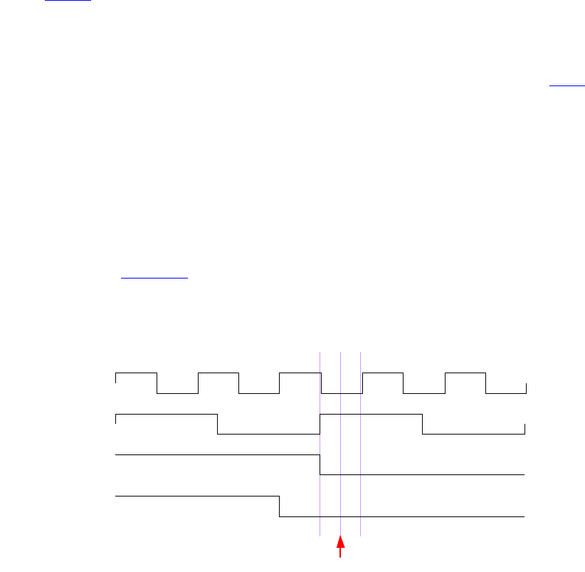
IEEE Std 1800-2012
IEEE STANDARD FOR SYSTEMVERILOG—UNIFIED HARDWARE DESIGN, SPECIFICATION, AND
VERIFICATION LANGUAGE
1079
Copyright © 2013 IEEE. All rights reserved.
—cbAssertionStepSuccess, cbAssertionStepFailure: cb_time is the time when the assertion
attempt step succeeded or failed.
—cbAssertionDisable, cbAssertionEnable, cbAssertionReset, cbAssertionKill: cb_time is
the time when the assertion attempt was disabled, enabled, reset, or killed.
d) In contrast to cb_time, the content of attemptStartTime is always the start time of the actual attempt
of an assertion. It can be used as a unique identifier that distinguishes the attempts of any given
assertion.
e) See 39.4.2.1 for callbacks for assertions containing global clocking future sampled value functions.
39.4.2.1 Placing callbacks for assertions with global clocking future sampled value
functions
Callback execution for assertions referring to global clocking future sampled value functions (see 16.9.4)
has the following peculiarities:
— The callback is executed at the nearest tick of the global clock strictly following the callback event.
—cb_time contains the time of the callback event.
For example:
a1: assert property(@(posedge clk) $falling_gclk(a) |=> b);
a2: assert property(@(posedge clk) a |=> $falling_gclk(b));
For both assertions a1 and a2 the callback executes at time 12, and not at time 11 when $assertkill
directive was issued (see Figure 39-1). cb_time has the time value of 11—the time when the callback event
actually happened—and attemptStartTime has the time value of 10.
Figure 39-1—Assertions with global clocking future sampled value functions
39.5 Control functions
This subclause defines how to obtain assertion system control and assertion control information.
39.5.1 Assertion system control
To control the assertion system, use vpi_control() with one of the following constants and a second handle
argument that is either a vpiHandle for a scope or a vpiCollection of handles for a list of scopes. A
NULL handle signifies that the control applies to all assertions regardless of scope.
$global_clock
clk
a
b
$assertkill
10 11 12
IEEE Std 1800-2012
IEEE STANDARD FOR SYSTEMVERILOG—UNIFIED HARDWARE DESIGN, SPECIFICATION, AND
VERIFICATION LANGUAGE
1080
Copyright © 2013 IEEE. All rights reserved.
— Usage example: vpi_control(vpiAssertionSysReset, handle)
—vpiAssertionSysReset discards all attempts in progress for all assertions and restores the
entire assertion system to its initial state. Any preexisting vpiAssertionStepSuccess and
vpiAssertionStepFailure callbacks shall be removed; all other assertion callbacks shall
remain.
— Usage example: vpi_control(vpiAssertionSysOff, handle)
—vpiAssertionSysOff disables any further assertions from being started. Assertions already
executing are not affected. This control has no effect on preexisting assertion callbacks.
—vpiAssertionSysKill discards all attempts in progress and disables any further assertions from
being started. This control has no effect on preexisting assertion callbacks.
— Usage example: vpi_control(vpiAssertionSysLock, handle)
—vpiAssertionSysLock locks the assertions from being changed. The status of the assertions
can not be changed without unlocking it.
— Usage example: vpi_control(vpiAssertionSysUnlock, handle)
—vpiAssertionSysUnlock unlocks the assertions. Now, the status of the assertion can be
changed.
— Usage example: vpi_control(vpiAssertionSysOn, handle)
—vpiAssertionSysOn restarts the assertion system after it was stopped or suspended (e.g., due
to vpiAssertionSysOff or vpiAssertionSysKill). Once started, attempts shall resume on all
assertions. This control has no effect on prior assertion callbacks.
— Usage example: vpi_control(vpiAssertionSysEnd, handle)
—vpiAssertionSysEnd discards all attempts in progress and disables any further assertions from
starting. All assertion callbacks currently installed shall be removed. Once this control is
issued, no further assertion-related actions shall be permitted.
— Usage example: vpi_control(vpiAssertionSysDisablePassAction, assertionHandle)
—vpiAssertionSysDisablePassAction disables execution of pass action for vacuous and
nonvacuous success of assertions. This has no effect on any existing attempts or if the assertion
pass action is already disabled. By default, all assertion pass actions are enabled.
— Usage example: vpi_control(vpiAssertionSysEnablePassAction, assertionHandle)
—vpiAssertionSysEnablePassAction enables execution of pass action for vacuous and
nonvacuous success of assertions. This has no effect on any existing attempts or if the assertion
pass action is already enabled.
— Usage example: vpi_control(vpiAssertionSysDisableFailAction, assertionHandle)
—vpiAssertionSysDisableFailAction disables execution of fail action for assertions. This has
no effect on any existing attempts or if the assertion fail action is already disabled. By default,
all fail actions are enabled.
— Usage example: vpi_control(vpiAssertionSysEnableFailAction, assertionHandle)
—vpiAssertionSysEnableFailAction enables execution of fail action for assertions. This has no
effect on any existing attempts or if the assertion fail action is already enabled.
— Usage example: vpi_control(vpiAssertionSysDisableVacuousAction,
assertionHandle)
—vpiAssertionSysDisableVacuousAction disables execution of pass action on vacuous success
of assertions. This has no effect on any existing attempts or if the execution of pass action on
vacuous success is already disabled. By default, all vacuous actions are enabled.
— Usage example: vpi_control(vpiAssertionSysEnableNonvacuousAction,
assertionHandle)
IEEE Std 1800-2012
IEEE STANDARD FOR SYSTEMVERILOG—UNIFIED HARDWARE DESIGN, SPECIFICATION, AND
VERIFICATION LANGUAGE
1081
Copyright © 2013 IEEE. All rights reserved.
—vpiAssertionSysEnableNonvacuousAction enables execution of pass action on nonvacuous
success of assertions. This has no effect on any existing attempts or if the pass action for
nonvacuous success is already enabled.
39.5.2 Assertion control
To obtain assertion control information for assertion statements (e.g., assume, assert, cover), use
vpi_control() with one of the operators in this subclause. Only assertion statement handles are valid here,
not sequence or property instances.
For the following operators, the second argument shall be a valid assertion handle:
— Usage example: vpi_control(vpiAssertionReset, assertionHandle)
—vpiAssertionReset discards all current attempts in progress for this assertion and resets this
assertion to its initial state.
— Usage example: vpi_control(vpiAssertionLock, assertionHandle)
—vpiAssertionLock locks the status of the assertion from being changed. The status of the
assertion cannot be changed without unlocking it.
— Usage example: vpi_control(vpiAssertionUnlock, assertionHandle)
—vpiAssertionUnlock unlocks the assertion. Now the status of the assertion can be changed.
— Usage example: vpi_control(vpiAssertionDisable, assertionHandle)
—vpiAssertionDisable disables the starting of any new attempts for this assertion. This has no
effect on any existing attempts or if the assertion is already disabled. By default, all assertions
are enabled.
— Usage example: vpi_control(vpiAssertionEnable, assertionHandle)
—vpiAssertionEnable enables starting new attempts for this assertion. This has no effect on any
existing attempts or if the assertion is already enabled.
— Usage example: vpi_control(vpiAssertionDisablePassAction, assertionHandle)
—vpiAssertionDisablePassAction disables execution of pass action for vacuous and
nonvacuous success of this assertion. This has no effect on any existing attempts or if the
assertion pass action is already disabled. By default, all pass actions are enabled.
— Usage example: vpi_control(vpiAssertionEnablePassAction, assertionHandle)
—vpiAssertionEnablePassAction enables execution of pass action for vacuous and nonvacuous
success of this assertion. This has no effect on any existing attempts or if the assertion pass
action is already enabled.
— Usage example: vpi_control(vpiAssertionDisableFailAction, assertionHandle)
—vpiAssertionDisableFailAction disables execution of fail action for this assertion. This has no
effect on any existing attempts or if the assertion fail action is already disabled. By default, all
fail actions are enabled.
— Usage example: vpi_control(vpiAssertionEnableFailAction, assertionHandle)
—vpiAssertionEnableFailAction enables execution of fail action for this assertion. This has no
effect on any existing attempts or if the assertion fail action is already enabled.
— Usage example: vpi_control( vpiAssertionDisableVacuousAction,
assertionHandle)
—vpiAssertionDisableVacuousAction disables execution of pass action on vacuous success of
this assertion. This has no effect on any existing attempts or if the execution of pass action on
vacuous success is already disabled. By default, all vacuous actions are enabled.
— Usage example: vpi_control(vpiAssertionEnableNonvacuousAction,
assertionHandle)

IEEE Std 1800-2012
IEEE STANDARD FOR SYSTEMVERILOG—UNIFIED HARDWARE DESIGN, SPECIFICATION, AND
VERIFICATION LANGUAGE
1082
Copyright © 2013 IEEE. All rights reserved.
—vpiAssertionEnableNonvacuousAction enables execution of pass action on nonvacuous
success of this assertion. This has no effect on any existing attempts or if the pass action is
already enabled for nonvacuous success of this assertion.
For the following operators, the second argument shall be a valid assertion handle, and the third argument
shall be an attempt start time (as a pointer to a correctly initialized s_vpi_time structure):
— Usage example:
vpi_control(vpiAssertionKill, assertionHandle, attemptStartTime)
—vpiAssertionKill discards the given attempt, but leaves the assertion enabled and does not
reset any state used by this assertion (e.g., past() sampling).
— Usage example:
vpi_control(vpiAssertionDisableStep, assertionHandle, attemptStartTime)
—vpiAssertionDisableStep disables step callbacks for this assertion. This has no effect if
stepping is not enabled or it is already disabled.
For the following operator, the second argument shall be a valid assertion handle, the third argument shall be
an attempt start time (as a pointer to a correctly initialized s_vpi_time structure), and the fourth argument
shall be a step control constant:
— Usage example:
vpi_control(vpiAssertionEnableStep, assertionHandle, attemptStartTime,
vpiAssertionClockSteps)
—vpiAssertionEnableStep enables step callbacks to occur for this assertion attempt. By default,
stepping is disabled for all assertions. This call has no effect if stepping is already enabled for
this assertion and attempt, other than possibly changing the stepping mode for the attempt if
the attempt has not occurred yet. The stepping mode of any particular attempt cannot be
modified after the assertion attempt in question has started.
— The fine-grained step control constant vpiAssertionClockSteps indicates callbacks on a per-
assertion/clock-tick basis. The assertion clock is the event expression supplied as the clocking
expression to the assertion declaration. This step callback shall occur at every clocking event,
when stepping is enabled, as the assertion “advances” in evaluation.
39.5.3 VPI functions on deferred assertions and procedural concurrent assertions
Deferred assertions (see 16.4) may be in a pending state where the assertion has executed but been placed in
a deferred assertion report queue. Similarly, procedural concurrent assertions (see 16.14.6) may have
pending instances in a procedural assertion queue waiting to mature. For any VPI function, if it discards
current evaluation attempts in progress, that also means it flushes any pending instances that have not yet
matured from these queues. If a VPI function does not interfere with current attempts, that also means it does
not affect or flush these queues.
For example, since vpiAssertionReset discards all current evaluation attempts in progress for the targeted
assertion, if applied to a deferred assertion, it flushes any pending reports for that assertion. However,
vpiAssertionDisable disables the starting of any new attempts without affecting existing attempts, so any
pending reports from a disabled deferred assertion that are already queued may still mature and be reported.

IEEE Std 1800-2012
IEEE STANDARD FOR SYSTEMVERILOG—UNIFIED HARDWARE DESIGN, SPECIFICATION, AND
VERIFICATION LANGUAGE
1083
Copyright © 2013 IEEE. All rights reserved.
40. Code coverage control and API
40.1 General
This clause describes the following:
— SystemVerilog coverage API
— Coverage constants
— Coverage VPI routines
— FSM recognition
— Coverage VPI extensions
40.2 Overview
This clause defines the coverage API in SystemVerilog.
40.2.1 SystemVerilog coverage API
The following criteria are used within this API:
a) This API shall be similar for all coverages. A wide number of coverage types are available, with
possibly different sets offered by different vendors. Maintaining a common interface across all the
different types enhances portability and ease of use.
b) At a minimum, the following types of coverage shall be supported:
1) Statement coverage
2) Toggle coverage
3) Finite state machine (FSM) coverage
i) FSM states
ii) FSM transitions
3) Assertion coverage
c) Coverage APIs shall be extensible in a transparent manner, i.e., adding a new coverage type shall
not break any existing coverage usage.
d) This API shall provide means to obtain coverage information from specific subhierarchies of the
design without requiring the user to enumerate all instances in those hierarchies.
40.2.2 Nomenclature
The following terms are used in this standard:
—assertion coverage: For each assertion, whether it has had at least one success. Implementations
permit querying for further details, such as attempt counts, success counts, failure counts, and failure
coverage.
—finite state machine (FSM) coverage: The number of states in an FSM that this simulation reached.
This standard does not require FSM automatic extraction, but a standard mechanism to force
specific extraction is available via pragmas.
—statement coverage: Whether a statement has been executed. Statement is anything defined as a
statement in the LRM. Covered means it executed at least once. Some implementations also permit
querying the execution count. The granularity of statement coverage can be per-statement or per-
statement block depending on the query (see 40.5.3 for details).

IEEE Std 1800-2012
IEEE STANDARD FOR SYSTEMVERILOG—UNIFIED HARDWARE DESIGN, SPECIFICATION, AND
VERIFICATION LANGUAGE
1084
Copyright © 2013 IEEE. All rights reserved.
—toggle coverage: For each bit of every signal (wire and register), whether that bit has both a 0 value
and a 1 value. Full coverage means both are seen; otherwise, some implementations can query for
partial coverage. Some implementations also permit querying the toggle count of each bit.
These terms define the primitives for each coverage type. Over instances or blocks, the coverage number is
merely the sum of all contained primitives in that instance or block.
40.3 SystemVerilog real-time coverage access
This subclause describes the mechanisms in SystemVerilog through which SystemVerilog code can query
and control coverage information. Coverage information is provided to SystemVerilog by means of a
number of built-in system functions (described in 40.3.2) using a number of predefined constants (described
in 40.3.1) to describe the types of coverage and the control actions to be performed.
40.3.1 Predefined coverage constants in SystemVerilog
The following predefined `define macros represent basic real-time coverage capabilities accessible
directly from SystemVerilog:
— Coverage control
`define SV_COV_START 0
`define SV_COV_STOP 1
`define SV_COV_RESET 2
`define SV_COV_CHECK 3
— Scope definition (hierarchy traversal/accumulation type)
`define SV_COV_MODULE 10
`define SV_COV_HIER 11
— Coverage type identification
`define SV_COV_ASSERTION 20
`define SV_COV_FSM_STATE 21
`define SV_COV_STATEMENT 22
`define SV_COV_TOGGLE 23
— Status results
`define SV_COV_OVERFLOW -2
`define SV_COV_ERROR -1
`define SV_COV_NOCOV 0
`define SV_COV_OK 1
`define SV_COV_PARTIAL 2
40.3.2 Built-in coverage access system functions
40.3.2.1 $coverage_control
$coverage_control(control_constant,
coverage_type,
scope_def,
modules_or_instance)
IEEE Std 1800-2012
IEEE STANDARD FOR SYSTEMVERILOG—UNIFIED HARDWARE DESIGN, SPECIFICATION, AND
VERIFICATION LANGUAGE
1085
Copyright © 2013 IEEE. All rights reserved.
This function is used to control or query coverage availability in the specified portion of the hierarchy. The
following control options are available:
—`SV_COV_START, if possible, starts collecting coverage information in the specified hierarchy.
There is no effect if coverage is already being collected. Coverage is automatically started at the
beginning of simulation for all portions of the hierarchy enabled for coverage.
—`SV_COV_STOP stops collecting coverage information in the specified hierarchy. There is no effect
if coverage is not being collected.
—`SV_COV_RESET resets all available coverage information in the specified hierarchy. There is no
effect if coverage not available.
—`SV_COV_CHECK checks whether coverage information can be obtained from the specified
hierarchy. The existence of coverage information does not imply that coverage is being collected, as
the coverage could have been stopped.
The return value is a `define name, with the value indicating the success of the action.
—`SV_COV_OK, on a check operation, denotes that coverage is fully available in the specified
hierarchy. For all other operations, it represents successful and complete execution of the desired
operation.
—`SV_COV_ERROR, on all operations, means that the control operation failed without any effect,
typically due to errors in arguments, such as a nonexisting module.
—`SV_COV_NOCOV, on a check or start operation, denotes that coverage is not available at any point in
the specified hierarchy.
—`SV_COV_PARTIAL, on a check or start operation, denotes that coverage is only partially available
in the specified hierarchy.
Table 40-1 describes the possible return values for each of the coverage control options.
Starting coverage on an instance that has already had coverage started via a prior call to
$coverage_control() shall have no effect. Similarly, repeated calls to stop or reset coverage shall have
no effect.
The hierarchy(ies) being controlled or queried are specified as follows:
—`SV_MODULE_COV, "unique module def name" provides coverage of all instances of the
given module (the unique module name is a string), excluding any child instances in the instances of
the given module. The module definition name can use special notation to describe nested module
definitions.
—`SV_COV_HIER, "module name" provides coverage of all instances of the given module,
including all the hierarchy below.
Table 40-1—Coverage control return values
`SV_COV_OK `SV_COV_ERROR `SV_COV_NOCOV `SV_COV_PARTIAL
`SV_COV_START Success Bad args No coverage Partial coverage
`SV_COV_STOP Success Bad args — —
`SV_COV_RESET Success Bad args — —
`SV_COV_CHECK Full coverage Bad args No coverage Partial coverage
IEEE Std 1800-2012
IEEE STANDARD FOR SYSTEMVERILOG—UNIFIED HARDWARE DESIGN, SPECIFICATION, AND
VERIFICATION LANGUAGE
1086
Copyright © 2013 IEEE. All rights reserved.
—`SV_MODULE_COV, instance_name provides coverage of the one named instance. The instance
is specified as a normal SystemVerilog hierarchical path.
—`SV_COV_HIER, instance_name provides coverage of the named instance, plus all the hierarchy
below it.
All the permutations are summarized in Table 40-2.
See Figure 40-1 for an example of hierarchical instances.
Table 40-2—Instance coverage permutations
Control/query Definition name instance.name
`SV_COV_MODULE The sum of coverage for all
instances of the named module,
excluding any hierarchy below
those instances.
Coverage for just the named
instance, excluding any
hierarchy in instances below that
instance.
`SV_COV_HIER The sum of coverage for all
instances of the named module,
including all coverage for all
hierarchy below those instances.
Coverage for the named instance
and any hierarchy below it.
NOTE—Definition names are represented as strings, whereas instance names are referenced by
hierarchical paths. A hierarchical path need not include any . if the path refers to an instance in the
current context (i.e., normal SystemVerilog hierarchical path rules apply).
IEEE Std 1800-2012
IEEE STANDARD FOR SYSTEMVERILOG—UNIFIED HARDWARE DESIGN, SPECIFICATION, AND
VERIFICATION LANGUAGE
1087
Copyright © 2013 IEEE. All rights reserved.
If coverage is enabled on all instances shown in Figure 40-1, then
—$coverage_control(`SV_COV_CHECK, `SV_COV_TOGGLE, `SV_COV_HIER, $root)
checks all instances to verify they have coverage and, in this case, returns `SV_COV_OK.
—$coverage_control(`SV_COV_RESET, `SV_COV_TOGGLE, `SV_COV_MODULE, "DUT")
resets coverage collection on both instances of the DUT, specifically, $root.tb.unit1 and
$root.tb.unit2, but leaves coverage unaffected in all other instances.
—$coverage_control(`SV_COV_RESET, `SV_COV_TOGGLE, `SV_COV_MODULE,
$root.tb.unit1)
resets coverage of only the instance $root.tb.unit1, leaving all other instances unaffected.
—$coverage_control(`SV_COV_STOP, `SV_COV_TOGGLE, `SV_COV_HIER,
$root.tb. unit1)
resets coverage of the instance $root.tb.unit1 and also resets coverage for all instances below it,
specifically $root.tb.unit1.comp and $root.tb.unit1.ctrl.
—$coverage_control(`SV_COV_START, `SV_COV_TOGGLE, `SV_COV_HIER, "DUT")
starts coverage on all instances of the module DUT and of all hierarchy(ies) below those instances.
In this design, coverage is started for the instances $root.tb.unit1, $root.tb.unit1.comp,
$root.tb.unit1.ctrl, $root.tb.unit2, $root.tb.unit2.comp,
and $root.tb.unit2.ctrl.
module component
instance comp
module control
instance ctrl
module DUT
instance unit1
module component
instance comp
module control
instance ctrl
module DUT
instance unit2
module TestBench
instance tb
module BusWatcher
instance watch
$root
Figure 40-1—Hierarchical instance example

IEEE Std 1800-2012
IEEE STANDARD FOR SYSTEMVERILOG—UNIFIED HARDWARE DESIGN, SPECIFICATION, AND
VERIFICATION LANGUAGE
1088
Copyright © 2013 IEEE. All rights reserved.
40.3.2.2 $coverage_get_max
$coverage_get_max(coverage_type, scope_def, modules_or_instance)
This function obtains the value representing 100% coverage for the specified coverage type over the
specified portion of the hierarchy. This value shall remain constant across the duration of the simulation.
NOTE—This value is proportional to the design size and structure; therefore, it also needs to be constant through
multiple independent simulations and compilations of the same design, assuming any compilation options do not modify
the coverage support or design structure.
The return value is an integer, with the following meanings:
—-2 (`SV_COV_OVERFLOW). The value exceeds a number that can be represented as an integer.
—-1 (`SV_COV_ERROR). An error occurred (typically due to using incorrect arguments).
—0 (`SV_COV_NOCOV). No coverage is available for that coverage type on that/those hierarchy(ies).
—+pos_num. This value is the maximum coverage number (where pos_num > 0), which is the sum
of all coverable items of that type over the given hierarchy(ies).
The scope of this function is specified per $coverage_control() (see 40.3.2.1).
40.3.2.3 $coverage_get
$coverage_get(coverage_type, scope_def, modules_or_instance)
This function obtains the current coverage value for the given coverage type over the given portion of the
hierarchy. This number can be converted to a coverage percentage by use of the following equation:
The return value follows the same pattern as $coverage_get_max() (see 40.3.2.2), but with pos_num
representing the current coverage level, i.e., the number of the coverable items that have been covered in
this/these hierarchy(ies).
The scope of this function is specified per $coverage_control() (see 40.3.2.1).
The return value is an integer, with the following meanings:
—-2 (`SV_COV_OVERFLOW). The value exceeds a number that can be represented as an integer.
—-1 (`SV_COV_ERROR). An error occurred (typically due to using incorrect arguments).
—0 (`SV_COV_NOCOV). No coverage is available for that coverage type on that/those hierarchy(ies).
—+pos_num. This value is the maximum coverage number (where pos_num > 0), which is the sum
of all coverable items of that type over the given hierarchy(ies).
40.3.2.4 $coverage_merge
$coverage_merge(coverage_type, "name")
This function loads and merges coverage data for the specified coverage into the simulator. name is an
arbitrary string used by the tool, in an implementation-specific way, to locate the appropriate coverage
database, i.e., tools are allowed to store coverage files any place they want with any extension they want as
long as the user can retrieve the information by asking for a specific saved name from that coverage
database. If name does not exist or does not correspond to a coverage database from the same design, an
coverage% =
coverage_get()
coverage_get_max()
×
100
IEEE Std 1800-2012
IEEE STANDARD FOR SYSTEMVERILOG—UNIFIED HARDWARE DESIGN, SPECIFICATION, AND
VERIFICATION LANGUAGE
1089
Copyright © 2013 IEEE. All rights reserved.
error shall occur. If an error occurs during loading, the coverage numbers generated by this simulation might
not be meaningful.
The return values from this function are as follows:
—`SV_COV_OK. The coverage data have been found and merged.
—`SV_COV_NOCOV. The coverage data have been found, but did not contain the coverage type
requested.
—`SV_COV_ERROR. The coverage data were not found, or they did not correspond to this design, or
another error occurred.
40.3.2.5 $coverage_save
$coverage_save(coverage_type, "name")
This function saves the current state of coverage to the tool’s coverage database and associates it with the
given name. This name will be mapped in an implementation-specific way into some file or set of files in the
coverage database. Data saved to the database shall be retrieved later by using $coverage_merge() and
supplying the same name. Saving coverage shall not have any effect on the state of coverage in this
simulation.
The return values from this function are as follows:
—`SV_COV_OK. The coverage data were successfully saved.
—`SV_COV_NOCOV. No such coverage is available in this design (nothing was saved).
—`SV_COV_ERROR. Some error occurred during the save. If an error occurs, the tool shall
automatically remove the coverage database entry for name to preserve the coverage database
integrity. It is not an error to overwrite a previously existing name.
Details:
1) The coverage database format is implementation dependent.
2) Mapping of names to actual directories or files is implementation dependent. There is no
requirement that a coverage name map to any specific set of files or directories.
40.4 FSM recognition
Coverage tools need to have automatic recognition of many of the common FSM coding idioms in
SystemVerilog. This standard does not attempt to describe or require any specific automatic FSM
recognition mechanisms. However, this standard does prescribe a means by which nonautomatic FSM
extraction occurs. The presence of any of these standard FSM description additions shall override the tool’s
default extraction mechanism.
Identification of an FSM consists of identifying the following items:
— The state register (or expression)
— The next state register (this is optional)
— The legal states
40.4.1 Specifying signal that holds current state
Use the following pragma to identify the vector signal that holds the current state of the FSM:
/* tool state_vector signal_name */
IEEE Std 1800-2012
IEEE STANDARD FOR SYSTEMVERILOG—UNIFIED HARDWARE DESIGN, SPECIFICATION, AND
VERIFICATION LANGUAGE
1090
Copyright © 2013 IEEE. All rights reserved.
where tool and state_vector are required keywords. This pragma needs to be specified inside the module
definition where the signal is declared.
Another pragma is also required that specifies an enumeration name for the FSM. This enumeration name is
also specified for the next state and any possible states, associating them with each other as part of the same
FSM. There are two ways to do this, as follows:
— Use the same pragma as above:
/* tool state_vector signal_name enum enumeration_name */
— Use a separate pragma in the signal’s declaration:
/* tool state_vector signal_name */
logic [7:0] /* tool enum enumeration_name */ signal_name;
In either case, enum is a required keyword. If using a separate pragma, tool is also a required keyword, and
the pragma needs to be specified immediately after the bit range of the signal.
40.4.2 Specifying part-select that holds current state
A part-select of a vector signal can be used to hold the current state of the FSM. When a coverage tool
displays or reports FSM coverage data, it names the FSM after the signal that holds the current state. If a
part-select holds the current state in the user’s FSM, the user needs to also specify a name for the FSM for
the coverage tool to use. The FSM name is not the same as the enumeration name.
Specify the part-select by using the following pragma:
/* tool state_vector signal_name[n:n] FSM_name enum enumeration_name */
40.4.3 Specifying concatenation that holds current state
Like specifying a part-select, a concatenation of signals can be specified to hold the current state (when
including an FSM name and an enumeration name):
/* tool state_vector {signal_name , signal_name, ...} FSM_name enum
enumeration_name */
The concatenation is composed of all the signals specified. Bit-selects or part-selects of signals cannot be
used in the concatenation.
40.4.4 Specifying signal that holds next state
The signal that holds the next state of the FSM can also be specified with the pragma that specifies the
enumeration name:
logic [7:0] /* tool enum enumeration_name */ signal_name
This pragma can be omitted if, and only if, the FSM does not have a signal for the next state.
40.4.5 Specifying current and next state signals in same declaration
The tool assumes the first signal following the pragma holds the current state and the next signal holds the
next state when a pragma is used for specifying the enumeration name in a declaration of multiple signals.
For example:

IEEE Std 1800-2012
IEEE STANDARD FOR SYSTEMVERILOG—UNIFIED HARDWARE DESIGN, SPECIFICATION, AND
VERIFICATION LANGUAGE
1091
Copyright © 2013 IEEE. All rights reserved.
/* tool state_vector cs */
logic [1:0] /* tool enum myFSM */ cs, ns, nonstate;
In this example, the tool assumes signal cs holds the current state and signal ns holds the next state. It
assumes nothing about signal nonstate.
40.4.6 Specifying possible states of FSM
The possible states of the FSM can also be specified with a pragma that includes the following enumeration
name:
parameter /* tool enum enumeration_name */
S0 = 0,
s1 = 1,
s2 = 2,
s3 = 3;
Put this pragma immediately after the keyword parameter, unless a bit width for the parameters is used, in
which case, specify the pragma immediately after the bit width:
parameter [1:0] /* tool enum enumeration_name */
S0 = 0,
s1 = 1,
s2 = 2,
s3 = 3;
40.4.7 Pragmas in one-line comments
These pragmas work in both block comments, between the /* and */ character strings, and one-line
comments, following the // character string. For example:
parameter [1:0] // tool enum enumeration_name
S0 = 0,
s1 = 1,
s2 = 2,
s3 = 3;
40.4.8 Example
See Figure 40-2 for an example of FSM specified with pragmas.
IEEE Std 1800-2012
IEEE STANDARD FOR SYSTEMVERILOG—UNIFIED HARDWARE DESIGN, SPECIFICATION, AND
VERIFICATION LANGUAGE
1092
Copyright © 2013 IEEE. All rights reserved.
40.5 VPI coverage extensions
40.5.1 VPI entity/relation diagrams related to coverage
40.5.2 Extensions to VPI enumerations
— Coverage control
vpiCoverageStart
vpiCoverageStop
vpiCoverageReset
vpiCoverageCheck
vpiCoverageMerge
vpiCoverageSave
— VPI properties
— Coverage type properties
vpiAssertCoverage
vpiFsmStateCoverage
vpiStatementCoverage
vpiToggleCoverage
— Coverage status properties
vpiCovered
vpiCoverMax
vpiCoveredCount
— Assertion-specific coverage status properties
vpiAssertAttemptCovered
vpiAssertSuccessCovered
vpiAssertFailureCovered
vpiAssertVacuousSuccessCovered
vpiAssertDisableCovered
vpiAssertKillCovered
— FSM-specific methods
vpiFsmStates
vpiFsmStateExpression
module m3;
reg[31:0] cs;
reg[31:0] /* tool enum MY_FSM */ ns;
reg[31:0] clk;
reg[31:0] rst;
// tool state_vector cs enum MY_FSM
parameter // tool enum MY_FSM
p1=10,
p2=11,
p3=12;
endmodule // m3
Signal ns holds the next state
Signal cs holds the current state
p1, p2, and p3 are possible states of
the FSM
Figure 40-2—FSM specified with pragmas

IEEE Std 1800-2012
IEEE STANDARD FOR SYSTEMVERILOG—UNIFIED HARDWARE DESIGN, SPECIFICATION, AND
VERIFICATION LANGUAGE
1093
Copyright © 2013 IEEE. All rights reserved.
— FSM handle types (vpi types)
vpiFsm
vpiFsmHandle
40.5.3 Obtaining coverage information
To obtain coverage information, the vpi_get() function is extended with additional VPI properties that can
be obtained from the following existing handles:
vpi_get(<coverageType>, instance_handle)
returns the number of covered items of the given coverage type in the given instance. Coverage type is one
of the coverage type properties described in 40.5.2. For example, given coverage type vpiStatement-
Coverage, this call would return the number of covered statements in the instance pointed to by
instance_handle.
vpi_get(vpiCovered, assertion_handle)
vpi_get(vpiCovered, statement_handle)
vpi_get(vpiCovered, signal_handle)
vpi_get(vpiCovered, fsm_handle)
vpi_get(vpiCovered, fsm_state_handle)
returns whether the item referenced by the handle has been covered. For handles that can contain multiple
coverable entities, such as statement, FSM, and signal handles, the return value indicates how many of the
entities have been covered.
— For assertion handle, the coverable entities are assertions.
— For statement handle, the entities are statements.
— For signal handle, the entities are individual signal bits.
— For FSM handle, the entities are FSM states.
For assertions, vpiCovered implies that the assertion has been attempted, has succeeded at least once, and
has never failed. More detailed coverage information can be obtained for assertions by the following
queries:
vpi_get(vpiAssertAttemptCovered, assertion_handle)
returns the number of times the assertion has been attempted.
vpi_get(vpiAssertSuccessCovered, assertion_handle)
returns the number of times the assertion has succeeded nonvacuously or, if the assertion handle corresponds
to a cover sequence, the number of times the sequence has been matched. Refer to 16.12.6 and 16.14 for the
definition of vacuity.
vpi_get(vpiAssertVacuousSuccessCovered, assertion_handle)
returns the number of times the assertion has succeeded vacuously. Refer to 16.12.6 and 16.14 for the
definition of vacuity.
vpi_get(vpiAssertDisableCovered, assertion_handle)
returns the number of times the assertion has reached the disabled state (e.g., as a result of disable iff
condition becoming true or if an attempt starts when the disable iff is true). Refer to 16.12 for the
definition of disabled evaluation.

IEEE Std 1800-2012
IEEE STANDARD FOR SYSTEMVERILOG—UNIFIED HARDWARE DESIGN, SPECIFICATION, AND
VERIFICATION LANGUAGE
1094
Copyright © 2013 IEEE. All rights reserved.
vpi_get(vpiAssertKillCovered, assertion_handle)
returns the number of times the assertion has been killed (e.g., as a result of a control action, see 39.5.2).
vpi_get(vpiAssertFailureCovered, assertion_handle)
returns the number of times the assertion has failed. For any assertion, the number of attempts that have not
yet reached any conclusion (success, failure, disabled, or killed) can be derived from the equation:
in progress = attempts - (successes + vacuous success + disabled + killed +
failures)
The equation does not apply to cover sequence statements as there can be multiple matches
corresponding to a single attempt. The following example illustrates some of these queries:
module covtest;
bit on = 1, off = 0;
logic clk;
initial begin
clk = 0;
forever begin
#10;
clk = ~clk;
end
end
always @(false) begin
anvr: assert(on ##1 on); // assertion will not be attempted
end
always @(posedge clk) begin
aundf: assert (on ##[1:$] off); // assertion will not pass or fail
afail: assert (on ##1 off); // assertion will always fail on 2nd tick
apass: assert (on ##1 on); // assertion will succeed on each attempt
end
endmodule
For this example, the assertions will have the coverage results shown in Table 40-3.
The number of times an item has been covered can be obtained by the vpiCoveredCount property.
vpi_get(vpiCoveredCount, assertion_handle)
vpi_get(vpiCoveredCount, statement_handle)
Table 40-3—Assertion coverage results
vpiCovered vpiAssertAttempt-
Covered
vpiAssertSuccess-
Covered
vpiAssertFailure-
Covered
anvr False False False False
aundf False True False False
afail False True False True
apass True True True False

IEEE Std 1800-2012
IEEE STANDARD FOR SYSTEMVERILOG—UNIFIED HARDWARE DESIGN, SPECIFICATION, AND
VERIFICATION LANGUAGE
1095
Copyright © 2013 IEEE. All rights reserved.
vpi_get(vpiCoveredCount, signal_handle)
vpi_get(vpiCoveredCount, fsm_handle)
vpi_get(vpiCoveredCount, fsm_state_handle)
returns the number of times each coverable entity referred by the handle has been covered. The handle
coverage information is only easily interpretable when the handle points to a unique coverable item (such as
an individual statement). When the handle points to an item containing multiple coverable entities (such as a
handle to a block statement containing a number of statements), the result is the sum of coverage counts for
each of the constituent entities.
vpi_get(vpiCoveredMax, assertion_handle)
vpi_get(vpiCoveredMax, statement_handle)
vpi_get(vpiCoveredMax, signal_handle)
vpi_get(vpiCoveredMax, fsm_handle)
vpi_get(vpiCoveredMax, fsm_state_handle)
returns the number of coverable entities pointed by the handle. The number returned shall always be 1 when
applied to an assertion or FSM state handle.
vpi_iterate(vpiFsm, instance-handle)
returns an iterator to all FSMs in an instance.
vpi_handle(vpiFsmStateExpression, fsm-handle)
returns the handle to the signal or expression encoding the FSM state.
vpi_iterate(vpiFsmStates, fsm-handle)
returns an iterator to all states of an FSM.
vpi_get_value(fsm_state_handle, state-handle)
returns the value of an FSM state.
40.5.4 Controlling coverage
Control of the collection of coverage shall be through the vpi_control() routine:
vpi_control(<coverageControl>, <coverageType>, instance_handle)
vpi_control(<coverageControl>, <coverageType>, assertion_handle)
Statement, toggle, and FSM coverage are not individually controllable (i.e., they are controllable only at the
instance level and not on a per-statement, signal, or FSM basis). The semantics and behavior are per the
$coverage_control() system function (see 40.3.2.1). coverageControl shall be vpiCoverageStart,
vpiCoverageStop, vpiCoverageReset, or vpiCoverageCheck, as defined in 40.5.2. coverageType is any
one of the VPI coverage type properties (see 40.5.2)
To save coverage for the current simulation use the following:
vpi_control(coverageSave, <coverageType>, name)
as defined in 40.5.2. The semantics and behavior are specified per the equivalent system function
$coverage_save() (see 40.3.2.5).

IEEE Std 1800-2012
IEEE STANDARD FOR SYSTEMVERILOG—UNIFIED HARDWARE DESIGN, SPECIFICATION, AND
VERIFICATION LANGUAGE
1096
Copyright © 2013 IEEE. All rights reserved.
To merge coverage for the current simulation use the following:
vpi_control(vpiCoverageMerge, <coverageType>, name)
as defined in 40.5.2. The semantics and behavior are specified per the equivalent system function
$coverage_merge() (see 40.3.2.4).
IEEE Std 1800-2012
IEEE STANDARD FOR SYSTEMVERILOG—UNIFIED HARDWARE DESIGN, SPECIFICATION, AND
VERIFICATION LANGUAGE
1097
Copyright © 2013 IEEE. All rights reserved.
41. Data read API
This clause has been deprecated. See IEEE Std 1800-2005 for the contents of this clause.
IEEE Std 1800-2012
IEEE STANDARD FOR SYSTEMVERILOG—UNIFIED HARDWARE DESIGN, SPECIFICATION, AND
VERIFICATION LANGUAGE
1098
Copyright © 2013 IEEE. All rights reserved.
Part Four:
Annexes
IEEE Std 1800-2012
IEEE STANDARD FOR SYSTEMVERILOG—UNIFIED HARDWARE DESIGN, SPECIFICATION, AND
VERIFICATION LANGUAGE
1099
Copyright © 2013 IEEE. All rights reserved.
Annex A
(normative)
Formal syntax
The formal syntax of SystemVerilog is described using Backus-Naur Form (BNF). The syntax of System-
Verilog source is derived from the starting symbol source_text. The syntax of a library map file is derived
from the starting symbol library_text. The conventions used are as follows:
— Keywords and punctuation are in bold-red text.
— Syntactic categories are named in nonbold text.
— A vertical bar ( | ) separates alternatives.
— Square brackets ([]) enclose optional items.
— Braces ( { } ) enclose items that can be repeated zero or more times.
The full syntax and semantics of SystemVerilog are not described solely using BNF. The normative text
description contained within the clauses and annexes of this standard provide additional details on the syntax
and semantics described in this BNF.
A qualified term in the syntax is a term such as array_identifier for which the “array” portion represents
some semantic intent and the “identifier” term indicates that the qualified term reduces to the “identifier”
term in the syntax. The syntax does not completely define the semantics of such qualified terms; for exam-
ple, while an identifier that would qualify semantically as an array_identifier is created by a declaration,
such declaration forms are not explicitly described using array_identifier in the syntax.
A.1 Source text
A.1.1 Library source text
library_text ::= { library_description }
library_description ::=
library_declaration
| include_statement
| config_declaration
|;
library_declaration ::=
library library_identifier file_path_spec { , file_path_spec }
[ -incdir file_path_spec { , file_path_spec } ] ;
include_statement ::= include file_path_spec ;
A.1.2 SystemVerilog source text
source_text ::= [ timeunits_declaration ] { description }
description ::=
module_declaration
| udp_declaration
| interface_declaration
| program_declaration

IEEE Std 1800-2012
IEEE STANDARD FOR SYSTEMVERILOG—UNIFIED HARDWARE DESIGN, SPECIFICATION, AND
VERIFICATION LANGUAGE
1100
Copyright © 2013 IEEE. All rights reserved.
| package_declaration
| { attribute_instance } package_item
| { attribute_instance } bind_directive
| config_declaration
module_nonansi_header ::=
{ attribute_instance } module_keyword [ lifetime ] module_identifier
{ package_import_declaration } [ parameter_port_list ] list_of_ports ;
module_ansi_header ::=
{ attribute_instance } module_keyword [ lifetime ] module_identifier
{ package_import_declaration }1 [ parameter_port_list ] [ list_of_port_declarations ] ;
module_declaration ::=
module_nonansi_header [ timeunits_declaration ] { module_item }
endmodule [ : module_identifier ]
| module_ansi_header [ timeunits_declaration ] { non_port_module_item }
endmodule [ : module_identifier ]
| { attribute_instance } module_keyword [ lifetime ] module_identifier ( .* ) ;
[ timeunits_declaration ] { module_item } endmodule [ : module_identifier ]
|extern module_nonansi_header
|extern module_ansi_header
module_keyword ::= module | macromodule
interface_declaration ::=
interface_nonansi_header [ timeunits_declaration ] { interface_item }
endinterface [ : interface_identifier ]
| interface_ansi_header [ timeunits_declaration ] { non_port_interface_item }
endinterface [ : interface_identifier ]
| { attribute_instance } interface interface_identifier ( .* ) ;
[ timeunits_declaration ] { interface_item }
endinterface [ : interface_identifier ]
|extern interface_nonansi_header
|extern interface_ansi_header
interface_nonansi_header ::=
{ attribute_instance } interface [ lifetime ] interface_identifier
{ package_import_declaration } [ parameter_port_list ] list_of_ports ;
interface_ansi_header ::=
{attribute_instance } interface [ lifetime ] interface_identifier
{ package_import_declaration }1 [ parameter_port_list ] [ list_of_port_declarations ] ;
program_declaration ::=
program_nonansi_header [ timeunits_declaration ] { program_item }
endprogram [ : program_identifier ]
| program_ansi_header [ timeunits_declaration ] { non_port_program_item }
endprogram [ : program_identifier ]
| { attribute_instance } program program_identifier ( .* ) ;
[ timeunits_declaration ] { program_item }
endprogram [ : program_identifier ]
|extern program_nonansi_header
|extern program_ansi_header
program_nonansi_header ::=
{ attribute_instance } program [ lifetime ] program_identifier
{ package_import_declaration } [ parameter_port_list ] list_of_ports ;
program_ansi_header ::=
{attribute_instance } program [ lifetime ] program_identifier

IEEE Std 1800-2012
IEEE STANDARD FOR SYSTEMVERILOG—UNIFIED HARDWARE DESIGN, SPECIFICATION, AND
VERIFICATION LANGUAGE
1101
Copyright © 2013 IEEE. All rights reserved.
{ package_import_declaration }1 [ parameter_port_list ] [ list_of_port_declarations ] ;
checker_declaration ::=
checker checker_identifier [ ( [ checker_port_list ] ) ] ;
{ { attribute_instance } checker_or_generate_item }
endchecker [ : checker_identifier ]
class_declaration ::=
[ virtual ] class [ lifetime ] class_identifier [ parameter_port_list ]
[ extends class_type [ ( list_of_arguments ) ] ]
[ implements interface_class_type { , interface_class_type } ] ;
{ class_item }
endclass [ : class_identifier]
interface_class_type ::= ps_class_identifier [ parameter_value_assignment ]
interface_class_declaration ::=
interface class class_identifier [ parameter_port_list ]
[ extends interface_class_type { , interface_class_type } ] ;
{ interface_class_item }
endclass [ : class_identifier]
interface_class_item ::=
type_declaration
| { attribute_instance } interface_class_method
| local_parameter_declaration ;
| parameter_declaration7 ;
|;
interface_class_method ::=
pure virtual method_prototype ;
package_declaration ::=
{ attribute_instance } package [ lifetime ] package_identifier ;
[ timeunits_declaration ] { { attribute_instance } package_item }
endpackage [ : package_identifier ]
timeunits_declaration ::=
timeunit time_literal [ / time_literal ] ;
|timeprecision time_literal ;
|timeunit time_literal ; timeprecision time_literal ;
|timeprecision time_literal ; timeunit time_literal ;
A.1.3 Module parameters and ports
parameter_port_list ::=
# ( list_of_param_assignments { , parameter_port_declaration } )
|# ( parameter_port_declaration { , parameter_port_declaration } )
|#( )
parameter_port_declaration ::=
parameter_declaration
| local_parameter_declaration
| data_type list_of_param_assignments
|type list_of_type_assignments
list_of_ports ::= ( port { , port } )
list_of_port_declarations2 ::=
( [ { attribute_instance} ansi_port_declaration { , { attribute_instance} ansi_port_declaration } ] )
IEEE Std 1800-2012
IEEE STANDARD FOR SYSTEMVERILOG—UNIFIED HARDWARE DESIGN, SPECIFICATION, AND
VERIFICATION LANGUAGE
1102
Copyright © 2013 IEEE. All rights reserved.
port_declaration ::=
{ attribute_instance } inout_declaration
| { attribute_instance } input_declaration
| { attribute_instance } output_declaration
| { attribute_instance } ref_declaration
| { attribute_instance } interface_port_declaration
port ::=
[ port_expression ]
|. port_identifier ( [ port_expression ] )
port_expression ::=
port_reference
|{ port_reference { , port_reference } }
port_reference ::=
port_identifier constant_select
port_direction ::= input | output | inout | ref
net_port_header ::= [ port_direction ] net_port_type
variable_port_header ::= [ port_direction ] variable_port_type
interface_port_header ::=
interface_identifier [ . modport_identifier ]
|interface [ . modport_identifier ]
ansi_port_declaration ::=
[ net_port_header | interface_port_header ] port_identifier { unpacked_dimension }
[ = constant_expression ]
| [ variable_port_header ] port_identifier { variable_dimension } [ = constant_expression ]
| [ port_direction ] . port_identifier ( [ expression ] )
A.1.4 Module items
elaboration_system_task ::=
$fatal [ ( finish_number [, list_of_arguments ] ) ] ;
|$error [ ( [ list_of_arguments ] ) ] ;
|$warning [ ( [ list_of_arguments ] ) ] ;
|$info [ ( [ list_of_arguments ] ) ] ;
finish_number ::= 0 | 1 | 2
module_common_item ::=
module_or_generate_item_declaration
| interface_instantiation
| program_instantiation
| assertion_item
| bind_directive
| continuous_assign
| net_alias
| initial_construct
| final_construct
| always_construct
| loop_generate_construct
| conditional_generate_construct
| elaboration_system_task
module_item ::=
port_declaration ;

IEEE Std 1800-2012
IEEE STANDARD FOR SYSTEMVERILOG—UNIFIED HARDWARE DESIGN, SPECIFICATION, AND
VERIFICATION LANGUAGE
1103
Copyright © 2013 IEEE. All rights reserved.
| non_port_module_item
module_or_generate_item ::=
{ attribute_instance } parameter_override
| { attribute_instance } gate_instantiation
| { attribute_instance } udp_instantiation
| { attribute_instance } module_instantiation
| { attribute_instance } module_common_item
module_or_generate_item_declaration ::=
package_or_generate_item_declaration
| genvar_declaration
| clocking_declaration
|default clocking clocking_identifier ;
|default disable iff expression_or_dist ;
non_port_module_item ::=
generate_region
| module_or_generate_item
| specify_block
| { attribute_instance } specparam_declaration
| program_declaration
| module_declaration
| interface_declaration
| timeunits_declaration3
parameter_override ::= defparam list_of_defparam_assignments ;
bind_directive4 ::=
bind bind_target_scope [: bind_target_instance_list] bind_instantiation ;
|bind bind_target_instance bind_instantiation ;
bind_target_scope ::=
module_identifier
| interface_identifier
bind_target_instance ::=
hierarchical_identifier constant_bit_select
bind_target_instance_list ::=
bind_target_instance { , bind_target_instance }
bind_instantiation ::=
program_instantiation
| module_instantiation
| interface_instantiation
| checker_instantiation
A.1.5 Configuration source text
config_declaration ::=
config config_identifier ;
{ local_parameter_declaration ; }
design_statement
{ config_rule_statement }
endconfig [ : config_identifier ]
design_statement ::= design { [ library_identifier . ] cell_identifier } ;
config_rule_statement ::=
default_clause liblist_clause ;

IEEE Std 1800-2012
IEEE STANDARD FOR SYSTEMVERILOG—UNIFIED HARDWARE DESIGN, SPECIFICATION, AND
VERIFICATION LANGUAGE
1104
Copyright © 2013 IEEE. All rights reserved.
| inst_clause liblist_clause ;
| inst_clause use_clause ;
| cell_clause liblist_clause ;
| cell_clause use_clause ;
default_clause ::= default
inst_clause ::= instance inst_name
inst_name ::= topmodule_identifier { . instance_identifier }
cell_clause ::= cell [ library_identifier . ] cell_identifier
liblist_clause ::= liblist {library_identifier}
use_clause ::= use [ library_identifier . ] cell_identifier [ : config ]
|use named_parameter_assignment { , named_parameter_assignment } [ : config ]
|use [ library_identifier . ] cell_identifier named_parameter_assignment
{ , named_parameter_assignment } [ : config ]
A.1.6 Interface items
interface_or_generate_item ::=
{ attribute_instance } module_common_item
| { attribute_instance } modport_declaration
| { attribute_instance } extern_tf_declaration
extern_tf_declaration ::=
extern method_prototype ;
|extern forkjoin task_prototype ;
interface_item ::=
port_declaration ;
| non_port_interface_item
non_port_interface_item ::=
generate_region
| interface_or_generate_item
| program_declaration
| interface_declaration
| timeunits_declaration3
A.1.7 Program items
program_item ::=
port_declaration ;
| non_port_program_item
non_port_program_item ::=
{ attribute_instance } continuous_assign
| { attribute_instance } module_or_generate_item_declaration
| { attribute_instance } initial_construct
| { attribute_instance } final_construct
| { attribute_instance } concurrent_assertion_item
| timeunits_declaration3
| program_generate_item
program_generate_item5 ::=
loop_generate_construct
| conditional_generate_construct

IEEE Std 1800-2012
IEEE STANDARD FOR SYSTEMVERILOG—UNIFIED HARDWARE DESIGN, SPECIFICATION, AND
VERIFICATION LANGUAGE
1105
Copyright © 2013 IEEE. All rights reserved.
| generate_region
| elaboration_system_task
A.1.8 Checker items
checker_port_list ::=
checker_port_item {, checker_port_item}
checker_port_item ::=
{ attribute_instance } [ checker_port_direction ] property_formal_type formal_port_identifier
{variable_dimension} [ = property_actual_arg ]
checker_port_direction ::=
input | output
checker_or_generate_item ::=
checker_or_generate_item_declaration
| initial_construct
| always_construct
| final_construct
| assertion_item
| continuous_assign
| checker_generate_item
checker_or_generate_item_declaration ::=
[ rand ] data_declaration
| function_declaration
| checker_declaration
| assertion_item_declaration
| covergroup_declaration
| overload_declaration
| genvar_declaration
| clocking_declaration
|default clocking clocking_identifier ;
|default disable iff expression_or_dist ;
|;
checker_generate_item6 ::=
loop_generate_construct
| conditional_generate_construct
| generate_region
| elaboration_system_task
A.1.9 Class items
class_item ::=
{ attribute_instance } class_property
| { attribute_instance } class_method
| { attribute_instance } class_constraint
| { attribute_instance } class_declaration
| { attribute_instance } covergroup_declaration
| local_parameter_declaration ;
| parameter_declaration7 ;
|;
class_property ::=
{ property_qualifier } data_declaration

IEEE Std 1800-2012
IEEE STANDARD FOR SYSTEMVERILOG—UNIFIED HARDWARE DESIGN, SPECIFICATION, AND
VERIFICATION LANGUAGE
1106
Copyright © 2013 IEEE. All rights reserved.
|const { class_item_qualifier } data_type const_identifier [ = constant_expression ] ;
class_method ::=
{ method_qualifier } task_declaration
| { method_qualifier } function_declaration
|pure virtual { class_item_qualifier } method_prototype ;
|extern { method_qualifier } method_prototype ;
| { method_qualifier } class_constructor_declaration
|extern { method_qualifier } class_constructor_prototype
class_constructor_prototype ::=
function new [ ( [ tf_port_list ] ) ] ;
class_constraint ::=
constraint_prototype
| constraint_declaration
class_item_qualifier8 ::=
static
|protected
|local
property_qualifier8 ::=
random_qualifier
| class_item_qualifier
random_qualifier8 ::=
rand
|randc
method_qualifier8 ::=
[ pure ] virtual
| class_item_qualifier
method_prototype ::=
task_prototype
| function_prototype
class_constructor_declaration ::=
function [ class_scope ] new [ ( [ tf_port_list ] ) ] ;
{ block_item_declaration }
[ super . new [ ( list_of_arguments ) ] ; ]
{ function_statement_or_null }
endfunction [ : new ]
A.1.10 Constraints
constraint_declaration ::= [ static ] constraint constraint_identifier constraint_block
constraint_block ::= { { constraint_block_item } }
constraint_block_item ::=
solve solve_before_list before solve_before_list ;
| constraint_expression
solve_before_list ::= constraint_primary { , constraint_primary }
constraint_primary ::= [ implicit_class_handle . | class_scope ] hierarchical_identifier select
constraint_expression ::=
[ soft ] expression_or_dist ;
| uniqueness_constraint ;
| expression –> constraint_set

IEEE Std 1800-2012
IEEE STANDARD FOR SYSTEMVERILOG—UNIFIED HARDWARE DESIGN, SPECIFICATION, AND
VERIFICATION LANGUAGE
1107
Copyright © 2013 IEEE. All rights reserved.
|if ( expression ) constraint_set [ else constraint_set ]
|foreach ( ps_or_hierarchical_array_identifier [ loop_variables ] ) constraint_set
|disable soft constraint_primary ;
uniqueness_constraint ::=
unique { open_range_list9 }
constraint_set ::=
constraint_expression
|{ { constraint_expression } }
dist_list ::= dist_item { , dist_item }
dist_item ::= value_range [ dist_weight ]
dist_weight ::=
:= expression
|:/ expression
constraint_prototype ::= [constraint_prototype_qualifier] [ static ] constraint constraint_identifier ;
constraint_prototype_qualifier ::= extern | pure
extern_constraint_declaration ::=
[ static ] constraint class_scope constraint_identifier constraint_block
identifier_list ::= identifier { , identifier }
A.1.11 Package items
package_item ::=
package_or_generate_item_declaration
| anonymous_program
| package_export_declaration
| timeunits_declaration3
package_or_generate_item_declaration ::=
net_declaration
| data_declaration
| task_declaration
| function_declaration
| checker_declaration
| dpi_import_export
| extern_constraint_declaration
| class_declaration
| class_constructor_declaration
| local_parameter_declaration ;
| parameter_declaration ;
| covergroup_declaration
| overload_declaration
| assertion_item_declaration
|;
anonymous_program ::= program ; { anonymous_program_item } endprogram
anonymous_program_item ::=
task_declaration
| function_declaration
| class_declaration
| covergroup_declaration
| class_constructor_declaration
|;

IEEE Std 1800-2012
IEEE STANDARD FOR SYSTEMVERILOG—UNIFIED HARDWARE DESIGN, SPECIFICATION, AND
VERIFICATION LANGUAGE
1108
Copyright © 2013 IEEE. All rights reserved.
A.2 Declarations
A.2.1 Declaration types
A.2.1.1 Module parameter declarations
local_parameter_declaration ::=
localparam data_type_or_implicit list_of_param_assignments
|localparam type list_of_type_assignments
parameter_declaration ::=
parameter data_type_or_implicit list_of_param_assignments
|parameter type list_of_type_assignments
specparam_declaration ::=
specparam [ packed_dimension ] list_of_specparam_assignments ;
A.2.1.2 Port declarations
inout_declaration ::=
inout net_port_type list_of_port_identifiers
input_declaration ::=
input net_port_type list_of_port_identifiers
|input variable_port_type list_of_variable_identifiers
output_declaration ::=
output net_port_type list_of_port_identifiers
|output variable_port_type list_of_variable_port_identifiers
interface_port_declaration ::=
interface_identifier list_of_interface_identifiers
| interface_identifier . modport_identifier list_of_interface_identifiers
ref_declaration ::= ref variable_port_type list_of_variable_identifiers
A.2.1.3 Type declarations
data_declaration10 ::=
[ const ] [ var ] [ lifetime ] data_type_or_implicit list_of_variable_decl_assignments ;
| type_declaration
| package_import_declaration11
net_type_declaration
package_import_declaration ::=
import package_import_item { , package_import_item } ;
package_import_item ::=
package_identifier :: identifier
| package_identifier :: *
package_export_declaration ::=
export *::* ;
|export package_import_item { , package_import_item } ;
genvar_declaration ::= genvar list_of_genvar_identifiers ;
net_declaration12 ::=
net_type [ drive_strength | charge_strength ] [ vectored | scalared ]
data_type_or_implicit [ delay3 ] list_of_net_decl_assignments ;
| net_type_identifier [ delay_control ]
list_of_net_decl_assignments ;
|interconnect implicit_data_type [ # delay_value ]

IEEE Std 1800-2012
IEEE STANDARD FOR SYSTEMVERILOG—UNIFIED HARDWARE DESIGN, SPECIFICATION, AND
VERIFICATION LANGUAGE
1109
Copyright © 2013 IEEE. All rights reserved.
net_identifier { unpacked_dimension }
[ , net_identifier { unpacked_dimension }] ;
type_declaration ::=
typedef data_type type_identifier { variable_dimension } ;
|typedef interface_instance_identifier constant_bit_select . type_identifier type_identifier ;
|typedef [ enum | struct | union | class | interface class ] type_identifier ;
net_type_declaration ::=
nettype data_type net_type_identifier
[ with [ package_scope | class_scope ] tf_identifier ] ;
|nettype [ package_scope | class_scope ] net_type_identifier net_type_identifier ;
lifetime ::= static | automatic
A.2.2 Declaration data types
A.2.2.1 Net and variable types
casting_type ::= simple_type | constant_primary | signing | string | const
data_type ::=
integer_vector_type [ signing ] { packed_dimension }
| integer_atom_type [ signing ]
| non_integer_type
| struct_union [ packed [ signing ] ] { struct_union_member { struct_union_member } }
{ packed_dimension }13
|enum [ enum_base_type ] { enum_name_declaration { , enum_name_declaration } }
{ packed_dimension }
|string
|chandle
|virtual [ interface ] interface_identifier [ parameter_value_assignment ] [ . modport_identifier ]
| [ class_scope | package_scope ] type_identifier { packed_dimension }
| class_type
|event
| ps_covergroup_identifier
| type_reference14
data_type_or_implicit ::=
data_type
| implicit_data_type
implicit_data_type ::= [ signing ] { packed_dimension }
enum_base_type ::=
integer_atom_type [ signing ]
| integer_vector_type [ signing ] [ packed_dimension ]
| type_identifier [ packed_dimension ]15
enum_name_declaration ::=
enum_identifier [ [ integral_number [ : integral_number ] ] ] [ = constant_expression ]
class_scope ::= class_type ::
class_type ::=
ps_class_identifier [ parameter_value_assignment ]
{ :: class_identifier [ parameter_value_assignment ] }
integer_type ::= integer_vector_type | integer_atom_type
integer_atom_type ::= byte | shortint | int | longint | integer | time
integer_vector_type ::= bit | logic | reg

IEEE Std 1800-2012
IEEE STANDARD FOR SYSTEMVERILOG—UNIFIED HARDWARE DESIGN, SPECIFICATION, AND
VERIFICATION LANGUAGE
1110
Copyright © 2013 IEEE. All rights reserved.
non_integer_type ::= shortreal | real | realtime
net_type ::= supply0 | supply1 | tri | triand | trior | trireg| tri0 | tri1 | uwire| wire | wand | wor
net_port_type:=
[ net_type ] data_type_or_implicit
| net_type_identifier
|interconnect implicit_data_type
variable_port_type ::= var_data_type
var_data_type ::= data_type | var data_type_or_implicit
signing ::= signed | unsigned
simple_type ::= integer_type | non_integer_type | ps_type_identifier | ps_parameter_identifier
struct_union_member16 ::=
{ attribute_instance } [random_qualifier] data_type_or_void list_of_variable_decl_assignments ;
data_type_or_void ::= data_type | void
struct_union ::= struct | union [ tagged ]
type_reference ::=
type ( expression17 )
|type ( data_type )
A.2.2.2 Strengths
drive_strength ::=
( strength0 , strength1 )
|( strength1 , strength0 )
|( strength0 , highz1 )
|( strength1 , highz0 )
|( highz0 , strength1 )
|( highz1 , strength0 )
strength0 ::= supply0 | strong0 | pull0 | weak0
strength1 ::= supply1 | strong1 | pull1 | weak1
charge_strength ::= ( small ) | ( medium ) | ( large )
A.2.2.3 Delays
delay3 ::= # delay_value | # ( mintypmax_expression [ , mintypmax_expression [ ,
mintypmax_expression ] ] )
delay2 ::= # delay_value | # ( mintypmax_expression [ , mintypmax_expression ] )
delay_value ::=
unsigned_number
| real_number
| ps_identifier
| time_literal
|1step
A.2.3 Declaration lists
list_of_defparam_assignments ::= defparam_assignment { , defparam_assignment }
list_of_genvar_identifiers ::= genvar_identifier { , genvar_identifier }
list_of_interface_identifiers ::= interface_identifier { unpacked_dimension }
{ , interface_identifier { unpacked_dimension } }
list_of_net_decl_assignments ::= net_decl_assignment { , net_decl_assignment }

IEEE Std 1800-2012
IEEE STANDARD FOR SYSTEMVERILOG—UNIFIED HARDWARE DESIGN, SPECIFICATION, AND
VERIFICATION LANGUAGE
1111
Copyright © 2013 IEEE. All rights reserved.
list_of_param_assignments ::= param_assignment { , param_assignment }
list_of_port_identifiers ::= port_identifier { unpacked_dimension }
{ , port_identifier { unpacked_dimension } }
list_of_udp_port_identifiers ::= port_identifier { , port_identifier }
list_of_specparam_assignments ::= specparam_assignment { , specparam_assignment }
list_of_tf_variable_identifiers ::= port_identifier { variable_dimension } [ = expression ]
{ , port_identifier { variable_dimension } [ = expression ] }
list_of_type_assignments ::= type_assignment { , type_assignment }
list_of_variable_decl_assignments ::= variable_decl_assignment { , variable_decl_assignment }
list_of_variable_identifiers ::= variable_identifier { variable_dimension }
{ , variable_identifier { variable_dimension } }
list_of_variable_port_identifiers ::= port_identifier { variable_dimension } [ = constant_expression ]
{ , port_identifier { variable_dimension } [ = constant_expression ] }
A.2.4 Declaration assignments
defparam_assignment ::= hierarchical_parameter_identifier = constant_mintypmax_expression
net_decl_assignment ::= net_identifier { unpacked_dimension } [ = expression ]
param_assignment ::=
parameter_identifier { unpacked_dimension } [ = constant_param_expression ]18
specparam_assignment ::=
specparam_identifier = constant_mintypmax_expression
| pulse_control_specparam
type_assignment ::=
type_identifier [ = data_type ]18
pulse_control_specparam ::=
PATHPULSE$ = ( reject_limit_value [ , error_limit_value ] )
|PATHPULSE$specify_input_terminal_descriptor$specify_output_terminal_descriptor
= ( reject_limit_value [ , error_limit_value ] )
error_limit_value ::= limit_value
reject_limit_value ::= limit_value
limit_value ::= constant_mintypmax_expression
variable_decl_assignment ::=
variable_identifier { variable_dimension } [ = expression ]
| dynamic_array_variable_identifier unsized_dimension { variable_dimension }
[ = dynamic_array_new ]
| class_variable_identifier [ = class_new ]
class_new19 ::=
[ class_scope ] new [ ( list_of_arguments ) ]
|new expression
dynamic_array_new ::= new [ expression ] [ ( expression ) ]
A.2.5 Declaration ranges
unpacked_dimension ::=
[ constant_range ]
|[ constant_expression ]

IEEE Std 1800-2012
IEEE STANDARD FOR SYSTEMVERILOG—UNIFIED HARDWARE DESIGN, SPECIFICATION, AND
VERIFICATION LANGUAGE
1112
Copyright © 2013 IEEE. All rights reserved.
packed_dimension20 ::=
[ constant_range ]
| unsized_dimension
associative_dimension ::=
[ data_type ]
|[ * ]
variable_dimension ::=
unsized_dimension
| unpacked_dimension
| associative_dimension
| queue_dimension
queue_dimension ::= [ $ [ : constant_expression ] ]
unsized_dimension ::= [ ]
A.2.6 Function declarations
function_data_type_or_implicit ::=
data_type_or_void
| implicit_data_type
function_declaration ::= function [ lifetime ] function_body_declaration
function_body_declaration ::=
function_data_type_or_implicit
[ interface_identifier . | class_scope ] function_identifier ;
{ tf_item_declaration }
{ function_statement_or_null }
endfunction [ : function_identifier ]
| function_data_type_or_implicit
[ interface_identifier . | class_scope ] function_identifier ( [ tf_port_list ] ) ;
{ block_item_declaration }
{ function_statement_or_null }
endfunction [ : function_identifier ]
function_prototype ::= function data_type_or_void function_identifier [ ( [ tf_port_list ] ) ]
dpi_import_export ::=
import dpi_spec_string [ dpi_function_import_property ] [ c_identifier = ] dpi_function_proto ;
|import dpi_spec_string [ dpi_task_import_property ] [ c_identifier = ] dpi_task_proto ;
|export dpi_spec_string [ c_identifier = ] function function_identifier ;
|export dpi_spec_string [ c_identifier = ] task task_identifier ;
dpi_spec_string ::= "DPI-C" | "DPI"
dpi_function_import_property ::= context | pure
dpi_task_import_property ::= context
dpi_function_proto21,22 ::= function_prototype
dpi_task_proto22 ::= task_prototype
A.2.7 Task declarations
task_declaration ::= task [ lifetime ] task_body_declaration
task_body_declaration ::=
[ interface_identifier . | class_scope ] task_identifier ;

IEEE Std 1800-2012
IEEE STANDARD FOR SYSTEMVERILOG—UNIFIED HARDWARE DESIGN, SPECIFICATION, AND
VERIFICATION LANGUAGE
1113
Copyright © 2013 IEEE. All rights reserved.
{ tf_item_declaration }
{ statement_or_null }
endtask [ : task_identifier ]
| [ interface_identifier . | class_scope ] task_identifier ( [ tf_port_list ] ) ;
{ block_item_declaration }
{ statement_or_null }
endtask [ : task_identifier ]
tf_item_declaration ::=
block_item_declaration
| tf_port_declaration
tf_port_list ::=
tf_port_item { , tf_port_item }
tf_port_item23 ::=
{ attribute_instance }
[ tf_port_direction ] [ var ] data_type_or_implicit
[ port_identifier { variable_dimension } [ = expression ] ]
tf_port_direction ::= port_direction | const ref
tf_port_declaration ::=
{ attribute_instance } tf_port_direction [ var ] data_type_or_implicit list_of_tf_variable_identifiers ;
task_prototype ::= task task_identifier [ ( [ tf_port_list ] ) ]
A.2.8 Block item declarations
block_item_declaration ::=
{ attribute_instance } data_declaration
| { attribute_instance } local_parameter_declaration ;
| { attribute_instance } parameter_declaration ;
| { attribute_instance } overload_declaration
| { attribute_instance } let_declaration
overload_declaration ::=
bind overload_operator function data_type function_identifier ( overload_proto_formals ) ;
overload_operator ::= + | ++ | – | – – | * | ** | / | % | == | != | < | <= | > | >= | =
overload_proto_formals ::= data_type {, data_type}
A.2.9 Interface declarations
modport_declaration ::= modport modport_item { , modport_item } ;
modport_item ::= modport_identifier ( modport_ports_declaration { , modport_ports_declaration } )
modport_ports_declaration ::=
{ attribute_instance } modport_simple_ports_declaration
| { attribute_instance } modport_tf_ports_declaration
| { attribute_instance } modport_clocking_declaration
modport_clocking_declaration ::= clocking clocking_identifier
modport_simple_ports_declaration ::=
port_direction modport_simple_port { , modport_simple_port }
modport_simple_port ::=
port_identifier
|. port_identifier ( [ expression ] )
modport_tf_ports_declaration ::=
IEEE Std 1800-2012
IEEE STANDARD FOR SYSTEMVERILOG—UNIFIED HARDWARE DESIGN, SPECIFICATION, AND
VERIFICATION LANGUAGE
1114
Copyright © 2013 IEEE. All rights reserved.
import_export modport_tf_port { , modport_tf_port }
modport_tf_port ::=
method_prototype
| tf_identifier
import_export ::= import | export
A.2.10 Assertion declarations
concurrent_assertion_item ::=
[ block_identifier : ] concurrent_assertion_statement
| checker_instantiation
concurrent_assertion_statement ::=
assert_property_statement
| assume_property_statement
| cover_property_statement
| cover_sequence_statement
| restrict_property_statement
assert_property_statement::=
assert property ( property_spec ) action_block
assume_property_statement::=
assume property ( property_spec ) action_block
cover_property_statement::=
cover property ( property_spec ) statement_or_null
expect_property_statement ::=
expect ( property_spec ) action_block
cover_sequence_statement::=
cover sequence ( [clocking_event ] [ disable iff ( expression_or_dist ) ]
sequence_expr ) statement_or_null
restrict_property_statement::=
restrict property ( property_spec ) ;
property_instance ::=
ps_or_hierarchical_property_identifier [ ( [ property_list_of_arguments ] ) ]
property_list_of_arguments ::=
[property_actual_arg] { , [property_actual_arg] } { , . identifier ( [property_actual_arg] ) }
|. identifier ( [property_actual_arg] ) { , . identifier ( [property_actual_arg] ) }
property_actual_arg ::=
property_expr
| sequence_actual_arg
assertion_item_declaration ::=
property_declaration
| sequence_declaration
| let_declaration
property_declaration ::=
property property_identifier [ ( [ property_port_list ] ) ] ;
{ assertion_variable_declaration }
property_spec [ ; ]
endproperty [ : property_identifier ]
property_port_list ::=
property_port_item {, property_port_item}
IEEE Std 1800-2012
IEEE STANDARD FOR SYSTEMVERILOG—UNIFIED HARDWARE DESIGN, SPECIFICATION, AND
VERIFICATION LANGUAGE
1115
Copyright © 2013 IEEE. All rights reserved.
property_port_item ::=
{ attribute_instance } [ local [ property_lvar_port_direction ] ] property_formal_type
formal_port_identifier {variable_dimension} [ = property_actual_arg ]
property_lvar_port_direction ::= input
property_formal_type ::=
sequence_formal_type
|property
property_spec ::=
[clocking_event ] [ disable iff ( expression_or_dist ) ] property_expr
property_expr ::=
sequence_expr
| strong ( sequence_expr )
| weak ( sequence_expr )
|( property_expr )
|not property_expr
| property_expr or property_expr
| property_expr and property_expr
| sequence_expr |-> property_expr
| sequence_expr |=> property_expr
|if ( expression_or_dist ) property_expr [ else property_expr ]
|case ( expression_or_dist ) property_case_item { property_case_item } endcase
| sequence_expr #-# property_expr
| sequence_expr #=# property_expr
|nexttime property_expr
|nexttime [ constant _expression ] property_expr
|s_nexttime property_expr
|s_nexttime [ constant_expression ] property_expr
|always property_expr
|always [ cycle_delay_const_range_expression ] property_expr
|s_always [ constant_range] property_expr
|s_eventually property_expr
|eventually [ constant_range ] property_expr
|s_eventually [ cycle_delay_const_range_expression ] property_expr
| property_expr until property_expr
| property_expr s_until property_expr
| property_expr until_with property_expr
| property_expr s_until_with property_expr
| property_expr implies property_expr
| property_expr iff property_expr
|accept_on ( expression_or_dist ) property_expr
|reject_on ( expression_or_dist ) property_expr
|sync_accept_on ( expression_or_dist ) property_expr
|sync_reject_on ( expression_or_dist ) property_expr
| property_instance
| clocking_event property_expr
property_case_item::=
expression_or_dist { , expression_or_dist } : property_expr [ ; ]
|default [ : ] property_expr [ ; ]
sequence_declaration ::=
sequence sequence_identifier [ ( [ sequence_port_list ] ) ] ;
{ assertion_variable_declaration }
sequence_expr [ ; ]
IEEE Std 1800-2012
IEEE STANDARD FOR SYSTEMVERILOG—UNIFIED HARDWARE DESIGN, SPECIFICATION, AND
VERIFICATION LANGUAGE
1116
Copyright © 2013 IEEE. All rights reserved.
endsequence [ : sequence_identifier ]
sequence_port_list ::=
sequence_port_item {, sequence_port_item}
sequence_port_item ::=
{ attribute_instance } [ local [ sequence_lvar_port_direction ] ] sequence_formal_type
formal_port_identifier {variable_dimension} [ = sequence_actual_arg ]
sequence_lvar_port_direction ::= input | inout | output
sequence_formal_type ::=
data_type_or_implicit
|sequence
|untyped
sequence_expr ::=
cycle_delay_range sequence_expr { cycle_delay_range sequence_expr }
| sequence_expr cycle_delay_range sequence_expr { cycle_delay_range sequence_expr }
| expression_or_dist [ boolean_abbrev ]
| sequence_instance [ sequence_abbrev ]
|( sequence_expr {, sequence_match_item } ) [ sequence_abbrev ]
| sequence_expr and sequence_expr
| sequence_expr intersect sequence_expr
| sequence_expr or sequence_expr
|first_match ( sequence_expr {, sequence_match_item} )
| expression_or_dist throughout sequence_expr
| sequence_expr within sequence_expr
| clocking_event sequence_expr
cycle_delay_range ::=
## constant_primary
|## [ cycle_delay_const_range_expression ]
|##[*]
|##[+]
sequence_method_call ::=
sequence_instance . method_identifier
sequence_match_item ::=
operator_assignment
| inc_or_dec_expression
| subroutine_call
sequence_instance ::=
ps_or_hierarchical_sequence_identifier [ ( [ sequence_list_of_arguments ] ) ]
sequence_list_of_arguments ::=
[sequence_actual_arg] { , [sequence_actual_arg] } { , . identifier ( [sequence_actual_arg] ) }
|. identifier ( [sequence_actual_arg] ) { , . identifier ( [sequence_actual_arg] ) }
sequence_actual_arg ::=
event_expression
| sequence_expr
boolean_abbrev ::=
consecutive_repetition
| non_consecutive_repetition
| goto_repetition
sequence_abbrev ::= consecutive_repetition
consecutive_repetition ::=
[* const_or_range_expression ]
IEEE Std 1800-2012
IEEE STANDARD FOR SYSTEMVERILOG—UNIFIED HARDWARE DESIGN, SPECIFICATION, AND
VERIFICATION LANGUAGE
1117
Copyright © 2013 IEEE. All rights reserved.
|[*]
|[+]
non_consecutive_repetition ::= [= const_or_range_expression ]
goto_repetition ::= [-> const_or_range_expression ]
const_or_range_expression ::=
constant_expression
| cycle_delay_const_range_expression
cycle_delay_const_range_expression ::=
constant_expression : constant_expression
| constant_expression : $
expression_or_dist ::= expression [ dist { dist_list } ]
assertion_variable_declaration ::=
var_data_type list_of_variable_decl_assignments ;
let_declaration ::=
let let_identifier [ ( [ let_port_list ] ) ] = expression ;
let_identifier ::=
identifier
let_port_list ::=
let_port_item {, let_port_item}
let_port_item ::=
{ attribute_instance } let_formal_type formal_port_identifier { variable_dimension } [ = expression ]
let_formal_type ::=
data_type_or_implicit
|untyped
let_expression ::=
[ package_scope ] let_identifier [ ( [ let_list_of_arguments ] ) ]
let_list_of_arguments ::=
[ let_actual_arg ] {, [ let_actual_arg ] } {, . identifier ( [ let_actual_arg ] ) }
|. identifier ( [ let_actual_arg ] ) { , . identifier ( [ let_actual_arg ] ) }
let_actual_arg ::=
expression
A.2.11 Covergroup declarations
covergroup_declaration ::=
covergroup covergroup_identifier [ ( [ tf_port_list ] ) ] [ coverage_event ] ;
{ coverage_spec_or_option }
endgroup [ : covergroup_identifier ]
coverage_spec_or_option ::=
{attribute_instance} coverage_spec
| {attribute_instance} coverage_option ;
coverage_option ::=
option.member_identifier = expression
|type_option.member_identifier = constant_expression
coverage_spec ::=
cover_point
| cover_cross
coverage_event ::=
clocking_event
IEEE Std 1800-2012
IEEE STANDARD FOR SYSTEMVERILOG—UNIFIED HARDWARE DESIGN, SPECIFICATION, AND
VERIFICATION LANGUAGE
1118
Copyright © 2013 IEEE. All rights reserved.
|with function sample ( [ tf_port_list ] )
|@@( block_event_expression )
block_event_expression ::=
block_event_expression or block_event_expression
|begin hierarchical_btf_identifier
|end hierarchical_btf_identifier
hierarchical_btf_identifier ::=
hierarchical_tf_identifier
| hierarchical_block_identifier
| [ hierarchical_identifier. | class_scope ] method_identifier
cover_point ::=
[ [ data_type_or_implicit ] cover_point_identifier : ] coverpoint expression [ iff ( expression ) ]
bins_or_empty
bins_or_empty ::=
{ {attribute_instance} { bins_or_options ; } }
|
;
bins_or_options ::=
coverage_option
|[
wildcard ] bins_keyword bin_identifier [ [ [ covergroup_expression ] ] ] =
{ covergroup_range_list } [ with ( with_covergroup_expression ) ]
[ iff ( expression ) ]
|[
wildcard ] bins_keyword bin_identifier [ [ [ covergroup_expression ] ] ] =
cover_point_identifier with ( with_covergroup_expression ) ] [ iff ( expression ) ]
|[
wildcard ] bins_keyword bin_identifier [ [ [ covergroup_expression ] ] ] =
set_covergroup_expression [ iff ( expression ) ]
|[
wildcard] bins_keyword bin_identifier [ [ ] ] = trans_list [ iff ( expression ) ]
| bins_keyword bin_identifier [
[ [ covergroup_expression ] ] ] = default [ iff ( expression ) ]
| bins_keyword bin_identifier
= default sequence [ iff ( expression ) ]
bins_keyword::= bins | illegal_bins | ignore_bins
trans_list ::= ( trans_set ) { , ( trans_set ) }
trans_set ::= trans_range_list { => trans_range_list }
trans_range_list ::=
trans_item
| trans_item [* repeat_range ]
| trans_item [–> repeat_range ]
| trans_item [= repeat_range ]
trans_item ::= covergroup_range_list
repeat_range ::=
covergroup_expression
| covergroup_expression : covergroup_expression
cover_cross ::=
[ cross_identifier : ] cross list_of_cross_items [ iff ( expression ) ] cross_body
list_of_cross_items ::= cross_item , cross_item { , cross_item }
cross_item ::=
cover_point_identifier
| variable_identifier
cross_body ::=
{ { cross_body_item ; } }
|;
cross_body_item ::=

IEEE Std 1800-2012
IEEE STANDARD FOR SYSTEMVERILOG—UNIFIED HARDWARE DESIGN, SPECIFICATION, AND
VERIFICATION LANGUAGE
1119
Copyright © 2013 IEEE. All rights reserved.
function_declaraton
| bins_selection_or_option ;
bins_selection_or_option ::=
{ attribute_instance } coverage_option
| { attribute_instance } bins_selection
bins_selection ::= bins_keyword bin_identifier = select_expression [ iff ( expression ) ]
select_expression24 ::=
select_condition
|! select_condition
| select_expression && select_expression
| select_expression || select_expression
|( select_expression )
| select_expression with ( with_covergroup_expression ) [ matches integer_covergroup_expression ]
| cross_identifier
| cross_set_expression [ matches integer_covergroup_expression ]
select_condition ::= binsof ( bins_expression ) [ intersect { covergroup_range_list } ]
bins_expression ::=
variable_identifier
| cover_point_identifier [ . bin_identifier ]
covergroup_range_list ::= covergroup_value_range { , covergroup_value_range }
covergroup_value_range ::=
covergroup_expression
|[ covergroup_expression : covergroup_expression ]25
with_covergroup_expression ::= covergroup_expression26
set_covergroup_expression ::= covergroup_expression27
integer_covergroup_expression ::= covergroup_expression
cross_set_expression ::= covergroup_expression
covergroup_expression ::= expression28
A.3 Primitive instances
A.3.1 Primitive instantiation and instances
gate_instantiation ::=
cmos_switchtype [delay3] cmos_switch_instance { , cmos_switch_instance } ;
| enable_gatetype [drive_strength] [delay3] enable_gate_instance { , enable_gate_instance } ;
| mos_switchtype [delay3] mos_switch_instance { , mos_switch_instance } ;
| n_input_gatetype [drive_strength] [delay2] n_input_gate_instance { , n_input_gate_instance } ;
| n_output_gatetype [drive_strength] [delay2] n_output_gate_instance
{ , n_output_gate_instance } ;
| pass_en_switchtype [delay2] pass_enable_switch_instance { , pass_enable_switch_instance } ;
| pass_switchtype pass_switch_instance { , pass_switch_instance } ;
|pulldown [pulldown_strength] pull_gate_instance { , pull_gate_instance } ;
|pullup [pullup_strength] pull_gate_instance { , pull_gate_instance } ;
cmos_switch_instance ::= [ name_of_instance ] ( output_terminal , input_terminal ,
ncontrol_terminal , pcontrol_terminal )
enable_gate_instance ::= [ name_of_instance ] ( output_terminal , input_terminal , enable_terminal )
IEEE Std 1800-2012
IEEE STANDARD FOR SYSTEMVERILOG—UNIFIED HARDWARE DESIGN, SPECIFICATION, AND
VERIFICATION LANGUAGE
1120
Copyright © 2013 IEEE. All rights reserved.
mos_switch_instance ::= [ name_of_instance ] ( output_terminal , input_terminal , enable_terminal )
n_input_gate_instance ::= [ name_of_instance ] ( output_terminal , input_terminal { , input_terminal } )
n_output_gate_instance ::= [ name_of_instance ] ( output_terminal { , output_terminal } ,
input_terminal )
pass_switch_instance ::= [ name_of_instance ] ( inout_terminal , inout_terminal )
pass_enable_switch_instance ::= [ name_of_instance ] ( inout_terminal , inout_terminal ,
enable_terminal )
pull_gate_instance ::= [ name_of_instance ] ( output_terminal )
A.3.2 Primitive strengths
pulldown_strength ::=
( strength0 , strength1 )
|( strength1 , strength0 )
|( strength0 )
pullup_strength ::=
( strength0 , strength1 )
|( strength1 , strength0 )
|( strength1 )
A.3.3 Primitive terminals
enable_terminal ::= expression
inout_terminal ::= net_lvalue
input_terminal ::= expression
ncontrol_terminal ::= expression
output_terminal ::= net_lvalue
pcontrol_terminal ::= expression
A.3.4 Primitive gate and switch types
cmos_switchtype ::= cmos | rcmos
enable_gatetype ::= bufif0 | bufif1 | notif0 | notif1
mos_switchtype ::= nmos | pmos | rnmos | rpmos
n_input_gatetype ::= and | nand | or | nor | xor | xnor
n_output_gatetype ::= buf | not
pass_en_switchtype ::= tranif0 | tranif1 | rtranif1 | rtranif0
pass_switchtype ::= tran | rtran
A.4 Instantiations
A.4.1 Instantiation
A.4.1.1 Module instantiation
module_instantiation ::=
module_identifier [ parameter_value_assignment ] hierarchical_instance { , hierarchical_instance } ;

IEEE Std 1800-2012
IEEE STANDARD FOR SYSTEMVERILOG—UNIFIED HARDWARE DESIGN, SPECIFICATION, AND
VERIFICATION LANGUAGE
1121
Copyright © 2013 IEEE. All rights reserved.
parameter_value_assignment ::= # ( [ list_of_parameter_assignments ] )
list_of_parameter_assignments ::=
ordered_parameter_assignment { , ordered_parameter_assignment }
| named_parameter_assignment { , named_parameter_assignment }
ordered_parameter_assignment ::= param_expression
named_parameter_assignment ::= . parameter_identifier ( [ param_expression ] )
hierarchical_instance ::= name_of_instance ( [ list_of_port_connections ] )
name_of_instance ::= instance_identifier { unpacked_dimension }
list_of_port_connections29 ::=
ordered_port_connection { , ordered_port_connection }
| named_port_connection { , named_port_connection }
ordered_port_connection ::= { attribute_instance } [ expression ]
named_port_connection ::=
{ attribute_instance } . port_identifier [ ( [ expression ] ) ]
| { attribute_instance } .*
A.4.1.2 Interface instantiation
interface_instantiation ::=
interface_identifier [ parameter_value_assignment ] hierarchical_instance { , hierarchical_instance } ;
A.4.1.3 Program instantiation
program_instantiation ::=
program_identifier [ parameter_value_assignment ] hierarchical_instance { , hierarchical_instance } ;
A.4.1.4 Checker instantiation
checker_instantiation ::=
ps_checker_identifier name_of_instance ( [list_of_checker_port_connections] ) ;
list_of_checker_port_connections29 ::=
ordered_checker_port_connection { , ordered_checker_port_connection }
| named_checker_port_connection { , named_checker_port_connection }
ordered_checker_port_connection ::= { attribute_instance } [ property_actual_arg ]
named_checker_port_connection ::=
{ attribute_instance } . formal_port_identifier [ ( [ property_actual_arg ] ) ]
| { attribute_instance } .*
A.4.2 Generated instantiation
generate_region ::=
generate { generate_item } endgenerate
loop_generate_construct ::=
for ( genvar_initialization ; genvar_expression ; genvar_iteration )
generate_block
genvar_initialization ::=
[ genvar ] genvar_identifier = constant_expression
genvar_iteration ::=
genvar_identifier assignment_operator genvar_expression
| inc_or_dec_operator genvar_identifier
| genvar_identifier inc_or_dec_operator

IEEE Std 1800-2012
IEEE STANDARD FOR SYSTEMVERILOG—UNIFIED HARDWARE DESIGN, SPECIFICATION, AND
VERIFICATION LANGUAGE
1122
Copyright © 2013 IEEE. All rights reserved.
conditional_generate_construct ::=
if_generate_construct
| case_generate_construct
if_generate_construct ::=
if ( constant_expression ) generate_block [ else generate_block ]
case_generate_construct ::=
case ( constant_expression ) case_generate_item { case_generate_item } endcase
case_generate_item ::=
constant_expression { , constant_expression } : generate_block
|default [ : ] generate_block
generate_block ::=
generate_item
| [ generate_block_identifier : ] begin [ : generate_block_identifier ]
{ generate_item }
end [ : generate_block_identifier ]
generate_item30 ::=
module_or_generate_item
| interface_or_generate_item
| checker_or_generate_item
A.5 UDP declaration and instantiation
A.5.1 UDP declaration
udp_nonansi_declaration ::=
{ attribute_instance } primitive udp_identifier ( udp_port_list ) ;
udp_ansi_declaration ::=
{ attribute_instance } primitive udp_identifier ( udp_declaration_port_list ) ;
udp_declaration ::=
udp_nonansi_declaration udp_port_declaration { udp_port_declaration }
udp_body
endprimitive [ : udp_identifier ]
| udp_ansi_declaration
udp_body
endprimitive [ : udp_identifier ]
|extern udp_nonansi_declaration
|extern udp_ansi_declaration
| { attribute_instance } primitive udp_identifier ( .* ) ;
{ udp_port_declaration }
udp_body
endprimitive [ : udp_identifier ]
A.5.2 UDP ports
udp_port_list ::= output_port_identifier , input_port_identifier { , input_port_identifier }
udp_declaration_port_list ::= udp_output_declaration , udp_input_declaration { , udp_input_declaration }
udp_port_declaration ::=
udp_output_declaration ;
| udp_input_declaration ;
IEEE Std 1800-2012
IEEE STANDARD FOR SYSTEMVERILOG—UNIFIED HARDWARE DESIGN, SPECIFICATION, AND
VERIFICATION LANGUAGE
1123
Copyright © 2013 IEEE. All rights reserved.
| udp_reg_declaration ;
udp_output_declaration ::=
{ attribute_instance } output port_identifier
| { attribute_instance } output reg port_identifier [ = constant_expression ]
udp_input_declaration ::= { attribute_instance } input list_of_udp_port_identifiers
udp_reg_declaration ::= { attribute_instance } reg variable_identifier
A.5.3 UDP body
udp_body ::= combinational_body | sequential_body
combinational_body ::= table combinational_entry { combinational_entry } endtable
combinational_entry ::= level_input_list : output_symbol ;
sequential_body ::= [ udp_initial_statement ] table sequential_entry { sequential_entry } endtable
udp_initial_statement ::= initial output_port_identifier = init_val ;
init_val ::= 1'b0 | 1'b1 | 1'bx | 1'bX | 1'B0 | 1'B1 | 1'Bx | 1'BX | 1 | 0
sequential_entry ::= seq_input_list : current_state : next_state ;
seq_input_list ::= level_input_list | edge_input_list
level_input_list ::= level_symbol { level_symbol }
edge_input_list ::= { level_symbol } edge_indicator { level_symbol }
edge_indicator ::= ( level_symbol level_symbol ) | edge_symbol
current_state ::= level_symbol
next_state ::= output_symbol | -
output_symbol ::= 0 | 1 | x | X
level_symbol ::= 0 | 1 | x | X | ? | b | B
edge_symbol ::= r | R | f | F | p | P | n | N | *
A.5.4 UDP instantiation
udp_instantiation ::= udp_identifier [ drive_strength ] [ delay2 ] udp_instance { , udp_instance } ;
udp_instance ::= [ name_of_instance ] ( output_terminal , input_terminal { , input_terminal } )
A.6 Behavioral statements
A.6.1 Continuous assignment and net alias statements
continuous_assign ::=
assign [ drive_strength ] [ delay3 ] list_of_net_assignments ;
|assign [ delay_control ] list_of_variable_assignments ;
list_of_net_assignments ::= net_assignment { , net_assignment }
list_of_variable_assignments ::= variable_assignment { , variable_assignment }
net_alias ::= alias net_lvalue = net_lvalue { = net_lvalue } ;
net_assignment ::= net_lvalue = expression
IEEE Std 1800-2012
IEEE STANDARD FOR SYSTEMVERILOG—UNIFIED HARDWARE DESIGN, SPECIFICATION, AND
VERIFICATION LANGUAGE
1124
Copyright © 2013 IEEE. All rights reserved.
A.6.2 Procedural blocks and assignments
initial_construct ::= initial statement_or_null
always_construct ::= always_keyword statement
always_keyword ::= always | always_comb | always_latch | always_ff
final_construct ::= final function_statement
blocking_assignment ::=
variable_lvalue = delay_or_event_control expression
| nonrange_variable_lvalue = dynamic_array_new
| [ implicit_class_handle . | class_scope | package_scope ] hierarchical_variable_identifier
select = class_new
| operator_assignment
operator_assignment ::= variable_lvalue assignment_operator expression
assignment_operator ::=
= | += | -= | *= | /= | %= | &= | |= | ^= | <<= | >>= | <<<= | >>>=
nonblocking_assignment ::=
variable_lvalue <= [ delay_or_event_control ] expression
procedural_continuous_assignment ::=
assign variable_assignment
|deassign variable_lvalue
|force variable_assignment
|force net_assignment
|release variable_lvalue
|release net_lvalue
variable_assignment ::= variable_lvalue = expression
A.6.3 Parallel and sequential blocks
action_block ::=
statement_or_null
| [ statement ] else statement_or_null
seq_block ::=
begin [ : block_identifier ] { block_item_declaration } { statement_or_null }
end [ : block_identifier ]
par_block ::=
fork [ : block_identifier ] { block_item_declaration } { statement_or_null }
join_keyword [ : block_identifier ]
join_keyword ::= join | join_any | join_none
A.6.4 Statements
statement_or_null ::=
statement
| { attribute_instance } ;
statement ::= [ block_identifier : ] { attribute_instance } statement_item
statement_item ::=
blocking_assignment ;
| nonblocking_assignment ;
| procedural_continuous_assignment ;

IEEE Std 1800-2012
IEEE STANDARD FOR SYSTEMVERILOG—UNIFIED HARDWARE DESIGN, SPECIFICATION, AND
VERIFICATION LANGUAGE
1125
Copyright © 2013 IEEE. All rights reserved.
| case_statement
| conditional_statement
| inc_or_dec_expression ;
| subroutine_call_statement
| disable_statement
| event_trigger
| loop_statement
| jump_statement
| par_block
| procedural_timing_control_statement
| seq_block
| wait_statement
| procedural_assertion_statement
| clocking_drive ;
| randsequence_statement
| randcase_statement
| expect_property_statement
function_statement ::= statement
function_statement_or_null ::=
function_statement
| { attribute_instance } ;
variable_identifier_list ::= variable_identifier { , variable_identifier }
A.6.5 Timing control statements
procedural_timing_control_statement ::=
procedural_timing_control statement_or_null
delay_or_event_control ::=
delay_control
| event_control
|repeat ( expression ) event_control
delay_control ::=
# delay_value
|# ( mintypmax_expression )
event_control ::=
@ hierarchical_event_identifier
|@ ( event_expression )
|@*
|@ (*)
|@ ps_or_hierarchical_sequence_identifier
event_expression31 ::=
[ edge_identifier ] expression [ iff expression ]
| sequence_instance [ iff expression ]
| event_expression or event_expression
| event_expression , event_expression
|( event_expression )
procedural_timing_control ::=
delay_control
| event_control
| cycle_delay
jump_statement ::=
IEEE Std 1800-2012
IEEE STANDARD FOR SYSTEMVERILOG—UNIFIED HARDWARE DESIGN, SPECIFICATION, AND
VERIFICATION LANGUAGE
1126
Copyright © 2013 IEEE. All rights reserved.
return [ expression ] ;
|break ;
|continue ;
wait_statement ::=
wait ( expression ) statement_or_null
|wait fork ;
|wait_order ( hierarchical_identifier { , hierarchical_identifier } ) action_block
event_trigger ::=
-> hierarchical_event_identifier ;
|->> [ delay_or_event_control ] hierarchical_event_identifier ;
disable_statement ::=
disable hierarchical_task_identifier ;
|disable hierarchical_block_identifier ;
|disable fork ;
A.6.6 Conditional statements
conditional_statement ::=
[ unique_priority ] if ( cond_predicate ) statement_or_null
{else if ( cond_predicate ) statement_or_null }
[ else statement_or_null ]
unique_priority ::= unique | unique0 | priority
cond_predicate ::=
expression_or_cond_pattern { &&& expression_or_cond_pattern }
expression_or_cond_pattern ::=
expression | cond_pattern
cond_pattern ::= expression matches pattern
A.6.7 Case statements
case_statement ::=
[ unique_priority ] case_keyword ( case_expression )
case_item { case_item } endcase
| [ unique_priority ] case_keyword (case_expression )matches
case_pattern_item { case_pattern_item } endcase
| [ unique_priority ] case ( case_expression ) inside
case_inside_item { case_inside_item } endcase
case_keyword ::= case | casez | casex
case_expression ::= expression
case_item ::=
case_item_expression { , case_item_expression } : statement_or_null
|default [ : ] statement_or_null
case_pattern_item ::=
pattern [ &&& expression ] : statement_or_null
|default [ : ] statement_or_null
case_inside_item ::=
open_range_list : statement_or_null
|default [ : ] statement_or_null
case_item_expression ::= expression

IEEE Std 1800-2012
IEEE STANDARD FOR SYSTEMVERILOG—UNIFIED HARDWARE DESIGN, SPECIFICATION, AND
VERIFICATION LANGUAGE
1127
Copyright © 2013 IEEE. All rights reserved.
randcase_statement ::=
randcase randcase_item { randcase_item } endcase
randcase_item ::= expression : statement_or_null
open_range_list ::= open_value_range { , open_value_range }
open_value_range ::= value_range25
A.6.7.1 Patterns
pattern ::=
. variable_identifier
|.*
| constant_expression
|tagged member_identifier [ pattern ]
|'{ pattern { , pattern } }
|'{ member_identifier : pattern { , member_identifier : pattern } }
assignment_pattern ::=
'{ expression { , expression } }
|'{ structure_pattern_key : expression { , structure_pattern_key : expression } }
|'{ array_pattern_key : expression { , array_pattern_key : expression } }
|'{ constant_expression { expression { , expression } } }
structure_pattern_key ::= member_identifier | assignment_pattern_key
array_pattern_key ::= constant_expression | assignment_pattern_key
assignment_pattern_key ::= simple_type | default
assignment_pattern_expression ::=
[ assignment_pattern_expression_type ] assignment_pattern
assignment_pattern_expression_type ::=
ps_type_identifier
| ps_parameter_identifier
| integer_atom_type
| type_reference
constant_assignment_pattern_expression32 ::= assignment_pattern_expression
assignment_pattern_net_lvalue ::=
'{ net_lvalue {, net_lvalue } }
assignment_pattern_variable_lvalue ::=
'{ variable_lvalue {, variable_lvalue } }
A.6.8 Looping statements
loop_statement ::=
forever statement_or_null
|repeat ( expression ) statement_or_null
|while ( expression ) statement_or_null
|for ( [ for_initialization ] ; [ expression ] ; [ for_step ] )
statement_or_null
|do statement_or_null while ( expression ) ;
|foreach ( ps_or_hierarchical_array_identifier [ loop_variables ] ) statement
for_initialization ::=
list_of_variable_assignments
| for_variable_declaration { , for_variable_declaration }
for_variable_declaration ::=

IEEE Std 1800-2012
IEEE STANDARD FOR SYSTEMVERILOG—UNIFIED HARDWARE DESIGN, SPECIFICATION, AND
VERIFICATION LANGUAGE
1128
Copyright © 2013 IEEE. All rights reserved.
[ var ] data_type variable_identifier = expression { , variable_identifier = expression }14
for_step ::= for_step_assignment { , for_step_assignment }
for_step_assignment ::=
operator_assignment
| inc_or_dec_expression
| function_subroutine_call
loop_variables ::= [ index_variable_identifier ] { , [ index_variable_identifier ] }
A.6.9 Subroutine call statements
subroutine_call_statement ::=
subroutine_call ;
|void ' ( function_subroutine_call ) ;
A.6.10 Assertion statements
assertion_item ::=
concurrent_assertion_item
| deferred_immediate_assertion_item
deferred_immediate_assertion_item ::= [ block_identifier : ] deferred_immediate_assertion_statement
procedural_assertion_statement ::=
concurrent_assertion_statement
| immediate_assertion_statement
| checker_instantiation
immediate_assertion_statement ::=
simple_immediate_assertion_statement
| deferred_immediate_assertion_statement
simple_immediate_assertion_statement ::=
simple_immediate_assert_statement
| simple_immediate_assume_statement
| simple_immediate_cover_statement
simple_immediate_assert_statement ::=
assert ( expression ) action_block
simple_immediate_assume_statement ::=
assume ( expression ) action_block
simple_immediate_cover_statement ::=
cover ( expression ) statement_or_null
deferred_immediate_assertion_statement ::=
deferred_immediate_assert_statement
| deferred_immediate_assume_statement
| deferred_immediate_cover_statement
deferred_immediate_assert_statement ::=
assert #0 ( expression ) action_block
|assert final ( expression ) action_block
deferred_immediate_assume_statement ::=
assume #0 ( expression ) action_block
|assume final ( expression ) action_block
deferred_immediate_cover_statement ::=
cover #0 ( expression ) statement_or_null
|cover final ( expression ) statement_or_null
IEEE Std 1800-2012
IEEE STANDARD FOR SYSTEMVERILOG—UNIFIED HARDWARE DESIGN, SPECIFICATION, AND
VERIFICATION LANGUAGE
1129
Copyright © 2013 IEEE. All rights reserved.
A.6.11 Clocking block
clocking_declaration ::= [ default ] clocking [ clocking_identifier ] clocking_event ;
{ clocking_item }
endclocking [ : clocking_identifier ]
|global clocking [ clocking_identifier ] clocking_event ; endclocking [ : clocking_identifier ]
clocking_event ::=
@ identifier
|@ ( event_expression )
clocking_item ::=
default default_skew ;
| clocking_direction list_of_clocking_decl_assign ;
| { attribute_instance } assertion_item_declaration
default_skew ::=
input clocking_skew
|output clocking_skew
|input clocking_skew output clocking_skew
clocking_direction ::=
input [ clocking_skew ]
|output [ clocking_skew ]
|input [ clocking_skew ] output [ clocking_skew ]
|inout
list_of_clocking_decl_assign ::= clocking_decl_assign { , clocking_decl_assign }
clocking_decl_assign ::= signal_identifier [ = expression ]
clocking_skew ::=
edge_identifier [ delay_control ]
| delay_control
clocking_drive ::=
clockvar_expression <= [ cycle_delay ] expression
cycle_delay ::=
## integral_number
|## identifier
|## ( expression )
clockvar ::= hierarchical_identifier
clockvar_expression ::= clockvar select
A.6.12 Randsequence
randsequence_statement ::= randsequence ( [ production_identifier ] )
production { production }
endsequence
production ::= [ data_type_or_void ] production_identifier [ ( tf_port_list ) ] : rs_rule { | rs_rule } ;
rs_rule ::= rs_production_list [ := weight_specification [ rs_code_block ] ]
rs_production_list ::=
rs_prod { rs_prod }
|rand join [ ( expression ) ] production_item production_item { production_item }
weight_specification ::=
integral_number
| ps_identifier
IEEE Std 1800-2012
IEEE STANDARD FOR SYSTEMVERILOG—UNIFIED HARDWARE DESIGN, SPECIFICATION, AND
VERIFICATION LANGUAGE
1130
Copyright © 2013 IEEE. All rights reserved.
| ( expression )
rs_code_block ::= { { data_declaration } { statement_or_null } }
rs_prod ::=
production_item
| rs_code_block
| rs_if_else
| rs_repeat
| rs_case
production_item ::= production_identifier [ ( list_of_arguments ) ]
rs_if_else ::= if ( expression ) production_item [ else production_item ]
rs_repeat ::= repeat ( expression ) production_item
rs_case ::= case ( case_expression ) rs_case_item { rs_case_item } endcase
rs_case_item ::=
case_item_expression { , case_item_expression } : production_item ;
|default [ : ] production_item ;
A.7 Specify section
A.7.1 Specify block declaration
specify_block ::= specify { specify_item } endspecify
specify_item ::=
specparam_declaration
| pulsestyle_declaration
| showcancelled_declaration
| path_declaration
| system_timing_check
pulsestyle_declaration ::=
pulsestyle_onevent list_of_path_outputs ;
|pulsestyle_ondetect list_of_path_outputs ;
showcancelled_declaration ::=
showcancelled list_of_path_outputs ;
|noshowcancelled list_of_path_outputs ;
A.7.2 Specify path declarations
path_declaration ::=
simple_path_declaration ;
| edge_sensitive_path_declaration ;
| state_dependent_path_declaration ;
simple_path_declaration ::=
parallel_path_description = path_delay_value
| full_path_description = path_delay_value
parallel_path_description ::=
( specify_input_terminal_descriptor [ polarity_operator ] => specify_output_terminal_descriptor )
full_path_description ::=
( list_of_path_inputs [ polarity_operator ] *> list_of_path_outputs )
list_of_path_inputs ::=
IEEE Std 1800-2012
IEEE STANDARD FOR SYSTEMVERILOG—UNIFIED HARDWARE DESIGN, SPECIFICATION, AND
VERIFICATION LANGUAGE
1131
Copyright © 2013 IEEE. All rights reserved.
specify_input_terminal_descriptor { , specify_input_terminal_descriptor }
list_of_path_outputs ::=
specify_output_terminal_descriptor { , specify_output_terminal_descriptor }
A.7.3 Specify block terminals
specify_input_terminal_descriptor ::=
input_identifier [ [ constant_range_expression ] ]
specify_output_terminal_descriptor ::=
output_identifier [ [ constant_range_expression ] ]
input_identifier ::= input_port_identifier | inout_port_identifier | interface_identifier.port_identifier
output_identifier ::= output_port_identifier | inout_port_identifier | interface_identifier.port_identifier
A.7.4 Specify path delays
path_delay_value ::=
list_of_path_delay_expressions
|( list_of_path_delay_expressions )
list_of_path_delay_expressions ::=
t_path_delay_expression
| trise_path_delay_expression , tfall_path_delay_expression
| trise_path_delay_expression , tfall_path_delay_expression , tz_path_delay_expression
| t01_path_delay_expression , t10_path_delay_expression , t0z_path_delay_expression ,
tz1_path_delay_expression , t1z_path_delay_expression , tz0_path_delay_expression
| t01_path_delay_expression , t10_path_delay_expression , t0z_path_delay_expression ,
tz1_path_delay_expression , t1z_path_delay_expression , tz0_path_delay_expression ,
t0x_path_delay_expression , tx1_path_delay_expression , t1x_path_delay_expression ,
tx0_path_delay_expression , txz_path_delay_expression , tzx_path_delay_expression
t_path_delay_expression ::= path_delay_expression
trise_path_delay_expression ::= path_delay_expression
tfall_path_delay_expression ::= path_delay_expression
tz_path_delay_expression ::= path_delay_expression
t01_path_delay_expression ::= path_delay_expression
t10_path_delay_expression ::= path_delay_expression
t0z_path_delay_expression ::= path_delay_expression
tz1_path_delay_expression ::= path_delay_expression
t1z_path_delay_expression ::= path_delay_expression
tz0_path_delay_expression ::= path_delay_expression
t0x_path_delay_expression ::= path_delay_expression
tx1_path_delay_expression ::= path_delay_expression
t1x_path_delay_expression ::= path_delay_expression
tx0_path_delay_expression ::= path_delay_expression
txz_path_delay_expression ::= path_delay_expression
tzx_path_delay_expression ::= path_delay_expression
path_delay_expression ::= constant_mintypmax_expression
edge_sensitive_path_declaration ::=
parallel_edge_sensitive_path_description = path_delay_value
IEEE Std 1800-2012
IEEE STANDARD FOR SYSTEMVERILOG—UNIFIED HARDWARE DESIGN, SPECIFICATION, AND
VERIFICATION LANGUAGE
1132
Copyright © 2013 IEEE. All rights reserved.
| full_edge_sensitive_path_description = path_delay_value
parallel_edge_sensitive_path_description ::=
( [ edge_identifier ] specify_input_terminal_descriptor [ polarity_operator ] =>
( specify_output_terminal_descriptor [ polarity_operator ] : data_source_expression ) )
full_edge_sensitive_path_description ::=
( [ edge_identifier ] list_of_path_inputs [ polarity_operator ] *>
( list_of_path_outputs [ polarity_operator ] : data_source_expression ) )
data_source_expression ::= expression
edge_identifier ::= posedge | negedge | edge
state_dependent_path_declaration ::=
if ( module_path_expression ) simple_path_declaration
|if ( module_path_expression ) edge_sensitive_path_declaration
|ifnone simple_path_declaration
polarity_operator ::= + | -
A.7.5 System timing checks
A.7.5.1 System timing check commands
system_timing_check ::=
$setup_timing_check
| $hold_timing_check
| $setuphold_timing_check
| $recovery_timing_check
| $removal_timing_check
| $recrem_timing_check
| $skew_timing_check
| $timeskew_timing_check
| $fullskew_timing_check
| $period_timing_check
| $width_timing_check
| $nochange_timing_check
$setup_timing_check ::=
$setup ( data_event , reference_event , timing_check_limit [ , [ notifier ] ] ) ;
$hold_timing_check ::=
$hold ( reference_event , data_event , timing_check_limit [ , [ notifier ] ] ) ;
$setuphold_timing_check ::=
$setuphold ( reference_event , data_event , timing_check_limit , timing_check_limit
[ , [ notifier ] [ , [ timestamp_condition ] [ , [ timecheck_condition ]
[ , [ delayed_reference ] [ , [ delayed_data ] ] ] ] ] ] ) ;
$recovery_timing_check ::=
$recovery ( reference_event , data_event , timing_check_limit [ , [ notifier ] ] ) ;
$removal_timing_check ::=
$removal ( reference_event , data_event , timing_check_limit [ , [ notifier ] ] ) ;
$recrem_timing_check ::=
$recrem ( reference_event , data_event , timing_check_limit , timing_check_limit
[ , [ notifier ] [ , [ timestamp_condition ] [ , [ timecheck_condition ]
[ , [ delayed_reference ] [ , [ delayed_data ] ] ] ] ] ] ) ;
$skew_timing_check ::=
$skew ( reference_event , data_event , timing_check_limit [ , [ notifier ] ] ) ;
IEEE Std 1800-2012
IEEE STANDARD FOR SYSTEMVERILOG—UNIFIED HARDWARE DESIGN, SPECIFICATION, AND
VERIFICATION LANGUAGE
1133
Copyright © 2013 IEEE. All rights reserved.
$timeskew_timing_check ::=
$timeskew ( reference_event , data_event , timing_check_limit
[ , [ notifier ] [ , [ event_based_flag ] [ , [ remain_active_flag ] ] ] ] ) ;
$fullskew_timing_check ::=
$fullskew ( reference_event , data_event , timing_check_limit , timing_check_limit
[ , [ notifier ] [ , [ event_based_flag ] [ , [ remain_active_flag ] ] ] ] ) ;
$period_timing_check ::=
$period ( controlled_reference_event , timing_check_limit [ , [ notifier ] ] ) ;
$width_timing_check ::=
$width ( controlled_reference_event , timing_check_limit , threshold [ , [ notifier ] ] ) ;
$nochange_timing_check ::=
$nochange ( reference_event , data_event , start_edge_offset , end_edge_offset [ , [ notifier ] ] );
A.7.5.2 System timing check command arguments
timecheck_condition ::= mintypmax_expression
controlled_reference_event ::= controlled_timing_check_event
data_event ::= timing_check_event
delayed_data ::=
terminal_identifier
| terminal_identifier [ constant_mintypmax_expression ]
delayed_reference ::=
terminal_identifier
| terminal_identifier [ constant_mintypmax_expression ]
end_edge_offset ::= mintypmax_expression
event_based_flag ::= constant_expression
notifier ::= variable_identifier
reference_event ::= timing_check_event
remain_active_flag ::= constant_mintypmax_expression
timestamp_condition ::= mintypmax_expression
start_edge_offset ::= mintypmax_expression
threshold ::= constant_expression
timing_check_limit ::= expression
A.7.5.3 System timing check event definitions
timing_check_event ::=
[timing_check_event_control] specify_terminal_descriptor [ &&& timing_check_condition ]
controlled_timing_check_event ::=
timing_check_event_control specify_terminal_descriptor [ &&& timing_check_condition ]
timing_check_event_control ::=
posedge
|negedge
|edge
| edge_control_specifier
specify_terminal_descriptor ::=
specify_input_terminal_descriptor
| specify_output_terminal_descriptor
edge_control_specifier ::= edge [ edge_descriptor { , edge_descriptor } ]

IEEE Std 1800-2012
IEEE STANDARD FOR SYSTEMVERILOG—UNIFIED HARDWARE DESIGN, SPECIFICATION, AND
VERIFICATION LANGUAGE
1134
Copyright © 2013 IEEE. All rights reserved.
edge_descriptor33 ::= 01 | 10 | z_or_x zero_or_one | zero_or_one z_or_x
zero_or_one ::= 0 | 1
z_or_x ::= x | X | z | Z
timing_check_condition ::=
scalar_timing_check_condition
|( scalar_timing_check_condition )
scalar_timing_check_condition ::=
expression
|~ expression
| expression == scalar_constant
| expression === scalar_constant
| expression != scalar_constant
| expression !== scalar_constant
scalar_constant ::= 1'b0 | 1'b1 | 1'B0 | 1'B1 | 'b0 | 'b1 | 'B0 | 'B1 | 1 | 0
A.8 Expressions
A.8.1 Concatenations
concatenation ::=
{ expression { , expression } }
constant_concatenation ::=
{ constant_expression { , constant_expression } }
constant_multiple_concatenation ::= { constant_expression constant_concatenation }
module_path_concatenation ::= { module_path_expression { , module_path_expression } }
module_path_multiple_concatenation ::= { constant_expression module_path_concatenation }
multiple_concatenation ::= { expression concatenation }34
streaming_concatenation ::= { stream_operator [ slice_size ] stream_concatenation }
stream_operator ::= >> | <<
slice_size ::= simple_type | constant_expression
stream_concatenation ::= { stream_expression { , stream_expression } }
stream_expression ::= expression [ with [ array_range_expression ] ]
array_range_expression ::=
expression
| expression : expression
| expression +: expression
| expression -: expression
empty_queue35 ::= { }
A.8.2 Subroutine calls
constant_function_call ::= function_subroutine_call36
tf_call37 ::= ps_or_hierarchical_tf_identifier { attribute_instance } [ ( list_of_arguments ) ]
system_tf_call ::=
system_tf_identifier [ ( list_of_arguments ) ]

IEEE Std 1800-2012
IEEE STANDARD FOR SYSTEMVERILOG—UNIFIED HARDWARE DESIGN, SPECIFICATION, AND
VERIFICATION LANGUAGE
1135
Copyright © 2013 IEEE. All rights reserved.
| system_tf_identifier ( data_type [ , expression ] )
subroutine_call ::=
tf_call
| system_tf_call
| method_call
|[
std:: ] randomize_call
function_subroutine_call ::= subroutine_call
list_of_arguments ::=
[ expression ] { , [ expression ] } { , . identifier ( [ expression ] ) }
|. identifier ( [ expression ] ) { , . identifier ( [ expression ] ) }
method_call ::= method_call_root . method_call_body
method_call_body ::=
method_identifier { attribute_instance } [ ( list_of_arguments ) ]
| built_in_method_call
built_in_method_call ::=
array_manipulation_call
| randomize_call
array_manipulation_call ::=
array_method_name { attribute_instance }
[ ( list_of_arguments ) ]
[ with ( expression ) ]
randomize_call ::=
randomize { attribute_instance }
[ ( [ variable_identifier_list | null ] ) ]
[ with [ ( [ identifier_list ] ) ] constraint_block ]38
method_call_root ::= primary | implicit_class_handle
array_method_name ::=
method_identifier | unique | and | or | xor
A.8.3 Expressions
inc_or_dec_expression ::=
inc_or_dec_operator { attribute_instance } variable_lvalue
| variable_lvalue { attribute_instance } inc_or_dec_operator
conditional_expression ::= cond_predicate ? { attribute_instance } expression : expression
constant_expression ::=
constant_primary
| unary_operator { attribute_instance } constant_primary
| constant_expression binary_operator { attribute_instance } constant_expression
| constant_expression ? { attribute_instance } constant_expression : constant_expression
constant_mintypmax_expression ::=
constant_expression
| constant_expression : constant_expression : constant_expression
constant_param_expression ::=
constant_mintypmax_expression | data_type | $
param_expression ::= mintypmax_expression | data_type | $
constant_range_expression ::=
constant_expression
| constant_part_select_range

IEEE Std 1800-2012
IEEE STANDARD FOR SYSTEMVERILOG—UNIFIED HARDWARE DESIGN, SPECIFICATION, AND
VERIFICATION LANGUAGE
1136
Copyright © 2013 IEEE. All rights reserved.
constant_part_select_range ::=
constant_range
| constant_indexed_range
constant_range ::= constant_expression : constant_expression
constant_indexed_range ::=
constant_expression +: constant_expression
| constant_expression -: constant_expression
expression ::=
primary
| unary_operator { attribute_instance } primary
| inc_or_dec_expression
|( operator_assignment )
| expression binary_operator { attribute_instance } expression
| conditional_expression
| inside_expression
| tagged_union_expression
tagged_union_expression ::=
tagged member_identifier [ expression ]
inside_expression ::= expression inside { open_range_list }
value_range ::=
expression
|[ expression : expression ]
mintypmax_expression ::=
expression
| expression : expression : expression
module_path_conditional_expression ::= module_path_expression ? { attribute_instance }
module_path_expression : module_path_expression
module_path_expression ::=
module_path_primary
| unary_module_path_operator { attribute_instance } module_path_primary
| module_path_expression binary_module_path_operator { attribute_instance }
module_path_expression
| module_path_conditional_expression
module_path_mintypmax_expression ::=
module_path_expression
| module_path_expression : module_path_expression : module_path_expression
part_select_range ::= constant_range | indexed_range
indexed_range ::=
expression +: constant_expression
| expression -: constant_expression
genvar_expression ::= constant_expression
A.8.4 Primaries
constant_primary ::=
primary_literal
| ps_parameter_identifier constant_select
| specparam_identifier [ [ constant_range_expression ] ]
| genvar_identifier39
| formal_port_identifier constant_select

IEEE Std 1800-2012
IEEE STANDARD FOR SYSTEMVERILOG—UNIFIED HARDWARE DESIGN, SPECIFICATION, AND
VERIFICATION LANGUAGE
1137
Copyright © 2013 IEEE. All rights reserved.
| [ package_scope | class_scope ] enum_identifier
| constant_concatenation [ [ constant_range_expression ] ]
| constant_multiple_concatenation [ [ constant_range_expression ] ]
| constant_function_call
| constant_let_expression
|( constant_mintypmax_expression )
| constant_cast
| constant_assignment_pattern_expression
| type_reference40
module_path_primary ::=
number
|identifier
| module_path_concatenation
| module_path_multiple_concatenation
| function_subroutine_call
|( module_path_mintypmax_expression )
primary ::=
primary_literal
| [ class_qualifier | package_scope ] hierarchical_identifier select
| empty_queue
| concatenation [ [ range_expression ] ]
| multiple_concatenation [ [ range_expression ] ]
| function_subroutine_call
| let_expression
|( mintypmax_expression )
| cast
| assignment_pattern_expression
| streaming_concatenation
| sequence_method_call
|this41
|$42
|null
class_qualifier := [ local::43 ] [ implicit_class_handle . | class_scope ]
range_expression ::=
expression
| part_select_range
primary_literal ::= number | time_literal | unbased_unsized_literal | string_literal
time_literal44 ::=
unsigned_number time_unit
| fixed_point_number time_unit
time_unit ::= s | ms | us | ns | ps | fs
implicit_class_handle41 ::= this | super | this . super
bit_select ::= { [ expression ] }
select ::=
[ { . member_identifier bit_select } . member_identifier ] bit_select [ [ part_select_range ] ]
nonrange_select ::=
[ { . member_identifier bit_select } . member_identifier ] bit_select
constant_bit_select ::= { [ constant_expression ] }
constant_select ::=

IEEE Std 1800-2012
IEEE STANDARD FOR SYSTEMVERILOG—UNIFIED HARDWARE DESIGN, SPECIFICATION, AND
VERIFICATION LANGUAGE
1138
Copyright © 2013 IEEE. All rights reserved.
[ { . member_identifier constant_bit_select } . member_identifier ] constant_bit_select
[ [ constant_part_select_range ] ]
constant_cast ::=
casting_type ' ( constant_expression )
constant_let_expression ::= let_expression45
cast ::=
casting_type ' ( expression )
A.8.5 Expression left-side values
net_lvalue ::=
ps_or_hierarchical_net_identifier constant_select
|{ net_lvalue { , net_lvalue } }
| [ assignment_pattern_expression_type ] assignment_pattern_net_lvalue
variable_lvalue ::=
[ implicit_class_handle . | package_scope ] hierarchical_variable_identifier select46
|{ variable_lvalue { , variable_lvalue } }
| [ assignment_pattern_expression_type ] assignment_pattern_variable_lvalue
| streaming_concatenation47
nonrange_variable_lvalue ::=
[ implicit_class_handle . | package_scope ] hierarchical_variable_identifier nonrange_select
A.8.6 Operators
unary_operator ::=
+ | - | ! | ~ | & | ~& | | | ~| | ^ | ~^ | ^~
binary_operator ::=
+ | - | * | / | % | == | != | === | !== | ==? | !=? | && | || | **
|< | <= | > | >= | & | | | ^ | ^~ | ~^ | >> | << | >>> | <<<
|-> | <->
inc_or_dec_operator ::= ++ | --
unary_module_path_operator ::=
! | ~ | & | ~& | | | ~| | ^ | ~^ | ^~
binary_module_path_operator ::=
== | != | && | || | & | | | ^ | ^~ | ~^
A.8.7 Numbers
number ::=
integral_number
| real_number
integral_number ::=
decimal_number
| octal_number
| binary_number
| hex_number
decimal_number ::=
unsigned_number

IEEE Std 1800-2012
IEEE STANDARD FOR SYSTEMVERILOG—UNIFIED HARDWARE DESIGN, SPECIFICATION, AND
VERIFICATION LANGUAGE
1139
Copyright © 2013 IEEE. All rights reserved.
| [ size ] decimal_base unsigned_number
| [ size ] decimal_base x_digit { _ }
| [ size ] decimal_base z_digit { _ }
binary_number ::= [ size ] binary_base binary_value
octal_number ::= [ size ] octal_base octal_value
hex_number ::= [ size ] hex_base hex_value
sign ::= + | -
size ::= non_zero_unsigned_number
non_zero_unsigned_number33 ::= non_zero_decimal_digit { _ | decimal_digit}
real_number33 ::=
fixed_point_number
| unsigned_number [ . unsigned_number ] exp [ sign ] unsigned_number
fixed_point_number33 ::= unsigned_number . unsigned_number
exp ::= e | E
unsigned_number33 ::= decimal_digit { _ | decimal_digit }
binary_value33 ::= binary_digit { _ | binary_digit }
octal_value33 ::= octal_digit { _ | octal_digit }
hex_value33 ::= hex_digit { _ | hex_digit }
decimal_base33 ::= '[s|S]d | '[s|S]D
binary_base33 ::= '[s|S]b | '[s|S]B
octal_base33 ::= '[s|S]o | '[s|S]O
hex_base33 ::= '[s|S]h | '[s|S]H
non_zero_decimal_digit ::= 1 | 2 | 3 | 4 | 5 | 6 | 7 | 8 | 9
decimal_digit ::= 0 | 1 | 2 | 3 | 4 | 5 | 6 | 7 | 8 | 9
binary_digit ::= x_digit | z_digit | 0 | 1
octal_digit ::= x_digit | z_digit | 0 | 1 | 2 | 3 | 4 | 5 | 6 | 7
hex_digit ::= x_digit | z_digit | 0 | 1 | 2 | 3 | 4 | 5 | 6 | 7 | 8 | 9 | a | b | c | d | e | f | A | B | C | D | E | F
x_digit ::= x | X
z_digit ::= z | Z | ?
unbased_unsized_literal ::= '0 | '1 | 'z_or_x 48
A.8.8 Strings
string_literal ::= " { Any_ASCII_Characters } "
A.9 General
A.9.1 Attributes
attribute_instance ::= (* attr_spec { , attr_spec } *)
attr_spec ::= attr_name [ = constant_expression ]
attr_name ::= identifier

IEEE Std 1800-2012
IEEE STANDARD FOR SYSTEMVERILOG—UNIFIED HARDWARE DESIGN, SPECIFICATION, AND
VERIFICATION LANGUAGE
1140
Copyright © 2013 IEEE. All rights reserved.
A.9.2 Comments
comment ::=
one_line_comment
| block_comment
one_line_comment ::= // comment_text \n
block_comment ::= /* comment_text */
comment_text ::= { Any_ASCII_character }
A.9.3 Identifiers
array_identifier ::= identifier
block_identifier ::= identifier
bin_identifier ::= identifier
c_identifier49 ::= [ a-zA-Z_ ] { [ a-zA-Z0-9_ ] }
cell_identifier ::= identifier
checker_identifier ::= identifier
class_identifier ::= identifier
class_variable_identifier ::= variable_identifier
clocking_identifier ::= identifier
config_identifier ::= identifier
const_identifier ::= identifier
constraint_identifier ::= identifier
covergroup_identifier ::= identifier
covergroup_variable_identifier ::= variable_identifier
cover_point_identifier ::= identifier
cross_identifier ::= identifier
dynamic_array_variable_identifier ::= variable_identifier
enum_identifier ::= identifier
escaped_identifier ::= \ {any_printable_ASCII_character_except_white_space} white_space
formal_identifier ::= identifier
formal_port_identifier ::= identifier
function_identifier ::= identifier
generate_block_identifier ::= identifier
genvar_identifier ::= identifier
hierarchical_array_identifier ::= hierarchical_identifier
hierarchical_block_identifier ::= hierarchical_identifier
hierarchical_event_identifier ::= hierarchical_identifier
hierarchical_identifier ::= [ $root . ] { identifier constant_bit_select . } identifier
hierarchical_net_identifier ::= hierarchical_identifier
hierarchical_parameter_identifier ::= hierarchical_identifier
hierarchical_property_identifier ::= hierarchical_identifier
hierarchical_sequence_identifier ::= hierarchical_identifier
hierarchical_task_identifier ::= hierarchical_identifier
IEEE Std 1800-2012
IEEE STANDARD FOR SYSTEMVERILOG—UNIFIED HARDWARE DESIGN, SPECIFICATION, AND
VERIFICATION LANGUAGE
1141
Copyright © 2013 IEEE. All rights reserved.
hierarchical_tf_identifier ::= hierarchical_identifier
hierarchical_variable_identifier ::= hierarchical_identifier
identifier ::=
simple_identifier
| escaped_identifier
index_variable_identifier ::= identifier
interface_identifier ::= identifier
interface_instance_identifier ::= identifier
inout_port_identifier ::= identifier
input_port_identifier ::= identifier
instance_identifier ::= identifier
library_identifier ::= identifier
member_identifier ::= identifier
method_identifier ::= identifier
modport_identifier ::= identifier
module_identifier ::= identifier
net_identifier ::= identifier
net_type_identifier ::= identifier
output_port_identifier ::= identifier
package_identifier ::= identifier
package_scope ::=
package_identifier ::
|$unit ::
parameter_identifier ::= identifier
port_identifier ::= identifier
production_identifier ::= identifier
program_identifier ::= identifier
property_identifier ::= identifier
ps_class_identifier ::= [ package_scope ] class_identifier
ps_covergroup_identifier ::= [ package_scope ] covergroup_identifier
ps_checker_identifier ::= [ package_scope ] checker_identifier
ps_identifier ::= [ package_scope ] identifier
ps_or_hierarchical_array_identifier ::=
[ implicit_class_handle . | class_scope | package_scope ] hierarchical_array_identifier
ps_or_hierarchical_net_identifier ::= [ package_scope ] net_identifier | hierarchical_net_identifier
ps_or_hierarchical_property_identifier ::=
[ package_scope ] property_identifier
| hierarchical_property_identifier
ps_or_hierarchical_sequence_identifier ::=
[ package_scope ] sequence_identifier
| hierarchical_sequence_identifier
ps_or_hierarchical_tf_identifier ::=
[ package_scope ] tf_identifier
| hierarchical_tf_identifier
ps_parameter_identifier ::=

IEEE Std 1800-2012
IEEE STANDARD FOR SYSTEMVERILOG—UNIFIED HARDWARE DESIGN, SPECIFICATION, AND
VERIFICATION LANGUAGE
1142
Copyright © 2013 IEEE. All rights reserved.
[ package_scope | class_scope ] parameter_identifier
| { generate_block_identifier [ [ constant_expression ] ] . } parameter_identifier
ps_type_identifier ::= [ local::43 | package_scope ] type_identifier
sequence_identifier ::= identifier
signal_identifier ::= identifier
simple_identifier49 ::= [ a-zA-Z_ ] { [ a-zA-Z0-9_$ ] }
specparam_identifier ::= identifier
system_tf_identifier50 ::= $[ a-zA-Z0-9_$ ]{ [ a-zA-Z0-9_$ ] }
task_identifier ::= identifier
tf_identifier ::= identifier
terminal_identifier ::= identifier
topmodule_identifier ::= identifier
type_identifier ::= identifier
udp_identifier ::= identifier
variable_identifier ::= identifier
A.9.4 White space
white_space ::= space | tab | newline | eof51
A.10 Footnotes (normative)
1) A package_import_declaration in a module_ansi_header, interface_ansi_header, or program_ansi_header shall be
followed by a parameter_port_list or list_of_port_declarations, or both.
2) The list_of_port_declarations syntax is explained in 23.2.2.2, which also imposes various semantic restrictions,
e.g., a ref port shall be of a variable type and an inout port shall not be. It shall be illegal to initialize a port that
is not a variable output port or to specify a default value for a port that is not an input port.
3) A timeunits_declaration shall be legal as a non_port_module_item, non_port_interface_item,
non_port_program_item, or package_item only if it repeats and matches a previous timeunits_declaration within
the same time scope.
4) If the bind_target_scope is an interface_identifier or the bind_target_instance is an interface_instance_identifier,
then the bind_instantiation shall be an interface_instantiation or a checker_instantiation.
5) It shall be illegal for a program_generate_item to include any item that would be illegal in a program_declaration
outside a program_generate_item.
6) It shall be illegal for a checker_generate_item to include any item that would be illegal in a checker_declaration
outside a checker_generate_item.
7) In a parameter_declaration that is a class_item, the parameter keyword shall be a synonym for the
localparam keyword.
8) In any one declaration, only one of protected or local is allowed, only one of rand or randc is allowed,
and static and/or virtual can appear only once.
9) The open_range_list in a uniqueness_constraint shall contain only expressions that denote scalar or array variables,
as described in 18.5.5.
10) In a data_declaration that is not within a procedural context, it shall be illegal to use the automatic keyword. In
a data_declaration, it shall be illegal to omit the explicit data_type before a list_of_variable_decl_assignments
unless the var keyword is used.
11) It shall be illegal to have an import statement directly within a class scope.

IEEE Std 1800-2012
IEEE STANDARD FOR SYSTEMVERILOG—UNIFIED HARDWARE DESIGN, SPECIFICATION, AND
VERIFICATION LANGUAGE
1143
Copyright © 2013 IEEE. All rights reserved.
12) A charge strength shall only be used with the trireg keyword. When the vectored or scalared keyword is
used, there shall be at least one packed dimension.
13) When a packed dimension is used with the struct or union keyword, the packed keyword shall also be used.
14) When a type_reference is used in a net declaration, it shall be preceded by a net type keyword; and when it is used
in a variable declaration, it shall be preceded by the var keyword.
15) A type_identifier shall be legal as an enum_base_type if it denotes an integer_atom_type, with which an additional
packed dimension is not permitted, or an integer_vector_type.
16) It shall be legal to declare a void struct_union_member only within tagged unions.
17) An expression that is used as the argument in a type_reference shall not contain any hierarchical references or
references to elements of dynamic objects.
18) It shall be legal to omit the constant_param_expression from a param_assignment or the data_type from a
type_assignment only within a parameter_port_list. However, it shall not be legal to omit them from localparam
declarations in a parameter_port_list.
19) In a shallow copy, the expression shall evaluate to an object handle.
20) In packed_dimension, unsized_dimension is permitted only as the sole packed dimension in a DPI import
declaration; see dpi_function_proto and dpi_task_proto.
21) dpi_function_proto return types are restricted to small values, per 35.5.5.
22) Formals of dpi_function_proto and dpi_task_proto cannot use pass-by-reference mode, and class types cannot be
passed at all; see 35.5.6 for a description of allowed types for DPI formal arguments.
23) In a tf_port_item, it shall be illegal to omit the explicit port_identifier except within a function_prototype or
task_prototype.
24) The matches operator shall have higher precedence than the && and || operators.
25) It shall be legal to use the $ primary in an open_value_range or covergroup_value_range of the form [ expression
: $ ] or [$:expression ].
26) The result of this expression shall be assignment compatible with an integral type.
27) This expression is restricted as described in 19.5.1.2.
28) This expression is restricted as described in 19.5.
29) The .* token shall appear at most once in a list of port connections.
30) Within an interface_declaration, it shall only be legal for a generate_item to be an interface_or_generate_item.
Within a module_declaration, except when also within an interface_declaration, it shall only be legal for a
generate_item to be a module_or_generate_item. Within a checker_declaration, it shall only be legal for a
generate_item to be a checker_or_generate_item.
31) Parentheses are required when an event expression that contains comma-separated event expressions is passed as an
actual argument using positional binding.
32) In a constant_assignment_pattern_expression, all member expressions shall be constant expressions.
33) Embedded spaces are illegal.
34) In a multiple_concatenation, it shall be illegal for the multiplier not to be a constant_expression unless the type of
the concatenation is string.
35) { } shall only be legal in the context of a queue.
36) In a constant_function_call, all arguments shall be constant_expressions.
37) It shall be illegal to omit the parentheses in a tf_call unless the subroutine is a task, void function, or class method.
If the subroutine is a nonvoid class function method, it shall be illegal to omit the parentheses if the call is directly
recursive.
38) In a randomize_call that is not a method call of an object of class type (i.e., a scope randomize), the optional
parenthesized identifier_list after the keyword with shall be illegal, and the use of null shall be illegal.
39) A genvar_identifier shall be legal in a constant_primary only within a genvar_expression.
IEEE Std 1800-2012
IEEE STANDARD FOR SYSTEMVERILOG—UNIFIED HARDWARE DESIGN, SPECIFICATION, AND
VERIFICATION LANGUAGE
1144
Copyright © 2013 IEEE. All rights reserved.
40) It shall be legal to use a type_reference constant_primary as the casting_type in a static cast. It shall be illegal for a
type_reference constant_primary to be used with any operators except the equality/inequality and case equality/
inequality operators.
41) implicit_class_handle shall only appear within the scope of a class_declaration or out-of-block method declaration.
42) The $ primary shall be legal only in a select for a queue variable, in an open_value_range,
covergroup_value_range, integer_covergroup_expression, or as an entire sequence_actual_arg or
property_actual_arg.
43) The local:: qualifier shall only appear within the scope of an inline constraint block.
44) The unsigned number or fixed-point number in time_literal shall not be followed by white_space.
45) In a constant_let_expression, all arguments shall be constant_expressions and its right-hand side shall be a
constant_expression itself provided that its formal arguments are treated as constant_primary there.
46) In a variable_lvalue that is assigned within a sequence_match_item any select shall also be a constant_select.
47) A streaming_concatenation expression shall not be nested within another variable_lvalue. A
streaming_concatenation shall not be the target of the increment or decrement operator nor the target of any
assignment operator except the simple ( =) or nonblocking assignment ( <= ) operator.
48) The apostrophe ( ' ) in unbased_unsized_literal shall not be followed by white_space.
49) A simple_identifier or c_identifier shall start with an alpha or underscore ( _ ) character, shall have at least one
character, and shall not have any spaces.
50) The $ character in a system_tf_identifier shall not be followed by white_space. A system_tf_identifier shall not be
escaped.
51) End of file.

IEEE Std 1800-2012
IEEE STANDARD FOR SYSTEMVERILOG—UNIFIED HARDWARE DESIGN, SPECIFICATION, AND
VERIFICATION LANGUAGE
1145
Copyright © 2013 IEEE. All rights reserved.
Annex B
(normative)
Keywords
SystemVerilog reserves the keywords listed in Table B.1.
Table B.1—Reserved keywords
accept_on
alias
always
always_comb
always_ff
always_latch
and
assert
assign
assume
automatic
before
begin
bind
bins
binsof
bit
break
buf
bufif0
bufif1
byte
case
casex
casez
cell
chandle
checker
class
clocking
cmos
config
const
constraint
context
continue
cover
covergroup
coverpoint
cross
deassign
default
defparam
design
disable
dist
do
edge
else
end
endcase
endchecker
endclass
endclocking
endconfig
endfunction
endgenerate
endgroup
endinterface
endmodule
endpackage
endprimitive
endprogram
endproperty
endspecify
endsequence
endtable
endtask
enum
event
eventually
expect
export
extends
extern
final
first_match
for
force
foreach
forever
fork
forkjoin
function
generate
genvar
global
highz0
highz1
if
iff
ifnone
ignore_bins
illegal_bins
implements
implies
import
incdir
include
initial
inout
input
inside
instance
int
integer
interconnect
interface
intersect
join
join_any
join_none
large
let
liblist
library
local
localparam
logic
longint
macromodule
matches
medium

IEEE Std 1800-2012
IEEE STANDARD FOR SYSTEMVERILOG—UNIFIED HARDWARE DESIGN, SPECIFICATION, AND
VERIFICATION LANGUAGE
1146
Copyright © 2013 IEEE. All rights reserved.
Table B.1—Reserved keywords (continued)
modport
module
nand
negedge
nettype
new
nexttime
nmos
nor
noshowcancelled
not
notif0
notif1
null
or
output
package
packed
parameter
pmos
posedge
primitive
priority
program
property
protected
pull0
pull1
pulldown
pullup
pulsestyle_ondetect
pulsestyle_onevent
pure
rand
randc
randcase
randsequence
rcmos
real
realtime
ref
reg
reject_on
release
repeat
restrict
return
rnmos
rpmos
rtran
rtranif0
rtranif1
s_always
s_eventually
s_nexttime
s_until
s_until_with
scalared
sequence
shortint
shortreal
showcancelled
signed
small
soft
solve
specify
specparam
static
string
strong
strong0
strong1
struct
super
supply0
supply1
sync_accept_on
sync_reject_on
table
tagged
task
this
throughout
time
timeprecision
timeunit
tran
tranif0
tranif1
tri
tri0
tri1
triand
trior
trireg
type
typedef
union
unique
unique0
unsigned
until
until_with
untyped
use
uwire
var
vectored
virtual
void
wait
wait_order
wand
weak
weak0
weak1
while
wildcard
wire
with
within
wor
xnor
xor
IEEE Std 1800-2012
IEEE STANDARD FOR SYSTEMVERILOG—UNIFIED HARDWARE DESIGN, SPECIFICATION, AND
VERIFICATION LANGUAGE
1147
Copyright © 2013 IEEE. All rights reserved.
Annex C
(normative)
Deprecation
C.1 General
This annex identifies constructs that either
— have been deprecated from SystemVerilog and no longer appear in this standard, or
— are under consideration for deprecation and might be removed from future versions of this standard.
C.2 Constructs that have been deprecated
C.2.1 PLI TF and ACC routine libraries
IEEE Std 1364-2005 deprecated the Programming Language Interface (PLI) libraries containing the task/
function (TF) and access (ACC) routines that were contained in previous versions of that standard. These
routines were described in Clause 21 through Clause 25, Annex E, and Annex F of IEEE Std 1364-2001.
The text of these deprecated clauses and annexes do not appear in this version of the standard. The text can
be found in IEEE Std 1364-2001.
C.2.2 $sampled with a clocking event argument
IEEE Std 1800-2005 17.7.3 required that an explicit or inferred clocking event argument be provided for the
$sampled assertion system function. In this version of the standard, the semantics of $sampled have been
changed to a form that does not depend on a clocking event. Therefore the syntax for defining the clocking
event argument to $sampled is deprecated and does not appear in this version of the standard.
C.2.3 ended sequence method
IEEE Std 1800-2005 17.7.3 required using the sequence method ended in sequence expressions and the
sequence method triggered in other contexts. Since these two constructs have the same meaning but
mutually exclusive usage contexts, in this version of the standard, the triggered method is allowed to be
used in sequence expressions, and the usage of ended is deprecated and does not appear in this version of
the standard.
C.2.4 vpi_free_object()
The semantics of this VPI routine have been clarified to account for the nature of dynamic data in the
SystemVerilog information model and the concept of handle validity. It has been renamed
vpi_release_handle(), and thus vpi_free_object() has been deprecated.
C.2.5 Data Read API
IEEE Std 1800-2009 deprecated the Data Read API that was contained in the previous version of the
standard. These routines were described in Clause 30 and Annex I of IEEE Std 1800-2005. The text of these

IEEE Std 1800-2012
IEEE STANDARD FOR SYSTEMVERILOG—UNIFIED HARDWARE DESIGN, SPECIFICATION, AND
VERIFICATION LANGUAGE
1148
Copyright © 2013 IEEE. All rights reserved.
deprecated clauses and annexes do not appear in this version of the standard. The text can be found in
IEEE Std 1800-2005.
C.2.6 Linked Lists
IEEE Std 1800-2009 deprecated the built-in Linked List package that was contained in the previous version
of the standard. This package was described in Annex D of IEEE Std 1800-2005. The text of this deprecated
annex does not appear in this version of the standard. The text can be found in IEEE Std 1800-2005.
C.2.7 always statement in checkers
The always procedure in checkers was allowed by IEEE Std 1800-2009, but always_comb,
always_latch, and always_ff were forbidden. The limitations imposed on the always procedure in
checkers included the limitations imposed on always_ff procedures outside checkers. In this version of the
standard always_comb, always_latch, and always_ff have been added for checkers. As a result the
general always procedure in checkers would have imposed the same limitations as always_ff does.
Therefore the usage of always procedures in checkers is deprecated and does not appear in this version of
the standard.
C.3 Accellera SystemVerilog 3.1a-compatible access to packed data
The Accellera SystemVerilog 3.1a [B3] semantics for svLogicPackedArrRef and svBitPackedArrRef
is deprecated. See H.13 for a full description of Accellera SystemVerilog 3.1a versus IEEE 1800 semantics.
C.4 Constructs identified for deprecation
NOTE—Certain SystemVerilog language features can be simulation inefficient, easily abused, and the source of design
problems. These features are being considered for removal from the SystemVerilog language if there is an alternate
method for these features.
The SystemVerilog language features that have been identified in this standard as ones that can be removed from Sys-
temVerilog are defparam and procedural assign/deassign.
C.4.1 Defparam statements
The defparam method of specifying the value of a parameter can be a source of design errors and can be an
impediment to tool implementation due to its usage of hierarchical paths. The defparam statement does not
provide a capability that cannot be done by another method that avoids these problems. Therefore, the
defparam statement is on a deprecation list. In other words, a future revision of IEEE Std 1800 might not
require support for this feature. This current standard still requires tools to support the defparam statement.
However, users are strongly encouraged to migrate their code to use one of the alternate methods of
parameter redefinition.
Prior to the acceptance of IEEE Std 1364-2001 (Verilog-2001), it was common practice to change one or
more parameters of instantiated modules using a separate defparam statement. The defparam statements
can be a source of tool complexity and design problems.
A defparam statement can precede the instance to be modified, can follow the instance to be modified, can
be at the end of the file that contains the instance to be modified, can be in a separate file from the instance
to be modified, can modify parameters hierarchically that are in turn passed to other defparam statements
to modify, and can modify the same parameter from two different defparam statements (with undefined
results). Due to the many ways that a defparam can modify parameters, a SystemVerilog compiler cannot
resolve the final parameter values for an instance until after all of the design files are compiled.

IEEE Std 1800-2012
IEEE STANDARD FOR SYSTEMVERILOG—UNIFIED HARDWARE DESIGN, SPECIFICATION, AND
VERIFICATION LANGUAGE
1149
Copyright © 2013 IEEE. All rights reserved.
Prior to IEEE Std 1364-2001, the only other method available to change the values of parameters on
instantiated modules was to use implicit inline parameter redefinition. This method uses
#(parameter_value) as part of the module instantiation. Implicit inline parameter redefinition syntax
requires that all parameters up to and including the parameter to be changed shall be placed in the correct
order and shall be assigned values.
IEEE Std 1364-2001 introduced explicit inline parameter redefinition, in the form #(.parameter_
name(value)), as part of the module instantiation. This method gives the capability to pass parameters by
name in the instantiation, which supplies all of the necessary parameter information to the model in the
instantiation itself.
The practice of using defparam statements is highly discouraged. Engineers are encouraged to take
advantage of the explicit inline parameter redefinition capability.
See 6.20 for more details on parameters.
C.4.2 Procedural assign and deassign statements
The procedural assign and deassign statements can be a source of design errors and can be an
impediment to tool implementation. The procedural assign and deassign statements do not provide a
capability that cannot be done by another method that avoids these problems. Therefore, the procedural
assign and deassign statements are on a deprecation list. In other words, a future revision of
IEEE Std 1800 might not require support for these statements. This current standard still requires tools to
support the procedural assign and deassign statements. However, users are strongly encouraged to
migrate their code to use one of the alternate methods of procedural or continuous assignments.
SystemVerilog has two forms of the assign statement, as follows:
— Continuous assignments, placed outside any procedures
— Procedural continuous assignments, placed within a procedure
Continuous assignment statements are a separate process that are active throughout simulation. The
continuous assignment statement accurately represents combinational logic at an RTL level of modeling and
is frequently used.
Procedural continuous assignment statements become active when the assign statement is executed in the
procedure. The process can be deactivated using a deassign statement. The procedural assign and
deassign statements are seldom needed to model hardware behavior. In the unusual circumstances where
the behavior of procedural continuous assignments are required, the same behavior can be modeled using
the procedural force and release statements.
Allowing the assign statement to be used both inside and outside a procedural block causes confusion and
is a source of errors in SystemVerilog models. The practice of using the assign and deassign statements
inside procedural blocks is highly discouraged.
C.4.3 VPI definitions
Certain object, relationship, and property definitions have been deprecated to implement corrections and
improvements to VPI. Some have been inherited from IEEE Std 1364 (see 36.12.1) and some have been
changed or removed to maintain consistency with related improvements.

IEEE Std 1800-2012
IEEE STANDARD FOR SYSTEMVERILOG—UNIFIED HARDWARE DESIGN, SPECIFICATION, AND
VERIFICATION LANGUAGE
1150
Copyright © 2013 IEEE. All rights reserved.
1) vpiMemory (as an object type)
The vpiArrayVar (vpiRegArray) object type has been generalized to include vpiMemory and all
other arrays of variables. vpiMemory therefore no longer represents a VPI object type, except under
certain backwards compatibility modes (see 36.12.1). However, it is still in use as a relationship (see
37.20 diagram and detail 1).
2) vpiMemoryWord (as an object type)
This was exclusively used to represent elements of vpiMemory objects in IEEE Std 1364. Since
vpiArrayVar (vpiRegArray) has replaced the definition of vpiMemory, and variable object types
now represent their elements, this is represented by vpiLogicVar (vpiReg) types. Therefore, it no
longer represents a VPI object type, except under certain backwards compatibility modes (see
36.12.1). It is still in use as a relationship, however (see 37.20 diagram and detail 1).
3) vpiArray property
In IEEE Std 1364, variable types vpiIntegerVar, vpiTimeVar, and vpiRealVar could represent
single variable objects or arrays of those objects. The vpiArray property was required to distinguish
those cases (the property returned TRUE when they were arrays). Also, the property indicated when
vpiReg types represented elements of vpiRegArrays. These two uses became conflicting and
unnecessary when vpiRegArrays and arrays of integer, time, and real variables were
generalized as vpiArrayVar (vpiRegArray) objects. To distinguish when any variable is an
element of an array, the vpiArrayMember property is now used, thus replacing the original use of
vpiArray for reg types. The vpiArray property now has only limited use in IEEE 1364 backwards
compatibility modes when vpiIntegerVar, vpiTimeVar, and vpiRealVar could represent arrays
(see 36.12.1).
4) vpiValid property
Significant revisions to VPI have rendered the original vpiValid property inconsistent with its
original purpose, which was to determine the extent to which a transient object represented by a VPI
handle was active or “alive” (see 37.2.4 and 37.3.7). Since the VPI object model no longer supports
maintaining handles to objects whose lifetimes have ended, such “validity” is implicit in their
existence, and their status must be determined by other means (see 38.36.1).
5) vpiInterfaceDecl one-to-many relationship
This relationship was used to return vpiRefObj objects representing virtual interface variables from
any scope. Its definition has been made equivalent to vpiVirtualInterfaceVar, which instead
returns vpiVirtualInterfaceVar object types. This was done to correctly reflect the true variable-
like characteristics of these objects (see 37.30 detail 11).
IEEE Std 1800-2012
IEEE STANDARD FOR SYSTEMVERILOG—UNIFIED HARDWARE DESIGN, SPECIFICATION, AND
VERIFICATION LANGUAGE
1151
Copyright © 2013 IEEE. All rights reserved.
Annex D
(informative)
Optional system tasks and system functions
D.1 General
The system tasks and system functions described in this annex are for informative purposes only and are not
part of this standard.
This annex describes system tasks and system functions, which are companions to the system tasks and
system functions described in Clause 20 and Clause 21. The system tasks and system functions described in
this annex may not be available in all implementations of SystemVerilog. The following system tasks and
system functions are described in this annex:
D.2 $countdrivers
Syntax:
$countdrivers (net, [ net_is_forced, number_of_01x_drivers, number_of_0_drivers,
number_of_1_drivers, number_of_x_drivers ] );
The $countdrivers system function is provided to count the number of drivers on a specified net so that
bus contention can be identified.
This system function returns a 0 if there is no more than one driver on the net and returns a 1 otherwise
(indicating contention). The specified net shall be a scalar or a bit-select of a vector net. The number of
arguments to the system function may vary according to how much information is desired.
If additional arguments are supplied to the $countdrivers function, each argument returns the
information described in Table D.1.
$countdrivers [D.2]
$getpattern [D.3]
$incsave [D.9]
$input [D.4]
$key [D.5]
$list [D.6]
$log [D.7]
$nokey [D.5]
$nolog [D.7]
$reset [D.8]
$reset_count [D.8]
$reset_value [D.8]
$restart [D.9]
$save [D.9]
$scale [D.10]
$scope [D.11]
$showscopes [D.12]
$showvars [D.13]
$sreadmemb [D.14]
$sreadmemh [D.14]
IEEE Std 1800-2012
IEEE STANDARD FOR SYSTEMVERILOG—UNIFIED HARDWARE DESIGN, SPECIFICATION, AND
VERIFICATION LANGUAGE
1152
Copyright © 2013 IEEE. All rights reserved.
D.3 $getpattern
Syntax:
$getpattern ( mem_element );
The system function $getpattern provides for fast processing of stimulus patterns that have to be
propagated to a large number of scalar inputs. The function reads stimulus patterns that have been loaded
into a memory using the $readmemb or $readmemh system tasks.
Use of this function is limited, however, it may only be used in a continuous assignment statement where the
left-hand side is a concatenation of scalar nets and the argument to the system function is a memory element
reference.
The following example shows how stimuli stored in a file can be read into a memory using $readmemb and
applied to the circuit one pattern at a time using $getpattern.
The memory in_mem is initialized with the stimulus patterns by the $readmemb task. The integer variable
index selects which pattern is being applied to the circuit. The for loop increments the integer variable
index periodically to sequence the patterns.
module top;
parameter in_width = 10,
patterns = 200,
delay = 20;
logic [1:in_width] in_mem[1:patterns];
integer index;
// declare scalar inputs
wire i1,i2,i3,i4,i5,i6,i7,i8,i9,i10;
// assign patterns to circuit scalar inputs (a new pattern
// is applied to the circuit each time index changes value)
assign {i1,i2,i3,i4,i5,i6,i7,i8,i9,i10} = $getpattern(in_mem[index]);
initial begin
// read stimulus patterns into memory
$readmemb("patt.mem", in_mem);
// step through patterns (each assignment
// to index will drive a new pattern onto the circuit
Table D.1—Argument return value for $countdriver function
Argument Return value
net_is_forced 1 if net is forced.
0 otherwise.
number_of_01x_drivers An integer representing the number of drivers on the net that are in 0, 1, or x
state. This represents the total number of drivers that are not forced.
number_of_0_drivers An integer representing the number of drivers on the net that are in 0 state.
number_of_1_drivers An integer representing the number of drivers on the net that are in 1 state.
number_of_x_drivers An integer representing the number of drivers on the net that are in x state.
IEEE Std 1800-2012
IEEE STANDARD FOR SYSTEMVERILOG—UNIFIED HARDWARE DESIGN, SPECIFICATION, AND
VERIFICATION LANGUAGE
1153
Copyright © 2013 IEEE. All rights reserved.
// inputs from the $getpattern system task specified above
for (index = 1; index <= patterns; index = index + 1)
#delay;
end
// instantiate the circuit module - e.g.,
mod1 cct (o1,o2,o3,o4,o5, i1,i2,i3,i4,i5,i6,i7,i8,i9,i10);
endmodule
D.4 $input
Syntax:
$input ("filename");
The $input system task allows command input text to come from a named file instead of from the terminal.
At the end of the command file, the input is switched back to the terminal.
D.5 $key and $nokey
Syntax:
$key [ ("filename") ] ;
$nokey ;
A key file is created whenever the interactive mode is entered for the first time during simulation. The key
file contains all of the text that has been typed in from the standard input. The file also contains information
about asynchronous interrupts.
The $nokey and $key system tasks are used to disable and reenable output to the key file. An optional file
name argument for $key causes the old key file to be closed, a new file to be created, and output to be
directed to the new file.
D.6 $list
Syntax:
$list [ ( hierarchical_name ) ] ;
When invoked without an argument, $list produces a listing of the module, task, function, or named block
that is defined as the current scope setting. If an optional argument is supplied, it shall refer to a specific
module, task, function, or named block, in which case the specified object is listed.
D.7 $log and $nolog
Syntax:
$log [ ("filename") ] ;
$nolog ;
IEEE Std 1800-2012
IEEE STANDARD FOR SYSTEMVERILOG—UNIFIED HARDWARE DESIGN, SPECIFICATION, AND
VERIFICATION LANGUAGE
1154
Copyright © 2013 IEEE. All rights reserved.
A log file contains a copy of all the text that is printed to the standard output. The log file may also contain,
at the beginning of the file, the host command that was used to run the tool.
The $nolog and $log system tasks are used to disable and reenable output to the log file. The $nolog task
disables output to the log file, while the $log task reenables the output. An optional file name argument for
$log causes the old file to be closed, a new log file to be created, and output to be directed to the new log
file.
D.8 $reset, $reset_count, and $reset_value
Syntax:
$reset [ ( stop_value [ , reset_value , [ diagnostics_value ] ] ) ] ;
$reset_count ;
$reset_value ;
The $reset system task enables a tool to be reset to its “time 0” state so that processing (e.g., simulation)
can begin again.
The $reset_count system function keeps track of the number of times the tool is reset. The
$reset_value system function returns the value specified by the reset_value argument to the $reset
system task. The $reset_value system function is used to communicate information from before a reset of
a tool to the time 0 state to after the reset.
The following are some of the simulation methods that can be employed with this system task and these
system functions:
— Determine the force statements a design needs to operate correctly, reset the simulation time to 0,
enter these force statements, and start to simulate again.
— Reset the simulation time to 0 and apply new stimuli.
— Determine that debug system tasks, such as $monitor and $strobe, are keeping track of the cor-
rect nets or variables, reset the simulation time to 0, and begin simulation again.
The $reset system task tells a tool to return the processing of the design to its logical state at time 0. When
a tool executes the $reset system task, it takes the following actions to stop the process:
a) Disables all concurrent activity, initiated in either initial or always procedures in the source
description or through interactive mode (disables, for example, all force and assign statements,
the current $monitor system task, and any other active tasks).
b) Cancels all scheduled simulation events.
After a simulation tool executes the $reset system task, the simulation is in the following state:
— The simulation time is 0.
— All variables and nets contain their initial values.
— The tool begins to execute the first procedural statements in all initial and always procedures.
The stop_value argument indicates if interactive mode or processing is entered immediately after
resetting of the tool. A value of 0 or no argument causes interactive mode to be entered after resetting the
tool. A nonzero value passed to $reset causes the tool to begin processing immediately.
The reset_value argument is an integer that specifies the value that shall be returned by the
$reset_value system function after the tool is reset. All declared integers return to their initial value after
reset, but entering an integer as this argument allows access to what its value was before the reset with the
IEEE Std 1800-2012
IEEE STANDARD FOR SYSTEMVERILOG—UNIFIED HARDWARE DESIGN, SPECIFICATION, AND
VERIFICATION LANGUAGE
1155
Copyright © 2013 IEEE. All rights reserved.
$reset_value system function. This argument provides a means of communicating information from
before the reset of a tool to after the reset of the tool.
The diagnostics_value specifies the kind of diagnostic messages a tool displays before it resets the time
to 0. Increasing integer values results in increased information. A value of zero results in no diagnostic
message.
D.9 $save, $restart, and $incsave
Three system tasks $save, $restart, and $incsave work in conjunction with one another to save the
complete state of simulation into a permanent file so that the simulation state can be reloaded at a later time
and processing can continue where it left off.
Syntax:
$save("filename ");
$restart("filename");
$incsave("incremental_filename ");
All three system tasks take a file name as an argument. The file name has to be supplied as a string enclosed
in quotation marks.
The $save system task saves the complete state into the file specified as an argument.
The $incsave system task saves only what has changed since the last invocation of $save. It is not
possible to do an incremental save on any file other than the one produced by the last $save.
The $restart system task restores a previously saved state from a specified file.
Restarting from an incremental save is similar to restarting from a full save, except that the name of the
incremental save file is specified in the restart command. The full save file on which the incremental save
file was based shall still be present, as it is required for a successful restart. If the full save file has been
changed in any way since the incremental save was performed, errors will result.
The incremental restart is useful for going back in time. If a full save is performed near the beginning of
processing and an incremental save is done at regular intervals, then going back in time is as simple as
restarting from the appropriate file.
For example:
module checkpoint;
initial
#500 $save("save.dat"); // full save
always begin // incremental save every 10000 units,
// files are recycled every 40000 units
#100000 $incsave("inc1.dat");
#100000 $incsave("inc2.dat");
#100000 $incsave("inc3.dat");
#100000 $incsave("inc4.dat");
end
endmodule
IEEE Std 1800-2012
IEEE STANDARD FOR SYSTEMVERILOG—UNIFIED HARDWARE DESIGN, SPECIFICATION, AND
VERIFICATION LANGUAGE
1156
Copyright © 2013 IEEE. All rights reserved.
D.10 $scale
Syntax:
$scale ( hierarchical_name ) ;
The $scale function takes a time value from a module with one time unit to be used in a module with a
different time unit. The time value is converted from the time unit of one module to the time unit of the
module that invokes $scale.
D.11 $scope
Syntax:
$scope ( hierarchical_name ) ;
The $scope system task allows a particular level of hierarchy to be specified as the scope for identifying
objects. This task accepts a single argument that shall be the complete hierarchical name of a module, task,
function, or named block. The initial setting of the interactive scope is the first top-level module.
D.12 $showscopes
Syntax:
$showscopes [ ( n ) ];
The $showscopes system task produces a complete list of modules, tasks, functions, and named blocks that
are defined at the current scope level. An optional integer argument can be given to $showscopes. A
nonzero argument value causes all the modules, tasks, functions, and named blocks in or below the current
hierarchical scope to be listed. No argument or a zero value results in only objects at the current scope level
being listed.
D.13 $showvars
Syntax:
$showvars [ ( list_of_variables ) ] ;
The $showvars system task produces status information for reg and net variables, both scalar and vector.
When invoked without arguments, $showvars displays the status of all variables in the current scope.
When invoked with a list of variables, $showvars shows only the status of the specified variables. If the list
of variables includes a bit-select or part-select of a vector, then the status information for all the bits of that
vector are displayed.
D.14 $sreadmemb and $sreadmemh
Syntax:
$sreadmemb ( mem_name , start_address , finish_address , string { , string } ) ;
$sreadmemh ( mem_name , start_address , finish_address , string { , string } ) ;
The system tasks $sreadmemb and $sreadmemh load data into memory mem_name from a character string.
IEEE Std 1800-2012
IEEE STANDARD FOR SYSTEMVERILOG—UNIFIED HARDWARE DESIGN, SPECIFICATION, AND
VERIFICATION LANGUAGE
1157
Copyright © 2013 IEEE. All rights reserved.
The $sreadmemh and $sreadmemb system tasks take memory data values and addresses as string literal
arguments. The start and finish addresses indicate the bounds for where the data from strings will be stored
in the memory. These strings take the same format as the strings that appear in the input files passed as
arguments to $readmemb and $readmemh.

IEEE Std 1800-2012
IEEE STANDARD FOR SYSTEMVERILOG—UNIFIED HARDWARE DESIGN, SPECIFICATION, AND
VERIFICATION LANGUAGE
1158
Copyright © 2013 IEEE. All rights reserved.
Annex E
(informative)
Optional compiler directives
E.1 General
The compiler directives described in this annex are for informative purposes only and are not part of this
standard.
This annex describes additional compiler directives as companions to the compiler directives described in
Clause 22. The compiler directives described in this annex may not be available in all implementations of
SystemVerilog. The following compiler directives are described in this annex:
E.2 `default_decay_time
The `default_decay_time compiler directive specifies the decay time for the trireg nets that do not have
any decay time specified in the declaration. This compiler directive applies to all of the trireg nets in all the
modules that follow it in the source description. An argument specifying the charge decay time shall be used
with this compiler directive.
Syntax:
`default_decay_time integer_constant | real_constant | infinite
Example 1: The following example shows how the default decay time for all trireg nets can be set to
100 time units:
`default_decay_time 100
Example 2: The following example shows how to avoid charge decay on trireg nets:
`default_decay_time infinite
The keyword infinite specifies no charge decay for all the trireg nets that do not have decay time
specification.
E.3 `default_trireg_strength
The `default_trireg_strength compiler directive specifies the charge strength of trireg nets.
Syntax:
`default_trireg_strength integer_constant
`default_decay_time [E.2]
`default_trireg_strength [E.3]
`delay_mode_distributed [E.4]
`delay_mode_path [E.5]
`delay_mode_unit [E.6]
`delay_mode_zero [E.7]
IEEE Std 1800-2012
IEEE STANDARD FOR SYSTEMVERILOG—UNIFIED HARDWARE DESIGN, SPECIFICATION, AND
VERIFICATION LANGUAGE
1159
Copyright © 2013 IEEE. All rights reserved.
The integer constant shall be between 0 and 250. It indicates the relative strength of the capacitance on the
trireg net.
E.4 `delay_mode_distributed
The `delay_mode_distributed compiler directive specifies the distributed delay mode for all modules
that follow this directive in the source description.
Syntax:
`delay_mode_distributed
This compiler directive shall be used before the declaration of the module whose delay mode is being
controlled.
E.5 `delay_mode_path
The `delay_mode_path compiler directive specifies the path delay mode for all modules that follow this
directive in the source description.
Syntax:
`delay_mode_path
This compiler directive shall be used before the declaration of the module whose delay mode is being
controlled.
E.6 `delay_mode_unit
The `delay_mode_unit compiler directive specifies the unit delay mode for all modules that follow this
directive in the source description.
Syntax:
`delay_mode_unit
This compiler directive shall be used before the declaration of the module whose delay mode is being
controlled.
E.7 `delay_mode_zero
The `delay_mode_zero compiler directive specifies the zero delay mode for all modules that follow this
directive in the source description.
Syntax:
`delay_mode_zero
This compiler directive shall be used before the declaration of the module whose delay mode is being
controlled.

IEEE Std 1800-2012
IEEE STANDARD FOR SYSTEMVERILOG—UNIFIED HARDWARE DESIGN, SPECIFICATION, AND
VERIFICATION LANGUAGE
1160
Copyright © 2013 IEEE. All rights reserved.
Annex F
(normative)
Formal semantics of concurrent assertions
F.1 General
This annex presents a formal semantics for SystemVerilog concurrent assertions. Immediate assertions and
coverage statements are not discussed here.
F.2 Overview
Throughout this annex, “assertion” is used to mean “concurrent assertion” and “iff” is used to mean “if and
only if.” The semantics is defined by a relation that determines when a finite or infinite word (i.e., trace)
satisfies an assertion. Intuitively, such a word represents a sequence of valuations of SystemVerilog
variables sampled at the finest relevant granularity of time (e.g., at the granularity of simulator cycles). The
process by which such words are produced is closely related to the SystemVerilog scheduling semantics and
is not defined here. In this annex, words are assumed to be sequences of elements, each element being either
a set of atomic propositions or one of two special symbols used as placeholders when extending finite
words. The atomic propositions are not further defined. The meaning of satisfaction of a SystemVerilog
Boolean expression by a set of atomic propositions is assumed to be understood.
The semantics in this annex describe each evaluation of a concurrent assertion, but there may be many
evaluations for each assertion implied within SystemVerilog code. This annex does not define the semantics
of queueing an instance of a concurrent assertion in procedural code (16.14.6). Once a pending procedural
assertion instance has matured, the semantics of the resulting property evaluation is defined by this annex. If
multiple evaluation attempts of a particular procedural concurrent assertion all mature, each of those
matured attempts is described separately by the equations in this annex. For a concurrent assertion statement
outside procedural code, which is continuously monitored, an instance of the equations in this annex exists
for each starting clock event of the assertion.
The semantics is based on an abstract syntax for SystemVerilog assertions. There are several advantages to
using the abstract syntax rather than the full SystemVerilog assertions BNF, as follows:
a) The abstract syntax facilitates separation of derived operators from basic operators. The satisfaction
relation is defined explicitly only for assertions built from basic operators.
b) The abstract syntax avoids reliance on operator precedence, associativity, and auxiliary rules for
resolving syntactic and semantic ambiguities.
c) The abstract syntax simplifies the assertion language by modifying or eliminating some features that
tend to encumber the definition of the formal semantics.
1) The abstract syntax modifies local variable declarations so that they are integrated with
sequence and property expressions. This change supports the rewriting algorithm (see F.4.1)
that replaces each instance of a named sequence or property with a flattened sequence or
property expression. The local variable declarations that appeared in the named sequence or
property declaration, including local variable formal arguments, become part of the flattened
expression. The abstract syntax also allows local variable declaration assignments. Local
variable declaration assignments are eliminated by a rewriting procedure after sequence and
property instances have been flattened (see F.4.2). The semantics of local variables does not
explicitly refer to their types.

IEEE Std 1800-2012
IEEE STANDARD FOR SYSTEMVERILOG—UNIFIED HARDWARE DESIGN, SPECIFICATION, AND
VERIFICATION LANGUAGE
1161
Copyright © 2013 IEEE. All rights reserved.
2) The abstract syntax eliminates instantiation of sequences and properties. The semantics of an
assertion with an instance of a named sequence or nonrecursive property is the same as the
semantics of a related assertion obtained by replacing the sequence or nonrecursive property
instance with an explicitly written sequence or property expression. F.4.1 defines a rewriting
algorithm that replaces each instance of a named sequence or nonrecursive property with a
flattened sequence or property expression. The semantics of an assertion that has one or more
instances of recursive properties is defined in F.7. The definition is in terms of an infinite set of
associated assertions, each of which may have instances of sequences and nonrecursive
properties, but has no instances of recursive properties. The semantics of each associated
assertion is obtained, as before, by using the rewriting algorithm.
3) The abstract syntax does not allow implicit clocks. Clocking event controls must be applied
explicitly in the abstract syntax.
In order to use this annex to determine the semantics of a SystemVerilog assertion, the assertion must first
be transformed into an assertion in the abstract syntax. For assertions that do not involve recursive
properties, this transformation involves eliminating sequence and nonrecursive property instances by using
the rewriting algorithm (see F.4.1), eliminating local variable declaration assignments (see F.4.2),
determining implicit or inferred clocking event controls, and eliminating redundant clocking event controls.
For example, the following SystemVerilog assertion:
property P(logic[3:0] a, property q);
(a[1:0] == 2'b10) ##1 (a[3:2] == 2'b01) |=> q;
endproperty
property Q(r, logic[1:2] d);
logic[1:2] v;
(1, v = d) ##1 r |=> d == v;
endproperty
always @(c) assert property ( P(A, Q(R, D)) );
is transformed into the assertion:
always @(c) assert property (
(
( item(type(logic[3:0])'(A))[1:0] == 2'b10 ) ##1
( item(type(logic[3:0])'(A))[3:2] == 2'b01 ) |=>
(
logic[1:2] v;
(1, v = item(type(logic[1:2])'(D))) ##1 item(type(R)'(R)) |=>
item(type(logic[1:2])'(D)) == v
)
)
);
in the abstract syntax, assuming R is not a variable_lvalue.
F.3 Abstract syntax
F.3.1 Clock control
In this annex, the clock controls are considered Boolean functions on the input alphabet, and in the @c
notation, c is assumed to be a Boolean. However, in SystemVerilog the notation @c is commonly used to
designate a value-change sensitive event control. To describe how value-change sensitive event controls are
IEEE Std 1800-2012
IEEE STANDARD FOR SYSTEMVERILOG—UNIFIED HARDWARE DESIGN, SPECIFICATION, AND
VERIFICATION LANGUAGE
1162
Copyright © 2013 IEEE. All rights reserved.
converted to Boolean, we introduce operator defining rewriting rules from an edge-sensitive clock control
to a level-sensitive clock control. b, b1,… denote a Boolean expression, and e, e1,… denote an event
expression.
In the following transformation it is assumed that all the clocking events occur at ticks of $global_clock.
—(
$global_clock) = 1
—(b) = $changing_gclk(b), for b $global_clock, see 14.14.
—(
posedge b) = $rising_gclk(b), see F.3.4.4.
—(
negedge b) = $falling_gclk(b), see F.3.4.4.
—(
edge b) = (posedge b) || (negedge b)
—(e) = $future_gclk(b), for a named event e (see 15.5), and for a dummy bit variable b
associated with the event e, such that b has value 1 in the time slots when the event e is triggered,
and value 0 in all other time slots.
—(e iff b) = (e) && b
—(e1 or e2) = (e1) || (e2)
—(e1, e2) = (e1) || (e2)
For example, the SystemVerilog event control @(posedge clk) corresponds to
@($rising_gclk(clk)) in the formal semantics description.
F.3.2 Abstract grammars
In the following abstract grammars, b denotes a Boolean expression, t denotes a type, v denotes a local
variable name, and e denotes an expression.
The abstract grammar for unclocked sequences is as follows:
R ::= b // "Boolean expression" form
| ( t v [ = e ]; R ) // "local variable declaration" form
| ( 1, v = e ) // "local variable sampling" form
| ( R ) // "parenthesis" form
| ( R ##1 R ) // "concatenation" form
| ( R ##0 R ) // "fusion" form
| ( R or R ) // "or" form
| ( R intersect R ) // "intersect" form
| first_match ( R ) // "first match" form
| R [ *0 ] // "null repetition" form
| R [ *1:$ ] // "unbounded repetition" form
The abstract grammar for clocked sequences is as follows:
S ::= @(b) R// "clock" form
| ( t v [ = e ]; S ) // "local variable declaration" form
| ( S ) // "parenthesized" form
| ( S ##1 S ) // "concatenation" form
The abstract grammar for unclocked properties is as follows:
P ::= strong ( R ) // "strong sequence" form
| weak ( R ) // "weak sequence" form
| ( t v [ = e ]; P ) // "local variable declaration" form
| ( P ) // "parenthesis" form
| not P// "negation" form
| ( P or P ) // "or" form
τ
τ
τ
=
τ
τ
τ
τ
τ
τ
τ
τ
τ
τ
τ
τ
τ
τ

IEEE Std 1800-2012
IEEE STANDARD FOR SYSTEMVERILOG—UNIFIED HARDWARE DESIGN, SPECIFICATION, AND
VERIFICATION LANGUAGE
1163
Copyright © 2013 IEEE. All rights reserved.
| ( P and P ) // "and" form
| ( R |-> P ) // "implication" form
| nexttime P // "nexttime" form
| ( P until P ) // "until" form
| accept_on ( b ) P // "abort" form
Each instance of R in this production shall be a nondegenerate unclocked sequence. In the “sequence” form,
R shall not be tightly satisfied by the empty word. See F.5.2 and F.5.5 for the definitions of nondegeneracy
and tight satisfaction.
The abstract grammar for clocked properties is as follows:
Q ::= @( b ) P// "clock" form
| strong ( S ) // "strong sequence" form
| weak ( S ) // "weak sequence" form
| ( t v [ = e ]; Q ) // "local variable declaration" form
| ( Q ) // "parenthesis" form
| not Q// "negation" form
| ( Q or Q ) // "or" form
| ( Q and Q ) // "and" form
| ( S |-> Q ) // "implication" form
| nexttime Q // "nexttime" form
| ( Q until Q ) // "until" form
| accept_on ( b ) Q // "abort" form
Each instance of S in this production shall be a nondegenerate clocked sequence. In the “sequence” form, S
shall not be tightly satisfied by the empty word. See F.5.2 and F.5.5 for the definitions of nondegeneracy and
tight satisfaction.
The abstract grammar for unclocked top-level properties is as follows:
T ::= P// plain form
| disable iff ( b ) P// "disable" form
| ( t v [ = e ]; T ) // "local variable declaration" form
| ( T ) // "parenthesis" form
The abstract grammar for clocked top-level properties is as follows:
U ::= Q// plain form
| disable iff ( b ) Q// "disable" form
| ( t v [ = e ]; U ) // "local variable declaration" form
| ( U ) // "parenthesis" form
The abstract grammar for assertions is as follows:
A ::= always assert property ( U ) // "always" form
| always @( b ) assert property ( T ) // "always with clock" form
| initial assert property ( U ) // "initial" form
| initial @( b ) assert property ( T ) // "initial with clock" form
F.3.3 Notations
Except where specified otherwise, the following notational conventions, including subscripted versions of
the notations, will be used throughout the remainder of this annex: b and c denote Boolean expressions; t
denotes a type; v denotes a local variable name; u denotes a free checker variable name; e denotes an
expression; uppercase R denotes an unclocked sequence; uppercase S denotes a clocked sequence; uppercase
P denotes an unclocked property; uppercase Q denotes a clocked property; uppercase T denotes an
IEEE Std 1800-2012
IEEE STANDARD FOR SYSTEMVERILOG—UNIFIED HARDWARE DESIGN, SPECIFICATION, AND
VERIFICATION LANGUAGE
1164
Copyright © 2013 IEEE. All rights reserved.
unclocked top-level property; uppercase U denotes a clocked top-level property; lowercase r and s denote
sequences, either clocked or unclocked; lowercase p and q denote properties, either clocked or unclocked
and either top-level or not; uppercase A denotes an assertion; i, j, k, m, and n denote non-negative integer
constants.
F.3.4 Derived forms
Internal parentheses are omitted in compositions of the (associative) operators ##1 and or.
F.3.4.1 Derived assertion statements
—restrict property assume property.
F.3.4.2 Derived sequence operators
F.3.4.2.1 Derived consecutive repetition operators
—Let
m > 0. R [*m] ( R [*m–1] ##1 R ).
—R [*0:$] ( R [*0] or R [*1:$] ).
—R [*m:m] R[*m].
—Let m < n. R [*m:n] ( R [*m:n–1] or R [*n]).
—Let
m > 1. R [*m:$] ( R [*m – 1] ##1 R [*1:$]).
—R [*] ( R [*0] or R [*1:$] ).
—R [+] ( R [*1:$] ).
F.3.4.2.2 Derived delay and concatenation operators
Let m < n.
—( ##[m:n] R ) (1[*m:n] ##1 R ).
—( ##[m:$] R ) (1[*m:$] ##1 R ).
—( ##m R ) (1[*m] ##1 R ).
—( ##[*] R ) (##[0:$] R ).
—( ##[+] R ) (##[1:$] R ).
—Let
m > 0. ( R1 ##[m:n] R2 ) ( R1 ##1 1[*m – 1:n – 1] ##1 R2 ).
—Let m > 0. ( R1 ##[m:$] R2 ) ( R1 ##1 1[*m – 1:$] ##1 R2 ).
—Let m > 1. ( R1 ##m R2 ) ( R1 ##1 1[*m – 1] ##1 R2 ).
—( R1 ##[0:0] R2 ) ( R1 ##0 R2 ).
—Let
n > 0. ( R1 ##[0:n] R2 ) (( R1 ##0 R2 ) or ( R1 ##[1:n] R2 )).
—( R1 ##[0:$] R2 ) (( R1 ##0 R2 ) or ( R1 ##[1:$] R2 )).
F.3.4.2.3 Derived nonconsecutive repetition operators
Let m < n.
—b [->m:n] ( !b [*0:$] ##1 b )[*m:n].
—b [->m:$] ( !b [*0:$] ##1 b )[*m:$].
—b [->m] ( !b [*0:$] ##1 b)[*m].
—b [=m:n] ( b [->m:n] ##1 !b [*0:$] ).
—b [=m:$] ( b [->m:$] ##1 !b [*0:$] ).
—b [=m] ( b [->m] ##1 !b [*0:$] ).

IEEE Std 1800-2012
IEEE STANDARD FOR SYSTEMVERILOG—UNIFIED HARDWARE DESIGN, SPECIFICATION, AND
VERIFICATION LANGUAGE
1165
Copyright © 2013 IEEE. All rights reserved.
F.3.4.2.4 Other derived operators
—( R1 and R2 )
((( R1 ##1 1[*0:$]) intersect R2 ) or ( R1 intersect ( R2 ##1 1[*0:$]))).
—( R1 within R2 ) ((1[*0:$] ##1 R1 ##1 1[*0:$]) intersect R2 ).
—( b throughout R ) (( b [*0:$]) intersect R ).
—( R, v = e ) ( R ##0 ( 1, v = e )).
—( R, v1 = e1,... ,vk = ek) (( R, v1 = e1) ##0 ( 1, v2 = e2 ,... , vk = ek )) for k > 1 .
F.3.4.3 Derived property operators
F.3.4.3.1 Derived sequential property
—R
strong(R) when used in a cover property or expect statement. R weak(R) when
used in an assert property or assume property statement.
F.3.4.3.2 Derived Boolean operators
—p1 implies p2 (not p1 or p2).
—p1 iff p2 ((p1 implies p2) and (p2 implies p1)).
F.3.4.3.3 Derived nonoverlapping implication operator
—(R |=> P) ((R ##1 1) |-> P).
—(S |=> Q) ((S ##1 @(1) 1) |-> Q).
F.3.4.3.4 Derived conditional operators
—(if(b) P) (b |-> P).
—(if(b) P1 else P2) ((b |-> P1) and (weak(b) or P2)).
F.3.4.3.5 Derived case operators
Let specify(b) be a function that expands a Boolean expression b and treats it as signed or unsigned
according to the rules mentioned in 12.5 for performing expression comparison while evaluating case
statements.
—( case ( b ) b1: P1 endcase ) ( if (specify(b) === specify(b1) ) P1 ) .
—( case ( b ) default: Pd endcase ) ( Pd ) .
—( case ( b ) b1: P1 default: Pd endcase ) ( if (specify(b) === specify(b1) ) P1 else Pd ) .
—( case ( b ) b1: P1 … bn: Pn endcase ) ( if (specify(b) === specify(b1) ) P1
else case (specify(b)) b2: P2 … bn: Pn endcase ) .
—( case ( b ) b1: P1 … bn: Pn default: Pd endcase ) ( if (specify(b) === specify(b1) ) P1
else case (specify(b) ) b2: P2 … bn: Pn default: Pd endcase ) .
F.3.4.3.6 Derived followed_by operators
—(r #-# p) (not(r |-> not p)).
—(r #=# p) (not(r |=> not p)).
F.3.4.3.7 Derived abort operators
—(reject_on ( b ) P ) (not accept_on ( b ) not P ) .
—( sync_accept_on ( b ) P ) (accept_on ( b ) P ) when the clock context is 1.
—( sync_reject_on ( b ) P ) (not (sync_accept_on ( b ) not P )) .
IEEE Std 1800-2012
IEEE STANDARD FOR SYSTEMVERILOG—UNIFIED HARDWARE DESIGN, SPECIFICATION, AND
VERIFICATION LANGUAGE
1166
Copyright © 2013 IEEE. All rights reserved.
F.3.4.3.8 Derived unbounded temporal operators
—(always p) (p until 0).
—(s_eventually p) (not (always(not p)).
—(p s_until q) ((p until q) and s_eventually q).
—(p until_with q) ((p until (p and q)).
—(p s_until_with q) ((p s_until (p and q)).
F.3.4.3.9 Derived bounded temporal operators
—(s_nexttime p) (not nexttime not p).
—(nexttime[0] p) (1 |-> p).
—Let m > 0. (nexttime[m] p) (nexttime(nexttime[m–1] p)).
—Let m > 0. (s_nexttime[m] p) (not nexttime[m] not p).
—Let m > 0. (eventually[m:m] p) (nexttime[m] p);
—Let m < n. (eventually[m:n] p) (eventually[m:n-1] p or nexttime[n] p).
—Let m > 0. (always[m:m] p) (nexttime[m] p).
—Let m < n. (always[m:n] p) (always[m:n–1] p and nexttime[n] p).
—Let m > 0. (always[m:$] p (nexttime[m] always p) .
—Let m < n. (s_eventually[m:n] p) (not always[m:n] not p).
—Let m > 0. (s_eventually[m:$] p) (s_nexttime[m] s_eventually p).
—Let m < n. (s_always[m:n] p) (not eventually[m:n] not p).
F.3.4.4 Derived sampled value functions
—$sampled(e) e.
—$rose(e,c) $past(b,1,1,c) !== 1 && b === 1, where b is the LSB of e.
—$fell(e,c) $past(b,1,1,c) !== 0 && b === 0, where b is the LSB of e.
—$stable(e,c) $past(e,1,1,c) === e.
—$changed(e,c) $past(e,1,1,c) !== e.
—$rose_gclk(e) $past_gclk(b) !== 1 && b === 1, where b is the LSB of e.
—$fell_gclk(e) $past_gclk(b) !== 0 && b === 0, where b is the LSB of e.
—$stable_gclk(e) $past_gclk(e) === e.
—$changed_gclk(e) $past_gclk(e) !== e.
—$rising_gclk(e) b !== 1 && $future_gclk(b) === 1, where b is the LSB of e.
—$falling_gclk(e) b !== 0 && $future_gclk(b) === 0, where b is the LSB of e.
—$steady_gclk(e) e === $future_gclk(e).
—$changing_gclk(e) e !== $future_gclk(e).
F.3.4.5 Other derived operators
—( t1 v1 [ = e1 ] ;... ; tk vk [ = ek ] ; X ) ( t1 v1 [ = e1 ] ; ( t2 v2 [ = e2 ] ;... ; tk vk [ = ek ] ; X ) )
for k > 1 and X any of P, Q, R, S, T, U .
F.3.4.6 Free checker variable assignment
—rand t u = e initial assume property (@1 u === e) .
—always_ff @c u <= e always_ff assume property (@1 $future_gclk(u) === c ?
e : u).

IEEE Std 1800-2012
IEEE STANDARD FOR SYSTEMVERILOG—UNIFIED HARDWARE DESIGN, SPECIFICATION, AND
VERIFICATION LANGUAGE
1167
Copyright © 2013 IEEE. All rights reserved.
If the assignment to u is in the scope of one or several conditional statements with a resulting
enabling condition b, then the equivalent assumption shall also be evaluated using the same enabling
condition b (see F.5.3.1).
F.4 Rewriting algorithms
F.4.1 Rewriting sequence and property instances
This subclause describes an algorithm for rewriting a sequence or property that contains one or more
instances of named sequences or nonrecursive properties. The result of the algorithm is one flattened
sequence or property without instances. The semantics of a hierarchical sequence or property is defined to
be the semantics of the flattened sequence or property resulting from the rewriting algorithm. The rewriting
algorithm does not itself account for name resolution and assumes that names have been resolved prior to the
substitution of actual arguments for references to the corresponding formal arguments. If the flattened
sequence or property is not legal, then the source is not legal. A property rewritten in the algorithm may be
the top-level property of a concurrent assertion.
For the rewriting algorithm, an auxiliary function item is defined as follows. The function item may be
applied to any SystemVerilog expression that may appear as an actual argument expression in an instance of
a named sequence or property. If e is such an expression, then item(e) behaves like e in all respects except
that operations allowed on a reference to or instance of a named item declared with the same type as e are
also allowed on item(e). Also any operation that is allowed on an instance of a named sequence
(respectively, property) is allowed on item applied to a sequence (respectively, property, including a top-
level property).
The function item is not a SystemVerilog function, and it is introduced only in the rewriting algorithm. The
rewriting algorithm uses item because operations that are legal on a reference to a formal argument within
the body of a declaration might no longer be legal when an actual argument expression is substituted for the
reference to the formal argument. For example, let a and b be variables of type logic[0:1], let v be a
variable of type logic[0:3], and let e be the cast expression type(logic[0:3])'({a,b}). If v is a
formal argument, then the part select expression v[1:2] is legal within the body of the declared item.
However, if e is an actual argument expression passed to v in an instance, then the part select operation
cannot be applied when e is substituted for v because (type(logic[0:3])'({a,b}))[1:2] is illegal.
Using the item function, the form item(type(logic[0:3])'({a,b}))[1:2] is legal. For expressions
with undefined type, item does not enable additional operations.
F.4.1.1 The rewriting algorithm
Given a sequence or property, possibly a top-level property:
While there are property instances in do:
begin
Select an arbitrary property instance p and replace it by flatten_property(p).
end
While there are sequence instances in do:
begin
1) Select an arbitrary sequence instance r.
2) If either (a) r appears as an event_expression in an event_control or a clocking_event, or (b) r is the
operand in a sequence_method_call, then replace r by item(sequence'flatten_sequence(r)).
3) Otherwise, replace r by flatten_sequence(r).
end
π
π
π

IEEE Std 1800-2012
IEEE STANDARD FOR SYSTEMVERILOG—UNIFIED HARDWARE DESIGN, SPECIFICATION, AND
VERIFICATION LANGUAGE
1168
Copyright © 2013 IEEE. All rights reserved.
flatten_property(p)
begin
1) Create a copy p' of the declaration of p.
2) For each formal argument f of p', let af be the corresponding actual argument expression for the
instance p. I.e., af is the actual argument expression bound to f in p, or, if no argument is bound to f
in p, then af is the default actual argument declared for f in p'.
3) For each untyped formal argument f of p', do the following for each reference to f in p':
a) If af is either $ or a variable_lvalue, then replace the reference by af .
b) Otherwise, replace the reference by item(type(af)'(af)).
4) For each typed formal argument f of p' that is not a local variable formal argument and whose type t
does not match (see 6.22.1) event, sequence, or property, do the following for each reference to
f in p':
a) If t is a casting_type (see 6.24), then replace the reference by item(t'(af )).
b) Otherwise, replace the reference by item(type(t)'(af)).
According to 16.8.1, none of the references so replaced is the variable_lvalue in an
operator_assignment or inc_or_dec_expression in a sequence_match_item.
5) For each typed formal argument f of p' whose type t matches (see 6.22.1) event, sequence, or
property (and therefore is not a local variable formal argument), do the following for each
reference to f in p':
a) If the reference stands as the operand of a sequence_method_call, then replace the reference by
item(af).
b) Otherwise, replace the reference by (af). The parentheses around af may be omitted if the
reference is itself already enclosed in parentheses.
6) For each local variable formal argument f of p' whose type is t, add to the beginning of the body of p'
the local variable declaration “t f = af ;”. These local variable declarations may be arranged in any
order.
7) Return the expression obtained by copying the local variable declarations and body property_spec
from p' and enclosing the result in parentheses.
end
flatten_sequence(r)
begin
1) Create a copy r' of the declaration of r.
2) For each formal argument f of r', let af be the corresponding actual argument expression for the
instance r. I.e., af is the actual argument expression bound to f in r, or, if no argument is bound to f in
r, then af is the default actual argument declared for f in r'.
3) For each untyped formal argument f of r', do the following for each reference to f in r':
a) If af is either $ or a variable_lvalue, then replace the reference by af .
b) Otherwise, replace the reference by item(type(af)'(af)).
4) For each typed formal argument f of r' that is not a local variable formal argument and whose type t
does not match (see 6.22.1) event or sequence, do the following for each reference to f in r':
a) If t is a casting_type (see 6.24), then replace the reference by item(t'(af)).
b) Otherwise, replace the reference by item(type(t)'(af)).
According to 16.8.1, none of the references so replaced is the variable_lvalue in an
operator_assignment or inc_or_dec_expression in a sequence_match_item.

IEEE Std 1800-2012
IEEE STANDARD FOR SYSTEMVERILOG—UNIFIED HARDWARE DESIGN, SPECIFICATION, AND
VERIFICATION LANGUAGE
1169
Copyright © 2013 IEEE. All rights reserved.
5) For each typed formal argument f of r' whose type t matches (see 6.22.1) event or sequence (and
therefore is not a local variable formal argument), do the following for each reference to f in r':
a) If the reference stands as the operand of a sequence_method_call, then replace the reference by
item(af).
b) Otherwise, replace the reference by (af). The parentheses around af may be omitted if the refer-
ence is itself already enclosed in parentheses.
6)
a) For each input local variable formal argument f of r' whose type is t, add to the beginning of the
body of r' the local variable declaration “t f = af ;”.
b) For each inout local variable formal argument f of r' whose type is t, add to the beginning of the
body of r' the local variable declaration “t f = af ;” and include the assignment “af = f” in a list of
match items attached to the end of the body sequence_expr of r'.
c) For each output local variable formal argument f of r' whose type is t, add to the beginning of the
body of r' the local variable declaration “t f ;” and include the assignment “af = f” in a list of
match items attached to the end of the body sequence_expr of r'.
The local variable declarations added to the beginning of the body of r' may be arranged in any
order.
7) Return the expression obtained by copying the local variable declarations and body sequence_expr
from r' and enclosing the result in parentheses.
end
According to 16.8.2, if f, f' are distinct local variable formal arguments of direction inout or input, then af
af'. Therefore, the overall result of the assignments to the actual arguments in 6(b) and 6(c) does not
depend on the order of these assignments.
F.4.2 Rewriting local variable declaration assignments
After replacing instances of named sequences and properties as described in F.4.1, local variable declaration
assignments are eliminated from the resulting sequences and properties. Corresponding local variable
assignments are added within the sequences and properties using the following procedure. Only after this
step is completed are the clock rewrite rules used.
At several points, the procedure for rewriting local variable declaration assignments queries whether a
sequence admits an empty match. The queries allow splitting of cases in order to avoid changing the empty
match behavior. Formally, a sequence admits an empty match if, and only if, it is tightly satisfied by the
empty word. The tight satisfaction relation is defined in F.5.2 and F.5.5, where it is assumed that the clock
rewrite rules have already been applied to eliminate clocking operators. The current procedure requires that
the clocking operators remain in the syntax. Therefore, an independent definition of admission of an empty
match is given below by the function admits_empty, which maps sequences to {0, 1}. It can be proved that
for a sequence r, admits_empty(r) = 1 if, and only if, the empty word tightly satisfies r', where r' is the
sequence that results from r by eliminating local variable declaration assignments and by applying the clock
rewrite rules.
—admits_empty(b) = 0.
—admits_empty((t v [= e ]; r)) = admits_empty(r).
—admits_empty((1, v = e)) = 0.
—admits_empty(( r )) = admits_empty(r).
—admits_empty((r1 ##1 r2)) = admits_empty(r1) && admits_empty(r2).
—admits_empty((r1 ##0 r2)) = 0.
—admits_empty((r1 or r2)) = admits_empty(r1) || admits_empty(r2).
=

IEEE Std 1800-2012
IEEE STANDARD FOR SYSTEMVERILOG—UNIFIED HARDWARE DESIGN, SPECIFICATION, AND
VERIFICATION LANGUAGE
1170
Copyright © 2013 IEEE. All rights reserved.
—admits_empty((r1 intersect r2)) = admits_empty(r1) && admits_empty(r2).
—admits_empty(first_match(r)) = admits_empty(r).
—admits_empty(r[*0]) = 1.
—admits_empty(r[*1:$]) = admits_empty(r).
—admits_empty(@(c)r) = admits_empty(r).
Let r be a sequence, and let c be the unique semantic leading clock of r (semantic leading clocks are defined
in 16.5.1). If c = inherited, then let (r) be the empty string. Otherwise, let (r) = @(c).
The procedure first eliminates all local variable declaration assignments that are attached to sequences. In
general, ( t v = e; r ) is replaced by
( t v; (r) ( ((1, v = e) ##0 (r)) or ((r) intersect 1[*0])) )
If admits_empty(r) = 0, then the replacement may be simplified to
( t v; (r) ( ((1, v = e) ##0 (r)) )
If admits_empty(r) = 1, then the replacement may be simplified to
( t v; (r) ( ((1, v = e) ##0 (r)) or 1[*0]) )
After this step, local variable declaration assignments remain only attached to properties. So that the
declaration assignments are executed after advancing to the alignment points with the appropriate semantic
leading clocks, the procedure next pushes these assignments down in the syntax using the function push
defined as follows. push takes a list of local variable declaration assignments as its first argument and a
property as its second argument. The property may be a top-level property. For clarity of notation,
concatenations of lists are enclosed in angle brackets (<, >), and the empty list is denoted by < >.
The procedure finishes by applying the function push with < > as first argument to each top-level property
and descending recursively.
Let E denote an ordered list of local variable assignments. Other notations are as in F.3.3.
—push(E, ( t v ; p )) = ( t v ; push(E, p) ).
—push(E, ( t v = e ; p )) = ( t v ; push(<E, v = e>, p) ).
—push(< >, r ) = r. If E is non-empty, then
push(E, r) = (r) (1, E) ##0 (r)
In this case, r is a sequence used as a property. According to 16.12.22, admits_empty(r) = 0.
—push(< >, r |-> p) = r |-> push(< >, p). If E is non-empty, then
push(E, r |-> p) = (r) (1, E) ##0 (r)|-> push(< >, p)
—push(< >, r |=> p) = r |=> push(< >, p). If E is non-empty and admits_empty(r) = 0, then
push(E, r |=> p) = (r) (1, E) ##0 (r)|=> push(< >, p)
If E is non-empty and admits_empty(r) = 1, then
push(E, r |=> p) = ((r) (1, E) ##0 (r)|=> push(< >, p) ) and push(E, p) )
—push(< >, if(b) p [ else q ] ) = if(b) push(< >, p) [ else push(< >, q) ]. If E is non-empty, then
push(E, if(b) p [ else q ] ) = (1, E) |-> if(b) push(< >, p) [ else push(< >, q) ].
—push(E, disable iff (b) p) = disable iff (b) push(E, p).
—push(E, @(c) p) = @(c) push(E, p).
—push(E, ( p )) = ( push(E, p) ).
—push(E, not p) = not push(E, p).
—push(E, p or q) = push(E, p) or push(E, q).
—push(E, p and q) = push(E, p) and push(E, q).
κ
κ
κ
κ
κ
κ
κ
κ
κ
IEEE Std 1800-2012
IEEE STANDARD FOR SYSTEMVERILOG—UNIFIED HARDWARE DESIGN, SPECIFICATION, AND
VERIFICATION LANGUAGE
1171
Copyright © 2013 IEEE. All rights reserved.
F.5 Semantics
Let P be the set of atomic propositions.
The semantics of assertions and properties is defined via a relation of satisfaction by empty, finite, and
infinite words over the alphabet Σ = 2P U {T, ⊥}. Such a word is an empty, finite, or infinite sequence of
elements of Σ. The number of elements in the sequence is called the length of the word, and the length of
word w is denoted |w|, where |w| is either a non-negative integer or infinity.
The sequence elements of a word are called its letters and are assumed to be indexed consecutively
beginning at zero. If |w| > 0, then the first letter of w is denoted w0; if |w| > 1, then the second letter of w is
denoted w1; and so forth. w
i.. denotes the word obtained from w by deleting its first i letters. If i <
|w|, then w i.. = w iw i+1.... If i > |w|, then w i.. is empty.
If i < j, then w i, j denotes the finite word obtained from w by deleting its first i letters and also deleting all
letters after its ( j + 1)st. If i < j < |w|, then w i, j = w iw i+1...w j.
If w is a word over Σ, define w to be the word obtained from w by interchanging T with ⊥. More precisely,
wi= T if w i = ⊥ ; w i = ⊥ if w i = T; and w i = w i if w i is an element in 2P.
The semantics of clocked sequences and properties is defined in terms of the semantics of unclocked
sequences and properties. See F.5.1.
It is assumed that the satisfaction relation ζ b is defined for elements ζ in 2P and Boolean expressions b.
For any Boolean expression b, define
T b and ⊥ b
F.5.1 Rewrite rules for clocks
The semantics of clocked sequences and properties is defined in terms of the semantics of unclocked
sequences and properties. The following rewrite rules define the transformation of a clocked sequence or
property into an unclocked version that is equivalent for the purposes of defining the satisfaction relation. In
this transformation, it is required that the conditions in event controls not be dependent upon any local
variables.
F.5.1.1 Rewrite rules for sequences
The transformation T s (S, c) recursively defined as follows produces a sequence R from a sequence S and a
clock c:
—T s (b, c) = (!c[*0:$] ##1 c & b).
—T s ((1, v = e), c) = (T s (1, c) ##0 (1, v = e)).
—T s ((@(c2) r), c1) = (T s (r, c2)).
—T s ((r1 ##1 r2), c) = (T s (r1, c) ##1 T s (r2, c)).
—T s ((r1 ##0 r2), c) = (T s (r1, c) ##0 T s (r2, c)).
—T s ((r1 or r2), c) = (T s (r1, c) or T s (r2, c)).
—T s ((r1 intersect r2), c) = (T s (r1, c) intersect T s (r2, c)).
—T s ((first_match (r)), c) = (first_match (T s (r, c))).
—T s ((r[*0]), c) = (T s (r, c)[*0]).
—T s ((r[*1:$]), c) = (T s (r, c)[*1:$]).
IEEE Std 1800-2012
IEEE STANDARD FOR SYSTEMVERILOG—UNIFIED HARDWARE DESIGN, SPECIFICATION, AND
VERIFICATION LANGUAGE
1172
Copyright © 2013 IEEE. All rights reserved.
F.5.1.2 Rewrite rules for properties
The transformation T p (p, c) recursively defined as follows produces a property P from a property p and a
clock c:
—T p (strong(r), c) = (strong(T s (r, c))).
—T p (weak(r), c) = (weak(T s (r, c))).
—T p ((@(c2) p), c1) = T p (p, c2).
—T p ((disable iff(b) p), c) = (disable iff(b) T p (p, c)).
—T p ((accept_on(b) p), c) = (accept_on(b) T p (p, c)).
—T p ((sync_accept_on(b) p), c) = (accept_on(b && c) T p (p, c)).
—T p ((not p), c) = (not T p (p, c)).
—T p ((r |-> p), c) = (T s (r, c) |-> T p (p, c)).
—T p ((p1 or p2), c) = (T p (p1, c) or T p (p2, c)).
—T p ((p1 and p2), c) = (T p (p1, c) and T p (p2, c)).
—T p ((nexttime p), c) = (!c until (c and nexttime (!c until (c and T p (p, c))))).
—T p ((p1 until p2), c) = ((not (c and not T p (p1, c))) until (c and T p (p2, c))).
F.5.2 Tight satisfaction without local variables
Tight satisfaction is denoted by . For unclocked sequences without local variables, tight satisfaction is
defined as follows: w, x, y, and z denote finite words over Σ.
—w b iff |w| = 1 and w0 b.
—w ( R ) iff w R.
—w ( R1 ##1 R2 ) iff there exist x, y so that w = xy and x R1 and y R2 .
—w ( R1 ##0 R2 ) iff there exist x, y, z so that w = xyz and |y| = 1, and xy R1 and yz R2 .
—w ( R1 or R2 ) iff either w R1 or w R2 .
—w ( R1 intersect R2 ) iff both w R1 and w R2 .
—w first_match ( R ) iff both
— w R and
— if there exist x, y so that w = xy and x R, then y is empty.
—w R [*0] iff |w| = 0.
—w R [*1:$] iff there exist words w1, w2,..., wj ( j > 1) so that w = w1w2...wj and for every i so that 1
< i < j, wi R.
If S is a clocked sequence, then w S iff w S', where S' is the unclocked sequence that results from S by
applying the rewrite rules.
An unclocked sequence R is nondegenerate iff there exists a nonempty finite word w over Σ so that w R.
A clocked sequence S is nondegenerate iff the unclocked sequence S' that results from S by applying the
rewrite rules is nondegenerate.
F.5.3 Satisfaction without local variables
F.5.3.1 Neutral satisfaction
w denotes a nonempty finite or infinite word over Σ. Assume that all properties, sequences, and unclocked
property fragments do not involve local variables.

IEEE Std 1800-2012
IEEE STANDARD FOR SYSTEMVERILOG—UNIFIED HARDWARE DESIGN, SPECIFICATION, AND
VERIFICATION LANGUAGE
1173
Copyright © 2013 IEEE. All rights reserved.
Neutral satisfaction of assertion statements is as follows:
For the definition of neutral satisfaction of assertion statements, b denotes the Boolean expression
representing the enabling condition for the assertion statement. Intuitively, b is derived from the conditions
causing a queued evaluation attempt of a procedural assertion statement (see 16.14.6), while b is 1 for a
declarative assertion statement.
—w, b always @(c) assert property T iff for every 0 < i < |w| so that w i c and w i b,
either w i.. @(c) Tor w i.. d @(c) T.
—w, b always assert property U iff for every 0 < i < |w|, if w i b then either
w i.. Uor w i.. d U.
—w, b initial @(c) assert property T iff for every 0 < i < |w| so that
w 0, i !c [*0:$] ##1 c and w i b, either w i.. @(c) T or w i.. d @(c) T.
—w, b initial assert property U iff (if w 0 b then either w Uor w d U ).
—w, b always @(c) assume property T iff w, b always @(c) assert property T.
—w, b always assume property U iff w, b always assert property U.
—w, b initial @(c) assume property T iff w, b initial @(c) assert property T.
—w, b initial assume property U iff w, b initial assert property U.
—w, b always @(c) cover property T iff there exists 0 < i < |w| so that w i c, w i b, and
wi.. @(c) T.
—w, b always cover property U iff there exists 0 < i < |w| so that w i b and w i.. U.
—w, b initial @(c) cover property T iff there exists 0 < i < |w| so that w0,i !c[*0:$]
##1 c, w i b, and w i.. @(c) T.
—w, b initial cover property U iff w0 b and w U.
The neutral satisfaction of assertion statements previously defined describes the behavior of an assertion
statement on a single word. Given a set of words and a set of assumptions, the following definitions describe
assertion statement satisfaction on the set of words predicated on the set of assumptions:
— A word in the set of words is feasible if every assumption in the set of assumptions is satisfied on the
word.
—An
assert property statement is satisfied on a set of words predicated on the set of assumptions
if it is satisfied on each feasible word.
—A
cover property statement is satisfied on a set of words predicated on the set of assumptions if it
is satisfied on at least one feasible word.
An assertion statement holds globally on the set of words predicated on the set of assumptions if it is
satisfied on every feasible word.
Neutral satisfaction of top-level properties is defined as follows:
— For T = P, w T iff w P.
— For U = Q, w U iff w Q.
— For T = disable iff (b) P, w T iff either
—w P and no letter of w satisfies b, or
— Some letter of w satisfies b and w 0, i–1 ⊥ω P for i the least index such that
w i b, 0 < i < |w|.
— For U = disable iff (b) Q, w U iff either
—w Q and no letter of w satisfies b, or
— Some letter of w satisfies b and w 0, i–1 ⊥ω Q for i the least index such that
w i b, 0 < i < |w|.

IEEE Std 1800-2012
IEEE STANDARD FOR SYSTEMVERILOG—UNIFIED HARDWARE DESIGN, SPECIFICATION, AND
VERIFICATION LANGUAGE
1174
Copyright © 2013 IEEE. All rights reserved.
—w ( T ) iff w T.
—w ( U ) iff w U.
Disabling of top-level properties is defined as follows:
— For T = P, w d T.
— For U = Q, w d U.
— For T = disable iff (b)P, w d T iff some letter of w satisfies b and both w 0, i–1 T ω P and
w 0, i–1 ⊥ω P for i the least index such that w i b, 0 < i < |w|.
— For U = disable iff (b)Q, w d U iff some letter of w satisfies b and both w 0, i–1 T ω Q
and w 0, i–1 ⊥ω Q for i the least index such that w i b, 0 < i < |w|.
—w d ( T ) iff w d T.
—w d ( U ) iff w d U.
T is said to pass on w if w T. T is said to be disabled on w if w d T. T is said to fail on w if T neither
passes nor is disabled on w. It can be proved that T cannot both pass and be disabled on w.
Neutral satisfaction of properties is defined as follows:
—w ( P ) iff w P.
—w Q iff w T p (Q, 1).
—w not P iff w P.
—w strong (R) iff there exists 0 < j < |w| so that w 0, j R.
—w weak (R) iff for every 0 < j < |w|, w 0, j T ω strong (R).
—w ( R |-> P ) iff for every 0 < j < |w| so that w 0, j R, w j.. P.
—w
( P1 or P2 ) iff w P1 or w P2.
—w
( P1 and P2 ) iff w P1 and w P2.
—w
( nexttime P) iff either |w| = 0 or w1.. P.
—w
(P1 until P2) iff either there exists 0 < j < |w| so that w j.. P2 and for every 0 < i < j,
wi.. P1, or for every 0 < i < |w|, wi.. P1.
—w
( accept_on (b) P) iff either:
— w P, or
— For some 0 < i < |w|, w i b and w 0, i–1 T ω P.
Here, w 0, –1 denotes the empty word.
Remark: Because w is nonempty, it can be proved that w not b iff w !b.
F.5.3.2 Weak and strong satisfaction by finite words
This subclause defines weak and strong satisfaction, denoted – and + (respectively) of an assertion A by
a finite (possibly empty) word w over Σ. These relations are defined in terms of the relation of neutral
satisfaction by infinite words as follows:
—w – A iff w Tω A.
—w + A iff w⊥ω A.
A tool checking for satisfaction of A by the finite word w should return the following:
— “Holds strongly” if w + A.
— “Fails” if w – A.
— “Holds (but does not hold strongly)” if w A and w + A.
— “Pending” if w – A and w A.

IEEE Std 1800-2012
IEEE STANDARD FOR SYSTEMVERILOG—UNIFIED HARDWARE DESIGN, SPECIFICATION, AND
VERIFICATION LANGUAGE
1175
Copyright © 2013 IEEE. All rights reserved.
F.5.3.3 Vacuity
This subclause defines the relation of non-vacuity, denoted , between a word w and a property P. An
evaluation of P on w is nonvacuous provided wP.
— Base:
—w strong(R).
—w weak(R).
— Induction:
—w(P) iff wP.
—wR
|-> P iff there exists i > 0 such that w 0..i R and w i.. P.
—wP
1 and P2 iff wP
1 or wP
2.
—wP
1 or P2 iff wP
1 or wP
2.
—wP
1 iff P2 iff wP
1 or wP
2.
—wP
1 implies P2 iff w P1, w P1, and w P2.
—wnot P iff wP.
—w nextime P iff |w| > 0 and wi.. P.
—w P
1 until P2 iff there exists 0 < i < |w| such that the following holds:
— Either wi.. P1 or wi.. P2 and
— For all 0 < j < i, wj.. P1 and not P2.
—w P
1 s_until P2 iff there exists 0 < i < |w| such that the following holds:
— Either wi.. P1 or wi.. P2 and
— For all 0 < j < i, wj.. P1 and not P2.
—w always P iff there exists 0 < i < |w| such that the following holds:
—wi.. P and
— For all 0 < j < i, wj.. P.
—w always [m : n]P iff there exists m < i < n such that the following holds:
—wi.. P and
— For all m < j < i, wj.. P.
—w s_always [m : n]P iff there exists m < i < n such that the following holds:
—wi.. P and
— For all m < j < i, wj.. P.
—w s_eventually P iff there exists 0 < i < |w| such that the following holds:
—wi.. P and
— For all 0 < j < i, wj.. not P.
—w eventually [m : n]P iff there exists m < i < n such that the following holds:
—wi.. P and
— For all m < j < i, wj.. not P.
—w s_eventually [m : n]P iff there exists m < i < n such that the following holds:
—wi.. P and
— For all m < j < i, wj.. not P.
—w disable iff (b) P iff wP and one of the following holds:
1) For every 0 < i < |w|, w i b.
2) There exists a prefix x of w, such that for every 0 < i < |x|, x i b, and either x ⊥ω P or
x Tω P.
non
non
non
non
non
non
non
non
non
non
non
non
non
non
non
non
non
non
non
non
non
non
non
non
non
non
non
non
non
non
non
non
non
non
non
non
non
non
non
non
non
non
non
non
IEEE Std 1800-2012
IEEE STANDARD FOR SYSTEMVERILOG—UNIFIED HARDWARE DESIGN, SPECIFICATION, AND
VERIFICATION LANGUAGE
1176
Copyright © 2013 IEEE. All rights reserved.
—w accept_on (b) P iff wP and one of the following holds:
1) For every 0 < i < |w|, w i b.
2) There exists a prefix x of w, such that for every 0 < i < |x|, x i b, and either x ⊥ω P or
x Tω P.
—w reject_on (b) P iff wP and one of the following holds:
1) For every 0 < i < |w|, w i b.
2) There exists a prefix x of w, such that for every 0 < i < |x|, x i b, and either x ⊥ω P or
x Tω P.
A word w satisfies property P nonvacuously iff w P and wP.
The relation is not explicitly defined for all the derived operators. For these operators the relation is
implicitly defined by unrolling their derivation.
F.5.4 Local variable flow
This subclause defines inductively how local variable names flow through unclocked sequences. In the
following, “U” denotes set union, “ ” denotes set intersection, “–” denotes set difference, and “{}” denotes
the empty set.
The function “sample” takes a sequence as input and returns a set of local variable names as output.
Intuitively, this function returns the set of local variable names that are sampled (i.e., assigned) in the
sequence.
The function “block” takes a sequence as input and returns a set of local variable names as output.
Intuitively, this function returns the set of local variable names that are blocked from flowing out of the
sequence.
The function “flow” takes a set X of local variable names and a sequence as input and returns a set of local
variable names as output. Intuitively, this function returns the set of local variable names that flow out of the
sequence given the set X of local variable names that flow into the sequence.
The function “sample” is defined by the following:
—sample (b) = {}.
—sample (( t v; R )) = sample (R) – {v}.
—sample (( 1, v = e )) = {v}.
—sample (( R )) = sample (R).
—sample (( R1 ##1 R2 )) = sample (R1) U sample (R2).
—sample (( R1 ##0 R2 )) = sample (R1) U sample (R2).
—sample (( R1 or R2 )) = sample (R1) U sample (R2).
—sample (( R1 intersect R2 )) = sample (R1) U sample (R2).
—sample (first_match ( R )) = sample (R).
—sample (R [*0]) = {}.
—sample (R [*1:$]) = sample (R).
The function “block” is defined by the following:
—block (b) = {}.
—block (( t v; R )) = block (R) – {v}.
—block (( 1, v = e )) = {}.
non
non
non
non
non
non
non
⊃
IEEE Std 1800-2012
IEEE STANDARD FOR SYSTEMVERILOG—UNIFIED HARDWARE DESIGN, SPECIFICATION, AND
VERIFICATION LANGUAGE
1177
Copyright © 2013 IEEE. All rights reserved.
—block (( R )) = block (R).
—block (( R1 ##1 R2 )) = (block (R1) – flow ({}, R2)) U block (R2).
—block (( R1 ##0 R2 )) = (block (R1) – flow ({}, R2)) U block (R2).
—block (( R1 or R2 )) = block (R1) U block (R2).
—block (( R1 intersect R2 )) = block (R1) U block (R2) U ( sample (R1) sample (R2)).
—block (first_match ( R )) = block (R).
—block (R [*0]) = {}.
—block (R [*1:$]) = block (R).
The function “flow” is defined by the following:
—flow (X, b) = X.
—flow (X , ( t v; R )) = (X {v}) U (flow (X – {v}, R) – {v} ).
—flow (X, ( 1, v = e )) = X U {v}.
—flow (X, ( R )) = flow (X, R).
—flow (X, ( R1 ##1 R2 )) = flow ( flow (X, R1), R2).
—flow (X, ( R1 ##0 R2 )) = flow ( flow (X, R1), R2).
—flow (X, ( R1 or R2 )) = flow (X, R1) flow (X, R2).
—flow (X, ( R1 intersect R2 )) = ( flow (X, R1) U flow (X, R2)) – block (( R1 intersect R2 )).
—flow (X, first_match(R)) = flow (X, R).
—flow (X, R [*0]) = X.
—flow (X, R [*1:$]) = flow (X, R).
Remark: It can be proved that flow (X, R) = (X U flow ({}, R)) – block (R). It follows that flow ({}, R) and
block (R) are disjoint. It can also be proved that flow ({}, R) is a subset of sample (R).
F.5.5 Tight satisfaction with local variables
A local variable context is a function that assigns values to local variable names. If L is a local variable
context, then dom(L) denotes the set of local variable names that are in the domain of L. If D dom(L),
then L|D means the local variable context obtained from L by restricting its domain to D. If v is a local
variable name, then L\v denotes L|dom(L)-{v} and L[v] denotes L|{v}.
In the presence of local variables, tight satisfaction is a four-way relation defining when a finite word w over
the alphabet Σ together with an input local variable context L0 satisfies an unclocked sequence R and yields
an output local variable context L1. This relation is denoted as follows:
w, L0, L1 R.
and is defined below. It can be proved that the definition guarantees that w, L0, L1 R implies
dom(L1)=flow (dom(L0), R).
—w, L0, L1 ( t v ; R ) iff there exists L such that w, L0\v, L R and L1 = L0[v] U (L\v).
—w, L0, L1 ( 1, v = e ) iff |w| = 1 and w0 1 and L1 = {(v, e[L0, w0])} U L0\v), where e[L0, w0]
denotes the value obtained from e by evaluating first according to L0 and second according to w0. In
case w 0 {T,}, e[L0,T] and e[L0,] can be any constant values of the type of e.
—w, L0, L1 b iff |w| = 1 and w0 b[L0] and L1 = L0. Here b[L0] denotes the expression obtained from
b by substituting values from L0 .
—w, L0, L1 ( R ) iff w, L0, L1 R.
⊃
⊃
⊃
∈
⊥
⊥

IEEE Std 1800-2012
IEEE STANDARD FOR SYSTEMVERILOG—UNIFIED HARDWARE DESIGN, SPECIFICATION, AND
VERIFICATION LANGUAGE
1178
Copyright © 2013 IEEE. All rights reserved.
—w, L0, L1 ( R1 ##1 R2 ) iff there exist x, y, L' so that w = xy and x, L0, L' R1 and y, L', L1 R2 .
—w, L0, L1 ( R1 ##0 R2 ) iff there exist x, y, z, L' so that w = xyz and |y| = 1, and xy, L0, L' R1 and
yz, L', L1 R2 .
—w, L0, L1 ( R1 or R2 ) iff there exists L' so that both of the following hold:
— Either w, L0, L' R1 or w, L0, L' R2, and
—
L1 = L' |D, where D = flow (dom(L0), ( R1 or R2 )).
—w, L0, L1 ( R1 intersect R2 ) iff there exist L', L" so that w, L0, L' R1 and w, L0, L" R2 and
L1 = L' |D’ U L" |D’’ , where
D’ = flow (dom(L0), R1) – (block (( R1 intersect R2 )) U sample (R2))
D’’ = flow (dom(L0), R2) – (block (( R1 intersect R2 )) U sample (R1))
Remark: It can be proved that if w, L0, L' R1 and w, L0, L" R2 , then L' |D’ U L" |D’’ is a function.
—w, L0, L1 first_match ( R ) iff both
—
w, L0, L1 R and
— If there exist x, y, L' so that w = xy and x, L0, L' R, then y is empty.
—w, L0, L1 R [*0] iff |w| = 0 and L1 = L0.
—w, L0, L1 R [*1:$] iff there exist L(0) = L0, w1, L(1), w2, L(2),..., wj, L( j) = L1 ( j > 1) so that
w=w1w2...wj and for every i so that 1 < i < j, wi, L(i –1), L(i) R.
If S is a clocked sequence, then w, L0, L1 S iff w, L0, L1 S', where S' is the unclocked sequence that
results from S by applying the rewrite rules.
An unclocked sequence R is nondegenerate iff there exist a nonempty finite word w over Σ and local
variable contexts L0, L1 so that w, L0, L1 R. A clocked sequence S is nondegenerate iff the unclocked
sequence S' that results from S by applying the rewrite rules is nondegenerate.
F.5.6 Satisfaction with local variables
F.5.6.1 Neutral satisfaction
w denotes a nonempty finite or infinite word over Σ. L0 and L1 denote local variable contexts.
The rules defining neutral satisfaction of an assertion are identical to those without local variables, but with
the understanding that the underlying properties can have local variables.
Neutral satisfaction of top-level properties is defined as follows:
— For T = P, w, L0 T iff w, L0 P.
— For U = Q, w, L0 U iff w, L0 Q.
— For T = disable iff (b) P, w, L0 T iff either
—w, L0 P and no letter of w satisfies b, or
— Some letter of w satisfies b and w 0, i–1 ⊥ω, L0 P for i the least index such that
w i b, 0 < i < |w|.
— For U = disable iff (b) Q, w, L0 U iff either
—w, L0 Q and no letter of w satisfies b, or
— Some letter of w satisfies b and w 0, i–1 ⊥ω, L0 Q for i the least index such that
w i b, 0 < i < |w|.
—w, L0 ( t v ; T ) iff w, L0\v T.

IEEE Std 1800-2012
IEEE STANDARD FOR SYSTEMVERILOG—UNIFIED HARDWARE DESIGN, SPECIFICATION, AND
VERIFICATION LANGUAGE
1179
Copyright © 2013 IEEE. All rights reserved.
—w, L0 ( t v ; U ) iff w, L0\v U.
—w, L0 ( T ) iff w, L0 T.
—w, L0 ( U ) iff w, L0 U.
Disabling of top-level properties is defined as follows:
— For T = P, w, L0 d T.
— For U = Q, w, L0 d U.
— For T = disable iff (b)P, w, L0 d T iff some letter of w satisfies b and both w 0, i–1 T ω, L0 P
and w 0, i–1 ⊥ω, L0 P for i the least index such that w i b, 0 < i < |w|.
— For U = disable iff (b)Q, w, L0 d U iff some letter of w satisfies b and both w 0, i–1 T ω, L0
Q and w 0, i–1 ⊥ω, L0 Q for i the least index such that w i b, 0 < i < |w|.
—w, L0 d ( t v ; T ) iff w, L0\v d T.
—w, L0 d ( t v ; U ) iff w, L0\v d U.
—w, L0 d ( T ) iff w, L0 d T.
—w, L0 d ( U ) iff w, L0 d U.
T is said to pass on w, L0 if w, L0 T. T is said to be disabled on w, L0 if w, L0 d T. T is said to fail on w,
L0 if T neither passes nor is disabled on w, L0. It can be proved that T cannot both pass and be disabled on w,
L0.
Neutral satisfaction of properties is defined as follows:
—w Q iff w, {} Q.
—w, L0 Q iff w, L0 T p (Q, 1).
—w, L0 ( t v ; P ) iff w, L0\v d P.
—w, L0 not P iff w, L0 P.
—w, L0 strong (R) iff there exist 0 < j < |w| and L1 so that w 0, j, L0, L1 R.
—w, L0 weak (R) iff for every 0 < j < |w|, w 0, j T ω, L0 strong (R).
—w, L0 ( R |-> P ) iff for every 0 < j < |w| and L1 so that w 0, j, L0, L1 R, w j.., L1 P.
—w, L0 ( P ) iff w, L0 P.
—w, L0 ( P1 or P2 ) iff w, L0 P1 or w, L0 P2.
—w, L0 ( P1 and P2 ) iff w, L0 P1 and w, L0 P2.
—w, L0 ( nexttime P ) iff either |w| = 0 or w1.., L0 P.
—w, L0 ( P1 until P2 ) iff either there exists 0 < j < |w| so that w j.., L0 P2 and for every
0 < i < j, w i.., L0 P1, or for every 0 < i < |w|, w i.., L0 P1.
—w, L0 ( accept_on (b) P) iff either:
— w, L0 P and no letter of w satisfies b, or
— For some 0 < i < |w|, w i b and w 0, i–1 T ω P. Here, w 0, –1 denotes the empty word.
F.5.6.2 Weak and strong satisfaction by finite words
The definition is identical to that without local variables, but with the understanding that the underlying
properties can have local variables.
F.5.6.3 Vacuity
The definition is identical to that without local variables (see F.5.3.3), but with the understanding that the
underlying properties can have local variables and that w, L0 ( t v ; P ) iff w, L0\v P.
non
non

IEEE Std 1800-2012
IEEE STANDARD FOR SYSTEMVERILOG—UNIFIED HARDWARE DESIGN, SPECIFICATION, AND
VERIFICATION LANGUAGE
1180
Copyright © 2013 IEEE. All rights reserved.
F.6 Extended expressions
This subclause describes the semantics of several constructs that are used like expressions, but whose
meaning at a point in a word may depend both on the letter at that point and on other letters in the word. By
abuse of notation, the meanings of these extended expressions are defined for letters denoted “w j” even
though they depend also on letters w i for i j. The reason for this abuse is to make clear the way these
definitions should be used in combination with those in preceding subclauses.
F.6.1 Extended Booleans
w denotes a nonempty finite or infinite word over Σ, j denotes an integer so that 0 < j < |w|, and T(V) denotes
an instance of a clocked or unclocked sequence that is passed the local variables V as actual arguments.
—w j,L0,L1 T(V).triggered iff there exist 0 < i < j and L so that both w i, j, {}, L T(V) and
L1=L0|DU LV , where D = dom(L0) – (dom(L) V).
—w j,L0,L1 @(c)(T(V).matched) iff there exists 0 < i < j so that w i,L0,L1 T(V).triggered and
wi+1, j , {}, {} c [->1]).
F.6.2 Past
w denotes a nonempty finite or infinite word over Σ, and j denotes an integer so that 0 < j < |w|.
—Let
n > 1. If there exist 0 < i < j so that
w i, j , {}, {} ((c && e2) ##1 (c && e2[=n-1] ##1 1),
then $past(e1, n, e2, c)[wj] = e1[wi]. Otherwise, $past(e1, n, e2, c)[wj] is the result of
evaluating the expression e1 using the initial values of the variables comprising the expression. The
initial value of a static variable is the value assigned in its declaration, or, in the absence of such an
assignment, it is the default (or uninitialized) value of the corresponding type (see 6.8, Table 6-7).
The initial value of any other variable or signal is the default value of the corresponding type (see
6.8, Table 6-7).
—If j < 0 then $past_gclk(e)[wj] = e[wi–1]. $past_gclk(e)[w0]is the result of evaluating the
expression e using the initial values of the variables comprising the expression.
NOTE—$past(e) is equivalent to $past(e, 1, 1'b1,1'b1).
F.6.3 Future
w denotes a nonempty finite or infinite word over Σ, and j denotes an integer so that 0 < j < |w| – 1.
$future_gclk(e)[wj] = e[wi+1]. If w is a finite word, $future_gclk(e)[w|w|–1] is undefined.
F.7 Recursive properties
This subclause defines the neutral semantics of properties, including top-level properties, with instances of
recursive properties in terms of the neutral semantics of properties with instances of nonrecursive properties.
The latter can be expanded to properties in the abstract syntax by applying the rewriting algorithm (see
F.4.1); therefore, their semantics is assumed to be understood.
Following are precise versions of the four restrictions given in 16.12.17 and the precise definition of
recursive property. The dependency digraph is the directed graph V, E , where V is the set of all named
properties and an order pair (p, q) is in E if, and only if, an instance of named property q appears in the
declaration of named property p. For example, for the set of properties
=
⊃
〈
〉
IEEE Std 1800-2012
IEEE STANDARD FOR SYSTEMVERILOG—UNIFIED HARDWARE DESIGN, SPECIFICATION, AND
VERIFICATION LANGUAGE
1181
Copyright © 2013 IEEE. All rights reserved.
property p1(v);
v |=> p2(p3());
endproperty
property p2(v);
a or (1'b1 |=> v);
endproperty
property p3;
p1(a && b);
endproperty
the dependency digraph is
{p1, p2, p3},{(p1,p2),(p1,p3),(p3,p1)}
A named property is recursive if it is in a nontrivial, strongly connected component of the dependency
digraph. An instance of named property q is recursive if it is in the declaration of a named property p so that
p and q are in the same nontrivial, strongly connected component of the dependency digraph. Here, p and q
need not be distinct properties. Define the weight of an instance of q in the declaration of p as the minimal
number of time steps that are guaranteed from the beginning of the declaration of p until the instance of q. In
the example above, the weights of p2(p3()) and of p3() in p1 are both one. Define the weight of an edge
(p, q) in the dependency digraph as the minimal weight among the weights of instances of q in the
declaration of p.
The following are the restrictions over recursive properties:
— RESTRICTION 1: The negation operator not cannot be applied to any property expression that
instantiates a property from which a recursive property can be reached in the dependency digraph.
— RESTRICTION 2: The operator disable iff cannot be used in the declaration of a recursive
property.
— RESTRICTION 3: In every cycle of the dependency digraph, the sum of the weights of the edges
shall be positive.
— RESTRICTION 4: For every recursive instance of property q in the declaration of property p, each
actual argument expression e of the instance satisfies at least one of the following conditions:
—e is itself a formal argument of p.
— No formal argument of p appears in e.
—e is bound to a local variable formal argument of q.
Let p be a named property. For k > 0, the k-fold approximation to p, denoted p[k], is a named property
without instances of recursive properties defined inductively as follows:
— The declaration of p[0] is obtained from the declaration of p by replacing the body property_spec
the literal 1'b1.
— For k > 0, the declaration of p[k] is obtained from the declaration of p by replacing each instance of
a recursive property by the corresponding instance of its (k -1)-fold approximation and by
replacing each instance of a nonrecursive property by the corresponding instance of its k-fold
approximation.
Let be a property, possibly the top-level property of a concurrent assertion. The k-fold approximation to ,
denoted [k], is obtained from by replacing each instance of a named property by the corresponding
instance of its k-fold approximation. The semantics of is then defined as follows: for any word w over Σ
and local variable context L, w, L iff for all k > 0, w, L[k]. Since [k] does not have instances of
recursive properties, its semantics is obtained using the rewriting algorithm (see F.4.1).
〈
〉
π
π
π
π
π
π
π
π

IEEE Std 1800-2012
IEEE STANDARD FOR SYSTEMVERILOG—UNIFIED HARDWARE DESIGN, SPECIFICATION, AND
VERIFICATION LANGUAGE
1182
Copyright © 2013 IEEE. All rights reserved.
Annex G
(normative)
Std package
G.1 General
This annex describes the contents of the built-in standard package, including the following:
— The semaphore class
— The mailbox class
— The randomize function
— The process class
G.2 Overview
The standard package contains system types (see 26.7). The following types are provided by the std built-in
package. The descriptions of the semantics of these types are defined in the indicated subclauses.
G.3 Semaphore
The semaphore class is described in 15.3, and its prototype is as follows:
class semaphore;
function new(int keyCount = 0);
function void put(int keyCount = 1);
task get(int keyCount = 1);
function int try_get(int keyCount = 1);
endclass
G.4 Mailbox
The mailbox class is described in 15.4, and its prototype is as follows:
The dynamic_singular_type below represents a special type that enables run-time type checking.
class mailbox #(type T = dynamic_singular_type) ;
function new(int bound = 0);
function int num();
task put( T message);
function int try_put( T message);
task get( ref T message );
function int try_get( ref T message );
task peek( ref T message );
function int try_peek( ref T message );
endclass

IEEE Std 1800-2012
IEEE STANDARD FOR SYSTEMVERILOG—UNIFIED HARDWARE DESIGN, SPECIFICATION, AND
VERIFICATION LANGUAGE
1183
Copyright © 2013 IEEE. All rights reserved.
G.5 Randomize
The randomize function is described in 18.12, and its prototype is as follows:
function int randomize( ... );
The syntax for the randomize function is defined as randomize_call in A.8.2. The specific form applicable to
std::randomize is summarized here:
randomize { attribute_instance } [ ( [ variable_identifier_list ] ) ]
[ with constraint_block ]
G.6 Process
The process class is described in 9.7, and its prototype is as follows:
class process;
enum state { FINISHED, RUNNING, WAITING, SUSPENDED, KILLED };
static function process self();
function state status();
function void kill();
task await();
function void suspend();
function void resume();
endclass

IEEE Std 1800-2012
IEEE STANDARD FOR SYSTEMVERILOG—UNIFIED HARDWARE DESIGN, SPECIFICATION, AND
VERIFICATION LANGUAGE
1184
Copyright © 2013 IEEE. All rights reserved.
Annex H
(normative)
DPI C layer
H.1 General
This annex describes the foreign language side of the direct programming interface (DPI).
H.2 Overview
The SystemVerilog DPI allows direct inter-language function calls between SystemVerilog and any foreign
programming language with a C function call protocol and linking model, as follows:
— Functions implemented in C and given import declarations in SystemVerilog can be called from
SystemVerilog; such functions are referred to as imported functions.
— Functions implemented in SystemVerilog and specified in export declarations can be called from C;
such functions are referred to as exported functions.
— Tasks implemented in SystemVerilog and specified in export declarations can be called from C;
such functions are referred to as exported tasks.
— Functions implemented in C that can be called from SystemVerilog and can in turn call exported
tasks; such functions are referred to as imported tasks.
The SystemVerilog DPI supports only SystemVerilog data types, which are the sole data types that can cross
the boundary between SystemVerilog and a foreign language in either direction. On the other hand, the data
types used in C code shall be C types; hence, the duality of types.
A value that is passed through the DPI is specified in SystemVerilog code as a value of SystemVerilog type,
while the same value shall be specified in C code as a value of C type. Therefore, a pair of matching type
definitions is required to pass a value through DPI: the SystemVerilog definition and the C definition.
It is the user’s responsibility to provide these matching definitions. A tool (such as a SystemVerilog
compiler) can facilitate this by generating C type definitions for the SystemVerilog definitions used in DPI
for imported and exported functions.
Some SystemVerilog types are directly compatible with C types; defining a matching C type for them is
straightforward. There are, however, SystemVerilog-specific types, namely packed types (arrays, structures,
and unions), 2-state or 4-state, which have no natural correspondence in C. DPI defines a canonical
representation of 4-state types that is exactly the same as the representation used by the VPI’s avalue/bvalue
representation of 4-state vectors. DPI defines a 2-state representation model that is consistent with the VPI
4-state model. DPI defines library functions to assist users in working with the canonical data representation.
The DPI C interface includes deprecated functions and definitions related to implementation-specific
representation of packed array arguments. These functions are enabled by using the "DPI" specification
string in import and export declarations (see 35.5). Refer to H.13 for details on the deprecated functionality.
Formal arguments in SystemVerilog can be specified as open arrays solely in import declarations; exported
SystemVerilog subroutines cannot have formal arguments specified as open arrays. A formal argument is an
open array when a range of one or more of its dimensions is unspecified (denoted in SystemVerilog by using

IEEE Std 1800-2012
IEEE STANDARD FOR SYSTEMVERILOG—UNIFIED HARDWARE DESIGN, SPECIFICATION, AND
VERIFICATION LANGUAGE
1185
Copyright © 2013 IEEE. All rights reserved.
empty square brackets, []). This corresponds to a relaxation of the DPI argument-matching rules (see
35.5.6.1). Actual arguments’ packed dimensions shall collectively match a solitary, unsized formal packed
dimension. Similarly, any actual unpacked dimension shall match a corresponding formal argument
dimension that is unsized. This facilitates writing generalized C code that can handle SystemVerilog arrays
of different sizes.
The C layer of DPI typically uses normalized ranges. The term normalized ranges means [n-1:0] indexing
for the packed part (which may involve linearizing multiple packed dimensions) and means [0:n-1]
indexing for an unpacked dimension. Normalized ranges are used for the canonical representation of packed
arrays in C and for SystemVerilog arrays passed as actual arguments to C. Standard open array query
functions (see H.12.2) return the original, SystemVerilog ranges for unpacked dimensions and return a
linearized, normalized range for the packed dimension.
Function arguments are generally passed by some form of reference or by value. All formal arguments,
except open arrays, are passed by direct reference or value, and, therefore, are directly accessible in C code.
Only small values of SystemVerilog input arguments (see H.8.7) are passed by value. Formal arguments
declared in SystemVerilog as open arrays are passed by a handle (type svOpenArrayHandle) and are
accessible via library functions. Array-querying functions are provided for open arrays.
The C layer of DPI defines a portable binary interface. Once DPI C code is compiled into object code, the
resulting object code shall work without recompilation in any compliant SystemVerilog implementation.
One normative include file, svdpi.h, is provided as part of the DPI C layer. This file defines all basic types,
the canonical 2-state and 4-state data representation, and all interface functions.
H.3 Naming conventions
All names introduced by this interface shall conform to the following conventions:
— All names defined in this interface are prefixed with sv or SV_.
— Function and type names start with sv, followed by initially capitalized words with no separators,
e.g., svLogicVecVal.
— Names of symbolic constants start with sv_, e.g., sv_x.
— Names of macro definitions start with SV_, followed by all uppercase words separated by a
underscore (_), e.g., SV_GET_UNSIGNED_BITS.
H.4 Portability
DPI applications are always portable at the binary level. When compiled on a given platform, DPI object
code shall work with every SystemVerilog simulator on that platform.
H.5 svdpi.h include file
The C layer of the DPI defines include file svdpi.h.
Applications that use the DPI with C code usually need this main include file. The include file svdpi.h
defines the types for canonical representation of 2-state (bit) and 4-state (logic) values and passing
references to SystemVerilog data objects. The file also provides function headers and defines a number of
helper macros and constants.

IEEE Std 1800-2012
IEEE STANDARD FOR SYSTEMVERILOG—UNIFIED HARDWARE DESIGN, SPECIFICATION, AND
VERIFICATION LANGUAGE
1186
Copyright © 2013 IEEE. All rights reserved.
The svdpi.h file is fully defined in Annex I. The content of svdpi.h does not depend on any particular
implementation; all simulators shall use the same file. For more details on svdpi.h, see H.10.1 and
Annex I.
This file may also contain the deprecated functions and data representations described in H.13. H.13 also
describes the deprecated header svdpi_src.h, which defines the implementation-dependent representation
of packed values.
H.6 Semantic constraints
NOTE—Constraints expressed here merely restate those expressed in 35.5.1.
Formal and actual arguments of both imported subroutines and exported subroutines are bound by the
WYSIWYG principle: What You Specify Is What You Get. This principle is binding both for the caller and
for the callee, in C code and in SystemVerilog code. For the callee, it guarantees the actual arguments are as
specified for the formal ones. For the caller, it means the function call arguments shall conform with the
types of the formal arguments, which might require type-coercion on the caller side.
Another way to state this is that no compiler (either C or SystemVerilog) can make argument coercions
between a caller’s declared formals and the callee’s declared formals. This is because the callee’s formal
arguments are declared in a different language from the caller’s formal arguments; hence there is no visible
relationship between the two sets of formals. Users are expected to understand all argument relationships
and provide properly matched types on both sides of the interface (see H.7.2).
In SystemVerilog code, the compiler can change the formal arguments of a native SystemVerilog subroutine
and modify its code accordingly because of optimizations, compiler pragmas, or command line switches.
The situation is different for imported tasks and functions. A SystemVerilog compiler cannot modify the C
code, perform any coercions, or make any changes whatsoever to the formal arguments of an imported
subroutine.
A SystemVerilog compiler shall provide any necessary coercions for the actual arguments of every imported
subroutine call. For example, a SystemVerilog compiler might truncate or extend bits of a packed array if
the widths of the actual and formal arguments are different.
Similarly, a C compiler can provide coercion for C types based on the relationship of the arguments in an
exported subroutine’s C prototype (formals) and the exported subroutine’s C call site (actuals). However, a
C compiler cannot provide such coercion for SystemVerilog types.
Coercion can be necessary when a SystemVerilog actual argument’s data type is ordinarily accepted by DPI
(H.7.4) and the argument is modified by an optional qualifier (such as rand), which has semantics unrelated
to the type’s representation. If a SystemVerilog compiler associates extra bits with such a data type, it shall
coerce an actual argument of that type to match the unqualified SystemVerilog form that lacks such bits.
When such a qualifier is associated with a DPI import function’s formal arguments, the DPI interface shall
not implement the qualifier’s semantics, shall expect the unqualified form of the type from SystemVerilog,
and shall deliver data for that type in the unqualified form back to SystemVerilog without manipulating any
extra bits associated with the qualified form.
For an inter-language function call between SystemVerilog and C in either direction, the compilers expect,
but cannot enforce, that the types on either side are compatible. Each compiler can coerce data to an
expected form for its side of the inter-language boundary. However, the imported or exported function types
must match the types of the corresponding subroutines in the foreign language, ignoring the presence of the
kind of qualifiers previously described.

IEEE Std 1800-2012
IEEE STANDARD FOR SYSTEMVERILOG—UNIFIED HARDWARE DESIGN, SPECIFICATION, AND
VERIFICATION LANGUAGE
1187
Copyright © 2013 IEEE. All rights reserved.
H.6.1 Types of formal arguments
The WYSIWYG principle verifies the types of formal arguments of imported functions: an actual argument
is required to be of the type specified for the formal argument, with the exception of open arrays (for which
unspecified ranges are statically unknown). Formal arguments, other than open arrays, are fully defined by
imported declaration; they shall have ranges of packed or unpacked arrays exactly as specified in the
imported declaration. Only the SystemVerilog declaration site of the imported function is relevant for such
formal arguments.
Formal arguments defined as open arrays in the C layer are passed by handle (see H.12). Their unpacked
dimensions match those of the corresponding actual argument, while their packed dimension is a linearized,
normalized version of all the actual argument’s packed dimensions. The unsized ranges of open arrays are
determined at a call site; the rest of the type information is specified at the import declaration. See also
H.7.1.
Therefore, if a formal argument is declared as bit [15:8] b [], then the import declaration specifies that
the formal argument is an unpacked array of packed bit array with bounds 15 to 8, while the actual argument
used at a particular call site defines the bounds for the unpacked part for that call.
H.6.2 Input arguments
Formal arguments specified in SystemVerilog as input shall not be modified by the foreign language code.
See also 35.5.1.2.
H.6.3 Output arguments
The initial values of formal arguments specified in SystemVerilog as output are undetermined and
implementation dependent. See also 35.5.1.2.
H.6.4 Value changes for output and inout arguments
The SystemVerilog simulator is responsible for handling value changes for output and inout arguments.
Such changes shall be detected and handled after the control returns from C code to SystemVerilog code.
H.6.5 Context and noncontext tasks and functions
Also refer to 35.5.3.
Some DPI imported subroutines or other interface functions called from them require that the context of
their call be known. It takes special instrumentation of their call instances to provide such context; for
example, a variable referring to the “current instance” might need to be set. To avoid any unnecessary
overhead, imported tasks and function calls in SystemVerilog code are not instrumented unless the imported
tasks or function is specified as context in its SystemVerilog import declaration.
The SystemVerilog context of DPI export subroutines must be known when they are called by
SystemVerilog subroutines, or they are called by DPI imports. When an import invokes the svSetScope
utility prior to calling the export, it sets the context explicitly. Otherwise, the context will be the context of
the instantiated scope where the import declaration is located. Because imports with diverse instantiated
scopes can export the same subroutine, multiple instances of such an export can exist after elaboration. Prior
to any invocations of svSetScope, these export instances would have different contexts, which would
reflect their imported caller’s instantiated scope.

IEEE Std 1800-2012
IEEE STANDARD FOR SYSTEMVERILOG—UNIFIED HARDWARE DESIGN, SPECIFICATION, AND
VERIFICATION LANGUAGE
1188
Copyright © 2013 IEEE. All rights reserved.
For the sake of simulation performance, a noncontext imported subroutine call shall not block
SystemVerilog compiler optimizations. An imported subroutine not specified as context shall not access any
data objects from SystemVerilog other than its actual arguments. Only the actual arguments can be affected
(read or written) by its call. Therefore, a call of noncontext imported subroutine is not a barrier for
optimizations. A context imported subroutine, however, can access (read or write) any SystemVerilog data
objects by calling VPI or by calling an embedded export subroutine. Therefore, a call to a context subroutine
is a barrier for SystemVerilog compiler optimizations.
Only the calls of context imported tasks and functions are properly instrumented and cause conservative
optimizations; therefore, only those tasks and functions can safely call all functions from other APIs,
including VPI functions or exported SystemVerilog functions. For imported subroutines not specified as
context, the effects of calling VPI or SystemVerilog functions can be unpredictable; and such calls can crash
if the callee requires a context that has not been properly set.
Special DPI utility functions exist that allow imported subroutines to retrieve and operate on their context.
For example, the C implementation of an imported subroutine can use svGetScope() to retrieve an
svScope corresponding to the instance scope of its corresponding SystemVerilog import declaration. See
H.9 for more details.
H.6.6 Memory management
See also 35.5.1.4.
The memory spaces owned and allocated by C code and SystemVerilog code are disjoined. Each side is
responsible for its own allocated memory. Specifically, C code shall not free the memory allocated by
SystemVerilog code (or the SystemVerilog compiler) nor expect SystemVerilog code to free the memory
allocated by C code (or the C compiler). This does not exclude scenarios in which C code allocates a block
of memory and then passes a handle (i.e., a pointer) to that block to SystemVerilog code, which in turn calls
a C function that directly (if it is the standard function free) or indirectly frees that block.
NOTE—In this last scenario, a block of memory is allocated and freed in C code, even when the standard functions
malloc and free are called directly from SystemVerilog code.
H.7 Data types
This subclause defines the data types of the C layer of the DPI.
H.7.1 Limitations
Packed arrays can have an arbitrary number of dimensions although they are eventually always equivalent to
a one-dimensional packed array and treated as such. If the packed part of an array in the type of a formal
argument in SystemVerilog is specified as multidimensional, the SystemVerilog compiler linearizes it.
Although the original ranges are generally preserved for open arrays, if the actual argument has a
multidimensional packed part of the array, it shall be linearized and normalized into an equivalent one-
dimensional packed array. (See H.7.5).
NOTE—The actual argument can have both packed and unpacked parts of an array; either can be multidimensional.
IEEE Std 1800-2012
IEEE STANDARD FOR SYSTEMVERILOG—UNIFIED HARDWARE DESIGN, SPECIFICATION, AND
VERIFICATION LANGUAGE
1189
Copyright © 2013 IEEE. All rights reserved.
H.7.2 Duality of types: SystemVerilog types versus C types
A value that crosses the DPI is specified in SystemVerilog code as a value of SystemVerilog type, while the
same value shall be specified in C code as a value of C type. Therefore, each data type that is passed through
the DPI requires two matching type definitions: the SystemVerilog definition and C definition.
The user needs to provide such matching definitions. Specifically, for each SystemVerilog type used in the
import declarations or export declarations in SystemVerilog code, the user shall provide the equivalent type
definition in C reflecting the argument passing mode for the particular type of SystemVerilog value and the
direction (input, output, or inout) of the formal SystemVerilog argument.
H.7.3 Data representation
DPI imposes the following additional restrictions on the representation of SystemVerilog data types:
— SystemVerilog types that are not packed and that do not contain packed elements have C-compatible
representation.
— Basic integer and real data types are represented as defined in H.7.4.
— Packed types, including time, integer and appropriate user-defined types, are represented using
the canonical format defined in H.7.7.
— Enumeration types are represented by C base types that correspond to the enumeration types’
SystemVerilog base types (see Table H.1). integer and time base types are represented as 4-state
packed arrays. The base type determines whether an enumeration type is considered a small value
(see 35.5.5). DPI supports all the SystemVerilog enumeration base types (see 6.19 and A.2.2.1).
Enumerated names are not available on the C side of the interface.
— Unpacked arrays embedded in a structure have C-compatible layout regardless of the type of
elements. Similarly, stand-alone arrays passed as actuals to a sized formal argument have
C-compatible representation.
— For a stand-alone array passed as an actual to an open array formal
— If the element type is a 2- or 4-state scalar or packed type, then the representation is in
canonical form.
— Otherwise, the representation is C compatible. Therefore, an element of an array shall have the
same representation as an individual value of the same type. Hence, an array’s elements can be
accessed from C code via normal C array indexing similarly to doing so for individual values.
— The natural order of elements for each dimension in the layout of an unpacked array shall be used,
i.e., elements with lower indices go first. For SystemVerilog range [L:R], the element with
SystemVerilog index min(L,R) has the C index 0 and the element with SystemVerilog index
max(L,R) has the C index abs(L-R).
H.7.4 Basic types
Table H.1 defines the mapping between the basic SystemVerilog data types and the corresponding C types.
Table H.1—Mapping data types
SystemVerilog type C type
byte char
shortint short int
int int
IEEE Std 1800-2012
IEEE STANDARD FOR SYSTEMVERILOG—UNIFIED HARDWARE DESIGN, SPECIFICATION, AND
VERIFICATION LANGUAGE
1190
Copyright © 2013 IEEE. All rights reserved.
The DPI also supports the SystemVerilog and C unsigned integer data types that correspond to the mappings
Table H.1 shows for their signed equivalents.
The input mode arguments of type byte unsigned and shortint unsigned are not equivalent to
bit[7:0] or bit[15:0], respectively, because the former are passed as C types unsigned char and
unsigned short and the latter are both passed by reference as svBitVecVal types. A similar lack of
equivalence applies to passing such parameters by reference for output and inout modes, e.g.,
byte unsigned is passed as C type unsigned char* while bit[7:0] is passed by reference as
svBitVecVal*.
In addition to declaring DPI formal arguments of packed bit and logic arrays, it is also possible to declare
formal arguments of packed struct and union types. DPI handles these types as if they were declared with
equivalent one-dimensional packed array syntax. See 6.22.2. The tag value for both 2- and 4-state packed
unions is a 2-state value, stored in the MSBs of the svBitVecVal canonical form for 2-state packed arrays
and in the most significant aval field bits of the svLogicVecVal canonical form for 4-state packed arrays.
See 7.3.2 for tag values and size, H.7.7 and H.10.1.2 for canonical forms.
Refer to H.7.8 for details on unpacked aggregate types that are composed of the basic types described in this
subclause.
The SystemVerilog rand and randc qualifiers can appear in DPI struct and union formal argument
declarations and can be associated with SystemVerilog actual arguments to DPI imports. In both cases these
qualifiers do not affect processing on the C side and the arguments associated with them are subjected to
DPI type coercion principles (see H.6).
The handling of string types varies depending on the argument passing mode. Refer to H.8.10 for further
details.
H.7.5 Normalized and linearized ranges
Packed arrays are treated as one-dimensional; the unpacked part of an array can have an arbitrary number of
dimensions. Normalized ranges mean [n-1:0] indexing for the packed part and [0:n-1] indexing for a
dimension of the unpacked part of an array. Normalized ranges are used for accessing all array arguments,
except for the unpacked dimensions of open arrays. The canonical representation of packed arrays also uses
normalized ranges.
longint long long
real double
shortreal float
chandle void *
string const char *
bitaunsigned char
logica/reg unsigned char
aEncodings for bit and logic are given in file svdpi.h. reg
parameters can use the same encodings as logic parameters.
Table H.1—Mapping data types (continued)
SystemVerilog type C type

IEEE Std 1800-2012
IEEE STANDARD FOR SYSTEMVERILOG—UNIFIED HARDWARE DESIGN, SPECIFICATION, AND
VERIFICATION LANGUAGE
1191
Copyright © 2013 IEEE. All rights reserved.
Linearizing a SystemVerilog array with multiple packed dimensions consists of treating an array with
dimension sizes (i, j, k) as if it had a single dimension with size (i*j*k) and had been stored as a
one-dimensional array. The one-dimensional array has the same layout as the corresponding
multidimensional array stored in row-major order. User C code can take the original dimensions into
account when referencing a linearized array element. For example, the bit in a SystemVerilog packed 2-state
array with dimension sizes (i, j, k) and a SystemVerilog reference myArray[l][m][n] (where the
ranges for l, m, and n have been normalized) maps to linearized C array
bit(n+(m*k)+(l*j*k)).
H.7.6 Mapping between SystemVerilog ranges and C ranges
The range of a sized dimension in an open array formal argument is specified by the import or export
declaration. Each unsized, unpacked dimension has the same range as the corresponding dimension of the
actual argument. An open array formal argument’s unsized, packed dimension has the linearized,
normalized range of all the actual’s packed dimensions (see H.7.5). Utility functions provide the original
ranges of open array unpacked dimensions and the normalized range of the packed dimension (see H.12.2).
For all types of formal argument other than open arrays, the SystemVerilog ranges are defined in the
corresponding SystemVerilog import or export declaration. Normalized ranges are used for accessing such
arguments in C code. C ranges for multiple packed dimensions are linearized and normalized. The mapping
between SystemVerilog ranges and C ranges is defined as follows:
a) If a packed part of an array has more than one dimension, it is linearized as specified by the
equivalence of packed types (see H.7.5 and 6.22.2).
b) A packed array of range [L:R] is normalized as [abs(L-R):0]; its MSB has a normalized index
abs(L-R) and its LSB has a normalized index 0.
c) The natural order of elements for each dimension in the layout of an unpacked array shall be used,
i.e., elements with lower indices go first. For SystemVerilog range [L:R], the element with
SystemVerilog index min(L,R) has the C index 0 and the element with SystemVerilog index
max(L,R) has the C index abs(L-R).
The above range mapping from SystemVerilog to C applies to calls made in both directions, i.e.,
SystemVerilog calls to C and C calls to SystemVerilog.
For example, if logic [2:3][1:3][2:0] b [1:10] [31:0] is used in SystemVerilog, it needs to be
defined in C as if it were declared in SystemVerilog in the following normalized form: logic [17:0] b
[0:9] [0:31].
H.7.7 Canonical representation of packed arrays
The DPI defines the canonical representation of packed 2-state (type svBitVecVal) and 4-state arrays (type
svLogicVecVal). svLogicVecVal is fully equivalent to type s_vpi_vecval, which is used to represent
4-state logic in VPI.
A packed array is represented as an array of one or more elements (of type svBitVecVal for 2-state values
and svLogicVecVal for 4-state values), each element representing a group of 32 bits. The first element of
an array contains the 32 LSBs, next element contains the 32 more significant bits, and so on. The last
element can contain a number of unused bits. The contents of these unused bits are undetermined, and the
user is responsible for the masking or the sign extension (depending on the sign) for the unused bits.

IEEE Std 1800-2012
IEEE STANDARD FOR SYSTEMVERILOG—UNIFIED HARDWARE DESIGN, SPECIFICATION, AND
VERIFICATION LANGUAGE
1192
Copyright © 2013 IEEE. All rights reserved.
H.7.8 Unpacked aggregate arguments
Imported and exported DPI tasks and functions can make use of unpacked aggregate types as formal or
actual arguments. Aggregate types include unpacked arrays and structures. Such types can be composed of
packed elements, unpacked elements, or combinations of either kind of element, including subaggregates.
Refer to Table H.1 for a list of legal basic types that can be used as nonaggregate elements in aggregate
types. Also refer to 35.5.6.
In the case of an unpacked type that consists purely of unpacked elements (including subaggregates), the
layout presented to the C programmer is guaranteed to be compatible with the C compiler’s layout on the
given operating system. It is also possible for unpacked aggregate types to include packed elements.
H.8 Argument passing modes
This subclause defines the ways to pass arguments in the C layer of the DPI.
H.8.1 Overview
Imported and exported function arguments are generally passed by some form of a reference, with the
exception of small values of SystemVerilog input arguments (see H.8.7), which are passed by value.
Similarly, the function result, which is restricted to small values, is passed by value, i.e., directly returned.
Formal arguments, except open arrays, are passed by direct reference or value and, therefore, are directly
accessible in C code. Formal arguments declared in SystemVerilog as open arrays are passed by a handle
(type svOpenArrayHandle) and are accessible via library functions.
H.8.2 Calling SystemVerilog tasks and functions from C
There is no difference in argument passing between calls from SystemVerilog to C and calls from C to
SystemVerilog. Tasks and functions exported from SystemVerilog cannot have open arrays as arguments.
Apart from this restriction, the same types of formal arguments can be declared in SystemVerilog for
exported tasks and functions and imported tasks and functions. A subroutine exported from SystemVerilog
shall have the same function header in C as would an imported function with the same function result type
and same formal argument list. In the case of arguments passed by reference, an actual argument to
SystemVerilog subroutine called from C shall be allocated using the same layout of data as SystemVerilog
uses for that type of argument; the caller is responsible for the allocation. It can be done while preserving the
binary compatibility (see H.12.5 and H.13).
Calling a SystemVerilog task from C is the same as calling a SystemVerilog function from C with the
exception that the return type of an exported task is an int value that has a special meaning related to
disable statements. See 35.9 for details on disable processing by DPI imported tasks and functions.
H.8.3 Argument passing by value
Only small values of formal input arguments (see H.8.7) are passed by value. Function results are also
directly passed by value. The user needs to provide the C type equivalent to the SystemVerilog type of a
formal argument if an argument is passed by value.

IEEE Std 1800-2012
IEEE STANDARD FOR SYSTEMVERILOG—UNIFIED HARDWARE DESIGN, SPECIFICATION, AND
VERIFICATION LANGUAGE
1193
Copyright © 2013 IEEE. All rights reserved.
H.8.4 Argument passing by reference
For arguments passed by reference, a reference (a pointer) to the actual data object is passed. In the case of
packed data, a reference to a canonical data object is passed. The actual argument is usually allocated by a
caller. The caller can also pass a reference to an object already allocated somewhere else, for example, its
own formal argument passed by reference.
If an argument of type T is passed by reference, the formal argument shall be of type T*. Packed arrays are
passed using a pointer to the appropriate canonical type definition, either svLogicVecVal* or
svBitVecVal*.
There shall be no assumptions made in DPI C applications about the lifetime of pass-by-reference
arguments. If it is required to store a pass-by-reference argument's value across multiple DPI calls, then the
value must be copied into memory owned and managed by the C application.
H.8.5 Allocating actual arguments for SystemVerilog-specific types
This is relevant only for calling exported SystemVerilog subroutines from C code. The caller is responsible
for allocating any actual arguments that are passed by reference.
Static allocation requires knowledge of the relevant data type. If such a type involves SystemVerilog packed
arrays, corresponding C arrays of canonical data types (either svLogicVecVal or svBitVecVal) must be
allocated and initialized before being passed by reference to the exported SystemVerilog subroutine.
H.8.6 Argument passing by handle—open arrays
Arguments specified as open (unsized) arrays are always passed by a handle, regardless of the direction of
the SystemVerilog formal argument, and are accessible via library functions. The actual implementation of a
handle is tool-specific and transparent to the user. A handle is represented by the generic pointer void
*(typedefed to svOpenArrayHandle). Arguments passed by handle shall always have a const qualifier
because the user shall not modify the contents of a handle.
H.8.7 Input arguments
input arguments of imported functions implemented in C shall always have a const qualifier.
input arguments, with the exception of open arrays, are passed by value or by reference, depending on the
size. Small values of formal input arguments are passed by value. The following data types are considered
small:
—byte, shortint, int, longint, real, shortreal
— Scalar bit and logic
—chandle, string
input arguments of other types are passed by reference.
H.8.8 Inout and output arguments
inout and output arguments, with the exception of open arrays, are always passed by reference.
Specifically, packed arrays are passed, accordingly, as svBitVecVal* or svLogicVecVal*. The same
rules about unused bits apply as in H.7.7.

IEEE Std 1800-2012
IEEE STANDARD FOR SYSTEMVERILOG—UNIFIED HARDWARE DESIGN, SPECIFICATION, AND
VERIFICATION LANGUAGE
1194
Copyright © 2013 IEEE. All rights reserved.
H.8.9 Function result
Types of a function result are restricted to the following SystemVerilog data types (see Table H.1 for the
corresponding C type):
—byte, shortint, int, longint, real, shortreal, chandle, string
— Scalar values of type bit and logic
Encodings for bit and logic are given in file svdpi.h. Refer to H.10.1.1.
H.8.10 String arguments
The layout of SystemVerilog string objects is implementation dependent. However, when a string value is
passed from SystemVerilog to C, implementations shall lay out all characters in memory per C string
conventions, including a trailing null character present at the end of the C string. Similarly, users shall make
sure that any C strings passed to SystemVerilog are properly null-terminated.
The direction mode for string arguments applies to the pointer to the string (i.e., the const char* variable
in Table H.1), not to the characters that compose the string.
Thus, the direction modes have the following meanings for imported tasks and functions:
—An
input mode string is accessed through a pointer value that is provided by SystemVerilog and
that shall not be freed by the DPI C application. There shall be no assumptions made in the C
application about the lifetime of this string storage. No user changes to this pointer value are
propagated back to the SystemVerilog sphere.
—An
output mode string does not arrive at the C interface with a meaningful value. It is represented
by a const char** variable. Upon return to SystemVerilog, the DPI application shall have written
a valid and initialized const char* address into the const char** variable. SystemVerilog shall
not free memory accessed through this address.
—An
inout mode string arrives at the C interface with a valid string address value stored in a const
char** variable. The string’s storage shall not be freed by the DPI C application. There shall be no
assumptions made in the C application about the lifetime of the string storage. Any changes to the
string shall be effected by the C application providing a new pointer value, which points to new
string contents and which SystemVerilog shall not attempt to free. The C application provides a new
string pointer value by writing the string’s address into the const char** variable. If the pointer
value is modified by the C application, SystemVerilog copies the indicated string contents into its
memory space and undertakes any actions sensitive to this change.
The direction modes have the following meanings for exported tasks and functions:
—An
input mode string is passed to SystemVerilog through a const char* pointer. SystemVerilog
only reads from the string. It shall not modify the characters that compose the string.
—An
output mode string is represented by a const char** variable. No meaningful initial value is
stored in the pointer variable. SystemVerilog shall write a valid string address into the output const
char** variable. The user shall not make any assumptions about the lifetime of the output string’s
storage, and the C code shall not free the string memory. If it is desired to refer to the string’s value
at some point in the future, the user shall copy the string value to memory owned by the C domain.
—An
inout mode string is represented by a const char** variable that contains a pointer to
memory allocated and initialized by the user. SystemVerilog only reads from the user’s string
storage, and it will not attempt to modify or free this storage. If SystemVerilog needs to effect a
change in the value of the inout mode string, then a valid SystemVerilog string address is written
into the const char** variable. The user shall not make any assumptions about the lifetime of this
string storage, nor should the SystemVerilog storage be freed by C code. If it is desired to refer to
the modified string value at some point in the future, the user shall copy the string value to memory
owned by the C domain.

IEEE Std 1800-2012
IEEE STANDARD FOR SYSTEMVERILOG—UNIFIED HARDWARE DESIGN, SPECIFICATION, AND
VERIFICATION LANGUAGE
1195
Copyright © 2013 IEEE. All rights reserved.
H.8.10.1 String types in aggregate arguments
When strings are contained in aggregate arguments, those string members shall also be represented by
const char* variables. All the same stipulations apply to string members of aggregate arguments as apply
to stand-alone string arguments.
NOTE—With arrays of string arguments, there is no need for the extra level of indirection that occurs with stand-alone
string output and inout arguments. By the rules specified in H.7.8, all arrays of string arguments are represented in C as
const char**, regardless of their directionality.
H.9 Context tasks and functions
Some DPI imported tasks and functions require that the context of their call be known. For example, those
calls can be associated with instances of C models that have a one-to-one correspondence with instances of
SystemVerilog modules that are making the calls. Alternatively, a DPI imported subroutine might need to
access or modify simulator data structures using VPI calls or by making a call back into SystemVerilog via
an export subroutine. Context knowledge is required for such calls to function properly. It can take special
instrumentation of their call to provide such context.
To avoid any unnecessary overhead, imported subroutine calls in SystemVerilog code are not instrumented
unless the imported subroutine is specified as context in its SystemVerilog import declaration. A DPI-C
context call chain is a sequence of C subroutine invocations that starts with a SystemVerilog entity calling a
DPI-C import declared with the context keyword and continues in C, unbroken by a call back into
SystemVerilog. A small set of DPI utility functions is available to assist programmers when working with
context subroutines (see H.9.3). The behavior of DPI utility functions that manipulate context is undefined
when they are invoked by any subroutine that is not part of a DPI context call chain (see 35.5.3). Similarly,
the behavior of exported subroutines is undefined when they are invoked by a DPI call chain that lacks the
context characteristic.
H.9.1 Overview of DPI and VPI context
Both DPI subroutines and VPI functions might need to understand their context. However, the meaning of
the term is different for the two categories of subroutines.
DPI imported tasks and functions are essentially proxies for native SystemVerilog tasks and functions.
Native SystemVerilog tasks and functions always operate in the scope of their declaration site. For example,
a native SystemVerilog function f() can be declared in a module m, which is instantiated as top.i1_m. The
top.i1_m instance of f() can be called via hierarchical reference from code in a distant design region.
Function f() is said to execute in the context (i.e., instantiated scope) of top.i1_m because it has
unqualified visibility only for variables local to that specific instance of m. Function f() does not have
unqualified visibility for any variables in the calling code’s scope.
DPI imported tasks and functions follow the same model as native SystemVerilog tasks and functions. They
execute in the context of their surrounding declarative scope, rather than the context of their call sites. This
type of context is termed DPI context.
This is in contrast to VPI functions. Such functions execute in a context associated with their call sites. The
VPI programming model relies on C code’s ability to retrieve a context handle associated with the
associated system task’s call site and then to work with the context handle to glean information about
arguments, items in the call site’s surrounding declarative scope, etc. This type of context is termed VPI
context.

IEEE Std 1800-2012
IEEE STANDARD FOR SYSTEMVERILOG—UNIFIED HARDWARE DESIGN, SPECIFICATION, AND
VERIFICATION LANGUAGE
1196
Copyright © 2013 IEEE. All rights reserved.
The SystemVerilog context of DPI export tasks and functions must be known when they are called,
including when they are called by imports. When an import invokes the svSetScope utility prior to calling
the export, it sets the context explicitly. Otherwise, the context will be the context of the instantiated scope
where the import declaration is located. Because imports with diverse instantiated scopes can export the
same subroutine, multiple instances of such an export can exist after elaboration. Prior to any invocations of
svSetScope, these export instances would have different contexts, which would reflect their imported
caller’s instantiated scope.
H.9.2 Context of imported and exported tasks and functions
DPI imported and exported tasks and functions can be declared in a module, program, interface,
package, compilation unit scope, or generate declarative scope.
A context imported subroutine executes in the context of the instantiated scope surrounding its declaration.
In other words, such tasks and functions can see other variables in that scope without qualification. As
explained in H.9.1, this should not be confused with the context of the task’s or function’s call site, which
can actually be anywhere in the SystemVerilog design hierarchy. The context of an imported or exported
subroutine corresponds to the fully qualified name of the subroutine, minus the subroutine name itself.
The context property is transitive through imported and exported context tasks and functions declared in the
same scope. In other words, if an imported subroutine is running in a certain context and if it in turn calls an
exported subroutine that is available in the same context, the exported subroutine can be called without any
use of svSetScope(). For example, consider a SystemVerilog call to a native function f(), which in turn
calls a native function g(). Now replace the native function f() with an equivalent imported context C
function, f'(). The system shall behave identically regardless if f() or f'() is in the call chain above g().
g() has the proper execution context in both cases.
When control passes across the boundary between SystemVerilog and a DPI import call chain with the
context property, the value of the import’s context is potentially either set or reset (see 35.5.3). Therefore,
user code behavior is undefined for DPI import C code that circumvents SystemVerilog exports unwinding
across the boundary to their import caller (e.g., by using C setjmp and longjmp constructs).
H.9.3 Working with DPI context tasks and functions in C code
DPI defines a small set of functions to help programmers work with DPI context tasks and functions. The
term scope is used in the subroutine names for consistency with other SystemVerilog terminology. The
terms scope and context are equivalent for DPI tasks and functions. A DPI context imported subroutine is
declared with the context keyword. A DPI-C context call chain is a sequence of calls to C subroutines that
begins with a SystemVerilog entity calling a DPI context import and continues in C, unbroken by a call back
into SystemVerilog.
There are functions that allow the user to retrieve and manipulate the current operational scope. The
behavior of these functions is undefined if they are invoked by an entity other than a member of a DPI
context call chain. The behavior of exported subroutines is undefined when they are invoked by a member of
a DPI call chain that lacks the context characteristic.
There are also functions that provide users with the power to set data specific to C models into the
SystemVerilog simulator for later retrieval. These are the “put” and “get” user data functions, which are
similar to facilities provided in VPI.
The put and get user data functions are flexible and allow for a number of use models. Users might wish to
share user data across multiple context imported functions defined in the same SystemVerilog scope. Users
IEEE Std 1800-2012
IEEE STANDARD FOR SYSTEMVERILOG—UNIFIED HARDWARE DESIGN, SPECIFICATION, AND
VERIFICATION LANGUAGE
1197
Copyright © 2013 IEEE. All rights reserved.
might wish to have unique data storage on a per-function basis. Shared or unique data storage is controllable
by a user-defined key.
To achieve shared data storage, a related set of context imported tasks and functions should all use the same
user key. To achieve unique data storage, a context import subroutine should use a unique key, and it is a
requirement on the user that such a key be truly unique from all other keys that could possibly be used by C
code. This includes completely unknown C code that could be running in the same simulation. It is
suggested that taking addresses of static C symbols (such as a function pointer or an address of some static C
data) always be done for user key generation. Generating keys based on arbitrary integers is not a safe
practice.
It is never possible to share user data storage across different contexts. For example, if a SystemVerilog
module m declares a context imported subroutine f, and m is instantiated more than once in the
SystemVerilog design, then f shall execute under different values of svScope. No such executing instances
of f can share user data with each other, at least not using the system-provided user data storage area
accessible via svPutUserData().
A user wanting to share a data area across multiple contexts must do so by allocating the common data area
and then storing the pointer to it individually for each of the contexts in question via multiple calls to
svPutUserData(). This is because, although a common user key can be used, the data must be associated
with the individual scopes (denoted by svScope) of those contexts.
/* Functions for working with DPI context functions */
/* Retrieve the active instance scope currently associated with the executing
* imported function.
* Unless a prior call to svSetScope has occurred, this is the scope of the
* function's declaration site, not call site.
* The return value is undefined if this function is invoked from a noncontext
* imported function.
*/
svScope svGetScope();
/* Set context for subsequent export function execution.
* This function must be called before calling an export function, unless
* the export function is called while executing an import function. In that
* case the export function shall inherit the scope of the surrounding import
* function. This is known as the “default scope”.
* The return is the previous active scope (per svGetScope)
*/
svScope svSetScope(const svScope scope);
/* Gets the fully qualified name of a scope handle */
const char* svGetNameFromScope(const svScope);
/* Retrieve svScope to instance scope of an arbitrary function declaration.
* (can be either module, program, interface, or generate scope)
* The return value shall be NULL for unrecognized scope names.
*/
svScope svGetScopeFromName(const char* scopeName);
/* Store an arbitrary user data pointer for later retrieval by svGetUserData()
* The userKey is generated by the user. It must be guaranteed by the user to
* be unique from all other userKey's for all unique data storage requirements
* It is recommended that the address of static functions or variables in the
* user's C code be used as the userKey.
* It is illegal to pass in NULL values for either the scope or userData
* arguments. It is also an error to call svPutUserData() with an invalid
IEEE Std 1800-2012
IEEE STANDARD FOR SYSTEMVERILOG—UNIFIED HARDWARE DESIGN, SPECIFICATION, AND
VERIFICATION LANGUAGE
1198
Copyright © 2013 IEEE. All rights reserved.
* svScope. This function returns -1 for all error cases, 0 upon success. It is
* suggested that userData values of 0 (NULL) not be used as otherwise it can
* be impossible to discern error status returns when calling svGetUserData()
*/
int svPutUserData(const svScope scope, void *userKey, void* userData);
/* Retrieve an arbitrary user data pointer that was previously
* stored by a call to svPutUserData(). See the comment above
* svPutUserData() for an explanation of userKey, as well as
* restrictions on NULL and illegal svScope and userKey values.
* This function returns NULL for all error cases, and a non-Null
* user data pointer upon success.
* This function also returns NULL in the event that a prior call
* to svPutUserData() was never made.
*/
void* svGetUserData(const svScope scope, void* userKey);
/* Returns the file and line number in the SV code from which the import call
* was made. If this information available, returns TRUE and updates fileName
* and lineNumber to the appropriate values. Behavior is unpredictable if
* fileName or lineNumber are not appropriate pointers. If this information is
* not available return FALSE and contents of fileName and lineNumber not
* modified. Whether this information is available or not is implementation-
* specific. Note that the string provided (if any) is owned by the SV
* implementation and is valid only until the next call to any SV function.
* Applications must not modify this string or free it
*/
int svGetCallerInfo(const char **fileName, int *lineNumber);
H.9.4 Example 1—Using DPI context functions
SV side:
// Declare an imported context sensitive C function with cname "MyCFunc"
import "DPI-C" context MyCFunc = function integer MapID(int portID);
C side:
// Define the function and model class on the C++ side:
class MyCModel {
private:
int locallyMapped(int portID); // Does something interesting...
public:
// Constructor
MyCModel(const char* instancePath) {
svScope svScope = svGetScopeByName(instancePath);
// Associate "this" with the corresponding SystemVerilog scope
// for fast retrieval during run time.
svPutUserData(svScope, (void*) MyCFunc, this);
}
friend int MyCFunc(int portID);
};
// Implementation of imported context function callable in SV
int MyCFunc(int portID) {

IEEE Std 1800-2012
IEEE STANDARD FOR SYSTEMVERILOG—UNIFIED HARDWARE DESIGN, SPECIFICATION, AND
VERIFICATION LANGUAGE
1199
Copyright © 2013 IEEE. All rights reserved.
// Retrieve SV instance scope (i.e., this function's context).
svScope = svGetScope();
// Retrieve and make use of user data stored in SV scope
MyCModel* me = (MyCModel*)svGetUserData(svScope, (void*) MyCFunc);
return me->locallyMapped(portID);
}
H.9.5 Relationship between DPI and VPI
DPI allows C code to run in the context of a SystemVerilog simulation; thus it is natural for users to consider
using VPI C code from within imported tasks and functions.
There is no specific relationship defined between DPI and VPI. Programmers must make no assumptions
about how DPI and the other interfaces interact. For example, a vpiHandle is not equivalent to an
svOpenArrayHandle, and the two must not be interchanged and passed between functions defined in the
two different interfaces.
If a user wants to call VPI functions from within an imported subroutine, the imported subroutine must be
flagged with the context qualifier.
Not all VPI functionality is available from within DPI context imported tasks and functions. For example, a
SystemVerilog imported subroutine is not a system task, and thus making the following call from within an
imported subroutine would result in an error:
/* Get handle to system task call site in preparation for argument scan */
vpiHandle myHandle = vpi_handle(vpiSysTfCall, NULL);
Similarly, callbacks and other activities associated with system tasks are not supported inside DPI imported
tasks and functions. Users should use VPI if they wish to accomplish such actions.
However, the following kind of code will work reliably from within DPI context imported tasks and
functions:
/* Prepare to scan all top-level modules */
vpiHandle myHandle = vpi_iterate(vpiModule, NULL);
H.10 Include files
The C layer of the DPI defines one include file, svdpi.h. This file is implementation independent and
defines the canonical representation, all basic types, and all interface functions. The actual file is shown in
Annex I.
H.10.1 Include file svdpi.h
Applications that use the DPI with C code usually need this main include file. The include file svdpi.h
defines the types for canonical representation of 2-state (bit) and 4-state (logic) values and passing
references to SystemVerilog data objects, provides function headers, and defines a number of helper macros
and constants.
This standard fully defines the svdpi.h file. The content of svdpi.h does not depend on any particular
implementation or platform; all simulators shall use the same file. Subclauses H.10.1.1, H.10.1.2, and
H.10.1.3 (and H.13) detail the contents of the svdpi.h file.

IEEE Std 1800-2012
IEEE STANDARD FOR SYSTEMVERILOG—UNIFIED HARDWARE DESIGN, SPECIFICATION, AND
VERIFICATION LANGUAGE
1200
Copyright © 2013 IEEE. All rights reserved.
H.10.1.1 Scalars of type bit and logic
/* canonical representation */
#define sv_0 0
#define sv_1 1
#define sv_z 2 /* representation of 4-st scalar z */
#define sv_x 3 /* representation of 4-st scalar x */
/* common type for 'bit' and 'logic' scalars. */
typedef unsigned char svScalar;
typedef svScalar svBit; /* scalar */
typedef svScalar svLogic; /* scalar */
H.10.1.2 Canonical representation of packed arrays
/*
* DPI representation of packed arrays.
* 2-state and 4-state vectors, exactly the same as PLI's avalue/bvalue.
*/
#ifndef VPI_VECVAL
#define VPI_VECVAL
typedef struct t_vpi_vecval {
uint32_t aval;
uint32_t bval;
} s_vpi_vecval, *p_vpi_vecval;
#endif
/* (a chunk of) packed logic array */
typedef s_vpi_vecval svLogicVecVal;
/* (a chunk of) packed bit array */
typedef uint32_t svBitVecVal;
/* Number of chunks required to represent the given width packed array */
#define SV_PACKED_DATA_NELEMS(WIDTH) (((WIDTH) + 31) >> 5)
/*
* Because the contents of the unused bits is undetermined,
* the following macros can be handy.
*/
#define SV_MASK(N) (~(-1 << (N)))
#define SV_GET_UNSIGNED_BITS(VALUE, N) \
((N) == 32 ? (VALUE) : ((VALUE) & SV_MASK(N)))
#define SV_GET_SIGNED_BITS(VALUE, N) \
((N) == 32 ? (VALUE) : \
(((VALUE) & (1 << (N))) ? ((VALUE) | ~SV_MASK(N)) : ((VALUE) & SV_MASK(N))))
H.10.1.3 Implementation-dependent representation
The svDpiVersion() function returns a string indicating which DPI standard is supported by the simulator
and in particular which canonical value representation is being provided. For example, a tool that is based on
IEEE Std 1800-2005, i.e., the VPI-based canonical value, shall return the string "1800-2005". Simulators
implementing to the prior Accellera SV3.1a standard [B3], and thus using the svLogicVec32 value
representation, shall return the string "SV3.1a".
/* Returns either version string "1800-2005" or "SV3.1a" */
IEEE Std 1800-2012
IEEE STANDARD FOR SYSTEMVERILOG—UNIFIED HARDWARE DESIGN, SPECIFICATION, AND
VERIFICATION LANGUAGE
1201
Copyright © 2013 IEEE. All rights reserved.
const char* svDpiVersion();
/* a handle to a scope (an instance of a module or an interface) */
typedef void *svScope;
/* a handle to a generic object (actually, unsized array) */
typedef void* svOpenArrayHandle;
H.10.2 Example 2—Simple packed array application
SystemVerilog:
typedef struct {int x; int y;} pair;
import "DPI-C" function void f1(input int i1, pair i2,
output logic [63:0] o3);
export "DPI-C" function exported_sv_func;
function void exported_sv_func(input int i, output int o [0:7]);
begin ... end
endfunction
C:
#include "svdpi.h"
typedef struct {int x; int y;} pair;
extern void exported_sv_func(int, int *); /* imported from SystemVerilog */
void f1(const int i1, const pair *i2, svLogicVecVal* o3)
{
int tab[8];
printf("%d\n", i1);
o3[0].aval = i2->x;
o3[0].bval = 0;
o3[1].aval = i2->y;
o3[1].b = 0;
/* call SystemVerilog */
exported_sv_func(i1, tab); /* tab passed by reference */
...
}
H.10.3 Example 3—Application with complex mix of types
SystemVerilog:
typedef struct {int a; bit [6:1][1:8] b [65:2]; int c;} triple;
// troublesome mix of C types and packed arrays
import "DPI-C" function void f1(input triple t);
export "DPI-C" function exported_sv_func;
function void exported_sv_func(input int i, output logic [63:0] o);
begin ... end
endfunction

IEEE Std 1800-2012
IEEE STANDARD FOR SYSTEMVERILOG—UNIFIED HARDWARE DESIGN, SPECIFICATION, AND
VERIFICATION LANGUAGE
1202
Copyright © 2013 IEEE. All rights reserved.
C:
#include "svdpi.h"
typedef struct {
int a;
svBitVecVal b[64][SV_PACKED_DATA_NELEMS(6*8)];
int c;
} triple;
/* Note that 'b' is defined as for 'bit [6*8-1:0] b [63:0]' */
extern void exported_sv_func(int, svLogicVecVal*); /* imported from
SystemVerilog */
void f1(const triple *t)
{
int i;
svBitVecVal aB;
svLogicVecVal aL[SV_PACKED_DATA_NELEMS(64)];
/* aB holds results of part-select from packed bit array 'b' in
struct triple. */
/* aL holds the packed logic array filled in by the export function. */
printf("%d %d\n", t->a, t->c);
for (i = 0; i < 64; i++) {
/* Read least significant byte of each word of b into aB, then
process... */
svGetPartselBit(&aB, t->b[i], 0, 8);
...
}
...
/* Call SystemVerilog */
exported_sv_func(2, aL); /* Export function writes data into
output arg "aL" */
...
}
H.11 Arrays
Normalized ranges are used for accessing SystemVerilog arrays, with the exception of formal arguments
specified as open arrays.
H.11.1 Example 4—Using packed 2-state arguments
This example shows two alternatives for working with 2-state packed data types. The first argument shows
classical int-to-int correspondence per Table H.1. The second argument demonstrates that a DPI formal
argument can be of a C-compatible type and that arbitrary 2-state bit vector actual arguments can be
associated with that C-compatible formal argument. The third argument shows a portable technique for
handling an arbitrary width 2-state vector. This technique is less efficient than techniques involving C-
compatible formal arguments, but it is required when 2-state vectors exceed 64 bits in length.
// SV code
module m;

IEEE Std 1800-2012
IEEE STANDARD FOR SYSTEMVERILOG—UNIFIED HARDWARE DESIGN, SPECIFICATION, AND
VERIFICATION LANGUAGE
1203
Copyright © 2013 IEEE. All rights reserved.
parameter W = 33;
int abv1;
bit [29:0] abv2;
bit [W-1:0] abv3;
// Two ways of handling 2-state packed array arguments
import "DPI-C" function void f7 (input int unsigned fbv1,
input int unsigned fbv2,
input [W-1:0] fbv3);
initial
f7(abv1, abv2, abv3);
endmodule
/* C code */
void f7(unsigned int fbv1, unsigned int fbv2,
const svBitVecVal* fbv3)
{
printf("fbv1 is %d, fbv2 is %d\n", fbv1, fbv2);
/* Use of the 2-state svdpi utilities is needed to transform fbv3 into a
C representation */
}
H.11.2 Multidimensional arrays
Multiple packed dimensions of a SystemVerilog array are linearized (see H.7.5). Unpacked arrays can have
an arbitrary number of dimensions.
H.11.3 Example 5—Using packed struct and union arguments
This example shows how packed struct and union arguments correspond to one-dimensional packed
array arguments.
// SV code
module m;
typedef bit [2:0] A;
typedef struct packed { bit a; bit b; bit c; } S;
typedef union packed { A a; S s; } U;
S s;
U u;
A a;
// Import function takes three arguments
import "DPI-C" function void f8(input A fa, input S fs, input U fu);
initial begin
s.a = 1'b1;
s.b = 1'b0;
s.c = 1'b0;
a = 3'b100;
u.a = 3'b100;
f8(a, s, u);
end

IEEE Std 1800-2012
IEEE STANDARD FOR SYSTEMVERILOG—UNIFIED HARDWARE DESIGN, SPECIFICATION, AND
VERIFICATION LANGUAGE
1204
Copyright © 2013 IEEE. All rights reserved.
endmodule
/* C code */
void f8(
const svBitVecVal* fa,
const svBitVecVal* fs,
const svBitVecVal* fu)
{
printf("fa is %d, fs is %d, fu is %d\n", *fa, *fs, *fu);
}
The output of the printf will be “fa is 4, fs is 4, fu is 4”.
H.11.4 Direct access to unpacked arrays
Unpacked arrays, with the exception of formal arguments specified as open arrays, shall have the same
layout as used by a C compiler; they are accessed using C indexing (see H.7.6).
H.11.5 Utility functions for working with the canonical representation
Packed arrays are accessible via canonical representation. This C layer interface provides utility functions
for working with bit-selects and limited (up to 32-bit) part-selects in the canonical representation.
A part-select is a slice of a packed array of types bit or logic. Array slices are not supported for unpacked
arrays. Functions for part-selects only allow access (read/write) to a narrow subrange of up to 32 bits. If the
specified range of a part-select is not fully contained within the normalized range of an array, the behavior is
undetermined.
DPI utilities behave in the following way, given part-select arguments of width w and starting index i. A
utility puts part-select source bits [w-1:0] into destination bits [(i+w-1):i] without changing the values
of destination bits that surround the part-select. A utility gets part-select source bits [(i+w-1):i] and
copies them into destination bits [w-1:0]. If w < 32, destination bits [31:w] shall be left unchanged by
the get part-select operation.
/*
* Bit-select utility functions.
*
* Packed arrays are assumed to be indexed n-1:0,
* where 0 is the index of LSB
*/
/* s=source, i=bit-index */
svBit svGetBitselBit(const svBitVecVal* s, int i);
svLogic svGetBitselLogic(const svLogicVecVal* s, int i);
/* d=destination, i=bit-index, s=scalar */
void svPutBitselBit(svBitVecVal* d, int i, svBit s);
void svPutBitselLogic(svLogicVecVal* d, int i, svLogic s);
/*
* Part-select utility functions.
*
* A narrow (<=32 bits) part-select is extracted from the
* source representation and written into the destination word.
*
* Normalized ranges and indexing [n-1:0] are used for both arrays.

IEEE Std 1800-2012
IEEE STANDARD FOR SYSTEMVERILOG—UNIFIED HARDWARE DESIGN, SPECIFICATION, AND
VERIFICATION LANGUAGE
1205
Copyright © 2013 IEEE. All rights reserved.
*
* s=source, d=destination, i=starting bit index, w=width
* like for variable part-selects; limitations: w <= 32
*/
void svGetPartselBit(svBitVecVal* d, const svBitVecVal* s, int i, int w);
void svGetPartselLogic(svLogicVecVal* d, const svLogicVecVal* s, int i, int w);
void svPutPartselBit(svBitVecVal* d, const svBitVecVal s, int i, int w);
void svPutPartselLogic(svLogicVecVal* d, const svLogicVecVal s, int i, int w);
H.12 Open arrays
Formal arguments specified as open arrays allows passing actual arguments of different sizes (i.e., different
range and/or different number of elements), which facilitates writing more general C code that can handle
SystemVerilog arrays of different sizes. The elements of an open array can be accessed in C by using the
same range of indices and the same indexing as in SystemVerilog. Plus, inquiries about the dimensions and
the original boundaries of SystemVerilog actual arguments are supported for open arrays.
Both the sole packed dimension (see H.7.1) and multiple unpacked dimensions can be unsized (see
35.5.6.1).
All formal arguments declared in SystemVerilog as open arrays are passed by handle
(type svOpenArrayHandle), regardless of the direction of a SystemVerilog formal argument. Such
arguments are accessible via interface functions that accept the handle. For example, the array address is
provided by a call to svGetArrayPtr.
For inout or output mode open array arguments the space available for user C code output is determined by
the actual argument’s size. The result of user C code writing more data to an open array address than the
actual argument’s capacity can accommodate is undefined.
H.12.1 Actual ranges
Formal arguments defined as open arrays have sizes and ranges determined by the actual argument on a per-
call basis. The programmer shall always have a choice about whether to specify a formal argument as a sized
array or as an open (unsized) array.
For sized formal array dimensions, all indices are normalized on the C side (i.e., 0 and up); the programmer
needs to know the size of an array and be capable of determining how the ranges of the actual argument map
onto C-style ranges (see H.7.6).
Tip: Programmers can decide to use [n:0]name[0:k] style ranges in SystemVerilog.
For unsized, unpacked formal array dimensions, the actual argument’s original range and indices are
available via query functions (see H.12.2). For unsized, packed formal array dimensions, the query functions
provide a linearized, normalized form of the actual’s packed dimensions. Thus, the actual argument’s
original indices can be retrieved from query functions and used as arguments to copying and access
functions (see H.12.4 and H.12.5). Similarly, the normalized indices of the actual argument’s packed
dimensions can be retrieved and used with the standard functions for accessing packed array canonical
representations (see H.11.5).
If a formal argument is specified as a sized array, then it shall be passed by reference, with no overhead, and
is directly accessible as a normalized array. If a formal argument is specified as an open (unsized) array, then
it shall be passed by handle, with some overhead, and is mostly indirectly accessible, again with some
overhead.

IEEE Std 1800-2012
IEEE STANDARD FOR SYSTEMVERILOG—UNIFIED HARDWARE DESIGN, SPECIFICATION, AND
VERIFICATION LANGUAGE
1206
Copyright © 2013 IEEE. All rights reserved.
NOTE—This provides some degree of flexibility and allows the programmer to control the trade-off of performance
versus convenience.
The following example shows the use of sized versus unsized arrays in SystemVerilog code:
// both unpacked arrays are 64 by 8 elements, packed 16-bit each
logic [15: 0] a_64x8 [63:0][7:0];
logic [31:16] b_64x8 [64:1][-1:-8];
import "DPI-C" function void f1(input logic [] i [][]);
// 2-dimensional unsized unpacked array of unsized packed logic
import "DPI-C" function void f2(input logic [31:16] i [64:1][-1:-8]);
// 2-dimensional sized unpacked array of sized packed logic
f1(a_64x8);
f1(b_64x8); // C code can use normalized packed and original unpacked
// ranges [15:0][64:1][-1:-8]
f2(b_64x8); // C code must use normalized ranges [15:0][0:63][0:7]
H.12.2 Array querying functions
These functions are modeled upon the SystemVerilog array querying functions and use the same semantics
(see 20.7).
If the dimension is 0, then the query refers to the packed part (which is one-dimensional) of an array, and
dimensions > 0 refer to the unpacked part of an array.
/* h= handle to open array, d=dimension */
int svLeft(const svOpenArrayHandle h, int d);
int svRight(const svOpenArrayHandle h, int d);
int svLow(const svOpenArrayHandle h, int d);
int svHigh(const svOpenArrayHandle h, int d);
int svIncrement(const svOpenArrayHandle h, int d);
int svSize(const svOpenArrayHandle h, int d);
int svDimensions(const svOpenArrayHandle h);
H.12.3 Access functions
There are library functions available for copying data between open array handles and canonical form
buffers provided by the C programmer. Likewise, there are functions to obtain the actual address of
SystemVerilog data objects or of an individual element of an unpacked array.
Depending on the type of an element of an unpacked array, different access methods shall be used when
working with elements, as follows:
— Packed arrays ( bit or logic) are accessed via copying to or from the canonical representation.
— Scalars (1-bit value of type bit or logic) are accessed (read or written) directly.
— Other types of values (e.g., structures) are accessed via generic pointers; a library function calculates
an address, and the user needs to provide the appropriate casting.
— Scalars and packed arrays are accessible via pointers only if the implementation supports this
functionality (per array), e.g., one array can be represented in a form that allows such access, while
another array might use a compacted representation that renders this functionality unfeasible (both
occurring within the same simulator).
IEEE Std 1800-2012
IEEE STANDARD FOR SYSTEMVERILOG—UNIFIED HARDWARE DESIGN, SPECIFICATION, AND
VERIFICATION LANGUAGE
1207
Copyright © 2013 IEEE. All rights reserved.
SystemVerilog allows arbitrary dimensions and, hence, an arbitrary number of indices. To facilitate this,
variable argument list functions shall be used. For the sake of performance, specialized versions of all
indexing functions are provided for one, two, or three indices.
H.12.4 Access to actual representation
The following functions provide an actual address of the whole array or of its individual elements. These
functions shall be used for accessing elements of arrays of types compatible with C. These functions are also
useful for vendors because they provide access to the actual representation for all types of arrays.
If the actual layout of the SystemVerilog array passed as an argument for an open unpacked array is different
from the C layout, then it is not possible to access such an array as a whole; therefore, the address and size of
such an array shall be undefined (0, to be exact). Nonetheless, the addresses of individual elements of an
array shall be always supported.
NOTE—No specific representation of an array is assumed here; hence, all functions use a generic pointer void *.
/* a pointer to the actual representation of the whole array of any type */
/* NULL if not in C layout */
void *svGetArrayPtr(const svOpenArrayHandle);
int svSizeOfArray(const svOpenArrayHandle); /* total size in bytes or 0 if not
in C layout */
/* Return a pointer to an element of the array
or NULL if index outside the range or null pointer */
void *svGetArrElemPtr(const svOpenArrayHandle, int indx1, ...);
/* specialized versions for 1-, 2- and 3-dimensional arrays: */
void *svGetArrElemPtr1(const svOpenArrayHandle, int indx1);
void *svGetArrElemPtr2(const svOpenArrayHandle, int indx1, int indx2);
void *svGetArrElemPtr3(const svOpenArrayHandle, int indx1, int indx2,
int indx3);
Access to an individual array element via pointer makes sense only if the representation of such an element
is the same as it would be for an individual value of the same type. Representation of array elements of type
scalar or packed value is implementation dependent; the above functions shall return NULL if the
representation of the array elements differs from the representation of individual values of the same type.
H.12.5 Access to elements via canonical representation
This group of functions is meant for accessing elements that are packed arrays (bit or logic).
The following functions copy a whole packed array (a single vector) from a canonical representation to an
element of an open array or they copy in the other direction. The actual argument’s original SystemVerilog
ranges are used to index the open array. The user is responsible for ensuring that the canonical
representation has an adequate size for the copy operation.
/* functions for translation between simulator and canonical representations*/
/* s=source, d=destination */
/* From user space into simulator storage */
void svPutBitArrElemVecVal(const svOpenArrayHandle d, const svBitVecVal* s,
int indx1, ...);
void svPutBitArrElem1VecVal(const svOpenArrayHandle d, const svBitVecVal* s,
int indx1);
IEEE Std 1800-2012
IEEE STANDARD FOR SYSTEMVERILOG—UNIFIED HARDWARE DESIGN, SPECIFICATION, AND
VERIFICATION LANGUAGE
1208
Copyright © 2013 IEEE. All rights reserved.
void svPutBitArrElem2VecVal(const svOpenArrayHandle d, const svBitVecVal* s,
int indx1, int indx2);
void svPutBitArrElem3VecVal(const svOpenArrayHandle d, const svBitVecVal* s,
int indx1, int indx2, int indx3);
void svPutLogicArrElemVecVal(const svOpenArrayHandle d, const svLogicVecVal* s,
int indx1, ...);
void svPutLogicArrElem1VecVal(const svOpenArrayHandle d, const svLogicVecVal* s,
int indx1);
void svPutLogicArrElem2VecVal(const svOpenArrayHandle d, const svLogicVecVal* s,
int indx1, int indx2);
void svPutLogicArrElem3VecVal(const svOpenArrayHandle d, const svLogicVecVal* s,
int indx1, int indx2, int indx3);
/* From simulator storage into user space */
void svGetBitArrElemVecVal(svBitVecVal* d, const svOpenArrayHandle s,
int indx1, ...);
void svGetBitArrElem1VecVal(svBitVecVal* d, const svOpenArrayHandle s,
int indx1);
void svGetBitArrElem2VecVal(svBitVecVal* d, const svOpenArrayHandle s,
int indx1, int indx2);
void svGetBitArrElem3VecVal(svBitVecVal* d, const svOpenArrayHandle s,
int indx1, int indx2, int indx3);
void svGetLogicArrElemVecVal(svLogicVecVal* d, const svOpenArrayHandle s,
int indx1, ...);
void svGetLogicArrElem1VecVal(svLogicVecVal* d, const svOpenArrayHandle s,
int indx1);
void svGetLogicArrElem2VecVal(svLogicVecVal* d, const svOpenArrayHandle s,
int indx1, int indx2);
void svGetLogicArrElem3VecVal(svLogicVecVal* d, const svOpenArrayHandle s,
int indx1, int indx2, int indx3);
H.12.6 Access to scalar elements (bit and logic)
Another group of functions is needed for scalars (i.e., when an element of an array is a simple scalar, bit, or
logic):
svBit svGetBitArrElem (const svOpenArrayHandle s, int indx1, ...);
svBit svGetBitArrElem1(const svOpenArrayHandle s, int indx1);
svBit svGetBitArrElem2(const svOpenArrayHandle s, int indx1, int indx2);
svBit svGetBitArrElem3(const svOpenArrayHandle s, int indx1, int indx2,
int indx3);
svLogic svGetLogicArrElem (const svOpenArrayHandle s, int indx1, ...);
svLogic svGetLogicArrElem1(const svOpenArrayHandle s, int indx1);
svLogic svGetLogicArrElem2(const svOpenArrayHandle s, int indx1, int indx2);
svLogic svGetLogicArrElem3(const svOpenArrayHandle s, int indx1, int indx2,
int indx3);
void svPutLogicArrElem (const svOpenArrayHandle d, svLogic value, int indx1,
...);
void svPutLogicArrElem1(const svOpenArrayHandle d, svLogic value, int indx1);
void svPutLogicArrElem2(const svOpenArrayHandle d, svLogic value, int indx1,
int indx2);
void svPutLogicArrElem3(const svOpenArrayHandle d, svLogic value, int indx1,
int indx2, int indx3);
void svPutBitArrElem (const svOpenArrayHandle d, svBit value, int indx1, ...);
void svPutBitArrElem1(const svOpenArrayHandle d, svBit value, int indx1);
void svPutBitArrElem2(const svOpenArrayHandle d, svBit value, int indx1,
int indx2);
IEEE Std 1800-2012
IEEE STANDARD FOR SYSTEMVERILOG—UNIFIED HARDWARE DESIGN, SPECIFICATION, AND
VERIFICATION LANGUAGE
1209
Copyright © 2013 IEEE. All rights reserved.
void svPutBitArrElem3(const svOpenArrayHandle d, svBit value, int indx1,
int indx2, int indx3);
H.12.7 Access to array elements of other types
If an array’s elements are of a type compatible with C, there is no need to use canonical representation. In
such situations, the elements are accessed via pointers, i.e., the actual address of an element shall be
computed first and then used to access the desired element.
H.12.8 Example 6—Two-dimensional open array
SystemVerilog:
typedef struct {int i; ... } MyType;
import "DPI-C" function void f1(input MyType i [][]);
/* 2-dimensional unsized unpacked array of MyType */
MyType a_10x5 [11:20][6:2];
MyType a_64x8 [64:1][-1:-8];
f1(a_10x5);
f1(a_64x8);
C:
#include "svdpi.h"
typedef struct {int i; ... } MyType;
void f1(const svOpenArrayHandle h)
{
MyType my_value;
int i, j;
int lo1 = svLow(h, 1);
int hi1 = svHigh(h, 1);
int lo2 = svLow(h, 2);
int hi2 = svHigh(h, 2);
for (i = lo1; i <= hi1; i++) {
for (j = lo2; j <= hi2; j++) {
my_value = *(MyType *)svGetArrElemPtr2(h, i, j);
...
*(MyType *)svGetArrElemPtr2(h, i, j) = my_value;
...
}
...
}
}
IEEE Std 1800-2012
IEEE STANDARD FOR SYSTEMVERILOG—UNIFIED HARDWARE DESIGN, SPECIFICATION, AND
VERIFICATION LANGUAGE
1210
Copyright © 2013 IEEE. All rights reserved.
H.12.9 Example 7—Open array
SystemVerilog:
typedef struct { ... } MyType;
import "DPI-C" function void f1(input MyType i [], output MyType o []);
MyType source [11:20];
MyType target [11:20];
f1(source, target);
C:
#include "svdpi.h"
typedef struct { ... } MyType;
void f1(const svOpenArrayHandle hin, const svOpenArrayHandle hout)
{
int count = svSize(hin, 1);
MyType *s = (MyType *)svGetArrayPtr(hin);
MyType *d = (MyType *)svGetArrayPtr(hout);
if (s && d) { /* both arrays have C layout */
/* an efficient solution using pointer arithmetic */
while (count--)
*d++ = *s++;
/* even more efficient:
memcpy(d, s, svSizeOfArray(hin));
*/
} else { /* less efficient yet implementation independent */
int i = svLow(hin, 1);
int j = svLow(hout, 1);
while (i <= svHigh(hin, 1)) {
*(MyType *)svGetArrElemPtr1(hout, j++) =
*(MyType *)svGetArrElemPtr1(hin, i++);
}
}
}
H.12.10 Example 8—Access to packed arrays
SystemVerilog:
import "DPI-C" function void f1(input logic [127:0]);
import "DPI-C" function void f2(input logic [127:0] i []); // open array of
// 128-bit

IEEE Std 1800-2012
IEEE STANDARD FOR SYSTEMVERILOG—UNIFIED HARDWARE DESIGN, SPECIFICATION, AND
VERIFICATION LANGUAGE
1211
Copyright © 2013 IEEE. All rights reserved.
C:
#include "svdpi.h"
/* Copy out one 128-bit packed vector */
void f1(const svLogicVecVal* packed_vec_128_bit)
{
svLogicVecVal arr[SV_PACKED_DATA_NELEMS(128)]; /* canonical rep */
memcpy(arr, packed_vec_128_bit, sizeof(arr));
...
}
* Copy out each word of an open array of 128-bit packed vectors */
void f2(const svOpenArrayHandle h)
{
int i;
svLogicVecVal arr[SV_PACKED_DATA_NELEMS(128)]; /* canonical rep */
for (i = svLow(h, 1); i <= svHigh(h, 1); i++) {
const svLogicVecVal* ptr = (svLogicVecVal*)svGetArrElemPtr1(h, i);
memcpy(arr, ptr, sizeof(arr));
...
}
...
}
H.13 SV3.1a-compatible access to packed data (deprecated functionality)
The functionality described in this subclause is deprecated and need not be implemented by an IEEE 1800
simulator. The functionality provides backwards compatibility with Accellera SystemVerilog 3.1a (SV3.1a)
[B3] regarding the semantics of packed array arguments. This subclause will describe the SV3.1a semantics.
The main difference between SV3.1a and IEEE 1800 semantics is that in SV3.1a, packed data arguments are
passed by opaque handle types svLogicPackedArrRef and svBitPackedArrRef. An implementation
need not do any conversion or marshalling of data into the canonical format. The C programmer is provided
a set of utility functions that copies data between actual vendor format and canonical format. Other utilities
are provided that put and get bit-selects and part-selects from actual vendor representation.
H.13.1 Determining the compatibility level of an implementation
Function svDpiVersion() is provided to allow the determination of an implementation’s support for this
standard. In simulators that only support the SV3.1a standard, users must make use of the opaque handle
types for all 2-state and 4-state arguments. See H.10.1.3.
When using an IEEE 1800 implementation, it is possible for users to make use of SV3.1a-compatible
semantics on a per-function basis. Import and export declarations annotated with the "DPI" syntax shall
yield the SV3.1a argument passing semantics on the C side of the interface. Import and export declarations
annotated with the "DPI-C" syntax shall yield the IEEE 1800 argument passing semantics. See 35.4 and
35.5.4.
The svdpi.h file may contain definitions and function prototypes for use with SV3.1a-compliant packed
data access. IEEE 1800 implementations are not obligated to provide these definitions and prototypes in the
include file.
IEEE Std 1800-2012
IEEE STANDARD FOR SYSTEMVERILOG—UNIFIED HARDWARE DESIGN, SPECIFICATION, AND
VERIFICATION LANGUAGE
1212
Copyright © 2013 IEEE. All rights reserved.
If an IEEE 1800 implementation does not support the functionality in this subclause, it is possible that the
DPI C code may not successfully bind to the implementation.
H.13.2 svdpi.h definitions for SV3.1a-style packed data processing
The following definitions are used to define SV3.1a-style canonical access to packed data:
/* 2-state and 4-state vectors, modeled upon PLI's avalue/bvalue */
#define SV_CANONICAL_SIZE(WIDTH) (((WIDTH)+31)>>5)
typedef uint32_t
svBitVec32; /* (a chunk of) packed bit array */
typedef struct { unsigned int c; unsigned int d;}
svLogicVec32; /* (a chunk of) packed logic array */
The following definitions describe implementation-dependent packed data representation:
/* reference to a standalone packed array */
typedef void* svBitPackedArrRef;
typedef void* svLogicPackedArrRef;
/* total size in bytes of the simulator's representation of a packed array */
/* width in bits */
int svSizeOfBitPackedArr(int width);
int svSizeOfLogicPackedArr(int width);
The following functions provide translation between actual vendor representation and canonical
representation. The functions copy the whole array in either direction. The user is responsible for providing
the correct width and for allocating an array in the canonical representation. The contents of the unused bits
are undetermined.
Although the put and get functionality provided for bit and logic packed arrays is sufficient, yet basic, it
requires unnecessary copying of the whole packed array when perhaps only some bits are needed. For the
sake of convenience and improved performance, bit-selects and limited (up to 32 bits) part-selects are also
supported.
/* s=source, d=destination, w=width */
/* actual <-- canonical */
void svPutBitVec32 (svBitPackedArrRef d, const svBitVec32* s, int w);
void svPutLogicVec32 (svLogicPackedArrRef d, const svLogicVec32* s, int w);
/* canonical <-- actual */
void svGetBitVec32 (svBitVec32* d, const svBitPackedArrRef s, int w);
void svGetLogicVec32 (svLogicVec32* d, const svLogicPackedArrRef s, int w);
The following functions provide support for bit-select processing on actual vendor data representation:
/* Packed arrays are assumed to be indexed n-1:0, where 0 is the index of
LSB */
/* functions for bit-select */
/* s=source, i=bit-index */
svBit svGetSelectBit(const svBitPackedArrRef s, int i);
svLogic svGetSelectLogic(const svLogicPackedArrRef s, int i);
/* d=destination, i=bit-index, s=scalar */

IEEE Std 1800-2012
IEEE STANDARD FOR SYSTEMVERILOG—UNIFIED HARDWARE DESIGN, SPECIFICATION, AND
VERIFICATION LANGUAGE
1213
Copyright © 2013 IEEE. All rights reserved.
void svPutSelectBit(svBitPackedArrRef d, int i, svBit s);
void svPutSelectLogic(svLogicPackedArrRef d, int i, svLogic s);
Limited (up to 32-bit) part-selects are supported. A part-select is a slice of a packed array of types bit or
logic. Array slices are not supported for unpacked arrays. Functions for part-selects only allow access
(read/write) to a narrow subrange of up to 32 bits. Canonical representation shall be used for such narrow
vectors. If the specified range of a part-select is not fully contained within the normalized range of an array,
the behavior is undetermined.
/*
* functions for part-select
*
* a narrow (<=32 bits) part-select is copied between
* the implementation representation and a single chunk of
* canonical representation
* Normalized ranges and indexing [n-1:0] are used for both arrays:
* the array in the implementation representation and the canonical array.
*
* s=source, d=destination, i=starting bit index, w=width
* like for variable part-selects; limitations: w <= 32
*
* In part-select operations, the data are copied to or from the
* canonical representation part ('chunk') designated by range [w-1:0]
* and the implementation representation part designated by range [w+i-1:i].
*/
/* canonical <-- actual */
void svGetPartSelectBit(svBitVec32* d, const svBitPackedArrRef s, int i,
int w);
svBitVec32 svGetBits(const svBitPackedArrRef s, int i, int w);
svBitVec32 svGet32Bits(const svBitPackedArrRef s, int i); // 32-bits
uint64_t svGet64Bits(const svBitPackedArrRef s, int i); // 64-bits
void svGetPartSelectLogic(svLogicVec32* d, const svLogicPackedArrRef s, int i,
int w);
/* actual <-- canonical */
void svPutPartSelectBit(svBitPackedArrRef d, const svBitVec32 s, int i,
int w);
void svPutPartSelectLogic(svLogicPackedArrRef d, const svLogicVec32 s, int i,
int w);
H.13.3 Source-level compatibility include file svdpi_src.h
Only two symbols are defined: the macros that allow declaring variables to represent the SystemVerilog
packed arrays of type bit or logic. Applications that do not need this file to compile are deemed binary
compatible. In other words, the DPI C code does not need to be recompiled to run on different simulators.
Applications that make use of svdpi_src.h must be recompiled for each simulator on which they are to be
run.
#define SV_BIT_PACKED_ARRAY(WIDTH,NAME) ...
#define SV_LOGIC_PACKED_ARRAY(WIDTH,NAME) ...
The actual definitions are implementation-specific, but shall not define an array type (see definition in 6.2.5
in ISO/IEC 9899:1999 [B2]). For example, a SystemVerilog simulator might define the latter macro as
follows:
#define SV_LOGIC_PACKED_ARRAY(WIDTH,NAME) \
struct { svLogicVec32 __unnamed [SV_CANONICAL_SIZE(WIDTH)]; } NAME
IEEE Std 1800-2012
IEEE STANDARD FOR SYSTEMVERILOG—UNIFIED HARDWARE DESIGN, SPECIFICATION, AND
VERIFICATION LANGUAGE
1214
Copyright © 2013 IEEE. All rights reserved.
H.13.4 Example 9—Deprecated SV3.1a binary-compatible application
SystemVerilog:
typedef struct {int x; int y;} pair;
import "DPI" function void f1(input int i1, pair i2, output logic [63:0] o3);
export "DPI" function exported_sv_func;
function void exported_sv_func(input int i, output int o [0:7]);
begin ... end
endfunction
C:
include "svdpi.h"
typedef struct {int x; int y;} pair;
extern void exported_sv_func(int, int *); /* imported from SystemVerilog */
void f1(const int i1, const pair *i2, svLogicPackedArrRef* o3)
{
svLogicVec32 arr[SV_CANONICAL_SIZE(64)]; /* 2 chunks needed */
int tab[8];
printf("%d\n", i1);
arr[0].c = i2->x;
arr[0].d = 0;
arr[1].c = i2->y;
arr[1].d = 0;
svPutLogicVec32(o3, arr, 64);
/* call SystemVerilog */
exported_sv_func(i1, tab); /* tab passed by reference */
...
}
H.13.5 Example 10—Deprecated SV3.1a source-compatible application
SystemVerilog:
typedef struct {int a; bit [6:1][1:8] b [65:2]; int c;} triple;
// troublesome mix of C types and packed arrays
import "DPI" function void f1(input triple t);
export "DPI" function exported_sv_func;
function void exported_sv_func(input int i, output logic [63:0] o);
begin ... end
endfunction
C:
#include "svdpi.h"
#include "svdpi_src.h"
typedef struct {
int a;
SV_BIT_PACKED_ARRAY(6*8, b) [64]; /* implementation-specific
representation */
IEEE Std 1800-2012
IEEE STANDARD FOR SYSTEMVERILOG—UNIFIED HARDWARE DESIGN, SPECIFICATION, AND
VERIFICATION LANGUAGE
1215
Copyright © 2013 IEEE. All rights reserved.
int c;
} triple;
/* Note that 'b' is defined as for 'bit [6*8-1:0] b [63:0]' */
extern void exported_sv_func(int, svLogicPackedArrRef); /* imported from
SystemVerilog */
void f1(const triple *t)
{
int j;
/* canonical representation */
svBitVec32 aB[SV_CANONICAL_SIZE(6*8)]; /* 6*8 packed bits */
svLogicVec32 aL[SV_CANONICAL_SIZE(64)];
/* implementation-specific representation */
SV_LOGIC_PACKED_ARRAY(64, my_tab);
printf("%d %d\n", t->a, t->c);
for (i = 0; i < 64; i++) {
svGetBitVec32(aB, (svBitPackedArrRef)&(t->b[i]), 6*8);
...
}
...
/* call SystemVerilog */
exported_sv_func(2, (svLogicPackedArrRef)&my_tab); /* by reference */
svGetLogicVec32(aL, (svLogicPackedArrRef)&my_tab, 64);
...
}
H.13.6 Example 11—Deprecated SV3.1a binary-compatible calls of export functions
This example demonstrates that the source compatibility include file svdpi_src.h is not needed if a C
function dynamically allocates the data structure for simulator representation of a packed array to be passed
to an exported SystemVerilog function.
SystemVerilog:
export "DPI" function myfunc;
...
function void myfunc (output logic [31:0] r); ...
...
C:
#include "svdpi.h"
extern void myfunc (svLogicPackedArrRef r); /* exported from SV */
/* output logic packed 32-bits */
...
svLogicVec32 my_r[SV_CANONICAL_SIZE(32)];
/* my array, canonical representation */
/* allocate memory for logic packed 32-bits in simulator's representation */
svLogicPackedArrRef r =
(svLogicPackedArrRef)malloc(svSizeOfLogicPackedArr(32));
myfunc(r);
/* canonical <-- actual */
IEEE Std 1800-2012
IEEE STANDARD FOR SYSTEMVERILOG—UNIFIED HARDWARE DESIGN, SPECIFICATION, AND
VERIFICATION LANGUAGE
1216
Copyright © 2013 IEEE. All rights reserved.
svGetLogicVec32(my_r, r, 32);
/* shall use only the canonical representation from now on */
free(r); /* do not need any more */
...
IEEE Std 1800-2012
IEEE STANDARD FOR SYSTEMVERILOG—UNIFIED HARDWARE DESIGN, SPECIFICATION, AND
VERIFICATION LANGUAGE
1217
Copyright © 2013 IEEE. All rights reserved.
Annex I
(normative)
svdpi.h
I.1 General
This annex lists the contents of the svdpi.h include file.
I.2 Overview
This is a normative include file that shall be provided by all SystemVerilog simulators. However, there is
deprecated functionality at the bottom of the file that need not be provided. This functionality is clearly
delimited by comments in the file.
Implementations shall define the types uint8_t and uint32_t, but the exact method of doing so is not
prescribed by this standard. The section in the include file shown below is a suggested way of defining
uint8_t and uint32_t for a wide variety of SystemVerilog platforms.
I.3 Source code
/*
* svdpi.h
*
* SystemVerilog Direct Programming Interface (DPI).
*
* This file contains the constant definitions, structure definitions,
* and routine declarations used by SystemVerilog DPI.
*/
#ifndef INCLUDED_SVDPI
#define INCLUDED_SVDPI
#ifdef __cplusplus
extern "C" {
#endif
/* Define size-critical types on all OS platforms. */
#if defined (_MSC_VER)
typedef unsigned __int64 uint64_t;
typedef unsigned __int32 uint32_t;
typedef unsigned __int8 uint8_t;
typedef signed __int64 int64_t;
typedef signed __int32 int32_t;
typedef signed __int8 int8_t;
#elif defined(__MINGW32__)
#include <stdint.h>
#elif defined(__linux)
#include <inttypes.h>
#else
#include <sys/types.h>
#endif
IEEE Std 1800-2012
IEEE STANDARD FOR SYSTEMVERILOG—UNIFIED HARDWARE DESIGN, SPECIFICATION, AND
VERIFICATION LANGUAGE
1218
Copyright © 2013 IEEE. All rights reserved.
/* Use to import a symbol into dll */
#if (defined(_MSC_VER) || defined(__MINGW32__) || defined(__CYGWIN__))
#define DPI_DLLISPEC __declspec(dllimport)
#else
#define DPI_DLLISPEC
#endif
/* Use to export a symbol from dll */
#if (defined(_MSC_VER) || defined(__MINGW32__) || defined(__CYGWIN__))
#define DPI_DLLESPEC __declspec(dllexport)
#else
#define DPI_DLLESPEC
#endif
/* Use to mark a function as external */
#ifndef DPI_EXTERN
#define DPI_EXTERN
#endif
#ifndef DPI_PROTOTYPES
#define DPI_PROTOTYPES
/* object is defined imported by the application */
#define XXTERN DPI_EXTERN DPI_DLLISPEC
/* object is exported by the application */
#define EETERN DPI_EXTERN DPI_DLLESPEC
#endif
/* canonical representation */
#define sv_0 0
#define sv_1 1
#define sv_z 2
#define sv_x 3
/* common type for 'bit' and 'logic' scalars. */
typedef uint8_t svScalar;
typedef svScalar svBit; /* scalar */
typedef svScalar svLogic; /* scalar */
/*
* DPI representation of packed arrays.
* 2-state and 4-state vectors, exactly the same as PLI's avalue/bvalue.
*/
#ifndef VPI_VECVAL
#define VPI_VECVAL
typedef struct t_vpi_vecval {
uint32_t aval;
uint32_t bval;
} s_vpi_vecval, *p_vpi_vecval;
#endif
/* (a chunk of) packed logic array */
typedef s_vpi_vecval svLogicVecVal;
/* (a chunk of) packed bit array */
typedef uint32_t svBitVecVal;
/* Number of chunks required to represent the given width packed array */
IEEE Std 1800-2012
IEEE STANDARD FOR SYSTEMVERILOG—UNIFIED HARDWARE DESIGN, SPECIFICATION, AND
VERIFICATION LANGUAGE
1219
Copyright © 2013 IEEE. All rights reserved.
#define SV_PACKED_DATA_NELEMS(WIDTH) (((WIDTH) + 31) >> 5)
/*
* Because the contents of the unused bits is undetermined,
* the following macros can be handy.
*/
#define SV_MASK(N) (~(-1 << (N)))
#define SV_GET_UNSIGNED_BITS(VALUE, N) \
((N) == 32 ? (VALUE) : ((VALUE) & SV_MASK(N)))
#define SV_GET_SIGNED_BITS(VALUE, N) \
((N) == 32 ? (VALUE) : \
(((VALUE) & (1 << (N))) ? ((VALUE) | ~SV_MASK(N)) : ((VALUE) & SV_MASK(N))))
/*
* Implementation-dependent representation.
*/
/*
* Return implementation version information string ("1800-2005" or "SV3.1a").
*/
XXTERN const char* svDpiVersion( void );
/* a handle to a scope (an instance of a module or interface) */
XXTERN typedef void* svScope;
/* a handle to a generic object (actually, unsized array) */
XXTERN typedef void* svOpenArrayHandle;
/*
* Bit-select utility functions.
*
* Packed arrays are assumed to be indexed n-1:0,
* where 0 is the index of LSB
*/
/* s=source, i=bit-index */
XXTERN svBit svGetBitselBit(const svBitVecVal* s, int i);
XXTERN svLogic svGetBitselLogic(const svLogicVecVal* s, int i);
/* d=destination, i=bit-index, s=scalar */
XXTERN void svPutBitselBit(svBitVecVal* d, int i, svBit s);
XXTERN void svPutBitselLogic(svLogicVecVal* d, int i, svLogic s);
/*
* Part-select utility functions.
*
* A narrow (<=32 bits) part-select is extracted from the
* source representation and written into the destination word.
*
* Normalized ranges and indexing [n-1:0] are used for both arrays.
*
* s=source, d=destination, i=starting bit index, w=width
* like for variable part-selects; limitations: w <= 32
*/
XXTERN void svGetPartselBit(svBitVecVal* d, const svBitVecVal* s, int i, int w);
XXTERN void svGetPartselLogic(svLogicVecVal* d, const svLogicVecVal* s, int i, int
w);
IEEE Std 1800-2012
IEEE STANDARD FOR SYSTEMVERILOG—UNIFIED HARDWARE DESIGN, SPECIFICATION, AND
VERIFICATION LANGUAGE
1220
Copyright © 2013 IEEE. All rights reserved.
XXTERN void svPutPartselBit(svBitVecVal* d, const svBitVecVal s, int i, int w);
XXTERN void svPutPartselLogic(svLogicVecVal* d, const svLogicVecVal s, int i, int w);
/*
* Open array querying functions
* These functions are modeled upon the SystemVerilog array
* querying functions and use the same semantics.
*
* If the dimension is 0, then the query refers to the
* packed part of an array (which is one-dimensional).
* Dimensions > 0 refer to the unpacked part of an array.
*/
/* h= handle to open array, d=dimension */
XXTERN int svLeft(const svOpenArrayHandle h, int d);
XXTERN int svRight(const svOpenArrayHandle h, int d);
XXTERN int svLow(const svOpenArrayHandle h, int d);
XXTERN int svHigh(const svOpenArrayHandle h, int d);
XXTERN int svIncrement(const svOpenArrayHandle h, int d);
XXTERN int svSize(const svOpenArrayHandle h, int d);
XXTERN int svDimensions(const svOpenArrayHandle h);
/*
* Pointer to the actual representation of the whole array of any type
* NULL if not in C layout
*/
XXTERN void *svGetArrayPtr(const svOpenArrayHandle);
/* total size in bytes or 0 if not in C layout */
XXTERN int svSizeOfArray(const svOpenArrayHandle);
/*
* Return a pointer to an element of the array
* or NULL if index outside the range or null pointer
*/
XXTERN void *svGetArrElemPtr(const svOpenArrayHandle, int indx1, ...);
/* specialized versions for 1-, 2- and 3-dimensional arrays: */
XXTERN void *svGetArrElemPtr1(const svOpenArrayHandle, int indx1);
XXTERN void *svGetArrElemPtr2(const svOpenArrayHandle, int indx1, int indx2);
XXTERN void *svGetArrElemPtr3(const svOpenArrayHandle, int indx1, int indx2,
int indx3);
/*
* Functions for copying between simulator storage and user space.
* These functions copy the whole packed array in either direction.
* The user is responsible for allocating an array to hold the
* canonical representation.
*/
/* s=source, d=destination */
/* From user space into simulator storage */
XXTERN void svPutBitArrElemVecVal(const svOpenArrayHandle d, const svBitVecVal* s,
int indx1, ...);
XXTERN void svPutBitArrElem1VecVal(const svOpenArrayHandle d, const svBitVecVal* s,
int indx1);
XXTERN void svPutBitArrElem2VecVal(const svOpenArrayHandle d, const svBitVecVal* s,
int indx1, int indx2);
XXTERN void svPutBitArrElem3VecVal(const svOpenArrayHandle d, const svBitVecVal* s,
int indx1, int indx2, int indx3);
IEEE Std 1800-2012
IEEE STANDARD FOR SYSTEMVERILOG—UNIFIED HARDWARE DESIGN, SPECIFICATION, AND
VERIFICATION LANGUAGE
1221
Copyright © 2013 IEEE. All rights reserved.
XXTERN void svPutLogicArrElemVecVal(const svOpenArrayHandle d, const svLogicVecVal*
s,
int indx1, ...);
XXTERN void svPutLogicArrElem1VecVal(const svOpenArrayHandle d, const svLogicVecVal*
s,
int indx1);
XXTERN void svPutLogicArrElem2VecVal(const svOpenArrayHandle d, const svLogicVecVal*
s,
int indx1, int indx2);
XXTERN void svPutLogicArrElem3VecVal(const svOpenArrayHandle d, const svLogicVecVal*
s,
int indx1, int indx2, int indx3);
/* From simulator storage into user space */
XXTERN void svGetBitArrElemVecVal(svBitVecVal* d, const svOpenArrayHandle s,
int indx1, ...);
XXTERN void svGetBitArrElem1VecVal(svBitVecVal* d, const svOpenArrayHandle s,
int indx1);
XXTERN void svGetBitArrElem2VecVal(svBitVecVal* d, const svOpenArrayHandle s,
int indx1, int indx2);
XXTERN void svGetBitArrElem3VecVal(svBitVecVal* d, const svOpenArrayHandle s,
int indx1, int indx2, int indx3);
XXTERN void svGetLogicArrElemVecVal(svLogicVecVal* d, const svOpenArrayHandle s,
int indx1, ...);
XXTERN void svGetLogicArrElem1VecVal(svLogicVecVal* d, const svOpenArrayHandle s,
int indx1);
XXTERN void svGetLogicArrElem2VecVal(svLogicVecVal* d, const svOpenArrayHandle s,
int indx1, int indx2);
XXTERN void svGetLogicArrElem3VecVal(svLogicVecVal* d, const svOpenArrayHandle s,
int indx1, int indx2, int indx3);
XXTERN svBit svGetBitArrElem(const svOpenArrayHandle s, int indx1, ...);
XXTERN svBit svGetBitArrElem1(const svOpenArrayHandle s, int indx1);
XXTERN svBit svGetBitArrElem2(const svOpenArrayHandle s, int indx1, int indx2);
XXTERN svBit svGetBitArrElem3(const svOpenArrayHandle s, int indx1, int indx2,
int indx3);
XXTERN svLogic svGetLogicArrElem(const svOpenArrayHandle s, int indx1, ...);
XXTERN svLogic svGetLogicArrElem1(const svOpenArrayHandle s, int indx1);
XXTERN svLogic svGetLogicArrElem2(const svOpenArrayHandle s, int indx1, int indx2);
XXTERN svLogic svGetLogicArrElem3(const svOpenArrayHandle s, int indx1, int indx2,
int indx3);
XXTERN void svPutLogicArrElem(const svOpenArrayHandle d, svLogic value, int indx1,
...);
XXTERN void svPutLogicArrElem1(const svOpenArrayHandle d, svLogic value, int indx1);
XXTERN void svPutLogicArrElem2(const svOpenArrayHandle d, svLogic value, int indx1,
int indx2);
XXTERN void svPutLogicArrElem3(const svOpenArrayHandle d, svLogic value, int indx1,
int indx2, int indx3);
XXTERN void svPutBitArrElem(const svOpenArrayHandle d, svBit value, int indx1, ...);
XXTERN void svPutBitArrElem1(const svOpenArrayHandle d, svBit value, int indx1);
XXTERN void svPutBitArrElem2(const svOpenArrayHandle d, svBit value, int indx1,
int indx2);
XXTERN void svPutBitArrElem3(const svOpenArrayHandle d, svBit value, int indx1,
int indx2, int indx3);
/* Functions for working with DPI context */
/*
IEEE Std 1800-2012
IEEE STANDARD FOR SYSTEMVERILOG—UNIFIED HARDWARE DESIGN, SPECIFICATION, AND
VERIFICATION LANGUAGE
1222
Copyright © 2013 IEEE. All rights reserved.
* Retrieve the active instance scope currently associated with the executing
* imported function. Unless a prior call to svSetScope has occurred, this
* is the scope of the function's declaration site, not call site.
* Returns NULL if called from C code that is *not* an imported function.
*/
XXTERN svScope svGetScope( void );
/*
* Set context for subsequent export function execution.
* This function must be called before calling an export function, unless
* the export function is called while executing an import function. In that
* case the export function shall inherit the scope of the surrounding import
* function. This is known as the "default scope".
* The return is the previous active scope (per svGetScope)
*/
XXTERN svScope svSetScope(const svScope scope);
/* Gets the fully qualified name of a scope handle */
XXTERN const char* svGetNameFromScope(const svScope);
/*
* Retrieve svScope to instance scope of an arbitrary function declaration.
* (can be either module, program, interface, or generate scope)
* The return value shall be NULL for unrecognized scope names.
*/
XXTERN svScope svGetScopeFromName(const char* scopeName);
/*
* Store an arbitrary user data pointer for later retrieval by svGetUserData()
* The userKey is generated by the user. It must be guaranteed by the user to
* be unique from all other userKey's for all unique data storage requirements
* It is recommended that the address of static functions or variables in the
* user's C code be used as the userKey.
* It is illegal to pass in NULL values for either the scope or userData
* arguments. It is also an error to call svPutUserData() with an invalid
* svScope. This function returns -1 for all error cases, 0 upon success. It is
* suggested that userData values of 0 (NULL) not be used as otherwise it can
* be impossible to discern error status returns when calling svGetUserData()
*/
XXTERN int svPutUserData(const svScope scope, void *userKey, void* userData);
/*
* Retrieve an arbitrary user data pointer that was previously
* stored by a call to svPutUserData(). See the comment above
* svPutUserData() for an explanation of userKey, as well as
* restrictions on NULL and illegal svScope and userKey values.
* This function returns NULL for all error cases, 0 upon success.
* This function also returns NULL in the event that a prior call
* to svPutUserData() was never made.
*/
XXTERN void* svGetUserData(const svScope scope, void* userKey);
/*
* Returns the file and line number in the SV code from which the import call
* was made. If this information available, returns TRUE and updates fileName
* and lineNumber to the appropriate values. Behavior is unpredictable if
* fileName or lineNumber are not appropriate pointers. If this information is
* not available return FALSE and contents of fileName and lineNumber not
* modified. Whether this information is available or not is implementation-
* specific. Note that the string provided (if any) is owned by the SV
* implementation and is valid only until the next call to any SV function.
IEEE Std 1800-2012
IEEE STANDARD FOR SYSTEMVERILOG—UNIFIED HARDWARE DESIGN, SPECIFICATION, AND
VERIFICATION LANGUAGE
1223
Copyright © 2013 IEEE. All rights reserved.
* Applications must not modify this string or free it
*/
XXTERN int svGetCallerInfo(const char** fileName, int *lineNumber);
/*
* Returns 1 if the current execution thread is in the disabled state.
* Disable protocol must be adhered to if in the disabled state.
*/
XXTERN int svIsDisabledState( void );
/*
* Imported functions call this API function during disable processing to
* acknowledge that they are correctly participating in the DPI disable protocol.
* This function must be called before returning from an imported function that is
* in the disabled state.
*/
XXTERN void svAckDisabledState( void );
/*
**********************************************************
* DEPRECATED PORTION OF FILE STARTS FROM HERE.
* IEEE-1800-compliant tools may not provide
* support for the following functionality.
**********************************************************
*/
/*
* Canonical representation of packed arrays
* 2-state and 4-state vectors, modeled upon PLI's avalue/bvalue
*/
#define SV_CANONICAL_SIZE(WIDTH) (((WIDTH)+31)>>5)
typedef unsigned int svBitVec32;/* (a chunk of) packed bit array */
typedef struct { unsigned int c; unsigned int d;}
svLogicVec32; /* (a chunk of) packed logic array */
/* reference to a standalone packed array */
typedef void* svBitPackedArrRef;
typedef void* svLogicPackedArrRef;
/*
* total size in bytes of the simulator's representation of a packed array
* width in bits
*/
XXTERN int svSizeOfBitPackedArr(int width);
XXTERN int svSizeOfLogicPackedArr(int width);
/* Translation between the actual representation and the canonical representation */
/* s=source, d=destination, w=width */
/* actual <-- canonical */
XXTERN void svPutBitVec32(svBitPackedArrRef d, const svBitVec32* s, int w);
XXTERN void svPutLogicVec32(svLogicPackedArrRef d, const svLogicVec32* s, int w);
/* canonical <-- actual */
XXTERN void svGetBitVec32(svBitVec32* d, const svBitPackedArrRef s, int w);
XXTERN void svGetLogicVec32(svLogicVec32* d, const svLogicPackedArrRef s, int w);
/*
* Bit-select functions
IEEE Std 1800-2012
IEEE STANDARD FOR SYSTEMVERILOG—UNIFIED HARDWARE DESIGN, SPECIFICATION, AND
VERIFICATION LANGUAGE
1224
Copyright © 2013 IEEE. All rights reserved.
* Packed arrays are assumed to be indexed n-1:0,
* where 0 is the index of LSB
*/
/* s=source, i=bit-index */
XXTERN svBit svGetSelectBit(const svBitPackedArrRef s, int i);
XXTERN svLogic svGetSelectLogic(const svLogicPackedArrRef s, int i);
/* d=destination, i=bit-index, s=scalar */
XXTERN void svPutSelectBit(svBitPackedArrRef d, int i, svBit s);
XXTERN void svPutSelectLogic(svLogicPackedArrRef d, int i, svLogic s);
/*
* functions for part-select
*
* a narrow (<=32 bits) part-select is copied between
* the implementation representation and a single chunk of
* canonical representation
* Normalized ranges and indexing [n-1:0] are used for both arrays:
* the array in the implementation representation and the canonical array.
*
* s=source, d=destination, i=starting bit index, w=width
* like for variable part-selects; limitations: w <= 32
*/
/* canonical <-- actual */
XXTERN void svGetPartSelectBit(svBitVec32* d, const svBitPackedArrRef s,
int i, int w);
XXTERN svBitVec32 svGetBits(const svBitPackedArrRef s, int i, int w);
XXTERN svBitVec32 svGet32Bits(const svBitPackedArrRef s, int i); /* 32-bits */
XXTERN uint64_t svGet64Bits(const svBitPackedArrRef s, int i);
/* 64-bits */
XXTERN void svGetPartSelectLogic(svLogicVec32* d, const svLogicPackedArrRef s,
int i, int w);
/* actual <-- canonical */
XXTERN void svPutPartSelectBit(svBitPackedArrRef d, const svBitVec32 s,
int i, int w);
XXTERN void svPutPartSelectLogic(svLogicPackedArrRef d, const svLogicVec32 s,
int i, int w);
/*
* Functions for open array translation between simulator and canonical
* representations. These functions copy the whole packed array in either
* direction. The user is responsible for allocating an array in the
* canonical representation.
*/
/* s=source, d=destination */
/* actual <-- canonical */
XXTERN void svPutBitArrElemVec32(const svOpenArrayHandle d, const svBitVec32* s,
int indx1, ...);
XXTERN void svPutBitArrElem1Vec32(const svOpenArrayHandle d, const svBitVec32* s,
int indx1);
XXTERN void svPutBitArrElem2Vec32(const svOpenArrayHandle d, const svBitVec32* s,
int indx1, int indx2);
XXTERN void svPutBitArrElem3Vec32(const svOpenArrayHandle d, const svBitVec32* s,
int indx1, int indx2, int indx3);
XXTERN void svPutLogicArrElemVec32(const svOpenArrayHandle d, const svLogicVec32* s,
int indx1, ...);
IEEE Std 1800-2012
IEEE STANDARD FOR SYSTEMVERILOG—UNIFIED HARDWARE DESIGN, SPECIFICATION, AND
VERIFICATION LANGUAGE
1225
Copyright © 2013 IEEE. All rights reserved.
XXTERN void svPutLogicArrElem1Vec32(const svOpenArrayHandle d, const svLogicVec32* s,
int indx1);
XXTERN void svPutLogicArrElem2Vec32(const svOpenArrayHandle d, const svLogicVec32* s,
int indx1, int indx2);
XXTERN void svPutLogicArrElem3Vec32(const svOpenArrayHandle d, const svLogicVec32* s,
int indx1, int indx2, int indx3);
/* canonical <-- actual */
XXTERN void svGetBitArrElemVec32(svBitVec32* d, const svOpenArrayHandle s,
int indx1, ...);
XXTERN void svGetBitArrElem1Vec32(svBitVec32* d, const svOpenArrayHandle s,
int indx1);
XXTERN void svGetBitArrElem2Vec32(svBitVec32* d, const svOpenArrayHandle s,
int indx1, int indx2);
XXTERN void svGetBitArrElem3Vec32(svBitVec32* d, const svOpenArrayHandle s,
int indx1, int indx2, int indx3);
XXTERN void svGetLogicArrElemVec32(svLogicVec32* d, const svOpenArrayHandle s,
int indx1, ...);
XXTERN void svGetLogicArrElem1Vec32(svLogicVec32* d, const svOpenArrayHandle s,
int indx1);
XXTERN void svGetLogicArrElem2Vec32(svLogicVec32* d, const svOpenArrayHandle s,
int indx1, int indx2);
XXTERN void svGetLogicArrElem3Vec32(svLogicVec32* d, const svOpenArrayHandle s,
int indx1, int indx2, int indx3);
/*
**********************************************************
* DEPRECATED PORTION OF FILE ENDS HERE.
**********************************************************
*/
#undef DPI_EXTERN
#ifdef DPI_PROTOTYPES
#undef DPI_PROTOTYPES
#undef XXTERN
#undef EETERN
#endif
#ifdef __cplusplus
}
#endif
#endif
IEEE Std 1800-2012
IEEE STANDARD FOR SYSTEMVERILOG—UNIFIED HARDWARE DESIGN, SPECIFICATION, AND
VERIFICATION LANGUAGE
1226
Copyright © 2013 IEEE. All rights reserved.
Annex J
(normative)
Inclusion of foreign language code
J.1 General
This annex describes common guidelines for the inclusion of foreign language code into a SystemVerilog
application. The intention of these guidelines is to enable the redistribution of C binaries in shared object
form.
J.2 Overview
Foreign language code is functionality that is included into SystemVerilog using the DPI. As a result, all
statements of this annex apply only to code included using this interface; code included by using other
interfaces (e.g., VPI) is outside the scope of this standard. Due to the nature of the DPI, most foreign
language code is usually created from C or C++ source code, although nothing precludes the creation of
appropriate object code from other languages. This annex adheres to this rule: its content is independent
from the actual language used.
In general, foreign language code is provided in the form of object code compiled for the actual platform.
The capability to include foreign language code in object-code form shall be supported by all simulators as
specified here.
This annex defines how to
— Specify the location of the corresponding files within the file system.
— Specify the files to be loaded (in case of object code).
— Provide the object code (as a shared library or archive).
Although this annex defines guidelines for a common inclusion methodology, it requires multiple
implementations (usually two) of the corresponding facilities. This takes into account that multiple users can
have different viewpoints and different requirements on the inclusion of foreign language code.
— A vendor that wants to provide its intellectual property (IP) in the form of foreign language code
often requires a self-contained method for the integration, which still permits an integration by a
third party. This use case is often covered by a bootstrap file approach.
— A project team that specifies a common, standard set of foreign language code might change the
code depending on technology, selected cells, back-annotation data, and other items. This use case is
often covered by a set of tool switches, although it might also use the bootstrap file approach.
— An user might want to switch between selections or provide additional code. This use case is
covered by providing a set of tool switches to define the corresponding information, although it
might also use the bootstrap file approach.
NOTE—This annex defines a set of switch names to be used for a particular functionality. This is of informative nature;
the actual naming of switches is not part of this standard. Further, it might not be possible to use certain character
configurations in all operating systems or shells. Therefore, any switch name defined within this standard is a
recommendation on how to name a switch, but not a requirement of the language.
IEEE Std 1800-2012
IEEE STANDARD FOR SYSTEMVERILOG—UNIFIED HARDWARE DESIGN, SPECIFICATION, AND
VERIFICATION LANGUAGE
1227
Copyright © 2013 IEEE. All rights reserved.
J.3 Location independence
All path names specified within this annex are intended to be location independent, which is accomplished
by using the switch -sv_root. It can receive a single directory path name as the value, which is then
prepended to any relative path name that has been specified. In absence of this switch, or when processing
relative file names before any -sv_root specification, the current working directory of the user shall be
used as the default value.
J.4 Object code inclusion
Compiled object code is required for cases where the compilation and linking of source code are fully
handled by the user; thus, the created object code only need be loaded to integrate the foreign language code
into a SystemVerilog application. All SystemVerilog applications shall support the integration of foreign
language code in object code form. Figure J.1 depicts the inclusion of object code and its relations to the
various steps involved in this integration process.
Compiled object code can be specified by one of the following two methods:
a) By an entry in a bootstrap file; see J.4.1 for more details on this file and its content. Its location shall
be specified with one instance of the switch -sv_liblist pathname. This switch can be used
multiple times to define the usage of multiple bootstrap files.
b) By specifying the file with one instance of the switch -sv_lib pathname_without_
extension (i.e., the file name shall be specified without the platform-specific extension). The
SystemVerilog application is responsible for appending the appropriate extension for the actual
platform. This switch can be used multiple times to define multiple libraries holding object code.
Both methods shall be provided and made available concurrently to permit any mixture of their usage. Every
location can be an absolute path name or a relative path name, where the value of the switch -sv_root is
used to identify an appropriate prefix for relative path names (see J.3 for more details on forming path
names).
The following conditions also apply:
— The compiled object code itself shall be provided in the form of a shared library having the
appropriate extension for the actual platform.
NOTE—Shared libraries use, for example, .so for Solaris and .sl for HP-UX; other operating systems might use
different extensions. In any case, the SystemVerilog application needs to identify the appropriate extension.
— The provider of the compiled code is responsible for any external references specified within these
objects. Appropriate data need to be provided to resolve all open dependencies with the correct
information.
Load
System-
Verilog
application
Object
code
Source
code
Compile
Object code
inclusion
Link
Performed by the user
Figure J.1—Inclusion of object code into a SystemVerilog application
IEEE Std 1800-2012
IEEE STANDARD FOR SYSTEMVERILOG—UNIFIED HARDWARE DESIGN, SPECIFICATION, AND
VERIFICATION LANGUAGE
1228
Copyright © 2013 IEEE. All rights reserved.
— The provider of the compiled code shall avoid interferences with other software and select the
appropriate software version (e.g., in cases where two versions of the same library are referenced).
Similar problems can arise when there are dependencies on the expected run-time environment in
the compiled object code (e.g., in cases where C++ global objects or static initializers are used).
— The SystemVerilog application need only load object code within a shared library that is referenced
by the SystemVerilog code or by registration functions; loading of additional functions included
within a shared library can interfere with other parts.
In the case of multiple occurrences of the same file (files having the same path name or that can easily be
identified as being identical, e.g., by comparing the inodes of the files to detect cases where links are used to
refer the same file), the above order also identifies the precedence of loading. A file located by method a)
(previously shown in this subclause) shall override files specified by method b).
All compiled object code needs to be loaded in the specification order similarly to the preceding scheme;
first the content of the bootstrap file is processed starting with the first line, then the set of -sv_lib
switches is processed in order of their occurrence. Any library shall only be loaded once.
J.4.1 Bootstrap file
The object code bootstrap file has the following syntax:
a) The first line contains the string #!SV_LIBRARIES.
b) An arbitrary amount of entries follow, one entry per line, where every entry holds exactly one
library location. Each entry consists only of the pathname_without_extension of the object
code file to be loaded and can be surrounded by an arbitrary number of blanks; at least one blank
shall precede the entry in the line. The value pathname_without_extension is equivalent to
the value of the switch -sv_lib.
c) Any amount of comment lines can be interspersed between the entry lines; a comment line starts
with the character # after an arbitrary (including zero) amount of blanks and is terminated with a
newline.
J.4.2 Examples
a) If the path-name root has been set by the switch -sv_root to /home/user and the following object
files need to be included:
/home/user/myclibs/lib1.so
/home/user/myclibs/lib3.so
/home/user/proj1/clibs/lib4.so
/home/user/proj3/clibs/lib2.so
then use either of the methods in Figure J.2. Both methods are equivalent.
...
-sv_lib myclibs/lib1
-sv_lib myclibs/lib3
-sv_lib proj1/clibs/lib4
-sv_lib proj3/clibs/lib2
...
Bootstrap file method Switch list method
#!SV_LIBRARIES
myclibs/lib1
myclibs/lib3
proj1/clibs/lib4
proj3/clibs/lib2
Figure J.2—Using a simple bootstrap file or a switch list
IEEE Std 1800-2012
IEEE STANDARD FOR SYSTEMVERILOG—UNIFIED HARDWARE DESIGN, SPECIFICATION, AND
VERIFICATION LANGUAGE
1229
Copyright © 2013 IEEE. All rights reserved.
b) If the current working directory is /home/user, using the series of switches shown in Figure J.3
(left column) results in loading the following files (right column):
c) Further, using the set of switches and contents of bootstrap files shown in Figure J.4:
results in loading the following files:
/home/usr1/lib1.ext
/home/usr1/lib2.ext
/home/usr2/lib3.ext
/common/libx.ext
/home/usr2/lib5.ext
where ext stands for the actual extension of the corresponding file.
Switches Files
-sv_lib svLibrary1
-sv_lib svLibrary2
-sv_root /home/project2/shared_code
-sv_lib svLibrary3
-sv_root /home/project3/code
-sv_lib svLibrary4
/home/user/svLibrary1.so
/home/user/svLibrary2.so
/home/project2/shared_code/svLibrary3.so
/home/project3/code/svLibrary4.so
Figure J.3—Using a combination of -sv_lib and -sv_root switches
#! SV_LIBRARIES
lib1
lib2
#! SV_LIBRARIES
lib3
/common/libx
lib5
bootstrap1:
bootstrap2:
-sv_root /home/usr1
-sv_liblist bootstrap1
-sv_root /home/usr2
-sv_liblist /home/mine/bootstrap2
Figure J.4—Mixing -sv_root and bootstrap files
IEEE Std 1800-2012
IEEE STANDARD FOR SYSTEMVERILOG—UNIFIED HARDWARE DESIGN, SPECIFICATION, AND
VERIFICATION LANGUAGE
1230
Copyright © 2013 IEEE. All rights reserved.
Annex K
(normative)
vpi_user.h
K.1 General
This annex shows the contents of the vpi_user.h include file. This is a normative include file that shall be
provided by all SystemVerilog simulators.
K.2 Source code
/*******************************************************************************
* vpi_user.h
*
* IEEE Std 1800 Programming Language Interface (PLI)
*
* This file contains the constant definitions, structure definitions, and
* routine declarations used by the SystemVerilog Verification Procedural
* Interface (VPI) access routines.
*
******************************************************************************/
/*******************************************************************************
* NOTE: the constant values 1 through 299 are reserved for use in this
* vpi_user.h file.
******************************************************************************/
#ifndef VPI_USER_H
#define VPI_USER_H
#include <stdarg.h>
#ifdef __cplusplus
extern "C" {
#endif
/*----------------------------------------------------------------------------*/
/*----------------------------- Portability Help -----------------------------*/
/*----------------------------------------------------------------------------*/
/* Define size-critical types on all OS platforms. */
#if defined (_MSC_VER)
typedef unsigned __int64 uint64_t;
typedef unsigned __int32 uint32_t;
typedef unsigned __int8 uint8_t;
typedef signed __int64 int64_t;
typedef signed __int32 int32_t;
typedef signed __int8 int8_t;
#elif defined(__MINGW32__)
#include <stdint.h>
#elif defined(__linux)
#include <inttypes.h>
#else
#include <sys/types.h>
IEEE Std 1800-2012
IEEE STANDARD FOR SYSTEMVERILOG—UNIFIED HARDWARE DESIGN, SPECIFICATION, AND
VERIFICATION LANGUAGE
1231
Copyright © 2013 IEEE. All rights reserved.
#endif
/* Sized variables */
#ifndef SVPI_TYPES
#define SVPI_TYPES
typedef int64_t PLI_INT64;
typedef uint64_t PLI_UINT64;
#endif
#ifndef PLI_TYPES
#define PLI_TYPES
typedef int PLI_INT32;
typedef unsigned int PLI_UINT32;
typedef short PLI_INT16;
typedef unsigned short PLI_UINT16;
typedef char PLI_BYTE8;
typedef unsigned char PLI_UBYTE8;
#endif
/* Use to import a symbol */
#if (defined(_MSC_VER) || defined(__MINGW32__) || defined(__CYGWIN__))
#ifndef PLI_DLLISPEC
#define PLI_DLLISPEC __declspec(dllimport)
#define VPI_USER_DEFINED_DLLISPEC 1
#endif
#else
#ifndef PLI_DLLISPEC
#define PLI_DLLISPEC
#endif
#endif
/* Use to export a symbol */
#if (defined(_MSC_VER) || defined(__MINGW32__) || defined(__CYGWIN__))
#ifndef PLI_DLLESPEC
#define PLI_DLLESPEC __declspec(dllexport)
#define VPI_USER_DEFINED_DLLESPEC 1
#endif
#else
#ifndef PLI_DLLESPEC
#define PLI_DLLESPEC
#endif
#endif
/* Use to mark a function as external */
#ifndef PLI_EXTERN
#define PLI_EXTERN
#endif
/* Use to mark a variable as external */
#ifndef PLI_VEXTERN
#define PLI_VEXTERN extern
#endif
#ifndef PLI_PROTOTYPES
#define PLI_PROTOTYPES
#define PROTO_PARAMS(params) params
/* object is defined imported by the application */
IEEE Std 1800-2012
IEEE STANDARD FOR SYSTEMVERILOG—UNIFIED HARDWARE DESIGN, SPECIFICATION, AND
VERIFICATION LANGUAGE
1232
Copyright © 2013 IEEE. All rights reserved.
#define XXTERN PLI_EXTERN PLI_DLLISPEC
/* object is exported by the application */
#define EETERN PLI_EXTERN PLI_DLLESPEC
#endif
/********************************** TYPEDEFS **********************************/
typedef PLI_UINT32 *vpiHandle;
/******************************** OBJECT TYPES ********************************/
#define vpiAlways 1 /* always procedure */
#define vpiAssignStmt 2 /* quasi-continuous assignment */
#define vpiAssignment 3 /* procedural assignment */
#define vpiBegin 4 /* block statement */
#define vpiCase 5 /* case statement */
#define vpiCaseItem 6 /* case statement item */
#define vpiConstant 7 /* numerical constant or string literal */
#define vpiContAssign 8 /* continuous assignment */
#define vpiDeassign 9 /* deassignment statement */
#define vpiDefParam 10 /* defparam */
#define vpiDelayControl 11 /* delay statement (e.g., #10) */
#define vpiDisable 12 /* named block disable statement */
#define vpiEventControl 13 /* wait on event, e.g., @e */
#define vpiEventStmt 14 /* event trigger, e.g., ->e */
#define vpiFor 15 /* for statement */
#define vpiForce 16 /* force statement */
#define vpiForever 17 /* forever statement */
#define vpiFork 18 /* fork-join block */
#define vpiFuncCall 19 /* function call */
#define vpiFunction 20 /* function */
#define vpiGate 21 /* primitive gate */
#define vpiIf 22 /* if statement */
#define vpiIfElse 23 /* if–else statement */
#define vpiInitial 24 /* initial procedure */
#define vpiIntegerVar 25 /* integer variable */
#define vpiInterModPath 26 /* intermodule wire delay */
#define vpiIterator 27 /* iterator */
#define vpiIODecl 28 /* input/output declaration */
#define vpiMemory 29 /* behavioral memory */
#define vpiMemoryWord 30 /* single word of memory */
#define vpiModPath 31 /* module path for path delays */
#define vpiModule 32 /* module instance */
#define vpiNamedBegin 33 /* named block statement */
#define vpiNamedEvent 34 /* event variable */
#define vpiNamedFork 35 /* named fork-join block */
#define vpiNet 36 /* scalar or vector net */
#define vpiNetBit 37 /* bit of vector net */
#define vpiNullStmt 38 /* a semicolon. Ie. #10 ; */
#define vpiOperation 39 /* behavioral operation */
#define vpiParamAssign 40 /* module parameter assignment */
#define vpiParameter 41 /* module parameter */
#define vpiPartSelect 42 /* part-select */
#define vpiPathTerm 43 /* terminal of module path */
#define vpiPort 44 /* module port */
#define vpiPortBit 45 /* bit of vector module port */
#define vpiPrimTerm 46 /* primitive terminal */
#define vpiRealVar 47 /* real variable */
#define vpiReg 48 /* scalar or vector reg */
#define vpiRegBit 49 /* bit of vector reg */
#define vpiRelease 50 /* release statement */
#define vpiRepeat 51 /* repeat statement */
IEEE Std 1800-2012
IEEE STANDARD FOR SYSTEMVERILOG—UNIFIED HARDWARE DESIGN, SPECIFICATION, AND
VERIFICATION LANGUAGE
1233
Copyright © 2013 IEEE. All rights reserved.
#define vpiRepeatControl 52 /* repeat control in an assign stmt */
#define vpiSchedEvent 53 /* vpi_put_value() event */
#define vpiSpecParam 54 /* specparam */
#define vpiSwitch 55 /* transistor switch */
#define vpiSysFuncCall 56 /* system function call */
#define vpiSysTaskCall 57 /* system task call */
#define vpiTableEntry 58 /* UDP state table entry */
#define vpiTask 59 /* task */
#define vpiTaskCall 60 /* task call */
#define vpiTchk 61 /* timing check */
#define vpiTchkTerm 62 /* terminal of timing check */
#define vpiTimeVar 63 /* time variable */
#define vpiTimeQueue 64 /* simulation event queue */
#define vpiUdp 65 /* user-defined primitive */
#define vpiUdpDefn 66 /* UDP definition */
#define vpiUserSystf 67 /* user-defined system task/function */
#define vpiVarSelect 68 /* variable array selection */
#define vpiWait 69 /* wait statement */
#define vpiWhile 70 /* while statement */
/********************** object types added with 1364-2001 *********************/
#define vpiAttribute 105 /* attribute of an object */
#define vpiBitSelect 106 /* Bit-select of parameter, var select */
#define vpiCallback 107 /* callback object */
#define vpiDelayTerm 108 /* Delay term which is a load or driver */
#define vpiDelayDevice 109 /* Delay object within a net */
#define vpiFrame 110 /* reentrant task/func frame */
#define vpiGateArray 111 /* gate instance array */
#define vpiModuleArray 112 /* module instance array */
#define vpiPrimitiveArray 113 /* vpiprimitiveArray type */
#define vpiNetArray 114 /* multidimensional net */
#define vpiRange 115 /* range declaration */
#define vpiRegArray 116 /* multidimensional reg */
#define vpiSwitchArray 117 /* switch instance array */
#define vpiUdpArray 118 /* UDP instance array */
#define vpiContAssignBit 128 /* Bit of a vector continuous assignment */
#define vpiNamedEventArray 129 /* multidimensional named event */
/********************** object types added with 1364-2005 *********************/
#define vpiIndexedPartSelect 130 /* Indexed part-select object */
#define vpiGenScopeArray 133 /* array of generated scopes */
#define vpiGenScope 134 /* A generated scope */
#define vpiGenVar 135 /* Object used to instantiate gen scopes */
/*********************************** METHODS **********************************/
/**************** methods used to traverse 1 to 1 relationships ***************/
#define vpiCondition 71 /* condition expression */
#define vpiDelay 72 /* net or gate delay */
#define vpiElseStmt 73 /* else statement */
#define vpiForIncStmt 74 /* increment statement in for loop */
#define vpiForInitStmt 75 /* initialization statement in for loop */
#define vpiHighConn 76 /* higher connection to port */
#define vpiLhs 77 /* left-hand side of assignment */
#define vpiIndex 78 /* index of var select, bit-select, etc. */
#define vpiLeftRange 79 /* left range of vector or part-select */
#define vpiLowConn 80 /* lower connection to port */
#define vpiParent 81 /* parent object */
#define vpiRhs 82 /* right-hand side of assignment */
#define vpiRightRange 83 /* right range of vector or part-select */
#define vpiScope 84 /* containing scope object */
#define vpiSysTfCall 85 /* task function call */
IEEE Std 1800-2012
IEEE STANDARD FOR SYSTEMVERILOG—UNIFIED HARDWARE DESIGN, SPECIFICATION, AND
VERIFICATION LANGUAGE
1234
Copyright © 2013 IEEE. All rights reserved.
#define vpiTchkDataTerm 86 /* timing check data term */
#define vpiTchkNotifier 87 /* timing check notifier */
#define vpiTchkRefTerm 88 /* timing check reference term */
/************* methods used to traverse 1 to many relationships ***************/
#define vpiArgument 89 /* argument to (system) task/function */
#define vpiBit 90 /* bit of vector net or port */
#define vpiDriver 91 /* driver for a net */
#define vpiInternalScope 92 /* internal scope in module */
#define vpiLoad 93 /* load on net or reg */
#define vpiModDataPathIn 94 /* data terminal of a module path */
#define vpiModPathIn 95 /* Input terminal of a module path */
#define vpiModPathOut 96 /* output terminal of a module path */
#define vpiOperand 97 /* operand of expression */
#define vpiPortInst 98 /* connected port instance */
#define vpiProcess 99 /* process in module */
#define vpiVariables 100 /* variables in module */
#define vpiUse 101 /* usage */
/******** methods which can traverse 1 to 1, or 1 to many relationships *******/
#define vpiExpr 102 /* connected expression */
#define vpiPrimitive 103 /* primitive (gate, switch, UDP) */
#define vpiStmt 104 /* statement in process or task */
/************************ methods added with 1364-2001 ************************/
#define vpiActiveTimeFormat 119 /* active $timeformat() system task */
#define vpiInTerm 120 /* To get to a delay device's drivers. */
#define vpiInstanceArray 121 /* vpiInstance arrays */
#define vpiLocalDriver 122 /* local drivers (within a module */
#define vpiLocalLoad 123 /* local loads (within a module */
#define vpiOutTerm 124 /* To get to a delay device's loads. */
#define vpiPorts 125 /* Module port */
#define vpiSimNet 126 /* simulated net after collapsing */
#define vpiTaskFunc 127 /* task/function */
/************************ methods added with 1364-2005 ************************/
#define vpiBaseExpr 131 /* Indexed part-select's base expression */
#define vpiWidthExpr 132 /* Indexed part-select's width expression */
/************************ methods added with 1800-2009 ************************/
#define vpiAutomatics 136 /* Automatic variables of a frame */
/********************************* PROPERTIES *********************************/
/************************** generic object properties *************************/
#define vpiUndefined -1 /* undefined property */
#define vpiType 1 /* type of object */
#define vpiName 2 /* local name of object */
#define vpiFullName 3 /* full hierarchical name */
#define vpiSize 4 /* size of gate, net, port, etc. */
#define vpiFile 5 /* File name in which the object is used*/
#define vpiLineNo 6 /* line number where the object is used */
/***************************** module properties ******************************/
#define vpiTopModule 7 /* top-level module (Boolean) */
#define vpiCellInstance 8 /* cell (Boolean) */
#define vpiDefName 9 /* module definition name */
#define vpiProtected 10 /* source protected module (Boolean) */
IEEE Std 1800-2012
IEEE STANDARD FOR SYSTEMVERILOG—UNIFIED HARDWARE DESIGN, SPECIFICATION, AND
VERIFICATION LANGUAGE
1235
Copyright © 2013 IEEE. All rights reserved.
#define vpiTimeUnit 11 /* module time unit */
#define vpiTimePrecision 12 /* module time precision */
#define vpiDefNetType 13 /* default net type */
#define vpiUnconnDrive 14 /* unconnected port drive strength */
#define vpiHighZ 1 /* No default drive given */
#define vpiPull1 2 /* default pull1 drive */
#define vpiPull0 3 /* default pull0 drive */
#define vpiDefFile 15 /* File name where the module is defined*/
#define vpiDefLineNo 16 /* line number for module definition */
#define vpiDefDelayMode 47 /* Default delay mode for a module */
#define vpiDelayModeNone 1 /* no delay mode specified */
#define vpiDelayModePath 2 /* path delay mode */
#define vpiDelayModeDistrib 3 /* distributed delay mode */
#define vpiDelayModeUnit 4 /* unit delay mode */
#define vpiDelayModeZero 5 /* zero delay mode */
#define vpiDelayModeMTM 6 /* min:typ:max delay mode */
#define vpiDefDecayTime 48 /* Default decay time for a module */
/*************************** port and net properties **************************/
#define vpiScalar 17 /* scalar (Boolean) */
#define vpiVector 18 /* vector (Boolean) */
#define vpiExplicitName 19 /* port is explicitly named */
#define vpiDirection 20 /* direction of port: */
#define vpiInput 1 /* input */
#define vpiOutput 2 /* output */
#define vpiInout 3 /* inout */
#define vpiMixedIO 4 /* mixed input-output */
#define vpiNoDirection 5 /* no direction */
#define vpiConnByName 21 /* connected by name (Boolean) */
#define vpiNetType 22 /* net subtypes: */
#define vpiWire 1 /* wire net */
#define vpiWand 2 /* wire-and net */
#define vpiWor 3 /* wire-or net */
#define vpiTri 4 /* tri net */
#define vpiTri0 5 /* pull-down net */
#define vpiTri1 6 /* pull-up net */
#define vpiTriReg 7 /* three-state reg net */
#define vpiTriAnd 8 /* three-state wire-and net */
#define vpiTriOr 9 /* three-state wire-or net */
#define vpiSupply1 10 /* supply-1 net */
#define vpiSupply0 11 /* supply-0 net */
#define vpiNone 12 /* no default net type (1364-2001) */
#define vpiUwire 13 /* unresolved wire net (1364-2005) */
#define vpiExplicitScalared 23 /* explicitly scalared (Boolean) */
#define vpiExplicitVectored 24 /* explicitly vectored (Boolean) */
#define vpiExpanded 25 /* expanded vector net (Boolean) */
#define vpiImplicitDecl 26 /* implicitly declared net (Boolean) */
#define vpiChargeStrength 27 /* charge decay strength of net */
/* Defined as part of strengths section.
#define vpiLargeCharge 0x10
#define vpiMediumCharge 0x04
#define vpiSmallCharge 0x02
*/
#define vpiArray 28 /* variable array (Boolean) */
#define vpiPortIndex 29 /* Port index */
/************************ gate and terminal properties ************************/
#define vpiTermIndex 30 /* Index of a primitive terminal */
IEEE Std 1800-2012
IEEE STANDARD FOR SYSTEMVERILOG—UNIFIED HARDWARE DESIGN, SPECIFICATION, AND
VERIFICATION LANGUAGE
1236
Copyright © 2013 IEEE. All rights reserved.
#define vpiStrength0 31 /* 0-strength of net or gate */
#define vpiStrength1 32 /* 1-strength of net or gate */
#define vpiPrimType 33 /* primitive subtypes: */
#define vpiAndPrim 1 /* and gate */
#define vpiNandPrim 2 /* nand gate */
#define vpiNorPrim 3 /* nor gate */
#define vpiOrPrim 4 /* or gate */
#define vpiXorPrim 5 /* xor gate */
#define vpiXnorPrim 6 /* xnor gate */
#define vpiBufPrim 7 /* buffer */
#define vpiNotPrim 8 /* not gate */
#define vpiBufif0Prim 9 /* zero-enabled buffer */
#define vpiBufif1Prim 10 /* one-enabled buffer */
#define vpiNotif0Prim 11 /* zero-enabled not gate */
#define vpiNotif1Prim 12 /* one-enabled not gate */
#define vpiNmosPrim 13 /* nmos switch */
#define vpiPmosPrim 14 /* pmos switch */
#define vpiCmosPrim 15 /* cmos switch */
#define vpiRnmosPrim 16 /* resistive nmos switch */
#define vpiRpmosPrim 17 /* resistive pmos switch */
#define vpiRcmosPrim 18 /* resistive cmos switch */
#define vpiRtranPrim 19 /* resistive bidirectional */
#define vpiRtranif0Prim 20 /* zero-enable resistive bidirectional */
#define vpiRtranif1Prim 21 /* one-enable resistive bidirectional */
#define vpiTranPrim 22 /* bidirectional */
#define vpiTranif0Prim 23 /* zero-enabled bidirectional */
#define vpiTranif1Prim 24 /* one-enabled bidirectional */
#define vpiPullupPrim 25 /* pullup */
#define vpiPulldownPrim 26 /* pulldown */
#define vpiSeqPrim 27 /* sequential UDP */
#define vpiCombPrim 28 /* combinational UDP */
/**************** path, path terminal, timing check properties ****************/
#define vpiPolarity 34 /* polarity of module path... */
#define vpiDataPolarity 35 /* ...or data path: */
#define vpiPositive 1 /* positive */
#define vpiNegative 2 /* negative */
#define vpiUnknown 3 /* unknown (unspecified) */
#define vpiEdge 36 /* edge type of module path: */
#define vpiNoEdge 0x00 /* no edge */
#define vpiEdge01 0x01 /* 0 -> 1 */
#define vpiEdge10 0x02 /* 1 -> 0 */
#define vpiEdge0x 0x04 /* 0 -> x */
#define vpiEdgex1 0x08 /* x -> 1 */
#define vpiEdge1x 0x10 /* 1 -> x */
#define vpiEdgex0 0x20 /* x -> 0 */
#define vpiPosedge (vpiEdgex1 | vpiEdge01 | vpiEdge0x)
#define vpiNegedge (vpiEdgex0 | vpiEdge10 | vpiEdge1x)
#define vpiAnyEdge (vpiPosedge | vpiNegedge)
#define vpiPathType 37 /* path delay connection subtypes: */
#define vpiPathFull 1 /* ( a *> b ) */
#define vpiPathParallel 2 /* ( a => b ) */
#define vpiTchkType 38 /* timing check subtypes: */
#define vpiSetup 1 /* $setup */
#define vpiHold 2 /* $hold */
#define vpiPeriod 3 /* $period */
#define vpiWidth 4 /* $width */
#define vpiSkew 5 /* $skew */
#define vpiRecovery 6 /* $recovery */
#define vpiNoChange 7 /* $nochange */
IEEE Std 1800-2012
IEEE STANDARD FOR SYSTEMVERILOG—UNIFIED HARDWARE DESIGN, SPECIFICATION, AND
VERIFICATION LANGUAGE
1237
Copyright © 2013 IEEE. All rights reserved.
#define vpiSetupHold 8 /* $setuphold */
#define vpiFullskew 9 /* $fullskew -- added for 1364-2001 */
#define vpiRecrem 10 /* $recrem -- added for 1364-2001 */
#define vpiRemoval 11 /* $removal -- added for 1364-2001 */
#define vpiTimeskew 12 /* $timeskew -- added for 1364-2001 */
/**************************** expression properties ***************************/
#define vpiOpType 39 /* operation subtypes: */
#define vpiMinusOp 1 /* unary minus */
#define vpiPlusOp 2 /* unary plus */
#define vpiNotOp 3 /* unary not */
#define vpiBitNegOp 4 /* bitwise negation */
#define vpiUnaryAndOp 5 /* bitwise reduction AND */
#define vpiUnaryNandOp 6 /* bitwise reduction NAND */
#define vpiUnaryOrOp 7 /* bitwise reduction OR */
#define vpiUnaryNorOp 8 /* bitwise reduction NOR */
#define vpiUnaryXorOp 9 /* bitwise reduction XOR */
#define vpiUnaryXNorOp 10 /* bitwise reduction XNOR */
#define vpiSubOp 11 /* binary subtraction */
#define vpiDivOp 12 /* binary division */
#define vpiModOp 13 /* binary modulus */
#define vpiEqOp 14 /* binary equality */
#define vpiNeqOp 15 /* binary inequality */
#define vpiCaseEqOp 16 /* case (x and z) equality */
#define vpiCaseNeqOp 17 /* case inequality */
#define vpiGtOp 18 /* binary greater than */
#define vpiGeOp 19 /* binary greater than or equal */
#define vpiLtOp 20 /* binary less than */
#define vpiLeOp 21 /* binary less than or equal */
#define vpiLShiftOp 22 /* binary left shift */
#define vpiRShiftOp 23 /* binary right shift */
#define vpiAddOp 24 /* binary addition */
#define vpiMultOp 25 /* binary multiplication */
#define vpiLogAndOp 26 /* binary logical AND */
#define vpiLogOrOp 27 /* binary logical OR */
#define vpiBitAndOp 28 /* binary bitwise AND */
#define vpiBitOrOp 29 /* binary bitwise OR */
#define vpiBitXorOp 30 /* binary bitwise XOR */
#define vpiBitXNorOp 31 /* binary bitwise XNOR */
#define vpiBitXnorOp vpiBitXNorOp /* added with 1364-2001 */
#define vpiConditionOp 32 /* ternary conditional */
#define vpiConcatOp 33 /* n-ary concatenation */
#define vpiMultiConcatOp 34 /* repeated concatenation */
#define vpiEventOrOp 35 /* event OR */
#define vpiNullOp 36 /* null operation */
#define vpiListOp 37 /* list of expressions */
#define vpiMinTypMaxOp 38 /* min:typ:max: delay expression */
#define vpiPosedgeOp 39 /* posedge */
#define vpiNegedgeOp 40 /* negedge */
#define vpiArithLShiftOp 41 /* arithmetic left shift (1364-2001) */
#define vpiArithRShiftOp 42 /* arithmetic right shift (1364-2001) */
#define vpiPowerOp 43 /* arithmetic power op (1364-2001) */
#define vpiConstType 40 /* constant subtypes: */
#define vpiDecConst 1 /* decimal integer */
#define vpiRealConst 2 /* real */
#define vpiBinaryConst 3 /* binary integer */
#define vpiOctConst 4 /* octal integer */
#define vpiHexConst 5 /* hexadecimal integer */
#define vpiStringConst 6 /* string literal */
#define vpiIntConst 7 /* integer constant (1364-2001) */
#define vpiTimeConst 8 /* time constant */
IEEE Std 1800-2012
IEEE STANDARD FOR SYSTEMVERILOG—UNIFIED HARDWARE DESIGN, SPECIFICATION, AND
VERIFICATION LANGUAGE
1238
Copyright © 2013 IEEE. All rights reserved.
#define vpiBlocking 41 /* blocking assignment (Boolean) */
#define vpiCaseType 42 /* case statement subtypes: */
#define vpiCaseExact 1 /* exact match */
#define vpiCaseX 2 /* ignore X's */
#define vpiCaseZ 3 /* ignore Z's */
#define vpiNetDeclAssign 43 /* assign part of decl (Boolean) */
/************************** task/function properties **************************/
#define vpiFuncType 44 /* function & system function type */
#define vpiIntFunc 1 /* returns integer */
#define vpiRealFunc 2 /* returns real */
#define vpiTimeFunc 3 /* returns time */
#define vpiSizedFunc 4 /* returns an arbitrary size */
#define vpiSizedSignedFunc 5 /* returns sized signed value */
/** alias 1364-1995 system function subtypes to 1364-2001 function subtypes ***/
#define vpiSysFuncType vpiFuncType
#define vpiSysFuncInt vpiIntFunc
#define vpiSysFuncReal vpiRealFunc
#define vpiSysFuncTime vpiTimeFunc
#define vpiSysFuncSized vpiSizedFunc
#define vpiUserDefn 45 /*user-defined system task/func(Boolean)*/
#define vpiScheduled 46 /* object still scheduled (Boolean) */
/*********************** properties added with 1364-2001 **********************/
#define vpiActive 49 /* reentrant task/func frame is active */
#define vpiAutomatic 50 /* task/func obj is automatic */
#define vpiCell 51 /* configuration cell */
#define vpiConfig 52 /* configuration config file */
#define vpiConstantSelect 53 /* (Boolean) bit-select or part-select
indices are constant expressions */
#define vpiDecompile 54 /* decompile the object */
#define vpiDefAttribute 55 /* Attribute defined for the obj */
#define vpiDelayType 56 /* delay subtype */
#define vpiModPathDelay 1 /* module path delay */
#define vpiInterModPathDelay 2 /* intermodule path delay */
#define vpiMIPDelay 3 /* module input port delay */
#define vpiIteratorType 57 /* object type of an iterator */
#define vpiLibrary 58 /* configuration library */
#define vpiOffset 60 /* offset from LSB */
#define vpiResolvedNetType 61 /* net subtype after resolution, returns
same subtypes as vpiNetType */
#define vpiSaveRestartID 62 /* unique ID for save/restart data */
#define vpiSaveRestartLocation 63 /* name of save/restart data file */
/* vpiValid,vpiValidTrue,vpiValidFalse were deprecated in 1800-2009 */
#define vpiValid 64 /* reentrant task/func frame or automatic
variable is valid */
#define vpiValidFalse 0
#define vpiValidTrue 1
#define vpiSigned 65 /* TRUE for vpiIODecl and any object in
the expression class if the object
has the signed attribute */
#define vpiLocalParam 70 /* TRUE when a param is declared as a
localparam */
#define vpiModPathHasIfNone 71 /* Mod path has an ifnone statement */
/*********************** properties added with 1364-2005 **********************/
#define vpiIndexedPartSelectType 72 /* Indexed part-select type */
#define vpiPosIndexed 1 /* +: */
IEEE Std 1800-2012
IEEE STANDARD FOR SYSTEMVERILOG—UNIFIED HARDWARE DESIGN, SPECIFICATION, AND
VERIFICATION LANGUAGE
1239
Copyright © 2013 IEEE. All rights reserved.
#define vpiNegIndexed 2 /* -: */
#define vpiIsMemory 73 /* TRUE for a one-dimensional reg array */
#define vpiIsProtected 74 /* TRUE for protected design information */
/*************** vpi_control() constants (added with 1364-2001) ***************/
#define vpiStop 66 /* execute simulator's $stop */
#define vpiFinish 67 /* execute simulator's $finish */
#define vpiReset 68 /* execute simulator's $reset */
#define vpiSetInteractiveScope 69 /* set simulator's interactive scope */
/**************************** I/O related defines *****************************/
#define VPI_MCD_STDOUT 0x00000001
/*************************** STRUCTURE DEFINITIONS ****************************/
/******************************* time structure *******************************/
typedef struct t_vpi_time
{
PLI_INT32 type; /* [vpiScaledRealTime, vpiSimTime,
vpiSuppressTime] */
PLI_UINT32 high, low; /* for vpiSimTime */
double real; /* for vpiScaledRealTime */
} s_vpi_time, *p_vpi_time;
/* time types */
#define vpiScaledRealTime 1
#define vpiSimTime 2
#define vpiSuppressTime 3
/****************************** delay structures ******************************/
typedef struct t_vpi_delay
{
struct t_vpi_time *da; /* pointer to application-allocated
array of delay values */
PLI_INT32 no_of_delays; /* number of delays */
PLI_INT32 time_type; /* [vpiScaledRealTime, vpiSimTime,
vpiSuppressTime] */
PLI_INT32 mtm_flag; /* true for mtm values */
PLI_INT32 append_flag; /* true for append */
PLI_INT32 pulsere_flag; /* true for pulsere values */
} s_vpi_delay, *p_vpi_delay;
/***************************** value structures *******************************/
/* vector value */
#ifndef VPI_VECVAL /* added in 1364-2005 */
#define VPI_VECVAL
typedef struct t_vpi_vecval
{
/* following fields are repeated enough times to contain vector */
PLI_UINT32 aval, bval; /* bit encoding: ab: 00=0, 10=1, 11=X, 01=Z */
} s_vpi_vecval, *p_vpi_vecval;
#endif
/* strength (scalar) value */
IEEE Std 1800-2012
IEEE STANDARD FOR SYSTEMVERILOG—UNIFIED HARDWARE DESIGN, SPECIFICATION, AND
VERIFICATION LANGUAGE
1240
Copyright © 2013 IEEE. All rights reserved.
typedef struct t_vpi_strengthval
{
PLI_INT32 logic; /* vpi[0,1,X,Z] */
PLI_INT32 s0, s1; /* refer to strength coding below */
} s_vpi_strengthval, *p_vpi_strengthval;
/* strength values */
#define vpiSupplyDrive 0x80
#define vpiStrongDrive 0x40
#define vpiPullDrive 0x20
#define vpiWeakDrive 0x08
#define vpiLargeCharge 0x10
#define vpiMediumCharge 0x04
#define vpiSmallCharge 0x02
#define vpiHiZ 0x01
/* generic value */
typedef struct t_vpi_value
{
PLI_INT32 format; /* vpi[[Bin,Oct,Dec,Hex]Str,Scalar,Int,Real,String,
Vector,Strength,Suppress,Time,ObjType]Val */
union
{
PLI_BYTE8 *str; /* string value */
PLI_INT32 scalar; /* vpi[0,1,X,Z] */
PLI_INT32 integer; /* integer value */
double real; /* real value */
struct t_vpi_time *time; /* time value */
struct t_vpi_vecval *vector; /* vector value */
struct t_vpi_strengthval *strength; /* strength value */
PLI_BYTE8 *misc; /* ...other */
} value;
} s_vpi_value, *p_vpi_value;
typedef struct t_vpi_arrayvalue
{
PLI_UINT32 format; /* vpi[Int,Real,Time,ShortInt,LongInt,ShortReal,
RawTwoState,RawFourState]Val */
PLI_UINT32 flags; /* array bit flags- vpiUserAllocFlag */
union
{
PLI_INT32 *integers; /* integer values */
PLI_INT16 *shortints; /* short integer values */
PLI_INT64 *longints; /* long integer values */
PLI_BYTE8 *rawvals; /* 2/4-state vector elements */
struct t_vpi_vecval *vectors; /* 4-state vector elements */
struct t_vpi_time *times; /* time values */
double *reals; /* real values */
float *shortreals; /* short real values */
} value;
} s_vpi_arrayvalue, *p_vpi_arrayvalue;
/* value formats */
#define vpiBinStrVal 1
#define vpiOctStrVal 2
#define vpiDecStrVal 3
#define vpiHexStrVal 4
#define vpiScalarVal 5
#define vpiIntVal 6
#define vpiRealVal 7
IEEE Std 1800-2012
IEEE STANDARD FOR SYSTEMVERILOG—UNIFIED HARDWARE DESIGN, SPECIFICATION, AND
VERIFICATION LANGUAGE
1241
Copyright © 2013 IEEE. All rights reserved.
#define vpiStringVal 8
#define vpiVectorVal 9
#define vpiStrengthVal 10
#define vpiTimeVal 11
#define vpiObjTypeVal 12
#define vpiSuppressVal 13
#define vpiShortIntVal 14
#define vpiLongIntVal 15
#define vpiShortRealVal 16
#define vpiRawTwoStateVal 17
#define vpiRawFourStateVal 18
/* delay modes */
#define vpiNoDelay 1
#define vpiInertialDelay 2
#define vpiTransportDelay 3
#define vpiPureTransportDelay 4
/* force and release flags */
#define vpiForceFlag 5
#define vpiReleaseFlag 6
/* scheduled event cancel flag */
#define vpiCancelEvent 7
/* bit mask for the flags argument to vpi_put_value() */
#define vpiReturnEvent 0x1000
/* bit flags for vpi_get_value_array flags field */
#define vpiUserAllocFlag 0x2000
/* bit flags for vpi_put_value_array flags field */
#define vpiOneValue 0x4000
#define vpiPropagateOff 0x8000
/* scalar values */
#define vpi0 0
#define vpi1 1
#define vpiZ 2
#define vpiX 3
#define vpiH 4
#define vpiL 5
#define vpiDontCare 6
/*
#define vpiNoChange 7 Defined under vpiTchkType, but
can be used here.
*/
/*********************** system task/function structure ***********************/
typedef struct t_vpi_systf_data
{
PLI_INT32 type; /* vpiSysTask, vpiSysFunc */
PLI_INT32 sysfunctype; /* vpiSysTask, vpi[Int,Real,Time,Sized,
SizedSigned]Func */
PLI_BYTE8 *tfname; /* first character must be '$' */
PLI_INT32 (*calltf)(PLI_BYTE8 *);
IEEE Std 1800-2012
IEEE STANDARD FOR SYSTEMVERILOG—UNIFIED HARDWARE DESIGN, SPECIFICATION, AND
VERIFICATION LANGUAGE
1242
Copyright © 2013 IEEE. All rights reserved.
PLI_INT32 (*compiletf)(PLI_BYTE8 *);
PLI_INT32 (*sizetf)(PLI_BYTE8 *); /* for sized function callbacks only */
PLI_BYTE8 *user_data;
} s_vpi_systf_data, *p_vpi_systf_data;
#define vpiSysTask 1
#define vpiSysFunc 2
/* the subtypes are defined under the vpiFuncType property */
/**************** SystemVerilog execution information structure ***************/
typedef struct t_vpi_vlog_info
{
PLI_INT32 argc;
PLI_BYTE8 **argv;
PLI_BYTE8 *product;
PLI_BYTE8 *version;
} s_vpi_vlog_info, *p_vpi_vlog_info;
/*********************** PLI error information structure **********************/
typedef struct t_vpi_error_info
{
PLI_INT32 state; /* vpi[Compile,PLI,Run] */
PLI_INT32 level; /* vpi[Notice,Warning,Error,System,Internal] */
PLI_BYTE8 *message;
PLI_BYTE8 *product;
PLI_BYTE8 *code;
PLI_BYTE8 *file;
PLI_INT32 line;
} s_vpi_error_info, *p_vpi_error_info;
/* state when error occurred */
#define vpiCompile 1
#define vpiPLI 2
#define vpiRun 3
/* error severity levels */
#define vpiNotice 1
#define vpiWarning 2
#define vpiError 3
#define vpiSystem 4
#define vpiInternal 5
/**************************** callback structures *****************************/
/* normal callback structure */
typedef struct t_cb_data
{
PLI_INT32 reason; /* callback reason */
PLI_INT32 (*cb_rtn)(struct t_cb_data *); /* call routine */
vpiHandle obj; /* trigger object */
p_vpi_time time; /* callback time */
p_vpi_value value; /* trigger object value */
PLI_INT32 index; /* index of the memory word or
var select that changed */
PLI_BYTE8 *user_data;
} s_cb_data, *p_cb_data;
/****************************** CALLBACK REASONS ******************************/
IEEE Std 1800-2012
IEEE STANDARD FOR SYSTEMVERILOG—UNIFIED HARDWARE DESIGN, SPECIFICATION, AND
VERIFICATION LANGUAGE
1243
Copyright © 2013 IEEE. All rights reserved.
/***************************** Simulation related *****************************/
#define cbValueChange 1
#define cbStmt 2
#define cbForce 3
#define cbRelease 4
/******************************** Time related ********************************/
#define cbAtStartOfSimTime 5
#define cbReadWriteSynch 6
#define cbReadOnlySynch 7
#define cbNextSimTime 8
#define cbAfterDelay 9
/******************************* Action related *******************************/
#define cbEndOfCompile 10
#define cbStartOfSimulation 11
#define cbEndOfSimulation 12
#define cbError 13
#define cbTchkViolation 14
#define cbStartOfSave 15
#define cbEndOfSave 16
#define cbStartOfRestart 17
#define cbEndOfRestart 18
#define cbStartOfReset 19
#define cbEndOfReset 20
#define cbEnterInteractive 21
#define cbExitInteractive 22
#define cbInteractiveScopeChange 23
#define cbUnresolvedSystf 24
/**************************** Added with 1364-2001 ****************************/
#define cbAssign 25
#define cbDeassign 26
#define cbDisable 27
#define cbPLIError 28
#define cbSignal 29
/**************************** Added with 1364-2005 ****************************/
#define cbNBASynch 30
#define cbAtEndOfSimTime 31
/**************************** FUNCTION DECLARATIONS ***************************/
/* Include compatibility mode macro definitions. */
#include "vpi_compatibility.h"
/* callback related */
XXTERN vpiHandle vpi_register_cb PROTO_PARAMS((p_cb_data cb_data_p));
XXTERN PLI_INT32 vpi_remove_cb PROTO_PARAMS((vpiHandle cb_obj));
XXTERN void vpi_get_cb_info PROTO_PARAMS((vpiHandle object,
p_cb_data cb_data_p));
XXTERN vpiHandle vpi_register_systf PROTO_PARAMS((p_vpi_systf_data
systf_data_p));
XXTERN void vpi_get_systf_info PROTO_PARAMS((vpiHandle object,
p_vpi_systf_data
systf_data_p));
/* for obtaining handles */
IEEE Std 1800-2012
IEEE STANDARD FOR SYSTEMVERILOG—UNIFIED HARDWARE DESIGN, SPECIFICATION, AND
VERIFICATION LANGUAGE
1244
Copyright © 2013 IEEE. All rights reserved.
XXTERN vpiHandle vpi_handle_by_name PROTO_PARAMS((PLI_BYTE8 *name,
vpiHandle scope));
XXTERN vpiHandle vpi_handle_by_index PROTO_PARAMS((vpiHandle object,
PLI_INT32 indx));
/* for traversing relationships */
XXTERN vpiHandle vpi_handle PROTO_PARAMS((PLI_INT32 type,
vpiHandle refHandle));
XXTERN vpiHandle vpi_handle_multi PROTO_PARAMS((PLI_INT32 type,
vpiHandle refHandle1,
vpiHandle refHandle2,
... ));
XXTERN vpiHandle vpi_iterate PROTO_PARAMS((PLI_INT32 type,
vpiHandle refHandle));
XXTERN vpiHandle vpi_scan PROTO_PARAMS((vpiHandle iterator));
/* for processing properties */
XXTERN PLI_INT32 vpi_get PROTO_PARAMS((PLI_INT32 property,
vpiHandle object));
XXTERN PLI_INT64 vpi_get64 PROTO_PARAMS((PLI_INT32 property,
vpiHandle object));
XXTERN PLI_BYTE8 *vpi_get_str PROTO_PARAMS((PLI_INT32 property,
vpiHandle object));
/* delay processing */
XXTERN void vpi_get_delays PROTO_PARAMS((vpiHandle object,
p_vpi_delay delay_p));
XXTERN void vpi_put_delays PROTO_PARAMS((vpiHandle object,
p_vpi_delay delay_p));
/* value processing */
XXTERN void vpi_get_value PROTO_PARAMS((vpiHandle expr,
p_vpi_value value_p));
XXTERN vpiHandle vpi_put_value PROTO_PARAMS((vpiHandle object,
p_vpi_value value_p,
p_vpi_time time_p,
PLI_INT32 flags));
XXTERN void vpi_get_value_array PROTO_PARAMS((vpiHandle object,
p_vpi_arrayvalue arrayvalue_p,
PLI_INT32 *index_p,
PLI_UINT32 num));
XXTERN void vpi_put_value_array PROTO_PARAMS((vpiHandle object,
p_vpi_arrayvalue arrayvalue_p,
PLI_INT32 *index_p,
PLI_UINT32 num));
/* time processing */
XXTERN void vpi_get_time PROTO_PARAMS((vpiHandle object,
p_vpi_time time_p));
/* I/O routines */
XXTERN PLI_UINT32 vpi_mcd_open PROTO_PARAMS((PLI_BYTE8 *fileName));
XXTERN PLI_UINT32 vpi_mcd_close PROTO_PARAMS((PLI_UINT32 mcd));
XXTERN PLI_BYTE8 *vpi_mcd_name PROTO_PARAMS((PLI_UINT32 cd));
XXTERN PLI_INT32 vpi_mcd_printf PROTO_PARAMS((PLI_UINT32 mcd,
PLI_BYTE8 *format,
...));
IEEE Std 1800-2012
IEEE STANDARD FOR SYSTEMVERILOG—UNIFIED HARDWARE DESIGN, SPECIFICATION, AND
VERIFICATION LANGUAGE
1245
Copyright © 2013 IEEE. All rights reserved.
XXTERN PLI_INT32 vpi_printf PROTO_PARAMS((PLI_BYTE8 *format,
...));
/* utility routines */
XXTERN PLI_INT32 vpi_compare_objects PROTO_PARAMS((vpiHandle object1,
vpiHandle object2));
XXTERN PLI_INT32 vpi_chk_error PROTO_PARAMS((p_vpi_error_info
error_info_p));
/* vpi_free_object() was deprecated in 1800-2009 */
XXTERN PLI_INT32 vpi_free_object PROTO_PARAMS((vpiHandle object));
XXTERN PLI_INT32 vpi_release_handle PROTO_PARAMS((vpiHandle object));
XXTERN PLI_INT32 vpi_get_vlog_info PROTO_PARAMS((p_vpi_vlog_info
vlog_info_p));
/* routines added with 1364-2001 */
XXTERN PLI_INT32 vpi_get_data PROTO_PARAMS((PLI_INT32 id,
PLI_BYTE8 *dataLoc,
PLI_INT32 numOfBytes));
XXTERN PLI_INT32 vpi_put_data PROTO_PARAMS((PLI_INT32 id,
PLI_BYTE8 *dataLoc,
PLI_INT32 numOfBytes));
XXTERN void *vpi_get_userdata PROTO_PARAMS((vpiHandle obj));
XXTERN PLI_INT32 vpi_put_userdata PROTO_PARAMS((vpiHandle obj,
void *userdata));
XXTERN PLI_INT32 vpi_vprintf PROTO_PARAMS((PLI_BYTE8 *format,
va_list ap));
XXTERN PLI_INT32 vpi_mcd_vprintf PROTO_PARAMS((PLI_UINT32 mcd,
PLI_BYTE8 *format,
va_list ap));
XXTERN PLI_INT32 vpi_flush PROTO_PARAMS((void));
XXTERN PLI_INT32 vpi_mcd_flush PROTO_PARAMS((PLI_UINT32 mcd));
XXTERN PLI_INT32 vpi_control PROTO_PARAMS((PLI_INT32 operation,
...));
XXTERN vpiHandle vpi_handle_by_multi_index PROTO_PARAMS((vpiHandle obj,
PLI_INT32 num_index,
PLI_INT32 *index_array));
/****************************** GLOBAL VARIABLES ******************************/
PLI_VEXTERN PLI_DLLESPEC void (*vlog_startup_routines[])( void );
/* array of function pointers, last pointer should be null */
#undef PLI_EXTERN
#undef PLI_VEXTERN
#ifdef VPI_USER_DEFINED_DLLISPEC
#undef VPI_USER_DEFINED_DLLISPEC
#undef PLI_DLLISPEC
#endif
#ifdef VPI_USER_DEFINED_DLLESPEC
#undef VPI_USER_DEFINED_DLLESPEC
#undef PLI_DLLESPEC
#endif
#ifdef PLI_PROTOTYPES
#undef PLI_PROTOTYPES
#undef PROTO_PARAMS
#undef XXTERN
#undef EETERN
#endif
IEEE Std 1800-2012
IEEE STANDARD FOR SYSTEMVERILOG—UNIFIED HARDWARE DESIGN, SPECIFICATION, AND
VERIFICATION LANGUAGE
1246
Copyright © 2013 IEEE. All rights reserved.
#ifdef __cplusplus
}
#endif
#endif /* VPI_USER_H */

IEEE Std 1800-2012
IEEE STANDARD FOR SYSTEMVERILOG—UNIFIED HARDWARE DESIGN, SPECIFICATION, AND
VERIFICATION LANGUAGE
1247
Copyright © 2013 IEEE. All rights reserved.
Annex L
(normative)
vpi_compatibility.h
L.1 General
This include file contains special macro definitions required to support VPI compatibility mode
functionality (see 36.12, especially 36.12.2.1). It is automatically included by vpi_user.h (see Annex K), and
therefore should not be included directly from user application code.
L.2 Source code
/*******************************************************************************
* vpi_compatibility.h
*
* IEEE 1800-2012 SystemVerilog Verification Procedural Interface (VPI)
*
* NOTE: THIS FILE IS INCLUDED BY vpi_user.h. DO NOT INCLUDE THIS FILE FROM
* USER APPLICATION CODE.
*
* This file contains the macro definitions used by the SystemVerilog PLI
* to implement backwards compatibility mode functionality.
*
******************************************************************************/
#ifdef VPI_COMPATIBILITY_H
#error "The vpi_compatibility.h file can only be included by vpi_user.h
directly."
#endif
#define VPI_COMPATIBILITY_H
/* Compatibility-mode variants of functions */
#if VPI_COMPATIBILITY_VERSION_1364v1995
#if VPI_COMPATIBILITY_VERSION_1364v2001 || VPI_COMPATIBILITY_VERSION_1364v2005
|| VPI_COMPATIBILITY_VERSION_1800v2005 || VPI_COMPATIBILITY_VERSION_1800v2009
|| VPI_COMPATIBILITY_VERSION_1800v2012
#error "Only one VPI_COMPATIBILITY_VERSION symbol definition is allowed."
#endif
#define vpi_compare_objects vpi_compare_objects_1364v1995
#define vpi_control vpi_control_1364v1995
#define vpi_get vpi_get_1364v1995
#define vpi_get_str vpi_get_str_1364v1995
#define vpi_get_value vpi_get_value_1364v1995
#define vpi_handle vpi_handle_1364v1995
#define vpi_handle_by_index vpi_handle_by_index_1364v1995
#define vpi_handle_by_multi_index vpi_handle_by_multi_index_1364v1995
#define vpi_handle_by_name vpi_handle_by_name_1364v1995
#define vpi_handle_multi vpi_handle_multi_1364v1995
#define vpi_iterate vpi_iterate_1364v1995
#define vpi_put_value vpi_put_value_1364v1995
#define vpi_register_cb vpi_register_cb_1364v1995
#define vpi_scan vpi_scan_1364v1995
#elif VPI_COMPATIBILITY_VERSION_1364v2001
#if VPI_COMPATIBILITY_VERSION_1364v1995 || VPI_COMPATIBILITY_VERSION_1364v2005
|| VPI_COMPATIBILITY_VERSION_1800v2005 || VPI_COMPATIBILITY_VERSION_1800v2009
|| VPI_COMPATIBILITY_VERSION_1800v2012
#error "Only one VPI_COMPATIBILITY_VERSION symbol definition is allowed."
IEEE Std 1800-2012
IEEE STANDARD FOR SYSTEMVERILOG—UNIFIED HARDWARE DESIGN, SPECIFICATION, AND
VERIFICATION LANGUAGE
1248
Copyright © 2013 IEEE. All rights reserved.
#endif
#define vpi_compare_objects vpi_compare_objects_1364v2001
#define vpi_control vpi_control_1364v2001
#define vpi_get vpi_get_1364v2001
#define vpi_get_str vpi_get_str_1364v2001
#define vpi_get_value vpi_get_value_1364v2001
#define vpi_handle vpi_handle_1364v2001
#define vpi_handle_by_index vpi_handle_by_index_1364v2001
#define vpi_handle_by_multi_index vpi_handle_by_multi_index_1364v2001
#define vpi_handle_by_name vpi_handle_by_name_1364v2001
#define vpi_handle_multi vpi_handle_multi_1364v2001
#define vpi_iterate vpi_iterate_1364v2001
#define vpi_put_value vpi_put_value_1364v2001
#define vpi_register_cb vpi_register_cb_1364v2001
#define vpi_scan vpi_scan_1364v2001
#elif VPI_COMPATIBILITY_VERSION_1364v2005
#if VPI_COMPATIBILITY_VERSION_1364v1995 || VPI_COMPATIBILITY_VERSION_1364v2001
|| VPI_COMPATIBILITY_VERSION_1800v2005 || VPI_COMPATIBILITY_VERSION_1800v2009
|| VPI_COMPATIBILITY_VERSION_1800v2012
#error "Only one VPI_COMPATIBILITY_VERSION symbol definition is allowed."
#endif
#define vpi_compare_objects vpi_compare_objects_1364v2005
#define vpi_control vpi_control_1364v2005
#define vpi_get vpi_get_1364v2005
#define vpi_get_str vpi_get_str_1364v2005
#define vpi_get_value vpi_get_value_1364v2005
#define vpi_handle vpi_handle_1364v2005
#define vpi_handle_by_index vpi_handle_by_index_1364v2005
#define vpi_handle_by_multi_index vpi_handle_by_multi_index_1364v2005
#define vpi_handle_by_name vpi_handle_by_name_1364v2005
#define vpi_handle_multi vpi_handle_multi_1364v2005
#define vpi_iterate vpi_iterate_1364v2005
#define vpi_put_value vpi_put_value_1364v2005
#define vpi_register_cb vpi_register_cb_1364v2005
#define vpi_scan vpi_scan_1364v2005
#elif VPI_COMPATIBILITY_VERSION_1800v2005
#if VPI_COMPATIBILITY_VERSION_1364v1995 || VPI_COMPATIBILITY_VERSION_1364v2001
|| VPI_COMPATIBILITY_VERSION_1364v2005 || VPI_COMPATIBILITY_VERSION_1800v2009
|| VPI_COMPATIBILITY_VERSION_1800v2012
#error "Only one VPI_COMPATIBILITY_VERSION symbol definition is allowed."
#endif
#define vpi_compare_objects vpi_compare_objects_1800v2005
#define vpi_control vpi_control_1800v2005
#define vpi_get vpi_get_1800v2005
#define vpi_get_str vpi_get_str_1800v2005
#define vpi_get_value vpi_get_value_1800v2005
#define vpi_handle vpi_handle_1800v2005
#define vpi_handle_by_index vpi_handle_by_index_1800v2005
#define vpi_handle_by_multi_index vpi_handle_by_multi_index_1800v2005
#define vpi_handle_by_name vpi_handle_by_name_1800v2005
#define vpi_handle_multi vpi_handle_multi_1800v2005
#define vpi_iterate vpi_iterate_1800v2005
#define vpi_put_value vpi_put_value_1800v2005
#define vpi_register_cb vpi_register_cb_1800v2005
#define vpi_scan vpi_scan_1800v2005
#elif VPI_COMPATIBILITY_VERSION_1800v2009
#if VPI_COMPATIBILITY_VERSION_1364v1995 || VPI_COMPATIBILITY_VERSION_1364v2001
|| VPI_COMPATIBILITY_VERSION_1364v2005 || VPI_COMPATIBILITY_VERSION_1800v2005
|| VPI_COMPATIBILITY_VERSION_1800v2012
#error "Only one VPI_COMPATIBILITY_VERSION symbol definition is allowed."
#endif
#define vpi_compare_objects vpi_compare_objects_1800v2009
#define vpi_control vpi_control_1800v2009
#define vpi_get vpi_get_1800v2009
IEEE Std 1800-2012
IEEE STANDARD FOR SYSTEMVERILOG—UNIFIED HARDWARE DESIGN, SPECIFICATION, AND
VERIFICATION LANGUAGE
1249
Copyright © 2013 IEEE. All rights reserved.
#define vpi_get_str vpi_get_str_1800v2009
#define vpi_get_value vpi_get_value_1800v2009
#define vpi_handle vpi_handle_1800v2009
#define vpi_handle_by_index vpi_handle_by_index_1800v2009
#define vpi_handle_by_multi_index vpi_handle_by_multi_index_1800v2009
#define vpi_handle_by_name vpi_handle_by_name_1800v2009
#define vpi_handle_multi vpi_handle_multi_1800v2009
#define vpi_iterate vpi_iterate_1800v2009
#define vpi_put_value vpi_put_value_1800v2009
#define vpi_register_cb vpi_register_cb_1800v2009
#define vpi_scan vpi_scan_1800v2009
#elif VPI_COMPATIBILITY_VERSION_1800v2012
#if VPI_COMPATIBILITY_VERSION_1364v1995 || VPI_COMPATIBILITY_VERSION_1364v2001
|| VPI_COMPATIBILITY_VERSION_1364v2005 || VPI_COMPATIBILITY_VERSION_1800v2005
|| VPI_COMPATIBILITY_VERSION_1800v2009
#error "Only one VPI_COMPATIBILITY_VERSION symbol definition is allowed."
#endif
#define vpi_compare_objects vpi_compare_objects_1800v2012
#define vpi_control vpi_control_1800v2012
#define vpi_get vpi_get_1800v2012
#define vpi_get_str vpi_get_str_1800v2012
#define vpi_get_value vpi_get_value_1800v2012
#define vpi_handle vpi_handle_1800v2012
#define vpi_handle_by_index vpi_handle_by_index_1800v2012
#define vpi_handle_by_multi_index vpi_handle_by_multi_index_1800v2012
#define vpi_handle_by_name vpi_handle_by_name_1800v2012
#define vpi_handle_multi vpi_handle_multi_1800v2012
#define vpi_iterate vpi_iterate_1800v2012
#define vpi_put_value vpi_put_value_1800v2012
#define vpi_register_cb vpi_register_cb_1800v2012
#define vpi_scan vpi_scan_1800v2012
#endif
IEEE Std 1800-2012
IEEE STANDARD FOR SYSTEMVERILOG—UNIFIED HARDWARE DESIGN, SPECIFICATION, AND
VERIFICATION LANGUAGE
1250
Copyright © 2013 IEEE. All rights reserved.
Annex M
(normative)
sv_vpi_user.h
M.1 General
This annex shows the contents of the sv_vpi_user.h include file. This is a normative include file that
shall be provided by all SystemVerilog simulators.
M.2 Source code
/***************************************************************************
* sv_vpi_user.h
*
* SystemVerilog VPI extensions.
*
* This file contains the constant definitions, structure definitions, and
* routine declarations used by the SystemVerilog Verification Procedural
* Interface (VPI) access routines.
*
**************************************************************************/
/***************************************************************************
* NOTE:
* The constant values 600 through 999 are reserved for use in this file.
* - the range 600-749 is reserved for SV VPI model extensions
* - the range 750-779 is reserved for the Coverage VPI
* - the range 800-899 is reserved for future use
* Overlaps in the numerical ranges are permitted for different categories
* of identifiers; e.g.
* - object types
* - properties
* - callbacks
**************************************************************************/
#ifndef SV_VPI_USER_H
#define SV_VPI_USER_H
#include "vpi_user.h"
#ifdef __cplusplus
extern "C" {
#endif
/****************************** OBJECT TYPES ******************************/
#define vpiPackage 600
#define vpiInterface 601
#define vpiProgram 602
#define vpiInterfaceArray 603
#define vpiProgramArray 604
#define vpiTypespec 605
IEEE Std 1800-2012
IEEE STANDARD FOR SYSTEMVERILOG—UNIFIED HARDWARE DESIGN, SPECIFICATION, AND
VERIFICATION LANGUAGE
1251
Copyright © 2013 IEEE. All rights reserved.
#define vpiModport 606
#define vpiInterfaceTfDecl 607
#define vpiRefObj 608
#define vpiTypeParameter 609
/* variables */
#define vpiVarBit vpiRegBit
#define vpiLongIntVar 610
#define vpiShortIntVar 611
#define vpiIntVar 612
#define vpiShortRealVar 613
#define vpiByteVar 614
#define vpiClassVar 615
#define vpiStringVar 616
#define vpiEnumVar 617
#define vpiStructVar 618
#define vpiUnionVar 619
#define vpiBitVar 620
#define vpiLogicVar vpiReg
#define vpiArrayVar vpiRegArray
#define vpiClassObj 621
#define vpiChandleVar 622
#define vpiPackedArrayVar 623
#define vpiVirtualInterfaceVar 728
/* typespecs */
#define vpiLongIntTypespec 625
#define vpiShortRealTypespec 626
#define vpiByteTypespec 627
#define vpiShortIntTypespec 628
#define vpiIntTypespec 629
#define vpiClassTypespec 630
#define vpiStringTypespec 631
#define vpiChandleTypespec 632
#define vpiEnumTypespec 633
#define vpiEnumConst 634
#define vpiIntegerTypespec 635
#define vpiTimeTypespec 636
#define vpiRealTypespec 637
#define vpiStructTypespec 638
#define vpiUnionTypespec 639
#define vpiBitTypespec 640
#define vpiLogicTypespec 641
#define vpiArrayTypespec 642
#define vpiVoidTypespec 643
#define vpiTypespecMember 644
#define vpiPackedArrayTypespec 692
#define vpiSequenceTypespec 696
#define vpiPropertyTypespec 697
#define vpiEventTypespec 698
#define vpiClockingBlock 650
#define vpiClockingIODecl 651
#define vpiClassDefn 652
#define vpiConstraint 653
#define vpiConstraintOrdering 654
#define vpiDistItem 645
#define vpiAliasStmt 646
IEEE Std 1800-2012
IEEE STANDARD FOR SYSTEMVERILOG—UNIFIED HARDWARE DESIGN, SPECIFICATION, AND
VERIFICATION LANGUAGE
1252
Copyright © 2013 IEEE. All rights reserved.
#define vpiThread 647
#define vpiMethodFuncCall 648
#define vpiMethodTaskCall 649
/* concurrent assertions */
#define vpiAssert 686
#define vpiAssume 687
#define vpiCover 688
#define vpiRestrict 901
#define vpiDisableCondition 689
#define vpiClockingEvent 690
/* property decl, spec */
#define vpiPropertyDecl 655
#define vpiPropertySpec 656
#define vpiPropertyExpr 657
#define vpiMulticlockSequenceExpr 658
#define vpiClockedSeq 659
#define vpiClockedProp 902
#define vpiPropertyInst 660
#define vpiSequenceDecl 661
#define vpiCaseProperty 662 /* property case */
#define vpiCasePropertyItem 905 /* property case item */
#define vpiSequenceInst 664
#define vpiImmediateAssert 665
#define vpiImmediateAssume 694
#define vpiImmediateCover 695
#define vpiReturn 666
/* pattern */
#define vpiAnyPattern 667
#define vpiTaggedPattern 668
#define vpiStructPattern 669
/* do .. while */
#define vpiDoWhile 670
/* waits */
#define vpiOrderedWait 671
#define vpiWaitFork 672
/* disables */
#define vpiDisableFork 673
#define vpiExpectStmt 674
#define vpiForeachStmt 675
#define vpiReturnStmt 691
#define vpiFinal 676
#define vpiExtends 677
#define vpiDistribution 678
#define vpiSeqFormalDecl 679
#define vpiPropFormalDecl 699
#define vpiArrayNet vpiNetArray
#define vpiEnumNet 680
#define vpiIntegerNet 681
#define vpiLogicNet vpiNet
#define vpiTimeNet 682
#define vpiStructNet 683
#define vpiBreak 684
#define vpiContinue 685
#define vpiPackedArrayNet 693
#define vpiConstraintExpr 747
#define vpiElseConst 748
#define vpiImplication 749
IEEE Std 1800-2012
IEEE STANDARD FOR SYSTEMVERILOG—UNIFIED HARDWARE DESIGN, SPECIFICATION, AND
VERIFICATION LANGUAGE
1253
Copyright © 2013 IEEE. All rights reserved.
#define vpiConstrIf 738
#define vpiConstrIfElse 739
#define vpiConstrForEach 736
#define vpiSoftDisable 733
#define vpiLetDecl 903
#define vpiLetExpr 904
/******************************** METHODS *********************************/
/************* methods used to traverse 1 to 1 relationships **************/
#define vpiActual 700
#define vpiTypedefAlias 701
#define vpiIndexTypespec 702
#define vpiBaseTypespec 703
#define vpiElemTypespec 704
#define vpiInputSkew 706
#define vpiOutputSkew 707
#define vpiGlobalClocking 708
#define vpiDefaultClocking 709
#define vpiDefaultDisableIff 710
#define vpiOrigin 713
#define vpiPrefix 714
#define vpiWith 715
#define vpiProperty 718
#define vpiValueRange 720
#define vpiPattern 721
#define vpiWeight 722
#define vpiConstraintItem 746
/************ methods used to traverse 1 to many relationships ************/
#define vpiTypedef 725
#define vpiImport 726
#define vpiDerivedClasses 727
#define vpiInterfaceDecl vpiVirtualInterfaceVar /* interface decl deprecated */
#define vpiMethods 730
#define vpiSolveBefore 731
#define vpiSolveAfter 732
#define vpiWaitingProcesses 734
#define vpiMessages 735
#define vpiLoopVars 737
#define vpiConcurrentAssertions 740
#define vpiMatchItem 741
#define vpiMember 742
#define vpiElement 743
/************* methods used to traverse 1 to many relationships ***************/
#define vpiAssertion 744
/*********** methods used to traverse both 1-1 and 1-many relations ***********/
#define vpiInstance 745
IEEE Std 1800-2012
IEEE STANDARD FOR SYSTEMVERILOG—UNIFIED HARDWARE DESIGN, SPECIFICATION, AND
VERIFICATION LANGUAGE
1254
Copyright © 2013 IEEE. All rights reserved.
/**************************************************************************/
/************************ generic object properties ***********************/
/**************************************************************************/
#define vpiTop 600
#define vpiUnit 602
#define vpiJoinType 603
#define vpiJoin 0
#define vpiJoinNone 1
#define vpiJoinAny 2
#define vpiAccessType 604
#define vpiForkJoinAcc 1
#define vpiExternAcc 2
#define vpiDPIExportAcc 3
#define vpiDPIImportAcc 4
#define vpiArrayType 606
#define vpiStaticArray 1
#define vpiDynamicArray 2
#define vpiAssocArray 3
#define vpiQueueArray 4
#define vpiArrayMember 607
#define vpiIsRandomized 608
#define vpiLocalVarDecls 609
#define vpiOpStrong 656 /* strength of temporal operator */
#define vpiRandType 610
#define vpiNotRand 1
#define vpiRand 2
#define vpiRandC 3
#define vpiPortType 611
#define vpiInterfacePort 1
#define vpiModportPort 2
/* vpiPort is also a port type. It is defined in vpi_user.h */
#define vpiConstantVariable 612
#define vpiStructUnionMember 615
#define vpiVisibility 620
#define vpiPublicVis 1
#define vpiProtectedVis 2
#define vpiLocalVis 3
/* Return values for vpiConstType property */
#define vpiOneStepConst 9
#define vpiUnboundedConst 10
#define vpiNullConst 11
#define vpiAlwaysType 624
#define vpiAlwaysComb 2
#define vpiAlwaysFF 3
#define vpiAlwaysLatch 4
IEEE Std 1800-2012
IEEE STANDARD FOR SYSTEMVERILOG—UNIFIED HARDWARE DESIGN, SPECIFICATION, AND
VERIFICATION LANGUAGE
1255
Copyright © 2013 IEEE. All rights reserved.
#define vpiDistType 625
#define vpiEqualDist 1 /* constraint equal distribution */
#define vpiDivDist 2 /* constraint divided distribution */
#define vpiPacked 630
#define vpiTagged 632
#define vpiRef 6 /* Return value for vpiDirection property */
#define vpiVirtual 635
#define vpiHasActual 636
#define vpiIsConstraintEnabled 638
#define vpiSoft 639
#define vpiClassType 640
#define vpiMailboxClass 1
#define vpiSemaphoreClass 2
#define vpiUserDefinedClass 3
#define vpiProcessClass 4
#define vpiMethod 645
#define vpiIsClockInferred 649
#define vpiIsDeferred 657
#define vpiIsFinal 658
#define vpiIsCoverSequence 659
#define vpiQualifier 650
#define vpiNoQualifier 0
#define vpiUniqueQualifier 1
#define vpiPriorityQualifier 2
#define vpiTaggedQualifier 4
#define vpiRandQualifier 8
#define vpiInsideQualifier 16
#define vpiInputEdge 651 /* returns vpiNoEdge, vpiPosedge,
vpiNegedge */
#define vpiOutputEdge 652 /* returns vpiNoEdge, vpiPosedge,
vpiNegedge */
#define vpiGeneric 653
/* Compatibility-mode property and values (object argument == NULL) */
#define vpiCompatibilityMode 654
#define vpiMode1364v1995 1
#define vpiMode1364v2001 2
#define vpiMode1364v2005 3
#define vpiMode1800v2005 4
#define vpiMode1800v2009 5
#define vpiPackedArrayMember 655
#define vpiStartLine 661
#define vpiColumn 662
#define vpiEndLine 663
#define vpiEndColumn 664
/* memory allocation scheme for transient objects */
#define vpiAllocScheme 658
#define vpiAutomaticScheme 1
#define vpiDynamicScheme 2
#define vpiOtherScheme 3
#define vpiObjId 660
IEEE Std 1800-2012
IEEE STANDARD FOR SYSTEMVERILOG—UNIFIED HARDWARE DESIGN, SPECIFICATION, AND
VERIFICATION LANGUAGE
1256
Copyright © 2013 IEEE. All rights reserved.
#define vpiDPIPure 665
#define vpiDPIContext 666
#define vpiDPICStr 667
#define vpiDPI 1
#define vpiDPIC 2
#define vpiDPICIdentifier 668
/******************************** Operators *******************************/
#define vpiImplyOp 50 /* -> implication operator */
#define vpiNonOverlapImplyOp 51 /* |=> nonoverlapped implication */
#define vpiOverlapImplyOp 52 /* |-> overlapped implication operator */
#define vpiAcceptOnOp 83 /* accept_on operator */
#define vpiRejectOnOp 84 /* reject_on operator */
#define vpiSyncAcceptOnOp 85 /* sync_accept_on operator */
#define vpiSyncRejectOnOp 86 /* sync_reject_on operator */
#define vpiOverlapFollowedByOp 87 /* overlapped followed_by operator */
#define vpiNonOverlapFollowedByOp 88 /* nonoverlapped followed_by operator */
#define vpiNexttimeOp 89 /* nexttime operator */
#define vpiAlwaysOp 90 /* always operator */
#define vpiEventuallyOp 91 /* eventually operator */
#define vpiUntilOp 92 /* until operator */
#define vpiUntilWithOp 93 /* until_with operator */
#define vpiUnaryCycleDelayOp 53 /* binary cycle delay (##) operator */
#define vpiCycleDelayOp 54 /* binary cycle delay (##) operator */
#define vpiIntersectOp 55 /* intersection operator */
#define vpiFirstMatchOp 56 /* first_match operator */
#define vpiThroughoutOp 57 /* throughout operator */
#define vpiWithinOp 58 /* within operator */
#define vpiRepeatOp 59 /* [=] nonconsecutive repetition */
#define vpiConsecutiveRepeatOp 60 /* [*] consecutive repetition */
#define vpiGotoRepeatOp 61 /* [->] goto repetition */
#define vpiPostIncOp 62 /* ++ post-increment */
#define vpiPreIncOp 63 /* ++ pre-increment */
#define vpiPostDecOp 64 /* -- post-decrement */
#define vpiPreDecOp 65 /* -- pre-decrement */
#define vpiMatchOp 66 /* match() operator */
#define vpiCastOp 67 /* type'() operator */
#define vpiIffOp 68 /* iff operator */
#define vpiWildEqOp 69 /* ==? operator */
#define vpiWildNeqOp 70 /* !=? operator */
#define vpiStreamLROp 71 /* left-to-right streaming {>>} operator */
#define vpiStreamRLOp 72 /* right-to-left streaming {<<} operator */
#define vpiMatchedOp 73 /* the .matched sequence operation */
#define vpiTriggeredOp 74 /* the .triggered sequence operation */
#define vpiAssignmentPatternOp 75 /* '{} assignment pattern */
#define vpiMultiAssignmentPatternOp 76 /* '{n{}} multi assignment pattern */
#define vpiIfOp 77 /* if operator */
#define vpiIfElseOp 78 /* if–else operator */
#define vpiCompAndOp 79 /* Composite and operator */
#define vpiCompOrOp 80 /* Composite or operator */
#define vpiImpliesOp 94 /* implies operator */
#define vpiInsideOp 95 /* inside operator */
#define vpiTypeOp 81 /* type operator */
IEEE Std 1800-2012
IEEE STANDARD FOR SYSTEMVERILOG—UNIFIED HARDWARE DESIGN, SPECIFICATION, AND
VERIFICATION LANGUAGE
1257
Copyright © 2013 IEEE. All rights reserved.
#define vpiAssignmentOp 82 /* Normal assignment */
/*********************** task/function properties ***********************/
#define vpiOtherFunc 6 /* returns other types; for property vpiFuncType */
/* vpiValid and vpiValidUnknown were deprecated in 1800-2009 */
/*********************** value for vpiValid *****************************/
#define vpiValidUnknown 2 /* Validity of variable is unknown */
/************************** STRUCTURE DEFINITIONS *************************/
/***************************** structure *****************************/
/**************************** CALLBACK REASONS ****************************/
#define cbStartOfThread 600 /* callback on thread creation */
#define cbEndOfThread 601 /* callback on thread termination */
#define cbEnterThread 602 /* callback on reentering thread */
#define cbStartOfFrame 603 /* callback on frame creation */
#define cbEndOfFrame 604 /* callback on frame exit */
#define cbSizeChange 605 /* callback on array variable size change */
#define cbCreateObj 700 /* callback on class object creation */
#define cbReclaimObj 701 /* callback on class object reclaimed by
automatic memory management */
#define cbEndOfObject 702 /* callback on transient object deletion */
/************************* FUNCTION DECLARATIONS **************************/
/**************************************************************************/
/*************************** Coverage VPI *********************************/
/**************************************************************************/
/* coverage control */
#define vpiCoverageStart 750
#define vpiCoverageStop 751
#define vpiCoverageReset 752
#define vpiCoverageCheck 753
#define vpiCoverageMerge 754
#define vpiCoverageSave 755
/* coverage type properties */
#define vpiAssertCoverage 760
#define vpiFsmStateCoverage 761
#define vpiStatementCoverage 762
#define vpiToggleCoverage 763
/* coverage status properties */
#define vpiCovered 765
#define vpiCoverMax 766
#define vpiCoveredCount 767
/* assertion-specific coverage status properties */
#define vpiAssertAttemptCovered 770
#define vpiAssertSuccessCovered 771
#define vpiAssertFailureCovered 772
#define vpiAssertVacuousSuccessCovered 773
#define vpiAssertDisableCovered 774
#define vpiAssertKillCovered 777
IEEE Std 1800-2012
IEEE STANDARD FOR SYSTEMVERILOG—UNIFIED HARDWARE DESIGN, SPECIFICATION, AND
VERIFICATION LANGUAGE
1258
Copyright © 2013 IEEE. All rights reserved.
/* FSM-specific coverage status properties */
#define vpiFsmStates 775
#define vpiFsmStateExpression 776
/* FSM handle types */
#define vpiFsm 758
#define vpiFsmHandle 759
/***************************************************************************/
/***************************** Assertion VPI *******************************/
/***************************************************************************/
/* assertion callback types */
#define cbAssertionStart 606
#define cbAssertionSuccess 607
#define cbAssertionFailure 608
#define cbAssertionVacuousSuccess 657
#define cbAssertionDisabledEvaluation 658
#define cbAssertionStepSuccess 609
#define cbAssertionStepFailure 610
#define cbAssertionLock 661
#define cbAssertionUnlock 662
#define cbAssertionDisable 611
#define cbAssertionEnable 612
#define cbAssertionReset 613
#define cbAssertionKill 614
#define cbAssertionEnablePassAction 645
#define cbAssertionEnableFailAction 646
#define cbAssertionDisablePassAction 647
#define cbAssertionDisableFailAction 648
#define cbAssertionEnableNonvacuousAction 649
#define cbAssertionDisableVacuousAction 650
/* assertion "system" callback types */
#define cbAssertionSysInitialized 615
#define cbAssertionSysOn 616
#define cbAssertionSysOff 617
#define cbAssertionSysKill 631
#define cbAssertionSysLock 659
#define cbAssertionSysUnlock 660
#define cbAssertionSysEnd 618
#define cbAssertionSysReset 619
#define cbAssertionSysEnablePassAction 651
#define cbAssertionSysEnableFailAction 652
#define cbAssertionSysDisablePassAction 653
#define cbAssertionSysDisableFailAction 654
#define cbAssertionSysEnableNonvacuousAction 655
#define cbAssertionSysDisableVacuousAction 656
/* assertion control constants */
#define vpiAssertionLock 645
#define vpiAssertionUnlock 646
#define vpiAssertionDisable 620
#define vpiAssertionEnable 621
#define vpiAssertionReset 622
#define vpiAssertionKill 623
#define vpiAssertionEnableStep 624
#define vpiAssertionDisableStep 625
IEEE Std 1800-2012
IEEE STANDARD FOR SYSTEMVERILOG—UNIFIED HARDWARE DESIGN, SPECIFICATION, AND
VERIFICATION LANGUAGE
1259
Copyright © 2013 IEEE. All rights reserved.
#define vpiAssertionClockSteps 626
#define vpiAssertionSysLock 647
#define vpiAssertionSysUnlock 648
#define vpiAssertionSysOn 627
#define vpiAssertionSysOff 628
#define vpiAssertionSysKill 632
#define vpiAssertionSysEnd 629
#define vpiAssertionSysReset 630
#define vpiAssertionDisablePassAction 633
#define vpiAssertionEnablePassAction 634
#define vpiAssertionDisableFailAction 635
#define vpiAssertionEnableFailAction 636
#define vpiAssertionDisableVacuousAction 637
#define vpiAssertionEnableNonvacuousAction 638
#define vpiAssertionSysEnablePassAction 639
#define vpiAssertionSysEnableFailAction 640
#define vpiAssertionSysDisablePassAction 641
#define vpiAssertionSysDisableFailAction 642
#define vpiAssertionSysEnableNonvacuousAction 643
#define vpiAssertionSysDisableVacuousAction 644
typedef struct t_vpi_assertion_step_info {
PLI_INT32 matched_expression_count;
vpiHandle *matched_exprs; /* array of expressions */
PLI_INT32 stateFrom, stateTo; /* identify transition */
} s_vpi_assertion_step_info, *p_vpi_assertion_step_info;
typedef struct t_vpi_attempt_info {
union {
vpiHandle failExpr;
p_vpi_assertion_step_info step;
} detail;
s_vpi_time attemptStartTime; /* Time attempt triggered */
} s_vpi_attempt_info, *p_vpi_attempt_info;
/* typedef for vpi_register_assertion_cb callback function */
typedef PLI_INT32(vpi_assertion_callback_func)(
PLI_INT32 reason, /* callback reason */
p_vpi_time cb_time, /* callback time */
vpiHandle assertion, /* handle to assertion */
p_vpi_attempt_info info, /* attempt related information */
PLI_BYTE8 *user_data /* user data entered upon registration */
);
vpiHandle vpi_register_assertion_cb(
vpiHandle assertion, /* handle to assertion */
PLI_INT32 reason, /* reason for which callbacks needed */
vpi_assertion_callback_func *cb_rtn,
PLI_BYTE8 *user_data /* user data to be supplied to cb */
);
#ifdef __cplusplus
}
#endif
#endif
IEEE Std 1800-2012
IEEE STANDARD FOR SYSTEMVERILOG—UNIFIED HARDWARE DESIGN, SPECIFICATION, AND
VERIFICATION LANGUAGE
1260
Copyright © 2013 IEEE. All rights reserved.
Annex N
(normative)
Algorithm for probabilistic distribution functions
N.1 General
This annex lists the C source code for the SystemVerilog probabilistic distribution system functions.
Table N.1 shows the SystemVerilog system function names with their corresponding C functions. See 20.15
for the syntactical definition of these system functions.
The algorithm for these functions is defined by the C code in N.2.
N.2 Source code
/*
* Algorithm for probabilistic distribution functions.
*
* IEEE Std 1800-2012 SystemVerilog Unified Hardware Design and Verification Language
*/
#include <limits.h>
static double uniform( long *seed, long start, long end );
static double normal( long *seed, long mean, long deviation);
static double exponential( long *seed, long mean);
static long poisson( long *seed, long mean);
static double chi_square( long *seed, long deg_of_free);
static double t( long *seed, long deg_of_free);
static double erlangian( long *seed, long k, long mean);
long
rtl_dist_chi_square( seed, df )
long *seed;
Table N.1—SystemVerilog to C function cross-listing
SystemVerilog function C function
$dist_uniform rtl_dist_uniform
$dist_normal rtl_dist_normal
$dist_exponential rtl_dist_exponential
$dist_poisson rtl_dist_poisson
$dist_chi_square rtl_dist_chi_square
$dist_t rtl_dist_t
$dist_erlang rtl_dist_erlang
$random rtl_dist_uniform (seed, LONG_MIN, LONG_MAX)
IEEE Std 1800-2012
IEEE STANDARD FOR SYSTEMVERILOG—UNIFIED HARDWARE DESIGN, SPECIFICATION, AND
VERIFICATION LANGUAGE
1261
Copyright © 2013 IEEE. All rights reserved.
long df;
{
double r;
long i;
if(df>0)
{
r=chi_square(seed,df);
if(r>=0)
{
i=(long)(r+0.5);
}
else
{
r = -r;
i=(long)(r+0.5);
i = -i;
}
}
else
{
print_error("WARNING: Chi_square distribution must ",
"have positive degree of freedom\n");
i=0;
}
return (i);
}
long
rtl_dist_erlang( seed, k, mean )
long *seed;
long k, mean;
{
double r;
long i;
if(k>0)
{
r=erlangian(seed,k,mean);
if(r>=0)
{
i=(long)(r+0.5);
}
else
{
r = -r;
i=(long)(r+0.5);
i = -i;
}
}
else
{
print_error("WARNING: k-stage erlangian distribution ",
"must have positive k\n");
i=0;
}
return (i);
}
IEEE Std 1800-2012
IEEE STANDARD FOR SYSTEMVERILOG—UNIFIED HARDWARE DESIGN, SPECIFICATION, AND
VERIFICATION LANGUAGE
1262
Copyright © 2013 IEEE. All rights reserved.
long
rtl_dist_exponential( seed, mean )
long *seed;
long mean;
{
double r;
long i;
if(mean>0)
{
r=exponential(seed,mean);
if(r>=0)
{
i=(long)(r+0.5);
}
else
{
r = -r;
i=(long)(r+0.5);
i = -i;
}
}
else
{
print_error("WARNING: Exponential distribution must ",
"have a positive mean\n");
i=0;
}
return (i);
}
long
rtl_dist_normal( seed, mean, sd )
long *seed;
long mean, sd;
{
double r;
long i;
r=normal(seed,mean,sd);
if(r>=0)
{
i=(long)(r+0.5);
}
else
{
r = -r;
i=(long)(r+0.5);
i = -i;
}
return (i);
}
long
rtl_dist_poisson( seed, mean )
IEEE Std 1800-2012
IEEE STANDARD FOR SYSTEMVERILOG—UNIFIED HARDWARE DESIGN, SPECIFICATION, AND
VERIFICATION LANGUAGE
1263
Copyright © 2013 IEEE. All rights reserved.
long *seed;
long mean;
{
long i;
if(mean>0)
{
i=poisson(seed,mean);
}
else
{
print_error("WARNING: Poisson distribution must have a ",
"positive mean\n");
i=0;
}
return (i);
}
long
rtl_dist_t( seed, df )
long *seed;
long df;
{
double r;
long i;
if(df>0)
{
r=t(seed,df);
if(r>=0)
{
i=(long)(r+0.5);
}
else
{
r = -r;
i=(long)(r+0.5);
i = -i;
}
}
else
{
print_error("WARNING: t distribution must have positive ",
"degree of freedom\n");
i=0;
}
return (i);
}
long
rtl_dist_uniform(seed, start, end)
long *seed;
long start, end;
{
double r;
long i;
if (start >= end) return(start);
if (end != LONG_MAX)
{
IEEE Std 1800-2012
IEEE STANDARD FOR SYSTEMVERILOG—UNIFIED HARDWARE DESIGN, SPECIFICATION, AND
VERIFICATION LANGUAGE
1264
Copyright © 2013 IEEE. All rights reserved.
end++;
r = uniform( seed, start, end );
if (r >= 0)
{
i = (long) r;
}
else
{
i = (long) (r-1);
}
if (i<start) i = start;
if (i>=end) i = end-1;
}
else if (start!=LONG_MIN)
{
start--;
r = uniform( seed, start, end) + 1.0;
if (r>=0)
{
i = (long) r;
}
else
{
i = (long) (r-1);
}
if (i<=start) i = start+1;
if (i>end) i = end;
}
else
{
r =(uniform(seed,start,end)+
2147483648.0)/4294967295.0;
r = r*4294967296.0-2147483648.0;
if (r>=0)
{
i = (long) r;
}
else
{
i = (long) (r-1);
}
}
return (i);
}
static double
uniform( seed, start, end )
long *seed, start, end;
{
union u_s
{
float s;
unsigned stemp;
} u;
double d = 0.00000011920928955078125;
double a,b,c;
IEEE Std 1800-2012
IEEE STANDARD FOR SYSTEMVERILOG—UNIFIED HARDWARE DESIGN, SPECIFICATION, AND
VERIFICATION LANGUAGE
1265
Copyright © 2013 IEEE. All rights reserved.
if ((*seed) == 0)
*seed = 259341593;
if (start >= end)
{
a = 0.0;
b = 2147483647.0;
}
else
{
a = (double) start;
b = (double) end;
}
*seed = 69069 * (*seed) + 1;
u.stemp = *seed;
/*
* This relies on IEEE floating point format
*/
u.stemp = (u.stemp >> 9) | 0x3f800000;
c = (double) u.s;
c = c+(c*d);
c = ((b - a) * (c - 1.0)) + a;
return (c);
}
static double
normal(seed,mean,deviation)
long *seed,mean,deviation;
{
double v1,v2,s;
double log(), sqrt();
s = 1.0;
while((s >= 1.0) || (s == 0.0))
{
v1 = uniform(seed,-1,1);
v2 = uniform(seed,-1,1);
s = v1 * v1 + v2 * v2;
}
s = v1 * sqrt(-2.0 * log(s) / s);
v1 = (double) deviation;
v2 = (double) mean;
return(s * v1 + v2);
}
static double
exponential(seed,mean)
long *seed,mean;
{
double log(),n;
n = uniform(seed,0,1);
if(n != 0)
{
n = -log(n) * mean;
IEEE Std 1800-2012
IEEE STANDARD FOR SYSTEMVERILOG—UNIFIED HARDWARE DESIGN, SPECIFICATION, AND
VERIFICATION LANGUAGE
1266
Copyright © 2013 IEEE. All rights reserved.
}
return(n);
}
static long
poisson(seed,mean)
long *seed,mean;
{
long n;
double p,q;
double exp();
n = 0;
q = -(double)mean;
p = exp(q);
q = uniform(seed,0,1);
while(p < q)
{
n++;
q = uniform(seed,0,1) * q;
}
return(n);
}
static double
chi_square(seed,deg_of_free)
long *seed,deg_of_free;
{
double x;
long k;
if(deg_of_free % 2)
{
x = normal(seed,0,1);
x = x * x;
}
else
{
x = 0.0;
}
for(k = 2; k <= deg_of_free; k = k + 2)
{
x = x + 2 * exponential(seed,1);
}
return(x);
}
static double
t(seed,deg_of_free)
long *seed,deg_of_free;
{
double sqrt(),x;
double chi2 = chi_square(seed,deg_of_free);
double div = chi2 / (double)deg_of_free;
double root = sqrt(div);
x = normal(seed,0,1) / root;
return(x);
}
static double
erlangian(seed,k,mean)
IEEE Std 1800-2012
IEEE STANDARD FOR SYSTEMVERILOG—UNIFIED HARDWARE DESIGN, SPECIFICATION, AND
VERIFICATION LANGUAGE
1267
Copyright © 2013 IEEE. All rights reserved.
long *seed,k,mean;
{
double x,log(),a,b;
long i;
x=1.0;
for(i=1;i<=k;i++)
{
x = x * uniform(seed,0,1);
}
a=(double)mean;
b=(double)k;
x= -a*log(x)/b;
return(x);
}
IEEE Std 1800-2012
IEEE STANDARD FOR SYSTEMVERILOG—UNIFIED HARDWARE DESIGN, SPECIFICATION, AND
VERIFICATION LANGUAGE
1268
Copyright © 2013 IEEE. All rights reserved.
Annex O
(informative)
Encryption/decryption flow
O.1 General
This annex describes a number of scenarios that can be used for IP protection. It also shows how the relevant
pragmas are used to achieve the desired effect of securely protecting, distributing, and decrypting the model.
O.2 Overview
The data to be protected from inappropriate access or from unauthorized modification is placed within a
protect begin-end block. Information in the begin-end block, once encrypted, is also protected.
O.3 Tool vendor secret key encryption system
In the secret key encryption system, the key is tool vendor proprietary and is embedded within the tool itself.
The same key is used for both encryption and decryption. [In the electronic design automation (EDA)
domain, this is the simplest scenario and is roughly equivalent to the historical `protect technique.] It has
the drawback of being completely tool vendor-specific. Using this technique, the IP author can encrypt the
IP, and any IP consumer with appropriate licenses and the same tool vendor can utilize the IP.
O.3.1 Encryption input
The following pragmas are expected when using the tool vendor secret key encryption system. The pragmas
required in the encryption input for use of the secret key encryption system are as follows:
data_keyname=<key name> Where <key name> is a valid name of a tool’s embedded key.
begin-end Surrounding the region(s) to be encrypted.
Additional optional pragmas that may be included are as follows:
author=<string> To embed author name.
author_info=<string> To embed arbitrary author information.
data_keyowner=<owner identity>This shall be the key owner of the provided name.
data_method=<method-specifier>A method appropriate for the given key name. This may be
necessary if something other than the default number of rounds,
initialization vector, or key width is used.
encoding=<encoding-specifier> To specify a different encoding.
digest_block If a message authorization code is desired to validate that the
message has not been modified.
decrypt_license If the IP author desires a decryption license.
runtime_license If the IP author desires a run-time license.
IEEE Std 1800-2012
IEEE STANDARD FOR SYSTEMVERILOG—UNIFIED HARDWARE DESIGN, SPECIFICATION, AND
VERIFICATION LANGUAGE
1269
Copyright © 2013 IEEE. All rights reserved.
O.3.2 Encryption output
The encrypting tool should take the input file and copy all cleartext to the corresponding output sections. For
each protect begin-end block, it should generate the following:
begin_protected To start the protected region.
data_keyowner= <owner identity>
data_keyname=<key name>
data_method=<method-specifier>
encoding=<encoding-specifier>
author=<string> If provided in the input.
author_info=<string> If provided in the input.
digest_block Followed on the next line(s) by the encoded encrypted digest.
data_block Followed on the next line(s) by the encoded encrypted data
composed of the following:
decrypt_license
encrypt_license
<text found between begin-end>
end_protected
O.4 IP author secret key encryption system
In this mechanism, the IP is encrypted with the public key (of a public/private key pair) of the IP author, and
the decrypting tool will have the IP author’s private key in its secure key database. The IP authors will have
to provide their private keys to the tools’ database so that the tool will be able to decrypt the design.
O.4.1 Encryption input
The following pragmas are expected when using the IP author secret key encryption system:
data_keyname=< provider’s key name>
begin-end Surrounding the region(s) to be encrypted.
Additional optional pragmas that may be included are as follows:
author=<string> To embed author name.
author_info=<string> To embed arbitrary author information.
data_keyowner=<owner identity>This shall be the key owner of the provided name.
data_method= some_publ_priv_encryption_scheme_name <method-specifier>
A method appropriate for the given key name. This may be
necessary if something other than the default number of rounds,
initialization vector, or key width is used.
encoding=<encoding-specifier> To specify a different encoding.
digest_block If a message authorization code is desired to validate that the
message has not been modified.
decrypt_license If the IP author desires a decryption license.
runtime_license If the IP author desires a run-time license.
IEEE Std 1800-2012
IEEE STANDARD FOR SYSTEMVERILOG—UNIFIED HARDWARE DESIGN, SPECIFICATION, AND
VERIFICATION LANGUAGE
1270
Copyright © 2013 IEEE. All rights reserved.
O.4.2 Encryption output
The encrypting tool should take the input file and copy all cleartext to the corresponding output sections. For
each protect begin-end block, it should generate the following:
begin_protected To start the protected region.
data_keyowner=<owner identity>
data_keyname=<provider’s key name>
data_method=some_publ_priv_encryption_scheme_name
encoding=<encoding-specifier>
author=<string> If provided in the input.
author_info=<string> If provided in the input.
digest_block Followed on the next line(s) by the encoded encrypted digest.
data_block Followed on the next line(s) by the encoded encrypted data
composed of the following:
decrypt_license
encrypt_license
<text found between begin-end>
end_protected
O.5 Digital envelopes
In this mechanism, each recipient has a public and private key for an asymmetric encryption algorithm. The
sender encrypts the design using a symmetric key encryption algorithm and then encrypts the symmetric key
using the recipient’s public key. The encrypted symmetric key is recorded in a key_block in the protected
envelope. The recipient is able to recover the symmetric key using the appropriate private key and then
decrypts the design with the symmetric key. This technique permits efficient encryption methods for the
design data, yet secret information is never transmitted without encryption. Digital envelopes can be created
using either tool secret key or IP author secret key protection schemes. The keys for the recipient user or tool
protect the transmission of the symmetric key that encrypts the design data. By using more than one
key_block, a single protected envelope can be decrypted by tools from different vendors and/or different
users.
In the following example, the data_method and data_keyowner/data_keyname are used to encrypt the
data_block. The key to encrypt the data_block can be specified either by a data_keyowner/
data_keyname pair or by a data_decrypt_key pragma expression. In the first case, the encrypting tool
encrypts the data_keyowner and data_keyname pragmas with the key_keymethod/key_keyname and
puts them in the key_block along with data_method. Alternatively, with the data_decrypt_key
pragma, the actual key is provided, which is then encrypted with key_method/key_keyname and stored in
the key_block.
In the first approach, the data_keyowner/data_keyname should also be present with the decrypting tool.
No such dependency exists with the second approach as the key is present in the file itself.
For better security in the first approach, the encrypting tool can actually read the data_keyowner/
data_keyname key and put it in the key_block as data_decrypt_key. This step not only will remove
the dependency mentioned above, but will also protect against the hit-and-trial breaking of the data_block
with the existing keys at the IP user’s end.
IEEE Std 1800-2012
IEEE STANDARD FOR SYSTEMVERILOG—UNIFIED HARDWARE DESIGN, SPECIFICATION, AND
VERIFICATION LANGUAGE
1271
Copyright © 2013 IEEE. All rights reserved.
O.5.1 Encryption input
The following pragmas are expected when using the digital envelopes:
key_keyowner=<owner identity>
key_method=some_encryption_scheme_name
key_keyname=<provider’s key name>
data_keyname=<provider’s key name>
begin-end Surrounding the region(s) to be encrypted.
Additional optional pragmas that may be included are as follows:
author=<string> To embed author name.
author_info=<string> To embed arbitrary author information.
data_keyowner=<owner identity>This shall be the key owner of the provided name.
data_method=<method-specifier>A method appropriate for the given key name. This may be
necessary if something other than the default number of rounds,
initialization vector, or key width is used
encoding=<encoding-specifier> To specify a different encoding.
digest_block If a message authorization code is desired to validate that the mes-
sage has not been modified.
decrypt_license If the IP author desires a decryption license.
runtime_license If the IP author desires a run-time license.
O.5.2 Encryption output
The encrypting tool should take the input file and copy all cleartext to the corresponding output sections. For
each protect begin-end block, it should generate the following:
begin_protected To start the protected region.
key_keyowner=<owner identity>
key_method=some_encryption_scheme_name
key_keyname=<provider’s key name>
key_block=<encrypted encoded data>
This contains the data_key_owner, data_method, and the symmetric
data_key itself in encrypted form.
encoding=<encoding-specifier>
author=<string> If provided in the input.
author_info=<string> If provided in the input.
digest_block Followed on the next line(s) by the encoded encrypted digest.
data_block Followed on the next line(s) by the encoded encrypted data
composed of the following:
decrypt_license
encrypt_license
<text found between begin-end>
end_protected

IEEE Std 1800-2012
IEEE STANDARD FOR SYSTEMVERILOG—UNIFIED HARDWARE DESIGN, SPECIFICATION, AND
VERIFICATION LANGUAGE
1272
Copyright © 2013 IEEE. All rights reserved.
Annex P
(informative)
Glossary
For the purposes of this document, the following terms and definitions apply. The IEEE Standards
Dictionary Online should be consulted for terms not defined in this clause. 14
aggregate: A set or collection of singular values, e.g., an aggregate expression, data object, or data type. An
aggregate data type is any unpacked structure, unpacked union, or unpacked array data type. Aggregates
may be copied or compared as a whole, but not typically used in an expression as a whole.
assertion: An assertion statement.
assertion statement: A statement that specifies the verification function to be performed on an underlying
property. An assertion statement is of one of the following kinds:
—assert, to specify the property as an obligation for the design that is to be checked to verify that the
property holds.
—assume, to specify the property as an assumption for the environment. Simulators check that the
property holds, while formal tools use the information to generate input stimulus.
—cover, to monitor the property evaluation for coverage.
—restrict, to specify the property as a constraint on formal verification computations. Simulators
do not check the property.
The underlying property describes the behavioral criterion that is evaluated by the assertion statement. The
property may be an immediate condition, e.g., that the read_enable and write_enable signals are
mutually exclusive, or it may be a temporal condition, e.g., that if a read_request occurs, then a
read_grant occurs within two clock cycles. An assertion statement is either immediate, for which the
underlying property must be an immediate condition, or concurrent, for which the underlying property may
be either an immediate or a temporal condition. There is no immediate restrict assertion statement.
Assertion statements can generate automatic messages to report that the disposition of the evaluation of the
underlying property is of interest for the kind of the assertion statement, e.g., a failing evaluation disposition
for an assert or assume, or a passing disposition for a cover.
NOTE—SystemVerilog provides special assertion constructs, which are discussed in Clause 16. See 16.2 for a
discussion of assertion statements.
bit-stream data type: Any data type whose values can be represented as a serial stream of bits. To qualify
as a bit-stream data type, each and every bit of the values shall be individually addressable. In other words, a
bit-stream data type can be any data type except for a handle, chandle, real, shortreal, or event.
canonical representation: A data representation format established by convention into which and from
which translations can be made with specialized representations.
constant: Either of two types of constants in SystemVerilog: elaboration constant or run-time constant.
Parameters and local parameters are elaboration constants. Their values are calculated before elaboration is
complete. Elaboration constants can be used to set the range of array types. Run-time constants are variables
that can only be set in an initialization expression using the const qualifier.
14IEEE Standards Dictionary Online subscription is available at:
http://www.ieee.org/portal/innovate/products/standard/standards_dictionary.html.
IEEE Std 1800-2012
IEEE STANDARD FOR SYSTEMVERILOG—UNIFIED HARDWARE DESIGN, SPECIFICATION, AND
VERIFICATION LANGUAGE
1273
Copyright © 2013 IEEE. All rights reserved.
context imported task: A direct programming interface (DPI) imported task declared with the “context”
property that is capable of calling exported subroutines and capable of accessing SystemVerilog objects via
the SystemVerilog Verification Procedural Interface (VPI) or Programming Language Interface (PLI) calls.
data object: A named entity that has a data value associated with it. Examples of data objects are nets,
variables, and parameters. A data object has a data type that determines which values the data object can
have.
data type: A set of values and a set of operations that can be performed on those values. Examples of data
types are logic, real, and string. Data types can be used to declare data objects or to define user-defined
data types that are constructed from other data types.
direct programming interface (DPI): An interface between SystemVerilog and foreign programming
languages permitting direct function calls from SystemVerilog to foreign code and from foreign code to
SystemVerilog. It has been designed to have low inherent overhead and permit direct exchange of data
between SystemVerilog and foreign code.
disable protocol: A set of conventions for setting, checking, and handling disable status.
dynamic: Having values that can be resized or reallocated at run time. Dynamic arrays, associative arrays,
queues, class handles, and data types that include such data types are dynamic data types.
elaboration: The process of binding together the components that make up a design. These components can
include module instances, primitive instances, interfaces, and the top level of the design hierarchy.
enumerated type: Data types that can declare a data object that can have one of a set of named values. The
numerical equivalents of these values can be specified. Values of an enumerated data type can be easily
referenced or displayed using the enumerated names, as opposed to the enumerated values.
exported task: A SystemVerilog task that is declared in an export declaration and can be enabled from an
imported task.
imported task: A direct programming interface (DPI) foreign code subprogram that can call exported tasks
and can directly or indirectly consume simulation time.
integral: (A) A data type representing integer values. (B) A integer value that may be signed or unsigned,
sliced into smaller integral values, or concatenated into larger values. Syn: vectored value. (C) An
expression of an integral data type. (D) An object of an integral data type.
interface: An encapsulation of the communication between blocks of a design, allowing a smooth migration
from abstract system-level design through successive refinement down to lower level register transfer and
structural views of the design. By encapsulating the communication between blocks, the interface construct
also facilitates design reuse. The inclusion of interface capabilities is one of the major advantages of
SystemVerilog.
Language Reference Manual (LRM): A document describing the syntax, semantics, and usage of a
programming language. SystemVerilog LRM refers to this standard.
open array: A direct programming interface (DPI) array formal argument for which the packed or unpacked
dimension size (or both) is not specified and for which interface routines describe the size of corresponding
actual arguments at run time.
IEEE Std 1800-2012
IEEE STANDARD FOR SYSTEMVERILOG—UNIFIED HARDWARE DESIGN, SPECIFICATION, AND
VERIFICATION LANGUAGE
1274
Copyright © 2013 IEEE. All rights reserved.
packed array: An array where the dimensions are declared before an object name. Packed arrays can have
any number of dimensions. A one-dimensional packed array is the same as a vector width declaration in
IEEE 1364-2005 Verilog. Packed arrays provide a mechanism for subdividing a vector into subfields, which
can be conveniently accessed as array elements. A packed array differs from an unpacked array, in that the
whole array is treated as a single vector for arithmetic operations.
process: A thread of one or more programming statements that can be executed independently of other
programming statements. Each elaborated instance of an initial procedure, always, always_comb,
always_latch, always_ff procedure, or continuous assignment statement in SystemVerilog is a separate
process. These are static processes; their existence is determined by the static instance hierarchy, their
execution begins at the start of simulation, and they cannot be created at run time. SystemVerilog also has
dynamic processes that can be created, stopped, restarted, and destroyed at run time.
signal: An informal term, usually meaning either a variable or net. The context where it is used may imply
further restrictions on allowed types.
singular: An expression, data object, or data type that represents a single value, symbol, or handle. A
singular data type is any data type except an unpacked structure, unpacked union, or unpacked array data
type.
subroutine: An encapsulation of executable code that can be invoked from one or more places. There are
two forms of subroutines, tasks and functions.
unpacked array: An array where the dimensions are declared after an object name. Unpacked arrays are the
same as arrays in IEEE 1364-2005 Verilog and can have any number of dimensions. An unpacked array
differs from a packed array in that the whole array cannot be used for arithmetic operations. Each element
shall be treated separately.
Verification Procedural Interface (VPI): The third generation programming language interface (PLI)
access libraries, providing object-oriented access to SystemVerilog behavioral, structural, assertion, and
coverage objects.
Verilog: The hardware description language (HDL) in IEEE Std 1364-2005.

IEEE Std 1800-2012
IEEE STANDARD FOR SYSTEMVERILOG—UNIFIED HARDWARE DESIGN, SPECIFICATION, AND
VERIFICATION LANGUAGE
1275
Copyright © 2013 IEEE. All rights reserved.
Annex Q
(informative)
Bibliography
[B1] IEEE Std 1497-2001, IEEE Standard for Standard Delay Format (SDF) for the Electronic Design
Process.15, 16
[B2] ISO/IEC 9899:1999, Programming Languages—C.17
[B3] SystemVerilog 3.1a Language Reference Manual, Accellera’s Extensions to Verilog®, 2004.18
15IEEE publications are available from The Institute of Electrical and Electronics Engineers (http://standards.ieee.org/).
16The IEEE standards or products referred to in this clause are trademarks of The Institute of Electrical and Electronics Engineers, Inc.
17ISO/IEC publications are available from the ISO Central Secretariat (http://www.iso.org/). ISO publications are also available in the
United States from the American National Standards Institute (http://www.ansi.org/).
18Available at http://www.eda.org/sv/SystemVerilog_3.1a.pdf.
