TDC 100/200 2014 Vit Catalog COMP4
User Manual: TDC-100/200
Open the PDF directly: View PDF ![]() .
.
Page Count: 72
1
Controller Enclosure Guide ........................................ 2-3
Heavy-Duty Enclosures .......................................... 4-11
Light-Duty Cabinets ............................................ 12-13
Backflow Cover Size Chart ...................................... 14-15
Backflow Enclosures ........................................... 16-23
Commercial Service Pedestals ................................... 24-32
Battery Backup Traffic Enclosures ...................................33
QuickPad® Enclosure Mounting Pad ..................................34
Enclosure Options ................................................35
Tree & Sprinkler Support & Protection ............................ 38-39
Specifications ................................................. 40-67
Technical Information & Trade Warranties ......................... 68-70
Telephone (800) 729-1314 ■ FAX (888) 310-3946 ■ www.vitproducts.com

2
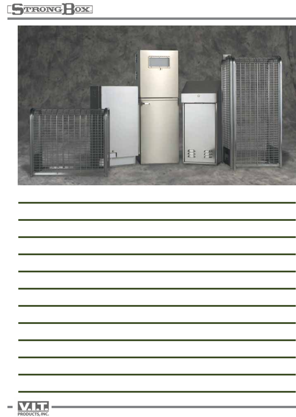
STRONG BOX
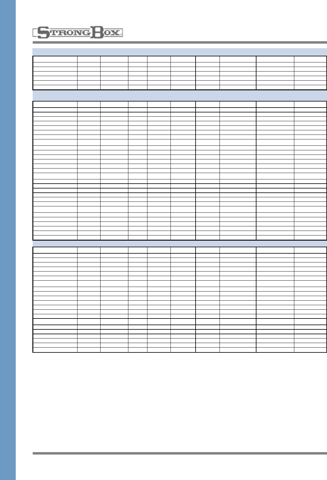
CONTROLLER ENCLOSURE GUIDE
Stations Width (in.) Height (in.) Depth (in.) Residential/Commercial
RainBIrd Controllers
EC Controller 4-9 stations 6.50 5.50 1.75 R
ESP-TM 4-8 stations 7.00 8.25 2.25 R
ESP-Modular 4-13 stations 11.00 8.00 4.50 R
ESP-LX Plus / LXi Plus 6-24 stations 9.50 10.25 4.50 R/C
ESP-LX Modular 8-32 stations 14.50 12.75 5.50 R/C
ESP-MC 8-40 stations 11.50 11.50 6.50 C
IQ LXM-DTC 8-32 stations 14.50 12.75 5.50 C
MDC (2 wire systems) 1-200 decoders 11.00 12.00 5.50 C
TWI (2 wire Interface) 28 satellites 15.50 12.50 6.00 C
LDI / SDI (Lg/Sm Decoder Interface) 1-200 decoders 9.50 10.25 4.50 C
CCU-6 (Cluster Control) 6 satellites 11.50 11.50 6.50 C
CCU-28 (Cluster Control) 28 satellites 11.50 11.50 6.50 C
ESP-SAT 12-40 stations 11.50 11.50 6.50 C
ESP-SITE SAT 12-40 stations 11.50 11.50 6.50 C
RainMaster
RME Sentar II SE 6-36 stations 13.25 10.25 4.75 C
SE-B / SE-SB 6-36 stations 13.25 18.00 4.50 C
RME Eagle EG 6-36 stations 13.25 10.25 4.75 C
EG-B / EG-SB 6-36 stations 13.25 18.00 4.50 C
RME Eagle-I central 6-36 stations 13.25 10.25 4.75 C
Egi-B / Egi-SB 6-36 stations 13.25 18.00 4.50 C
RME - DX2 Evolution 6-48 stations 13.25 10.25 4.75 C
Toro
DDC-WP 2-8 stations 5.75 5.00 2.00 R
DDC 4-8 stations 3.50 8.50 7.00 R
TMC-212 outdoor 2-12 stations 13.00 9.50 3.50 R/C
TMC-424 4-24 stations 15.25 10.25 5.25 C
TIS-612 6-12 stations 9.75 7.50 5.75 C
TIS-240 24 stations 11.75 8.50 5.75 C
Custom Command
Plastic 12-24 Station 12-24 stations 11.50 6.00 8.50 C
Metal 12-24 Station 12-24 stations 10.75 9.75 5.75 C
Metal 36-48 Station 36-48 stations 10.75 15.75 5.75 C
TDC-100/200 100, 200 decoders 14.00 13.00 6.00 C
Sentinel WallMount 12-48 stations 10.75 15.75 5.75 C
Irritrol
RainDial Series 6-12 stations 7.75 10.75 4.00 R
Smart Dial 6-24 stations 7.75 10.75 4.00 R
Total Control Series 6-24 stations 8.50 10.50 5.00 R
KwikDial Series 4-12 stations 9.00 7.00 4.00 R
JR Max Series 4-8 stations 8.00 6.75 4.00 R
MC-E Series 4-48 stations 9.75 10.50 4.25 C
IBOC Plus 4-12 stations 9.25 10.75 5.25 C
Hunter
I-Core-600-PL 6 stations mod. 13.50 11.00 6.50 C
I-Core-600-M 6 stations mod. 15.50 12.50 6.50 C
PRO-C Series 3-15 stations 9.00 10.00 4.50 C
ICC-Series 8-32 stations 11.00 13.25 4.75 C
ICC-M Series 8-48 stations 12.25 16.00 4.75 C
ACC Series 12-48 stations 12.50 15.50 6.50 C
ACC 990 99 stations 12.50 15.50 6.50 C
ET Module 6.00 4.00 2.00 C
AquaConserve
ET- 8 8-12 stations 9.00 8.75 3.25 R
ET-16 Series 16-32 stations 9.75 10.75 4.25 R
ULTIMO Series 16-66 stations 12.00 14.25 4.75 R/C
Signature
Constellation 8-24 stations 14.00 12.75 4.25 C
28-48 stations 14.00 18.00 4.25 C
Galaxy 8-48 stations 14.00 12.75 4.25 C
28-48 stations 14.00 18.00 4.25 C
HydroPoint
ET Plus 9-24 stations 6.00 7.00 1.00 R
WeatherTRAK ET Pro 2 12-24 stations 9.75 10.50 4.25 R/C
WeatherTRAK ET Pro 2 28-48 stations 9.75 10.50 4.25 R/C
Calsense
ET2000 8-40 stations 11.15 11.40 7.25 C
ET2000e 8-48 stations 11.15 11.40 7.25 C
3
RainBIrd Controllers
EC Controller x x x x x
ESP-TM x x x x x
ESP-Modular x x x x x
ESP-LX Plus / LXi Plus x x xx xx xx x x x x x
ESP-LX Modular x x xx xx xx x x
ESP-MC x x xx xx xx x x xx x x x
IQ LXM-DTC x x xx xx xx x x x x x
MDC (2 wire systems) x x xx xx xx x x x x x x
TWI (2 wire Interface) x x xx xx xx x
LDI / SDI (Lg/Sm Decoder Interface) x x xx xx xx x x x x
CCU-6 (Cluster Control) x x xx xx xx x x x x x
CCU-28 (Cluster Control) x x xx xx xx x x x x x
ESP-SAT x x xx xx xx x x x x x x
ESP-SITE SAT x x xx xx xx x x x x x x
RainMaster
RME Sentar II SE x x xx xx xx x x x x x x
SE-B / SE-SB x x xx xx xx x x
RME Eagle EG x x xx xx xx x x x x x x
EG-B / EG-SB x x xx xx xx
RME Eagle-I central x x xx xx xx x x x x x x
Egi-B / Egi-SB x x xx xx xx x x
RME - DX2 Evolution x x xx xx xx x x x x x x
Toro
DDC-WP x x x x x
DDC x x x x x
TMC-212 outdoor x x xx xx xx x x x x x x
TMC-424 x x xx xx xx x x
TIS-612 x x xx xx xx x x x x x x
TIS-240 x x xx xx xx x x x x x x
Custom Command
Plastic 12-24 Station x x xx xx xx x x x x x x
Metal 12-24 Station x x xx xx xx x x x x x x
Metal 36-48 Station x x xx xx xx
TDC-100/200 x x xx xx xx x x x x x
Sentinel WallMount x x xx xx xx x
Irritrol
RainDial Series x x x x x
Smart Dial x x x x x
Total Control Series x x x x x
KwikDial Series x x x x x
JR Max Series x x x x x
MC-E Series x x xx xx xx x x x x x x
IBOC Plus x x xx xx xx x x x x x x
Hunter
SRC-Series x x x x x
XC-Series x x x x x
PRO-C Series x x xx xx xx x x x x x x
ICC-Series x x xx xx xx x x x x x x
ICC-M Series x x xx xx xx x x
ACC Series x x xx xx xx x x
ACC 990 x x xx xx xx x x
ET Module x x x x x
AquaConserve
ET- 8 x x x x
ET-16 Series x x x x
ULTIMO Series x x xx xx xx x x x
Signature
Constellation x x xx xx xx x x
x x xx xx xx
Galaxy x x xx xx xx x x
x x xx xx xx
HydroPoint
ET Plus x x xx xx xx x x x x x x
WeatherTRAK ET Pro 2 x x xx xx xx x x x x x x
WeatherTRAK ET Pro 2 x x xx xx xx x x x x x x
Calsense
ET2000 x x xx xx xx x x x x x x
ET2000e x x xx xx xx x x x x x x
SB-18SS
Front Entry Pedestal
18” x 36” x 12”
SB-24SS
Front Entry Pedestal
24” x 36” x 12”
SB-36SS
Front Entry Pedestal
36” x 36” x 12”
SB-18DSS
Front Entry Pedestal
18” x 36” x 24”
SB-24DSS
Front Entry Pedestal
24” x 36” x 24”
SB-16SSW
Front Entry Wall Mount
16” x 18” x 12”
SB-16SS
Top Entry Pedestal
16” x 38” x 15.5”
SB-22SS
Top Entry Pedestal
24” x 38” x 17”
LD-16S Light Duty
Front Entry Pedestal
16” x 30” x 8”
LD-16SW Light Duty
Front Entry Wall Mount
16” x 30” x 8”
LD-18SW Light Duty
Front Entry Wall Mount
18” x 18” x 8”
x Room for one controller
xx Room for two controllers
4
THE ULTIMATE FRONT ENTRY ENCLOSURE
WEATHER RESISTANT—VANDAL RESISTANT
• 100%stainlesssteelconstructionassureslong-term,rustproofdurabilityandadditionalstrength
• Threepointlockingmechanism,flushmountedaccesshandleandheavydutycontinuoushingeensures
maximum security
• Removable,predrilledbackboardprovidesforeasyinstallationandanattractivefinishedproduct
• Chameleoneffectofthenaturalbrushedstainlesssteelfinishprovidesanunobtrusivequality
• Largedoormountedstorageareaandliteraturestoragepocketprovideseasyaccesstoplansand
scheduling information
• Filteredsidelouversatbottomandtopallowpassivecrossflowventilation
• Mountingtemplate,stainlesssteelanchorsandinstructions
• Tenyearlimitedwarranty
• NEMATYPE3RratedULListed
• Allstainlesssteelenclosuresmaybepowdercoatedinmanycolorsatanadditionalcharge
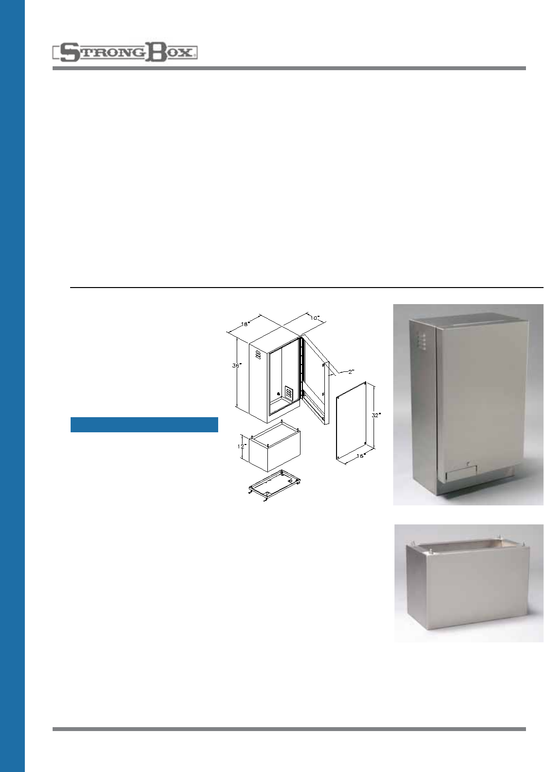
SB-18SS
18” Wide Enclosure
• 18”Wide,36”High,12”Deep
• NEMATYPE3RWeatherproof
• Threepointlockingdoor
• Padlocksecurityprovisions
• Mountingtemplateand
Jboltanchors
HEAVY-DUTY ENCLOSURES
stainless steel
PED-18SS
12” Riser Pedestal
• 18”Wide,12”High,10”Deep
• Stainlesssteel
• Hardwareinstalled
SPECIFICATION ON PAGE 41
5
HEAVY-DUTY ENCLOSURES
STAINLESS STEEL
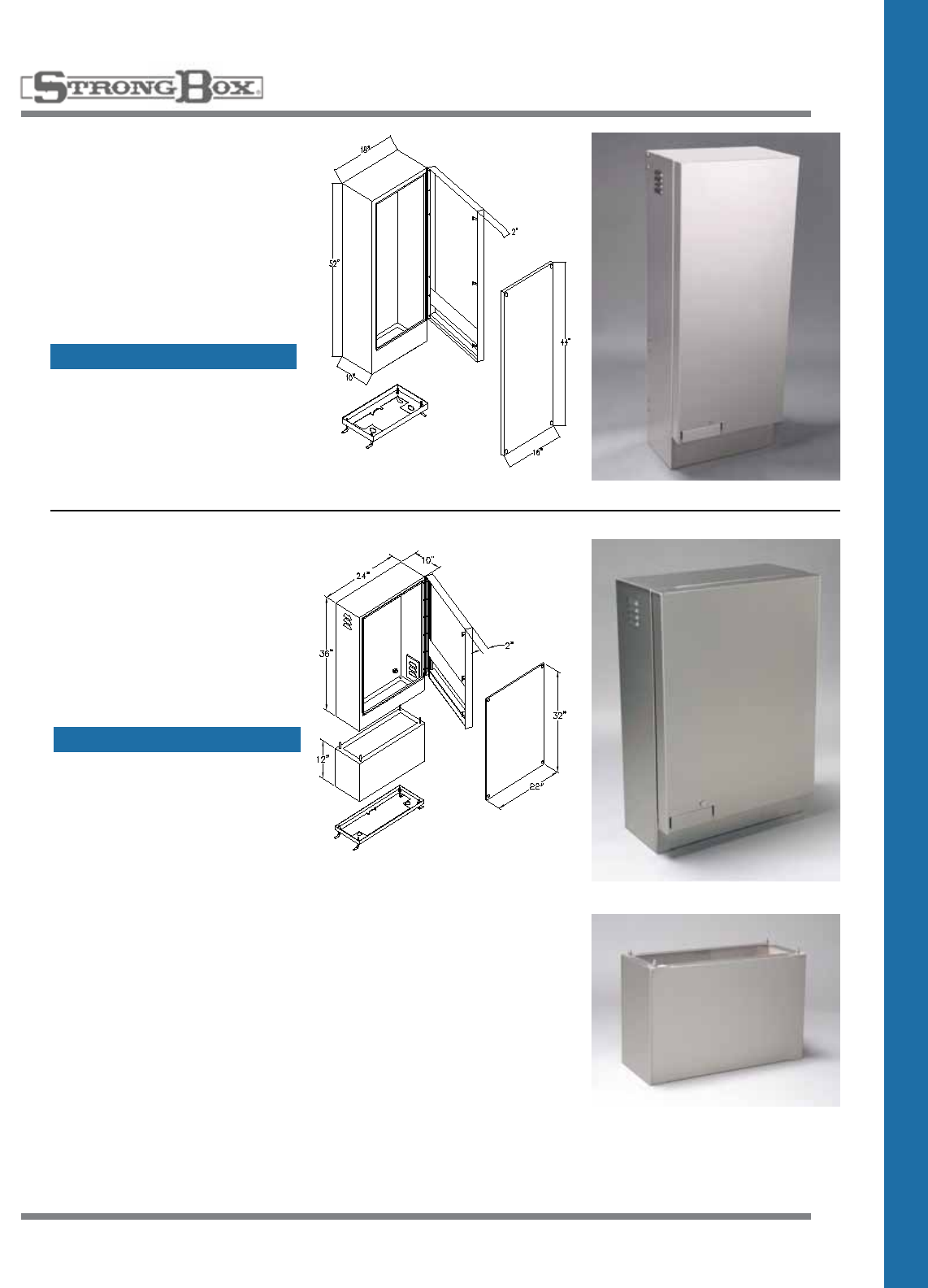
SB-1852SS
Service Pedestal
Companion Enclosure
• 18”Wide,52”High,12”Deep
• NEMATYPE3RWeatherproof
• Threepointlockingdoor
• Padlocksecurityprovisions
• Mountingtemplateand
Jboltanchors
SB-24SS
24” Wide Enclosure
• 24”Wide,36”High,12”Deep
• NEMATYPE3RWeatherproof
• Threepointlockingdoor
• Padlocksecurityprovisions
• Mountingtemplateand
Jboltanchors
PED-24SS
12” Riser Pedestal
• 24”Wide,12”High,10”Deep
• Stainlesssteel
• Hardwareinstalled
SPECIFICATION ON PAGE 41
SPECIFICATION ON PAGE 41
6
THE ULTIMATE FRONT ENTRY ENCLOSURE
WEATHER RESISTANT—VANDAL RESISTANT
• 100%stainlesssteelconstructionassureslong-term,rustproofdurabilityandadditionalstrength
• Threepointlockingmechanism,flushmountedaccesshandleandheavydutycontinuoushingeensures
maximum security
• Removable,predrilledbackboardprovidesforeasyinstallationandanattractivefinishedproduct
• Chameleoneffectofthenaturalbrushedstainlesssteelfinishprovidesanunobtrusivequality
• Largedoormountedstorageareaandliteraturestoragepocketprovideseasyaccesstoplansand
scheduling information
• Filteredsidelouversatbottomandtopallowpassivecrossflowventilation
• Mountingtemplate,stainlesssteelanchorsandinstructions
• Tenyearlimitedwarranty
• NEMATYPE3RratedULListed
• Allstainlesssteelenclosuresmaybepowdercoatedinmanycolorsatanadditionalcharge
HEAVY-DUTY ENCLOSURES
STAINLESS STEEL
SB-36SS
36” Wide Enclosure
• 36”Wide,36”High,12”Deep
• NEMATYPE3RWeatherproof
• Threepointlockingdoor
• Padlocksecurityprovisions
• Mountingtemplateand
Jboltanchors
PED-36SS
12” Riser Pedestal
• 36”Wide,12”High,10”Deep
• Stainlesssteel
• Hardwareinstalled
SPECIFICATION ON PAGE 41
7
HEAVY-DUTY ENCLOSURES
STAINLESS STEEL
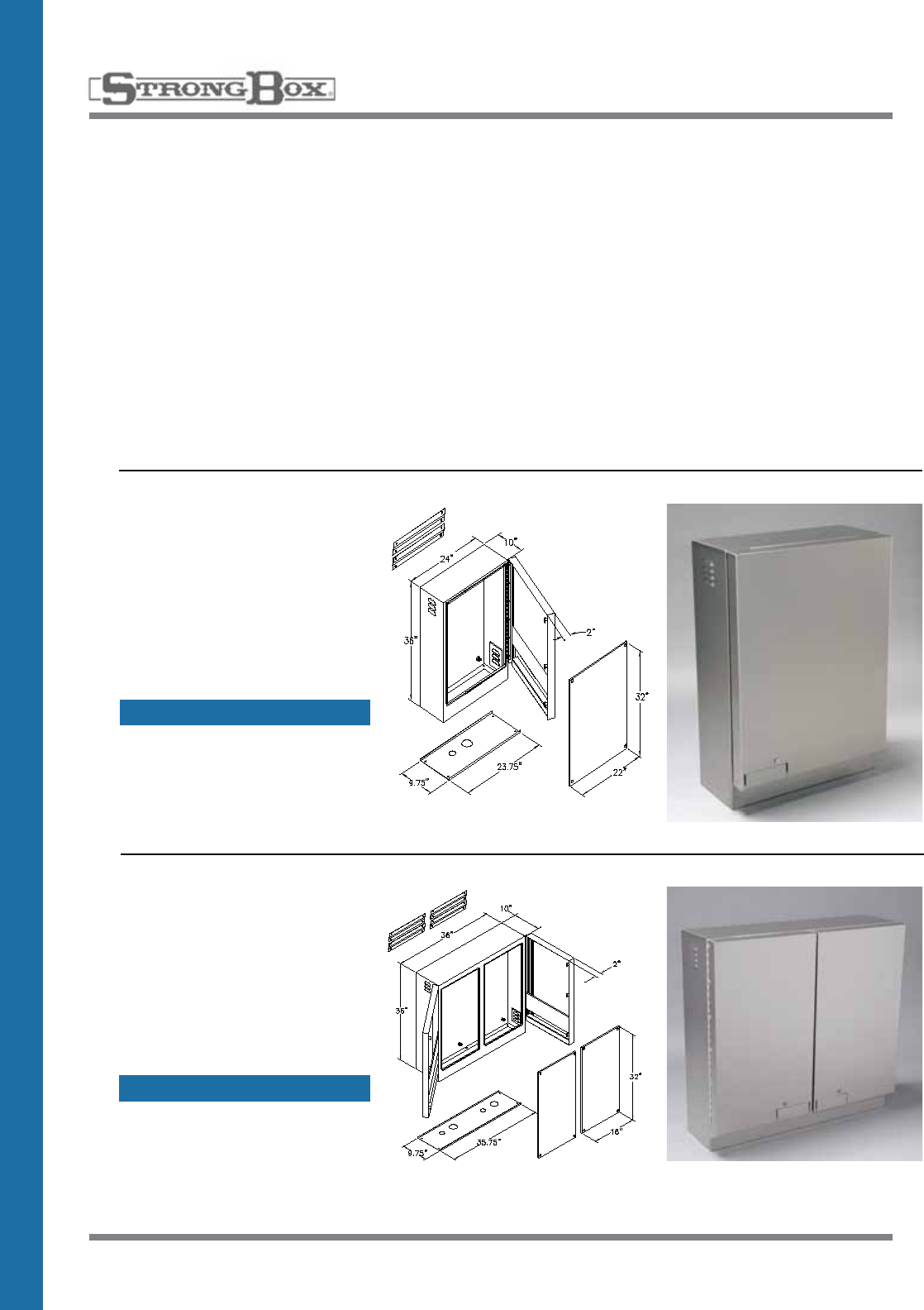
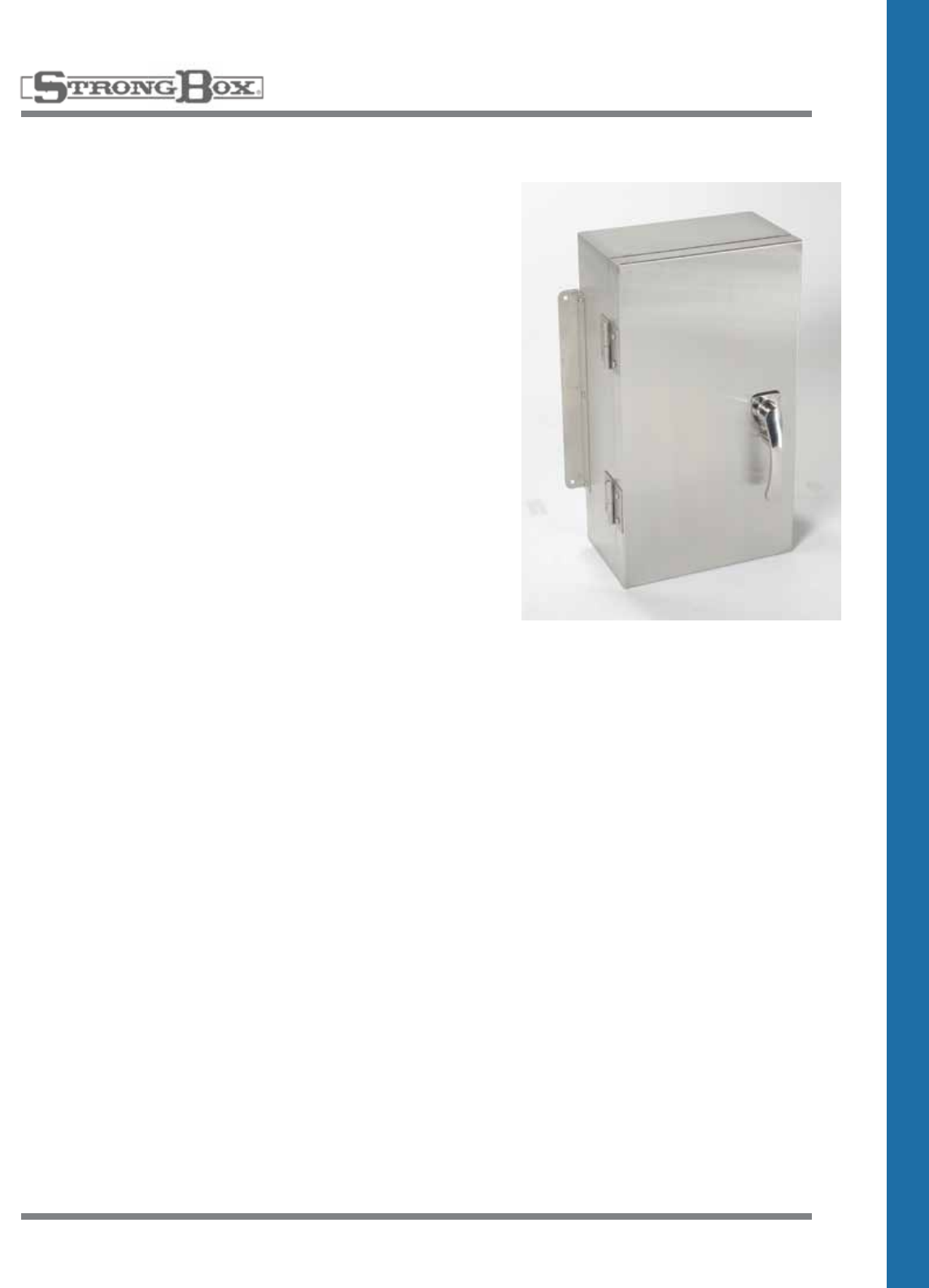
SB-18DSS
Service Pedestal
• 18”Wide,36”High,24”Deep
• NEMATYPE3RWeatherproof
• Threepointlockingdoor
• Padlocksecurityprovisions
• Mountingtemplateand
Jboltanchors
SB-24DSS
24” Wide Double Door
Enclosure
• 24”Wide,36”High,24”Deep
• NEMATYPE3RWeatherproof
• Threepointlockingdoor
• Padlocksecurityprovisions
• Mountingtemplateand
Jboltanchors
PED-18DSS
12” Riser Pedestal
• 18”Wide,12”High,20”Deep
• Stainlesssteel
• Hardwareinstalled
PED-24DSS
12” Riser Pedestal
• 24”Wide,12”High,20”Deep
• Stainlesssteel
• Hardwareinstalled
SPECIFICATION ON PAGE 41
SPECIFICATION ON PAGE 41
8
HEAVY-DUTY ENCLOSURES
TOP ENTRY – STAINLESS STEEL
THE ULTIMATE TOP ENTRY ENCLOSURE
WEATHER RESISTANT—VANDAL RESISTANT
• 100%stainlesssteelconstructionassureslong-term,rustproofdurabilityandadditionalstrength
• Threepointlockingmechanism,flushmountedaccesshandleandheavydutycontinuoushinge
ensures maximum security
• Removable,predrilledbackboardandtraysprovideforeasyinstallationofcontrollers
• Chameleoneffectofthenaturalbrushedstainlesssteelfinishprovidesanunobtrusivequality
• 38”heightwithfliptopaccessprovideseaseofviewingandprogramming
• Filteredsidelouversatbottomandtopallowpassivecrossflowventilation
• Mountingtemplate,stainlesssteelanchorsandinstructions
• Tenyearlimitedwarranty
• NEMATYPE3RratedULListed
• Allstainlesssteelenclosuresmaybepowdercoatedinmanycolorsatanadditionalcharge
SB-16SS
16” Wide Enclosure
• 16”Wide,38”High,15.5"Deep
• NEMATYPE3RWeatherproof
• Threepointlockingdoor
• Padlocksecurityprovisions
• Mountingtemplateand
Jboltanchors
• Standardtrayandbackboards
included
SB-22SS
24” Wide Enclosure
• 24”Wide,38”High,17”Deep
• NEMATYPE3RWeatherproof
• Threepointlockingdoor
• Padlocksecurityprovisions
• Mountingtemplateand
Jboltanchors
• Standardtrayandbackboards
included
SPECIFICATION ON PAGE 42
SPECIFICATION ON PAGE 42
9
HEAVY-DUTY ENCLOSURES
WALL MOUNT– STAINLESS STEEL
THE ULTIMATE WALL MOUNT ENCLOSURE
WEATHER RESISTANT – VANDAL RESISTANT
• 100%stainlesssteelconstructionassureslong-term,rust-proofdurabilityandadditionalstrength
• Wallmountbracketsprovidestrengthandsecurity,whilebottomplateincludesconduitholes
• Threepointlockingmechanism,flushmountedaccesshandleandheavydutycontinuoushinge
ensures maximum security
• Removable,predrilledbackboardandtraysprovideforeasyinstallationofcontrollers
• Chameleoneffectofthenaturalbrushedstainlesssteelfinishprovidesanunobtrusivequality
• Filteredsidelouversatbottomandtopallowpassivecrossflowventilation
• Mountingtemplate,stainlesssteelanchorsandinstructions
• Tenyearlimitedwarranty
• NEMATYPE3RratedULListed
• Allstainlesssteelenclosuresmaybepowdercoatedinmanycolorsatanadditionalcharge
SB-16SSW
16” Wide Enclosure
• 16”Wide,18”High,10”Deep
• Twopointlockingdoor
• Padlocksecurityprovisions
SB-18SSW
18” Wide Enclosure
• 18”Wide,36”High,12”Deep
• NEMATYPE3RWeatherproof
• Threepointlockingdoor
• Padlocksecurityprovisions
• Wallmountbracketsand
bottomplate
PED-16SSW
4” Riser Pedestal
• 16”Wide,4”High,8”Deep
SPECIFICATION ON PAGE 43
SPECIFICATION ON PAGE 43
10
HEAVY-DUTY ENCLOSURES
WALL MOUNT– STAINLESS STEEL
SB-24SSW
24” Wide Enclosure
• 24”Wide,36”High,12”Deep
• NEMATYPE3RWeatherproof
• Conduitopeningsin
bottomplate
• Padlocksecurityprovisions
• Wallmountbrackets
THE ULTIMATE WALL MOUNT ENCLOSURE
WEATHER RESISTANT – VANDAL RESISTANT
• 100%stainlesssteelconstructionassureslong-term,rust-proofdurabilityandadditionalstrength
• Wallmountbracketsprovidestrengthandsecurity,whilebottomplateincludesconduitholes
• ThreePointlockingmechanism,flushmountedaccesshandleandheavydutycontinuoushinge
ensures maximum security
• Removable,predrilledbackboardandtraysprovideforeasyinstallationofcontrollers
• Chameleoneffectofthenaturalbrushedstainlesssteelfinishprovidesanunobtrusivequality
• Filteredsidelouversatbottomandtopallowpassivecrossflowventilation
• Mountingtemplate,stainlesssteelanchorsandinstructions
• Tenyearlimitedwarranty
• NEMATYPE3RratedULListed
• Allstainlesssteelenclosuresmaybepowdercoatedinmanycolorsatanadditionalcharge
SB-36SSW
36” Wide Enclosure
• 36”Wide,36”High,12”Deep
• NEMATYPE3RWeatherproof
• Conduitopeningsin
bottomplate
• Padlocksecurityprovisions
• Wallmountbrackets
SPECIFICATION ON PAGE 43
SPECIFICATION ON PAGE 43
11
HEAVY-DUTY ENCLOSURES
STAINLESS STEEL
NEMA 3SX & 4X ENCLOSURES AVAILABLE FOR OEM DESIGN
WEATHER RESISTANT – VANDAL RESISTANT
TheStrongBoxNEMATYPE3SXSerieswasdesignedto
operate even in the coldest climates with ice formation
aroundcabinet.Our3SXSeriesisavailableaswallmount
or pedestal mount. When covering electronics or controllers
and protecting them from the harsh elements like snow and
icebuildup,thenwehavetheenclosureforyou.
• Watertight,dustproof,operablewheniceladen
• 14gauge304stainlesssteel
• Threepointlockingpadlockablehandle
• Removablebackboard
• NEMArated,ULlisted
• Tenyearlimitedwarranty
• Contactusformoreinformation
NEMA Enclosure Types
Type 3R:
Enclosures constructed for either indoor or outdoor use to
provide a degree of protection to personnel against access
to hazardous parts; to provide a degree of protection of the
equipmentinsidetheenclosureagainstingressofsolidfor-
eignobjects(fallingdirt);toprovideadegreeofprotection
withrespecttoharmfuleffectsontheequipmentduetothe
ingressofwater(rain,sleet,snow);andthatwillbeundam-
agedbytheexternalformationoficeontheenclosure.
Type 3SX:
Enclosures constructed for either indoor or outdoor use to
provide a degree of protection to personnel against access
to hazardous parts; to provide a degree of protection of the
equipmentinsidetheenclosureagainstingressofsolid
foreignobjects(fallingdirtandwindblowndust);toprovide
a degree of protection with respect to harmful effects on the
equipmentduetotheingressofwater(rain,sleet,snow);
that provides an additional level of protection against
corrosion; and for which the external mechanism(s) remain
operablewheniceladen.
Type 4X:
Enclosures constructed for either indoor or outdoor use to
provide a degree of protection to personnel against access
to hazardous parts; to provide a degree of protection of the
equipmentinsidetheenclosureagainstingressofsolidfor-
eignobjects(windblowndust);toprovideadegreeofpro-
tectionwithrespecttoharmfuleffectsontheequipmentdue
to the ingress of water (rain, sleet, snow, splashing water,
and hose directed water); that provides an additional level
ofprotectionagainstcorrosion;andthatwillbeundamaged
bytheexternalformationoficeontheenclosure.
12
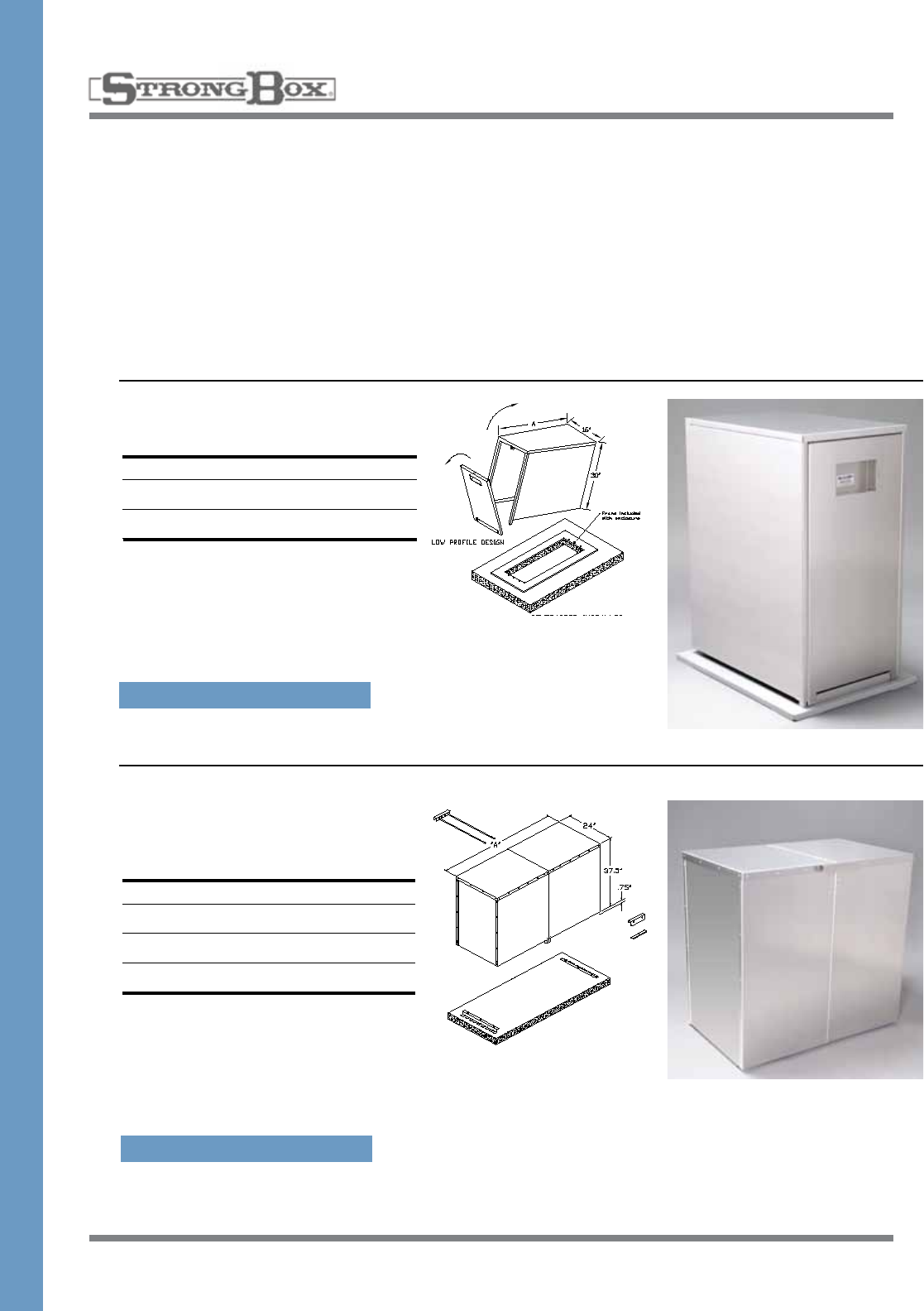
LIGHT DUTY ENCLOSURES
PEDESTAL – STAINLESS STEEL
THE WEATHER RESISTANT CABINET
• 100%stainlesssteelconstructionassureslong-term,rustproofdurabilityandadditionalstrength
• Flushmountedremovabledoorwithkeyedcamlock,
• Chameleoneffectofthenaturalbrushedstainlesssteelfinishprovidesanunobtrusivequality
• Filteredsidelouversatbottomandtopallowpassivecrossflowventilation
• Mountingtemplate,stainlesssteelanchorsandinstructions
• Tenyearlimitedwarranty
• NEMATYPE3RratedULListed
• Allstainlesssteelenclosuresmaybepowdercoatedinvariouscolorsatanadditionalcharge
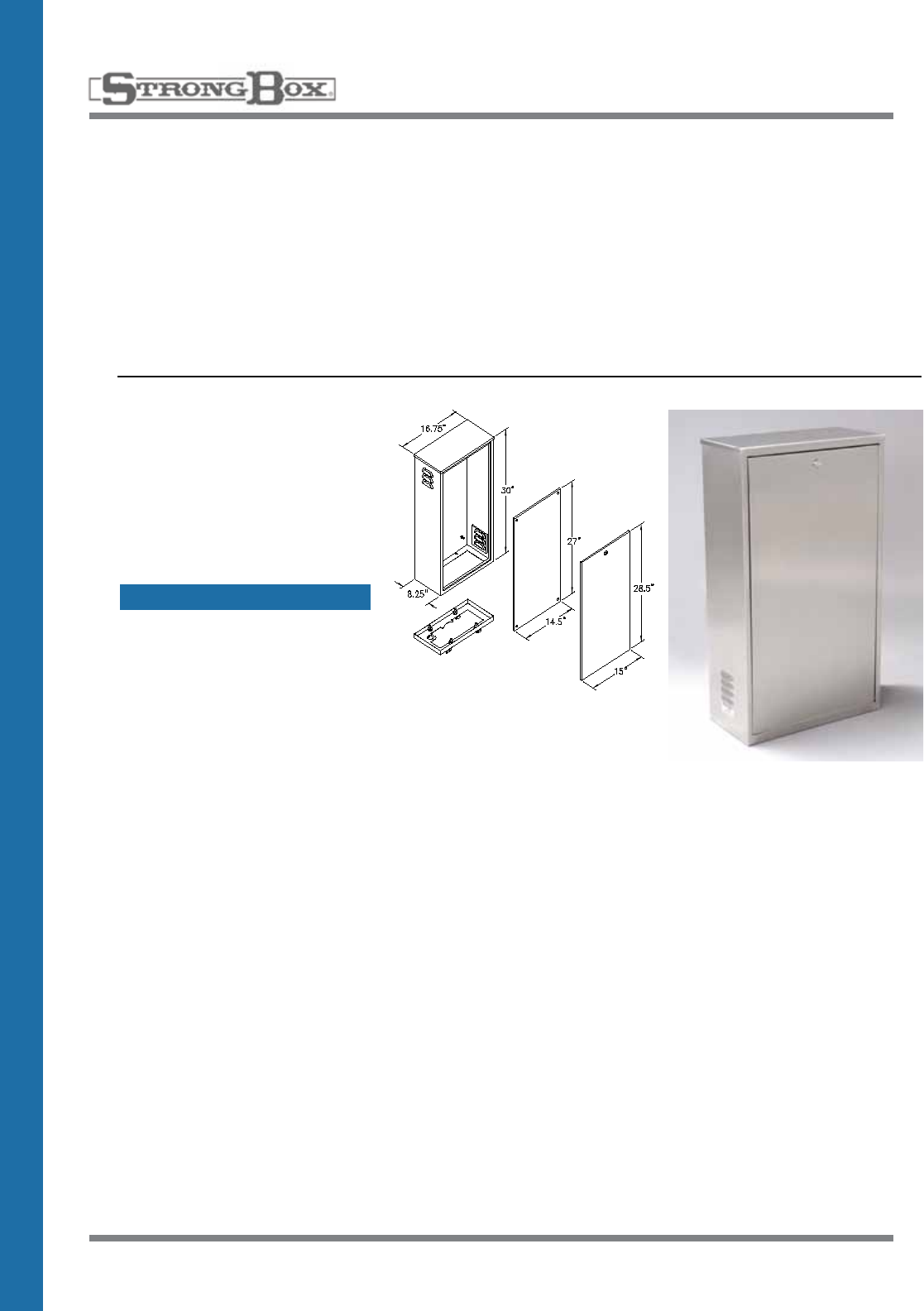
LD-16S
17” Wide Enclosure
• 16.75”Wide,30”High,8.25"Deep
• NEMATYPE3RWeatherproof
• Dropinkeyedlockingdoor
• Mountingtemplateand
Jboltanchors
SPECIFICATION ON PAGE 44
13
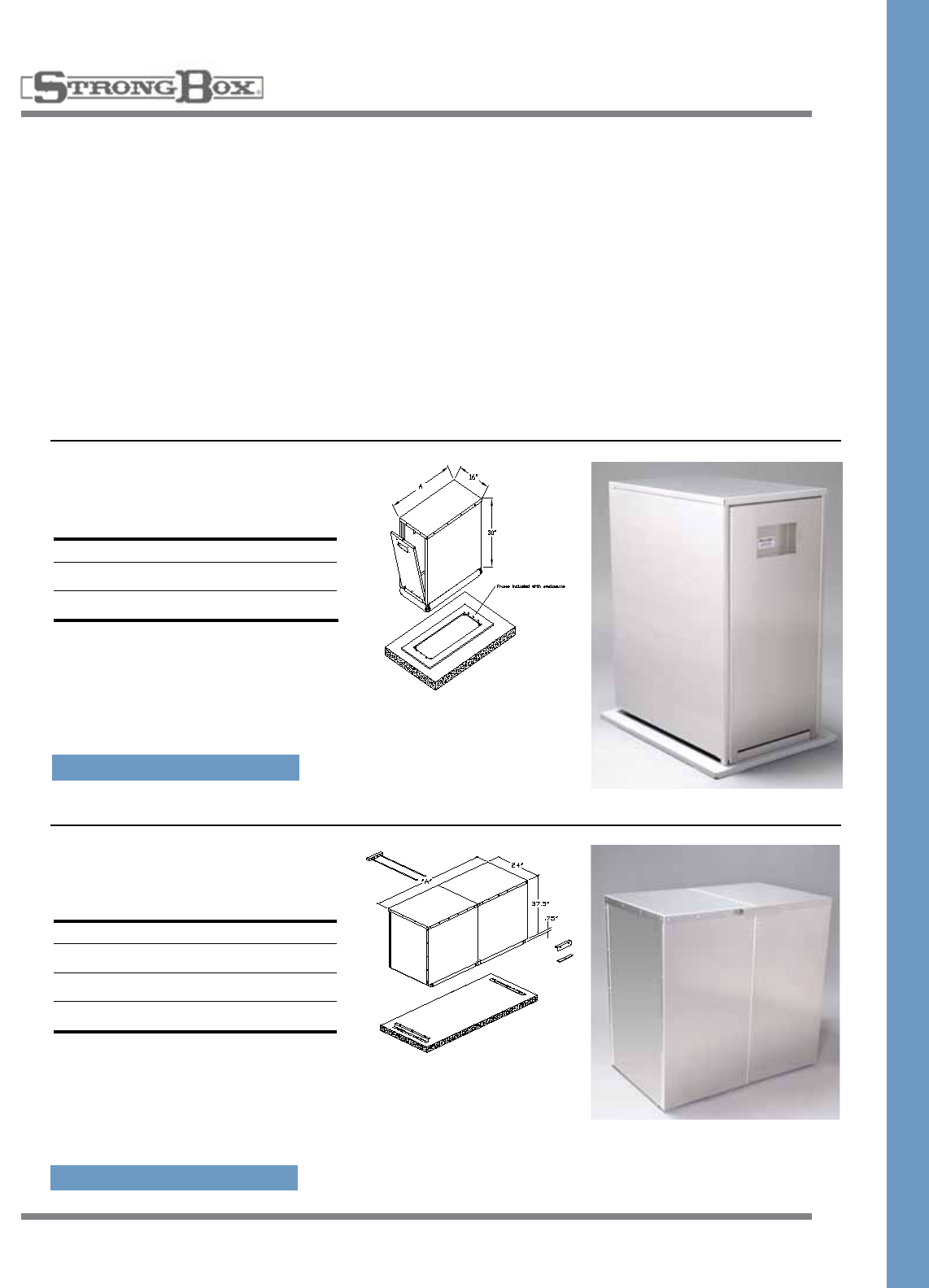
LIGHT DUTY ENCLOSURES
WALL MOUNT – STAINLESS STEEL
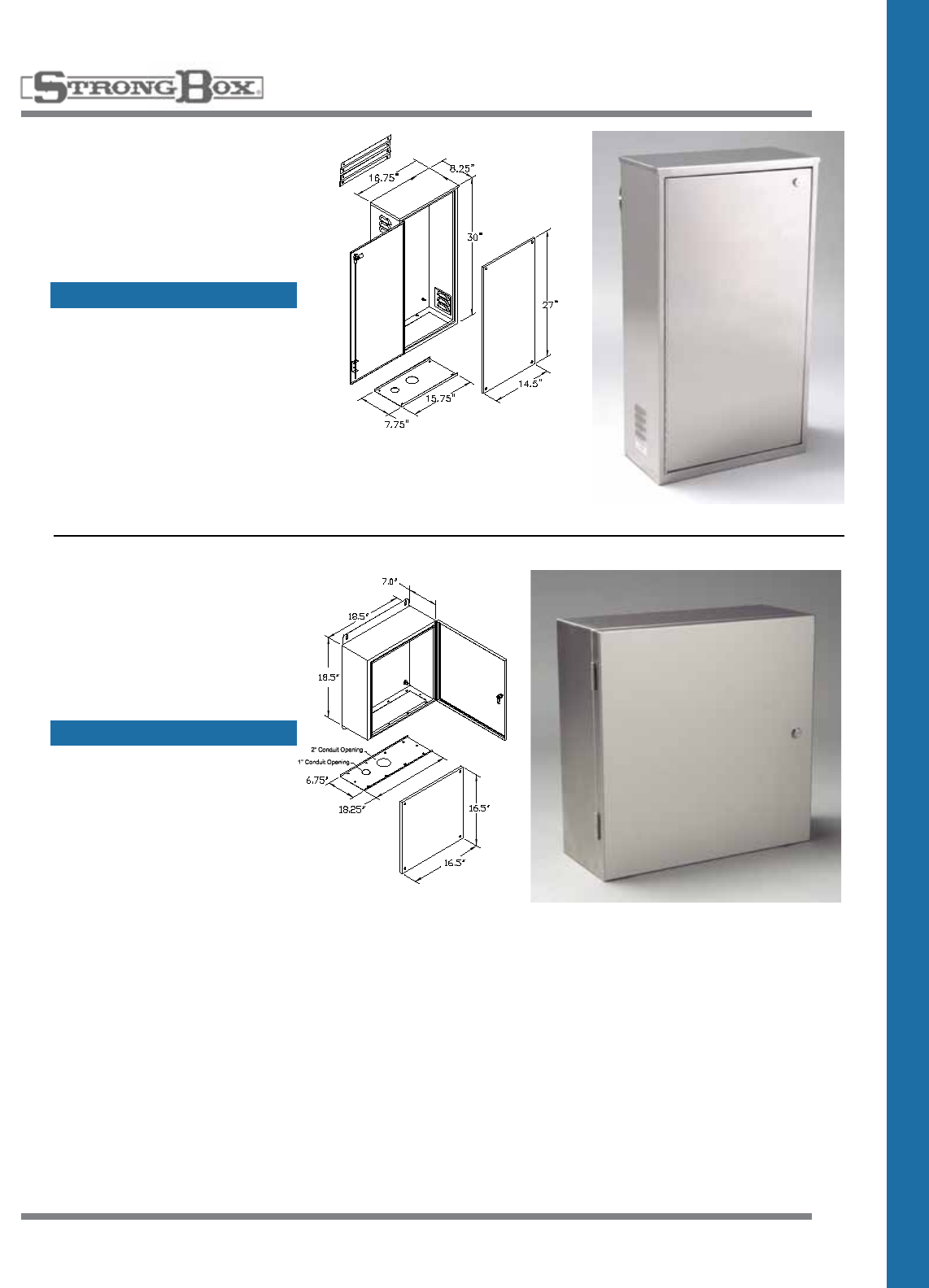
LD-16SW
16” Wide Light Duty
Enclosure
• 16.75”Wide,30”High,8”Deep
• NEMATYPE3RWeatherproof
• Hingedkeyedlockdoor
LD-18SW
18” Wide Wall Mount
Cabinet
• 18”Wide,18”High,8”Deep
• NEMATYPE3RWeatherproof
• Hingedkeyedlockdoor
SPECIFICATION ON PAGE 45
SPECIFICATION ON PAGE 46
14
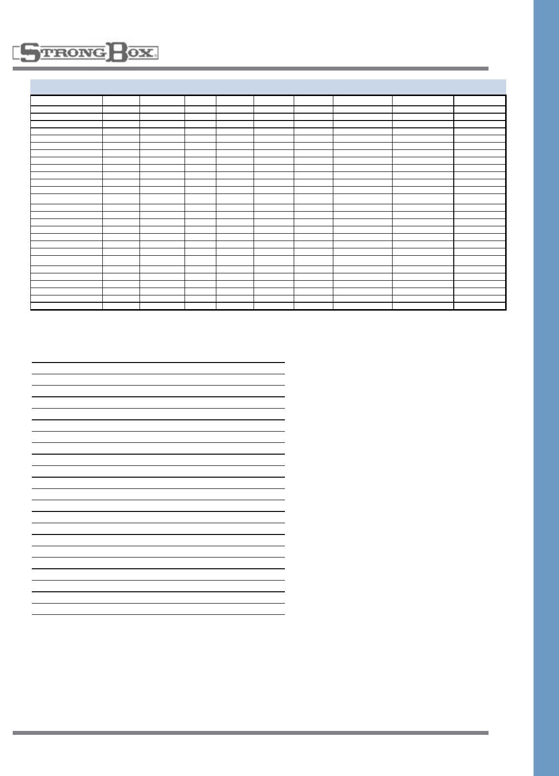
BACKFLOW COVER
SIZE CHART
Apollo
4A-200 Series Alum Smooth Expanded
Length Installed nip nip total elbow total Total inches
3/4" 12.75 20.00 3.00 5.00 4.00 21.75 SBBC-30AL SBBC-30SS & CR BC-30CR
1" 14.75 20.00 3.00 5.00 5.00 24.75 SBBC-30AL SBBC-30SS & CR BC-30CR
1 1/4" 18.75 22.00 3.00 5.00 5.50 29.25 SBBC-45AL SBBC-45SS & CR BC-45CR
1 1/2" 18.75 22.00 3.00 5.00 6.00 29.75 SBBC-45AL SBBC-45SS & CR BC-45CR
2" 20.25 23.00 3.00 5.00 7.50 32.75 SBBC-45AL SBBC-45SS & CR BC-45CR
FEBCO
825Y & LF860 Alum Smooth Expanded
Length Installed nip nip total elbow total Total inches
3/4" 12.00 19.00 3.00 5.00 4.00 21.00 SBBC-30AL SBBC-30SS & CR BC-30CR
1" 12.75 20.00 3.00 5.00 5.00 22.75 SBBC-30AL SBBC-30SS & CR BC-30CR
1 1/4" 16.00 22.00 3.00 5.00 5.50 26.50 SBBC-30AL SBBC-30SS & CR BC-30CR
1 1/2" 17.00 22.00 3.00 5.00 6.00 28.00 SBBC-45AL SBBC-45SS & CR BC-45CR
2" 17.75 22.00 3.00 5.00 7.50 30.25 SBBC-45AL SBBC-45SS & CR BC-45CR
LF860 Alum Smooth Expanded
Length Installed nip nip total elbow total Total inches
2 1/2" 40.75 38.50 n/a n/a 17.00 57.75 SBBC-75ALHP SBBC-75SS & CR BC-75CR
3" 42.00 44.25 n/a n/a 18.50 60.50 N/A N/A N/A
4" 46.25 46.50 n/a n/a 22.00 68.25 N/A N/A N/A
6" 56.00 53.25 n/a n/a 27.00 83.00 N/A N/A N/A
825YA Alum Smooth Expanded
Length Installed nip nip total elbow total Total inches
3/4" 10.00 17.00 n/a n/a n/a 10.00 SBBC-22AL SBBC-22SS & CR BC-30CR
1" 10.25 18.00 n/a n/a n/a 10.25 SBBC-22AL SBBC-22SS & CR BC-30CR
1 1/2" 14.25 19.00 n/a n/a n/a 14.25 SBBC-22AL SBBC-22SS & CR BC-30CR
2" 15.00 20.00 n/a n/a n/a 15.00 SBBC-22AL SBBC-22SS & CR BC-30CR
LF880V Alum Smooth Expanded
Length Installed nip nip total elbow total Total inches
2 1/2" 25.50 32.00 n/a n/a n/a 25.50 SBBC-40ALHP SBBC-40SS & CR BC-75CR
3" 25.75 32.00 n/a n/a n/a 25.75 SBBC-40ALHP SBBC-40SS & CR BC-75CR
4" 28.00 36.00 n/a n/a n/a 28.00 SBBC-40ALHP SBBC-40SS & CR BC-75CR
6" 32.25 39.00 n/a n/a n/a 32.25 SBBC-40ALHP SBBC-40SS & CR BC-75CR
Watts
U009AQT M2AQT Alum Smooth Expanded
Length Installed nip nip total elbow total Total inches
3/4" 16.25 22.00 n/a n/a n/a 16.25 SBBC-22AL SBBC-22SS & CR BC-30CR
1" 17.50 23.00 n/a n/a n/a 17.25 SBBC-22AL SBBC-22SS & CR BC-30CR
1 1/2" 20.50 24.00 n/a n/a n/a 20.50 SBBC-30AL SBBC-30SS & CR BC-30CR
2" 25.50 24.00 n/a n/a n/a 25.50 SBBC-30AL SBBC-30SS & CR BC-30CR
U009QT M2QT Alum Smooth Expanded
Length Installed nip nip total elbow total Total inches
3/4" 13.75 22.00 3.00 5.00 4.00 23.00 SBBC-30AL SBBC-30SS & CR BC-30CR
1" 17.50 23.00 3.00 5.00 5.00 27.50 SBBC-30AL SBBC-30SS & CR BC-30CR
1 1/4" 24.50 24.00 3.00 5.00 5.50 35.00 SBBC-45AL SBBC-45SS & CR BC-45CR
1 1/2" 25.50 24.00 3.00 5.00 6.00 36.50 SBBC-45AL SBBC-45SS & CR BC-45CR
2" 27.50 24.00 3.00 5.00 7.50 40.00 SBBC-45AL SBBC-45SS & CR BC-45CR
909 RPDA Alum Smooth Expanded
Length Installed nip nip total elbow total Total inches
2 1/2" 42.25 34.00 n/a n/a 17.00 59.25 SBBC-75ALHP SBBC-75SS & CR BC-75CR
3" 42.25 37.00 n/a n/a 18.50 60.75 SBBC-75ALHP SBBC-75SS & CR BC-75CR
4" 55.25 41.00 n/a n/a 22.00 77.25 N/A N/A BC-75CR
6" 66.00 49.00 n/a n/a 27.00 93.00 N/A N/A N/A
15
BACKFLOW COVER
SIZE CHART
Inside Dimensions
Wt. Length Width Height
SBBC-22SS/CR 43 20 14 27
SBBC-30SS/CR 53 27 14 27
SBBC-45SS/CR 61 42 14 27
SBBC-20SS 53 18 14 48.5
SBBC-40SS/CR 80 38 23 37.5
SBBC-75SS/CR 150 72 23 37.5
SBBC-15AL 35 11.75 14 27.5
SBBC-30AL 51 27 14 27.5
SBBC-45AL 67 42 14 27.5
SBBC-60AL 82 57 14 27.5
SBBC-40ALHP 88 38 21.5 37.5
SBBC-60ALHP 118 58 21.5 37.5
SBBC-75ALHP 128 73 21.5 37.5
SBBC-90ALHP 158 88 21.5 37.5
PE-40AL 98 38 36 37.5
PE-60AL 128 58 36 37.5
BC-30CR/CRG 45 27 9 25
BC-45CR/CRG 73 42 15 31
BC-75CR/CRG 160 72 27 43
Apollo
4A-200 Series Alum Smooth Expanded
Length Installed nip nip total elbow total Total inches
3/4" 12.75 20.00 3.00 5.00 4.00 21.75 SBBC-30AL SBBC-30SS & CR BC-30CR
1" 14.75 20.00 3.00 5.00 5.00 24.75 SBBC-30AL SBBC-30SS & CR BC-30CR
1 1/4" 18.75 22.00 3.00 5.00 5.50 29.25 SBBC-45AL SBBC-45SS & CR BC-45CR
1 1/2" 18.75 22.00 3.00 5.00 6.00 29.75 SBBC-45AL SBBC-45SS & CR BC-45CR
2" 20.25 23.00 3.00 5.00 7.50 32.75 SBBC-45AL SBBC-45SS & CR BC-45CR
FEBCO
825Y & LF860 Alum Smooth Expanded
Length Installed nip nip total elbow total Total inches
3/4" 12.00 19.00 3.00 5.00 4.00 21.00 SBBC-30AL SBBC-30SS & CR BC-30CR
1" 12.75 20.00 3.00 5.00 5.00 22.75 SBBC-30AL SBBC-30SS & CR BC-30CR
1 1/4" 16.00 22.00 3.00 5.00 5.50 26.50 SBBC-30AL SBBC-30SS & CR BC-30CR
1 1/2" 17.00 22.00 3.00 5.00 6.00 28.00 SBBC-45AL SBBC-45SS & CR BC-45CR
2" 17.75 22.00 3.00 5.00 7.50 30.25 SBBC-45AL SBBC-45SS & CR BC-45CR
LF860 Alum Smooth Expanded
Length Installed nip nip total elbow total Total inches
2 1/2" 40.75 38.50 n/a n/a 17.00 57.75 SBBC-75ALHP SBBC-75SS & CR BC-75CR
3" 42.00 44.25 n/a n/a 18.50 60.50 N/A N/A N/A
4" 46.25 46.50 n/a n/a 22.00 68.25 N/A N/A N/A
6" 56.00 53.25 n/a n/a 27.00 83.00 N/A N/A N/A
825YA Alum Smooth Expanded
Length Installed nip nip total elbow total Total inches
3/4" 10.00 17.00 n/a n/a n/a 10.00 SBBC-22AL SBBC-22SS & CR BC-30CR
1" 10.25 18.00 n/a n/a n/a 10.25 SBBC-22AL SBBC-22SS & CR BC-30CR
1 1/2" 14.25 19.00 n/a n/a n/a 14.25 SBBC-22AL SBBC-22SS & CR BC-30CR
2" 15.00 20.00 n/a n/a n/a 15.00 SBBC-22AL SBBC-22SS & CR BC-30CR
LF880V Alum Smooth Expanded
Length Installed nip nip total elbow total Total inches
2 1/2" 25.50 32.00 n/a n/a n/a 25.50 SBBC-40ALHP SBBC-40SS & CR BC-75CR
3" 25.75 32.00 n/a n/a n/a #VALUE! SBBC-40ALHP SBBC-40SS & CR BC-75CR
4" 28.00 36.00 n/a n/a n/a #VALUE! SBBC-40ALHP SBBC-40SS & CR BC-75CR
6" 32.25 39.00 n/a n/a n/a #VALUE! SBBC-40ALHP SBBC-40SS & CR BC-75CR
Watts
U009AQT M2AQT Alum Smooth Expanded
Length Installed nip nip total elbow total Total inches
3/4" 16.25 22.00 n/a n/a n/a 16.25 SBBC-22AL SBBC-22SS & CR BC-30CR
1" 17.50 23.00 n/a n/a n/a 17.25 SBBC-22AL SBBC-22SS & CR BC-30CR
1 1/2" 20.50 24.00 n/a n/a n/a 20.50 SBBC-30AL SBBC-30SS & CR BC-30CR
2" 25.50 24.00 n/a n/a n/a 25.50 SBBC-30AL SBBC-30SS & CR BC-30CR
U009QT M2QT Alum Smooth Expanded
Length Installed nip nip total elbow total Total inches
3/4" 13.75 22.00 3.00 5.00 4.00 23.00 SBBC-30AL SBBC-30SS & CR BC-30CR
1" 17.50 23.00 3.00 5.00 5.00 27.50 SBBC-30AL SBBC-30SS & CR BC-30CR
1 1/4" 24.50 24.00 3.00 5.00 5.50 35.00 SBBC-45AL SBBC-45SS & CR BC-45CR
1 1/2" 25.50 24.00 3.00 5.00 6.00 36.50 SBBC-45AL SBBC-45SS & CR BC-45CR
2" 27.50 24.00 3.00 5.00 7.50 40.00 SBBC-45AL SBBC-45SS & CR BC-45CR
909 RPDA Alum Smooth Expanded
Length Installed nip nip total elbow total Total inches
2 1/2" 42.25 34.00 n/a n/a 17.00 59.25 SBBC-75ALHP SBBC-75SS & CR BC-75CR
3" 42.25 37.00 n/a n/a 18.50 60.75 SBBC-75ALHP SBBC-75SS & CR BC-75CR
4" 55.25 41.00 n/a n/a 22.00 77.25 N/A N/A BC-75CR
6" 66.00 49.00 n/a n/a 27.00 93.00 N/A N/A N/A
Wilkins
375 XL/VSR Alum Smooth Expanded
Length Installed nip nip total elbow total Total inches
3/4" 12.75 20.00 3.00 5.00 4.00 21.75 SBBC-30AL SBBC-30SS & CR BC-30CR
1" 15.75 20.50 3.00 5.00 5.00 25.75 SBBC-30AL SBBC-30SS & CR BC-30CR
1 1/4" 20.50 22.00 3.00 5.00 5.50 31.00 SBBC-45AL SBBC-45SS & CR BC-45CR
1 1/2" 21.75 23.00 3.00 5.00 6.00 32.75 SBBC-45AL SBBC-45SS & CR BC-45CR
2" 24.25 25.00 3.00 5.00 7.50 36.75 SBBC-45AL SBBC-45SS & CR BC-45CR
2 1/2" 31.00 33.00 n/a n/a 17.00 48.00 SBBC-60ALHP SBBC-75SS & CR BC-75CR
3" 32.00 34.00 n/a n/a 18.50 50.50 SBBC-60ALHP SBBC-75SS & CR BC-75CR
4" 38.00 38.00 n/a n/a 22.00 60.00 SBBC-75ALHP SBBC-75SS & CR BC-75CR
6" 45.00 44.00 n/a n/a 27.00 72.00 SBBC-90ALHP N/A N/A
975 XL/XL2V Alum Smooth Expanded
Length Installed nip nip total elbow total Total inches
3/4" 15.00 22.00 3.00 5.00 4.00 24.00 SBBC-30AL SBBC-30SS & CR BC-30CR
1" 16.00 23.00 3.00 5.00 5.00 26.00 SBBC-30AL SBBC-30SS & CR BC-30CR
1 1/4" 17.00 24.00 3.00 5.00 5.50 27.50 SBBC-30AL SBBC-30SS & CR BC-30CR
1 1/2" 17.50 24.00 3.00 5.00 6.00 28.50 SBBC-45AL SBBC-45SS & CR BC-45CR
2" 18.50 24.00 3.00 5.00 7.50 31.00 SBBC-45AL SBBC-45SS & CR BC-45CR
475 vAlum Smooth Expanded
Length Installed nip nip total elbow total Total inches
2 1/2" 33.00 34.00 n/a n/a n/a 34.00 SBBC-40ALHP SBBC-40SS & CR BC-75CR
3" 34.00 36.00 n/a n/a n/a 36.00 SBBC-40ALHP SBBC-40SS & CR BC-75CR
4" 42.00 36.00 n/a n/a n/a 36.00 N/A N/A BC-75CR
6" 48.00 38.00 n/a n/a n/a 38.00 N/A N/A N/A
16
High Profile Two Piece
Enclosure
“A”Length Height Width
SBBC-40ALHP 40” 39” 24”
SBBC-60ALHP 60” 39” 24”
SBBC-75ALHP 75” 39” 24”
SBBC-90ALHP 90” 39” 24”
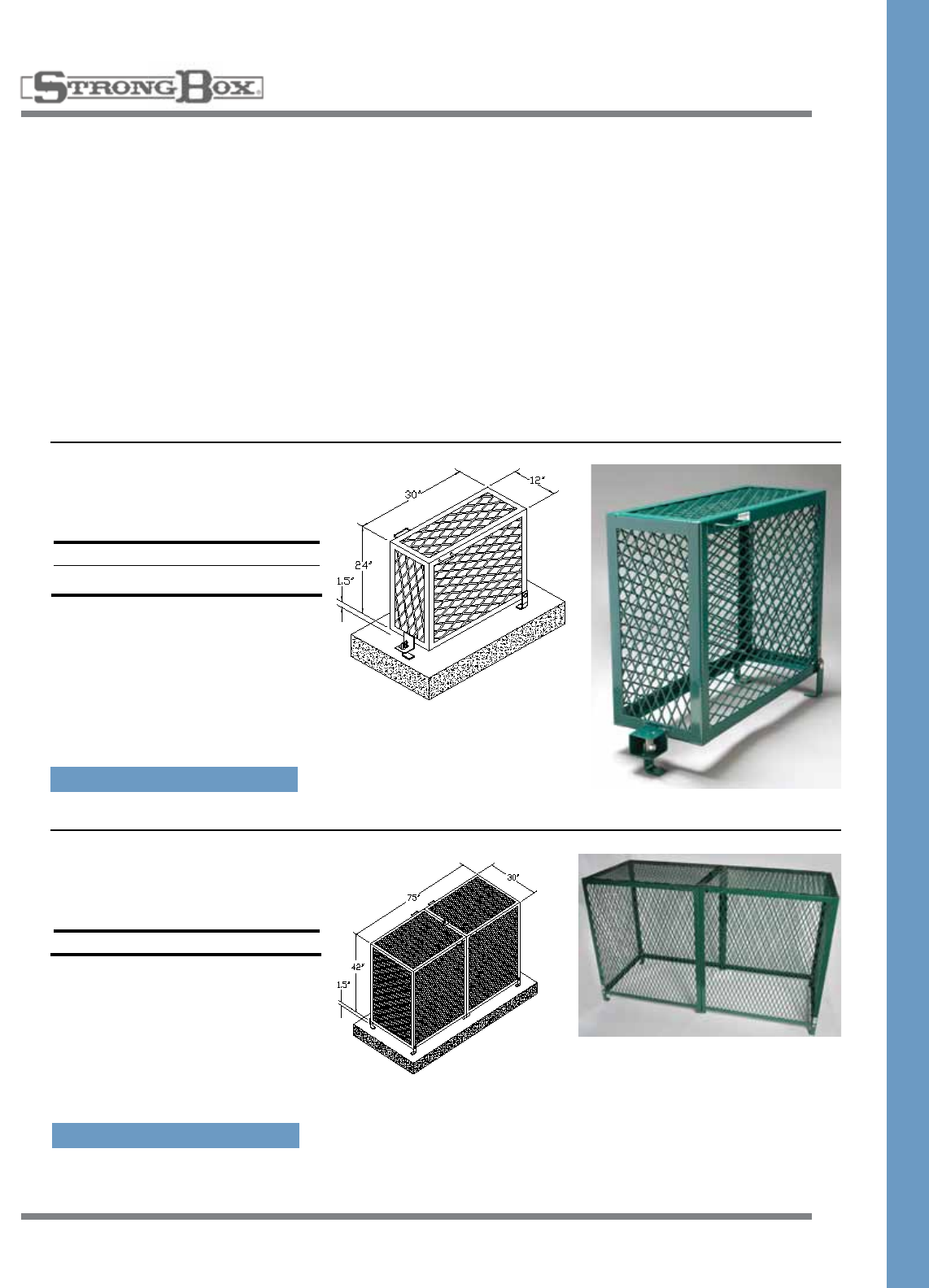
Low Profile Enclosure
“A”Length Height Width
SBBC-22AL 22” 30” 16.25”
SBBC-30AL 30” 30” 16.25”
SBBC-45AL 45” 30” 16.25”
BACKFLOW ENCLOSURES
ALUMINUM
VANDAL-RESISTANT EASY ACCESS
BACKFLOW ENCLOSURE
• Marinegradealuminumalloyconstructionprovideslastingdurabilityandstrength,withlightweightfor
ease of handling
• 100%stainlesssteelhardwareassureslong-term,rustproofdurabilityandadditionalstrength
• Enclosuressecuredtomountinghardwareprovidingeasyaccessforserviceandrepair
• Flush-mountedlockingmechanismandsolidsheetconstructionensuresmaximumsecurity
• Chameleoneffectofthenaturalfinishprovidesanunobtrusivequality
• Fiveyearlimitedwarranty
• Allaluminumenclosuresmaybepowdercoatedinmanycolorsatanextracharge
Note:Forinsidedimensions,seeBackflowCover
Sizing Chart on pages 14-15.
Note:Forinsidedimensions,seeBackflowCover
Sizing Chart on pages 14-15.
SPECIFICATION ON PAGE 48
SPECIFICATION ON PAGE 49
• Marinegradealuminum
• Stainlesssteelhardware
• Weatherresistant
• Patentedlockingsystemacceptspadlock
• Marinegradealuminum
• Stainlesssteelhardware
• Weatherresistant
• Patentedlockingsystemacceptspadlock
Contractor installed
concrete pad
Contractor installed
concrete pad
17
INSULATED BACKFLOW ENCLOSURES
ALUMINUM
ALL WEATHER INSULATED
BACKFLOW ENCLOSURE
• Marinegradealuminumalloyconstructionprovideslastingdurabilityandstrength,withlightweightfor
ease of handling
• 100%stainlesssteelhardwareassureslong-term,rustproofdurabilityandadditionalstrength
• Enclosuressecuredtomountinghardwareprovidingeasyaccessforserviceandrepair
• Flush-mountedlockingmechanismandsolidsheetconstructionensuresmaximumsecurity
• Chameleoneffectofthenaturalfinishprovidesanunobtrusivequality
• R-19insulationvaluePolarBearierBlanket*
• Flexiblerubberskirtprovidesprotectionfromwindbutallowsdrainage
• Fiveyearlimitedwarranty
• Allaluminumenclosuresmaybepowdercoatedinmanycolorsatanextracharge
*PolarBearierBlanketsforinsulatingbackflowdevicesincludedasinsulationforinsulatedenclosures
Low Profile Insulated
Enclosure
“A”Length Height Width
SBBC-22ALI 22” 30” 16.25”
SBBC-30ALI 30” 30” 16.25”
SBBC-45ALI 45” 30” 16.25”
High Profile Insulated Two
Piece Enclosure
“A”Length Height Width
SBBC-40ALHPI 40” 39” 24”
SBBC-60ALHPI 60” 39” 24”
SBBC-75ALHPI 75” 39” 24”
SBBC-90ALHPI 90” 39” 24”
Note:Forinsidedimensions,seeBackflowCover
Sizing Chart on pages 14-15.
Note:Forinsidedimensions,seeBackflowCover
Sizing Chart on pages 14-15.
SPECIFICATION ON PAGE 51
• Marinegradealuminum
• Stainlesssteelhardware
• Weatherresistant
• Patentedlockingsystemacceptspadlock
SPECIFICATION ON PAGE 50
• Marinegradealuminum
• Stainlesssteelhardware
• Weatherresistant
• Patentedlockingsystemacceptspadlock
Contractor installed
concrete pad
Contractor installed
concrete pad
18
VANDAL RESISTANT EASY ACCCESS
PUMP AND POWER CONDITIONERS ENCLOSURE
• Marinegradealuminumalloyconstructionprovideslastingdurabilityandstrength,withlightweightfor
ease of handling
• 100%stainlesssteelhardwareassureslong-termrustproofdurabilityandadditionalstrength
• Fullreleaselockingmechanismrequiresnotoolsandprovideseasyaccessforserviceandrepair
• Flush-mountedlockingmechanismandsollidsheetconstructionensuresmaximumsecurity
• Chameleoneffectofthenaturalfinishprovidesanunobtrusivequality
• Fiveyearlimitedwarranty
• Allaluminumenclosuresmaybepowdercoatedinmanycolorsatanadditionalcharge
PUMP & POWER CONDITIONER
ALUMINUM
Power Conditioner Enclosure
“A”Length Height Width
SBBC-40ALHPPC40” 39” 24”
• Marinegradealuminum
• Stainlesssteelhardware
• Weatherresistant
• Patentedlockingsystem
accepts padlock
• Removablewithouttools
Pump Enclosure
“A”Length Height Width
PE-40AL 40” 39” 38”
PE-60AL 60" 39" 38"
• Marinegradealuminum
• Stainlesssteelhardware
• Weatherresistant
• Patentedlockingsystem
accepts padlock
• Removablewithouttools
SPECIFICATION ON PAGE 47
SPECIFICATION ON PAGE 49
Contractor installed
concrete pad
Contractor installed
concrete pad
19
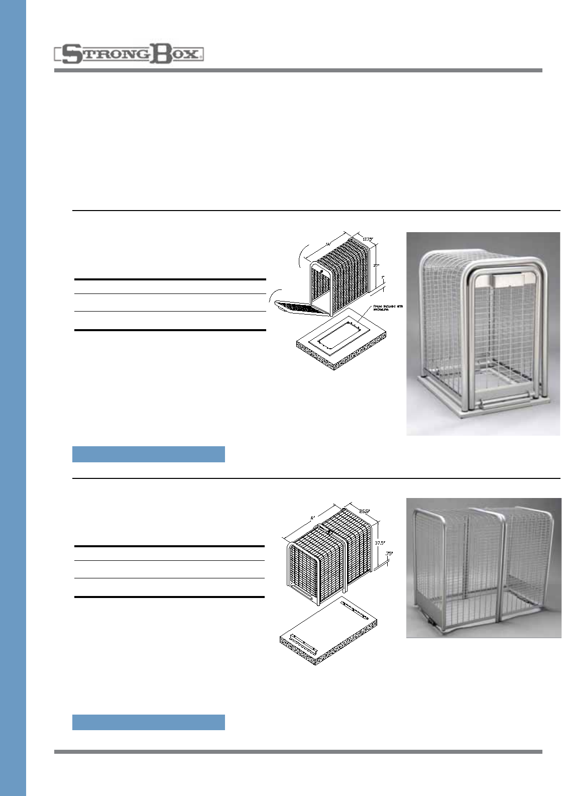
EXPANDED METAL VANDAL RESISTANT
BACKFLOW COVER
• 1½”number9,flattenedexpandedmetalallowsfullviewingofbackflowpreventer
• Coldrolled,formedsteelframeprovidesstrengthandstability
• Locktabprovidesforuseofpadlock
• Easylifthandlesandhingesaccessprovidesforserviceandtesting
• Coatedwithaperformancepolymeralloycoatingtopreventhandlinginjury.
• Opendiamond-patternedpanelsminimizessurfaceareaforgraffiti
• Oneyearlimitedwarranty
• Standardcolorsforpowdercoatedenclosuresaredarkgreenandtan.Allothercolorsareavailableat
an extra charge
Low Profile Expanded
Metal Cover
“A”Length Height Width
BC-30CR 30” 25.5” 12”
BC-45CR 45” 31.5” 18”
• Plasticotepowdercoatfinish
• Acceptspadlock
• Hingedforeasyaccess
• Minimizedsurfacearea
for graffiti
High Profile Expanded
Metal Cover
“A”Length Height Width
BC-75CR 75” 43.5” 30”
• Plasticotepowdercoatfinish
• Acceptspadlock
• Hingedforeasyaccess
• Minimizedsurfacearea
for graffiti
BACKFLOW ENCLOSURES
COLD ROLLED STEEL
Note:Forinsidedimensions,seeBackflow
Cover Sizing Chart on pages 14-15.
Note:Forinsidedimensions,seeBackflow
Cover Sizing Chart on pages 14-15.
SPECIFICATION ON PAGE 57
SPECIFICATION ON PAGE 56
Contractor installed
concrete pad
Contractor installed
concrete pad
20
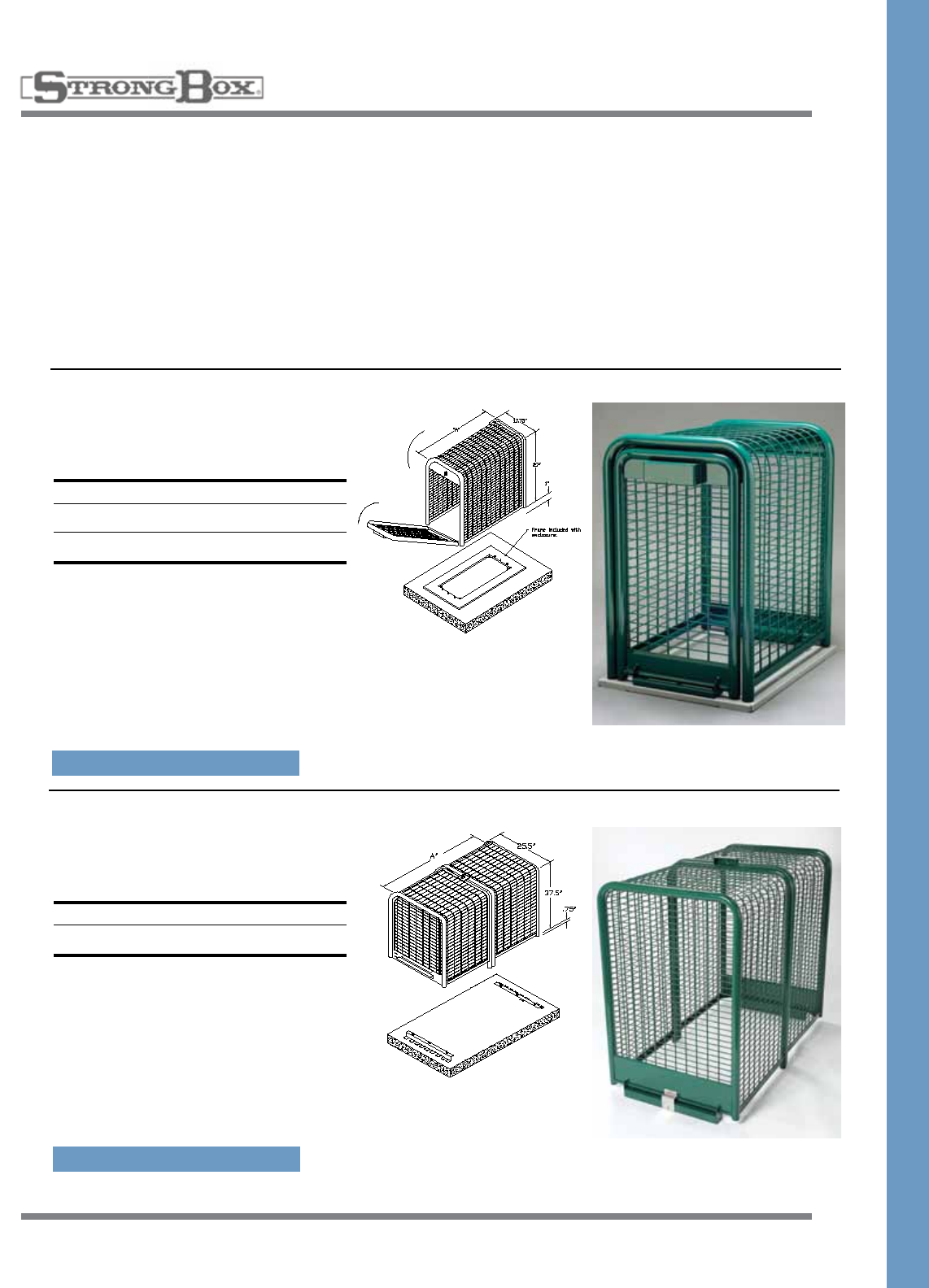
Low Profile Smooth Touch™
Enclosure
“A”Length Height Width
SBBC-22SS 23.5” 28” 17.75”
SBBC-30SS 31.5” 28” 17.75”
SBBC-45SS 46.5” 28” 17.75”
• 100%stainlesssteel
• Stainlesssteelhardware
• Weatherresistant
• Patentedlockingsystem
accepts padlock
• Minimalsurfaceareadetersgraffiti
BACKFLOW ENCLOSURES
STAINLESS STEEL
SMOOTH TOUCH™ VANDAL RESISTANT
BACKFLOW ENCLOSURE
• Tubeandwireconstructionprovidesasmoothsurfacetoprotectagainsthandlinginjury
• Architecturallinesoftheenclosureblendbeautifullyintothelandscapeenvironment
• 100%stainlesssteelconstructionassureslong-term,rustproofdurabilityandadditionalstrength
• Tenyearlimitedwarranty
• Allstainlesssteelenclosuresmaybepowdercoatedinmanycolorsatanextracharge
Note:Forinsidedimensions,seeBackflow
Cover Sizing Chart on pages 14-15.
High Profile Smooth Touch™
Enclosure
“A”Length Height Width
SBBC-20SS 20” 46.5” 17.75”
SBBC-40SS 40” 39” 25.5”
SBBC-75SS 76.5” 39” 25.5”
• 100%stainlesssteel
• Stainlesssteelhardware
• Weatherresistant
• Patentedlockingsystem
accepts padlock
• Minimalsurfaceareadetersgraffiti
Note:Forinsidedimensions,seeBackflow
Cover Sizing Chart on pages 14-15.
SPECIFICATION ON PAGE 52
SPECIFICATION ON PAGE 53
Contractor installed
concrete pad
Contractor installed
concrete pad
21
Low Profile Smooth Touch™
Enclosure
“A”Length Height Width
SBBC-22CR 23.5” 28” 17.75”
SBBC-30CR 31.5” 28” 17.75”
SBBC-45CR 46.5” 28” 17.75”
• 100%stainlesssteel
• Stainlesssteelhardware
• Weatherresistant
• Patentedlockingsystem
accepts padlock
• Minimalsurfaceareadetersgraffiti
High Profile Smooth Touch™
Enclosure
“A”Length Height Width
SBBC-40CR 40” 39” 25.5”
SBBC-75CR 76.5” 39” 25.5”
• 100%stainlesssteel
• Stainlesssteelhardware
• Weatherresistant
• Patentedlockingsystem
accepts padlock
• Minimalsurfaceareadetersgraffiti
BACKFLOW ENCLOSURES
COLD ROLLED STEEL
SMOOTH TOUCH™ VANDAL RESISTANT
BACKFLOW ENCLOSURE
• Tubeandwireconstructionprovidesasmoothsurfacetoprotectagainsthandlinginjury
• Architecturallinesoftheenclosureblendbeautifullyintothelandscapeenvironment
• Coatedwithaperformancepolymeralloycoatingtopreventhandlinginjury.
• Oneyearlimitedwarranty
• Standardcolorsforpowdercoatedenclosuresaredarkgreenandtan.Allothercolorsareavailableat
an extra charge
Note:Forinsidedimensions,seeBackflow
Cover Sizing Chart on pages 14-15.
Note:Forinsidedimensions,seeBackflow
Cover Sizing Chart on pages 14-15.
SPECIFICATION ON PAGE 54
SPECIFICATION ON PAGE 55
Contractor installed
concrete pad
Contractor installed
concrete pad
22
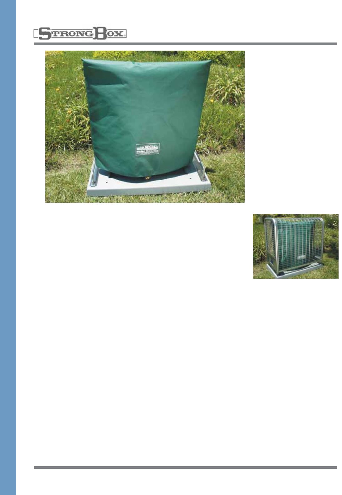
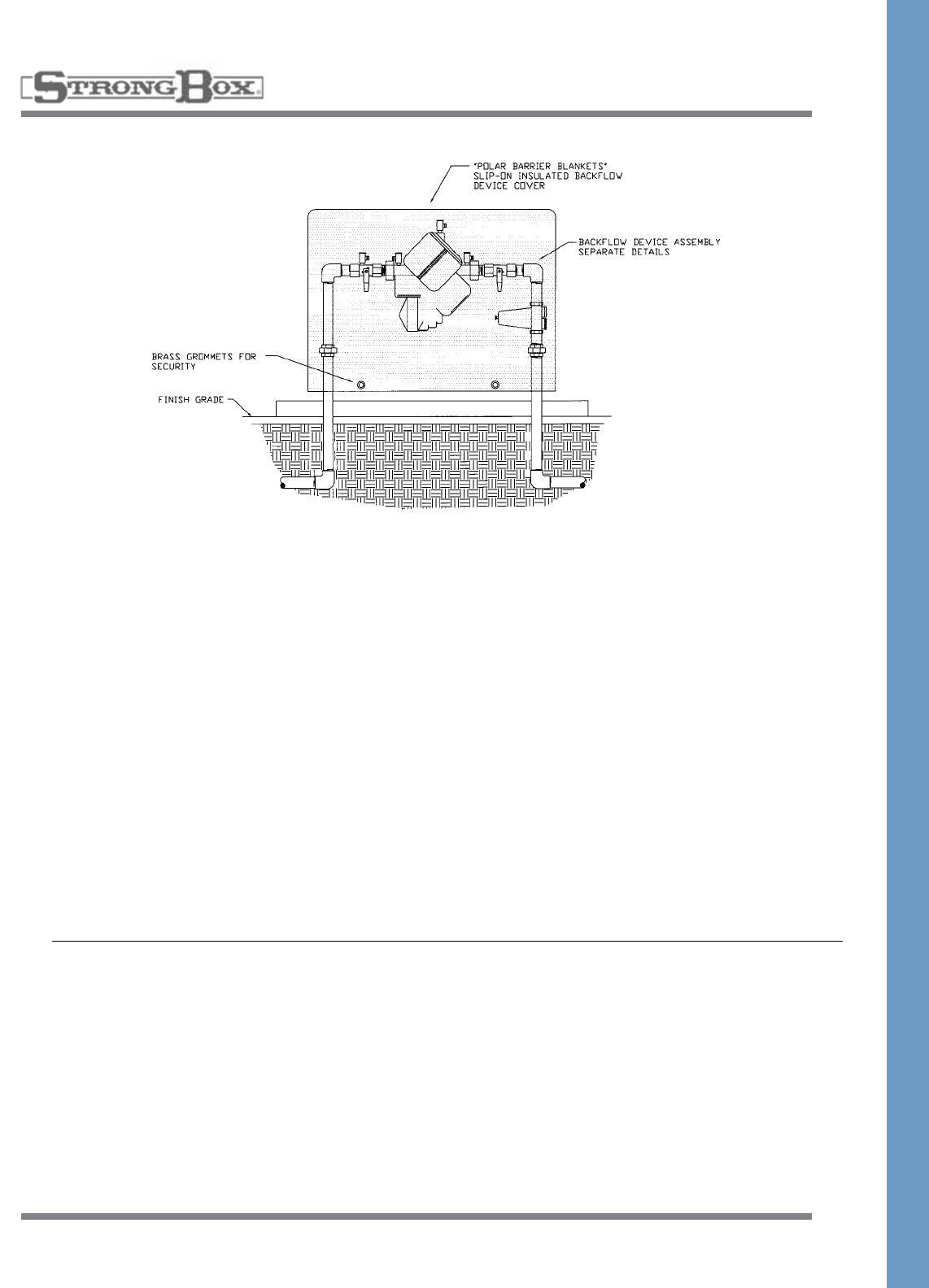
POLAR BEARIER
SLIP-ON INSULATING COVER
A simple, effective, and stylish
waytoinsulatebackflowdevices
to help prevent freezing. The
Polar Bearier is a slip-on insulat-
ing cover that installs in seconds
andremovesevenquickerfor
backflowmaintenance.This
uniquedeviceusesspace
age insulation materials to pro-
vide R-19 insulation while
maintaining a sleek and
attractive appearance.
The construction materials
include:
1. A heavy-duty, water repellent
exterior cover of acrylic
impregnation coated polyester
fabric.Standardcolorsisfor-
estgreen.Thismarinefabricis
guaranteed for a five year peri-
od against excessive loss of
color or strength under normal
exposure conditions. The
coverhasbeendesignedto
beremovable.Customexterior
colors as well as silk screened
agencylogosareavailableby
special order.
2. A layer of Radiant Barrier Foil
(RBF)thatblocks97%ofradi-
ant heat. This material consists
ofalayerofpolyethylenebub-
blesbondedtoandsand-
wichedbetweentwoindustrial
strength aluminum foil sheets.
This material is impervious to
moisture, does not promote
fungusorbacteriagrowthand
isunsuitableforpestnesting
material.
3.A1/4"thickpolyolefinfoam
layer for added additional
insulation also provides sup-
port to the Polar Bearier.
4. R-19 Polar Beariers use a
second layer of RBF to provide
added insulation.
5. A water repellent lining of 200
deniernylonfabrictoresist
tearsfrombackflowparts.
6. A Velcro®stripatthebaseof
the Polar Bearier closes the
system to prevent drafts and
allows water to exit the cover
shouldthebackflowunitdevel-
op a leak.
7.Brassgrommetsatthebaseof
the Polar Bearier allow for mul-
tiple pad lock security.
Whycontinuetowrapyourback-
flowdeviceswithlumpyfiber-
glass and tape when you can
simply slip on a Polar Bearier?
Wrappingabackflowdeviceis
expensiveandthewrapmustbe
replaced annually or when the
fiberglassbecomeswetinorder
to retain the insulating value. In
fact,compressionofthefiber-
glass material during wrapping
significantly reduces the insulat-
ingor"R"value.Onaveragea
PolarBeariercanbeinstalledon
abackflowdeviceforabout1½
times the cost of one year’s
wrappingwithineffectivefiber-
glass and tape.
• PolarBearierhelpsprevent
freezedamagetobackflow
devices.
• Providesvandalresistant
protectiontobackflowdevices.
• Reducesliabilitybycushioning
backflowdevices.
• Reducestimeandmaterials
wastedonannualbackflow
wrapping.
• Canbeinstalledinside
existingbackflowenclosures.
• Providesanaesthetic
alternative to exposed
backflowdevices.
23
Specification of the correct Polar
Bearierforyourprojectcanbe
easilyaccomplishedbyusingthe
following product information.
Backflow devices installed in
areas where long freezing peri-
odscanbeanticipatedshould
bedrainedorprotectedwith
backflowheatingdevices.
Determinetheheightoftheback-
flowdeviceabovefinished
grade. Keep in mind that most
localcodesrequirethatthebot-
tomofthebackflowdevicebe
12"abovefinishedgrade.Most
1½"and2"backflowdevice
assembliesinstalledtocodewill
bebetween20"and24"high.
Part No. Dimensions
PBB-15 16"Lx6"Dx24"H
PBB-22 22"Lx6"Dx24"H
PBB-30 28"Lx6"Dx24"H
PBB-45 46"Lx6"Dx24"H
PBB-60 56"Lx6"Dx24"H
PBB-40HP 40"Lx6"Dx36"H
PBB-60HP 60"Lx6"Dx36"H
PBB-75HP 72"Lx6"Dx36"H
PBB-90HP 90"Lx6"Dx36"H
PBB-20HP 24"Lx6"Dx46"H
Usea24"highPolarBearierfor
these applications.
Pressurebackflowdevices
installed12"abovethehighest
headwilloftenrequiretheuse
ofthelarger34"and46"high
Polar Beariers.
Thelengthofthebackflow
deviceassemblyisthemostdiffi-
cult dimension to determine. The
lengthoftheassemblywillbe
basedonthetypeofbackflow
device used, the size and type of
additionalequipmentsuchas
regulators and wye strainers, the
locationoftheadditionalequip-
mentontheassembly,andthe
lengthofthenipplesbetween
equipment.Fieldmeasurementof
theinstalledequipmentwillresult
inthebestdeterminationof
assemblylength.Measurethe
overalllengthoftheassembly
andadd6"tofindthesizeofthe
backflowcover.Iftheresulting
measurementfallsinbetween
sizes on the Polar Bearier use
the larger of the two sizes to
insure a correct fit.
POLAR BEARIER
SPECIFICATIONS
24
COMMERCIAL METER PEDESTALS
STAINLESS STEEL
MPS-A16-10K* Metered Enclosure
• 100 amp meter/100 amp load center
• 16Circuitswithmainbreaker,SinglePhase
MPS-C20-10K* Metered Enclosure
• 200 amp meter/200 amp load center
• 20Circuitswithmainbreaker,SinglePhase
MPS-C32-10K* Metered Enclosure
• 200 amp meter/200 amp load center
• 32Circuitswithmainbreaker,SinglePhase
MPS-D18-10K* Metered Enclosure
• 100 amp meter/100 amp load center
• 18Circuitswithmainbreaker,ThreePhase
MPS-E24-10K* Metered Enclosure
• 200 amp meter/200 amp load center
• 24Circuitswithmainbreaker,ThreePhase
METER SECTION
• 0-200ampmetersockets;4,5,7Jawavailable
• 120v,280v,240vand480vmodelsavailable
• NEMATYPE3RRatedULListed
• E.U.S.E.R.C.308compliantcommercialmeterpedestal
CUSTOMER SECTION
• Uniquedesignprovideslargeelectricalcustomercompart-
mentbutmaintainsaslim,smallcabinetprofile
• 0-200amploadcenterswithupto32circuits
• 20”x30”customerelectricalcompartment
COMMERCIAL METER PEDESTAL
WITH CUSTOMER SECTION
• Providesmeteredpowerdistributionforstreetlighting,parklighting,privatedevelopmentlighting,
signage, irrigation, pump, and cellular applications
• 100%stainlesssteelconstructionassureslongterm,rustproofdurabilityandadditionalstrength
• Swingsidetopallowsforfullexposureofmetercompartment
• Topiseasiertoopenandcontrolthanfliptops,andlocksopenforsafety
• Allstainlesssteelenclosuresmaybepowdercoatedinvariouscolorsatanadditionalcharge
• Doubledoordesign
• Mountingtemplateandanchorsincluded
• Tenyearlimitedwarranty
• NEMATYPE3RULListed
SPECIFICATION ON PAGE 59-60
25
METER PEDESTALS WITH ENCLOSURE
STAINLESS STEEL
MPE-A16-10K* Metered Enclosure
• 100 amp meter/100 amp load center
• 16Circuitswithmainbreaker,SinglePhase
MPE-C20-10K* Metered Enclosure
• 200 amp meter/200 amp load center
• 20Circuitswithmainbreaker,SinglePhase
MPE-C32-22K* Metered Enclosure
• 200 amp meter/200 amp load center
• 32Circuitswithmainbreaker,SinglePhase
METER SECTION
• 0-200ampmetersockets;4,5,7jawavailable
• 120v,280v,240vand480vmodelsavailable
• NEMATYPE3RRatedULListed
• E.U.S.E.R.C.308compliantcommercialmeterpedestal
CUSTOMER SECTION
• Uniquedesignprovideslargeelectricalcustomercompartment
butmaintainsaslim,smallcabinetprofile
• 0-200amploadcenterswithupto32circuits
• 20”x30”customerelectricalcompartment
COMMERCIAL SERVICE PEDESTAL WITH CUSTOMER
AND ENCLOSURE SECTIONS
• Providesmeteredpowerdistributionforstreetlighting,parklighting,privatedevelopmentlighting,
signage, irrigation, pump, and cellular applications
• 100%stainlesssteelconstructionassureslongterm,rustproofdurabilityandadditionalstrength
• Swingsidetopallowsforfullexposureofmetercompartment
• Topiseasiertoopenandcontrolthanfliptops,andlocksopenforsafety
• Allstainlesssteelenclosuresmaybepowdercoatedinvariouscolorsatanadditionalcharge
• Doubledoordesign
• Mountingtemplateandanchorsincluded
• Tenyearlimitedwarranty
• NEMATYPE3RULListed
* All meter pedestals available with AIC ratings of 22k, 65k and higher.
Photocell, time clocks, lighting contractors and circuit breakers available factory installed.
ENCLOSURE SECTION
• Removablebackboardsprovidesforeasyinstallationandan
attractive finished product
• Largedoor-mountedstorageareaprovidesaccesstoplans
and scheduling information
• Sidelouversatbottomandtopallowcrossflowventilation
MPE-D18-10K* Metered Enclosure
• 100 amp meter/100 amp load center
• 18Circuitswithmainbreaker,ThreePhase
MPE-E24-10K* Metered Enclosure
• 200 amp meter/200 amp load center
• 24Circuitswithmainbreaker,ThreePhase
SPECIFICATION ON PAGE 61-62
26
COMMERCIAL SERVICE PEDESTAL
STAINLESS STEEL
COMMERCIAL SERVICE PEDESTAL
• Providesmeteredpowerdistributionforstreetlighting,parkinglotlighting,privatedevelopmentlighting,
signage, irrigation, pump stations, and cellular applications
• CaltransTypeIII-AFandCaltransSpecES-2Dcompliant
• 100%stainlesssteelweldedconstructionprovidesultimateprotectionagainstcorrosionandvandalism
• Fliptopallowsforfullexposureofmetercompartment
• Toplocksaccept5/16padlockandutilityseal
• Allstainlesssteelconstruction
• Optionalcolors,standardgray
• Weatherandvandalresistant
FEATURES
• StandardVoltage120/240V,1
Phase 3W
• MeterSocket:4Jaw,100Amp
• MainBreaker:100Amp,10KAIC
• MeterSocketwithTestBlocks
• UtilityLandingLugs:200Amp
• FlipTopMeterDoor
• LoadCenterPanelsorLugStyle
BussesAvailable
• AccessPanelsDesignedfor
Padlock & Utility Seal
• TemplatewithAnchorBolts
• 5YearLimitedWarranty
OPTIONS
• MeterSocket:5Jaw,100Amp
• MaximumVoltage:240V,1
Phase, 3W
• HigherAICAvailable:22K,42K
• PowdercoatColorsAvailable
• Optional Time Clock, Lighting &
Contact Block
SPECIFICATIONS
• Caltrans Type III-AF Compliant
• Caltrans Spec. ES-2D
Compliant
• 16 Gauge Stainless Steel
Welded Construction
• Vandal Resistant Enclosure
• ListedbyUnderwriters
Laboratories
• Complies with EUSERC 308
• Rainproof Type 3R Rated
• UL 508A Panel Shop
CSP-A Model Numbers & Service Options
ModelNo. Amps Voltage AICRating Main
CSP-A106-10K* 100A 120/240 10,000 100A
CSP-A106-42K* 100A 120/240 42,000 100A
CSP-A112-10K* 100A 120/240 10,000 100A
CSP-A112-42K* 100A 120/240 42,000 100A
*SeriesAICRatingsAvailable:10K,22K,42K,65K
#4atendofpartnumbersignifiesbrushedstainlessfinish
SPECIFICATION ON PAGE 63
27
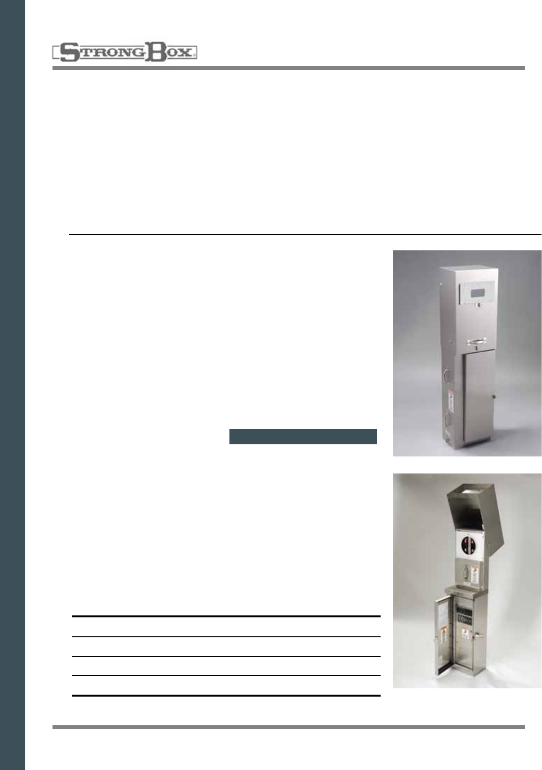
CSP-A SERIES METERED ENCLOSURE
Designed to supply metered power to remote locations. Typical
applications include street lighting, traffic signal circuits, parking
lot lighting, highway and pump stations and cellular applications.
COMMERCIAL SERVICE PEDESTAL
STAINLESS STEEL
METER SPECIFICATIONS
•0-100AmpLoadCenterwithupto
6 Circuits or 12 Circuits
•120V&240V1PhaseModels
Available
•TestBlocks
•ULListed,NEMATYPE3RRated
•EUSERC308Compliant
Commercial Meter Pedestal
•CabinetProfilewithRemovable
Doors
•12”Wx50”Hx9”DCabinet
•12”Wx63”Hx9”DCabinet
•5YearLimitedWarranty
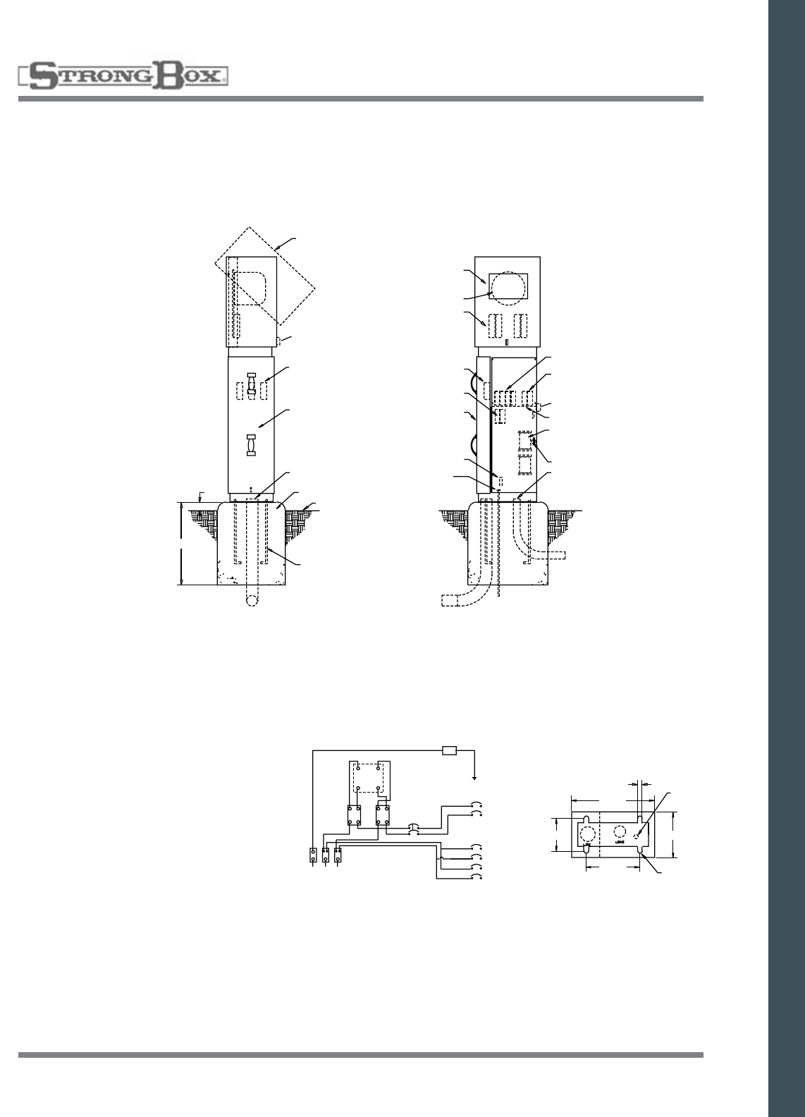
METER SECTION
HOOD ROTATES UP
PADLOCK
HASP
LANDING LUGS
#6-250 MCM
AL/CU
UTILITY
DOOR
SERVICE CONDUIT
3” MAXIMUM SIZE
CONCRETE
FOUNDATION
FINISHED GRADE
GALV. ANCHOR BOLT S
5/8” X 16” X 4”
WITH 90 DEGREE BEND
(4 REQUIRED)
2”
24”
SIDE VIEW FRONT VIEW
READING COVER 3/16”
POLYCARB UV PLASTIC
VIEWING WINDOW
METER SOCKET
TEST BYPASS
BLOCKS
LANDING
LUGS
METERED BRANCH
BREAKERS
REMOVE UTILITY SEALABLE
SIDE DOOR FOR ACCESS TO
LANDING LUGS AND
TERMINATION SECTION
GROUNDING LUG
GROUNDING ROD
SEE STANDARDS
FOR SIZING
UNMETERED
BRANCH BREAKERS
MAIN BREAKERS
PADLOCK HASP
SPLIT DEADFRONT
CONTACTORS
HINGED DEADFRONT
2” LOAD CONDUITS
S/N
GRD
4-JAW
METER
MAIN
BRKR
TEST
BLOCKS
N L1 L2
120V/240V
1PH 3 WIRE
SERVICE
WIRING SCHEMATIC
13/16”
GROUNDING
ELECTRODE
MOUNTING SLOTS
12”
5.25”7.5”
8”
BASE FOR SERVICE
EQUIPMENT ENCLOSURE
METER SECTION
HOOD ROTATES UP
PADLOCK
HASP
LANDING LUGS
#6-250 MCM
AL/CU
UTILITY
DOOR
SERVICE CONDUIT
3” MAXIMUM SIZE
CONCRETE
FOUNDATION
FINISHED GRADE
GALV. ANCHOR BOLT S
5/8” X 16” X 4”
WITH 90 DEGREE BEND
(4 REQUIRED)
2”
24”
SIDE VIEW FRONT VIEW
READING COVER 3/16”
POLYCARB UV PLASTIC
VIEWING WINDOW
METER SOCKET
TEST BYPASS
BLOCKS
LANDING
LUGS
METERED BRANCH
BREAKERS
REMOVE UTILITY SEALABLE
SIDE DOOR FOR ACCESS TO
LANDING LUGS AND
TERMINATION SECTION
GROUNDING LUG
GROUNDING ROD
SEE STANDARDS
FOR SIZING
UNMETERED
BRANCH BREAKERS
MAIN BREAKERS
PADLOCK HASP
SPLIT DEADFRONT
CONTACTORS
HINGED DEADFRONT
2” LOAD CONDUITS
S/N
GRD
4-JAW
METER
MAIN
BRKR
TEST
BLOCKS
N L1 L2
120V/240V
1PH 3 WIRE
SERVICE
WIRING SCHEMATIC
13/16”
GROUNDING
ELECTRODE
MOUNTING SLOTS
12”
5.25
”7
.5”
8”
BASE FOR SERVICE
EQUIPMENT ENCLOSURE
28
COMMERCIAL SERVICE PEDESTAL
STAINLESS STEEL
COMMERCIAL SERVICE PEDESTAL
• Providesmeteredpowerdistributionforstreetlighting,parkinglotlighting,trafficsignalcircuits,private
development lighting, signage, irrigation, pump stations, and cellular applications
• CaltransTypeIII-BFandCaltransSpecES-2Ecompliant
• 100%stainlesssteelweldedconstructionprovidesultimateprotectionagainstcorrosionandvandalism
• Swingsidetopallowsforfullexposureofmetercompartment
• Topiseasiertoopenandcontrolthanfliptops,andlocksoutforsafety
• Allstainlesssteelconstruction
• Weatherandvandalresistant
• Meteredandunmeteredavailable
FEATURES
• StandardVoltage120/240V,1
Phase 3W
• MeterSocket:4Jaw,100Amp
• MainBreaker:100Amp,10KAIC
• MeterSocketwithTestBlocks
• UtilityLandingLugs:200Amp
• SwingsideTopMeterDoor
• 6-20CircuitCopperBussedInter-
iororLugStyleBussesAvailable
• AccessPanelsDesignedfor
Padlock & Utility Seal
• TemplatewithAnchorBolts
• 5YearLimitedWarranty
OPTIONS
• MeterSocket:5Jaw,100or200Amp
• Metered&UnmeteredAvailable
• MaximumVoltage:240Vor480V,
1 Phase, 3W or 3 Phase, 4W
• HigherAICAvailable:22K,42K
• PowdercoatColorsAvailable
• Optional Time Clock, Lighting &
Contact Block
SPECIFICATIONS
• Caltrans Type III-BF Compliant
• Caltrans Spec. ES-2E Compliant
• 16 Gauge Stainless Steel
Welded Construction
• Vandal Resistant Enclosure
• ListedbyUnderwriters
Laboratories
• Complies with EUSERC 308
• Rainproof Type 3R Rated
• UL 508A Panel Shop
CSP-B Model Numbers & Service Options
ModelNo. Amps Voltage AICRating Main
CSP-B188-10K* 100A 120/240 10,000 (2x)100A
CSP-B108-10K* 100A 120/240 10,000 100A
CSP-B116-10K* 100A 120/240 10,000 100A
CSP-B208-10K* 200A 120/240 10,000 200A
CSP-B216-10K* 200A 120/240 10,000 200A
CSP-B116-42K* 100A 120/240 42,000 100A
*SeriesAICRatingsAvailable:10K,22K,42K,65K#4atendofpartnumbersignifies
brushedstainlessfinish
SPECIFICATION ON PAGE 63
29
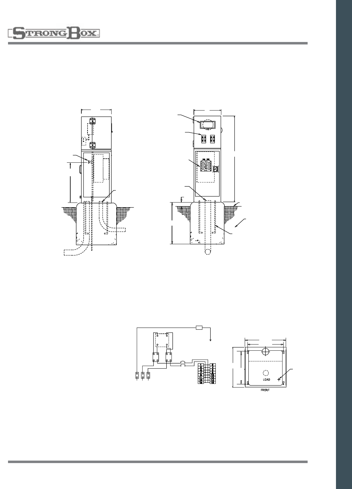
CSP-B SERIES METERED ENCLOSURE
Designed to supply metered power to remote locations. Typical applica-
tions include street lighting, traffic signal circuits, parking lot lighting,
highway and pump stations and cellular applications.
COMMERCIAL SERVICE PEDESTAL
STAINLESS STEEL
METER SPECIFICATIONS
•0-200AmpLoadCenterwithup
to 32 Circuits
•120V&240VModelsAvailable
•TestBlocks
•ULListed,NEMATYPE3RRated
•EUSERC308Compliant
Commercial Meter Pedestal
•SmallCabinetProfilewithSide
Swinging Doors
•16”Wx48”Hx16”DCabinet
•5YearLimitedWarranty
16.5”
LANDING LUGS AND
FACTORY INSTALLED
CONDUCTORS
17” MIN.
LOAD CONDUITS
HINGED DEMAND RESET
COVER WITH 3/16” LEXAN
VIEWING WINDOW
TEST BYPASS
BLOCKS
12 POSITION
LOAD CENTER(S)
SERVICE CONDUIT
3” MAXIMUM SIZE
16”
48”
FINISHED GRADE
CONCRETE
FOUNDATION
GALV. ANCHOR BOLTS
5/8” X 18” X 4”
WITH 90 DEGREE BEND
(4 REQUIRED)
SIDE VIEW FRONT VIEW
24”
2”
S/N
GRD
MAIN
BRKR
4-JAW
METER
TEST
BLOCKS
N L1 L2
120V/240V
1PH 3 WIRE
SERVICE
WIRING SCHEMATICCSP - BASE FOR SERVICE
EQUIPMENT ENCLOSURE
16”
14.5”
LINE
RECOMMENDED
GROUND ROD
LOCATION
16.25”
12.25”
30
COMMERCIAL SERVICE DUAL PEDESTAL
STAINLESS STEEL
COMMERCIAL SERVICE PEDESTAL
• Providesseparatebillingofmeteredpowerdistributionforstreetlighting,parkinglotlighting,traffic
signal circuits, private development lighting, signage, irrigation, pump stations, and cellular applications
• CaltransTypeIII-CF
• 100%stainlesssteelweldedconstructionprovidesultimateprotectionagainstcorrosionandvandalism
• Lift-uptopprovideseasyaccesstometer
• Allstainlesssteelconstruction
• Weatherandvandalresistant
• Meteredandunmeteredavailable
FEATURES
• StandardVoltage120/240V,
1 Phase 3W
• MeterSockets:4Jaw,100Amp
• MainBreakers:100Amp,10KAIC
• MeterSocketswithTestBlocks
• UtilityLandingLugs:200or400Amp
• FlipTopMeterDoor
• 6-20CircuitCopperBussedorLug
StyleBussesAvailable(PerMeter)
• AccessPanelsDesignedfor
Padlock & Utility Seal
• TemplatewithAnchorBolts
• 5YearLimitedWarranty
OPTIONS
• MeterSocket:5Jaw,100or200Amp
• Metered&UnmeteredAvailable
• MaximumVoltage:240Vor480V,
1 Phase, 3W or 3 Phase, 4W
• HigherAICAvailable:22K,42K
• PowdercoatColorsAvailable
• Optional Time Clock, Lighting &
Contact Block
SPECIFICATIONS
• CaltransTypeIII-CF
Compliant
• 16GaugeStainlessSteel
Welded Construction
• VandalResistantEnclosure
• ListedbyUnderwriters
Laboratories
• ComplieswithEUSERC308
• RainproofType3RRated
• UL508APanelShop
CSP-C Model Numbers & Service Options
ModelNo. Amps Voltage AICRating Main
CSP-C188-10K* 100A 120/240 10,000 (2x)100A
CSP-C120-10K* 100A 120/240 10,000 100A
CSP-C116-10K* 100A 120/240 10,000 100A
CSP-C208-10K* 200A 120/240 10,000 200A
CSP-C216-10K* 200A 120/240 10,000 200A
CSP-C288-42K* 200A 120/240 42,000 200A
*SeriesAICRatingsAvailacle:10K,22K,42K,65K
#4atendofpartnumbersignifiesbrushedstainlessfinish
SPECIFICATION ON PAGE 63
31
METER COVER
METER SOCKETS
TEST BLOCKS
RECESSED
SERVICE DOOR
LANDING LUGS AND
FACTORY INSTALLED
CONDUCTORS
17” MIN
SERVICE
CONDUIT
3” MAX
HINGED READING COVER 3/16”
POLYCARBONATE UV RESISTANT
WINDOWS
LIFTING
HANDLE
PADLOCK HASP
CONTINUOUS
PIANO HINGE
PEU
WINDOW
LOAD CONDUITS
24”
26”
48”
RECESSED
PADLOCKABLE
T HANDLE
DEADFRONT
PANEL
2”
FINISHED GRADE
CONCRETE
FOUNDATION
GALV. ANCHOR BOLTS
5/8” X 18” X 4”
WITH 90 DEGREE BEND
(4 REQUIRED)
SIDE VIEW FRONT VIEW
22.25”
6” MIN.
12.25”
RECOMMENDED
GROUND ROD
LOCATION
CSP C-SERIES - BASE FOR SERVICE
EQUIPMENT ENCLOSURE
LINE
LOAD
CSP-C SERIES METERED ENCLOSURE
Designed to supply metered power to remote locations. Typical
applications include street lighting, traffic signal circuits, parking
lot lighting, highway and pump stations and cellular applications.
COMMERCIAL SERVICE DUAL PEDESTAL
STAINLESS STEEL
METER SPECIFICATIONS
•0-200AmpLoadCenterwithupto
20 Circuits Per Meter
•120V,240V&480VModels
Available
•TestBlocks
•ULListed,NEMATYPE3RRated
•EUSERC308Compliant
Commercial Meter Pedestal
•FlipTopMeterDoor
•25”Wx48”Hx16.5”DCabinet
•5YearLimitedWarranty
32
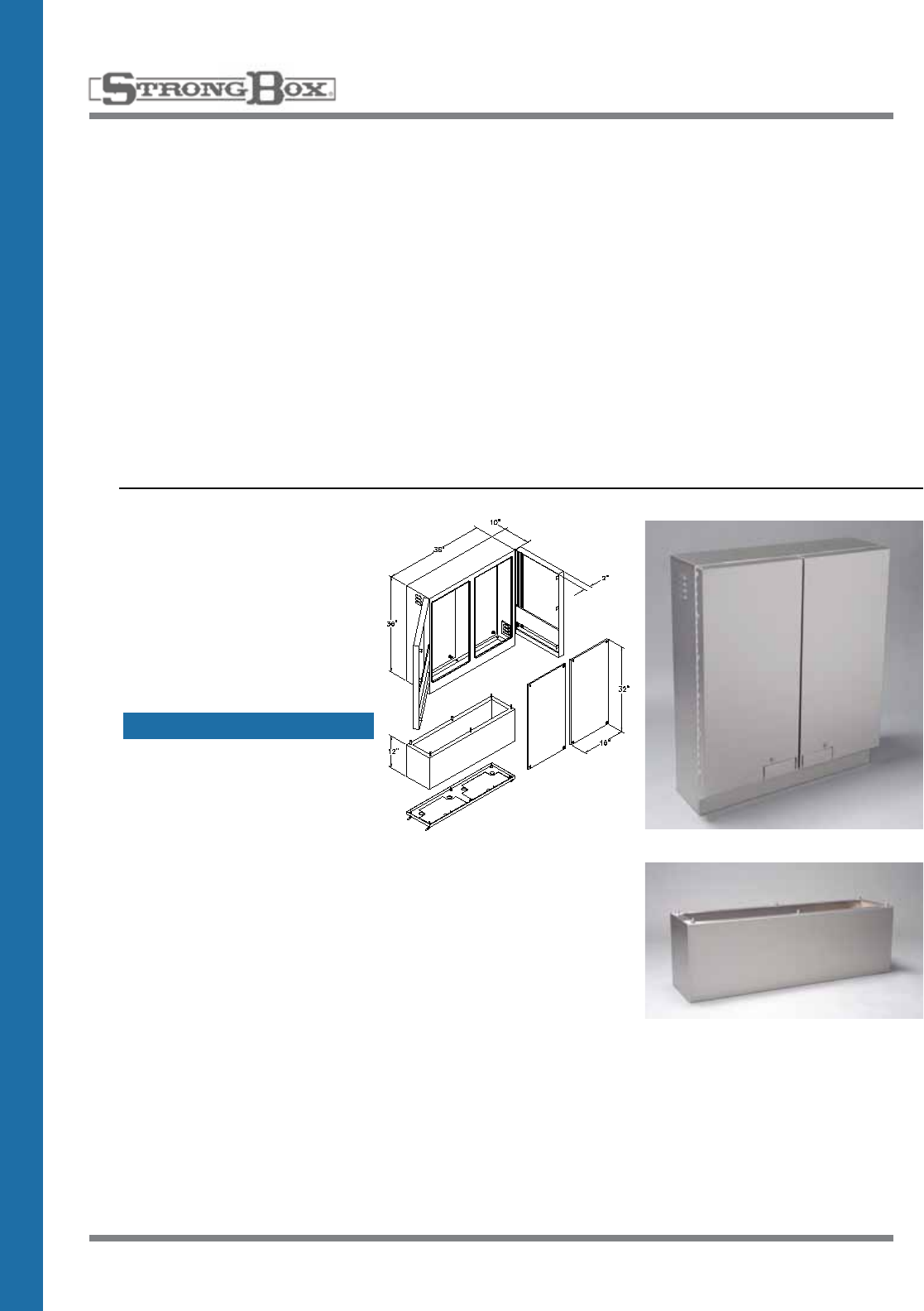
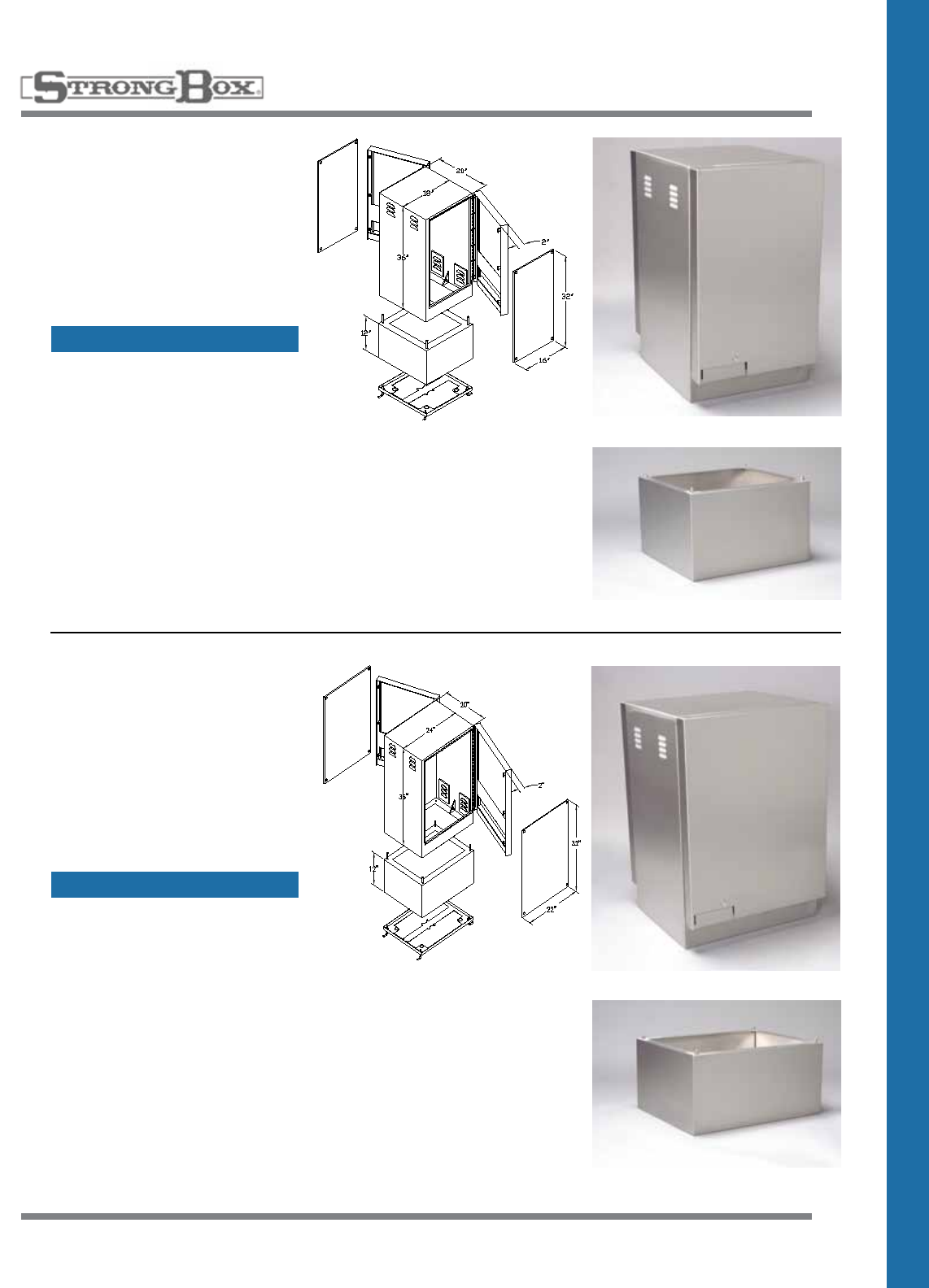
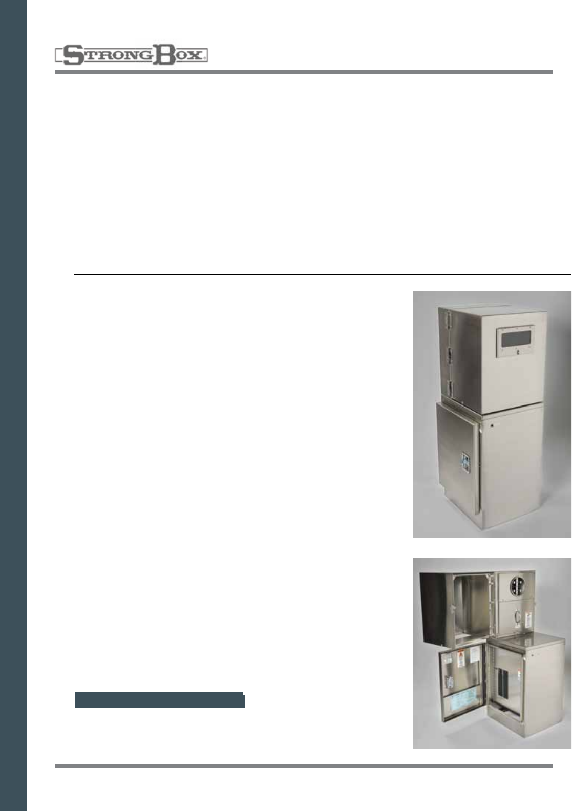
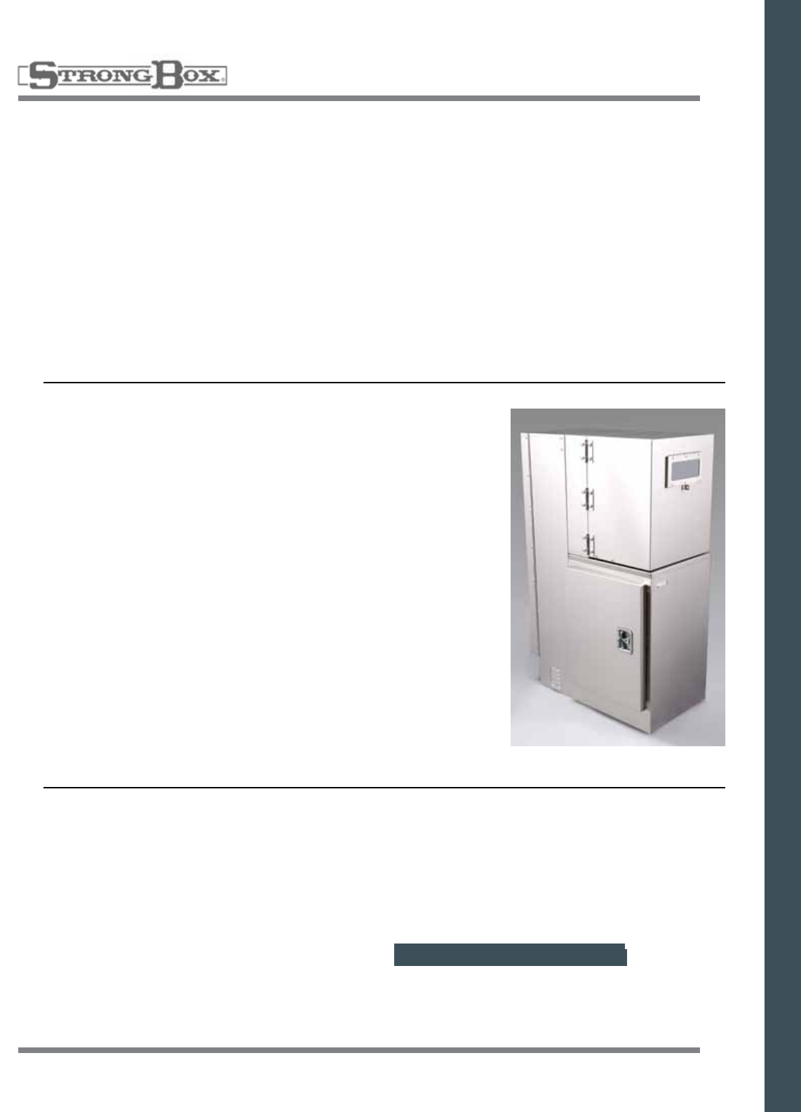
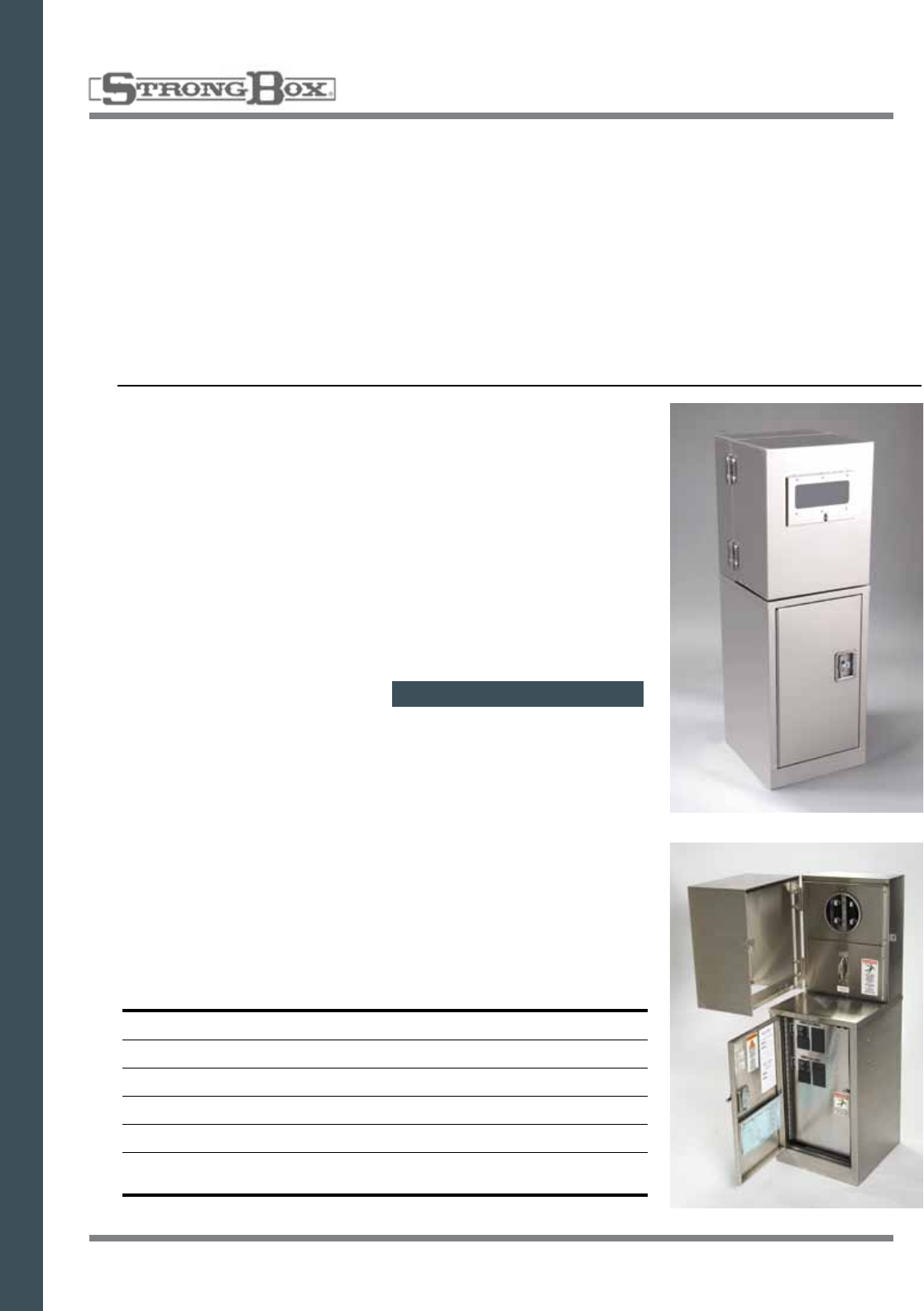
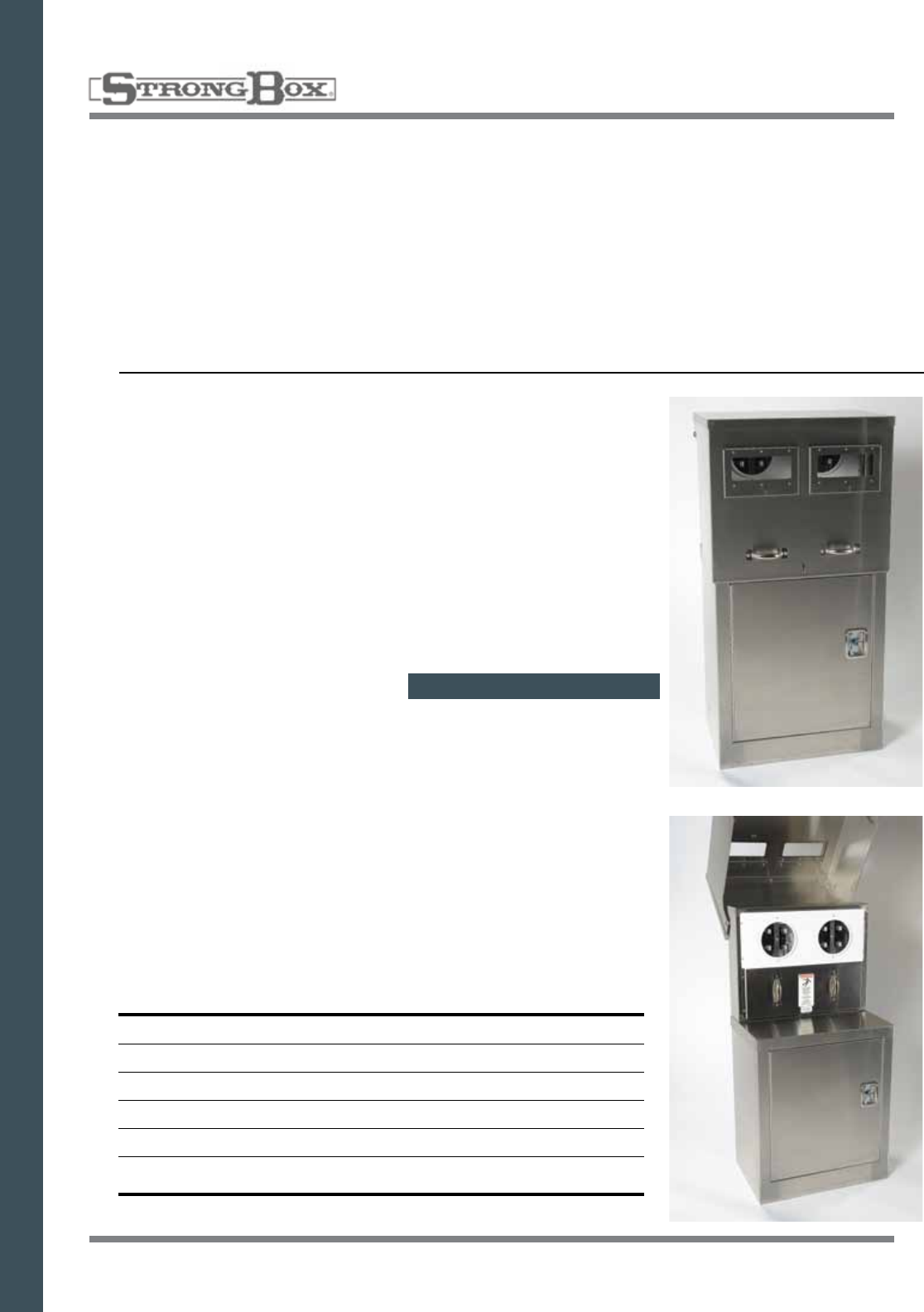
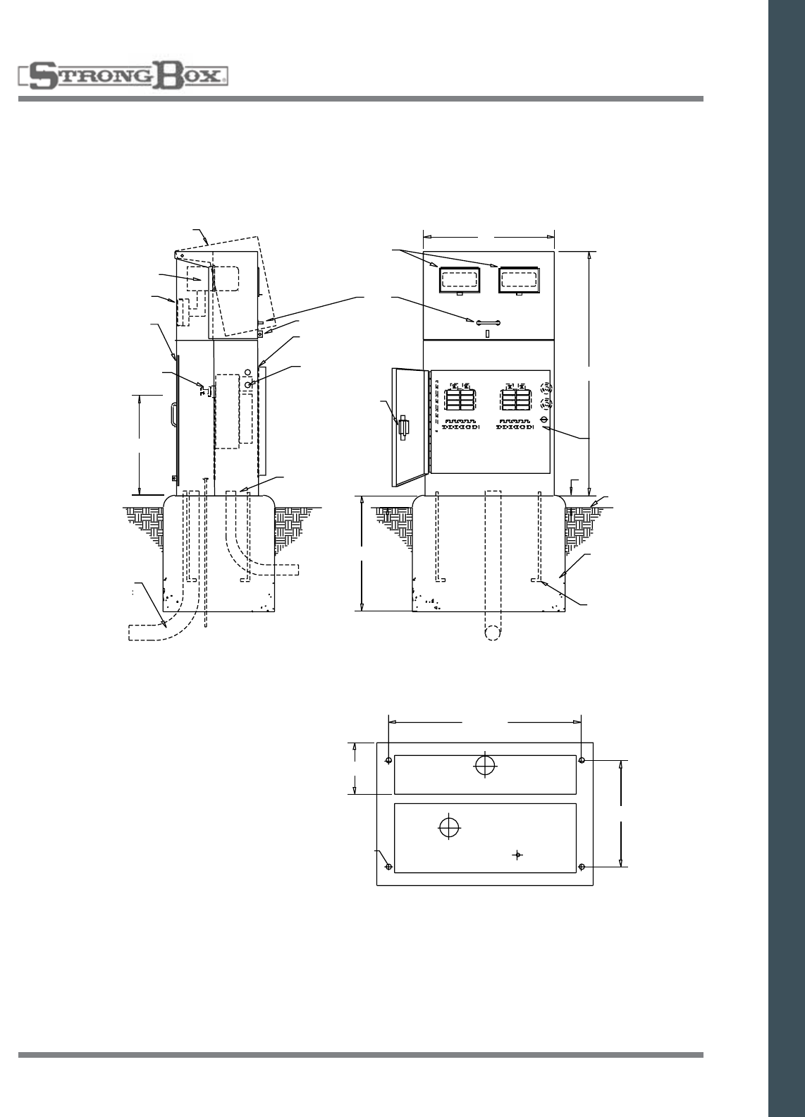
COMBINED COMMERCIAL METER SOCKET
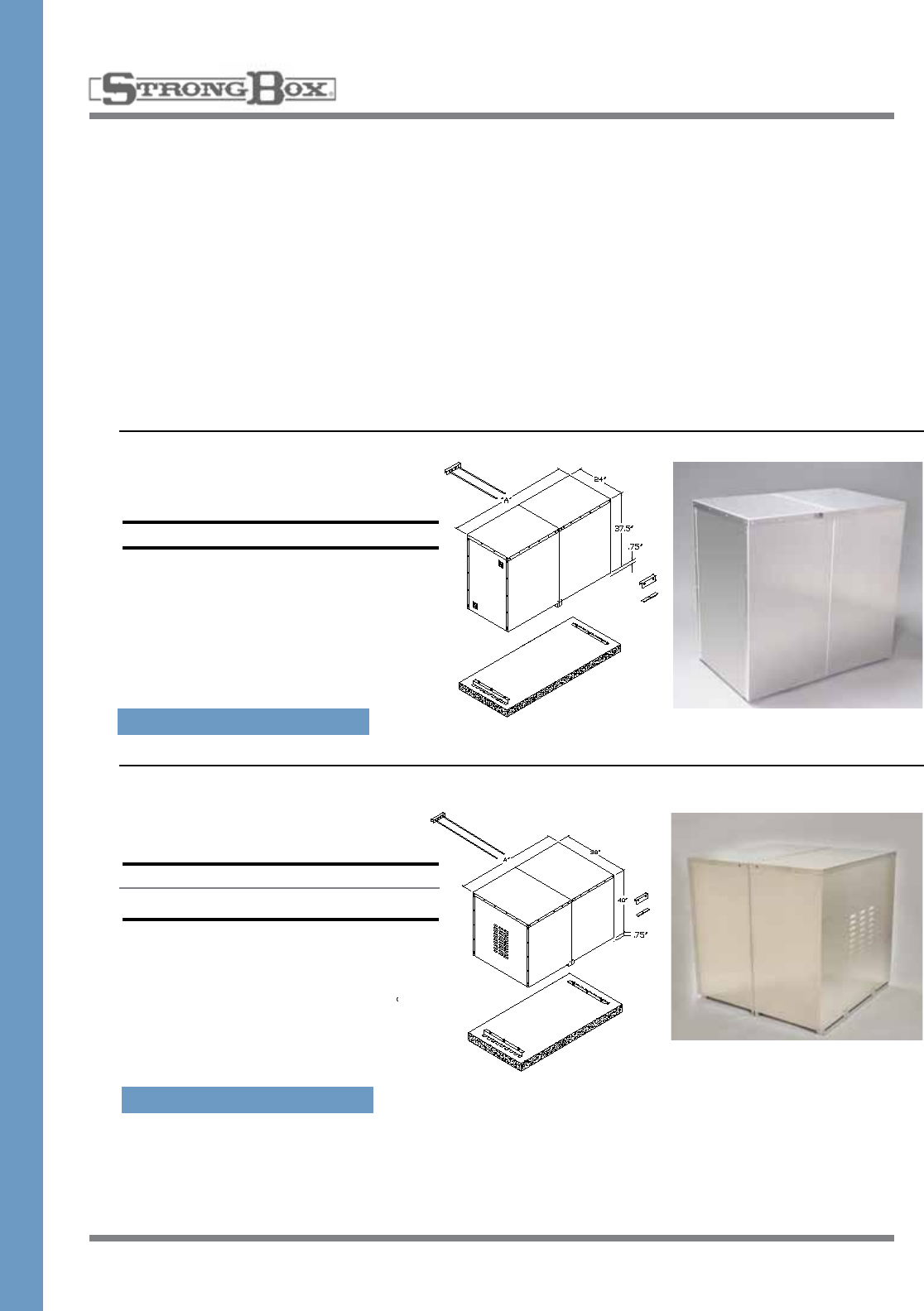
WITH THE ULTIMATE ENCLOSURE
• Compact,doubledoor,frontandbackdesign,providesviewingandprogrammingconvenience
• 100%stainlesssteelconstructionassureslong-term,rust-proofdurabilityandadditionalstrength
• Chameleoneffectofthenaturalbrushedstainlesssteelfinishprovidesanunobtrusivequality
• Allstainlesssteelenclosuresmaybepowdercoatedinmanycolorsatanadditionalcharge
METER SECTION
• ULlisted,E.U.S.E.R.C.309approvedcommercialmetersocket,100amprated,withtestblock
bypassprovision
• Hingedviewingwindowprovidesconvenientaccessformeteringagency
• 100amploadcenter
• 120vand240vmodelsavailable
ENCLOSURE SECTION
• Removable,predrilledbackboardprovidesforeasyinstallationandanattractivefinishedproduct
• Largedoor-mountedstorageareaandliteraturestoragepocketprovideseasyaccesstoplans
and scheduling information
• Filteredsidelouversatbottomandtopallowcrossflowventilation
• Mountingtemplateandanchorsincluded
• Tenyearlimitedwarranty
SB-24SS/120V
Metered Enclosure
120 Volt
• 24”Wide,48”High,29”Deep
• 120VoltMeterSocket
• TestBlocks
• 8PositionLoadCenter
• DoubleDoorDesign
• 12”DeepStorageonBackSide
• 100%StainlessSteel
• Weather&VandalResistant
• Three-PointLockingSystem
• Removable,Predrilled
Backboard
• LargeDoor-MountedStorage&
Literature Pocket
• LouveredForVentilation
• MountingTemplate&Anchors
• ULListed
• NEMATYPE3RRated
• Weather&VandalResistant
• Three-PointLockingSystem
• Removable,PredrilledBackboard
• LargeDoor-MountedStorage&Literature
Pocket
• LouveredForVentilation
• MountingTemplate&Anchors
• ULListed
• NEMATYPE3RRated
SB-24SS/240V
Metered Enclosure
240 Volt
• 24”Wide,48”High,29”Deep
• 240VoltMeterSocket
• TestBlocks
• 8PositionLoadCenter
• DoubleDoorDesign
• 12”DeepStorageonBackSide
• 100%StainlessSteel
COMMERCIAL SERVICE DUAL PEDESTAL
STAINLESS STEEL
SPECIFICATION ON PAGE 58
SPECIFICATION ON PAGE 58
33
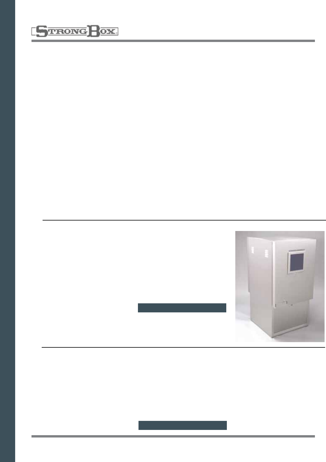
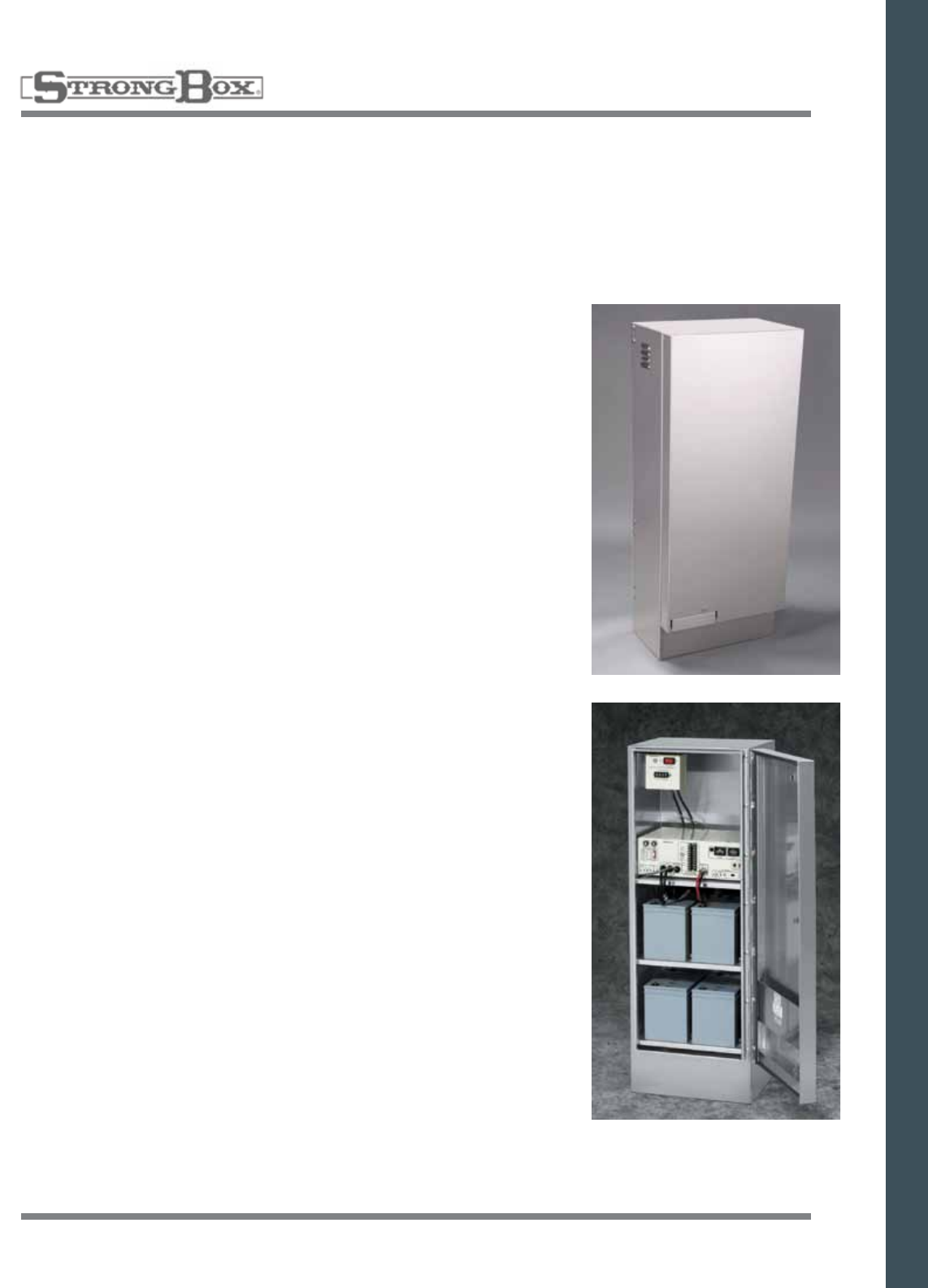
BBS SERIES BATTERY BACKUP
TheStrongBoxBatteryBackupSystemTrafficEnclosureisusedtoconcealbatteriesfortrafficsignals.
ThesecabinetsmaybemountedtoorwiththeStrongBoxMPSSeriesmeterpedestalsorusedasastand
alone pedestal. Our enclosures come with passive ventilation or fan with thermostat, louvers with dust fil-
ters, rain channel, gasket and a three point compression locking door.
Removableshelvesgiveaccesstothebatterycompartmentsforwiring.TheStrongBoxBBSenclosure
comes configured to accept most Battery Backup Systems for shelf mounted traffic applications.
BBS TRAFFIC ENCLOSURES
STAINLESS STEEL
SPECIFICATIONS
• Material:14ga.304stainlesssteelweldedconstruction
• Certification:NEMATYPE3R
• Cooling:Optionalthermostaticallycontrolledfan,
louvered door
• Security:Threepointlockwithpadlockprovision
FEATURES
• DesignedtoattachtoMPSseriespedestalorstand
alone
• Removableshelvesforeaseofwiring
• 3pointcompressionlatchdoor
• Stainlesspianohingeonentrydoor
• Integratedrainchannelaroundentrydoor
BBS-185212
• 18”Wide,52”High,12”Deep
34
Our new QuickPad™mountingpadwithsupportbase
makes installation and mounting of Strong Box®
enclosureseasierthanever.Noconcreteisneeded.
Themountingpadhasouruniquefasteningsystem
that allows for easy, secure attachment of the pad to
thesupportbaseandtheenclosuretothepad.
Together,theheavy-dutypad,supportbaseanda
Strong Box® enclosure form a complete unit that is
secure,stableandvandalresistant.
Theburiedsupportbaseprovidesaddedstabilityand
securityfortheentireassembly.
All mounting hardware is stainless steel to prevent
corrosion and rust.
PatentNo6,321,928.
QUICKPAD™ ENCLOSURE MOUNTING PAD
FOR STRONG BOX® ENCLOSURES
QuickPad for Strong Box® Controller Enclosures
DIMENSIONS
A B
QP-16 QuickPadforSB-16 28.5"Wide,18.5"Deep
QP-18 QuickPadforSB-18 28.5"Wide,18.5"Deep
QP-18D QuickPadforSB-18D 28.5"Wide,28.5"Deep
QP-22 QuickPadforSB-22 28.5"Wide,28.5"Deep
QP-24 QuickPadforSB-24 28.5"Wide,18.5"Deep
QP-24D QuickPadforSB-24D 28.5"Wide,28.5"Deep
QP-M QuickPadforMeteredEnclosure 28.5"Wide,28.5"Deep
QP-LD16 QuickPadforLightDutyCabinetsLD-16 28.5"Wide,18.5"Deep
QP-CSP QuickPadforCSP-Meters 28.5"Wide,18.5"Deep
QP-MPE QuickPadforMPE-Meters 32"Wide,25"Deep
QP-MPS QuickPadforMPS-Meters 32"Wide,25"Deep
QuickPad for Strong Box® Backflow Enclosures
DIMENSIONS
A B
QP-22BF QuickPadforSBBC-22Series 28.5”Wide,19”Deep
QP-20BF QuickPadforSBBC-20Series 32"Wide,19"Deep
QP-30BF QuickPadforSBBC-30Series 32"Wide,19"Deep
QP-45BF QuickPadforSBBC-45Series 49”Wide,19”Deep
SPECIFICATION ON PAGE 40
35
ENCLOSURE
OPTIONS
36 & 52 STATION CONTROLLER
SUBASSEMBLY
This package includes 120 volt, 15 amp, ground fault protected
duplexboxwithreceptacleandlockingswitch:flexibleconduitand
condulet; and terminal strips with placards.
CSA 36 Stations
CSA-52 52 Stations
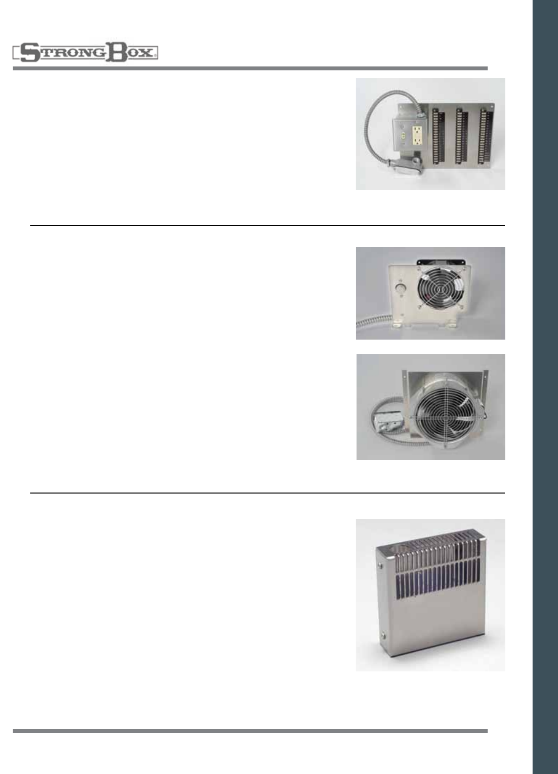
THERMOSTATICALLY CONTROLLED FAN
Thefaniseasilyinstalledandcanbeadjustedinthefieldtohelp
maintain desired enclosure temperature.
OPT-FAN
SOLAR SYNC COVER
Solar Sync Cover is designed to protect Solar Sync switches from
vandalism and made to attach to StrongBox enclosures with gasket
seal.
SRSE
OPT-FAN8-120PE 120VVersion
OPT-FAN8-230PE 230VVersion
36
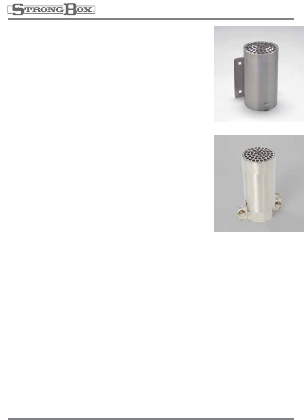
RAIN SWITCH ENCLOSURE
The Rain Switch Enclosure is designed to protect WCS and Mini-
Click Rain Switches from vandalism.
RGVRSS
POLE MOUNT RAIN SWITCH ENCLOSURE
Mountsto2”galvanizedpipe.
RGVRSS-P
ENCLOSURE
OPTIONS
37
StrongBox™, Cinch-Tie™, Twist-Brace™, Cinch-Belt™ and QuickPad™ are registered trademarks of VIT Products, Inc. ©2014 VIT Products, Inc.
VIT Products, Inc.
1.800.729.1314
Makers of the original StrongBox®
www.vitproducts.com
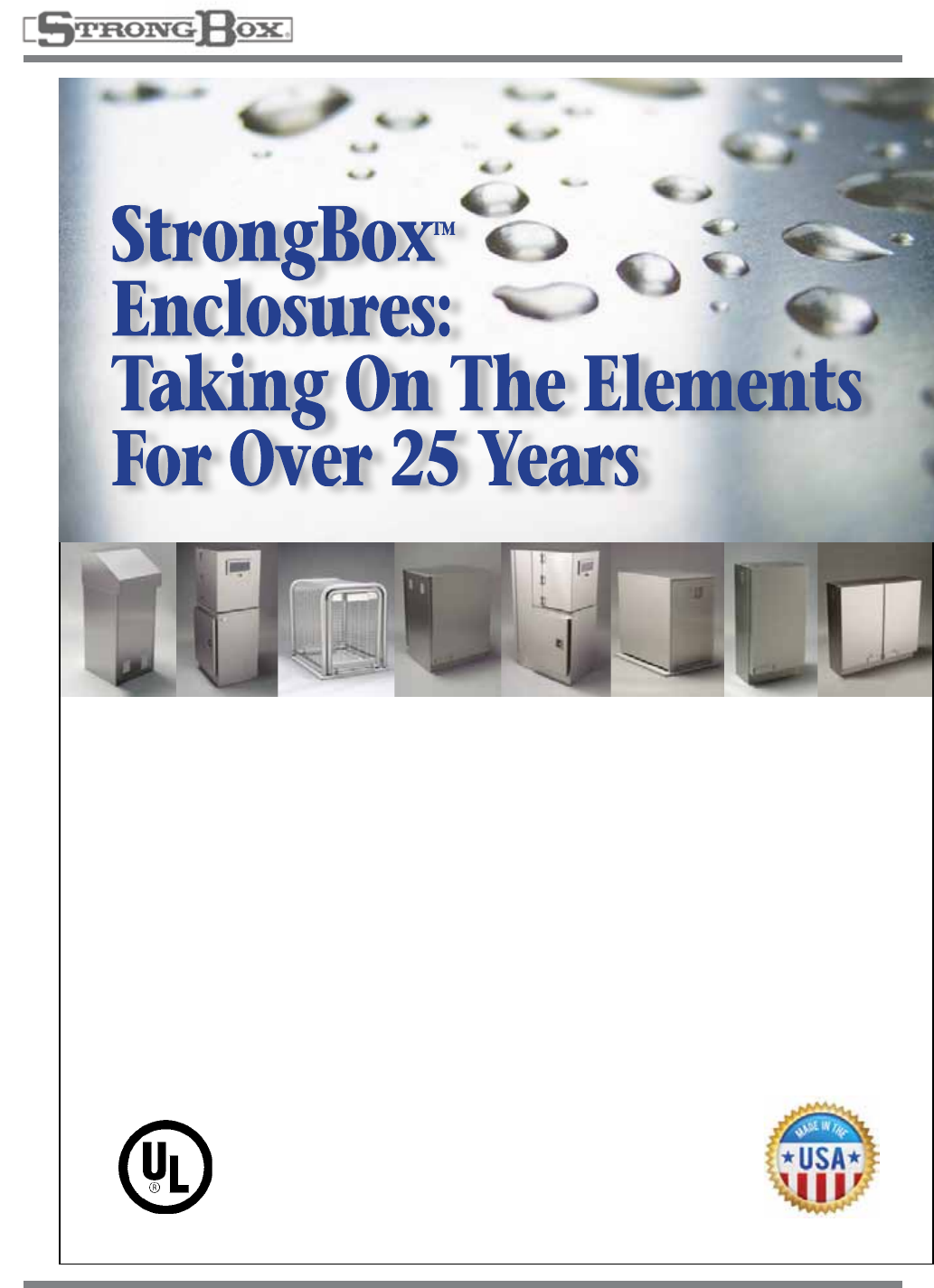
StrongBoxTM manufactures high quality irrigation, plumbing
and electrical landscape enclosures for every application. We
also offer an extensive line of meter pedestals, tree tying and
sprinkler support products for the landscape professional.
•Heavydutystainlesssteelfordurability
•Weatherandvandalresistant
•Promptproductavailability
•Excellentsalesandtechnicalsupport
Call or visit our website to specify VIT products for your
next project.
38
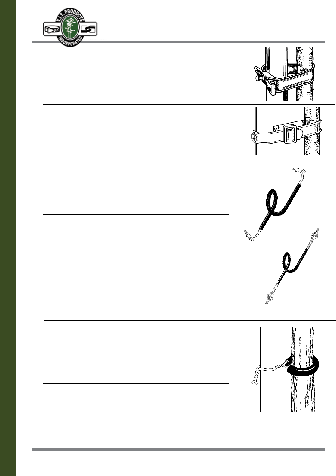
CINCH-TIE TREE SUPPORTS
UV resistant Flexible Vinyl
CT24 24”Long.ForStakingofa5-15GallonTree
CT32 32”Long.ForStakingofa24”BoxTree
Sold in Bundles of 100
CINCH-BELT TREE SUPPORT
UV resistant Flexible Vinyl
CB250 250’ Roll For Staking Trees.
Comeswith70BucklesPerRoll—ExtraBucklesAreAvailable
TWIST-BRACE TREE SUPPORTS
NAIL BRACKET STYLE
5/16” round metal rod with a 4 1/2” loop
encased in UV resistant vinyl tubing
TB24 24”long,forstaking5-15gallonto24”boxtrees
TWIST-BRACE TREE SUPPORTS
BOLT STYLE
1/2” round metal rod with a 4 1/2” loop encased
in UV resistant vinyl tubing
TB36 36”long,forstaking24“-36”boxtrees
HOSE & WIRE TREE SUPPORTS
12 Gauge galvanized wire encased in 10 1/2”
long UV resistant vinyl tubing
HW27 27”long,forstaking5-15gallontrees
HW36 36”long,forstaking24”boxtrees
Sold in Bundles of 100
12 Gauge galvanized wire encased in 16” long
UV resistant vinyl tubing
HW3616 36”long,forstaking24”boxtrees
HW4816 48”long,forstaking24”boxtrees
Sold in Bundles of 100
TREE & SPRINKLER SUPPORT
AND PROTECTION PRODUCTS
39
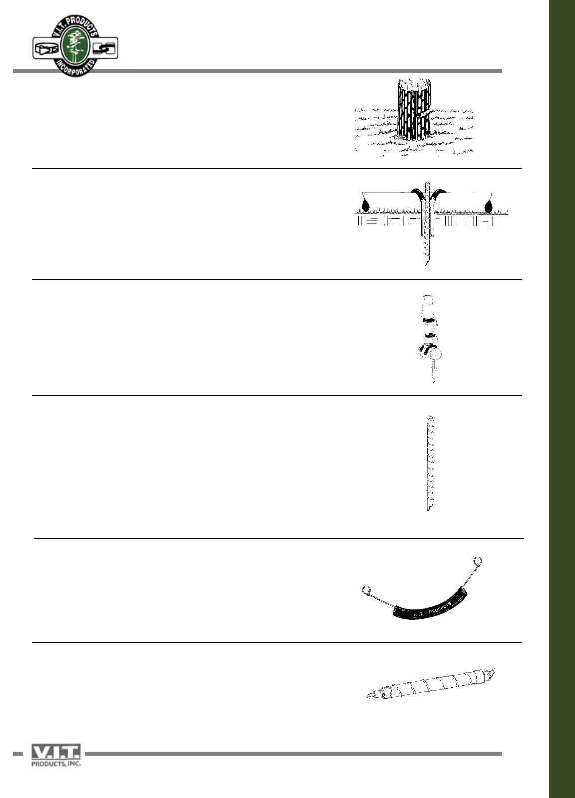
TRIM GUARD TREE TRUNK PROTECTION
TG4 Protects trees from tree trimmer damage
PIPE STABILIZER
Usebetweenthesprinklerheadstocontrolmovementofthepipe
PS12 12”PipeStabilizer
PS18 18”PipeStabilizer
PS24 24”PipeStabilizer
Sold in Bundles of 5
SPRINKLER STABILIZER
Use to secure pipe and sprinkler heads to prevent movement,
vandalism and damage
SS18 18”SprinklerStabilizer
SS24 24”SprinklerStabilizer
Sold in Bundles of 5
STRAIGHT RISER STABILIZER
Use to secure risers to prevent movement, vandalism and damage.
The steel shaft gives additional support and allows good penetration
even in tough soils.
RS12 12”StraightRiserStabilizer
RS18 18”StraightRiserStabilizer
RS24 24”StraightRiserStabilizer
SPRINKLER TIE
UsetosecurethesprinklertotheSprinklerStabilizer
ST9 9”SprinklerTieforshrubs
ST12 12”SprinklerTieforPop-ups
Sold in Packs of 50
RATCHET TOOL FOR SPRINKLER TIES
RT Use to install Sprinkler Ties
TREE & SPRINKLER SUPPORT
AND PROTECTION PRODUCTS
40 40
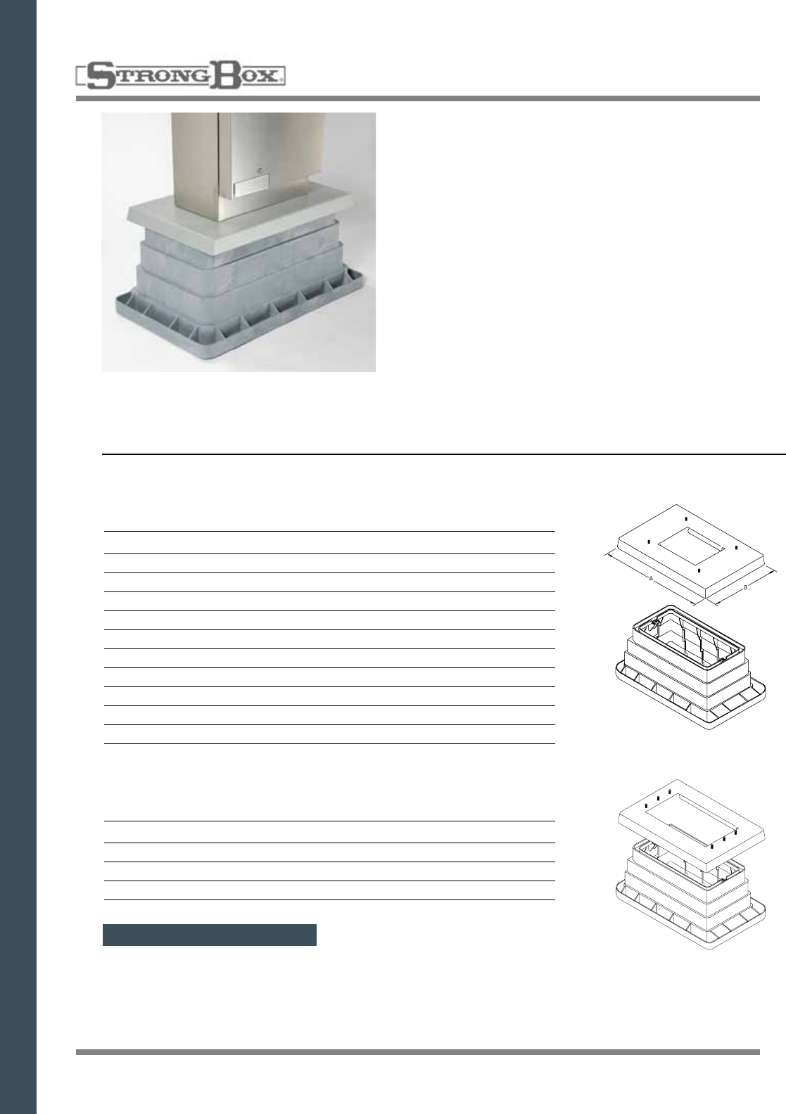
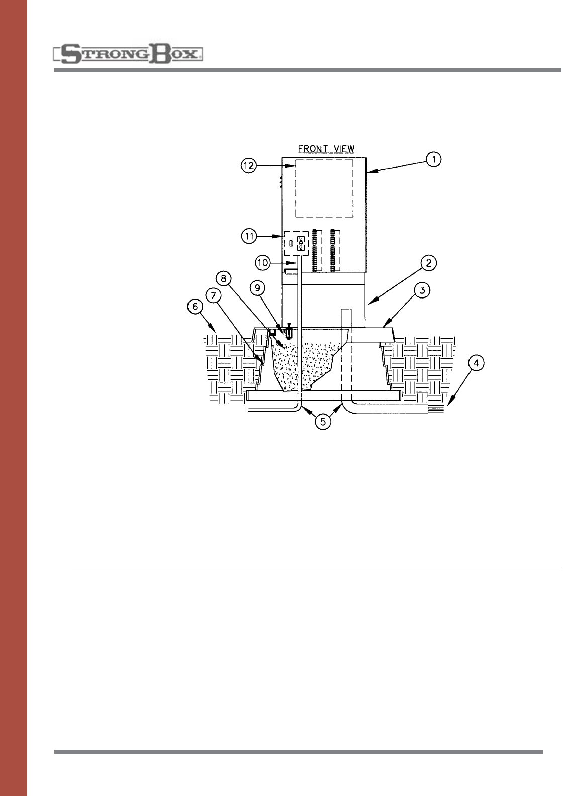
QUICKPAD
ENCLOSURE MOUNTING PAD
QP SERIES
The controller enclosure mount-
ingpadassemblyshallconsistof
a reinforced plastic support
base,athreesixteenthinchthick
5052H32MarineGrade
Aluminum mounting pad and
stainlesssteelfasteningbrack-
ets.Thesupportbaseshallbe
installed and compacted in earth
allowing the top two inches of the
supportbasetobeexposed
abovetheearth.The5052H32
Marine Grade Aluminum mount-
ingpadshallbeclampedtothe
supportbasewiththestainless
steelfasteningbrackets.The
controllerenclosureshallbebolt-
ed from the inside of the enclo-
sure to the mounting pad, thus
preventing outside access to the
mountingbolts.
1. Controller Enclosure
2. Optional Pedestal
3. QuickPad–3/16”min.thicknessaluminum
powder coated preformed pad
4. Directburialcontrolwirestocontrolvalves
5. PVC long sweep ells
6. Finishgrade2”belowtopofQuickPad
7. QuickPadsupportbase
8. Fillinsidebasewithpeagravel
9. QuickPadfasteningbracket(2)
10. 120 volt service conduit
11. Controllersub-assembly(CSA)
includes terminal strips with placards
12. Automatic controller
INSTALLATION DETAILS
SPECIFICATIONS
*QuickPadsusedforallStrongBox
enclosures.
41 41
Telephone (800) 729-1314 ■ FAX (888) 310-3946 ■ www.vitproducts.com
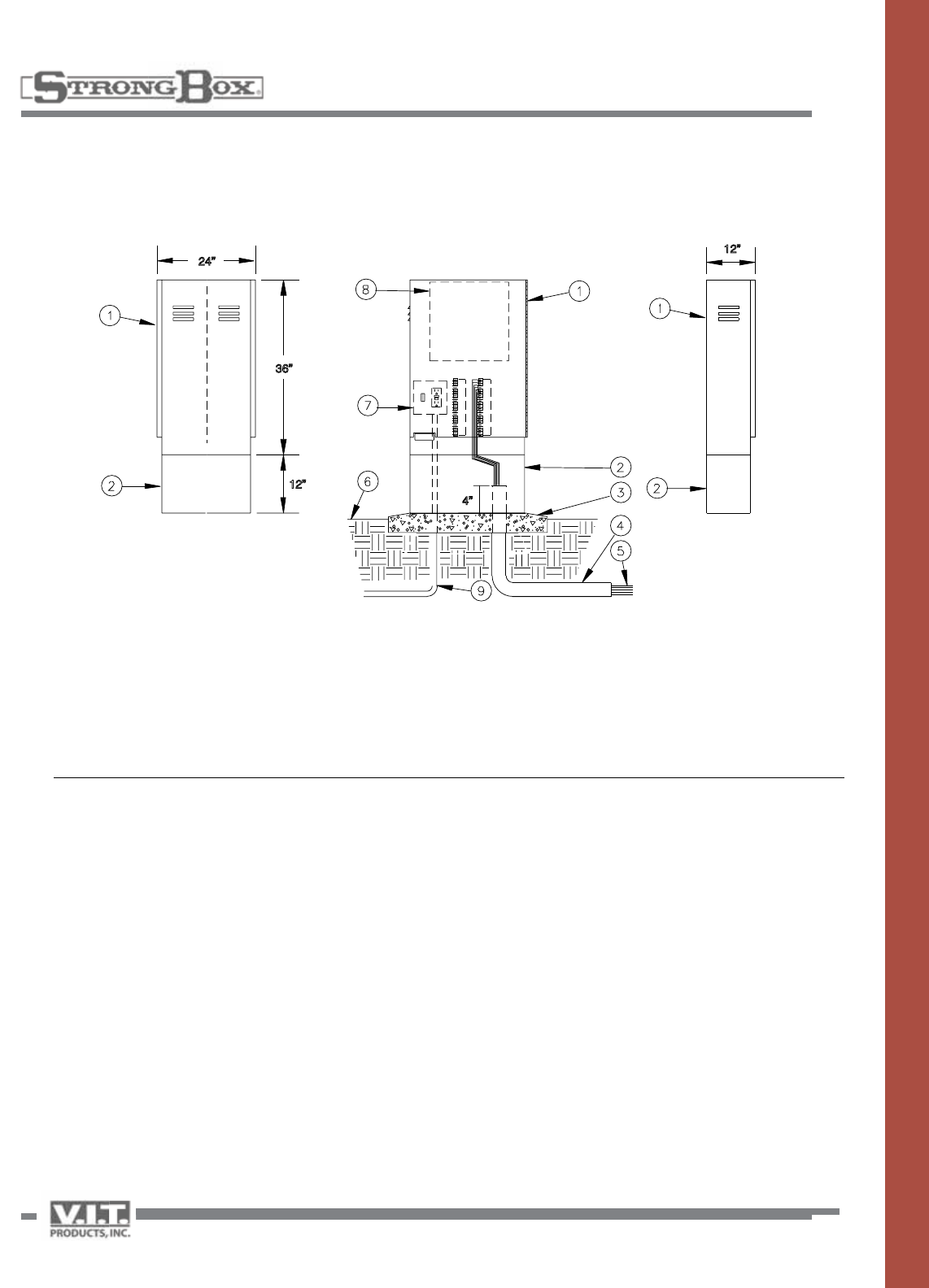
STAINLESS STEEL
ENCLOSURE
FRONT ENTRY ENCLOSURE
MODELS: SB-18SS, SB-18DSS, SB-24SS,
SB-24DSS, SB36SS
24”
36”
12”
4”
12”
Theenclosureshallbeofavandal
and weather resistant nature man-
ufactured entirely of stainless
steel.Themainhousingshallbe
louveredupperandlowerbody
to allow for cross flow ventilation.
Filter screens shall cover all lou-
vers to deflect against water
spray, insects and dust. A stain-
lesssteelbackboardshallbe
provided for the purpose of
mounting electronic and various
othertypesofequipment.The
backboardshallbemountedon
fourstainlesssteelboltsthatwill
allowforremovaloftheback-
board.Theinsidedoorareashall
provideadequatestoragefor
plans, operating instructions, and
scheduling information. The
enclosure door shall have a con-
tinuous stainless steel piano
hinge,carriageboltedonone
side, and a three point locking
mechanism on the other side.
Theedgeofthedoorshallbe
hemmed to eliminate any sharp
edges. The handle controlling the
lockingmechanismshallbe
locatedatthebaseofthedoor
andbeconcealedwithinthesur-
face of the door. A stainless steel
camstylelockshallbemounted
in the door and a provision for a
padlockshallbeincludedwithin
the locking mechanism. The
enclosureshallbemanufactured
with a continuous drainage chan-
nel which mates with a teardrop
shaped, hollow center, water-tight,
thermoplastic door seal. The
abovedescribedproductshall
beaNEMATYPE3RRainproof
Enclosureaslistedby
UnderwriterLaboratories,Inc.
1. Controller enclosure
2. Optional pedestal
3. Pouredconcretebase—6"min.thickness—
extendconcrete6"beyondoutsidedimensions
ofenclosurewith1/2%slopefordrainage
4. PVClongsweepell—sizeasrequired
5. Directburialcontrolwirestocontrolvalves
6. Finish grade
7. Controllersub-assembly(CSA)includesGFI
& terminal strips with placards
8. Automatic controller
9. 120 volt service in conduit
INSTALLATION DETAILS
SPECIFICATIONS
DoubleDoorSideView Single Door Side View
42
STAINLESS STEEL
ENCLOSURE
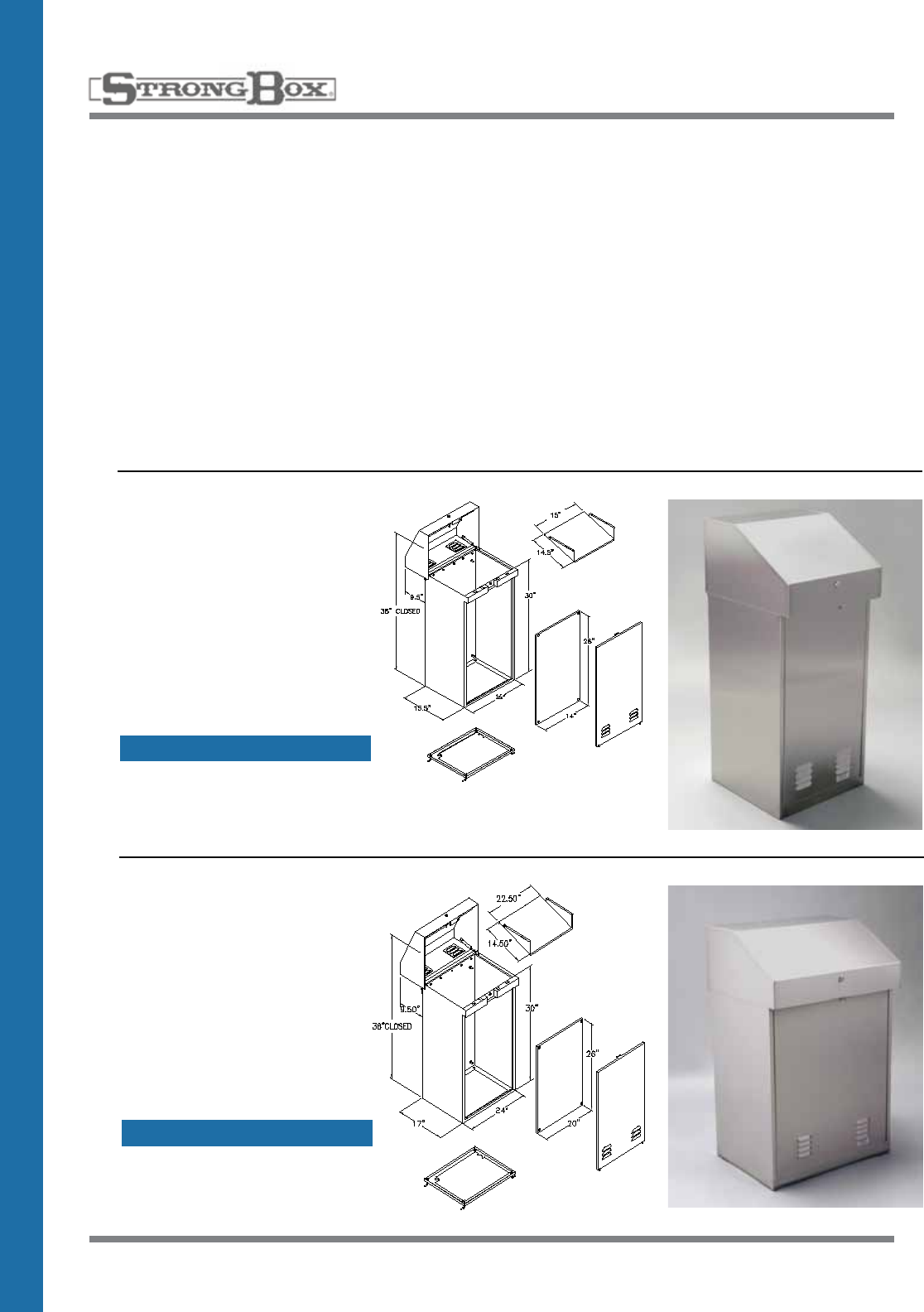
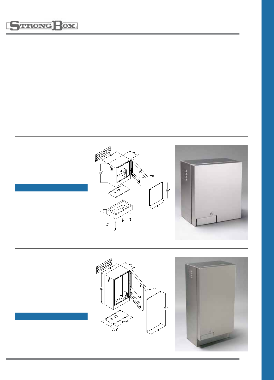
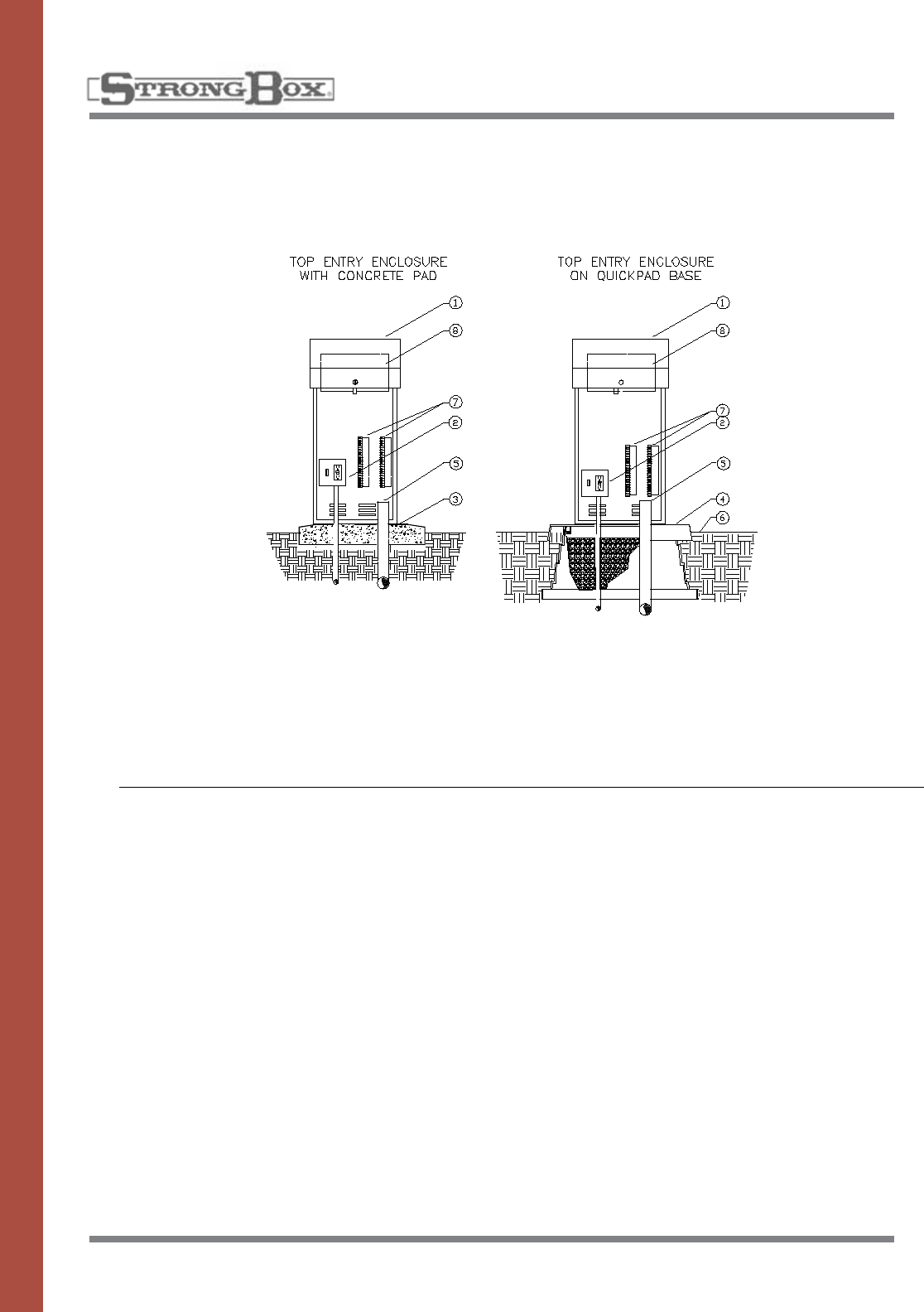
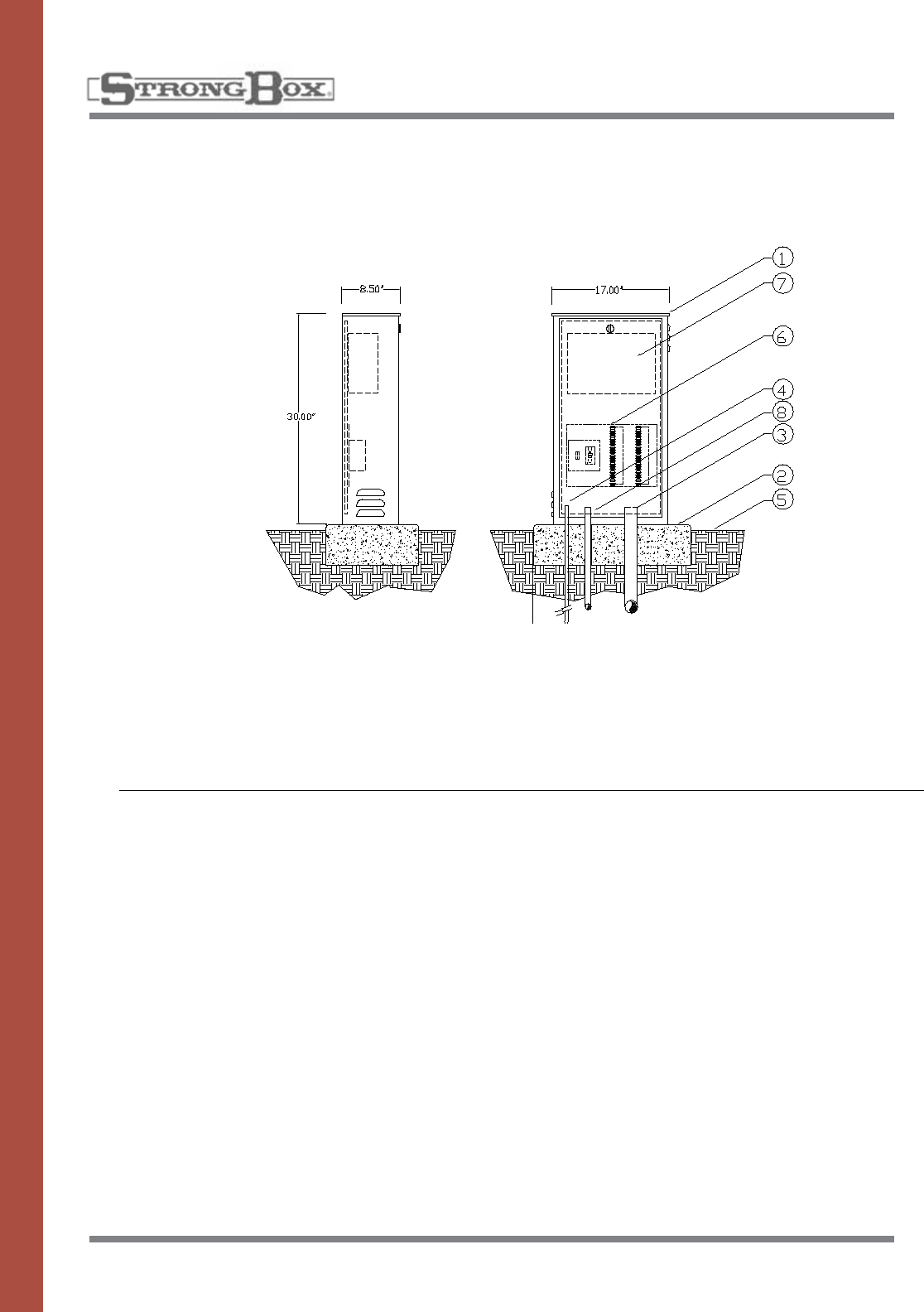
TOP ENTRY ENCLOSURE
MODELS: SB-16SS, SB-22SS
Theenclosureshallbeofavan-
dal and weather resistant nature
manufactured entirely of stainless
steel. The main housing door
shallbelouveredatthebottom
andequippedwithateardrop
shaped, hollow center thermo-
plastic door seal. The entry lid
shallbelouveredontheback
side to allow for cross flow venti-
lation. Filter screens shall cover
all louvers to deflect against
water spray, insects and dust.
Thetopentrylidshallbeassist-
edbytwogasspringsforeasy
access. The edge of the lid shall
behemmedtoeliminateany
sharp edges. The top entry lid
shall have a continuous stainless
steelpianohinge,carriagebolt-
ed on the rear, and a three point
locking mechanism on the front.
A stainless steel cam style lock
shallbemountedinthelidanda
provisionforapadlockshallbe
included within the locking mech-
anism.Aremovablestainless
steeltrayshallbeprovidedfor
the purpose of mounting elec-
tronics and various other types of
equipment.Aremovablestain-
lesssteelbackboardshallbe
providedinthelowerbodyand
mounted on four stainless steel
bolts.Theinsidedoorareashall
provideadequatestoragefor
plans, operating instructions, and
scheduling information. The
abovedescribedproductshall
beaNEMATYPE3RRainproof
Enclosureaslistedby
UnderwriterLaboratories,Inc.
1. Controller enclosure
2. 120 volt service in conduit
3. Pouredconcretebase—6"min.thickness—
extendconcrete6"beyondoutsidedimen
sionsofenclosurewith1/2%slopefordrainage
4. QuickPadmountingbase
5. Directburialcontrolwirestocontrolvalves
6. Finish grade
7. Controllersub-assembly(CSA)includesGFI
& terminal strips with placards
8. Automatic controller
INSTALLATION DETAILS
SPECIFICATIONS
43
STAINLESS STEEL
ENCLOSURE
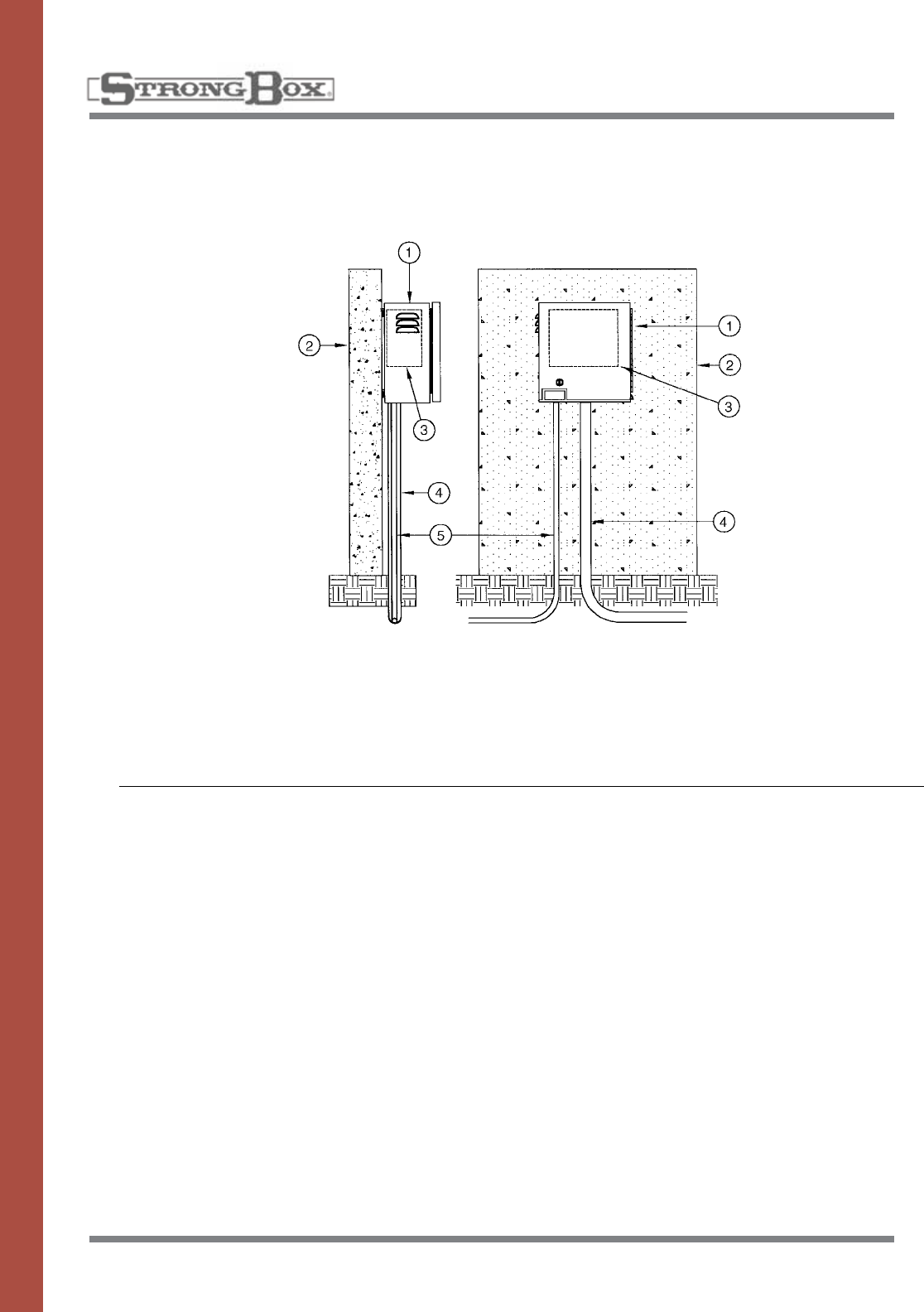
WALL MOUNT ENCLOSURE
MODELS: SB-16SSW, SB-18SSW,
SB-24SSW, SB-36SSW
Theenclosureshallbeofavan-
dal and weather resistant nature
manufactured entirely of stainless
steel.Themainhousingshallbe
louveredupperandlowerbody
to allow for cross flow ventilation.
Filter screens shall cover all lou-
vers to deflect against water
spray, insects and dust. A stain-
lesssteelbackboardshallbe
provided for the purpose of
mounting electronic and various
othertypesofequipment.The
backboardshallbemountedon
fourstainlesssteelboltsthatwill
allowforremovaloftheback-
board.Theinsidedoorareashall
provideadequatestoragefor
plans, operating instructions and
scheduling information. The
enclosure door shall have a con-
tinuous stainless steel piano
hinge,carriageboltedonone
side, and a two-point locking
mechanism on the other side.
Theedgeofthedoorshallbe
hemmed to eliminate any sharp
edges. The handle controlling the
lockingmechanismshallbe
locatedatthebaseofthedoor
andbeconcealedwithinthesur-
face of the door. A stainless steel
camstylelockshallbemounted
in the door and the provision for
apadlockshallbeincludedwith-
in the locking mechanism. The
enclosureshallbemanufactured
with a continuous drainage chan-
nel which mates with a tear-drop
shaped, hollow center, water-
tight, thermoplastic door seal.
Theabovedescribedproduct
shallbeaNEMATYPE3R
RainproofEnclosureaslistedby
UnderwriterLaboratories,Inc.
1. Controller enclosure
2. Wall
3. Automatic controller
4. 24 volt conduit
5. 120 volt conduit
NOTE:Installcontrollerenclosuretowallasper
manufacturer's installation instructions
INSTALLATION DETAILS
SPECIFICATIONS
44
STAINLESS STEEL
CABINET
Thecabinetshallbeofaweather
resistant nature manufactured
entirely of stainless steel. The
mainhousingshallbelouvered
upperandlowerbodytoallow
for cross flow ventilation. Filter
screens shall cover all louvers to
deflect against water spray,
insects and dust. A stainless
steelbackboardshallbeprovid-
ed for the purpose of mounting
electronic and various other
typesofequipment.Theback-
boardshallbemountedonfour
stainlesssteelboltsthatwillallow
forremΩovalofthebackboard.A
stainless steel cam style lock
shallbemountedinthedoor.The
cabinetshallbeequippedwitha
teardrop shaped, hollow center,
watertight, thermoplastic door
seal.Theabovedescribedprod-
uctshallbeaNEMATYPE3R
RainproofEnclosureaslistedby
UnderwriterLaboratories,Inc.
1. Controllercabinet
2. Pouredconcretebase–6"Min.thickness–extend6"
beyondoutsidedimensionsofenclosurewith1/2%
slope for drainage
3. PVC long sweep ell – use one sweep ell per
controller
4. Ground rod
5. Finish grade
6. Controllersub-assembly(CSA)includesGFI
and terminal strips with placards
7. Automatic controller
8. 120-volt service in conduit
INSTALLATION DETAILS
SPECIFICATIONS
LIGHT DUTY CABINET
MODEL: LD-16S
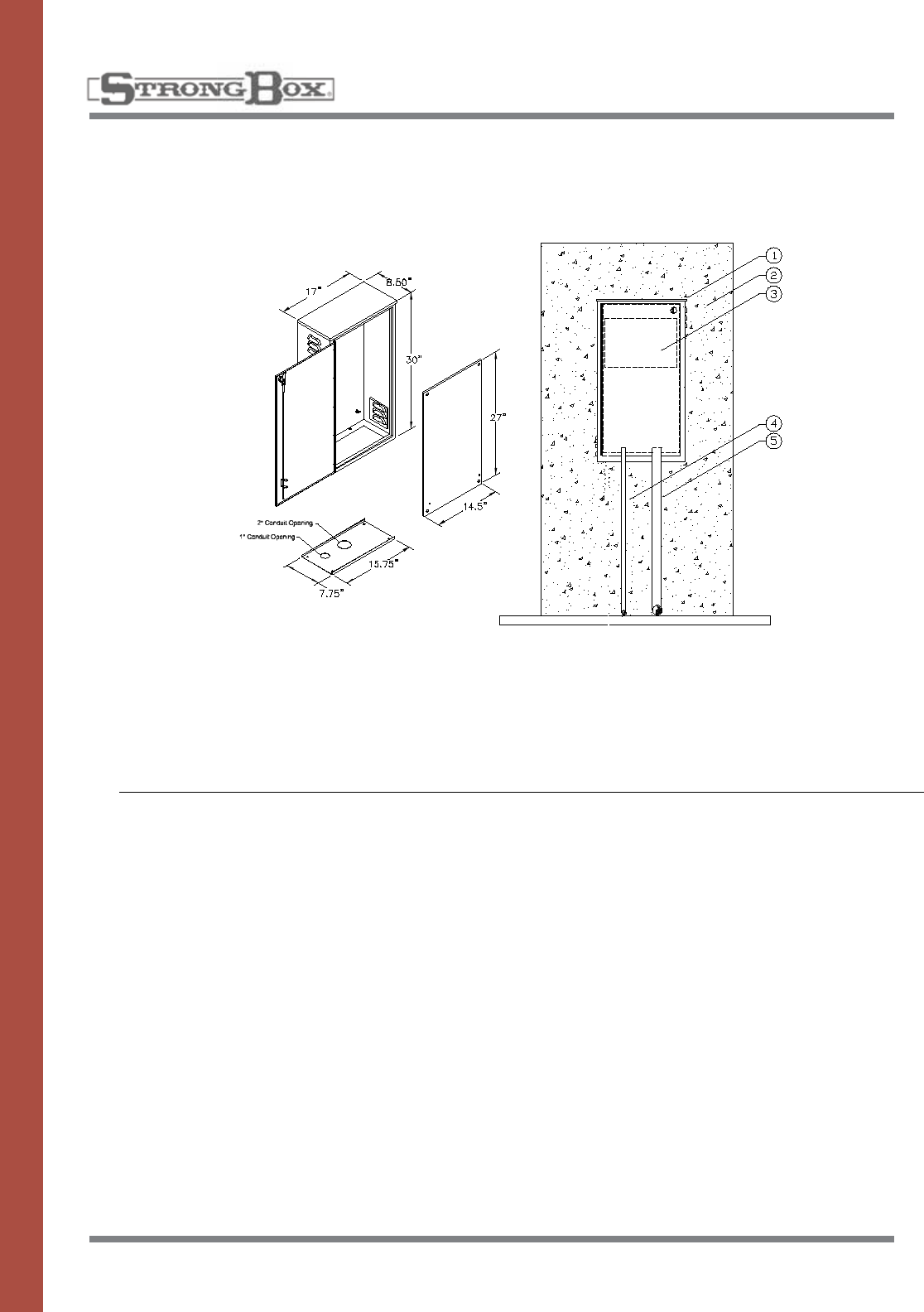
45
STAINLESS STEEL
CABINET
Thecabinetshallbeofaweather
resistant nature manufactured
entirely of stainless steel. The
mainhousingshallbelouvered
to deflect against water spray,
insects and dust. A stainless
steelbackboardshallbeprovid-
ed for the purpose of mounting
electronic and various other
typesofequipment.Theback-
boardshallbemountedonfour
stainlesssteelboltsthatwillallow
forremovalofthebackboard.
Thecabinetdoorshallhavea
continuous stainless steel piano
hinge on one side with a stain-
less steel cam style lock mount-
edinthedoor.Thecabinetshall
beequippedwithateardrop,
hollow center, watertight, thermo-
plasticdoorseal.Thebottomof
thecabinetshallbeprepunched
forelectricalconduit.Theabove
describedproductshallbea
NEMATYPE3RRainproof
Enclosureaslistedby
UnderwriterLaboratories,Inc.
1. Controllercabinet
2. Wall
3. Automatic controller
4. 24-volt conduit
5. 120-volt conduit
Note:
Installcontrollercabinettoawallasper
manufacturer’s installation instructions.
INSTALLATION DETAILS
LIGHT DUTY CABINET
MODEL: LD-16SW
SPECIFICATIONS
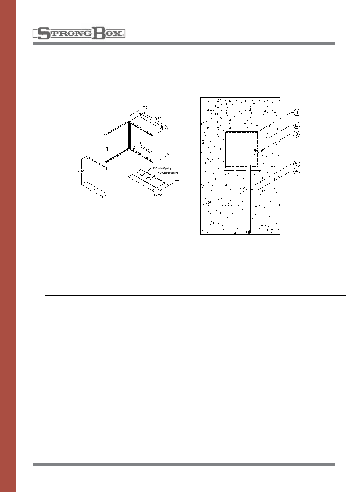
46
STAINLESS STEEL
CABINET
Thecabinetshallbeofaweather
resistant nature manufactured
entirely of stainless steel. A stain-
lesssteelbackboardshallbe
provided for the purpose of
mounting electronic and various
typesofequipment.Theback-
boardshallbemountedonfour
stainlesssteelboltsthatwillallow
forremovalofthebackboard.
Thecabinetdoorshallhavea
continuous stainless steel piano
hinge on one side with a stain-
less steel cam style lock mount-
edinthedoor.Thecabinetshall
bemanufacturedwithacontinu-
ous drainage channel which
mates with a teardrop shaped,
hollow center, watertight, thermo-
plasticdoorseal.Thebottomof
thecabinetshallbeprepunched
forelectricalconduit.Theabove
describedproductshallbea
NEMATYPE3RRainproof
Enclosureaslistedby
UnderwriterLaboratories,Inc.
1. Controllercabinet
2. Wall
3. Automatic controller
4. 24-volt conduit
5. 120-volt conduit
Note:
Installcontrollercabinettoawallasper
manufacturer’s installation instructions.
INSTALLATION DETAILS
SPECIFICATIONS
LIGHT DUTY CABINET
MODEL: LD-18SW
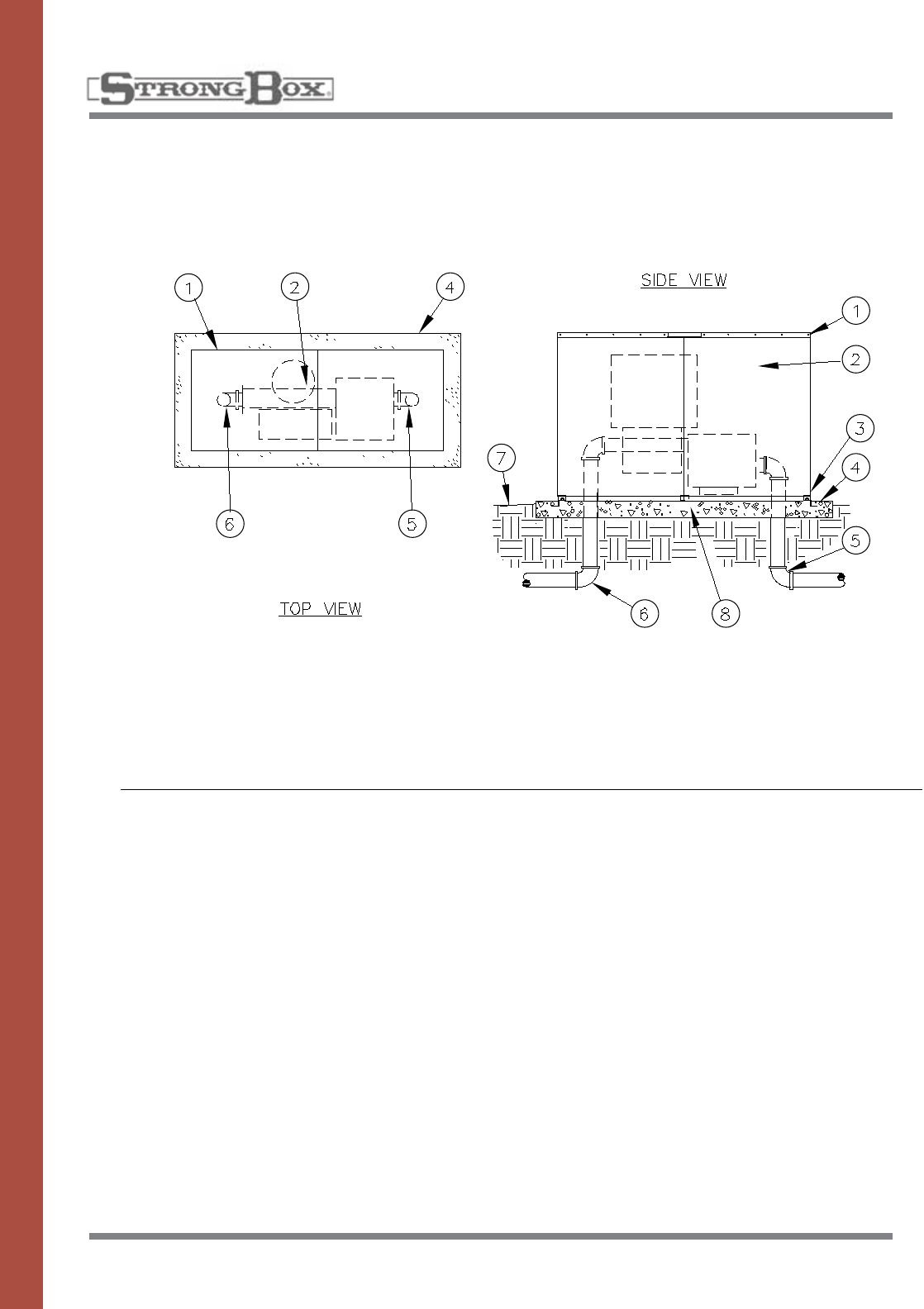
47
ALUMINUM ALLOY
PUMP ENCLOSURE
MODELS PE-40AL
& PE-60AL
INSTALLATION DETAILS
SPECIFICATIONS
1. Aluminum pump enclosure
2. Pump/Filter/Controls+
3. AnchorRakebrace
4. Pouredconcretebase—6"min.
thickness—extended4"beyond
outside dimensions of enclosure
5. Water service inlet piping
6. Water service outlet piping
7. Finish grade
8. Enclosure Foot
Thepumpenclosureshallbeofa
vandal and weather resistant
nature manufactured entirely of
marine grade aluminum alloy
5052-H32,withawallthickness
of one eighth inch. The mounting
baseshallbemanufactured
entirely of stainless steel. The
mainhousingshallbeofsolid
sheet construction punched on
the ends with louvers for ventila-
tion.Theenclosureshallbea
center split design, having
mounting lips on each end. The
mountingbaseshallbesub-
merged into the concrete a mini-
mum of two inches, positioning
the enclosure two and one half
inchesabovetheconcretefor
drainage purposes. The locking
mechanismshallbeofthefull
release type which allows for
complete removal of the enclo-
surefromitsmountingbasewith-
out the use of tools. The locking
mechanismshallbeaStainless
Steel Cross Bar style and provide
for a padlock.
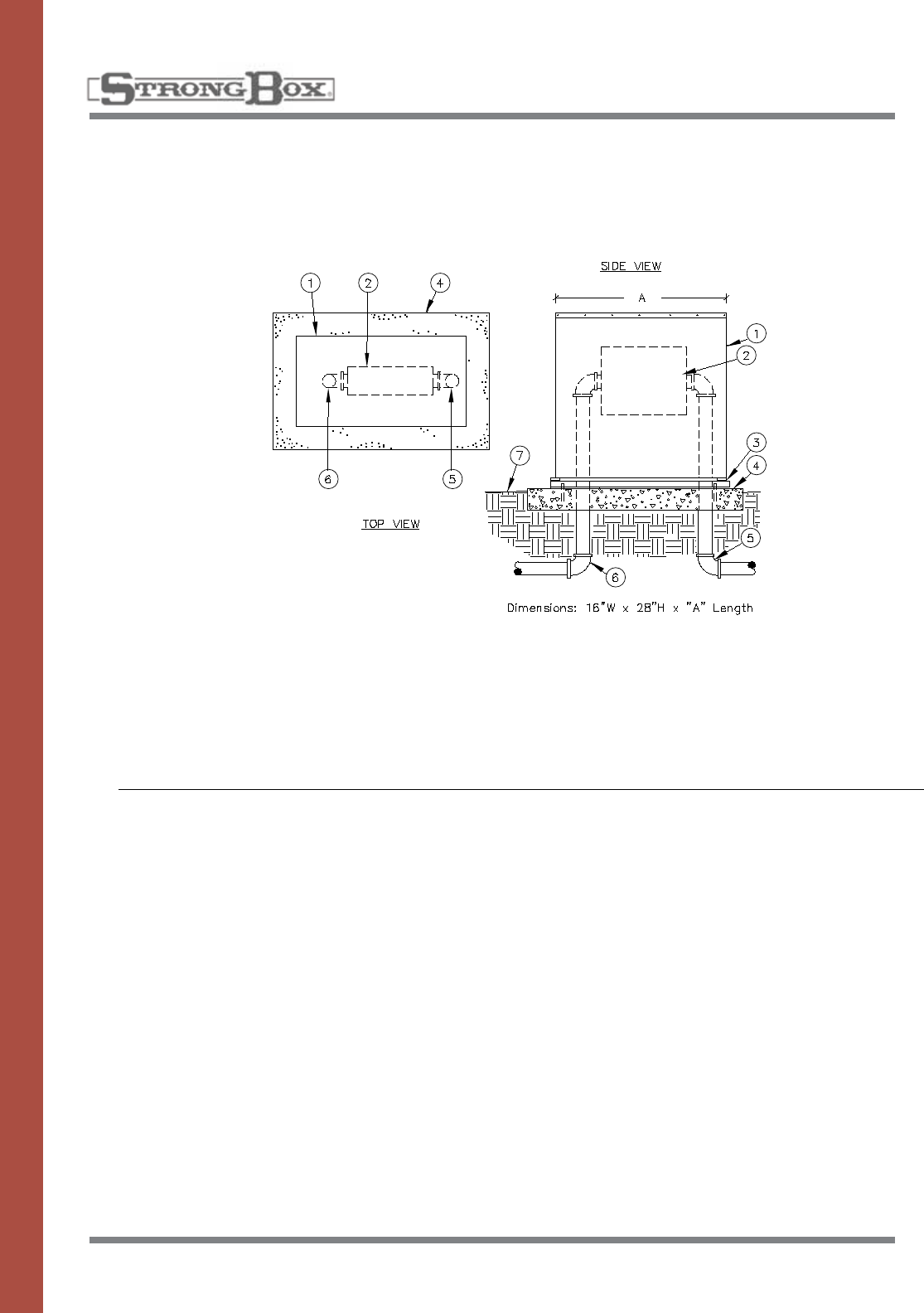
48
ALUMINUM
ENCLOSURE
Thebackflowenclosureshallbe
of a vandal resistant nature man-
ufactured entirely of marine
gradealuminumalloy5052-H32,
with a wall thickness of one
eighthinch.Themountingbase
plateshallbemanufacturedof
stainless steel and powder coat-
ed.Themainhousingshallbeof
solid sheet construction with
stainlesscarriageboltsusedfor
assemblingenclosuresidestop
and ends. The enclosure shall
have a drop down door with
stainless hardware hidden
beneathdoorframe.Theenclo-
surebodyshallliftopen,pivoting
fromthebackedgemountedto
basealsowithhiddenstainless
hardware. Enclosure shall stay
securedtomountingbaseplate
in open and closed positions.
Mounting Base shall have con-
creteanchorboltstosubmerge
into concrete leaving mounting
baseflushonconcretesurface.
The enclosure door shall have a
recessed handle and provide a
concealed hasp for a padlock.
1. Aluminum Backflow Enclosure
2. Backflow Preventer
3. Framed Mounting Base – powder coated polymer with
anchorsinsetforenclosureandanchorboltsforconcrete
4. PouredConcreteBase–6”minimumthickness–
extend4”beyondoutsidedimensionsofenclosure
5. Water Service Inlet Piping
6. Water Service Outlet Piping
7. Finish Grade
INSTALLATION DETAILS
BACKFLOW ENCLOSURE
MODELS: SBBC–22AL, SBBC–30AL,
SBBC–45AL
SPECIFICATIONS
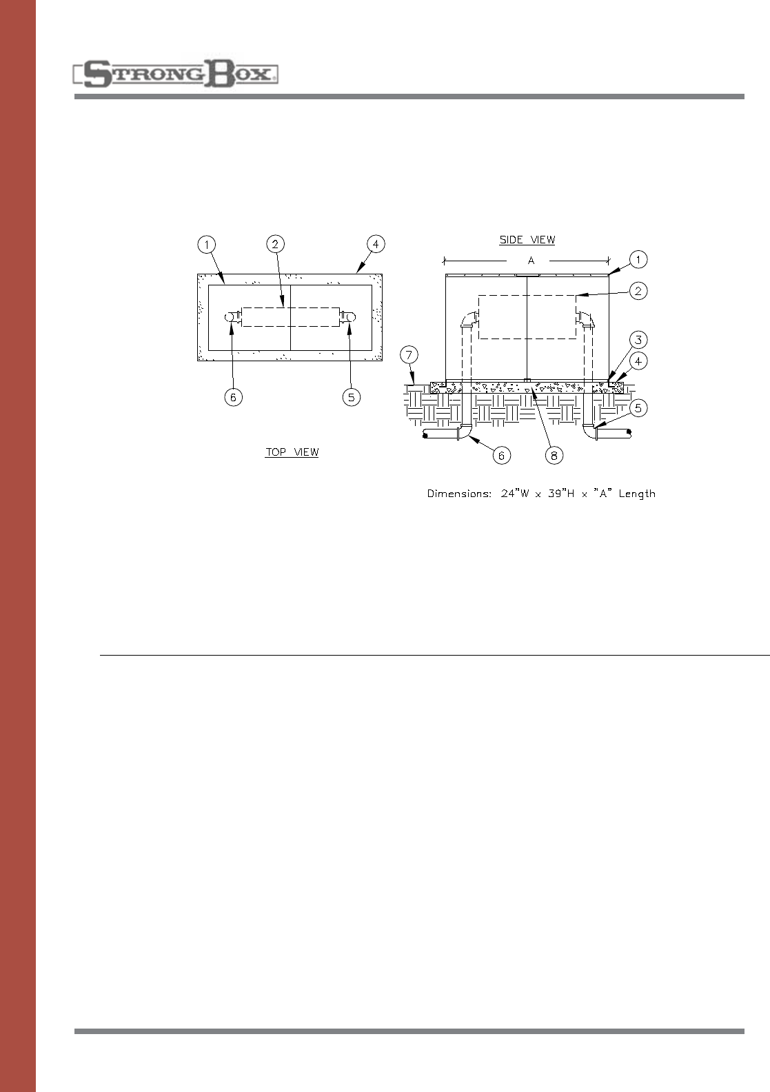
49
ALUMINUM
ENCLOSURE
Thebackflowenclosureshallbe
of a vandal and weather resistant
nature manufactured entirely of
marine grade aluminum alloy
5052-H32,withawallthickness
of one eighth inch. The mounting
baseshallbemanufactured
entirely of stainless steel. The
mainhousingshallbeofsolid
sheet construction punched on
the sides with a rectangular pat-
ternforviewingbackflowopera-
tion.Theenclosureshallbea
center split design, having
mounting lips on each end. The
mountingbaseshallbesub-
merged into the concrete a mini-
mum of two inches, positioning
the enclosure one and one half
inchesabovetheconcretefor
drainage purposes. The locking
mechanismshallbeofthefull
release type which allows for
complete removal of the enclo-
surefromitsmountingbasewith-
out the use of tools. The locking
mechanismshallbeaStainless
Steel Cross Bar style and provide
for a padlock.
1. Aluminum Backflow Enclosure
2. Backflow Preventer
3. Anchor Rake Brace
4. PouredConcreteBase–6”minimumthickness–
extend4”beyondoutsidedimensionsofenclosure
5. Water Service Inlet Piping
6. Water Service Outlet Piping
7. Finish Grade
8. Enclosure Foot
INSTALLATION DETAILS
BACKFLOW ENCLOSURE
MODELS: SBBC–40ALHP, SBBC–40WALHP,
SBBC–60ALHP, SBBC–75ALHP,
SBBC–90ALHP
SPECIFICATIONS
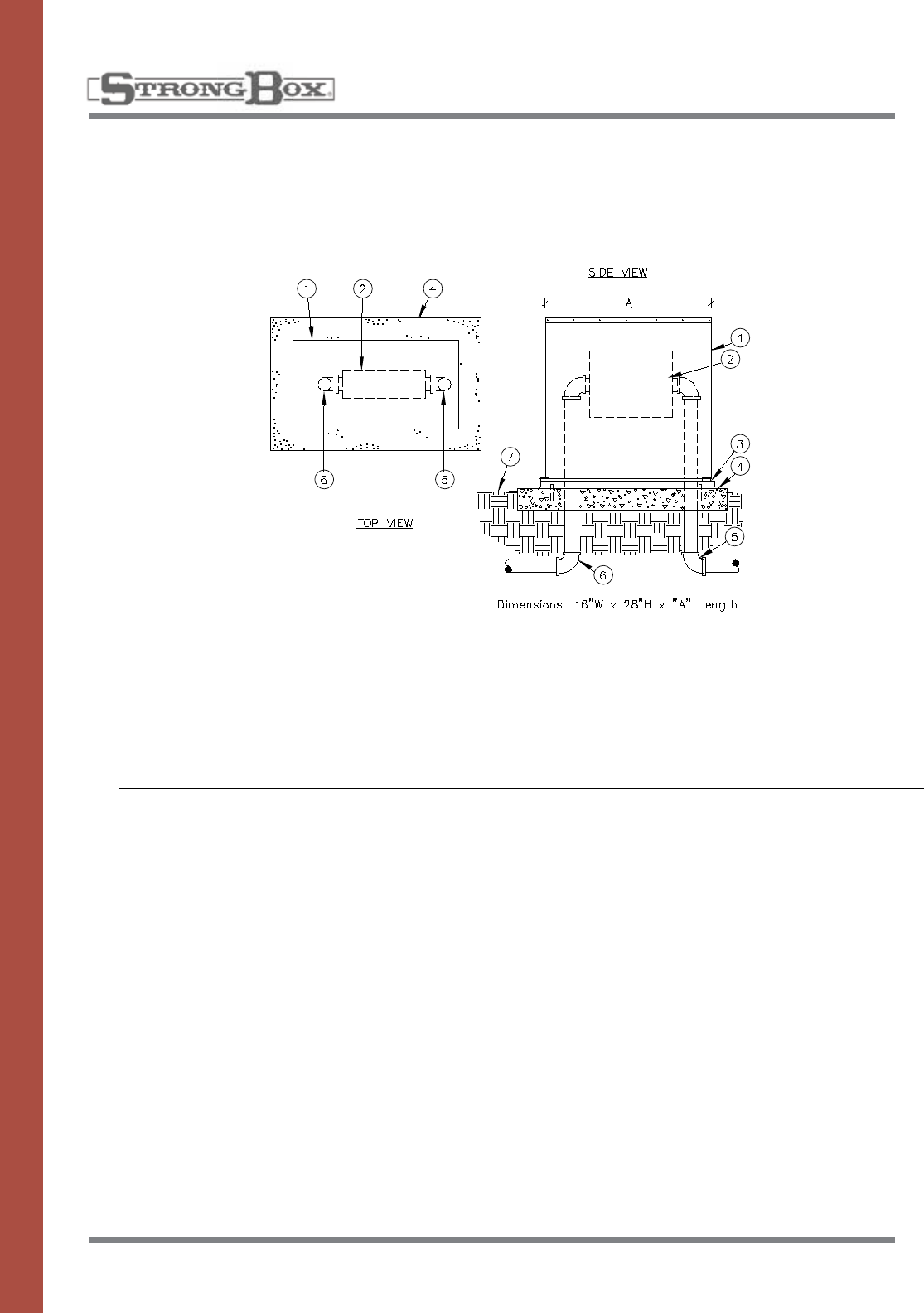
50
INSULATED ALUMINUM
ENCLOSURE
Thebackflowenclosureshallbe
of a vandal resistant nature
manufactured entirely of marine
gradealuminumalloy5052-H32,
with a wall thickness of one
eighthinch.Themountingbase
plateshallbemanufacturedof
stainless steel and powder coat-
ed.Themainhousingshallbeof
solid sheet construction with
stainlesscarriageboltsusedfor
assemblingenclosuresidestop
and ends. The enclosure shall
have a drop down door with
stainless hardware hidden
beneathdoorframe.Theenclo-
surebodyshallliftopen,pivoting
fromthebackedgemountedto
basealsowithhiddenstainless
hardware. Enclosure shall stay
securedtomountingbaseplate
in open and closed positions.
Mounting Base shall have con-
creteanchorboltstosubmerge
into concrete leaving mounting
baseflushonconcretesurface.
The enclosure door shall have a
recessed handle and provide a
concealed hasp for a padlock.
InsulatedPolarBeariersshallbe
usedtoprotectbackflowdevices
from freezing temperatures inside
StrongboxInsulatedAluminum
Enclosures. Polar Beariers pro-
tect to a R19 insulation rating
using Radiant Barrier Foil (RBF)
insertedbetweenacrylicpolyes-
terandairbubblepack.These
layersforminganinsulatedbag
shallbeimpervioustomoisture.
1. Aluminum Backflow Enclosure
2. Backflow Preventer
3. Framed Mounting Base – powder coated polymer with
anchorsinsetforenclosureandanchorboltsforconcrete
4. PouredConcreteBase–6”minimumthickness–
extend4”beyondoutsidedimensionsofenclosure
5. Water Service Inlet Piping
6. Water Service Outlet Piping
7. Finish Grade
INSTALLATION DETAILS
SPECIFICATIONS
BACKFLOW ENCLOSURE
MODELS: SBBC–22ALI, SBBC–30ALI,
SBBC–45ALI
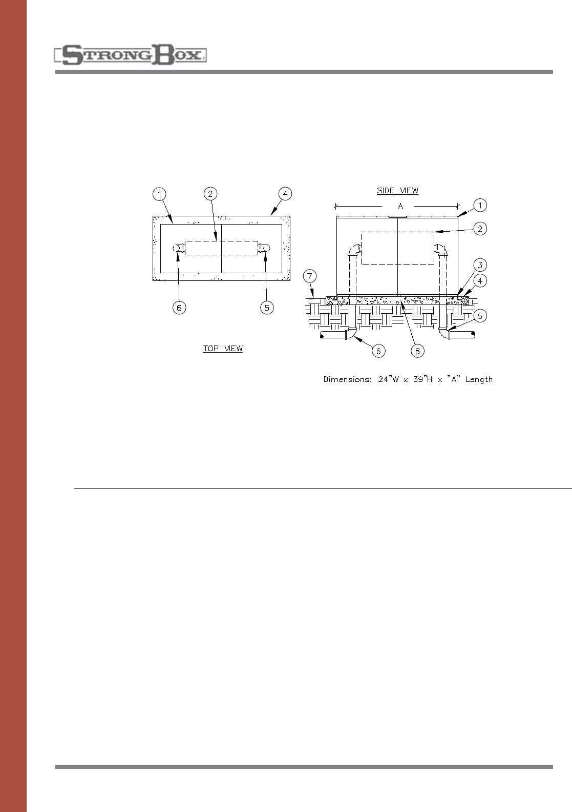
51
INSULATED ALUMINUM
ENCLOSURE
Thebackflowenclosureshallbe
of a vandal and weather resistant
nature manufactured entirely of
marine grade aluminum alloy
5052-H32,withawallthickness
of one eighth inch. The mounting
baseshallbemanufactured
entirely of stainless steel. The
mainhousingshallbeofsolid
sheet construction with a R-19
Polar Bearier insulation cover. A
flexiblerubberinsertformedinto
a loop to provide dead air space
shallbeinstalledalongthebot-
tom.Theenclosureshallbea
center split design, having
mounting lips on each end. The
mountingbaseshallbesub-
merged into the concrete a mini-
mum of two inches, positioning
the enclosure one and one half
inchesabovetheconcretefor
drainage purposes. The locking
mechanismshallbeofthefull
release type which allows for
complete removal of the enclo-
surefromitsmountingbasewith-
out the use of tools.The locking
mechanismshallbeaStainless
Steel Cross Bar style and provide
for a padlock.
1. Aluminum Backflow Enclosure
2. Backflow Preventer
3. Anchor Rake Brace
4. PouredConcreteBase–6”minimumthickness–
extend4”beyondoutsidedimensionsofenclosure
5. Water Service Inlet Piping
6. Water Service Outlet Piping
7. Finish Grade
8. Enclosure Foot
INSTALLATION DETAILS
SPECIFICATIONS
HIGH PROFILE
BACKFLOW ENCLOSURE
MODELS: SBBC–40ALHPI, SBBC–40WALHPI,
SBBC–60ALHPI, SBBC–75ALHPI, SBBC–90ALHPI
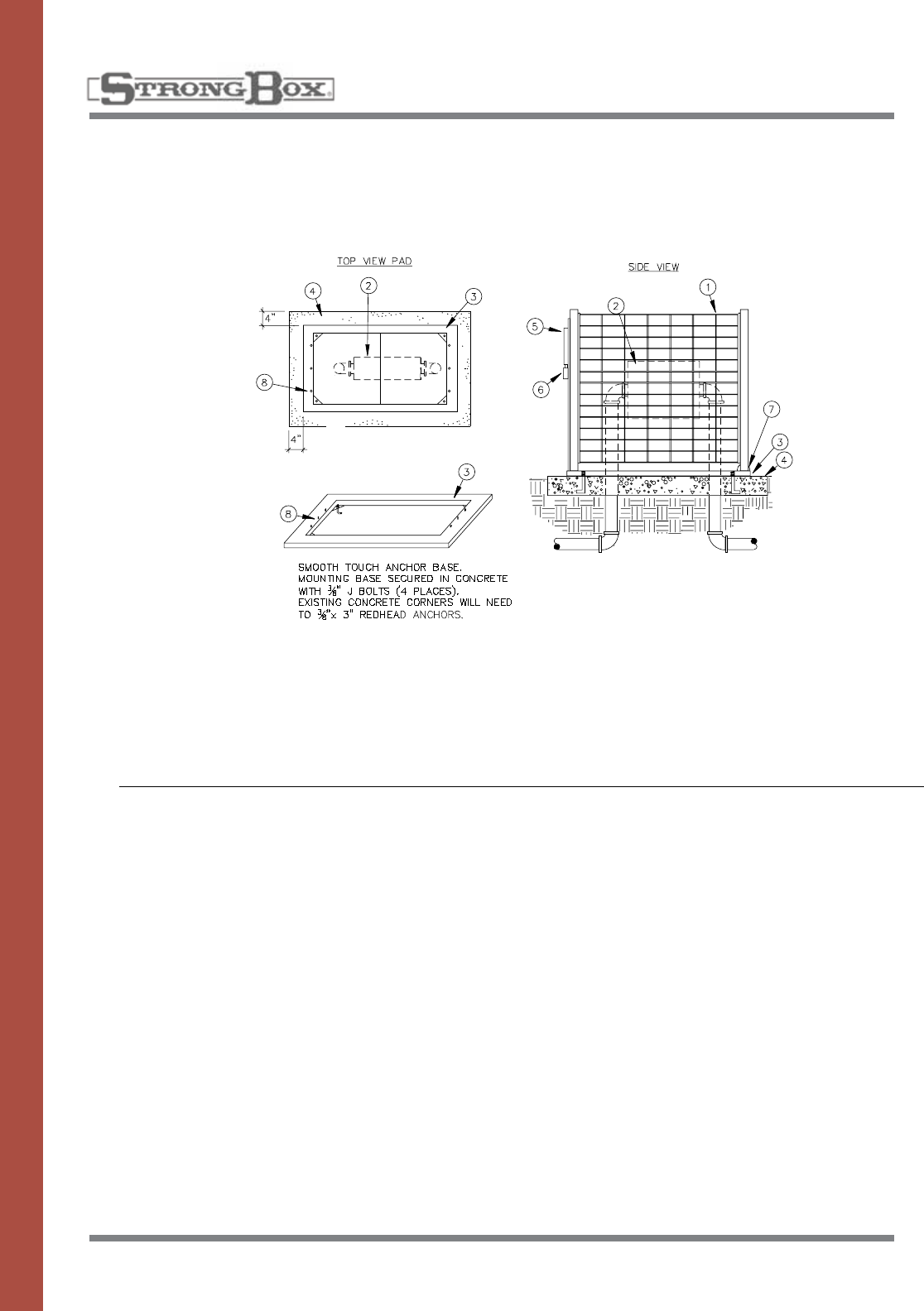
52
STAINLESS STEEL
ENCLOSURE
The Backflow cage enclosure
shallbeofavandalresistant
nature manufactured of formed
stainlesssteeltubingandrod,
coated with a performance poly-
mer alloy coating. Special pow-
dercoatedcolorsavailableas
perspecifiedbycity.Alllocking
andmountinghardwareshallbe
manufactured entirely of stainless
steel. The frame of the enclosure
shallbeconstructedofoneand
onequarterinchtubingasamin-
imum, including the drop down
door which inserts into the open
end of the frame. The top, sides
andendpanelsshallbecon-
structed of rod forming a one
inchbytwoandahalfinchrect-
angular pattern as a maximum
opening. The vertical rods shall
beaminimumofthreesixteenths
inch thick and the horizontal rods
shallbeaminimumofone
eighth.Theserodsshallbeweld-
ed together forming grids. These
gridsshallbeweldedintothe
tubeframeshalfinchweldsnot
more than four inches apart. The
enclosure door and enclosure
shallbecleanedandcoated
with not less than three mils
powder coat.
Each enclosure shall have a
mountingpadwhichshallbe
used as installation frame.
Enclosure hardware on the
mountingframeshallbestainless
steel.Mountingframeshallbe
installedusingfoureach,3/8”“L”
anchorboltssubmergedincon-
crete a minimum two inches. The
backflowcageenclosureshall
remainboltedtoframeinopen
and closed positions. Enclosure
and door shall close with con-
cealedlockingtabwithsevensix-
teenths hole to accept padlock.
1. Smooth Touch Backflow Cover
2. Backflow Preventer
3. Anchor Base Mount
4. PouredConcreteBase–6”minimumthickness–
extend4”beyondoutsidedimensionsofenclosure
5. Enclosure Locking Swing Door (door mounted to
anchorbase)
6. Padlock Protective Cover
7. Enclosure Swivel Point – attached to mounting
base.Enclosuresecuredtobase(6places)
8. EnclosureMountingBaseStuds.3/8”x3/4”
INSTALLATION DETAILS
SPECIFICATIONS
BACKFLOW COVER
MODELS: SBBC–22SS, SBBC–30SS,
SBBC–45SS
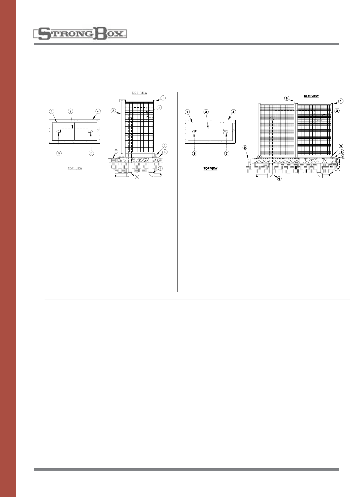
53
STAINLESS STEEL
ENCLOSURE
Thebackflowenclosureshallbe
of a vandal resistant nature man-
ufactured of formed stainless
steeltubingandrodtoprevent
handlinginjury.Thelocking
mechanism and mounting hard-
wareshallbemanufactured
entirely of stainless steel. The
frameoftheenclosureshallbe
constructed of one and one
quarterinchtubing.Thetop
sides,andendpanelsshallbe
constructed of rod welded
togetherformingaonebytwo
inch rectangular pattern. The ver-
ticalrodshallbethreesixteenths
andhorizontalrodshallbeone
eighth inch thick. The SBBC-
20SS shall have inner door on
one end to provide entry with
covered padlock at top of door
for security. The SBBC-40SS and
SBBC-75SSshallbeclamshell
design with padlock hasp on to
wheretwopiecesjoininthe
closed position. Enclosure ends
shall have a mounting lip on each
side which attaches to mounting
whichissubmergedintocon-
crete.Enclosureshallbeposi-
tioned one and one half inches
aboveconcretetoallowfordrain-
age.Vandalproofbracketsshall
beinstalledduringinstallation.
1. Smooth Touch Backflow Cover
2. Backflow Preventer
3. Anchor Plates (typical)
4. PouredConcreteBase–6”minimum
thickness–extend4”beyondoutside
dimensions of enclosure
5. Water Service Inlet Piping
6. Water Service Outlet Piping
7. Finish Grade
8. RemovableLockingEnd
INSTALLATION DETAILS
SPECIFICATIONS
BACKFLOW COVER
MODELS: SBBC–20SS, SBBC–40SS,
SBBC–75SS
SBBC-20SS SBBC-40SS, SBBC-75SS
1. Smooth Touch Backflow Cover
2. Backflow Preventer
3. Secured Swivel Mounting Plates
4. PouredConcreteBase–6”minimumthickness–
extend4”beyondoutsidedimensionsofenclosure
5. SBBCMountingBase–fastenedoranchorbolted
to concrete
6. Water Service Outlet Piping
7. Water Service Inlet Piping
8. PadlockLockingHasp
9. Finish Grade
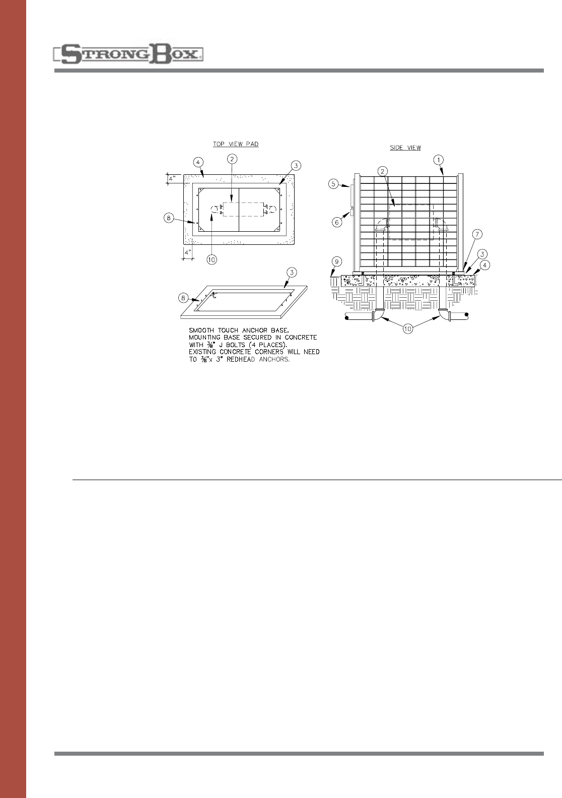
54
POWDER COATED
ENCLOSURE
The Backflow cage enclosure
shallbeofavandalresistant
nature manufactured of formed
coldrolledsteeltubingandrod,
coated with a performance poly-
mer alloy coating. Special pow-
dercoatedcolorsavailableas
perspecifiedbycity.Alllocking
andmountinghardwareshallbe
manufactured entirely of stainless
steel. The frame of the enclosure
shallbeconstructedofoneand
onequarterinchtubingasamin-
imum, including the drop down
door which inserts into the open
end of the frame. The top, sides
andendpanelsshallbecon-
structed of rod forming a one
inchbytwoandahalfinchrect-
angular pattern as a maximum
opening. The vertical rods shall
beaminimumofthreesixteenths
inch thick and the horizontal
rodsshallbeaminimumofone
eighth.Theserodsshallbeweld-
ed together forming grids. These
gridsshallbeweldedintothe
tubeframeshalfinchweldsnot
more than four inches apart.
The enclosure door and enclo-
sureshallbecleanedandcoated
with not less than three mils
powder coat.
Each enclosure shall have a
mountingpadwhichshallbe
used as installation frame.
Enclosure hardware on the
mountingframeshallbe
stainless steel. Mounting frame
shallbeinstalledusingfour
each,3/8”“L”anchorboltssub-
merged in concrete a minimum
twoinches.Thebackflowcage
enclosureshallremainboltedto
frame in open and closed posi-
tions. Enclosure and door shall
closewithconcealedlockingtab
with seven sixteenths hole to
accept padlock.
1. Smooth Touch Backflow Cover
2. Backflow Preventer
3. Anchor Base Mount
4. PouredConcreteBase–6”minimumthickness–
extend4”beyondoutsidedimensionsofenclosure
5. Enclosure Locking Swing Door (door mounted to
anchorbase)
6. Padlock Protective Cover
7. Enclosure Swivel Point – attached to mounting
base.Enclosuresecuredtobase(6places)
8. EnclosureMountingBaseStudes3/8”x3/4”
9. Finish Grade
10. Water Service Inlet Piping
INSTALLATION DETAILS
SPECIFICATIONS
BACKFLOW COVER
MODELS: SBBC–22CR, SBBC–30CR,
SBBC–45CR
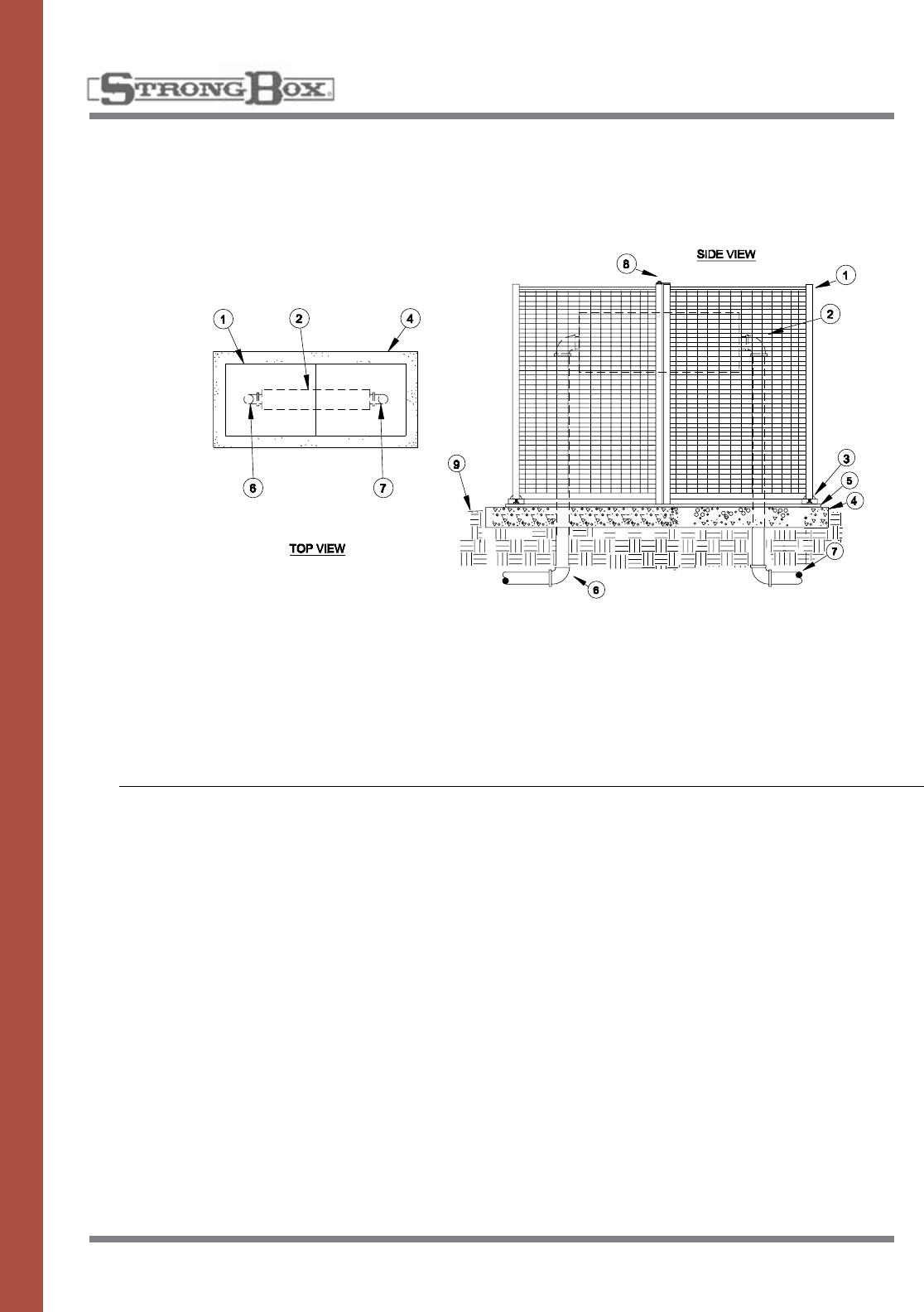
55
POWDER COATED
ENCLOSURE
Thebackflowenclosureshallbe
of a vandal resistant nature man-
ufactured of formed cold rolled
steeltubingandrodtoprevent
handlinginjury.Thelocking
mechanism and mounting hard-
wareshallbemanufactured
entirely of stainless steel. The
frameoftheenclosureshallbe
constructed of one and one
quarterinchtubing.Thetop
sides,andendpanelsshallbe
constructed of rod welded
togetherformingaonebytwo
inch rectangular pattern. The ver-
ticalrodshallbethreesixteenths
andhorizontalrodshallbeone
eighth inch thick. The SBBC-
40CRandSBBC-75CRshallbe
clam shell design with padlock
haspontowheretwopiecesjoin
in the closed position. Enclosure
ends shall have a mounting lip
on each side which attaches to
mountingwhichissubmerged
into concrete. Enclosure shall
bepositionedoneandonehalf
inchesaboveconcretetoallow
for drainage. Vandal proof
bracketsshallbeinstalled
during installation. The cover
shallbecoveredwithazincbase
powder coat then powder coated
with a polyester TGIC coating
having a minimum thickness
of 2.5 mils.
1. Smooth Touch Backflow Cover
2. Backflow Preventer
3. Secured Swivel Mounting Plates
4. PouredConcreteBase–6”minimumthickness–
extend4”beyondoutsidedimensionsofenclosure
5. SBBCMountingBase–fastenedoranchorboltedto
concrete
6. Water Service Outlet Piping
7. Water Service Inlet Piping
8. PadlockLockingHasp
9. Finish Grade
Note:Enclosureshallswiveloutwardtoexposeback-
flow.Backflowcoverissecuredtobaseandtoolsmust
beusedtoremovecompletely.
INSTALLATION DETAILS
SPECIFICATIONS
BACKFLOW COVER
MODELS: SBBC–40CR, SBBC–75CR
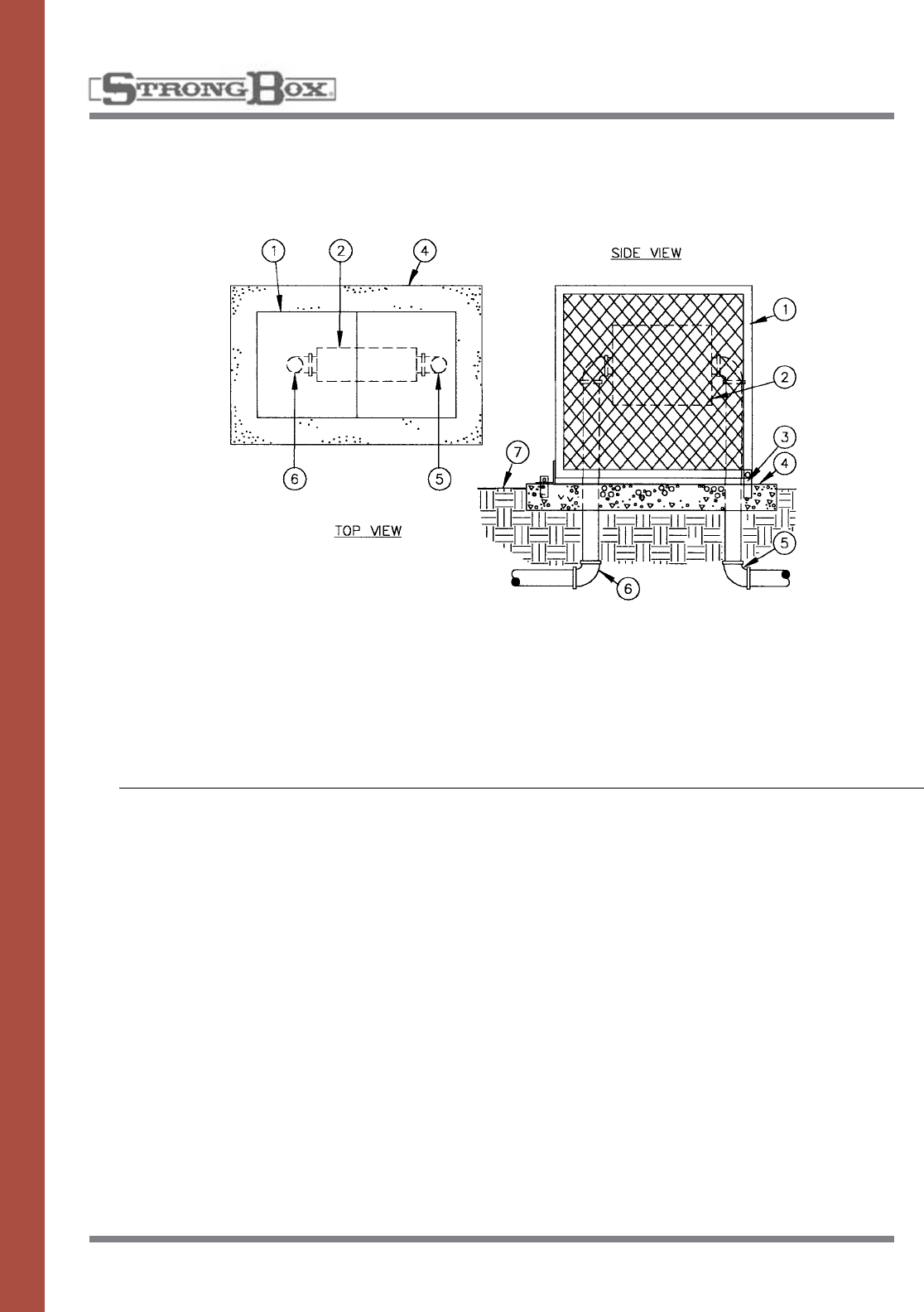
56
EXPANDED METAL
BACKFLOW COVER
Thebackflowcovershallbeofa
vandal resistant nature manufac-
tured of formed and expanded
metal, coated with a perfor-
mance polymer alloy coating to
preventhandlinginjury.The
cover shall have a hinge on one
endandalockingtabonthe
otherend.Thehingeshallbe
attachedtomountingbrackets
withcarriageboltstoallow
removal of the cover from the
hinges.Themountingbrackets
shallbesubmergedintothecon-
crete a minimum of two inches,
positioning the cover one and
onehalfinchesabovethecon-
crete.Thelockingtabshall
acceptapadlock.Handlesshall
beattachedtothesidestofacili-
tate raising and lowering of the
cover.
Thecovershallbecoveredwith
azincbasepowdercoatthen
powder coated with a polyester
TGIC coating having a minimum
thickness of 2.5 mils.
1. Expanded Metal Backflow Enclosure
2. Backflow Preventer
3. Anchor Bracket
4. PouredConcreteBase–6”minimumthickness–
extend4”beyondoutsidedimensionsofenclosure
5. Water Service Inlet Pipe
6. Water Service Outlet Pipe
7. Finish Grade
INSTALLATION DETAILS
SPECIFICATIONS
BACKFLOW COVER
MODELS: BC–30CR, BC–45CR,
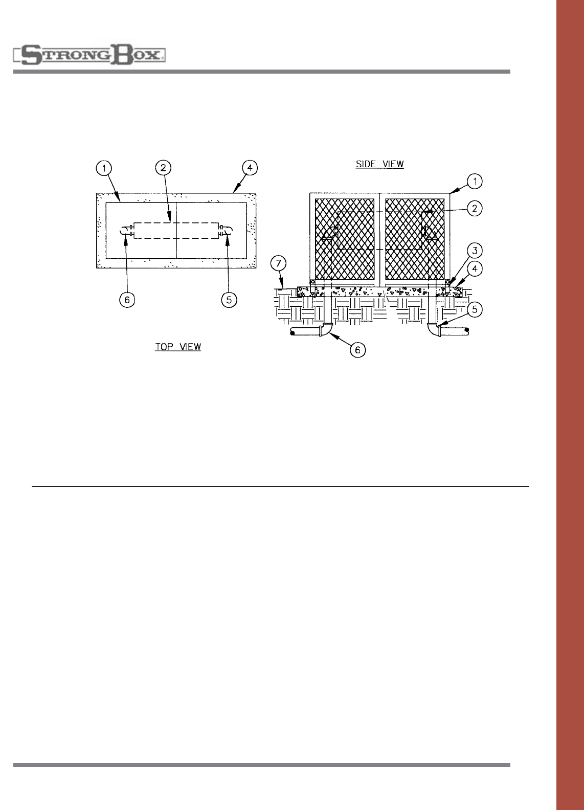
57
EXPANDED METAL
BACKFLOW COVER
Thebackflowcovershallbeofa
vandal resistant nature manufac-
tured of formed and expanded
metal, coated with a perfor-
mance polymer alloy coating to
preventhandlinginjury.The
covershallbeintwosections
with a hinge on each end and a
lockingtabatthecenter.The
hingesshallbeattachedto
mountingbracketswithcarriage
boltstoallowremovalofthe
cover from the hinges. The
mountingbracketsshallbesub-
merged into the concrete a mini-
mum of two inches, positioning
the cover one and one half inch-
esabovetheconcrete.Thelock-
ingtabshallacceptapadlock.
Handlesshallbeattachedtothe
sides to facilitate raising and
lowering of the cover.
Thecovershallbecoveredwith
azincbasepowdercoatthen
powder coated with a polyester
TGIC coating having a minimum
thickness of 2.5 mils.
1. Expanded Metal Backflow Enclosure
2. Backflow Preventer
3. Anchor Bracket
4. PouredConcreteBase–6”minimumthickness–
extend4”beyondoutsidedimensionsofenclosure
5. Water Service Inlet Pipe
6. Water Service Outlet Pipe
7. Finish Grade
INSTALLATION DETAILS
SPECIFICATIONS
HIGH PROFILE
BACKFLOW COVER
MODELS: BC–75CR
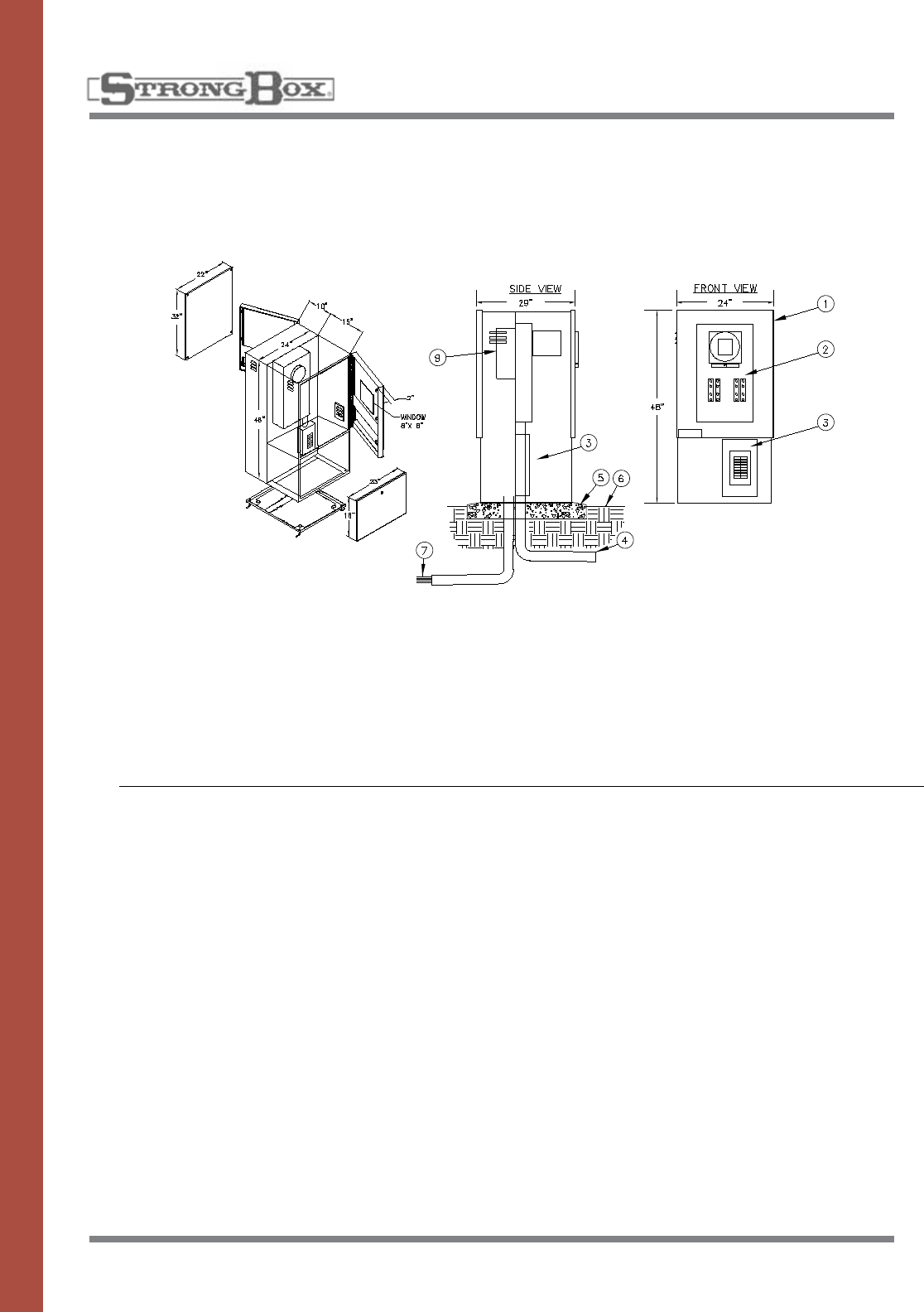
58
STAINLESS STEEL
ENCLOSURE
METERED ENCLOSURE
MODELS: SB-24SS/120V, SB-24SS/240V
The metered controller enclosure
shallbeadoubledoordesign
positionedfrontandback,vandal
and weather resistant, manufac-
tured entirely of stainless steel.
The front section shall house a
UL listed, E.U.S.E.R.C. approved
100 Amp rated commercial meter
socketwithtestblockbypass
provision.Thebacksectionshall
belouveredupperandlower
bodytoallowforcrossflowventi-
lation. Filter screens shall cover
all louvers to deflect against
water spray, insects and dust.
Thebacksectionshallhavea
stainlesssteelbackboardprovid-
ed for the purpose of mounting a
controller.Thebackboardshall
bemountedonfourstainless
steelboltsthatwillallowfor
removalofthebackboard.The
inside door area shall provide
adequatestorageforplans,
operating instructions and
scheduling information. The
enclosure shall have continuous
stainless steel piano hinges on
one side of each door. The edge
ofthedoorshallbehemmedto
eliminate any sharp edges. The
handles controlling the locking
mechanismsshallbelocatedat
thebaseofthedoorsandbe
concealed within the surface of
the doors. The provision for pad-
locksshallbeincludedwithinthe
locking mechanisms. The enclo-
sureshallbemanufacturedwith
a continuous drainage channel
which mates with a tear-drop
shaped, hollow center, water-
tight, thermoplastic door seal.
Theabovedescribedproduct
shallbeaNEMATYPE3R
Rainproofenclosureaslistedby
UnderwriterLaboratories,Inc.
1. Metered controller enclosure
2. Metersocketwithtestblocks
3. Load center
4. Conduit (not supplied) for line feed into meter
5. Pouredconcretebase—6"min.thickness—extend6"
beyondoutsidedimensionsofenclosurewith1/2%slope
for drainage
6. Finish grade
7. Directburialcontrolwirestocontrolvalves
8. PVC long sweep ell—use one sweep
ell per controller
9. Automatic controller
INSTALLATION DETAILS
SPECIFICATIONS
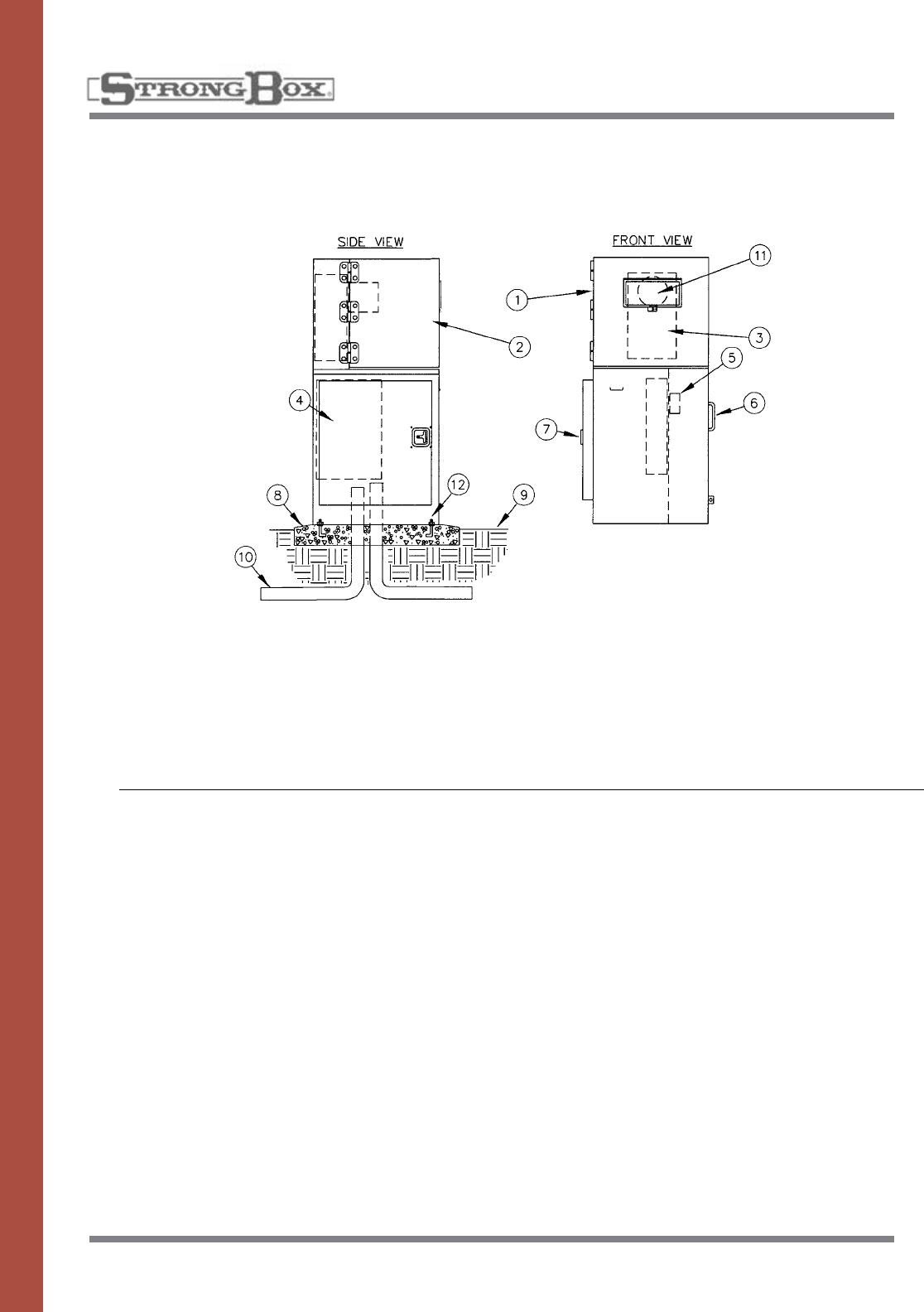
59
100 AMP
MODELS: MPS-A16, MPS-B16, MPS-D18
INSTALLATION DETAILS
Themeterpedestalshallbemade
entirely of stainless steel, #4
brushedfinish,utilizingallwelded
construction providing superior van-
dal and weather resistance.
Thetopshallbeasideswingstyle
that locks out for safety. The side
swing top shall fully expose the
meter compartment for ease of set-
ting the meter and access to the
testblocks.Thetopshallbesup-
portedby3largeallstainlesssteel
hingeswith1/4”pinsthatare“lift
off”styleallowingthetoptobe
completelyremoved.Areplaceable
5”x10”,3/16”thickLexanviewing
windowshallbeprovided.
Themetersockettestblockcom-
partmentshallbeequippedwitha
watershed drainage channel and
overlappingequipmentpanelsthat
ensures a watertight design. Within
the top meter compartment the
metersockettestblockassembly
shallbeinstalled.Thetopshallbe
completelypadlockableandaccept
a utility seal.
Theutilitycompartmentshallbe
located on the right side and house
the landing lugs. A cover panel that
can accommodate a padlock and
utilitysealshallbeprovided.
The left side of the pedestal shall
housethe20”x30”customerelec-
trical compartment. This compart-
mentshallbeoutfittedwithafully
welded and hemmed stainless steel
gasketed door that closes against a
watershed drainage channel. The
door design and all stainless steel
T handle latching system shall
ensure water tightness and vandal
resistance.
The interior portion of this compart-
ment shall house up to a 20 circuit
capableloadcenterwitharemov-
ableprotectivepanel.Astainless
steelelectricalbackboardshall
beprovidedforeaseofwiring
and grounding of electrical
components.
Thepedestalassemblyshallbea
single phase or three phase,
120V/240V or 480V rated unit.
Theenclosureshallberainproof
NEMATYPE3Randtheassembly
shallbelistedbyUnderwriter
Laboratories,Inc.forservice
entranceequipment.
1. StrongBox metered enclosure, stainless steel,
NEMATYPE3R—18”x20”x52”#MPS-XXX-XX
2. Hingedremovablelid
3. Metersocketwithtestblocks
4. Load center
5. Landing lugs
6. Landing lug compartment
7. Load center compartment
8. Pouredconcretebase—6"min.thickness—
extend6"beyondoutsidedimensionsof
enclosurewith1/2%slopefordrainage
9. Finish grade
10. Underground service
11. Meterviewingwindow5”x10”
12. 3/8”stainlessanchorbolts
STAINLESS STEEL
METER PEDESTAL
SPECIFICATIONS
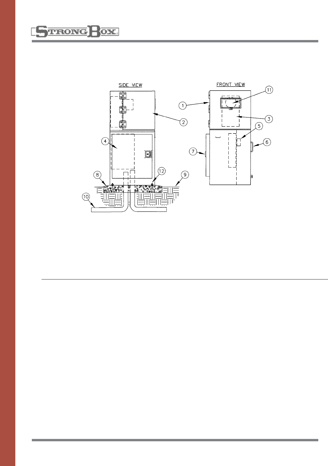
60
STAINLESS STEEL
METER PEDESTAL
200 AMP
MODELS: MPS-C20, MPS-E24
INSTALLATION DETAILS
SPECIFICATIONS
Themeterpedestalshallbemade
entirely of stainless steel, #4
brushedfinish,utilizingallwelded
construction providing superior
vandal and weather resistance.
Thetopshallbeasideswingstyle
that locks out for safety. The side
swing top shall fully expose the
meter compartment for ease of set-
ting the meter and access to the
testblocks.Thetopshallbesup-
portedby3largeallstainlesssteel
hingeswith1/4”pinsthatare“lift
off”styleallowingthetoptobe
completelyremoved.Areplaceable
5”x10”,3/16”thickLexanviewing
windowshallbeprovided.
Themetersockettestblockcom-
partmentshallbeequippedwitha
watershed drainage channel and
overlappingequipmentpanelsthat
ensures a watertight design. Within
the top meter compartment the
metersockettestblockassembly
shallbeinstalled.Thetopshallbe
completelypadlockableand
accept a utility seal.
Theutilitycompartmentshallbe
located on the right side and house
the landing lugs. A cover panel that
can accommodate a padlock and
utilitysealshallbeprovided.
The left side of the pedestal shall
housethe20”x30”customerelec-
trical compartment. This compart-
mentshallbeoutfittedwithafully
welded and hemmed stainless
steel gasketed door that closes
against a watershed drainage
channel. The door design and all
stainless steel T handle latching
system shall ensure water
tightness and vandal resistance.
The interior portion of this
compartment shall house up to a
20circuitcapableloadcenterwith
aremovableprotectivepanel.A
stainlesssteelelectricalbackboard
shallbeprovidedforeaseof
wiring and grounding of electrical
components.
Thepedestalassemblyshallbea
single phase or three phase,
120V/240V or 480V rated unit.
Theenclosureshallberainproof
NEMATYPE3Randtheassembly
shallbelistedbyUnderwriter
Laboratories,Inc.forservice
entranceequipment.
1. StrongBox metered enclosure, stainless steel,
NEMATYPE3R—18”x20”x52”#MPS-XXX-XX
2. Hingedremovablelid
3. Metersocketwithtestblocks
4. Load center
5. Landing lugs
6. Landing lug compartment
7. Load center compartment
8. Pouredconcretebase—6"min.thickness—extend6"
beyondoutsidedimensionsofenclosurewith1/2%
slope for drainage
9. Finish grade
10. Underground service
11.Meterviewingwindow5”x10”
12.3/8”stainlessanchorbolts
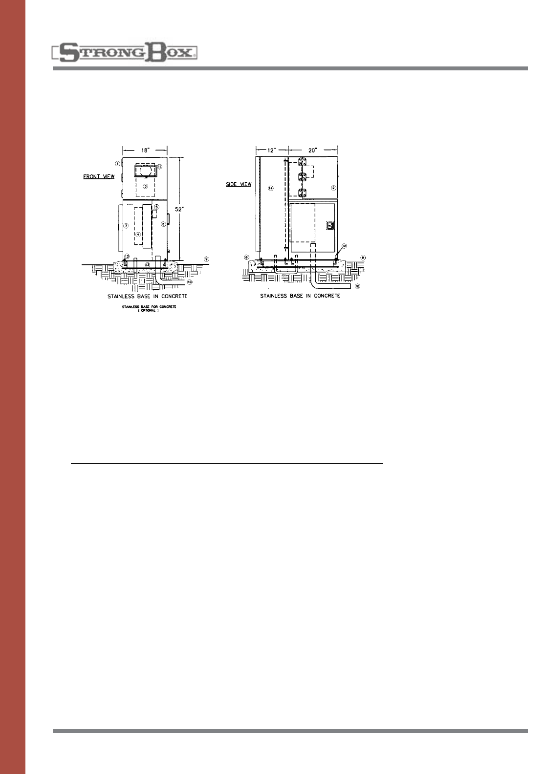
61
STAINLESS STEEL
METER PEDESTAL WITH ENCLOSURE
100 AMP
MODELS: MPE-A16, MPE-B16, MPE-D18
Themeterpedestalshallbemadee
ntire-
lyofstainlesssteel,#4brushedfin-
ish, utilizing all welded construction
providing superior vandal and weath-
er resistance.
Thetopshallbeasideswingstyle
that locks out for safety. The side
swing top shall fully expose the meter
compartment for ease of setting the
meterandaccesstothetestblocks.
Thetopshallbesupportedby3large
allstainlesssteelhingeswith1/4”
pinsthatare“liftoff”styleallowing
thetoptobecompletelyremoved.
Areplaceable5”x10”,3/16”thick
Lexan viewing window shall
beprovided.
Themetersockettestblockcompart-
mentshallbeequippedwithawater-
shed drainage channel and overlap-
pingequipmentpanelsthatensuresa
watertight design. Within the top
meter compartment the meter socket
testblockassemblyshallbeinstalled.
Thetopshallbecompletelypadlock-
ableandacceptautilityseal.
Theutilitycompartmentshallbelocat-
ed on the right side and house the
landing lugs. A cover panel that can
accommodate a padlock and utility
sealshallbeprovided.
The left side of the pedestal shall
housethe20”x30”customerelectri-
cal compartment. This compartment
shallbeoutfittedwithafullywelded
and hemmed stainless steel gasketed
door that closes against a watershed
drainage channel. The door design
and all stainless steel T handle latch-
ing system shall ensure water tight-
ness and vandal resistance.
The interior portion of this compart-
ment shall house up to a 20 circuit
capableloadcenterwitharemovable
protective panel. A stainless steel
electricalbackboardshallbeprovid-
ed for ease of wiring and grounding
of electrical components.
Thepedestalassemblyshallbeasin-
gle phase or three phase, 120V/240V
or 480V rated unit. The enclosure
shallberainproofNEMATYPE3R
andtheassemblyshallbeULlisted
forserviceentranceequipment.
Theenclosuresectionshallbeofa
vandal and weather resistant nature
manufactured entirely of stainless
steel.Themainhousingshallbelou-
veredupperandlowerbodytoallow
for cross flow ventilation. Filter
screens shall cover all louvers to
deflect against water spray, insects
and dust.
Astainlesssteelbackboardshallbe
provided for the purpose of mounting
electronic and various other types of
equipment.Thebackboardshallbe
mountedonsixstainlesssteelbolts
thatwillallowforremovaloftheback-
board.Theinsidedoorareashall
provideadequatestorageforplans,
operating instructions, and schedul-
ing information.
The enclosure door shall have a con-
tinuous stainless steel piano hinge,
carriageboltedononeside,anda
three point locking mechanism on the
other side. The edge of the door shall
behemmedtoeliminateanysharp
edges. The handle controlling the
lockingmechanismshallbelocated
atthebaseofthedoorandbecon-
cealed within the surface of the door.
A stainless steel cam style lock shall
bemountedinthedoorandaprovi-
sionforapadlockshallbeincluded
within the locking mechanism. The
enclosureshallbemanufacturedwith
a continuous drainage channel which
mates with a teardrop shaped, hollow
center, watertight, thermoplastic
door seal.
Theabovedescribedproduct
shallbeaNEMA3RRainproof
EnclosureaslistedbyUnderwriter
Laboratories,Inc.
INSTALLATION DETAILS
1. StrongBox metered enclosure,
stainlesssteel,NEMATYPE3R—
# MPE-XX-XXKAIC
2. Hingedremovablelid
3. Metersocketwithtestblocks
4. Load center
5. Landing lugs
6. Landing lug compartment
7. Load center compartment
8. Pouredconcretebase—6"min.
thickness—extend6"beyond
outside dimensions of enclosure
with1/2%slopefordrainage
9. Finish grade
10. Underground service
11.Meterviewingwindow2”x4”
12.3/8”stainlessanchorbolts
13.Stainlessmountingbasein
concrete
14. SB-1852SS stainless customer
enclosure
SPECIFICATIONS
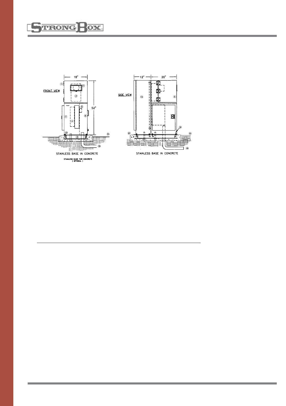
62
STAINLESS STEEL
METER PEDESTAL WITH ENCLOSURE
200 AMP
MODELS: MPE-C20, MPE-E24
Themeterpedestalshallbemade
entirelyofstainlesssteel,#4brushed
finish, utilizing all welded construction
providing superior vandal and
weather resistance.
Thetopshallbeasideswingstyle
that locks out for safety. The side
swing top shall fully expose the meter
compartment for ease of setting the
meterandaccesstothetestblocks.
Thetopshallbesupportedby3large
allstainlesssteelhingeswith1/4”
pinsthatare“liftoff”styleallowing
thetoptobecompletelyremoved.
Areplaceable5”x10”,3/16”thick
Lexan viewing window shall
beprovided.
Themetersockettestblockcompart-
mentshallbeequippedwithawater-
shed drainage channel and overlap-
pingequipmentpanelsthatensuresa
watertight design. Within the top
meter compartment the meter socket
testblockassemblyshallbeinstalled.
Thetopshallbecompletelypadlock-
ableandacceptautilityseal.
Theutilitycompartmentshallbelocat-
ed on the right side and house the
landing lugs. A cover panel that can
accommodate a padlock and utility
sealshallbeprovided.
The left side of the pedestal shall
housethe20”x30”customerelectri-
cal compartment. This compartment
shallbeoutfittedwithafullywelded
and hemmed stainless steel gasketed
door that closes against a watershed
drainage channel. The door design
and all stainless steel T handle latch-
ing system shall ensure water tight-
ness and vandal resistance.
The interior portion of this compart-
ment shall house up to a 20 circuit
capableloadcenterwitharemovable
protective panel. A stainless steel
electricalbackboardshallbeprovid-
ed for ease of wiring and grounding
of electrical components.
Thepedestalassemblyshallbeasin-
gle phase or three phase, 120V/240V
or 480V rated unit. The enclosure
shallberainproofNEMATYPE3R
andtheassemblyshallbeULlisted
forserviceentranceequipment.
Theenclosuresectionshallbeofa
vandal and weather resistant nature
manufactured entirely of stainless
steel.Themainhousingshallbelou-
veredupperandlowerbodytoallow
for cross flow ventilation. Filter
screens shall cover all louvers to
deflect against water spray, insects
and dust.
Astainlesssteelbackboardshallbe
provided for the purpose of mounting
electronic and various other types of
equipment.Thebackboardshallbe
mountedonsixstainlesssteelbolts
thatwillallowforremovaloftheback-
board.Theinsidedoorareashallpro-
videadequatestorageforplans,
operating instructions, and schedul-
ing information.
The enclosure door shall have a con-
tinuous stainless steel piano hinge,
carriageboltedononeside,anda
three point locking mechanism on the
other side. The edge of the door shall
behemmedtoeliminateanysharp
edges. The handle controlling the
lockingmechanismshallbelocated
atthebaseofthedoorandbecon-
cealed within the surface of the door.
A stainless steel cam style lock shall
bemountedinthedoorandaprovi-
sionforapadlockshallbeincluded
within the locking mechanism. The
enclosureshallbemanufacturedwith
a continuous drainage channel which
mates with a teardrop shaped, hollow
center, watertight, thermoplastic
door seal.
Theabovedescribedproductshall
beaNEMATYPE3RRainproof
EnclosureaslistedbyUnderwriter
Laboratories,Inc.
INSTALLATION DETAILS
SPECIFICATIONS
1. StrongBox metered enclosure,
stainlesssteel,NEMATYPE3R—
# MPE-XX-XXKAIC
2. Hingedremovablelid
3. Metersocketwithtestblocks
4. Load center
5. Landing lugs
6. Landing lug compartment
7. Load center compartment
8. Pouredconcretebase—6"min.
thickness—extend6"beyond
outside dimensions of enclosure
with1/2%slopefordrainage
9. Finish grade
10. Underground service
11.Meterviewingwindow2”x4”
12.3/8”stainlessanchorbolts
13.Stainlessmountingbasein
concrete
14. SB-1852SS stainless customer
enclosure
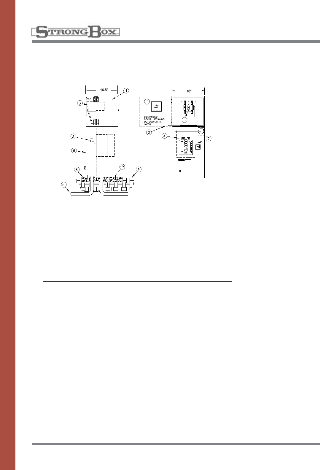
63
STAINLESS STEEL
METER PEDESTALS
METERED ENCLOSURE
MODELS: CSP-A, CSP-B, CSP-C
Themeterpedestalshallbe
made entirely of stainless steel,
using welded construction
and finishing.
Pedestalsshallbecoveredby
polyester TGIC powder coating
having a minimum thickness of
2.5 mils.
Topcovershallbeasideswing
style that locks out for safety. The
swing top will open 180 degrees
to provide clear access to meter
socketandtestblocks.The
swingtopshallbesupportedby
two heavy duty stainless steel
hingeswith3/8”pinsandthatare
“liftoff”styleallowingthetopto
becompletelyremoved.The
Swing top shall also have
hemmed edges to eliminate
sharpedges.Areplaceable
3/16”thicklexanwindowfor
viewingshallbeinstalledfor
meter reading. Lexan window
shallbehingedandavailable
with hasps to lock out for safety.
Themetersocketandtestblock
sectionshallbeequippedwith
rainwater drainage channel and
overlappingequipmentpanelsto
ensure watertight design. The
meter socket compartment shall
house EUSERC approved com-
mercial meter socket and test
blocks.Themetersectionshall
accept ring style meter and
meterfacebeattachedtometer
socket so meter face panel may
notberemovedwithoutdiscon-
nectingmeterbulb.Metersec-
tionmustbepadlockablefor
safety as well as utility seal.
The Utility landing section shall
betherearwitharemoveable
panel for full access to landing
lugs.Landinglugsshallbealu-
minum type lugs using hexagon
screws for tightening.
A cover panel that will accommo-
date a padlock and utility seal
shallbeprovided.
Thecustomersectionwillbein
the lower front of the pedestal.
Thecompartmentshallbefitted
with a fully welded door with
hemmed edges to eliminate
sharp edges. The door design
shall use a T-handle latching
system to ensure a watertight
seal and vandal resistance. A
continuouspianohingeshallbe
used and installed using
carriagebolts.
This compartment will house a
GEloadcenterwithmainbreak-
er.theinternalhousingwillbe
fitted with a protective panel
and shall only expose the
breakerswitches.
Themeterpedestalassemblies
shallbe0-200Amp,singlephase
only 120V/240V rated. The encl
sure shall comply with EUSERC
electrical standards and current
NECcodes.Theenclosureshall
beratedNEMATYPE3Rrain-
proofandbelistedby
UnderwriterLaboratories,Inc.
1. StrongBox metered enclosure,
stainlesssteel,NEMATYPE3R
#CSP-XXX-XX
2. Hingedremovablelid
3. Metersocketwithtestblocks
4. Load center
5. Landing lugs
6. Landing lug compartment
7. Load center compartment
INSTALLATION DETAILS
8. Pouredconcretebase—6”min.
thickness—extend6”beyond
outside dimensions of enclosure
with1/2%slopefordrainage
9. Finish grade
10. Underground service
11.Meterviewingwindow5”x10”
12.3/8”stainlessanchorbolts
SPECIFICATIONS
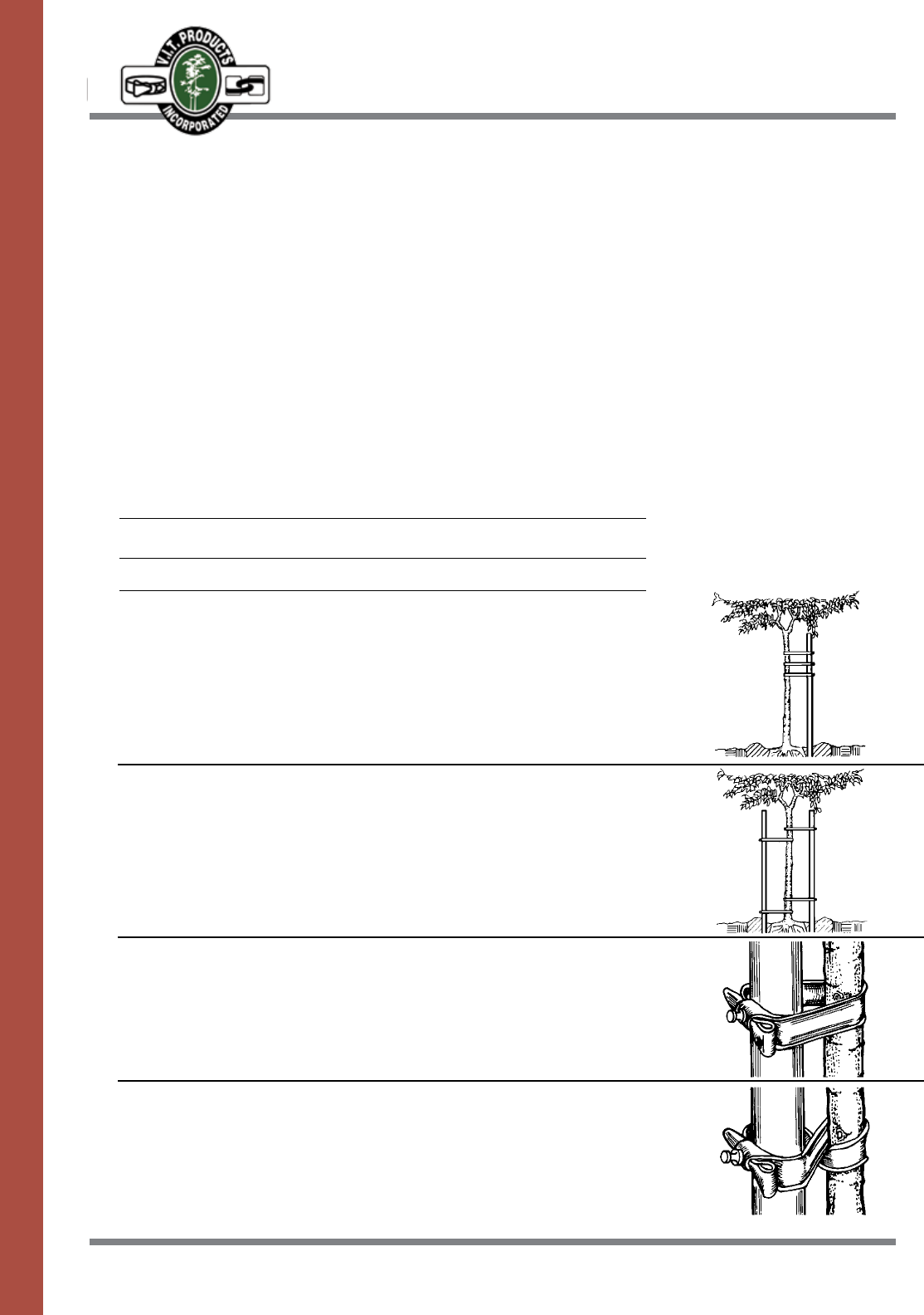
64
TREE & SPRINKLER SUPPORT
AND PROTECTION PRODUCTS
CINCH-TIE®
MODELS
Cinch-Tie24” 5-15gal.,singleordoublesstakes
Cinch-Tie32” 20”boxandlargerforsingleordoublestakes.
Treetiesshallbemanufactured
ofvirginflexiblevinylmeeting
ASTM-D-412 standards for
tensile and elongation strength.
Materialshallbeblackforultravi-
oletresistance.Treetiesshallbe
manufacturedwithadoubleback
locking configuration and
secured with one galvanized nail
to prevent slippage. Tree ties
shall elongate with the tree
growth preventing damage to
the tree.
HOW TO USE CINCH-TIES
Single Stake
Asinglestakeshouldbeplacedonthesideoftheprevailingwind.
ThetreeshouldbesupportedwithaminimumoftwoCinch-Ties.Use
either the Standard or Figure Eight tying method.
Double Stakes
Onestakeshouldbeplacedonthesideoftheprevailingwindwith
theotherstakeontheoppositesideofthetree.Thetreeshouldbe
supported with four Cinch-Ties to assure a straight, firm position. Use
either the Standard or Figure Eight tying method.
Standard Tie
Wrap Cinch-Tie around the tree trunk and the stake to form a loop. Tie
withthedouble-backlockingconfiguration.Securewithagalvanized
nail driven through the Cinch-Tie and into the stake to prevent slip-
page.
Figure Eight Tie
Wrap Cinch-Tie around the tree trunk and the stake twisting to form a
figureeight.Tiewiththedouble-backlockingconfiguration.Secure
with a galvanized nail driven through the Cinch-Tie and into the stake
to prevent slippage.
Location Guideline
Step 1. Cut the nursery provided
supports away from the young
tree.
Step2.Todeterminethebest
place to install Cinch-Tie, hold
the tree trunk at different points
to find the spot where the top
doesnotbendover.Install
theCinch-Tie6”tallerthan
this height.
Step 3. The first Cinch-Tie should
beplaced6”higherthanthe
spot on the trunk where your
hand previously determined sup-
port for the top.
Step4.Treesshouldbesecured
with at least two Cinch-Ties to
assure a straight, firm hold.
SPECIFICATIONS
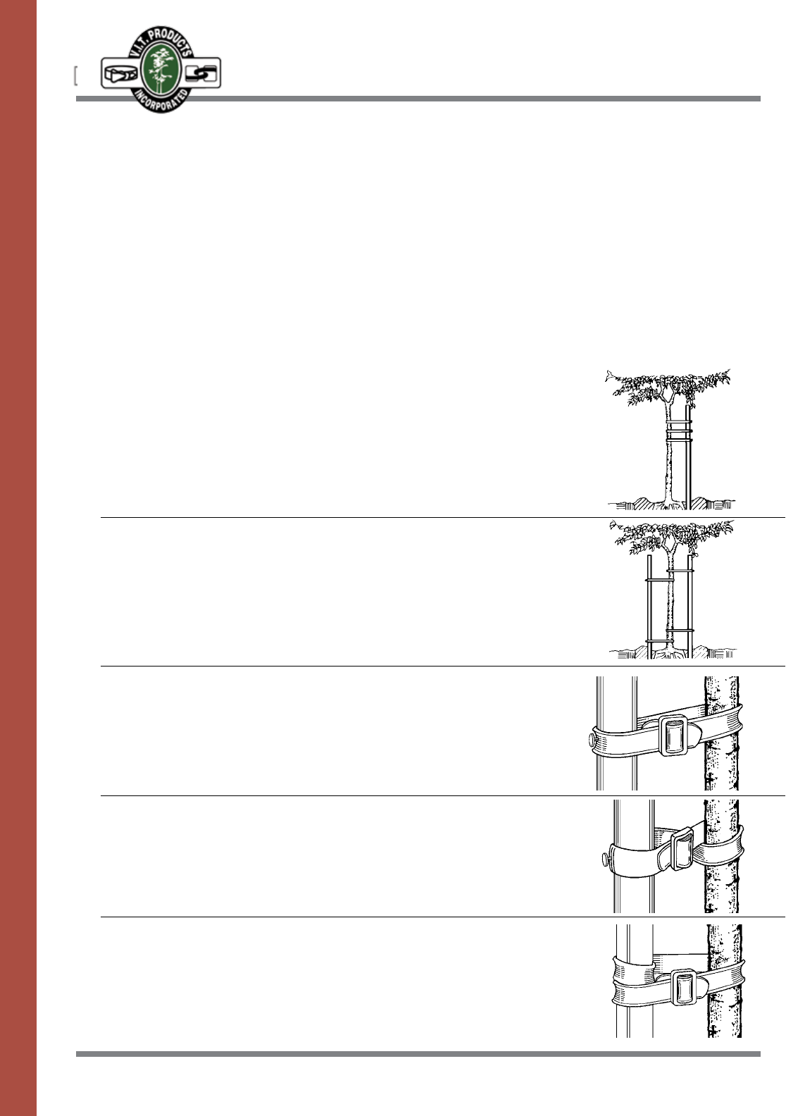
65
TREE & SPRINKLER SUPPORT
AND PROTECTION PRODUCTS
CINCH-BELT™
Thetreetiesshallbemanufac-
turedofvirginflexiblevinylmeet-
ing ASTM-D412 standards for
tensile and elongation strength.
Materialshallbeblackforultravi-
oletresistance.Treetiesshallbe
manufactured with a rounded
backsidetoprotectthetreeand
lockedintopositionwithabuckle.
SPECIFICATIONS
Thetreetieshallbesecuredtoa
wooden post with one galvanized
nail,ordoublewrappedarounda
metal post to prevent slippage.
Tree ties shall elongate with the
tree growth preventing damage
to the tree.
HOW TO USE CINCH-BELT
Single Stake
Asinglestakeshouldbeplacedonthesideoftheprevailingwind.
ThetreeshouldbesupportedwithaminimumoftwoCinch-Belts.Use
either the Standard or Figure Eight tying method.
Double Stakes
Onestakeshouldbeplacedonthesideoftheprevailingwindwith
theotherstakeontheoppositesideofthetree.Thetreeshouldbe
supported with four Cinch-Belts to assure a straight, firm position. Use
either the Standard or Figure Eight tying method.
Standard Tie
Wrap Cinch-Belt around the tree trunk and the stake to form a loop. Insert
bothendsofCinch-Beltthroughbuckle.Securewithasgalvanizednail
driven through the Cinch-Belt and into the stake to prevent slippage.
Figure Eight Tie
Wrap Cinch-Belt around the tree trunk and the stake twisting to form a
figureeight.InsertbothendsofCinch-Beltthroughbuckle.Secure
with a galvanized nail driven through the Cinch-Belt and into the stake
to prevent slippage.
Metal Stake Tie
WrapCinch-Beltaroundthetreetrunkanddouble-wrapthestaketo
preventslippage.InsertbothendsofCinch-Beltthroughbuckle.
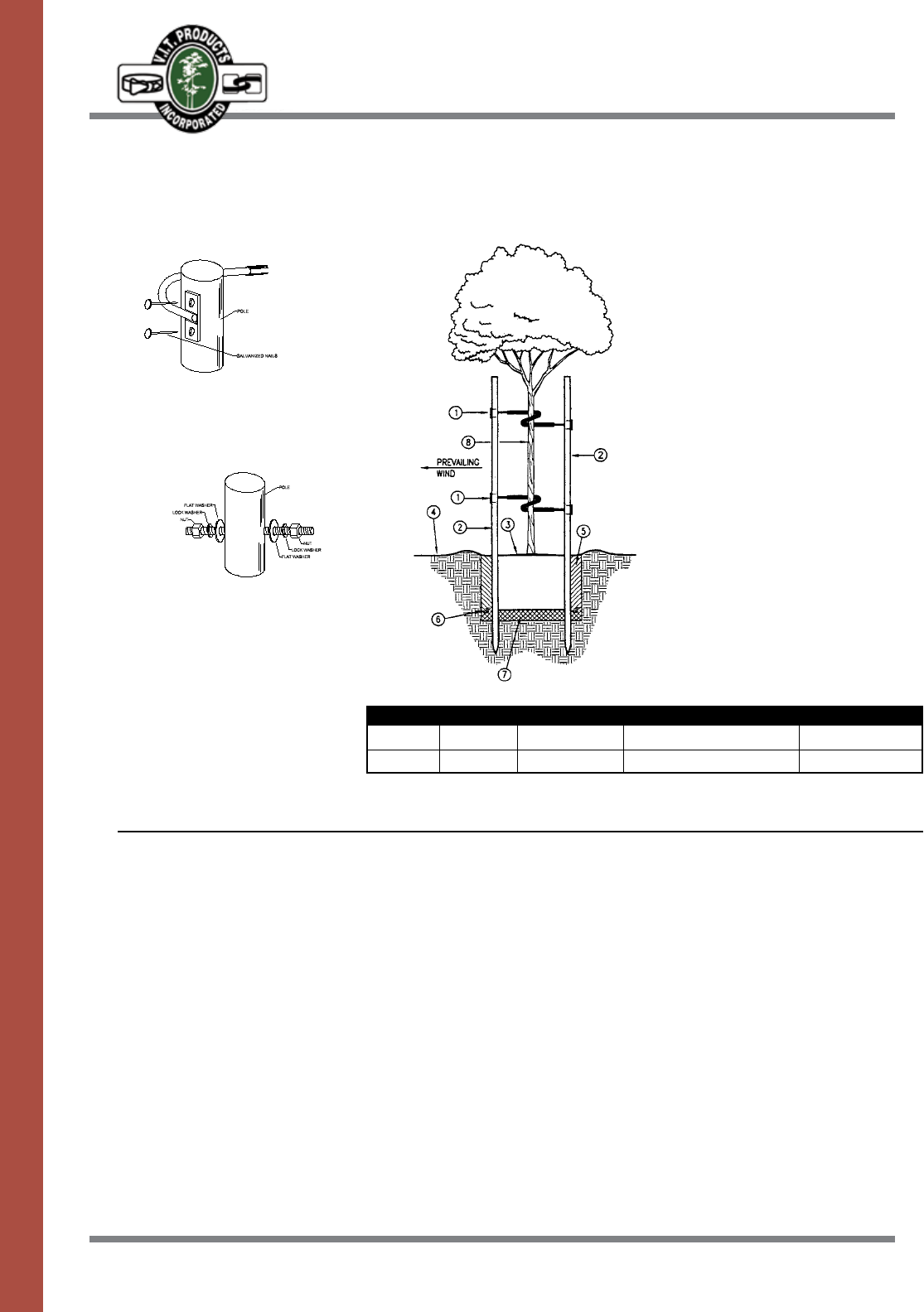
66
TREE & SPRINKLER SUPPORT
AND PROTECTION PRODUCTS
TWIST-BRACE®
SPECIFICATIONS–NAIL BRACKET STYLE
Mounting Methods
NailBracketStyleisdesignedtobe
naileddirectlytolodgepolesorsquare
stakes. (TB 18, TB 24)
Bolt Style is designed for through pole
installation using either galvanized pipe
or lodge pole pines. Threaded ends are
insertedthroughdrilledholesandbolted
securely. (TB 36, TB 42)
Pole
Galvanized
Nails
Flat
Washer
Nut
Lock
Washer
Lock
Washer
Nut
Flat
Washer
Model loop dia. overall length SuggeSted for: SuggeSted pole
TB24 4-1/2" 24" 5-15gal.–24"boxtrees 2"x10’
TB36 4-1/2" 36 24"–30"boxtrees 2"x10’
The5/16"roundmetalrodshall
beencasedinblackU.V.resis-
tantvinyltubingplacedatthe
centeroftherod.The5/16"rodis
tobebentina360°circle.The
meetingpointsoftherodshallbe
spread apart permitting the
The1/2"roundthreadedmetal
rodshallbeencasedinblack
U.V.resistantvinyltubingplaced
at the center of the rod. The rod
istobebentina360°circle.The
meetingpointsoftherodshallbe
spread apart permitting the
bracetobeplacedonthetree
byholdingitparalleltothetree
trunk with the open part of the
circle on either side of the trunk.
Thetreetrunkshallbeenclosed
inthecircleasthebraceistwist-
ed at right angles to the trunk.
Mounting plates with nail holes
foreithersquareorroundstakes,
shallbeweldedateachendof
the rod. Exposed metal ends
shallbetreatedwitharust
inhibitingcoating.
SPECIFICATIONS–BOLT STYLE
bracetobeplacedonthetree
byholdingitparalleltothetree
trunk with the open part of the
circle on either side of the trunk.
Thetreetrunkshallbeenclosed
inthecircleasthebraceistwist-
ed at right angles to the trunk.
Thethreadedendsshallbe
inserted through drilled holes in
the stakes or poles and secured
with nuts, lock washers and flat
washers.
INSTALLATION DETAILS
NOTES:
• Stakealltrees24”boxand
smaller. Install V.I.T. Products
Model TG-4 Trim Guard on all
trees planted in turf.
• Refertospecificationsforplant
pit size.
• InstallTwist-Braceper
manufacturer’s recommenda
tions.
1. V.I.T. Twist Brace–secure to
each pole
2. 2”dia.lodgepolepinetreestake
3. Depressedwateringbasin
remove from turf areas during
finish grading
4. Finish grade
5. Backfill mix per specs.
6. Plant packets per specs.
7. Compactedbackfillmixper
specs.
8. Tree
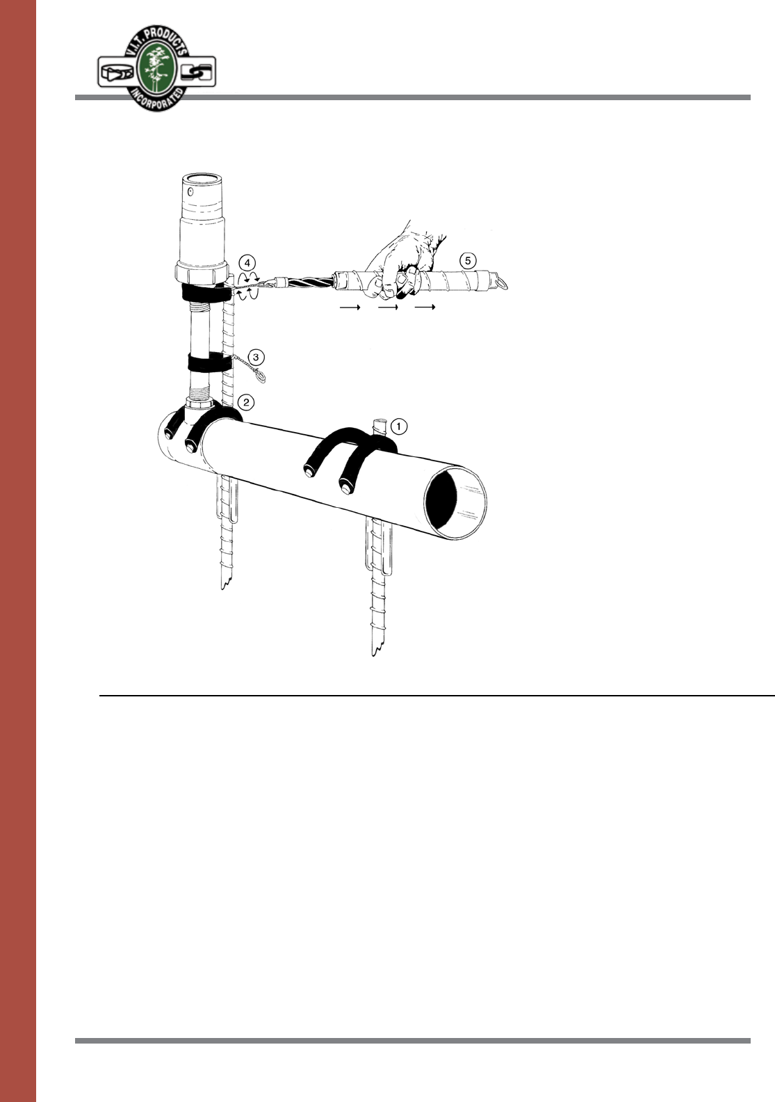
67
TREE & SPRINKLER SUPPORT
AND PROTECTION PRODUCTS
STABILIZERS AND SPRINKLER TIES
SPECIFICATIONS
1.PipeStabilizer–12",18",24"
2.SprinklerStabilizer–18"24"
3.ST-9SprinklerTie–9"
4.ST-12SprinklerTie–12"
5. Ratchet Tool – Automatic Twister
Pipe Stabilizer-Usedinbetween
sprinkler heads to control move-
ment of the pipe. The vertical
striking area provides good pen-
etration in even the toughest soils
andminimizestheaboveground
exposure. Since the hammer only
touches the vertical metal the
rounded J hook is untouched
and damage is avoided. Vinyl
covered J hooks shall protect the
pipe from damage.
Sprinkler Stabilizer- Used to
secure pipe and sprinkler heads
to prevent movement, vandalism
and damage. The vertical metal
providesareatodrivethestabi-
lizer into the soil. The vinyl cov-
ered J hooks secure the pipe to
the ground while the steel shaft
at the top gives the sprinkler
head additional support.
Sprinkler Ties- Used to secure
the sprinkler to the Sprinkler
Stabilizer.Theuniquedesign
allows fast installation while pro-
ducingastrongbondbetween
the stake and the sprinkler head.
The stainless steel wire and the
vinyl covering produces a secure
solution to attaching sprinklers to
the stakes.
Ratchet Tool- Installation tool pro-
viding a solid grip. Attach the
Ratchet Tool hook into the eyelets
of the Sprinkler Tie and pull
back.Thetwistingactionis
uniquetothetool.Thissecures
the sprinkler against the stake.
The Ratchet Tool is designed to
spin wires to tighten.

LIMITED
TRADE WARRANTIES
Stainless Products
V.I.T. Products, Inc. warrants to its trade customers that its Strong Box®productswillbefreefromoriginal
defects in materials and workmanship for a period of ten years from the original date of purchase. It will repair
orreplaceatitsdiscretion,parts found to be defective under normaluseandservicewithinthewarranty
period,uponreturnofsuchpartsatthetradecustomer’sexpense.V.I.T.Products,Inc.willnotberesponsible
forincidentalorconsequentialdamagesorforproductswhichhavebeenalteredormodifiedanditsliability
underthiswarrantyislimitedsolelytoreplacementorrepairofdefectiveparts.Noagentorrepresentative
has authority to waive, alter, or add to the printed provisions of this warranty, to make any representation or
warranty not contained herein or to extend this warranty to anyone other than the Strong Box® customer. This
warrantyisgivenexpresslyandinplaceofallotherexpressedorimpliedwarrantiesofmerchantabilityand
fitness for particular purpose and this warranty is the only warranty made by V.I.T. Products, Inc. V.I.T.
Products,Inc.cannotanddoesnotassumeliabilityfordefectiveproducts,ordamagecausedbydefective
products,notmanufacturedorsuppliedbyit,eventhoughsuchproductsbeusedinconjunctionwithStrong
Box® products. V.I.T. Products, Inc. reserves the right to redesign, alter or modify its products without incurring
anyliabilityfromanyone’sinventoryofsuchpartsorproductsthatmaybeobsolete.
Cold Rolled Steel Products
V.I.T. Products, Inc. warrants to its trade customers that its Strong Box®productswillbefreefromoriginal
defects in materials and workmanship for a period of one year from the original date of purchase. It will repair
orreplaceatitsdiscretion,parts found to be defective under normaluseandservicewithinthewarranty
period,uponreturnofsuchpartsatthetradecustomer’sexpense.V.I.T.Products,Inc.willnotberesponsible
forincidentalorconsequentialdamagesorforproductswhichhavebeenalteredormodifiedanditsliability
underthiswarrantyislimitedsolelytoreplacementorrepairofdefectiveparts.Noagentorrepresentative
has authority to waive, alter, or add to the printed provisions of this warranty, to make any representation or
warranty not contained herein or to extend this warranty to anyone other than the Strong Box® customer. This
warrantyisgivenexpresslyandinplaceofallotherexpressedorimpliedwarrantiesofmerchantabilityand
fitness for particular purpose and this warranty is the only warranty made by V.I.T. Products, Inc. V.I.T.
Products,Inc.cannotanddoesnotassumeliabilityfordefectiveproducts,ordamagecausedbydefective
products,notmanufacturedorsuppliedbyit,eventhoughsuchproductsbeusedinconjunctionwithStrong
Box® products. V.I.T. Products, Inc. reserves the right to redesign, alter or modify its products without incurring
anyliabilityfromanyone’sinventoryofsuchpartsorproductsthatmaybeobsolete.
Aluminum Products
V.I.T. Products, Inc. warrants to its trade customers that its Strong Box®productswillbefreefromoriginal
defects in materials and workmanship for a period of five years from the original date of purchase. It will repair
orreplaceatitsdiscretion,parts found to be defective under normaluseandservicewithinthewarranty
period,uponreturnofsuchpartsatthetradecustomer’sexpense.V.I.T.Products,Inc.willnotberesponsible
forincidentalorconsequentialdamagesorforproductswhichhavebeenalteredormodifiedanditsliability
underthiswarrantyislimitedsolelytoreplacementorrepairofdefectiveparts.Noagentorrepresentative
has authority to waive, alter, or add to the printed provisions of this warranty, to make any representation or
warranty not contained herein or to extend this warranty to anyone other than the Strong Box® customer. This
warrantyisgivenexpresslyandinplaceofallotherexpressedorimpliedwarrantiesofmerchantabilityand
fitness for particular purpose and this warranty is the only warranty made by V.I.T. Products, Inc. V.I.T.
Products,Inc.cannotanddoesnotassumeliabilityfordefectiveproducts,ordamagecausedbydefective
products,notmanufacturedorsuppliedbyit,eventhoughsuchproductsbeusedinconjunctionwithStrong
Box® products. V.I.T. Products, Inc. reserves the right to redesign, alter or modify its products without incurring
anyliabilityfromanyone’sinventoryofsuchpartsorproductsthatmaybeobsolete.
69
PRODUCT/MATERIAL
COMPARISON CHART
VANDAL
RESISTANCE
HighTensile
Strength
Three-point Locking
System
Concealed Padlock
Cam Style Lock
Provided
Graffiti Easily
Removed
Scratch Resistant
Finish
Three-point Locking
System
Exposed Padlock
NoCamStyleLock
Graffiti Removal
Damages Finish
RequiringRepainting
Finish Easily
Scratched
Three-point Locking
System
Cam Style Lock Only
NoPadlock
Capability
Graffiti Removal
Damages Finish
Finish Easily
Scratched–
Difficult To Repair
Stainless
Steel
Carbon
Steel
Plastic/
Fiberglass
WEATHER
RESISTANCE
Impervious To
Corrosion
Rain Gutter
Drainage Channel
Teardrop Shaped,
HollowCenter,Water
tight, Thermoplastic
Door Seal
Enhances Lightning
Protection
UL Listed
NEMATYPE3R
Rated
SubjectToCorrosion
RequiringContinual
Maintenance
Rain Gutter
Drainage Channel
Enhances Lightning
Protection
Door Gasket
Resistant To
Corrosion
NoDoorSeal
UV
RESISTANCE
Impervious To UV
Deterioration
FinishSubjectTo
Fading
FinishSubjectTo
Fading
Permanent Damage
To Material
HEAT
DISSIPATION
HighReflective
Value, Lowest
Internal
Temperatures
MinimizesHeat
Affect On
Electronics
Poor Reflective
Value Unless Very
Light Color Used
VerySlowHeat
Dissipation
RetainedHeatWill
Damage Electronic
Components
VENTILATION
Filtered Cross flow
Ventilation
Minimizes Internal
Condensation
Buildup, Allows
RapidHeat
Dissipation, Filters
Dust, Dirt & Insects
FanKitAvailable
Non-crossflow
Louvered Door
NoVentilation
ContributesTo
Condensation
BuildupAndHeat
Retention
AESTHETICS
Chameleon Effect
OnTheNatural
Brushed Stainless
Steel Finish Blends
With It’s Environment
And Provides An
UnobtrusiveQuality
Painted Finish
Difficult To Match To
NaturalEnvironment
SubjectToFading&
Rusting
Color Difficult To
MatchToNatural
Environment
SubjectToFading,
Scratching
Difficult To Repaint
CONVENIENCE
OF USE
Installation Template
Guides Placement
OfLow&High
Voltage Conduit
And Anchor Bolts
Removable
Predrilled
BackboardProvides
For Easy Installation
Accepts QuickPad
Mounting Platform
Set In Concrete

SUSTAINABILITY & LIFE CYCLE
COST COMPARISON CHART
STAINLESS STEEL VS. COLD ROLLED STEEL
ComparisonDuration-10Years(lifeoftypicalcoldrolledenclosure)
Model # SB-18SS
Life Cycle Cost = Enclosure Cost + Installation Cost + Maintenance Cost + Removal & Reinstallation Cost - Scrap Value
Stainless Steel Cold Rolled Steel
Enclosure Cost $1,290.00 $ 825.00
Installation Cost 400.00 400.00
Total Initial Cost $1,690.00 $1,225.00
Difference In Cost of Initial Investment Using Stainless Steel $ 465.00
MaintenanceCostOver10yearPeriod N/A $825.00
(10%peryearforcoldrolledsteel)
EnclosureReplacementCostAtEndof10Years N/A $990.00
(Adjustedfor2%annualinflation)
Removal&ReinstallationCost N/A $480.00
(Adjustedfor2%annualinflation)
ScrapValue N/A $82.50
(10%ofinitialvalue)
TotalMaintenance,RemovalAndReplacementCost N/A $2,212.50
Total Cost Over 10 Year Period $1,690.00 $3,437.50
(Initial cost plus maintenance, removal and replacement costs)
Savings At The End Of 10 Years Using Stainless Steel $1,747.50
InvestmentRecoveryTime:3.6Years
71 71
Telephone (800) 729-1314 ■ FAX (888) 310-3946 ■ www.vitproducts.com
10/14
R
2063 Wineridge Place
Escondido, California 92029
(800) 729-1314
Fax: (888) 310-3946
http://www.vitproducts.com
E-Mail: sales@vitproducts.com
Northern California,
Northern Nevada
JPHGroup
(916) 714-0061
Southern California
Southern Nevada
Gentile & Associates
(951) 461-0942
(760) 214-5734
(619) 823-9530
Arizona
VPC Sales
(480) 772-0651
Texas
Copeland,O’Neill&Dunbar
(800) 777-9512
(512) 626-1305
Colorado, Wyoming, Montana
RepMasters, Inc.
(303) 286-7575
Idaho, Utah
Inman Interwest, Inc.
(303) 421-7885
(801) 557-4959
Mid West
Warren Thoma & Associates
(815) 477-1814
(847) 224-8843
(314) 495-7667
(507) 458-6414
Northeast
Bartlett Resources, Inc.
(508) 763-8100
Mid-Atlantic, Florida
Warren Thoma Associates
(404) 538-4871
(352) 476-7527
Hawaii
Gentile & Associates
(951) 461-0942
(760) 214-5734
(619) 823-9530
Northwest
RG Sales
(425) 481-1213
East Canada
R. Stephen Ross Associates
(585) 458-7599
AREA REPRESENTATIVES
PRECISION
QUALITY CONTROLLED
At V.I.T. Products we are committed to manufacturing
thefinestqualityproductsavailable.Wecontinually
evaluateandupgradeourequipmentandmanufac-
turingtechniquessowecanofferyouenclosures
with superior fit and finish every time. For example,
our computer controlled Strippit LVD 4000 watt laser
can cut parts with tolerances as close as .003 of an
inch, so each one fits perfectly. And that’s not all.
Superiorqualitycontrolisevidentthroughoutthe
manufacturingandassemblyprocess.Theend
result is a product we are proud to manufacture in
the U.S.A., and one that will give you outstanding
performanceanddurabilityformanyyears.
