TB 60 Repair Parts.vp PRO 66 220082169
User Manual: PRO-66
Open the PDF directly: View PDF ![]() .
.
Page Count: 282 [warning: Documents this large are best viewed by clicking the View PDF Link!]
- Table of Contents
- Service and parts information
- Section 1. - Repair parts
- Chassis/turntable mounting 1-2
- Drive 1-4
- Steering 1-6
- Steer yoke and wheel, 2 wheel drive 1-8
- Steer yoke and wheel, 4 wheel drive 1-10
- Lift and swing 1-12
- Swing drive 1-14
- Fuel tank 1-16
- Hydraulic oil reservoir mounting 1-18
- Boom and hose carrier 1-20
- Booms 1-23
- Hose carrier 1-26
- Extension cylinder 1-29
- Platform mounting 1-30
- Platform gate 1-32
- Platform rotator 1-34
- En gine mount ing, Cummins 3.3 1-36
- En gine and ra di a tor, Cummins 3.3 1-39
- Ra di a tor, Cummins 3.3 1-40
- En gine tray, Cummins 3.3 1-42
- Engine mounting, Deutz F4L-1011F 1-44
- Engine, Deutz F4L-1011F 1-47
- Engine mounting, Ford LRG-423 1-48
- Engine, Ford LRG-423 1-51
- Engine mounting, Ford LRG-425 1-52
- Engine, Ford LRG-425 1-55
- Air cleaner 1-56
- Exhaust and air cleaner, Deutz 1-57
- Exhaust and air cleaner, Ford 1-58
- Metal cowling, Deutz engine 1-61
- Metal cowling, Ford engine 1-62
- Plastic cowling, Deutz engine 1-65
- Plastic cowling, Cummins and Ford engine 1-66
- Placards and decals 1-69
- Gear hub, high torque 1-74
- Swing drive, Auburn Gear 1-76
- Swing drive, Fairfield 1-78
- Swing drive, Gear Products 1-80
- Swing drive, Perfection 1-82
- Swing drive, Tulsa Winch 1-84
- Section 2. - Hydraulics
- Chassis hydraulic equipment, 2 wheel drive 2-2
- Chassis hydraulic equipment, 4 wheel drive 2-5
- Turntable hydraulic equipment 2-6
- Pack age valve, non-proportional 2-9
- Control valve package, non-proportional 2-10
- Valve, drive/lift/swing 2-12
- Control valve, drive/lift /swing 2-14
- Drive motor 2-16
- Drive motor with brake 2-18
- Hydraulic oil reservoir 2-20
- Drive valve, high torque 2-22
- AC generator valve 2-23
- Accumulator 2-24
- Anti-cavitation valve 2-25
- Centerpost and fittings 2-26
- Check valve 2-27
- Cylinder, extension - GBI 2-28
- Cylinder, extension - Seabee 2-29
- Lift cylinder 2-30
- Cylinder, lift - GBI 2-31
- Cylinder, lift - Rosenboom 2-32
- Cylinder, master level - GBI 2-33
- Cylinder, master level - Prince 2-34
- Cyl in der, mas ter level - Rosenboom 2-35
- Cyl in der, master level - Seabee 2-36
- Cylinder, slave level - GBI 2-37
- Cylinder, slave level - Prince 2-38
- Cyl in der, slave level - Rosenboom 2-39
- Cylinder, slave level - Seabee 2-40
- Cylinder, steering - GBI 2-41
- Cylinder, steering - Prince 2-42
- Cyl in der, steering - Rosenboom 2-43
- Cyl in der, steering - Seabee 2-44
- Drive sequence valve, right hand 2-45
- Drive sequence valve, left hand 2-46
- Dual holding valve, platform rotation 2-47
- Dump valve 2-48
- Emergency power unit 2-49
- Flow di vider/combiner valve 2-50
- Flow divider valve 2-51
- Hydraulic pump 2-52
- Hydraulic warm-up valve 2-53
- Motion control valve, drive 2-54
- Motion control valve, turntable swing 2-55
- Platform rotator, Helac 2-56
- Platform rotator, Parker 2-57
- Range valve 2-58
- Selector valve, 2 wheel drive 2-59
- Selector valve, 4 wheel drive 2-60
- Selector valve, right hand 2-61
- Selector valve, left hand 2-62
- Sec tion 3. - Electrical
- Turn ta ble elec tri cal, Cummins 3.3 3-3
- Turntable electrical, Deutz F4L-1011F 3-9
- Turntable electrical, Ford LRG-423 3-15
- Turntable electrical, Ford LRG-425 3-21
- Lower con trols, Cummins 3.3 3-26
- Lower controls, Deutz before 11-09-99 3-28
- Lower controls, Deutz after 11-09-1999 3-31
- Lower controls, Ford LRG-423 3-32
- Lower controls, Ford LRG-425 3-35
- Wiring box, Deutz and Ford LRG-423 3-36
- Wiring box panel, Deutz and Ford LRG-423 3-39
- Wiring box, Ford LRG-425 3-40
- Wiring box panel, Ford LRG-425 3-43
- Boom switch 3-44
- Platform foot switch 3-45
- Upper con trol box 3-47
- Electric fuel pump 3-51
- Controller, drive/steer 3-52
- Controller, lift/swing 3-54
- GFCI 110 volt power 3-56
- Upper control box, proportional 3-57
- Section 4. - Factory installed options
- AC generator mounting 4-2
- AC generator 4-5
- Air line to platform 4-6
- Dual fuel, Ford engine 4-9
- Dual fuel, Ford with 40 gal lon gasoline tank 4-10
- LP fuel only, Ford engine 4-13
- Dual fuel engine, Ford LRG-423 4-14
- LP fuel only engine, Ford LRG-423 4-16
- Dual fuel engine, Ford LRG-425 4-18
- Driving and tail lights 4-20
- Proportional extend/retract 4-23
- Air inlet heater, Deutz 4-24
- Engine block heater 4-25
- Upper control box cover 4-26
- Horn 4-27
- Hydraulic warm-up 4-28
- Tow package 4-31
- Isolation valve 4-32
- Platform lights 4-33
- Work lights 4-34
- Motion alarm, drive 4-35
- Sandblast kit for metal cowling 4-36
- Spark arrestor muffler, Deutz 4-37
- Warn ing light, sin gle bea con 4-38
- index
- A
- AC gen er a tor, 4-2, 4-5
- AC gen er a tor valve, 2-23, 4-5
- Ac cess cover, chas sis, 1-2
- Ac cess cover, cowl ing, 1-65, 1-66
- Ac cess cover, drive, 1-2
- Ac cu mu la tor, 2-6, 2-24
- Ac tu a tor kit, 1-47
- Ac tu a tor mod ule, 3-9
- Adapter plate, centerpost, 1-12
- Ad just ment bolt, 1-12
- Air cleaner, 1-39, 1-56, 1-57, 1-58
- Air cleaner ac cess door, 1-61, 1-62
- Air cleaner bracket, 1-39
- Air cleaner el bow, 1-58
- Air cleaner hose cou pler, 1-39
- Air cleaner mount bracket, 1-39
- Air cleaner mount ing band, 1-57, 1-58
- Air hose, 4-6
- Air in let heater kit, 4-24
- Air in let hood, 1-57, 1-58
- Air in let tube, 1-57, 1-58
- Air in take hose, 1-57
- Air in take hose adapter, 1-39
- Air in take tube, 1-57
- Air in take tube clamp, 1-39
- Al ter na tor, 1-42
- Al ter na tor con nec tion wire, 3-9
- Al ter na tor wire, 3-10
- An chor bolt, 1-23
- An chor plate, 1-26
- An gle, ra di a tor, 1-48, 1-52
- Anti-cav i ta tion valve, 2-22, 2-25
- B
- Bar ber/Coleman gov er nor, 3-15
- Base boom, 1-23
- Bat tery hold down, 3-3, 3-9, 3-15, 3-21
- Bat tery hold down bolt, 3-3, 3-9, 3-15, 3-21
- Bat tery, 12 volt DC - 550 CCA, 3-3, 3-9, 3-15, 3-21
- Bear ing spacer, 1-30
- Bear ing, self align ing, 1-8
- Bel lows, lev el ing cyl in ders, 4-36
- Bel lows, mas ter level cyl in der, 4-36
- Boom switch, 1-23, 3-44
- Booms, 1-20, 1-23
- Bracket, bat tery dis con nect switch, 3-3, 3-9, 3-15, 3-21
- Bracket, drive valve, 2-22
- Bracket, float valve, 4-31
- Bracket, LP gas cyl in der, 4-9, 4-10
- Bracket, ra di a tor sup port, 1-48, 1-52
- Bracket, spark mod ule mount, 1-51
- Bracket, tilt alarm, 3-3, 3-9, 3-15, 3-21
- Bumper, 1-65, 1-66
- C
- Ca ble guide bracket, 4-6
- Ca ble guide, 4 roller, 4-6
- Ca ble re tainer, 1-23
- Ca ble sheave, 1-23, 1-29
- Ca ble, 110 volt power AC gen er a tor, 4-2
- Ca ble, 110 volt power to plat form, 3-56
- Car rier tube, 1-26
- Car tridge hold ing valve, 2-39
- Centerpost and fit tings, 1-12
- Chan nel sup port, LP gas cyl in der, 4-9, 4-13
- Chas sis, 1-2
- Check valve, 2-6, 2-27
- Cir cuit breaker, 15 amp ca pac ity, 3-36, 3-40, 3-56
- Cir cuit breaker, 20 amp ca pac ity, 3-47, 3-57
- Cir cuit breaker, 25 amp ca pac ity, 3-36, 3-40
- Cir cuit breaker, 3 amp ca pac ity, 3-26, 3-28, 3-31, 3-32, 3-35, 3-47, 3-57
- Clamp, T-bolt, 1-39
- Clevis pin, 1-20
- Close-up plug, 3-36, 3-40
- Col lar, 1-34
- Con trol valve pack age, non-pro por tional, 2-9, 2-10
- Con trol valve, drive/lift/swing, 2-12, 2-14
- Con trol wire #1, 18 gauge/12 con duc tor, 1-26
- Con trol wire #2, 18 gauge/12 con duc tor, 1-26
- Con trol ler, drive/steer, 3-52
- Con trol ler, ex tend/re tract, 3-58
- Con trol ler, lift/swing, 3-54
- Cor ro sion in hib i tor, 3-36, 3-40, 3-47
- Coun ter weight , 1-2
- Cou pler kit, 3-26
- Cover gas ket, hy drau lic oil res er voir, 1-18
- Cover plate, hy drau lic oil res er voir, 1-18
- Cover, chas sis - 4 wheel drive, 1-10
- Cover, cowl ing rear, 1-61, 1-62
- Cover, drive mo tor, 1-10
- Cover, fil ter ac cess, 1-61, 1-62
- Cover, GFCI out let, 3-56
- Cover, hoses, 1-10
- Cover, lower con trols, 1-65, 1-66
- Cover, plas tic cowl ing, 1-65, 1-66
- Cover, plat form ro ta tor, 1-30
- Cover, turn ta ble rear, 1-65, 1-66
- Cowl ing door, 1-61, 1-62, 1-65, 1-66
- Cowl ing side, 1-61, 1-62, 1-65, 1-66
- Cyl in der an chor, 1-23
- Cyl in der an chor pin, 1-23
- Cyl in der, ex ten sion, 1-29, 2-28, 2-29
- Cyl in der, lift, 1-12, 2-31
- Cyl in der, mas ter level, 1-12, 2-33, 2-34, 2-35, 2-36
- Cyl in der, slave level, 1-23, 2-40
- Cyl in der, Slave level, 2-37
- Cyl in der, steer ing, 1-6, 2-41, 2-42, 2-43, 2-44
- D
- De cal, 4 x 4 logo, 1-69
- De cal, at tach fall re straint, 1-69
- De cal, blue ar row, 1-69
- De cal, cau tion gov er nor dam age, 1-69
- De cal, cau tion liq uid with drawal, 4-9, 4-10, 4-13
- De cal, con trol wire #1, 3-39, 3-43, 3-47, 3-57
- De cal, con trol wire #2, 3-39, 3-43, 3-47
- De cal, dan ger crush ing haz ard, 1-70, 4-31
- De cal, dan ger cyl in der fail ure, 1-69
- De cal, dan ger do not reach, 1-69
- De cal, dan ger do not ride, 1-70, 4-31
- De cal, dan ger elec tri cal haz ard, 1-69, 3-47, 3-57
- De cal, dan ger elec tri cal/tip ping haz ard, 1-69
- De cal, dan ger ro tat ing en gine parts, 1-69
- De cal, dan ger tow pack age, 1-70, 4-31
- De cal, dan ger you must not op er ate, 1-69
- De cal, die sel fuel, 1-69
- De cal, di ode, 3-39
- De cal, dual fuel in struc tions, 1-70, 4-9, 4-10
- De cal, en gine con trol mod ule, 1-52, 1-69
- De cal, gas o line fuel, 1-69
- De cal, hy drau lic oil, 1-69
- De cal, hy drau lic warm-up in struc tions, 1-70, 4-28
- De cal, in spect wire ropes, 1-69
- De cal, lift, 1-69
- De cal, lift/tie down, 1-69
- De cal, LPS logo, 1-70
- De cal, lube rec om men da tions, 1-69
- De cal, made in USA, 1-69
- De cal, main cir cuit breaker, 3-40
- De cal, no tice man ual re or der, 1-69
- De cal, OmniQuip logo, 1-69
- De cal, op er at ing man ual en closed, 1-69
- De cal, power wire, 3-39, 3-43, 3-47
- De cal, ro tate while greas ing, 1-69
- De cal, safe op er a tion in for ma tion, 1-69
- De cal, Snor kel brand logo, 1-69
- De cal, TB 60 logo, 1-69
- De cal, ter mi nal strip, 3-39
- De cal, throt tle, 3-40
- De cal, tie down sym bol, 1-69
- De cal, tow ing in struc tions, 1-70, 4-31
- De cal, yel low ar row, 1-69
- Di ode holder, 3-39, 3-43
- Di ode stand off, 3-39, 3-43
- Door latch, 1-32
- Drive mo tor, 1-4, 1-10, 2-16
- Drive mo tor brake, 4 cu bic inch, 2-18
- Drive mo tor with brake, 2-18
- Drive se quence valve, left hand, 2-2, 2-5, 2-46
- Drive se quence valve, right hand, 2-2, 2-5, 2-45
- Drive valve, high torque, 2-2, 2-5, 2-22
- Dual fuel en gine, Ford LRG-423, 4-10, 4-14
- Dual fuel en gine, Ford LRG-425, 4-13, 4-18
- Dual fuel kit, liq uid cooled, 4-14, 4-16, 4-18
- Dual hold ing valve, plat form ro ta tion, 1-34, 2-47
- Dump valve, 2-6, 2-48
- E
- El bow, 3 inch 90° rub ber, 1-57, 1-58
- Elec tric fuel pump, 1-48, 3-51
- Elec tri cal box, drilled, 3-56
- Elec tri cal haz ard
- Emer gency power unit, 2-6, 2-49
- Emis sion con trol hose, 1-58
- En gine - LP fuel only, Ford LRG-423, 4-16
- En gine adapter, Ford en gine, 1-51, 1-55
- En gine and ra di a tor, Cummins 3.3, 1-36, 1-39
- En gine block heater, Ford LRG-423 en gine, 4-25
- En gine con trol mod ule, 1-52
- En gine har ness cover plate, 1-55
- En gine iso la tor, 1-42
- En gine mount, 1-44, 1-48, 1-52
- En gine mount bracket, front, 1-44
- En gine mount washer, 1-42, 1-44, 1-48, 1-52
- En gine mount, Cummins 3.3, 1-36
- En gine pro tec tion mod ule, Deutz, 3-9
- En gine tray, 1-42
- En gine tray, Cummins 3.3, 1-42
- En gine, Deutz F4L-1011F die sel, 1-44, 1-47
- En gine, Ford LRG 423, 4-14, 4-16
- En gine, Ford LRG-423, 1-48, 1-51
- En gine, Ford LRG-423 gas o line, 1-51
- En gine, Ford LRG-425, 1-52, 1-55, 4-18
- En gine, Ford LRG-425 gas o line, 1-55
- EPS anti-re start mod ule, 3-3, 3-9
- Ex haust bracket, 1-51, 1-55
- Ex haust flange, LRG Ford, 1-51, 1-55
- Ex haust gas ket, 1-51, 1-55
- Ex haust pipe, 1-39, 1-51, 1-57, 4-37
- Ex ten sion cyl in der, 1-23, 1-29
- Ex ten sion with gas ket, 3-36, 3-40
- F
- Fil ter con di tion in di ca tor, 1-36, 1-57, 1-58
- Fil ter, sump strainer, 2-20
- Flanged elec tri cal out let with cover, 3-36, 3-40
- Flasher, 4-20
- Flasher base, 4-20
- Flex i ble cou pling, 1-47, 1-51, 1-55
- Float valve, 4-31
- Flow di vider valve, 2-22, 2-51
- Flow di vider/combiner valve, 2-5, 2-50
- Front cowl ing, 1-61, 1-62, 1-65, 1-66
- Front en gine mount bracket, 1-42
- Fuel fil ter, 1-44, 1-52, 3-51
- Fuel gauge, 1-16
- Fuel hose, 1-40, 1-44, 1-48, 1-52, 4-14, 4-16, 4-18
- Fuel pump, 1-52
- Fuel tank strap, 1-16
- Fuel tank sup port, 1-16, 4-9
- Fuel tank, 40 gal lon ca pac ity, 1-16
- Fuel tank, gas o line 20 gal lon ca pac ity, 4-9
- Full height swing ing gate, steel plat form, 1-32
- Fuse holder, in-line, 4-20, 4-33, 4-34
- Fuse, 10 amp ca pac ity, 4-20, 4-33, 4-34
- G
- Gas spring, 1-65, 1-66
- Gas ket, hub cap, 1-8
- Gas ket, swing drive, 1-14
- Gas ket, up per con trol box, 3-47
- Gas o line fuel shut-off valve, 4-14
- Gear hub, 1-10, 1-74
- Grav ity gate, plat form, 1-32
- Grom met, 3-36, 3-40
- Guard, boom switch, 1-24
- Guard, emer gency stop switch, 3-26, 3-28, 3-31, 3-32, 3-35
- Guide bar, 1-20
- H
- Hair pin clip pin, 1-20
- Horn re lay, 12 volt DC, 4-27
- Horn, 12 volt DC, 4-27
- Hose bracket, 4-6
- Hose car rier, 1-20, 1-26
- Hose car rier sup port tube, 1-20
- Hose reel, 4-6
- Hour me ter, 3-36, 3-40
- Hub, 1-8
- Hub cap, 1-8
- Hy drau lic oil fil ter, 2-20
- Hy drau lic oil res er voir, 1-18, 2-20
- Hy drau lic pump, 1-47, 1-51, 1-55, 2-52
- Hy drau lic warm-up valve, 2-53, 4-28
- I
- K
- L
- Last chance fil ter, 2-2, 2-5
- Latch stop, 1-32
- Light bracket, 4-33
- Light mount bracket, 4-38
- Light, flood with round base, 4-20
- Light, halo gen with clamp bracket, 4-34
- Light, in can des cent with clamp bracket, 4-34
- Light, plat form, 4-33
- Light, turn sig nal, 4-20
- Link, 1-29
- Link pin, 1-29
- Liq uid level gauge with ther mom e ter, 2-20
- Lit er a ture com part ment, 1-69
- Lock pin, 1-6
- Locking pin, 1-6
- Lower con trol panel and hinge, 3-26, 3-28, 3-31, 3-32, 3-35
- Lower con trols door, 1-65, 1-66
- Lower con trols, Cummins 3.3, 3-26
- Lower con trols, Deutz, 3-28, 3-31
- Lower con trols, Ford LRG-423, 3-32
- Lower con trols, Ford LRG-425, 3-35
- Lower ra di a tor hose, 1-39
- LP fuel en gine, Ford LRG-423, 4-13
- LP gas cyl in der, liq uid with drawal, 4-9, 4-10, 4-13
- LP gas fuel hose, 4-9, 4-10, 4-13
- Lu bri ca tion hose, 1-2
- Lu bri ca tion tube, 1/4 inch cop per tube, 1-2
- Lug nut, 1-4, 1-10
- M
- Mini si ren, 3-36, 3-40, 3-47
- Mini si ren, en gine alarm, 3-58
- Mo tion con trol valve, drive, 2-2, 2-5, 2-54
- Mo tion con trol valve, turn ta ble swing, 1-14, 2-55
- Mo tion warn ing alarm, stan dard, 4-35
- Mo tion warn ing alarm, UL ap proved, 4-35
- Mo tor mount, front, 1-47, 1-48, 1-52
- Mo tor mount, left hand, 1-51, 1-55
- Mo tor mount, rear, 1-47
- Mo tor mount, right hand, 1-51, 1-55
- Mo tor, swing drive, 1-14
- Mount kit, Addco ac tu a tor, 1-47
- Mount plate, ac tu a tor mod ule, 3-9
- Mount plate, gov er nor, 3-15
- Mount plate, over flow res er voir, 1-40, 1-48, 1-52
- Mount ing frame, plat form ro ta tor, 1-34
- Muf fler, 1-51, 1-55
- Muf fler clamp, 1-39
- Muf fler, spark arrestor, 1-51, 1-55, 4-37
- Muf fler, stan dard, 1-39
- O
- P
- Pack age valve, non-pro por tional, 2-6, 2-9
- Pad plate, 1-23
- Panel, drilled, 3-39, 3-43
- Pin joint plate, 1-20
- Pin lock, 1-12, 1-20, 1-23, 1-29, 1-30
- Pin, ca ble re tainer, 1-23
- Pin, ex tend sheave, 1-29
- Pin, gate hinge, 1-32
- Pin, lift cyl in der base end, 1-12
- Pin, lift cyl in der rod end, 1-12
- Pin, mas ter level cyl in der base end, 1-12
- Pin, mas ter level cyl in der rod end, 1-12
- Pin, plat form to tip boom, 1-30
- Pin, re tract sheave, 1-23
- Pin, slave level cyl in der to plat form, 1-30
- Pin, slave level cyl in der to tip boom, 1-23
- Plac ard, 110 volt power, 3-36, 3-40
- Plac ard, 125 volts 15 amps, 1-69
- Plac ard, AC gen er a tor, 4-2
- Plac ard, ANSI stan dard, 1-69
- Plac ard, bat tery dis con nect switch, 3-3, 3-9, 3-15, 3-21
- Plac ard, cau tion liq uid with drawal, 1-70
- Plac ard, cau tion se rial num ber, 1-69
- Plac ard, cir cuit breaker, 3-36
- Plac ard, dan ger foam filled tires, 1-69
- Plac ard, dual fuel switch, 4-9, 4-10
- Plac ard, emer gency bleed down valve, 1-69
- Plac ard, en gine rpm, 1-69
- Plac ard, heater in struc tions, 4-24
- Plac ard, horn, 3-58, 4-27
- Plac ard, light switch, 4-20
- Plac ard, lower con trols, 3-26, 3-28, 3-31, 3-32, 3-35
- Plac ard, lug nut torque, 1-69
- Plac ard, plat form ca pac ity, 1-69
- Plac ard, plat form iden ti fi ca tion, 1-69
- Plac ard, plat form ro ta tion, 3-58
- Plac ard, pre-start in struc tions, 1-69
- Plac ard, tire pres sure, 1-70
- Plac ard, up per con trol box, 3-47
- Plac ard, up per con trol box front, 3-57
- Plac ard, up per con trol box top, 3-47, 3-58
- Plac ard, warm-up switch, 4-28
- Plate, en gine cou pling, 1-47
- Plat form, 1-30
- Plat form foot switch, 3-45
- Plat form ro ta tor, 1-30, 1-34, 2-56, 2-57
- Power wire, 12 gauge/8 con duc tor, 1-26
- PWM mod ule, 3-3, 3-9, 3-15, 3-21
- Py lon, plat form ro ta tor, 1-34
- R
- Ra di a tor, 1-48, 1-52
- Ra di a tor bracket, 1-40
- Ra di a tor cap, 1-40, 1-48, 1-52
- Ra di a tor cush ion, 1-40, 1-48, 1-52
- Ra di a tor hose, 1-48, 1-52
- Ra di a tor mount an gle, 1-40
- Ra di a tor over flow hose, 1-48, 1-52
- Ra di a tor, Cummins 3.3, 1-40
- Range valve, 2-6, 2-58
- Rear en gine mount bracket, left hand, 1-42
- Rear en gine mount bracket, right hand, 1-42
- Re cep ta cle, GFCI out let - 20 amp, 3-56
- Re lay, 12 volt DC, 3-3, 3-9, 3-15, 3-21, 3-36, 3-39, 3-40, 3-43, 3-47, 3-57, 4-20
- Re taining ring, 1-12
- Rheo stat switch, 3-28, 3-31, 3-32, 3-35
- Roller spacer, alu mi num grav ity gate, 1-32
- Roller spacer, steel grav ity gate, 1-32
- Roller, alu mi num grav ity gate, 1-32
- Roller, steel grav ity gate, 1-32
- Ro ta tion bear ing gear, 1-2
- Rub ber bumper, 1-69
- S
- Se lec tor valve, 2 wheel drive, 2-22, 2-59
- Se lec tor valve, 4 wheel drive, 2-22, 2-60
- Se lec tor valve, left hand, 2-5
- Se lec tor valve, right hand, 2-5, 2-61, 2-62
- Sheave cage, 1-24
- Shroud, cowl ing, 1-65, 1-66
- Shroud, outer air in take, 1-65
- Shut-off so le noid, 4-14
- Si ren, tilt alarm, 3-3, 3-9, 3-15, 3-21, 3-57
- Slide pad, 1-20, 1-23, 1-24, 1-26, 1-29
- Slide pad mount, 1-23
- Slide pad plate, 1-29
- Slide pad shim, 1-23, 1-24, 1-29
- Slide pad spacer, 1-23, 1-24
- Spacer, air cleaner, 1-57, 1-58
- Spacer, flow di vider/combiner valve, 2-5
- Spacer, steer ing arm, 1-6
- Spacer, tie rod mount ing, 1-6
- Spark mod ule, Ford LRG-423 en gine, 1-51
- Speed con trol switch, 3-47
- Spin dle nut, 1-8, 1-10
- Spring, tor sion, 1-32
- Steering arm, 1-6
- Steering arm, tow pack age, 4-31
- Steering yoke, 2 wheel drive, 1-8
- Steering yoke, 4 wheel drive, 1-10
- Sup port bracket, ex tend cyl in der base end, 1-29
- Sup port bracket, ex tend cyl in der rod end, 1-29
- Swing drive, 1-12, 1-14, 1-78, 1-80, 1-82, 1-84
- Swinging gate, plat form, 1-32
- Switch boot, short, 4-20
- Switch knob, 3-26, 3-28, 3-31, 3-32, 3-35, 3-47
- Switch seal, 4-27
- Switch, anti-re start ig ni tion, 3-47
- Switch, bat tery dis con nect, 3-3, 3-9, 3-15, 3-21
- Switch, emer gency stop push/pull, 3-47, 3-58
- Switch, en gine shut down, 3-28, 3-32
- Switch, keyed start, 3-28, 3-31, 3-32, 3-35
- Switch, oil pres sure, 1-42, 1-51, 1-55
- Switch, push but ton, 3-58, 4-27
- Switch, tog gle, 3-26, 3-28, 3-31, 3-32, 3-35, 3-47, 3-57, 4-2, 4-9, 4-10, 4-20, 4-24, 4-28, 4-33
- T
- Tail pipe, 1-39, 1-58, 4-37
- Tail pipe brace, 4-37
- Tem per a ture gauge, 3-26, 3-28, 3-31, 3-32, 3-35
- Tem per a ture gauge , 3-31
- Tem per a ture sen sor, 1-42, 3-9
- Tem per a ture switch, 4-28
- Ter mi nal strip, 10 cir cuit #10 stud, 3-47, 3-57
- Ter mi nal strip, 12 cir cuit #10 stud, 3-39, 3-43
- Ter mi nal strip, 12 cir cuit .188 tab slip-on, 3-39, 3-43, 3-47, 3-57
- Ter mi nal strip, 18 cir cuit .188 tab slip-on, 3-47, 3-57
- Ter mi nal strip, 6 cir cuit #10 stud, 3-26, 3-31
- Throt tle ac tu a tor, 1-42
- Throt tle le ver ex ten sion, 1-42
- Tie rod, 1-6
- Tie rod end for ad just able tie rod, 1-6
- Tie rod hex jam nut for ad just able tie rod, 1-6
- Tilt alarm sen sor 5°, 3-3, 3-9, 3-15, 3-21
- Tip boom, 1-23
- Tire and wheel, 1-4, 1-8, 1-10
- Torque plate, plat form ro ta tor, 1-34
- Tow bar, 4-31
- Tow bar stor age cra dle, 4-31
- Towing pin, 4-31
- Tube bracket, 1-20
- Turn ta ble, 1-2
- Turn ta ble cover, 4-36
- U
- V
- W
- Warn ing light, am ber or red lens, 4-38
- War ranty
- Wheel nut, 1-8
- Wire har ness, al ter na tor, 1-51, 1-55
- Wire har ness, boom switch, 3-44
- wire har ness, crank sen sor, 3-16
- Wire har ness, crank sen sor, 1-51
- Wire har ness, Cummins 3.3 en gine, 3-3
- Wire har ness, Deutz en gine, 3-9
- Wire har ness, EPS, 3-26, 3-31
- Wire har ness, Ford LRG-423 en gine, 3-15, 3-21
- Wire har ness, plat form foot switch, 3-45
- Wire har ness, pro por tional ex tend/re tract, 4-23
- Wire har ness, tail lights, 4-20
- Wire har ness, turn ta ble, 3-3, 3-9, 3-15, 3-21
- Wire har ness, up per con trol box con trol, 3-47
- Wire har ness, up per con trol box power, 3-47
- Wire har ness, wir ing box in ter nal, 3-36, 3-40
- Wire rope an chor, 1-23
- Wire rope, ex tend, 1-29
- Wire rope, re tract, 1-23
- Wiring box panel, 3-39, 3-43
- Wiring box, Deutz and Ford LRG-423, 3-36
- Wiring box, drilled, 3-36, 3-40
- Wiring box, Ford LRG-425, 3-40
- A
- Maintenance

Repair Parts
Manual
P/N 0082169
May 1997 - revised December 2001
engine powered
diesel
gasoline
LPG
Manufactured 01-97 through 01-01

General information
© Snorkel – all rights reserved
Printed in USA
C
A
U
TI
O
N
DANGER
About this manual:
This repair parts manual covers current production ma-
chines only.
While Snorkel has attempted in every way to confirm
that all information in this manual is correct, improve-
ments are being constantly made to the machine that
may not be reflected in this manual.
If you find information in this manual that is not correct,
or is confusing, you are urged to report your findings to
Snorkel for our evaluation.
Your input is important to us and will be used in future
printings of this manual.
Every person who repairs this machine must be quali-
fied and authorized to do so.
DO NOT modify this aerial platform without prior
written consent of Snorkel Engineering Depart-
ment. Modification may void the warranty, ad-
versely affect stability, or affect the operational
characteristics of the aerial platform.
This machine is covered by a limited warranty that spe-
cifically identifies items warrantied by Snorkel and those
items covered by original manufacturers warranty.
A copy of the Snorkel Limited Warranty is located on the
inside of the back cover of this manual.
All correspondence relative to this machine, such as
field reports, discrepancy reports, requests for informa-
tion, etc., should be directed to:
Snorkel International, Inc.
P.O. Box 1160
St. Joseph, MO 64502-1160 USA
Phone: (816)-364-0317
http://www.snorkelusa.com
Abbreviations
The following abbreviations may be used in this manual:
AC. . . . . . . . . . . . . . . . . . . . . . . . . alternating current
ANSI . . . . . . . American National Standards Institute
CCA. . . . . . . . . . . . . . . . . . . . . . . cold cranking amps
cm. . . . . . . . . . . . . . . . . . . . . . . . . . . . . . . centimeter
DC. . . . . . . . . . . . . . . . . . . . . . . . . . . . . direct current
EMS . . . . . . . . . . . . . envelope management system
GFCI . . . . . . . . . . . . . . . . ground fault circuit interrupt
LP . . . . . . . . . . . . . . . . . . . . . . . . . liquified petroleum
LPG . . . . . . . . . . . . . . . . . . . . liquified petroleum gas
mm . . . . . . . . . . . . . . . . . . . . . . . . . . . . . . millimeters
ft . . . . . . . . . . . . . . . . . . . . . . . . . . . . . . . . . . . . . feet
in . . . . . . . . . . . . . . . . . . . . . . . . . . . . . . . . . . . . . inch
lbs . . . . . . . . . . . . . . . . . . . . . . . . . . . . . . . . . pounds
no . . . . . . . . . . . . . . . . . . . . . . . . . . . . . . . . . number
NPT . . . . . . . . . . . . . . . . . . . . . . national pipe thread
psi . . . . . . . . . . . . . . . . . . . . . pounds per square inch
qty . . . . . . . . . . . . . . . . . . . . . . . . . . . . . . . . . quantity
UL . . . . . . . . . . . . . . . Underwriters Laboratories Inc.
Electrical Hazard
The aerial platform is not electrically insulated.
Death or serious injury can result from contact with,
or inadequate clearance from, an energized
conductor.
Do not go closer than the minimum safe approach
distance as defined by the minimum Safe Approach
Distance as defined by ANSI Standards.
Regard all conductors as energized.
Allow for electrical wire sag and aerial platform sway.
If the work platform, or any part of the aerial platform
contacts a high-voltage electrical conductor, the entire
machine can become electrically charged.
If that happens, remain on the machine and do not con-
tact any other structure or object. This includes the
ground, adjacent buildings, poles, and any other objects
that are not part of the aerial platform.
Such contact could make your body a conductor to the
other object, creating an electrical shock hazard result-
ing in death or serious injury.
If an aerial platform is in contact with an energized con-
ductor the platform operator must warn ground person-
nel in the vicinity to stay away. Their bodies can conduct
electricity creating an electrical shock hazard resulting
in death or serious injury.
Do not approach or leave the aerial platform until the
electricity has been turned off.
Do not attempt to operate the lower controls when the
work platform or any part of the aerial platform is in con-
tact with a high-voltage electrical conductor or if there is
an immediate danger of such contact.
Personnel on or near an aerial platform must be continu-
ously aware of electrical hazards, recognizing that
death or serious injury can result from contact with an
energized conductor.

Table of Contents
Service and parts information
To order service or repair parts . . . . . . . . . . . . . . . . . . i
ANSI and OSHA compliance . . . . . . . . . . . . . . . . . . . . i
Manuals . . . . . . . . . . . . . . . . . . . . . . . . . . . . . . . . . . . i
Parts order form . . . . . . . . . . . . . . . . . . . . . . . . . . . . . ii
Section 1. - Repair parts
Chassis/turntable mounting. . . . . . . . . . . . . . . . . . . 1-2
Drive . . . . . . . . . . . . . . . . . . . . . . . . . . . . . . . . . . . . 1-4
Steering . . . . . . . . . . . . . . . . . . . . . . . . . . . . . . . . . . 1-6
Steer yoke and wheel, 2 wheel drive . . . . . . . . . . . 1-8
Steer yoke and wheel, 4 wheel drive . . . . . . . . . . 1-10
Lift and swing . . . . . . . . . . . . . . . . . . . . . . . . . . . . 1-12
Swing drive . . . . . . . . . . . . . . . . . . . . . . . . . . . . . . 1-14
Fuel tank . . . . . . . . . . . . . . . . . . . . . . . . . . . . . . . . 1-16
Hydraulic oil reservoir mounting . . . . . . . . . . . . . . 1-18
Boom and hose carrier . . . . . . . . . . . . . . . . . . . . . 1-20
Booms . . . . . . . . . . . . . . . . . . . . . . . . . . . . . . . . . . 1-23
Hose carrier. . . . . . . . . . . . . . . . . . . . . . . . . . . . . . 1-26
Extension cylinder . . . . . . . . . . . . . . . . . . . . . . . . . 1-29
Platform mounting . . . . . . . . . . . . . . . . . . . . . . . . . 1-30
Platform gate . . . . . . . . . . . . . . . . . . . . . . . . . . . . . 1-32
Platform rotator . . . . . . . . . . . . . . . . . . . . . . . . . . . 1-34
Engine mounting, Cummins 3.3 . . . . . . . . . . . . . . 1-36
Engine and radiator, Cummins 3.3 . . . . . . . . . . . . 1-39
Radiator, Cummins 3.3 . . . . . . . . . . . . . . . . . . . . . 1-40
Engine tray, Cummins 3.3 . . . . . . . . . . . . . . . . . . . 1-42
Engine mounting, Deutz F4L-1011F . . . . . . . . . . . 1-44
Engine, Deutz F4L-1011F . . . . . . . . . . . . . . . . . . . 1-47
Engine mounting, Ford LRG-423 . . . . . . . . . . . . . 1-48
Engine, Ford LRG-423 . . . . . . . . . . . . . . . . . . . . . 1-51
Engine mounting, Ford LRG-425 . . . . . . . . . . . . . 1-52
Engine, Ford LRG-425 . . . . . . . . . . . . . . . . . . . . . 1-55
Air cleaner . . . . . . . . . . . . . . . . . . . . . . . . . . . . . . . 1-56
Exhaust and air cleaner, Deutz . . . . . . . . . . . . . . . 1-57
Exhaust and air cleaner, Ford . . . . . . . . . . . . . . . . 1-58
Metal cowling, Deutz engine . . . . . . . . . . . . . . . . . 1-61
Metal cowling, Ford engine . . . . . . . . . . . . . . . . . . 1-62
Plastic cowling, Deutz engine . . . . . . . . . . . . . . . . 1-65
Plastic cowling, Cummins and Ford engine . . . . . 1-66
Placards and decals . . . . . . . . . . . . . . . . . . . . . . . 1-69
Gear hub, high torque . . . . . . . . . . . . . . . . . . . . . . 1-74
Swing drive, Auburn Gear . . . . . . . . . . . . . . . . . . . 1-76
Swing drive, Fairfield . . . . . . . . . . . . . . . . . . . . . . . 1-78
Swing drive, Gear Products . . . . . . . . . . . . . . . . . 1-80
Swing drive, Perfection . . . . . . . . . . . . . . . . . . . . . 1-82
Swing drive, Tulsa Winch . . . . . . . . . . . . . . . . . . . 1-84
Section 2. - Hydraulics
Chassis hydraulic equipment, 2 wheel drive. . . . . . 2-2
Chassis hydraulic equipment, 4 wheel drive. . . . . . 2-5
Turntable hydraulic equipment . . . . . . . . . . . . . . . . 2-6
Package valve, non-proportional. . . . . . . . . . . . . . . 2-9
Control valve package, non-proportional . . . . . . . 2-10
Valve, drive/lift/swing. . . . . . . . . . . . . . . . . . . . . . . 2-12
Control valve, drive/lift /swing . . . . . . . . . . . . . . . . 2-14
Drive motor . . . . . . . . . . . . . . . . . . . . . . . . . . . . . . 2-16
Drive motor with brake . . . . . . . . . . . . . . . . . . . . . 2-18
Hydraulic oil reservoir . . . . . . . . . . . . . . . . . . . . . . 2-20
Drive valve, high torque . . . . . . . . . . . . . . . . . . . . 2-22
AC generator valve . . . . . . . . . . . . . . . . . . . . . . . . 2-23
Accumulator . . . . . . . . . . . . . . . . . . . . . . . . . . . . . 2-24
Anti-cavitation valve . . . . . . . . . . . . . . . . . . . . . . . 2-25
Centerpost and fittings . . . . . . . . . . . . . . . . . . . . . 2-26
Check valve. . . . . . . . . . . . . . . . . . . . . . . . . . . . . . 2-27
Cylinder, extension - GBI . . . . . . . . . . . . . . . . . . . 2-28
Cylinder, extension - Seabee . . . . . . . . . . . . . . . . 2-29
Lift cylinder . . . . . . . . . . . . . . . . . . . . . . . . . . . . . . 2-30
Cylinder, lift - GBI . . . . . . . . . . . . . . . . . . . . . . . . . 2-31
Cylinder, lift - Rosenboom . . . . . . . . . . . . . . . . . . . 2-32
Cylinder, master level - GBI . . . . . . . . . . . . . . . . . 2-33
Cylinder, master level - Prince . . . . . . . . . . . . . . . 2-34
Cylinder, master level - Rosenboom . . . . . . . . . . . 2-35
Cylinder, master level - Seabee . . . . . . . . . . . . . . 2-36
Cylinder, slave level - GBI . . . . . . . . . . . . . . . . . . . 2-37
Cylinder, slave level - Prince . . . . . . . . . . . . . . . . . 2-38
Cylinder, slave level - Rosenboom . . . . . . . . . . . . 2-39
Cylinder, slave level - Seabee. . . . . . . . . . . . . . . . 2-40
Cylinder, steering - GBI . . . . . . . . . . . . . . . . . . . . . 2-41
Cylinder, steering - Prince . . . . . . . . . . . . . . . . . . . 2-42
Cylinder, steering - Rosenboom . . . . . . . . . . . . . . 2-43
Cylinder, steering - Seabee. . . . . . . . . . . . . . . . . . 2-44
Drive sequence valve, right hand . . . . . . . . . . . . . 2-45
Drive sequence valve, left hand . . . . . . . . . . . . . . 2-46
Dual holding valve, platform rotation. . . . . . . . . . . 2-47
Dump valve . . . . . . . . . . . . . . . . . . . . . . . . . . . . . . 2-48
Emergency power unit . . . . . . . . . . . . . . . . . . . . . 2-49
Flow divider/combiner valve . . . . . . . . . . . . . . . . . 2-50
Flow divider valve . . . . . . . . . . . . . . . . . . . . . . . . . 2-51
Hydraulic pump . . . . . . . . . . . . . . . . . . . . . . . . . . . 2-52
Hydraulic warm-up valve. . . . . . . . . . . . . . . . . . . . 2-53
Motion control valve, drive . . . . . . . . . . . . . . . . . . 2-54
Motion control valve, turntable swing . . . . . . . . . . 2-55
Platform rotator, Helac . . . . . . . . . . . . . . . . . . . . . 2-56
Platform rotator, Parker . . . . . . . . . . . . . . . . . . . . . 2-57
Range valve . . . . . . . . . . . . . . . . . . . . . . . . . . . . . 2-58
Selector valve, 2 wheel drive . . . . . . . . . . . . . . . . 2-59
Selector valve, 4 wheel drive . . . . . . . . . . . . . . . . 2-60
Selector valve, right hand . . . . . . . . . . . . . . . . . . . 2-61
Selector valve, left hand . . . . . . . . . . . . . . . . . . . . 2-62
Section 3. - Electrical
Turntable electrical, Cummins 3.3. . . . . . . . . . . . . . 3-3
Turntable electrical, Deutz F4L-1011F . . . . . . . . . . 3-9
Turntable electrical, Ford LRG-423. . . . . . . . . . . . 3-15
Turntable electrical, Ford LRG-425. . . . . . . . . . . . 3-21
Lower controls, Cummins 3.3 . . . . . . . . . . . . . . . . 3-26
Lower controls, Deutz before 11-09-99. . . . . . . . . 3-28
Lower controls, Deutz after 11-09-1999 . . . . . . . . 3-31
Lower controls, Ford LRG-423 . . . . . . . . . . . . . . . 3-32
Lower controls, Ford LRG-425 . . . . . . . . . . . . . . . 3-35
Wiring box, Deutz and Ford LRG-423. . . . . . . . . . 3-36
Wiring box panel, Deutz and Ford LRG-423. . . . . 3-39
Wiring box, Ford LRG-425 . . . . . . . . . . . . . . . . . . 3-40
TB 60 – 01-97 through 01-01

Wiring box panel, Ford LRG-425 . . . . . . . . . . . . . 3-43
Boom switch . . . . . . . . . . . . . . . . . . . . . . . . . . . . . 3-44
Platform foot switch . . . . . . . . . . . . . . . . . . . . . . . . 3-45
Upper control box . . . . . . . . . . . . . . . . . . . . . . . . . 3-47
Electric fuel pump . . . . . . . . . . . . . . . . . . . . . . . . . 3-51
Controller, drive/steer . . . . . . . . . . . . . . . . . . . . . . 3-52
Controller, lift/swing . . . . . . . . . . . . . . . . . . . . . . . . 3-54
GFCI 110 volt power . . . . . . . . . . . . . . . . . . . . . . . 3-56
Upper control box, proportional. . . . . . . . . . . . . . . 3-57
Section 4. - Factory installed options
AC generator mounting . . . . . . . . . . . . . . . . . . . . . . 4-2
AC generator . . . . . . . . . . . . . . . . . . . . . . . . . . . . . . 4-5
Air line to platform . . . . . . . . . . . . . . . . . . . . . . . . . . 4-6
Dual fuel, Ford engine . . . . . . . . . . . . . . . . . . . . . . . 4-9
Dual fuel, Ford with 40 gallon gasoline tank . . . . . 4-10
LP fuel only, Ford engine. . . . . . . . . . . . . . . . . . . . 4-13
Dual fuel engine, Ford LRG-423 . . . . . . . . . . . . . . 4-14
LP fuel only engine, Ford LRG-423. . . . . . . . . . . . 4-16
Dual fuel engine, Ford LRG-425 . . . . . . . . . . . . . . 4-18
Driving and tail lights . . . . . . . . . . . . . . . . . . . . . . . 4-20
Proportional extend/retract . . . . . . . . . . . . . . . . . . 4-23
Air inlet heater, Deutz . . . . . . . . . . . . . . . . . . . . . . 4-24
Engine block heater. . . . . . . . . . . . . . . . . . . . . . . . 4-25
Upper control box cover . . . . . . . . . . . . . . . . . . . . 4-26
Horn. . . . . . . . . . . . . . . . . . . . . . . . . . . . . . . . . . . . 4-27
Hydraulic warm-up . . . . . . . . . . . . . . . . . . . . . . . . 4-28
Tow package . . . . . . . . . . . . . . . . . . . . . . . . . . . . . 4-31
Isolation valve . . . . . . . . . . . . . . . . . . . . . . . . . . . . 4-32
Platform lights . . . . . . . . . . . . . . . . . . . . . . . . . . . . 4-33
Work lights. . . . . . . . . . . . . . . . . . . . . . . . . . . . . . . 4-34
Motion alarm, drive . . . . . . . . . . . . . . . . . . . . . . . . 4-35
Sandblast kit for metal cowling . . . . . . . . . . . . . . . 4-36
Spark arrestor muffler, Deutz . . . . . . . . . . . . . . . . 4-37
Warning light, single beacon . . . . . . . . . . . . . . . . . 4-38
Table of contents
TB 60 – 01-97 through 01-01

Service and parts information
To order service or repair parts
When placing an order for service or repair parts, please
have the following information available for your ma-
chine.
üMachine model number
üMachine serial number
üSnorkel part number
üDescription of part
üQuantity of parts required
üYour purchase order number
üAddress for order to “Ship To”
üYour desired shipment method
The parts order form on the following page may be
mailed or faxed to the attention of Parts Worldwide at the
following location:
Snorkel International, Inc.
P.O. Box 1160
St. Joseph, MO 64502-1160 USA
Phone: 1-(800)-255-0317
Parts Worldwide Fax: (816)-364-6312
Attention: Parts Department
For your convenience, our electronic on-line ordering
system is available at the following Internet location:
http://www.omniquip.com
ANSI and OSHA compliance
All owners and users of the aerial platform must read,
understand, and comply with all applicable regulations.
Ultimate compliance to OSHA regulations is the respon-
sibility of the user and their employer.
ANSI publications clearly identify the responsibilities of
all personnel who may be involved with the aerial plat-
form. A reprint of the “Manual of Responsibilities for
Dealers, Owners, Users, Operators, Lessors and Les-
sees of ANSI/SIA A92.5-1992 Boom-Supported Ele-
vating Work Platforms” is available from Snorkel dealers
or from the factory upon request.
Copies are also available from:
Scaffold Industry Association
20335 Ventura Blvd. Suite 310
Woodland Hills, CA 91364-2471 USA
Manuals
Manuals are available from Snorkel to support any of the
machines that we produce.
The specific manuals for TB 60 are as follows:
üOperator’s Manual
Snorkel part number - 0082168
üRepair Parts Manual
Snorkel part number - 0082169
üTroubleshooting Guide
Snorkel part number - 0082801
üANSI Manual of Responsibilities
ANSI/SIA A92.5-1992
TB 60 – 01-97 through 01-01 i
Record machine information here:
Model number
Serial number
Date of purchase
Purchased from
Snorkel dealer or distributor

ii TB 60 – 01-97 through 01-01
Parts order form
Fill out completely and fax to (816)-364-6312 attention: Parts Worldwide
Address
Contact name
Phone number
Fax number
Account number
Purchase order number
Company
Date
Purchase order number
Model
Serial number
Optional equipment
Ship to
Ship by
Part number Description Quantity Price
Backordered parts will be shipped as soon as available by the same shipping method
as the original order unless indicated below:
Note:
Ship complete order only - do not backorder parts.
Ship all available parts and supply information of disposition of backordered parts.
Other instructions as specified

Section 1. - Repair parts
TB 60 – 01-97 through 01-01 1-1

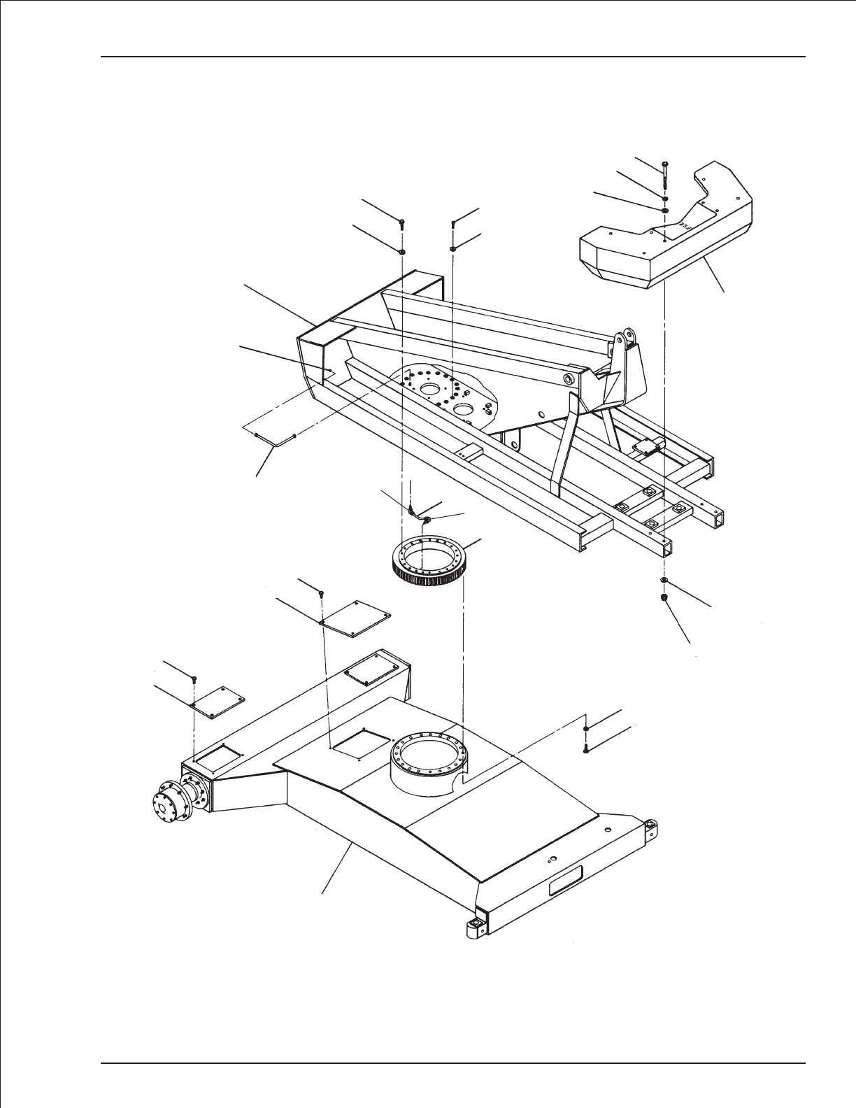
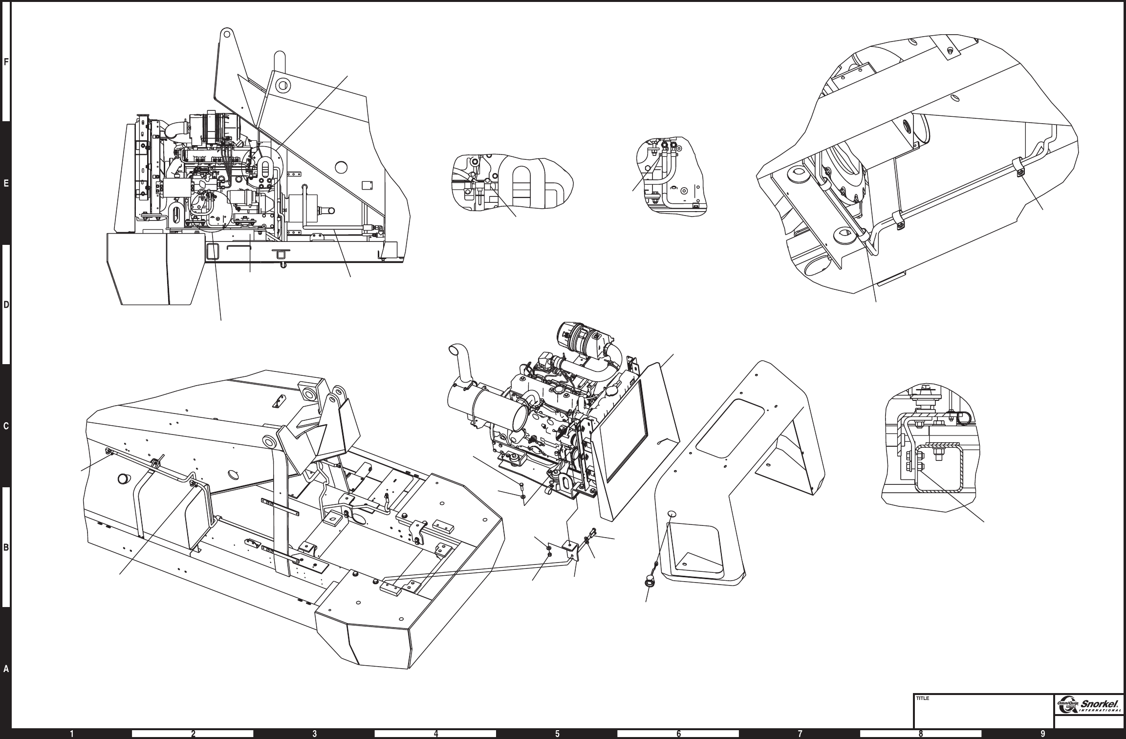
Chassis/turntable mounting
item part no qty description
1 1 Chassis - (consult factory)
2 1 Turntable - (consult factory)
3 1 Counterweight - (consult factory)
4 0070021 1 Rotation bearing gear
5 5560149 20 Capscrew special 5/8-11 self locking
6 5560169 44 Washer 5/8 hard flat ASTM-F436
7 5560052 18 Capscrew special 5/8-11 self locking
8 5560063 2 Capscrew special 5/8-11 self locking
9 0070024 2 Access cover, drive
10 0070328 1 Access cover, chassis
11 970449 2 Capscrew 3/8-16 x 3/4 inch long hex head grade 5
12 0070553 1 Lubrication tube, 1/4 inch copper tube
13 0020655 1 Lubrication hose
14 5570001 1 Grease fitting, 1/8 NPT straight
15 5560036 4 Nut 5/8-11 self locking
16 987159 8 Washer 5/8 medium lock
17 971379 4 Capscrew 5/8-11 x 3-3/4 inch long hex head grade 8
18 5033704 1 Male 90° elbow
19 5033703 1 Male 90° elbow
1-2 TB 60 – 01-97 through 01-01
Chassis/turntable mounting
TB 60 – 01-97 through 01-01 1-3
1
9
11
10
11
6
5
16
15
3
17
6
16
8
6
7
6
2
14
13
4
12
AW0080055
19
18

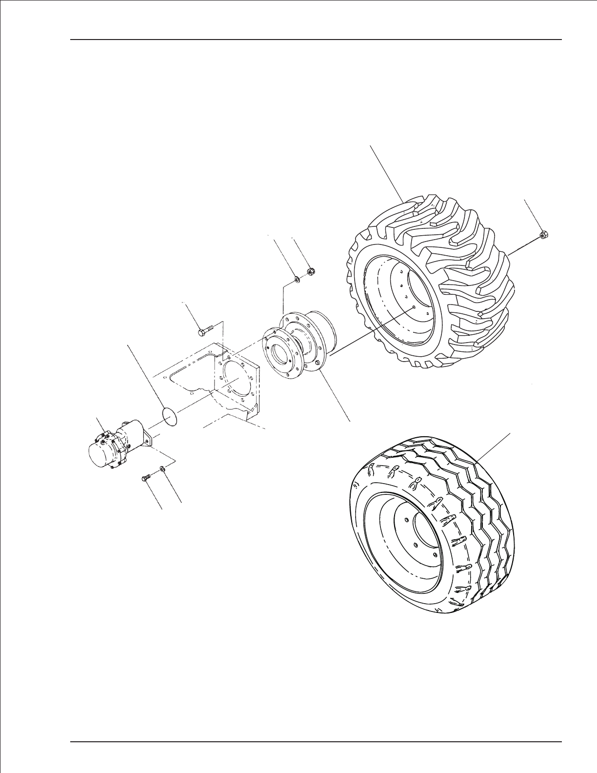
Drive
item part no qty description
1 6030040 2 Drive motor with integral brake - (see page 2-18 for parts breakdown)
2 5560078 4 Capscrew 1/2-13 x 1/2 inch long self locking grade 8
3 987139 4 Washer 1/2 medium lock
4 7110242 2 O-ring
5 5560642 16 Capscrew 5/8-11 x 3-1/4 inch long hex head grade 8
6 5560169 16 Washer 5/8 hard flat ASTM-F436
7 5560131 16 Nut 5/8-11 self locking
8 0081674 2 Gear hub, high torque - (see page 1-74 for parts breakdown)
9 0080965 1 Tire and wheel, foam filled right hand 15-19.5 12 ply lug
10 0080966 1 Tire and wheel, foam filled left hand 15-19.5 12 ply lug
11 0081462 2 Tire and wheel, foam filled 15-19.5 14 ply highway
0083558 2 Tire and wheel, flotation - (used on 4 wheel drive only)
7280072 1 Tire, 40/19 x 19.5 flotation
7280078 1 Drive rim
7280073 1 Valve stem
12 7280001 16 Lug nut
1-4 TB 60 – 01-97 through 01-01
Drive
TB 60 – 01-97 through 01-01 1-5
Note: Do not mix tire brands or sizes on any one machine
Standard tires
Optional tires
1
23
4
5
67
8
9
10
12
11
AW0080058

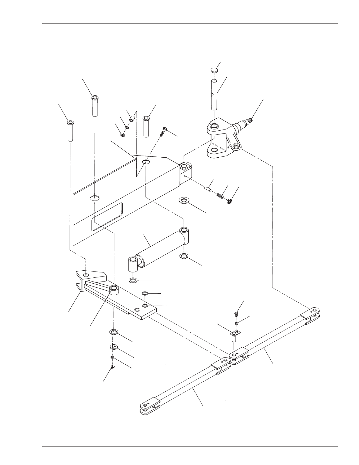
Steering
item part no qty description
1 1 Steer yoke and wheel - (see page 1-8 for 2 wheel drive, page 1-10 for 4 wheel drive)
2 0080182 2 King pin
3 0080184 2 King pin cap
4 0080183 2 Locking pin
5 5569836 2 Set screw 3/4-10 x 1-3/4 inch long hex socket head
6 984469 2 Nut 3/4-10 hex jam
7 0070442 3 Pin
8 970949 1 Capscrew 1/2-13 x 2-1/2 inch long hex head grade 5
9 0080098 1 Spacer
10 987139 1 Washer 1/2 medium lock
11 984149 1 Nut 1/2-13 hex
12 0070007 1 Cylinder, steering - (see hydraulics section for parts breakdown)
13 2580001 2 Thrust bearing
14 5560252 3 Machine bushing
15 0083562 1 Steering arm
16 0080187 1 Spacer, steering arm
17 2502416 2 Bearing
18 0070033 2 Pin lock
19 987109 8 Washer 5/16 medium lock
20 0070473 4 Capscrew 5/16-18 drilled head
21 9980012 1 .040 inch diameter stainless steel safety lockwire - (sold in one pound can)
22 0110320 4 Lock pin
23 970239 4 Capscrew 5/16-18 x 3/4 inch long hex head grade 5
24 0080348 4 Spacer, tie rod mounting
25 2690001 2 Bearing, self aligning
26 5570002 2 Grease fitting 1/8 NPT 45°
27 0080094 2 Tie rod, non-adjustable - (machines prior to July 1999)
28 0083416 2 Tie rod, adjustable - (machines after July 1999, requires items 29 and 30)
29 5560202 2 Tie rod hex jam nut for adjustable tie rod
30 0083418 2 Tie rod end for adjustable tie rod
31 5570003 2 Grease fitting 1/8 NPT 90°
1-6 TB 60 – 01-97 through 01-01
Steering
TB 60 – 01-97 through 01-01 1-7
7
7
11
10
97
8
3
2
1
456
13
12
14
14
24
25 26
15
16
17
14
19
20
21
18
27 - old style shown
28
27 - old style shown
28
23
19
22
31
AWM00322

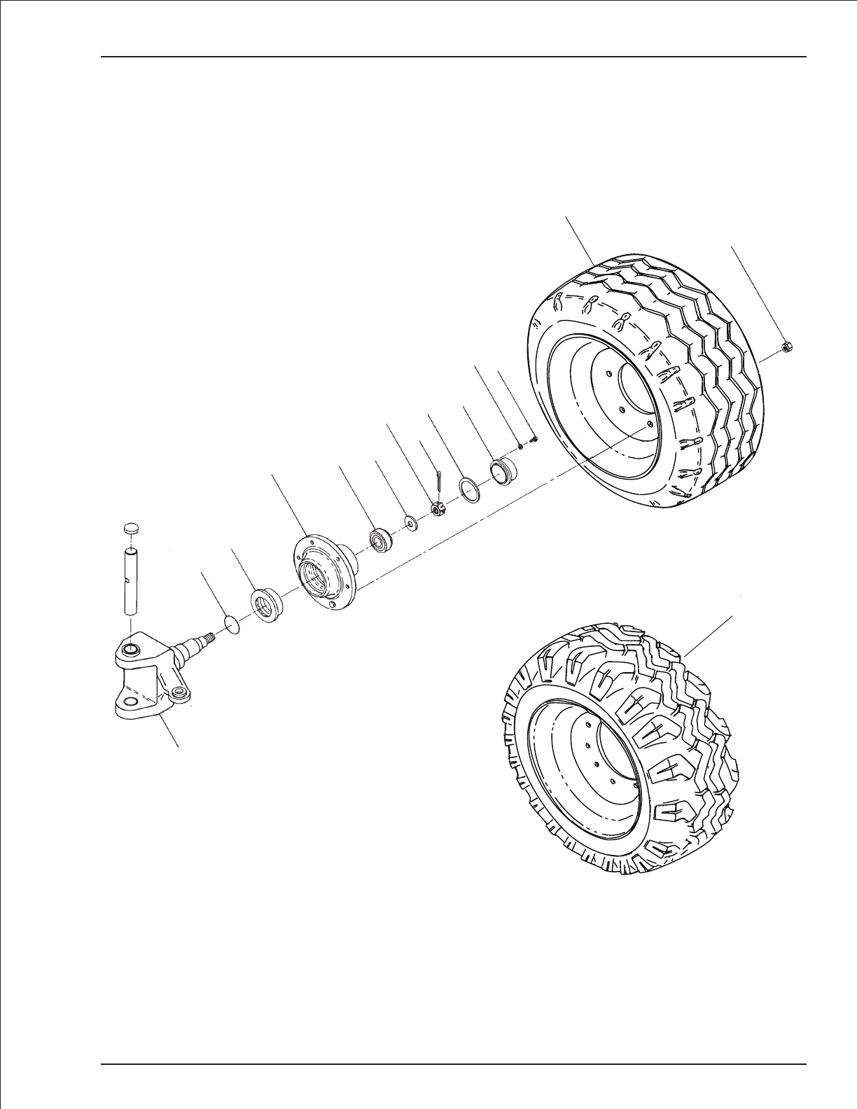
Steer yoke and wheel, 2 wheel drive
item part no qty description
1 0080349 1 Steering yoke, 2 wheel drive - (before 7-31-00)
0083571 1 Steering yoke, 2 wheel drive - (after 7-31-00)
2 2690001 2 Bearing, self aligning
3 2503224 4 Bearing
4 5570001 4 Grease fitting, 1/8 NPT straight
5 7150001 2 Grease seal
6 2560006 2 Inner bearing cone
7 0080181 2 Hub
7280024 20 Replacement wheel bolt
8 2540005 2 Inner bearing cup
9 2540006 2 Outer bearing cup
10 2560005 2 Outer bearing cone
11 5560025 2 Key washer
12 5560661 2 Cotter pin 3/8 inch diameter x 2-1/2 inch long
13 5560026 2 Spindle nut
14 0080185 2 Gasket, hub cap
15 0080186 2 Hub cap
16 987099 8 Washer 1/4 medium lock
17 970009 8 Capscrew 1/4-20 x 1/2 inch long hex head grade 5
18 0080365 1 Tire and wheel, foam filled right hand 15-19.5 14 ply steer
19 0082185 1 Tire and wheel, foam filled left hand 15-19.5 14 ply steer
20 0082205 2 Tire and wheel, foam filled 15-19.5 14 ply highway tread
21 7280010 20 Wheel nut
1-8 TB 60 – 01-97 through 01-01
Steer yoke and wheel, 2 wheel drive
TB 60 – 01-97 through 01-01 1-9
Note: Do not mix tire brands or sizes on any one machine
Standard tires
Optional tires
18
1
2
34
5
6
7
8
9
10 11
12
13 14 15
16 17
20
21
19
AW0080063-2

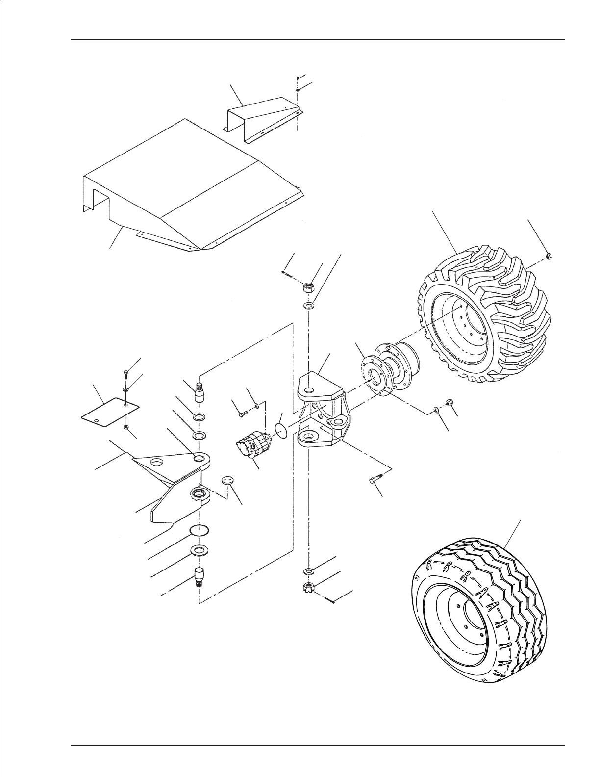
Steer yoke and wheel, 4 wheel drive
item part no qty description
1 0082282 1 Cover, chassis-4wheel drive
2 0080920 1 Cover, hoses
3 0080919 2 Cover, drive motor
4 970449 9 Capscrew 3/8-16 x 3/4 inch long hex head grade 5
5 986299 17 Washer 3/8 medium flat
6 988229 4 Cotter pin 1/4 inch diameter x 2-1/2 inch long
7 5560018 4 Spindle nut
8 0072438 4 Washer
9 0083573 2 Steering yoke, 4 wheel drive
10 0080885 2 King pin
11 25560089 2 Shim, .031 inch thick
5560091 2 Shim, .015 inch thick
12 5560660 6 Machine bushing 3 inch OD x 2 inch ID x 14 gauge thick
13 2503220 4 Bearing
14 0080948 2 Special O-ring
15 2580001 2 Thrust bearing
16 0070026 2 King pin cap
17 6030018 2 Drive motor - (see page 2-16 for parts breakdown)
18 5560078 4 Capscrew 1/2-13 x 1/2 inch long self locking grade 8
19 987139 4 Washer 1/2 medium lock
20 7110242 2 O-ring
21 5560640 16 Capscrew 5/8-11 x 3 inch long hex head grade 8
22 0081674 2 Gear hub, high torque - (see page 1-74 for parts breakdown)
23 5560169 16 Washer 5/8 hard flat ASTM-F436
24 5560131 16 Nut 5/8-11 self locking
25 0080965 1 Tire and wheel, foam filled right hand 15-19.5 12 ply lug
26 0080966 1 Tire and wheel, foam filled left hand 15-19.5 12 ply lug
27 0081462 2 Tire and wheel, foam filled 15-19.5 14 ply highway
0083558 2 Tire and wheel, flotation - (used on 4 wheel drive only)
7280072 1 Tire, 40/19 x 19.5 flotation
7280078 1 Drive rim
7280073 1 Valve stem
28 7280001 16 Lug nut
29 970889 2 Capscrew 1/2-13 x 1 inch long hex head grade 5
30 986359 2 Washer 1/2 medium flat
31 5560039 2 Nut 1/2-13 self locking
1-10 TB 60 – 01-97 through 01-01
Steer yoke and wheel, 4 wheel drive
TB 60 – 01-97 through 01-01 1-11
Note: Do not mix tire brands or sizes on any one machine
Optional tires
Standard tires
25
26
28
22
24
23
9
45
3
26
78
21 - Torque 180 ft lbs
18
19
20
10
11
12
13
17
16
8
7
6
14
15
10
29
30
1
31
27
AW0080063-4

Lift and swing
item part no qty description
1 0081486 1 Centerpost and fittings - (see page 2-26 for parts breakdown)
2 0070472 1 Key
3 0070256 1 Adapter plate, centerpost
4 5590003 1 Retaining ring
5 987159 5 Washer 5/8 medium lock
6 5560051 8 Capscrew 5/8-11 self locking
7 0073026 1 Swing drive - (see page 1-14 for parts breakdown)
8 984449 6 Nut 5/8-11 hex jam
9 5560022 6 Adjustment bolt
10 0080053 1 Cylinder, lift - (see page 2-30 for parts breakdown)
11 0080020 1 Pin, lift cylinder base end
12 0080024 1 Pin, lift cylinder rod end
13 0080023 2 Pin lock
14 987109 8 Washer 5/16 medium lock
15 0070473 8 Capscrew 5/16-18 drilled head
16 9980012 1 .040 inch diameter stainless steel safety lockwire - (sold in one pound can)
17 0070007 1 Cylinder, master level - (see hydraulics section for parts breakdown)
18 0070442 1 Pin, master level cylinder base end
19 0080028 1 Pin, master level cylinder rod end
20 0070033 2 Pin lock
21 5560169 4 Washer 5/8 hard flat ASTM-F436
22 0080018 1 3/8 inch hydraulic tube - (GBI lift cylinder only)
1-12 TB 60 – 01-97 through 01-01
Lift and swing
TB 60 – 01-97 through 01-01 1-13
7
6
21
6
5
4
23
9
8
1
17
18
19
20
14
15
16
10
11
22
15
16
14
13
12
AW0080054

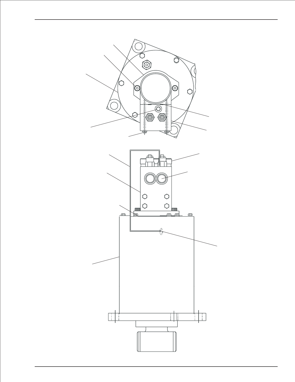
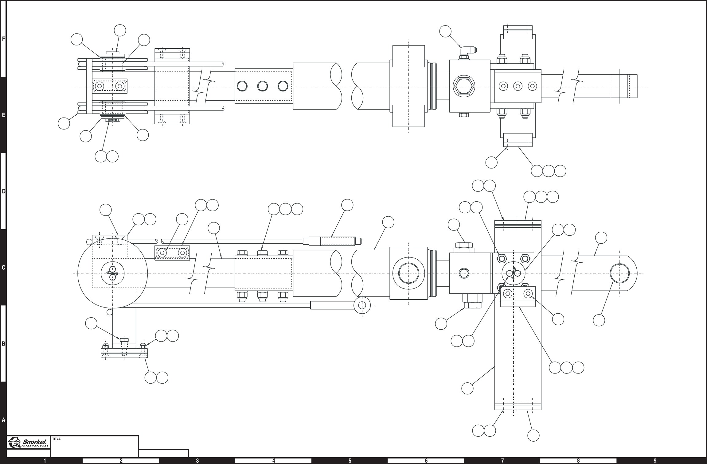
Swing drive
item part no qty description
0073026 1 Swing drive, complete
1 0070047 1 Swing drive
(Auburn gear swing drive, see page 1-76 for parts breakdown)
(Fairfield swing drive, see page 1-78 for parts breakdown)
(Gear Products swing drive, see page 1-80 for parts breakdown)
(Perfection swing drive, see page 1-74 for parts breakdown)
(Tulsa Winch swing drive, see page 1-84 for parts breakdown)
2 6030020 1 Motor, swing drive
8200004 1 Seal repair kit - Ross/TRW motor
0090352 1 Seal repair kit - Charlynn/Eaton motor
0073359 1 Seal repair kit - White/Roller Stator motor
3 6010250 1 Motion control valve, turntable swing - (see page 2-55 for parts breakdown)
4 5560641 4 Capscrew 5/16-18 x 3-1/2 inch long hex head grade 5
5 986269 4 Washer 5/16 medium flat
6 987109 4 Washer 5/16 medium lock
7 5560087 2 Capscrew special self locking
8 5035303 1 Straight thread 90° elbow
9 5065703 1 Straight thread adapter
10 5075726 1 Straight thread adapter
11 7190005 1 Gasket, swing drive
12 5037003 1 Swivel nut 90° elbow
13 0020283 1 1/4 inch hydraulic hose
14 5036905 2 Swivel nut 45° elbow
15 7110112 2 O-ring
1-14 TB 60 – 01-97 through 01-01
Swing drive
TB 60 – 01-97 through 01-01 1-15
V1
BR
V2 V2
V1
BR
2
10 14
11
3
13
4
5
6
3
15
9
12
2
7
1
8
1
AW0073026

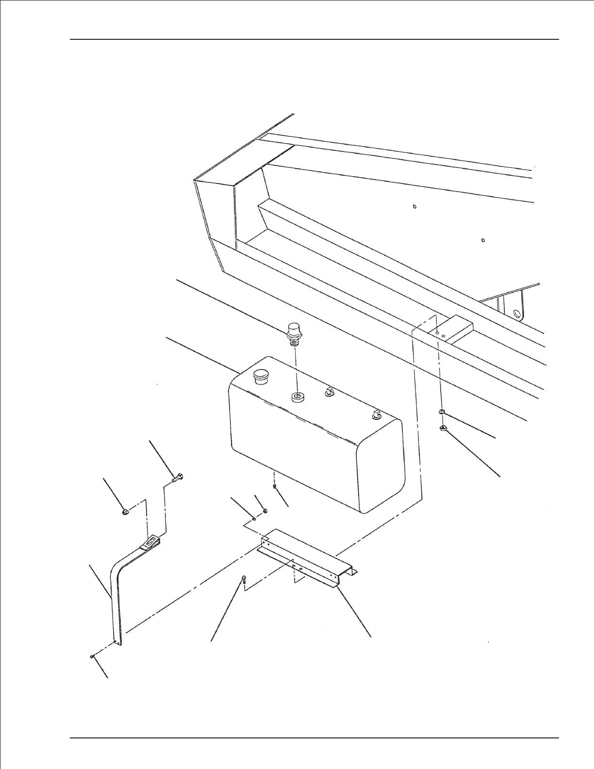
Fuel tank
item part no qty description
1 0080030 1 Fuel tank, 40 gallon capacity - (used with metal cowling)
(includes 9940001 replacement cap and fuel gauge, item 2)
0082906 1 Fuel tank, 40 gallon capacity - (used with plastic cowling)
(includes 9940001 replacement cap and fuel gauge, item 2)
2 0070483 1 Fuel gauge - (includes gauge lens)
8180014 1 Replacement gauge lens
3 7714202 1 Pipe plug 1/4 NPT square head
4 0071940 2 Fuel tank strap
5 970569 2 Capscrew 3/8-16 x 3-1/2 inch long hex head grade 5
6 5560033 2 Nut 3/8-16 self locking
7 970029 4 Capscrew 1/4-20 x 3/4 inch long hex head grade 5
8 987099 4 Washer 1/4 medium lock
9 984069 4 Nut 1/4-20 hex
10 0080031 1 Fuel tank support
11 970469 8 Capscrew 3/8-16 x 1 inch long hex head grade 5
12 987119 8 Washer 3/8 medium lock
13 984109 8 Nut 3/8-16 hex
1-16 TB 60 – 01-97 through 01-01
Fuel tank
TB 60 – 01-97 through 01-01 1-17
2
1
5
4
6
7
11 10
89
3
13
12
AW0080056

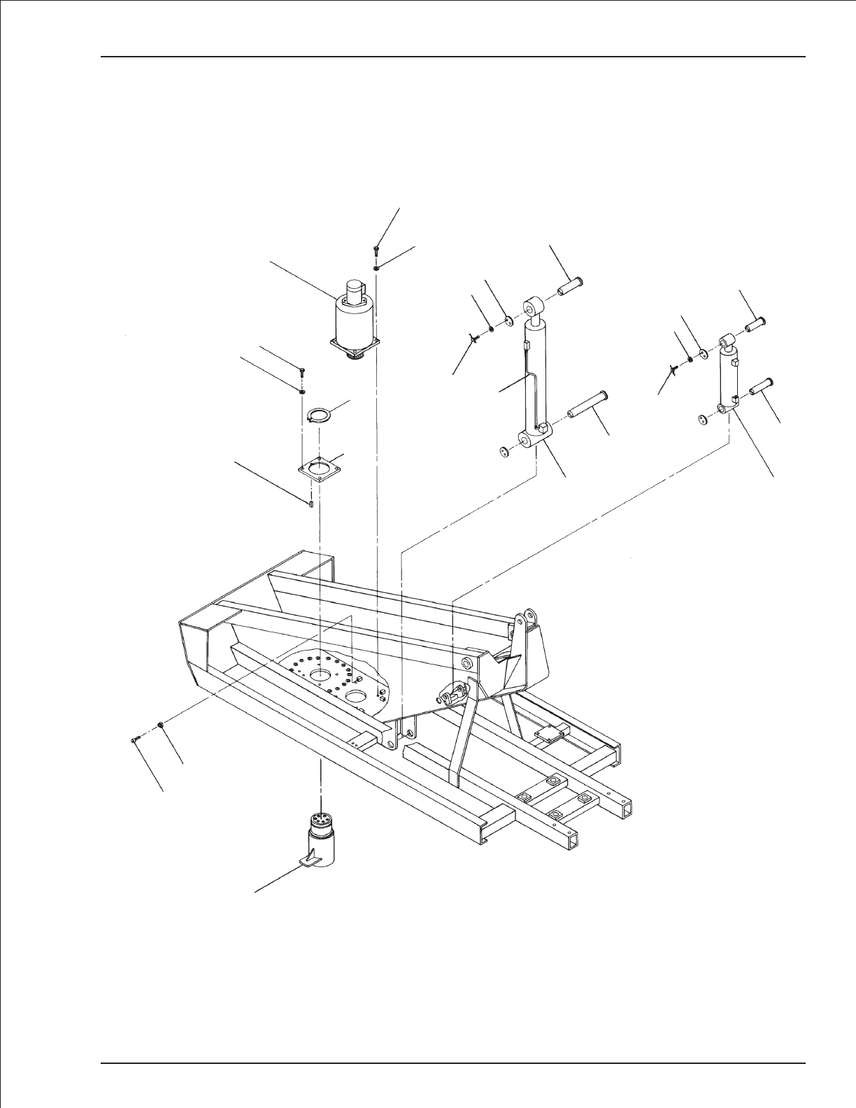
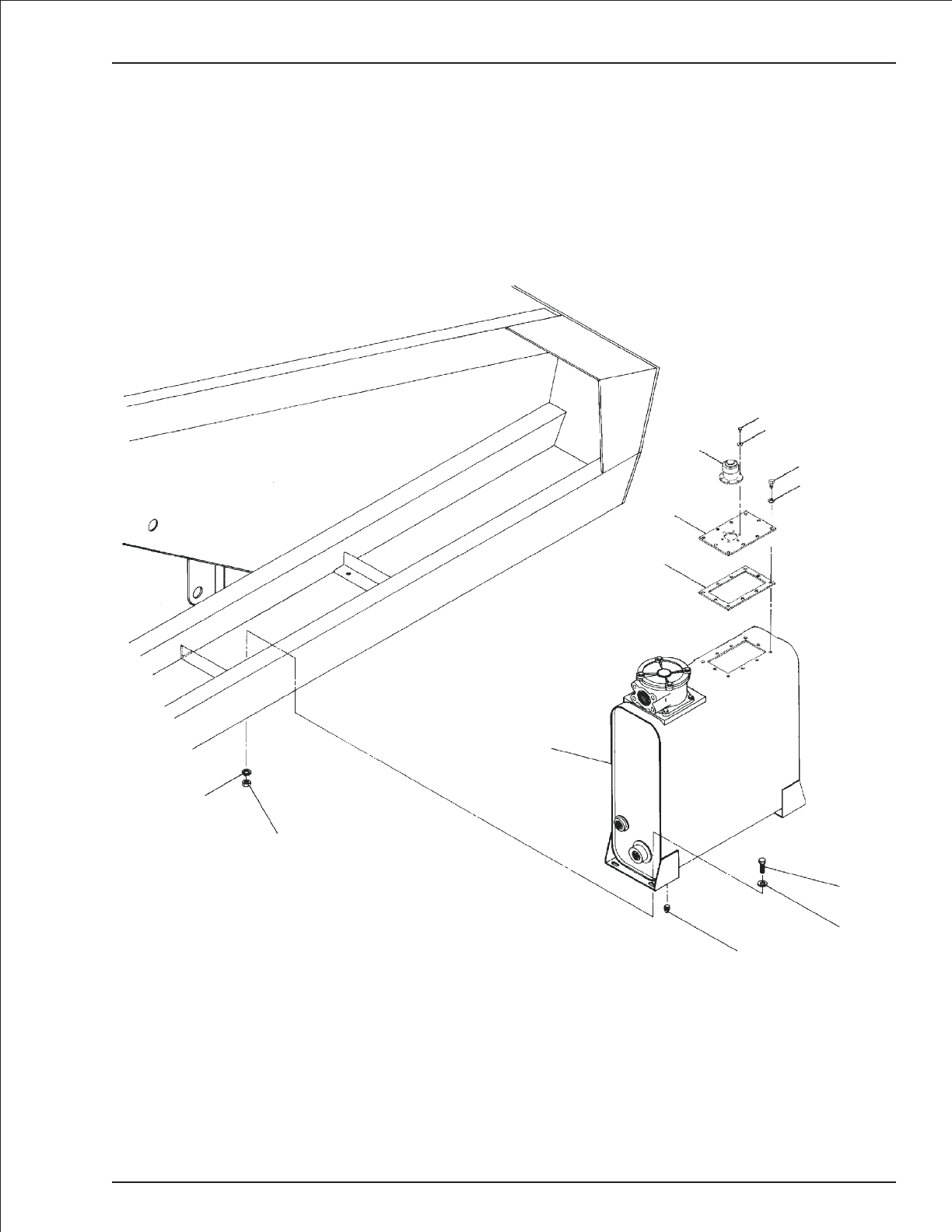
Hydraulic oil reservoir mounting
item part no qty description
1 0081875 1 Hydraulic oil reservoir - (see page 2-20 for parts breakdown)
2 970479 4 Capscrew 3/8-16 x 1-1/4 inch long hex head grade 5
3 986299 4 Washer 3/8 medium flat
4 987119 4 Washer 3/8 medium lock
5 984109 4 Nut 3/8-16 hex
6 8010249 1 Cover plate
7 8010250 1 Cover gasket
8 5090008 1 Filler/breather cap
9 5560609 6 Machine screw #10-24 x 1/2 inch long hex head
10 987089 6 Washer #10 medium lock
11 970369 6 Capscrew 5/16-18x1inchlong hex head grade 5
12 987109 6 Washer 5/16 medium lock
1-18 TB 60 – 01-97 through 01-01
Hydraulic oil reservoir mounting
TB 60 – 01-97 through 01-01 1-19
1
2
3
4
5
6
7
8
9
10
11
12
AW0081966

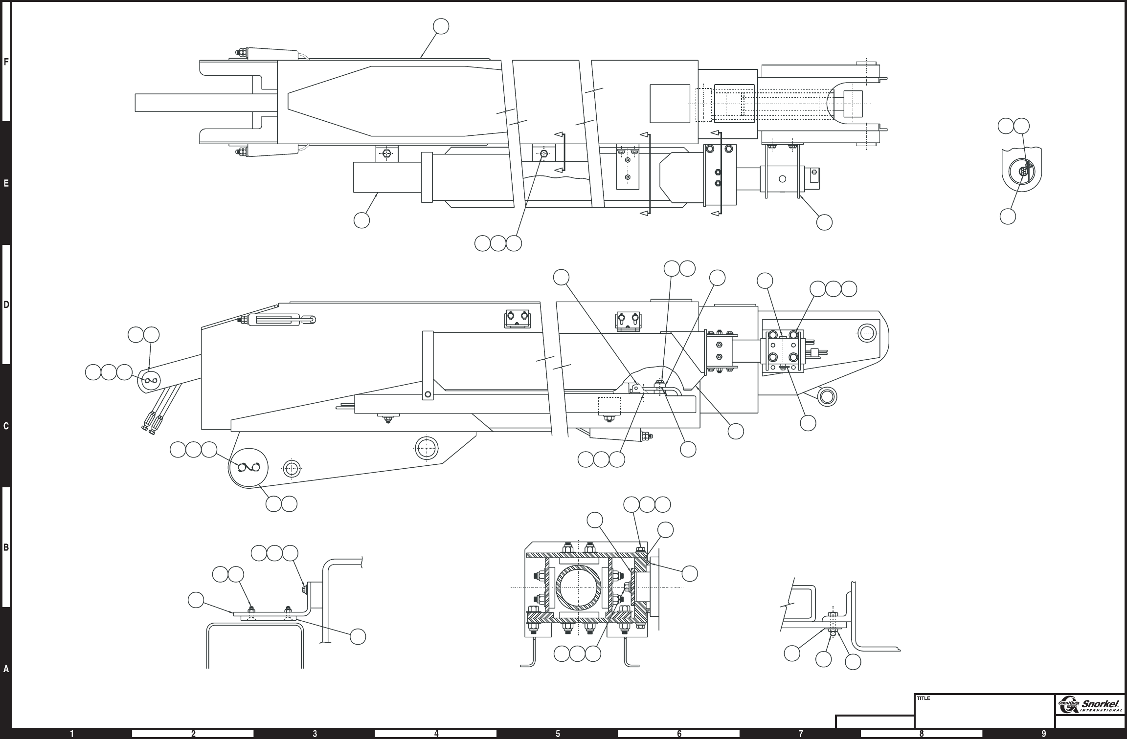
Boom and hose carrier
item part no qty description
1 0080969 1 Booms - (see page 1-23 for parts breakdown)
2 0072727 1 Hose carrier - (see page 1-26 for parts breakdown)
3 0080962 1 Hose carrier support tube
4 0072951 2 Guide bar
5 5093009 1 Hose clamp
6 0070029 2 Slide pad
7 972559 4 Capscrew 3/8-16 x 1 inch long socket flat head
8 970029 2 Capscrew 1/4-20 x 3/4 inch long hex head grade 5
9 970369 4 Capscrew 5/16-18x1inchlong hex head grade 5
10 986019 12 Washer 1/4 medium flat
11 987109 4 Washer 1/4 medium lock
12 0070505 1 Spacer
13 0070504 1 Pin joint plate
14 0070506 1 Pin lock
15 970426 6 Capscrew 3/8-16 x 7/8 inch long hex head grade 5
16 986299 4 Washer 3/8 medium flat
17 987119 8 Washer 3/8 medium lock
18 0072105 1 Clevis pin
19 5560014 1 Hairpin clip pin
20 970849 9 Capscrew 1/2-13 x 1-1/4 inch long hex head grade 5
21 986359 9 Washer 1/2 medium flat
22 5560039 9 Nut 1/2-13 self locking
23 0082023 1 Tube bracket
24 9920016 1 Mounting bracket
25 0072937 1 Clamp bar
26 972509 2 Capscrew 3/8-16 x 2 inch long socket flat head
27 5560033 5 Nut 3/8-16 self locking
28 5560004 2 Nut 1/4-20 self locking
29 0110581 2 Spacer
30 970629 1 Capscrew 3/8-16 x 5 inch long hex head grade 5
1-20 TB 60 – 01-97 through 01-01
Page1-21
Boom and hose carrier
Snorkel model TB 60
DWG. 0080977
2730
5
1
222120
23
Section C-C
21 20 22
Section A-A
11
109
277
4
6
Section B-B
12
13
14
171615
25
817
24
81028
29
15 16 17
2
18
19
20 21 22
3
113738
3536
33 34
113738
C
A
A
B
B
C
AW0080977
Page1-21
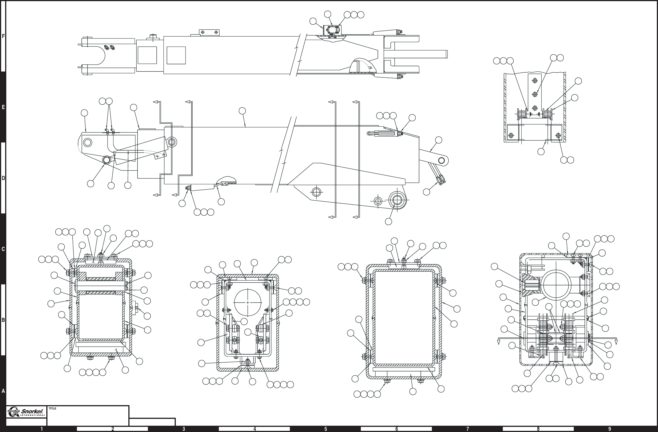
Page1-22
Booms
Snorkel model TB 60 DWG. 0080969
195310 19 35
78
66
19 35
54
42
43
72 19 13 14 15
11
19 72
46
47
66
10 19 28
23
22
19 53
54
25
11
49
5
151413
35 19
51
2
3
64
4
44
45
50 10 19 53
2
3
21
79
12
15
2010977 40 41
10937
17
16 18 19 8 9
228 19
19 72
24 29 30 31
24 39 30 31
28
11
151413
25
3332
52
151413
34
5
19
36
14
52 1
25
23
22
80
21
27
26
2010977
11
131415
12
2
1
6
1098
67
687576
48
16 17 18
19 38 65
8 9 80
59
55 58 57 56
4
61
636260
70
73
1
6974
2
771 71
3
5
60 62 63
61
C
D
D
B
B
CA
A
View C-C
View B-B
View A-A
EE
View E-E
View D-D
AW0080969
Page1-22

Booms
item part no qty description
0080969 1 Booms
1 0080953 1 Tip boom
2 0080955 1 Intermediate boom
3 0080967 1 Base boom
4 0080978 1 Extension cylinder - (see hydraulics section for parts breakdown)
5 0081215 2 Wire rope, retract
6 0070443 1 Pin, slave level cylinder to tip boom
7 0071486 1 Cylinder, slave level - (see hydraulics section for parts breakdown)
8 970449 16 Capscrew 3/8-16 x 3/4 inch long hex head grade 5
9 987119 36 Washer 3/8 medium lock
10 986299 40 Washer 3/8 medium flat
11 0080293 6 Slide pad
12 0070485 6 Slide pad spacer
13 0070030 14 Slide pad shim, .030 inch thick
14 0072567 16 Slide pad shim, .063 inch thick
15 0090141 14 Slide pad shim, .090 inch thick
16 0072681 2 Slide pad mount
17 0072682 2 Slide pad
18 972559 8 Capscrew 3/8-16x1inchlongsocket flat head
19 5560033 56 Nut 3/8-16 self locking
20 970469 12 Capscrew 3/8-16x1inchlonghexhead grade 5
21 970439 24 Capscrew 3/8-16 x 5/8 inch long socket flat head
22 0070033 2 Pin lock
23 0070473 4 Capscrew 5/16-18 drilled head
24 987109 8 Washer 5/16 medium lock
25 9980012 1 .040 inch diameter stainless steel safety lockwire - (sold in one pound can)
26 0080951 1 Pad plate
27 0080147 1 Slide pad
28 5560644 17 Capscrew 3/8-16 x 1-1/4 inch long socket flat head
29 970369 4 Capscrew 5/16-18x1inchlong hex head grade 5
30 986269 8 Washer 5/16 medium flat
31 5560031 8 Nut 5/16-18 self locking
32 986359 4 Washer 1/2 medium flat
33 5560033 4 Nut 1/2-13 hex jam, drilled
34 0080045 2 Wire rope anchor
35 972539 4 Capscrew 3/8-16 x 2-3/4 inch long socket flat head
36 5560005 4 Anchor bolt
37 970429 8 Capscrew 3/8-16 x 1/2 inch long hex head grade 5
38 0072683 1 Slide pad spacer, 1/4 inch thick
39 970269 4 Capscrew 5/16-18 x 1-1/4 inch long hex head grade 5
40 0080952 1 Pad plate
41 0081048 1 Slide pad
42 0072680 2 Slide pad shim
43 0070639 2 Slide pad
44 0070390 2 Cylinder anchor pin
45 0072751 2 Cylinder anchor
46 988179 1 Cotter pin 1/8 inch diameter x 1 inch long
47 0070448 1 Pin, cable retainer
48 0080294 2 Slide pad
49 0081675 2 Cable sheave
50 2500035 2 Bearing
51 0070439 1 Pin, retract sheave
52 0070031 8 Slide pad
53 9702509 6 Capscrew 3/8-16x2inchlongsocket flat head
54 0081450 1 Cable retainer
55 0081975 1 Boom switch - (see page 3-44 for parts breakdown)
Parts list continued on next page
TB 60 – 01-97 through 01-01 1-23

Booms
item part no qty description
56 5560649 3 Machine screw #10-24 x 1 inch long truss head
57 986009 6 Washer #10 medium flat
58 984049 3 Nut #10-24 hex
59 0071216 1 Guard, boom switch
60 5560170 8 Washer 3/4 hard flat ASTM-F436
61 984469 8 Nut 3/4-10 hex jam
62 0071922 4 Spacer, 1-1/8 inch thick
63 0071921 4 Spacer, 5/8 inch thick
64 2502028 2 Bearing
65 0073111 1 Slide pad spacer, 1/8 inch thick
66 0073535 2 Sheave cage
67 0073340 2 Slide pad spacer, 1/4 inch thick
68 0070043 2 Slide pad shim, .030 inch thick
69 5034501 2 Bulkhead straight thread 90° elbow
70 0100422 2 3/8 inch hydraulic hose
71 0070768 2 1/4 inch hydraulic hose
72 978409 22 Capscrew 3/8-16 x 1-1/2 inch long socket flat head
73 2503644 2 Bearing
74 5074401 2 Bulkhead run tee
75 0073342 2 Slide pad shim, .063 inch thick
76 0073343 2 Slide pad shim, .090 inch thick
77 5560015 18 Thread insert 3/8-16
78 0074639 8 Slide pad 3/8 Cable sheave
1-24 TB 60 – 01-97 through 01-01


Hose carrier
item part no qty description
0072727 1 Hose carrier
1 0072743 1 Hose carrier
2 0072737 1 Carrier tube
3 0081089 2 3/16 inch hydraulic hose, 739 inch long - (leveling hoses)
4 0081090 2 3/16 inch hydraulic hose, 790 inch long - (rotation hoses)
5 3010006 1 Power wire, 12 gauge/8 conductor x 75 feet long - (terminals not included)
3044854 Replacement terminal
6 3010009 1 Control wire #1, 18 gauge/12 conductor x 75 feet long - (terminals not included)
3046972 Replacement terminal
7 0080963 1 Plastic track
9920014 111 Replacement plastic track link
8 0092934 2 Slide pad
9 0072910 2 Capscrew, special
10 978409 2 Capscrew 3/8-16 x 1-1/2 inch long socket flat head
11 0100105 4 Slide pad
12 0070029 2 Slide pad
13 0072936 1 Slide pad
14 0080284 6 Spacer
15 0110610 1 Anchor plate
16 0072935 2 Slide pad
17 5560644 8 Capscrew 3/8-16 x 1-1/4 inch long socket flat head
18 5560033 20 Nut 3/8-16 self locking
19 986299 28 Washer 3/8 medium flat
20 972489 4 Capscrew 3/8-16 x 1-1/2 inch long hex head grade 5
21 972449 7 Capscrew 3/8-16 x 3/4 inch long socket flat head
22 3010005 1 Control wire #2, 18 gauge/19 conductor x 75 feet long - (terminals not included)
3046972 Replacement terminal
23 5560605 6 Capscrew 3/8-16 x 7 inch long hex head grade 5
24 5560606 1 Capscrew 1/2-13 x 7 inch long hex head grade 5
25 986359 2 Washer 1/2 medium flat
26 5560039 1 Nut 1/2-13 self locking
1-26 TB 60 – 01-97 through 01-01
Page1-27Page1-27
Hose carrier
Snorkel model TB 60
DWG. 0072727
16 10 18
13
24 25 26
11
17 18 19
18 19 20
7
1
9
821
12
2
15
21
14 18 19 23
5
22
3
4
6
3
2
1
4
AW0072727
Page1-27
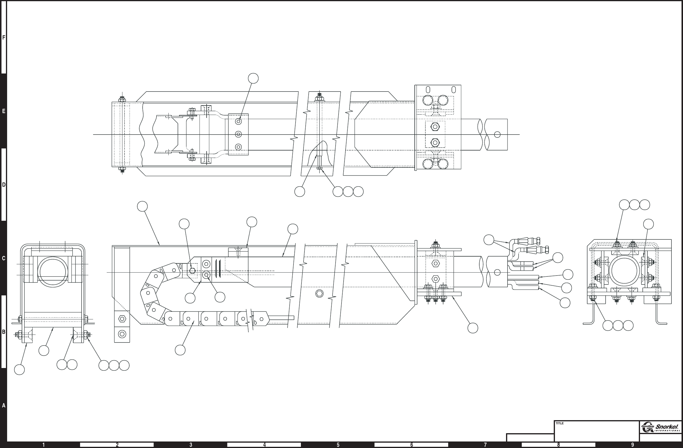
Page1-28Page1-28
Extension cylinder
Snorkel model TB 60 DWG. 0080978
18
17
14 15
16
10 27
19 20 21
2223
1
29
16
14 15
2
31
C
L
7
630
10
12
6
5
11
22 23
14
16 14
16
15
15
24
24
1112
8
1326
8
4
22 33
23
913 25
3
28
32
AW0080978
Page1-28

Extension cylinder
item part no qty description
0080978 1 Extension cylinder
1 0080975 1 Cylinder, extension - (see hydraulics section for parts breakdown)
2 0081214 2 Wire rope, extend
3 0082054 1 Support bracket, extend cylinder base end
4 0080980 1 Support bracket, extend cylinder rod end
5 0081675 2 Cable sheave
6 5560254 7 Thrust washer
7 0070438 1 Pin, extend sheave
8 6010116 2 Cartridge holding valve, included with extension cylinder - (factory preset, do not reset)
9 5560168 6 Washer 1/2 hard flat ASTM-F436
10 0070033 2 Pin lock
11 9980012 1 .040 inch diameter stainless steel safety lockwire - (sold in one pound can)
12 0070473 4 Capscrew 5/16-18 drilled head
13 5560039 11 Nut 1/2-13 self locking
14 0070141 5 Slide pad
15 0071341 5 Slide pad shim, .063 inch thick
16 972449 10 Capscrew 3/8-16 x 3/4 inch long socket flat head
17 0080019 1 Link
18 2502432 2 Bearing
19 0070029 1 Slide pad
20 0070838 2 Slide pad shim, .030 inch thick
21 0071272 2 Slide pad shim, .063 inch thick - (before 1-17-00)
22 5560644 10 Capscrew 3/8-16 x 1-1/4 inch long socket flat head
23 5560033 10 Nut 3/8-16 self locking
24 0073650 2 Slide pad shim, 1/4 inch thick
25 970849 3 Capscrew 1/2-13 x 1-1/4 inch long hex head grade 5
26 970919 8 Capscrew 1/2-13 x 1-3/4 inch long socket flat head
27 0070440 1 Link pin
28 5560005 2 Shoulder bolt
29 5035306 2 Straight thread 90° elbow
30 2502028 2 Bearing
31 0191071 1 Slide pad
32 0191070 2 Slide pad plate
33 0150121 1 Slide pad - (before 1-17-00)
0150122 1 Slide pad - (after 1-17-00)
TB 60 – 01-97 through 01-01 1-29

Platform mounting
item part no qty description
1 1 Platform - (consult factory)
2 0072552 1 Platform rotator - (see page 1-34 for parts breakdown)
3 1 Platform gate - (see page 1-32 for proper platform gate)
4 0070441 1 Pin, slave level cylinder to platform
5 0070446 1 Pin, platform to tip boom
6 0070033 1 Pin lock
7 0070132 1 Pin lock
8 987109 4 Washer 5/16 medium lock
9 0070473 4 Capscrew 5/16-18 drilled head
10 9980012 1 .040 inch diameter stainless steel safety lockwire - (sold in one pound can)
11 5560039 4 Nut 1/2-13 self locking
12 986359 8 Washer 1/2 medium flat
13 971009 2 Capscrew 1/2-13 x 4 inch long hex head grade 5
14 970909 2 Capscrew 1/2-13 x 1-1/2 inch long hex head grade 5
15 0070874 1 Cover, platform rotator
16 0070351 1 Bearing spacer
17 2502832 2 Bearing
1-30 TB 60 – 01-97 through 01-01
Platform mounting
TB 60 – 01-97 through 01-01 1-31
1
3
2
4
5
16
17
6
8
9
10
7
12
11
12 13
14 12
12 11
15
AWM00330

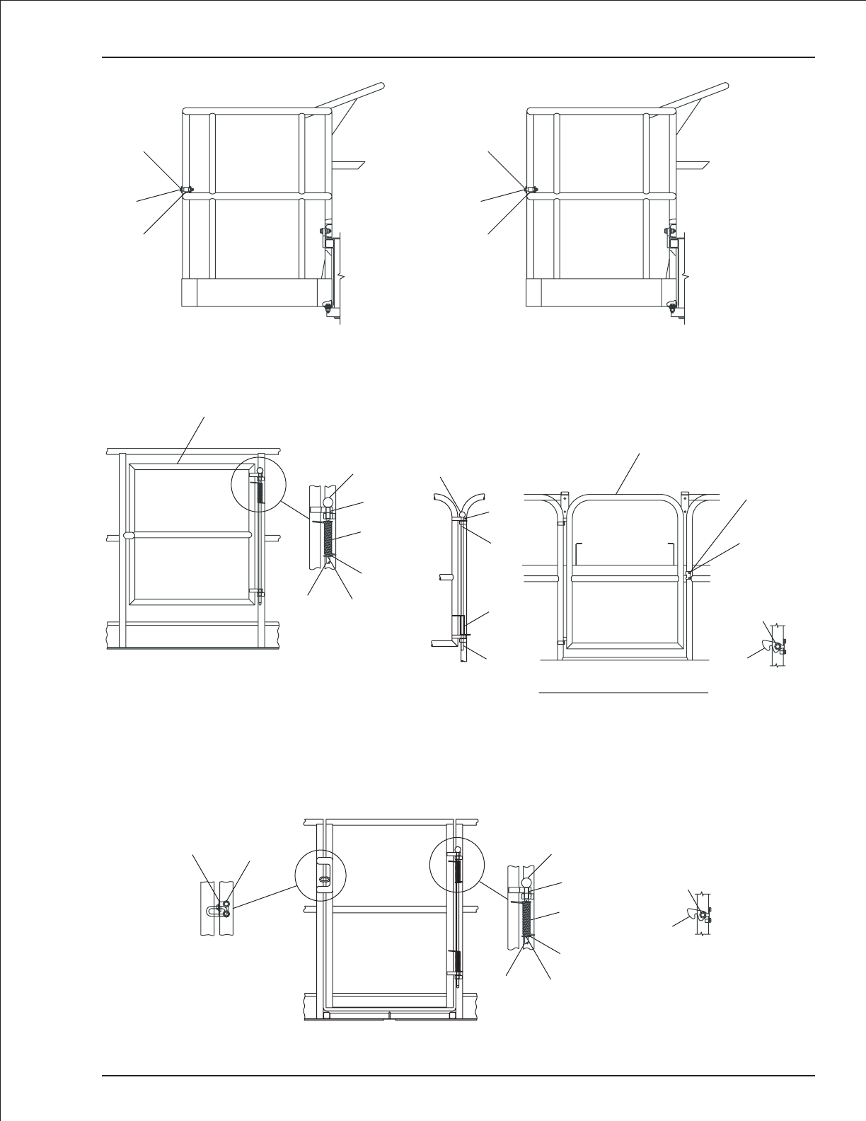
Platform gate
item part no qty description
Gravity gate for 5 ft and 8 ft steel platforms
1 0071951 1 Gravity gate, steel platform
2 0150509 2 Roller, steel gravity gate
3 0071953 2 Roller spacer, steel gravity gate
4 970529 2 Capscrew 3/8-16 x 2-1/2 inch long hex head grade 5
5 5560033 2 Nut 3/8-16 self locking
Gravity gate for 5 ft and 8 ft aluminum platforms
016117728 1 Gravity gate service kit - (kit includes items 6 through 10)
6 0161177 1 Gravity gate, aluminum platform
7 0161182 2 Roller, aluminum gravity gate
8 0161184 2 Roller spacer, aluminum gravity gate
9 970889 2 Capscrew 1/2-13 x 1 inch long hex head grade 5
10 5560039 2 Nut 1/2-13 self locking
Swinging gate for 5 ft and 8 ft steel platforms
11 0071834 1 Swinging gate, steel platform
12 0322724 1 Pin, gate hinge
13 988179 2 Cotter pin 1/8 inch diameter x 1 inch long
14 986359 2 Washer 1/2 medium flat
15 0071837 1 Spring, torsion
16 2570002 2 Bearing
17 2667500 1 Knob, gate hinge pin
Swinging gate for 5 ft and 8 ft aluminum platforms
18 0160970 1 Swinging gate, aluminum platform
19 0322724 1 Pin, gate hinge
20 5560056 1 Roll pin 1/8 inch diameterx1inchlong
21 0071837 1 Spring, torsion
22 2570002 2 Bearing
23 2667500 1 Knob, gate hinge pin
24 0161472 1 Latch stop
25 970099 3 Capscrew 1/4-20 x 5/8 inch long hex head grade 5
26 984529 3 Nut sert 1/4-20
27 987099 2 Washer 1/4 medium lock
28 986019 1 Washer 1/4 medium flat
29 300891 1 Door latch
Full height swinging gate for 8 ft steel platforms
30 0074468 1 Full height swinging gate, steel platform
31 0322724 1 Pin, gate hinge
32 988179 2 Cotter pin 1/8 inch diameter x 1 inch long
33 986359 2 Washer 1/2 medium flat
34 0071837 1 Spring, torsion
35 2572002 2 Bearing
36 2667500 1 Knob, gate hinge pin
37 300891 1 Door latch
38 984529 3 Nut sert 1/4-20
39 970099 3 Capscrew 1/4-20 x 5/8 inch long hex head grade 5
40 987099 2 Washer 1/4 medium lock
41 986019 1 Washer 1/4 medium flat
42 0181574 1 Latch stop
1-32 TB 60 – 01-97 through 01-01
Platform gate
TB 60 – 01-97 through 01-01 1-33
Gravity gate, aluminum platform
Gravity gate, steel platform
1
2
3
4
5
6
7
8
9
10
Swinging gate, steel platform
11
12 13
14
15
16
17
Swinging gate, aluminum platform
Gate pin
Rear view
Door latch
rear view
29
25
26
28
18
19
21
20
22
23
25 26 27
24
Full height swinging gate, steel platform
31 32
33
34
35
36
Door latch
rear view
37
38
39
41
Rear view
42 38
39
40
AWM00207

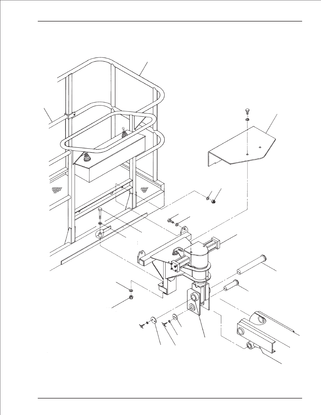
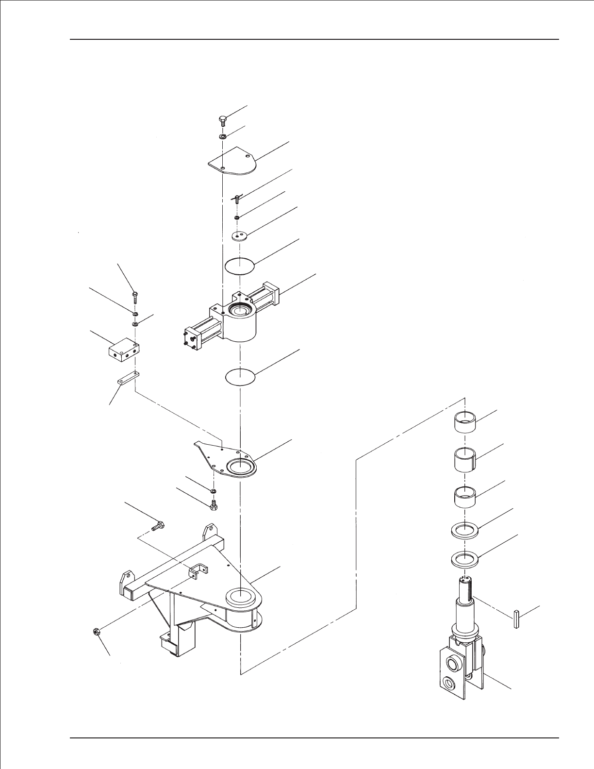
Platform rotator
item part no qty description
0072552 1 Platform rotator
1 0072553 1 Pylon, platform rotator
2 0070916 1 Key
3 0072555 1 Collar
4 0072561 1 Thrust bearing
5 2504856 2 Bearing
6 0072562 1 Bearing spacer
7 0072556 1 Mounting frame, platform rotator
8 970919 2 Capscrew 1/2-13 x 1-3/4 inch long hex head grade 5
9 970849 6 Capscrew 1/2-13 x 1-1/4 inch long hex head grade 5
10 987139 6 Washer 1/2 medium lock
11 0072818 1 Torque plate, platform rotator
12 0073783 1 Valve spacer
13 6010628 1 Dual holding valve, platform rotation - (see page 2-47 for parts breakdown)
14 986269 2 Washer 5/16 medium flat
15 987109 4 Washer 5/16 medium lock
16 970349 2 Capscrew 5/16-18 x 2-3/4 inch long hex head grade 5
17 7110157 1 O-ring - (used on Helac rotator only)
7110348 1 O-ring - (used on Parker rotator only)
18 0070570 1 Platform rotator
(see page 2-56 Helac rotator)
1 (see page 2-57 for Parker rotator)
19 0070132 1 Pin lock
20 0070473 2 Capscrew 7/16-18 drilled head
21 9980012 1 .040 inch diameter stainless steel safety lockwire - (sold in one pound can)
22 0072508 1 Cover plate, platform rotator
23 7110157 1 O-ring - (used on Helac rotator only)
7110348 1 O-ring - (used on Parker rotator only)
24 984409 2 Nut 1/2-13 hex jam
1-34 TB 60 – 01-97 through 01-01
Platform rotator
TB 60 – 01-97 through 01-01 1-35
1
2
3
4
5
6
5
7
8
24
9
10
11
12
13
14
15
16
23
18
17
19
15
20 21
22
10
9
AW0072552

Engine mounting, Cummins 3.3
item part no qty description
1 0070792 1 1/2 inch hydraulic hose
2 0083436 1 Engine and radiator, Cummins 3.3 - (see page 1-39 for parts breakdown)
3 0083438 4 Engine mount, Cummins 3.3
4 970019 4 Capscrew 1/4-20 x 5/8 inch long hex head grade 5
5 970909 8 Capscrew 1/2-13 x 1-1/2 inch long hex head grade 5
6 970919 4 Capscrew 1/2-13 x 1-3/4 inch long hex head grade 5
7 986019 4 Washer 1/4 medium flat
8 987099 8 Washer 1/4 medium lock
9 5010005 1 Hose 3/8 inch diameter x 126 inch long
10 5010005 1 Hose 3/8 inch diameter x 78 inch long
11 5093024 4 Clamp
12 5093045 2 Fitting, straight brass
13 5550006 4 Clamp
14 5560039 12 Nut 1/2-13 self locking
15 5560168 16 Washer 1/2 hard flat ASTM-F436
16 7630140 1 Filter condition indicator
1-36 TB 60 – 01-97 through 01-01
Page1-37
Engine mounting
Cummins 3.3
Snorkel model TB 60
SECTION A-A
(SEC A-A
FAR SIDE)
DETAIL D
DETAIL E
(FUEL FILTER NOT
SHOWN FOR CLARITY)
14
16
3
15
5
14
15
6
15
2
13 12 9
13
12
10
13
1
SEE DETAIL E
SEE DETAIL D
13
11
4
7
8
11
7
4
8
AW0083543
Page1-38
Engine and radiator
Cummins 3.3
Snorkel model TB 60
DETAIL: FUEL LINE ROUTING
2338
16
1
30 7
37
2
25
20
26
25
32
15
33
26
6
31
21
28
11
34
41
40
24
27
13
18
12
9
14
19
8
5
22
35
36
29
10
39
17
32
35
3
24
27
4
29
46
43 46
45
47
42
44
46
46
47
AW0083436

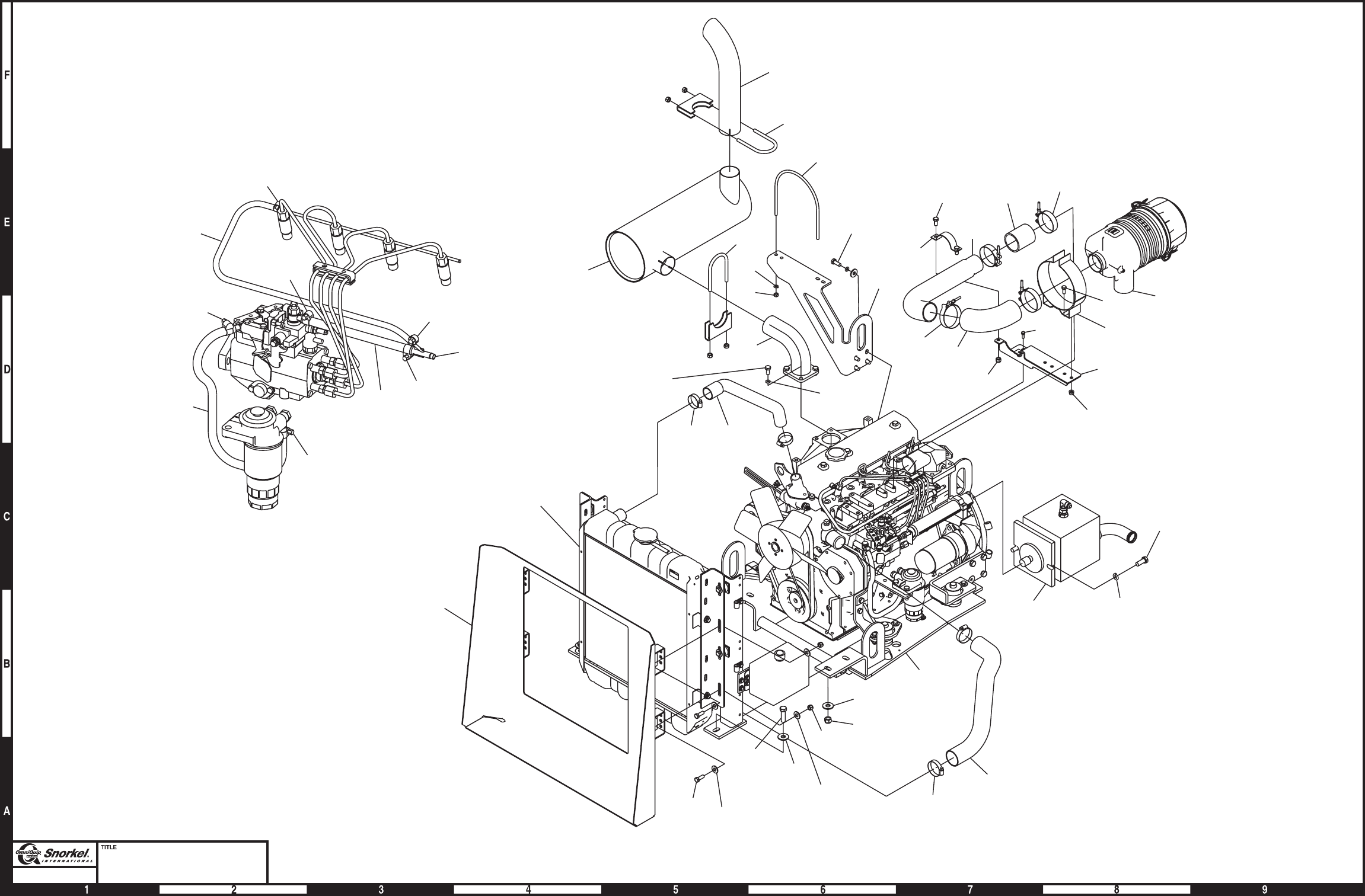
Engine and radiator, Cummins 3.3
item part no qty description
0083436 1 Engine and radiator, Cummins 3.3
1 0073634 1 Radiator - (see page 1-40 for parts breakdown)
2 0074641 1 Exhaust pipe
3 0074644 1 Muffler, standard
4 0074645 1 Tail pipe
5 0074664 1 Muffler clamp
6 0074684 1 Lower radiator hose
7 0074685 1 Upper radiator hose
8 0074687 1 Air intake tube clamp
9 0074688 1 Air intake hose adapter
10 0074786 1 Muffler support bracket
11 0082138 1 Hydraulic pump - (see page 2-52 for parts breakdown)
12 0083165 2 Clamp, T-bolt
13 0083167 1 Air cleaner mount bracket
14 0083175 1 Air cleaner hose coupler
15 0083445 1 Engine tray, Cummins 3.3 - (see page 1-42 for parts breakdown)
16 0083501 1 Shroud
17 0083544 2 Clamp, T-bolt
18 970239 2 Capscrew 5/16-18 x 3/4 inch long hex head grade 5
19 970449 2 Capscrew 3/8-16 x 3/4 inch long hex head grade 5
20 970469 4 Capscrew 3/8-16x1inchlonghexhead grade 5
21 970919 4 Capscrew 1/2-13 x 1-3/4 inch long hex head grade 5
22 972019 4 Capscrew metric M10-1.5 x 25mm long hex head
23 975209 2 Capscrew metric M6-1.00 x 18mm long hex head
24 984089 4 Nut 5/16-18 hex
25 986299 8 Washer 3/8 medium flat
26 986359 8 Washer 1/2 medium flat
27 987109 2 Washer 5/16 medium lock
28 987139 2 Washer 1/2 medium lock
29 5550026 2 Clamp
30 5550038 2 Clamp
31 5550040 2 Clamp
32 5560033 6 Nut 3/8-16 self locking
33 5560039 4 Nut 1/2-13 self locking
34 5560136 2 Capscrew 1/2-13 self locking drilled head
35 5560356 8 Washer metric M10 lock
36 5560364 4 Washer metric M10 flat
37 5560625 4 Capscrew metric M10-1.5 x 20mm long hex head
38 5560664 2 Washer metric M6 lock
39 7630015 1 Elbow, 90° rubber
40 7630755 1 Air cleaner
8140011 1 Replacement primary filter element
8140012 1 Replacement dust ejector
8140013 1 Replacement cover
8140014 1 Replacement clip
41 7630759 1 Air cleaner bracket
42 5010005 1 Hose 3/8 inch diameter x 33 inch long
43 5010005 1 Hose 3/8 inch diameterx9inchlong
44 5010027 1 Fuel hose 3/16 inch diameter x 24 inch long
45 5093044 1 Nylon tee
46 5550006 4 Clamp
47 5550028 2 Clamp
TB 60 – 01-97 through 01-01 1-39

Radiator, Cummins 3.3
item part no qty description
0074634 1 Radiator, Cummins 3.3
1 0074630 2 Radiator bracket
2 0083153 2 Radiator mount angle
3 0180832 1 Mount plate, overflow reservoir
4 970039 8 Capscrew 1/4-20 x 7/8 inch long hex head grade 5
5 970249 4 Capscrew 5/16-18 x 7/8 inch long hex head grade 5
6 970519 4 Capscrew 3/8-16 x 2-1/4 inch long hex head grade 5
7 986019 8 Washer 1/4 medium flat
8 986269 4 Washer 5/16 medium flat
9 986299 4 Washer 3/8 medium flat
10 987099 2 Washer 1/4 medium lock
11 987109 4 Washer 5/16 medium lock
12 5010011 1 Fuel hose 5/16 inch diameter x 48 inch long
13 5093001 2 Clamp
14 5560004 8 Nut 1/4-20 self locking
15 5560033 4 Nut 3/8-16 self locking
16 5560179 8 Washer, snubbing
17 7630180 1 Radiator cushion
18 7630227 1 Overflow reservoir
8060277 1 Replacement reservoir cap
19 7630239 1 Radiator cap - 13 psi
20 7630756 1 Radiator
1-40 TB 60 – 01-97 through 01-01
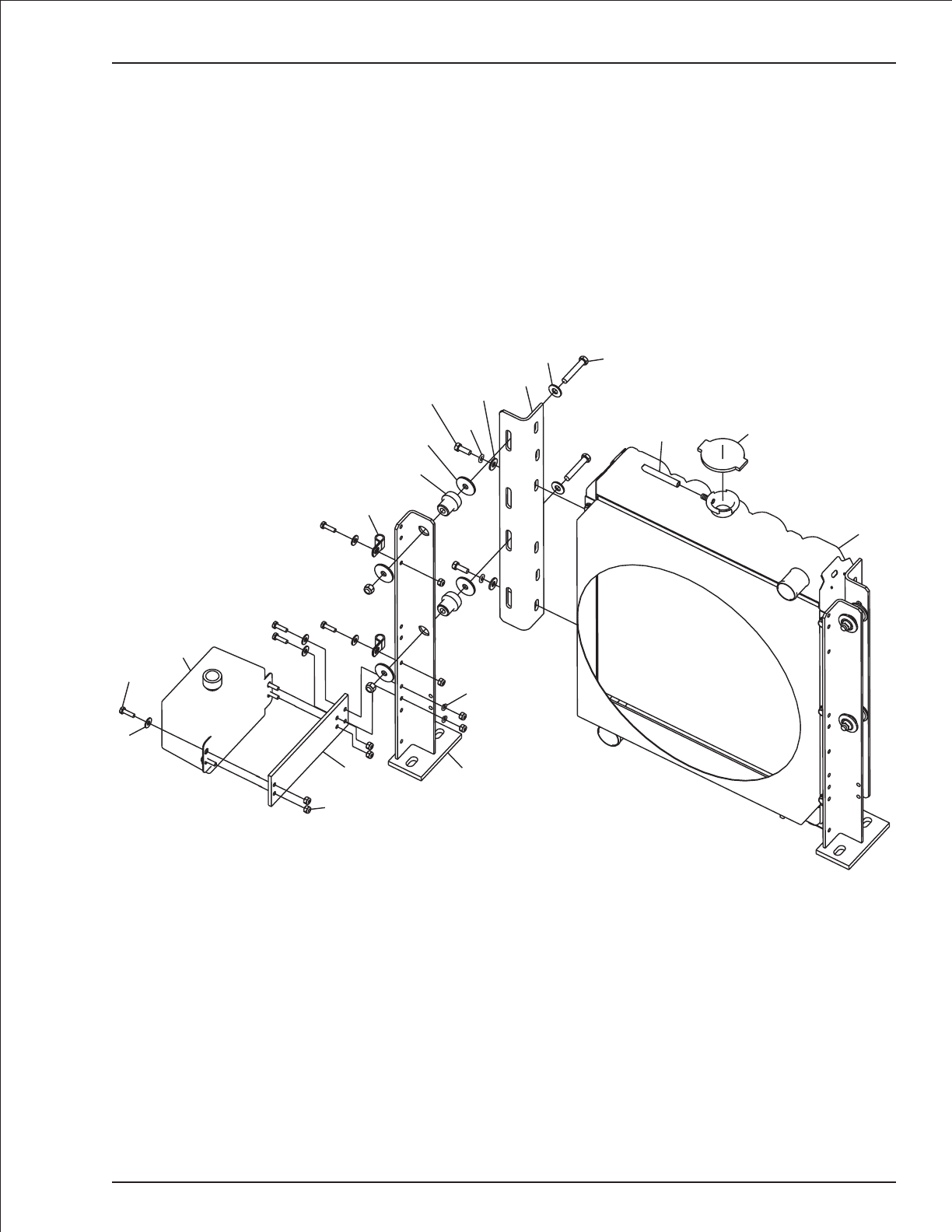
Radiator, Cummins 3.3
TB 60 – 01-97 through 01-01 1-41
18
4
7
14
31
10
17
13
16
5
11
2
8
96
19
12
20
AW0074634

Engine tray, Cummins 3.3
item part no qty description
0083445 1 Engine tray, Cummins 3.3
1 0070148 4 Engine mount washer
2 0074615 1 Engine tray
3 0074622 2 Front engine mount bracket
4 0074625 1 Rear engine mount bracket, left hand
5 0074628 1 Rear engine mount bracket, right hand
6 20082045 1 Throttle actuator
7 0083155 1 Throttle lever extension
8 0083437 1 Flywheel coupling
9 0083512 1 Jumper wire - (after 3-30-00)
10 0083529 1 Fuel filter mount bracket
11 0083570 1 Throttle actuator mount bracket
12 0083586 1 Throttle actuator coupler
13 0083587 1 Rod end
14 970049 2 Capscrew 1/4-20 x 1 inch long hex head grade 5
15 970019 2 Capscrew 1/4-20 x 5/8 inch long hex head grade 5
16 970419 8 Capscrew 3/8-16 x 1-1/4 inch long hex head grade 5
17 971069 4 Capscrew 1/2-13 x 2-3/4 inch long hex head grade 5
18 972019 10 Capscrew metric M10-1.5 x 25mm long hex head
19 972049 2 Capscrew metric M10-1.5 x 40mm long hex head
20 984069 1 Nut 1/4-20 hex
21 984329 1 Nut 1/4-20 hex jam
22 986019 3 Washer 1/4 medium flat
23 986269 2 Washer 5/16 medium flat
24 986299 16 Washer 3/8 medium flat
25 987099 3 Washer 1/4 medium lock
26 987139 4 Washer 1/2 medium lock
27 3020095 1 Switch, oil pressure
28 3070038 1 Temperature sensor
29 5093000 1 Clamp
30 5093002 1 Clamp
31 5093021 4 Clamp
32 5093024 1 Clamp
33 5530017 1 Washer 3/8 curved spring
34 5560004 2 Nut 1/4-20 self locking
35 5560033 8 Nut 3/8-16 self locking
36 5560356 12 Washer metric M10 lock
37 5560364 4 Washer metric M10 flat
38 5560598 2 Capscrew metric M12-1.75 x 25mm long socket flat head
39 5560614 6 Washer metric M12 lock
40 5560615 1 Capscrew 1/4-20 x 5/8 inch long button head
41 5560618 1 Shoulder bolt 3/8 x 3/8 inch long
42 5560626 2 Capscrew metric M10-1.5 x 30mm long hex head
43 5560631 6 Capscrew metric M12-1.75 x 20mm long hex head
44 5560719 2 Nut metric M10-1.50 self locking
45 5569838 1 Washer metric M16 flat copper - (after 3-30-00)
46 7620065 1 Engine, Cummins 3.3
8036201 1 Replacement fuel filter
8036204 1 Replacement oil filter
47 7630323 1 Mounting block
48 7630707 4 Engine isolator
1-42 TB 60 – 01-97 through 01-01
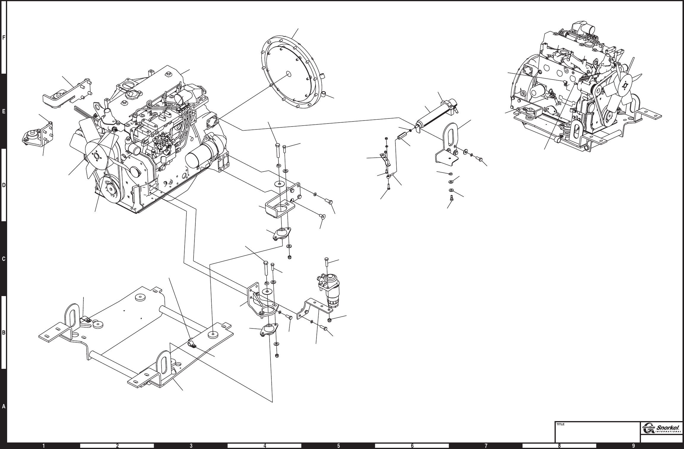
Page1-43
Engine tray
Cummins 3.3
Snorkel model TB 60
5
30
18
36
46
8
31
45
28
47
6
29
27
11
7
15
20
25 41
23
23
33
40 34
21
12
18
36
37
38
43
39
19
16 24 35
17
26
1
4
48
17
26
1
44
42
36
3
48
18
36 10
16 24 35
32
15
22
34
31
14
22
25
2
31
14 22 25
9
13
AW0083445

Engine mounting, Deutz F4L-1011F
item part no qty description
1 0082013 1 Engine, Deutz F4L-1011F diesel - (see page 1-47 for parts breakdown)
2 0081630 1 Engine mount bracket, right hand front
3 0081631 1 Engine mount bracket, left hand front
4 0071599 8 Engine mount washer
5 7630130 1 Engine mount
6 7630286 1 Fuel filter
7 0151786 1 Fuel hose
8 5010011 1 Fuel hose 5/16 inch diameter x 96 inch long
9 5033604 1 Male adapter
10 5090032 1 Fitting, straight barbed
11 5560169 4 Washer 5/8 hard flat ASTM-F436
12 5550028 5 Hose clamp
13 5560131 4 Nut 5/8-11 self locking
14 5560168 16 Washer 1/2 hard flat ASTM-F436
15 5560039 8 Nut 1/2-13 self locking
16 5560639 4 Capscrew 5/8-11 x 4-1/2 inch long hex head grade 5
17 970909 6 Capscrew 1/2-13 x 1-1/2 inch long hex head grade 5
18 970929 2 Capscrew 1/2-13 x 2 inch long hex head grade 5
19 5093002 1 Clamp
20 5093006 4 Clamp
21 5560638 1 Capscrew metric M8-1.25 x 16mm long hex head
22 5560355 1 Washer metric M8 lock
23 0080522 1 1/2 inch hydraulic hose
24 970009 3 Capscrew 1/4-20 x 1/2 inch long hex head grade 5
25 986019 3 Washer 1/4 medium flat
26 987099 3 Washer 1/4 medium lock
1-44 TB 60 – 01-97 through 01-01
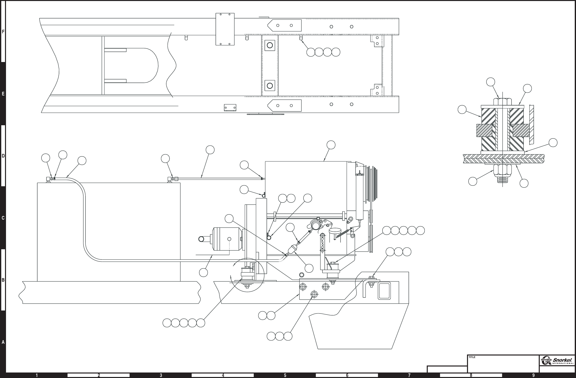
Page1-45Page1-45
Engine mounting
Deutz F4L-1011F
Snorkel model TB 60
DWG. 0082015
1
12
12
12
6
16 4 5 11 13
23
18 15 14
171514
16451113
A
Fuel tank
10 12
89
7
19
20
21 22
20 24 25 26
23
Drain
Detail "A"
typical installation
4 places
16
4
5
13 11
4
AW0082015
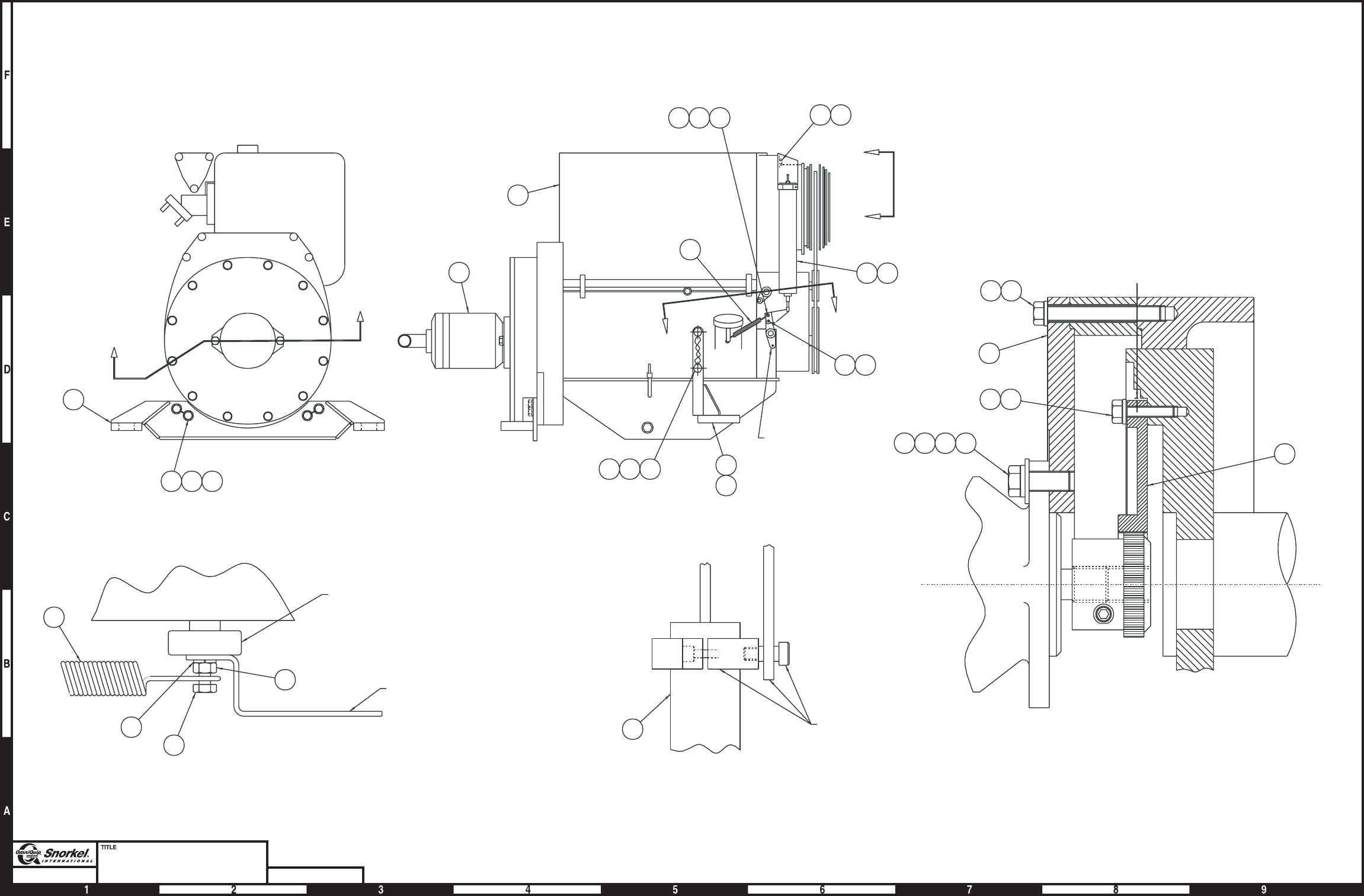
Page1-46Page1-46
Engine
Deutz F4L-1011F
Snorkel model TB 60 DWG. 0082013
15 20
1520
5
28
2728 24
9
18
12
192021
14
7
13
16
6
SECTION A-A
2
A
A
11
3
4
NEAR SIDE
FAR SIDE
17
8
22
23
25
26
1
B
B
THROTTLE LEVER
C
C
THROTTLE LEVER
ACTUATOR BRACKET
(INCLUDED WITH ITEM 9)
VIEW B-B
22
26
27
10
VIEW C-C
INCLUDED WITH ITEM 9
8
AW0082013

Engine, Deutz F4L-1011F
item part no qty description
0082013 1 Engine, Deutz F4L-1011F diesel
1 7620041 1 Engine, Deutz F4L-1011F diesel
2 0181525 1 Hydraulic pump - (see page 2-52 for parts breakdown)
3 0081624 1 Motor mount, rear
4 0081619 1 Motor mount, front right hand
5 0081614 1 Motor mount, front left hand
6 7630249 1 Flexible coupling
7 0081226 1 Plate, engine coupling
8 20082045 1 Actuator
9 7630311 1 Mount kit, Addco actuator - (includes spring - item 22)
10 5560664 1 Washer metric M6 lock
11 5560207 4 Capscrew metric M12-2.00 x 30mm long hex head drilled
12 986299 6 Washer 3/8 medium flat
13 987139 2 Washer 1/2 medium lock
14 5560356 8 Washer metric M10 lock
15 5560377 8 Washer metric M14 lock
16 5560626 6 Capscrew metric M10-1.5 x 30mm long hex head
17 5560028 4 Capscrew metric M14-2.00 x 50mm long hex head drilled
18 5560653 8 Capscrew metric M10-1.5 x 85mm long hex head
19 5560168 2 Washer 1/2 hard flat ASTM-F436
20 9980012 1 .040 inch diameter stainless steel safety lockwire - (sold in one pound can)
21 5560136 2 Capscrew 1/2-13 self locking drilled head
22 8010246 1 Spring - (included with mount kit)
23 5560638 2 Capscrew metric M8-1.25 x 16mm long hex head
24 5560355 2 Washer metric M8 lock
25 5560628 1 Capscrew metric M6-1.0 x 12mm long hex head
26 984169 2 Nut metric M6-1.0 hex
TB 60 – 01-97 through 01-01 1-47

Engine mounting, Ford LRG-423
item part no qty description
1 0111845 1 Engine, Ford LRG-423 - (see page 1-51 for parts breakdown)
2 7630242 1 Radiator - (does not include radiator cap)
3 0180441 1 Bracket, radiator support
4 0081860 2 Angle, radiator
5 7630180 4 Radiator cushion
6 5560179 8 Washer
7 7630332 1 Radiator hose, lower
8 7630191 1 Radiator hose, upper
9 5550030 4 Clamp
10 7630117 4 Engine mount
11 0071599 8 Engine mount washer
12 0180832 1 Mount plate, overflow reservoir
13 7630227 1 Overflow reservoir
8060277 1 Replacement reservoir cap
14 5010012 1 Radiator overflow hose 5/16 inch diameter x 60 inch long
15 970909 6 Capscrew 1/2-13 x 1-1/2 inch long hex head grade 5
16 5560039 6 Nut 1/2-13 self locking
17 5550028 4 Clamp
18 5010011 1 Fuel hose 5/16 inch diameter x 120 inch long
19 7714202 1 Pipe plug 1/4 NPT square head
20 5090032 1 Fitting, straight barbed
21 1 Drain cock - (included with engine)
22 970239 4 Capscrew 5/16-18 x 3/4 inch long hex head grade 5
23 987109 4 Washer 5/16 medium lock
24 970369 4 Capscrew 5/16-18x1inchlong hex head grade 5
25 986359 4 Washer 1/2 medium flat
26 987139 4 Washer 1/2 medium lock
27 5560639 4 Capscrew 5/8-11 x 4-1/2 inch long hex head grade 5
28 5560169 4 Washer 5/8 hard flat ASTM-F436
29 5560036 4 Nut 5/8-11 self locking
30 5560086 6 Capscrew 1/4-20 x 1 inch long hex head grade 5
31 5560004 6 Nut 1/4-20 self locking
32 986019 4 Washer 1/4 medium flat
33 0081464 2 Motor mount, front
34 986269 4 Washer 5/16 medium flat
35 7630239 1 Radiator cap - 13 psi
36 970519 4 Capscrew 3/8-16 x 2-1/4 inch long hex head grade 5
37 986299 4 Washer 3/8 medium flat
38 5560033 4 Nut 3/8-16 self locking
39 5093004 2 Clamp
40 987099 1 Washer 1/4 medium lock
41 970029 4 Capscrew 1/4-20 x 3/4 inch long hex head grade 5
42 0070792 1 1/2 inch hydraulic hose
43 0110868 1 Electric fuel pump - (see page 3-51 for parts breakdown)
1-48 TB 60 – 01-97 through 01-01
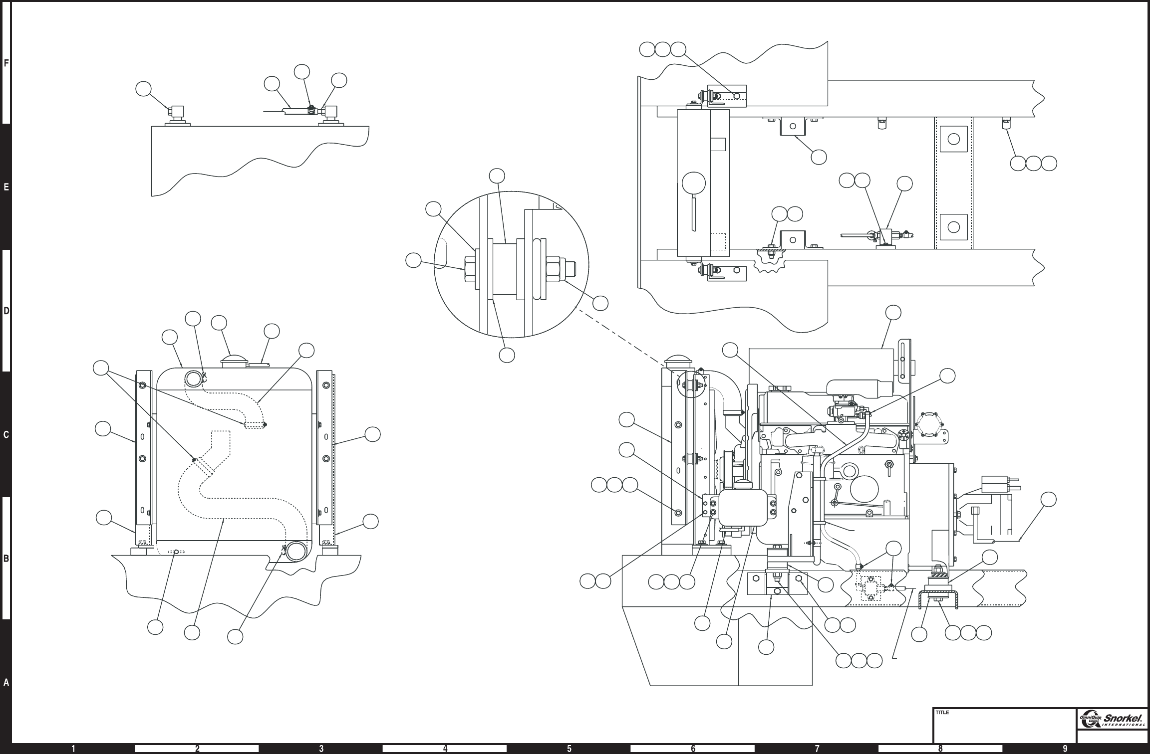
Page1-49Page1-49
Engine mounting
Ford LRG-423
Snorkel model TB 60
DRAIN
TO FUEL TANK
1
17
TY-RAP TO
WATER HOSE
17
18
4041 43
8
9
7
9
27 28 29
11
10
27 28 29
13
14
3031
3031
15 16
222334
4
12
10
33
5
37
36
38
6
32
42
15 16
33
242526
39 40 41
33
2
9
21
35 14
4
4
FUEL TANK
TO ELECTRIC
FUEL PUMP
20
17
18
19
AW0111846
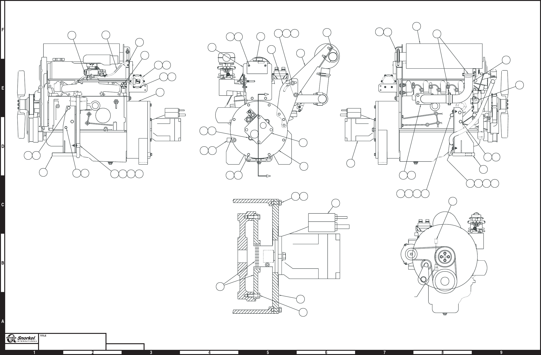
Page1-50Page1-50
Engine
Ford LRG-423
Snorkel model TB 60 DWG. 0111845
B
B
SECTION B-B
8
2
13
32
12
7
12
9
5
21
2
31
24
35
33
34
11
6
26
23
1
17
418
15
28
37
41
39
39
40
2
24
24
19
5
PUMP SUB ASSY
NOT SHOWN IN
TRUE ROTATION
LOCTITE
THREADS
43
FRONT VIEW OF
ENGINE
CRANK SENSOR PLUG
(NEXT TO CRANK PULLEY)
16
20 29 30 31
42
38
36 24 27
23
22
14 15
3
28 29 30 31
10
282930
25
25
26
AW0111845

Engine, Ford LRG-423
item part no qty description
0111845 Engine, Ford LRG-423
1 7620040 1 Engine, Ford LRG-423 gasoline
7630328 1 Replacement carburetor
7630718 1 Carburetor rebuild kit
7630348 1 Replacement choke
7630349 1 Replacement metal float
8260003 1 Replacement fiber float
7630722 1 Replacement oil filter
2 0181525 1 Hydraulic pump - (see page 2-52 for parts breakdown)
3 0111838 1 Motor mount, right hand
4 0111839 1 Motor mount, left hand
5 0080827 1 Engine adapter, Ford engine
6 0181535 1 Exhaust bracket, lower
7 7630255 1 Muffler, standard
7630307 1 Muffler, spark arrestor
8 0181453 1 Exhaust pipe
9 0111866 1 Exhaust flange, LRG Ford
10 1 Exhaust gasket - (included with engine, item 1)
11 0181534 1 Exhaust bracket, upper
12 5550014 3 Exhaust clamp
13 5093004 1 Clamp
14 5560652 2 Capscrew metric M10-1.5 x 70mm long hex head
15 5560356 4 Washer metric M10 lock
16 971999 2 Capscrew metric M10-1.5 x 25mm long hex head
17 3020095 1 Switch, oil pressure
18 5560357 1 Capscrew metric M8-1.25 x 25mm long hex head
19 7630249 1 Flexible coupling
20 5560355 3 Washer metric M8 lock
21 970849 2 Capscrew 1/2-13 x 1-1/4 inch long hex head grade 5
22 5560168 2 Washer 1/2 hard flat ASTM-F436
23 986299 3 Washer 3/8 medium flat
24 970479 17 Capscrew 3/8-16 x 1-1/4 inch long hex head grade 5
25 987119 8 Washer 3/8 medium lock
26 986269 2 Washer 5/16 medium flat
27 5560033 2 Nut 3/8-16 self locking
28 970029 3 Capscrew 1/4-20 x 3/4 inch long hex head grade 5
29 986019 3 Washer 1/4 medium flat
30 5560004 3 Nut 1/4-20 self locking
31 5093006 3 Clamp
32 0111869 1 wire harness, alternator
33 0110862 1 Bracket, spark module mount
34 7630329 1 Spark module - (included with engine, item 1)
35 5560650 2 Machine screw #10-24 x 2 inch long truss head
36 5560034 2 Nut #10-24 self locking
37 3020054 1 Vacuum switch - (included with engine, item 1)
8130005 1 Replacement switch
38 5090024 1 Vacuum fitting 1/8 NPT brass straight
39 5010007 1 Vacuum hose, 3/16 inch diameter x 18 inch long
40 5090026 4 Clamp
41 5560651 2 Machine screw #10-32 x 1 inch long truss head
42 5560038 2 Nut #10-32 self locking
43 0111887 1 Wire harness, crank sensor
TB 60 – 01-97 through 01-01 1-51

Engine mounting, Ford LRG-425
item part no qty description
1 0083368 1 Engine, Ford LRG-425 - (see page 1-55 for parts breakdown)
2 7630677 1 Radiator
3 0180441 2 Bracket, radiator support
4 0081860 2 Angle, radiator
5 7630180 4 Radiator cushion
6 5560179 8 Washer
7 7630332 1 Radiator hose, lower
8 7630749 1 Radiator hose, upper
9 5550030 4 Clamp
10 7630117 4 Engine mount
11 0071599 8 Engine mount washer
12 0180832 1 Mount plate, overflow reservoir
13 7630227 1 Overflow reservoir
8060277 1 Replacement reservoir cap
14 5010012 1 Radiator overflow hose 5/16 inch diameter x 60 inch long
15 970909 6 Capscrew 1/2-13 x 1-1/2 inch long hex head grade 5
16 5560039 6 Nut 1/2-13 self locking
17 5550028 5 Clamp
18 5010011 1 Fuel hose 5/16 inch diameter x 120 inch long
19 5093012 1 Hose clamp
20 5090032 2 Fitting, straight barbed
21 1 Drain cock - (included with engine)
22 970239 4 Capscrew 5/16-18 x 3/4 inch long hex head grade 5
23 987109 4 Washer 5/16 medium lock
24 970889 4 Capscrew 1/2-13 x 1 inch long hex head grade 5
25 986359 4 Washer 1/2 medium flat
26 987139 4 Washer 1/2 medium lock
27 5560639 4 Capscrew 5/8-11 x 4-1/2 inch long hex head grade 5
28 5560169 4 Washer 5/8 hard flat ASTM-F436
29 5560036 4 Nut 5/8-11 self locking
30 5560086 14 Capscrew 1/4-20 x 1 inch long hex head grade 5
31 5560004 16 Nut 1/4-20 self locking
32 986019 11 Washer 1/4 medium flat
33 0081464 2 Motor mount, front
34 986269 4 Washer 5/16 medium flat
35 7630239 1 Radiator cap - 13 psi
36 970519 4 Capscrew 3/8-16 x 2-1/4 inch long hex head grade 5
37 986299 4 Washer 3/8 medium flat
38 5560033 4 Nut 3/8-16 self locking
39 0112092 1 Decal, engine control module
40 970029 8 Capscrew 1/4-20 x 3/4 inch long hex head grade 5
41 3020081 1 Switch, toggle
42 5093008 1 Clamp
43 5093004 2 Clamp
44 0181154 1 Shield
45 7630688 1 Indicator lamp
46 0112093 1 Bracket, ECM mounting
47 987099 4 Washer 1/4 medium lock
48 7630687 1 Engine control module, Barber Coleman - (included with engine)
7630775 1 Engine control module, Precision - (included with engine)
49 7630678 1 Fuel line connector - (included with engine, item 1)
50 7630679 1 Fuel line connector - (included with engine, item 1)
51 7630680 1 Fuel line connector - (included with engine, item 1)
52 7630681 1 Pressure regulator - (included with engine, item 1)
53 7630682 1 Fuel pump - (included with engine, item 1)
54 7630683 1 Fuel filter - (included with engine, item 1)
55 7630686 1 High pressure hose - (included with engine, item 1)
56 7630685 1 Pressure regulator clamp - (included with engine, item 1)
57 7630691 1 High pressure fuel clamp - (included with engine, item 1)
1-52 TB 60 – 01-97 through 01-01
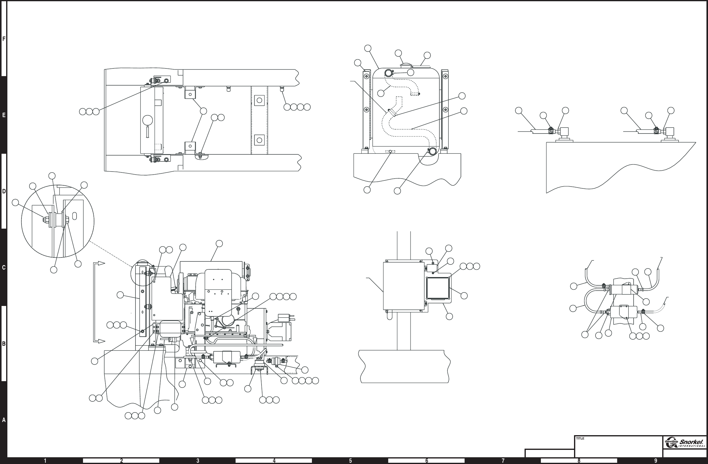
Page1-53Page1-53
Engine mounting
Ford LRG-425
Snorkel model TB 60
DWG. 0082693
36
37
38
5
6
6
33 15 16
27 28 29
10
11
27 28 29
10
33
15 16
B
B
17
49
52
56
49 53 31 32
51
45
1
18
55
55
CC
Section C-C
242526
43 40 41
342334
4
40 30 44
To tank
13
14
323130
3031
12
To engine
57
To tank
30 31 32 42
32
54
19 32 40 41
Section B-B
3
2
35 14
21 9
7
9
9
8
Note 1
Fuel tank
To fuel filter
To fuel filter
18
17
2018
17
20
Ground controls
48
47 31
39
41
45
46
32
AW0082693
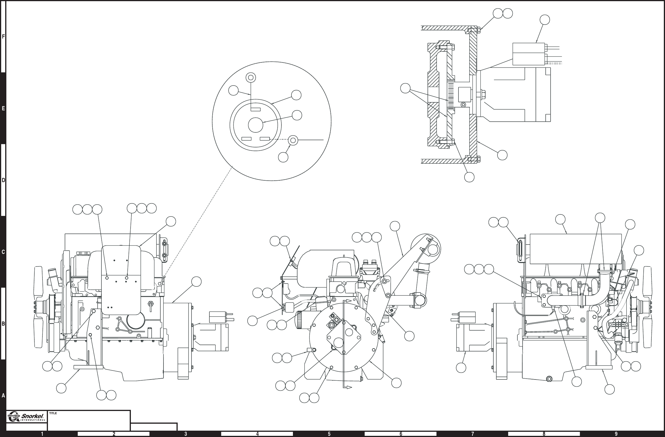
Page1-54Page1-54
Engine
Ford LRG-425
Snorkel model TB 60 DWG. 0083368
12
3
7
910
2
2612
32
8
5
11
23
6
31
37
2524
A
A
28
29 30 34 35
3335
20 18
4
16 15
1
36
14 15
NC NO
C
From Ford
harness
40
C
Oil pressure
switch
39 17
13
42
To ground
21
4647
3842
42
22
23
2427
35
2
24 25
24
19
5
Pump assembly
not shown in
true view
Section A-A
AW0083368

Engine, Ford LRG-425
item part no qty description
0083368 1 Engine, Ford LRG-425
1 7620055 1 Engine, Ford LRG-425 gasoline
7630722 1 Replacement oil filter
2 0082138 1 Hydraulic pump - (see page 2-52 for parts breakdown)
3 0111838 1 Motor mount, right hand
4 0111839 1 Motor mount, left hand
5 0080827 1 Engine adapter, Ford engine
6 0181525 1 Exhaust bracket, lower
7 7630255 1 Muffler
7630307 1 Muffler, spark arrestor
8 0181453 1 Exhaust pipe
9 0112088 1 Exhaust flange, LRG Ford
10 1 Exhaust gasket - (included with engine, item 1)
11 0181543 1 Exhaust bracket, upper
12 5550014 3 Exhaust clamp
13 7720201 1 Reducer
14 5560652 2 Capscrew metric M10-1.5 x 70mm long hex head
15 5560356 4 Washer metric M10 lock
16 971999 2 Capscrew metric M10-1.5 x 25mm long hex head
17 3020095 1 Switch, oil pressure
18 5560357 1 Capscrew metric M8-1.25 x 25mm long hex head
19 7630249 1 Flexible coupling
20 5560355 3 Washer metric M8 lock
21 5560136 2 Capscrew 1/2-13 self locking drilled head
22 5560168 2 Washer 1/2 hard flat ASTM-F436
23 986299 1 Washer 3/8 medium flat
24 970479 14 Capscrew 3/8-16 x 1-1/4 inch long hex head grade 5
25 987119 14 Washer 3/8 medium lock
26 986269 2 Washer 5/16 medium flat
27 5560033 2 Nut 3/8-16 self locking
28 1 Hego sensor - (included with engine)
29 0112084 1 Spacer, 3 inch
30 0112085 1 Spacer, 4 inch
31 5093006 2 Clamp
32 0111869 1 wire harness, alternator
33 5569823 1 Capscrew metric M8-1.25 x 105mm long hex head
34 5569824 1 Capscrew metric M8-1.25 x 130mm long hex head
35 5560610 2 Machine screw #10-24 x 1-1/4 inch long truss head
36 0112086 1 Engine harness cover plate
37 0112087 1 Connector bracket, 42 pin
38 5560609 5 Machine screw #10-24 x 1/2 inch long truss head
39 0071563 1 Jumper wire
40 3044145 1 Terminal #8 stud insulated 22/18 wire
41 5560034 2 Nut #10-24 self locking
42 5560625 1 Capscrew metric M10-1.5 x 20mm long hex head
TB 60 – 01-97 through 01-01 1-55
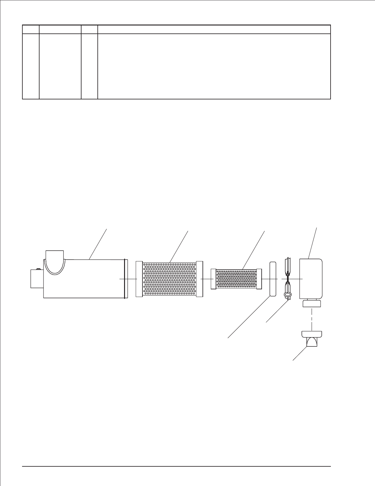
Air cleaner
item part no qty description
7630003 1 Air cleaner
1 1 Housing - (not sold separately)
2 8040106 1 Primary filter element
3 8040107 1 Secondary filter element
4 8040112 1 Cleaner cap baffle
5 8040114 1 Clamp
6 8040111 1 Dust cap
7 8040115 1 Vacuator valve
1-56 TB 60 – 01-97 through 01-01
123
4
5
6
7
AW7630003
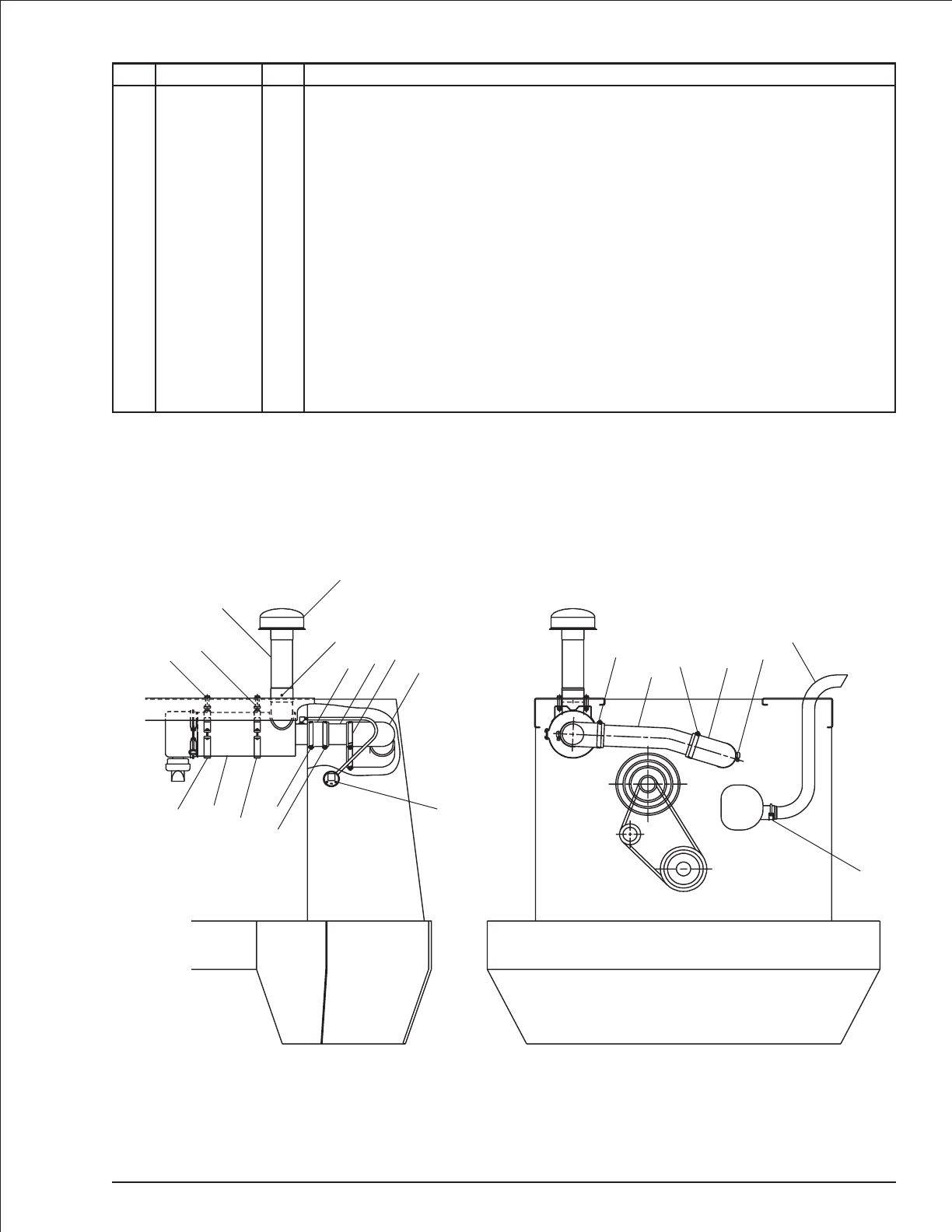
Exhaust and air cleaner, Deutz
item part no qty description
1 7630003 1 Air cleaner - (see page 1-56 for parts breakdown)
2 7630005 2 Air cleaner mounting band
3 0080879 1 Air inlet tube
4 7630004 1 Air inlet hood
5 0071510 4 Spacer, air cleaner
6 7630016 2 Elbow, 3 inch 90° rubber
7 0081053 1 Air intake hose
8 0081052 1 Air intake tube
9 0081639 1 Air intake tube
10 5560659 1 Pop rivet #AD44-ABS
11 0081640 1 Exhaust pipe
12 5550007 1 Exhaust clamp
13 5550050 1 Clamp
14 7630140 1 Filter condition indicator
15 970499 4 Capscrew 3/8-16 x 1-3/4 inch long hex head grade 5
16 986299 4 Washer 3/8 medium flat
17 5560033 4 Nut 3/8-16 self locking
TB 60 – 01-97 through 01-01 1-57
12
11
13 613
9
13
21213
13
14
4
10
7813 6
3
5
15
16
17
AW0081638

Exhaust and air cleaner, Ford
item part no qty description
1 7630003 1 Air cleaner, Ford LRG-423 - (see page 1-56 for parts breakdown)
7630689 1 Air cleaner, Ford LRG-425
8140006 1 Replacement primary filter element
2 7630004 1 Air inlet hood
3 7630005 2 Air cleaner mounting band - (Ford LRG-423 only)
4 0071510 4 Spacer, air cleaner - (Ford LRG-423)
0071510 2 Spacer, air cleaner - (Ford LRG-425)
5 0080679 1 Air inlet tube
6 0082123 1 Air cleaner elbow
7 0180988 1 Tail pipe - (Ford LRG-423)
0111959 1 Tail pipe - (Ford LRG-425)
8 7630016 1 Elbow, 3 inch 90° rubber
9 7630197 2 Elbow, 2 inch 90° rubber - (LRG-425 only)
10 5550050 2 Clamp
11 5550040 4 Clamp
12 0082694 1 Tube elbow
13 7630140 1 Filter condition indicator
14 5010001 1 Emission control hose 11/32 inch diameter - (Ford LRG-423)
5010020 1 Emission control hose 5/8 inch diameter - (Ford LRG-425)
15 5090030 1 Vacuum fitting - (Ford LRG-423 0nly)
16 5093006 1 Street elbow 1/8 NPT 90° brass - (Ford LRG-423 only)
17 5090024 1 Vacuum fitting 1/8 NPT brass straight - (Ford LRG-423 only)
18 5560658 3 Pop rivet #AD36-ABS
19 970509 4 Capscrew 3/8-16 x 2 inch long hex head grade 5 - (Ford LRG-423)
5560357 2 Capscrew metric 8M-1.25 x 25mm long hex head - (Ford LRG-425)
20 986299 8 Washer 3/8 medium flat
21 5560033 4 Nut 3/8-16 self locking
22 5090027 1 Union elbow female 1/8 x 1/8 brass
23 5090302 1 Tube clamp
24 5560609 4 Machine screw #10-24 x 1/2 inch long truss head
25 5560034 4 Nut #10-24 self locking
1-58 TB 60 – 01-97 through 01-01
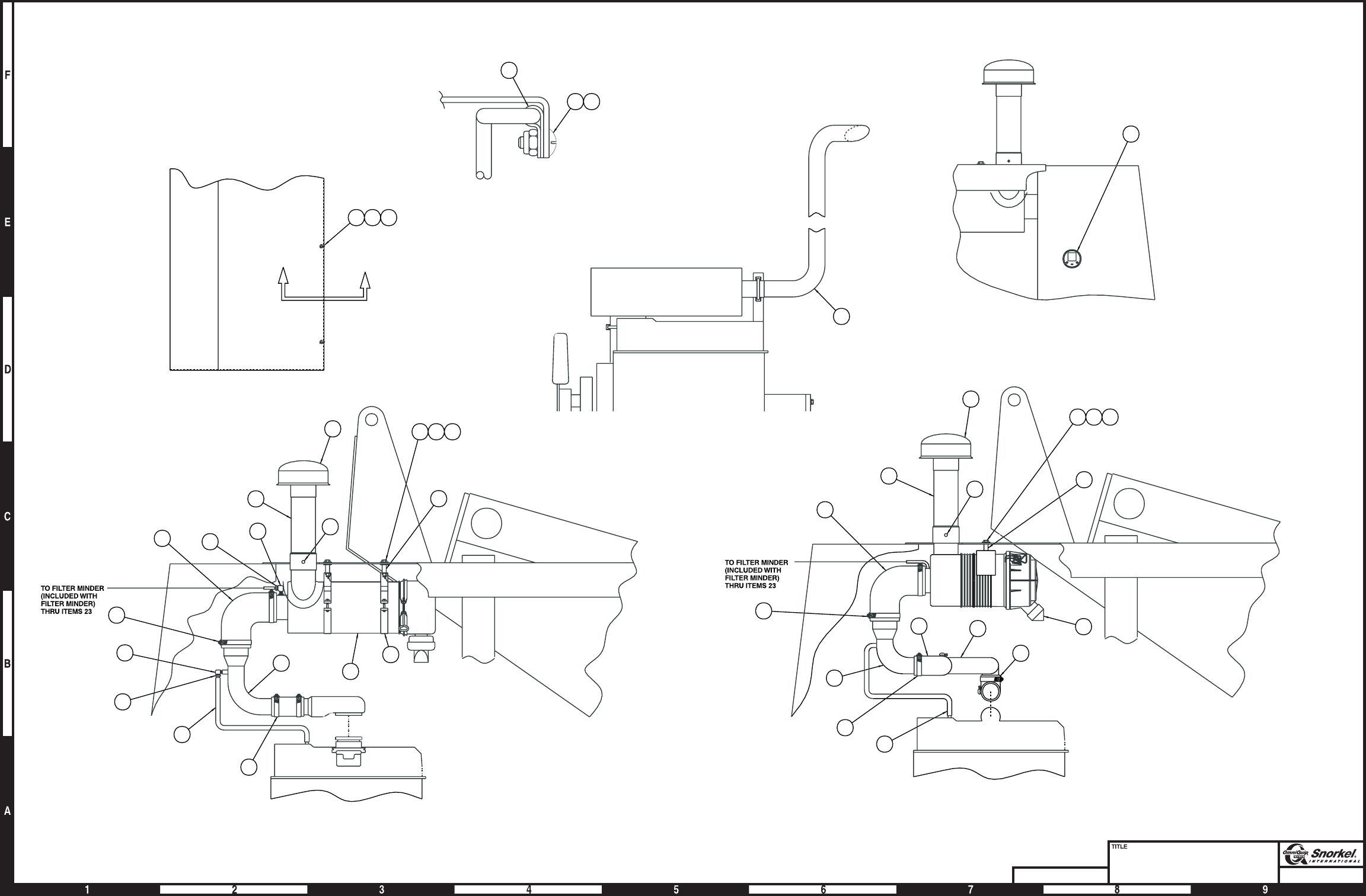
Page1-59Page1-59
Exhaust and air cleaner
Ford LRG-423 and LRG-425
Snorkel model TB 60
DWG. 0082695
7
Exhaust installation
5
CARB.
2
Section A-A
A
A
23 24 25
23
24
26
SLIDE ITEM 1 TOWARD FRONT COWLING
TO ALLOW REMOVAL OF AIR CLEANER
ELEMENT
18
10
8
11
6
12
19 20 21
14
1
9
9
4
Ford LRG-425
25
5
8
10
11
14
3
1
19 20 21
4
CARB
16
15
22
17
18
2
6
Ford LRG-423 AW0082695
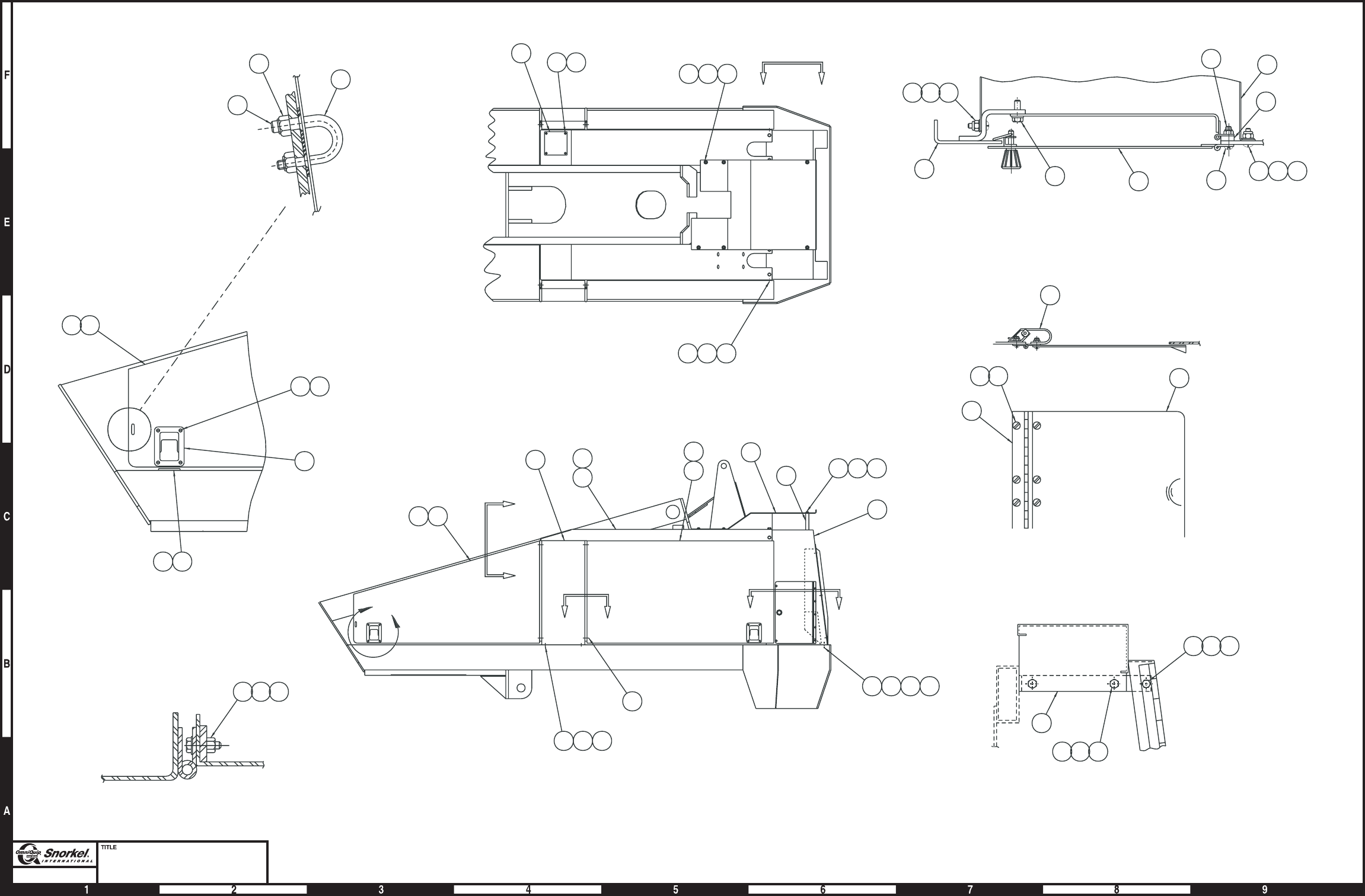
Page1-60Page1-60
Metal cowling
Deutz engine
Snorkel model TB 60
37
13
38
45 22 35
SECTION A-A
26
181617
23 24 25
VIEW B-B
8
9
27 28
SECTION C-C
33
32
1213
34
VIEW D-D
11
12
1415
DETAIL "F"
12
46
462035
10
29
13
"F"
12
B
B
3
19
16
4
5
NEAR SIDE
FAR SIDE
AA
6
739
41
8
40
17
CC
31 22 30
424344
161718
D
D
13
18 21 36
17 18
20 35
43 44
AW0081655

Metal cowling, Deutz engine
item part no qty description
1 0080006 1 Cowling door, rear left hand
2 0080005 1 Cowling door, rear right hand
3 0080007 2 Door post
4 0081641 1 Cowling side, left hand
5 0080972 1 Cowling side, right hand
6 0080008 1 Cowling door, front right hand
7 0080009 1 Cowling door, front left hand
8 0081877 1 Front cowling, complete - (includes the following replacement parts)
0080974 1 Front cowling
0081670 1 Shroud, inner air intake
0081671 1 Shroud, outer
5560137 6 Speed nut 5/16-18 with captive nut
970259 6 Capscrew 5/16-18x1inchlong hex head grade 5
986269 6 Washer 5/16 medium flat
9 007414928 1 Lower controls door
5510003 1 Replacement door latch
10 0110483 1 Cover, cowling rear
11 0070539 4 Door latch
12 5560609 24 Machine screw #10-24 x 1/2 inch long truss head
13 5560034 45 Nut #10-24 self locking
14 0070549 4 Door striker
15 0070441 4 Spacer, door striker
16 970849 20 Capscrew 1/2-13 x 1-1/4 inch long hex head grade 5
17 984149 24 Nut 1/2-13 hex
18 987139 20 Washer 1/2 medium lock
19 970029 10 Capscrew 1/4-20 x 3/4 inch long hex head grade 5
20 5560004 15 Nut 1/4-20 self locking
21 970949 4 Capscrew 1/2-13 x 2-1/2 inch long hex head grade 5
22 5560086 14 Capscrew 1/4-20x1inchlonghexhead grade 5
23 970479 4 Capscrew 3/8-16 x 1-1/4 inch long hex head grade 5
24 987119 4 Washer 3/8 medium lock
25 984109 4 Nut 3/8-16 hex
26 0080010 2 Upper door post bracket
27 5560086 2 Capscrew screw 1/4-20 x 1 inch long hex head with sems
28 5560649 5 Machine screw #10-24 x 1 inch long truss head
29 0110482 1 Spacer bar
30 987099 4 Washer 1/4 medium lock
31 0070295 1 Cover, filter access
32 0070554 1 Hinge, air cleaner access door
33 0070555 1 Air cleaner access door
34 0070548 1 Door spring
35 986019 24 Washer 1/4 medium flat
36 986359 4 Washer 1/2 medium flat
37 5560135 4 Staple plate
38 976689 8 Machine screw #10-24 x 3/4 inch long flat head
39 0081117 1 Cover
40 0073158 3 Spacer
41 5560654 3 Capscrew 3/8-16 x 5-1/2 inch long hex head grade 5
42 970469 4 Capscrew 3/8-16x1inchlonghexhead grade 5
43 986299 7 Washer 3/8 medium flat
44 5560033 7 Nut 3/8-16 self locking
45 984069 10 Nut 1/4-20 hex
46 5560646 5 Capscrew 1/4-20 x 3/4 inch long truss head
47 5569012 10 Bumper - (not shown)
TB 60 – 01-97 through 01-01 1-61

Metal cowling, Ford engine
item part no qty description
1 0080006 1 Cowling door, rear left hand
2 0080005 1 Cowling door, rear right hand
3 0080007 2 Door post
4 0080971 1 Cowling side, left hand
5 0080972 1 Cowling side, right hand
6 0080008 1 Cowling door, front right hand
7 0080009 1 Cowling door, front left hand
8 0080973 1 Front cowling, complete - (includes the following replacement parts)
0080974 1 Front cowling
0080626 1 Shroud
5560137 6 Speed nut 5/16-18 with captive nut
970259 6 Capscrew 5/16-18x1inchlong hex head grade 5
986269 6 Washer 5/16 medium flat
9 007414928 1 Lower controls door
5510003 1 Replacement door latch
10 0110483 1 Cover, cowling rear
11 0070539 4 Door latch
12 5560609 12 Machine screw #10-24 x 1/2 inch long truss head
13 5560034 26 Nut #10-24 self locking
14 0070549 4 Door striker
15 0070441 4 Spacer, door striker
16 970849 20 Capscrew 1/2-13 x 1-1/4 inch long hex head grade 5
17 984149 24 Nut 1/2-13 hex
18 987139 20 Washer 1/2 medium lock
19 970029 10 Capscrew 1/4-20 x 3/4 inch long hex head grade 5
20 5560004 14 Nut 1/4-20 self locking
21 970949 4 Capscrew 1/2-13 x 2-1/2 inch long hex head grade 5
22 5560086 14 Capscrew 1/4-20 x 1 inch long hex head grade 5
23 970479 4 Capscrew 3/8-16 x 1-1/4 inch long hex head grade 5
24 987119 4 Washer 3/8 medium lock
25 984109 4 Nut 3/8-16 hex
26 0080010 2 Upper door post bracket
27 5560086 2 Machine screw 1/4-20x1inchlong hex head with sems
28 5560649 5 Machine screw #10-24 x 1 inch long truss head
29 0110482 1 Spacer bar
30 987099 4 Washer 1/4 medium lock
31 0070295 1 Cover, filter access
32 0070554 1 Hinge, air cleaner access door
33 0070555 1 Air cleaner access door
34 0070548 1 Door spring
35 986019 24 Washer 1/4 medium flat
36 986359 4 Washer 1/2 medium flat
37 5560135 4 Staple plate
38 976689 8 Machine screw #10-24 x 3/4 inch long flat head
39 0081357 1 Cover
40 0073481 1 Access door
41 5560654 3 Capscrew 3/8-16 x 5-1/2 inch long hex head grade 5
42 970469 7 Capscrew 3/8-16 x 1 inch long hex head grade 5
43 986299 7 Washer 3/8 medium flat
44 5560033 7 Nut 3/8-16 self locking
45 984069 10 Nut 1/4-20 hex
46 5560646 5 Capscrew 1/4-20 x 3/4 inch long truss head
47 5569012 10 Bumper - (not shown)
1-62 TB 60 – 01-97 through 01-01
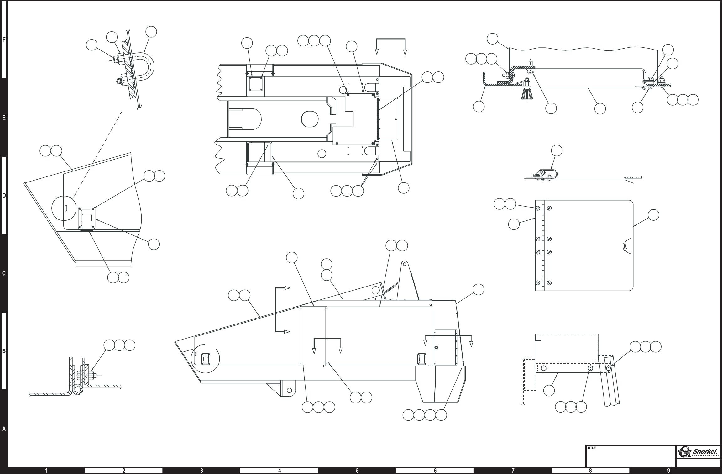
Page1-63
Metal cowling
Ford engine
Snorkel model TB 60
31
22
42
D
D
16
16 26
39
40
41
"F"
1
B
B
3
19
16
4
NEAR SIDE
FAR SIDE
AA
6
8
CC
17
37
13
38
45 22 35
SECTION A-A
26
1816
17
23 24 25
VIEW B-B
89
27 28
SECTION C-C
32
34
VIEW D-D
11
12 13
14 15
DETAIL "F"
12
29
13
46 20 35
462035
10
30
4344
13
1718
17
5
2
7
182136
20
17 18
33
1213
AW0081934
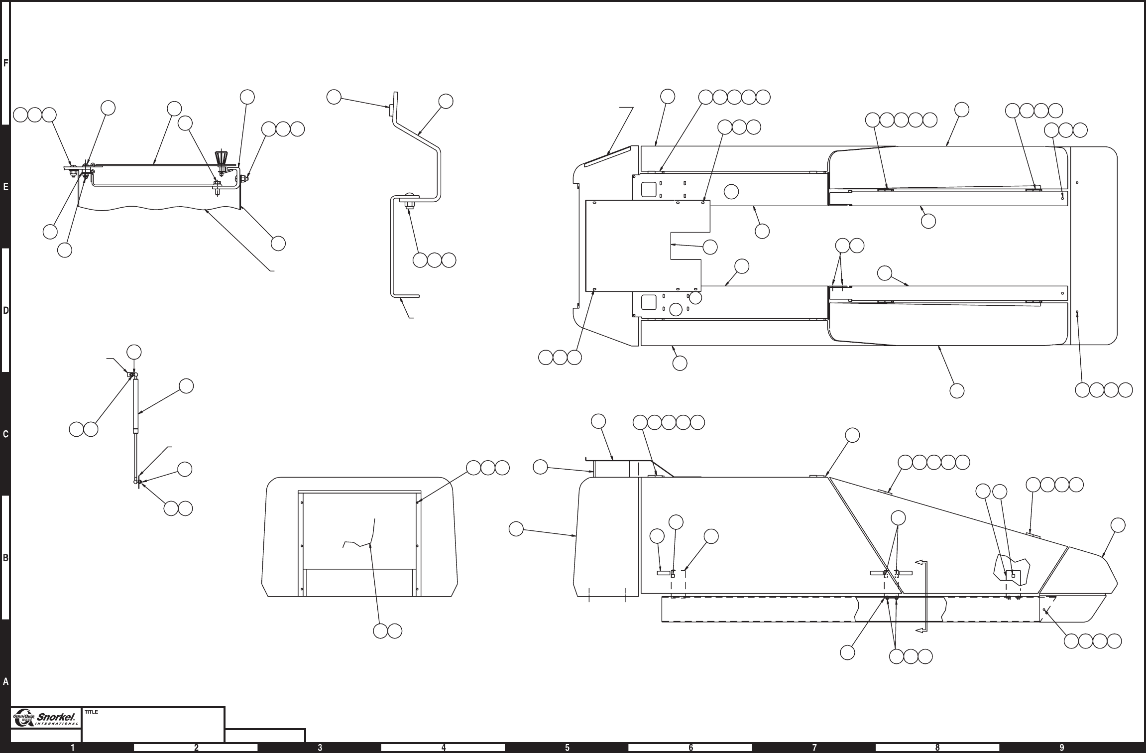
Page1-64
Plastic cowling
Deutz
Snorkel model TB 60 DWG. 0082368
DETAIL "A"
VIEW LOOKING DOWN GROUND CONTROL
PANEL AND HINGE
TURNTABLE SIDE RAIL
VIEW C-C
DOOR GUSSET
DOOR HINGE
DETAIL "B"
CONTROL BOX RECESS
SEE DETAIL "A"
C
C
20
37
38 39 40 41 2
42
16
38 39 40
50 9
26 27 28
24
17
44
46
24
46 44
21
43 44 45 36
14
349
418 26 27 28
17
9
50
22
23
50
17 19 26 27 29
950 19 26 27 28
926 27 28
15
27 28 47 25
27 28 51 5
727 28 47 35
4
11
10
13
12
31 33
617 19 26 2827
27 28 34 17 18 26 27 28
818 26 27 28
27 28 47
AW0082368

Plastic cowling, Deutz engine
item part no qty description
1 0073481 1 Cover, plastic cowling
2 0074149 1 Lower controls door
3 0081670 1 Shroud, cowling
4 0081117 1 Access cover, cowling
5 0082288 1 Cowling door, front left hand
6 0082290 1 Cowling door, front right hand
7 0082293 1 Cowling door, rear left hand
8 0082294 1 Cowling door, rear right hand
9 0082303 4 Door stop
10 0082304 1 Cowling side, left front
11 0082307 1 Cowling side, right front
12 0082310 1 Rail, side left rear
13 0082311 1 Rail, side right rear
14 008231928 1 Front cowling - (includes following items)
300808201 1 Installation drawing for front cowling
0083274 1 Front cowling
0162758 1 Front cowling support
5569833 6 Speed nut 5/16-18 with captive nut
15 0082320 1 Cover, turntable rear
16 0082335 1 Mount box
17 0082321 6 Gas spring
18 0082346 4 Hinge half, left front
19 0082349 4 Hinge half, right front
20 0110482 1 Spacer bar
21 0110483 1 Cover, lower controls
22 5510002 6 Adjustable level latch
23 5560310 8 Cap nut 3/8 inch shaft
24 5560311 12 Ball stud
25 0082547 12 Shim
26 5560531 28 Carriage bolt 3/8-16 x 1-1/2 inch long
27 986299 47 Washer 3/8 medium flat
28 5560033 40 Nut 3/8-16 self locking
29 970949 4 Capscrew 1/2-13 x 2-1/2 inch long hex head grade 5
30 986359 4 Washer 1/2 medium flat
31 987139 12 Washer 1/2 medium lock
32 984149 8 Nut 1/2-13 hex
33 970849 8 Capscrew 1/2-13 x 1-1/4 inch long hex head grade 5
34 970469 4 Capscrew 3/8-16x1inchlonghexhead grade 5
35 0082546 20 Shim
36 0073158 2 Spacer
37 5560034 5 Nut #10-24 self locking
38 970029 5 Capscrew 1/4-20 x 3/4 inch long hex head grade 5
39 5560004 5 Nut 1/4-20 self locking
40 986019 5 Washer 1/4 medium flat
41 5560649 5 Machine screw #10-24 x 1 inch long truss head
42 5560086 2 Capscrew 1/4-20x1inchlonghexhead grade 5
43 970259 6 Capscrew 5/16-18x1inchlong hex head grade 5
44 986269 18 Washer 5/16 medium lock
45 5560137 6 Speed nut 5/16-18 with captive nut
46 5560031 12 Nut 5/16-18 self locking
47 970489 6 Capscrew 3/8-16 x 1-1/2 inch long hex head grade 5
48 5560313 1 Trim lock, .063 inch rubber edge
49 0081671 1 Shroud, outer air intake
50 5560080 10 Bumper
51 5560654 2 Capscrew 3/8-16 x 5-1/2 inch long hex head grade 5
TB 60 – 01-97 through 01-01 1-65

Plastic cowling, Cummins and Ford engine
item part no qty description
1 0073481 1 Cover, plastic cowling
2 0074149 1 Lower controls door
3 0080626 1 Shroud, cowling
4 0081357 1 Access cover, cowling
5 0082288 1 Cowling door, front left hand
6 0082290 1 Cowling door, front right hand
7 0082293 1 Cowling door, rear left hand
8 0082294 1 Cowling door, rear right hand
9 0082303 4 Door stop
10 0082304 1 Cowling side, left front
11 0082307 1 Cowling side, right front
12 0082310 1 Rail, side left rear
13 0082311 1 Rail, side right rear
14 008231928 1 Front cowling - (includes following items)
300808201 1 Installation drawing for front cowling
0083274 1 Front cowling
0162758 1 Front cowling support
5569833 6 Speed nut 5/16-18 with captive nut
15 0082320 1 Cover, turntable rear
16 0082335 1 Mount box
17 0082321 6 Gas spring
18 0082346 4 Hinge half, left front
19 0082349 4 Hinge half, right front
20 0110482 1 Spacer bar
21 0110483 1 Cover, lower controls
22 5510002 6 Adjustable level latch
23 5560310 8 Cap nut 3/8 inch shaft
24 5560311 12 Ball stud
25 0082547 12 Shim
26 5560531 28 Carriage bolt 3/8-16 x 1-1/2 inch long
27 986299 44 Washer 3/8 medium flat
28 5560033 38 Nut 3/8-16 self locking
29 970949 4 Capscrew 1/2-13 x 2-1/2 inch long hex head grade 5
30 986359 4 Washer 1/2 medium flat
31 987139 12 Washer 1/2 medium lock
32 984149 8 Nut 1/2-13 hex
33 970849 8 Capscrew 1/2-13 x 1-1/4 inch long hex head grade 5
34 970469 4 Capscrew 3/8-16 x 1 inch long hex head grade 5
35 5560080 10 Bumper
36 5560609 5 Machine screw #10-24 x 1/2 inch long truss head
37 5560034 10 Nut #10-24 self locking
38 970029 5 Capscrew 1/4-20 x 3/4 inch long hex head grade 5
39 5560004 5 Nut 1/4-20 self locking
40 986019 5 Washer 1/4 medium flat
41 5560649 5 Machine screw #10-24 x 1 inch long truss head
42 5560086 2 Capscrew 1/4-20 x 1 inch long hex head grade 5
43 970259 6 Capscrew 5/16-18x1inchlong hex head grade 5
44 986269 18 Washer 5/16 medium lock
45 5560137 6 Speed nut 5/16-18 with captive nut
46 5560031 12 Nut 5/16-18 self locking
47 970489 6 Capscrew 3/8-16 x 1-1/2 inch long hex head grade 5
48 5560313 1 Trim lock, .063 inch rubber edge
1-66 TB 60 – 01-97 through 01-01
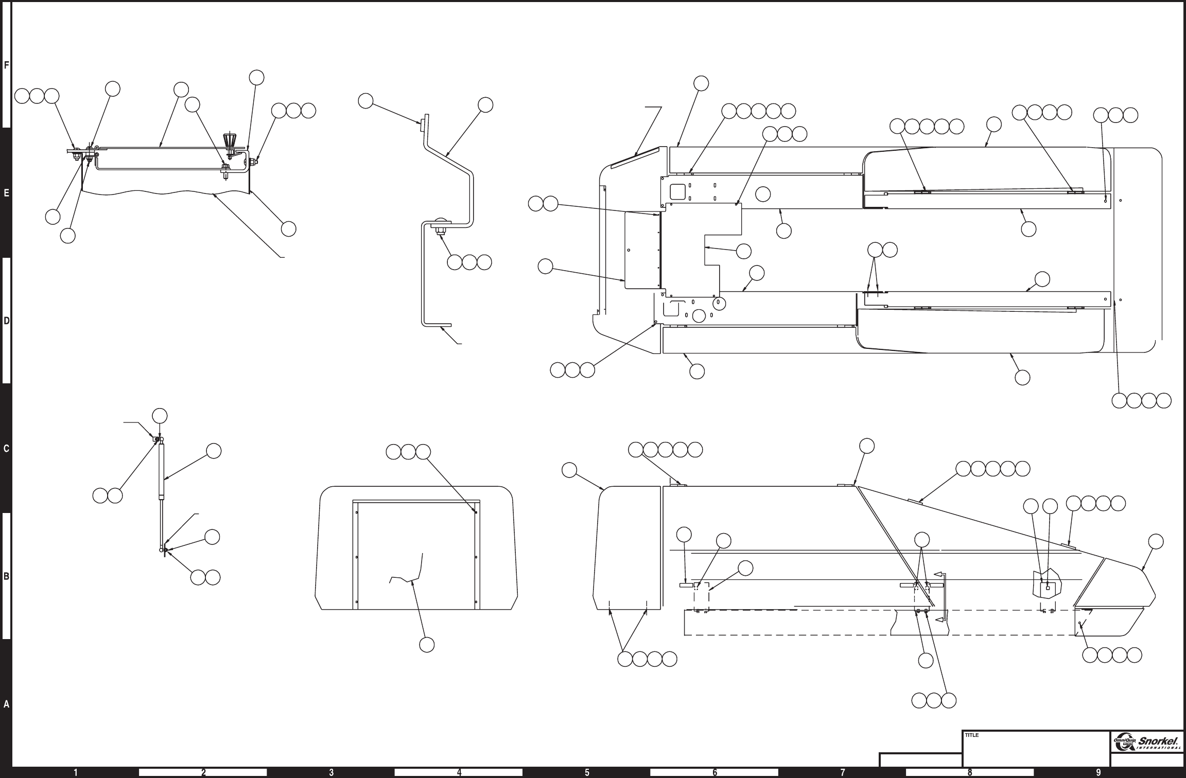
Page1-67
Plastic cowling
Cummins and Ford
Snorkel model TB 60
DWG. 0082341
DETAIL "A"
VIEW LOOKING DOWN GROUND CONTROL
PANEL AND HINGE
VIEW C-C
CONTROL BOX
SEE DETAIL "A"
DETAIL "B"
DOOR HINGE
DOOR GUSSET
38 39 40 41 2
42
16
38 39 40
20
37 21
35 9
26 27 28 1
36 37
6
17 19 26 27 28
27 28 34
11
4
10
31 33
17 18 26 27 28 8
27 28 27 28 47
13
12
7
27 28 35 47
5
31 32 33
TURNTABLE
SIDE RAIL
24
17
44 46
24
44 46
43 44 45
14
17 18 26 27 28 23
22 35
9
17 19 26 27 28
9
35
35 19
26 27 28
15
27 28 47 25
9
26 27 28
29 30 31 32
3
C
C
18 26
AW0082341

Placards and decals
item part no qty description
0082952 1 Complete placard and decals kit, TB 60 - (does not include upper control box placards)
0082953 1 Platform decal kit, TB 60 - (does not include upper control box placards)
1 0073298 2 Placard, danger foam filled tires
2 0323896 5 Decal, danger electrical hazard
3 0070420 1 Placard, emergency bleed down valve
4 560239 4 Decal, Snorkel brand logo
5 0323897 1 Decal, danger you must not operate
6 0074209 1 Placard, pre-start instructions
7 1 Placard, platform capacity - (consult factory)
8 0323899 1 Decal, danger electrical hazard
9 0070540 3 Decal, yellow arrow
10 0070541 3 Decal, blue arrow
11 0070901 1 Placard, caution serial number
12 5560655 8 Pop rivet #AD32-ABS
13 0071425 1 Placard, platform identification
14 0071927 1 Decal, hydraulic oil
15 7030004 2 Decal, OmniQuip logo
16 562386 1 Literature compartment
17 0073491 1 Decal, safe operation information
18 0082176 2 Decal, TB 60 logo
19 0073224 1 Decal, notice manual reorder
20 0072277 2 Placard, lug nut torque
21 5560080 4 Bumper
22 970009 2 Capscrew 1/4-20 x 1/2 inch long hex head grade 5
23 0072531 1 Decal, danger electrical hazard
24 7030003 1 Decal, lube recommendations
25 0070921 2 Placard, 125 volts 15 amps
26 0073043 1 Decal, operating manual enclosed
27 0073139 1 Crankcase oil tag - (used for shipping only)
28 0074311 5 Decal, danger cylinder failure - (1 per cylinder)
29 9980021 2 Plug 3-1/2 inch diameter
30 5569012 8 Rubber bumper
31 0150448 1 Decal, attach fall restraint
32 0073492 1 Decal, rotate while greasing
33 9980022 1 Plug 4 inch diameter
34 0074372 1 Placard, engine rpm
35 0073667 2 Decal, inspect wire ropes
36 0074210 1 Decal, danger electrical/tipping hazard
37 5560004 2 Nut 1/4-20 self locking
38 0073585 2 Decal, made in USA
39 0190989 1 Decal, danger do not reach
40 9980013 2 Cap
41 0181562 1 Placard, ANSI standard
42 0083431 1 Decal, lift/tie down
43 0083426 4 Decal, tie down symbol
44 0080650 4 Decal, lift
45 0071925 1 Decal, gasoline fuel - (gasoline machine)
0071926 1 Decal, diesel fuel - (diesel machine)
46 0151410 3 Decal, danger rotating engine parts - (Ford only)
47 0074316 1 Decal, caution governor damage - (Ford only)
48 0112092 1 Decal, engine control module - (Ford only)
49 0072276 2 Placard, lug nut torque - (4 x 2 machine)
0072277 2 Placard, lug nut torque - (4 x 4 machine)
50 0111390 2 Decal,4x4logo-(4wheel drive machine)
Parts list continued on next page
TB 60 – 01-97 through 01-01 1-69

Placards and decals
item part no qty description
51 0081441 1 Placard, caution liquid withdrawal - (dual fuel or LP fuel)
52 0081377 1 Decal, LPS logo - (LP fuel only)
53 0090493 1 Decal, dual fuel instructions - (dual fuel machine)
54 0072203 2 Decal, towing instructions - (towing option)
55 0082160 1 Decal, danger tow package - (towing option)
56 0082164 1 Decal, danger do not ride - (towing option)
57 0082203 1 Decal, danger crushing hazard - (towing option)
58 0071793 1 Decal, hydraulic warm-up instructions - (hydraulic warm-up option)
59 0070421 4 Placard, tire pressure - (flotation tire option, 1 per wheel)
1-70 TB 60 – 01-97 through 01-01
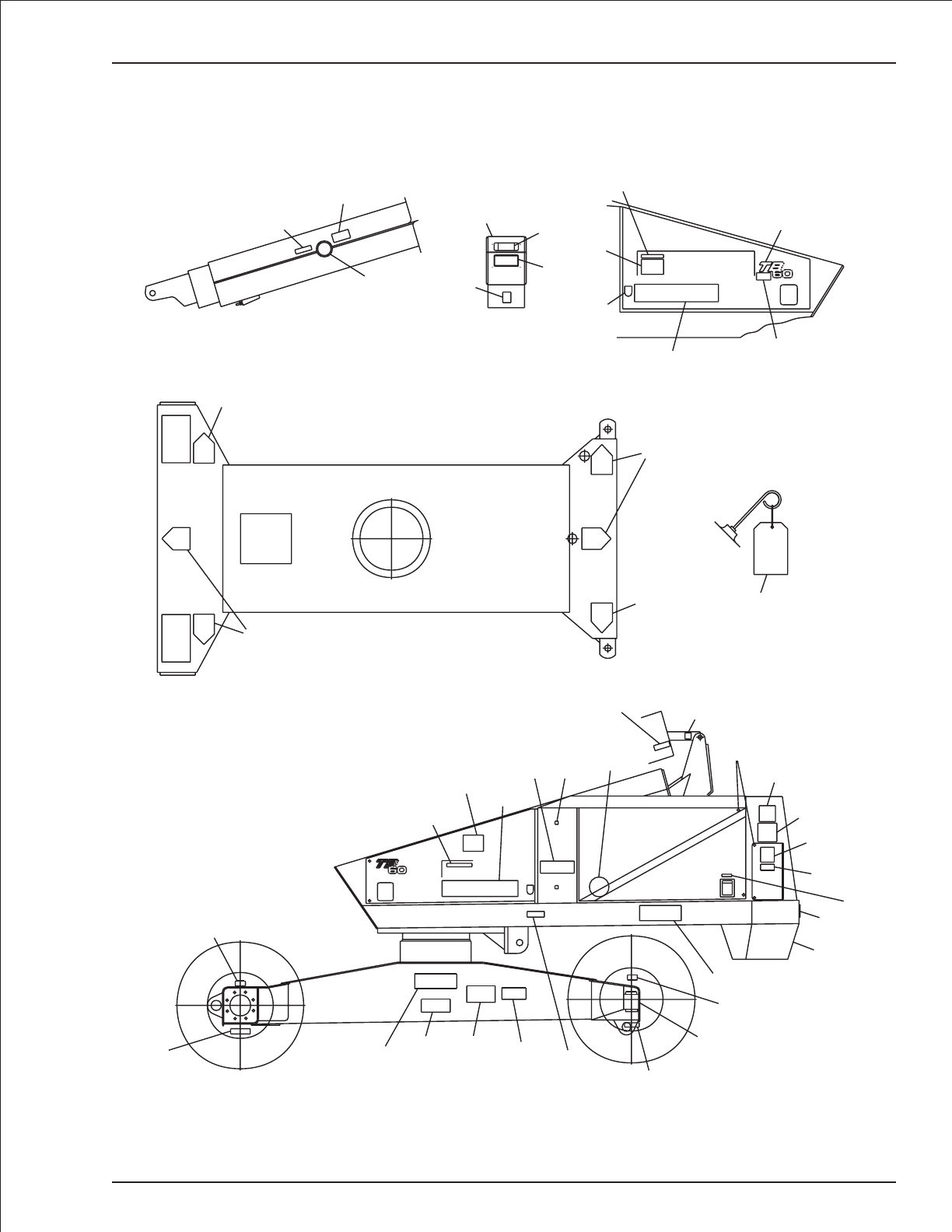
Placards and decals
TB 60 – 01-97 through 01-01 1-71
10
9
10
927
39
35
40
38
14
24
4
18
47
RECORD BOX
16 19
26
3412
59
49
45
51 4
21
50
35 28
30
52
11
12
5
41
2
57
17
2
15
3
54
55
1
2
20
54
59 AWA08065F-2
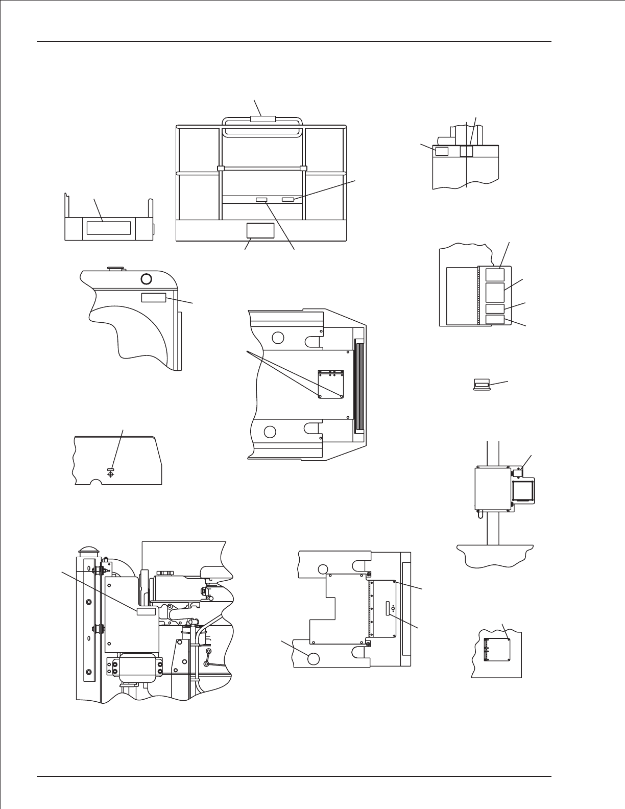
Placards and decals
1-72 TB 60 – 01-97 through 01-01
FORD ENGINE
SIDE VIEW
46
TIP BOOM
8
56
FRONT VIEW OF
TURNTABLE
32
RADIATOR
FORD ENGINE
46
48
FRONT COWLING
DEUTZ ENGINE
TOP VIEW
30 LOWER CONTROL DOOR
(SHOWN OPEN)
6
36
58
53
TOP VIEW OF
GFCI OUTLET BOX
25
FRONT COWLING
LH SIDE
30
FRONT COWLING
FORD ENGINE
TOP VIEW
46
30
29
33
4
23
31
12
13
7
AWA08065F-3
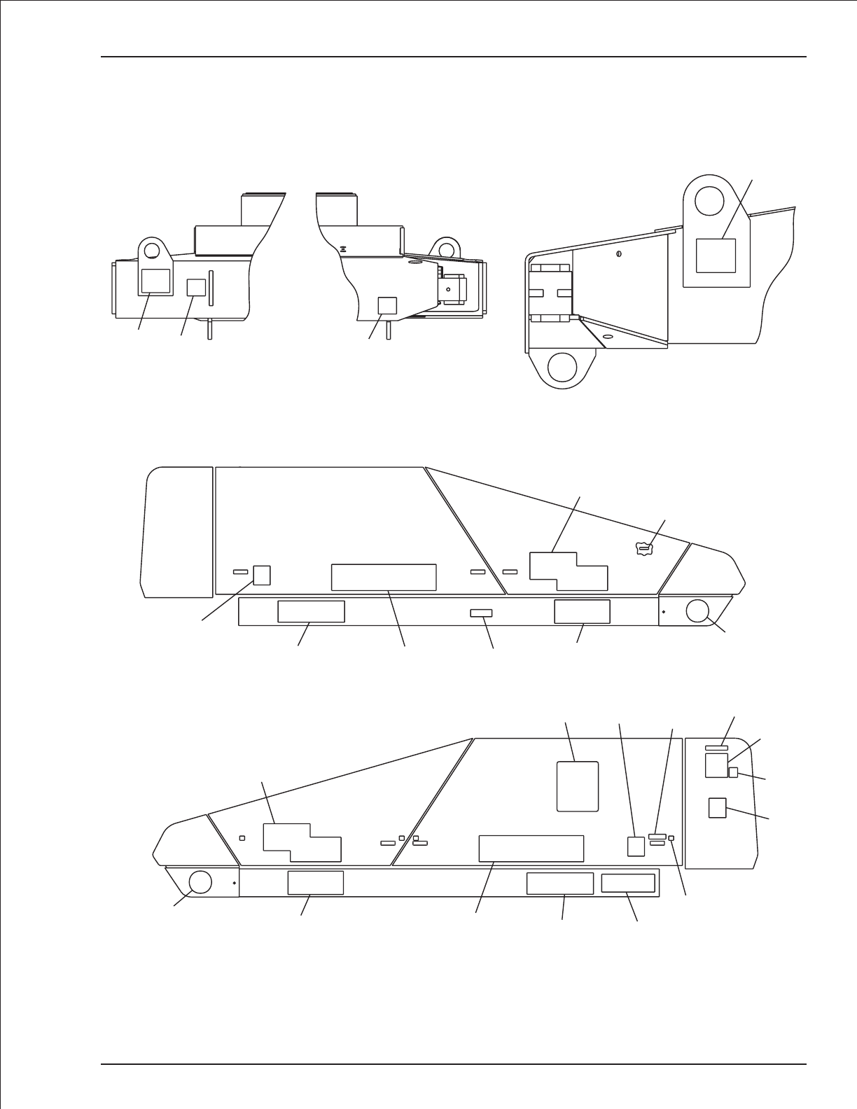
Placards and decals
TB 60 – 01-97 through 01-01 1-73
SIDE VIEW
STEER END
STEER END
DRIVE END
PLASTIC COWLING
15
18
50 242
4
5
21
34
11
41
17
38
16
22
18
50
15
32
23
38
4
44 43 43
44
AWA08065F-4

Gear hub, high torque
item part no qty description
0081674 1 Gear hub, high torque
1 8010106 1 Secondary carrier
2 8010107 1 Primary carrier
3 8010097 1 Cover
4 986299 12 Washer 3/8 medium flat
5 8010069 12 Capscrew hex head
6 8010157 1 Ring gear
7 8010175 2 Thrust washer
8 7280022 8 Wheel bolt
9 8010151 1 Spring
10 8010173 1 Thrust washer
11 8010031 1 Bearing cup
12 8010032 1 Bearing cone
13 8010029 1 Bearing cup
14 8010030 1 Bearing cone
15 8010186 1 Hub
16 8010013 1 Coupling
17 8010027 1 Oil seal
18 8010109 1 Spindle
19 8010028 1 Magnetic plug
20 8010108 1 Sun gear
21 8010143 1 Plunger
22 8010149 1 O-ring
23 8010168 2 Capscrew hex head
24 8010080 1 Disengage cover
25 8010169 1 Input shaft
26 8010075 1 Thrust washer
27 8010145 2 Retaining ring
28 8010150 1 Retainer nut
1-74 TB 60 – 01-97 through 01-01
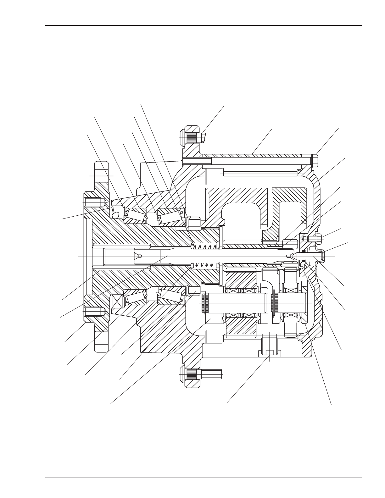
Gear hub, high torque
TB 60 – 01-97 through 01-01 1-75
17
16
18
15
7
29
28
25
119 2
26
3
20
27
23
24
21
22
5
4
6
8
10
9
13
14
11
12
AW0081674

Swing drive, Auburn Gear
item part no qty description
0070047 1 Swing drive, Auburn Gear
1 8010232 1 Output shaft
2 8010260 1 Oil seal
3 8010227 1 Bearing cone
4 8010226 1 Bearing cup
5 8010235 12 Capscrew, socket head
6 8010221 12 Washer, flat
7 8010225 1 Bearing cone
8 8010224 1 Bearing cup
9 8010236 1 Thrust washer
10 8010222 1 Washer, lock
11 8010229 1 Nut, lock
12 8010261 3 Sealing compound
13 8010262 1 Pipe plug
14 8010219 1 Cover
15 8010263 1 Gasket
16 8010238 1 Adapter, spline
17 8010264 1 Shipping plug
18 8010223 1 Bearing, flange sleeve
19 8010265 1 Brake
8010247 1 Seal repair kit - Q series
8010248 1 Seal repair kit - P series
20 8010266 4 Washer, flat
21 8010217 1 Thrust washer
22 8010267 8 Bolt, hex head
23 8010220 8 Washer, flat
24 8010231 1 Gear, sun
25 8010230 1 Gear, ring
26 8010237 1 Carrier
27 8010233 1 Hub
28 8010218 1 Hub flange
29 8010268 1 Pipe plug
30 8010269 2 Pipe plug
31 8010270 4 Bolt, hex head
32 8010271 2 Pipe plug
33 8010239 1 Piston kit - (not shown)
34 8010240 1 Friction disc kit - (not shown)
1-76 TB 60 – 01-97 through 01-01
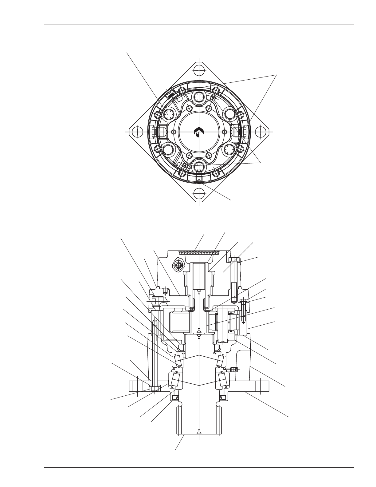
Swing drive, Auburn Gear
TB 60 – 01-97 through 01-01 1-77
P
U
T
R
T
A
S
P
I
T
O
R
O
R
O
T
D
T
B
E
F
S
T
U
L
E
L
I
B
U
S
T
U
N
I
-
I
R
-
T
A
N
C
M
L
U
T
O
I
T
H
E
D
P
H
I
P
W
P
O
P
E
R
H
E
L
E
V
E
L
R
570
563
3920
3984
16T
30T
77T
1
2
3
4
5
6
7
8
9
10
11
12
12
12
13 - torque 35-45 ft lb
14
15
16
17
18 19
20
21
22 - torque 16-21 ft lb
23
24
25
26
27
28
29 - torque 15-45 ft lb
32 - torque 15-45 ft lb
30 - torque 4-8 ft lb
31 - torque 60-70 ft lb
AWV00200

Swing drive, Fairfield
item part no qty description
0070047 1 Swing drive, Fairfield
8060060 1 Seal repair kit - (seal kit includes items 5, 18, 20, 23, 32 and 33)
1 8060200 1 Input shaft
2 8060121 1 Coupling
3 8060201 1 Brake hub
4 8060090 3 Planet shaft
5 8060202 2 Thrust washer
6 8060091 6 Washer, tanged thrust
7 8060203 1 Carrier
8 8060092 96 Needle bearing
9 8060093 3 Thrust spacer
10 8060123 3 Planet gear
11 8060204 1 Ring gear
12 8060065 1 Output shaft
13 8060205 1 Housing
14 8200017 1 Tapered bearing cup
15 8200018 1 Tapered bearing cone
16 8200019 1 Tapered bearing cup
17 8200020 1 Tapered bearing cone
18 8060206 1 Lip seal
19 8060207 2 Dowel pin
20 8060208 2 Special o-ring
21 8060209 1 Adapter coupling
22 8060122 1 Thrust washer
23 8060210 1 External retaining ring
24 8060094 1 External retaining ring
25 8060095 1 External retaining ring
26 8060096 1 Internal retaining ring
27 8060097 3 Roll pin
28 8060216 4 Capscrew 1/2-13 x 2-3/4 inch long socket head
29 8060141 12 Bolt 5/16-18 x 2-1/4 inch long 12 point flange
30 8060212 2 Pipe plug
31 8060213 3 Magnetic pipe plug
32 8060214 1 Washer, tanged lock
33 8060215 1 Washer, tanged lock
34 8060098 1 Bearing nut
35 8060124 1 Input brake
36 8060211 2 Drive screw
Swing drive brake replacement parts kits: - (parts not shown)
A 8060112 1 Lining kit
B 8060113 1 Spring kit
C 8060114 1 O-ring kit
1-78 TB 60 – 01-97 through 01-01
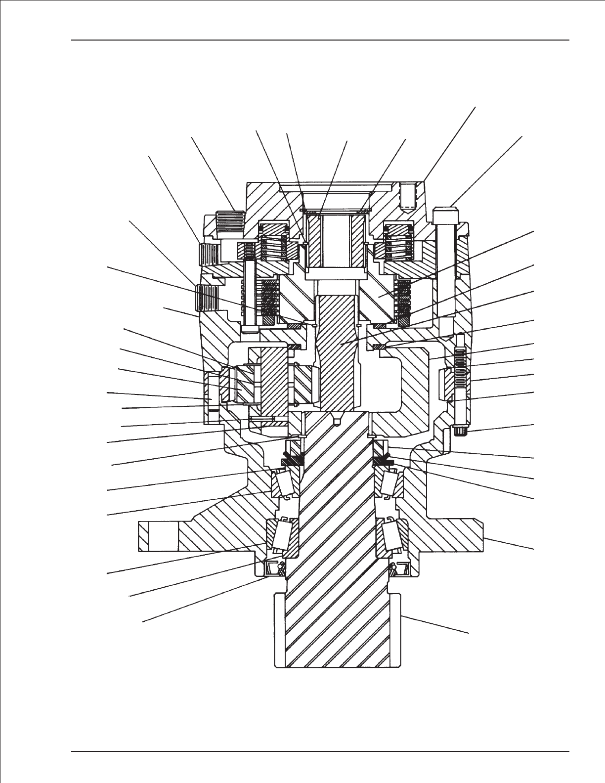
Swing drive, Fairfield
TB 60 – 01-97 through 01-01 1-79
28
2
5
1
5
7
20
11
20
29
34
32
33
13
12
18
17
16
14
15
23
4
27
6
19
10
9
8
3
24
31
30
31 25 26 21 22
35
36
AWV00201

Swing drive, Gear Products
item part no qty description
0070047 1 Swing drive, Gear Products
0072059 1 Seal repair kit - (seal kit includes items 2, 7, 9, 21, 22, 23, 27 and 28)
8070282 1 Replacement air vent - (not shown)
1 8070001 1 Output shaft
2 Kit item 2 Seal
3 8070142 2 Bearing cone
4 8070143 2 Bearing cup
5 8070317 1 Base
6 8070116 1 Bearing spacer
7 Kit item 1 Gasket
8 8070316 5 Capscrew 7/16-14 x 1-1/4 inch long 12 point flange head
9 Kit item 3 O-ring
10 8070125 3 Planetary shaft gear
11 8070318 3 Set screw 5/16-28 x 5/8 inch long socket cup point
12 8070133 1 Planetary gear
13 8070186 1 Housing
14 8070140 3 Thrust ring
15 8070315 1 Planet carrier
16 8070198 1 Washer
17 8070002 1 Castle nut
18 8070319 2 Snap ring
19 8070147 1 Brake drive
20 8070129 1 Cylinder plate
21 Kit item 1 Back-up ring
22 Kit item 1 O-ring
23 Kit item 1 Gasket, 1/64 inch thick
24 8070005 7 Brake disc
25 8070006 7 Friction disc
26 8070007 7 Piston brake
27 Kit item 1 O-ring
28 Kit item 1 Back-up ring
29 8070205 1 Cover
30 8070141 1 Input gear
31 8070004 12 Brake spring
32 8070003 1 Back-up plate
33 970589 6 Capscrew 3/8-16 x 4-1/2 inch long hex head grade 5
34 987119 6 Washer 3/8 medium lock
35 8070320 1 Cotter pin 1/8 inch diameter x 1-1/2 inch long - (not shown)
36 7790005 1 Motor gasket - (not shown)
1-80 TB 60 – 01-97 through 01-01

Swing drive, Gear Products
TB 60 – 01-97 through 01-01 1-81
33 31 18 30 29 28 27
22
21
20
19
18
17
16
15
3
4
7
8
3
2
1
4
5
6
9
10
11
12
13
14
32
23
24
25
26
23
34
AWV00202

Swing drive, Perfection
item part no qty description
0070047 1 Swing drive, Perfection
0074837 1 Seal and shim repair kit #1 - (kit includes items 11, 18, 25 and 41)
0074838 1 Brake repair kit - (kit includes items 32, 33 and 40)
0074839 1 Seal and shim repair kit #2 - (kit includes items 11, 36, 37, 38 and 39)
1 0074800 1 Housing
2 0074801 1 Mounting flange
3 0074802 1 Motor adapter
4 0074803 1 Planetary carrier
5 0074804 1 Input pinion
6 0074805 1 Lock nut
7 0074806 3 Spur gear
8 0074807 1 Washer
9 0074808 3 Washer idler
10 0074809 3 Idler pin
11 Kit item 1 Hydraulic motor gasket - (not sold separately)
12 0172054 1 Reducer bushing
13 0074836 2 Brake gasket
14 0074811 1 Hydraulic motor cover
15 0074812 1 Lock washer
16 0074813 2 Bearing cup
17 0074814 2 Bearing cone
18 Kit item 1 O-ring - (not sold separately)
19 0074816 1 Output shaft
20 0172053 1 Pressure vent plug
21 0071817 8 Bolt 3/8-16 x 1-1/4
22 0074818 6 Bolt 3/8-16 x 5-1/4
23 0074819 3 Dowel pin
24 0074820 1 Eyebolt
25 Kit item 1 Oil seal - (not sold separately)
26 0074822 3 Screw
27 0074823 1 Bushing
28 0074824 2 Nut, hex 1/2-13
29 0074825 6 Lock washer
30 0074826 2 Bolt
31 0074827 1 Housing brake
32 Kit item 7 Pressure disc (thin) - (not sold separately)
33 Kit item 7 Friction disc
34 0074830 1 Pressure disc (thick)
35 0074831 1 Piston
36 Kit item 1 O-ring - (not sold separately)
37 Kit item 1 O-ring plate - (not sold separately)
38 Kit item 1 O-ring - (not sold separately)
39 Kit item 1 O-ring plate - (not sold separately)
40 Kit item 24 Spring - (not sold separately)
41 Kit item 1 Oil seal - (not sold separately)
42 0172050 5 Pipe plug
1-82 TB 60 – 01-97 through 01-01
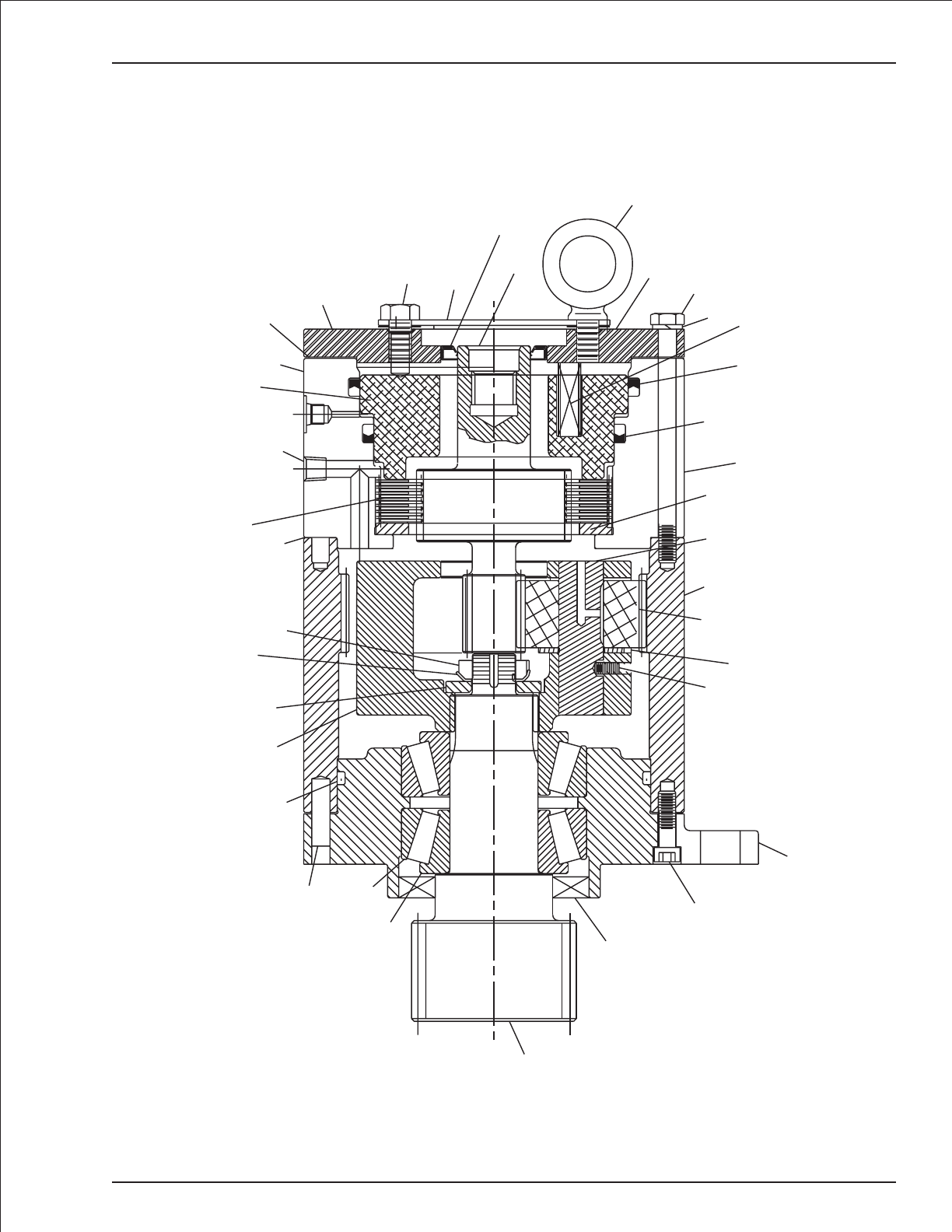
Swing drive, Perfection
TB 60 – 01-97 through 01-01 1-83
24
2
19
25
21
17
16
23
18
4
8
6
15
3
30
13
31
35
42
13
32
33
14
5
41
11 22
29
9
7
1
26
20
34
10
36 37
38 39
40
AWV00372

Swing drive, Tulsa Winch
item part no qty description
0070047 1 Swing drive, Tulsa Winch
8200059 1 Seal repair kit
1 8200051 1 Output pinion shaft
2 8200052 1 Oil seal
3 8200060 2 Bearing cone
4 8200061 2 Bearing cup
5 8200062 1 Housing
6 8200055 8 Stator plate
7 8200064 7 Friction disc
8 8200057 12 Brake spring
9 8200066 1 Motor adapter
10 8200053 2 Oil seal
11 8200039 1 Gasket
12 8200054 2 O-ring
13 8200069 1 Brake housing
14 8200070 2 Pipe plug
15 8200096 1 Gear set
16 8200071 1 Brake piston
17 8200072 8 Capscrew
18 8200073 1 Input gear
19 8200074 1 Retaining ring
20 8200075 1 Brake driver
21 8200076 1 Retaining ring
22 8200077 1 Cap plug
23 8200078 1 Protector
24 8200079 2 Washer
25 8200080 2 Capscrew
26 8200081 1 Pipe bushing - (not shown)
27 8200082 1 Breather - (not shown)
1-84 TB 60 – 01-97 through 01-01
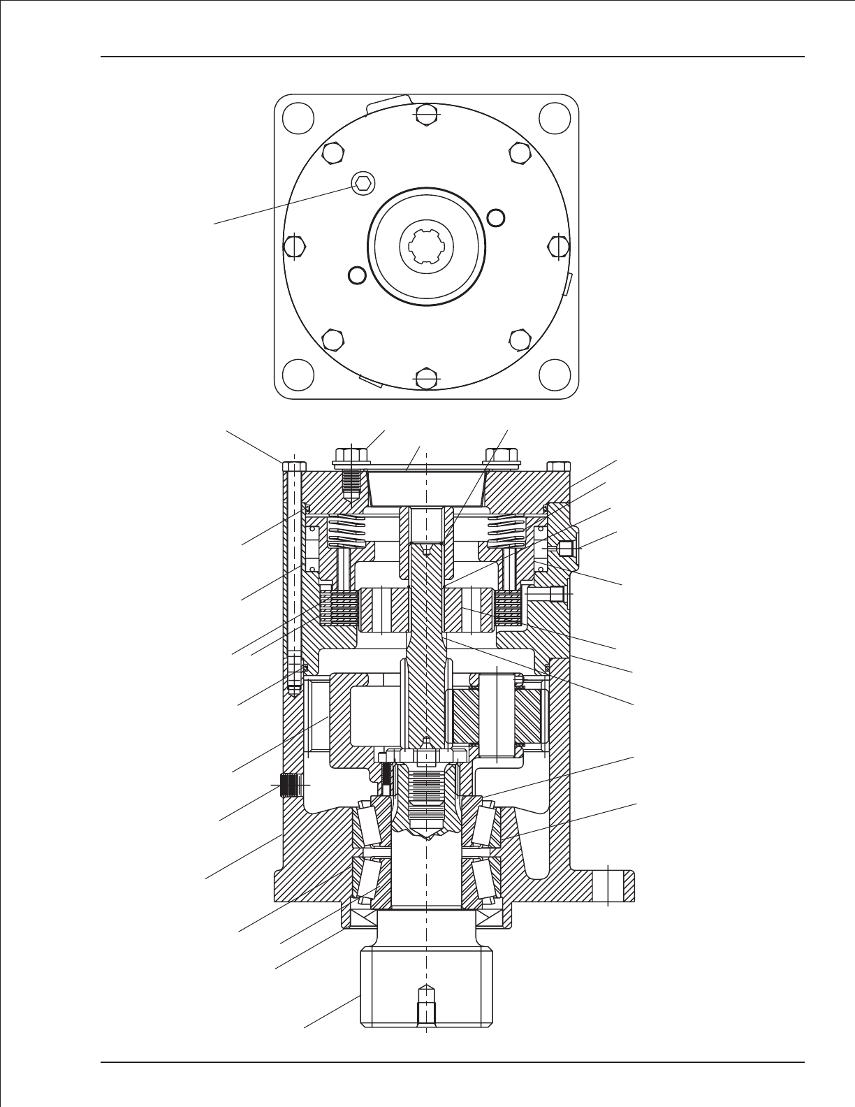
Swing drive, Tulsa Winch
TB 60 – 01-97 through 01-01 1-85
1
2
3
4
5
14
15
12
6
7
10
12
17
14
24
25
11
23 19
9
8
21
22
16
20
13
18
3
4
AWV00203


Section 2. - Hydraulics
TB 60 – 01-97 through 01-01 2-1

Chassis hydraulic equipment, 2 wheel drive
item part no qty description
1 0081423 1 Drive valve, high torque - (see page 2-22 for parts breakdown)
2 0081042 1 Motion control valve, drive - (see page 2-54 for parts breakdown)
3 0081600 1 Drive sequence valve, right hand - (see page 2-45 for parts breakdown)
4 0081604 1 Drive sequence valve, left hand - (see page 2-46 for parts breakdown)
5 5080015 4 Last chance filter
6 0080543 4 3/4 inch hydraulic hose
7 0400483 1 3/4 inch hydraulic hose
8 0080522 1 1/2 inch hydraulic hose
9 0070772 3 1/4 inch hydraulic hose
10 0070783 2 1/4 inch hydraulic hose
11 0070781 1 1/4 inch hydraulic hose
12 0110490 1 3/4 inch hydraulic hose
13 0080524 1 3/4 inch hydraulic hose
14 0070792 1 1/4 inch hydraulic hose
15 0070782 1 1/4 inch hydraulic hose
16 0020267 2 3/8 inch hydraulic hose
17 0040276 1 1/4 inch hydraulic hose
18 0070768 1 1/4 inch hydraulic hose
19 0020275 1 3/8 inch hydraulic hose
2-2 TB 60 – 01-97 through 01-01
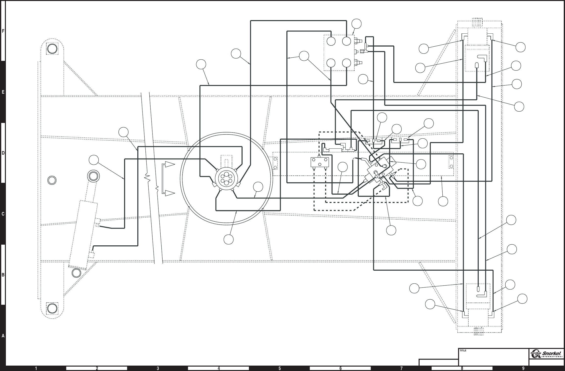
Page2-3
Chassis hydraulic equipment
2 wheel drive
Snorkel model TB 60
DWG. 0080551
15
10
8
9
7
12
A
A
5
3
14
2
6
BA
6
9
10
BRAKE
RELEASE
DRIVE
AB
DRIVE
BRAKE
RELEASE
6
11
9
6
2
M2 V2
V1M1
BRAKE
PORT
17
13
34
18
19
16
19
14
16
F
B
A
C
D
E
6
12
1
5
5
55
AW0080551
Page2-3
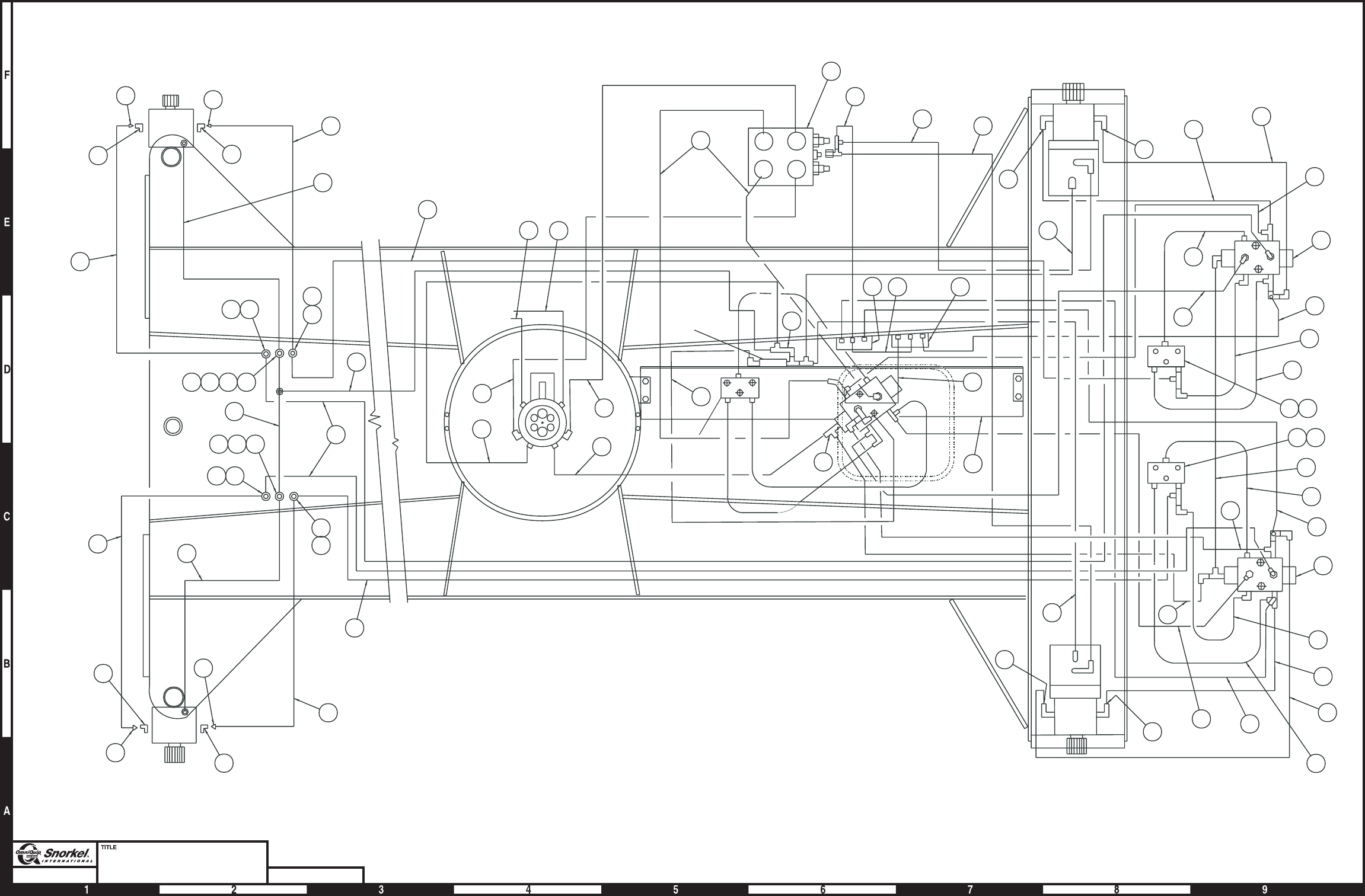
Page2-4
Chassis hydraulic equipment
4 wheel drive
Snorkel model TB 60 DWG. 0080886
2
1
{
3
14
2
6
5
25
33
41
9
7
43
30
31
24
29
5 6
8
5 6
43
29
38
25
30
42
40
47
31
18
28
9
9
22
9
21
21
46
2
23
RH Rear
motor
25
1
3
44
4
45
Selector
valve
10
11
Flow
divider
combiner
valve
Anti-cavitation
valve
26
24
19
21
20
C'post
To steer
cylinder Rod
Base
22
27
36
34
9
9
17 17
32
Drain
B
A
RH Front
motor
35
15
39
15
11
16
16
121314
45
Bulkhead fittings
37
12
34
15
1314
16
35
15
16
Bulkhead fittings
32
36
17
9
9
17
LH Front
motor
BA
Drain
M2
M1 V1
V2
Brake
M1 P M2 M1 PM2
F
B
C
A
D
E
LH Rear
motor
BA
Brake
rel
Dr
AB
Brake
rel
Dr
FB
C
A
E
D
F
D
EA
C
B
AW0080886
Page2-4

Chassis hydraulic equipment, 4 wheel drive
item part no qty description
1 0081423 1 Drive valve, high torque - (see page 2-22 for parts breakdown)
2 0081042 1 Motion control valve, drive - (see page 2-54 for parts breakdown)
3 0081600 1 Drive sequence valve, right hand - (see page 2-45 for parts breakdown)
4 0081604 1 Drive sequence valve, left hand - (see page 2-46 for parts breakdown)
5 0080958 2 Flow divider/combiner valve - (see page 2-50 for parts breakdown)
6 0081547 2 Spacer, flow divider/combiner valve
7 0080928 1 Selector valve, right hand - (see page 2-61 for parts breakdown)
8 0080929 1 Selector valve, left hand - (see page 2-62 for parts breakdown)
9 5080015 8 Last chance filter
10 5036703 1 Swivel nut run tee
11 5036705 2 Swivel nut run tee
12 5034502 2 Bulkhead 90° elbow
13 5037005 2 Swivel nut 90° elbow
14 5074403 2 Bulkhead locknut
15 5034505 4 Bulkhead straight thread 90° elbow
16 5074406 4 Bulkhead locknut
17 5034206 4 Union 90° elbow - (not used after 6-11-01)
18 0080543 1 3/4 inch hydraulic hose
19 0400483 1 3/4 inch hydraulic hose
20 0080522 1 1/2 inch hydraulic hose
21 0070772 3 1/4 inch hydraulic hose
22 0070783 2 1/4 inch hydraulic hose
23 0070781 1 1/4 inch hydraulic hose
24 0110490 2 3/4 inch hydraulic hose
25 0080524 4 3/4 inch hydraulic hose
26 0070792 1 1/2 inch hydraulic hose
27 0070782 1 1/4 inch hydraulic hose
28 0020655 1 1/4 inch hydraulic hose
29 0080936 2 3/4 inch hydraulic tube
30 0080934 2 3/4 inch hydraulic tube
31 0080937 2 3/4 inch hydraulic tube
32 0080946 2 3/4 inch hydraulic hose - (before 6-11-01)
0080945 2 3/4 inch hydraulic hose - (after 6-11-01)
33 0080940 1 3/4 inch hydraulic hose
34 0072570 2 1/4 inch hydraulic hose
35 0080945 2 3/4 inch hydraulic hose
36 0080931 2 3/4 inch hydraulic hose
37 0080932 2 3/4 inch hydraulic hose
38 0020283 1 1/4 inch hydraulic hose
39 0080362 1 3/8 inch hydraulic hose
40 0080930 1 3/4 inch hydraulic hose
41 0080941 1 3/4 inch hydraulic hose
42 0080939 1 3/4 inch hydraulic hose
43 0020273 2 3/8 inch hydraulic hose
44 0070766 1 1/4 inch hydraulic hose
45 0070786 2 3/8 inch hydraulic hose
46 0040276 1 1/4 inch hydraulic hose
47 0070764 1 3/8 inch hydraulic hose
TB 60 – 01-97 through 01-01 2-5

Turntable hydraulic equipment
item part no qty description
1 0081874 1 Package valve, non-proportional - (see page 2-9 for parts breakdown)
2 0081873 1 Valve, drive/lift/swing - (see page 2-12 for parts breakdown)
3 0081980 1 Check valve - (see page 2-27 for parts breakdown)
4 0072940 1 Emergency power unit - (see page 2-49 for parts breakdown)
5 0082055 1 Accumulator - (see page 2-24 for parts breakdown)
6 0081982 1 Dump valve - (see page 2-48 for parts breakdown)
7 0081981 1 Range valve - (see page 2-58 for parts breakdown)
8 5037003 1 Swivel nut 90° elbow
9 5093014 2 Hose clamp
10 5058824 2 Clamp
11 5035403 2 Bulkhead run tee
12 5074401 4 Bulkhead locknut
13 5034501 2 Bulkhead straight thread 90° elbow
14 5070005 2 Diagnostic nipple
15 0070927 1 1/2 inch hydraulic hose
16 0020273 4 3/8 inch hydraulic hose
17 0070789 2 3/8 inch hydraulic hose
18 0400497 2 3/4 inch hydraulic hose
19 0100277 1 1/2 inch hydraulic hose
20 0080359 3 1/4 inch hydraulic hose
21 0070765 4 1/4 inch hydraulic hose
22 0080362 2 3/8 inch hydraulic hose
23 0050137 2 1/4 inch hydraulic hose
24 0110199 2 1 inch hydraulic hose
25 0020372 1 1/2 inch hydraulic hose
26 0070926 1 1/2 inch hydraulic hose
27 0020283 2 1/4 inch hydraulic hose
28 0070911 1 1/4 inch hydraulic hose
29 0020280 2 1/4 inch hydraulic hose
30 0080843 1 1-1/2 inch suction hose
31 0081992 1 1 inch hydraulic hose
2-6 TB 60 – 01-97 through 01-01
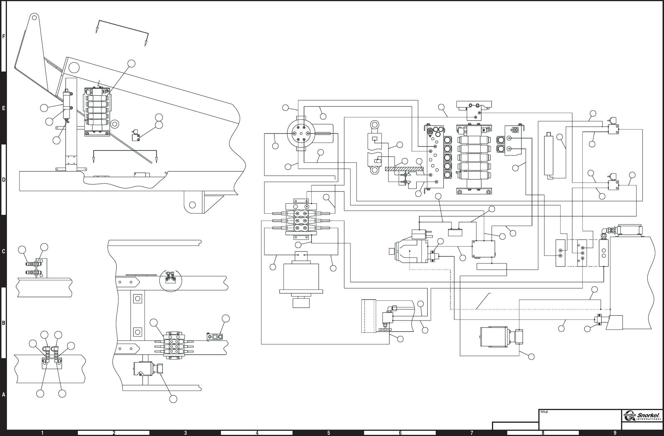
Page2-7
Turntable hydraulic equipment
Snorkel model TB 60
DWG. 0081872
P
DV VP
EP
C1
C2
T
LS
P
C1
C2
C1
C2
B
B
A
A
C
C
A1
B1
A2
A3
B2
B3
A4
B4
B5
A5
VS
SENSE
P1
T1
3
4
5
6
7
8
9
31
4
2
56
7
14
32
V1 V2
Sense
Drain Out
In
Hydraulic
oil reservoir
Range valve
Dump valve
Accumulator
Valve package assembly
Centerpost
Valve assembly
Pump Check valve
Emergency
power unit
Lift cylinder
Swing drive
Master
level
cylinder
Bulkhead
angle
2
1
BOOMEXT RET
STEER
PLAT
LEVEL
DN UP
RT LT
P
Drive Drive
Lift Lift
Swing Swing
15
30
24
16
16
16
17
17
18
28
19
22
22
10
20
20
25
24
26
27
29 23
27
23
16
10
31
21
21
CCW
CW PLAT
ROT
SV
Bulkhead
angle
21
21
NOT USED
18
Drain hose
29
20
6
7
9
5
1
A
A
Far side
Near side
B
B
8
View "C"
12
12
13 13
14 14
View B-B
12
11
4
3
2
View A-A
C
AW0081872
Page2-7
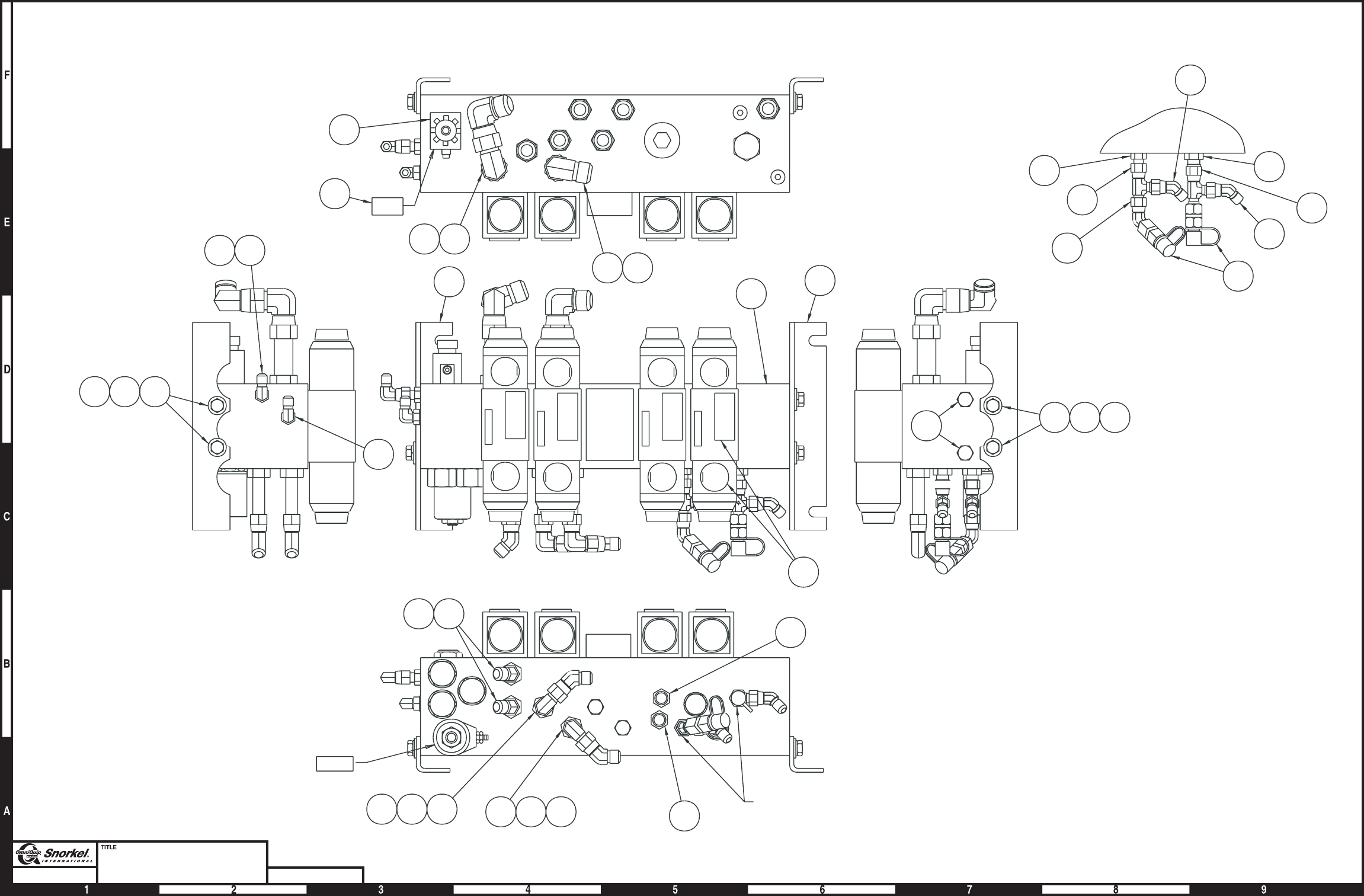
Page2-8
Package valve
non-proportional
Snorkel model TB 60 DWG. 0081874
A5
B5
B4
A4
B3
A3
B2
A2
B1
A1
UP 13
CCW 27
LEFT 19RET 15
20 RGHT
14 EXT 26 CW 12 DWN
BOOM
STEER
PLATFORM
ROTATE
PLATFORM
LEVEL
P2
T2
16B
Sense
VS
160C
P1 T1 21
9
16
17
16
9
16
21
13 14 15
VIew A-A
TopviewofportsA5andB5
without solenoids
21
41920 419 20
519
131415
2
1
12
8
25
2
611
22
3
12
710
710
See view A-A AW0081874
Page2-8

Package valve, non-proportional
item part no qty description
0081874 1 Package valve, non-proportional
1 6010844 1 Control valve package, non-proportional - (see page 2-10 for parts breakdown)
2 0181449 2 Valve mount angle
3 6010591 1 Solenoid valve and coil
0180802 1 Seal repair kit
6010392 1 Replacement cartridge
3040496 1 Replacement coil, 12 volt DC
4 5065805 2 Long straight thread adapter
5 5065815 2 Long straight thread adapter
6 5065703 1 Straight thread adapter
7 5065807 2 Long straight thread adapter
8 5075205 2 Hex head plug
9 5036703 2 Swivel nut run tee
10 5037007 3 Swivel nut 90° elbow
11 5037003 1 Swivel nut 90° elbow
12 0082010 1 Decal set, non-proportional control valve
13 987109 4 Washer 5/16 medium lock
14 970239 4 Capscrew 5/16-18 x 3/4 inch long hex head grade 5
15 986269 4 Washer 5/16 medium flat
16 5036903 3 Swivel nut 45° elbow
17 5070005 2 Diagnostic nipple
18 5035303 1 Straight thread 90° elbow
19 5036905 4 Swivel nut 45° elbow
20 5037005 2 Swivel nut 90° elbow
21 5065705 4 Straight thread adapter
TB 60 – 01-97 through 01-01 2-9

Control valve package, non-proportional
item part no qty description
6010844 1 Control valve package, non-proportional - Vickers
1 6010694 1 Manifold body
2 6010697 1 Extend control valve
3040551 2 Replacement solenoid, 12 volt DC
3 6010697 1 Steer control valve
3040551 2 Replacement solenoid, 12 volt DC
4 1 Cover plate - (not sold separately)
5 6010696 1 Platform swing control valve
3040551 2 Replacement solenoid, 12 volt DC
6 6010696 1 Level control valve
3040551 2 Replacement solenoid, 12 volt DC
7 6010700 2 Pressure relief cartridge valve
6010553 1 Seal repair kit
8 6010699 2 Check valve cartridge
9 6010698 1 3-way inlet cartridge valve
6010537 1 Seal repair kit
6010707 1 Replacement cartridge
8220094 1 Replacement solenoid, 12 volt DC
10 6010703 1 Flow regulator cartridge valve
565666 1 Seal repair kit
11 6010702 1 Flow control cartridge valve
565666 1 Seal repair kit
12 6010701 1 3-way pilot operated cartridge atmosphere vented
6010551 1 Seal repair kit
13 6010704 1 Shuttle valve cartridge
6010537 1 Seal repair kit
14 6010705 1 Check valve cartridge
565666 1 Seal repair kit
15 6010706 3 Relief valve cartridge
565666 1 Seal repair kit
16 6010591 1 Solenoid valve and coil
0180802 1 Seal repair kit
6010392 1 Replacement cartridge
3040496 1 Replacement coil, 12 volt DC
2-10 TB 60 – 01-97 through 01-01
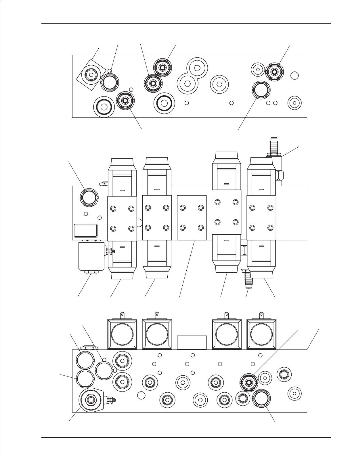
Control valve package, non-proportional
TB 60 – 01-97 through 01-01 2-11
P1
C2-8-2
T1
14 15 15
15
7
8
Boom Steer
Platform
Swing Platform
Level
13
923456
7
7
71
98
10
11
12
A1
B1 A2
B2
A3
B3
A4
B4
A5
B5
16
AW6010844

Valve, drive/lift/swing
item part no qty description
0081873 1 Valve, drive/lift/swing
1 6010823 1 Control valve, drive/lift/swing - (see page 2-14 for parts breakdown)
2 5075208 2 Hex head plug
3 5037010 1 Swivel nut 90° elbow
4 5037005 4 Swivel nut 90° elbow
5 5037003 1 Swivel nut 90° elbow
6 5065703 1 Straight thread adapter
7 5065731 2 Straight thread adapter
8 5065708 2 Straight thread adapter
9 5065719 1 Straight thread adapter
10 5035311 1 Straight thread 90° elbow
11 5065815 2 Long straight thread adapter
2-12 TB 60 – 01-97 through 01-01
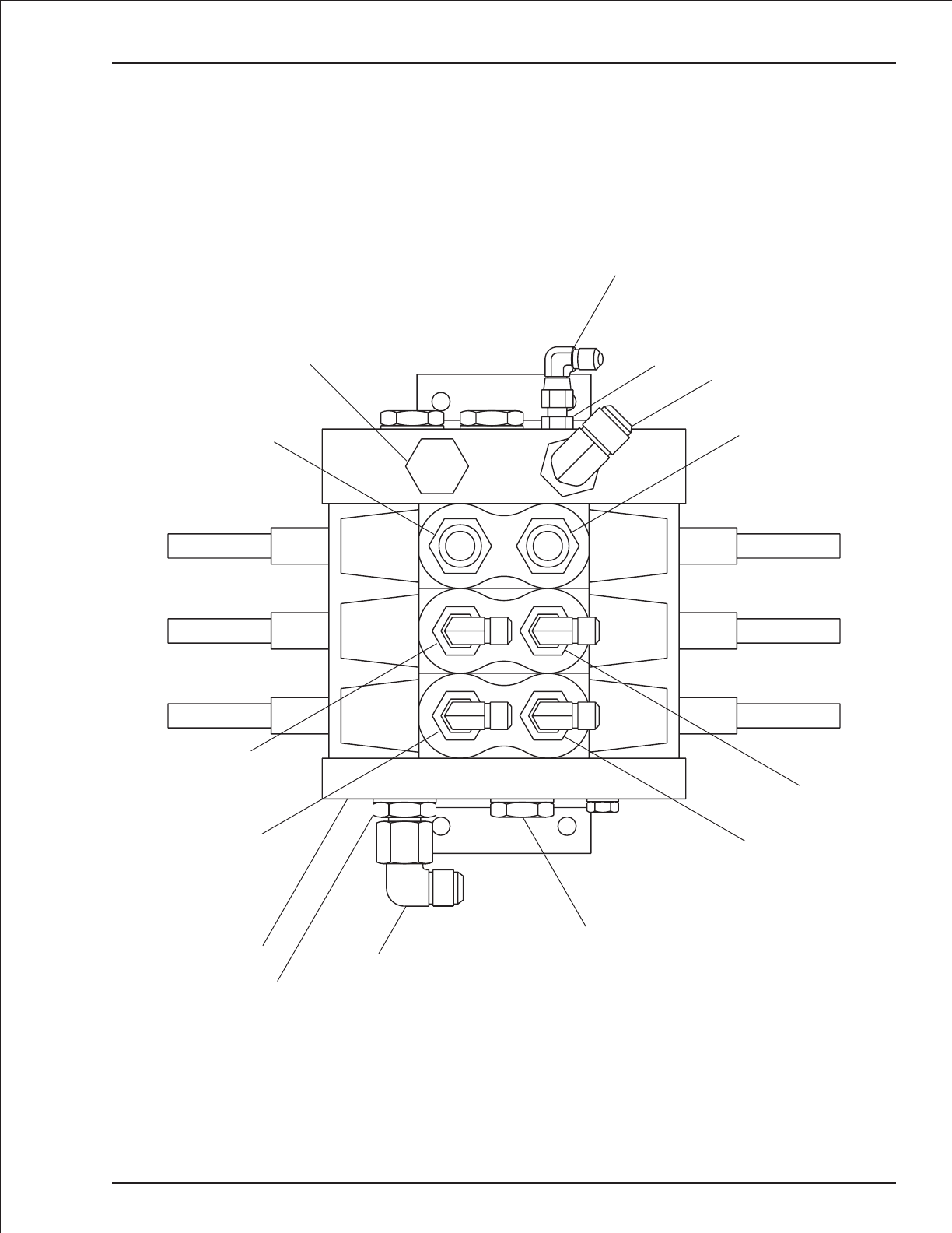
Valve, drive/lift/swing
TB 60 – 01-97 through 01-01 2-13
LSPT
C1
C1
C1
C2
C2
C2
TP
TPLS
5
610
7
2
7
4
11
4
11
1
9
3
2
48
48
AW0081873

Control valve, drive/lift /swing
item part no qty description
6010823 1 Control valve, drive/lift/swing - Apitech
0082072 1 Seal repair kit, valve section - (total of four (4) kits required to reseal complete valve)
1 6010849 1 Inlet section
8010272 2 Set screw
8010273 2 Sealing nut with washer
2 6010850 1 Drive control section
8010272 2 Set screw
8010273 2 Sealing nut with washer
3 6010851 1 Boom lift control valve section
8010272 2 Set screw
8010273 2 Sealing nut with washer
4 6010852 1 Swing control valve section
8010272 2 Set screw
8010273 2 Sealing nut with washer
5 6010853 1 Outlet section
8010272 2 Set screw
8010273 2 Sealing nut with washer
6 6010653 6 Solenoid cartridge, 12 volt DC - (black = 33 Hz Frequency)
(includes solenoid, cartridge, o-ring and orifice disc - must be installed as a complete unit)
2-14 TB 60 – 01-97 through 01-01
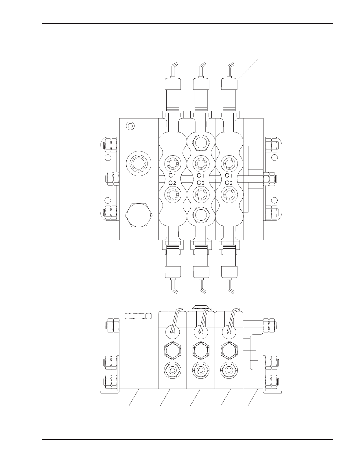
Control valve, drive/lift /swing
TB 60 – 01-97 through 01-01 2-15
6
12
345
Inlet Outlet
Drive Lift Swing
AW6010823

Drive motor
item part no qty description
6030018 1 Drive motor
0071092 1 Seal repair kit - (kit includes items 10, 18, 19, 23 and 31)
1 8220126 3 Woodruff key
2 8220127 1 Drive pin
3 8220005 2 Retaining ring
4 8220128 1 Gear drive
5 8220129 1 Spacer washer
6 8220130 1 Retaining ring
7 8220006 2 Thrust bearing race
8 8220007 1 Thrust bearing
9 8220027 2 Needle bearing
10 8220131 3 Oil seal
11 8220132 1 Rear end cap
12 8220133 3 Tip seal roller
13 8220134 1 Rotor
14 8220020 3 Seal plate
15 8220135 2 Abutment valve
16 8220028 4 Needle bearing
17 28220030 4 Step bearing
18 8220136 4 O-ring
19 8220137 4 Back-Up ring
20 8220138 4 Dowel pin
21 8220139 9 Capscrew
22 8220140 18 Body seal roller
23 8220146 1 Shaft seal
24 8220031 1 Front end cap
25 8220141 1 Displacement housing
26 8220142 4 Retaining ring
27 8220143 2 Gear pinion (std)
28 8220156 1 S-shaft
29 8220147 1 Gear cover
30 8220148 7 Capscrew
31 8220144 1 Retaining ring
32 8220145 1 O-ring
33 8220117 1 Front sealing cap
2-16 TB 60 – 01-97 through 01-01
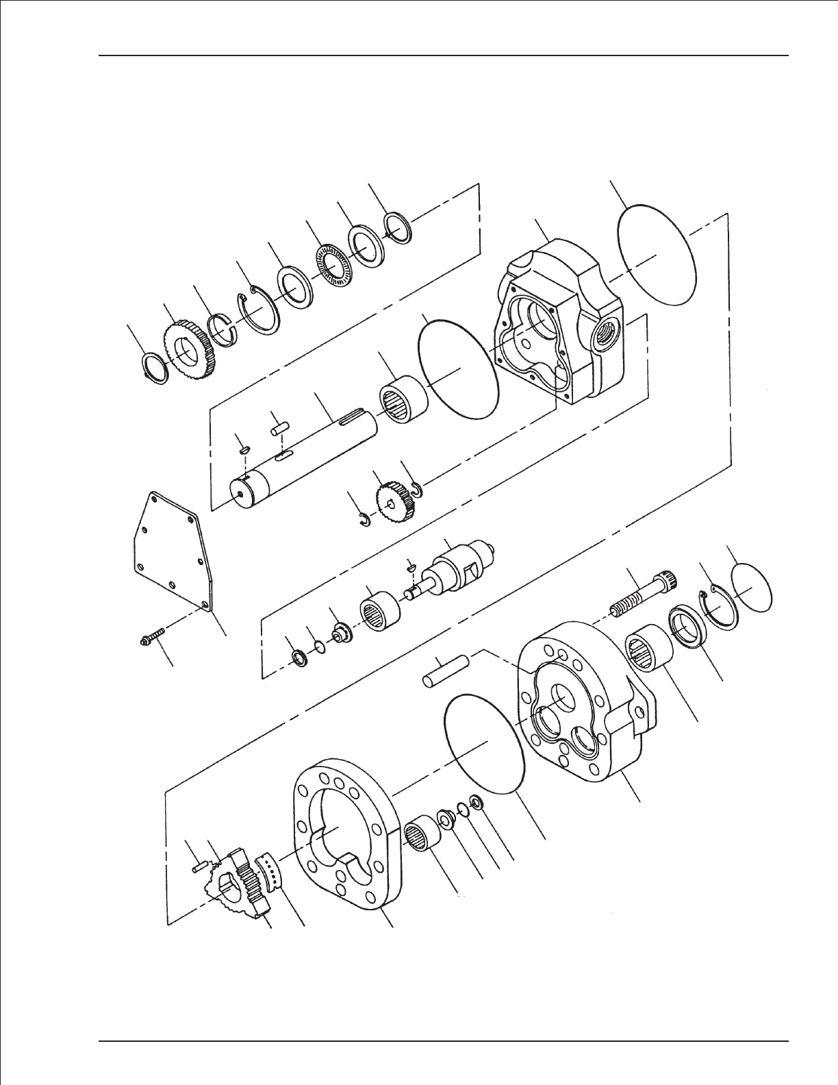
Drive motor
TB 60 – 01-97 through 01-01 2-17
3
4
5
6
7
8
7
3
30
29
1
2
28
26
27 26
9
10
11
10
19 18
17
16
1
15
12 22
13 14 25
16 17 1819
10
20
21
9
23
31
32
24
AWV00204

Drive motor with brake
item part no qty description
6030040-79 1 Drive motor with brake
0071092 1 Seal repair kit, drive motor - (kit includes items 10, 18, 19, 23 and 31)
8220149 1 Seal repair kit, drive motor brake - (kit includes items 39, 40, 43, 44, 46 and 47)
1 8220126 3 Woodruff key
2 8220127 1 Drive pin
3 8220005 2 Retaining ring
4 8220128 1 Gear drive
5 8220129 1 Spacer washer
6 8220130 1 Retaining ring
7 8220006 2 Thrust bearing race
8 8220007 1 Thrust bearing
9 8220027 2 Needle bearing
10 Kit item 3 Oil seal - (not sold separately)
11 8220132 1 Rear end cap
12 8220133 3 Tip seal roller
13 8220134 1 Rotor
14 8220020 3 Seal plate
15 8220135 2 Abutment valve
16 8220028 4 Needle bearing
17 28220030 4 Step bearing
18 Kit item 4 O-ring - (not sold separately)
19 Kit item 4 Back-Up ring - (not sold separately)
20 8220138 4 Dowel pin
21 8220139 9 Capscrew
22 8220140 18 Body seal roller
23 Kit item 1 Shaft seal - (not sold separately)
24 8220031 1 Front end cap
25 8220141 1 Displacement housing
26 8220142 4 Retaining ring
27 8220143 2 Gear pinion (std)
28 8220017 1 S-shaft for brake
29 8220144 1 Retaining ring
30 8220145 1 O-ring
31 Kit item 1 Front sealing cap - (not sold separately)
32 8220155 1 Drive motor brake, 4 cubic inch - (complete brake, includes items 33 through 47)
8220038 1 Brake replacement kit - (includes items 33, 40 and 45)
33 Kit item 1 Housing - (not sold separately)
34 8220150 1 Spacer ring
35 8220014 5 Friction disc
36 8220015 4 Driver plate
37 8220010 1 O-ring
38 8220011 7 Brass washer
39 Kit item 7 Capscrew - (not sold separately)
40 Kit item 1 Adapter plate - (not sold separately)
41 8220025 8 Die spring
42 8220153 1 Pressure plate
43 Kit item 1 Back-up ring - (not sold separately)
44 Kit item 1 O-ring - (not sold separately)
45 8220154 8 Capscrew
46 Kit item 1 O-ring - (not sold separately)
47 Kit item 2 Back-up ring - (not sold separately)
2-18 TB 60 – 01-97 through 01-01
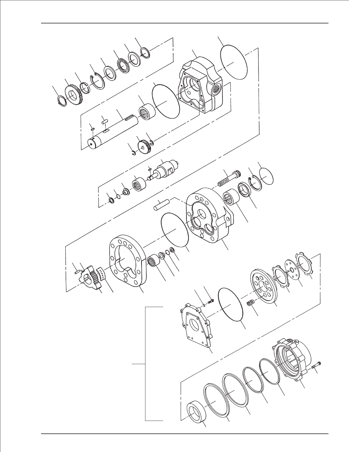
Drive motor with brake
TB 60 – 01-97 through 01-01 2-19
3
4
5
6
7
8
7
3
1
2
28
9
10
11
10
26
27 26
19 18
17
16
1
15
20
21 29
30
9
23
24
10
19
18
17
16
25
14
13
12 22
38 39 35
36
35
42
41
37
40
32
34 43
44
46
47
33
45
Brake
Assembly
AWV00205

Hydraulic oil reservoir
item part no qty description
0181875 1 Hydraulic oil reservoir
1 0081562 1 Hydraulic oil reservoir, 26 gallon capacity
5090008 1 Replacement filler/breather cap
2 5080004 1 Filter, sump strainer
3 5090007 1 Liquid level gauge with thermometer
4 5080003 1 Hydraulic oil filter, in-tank - (includes filter gauge, item 16)
5080009 1 Replacement filter element
5080067 1 Hydraulic oil return filter, remote spin-on - (used with plastic cowling)
5080068 1 Replacement filter element
5 0080425 1 Outlet adapter
6 5033614 1 Male adapter
7 7734204 1 Street tee, 1/2 inch NPT
8 5033713 1 Male 90° elbow
9 7721208 1 Reducer bushing, 1-1/2 inch NPT to 1 inch NPT
10 0110156 1 Pressure manifold
11 5560643 4 Capscrew 3/8-16 x 3-1/4 inch long hex head grade 5
12 7714204 1 Plug, 1/2 inch NPT square head
13 7734701 1 Street 90° elbow, 1/8 inch NPT
14 7740120 1 Nipple, 1/8 inch NPT x 2-1/2 inch long
15 7734401 1 Pipe 45° elbow, 1/8 inch NPT
16 5080011 1 Filter gauge - (included with filter, item 4)
17 5033621 1 Male adapter
18 5037010 1 Swivel nut 90° elbow
19 5025202 1 Straight thread adapter, 37° swivel
20 5037003 1 Swivel nut 90° elbow
21 5075205 2 Hex head plug
22 5065705 1 Straight thread adapter
23 5035305 1 Straight thread 90° elbow
24 5035318 1 Straight thread 90° elbow
25 5065709 1 Straight thread adapter
26 5036906 1 Swivel nut 45° elbow
27 5035322 1 Straight thread 90° elbow
28 5065718 1 Straight thread adapter
2-20 TB 60 – 01-97 through 01-01
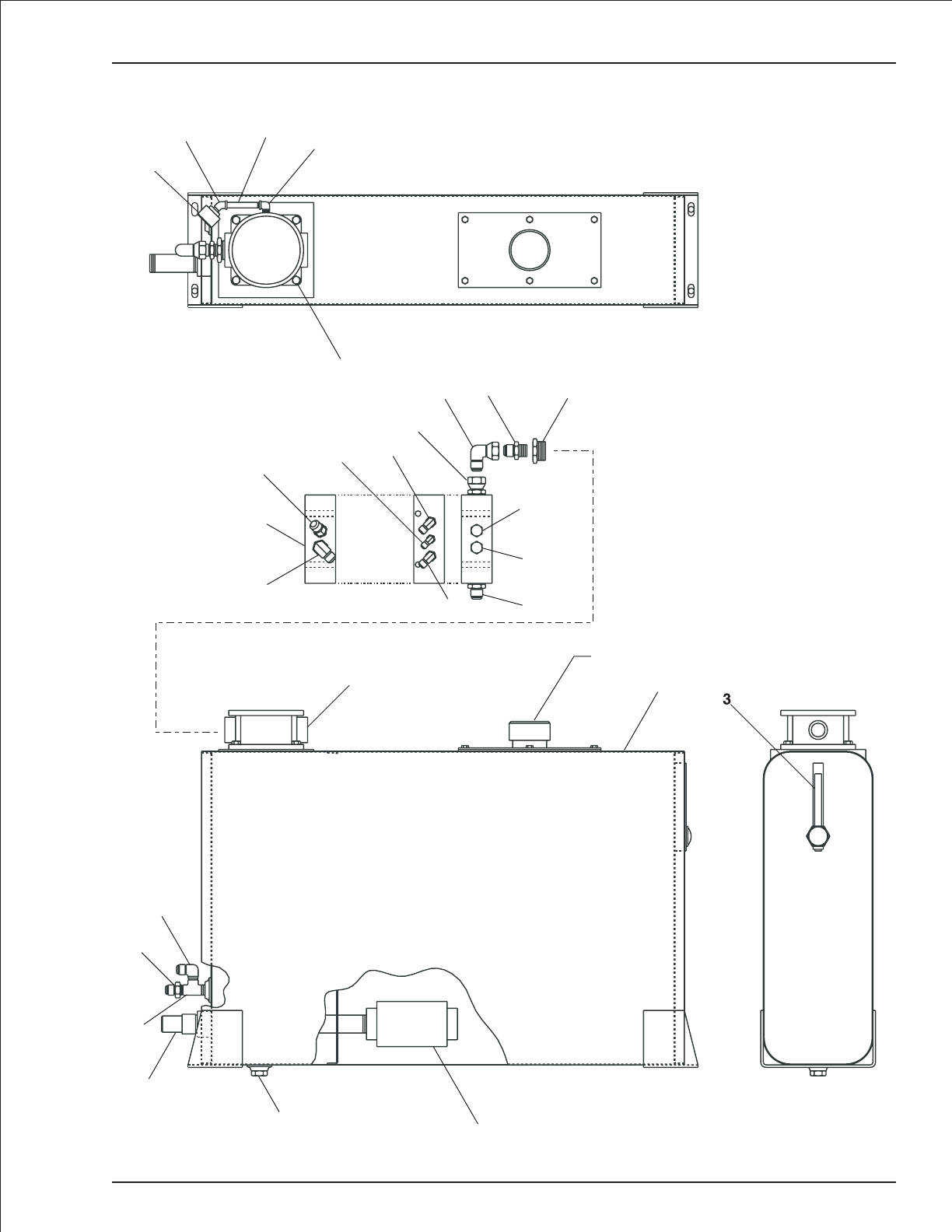
Hydraulic oil reservoir
TB 60 – 01-97 through 01-01 2-21
16
15 14 13
11
8
97
6
5
2
4
3
1
9
17
18
19
24
20
22
25
26
10
27
23 28
21
21
1
Filler/breather cap
4
8
6
7
5
12 2AW0081875
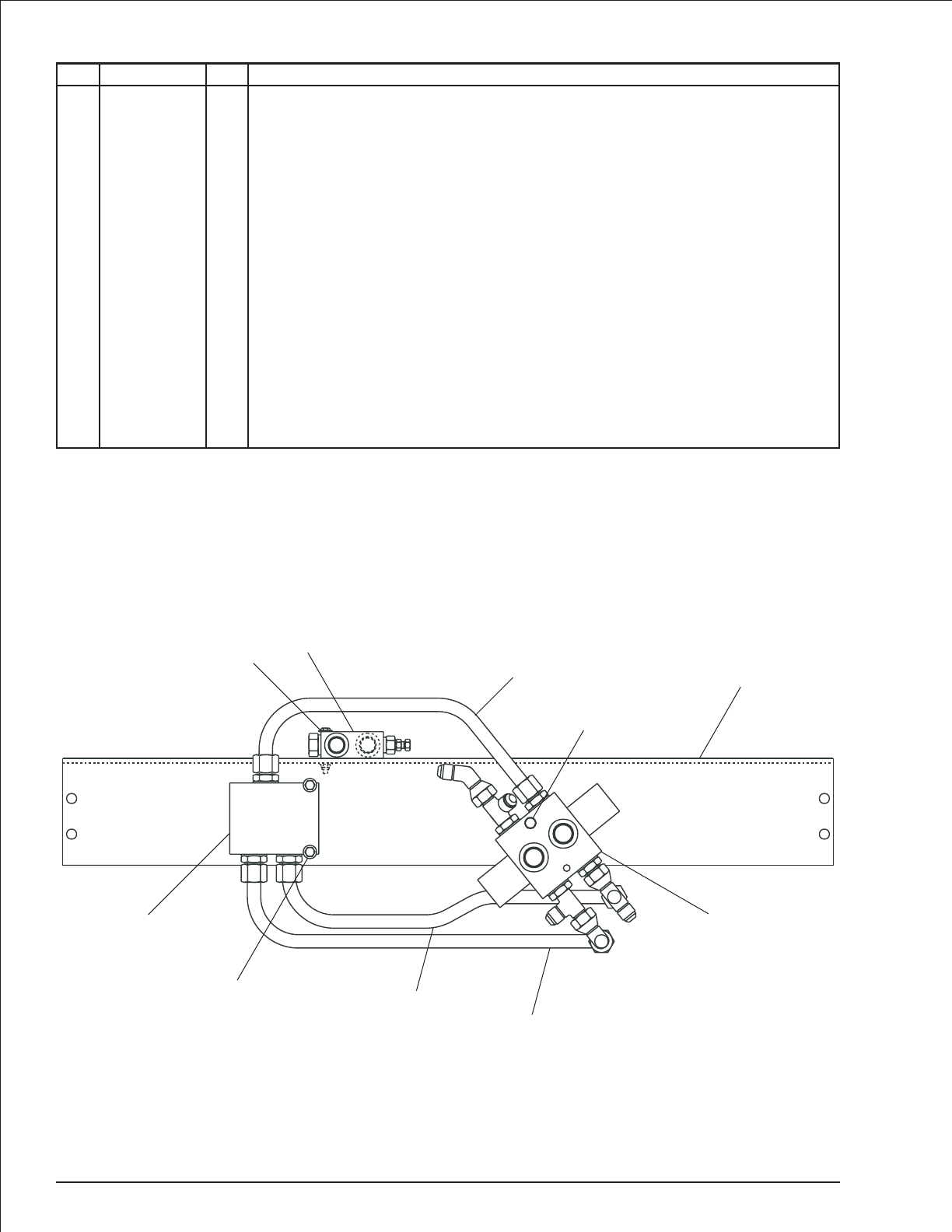
Drive valve, high torque
item part no qty description
0081423 1 Drive valve, high torque
1 0080514 1 Bracket, drive valve
2 0081425 1 Selector valve, 2 wheel drive - (see page 2-59 for parts breakdown)
0081598 1 Selector valve, 4 wheel drive - (see page 2-60 for parts breakdown)
3 0081181 1 Anti-cavitation valve - (see page 2-25 for parts breakdown)
4 0081424 1 Flow divider valve - (see page 2-51 for parts breakdown)
5 0080513 1 3/4 inch hydraulic tube
6 0080512 1 3/4 inch hydraulic tube
7 0080511 1 3/4 inch hydraulic tube
8 970549 1 Capscrew 3/8-16 x 3 inch long hex head grade 5
9 5560031 2 Nut 5/16-18 self locking
10 5560033 1 Nut 3/8-16 self locking
11 986299 1 Washer 3/8 medium flat
12 969999 2 Capscrew 1/4-20 x 2-1/4 inch long hex head grade 5
13 5560004 2 Nut 1/4-20 self locking
14 986019 4 Washer 1/4 medium flat
15 970349 2 Capscrew 5/16-18 x 2-3/4 inch long hex head grade 5
16 986269 4 Washer 5/16 medium flat
17 987119 2 Washer 3/8 medium lock
2-22 TB 60 – 01-97 through 01-01
V
C1 C2 F
B
C
D
E
A
2
1
1
2
5
8
10
11
17
3
12
13
14
4
6
7
9
15
16
AW0081423
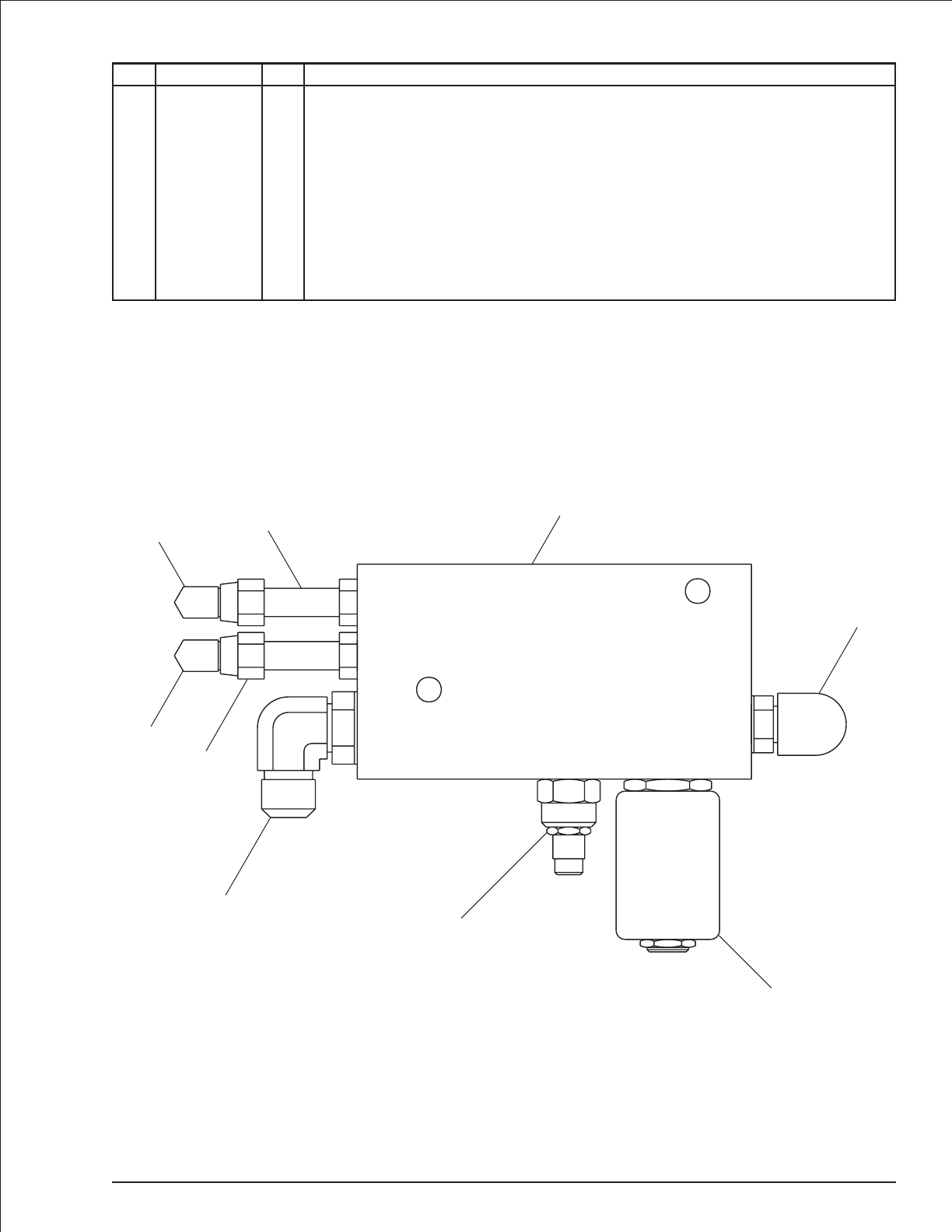
AC generator valve
item part no qty description
0152831 1 AC generator valve
1 6010489 1 AC generator valve - (includes items 2, 3 and 4 — valve is not preset)
2 6010508 1 Cartridge valve with coil
6010509 1 Replacement cartridge valve
3040457 1 Replacement coil, 12 volt DC
3 6018901 1 Flow control valve cartridge
4 6010510 1 Shuttle valve cartridge
5 5065803 2 Long straight thread adapter
6 5037003 2 Swivel nut 90° elbow
7 5035306 1 Straight thread 90° elbow
8 5035320 1 Straight thread 90° elbow
TB 60 – 01-97 through 01-01 2-23
P
M
VS
S
2
1
3
4
5
5
6
6
7
8
AW0152831
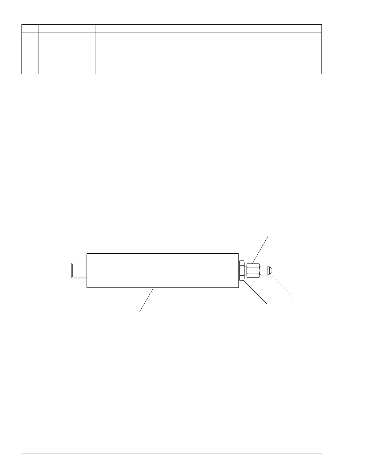
Accumulator
item part no qty description
0082055 1 Accumulator - (shipped charged)
1 6070005 1 Accumulator - (shipped uncharged, charge to 300 psi with dry nitrogen before use)
2 5065711 1 Straight thread adapter
3 5064002 1 Tube end reducer
4 6063905 1 Fitting nut
2-24 TB 60 – 01-97 through 01-01
1
2
3
4
AW0082055
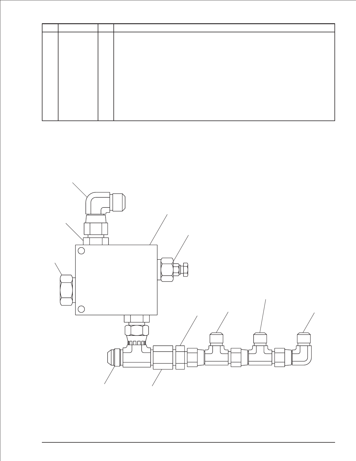
Anti-cavitation valve
item part no qty description
0081181 1 Anti-cavitation valve
1 6010229 1 Anti-cavitation valve - (includes items 2 and 3)
0110683 1 Seal repair kit
2 8230099 1 Relief valve cartridge - (factory preset, do not reset)
3 6010563 1 Check valve cartridge
4 5065710 2 Straight thread adapter
5 5036806 1 Swivel nut branch tee
6 5063906 1 Fitting nut
7 5064003 1 Tube end reducer
8 5036705 2 Swivel nut run tee
9 5037005 1 Swivel nut 90° elbow
10 5037006 1 Swivel nut 90° elbow
TB 60 – 01-97 through 01-01 2-25
1
2
1
2
3
4
10
789
8 - used on
4 wheel drive only
56
AW0081181
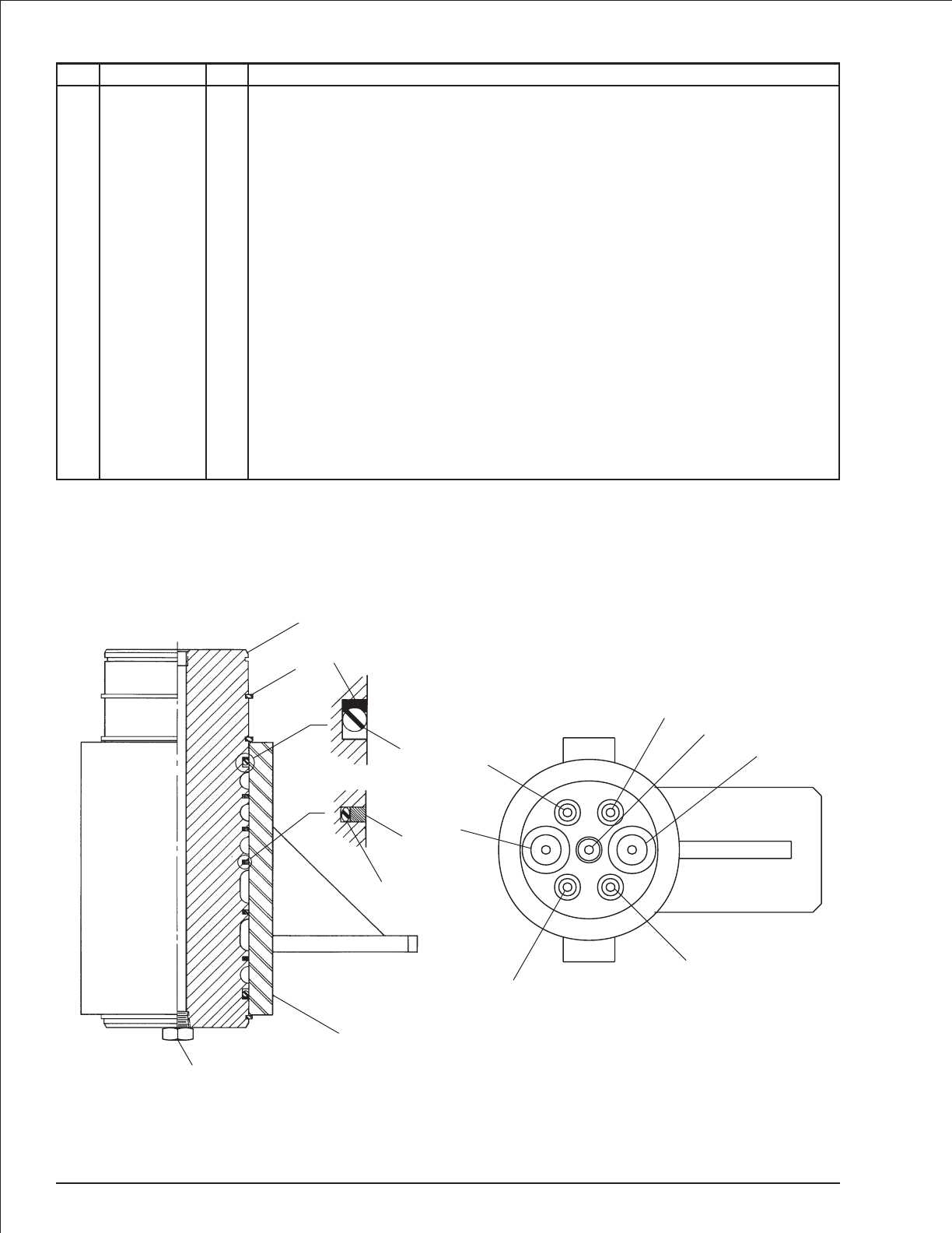
Centerpost and fittings
item part no qty description
1 0110465 1 Centerpost - (includes items 2 through 8)
0070991 1 Seal repair kit - (kit includes items 5, 6, 7 and 8)
2 0110466 1 Centerpost
3 0110467 1 Centerpost manifold
4 5590003 3 Retaining ring
5 Kit item 2 Parbak seal - (not sold separately)
6 Kit item 2 O-ring - (not sold separately)
7 Kit item 5 Seal ring - (not sold separately)
8 Kit item 5 O-ring - (not sold separately)
9 7714203 1 Hex head plug
Centerpost and manifold port fittings - (fittings not shown, ports marked on parts)
10 5035308 2 Straight thread 90° elbow - (manifold ports no 2 and no 3)
11 5035316 1 Straight thread 90° elbow - (manifold port no 1)
12 5035318 1 Straight thread 90° elbow - (manifold port no 4)
13 5075205 3 Hex head plug - (centerpost port no 7, manifold ports no 8 and no 9)
14 5065707 2 Straight thread adapter - (centerpost ports no 5 and no 6)
15 5065714 2 Straight thread adapter - (centerpost ports no 2 and no 3)
16 5035305 2 Straight thread 90° elbow - (manifold ports no 5 and no 6)
17 5065705 1 Straight thread adapter - (centerpost port no 4)
18 5065728 1 Straight thread adapter - (centerpost port no 1)
2-26 TB 60 – 01-97 through 01-01
9
3
5
4
2
2
41
3
5
6
7
8
7
6
13
18
15
15
14
14
17
Top view of centerpost
AWM00208
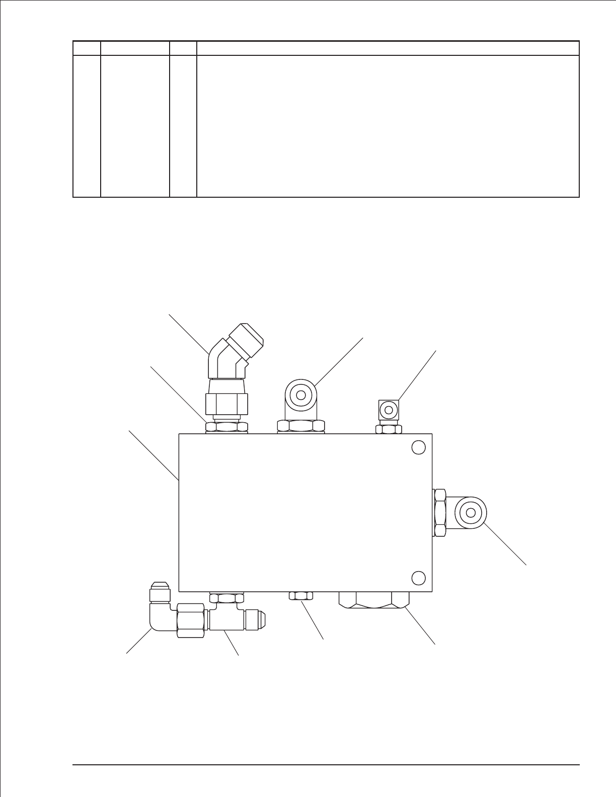
Check valve
item part no qty description
0081980 1 Check valve
1 6010579 1 Check valve - (includes cartridge, item 2)
2 6010565 1 Check valve cartridge
6010605 1 Seal repair kit
3 5035310 2 Straight thread 90° elbow
4 5036505 1 Straight thread branch tee
5 5037005 1 Swivel nut 90° elbow
6 5065729 1 Straight thread adapter
7 5036907 1 Swivel nut 45° elbow
8 5035318 1 Straight thread 90° elbow
9 5075203 1 Hex head plug
TB 60 – 01-97 through 01-01 2-27
P
TEP
VP DV SV
1
2
3
4
5
6
7
8
3
9
AW0081980

Cylinder, extension - GBI
item part no qty description
0080975 1 Cylinder, extension - GBI
0080473 1 Seal repair kit - (kit includes items 10 through 18)
1 1 Tube - (not sold separately)
2 8070296 1 Rod
3 8070297 1 Retainer
4 8070298 1 bearing
5 8070299 1 Spacer
6 8070131 1 Piston
7 8070018 1 Nut
8 8070300 1 Lock washer
9 8070301 1 Capscrew
10 Kit item 1 Snap ring - (not sold separately)
11 Kit item 1 Nylon plug - (not sold separately)
12 Kit item 1 O-ring - (not sold separately)
13 Kit item 1 Back-up - (not sold separately)
14 Kit item 2 O-ring - (not sold separately)
15 Kit item 2 Teflon ring - (not sold separately)
16 Kit item 1 O-ring - (not sold separately)
17 Kit item 1 U-ring - (not sold separately)
18 Kit item 1 Wiper - (not sold separately)
19 6010116 2 Cartridge holding valve - (factory preset, do not reset)
0071918 1 Seal repair kit
2-28 TB 60 – 01-97 through 01-01
19 2
18
3
12
13 411
5
6
15
14
10 7 16 1 8
9
1917
AW0080975
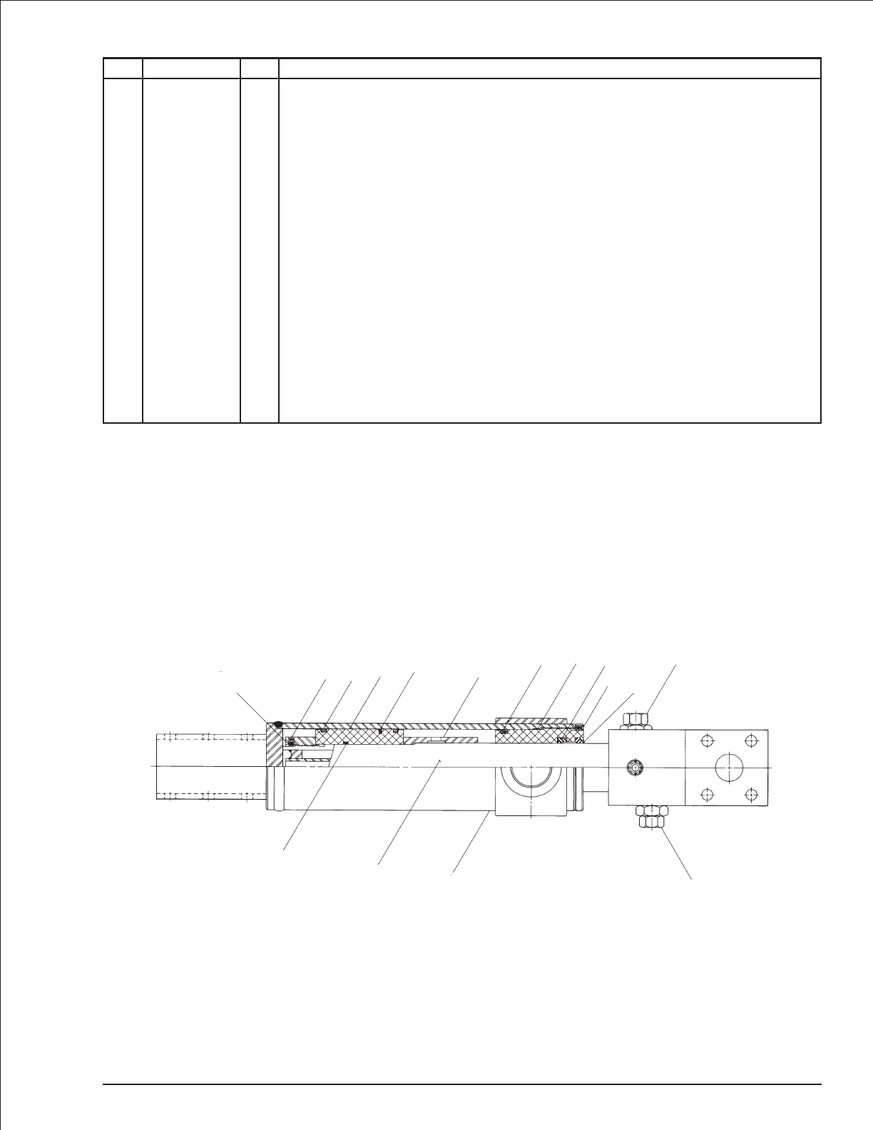
Cylinder, extension - Seabee
item part no qty description
0080975 1 Cylinder, extension - Seabee
0073286 1 Seal repair kit - (kit includes items 8 through 15)
1 1 Case - (not sold separately)
2 8190126 1 Rod
3 8190103 1 Piston
4 8190098 1 Head gland
5 8190127 1 Piston ring nut
6 8190128 1 Spacer
7 8190129 3 Set screw
8 Kit item 1 Wiper - (not sold separately)
9 Kit item 1 U-cup - (not sold separately)
10 Kit item 1 O-ring - (not sold separately)
11 Kit item 1 Back-up - (not sold separately)
12 Kit item 1 O-ring - (not sold separately)
13 Kit item 2 Back-up - (not sold separately)
14 Kit item 1 Piston seal - (not sold separately)
15 Kit item 1 O-ring - (not sold separately)
16 6090037 1 Cast iron piston ring
17 6010116 2 Cartridge holding valve - (factory preset, do not reset)
0071918 1 Seal repair kit
TB 60 – 01-97 through 01-01 2-29
17
1
2
12
13
5
716 314
15
610
11
49
78
17
AWV00216
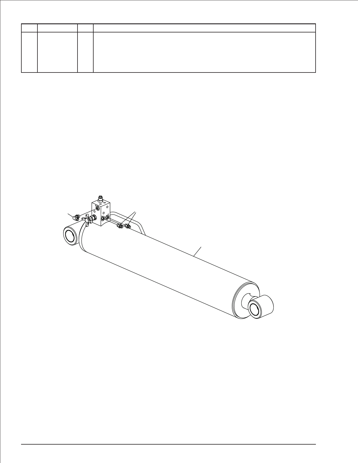
Lift cylinder
item part no qty description
0080053 1 Lift cylinder
1 0080061 1 Cylinder, lift - (see page 2-31 for GBI cylinder)
0083473-99 1 Cylinder, lift - (see page 2-32 for Rosenboom cylinder
2 5035305 1 Straight thread 90° elbow
3 5065707 2 Straight thread adapter
2-30 TB 60 – 01-97 through 01-01
3
2
1
AW0080053
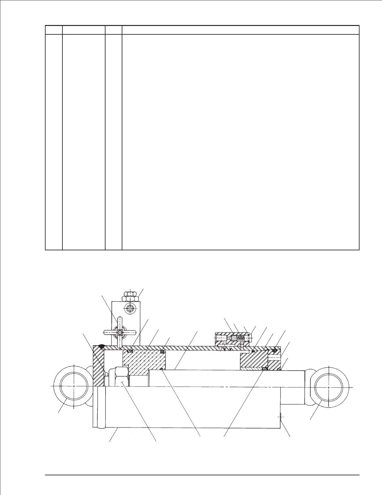
Cylinder, lift - GBI
item part no qty description
0080061 1 Cylinder, lift - GBI
0080615 1 Seal repair kit - (kit includes items 13 through 23)
1 1 Tube - (not sold separately)
2 8070247 1 Rod
3 8070295 1 Retainer
4 8070220 1 Bearing
5 8070217 1 Piston
6 2503628 4 Bearing
7 8070030 1 Bearing spacer
8 8070012 1 Poppet
9 8070014 1 Pipe plug
10 8070218 1 Nut
11 8070017 1 Spring
12 8070015 1 Port plug
13 Kit item 1 Cotter pin - (not sold separately)
14 Kit item 1 O-ring - (not sold separately)
15 Kit item 1 Wiper - (not sold separately)
16 Kit item 1 Nylon plug - (not sold separately)
17 Kit item 1 O-ring - (not sold separately)
18 Kit item 1 Back-up - (not sold separately)
19 Kit item 1 U-ring - (not sold separately)
20 Kit item 1 Back-up - (not sold separately)
21 Kit item 1 O-ring - (not sold separately)
22 Kit item 1 Cast iron piston ring - (not sold separately)
23 Kit item 1 Quad seal - (not sold separately)
24 6010115 1 Cartridge needle valve
0071845 1 Seal repair kit
25 6010116 1 Cartridge holding valve - (factory preset, do not reset)
0071918 1 Seal repair kit
TB 60 – 01-97 through 01-01 2-31
6
7
110 21 19
20
9
6
15
3
16
4
17
18
12
14
11
8
2
22
5
23
25
24
13
AWV00217
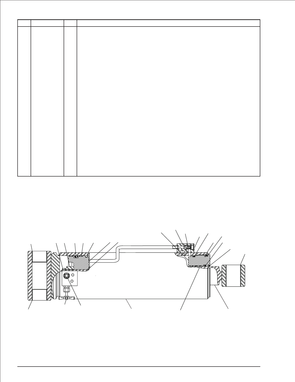
Cylinder, lift - Rosenboom
item part no qty description
0083473-99 1 Cylinder, lift - Rosenboom
6091253 1 Seal repair kit - (kit includes items 10 through 21)
1 1 Tube - (not sold separately)
2 6091251 1 Rod
3 6091250 1 Head gland cap
4 6091249 1 Piston
5 2503628 4 Bearing
6 6091241 1 Poppet
7 6091246 1 Spring
8 6091252 1 Locking nut
9 5075306 1 Hex plug
10 Kit item 1 Snap ring - (not sold separately)
11 Kit item 1 Capped T-seal - (not sold separately)
12 Kit item 2 Wearband - (not sold separately)
13 Kit item 1 Cast iron ring - (not sold separately)
14 Kit item 1 O-ring - (not sold separately)
15 Kit item 1 O-ring - (not sold separately)
16 Kit item 1 Back-up - (not sold separately)
17 Kit item 2 Wearband - (not sold separately)
18 Kit item 2 Locking insert - (not sold separately)
19 Kit item 1 O-ring - (not sold separately)
20 Kit item 1 Deep Z-seal - (not sold separately)
21 Kit item 1 Rod wiper - (not sold separately)
22 6010115 1 Cartridge needle valve
0071845 1 Seal repair kit
23 6091314 1 Counterbalance holding valve - (factory preset, do not reset)
2-32 TB 60 – 01-97 through 01-01
1
4
810 14
13
11 12
5
9
67
3
2
15 19
16
20
21
17
18
5
5
22 23
AW0083473
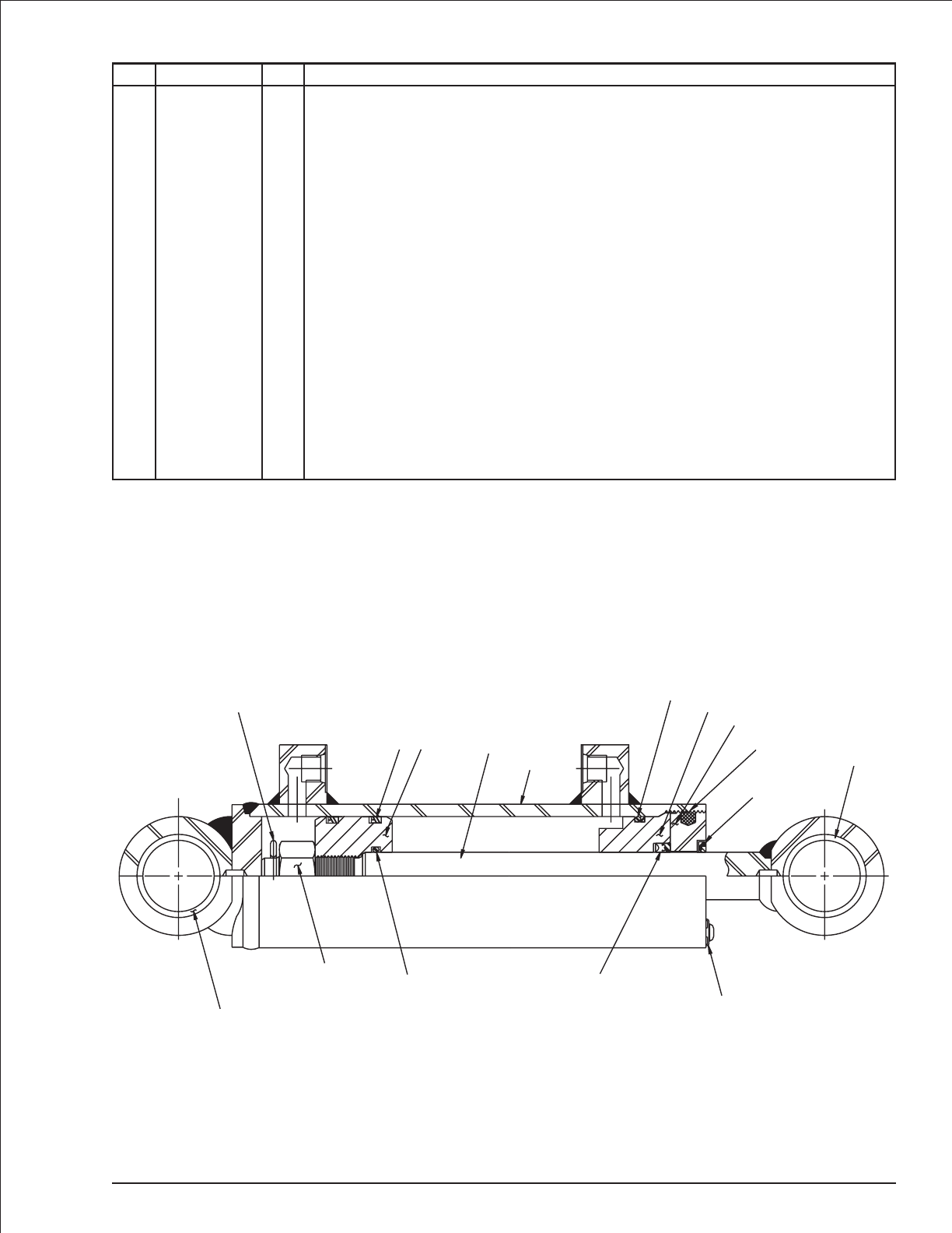
Cylinder, master level - GBI
item part no qty description
0070007 1 Cylinder, master level - GBI
8070611 1 Seal repair kit - (kit includes items 12 through 19)
1 8070623 1 Rod
2 1 Tube - (not sold separately)
3 8070621 1 Retainer
4 8070620 1 Bearing
5 8070619 1 Piston
6 8070618 1 Spacer
7 8070184 1 Spacer
8 8070616 4 Bushing
9 8070033 1 Nut
10 8070300 1 Lock washer
11 8070301 1 Capscrew
12 Kit item 1 Cotter pin - (not sold separately)
13 Kit item 1 Nylon plug - (not sold separately)
14 Kit item 1 Back-up - (not sold separately)
15 Kit item 1 O-ring - (not sold separately)
16 Kit item 2 U-ring - (not sold separately)
17 Kit item 1 O-ring - (not sold separately)
18 Kit item 1 U-ring - (not sold separately)
19 Kit item 1 Wiper - (not sold separately)
TB 60 – 01-97 through 01-01 2-33
7
8
19
13
3
4
14
15
1
2
5
16
12
6
8
11 17 18
9
10
AWV00274

Cylinder, master level - Prince
item part no qty description
0070007 1 Cylinder, master level - Prince
8160088 1 Seal repair kit - (kit includes items 12 through 18)
1 8160207 1 Piston rod
2 1 Butt and tube - (not sold separately)
3 8160209 1 Piston
4 8160210 1 Gland
5 6091082 1 Locknut
6 8160212 1 Cotter pin
7 6091083 1 Set screw
8 8160131 2 Port plug
9 8160199 4 DU bushing
10 8160213 1 Spacer
11 8160214 1 Spacer
12 Kit item 1 Wear ring - (not sold separately)
13 Kit item 1 Teflon seal - (not sold separately)
14 Kit item 1 O-ring - (not sold separately)
15 Kit item 1 O-ring - (not sold separately)
16 Kit item 1 BU-washer - (not sold separately)
17 Kit item 1 U-cup - (not sold separately)
18 Kit item 1 Wiper - (not sold separately)
19 8160219 1 Rod and wiper cover
2-34 TB 60 – 01-97 through 01-01
9
11
658312
1314
12415 16 17 7
19
18 9
10
AWV00246

Cylinder, master level - Rosenboom
item part no qty description
0070007 1 Cylinder, master level - Rosenboom
6091260 1 Seal repair kit - (kit includes items 9 through 18)
1 1 Tube - (not sold separately)
2 6091374 1 Rod
3 6091257 1 Head gland
4 6091256 1 Piston
5 6091250 1 Head gland cap
6 6091259 1 Lock nut
7 5569835 1 Set screw
8 2502416 4 Bearing
9 Kit item 1 Snap ring - (not sold separately)
10 Kit item 1 O-ring - (not sold separately)
11 Kit item 1 O-ring - (not sold separately)
12 Kit item 1 Back-up - (not sold separately)
13 Kit item 1 Capped T-seal - (not sold separately)
14 Kit item 1 Deep Z-seal - (not sold separately)
15 Kit item 1 Rod wiper - (not sold separately)
16 Kit item 1 Wearband - (not sold separately)
17 Kit item 2 Wearband - (not sold separately)
18 Kit item 1 Locking insert - (not sold separately)
TB 60 – 01-97 through 01-01 2-35
4
61
2
910
13 17
8
7
5
3
11
12
14
15
16
18
8
AWV00373

Cylinder, master level - Seabee
item part no qty description
0070007 1 Cylinder, master level - Seabee
0072833 1 Seal repair kit - (kit includes items 11 through 20)
1 1 Case - (not sold separately)
2 8190060 1 Rod
3 8190038 1 Piston
4 8190074 1 Head gland
5 8190123 1 Piston nut
6 8190124 1 Thrust plate
7 2502416 4 Bearing
8 8190066 1 Bearing spacer
9 8190067 1 Bearing spacer
10 8190129 1 Set screw
11 Kit item 1 Wiper - (not sold separately)
12 Kit item 1 U-cup - (not sold separately)
13 Kit item 1 O-ring - (not sold separately)
14 Kit item 1 Back-up - (not sold separately)
15 Kit item 1 O-ring - (not sold separately)
16 Kit item 2 Back-up - (not sold separately)
17 Kit item 1 Piston seal - (not sold separately)
18 Kit item 1 O-ring - (not sold separately)
19 Kit item 2 Piston ring - (not sold separately)
20 Kit item 1 Cotter pin - (not sold separately)
2-36 TB 60 – 01-97 through 01-01
2
7
8
112
13
14
10
411
20 319 6
17
18
15
16
5
7
9
AWV00206
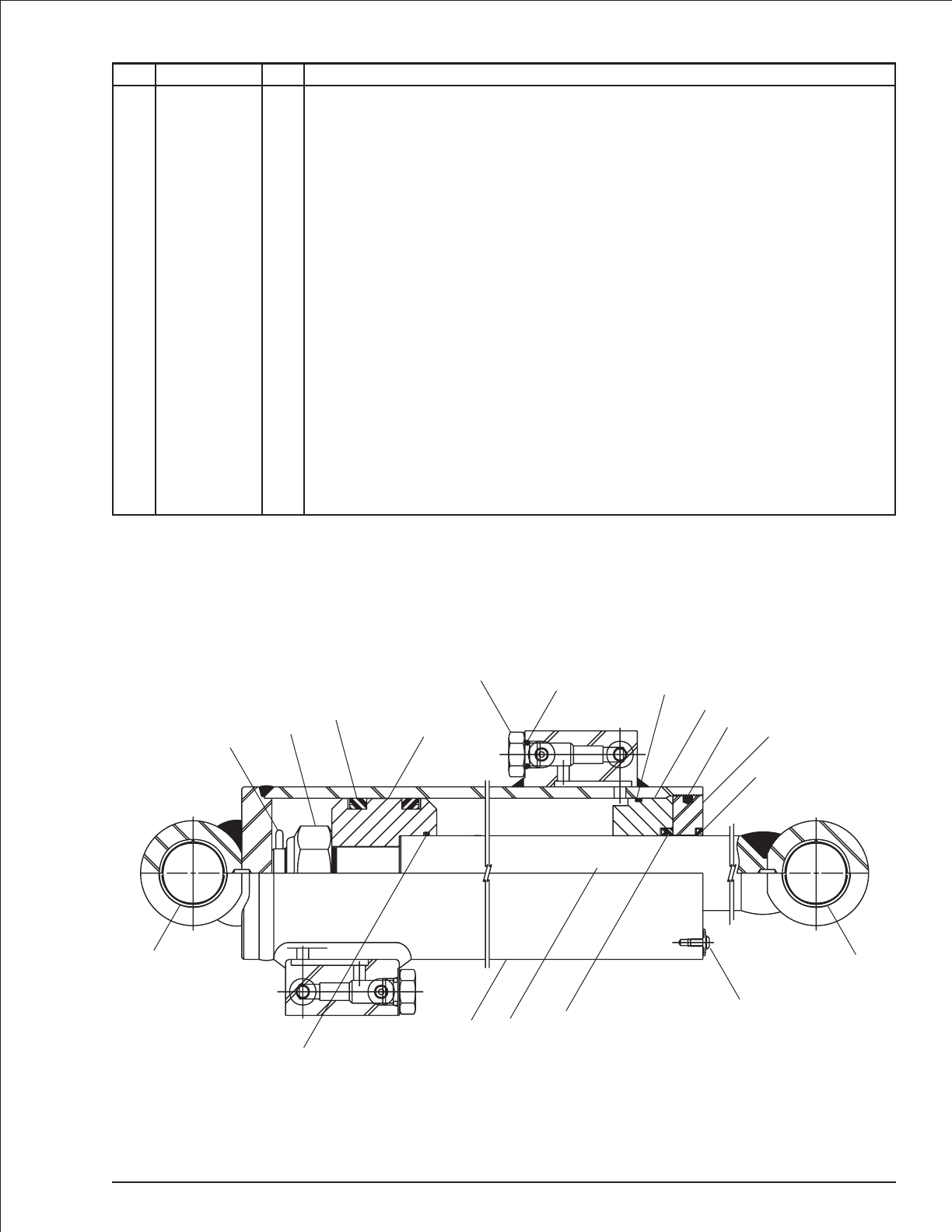
Cylinder, slave level - GBI
item part no qty description
0071486 1 Cylinder, Slave level - GBI
8070624 Seal repair kit - (kit includes items 13 through 21)
1 1 Tube - (not sold separately)
2 8070625 1 Rod
3 8070621 1 Retainer
4 8070620 1 Bearing
5 8070619 1 Piston
6 8070503 1 Nut
7 8070618 1 Spacer
8 8070617 1 Spacer
9 8070564 2 Port plug
10 8070616 4 Bushing
11 8070507 1 Lock washer
12 8070506 1 Capscrew
13 Kit item 2 O-ring - (not sold separately)
14 Kit item 1 Cotter pin - (not sold separately)
15 Kit item 1 Back-up - (not sold separately)
16 Kit item 1 O-ring - (not sold separately)
17 Kit item 2 U-ring - (not sold separately)
18 Kit item 1 O-ring - (not sold separately)
19 Kit item 1 U-ring - (not sold separately)
20 Kit item 1 Wiper - (not sold separately)
21 Kit item 1 Nylon plug - (not sold separately)
TB 60 – 01-97 through 01-01 2-37
8
10
18
12 19 11
12
7
10
20
3
21
4
15
16
13
9
5
17
6
14
AWV00288
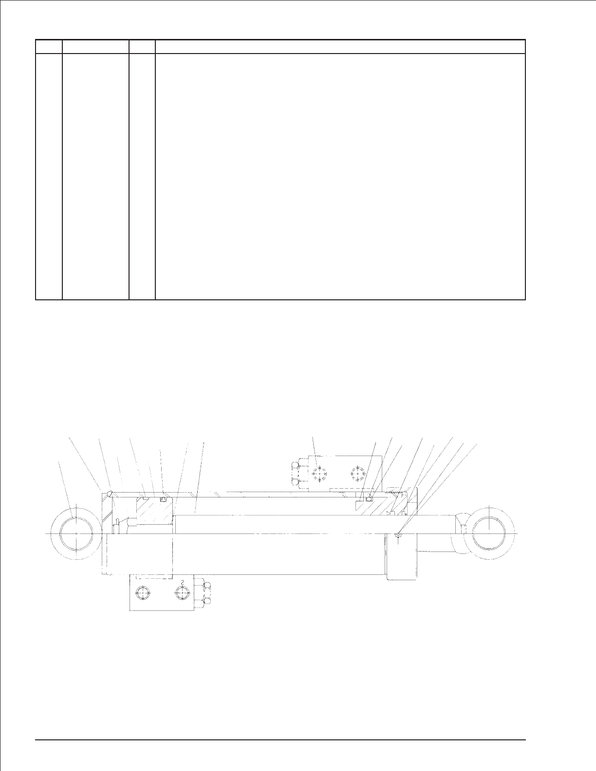
Cylinder, slave level - Prince
item part no qty description
0071486 1 Cylinder, slave level - Prince
8160206 1 Seal repair kit - (kit includes items 4 and 12 through 18)
1 8160195 1 Piston rod
2 8160196 1 Piston
3 6091104 1 Locknut
4 Kit item 1 Cotter pin
5 1 Butt and tube - (not sold separately)
6 8160037 1 Gland
7 8160198 1 Gland cap
8 8160039 1 Nylon lock
9 8160038 1 Set screw
10 8160199 4 Bearing
11 8160131 6 Plug
12 Kit item 1 Piston ring - (not sold separately)
13 Kit item 1 T-seal - (not sold separately)
14 Kit item 1 O-ring - (not sold separately)
15 Kit item 1 O-ring - (not sold separately)
16 Kit item 1 BU-washer - (not sold separately)
17 Kit item 1 U-cup - (not sold separately)
18 Kit item 1 Wiper - (not sold separately)
19 28160205 2 Plug
2-38 TB 60 – 01-97 through 01-01
10
54
3
12
2
13 14 111 615 16 1718 789
AWV00248
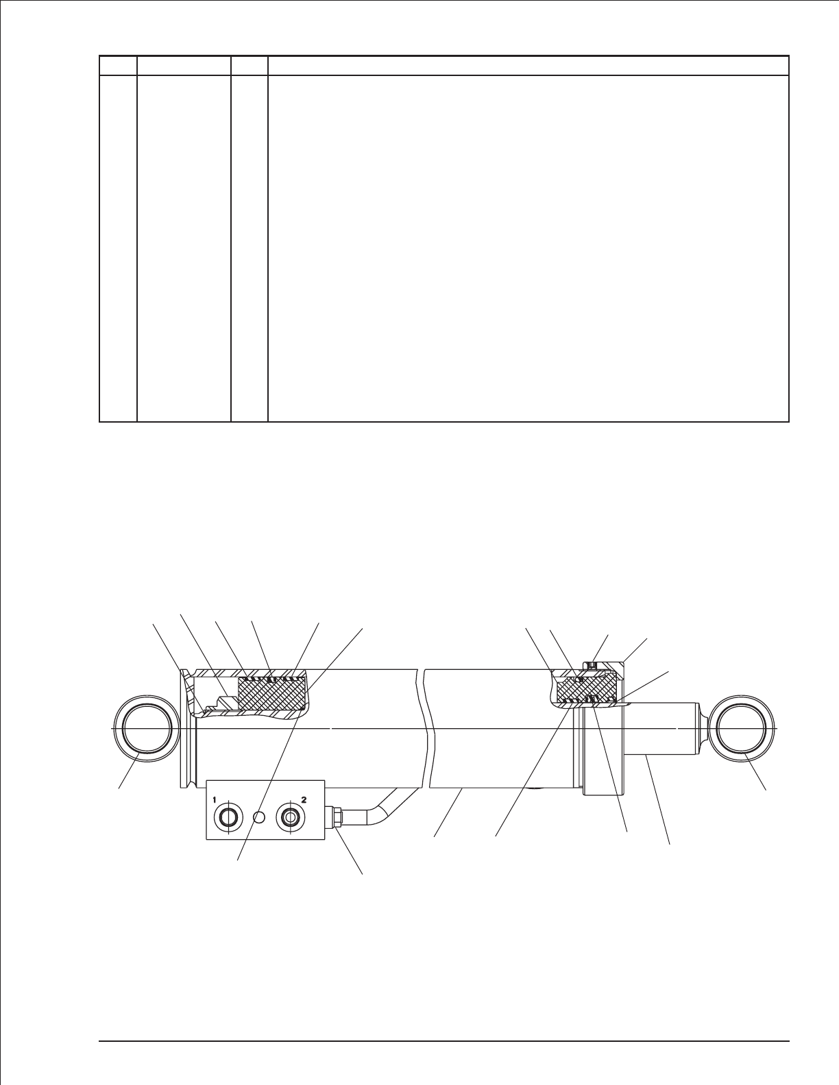
Cylinder, slave level - Rosenboom
item part no qty description
0074713 1 Cylinder, slave level - Rosenboom
6091260 1 Seal repair kit - (kit includes items 10 through 19)
1 1 Cylinder tube - (not sold separately)
2 6091258 1 Rod
3 6091255 1 Head gland cap
4 6091257 1 Head gland
5 6091256 1 Piston
6 6091259 1 Lock nut
7 5569835 1 Set screw
8 2502416 4 Bushing
9 6010794 2 Cartridge holding valve - (factory preset, do not reset)
10 Kit item 1 External snap ring - (not sold separately)
11 Kit item 1 O-ring - (not sold separately)
12 Kit item 1 O-ring - (not sold separately)
13 Kit item 1 Back-up ring - (not sold separately)
14 Kit item 1 T-seal - (not sold separately)
15 Kit item 1 Deep Z-seal - (not sold separately)
16 Kit item 1 Rod wiper - (not sold separately)
17 Kit item 1 Wearband - (not sold separately)
18 Kit item 2 Wearband - (not sold separately)
19 Kit item 1 Locking insert - (not sold separately)
TB 60 – 01-97 through 01-01 2-39
10 614 18 14 5
11
8
9
12
8
17 15
16
3
412
13
7
19
AWV00290
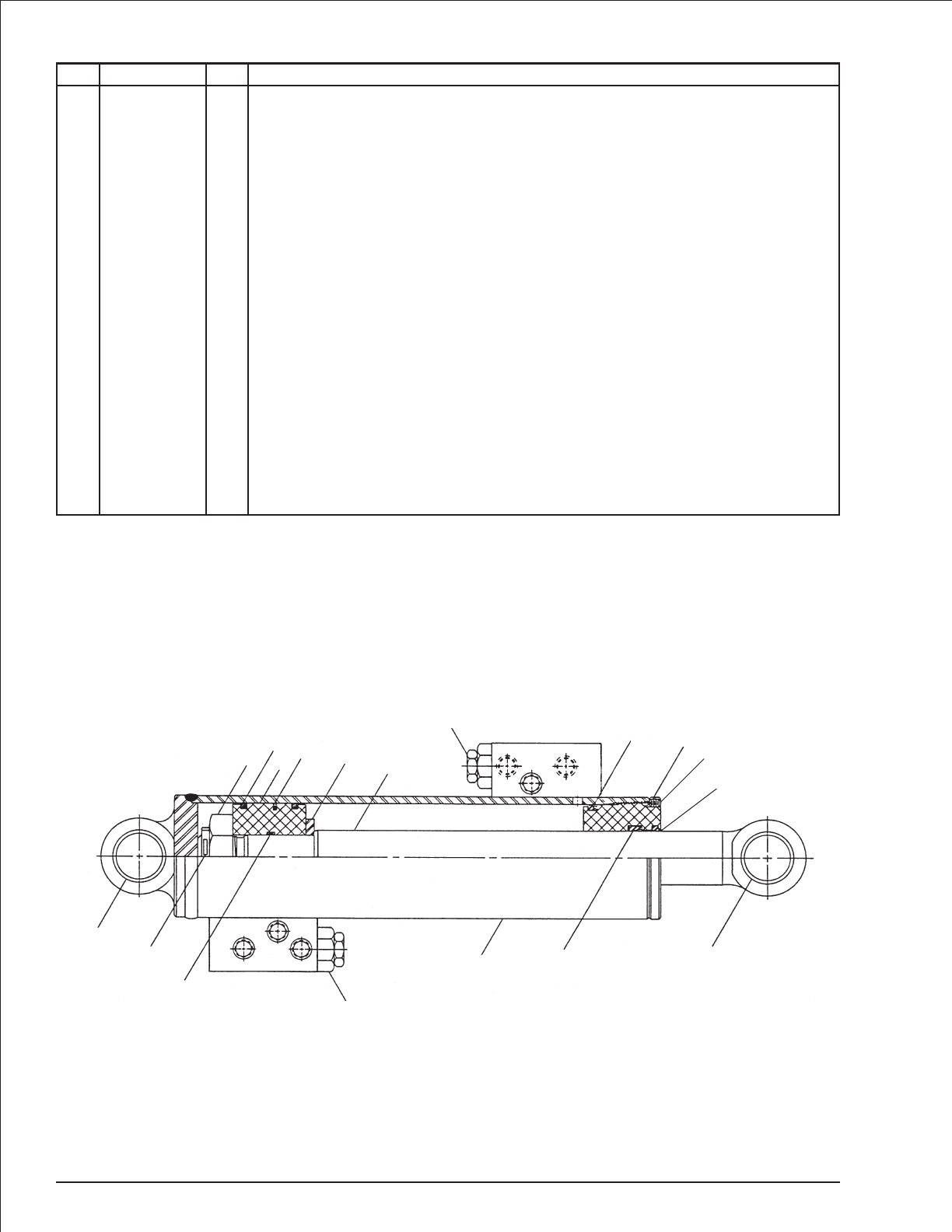
Cylinder, slave level - Seabee
item part no qty description
0071486 1 Cylinder, slave level - Seabee
0072833 1 Seal repair kit - (kit includes items 11 through 20)
1 1 Case - (not sold separately)
2 8190036 1 Shaft
3 8190038 1 Piston
4 8190074 1 Head gland
5 8190123 1 Piston nut
6 8190124 1 Thrust plate
7 8190125 1 Set screw
8 2502416 4 Bearing
9 8190066 1 Bearing spacer, rod end
10 8190067 1 Bearing spacer, base end
11 Kit item 1 Wiper - (not sold separately)
12 Kit item 1 U-ring - (not sold separately)
13 Kit item 1 O-ring - (not sold separately)
14 Kit item 1 Back-up - (not sold separately)
15 Kit item 1 O-ring - (not sold separately)
16 Kit item 2 Back-up - (not sold separately)
17 Kit item 1 Piston seal - (not sold separately)
18 Kit item 2 O-ring - (not sold separately)
19 Kit item 2 Piston ring - (not sold separately)
20 Kit item 1 Cotter pin - (not sold separately)
21 6010120 1 Cartridge holding valve - (factory preset, do not reset)
2-40 TB 60 – 01-97 through 01-01
13
14
47
11
8
9
112
21
15
16
20
8
10
5
19
317
18
62
21
AWV00208

Cylinder, steering - GBI
item part no qty description
0070007 1 Cylinder, steering - GBI
8070611 1 Seal repair kit - (kit includes items 12 through 19)
1 8070623 1 Rod
2 1 Tube - (not sold separately)
3 8070621 1 Retainer
4 8070620 1 Bearing
5 8070619 1 Piston
6 8070618 1 Spacer
7 8070184 1 Spacer
8 8070616 4 Bushing
9 8070033 1 Nut
10 8070300 1 Lock washer
11 8070301 1 Capscrew
12 Kit item 1 Cotter pin - (not sold separately)
13 Kit item 1 Nylon plug - (not sold separately)
14 Kit item 1 Back-up - (not sold separately)
15 Kit item 1 O-ring - (not sold separately)
16 Kit item 2 U-ring - (not sold separately)
17 Kit item 1 O-ring - (not sold separately)
18 Kit item 1 U-ring - (not sold separately)
19 Kit item 1 Wiper - (not sold separately)
TB 60 – 01-97 through 01-01 2-41
7
8
19
13
3
4
14
15
1
2
5
16
12
6
8
11 17 18
9
10
AWV00274
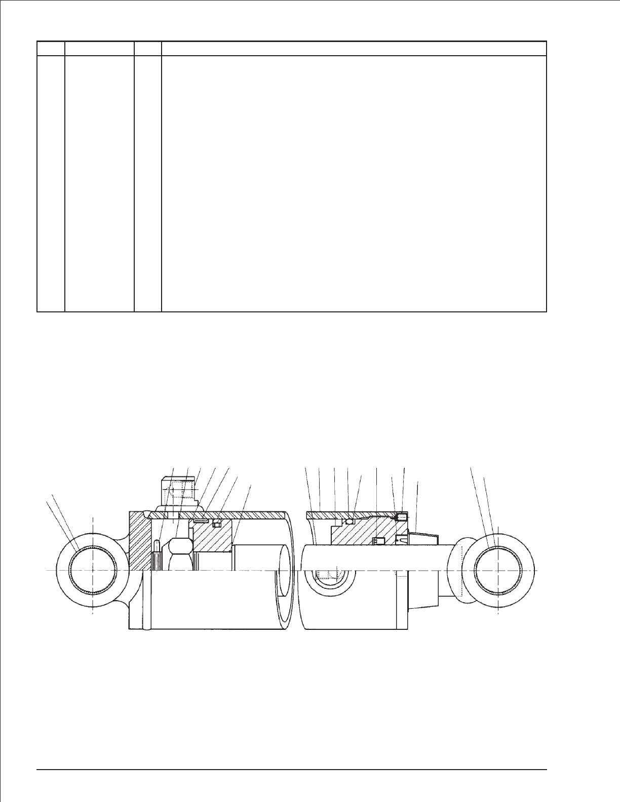
Cylinder, steering - Prince
item part no qty description
0070007 1 Cylinder, steering - Prince
8160088 1 Seal repair kit - (kit includes items 12 through 18)
1 8160207 1 Piston rod
2 1 Butt and tube - (not sold separately)
3 8160209 1 Piston
4 8160210 1 Gland
5 6091082 1 Locknut
6 8160212 1 Cotter pin
7 6091083 1 Set screw
8 8160131 2 Port plug
9 8160199 4 DU bushing
10 8160213 1 Spacer
11 8160214 1 Spacer
12 Kit item 1 Wear ring - (not sold separately)
13 Kit item 1 Teflon seal - (not sold separately)
14 Kit item 1 O-ring - (not sold separately)
15 Kit item 1 O-ring - (not sold separately)
16 Kit item 1 BU-washer - (not sold separately)
17 Kit item 1 U-cup - (not sold separately)
18 Kit item 1 Wiper - (not sold separately)
19 8160219 1 Rod and wiper cover
2-42 TB 60 – 01-97 through 01-01
9
11
658312
1314
12415 16 17 7
19
18 9
10
AWV00246
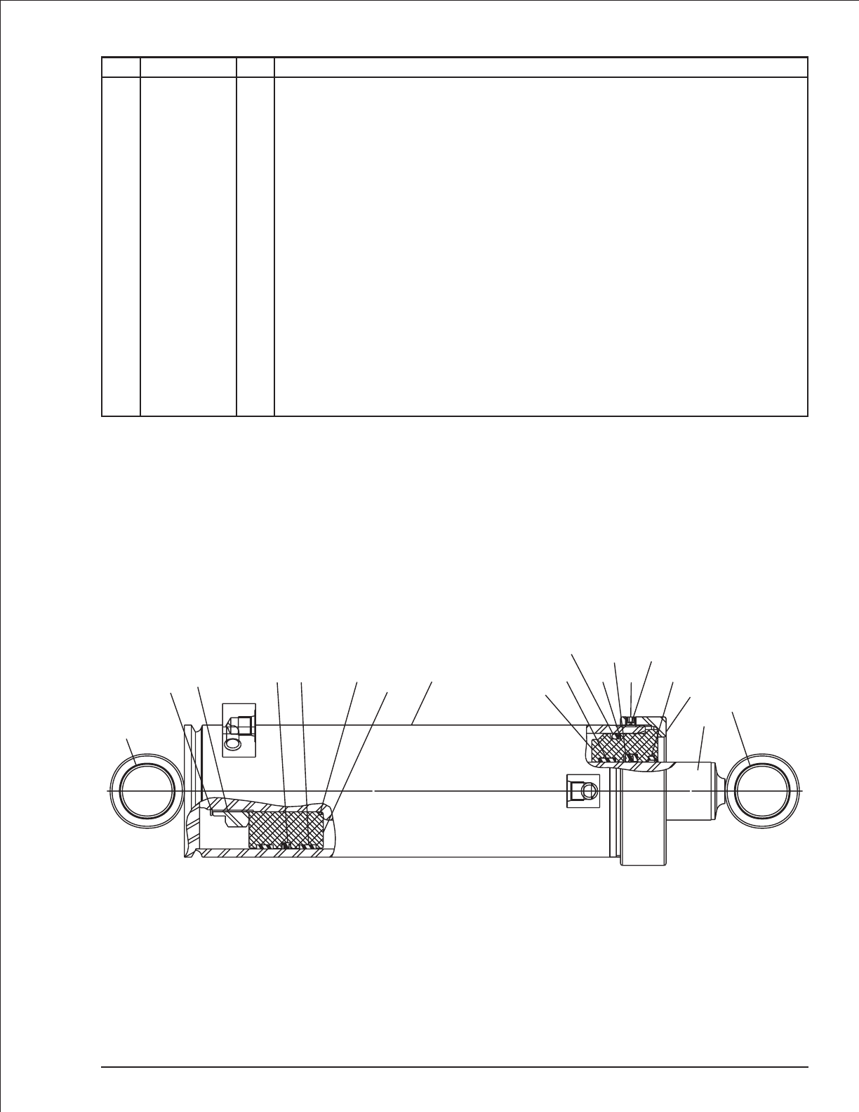
Cylinder, steering - Rosenboom
item part no qty description
0070007 1 Cylinder, Steering - Rosenboom
6091260 1 Seal repair kit - (kit includes items 9 through 18)
1 1 Tube - (not sold separately)
2 6091374 1 Rod
3 6091257 1 Head gland
4 6091256 1 Piston
5 6091250 1 Head gland cap
6 6091259 1 Lock nut
7 5569835 1 Set screw
8 2502416 4 Bearing
9 Kit item 1 Snap ring - (not sold separately)
10 Kit item 1 O-ring - (not sold separately)
11 Kit item 1 O-ring - (not sold separately)
12 Kit item 1 Back-up - (not sold separately)
13 Kit item 1 Capped T-seal - (not sold separately)
14 Kit item 1 Deep Z-seal - (not sold separately)
15 Kit item 1 Rod wiper - (not sold separately)
16 Kit item 1 Wearband - (not sold separately)
17 Kit item 2 Wearband - (not sold separately)
18 Kit item 1 Locking insert - (not sold separately)
TB 60 – 01-97 through 01-01 2-43
4
61
2
910
13 17
8
7
5
3
11
12
14
15
16
18
8
AWV00373
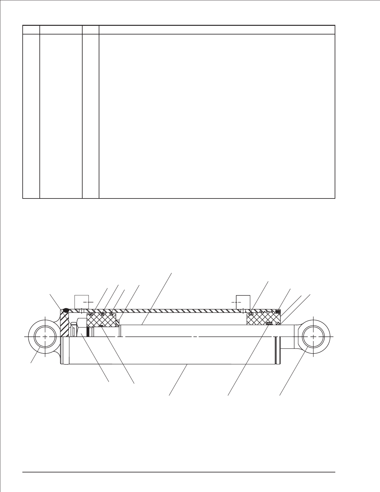
Cylinder, steering - Seabee
item part no qty description
0070007 1 Cylinder, steering - Seabee
0072833 1 Seal repair kit - (kit includes items 11 through 20)
1 1 Case - (not sold separately)
2 8190060 1 Rod
3 8190038 1 Piston
4 8190074 1 Head gland
5 8190123 1 Piston nut
6 8190124 1 Thrust plate
7 2502416 4 Bearing
8 8190066 1 Bearing spacer
9 8190067 1 Bearing spacer
10 8190129 1 Set screw
11 Kit item 1 Wiper - (not sold separately)
12 Kit item 1 U-cup - (not sold separately)
13 Kit item 1 O-ring - (not sold separately)
14 Kit item 1 Back-up - (not sold separately)
15 Kit item 1 O-ring - (not sold separately)
16 Kit item 2 Back-up - (not sold separately)
17 Kit item 1 Piston seal - (not sold separately)
18 Kit item 1 O-ring - (not sold separately)
19 Kit item 2 Piston ring - (not sold separately)
20 Kit item 1 Cotter pin - (not sold separately)
2-44 TB 60 – 01-97 through 01-01
2
7
8
112
13
14
10
411
20 319 6
17
18
15
16
5
7
9
AWV00206
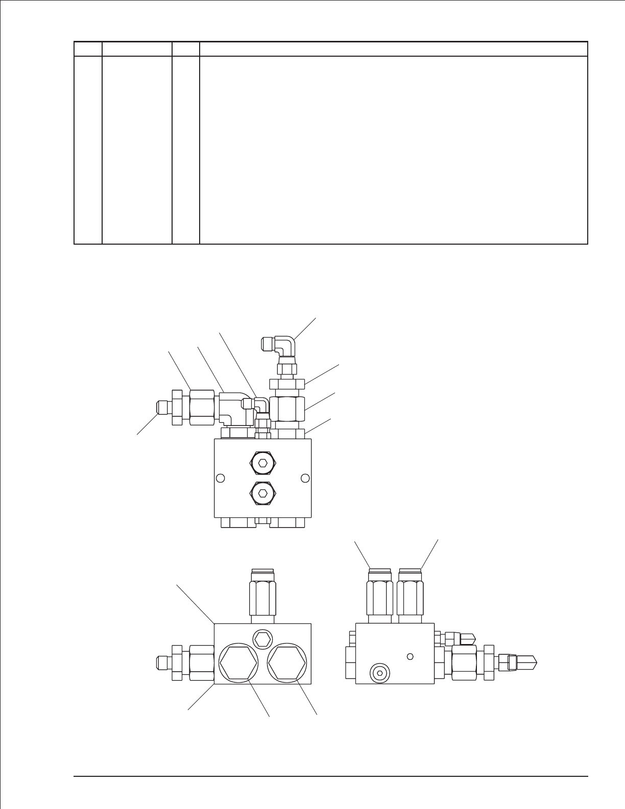
Drive sequence valve, right hand
item part no qty description
0081600 1 Drive sequence valve, right hand
1 6010613 1 Dual sequence valve, Fluid Tech or Weco- (includes items 2 and 3)
2 6010614 1 Valve body, Fluid Tech
6010624 1 Valve body, Weco
3 6010615 2 Cartridge sequence valve, Fluid Tech - (factory preset, do not reset)
6010269 2 Cartridge sequence valve, Weco - (factory preset, do not reset)
4 5075208 2 Hex head plug
5 5065703 1 Straight thread adapter
6 5065714 1 Straight thread adapter
7 5035308 1 Straight thread 90° elbow
8 5075203 1 Hex head plug
9 5063908 2 Fitting nut
10 5064007 2 Tube end reducer
11 5037005 1 Swivel nut 90° elbow
12 5037003 1 Swivel nut 90° elbow
TB 60 – 01-97 through 01-01 2-45
M1
M1
M2
M2
P
P
M1 M2
P
1
2
33
44
6
9
10
11
10
97
5
12
AW0081600
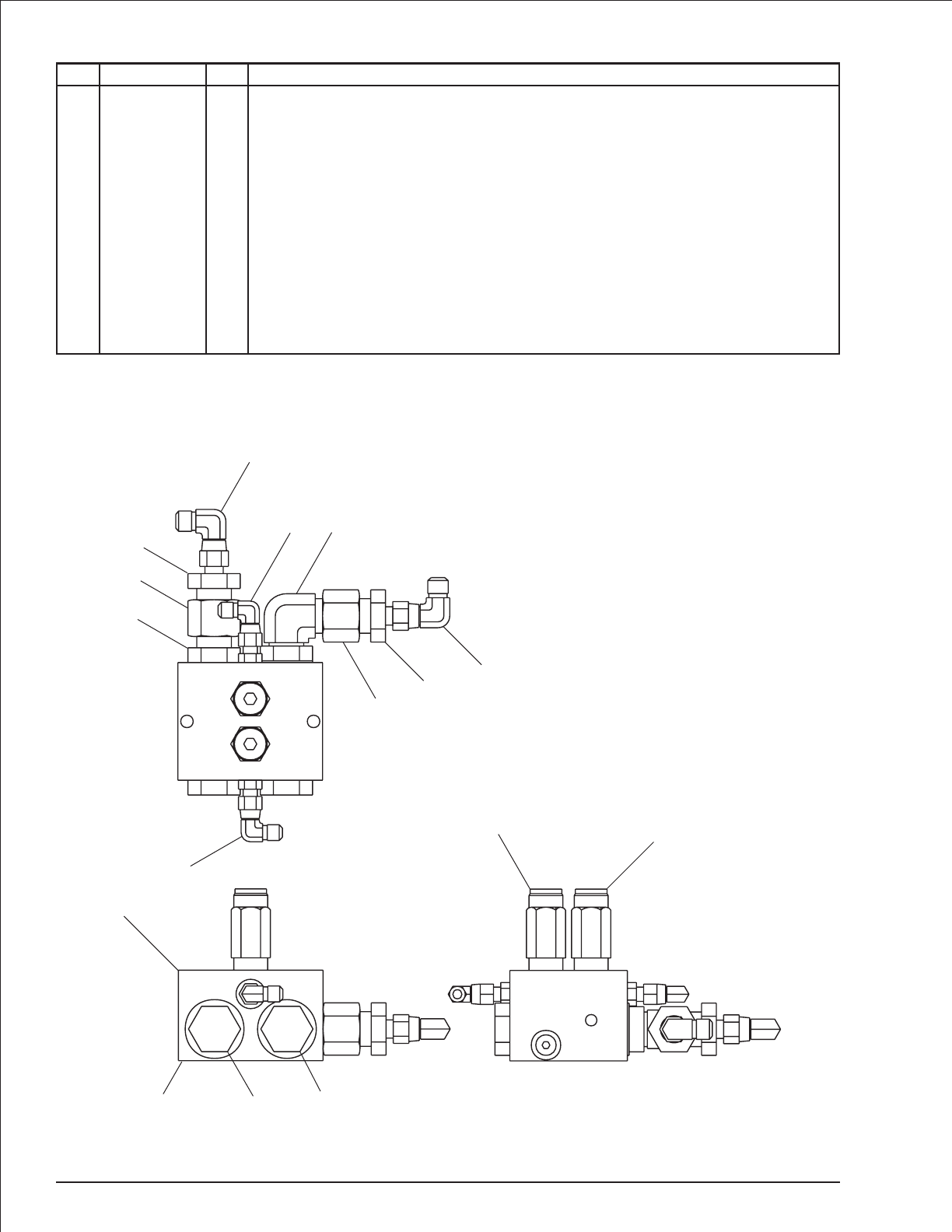
Drive sequence valve, left hand
item part no qty description
0081604 1 Drive sequence valve, left hand
1 6010613 1 Dual sequence valve, Fluid Tech or Weco- (includes items 2 and 3)
2 6010614 1 Valve body, Fluid Tech
6010624 1 Valve body, Weco
3 6010615 2 Cartridge sequence valve, Fluid Tech - (factory preset, do not reset)
6010269 2 Cartridge sequence valve, Weco - (factory preset, do not reset)
4 5075208 2 Hex head plug
5 5065703 2 Straight thread adapter
6 5065714 1 Straight thread adapter
7 5035308 1 Straight thread 90° elbow
8 5063908 2 Fitting nut
9 5064007 2 Tube end reducer
10 5037003 2 Swivel nut 90° elbow
11 5037005 2 Swivel nut 90° elbow
2-46 TB 60 – 01-97 through 01-01
M1 M2
P
M2
P
M1
M1 M2
P
33
1
244
5
10
8
911
6
8
9
11
5
10
7
AW0081604
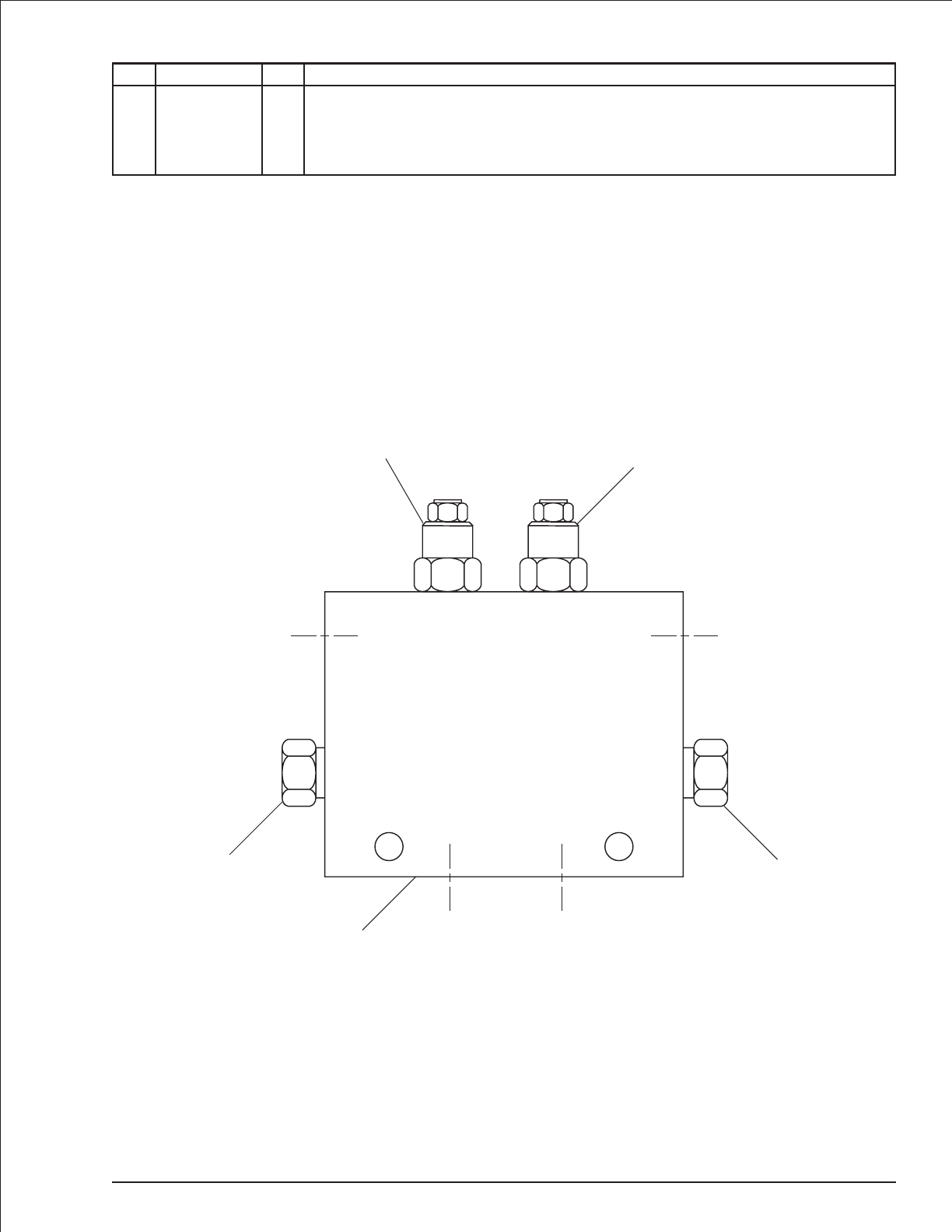
Dual holding valve, platform rotation
item part no qty description
1 6010628 1 Dual holding valve, platform rotation
2 6010794 2 Cartridge holding valve - (factory preset, do not reset)
0150563 1 Seal repair kit
3 6010640 2 Flow control cartridge
TB 60 – 01-97 through 01-01 2-47
C1 C2
V1 V2
1
22
33
AW6010628
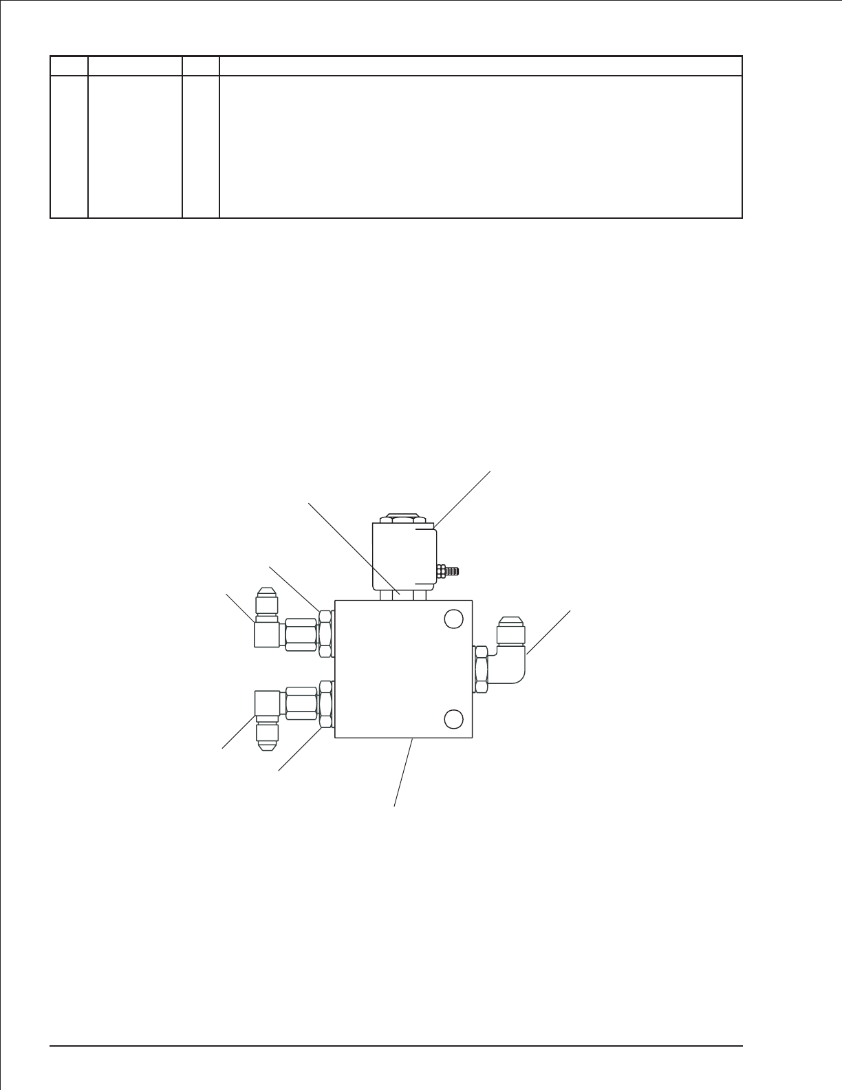
Dump valve
item part no qty description
0081982 1 Dump valve
1 6010499 1 Dump valve - (includes items 2 and 3)
0073620 1 Seal repair kit
2 6010472 1 Cartridge - (factory preset, do not reset)
3 3040473 1 Cartridge solenoid, 10 volt DC
4 5065705 2 Straight thread adapter
5 5037003 2 Swivel nut 90° elbow
6 5035318 1 Straight thread 90° elbow
2-48 TB 60 – 01-97 through 01-01
A
B
C
2
3
1
5
6
4
5
4
AW0081982
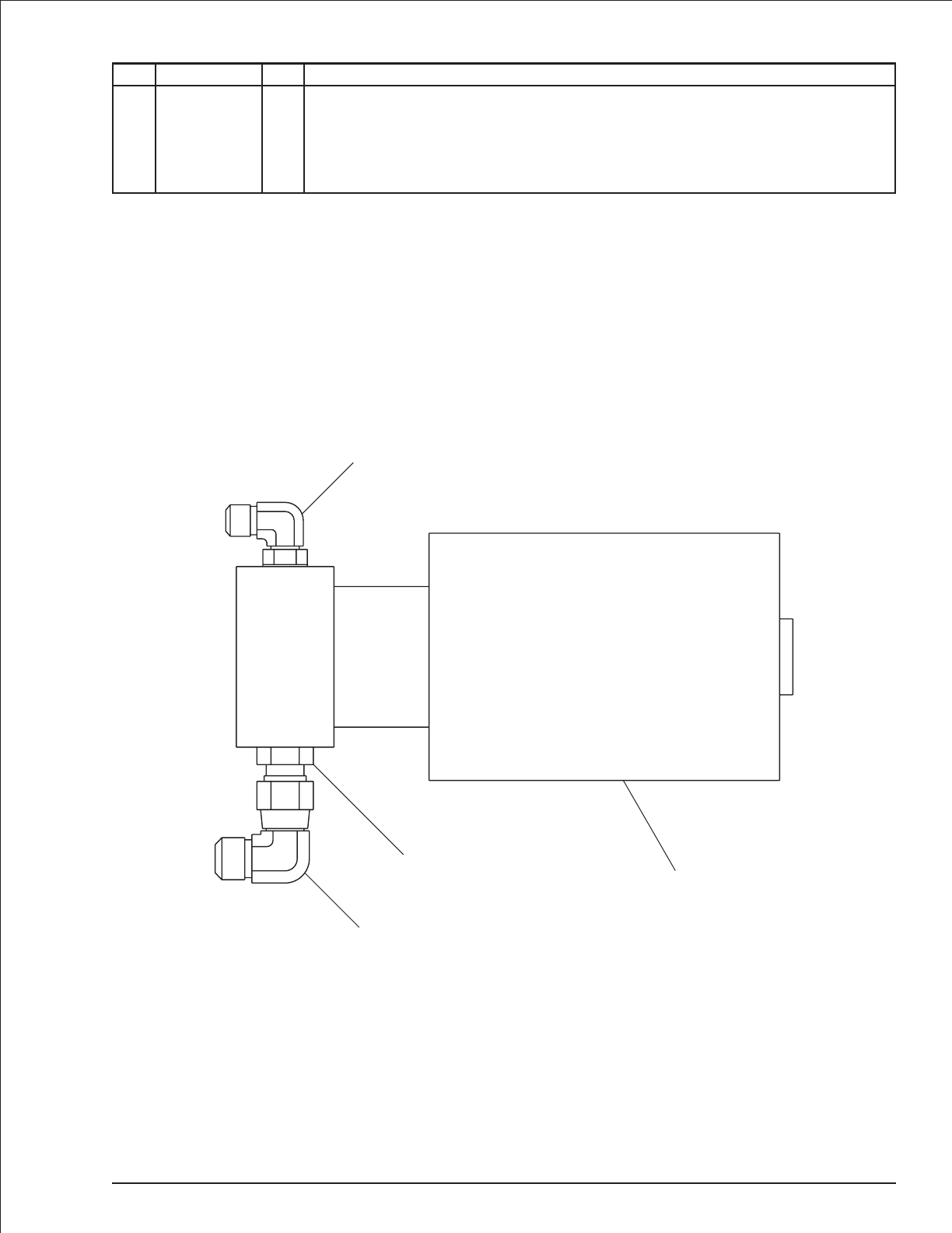
Emergency power unit
item part no qty description
0072940 1 Emergency power unit
1 6020058 1 Emergency power motor/pump
2 5037006 1 Swivel nut 90° elbow
3 5035305 1 Straight thread 90° elbow
4 5065709 1 Straight thread adapter
TB 60 – 01-97 through 01-01 2-49
P
(OUT)
T
(IN)
3
4
2
1
AW0072940
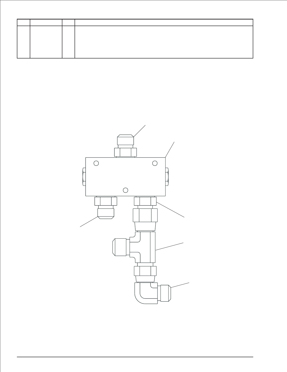
Flow divider/combiner valve
item part no qty description
0080958 1 Flow divider/combiner valve
1 6010437 1 Flow divider/combiner valve
2 5065731 3 Straight thread adapter
3 5036708 1 Swivel nut run tee
4 5037008 1 Swivel nut 90° elbow
2-50 TB 60 – 01-97 through 01-01
1
2
2
2
3
4
AW0080958
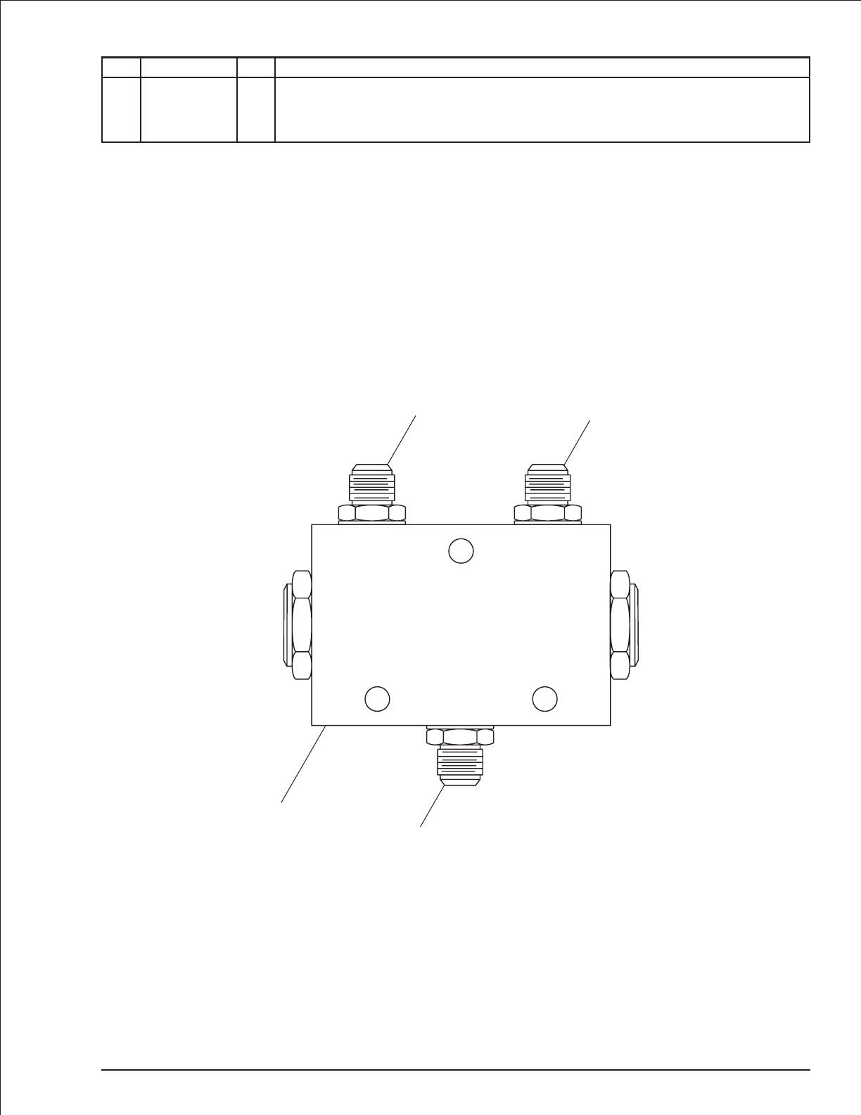
Flow divider valve
item part no qty description
0081424 1 Flow divider valve
1 6010231 1 Flow divider/combiner valve
2 5065714 3 Straight thread adapter
TB 60 – 01-97 through 01-01 2-51
C1 C2
V
1
2
22
AW6010231
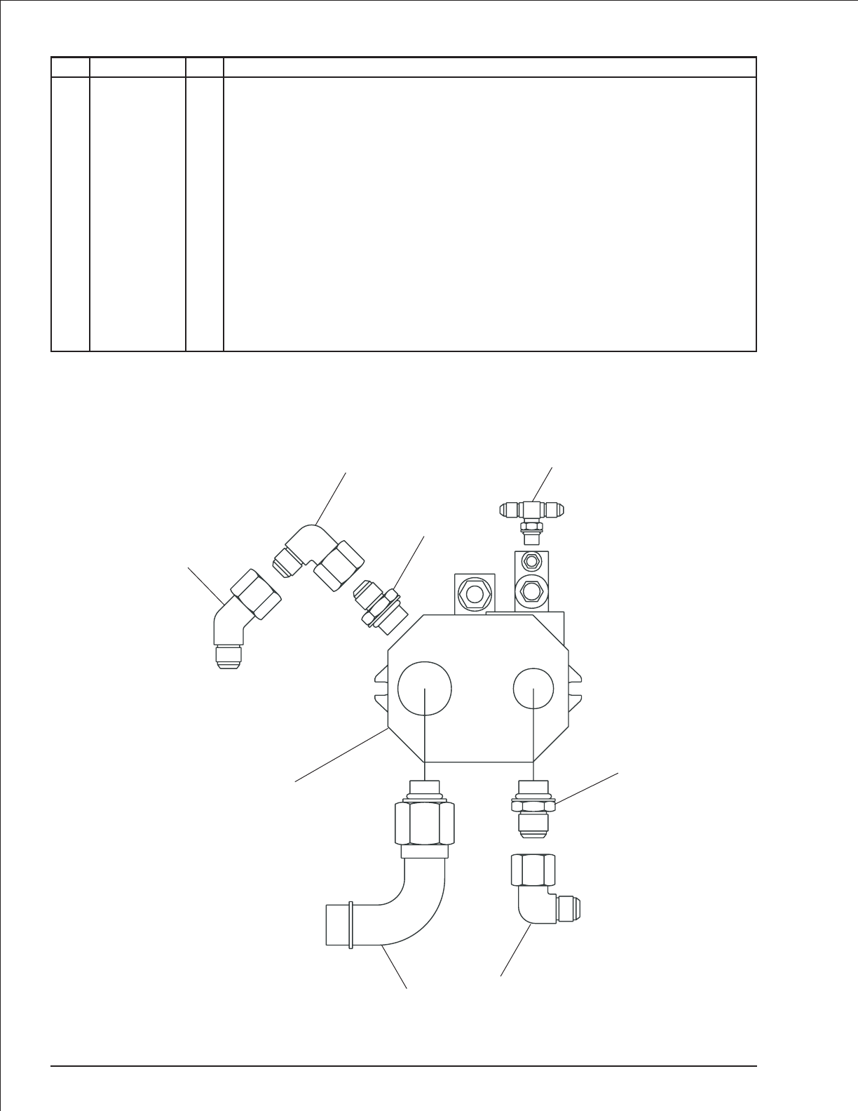
Hydraulic pump
item part no qty description
0082138 1 Hydraulic pump, Deutz and Ford LRG-423 engines - (includes items1 through 7)
0181525 1 Hydraulic pump, Ford LRG-425 engines - (includes items 1 through 8)
1 6020065 1 Hydraulic pump - (pump compensator is not preset)
8220119 1 Seal repair kit - Vickers pump
8160100 1 Seal repair kit - Parker pump
8180021 1 Seal repair kit - Rexroth pump
8220120 1 Replacement compensator - Vickers pump
6090057 1 Replacement compensator - Parker pump
8180023 1 Replacement compensator - Rexroth pump
2 5038005 1 Beaded 90° elbow
3 5065718 1 Straight thread adapter
4 5037010 1 Swivel nut 90° elbow
5 5065710 1 Straight thread adapter
6 5037006 1 Swivel nut 90° elbow
7 5036503 1 Straight thread branch tee
8 5036906 1 Swivel nut 45° elbow - (used on Ford LRG-425 engine only)
2-52 TB 60 – 01-97 through 01-01
IN OUT
1
24
5
6
7
8
3
AW0181525
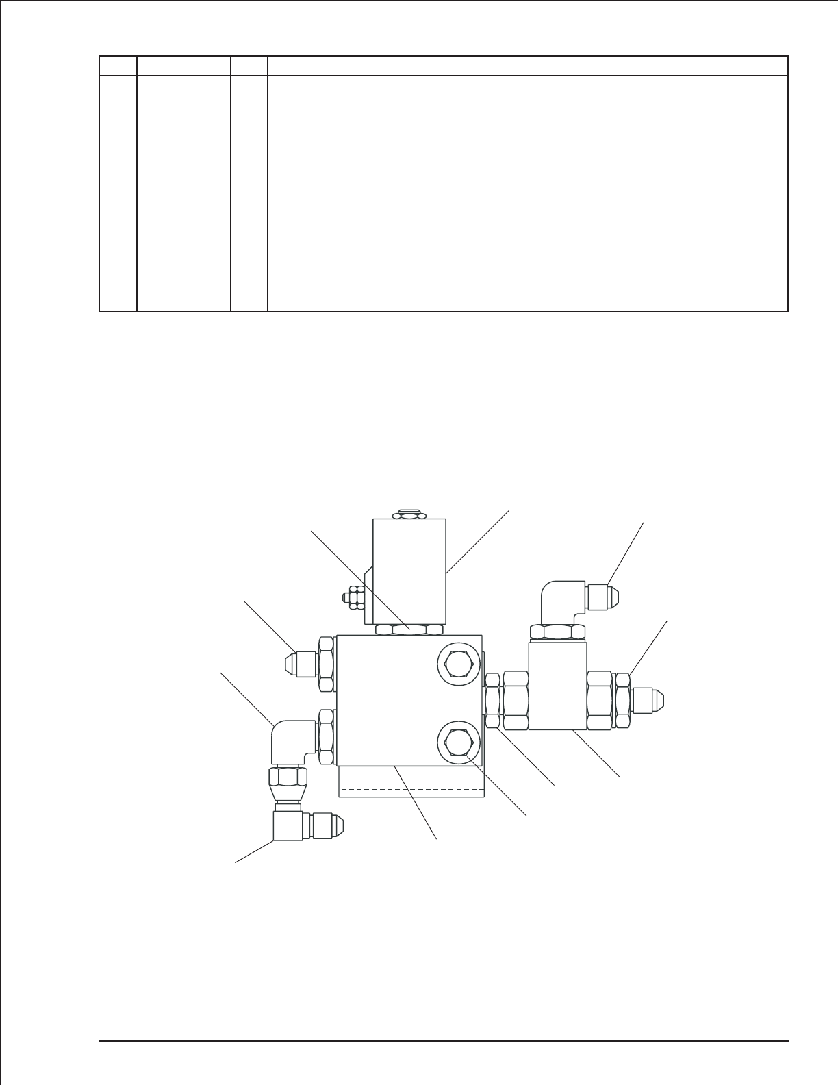
Hydraulic warm-up valve
item part no qty description
0082053 1 Hydraulic warm-up valve
1 6010499 1 Warm-up valve - (includes items 2 and 3)
0073620 1 Seal repair kit
2 6010472 1 Cartridge - (factory preset, do not reset)
3 3040473 1 Cartridge solenoid, 10 volt DC
4 6010083 1 Shuttle valve
5 5065705 2 Straight thread adapter
6 5035318 1 Straight thread 90° elbow
7 5076301 1 Union
8 0071805 1 Mounting bracket
9 5037003 1 Swivel nut 90° elbow
10 970169 2 Capscrew 1/4-20x2inchlonghexhead grade 5
11 986019 2 Washer 1/4 medium flat
12 5560004 2 Nut 1/4-20 self locking
TB 60 – 01-97 through 01-01 2-53
1
2
3
4
5
6
5
6
9
7
101112
AW0082053
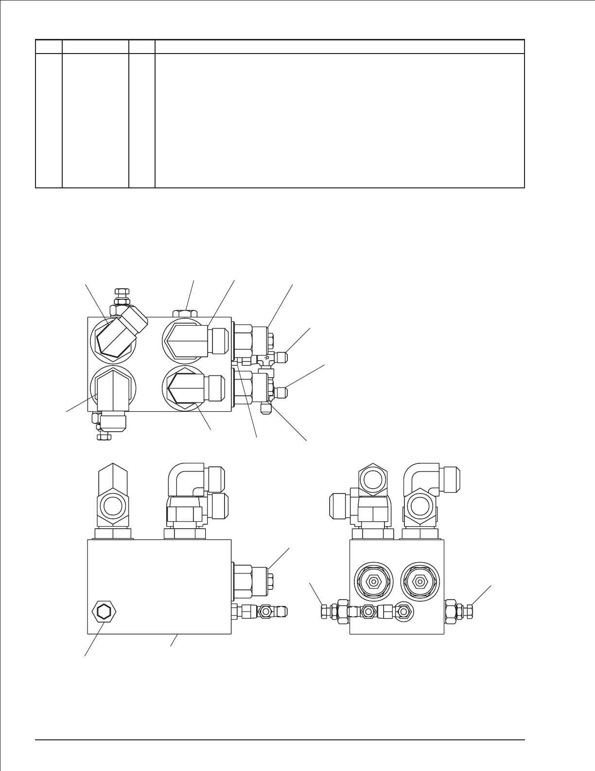
Motion control valve, drive
item part no qty description
0081042 1 Motion control valve, drive
1 6010228 1 Motion control valve, drive - (includes items 2, 3 and 4)
0110683 1 Seal repair kit
2 6010523 2 Counterbalance valve cartridge - (factory preset, do not reset)
3 6010269 2 Sequence valve cartridge - (factory preset, do not reset)
4 6010531 1 Shuttle valve cartridge
5 5065715 2 Straight thread adapter
6 5035319 2 Straight thread 90° elbow
7 5037008 2 Swivel nut 90° elbow
8 5065703 1 Straight thread adapter
9 5036703 2 Swivel nut run tee
2-54 TB 60 – 01-97 through 01-01
M2 V2
M1
M2
V1
V2
V2 V1
Brake
33
2
1
3
2
2
9
9
8
5
6
7
6
5
74
AW0081042
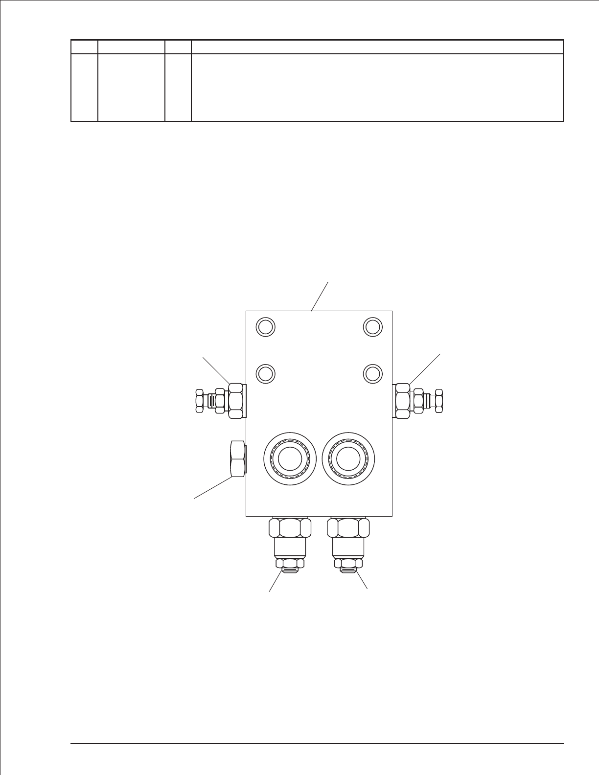
Motion control valve, turntable swing
item part no qty description
1 6010250 1 Motion control valve, turntable swing
2 6010256 2 Counterbalance valve cartridge - (factory preset, do not reset)
3 6010321 2 Cartridge relief valve - (factory preset, do not reset)
0150563 1 Seal repair kit
4 6010531 1 Shuttle valve
TB 60 – 01-97 through 01-01 2-55
V1 V2
22
1
33
4
AW6010250
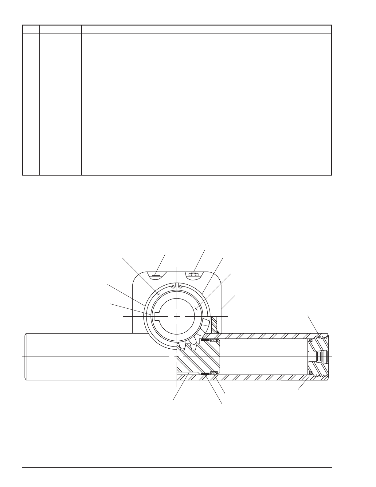
Platform rotator, Helac
item part no qty description
0070570 1 Platform rotator, Helac
0073223 1 Seal repair kit - (kit includes items 12 through 16)
0074709 1 Bearing kit - (wear guides only, kit includes items 7, 9 and 11)
1 8080119 2 End cap
2 8080114 1 Housing, foot mounted
3 8080115 1 Pinion
4 8080099 2 Snap ring
5 8080100 1 Relief valve
6 8080116 2 Filler plug
7 Kit item 2 Wear guides
8 8080117 2 Shaft bearing
9 Kit item 1 Wear guides
10 8080118 2 Rack
11 Kit item 2 Wear guides
12 Kit item 2 Polypak seal
13 Kit item 2 O-ring
14 Kit item 2 Back-up
15 Kit item 2 O-ring
16 Kit item 2 Polypak seal
2-56 TB 60 – 01-97 through 01-01
5
64
3
2
1
13
14
12
11
10
16 15
8
7
9
AWV00213
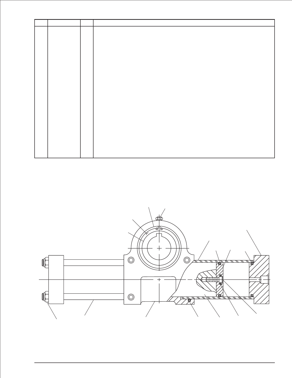
Platform rotator, Parker
item part no qty description
0070570 1 Platform rotator, Parker
0071275 1 Seal repair kit - (kit includes items 13 through 21)
1 8080018 2 Rack bolt
2 8080016 2 End cap
3 8080015 2 Piston
4 8080040 2 Cylinder
5 8080060 1 Rack
6 8080039 1 Housing
7 0073281 8 Tie rod
8 8080041 8 Lock nut
9 8080061 1 Pinion
10 8080038 2 Pinion bushing
11 8080062 2 Snap ring
12 8080064 1 Relief valve
13 Kit item 2 O-ring - (not sold separately)
14 Kit item 2 Parbat seal - (not sold separately)
15 Kit item 2 O-ring - (not sold separately)
16 Kit item 2 O-ring - (not sold separately)
17 Kit item 2 Parbat seal - (not sold separately)
18 Kit item 2 Polypak seal - (not sold separately)
19 Kit item 2 O-ring - (not sold separately)
20 Kit item 2 Parbat seal - (not sold separately)
21 Kit item 1 O-ring - (not sold separately)
TB 60 – 01-97 through 01-01 2-57
TOP
87615 513
14
1
4
2
16
17
3
18
12
11
20
19
10
21 9
AWV00214
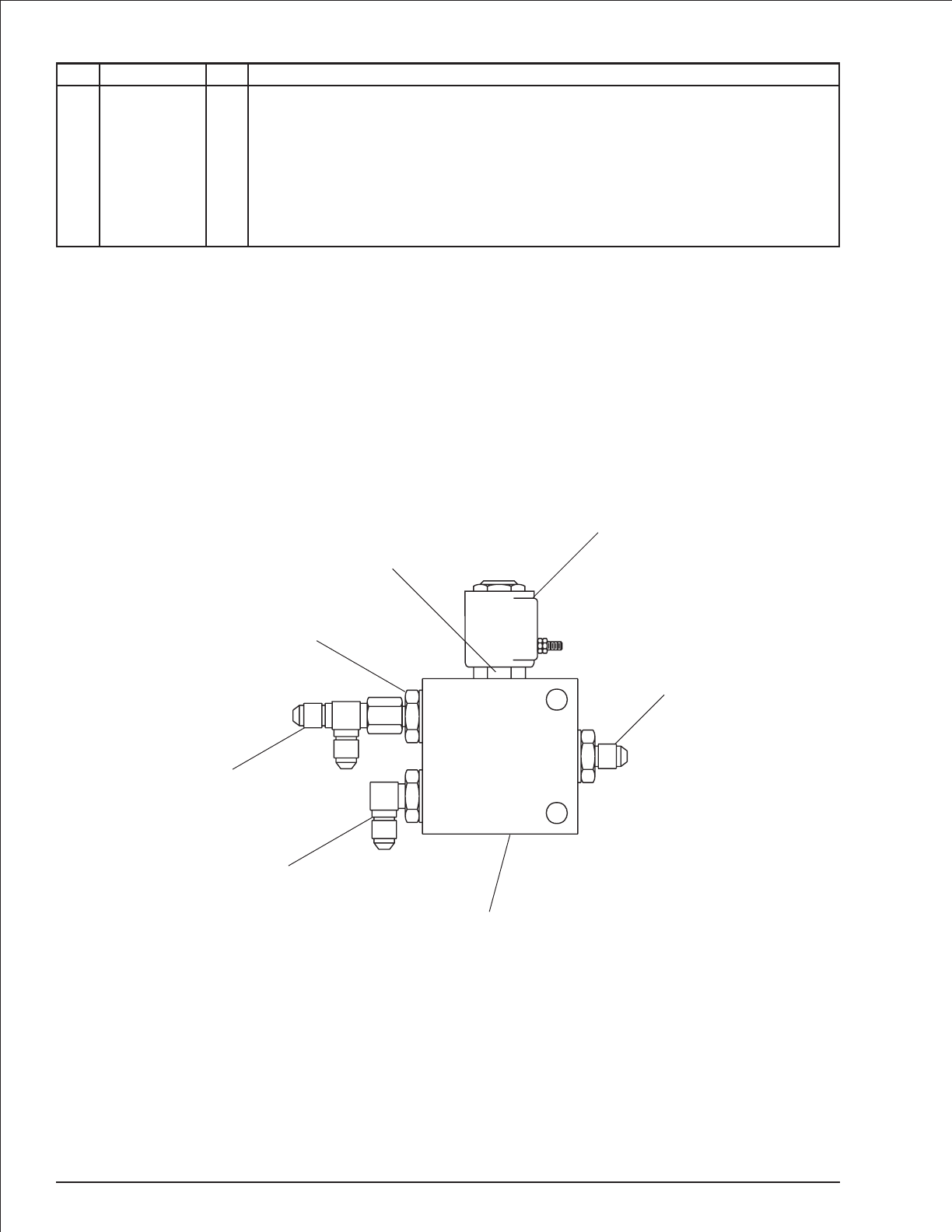
Range valve
item part no qty description
0081981 1 Range valve
1 6010499 1 Range valve - (includes items 2 and 3)
0073620 1 Seal repair kit
2 6010472 1 Cartridge - (factory preset, do not reset)
3 3040473 1 Cartridge solenoid, 10 volt DC
4 5065705 2 Straight thread adapter
5 5035318 1 Straight thread 90° elbow
6 5036703 1 Swivel nut run tee
2-58 TB 60 – 01-97 through 01-01
A
B
C
2
3
1
5
6
4
4
AW0081981
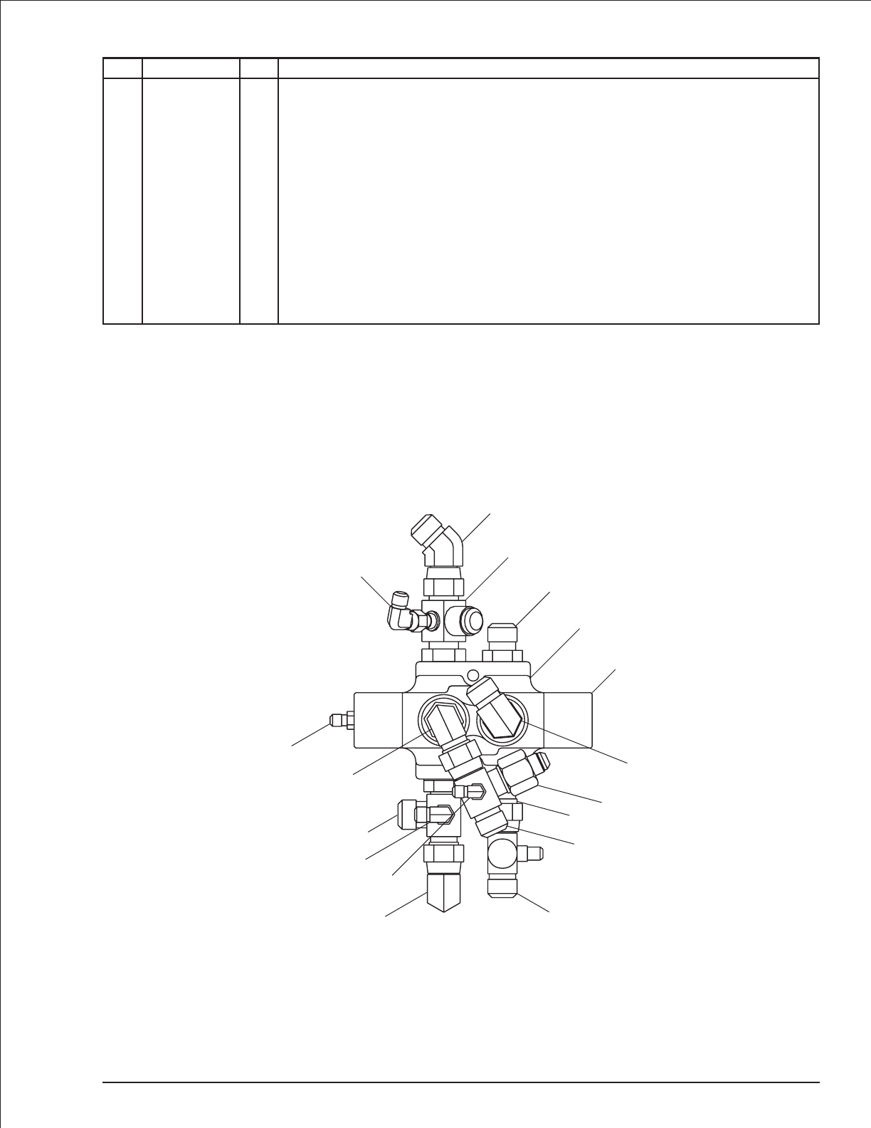
Selector valve, 2 wheel drive
item part no qty description
0081425 1 Selector valve, 2 wheel drive
1 0080529 1 Selector valve - (includes item 2)
0081127 1 Seal repair kit
2 0080528 1 Valve end cap
3 0081596 2 Special swivel nut run tee with side port
4 5036908 1 Swivel nut 45° elbow
5 5037008 2 Swivel nut 90° elbow
6 5065714 3 Straight thread adapter
7 5065703 1 Straight thread adapter
8 0081597 2 Special swivel nut run tee with side port
9 5064008 1 Tube end reducer
10 5035308 1 Straight thread 90° elbow
11 5063908 1 Fitting nut
12 5037005 3 Swivel nut 90° elbow
TB 60 – 01-97 through 01-01 2-59
A
B
E
C
D
F
1
2
8
8
3
12
5
12
10
6911
6
3
4
12
7
5
AW0081425
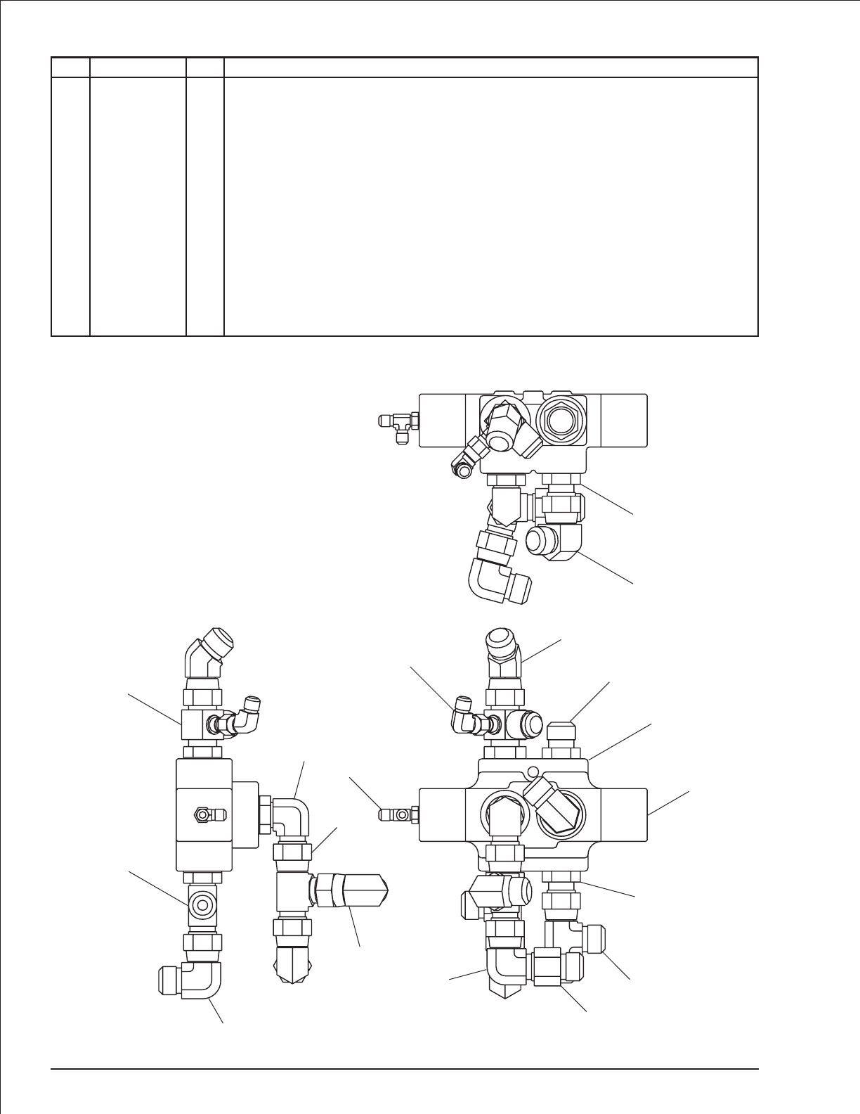
Selector valve, 4 wheel drive
item part no qty description
0081598 1 Selector valve, 4 wheel drive
1 0080529 1 Selector valve - (includes item 2)
0081127 1 Seal repair kit
2 0080528 1 Valve end cap
3 5036108 1 Straight thread run tee
4 5036908 1 Swivel nut 45° elbow
5 5037008 2 Swivel nut 90° elbow
6 5065714 3 Straight thread adapter
7 5036708 4 Swivel nut run tee
8 5064008 1 Tube end reducer
9 5035308 1 Straight thread 90° elbow
10 5063908 1 Fitting nut
11 0081596 1 Special swivel nut run tee with side port
12 5037005 1 Swivel nut 90° elbow
13 5036103 1 Straight thread run tee
2-60 TB 60 – 01-97 through 01-01
FB
C
A
D
E
1
2
13
3
4
11
7
9
5
5
810
7
6
6
12
4
5
6
AW0081598
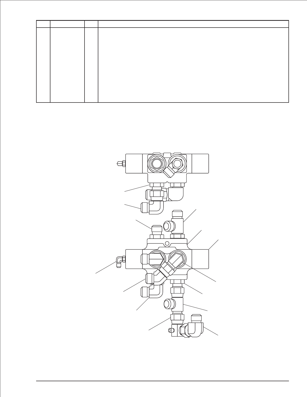
Selector valve, right hand
item part no qty description
0080928 1 Selector valve, right hand
1 0080529 1 Selector valve - (includes item 2)
0081127 1 Seal repair kit
2 0080528 1 Valve end cap
3 5035308 2 Straight thread 90° elbow
4 5036908 1 Swivel nut 45° elbow
5 5036108 1 Straight thread run tee
6 5065714 3 Straight thread adapter
7 5037008 2 Swivel nut 90° elbow
8 5036708 1 Swivel nut run tee
9 5035303 1 Straight thread 90° elbow
10 0140500 1 Special swivel nut 90° elbow with side port
TB 60 – 01-97 through 01-01 2-61
A
B
E
C
D
F
1
2
9
3
7
3
6
8
4
9
5
6
6
7
AW0080928
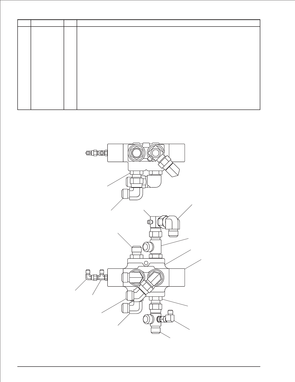
Selector valve, left hand
item part no qty description
0080929 1 Selector valve, left hand
1 0080529 1 Selector valve - (includes item 2)
0081127 1 Seal repair kit
2 0080528 1 Valve end cap
3 5035308 2 Straight thread 90° elbow
4 5036908 1 Swivel nut 45° elbow
5 5036108 1 Straight thread run tee
6 5037008 2 Swivel nut 90° elbow
7 5065714 3 Straight thread adapter
8 5036103 1 Straight thread run tee
9 5037003 1 Swivel nut 90° elbow
10 0140288 1 Special swivel nut 90° elbow with side port
11 0081595 1 Special swivel nut run tee with side port
12 5037005 1 Swivel nut 90° elbow
2-62 TB 60 – 01-97 through 01-01
A
B
E
C
D
F
7
6
6
10
5
1
2
7
7
13
11
3
4
8
9
AW0080929

Section 3. - Electrical
TB 60 – 01-97 through 01-01 3-1


Turntable electrical, Cummins 3.3
item part no qty description
1 0081998 1 Wiring box - (see page 3-36 for parts breakdown)
2 0083530 1 Lower controls - (see page 3-26 for parts breakdown)
3 3050002 2 Battery, 12 volt DC - 550 CCA
4 3020049 1 Switch, battery disconnect
5 3050008 2 Battery hold down
6 3050004 4 Battery hold down bolt
7 0181503 1 Bracket, tilt alarm
8 0073051 1 Bracket, battery disconnect switch
9 3020040 1 Tilt alarm sensor 5°
10 480652 1 Siren, tilt alarm
11 0083508 1 Wire harness, Cummins 3.3 engine
12 0081846 1 Wire harness, turntable
13 3040534 1 PWM module
14 5560666 2 Machine screw #6-32 x 1/2 inch long truss head
15 20082046 1 Actuator module - (included with engine)
16 5093008 2 Clamp
17 5093002 2 Clamp
18 5093024 4 Clamp
19 3040506 1 Solenoid, 12 volt DC
20 0073089 1 Placard, battery disconnect switch
21 3040469 1 Relay, 12 volt DC
22 3040047 2 Terminal .250 tab female slip-on fully insulated 22/18 wire
23 0150545 1 Jumper wire
24 0071568 1 Jumper wire
25 3044146 2 Terminal #10 ring tongue insulated 22/18 wire
26 3040082 4 Terminal .250 tab male slip-on fully insulated 16/14 wire
27 0130115 1 Jumper wire
28 0080483 1 Jumper wire
29 0080484 1 Jumper wire
30 0080482 1 Jumper wire
31 3030122 1 EPS anti-restart module
32 3040268 3 Insulator boot
33 0070705 1 Jumper wire
34 3044161 1 Terminal #10 stud insulated 16/14 wire
35 0090319 1 Jumper wire
36 3044162 1 Terminal 1/4 ring tongue insulated 16/14 wire
37 3040270 1 Insulator boot
38 3040269 1 Insulator boot
39 974289 2 Machine screw #6-32 x 1-1/4 inch long round head
40 984009 4 Nut #6-32 hex
41 986159 4 Washer #6 medium flat
42 987349 4 Washer #6 medium lock
43 987109 1 Washer 5/16 medium lock
44 5560034 6 Nut #10-24 self locking
45 974659 4 Machine screw #10-24 x 1/2 inch long round head
46 974709 2 Machine screw #10-24 x 1 inch long round head
47 986009 2 Washer #10 medium flat
48 5560703 1 Washer #10 star tooth lock
49 970029 4 Capscrew 1/4-20 x 3/4 inch long hex head grade 5
50 987099 9 Washer 1/4 medium lock
51 5560004 12 Nut 1/4-20 self locking
52 986019 12 Washer 1/4 medium flat
53 970049 7 Capscrew 1/4-20x1inchlonghexhead grade 5
54 970009 3 Capscrew 1/4-20 x 1/2 inch long hex head grade 5
55 970029 1 Capscrew 1/4-20 x 3/4 inch long hex head grade 5
Parts list continued on next page
TB 60 – 01-97 through 01-01 3-3

Turntable electrical, Cummins 3.3
item part no qty description
56 970489 2 Capscrew 3/8-16 x 1-1/2 inch long hex head grade 5
57 5560033 2 Nut 3/8-16 self locking
58 970469 2 Capscrew 3/8-16 x 1 inch long hex head grade 5
59 987119 2 Washer 3/8 medium lock
60 986299 2 Washer 3/8 medium flat
61 970239 1 Capscrew 5/16-18 x 3/4 inch long hex head grade 5
62 987109 1 Washer 5/16 medium lock
3-4 TB 60 – 01-97 through 01-01
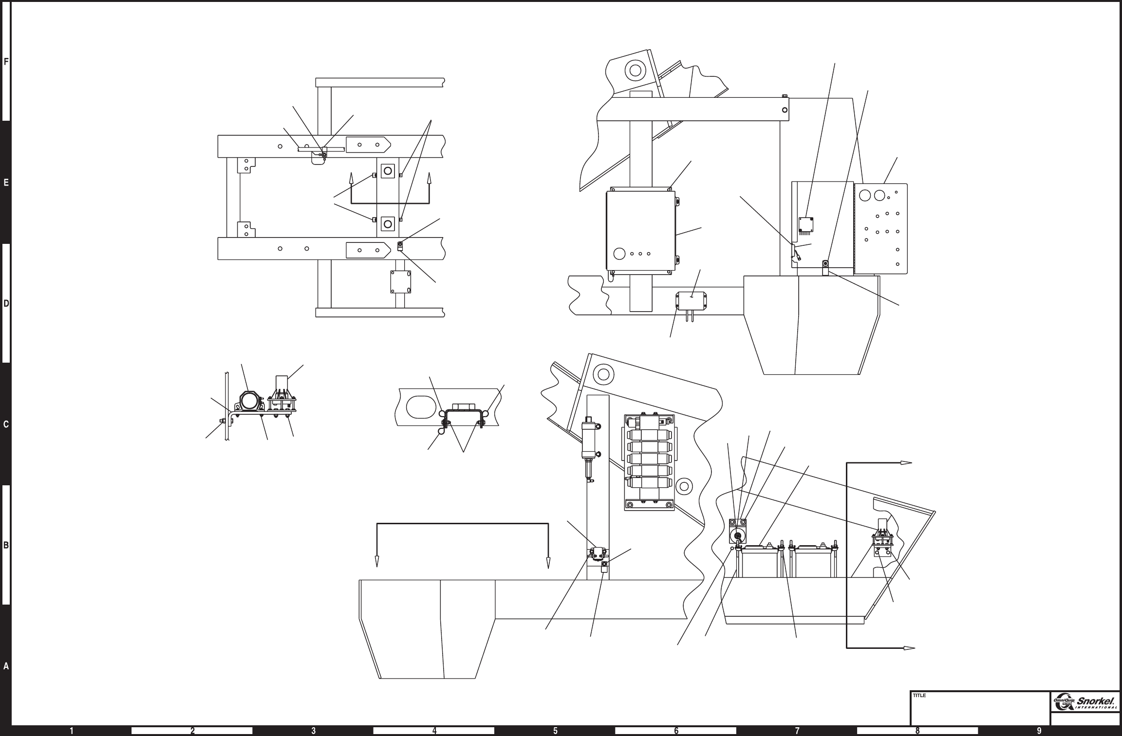
Page3-5
Turntable electrical
Cummins 3.3, sheet 1
Snorkel model TB 60
18
52
51
53
18
17
VIEW B-B
51
52
53
44
48
47
46
57
56
7
10 9
VIEW A-A
42
41
40
14
31
44
45
15
55
52
51
16
51
50
49
1
42
41
40
39
13
2
11
52
50
54
16
53
51
52
18
52 51
53
17
16
50 52 54
16
B
B
VIEW C-C
19
52
50
54
60
59
58
8
20
4
43
62
61
6
3
5
57
56
7
CC
A
A
50 54
18
21
AW0083509-1
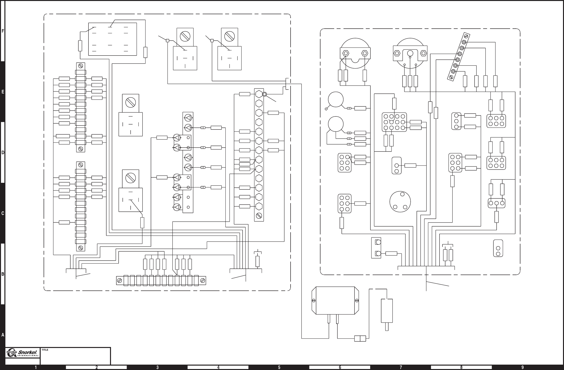
Page3-6
Turntable electrical
Cummins 3.3, sheet 2
Snorkel model TB 60
BAT
IGN ST
-
+
SENS
3
TACH
164B
I
S
G
6A
GROUND CONTROL PANEL
11
ENGINE WIRE
TIE BACK
167
PLATFORM
ROTATE
PLATFORM
LEVEL
START
LIFT/SWING
CIRCUIT
BREAKER
ENGINE
SPEED
T/T
SWING
GROUND
OPERATION
EMER.
STOP
EMER.
POWER
SELECTOR
SWITCH
BOOM
ELEVATION
BOOM
EXTEND
22C
21C
67A
28A
31
172
23
24
15
14
5
27
26
126
1B
160A
4
4A
13
12
5C
1
REAR
RHEOSTAT
FRONT
RHEOSTAT
175
174
16A
173
56
57
1A
22B
21B
AMMETER
TEMPERATURE
GAUGE
164
3C
126
8D
GRAY BLACK ACTUATOR
(ON ENGINE)
ADDCO
ACTUATOR
MODULE
34
RED
WHITE
BLACK
3C
TIE
BACK
12
11
TURNTABLE WIRE ENGINE WIRE
55A
6A
1A
1B
1
5C
6
26
27
26
164
27
1D
3
28A
31
160A
28B
160C
16A
74
126
167
34
16B
5
4A
4
73
24 24
23 23
22B 22B
22C 22C
21C 21C
21B/A 21B
20
19
18
17
15 15
14 14
13 13
12 12
5B
3
38
1D
55
164
27
26
6
5C
2
1
1B
1A
78
77B
77A
126
167
34
16B
16
5
4A
4
164B
22A
22B
22C
23
24
25
28
70
73
125
160
170
11
12
13
14
15
17
18
19
20
21A
21B
21C
TILT
AUX.
HIGH
THROTTLE
MEDIUM
THROTTLE
ENGINE ALARM
6
4A
28A
28
31
25
160A
160
16A
16
WIRING BOX
86
87
87a 85
30
86
87
87a 85
30
22 22
86
87
87a 85
30
86
87
87a 85
30
1
4
7
A
2
5
8
3
6
9
B
AW0083509-2
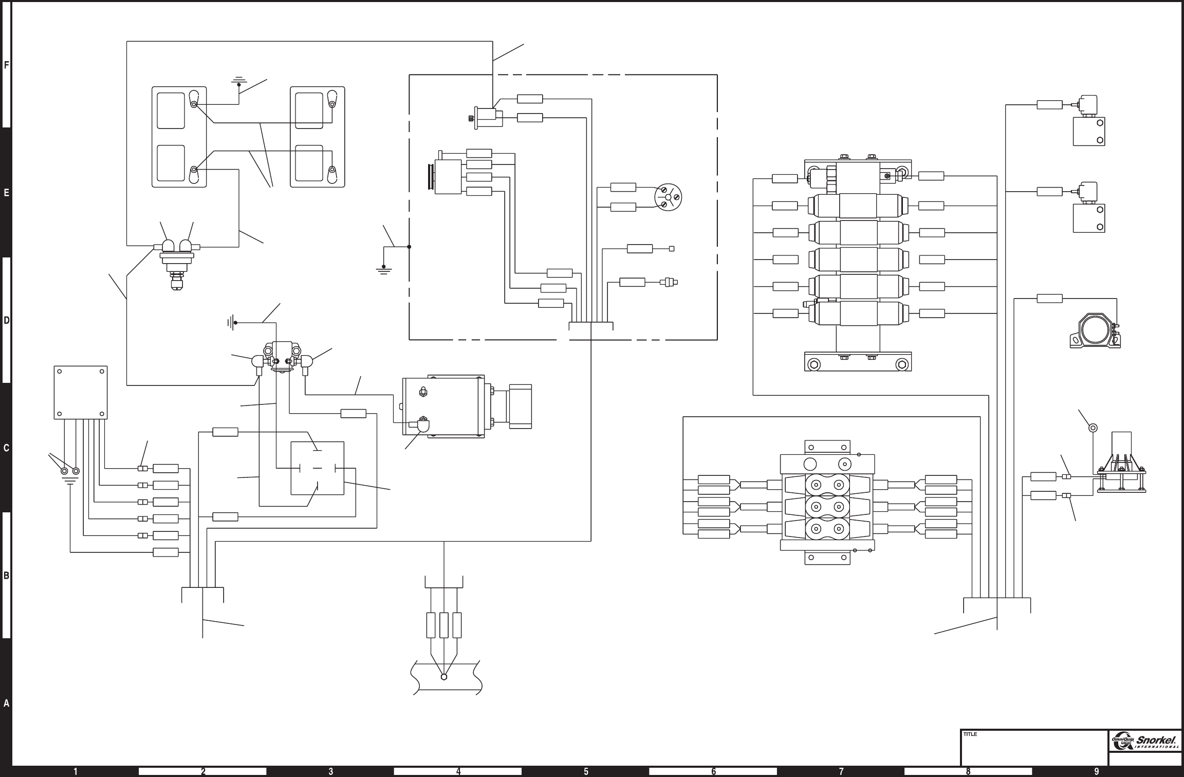
Page3-7
Turntable electrical
Cummins 3.3, sheet 3
Snorkel model TB 60
3
8D
TAC H
ENG TEMP
SENSOR
TAC H
TAC H
B+
IG 3
3
23
3
22B
3
18
3
24
3
21B/A
3
BLACK
BLACK
175
174
173
172
67A
ENGINE WIRE
PWM
MODULE
BATTERY
DISCONNECT
SWITCH
BATTERYBATTERY
RED
BLUE
GRAY
YELLOW
PURPLE
23
25
11
33
38
37
29
29
28
30
CUMMINS ENGINE
ALTERNATOR
STARTER
PRESSURE
SWITCH
29
164B
56
5A
57
3C
164B
56
NOT
USED
PLAT
LEVEL
PLAT
ROT
STEER
BOOM
RANGE VALVE
DUMP VALVE
TILT ALARM SIREN
PROPORTIONAL
PACKAGE VALVE
NON-PROPORTIONAL
PACKAGE VALVE
TILT
ALARM
36
26
26
BLK
WHT
RED
12 TURNTABLE WIRE
73
1D
74
28B
34
160C 16B
12
26
21C
20
14
13
27
22C
19
15
17
86
87
87a 85
30
5B
EMERGENCY
POWER UNIT
5A
6A
56
B-POST
NC
SENS
FUEL INJ.
PUMP SOLENOID
START
RELAY
EMER SOL
3
3
3
32 32
32
24
27
23
21
35
AW0083509-3

Turntable electrical, Deutz F4L-1011F
item part no qty description
1 0081998 1 Wiring box - (see page 3-36 for parts breakdown)
2 0082032 1 Lower controls - (prior to 11-09-1999, see page 3-28 for parts breakdown)
0083397 1 Lower controls - (after 11-09-1999, see page 3-31 for parts breakdown)
3 3020005 2 Battery, 12 volt DC - 550 CCA
4 3020049 1 Switch, battery disconnect
5 3050008 2 Battery hold down
6 3050004 4 Battery hold down bolt
7 0181503 1 Bracket, tilt alarm
8 0073051 1 Bracket, battery disconnect switch
9 3020040 1 Tilt alarm sensor 5°
10 480652 1 Siren, tilt alarm
11 0081859 1 Wire harness, Deutz engine - (before 11-08-99)
0083395 1 Wire harness, Deutz engine - (after 11-08-99)
12 0081846 1 Wire harness, turntable
13 3040534 1 PWM module
14 0082029 1 Mount plate, actuator module - (before 3-20-00)
15 20082046 1 Actuator module
16 5093008 2 Clamp
17 5093004 2 Clamp
18 5093000 2 Clamp
19 3040506 2 Relay, 12 volt DC
20 0073089 1 Placard, battery disconnect switch
21 5560666 2 Machine screw #6-32 x 1/2 inch long truss head
22 5093002 1 Clamp
23 3030117 1 Engine protection module - (11-09-99 to 6-19-00)
3030122 1 EPS anti-restart module - (after 6-19-00)
24 3072118 1 Temperature sensor - (11-08-99 to 6-19-00)
3070039 1 Temperature sensor - (after 6-19-00)
25 3044146 1 Terminal #10 stud insulated 22/18 wire
26 3040082 4 Terminal .250 tab male slip-on fully insulated 16/14 wire
27 0151920 1 Alternator connection wire
28 0080483 1 Jumper wire
29 0080484 4 Jumper wire
30 0080482 1 Jumper wire
31 0151372 1 Jumper wire
32 0151370 1 Jumper wire
33 0070705 1 Jumper wire
34 0070724 1 Jumper wire
35 0090319 1 Jumper wire
36 3044162 1 Terminal 1/4 stud insulated 16/14 wire
37 3040270 1 Insulator boot
38 3040269 1 Insulator boot
39 974289 2 Machine screw #6-32 x 1-1/4 inch long round head
40 984009 4 Nut #6-32 hex
41 986159 4 Washer #6 medium flat
42 987349 4 Washer #6 medium lock
43 7630230 3 Sandwich mount - (after 3-20-00)
44 5560034 4 Nut #10-24 self locking
45 974659 2 Machine screw #10-24 x 1/2 inch long round head
46 974709 2 Machine screw #10-24 x 1 inch long round head
47 986009 2 Washer #10 medium flat
48 5560654 1 Washer #10 star tooth lock
49 970029 4 Capscrew 1/4-20 x 3/4 inch long hex head grade 5
50 987099 10 Washer 1/4 medium lock
Parts list continued on next page
TB 60 – 01-97 through 01-01 3-9

Turntable electrical, Deutz F4L-1011F
item part no qty description
51 986019 10 Washer 1/4 medium flat
52 5560004 17 Nut 1/4-20 self locking
53 970049 9 Capscrew 1/4-20 x 1 inch long hex head grade 5
54 970009 6 Capscrew 1/4-20 x 1/2 inch long hex head grade 5
55 970029 1 Capscrew 1/4-20 x 3/4 inch long hex head grade 5
56 972489 2 Capscrew 3/8-16 x 1-1/2 inch long hex head grade 5
57 5560033 2 Nut 3/8-16 self locking
58 970469 2 Capscrew 3/8-16 x 1 inch long hex head grade 5
59 987119 2 Washer 3/8 medium lock
60 986299 2 Washer 3/8 medium flat
61 970239 1 Capscrew 5/16-18 x 3/4 inch long hex head grade 5
62 986269 2 Washer 5/16 medium flat
63 987109 1 Washer 5/16 medium lock
64 0082006 1 Alternator wire - (prior to 11-09-1999)
0074579 1 Alternator wire - (after 11-09-1999)
65 0181026 1 Diode wire
66 3044161 1 Terminal #10 stud insulated 16/14 wire
67 3040268 3 Insulator boot
68 3040452 2 Insulator boot
69 5093002 1 Clamp
3-10 TB 60 – 01-97 through 01-01
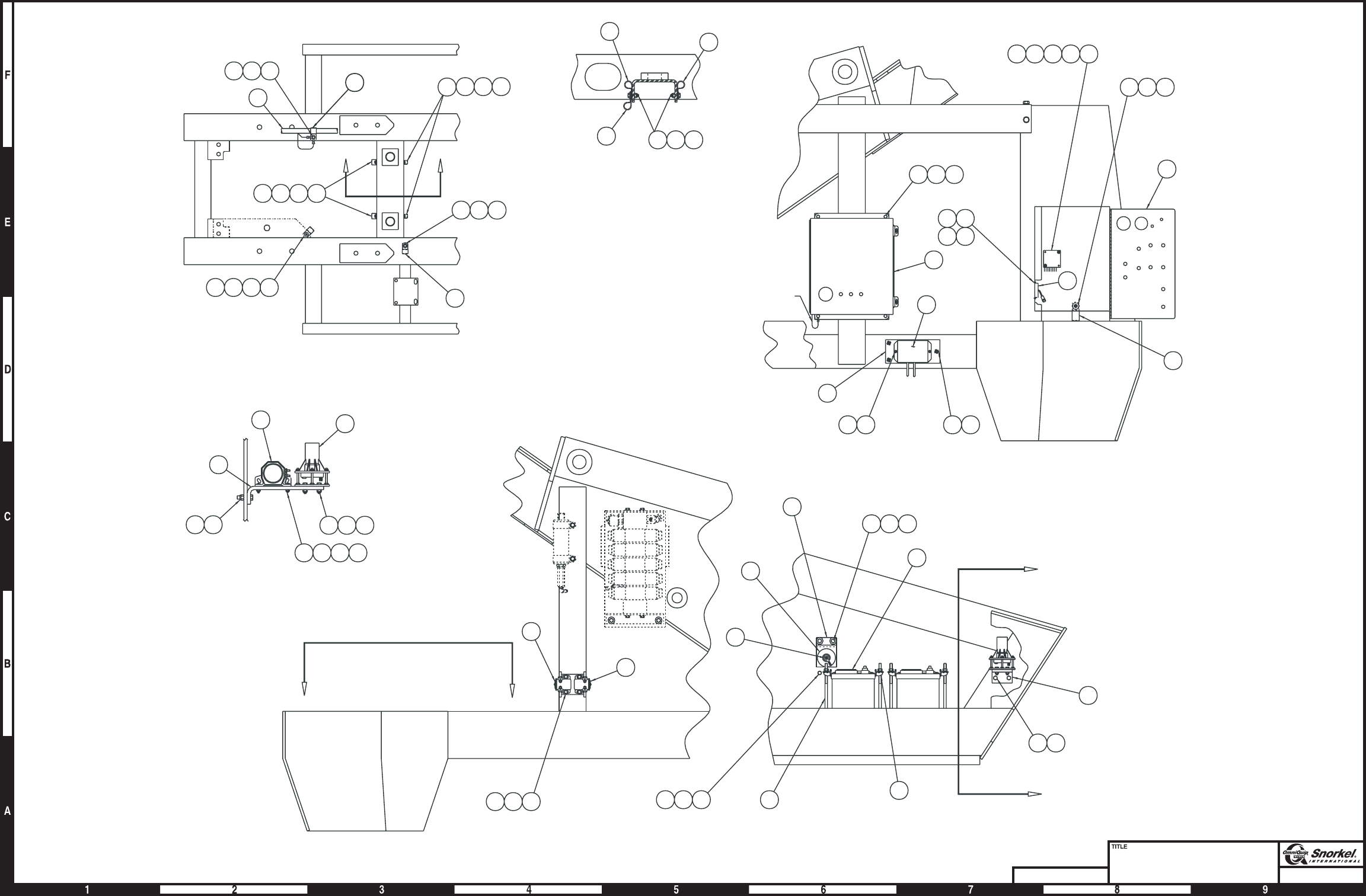
Page3-11Page3-11
Turntable electrical
Deutz F4L-1011F - sheet 1
Snorkel model TB 60
DWG. 0082009-1
22
18
18
A
A
C
C7
56 57
5
3
6616263
4
20
8
58 59 60
545052
19
19
VIEW C-C
BB
16
54 52 50
17535152
535152
52 51 53
2
1339404142
1
49 50 51
16
51 52 55
43 51
15
4544
14
VIEW A-A
9
10
7
5657
46 47 48 44
53 52 51
VIEW B-B
17
17 53 51 52
545052
11
110 volt ground
23
2140
41 42
16
AW0082009-1
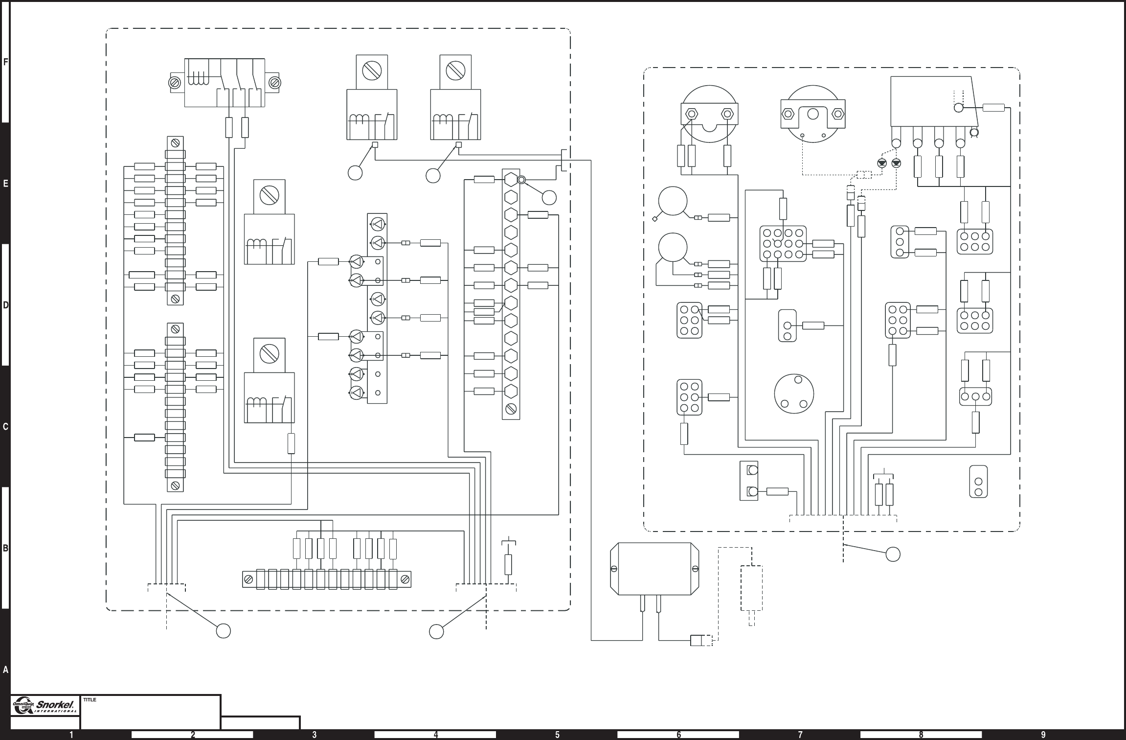
Page3-12Page3-12
Turntable electrical
Deutz F4L-1011F - sheet 2
Snorkel model TB 60 DWG. 0082009-2
Used on machines manufactured
prior to 11-09-1999
BAT
IGN ST
-
+
6A
GROUND CONTROL PANEL
11
ENGINE WIRE
ASSEMBLY (DEUTZ)
TIE
BACK
167
PLATFORM
ROTATE
PLATFORM
LEVEL
START
LIFT/SWING
CIRCUIT
BREAKER
ENGINE
SPEED
T/T
SWING
GROUND
OPERATION
EMER
STOP
EMER
POWER
SELECTOR
SWITCH
BOOM
ELEVATION
BOOM
EXTEND
22C
21C
67A
28A
31
172
23
24
15
14
5
27
26
126
1B
160A
4
4A
13
12
5C
1
REAR
RHEOSTAT
FRONT
RHEOSTAT
175
174
16A
173
56
57
1A
22B
21B
AMMETER ENGINE
TEMPERATURE
126
GRAY BLACK ACTUATOR
(ON ENGINE)
ADDCO
ACTUATOR
MODULE
22 22
66
RED WHITE
BLACK
3C
TIE
BACK
12 11
TURNTABLE
WIRE ASSEMBLY
ENGINE WIRE
ASSEMBLY (DEUTZ)
55A
6A
1A
1B
1
5C
6
26
27
26
164
27
1D
3
28A
31
160A
28B
160C
16A
74
126
167
34
16B
5
4A
4
73
24 24
23 23
22B 22B
22C 22C
21C 21C
21B/A 21B
20
19
18
17
15 15
14 14
13 13
12 12
5B
3
38
1D
55
164
27
26
6
5C
2
1
1B
1A
78
77B
77A
126
167
34
16B
16
5
4A
4
164B
22A
22B
22C
23
24
25
28
70
73
125
160
170
11
12
13
14
15
17
18
19
20
21A
21B
21C
TILT
AUX
HIGH
THROTTLE
MEDIUM
THROTTLE
ANTI-RESTART
36
2
5
1
4
9
8
7
B
A
6
4A
28A
28
31
25
160A
160
16A
16
87
85
86
30
87A
87
85
86
30
87A
87
85
86
30
87A
87A
30
87
86
85
WIRING BOX
NO NC S B
G
MAGNETIC
SWITCH
164
3C
BLACK
8D
3
AW0082009-2
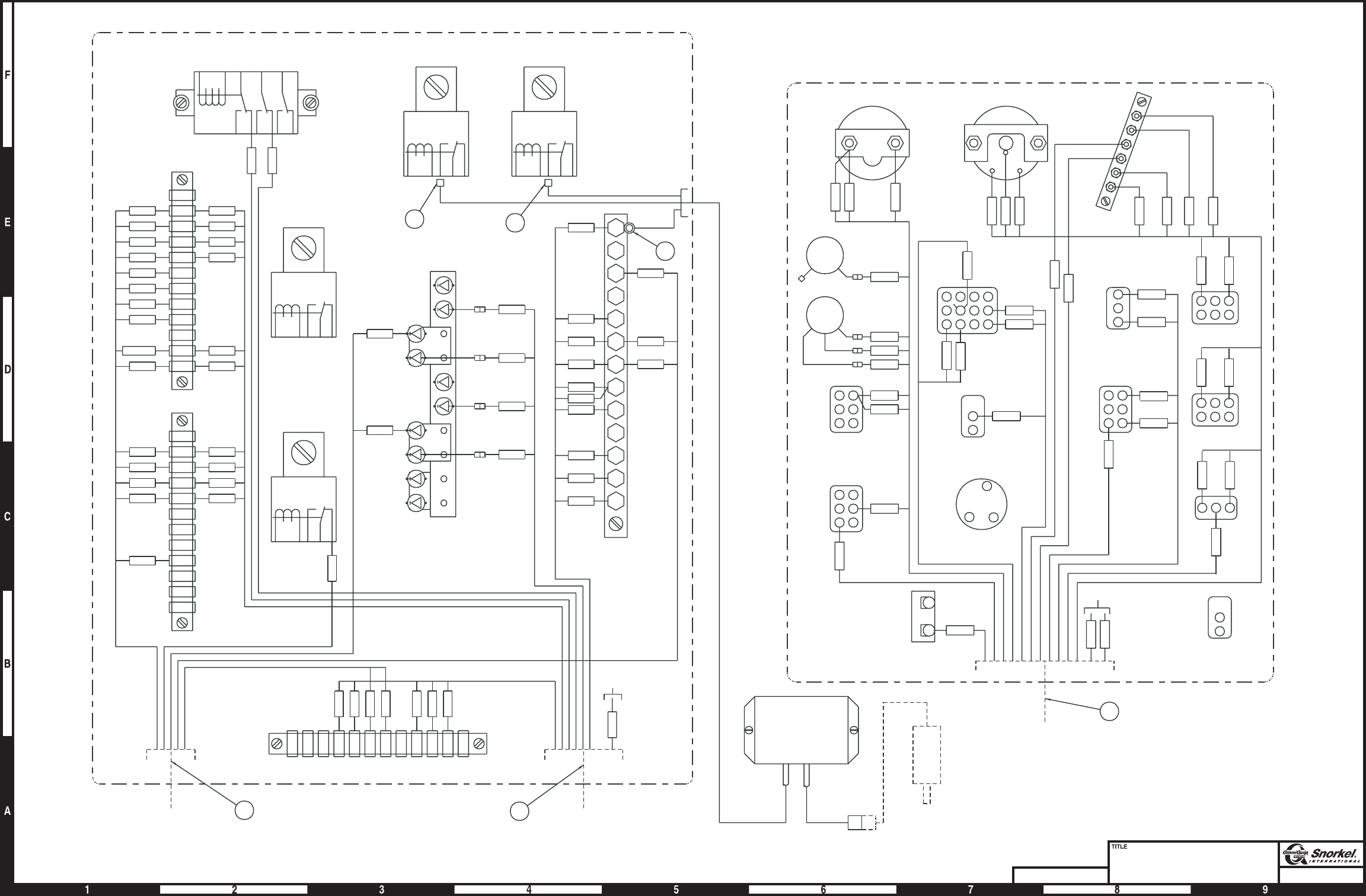
Page3-13Page3-13
Turntable electrical
Deutz F4L-1011F - sheet 3
Snorkel model TB 60
DWG. 0082009-3
Used on machines manufactured
after 11-09-1999
WIRING BOX
85
86
87
30
87A
87A
30
86
85
87
87A
30
86
85
87
87A
30
86
85
87
16
16A
160
160A
25
31
28
28A
4A
6
AB789
415263
ANTI-RESTART
MEDIUM
THROTTLE
HIGH
THROTTLE
AUX
TILT
21C
21B
21A
20
19
18
17
15
14
13
12
11
170
160
125
73
70
28
25
24
23
22C
22B
22A
164B
4
4A
5
16
16B
34
167
126
77A
77B
78
1A
1B
1
2
5C
6
26
27
164
55
1D
38
3
5B
1212
1313
1414
1515
17
18
19
20
21B21B/A
21C21C
22C22C
22B22B
2323
2424
73
4
4A
5
16B
34
167
126 74
16A
160C
28B
160A
31
28A
3
1D
27
164
26
27
26
6
5C
1
1B
1A
6A
55A
ENGINE WIRE
ASSEMBLY (DEUTZ)
TURNTABLE
WIRE ASSEMBLY
11
12
TIE
BACK
3C
BLACK
WHITE
RED
66
22
22
ADDCO
ACTUATOR
MODULE
ACTUATOR
(ON ENGINE)
BLACKGRAY
8D
126
3C
164
ENGINE
TEMPERATURE
AMMETER
21B
22B
1A
57
56
173
16A
174
175
FRONT
RHEOSTAT
REAR
RHEOSTAT
1
5C
12
13
4A
4
160A
1B
612
26
27
5
14
15
24
23
172
31
28A
67A
21C
22C
BOOM
EXTEND
BOOM
ELEVATION
SELECTOR
SWITCH
EMER
POWER
EMER
STOP
GROUND
OPERATION
T/T
SWING
ENGINE
SPEED
LIFT/SWING
CIRCUIT
BREAKER
START
PLATFORM
LEVEL
PLATFORM
ROTATE
167
TIE
BACK
ENGINE WIRE
ASSEMBLY (DEUTZ)
11
GROUND CONTROL PANEL
6A
164B
TACH
3
SENS
+-
STIGN
BAT
G
SI
AW0082009-3
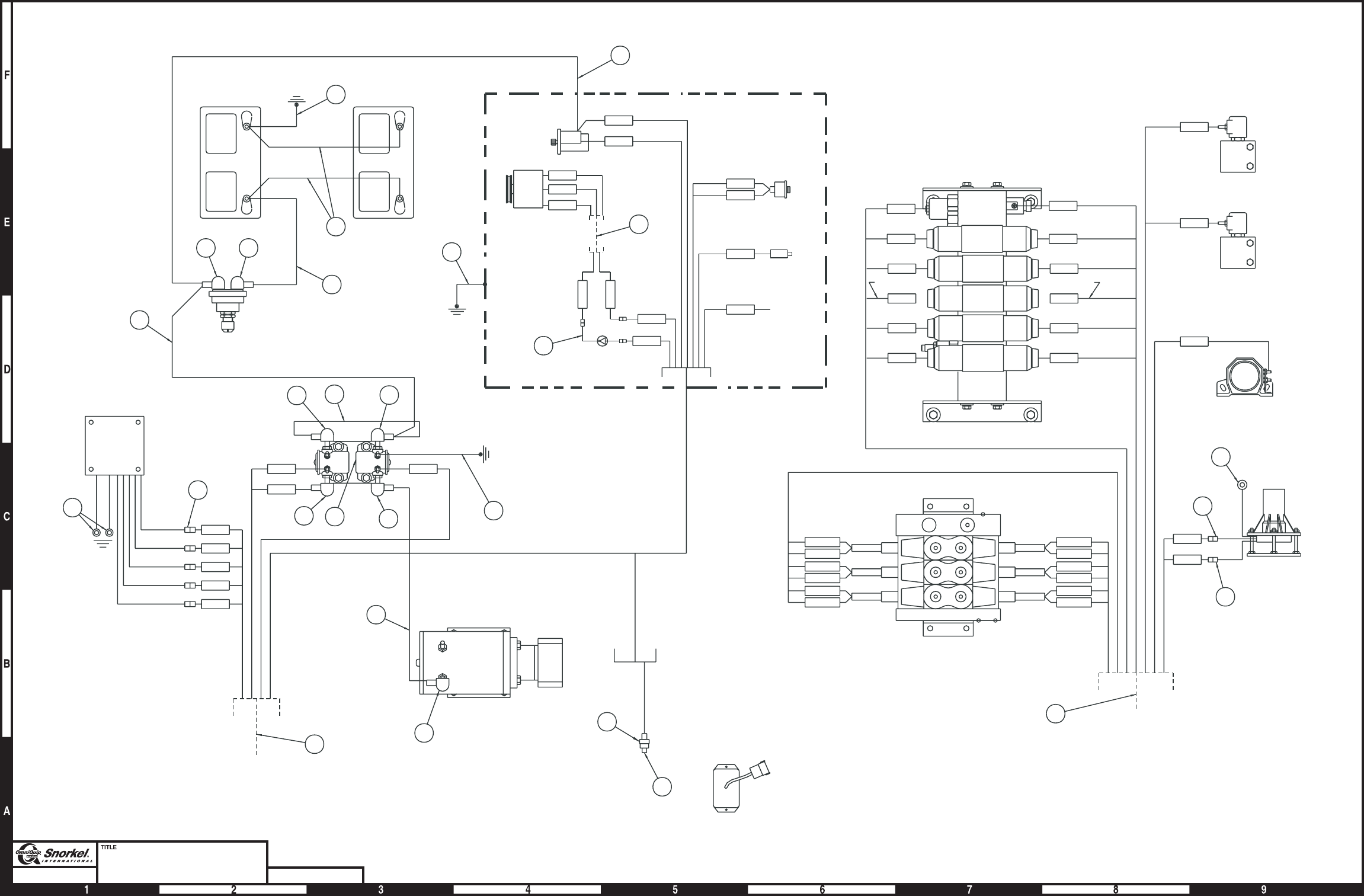
Page3-14Page3-14
Turntable electrical
Deutz F4L-1011F - sheet 4
Snorkel model TB 60 DWG. 0082009-4
17
15
19
22C
27
13
14
20
21C
26
12
16B
160C
34
28B
74
1D
73
TURNTABLE
WIRE ASSEMBLY
12
RED
WHT
BLACK
26
26
36
TILT
ALARM
NON-PROPORTIONAL
PACKAGE VALVE
PROPORTIONAL
PACKAGE VALVE
TILT ALARM
SIREN
DUMP VALVE
RANGE VALVE
BOOM
STEER
PLAT
ROT
PLAT
LEVEL
NOT
USED
TIE BACK
TIE BACK
64
65
56
164B
56
164B
55A
8D
3C
57
5A
56
164B
29
TIE
BACK
RUN
SOLENOID
PRESSURE
SWITCH
STARTER
ALTERNATOR
DEUTZ ENGINE
30
28
29
29
37 38
33
34
11
25
23
PURPLE
YELLOW
GRAY
BLUE
RED
BATTERY BATTERY
BATTERY
DISCONNECT
SWITCH
START/EMER
POWER RELAYS
PWM
MODULE
EMERGENCY
POWER UNIT
ENGINE WIRE
ASSEMBLY (DEUTZ)
32
67A
172
173
174
175
5A
5B 6A
BLACK
BLACK
3
21B/A
3
24
3
18
3
22B
3
23
3
TACH
D+
B+
W
ENG TEMP
SENSOR
24
35
68 31 67
67
68
67
3C
CONNECT EPS/ANTI-RESTART
MODULE TO EPS WIRE ASSEMBLY
COMING FROM GROUND CONTROLS
64
AW0082009-4

Turntable electrical, Ford LRG-423
item part no qty description
1 0081998 1 Wiring box - (see page 3-36 for parts breakdown)
2 0081999 1 Lower controls - (see page 3-32 for parts breakdown)
3 3050002 1 Battery, 12 volt DC - 550 CCA
4 3020049 1 Switch, battery disconnect
5 3050008 1 Battery hold down
6 3050004 2 Battery hold down bolt
7 0181503 1 Bracket, tilt alarm
8 0073051 1 Bracket, battery disconnect switch
9 3020040 1 Tilt alarm sensor 5°
10 480652 1 Siren, tilt alarm
11 0111865 1 Wire harness, Ford LRG-423 engine
12 0081846 1 Wire harness, turntable
13 3040534 1 PWM module
14 0074128 1 Mount plate, governor
15 7630319 1 Barber/Coleman governor
16 5093008 4 Clamp
17 5093004 5 Clamp
18 986299 3 Washer 3/8 medium flat
19 3040506 2 Relay 12 volt DC
20 0073089 1 Placard, battery disconnect switch
21 3040452 2 Insulator boot
22 3040268 3 Insulator boot
23 970239 1 Washer 5/16 medium lock
24 986269 1 Washer 5/16 medium flat
25 3044146 1 Terminal #10 stud insulated 22/18 wire
26 3040082 2 Terminal .250 tab male slip-on fully insulated 16/14 wire
27 987119 3 Washer 3/8 medium lock
28 0080483 1 Jumper wire
29 0080484 2 Jumper wire
30 0080482 1 Jumper wire
31 0151372 1 Jumper wire
32 0151370 1 Jumper wire
33 0070705 1 Jumper wire
34 0070724 1 Jumper wire
35 0090319 1 Jumper wire
36 3044162 1 Terminal 1/4 stud insulated 16/14 wire
37 3040270 1 Insulator boot
38 3040269 1 Insulator boot
39 974289 2 Machine screw #6-32 x 1-1/4 inch long round head
40 984009 2 Nut #6-32 hex
41 986159 2 Washer #6 medium flat
42 987349 2 Washer #6 medium lock
43 970239 1 Capscrew 5/16-18 x 3/4 inch long hex head grade 5
44 5560034 4 Nut #10-24 self locking
45 5560649 2 Machine screw #10-24 x 1 inch long truss head
46 974709 2 Machine screw #10-24 x 1 inch long round head
47 986009 2 Washer #10 medium flat
48 5560654 1 Washer #10 star tooth lock
49 970239 5 Capscrew 1/4-20 x 3/4 inch long hex head grade 5
50 987099 10 Washer 1/4 medium lock
Parts list continued on next page
TB 60 – 01-97 through 01-01 3-15

Turntable electrical, Ford LRG-423
item part no qty description
51 5560004 16 Nut 1/4-20 self locking
52 986019 16 Washer 1/4 medium flat
53 970049 10 Capscrew 1/4-20 x 1 inch long hex head grade 5
54 970009 6 Capscrew 1/4-20 x 1/2 inch long hex head grade 5
55 970029 1 Capscrew 1/4-20 x 3/4 inch long hex head grade 5
56 972489 2 Capscrew 3/8-16 x 1-1/2 inch long hex head grade 5
57 5560033 2 Nut 3/8-16 hex self locking
58 970469 3 Capscrew 3/8-16 x 1 inch long hex head grade 5
59 0081558 1 Jumper wire
60 5093006 1 Clamp
61 0111887 1 Wire harness, crank sensor
3-16 TB 60 – 01-97 through 01-01
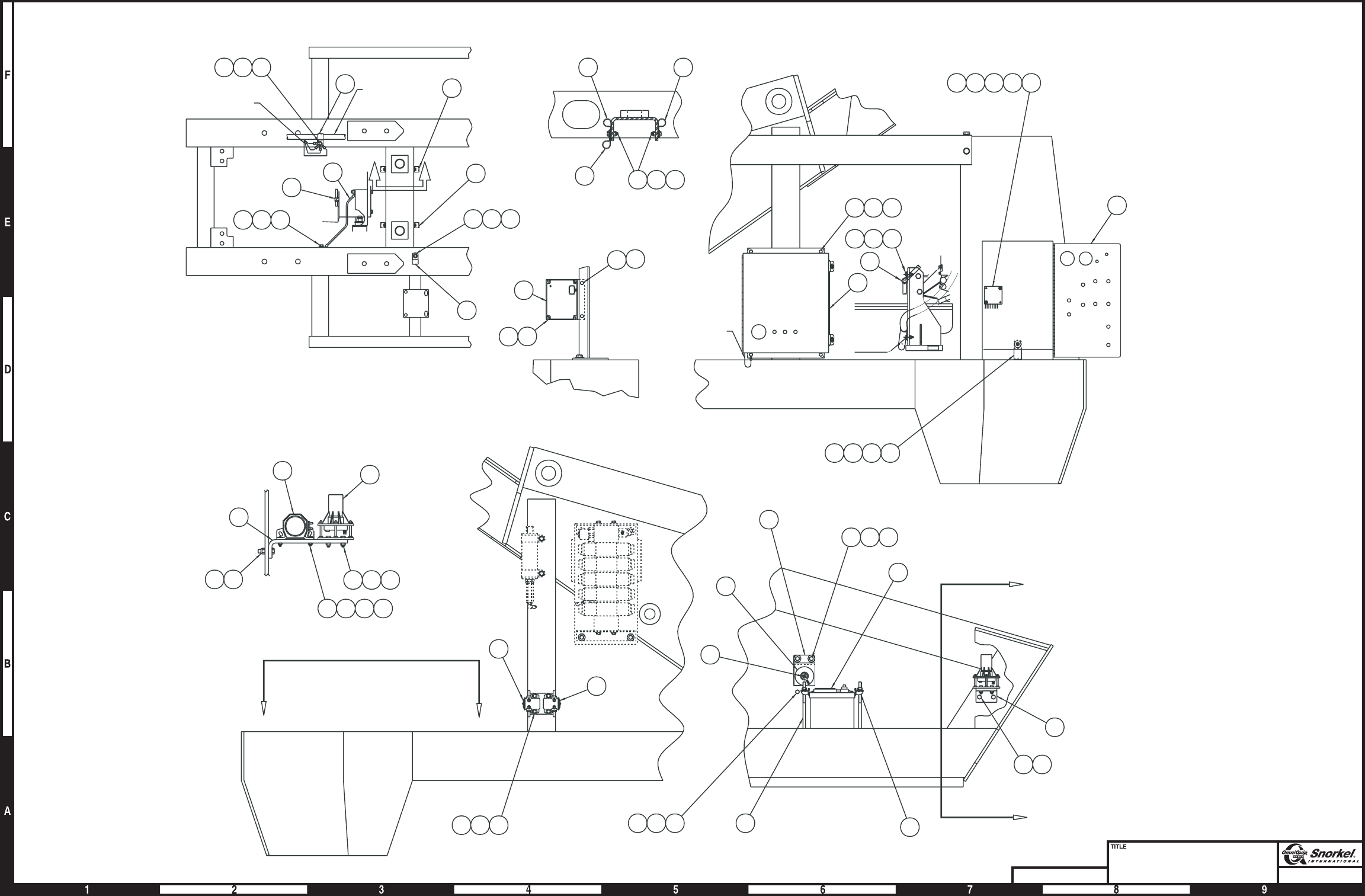
Page3-17Page3-17
Turntable electrical
Ford LRG-423 - sheet 1
Snorkel model TB 60
DWG. 0082085-1
A
A
C
C
7
56 57
5
3
6432324
4
20
8
58 27 18
545052
19
19
VIEW C-C
BB
16
54 52 50
16
2
1339404142
16515255
1
49 50 51
51
44
VIEW A-A
9
10
7
5657
46 47 48 44
53 52 51
VIEW B-B
17
16 53 51 52
17
495152
17
60
29
581827
545250
ENG. WIRE
ASSY
ENG. WIRE
ASSY GRD'S.
110 Volt ground
17
53
45
15
17
AW0082085-1
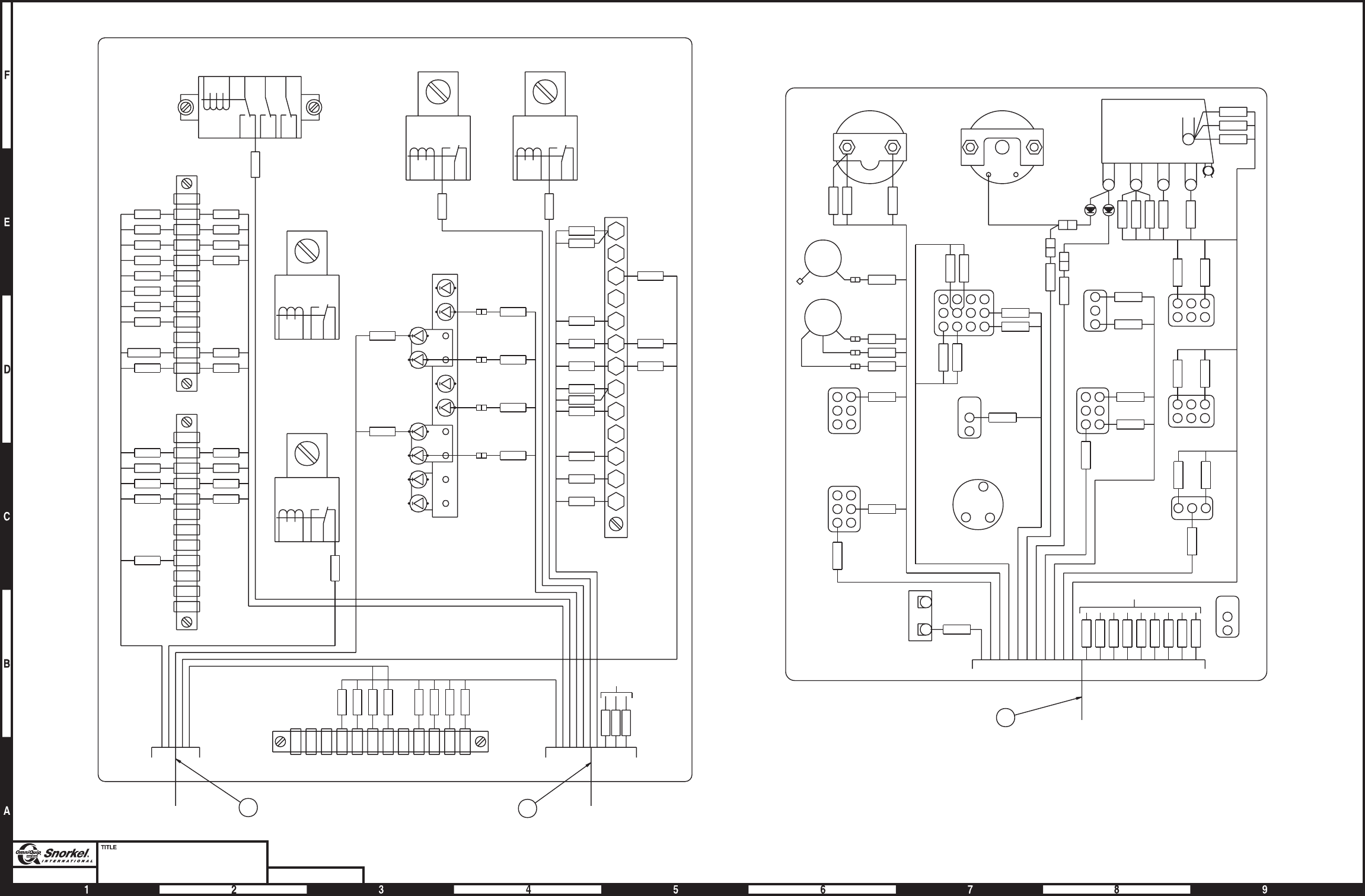
Page3-18Page3-18
Turntable electrical
Ford LRG-423 - sheet 2
Snorkel model TB 60 DWG. 0082085-2
WIRING BOX
55B
85
86
87
30
87A
87A
30
86
85
87
87A
30
86
85
87
87A
30
86
85
87
16
16A
160
160A
25
31
28
28A
4A
6
AB7 8 9
1
42
53
6
ANTI-RESTART
MEDIUM
THROTTLE
HIGH
THROTTLE
AUX.
TILT
21C
21B
21A
20
19
18
17
15
14
13
12
11
170
160
125
73
70
28
25
24
23
22C
22B
22A
164B
4
4A
5
16
16B
34
167
126
77A
77B
78
1A
1B
1
2
5C
6
26
27
164
55
1D
38
3
55A
5B
1212
1313
1414
1515
17
18
19
20
21B21B/A
21C21C
22B22B
2323
2424
73
164B
4
4A
5
16B
34
167
126 74
16A
160C
28B
160A
31
28A
3
1D
27
164
26
27
26
6
5C
1
1B
1A
6A
118
11B
11
ENGINE WIRE
ASSEMBLY (FO)
TURNTABLE
WIRE ASSEMBLY
11
12
TIE
BACK
22C22C
3
3
80A
126
BLACK
80C
3C
164
80
3
MAGNETIC
SWITCH
ENGINE TEMPERATURE
GAUGE
AMMETER
21B
22B
1A
57
56
173
16A
174
175
FRONT
RHEOSTAT
REAR
RHEOSTAT
15C
5C
12
13
4A
4
160A
1B
612
26
27
5
14
15
24
23
172
31
28A
67A
77A
77B
78
118
11B
11
21C
22C
BOOM
EXTEND
BOOM
ELEVATION
SELECTOR
SWITCH
EMER.
POWER
EMER.
STOP
GROUND
OPERATION
TURNTABLE
SWING
ENGINE
SPEED
LIFT/SWING
CIRCUIT
BREAKER
START
PLATFORM
LEVEL
PLATFORM
ROTATE
167
TIE BACK
ENGINE WIRE
ASSEMBLY (FO)
11
GROUND CONTROL PANEL
3
78B
G
+-
B
SNC
NO
ST
IGN
BAT
AW0082085-2
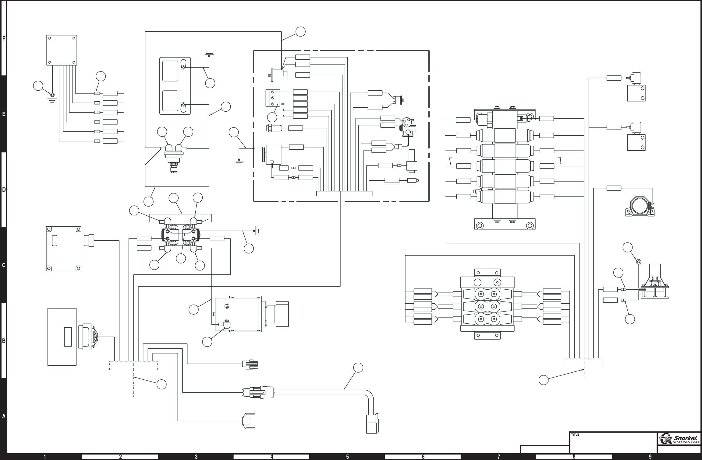
Page3-19Page3-19
Turntable electrical
Ford LRG-423 - sheet 3
Snorkel model TB 60
DWG. 0082085-3
15
19
22C
27
13
14
20
21C
26
12
16B
160C
34
28B
74
1D
73
6A5B
5A
175
174
173
172
67A
57
5A
80D
77B
56
164B
3
80C
80D
A1
A2
78
3C
5C
78A
TURNTABLE
WIRE ASSEMBLY
ENGINE WIRE
ASSEMBLY (FO)
FORD ENGINE
12
RED
WHT
BLK
26
26
36
TILT
ALARM
NON-PROPORTIONAL
PACKAGE VALVE
PROPORTIONAL
PACKAGE VALVE
TILT ALARM
SIREN
DUMP VALVE
RANGE VALVE
BOOM
STEER
PLAT
ROT
PLAT
LEVEL
NOT
USED
TIE BACK
TIE BACK
57
FUEL SHUT OFF
CARB.
OIL PRESS.
SWITCH
STARTER
VACUUM SWITCH
FILTERLOCK
ALT.
29
30
PURPLE
YELLOW
GRAY
BLUE
RED
BLACK
BLACK
25
23
PWM
MODULE
EMERGENCY
POWER UNIT
BARBER/COLEMAN
GOVERNOR
35
34
31
33
BATTERY
DISCONNECT
SWITCH
BATTERY
START/EMER. POWER
RELAYS
29
28
3837
32
11
(DUAL FUEL)
(DUAL FUEL)
(DUAL FUEL)
(DUAL FUEL)
(DUAL FUEL)
IGN
STR
SOL
17
3
21B/A
3
24
3
18
3
22B
3
23
3
3
78A
57
164B
57
77A (DUAL FUEL)
78B (DUAL FUEL)
SPARK MODULE
CRANK POSITION
SENSOR
DISTRIBUTOR
ENGINE COOLANT
SENSOR
59
+
-
FUEL
PUMP
(LOCATED BELOW ENGINE
COOLANT SENSOR AT FRONT
OF ENGINE)
61
21
22
22
21
22
AW0082085-3

Turntable electrical, Ford LRG-425
item part no qty description
1 0082689 1 Wiring box - (see page 3-40 for parts breakdown)
2 0082691 1 Lower controls - (see page 3-35 for parts breakdown)
3 3050002 1 Battery, 12 volt DC - 550 CCA
4 3020049 1 Switch, battery disconnect
5 3050008 1 Battery hold down
6 3050004 2 Battery hold down bolt
7 0181503 1 Bracket, tilt alarm
8 0073051 1 Bracket, battery disconnect switch
9 3020040 1 Tilt alarm sensor 5°
10 480652 1 Siren, tilt alarm
11 0111865 1 Wire harness, Ford LRG-423 engine
12 0081846 1 Wire harness, turntable
13 3040534 1 PWM module
14 0071563 1 Jumper wire
15 3040046 1 Terminal .250 tab male slip-on fully insulated 22/18 wire
16 5093008 4 Clamp
17 5093004 4 Clamp
18 986299 3 Washer 3/8 medium flat
19 3040506 2 Relay 12 volt DC
20 0073089 1 Placard, battery disconnect switch
21 3040047 1 Terminal .250 tab female slip-on fully insulated 22/18 wire
22 3040268 3 Insulator boot
23 970239 1 Washer 5/16 medium lock
24 986269 1 Washer 5/16 medium flat
25 3044146 1 Terminal #10 stud insulated 22/18 wire
26 3040082 2 Terminal .250 tab male slip-on fully insulated 16/14 wire
27 987119 3 Washer 3/8 medium lock
28 0080483 1 Jumper wire
29 0080484 2 Jumper wire
30 0080482 1 Jumper wire
31 5093008 1 Clamp
32 0151370 1 Jumper wire
33 0070705 1 Jumper wire
34 970469 3 Capscrew 3/8-16x1inchlonghexhead grade 5
35 0090319 1 Jumper wire
36 3044162 1 Terminal 1/4 stud insulated 16/14 wire
37 3040270 1 Insulator boot
38 3040269 1 Insulator boot
39 974289 2 Machine screw #6-32 x 1-1/4 inch long round head
40 984009 2 Nut #6-32 hex
41 986159 2 Washer #6 medium flat
42 987349 2 Washer #6 medium lock
43 970239 1 Capscrew 5/16-18 x 3/4 inch long hex head grade 5
44 5560034 2 Nut #10-24 self locking
45 5560033 2 Nut 3/8-16 self locking
46 974709 2 Machine screw #10-24 x 1 inch long round head
47 986009 2 Washer #10 medium flat
48 5560654 1 Washer #10 star tooth lock
49 970239 5 Capscrew 1/4-20 x 3/4 inch long hex head grade 5
50 987099 8 Washer 1/4 medium lock
Parts list continued on next page
TB 60 – 01-97 through 01-01 3-21

Turntable electrical, Ford LRG-425
item part no qty description
51 5560004 14 Nut 1/4-20 self locking
52 986019 14 Washer 1/4 medium flat
53 970049 8 Capscrew 1/4-20 x 1 inch long hex head grade 5
54 970009 4 Capscrew 1/4-20 x 1/2 inch long hex head grade 5
55 970029 1 Capscrew 1/4-20 x 3/4 inch long hex head grade 5
56 972489 2 Capscrew 3/8-16 x 1-1/2 inch long hex head grade 5
3-22 TB 60 – 01-97 through 01-01
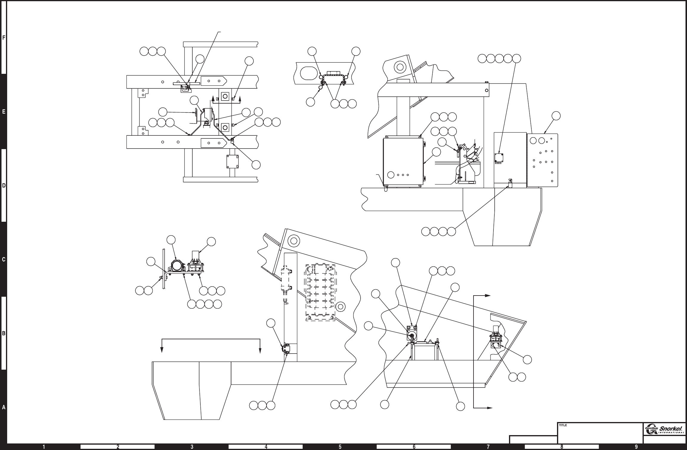
Page3-23Page3-23
Turntable electrical
Ford LRG-425 - sheet 1
Snorkel model TB 60
DWG. 0082690-1
ENGINE WIRE
ASSEMBLY
50 52 54
16 17
16
54
5250
17
29
29
BB
31
18 27 34
VIEW C-C
10
7
56 57 51 52 53
44 46 47 48
VIEW A-A
CC
19
50 52 54 23 24 43
4
20
66
A
A
7
56
3
18
45
27 34
8
16 51 52 53
110 VOLT GROUND
1
17
49 51 52
49 50 51 2
17 17
16 51 52 53
VIEW B-B
9
13 39 40 41 42
AW0082690-1
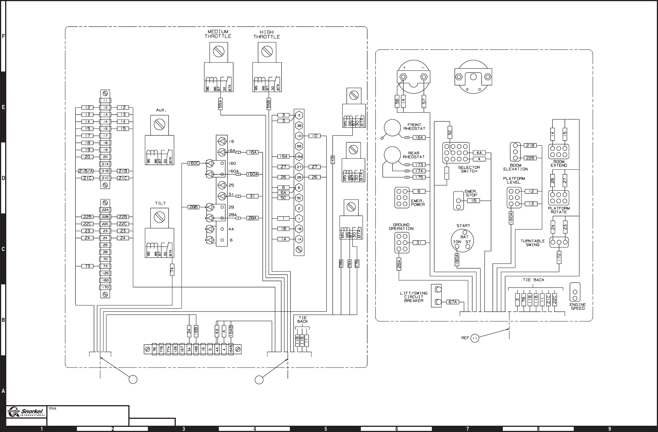
Page3-24Page3-24
Turntable electrical
Ford LRG-425 - sheet 2
Snorkel model TB 60 DWG. 0082690-2
12 11
TURNTABLE
WIRE ASSEMBLY
ENGINE WIRE
ASSEMBLY
ENGINE WIRE
ASSEMBLY
GROUND CONTROL PANEL
AMMETER ENGINE TEMPERATURE
GAUGE
WIRING BOX
AW0082690-2
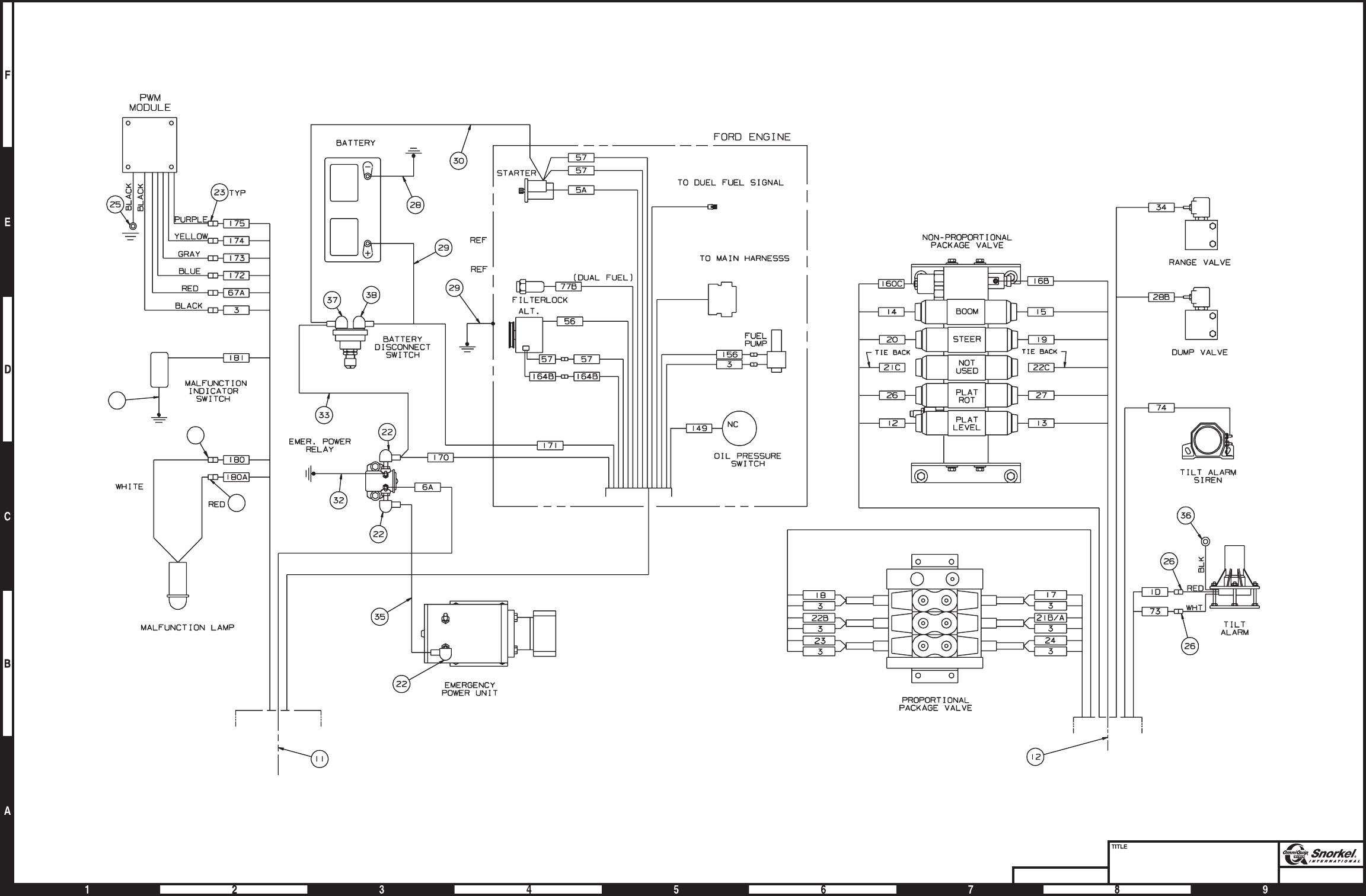
Page3-25Page3-25
Turntable electrical
Ford LRG-425 - sheet 3
Snorkel model TB 60
DWG. 0082690-3
21
15
14
ENGINE WIRE
ASSEMBLY
TURNTABLE
WIRE ASSEMBLY
AW0082690-3

Lower controls, Cummins 3.3
item part no qty description
0083530 1 Lower controls, Cummins 3.3
1 0060373 3 Jumper strap
2 0070730 3 Jumper wire
3 0070735 1 Jumper wire
4 0070742 2 Jumper wire
5 0070746 3 Jumper wire
6 0070747 5 Jumper wire
7 0070753 3 Jumper wire
8 0071541 1 Jumper wire
9 0074585 1 Lower control panel and hinge
10 0082002 1 Rheostat switch
3040619 1 Replacement switch
0150647 1 Replacement jumper wire
11 0082003 1 Placard, lower controls
12 0083300 1 Wire harness, EPS
13 0090757 1 Jumper wire
14 0180949 1 Speed control switch
3040497 1 Replacement switch
15 0181104 1 Jumper wire
16 0240483 1 Jumper wire
17 300489 1 Terminal strip, 6 circuit #10 stud
18 3020013 2 Switch, toggle
19 3020016 2 Switch, toggle
20 3020018 3 Switch, toggle
21 3020048 1 Switch, toggle
22 3020081 2 Switch, toggle
23 3020087 1 Switch, keyed start
8030044 1 Replacement key
24 3040348 1 Switch knob
25 3040535 1 Circuit breaker, 3 amp capacity
26 3040620 1 Coupler kit
27 3070003 1 Ammeter
28 3070040 1 Temperature gauge
29 5093006 1 Clamp
30 562236 1 Guard, emergency stop switch
31 970029 1 Capscrew 1/4-20 x 3/4 inch long hex head grade 5
32 5560004 1 Nut 1/4-20 self locking
33 986019 1 Washer 1/4 medium flat
34 5560649 2 Machine screw #10-24 x 1 inch long truss head
35 5560034 2 Nut #10-24 self locking
3-26 TB 60 – 01-97 through 01-01

Page3-27
Lower controls
Cummins 3.3
Snorkel model TB 60
AMPS
FRT
RHEOSTAT
REAR
RHEOSTAT
SELECTOR SWITCH
BOOM ELEV
BOOM
EXTEND
EMERGENCY POWER EMERGENCY STOP
PLAT
LEVEL
PLAT
ROT
T/T SWING
ENGINE
SPEED
LIFT/SWING
CIRCUIT BRKR
3AMP
MASTER
SWITCH
GRD
OPER
G
SI
3
164
3C
TACH
SENS
T1
T2
T3
126
167
8D
164B
BAT
IGN ST
-
+
ENGINE
SPEED
GROUND
OPERATION
EMERGENCY
POWER
BOOM
SPEED
SELECTOR
SWITCH
FAST
SLOW
UP FOR
GROUND
OPERATION
DOWN FOR
EMERGENCY
OPERATION
GROUND FAST
SLOW
PLATFORM
LEVEL
PLATFORM
ROTATION
TURNTABLE
SWING
BOOM
EXTENSION MAIN BOOM
ELEVATION
CCW
CW
CCW
CW
DN
UP
IN
OUT
DN
UP
LIFT/SWING
CIRCUIT
BREAKER
3
OFF
ON
START
MASTER
UP
FOR
RUN
EMERGENCY
STOP
PLATFORM
5
45
7
2
6
1
3
15
1
6
2
1
6
16
13
7
4
5
8
6
6
19
28
11
17
35
34
19
12
20
18 25
23
33
32
31
29
18
22
22
30
21
27
14
24
26
10
AW0083530

Lower controls, Deutz before 11-09-99
item part no qty description
0082032 1 Lower controls, Deutz - (machines before 11-09-1999)
1 0060373 3 Jumper strap
2 0070730 2 Jumper wire
3 0070742 2 Jumper wire
4 0070746 4 Jumper wire
5 0070747 5 Jumper wire
6 0070753 3 Jumper wire
7 0071541 1 Jumper wire
8 0070735 1 Jumper wire
9 0081819 1 Lower control panel and hinge
10 0082002 1 Rheostat switch
3040619 1 Replacement switch
0150647 1 Replacement jumper wire
11 0082003 1 Placard, lower controls
12 0111552 1 Jumper wire
13 562236 1 Guard, emergency stop switch
14 3070023 1 Temperature gauge
15 0151813 2 Diode wire
16 0090757 1 Jumper wire
17 0180949 1 Rheostat switch
3040497 1 Replacement switch
18 0181104 1 Jumper wire
19 0240483 1 Jumper wire
20 3011801 1 Wire 18 gauge single conductor x 5 feet long
21 3020013 2 Switch, toggle
22 3020016 2 Switch, toggle
23 3020018 3 Switch, toggle
24 3020087 1 Switch, keyed start
8030044 1 Replacement key
25 3020048 1 Switch, toggle
26 3020081 2 Switch, toggle
27 3020093 1 Switch, engine shut down
28 3040047 1 Terminal .250 tab female slip-on fully insulated 22/18 wire
29 3040083 1 Terminal .250 tab male fully insulated 16/14 wire
30 3040348 1 Switch knob
31 3040535 1 Circuit breaker, 3 amp capacity
32 3070003 1 Ammeter
33 3040620 1 Coupler kit
34 3044145 2 Terminal #8 stud insulated 22/18 wire
35 5093006 1 Clamp
36 970029 1 Capscrew 1/4-20 x 3/4 inch long hex head grade 5
37 986019 1 Washer 1/4 medium flat
38 5560004 1 Nut 1/4-20 self locking
3-28 TB 60 – 01-97 through 01-01
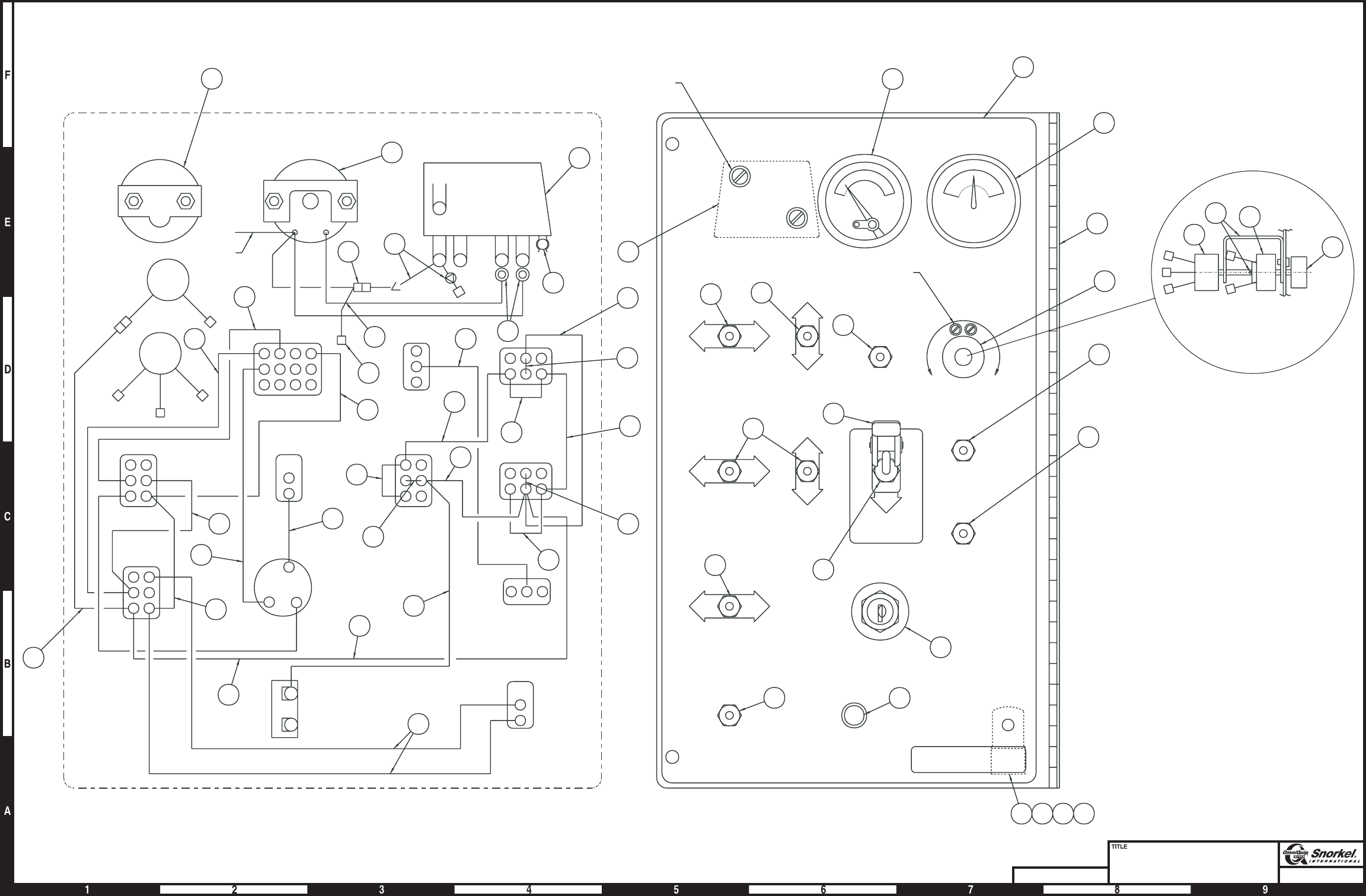
Page3-29Page3-29
Lower controls
Deutz before 11-09-1999
Snorkel model TB 60
DWG. 0082032
MAGNETIC SWITCH
ENGINE TEMPERATURE
GAUGE
TIE BACK
FRT
RHEOSTAT
REAR
RHEOSTAT
16
3
18
7
5
19
3
5
6
4
5
2
5
4
6
2
5
28
20 34
12
29
4
1
1
SELECTOR SWITCH
BOOM ELEV
BOOM
EXTEND
EMERGENCY POWER EMERGENCY STOP
4
8
1
PLAT
LEVEL
PLAT
ROT
T/T SWING
ENGINE
SPEED
LIFT/SWING
CIRCUIT BRKR
3AMP
MASTER
SWITCH
GRD
OPER
15
11
23
25
26
26
23
22
21
30
9
3
24
31
35
10
17
30
Shown side view
33
21
13
HARDWARE INCLUDED
WITH ITEM 27
27
14
32 14
32
27
22
HARDWARE INCLUDED
WITH ITEM 33
REAR VIEW FRONT VIEW
36 37 38
AMPS
BAT
IGN ST
RED
BLACK
WHITE
BLACK
NO NC S B
-
+G
SPEED
ENGINE
SPEED
GROUND
OPERATION
EMERGENCY
POWER
BOOM
SELECTOR
SWITCH
FAST
SLOW
UP FOR
GROUND
OPERATION
DOWN FOR
EMERGENCY
OPERATION
GROUND
PLATFORM
FAST
SLOW
PLATFORM
LEVEL
PLATFORM
ROTATION
TURNTABLE
SWING
BOOM
EXTENSION MAIN BOOM
ELEVATION
CCW
CW
CCW
CW
DN
UP
IN
OUT
DN
UP
LIFT/SWING
CIRCUIT
BREAKER
OFF
ON
START
MASTER
UP
FOR
RUN
EMERGENCY
STOP
TURN ENGINE
SWITCH OFF
THEN ON TO
RESET.
30 SEC.TIME
DELAY FOR
STARTING.
SYSTEM
ENGINE PROTECTION
AW0082032
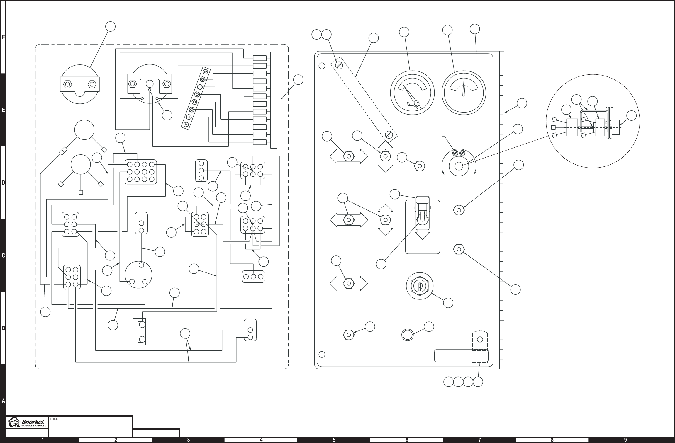
Page3-30Page3-30
Lower controls
Deutz after 11-09-1999
Snorkel model TB 60 DWG. 0083397
AMPS
FRT
RHEOSTAT
REAR
RHEOSTAT
16
3
18
7
5
19
3
5
6
4
5
2
5
6
25
4
1
1
SELECTOR SWITCH
BOOM ELEV
BOOM
EXTEND
EMERGENCY POWER EMERGENCY STOP
4
8
1
PLAT
LEVEL
PLAT
ROT
T/T SWING
ENGINE
SPEED
LIFT/SWING
CIRCUIT BRKR
3AMP
MASTER
SWITCH
GRD
OPER
21
9
3
24
31
G
SI
BAT
IGN ST
-
+
SPEED
ENGINE
SPEED
GROUND
OPERATION
EMERGENCY
POWER
BOOM
SELECTOR
SWITCH
FAST
SLOW
UP FOR
GROUND
OPERATION
DOWN FOR
EMERGENCY
OPERATION
GROUND
PLATFORM
FAST
SLOW
PLATFORM
LEVEL
PLATFORM
ROTATION
TURNTABLE
SWING
BOOM
EXTENSION MAIN BOOM
ELEVATION
CCW
CW
CCW
CW
DN
UP
IN
OUT
DN
UP
LIFT/SWING
CIRCUIT
BREAKER
OFF
ON
START
MASTER
UP
FOR
RUN
EMERGENCY
STOP
14 32 11
2728 20
26
26
21
23 22
25
30
23 13
HARDWARE
INCLUDED
WITH ITEM 33
22
29343536
FRONT VIEW
ENGINE TEMPERATURE
GAUGE 3
164
3C
TACH
SENS
T1
T2
T3
126
167
8D
164B
TIE
BACK
T1 & T2
32
12
REAR VIEW
14
10
17
30
33
Shown side view
AMMETER
AW0083397

Lower controls, Deutz after 11-09-1999
item part no qty description
0083397 1 Lower controls, Deutz - (machines after 11-09-1999)
1 0060373 3 Jumper strap
2 0070730 3 Jumper wire
3 0070742 3 Jumper wire
4 0070746 4 Jumper wire
5 0070747 3 Jumper wire
6 0070753 3 Jumper wire
7 0071541 1 Jumper wire
8 0070735 1 Jumper wire
9 0074585 1 Lower control panel and hinge
10 0082002 1 Rheostat switch
3040619 1 Replacement switch
0150647 1 Replacement jumper wire
11 0082003 1 Placard, lower controls
12 0083300 1 Wire harness, EPS
13 562236 1 Guard, emergency stop switch
14 3072120 1 Temperature gauge - (before 6-19-00)
3070041 1 Temperature gauge - (after 6-19-00)
15 0151813 2 Diode wire
16 0090757 1 Jumper wire
17 0180949 1 Rheostat switch
3040497 1 Replacement switch
18 0181104 1 Jumper wire
19 0240483 1 Jumper wire
20 300489 1 Terminal strip, 6 circuit #10 stud
21 3020013 2 Switch, toggle
22 3020016 2 Switch, toggle
23 3020018 3 Switch, toggle
24 3020087 1 Switch, keyed start
8030044 1 Replacement key
25 3020048 1 Switch, toggle
26 3020081 2 Switch, toggle
27 974709 2 Machine screw #10-24 x 1 inch long round head
28 5560034 2 Nut #10-24 self locking
29 986019 1 Washer 1/4 medium flat
30 3040348 1 Switch knob
31 3040535 1 Circuit breaker, 3 amp capacity
32 3070003 1 Ammeter
33 3040620 1 Coupler kit
34 5560004 1 Nut 1/4-20 self locking
35 5093006 1 Clamp
36 970029 1 Capscrew 1/4-20 x 3/4 inch long hex head grade 5
TB 60 – 01-97 through 01-01 3-31

Lower controls, Ford LRG-423
item part no qty description
0081999 1 Lower controls, Ford LRG-423
1 0060373 3 Jumper strap
2 0070730 2 Jumper wire
3 0070742 2 Jumper wire
4 0070746 4 Jumper wire
5 0070747 5 Jumper wire
6 0070753 3 Jumper wire
7 0071541 1 Jumper wire
8 0070735 1 Jumper wire
9 0081819 1 Lower control panel and hinge
10 0082002 1 Rheostat switch
3040619 1 Replacement switch
0150647 1 Replacement jumper wire
11 0082003 1 Placard, Lower controls
12 0111512 1 Jumper bar
13 562236 1 Guard, emergency stop switch
14 3070021 1 Temperature gauge
15 0151813 2 Diode wire
16 0090757 1 Jumper wire
17 0180949 1 Rheostat switch
3040497 1 Replacement switch
18 0181104 1 Jumper wire
19 0240483 1 Jumper wire
20 3011801 1 Wire 18 gauge single conductor x 5 feet long
21 3020013 2 Switch, toggle
22 3020016 2 Switch, toggle
23 3020018 3 Switch, toggle
24 3020087 1 Switch, keyed start
8030044 1 Replacement key
25 3020048 1 Switch, toggle
26 3020081 2 Switch, toggle
27 3020093 1 Switch, engine shut down
28 3040046 1 Terminal .250 tab male slip-on fully insulated 22/18 wire
29 3040083 1 Terminal .250 tab male fully insulated 16/14 wire
30 3040348 1 Switch knob
31 3040535 1 Circuit breaker, 3 amp capacity
32 3070003 1 Ammeter
33 3040620 1 Coupler kit
34 3044145 2 Terminal #8 stud insulated 22/18 wire
35 5093006 1 Clamp
36 970029 1 Capscrew 1/4-20 x 3/4 inch long hex head grade 5
37 986019 1 Washer 1/4 medium flat
38 5560004 1 Nut 1/4-20 self locking
3-32 TB 60 – 01-97 through 01-01
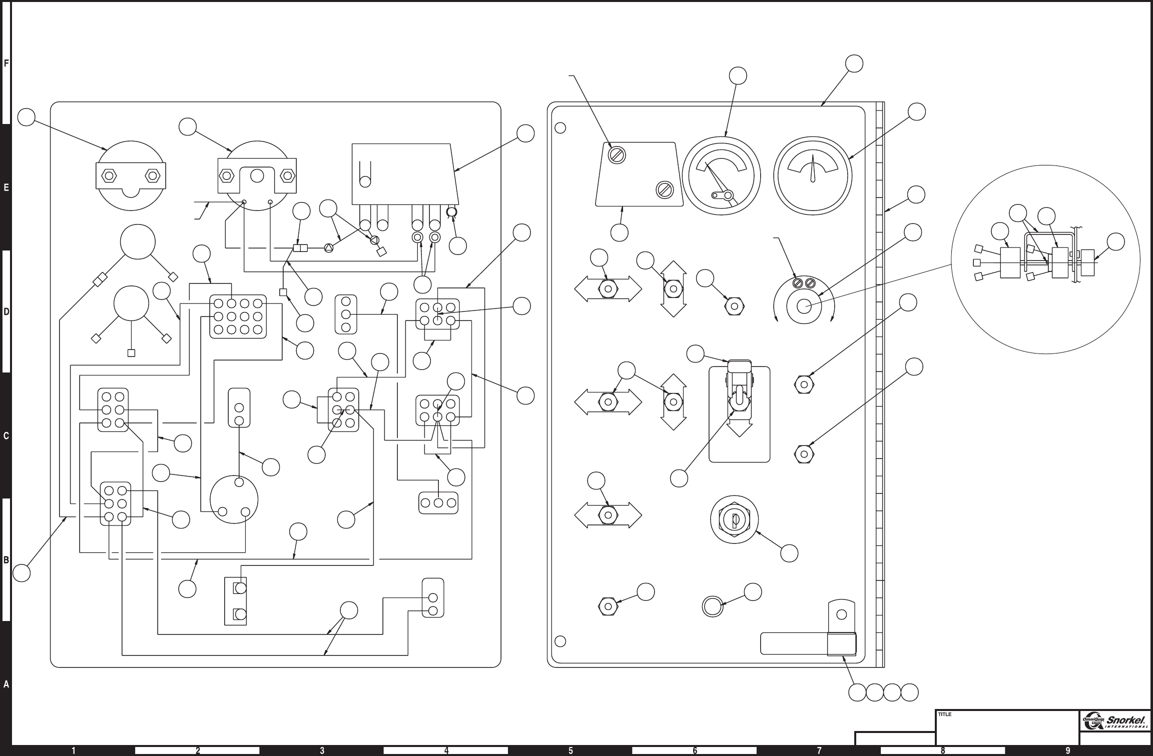
Page3-33Page3-33
Lower controls
Ford LRG-423
Snorkel model TB 60
DWG. 0081999
MAGNETIC SWITCH
ENGINE TEMPERATURE
GAUGE
TIE BACK
FRT
RHEOSTAT
REAR
RHEOSTAT
16
3
18
7
5
19
3
5
6
4
5
2
5
4
6
2
5
28
20
34
12
29
4
1
1
SELECTOR SWITCH
BOOM ELEV
BOOM
EXTEND
EMERGENCY POWER EMERGENCY STOP
4
8
1
PLAT
LEVEL
PLAT
ROT
T/T SWING
ENGINE
SPEED
LIFT/SWING
CIRCUIT BRKR
3AMP
MASTER
SWITCH
GRD
OPER
15
11
23
25
26
26
23
22
21
27 30
9
3
HARDWARE INCLUDED
WITH ITEM 27
24
31
35
10
17
30
Shown side view
33
21
13
22
14
32
HARDWARE INCLUDED
WITH ITEM 33
36 37 38
27
14
32
REAR VIEW FRONT VIEW
AMPS
BAT
IGN ST
RED
BLACK
WHITE
BLACK
NO NC S B
-
+G
SPEED
ENGINE
SPEED
MASTER
GROUND
OPERATION
EMERGENCY
POWER
BOOM
SELECTOR
SWITCH
FAST
SLOW
START
ON
OFF
UP FOR
GROUND
OPERATION
DOWN FOR
EMERGENCY
OPERATION
GROUND
PLATFORM
FAST
SLOW
PLATFORM
LEVEL
PLATFORM
ROTATION
TURNTABLE
SWING
BOOM
EXTENSION MAIN BOOM
ELEVATION
CCW
CW
CCW
CW
DN
UP
IN
OUT
DN
UP
LIFT/SWING
CIRCUIT
BREAKER
UP
FOR
RUN
EMERGENCY
STOP
TURN ENGINE
SWITCH OFF
THEN ON TO
RESET.
30 SEC.TIME
DELAY FOR
STARTING.
SYSTEM
ENGINE PROTECTION
AW0081999
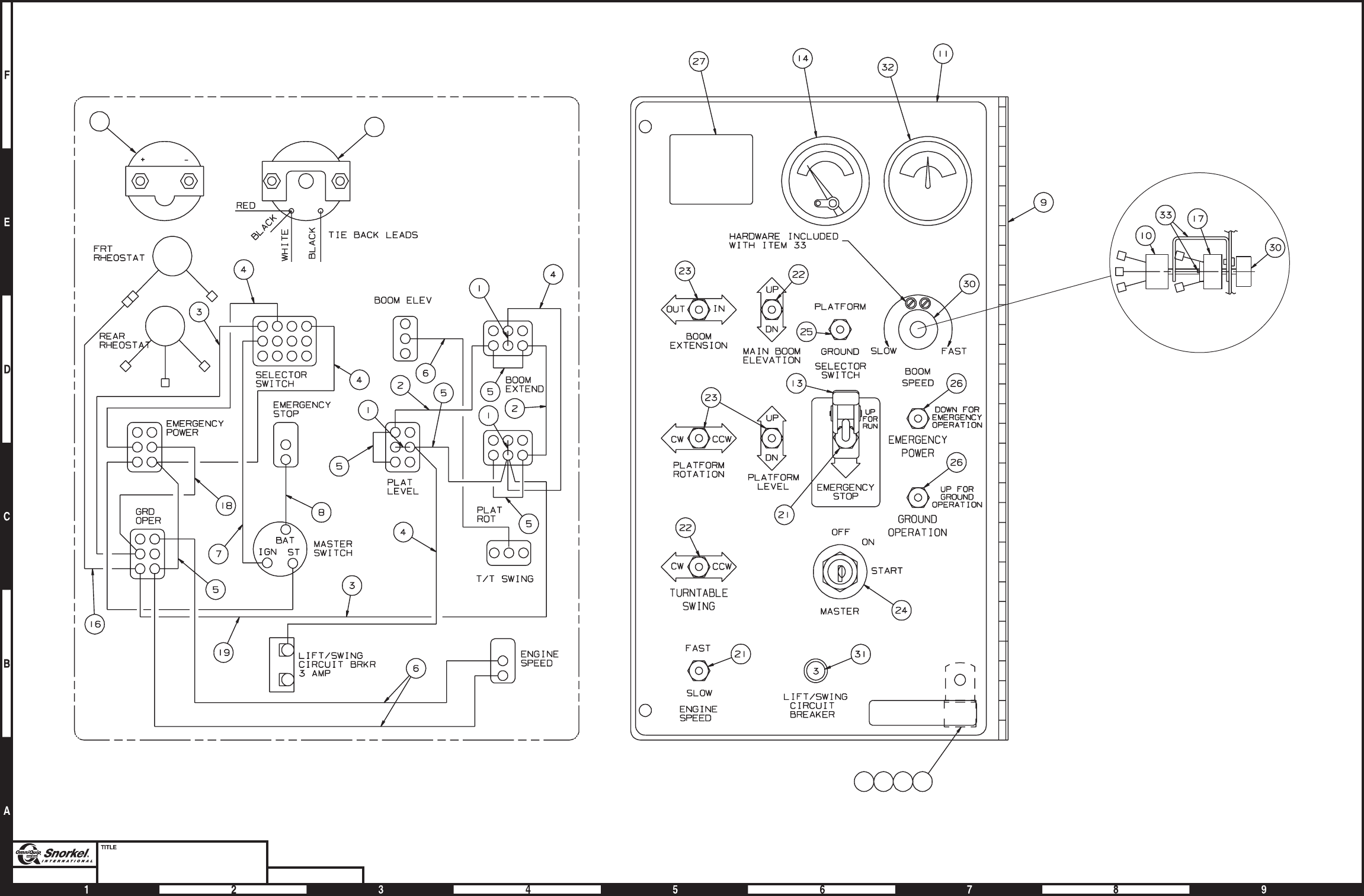
Page3-34Page3-34
Lower controls
Ford LRG-425
Snorkel model TB 60 DWG. 0082691
SHOWN SIDE VIEW
FRONT VIEW
REAR VIEW
AMMETER
ENGINE
TEMPERATURE GAGUE
32 14
12 15 28 29
AW0082691

Lower controls, Ford LRG-425
item part no qty description
0082691 1 Lower controls, Ford LRG-425
1 0060373 3 Jumper strap
2 0070730 2 Jumper wire
3 0070742 2 Jumper wire
4 0070746 4 Jumper wire
5 0070747 5 Jumper wire
6 0070753 3 Jumper wire
7 0071541 1 Jumper wire
8 0070735 1 Jumper wire
9 0081819 1 Lower control panel and hinge
10 0082002 1 Rheostat switch
3040619 1 Replacement switch
0150647 1 Replacement jumper wire
11 0082003 1 Placard, lower controls
12 5093006 1 Clamp
13 562236 1 Guard, emergency stop switch
14 3070021 1 Temperature gauge
15 970029 1 Capscrew 1/4-20 x 3/4 inch long hex head grade 5
16 0090757 1 Jumper wire
17 0180949 1 Rheostat switch
3040497 1 Replacement switch
18 0181104 1 Jumper wire
19 0240483 1 Jumper wire
20 3044145 2 Terminal #8 stud insulated 22/18 wire
21 3020013 2 Switch, toggle
22 3020016 2 Switch, toggle
23 3020018 3 Switch, toggle
24 3020087 1 Switch, keyed start
8030044 1 Replacement key
25 3020048 1 Switch, toggle
26 3020081 2 Switch, toggle
27 0082828 1 Placard, blank
28 986019 Washer 1/4 medium flat
29 5560004 Nut 1/4-20 self locking
30 3040348 1 Switch knob
31 3040535 1 Circuit breaker, 3 amp capacity
32 3070003 1 Ammeter
33 3040620 1 Coupler kit
TB 60 – 01-97 through 01-01 3-35

Wiring box, Deutz and Ford LRG-423
item part no qty description
0081998 1 Wiring box, Deutz and Ford LRG-423
1 0081996 1 Wiring box, drilled
2 3040411 1 Mini siren
3 3040469 1 Relay, 12 volt DC
4 3040252 2 Circuit breaker, 15 amp capacity
5 3040069 1 Circuit breaker, 25 amp capacity
6 3070001 1 Hour meter
7 0081997 1 Wire harness, wiring box internal
8 5093001 1 Clamp
9 3040118 1 Extension with gasket
10 3040121 4 Close-up plug
11 0081995 1 Wiring box panel - (before 11-08-1999, see page 3-39 for parts breakdown)
0112165 1 Wiring box panel - (between 11-08-1999 and 1-04-00, see page 3-39 for parts breakdown)
0083467 1 Wiring box panel - (after 1-04-00, see page 3-39 for parts breakdown)
12 0070967 1 Corrosion inhibitor
13 3045278 1 Flanged electrical outlet with cover
14 0111735 1 Placard, circuit breaker
15 3040386 1 Connector
16 3040387 1 Locknut
17 3040116 2 Connector - (before 11-08-99)
3040116 1 Connector - (after 11-08-99)
18 3040110 4 Locknut
19 3040298 1 Connector
20 3040285 1 Connector
21 3040187 3 Connector
22 3040070 3 Locknut
23 0070921 1 Placard, 110 volt power
24 5560655 2 Pop rivet #AD32-ABS
25 974239 2 Machine screw #6-32 x 1/2 inch long round head
26 984009 2 Nut #6-32 hex
27 5560648 2 Machine screw #10-24 x 3/4 inch long truss head
28 5560654 1 Washer #10 star tooth lock
29 987089 1 Washer #10 medium lock
30 984049 1 Nut #10-24 hex
31 5560034 2 Nut #10-24 self locking
32 986159 2 Washer #6 medium flat
33 987349 2 Washer #6 medium lock
34 986019 1 Washer 1/4 medium flat
35 970029 1 Capscrew 1/4-20 x 3/4 inch long hex head grade 5
36 5560004 1 Nut 1/4-20 self locking
37 0070735 2 Jumper wire
38 0181028 1 Jumper wire
39 0240483 1 Jumper wire
40 0081559 1 Jumper wire
41 0071528 1 Jumper wire
42 0073057 1 Jumper wire
43 970469 1 Capscrew 3/8-16 x 1 inch long hex head grade 5
44 0071561 1 Jumper wire
45 5569003 1 Grommet
46 3040295 1 Connector
3-36 TB 60 – 01-97 through 01-01
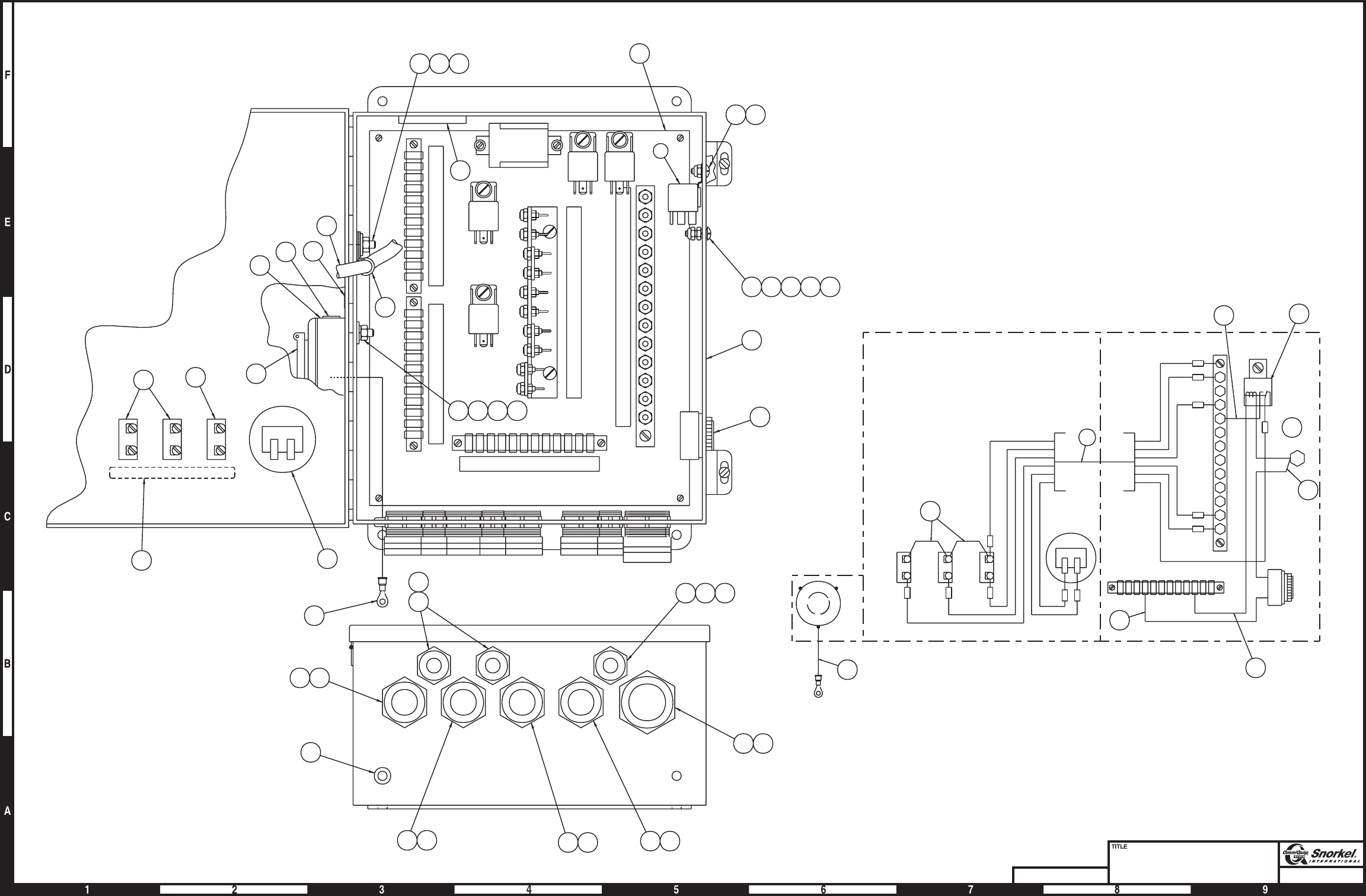
Page3-37
Wiring box
Deutz and Ford LRG-423
Snorkel model TB 60
DWG. 0081998
46 18
18 19
21
11
27
45
14 6
13
10 23
7
9
ENGINE
12/8T/T
18/12
18/12
PROX
SW
BOOM
SW
25
8
34
12
3
ADDCO
ACTUATOR
(DZ)
44
45
18 20
1817
22
31
35 36
26 32 33
RELAY
ALARM
42
39
3
41
38
HOURMETER
THROTTLE
15 AMP
RUN
15 AMP
MAIN
25 AMP
37
WIRING BOX WIRING
+-
7
3
38
55
1B
1A
1B
GND
1C
38
3
1B
1C
55
1A
+-
4A
164B
4
5
16
16B
34
167
126
77A
77B
78
38
1D
55
164
27
26
6
5C
2
1
1A
85
86
87
30
87A
BRASS SILVER
GREEN
44
27 28 29 30 31
1
2
15 16
21 22 43
AW0081998
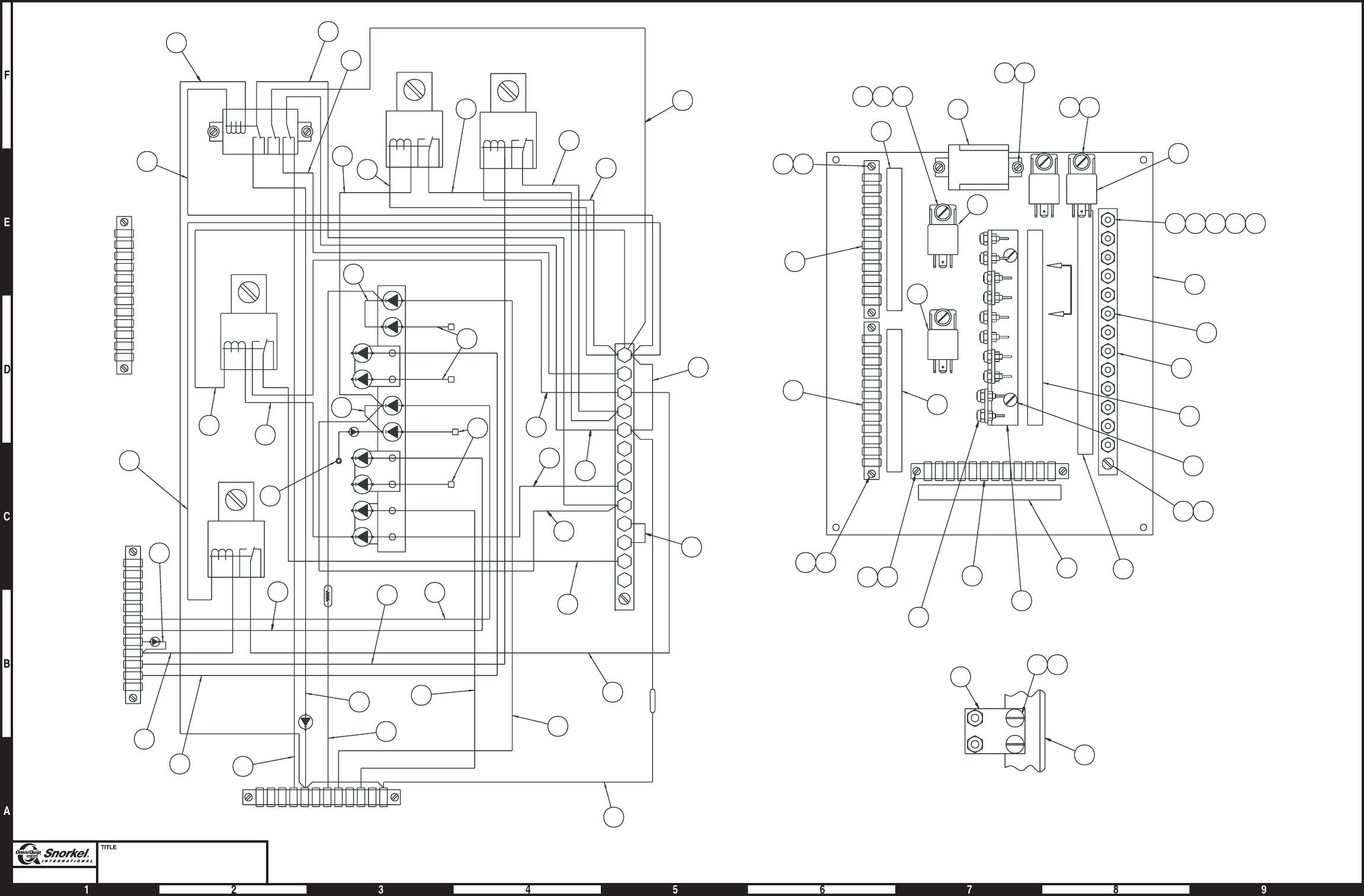
Page3-38
Wiring box panel
Deutz & Ford 423
Snorkel model TB 60
3
1A
11
21C
22A
170
122
78
164B
16
6
MED
THROT
HIGH
THROT
AUX
TILT
ENGINE
ALARM
10
3
11
4419
4419
A
A
22A
22B
22C
23
24
25
28
70
73
125
160
170
122
11
12
13
14
15
17
18
19
20
21A
21B
21C
AB79
1
436
85
86
87
30
87A
85
86
87
30
87A
85
86
87
30
87A
85
86
87
30
87A
16
16A
160
160A
25
31
28
28A
4A
6
78
77B
77A
126
167
34
16B
16
5
4A
4
164B
38
1D
3
27
26
6
5C
2
1
1B
1A
55
28
33
40
22
23
41 MED
THROTTLE
RELAY
HIGH
THROTTLE
RELAY
ENGINE ALARM
RELAY
8
52
40
49
VIEW A-A
10
21
17 16
1944
7
121319
9
1213
1718
8
3
3
6
2
11
1
15 16 18 43 50
20
17
14 18
4
5
164
24
28
33
27
26
28
36
39
41
46
29
47
35 34
30
51
32
32
TILT
RELAY
AUX
RELAY
42
37
37
38
45
42
48
38
31
31
24
51
used before
11-08-99 only
used before
11-08-99 only
8
8
AW0081995

Wiring box panel, Deutz and Ford LRG-423
item part no qty description
0081995 1 Wiring box panel, Deutz & Ford 423 - (before 11-08-1999)
0112165 1 Wiring box panel, Deutz & Ford 423 - (between 11-08-1999 and 1-04-00)
0083467 1 Wiring box panel, Deutz & Ford 423 - (after 1-04-00)
1 0180796 1 Panel, drilled
2 3044712 1 Terminal strip, 12 circuit #10 stud
3 3040433 3 Terminal strip, 12 circuit .188 tab slip-on
4 0181552 1 Decal, power wire
5 0181553 1 Decal, terminal strip
6 0181107 1 Decal, control wire #2
7 0181106 1 Decal, control wire #1
8 3040469 4 Relay, 12 volt DC
9 3040287 1 Relay, 12 volt DC
10 0150488 1 Diode holder
11 5560038 22 Nut #10-32 self locking
12 974239 4 Machine screw #6-32 x 1/2 inch long round head
13 986159 4 Washer #6 medium flat
14 974689 1 Machine screw #10-24 x 3/4 inch long round head
15 974729 1 Machine screw #10-24 x 1-1/4 inch long round head
16 5560034 7 Nut #10-24 self locking
17 5560609 10 Machine screw #10-24 x 1/2 inch long truss head
18 987089 4 Washer #10 medium lock
19 987349 10 Washer #6 medium lock
20 0181554 1 Decal, diode
21 0073631 3 Diode stand off
22 0070681 1 Jumper wire
23 0070711 1 Jumper wire
24 0071812 2 Jumper wire - (before 1-04-00)
0071812 1 Jumper wire - (after 1-04-00)
25 0181434 1 Diode/resister wire
26 0070682 1 Diode wire
27 0181073 1 Resister wire - (5 ohm)
28 0140317 3 Diode wire
29 0151205 1 Jumper wire
30 0081560 1 Jumper wire
31 0070724 2 Jumper wire
32 0180110 4 Diode wire
3040108 1 Replacement diode
33 0181031 2 Jumper wire
34 0081559 1 Jumper wire
35 0081515 1 Jumper wire
36 0181030 1 Diode wire
37 0181136 2 Jumper wire
38 0181111 2 Jumper wire
39 0181432 1 Diode wire - (before 1-04-00)
0112164 1 Diode wire - (after 1-04-00)
40 0070713 2 Jumper wire
41 0140323 2 Jumper wire
42 0140332 2 Jumper wire
43 5560654 1 Washer #10 star tooth lock
44 974279 6 Machine screw #6-32 x 3/4 inch long round head
45 0090621 1 Jumper wire
46 0110471 1 Diode wire
47 0170335 1 Diode wire
48 0181113 1 Jumper wire
49 0073253 2 Jumper wire
50 984049 1 Nut #10-24 hex
51 0181434 1 Diode wire - (used on machines before 1-04-00)
TB 60 – 01-97 through 01-01 3-39

Wiring box, Ford LRG-425
item part no qty description
0082689 1 Wiring box, Ford LRG-425
1 0081996 1 Wiring box, drilled
2 3040411 1 Mini siren
3 3040469 3 Relay, 12 volt DC
4 3040252 1 Circuit breaker, 15 amp capacity
5 3040069 1 Circuit breaker, 25 amp capacity
6 3070001 1 Hour meter
7 0081997 1 Wire harness, wiring box internal
8 5093001 1 Clamp
9 3040118 1 Extension with gasket
10 3040121 4 Close-up plug
11 0082688 1 Wiring box panel - (see page 3-43 for parts breakdown)
12 0070967 1 Corrosion inhibitor
13 3045278 1 Flanged electrical outlet with cover
14 0170623 1 Decal, throttle
15 3040386 1 Connector
16 3040387 1 Locknut
17 3040116 1 Connector
18 3040110 4 Locknut
19 3040298 1 Connector
20 3040285 1 Connector
21 3040187 3 Connector
22 3040070 3 Locknut
23 0070921 1 Placard, 110 volt power
24 5560655 2 Pop rivet #AD32-ABS
25 974239 2 Machine screw #6-32 x 1/2 inch long round head
26 984009 2 Nut #6-32 hex
27 5560648 5 Machine screw #10-24 x 3/4 inch long truss head
28 5560654 2 Washer #10 star tooth lock
29 987089 1 Washer #10 medium lock
30 984049 1 Nut #10-24 hex
31 5560034 4 Nut #10-24 self locking
32 986159 2 Washer #6 medium flat
33 987349 2 Washer #6 medium lock
34 986019 1 Washer 1/4 medium flat
35 970029 1 Capscrew 1/4-20 x 3/4 inch long hex head grade 5
36 5560004 1 Nut 1/4-20 self locking
37 0070735 2 Jumper wire
38 0181028 1 Jumper wire
39 0240483 1 Jumper wire
40 0081559 1 Jumper wire
41 5560667 4 Machine screw #10-24 x 3/8 inch long pan head
42 0073057 1 Jumper wire
43 970469 1 Capscrew 3/8-16 x 1 inch long hex head grade 5
44 0071561 1 Jumper wire
45 5569003 1 Grommet
46 0071528 4 Jumper wire
47 0071555 3 Jumper wire
48 0071778 1 Decal, main circuit breaker
49 3040115 1 Hole plug, 1/2 inch diameter
50 3040295 1 Connector
51 0181031 1 Jumper wire
52 0112231 1 Jumper wire
3-40 TB 60 – 01-97 through 01-01
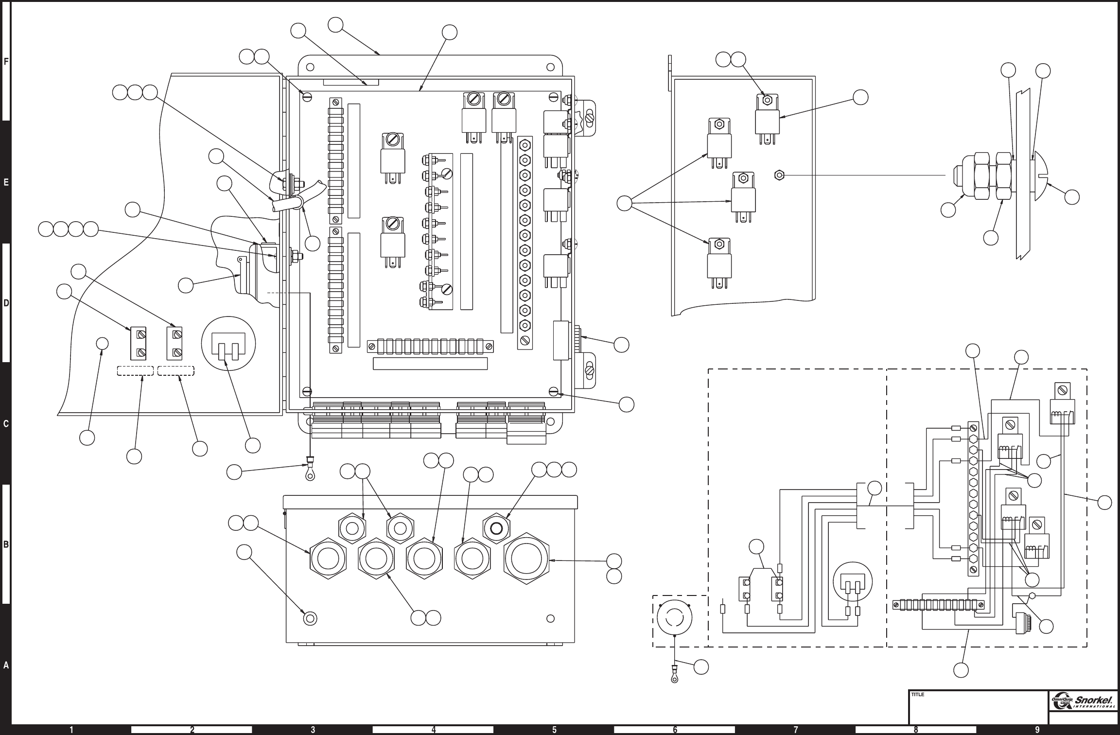
Page3-41
Wiring box
Ford LRG-425
Snorkel model TB 60
3
38
55
1B
1A
38
3
1B
55
IC
1A
+-
GROUND
(-)
(+)
BRASS SILVER
GREEN
44
WIRING BOX WIRING
TIE BACK
THROTTLE
15 AMP
MAIN
25 AMP
37
7
HOURMETER
46
52
51
42
47
46
50
40
1A
1B
1
2
5C
6
26
27
164
55
1D
38 RUN
RELAY
85
86
87
30
87A
HARD
START
RELAY
30
87A
87
86
85
BOOM
START
RELAY
DUAL
FUEL
RELAY
85
86
87
30
87A
85
86
87
30
87A
78
77B
77A
126
167
34
16B
16
5
4A
4
164B
31 27
3
3
FAST
START
RELAY
RUN
RELAY
BOOM
START
RELAY
DUAL
FUEL
RELAY
41
41 28
12 111
2
ADDCO
ACTUATOR
(DZ)
BOOM
SW
PROX.
SW
ENGINE
12/8
T/T18/1218/12
1918
19 18
1850
16
15
432221
22 21
17 18
45
44
36 35 34
33 32 26 25
8
7
9
10
13
5
4
6
48
14
41
INSIDE VIEW
SIDE VIEW
GROUND SCREW
30
27
31
29 28
GROUND
AW0082689
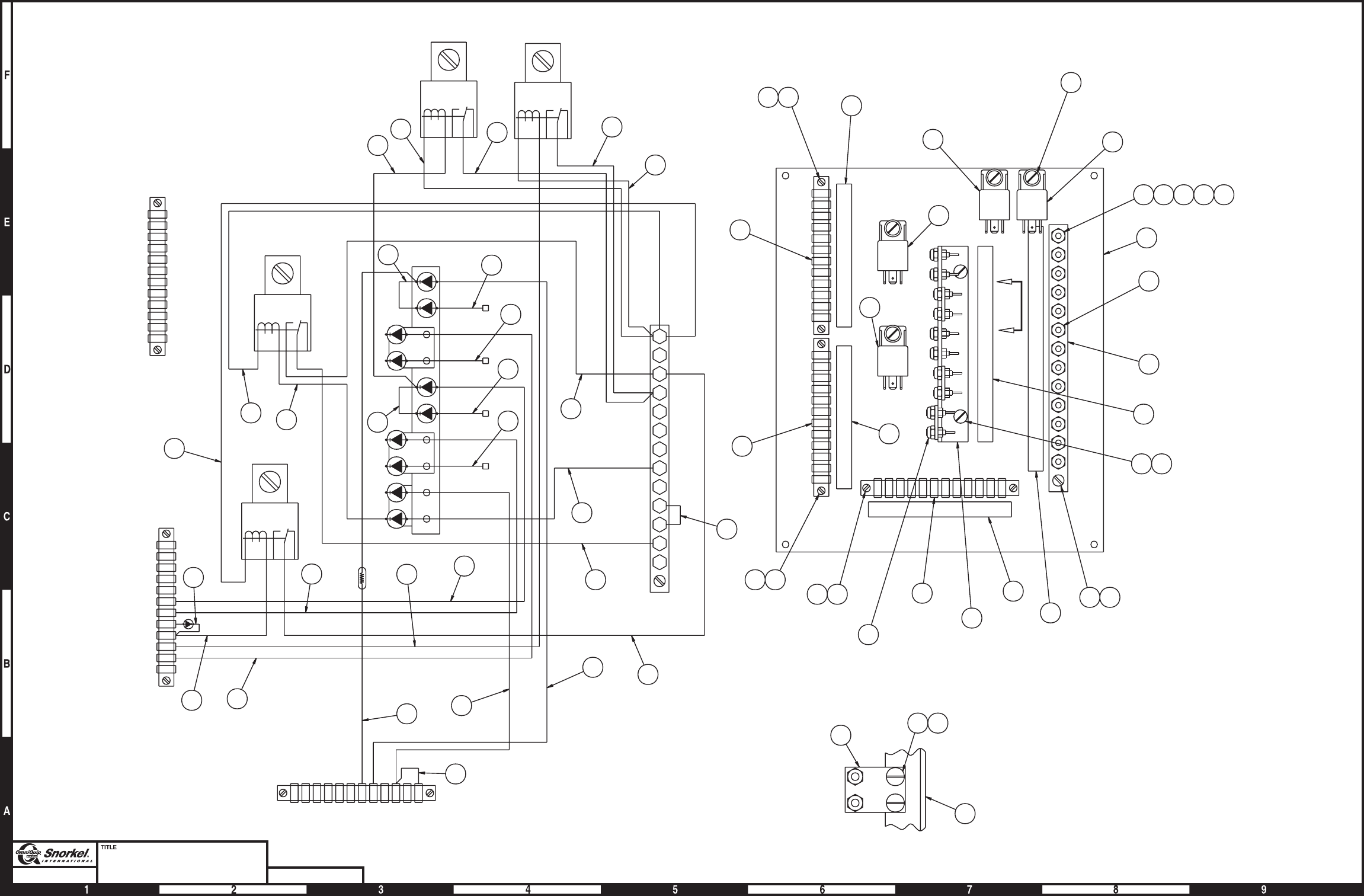
Page3-42
Wiring box panel
Ford LRG-425
Snorkel model TB 60 DWG. 0082688
3
1A
11
21C
22A
170
122
78
164B
16
6
MED
THROT HIGH
THROT
AUX
TILT
17
8
15 16
20
17
14 18
4
5
10
3
11
6
7
4419
4419
3
3
4419
A
A
2
11
1
39 40 18
18
22A
22B
22C
23
24
25
28
70
73
125
160
170
122
11
12
13
14
15
17
18
19
20
21A
21B
21C
85
86
87
30
87A
85
86
87
30
87A
85
86
87
30
87A
85
86
87
30
87A
16
16A
160
160A
25
31
28
28A
4A
6
78
77B
77A
126
167
34
16B
16
5
4A
4
164B
38
1D
3
164
27
26
6
5C
2
1
1B
1A
55
42
27 26
28
36 28
28
30
34
35 31
32
32
32
32
33
22
33
23
37
38 37
AUX.
RELAY
TILT
RELAY
MED
THROTTLE
RELAY
HIGH
THROTTLE
RELAY
38
24
29
41
31
9
25
VIEW A-A
10
21
17 16
8
8
8
AW0082688

Wiring box panel, Ford LRG-425
item part no qty description
0082688 1 Wiring box panel, Ford LRG-425
1 0180796 1 Panel, drilled
2 3044712 1 Terminal strip, 12 circuit #10 stud
3 3040433 3 Terminal strip, 12 circuit .187 tab slip-on
4 0181552 1 Decal, power wire
5 0181553 1 Decal, terminal strip
6 0181107 1 Decal, control wire #2
7 0181106 1 Decal, control wire #1
8 3040469 4 Relay, 12 volt DC
9 0181113 1 Jumper wire
10 0150488 1 Diode holder
11 5560038 22 Nut #10-32 self locking
12 974239 1 Machine screw #6-32 x 1/2 inch long round head
13 986159 3 Washer #6 medium flat
14 974689 1 Machine screw #10-24 x 3/4 inch long round head
15 974729 1 Machine screw #10-24 x 1-1/4 inch long round head
16 5560034 7 Nut #10-24 self locking
17 5560609 12 Machine screw #10-24 x 1/2 inch long truss head
18 987089 3 Washer #10 medium lock
19 987349 10 Washer #6 medium lock
20 0181554 1 Decal, diode
21 0073631 3 Diode stand off
22 0070681 1 Jumper wire
23 0070711 1 Jumper wire
24 0071812 2 Jumper wire
25 0110458 1 Jumper wire
26 0070682 1 Diode wire
27 0181073 1 Resister wire - (5 ohm)
28 0140317 3 Diode wire
29 0151205 1 Jumper wire
30 0081560 1 Jumper wire
31 0070724 2 Jumper wire
32 0180110 4 Diode wire
3040108 1 Replacement diode
33 0181031 2 Jumper wire
34 0081559 1 Jumper wire
35 0081515 1 Jumper wire
36 0181030 1 Diode wire
37 0181136 2 Jumper wire
38 0181111 2 Jumper wire
39 984049 1 Nut #10-24 hex
40 5560654 1 Washer #10 star tooth lock
41 0170335 1 Diode wire
42 0110471 1 Diode wire
TB 60 – 01-97 through 01-01 3-43
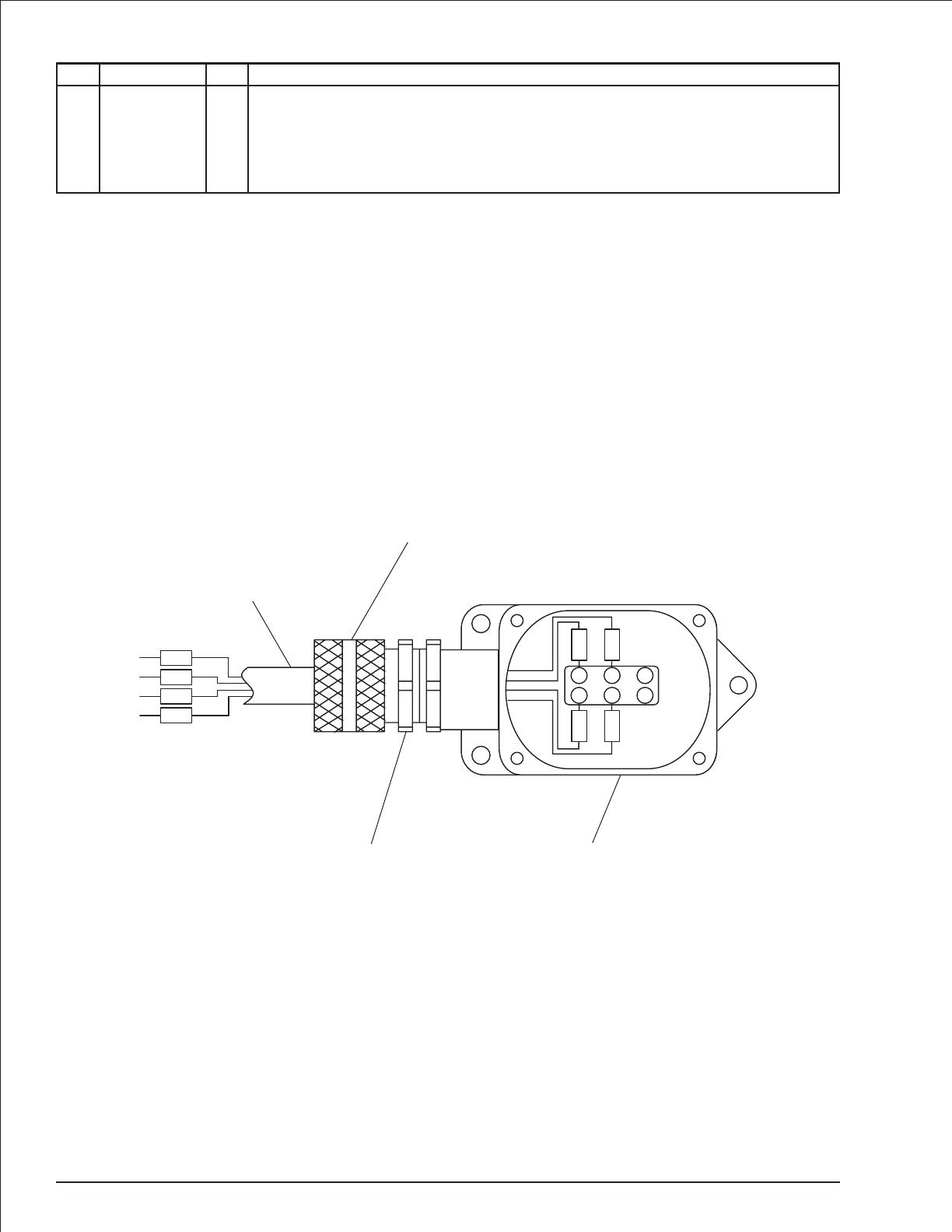
Boom switch
item part no qty description
0081975 1 Boom switch
1 3020019 1 Switch
2 0081976 1 wire harness, boom switch
3 3040187 1 Connector
4 3040070 1 Locknut
3-44 TB 60 – 01-97 through 01-01
3
41
2
70
1D
NO
NO
C
C
NC
NC
11
34
1D
70
11
34
AW0081975
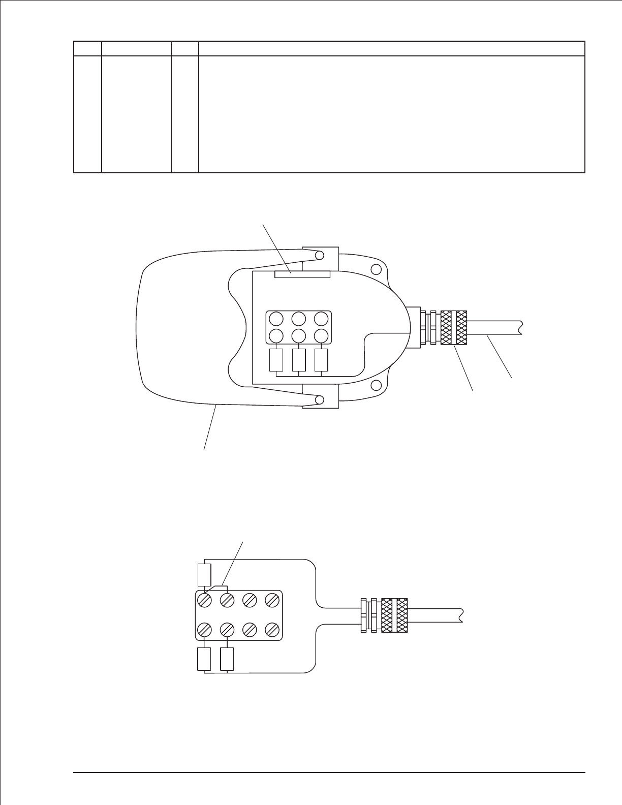
Platform foot switch
item part no qty description
0071800 1 Platform foot switch
1 3020021 1 Foot switch
3020037 1 Replacement switch, Square D switch
3020038 1 Replacement switch, Linemaster switch
2 0070596 1 wire harness, platform foot switch
3 3040116 1 Connector
4 3040110 1 Locknut
5 0070967 1 Corrosion inhibitor
6 0060373 1 Jumper strap - (used on Square D switch only)
TB 60 – 01-97 through 01-01 3-45
2
3
4
1
C
C
NO
NO
NC
NC
10
9
8
5
Foot switch wiring shown for
Square D switch
Foot switch wiring shown for
Linemaster switch
8
10
9
2B2A1A1B
6
AW0071800


Upper control box
item part no qty description
0081986 1 Upper control box
1 0180842 1 Control box
2 0180846 1 Placard, upper control box front
3 0082014 1 Placard, upper control box top
4 3040068 1 Circuit breaker, 20 amp capacity
5 3040535 3 Circuit breaker, 3 amp capacity
6 0073295 1 Jumper wire
7 3020020 1 Switch, emergency stop push/pull
3040194 1 Replacement switch knob
8 0070967 1 Corrosion inhibitor
9 3020080 1 Switch, toggle
10 3020018 3 Switch, toggle
11 3040469 1 Relay, 12 volt DC
12 3040493 1 Controller, lift/swing - (see page 3-54 for parts breakdown)
13 3040492 1 Controller, drive/steer - (see page 3-52 for parts breakdown)
14 3040057 1 Terminal strip, 18 circuit .188 tab slip-on
15 3040433 1 Terminal strip, 12 circuit .188 tab slip-on
16 3044710 1 Terminal strip, 10 circuit #10 stud
17 0180949 1 Speed control switch
3040497 1 Replacement switch
18 3040348 1 Switch knob
19 3040411 1 Mini siren, engine alarm
20 3040188 1 Relay, 12 volt DC
21 0071557 1 Jumper wire
22 0072530 1 Decal, danger electrical hazard
23 7190001 1 Gasket, weatherproof x 72 inch long
24 3040031 1 Hole plug, 3/4 inch diameter
25 5560649 1 Machine screw #10-24 x 1 inch long truss head
26 3040110 4 Locknut
27 3040285 1 Connector
28 3040116 3 Connector
29 3040295 1 Connector
30 5569003 1 Grommet - (before 4-11-00)
31 3020090 1 Switch, anti-restart ignition
32 974279 3 Machine screw #6-32 x 3/4 inch long round head
33 987349 10 Washer #6 medium lock
34 986159 14 Washer #6 medium flat
35 984009 10 Nut #6-32 hex
36 974689 1 Machine screw #10-24 x 3/4 inch long round head
37 5560034 3 Nut #10-24 self locking
38 5560038 14 Nut #10-32 self locking
39 974239 6 Machine screw #6-32 x 1/2 inch long round head
40 5560086 2 Capscrew 1/4-20x1inchlonghexplated with sems
41 5560004 4 Nut 1/4-20 self locking
42 0180886 1 Decal, power wire
43 0180887 1 Decal, control wire #1
44 0180888 1 Decal, control wire #2
45 0180850 1 Wire harness, upper control box power
46 0082007 1 Wire harness, upper control box control
47 974269 1 Machine screw #6-32 x 1 inch long round head
48 0060373 3 Jumper strap
49 0070747 5 Jumper wire
50 0151910 2 Jumper wire
Parts list continued on next page
TB 60 – 01-97 through 01-01 3-47

Upper control box
item part no qty description
51 0070730 3 Jumper wire
52 0070711 1 Jumper wire
53 0070712 3 Jumper wire
54 5560654 1 Washer #10 star tooth lock
55 0240483 1 Jumper wire
56 0181074 1 Jumper wire
57 0071511 1 Jumper wire
58 0071534 1 Jumper wire
59 0090622 2 Jumper wire
60 3044161 1 Terminal #10 stud insulated 16/14 wire
61 0181028 2 Jumper wire
62 0110468 1 Jumper wire
63 0151816 1 Jumper wire
64 0070713 1 Jumper wire
65 3040046 1 Terminal .250 tab male slip-on fully insulated 22/18 wire
66 3020013 2 Switch, toggle
67 0181030 1 Jumper wire
68 0181029 1 Jumper wire
69 480652 1 Alarm, tilt sensor
70 5569711 1 Grommet
71 0070746 3 Jumper wire
72 986019 2 Washer 1/4 medium flat
73 5560341 1 Washer 1/4 star tooth lock
74 970029 2 Capscrew 1/4-20 x 3/4 inch long hex head grade 5
75 984049 2 Nut #10-24 hex
76 5560663 1 Washer #6 star tooth lock
3-48 TB 60 – 01-97 through 01-01
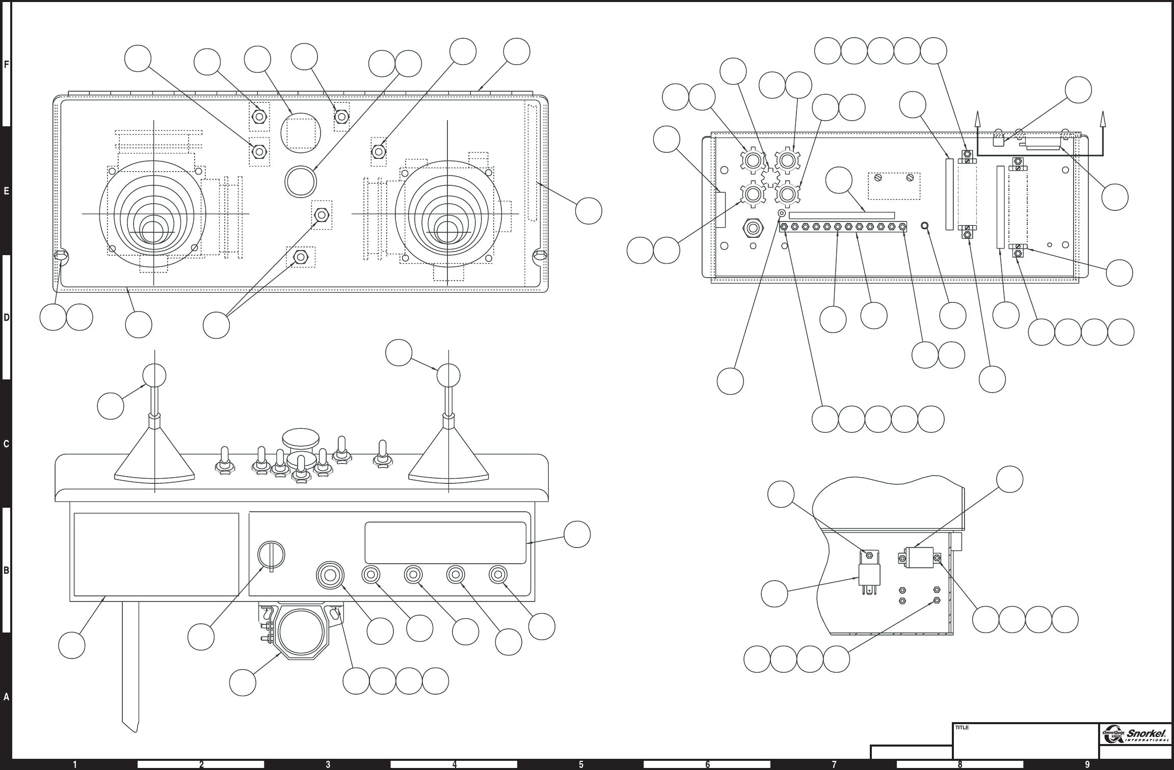
Page3-49
Upper control box
sheet 1
Snorkel model TB 60
DWG. 0020420
35 34 33 39
3
12
22
FILL HOLES
6776
76
26 271
ENGINE
ALARM
TILT
ALARM
69 72417374
35343339
10
10
37
11
11
AA
555
9
7
26 28
2629
37
36
375425
38 16
30
8
24
28 26 26 27
70
42
15
43
44
35343332
14
35 34 33 47
20
66 18 17 66
23
1
4140
31
2
19 4
13
TILT ALARM
RELAY
20
Section A-A AW0081986-1
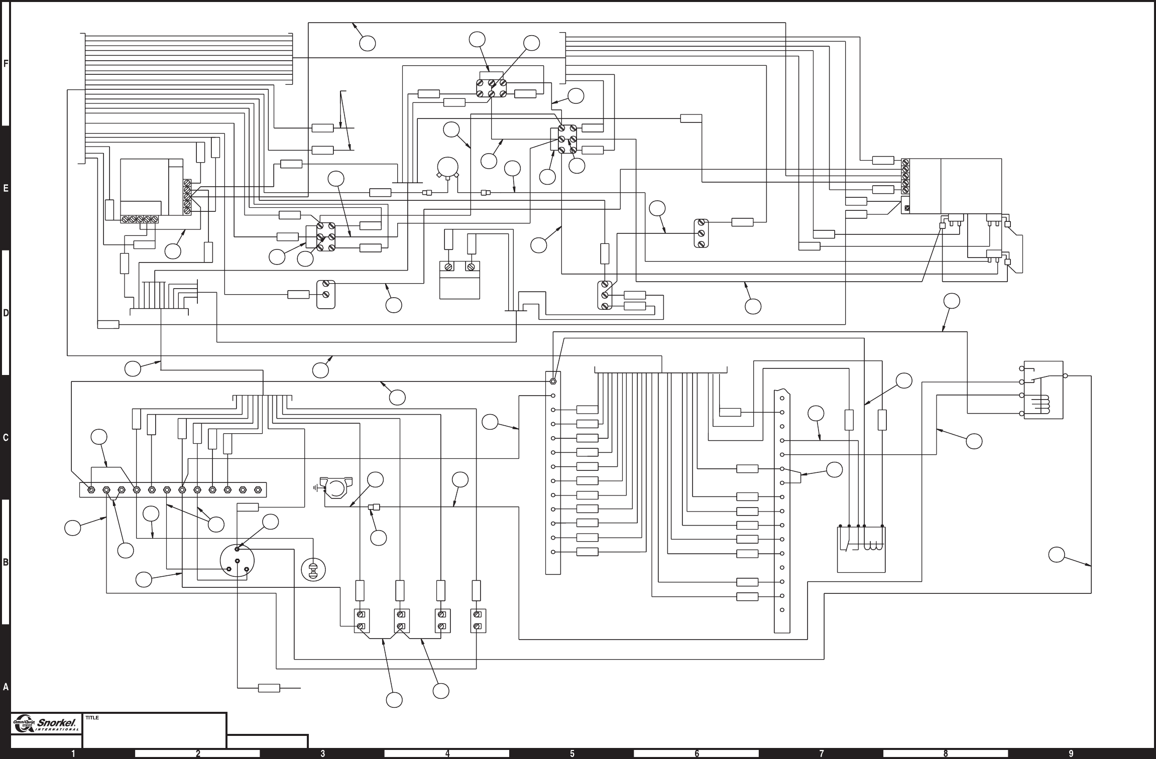
Page3-50
Upper control box
Sheet 2
Snorkel model TB 60 DWG. 0081986-2
58
6721
50
IGN
STRT
BATT ACC
ENG.
ALARM
MASTER
SWITCH
SWING
C/B
LIFT
C/B
+
-
52
55
53
53
DRIVE
C/B
CIRCUIT
BREAKER
123689102627
28
20
19
18
4
11
17
16
15
14
13
12
170
160
139
125
73
70A
70
25
24
23
22C
22B
22A
21C
21B
21A
7
B
A
2
5
TILT ALARM
RELAY
NC NO
C
NC NO
C
NC
NO
C
DRIVE
STEER
B
X
-
+
A
18
17
DRIVE
RANGE
EM
PWR
LEV
PLAT ROT
48
SPEED
SWITCH
EM
STOP
ENG
SPD
EXT
48
BX-+A
SWING
A
+
-
X
B
MAIN
LIFT
71
63
TILT
ALARM
49
49
64
ENGINE
SPEED
RELAY
61
6
59
46
70A
70A
56
20
19
69
6
4C
4
61
10
1C
16
12
13
3
26
9
27
21C
22C
15
14
125A
54
160
25
24
67
23
21B
68
22B
70A
1C
69
68
67
3
6
9
10
26
27
4C
70A
25
24
23
22B
22C
21B
21C
160
20
19
18
17
16
15
14
13
12
4
125A
70A
59
11
51
TIE BACK
48
51
51
71
71
11
65
-
+
49
50
49
57
5
85
86
87
30
87A
R
62
68 38
TO ENGINE
STARTER
45
49
AW0081986-2
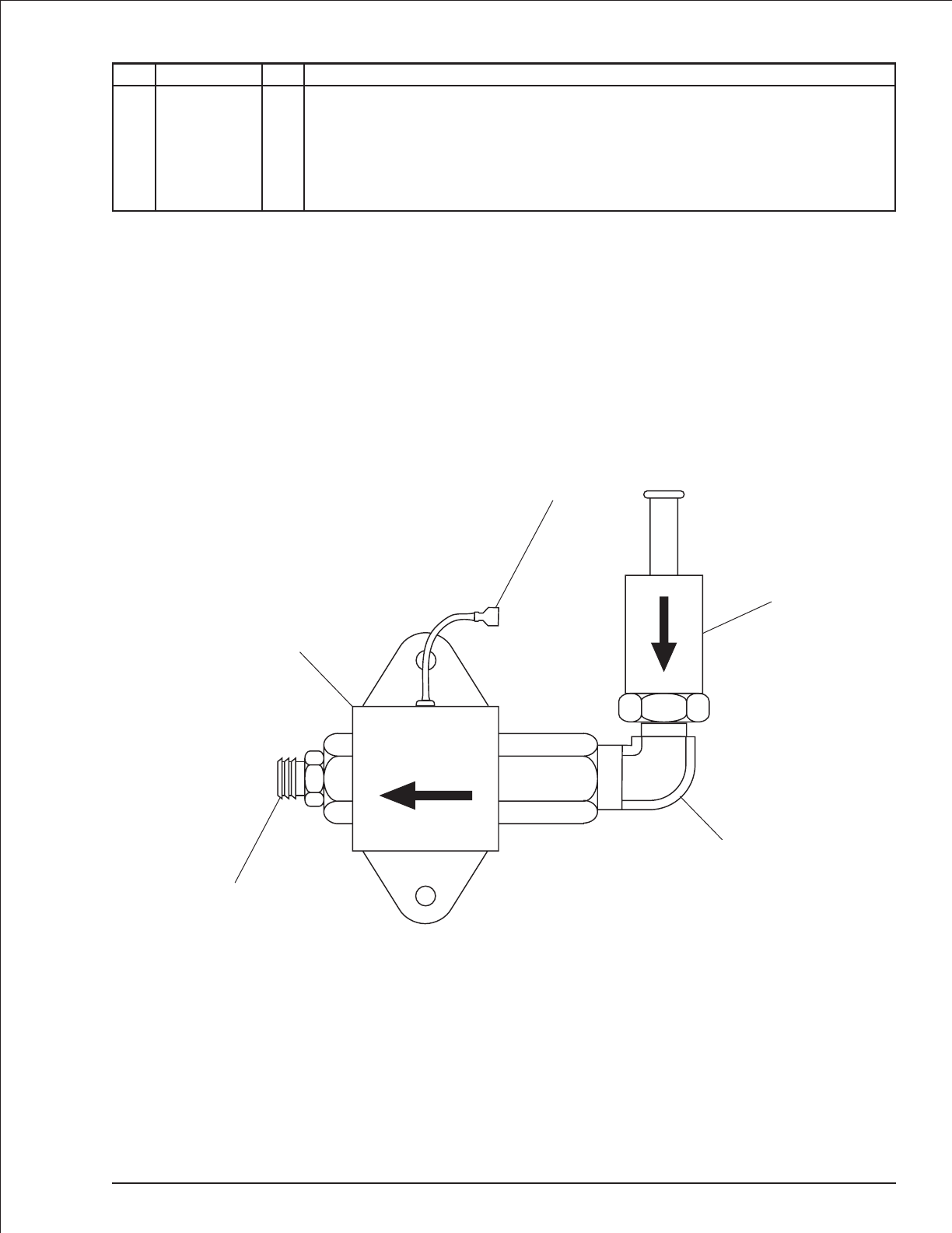
Electric fuel pump
item part no qty description
0111868 1 Electric fuel pump complete
1 7630085 1 Electric fuel pump
2 5090006 1 Street 90° elbow, brass
3 7630153 1 Fuel filter
4 5090035 1 Vacuum fitting
5 3040082 1 Terminal .250 tab male slip-on fully insulated 16/14 wire
TB 60 – 01-97 through 01-01 3-51
4
1
2
3
5
FLOW
AW0111868

Controller, drive/steer
item part no qty description
3040492 1 Controller, drive/steer
1 2660002 1 Knob
2 3040086 1 Shaft
3 3040146 1 Boot
4 8150145 1 Ring
5 8150146 1 Tension clip
6 3040169 1 Boot clamp ring
7 8150147 2 Cam
8 8150009 1 Fixed cam
9 8150135 4 “E” clip
10 8150148 1 Modified bracket
11 8150138 4 Insulator
12 8150139 2 Insulator
13 3020033 6 Microswitch
14 8150136 2 Cam spacer
15 8150149 1 Brass washer
16 8150005 2 Spring return with housing
17 8150004 2 Spring return bolt
18 8150150 2 Washer
19 8150144 2 Washer split 5M black
20 8150143 2 Nut 5M hex
21 8150003 1 Casting, modified
22 3040271 4 Bushing
23 8150094 1 Second axis
24 8150151 1 Bracket, right side
25 8150152 1 Bracket, left side
26 3040073 1 Drive gear
27 3040072 1 Slave gear
28 8150082 2 Blank cam shaft
29 8150013 4 Tension pin
30 8150153 1 Heat sink
31 8150140 4 Screw #4-40 x 1-1/4 inch long
32 8150137 4 Screw #4-40 x 3/4 inch long
33 3040392 1 Pot with bracket and connector
34 8150084 2 Fixed cam
35 8150154 2 Screw metric M4 x 6mm long din 85
36 8150155 2 Washer metric M4
37 8150141 2 Washer metric M3.5 x 16mm long din 85
38 8150156 4 Washer
39 8150142 1 Gate for drive/steer controller
40 3040518 1 Circuit board, 33 Hertz - (trim pots not preset, controller adjustment required)
3-52 TB 60 – 01-97 through 01-01
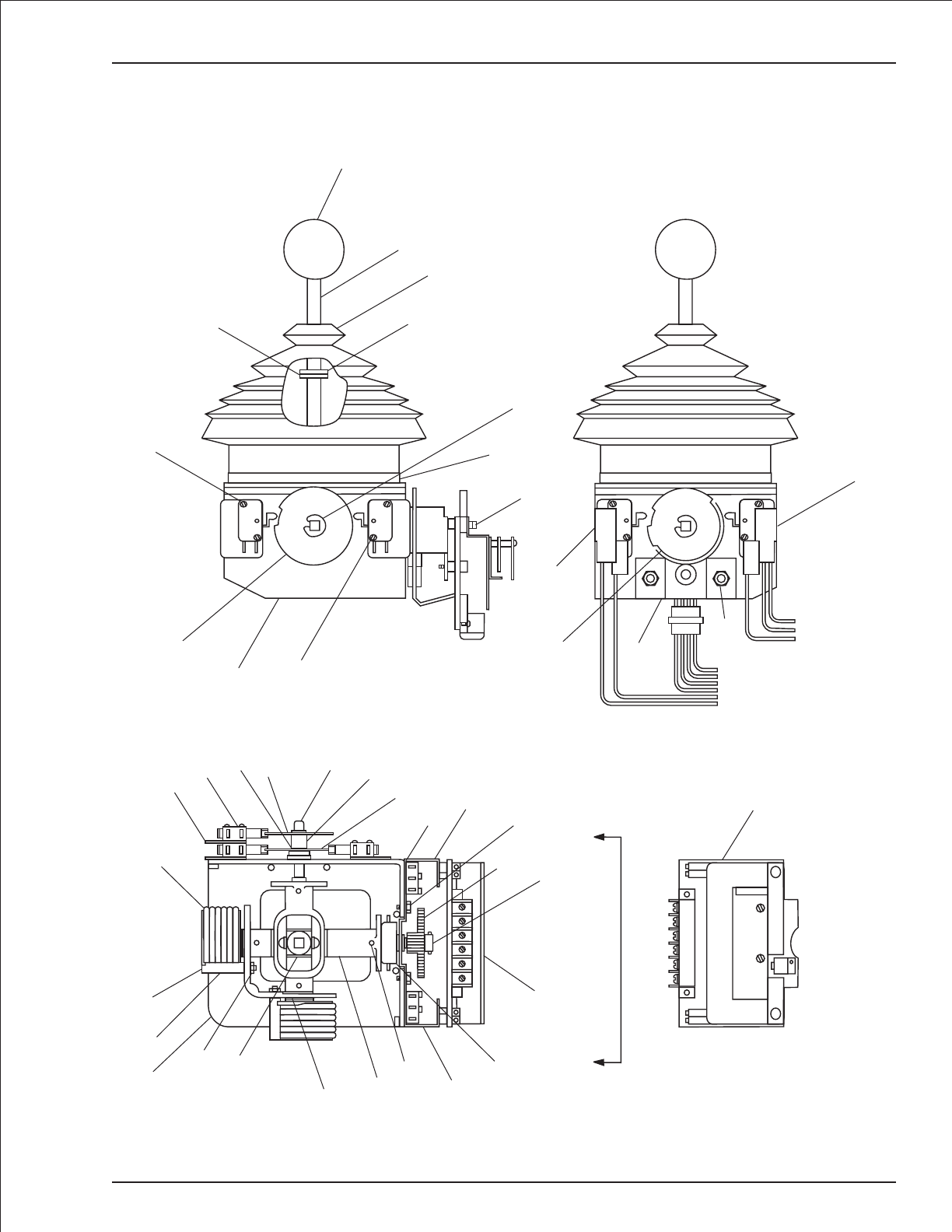
Controller, drive/steer
TB 60 – 01-97 through 01-01 3-53
1
A
AView A–A
A
+
-
X
B
R
39
14
13
11
16
17
18
21
2
22 23 24
33
30
26
25
15 728
34
12 35
36
27 28
29
19
20
}
}
To P.C.
Board
To P.C.
Board
24
10
25
7
9
4
3
2
5
31
32
8
37 38
35
36
40
6
AW3040492

Controller, lift/swing
item part no qty description
3040493 1 Controller, lift/swing
1 2660002 1 Knob
2 3040086 1 Shaft
3 3040146 1 Boot
4 8150145 1 Ring
5 8150146 1 Tension clip
6 3040169 1 Boot clamp ring
7 8150009 1 Fixed cam
8 8150135 4 “E” clip
9 8150148 2 Modified bracket
10 8150138 4 Insulator
11 3020033 4 Microswitch
12 8150005 2 Spring return with housing
13 8150004 2 Spring return bolt
14 8150150 2 Washer
15 8150144 2 Washer split 5M black
16 8150143 2 Nut 5M hex
17 8150003 1 Casting, modified
18 3040271 4 Bushing
19 8150094 1 Second axis
20 8150151 2 Bracket, right side
21 8150152 2 Bracket, left side
22 3040073 2 Drive gear
23 3040072 2 Slave gear
24 8150082 4 Blank cam shaft
25 8150013 4 Tension pin
26 8150153 2 Heat sink
27 8150140 8 Screw #4-40 x 1-1/4 inch long
28 3040392 2 Pot with bracket and connector
29 8150154 4 Screw metric M4 x 6mm long din 85
30 8150155 4 Washer metric M4
31 8150141 4 Screw metric M3.5 x 16mm long din 85
32 8150156 8 Washer
33 3040518 1 Circuit board, 33 Hertz - (trim pots not preset, controller adjustment required)
3-54 TB 60 – 01-97 through 01-01
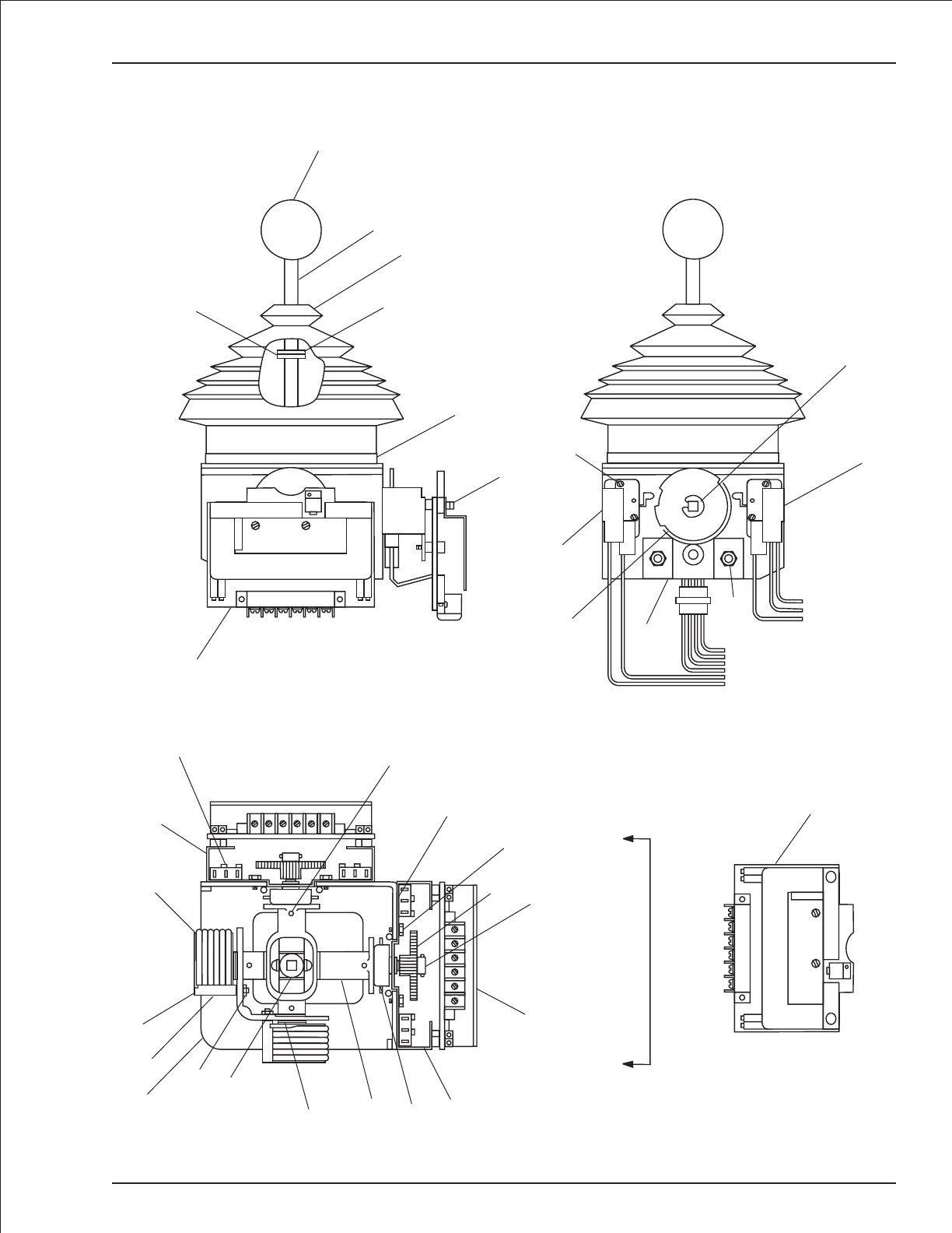
Controller, lift/swing
TB 60 – 01-97 through 01-01 3-55
View A–A
A
+
-
X
B
R
33
A
A
12
13
14
17
2
15
16 19 20
28
26
22
29
30
23 24
21
18
11 25
10
}
}
To P.C.
Board
To P.C.
Board
20
9
21
27
7
29
30
8
31 32
4
3
2
1
5
33
A
+
XBR
-
6
AW3040493
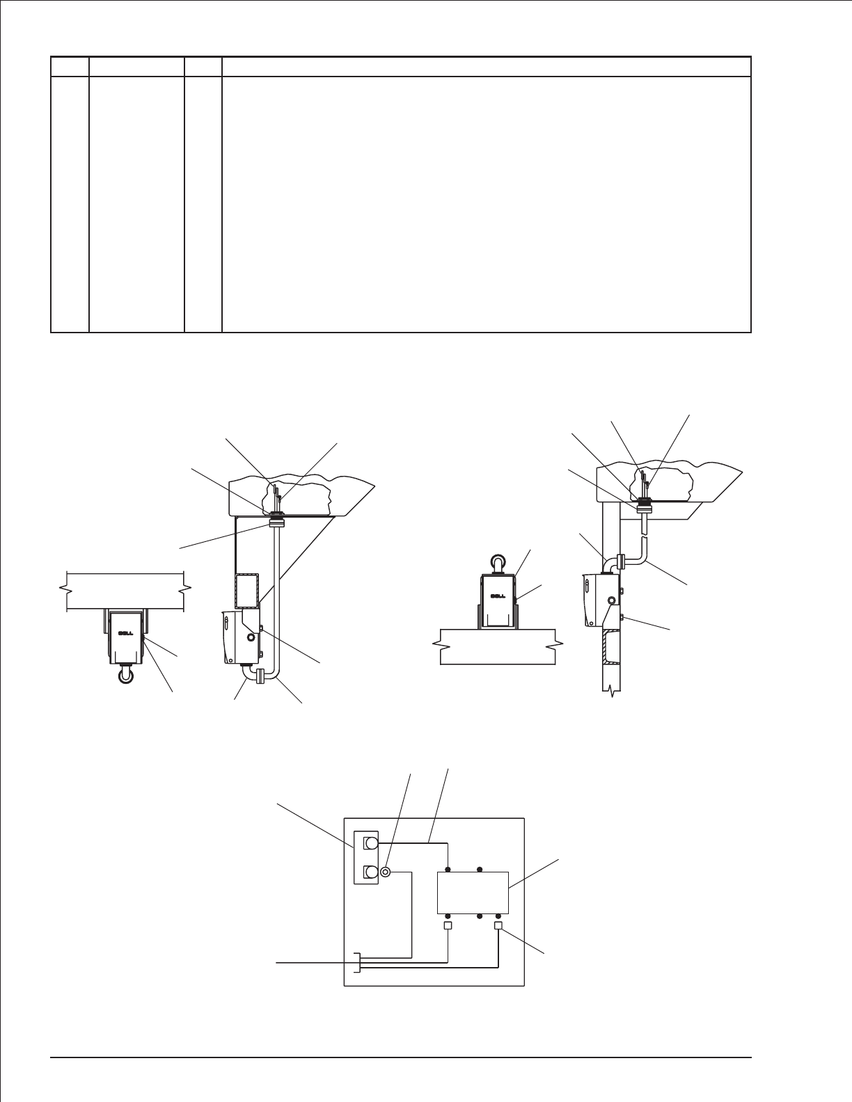
GFCI 110 volt power
item part no qty description
1 3040252 1 Circuit breaker, 15 amp capacity
2 3044854 1 Terminal ring tongue insulated 12/10 wire
3 0071582 1 Jumper wire
4 3040624 1 Receptacle, GFCI outlet - 20 amp
5 3040397 2 Terminal #8 spade 12/10 wire
6 3040691 1 Connector
7 0074368 1 Cable, 110 volt power to platform - (used on aluminum platforms only)
8 3040116 1 Connector
9 3040110 1 Locknut
10 3044072 2 Terminal butt connector insulated 12/10 wire
11 3044836 1 Terminal ring tongue insulated 12/10 wire
12 0074379 1 Electrical box, drilled
13 3040625 1 Cover, GFCI outlet
14 0074369 1 Cable, 110 volt power to platform - (used on steel platforms only)
15 978629 2 Capscrew 1/4-20 x 1/2 inch long hex head self tapping
3-56 TB 60 – 01-97 through 01-01
BRASS
SILVER GREEN
BLACK WHITE GREEN
Aluminum platform
1
4
12
13
15
67
11
10
9
8
Steel platform
1
4
12
13
15
14
11
10
9
8
6
To platform
110 volt outlet on platform
1
23
4
5
AWA07034

Upper control box, proportional
item part no qty description
0111893 1 Upper control box, proportional
1 0111928 1 Control box
2 0180846 1 Placard, upper control box front
3 5560663 1 Washer #6 star tooth lock
4 3040068 1 Circuit breaker, 20 amp capacity
5 3020080 1 Switch, toggle
6 3040116 2 Connector
7 3040110 5 Connector locknut
8 3040493 1 Controller, lift/swing - (see page 3-54 for parts breakdown)
9 3040492 1 Controller, drive/steer - (see page 3-52 for parts breakdown)
10 3040285 1 Connector
11 3020018 2 Switch, toggle
12 0101878 1 Jumper wire
13 3020013 2 Switch, toggle
14 5560648 1 Machine screw #10-24 x 3/4 inch long truss head
15 5560034 4 Nut #10-24 self locking
16 0180886 1 Decal, power wire
17 5560038 10 Nut #10-32 self locking
18 3044710 1 Terminal strip, 10 circuit #10 stud
19 3040057 1 Terminal strip, 18 circuit .188 tab slip-on
20 0180887 1 Decal, control wire #1
21 974279 3 Machine screw #6-32 x 3/4 inch
22 986159 4 Washer #6 medium flat
23 987349 4 Washer #6 medium lock
24 984009 4 Nut #6-32 hex
25 3020080 1 Switch, toggle
26 3040469 2 Relay, 12 volt DC
27 3040535 3 Circuit breaker, 3 amp capacity
28 480652 1 Siren, tilt alarm
29 0070967 1 Corrosion inhibitor
30 0072530 1 Decal, danger electrical hazard
31 0151910 1 Jumper wire
32 0180850 1 Wire harness, upper control box power
33 0082007 1 Wire harness, upper control box control
34 3040295 1 Connector
35 3040433 1 Terminal strip, 12 circuit .188 tab slip-on
36 987089 1 Washer #10 medium lock
37 7190001 1 Gasket, weatherproof x 72 inch long
38 0180888 1 Decal, control wire #2
39 0070713 1 Jumper wire
40 974269 1 Machine screw #6-32 x 1 inch long round head
41 0072388 1 Jumper wire
42 986019 2 Washer 1/4 medium flat
43 0070746 2 Jumper wire
44 0070753 1 Jumper wire
45 0060373 2 Jumper strap
46 0070712 3 Jumper wire
47 0181029 1 Jumper wire
48 986009 1 Washer #10 medium flat
49 984069 2 Nut 1/4-20 hex
50 0070711 1 Jumper wire
Parts list continued on next page
TB 60 – 01-97 through 01-01 3-57

Upper control box, proportional
item part no qty description
51 5560703 1 Washer #10 star tooth lock
52 984049 1 Nut #10-24 hex
53 0110468 1 Jumper wire
54 0090622 2 Jumper wire
55 0181103 1 Jumper wire
56 0071557 1 Jumper wire
57 0071812 1 Jumper wire
58 0151816 1 Jumper wire
59 3040411 1 Mini siren, engine alarm
60 5560609 2 Machine screw #10-24 x 1/2 inch long truss head
61 970029 2 Capscrew 1/4-20 x 3/4 inch long hex head grade 5
62 5560004 2 Nut 1/4-20 self locking
63 5569711 1 Grommet
64 0073295 2 Jumper wire
65 5560649 2 Machine screw #10-24 x 1 inch long truss head
66 0110598 1 Jumper wire
67 3026027 1 Switch, push button
68 7140092 1 Switch seal
69 0071269 1 Placard, horn
70 0070733 1 Jumper wire
71 3040525 1 Controller, extend/retract
72 0110959 1 Placard, upper control box top
73 3020020 1 Switch, emergency stop push/pull
3040194 1 Replacement switch knob
74 0070922 1 Placard, platform rotation
75 0070747 4 Jumper wire
76 0181028 1 Jumper wire
77 0240483 1 Jumper wire
78 0070758 2 Jumper wire
79 0151556 1 Jumper wire
80 3040116 1 Connector
81 3040110 1 Connector locknut
3-58 TB 60 – 01-97 through 01-01
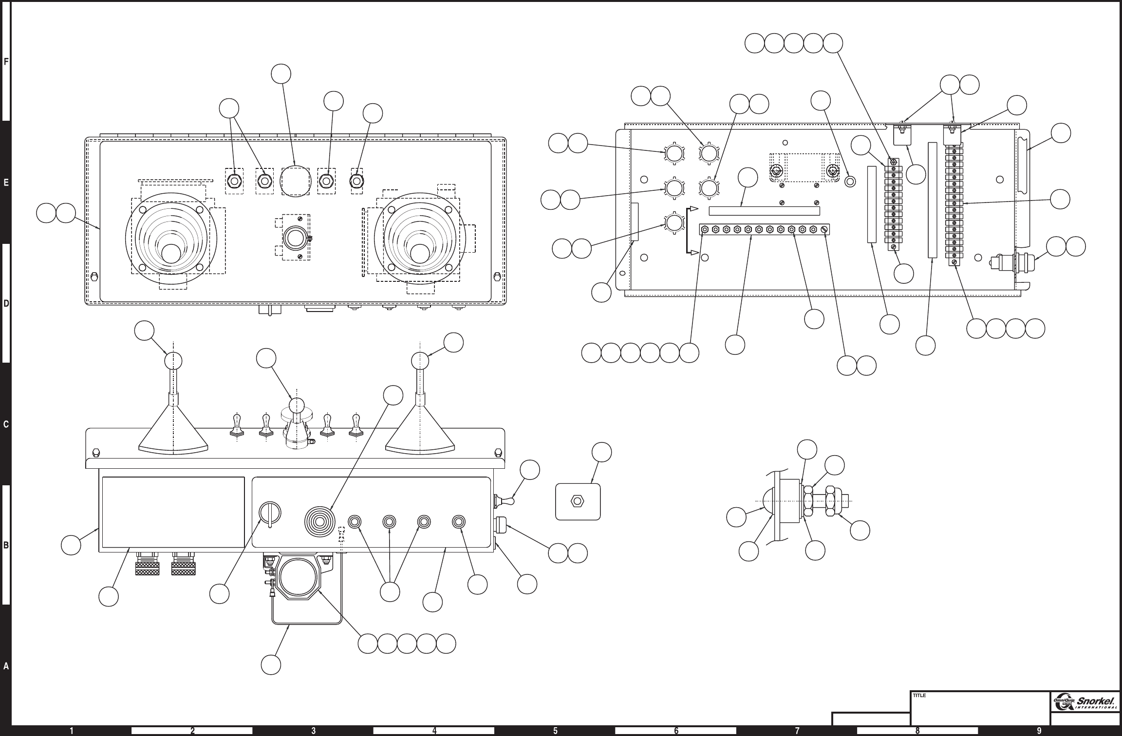
Page3-59
Upper control box
proportional, sheet 1
Snorkel model TB 60
DWG. 0111893-1
5
126 27
18/19 CONTROL
18/12 CONTROL
12/8 POWER
FOOTSWITCH
65
36
52
15
VIEW A-A
48
51
A
A
26
37
19
67 68
21 22 23 24
20
38
15 60
26
222324403
35
14 15
17
18
154852653651
29
67
67
710 734
16
63
13
100
73
11
25
8
1
30
71
67 68
69
4
2
27
55
28 61 62 42
9
11
74
59
155
21
8081
49
AW0111893-1

Page3-60
Upper control box
proportional, sheet 2
Snorkel model TB 60 DWG. 0111893-2
122
85
86
87A
87
30
TILT ALARM
RELAY
70A
125A
85
86
87
30
87A
ENGINE
SPEED
RELAY
21A
21B
21C
22A
22B
22C
23
24
25
70
70A
73
125
139
160
170/122
21B
160
22B
23
24
25
4
70A
11
12
13
14
15
16
17
18
19
20
28
4
11
12
13
14
15
17
18
19
20
1C
69
68
67
CIRCUIT
BREAKER
DRIVE
C/B
LIFT
C/B
SWING
C/B
+
-
ENGINE
ALARM
MASTER
SWITCH
TILT
ALARM
START
IGN
BATT
ACC
4C
12 368 910 26 27
27
26
10
9
6
3
27
26
6
4C
4
9
160
13
12
19
20
1C
10
15
14
B
X
-
+
A
18
17
69
70A
70A
EMER STOP
RANGE
THROTTLE
11
125
22
68
21
23
24
3
67
A
+
-
R
X
B
PLATFORM
ROTATOR
CCW
CW
64
53
54 64
29
HORN
BUTTON
(LOCATED ON RH
SIDE OF BOX)
39
12
44
43 66 78
43
41
45
76
33
25
75
R
TOP
BOTTOM
70
56
46
32
31
77
47
58
50
46
55
75
75
54
45
79
75
78
57
BOTTOM AND
SIDES OF BOX
A
+
-
R
X
B
LIFT
SWING
EMER
POWER
LEVEL
X
B
-
+
A
DRIVE
NO NC
R
NC NO
L
NO
AW0111893-2

Section 4. - Factory installed options
TB 60 – 01-97 through 01-01 4-1

AC generator mounting
item part no qty description
1 0151471 1 AC generator - (see page 4-5 for parts breakdown)
2 0073543 1 Shield
3 3020048 1 Switch, toggle
4 0151459 1 Placard, AC generator
5 0073544 1 Cable, 110 volt power AC generator
6 5093008 2 Clamp
7 3040046 1 Terminal .250 tab male slip-on fully insulated 22/18 wire
8 3040064 1 Terminal .250 tab male slip-on fully insulated 12/10 wire
9 0090757 2 Jumper wire
10 0070747 3 Jumper wire
11 0071517 3 Jumper wire
12 0071541 1 Jumper wire
13 0181187 1 Jumper wire
14 0101247 1 1/2 inch hydraulic hose
15 0100422 1 3/8 inch hydraulic hose
16 3011801 1 Wire 18 gauge single conductor x 15 feet long
17 3090019 1 Flexgard tube, 15 feet long
18 3040047 1 Terminal .250 tab female slip-on fully insulated 22/18 wire
19 3044146 1 Terminal #10 stud insulated 22/18 wire
20 0151583 1 Set-up and start procedure drawing
21 0111287 1 1/4 inch hydraulic hose
22 3040452 1 Insulator boot
23 5064001 1 Tube end reducer
24 5063905 1 Fitting nut
25 5036505 1 Straight thread branch tee
26 0100271 1 1/4 inch hydraulic hose
27 5036706 1 Swivel nut run tee
28 970909 2 Capscrew 1/2-13 x 1-1/2 inch long hex head grade 5
29 5560039 2 Nut 1/2-13 self locking
30 970009 2 Capscrew 1/4-20 x 1/2 inch long hex head grade 5
31 986019 2 Washer 1/4 medium flat
32 987099 2 Washer 1/4 medium lock
33 3044158 1 Terminal #6 stud insulated 16/14 wire
4-2 TB 60 – 01-97 through 01-01
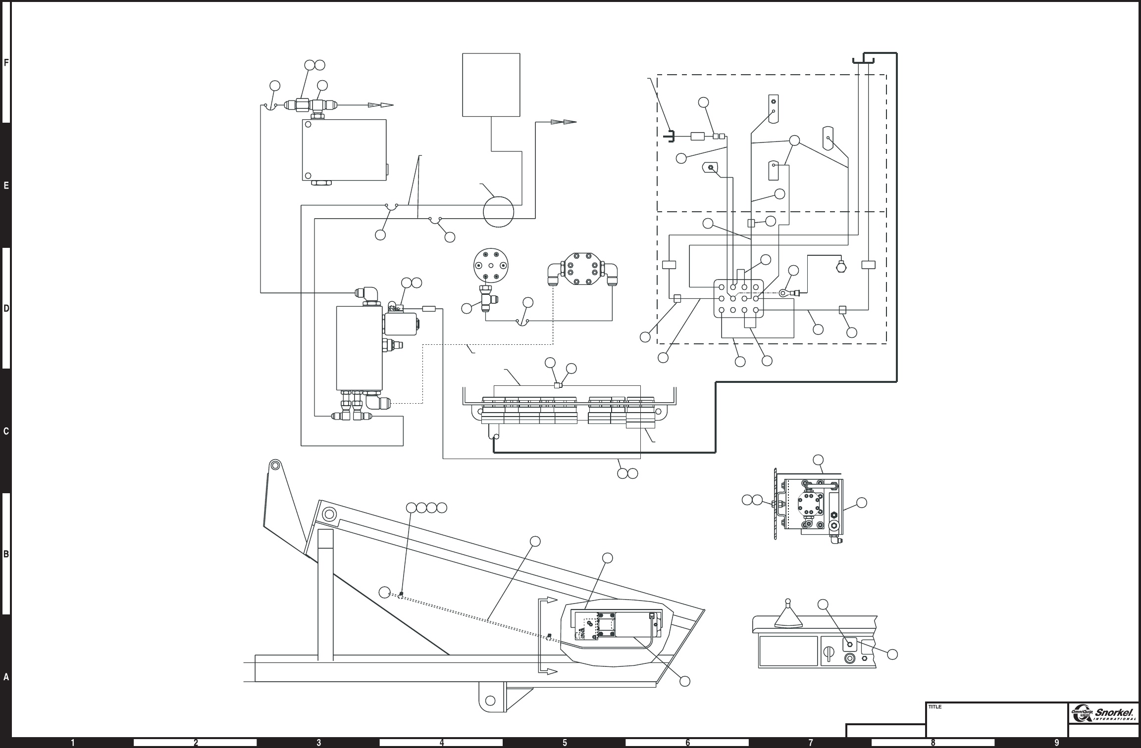
Page4-3
AC generator mounting
Snorkel model TB 60
DWG. 0082051
A
A
VIEW A-A
3
4
PLATFORM BOX
2
28 1
5
6 303132
2
1
29
25 169
SWING
FUSE
9
INTERNAL WIRE ASSY
18/19
BOOM WIRE
SV
FROM SENSE PORT
ON APITECH VALVE
CHECK
VALVE
HYDACGEN
MOTOR
STEEL TUBE
SPSM
P
HYDACGEN
VALVE
169
18 7
16
SPARE
BOOM WIRE
ENGINE WIRE
CONNECTOR
14
22
27
23
TO BULKHEAD
ANGLE
6" TURNTABLE
ACCESS HOLE
TY-RAP TO OTHER
HOSES AND WIRES
15
PLATFORM CONTROL
BOX WIRING
GROUND CONTROL BOX
10
33
10
10
11
13
8
25
12
VS
NON-PROP
PKG VALVE
21
26
7
7
9
9
7
9
24
19
17
56
7
14
3
2
9
28
4
25
CENTERPOST
AW0082051
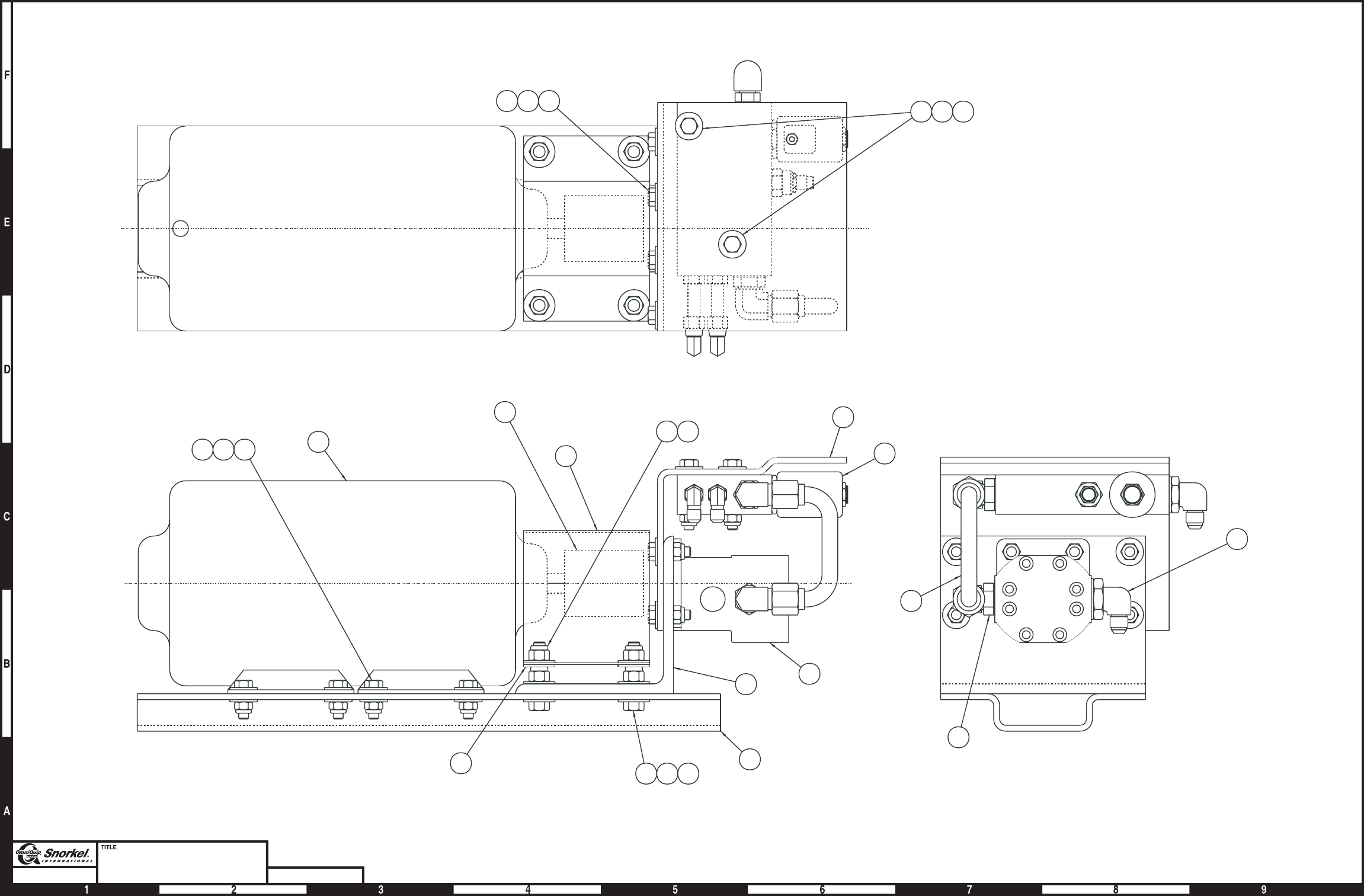
Page4-4
AC generator
Snorkel model TB 60 DWG. 0151471
9
10
5
7
17
2
18
4
8
3
18
1
16
11 14 19
15
12
6
1911
18 13
1911
Generator shaft and motor
must line-up for proper
coupling installation.
13
AW0151471

AC generator
item part no qty description
0151471 1 AC generator
1 3080001 1 Generator, AC hydraulic powered
2 0151457 1 Mount plate
3 7240012 1 Coupling
4 0151458 1 Motor mounting angle
5 6030029 1 Hydraulic motor, AC generator
8020018 1 Seal repair kit
6 0151469 1 Bracket, valve mounting
7 0152831 1 AC generator valve - (see page 2-23 for parts breakdown)
8 0151484 1 Coupling cover
9 0151470 1 1/2 inch hydraulic tube
10 5035306 1 Straight thread 90° elbow
11 5560031 18 Nut 5/16-18 self locking
12 5035320 1 Straight thread 90° elbow
13 5560033 8 Nut 3/8-16 self locking
14 970299 2 Capscrew 5/16-18x2inchlong hex head grade 5
15 970269 8 Capscrew 5/16-18 x 1-1/4 inch long hex head grade 5
16 970369 8 Capscrew 5/16-18x1inchlong hex head grade 5
17 970499 4 Capscrew 3/8-16 x 1-3/4 inch long hex head grade 5
18 986299 12 Washer 3/8 medium flat
19 986269 30 Washer 5/16 medium flat
TB 60 – 01-97 through 01-01 4-5

Air line to platform
item part no qty description
1 5240002 1 Hose reel
2 0081104 1 Air hose, 54 feet - 6 inch long
3 5550021 1 Cable guide, 4 roller
4 0080749 3 Cable guide bracket, base boom
5 0080752 1 Cable guide bracket, intermediate boom
6 5093006 2 Hose clamp
7 0080754 2 Mounting bar
8 0080762 2 Hose bracket
9 0080759 1 Angle
10 970849 2 Capscrew 1/2-13 x 1-1/4 inch long hex head grade 5
11 970426 10 Capscrew 3/8-16 x 7/8 inch long hex head grade 5
12 986359 4 Washer 1/2 medium flat
13 987119 14 Washer 3/8 medium lock
14 5093012 1 Hose clamp
15 5560039 4 Nut 1/2-13 self locking
16 970909 2 Capscrew 1/2-13 x 1-1/2 inch long hex head grade 5
17 970049 8 Capscrew 1/4-20 x 1 inch long hex head grade 5
18 972489 4 Capscrew 3/8-16 x 1-1/2 inch long hex head grade 5
19 986019 3 Washer 1/4 medium flat
20 5560004 6 Nut 1/4-20 self locking
21 5093010 2 Hose clamp
22 5560082 1 Trim lock, 1/4 inchx4inchlong - (used on hydraulic rotator machines only)
23 7714202 2 Pipe plug 1/4 NPT square head
4-6 TB 60 – 01-97 through 01-01
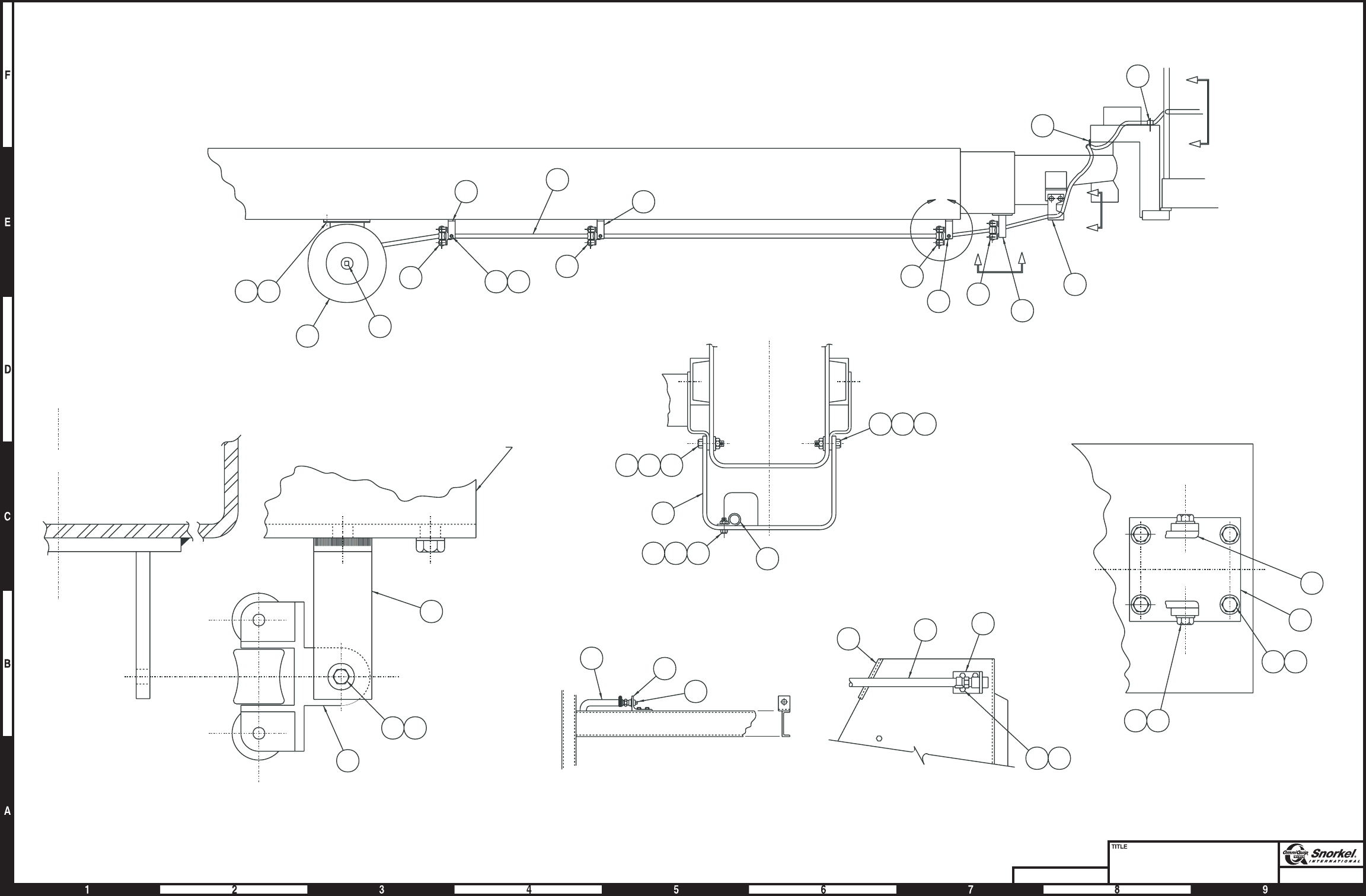
Page4-7
Air line to platform
Snorkel model TB 60
DWG. 0080699
View G-G
Hydraulic rotator
View F-F
Non-rotator
View D-D
Detail C
C
C
L
Boom
L
C
G
G
DD
10 12 15
6
8
171920
121516
3
5
13 18
1113
22 29
17 20
29
23
4
3
11 13
Front of base boom
123
1113
4
11 13
3
2
3
4
8
5
4
3
3
14
21 F
F
AW0080699
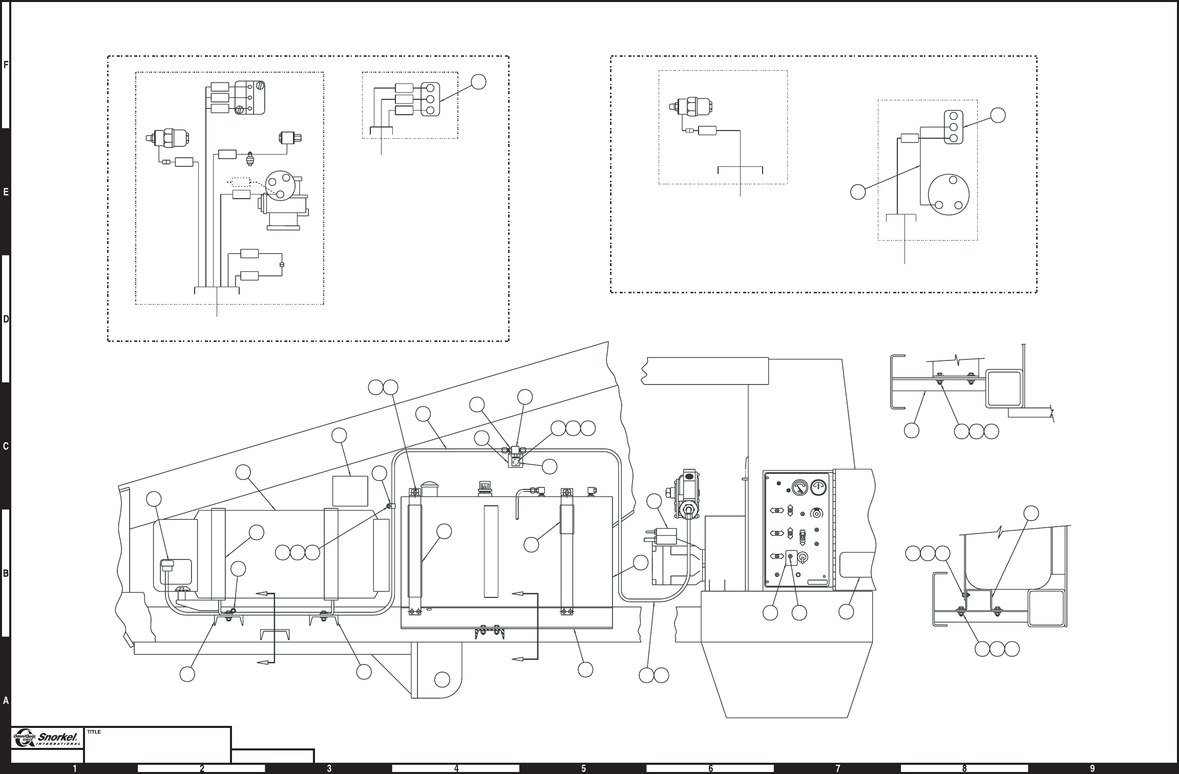
Page4-8
Dual fuel
Ford engine
Snorkel model TB 60 DWG. 0082685
78
ENGINE WIRE
ASSEMBLY
DUAL FUEL
SWITCH
ENGINE WIRE
ASSEMBLY
GROUND CONTROL PANEL
BAT
IGN ST
23
3
4
24
20 20
21
24
292219
2526
9
8
16 13 14
18
17
A
A
7
6
12
6
5
1011
1
B
B15
227 26 28
20
VIEW B-B
80D
SOL
STR
IGN
5C
77A
77B
78
80C
80D
77B
78
ENGINE WIRE
ASSEMBLY
DUAL FUEL
SWITCH
ENGINE WIRE
ASSEMBLY
CARBURETOR
FUEL
SHUT OFF
FILTERLOCK
VACUUM
SWITCH
CHOKE
77A
GROUND CONTROL PANEL
ENGINE FORD LRG-423
10
FUEL
SHUT OFF
SOLENOID
78A
78
27 26 28
293019
15
VIEW A-A
FILTERLOCK
77B
ENGINE FORD LRG-425
10
32
24
MASTER
SWITCH
Liquid withdrawal
AW0082685

Dual fuel, Ford engine
item part no qty description
1 0111927 1 Dual fuel engine, Ford LRG-423 - (see page 4-14 for parts breakdown)
0112100 1 Dual fuel engine, Ford LRG-425 - (see page 4-18 for parts breakdown)
2 0080668 1 Relief valve mount bracket
3 9940005 1 LP gas cylinder, liquid withdrawal 43.5 lb capacity
4 0070969 1 Bracket, LP gas cylinder - (includes left and right hand brackets)
5 0090493 1 Decal, dual fuel instructions
6 0090483 2 LP gas fuel hose
7 Kit item 1 Hydrostatic relief valve - (included in dual fuel kit 0073444)
8 Kit item 1 Straight thread adapter 1/4 NPT brass - (included in dual fuel kit 0073444)
9 Kit item 1 Bulkhead tee - (included in dual fuel kit 0073444)
10 3020017 1 Switch, toggle - (used on Ford LRG-423)
3020013 1 Switch, toggle - (used on Ford LRG-425)
11 0090492 1 Placard, dual fuel switch
12 0070331 1 Fuel tank, gasoline 20 gallon capacity
9940001 1 Replacement fuel tank cap
13 986269 1 Washer 5/16 medium flat
14 5560031 1 Nut 5/16-18 self locking
15 0080767 1 Fuel tank support
16 970369 1 Capscrew 5/16-18x1inchlong hex head grade 5
17 0080766 1 Spacer tube
18 0080326 1 Spacer tube
19 987099 5 Washer 1/4 medium lock
20 0072135 3 Channel support - (before 3-20-00)
0083507 3 Channel support, LP gas cylinder - (after 3-20-00)
21 0081441 1 Decal, caution liquid withdrawal
22 984069 5 Nut 1/4-20 hex
23 0070974 1 Coupler, female LPG
24 5093002 4 Hose clamp
25 970569 2 Capscrew 3/8-16 x 3-1/2 inch long hex head grade 5
26 984109 10 Nut 3/8-16 hex
27 972489 8 Capscrew 3/8-16 x 1-1/2 inch long hex head grade 5
28 986299 8 Washer 3/8 medium flat
29 970029 5 Capscrew 1/4-20 x 3/4 inch long hex head grade 5
30 0151815 1 Jumper wire - (used on Ford LRG-425 engine only)
TB 60 – 01-97 through 01-01 4-9

Dual fuel, Ford with 40 gallon gasoline tank
item part no qty description
1 0111927 1 Dual fuel engine, Ford LRG-423 - (see page 4-14 for parts breakdown)
2 0080668 1 Relief valve mount bracket
3 9940005 1 LP gas cylinder, liquid withdrawal 43.5 lb capacity
4 0070969 1 Bracket, LP gas cylinder - (includes left and right hand brackets)
5 0081553 2 Mounting bracket
6 0090483 1 LP gas fuel hose
7 Kit item 1 Hydrostatic relief valve - (included in dual fuel kit 0073444)
8 Kit item 1 Straight thread adapter 1/4 NPT brass - (included in dual fuel kit 0073444)
9 Kit item 1 Bulkhead tee - (included in dual fuel kit 0073444)
10 3020017 1 Switch, toggle
11 0090492 1 Placard, dual fuel switch
12 970369 1 Capscrew 5/16-18x1inchlong hex head grade 5
13 986269 1 Washer 5/16 medium flat
14 5560031 1 Nut 5/16-18 self locking
15 5093002 2 Clamp
16 0081441 1 Decal, caution liquid withdrawal
17 0090493 1 Decal, dual fuel instructions
18 0152108 1 LP gas fuel hose
19 970569 4 Capscrew 3/8-16 x 3-1/2 inch long hex head grade 5
20 986299 4 Washer 3/8 medium flat
21 5560033 4 Nut 3/8-16 self locking
22 987119 4 Washer 3/8 medium lock
23 0070974 1 Coupler, female LPG
4-10 TB 60 – 01-97 through 01-01
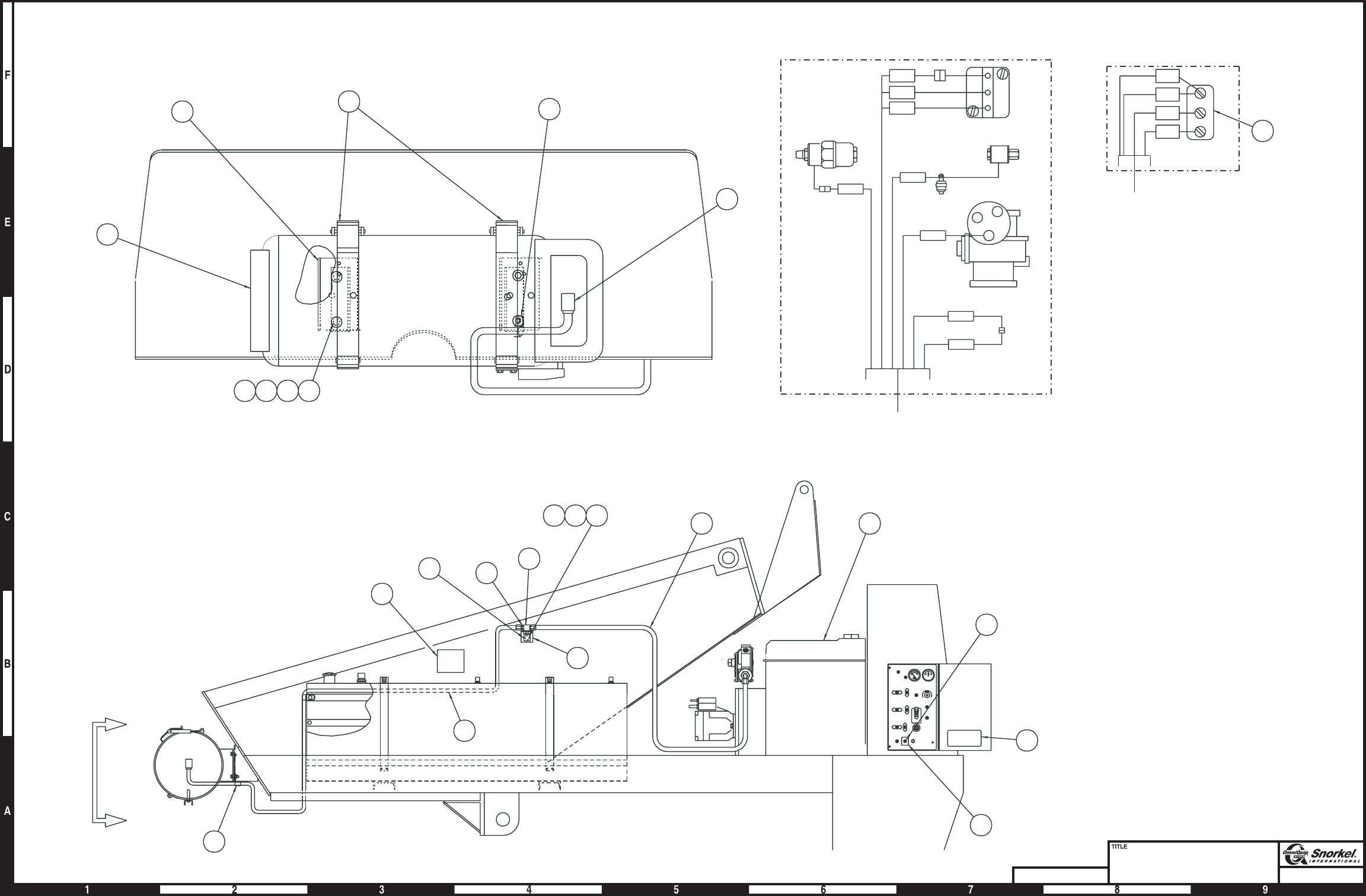
Page4-11
Dual fuel
Ford with 40 gallon gas tank
Snorkel model TB 60
DWG. 0082117
A
A
1
6
9
8
121314
17
11
10
VIEW A-A
3
4
19202122
23
10
15
18
15
FUEL
SHUT OFF
SOLENOID
78A
78B
78B
80D
SOL
STR
IGN
5C
77A
77B
78
80D
77B
78
ENGINE WIRE
ASSEMBLY
FORD LRG-423
DUAL FUEL
SWITCH
ENGINE WIRE
ASSEMBLY
FORD LRG-423
CARBURETOR
FUEL
SHUT OFF
FILTERLOCK
VACUUM
SWITCH
CHOKE
77A
GROUND
CONTROL PANEL
FORD LRG-423 ENGINE
5
7
2
16
Liquid withdrawal
AW0082117
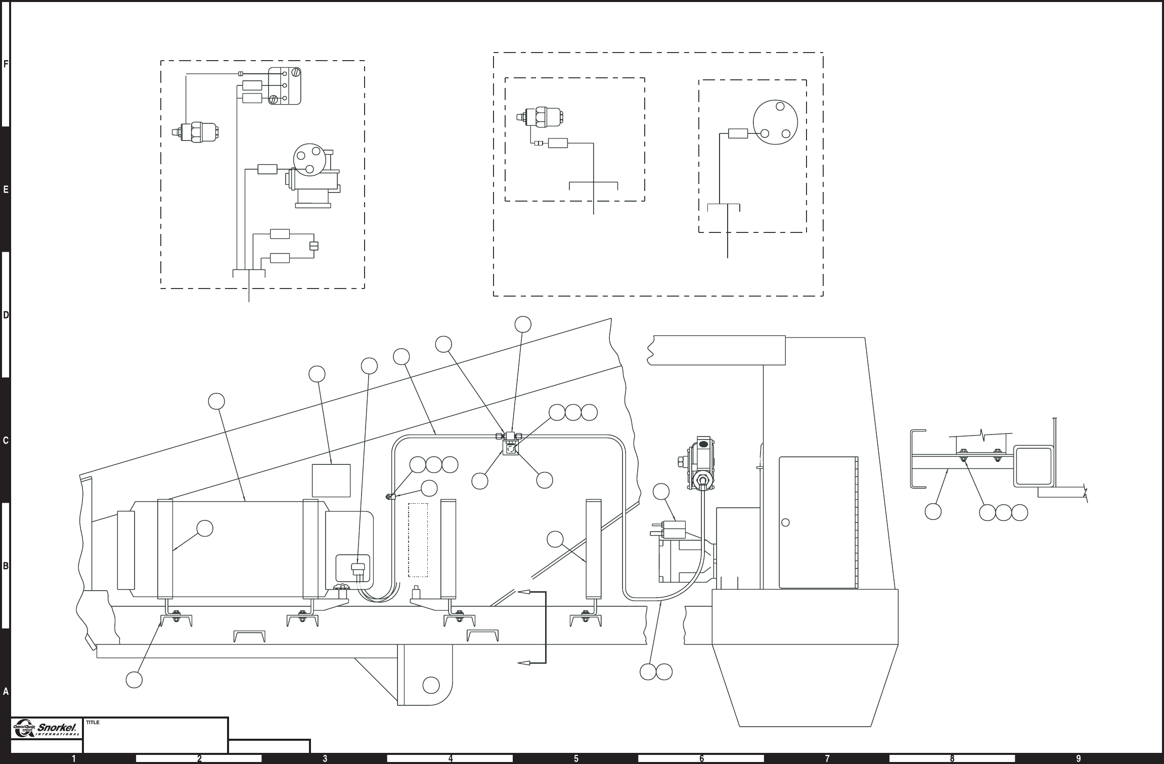
Page4-12
LP fuel only
Ford engine
Snorkel model TB 60 DWG. 0082686
11
10
9
15 16 17
A
8
6
714
1
2
4
3
A
14
18 19 20
4
5
13
21 22 12
5
VIEW A-A
80D
SOL
STR
IGN
5C
80C
80D
ENGINE WIRE
ASSEMBLY
CARBURETOR
FILTERLOCK
VACUUM
SWITCH
CHOKE
ENGINE FORD LRG-423
78A
78B
77B
ENGINE WIRE
ASSEMBLY
ENGINE WIRE
ASSEMBLY
FILTERLOCK
GROUND
CONTROL PANEL
ENGINE
BAT
IGN ST
78
Liquid withdrawal
ENGINE FORD LRG-425
MASTER
SWITCH
AW0082686

LP fuel only, Ford engine
item part no qty description
1 0111937 1 LP fuel engine, Ford LRG-423 - (see page 4-16 for parts breakdown)
0112100 1 Dual fuel engine, Ford LRG-425 - (see page 4-18 for parts breakdown)
2 0080668 1 Relief valve mount bracket
3 9940005 1 LP gas cylinder, liquid withdrawal 43.5 lb capacity
4 0070969 1 Bracket, LP gas cylinder - (includes left and right hand brackets)
5 0072135 4 Channel support, LP gas cylinder - (before 3-20-00)
0083507 4 Channel support, LP gas cylinder - (after 3-20-00)
6 0080676 1 LP gas fuel hose
7 0072117 1 LP gas fuel hose - (before 11-11-99)
0090483 1 LP gas fuel hose - (after 11-11-99)
8 Kit item 1 Hydrostatic relief valve - (included in dual fuel kit 0073444)
9 Kit item 1 Straight thread adapter 1/4 NPT brass - (included in dual fuel kit 0073444)
10 Kit item 1 Bulkhead tee - (included in dual fuel kit 0073444)
11 0081441 1 Decal, caution liquid withdrawal
12 986299 8 Washer 3/8 medium flat
13 0070974 1 Coupler, female LPG
14 5093004 4 Hose clamp
15 970369 1 Capscrew 5/16-18x1inchlong hex head grade 5
16 5560031 1 Nut 5/16-18 self locking
17 986269 1 Washer 5/16 medium flat
18 970029 1 Capscrew 1/4-20 x 3/4 inch long hex head grade 5
19 984069 1 Nut 1/4-20 hex
20 987099 1 Washer 1/4 medium lock
21 972489 8 Capscrew 3/8-16 x 1-1/2 inch long hex head grade 5
22 5560033 8 Nut 3/8-16 self locking
23 986299 8 Washer 3/8 medium flat
TB 60 – 01-97 through 01-01 4-13

Dual fuel engine, Ford LRG-423
item part no qty description
0111927 1 Dual fuel engine, Ford LRG-423
1 0111845 1 Engine, Ford LRG-423
2 0073444 1 Dual fuel kit, liquid cooled - (kit includes items 3 through 14)
3 8020009 1 Regulator
4 8020036 1 Filter lock
5 Kit item 1 Hose adapter - (not sold separately)
6 Kit item 1 LP hose, 5/8 inch diameter x 24 inch long - (not sold separately)
7 Kit item 2 Street 3/8 NPT 90° elbow, brass - (not sold separately)
8 Kit item 2 Street 1/4 NPT 90° elbow, brass - (not sold separately)
9 Kit item 2 Connector 3/8 NPT to 5/8 inch hose, brass - (not sold separately)
10 Kit item 1 Male 1/4 NPT to -6 SAE 90° elbow, brass - (not sold separately)
11 Kit item 1 Street tee 1/8 NPT brass - (not sold separately)
12 Kit item 1 Hydrostatic relief valve - (not sold separately)
13 Kit item 2 Straight thread adapter 1/4 NPT brass - (not sold separately)
14 Kit item 1 Bulkhead tee - (not sold separately)
15 5090024 1 Vacuum fitting
16 7630335 1 Shut-off solenoid
17 5560038 1 Nut #10-32 self locking
18 970029 2 Capscrew 1/4-20 x 3/4 inch long hex head grade 5
19 987099 2 Washer 1/4 medium lock
20 3044146 1 Terminal #10 stud insulated 22/18 wire
21 3040083 1 Terminal .250 tab male fully insulated 16/14 wire
22 5090026 2 Hose clamp
23 5090011 1 Nipple 1/8 NPT brass
24 5090027 1 Street 90° elbow1/8 NPT brass
25 5090035 1 Straight fitting 5/16 barb to 1/8 NPT
26 3044145 1 Terminal #8 stud insulated 22/18 wire
27 5010020 1 Fuel hose, 5/8 inch diameter x 18 inch long
28 5010007 1 Vacuum hose, 3/16 inch diameter x 6 inch long
29 5550010 5 Clamp
30 5039501 2 Beaded 90° elbow
31 5230005 1 Gasoline fuel shut-off valve
32 3020054 1 Vacuum switch - (included with engine, item 1)
8130005 1 Replacement switch
4-14 TB 60 – 01-97 through 01-01
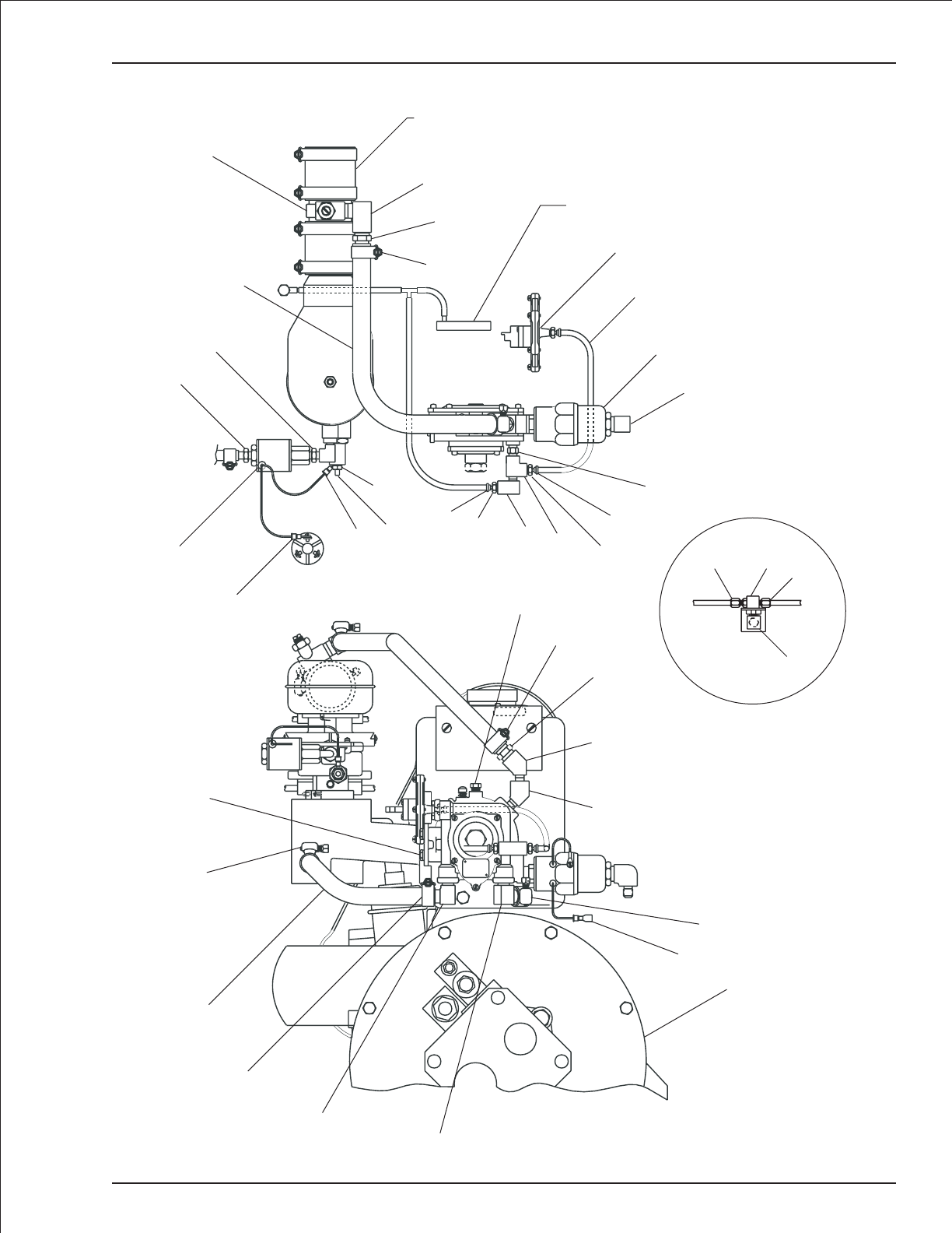
Dual fuel engine, Ford LRG-423
TB 60 – 01-97 through 01-01 4-15
1
21
29
7
7
30
30
29
27
18
19
29
3
29
9
Oil pressure
switch
26
31
25
23
Hose supplied with engine
split in half, item 5 installed
between halves.
5
8
9
29
Spark module
32
28
4
10
23
22
15
11
24
15
22
17
16
20
12
13
13 14
These items installed
on side of turntable.
6
AW0111927

LP fuel only engine, Ford LRG-423
item part no qty description
0111937 1 Engine - LP fuel only, Ford LRG-423
1 0111845 1 Engine, Ford LRG-423 - (see page 4-14 for parts breakdown)
2 0073444 1 Dual fuel kit, liquid cooled - (kit includes items 3 through 14)
3 8020009 1 Regulator
4 8020036 1 Filter lock
5 Kit item 1 Hose adapter - (not sold separately)
6 Kit item 1 LP hose, 5/8 inch diameter x 24 inch long - (not sold separately)
7 Kit item 2 Street 3/8 NPT 90° elbow, brass - (not sold separately)
8 Kit item 2 Street 1/4 NPT 90° elbow, brass - (not sold separately)
9 Kit item 2 Connector 3/8 NPT to 5/8 inch hose, brass - (not sold separately)
10 Kit item 1 Male 1/4 NPT to -6 SAE 90° elbow, brass - (not sold separately)
11 Kit item 1 Street tee 1/8 NPT brass - (not sold separately)
12 Kit item 1 Hydrostatic relief valve - (not sold separately)
13 Kit item 2 Straight thread adapter 1/4 NPT brass - (not sold separately)
14 Kit item 1 Bulkhead tee - (not sold separately)
15 5090024 1 Vacuum fitting
16 970029 2 Capscrew 1/4-20 x 3/4 inch long hex head grade 5
17 987099 2 Washer 1/4 medium lock
18 3040083 1 Terminal .250 tab male fully insulated 16/14 wire
19 5090026 2 Hose clamp
20 5090011 1 Nipple 1/8 NPT brass
21 5090027 1 Street 90° elbow 1/8 NPT brass
22 5010007 1 Vacuum hose, 3/16 inch diameter x 6 inch long
23 5550010 5 Clamp
24 5039501 2 Beaded 90° elbow
25 5010020 1 Fuel hose, 5/8 inch diameter x 18 inch long
26 3020054 1 Vacuum switch - (included with engine, item 1)
8130005 1 Replacement switch
4-16 TB 60 – 01-97 through 01-01
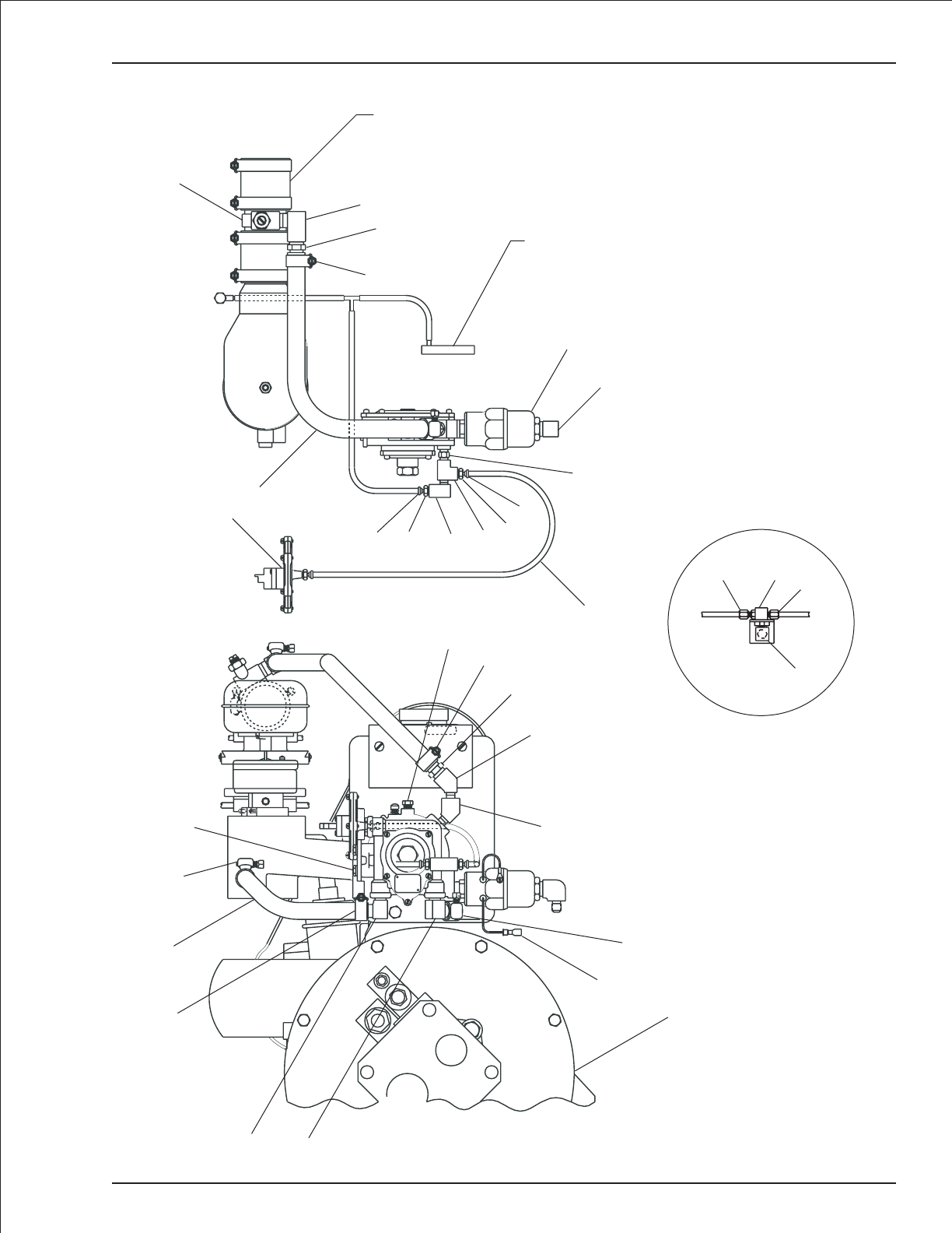
LP fuel only engine, Ford LRG-423
TB 60 – 01-97 through 01-01 4-17
12
13
13 14
These items installed
on side of turntable.
1
23
18
24 24
23
25
16
17
23
7
7
3
23
9
26
22
6
19 15 21 11 15
19
Spark module
4
10
20
8
9
23
Hose supplied with engine
split in half, item 5 installed
between halves.
5
AW0111937

Dual fuel engine, Ford LRG-425
item part no qty description
0112100 1 Dual fuel engine, Ford LRG-425
1 0112083 1 Engine, Ford LRG-425
2 0073444 1 Dual fuel kit, liquid cooled - (kit includes items 3 through 14)
3 8020009 1 Regulator
4 8020036 1 Filter lock
5 Kit item 1 Hose adapter - (not sold separately)
6 Kit item 1 LP hose, 5/8 inch diameter x 24 inch long - (not sold separately)
7 Kit item 2 Street 3/8 NPT 90° elbow, brass - (not sold separately)
8 Kit item 2 Street 1/4 NPT 90° elbow, brass - (not sold separately)
9 Kit item 2 Connector 3/8 NPT to 5/8 inch hose, brass - (not sold separately)
10 Kit item 1 Male 1/4 NPT to -6 SAE 90° elbow, brass - (not sold separately)
11 Kit item 1 Street tee 1/8 NPT brass - (not sold separately)
12 Kit item 1 Hydrostatic relief valve - (not sold separately)
13 Kit item 2 Straight thread adapter 1/4 NPT brass - (not sold separately)
14 Kit item 1 Bulkhead tee - (not sold separately)
15 5090024 1 Vacuum fitting
16 0111862 1 Mount plate
17 970029 2 Capscrew 1/4-20 x 3/4 inch long hex head grade 5
18 987099 2 Washer 1/4 medium lock
19 3040083 1 Terminal .250 tab male fully insulated 16/14 wire
20 5550030 2 Clamp
21 7630327 1 Hose 2 inch flame resistant x 2 inch long
22 5010020 1 Fuel hose, 5/8 inch diameter x 48 inch long
23 5010007 1 Vacuum hose, 3/16 inch diameter x 12 inch long
24 5090044 1 Vacuum tee
25 5090026 1 Hose clamp
26 5550010 6 Clamp
27 5039501 2 Beaded 90° elbow
28 5039601 1 Splice
29 3020054 1 Vacuum switch - (included with engine, item 1)
8130005 1 Replacement switch
4-18 TB 60 – 01-97 through 01-01
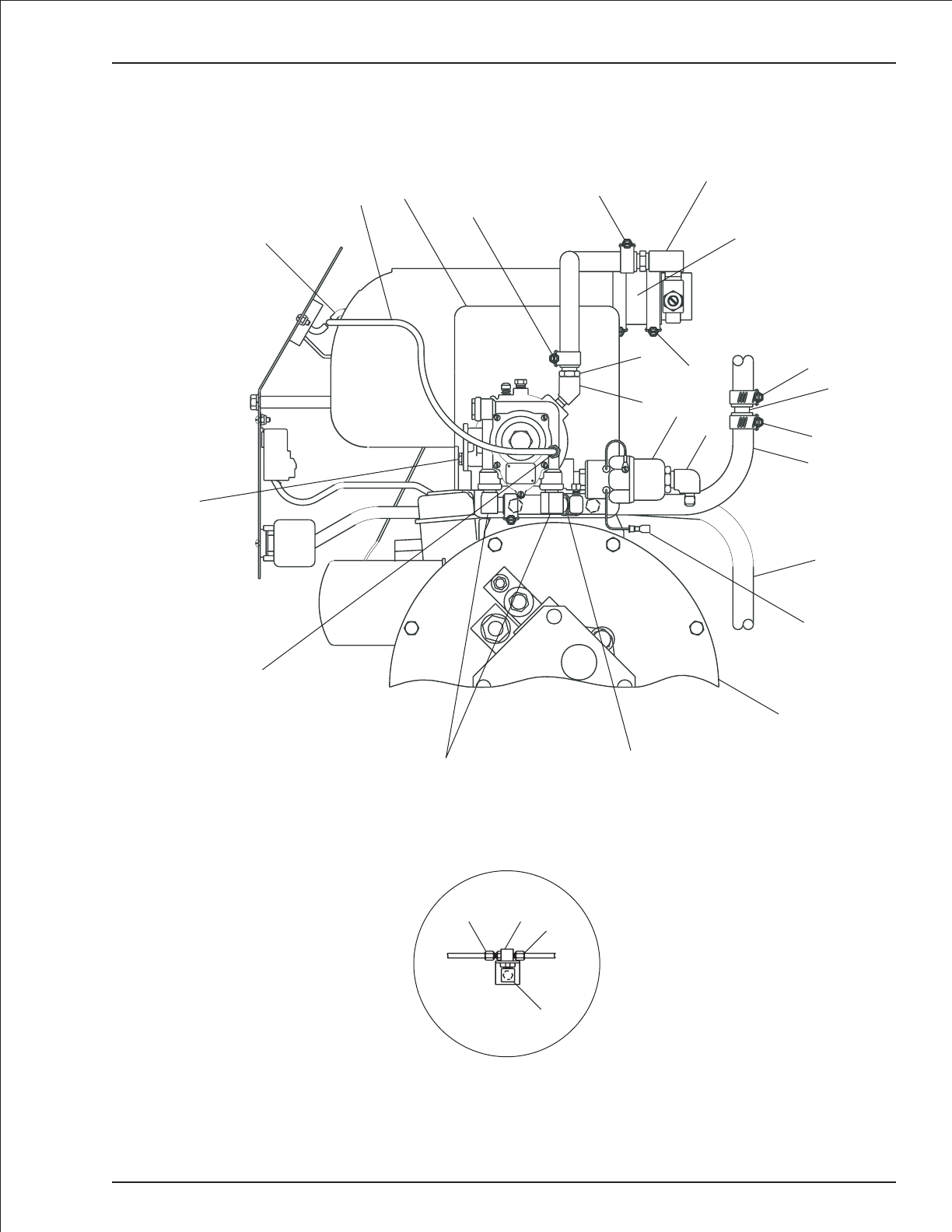
Dual fuel engine, Ford LRG-425
TB 60 – 01-97 through 01-01 4-19
12
13
13 14
These items installed
on side of turntable.
1
27 26
19
4
22
22
10
28
26
26
9
7
20
26
26
16
23
24
25
17
18
21
5
15
25
AW0112100

Driving and tail lights
item part no qty description
1 3064414 2 Light, flood with round base
2 3040038 1 Fuse holder, in-line
3 3040039 1 Fuse, 10 amp capacity
4 3044161 3 Terminal #10 stud insulated 16/14 wire
5 3044158 3 Terminal #6 stud insulated 16/14 wire
6 3040082 2 Terminal .250 tab male fully insulated 16/14 wire
7 3060017 2 Light, turn signal
8 3020013 1 Switch, toggle
9 3040009 1 Switch boot, short
10 0074779 1 Wire harness, tail lights
11 3040113 1 Mounting base
12 5093002 3 Hose clamp
13 3040083 3 Terminal .250 tab female fully insulated 16/14 wire
14 3060019 1 Flasher
15 3060018 1 Flasher base
16 3044071 1 Terminal butt connector insulated 16/14 wire
17 970029 3 Capscrew 1/4-20 x 3/4 inch long hex head grade 5
18 987099 3 Washer 1/4 medium lock
19 5560034 10 Nut #10-24 self locking
20 974679 2 Machine screw #10-24 x 5/8 inch long round head
21 974709 8 Machine screw #10-24 x 1 inch long round head
22 3090006 1 Flexgard tube, 120 inch long
23 986009 8 Washer #10 medium flat
24 3011601 1 Wire, 16 gauge single conductor x 120 inch long
25 0181376 1 Placard, light switch
26 3040469 1 Relay, 12 volt DC
27 0072418 2 Jumper wire
28 0073250 2 Jumper wire
29 0070758 1 Jumper wire
4-20 TB 60 – 01-97 through 01-01
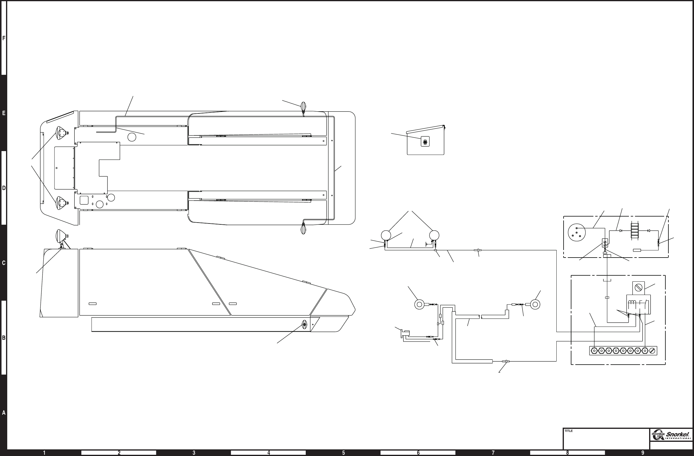
Page4-21
Driving and tail lights
Snorkel model TB 60
11
TO GROUND PANEL
18
17
12
10
1
7
21
24
19
LOCATION OF LIGHTS
SWITCH ON PLATFORM
25
HEAD LIGHT SCHEMATIC
++
-
-
1
TAIL LIGHT SCHEMATIC
(REMOVE)
YELLOW
BROWN
BLUE
10
A
A
B
7
7
14
15
13
RIGHT REAR LEFT REAR
IN LINE FUSE
13
6
13
16
LEFT FRONT RIGHT FRONT
2
3
4
22
24
22
24
87
30
85 86
1A
3
LIGHTS
RELAY
27
27
13
JUNCTION BOX
25
IGN
BAT STRT
ACC
25
26
29 28
985
25
10
10
13
6
AWA08067
7

Page4-22
Proportional extend/retract
Snorkel model TB 60 DWG. 0111893-2
APITECH
PROPORTIONAL
VALVE
VICKERS
NON-PROPORTIONAL
VALVE
BOOM
EXTENSION
CYLINDER
PORT #2
"EXTEND"
PORT #1
"RETRACT"
DRIVE
LIFT
SWING
EXT/RET
C2 C1
NON-PROP
EXT/RET
B1
A1
2
4
6
"2"
"1"
TURNTABLE
WIRE ASSEMBLY
3
APITECH
PROPORTIONAL
VALVE
VICKERS
NON-PROPORTIONAL
VALVE
14
15
14
15
15
14
3
3
14 15
3
3
EXT RET
2
710
810
5
PROPORTIONAL
VALVE INSTALLATION
PLATFORM BOX
INSTALLATION
910
1
EXT RET
11
AW0082182

Proportional extend/retract
item part no qty description
1 0111893 1 Upper control box, proportional - (see page 3-57 for parts breakdown)
2 0082181 1 Proportional control valve, Apitech
3 0082179 1 Wire harness, proportional extend/retract
4 0080362 2 3/8 inch hydraulic hose
5 0082180 1 Mount plate
6 5075206 2 Hex head plug
7 978409 2 Capscrew 3/8-16 x 1-1/2 inch long socket head
8 5560665 4 Capscrew 3/8-16 x 1-3/4 inch long socket head
9 970529 4 Capscrew 3/8-16 x 2-1/2 inch long hex head grade 5
10 5560033 10 Nut 3/8-16 self locking
11 986299 8 Washer 3/8 medium flat
TB 60 – 01-97 through 01-01 4-23
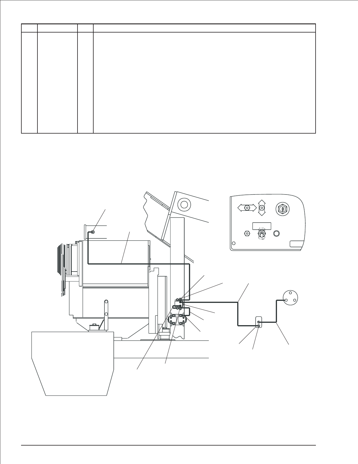
Air inlet heater, Deutz
item part no qty description
1 7630215 1 Air inlet heater kit
8040135 1 Replacement glow plug
2 3040506 1 Solenoid, 12 volt DC
3 3011001 1 Wire, 10 gauge single conductor x 144 inch long
4 3011601 1 Wire, 16 gauge single conductor x 72 inch long
5 0071568 1 Jumper wire
6 3040268 3 Insulator boot
7 3040161 3 Terminal 5/16 stud insulated 8 gauge wire
8 0082064 1 Placard, heater instructions
9 3090006 1 Flexgard tube, 84 inch long
10 3042263 1 Terminal #10 stud insulated 8 gauge wire
11 3044142 1 Terminal #6 stud insulated 22/18 wire
12 3020080 1 Switch, toggle
13 0073781 1 Jumper wire
4-24 TB 60 – 01-97 through 01-01
ST
BAT
IGN
MASTER
SWITCH
ENGINE
SPEED
FAST
SLOW
TURNTABLE
SWING
CCW
CW
UP
DN
JIB
BOOM
OFF
ON
START
MASTER
LIFT/SWING
CIRCUIT
BREAKER
3
0082064
MANIFOLD HEATER
HOLD SWITCH ON FOR
APPROX. 60 SECONDS
START ENGINE
4
12
11 13
3
7
6
6
7
5
2
3
9
1
6
10
AW0082058
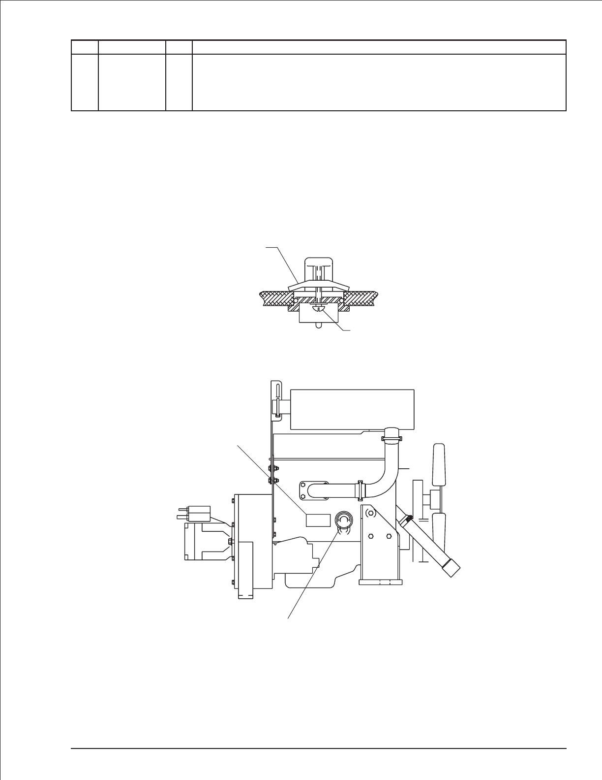
Engine block heater
item part no qty description
1 7630325 1 Engine block heater with cord, Ford LRG-423 engine
2 0181634 1 Decal, engine block heater
TB 60 – 01-97 through 01-01 4-25
1-
Yoke
Locking screw
Heater installation position
install with element pointed
down as shown
2
AW011997
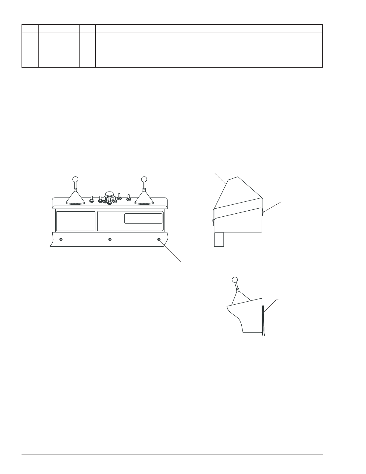
Upper control box cover
item part no qty description
1 0073076 1 Upper control box cover, standard
0074782 1 Upper control box cover, fire resistant
2 5560657 3 Pop rivet 1/8 inch aluminum #RVT-AD48 ABS
3 5560656 3 Pop rivet 1/8 inch aluminum #RVT-AD46 ABS
4-26 TB 60 – 01-97 through 01-01
1
Front view - Upper control box
2
3
Side view
cover shown
in stowed position
Snap
Side view - cover installed
AW0071654
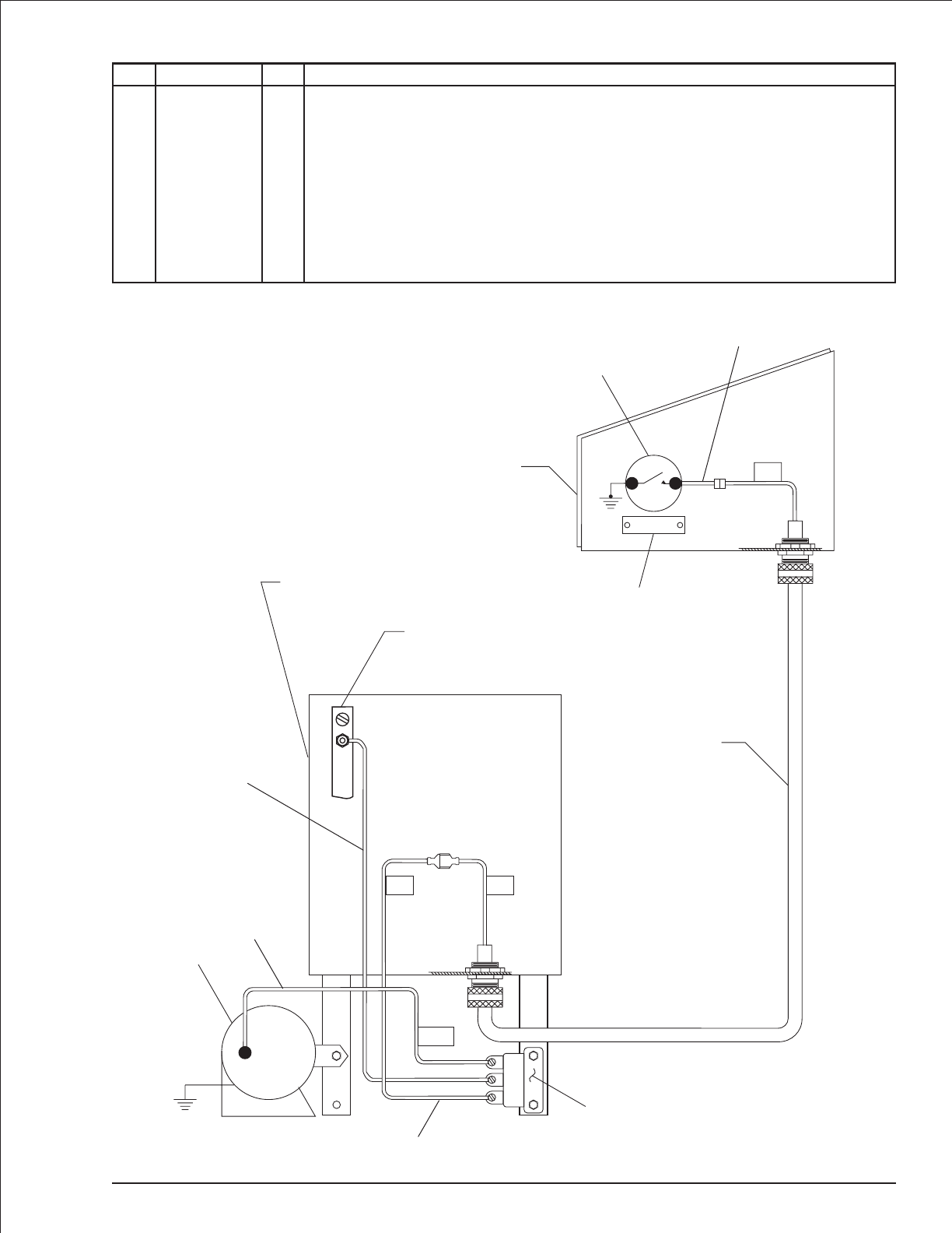
Horn
item part no qty description
1 3026027 1 Switch, push button
2 7140092 1 Switch seal
3 0071269 1 Placard, horn
4 5560655 2 Pop rivet #AD32-ABS
5 3040128 1 Horn relay, 12 volt DC
6 3040127 1 Horn, 12 volt DC
7 0071557 1 Jumper wire
8 0070733 2 Jumper wire
9 0070759 1 Jumper wire
10 0070760 1 Jumper wire
TB 60 – 01-97 through 01-01 4-27
2929
H
B
S
1
29A
29
HORN
Upper control box
1
2
3
4
Control
wire #2
6
5
Wiring box
terminal strip
Wiring box
7
8
9
10 AW0071270

Hydraulic warm-up
item part no qty description
1 0082053 1 Hydraulic warm-up valve - (see page 2-53 for parts breakdown)
2 3020013 1 Switch, toggle
3 3020078 1 Temperature switch
4 0071792 1 Placard, warm-up switch
5 0071793 1 Decal, hydraulic warm-up instructions
6 0071844 2 Jumper wire
7 3040047 1 Terminal .250 tab female slip-on fully insulated 22/18 wire
8 0181398 1 Diode jumper wire
9 0181285 1 Diode jumper wire
10 0050137 1 1/4 inch hydraulic hose
11 0020283 2 1/4 inch hydraulic hose
12 5036703 2 Swivel nut run tee
13 5037003 1 Swivel nut 90° elbow
14 970029 2 Capscrew 1/4-20 x 3/4 inch long hex head grade 5
15 987099 2 Washer 1/4 medium lock
16 986019 2 Washer 1/4 medium flat
17 3044142 1 Terminal #6 stud insulated 22/18 wire
4-28 TB 60 – 01-97 through 01-01
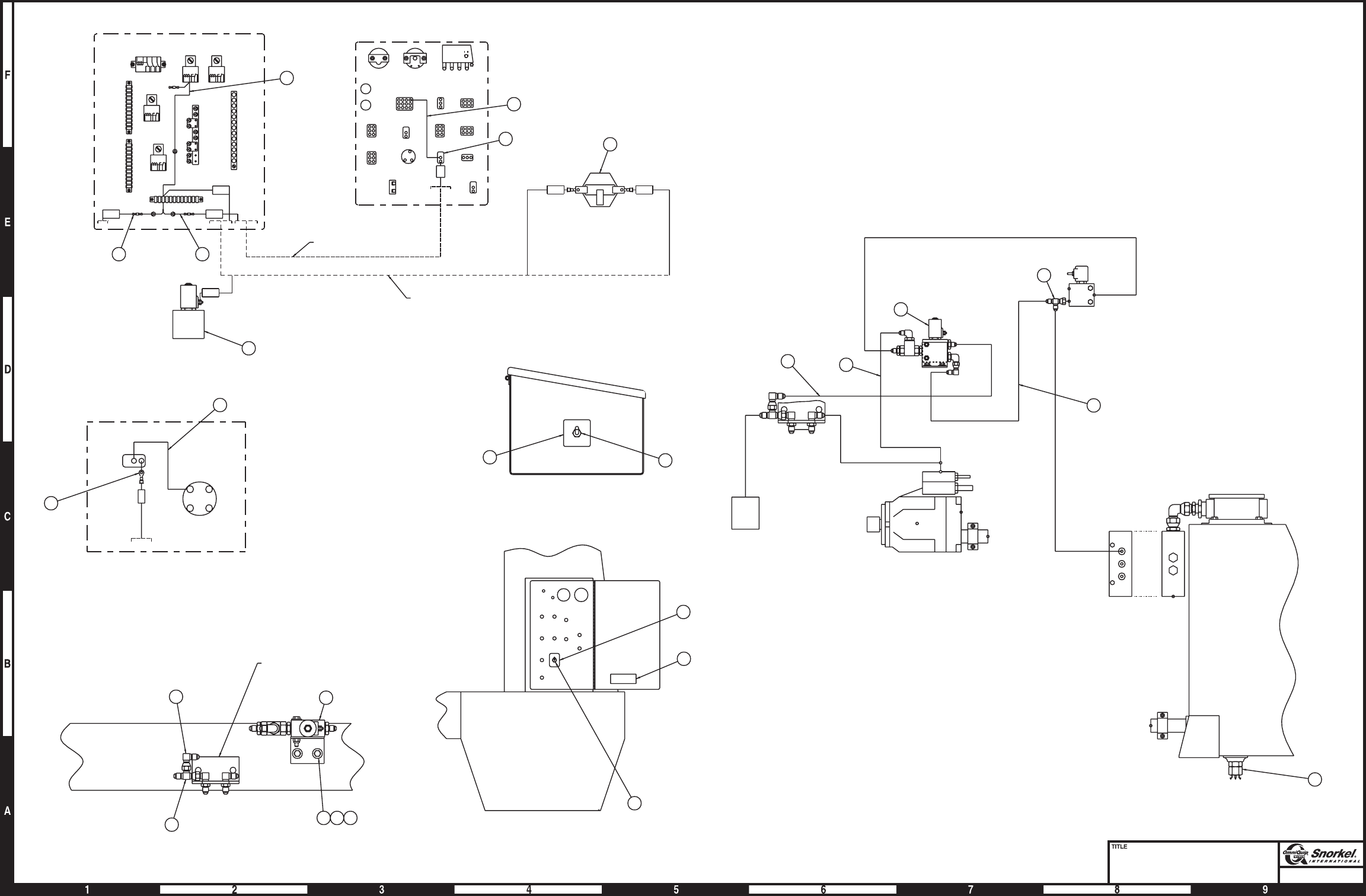
Page4-29
Hydraulic warm-up
Snorkel model TB 60
PLATFORM CONTROL BOX
42
5
4
2
155
IGN START
BATT ACC
ANTI-RESTART
SWITCH
PLATFORM CONTROL
BOX WIRING
6
17
155B
155B155A
TEMPERATURE
SWITCH
WARM UP
DUMP
VALVE
155A
78
77B 77A/155
126
167
34
16B
16
5
4A
4
164B
155A155A
ENGINE WIRE ASSY
TURNTABLE WIRE ASSY
3
6
2
155
1
8
9
MID
THROTTLE HI
THROTTLE
GROUND CONTROL
PANEL
WIRING BOX
7
13
12
1
14 15 16
BULKHEAD MTG. ANGLE
3
10
WARM UP DUMP
VALVE
SENSE LINE
DUMP VALVE
12
1
10
CHECK
VALVE
11
AWA08116
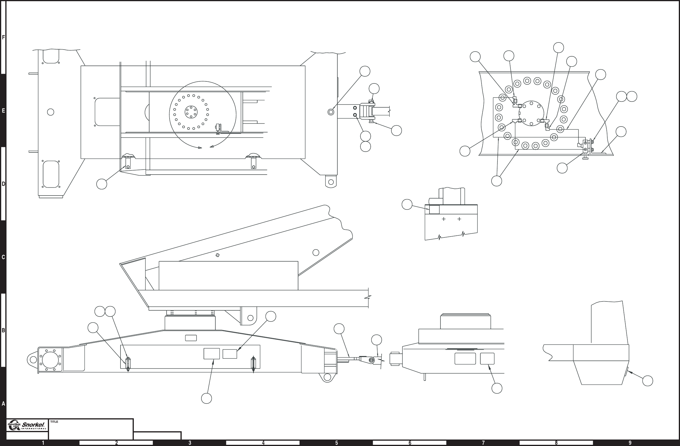
Page4-30
Tow package
Snorkel model TB 60 DWG. 0080663
25
13
23
13
4
1718
1
2
FUEL
TANK
12
15 16
11
9
6
7
8
10
5
8
19
20
3
21
22
4
24
ROTATOR COVER
4
2
6
531
A
DETAIL "A"
AW0080663

Tow package
item part no qty description
1 0072214 1 Tow bar
2 0081063 1 Steering arm, tow package
3 0072216 1 Towing pin
4 0072224 2 Tow bar storage cradle
5 0072225 1 Float valve
6 5037006 1 Swivel nut 90° elbow
7 5037005 1 Swivel nut 90° elbow
8 5036705 2 Swivel nut run tee
9 5036706 1 Swivel nut run tee
10 0070766 1 1/4 inch hydraulic hose
11 0070927 1 1/2 inch hydraulic hose
12 0072226 1 Bracket, float valve
13 0072203 1 Decal, towing instructions
14 5560662 12 Drive screw #4 x 1/4 inch long PK type U
15 970239 2 Capscrew 5/16-18 x 3/4 inch long hex head grade 5
16 987109 2 Washer 5/16 medium lock
17 5560647 2 Capscrew 1/2-13x5inchlonghexhead grade 5
18 5560039 2 Nut 1/2-13 self locking
19 2690001 2 Bearing, self aligning
20 5570003 2 Grease fitting
21 5580002 1 Snapper pin
22 2502416 2 Bearing
23 0082160 1 Decal, danger tow package
24 0082164 1 Decal, danger do not ride
25 0082203 1 Decal, danger crushing hazard
TB 60 – 01-97 through 01-01 4-31
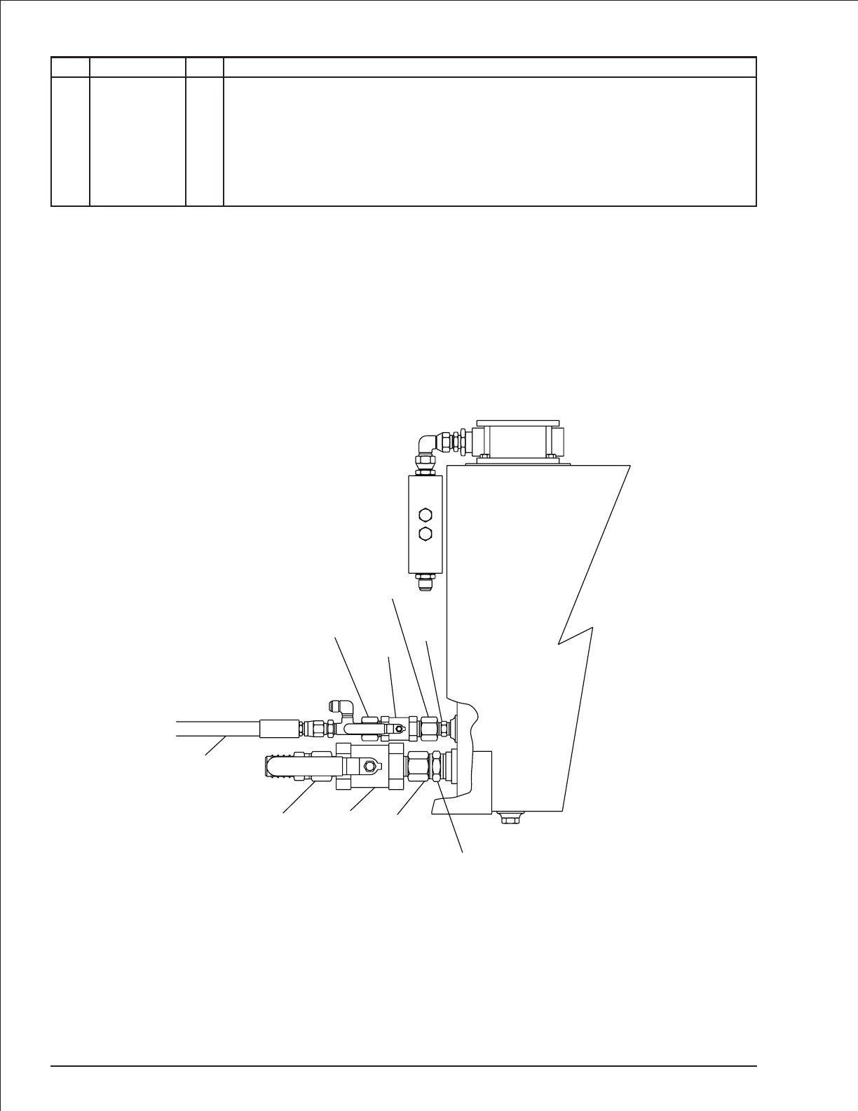
Isolation valve
item part no qty description
1 6010495 1 Ball valve
2 6010498 1 Ball valve
3 7740014 1 Close nipple 1/2 NPT
4 7740110 1 Close nipple 1-1/4 NPT
5 7720604 2 Reducer bushing 3/4 x 1/2
6 7721210 2 Reducer bushing 1-1/2 x 1-1/4
7 0070792 1 1/2 inch hydraulic hose - (Deutz machines only)
4-32 TB 60 – 01-97 through 01-01
1
2
3
5
6
4
5
6
7
AWA08081
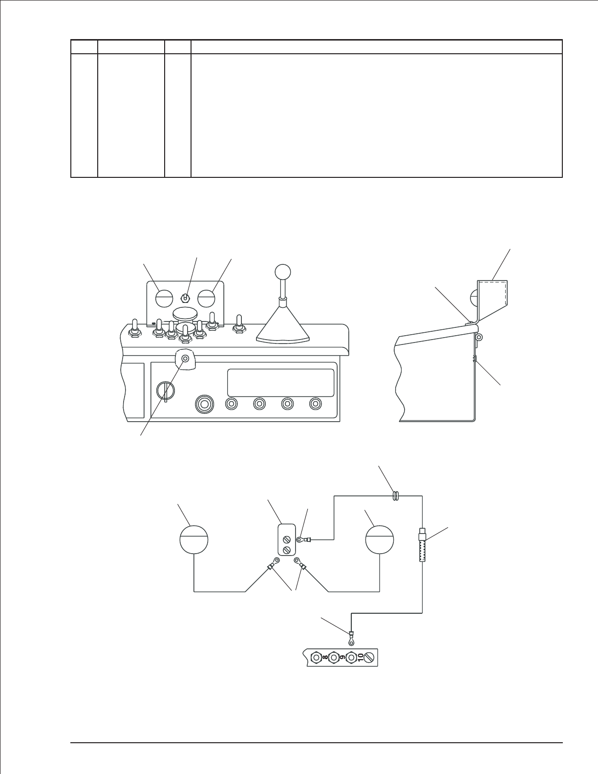
Platform lights
item part no qty description
1 0072004 1 Light bracket
2 5560648 2 Machine screw #10-24 x 3/4 inch long truss head
3 5560034 2 Nut #10-24 self locking
4 5569003 1 Grommet
5 3040038 1 Fuse holder, in-line
6 3040039 1 Fuse, 10 amp capacity
7 3060008 2 Light, platform
8 3020013 1 Switch, toggle
9 3044161 1 Terminal #10 stud insulated 16/14 wire
10 3044158 3 Terminal #6 stud insulated 16/14 wire
TB 60 – 01-97 through 01-01 4-33
Upper control box
terminal strip
56
9
10
7
7
4
10
8
1
2
3
4
Upper control box
Front view
4
787
AW0072012
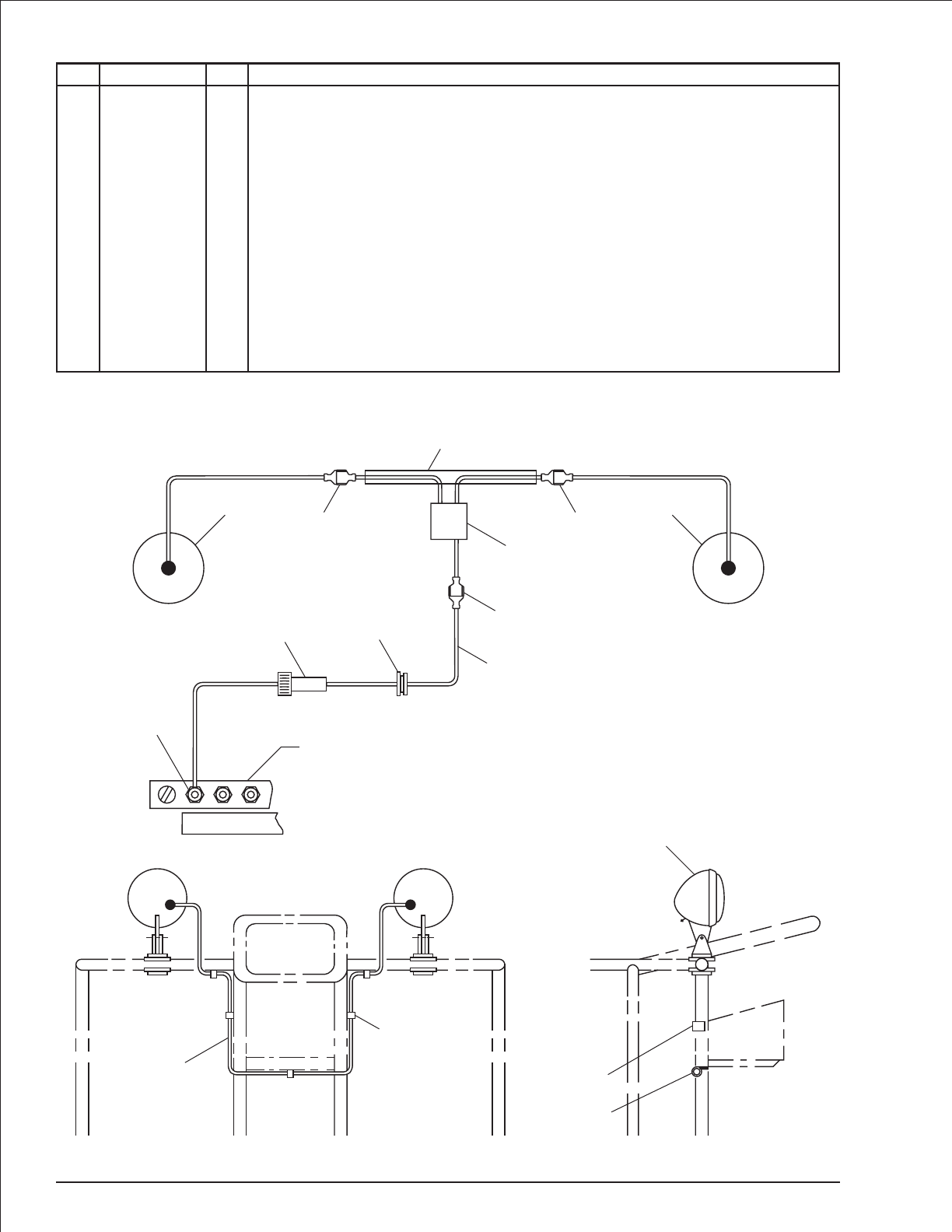
Work lights
item part no qty description
1 3064413 2 Light, incandescent with clamp bracket
3067620 2 Light, halogen with clamp bracket
2 5093019 7 Hose clamp
3 3090019 1 Flexgard tube, 80 inch long
4 5569003 1 Grommet
5 970029 7 Capscrew 1/4-20 x 3/4 inch long hex head grade 5
6 986019 7 Washer 1/4 medium flat
7 987099 7 Washer 1/4 medium lock
8 3040082 3 Terminal .250 tab male slip-on fully insulated 16/14 wire
9 3011601 1 Wire, 16 gauge single conductor x 80 inch long
10 3040114 1 Connector, in-line 16/14 wire
11 3044161 1 Terminal #10 stud insulated 16/14 wire
12 3040038 1 Fuse holder, in-line
13 3040039 1 Fuse, 10 amp capacity
14 3040083 3 Terminal .250 tab female slip-on fully insulated 16/14 wire
4-34 TB 60 – 01-97 through 01-01
1
2
5
6
7
3
2
Light Light
1
3
2
Upper control box
terminal strip
11
88
14 14
10
814
9
11
4
12
13
3
AW0080768
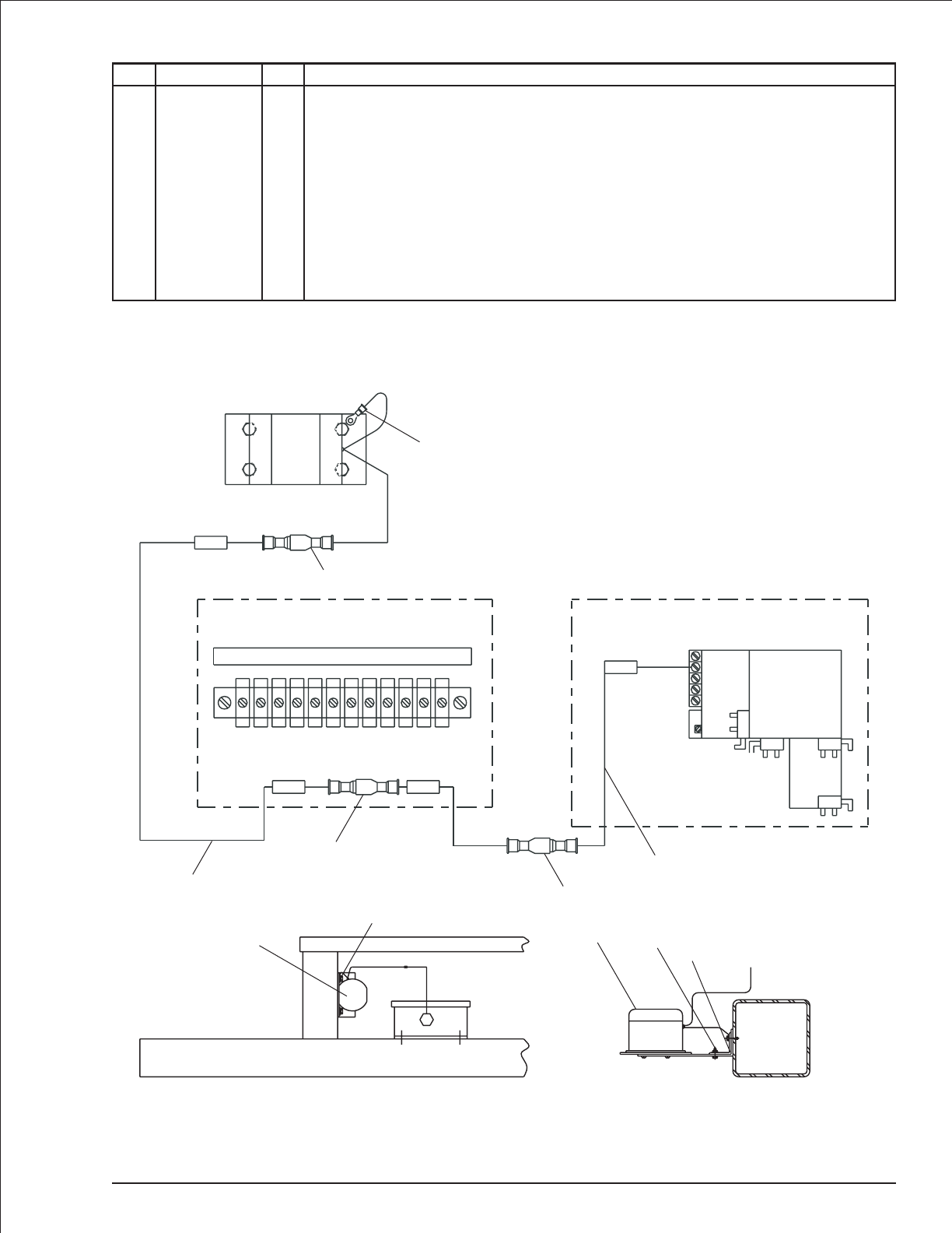
Motion alarm, drive
item part no qty description
1 3040129 1 Motion warning alarm, standard
3040462 1 Motion warning alarm, UL approved
2 0081422 1 Mount angle - (used with UL approved warning alarm only)
3 0073642 1 Jumper wire
4 0073071 1 Jumper wire
5 3040046 2 Terminal .250 tab male slip-on fully insulated 22/18 wire
6 3040082 1 Terminal .250 tab male slip-on fully insulated 16/14 wire
7 970029 4 Capscrew 1/4-20 x 3/4 inch long hex head grade 5
8 987099 4 Washer 1/4 medium lock
9 986019 4 Washer 1/4 medium flat
10 3044162 1 Terminal 1/4 stud insulated 16/14 wire
TB 60 – 01-97 through 01-01 4-35
NC NO
C
NC NO
C
NC
NO
C
C
NO
NC
DRIVE
STEER
B
X
-
+
A
39
39
39 39
R
Wiring box
Drive controller
Upper control box
Standard motion alarm UL approved motion alarm
1
2
7
8
9
1
7
89
10
6
3
5
5
4
AW0073066
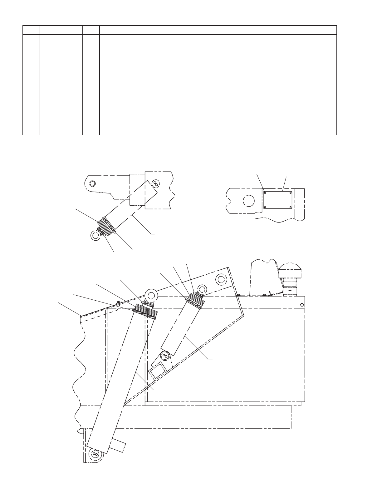
Sandblast kit for metal cowling
item part no qty description
1 0080642 1 Turntable cover
2 0080621 1 Bellows, Lift cylinder
3 1 Bellows, master and slave level cylinders - (use 1 per cylinder)
0071982 Level cylinders by GBI or Seabee
0071998 Level cylinders by Prince or Texas
4 5550050 2 Clamp
5 5550040 1 Clamp
6 5550060 2 Clamp
7 5550037 2 Clamp
8 0081106 1 Cover - (diesel machines only)
9 970469 4 Capscrew 3/8-16 x 1 inch long hex head grade 5
10 987119 4 Washer 3/8 medium lock
11 984109 4 Nut 3/8-16 hex
4-36 TB 60 – 01-97 through 01-01
8
9
10
11
Slave level cylinder
3
76
Master level cylinder
Lift cylinder
7
3
6
5
2
4
1
AW0081815
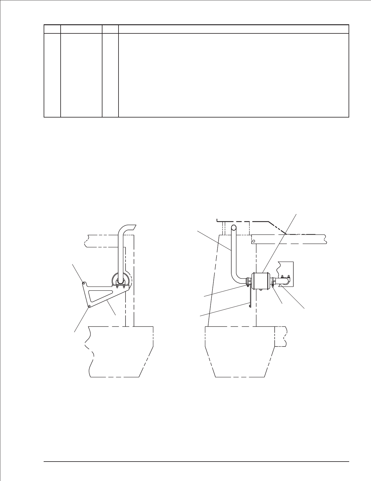
Spark arrestor muffler, Deutz
item part no qty description
1 7630243 1 Muffler, spark arrestor
2 0082096 1 Tail pipe brace
3 0082097 1 Exhaust pipe
4 0082098 1 Tail pipe
5 5550014 2 Exhaust clamp
6 5560625 1 Capscrew metric M10-1.5 x 20mm long hex head
7 5560356 1 Washer metric M10 lock
8 972029 1 Capscrew metric M8-1.25 x 20mm long hex head
9 5560355 1 Washer metric M8 lock
10 987109 2 Washer 5/16 medium lock
11 986269 2 Washer 5/16 medium flat
TB 60 – 01-97 through 01-01 4-37
1
4
53
2
5
10
11
8
9
6
7
2
AW0082095
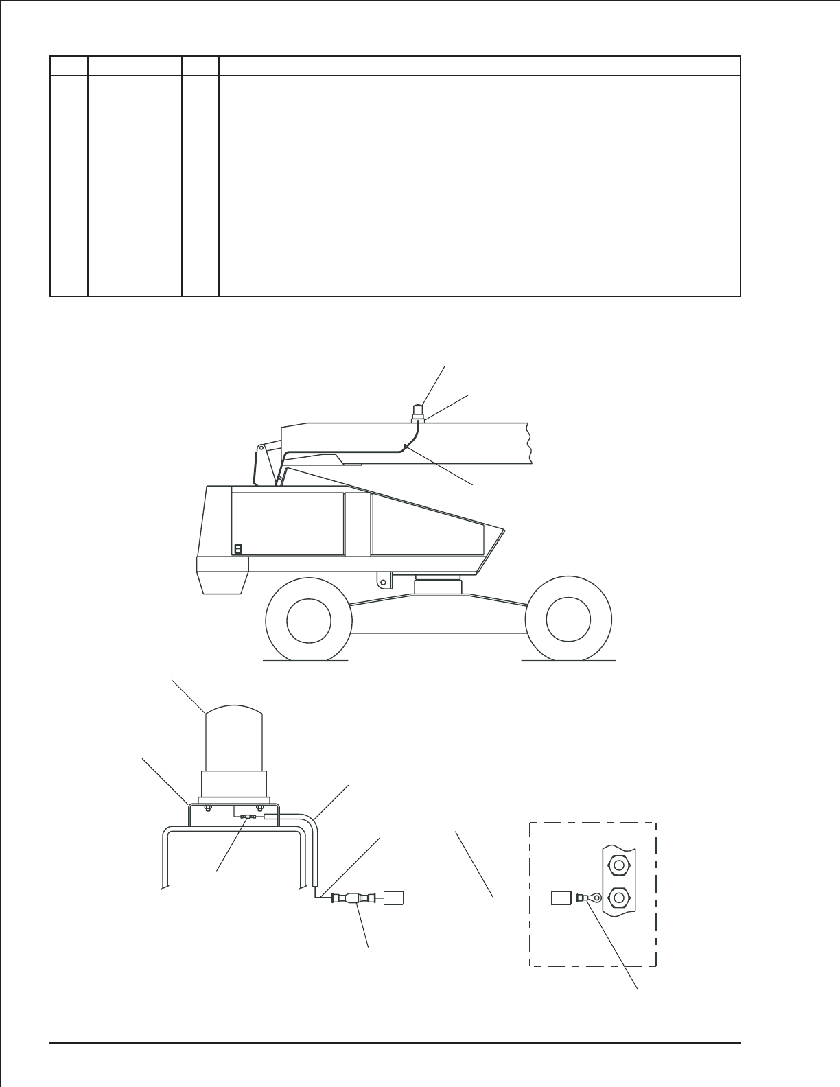
Warning light, single beacon
item part no qty description
1 3060083 1 Warning light, amber lens
3060084 1 Warning light, red lens
8160047 1 Replacement bulb
2 3011601 1 Wire, 16 gauge single conductor x 144 inch long
3 0071395 1 Light mount bracket
4 3090006 1 Flexgard tube, 144 inch long
5 0072209 1 Jumper wire
6 5090305 1 Hose clamp
7 974659 1 Machine screw #10-24 x 1/2 inch long round head
8 987089 1 Washer #10 medium lock
9 3040046 1 Terminal .250 tab male slip-on fully insulated 22/18 wire
10 3044146 1 Terminal #10 stud insulated 22/18 wire
11 3040083 1 Terminal .250 tab male fully insulated 16/14 wire
4-38 TB 60 – 01-97 through 01-01
1
3
678
1D
47
47
Wiring box
Light mounted on boom
10
2
11
5
4
9
1
3
AW0082042

index
A
AC generator, 4-2, 4-5
AC generator valve, 2-23, 4-5
Access cover, chassis, 1-2
Access cover, cowling, 1-65, 1-66
Access cover, drive, 1-2
Accumulator, 2-6, 2-24
Actuator kit, 1-47
Actuator module, 3-9
Adapter plate, centerpost, 1-12
Adjustment bolt, 1-12
Air cleaner, 1-39, 1-56, 1-57, 1-58
Air cleaner access door, 1-61, 1-62
Air cleaner bracket, 1-39
Air cleaner elbow, 1-58
Air cleaner hose coupler, 1-39
Air cleaner mount bracket, 1-39
Air cleaner mounting band, 1-57, 1-58
Air hose, 4-6
Air inlet heater kit, 4-24
Air inlet hood, 1-57, 1-58
Air inlet tube, 1-57, 1-58
Air intake hose, 1-57
Air intake hose adapter, 1-39
Air intake tube, 1-57
Air intake tube clamp, 1-39
Alternator, 1-42
Alternator connection wire, 3-9
Alternator wire, 3-10
Anchor bolt, 1-23
Anchor plate, 1-26
Angle, radiator, 1-48, 1-52
Anti-cavitation valve, 2-22, 2-25
B
Barber/Coleman governor, 3-15
Base boom, 1-23
Battery hold down, 3-3, 3-9, 3-15, 3-21
Battery hold down bolt, 3-3, 3-9, 3-15, 3-21
Battery, 12 volt DC - 550 CCA, 3-3, 3-9, 3-15, 3-21
Bearing spacer, 1-30
Bearing, self aligning, 1-8
Bellows, leveling cylinders, 4-36
Bellows, master level cylinder, 4-36
Boom switch, 1-23, 3-44
Booms, 1-20, 1-23
Bracket, battery disconnect switch, 3-3, 3-9, 3-15, 3-21
Bracket, drive valve, 2-22
Bracket, float valve, 4-31
Bracket, LP gas cylinder, 4-9, 4-10
Bracket, radiator support, 1-48, 1-52
Bracket, spark module mount, 1-51
Bracket, tilt alarm, 3-3, 3-9, 3-15, 3-21
Bumper, 1-65, 1-66
C
Cable guide bracket, 4-6
Cable guide, 4 roller, 4-6
Cable retainer, 1-23
Cable sheave, 1-23, 1-29
Cable, 110 volt power AC generator, 4-2
Cable, 110 volt power to platform, 3-56
Carrier tube, 1-26
Cartridge holding valve, 2-39
Centerpost and fittings, 1-12
Channel support, LP gas cylinder, 4-9, 4-13
Chassis, 1-2
Check valve, 2-6, 2-27
Circuit breaker, 15 amp capacity, 3-36, 3-40, 3-56
Circuit breaker, 20 amp capacity, 3-47, 3-57
Circuit breaker, 25 amp capacity, 3-36, 3-40
Circuit breaker, 3 amp capacity, 3-26, 3-28, 3-31, 3-32, 3-35,
3-47, 3-57
Clamp, T-bolt, 1-39
Clevis pin, 1-20
Close-up plug, 3-36, 3-40
Collar, 1-34
Control valve package, non-proportional, 2-9, 2-10
Control valve, drive/lift/swing, 2-12, 2-14
Control wire #1, 18 gauge/12 conductor, 1-26
Control wire #2, 18 gauge/12 conductor, 1-26
Controller, drive/steer, 3-52
Controller, extend/retract, 3-58
Controller, lift/swing, 3-54
Corrosion inhibitor, 3-36, 3-40, 3-47
Counterweight , 1-2
Coupler kit, 3-26
Cover gasket, hydraulic oil reservoir, 1-18
Cover plate, hydraulic oil reservoir, 1-18
Cover, chassis - 4 wheel drive, 1-10
Cover, cowling rear, 1-61, 1-62
Cover, drive motor, 1-10
Cover, filter access, 1-61, 1-62
Cover, GFCI outlet, 3-56
Cover, hoses, 1-10
Cover, lower controls, 1-65, 1-66
Cover, plastic cowling, 1-65, 1-66
Cover, platform rotator, 1-30
Cover, turntable rear, 1-65, 1-66
Cowling door, 1-61, 1-62, 1-65, 1-66
Cowling side, 1-61, 1-62, 1-65, 1-66
Cylinder anchor, 1-23
Cylinder anchor pin, 1-23
Cylinder, extension, 1-29, 2-28, 2-29
Cylinder, lift, 1-12, 2-31
Cylinder, master level, 1-12, 2-33, 2-34, 2-35, 2-36
Cylinder, slave level, 1-23, 2-40
Cylinder, Slave level, 2-37
Cylinder, steering, 1-6, 2-41, 2-42, 2-43, 2-44
D
Decal,4x4logo, 1-69
Decal, attach fall restraint, 1-69
Decal, blue arrow, 1-69
Decal, caution governor damage, 1-69
Decal, caution liquid withdrawal, 4-9, 4-10, 4-13
Decal, control wire #1, 3-39, 3-43, 3-47, 3-57
Decal, control wire #2, 3-39, 3-43, 3-47
Decal, danger crushing hazard, 1-70, 4-31
Decal, danger cylinder failure, 1-69
Decal, danger do not reach, 1-69
Decal, danger do not ride, 1-70, 4-31
Decal, danger electrical hazard, 1-69, 3-47, 3-57
Decal, danger electrical/tipping hazard, 1-69
Decal, danger rotating engine parts, 1-69
Decal, danger tow package, 1-70, 4-31
Decal, danger you must not operate, 1-69
Decal, diesel fuel, 1-69
Decal, diode, 3-39
Decal, dual fuel instructions, 1-70, 4-9, 4-10
Decal, engine control module, 1-52, 1-69
Decal, gasoline fuel, 1-69
Decal, hydraulic oil, 1-69
Decal, hydraulic warm-up instructions, 1-70, 4-28
Decal, inspect wire ropes, 1-69
Decal, lift, 1-69
Decal, lift/tie down, 1-69
TB 60 – 01-97 through 01-01 index 1

Decal, LPS logo, 1-70
Decal, lube recommendations, 1-69
Decal, made in USA, 1-69
Decal, main circuit breaker, 3-40
Decal, notice manual reorder, 1-69
Decal, OmniQuip logo, 1-69
Decal, operating manual enclosed, 1-69
Decal, power wire, 3-39, 3-43, 3-47
Decal, rotate while greasing, 1-69
Decal, safe operation information, 1-69
Decal, Snorkel brand logo, 1-69
Decal, TB 60 logo, 1-69
Decal, terminal strip, 3-39
Decal, throttle, 3-40
Decal, tie down symbol, 1-69
Decal, towing instructions, 1-70, 4-31
Decal, yellow arrow, 1-69
Diode holder, 3-39, 3-43
Diode stand off, 3-39, 3-43
Door latch, 1-32
Drive motor, 1-4, 1-10, 2-16
Drive motor brake, 4 cubic inch, 2-18
Drive motor with brake, 2-18
Drive sequence valve, left hand, 2-2, 2-5, 2-46
Drive sequence valve, right hand, 2-2, 2-5, 2-45
Drive valve, high torque, 2-2, 2-5, 2-22
Dual fuel engine, Ford LRG-423, 4-10, 4-14
Dual fuel engine, Ford LRG-425, 4-13, 4-18
Dual fuel kit, liquid cooled, 4-14, 4-16, 4-18
Dual holding valve, platform rotation, 1-34, 2-47
Dump valve, 2-6, 2-48
E
Elbow, 3 inch 90° rubber, 1-57, 1-58
Electric fuel pump, 1-48, 3-51
Electrical box, drilled, 3-56
Electrical hazard
See inside front cover
Emergency power unit, 2-6, 2-49
Emission control hose, 1-58
Engine - LP fuel only, Ford LRG-423, 4-16
Engine adapter, Ford engine, 1-51, 1-55
Engine and radiator, Cummins 3.3, 1-36, 1-39
Engine block heater, Ford LRG-423 engine, 4-25
Engine control module, 1-52
Engine harness cover plate, 1-55
Engine isolator, 1-42
Engine mount, 1-44, 1-48, 1-52
Engine mount bracket, front, 1-44
Engine mount washer, 1-42, 1-44, 1-48, 1-52
Engine mount, Cummins 3.3, 1-36
Engine protection module, Deutz, 3-9
Engine tray, 1-42
Engine tray, Cummins 3.3, 1-42
Engine, Deutz F4L-1011F diesel, 1-44, 1-47
Engine, Ford LRG 423, 4-14, 4-16
Engine, Ford LRG-423, 1-48, 1-51
Engine, Ford LRG-423 gasoline, 1-51
Engine, Ford LRG-425, 1-52, 1-55, 4-18
Engine, Ford LRG-425 gasoline, 1-55
EPS anti-restart module, 3-3, 3-9
Exhaust bracket, 1-51, 1-55
Exhaust flange, LRG Ford, 1-51, 1-55
Exhaust gasket, 1-51, 1-55
Exhaust pipe, 1-39, 1-51, 1-57, 4-37
Extension cylinder, 1-23, 1-29
Extension with gasket, 3-36, 3-40
F
Filter condition indicator, 1-36, 1-57, 1-58
Filter, sump strainer, 2-20
Flanged electrical outlet with cover, 3-36, 3-40
Flasher, 4-20
Flasher base, 4-20
Flexible coupling, 1-47, 1-51, 1-55
Float valve, 4-31
Flow divider valve, 2-22, 2-51
Flow divider/combiner valve, 2-5, 2-50
Front cowling, 1-61, 1-62, 1-65, 1-66
Front engine mount bracket, 1-42
Fuel filter, 1-44, 1-52, 3-51
Fuel gauge, 1-16
Replacement gauge lens, 1-16
Fuel hose, 1-40, 1-44, 1-48, 1-52, 4-14, 4-16, 4-18
Fuel pump, 1-52
Fuel tank strap, 1-16
Fuel tank support, 1-16, 4-9
Fuel tank, 40 gallon capacity, 1-16
Fuel tank, gasoline 20 gallon capacity, 4-9
Full height swinging gate, steel platform, 1-32
Fuse holder, in-line, 4-20, 4-33, 4-34
Fuse, 10 amp capacity, 4-20, 4-33, 4-34
G
Gas spring, 1-65, 1-66
Gasket, hub cap, 1-8
Gasket, swing drive, 1-14
Gasket, upper control box, 3-47
Gasoline fuel shut-off valve, 4-14
Gear hub, 1-10, 1-74
Gravity gate, platform, 1-32
Grommet, 3-36, 3-40
Guard, boom switch, 1-24
Guard, emergency stop switch, 3-26, 3-28, 3-31, 3-32, 3-35
Guide bar, 1-20
H
Hairpin clip pin, 1-20
Horn relay, 12 volt DC, 4-27
Horn, 12 volt DC, 4-27
Hose bracket, 4-6
Hose carrier, 1-20, 1-26
Hose carrier support tube, 1-20
Hose reel, 4-6
Hour meter, 3-36, 3-40
Hub, 1-8
Hub cap, 1-8
Hydraulic oil filter, 2-20
Hydraulic oil reservoir, 1-18, 2-20
Hydraulic oil reservoir, 26 gallon capacity, 2-20
Hydraulic pump, 1-47, 1-51, 1-55, 2-52
Hydraulic warm-up valve, 2-53, 4-28
I
Insulator boot, 3-3, 3-9, 3-10, 3-15, 4-24
Intermediate boom, 1-23
K
King pin, 1-6, 1-10
King pin cap, 1-6, 1-10
Knob, gate hinge pin, 1-32
L
Last chance filter, 2-2, 2-5
Latch stop, 1-32
index 2 TB 60 – 01-97 through 01-01
Index

Light bracket, 4-33
Light mount bracket, 4-38
Light, flood with round base, 4-20
Light, halogen with clamp bracket, 4-34
Light, incandescent with clamp bracket, 4-34
Light, platform, 4-33
Light, turn signal, 4-20
Link, 1-29
Link pin, 1-29
Liquid level gauge with thermometer, 2-20
Literature compartment, 1-69
Lock pin, 1-6
Locking pin, 1-6
Lower control panel and hinge, 3-26, 3-28, 3-31, 3-32, 3-35
Lower controls door, 1-65, 1-66
Lower controls, Cummins 3.3, 3-26
Lower controls, Deutz, 3-28, 3-31
Lower controls, Ford LRG-423, 3-32
Lower controls, Ford LRG-425, 3-35
Lower radiator hose, 1-39
LP fuel engine, Ford LRG-423, 4-13
LP gas cylinder, liquid withdrawal, 4-9, 4-10, 4-13
LP gas fuel hose, 4-9, 4-10, 4-13
Lubrication hose, 1-2
Lubrication tube, 1/4 inch copper tube, 1-2
Lug nut, 1-4, 1-10
M
Mini siren, 3-36, 3-40, 3-47
Mini siren, engine alarm, 3-58
Motion control valve, drive, 2-2, 2-5, 2-54
Motion control valve, turntable swing, 1-14, 2-55
Motion warning alarm, standard, 4-35
Motion warning alarm, UL approved, 4-35
Motor mount, front, 1-47, 1-48, 1-52
Motor mount, left hand, 1-51, 1-55
Motor mount, rear, 1-47
Motor mount, right hand, 1-51, 1-55
Motor, swing drive, 1-14
Mount kit, Addco actuator, 1-47
Mount plate, actuator module, 3-9
Mount plate, governor, 3-15
Mount plate, overflow reservoir, 1-40, 1-48, 1-52
Mounting frame, platform rotator, 1-34
Muffler, 1-51, 1-55
Muffler clamp, 1-39
Muffler, spark arrestor, 1-51, 1-55, 4-37
Muffler, standard, 1-39
O
Overflow reservoir, 1-48, 1-52
P
Package valve, non-proportional, 2-6, 2-9
Pad plate, 1-23
Panel, drilled, 3-39, 3-43
Pin joint plate, 1-20
Pin lock, 1-12, 1-20, 1-23, 1-29, 1-30
Pin, cable retainer, 1-23
Pin, extend sheave, 1-29
Pin, gate hinge, 1-32
Pin, lift cylinder base end, 1-12
Pin, lift cylinder rod end, 1-12
Pin, master level cylinder base end, 1-12
Pin, master level cylinder rod end, 1-12
Pin, platform to tip boom, 1-30
Pin, retract sheave, 1-23
Pin, slave level cylinder to platform, 1-30
Pin, slave level cylinder to tip boom, 1-23
Placard, 110 volt power, 3-36, 3-40
Placard, 125 volts 15 amps, 1-69
Placard, AC generator, 4-2
Placard, ANSI standard, 1-69
Placard, battery disconnect switch, 3-3, 3-9, 3-15, 3-21
Placard, caution liquid withdrawal, 1-70
Placard, caution serial number, 1-69
Placard, circuit breaker, 3-36
Placard, danger foam filled tires, 1-69
Placard, dual fuel switch, 4-9, 4-10
Placard, emergency bleed down valve, 1-69
Placard, engine rpm, 1-69
Placard, heater instructions, 4-24
Placard, horn, 3-58, 4-27
Placard, light switch, 4-20
Placard, lower controls, 3-26, 3-28, 3-31, 3-32, 3-35
Placard, lug nut torque, 1-69
Placard, platform capacity, 1-69
Placard, platform identification, 1-69
Placard, platform rotation, 3-58
Placard, pre-start instructions, 1-69
Placard, tire pressure, 1-70
Placard, upper control box, 3-47
Placard, upper control box front, 3-57
Placard, upper control box top, 3-47, 3-58
Placard, warm-up switch, 4-28
Plate, engine coupling, 1-47
Platform, 1-30
Platform foot switch, 3-45
Platform rotator, 1-30, 1-34, 2-56, 2-57
Power wire, 12 gauge/8 conductor, 1-26
PWM module, 3-3, 3-9, 3-15, 3-21
Pylon, platform rotator, 1-34
R
Radiator, 1-48, 1-52
Radiator bracket, 1-40
Radiator cap, 1-40, 1-48, 1-52
Radiator cushion, 1-40, 1-48, 1-52
Radiator hose, 1-48, 1-52
Radiator mount angle, 1-40
Radiator overflow hose, 1-48, 1-52
Radiator, Cummins 3.3, 1-40
Range valve, 2-6, 2-58
Rear engine mount bracket, left hand, 1-42
Rear engine mount bracket, right hand, 1-42
Receptacle, GFCI outlet - 20 amp, 3-56
Relay, 12 volt DC, 3-3, 3-9, 3-15, 3-21, 3-36, 3-39, 3-40,
3-43, 3-47, 3-57, 4-20
Retaining ring, 1-12
Rheostat switch, 3-28, 3-31, 3-32, 3-35
Roller spacer, aluminum gravity gate, 1-32
Roller spacer, steel gravity gate, 1-32
Roller, aluminum gravity gate, 1-32
Roller, steel gravity gate, 1-32
Rotation bearing gear, 1-2
Rubber bumper, 1-69
S
Selector valve, 2 wheel drive, 2-22, 2-59
Selector valve, 4 wheel drive, 2-22, 2-60
Selector valve, left hand, 2-5
Selector valve, right hand, 2-5, 2-61, 2-62
Sheave cage, 1-24
Shroud, cowling, 1-65, 1-66
Shroud, outer air intake, 1-65
Shut-off solenoid, 4-14
Siren, tilt alarm, 3-3, 3-9, 3-15, 3-21, 3-57
Slide pad, 1-20, 1-23, 1-24, 1-26, 1-29
Index
TB 60 – 01-97 through 01-01 index 3

index 4 TB 60 – 01-97 through 01-01

LIMITED WARRANTY
Snorkel warrants each new machine manufactured and sold by it to be free from defects in material and workmanship for a
period of one (1) year from date of delivery to a Customer or for one year after the machine has been placed in first service in a
Dealer rental fleet, whichever comes first. Any part or parts which, upon examination by the Snorkel Service Department, are
found to be defective, will be replaced or repaired, at the sole discretion of Snorkel, through its local Authorized Dealer at no
charge.
Snorkel further warrants the structural components; specifically, the mainframe chassis, turntable, booms and scissor arms,
of each new machine manufactured by it to be free from defects in material and workmanship for an additional period of four
(4) years. Any such part or parts which, upon examination by the Snorkel Service Department, are found to be defective will
be replaced or repaired by Snorkel through its local Authorized Dealer at no charge; however, any labor charges incurred as
a result of such replacement or repair will be the responsibility of the Customer or Dealer.
The Snorkel Service Department must be notified within forty-eight (48) hours of any possible warranty situation during the
applicable warranty period. Personnel performing warranty repair or replacement must obtain specific approval by Snorkel
Service Department prior to performing any warranty repair or replacement.
Customer and Dealer shall not be entitled to the benefits of this warranty and Snorkel shall have no obligations hereunder
unless the “Pre-Delivery and Inspection Report” has been properly completed and returned to the Snorkel Service
Department within ten (10) days after delivery of the Snorkel product to Customer or Dealer’s rental fleet. Snorkel must be
notified, in writing, within ten (10) days, of any machine sold to a Customer from a Dealer’s rental fleet during the warranty
period.
At the direction of the Snorkel Service Department, any component part(s) of Snorkel products to be replaced or repaired
under this warranty program must be returned freight prepaid to the Snorkel Service Department for inspection. All warranty
replacement parts will be shipped freight prepaid (standard ground) from the Snorkel Service Department or from Snorkel’s
Vendor to Dealer or Customer.
REPLACEMENT PARTS WARRANTY
Any replacement or service part made or sold by Snorkel is not subject to the preceding Limited Warranty beyond the
normal warranty period of the machine upon which the part was installed.
THIS WARRANTY EXCLUDES AND SNORKEL DOES NOT WARRANT:
1. Engines, motors, tires and batteries which are manufactured by suppliers to Snorkel, who furnish their own warranty.
Snorkel will, however, to the extent permitted, pass through any such warranty protection to the Customer or Dealer.
2. Any Snorkel product which has been modified or altered outside Snorkel’s factory without Snorkel’s written approval, if
such modification or alteration, in the sole judgment of Snorkel’s Engineering and/or Service Departments, adversely
affects the stability, reliability or service life of the Snorkel product or any component thereof.
3. Any Snorkel product which has been subject to misuse, improper maintenance or accident. “Misuse” includes but is not
limited to operation beyond the factory-rated load capacity and speeds. “Improper maintenance” includes but is not
limited to failure to follow the recommendations contained in the Snorkel Operation, Maintenance, Repair Parts
Manuals. Snorkel is not responsible for normal maintenance, service adjustments and replacements, including but not
limited to hydraulic fluid, filters and lubrication.
4. Normal wear of any Snorkel component part(s). Normal wear of component parts may vary with the type application or
type of environment in which the machine may be used; such as, but not limited to sandblasting applications.
5. Any Snorkel product that has come in direct contact with any chemical or abrasive material.
6. Incidental or consequential expenses, losses, or damages related to any part or equipment failure, including but not
limited to freight cost to transport the machine to a repair facility, downtime of the machine, lost time for workers, lost
orders, lost rental revenue, lost profits or increased cost.
This warranty is expressly in lieu of all other warranties, representations or liabilities of Snorkel, either expressed or implied,
unless otherwise amended in writing by Snorkel’s President, Vice President-Engineering, Vice President-Sales or Vice
President-Marketing.
SNORKEL MAKES NO WARRANTIES WHICH EXTEND BEYOND THE DESCRIPTION OF THIS LIMITED WARRANTY.
SNORKEL MAKES NO IMPLIED WARRANTY OF MERCHANTABILITY OR FITNESS FOR A PARTICULAR PURPOSE
AND DISCLAIMS ALL LIABILITY FOR INCIDENTAL OR CONSEQUENTIAL DAMAGES, INCLUDING BUT NOT
LIMITED TO INJURY TO PERSONS OR PROPERTY.
The Customer shall make all warranty claims through its local Authorized Dealer and should contact the Dealer from whom
the Snorkel product was purchased for warranty service. Or, if unable to contact the Dealer, contact the Snorkel Service
Department for further assistance.
Effective July 1995


TB 60 – revised December 2001 1
Maintenance and Schematics
Maintenance information
The parts drawings located in the repair parts sections,
are designed for use as a guide for proper disassembly
of the machine and components as well as for parts re-
placement. Always refer to the hydraulic system installa-
tion drawings and the electrical wiring diagram before
removing or disassembling associated parts.
Do not attempt to disconnect or remove any hydrau-
lic line before reading and understanding all text
concerning the system hydraulics. In most cases,
disassembly of the machine will be obvious from the
illustration.
When disassembling or reassembling components,
complete the procedural steps in sequence. Do not par-
tially disassemble or assemble one part, then start on
another. Always check your work to assure that nothing
has been overlooked.
The following list is a gentle reminder when disassem-
bling or assembling the machine.
Always be conscious of weight.
Never attempt to lift heavy objects without the aid of
a mechanical device.
Do not allow heavy objects to rest in an unstable
condition.
Always make sure work platform is in stowed
position - blocked or the weight removed by a
suitable lifting device before disconnecting the
hydraulic hose from the motor/pump unit to the lift
cylinder.
When raising a portion of the machine, be sure that
adequate blocking is properly positioned - Do not
depend on lifting device to hold and secure weight.
If a part resists removal, check to see if all
fasteners, electrical wiring, hydraulic lines, etc.,
have been removed or that other parts are not
interfering.
Parts should be thoroughly inspected before restoring to
service at the time of reassembly. Burrs, nicks or
scratches may be removed from machined surfaces by
honing or polishing with #600 crocus cloth, followed by a
thorough cleaning in an approved cleaning solvent, and
blown dry with compressed air. Do not alter the contour
of any part. If this operation does not restore the part to a
serviceable condition, replace the part. Replace all
O-rings, seals, and gaskets at reassembly. Use new roll
pins or cotter pins. Dip all packing rings and seals in hy-
draulic oil before reassembling in cylinder and manifold
installations.Replace any part having imperfect threads.
In general, units that have been disassembled can be
reassembled by reversing the order of disassembly.
Remember that the service life of a machine can be in-
creased by keeping dirt and foreign materials out of the
vital components. Precautions have been taken to safe-
guard against this; shields, covers, seals and filters are
provided to keep air and oil supplies clean; however,
these items must be maintained on a scheduled basis in
order to function properly.
At any time air or oil lines are disconnected, clean sur-
rounding areas as well as the opening and fittings them-
selves. As soon as a line or component is disconnected,
cap or cover all openings to prevent the entry of dirt or
foreign materials.
New parts should remain in their container until they are
ready to be used.
Clearly mark or tag hydraulic lines and electrical wiring
connections when disconnecting or removing them from
unit. This will assure that they are correctly reinstalled.
Proper assembly is critical to the successful rebuilding
of any unit. Carefully inspect any parts which are to be
reused. If in doubt, replace.
“SAFETY FIRST” is a good slogan.
Replace any guards and protective devices that have
been removed to carry out maintenance and repair
work.
C
A
U
TI
O
N

2TB 60 – revised December 2001
Maintenance schedules
Snorkel has established a Preventive Maintenance
Schedule that includes Daily Maintenance (Operator's
Inspection), 90 Day or 150 Hour (frequent) Maintenance
and Yearly or 500 Hour (annual) Maintenance, to detect
any defective, damaged or improperly secured parts
and provide information regarding lubrication and other
minor maintenance items.
The Maintenance Schedule following, outlines the re-
quirements of these maintenance checks for each time
interval. The Operator's Daily Maintenance and inspec-
tion must be performed by a trained operator. All other
maintenance and inspections must be performed by a
trained service technician only.
Note that the 90 Day or 150 hour (frequent) and yearly or
500 hour (annual) Maintenance, require use of the Pre-
ventive Inspection Maintenance Checklist to pinpoint all
inspection items. Retain a copy of these forms for your
records.
They also require that all placards and decals on the unit
are to be inspected.
All placards and decals must be in place and legible.Use
the placards installation drawing and parts listing in the
repair parts section 1 of this manual to check these plac-
ards and decals.
Snorkel recommends that you make additional copies of
the Preventive Inspection Maintenance Checklist forms
for your use in performing these inspections.
Failure to perform the Preventive Maintenance at
the intervals outlined in the Maintenance Schedule
may result in a unit being operated with a defect that
could result in INJURY or DEATH of the unit opera-
tor. Do not allow a unit to be operated that has been
found to be defective.Repair all defects before return-
ing the unit to service.
Daily maintenance
(operator’s inspection)
Components Service Required
Emergency power motor/pump Check operation
Air filter Check condition
Engine oil Check oil level
Fuel leaks Visually inspect (hoses, connections, etc.)
Fuel tank cap Visually inspect (installation)
Engine coolant Check fluid level
Engine fuel level Check fuel gauge
Bolts and fasteners Visually inspect (looseness)
Platform gate Visually inspect (operation)
Slide pads Visually inspect (boom wear marks)
Structural damage and welds Visually inspect (weld cracks, dents)
Tires and wheels Visually inspect (condition)
Battery fluid level Check fluid level
Battery terminals Visually inspect (corrosion)
Charging system Visually inspect (belt, gauge)
Control switches Visually inspect (operation)
Wiring harnesses Visually inspect (installation, condition)
Hydraulic leaks Visually inspect (hoses, tubes, fittings)
Hydraulic oil Check fluid level
Placards and decals Visually inspect (installation, condition)
DANGER

TB 60 – revised December 2001 3
Maintenance schedules
90 day or 150 hour maintenance
(trained service technician)
Components Service Required Recommended Lubricant or
Further Instructions
Daily maintenance Perform maintenance as per schedule
Preventive inspection mainte-
nance checklist
Perform inspection, complete form Retain copy of checklist
Placards and decals inspection Inspect using drawing and parts listing
in section 1 (repair parts)
Replace any missing or unread-
able decals/placards
Door hinges and latches Lubricate SAE 10W oil or spray lubricant
Rotation bearing Lubricate Conoco Super Sta #2
Above 32° Mobilgrease CM-P
Below 32° Mobilgrease CM-L
Rotation bearing teeth & pinion Lubricate Mobil Mobiltac 375NC
Tie rods Lubricate Conoco Super Sta #2
Above 32° Mobilgrease CM-P
Below 32° Mobilgrease CM-L
Gear hubs Check fluid level, fill if low Mobil Mobilube HD 80W-90
Swing drive Check fluid level, fill if low Mobil Mobilube HD 80W-90
Platform rotator Refill if disassembled for repairs Consult factory
Platform controller Check smooth operation & speeds
Batteries Check specific gravity 1.260/1.275 at 80° F.
Hydraulic return filter Check condition Replace if dirty
Engine RPM Check for proper engine RPM See engine manufactures
owner's manual
Engine oil and filter Replace per engine owners manual
Engine fuel filter Check condition Replace every 6 months or if dirty
Yearly or 500 hour maintenance
(trained service technician
Components Service Required Recommended Lubricant or
Further Instructions
90 day or 150 hour maintenance Perform maintenance per schedule
Hydraulic oil reservoir Clean and replace fluid Above 10° Mobil DTE-13M
Below 10° Mobil DTE-11M
Hydraulic return filter Replace After 1st. 50 hours, thereafter
at recommended interval
Hydraulic reservoir suction filter Clean and reinstall
Hydraulic pressures Check pressures
Gear hubs Replace fluid Mobil Mobilube HD 80W-90
Swing drive Replace fluid Mobil Mobilube HD 80W-90
Engine coolant Check Condition See engine manufacturer's
owner's manual
Front wheel bearings Clean and repack Conoco Super Sta #2
Above 32° Mobilgrease CM-P
Below 32° Mobilgrease CM-L
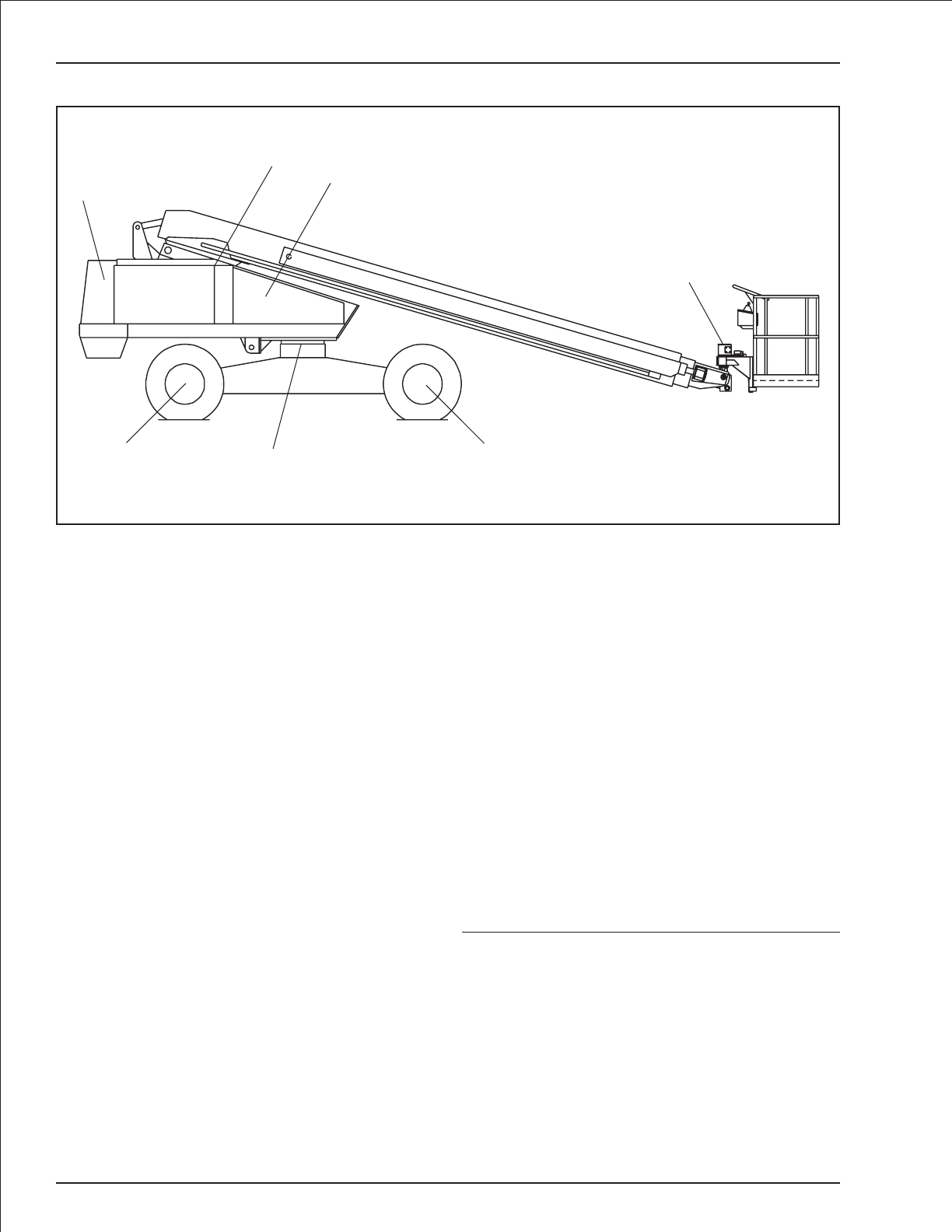
4TB 60 – revised December 2001
Service information
Lubricants
Specific lubricants as recommended by Snorkel, should
be used in maintaining your unit.If in doubt regarding the
use of lubricants other than those listed, contact Snorkel
Customer Service Department, St. Joseph Missouri, for
evaluation and recommendation.
Refer to the above lubrication illustration for location of
item numbers.
Pressure gun application
Service all fittings as indicated in the Maintenance
Schedule and lubrication illustration. Wipe away all ex-
cess lubricant from exposed surfaces. Over lubrication
can collect dirt and foreign matter which acts as an abra-
sive. Lubrication of accessory equipment should be in
accordance with the manufacturer’s recommendations.
Rotation bearing
Rotation bearing (item 1.): Pressure gun lubricate bear-
ing at recommended interval using lubricant as outlined
in the maintenance schedule. Rotate while lubricating.
Lubrication fitting is located on the font plate of the turn-
table.
Rotation gear teeth and pinion
Rotation gear teeth and pinion (item 2.): Gear teeth and
gear box pinion should be lubricated with a spray-on
type open gear lubricant.
Tie rods
Tie rods (item 3.): Lubricate at recommended interval
using lubricant as outlined in the maintenance schedule.
Swing drive
To check oil level, remove check plug located on the side
of the gear box. Unit is full if oil is level with bottom of fill
hole or just starts to run out.
Gear hubs
Gear hubs (item 5.): To check and fill Gear hubs:
1. Rotate wheel until bottom of filler/drain plug is
about 1 inch above horizontal centerline.
2. Remove plug with drive ratchet and extension.
3. Fill until lubricant is level with bottom of fill hole.
Note:
Do not overfill gear hubs as they are not vented and
need air space for expansion of oil to prevent damage
to hubs.
Hydraulic oil reservoir
Hydraulic oil reservoir (item 6.): The fluid level should be
kept between the low and full marks on the sight gauge
indicator and should be checked with all cylinders fully
retracted and the platform in stowed position.
The interior of the reservoir should be wiped out and
cleaned each time the hydraulic oil is changed.
9
6
10
11
8
7
31
2
4
5
Steer Drive
The illustration locates the lubrication points of the TB 60.
Lubrication illustration

TB 60 – revised December 2001 5
Service information
The reservoir filler/breather cap should be removed and
the cap strainer cleaned with Kerosene, Fuel Oil, or
other solvent at this time.
It is absolutely necessary that only new, clean hydraulic
oil is added.
Note:
If it becomes necessary to add or use an oil other
than the recommended fluid, it is important that it be
compatible and equivalent to the factory fill. Local oil
suppliers can generally furnish this information.
If questions still remain, contact Snorkel Customer Ser-
vice Department, St. Joseph, Missouri, for further infor-
mation.
Engines
Engine (item 7.): Refer to the engine manufacturer’s in-
struction manual or consult your local engine service
representative if engine adjustments or repairs are
needed. The engine MUST be operated in accordance
with manufacturer’s instructions and serviced at recom-
mended intervals.
Door hinges and latches
Door hinges and latches (item 8.): After lubricating, re-
move any excess oil or over spray so it will not collect dirt
or debris.
Platform rotator
Platform rotator (item 9.): Platform rotators will require
lubrication only if disassembled for repairs.
Consult factory for proper lubricant if replacement of
platform rotator is required.
Hydraulic oil return filter
Return filter (item 10.): On TB 60 models, the hydraulic
oil return filter is mounted on top of the hydraulic oil res-
ervoir.
The filter element is a throw-away type filter and should
be changed after the initial break-in period (approxi-
mately 50 hours operation time).
The filter is equipped with a hydraulic pressure gauge to
indicate the filter element condition. A by-pass relief
within the filter base is provided and is set to by-pass at
25 PSI. If pressure readings are above 25 PSI, the filter
should be changed.
The filter condition should be checked at the 90 day or
150 hour Preventive Inspection Maintenance interval or
more frequently under extreme working conditions.
The filter condition indicator is accurate only when the
engine is running at maximum RPM and pump is dis-
charging maximum flow, which occurs only during full
speed driving. This requires that the indicator be ob-
served while the unit is in motion, booms fully retracted
and in stowed position, drive range switch in “LO” posi-
tion, and drive controller fully forward. Oil temperature
should be at least 90 degrees.
Note:
Use extreme caution while observing the condition
indicator because of the motion of the drive wheels.
The condition indicator is best observed from outside
of the tract of the vehicle wheels to avoid possible
personal injury or machine damage.
When changing the filter element, the oil inside of the fil-
ter element, should be examined for deposits of metal
cuttings, which is present, could indicate excessive
wear in some of the system components.
Suction strainer
Suction strainer (item 11.): A 100 mesh strainer is lo-
cated within the hydraulic oil reservoir and filters the
pump suction flow.
The strainer is cleanable and should be cleaned at the
time interval shown in the maintenance schedule chart,
using Kerosene, Fuel oil or other solvent and a soft bris-
tled brush.
Inspect filter for damage to wire cloth. Holes in the filter
cloth leak dirt into the pump and other vital hydraulic
components. If element is damaged, replace.
When filter has been thoroughly cleaned, reinstall filter
on suction line and tighten securely.
Batteries
Batteries (not shown): Batteries will have longer life if the
water level is maintained and they are kept charged.The
unit will have better starting characteristics with a fully
charged battery.
n cold weather the battery should be maintained at full
charge to keep from freezing. An extremely low or dead
battery can freeze in cold weather. Make sure connec-
tions are clean and tight.
Make sure charging equipment is operating properly.
Lead-acid batteries produce flammable and explo-
sive gases. Never allow smoking, flames or sparks
around batteries.
Lead-acid batteries contain sulfuric acid which will
damage eyes or skin on contact. When working
around batteries, always wear a face shield to avoid
acid in eyes.
If acid contacts eyes, flush immediately with clear water
and get medical attention.
Wear rubber gloves and protective clothing to keep acid
off skin, if acid contacts skin, wash off immediately with
clear water.
DANGER

6TB 60 – revised December 2001
Preventive inspection maintenance
90 day or 150 hour checklist
Serial Number _____________________________
OK OK - No service required
✔Corrective action required
X Corrected, (record description of corrective action).
INSPECTION PROCEDURES CODES
(1) Weld cracks, dents and/or rust
(2) Installation
(3) Leaks
(4) Operation
(5) Condition
(6) Tightness
(7) Residue buildup
(8) See placards and decals inspection chart
Check OK ✔X
C GROUND CONTROL STATION
1 Station selector switch ñ ground controls
platform controls DO NOT work
2 Station selector switch ñ platform controls
ground controls DO NOT work
3 Ground controls switches (4)
4 Turntable rotation (4)
5 Boom UP-DOWN (4)
6 Boom extension IN-OUT (4)
7 Platform leveling (4)
8 Emergency power, all functions (4)
9 Platform rotation (4)
D BOOMS
1 Structural (1)
2 Lift cylinder pin caps and tie wire (2,6)
3 Hydraulic hoses and tubes (3,5)
4 Extension cylinder and holding valve (3,4)
5 Hose carrier tube (7)
6 Hose carrier support (7)
7 Plastic hose track (5)
8 Electrical wires (5)
9 Extend/retract wire ropes and sheaves (2,5,6)
E PLATFORM
1 Structural (1)
2 Decals and placards (2,8)
3 Gravity gate (4)
4 Hydraulic tubes and hoses (3,5)
5 Slave level cylinder pin caps and tie wire (2,6)
6 Slave level cylinder and holding valve (3,4)
F PLATFORM CONTROL STATION
1 Foot switch, unit will not start when engaged (4)
2 Foot switch, functions operate when engaged (4)
3 Engine START-STOP (4)
4 Electric throttle, if equipped (4)
5 Turntable rotation (4)
6 Boom UP-DOWN (4)
7 Boom extension IN-OUT (4)
8 Platform leveling (4)
9 Platform rotation (4)
10 Drive speed, HIGH-LOW (4)
11 Drive range, HIGH-LOW (4)
12 Engine choke, (gasoline unit only) (4)
13 Emergency power, all functions (4)
14 Emergency shutdown control (4)
15 Gradual start to stop lift/swing/drive controls (4)
16 Speed limit switch (4)
17 5 tilt alarm (4)
18 110 volt AC power to platform (2,4)
Check OK ✔X
A CHASSIS
1 Structural (1)
2 Steering cylinder pin caps (2,6)
3 Steering linkage (4)
4Tires(5)
5 Hydraulic tubes and hoses (3,5)
6 Decals and placards (2,8)
7Drivemotorbrake(4)
8 Torque drive wheel lugs per placard on wheel (6)
9 Torque steer wheel lugs per placard on wheel (6)
10 Right drive motor (3)
11 Left drive motor (3)
12 Lubrication points
B TURNTABLE
1 Structural (1)
2 Torque turntable top bolts @180 ft. lbs. (6)
3 Torque turntable bottom bolts @180 ft. lbs. (6)
4 Hydraulic hoses and tubes (3,5)
5 Centerpost (3)
6 Centerpost securing bolts (6)
7 Lift cylinder pin caps and tie wire (2,6)
8 Emergency bleed down valve (4)
9 Cowling (5,6)
10 Wire harness (2,5)
11 Lift cylinder and holding valves (3,4)
12 Decals and placards (2,8)
13 Master level cylinder pin caps and tie wire (2,6)
14 Master level cylinder and holding valves (3,4)
15 Rotation brake (4)
16 Rotation backlash (5)
17 Correct operators manual in document holder
18 System pressure
19 Lubrication Points

TB 60 – revised December 2001 7
Preventive inspection maintenance
CORRECTIVE ACTION REQUIRED
___________________________________________________________________________________________________________________
___________________________________________________________________________________________________________________
___________________________________________________________________________________________________________________
___________________________________________________________________________________________________________________
___________________________________________________________________________________________________________________
___________________________________________________________________________________________________________________
___________________________________________________________________________________________________________________
___________________________________________________________________________________________________________________
___________________________________________________________________________________________________________________
___________________________________________________________________________________________________________________
___________________________________________________________________________________________________________________
___________________________________________________________________________________________________________________
___________________________________________________________________________________________________________________
___________________________________________________________________________________________________________________
___________________________________________________________________________________________________________________
___________________________________________________________________________________________________________________
___________________________________________________________________________________________________________________
___________________________________________________________________________________________________________________
___________________________________________________________________________________________________________________
___________________________________________________________________________________________________________________
___________________________________________________________________________________________________________________
___________________________________________________________________________________________________________________
___________________________________________________________________________________________________________________
___________________________________________________________________________________________________________________
___________________________________________________________________________________________________________________
___________________________________________________________________________________________________________________
___________________________________________________________________________________________________________________
___________________________________________________________________________________________________________________
NOTE: Attach additional sheets if required:
All items have been properly checked and tested and found to be operating satisfactorily or necessary corrective action has been completed.
INSPECTED BY: __________________________________________________ DATE: ____________________________________
Check OK ✔X
J OPTIONAL EQUIPMENT
1 110 volt onboard AC generator (2,4)
2 Dual fuel system (2,4)
3 LP gas system and control (2,4)
4 Horn (2,4)
5 Motion warning alarm (2,4)
6 Operation warning light (2,4)
7 Key type master switch (2,4)
8 Cold weather start kit ñ diesel only (2,4)
9 Hydraulic system, cold weather warm up kit (2,4)
10 Extension cylinder bleed down (2,4)
11 Driving lights (2,4)
12 Platform work lights (2,4)
13 Sandblast protection kit (2,4)
14 Airline to platform (2,4)
15 Tow package (2,4)
16 Optional platform (2,4,6)
17 Manual rotator (2,4,6)
18 Hydraulic rotator ñ self contained (2,4,6)
19 Four wheel drive (2,4)
20 Lifting lugs (2,5)
Check OK ✔X
G HYDRAULIC RESERVOIR
1 Filler/breather cap and tank (6)
2 Hydraulic fluid level (5)
HENGINE
1 Charging system (4)
2 Air filter (5)
3 Hour meter (4)
4 Belts and hoses (5)
5 Hydraulic pump (4)
6 Battery terminals (6)
7 Indicator gauges (4,5)
8 Engine START-STOP (4)
9 Electric throttle (4)
10 Electric choke, if equipped (4)
11 Engine governor setting (4)
I PLATFORM ROTATOR
1 Structural (1)
2 Hydraulic rotator actuator (3)
3 Platform rotation holding valve (4)
4 Mounting bolts and pin caps (2,6)
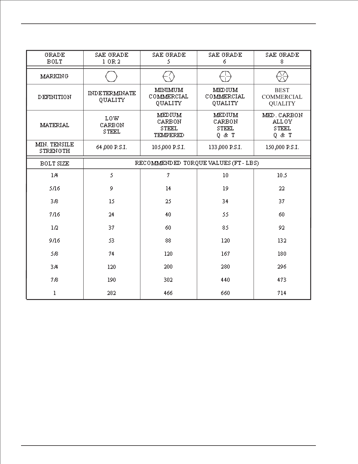
Capscrew torque chart
8TB 60 – revised December 2001
The following rules apply to the chart
1. Consult manufacturers' specific recommendations when available.
2. The chart may be used with both course and fine thread fasteners lightly lubricated.
3. Increase torque by 20% when multiple tapered tooth (shake proof) lock washers are used.
4. The torque values are given in foot-pounds.
5. Inch pound equivalent may be obtained by multiplying by 12.

TB 60 – revised December 2001 9
Wire code and function
Wire Color Circuit function
1 red power to platform controls 12 volt DC
1A red Power to ground controls12 volt DC
1B red power from circuit breaker to emergency stop switch
1C red power to auxiliary circuit
1D red starter to ammeter Deutz diesel machine
2 red power to platform controls 12 volt DC
3 black ground circuit
3B black ground circuit
3C black ground circuit, magnetic switch to oil pressure switch
4 red run from platform
4A red ignition signal to run relay
4C red power to platform range switch
5 blue start from platform
5A white start signal to engine starter
5B yellow start solenoid signal
5C gray start signal to start solenoid switch
6 brown emergency power from platform
6A green emergency power solenoid signal
8 red platform foot switch start
8D red run solenoid, Deutz diesel machine
9 white platform foot switch to controls
10 black power to platform foot switch
11 pink motor low range signal
12 blue level function - down
13 gray level function - up
14 yellow boom extend/retract function - extend
15 green boom extend/retract function - retract
16 blue hydraulic speed
16A blue speed signal at ground
16B pink speed signal valve
17 orange drive function - forward
18 purple drive function - reverse
19 brown steer function - left
20 blue steer function - right
21B yellow/black boom raise/lower function - down
22B yellow/orange boom raise/lower function - up
23 pink turntable swing function - counter clockwise rotation
24 purple turntable swing function - clockwise rotation
25 red medium throttle signal
26 orange platform rotation function - clockwise rotation
27 blue platform rotation function - counter clockwise rotation
28 green sense line dump
28A white ground controls switch to controls
28B white sense line dump valve
31 red throttle from ground controls
34 pink range from boom switch
54 blue tachometer pick-up
55A red medium throttle power to solenoid

Wire code and function
Wire Color Circuit function
55B red high throttle power to solenoid
56 red alternator power to ammeter
57 red starter to ammeter
67 red swing joystick controller power
67A red power to PWM module
68 red lift joystick controller power
69 red drive joystick controller power
70 pink boom speed signal
73 orange level sensor signal
74 red tilt alarm signal from tilt relay
77A yellow fuel valve signal from vacuum switch solenoid
77B gray dual fuel switch to filter lock
78 red dual fuel select, gasoline fuel
80A white power to ignition module
80B white power from hot start relay to coil
80C white magnetic switch to choke - (Ford engine machines only)
110 blue 110 volt power to platform
125 green high throttle signal
125A white high throttle
126 yellow engine kill signal
160 green blocking valve power from platform
160A pink blocking valve power from ground
160C yellow power to blocking valve
164 red run power from run relay
164B red run power to alternator field
172 white PWM module to controls
173 white resister bridge module to PWM module
174 white resister bridge module to PWM module
175 white resister bridge module to PWM module
A1 white throttle actuator
A2 white throttle actuator
10 TB 60 – revised December 2001
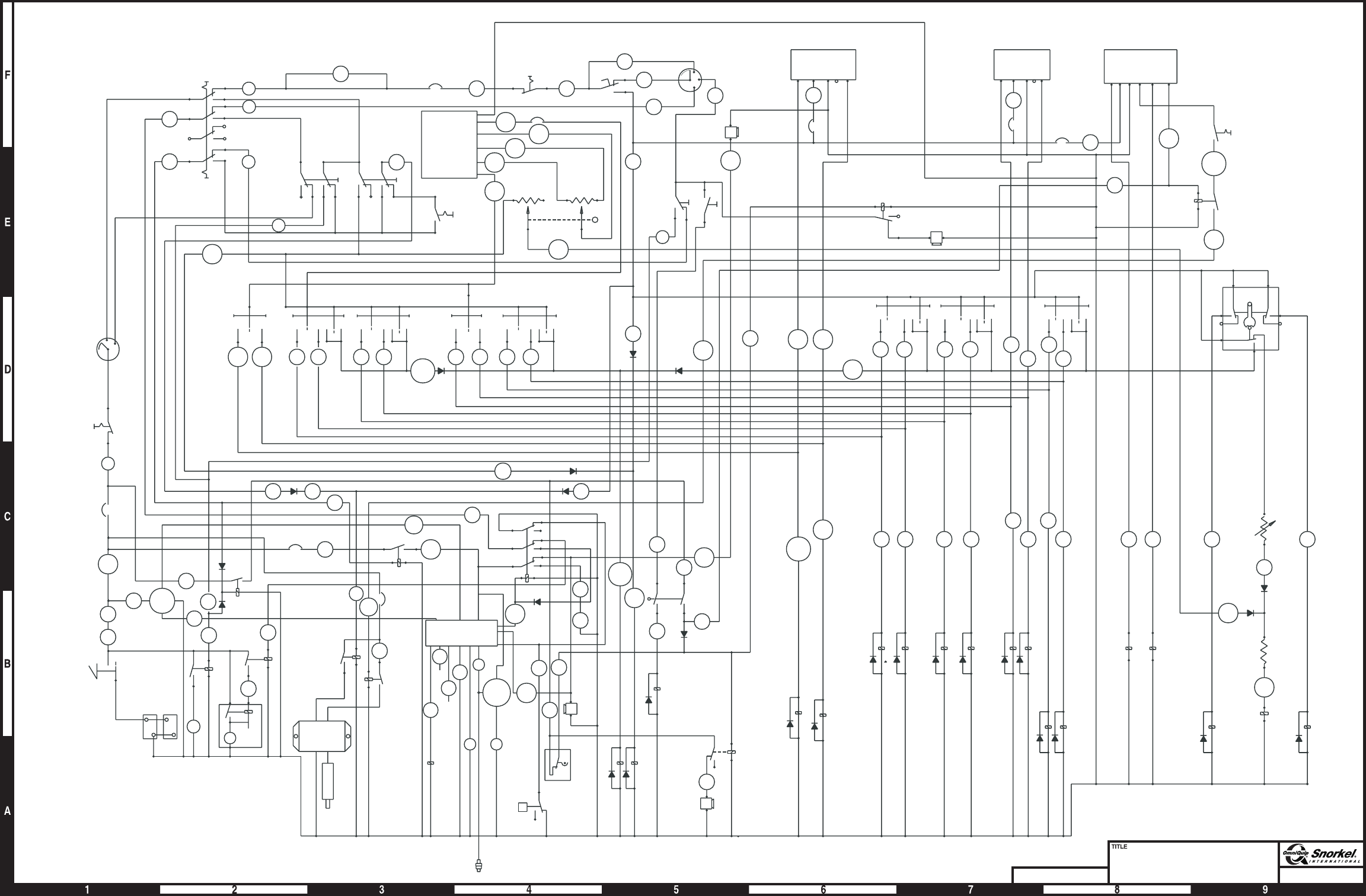
Page 11
6
TACH
GROUND
CONTROL
START
SWITCH
IGN
BAT
STR
1B
GROUND
EMERGENCY
STOP
SWITCH
GROUND
CONTROL
CIRCUIT
BREAKER
25 AMP
AMMETER
1A
A
57
MASTER
BATTERY
DISCONNECT
SWITCH
BATTERIES
12 VOLTS
5C
4A 4
GROUND
CONTROL
SELECTOR
PLATFORM
1
5
28
A
6
GROUND
EMER
POWER
GROUND
CONTROL
THROTTLE
21
B
22
B
MAIN
BOOM
12 13
LEVEL
14 15
BOOM
EXTEND
23 24 27 26
SWING PLATFORM
ROTATION
160
A
2
31
1C
GROUND
OPERATION
PLATFORM
CIRCUIT
BREAKER
20 AMP
REAR
RHEOSTAT
(BOOM
SPEED)
FRONT
RHEOSTAT
(BOOM
SPEED)
LIFT/SWING CIRCUIT
BREAKER 3 AMP
67
A
172
173
175
174
16A
BLACK
RED
YELLOW
PURPLE
GRAY
BLUE
PWM
MODULE
PLATFORM
EMER STOP
SWITCH
FOOT SWITCH
10
10
5
9
4C
8BAT
STR
IGN
ACC
PLATFORM
START
SWITCH
126
PLATFORM
RANGE
SWITCH
PLATFORM
ENG ALARM
LIFT
CIRCUIT
BREAKER
3AMP
68
A+-XB
LIFT
PLATFORM
EMER
POWER
PLATFORM
TILT RELAY
PLATFORM
TILT ALARM
70
A
125
A
125
70
DRIVE
CIRCUIT
BREAKER
3AMP
SWING
CIRCUIT
BREAKER
3AMP
PLATFORM
THROTTLE
PLATFORM
THROTTLE
RELAY
69
A+-XB
SWING
67
DRIVE
A+ - XB R
BOOM
EXTENDLEVEL
PLATFORM
ROTATION C
NC
NO
C
STEER C
NC
NO
NCNO
28
125
73 21
B
22
B
160
RIGHTLEFT
RESISTOR
5OHM
DRIVE
FORWARD
DRIVE
REVERSE
20
16
16
A
16
B
19
PLATFORM
RHEOSTAT
(BOOM SPEED)
PROPORTIONAL
BY-PASS COIL
17 18
UP
DOWN
GRD
TILT
RELAY
GRD
TILT
ALARM
RANGE
VALVE
74
DOWN UP CCW CW
RETRACT
EXTEND
CCW CW
21
B/A
22
B12 13
12 13
14 15
14 15
56
1B
6
6A 5B
5A
D
B
W
ALTNTR
START
RELAY
AUX
CIRCUIT
RELAY
MEDIUM
THROTTLE
RELAY
31 25
4A
1C 164
25
125
55
RUN
RELAY
THROTTLE
CIRCUIT
BREAKER
15 AMP
RED WHT
BLK
FUEL
ADDCO
ACTUATOR
ACTUATOR
MODULE
HIGH
THROTTLE
RELAY
164
B
5C
28
A
RUN
CIRCUIT
BREAKER 10 AMP
EMERGENCY
POWER UNIT
EMERGENCY
POWER RELAY
STARTER
MOTOR
M
M
25
11
126
1D
28
B
34
70
38
167
23
24
27
26
23
24
27
26
ANTI
RESTART
RELAY
HM
8D
33
T3
T2
T1
ENGINE
OIL
PRESSURE
SWITCH
P
ENG PROTECTION/
ANTI RESTART
MODULE
SENS 73
3C
1D
126
GRD
ENG
ALARM
LEVEL
SENSOR
(SHOWN
LEVEL) SENSE
DUMP
VALVE
BLOCK
VALVE
I
G
STEMP
GAUGE
BOOM
SWITCH
(SHOWN
BOOM UP)
ENG TEMP
SENSOR
160
C
Electrical wiring schematic
Deutz F4L-1011F engine
Snorkel model TB 60
DWG. A08090
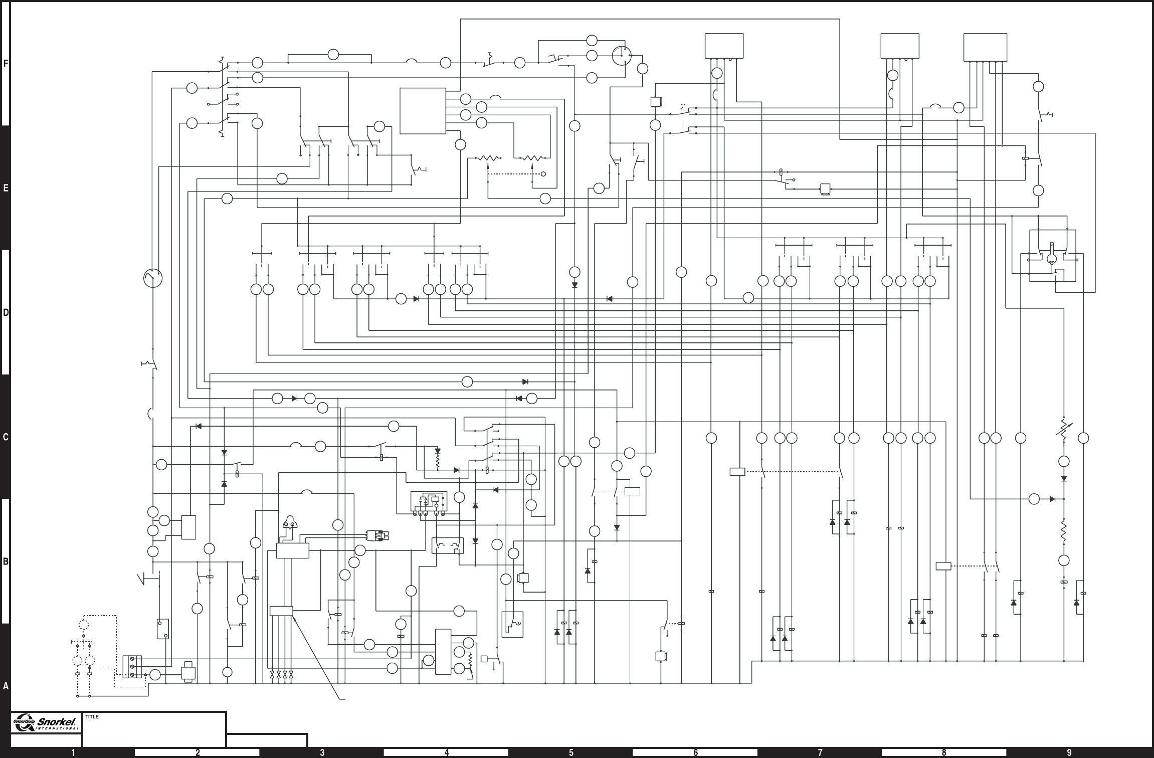
Page 12
Electrical wiring schematic
Ford LRG 423 engine
Snorkel model TB 60 DWG. 0082761
2
6
31
GROUND
EMERGENCY
POWER
GROUND
OPERATION
GROUND
CONTROL
THROTTLE
1C 10
FOOT SWITCH
PLATFORM
CIRCUIT BREAKER
20 AMP
PLATFORM
EMERGENCY
STOP SWITCH
10
8
5
4C
BAT
ACC
IGN
STR
PLATFORM
START
SWITCH
68
126
73
9
6
16A
A+- XB
LIFT
LIFT
CIRCUIT
BREAKER
3AMP
PLATFORM
ENGINE
ALARM
PLATFORM
RANGE SWITCH
PLATFORM
EMERGENCY
POWER
FRONT
RHEOSTAT
(BOOM
SPEED)
MAIN
BOOM LEVEL
BOOM
EXTEND SWING PLATFORM
ROTATION
28
A
21
B
22
B
28
27 262423
160
A
15
14
13
12
67
69
SWING
A+-XB
PLATFORM
TILT ALARM
PLATFORM
TILT RELAY
SWING
CIRCUIT
BREAKER
3AMP
DRIVE
CIRCUIT
BREAKER
3AMP
A+- XBR
PLATFORM
THROTTLE
PLATFORM
ROTATION
BOOM
EXTEND
LEVEL
125
160
21
B
22
B12 13 14 15 23 24 27 26
20
16
19
18
17
16
A
16
B
RIGHTLEFT
DRIVE
REVERSE
DRIVE
FORWARD
PLATFORM
RHEOSTAT
(BOOM SPEED)
STEER
CC
NC
NO
CNO NC
NO
NC
RESISTOR
PROPORTIONAL
BY-PASS COIL
RUN CIRCUIT
BREAKER 10 AMP
1C
RUN
RELAY
4A
25
31
164
B
25
160
C
28
B
11
1D
34
28
A
126
BLOCK
VALVE
SENSE
DUMP
VALVE
RANGE
VALVE
1D
73
230° 220°
ENGINE
TEMPERATURE
GAUGE
GROUND
CONTROL
CIRCUIT
BREAKER
25 AMP
P
LEVEL
SENSOR
(SHOWN
LEVEL)
ENGINE OIL
PRESSURE
SWITCH
38
HM
2423
15
14
13
12
22
B
21
B/A
CW
UP
DOWN
DOWN
RETRACT
EXTEND
GROUND
EMERGENCY
STOP
SWITCH
MAGNETIC SWITCH
GNO NC S B
C
TD
GND
ENG
ALARM
ANTI
RESTART
RELAY
GRD
TILT
RELAY
GRD
TILT
ALARM
AUX
CIRCUIT
RELAY
125
A
PLATFORM
THROTTLE
RELAY
125
164
3C
BLK
BLK WHT
UP
A
1A
56
57 6
M
-
AMMETER
MASTER
BATTERY
DISCONNECT
SWITCH
BATTERY
12 VOLTS
EMER.
POWER
UNIT
EMER.
POWER
RELAY
ALTERNATOR
5A
M
-
STARTER
SOLENIOD
5B
80
25
A
125
HIGH
THROTTLE
RELAY
MEDIUM
THROTTLE
RELAY
SPARK
PLUGS
START
RELAY
IGNITION
MODULE
ELECTRONIC
GOVERNOR
55
A55
B
54
G
H
C
D
A
B
E
F
80
A
3
A2
54
A1
ACTUATOR
VACUUM
SWITCH
78A
55
180
D
3C
1
5
4
4A
5C
GROUND
PLATFORM
CONTROL
SELECTOR
IGN
STR
BAT
GROUND
CONTROLS
START
SWITCH
67
A
175
172
174
173
REAR
RHEOSTAT
(BOOM
SPEED)
BLACK
RED
YELLOW
PURPLE
GRAY
BLUE
PWM
MODULE
LIFT/SWING
CIRCUIT BREAKER
3AMP
70
1B
DRIVE
CWCCW
2627
PROX
HI RANGE CUT OUT
(SHOWN BOOM OUT)
PROX
PROX
EXT/LIFT
CUT OUT
(SHOWN
WIFFLE
TRIPPED)
DRIVE
CUT OUT
(SHOWN
BOOM UP)
BOOMS/DRIVE
SELECTOR
SWITCH
DRIVE
BOOMS
CCW
THOTTLE CIRCUIT
BREAKER 15 AMP
CHOKE
DISTRIBUTERLESS
IGNITION COIL
ENG.
COOLANT
SENSOR
CRANK
POSITION
SENSOR
DUAL
FUEL
SWITCH
77A
78
77B
FILTER
LOCK FUEL
SHUTOFF
FUEL
PUMP
W
B+
B
A
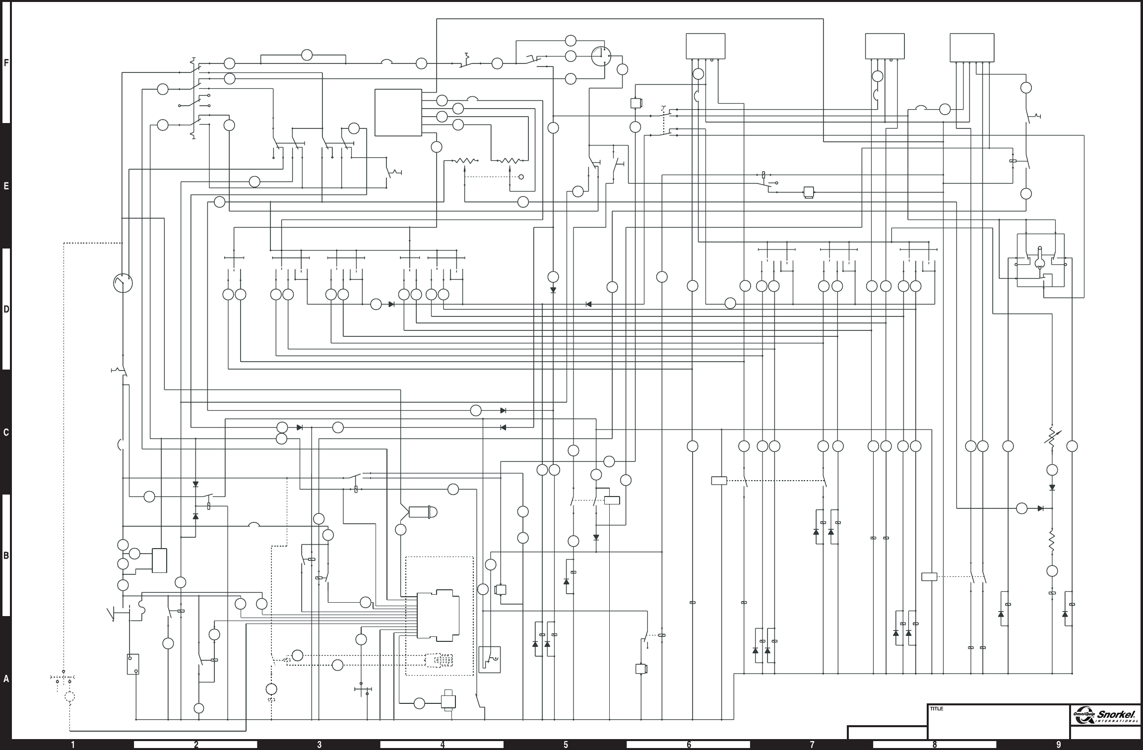
Page 13
Electrical wiring schematic
Ford LRG 425 engine
Snorkel model TB 60
DWG. 0082775
2
6
31
GROUND
EMERGENCY
POWER
GROUND
OPERATION
GROUND
CONTROL
THROTTLE
1C 10
FOOT SWITCH
PLATFORM
CIRCUIT BREAKER
20 AMP
PLATFORM
EMERGENCY
STOP SWITCH
10
8
5
4C
BAT
ACC
IGN
STR
PLATFORM
START
SWITCH
68
126
73
9
6
16A
A+- XB
LIFT
LIFT
CIRCUIT
BREAKER
3AMP
PLATFORM
ENGINE
ALARM
PLATFORM
RANGE SWITCH
PLATFORM
EMERGENCY
POWER
FRONT
RHEOSTAT
(BOOM
SPEED)
MAIN
BOOM LEVEL
BOOM
EXTEND SWING PLATFORM
ROTATION
28
A
21
B
22
B
28
27 262423
160
A
15
14
13
12
67
69
SWING
A+-XB
PLATFORM
TILT ALARM
PLATFORM
TILT RELAY
SWING
CIRCUIT
BREAKER
3AMP
DRIVE
CIRCUIT
BREAKER
3AMP
A+- XBR
PLATFORM
THROTTLE
PLATFORM
ROTATION
BOOM
EXTEND
LEVEL
125
160
21
B
22
B12 13 14 15 23 24 27 26
20
16
19
18
17
16
A
16
B
RIGHTLEFT
DRIVE
REVERSE
DRIVE
FORWARD
PLATFORM
RHEOSTAT
(BOOM SPEED)
STEER
CC
NC
NO
CNO NC
NO
NC
RESISTOR
PROPORTIONAL
BY-PASS COIL
160
C
28
B
11
1D
34
126
SENSE
DUMP
VALVE
RANGE
VALVE
2423
15
14
13
12
22
B
21
B/A
CW
UP
DOWN
DOWN
RETRACT
EXTEND
GROUND
EMERGENCY
STOP
SWITCH
GRD
TILT
RELAY
GRD
TILT
ALARM
125
A
PLATFORM
THROTTLE
RELAY
125
UP
1
5
4
4A
5C
GROUND
PLATFORM
CONTROL
SELECTOR
IGN
STR
BAT
GROUND
CONTROLS
START
SWITCH
25
31
28
A
A
1A
56
57 6
M
-
AMMETER
MASTER
BATTERY
DISCONNECT
SWITCH
BATTERY
12 VOLTS
EMER.
POWER
UNIT
EMER.
POWER
RELAY
ALTERNATOR
5A
M
-
STARTER
SOLENIOD
125
HIGH
THROTTLE
RELAY
MEDIUM
THROTTLE
RELAY
55
AUX
CIRCUIT
RELAY
GROUND
CONTROL
CIRCUIT
BREAKER
25 AMP
4A
RUN
RELAY
77B
78B
78A
156
55
B
170 171
GND
ENG
ALARM
HM
38
LEVEL
SENSOR
(SHOWN
LEVEL)
73
1D
180
181
149
67
A
175
172
174
173
REAR
RHEOSTAT
(BOOM
SPEED)
BLACK
RED
YELLOW
PURPLE
GRAY
BLUE
PWM
MODULE
LIFT/SWING
CIRCUIT BREAKER
3AMP
70
DRIVE
CWCCW
2627
PROX
HI RANGE CUT OUT
(SHOWN BOOM OUT)
PROX
PROX
EXT/LIFT
CUT OUT
(SHOWN
WIFFLE
TRIPPED)
DRIVE
CUT OUT
(SHOWN
BOOM UP)
BOOMS/DRIVE
SELECTOR
SWITCH
DRIVE
BOOMS
CCW
THOTTLE CIRCUIT
BREAKER 15 AMP
1B
FILTER
LOCK MALFUNCTION
INDICATOR
SWITCH
MALFUNCTION INDICATOR
LAMP
TO ENGINE HARNESS
(SEE FORD 425 EFI
ENGINE HARNESS
DRAWING)
DUAL FUEL
DUAL
FUEL
RELAY
NC
OIL PRESSURE
SWITCH
C
W
B+
FUEL
PUMP
78
DUAL
FUEL
SWITCH
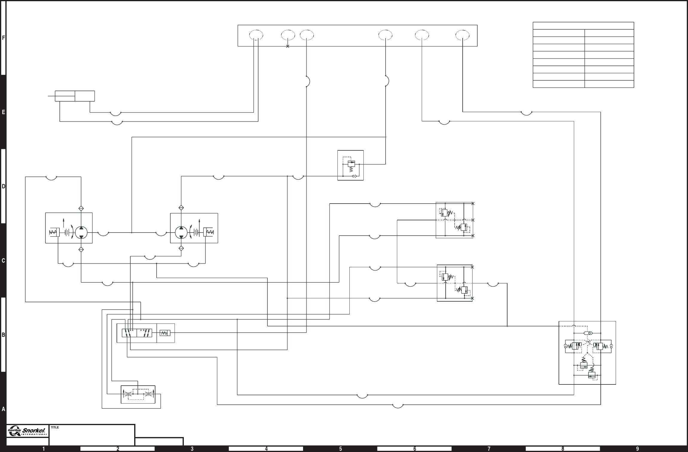
Page 14
Hydraulic schematic
Chassis, 2 wheel drive
Snorkel model TB 60 DWG. 0082089
FUNCTION CENTERPOST NO.
7
6
5
4
3
2
1
NOT USED
STEER - LEFT
STEER - RIGHT
PILOT
DRIVE - REVERSE
DRIVE - FORWARD
RETURN
OIL FLOW CHART
Centerpost
manifold
Anti-cavitation
valve
Rear drive
Steering cylinder
2500 PSI
FWD
1
2
B
A
A
B
FWD
LH RH
CDCD
BFA
E
Selector
valve
C2
V
C1
Flow
divider/combiner
M2
P
M1
M2
P
M1
1000
PSI
1000
PSI
Dual sequence valve
M1
P
M2
M2
P
M1
1000
PSI
1000
PSI
V2 V1
BR
3000
PSI
M1
M2
3000
PSI
1000
PSI Motion control
valve
1000
PSI
65 74 123
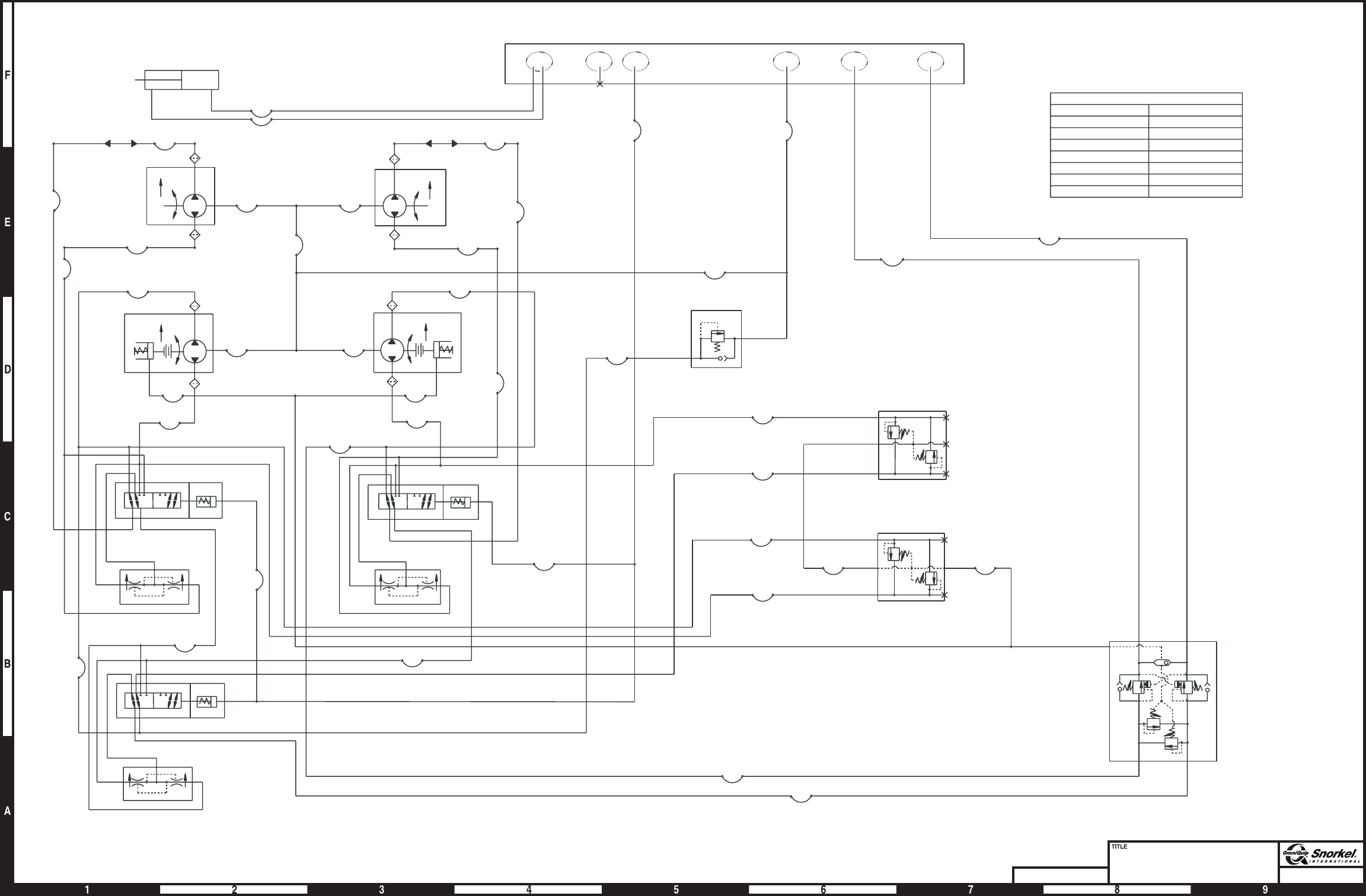
Page 15
Hydraulic schematic
chassis - 4 wheel drive
Snorkel model TB 60
DWG. 0082090
OIL FLOW CHART
RETURN
DRIVE - FORWARD
DRIVE - REVERSE
PILOT
STEER - RIGHT
STEER - LEFT
NOT USED
1
2
3
4
5
6
7
CENTERPOST NO.FUNCTION
2
1
CDCD
E
BFA
CDCD
EB FA
E
A
F
REV FWD
LH RH
LH RH
FWD
B
A
A
B
FWD
FWD FWD
A
A
B
B
B
CD CD
C2 C1
V
C2
C2
V
V
C1
C1
2500 PSI
M2
P
M1
M2
M2
M2
P
P
P
M1
M1
M1
1000
PSI
1000
PSI
BR
V2 V1
3000
PSI
M2 M1
Steering cylinder
FWD REV
Front motors
Rear motors
Dual sequence
valves
Anti-cavitaion
valve
Centerpost
manifold
65 74132
Motion control
valve
1000
PSI
1000
PSI
3000
PSI
1000
PSI
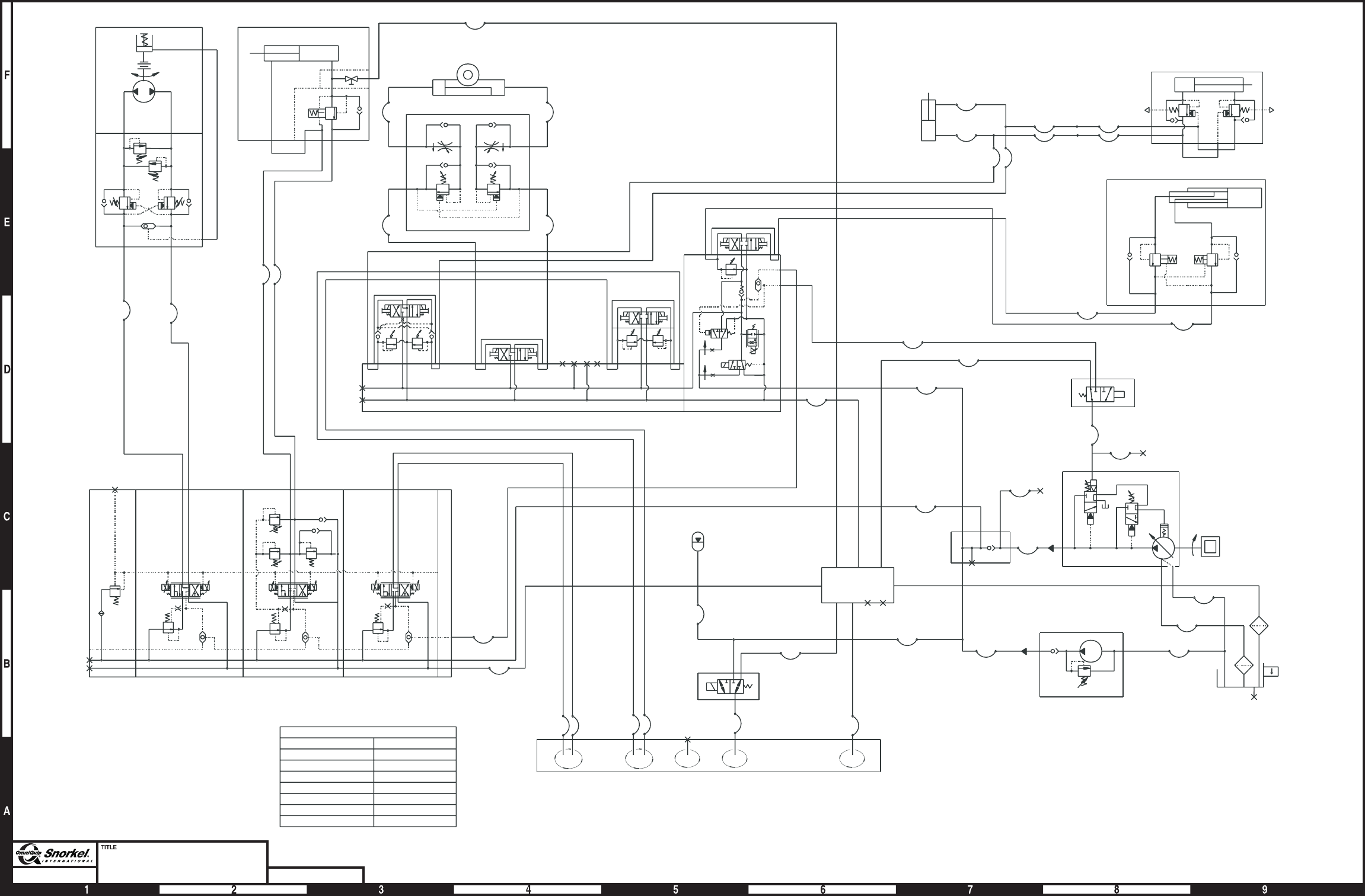
Page 16
Hydraulic schematic
turntable - booms
Snorkel model TB 60 DWG. 0082091
SWING
CCW
CW
900
PSI
900
PSI
1800
PSI
1800
PSI
BR
B
A
LIFT
312
3000 PSI
PLATFORM ROTATION
CCW CW
C1 C2
PLATFORM
CONTROL VALVE
3000 PSI 3000 PSI
V2V1
.25 GPM.25 GPM
LEVEL
2000
PSI
2000
PSI
B5 A5 B4 A4 B3 A3 B2 A2
2000
PSI
2000
PSI
STEER
EXTEND
B1 A1 VS
S
1700
PSI
3GPM
3.5 GPM P1
T1
CONTROL VALVE
PACKAGE
1
2
MASTER
LEVEL
SLAVE LEVEL
2200
PSI
2200
PSI
RET 6
5
21
3
4
EXTEND
3000 PSI 3000 PSI
12
CA
B
S
SENSE LINE
DUMP VALVE
TEST
PUMP
3000
PSI
350
PSI
TEST
T
P
P
SV
DV
EMERGENCY POWER
3000
PSI
RETURN
MANIFOLD
597
1
68
34
2
VP
EP T
CHECK
VALVE
MANIFOLD
ACCUMULATOR
CHARGE 300 PSI
RANG VALVE
CENTERPOST
C
A
B
23 5674 1
REV
C1
FWD
C2
24 GPM
24 GPM
DRIVE
33HZ 33HZ
LS
P
T
DRIVE/LIFT/SWING VALVE
LOWER
C1
LIFT
C2
LIFT
5.2 GPM
650
PSI
6.6 GPM
2500 PSI 1150 PSI
33HZ 33HZ
CCW
C1
CW
C2
SWING
3.3 GPM 3.3 GPM
33HZ
33HZ
OIL FLOW CHART
FUNCTION CENTERPOST NO
RETURN
DRIVE - FORWARD
DRIVE - REVERSE
PILOT
STEER - RIGHT
STEER - LEFT
NOT USED
1
2
3
4
5
6
7
