!! 2810223 1101 B
Preview ! 2810223_1101_b Progressive Turf Equipment Lawn Mower Manuals - Lawn Mower Manuals – The Best Lawn Mower Manuals Collection
User Manual: !! Progressive Turf Equipment Lawn Mower Manuals - Lawn Mower Manuals – The Best Lawn Mower Manuals Collection
Open the PDF directly: View PDF ![]() .
.
Page Count: 154 [warning: Documents this large are best viewed by clicking the View PDF Link!]

3DUWV0DLQWHQDQFH
0DQXDO
GB Part No. 2810223-Rev B
HR-9016 Turbo™ Rotary Mower
70524 - Detroit Diesel D704LT, 4WD
70525 - Detroit Diesel D704LT, 4WD with ROPS

Copyright 1999 Textron Inc. “All rights reserved, including the
right to reproduce this material or portions thereof in any form.”
To Order Parts
1. Write your full name and complete address on the
order.
2. Explain where and how to make shipment.
3. Give product number, name and serial number that is
stamped on the name plate or serial plate located on
the left rear frame of your product.
4. Order by the quantity desired, the part number, and
description of the part as given in the parts list.
5. Send or bring the order to an authorized Textron Turf
Care And Specialty Products Dealer.
6. Inspect all shipments on receipt. If any parts are
damaged or missing, file a claim with the carrier
before accepting.
7. Do not return material without a letter of explanation,
listing the parts being returned. Transportation
charges must be prepaid.
Use of other than Textron Turf Care And Specialty Products
authorized parts and accessories will void the warranty.
Table of Contents
1 Safety
1.1 Operating Safety............................................... 4
1.2 Important Safety Notes .....................................5
2 Specifications
2.1 Product Identification ........................................ 6
2.2 Engine ...............................................................6
2.3 Tractor ..............................................................6
2.4 Weights and Dimensions ..................................7
2.5 Cutting Units .....................................................7
2.6 Accessories & SUpport Literature .....................7
3 Adjustments
3.1 General ............................................................. 8
3.2 Leveling Decks .................................................8
3.3 Servicing Front Deck ........................................9
3.4 Winglet Adjustment ...........................................9
3.5 Cutting Height .................................................10
3.6 Parking Brake .................................................11
3.7 Neutral Adjustment .........................................11
3.8 Neutral Sensing Switch ...................................12
3.9 Forward Sensing Switch .................................12
3.10 Lift Limit Switches ...........................................13
3.11 Traction Pedal .................................................14
3.12 Steering Toe-In ...............................................14
3.13 Steering Stop Bolts .........................................14
3.14 Torque Specification .......................................15
4 Maintenance
4.1 General .......................................................... 16
4.2 Inspecting Blades ........................................... 16
4.3 Sharpening Blades ......................................... 17
4.4 Engine ............................................................ 18
4.5 Engine Oil ....................................................... 18
4.6 Muffler and Exhaust ....................................... 18
4.7 Air filter ........................................................... 19
4.8 Fuel ................................................................ 19
4.9 Fuel System ................................................... 20
4.10 Battery ............................................................ 20
4.11 Jump Starting ................................................. 20
4.12 Charging Battery ............................................ 21
4.13 Hydraulic Hoses ............................................. 21
4.14 Hydraulic Oil ................................................... 22
4.15 Hydraulic Filters ............................................. 22
4.16 Radiator & Oil Cooler ..................................... 23
4.17 Care and Cleaning ......................................... 24
4.18 Electrical System ............................................ 24
4.19 Tires ............................................................... 26
4.20 Wheel Mounting Procedure ............................ 26
4.21 Rollover Protection Structure (ROPS) ............ 27
4.22 Storage ........................................................... 27
4.23 Maintenance Chart ......................................... 28
4.24 Lubrication Chart ............................................ 29
5 Troubleshooting
5.1 General .......................................................... 30
6 Parts List
6.1 Table of Contents........................................... 31
Litho in U.S.A. 11-2001
3
Suggested Stocking Guide
To Keep your Equipment fully operational and productive, Textron Turf Care And Specialty Products suggests you
maintain a stock of the more commonly used maintenance items. We have included part numbers for additional
support materials and training aids.
To order any of the following material:
1. Write your full name and complete address on your
order form.
2. Explain where and how to make shipment:
❑ UPS ❑ Regular Mail
❑ Overnight ❑ 2nd Day
3. Order by the quantity desired, the part number, and
the description of the part.
4. Send or bring the order to your authorized Textron
Turf Care And Specialty Products Dealer.
How To Use This Manual
Abbreviations
N/S - Not serviced seperately, can only be obtained by ordering main component or kit.
AR -Variable quantity or measurement is required to obtain correct adjustment.
Symbols such as ●, next to the item number, indicate that a note exists which contain additional information
important in ordering that part.
Bulleted Items
Bulleted items indicate component parts that are included as part of an assembly or another component. These parts
can be ordered separetely or as part of the main component.
Item Part No. Qty Description Serial Numbers/Notes
●1 123456 1 Mount, Valve Indicates a piece part
2 789012 1 Valve, Lift Includes Items 2 and 3
3 345678 1 • Handle Serviced part included with Item 2
4 N/S 1 • Seal Kit Non serviced part included with Item 2
5 901234 1 Screw, 1/4-20 x 2” Hex Head
Service Parts
Service Support Material
Qty. Part No. Description Qty. Part No. Description
5003207 Engine Oil Filter 5003691 Hydraulic Charge Filter
5003370 Engine Air Filter 5002693 Hydraulic Return Filter
5003212 Engine Fuel Filter
Qty. Part No. Description
2810264 Safety & Operation Manual
2810223 Parts & Maintenance
5003465 Video, Operator Training
Qty. Description
Service Manual

1 SAFETY
4
1 S AFETY
1.1 OPERATING SAFETY ______________________________________________________
1. Safety is dependent upon the awareness, concern
and prudence of those who operate or service the
equipment. Never allow minors to operate any
equipment.
2. It is your responsibility to read this manual and all
publications associated with this equipment (Safety
and Operation manual, engine manual, accessories
and attachments). If the operator can not read
English it is the owner’s responsibility to explain the
material contained in this manual to them.
3. Learn the proper use of the machine, the location
and purpose of all the controls and gauges before
you operate the equipment. Working with unfamiliar
equipment can lead to accidents.
4. Never allow anyone to operate or service the
machine or its attachments without proper training
and instructions; or while under the influence of
alcohol or drugs.
5. Wear all the necessary protective clothing and
personal safety devices to protect your head, eyes,
ears hands and feet. Operate the machine only in
daylight or in good artificial light.
6. Inspect the area where the equipment will be used.
Pick up all the debris you can find before operating.
Beware of overhead obstructions (low tree limbs,
electrical wires, etc.) and also underground
obstacles (sprinklers, pipes, tree roots, etc.) Enter a
new area cautiously. Stay alert for hidden hazards.
7. Never direct discharge of material toward
bystanders, nor allow anyone near the machine
while in operation. The owner/operator can prevent
and is responsible for injuries inflicted to
themselves, to bystanders and damage to property.
8. Never operate equipment that is not in perfect
working order or is without decals, guards, shields,
discharge deflectors or other protective devices
securely fastened in place.
9. Never disconnect or bypass any switch.
10. Carbon monoxide in the exhaust fumes can be fatal
when inhaled. Never operate the engine without
proper ventilation.
11. Fuel is highly flammable, handle with care.
12. Keep the engine clean. Allow the engine to cool
before storing and always remove the ignition key.
13. Disengage all drives and engage parking brake
before starting the engine (motor). Start the engine
only when sitting in operator’s seat, never while
standing beside the unit.
14. Equipment must comply with the latest federal,
state, and local requirements when driven or
transported on public roads.
15. Never use your hands to search for oil leaks.
Hydraulic fluid under pressure can penetrate the
skin and cause serious injury.
16. Operate the machine up and down the face of the
slopes (vertically), not across the face (horizontally).
17. To prevent tipping or loss of control, do not start or
stop suddenly; reduce speed when making sharp
turns. Use caution when changing direction on
slopes.
18. Always use the seat belt when operating tractors
equipped with a ROPS.
Never use a seat belt when operating tractors
without a ROPS.
19. Keep legs, arms and body inside the seating
compartment while the vehicle is in motion.
This machine is to be operated and maintained as specified in this manual and is intended for the professional
maintenance of specialized turf grasses. It is not intended for use on rough terrain or long grasses.
WARNING
EQUIPMENT OPERATED IMPROPERLY OR BY UNTRAINED PERSONNEL CAN BE DANGEROUS.
Familiarize yourself with the location and proper use of all controls. Inexperienced operator’s should receive
instruction from someone familiar with the equipment before being allowed to operate the machine.
!

SAFETY 1
5
1.2 IMPORTANT SAFETY NOTES ________________________________________________
This safety alert symbol is used to alert you to potential hazards.
DANGER - Indicates an imminently hazardous situation which, if not avoided, WILL result in death or serious injury.
WARNING - Indicates a potentially hazardous situation which, if not avoided, COULD result in death or serious
injury.
CAUTION - Indicates a potentially hazardous situation which, if not avoided, MAY result in minor or moderate injury
and property damage. It may also be used to alert against unsafe practices.
For pictoral clarity, some illustrations in this manual may show shields, guards or plates open or removed. Under no
circumstances should this equipment be operated without these devices securely fastened in place
By following all instructions in this manual, you will prolong the life of your machine and maintain its maximum
efficiency. Adjustments and maintenance should always be performed by a qualified technician.
If additional information or service is needed, contact your Authorized Textron Turf Care And Specialty Products Dealer
who is kept informed of the latest methods to service this equipment and can provide prompt and efficient service. Use
of other than original or authorized Textron Turf Care And Specialty Products parts and Accessories will void
the warranty.
WARNING
The operator back-up system on this tractor prevents the tractor from starting
unless the brake pedal is engaged, mower switch is off and traction pedal is
in neutral. The system will stop the engine if the operator leaves the seat
without engaging the parking brake or setting the mower switch off.
NEVER operate tractor unless the operator back-up system is working.
!
!
WARNING
1. Before leaving the operator’s position for any reason:
a. Return traction pedal to neutral.
b. Disengage all drives.
c. Lower all implements to the ground.
d. Engage parking brake.
e. Stop engine and remove the ignition key.
2. Keep hands, feet, and clothing away from moving parts. Wait for all
movement to stop before you clean, adjust or service the machine.
3. Keep the area of operation clear of all bystanders and pets.
4. Never carry passengers, unless a seat is provided for them.
5. Never operate mowing equipment without the discharge deflector
securely fastened in place.
!

2 SPECIFICATIONS
6
2 SPECIFICATIONS
2.1 PRODUCT IDENTIFICATION _________________________________________________
70524.............................. HR 9016 Turbo, 4 Wheel Drive
70525.............................. HR 9016 Turbo, 4 Wheel Drive
with ROPS
Serial Number ................ An identification plate, like the one
shown, listing the serial number, is
attached to the frame of the
tractor and is located to the
operator’s right just over the rear
axle.
Always provide the serial number of the unit when
ordering replacement parts or requesting service
information. * With engine at 2400 RPM (No Load)
2.2 ENGINE__________________________________________________________________
Make ............................... Detroit Diesel Corp
Model .............................. D704LT
Horsepower..................... 87 hp (66 kW) @ 3000 rpm
Displacement .................. 169.4 cu. In. (2.776 liter)
Torque ............................. 236 ft. lbs. (320 Nm) @ 1200 rpm
Fuel:
Type .......................... No. 2 Diesel (CUNA NC 630.01)
Rating ....................... Min. cetane rating 45
Capacity.................... 35 U.S. Gal. (151 liters)
Governor Setting:
High Idle:
Throttle Stop On ....... 2400 rpm (PTO off)
2300 rpm (PTO engaged)
Throttle Stop Off ....... 2750 rpm (Non EU only)
Low Idle .................... 1050 rpm
Lubrication:
Capacity.................... 7 qts.
Type .......................... SAE 15 W40
API Classification ..... CF 4, CD-II, CE
Air Filter .......................... Dry type with evacuator valve and
service indicator.
Alternator........................ 55 amp
2.3 TRACTOR ________________________________________________________________
Tires:
Front ......................... 29 x 14 - 15: 8 ply
Rear ......................... 24 x 12 -12: 6 ply
Pressure ................... 20-22 psi (138-152 kPa)
Battery:
Type .......................... Two maintenance Free 12 Volt
Batteries
1390 CCA @ 0°F (-18°C)
Group........................ 75-84N
Brakes:
Service ..................... Dynamic braking through traction
circuit.
Parking...................... Mechanical front wheel drum
Hand lever actuated
Turn-assist ................ Mechanical front wheel drum
Two pedal actuation
Speed:
Mow ......................... 0 - 8.5 mph (13.6 kph)
Transport - 2 WD ...... 0-20 mph (32 kph)
Reverse - 2WD ......... 0-5.5 mph (8.9 kph)
Reverse - 4 WD ........ 0 - 3 mph (4.8 kph)
Production ...................... 16.5 acres per hour @ 8.5 mph
Hydraulic System:
Capacity.......................... 55 U.S. gal. (208 liters) System
Reservoir ........................ 33 U.S. gal. (125 liters)
Fluid Type ....................... ISO VG 68
Cooling ........................... Hydraulic oil Cooler
Charge Filter................... 10 micron
Return Line Filter............ 10 micron
Steering ......................... Hydrostatic power steering
Product* EEC Sound
Power
Sound Pressure
Level Operator Ear
Vibration M/S2
Arms Body
70524 105 dba 90 dba .755 .026
70525 105 dba 90 dba .755 .026
JACOBSEN DIVISION OF TEXTRON INC.
RA
RA
CINE,
CINE,
WIS
WIS
.
MADE IN U
MADE IN U
.S.A.
.A.
SERIAL NUMBER
88006 1651
70524 1601

SPECIFICATIONS 2
7
2.4 WEIGHTS AND DIMENSIONS ________________________________________________
Dimensions: Inches (mm)
Length - Front deck down.............................. 174 (4420)
Height - Top of Steering Wheel ...................... 60 (1524)
Height - Top of ROPS...................................... 94 (2388)
Width - Mow .................................................. 198 (5029)
Width - Transport............................................. 95 (2413)
Weights: Lbs. (kg)
Overall (less operator) ................................ 6385 (2880)
2.5 CUTTING UNITS ___________________________________________________________
Width
Front Deck.................92 in. (2336 mm)
Side Decks ................59 in. (1499 mm)
Number of Blades
Front Deck.................5
Side Decks ................3
Overall Cutting Width ......16 ft. (2.4 m)
Cutting Height .................1-5.5 in. (25 - 140 mm)
Blade size ....................... 21 in. (533 mm)
Tip speed........................ 16,500 ft./min. (5029 m/min.)
Tires
Size........................... Ten 11 x 4.00 - 5.0 (4 ply)
Two 13 x 6.50 - 6.0 (4 ply)
Pressure ................... 20-25 psi (138-173 kPa)
2.6 ACCESSORIES & SUPPORT LITERATURE _____________________________________
Contact your area Textron Turf Care And Specialty Products Dealer for a complete listing of accessories and
attachments.
Air Blow Gun ...........................................................JAC5098
Orange Touch-up Paint (12 oz. spray) ...................... 554598
2-Post ROPS with Seat Belt........................................ 78138
● All Weather Cab w ROPS and Seat Belt.......... See Below
● Air Conditioner Kit ............................................ See Below
Leaf Mulching Kit ........................................................ 71055
High Lift Blade Kit ................................................... 4116825
Light Harness Kit..................................................... 5003564
Road Light Kit (Requires 5003564)............................. 78154
Work Light Kit (Requires 5003564) ............................. 78155
Canopy / Sunshade..................................................... 67857
Rear Steering Wheel Weight Kit ..............................2812307
Carefree Tire Kit ......................................................2811453
Hood Locking Latch .................................................1004049
Cruise Control..............................................................67888
◆ Snowthrower .....................................................See Below
▲ Rotary Broom ...................................................See Below
Service and Support Literature
Safety and Operation Manual ..................................3010791
Parts and Maintenance Manual ...............................2810223
Operator Training Video...........................................5003465
Service & Repair Manual
● Contact: Jodale Perry Corporation
Box 990, 300 Route 100
Morden, Manitoba, Canada R6M 1A8
Phone: (204) 822-9100
Fax: (204) 822-9111
◆ Contact: Loftness Specialized Equipment, Inc.
South Highway 4
Hector, MN 55342
Phone 800-828-7624
Fax (320) 848-6269
ATTN Doug Haley
▲ Contact: M-B Companies, Inc.
1200 S. Park Street, Box 148
Chilton, WI 53014
Phone: (888) 558-5801
Fax: (920) 898-4588
CAUTION
Use of other than Textron Turf Care And Specialty Products authorized parts and accessories may cause personal
injury or damage to the equipment and will void the warranty.
!
3 ADJUSTMENTS
8
3 ADJUSTMENTS
3.1 GENERAL________________________________________________________________
1. Adjustments and maintenance should always be
performed by a qualified technician. If proper
adjustment cannot be made, contact an authorized
Textron Turf Care And Specialty Products Dealer.
2. Replace, do not adjust, worn or damaged
components.
3. Do not wear jewelry or loose fitting clothing when
making adjustments or repairs.
4. Do not change governor settings or overspeed the
engine.
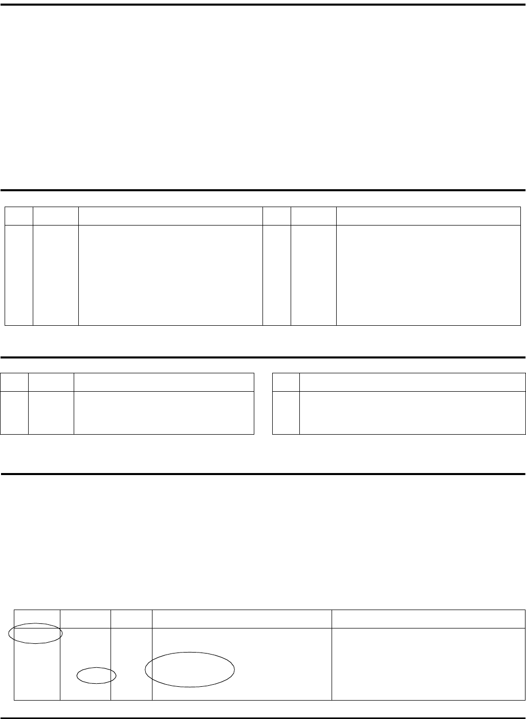
3.2 LEVELING DECKS _________________________________________________________
If the decks or casters have been removed for service or
cutting height appears uneven, it may be necessary to
level decks. Adjust casters so cutting heights of outer
blades are within 1/8” (3 mm) of each other.
1. Position tractor and decks on a hard, flat, level
surface. Position blades parallel to tractor as shown.
2. Check that air pressure in all caster tires is adjusted
equally.
3. Set desired cutting height of deck using the 1/2” (13
mm) spacers (E) provided. See Section 3.5
4. Measure the height from the ground surface to the
front edge (B) of the two outer blades for the wing
decks and the center section of the front deck.
Position the 1/8” (3 mm) leveling washers (C) above
or below caster pivot as needed to obtain an even
cutting height across decks. Keep the 1/16” (1.5
mm) thrust washers (D) positioned as shown, one
above and one below caster pivot.
Figure 3A
WARNING
To prevent injury, lower implements to the ground,
disengage all drives, engage parking brake, stop
engine and remove key from ignition switch before
making any adjustments or performing maintenance.
Make sure the tractor is parked on a solid and level
surface. Never work on a tractor that is supported only
by the jack. Always use jack stands.
If only the front or rear of the tractor is raised, place
chocks in front of and behind the wheels that are not
raised.
!
CAUTION
Be careful to prevent entrapment of the hands and
fingers between moving and fixed components of the
machine.
!
B
B
BB
B
C
C
E
D
HR018
LL
ADJUSTMENTS 3
9
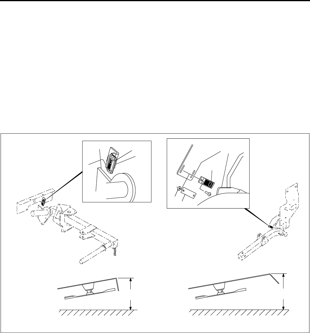
3.3 SERVICING FRONT DECK___________________________________________________
The front deck can be raised and tilted up to improve
access to the cutting unit and blades for service and
cleaning. Be sure to disengage all drives, engage parking
brake, stop engine and remove ignition key before
working around deck.
To tilt front deck up to its service position:
1. Rotate anti-sway mechanism (F), located under left
side floor panel, to Service position. Figure 3C
2. Start engine and raise deck until rear gauge wheels
are off ground. Stop engine.
3. Remove cut height adjustment pins from gauge
wheel bracket so yoke assembly floats freely.
4. Start engine and raise deck to full up position. Stop
engine.
5. Manually lift and rotate front of deck up until it is
securely latched.
To return deck to service:
1. Lift up on deck and pull locking latch (A) out.
2. Start engine and lower deck until it is level and
caster wheels are just above ground. Stop engine.
3. Insert height adjustment pin for rear casters to
match cutting height. Figure 3F
4. Rotate anti-sway mechanism (F) to it’s operating
position. Figure 3C
Figure 3B
Figure 3C
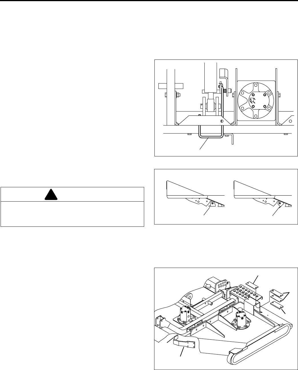
3.4 WINGLET ADJUSTMENT____________________________________________________
1. Winglets must be adjusted to front deck to prevent
scalping and possible damage to deck winglets.
2. Rotate front deck blades to positions shown in
Figure 3A.
3. Measure the height from the ground to the front
edge of the center front deck blade (B) and the
outside edges of winglet blades (L). Add or remove
shims (G) as required between pad (H) and support
bracket of winglets, until all front deck blades are at
the same height.
4. Store excess shims (G) above support bracket.
5. Adjust front winglet support arms (J) up or down as
required until arm is resting against stop (K).
Figure 3D
CAUTION
Pulling latch out will release the full weight of the
deck. Make sure antone assisting in this procedure is
made aware of this before the latch is released.
!
AHR007
Operating
Position
Service
Position
FFHR029
K
J
H
G
G
3 ADJUSTMENTS
10
3.5 CUTTING HEIGHT _________________________________________________________
Cutting height for decks can be adjusted from 1 to 5-1/2
in. (25-125 mm) in 1/2 in. (13 mm) increments. Actual
cutting height may vary somewhat from the heights given
depending on turf conditions and other factors.
Note: When cutting undulating areas, lower cutting
heights may cause scalping. Adjust height accordingly to
prevent turf damage.
1. Park the tractor on a flat, level surface. Raise the
decks until the caster wheels are raised off the
ground enough so caster wheels can be removed
from deck. Place blocks under decks so they are
supported on all sides.
To remove inside, front caster from side decks raise
the decks to their full upright position and lock in the
transport position.
2. Figure 3E shows the height adjustment decal for the
casters.
Column 1 - Height of cut
Column 2 - Mount Location
Column 3 - Arrangement of spacers
Adjust spacers in quantity listed. Store extra spacers
on top of spindle. If necessary, reposition wheel
mount in holes indicated for height of cut.
IMPORTANT: Do not reposition the thin thrust
washers (1/16”) and leveling washers (1/8”) on the
spindle. These washers should remain in the same
position and quantity they were originally installed.
They need only be repositioned if needed to level
new casters or decks, Section 3.2
3. To adjust rear gauge wheels on front deck refer to
Figure 3F. Raise front deck approximately 12” and
support underneath with blocks. Lower deck so it is
completely resting on blocks
4. Remove pin from rear gauge wheel yoke and
reposition in bracket for desired height of cut. When
setting cutting height at 5-1/2”, gauge wheel must
be repositioned in arm. Follow wheel mounting
instructions on decal, Figure 3F.
Figure 3E
Figure 3F
Tire pressure
Check air pressure in caster tires, while tires are cool.
Maintain air pressure between 20-25 psi (138-173 kPa)
to improve accuracy of cutting height.
Note: It is important to keep inflation pressures on all
caster and gauge tires equal, within the range specified,
to ensure an accurate, level cut.
WARNING
To prevent serious injury, lower deck until it is
resting completely on the supports. This will
prevent it from accidentally lowering while making
adjustments. Disengage all drives, engage
parking brake, stop engine and remove ignition
key.
!
Upper
Mount
Lower
Spacers
Under
Mount
Middle
Thrust
Washer &
Leveling
Washer
Never reposition the thrust washer(s) (1/16" thick)
and leveling washer(s) (1/8" thick)
when setting cut height
Cut Mount No. of Spacers
Height Location Under Mount
1 1/2 Lower 1
2 Lower 2
2 1/2 Lower 3
2 1/2 Middle 0
3 Middle 1
3 1/2 Middle 2
4 Middle 3
4 Upper 0
4 1/2 Upper 1
5 Upper 2
5 1/2 Upper 3
BCDE
A
FR
1234
5678
Arm
Bracket
Wheel
Mounting
Cut Bracket Arm Wheel
Height Hole Hole Mounting
13AF
1 1/2 1 B F
22CF
2 1/2 3 D F
34EF
3 1/2 5 B F
46CF
4 1/2 7 D F
58EF
5 1/2 8 E R
Wheel Mounting Instruction
1 While rotating wheel, tighten
nut until wheel is difficult to
rotate.
2 Loosen nut 1/4 turn or just
until wheel rotates freely.
3 lock nut into place using
second nut. Do not allow
first nut to rotate when
tightening second nut securely.
4 Rotate wheel to check for
free rotation with zero end
play.
Gauge Wheel Adjustment for Front Deck
ADJUSTMENTS 3
11
3.6 PARKING BRAKE _________________________________________________________
The brake switch is part of the operator back-up system
and senses when the parking brake is engaged. If this
switch fails the machine may not start and the operator
back-up system will not operate correctly.
To adjust switch:
1. Place the parking brake in its full upright (engaged)
position.
2. Adjust switch (C) by pivoting switch mounting
bracket (B). Align sensing area on switch with brake
handle (D).
3. Adjust gap between sensing area on switch and
brake lever to 1/16 - 1/8” (1.5 - 3 mm). To adjust
gap use shims (E) or #10 washers (F) as required
between switch and switch mount.
4. When properly installed the switch will be closed
when the parking brake is engaged and open when
the brake is disengaged.
Important: Always check operator back-up system after
replacing or adjusting switch. (See Safety and Operation
Manual)
Figure 3G
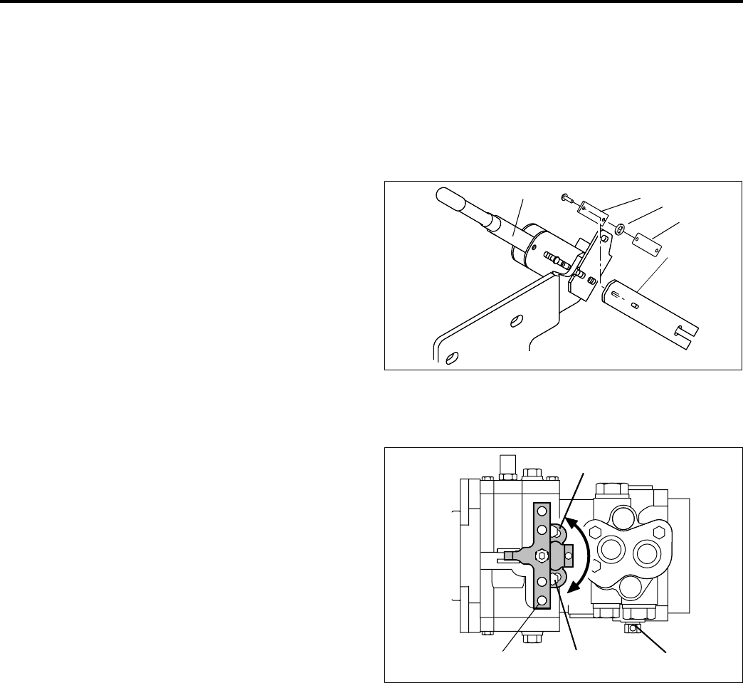
3.7 NEUTRAL ADJUSTMENT ___________________________________________________
Important: The neutral adjustment on the drive pump is
preset at the factory on all new tractors and replacement
pumps. Further adjustment is required only if the pump
has been disassembled for service or neutral lever
bracket (F) has become loose.
To adjust neutral on pump:
1. Disconnect traction pedal linkage from pump.
Remove switch mounting bracket from pump.
2. Place tractor securely on jack stands so All wheels
are raised off ground.
3. Check that tow valve (H) is completely closed.
4. Loosen screws (G) holding pump return arm bracket
just enough so it can be moved.
5. Engage parking brake and set PTO switch to
neutral.
The neutral sensing switch must be closed in order to
start the tractor. At this point the switch may not yet
be assembled to pump. To close switch so engine
can be started, place it face down on metal frame.
6. Start engine and observe wheels. Rotate bracket (F)
in slotted holes until wheels do not turn. Turn off
engine and tighten bracket in place.
7. Connect traction pedal linkage, Section 3.11, and
install and adjust switches, Sections 3.8 and 3.9.
8. Start engine and check operation of traction pedal.
Wheels must not turn when pedal returns to neutral.
Figure 3H
B
C
D
HR020
E
F
F
H
G
K
HR027
3 ADJUSTMENTS
12
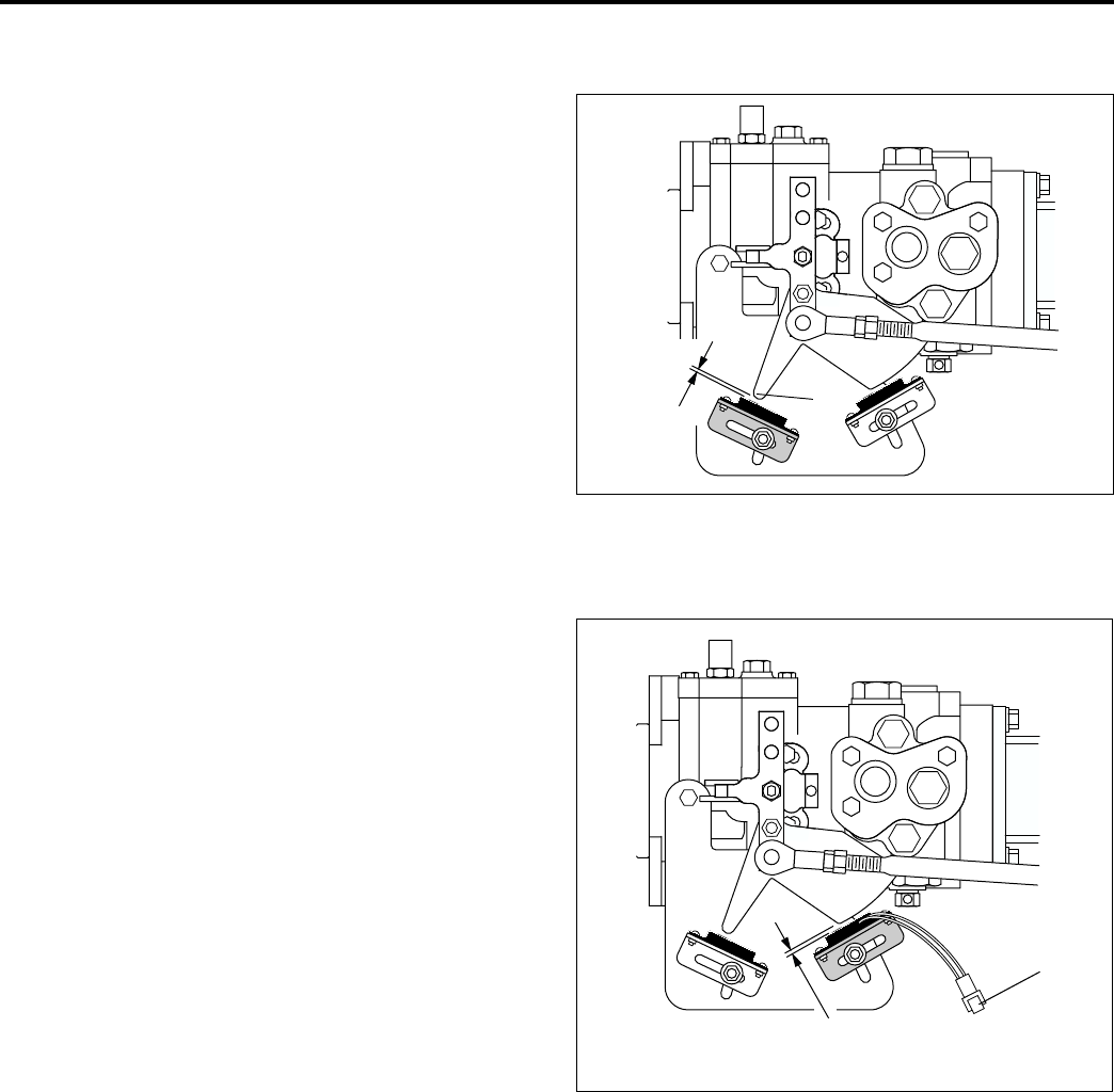
3.8 NEUTRAL SENSING SWITCH________________________________________________
The neutral sensing switch is part of the operator backup
system. It is designed to prevent the tractor from starting
unless the traction pedal is in neutral. If this switch fails or
is out of adjustment the tractor will not start.
1. Make sure drive pump and traction pedal linkage are
adjusted to neutral. Sections 3.7 and 3.11.
2. Position switch so pointer (A) on activator plate is
centered over sensing area on switch.
3. Adjust switch so gap between sensing surface on
switch and end of pointer is between 1/16” - 1/8”
(1.5 - 3 mm). Secure switch in this position.
4. After adjustment check operation of operator backup
system.
Figure 3I
3.9 FORWARD SENSING SWITCH _______________________________________________
The forward sensing switch allows the tractor to operate
in four wheel drive only with the traction pedal in its
forward position. When operating in reverse the switch
opens and returns the tractor to two wheel drive. If four
wheel drive fails to operate, check adjustment and
operation of sensing switch.
1. Make sure drive pump, traction pedal linkage and
neutral sensing switch are adjusted to neutral,
Sections 3.7, 3.11 and 3.8.
2. Adjust switch so gap between sensing surface on
switch and edge of activator plate is between 1/16” -
1/8” (1.5 - 3 mm).
3. Disconnect switch from wiring harness and connect
a continuity meter across switch leads (B). With
traction pedal in neutral, slide switch back until it
opens, then forward until it closes. Secure switch in
this position.
4. With continuity meter still attached check adjustment
by pressing traction pedal.
Switch closed - traction pedal in neutral and during
full forward range of pedal.
Switch open - Full reverse range of pedal.
5. Connect switch to wiring harness and check
operation of four wheel drive.
Figure 3J
A
1/16” - 1/8”
(1.5 - 3 mm)
HR010
B
1/16” - 1/8”
(1.5 - 3 mm)
HR012
ADJUSTMENTS 3
13
3.10 LIFT LIMIT SWITCHES _____________________________________________________
The rotation of the cutting blades is controlled by limit
switches positioned on the tractor frame near the lift arms
for each deck. When a deck is raised the switch opens
and automatically disengages the cutting blades. As the
deck is lowered, the switch closes and the blades
engage. If a switch fails, the cutting blades will not
engage when lowered.
To adjust limit switches:
1. Park tractor on a level surface.
2. Start tractor and raise or lower decks until the
highest point on the top corner of the deck reaches
the height shown in Figure 3K.
3. Shut off engine and remove key. Support decks
using blocks. This will prevent them from accidently
lowering while making adjustments.
4. Position switch so sensing area (C) on switch is
centered over leading edge (A) of activator plate on
lift arm.
5. Adjust gap between sensing area on switch and
activator plate on lift arm to 1/16”-1/8” (1.5 - 3 mm).
To adjust gap for front lift arm use shims (D) or #10
flat washers (B) between switch and switch mount.
Check operation of limit switches. Blades must stop
rotating as decks are raised above heights shown.
Figure 3K
Side Decks Front Deck
21 in.
(61 cm)
20 5/8 in.
(53 cm)
A
B
AC
C
HR028
D
3 ADJUSTMENTS
14
3.11 TRACTION PEDAL _________________________________________________________
The traction pedal must be adjusted so the pump is at full
stroke when the pedal is fully depressed in the forward
position.
1. Make sure return arm (K-Figure 3H) on pump is
adjusted to neutral, Section 3.7.
2. Push traction pedal forward (I) until it touches floor
panel and hold in this position.
3. Adjust turn buckle (J) until you feel the return arm
hit the internal stop in pump. Backoff rod 2-3 turns
from this position. This ensures that the traction
pedal bottoms out before the return arm. Figure 3L
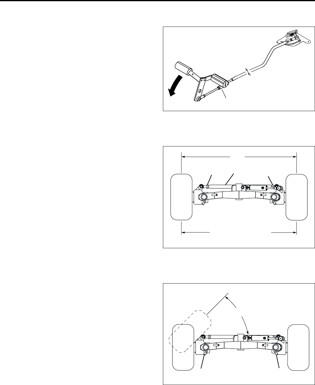
3.12 STEERING TOE-IN _________________________________________________________
1. Turn wheels to straight ahead position.
2. Loosen jam nuts (M) on both ends of tie rod (N).
3. Turn tie rod (N) to provide proper toe-in. Toe-in must
not exceed X + 1/4” (6.3 mm). Tighten jam nuts (M).
Figure 3M
3.13 STEERING STOP BOLTS ___________________________________________________
1. Steering toe-in must be set before adjusting stop
bolts. If toe-in is changed, stop bolts must be re-
adjusted.
2. Turn stop bolts (P and Q) out as far as possible
without removing them.
3. Turn steering wheel to the right until right rear tire is
at a 45° angle to steering axle. Thread stop bolt (P)
in until bolt touches axle.
4. Turn steering wheel to the left until left rear tire is at
a 45° angle to steering axle. Thread stop bolt (Q) in
until bolt touches axle.
Figure 3N
IJHR019
X
X + 5/32" 3/32"
-
+
(4 mm 2.3 mm)
-
+
X +
MM
N
45
PQ
°
ADJUSTMENTS 3
15
3.14 TORQUE SPECIFICATION ___________________________________________________
Textron Turf Care And Specialty Products uses Grade 5 Plated bolts as standard, unless otherwise noted. For
tightening plated bolts, use the value given for lubricated.
CAUTION
All torque values included in these charts are approximate and are for reference only. Use of these torque values is
at your sole risk. Textron Turf Care And Specialty Products is not responsible for any loss, claim, or damage arising
from the use of these charts. Extreme caution should always be used when using any torque value.
AMERICAN NATIONAL STANDARD FASTENERS
SIZE UNITS GRADE 5 GRADE 8 SIZE UNITS GRADE 5 GRADE 8
Lubricated Dry Lubricated Dry Lubri-
cated
Dry Lubri-
cated
Dry
#6-32 in-lb (Nm) –20 (2.3) ––7/16-14 ft-lb (Nm) 37 (50.1) 50 (67.8) 53 (71.8) 70 (94.9)
#8-32 in-lb (Nm) –24 (2.7) –30 (3.4) 7/16-20 ft-lb (Nm) 42 (56.9) 55 (74.6) 59 (80.0) 78 (105)
#10-24 in-lb (Nm) –35 (4.0) –45 (5.1) 1/2-13 ft-lb (Nm) 57 (77.2) 75 (101) 80 (108) 107 (145)
#10-32 in-lb (Nm) –40 (4.5) –50 (5.7) 1/2-20 ft-lb (Nm) 64 (86.7) 85 (115) 90 (122) 120 (162)
#12-24 in-lb (Nm) –50 (5.7) –65 (7.3) 9/16-12 ft-lb (Nm) 82 (111) 109 (148) 115 (156) 154 (209)
1/4-20 in-lb (Nm) 75 (8.4) 100 (11.3) 107 (12.1) 143 (16.1) 9/16-18 ft-lb (Nm) 92 (124) 122 (165) 129 (174) 172 (233)
1/4-28 in-lb (Nm) 85 (9.6) 115 (13.0) 120 (13.5) 163 (18.4) 5/8-11 ft-lb (Nm) 113 (153) 151 (204) 159 (215) 211 (286)
5/16-18 in-lb (Nm) 157 (17.7) 210 (23.7) 220 (24.8) 305 (34.4) 5/8-18 ft-lb (Nm) 128 (173) 170 (230) 180 (244) 240 (325)
5/16-24 in-lb (Nm) 173 (19.5) 230 (26.0) 245 (27.6) 325 (36.7) 3/4-10 ft-lb (Nm) 200 (271) 266 (360) 282 (382) 376 (509)
3/8-16 ft-lb (Nm) 23 (31.1) 31 (42.0) 32 (43.3) 44 (59.6) 3/4-16 ft-lb (Nm) 223 (302) 298 404 315 (427) 420 (569)
3/8-24 ft-lb (Nm) 26 (35.2) 35 (47.4) 37 (50.1) 50 (67.8) 7/8-14 ft-lb (Nm) 355 (481) 473 (641) 500 (678) 668 (905)
METRIC FASTENERS
SIZE UNITS
Non Critical
Fasteners
into
Aluminum
Lubricated Dry Lubricated Dry Lubricated Dry Lubricated Dry
M4 Nm (in-lb) ––––––3.83 (34) 5.11 (45) 2.0 (18)
M5 Nm (in-lb) 1.80 (16) 2.40 (21) 4.63 (41) 6.18 (54) 6.63 (59) 8.84 (78) 7.75 (68) 10.3 (910 4.0 (35)
M6 Nm (in-lb) 3.05 (27) 4.07 (36) 7.87 (69) 10.5 (93) 11.3 (102) 15.0 (133) 13.2 (117) 17.6 (156) 6.8 (60)
M8 Nm (in-lb) 7.41 (65) 9.98 (88) 19.1 (69) 25.5 (226) 27.3 (241) 36.5 (323) 32.0 (283) 42.6 (377) 17.0 (150)
M10 Nm (ft-lb) 14.7 (11) 19.6 (14) 37.8 (29) 50.5 (37) 54.1 (40) 72.2 (53) 63.3 (46) 84.4 (62) 33.9 (25)
M12 Nm (ft-lb) 25.6 (19) 34.1 (25) 66.0 (48) 88.0 (65) 94.5 (70) 125 (92) 110 (81) 147 (108) 61.0 (45)
M14 Nm (ft-lb) 40.8 (30) 54.3 (40) 105 (77) 140 (103) 150 (110) 200 (147) 175 (129) 234 (172) 94.9 (70)
4.6 8.8 10.9 12.9
4 MAINTENANCE
16
4 MA INTE NANCE
4.1 GENERAL________________________________________________________________
1. Adjustment and maintenance should always be
performed by a qualified technician. If proper
adjustments cannot be made, contact an Authorized
Textron Turf Care And Specialty Products Dealer.
2. Inspect the equipment on a regular basis, establish
a maintenance schedule and keep detailed records.
a. Keep the equipment clean.
b. Keep all moving parts properly adjusted and
lubricated.
c. Replace worn or damaged parts before operating
the machine.
d. Keep all fluids at their proper levels.
e. Keep shields in place and all hardware securely
fastened.
f. Keep tires properly inflated.
3. Do not wear jewelry or loose fitting clothing when
making adjustments or repairs.
4. Use the illustrations in the Parts List as reference
for the disassembly and reassembly of components.
5. Recycle or dispose of all hazardous materials
(batteries, fuel, lubricants, anti-freeze, etc.)
according to local, state or federal regulations.
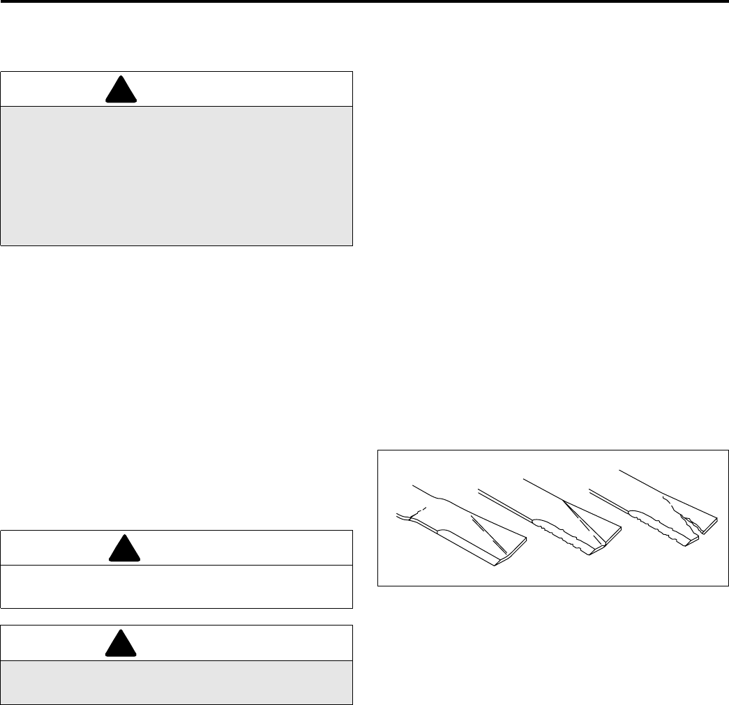
4.2 INSPECTING BLADES______________________________________________________
1. Every 50 hours of operation or whenever mower is
removed from tractor, carefully examine the blades to
make sure they are in good operating condition.
Blades showing any bends (G), grooves (H) or
cracks (J) must be replaced.
2. Any of the above conditions can cause a piece of
the blade to break away and be hurled from the
mower; causing very serious injury to bystanders or
property damage.
3. A bent blade could have a microscopic crack (G)
that can grow and allow a piece of the blade to
break. Bent blades will also create vibration and
other stress on the machinery.
4. Dust or sand particles can wear a dangerous groove
in the blade (H) between the air vanes and the flat
portion of the blade that will rapidly grow and
produce a crack (J), permitting a piece of the vane
to break off.
Figure 4A
WARNING
Before you clean, adjust, or repair this equipment,
disengage all drives, lower implements to the ground,
engage parking brake, stop engine and remove key
from ignition switch to prevent injuries
Make sure the tractor is parked on a solid and level
surface. Never work on a tractor that is supported only
by the jack. Always use jack stands.
!
CAUTION
Use care when checking blades to avoid pinching hands
and fingers between blade ends.
WARNING
Never attempt to straighten, weld or repair a damaged
blade. Always replace a damaged blade.
!
!
GHJ
HR025
MAINTENANCE 4
17
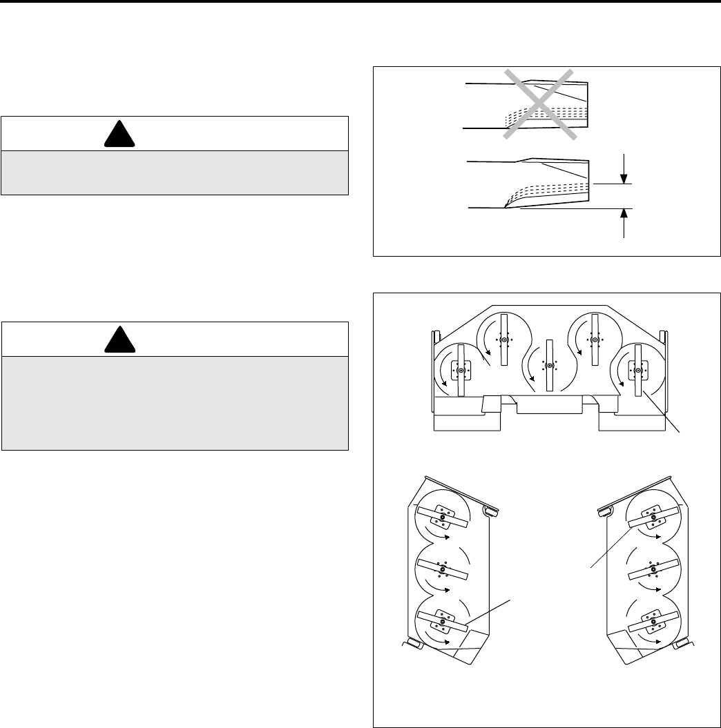
4.3 SHARPENING BLADES _____________________________________________________
1. Place a wooden block between the blade and mower
housing to stop the blade from moving. To remove
blade, turn screw holding blade counterclockwise.
2. When dressing or sharpening the blade, do not
follow the original pattern of grind as shown in (A).
Grind new cutting edges at an angle as shown in
(B).
If the maximum total loss of the blade reaches 1/2 in.,
(13 mm), do not sharpen further, replace blade.
3. Make sure an equal amount of material is removed
from both sides of blade to prevent having an
unbalanced blade. An unbalanced blade will cause
excessive vibration and may damage the mower.
4. Use a blade balancer to check the blade after
sharpening.
5. Attach blade to mower. Install blades so cutting
edges (C) face the direction of rotation as shown in
Figure 4C. Beveled cutting edge of blade must face
in toward deck housing.
Torque center mounting screw holding blade to 75
to 90 ft. lb. (100 to 120 Nm).
Figure 4B
Figure 4C
WARNING
The mower blades can develop sharp edges. Use
caution whenever servicing and handling.
WARNING
Resharpening the blade beyond the allowable 1/2
in., (13 mm) may allow blade tip break off and be
thrown from the mower. Such an incident can cause
very serious injury to bystanders and/or property
damage.
!
!
A
B
1/2” (13 mm)
Maximum
HR024
Bottom view of front deck
in its service position
Bottom view of side decks
raised to their transport position.
Left Side Right Side
C
C
C
HR015
4 MAINTENANCE
18
4.4 ENGINE _________________________________________________________________
IMPORTANT: A separate Engine Manual, prepared by
the engine manufacturer, is supplied with this
tractor. Read the engine manual carefully until you
are familiar with the operation and maintenance of
the engine. Proper attention to the engine
manufacturer’s directions will assure maximum
service life of the engine. To order replacement
engine manuals contact the engine manufacturer.
The proper break-in of a new engine can make a
considerable difference to the performance and life of the
engine.
During the break-in period, Textron Turf Care And
Specialty Products recommends the following:
1. During the first 50 hours of operation, a new engine
should be allowed to reach an operating temperature
of at least 140°F (60°C) prior to operation at full load.
2. Check the engine oil level twice daily during the first
50 hours of operation. Higher than normal oil
consumption is not uncommon during the initial
break-in period.
3. Change engine oil and oil filter element after first 50
hours of operation.
4. Check and adjust fan and alternator belts.
5. Refer to Section 4.23 and Engine Manual for
specific maintenance intervals and procedures.
If the injection pump, injectors or the fuel system require
service, contact an authorized Textron Turf Care And
Specialty Products Dealer.
Note: The tractor is designed to operate and cut most
efficiently at the preset governor setting. Do not change
the engine governor settings or overspeed the engine.
4.5 ENGINE OIL ______________________________________________________________
Check the engine oil at the start of each day, before
starting the engine. If the oil level is low, remove oil filler
cap and add oil as required up to MAX mark on dipstick.
Perform initial oil change after first 25 hours of operation
and every 250 hours thereafter. See Engine Manual.
Use engine oil with API classification CD-II, CE, CF-4.
See Engine Manual for complete specifications.
Figure 4D
4.6 MUFFLER AND EXHAUST __________________________________________________
To protect from carbon monoxide poisoning, inspect the
complete exhaust system regularly and always replace a
defective muffler. If you notice a change in the color or
sound of the exhaust, stop the engine immediately.
Identify the problem and have the system repaired.
Torque all exhaust manifold hardware evenly. Tighten or
replace exhaust clamps.
SAE 15W-40
+45˚C
+113˚F
-20˚C
-4˚F
HR005
WARNING
Exhaust fumes contain carbon monoxide that is toxic
and can be fatal when inhaled.
NEVER operate an engine without proper ventilation.
!
MAINTENANCE 4
19
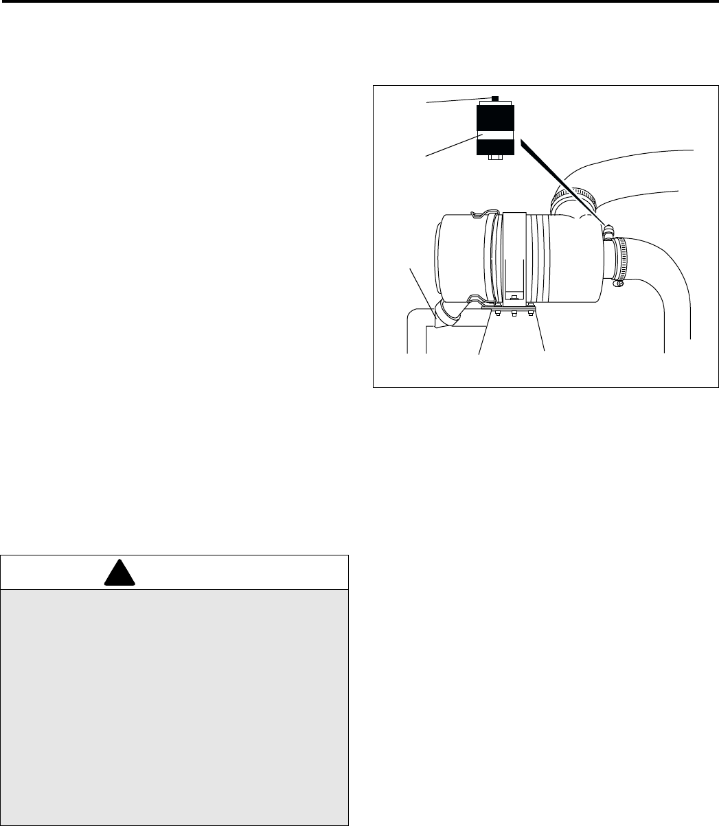
4.7 AIR FILTER _______________________________________________________________
Check the service indicator daily. Replace air cleaner
element immediately when red band becomes visible (A)
Do not remove the element for inspection or
cleaning. Unnecessary removal of the filter increases
the risk of injecting dust and other impurities into the
engine.
When service is required, first clean the outside of the
filter housing; then remove the old element as gently as
possible and discard.
1. Carefully clean the inside of the filter housing without
allowing dust into the air intake.
2. Inspect the new element. Do not use a damaged
element and never use an incorrect element.
3. Assemble the new element and make sure it seats
properly. Reset the indicator by depressing button
(B).
4. Reassemble cap making sure it seals completely
around the filter housing. Dust evacuator (C) must
be facing down.
5. Check all hoses and air ducts. Tighten hose clamps.
Figure 4E
4.8 FUEL ____________________________________________________________________
Handle fuel with care - it is highly flammable. Use an
approved container, the spout must fit inside the fuel filler
neck. Avoid using cans and funnels to transfer fuel.
•Fill the fuel tank to within 1 in. (25 mm) below the filler
neck.
•Use clean, fresh, #2 Diesel fuel. Minimum Cetane
Rating 45. Refer to Engine Manual for additional
information.
•Replace fuel lines and clamps at the first sign of
damage.
•Store fuel according to local, state or federal
ordinances and recommendations from your fuel
supplier.
•Never overfill or allow the tank to become empty.
Read Engine Owner’s Manual for additional fueling
information.
A
C
B
HR009
WARNING
Never remove the fuel cap from the fuel tank, or add
fuel, when the engine is running or while the engine is
hot.
Do not smoke when handling fuel. Never fill or drain
the fuel tank indoors.
Use4 care to avoid spilling fuel. If fuel is spilled, clean
it up immediately.
Never handle or store fuel containers near an open
flame or any device that may create sparks and ignite
the fuel or fuel vapors.
Be sure to reinstall and tighten fuel cap securely.
!

4 MAINTENANCE
20
4.9 FUEL SYSTEM ____________________________________________________________
Refer to Section 4.23 for specific maintenance intervals.
See Engine Manual for detailed procedures.
Before replacing any filter, thoroughly clean the filter
housing and the area around the filter. Dirt must not be
allowed to enter into fuel system.
Bleed the fuel system after the fuel filter and lines have
been removed, or the fuel tank has become empty.
To change fuel filter:
1. Close fuel valve on tank; then remove and discard
the existing filter.
2. Apply a light coat of oil to the gasket and hand
tighten new filter.
3. Fill fuel tank. Open fuel valve on tank and bleed the
filter. See Engine Manual. Clean any spilled fuel
immediately.
4.10 BATTERY ________________________________________________________________
Make absolutely certain the ignition switch is “Off” and
the key has been removed before servicing the battery.
Tighten cables securely to battery terminals and apply a
light coat of silicone dielectric grease to terminals and
cable ends to prevent corrosion. Keep vent caps and
terminal covers in place
Keep the cable ends, battery and battery posts clean.
Verify battery polarity before connecting or disconnecting
the battery cables.
1. When installing the battery, always assemble the
RED, positive (+) battery cable first and the ground,
BLACK, negative (-) cable last.
2. When removing the battery, always remove the
ground, BLACK, negative (-) cable first and the
RED, positive (+) cable last.
3. Make sure battery is properly installed and secured
to the battery tray.
4.11 JUMP STARTING __________________________________________________________
Before attempting to “jump start” the tractor, check the
condition of the discharged battery. Section 4.10
When connecting jumper cables:
1. Stop the engine on vehicle with good battery.
2. Connect RED jumper cable to the positive (+)
terminal on the good battery and to the positive (+)
terminal on the “discharged” battery.
3. Connect the BLACK jumper cable from the negative
(-) terminal on the good battery to the frame of
tractor with discharged battery.
After cables have been connected, start the engine on
the vehicle with the good battery then start the tractor.
CAUTION
Always use insulated tools, wear protective glasses or
goggles and protective clothing when working with
batteries. You must read and obey all battery
manufacturer’s instructions
!
WARNING
Battery posts, terminals and related accessories
contain lead and lead compounds, chemicals known
to the State of California to cause cancer and
reproductive harm. Wash your hands after
handling.
!
WARNING
Batteries generate explosive hydrogen gas. To reduce
the chance of an explosion, avoid creating sparks
near battery. Always connect the negative jumper
cable to the frame of the tractor with the discharged
battery, away from the battery.
!

MAINTENANCE 4
21
4.12 CHARGING BATTERY _____________________________________________________
1. Refer to Section 4.10. Read the Battery and
Charger’s manual for specific instructions.
2. Whenever possible, remove the battery from the
tractor before charging. If battery is not sealed,
check that the electrolyte covers the plates in all the
cells.
3. Make sure the charger is “Off”, then connect the
charger to the battery terminals as specified in the
charger’s manual.
4. Always turn the charger “Off” before disconnecting
charger from the battery terminals.
4.13 HYDRAULIC HOSES _______________________________________________________
1. Always lower implements to ground, disengage all
drives, engage parking brake, stop engine and
remove key before inspecting or disconnecting
hydraulic lines or hoses.
2. Check visible hoses and tubes daily. Look for wet
hoses or oil spots. Replace worn or damaged hoses
and tubes before operating the machine.
3. The replacement tube or hoses must be routed in
the same path as the existing hose, do not move
clamps, brackets and ties to a new location.
4. Thoroughly inspect all tubes, hoses and connections
every 300 hours.
IMPORTANT: The hydraulic system can be
permanently damaged if the oil becomes
contaminated. Before disconnecting any hydraulic
component, clean the area around the fittings and
the hose ends to keep impurities out of the system.
a. Before disconnecting any hydraulic component,
tag or mark the location of each hose then clean
the area around the fittings.
b. As you disconnect the component, be prepared
to assemble plugs or caps to the hose ends and
open ports. This will keep impurities out of the
hydraulic system and also prevent oil spills.
c. Make sure “O” rings are clean and hose fittings
are properly seated before tightening.
d. Keep the hose from twisting. Twisted hoses can
cause couplers to loosen as the hose flexes dur-
ing operation resulting in oil leaks.
e. Kinked or twisted hoses can restrict the oil flow
causing the system to malfunction and the oil to
overheat and also lead to hose failure.
WARNING
Charge battery in a well ventilated area. Batteries
generate explosive gases. To prevent an explosion,
keep any device that may create sparks or flames
away from the battery.
To prevent injury, stand away from battery when the
charger is turned on. A damaged battery could
explode.
!
WARNING
To prevent serious injury from hot, high pressure oil,
never use your hands to check for oil leaks, use paper
or cardboard.
Hydraulic fluid escaping under pressure can have
sufficient force to penetrate skin. If fluid is injected into
the skin it must be surgically removed within a few
hours by a doctor familiar with this form of injury or
gangrene may result.
!

4 MAINTENANCE
22
4.14 HYDRAULIC OIL __________________________________________________________
Refer to Section for specific maintenance intervals.
Drain and replace the hydraulic oil if you notice the
presence of water or foam in the oil, a rancid odor
(indicating excessive heat), or after a major component
failure,
Always replace both hydraulic filters when oil filter light
stays on or when changing oil.
To change hydraulic oil:
1. Clean the area around the oil cap to prevent
impurities from entering and contaminating the
system.
2. Remove drain plug from bottom of tank.
3. After oil has drained install drain plug and fill with
Textron Turf Care And Specialty Products Hydraulic
oil.
4. Purge air from system.
a. Operate all tractor functions for about 5 minutes
to purge air out of the system and stabilize the oil
level. During this time, the oil level alarm may
sound.
b. Once the level has stabilized and the air is
purged, fill the tank to the full mark on dipstick.
Start engine and check that oil alarm remains off.
4.15 HYDRAULIC FILTERS ______________________________________________________
The hydraulic system is protected by two 10 micron
filters; a charge filter (B) and return line filter (A). Flow
though the filters is monitored during operation. When
pressure drop across the filters is too high the hydraulic
oil filter warning light will come on. To ensure continued
protection to the hydraulic system, replace filters as soon
as possible if light continues to remain on even after
hydraulic fluid has warmed up.
Note: The warning light will normally come on
immediately after starting tractor and remain on until oil
has warmed to operating temperature. Wait until oil has
warmed up and light goes out before operating tractor.
To replace hydraulic filters:
Replace filters once a year when changing hydraulic
fluid, or when filter warning light on instrument panel
remains on.
The return line filter is mounted to the left side of the oil
cooler. The charge filter is mounted to the lower part of
the tractor frame behind the left side lift arm.
1. Remove the old filters.
Note: Some hydraulic fluid will drain when removing
the lower charge filter. Place a drip pan under filter
before removing.
2. Install new filters. Hand tighten only.
3. Operate engine at idle speed with hydraulic system
in neutral for five minutes. The oil level alarm may
sound during this time.
4. Check hydraulic oil level in reservoir and fill to full
mark on dipstick.
MAINTENANCE 4
23
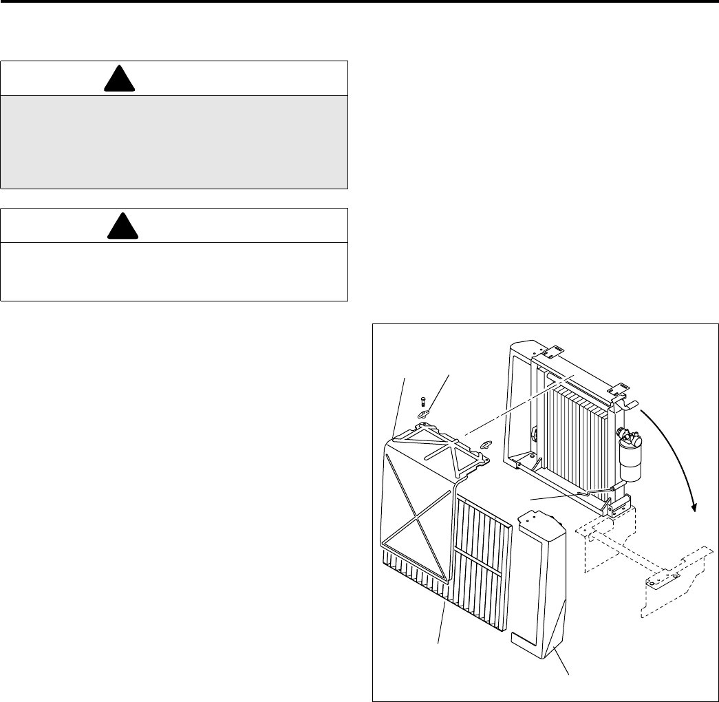
4.16 RADIATOR & OIL COOLER __________________________________________________
Check coolant level daily. Radiator should be full and
recovery bottle should be up to the cold mark.
If you have to add coolant more than once a month, or
add more than one quart at a time, have a Textron Turf
Care And Specialty Products Dealer check the cooling
system.
Drain and refill annually. Remove the radiator cap, open
the engine block drain and the radiator drain. Empty and
clean the recovery bottle.
Mix clean water with ethylene glycol based anti-freeze for
the coldest ambient temperature. Read and follow the
instructions on the anti-freeze container and engine
manual.
Keep screen, oil cooler and radiator air passages clean.
Use compressed air (30 psi maximum) to clean the fins.
Front Screen
Inspect front screen (B) daily and clean as required to
remove grass clippings, leaves and other debris that may
restrict air flow through oil cooler and radiator.
To remove screen, remove end cap (A) from left side of
oil cooler. Slide screen out from side and blow out from
back side using compressed air.
Oil Cooler and Radiator
Inspect oil cooler and radiator daily and clean as required
to maintain good air flow.
1. Remove screen (B) from front of oil cooler.
2. Unfasten knobs (C) located on top of oil cooler
and remove plastic shield from front of oil cooler.
3. Release prop rod (D) at bottom of cooler and
position hydraulic line to the front of it so hose can
move freely. Swing cooler up and away from
radiator as shown (E). Insert prop rod into hole in
frame to hold oil cooler in its service position.
4. Use a blow gun to clean the radiator and oil cooler
fins.
5. After cleaning, swing cooler back in place in front of
radiator. Secure prop rod (D) down so it holds
hydraulic line running behind it in place.
6. Replace front screen and shields, and install knobs
on top of oil cooler to secure assembly in place.
Figure 4F
WARNING
To prevent serious bodily injury from hot coolant or
steam blow-out, never attempt to remove the radiator
cap while the engine is running. Stop the engine and
wait until it is cool. Even then, use extreme care when
removing the cap.
CAUTION
Do not pour cold water into a hot radiator. Do not operate
engine without a proper coolant mixture. Install cap and
tighten securely.
!
!
A
B
C
D
E
F
HR008
HR022
4 MAINTENANCE
24
4.17 CARE AND CLEANING _____________________________________________________
Wash the tractor and implements after each use. Keep the
equipment clean.
Note: Do not wash any portion of the equipment while it is
hot. Do not use high pressure spray or steam. Use cold
water and automotive cleaners.
1. Use compressed air to clean engine and radiator fins. A
special blow gun is available through Textron Turf Care
And Specialty Products Dealer.
2. Use only fresh water for cleaning your equipment.
Note: Use of salt water or affluent water has been known
to encourage rust and corrosion of metel parts resulting
in premature deterioration or failure. Damage of this
nature is not covered by the factory warranty.
3. Do not spray water directly at the instrument panel,
ignition switch, controller or any other electrical
components, or at bearing housings and seals.
4. Clean all plastic or rubber trim with a mild soap
solution or use commercially available vinyl/rubber
cleaners.
Repair damaged metal surfaces and use Textron Turf Care
And Specialty Products touch-up paint. Wax the equipment
for maximum paint protection.
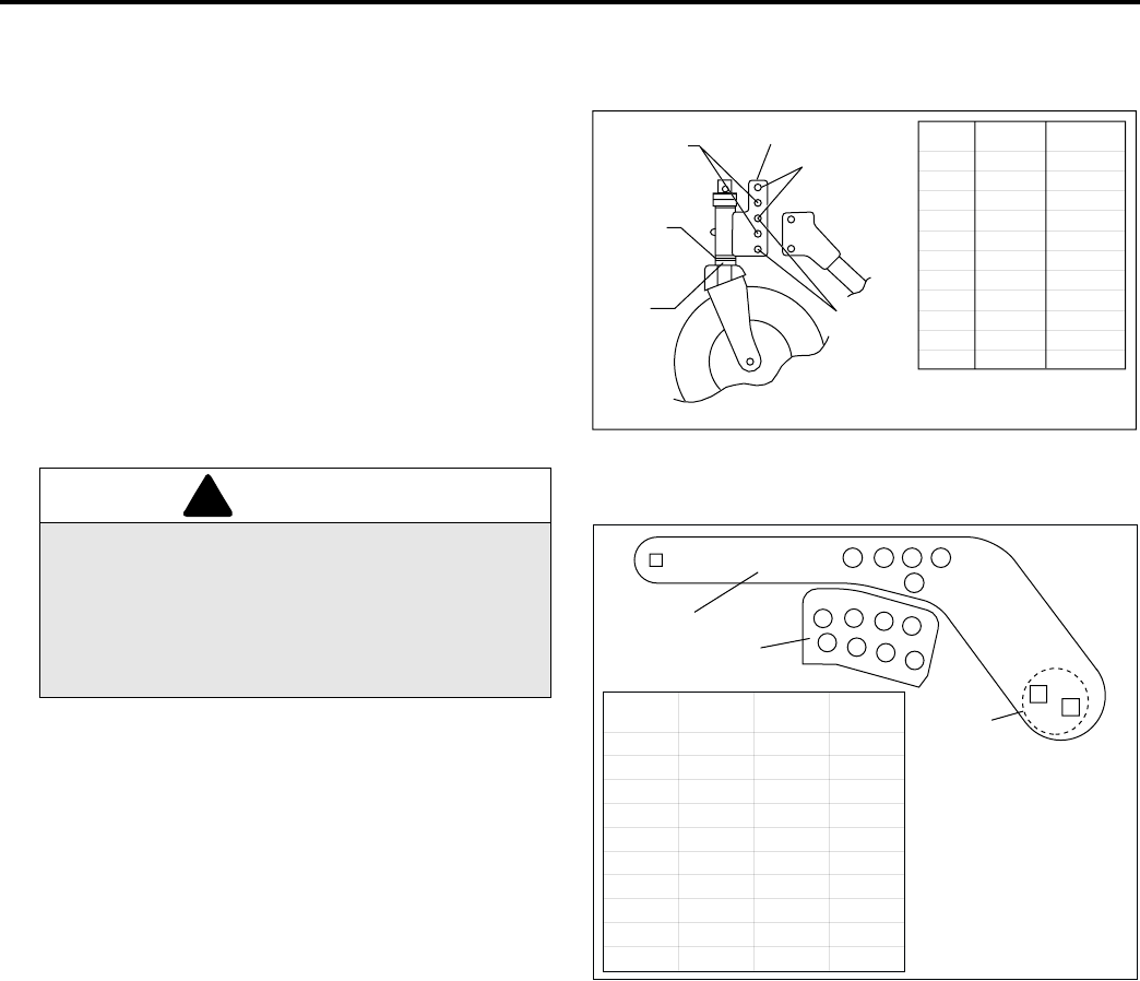
4.18 ELECTRICAL SYSTEM _____________________________________________________
General precautions that can be taken to reduce
electrical problems are listed below.
1. Make certain all terminals and connections are clean
and properly secured.
2. Check the operator backup system, fuses and
circuit breakers regularly.
If the operator backup system does not function
properly and the problem cannot be corrected,
contact an authorized Textron Turf Care And
Specialty Products Dealer.
3. Keep the wire harness and all individual wires away
from moving parts to prevent damage.
4. Make sure the seat switch harness is connected to
the main wire harness.
5. Check the battery and battery charging circuit.
6. Do not wash or pressure spray around electrical
connections and components.
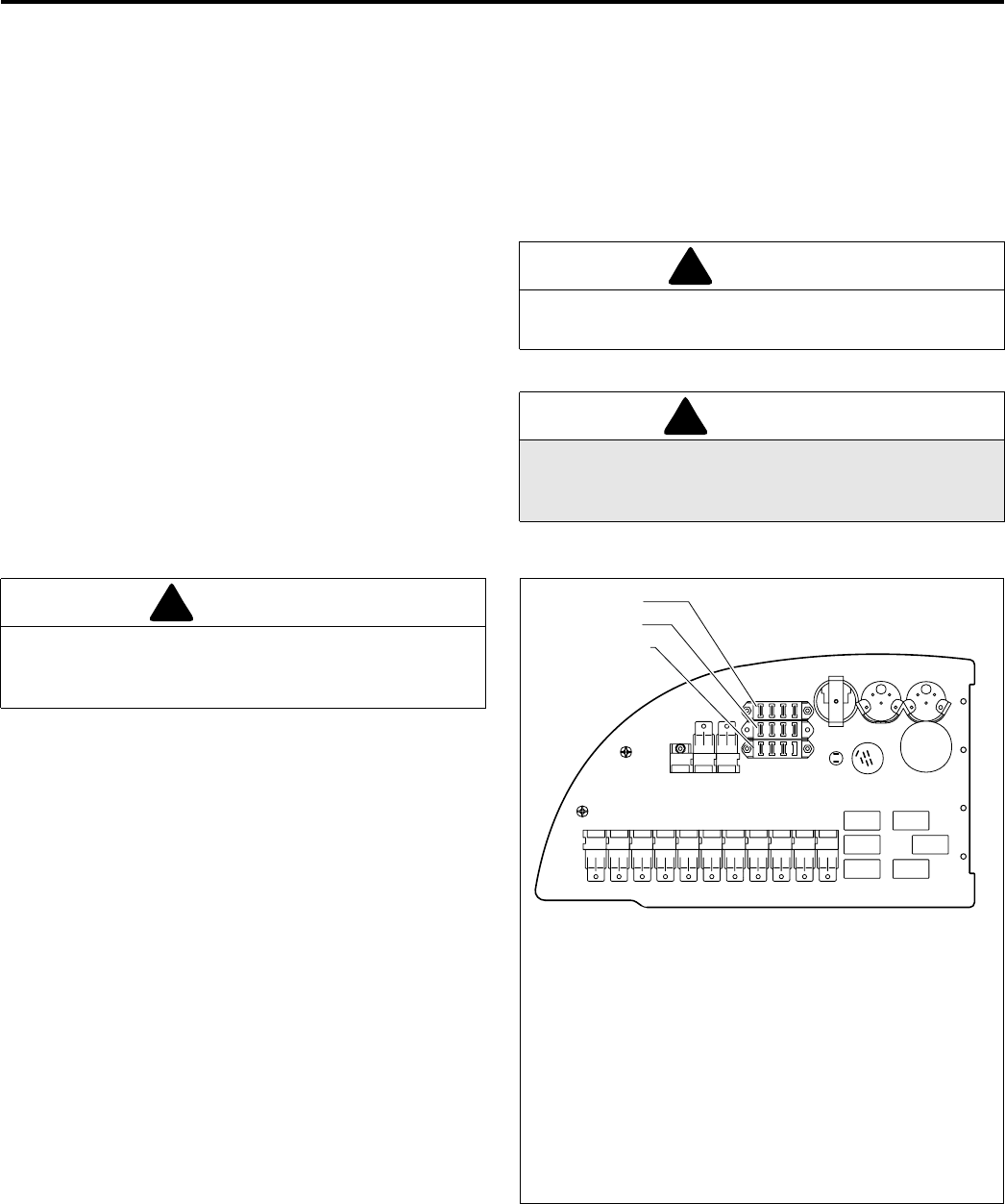
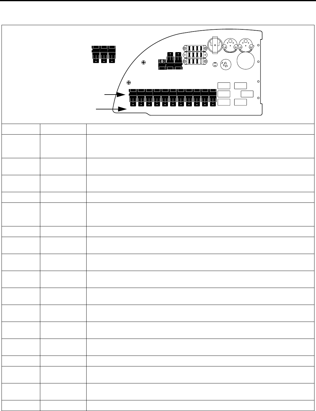
Circuits are protected by a circuit breaker (located above
batteries), plus fuses and relays mounted under the
instrument panel (See Figure 4G and ).
Figure 4G
identifies the location and basic functions of the electrical relays located under the control panel. For more detailed
information refer to the electrical schematic in this manual.
CAUTION
Clean grass and debris from cutting units, drives, muffler
and engine to prevent fires.
WARNING
NEVER use your hands to clean cutting units. Use a
brush to remove grass clippings from blades. Blades are
extremely sharp and can cause serious injuries.
!
!
CAUTION
Always turn the igniton switch off and remove the
negative battery cable (Black) before inspecting or
working on the electrical system.
!F1 F2 F3 F4
F5 F6 F7 F8
F9F10F11F12
FUSES
F1 5A Spare
F2 5A Spare
F3 15A Spare
F4 15A Spare
F5 5A Ignition
F6 5A Gauges
F7 5A Fuel solenoid, Glow Plugs
F8 15A Seat air system
F9 5A Cruise Control
F10 5A 4-WD Solenoid
F11 15A Deck Valve
F12 Not Used HR006
MAINTENANCE 4
25
Always check operator back-up system after servicing the electrical system!
Relay Description Function
KYA / K2 Run Relay Holds fuel stop solenoid valve open when ignition switch is in the RUN position and opera-
tor is seated.
Activates glow plug timer if engine isn’t running.
KYI / K1 Interlock Opens fuel stop solenoid valve when ignition switch is in the START position, power take-
off switch is OFF, parking brake and neutral switches are closed.
KYS / K3 Start Cranks starter motor when ignition switch is in the START position, power take-off switch is
OFF, parking brake and neutral switches are closed.
BK1 / K4 Brake -Start Part of starting circuit. Relay closes when parking brake is engaged.
BK2 / K5 Brake-Run Disconnects power to cruise control relay (CRS) with parking brake engaged.
Disconnects power to the fuel valve when the operator leaves seat with parking brake dis-
engaged.
NT1 / K6 Neutral-Start Part of starting circuit. Relay closes when traction pedal is in neutral.
NT2 / K7 Neutral-Run Disconnects power to the fuel stop solenoid valve when operator leaves seat with neutral
switch still open (traction pedal pressed).
NT3 / K8 Neutral-Cruise Disconnects power to cruise control when neutral switch is closed (traction pedal in neu-
tral).
ML / K9 Mow -Left
Deck
Energizes solenoid to left side deck valve when deck is lowered and power take-off switch
is ON.
MC / K10 Mow-Center
Deck
Energizes solenoid to front deck valve when deck is lowered and power take-off switch is
ON.
MR / K11 Mow-RIght
Deck
Energizes solenoid to right side deck valve when deck is lowered and power take-off switch
is ON.
CRS / K12 Cruise Control Activates cruise control when cruise control switch is closed, traction pedal is pressed and
parking brake is disengaged.
4WD / K13 Four Wheel
Drive
Energizes solenoid to four wheel drive valve when four wheel drive switch on instrument
panel and forward sensing switch on traction pump are closed.
LT S Lights Included with light harness kit 5003564. Controls operation of lights.
K15 Run Circuit
Cutout
Disables run circuit when keyswitch is turned to START position.
K16 Auxilliary Provides power to ignition circuit with keyswitch in RUN position. Disables ignition circuit in
START position
K17 Ignition Provides power to gauges, mow circuit, 4WD circuit and seat switch circuit
K1K2K3K4K5K6K7K8K9K10K11
K12K13
K17K16K15
MR MC ML NT3 NT2 NT1 BK2 BK1 KYS KYA KYI
K15 K16 K17
LTS 4WD CRS
Wire Harness Label
Schematic Code
4 MAINTENANCE
26
4.19 TIRES ___________________________________________________________________
1. Keep tires properly inflated to prolong tire life. Check
inflation pressure while the tires are cool. Inspect
tread wear.
2. Check pressure yearly. Use an accurate, low
pressure tire gauge.
3. Keep tires inflated to proper pressure
Tractor: 20-22 psi (138 -152kPa).
Decks: 20-25 psi (138 -173 kPa)
4.20 WHEEL MOUNTING PROCEDURE ____________________________________________
Tractor Wheels
1. Remove dirt, grease and oil from stud thread. Do not
lubricate threads.
2. Position wheel on hub and inspect to insure full
contact between mounting surface of wheel and hub
or brake drum.
3. Finger tighten all hardware then torque hardware in
crisis-cross order; always tighten nuts in the top
position.
NOTE: Check and torque lug bolts daily for the first 100
hours of operation.
4. After recieving new unit or if tires were removed,
check and torque lug bolts daily until torque is
maintained, 65-75 ft.lbs. (88-102 Nm)
Caster Wheels
To extend bearing life check and adjust caster and gauge
wheels every year. Lubricate bearings every 100 hours
using NLGI Grade 2 grease.
1. Raise deck so wheels are off ground and can be
rotated freely by hand.
2. Check wheels for end play (I). Wheels should rotate
freely with zero end play.
3. To eliminate end play, tighten inner nut (G) until
wheel just begins to bind then loosen it 1/4 turn.
Lock inner nut in position using outer nut (H). Do not
allow inner nut to rotate while tightening outer nut.
4. Repeat step 2 and check for end play.
Figure 4H
CAUTION
Unless you have the proper training tools and
experience, DO Not attempt to mount a tire on a rim.
Improper mounting can produce an explosion which may
result in serious injury.
!
WARNING
Make sure the tractor is parked on a solid and level
surface. Never work on a tractor that is supported only
by the jack. Always use jack stands.
If only the front or rear of the tractor is raised, place
chocks in front of and behind the wheels that are not
raised.
!
G
H
I
HR021

MAINTENANCE 4
27
4.21 ROLLOVER PROTECTION STRUCTURE (ROPS) ________________________________
A Rollover Protection System (ROPS), designed for this
tractor, is available as an optional accessory. If your
tractor is equipped with this device, inspect it periodically
and follow operating procedures described in Safety and
Operation Manual
1. The seat, the seat belt, mounting hardware and any
accessories within the ROPS, should be inspected
regularly and all damaged parts replaced
immediately.
2. Once the ROPS has been subjected to any form of
impact it should be replaced.
3. Check and retorque all hardware. All replacement
components used for the ROPS must be as
specified in the Textron Turf Care And Specialty
Products Parts List.
4.22 STORAGE ________________________________________________________________
General
1. Wash the tractor thoroughly and lubricate. Repair
and paint damaged or exposed metal.
2. Inspect the tractor, tighten all hardware, replace
worn or damaged components.
3. Drain and refill radiator.
4. Clean the tires thoroughly and store the tractor so
the load is off the tires. If tractor is not on jack
stands, check tires at regular intervals and reinflate
as necessary.
5. Keep the machine and all its accessories clean, dry
and protected from the elements during storage.
Never store equipment near an open flame or spark
which could ignite fuel or fuel vapors.
Battery
1. Remove, clean and store battery in upright position in
a cool, dry place.
2. Check and recharge battery every 60 to 90 days
while in storage.
3. Store batteries in a cool, dry place. To reduce the
self discharge rate, room temperature should not be
above 80°F (27°C) or fall below 20°F (-7°C) to
prevent electrolyte from freezing.
Engine
1. While the engine is warm, remove drain plug, drain
the oil from the crankcase and change oil filter. Install
drain plug and refill with fresh oil. Torque drain plug
to 22 ft. lb. (30 Nm).
2. Clean exterior of engine. Paint exposed metal or
apply a light coat of rust preventative oil.
3. Add a fuel conditioner or biocide to prevent gelling
or bacterial growth in fuel. See your local fuel
supplier.
Cutting Units
1. Wash the cutting units thoroughly, then repair and
paint any damaged or exposed metal.
2. Lubricate all fittings and friction points.
3. Apply a light coat of rust preventative oil to the
sharpened edges of the blades.
After Storage
1. Check and reinstall battery
2. Check or service fuel filter and air cleaner.
3. Check the radiator coolant level.
4. Check oil level in the engine crankcase and
hydraulic system.
5. Fill the fuel tank with fresh fuel. Bleed the fuel
system.
6. Make certain that the tires are properly inflated.
7. Remove all oil from the deck blades. Readjust
cutting height.
8. Start and operate the engine at 1/2 throttle. Allow
enough time for the engine to become properly
warmed and lubricated.
CAUTION
Do not loosen or remove bolts, do not weld, drill, modify,
bend or straighten a damaged structure.
!
WARNING
Never operate the engine without proper ventilation;
exhaust fumes can be fatal when inhaled.
!

4 MAINTENANCE
28
4.23 MAINTENANCE CHART ____________________________________________________
For smooth operation of pivot points and other friction
points, apply several drops of SAE 30 oil every 50 hours
or as required.
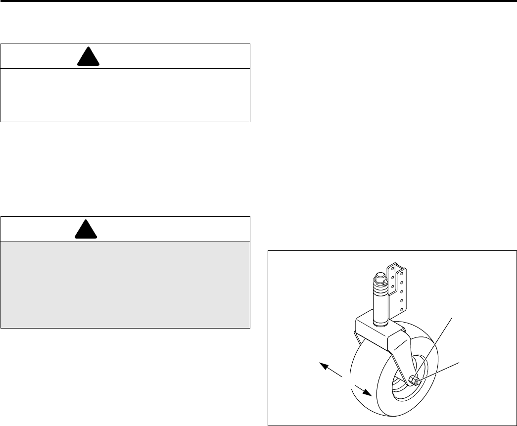
Remove wheels and repack bearings once a year.
A - Add or Adjust C - Clean I - Inspect L- Lubricate R - Replace AR - As Required
* Indicates initial service for new machines.
** See Engine Manual
***Clean as Required
**** Check lug bolt torque daily for first 100 hours of operation.
IPack bearings with NLGI Grade 2 (Service Class GB)
II Manual grease gun with NLGI Grade 2 (Service Class LB).
III Engine Oil - See Section 4.5
IV Textron Turf Care And Specialty Products Hydraulic Oil -
VG ISO 68
WARNING
Before you clean, adjust, or repair this equipment,
disengage all drives, lower implements to the ground,
engage parking brake, stop engine and remove key
from ignition switch to prevent injuries.
!
Recommended Service and Lubrication Intervals
Daily
Before
Starting
Every
25
Hours
Every
50
Hours
Every
100
Hours
Every
250
Hours
Every
Year
See
Section
Lubricant
Type
Air Cleaner Indicator I4.7
Air Cleaner Element R-AR R 4.7
Battery I-C I-C 4.10
Caster Wheel Bearings A* L I-A 4.20 I
Engine Fan Belt I* I-A **
Engine Oil I-A R* R 4.5 III
Engine Oil Filter R* R 4.5
Fuel Filter R4.9
Drain Water from Fuel Filter C**
Grease Fittings - F1 L4.24II
Grease Fittings - F2 L4.24II
Hydraulic Fluid I-A R 4.14 IV
Hydraulic Fluid FIlters R-AR R 4.15
Oil Cooler I-C*** 4.16
Radiator Screen I-C 4.16
Radiator Coolant I-A R 4.16
Tires I**** I-A 4.19
MAINTENANCE 4
29
4.24 LUBRICATION CHART______________________________________________________
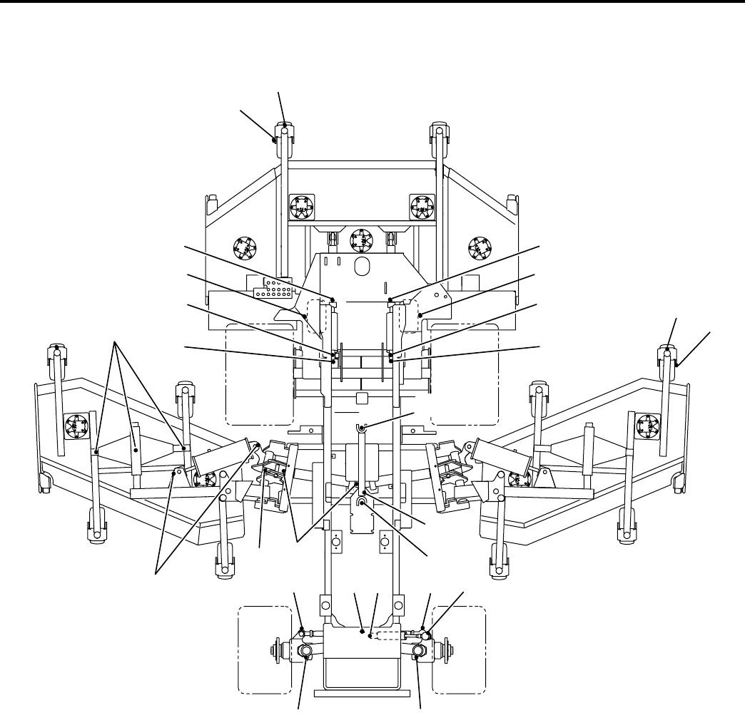
1
2
2
4
3
44
6
13
14
77
1
1
Grease Fitting Locations
F1 - 50 Hours (Every Week) Qty
1 Caster Spindles (10)
2 Caster Wheel Axles (10)
3 Gauge Wheel Axles (2)
4 Lift Cylinder - Front Deck (4)
5 Lift Arm - Front Deck (2)
6 Side Deck Pivots (6)
7 Steering Cylinder (2)
8Tie Rod (2)
9 Axle Pivot (1)
10 Wheel Pivot (2)
11 Lift Arm - Side Deck (2)
12 Lift Cylinder - Side Deck (4)
F2 - 150 Hours Qty
13 Drive Shaft U-Joint (2)
14 Drive Shaft Slip Joint (1)
15 Return Canister Pivot (6)
4
3
89
10 10
12
15
11
12
8
HR014
55

5 TROUBLESHOOTING
30
5 TR OU BLESH OOT ING
5.1 GENERAL________________________________________________________________
The troubleshooting chart below lists basic problems that may occur during start-up and operation. For more detailed
information regarding the hydraulic and electrical systems contact your area Textron Turf Care And Specialty Products
Dealer.
Symptoms Possible Causes Action
Engine will not
start.
1. Parking brake disengaged
or power take-off switch on.
1. Check operator back-up system and start-up procedure.
2. Glow plug has not timed
out.
2. Reset ignition switch and allow glow plug to time out
before cranking engine.
3. Battery low on charge or
defective.
3. Inspect condition of battery and battery connections.
4. Fuel tank empty or dirty. 4. Fill with fresh fuel. Change fuel filter. Bleed fuel lines.
5. Fuse blown. 5. Replace fuse.
6. Relay(s) defective 6. Test and replace relay.
7. Traction pedal not in
neutral.
7. Check position of pedal. Adjust Linkage.
8. Neutral switch on drive
pump not working.
8. Test, adjust or replace switch.
9. Forward sensing switch on
drive pump not working.
9. Test, adjust or replace switch.
Engine hard to
start or runs
poorly.
1. Fuel level low, fuel or fuel
filter dirty.
1. Fill with fresh fuel. Change fuel filter. Bleed fuel lines.
2. Air cleaner dirty. 2. Inspect and replace air filter.
3. Injectors, fuel pump 3. Consult engine manual.
4. Engine problem. 4. Consult engine manual
Engine stops. 1. Fuel tank empty. 1. Fill with fresh fuel and bleed fuel lines.
2. Interlocks not set before
leaving operator’s seat.
2. Engage parking brake and set power take-off switch to
OFF.
Engine
overheating
1. Coolant level low. 1. Inspect and add coolant.
2. Air intake restricted. 2. Clean air intake at radiator.
3. Water pump belt broken or
loose.
3. Tighten or replace belt. See engine manual.
Battery not
holding charge.
1. Loose or corroded battery
terminals.
1. Inspect and clean terminals
Battery light on. 2. Low electrolyte. 2. Refill to correct level.
3. Alternator belt loose or
broken
3. Tighten or replace belt. See engine manual.
4. Charging system defective. 4. See engine manual
Cutting units not
cutting evenly
1. Cutting heights not set
evenly.
1. Check that decks are level. Check and adjust cutting height.
2. Engine speed too low. 2. Check engine speed with throttle stop in its mow position.
3. Mow speed not adjusted for
turf conditions.
3. Adjust mow speed for best cut.
4. Air pressure in caster tires
not adjusted correctly.
4. Check tires and adjust to correct pressure.

PARTS LIST 6
31
6 PARTS LIST
6.1 TABLE OF CONTENTS______________________________________________________
Body
1.1 ....... Decals-Tractor ............................................ 32
2.1 ....... Hood ........................................................... 34
3.1 ....... Cowlings and Skirts .................................... 36
4.1 ....... Seat Pan and Heat Shield .......................... 38
Controls
5.1 ....... Instrument Panel......................................... 40
5.2 ....... Instrument Panel......................................... 42
6.1 ....... Throttle Cable ............................................. 44
7.1 ....... Lift Valve and Controls................................ 46
8.1 ....... Accelerator Pedal ....................................... 48
9.1 ....... Steering Assist............................................ 50
10.1 ..... Parking Brake ............................................. 52
Frame
11.1 ..... Frame ......................................................... 54
12.1 ..... Frame With ROPS ...................................... 56
13.1 ..... Steering Axle .............................................. 58
14.1 ..... Steering Axle Installation ............................ 60
15.1 ..... Battery Tray ................................................ 61
16.1 ..... Tilt Steering................................................. 62
Engine and Radiator
17.1 ..... Radiator ...................................................... 64
18.1 ..... Oil Cooler.................................................... 66
19.1 ..... Air Cleaner and Muffler............................... 68
20.1 ..... Engine Mounting......................................... 70
21.1 ..... Engine and Pump Assembly....................... 72
Tanks
22.1 ..... Tank Mounting ............................................ 74
23.1 ..... Hydraulic Tank............................................ 76
24.1 ..... Fuel Tank.................................................... 77
Traction Pump
25.1 ..... Pump and 4WD Valve Mounting................. 78
26.1 ..... Pump Assembly.......................................... 79
Lift Arms and Deck Valves
27.1 ..... Front Lift Arms and Cylinders ..................... 80
28.1 ..... Front Deck Latch ........................................ 82
29.1 ..... Side Lift Arms ............................................. 84
30.1 ..... Side Lift Cylinders and Return Canisters.... 86
31.1 ..... Front Deck Valves ...................................... 88
32.1 ..... Wing Deck Valves....................................... 89
Hydraulics and Electrical
33.1 ..... Side Deck Valve Supply ............................. 90
34.1 ..... Front Deck Valve Supply ............................ 91
35.1 ..... Pump Supply .............................................. 92
36.1 ..... Return Manifold .......................................... 93
37.1 ..... Traction Hydraulics ..................................... 94
38.1 ..... Return Hydraulics ....................................... 96
39.1 ..... 4WD Hose Clamps ..................................... 98
40.1 ..... Charge Pressure......................................... 99
41.1 ..... Lift Valve Hydraulics ................................. 100
42.1 ..... Power Steering Hoses.............................. 102
43.1..... Engine Compartment Clamps .................. 104
44.1..... Wire Harness Routing .............................. 105
Components
45.1..... Steering Valve .......................................... 106
46.1..... Air Suspension ......................................... 108
47.1..... Seat Assembly.......................................... 110
48.1..... Steering Cylinder...................................... 111
49.1..... Rear Wheel Motor .................................... 112
50.1..... Deck Return Canister ............................... 113
51.1..... Lift Valve................................................... 114
52.1..... Front Lift Cylinder ..................................... 116
53.1..... Wing Lift Cylinders.................................... 117
54.1..... Deck Valve ............................................... 118
55.1..... 4WD Valve................................................ 119
Decks
56.1..... Decals - Decks ......................................... 120
57.1..... Front Deck................................................ 122
58.1..... Front Deck Center Section ....................... 124
59.1..... Front Deck Winglets ................................. 126
60.1..... Front Deck Hydraulics .............................. 128
61.1..... Wing Decks .............................................. 130
62.1..... Wing Deck Hydraulics .............................. 132
63.1..... Caster Assemblies.................................... 134
64.1 ..... Wheel and Tire Assemblies...................... 135
65.1 ..... Gage Wheels and Latch ........................... 136
Schematics
66.1..... Hydraulic Schematic................................. 138
67.1..... Electrical Schematic ................................. 140
67.2..... Electrical Schematic ................................. 143
68.1..... O-Ring Chart ............................................ 148
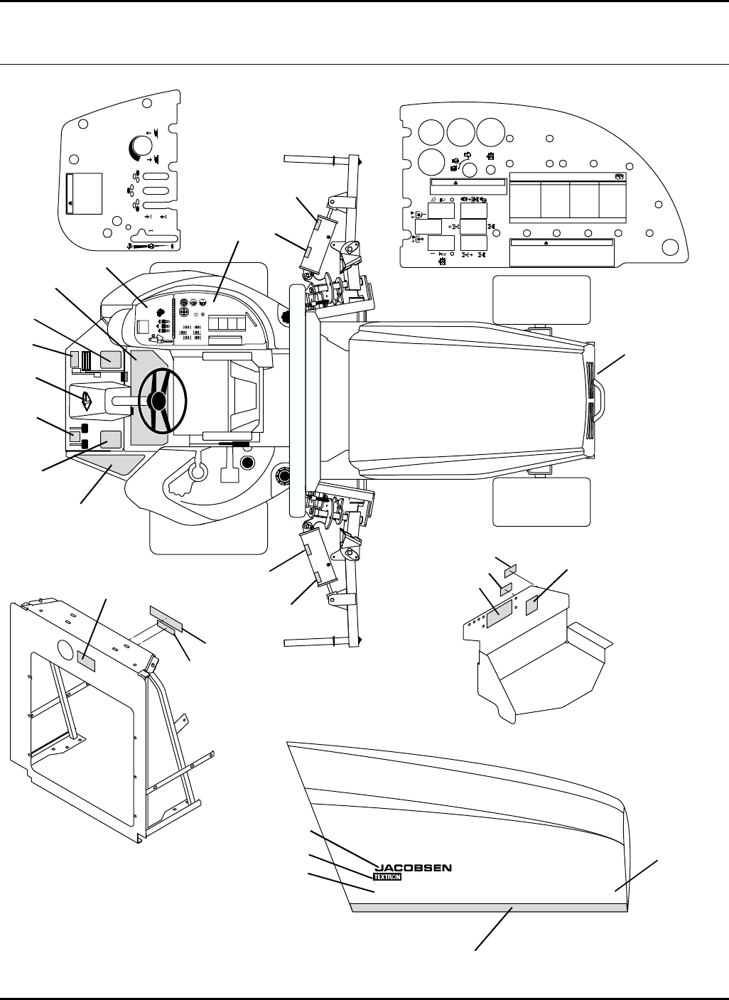
32
HR 9016 TURBO 4WD
1) READ OPERATORS MANUAL. DO NOT
ALLOW UNTRAINED OPERATORS TO
USE THIS MACHINE.
2) KEEP SHIELDS IN PLACE AND
HARDWARE SECURELY FASTENED.
3) BEFORE YOU CLEAN, ADJUST,
OR REPAIR THIS EQUIPMENT,
DISENGAGE ALL DRIVES, ENGAGE
PARKING BRAKE AND STOP ENGINE.
4) KEEP HANDS, FEET AND CLOTHING
AWAY FROM MOVING PARTS.
5) NEVER CARRY PASSENGERS
6) KEEP BYSTANDERS AWAY.
!
WARNING
!ADVERTENCIA
1. Leer el manual del operador. No permiter que
personas no capacitadas para ellousen la maquina.
2. Tenga todas las guardas en su lugar piezas
bien aseguradas.
3. Neutralice todas la velocidades y apague el
motor antes de vaciar los recolectores de
pasto, darle servicio, limpiar, ajustar y
destrabar la maquina
4. Mantenga las manos, los pies y ropa suelta
lejos de piezas en movimiento.
5. No deberan transportar pasajeros si no existe
un asiento para ellos.
6. Si no sabe leer ingles, pida que alquien le lea
las calcomanias de avisos y los manuales
de instruccion y operacion.
OPERATING INSTRUCTIONS
READ MANUAL THOROUGHLY FOR OPERATING AND SAFETY INSTRUCTIONS.
REPLACEMENT MANUAL AVAILABLE BY SENDING PRODUCT NO. TO : TEXTRON GOLF AND TURF, P.O. BOX 7708, CHARLOTTE, NC28241
TO START TO TRANSPORT TO MOW TO STOP
1. TRACTION PEDAL.......NEUTRAL
2. PTO SWITCH..........................OFF
3. PARKING BRAKE....................ON
4. THROTTLE POSITION.........HALF
5. ALLOW TURBOCHARGER TO
COOL FOR 4 TO 5 MINUTES
6. THROTTLE POSITION........SLOW
7. TURN IGNITION TO OFF
POSITION AND REMOVE KEY
1. DECK LATCHES............DISENGAGED
2. CUTTING UNITS..................LOWERED
3. FOUR WHEEL DRIVE SWITCH.......ON
4. PTO SWITCH...................................ON
5. PARKING BRAKE..........................OFF
6. THROTTLE POSITION........................1
7. DEPRESS TRACTION PEDAL FOR
DESIRED GROUND SPEED.
1. PTO SWITCH..................NEUTRAL
2. CUTTING UNITS................RAISED
3. DECK LATCHES............ENGAGED
4. PARKING BRAKE....................OFF
5. THROTTLE POSITION...........FAST
6. DEPRESS TRACTION PEDAL FOR
DESIRED GROUND SPEED.
1. PARKING BRAKE...........................ON
2. TRACTION PEDAL..............NEUTRAL
3. PTO SWITCH.................................OFF
4. THROTTLE POSITION.................HALF
5. IN COLD STARTINGCONDITIONS,
TURN IGNITION KEY TO RUN
POSITION TO ACTIVATE
GLOWPLUG PREHEAT, WHEN
GLOWPLUG LIGHT SWITCHES OFF,
ENGINE IS READY.
6. IGNITION SWITCH.....................START
!CAUTION
Premature engine shutdown may lead to permanant damage to turbocharger.
For proper cooling of turbocharger, run the engine with no load and throttle
position at 50 percent of full speed for 4 to 5 minutes prior to shutdown.
VEHICLE WEIGHT WET: 2880 KG
VEHICLE POWER: 64.9 KW AT 2750 RPM
HR9016
TURBO
HR-9016
Body
1.1 Decals-Tractor Serial No. All
9016-26
1
23
4
5
6
7
8
9
10
11
12
13
14
15
16
17
18
19
20
21
22
8
10
11
17
22
33
> Change from previous revision
To avoid injury when working with battery
1. Always connect the black ground (–)
cable last and remove it first.
2. Keep sparks and flames away, and
avoid contatc with acid.
To avoid injury when jumping battery
1. Connect positive (+) terminal to
positive (+) terminal.
2. Connect negative (–) terminal on good
battery to frame of vehicle that
has dead battery.
!DANGER
Radiator is under pressure. Remove
cap slowly to avoid personal injury
!WARNING
STORED ENERGY DEVICE
To prevent injury, do not
disassemble canister.
Contents under extreme load
!WARNING
THIS RADIATOR CONTAINS
ANTI-FREEZE
PROTECTED TO -26 F (-32 C)
Mix equal parts of clean water and a premium
quality ethylene glycol based anti-freeze to
maintain the boil over, rust and corrosion
protection.
Drain and discard coolant yearly. Read manual
for additional instructions.
IMPORTANT
DO NOT USE STARTING
ASSIST FLUIDS
USE OF STARTING ASSIST FLUIDS IN THE
AIR INTAKE SYSTEM MAY BE POTENTIALLY
EXPLOSIVE OR CAUSE A "RUNAWAY"
ENGINE CONDITION. THIS COULD RESULT
IN SERIOUS ENGINE DAMAGE.
BRAKE
To prevent burns, do not touch
muffler or muffler shield.
Temperatures may exceed 150 F (66 C)
!WARNING
ENGAGE LOCKUP
PINS WITH WING
ARMS IN RAISED
POSITION FOR
TRANSPORT,
STORAGE OR
MAINTENANCE
!WARNING
Daily Service Instructions
Read manual thoroughly before operating for maintenance instructions
Maintain fluid level in radiator recovery tank between
"Full" and "Low" mark when engine is cold.
Clear the radiator core & radiator screen of any dirt
or grass clippings.
Check the engine oil each time you stop for fuel.
Read operator's manual for more detailed service
instructions.
1
2
3
4
5
6
7
8
9
10
11
20
24
23
This structure's proctective
capability may be impaired
by structural damage,
overturn, or alteration.
If any of these conditions
occur, the structure must
be replaced.
!WARNING
!
CAUTION
OPEN TOW VALVE BEFORE TOWING
DO NOT TOW OVER 2 MPH
SEE OPERATIONS MANUAL FOR COMPLETE
TOWING INSTRUCTIONS
JT-2812396
HR-9016
Item Part No. Qty. Description Serial Numbers/Notes
1360053 1 Decal, Brake
2 3008521 1 Decal, Traction
3 2812396 1 Decal, Towing Caution
4 365956 1 Decal, Radiator Cap Warning
5 3001435 1 Decal, Battery Danger
6 339237 1 Decal, Heat Warning
7 363994 1 Decal, Daily Service
8 3000435 2 Decal, Start Assist Fluids
9 363995 1 Decal, Antifreeze
10 363704 2 Decal, Latch Pin Warning
11 3009266 2 Decal, Stored Energy Warning
12 3007505 2 Decal, Jacobsen
13 3007514 2 Decal, Textron
14 3009217 2 Decal, HR 9016 Turbo
15 3008327 2 Decal, 4WD
16 3008754 2 Decal, Stripe
17 3004287 2 Pad, Center Panel
18 3009268 1 Pad, Step
19 3009267 1 Pad, Floorboard
20 3007129 1 Emblem, Diamond J
21 3009073 1 Decal, Control Panel
> 22 3009055 1 Decal, Instrument Panel Serial No 70524 1601 ~ 1725
Serial No 70525 1601 ~ 1777
> 22 4103841 1 Decal, Instrument Panel Serial No 70524 1726 ~ 1756
Serial No 70524 1778 ~ 1882
> 22 4116908 1 Decal, Instrument Panel Serial No 70524 1757 and up
Serial No 70524 1883 and up
23 5002952 1 Decal, ROPS Seat Belt Used On 70525 Only
24 557844 1 Decal, ROPS Structure Used On 70525 Only
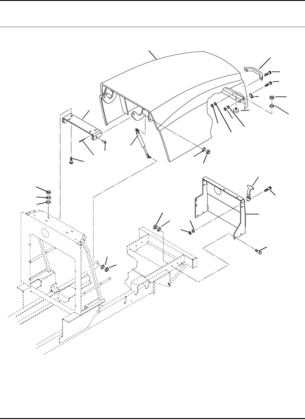
34
HR-9016
2.1 Hood Serial No. All
9016-21
1
2
3
4
5
6
7
8
9
10
12
13
14
15
16
17
18
19
20
7
7
7
8
8
8
7
16
17
11
11
21
21

35
> Change from previous revision
HR-9016
Item Part No. Qty. Description Serial Numbers/Notes
15003592 1 Hood
2 1003679 1 Pivot, Hood
3 3006644 2 Pin, Special Clevis
4 460028 2 Cotter pin, 1/8 x 1”
5 440120 4 Carriage Bolt, 3/8-16 x 1-1/4”
6 452008 4 Flat Washer, 3/8
7 446142 14 Lockwasher, 3/8 Heavy
8 443110 12 Nut, 3/8-16 Hex
9 354989 2 Stop, Rubber
10 443112 2 Nut, 3/8-24 Hex
11 444310 8 Nut, #10-24 Hex
12 340795 1 Handle, Hood
13 402230 2 Screw, 1/4-20 x 1” Slotted
14 446128 2 Lockwasher, 1/4
15 443102 2 Nut, 1/4-20 Hex
16 1004686 2 Latch, Flexible Draw
17 403914 8 Screw, #10-24 x 3/4” Truss Head
18 3009793 2 Spring, Gas
19 2811476 1 Support, Rear Hood
20 400264 4 Screw, 3/8-16 x 1-1/4” Hex Head
21 446116 8 Lockwasher, #10
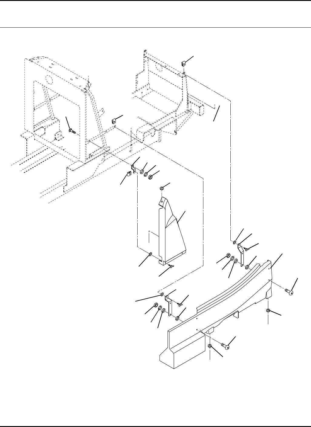
36
A
B
C
A
B
C
HR-9016
3.1 Cowlings and Skirts Serial No. All
9016-24
1
2
3 / 4
5
6
7
8
9
10
11
12 / 13
14 / 15
16
17
18
2
5
5
6
6
7
7
8
8
9
11
16
17
1
9
11
17

37
> Change from previous revision
HR-9016
Item Part No. Qty. Description Serial Numbers/Notes
1447414 8 Lockwasher, 3/8 External Tooth
2 404118 8 Screw, 3/8-16 x 7/8” Truss Head
3 3006663 1 Left Side Cowling
4 3006664 1 Right Side Cowling
5 352604 6 Grommet
6 3005604 8 Receptacle, #85 1/4 Turn
7 3007704 8 Stud, #85 1/4 Turn
8 3005603 8 Retainer
9 443110 12 Nut, 3/8-16 Hex
10 3006915 4 Bracket, Cowling Mounting
11 446142 8 Lockwasher, 3/8 Heavy
12 3006723 1 Left Side Skirt
13 3006724 1 Right Side Skirt
14 3007099 1 Bracket, Left Side Skirt Mounting
15 3007100 1 Bracket, Right Side Skirt Mounting
16 440120 4 Carriage Bolt, 3/8-16 x 1-1/4”
17 452008 12 Flat Washer, 3/8
18 3008015 2 Bracket, Front Skirt
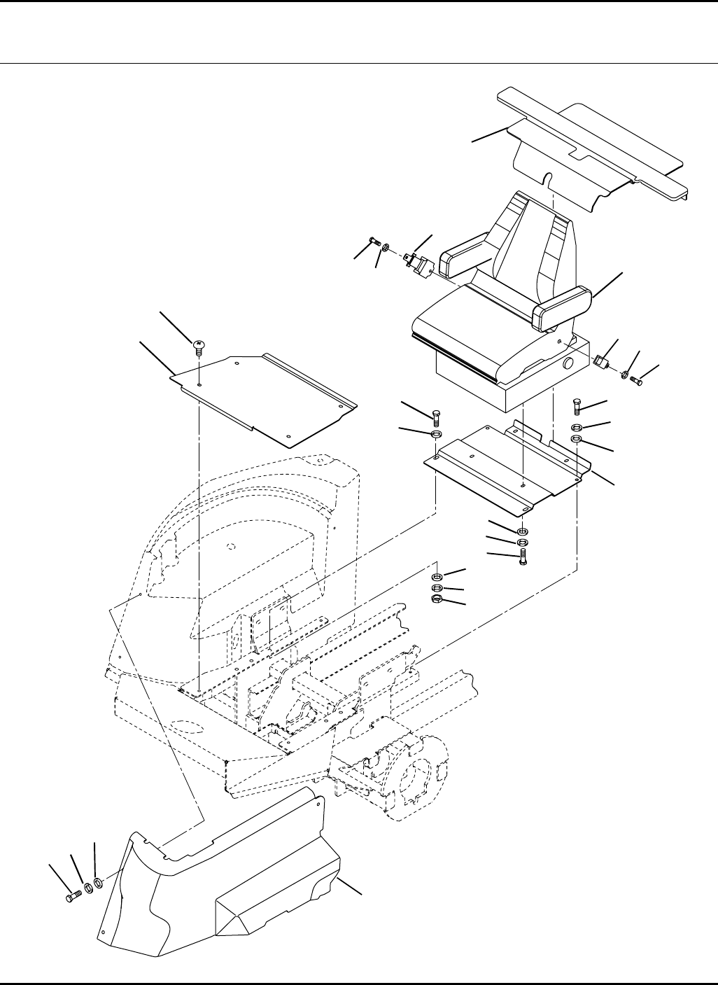
38
HR-9016
4.1 Seat Pan and Heat Shield Serial No. All
9016-25
1
2
3
4
5
6
7
8
9
10
11
12
13
2
4
5
5
10
11
14
15
15
16
17
17
16

39
> Change from previous revision
HR-9016
Item Part No. Qty. Description Serial Numbers/Notes
13007032 1 Seat Pan
2 400264 4 Screw, 3/8-16 x 1-1/4” Hex Head
3 443110 2 Nut, 3/8-16 Hex
4 446142 4 Lockwasher, 3/8 Heavy
5 452008 6 Flat Washer, 3/8
6 5003457 1 Plate, Floorboard
7 404118 4 Screw, 3/8-16 x 7/8” Truss Head
8–1 Seat with Air Suspension
5003625 1 •Air Ride Suspension See 46.1
5003626 1 •Seat Assembly See 47.1
9 361005 4 Screw, M8-1.25 x 25mm Hex Head
10 446136 7 Lockwasher, 5/16 Heavy
11 452006 7 Flat Washer, 5/16
12 3006880 1 Heat Shield
13 400182 3 Screw, 5/16-18 x 5/8” Hex Head
14 3010013 1 Shield, Floor Used On 70524
14 3010789 1 Shield, ROPS Floor Used On 70525
15 5003617 1 Seat Belt Assembly Used On 70525 Only
16 400370 2 Screw, 7/16-20 x 1” Hex Head Used On 70525 Only
17 446148 2 Lockwasher, 7/16 Heavy Used On 70525 Only
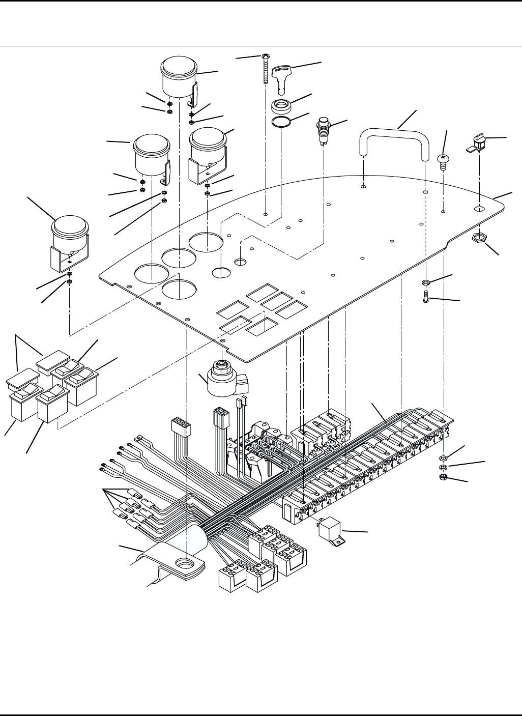
40
HR-9016
Controls
5.1 Instrument Panel Serial No. 70524 1601 ~ 1756
Serial No. 70525 1601 ~ 1882
9016-01
1
2
3
4
5
6
7
8
9
10
11
12
13
14
15
16
17
18
19
20
21
22
23 24
25
26
27
28
29
30
31
32
33
34
35
36
37
4
38
39
39
HR 9016 Units with Indak Keyswitch Part No. 1001958
Serial Number 70524 1601 ~ 1725
Serial Number 70525 1601 ~ 1777
Your machine was built before the Kubota Key Switch (Shown Above) was introduced. To
update your tractor, order Keyswitch Update Kit Part No. 2822522.
Note: The update kit will update the keyswitch and add three relays to the electrical system.

41
> Change from previous revision
HR-9016
Item Part No. Qty. Description Serial Numbers/Notes
15003768 1 Dash Panel with Decal Serial Number 70524 1601 ~ 1725
Serial Number 70525 1601 ~ 1777
1 4103860 1 Dash Panel with Decal Serial Number 70524 1726 ~ 1756
Serial Number 70525 1778 ~ 1882
2 403920 4 Screw, #10-24 x 2-1/2” Truss Head
3 366283 1 Handle
4 3006446 2 Switch, Test / 4WD-Reverse
5 3006436 1 4WD Switch
6 3006440 1 Switch, PTO Locking
7 3006509 2 Hole Plug
> 8 2810269 1 Switch, Ignition
>9N/S1•Lockwasher
>10N/S 1•Nut
> 11 2811020 1 •Key
12 366751 1 Indicator Light, Yellow
13 1002679 1 Gauge, Warning Light
5003091 3 •Light Bulb and Socket
14 447006 1 •Lockwasher, #10 External Tooth
15 444310 1 •Nut, #10-24 Hex
16 3005121 1 Gauge, Water Temperature
17 447002 3 •Lockwasher, #6 External Tooth
18 444304 3 •Nut, #6-32 Hex
19 447206 2 •Lockwasher, #8 Internal Tooth
20 444306 2 •Nut, #8-32 Hex
21 365943 1 Gauge, Fuel Level
22 447002 3 •Lockwasher, #6 External Tooth
23 444304 3 •Nut, #6-32 Hex
24 447206 2 •Lockwasher, #8 Internal Tooth
25 444306 2 •Nut, #8-32 Hex
26 162723 1 Gauge, Hour Meter
27 447006 1 •Lockwasher, #10 External Tooth
28 444310 1 •Nut, #10-24 Hex
29 3001307 13 Relay, SPDT With Resistor
30 REF 1 Wire harness, Console See 44.1
5003278 7 •Fuse, 5 Amp (Tan)
5003281 4 •Fuse, 15 Amp (Light Blue)
31 555846 3 •Diode
32 400106 2 Screw, 1/4-20 x 5/8” Hex Head
33 446128 2 Lockwasher, 1/4
34 452002 12 Flat Washer, #10
35 446118 12 Lockwasher, #10 Heavy
36 444310 12 Nut, #10-24Hex
37 403910 8 Screw, #10-24 x 1/2” Truss Head
38 364016 1 Clamp, Wire Harness
39 1004992 1 Latch, Panel
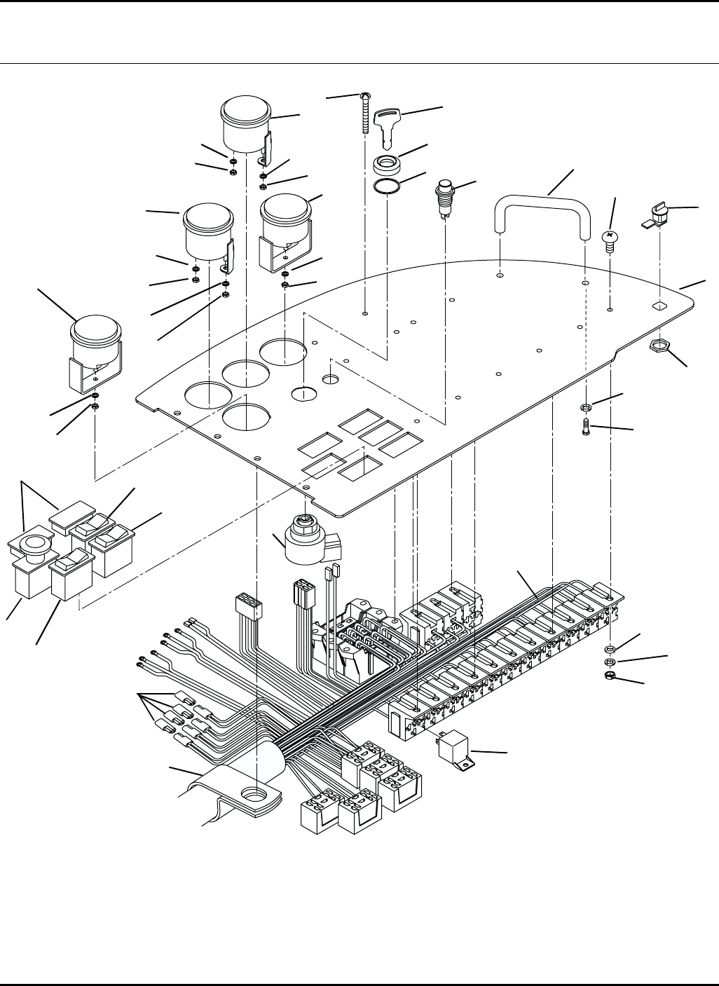
42
HR-9016
5.2 Instrument Panel Serial No. 70524 1757 and Up
Serial No. 70525 1883 and Up
9016-01
1
2
3
4
5
6
7
8
9
10
11
12
13
14
15
16
17
18
19
20
21
22
23 24
25
26
27
28
29
30
31
32
33
34
35
36
37
4
38
39
39

43
> Change from previous revision
HR-9016
Item Part No. Qty. Description Serial Numbers/Notes
>14116910 1 Panel, Dash
2 403920 4 Screw, #10-24 x 2-1/2” Truss Head
3 366283 1 Handle
4 3006446 2 Switch, Test / 4WD-Reverse
> 5 2721505 1 Switch, PTO
> 6 3006436 1 4WD Switch
7 3006509 2 Hole Plug
> 8 2810269 1 Switch, Ignition
>9N/S1•Lockwasher
>10N/S 1•Nut
> 11 2811020 1 •Key
12 366751 1 Indicator Light, Yellow
13 1002679 1 Gauge, Warning Light
5003091 3 •Light Bulb and Socket
14 447006 1 •Lockwasher, #10 External Tooth
15 444310 1 •Nut, #10-24 Hex
16 3005121 1 Gauge, Water Temperature
17 447002 3 •Lockwasher, #6 External Tooth
18 444304 3 •Nut, #6-32 Hex
19 447206 2 •Lockwasher, #8 Internal Tooth
20 444306 2 •Nut, #8-32 Hex
21 365943 1 Gauge, Fuel Level
22 447002 3 •Lockwasher, #6 External Tooth
23 444304 3 •Nut, #6-32 Hex
24 447206 2 •Lockwasher, #8 Internal Tooth
25 444306 2 •Nut, #8-32 Hex
26 162723 1 Gauge, Hour Meter
27 447006 1 •Lockwasher, #10 External Tooth
28 444310 1 •Nut, #10-24 Hex
29 3001307 13 Relay, SPDT With Resistor
30 REF 1 Wire harness, Console See 44.1
5003278 7 •Fuse, 5 Amp (Tan)
5003281 4 •Fuse, 15 Amp (Light Blue)
31 555846 3 •Diode
32 400106 2 Screw, 1/4-20 x 5/8” Hex Head
33 446128 2 Lockwasher, 1/4
34 452002 12 Flat Washer, #10
35 446118 12 Lockwasher, #10 Heavy
36 444310 12 Nut, #10-24Hex
37 403910 8 Screw, #10-24 x 1/2” Truss Head
38 364016 1 Clamp, Wire Harness
39 1004992 1 Latch, Panel
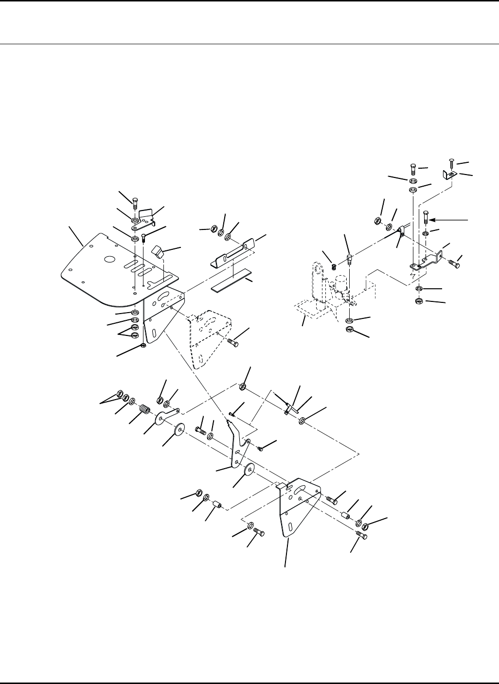
44
Screw as
part of
engine
HR-9016
6.1 Throttle Cable Serial No. All
9016-15
Part Of Item 1
1
2
3
4
5
6
7
8
9
10
11
12 13
14
15
16
17
18
19 20
21
22
23
24
25
26
27
28
30
31
32
33
3
59
9
11
19
19
20
20
20
24
24
26
7
9
24
8
19
20
19
19
20
34
19 9
Part of
Engine
19
20
36
35

45
> Change from previous revision
HR-9016
Item Part No. Qty. Description Serial Numbers/Notes
15003425 1 Control Panel
2 1004252 1 Throttle Cable
3 558021 2 •Clip, Conduit
4 303962 1 •Wire Stop
5 558020 1 •Swivel
6 3006730 1 Lever, Throttle
7 400116 2 Screw, 1/4-20 x 1-1/2” Hex Head
8 400110 3 Screw, 1/4-20 x /8” Hex Head
9 453023 6 Flat Washer, 1/4
10 400274 1 Screw, 3/8-16 x 2-1/2” Hex Head
11 360885 2 Washer, Friction
12 452008 1 Flat Washer, 3/8
13 351956 1 Spring, Compression
14 443110 2 Nut, 3/8-16 Hex
15 3006729 1 Tab, Throttle Support
16 400108 1 Screw, 1/4-20 x 3/4” Hex Head
17 366768 1 Knob
18 3008901 1 Plate, Back Up
19 446130 9 Lockwasher, 1/4 Heavy
20 443102 8 Nut, 1/4-20 Hex
21 3008738 1 Stop, Throttle Control
22 400188 1 Screw, 5/16-18 x 1” Hex Head
23 443106 2 Nut, 5/16-18 Hex
24 453009 4 Flat Washer, 5/16
25 446134 1 Lockwasher, 5/16
26 367176 2 Spacer
27 440040 1 Carriage Bolt, 1/4-20 x 5/8”
28 444708 1 Locknut, 1/4-20 Center
29
30 558012 AR Pad, Cork / Rubber
31 3007719 1 Pivot, Throttle Cable
32 444718 1 Locknut, 5/16-18 Center
33 3007305 1 Bracket, Throttle Cable
34 4102420 1 Screw, M6-1 x 16mm, Socket Head
35 440042 1 Bolt, 1/4-20 x 3/4”,Carriage
36 4103000 1 Bracket, Stop
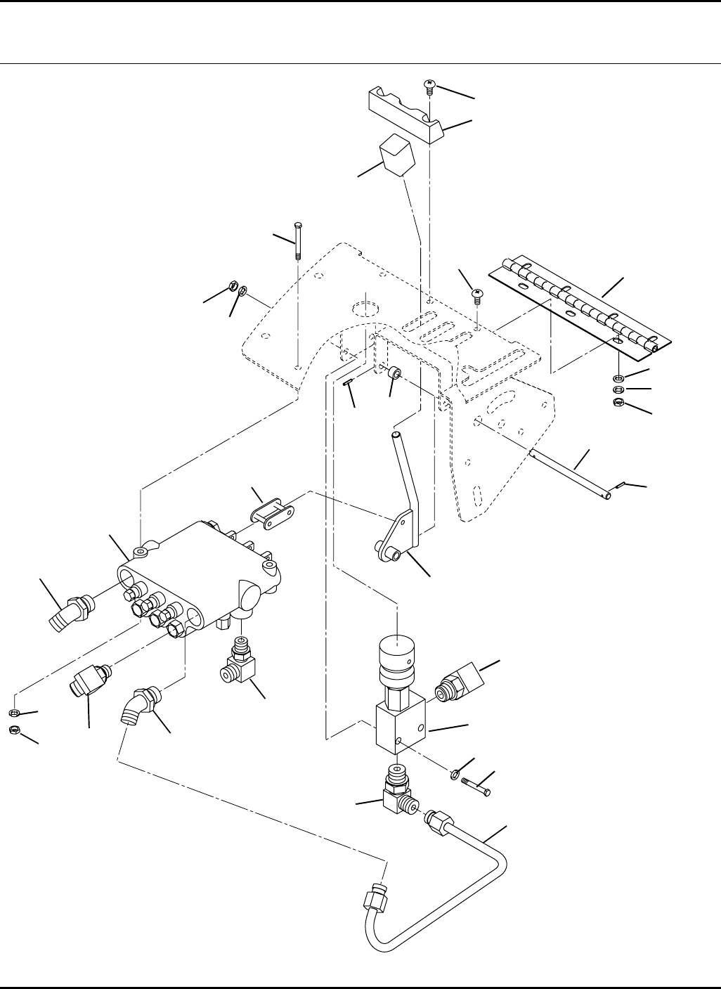
46
HR-9016
7.1 Lift Valve and Controls Serial No. All
9016-14
1
2
3
4
5
6
7
8
9
10
11
12
13
14
15
16
17
18
19
20
6
7
6
7
11
5
13
20
21
4

47
> Change from previous revision
HR-9016
Item Part No. Qty. Description Serial Numbers/Notes
1340061 1 Adapter, 90°
2 1003611 1 Tube, Lift Valve to Backpressure
3 3006737 1 Hinge, Control Panel
4 404022 3 Screw, 1/4-20 x 1” Truss Head
5 453023 5 Flat Washer, 1/4
6 446128 7 Lockwasher, 1/4
7 443102 7 Nut, 1/4-20 Hex
8 1004584 1 Backpressure Valve
5003539 1 •Seal Kit
5003538 1 •Adjusting Knob
9 340062 1 Adapter, 90°
10 340029 1 Adapter, 45°
11 400120 4 Screw, 1/4-20 x 2” Hex Head
12 1001802 1 Lift Valve See 51.1
13 340027 2 Adapter, 45°
14 340026 3 Adapter, 45°
15 366133 3 Chain, Master Link With Clip
16 1003100 3 Lever, Lift
17 361833 1 Pin
18 3005157 3 Knob
19 367631 2 Spacer
20 461356 2 Roll Pin, 3/32 x 1/2”
21 3010082 1 Stop, Dash Panel
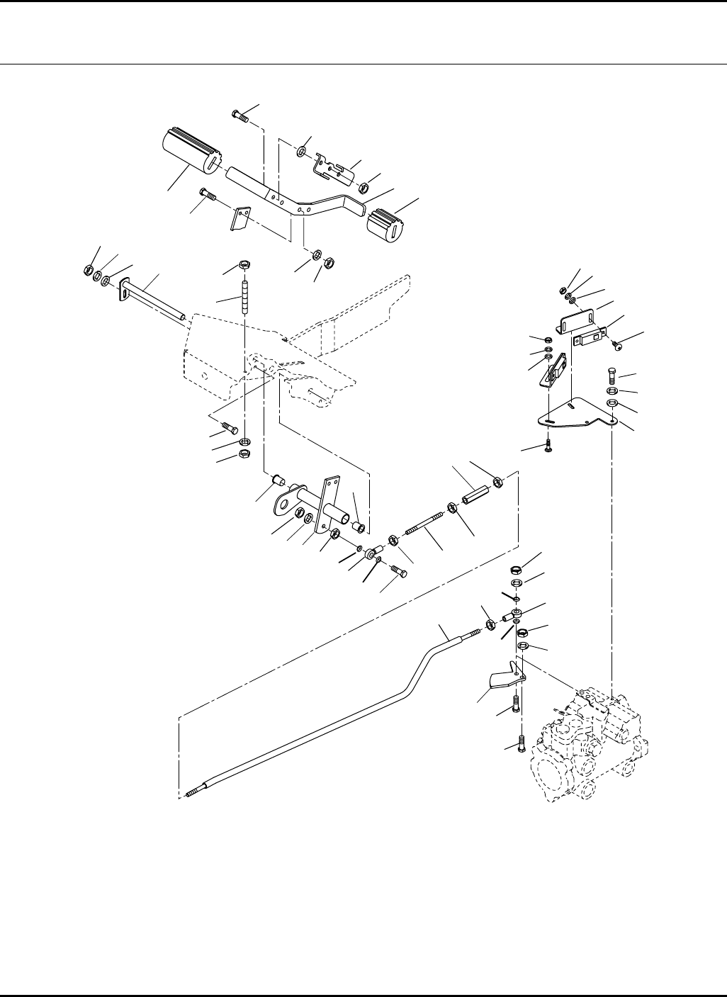
48
HR-9016
8.1 Accelerator Pedal Serial No. All
9016-08
1
28
3
4
5
6
7
8
910
11
12
13
14
15
16
17 18
19
20
21
22
23
24
25
26
27
2
29
30
31
32
33
34
35
36
37
4
6
7
9
10
18
39
24
16
16
4
2
16
16
10
15
15
16
15
38
38
38
38

49
> Change from previous revision
HR-9016
Item Part No. Qty. Description Serial Numbers/Notes
11003244 1 Arm, Hydro Pedal
471214 1 •Grease Fitting (Not Shown)
2 3010305 2 •Bushing
3 1003071 1 Shaft
4 400190 4 Screw, 5/16-18 x 1-1/4” Hex Head
5 453009 1 Flat Washer, 5/16
6 446134 3 Lockwasher, 5/16
7 443106 3 Nut, 5/16-18 Hex
8 1003145 1 Link, Hydro Control
9 366974 2 Rod End
10 443112 3 Nut, 3/8-24 Hex
11 445785 1 Nut, 3/8-24 Hex Left Hand
12 3006889 1 Turnbuckle
13 3006886 1 Threaded Rod
14 400268 1 Screw, 3/8-16 x 1-3/4” Hex Head
15 446140 4 Lockwasher, 3/8
16 443110 6 Nut, 3/8-16 Hex
17 3006888 1 Pedal, Hydro
18 3003475 2 Grip, Pedal
19 3002695 1 Washer
20 3007230 1 Stop, Mow Speed
21 3007228 1 Plate, Activator
22 3007220 1 Plate, Switch
23 452004 2 Flat Washer, 1/4
24 446128 4 Lockwasher, 1/4
25 400106 2 Screw, 1/4-20 x 5/8” Hex Head
26 333542 1 Tie Stud
27 400266 1 Screw, 3/8-16 x 1-1/2” Hex Head
28 400262 1 Screw, 3/8-16 x 1” Hex Head
29 3009026 2 Angle, Switch
30 3007392 2 Switch, Proximity
31 403912 4 Screw, #10-24 x 5/8” Truss Head
32 452002 4 Flat Washer, #10
33 446118 4 Lockwasher, #10 Heavy
34 444310 4 Nut, #10-24 Hex
35 441606 2 Carriage Bolt, 1/4-20 x 3/4”
36 453023 2 Flat Washer, 1/4
37 443102 2 Nut, 1/4-20 Hex
38 3004385 4 Seal, Rod End
39 444718 1 Locknut, 5/16-18 Center
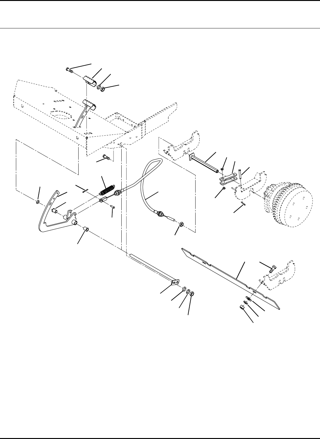
50
HR-9016
9.1 Steering Assist Serial No. All
9016-04
1
2
3
4
5
6
7
8
9 / 10
11
12
13
14
15
16
17 18
19
20
21
22
23
2
15
5
6
8
12
24

51
> Change from previous revision
HR-9016
Item Part No. Qty. Description Serial Numbers/Notes
11003794 2 Steering Assist Pedal
471214 1 •Grease Fitting (Not Shown)
2 3010305 4 •Bushing
3 1003245 1 Shaft
4 452006 1 Flat Washer, 5/16
5 446134 3 Lockwasher, 5/16
6 443106 3 Nut, 5/16-18Hex
7 3006107 2 Spring, Pedal Return
8 400188 3 Screw, 5/16-18 x 1” Hex Head
9 3008342 1 Cable, Right Turn Assist
10 3008343 1 Cable, Left Turn Assist
11 461453 2 Clevis Pin, 5/16 x 1”
12 460028 4 Cotter Pin, 1/8 x 1”
13 1003825 2 Connector, Brake
14 1003824 2 Pivot, Brake Lever
15 364154 4 •Bushing
16 3008344 2 Pin, Clevis
17 3008907 1 Shield, Cable
18 400262 2 Screw, 3/8-16 x 1” Hex Head
19 452008 2 Flat Washer, 3/8
20 446142 2 Lockwasher, 3/8 Heavy
21 443110 2 Nut, 3/8-16 Hex
22 1006812 2 Pad, Pedal
23 3009607 2 Nut, M12-1.75 Hex Jam
24 455048 2 Flat Washer, 3/4
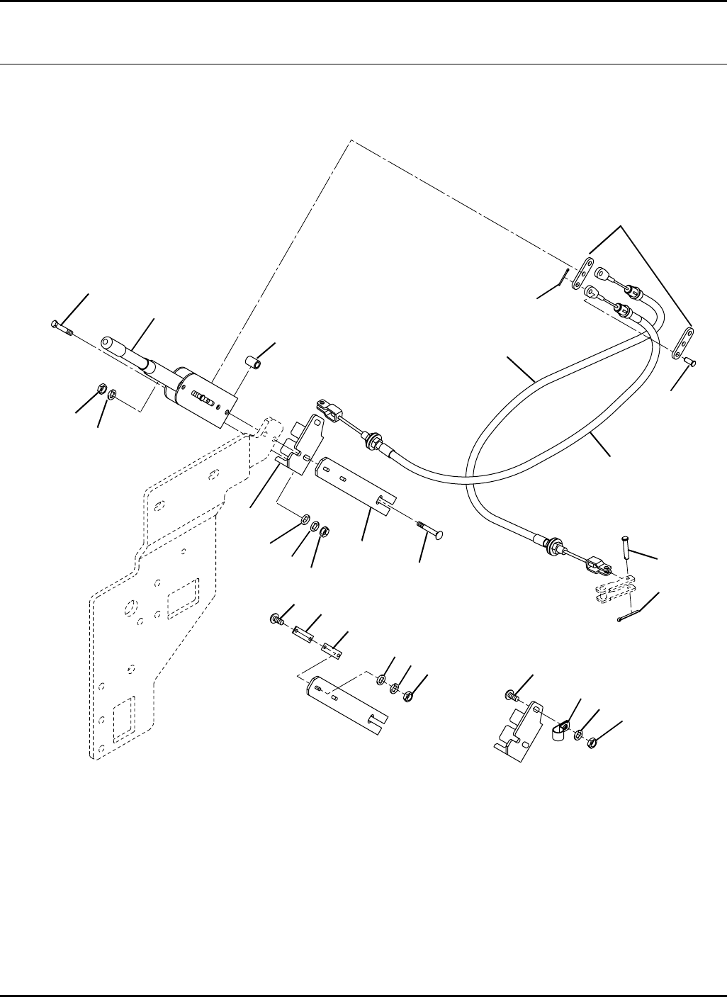
52
HR-9016
10.1 Parking Brake Serial No. All
9016-03
1
2
4
3
6
7
8
9
10 11 12
13
14
15
16
23
18 19
5
6
11
12
20 21
22 11 12
17

53
> Change from previous revision
HR-9016
Item Part No. Qty. Description Serial Numbers/Notes
11003838 1 Parking Brake Lever
2N/S 2•Stabilizer Bar
3 545234 2 •Clevis Pin
4 460004 2 •Cotter Pin
5 545237 2 •Spacer
6 3006108 2 Cable, Parking Brake
7 3008548 1 Mount, Brake Lever
8 3008874 1 Plate, Switch Mount
9 441672 2 Carriage Bolt, 5/16-18 x 2-1/2”
10 453009 2 Flat Washer, 5/16
11 446134 4 Lockwasher, 5/16
12 443106 5 Nut, 5/16-18 Hex
13 400188 2 Screw, 5/16-18 x 1” Hex Head
14 461456 2 Clevis Pin, 5/16 x 1-5/8” Hex Head
15 460016 2 Cotter Pin, 3/32 x 1”
16 403746 2 Screw, #10-24 x 3/4” Truss Head
17 3007392 1 Switch, Proximity
18 452002 2 Flat Washer, #10
19 446118 2 Lockwasher, #10 Heavy
20 444310 2 Nut, #10-24 Hex
21 441602 1 Carriage Bolt, 5/16-18 x 3/4”
22 354081 1 Clamp, Wire Harness
23 3009193 5 Shim, Switch
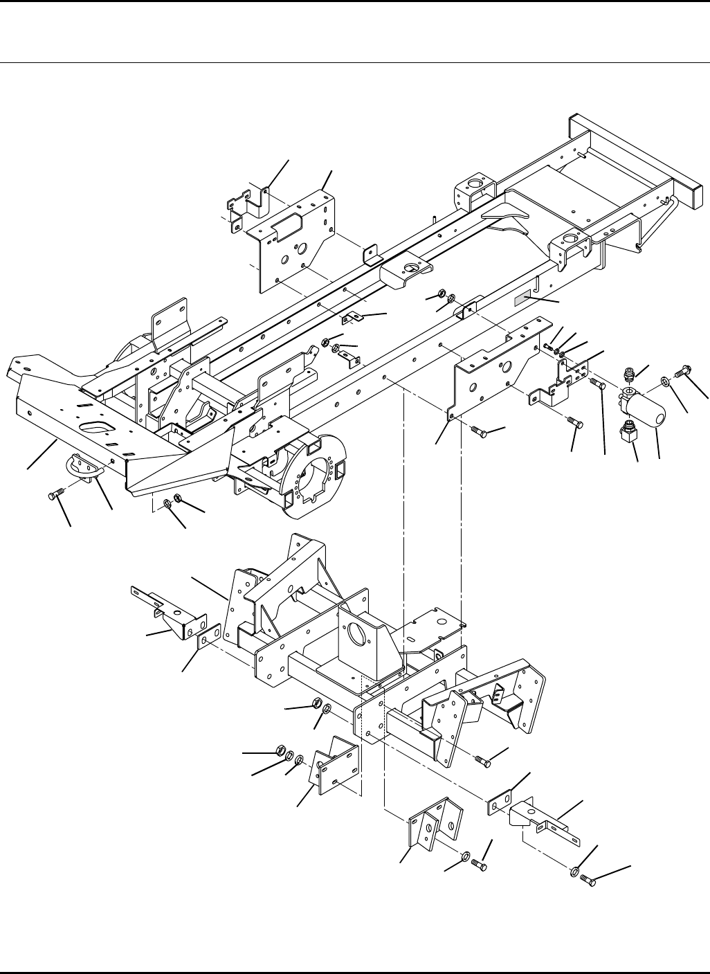
54
HR-9016
Frame
11.1 Frame Serial No. 70524 All
9016-02
1
2
3
4
5
7
6
8
910
11
12
13 14
15
16
17
18
19
20
21
22
25
22
10
24
26
27
28
29
30
31
28
7
6
32
33
34
34
10
23
11
12

55
> Change from previous revision
HR-9016
Item Part No. Qty. Description Serial Numbers/Notes
15003272 1 Frame
2 1002889 1 Cross Frame
3 1002895 1 Cylinder Mount, Right
4 1002896 1 Cylinder Mount, Left
5 400416 4 Screw, 1/2-13 x 2-1/2” Hex Head
6 446154 6 Lockwasher, 1/2 Heavy
7 443118 6 Nut, 1/2-13 Hex
8 3006814 1 Bracket, Right Radiator
9 3006815 1 Bracket, Left Radiator
10 400616 8 Screw, 5/8-11 x 2” Hex Head
11 446166 8 Lockwasher, 5/8 Heavy
12 443126 8 Nut, 5/8-11 Hex Head
13 400406 2 Screw, 1/2-13 x 1-1/4” Hex Head
14 1004938 1 Charge Filter Assembly
556417 1 •Head
5003691 1 •Oil Filter Cartridge
556419 1 •Charge Pressure Switch
15 3007919 1 Bracket, Valve Mounting
16 340075 1 Adapter, 90°
17 339996 1 Adapter, Straight
18 452008 4 Flat Washer, 3/8
19 446140 4 Lockwasher, 3/8
20 400260 4 Screw, 3/8-16 x 7/8” Hex Head
21 3007920 1 Bracket, Deck Valve Mounting
22 453017 8 Flat Washer, 1/2
23 1004691 2 Tie Down
24 3009197 2 Bracket, Hose
25 REF 1 Plate, Serial Number
26 1004308 1 Mount, Fuel Tank Rear
27 1004309 1 Mount, Hydraulic Tank Rear
28 400778 8 Screw, 3/4-10 x 2-1/2” Hex Head
29 452018 4 Flat Washer, 3/4
30 446178 8 Lockwasher, 3/4 Heavy
31 443130 8 Nut, 3/4-10 Heavy
32 453004 1 Flat Washer, #8
33 409701 1 Screw, #8-18 x 3/8” Thread Form
34 3010035 2 Plate
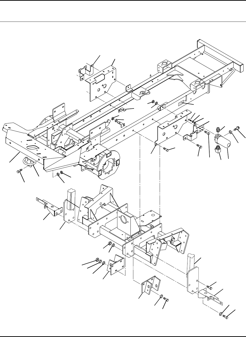
56
HR-9016
12.1 Frame With ROPS Serial No. 70525 All
9016-02
1
2
3
4
5
7
6
8
910
11
12
13 14
15
16
17
18
19
20
21
22
25
22
10
24
26
27
28
29
30
31
28
7
6
32
33
P/O 34
34
10
23
11
12

57
> Change from previous revision
HR-9016
Item Part No. Qty. Description Serial Numbers/Notes
15003272 1 Frame
2 1002889 1 Cross Frame
3 1002895 1 Cylinder Mount, Right
4 1002896 1 Cylinder Mount, Left
5 400416 4 Screw, 1/2-13 x 2-1/2” Hex Head
6 446154 6 Lockwasher, 1/2 Heavy
7 443118 6 Nut, 1/2-13 Hex
8 3006814 1 Bracket, Right Radiator
9 3006815 1 Bracket, Left Radiator
10 400616 8 Screw, 5/8-11 x 2” Hex Head
11 446166 8 Lockwasher, 5/8 Heavy
12 443126 8 Nut, 5/8-11 Hex Head
13 400406 2 Screw, 1/2-13 x 1-1/4” Hex Head
14 1004938 1 Charge Filter Assembly
556417 1 •Head
5003691 1 •Oil Filter Cartridge
556419 1 •Charge Pressure Switch
15 3007919 1 Bracket, Valve Mounting
16 340075 1 Adapter, 90°
17 339996 1 Adapter, Straight
18 452008 4 Flat Washer, 3/8
19 446140 4 Lockwasher, 3/8
20 400260 4 Screw, 3/8-16 x 7/8” Hex Head
21 3007920 1 Bracket, Deck Valve Mounting
22 453017 8 Flat Washer, 1/2
23 1004691 2 Tie Down
24 3009197 2 Bracket, Hose
25 REF 1 Plate, Serial Number
26 1004308 1 Mount, Fuel Tank Rear
27 1004309 1 Mount, Hydraulic Tank Rear
28 400778 8 Screw, 3/4-10 x 2-1/2” Hex Head
29 452018 4 Flat Washer, 3/4
30 446178 8 Lockwasher, 3/4 Heavy
31 443130 8 Nut, 3/4-10 Heavy
32 453004 1 Flat Washer, #8
33 409701 1 Screw, #8-18 x 3/8” Thread Form
34 1002893 1 ROPS Includes Decals and Seat Belt
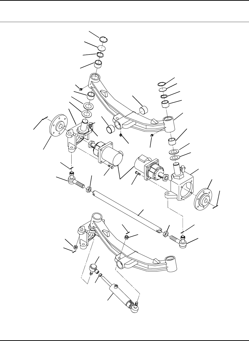
58
HR-9016
13.1 Steering Axle Serial No. All
9016-38
1
2
3
4
5
6
7
8
9
10
11
12
13
14
15
16
17
18
19
20
21
22
23
24
25
2
2
2
4
7
9
10 11
12
12
12
20
20
21
22
23
24
17
17
17

59
> Change from previous revision
HR-9016
Item Part No. Qty. Description Serial Numbers/Notes
15003540 2 Wheel Motor See 49.1
2 460030 4 Cotter Pin, 1/8 x 1-1/4”
3 443842 1 Nut, 1-1/8 -12 Hex Jam
4 401208 8 Screw, 1/2-13 x 1-3/4” Grade 8
5 5003530 1 Frame, RH Wheel Motor
6 5003529 1 Frame, LH Wheel Motor
7 5003521 2 Hub, Wheel
8 5003526 1 Axle, Center Section
9 5003518 2 Washer, Thrust
10 5003515 2 Washer, Thrust
11 5003528 2 Bushing, Bronze
12 5003527 4 Bushing, Bronze
13 5003522 1 Tie Rod
14 5003519 1 Nut, 1-1/8 -12 Left Hand Thread
15 5003523 1 Tie Rod End, Left Hand Thread
16 5003524 1 Tie Rod End, Right Hand Thread
17 5003541 1 Cylinder, Steering See 48.1
5003542 1 •Seal Kit
18 5003562 2 Screw, 5/8-11 Socket Head Set
19 443826 2 Nut, 5/8-11 Hex Jam
20 471214 3 Grease Fitting
21 460035 2 Cotter Pin, 1/8 x 2”
22 458126 2 Snap Ring
23 5003520 2 Snap RIng, External
24 5003531 2 Plug, Expansion
25 5003543 1 Socket Assembly
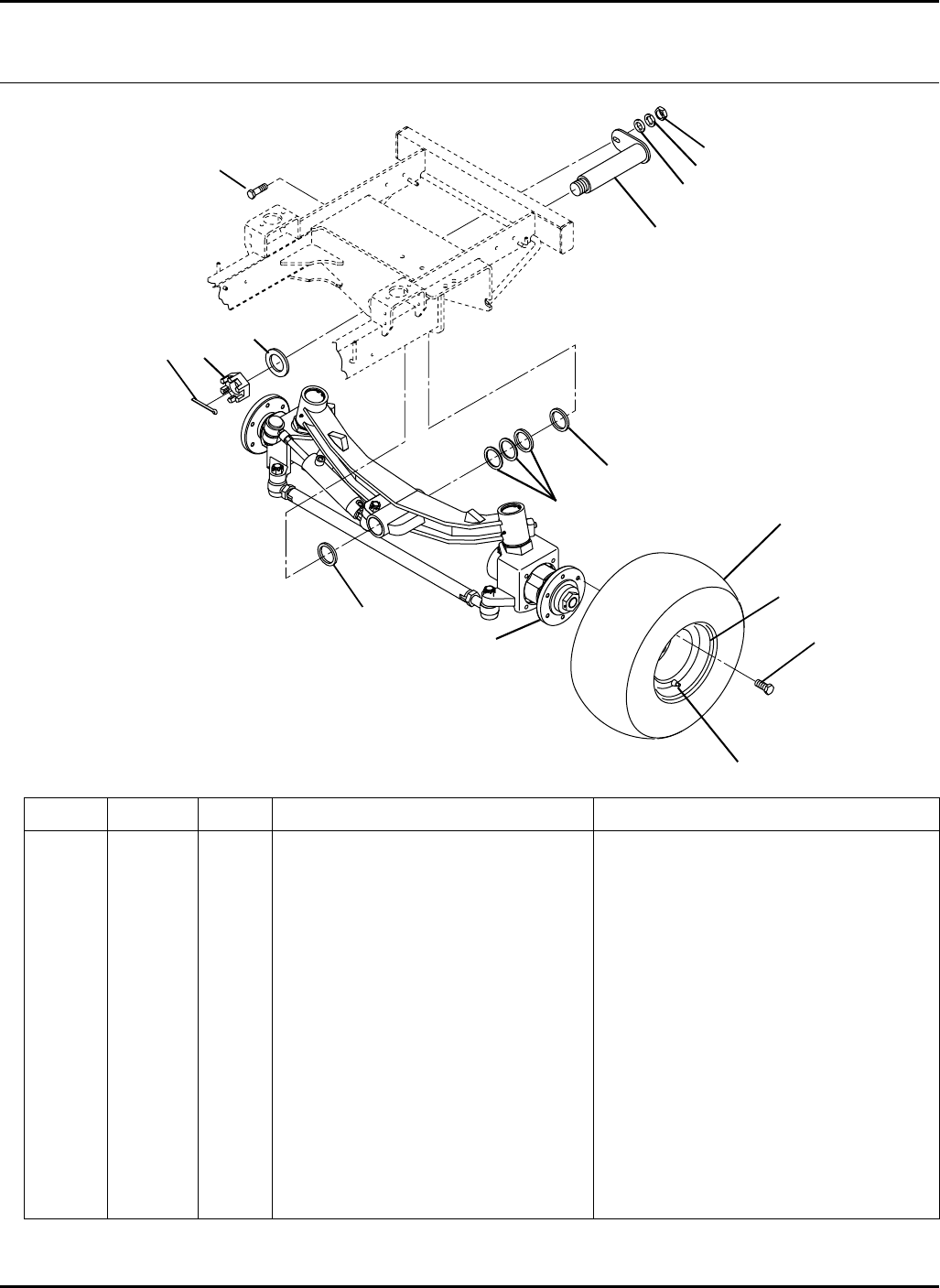
60
> Change from previous revision
HR-9016
14.1 Steering Axle Installation Serial No. All
9016-36
Item Part No. Qty. Description Serial Numbers/Notes
1–1 Steering Axle See 13.1
2 1003001 1 Pivot Shaft
3 3006475 AR Washer, 3/32” Thick Thrust
4 363766 1 Washer
5 445642 1 Nut, 1-1/2 -12 Slotted Hex
6 460072 1 Cotter Pin, 1/4 x 2-1/2”
7 400408 1 Screw, 1/2-13 x 1-1/2” Hex Head
8 446152 1 Lockwasher, 1/2
9 443118 1 Nut, 1/2-13 Hex
10 3003101 AR Washer, 1/32” Thick Thrust
11 3007683 12 Wheel Bolt, 1/2-20
12 5003419 2 Tire, 24 x 12-12 Turf Trac
13 5003420 2 Wheel
14 360111 2 Valve, Inflation
15 453017 1 Flat Washer, 1/2
1
2
3
4
56
78
9
3
3 / 10
As Required
11
12
13
14
15
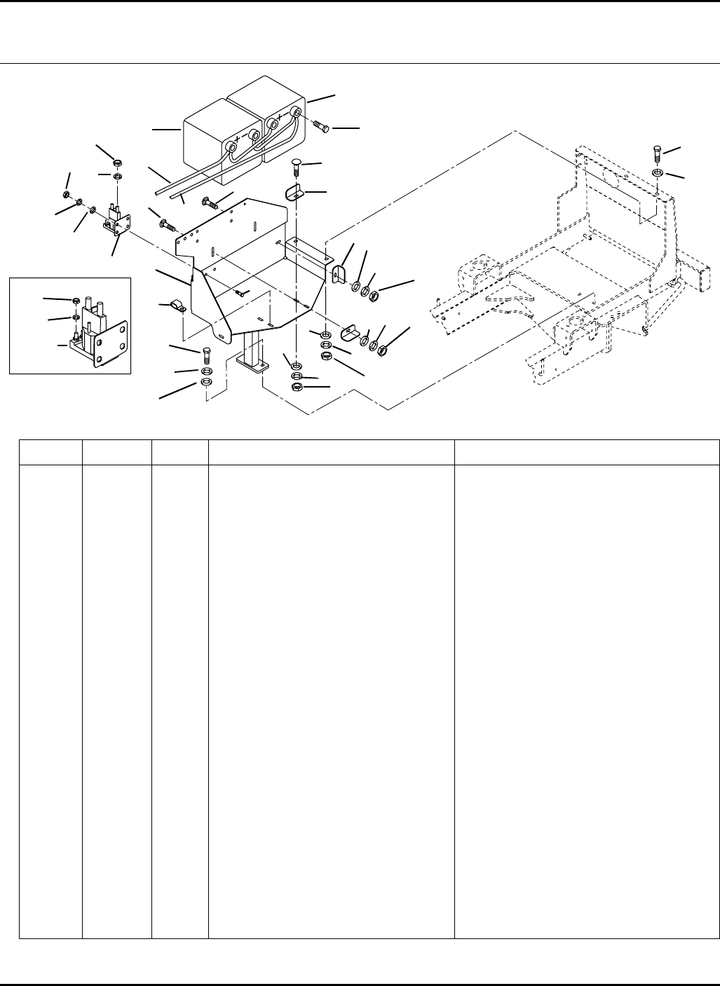
61
> Change from previous revision
HR-9016
Item Part No. Qty. Description Serial Numbers/Notes
15003622 1 Battery Tray Includes Decals
2 400264 4 Screw, 3/8-16 x 1-1/4” Hex Head
3 446142 4 Lockwasher, 3/8 Heavy
4 452008 6 Flat Washer, 3/8
5 N/S 2 Battery, 12 Volt Group 75-84N
6 3008461 5 Angle, Battery Clamp
7 440078 7 Carriage Bolt, 5/16-18 x 3/4”
8 452006 7 Flat Washer, 5/16
9 446134 7 Lockwasher, 5/16
10 443106 7 Nut, 5/16-18 Hex
11 3010291 1 Cable, Positive Battery
12 3010292 1 Cable, Nagative Battery
13 443110 2 Nut, 3/8-16 Hex
14 3008820 2 Clamp, Double Hose
15 3010346 4 Bolt, Battery Terminal
16 131905 1 Solenoid
17 400108 2 Screw, 1/4-20 x 3/4” Hex Head
18 443102 2 Nut, 1/4-20 Hex
19 446130 2 Lockwasher, 1/4 Heavy
20 452004 2 Flat Washer, 1/4
21 443808 2 Nut, 5/16-24 Hex Jam
22 447214 2 Lockwasher, 5/16 Internal
23 446118 2 Lockwasher, #10 Heavy
24 444312 2 Nut, #10-32
15.1 Battery Tray Serial No.
9016-37
1
2
3
4
5
6
7
8
910
12
11
13
23
4
4
6
8
8
7
9
9
10
10
7
14
15
5
16
17
18
19
20
21
22
16
23
24
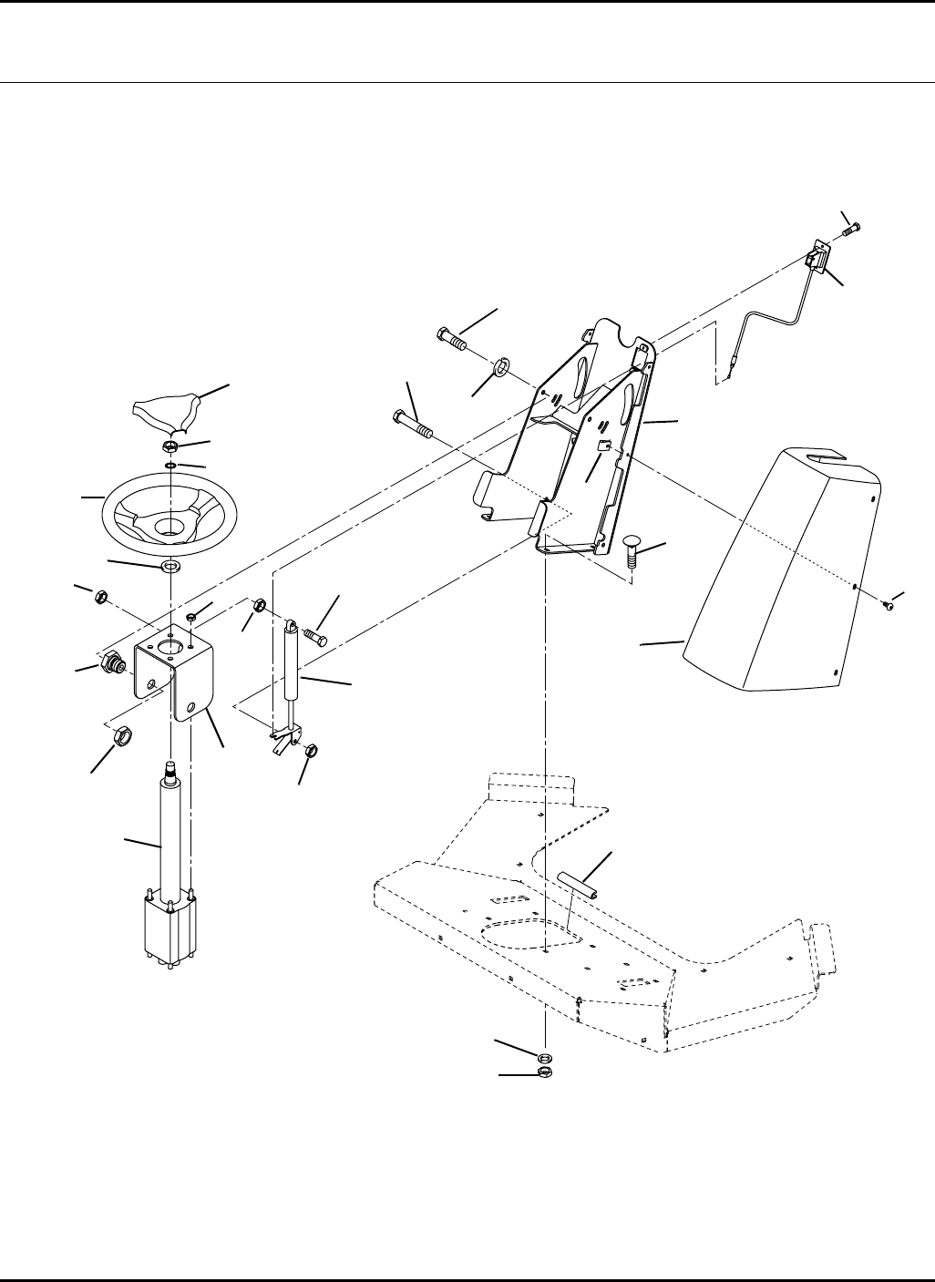
62
HR-9016
16.1 Tilt Steering Serial No. All
9016-17
1
2
3
4
5
7
9
8
6
10
11
12
13
14
15
16
17
18
19
20
21
4
11
11
23
22
24
25

63
> Change from previous revision
HR-9016
Item Part No. Qty. Description Serial Numbers/Notes
15002918 1 Actuator, Gas Spring
2 5002919 1 Cable, Actuator
3 2811346 1 Tower, Steering
4 1002800 1 Pump, Steering See 45.1
339979 5 •Adapter, Straight
5 2811364 1 Steering Wheel
6 2811365 1 •Cap, Steering Wheel
7 3010651 1 Cover, Steering Tower
8 3005981 1 Bracket, Steering Pump
9 3005934 2 Bolt, Shoulder
10 400192 1 Screw, 5/16-18 x 1-1/2” Hex Head
11 444718 3 Locknut, 5/16-18 Center
12 444849 2 Locknut, 3/4-10 Center Jam
13 444754 4 Locknut, 5/16-24 Center
14 447224 1 Lockwasher, 5/8 Internal
15 400216 1 Screw, 5/16-18 x 2-3/4” Hex Head
16 443106 4 Nut, 5/16-18 Hex
17 416911 2 Screw, #10-24 x 1/2” Thread Cutting
18 404016 6 Screw, 1/4-20 x 5/8: Truss Head
19 446142 2 Lockwasher, 3/8 Heavy
20 400258 2 Screw, 3/8-16 x 3/4” Hex Head
21 441602 4 Carriage Bolt, 5/16-18 x 3/4”
22 551651 1 Moulding (Cut to 10”)
23 446136 4 Lockwasher, 5/16 Heavy
24 445245 6 Tinnerman Nut
25 2811547 1 Washer
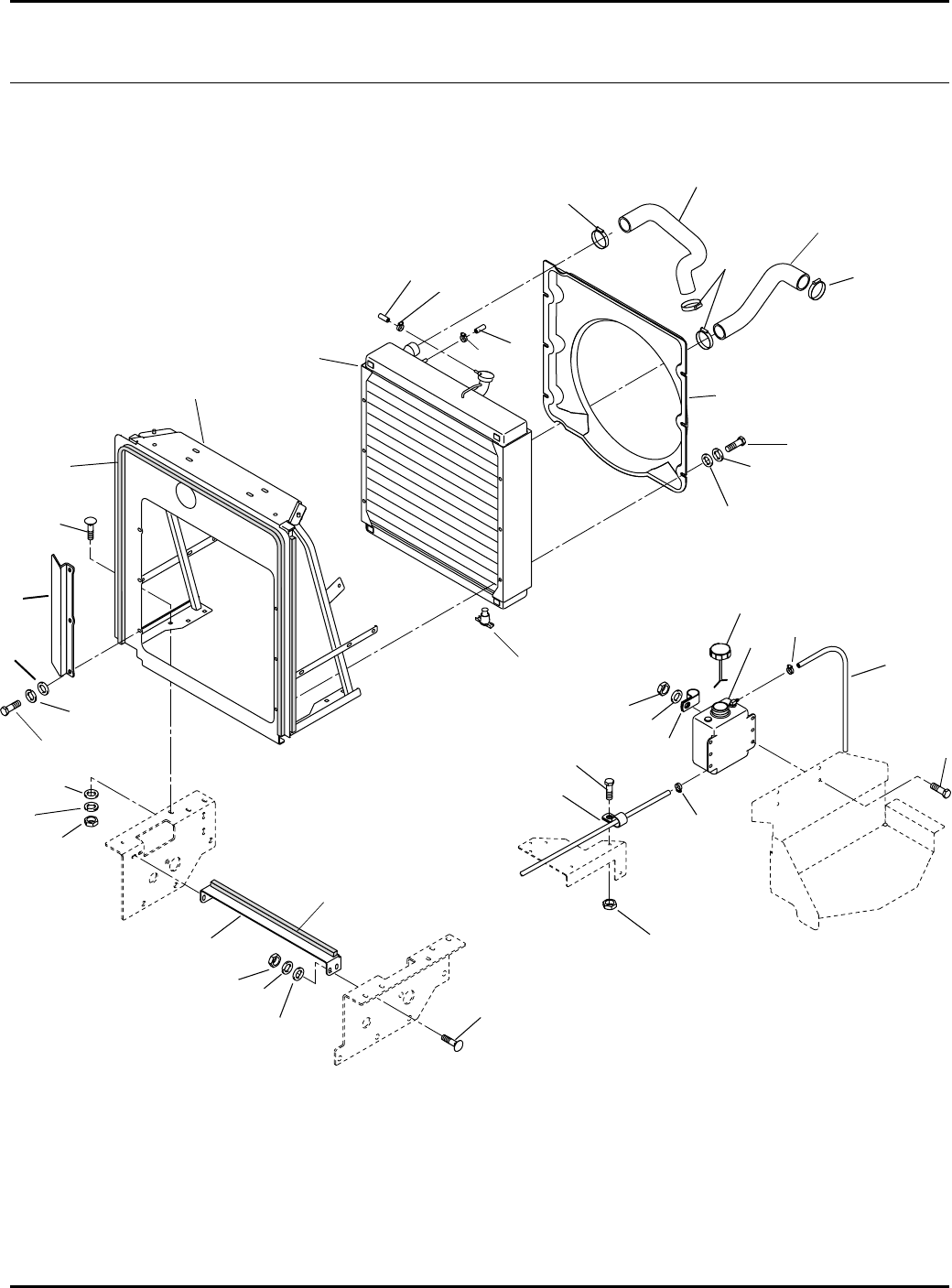
64
A
AB
HR-9016
Engine and Radi ator
17.1 Radiator Serial No. All
9016-12
1
2
3
4
5
6
9
8
7
10
11
12
13
14
15
16
17
18
19
20
22
23
22
3
4
6
8
8
10
10
10
15
4
4
6
617
12
23
22
B – To Top Engine Bleed Port
20
21
24

65
> Change from previous revision
HR-9016
Item Part No. Qty. Description Serial Numbers/Notes
15003355 1 Radiator Firewall
2 1002953 1 Radiator
555867 1 •Radiator Cap
3 400258 12 Screw, 3/8-16 x 3/4” Hex Head
4 446142 22 Lockwasher, 3/8 Heavy
5 3006427 1 Radiator Fan Shroud
6 452008 18 Flat Washer, 3/8
7 3008626 1 Hose, Upper Radiator
8 326799 4 Clamp, Hose
9 3008625 1 Hose, Lower Radiator
10 366526 5 Clamp, Hose
11 3007731 1 Reserve Tank
12 360970 2 Clamp, Hose
13 162479 1 Drain Cock
14 400184 4 Screw, 5/16-18 x 3/4” Hex Head
15 443110 10 Nut, 3/8-16 Hex
16 3008885 1 Brace, Cooler
17 440120 10 Carriage Bolt, 3/8-16 x 1-1/4”
18 400186 1 Screw, 5/16-18 x 7/8” Hex Head
19 453009 4 Flat Washer, 5/16
20 444718 5 Locknut, 5/16-18 Center
21 3009537 1 Cap, Reserve Tank
22 554748 AR Hose, 5/16 I.D.
23 5003216 AR Seal (10 Foot Roll)
24 2810492 1 Plate, Indent
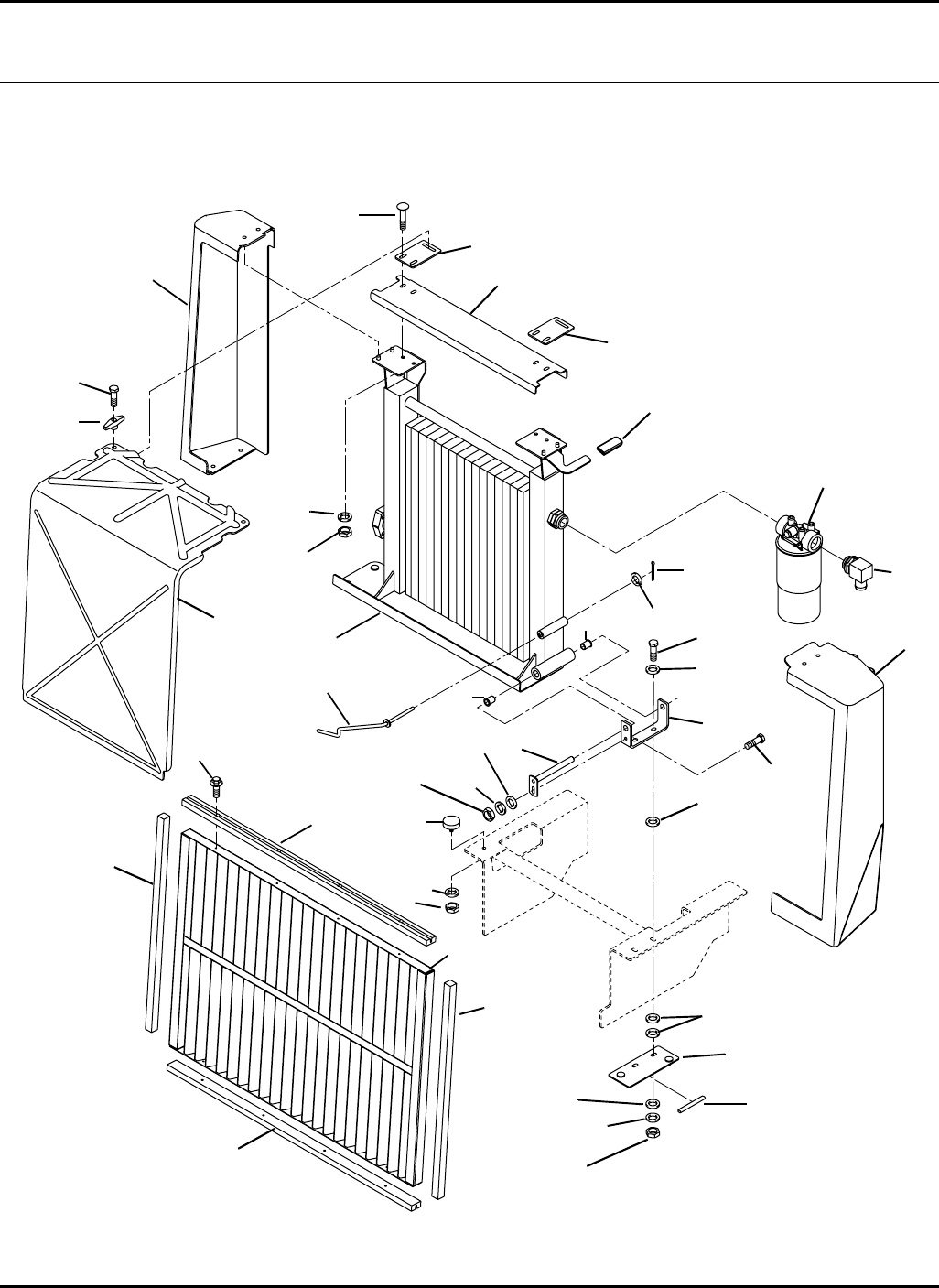
66
HR-9016
18.1 Oil Cooler Serial No. All
9016-13
1
2
3
4
5
6
7
8
9
10
11
12
13
14
15
16
17
20
21
22
23
24
25
26
27
28
29
30
31
32
2
6
35
87
13
15
34
18
28
30
33
35
19

67
> Change from previous revision
HR-9016
Item Part No. Qty. Description Serial Numbers/Notes
11002952 1 Oil Cooler
2 3004113 2 Bushing
3 2810633 1 Plate, Cap Mounting
4 3007011 1 Bracket, Cooler Pivot
5 400270 2 Screw, 3/8-16 x 2” Hex Head
6 452008 4 Flat Washer, 3/8
7 446142 3 Lockwasher, 3/8 Heavy
8 443110 3 Nut, 3/8-16 Hex
9 1004028 1 Pin, Cooler Pivot
10 400186 1 Screw, 5/16-18 x 7/8” Hex Head
11 452006 1 Flat Washer, 5/16
12 446134 1 Lockwasher, 5/16
13 443106 5 Nut, 5/16-18 Hex
14 3008562 1 Angle, Cooler Top
15 3008563 2 Plate, Cooler Lock
16 400190 2 Screw, 5/16-18 x 1-1/4” Hex Head
17 446136 4 Lockwasher, 5/16 Heavy
18 362008 2 Knob
19 358794 4 Washer
20 3007674 1 Fitting, 90°
21 1003011 1 Return Filter
5002693 1 •Return Filter Cartridge
556419 1 •Switch
22 460016 1 Cotter Pin, 3/32 x 1”
23 1004172 1 Stand, Cooler Pivot
24 361723 1 Stop, Rubber
25 351491 1 Grip
26 551651 AR Molding
27 1003942 1 Screen
28 3008561 2 Guide, Screen
29 409804 8 Screw, #10-24 x 1/2” Thread Cut
30 3009095 2 Seal, Neoprene
31 3008554 1 Cap, Right Side
32 2810634 1 Cap, Left Side
33 3010014 1 Shield, Screen
34 440082 4 Carriage Bolt, 5/16-18 x 1”
35 453011 3 Flat Washer, 3/8
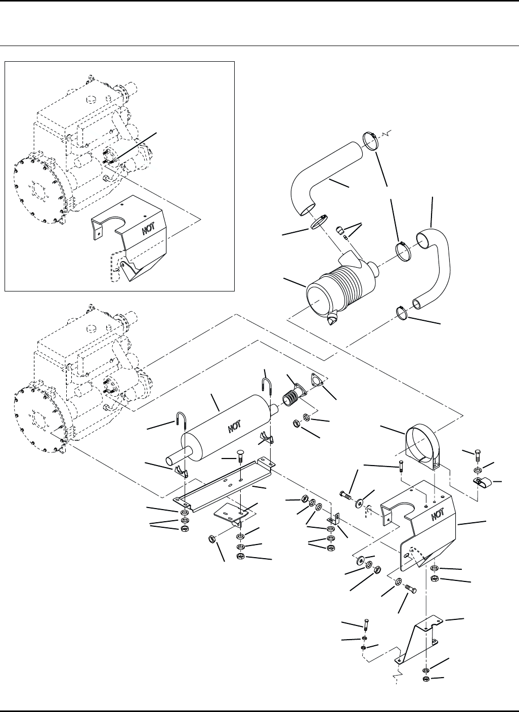
68
To Intake Tube
on Radiator
Tower
Mounts to Stud
on Engine
Exhaust
Manifold
1
2
3
4
56
7
8910
12
11
13
14
15
16
5
18
19
20
21
22
23
24
25
26
28
29
9
25
25
25
25
6
25
6
15
15
33
15
6
16
27
13
30
31
32 17
15
16
HR-9016
19.1 Air Cleaner and Muffler Serial No. All
9016-16

69
> Change from previous revision
HR-9016
Item Part No. Qty. Description Serial Numbers/Notes
11004417 1 Air Cleaner
5003370 1 •Filter Element
5003372 1 •Cover
5003373 1 •Valve
2 3009505 1 Clamp, Air Cleaner Mounting
3 3010182 1 Heat Shield, Muffler
4 3010340 1 Tab, Heat Shield
5 400186 4 Screw, 5/16-18 x 7/8” Hex Head
6 452006 10 Flat Washer, 5/16
7 443106 2 Nut, 5/16-18 Hex
8 3009270 1 Hose, Air Cleaner Intake
9 3009463 3 Clamp, Hose
10 3009271 1 Hose, Air Cleaner to Engine
11 359615 1 Clamp, Hose
12 1001752 1 Indicator, Mini Kit
13 362615 1 Washer, Special
14 400190 2 Screw, 5/16-18 x 1-1/4” Hex Head
15 446136 10 Lockwasher, 5/16 Heavy
16 444718 2 Locknut, 5/16-18 Center
17 452002 2 Flat Washer, 1/4
18 5003767 1 Gasket, Exhaust
19 3006656 1 Bracket, Muffler
20 441624 3 Carriage Bolt, 3/8-16 x 1”
21 452008 3 Flat Washer, 3/8
22 446142 3 Lockwasher, 3/8 Heavy
23 443110 3 Nut, 3/8-16 Hex
24 4114707 1 Muffler
25 162236 2 Clamp, Exhaust
26 4113811 1 Bracket, Muffler Support
27 3009272 1 Clamp, Double Tube
28 4114637 1 Adapter, Flex Pipe
29 362524 2 Nut, M10
30 2811344 1 Plate, Air Filter Support
31 4102420 2 Screw, M6 x1
32 446128 2 Lockwasher, 1/4
33 4114366 3 Lock Nut, Top
★Non Serviced Component of Engine
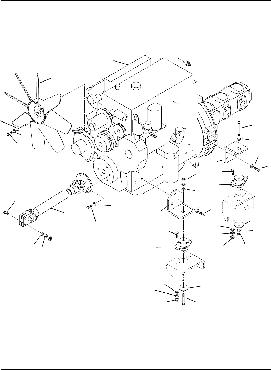
70
HR-9016
20.1 Engine Mounting Serial No. All
9016-11
1
2
3
4 / 17
5
67
8
9
12 13
10
14
15
16
17
18
19
20
7
7
8
8
13
11
11
12
12
14
16
18
19
20
15
21
22
23
24
25

71
> Change from previous revision
HR-9016
Item Part No. Qty. Description Serial Numbers/Notes
1–1 Engine and Pump Assembly See 21.1
2 3007671 1 Fan Mounting Hardware Part of Engine
3 3008821 1 Temperature Sender
4 400420 1 Screw, 1/2-13 x 3-1/2” Hex Head Front Right Engine Mount Only
5 3006526 1 Bracket, Front Iso-Mount
6 3006525 2 Bracket, Rear Iso-Mount
7 361619 17 Screw, M10-1.5 x 25mm Hex Head
8 363385 17 Lockwasher, M10
9 4108680 1 Drive Shaft
10 400270 2 Screw, 3/8-16 x 2-1/4” Hex Head
11 452008 8 Flat Washer, 3/8
12 446142 10 Lockwasher, 3/8 Heavy
13 443110 8 Nut, 3/8-16 Hex
14 4114711 4 Isolator
15 323943 4 Washer, 2”O.D. x 17/32” I.D.
16 400264 8 Screw, 3/8-16 x 1-1/4” Hex Head
17 400422 3 Screw, 1/2-13 x 4” Hex Head
18 452012 4 Flat Washer, 1/2
19 446152 4 Lockwasher, 1/2
20 443118 4 Nut, 1/2-13 Hex
21 446136 3 Lockwasher, 5/16 Heavy
22 362540 3 Screw, M8-1.25 x 16mm Hex Head
23 453009 3 Flat Washer, 5/16
24 444762 2 Locknut, 3/8-16 Center
25 452006 4 Flat Washer
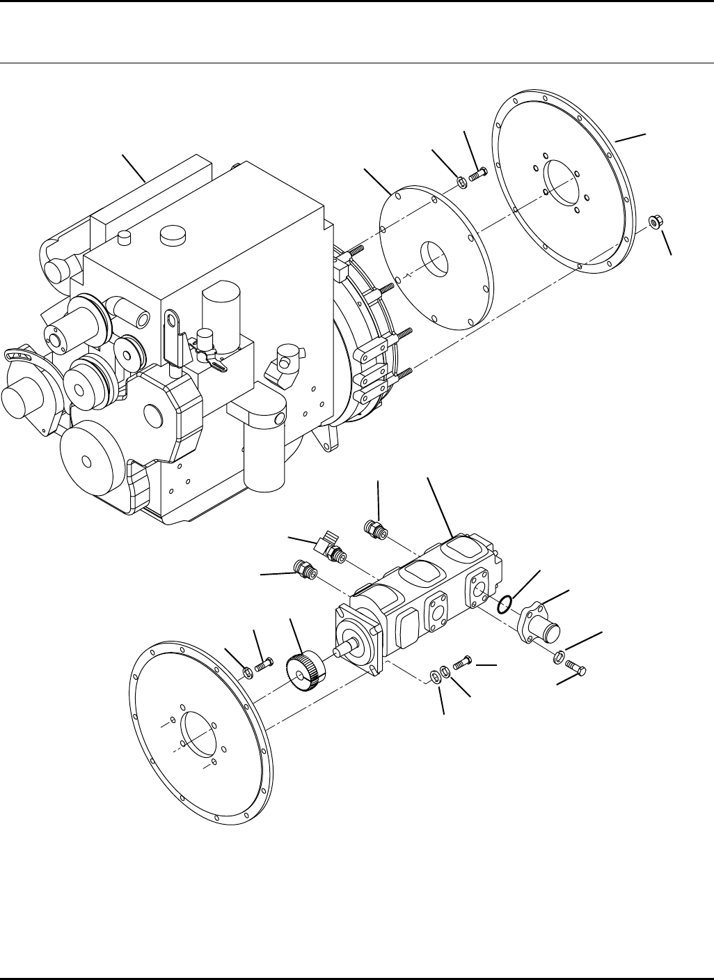
72
Part of
Engine
HR-9016
21.1 Engine and Pump Assembly Serial No. All
9016-10
1
2
3
4
5
6
7
8
9
10
11
12
13
14
15
16
17
3
14

73
> Change from previous revision
HR-9016
Item Part No. Qty. Description Serial Numbers/Notes
1REF 1 Engine, DDC D704LT
5003207 1 •Engine Oil Filter
5003208 1 •Oil Cooler Hose
5003209 1 •Thermostat Housing
5003210 1 •Fuel Line (Fuel Pump to Filter)
5003211 1 •Fan Belt
5003212 1 •Fuel Filter
5003213 1 •Oil Cooler Hose
5003214 1 •Fuel Line, (Filter to Injection)
5003689 1 •Alternator Belt
2 1003247 1 Pump, Triple
5003163 1 •Seal Kit, Front Section
5003164 2 •Seal Kit, Section One kit required for each section
3 339989 2 Adapter, Straight
4 340070 1 Adapter, 90°
5 3006829 2 Fitting, Four Bolt Flange
6 3006835 2 O-Ring, 1-3/4” O.D. x 1-1/2” I.D.
7 400336 8 Screw, 7/16-14 x 1-1/4” Hex Head
8 446148 8 Lockwasher, 7/16 Heavy
9 3006238 1 Hub, 48 Tooth
10 3006240 1 Flange, 10”
11 361619 8 Screw, M10-1.5 x 25mm Hex Head
12 363385 8 Lockwasher, M10
13 3006241 1 Plate, Pump SAE #4
14 446154 6 Lockwasher, 1/2 Heavy
15 453017 4 Flat Washer, 1/2
16 400404 2 Screw, 1/2-13 x 1” Hex Head
17 400406 4 Screw, 1/2-13 x 1-1/4” Hex Head
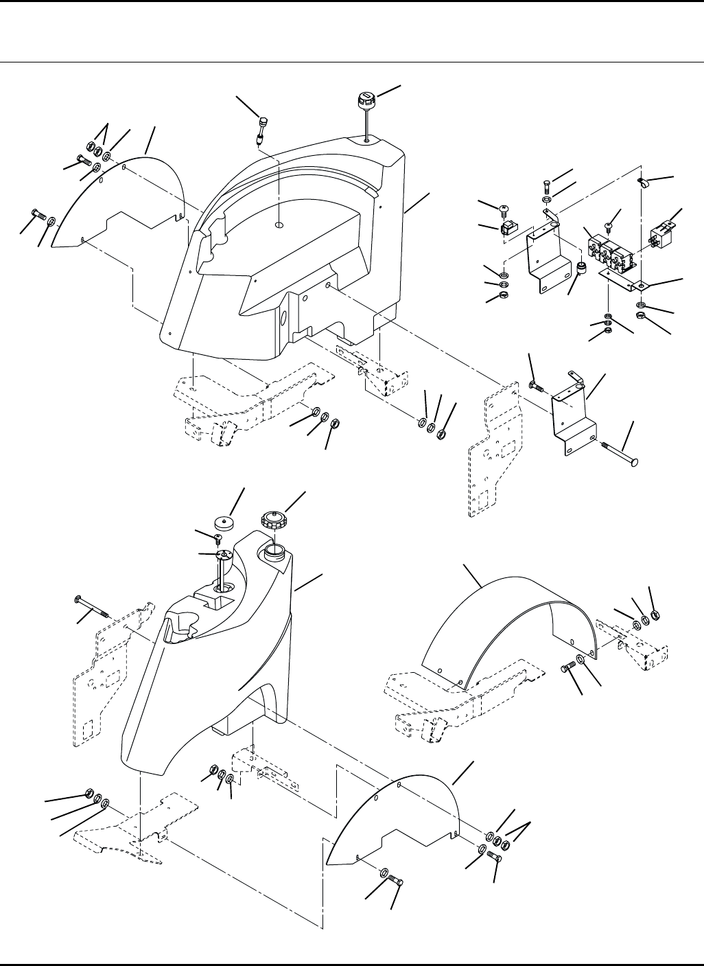
74
HR-9016
Tanks
22.1 Tank Mounting Serial No. All
9016-18
1
2
3
4
5
6
78
13
14
15
16
17
18
19
20
4
5
7
8
11
11
11
11
32
32
32
14
14
14
14
14
14
15
15
15
14
32
21
22
23
24
25
26
27
28
29
30
31
32
9 /10
12
14
11
15
19
33
34
35
36
38
37

75
> Change from previous revision
HR-9016
Item Part No. Qty. Description Serial Numbers/Notes
1–1 Tank, Hydraulic Oil See 23.1
2 3008808 1 Cap, Breather Filler
3 3009203 1 Sensor, Oil Level
4 441689 4 Carriage Bolt, 1/2-13 x 8-1/2”
5 3009236 2 Wall, Fender
6 3008219 1 Bracket, Hose Retainer
7 452012 4 Flat Washer, 1/2
8 443118 8 Nut, 1/2-13 Hex
9 3009980 1 Fender, Right Side
10 3009979 1 Fender, Left Side
11 446136 12 Lockwasher, 5/16 Heavy
12 362615 8 Washer, Special
13 440088 2 Carriage Bolt, 5/16-18 x 1-3/4”
14 452006 16 Flat Washer, 5/16
15 443106 12 Nut, 5/16-18 Hex
16 –1 Tank, Fuel See 24.1
> 17 2721806 1 Cap, Fuel
18 340481 1 Cover, Sender
19 403910 7 Screw, #10-32 x 1/2” Truss Head
20 3006639 1 Sender, Fuel Level
21 366670 1 Horn
22 364016 1 Clamp, Wire Harness
23 400260 1 Screw, 3/8-16 x 7/8” Hex Head
24 453011 1 Flat Washer, 3/8
25 446140 1 Lockwasher, 3/8
26 443110 1 Nut, 3/8-16 Hex
27 3009544 1 Relay, Time Delay
28 403860 2 Screw, #8-32 x 5/8” Truss Head
29 453004 2 Flat Washer, #8
30 446112 2 Lockwasher, #8 Heavy
31 444306 2 Nut, #8-32 Hex
32 400188 12 Screw, 5/16-18 x 1” Hex Head
33 2822524 1 Bracket, Relay
Serial Number 70524 1726 and Up
Serial Number 70525 1778 ang Up
34 452002 2 Flat Washer, #10
35 446118 2 Lockwasher, #10
36 444310 2 Nut, #10-24 Hex
37 3001307 3 Relay, SPDT with Resistor
38 REF 1 Harness, Kubota Key Switch See 44.1
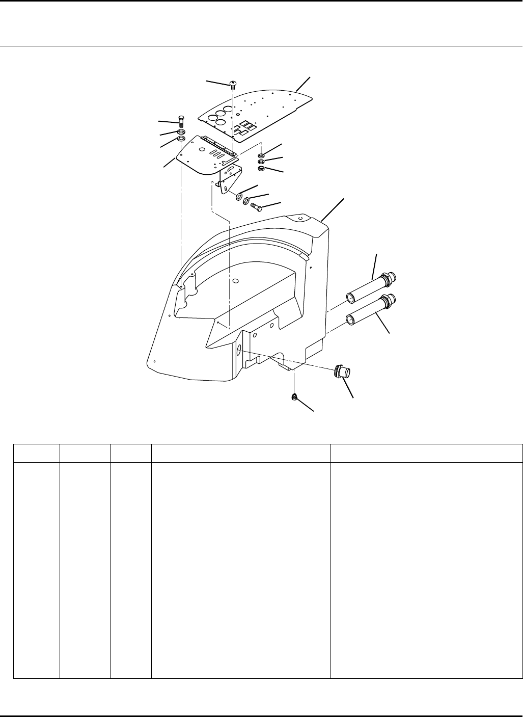
76
> Change from previous revision
HR-9016
23.1 Hydraulic Tank Serial No. All
9016-19
Item Part No. Qty. Description Serial Numbers/Notes
13006264 1 Tank, Hydraulic oil
2 3006566 2 Strainer
339904 2 •O-Ring SAE -32
3 3006847 1 Fitting, Beaded
339904 1 •O-Ring SAE -32
4 3002397 1 Plug, Magnetic
5–1 Control Panel See 6.1 and 7.1
6–1 Instrument Panel See 5.1
7 400182 3 Screw, 5/16-18 x 5/8” Hex Head
8 446134 3 Lockwasher, 5/16
9 453009 3 Flat Washer, 5/16
10 404022 4 Screw, 1/4-20 x 1” Truss Head
11 453023 4 Flat Washer, 1/4
12 446128 4 Lockwasher, 1/4
13 443102 4 Nut, 1/4-20 Hex
1
2
3
4
5
6
7
8
9
10
12
13
2
7
8
9
11
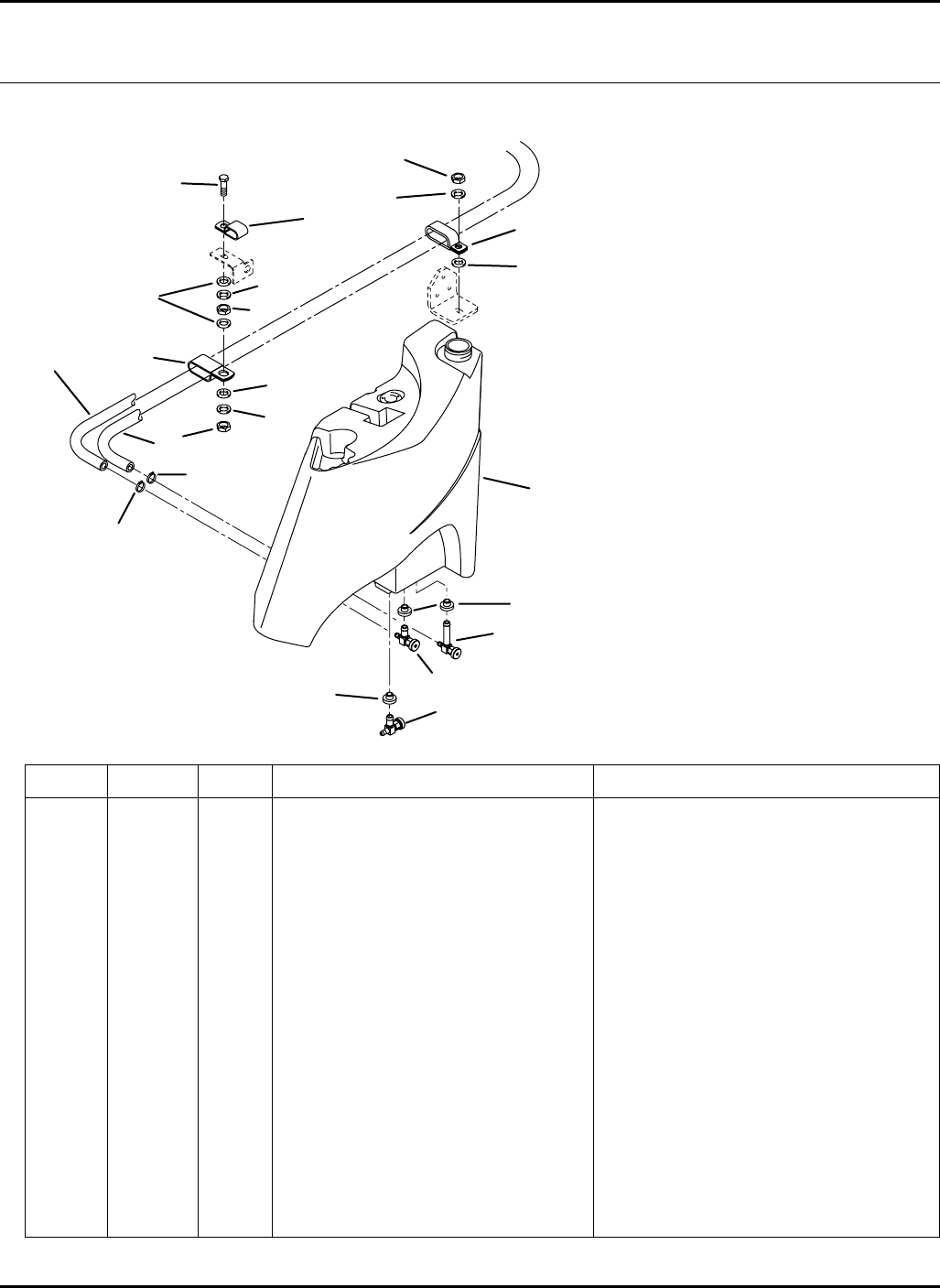
77
> Change from previous revision
A
B
A - Connects to Fuel Injection Pump
Return Port
B - Connects to Fuel Pump Inlet
1
2
3
4
5
6
8
9
10
12
11
13
14
15
16
17
2
4
5
7
6
9
7
HR-9016
Item Part No. Qty. Description Serial Numbers/Notes
13006265 1 Tank, Fuel
2 361117 3 Bushing
3 132647 1 Fuel Shutoff
4 554748 AR Fuel Line, 5/16 I.D.
5 366526 4 Clamp, Hose
6 3008820 2 Clamp, Double Hose (5/8” O.D.)
7 452008 3 Flat Washer, 3/8
8 446140 1 Lockwasher, 3/8
9 443110 2 Nut, 3/8-16 Hex
10 452012 1 Flat Washer, 1/2
11 446152 1 Lockwasher, 1/2
12 443118 1 Nut, 1/2-13 Hex
13 446142 1 Lockwasher, 3/8 Heavy
14 400264 1 Screw, 3/8-16 x 1-1/4” Hex Head
15 3009272 1 Clamp, Double Hose (3/8” O.D.) Retains Steering Tubes
16 2810702 1 Valve, Needle
17 3003704 1 Elbow, 90° Fuel
24.1 Fuel Tank Serial No. All
9016-20
78
> Change from previous revision
HR-9016
Traction Pump
25.1 Pump and 4WD Valve Mounting Serial No. All
9016-06
Item Part No. Qty. Description Serial Numbers/Notes
1–1 Pump Assembly See 26.1
2 1002977 1 4WD Valve with Oil Shuttle See 55.1
3 400406 4 Screw, 1/2-13 x 1-1/4” Hex Head
4 446154 6 Lockwasher, 1/2 Heavy
5 453017 4 Flat Washer, 1/2
6 400412 2 Screw, 1/2-13 x 2” Hex Head
7 3006658 1 Bracket, Pump Support
8 443118 2 Nut, 1/2-13 Hex
9 440082 4 Carriage Bolt, 5/16-18 x 1”
10 452006 4 Flat Washer, 5/16
11 446136 4 Lockwasher, 5/16 Heavy
12 443106 4 Nut, 5/16-18 Hex
13 3006913 1 Bracket, Pump Support
14 446140 2 Lockwasher, 3/8 Included with Pump
15 443110 2 Nut, 3/8-16 Hex Included with Pump
1
2
3
4
5
6
4
8
9
10
11
12
13
14
9
10
11
12
15
7
79
> Change from previous revision
HR-9016
Item Part No. Qty. Description Serial Numbers/Notes
11002927 1 Pump, Traction
5003034 1 •Seal Kit
5003432 1 •Control Kit
5003433 1 •Shaft Seal Kit
5003544 1 •System Relief Kit
2 1003248 1 Pump, Double
5003165 1 •Seal Kit, Front Section
5003166 1 •Seal Kit, Rear Section
3 362743 1 O-RIng
4 400262 2 Screw, 3/8-16 x 1” Hex Head
5 446142 2 Lockwasher, 3/8 Heavy
6 340077 1 Adapter, 90°
7 340269 1 Adapter, Tee
8 340070 2 Adapter, 90°
9 3006829 1 Fitting, 4 Bolt Flange
10 3006835 1 O-Ring, 1-3/4” O.D. x 1-1/2” I.D.
11 400336 4 Screw, 7/16-14 x 1-1/4” Hex Head
12 446148 4 Lockwasher, 7/16 Heavy
13 339984 1 Adapter, Straight
14 339999 1 Adapter, Straight
26.1 Pump Assembly Serial No. All
9016-07
1
23
4
5
6
7
8
910
11 12
13
14
8
80
HR-9016
Lift Arms and Deck Valves
27.1 Front Lift Arms and Cylinders Serial No. All
9016-09
1
2
3
4
56
7
8
9
10
11
12
13
14 15
16
17 18
19
20
22
23
24
25
3
5
8
8
8
8
9
10
10
10
10
11
11
11
11
15
21
26
27 28293031
33
33
34
32
35

81
> Change from previous revision
HR-9016
Item Part No. Qty. Description Serial Numbers/Notes
11002785 1 R.H. Front Lift Arm
2 1003900 1 L.H. Front Lift Arm
3 342033 4 •Bushing
4 471214 2 •Grease Fitting
5 3006490 4 Bracket, Front Deck Pivot
6 3007091 1 Angle, R.H. Valve Mount
7 3007092 1 Angle, L.H. Valve Mount
8 400412 28 Screw, 1/2-13 x 2” Hex Head
9 453017 4 Flat Washer, 1/2
10 446154 28 Lockwasher, 1/2 Heavy
11 443118 28 Nut, 1/2-13 Hex
12 3006008 2 Front Lift Cylinder See 52.1
13 340061 2 Adapter, 90°
14 339979 2 Adapter, Straight
15 3006491 4 Bracket, Front Cylinder Pivot
16 1003274 2 Pin, Front Cylinder
17 1003275 2 Pin, Front Lift Arm Pivot
18 3007468 1 Bracket, Switch
19 403746 2 Screw, #10-24 x 3/4” Truss Head
20 3007392 1 Switch, Proximity
21 452002 2 Flat Washer, #10
22 446118 2 Lockwasher, #10 Heavy
23 444310 2 Nut, #10-24 Hex
24 3007680 2 Pin, Front Deck Mounting
25 460054 2 Cotter Pin, 3/16 x 1-3/4”
26 400192 2 Screw, 5/16-18 x 1-1/2” Hex Head
27 3004410 2 Spacer
28 3009269 2 Clamp, Wire Harness Twisted
29 452006 2 Flat Washer, 5/16
30 446134 2 Lockwasher, 5/16
31 443106 2 Nut, 5/16-18 Hex
32 455004 2 Flat Washer, 1”
33 3010015 4 Spacer
34 364830 AR Thrust Washer
35 3009193 5 Shim, Switch
82
HR-9016
28.1 Front Deck Latch Serial No. All
9016-05
1
2
3
5
6
7
8
9
10
11
12
13
14
15
16
17
18
19
20
21
22
23 24
25
26
27
4
6
8
11
2
16
16
17
17
27
27
4
28
29
30
31

83
> Change from previous revision
HR-9016
Item Part No. Qty. Description Serial Numbers/Notes
11003483 1 Brace, Stand Up
2 365826 2 Spacer
3 400430 1 Screw, 1/2-13 x 5-1/2” Hex Head
4 1003277 2 Pin, Cylinder Rod End
5 446154 1 Lockwasher, 1/2 Heavy
6 443118 3 Nut, 1/2-13 Hex
7 1003484 1 Latch, Front Deck
8 352936 2 •Bushing
9 3008472 1 Spring, Torsion
10 441690 1 Carriage Bolt, 1/2-13 x 7”
11 453017 2 Flat Washer, 1/2
12 3008453 1 Stop, Anti Sway Latch
13 352435 1 Spacer
14 319755 1 Washer
15 400264 1 Screw, 3/8-16 x 1-1/4” Hex Head
16 446142 4 Lockwasher, 3/8 Heavy
17 443110 4 Nut, 3/8-16 Hex
18 3007297 1 Tab, Spring
19 400114 2 Screw, 1/4-20 x 1-1/4” Hex Head
20 3007712 2 Shim
21 446128 2 Lockwasher, 1/4
22 443102 2 Nut, 1/4-20 Hex
23 400194 1 Screw, 5/16-18 x 1-3/4” Hex Head
24 346802 1 Spring, Extension
25 443806 1 Nut, 5/16-18 Hex Jam
26 444718 1 Locknut, 5/16-18 Center
27 361723 3 Stop, Rubber
28 400186 1 Screw, 5/16-18 x 7/8” Hex Head
29 354081 1 Clamp, Wire Harness
30 446134 1 Lockwasher, 5/16
31 443106 1 Nut, 5/16-18 Hex
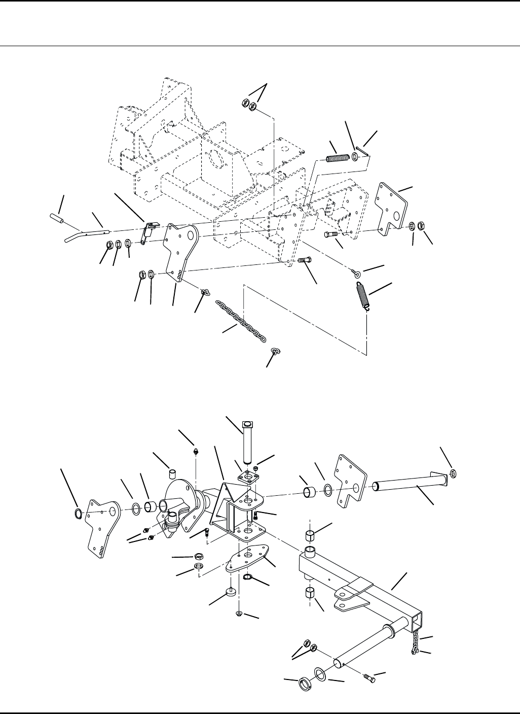
84
HR-9016
29.1 Side Lift Arms Serial No. All
9016-28
1 / 2
3
4
5
6
7
8
9
10
11
12
13 / 14
15
16
38
39
20
21 / 22
23 / 24
25
26
27
28
29
30
31 32
33
34
35
36
4
5
8
9
9
10
10
12
18
15
19
19
19
29
34
37
34
16
17
40
42
43
41

85
> Change from previous revision
HR-9016
Item Part No. Qty. Description Serial Numbers/Notes
11005016 1 Pivot, Left Side Arm
2 1005017 1 Pivot, Right Side Arm
3 304569 4 •Bushing
4 332351 4 •Bushing
5 471214 6 •Grease Fitting
6 3006294 2 Plate, Side Arm Pivot
7 3006295 2 Plate, Side Arm Pivot
8 400412 20 Screw, 1/2-13 x 2” Hex Head
9 446154 20 Lockwasher, 1/2 Heavy
10 444758 20 Locknut, 1/2-13 Center
11 2809628 2 Pin, Side Arm Pivot
12 3006727 4 Washer, Thrust
13 1002885 1 Left Side Lift Arm
14 1002886 1 Right Side Lift Arm
471214 2 •Grease Fitting
15 350800 4 •Bushing
16 362464 16 Wheel Bolt
17 346294 8 Wheel Nut
18 446142 8 Lockwasher, 3/8 Heavy
19 443110 16 Nut, 3/8-16 Hex
20 361723 8 Stop, Rubber
21 3007897 1 Bracket, Left Side Deck Latch
22 3007896 1 Bracket, Right Side Deck Latch
23 3009163 1 Bolt, Left Side Deck Latch
24 3009162 1 Bolt, Right Side Deck Latch
25 3009309 2 Spring, Compression
26 453020 2 Flat Washer, 5/8
27 460052 2 Cotter Pin, 3/16 x 1-1/2”
28 461408 2 Spring Pin, 1/4 x 1-1/2”
29 452012 6 Flat Washer, 1/2
30 363746 2 Chain, Dump Box
31 3006204 2 Collar
32 401030 2 Screw, 3/8-16 x 3-3/4” Hex Head
33 363572 AR Washer
34 162716.6 8 Shackle, Chain
35 366978 2 Eyebolt
36 3008374 2 Spring, Extension
37 1005018 2 Pin, Lift Arm
38 2809630 2 Retaining Ring, Side Arm Pivot
39 3010825 2 Retaining Ring, Lift Arm
40 2811064 2 Plate, Bottom
41 444730 8 Locknut, 7/16-20 Hex
42 3010811 2 Collar
43 363746 4 Chain
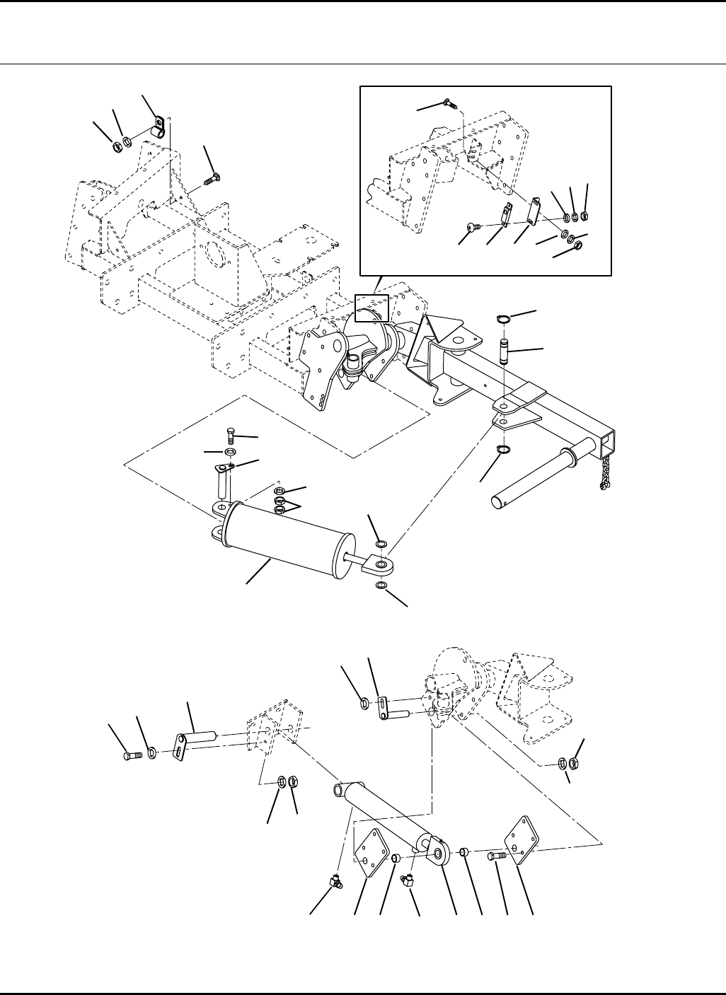
86
HR-9016
30.1 Side Lift Cylinders and Return Canisters Serial No. All
9016-29
1
2
3
4
5
6
7
8
9
10 11
12
13
14
15
16
17
18
19
20
7
8
1014
12 13
21 22
23
24 25
26
27
28
29
30
31
32 33
34 35
36

87
> Change from previous revision
HR-9016
Item Part No. Qty. Description Serial Numbers/Notes
15003371 2 Canister, Deck Return See 50.1
2 1003823 2 Pin, Canister Mount
3 400266 2 Screw, 3/8-16 x 1-1/2” Hex Head
4 446140 2 Lockwasher, 3/8
5 443110 4 Nut, 3/8-16 Hex
6 3009535 2 Pin, Shear
7 458039 4 Retaining Ring
8 455004 4 Flat Washer
9 453011 2 Flat Washer, 3/8
10 3006293 4 Plate, Side Cylinder Mounting
11 400412 14 Screw, 1/2-13 x 2” Hex Head
12 446154 14 Lockwasher, 1/2 Heavy
13 444758 14 Locknut, 1/2-13 Center
14 3004092 4 Spacer
15 1003277 1 Pin, Cylinder Rod End Mounting
16 452012 2 Flat Washer, 1/2
17 3006249 2 Cylinder, Rear Lift See 53.1
18 340061 2 Adapter, 90°
19 340078 2 Adapter, 90°
20 1003272 2 Pin, Side Cylinder Mounting
21 400408 2 Screw, 1/2-13 x 1-1/2” Hex Head
22 453017 2 Flat Washer, 1/2
23 441606 2 Carriage Bolt, 1/4-20 x 3/4”
24 403912 4 Screw, #10-24 x 5/8” Truss Head
25 453023 2 Flat Washer, 1/4
26 443102 2 Nut, 1/4-20 Hex
27 444310 4 Nut, #10-24 Hex
28 446118 4 Lockwasher, #10 Heavy
29 452002 8 Flat Washer, #10
30 441614 2 Carriage Bolt, 5/16-18 x 1”
31 354081 2 Clamp, Wire Harness
32 443106 2 Nut, 5/16-18 Hex
33 446134 2 Lockwasher, 5/16
34 3007392 2 Switch, Proximity
35 3009026 2 Angle, Switch
36 446128 2 Lockwasher, 1/4
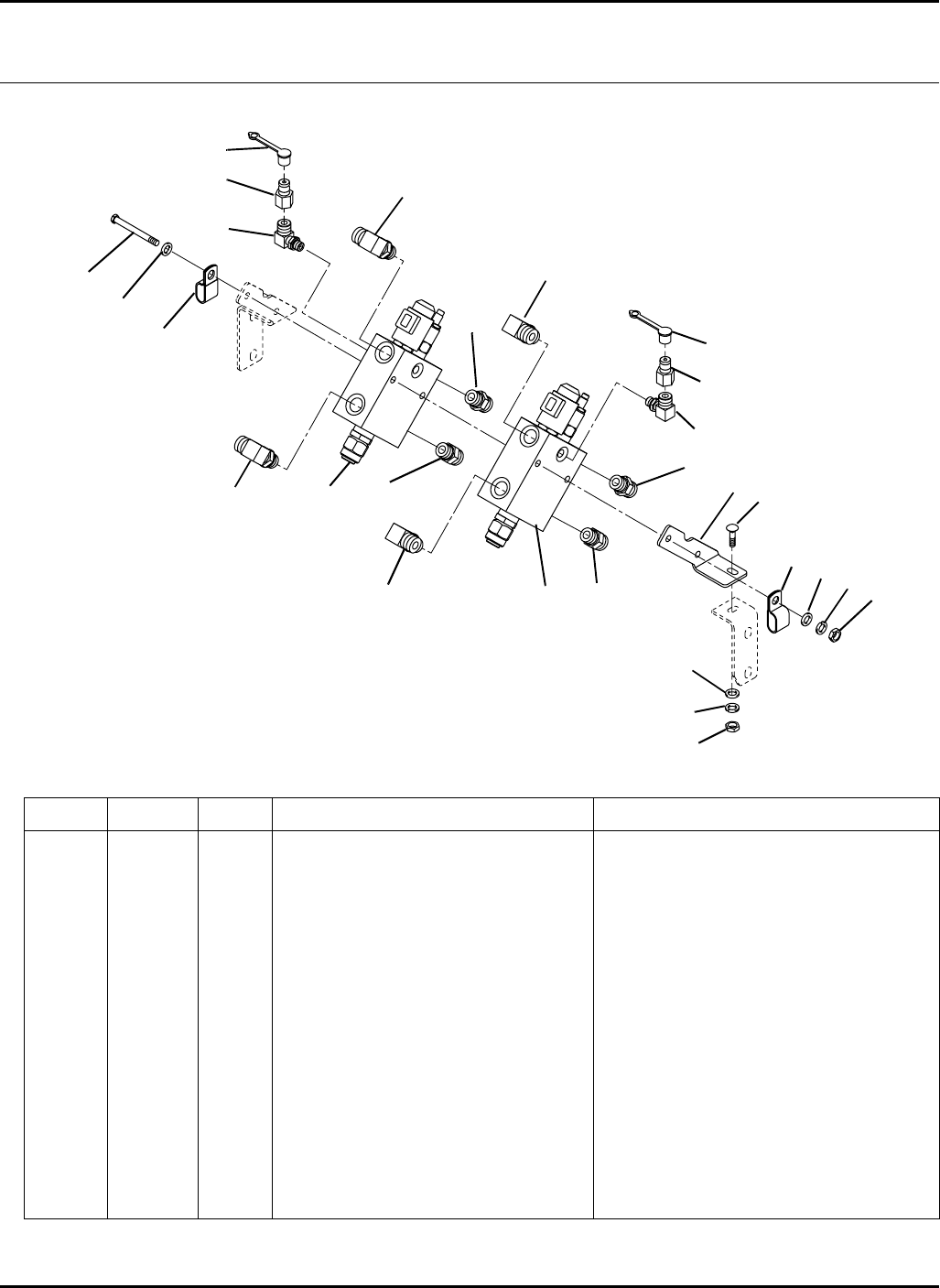
88
> Change from previous revision
HR-9016
31.1 Front Deck Valves Serial No. All
9016-22
Item Part No. Qty. Description Serial Numbers/Notes
11004337 2 Valve, Deck See 54.1
2 339989 4 Adapter, Straight
3 441624 1 Carriage Bolt, 3/8-16 x 1”
4 340070 4 Adapter, 90°
5 340065 2 Adapter, 90°
6 364945 2 Fitting, Diagnostic
7 363030 2 Cover, Dust
8 452008 6 Flat Washer, 3/8
9 446142 3 Lockwasher, 3/8 Heavy
10 443110 3 Nut, 3/8-16 Hex
11 401225 2 Screw, 3/8-16 x 6-1/2” Hex Head
12 3008820 2 Clamp, Double Hose
13 3008357 1 Angle, L.H. Valve Mount
1
2
3
4
5
6
7
8
910
11
12
13
12
2
2
4
4
4
5
6
7
8
8
9
10
12
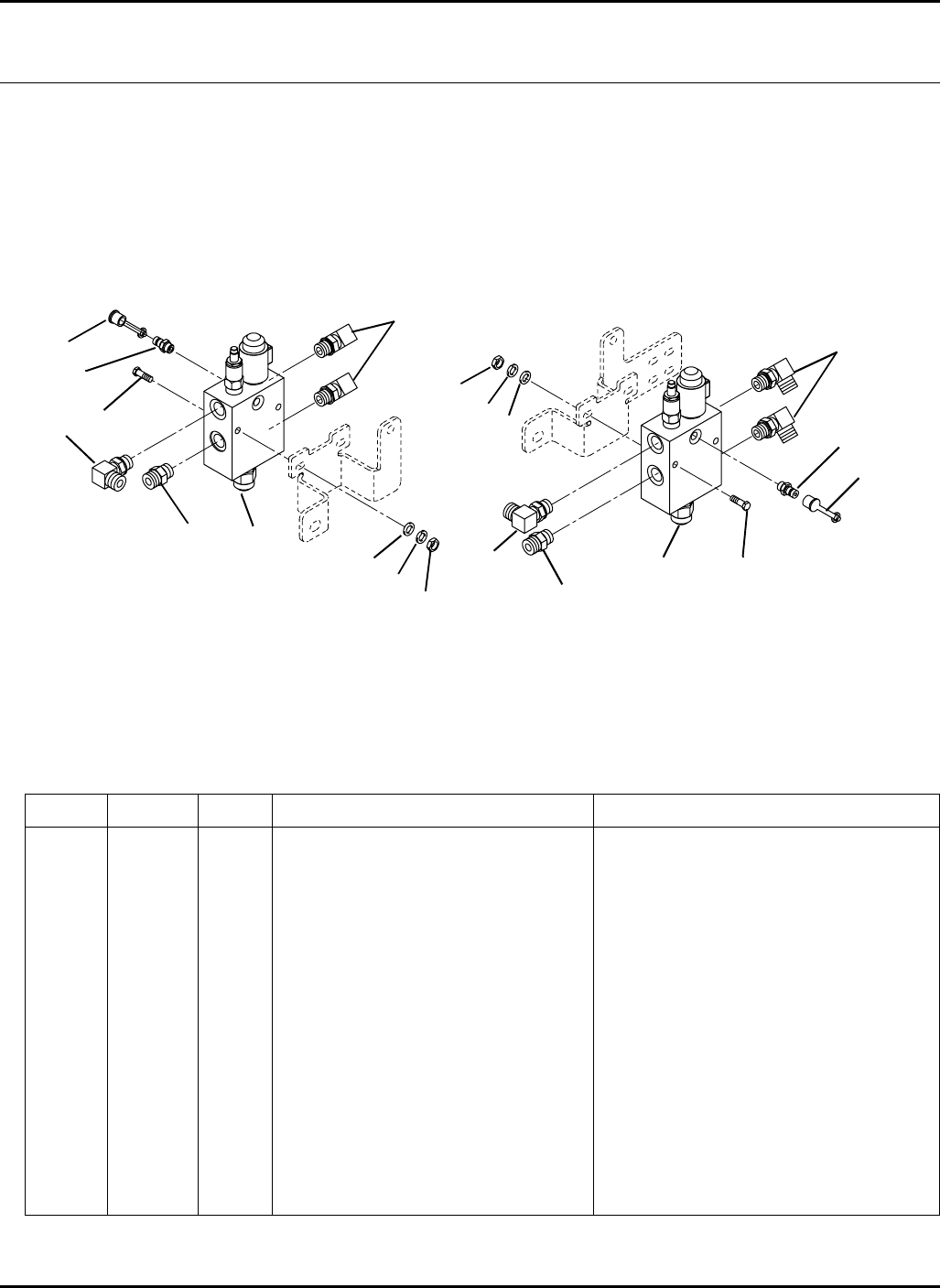
89
> Change from previous revision
HR-9016
Item Part No. Qty. Description Serial Numbers/Notes
11004337 2 Valve, Deck See 54.1
2 339989 2 Adapter, Straight
3 340070 6 Adapter, 90°
4 363030 2 Cover, Dust
5 365466 2 Fitting, Diagnostic
6 401028 4 Screw, 3/8-16 x 3-1/4” Hex Head
7 452008 4 Flat Washer, 3/8
8 446142 4 Lockwasher, 3/8 Heavy
9 443110 4 Nut, 3/8-16 Hex
32.1 Wing Deck Valves Serial No. All
9016-23
1
2
3
4
5
6
7
8
9
Right Wing Valve Left Wing Valve
1
2
3
3
3
4
5
9
8
7
6
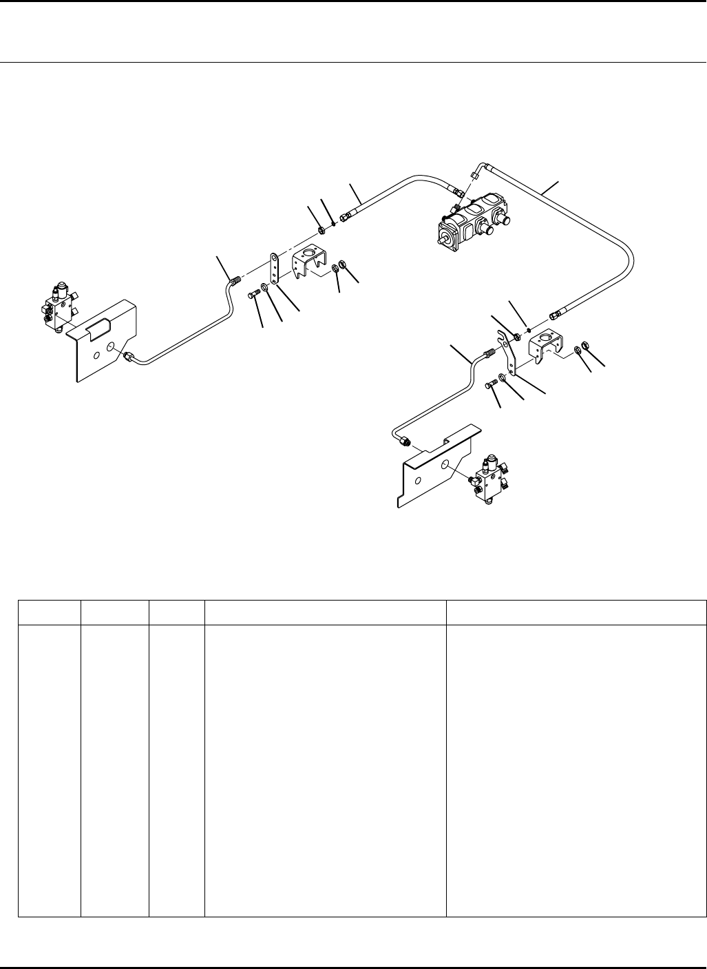
90
> Change from previous revision
HR-9016
Hydraulics and Electr ical
33.1 Side Deck Valve Supply Serial No. All
9016-31
Item Part No. Qty. Description Serial Numbers/Notes
1400264 4 Screw, 3/8-16 x 1-1/4” Hex Head
2 446142 4 Lockwasher, 3/8 Heavy
3 443110 4 Nut, 3/8-16 Hex
4 3008423 1 Plate, Right Side Tube Mounting
5 2811712 1 Plate, Left Side Tube Mounting
6 452008 4 Flat Washer, 3/8
7 339963 2 Locknut, Bulkhead
8 339899 2 O-Ring, SAE #10
9 1003866 1 Tube, Right Side Deck Valve Supply
10 1003863 1 Tube, Left Side Deck Valve Supply
11 1003587 1 Hose, Pump to Right Side Tube
12 1003586 1 Hose, Pump to Left Side Tube
1
2
3
4
5
6
78
9
10
11 12
1
2
3
6
78
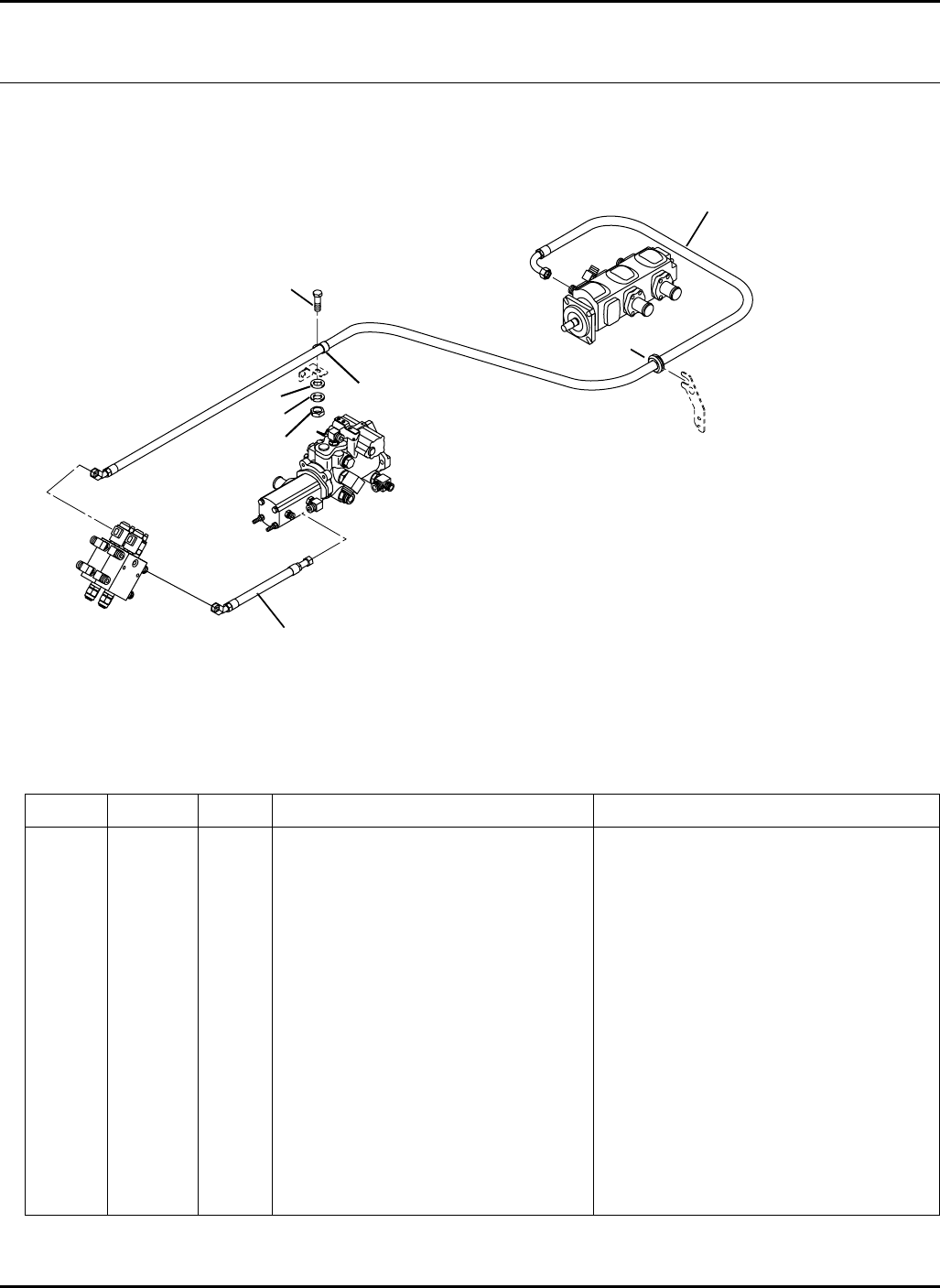
91
> Change from previous revision
HR-9016
Item Part No. Qty. Description Serial Numbers/Notes
1400264 1 Screw, 3/8-16 x 1-1/4” Hex Head
2 446142 1 Lockwasher, 3/8 Heavy
3 443110 1 Nut, 3/8-16 Hex
4 452008 1 Flat Washer, 3/8
5 3008474 1 Clamp, Tube
6 365660 1 Grommet
7 2811968 1 Hose, Pump to Right Front Valve
8 1003607 1 Hose, Pump to Left Front Valve
9 473144 1 Tie Wrap (Not Shown)
34.1 Front Deck Valve Supply Serial No. All
9016-32
3
45
6
7
8
1
2
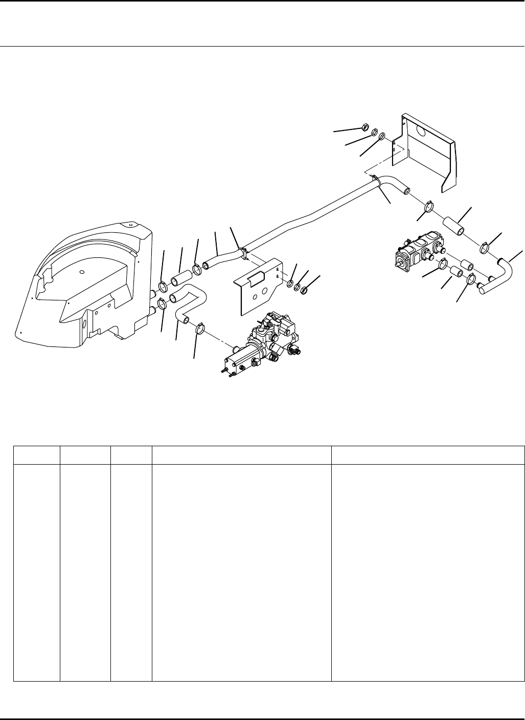
92
> Change from previous revision
HR-9016
35.1 Pump Supply Serial No. All
9016-30
Item Part No. Qty. Description Serial Numbers/Notes
13007778 1 Tube, Rear Pump Suction
2 162236 2 Clamp
3 3007775 2 Hose, Rear Pump Inlet
4 1003610 1 Manifold, Rear Pump Suction
5 3007779 2 Hose, Rear Pump Suction
6 359615 5 Clamp, Hose
7 326112 5 Clamp, Hose
8 452006 4 Flat Washer, 5/16
9 446134 4 Lockwasher, 5/16
10 443106 4 Nut, 5/16-18 Hex
11 3007060 1 Hose, Front Pump Inlet
12
3
4
5
6
7
89
10
11
2
5
6
6
6
7
8
9
10
6
7
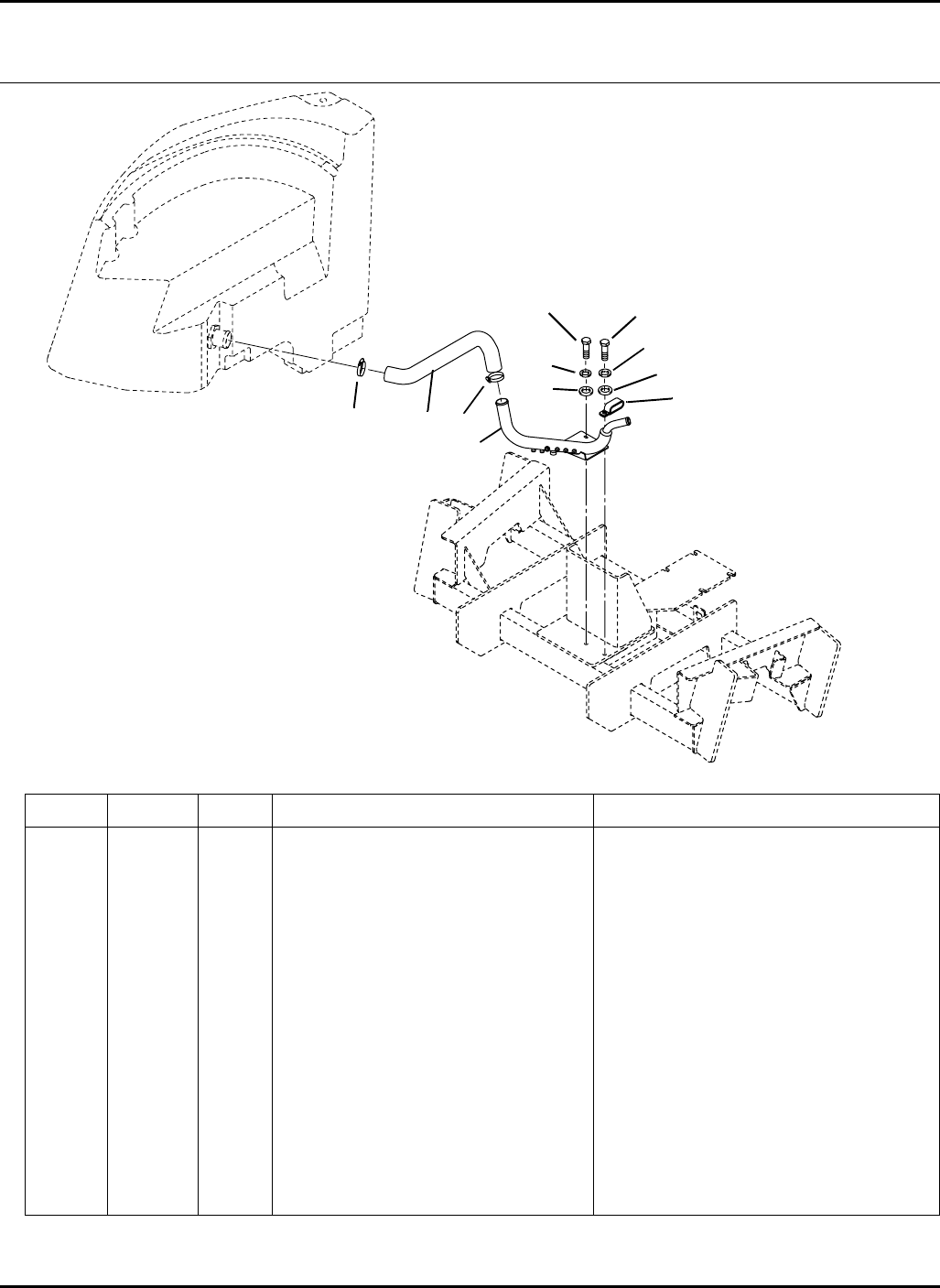
93
> Change from previous revision
HR-9016
Item Part No. Qty. Description Serial Numbers/Notes
11003891 1 Return Manifold
2 400266 2 Screw, 3/8-16 x 1-1/2” Hex Head
3 452008 2 Flat Washer, 3/8
4 446140 2 Lockwasher, 3/8
5 3007061 1 Hose, Return
6 3008820 1 Clamp, Double Hose
7 359615 2 Clamp, Hose
36.1 Return Manifold Serial No.
9016-39
1
3
4
2
6
7
5
7
2
3
4
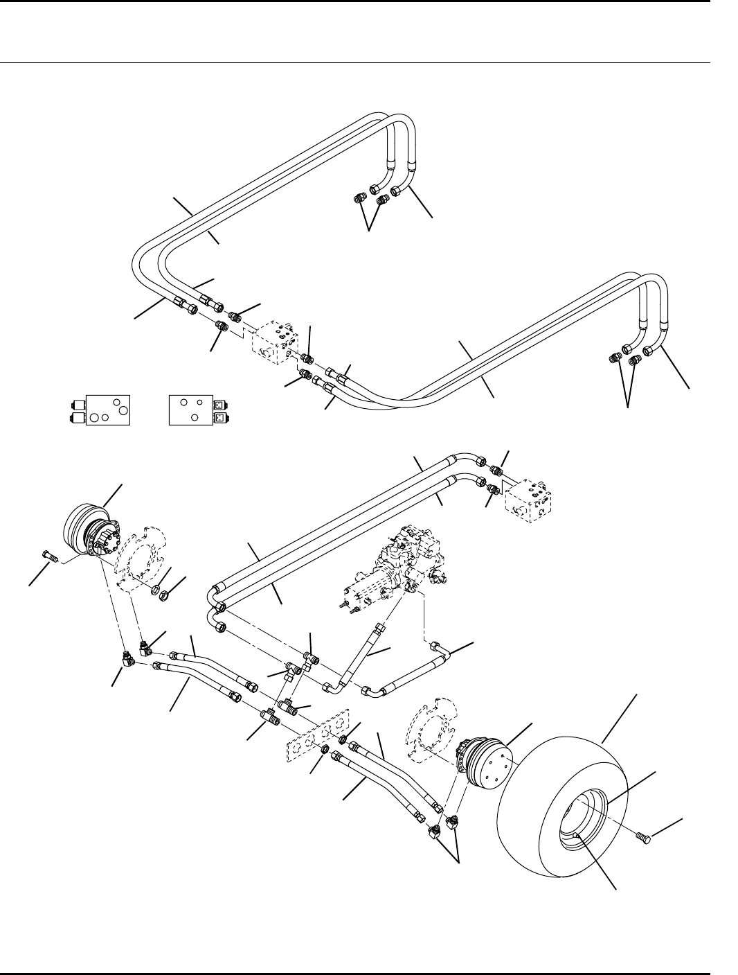
94
A
B
12
T
34
To Port 1
4WD Valve
To Port 2
4WD Valve
To Port 3
4WD Valve
To Port 4
4WD Valve
To Port A
4WD Valve
To Port B
4WD Valve
To Bottom Port
Right Rear Wheel Motor
To Top Por t
Left Rear Wheel Motor
To Top Por t
Right Rear Wheel Motor
To Bottom Port
Left Rear Wheel Motor
Left Side
4WD Valve
Right Side
4WD Valve
HR-9016
37.1 Traction Hydraulics Serial No. All
9016-33
1
2
3
45
6
7
8
9
10
11
12
13
14
15
16
17
1
2
267
8
9
10
13
14
14
14
15
15
15
18
18
19
20
21
22

95
> Change from previous revision
HR-9016
Item Part No. Qty. Description Serial Numbers/Notes
11002769 2 Wheel Motor, Front
5003641 1 •Brake Shoe Kit
5003642 1 •Mechanical Control Kit
5003643 1 •Adjusting System Kit
5003651 1 •Motor Seal Kit
2 340074 4 Adapter, 90°
3 400410 20 Screw, 1/2-13 x 1-3/4” Hex Head
4 446154 20 Lockwasher, 1/2 Heavy
5 443118 20 Nut, 1/2-13 Hex
6 1003307 2 Hose, Tee to Right Wheel Motor
7 340147 2 Adapter, Tee
8 340219 2 Adapter, Bulkhead Tee
9 339965 2 Nut, Bulkhead
10 1003308 2 Hose, Tee to Left Wheel Motor
11 1003310 1 Hose, Traction Pump to Front Tee
12 1003309 1 Hose, Traction Pump to Rear Tee
13 339994 2 Adapter, Straight
14 339989 4 Adapter, Straight
15 1003313 4 Hose, 4WD Valve to Rear Motors
16 1003311 1 Hose, Rear Tee to 4WD Valve
17 1003312 1 Hose, Front Tee to 4WD Valve
18 339990 4 Adapter, Straight
19 5003421 2 Tire, 29 x 14-15 Ultra Trac TL
20 5003422 2 Wheel
21 363233 2 Inflation Valve
22 3007683 12 Wheel Bolt, 1/2-20
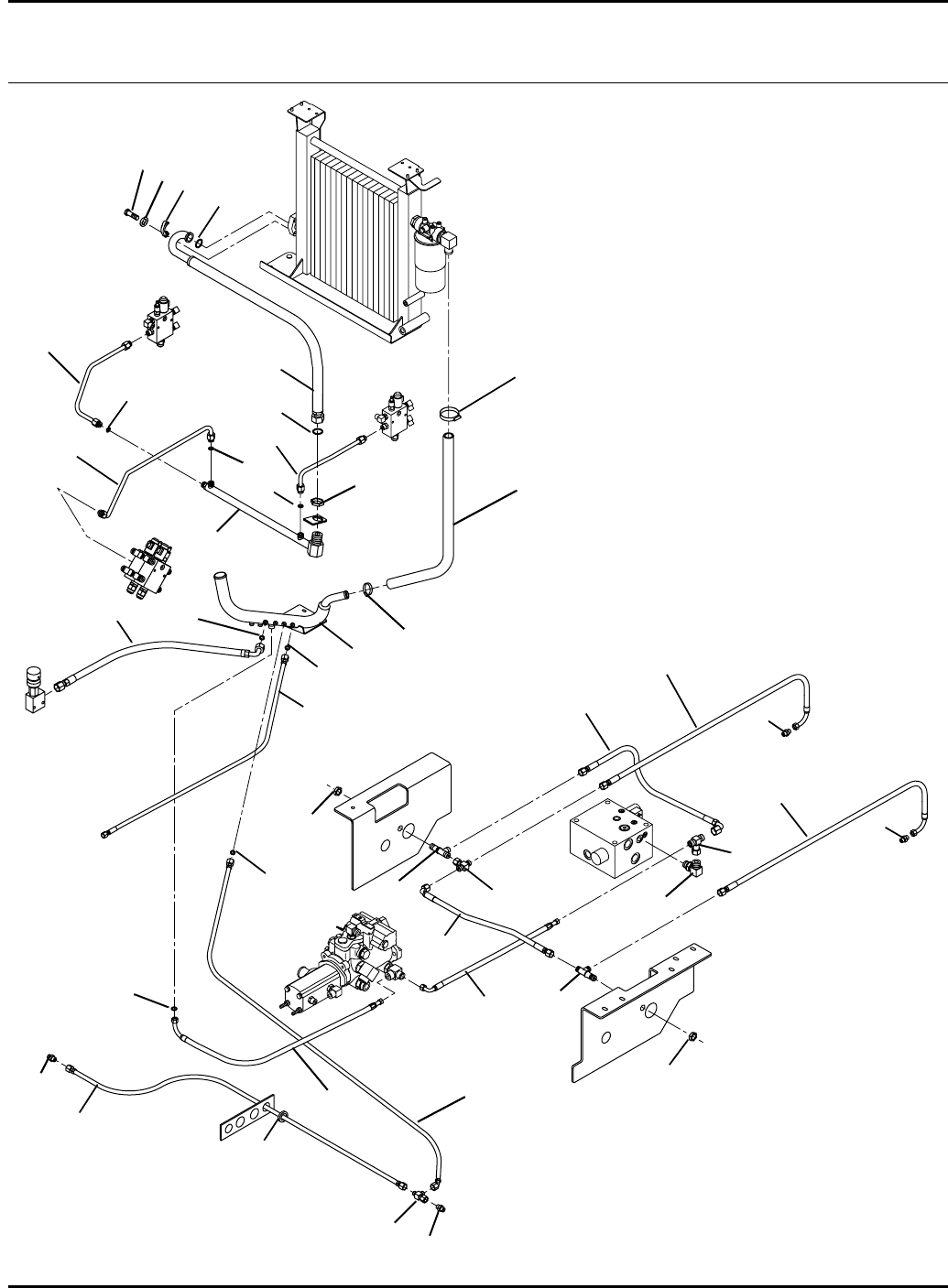
96
Right Rear Wheel Motor
Case Drain
Left Rear Wheel Motor
Case Drain
Left Wing Deck Motors
Case Drain
Right Wing Deck Motors
Case Drain
Right Front Deck Valve
T Port
Right Front Wheel Motor
Case Drain
Left Front Wheel Motor
Case Drain
Front Deck Motors
Case Drain
HR-9016
38.1 Return Hydraulics Serial No. All
9016-34
1
2
3
4
5
6
8
9
10
11
12
13
14
15
16
17
18
19
20
21
23
24
25
7
6
8
12
15
15
22
25
24
26
27
28
29
30
31
26
32
32
31
33
34 35

97
> Change from previous revision
HR-9016
Item Part No. Qty. Description Serial Numbers/Notes
1–1 Return Manifold See 36.1
2 1003573 1 Hose, Pump to Return Manifold
3 1003575 1 Hose, 4WD Valve to Pump
4 339911 1 O-Ring, SAE #10 Face Seal
5 340065 1 Adapter, 90°
6 1003604 2 Hose, Rear Wheel Motor Drain
7 1003577 1 Hose, Right Tee to 4WD Valve
8 339961 2 Locknut, Bulkhead
9 340143 1 Adapter, Tee
10 1003574 1 Hose, Right Tee to Left Tee
11 340144 1 Adapter, Tee
12 340215 2 Adapter, Bulkhead Tee
13 1003988 1 Manifold, Cooler Inlet
14 339966 1 Locknut, Bulkhead
15 339899 3 O-ring, SAE #10
16 1003862 1 Tube, Right Front Valve to Inlet
17 1003860 1 Tube, Right Side Valve to Inlet
18 1003861 1 Tube, Left Side Deck to Inlet
19 1004266 1 Hose, Cooler Inlet to Cooler
20 3006835 1 O-Ring, 1-3/4” O.D. x 1-1/2” I.D.
21 3009496 2 Flange Half, 1-1/4 SAE #20
22 400336 4 Screw, 7/16-14 x 1-1/4 Hex Head
23 446148 4 Lockwasher, 7/16 Heavy
24 3007767 1 Hose, Cooler to Return Manifold
25 3008673 2 Clamp, Constant Torque
26 339974 2 Adapter, Straight
27 340118 1 Adapter, Tee
28 1003592 1 Hose, Tee to Return Manifold
29 1003603 1 Hose, Right Motor to Left Motor
30 365660 1 Grommet
31 339909 2 O-Ring, SAE #6 Face Seal
32 339972 2 Adapter, Straight
33 2810188 1 Hose, Front Deck Motor Case Drain
34 1003608 1 Hose, Back Pressure Valve Return
35 339910 1 O-Ring, SAE #8 Face Seal
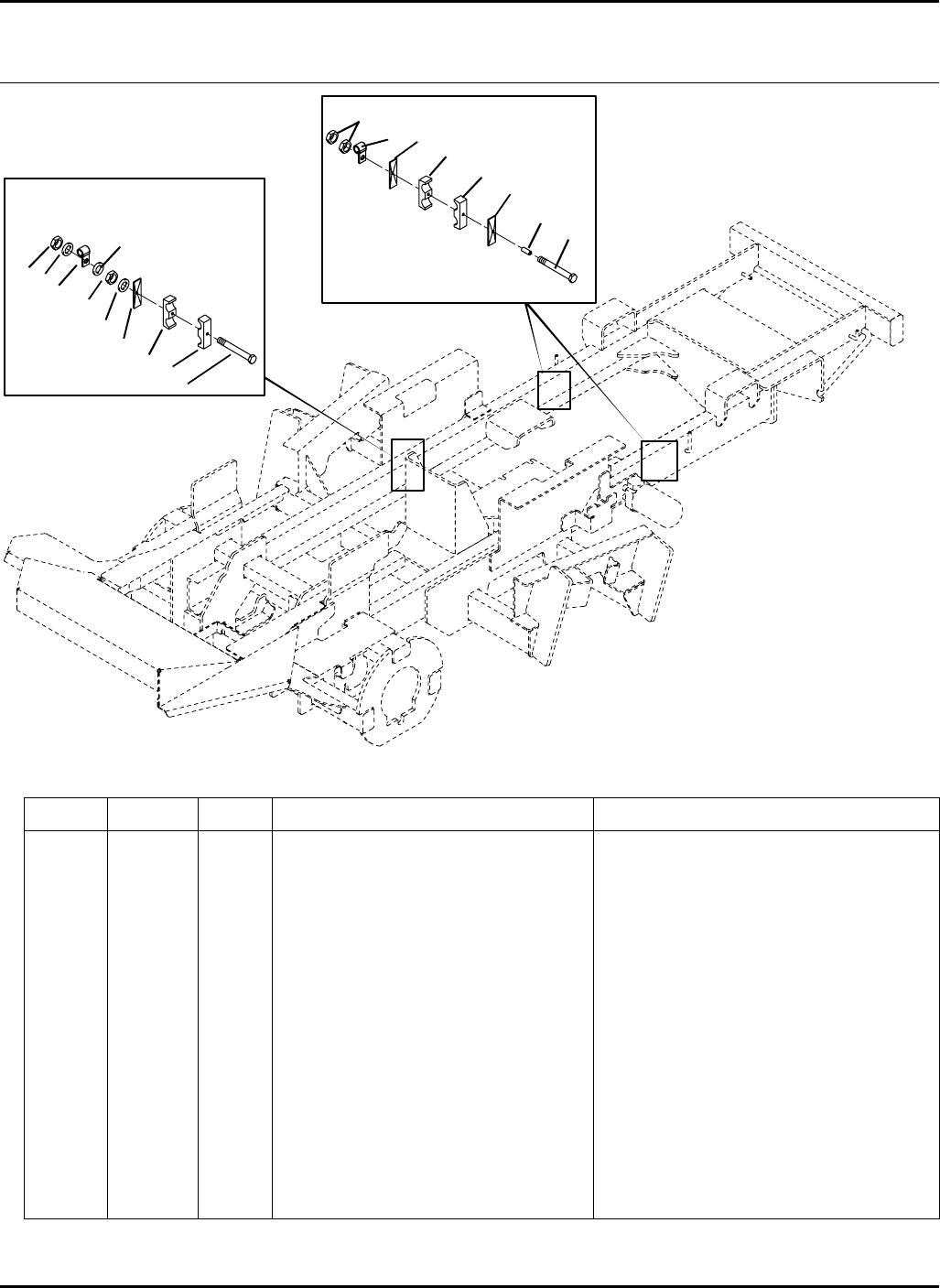
98
> Change from previous revision
HR-9016
39.1 4WD Hose Clamps Serial No. All
9016-41
Item Part No. Qty. Description Serial Numbers/Notes
1400210 2 Screw, 5/16-18 x 5” Hex Head
2 366114 2 Spacer
3 3008792 5 Spacer Plate
4 3008793 6 Clamp, Double Hose
5 366424 2 Clamp, Hose
6 452006 3 Flat Washer, 5/16
7 443106 4 Nut, 5/16-18 Hex
8 400204 1 Screw, 5/16-18 x 3-1/2” Hex Head
9 444718 2 Nut, 5/16-18 Center
10 473144 2 Tie Wrap (Not Shown) Used on rear motor hoses after clamp.
11 365566 1 Clamp, Wire Harness
1
2
3
4
5
6
7
8
3
3
4
44
9
Rear Motor Hoses
Valve Supply Hoses
Wire Harness
6
6
9
11
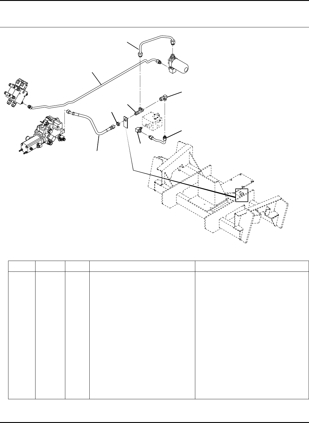
99
> Change from previous revision
HR-9016
Item Part No. Qty. Description Serial Numbers/Notes
1340069 1 Adapter, 90°
2 340217 1 Adapter, Tee
3 339963 1 Locknut, Bulkhead
4 340377 1 Adapter, 90°
5 1003878 1 Tube, 4WD Valve to Tee
6 1003605 1 Hose, Tee to Pump
7 1003865 1 Tube, Lift Valve to Filter
8 1003864 1 Tube, Filter to Tee
40.1 Charge Pressure Serial No.
9016-40
1
2
3
4
5
6
7
8
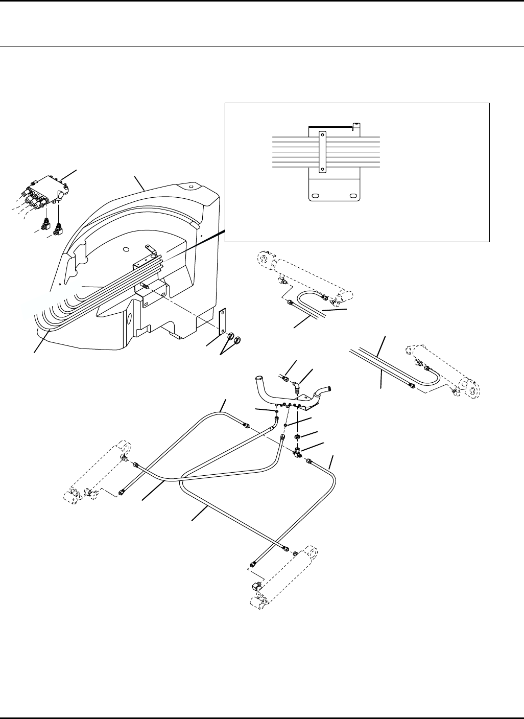
100
A
CD
D
F
F
A
B
B
B
C
C
DE
E
E
F
A - To Steering Valve AUX Port
1003601 Right Side Cylinder Base End
1003602 Right Side Cylinder Rod End
1003599 Left Side Cylinder Base End
1003600 Left Side Cylinder Rod End
1003590 Front Lift Cylinder Rod End Tee
1003593 Steering Valve AUX Port
Hose
Part Number
B
E
D
F
C
A
Important: The hoses must be routed through
the retaining clamp in the order shown to
allow proper clearance of the heat shield.
Hose
Destination
To Fitting
Labled
HR-9016
41.1 Lift Valve Hydraulics Serial No. All
9016-35
1
23
4
5
6
78
9
10
11
12
13
14
15
16
17
8
10

101
> Change from previous revision
HR-9016
Item Part No. Qty. Description Serial Numbers/Notes
11003601 1 Hose, Right Side Cylinder Base End
2 1003602 1 Hose, Right Side Cylinder Rod End
3 1003599 1 Hose, Left Side Cylinder Base End
4 1003600 1 Hose, Left Side Cylinder Rod End
5 340167 1 Adapter, 90° Bulkhead
6 339961 1 Nut, Bulkhead
7 340143 1 Adapter, Tee
8 1003591 2 Hose, Front Cylinders Rod End
9 1003590 1 Hose, Lift Valve to Tee
10 339909 2 O-Ring, SAE #6 Face Seal
11 1003598 1 Hose, Right Front Cylinder Rod End
12 1002940 1 Hose, Left Front Cylinder Rod End
13 3008459 1 Plate, Hose Retaining Clamp
14 443106 4 Nut, 5/16-18 Hex
15 1003594 1 Hose, Steering Valve to Lift Valve
16 –1 Hydraulic Tank See 22.1
17 –1 Lift Valve See 7.1
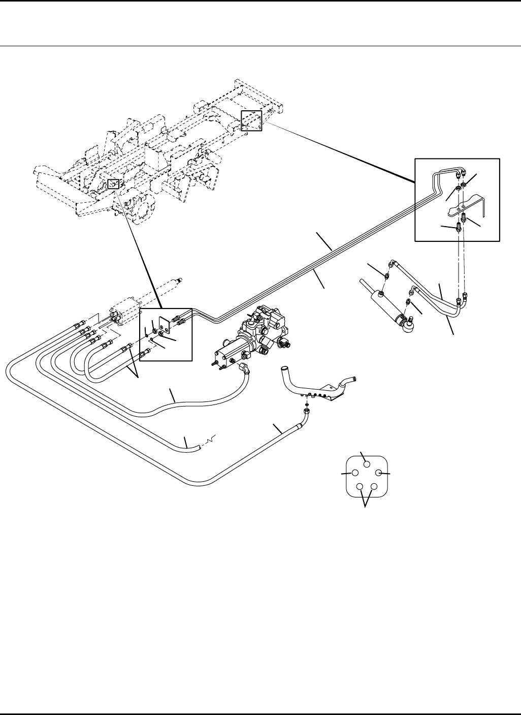
102
To Lift Valve
To Lift Valve
To Return Manifold From Pump
To Steering Cylinder
Aux
InOut
LT RT
IN
OUT
AUX
LT
RT
HR-9016
42.1 Power Steering Hoses Serial No. All
9016-42
1
2
3
4
5
7
6
8
9
10
11
12
13
3
4
9
10
11

103
> Change from previous revision
HR-9016
Item Part No. Qty. Description Serial Numbers/Notes
11003876 1 Tube, RT Hose to Rod End Hose
2 1003875 1 Tube, LT Hose to Base End Hose
3 339961 2 Locknut, Bulkhead
4 339909 2 O-Ring, SAE #6 Face Seal
5 1003606 2 Hose, Valve to Cylinder Tubes
6 1003593 1 Hose, Valve to Return Manifold
7–1 Hose, Steering Valve to Lift Valve See 41.1
8 1003596 1 Hose, Gear Pump to Valve
9 339979 2 Adapter, Straight
10 340239 2 Adapter, Straight Bulkhead
11 339961 2 Locknut, Bulkhead
12 1003597 1 Hose, LT Tube to Cylinder Base End
13 1003595 1 Hose, RT Tube to Cylinder Rod End
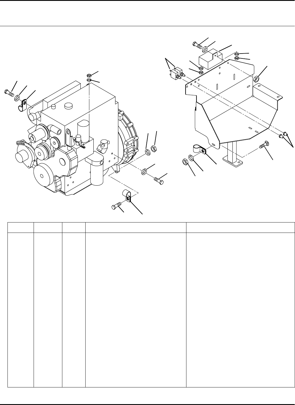
104
> Change from previous revision
HR-9016SW
43.1 Engine Compartment Clamps Serial No. All
9016-43
Item Part No. Qty. Description Serial Numbers/Notes
1364190 3 Clamp, Wire Harness
2 400266 2 Screw, 3/8-16 x 1-1/2” Hex Head
3 446140 2 Lockwasher, 3/8
4 443110 2 Nut, 3/8-16 Hex
5 365566 1 Clamp,Wire Harness
6 440078 1 Carriage Bolt, 5/16-18 x 3/4”
7 446134 1 Lockwasher, 5/16
8 443106 1 Nut, 5/16-18 Hex
9 444708 1 Locknut, 1/4-20 Center
10 453023 1 Flat Washer, 1/4
11 400108 1 Screw, 1/4-20 x 3/4” Hex Head
12 364774 2 Boot, Protective
13 3000359 2 Circuit Breaker, 50A
14 361500 2 Screw, M10-1.5 x 20mm Hex Head
15 363385 2 Lockwasher, M10
16 362534 2 Nut, M5 Hex
17 446118 2 Lockwasher, #10 Heavy
18 446130 1 Lockwasher, 1/4 Heavy
19 361001 1 Nut, M6 Hex
2
34
56
7
8
9
11
12
13
14
15
1
1
10
14 15
Engine Ground
Part of Engine
Glow Plug Module
16
16
17
17
18
19
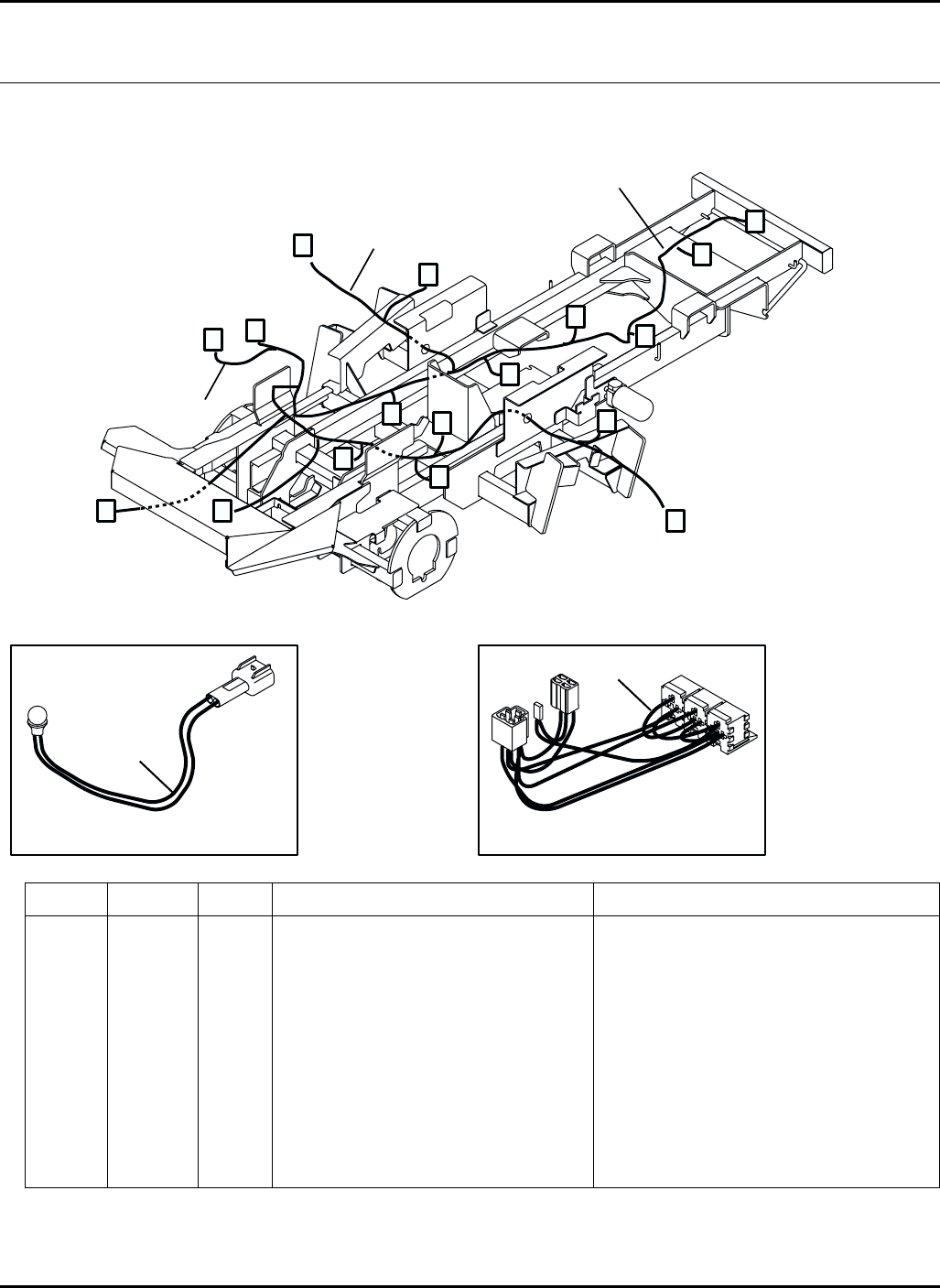
105
> Change from previous revision
AB
C D
E
F
G
H
I
J
K
L
M
N
O
P
Q
A - Instrument Panel
B - Oil Level, Horn and Seat Relay
C - Front Limit Switch and Cruise Magnet
D - Front Deck Valves
E - Neutral and Forward Switches
F - Seat Switch and Air Ride
G - Parking Brake
H - Right Wing Deck Valve
I - Right Deck Limit Switch
J - Left Wing Deck Valve and Charge Filter
K - Left Deck Limit Switch
L - 4WD Valve
M - Fuel Level Sender
N - Engine Connections
O - Engine Ground
P - Circuit Breakers
Q - Glow Plug Relay
Glow Plug Light Adapter
Located under Instrument Panel
Kubota Key Switch Adapter
Located under Instrument Panel
HR-9016
Item Part No. Qty. Description Serial Numbers/Notes
12811003 1 Wire Harness, Console Serial Number 70524 1601 ~ 1756
Serial Number 70525 1601 ~ 1882
1 4116909 1 Wire Harness, Console Serial Number 70524 1757 and Up
Serial Number 70525 1883 and Up
2 2811004 1 Wire Harness, Chassis
3 1004797 1 Wire Harness, Engine
4 1004931 1 Wire Harness, Glow Plug Light
5 2822523 1 Wire Harness, Kubota Keyswitch Serial Number 70524 1726 and Up
Serial Number 70525 1778 and Up
44.1 Wire Harness Routing Serial No. All
9016-44
1
2
3
5
4
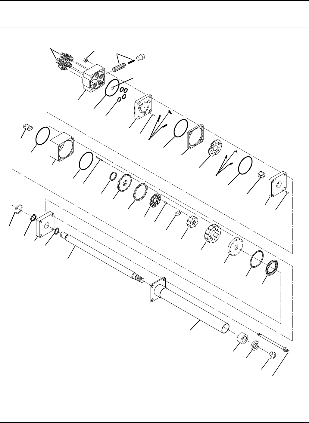
106
HR-9016
Components
45.1 Steering Valve
Part Number 1002800
Serial No. All
TC500-28
1
2
3
4
5
6
7
8
10
9
11
12
13
14
15
16
17
18
19
20
21
22
23
24
25
26
27
28
29
31 32
33
34
35
36
37
4
4
4
11
11
39
30
38

107
> Change from previous revision
HR-9016
Item Part No. Qty. Description Serial Numbers/Notes
1443108 4 Locknut, 5/16-18 Center
2 N/S 1 Port Cover
3 C 1 Seal, O-Ring
4 C 4 Seal, O-RIng
5 C 4 Seal, O-RIng
6 443828 1 Nut, 5/8-18 Hex Jam
7 N/S 4 Special Bolt
8 N/S 1 Port Manifold
9 B 3 Spring, Port Side
10 503387 1 Hex Drive
11 A and E 9 Needle Roller
12 503398 1 Valve Ring
13 503398 1 Valve Plate
14 B 3 Spring, Shaft Side
15 554854 1 Isolation Manifold
16 551105 1 Drive Link
17 N/S 1 Metering Ring
18 A 11 Screw, Socket Head
19 C 1 Seal, Commutator
20 A 1 Commutator Cover
21 A 1 Commutator RIng
22 A 1 Commutator
23 A 1 Spacer
24 A 1 Rotor
25 A 1 Stator
26 A 1 Drive Plate
27 554855 1 Spacer
28 554856 1 Thrust Bearing
29 C 1 Face Seal
30 N/S 1 Ball, 9/32”
31 554857 1 Seal, Spacer
32 N/S 1 Upper Cover Plate
33 D 1 Shaft
34 D 1 Retaining RIng
35 D 1 Bushing
36 D 1 Seal
37 D 1 Jacket
38 557733 1 Relief Valve Cartridge
39 339979 5 Adapter, Straight
Service Kits
A 5003548 1 Metering Assembly Kit
B 502924 1 Spring Kit
C 557738 1 Seal Kit
D 5003219 1 Jacket Tube Kit
E 502925 1 Needle Roller Kit
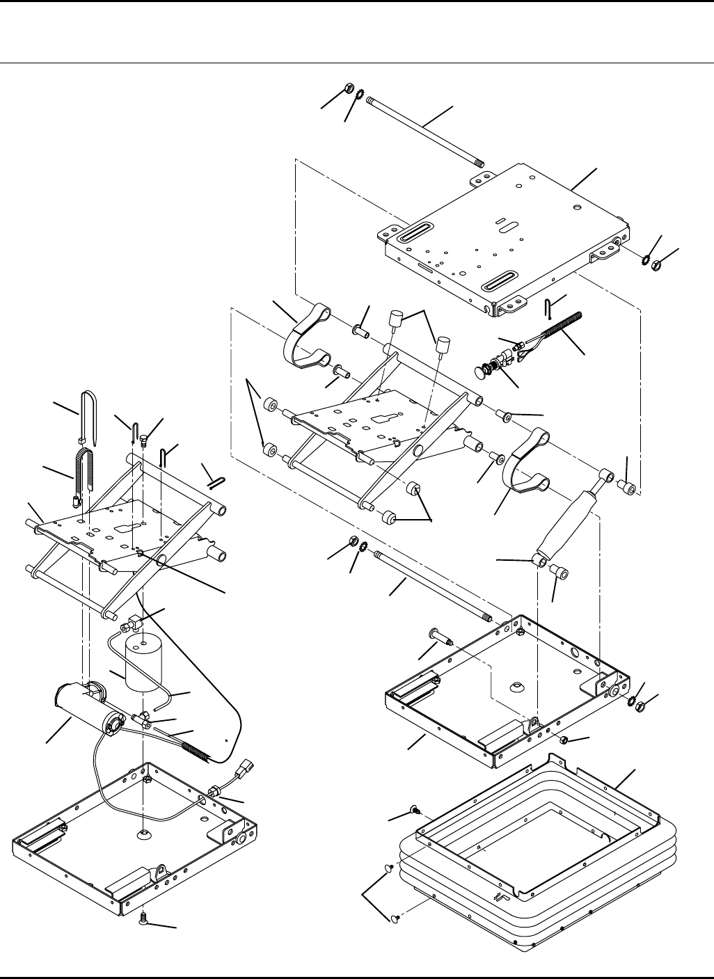
108
A
A
HR-9016
46.1 Air Suspension
Part No. 5003625
Serial No. All
9016-62
1
2
3
4
5
6
7
8
9
10
11
12
13
14
15
16
17
18
19
20
21
22
23
24
25
26
27
28
29 30
31
32
7
77
22
26
27
27
27
29
30
31
31
31
32
32
32

109
> Change from previous revision
HR-9016
Item Part No. Qty. Description Serial Numbers/Notes
1N/S 1 Lower Housing
2 N/S 1 Scissors
3 N/S 1 Upper Housing
5003627 1 Compressor Kit
4N/S 1•Compressor
5N/S 1•Tie Wrap
6N/S 1•Clamp, Compressor
7N/S 4•Tie Wrap
8N/S 1•Bushing, Strain
5003628 1 Air Fitting/Tubing Kit
9N/S 1•Braided Sleeve
10 N/S 1 •Fitting, Tee
11 N/S 1 •3/16 O.D. Tubing
12 N/S 1 •3/16 O.D. Tubing
13 N/S 1 •Fitting, 90°
14 N/S 1 •Fitting, Straight
5003629 1 Boot and Clip Kit
15 N/S 1 •Boot with Label
16 N/S 21 •Clip, Christmas Tree
17 N/S 6 •Clip, Christmas Tree
5003630 1 Airspring Kit
18 N/S 1 •Airspring
19 N/S 1 •Cap Screw
20 N/S 1 •Cap Screw
21 5003631 1 Valve Kit
5003632 1 Damper Kit
22 N/S 2 •Bearing, Flanged
23 N/S 1 •Threaded Pin
24 N/S 1 •Nut, Hex Lock
25 N/S 1 •Damper
5003633 1 Miscellaneous Kit
26 N/S 2 •Shaft, Threaded
27 N/S 4 •Bearing, Flanged
28 N/S 2 •Bumper
29 N/S 4 •Roller
30 N/S 2 •Te th e r
31 N/S 4 •Jam Nut
32 N/S 4 •Lockwasher
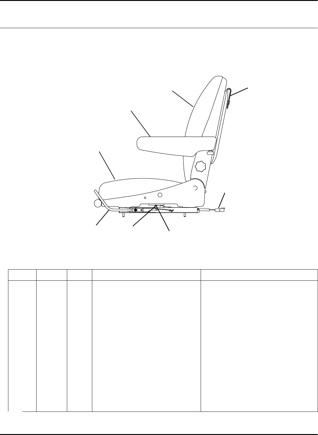
110
> Change from previous revision
HR-9016
Item Part No. Qty. Description Serial Numbers/Notes
15003634 1 Pad, Back
2 5003635 1 Pad, Seat
3 5003636 1 Arm Rest, Left Side
4 5003637 1 Arm Rest, Right Side
5 5003690 1 Adjuster Assembly
6 554390 1 Seat Switch
7 3003928 1 Literature Pouch
8 409757 2 Screw, Seat Switch
9 5003769 1 Wire Assembly
47.1 Seat Assembly
Part No. 5003626
Serial No. All
9016-63
1
2
3 / 4
56
7
8
9
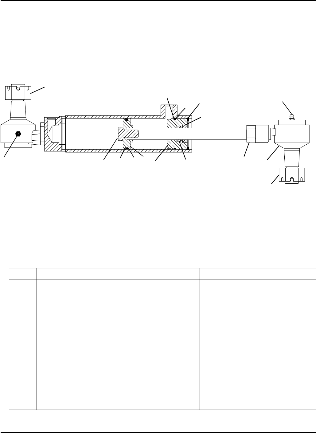
111
> Change from previous revision
HR-9016
Item Part No. Qty. Description Serial Numbers/Notes
5003542 1 Seal Kit
1N/S 1 •Retaining Ring
2N/S 1•O-Ring, Piston
3N/S 1•Seal, Piston
4N/S 1•Seal, Rod
5N/S 1•Wiper
6N/S 1•Backup Ring, Gland
7N/S 1•O-Ring, Gland
8 443126 1 Nut, 5/8-11 Hex
9 5003543 1 Socket Assembly
10 N/S 1 Piston
11 N/S 1 Screw, Piston
12 471214 2 Grease Fitting
13 N/S 1 Gland
14 N/S 2 Nut, 7/8-14 Castle
48.1 Steering Cylinder
Part No. 5003541
Serial No. All
9016-64
1
234
5
6
7
89
10
11
12 13
14
12
14
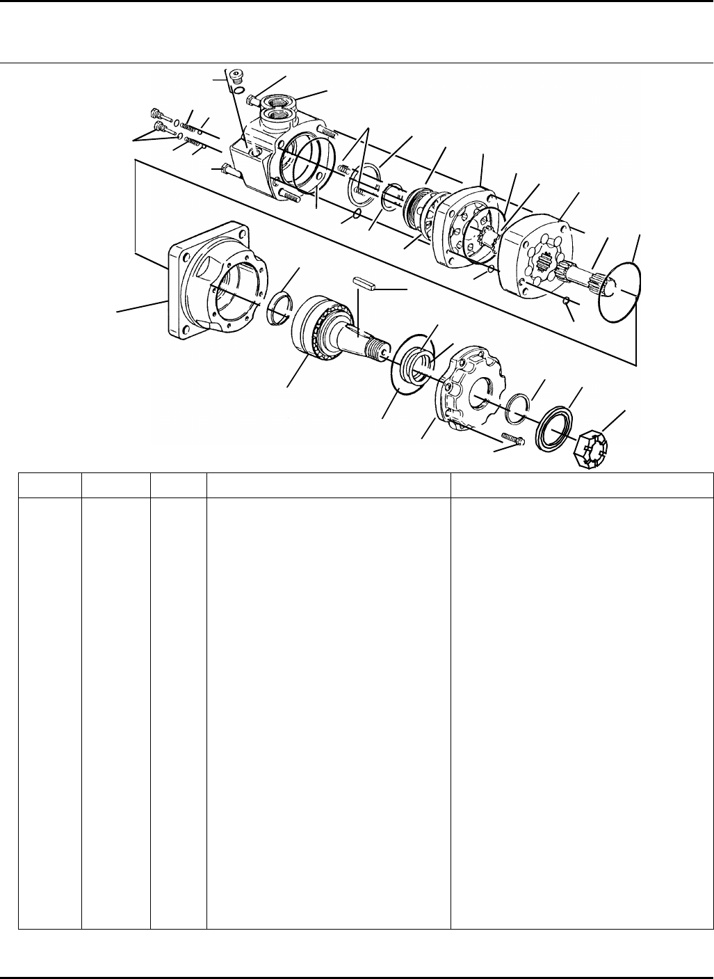
112
> Change from previous revision
16
18 19 20
19 20
HR-9016
49.1 Rear Wheel Motor
Part Number 5003540
Serial No. All
Serial No. All
Item Part No. Qty. Description Serial Numbers/Notes
1558066 8 Screw, Torx
2 5002110 1 Front Retainer
3 558063 1 Shaft and Bearing Kit
4 557624 1 Nut, Hex
5 557623 1 Key
6 558064 1 Bearing Housing
7 557629 1 Drive
8 5003590 1 Geroler
9 557632 1 Drive, Valve
10 557631 1 Plate, Valve
11 557633 1 Valve
12 557637 1 Balance Ring and Pins
◆13 557634 1 Seal, Inner Face
◆14 557635 1 Seal, Outer Face
15 557636 2 Spring
16 557650 3 Bolt, 5-3/4”
17 5003591 1 Housing, Valve
18 557639 2 Check Plug Assembly
19 557642 2 Spring
20 557640 2 Ball, Steel
21 5000318 1 Bolt
22 557641 1 Plug
9016-46
1
2
34
5
6
7
9
10
11
12
13
14
15
17
21
8
◆
Included In Seal Kit 557651
●
Included In Seal Kit 5002111
22
◆
◆●
●
●
●
●
●
◆●
◆●
◆
◆
◆
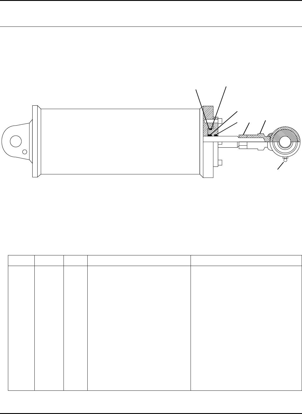
113
> Change from previous revision
HR-9016
50.1 Deck Return Canister
Part Number 5003371
Item Part No. Qty. Description Serial Numbers/Notes
1●1O-Ring
2●1 Back Up Ring
3●1 Loaded U-Cup
4●1 Rod Wiper
5 471214 1 Grease Fitting
6 443132 1 Nut, 3/4-16 Hex
7 5003428 1 Collar Assembly
●5003427 1 Seal Kit Gold Star Return Canisters
●5003662 1 Seal Kit HDM Return Canisters
9016-47
12
3
4
5
67
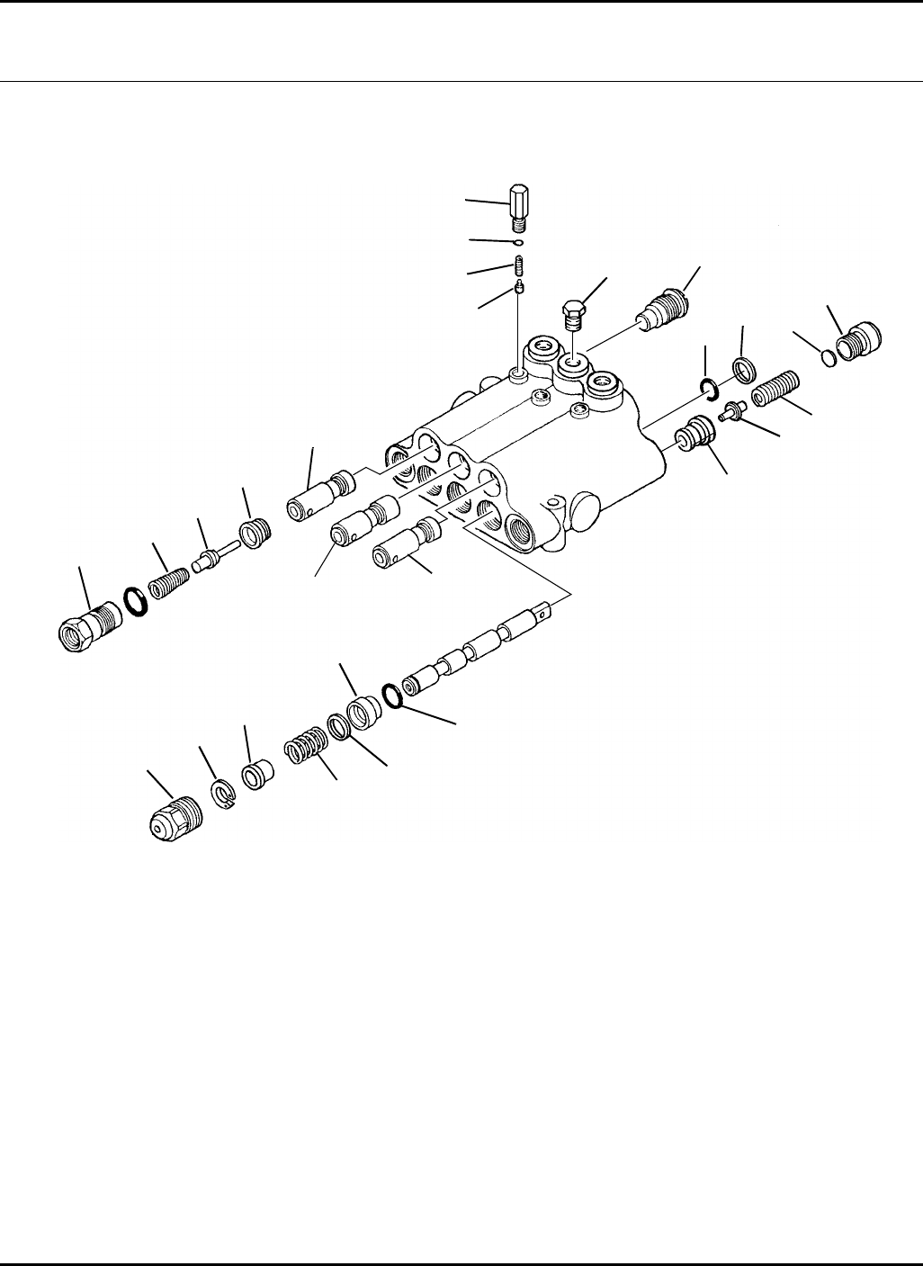
114
HR-9016
51.1 Lift Valve
Part Number 1001802
Serial No. All
9016-48
2
3
4
5
7
17
24
18
19
20 21
14
25 23
1
10
16
15
7
6
14
13
22
12
11
9
8

115
> Change from previous revision
HR-9016
Item Part No. Qty. Description Serial Numbers/Notes
1558005 1 Plug Assembly, Relief Valve
2 500745 3 Plug Assembly, Port Adapter
3 545914 3 Spring, Lockout
4■3 Poppet Assembly
5 500736 3 Seat Assembly
6 5001599 1 Plunger, Lockout
7 5001603 2 Plunger, Lockout
8 558004 3 Cap Assembly
9 558007 3 Retaining Ring
10 5001613 1 Seat
11 558011 3 Spacer
12 5001616 3 Spring, Spool Centering
13 545921 3 Bushing
14 ■6O-Ring
15 5001614 1 Spring Relief Valve (Yellow)
16 5001615 1 Poppet, Relief Valve
17 ◆3 Plug Assembly, Plunger Detent
18 ◆3 Spring, Detent
19 ◆3 Plunger, Detent
20 351122 3 Hex Plug Assembly
21 500750 3 Plug Assembly
22 558008 3 Washer
23 545925 AR Shim (.015 Thick)
545926 AR Shim (.010 Thick)
545927 AR Shim (.035 Thick)
24 546112 AR Disc, Plain
25 5001617 3 Wiper Seal
◆5001612 1 Detent Reapir Kit
■558010 1 Seal Kit
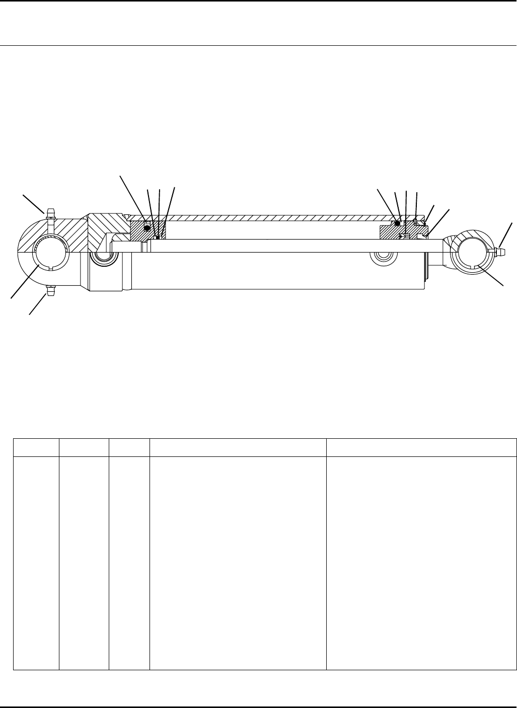
116
> Change from previous revision
HR-9016
52.1 Front Lift Cylinder
Part Number 3006008
Serial No. All
9016-49
Item Part No. Qty. Description Serial Numbers/Notes
1●1 PSP Seal
2●2 Back Up Ring
3●1O-Ring
4●1O-Ring
5●1 Back Up Ring
6●1 Internal Snap Ring
7●1 External Snap Ring
8●1 Loaded U-Cup
9●1 Rod Wiper
10 471214 3 Grease Fitting
11 5003415 1 Bushing
12 5003566 2 Bushing
●5003414 1 Seal Kit Gold Star Cylinders
●5003667 1 Seal Kit HDM Cylinders
123456
7
8
9
10
11
12
2
10
10
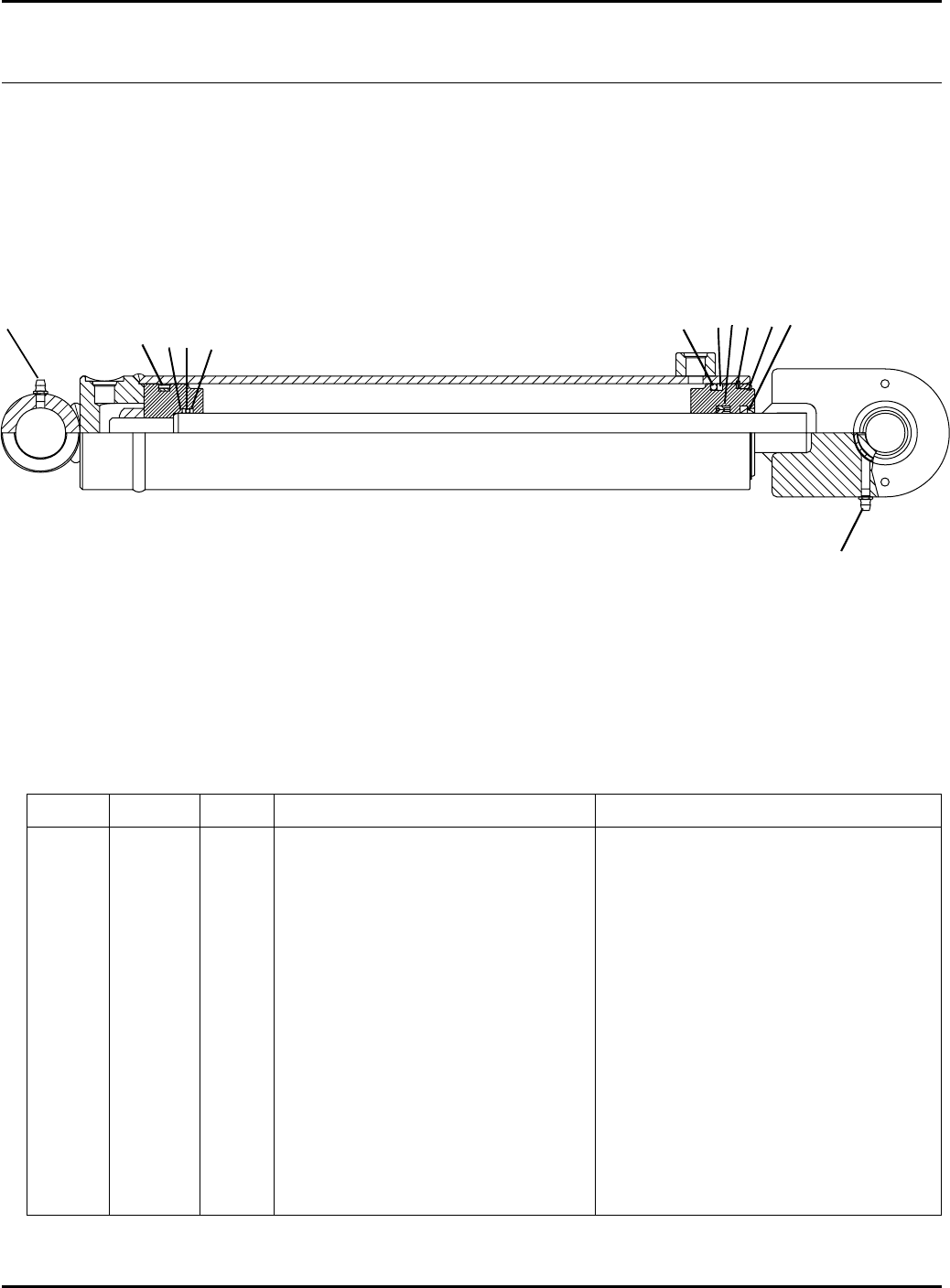
117
> Change from previous revision
HR-9016
Item Part No. Qty. Description Serial Numbers/Notes
1●1 PSP Seal
2●2 Back Up Ring
3●1O-Ring
4●1O-Ring
5●1 Back Up Ring
6●1 Internal Snap Ring
7●1 External Snap Ring
8●1 Loaded U-Cup
9●1 Rod Wiper
10 471214 2 Grease Fitting
●5003413 1 Seal Kit Gold Star Cylinders
●5003659 1 Seal Kit HDM Cylinders
53.1 Wing Lift Cylinders
Part Number 3006249
Serial No. All
9016-50
123456
7
89
10
10
2
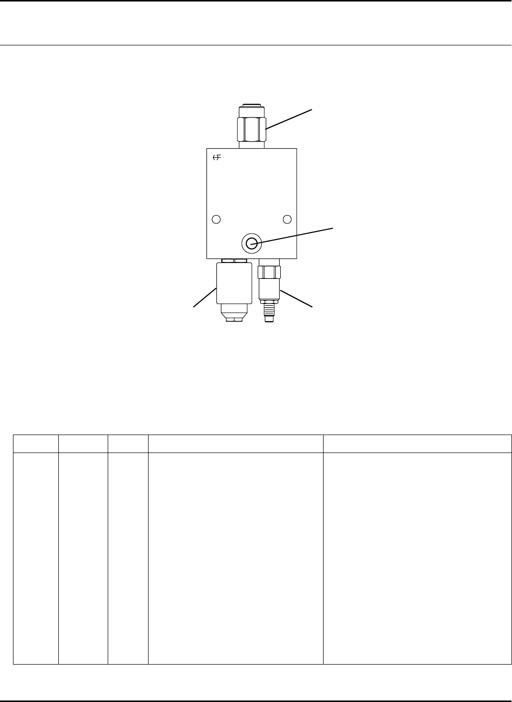
118
> Change from previous revision
HR-9016
54.1 Deck Valve
Part Number 1004337
Serial No. All
9016-51
Item Part No. Qty. Description Serial Numbers/Notes
15002911 1 Relief Valve
5003579 1 •Seal Kit
2 5002912 1 Relief Valve
5003554 1 •Seal Kit
3 3010199 1 Plug, SAE #6 Located opposite Diagnostic port
339897 1 •O-Ring
4 5002913 1 Solenoid Valve
5003579 1 •Seal Kit
5 5003507 1 Coil, 12 Volt DC
1
2
3
4 / 5
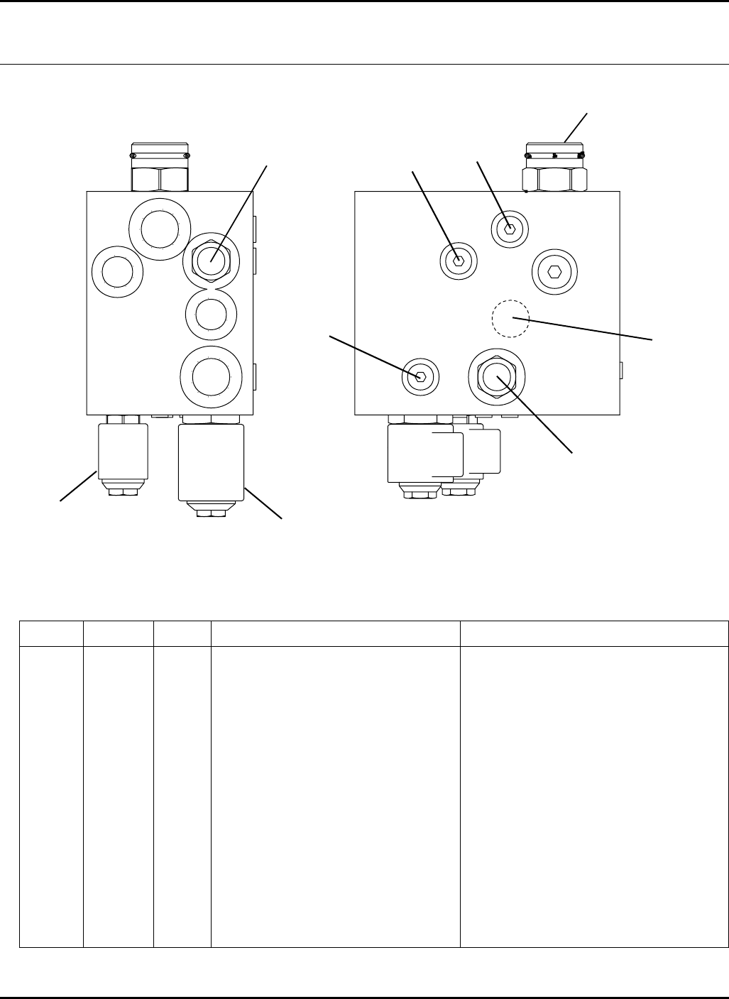
119
> Change from previous revision
HR-9016
Item Part No. Qty. Description Serial Numbers/Notes
15003342 1 Check Valve
5003582 1 •Seal Kit
2 5003344 1 Shuttle, Hot Oil
5003582 1 •Seal Kit
3 5003346 1 3-Way Spool
5003583 1 •Seal Kit
4 5003348 1 Solenoid Vlave
5003583 1 •Seal Kit
5 5003506 1 Coil, 10 Volt DC
6 5003350 1 Solenoid Valve
5003578 1 •Seal Kit
7 5003508 1 Coil, 12 Volt DC
8 5003353 3 Plug, SAE #6
339897 3 •O-ring
9 5003353 1 Plug, Orifice
9016-52
55.1 4WD Valve
Part Number 1002977
Serial No.
1
2
3
4 / 5
6 / 7
8
88
9
120
1234
5678
A
BCDE
F
R
Cut
Height
Bracket
Hole
Arm
Hole
Wheel
Mounting
Wheel
Mounting
FA31
FB11-1/2
FC22
FD32-1/2
FE43
FB53-1/2
FC64
FD74-1/2
FE85
RE85-1/2
Arm
Bracket
Wheel Mounting Instructions
1. While Roatating wheel, tighten
nut until wheel is difficult to
rotate.
2. Loosen nut 1/4 turn or just
until wheel rotates freely.
3. Lock nut into place using
second nut. Do not allow
first nut to rotate when
tighteneing second nut securely.
4. Rotate wheel to check for
free rotation with zero end
play.
Serious injury or death can result from blade contact
or from objects being thrown very long distances
Do not operate machine with discharge chute or guards flipped up or removed.
Do not operate machine with bent components or with implement
in raised position.
Keep yourself and others away from the mower when in operation
Cut
Height
1
1-1/2
2
2-1/2
3
3-1/2
4
2-1/2
4
4-1/2
5
5-1/2
Mount
Location
Lower
Lower
Lower
Lower
Lower
Middle
Middle
Middle
Middle
Middle
Upper
Upper
Upper
Upper
Upper
Number of Spacers
Under Mount
0
1
2
3
1
2
3
0
0
1
2
3
Mount
Spacers
Under
Mount
Thrust
Washer
and
Leveling
Washer
Never reposition the thrust washer(s)
(1/16 th'k) and leveling washer(s)
(1/8 th'k) when setting cut height
1. Rotate anti-sway mechanism downward.
(Located under tractor floorboard)
2. Start tractor engine and raise deck
until gage wheels are off the ground.
3. Remove cut height adjustment pins from
rear gage wheel arms.
4. Raise deck to full raised position.
5. Turn tractor engine off.
6. Rotate front of deck upward
until support is securely latched.
Deck Flip Up Procedure
NO STEP
DANGER
HR-9016
Decks
56.1 Decals - Decks Serial No. All
9016-64
1
2
3
4
5
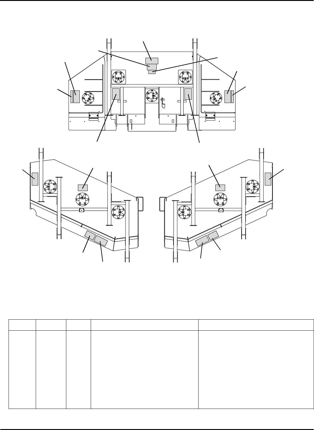
121
> Change from previous revision
HR-9016
Item Part No. Qty. Description Serial Numbers/Notes
13009317 5 Decal, Caster Cut Height
2 3009318 2 Decal, Gage Wheel Cut Height
3 3009319 1 Decal, Flip Up Deck
4 366609 2 Decal, No Step
5 3002502 7 Decal, Danger
Left Wing Right Wing
Front
9016-63
1
1
11
1
22
3
44
5
5
5
5
55
5
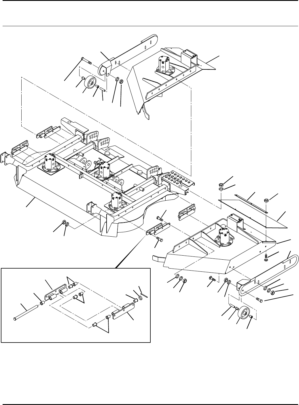
122
HR-9016
57.1 Front Deck Serial No. All
9016-57
1
2
3
4
5
6
7
8
9
10
11
12
13
14
15
16
17
18
19
20
21
22
23
24
25
26
1
3
3
4
4
6
9
10 11
11
11
11
11
11
11 11
13
14 15
23

123
> Change from previous revision
HR-9016
Item Part No. Qty. Description Serial Numbers/Notes
11003430.6 8 Hinge Assembly
2 400286 12 Screw, 3/8-16 x 2-3/4” Hex Head
3 446142 32 Lockwasher, 3/8 Hvy
4 444762 32 Locknut, 3/8-16 Center
5 400264 12 Screw, 3/8-16 x 1-1/4” Hex Hd
6 453011 20 Flat Washer, 3/8
7 3007678 4 Pin, Clevis
8 460050 4 Cotter Pin, 3/16 x 1-1/4”
9 3003939 2 Wheel, Deck
10 3003714 2 Spacer, Wheel
11 3004113 36 Bushing
12 453020 4 Flat Washer, 5/8
13 446152 2 Lockwasher, 1/2
14 444758 2 Locknut, 1/2-13 Center
15 400420 2 Screw, 1/2-13 x 3-1/2” Hex Head
16 1003325.6 1 Skid Assembly, Anti Scalp
17 1003321.6 1 Skid Assembly, Anti Scalp
18 441624 8 Carriage Bolt, 3/8-16 x 1”
19 3008840 2 Flap, Rear
20 3009175 2 Hold Down, Drag Flap
21 441606 8 Carriage Bolt, 1/4-20 x 3/4”
22 452004 2 Flat Washer, 1/4
23 444708 8 Locknut, 1/4-20 Center
24 –1 Front Deck Center Section See 58.1
25 –1 Right Side Winglet See 59.1
26 –1 Left Side Winglet See 59.1
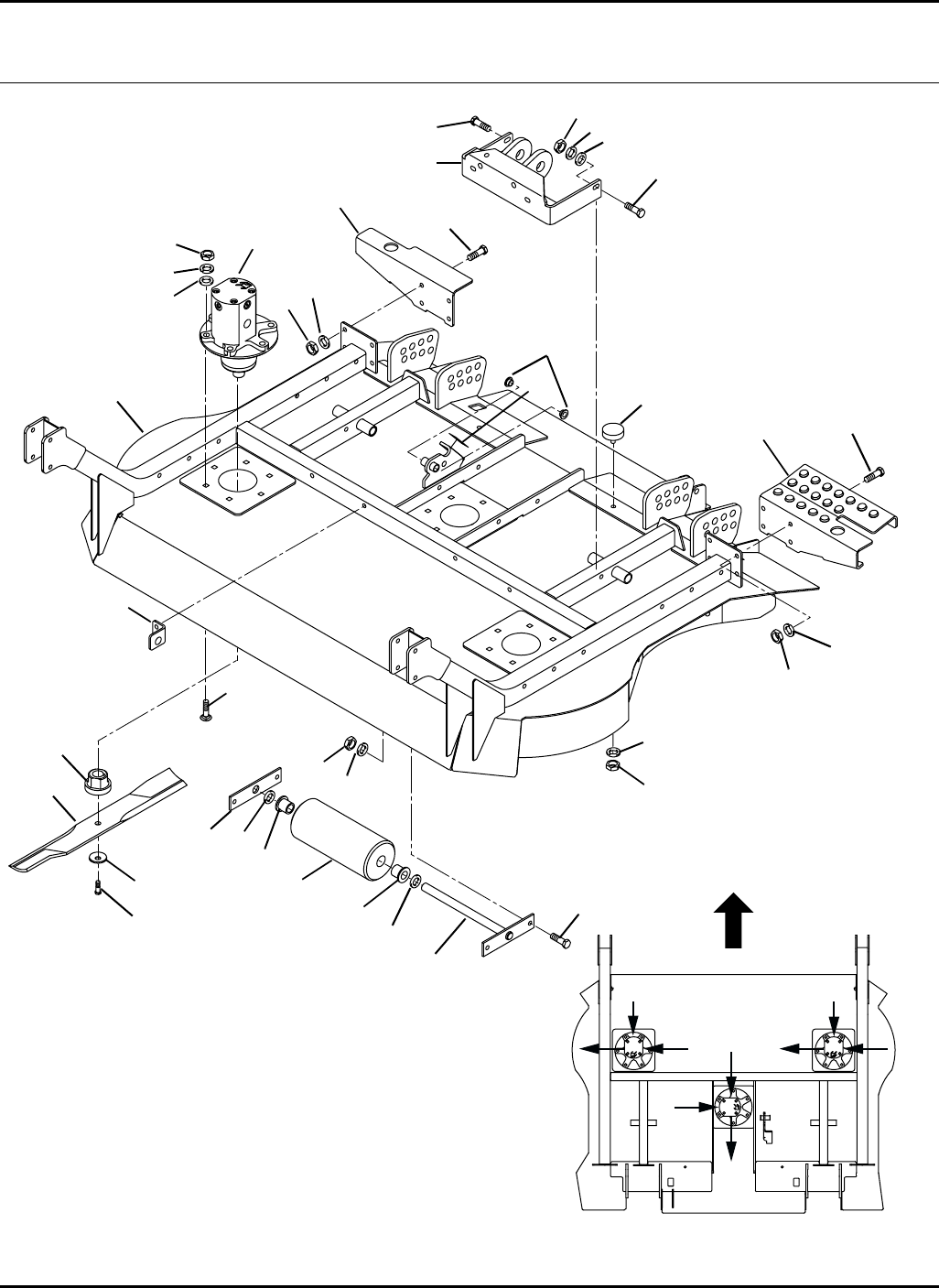
124
Inlet Inlet
Outlet
Outlet
Outlet
Case
Drain
Case
Drain
Case
Drain
Motor
Orientation
Front
HR-9016
58.1 Front Deck Center Section Serial No. All
9016-56
1
2
3
5
6
7
9 / 10 11
12
13
14
15
16
17
18
19
20
21
22
23
24
25
26
8
8
8
87
7
7
7
7
8
6
15
16
12
12
12
4

125
> Change from previous revision
HR-9016
Item Part No. Qty. Description Serial Numbers/Notes
15003188 1 Deck, Front Assembly
2 352936 2 •Bushing
3 2810069 3 Motor, Spindle Assembly
5003763 1 •Seal Kit
4 REF 1 Serial Plate, Front Deck
5 440124 18 Carriage Bolt, 3/8-16 x 1-3/4”
6 453011 26 Flat Washer, 3/8
7 446142 40 Lockwasher, 3/8 Hvy
8 444762 22 Locknut, 3/8-16 Center
9 1003424.6 1 Bracket Assembly, RH
10 1003425.6 1 Bracket Assembly, LH
11 400274 6 Screw, 3/8-16 x 2-1/2” Hex Head
12 400262 14 Screw, 3/8-16 x 1” Hex Head
13 361723 2 Stop, Rubber
14 163302 1 Roller
15 552824 2 •Bushing
16 455048 2 Flat Washer, 3/4
17 1003429 1 Shaft Assembly, Roller
18 3007374.6 1 Plate, Shaft Support
19 3008388 3 Adapter, Blade
20 2810030 3 Bar, Rotary Mower Cutter
21 3007764 3 Washer, Blade
22 400410 3 Screw, 1/2-13 x 1-3/4” Hex Head
23 3007368.6 1 Arm, Winglet Support
24 3007369.6 1 Arm, Winglet Support
25 2810195.6 1 Angle, Bulkhead
26 443110 18 Nut, 3/8-16 Hex
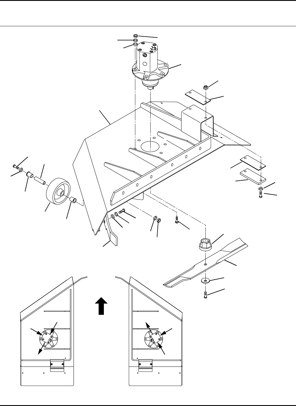
126
Inlet
Outlet
Case
Drain Motor
Orientation
Left Winglet Right Winglet
Front
Inlet
Outlet
Case
Drain
HR-9016
59.1 Front Deck Winglets
(Right Winglet Shown)
Serial No. All
9016-55
1 / 2
8
3
6
724
9
10
11
12
13
14
15
16
17
18
19
20
21
22
23
4
5
6
14
4
6
7

127
> Change from previous revision
HR-9016
Item Part No. Qty. Description Serial Numbers/Notes
15003186 1 Deck, RH Winglet
2 5003187 1 Deck, LH Winglet
3 2810069 2 Motor, Spindle Assembly
5003763 1 •Seal Kit
4 366613 4 Shim
5 440124 12 Carriage Bolt, 3/8-16 x 1-3/4”
6 453011 24 Flat Washer, 3/8
7 446142 20 Lockwasher, 3/8 Hvy
8 400264 4 Screw, 3/8-16 x 1-1/4” Hex head
9 366473 2 Bumper, Arm
10 400262 8 Screw, 3/8-16 x 1” Hex Head
11 444762 4 Locknut, 3/8-16 Center
12 3003939 2 Wheel, Deck
13 3003714 2 Spacer, Wheel
14 3004113 4 Bushing
15 455012 2 Flat Washer, 1/2
16 446152 2 Lockwasher, 1/2
17 444758 2 Locknut, 1/2-13 Center
18 400420 2 Screw, 1/2-13 x 3-1/2” Hex Head
19 3008388 2 Adapter, Blade
20 2810030 2 Bar, Rotary Mower Cutter
21 400410 2 Screw, 1/2-13 x 1-3/4”Hex Head
22 3007764 2 Washer, Blade
23 3007376.6 2 Arm, Winglet Support, Front
24 443110 12 Nut, 3/8-16 Hex
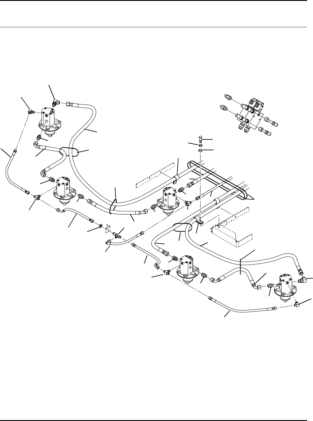
128
A
A
B
B
C
C
D
D
E - To Return Manifold
E
HR-9016
60.1 Front Deck Hydraulics Serial No. All
9016-58
1
2
3
4
5
6
7
8
9
10
11
12 13
14
15
16
17
19
20
1
2
2
2
2
2
3
44
2
2
7
10
15
15
15
15
16
21
Right
Winglet
Motor
Right
Center
Motor
Center
Motor
Left
Center
Motor Left
Winglet
Motor
6
22

129
> Change from previous revision
HR-9016
Item Part No. Qty. Description Serial Numbers/Notes
1340070 2 Adapter, 90°
2 339989 8 Adapter, Straight
3 340055 2 Adapter, 90°
4 340095 3 Adapter, Tee
5 REF 1 Hose, Front Deck Motor Case Drain See 38.1
6 1003557 2 Hose, Winglet
7 2810190 2 Hose, Winglet Motor Drain
8 1003607 1 Hose, Left Center to Center Motor
9 2810189 1 Hose, Tee to Left Center Motor Drain
10 2810191 2 Hose, Right Center and Center Drain
11 1003559 1 Hose, Right Valve to Right Winglet
12 1003556 1 Hose, Left Valve to Left Center
13 1003558 1 Hose, Left Winglet to Left Valve
14 1003562 1 Hose, Center Motor to Right Valve
15 473144 6 Tie Wrap
16 363514 3 Clamp, 1-1/8” Diameter
17 400188 3 Screw, 5/16-18 x 1” Hex Head
18 443106 2 Nut, 5/16-18 Hex
19 340214 1 Adapter, Bulkhead Tee
20 339960 1 Locknut, Bulkhead
21 446134 3 Lockwasher, 5/16
22 453009 1 Flat Washer, 5/16
130
Motor
Orientation
Left Wing Right Wing
Front
Inlet
Inlet
Inlet
Inlet
Inlet
Inlet
Outlet
Outlet
Outlet
Outlet
Outlet
Outlet
Case
Drain
Case
Drain
Case
Drain
Case
Drain
Case
Drain
Case
Drain
HR-9016
61.1 Wing Decks
Right Wing Shown
Serial No. All
9016-59
1 / 2
3
5
6
7
30
9
10
11
12
13
14
15
16
17
18
19
20 / 21
22
23
24
25
26
27
28
29
4
678
6
7
8
7
8
10
11
12 12
13
22
23
23
23
24
25
27 28
14

131
> Change from previous revision
HR-9016
Item Part No. Qty. Description Serial Numbers/Notes
15003190 1 Deck, Right Wing
2 5003189 1 Deck, Left Wing
3 2810069 6 Motor, Spindle Assembly
5003763 1 •Seal Kit
4 REF 2 Wing Deck Serial Plate
5 440124 36 Carriage Bolt, 3/8-16 x 1-3/4”
6 453011 48 Flat Washer, 3/8
7 446142 50 Lockwasher, 3/8 Hvy
8 444762 14 Locknut, 3/8-16 Center
9 116686.6 2 Deck Mount Assembly
10 363574 4 •Bushing
11 363562 4 •Bushing
12 471214 6 Fitting, Grease 1/4-28
13 363568 4 Washer, Thrust
14 163306.6 4 Pin Assembly
15 400264 4 Screw, 3/8-16 x 1-1/4” Hex Head
16 3008388 6 Adapter, Blade
17 2810030 6 Bar, Rotary Mower Cutter
18 3007764 6 Washer, Blade
19 400410 6 Screw, 1/2-13 x 1-3/4” Hex Head
20 1003321.6 1 Skid, Right Wing Anti-Scalp
21 1003325.6 1 Skid, Left Wing Anti Scalp
22 400420 4 Screw, 1/2-13 x 3-1/2” Hex Head
23 3004113 8 Bushing
24 3003714 4 Spacer, Wheel
25 3003939 4 Wheel, Deck
26 361723 2 Stop, Rubber
27 446152 4 Lockwasher, 1/2
28 444758 4 Locknut, 1/2-13 Center
29 441624 8 Carriage Bolt, 3/8-16 x 1”
30 443110 36 Nut, 3/8-16 Hex
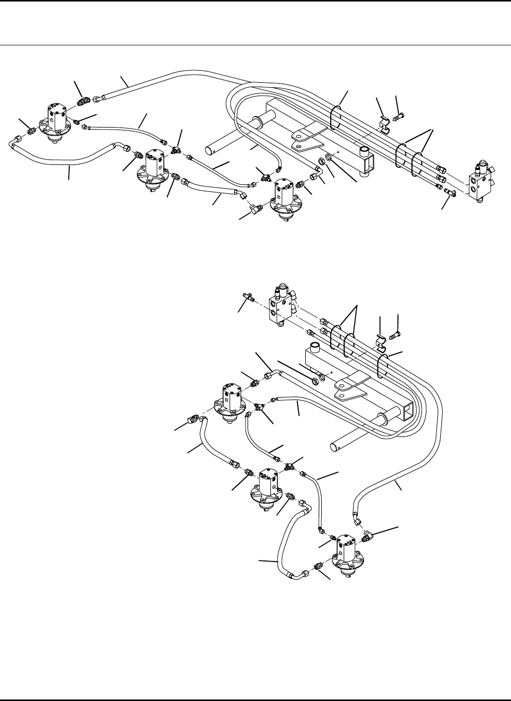
132
Right Wing Deck Hydraulics
Left Wing Deck Hydraulics
HR-9016
62.1 Wing Deck Hydraulics Serial No. All
9016-60
1
2
3
4
5
6
7
8
9
10
11
12 13
14
15
16
1
2
3
4
5
6
7
8
9
10
11
12 13
14
15
16
1
2
2
2
4
14
1
2
2
4
14
17
17
Right
Center
Motor
Left
Outside
Motor
Left
Center
Motor
Left
Inside
Motor
Right
Outside
Motor
Right
Inside
Motor
2

133
> Change from previous revision
HR-9016
Item Part No. Qty. Description Serial Numbers/Notes
1340070 4 Adapter, 90°
2 339989 8 Adapter, Straight
3 339972 2 Adapter, Straight
4 340095 4 Adapter, Tee
5 1003580 2 Hose, Outside to Center Motor
6 1003579 2 Hose, Inside to Center Motor
7 2810194 2 Hose, Center to Inside Motor Drain
8 2810193 2 Hose, Outside to Center Motor Drain
9 2810192 2 Hose, Wing Motor Drain to Tee
10 1003584 2 Hose, Wing Motor Pressure
11 1003583 2 Hose, Wing Motor Return
12 359860 2 Clamp, Hose
13 400206 2 Screw, 5/16-18 x 4” Hex Head
14 473144 6 Tie Wrap
15 446136 2 Lockwasher, 5/16 Heavy
16 443106 2 Nut, 5/16-18 Hex
17 REF 2 Adapter, Bulkhead Tee See 38.1
134
> Change from previous revision
HR-9016
63.1 Caster Assemblies Serial No. All
9016-62
Item Part No. Qty. Description Serial Numbers/Notes
11004276 8 Yoke, 11” Tire Wing Decks Only
1 1004275.6 2 Yoke, 13” Tire Front Deck Only
2 1004277.6 10 Tube, Yoke Pivot
3 363539 2 •Bushing
4 471214 1 •Grease Fitting
5 366593 20 Spacer, Caster Wheel
6 365772 30 Spacer, Caster Wheel
7 361648 10 Washer, Thrust
8 1004023 8 Wheel and Tire, 11”Wing Decks Only, See 64.1
8 1004024 2 Wheel and Tire, 13”Front Deck Only, See 64.1
9 441690 8 Carriage Bolt, 1/2-13 x 7”Wing Decks Only
9 441689 2 Carriage Bolt, 1/2-13 x 8-1/2”Front Deck Only
10 443118 20 Nut, 1/2-13 Hex
11 401028 20 Screw, 3/8-16 x 3-1/4” Hex Head
12 446142 20 Lockwasher, 3/8 Heavy
13 443110 20 Nut, 3/8-16 Hex
14 3004894 10 Pin, Klik Type
1
2
3
4
5
78
9
10
11
12
13
5
6
6
3
14
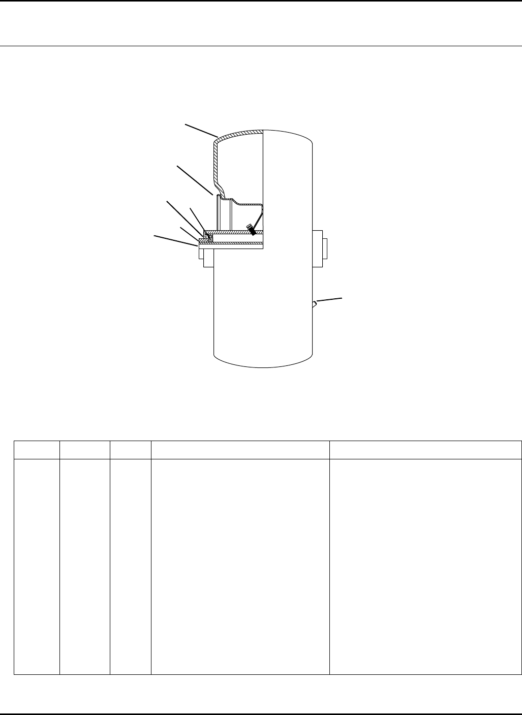
135
> Change from previous revision
HR-9016
Item Part No. Qty. Description Serial Numbers/Notes
1550346 1 Tire, 11 x 4-5 Smooth 1004023 Only
1 5003200 1 Tire, 13 x 6.5-6 Multi Rib 1004024 Only
2 5003196 1 Wheel 1004023 Only
2 5003201 1 Wheel 1004024 Only
3 5003197 2 Grease Seal
4 5003198 2 Bearing Cone
5 360111 1 Inflation Valve
6 346883 2 Spacer
7 5003199 1 Spacer 1004023 Only
7 5003202 1 Spacer 1004024 Only
64.1 Wheel and Tire Assemblies
Part Numbers 1004023 and 1004024
Serial No.
9016-61
1
2
34
5
6
7
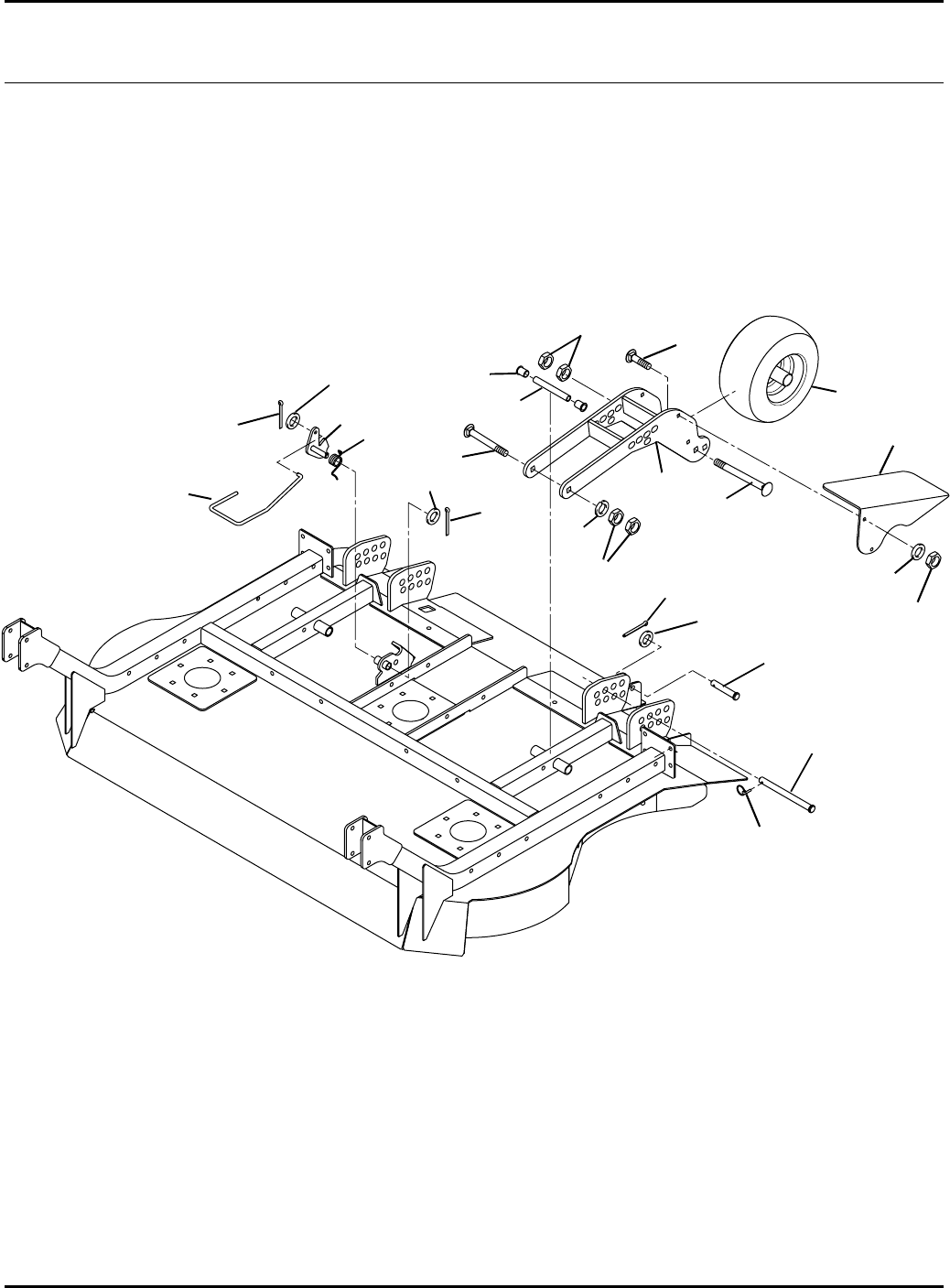
136
HR-9016
65.1 Gage Wheels and Latch Serial No. All
1
2
3
4
5
6
7
8
9
10
11
12
13
14
15
16
13
2
6
17
9016-63
8
18 / 19
20
21
22

137
> Change from previous revision
Item Part No. Qty. Description Serial Numbers/Notes
1461495 1 Clevis pin, 1/2 x 2-1/2”
2 460028 2 Cotter Pin, 1/8 x 1”
3 1003423.6 2 Yoke, Gage Wheel
4 3007442 2 Spacer, Arm Pivot
5 3004113 4 Bushing
6 441690 4 Carriage Bolt, 1/2-13 x 7”
7 446152 2 Lockwasher, 1/2
8 443118 8 Nut, 1/2-13 Hex
9 3007679 2 Clevis Pin, 5/8 x 9-5/16”
10 342675 2 Snap Ring
11 1003902 1 Latch, Standup
12 3008471 1 Spring, Torsion
13 453017 1 Flat Washer, 1/2
14 3008478 1 Rod, Latch
15 453009 1 Flat Washer, 5/16
16 460014 1 Cotter Pin, 3/32 x 3/4”
17 1004023 2 Wheel and Tire, 11”See 64.1
18 3010075 1 Deflector, Left Side Grass
19 3010074 1 Deflector, Right Side Grass
20 441614 4 Carriage Bolt, 5/16-18 x 1”
21 452006 4 Flat Washer, 5/16
22 444718 4 Locknut, 5/16-18 Center
HR-9016
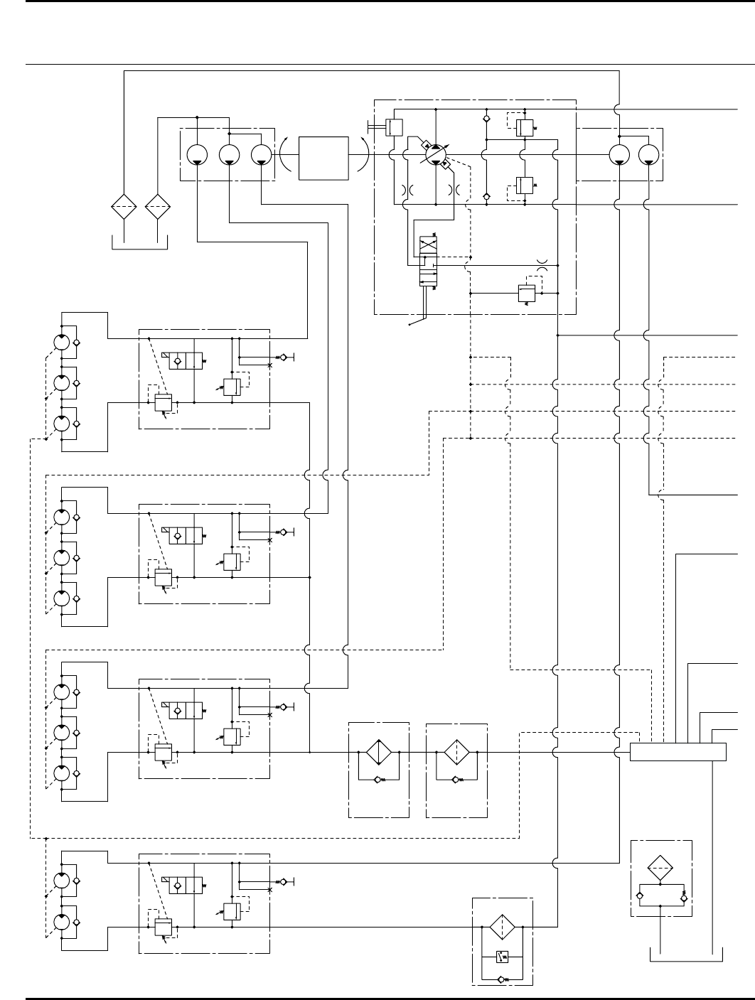
138
4387 psi
4387 psi
313 psi
2.81 ci
Tow
Valve
A
CPT
T
P
B
A
D
D
T
P
B
A
D
D
T
P
B
A
D
D
T
P
B
A
D
D
B
Traction
Pump
A
C
B
D
E
F
G
H
J
K
L
M
25 psi
25 psi
10 Micron
10 Micron
25 psi
Crack
Bypass
10 Micron Air
2.9 psi
30 psi
Crack
Bypass
Return
Filter
Charge
Filter
Left Front Deck Valve
Right Wing Deck Valve
Two
Left
Front
Motors
Right
Wing
Motors
Left Wing Deck Valve
Left
Wing
Motors
Right Front Deck Valve
Three
Right
Front
Motors
Return
Manifold
Tank Fill
Cap
Oil
Cooler
630 psi Brake
3000 psi
630 psi Brake
3000 psi
630 psi Brake
3000 psi
630 psi Brake
3000 psi
.98 ci
Typ (11 Places)
Mow
2400 RPM
Transport
2750 RPM
Engine
1.28 ci 1.28 ci 1.28 ci
CW CCW .49 ci
HR-9016
Sch ema t ics
66.1 Hydraulic Schematic Serial No. All
9016-54
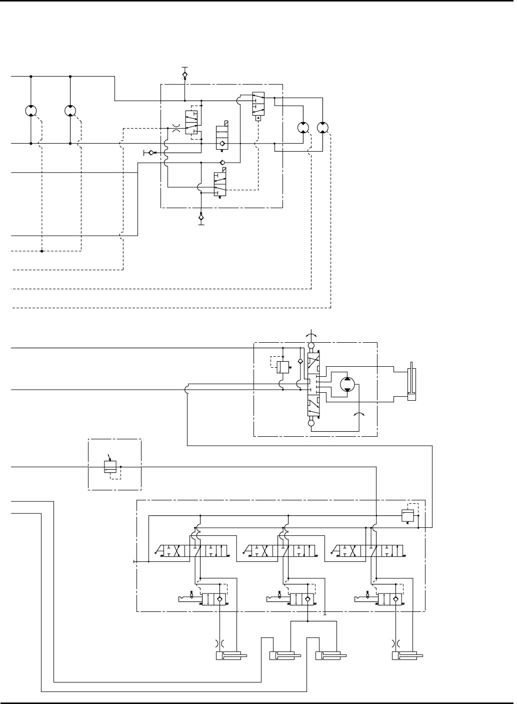
139
> Change from previous revision
HR-9016
15.56 ci 15.56 ci
Front
Wheel
Motors
4WD Valve
Rear
Wheel
Motors
12.5 ci
.031 12.5 ci
2
1
3
4
A
DA
B
T
CP
DC
DB
A
C
B
D
E
F
G
H
J
K
L
M
Steering
Unit
Lift Valve
Backpressure
Valve
Left Wing
Cylinder
Right Front
Cylinder
Left Front
Cylinder
Right Wing
Cylinder
Steering
Cylinder
In
In
Out
Out
Aux
LT
RT
6.6 ci
1450 psi
1500 psi
300 psi 300 psi 300 psi
30 ~ 275 psi
.0595" .0595"
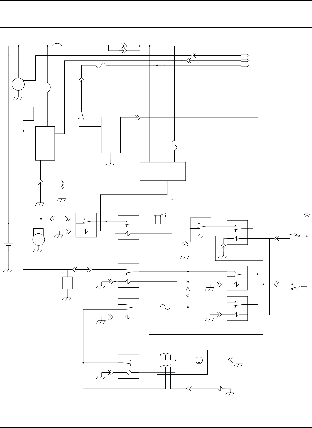
140
F9
3-3
VT/YE
VT/YE
VT/YE
K12
12
SW5
DG/WH
DG/WH DG/WH
DG/WH
S5
WH/BU
OR/BU
K8
3-4
2-7
2-6
A
A
B
B
SW7
SW6
GY/WH
GY/YE
GY/YE
WH/VT
GY/YE
GY/YE
DB/YE
DB/YE
SAI
B
YE/RD
1
2
F5
SW1
OFF-NONE
RUN - B+I+A; X+Y
START - B+I+S
1-7
1-1
YE/BK YE/BK
GY/RD GY/RD
OR
OR
OR
Y
X
RD/YE
OR
RD
BK
+
-B1
M1
G
G
S1
R1
BS
RD
RD
GY/RD
1
2
CB2
51-BU
8
3
4
1
9
5
RUN
START
GLOWPLUG
GRD
LIGHT
B+
BK
1-8
YE/BK
BN/YE
CB1
1 2
3-11
3-12
F7
BN/YE RD/YE
J2-10
P2-10
OR
U2
BK
YE/GN
3
1SW-IN
HOLD
COIL
+12V
WH/BU
RD/BU RD/BU
SW3A
1
2
3
H
4-4
1-4 GY
GY
RD
GY/RD
GY
GN 4-3
4-12
4-12
4-11
4-11
4-11
4-11
4-11
4-9
1-3
GY
K2
K1
K3
K6 K4
SW2
1
2
WH
2
4
2-9
YE/GN
K5
OR/BNOR/BN
D1
K7
BN/YE
GRD
U1
BK/WH
GN
4-12
G
Ig
L
B
U7
87A
87 30
86
85
87A
87 30
86
85
87A
87 30
86
85
87A
87 30
86
85
87A
87 30
86
85
87A
87 30
86
85
87A
87 30
86
85
87A
87
30
86
85
87A
87 30
86
85
3
456
AB
BK BK
BK
BK
BK BK
OR/GN
OR/GN
OR/GN
GY/BU
HR-9016
67.1 Electrical Schematic
Interlock, Starting, Charging and Cruise Control Circuits
Serial No. 70524 1601 ~ 1725
Serial No. 70525 1601 ~ 1777
9016-35
A
B
C
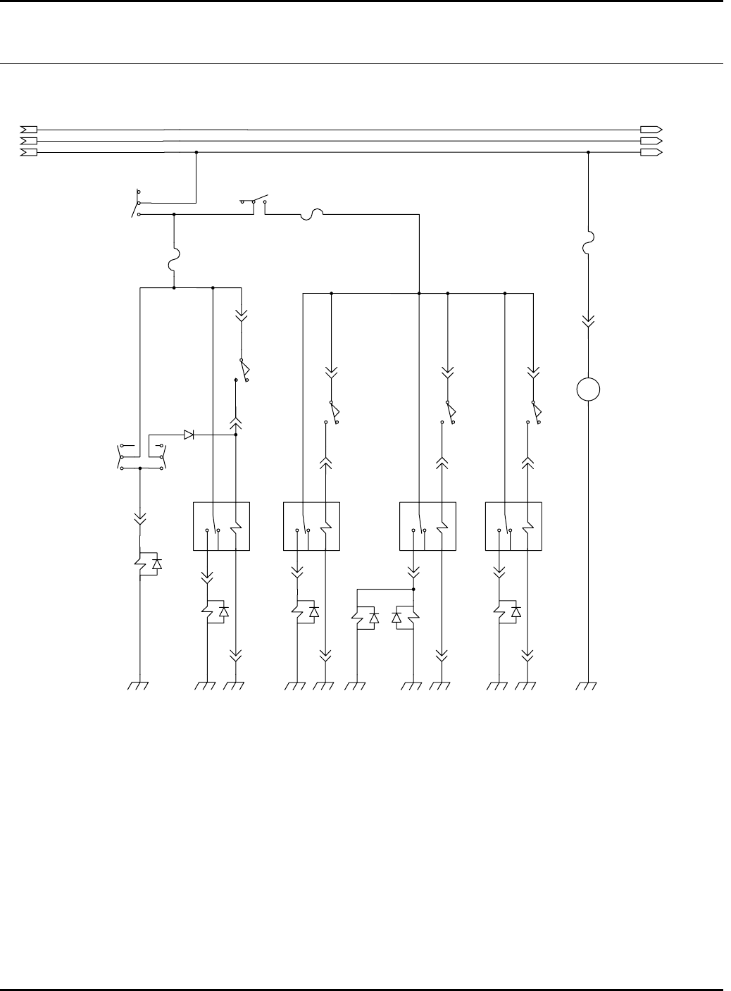
141
2
1
F8
WH/RD
4-8
RD/YE
WH/RD
U12
+
PM
-
BK
2
1
21
YE/BU
4
5
6
SW3B
TN/GN
2-4
F10
1
2
DG/YE
RD/YE
2
3
WH/BK
3-5
WH/BK
TN/GN
A-1
B-2
B-2
A-1
VT/WH
SW10
B
A
GY/BK
3-6
SW13
SW12
D4
1
2
3
WH/BK
PK/WH
S7
3-7
A
B
SW4
2-3
BN/GN
K13 K9 K10 K11
3-8
A-1
B-2
A-1
B-2 B-2
A-1
S2 S3 S8
2-2
BK
BK
BK
BK
BK
RD/BK
OR/WH
S6
BK
BK
WH/BK
BK
BK
F11
4
5
6
87A
87
30 86
85 87A
87
30 86
85
2-4
TN/GN
A
B
SW8
3-1
RD/WH
3-2
87A
87
30 86
85
2-4
TN/GN
A
B
SW9
3-9
BN/WH
B-2
A-1
S4
3-10
4-114-114-114-9
BK RD
87A
87
30 86
85
HR-9016
67.1 Electrical Schematic
4WD, Mow and Seat Control Circuits
Serial No. 70524 1601 ~ 1725
Serial No. 70525 1601 ~ 1777
A
B
C
A
B
C
Color Abbreviations
BK - Black
DG - Dark Green
LG - Light Green
TN - Tan
BN - Brown
GN - Green
OG - Orange
VT - Violet
BU - Blue
GY - Grey
PK - Pink
WH - White
DB - Dark Blue
LB - Light Blue
RD - Red
YE - Yellow
Component Abbreviations
CB1 - 50 Amp Circuit Breaker
CB2 - 50 Amp Circuit Breaker
D1 - Inter-Lock Diode Connector
D2 - Test Diode Connector
D3 - Alarm Diode Connector
D4 - 4WD Diode Connector
F1 - 5 Amp (Spare Fuse-Not Shown)
F2 - 5 Amp (Spare Fuse-Not Shown)
F3 - 15 Amp (Spare Fuse-Not Shown)
F4 - 15 Amp (Spare Fuse-Not Shown)
F5 - 5 Amp (Ignition Switch)
F6 - 5 Amp (Gauges)
F7 - 5 Amp (Interlock)
F8 - 15 Amp (Air Ride Seat)
F9 - 5 Amp (Cruise Control)
F10 - 5 Amp (4WD)
F11 - 15 Amp (Mow)
F12 - Not Used
K1 - Interlock Relay
K2 - Run Circuit Relay
K3 - Start Circuit Relay
K4 - Brake (Start) Relay
K5 - Brake (Run) Relay
K6 - Neutral (Start) Relay
K7 - Neutral (Run) Relay
K8 - Neutral (Cruise) Relay
K9 - Left Mow Relay
K10 - Center Mow Relay
K11 - Right Mow Relay
K12 - Cruise Control Relay
K13 - 4WD Relay
M1 - Starter Motor
R1 - Glow Plug
S1 - Fuel Solenoid
S2 - Left Mow Solenoid
S3 - Center Mow Solenoid 1
S4 - Right Mow Solenoid
S5 - Cruise Control Solenoid
S6 - 4WD Solenoid
S7 - 4WD Reverse Solenoid
S8 - Center Mow Solenoid 2
SW1 - Ignition Switch
SW2 - Seat Switch
SW3 - PTO Switch
SW4 - Left Wing Limit Switch
SW5 - Cruise Control Switch
SW6 - Neutral Switch
SW7 - Brake Switch
SW8 - Front Limit Switch
SW9 - Right Wing Limit Switch
SW10 - Forward Switch
SW11 - Hydraulic Level Switch
SW12 - 4WD Reverse Switch
SW13 - 4WD Switch
SW14 - Test Switch
SW15 - Charge Filter Switch
SW16 - Engine Oil Switch
SW17 - High Water Temperature Switch
U1 - Glowplug Module
U2 - Seat Time Delay Relay
U3 - Hour Meter
U4 - Fuel Sender
U5 - Light Gauge
U5.2 - Glow Plug Light
U6 - Temperature Sender
U7 - Alternator
U8 - Oil Light
U9 - Fuel Gauge
U10 - Temperature Gauge
U11 - Alarm
U12 - Air Ride Seat
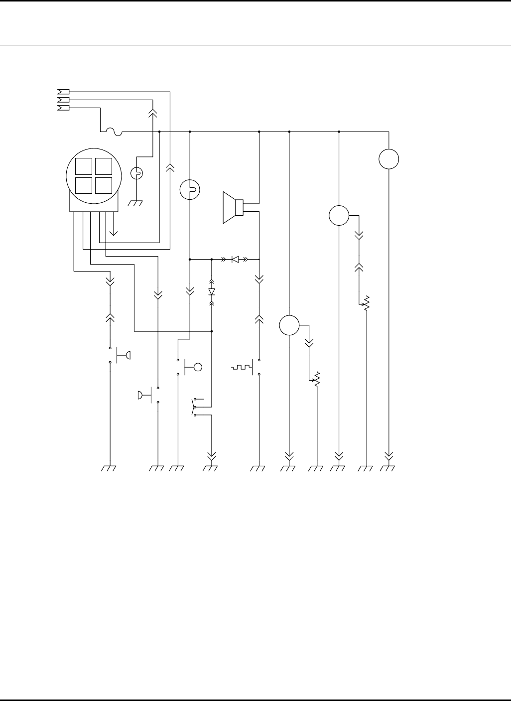
142
1-5
VT
2
1
U6
I
G
G
S
PK
2-8
4-12 4-10 4-10 4-9
PK
U4
BK
BK
BK
BK
YE
4-6
D2
1-6
WH/BN
WH/BN
2-11
SW17
BK
+
-
YE
LB/BK
1
2
3
BK
SW11
SW14
BU
2-1
BU
+
-
BK
SW15
+
-
4-2
1-2
BN
BN
+
-
BK
SW16
BU
WH/BN
604-YE
OR/BK
U9
U10
U3
WH/BN
2
U8
1
OR/BK
2
1
F6
ENG
F
GLOW
A
BAT
E
CHRG
B
F
BN
GY/RD
LB/BK
OR/BK
BU
YE/BK
YE/BK
U5
U5.2
YE/BK
YE/BK
4-7
4-1
GY/RD
GY/RD
E DCB
B
A
A
RD/YE
U11
+
-
OR/BK
D3
YE
BK
1-BK
VT
4-5
VT
SIG
+
-
B+
HR-9016
67.1 Electrical Schematic
Gauges and Warning Lights
Serial No. 70524 1601 ~ 1725
Serial No. 70525 1601 ~ 1777
Color Abbreviations
BK - Black
DG - Dark Green
LG - Light Green
TN - Tan
BN - Brown
GN - Green
OG - Orange
VT - Violet
BU - Blue
GY - Grey
PK - Pink
WH - White
DB - Dark Blue
LB - Light Blue
RD - Red
YE - Yellow
Component Abbreviations
CB1 - 50 Amp Circuit Breaker
CB2 - 50 Amp Circuit Breaker
D1 - Inter-Lock Diode Connector
D2 - Test Diode Connector
D3 - Alarm Diode Connector
D4 - 4WD Diode Connector
F1 - 5 Amp (Spare Fuse-Not Shown)
F2 - 5 Amp (Spare Fuse-Not Shown)
F3 - 15 Amp (Spare Fuse-Not Shown)
F4 - 15 Amp (Spare Fuse-Not Shown)
F5 - 5 Amp (Ignition Switch)
F6 - 5 Amp (Gauges)
F7 - 5 Amp (Interlock)
F8 - 15 Amp (Air Ride Seat)
F9 - 5 Amp (Cruise Control)
F10 - 5 Amp (4WD)
F11 - 15 Amp (Mow)
F12 - Not Used
K1 - Interlock Relay
K2 - Run Circuit Relay
K3 - Start Circuit Relay
K4 - Brake (Start) Relay
K5 - Brake (Run) Relay
K6 - Neutral (Start) Relay
K7 - Neutral (Run) Relay
K8 - Neutral (Cruise) Relay
K9 - Left Mow Relay
K10 - Center Mow Relay
K11 - Right Mow Relay
K12 - Cruise Control Relay
K13 - 4WD Relay
M1 - Starter Motor
R1 - Glow Plug
S1 - Fuel Solenoid
S2 - Left Mow Solenoid
S3 - Center Mow Solenoid 1
S4 - Right Mow Solenoid
S5 - Cruise Control Solenoid
S6 - 4WD Solenoid
S7 - 4WD Reverse Solenoid
S8 - Center Mow Solenoid 2
SW1 - Ignition Switch
SW2 - Seat Switch
SW3 - PTO Switch
SW4 - Left Wing Limit Switch
SW5 - Cruise Control Switch
SW6 - Neutral Switch
SW7 - Brake Switch
SW8 - Front Limit Switch
SW9 - Right Wing Limit Switch
SW10 - Forward Switch
SW11 - Hydraulic Level Switch
SW12 - 4WD Reverse Switch
SW13 - 4WD Switch
SW14 - Test Switch
SW15 - Charge Filter Switch
SW16 - Engine Oil Switch
SW17 - High Water Temperature Switch
U1 - Glowplug Module
U2 - Seat Time Delay Relay
U3 - Hour Meter
U4 - Fuel Sender
U5 - Light Gauge
U5.2 - Glow Plug Light
U6 - Temperature Sender
U7 - Alternator
U8 - Oil Light
U9 - Fuel Gauge
U10 - Temperature Gauge
U11 - Alarm
U12 - Air Ride Seat
A
B
C
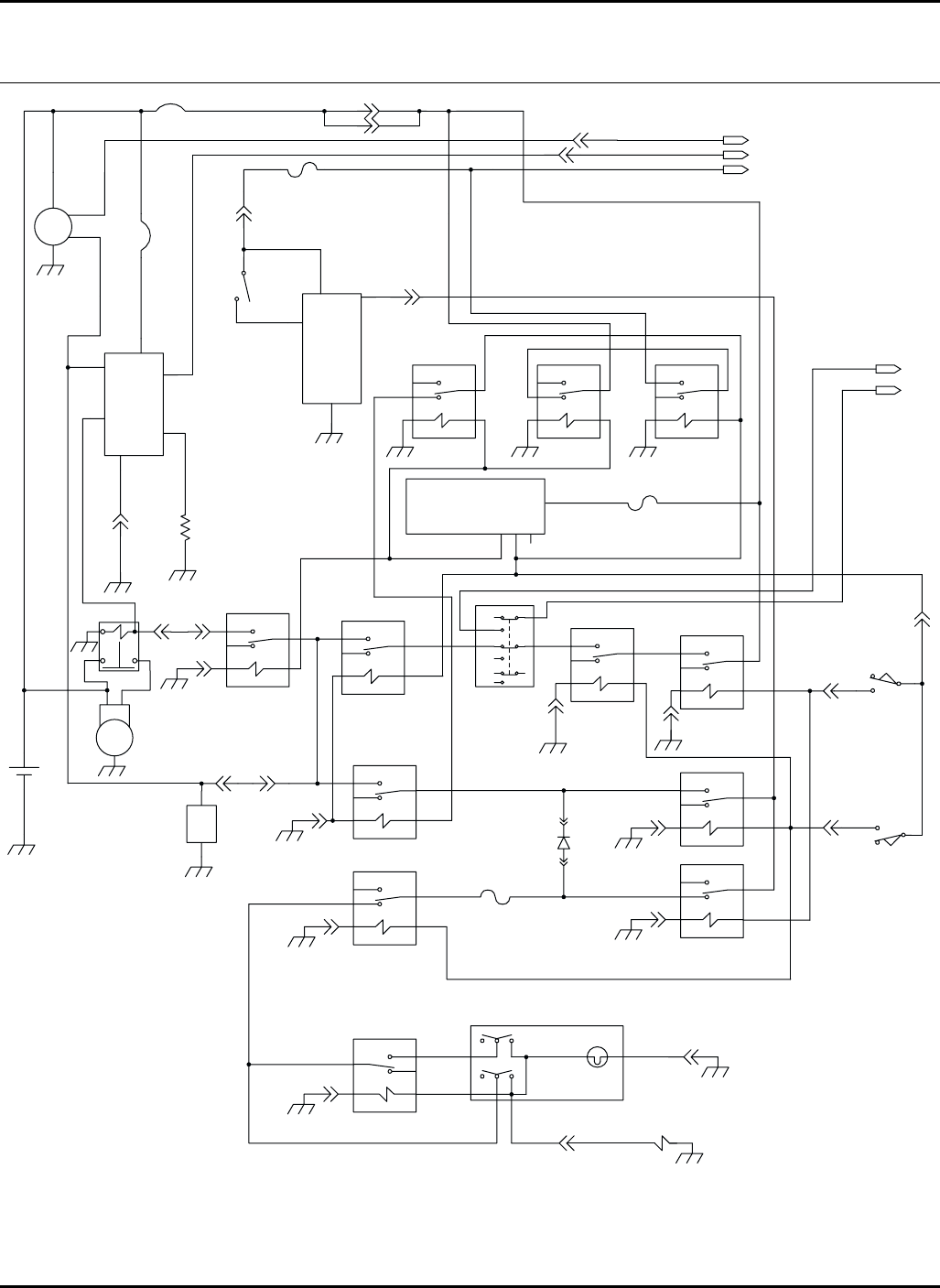
143
F9
3-3
VT/YE
VT/YE
VT/YE
K12
12
SW5
DG/WH
DG/WH DG/WH
DG/WH
S5
WH/BU
OR/BU
K8
3-4
2-7
2-6
A
A
B
B
SW7
SW6
GY/WH
GY/YE
GY/YE
WH/VT WH/VT
WH/VT WH/VT
GY/YE
GY/YEGY/YE
GY/YE
GY/YE
DB/YE
DB/YE
YE/RD F5
1-7
1-1
YE/BK YE/BK
GY/RD GY/RD
OR
OR
OR
OR
OR
RD/YE
RD/YE
RD/YERD/YE
RD/YE
OR
OR
RD
BK
+
-B1
M1
G
G
S1
R1
BS
RD
RD
GY/RD
1
2
CB2
51-BU
8
3
4
1
9
5
RUN
START
GLOWPLUG
GRD
LIGHT
B+
BK
1-8
YE/BK
BN/YE
CB1
1 2
3-11
3-12
F7
BN/YE RD/YE
J2-10
P2-10
OR
U2
BK
YE/GN
3
1SW-IN
HOLD
COIL
+12V
WH/BU
RD/BU RD/BU
SW3
H
4-4
1-4 GY
GY
RD
GY/RD
GY
GN
GN
GN
BK
RD
OG/BU
4-3
4-12
4-12
4-11
4-11
4-11
4-11
4-11
4-9
1-3
GY
K2
K1
K3
K14 K6 K4
SW2
1
2
WH
2
4
2-9
YE/GN
K5
OR/BNOR/BN
D1
K7
BN/YE
GRD
U1
BK/WH
GN
DG/YE
YE/WH
DG/YE
YE/WH
4-12
G
Ig
L
B
U7
87A
87 30
86
85
87A
87 30
86
85
87A
87 30
86
85
K17
87A
87 30
86
85
K16
87A
87 30
86
85
K15
87A
87 30
86
85
87A
87 30
86
85
87A
87 30
86
85
87A
87 30
86
85
87A
87 30
86
85
87A
87
30
86
85
87A
87 30
86
85
SGPI
B
SW1
OFF-NONE
RUN-B+I
GP-B+I+GP
START-B+I+GP+S
3
456
AB
BK BK
BKBKBK
BK
BK
BK BK
OR/GN
OR/GN
OR/GN
GY/BU
CC
NCC
CB
NOB
NOC
NCB
NCA CA
HR-9016
67.2 Electrical Schematic
Interlock, Starting, Charging and Cruise Control Circuits
Serial No. 70524 1726 and Up
Serial No. 70525 1778 and Up
9016-35
A
B
C
D
E
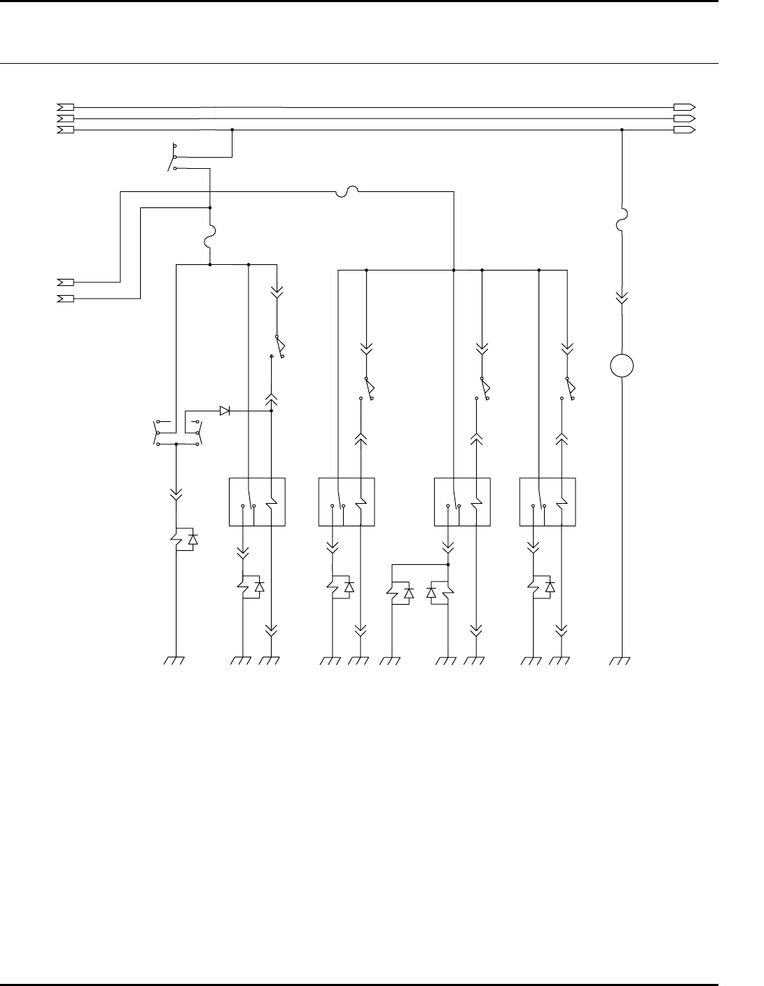
144
2
1
F8
WH/RD
4-8
RD/YE
WH/RD
U12
+
PM
-
BK
2
1
21
TN/GN
2-4
F10
1
2
DG/YE
DG/YE
DG/YE
DG/YE
DG/YE
RD/YE
GY/RD
YE/BK
RD/YE
GY/RD
YE/BK
RD/YE
2
3
WH/BK
3-5
WH/BK
TN/GN
A-1
B-2
B-2
A-1
VT/WH
SW10
B
A
GY/BK
3-6
SW13
SW12
D4
1
2
3
WH/BK
PK/WH
S7
3-7
A
B
SW4
2-3
BN/GN
K13 K9 K10 K11
3-8
A-1
B-2
A-1
B-2 B-2
A-1
S2 S3 S8
2-2
BK
BK
BK
BK
BK
RD/BK
OR/WH
S6
BK
BK
WH/BK
BK
BK
F11
4
5
6
87A
87
30 86
85 87A
87
30 86
85
2-4
TN/GN
A
B
SW8
3-1
RD/WH
3-2
87A
87
30 86
85
2-4
TN/GN
A
B
SW9
3-9
BN/WH
B-2
A-1
S4
3-10
4-114-114-114-9
BK RD
87A
87
30 86
85
HR-9016
67.2 Electrical Schematic
4WD, Mow and Seat Control Circuits
Serial No. 70524 1726 and Up
Serial No. 70525 1778 and Up
A
B
C
A
B
C
Color Abbreviations
BK - Black
DG - Dark Green
LG - Light Green
TN - Tan
BN - Brown
GN - Green
OG - Orange
VT - Violet
BU - Blue
GY - Grey
PK - Pink
WH - White
DB - Dark Blue
LB - Light Blue
RD - Red
YE - Yellow
Component Abbreviations
CB1 - 50 Amp Circuit Breaker
CB2 - 50 Amp Circuit Breaker
D1 - Inter-Lock Diode Connector
D2 - Test Diode Connector
D3 - Alarm Diode Connector
D4 - 4WD Diode Connector
F1 - 5 Amp (Spare Fuse-Not Shown)
F2 - 5 Amp (Spare Fuse-Not Shown)
F3 - 15 Amp (Spare Fuse-Not Shown)
F4 - 15 Amp (Spare Fuse-Not Shown)
F5 - 5 Amp (Ignition Switch)
F6 - 5 Amp (Gauges)
F7 - 5 Amp (Interlock)
F8 - 15 Amp (Air Ride Seat)
F9 - 5 Amp (Cruise Control)
F10 - 5 Amp (4WD)
F11 - 15 Amp (Mow)
F12 - Not Used
K1 - Interlock Relay
K2 - Run Circuit Relay
K3 - Start Circuit Relay
K4 - Brake (Start) Relay
K5 - Brake (Run) Relay
K6 - Neutral (Start) Relay
K7 - Neutral (Run) Relay
K8 - Neutral (Cruise) Relay
K9 - Left Mow Relay
K10 - Center Mow Relay
K11 - Right Mow Relay
K12 - Cruise Control Relay
K13 - 4WD Relay
K14 - Starter Solenoid
K15 - Run Circuit Cutout Relay
K16 - Auxiliary Circuit
K17 - Ignition Circuit
M1 - Starter Motor
R1 - Glow Plug
S1 - Fuel Solenoid
S2 - Left Mow Solenoid
S3 - Center Mow Solenoid 1
S4 - Right Mow Solenoid
S5 - Cruise Control Solenoid
S6 - 4WD Solenoid
S7 - 4WD Reverse Solenoid
S8 - Center Mow Solenoid 2
SW1 - Ignition Switch
SW2 - Seat Switch
SW3 - PTO Switch
SW4 - Left Wing Limit Switch
SW5 - Cruise Control Switch
SW6 - Neutral Switch
SW7 - Brake Switch
SW8 - Front Limit Switch
SW9 - Right Wing Limit Switch
SW10 - Forward Switch
SW11 - Hydraulic Level Switch
SW12 - 4WD Reverse Switch
SW13 - 4WD Switch
SW14 - Test Switch
SW15 - Charge Filter Switch
SW16 - Engine Oil Switch
SW17 - High Water Temperature Switch
U1 - Glowplug Module
U2 - Seat Time Delay Relay
U3 - Hour Meter
U4 - Fuel Sender
U5 - Light Gauge
U5.2 - Glow Plug Light
U6 - Temperature Sender
U7 - Alternator
U8 - Oil Light
U9 - Fuel Gauge
U10 - Temperature Gauge
U11 - Alarm
U12 - Air Ride Seat
D
E
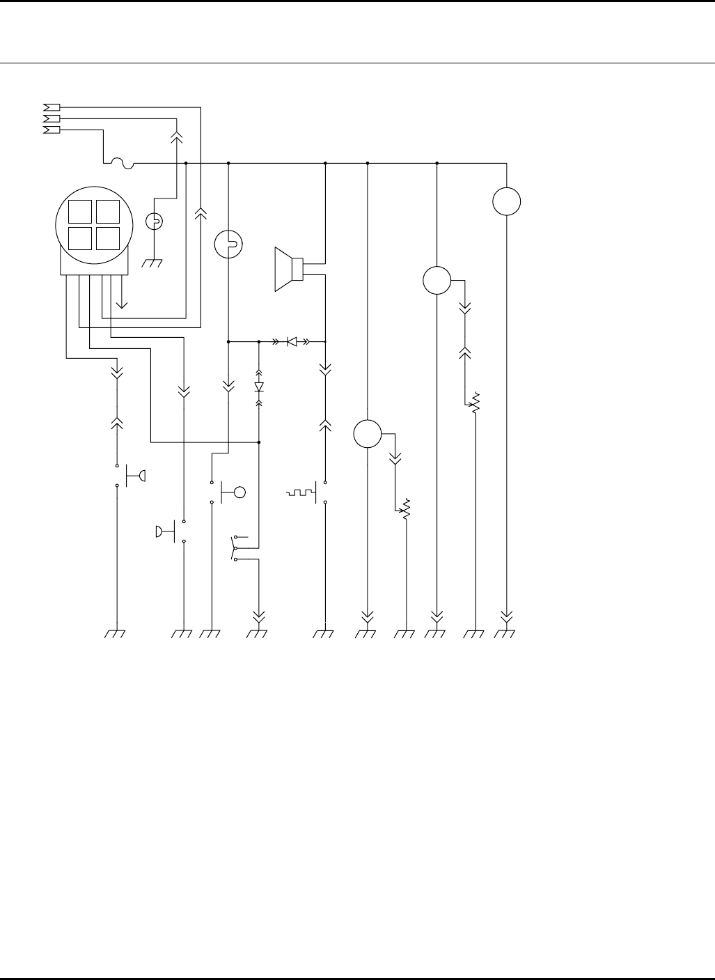
145
1-5
VT
2
1
U6
I
G
G
S
PK
2-8
4-12 4-10 4-10 4-9
PK
U4
BK
BK
BK
BK
YE
4-6
D2
1-6
WH/BN
WH/BN
2-11
SW17
BK
+
-
YE
LB/BK
1
2
3
BK
SW11
SW14
BU
2-1
BU
+
-
BK
SW15
+
-
4-2
1-2
BN
BN
+
-
BK
SW16
BU
WH/BN
604-YE
OR/BK
U9
U10
U3
WH/BN
2
U8
1
OR/BK
2
1
F6
ENG
F
GLOW
A
BAT
E
CHRG
B
F
BN
GY/RD
LB/BK
OR/BK
BU
YE/BK
YE/BK
U5
U5.2
YE/BK
YE/BK
4-7
4-1
GY/RD
GY/RD
E DCB
B
A
A
RD/YE
U11
+
-
OR/BK
D3
YE
BK
1-BK
VT
4-5
VT
SIG
+
-
B+
HR-9016
67.2 Electrical Schematic
Gauges and Warning Lights
Serial No. 70524 1726 and Up
Serial No. 70525 1778 and Up
Color Abbreviations
BK - Black
DG - Dark Green
LG - Light Green
TN - Tan
BN - Brown
GN - Green
OG - Orange
VT - Violet
BU - Blue
GY - Grey
PK - Pink
WH - White
DB - Dark Blue
LB - Light Blue
RD - Red
YE - Yellow
Component Abbreviations
CB1 - 50 Amp Circuit Breaker
CB2 - 50 Amp Circuit Breaker
D1 - Inter-Lock Diode Connector
D2 - Test Diode Connector
D3 - Alarm Diode Connector
D4 - 4WD Diode Connector
F1 - 5 Amp (Spare Fuse-Not Shown)
F2 - 5 Amp (Spare Fuse-Not Shown)
F3 - 15 Amp (Spare Fuse-Not Shown)
F4 - 15 Amp (Spare Fuse-Not Shown)
F5 - 5 Amp (Ignition Switch)
F6 - 5 Amp (Gauges)
F7 - 5 Amp (Interlock)
F8 - 15 Amp (Air Ride Seat)
F9 - 5 Amp (Cruise Control)
F10 - 5 Amp (4WD)
F11 - 15 Amp (Mow)
F12 - Not Used
K1 K1 - Interlock Relay
K2 - Run Circuit Relay
K3 - Start Circuit Relay
K4 - Brake (Start) Relay
K5 - Brake (Run) Relay
K6 - Neutral (Start) Relay
K7 - Neutral (Run) Relay
K8 - Neutral (Cruise) Relay
K9 - Left Mow Relay
K10 - Center Mow Relay
K11 - Right Mow Relay
K12 - Cruise Control Relay
K13 - 4WD Relay
K14 - Starter Solenoid
K15 - Run Circuit Cutout Relay
K16 - Auxiliary Circuit
K17 - Ignition Circuit
M1 - Starter Motor
R1 - Glow Plug
S1 - Fuel Solenoid
S2 - Left Mow Solenoid
S3 - Center Mow Solenoid 1
S4 - Right Mow Solenoid
S5 - Cruise Control Solenoid
S6 - 4WD Solenoid
S7 - 4WD Reverse Solenoid
S8 - Center Mow Solenoid 2
SW1 - Ignition Switch
SW2 - Seat Switch
SW3 - PTO Switch
SW4 - Left Wing Limit Switch
SW5 - Cruise Control Switch
SW6 - Neutral Switch
SW7 - Brake Switch
SW8 - Front Limit Switch
SW9 - Right Wing Limit Switch
SW10 - Forward Switch
SW11 - Hydraulic Level Switch
SW12 - 4WD Reverse Switch
SW13 - 4WD Switch
SW14 - Test Switch
SW15 - Charge Filter Switch
SW16 - Engine Oil Switch
SW17 - High Water Temperature Switch
U1 - Glowplug Module
U2 - Seat Time Delay Relay
U3 - Hour Meter
U4 - Fuel Sender
U5 - Light Gauge
U5.2 - Glow Plug Light
U6 - Temperature Sender
U7 - Alternator
U8 - Oil Light
U9 - Fuel Gauge
U10 - Temperature Gauge
U11 - Alarm
U12 - Air Ride Seat
A
B
C
146
XW
W
W
X
W
X
WW-X
O-Ring Face
Seal Size
O-Ring Boss
Dash Size
W-X
O-Ring Face
Seal Size
O-Ring Boss
Dash Size
W-X
O-Ring Face
Seal Size
W-X
O-Ring Face
Seal Size
O-Ring Face
Seal Size
W-X
O-Ring Face
Seal Size
O-Ring Face
Seal Size
O-Ring Face
Seal Size
W-X
O-Ring Face
Seal Size
O-Ring Face
Seal Size
O-Ring Face
Seal Size
W-X
O-Ring Face
Seal Size
O-Ring Boss
Dash Size
X
W
X X
W
W-X
O-Ring Face
Seal Size
O-Ring Not
Needed
W-X
O-Ring Face
Seal Size
X
XX
W
X
Y
W
W-X-Y
O-Ring Face
Seal Size O-Ring Face
Seal Size
O-Ring Boss
Dash Size
X
Y
W
W
X
Y
W
X
Y
W
W-X-Y
O-Ring Face
Seal Size
O-Ring Face
Seal Size
O-Ring Boss
Dash Size
W-X-Y
O-Ring Face
Seal Size O-Ring Face
Seal Size
W-X-Y
O-Ring Face
Seal Size
O-Ring Not
Needed O-Ring Not
Needed
O-Ring Face
Seal Size
W-X-Y
O-Ring Face
Seal Size
O-Ring Face
Seal Size
O-Ring Face
Seal Size
W-X-Y
O-Ring Face
Seal Size
O-Ring Face
Seal Size
O-Ring Face
Seal Size
W-X-Y-Z
O-Ring Face
Seal Size
O-Ring Face
Seal Size
O-Ring Face
Seal Size
O-Ring Face
Seal Size
X
Y
X
W
Z
Y
W
W
X
W
HR-9016
68.1 O-Ring Chart Serial No. All
147
> Change from previous revision
HR-9016
Adapter Part
Number.
Dash
Size Adapter Type (W) O-Ring (X) O-Ring (Y) O-Ring (Z) O-Ring
339972 4-4 Straight Adapter 339908 339896
339974 4-6 Straight Adapter 339908 339897
339979 6-6 Straight Adapter 339909 339897
339984 8-8 Straight Adapter 339910 339898
339989 10-10 Straight Adapter 339911 339899
339990 10-12 Straight Adapter 339911 339900
339994 12-12 Straight Adapter 339912 339900
339996 12-16 Straight Adapter 339912 339901
339999 16-16 Straight Adapter 339913 339901
340026 6-6 45° Adapter 339909 339897
340027 6-8 45° Adapter 339909 339898
340029 8-8 45° Adapter 339910 339898
340055 4-4 90° Adapter 339908 339896
340061 6-6 90° Adapter 339909 339897
340062 6-8 90° Adapter 339909 339898
340065 8-6 90° Adapter 339910 339897
340069 10-8 90° Adapter 339911 339898
340070 10-10 90° Adapter 339911 339899
340074 12-12 90° Adapter 339912 339900
340075 12-16 90° Adapter 339912 339901
340077 16-16 90° Adapter 339913 339901
340078 6-6 90° Adapter 339909 339897
340095 4-4-4 Straight Thread Branch Tee 339908 339908 339896
340118 4-4-4 Swivel Run Tee 339908 339908
340143 6-6-6 Swivel Branch Tee 339909 339909
340144 8-8-8 Swivel Branch Tee 339910 339910
340147 16-16-16 Swivel Branch Tee 339913 339913
340167 6-6 90° Bulkhead Adapter 339909 339909
340214 4-4-4 Bulkhead Run Tee 339908 339908 339908
340215 6-6-6 Bulkhead Run Tee 339909 339909 339909
340217 10-10-10 Bulkhead Run Tee 339911 339911 339911
340219 16-16-16 Bulkhead Run Tee 339913 339913 339913
340239 6-6 Union Bulkhead Adapter 339909 339909
340269 10-12-12 Straight Thread Run Tee 339911 339899 339912
340377 10-10 90° Swivel Adapter 339911
SAE Boss O-Rings ORS Face Seal O-Rings
Dash Size Thread Size O-Ring Tube Size Thread Size O-Ring
4 7/16-20 339896 4 9/16-18 339908
6 9/16-18 339897 6 11/16-16 339909
8 3/4-16 339898 8 13/16-16 339910
10 7/8-14 339899 10 1-14 339911
12 1 1/16-12 339900 12 1 3/16-12 339912
14 1 3/16-12 459296 16 1 7/16-12 339913
16 1 5/16-12 339901 20 1 11/16-12 339914
20 1 5/8-12 339902 24 2-12 339915
24 1 7/8-12 339903
32 2 1/2-12 339904
Fluids and Compounds
* Refer to the Parts & Maintenance manual for the correct hydraulic oil requirements for your machine.
Textron Golf, Turf & Specialty Products offers a High Usage Parts Catalog illustrating commonly used Parts through easy to read
line Drawings. See your local TGTSP Dealer for a copy.
Hydraulic Fluid*
5001405 Two 2-1/2 Gallon Container of ISO VG68 Oil
5001404 One 5 Gallon Pail of ISO VG68 Oil
2500548 Two 2-1/2 Gallon Container of 10W30 Oil
2500546 One 5 Gallon Pail of 10W30 Oil
503409 Two 2-1/2 Gallon Container of ATF Fluid
503407 One 5 Gallon Pail of ATF Fluid
2-Cycle Oil
554600 Twenty Four 16 Ounce Plastic Container
554599 Twenty Four 8 Ounce Plastic Container
Grease
5000067 One 5 Gallon Pail OO-Grease
5000068 Twenty Four 8 Ounce Tube OO-Grease
Paint
5003469 16 Ounce Gray Aerosol
554598 Six 12 Ounce Orange Aerosol
2500789 Twelve 1 Quart Can Orange
546409 Two 1 Gallon Can Orange
Lapping Compound
5002488 One 10 Pound Pail of 80 Grit
5002490 One 25 Pound Pail of 80 Grit
5002489 One 10 Pound Pail of 120 Grit
5002491 One 25 Pound Pail of 120 Grit
Specialty Compound
365422 5.3 Ounce Tube of Electrical Insulating Gel
5001581 14 Ounce Can of Lubriplate Multi Lube A
Biodegradable Hydraulic Fluid*
5003102 One 55 Gallon Drum TGTSP GreensCare 68
5003103 One 5 Gallon Pail TGTSP GreensCare 68
5003105 One 55 Gallon Drum TGTSP GreensCare 46
5003104 One 5 Gallon Pail TGTSP GreensCare 46
4115976 One 55 Gallon Drum TGTSP GreensCare 32
4115977 One 5 Gallon Pail TGTSP Greens Care 32
5003106 Twenty Four 14 Ounce Tube Greens Care Grease
O-Ring Kit
5002452 SAE O-Ring Boss (3/32 ~ 2” Tub e O. D. )
5002453 Common O-Ring Kit
5002454 O-Ring Face Seal ORFS (-4 ~ -24 ORS Tube Size)
Right Start Kit for New Machines
See your local TGTSP Dealer
On-Time Maintenance Kit
See your local TGTSP Dealer

149
INDEX
1001752 ...................... 69
1001802 ...................... 47
1002679 ................ 41, 43
1002769 ...................... 95
1002785 ...................... 81
1002800 ...................... 63
1002885 ...................... 85
1002886 ...................... 85
1002889 ................ 55, 57
1002893 ...................... 57
1002895 ................ 55, 57
1002896 ................ 55, 57
1002927 ...................... 79
1002940 .................... 101
1002952 ...................... 67
1002953 ...................... 65
1002977 ...................... 78
1003001 ...................... 60
1003011 ...................... 67
1003100 ...................... 47
1003145 ...................... 49
1003244 ...................... 49
1003245 ...................... 51
1003247 ...................... 73
1003248 ...................... 79
1003272 ...................... 87
1003274 ...................... 81
1003275 ...................... 81
1003277 ................ 83, 87
1003307 ...................... 95
1003308 ...................... 95
1003309 ...................... 95
1003310 ...................... 95
1003311 ...................... 95
1003312 ...................... 95
1003313 ...................... 95
1003321.6......... 123, 131
1003325.6......... 123, 131
1003423.6................. 137
1003424.6................. 125
1003425.6................. 125
1003429 .................... 125
1003430.6................. 123
1003483 ...................... 83
1003484 ...................... 83
1003556 .................... 129
1003557 .................... 129
1003558 .................... 129
1003559 .................... 129
1003562 .................... 129
1003570 .................... 105
1003573 ...................... 97
1003574 ...................... 97
1003575 ...................... 97
1003577 ...................... 97
1003579 .................... 133
1003580 .................... 133
1003583 .................... 133
1003584 .................... 133
1003586 ...................... 90
1003587 ...................... 90
1003590 .................... 101
1003591 .................... 101
1003592 ...................... 97
1003593 .................... 103
1003594 .................... 101
1003595 .................... 103
1003596 .................... 103
1003597 .................... 103
1003598 .................... 101
1003599 .................... 101
1003600 .................... 101
1003601 .................... 101
1003602 .................... 101
1003603 ...................... 97
1003604 ...................... 97
1003605 ...................... 99
1003606 .................... 103
1003607 .............. 91, 129
1003608 ...................... 97
1003610 ...................... 92
1003611 ...................... 47
1003679 ...................... 35
1003794 ...................... 51
1003823 ...................... 87
1003824 ...................... 51
1003825 ...................... 51
1003838 ...................... 53
1003860 ...................... 97
1003861 ...................... 97
1003862 ...................... 97
1003863 ...................... 90
1003864 ...................... 99
1003865 ...................... 99
1003866 ...................... 90
1003875 .................... 103
1003876 .................... 103
1003878 ...................... 99
1003891 ...................... 93
1003900 ...................... 81
1003902 .................... 137
1003942 ...................... 67
1003988 ...................... 97
1004023 ............ 134, 137
1004024 .................... 134
1004028 ...................... 67
1004172 ...................... 67
1004252 ...................... 45
1004266 ...................... 97
1004275.6 ................. 134
1004276 .................... 134
1004277.6 ................. 134
1004308 ................55, 57
1004309 ................55, 57
1004337 ................88, 89
1004417 ...................... 69
1004584 ...................... 47
1004686 ...................... 35
1004691 ................55, 57
1004797 .................... 105
1004921 .................... 105
1004931 .................... 105
1004938 ................55, 57
1004992 ................41, 43
1005016 ...................... 85
1005017 ...................... 85
1005018 ...................... 85
1006812 ...................... 51
116686.6 ................... 131
123096 ........................ 63
131905 ........................ 61
132647 ........................ 77
162236 ..................69, 92
162479 ........................ 65
162716.6 ..................... 85
162723 ..................41, 43
163302 ......................125
163306.6 ................... 131
2721505 ...................... 43
2721806 ...................... 75
2809628 ...................... 85
2809630 ...................... 85
2810030 ....125, 127, 131
2810069 ....125, 127, 131
2810188 ...................... 97
2810189 .................... 129
2810190 .................... 129
2810191 .................... 129
2810192 .................... 133
2810193 .................... 133
2810194 .................... 133
2810195.6 ................. 125
2810269 ................41, 43
2810492 ...................... 65
2810633 ...................... 67
2810634 ...................... 67
2810702 ...................... 77
2811020 ................41, 43
2811344 ...................... 69
2811476 ...................... 35
2811547 ...................... 63
2811712 ...................... 90
2811968 ...................... 91
2812396 ...................... 33
2822524 ...................... 75
3000359 .................... 104
3000435 ...................... 33
3001307 ..........41, 43, 75
3001435 ...................... 33
3002397 ...................... 76
3002502 ....................121
3002695 ...................... 49
3003101 ...................... 60
3003475 ...................... 49
3003714 ... 123, 127, 131
3003928 ....................110
3003939 ... 123, 127, 131
3004092 ...................... 87
3004113 .... 67, 123, 127,
131, .............137
3004287 ...................... 33
3004385 ...................... 49
3004410 ...................... 81
3004894 ....................134
3005121 ................41, 43
3005157 ...................... 47
3005603 ...................... 37
3005604 ...................... 37
3005934 ...................... 63
3005981 ...................... 63
3006008 ...................... 81
3006107 ...................... 51
3006108 ...................... 53
3006204 ...................... 85
3006238 ...................... 73
3006240 ...................... 73
3006241 ...................... 73
3006249 ...................... 87
3006264 ...................... 76
3006265 ...................... 77
3006293 ...................... 87
3006294 ...................... 85
3006295 ...................... 85
3006427 ...................... 65
3006436 ................41, 43
3006440 ...................... 41
3006446 ................41, 43
3006475 ...................... 60
3006490 ...................... 81
3006491 ...................... 81
3006509 ................41, 43
3006525 ...................... 71
3006526 ...................... 71
3006566 ...................... 76
3006639 ...................... 75
3006644 ...................... 35
3006656 ...................... 69
3006658 ...................... 78
3006663 ...................... 37
3006664 ...................... 37
3006723 ...................... 37
3006724 ...................... 37
3006727 ...................... 85
3006729 ...................... 45

150
INDEX
3006730.......................45
3006737.......................47
3006814.................55, 57
3006815.................55, 57
3006829.................73, 79
3006835.......... 73, 79, 97
3006847.......................76
3006880.......................39
3006886.......................49
3006888.......................49
3006889.......................49
3006913.......................78
3006915.......................37
3007011.......................67
3007032.......................39
3007060.......................92
3007061.......................93
3007091.......................81
3007092.......................81
3007099.......................37
3007100.......................37
3007129.......................33
3007220.......................49
3007228.......................49
3007230.......................49
3007297.......................83
3007305.......................45
3007368.6..................125
3007369.6..................125
3007374.6..................125
3007376.6..................127
3007392.... 49, 53, 81, 87
3007442.....................137
3007468.......................81
3007505.......................33
3007514.......................33
3007671.......................71
3007674.......................67
3007678.....................123
3007679.....................137
3007680.......................81
3007683.................60, 95
3007704.......................37
3007712.......................83
3007719.......................45
3007731.......................65
3007764.... 125, 127, 131
3007767.......................97
3007775.......................92
3007778.......................92
3007779.......................92
3007896.......................85
3007897.......................85
3007919.................55, 57
3007920.................55, 57
3008015.......................37
3008219.......................75
3008327.......................33
3008342.......................51
3008343.......................51
3008344.......................51
3008357.......................88
3008374.......................85
3008388.... 125, 127, 131
3008423.......................90
3008453.......................83
3008459.....................101
3008461.......................61
3008471.....................137
3008472.......................83
3008474.......................91
3008478.....................137
3008521.......................33
3008548.......................53
3008554.......................67
3008561.......................67
3008562.......................67
3008563.......................67
3008625.......................65
3008626.......................65
3008673.......................97
3008738.......................45
3008754.......................33
3008792.......................98
3008793.......................98
3008808.......................75
3008820.... 61, 77, 88, 93
3008821.......................71
3008840.....................123
3008874.......................53
3008885.......................65
3008901.......................45
3008907.......................51
3009026................ 49, 87
3009055.......................33
3009073.......................33
3009095.......................67
3009162.......................85
3009163.......................85
3009175.....................123
3009193................ 53, 81
3009197................ 55, 57
3009203.......................75
3009217.......................33
3009236.......................75
3009266.......................33
3009267.......................33
3009268.......................33
3009269.......................81
3009270.......................69
3009271.......................69
3009272................ 69, 77
3009309 ...................... 85
3009317 .................... 121
3009318 .................... 121
3009319 .................... 121
3009463 ...................... 69
3009496 ...................... 97
3009505 ...................... 69
3009535 ...................... 87
3009537 ...................... 65
3009544 ...................... 75
3009607 ...................... 51
3009793 ...................... 35
3009979 ...................... 75
3009980 ...................... 75
3010013 ...................... 39
3010014 ...................... 67
3010015 ...................... 81
3010035 ...................... 55
3010074 .................... 137
3010075 .................... 137
3010082 ...................... 47
3010182 ...................... 69
3010199 .................... 118
3010291 ...................... 61
3010292 ...................... 61
3010305 ................ 49, 51
3010340 ...................... 69
3010346 ...................... 61
3010651 ...................... 63
3010789 ...................... 39
3010811 ...................... 85
3010812 ...................... 85
3010825 ...................... 85
303962 ........................ 45
304569 ........................ 85
319755 ........................ 83
323943 ........................ 71
326112 ........................ 92
326799 ........................ 65
332351 ........................ 85
333542 ........................ 49
339237 ........................ 33
339897 .............. 118, 119
339899 .................. 90, 97
339904 ........................ 76
339909 ........ 97, 101, 103
339910 ........................ 97
339911 ........................ 97
339960 ...................... 129
339961 ........ 97, 101, 103
339963 .................. 90, 99
339965 ........................ 95
339966 ........................ 97
339972 ................ 97, 133
339974 ........................ 97
339979 ..63, 81, 103, 107
339984 ........................ 79
339989 .....73, 88, 89, 95,
129, ............. 133
339990 ........................ 95
339994 ........................ 95
339996 ..................55, 57
339999 ........................ 79
340026 ........................ 47
340027 ........................ 47
340029 ........................ 47
340055 ...................... 129
340061 ............47, 81, 87
340062 ........................ 47
340065 ..................88, 97
340069 ........................ 99
340070 .....73, 79, 88, 89,
129, ............. 133
340074 ........................ 95
340075 ..................55, 57
340077 ........................ 79
340078 ........................ 87
340095 ..............129, 133
340118 ........................ 97
340143 ................97, 101
340144 ........................ 97
340147 ........................ 95
340167 ...................... 101
340214 ...................... 129
340215 ........................ 97
340217 ........................ 99
340219 ........................ 95
340239 ...................... 103
340269 ........................ 79
340377 ........................ 99
340481 ........................ 75
340795 ........................ 35
342033 ........................ 81
342675 ...................... 137
346294 ........................ 85
346802 ........................ 83
346883 ...................... 135
350800 ........................ 85
351122 ...................... 115
351491 ........................ 67
351956 ........................ 45
352435 ........................ 83
352604 ........................ 37
352936 ................83, 125
354081 ............53, 83, 87
358794 ........................ 67
359615 ............69, 92, 93
359860 ...................... 133
360053 ........................ 33
360111 ................60, 135
360885 ........................ 45
360970 ........................ 65

151
INDEX
361001 ...................... 104
361005 ........................ 39
361117 ........................ 77
361500 ...................... 104
361619 .................. 71, 73
361648 ...................... 134
361723 ..... 35, 67, 83, 85,
125, ............. 131
361833 ........................ 47
362008 ........................ 67
362464 ........................ 85
362524 ........................ 69
362534 ...................... 104
362540 ........................ 71
362615 .................. 69, 75
362743 ........................ 79
363030 .................. 88, 89
363233 ........................ 95
363385 .......... 71, 73, 104
363514 ...................... 129
363539 ...................... 134
363562 ...................... 131
363568 ...................... 131
363572 ........................ 85
363574 ...................... 131
363704 ........................ 33
363746 ........................ 85
363766 ........................ 60
363994 ........................ 33
363995 ........................ 33
364016 ............ 41, 43, 75
364154 ........................ 51
364190 ...................... 104
364774 ...................... 104
364830 ........................ 81
364945 ........................ 88
365466 ........................ 89
365566 ................ 98, 104
365660 .................. 91, 97
365772 ...................... 134
365826 ........................ 83
365943 .................. 41, 43
365956 ........................ 33
366114 ........................ 98
366133 ........................ 47
366283 .................. 41, 43
366424 ........................ 98
366473 ...................... 127
366526 .................. 65, 77
366593 ...................... 134
366609 ...................... 121
366613 ...................... 127
366670 ........................ 75
366751 .................. 41, 43
366768 ........................ 45
366822 ........................ 63
366974 ........................ 49
366978 ........................ 85
367176 ........................ 45
367631 ........................ 47
4102420 ................ 45, 69
4103000 ...................... 45
4103860 ...................... 41
4108680 ...................... 71
4113811 ...................... 69
4114637 ...................... 69
4114707 ...................... 69
4114711 ...................... 71
4116908 ...................... 33
4116910 ...................... 43
5000318 .................... 112
5001599 .................... 115
5001603 .................... 115
5001612 .................... 115
5001613 .................... 115
5001614 .................... 115
5001615 .................... 115
5001616 .................... 115
5001617 .................... 115
5002110 .................... 112
5002693 ...................... 67
5002911 .................... 118
5002912 .................... 118
5002913 .................... 118
5002918 ...................... 63
5002919 ...................... 63
5002952 ...................... 33
5003034 ...................... 79
5003091 ................ 41, 43
5003163 ...................... 73
5003164 ...................... 73
5003165 ...................... 79
5003166 ...................... 79
5003187 .................... 127
5003188 .................... 125
5003189 .................... 131
5003190 .................... 131
5003196 .................... 135
5003197 .................... 135
5003198 .................... 135
5003199 .................... 135
5003200 .................... 135
5003201 .................... 135
5003202 .................... 135
5003207 ...................... 73
5003208 ...................... 73
5003209 ...................... 73
5003210 ...................... 73
5003211 ...................... 73
5003212 ...................... 73
5003213 ...................... 73
5003214 ...................... 73
5003216 ...................... 65
5003219 .................... 107
5003272 ................55, 57
5003278 ................41, 43
5003281 ................41, 43
5003342 .................... 119
5003344 .................... 119
5003346 .................... 119
5003348 .................... 119
5003350 .................... 119
5003353 .................... 119
5003355 ...................... 65
5003370 ...................... 69
5003371 ...................... 87
5003372 ...................... 69
5003373 ...................... 69
5003413 .................... 117
5003414 .................... 116
5003415 .................... 116
5003419 ...................... 60
5003420 ...................... 60
5003421 ...................... 95
5003422 ...................... 95
5003425 ...................... 45
5003427 .................... 113
5003428 .................... 113
5003432 ...................... 79
5003433 ...................... 79
5003457 ...................... 39
5003506 .................... 119
5003507 .................... 118
5003508 .................... 119
5003515 ...................... 59
5003518 ...................... 59
5003519 ...................... 59
5003520 ...................... 59
5003521 ...................... 59
5003522 ...................... 59
5003523 ...................... 59
5003524 ...................... 59
5003526 ...................... 59
5003527 ...................... 59
5003528 ...................... 59
5003529 ...................... 59
5003530 ...................... 59
5003531 ...................... 59
5003538 ...................... 47
5003539 ...................... 47
5003540 ...................... 59
5003541 ...................... 59
5003542 ..............59, 111
5003543 ..............59, 111
5003544 ...................... 79
5003548 .................... 107
5003554 .................... 118
5003562 ...................... 59
5003566 ....................116
5003578 ....................119
5003579 ....................118
5003582 ....................119
5003583 ....................119
5003590 ....................112
5003591 ....................112
5003592 ...................... 35
5003617 ...................... 39
5003622 ...................... 61
5003625 ...................... 39
5003626 ...................... 39
5003627 ....................109
5003628 ....................109
5003629 ....................109
5003630 ....................109
5003631 ....................109
5003632 ....................109
5003633 ....................109
5003634 ....................110
5003635 ....................110
5003636 ....................110
5003637 ....................110
5003641 ...................... 95
5003642 ...................... 95
5003643 ...................... 95
5003651 ...................... 95
5003662 ....................113
5003689 ...................... 73
5003690 ....................110
5003691 ................55, 57
5003763 ... 125, 127, 131
5003767 ...................... 69
5003768 ...................... 41
5003769 ....................110
500736 ......................115
500745 ......................115
500750 ......................115
502924 ......................107
502925 ......................107
503387 ......................107
503398 ......................107
545234 ........................53
545237 ........................53
545914 ......................115
545921 ......................115
545925 ......................115
545926 ......................115
545927 ......................115
546112 ......................115
550346 ......................135
551105 ......................107
551651 ..................63, 67
552824 ......................125
554390 ......................110
554748 ..................65, 77

152
INDEX
554854.......................107
554855.......................107
554856.......................107
554857.......................107
555846...................41, 43
555867.........................65
556417...................55, 57
556419............ 55, 57, 67
557623.......................112
557624.......................112
557629.......................112
557631.......................112
557632.......................112
557633.......................112
557634.......................112
557635.......................112
557636.......................112
557637.......................112
557639.......................112
557640.......................112
557641.......................112
557642.......................112
557650.......................112
557733.......................107
557738.......................107
557844.........................33
558004.......................115
558005.......................115
558007.......................115
558008.......................115
558010.......................115
558011.......................115
558012.........................45
558020.........................45
558021.........................45
558063.......................112
558064.......................112
558066.......................112

153
INDEX
