Intel® 64 And IA 32 Architectures Software Developer’s Manual, Volume 3C: System Programming Guide, Part 3 326019 Sdm Vol 3c Guide P2
Intel%202018-11%20%5BIntel%2064%20and%20IA-32%20Architectures%20Software%20Developer%E2%80%99s%20Manual%20Vol.3C%20-%20System%20
User Manual:
Open the PDF directly: View PDF ![]() .
.
Page Count: 326 [warning: Documents this large are best viewed by clicking the View PDF Link!]
- Chapter 23 Introduction to Virtual Machine Extensions
- Chapter 24 Virtual Machine Control Structures
- 24.1 Overview
- 24.2 Format of the VMCS Region
- 24.3 Organization of VMCS Data
- 24.4 Guest-State Area
- 24.5 Host-State Area
- 24.6 VM-Execution Control Fields
- 24.6.1 Pin-Based VM-Execution Controls
- 24.6.2 Processor-Based VM-Execution Controls
- 24.6.3 Exception Bitmap
- 24.6.4 I/O-Bitmap Addresses
- 24.6.5 Time-Stamp Counter Offset and Multiplier
- 24.6.6 Guest/Host Masks and Read Shadows for CR0 and CR4
- 24.6.7 CR3-Target Controls
- 24.6.8 Controls for APIC Virtualization
- 24.6.9 MSR-Bitmap Address
- 24.6.10 Executive-VMCS Pointer
- 24.6.11 Extended-Page-Table Pointer (EPTP)
- 24.6.12 Virtual-Processor Identifier (VPID)
- 24.6.13 Controls for PAUSE-Loop Exiting
- 24.6.14 VM-Function Controls
- 24.6.15 VMCS Shadowing Bitmap Addresses
- 24.6.16 ENCLS-Exiting Bitmap
- 24.6.17 ENCLV-Exiting Bitmap
- 24.6.18 Control Field for Page-Modification Logging
- 24.6.19 Controls for Virtualization Exceptions
- 24.6.20 XSS-Exiting Bitmap
- 24.7 VM-Exit Control Fields
- 24.8 VM-Entry Control Fields
- 24.9 VM-Exit Information Fields
- 24.10 VMCS Types: Ordinary and Shadow
- 24.11 Software Use of the VMCS and Related Structures
- Chapter 25 VMX Non-Root Operation
- 25.1 Instructions That Cause VM Exits
- 25.2 Other Causes of VM Exits
- 25.3 Changes to Instruction Behavior in VMX Non-Root Operation
- 25.4 Other Changes in VMX Non-Root Operation
- 25.5 Features Specific to VMX Non-Root Operation
- 25.6 Unrestricted Guests
- Chapter 26 VM Entries
- 26.1 Basic VM-Entry Checks
- 26.2 Checks on VMX Controls and Host-State Area
- 26.3 Checking and Loading Guest State
- 26.3.1 Checks on the Guest State Area
- 26.3.1.1 Checks on Guest Control Registers, Debug Registers, and MSRs
- 26.3.1.2 Checks on Guest Segment Registers
- 26.3.1.3 Checks on Guest Descriptor-Table Registers
- 26.3.1.4 Checks on Guest RIP and RFLAGS
- 26.3.1.5 Checks on Guest Non-Register State
- 26.3.1.6 Checks on Guest Page-Directory-Pointer-Table Entries
- 26.3.2 Loading Guest State
- 26.3.3 Clearing Address-Range Monitoring
- 26.3.1 Checks on the Guest State Area
- 26.4 Loading MSRs
- 26.5 Event Injection
- 26.6 Special Features of VM Entry
- 26.6.1 Interruptibility State
- 26.6.2 Activity State
- 26.6.3 Delivery of Pending Debug Exceptions after VM Entry
- 26.6.4 VMX-Preemption Timer
- 26.6.5 Interrupt-Window Exiting and Virtual-Interrupt Delivery
- 26.6.6 NMI-Window Exiting
- 26.6.7 VM Exits Induced by the TPR Threshold
- 26.6.8 Pending MTF VM Exits
- 26.6.9 VM Entries and Advanced Debugging Features
- 26.7 VM-Entry Failures During or After Loading Guest State
- 26.8 Machine-Check Events During VM Entry
- Chapter 27 VM Exits
- 27.1 Architectural State Before a VM Exit
- 27.2 Recording VM-Exit Information and Updating VM-Entry Control Fields
- 27.3 Saving Guest State
- 27.4 Saving MSRs
- 27.5 Loading Host State
- 27.5.1 Loading Host Control Registers, Debug Registers, MSRs
- 27.5.2 Loading Host Segment and Descriptor-Table Registers
- 27.5.3 Loading Host RIP, RSP, and RFLAGS
- 27.5.4 Checking and Loading Host Page-Directory-Pointer-Table Entries
- 27.5.5 Updating Non-Register State
- 27.5.6 Clearing Address-Range Monitoring
- 27.6 Loading MSRs
- 27.7 VMX Aborts
- 27.8 Machine-Check Events During VM Exit
- Chapter 28 VMX Support for Address Translation
- 28.1 Virtual Processor Identifiers (VPIDs)
- 28.2 The Extended Page Table Mechanism (EPT)
- 28.3 Caching Translation Information
- Chapter 29 APIC Virtualization and Virtual Interrupts
- 29.1 Virtual APIC State
- 29.2 Evaluation and Delivery of Virtual Interrupts
- 29.3 Virtualizing CR8-Based TPR Accesses
- 29.4 Virtualizing Memory-Mapped APIC Accesses
- 29.4.1 Priority of APIC-Access VM Exits
- 29.4.2 Virtualizing Reads from the APIC-Access Page
- 29.4.3 Virtualizing Writes to the APIC-Access Page
- 29.4.4 Instruction-Specific Considerations
- 29.4.5 Issues Pertaining to Page Size and TLB Management
- 29.4.6 APIC Accesses Not Directly Resulting From Linear Addresses
- 29.5 Virtualizing MSR-Based APIC Accesses
- 29.6 Posted-Interrupt Processing
- Chapter 30 VMX Instruction Reference
- 30.1 Overview
- 30.2 Conventions
- 30.3 VMX Instructions
- INVEPT— Invalidate Translations Derived from EPT
- INVVPID— Invalidate Translations Based on VPID
- VMCALL—Call to VM Monitor
- VMCLEAR—Clear Virtual-Machine Control Structure
- VMFUNC—Invoke VM function
- VMLAUNCH/VMRESUME—Launch/Resume Virtual Machine
- VMPTRLD—Load Pointer to Virtual-Machine Control Structure
- VMPTRST—Store Pointer to Virtual-Machine Control Structure
- VMREAD—Read Field from Virtual-Machine Control Structure
- VMRESUME—Resume Virtual Machine
- VMWRITE—Write Field to Virtual-Machine Control Structure
- VMXOFF—Leave VMX Operation
- VMXON—Enter VMX Operation
- 30.4 VM Instruction Error Numbers
- Chapter 31 Virtual-Machine Monitor Programming Considerations
- 31.1 VMX System Programming Overview
- 31.2 Supporting Processor Operating Modes in Guest Environments
- 31.3 Managing VMCS Regions and Pointers
- 31.4 Using VMX Instructions
- 31.5 VMM Setup & Tear Down
- 31.6 Preparation and Launching a Virtual Machine
- 31.7 Handling of VM Exits
- 31.8 Multi-Processor Considerations
- 31.9 32-Bit and 64-Bit Guest Environments
- 31.10 Handling Model Specific Registers
- 31.11 Handling Accesses to Control Registers
- 31.12 Performance Considerations
- 31.13 Use of The VMX-Preemption Timer
- Chapter 32 Virtualization of System Resources
- 32.1 Overview
- 32.2 Virtualization Support for Debugging Facilities
- 32.3 Memory Virtualization
- 32.4 Microcode Update Facility
- Chapter 33 Handling Boundary Conditions in a Virtual Machine Monitor
- 33.1 Overview
- 33.2 Interrupt Handling in VMX Operation
- 33.3 External Interrupt Virtualization
- 33.4 Error Handling by VMM
- 33.5 Handling Activity States by VMM
- Chapter 34 System Management Mode
- 34.1 System Management Mode Overview
- 34.2 System Management Interrupt (SMI)
- 34.3 Switching Between SMM and the Other Processor Operating Modes
- 34.4 SMRAM
- 34.5 SMI Handler Execution Environment
- 34.6 Exceptions and Interrupts Within SMM
- 34.7 Managing Synchronous and Asynchronous System Management Interrupts
- 34.8 NMI Handling While in SMM
- 34.9 SMM Revision Identifier
- 34.10 Auto HALT Restart
- 34.11 SMBASE Relocation
- 34.12 I/O Instruction Restart
- 34.13 SMM Multiple-Processor Considerations
- 34.14 Default Treatment of SMIs and SMM with VMX Operation and SMX Operation
- 34.15 Dual-Monitor Treatment of SMIs and SMM
- 34.15.1 Dual-Monitor Treatment Overview
- 34.15.2 SMM VM Exits
- 34.15.3 Operation of the SMM-Transfer Monitor
- 34.15.4 VM Entries that Return from SMM
- 34.15.4.1 Checks on the Executive-VMCS Pointer Field
- 34.15.4.2 Checks on VM-Execution Control Fields
- 34.15.4.3 Checks on VM-Entry Control Fields
- 34.15.4.4 Checks on the Guest State Area
- 34.15.4.5 Loading Guest State
- 34.15.4.6 VMX-Preemption Timer
- 34.15.4.7 Updating the Current-VMCS and SMM-Transfer VMCS Pointers
- 34.15.4.8 VM Exits Induced by VM Entry
- 34.15.4.9 SMI Blocking
- 34.15.4.10 Failures of VM Entries That Return from SMM
- 34.15.5 Enabling the Dual-Monitor Treatment
- 34.15.6 Activating the Dual-Monitor Treatment
- 34.15.7 Deactivating the Dual-Monitor Treatment
- 34.16 SMI and Processor Extended State Management
- 34.17 Model-Specific System Management Enhancement
- Chapter 35 Intel® Processor Trace
- 35.1 Overview
- 35.2 Intel® Processor Trace Operational Model
- 35.2.1 Change of Flow Instruction (COFI) Tracing
- 35.2.2 Software Trace Instrumentation with PTWRITE
- 35.2.3 Power Event Tracing
- 35.2.4 Trace Filtering
- 35.2.5 Packet Generation Enable Controls
- 35.2.6 Trace Output
- 35.2.7 Enabling and Configuration MSRs
- 35.2.7.1 General Considerations
- 35.2.7.2 IA32_RTIT_CTL MSR
- 35.2.7.3 Enabling and Disabling Packet Generation with TraceEn
- 35.2.7.4 IA32_RTIT_STATUS MSR
- 35.2.7.5 IA32_RTIT_ADDRn_A and IA32_RTIT_ADDRn_B MSRs
- 35.2.7.6 IA32_RTIT_CR3_MATCH MSR
- 35.2.7.7 IA32_RTIT_OUTPUT_BASE MSR
- 35.2.7.8 IA32_RTIT_OUTPUT_MASK_PTRS MSR
- 35.2.8 Interaction of Intel® Processor Trace and Other Processor Features
- 35.2.8.1 Intel® Transactional Synchronization Extensions (Intel® TSX)
- 35.2.8.2 TSX and IP Filtering
- 35.2.8.3 System Management Mode (SMM)
- 35.2.8.4 Virtual-Machine Extensions (VMX)
- 35.2.8.5 Intel® Software Guard Extensions (Intel® SGX)
- 35.2.8.6 SENTER/ENTERACCS and ACM
- 35.2.8.7 Intel® Memory Protection Extensions (Intel® MPX)
- 35.3 Configuration and programming Guideline
- 35.3.1 Detection of Intel Processor Trace and Capability Enumeration
- 35.3.2 Enabling and Configuration of Trace Packet Generation
- 35.3.3 Flushing Trace Output
- 35.3.4 Warm Reset
- 35.3.5 Context Switch Consideration
- 35.3.6 Cycle-Accurate Mode
- 35.3.7 Decoder Synchronization (PSB+)
- 35.3.8 Internal Buffer Overflow
- 35.3.9 Operational Errors
- 35.4 Trace Packets and Data Types
- 35.4.1 Packet Relationships and Ordering
- 35.4.2 Packet Definitions
- 35.4.2.1 Taken/Not-taken (TNT) Packet
- 35.4.2.2 Target IP (TIP) Packet
- 35.4.2.3 Deferred TIPs
- 35.4.2.4 Packet Generation Enable (TIP.PGE) Packet
- 35.4.2.5 Packet Generation Disable (TIP.PGD) Packet
- 35.4.2.6 Flow Update (FUP) Packet
- 35.4.2.7 Paging Information (PIP) Packet
- 35.4.2.8 MODE Packets
- 35.4.2.9 TraceStop Packet
- 35.4.2.10 Core:Bus Ratio (CBR) Packet
- 35.4.2.11 Timestamp Counter (TSC) Packet
- 35.4.2.12 Mini Time Counter (MTC) Packet
- 35.4.2.13 TSC/MTC Alignment (TMA) Packet
- 35.4.2.14 Cycle Count (CYC) Packet
- 35.4.2.15 VMCS Packet
- 35.4.2.16 Overflow (OVF) Packet
- 35.4.2.17 Packet Stream Boundary (PSB) Packet
- 35.4.2.18 PSBEND Packet
- 35.4.2.19 Maintenance (MNT) Packet
- 35.4.2.20 PAD Packet
- 35.4.2.21 PTWRITE (PTW) Packet
- 35.4.2.22 Execution Stop (EXSTOP) Packet
- 35.4.2.23 MWAIT Packet
- 35.4.2.24 Power Entry (PWRE) Packet
- 35.4.2.25 Power Exit (PWRX) Packet
- 35.5 Tracing in VMX Operation
- 35.6 Tracing and SMM Transfer Monitor (STM)
- 35.7 Packet Generation Scenarios
- 35.8 Software Considerations

Intel® 64 and IA-32 Architectures
Software Developer’s Manual
Volume 3C:
System Programming Guide, Part 3
NOTE: The Intel® 64 and IA-32 Architectures Software Developer's Manual consists of ten volumes:
Basic Architecture, Order Number 253665; Instruction Set Reference A-L, Order Number 253666;
Instruction Set Reference M-U, Order Number 253667; Instruction Set Reference V-Z, Order Number
326018; Instruction Set Reference, Order Number 334569; System Programming Guide, Part 1, Order
Number 253668; System Programming Guide, Part 2, Order Number 253669; System Programming
Guide, Part 3, Order Number 326019; System Programming Guide, Part 4, Order Number 332831;
Model-Specific Registers, Order Number 335592. Refer to all ten volumes when evaluating your design
needs.
Order Number: 326019-068US
November 2018

Intel technologies features and benefits depend on system configuration and may require enabled hardware, software, or service activation. Learn
more at intel.com, or from the OEM or retailer.
No computer system can be absolutely secure. Intel does not assume any liability for lost or stolen data or systems or any damages resulting
from such losses.
You may not use or facilitate the use of this document in connection with any infringement or other legal analysis concerning Intel products
described herein. You agree to grant Intel a non-exclusive, royalty-free license to any patent claim thereafter drafted which includes subject
matter disclosed herein.
No license (express or implied, by estoppel or otherwise) to any intellectual property rights is granted by this document.
The products described may contain design defects or errors known as errata which may cause the product to deviate from published specifica-
tions. Current characterized errata are available on request.
This document contains information on products, services and/or processes in development. All information provided here is subject to change
without notice. Contact your Intel representative to obtain the latest Intel product specifications and roadmaps
Copies of documents which have an order number and are referenced in this document, or other Intel literature, may be obtained by calling 1-
800-548-4725, or by visiting http://www.intel.com/design/literature.htm.
Intel, the Intel logo, Intel Atom, Intel Core, Intel SpeedStep, MMX, Pentium, VTune, and Xeon are trademarks of Intel Corporation in the U.S.
and/or other countries.
*Other names and brands may be claimed as the property of others.
Copyright © 1997-2018, Intel Corporation. All Rights Reserved.

Vol. 3C 23-1
CHAPTER 23
INTRODUCTION TO VIRTUAL MACHINE EXTENSIONS
23.1 OVERVIEW
This chapter describes the basics of virtual machine architecture and an overview of the virtual-machine extensions
(VMX) that support virtualization of processor hardware for multiple software environments.
Information about VMX instructions is provided in Intel® 64 and IA-32 Architectures Software Developer’s Manual,
Volume 2B. Other aspects of VMX and system programming considerations are described in chapters of Intel® 64
and IA-32 Architectures Software Developer’s Manual, Volume 3B.
23.2 VIRTUAL MACHINE ARCHITECTURE
Virtual-machine extensions define processor-level support for virtual machines on IA-32 processors. Two principal
classes of software are supported:
•Virtual-machine monitors (VMM) — A VMM acts as a host and has full control of the processor(s) and other
platform hardware. A VMM presents guest software (see next paragraph) with an abstraction of a virtual
processor and allows it to execute directly on a logical processor. A VMM is able to retain selective control of
processor resources, physical memory, interrupt management, and I/O.
•Guest software — Each virtual machine (VM) is a guest software environment that supports a stack consisting
of operating system (OS) and application software. Each operates independently of other virtual machines and
uses on the same interface to processor(s), memory, storage, graphics, and I/O provided by a physical
platform. The software stack acts as if it were running on a platform with no VMM. Software executing in a
virtual machine must operate with reduced privilege so that the VMM can retain control of platform resources.
23.3 INTRODUCTION TO VMX OPERATION
Processor support for virtualization is provided by a form of processor operation called VMX operation. There are
two kinds of VMX operation: VMX root operation and VMX non-root operation. In general, a VMM will run in VMX
root operation and guest software will run in VMX non-root operation. Transitions between VMX root operation and
VMX non-root operation are called VMX transitions. There are two kinds of VMX transitions. Transitions into VMX
non-root operation are called VM entries. Transitions from VMX non-root operation to VMX root operation are called
VM exits.
Processor behavior in VMX root operation is very much as it is outside VMX operation. The principal differences are
that a set of new instructions (the VMX instructions) is available and that the values that can be loaded into certain
control registers are limited (see Section 23.8).
Processor behavior in VMX non-root operation is restricted and modified to facilitate virtualization. Instead of their
ordinary operation, certain instructions (including the new VMCALL instruction) and events cause VM exits to the
VMM. Because these VM exits replace ordinary behavior, the functionality of software in VMX non-root operation is
limited. It is this limitation that allows the VMM to retain control of processor resources.
There is no software-visible bit whose setting indicates whether a logical processor is in VMX non-root operation.
This fact may allow a VMM to prevent guest software from determining that it is running in a virtual machine.
Because VMX operation places restrictions even on software running with current privilege level (CPL) 0, guest
software can run at the privilege level for which it was originally designed. This capability may simplify the devel-
opment of a VMM.
23-2 Vol. 3C
INTRODUCTION TO VIRTUAL MACHINE EXTENSIONS
23.4 LIFE CYCLE OF VMM SOFTWARE
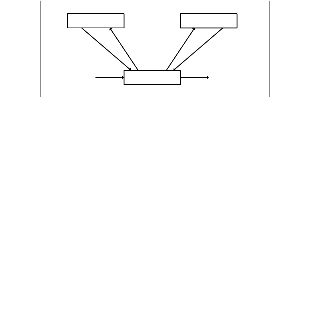
Figure 23-1 illustrates the life cycle of a VMM and its guest software as well as the interactions between them. The
following items summarize that life cycle:
•Software enters VMX operation by executing a VMXON instruction.
•Using VM entries, a VMM can then enter guests into virtual machines (one at a time). The VMM effects a
VM entry using instructions VMLAUNCH and VMRESUME; it regains control using VM exits.
•VM exits transfer control to an entry point specified by the VMM. The VMM can take action appropriate to the
cause of the VM exit and can then return to the virtual machine using a VM entry.
•Eventually, the VMM may decide to shut itself down and leave VMX operation. It does so by executing the
VMXOFF instruction.
23.5 VIRTUAL-MACHINE CONTROL STRUCTURE
VMX non-root operation and VMX transitions are controlled by a data structure called a virtual-machine control
structure (VMCS).
Access to the VMCS is managed through a component of processor state called the VMCS pointer (one per logical
processor). The value of the VMCS pointer is the 64-bit address of the VMCS. The VMCS pointer is read and written
using the instructions VMPTRST and VMPTRLD. The VMM configures a VMCS using the VMREAD, VMWRITE, and
VMCLEAR instructions.
A VMM could use a different VMCS for each virtual machine that it supports. For a virtual machine with multiple
logical processors (virtual processors), the VMM could use a different VMCS for each virtual processor.
23.6 DISCOVERING SUPPORT FOR VMX
Before system software enters into VMX operation, it must discover the presence of VMX support in the processor.
System software can determine whether a processor supports VMX operation using CPUID. If
CPUID.1:ECX.VMX[bit 5] = 1, then VMX operation is supported. See Chapter 3, “Instruction Set Reference, A-L” of
Intel® 64 and IA-32 Architectures Software Developer’s Manual, Volume 2A.
The VMX architecture is designed to be extensible so that future processors in VMX operation can support addi-
tional features not present in first-generation implementations of the VMX architecture. The availability of exten-
sible VMX features is reported to software using a set of VMX capability MSRs (see Appendix A, “VMX Capability
Reporting Facility”).
Figure 23-1. Interaction of a Virtual-Machine Monitor and Guests
VM Monitor
Guest 0 Guest 1
VM Exit VM Exit
VM Entry
VMXOFFVMXON

Vol. 3C 23-3
INTRODUCTION TO VIRTUAL MACHINE EXTENSIONS
23.7 ENABLING AND ENTERING VMX OPERATION
Before system software can enter VMX operation, it enables VMX by setting CR4.VMXE[bit 13] = 1. VMX operation
is then entered by executing the VMXON instruction. VMXON causes an invalid-opcode exception (#UD) if executed
with CR4.VMXE = 0. Once in VMX operation, it is not possible to clear CR4.VMXE (see Section 23.8). System soft-
ware leaves VMX operation by executing the VMXOFF instruction. CR4.VMXE can be cleared outside of VMX opera-
tion after executing of VMXOFF.
VMXON is also controlled by the IA32_FEATURE_CONTROL MSR (MSR address 3AH). This MSR is cleared to zero
when a logical processor is reset. The relevant bits of the MSR are:
•Bit 0 is the lock bit. If this bit is clear, VMXON causes a general-protection exception. If the lock bit is set,
WRMSR to this MSR causes a general-protection exception; the MSR cannot be modified until a power-up reset
condition. System BIOS can use this bit to provide a setup option for BIOS to disable support for VMX. To
enable VMX support in a platform, BIOS must set bit 1, bit 2, or both (see below), as well as the lock bit.
•Bit 1 enables VMXON in SMX operation. If this bit is clear, execution of VMXON in SMX operation causes a
general-protection exception. Attempts to set this bit on logical processors that do not support both VMX
operation (see Section 23.6) and SMX operation (see Chapter 6, “Safer Mode Extensions Reference,” in Intel®
64 and IA-32 Architectures Software Developer’s Manual, Volume 2D) cause general-protection exceptions.
•Bit 2 enables VMXON outside SMX operation. If this bit is clear, execution of VMXON outside SMX
operation causes a general-protection exception. Attempts to set this bit on logical processors that do not
support VMX operation (see Section 23.6) cause general-protection exceptions.
NOTE
A logical processor is in SMX operation if GETSEC[SEXIT] has not been executed since the last
execution of GETSEC[SENTER]. A logical processor is outside SMX operation if GETSEC[SENTER]
has not been executed or if GETSEC[SEXIT] was executed after the last execution of
GETSEC[SENTER]. See Chapter 6, “Safer Mode Extensions Reference,” in Intel® 64 and IA-32
Architectures Software Developer’s Manual, Volume 2D.
Before executing VMXON, software should allocate a naturally aligned 4-KByte region of memory that a logical
processor may use to support VMX operation.1 This region is called the VMXON region. The address of the VMXON
region (the VMXON pointer) is provided in an operand to VMXON. Section 24.11.5, “VMXON Region,” details how
software should initialize and access the VMXON region.
23.8 RESTRICTIONS ON VMX OPERATION
VMX operation places restrictions on processor operation. These are detailed below:
•In VMX operation, processors may fix certain bits in CR0 and CR4 to specific values and not support other
values. VMXON fails if any of these bits contains an unsupported value (see “VMXON—Enter VMX Operation” in
Chapter 30). Any attempt to set one of these bits to an unsupported value while in VMX operation (including
VMX root operation) using any of the CLTS, LMSW, or MOV CR instructions causes a general-protection
exception. VM entry or VM exit cannot set any of these bits to an unsupported value. Software should consult
the VMX capability MSRs IA32_VMX_CR0_FIXED0 and IA32_VMX_CR0_FIXED1 to determine how bits in CR0
are fixed (see Appendix A.7). For CR4, software should consult the VMX capability MSRs
IA32_VMX_CR4_FIXED0 and IA32_VMX_CR4_FIXED1 (see Appendix A.8).
NOTES
The first processors to support VMX operation require that the following bits be 1 in VMX operation:
CR0.PE, CR0.NE, CR0.PG, and CR4.VMXE. The restrictions on CR0.PE and CR0.PG imply that VMX
operation is supported only in paged protected mode (including IA-32e mode). Therefore, guest
software cannot be run in unpaged protected mode or in real-address mode. See Section 31.2,
1. Future processors may require that a different amount of memory be reserved. If so, this fact is reported to software using the
VMX capability-reporting mechanism.

23-4 Vol. 3C
INTRODUCTION TO VIRTUAL MACHINE EXTENSIONS
“Supporting Processor Operating Modes in Guest Environments,” for a discussion of how a VMM
might support guest software that expects to run in unpaged protected mode or in real-address
mode.
Later processors support a VM-execution control called “unrestricted guest” (see Section 24.6.2).
If this control is 1, CR0.PE and CR0.PG may be 0 in VMX non-root operation (even if the capability
MSR IA32_VMX_CR0_FIXED0 reports otherwise).1 Such processors allow guest software to run in
unpaged protected mode or in real-address mode.
•VMXON fails if a logical processor is in A20M mode (see “VMXON—Enter VMX Operation” in Chapter 30). Once
the processor is in VMX operation, A20M interrupts are blocked. Thus, it is impossible to be in A20M mode in
VMX operation.
•The INIT signal is blocked whenever a logical processor is in VMX root operation. It is not blocked in VMX non-
root operation. Instead, INITs cause VM exits (see Section 25.2, “Other Causes of VM Exits”).
•Intel® Processor Trace (Intel PT) can be used in VMX operation only if IA32_VMX_MISC[14] is read as 1 (see
Appendix A.6). On processors that support Intel PT but which do not allow it to be used in VMX operation,
execution of VMXON clears IA32_RTIT_CTL.TraceEn (see “VMXON—Enter VMX Operation” in Chapter 30); any
attempt to write IA32_RTIT_CTL while in VMX operation (including VMX root operation) causes a general-
protection exception.
1. “Unrestricted guest” is a secondary processor-based VM-execution control. If bit 31 of the primary processor-based VM-execution
controls is 0, VMX non-root operation functions as if the “unrestricted guest” VM-execution control were 0. See Section 24.6.2.

Vol. 3C 24-1
CHAPTER 24
VIRTUAL MACHINE CONTROL STRUCTURES
24.1 OVERVIEW
A logical processor uses virtual-machine control data structures (VMCSs) while it is in VMX operation. These
manage transitions into and out of VMX non-root operation (VM entries and VM exits) as well as processor behavior
in VMX non-root operation. This structure is manipulated by the new instructions VMCLEAR, VMPTRLD, VMREAD,
and VMWRITE.
A VMM can use a different VMCS for each virtual machine that it supports. For a virtual machine with multiple
logical processors (virtual processors), the VMM can use a different VMCS for each virtual processor.
A logical processor associates a region in memory with each VMCS. This region is called the VMCS region.1 Soft-
ware references a specific VMCS using the 64-bit physical address of the region (a VMCS pointer). VMCS pointers
must be aligned on a 4-KByte boundary (bits 11:0 must be zero). These pointers must not set bits beyond the
processor’s physical-address width.2,3
A logical processor may maintain a number of VMCSs that are active. The processor may optimize VMX operation
by maintaining the state of an active VMCS in memory, on the processor, or both. At any given time, at most one
of the active VMCSs is the current VMCS. (This document frequently uses the term “the VMCS” to refer to the
current VMCS.) The VMLAUNCH, VMREAD, VMRESUME, and VMWRITE instructions operate only on the current
VMCS.
The following items describe how a logical processor determines which VMCSs are active and which is current:
•The memory operand of the VMPTRLD instruction is the address of a VMCS. After execution of the instruction,
that VMCS is both active and current on the logical processor. Any other VMCS that had been active remains so,
but no other VMCS is current.
•The VMCS link pointer field in the current VMCS (see Section 24.4.2) is itself the address of a VMCS. If VM entry
is performed successfully with the 1-setting of the “VMCS shadowing” VM-execution control, the VMCS
referenced by the VMCS link pointer field becomes active on the logical processor. The identity of the current
VMCS does not change.
•The memory operand of the VMCLEAR instruction is also the address of a VMCS. After execution of the
instruction, that VMCS is neither active nor current on the logical processor. If the VMCS had been current on
the logical processor, the logical processor no longer has a current VMCS.
The VMPTRST instruction stores the address of the logical processor’s current VMCS into a specified memory loca-
tion (it stores the value FFFFFFFF_FFFFFFFFH if there is no current VMCS).
The launch state of a VMCS determines which VM-entry instruction should be used with that VMCS: the
VMLAUNCH instruction requires a VMCS whose launch state is “clear”; the VMRESUME instruction requires a VMCS
whose launch state is “launched”. A logical processor maintains a VMCS’s launch state in the corresponding VMCS
region. The following items describe how a logical processor manages the launch state of a VMCS:
•If the launch state of the current VMCS is “clear”, successful execution of the VMLAUNCH instruction changes
the launch state to “launched”.
•The memory operand of the VMCLEAR instruction is the address of a VMCS. After execution of the instruction,
the launch state of that VMCS is “clear”.
•There are no other ways to modify the launch state of a VMCS (it cannot be modified using VMWRITE) and there
is no direct way to discover it (it cannot be read using VMREAD).
1. The amount of memory required for a VMCS region is at most 4 KBytes. The exact size is implementation specific and can be deter-
mined by consulting the VMX capability MSR IA32_VMX_BASIC to determine the size of the VMCS region (see Appendix A.1).
2. Software can determine a processor’s physical-address width by executing CPUID with 80000008H in EAX. The physical-address
width is returned in bits 7:0 of EAX.
3. If IA32_VMX_BASIC[48] is read as 1, these pointers must not set any bits in the range 63:32; see Appendix A.1.
24-2 Vol. 3C
VIRTUAL MACHINE CONTROL STRUCTURES
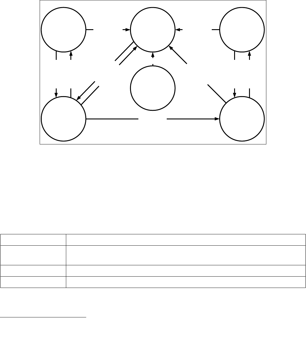
Figure 24-1 illustrates the different states of a VMCS. It uses “X” to refer to the VMCS and “Y” to refer to any other
VMCS. Thus: “VMPTRLD X” always makes X current and active; “VMPTRLD Y” always makes X not current (because
it makes Y current); VMLAUNCH makes the launch state of X “launched” if X was current and its launch state was
“clear”; and VMCLEAR X always makes X inactive and not current and makes its launch state “clear”.
The figure does not illustrate operations that do not modify the VMCS state relative to these parameters (e.g.,
execution of VMPTRLD X when X is already current). Note that VMCLEAR X makes X “inactive, not current, and
clear,” even if X’s current state is not defined (e.g., even if X has not yet been initialized). See Section 24.11.3.
Because a shadow VMCS (see Section 24.10) cannot be used for VM entry, the launch state of a shadow VMCS is
not meaningful. Figure 24-1 does not illustrate all the ways in which a shadow VMCS may be made active.
24.2 FORMAT OF THE VMCS REGION
A VMCS region comprises up to 4-KBytes.1 The format of a VMCS region is given in Table 24-1.
The first 4 bytes of the VMCS region contain the VMCS revision identifier at bits 30:0.2 Processors that maintain
VMCS data in different formats (see below) use different VMCS revision identifiers. These identifiers enable soft-
Figure 24-1. States of VMCS X
Table 24-1. Format of the VMCS Region
Byte Offset Contents
0 Bits 30:0: VMCS revision identifier
Bit 31: shadow-VMCS indicator (see Section 24.10)
4VMX-abort indicator
8 VMCS data (implementation-specific format)
1. The exact size is implementation specific and can be determined by consulting the VMX capability MSR IA32_VMX_BASIC to deter-
mine the size of the VMCS region (see Appendix A.1).
Active
Not Current
Clear
Active
Current
Clear
Inactive
Not Current
Clear
Active
Not Current
Launched
Active
Current
Launched
VMPTRLD X
VMCLEAR X
VMLAUNCH
VMCLEAR X
VMCLEAR XVMCLEAR X
VMCLEAR X
Anything
Else
VMPTRLD X
VMPTRLD Y
VMPTRLD X
VMPTRLD Y

Vol. 3C 24-3
VIRTUAL MACHINE CONTROL STRUCTURES
ware to avoid using a VMCS region formatted for one processor on a processor that uses a different format.1 Bit 31
of this 4-byte region indicates whether the VMCS is a shadow VMCS (see Section 24.10).
Software should write the VMCS revision identifier to the VMCS region before using that region for a VMCS. The
VMCS revision identifier is never written by the processor; VMPTRLD fails if its operand references a VMCS region
whose VMCS revision identifier differs from that used by the processor. (VMPTRLD also fails if the shadow-VMCS
indicator is 1 and the processor does not support the 1-setting of the “VMCS shadowing” VM-execution control; see
Section 24.6.2) Software can discover the VMCS revision identifier that a processor uses by reading the VMX capa-
bility MSR IA32_VMX_BASIC (see Appendix A.1).
Software should clear or set the shadow-VMCS indicator depending on whether the VMCS is to be an ordinary
VMCS or a shadow VMCS (see Section 24.10). VMPTRLD fails if the shadow-VMCS indicator is set and the processor
does not support the 1-setting of the “VMCS shadowing” VM-execution control. Software can discover support for
this setting by reading the VMX capability MSR IA32_VMX_PROCBASED_CTLS2 (see Appendix A.3.3).
The next 4 bytes of the VMCS region are used for the VMX-abort indicator. The contents of these bits do not
control processor operation in any way. A logical processor writes a non-zero value into these bits if a VMX abort
occurs (see Section 27.7). Software may also write into this field.
The remainder of the VMCS region is used for VMCS data (those parts of the VMCS that control VMX non-root
operation and the VMX transitions). The format of these data is implementation-specific. VMCS data are discussed
in Section 24.3 through Section 24.9. To ensure proper behavior in VMX operation, software should maintain the
VMCS region and related structures (enumerated in Section 24.11.4) in writeback cacheable memory. Future
implementations may allow or require a different memory type2. Software should consult the VMX capability MSR
IA32_VMX_BASIC (see Appendix A.1).
24.3 ORGANIZATION OF VMCS DATA
The VMCS data are organized into six logical groups:
•Guest-state area. Processor state is saved into the guest-state area on VM exits and loaded from there on
VM entries.
•Host-state area. Processor state is loaded from the host-state area on VM exits.
•VM-execution control fields. These fields control processor behavior in VMX non-root operation. They
determine in part the causes of VM exits.
•VM-exit control fields. These fields control VM exits.
•VM-entry control fields. These fields control VM entries.
•VM-exit information fields. These fields receive information on VM exits and describe the cause and the
nature of VM exits. On some processors, these fields are read-only.3
The VM-execution control fields, the VM-exit control fields, and the VM-entry control fields are sometimes referred
to collectively as VMX controls.
2. Earlier versions of this manual specified that the VMCS revision identifier was a 32-bit field. For all processors produced prior to this
change, bit 31 of the VMCS revision identifier was 0.
1. Logical processors that use the same VMCS revision identifier use the same size for VMCS regions.
2. Alternatively, software may map any of these regions or structures with the UC memory type. Doing so is strongly discouraged
unless necessary as it will cause the performance of transitions using those structures to suffer significantly. In addition, the pro-
cessor will continue to use the memory type reported in the VMX capability MSR IA32_VMX_BASIC with exceptions noted in Appen-
dix A.1.
3. Software can discover whether these fields can be written by reading the VMX capability MSR IA32_VMX_MISC (see Appendix A.6).

24-4 Vol. 3C
VIRTUAL MACHINE CONTROL STRUCTURES
24.4 GUEST-STATE AREA
This section describes fields contained in the guest-state area of the VMCS. VM entries load processor state from
these fields and VM exits store processor state into these fields. See Section 26.3.2 and Section 27.3 for details.
24.4.1 Guest Register State
The following fields in the guest-state area correspond to processor registers:
•Control registers CR0, CR3, and CR4 (64 bits each; 32 bits on processors that do not support Intel 64 archi-
tecture).
•Debug register DR7 (64 bits; 32 bits on processors that do not support Intel 64 architecture).
•RSP, RIP, and RFLAGS (64 bits each; 32 bits on processors that do not support Intel 64 architecture).1
•The following fields for each of the registers CS, SS, DS, ES, FS, GS, LDTR, and TR:
— Selector (16 bits).
— Base address (64 bits; 32 bits on processors that do not support Intel 64 architecture). The base-address
fields for CS, SS, DS, and ES have only 32 architecturally-defined bits; nevertheless, the corresponding
VMCS fields have 64 bits on processors that support Intel 64 architecture.
— Segment limit (32 bits). The limit field is always a measure in bytes.
— Access rights (32 bits). The format of this field is given in Table 24-2 and detailed as follows:
•The low 16 bits correspond to bits 23:8 of the upper 32 bits of a 64-bit segment descriptor. While bits
19:16 of code-segment and data-segment descriptors correspond to the upper 4 bits of the segment
limit, the corresponding bits (bits 11:8) are reserved in this VMCS field.
•Bit 16 indicates an unusable segment. Attempts to use such a segment fault except in 64-bit mode.
In general, a segment register is unusable if it has been loaded with a null selector.2
•Bits 31:17 are reserved.
1. This chapter uses the notation RAX, RIP, RSP, RFLAGS, etc. for processor registers because most processors that support VMX oper-
ation also support Intel 64 architecture. For processors that do not support Intel 64 architecture, this notation refers to the 32-bit
forms of those registers (EAX, EIP, ESP, EFLAGS, etc.). In a few places, notation such as EAX is used to refer specifically to lower 32
bits of the indicated register.
2. There are a few exceptions to this statement. For example, a segment with a non-null selector may be unusable following a task
switch that fails after its commit point; see “Interrupt 10—Invalid TSS Exception (#TS)” in Section 6.14, “Exception and Interrupt
Handling in 64-bit Mode,” of the Intel® 64 and IA-32 Architectures Software Developer’s Manual, Volume 3A. In contrast, the TR reg-
ister is usable after processor reset despite having a null selector; see Table 10-1 in the Intel® 64 and IA-32 Architectures Software
Developer’s Manual, Volume 3A.
Table 24-2. Format of Access Rights
Bit Position(s) Field
3:0 Segment type
4 S — Descriptor type (0 = system; 1 = code or data)
6:5 DPL — Descriptor privilege level
7 P — Segment present
11:8 Reserved
12 AVL — Available for use by system software

Vol. 3C 24-5
VIRTUAL MACHINE CONTROL STRUCTURES
The base address, segment limit, and access rights compose the “hidden” part (or “descriptor cache”) of each
segment register. These data are included in the VMCS because it is possible for a segment register’s descriptor
cache to be inconsistent with the segment descriptor in memory (in the GDT or the LDT) referenced by the
segment register’s selector.
The value of the DPL field for SS is always equal to the logical processor’s current privilege level (CPL).1
On some processors, executions of VMWRITE ignore attempts to write non-zero values to any of bits 11:8 or
bits 31:17. On such processors, VMREAD always returns 0 for those bits, and VM entry treats those bits as if
they were all 0 (see Section 26.3.1.2).
•The following fields for each of the registers GDTR and IDTR:
— Base address (64 bits; 32 bits on processors that do not support Intel 64 architecture).
— Limit (32 bits). The limit fields contain 32 bits even though these fields are specified as only 16 bits in the
architecture.
•The following MSRs:
— IA32_DEBUGCTL (64 bits)
— IA32_SYSENTER_CS (32 bits)
— IA32_SYSENTER_ESP and IA32_SYSENTER_EIP (64 bits; 32 bits on processors that do not support Intel 64
architecture)
— IA32_PERF_GLOBAL_CTRL (64 bits). This field is supported only on processors that support the 1-setting
of the “load IA32_PERF_GLOBAL_CTRL” VM-entry control.
— IA32_PAT (64 bits). This field is supported only on processors that support either the 1-setting of the “load
IA32_PAT” VM-entry control or that of the “save IA32_PAT” VM-exit control.
— IA32_EFER (64 bits). This field is supported only on processors that support either the 1-setting of the “load
IA32_EFER” VM-entry control or that of the “save IA32_EFER” VM-exit control.
— IA32_BNDCFGS (64 bits). This field is supported only on processors that support either the 1-setting of the
“load IA32_BNDCFGS” VM-entry control or that of the “clear IA32_BNDCFGS” VM-exit control.
•The register SMBASE (32 bits). This register contains the base address of the logical processor’s SMRAM image.
13 Reserved (except for CS)
L — 64-bit mode active (for CS only)
14 D/B — Default operation size (0 = 16-bit segment; 1 = 32-bit segment)
15 G — Granularity
16 Segment unusable (0 = usable; 1 = unusable)
31:17 Reserved
1. In protected mode, CPL is also associated with the RPL field in the CS selector. However, the RPL fields are not meaningful in real-
address mode or in virtual-8086 mode.
Table 24-2. Format of Access Rights (Contd.)
Bit Position(s) Field

24-6 Vol. 3C
VIRTUAL MACHINE CONTROL STRUCTURES
24.4.2 Guest Non-Register State
In addition to the register state described in Section 24.4.1, the guest-state area includes the following fields that
characterize guest state but which do not correspond to processor registers:
•Activity state (32 bits). This field identifies the logical processor’s activity state. When a logical processor is
executing instructions normally, it is in the active state. Execution of certain instructions and the occurrence
of certain events may cause a logical processor to transition to an inactive state in which it ceases to execute
instructions.
The following activity states are defined:1
—0: Active. The logical processor is executing instructions normally.
—1: HLT. The logical processor is inactive because it executed the HLT instruction.
—2: Shutdown. The logical processor is inactive because it incurred a triple fault2 or some other serious
error.
—3: Wait-for-SIPI. The logical processor is inactive because it is waiting for a startup-IPI (SIPI).
Future processors may include support for other activity states. Software should read the VMX capability MSR
IA32_VMX_MISC (see Appendix A.6) to determine what activity states are supported.
•Interruptibility state (32 bits). The IA-32 architecture includes features that permit certain events to be
blocked for a period of time. This field contains information about such blocking. Details and the format of this
field are given in Table 24-3.
1. Execution of the MWAIT instruction may put a logical processor into an inactive state. However, this VMCS field never reflects this
state. See Section 27.1.
2. A triple fault occurs when a logical processor encounters an exception while attempting to deliver a double fault.
Table 24-3. Format of Interruptibility State
Bit
Position(s)
Bit Name Notes
0 Blocking by STI See the “STI—Set Interrupt Flag” section in Chapter 4 of the Intel® 64 and IA-32 Architectures
Software Developer’s Manual, Volume 2B.
Execution of STI with RFLAGS.IF = 0 blocks maskable interrupts on the instruction boundary
following its execution.1 Setting this bit indicates that this blocking is in effect.
1Blocking by
MOV SS
See Section 6.8.3, “Masking Exceptions and Interrupts When Switching Stacks,” in the Intel® 64
and IA-32 Architectures Software Developer’s Manual, Volume 3A.
Execution of a MOV to SS or a POP to SS blocks or suppresses certain debug exceptions as well
as interrupts (maskable and nonmaskable) on the instruction boundary following its execution.
Setting this bit indicates that this blocking is in effect.2 This document uses the term “blocking
by MOV SS,” but it applies equally to POP SS.
2 Blocking by SMI See Section 34.2, “System Management Interrupt (SMI).” System-management interrupts
(SMIs) are disabled while the processor is in system-management mode (SMM). Setting this bit
indicates that blocking of SMIs is in effect.
3 Blocking by NMI See Section 6.7.1, “Handling Multiple NMIs,” in the Intel® 64 and IA-32 Architectures Software
Developer’s Manual, Volume 3A and Section 34.8, “NMI Handling While in SMM.”
Delivery of a non-maskable interrupt (NMI) or a system-management interrupt (SMI) blocks
subsequent NMIs until the next execution of IRET. See Section 25.3 for how this behavior of
IRET may change in VMX non-root operation. Setting this bit indicates that blocking of NMIs is
in effect. Clearing this bit does not imply that NMIs are not (temporarily) blocked for other
reasons.
If the “virtual NMIs” VM-execution control (see Section 24.6.1) is 1, this bit does not control the
blocking of NMIs. Instead, it refers to “virtual-NMI blocking” (the fact that guest software is not
ready for an NMI).

Vol. 3C 24-7
VIRTUAL MACHINE CONTROL STRUCTURES
•Pending debug exceptions (64 bits; 32 bits on processors that do not support Intel 64 architecture). IA-32
processors may recognize one or more debug exceptions without immediately delivering them.1 This field
contains information about such exceptions. This field is described in Table 24-4.
•VMCS link pointer (64 bits). If the “VMCS shadowing” VM-execution control is 1, the VMREAD and VMWRITE
instructions access the VMCS referenced by this pointer (see Section 24.10). Otherwise, software should set
this field to FFFFFFFF_FFFFFFFFH to avoid VM-entry failures (see Section 26.3.1.5).
4Enclave
interruption
A VM exit saves this bit as 1 to indicate that the VM exit was incident to enclave mode.
31:5 Reserved VM entry will fail if these bits are not 0. See Section 26.3.1.5.
NOTES:
1. Nonmaskable interrupts and system-management interrupts may also be inhibited on the instruction boundary following such an
execution of STI.
2. System-management interrupts may also be inhibited on the instruction boundary following such an execution of MOV or POP.
1. For example, execution of a MOV to SS or a POP to SS may inhibit some debug exceptions for one instruction. See Section 6.8.3 of
Intel® 64 and IA-32 Architectures Software Developer’s Manual, Volume 3A. In addition, certain events incident to an instruction
(for example, an INIT signal) may take priority over debug traps generated by that instruction. See Table 6-2 in the Intel® 64 and
IA-32 Architectures Software Developer’s Manual, Volume 3A.
Table 24-4. Format of Pending-Debug-Exceptions
Bit
Position(s)
Bit Name Notes
3:0 B3 – B0 When set, each of these bits indicates that the corresponding breakpoint condition was met.
Any of these bits may be set even if the corresponding enabling bit in DR7 is not set.
11:4 Reserved VM entry fails if these bits are not 0. See Section 26.3.1.5.
12 Enabled
breakpoint
When set, this bit indicates that at least one data or I/O breakpoint was met and was enabled in
DR7.
13 Reserved VM entry fails if this bit is not 0. See Section 26.3.1.5.
14 BS When set, this bit indicates that a debug exception would have been triggered by single-step
execution mode.
15 Reserved VM entry fails if this bit is not 0. See Section 26.3.1.5.
16 RTM When set, this bit indicates that a debug exception (#DB) or a breakpoint exception (#BP)
occurred inside an RTM region while advanced debugging of RTM transactional regions was
enabled (see Section 16.3.7, “RTM-Enabled Debugger Support,” of Intel® 64 and IA-32
Architectures Software Developer’s Manual, Volume 1).1
NOTES:
1. In general, the format of this field matches that of DR6. However, DR6 clears bit 16 to indicate an RTM-related exception, while this
field sets the bit to indicate that condition.
63:17 Reserved VM entry fails if these bits are not 0. See Section 26.3.1.5. Bits 63:32 exist only on processors
that support Intel 64 architecture.
Table 24-3. Format of Interruptibility State (Contd.)
Bit
Position(s)
Bit Name Notes

24-8 Vol. 3C
VIRTUAL MACHINE CONTROL STRUCTURES
•VMX-preemption timer value (32 bits). This field is supported only on processors that support the 1-setting
of the “activate VMX-preemption timer” VM-execution control. This field contains the value that the VMX-
preemption timer will use following the next VM entry with that setting. See Section 25.5.1 and Section 26.6.4.
•Page-directory-pointer-table entries (PDPTEs; 64 bits each). These four (4) fields (PDPTE0, PDPTE1,
PDPTE2, and PDPTE3) are supported only on processors that support the 1-setting of the “enable EPT” VM-
execution control. They correspond to the PDPTEs referenced by CR3 when PAE paging is in use (see Section
4.4 in the Intel® 64 and IA-32 Architectures Software Developer’s Manual, Volume 3A). They are used only if
the “enable EPT” VM-execution control is 1.
•Guest interrupt status (16 bits). This field is supported only on processors that support the 1-setting of the
“virtual-interrupt delivery” VM-execution control. It characterizes part of the guest’s virtual-APIC state and
does not correspond to any processor or APIC registers. It comprises two 8-bit subfields:
—Requesting virtual interrupt (RVI). This is the low byte of the guest interrupt status. The processor
treats this value as the vector of the highest priority virtual interrupt that is requesting service. (The value
0 implies that there is no such interrupt.)
—Servicing virtual interrupt (SVI). This is the high byte of the guest interrupt status. The processor treats
this value as the vector of the highest priority virtual interrupt that is in service. (The value 0 implies that
there is no such interrupt.)
See Chapter 29 for more information on the use of this field.
•PML index (16 bits). This field is supported only on processors that support the 1-setting of the “enable PML”
VM-execution control. It contains the logical index of the next entry in the page-modification log. Because the
page-modification log comprises 512 entries, the PML index is typically a value in the range 0–511. Details of
the page-modification log and use of the PML index are given in Section 28.2.5.
24.5 HOST-STATE AREA
This section describes fields contained in the host-state area of the VMCS. As noted earlier, processor state is
loaded from these fields on every VM exit (see Section 27.5).
All fields in the host-state area correspond to processor registers:
•CR0, CR3, and CR4 (64 bits each; 32 bits on processors that do not support Intel 64 architecture).
•RSP and RIP (64 bits each; 32 bits on processors that do not support Intel 64 architecture).
•Selector fields (16 bits each) for the segment registers CS, SS, DS, ES, FS, GS, and TR. There is no field in the
host-state area for the LDTR selector.
•Base-address fields for FS, GS, TR, GDTR, and IDTR (64 bits each; 32 bits on processors that do not support
Intel 64 architecture).
•The following MSRs:
— IA32_SYSENTER_CS (32 bits)
— IA32_SYSENTER_ESP and IA32_SYSENTER_EIP (64 bits; 32 bits on processors that do not support Intel 64
architecture).
— IA32_PERF_GLOBAL_CTRL (64 bits). This field is supported only on processors that support the 1-setting of
the “load IA32_PERF_GLOBAL_CTRL” VM-exit control.
— IA32_PAT (64 bits). This field is supported only on processors that support the 1-setting of the “load
IA32_PAT” VM-exit control.
— IA32_EFER (64 bits). This field is supported only on processors that support the 1-setting of the “load
IA32_EFER” VM-exit control.
In addition to the state identified here, some processor state components are loaded with fixed values on every
VM exit; there are no fields corresponding to these components in the host-state area. See Section 27.5 for details
of how state is loaded on VM exits.

Vol. 3C 24-9
VIRTUAL MACHINE CONTROL STRUCTURES
24.6 VM-EXECUTION CONTROL FIELDS
The VM-execution control fields govern VMX non-root operation. These are described in Section 24.6.1 through
Section 24.6.8.
24.6.1 Pin-Based VM-Execution Controls
The pin-based VM-execution controls constitute a 32-bit vector that governs the handling of asynchronous events
(for example: interrupts).1 Table 24-5 lists the controls. See Chapter 27 for how these controls affect processor
behavior in VMX non-root operation.
All other bits in this field are reserved, some to 0 and some to 1. Software should consult the VMX capability MSRs
IA32_VMX_PINBASED_CTLS and IA32_VMX_TRUE_PINBASED_CTLS (see Appendix A.3.1) to determine how to
set reserved bits. Failure to set reserved bits properly causes subsequent VM entries to fail (see Section 26.2.1.1).
The first processors to support the virtual-machine extensions supported only the 1-settings of bits 1, 2, and 4.
The VMX capability MSR IA32_VMX_PINBASED_CTLS will always report that these bits must be 1. Logical proces-
sors that support the 0-settings of any of these bits will support the VMX capability MSR
IA32_VMX_TRUE_PINBASED_CTLS MSR, and software should consult this MSR to discover support for the 0-
settings of these bits. Software that is not aware of the functionality of any one of these bits should set that bit to 1.
24.6.2 Processor-Based VM-Execution Controls
The processor-based VM-execution controls constitute two 32-bit vectors that govern the handling of synchronous
events, mainly those caused by the execution of specific instructions.2 These are the primary processor-based
VM-execution controls and the secondary processor-based VM-execution controls.
Table 24-6 lists the primary processor-based VM-execution controls. See Chapter 25 for more details of how these
controls affect processor behavior in VMX non-root operation.
1. Some asynchronous events cause VM exits regardless of the settings of the pin-based VM-execution controls (see Section 25.2).
Table 24-5. Definitions of Pin-Based VM-Execution Controls
Bit Position(s) Name Description
0 External-interrupt
exiting
If this control is 1, external interrupts cause VM exits. Otherwise, they are delivered normally
through the guest interrupt-descriptor table (IDT). If this control is 1, the value of RFLAGS.IF
does not affect interrupt blocking.
3 NMI exiting If this control is 1, non-maskable interrupts (NMIs) cause VM exits. Otherwise, they are
delivered normally using descriptor 2 of the IDT. This control also determines interactions
between IRET and blocking by NMI (see Section 25.3).
5 Virtual NMIs If this control is 1, NMIs are never blocked and the “blocking by NMI” bit (bit 3) in the
interruptibility-state field indicates “virtual-NMI blocking” (see Table 24-3). This control also
interacts with the “NMI-window exiting” VM-execution control (see Section 24.6.2).
6Activate VMX-
preemption timer
If this control is 1, the VMX-preemption timer counts down in VMX non-root operation; see
Section 25.5.1. A VM exit occurs when the timer counts down to zero; see Section 25.2.
7 Process posted
interrupts
If this control is 1, the processor treats interrupts with the posted-interrupt notification vector
(see Section 24.6.8) specially, updating the virtual-APIC page with posted-interrupt requests
(see Section 29.6).
2. Some instructions cause VM exits regardless of the settings of the processor-based VM-execution controls (see Section 25.1.2), as
do task switches (see Section 25.2).

24-10 Vol. 3C
VIRTUAL MACHINE CONTROL STRUCTURES
Table 24-6. Definitions of Primary Processor-Based VM-Execution Controls
Bit Position(s) Name Description
2Interrupt-window
exiting
If this control is 1, a VM exit occurs at the beginning of any instruction if RFLAGS.IF = 1 and
there are no other blocking of interrupts (see Section 24.4.2).
3 Use TSC offsetting This control determines whether executions of RDTSC, executions of RDTSCP, and executions
of RDMSR that read from the IA32_TIME_STAMP_COUNTER MSR return a value modified by
the TSC offset field (see Section 24.6.5 and Section 25.3).
7 HLT exiting This control determines whether executions of HLT cause VM exits.
9 INVLPG exiting This determines whether executions of INVLPG cause VM exits.
10 MWAIT exiting This control determines whether executions of MWAIT cause VM exits.
11 RDPMC exiting This control determines whether executions of RDPMC cause VM exits.
12 RDTSC exiting This control determines whether executions of RDTSC and RDTSCP cause VM exits.
15 CR3-load exiting In conjunction with the CR3-target controls (see Section 24.6.7), this control determines
whether executions of MOV to CR3 cause VM exits. See Section 25.1.3.
The first processors to support the virtual-machine extensions supported only the 1-setting
of this control.
16 CR3-store exiting This control determines whether executions of MOV from CR3 cause VM exits.
The first processors to support the virtual-machine extensions supported only the 1-setting
of this control.
19 CR8-load exiting This control determines whether executions of MOV to CR8 cause VM exits.
20 CR8-store exiting This control determines whether executions of MOV from CR8 cause VM exits.
21 Use TPR shadow Setting this control to 1 enables TPR virtualization and other APIC-virtualization features. See
Chapter 29.
22 NMI-window
exiting
If this control is 1, a VM exit occurs at the beginning of any instruction if there is no virtual-
NMI blocking (see Section 24.4.2).
23 MOV-DR exiting This control determines whether executions of MOV DR cause VM exits.
24 Unconditional I/O
exiting
This control determines whether executions of I/O instructions (IN, INS/INSB/INSW/INSD, OUT,
and OUTS/OUTSB/OUTSW/OUTSD) cause VM exits.
25 Use I/O bitmaps This control determines whether I/O bitmaps are used to restrict executions of I/O instructions
(see Section 24.6.4 and Section 25.1.3).
For this control, “0” means “do not use I/O bitmaps” and “1” means “use I/O bitmaps.” If the I/O
bitmaps are used, the setting of the “unconditional I/O exiting” control is ignored.
27 Monitor trap flag If this control is 1, the monitor trap flag debugging feature is enabled. See Section 25.5.2.
28 Use MSR bitmaps This control determines whether MSR bitmaps are used to control execution of the RDMSR
and WRMSR instructions (see Section 24.6.9 and Section 25.1.3).
For this control, “0” means “do not use MSR bitmaps” and “1” means “use MSR bitmaps.” If the
MSR bitmaps are not used, all executions of the RDMSR and WRMSR instructions cause
VM exits.
29 MONITOR exiting This control determines whether executions of MONITOR cause VM exits.
30 PAUSE exiting This control determines whether executions of PAUSE cause VM exits.
31 Activate secondary
controls
This control determines whether the secondary processor-based VM-execution controls are
used. If this control is 0, the logical processor operates as if all the secondary processor-based
VM-execution controls were also 0.

Vol. 3C 24-11
VIRTUAL MACHINE CONTROL STRUCTURES
All other bits in this field are reserved, some to 0 and some to 1. Software should consult the VMX capability MSRs
IA32_VMX_PROCBASED_CTLS and IA32_VMX_TRUE_PROCBASED_CTLS (see Appendix A.3.2) to determine how
to set reserved bits. Failure to set reserved bits properly causes subsequent VM entries to fail (see Section
26.2.1.1).
The first processors to support the virtual-machine extensions supported only the 1-settings of bits 1, 4–6, 8, 13–
16, and 26. The VMX capability MSR IA32_VMX_PROCBASED_CTLS will always report that these bits must be 1.
Logical processors that support the 0-settings of any of these bits will support the VMX capability MSR
IA32_VMX_TRUE_PROCBASED_CTLS MSR, and software should consult this MSR to discover support for the 0-
settings of these bits. Software that is not aware of the functionality of any one of these bits should set that bit to 1.
Bit 31 of the primary processor-based VM-execution controls determines whether the secondary processor-based
VM-execution controls are used. If that bit is 0, VM entry and VMX non-root operation function as if all the
secondary processor-based VM-execution controls were 0. Processors that support only the 0-setting of bit 31 of
the primary processor-based VM-execution controls do not support the secondary processor-based VM-execution
controls.
Table 24-7 lists the secondary processor-based VM-execution controls. See Chapter 25 for more details of how
these controls affect processor behavior in VMX non-root operation.
Table 24-7. Definitions of Secondary Processor-Based VM-Execution Controls
Bit Position(s) Name Description
0 Virtualize APIC
accesses
If this control is 1, the logical processor treats specially accesses to the page with the APIC-
access address. See Section 29.4.
1 Enable EPT If this control is 1, extended page tables (EPT) are enabled. See Section 28.2.
2 Descriptor-table
exiting
This control determines whether executions of LGDT, LIDT, LLDT, LTR, SGDT, SIDT, SLDT, and
STR cause VM exits.
3 Enable RDTSCP If this control is 0, any execution of RDTSCP causes an invalid-opcode exception (#UD).
4 Virtualize x2APIC
mode
If this control is 1, the logical processor treats specially RDMSR and WRMSR to APIC MSRs (in
the range 800H–8FFH). See Section 29.5.
5 Enable VPID If this control is 1, cached translations of linear addresses are associated with a virtual-
processor identifier (VPID). See Section 28.1.
6 WBINVD exiting This control determines whether executions of WBINVD cause VM exits.
7 Unrestricted guest This control determines whether guest software may run in unpaged protected mode or in real-
address mode.
8APIC-register
virtualization
If this control is 1, the logical processor virtualizes certain APIC accesses. See Section 29.4 and
Section 29.5.
9Virtual-interrupt
delivery
This controls enables the evaluation and delivery of pending virtual interrupts as well as the
emulation of writes to the APIC registers that control interrupt prioritization.
10 PAUSE-loop exiting This control determines whether a series of executions of PAUSE can cause a VM exit (see
Section 24.6.13 and Section 25.1.3).
11 RDRAND exiting This control determines whether executions of RDRAND cause VM exits.
12 Enable INVPCID If this control is 0, any execution of INVPCID causes a #UD.
13 Enable
VM functions
Setting this control to 1 enables use of the VMFUNC instruction in VMX non-root operation. See
Section 25.5.5.
14 VMCS shadowing If this control is 1, executions of VMREAD and VMWRITE in VMX non-root operation may access
a shadow VMCS (instead of causing VM exits). See Section 24.10 and Section 30.3.
15 Enable ENCLS
exiting
If this control is 1, executions of ENCLS consult the ENCLS-exiting bitmap to determine whether
the instruction causes a VM exit. See Section 24.6.16 and Section 25.1.3.
16 RDSEED exiting This control determines whether executions of RDSEED cause VM exits.
17 Enable PML If this control is 1, an access to a guest-physical address that sets an EPT dirty bit first adds an
entry to the page-modification log. See Section 28.2.5.

24-12 Vol. 3C
VIRTUAL MACHINE CONTROL STRUCTURES
All other bits in this field are reserved to 0. Software should consult the VMX capability MSR
IA32_VMX_PROCBASED_CTLS2 (see Appendix A.3.3) to determine which bits may be set to 1. Failure to clear
reserved bits causes subsequent VM entries to fail (see Section 26.2.1.1).
24.6.3 Exception Bitmap
The exception bitmap is a 32-bit field that contains one bit for each exception. When an exception occurs, its
vector is used to select a bit in this field. If the bit is 1, the exception causes a VM exit. If the bit is 0, the exception
is delivered normally through the IDT, using the descriptor corresponding to the exception’s vector.
Whether a page fault (exception with vector 14) causes a VM exit is determined by bit 14 in the exception bitmap
as well as the error code produced by the page fault and two 32-bit fields in the VMCS (the page-fault error-code
mask and page-fault error-code match). See Section 25.2 for details.
24.6.4 I/O-Bitmap Addresses
The VM-execution control fields include the 64-bit physical addresses of I/O bitmaps A and B (each of which are
4 KBytes in size). I/O bitmap A contains one bit for each I/O port in the range 0000H through 7FFFH; I/O bitmap B
contains bits for ports in the range 8000H through FFFFH.
A logical processor uses these bitmaps if and only if the “use I/O bitmaps” control is 1. If the bitmaps are used,
execution of an I/O instruction causes a VM exit if any bit in the I/O bitmaps corresponding to a port it accesses is
1. See Section 25.1.3 for details. If the bitmaps are used, their addresses must be 4-KByte aligned.
24.6.5 Time-Stamp Counter Offset and Multiplier
The VM-execution control fields include a 64-bit TSC-offset field. If the “RDTSC exiting” control is 0 and the “use
TSC offsetting” control is 1, this field controls executions of the RDTSC and RDTSCP instructions. It also controls
executions of the RDMSR instruction that read from the IA32_TIME_STAMP_COUNTER MSR. For all of these, the
value of the TSC offset is added to the value of the time-stamp counter, and the sum is returned to guest software
in EDX:EAX.
Processors that support the 1-setting of the “use TSC scaling” control also support a 64-bit TSC-multiplier field.
If this control is 1 (and the “RDTSC exiting” control is 0 and the “use TSC offsetting” control is 1), this field also
affects the executions of the RDTSC, RDTSCP, and RDMSR instructions identified above. Specifically, the contents
of the time-stamp counter is first multiplied by the TSC multiplier before adding the TSC offset.
See Chapter 27 for a detailed treatment of the behavior of RDTSC, RDTSCP, and RDMSR in VMX non-root operation.
18 EPT-violation #VE If this control is 1, EPT violations may cause virtualization exceptions (#VE) instead of VM exits.
See Section 25.5.6.
19 Conceal VMX from
PT
If this control is 1, Intel Processor Trace suppresses from PIPs an indication that the processor
was in VMX non-root operation and omits a VMCS packet from any PSB+ produced in VMX non-
root operation (see Chapter 35).
20 Enable
XSAVES/XRSTORS
If this control is 0, any execution of XSAVES or XRSTORS causes a #UD.
22 Mode-based
execute control for
EPT
If this control is 1, EPT execute permissions are based on whether the linear address being
accessed is supervisor mode or user mode. See Chapter 28.
25 Use TSC scaling This control determines whether executions of RDTSC, executions of RDTSCP, and executions
of RDMSR that read from the IA32_TIME_STAMP_COUNTER MSR return a value modified by the
TSC multiplier field (see Section 24.6.5 and Section 25.3).
28 Enable ENCLV
exiting
If this control is 1, executions of ENCLV consult the ENCLV-exiting bitmap to determine whether
the instruction causes a VM exit. See Section 24.6.17 and Section 25.1.3.
Table 24-7. Definitions of Secondary Processor-Based VM-Execution Controls (Contd.)
Bit Position(s) Name Description

Vol. 3C 24-13
VIRTUAL MACHINE CONTROL STRUCTURES
24.6.6 Guest/Host Masks and Read Shadows for CR0 and CR4
VM-execution control fields include guest/host masks and read shadows for the CR0 and CR4 registers. These
fields control executions of instructions that access those registers (including CLTS, LMSW, MOV CR, and SMSW).
They are 64 bits on processors that support Intel 64 architecture and 32 bits on processors that do not.
In general, bits set to 1 in a guest/host mask correspond to bits “owned” by the host:
•Guest attempts to set them (using CLTS, LMSW, or MOV to CR) to values differing from the corresponding bits
in the corresponding read shadow cause VM exits.
•Guest reads (using MOV from CR or SMSW) return values for these bits from the corresponding read shadow.
Bits cleared to 0 correspond to bits “owned” by the guest; guest attempts to modify them succeed and guest reads
return values for these bits from the control register itself.
See Chapter 27 for details regarding how these fields affect VMX non-root operation.
24.6.7 CR3-Target Controls
The VM-execution control fields include a set of 4 CR3-target values and a CR3-target count. The CR3-target
values each have 64 bits on processors that support Intel 64 architecture and 32 bits on processors that do not.
The CR3-target count has 32 bits on all processors.
An execution of MOV to CR3 in VMX non-root operation does not cause a VM exit if its source operand matches one
of these values. If the CR3-target count is n, only the first n CR3-target values are considered; if the CR3-target
count is 0, MOV to CR3 always causes a VM exit
There are no limitations on the values that can be written for the CR3-target values. VM entry fails (see Section
26.2) if the CR3-target count is greater than 4.
Future processors may support a different number of CR3-target values. Software should read the VMX capability
MSR IA32_VMX_MISC (see Appendix A.6) to determine the number of values supported.
24.6.8 Controls for APIC Virtualization
There are three mechanisms by which software accesses registers of the logical processor’s local APIC:
•If the local APIC is in xAPIC mode, it can perform memory-mapped accesses to addresses in the 4-KByte page
referenced by the physical address in the IA32_APIC_BASE MSR (see Section 10.4.4, “Local APIC Status and
Location” in the Intel® 64 and IA-32 Architectures Software Developer’s Manual, Volume 3A and Intel® 64
Architecture Processor Topology Enumeration).1
•If the local APIC is in x2APIC mode, it can accesses the local APIC’s registers using the RDMSR and WRMSR
instructions (see Intel® 64 Architecture Processor Topology Enumeration).
•In 64-bit mode, it can access the local APIC’s task-priority register (TPR) using the MOV CR8 instruction.
There are five processor-based VM-execution controls (see Section 24.6.2) that control such accesses. There are
“use TPR shadow”, “virtualize APIC accesses”, “virtualize x2APIC mode”, “virtual-interrupt delivery”, and “APIC-
register virtualization”. These controls interact with the following fields:
•APIC-access address (64 bits). This field contains the physical address of the 4-KByte APIC-access page.
If the “virtualize APIC accesses” VM-execution control is 1, access to this page may cause VM exits or be
virtualized by the processor. See Section 29.4.
The APIC-access address exists only on processors that support the 1-setting of the “virtualize APIC accesses”
VM-execution control.
•Virtual-APIC address (64 bits). This field contains the physical address of the 4-KByte virtual-APIC page.
The processor uses the virtual-APIC page to virtualize certain accesses to APIC registers and to manage virtual
interrupts; see Chapter 29.
1. If the local APIC does not support x2APIC mode, it is always in xAPIC mode.

24-14 Vol. 3C
VIRTUAL MACHINE CONTROL STRUCTURES
Depending on the setting of the controls indicated earlier, the virtual-APIC page may be accessed by the
following operations:
— The MOV CR8 instructions (see Section 29.3).
— Accesses to the APIC-access page if, in addition, the “virtualize APIC accesses” VM-execution control is 1
(see Section 29.4).
— The RDMSR and WRMSR instructions if, in addition, the value of ECX is in the range 800H–8FFH (indicating
an APIC MSR) and the “virtualize x2APIC mode” VM-execution control is 1 (see Section 29.5).
If the “use TPR shadow” VM-execution control is 1, VM entry ensures that the virtual-APIC address is 4-KByte
aligned. The virtual-APIC address exists only on processors that support the 1-setting of the “use TPR shadow”
VM-execution control.
•TPR threshold (32 bits). Bits 3:0 of this field determine the threshold below which bits 7:4 of VTPR (see
Section 29.1.1) cannot fall. If the “virtual-interrupt delivery” VM-execution control is 0, a VM exit occurs after
an operation (e.g., an execution of MOV to CR8) that reduces the value of those bits below the TPR threshold.
See Section 29.1.2.
The TPR threshold exists only on processors that support the 1-setting of the “use TPR shadow” VM-execution
control.
•EOI-exit bitmap (4 fields; 64 bits each). These fields are supported only on processors that support the 1-
setting of the “virtual-interrupt delivery” VM-execution control. They are used to determine which virtualized
writes to the APIC’s EOI register cause VM exits:
— EOI_EXIT0 contains bits for vectors from 0 (bit 0) to 63 (bit 63).
— EOI_EXIT1 contains bits for vectors from 64 (bit 0) to 127 (bit 63).
— EOI_EXIT2 contains bits for vectors from 128 (bit 0) to 191 (bit 63).
— EOI_EXIT3 contains bits for vectors from 192 (bit 0) to 255 (bit 63).
See Section 29.1.4 for more information on the use of this field.
•Posted-interrupt notification vector (16 bits). This field is supported only on processors that support the 1-
setting of the “process posted interrupts” VM-execution control. Its low 8 bits contain the interrupt vector that
is used to notify a logical processor that virtual interrupts have been posted. See Section 29.6 for more
information on the use of this field.
•Posted-interrupt descriptor address (64 bits). This field is supported only on processors that support the 1-
setting of the “process posted interrupts” VM-execution control. It is the physical address of a 64-byte aligned
posted interrupt descriptor. See Section 29.6 for more information on the use of this field.
24.6.9 MSR-Bitmap Address
On processors that support the 1-setting of the “use MSR bitmaps” VM-execution control, the VM-execution control
fields include the 64-bit physical address of four contiguous MSR bitmaps, which are each 1-KByte in size. This
field does not exist on processors that do not support the 1-setting of that control. The four bitmaps are:
•Read bitmap for low MSRs (located at the MSR-bitmap address). This contains one bit for each MSR address
in the range 00000000H to 00001FFFH. The bit determines whether an execution of RDMSR applied to that
MSR causes a VM exit.
•Read bitmap for high MSRs (located at the MSR-bitmap address plus 1024). This contains one bit for each
MSR address in the range C0000000H toC0001FFFH. The bit determines whether an execution of RDMSR
applied to that MSR causes a VM exit.
•Write bitmap for low MSRs (located at the MSR-bitmap address plus 2048). This contains one bit for each
MSR address in the range 00000000H to 00001FFFH. The bit determines whether an execution of WRMSR
applied to that MSR causes a VM exit.
•Write bitmap for high MSRs (located at the MSR-bitmap address plus 3072). This contains one bit for each
MSR address in the range C0000000H toC0001FFFH. The bit determines whether an execution of WRMSR
applied to that MSR causes a VM exit.

Vol. 3C 24-15
VIRTUAL MACHINE CONTROL STRUCTURES
A logical processor uses these bitmaps if and only if the “use MSR bitmaps” control is 1. If the bitmaps are used, an
execution of RDMSR or WRMSR causes a VM exit if the value of RCX is in neither of the ranges covered by the
bitmaps or if the appropriate bit in the MSR bitmaps (corresponding to the instruction and the RCX value) is 1. See
Section 25.1.3 for details. If the bitmaps are used, their address must be 4-KByte aligned.
24.6.10 Executive-VMCS Pointer
The executive-VMCS pointer is a 64-bit field used in the dual-monitor treatment of system-management interrupts
(SMIs) and system-management mode (SMM). SMM VM exits save this field as described in Section 34.15.2.
VM entries that return from SMM use this field as described in Section 34.15.4.
24.6.11 Extended-Page-Table Pointer (EPTP)
The extended-page-table pointer (EPTP) contains the address of the base of EPT PML4 table (see Section
28.2.2), as well as other EPT configuration information. The format of this field is shown in Table 24-8.
The EPTP exists only on processors that support the 1-setting of the “enable EPT” VM-execution control.
24.6.12 Virtual-Processor Identifier (VPID)
The virtual-processor identifier (VPID) is a 16-bit field. It exists only on processors that support the 1-setting
of the “enable VPID” VM-execution control. See Section 28.1 for details regarding the use of this field.
24.6.13 Controls for PAUSE-Loop Exiting
On processors that support the 1-setting of the “PAUSE-loop exiting” VM-execution control, the VM-execution
control fields include the following 32-bit fields:
Table 24-8. Format of Extended-Page-Table Pointer
Bit
Position(s)
Field
2:0 EPT paging-structure memory type (see Section 28.2.6):
0 = Uncacheable (UC)
6= Write-back (WB)
Other values are reserved.1
NOTES:
1. Software should read the VMX capability MSR IA32_VMX_EPT_VPID_CAP (see Appendix A.10) to determine what EPT paging-struc-
ture memory types are supported.
5:3 This value is 1 less than the EPT page-walk length (see Section 28.2.2)
6 Setting this control to 1 enables accessed and dirty flags for EPT (see Section 28.2.4)2
2. Not all processors support accessed and dirty flags for EPT. Software should read the VMX capability MSR
IA32_VMX_EPT_VPID_CAP (see Appendix A.10) to determine whether the processor supports this feature.
11:7 Reserved
N–1:12 Bits N–1:12 of the physical address of the 4-KByte aligned EPT PML4 table3
3. N is the physical-address width supported by the logical processor. Software can determine a processor’s physical-address width by
executing CPUID with 80000008H in EAX. The physical-address width is returned in bits 7:0 of EAX.
63:N Reserved

24-16 Vol. 3C
VIRTUAL MACHINE CONTROL STRUCTURES
•PLE_Gap. Software can configure this field as an upper bound on the amount of time between two successive
executions of PAUSE in a loop.
•PLE_Window. Software can configure this field as an upper bound on the amount of time a guest is allowed to
execute in a PAUSE loop.
These fields measure time based on a counter that runs at the same rate as the timestamp counter (TSC). See
Section 25.1.3 for more details regarding PAUSE-loop exiting.
24.6.14 VM-Function Controls
The VM-function controls constitute a 64-bit vector that governs use of the VMFUNC instruction in VMX non-root
operation. This field is supported only on processors that support the 1-settings of both the “activate secondary
controls” primary processor-based VM-execution control and the “enable VM functions” secondary processor-
based VM-execution control.
Table 24-9 lists the VM-function controls. See Section 25.5.5 for more details of how these controls affect
processor behavior in VMX non-root operation.
All other bits in this field are reserved to 0. Software should consult the VMX capability MSR IA32_VMX_VMFUNC
(see Appendix A.11) to determine which bits are reserved. Failure to clear reserved bits causes subsequent
VM entries to fail (see Section 26.2.1.1).
Processors that support the 1-setting of the “EPTP switching” VM-function control also support a 64-bit field called
the EPTP-list address. This field contains the physical address of the 4-KByte EPTP list. The EPTP list comprises
512 8-Byte entries (each an EPTP value) and is used by the EPTP-switching VM function (see Section 25.5.5.3).
24.6.15 VMCS Shadowing Bitmap Addresses
On processors that support the 1-setting of the “VMCS shadowing” VM-execution control, the VM-execution control
fields include the 64-bit physical addresses of the VMREAD bitmap and the VMWRITE bitmap. Each bitmap is 4
KBytes in size and thus contains 32 KBits. The addresses are the VMREAD-bitmap address and the VMWRITE-
bitmap address.
If the “VMCS shadowing” VM-execution control is 1, executions of VMREAD and VMWRITE may consult these
bitmaps (see Section 24.10 and Section 30.3).
24.6.16 ENCLS-Exiting Bitmap
The ENCLS-exiting bitmap is a 64-bit field. If the “enable ENCLS exiting” VM-execution control is 1, execution of
ENCLS causes a VM exit if the bit in this field corresponding to the value of EAX is 1. If the bit is 0, the instruction
executes normally. See Section 25.1.3 for more information.
24.6.17 ENCLV-Exiting Bitmap
The ENCLV-exiting bitmap is a 64-bit field. If the “enable ENCLV exiting” VM-execution control is 1, execution of
ENCLV causes a VM exit if the bit in this field corresponding to the value of EAX is 1. If the bit is 0, the instruction
executes normally. See Section 25.1.3 for more information.
Table 24-9. Definitions of VM-Function Controls
Bit Position(s) Name Description
0 EPTP switching The EPTP-switching VM function changes the EPT pointer to a value chosen from the EPTP list.
See Section 25.5.5.3.

Vol. 3C 24-17
VIRTUAL MACHINE CONTROL STRUCTURES
24.6.18 Control Field for Page-Modification Logging
The PML address is a 64-bit field. It is the 4-KByte aligned address of the page-modification log. The page-
modification log consists of 512 64-bit entries. It is used for the page-modification logging feature. Details of the
page-modification logging are given in Section 28.2.5.
If the “enable PML” VM-execution control is 1, VM entry ensures that the PML address is 4-KByte aligned. The PML
address exists only on processors that support the 1-setting of the “enable PML” VM-execution control.
24.6.19 Controls for Virtualization Exceptions
On processors that support the 1-setting of the “EPT-violation #VE” VM-execution control, the VM-execution
control fields include the following:
•Virtualization-exception information address (64 bits). This field contains the physical address of the
virtualization-exception information area. When a logical processor encounters a virtualization exception,
it saves virtualization-exception information at the virtualization-exception information address; see Section
25.5.6.2.
•EPTP index (16 bits). When an EPT violation causes a virtualization exception, the processor writes the value
of this field to the virtualization-exception information area. The EPTP-switching VM function updates this field
(see Section 25.5.5.3).
24.6.20 XSS-Exiting Bitmap
On processors that support the 1-setting of the “enable XSAVES/XRSTORS” VM-execution control, the VM-execu-
tion control fields include a 64-bit XSS-exiting bitmap. If the “enable XSAVES/XRSTORS” VM-execution control is
1, executions of XSAVES and XRSTORS may consult this bitmap (see Section 25.1.3 and Section 25.3).
24.7 VM-EXIT CONTROL FIELDS
The VM-exit control fields govern the behavior of VM exits. They are discussed in Section 24.7.1 and Section
24.7.2.
24.7.1 VM-Exit Controls
The VM-exit controls constitute a 32-bit vector that governs the basic operation of VM exits. Table 24-10 lists the
controls supported. See Chapter 27 for complete details of how these controls affect VM exits.
Table 24-10. Definitions of VM-Exit Controls
Bit Position(s) Name Description
2 Save debug controls This control determines whether DR7 and the IA32_DEBUGCTL MSR are saved on VM exit.
The first processors to support the virtual-machine extensions supported only the 1-
setting of this control.
9 Host address-space
size
On processors that support Intel 64 architecture, this control determines whether a logical
processor is in 64-bit mode after the next VM exit. Its value is loaded into CS.L,
IA32_EFER.LME, and IA32_EFER.LMA on every VM exit.1
This control must be 0 on processors that do not support Intel 64 architecture.
12 Load
IA32_PERF_GLOBAL_
CTRL
This control determines whether the IA32_PERF_GLOBAL_CTRL MSR is loaded on VM exit.

24-18 Vol. 3C
VIRTUAL MACHINE CONTROL STRUCTURES
All other bits in this field are reserved, some to 0 and some to 1. Software should consult the VMX capability MSRs
IA32_VMX_EXIT_CTLS and IA32_VMX_TRUE_EXIT_CTLS (see Appendix A.4) to determine how it should set the
reserved bits. Failure to set reserved bits properly causes subsequent VM entries to fail (see Section 26.2.1.2).
The first processors to support the virtual-machine extensions supported only the 1-settings of bits 0–8, 10, 11,
13, 14, 16, and 17. The VMX capability MSR IA32_VMX_EXIT_CTLS always reports that these bits must be 1.
Logical processors that support the 0-settings of any of these bits will support the VMX capability MSR
IA32_VMX_TRUE_EXIT_CTLS MSR, and software should consult this MSR to discover support for the 0-settings of
these bits. Software that is not aware of the functionality of any one of these bits should set that bit to 1.
24.7.2 VM-Exit Controls for MSRs
A VMM may specify lists of MSRs to be stored and loaded on VM exits. The following VM-exit control fields deter-
mine how MSRs are stored on VM exits:
•VM-exit MSR-store count (32 bits). This field specifies the number of MSRs to be stored on VM exit. It is
recommended that this count not exceed 512.1 Otherwise, unpredictable processor behavior (including a
machine check) may result during VM exit.
•VM-exit MSR-store address (64 bits). This field contains the physical address of the VM-exit MSR-store area.
The area is a table of entries, 16 bytes per entry, where the number of entries is given by the VM-exit MSR-store
count. The format of each entry is given in Table 24-11. If the VM-exit MSR-store count is not zero, the address
15 Acknowledge
interrupt on exit
This control affects VM exits due to external interrupts:
• If such a VM exit occurs and this control is 1, the logical processor acknowledges the
interrupt controller, acquiring the interrupt’s vector. The vector is stored in the VM-exit
interruption-information field, which is marked valid.
• If such a VM exit occurs and this control is 0, the interrupt is not acknowledged and the
VM-exit interruption-information field is marked invalid.
18 Save IA32_PAT This control determines whether the IA32_PAT MSR is saved on VM exit.
19 Load IA32_PAT This control determines whether the IA32_PAT MSR is loaded on VM exit.
20 Save IA32_EFER This control determines whether the IA32_EFER MSR is saved on VM exit.
21 Load IA32_EFER This control determines whether the IA32_EFER MSR is loaded on VM exit.
22 Save VMX-
preemption timer
value
This control determines whether the value of the VMX-preemption timer is saved on
VM exit.
23 Clear IA32_BNDCFGS This control determines whether the IA32_BNDCFGS MSR is cleared on VM exit.
24 Conceal VMX from PT If this control is 1, Intel Processor Trace does not produce a paging information packet (PIP)
on a VM exit or a VMCS packet on an SMM VM exit (see Chapter 35).
NOTES:
1. Since the Intel 64 architecture specifies that IA32_EFER.LMA is always set to the logical-AND of CR0.PG and IA32_EFER.LME, and
since CR0.PG is always 1 in VMX root operation, IA32_EFER.LMA is always identical to IA32_EFER.LME in VMX root operation.
1. Future implementations may allow more MSRs to be stored reliably. Software should consult the VMX capability MSR
IA32_VMX_MISC to determine the number supported (see Appendix A.6).
Table 24-10. Definitions of VM-Exit Controls (Contd.)
Bit Position(s) Name Description

Vol. 3C 24-19
VIRTUAL MACHINE CONTROL STRUCTURES
must be 16-byte aligned.
See Section 27.4 for how this area is used on VM exits.
The following VM-exit control fields determine how MSRs are loaded on VM exits:
•VM-exit MSR-load count (32 bits). This field contains the number of MSRs to be loaded on VM exit. It is
recommended that this count not exceed 512. Otherwise, unpredictable processor behavior (including a
machine check) may result during VM exit.1
•VM-exit MSR-load address (64 bits). This field contains the physical address of the VM-exit MSR-load area.
The area is a table of entries, 16 bytes per entry, where the number of entries is given by the VM-exit MSR-load
count (see Table 24-11). If the VM-exit MSR-load count is not zero, the address must be 16-byte aligned.
See Section 27.6 for how this area is used on VM exits.
24.8 VM-ENTRY CONTROL FIELDS
The VM-entry control fields govern the behavior of VM entries. They are discussed in Sections 24.8.1 through
24.8.3.
24.8.1 VM-Entry Controls
The VM-entry controls constitute a 32-bit vector that governs the basic operation of VM entries. Table 24-12 lists
the controls supported. See Chapter 24 for how these controls affect VM entries.
Table 24-11. Format of an MSR Entry
Bit Position(s) Contents
31:0 MSR index
63:32 Reserved
127:64 MSR data
1. Future implementations may allow more MSRs to be loaded reliably. Software should consult the VMX capability MSR
IA32_VMX_MISC to determine the number supported (see Appendix A.6).
Table 24-12. Definitions of VM-Entry Controls
Bit Position(s) Name Description
2 Load debug
controls
This control determines whether DR7 and the IA32_DEBUGCTL MSR are loaded on VM entry.
The first processors to support the virtual-machine extensions supported only the 1-setting of
this control.
9 IA-32e mode guest On processors that support Intel 64 architecture, this control determines whether the logical
processor is in IA-32e mode after VM entry. Its value is loaded into IA32_EFER.LMA as part of
VM entry.1
This control must be 0 on processors that do not support Intel 64 architecture.
10 Entry to SMM This control determines whether the logical processor is in system-management mode (SMM)
after VM entry. This control must be 0 for any VM entry from outside SMM.
11 Deactivate dual-
monitor treatment
If set to 1, the default treatment of SMIs and SMM is in effect after the VM entry (see Section
34.15.7). This control must be 0 for any VM entry from outside SMM.
13 Load
IA32_PERF_GLOBA
L_CTRL
This control determines whether the IA32_PERF_GLOBAL_CTRL MSR is loaded on VM entry.
14 Load IA32_PAT This control determines whether the IA32_PAT MSR is loaded on VM entry.

24-20 Vol. 3C
VIRTUAL MACHINE CONTROL STRUCTURES
All other bits in this field are reserved, some to 0 and some to 1. Software should consult the VMX capability MSRs
IA32_VMX_ENTRY_CTLS and IA32_VMX_TRUE_ENTRY_CTLS (see Appendix A.5) to determine how it should set
the reserved bits. Failure to set reserved bits properly causes subsequent VM entries to fail (see Section 26.2.1.3).
The first processors to support the virtual-machine extensions supported only the 1-settings of bits 0–8 and 12.
The VMX capability MSR IA32_VMX_ENTRY_CTLS always reports that these bits must be 1. Logical processors that
support the 0-settings of any of these bits will support the VMX capability MSR IA32_VMX_TRUE_ENTRY_CTLS
MSR, and software should consult this MSR to discover support for the 0-settings of these bits. Software that is not
aware of the functionality of any one of these bits should set that bit to 1.
24.8.2 VM-Entry Controls for MSRs
A VMM may specify a list of MSRs to be loaded on VM entries. The following VM-entry control fields manage this
functionality:
•VM-entry MSR-load count (32 bits). This field contains the number of MSRs to be loaded on VM entry. It is
recommended that this count not exceed 512. Otherwise, unpredictable processor behavior (including a
machine check) may result during VM entry.1
•VM-entry MSR-load address (64 bits). This field contains the physical address of the VM-entry MSR-load
area. The area is a table of entries, 16 bytes per entry, where the number of entries is given by the VM-entry
MSR-load count. The format of entries is described in Table 24-11. If the VM-entry MSR-load count is not zero,
the address must be 16-byte aligned.
See Section 26.4 for details of how this area is used on VM entries.
24.8.3 VM-Entry Controls for Event Injection
VM entry can be configured to conclude by delivering an event through the IDT (after all guest state and MSRs have
been loaded). This process is called event injection and is controlled by the following three VM-entry control
fields:
•VM-entry interruption-information field (32 bits). This field provides details about the event to be injected.
Table 24-13 describes the field.
15 Load IA32_EFER This control determines whether the IA32_EFER MSR is loaded on VM entry.
16 Load
IA32_BNDCFGS
This control determines whether the IA32_BNDCFGS MSR is loaded on VM entry.
17 Conceal VMX from
PT
If this control is 1, Intel Processor Trace does not produce a paging information packet (PIP) on
a VM entry or a VMCS packet on a VM entry that returns from SMM (see Chapter 35).
NOTES:
1. Bit 5 of the IA32_VMX_MISC MSR is read as 1 on any logical processor that supports the 1-setting of the “unrestricted guest” VM-
execution control. If it is read as 1, every VM exit stores the value of IA32_EFER.LMA into the “IA-32e mode guest” VM-entry control
(see Section 27.2).
1. Future implementations may allow more MSRs to be loaded reliably. Software should consult the VMX capability MSR
IA32_VMX_MISC to determine the number supported (see Appendix A.6).
Table 24-12. Definitions of VM-Entry Controls (Contd.)
Bit Position(s) Name Description

Vol. 3C 24-21
VIRTUAL MACHINE CONTROL STRUCTURES
—The vector (bits 7:0) determines which entry in the IDT is used or which other event is injected.
—The interruption type (bits 10:8) determines details of how the injection is performed. In general, a VMM
should use the type hardware exception for all exceptions other than the following:
•breakpoint exceptions (#BP; a VMM should use the type software exception);
•overflow exceptions (#OF a VMM should use the use type software exception); and
•those debug exceptions (#DB) that are generated by INT1 (a VMM should use the use type privileged
software exception).1
The type other event is used for injection of events that are not delivered through the IDT.2
—For exceptions, the deliver-error-code bit (bit 11) determines whether delivery pushes an error code on
the guest stack.
— VM entry injects an event if and only if the valid bit (bit 31) is 1. The valid bit in this field is cleared on
every VM exit (see Section 27.2).
•VM-entry exception error code (32 bits). This field is used if and only if the valid bit (bit 31) and the deliver-
error-code bit (bit 11) are both set in the VM-entry interruption-information field.
•VM-entry instruction length (32 bits). For injection of events whose type is software interrupt, software
exception, or privileged software exception, this field is used to determine the value of RIP that is pushed on
the stack.
See Section 26.5 for details regarding the mechanics of event injection, including the use of the interruption type
and the VM-entry instruction length.
VM exits clear the valid bit (bit 31) in the VM-entry interruption-information field.
24.9 VM-EXIT INFORMATION FIELDS
The VMCS contains a section of fields that contain information about the most recent VM exit.
On some processors, attempts to write to these fields with VMWRITE fail (see “VMWRITE—Write Field to Virtual-
Machine Control Structure” in Chapter 30).3
Table 24-13. Format of the VM-Entry Interruption-Information Field
Bit Position(s) Content
7:0 Vector of interrupt or exception
10:8 Interruption type:
0: External interrupt
1: Reserved
2: Non-maskable interrupt (NMI)
3: Hardware exception (e.g,. #PF)
4: Software interrupt (INT n)
5: Privileged software exception (INT1)
6: Software exception (INT3 or INTO)
7: Other event
11 Deliver error code (0 = do not deliver; 1 = deliver)
30:12 Reserved
31 Valid
1. The type hardware exception should be used for all other debug exceptions.
2. INT1 and INT3 refer to the instructions with opcodes F1 and CC, respectively, and not to INT n with values 1 or 3 for n.
3. Software can discover whether these fields can be written by reading the VMX capability MSR IA32_VMX_MISC (see Appendix A.6).

24-22 Vol. 3C
VIRTUAL MACHINE CONTROL STRUCTURES
24.9.1 Basic VM-Exit Information
The following VM-exit information fields provide basic information about a VM exit:
•Exit reason (32 bits). This field encodes the reason for the VM exit and has the structure given in Table 24-14.
— Bits 15:0 provide basic information about the cause of the VM exit (if bit 31 is clear) or of the VM-entry
failure (if bit 31 is set). Appendix C enumerates the basic exit reasons.
— Bit 16 is always cleared to 0.
— Bit 28 is set only by an SMM VM exit (see Section 34.15.2) that took priority over an MTF VM exit (see
Section 25.5.2) that would have occurred had the SMM VM exit not occurred. See Section 34.15.2.3.
— Bit 29 is set if and only if the processor was in VMX root operation at the time the VM exit occurred. This can
happen only for SMM VM exits. See Section 34.15.2.
— Because some VM-entry failures load processor state from the host-state area (see Section 26.7), software
must be able to distinguish such cases from true VM exits. Bit 31 is used for that purpose.
•Exit qualification (64 bits; 32 bits on processors that do not support Intel 64 architecture). This field contains
additional information about the cause of VM exits due to the following: debug exceptions; page-fault
exceptions; start-up IPIs (SIPIs); task switches; INVEPT; INVLPG;INVVPID; LGDT; LIDT; LLDT; LTR; SGDT;
SIDT; SLDT; STR; VMCLEAR; VMPTRLD; VMPTRST; VMREAD; VMWRITE; VMXON; XRSTORS; XSAVES; control-
register accesses; MOV DR; I/O instructions; and MWAIT. The format of the field depends on the cause of the
VM exit. See Section 27.2.1 for details.
•Guest-linear address (64 bits; 32 bits on processors that do not support Intel 64 architecture). This field is
used in the following cases:
— VM exits due to attempts to execute LMSW with a memory operand.
— VM exits due to attempts to execute INS or OUTS.
— VM exits due to system-management interrupts (SMIs) that arrive immediately after retirement of I/O
instructions.
— Certain VM exits due to EPT violations
See Section 27.2.1 and Section 34.15.2.3 for details of when and how this field is used.
•Guest-physical address (64 bits). This field is used VM exits due to EPT violations and EPT misconfigurations.
See Section 27.2.1 for details of when and how this field is used.
24.9.2 Information for VM Exits Due to Vectored Events
Event-specific information is provided for VM exits due to the following vectored events: exceptions (including
those generated by the instructions INT3, INTO, INT1, BOUND, UD0, UD1, and UD2); external interrupts that occur
Table 24-14. Format of Exit Reason
Bit Position(s) Contents
15:0 Basic exit reason
16 Always cleared to 0
26:17 Reserved (cleared to 0)
27 A VM exit saves this bit as 1 to indicate that the VM exit was incident to enclave mode.
28 Pending MTF VM exit
29 VM exit from VMX root operation
30 Reserved (cleared to 0)
31 VM-entry failure (0 = true VM exit; 1 = VM-entry failure)

Vol. 3C 24-23
VIRTUAL MACHINE CONTROL STRUCTURES
while the “acknowledge interrupt on exit” VM-exit control is 1; and non-maskable interrupts (NMIs). This informa-
tion is provided in the following fields:
•VM-exit interruption information (32 bits). This field receives basic information associated with the event
causing the VM exit. Table 24-15 describes this field.
•VM-exit interruption error code (32 bits). For VM exits caused by hardware exceptions that would have
delivered an error code on the stack, this field receives that error code.
Section 27.2.2 provides details of how these fields are saved on VM exits.
24.9.3 Information for VM Exits That Occur During Event Delivery
Additional information is provided for VM exits that occur during event delivery in VMX non-root operation.1 This
information is provided in the following fields:
•IDT-vectoring information (32 bits). This field receives basic information associated with the event that was
being delivered when the VM exit occurred. Table 24-16 describes this field.
Table 24-15. Format of the VM-Exit Interruption-Information Field
Bit Position(s) Content
7:0 Vector of interrupt or exception
10:8 Interruption type:
0: External interrupt
1: Not used
2: Non-maskable interrupt (NMI)
3: Hardware exception
4: Not used
5: Privileged software exception
6: Software exception
7: Not used
11 Error code valid (0 = invalid; 1 = valid)
12 NMI unblocking due to IRET
30:13 Reserved (cleared to 0)
31 Valid
1. This includes cases in which the event delivery was caused by event injection as part of VM entry; see Section 26.5.1.2.
Table 24-16. Format of the IDT-Vectoring Information Field
Bit Position(s) Content
7:0 Vector of interrupt or exception
10:8 Interruption type:
0: External interrupt
1: Not used
2: Non-maskable interrupt (NMI)
3: Hardware exception
4: Software interrupt
5: Privileged software exception
6: Software exception
7: Not used
11 Error code valid (0 = invalid; 1 = valid)
12 Undefined
30:13 Reserved (cleared to 0)

24-24 Vol. 3C
VIRTUAL MACHINE CONTROL STRUCTURES
•IDT-vectoring error code (32 bits). For VM exits the occur during delivery of hardware exceptions that would
have delivered an error code on the stack, this field receives that error code.
See Section 27.2.3 provides details of how these fields are saved on VM exits.
24.9.4 Information for VM Exits Due to Instruction Execution
The following fields are used for VM exits caused by attempts to execute certain instructions in VMX non-root oper-
ation:
•VM-exit instruction length (32 bits). For VM exits resulting from instruction execution, this field receives the
length in bytes of the instruction whose execution led to the VM exit.1 See Section 27.2.4 for details of when
and how this field is used.
•VM-exit instruction information (32 bits). This field is used for VM exits due to attempts to execute INS,
INVEPT, INVVPID, LIDT, LGDT, LLDT, LTR, OUTS, SIDT, SGDT, SLDT, STR, VMCLEAR, VMPTRLD, VMPTRST,
VMREAD, VMWRITE, or VMXON.2 The format of the field depends on the cause of the VM exit. See Section
27.2.4 for details.
The following fields (64 bits each; 32 bits on processors that do not support Intel 64 architecture) are used only for
VM exits due to SMIs that arrive immediately after retirement of I/O instructions. They provide information about
that I/O instruction:
•I/O RCX. The value of RCX before the I/O instruction started.
•I/O RSI. The value of RSI before the I/O instruction started.
•I/O RDI. The value of RDI before the I/O instruction started.
•I/O RIP. The value of RIP before the I/O instruction started (the RIP that addressed the I/O instruction).
24.9.5 VM-Instruction Error Field
The 32-bit VM-instruction error field does not provide information about the most recent VM exit. In fact, it is
not modified on VM exits. Instead, it provides information about errors encountered by a non-faulting execution of
one of the VMX instructions.
24.10 VMCS TYPES: ORDINARY AND SHADOW
Every VMCS is either an ordinary VMCS or a shadow VMCS. A VMCS’s type is determined by the shadow-VMCS
indicator in the VMCS region (this is the value of bit 31 of the first 4 bytes of the VMCS region; see Table 24-1): 0
indicates an ordinary VMCS, while 1 indicates a shadow VMCS. Shadow VMCSs are supported only on processors
that support the 1-setting of the “VMCS shadowing” VM-execution control (see Section 24.6.2).
A shadow VMCS differs from an ordinary VMCS in two ways:
•An ordinary VMCS can be used for VM entry but a shadow VMCS cannot. Attempts to perform VM entry when
the current VMCS is a shadow VMCS fail (see Section 26.1).
•The VMREAD and VMWRITE instructions can be used in VMX non-root operation to access a shadow VMCS but
not an ordinary VMCS. This fact results from the following:
31 Valid
1. This field is also used for VM exits that occur during the delivery of a software interrupt or software exception.
2. Whether the processor provides this information on VM exits due to attempts to execute INS or OUTS can be determined by consult-
ing the VMX capability MSR IA32_VMX_BASIC (see Appendix A.1).
Table 24-16. Format of the IDT-Vectoring Information Field (Contd.)
Bit Position(s) Content

Vol. 3C 24-25
VIRTUAL MACHINE CONTROL STRUCTURES
— If the “VMCS shadowing” VM-execution control is 0, execution of the VMREAD and VMWRITE instructions in
VMX non-root operation always cause VM exits (see Section 25.1.3).
— If the “VMCS shadowing” VM-execution control is 1, execution of the VMREAD and VMWRITE instructions in
VMX non-root operation can access the VMCS referenced by the VMCS link pointer (see Section 30.3).
— If the “VMCS shadowing” VM-execution control is 1, VM entry ensures that any VMCS referenced by the
VMCS link pointer is a shadow VMCS (see Section 26.3.1.5).
In VMX root operation, both types of VMCSs can be accessed with the VMREAD and VMWRITE instructions.
Software should not modify the shadow-VMCS indicator in the VMCS region of a VMCS that is active. Doing so may
cause the VMCS to become corrupted (see Section 24.11.1). Before modifying the shadow-VMCS indicator, soft-
ware should execute VMCLEAR for the VMCS to ensure that it is not active.
24.11 SOFTWARE USE OF THE VMCS AND RELATED STRUCTURES
This section details guidelines that software should observe when using a VMCS and related structures. It also
provides descriptions of consequences for failing to follow guidelines.
24.11.1 Software Use of Virtual-Machine Control Structures
To ensure proper processor behavior, software should observe certain guidelines when using an active VMCS.
No VMCS should ever be active on more than one logical processor. If a VMCS is to be “migrated” from one logical
processor to another, the first logical processor should execute VMCLEAR for the VMCS (to make it inactive on that
logical processor and to ensure that all VMCS data are in memory) before the other logical processor executes
VMPTRLD for the VMCS (to make it active on the second logical processor).1 A VMCS that is made active on more
than one logical processor may become corrupted (see below).
Software should not modify the shadow-VMCS indicator (see Table 24-1) in the VMCS region of a VMCS that is
active. Doing so may cause the VMCS to become corrupted. Before modifying the shadow-VMCS indicator, software
should execute VMCLEAR for the VMCS to ensure that it is not active.
Software should use the VMREAD and VMWRITE instructions to access the different fields in the current VMCS (see
Section 24.11.2). Software should never access or modify the VMCS data of an active VMCS using ordinary
memory operations, in part because the format used to store the VMCS data is implementation-specific and not
architecturally defined, and also because a logical processor may maintain some VMCS data of an active VMCS on
the processor and not in the VMCS region. The following items detail some of the hazards of accessing VMCS data
using ordinary memory operations:
•Any data read from a VMCS with an ordinary memory read does not reliably reflect the state of the VMCS.
Results may vary from time to time or from logical processor to logical processor.
•Writing to a VMCS with an ordinary memory write is not guaranteed to have a deterministic effect on the VMCS.
Doing so may cause the VMCS to become corrupted (see below).
(Software can avoid these hazards by removing any linear-address mappings to a VMCS region before executing a
VMPTRLD for that region and by not remapping it until after executing VMCLEAR for that region.)
If a logical processor leaves VMX operation, any VMCSs active on that logical processor may be corrupted (see
below). To prevent such corruption of a VMCS that may be used either after a return to VMX operation or on
another logical processor, software should execute VMCLEAR for that VMCS before executing the VMXOFF instruc-
tion or removing power from the processor (e.g., as part of a transition to the S3 and S4 power states).
This section has identified operations that may cause a VMCS to become corrupted. These operations may cause
the VMCS’s data to become undefined. Behavior may be unpredictable if that VMCS used subsequently on any
logical processor. The following items detail some hazards of VMCS corruption:
1. As noted in Section 24.1, execution of the VMPTRLD instruction makes a VMCS is active. In addition, VM entry makes active any
shadow VMCS referenced by the VMCS link pointer in the current VMCS. If a shadow VMCS is made active by VM entry, it is neces-
sary to execute VMCLEAR for that VMCS before allowing that VMCS to become active on another logical processor.

24-26 Vol. 3C
VIRTUAL MACHINE CONTROL STRUCTURES
•VM entries may fail for unexplained reasons or may load undesired processor state.
•The processor may not correctly support VMX non-root operation as documented in Chapter 27 and may
generate unexpected VM exits.
•VM exits may load undesired processor state, save incorrect state into the VMCS, or cause the logical processor
to transition to a shutdown state.
24.11.2 VMREAD, VMWRITE, and Encodings of VMCS Fields
Every field of the VMCS is associated with a 32-bit value that is its encoding. The encoding is provided in an
operand to VMREAD and VMWRITE when software wishes to read or write that field. These instructions fail if given,
in 64-bit mode, an operand that sets an encoding bit beyond bit 32. See Chapter 30 for a description of these
instructions.
The structure of the 32-bit encodings of the VMCS components is determined principally by the width of the fields
and their function in the VMCS. See Table 24-17.
The following items detail the meaning of the bits in each encoding:
•Field width. Bits 14:13 encode the width of the field.
— A value of 0 indicates a 16-bit field.
— A value of 1 indicates a 64-bit field.
— A value of 2 indicates a 32-bit field.
— A value of 3 indicates a natural-width field. Such fields have 64 bits on processors that support Intel 64
architecture and 32 bits on processors that do not.
Fields whose encodings use value 1 are specially treated to allow 32-bit software access to all 64 bits of the
field. Such access is allowed by defining, for each such field, an encoding that allows direct access to the high
32 bits of the field. See below.
•Field type. Bits 11:10 encode the type of VMCS field: control, guest-state, host-state, or VM-exit information.
(The last category also includes the VM-instruction error field.)
•Index. Bits 9:1 distinguish components with the same field width and type.
•Access type. Bit 0 must be 0 for all fields except for 64-bit fields (those with field-width 1; see above). A
VMREAD or VMWRITE using an encoding with this bit cleared to 0 accesses the entire field. For a 64-bit field
Table 24-17. Structure of VMCS Component Encoding
Bit Position(s) Contents
0 Access type (0 = full; 1 = high); must be full for 16-bit, 32-bit, and natural-width fields
9:1 Index
11:10 Type:
0: control
1: VM-exit information
2: guest state
3: host state
12 Reserved (must be 0)
14:13 Width:
0: 16-bit
1: 64-bit
2: 32-bit
3: natural-width
31:15 Reserved (must be 0)

Vol. 3C 24-27
VIRTUAL MACHINE CONTROL STRUCTURES
with field-width 1, a VMREAD or VMWRITE using an encoding with this bit set to 1 accesses only the high 32 bits
of the field.
Appendix B gives the encodings of all fields in the VMCS.
The following describes the operation of VMREAD and VMWRITE based on processor mode, VMCS-field width, and
access type:
•16-bit fields:
— A VMREAD returns the value of the field in bits 15:0 of the destination operand; other bits of the destination
operand are cleared to 0.
— A VMWRITE writes the value of bits 15:0 of the source operand into the VMCS field; other bits of the source
operand are not used.
•32-bit fields:
— A VMREAD returns the value of the field in bits 31:0 of the destination operand; in 64-bit mode, bits 63:32
of the destination operand are cleared to 0.
— A VMWRITE writes the value of bits 31:0 of the source operand into the VMCS field; in 64-bit mode,
bits 63:32 of the source operand are not used.
•64-bit fields and natural-width fields using the full access type outside IA-32e mode.
— A VMREAD returns the value of bits 31:0 of the field in its destination operand; bits 63:32 of the field are
ignored.
— A VMWRITE writes the value of its source operand to bits 31:0 of the field and clears bits 63:32 of the field.
•64-bit fields and natural-width fields using the full access type in 64-bit mode (only on processors that support
Intel 64 architecture).
— A VMREAD returns the value of the field in bits 63:0 of the destination operand
— A VMWRITE writes the value of bits 63:0 of the source operand into the VMCS field.
•64-bit fields using the high access type.
— A VMREAD returns the value of bits 63:32 of the field in bits 31:0 of the destination operand; in 64-bit
mode, bits 63:32 of the destination operand are cleared to 0.
— A VMWRITE writes the value of bits 31:0 of the source operand to bits 63:32 of the field; in 64-bit mode,
bits 63:32 of the source operand are not used.
Software seeking to read a 64-bit field outside IA-32e mode can use VMREAD with the full access type (reading
bits 31:0 of the field) and VMREAD with the high access type (reading bits 63:32 of the field); the order of the two
VMREAD executions is not important. Software seeking to modify a 64-bit field outside IA-32e mode should first
use VMWRITE with the full access type (establishing bits 31:0 of the field while clearing bits 63:32) and then use
VMWRITE with the high access type (establishing bits 63:32 of the field).
24.11.3 Initializing a VMCS
Software should initialize fields in a VMCS (using VMWRITE) before using the VMCS for VM entry. Failure to do so
may result in unpredictable behavior; for example, a VM entry may fail for unexplained reasons, or a successful
transition (VM entry or VM exit) may load processor state with unexpected values.
It is not necessary to initialize fields that the logical processor will not use. (For example, it is not necessary to
unitize the MSR-bitmap address if the “use MSR bitmaps” VM-execution control is 0.)
A processor maintains some VMCS information that cannot be modified with the VMWRITE instruction; this
includes a VMCS’s launch state (see Section 24.1). Such information may be stored in the VMCS data portion of a
VMCS region. Because the format of this information is implementation-specific, there is no way for software to
know, when it first allocates a region of memory for use as a VMCS region, how the processor will determine this
information from the contents of the memory region.
In addition to its other functions, the VMCLEAR instruction initializes any implementation-specific information in
the VMCS region referenced by its operand. To avoid the uncertainties of implementation-specific behavior, soft-

24-28 Vol. 3C
VIRTUAL MACHINE CONTROL STRUCTURES
ware should execute VMCLEAR on a VMCS region before making the corresponding VMCS active with VMPTRLD for
the first time. (Figure 24-1 illustrates how execution of VMCLEAR puts a VMCS into a well-defined state.)
The following software usage is consistent with these limitations:
•VMCLEAR should be executed for a VMCS before it is used for VM entry for the first time.
•VMLAUNCH should be used for the first VM entry using a VMCS after VMCLEAR has been executed for that
VMCS.
•VMRESUME should be used for any subsequent VM entry using a VMCS (until the next execution of VMCLEAR
for the VMCS).
It is expected that, in general, VMRESUME will have lower latency than VMLAUNCH. Since “migrating” a VMCS from
one logical processor to another requires use of VMCLEAR (see Section 24.11.1), which sets the launch state of the
VMCS to “clear”, such migration requires the next VM entry to be performed using VMLAUNCH. Software devel-
opers can avoid the performance cost of increased VM-entry latency by avoiding unnecessary migration of a VMCS
from one logical processor to another.
24.11.4 Software Access to Related Structures
In addition to data in the VMCS region itself, VMX non-root operation can be controlled by data structures that are
referenced by pointers in a VMCS (for example, the I/O bitmaps). While the pointers to these data structures are
parts of the VMCS, the data structures themselves are not. They are not accessible using VMREAD and VMWRITE
but by ordinary memory writes.
Software should ensure that each such data structure is modified only when no logical processor with a current
VMCS that references it is in VMX non-root operation. Doing otherwise may lead to unpredictable behavior
(including behaviors identified in Section 24.11.1).
24.11.5 VMXON Region
Before executing VMXON, software allocates a region of memory (called the VMXON region)1 that the logical
processor uses to support VMX operation. The physical address of this region (the VMXON pointer) is provided in an
operand to VMXON. The VMXON pointer is subject to the limitations that apply to VMCS pointers:
•The VMXON pointer must be 4-KByte aligned (bits 11:0 must be zero).
•The VMXON pointer must not set any bits beyond the processor’s physical-address width.2,3
Before executing VMXON, software should write the VMCS revision identifier (see Section 24.2) to the VMXON
region. (Specifically, it should write the 31-bit VMCS revision identifier to bits 30:0 of the first 4 bytes of the VMXON
region; bit 31 should be cleared to 0.) It need not initialize the VMXON region in any other way. Software should
use a separate region for each logical processor and should not access or modify the VMXON region of a logical
processor between execution of VMXON and VMXOFF on that logical processor. Doing otherwise may lead to unpre-
dictable behavior (including behaviors identified in Section 24.11.1).
1. The amount of memory required for the VMXON region is the same as that required for a VMCS region. This size is implementation
specific and can be determined by consulting the VMX capability MSR IA32_VMX_BASIC (see Appendix A.1).
2. Software can determine a processor’s physical-address width by executing CPUID with 80000008H in EAX. The physical-address
width is returned in bits 7:0 of EAX.
3. If IA32_VMX_BASIC[48] is read as 1, the VMXON pointer must not set any bits in the range 63:32; see Appendix A.1.

Vol. 3C 25-1
CHAPTER 25
VMX NON-ROOT OPERATION
In a virtualized environment using VMX, the guest software stack typically runs on a logical processor in VMX non-
root operation. This mode of operation is similar to that of ordinary processor operation outside of the virtualized
environment. This chapter describes the differences between VMX non-root operation and ordinary processor oper-
ation with special attention to causes of VM exits (which bring a logical processor from VMX non-root operation to
root operation). The differences between VMX non-root operation and ordinary processor operation are described
in the following sections:
•Section 25.1, “Instructions That Cause VM Exits”
•Section 25.2, “Other Causes of VM Exits”
•Section 25.3, “Changes to Instruction Behavior in VMX Non-Root Operation”
•Section 25.4, “Other Changes in VMX Non-Root Operation”
•Section 25.5, “Features Specific to VMX Non-Root Operation”
•Section 25.6, “Unrestricted Guests”
Chapter 26, “VM Entries,” describes the data control structures that govern VMX non-root operation. Chapter 26,
“VM Entries,” describes the operation of VM entries by which the processor transitions from VMX root operation to
VMX non-root operation. Chapter 25, “VMX Non-Root Operation,” describes the operation of VM exits by which the
processor transitions from VMX non-root operation to VMX root operation.
Chapter 28, “VMX Support for Address Translation,” describes two features that support address translation in VMX
non-root operation. Chapter 29, “APIC Virtualization and Virtual Interrupts,” describes features that support virtu-
alization of interrupts and the Advanced Programmable Interrupt Controller (APIC) in VMX non-root operation.
25.1 INSTRUCTIONS THAT CAUSE VM EXITS
Certain instructions may cause VM exits if executed in VMX non-root operation. Unless otherwise specified, such
VM exits are “fault-like,” meaning that the instruction causing the VM exit does not execute and no processor state
is updated by the instruction. Section 27.1 details architectural state in the context of a VM exit.
Section 25.1.1 defines the prioritization between faults and VM exits for instructions subject to both. Section
25.1.2 identifies instructions that cause VM exits whenever they are executed in VMX non-root operation (and thus
can never be executed in VMX non-root operation). Section 25.1.3 identifies instructions that cause VM exits
depending on the settings of certain VM-execution control fields (see Section 24.6).
25.1.1 Relative Priority of Faults and VM Exits
The following principles describe the ordering between existing faults and VM exits:
•Certain exceptions have priority over VM exits. These include invalid-opcode exceptions, faults based on
privilege level,1 and general-protection exceptions that are based on checking I/O permission bits in the task-
state segment (TSS). For example, execution of RDMSR with CPL = 3 generates a general-protection exception
and not a VM exit.2
•Faults incurred while fetching instruction operands have priority over VM exits that are conditioned based on
the contents of those operands (see LMSW in Section 25.1.3).
•VM exits caused by execution of the INS and OUTS instructions (resulting either because the “unconditional I/O
exiting” VM-execution control is 1 or because the “use I/O bitmaps control is 1) have priority over the following
faults:
1. These include faults generated by attempts to execute, in virtual-8086 mode, privileged instructions that are not recognized in that
mode.
2. MOV DR is an exception to this rule; see Section 25.1.3.

25-2 Vol. 3C
VMX NON-ROOT OPERATION
— A general-protection fault due to the relevant segment (ES for INS; DS for OUTS unless overridden by an
instruction prefix) being unusable
— A general-protection fault due to an offset beyond the limit of the relevant segment
— An alignment-check exception
•Fault-like VM exits have priority over exceptions other than those mentioned above. For example, RDMSR of a
non-existent MSR with CPL = 0 generates a VM exit and not a general-protection exception.
When Section 25.1.2 or Section 25.1.3 (below) identify an instruction execution that may lead to a VM exit, it is
assumed that the instruction does not incur a fault that takes priority over a VM exit.
25.1.2 Instructions That Cause VM Exits Unconditionally
The following instructions cause VM exits when they are executed in VMX non-root operation: CPUID, GETSEC,1
INVD, and XSETBV. This is also true of instructions introduced with VMX, which include: INVEPT, INVVPID,
VMCALL,2 VMCLEAR, VMLAUNCH, VMPTRLD, VMPTRST, VMRESUME, VMXOFF, and VMXON.
25.1.3 Instructions That Cause VM Exits Conditionally
Certain instructions cause VM exits in VMX non-root operation depending on the setting of the VM-execution
controls. The following instructions can cause “fault-like” VM exits based on the conditions described:3
•CLTS. The CLTS instruction causes a VM exit if the bits in position 3 (corresponding to CR0.TS) are set in both
the CR0 guest/host mask and the CR0 read shadow.
•ENCLS. The ENCLS instruction causes a VM exit if the “enable ENCLS exiting” VM-execution control is 1 and
one of the following is true:
— The value of EAX is less than 63 and the corresponding bit in the ENCLS-exiting bitmap is 1 (see Section
24.6.16).
— The value of EAX is greater than or equal to 63 and bit 63 in the ENCLS-exiting bitmap is 1.
•ENCLV. The ENCLV instruction causes a VM exit if the “enable ENCLV exiting” VM-execution control is 1 and
one of the following is true:
— The value of EAX is less than 63 and the corresponding bit in the ENCLV-exiting bitmap is 1 (see Section
24.6.17).
— The value of EAX is greater than or equal to 63 and bit 63 in the ENCLV-exiting bitmap is 1.
•HLT. The HLT instruction causes a VM exit if the “HLT exiting” VM-execution control is 1.
•IN, INS/INSB/INSW/INSD, OUT, OUTS/OUTSB/OUTSW/OUTSD. The behavior of each of these instruc-
tions is determined by the settings of the “unconditional I/O exiting” and “use I/O bitmaps” VM-execution
controls:
— If both controls are 0, the instruction executes normally.
— If the “unconditional I/O exiting” VM-execution control is 1 and the “use I/O bitmaps” VM-execution control
is 0, the instruction causes a VM exit.
— If the “use I/O bitmaps” VM-execution control is 1, the instruction causes a VM exit if it attempts to access
an I/O port corresponding to a bit set to 1 in the appropriate I/O bitmap (see Section 24.6.4). If an I/O
operation “wraps around” the 16-bit I/O-port space (accesses ports FFFFH and 0000H), the I/O instruction
1. An execution of GETSEC in VMX non-root operation causes a VM exit if CR4.SMXE[Bit 14] = 1 regardless of the value of CPL or RAX.
An execution of GETSEC causes an invalid-opcode exception (#UD) if CR4.SMXE[Bit 14] = 0.
2. Under the dual-monitor treatment of SMIs and SMM, executions of VMCALL cause SMM VM exits in VMX root operation outside SMM.
See Section 34.15.2.
3. Many of the items in this section refer to secondary processor-based VM-execution controls. If bit 31 of the primary processor-
based VM-execution controls is 0, VMX non-root operation functions as if these controls were all 0. See Section 24.6.2.

Vol. 3C 25-3
VMX NON-ROOT OPERATION
causes a VM exit (the “unconditional I/O exiting” VM-execution control is ignored if the “use I/O bitmaps”
VM-execution control is 1).
See Section 25.1.1 for information regarding the priority of VM exits relative to faults that may be caused by
the INS and OUTS instructions.
•INVLPG. The INVLPG instruction causes a VM exit if the “INVLPG exiting” VM-execution control is 1.
•INVPCID. The INVPCID instruction causes a VM exit if the “INVLPG exiting” and “enable INVPCID”
VM-execution controls are both 1.
•LGDT, LIDT, LLDT, LTR, SGDT, SIDT, SLDT, STR. These instructions cause VM exits if the “descriptor-table
exiting” VM-execution control is 1.
•LMSW. In general, the LMSW instruction causes a VM exit if it would write, for any bit set in the low 4 bits of
the CR0 guest/host mask, a value different than the corresponding bit in the CR0 read shadow. LMSW never
clears bit 0 of CR0 (CR0.PE); thus, LMSW causes a VM exit if either of the following are true:
— The bits in position 0 (corresponding to CR0.PE) are set in both the CR0 guest/host mask and the source
operand, and the bit in position 0 is clear in the CR0 read shadow.
— For any bit position in the range 3:1, the bit in that position is set in the CR0 guest/host mask and the
values of the corresponding bits in the source operand and the CR0 read shadow differ.
•MONITOR. The MONITOR instruction causes a VM exit if the “MONITOR exiting” VM-execution control is 1.
•MOV from CR3. The MOV from CR3 instruction causes a VM exit if the “CR3-store exiting” VM-execution
control is 1. The first processors to support the virtual-machine extensions supported only the 1-setting of this
control.
•MOV from CR8. The MOV from CR8 instruction causes a VM exit if the “CR8-store exiting” VM-execution
control is 1.
•MOV to CR0. The MOV to CR0 instruction causes a VM exit unless the value of its source operand matches, for
the position of each bit set in the CR0 guest/host mask, the corresponding bit in the CR0 read shadow. (If every
bit is clear in the CR0 guest/host mask, MOV to CR0 cannot cause a VM exit.)
•MOV to CR3. The MOV to CR3 instruction causes a VM exit unless the “CR3-load exiting” VM-execution control
is 0 or the value of its source operand is equal to one of the CR3-target values specified in the VMCS. Only the
first n CR3-target values are considered, where n is the CR3-target count. If the “CR3-load exiting” VM-
execution control is 1 and the CR3-target count is 0, MOV to CR3 always causes a VM exit.
The first processors to support the virtual-machine extensions supported only the 1-setting of the “CR3-load
exiting” VM-execution control. These processors always consult the CR3-target controls to determine whether
an execution of MOV to CR3 causes a VM exit.
•MOV to CR4. The MOV to CR4 instruction causes a VM exit unless the value of its source operand matches, for
the position of each bit set in the CR4 guest/host mask, the corresponding bit in the CR4 read shadow.
•MOV to CR8. The MOV to CR8 instruction causes a VM exit if the “CR8-load exiting” VM-execution control is 1.
•MOV DR. The MOV DR instruction causes a VM exit if the “MOV-DR exiting” VM-execution control is 1. Such
VM exits represent an exception to the principles identified in Section 25.1.1 in that they take priority over the
following: general-protection exceptions based on privilege level; and invalid-opcode exceptions that occur
because CR4.DE=1 and the instruction specified access to DR4 or DR5.
•MWAIT. The MWAIT instruction causes a VM exit if the “MWAIT exiting” VM-execution control is 1. If this
control is 0, the behavior of the MWAIT instruction may be modified (see Section 25.3).
•PAUSE. The behavior of each of this instruction depends on CPL and the settings of the “PAUSE exiting” and
“PAUSE-loop exiting” VM-execution controls:
—CPL= 0.
•If the “PAUSE exiting” and “PAUSE-loop exiting” VM-execution controls are both 0, the PAUSE
instruction executes normally.
•If the “PAUSE exiting” VM-execution control is 1, the PAUSE instruction causes a VM exit (the “PAUSE-
loop exiting” VM-execution control is ignored if CPL = 0 and the “PAUSE exiting” VM-execution control
is 1).

25-4 Vol. 3C
VMX NON-ROOT OPERATION
•If the “PAUSE exiting” VM-execution control is 0 and the “PAUSE-loop exiting” VM-execution control is
1, the following treatment applies.
The processor determines the amount of time between this execution of PAUSE and the previous
execution of PAUSE at CPL 0. If this amount of time exceeds the value of the VM-execution control field
PLE_Gap, the processor considers this execution to be the first execution of PAUSE in a loop. (It also
does so for the first execution of PAUSE at CPL 0 after VM entry.)
Otherwise, the processor determines the amount of time since the most recent execution of PAUSE that
was considered to be the first in a loop. If this amount of time exceeds the value of the VM-execution
control field PLE_Window, a VM exit occurs.
For purposes of these computations, time is measured based on a counter that runs at the same rate as
the timestamp counter (TSC).
—CPL> 0.
•If the “PAUSE exiting” VM-execution control is 0, the PAUSE instruction executes normally.
•If the “PAUSE exiting” VM-execution control is 1, the PAUSE instruction causes a VM exit.
The “PAUSE-loop exiting” VM-execution control is ignored if CPL > 0.
•RDMSR. The RDMSR instruction causes a VM exit if any of the following are true:
— The “use MSR bitmaps” VM-execution control is 0.
— The value of ECX is not in the ranges 00000000H – 00001FFFH and C0000000H – C0001FFFH.
— The value of ECX is in the range 00000000H – 00001FFFH and bit n in read bitmap for low MSRs is 1, where
n is the value of ECX.
— The value of ECX is in the range C0000000H – C0001FFFH and bit n in read bitmap for high MSRs is 1,
where n is the value of ECX & 00001FFFH.
See Section 24.6.9 for details regarding how these bitmaps are identified.
•RDPMC. The RDPMC instruction causes a VM exit if the “RDPMC exiting” VM-execution control is 1.
•RDRAND. The RDRAND instruction causes a VM exit if the “RDRAND exiting” VM-execution control is 1.
•RDSEED. The RDSEED instruction causes a VM exit if the “RDSEED exiting” VM-execution control is 1.
•RDTSC. The RDTSC instruction causes a VM exit if the “RDTSC exiting” VM-execution control is 1.
•RDTSCP. The RDTSCP instruction causes a VM exit if the “RDTSC exiting” and “enable RDTSCP” VM-execution
controls are both 1.
•RSM. The RSM instruction causes a VM exit if executed in system-management mode (SMM).1
•VMREAD. The VMREAD instruction causes a VM exit if any of the following are true:
— The “VMCS shadowing” VM-execution control is 0.
— Bits 63:15 (bits 31:15 outside 64-bit mode) of the register source operand are not all 0.
—Bitn in VMREAD bitmap is 1, where n is the value of bits 14:0 of the register source operand. See Section
24.6.15 for details regarding how the VMREAD bitmap is identified.
If the VMREAD instruction does not cause a VM exit, it reads from the VMCS referenced by the VMCS link
pointer. See Chapter 30, “VMREAD—Read Field from Virtual-Machine Control Structure” for details of the
operation of the VMREAD instruction.
•VMWRITE. The VMWRITE instruction causes a VM exit if any of the following are true:
— The “VMCS shadowing” VM-execution control is 0.
— Bits 63:15 (bits 31:15 outside 64-bit mode) of the register source operand are not all 0.
—Bitn in VMWRITE bitmap is 1, where n is the value of bits 14:0 of the register source operand. See Section
24.6.15 for details regarding how the VMWRITE bitmap is identified.
1. Execution of the RSM instruction outside SMM causes an invalid-opcode exception regardless of whether the processor is in VMX
operation. It also does so in VMX root operation in SMM; see Section 34.15.3.

Vol. 3C 25-5
VMX NON-ROOT OPERATION
If the VMWRITE instruction does not cause a VM exit, it writes to the VMCS referenced by the VMCS link
pointer. See Chapter 30, “VMWRITE—Write Field to Virtual-Machine Control Structure” for details of the
operation of the VMWRITE instruction.
•WBINVD. The WBINVD instruction causes a VM exit if the “WBINVD exiting” VM-execution control is 1.
•WRMSR. The WRMSR instruction causes a VM exit if any of the following are true:
— The “use MSR bitmaps” VM-execution control is 0.
— The value of ECX is not in the ranges 00000000H – 00001FFFH and C0000000H – C0001FFFH.
— The value of ECX is in the range 00000000H – 00001FFFH and bit n in write bitmap for low MSRs is 1,
where n is the value of ECX.
— The value of ECX is in the range C0000000H – C0001FFFH and bit n in write bitmap for high MSRs is 1,
where n is the value of ECX & 00001FFFH.
See Section 24.6.9 for details regarding how these bitmaps are identified.
•XRSTORS. The XRSTORS instruction causes a VM exit if the “enable XSAVES/XRSTORS” VM-execution control
is 1and any bit is set in the logical-AND of the following three values: EDX:EAX, the IA32_XSS MSR, and the
XSS-exiting bitmap (see Section 24.6.20).
•XSAVES. The XSAVES instruction causes a VM exit if the “enable XSAVES/XRSTORS” VM-execution control is
1 and any bit is set in the logical-AND of the following three values: EDX:EAX, the IA32_XSS MSR, and the XSS-
exiting bitmap (see Section 24.6.20).
25.2 OTHER CAUSES OF VM EXITS
In addition to VM exits caused by instruction execution, the following events can cause VM exits:
•Exceptions. Exceptions (faults, traps, and aborts) cause VM exits based on the exception bitmap (see Section
24.6.3). If an exception occurs, its vector (in the range 0–31) is used to select a bit in the exception bitmap. If
the bit is 1, a VM exit occurs; if the bit is 0, the exception is delivered normally through the guest IDT. This use
of the exception bitmap applies also to exceptions generated by the instructions INT1, INT3, INTO, BOUND,
UD0, UD1, and UD2.1
Page faults (exceptions with vector 14) are specially treated. When a page fault occurs, a processor consults
(1) bit 14 of the exception bitmap; (2) the error code produced with the page fault [PFEC]; (3) the page-fault
error-code mask field [PFEC_MASK]; and (4) the page-fault error-code match field [PFEC_MATCH]. It checks if
PFEC & PFEC_MASK = PFEC_MATCH. If there is equality, the specification of bit 14 in the exception bitmap is
followed (for example, a VM exit occurs if that bit is set). If there is inequality, the meaning of that bit is
reversed (for example, a VM exit occurs if that bit is clear).
Thus, if software desires VM exits on all page faults, it can set bit 14 in the exception bitmap to 1 and set the
page-fault error-code mask and match fields each to 00000000H. If software desires VM exits on no page
faults, it can set bit 14 in the exception bitmap to 1, the page-fault error-code mask field to 00000000H, and
the page-fault error-code match field to FFFFFFFFH.
•Triple fault. A VM exit occurs if the logical processor encounters an exception while attempting to call the
double-fault handler and that exception itself does not cause a VM exit due to the exception bitmap. This
applies to the case in which the double-fault exception was generated within VMX non-root operation, the case
in which the double-fault exception was generated during event injection by VM entry, and to the case in which
VM entry is injecting a double-fault exception.
•External interrupts. An external interrupt causes a VM exit if the “external-interrupt exiting” VM-execution
control is 1. (See Section 25.6 for an exception.) Otherwise, the interrupt is delivered normally through the
IDT. (If a logical processor is in the shutdown state or the wait-for-SIPI state, external interrupts are blocked.
The interrupt is not delivered through the IDT and no VM exit occurs.)
•Non-maskable interrupts (NMIs). An NMI causes a VM exit if the “NMI exiting” VM-execution control is 1.
Otherwise, it is delivered using descriptor 2 of the IDT. (If a logical processor is in the wait-for-SIPI state, NMIs
are blocked. The NMI is not delivered through the IDT and no VM exit occurs.)
1. INT1 and INT3 refer to the instructions with opcodes F1 and CC, respectively, and not to INT n with value 1 or 3 for n.

25-6 Vol. 3C
VMX NON-ROOT OPERATION
•INIT signals. INIT signals cause VM exits. A logical processor performs none of the operations normally
associated with these events. Such exits do not modify register state or clear pending events as they would
outside of VMX operation. (If a logical processor is in the wait-for-SIPI state, INIT signals are blocked. They do
not cause VM exits in this case.)
•Start-up IPIs (SIPIs). SIPIs cause VM exits. If a logical processor is not in the wait-for-SIPI activity state
when a SIPI arrives, no VM exit occurs and the SIPI is discarded. VM exits due to SIPIs do not perform any of
the normal operations associated with those events: they do not modify register state as they would outside of
VMX operation. (If a logical processor is not in the wait-for-SIPI state, SIPIs are blocked. They do not cause
VM exits in this case.)
•Task switches. Task switches are not allowed in VMX non-root operation. Any attempt to effect a task switch
in VMX non-root operation causes a VM exit. See Section 25.4.2.
•System-management interrupts (SMIs). If the logical processor is using the dual-monitor treatment of
SMIs and system-management mode (SMM), SMIs cause SMM VM exits. See Section 34.15.2.1
•VMX-preemption timer. A VM exit occurs when the timer counts down to zero. See Section 25.5.1 for details
of operation of the VMX-preemption timer.
Debug-trap exceptions and higher priority events take priority over VM exits caused by the VMX-preemption
timer. VM exits caused by the VMX-preemption timer take priority over VM exits caused by the “NMI-window
exiting” VM-execution control and lower priority events.
These VM exits wake a logical processor from the same inactive states as would a non-maskable interrupt.
Specifically, they wake a logical processor from the shutdown state and from the states entered using the HLT
and MWAIT instructions. These VM exits do not occur if the logical processor is in the wait-for-SIPI state.
In addition, there are controls that cause VM exits based on the readiness of guest software to receive interrupts:
•If the “interrupt-window exiting” VM-execution control is 1, a VM exit occurs before execution of any instruction
if RFLAGS.IF = 1 and there is no blocking of events by STI or by MOV SS (see Table 24-3). Such a VM exit
occurs immediately after VM entry if the above conditions are true (see Section 26.6.5).
Non-maskable interrupts (NMIs) and higher priority events take priority over VM exits caused by this control.
VM exits caused by this control take priority over external interrupts and lower priority events.
These VM exits wake a logical processor from the same inactive states as would an external interrupt. Specifi-
cally, they wake a logical processor from the states entered using the HLT and MWAIT instructions. These
VM exits do not occur if the logical processor is in the shutdown state or the wait-for-SIPI state.
•If the “NMI-window exiting” VM-execution control is 1, a VM exit occurs before execution of any instruction if
there is no virtual-NMI blocking and there is no blocking of events by MOV SS (see Table 24-3). (A logical
processor may also prevent such a VM exit if there is blocking of events by STI.) Such a VM exit occurs
immediately after VM entry if the above conditions are true (see Section 26.6.6).
VM exits caused by the VMX-preemption timer and higher priority events take priority over VM exits caused by
this control. VM exits caused by this control take priority over non-maskable interrupts (NMIs) and lower
priority events.
These VM exits wake a logical processor from the same inactive states as would an NMI. Specifically, they wake
a logical processor from the shutdown state and from the states entered using the HLT and MWAIT instructions.
These VM exits do not occur if the logical processor is in the wait-for-SIPI state.
25.3 CHANGES TO INSTRUCTION BEHAVIOR IN VMX NON-ROOT OPERATION
The behavior of some instructions is changed in VMX non-root operation. Some of these changes are determined
by the settings of certain VM-execution control fields. The following items detail such changes:2
1. Under the dual-monitor treatment of SMIs and SMM, SMIs also cause SMM VM exits if they occur in VMX root operation outside SMM.
If the processor is using the default treatment of SMIs and SMM, SMIs are delivered as described in Section 34.14.1.
2. Some of the items in this section refer to secondary processor-based VM-execution controls. If bit 31 of the primary processor-
based VM-execution controls is 0, VMX non-root operation functions as if these controls were all 0. See Section 24.6.2.

Vol. 3C 25-7
VMX NON-ROOT OPERATION
•CLTS. Behavior of the CLTS instruction is determined by the bits in position 3 (corresponding to CR0.TS) in the
CR0 guest/host mask and the CR0 read shadow:
— If bit 3 in the CR0 guest/host mask is 0, CLTS clears CR0.TS normally (the value of bit 3 in the CR0 read
shadow is irrelevant in this case), unless CR0.TS is fixed to 1 in VMX operation (see Section 23.8), in which
case CLTS causes a general-protection exception.
— If bit 3 in the CR0 guest/host mask is 1 and bit 3 in the CR0 read shadow is 0, CLTS completes but does not
change the contents of CR0.TS.
— If the bits in position 3 in the CR0 guest/host mask and the CR0 read shadow are both 1, CLTS causes a
VM exit.
•INVPCID. Behavior of the INVPCID instruction is determined first by the setting of the “enable INVPCID”
VM-execution control:
— If the “enable INVPCID” VM-execution control is 0, INVPCID causes an invalid-opcode exception (#UD).
This exception takes priority over any other exception the instruction may incur.
— If the “enable INVPCID” VM-execution control is 1, treatment is based on the setting of the “INVLPG
exiting” VM-execution control:
•If the “INVLPG exiting” VM-execution control is 0, INVPCID operates normally.
•If the “INVLPG exiting” VM-execution control is 1, INVPCID causes a VM exit.
•IRET. Behavior of IRET with regard to NMI blocking (see Table 24-3) is determined by the settings of the “NMI
exiting” and “virtual NMIs” VM-execution controls:
— If the “NMI exiting” VM-execution control is 0, IRET operates normally and unblocks NMIs. (If the “NMI
exiting” VM-execution control is 0, the “virtual NMIs” control must be 0; see Section 26.2.1.1.)
— If the “NMI exiting” VM-execution control is 1, IRET does not affect blocking of NMIs. If, in addition, the
“virtual NMIs” VM-execution control is 1, the logical processor tracks virtual-NMI blocking. In this case,
IRET removes any virtual-NMI blocking.
The unblocking of NMIs or virtual NMIs specified above occurs even if IRET causes a fault.
•LMSW. Outside of VMX non-root operation, LMSW loads its source operand into CR0[3:0], but it does not clear
CR0.PE if that bit is set. In VMX non-root operation, an execution of LMSW that does not cause a VM exit (see
Section 25.1.3) leaves unmodified any bit in CR0[3:0] corresponding to a bit set in the CR0 guest/host mask.
An attempt to set any other bit in CR0[3:0] to a value not supported in VMX operation (see Section 23.8)
causes a general-protection exception. Attempts to clear CR0.PE are ignored without fault.
•MOV from CR0. The behavior of MOV from CR0 is determined by the CR0 guest/host mask and the CR0 read
shadow. For each position corresponding to a bit clear in the CR0 guest/host mask, the destination operand is
loaded with the value of the corresponding bit in CR0. For each position corresponding to a bit set in the CR0
guest/host mask, the destination operand is loaded with the value of the corresponding bit in the CR0 read
shadow. Thus, if every bit is cleared in the CR0 guest/host mask, MOV from CR0 reads normally from CR0; if
every bit is set in the CR0 guest/host mask, MOV from CR0 returns the value of the CR0 read shadow.
Depending on the contents of the CR0 guest/host mask and the CR0 read shadow, bits may be set in the
destination that would never be set when reading directly from CR0.
•MOV from CR3. If the “enable EPT” VM-execution control is 1 and an execution of MOV from CR3 does not
cause a VM exit (see Section 25.1.3), the value loaded from CR3 is a guest-physical address; see Section
28.2.1.
•MOV from CR4. The behavior of MOV from CR4 is determined by the CR4 guest/host mask and the CR4 read
shadow. For each position corresponding to a bit clear in the CR4 guest/host mask, the destination operand is
loaded with the value of the corresponding bit in CR4. For each position corresponding to a bit set in the CR4
guest/host mask, the destination operand is loaded with the value of the corresponding bit in the CR4 read
shadow. Thus, if every bit is cleared in the CR4 guest/host mask, MOV from CR4 reads normally from CR4; if
every bit is set in the CR4 guest/host mask, MOV from CR4 returns the value of the CR4 read shadow.
Depending on the contents of the CR4 guest/host mask and the CR4 read shadow, bits may be set in the
destination that would never be set when reading directly from CR4.
•MOV from CR8. If the MOV from CR8 instruction does not cause a VM exit (see Section 25.1.3), its behavior
is modified if the “use TPR shadow” VM-execution control is 1; see Section 29.3.

25-8 Vol. 3C
VMX NON-ROOT OPERATION
•MOV to CR0. An execution of MOV to CR0 that does not cause a VM exit (see Section 25.1.3) leaves
unmodified any bit in CR0 corresponding to a bit set in the CR0 guest/host mask. Treatment of attempts to
modify other bits in CR0 depends on the setting of the “unrestricted guest” VM-execution control:
— If the control is 0, MOV to CR0 causes a general-protection exception if it attempts to set any bit in CR0 to
a value not supported in VMX operation (see Section 23.8).
— If the control is 1, MOV to CR0 causes a general-protection exception if it attempts to set any bit in CR0
other than bit 0 (PE) or bit 31 (PG) to a value not supported in VMX operation. It remains the case,
however, that MOV to CR0 causes a general-protection exception if it would result in CR0.PE = 0 and
CR0.PG = 1 or if it would result in CR0.PG = 1, CR4.PAE = 0, and IA32_EFER.LME = 1.
•MOV to CR3. If the “enable EPT” VM-execution control is 1 and an execution of MOV to CR3 does not cause a
VM exit (see Section 25.1.3), the value loaded into CR3 is treated as a guest-physical address; see Section
28.2.1.
— If PAE paging is not being used, the instruction does not use the guest-physical address to access memory
and it does not cause it to be translated through EPT.1
— If PAE paging is being used, the instruction translates the guest-physical address through EPT and uses the
result to load the four (4) page-directory-pointer-table entries (PDPTEs). The instruction does not use the
guest-physical addresses the PDPTEs to access memory and it does not cause them to be translated
through EPT.
•MOV to CR4. An execution of MOV to CR4 that does not cause a VM exit (see Section 25.1.3) leaves
unmodified any bit in CR4 corresponding to a bit set in the CR4 guest/host mask. Such an execution causes a
general-protection exception if it attempts to set any bit in CR4 (not corresponding to a bit set in the CR4
guest/host mask) to a value not supported in VMX operation (see Section 23.8).
•MOV to CR8. If the MOV to CR8 instruction does not cause a VM exit (see Section 25.1.3), its behavior is
modified if the “use TPR shadow” VM-execution control is 1; see Section 29.3.
•MWAIT. Behavior of the MWAIT instruction (which always causes an invalid-opcode exception—#UD—if
CPL > 0) is determined by the setting of the “MWAIT exiting” VM-execution control:
— If the “MWAIT exiting” VM-execution control is 1, MWAIT causes a VM exit.
— If the “MWAIT exiting” VM-execution control is 0, MWAIT operates normally if one of the following are true:
(1) ECX[0] is 0; (2) RFLAGS.IF = 1; or both of the following are true: (a) the “interrupt-window exiting” VM-
execution control is 0; and (b) the logical processor has not recognized a pending virtual interrupt (see
Section 29.2.1).
— If the “MWAIT exiting” VM-execution control is 0, ECX[0] = 1, and RFLAGS.IF = 0, MWAIT does not cause
the processor to enter an implementation-dependent optimized state if either the “interrupt-window
exiting” VM-execution control is 1 or the logical processor has recognized a pending virtual interrupt;
instead, control passes to the instruction following the MWAIT instruction.
•RDMSR. Section 25.1.3 identifies when executions of the RDMSR instruction cause VM exits. If such an
execution causes neither a fault due to CPL > 0 nor a VM exit, the instruction’s behavior may be modified for
certain values of ECX:
— If ECX contains 10H (indicating the IA32_TIME_STAMP_COUNTER MSR), the value returned by the
instruction is determined by the setting of the “use TSC offsetting” VM-execution control:
•If the control is 0, RDMSR operates normally, loading EAX:EDX with the value of the
IA32_TIME_STAMP_COUNTER MSR.
•If the control is 1, the value returned is determined by the setting of the “use TSC scaling” VM-execution
control:
— If the control is 0, RDMSR loads EAX:EDX with the sum of the value of the
IA32_TIME_STAMP_COUNTER MSR and the value of the TSC offset.
— If the control is 1, RDMSR first computes the product of the value of the
IA32_TIME_STAMP_COUNTER MSR and the value of the TSC multiplier. It then shifts the value of
1. A logical processor uses PAE paging if CR0.PG = 1, CR4.PAE = 1 and IA32_EFER.LMA = 0. See Section 4.4 in the Intel® 64 and IA-32
Architectures Software Developer’s Manual, Volume 3A.

Vol. 3C 25-9
VMX NON-ROOT OPERATION
the product right 48 bits and loads EAX:EDX with the sum of that shifted value and the value of the
TSC offset.
The 1-setting of the “use TSC-offsetting” VM-execution control does not affect executions of RDMSR if ECX
contains 6E0H (indicating the IA32_TSC_DEADLINE MSR). Such executions return the APIC-timer deadline
relative to the actual timestamp counter without regard to the TSC offset.
— If ECX is in the range 800H–8FFH (indicating an APIC MSR), instruction behavior may be modified if the
“virtualize x2APIC mode” VM-execution control is 1; see Section 29.5.
•RDPID. Behavior of the RDPID instruction is determined first by the setting of the “enable RDTSCP”
VM-execution control:
— If the “enable RDTSCP” VM-execution control is 0, RDPID causes an invalid-opcode exception (#UD).
— If the “enable RDTSCP” VM-execution control is 1, RDPID operates normally.
•RDTSC. Behavior of the RDTSC instruction is determined by the settings of the “RDTSC exiting” and “use TSC
offsetting” VM-execution controls:
— If both controls are 0, RDTSC operates normally.
— If the “RDTSC exiting” VM-execution control is 0 and the “use TSC offsetting” VM-execution control is 1, the
value returned is determined by the setting of the “use TSC scaling” VM-execution control:
•If the control is 0, RDTSC loads EAX:EDX with the sum of the value of the IA32_TIME_STAMP_COUNTER
MSR and the value of the TSC offset.
•If the control is 1, RDTSC first computes the product of the value of the IA32_TIME_STAMP_COUNTER
MSR and the value of the TSC multiplier. It then shifts the value of the product right 48 bits and loads
EAX:EDX with the sum of that shifted value and the value of the TSC offset.
— If the “RDTSC exiting” VM-execution control is 1, RDTSC causes a VM exit.
•RDTSCP. Behavior of the RDTSCP instruction is determined first by the setting of the “enable RDTSCP”
VM-execution control:
— If the “enable RDTSCP” VM-execution control is 0, RDTSCP causes an invalid-opcode exception (#UD). This
exception takes priority over any other exception the instruction may incur.
— If the “enable RDTSCP” VM-execution control is 1, treatment is based on the settings of the “RDTSC exiting”
and “use TSC offsetting” VM-execution controls:
•If both controls are 0, RDTSCP operates normally.
•If the “RDTSC exiting” VM-execution control is 0 and the “use TSC offsetting” VM-execution control is 1,
the value returned is determined by the setting of the “use TSC scaling” VM-execution control:
— If the control is 0, RDTSCP loads EAX:EDX with the sum of the value of the
IA32_TIME_STAMP_COUNTER MSR and the value of the TSC offset.
— If the control is 1, RDTSCP first computes the product of the value of the
IA32_TIME_STAMP_COUNTER MSR and the value of the TSC multiplier. It then shifts the value of
the product right 48 bits and loads EAX:EDX with the sum of that shifted value and the value of the
TSC offset.
In either case, RDTSCP also loads ECX with the value of bits 31:0 of the IA32_TSC_AUX MSR.
•If the “RDTSC exiting” VM-execution control is 1, RDTSCP causes a VM exit.
•SMSW. The behavior of SMSW is determined by the CR0 guest/host mask and the CR0 read shadow. For each
position corresponding to a bit clear in the CR0 guest/host mask, the destination operand is loaded with the
value of the corresponding bit in CR0. For each position corresponding to a bit set in the CR0 guest/host mask,
the destination operand is loaded with the value of the corresponding bit in the CR0 read shadow. Thus, if every
bit is cleared in the CR0 guest/host mask, SMSW reads normally from CR0; if every bit is set in the CR0
guest/host mask, SMSW returns the value of the CR0 read shadow.
Note the following: (1) for any memory destination or for a 16-bit register destination, only the low 16 bits of
the CR0 guest/host mask and the CR0 read shadow are used (bits 63:16 of a register destination are left
unchanged); (2) for a 32-bit register destination, only the low 32 bits of the CR0 guest/host mask and the CR0
read shadow are used (bits 63:32 of the destination are cleared); and (3) depending on the contents of the

25-10 Vol. 3C
VMX NON-ROOT OPERATION
CR0 guest/host mask and the CR0 read shadow, bits may be set in the destination that would never be set
when reading directly from CR0.
•WRMSR. Section 25.1.3 identifies when executions of the WRMSR instruction cause VM exits. If such an
execution neither a fault due to CPL > 0 nor a VM exit, the instruction’s behavior may be modified for certain
values of ECX:
— If ECX contains 79H (indicating IA32_BIOS_UPDT_TRIG MSR), no microcode update is loaded, and control
passes to the next instruction. This implies that microcode updates cannot be loaded in VMX non-root
operation.
— On processors that support Intel PT but which do not allow it to be used in VMX operation, if ECX contains
570H (indicating the IA32_RTIT_CTL MSR), the instruction causes a general-protection exception.1
— If ECX contains 808H (indicating the TPR MSR), 80BH (the EOI MSR), or 83FH (self-IPI MSR), instruction
behavior may modified if the “virtualize x2APIC mode” VM-execution control is 1; see Section 29.5.
•XRSTORS. Behavior of the XRSTORS instruction is determined first by the setting of the “enable
XSAVES/XRSTORS” VM-execution control:
— If the “enable XSAVES/XRSTORS” VM-execution control is 0, XRSTORS causes an invalid-opcode exception
(#UD).
— If the “enable XSAVES/XRSTORS” VM-execution control is 1, treatment is based on the value of the XSS-
exiting bitmap (see Section 24.6.20):
•XRSTORS causes a VM exit if any bit is set in the logical-AND of the following three values: EDX:EAX,
the IA32_XSS MSR, and the XSS-exiting bitmap.
•Otherwise, XRSTORS operates normally.
•XSAVES. Behavior of the XSAVES instruction is determined first by the setting of the “enable
XSAVES/XRSTORS” VM-execution control:
— If the “enable XSAVES/XRSTORS” VM-execution control is 0, XSAVES causes an invalid-opcode exception
(#UD).
— If the “enable XSAVES/XRSTORS” VM-execution control is 1, treatment is based on the value of the XSS-
exiting bitmap (see Section 24.6.20):
•XSAVES causes a VM exit if any bit is set in the logical-AND of the following three values: EDX:EAX, the
IA32_XSS MSR, and the XSS-exiting bitmap.
•Otherwise, XSAVES operates normally.
25.4 OTHER CHANGES IN VMX NON-ROOT OPERATION
Treatments of event blocking and of task switches differ in VMX non-root operation as described in the following
sections.
25.4.1 Event Blocking
Event blocking is modified in VMX non-root operation as follows:
•If the “external-interrupt exiting” VM-execution control is 1, RFLAGS.IF does not control the blocking of
external interrupts. In this case, an external interrupt that is not blocked for other reasons causes a VM exit
(even if RFLAGS.IF = 0).
•If the “external-interrupt exiting” VM-execution control is 1, external interrupts may or may not be blocked by
STI or by MOV SS (behavior is implementation-specific).
•If the “NMI exiting” VM-execution control is 1, non-maskable interrupts (NMIs) may or may not be blocked by
STI or by MOV SS (behavior is implementation-specific).
1. Software should read the VMX capability MSR IA32_VMX_MISC to determine whether the processor allows Intel PT to be used in
VMX operation (see Appendix A.6).

Vol. 3C 25-11
VMX NON-ROOT OPERATION
25.4.2 Treatment of Task Switches
Task switches are not allowed in VMX non-root operation. Any attempt to effect a task switch in VMX non-root oper-
ation causes a VM exit. However, the following checks are performed (in the order indicated), possibly resulting in
a fault, before there is any possibility of a VM exit due to task switch:
1. If a task gate is being used, appropriate checks are made on its P bit and on the proper values of the relevant
privilege fields. The following cases detail the privilege checks performed:
a. If CALL, INT n, INT1, INT3, INTO, or JMP accesses a task gate in IA-32e mode, a general-protection
exception occurs.
b. If CALL, INT n, INT3, INTO, or JMP accesses a task gate outside IA-32e mode, privilege-levels checks are
performed on the task gate but, if they pass, privilege levels are not checked on the referenced task-state
segment (TSS) descriptor.
c. If CALL or JMP accesses a TSS descriptor directly in IA-32e mode, a general-protection exception occurs.
d. If CALL or JMP accesses a TSS descriptor directly outside IA-32e mode, privilege levels are checked on the
TSS descriptor.
e. If a non-maskable interrupt (NMI), an exception, or an external interrupt accesses a task gate in the IDT in
IA-32e mode, a general-protection exception occurs.
f. If a non-maskable interrupt (NMI), an exception other than breakpoint exceptions (#BP) and overflow
exceptions (#OF), or an external interrupt accesses a task gate in the IDT outside IA-32e mode, no
privilege checks are performed.
g. If IRET is executed with RFLAGS.NT = 1 in IA-32e mode, a general-protection exception occurs.
h. If IRET is executed with RFLAGS.NT = 1 outside IA-32e mode, a TSS descriptor is accessed directly and no
privilege checks are made.
2. Checks are made on the new TSS selector (for example, that is within GDT limits).
3. The new TSS descriptor is read. (A page fault results if a relevant GDT page is not present).
4. The TSS descriptor is checked for proper values of type (depends on type of task switch), P bit, S bit, and limit.
Only if checks 1–4 all pass (do not generate faults) might a VM exit occur. However, the ordering between a VM exit
due to a task switch and a page fault resulting from accessing the old TSS or the new TSS is implementation-
specific. Some processors may generate a page fault (instead of a VM exit due to a task switch) if accessing either
TSS would cause a page fault. Other processors may generate a VM exit due to a task switch even if accessing
either TSS would cause a page fault.
If an attempt at a task switch through a task gate in the IDT causes an exception (before generating a VM exit due
to the task switch) and that exception causes a VM exit, information about the event whose delivery that accessed
the task gate is recorded in the IDT-vectoring information fields and information about the exception that caused
the VM exit is recorded in the VM-exit interruption-information fields. See Section 27.2. The fact that a task gate
was being accessed is not recorded in the VMCS.
If an attempt at a task switch through a task gate in the IDT causes VM exit due to the task switch, information
about the event whose delivery accessed the task gate is recorded in the IDT-vectoring fields of the VMCS. Since
the cause of such a VM exit is a task switch and not an interruption, the valid bit for the VM-exit interruption infor-
mation field is 0. See Section 27.2.
25.5 FEATURES SPECIFIC TO VMX NON-ROOT OPERATION
Some VM-execution controls support features that are specific to VMX non-root operation. These are the VMX-
preemption timer (Section 25.5.1) and the monitor trap flag (Section 25.5.2), translation of guest-physical
addresses (Section 25.5.3), VM functions (Section 25.5.5), and virtualization exceptions (Section 25.5.6).

25-12 Vol. 3C
VMX NON-ROOT OPERATION
25.5.1 VMX-Preemption Timer
If the last VM entry was performed with the 1-setting of “activate VMX-preemption timer” VM-execution control,
the VMX-preemption timer counts down (from the value loaded by VM entry; see Section 26.6.4) in VMX non-
root operation. When the timer counts down to zero, it stops counting down and a VM exit occurs (see Section
25.2).
The VMX-preemption timer counts down at rate proportional to that of the timestamp counter (TSC). Specifically,
the timer counts down by 1 every time bit X in the TSC changes due to a TSC increment. The value of X is in the
range 0–31 and can be determined by consulting the VMX capability MSR IA32_VMX_MISC (see Appendix A.6).
The VMX-preemption timer operates in the C-states C0, C1, and C2; it also operates in the shutdown and wait-for-
SIPI states. If the timer counts down to zero in any state other than the wait-for SIPI state, the logical processor
transitions to the C0 C-state and causes a VM exit; the timer does not cause a VM exit if it counts down to zero in
the wait-for-SIPI state. The timer is not decremented in C-states deeper than C2.
Treatment of the timer in the case of system management interrupts (SMIs) and system-management mode
(SMM) depends on whether the treatment of SMIs and SMM:
•If the default treatment of SMIs and SMM (see Section 34.14) is active, the VMX-preemption timer counts
across an SMI to VMX non-root operation, subsequent execution in SMM, and the return from SMM via the RSM
instruction. However, the timer can cause a VM exit only from VMX non-root operation. If the timer expires
during SMI, in SMM, or during RSM, a timer-induced VM exit occurs immediately after RSM with its normal
priority unless it is blocked based on activity state (Section 25.2).
•If the dual-monitor treatment of SMIs and SMM (see Section 34.15) is active, transitions into and out of SMM
are VM exits and VM entries, respectively. The treatment of the VMX-preemption timer by those transitions is
mostly the same as for ordinary VM exits and VM entries; Section 34.15.2 and Section 34.15.4 detail some
differences.
25.5.2 Monitor Trap Flag
The monitor trap flag is a debugging feature that causes VM exits to occur on certain instruction boundaries in
VMX non-root operation. Such VM exits are called MTF VM exits. An MTF VM exit may occur on an instruction
boundary in VMX non-root operation as follows:
•If the “monitor trap flag” VM-execution control is 1 and VM entry is injecting a vectored event (see Section
26.5.1), an MTF VM exit is pending on the instruction boundary before the first instruction following the
VM entry.
•If VM entry is injecting a pending MTF VM exit (see Section 26.5.2), an MTF VM exit is pending on the
instruction boundary before the first instruction following the VM entry. This is the case even if the “monitor
trap flag” VM-execution control is 0.
•If the “monitor trap flag” VM-execution control is 1, VM entry is not injecting an event, and a pending event
(e.g., debug exception or interrupt) is delivered before an instruction can execute, an MTF VM exit is pending
on the instruction boundary following delivery of the event (or any nested exception).
•Suppose that the “monitor trap flag” VM-execution control is 1, VM entry is not injecting an event, and the first
instruction following VM entry is a REP-prefixed string instruction:
— If the first iteration of the instruction causes a fault, an MTF VM exit is pending on the instruction boundary
following delivery of the fault (or any nested exception).
— If the first iteration of the instruction does not cause a fault, an MTF VM exit is pending on the instruction
boundary after that iteration.
•Suppose that the “monitor trap flag” VM-execution control is 1, VM entry is not injecting an event, and the first
instruction following VM entry is the XBEGIN instruction. In this case, an MTF VM exit is pending at the fallback
instruction address of the XBEGIN instruction. This behavior applies regardless of whether advanced debugging
of RTM transactional regions has been enabled (see Section 16.3.7, “RTM-Enabled Debugger Support,” of
Intel® 64 and IA-32 Architectures Software Developer’s Manual, Volume 1).
•Suppose that the “monitor trap flag” VM-execution control is 1, VM entry is not injecting an event, and the first
instruction following VM entry is neither a REP-prefixed string instruction or the XBEGIN instruction:

Vol. 3C 25-13
VMX NON-ROOT OPERATION
— If the instruction causes a fault, an MTF VM exit is pending on the instruction boundary following delivery of
the fault (or any nested exception).1
— If the instruction does not cause a fault, an MTF VM exit is pending on the instruction boundary following
execution of that instruction. If the instruction is INT1, INT3, or INTO, this boundary follows delivery of any
software exception. If the instruction is INT n, this boundary follows delivery of a software interrupt. If the
instruction is HLT, the MTF VM exit will be from the HLT activity state.
No MTF VM exit occurs if another VM exit occurs before reaching the instruction boundary on which an MTF VM exit
would be pending (e.g., due to an exception or triple fault).
An MTF VM exit occurs on the instruction boundary on which it is pending unless a higher priority event takes
precedence or the MTF VM exit is blocked due to the activity state:
•System-management interrupts (SMIs), INIT signals, and higher priority events take priority over MTF
VM exits. MTF VM exits take priority over debug-trap exceptions and lower priority events.
•No MTF VM exit occurs if the processor is in either the shutdown activity state or wait-for-SIPI activity state. If
a non-maskable interrupt subsequently takes the logical processor out of the shutdown activity state without
causing a VM exit, an MTF VM exit is pending after delivery of that interrupt.
Special treatment may apply to Intel SGX instructions or if the logical processor is in enclave mode. See Section
42.2 for details.
25.5.3 Translation of Guest-Physical Addresses Using EPT
The extended page-table mechanism (EPT) is a feature that can be used to support the virtualization of physical
memory. When EPT is in use, certain physical addresses are treated as guest-physical addresses and are not used
to access memory directly. Instead, guest-physical addresses are translated by traversing a set of EPT paging
structures to produce physical addresses that are used to access memory.
Details of the EPT mechanism are given in Section 28.2.
25.5.4 APIC Virtualization
APIC virtualization is a collection of features that can be used to support the virtualization of interrupts and the
Advanced Programmable Interrupt Controller (APIC). When APIC virtualization is enabled, the processor emulates
many accesses to the APIC, tracks the state of the virtual APIC, and delivers virtual interrupts — all in VMX non-
root operation without a VM exit.
Details of the APIC virtualization are given in Chapter 29.
25.5.5 VM Functions
A VM function is an operation provided by the processor that can be invoked from VMX non-root operation
without a VM exit. VM functions are enabled and configured by the settings of different fields in the VMCS. Soft-
ware in VMX non-root operation invokes a VM function with the VMFUNC instruction; the value of EAX selects the
specific VM function being invoked.
Section 25.5.5.1 explains how VM functions are enabled. Section 25.5.5.2 specifies the behavior of the VMFUNC
instruction. Section 25.5.5.3 describes a specific VM function called EPTP switching.
25.5.5.1 Enabling VM Functions
Software enables VM functions generally by setting the “enable VM functions” VM-execution control. A specific
VM function is enabled by setting the corresponding VM-function control.
1. This item includes the cases of an invalid opcode exception—#UD— generated by the UD0, UD1, and UD2 instructions and a BOUND-
range exceeded exception—#BR—generated by the BOUND instruction.

25-14 Vol. 3C
VMX NON-ROOT OPERATION
Suppose, for example, that software wants to enable EPTP switching (VM function 0; see Section 24.6.14).To do
so, it must set the “activate secondary controls” VM-execution control (bit 31 of the primary processor-based VM-
execution controls), the “enable VM functions” VM-execution control (bit 13 of the secondary processor-based VM-
execution controls) and the “EPTP switching” VM-function control (bit 0 of the VM-function controls).
25.5.5.2 General Operation of the VMFUNC Instruction
The VMFUNC instruction causes an invalid-opcode exception (#UD) if the “enable VM functions” VM-execution
controls is 01 or the value of EAX is greater than 63 (only VM functions 0–63 can be enable). Otherwise, the instruc-
tion causes a VM exit if the bit at position EAX is 0 in the VM-function controls (the selected VM function is not
enabled). If such a VM exit occurs, the basic exit reason used is 59 (3BH), indicating “VMFUNC”, and the length of
the VMFUNC instruction is saved into the VM-exit instruction-length field. If the instruction causes neither an
invalid-opcode exception nor a VM exit due to a disabled VM function, it performs the functionality of the
VM function specified by the value in EAX.
Individual VM functions may perform additional fault checking (e.g., one might cause a general-protection excep-
tion if CPL > 0). In addition, specific VM functions may include checks that might result in a VM exit. If such a
VM exit occurs, VM-exit information is saved as described in the previous paragraph. The specification of a
VM function may indicate that additional VM-exit information is provided.
The specific behavior of the EPTP-switching VM function (including checks that result in VM exits) is given in
Section 25.5.5.3.
25.5.5.3 EPTP Switching
EPTP switching is VM function 0. This VM function allows software in VMX non-root operation to load a new value
for the EPT pointer (EPTP), thereby establishing a different EPT paging-structure hierarchy (see Section 28.2 for
details of the operation of EPT). Software is limited to selecting from a list of potential EPTP values configured in
advance by software in VMX root operation.
Specifically, the value of ECX is used to select an entry from the EPTP list, the 4-KByte structure referenced by the
EPTP-list address (see Section 24.6.14; because this structure contains 512 8-Byte entries, VMFUNC causes a
VM exit if ECX ≥ 512). If the selected entry is a valid EPTP value (it would not cause VM entry to fail; see Section
26.2.1.1), it is stored in the EPTP field of the current VMCS and is used for subsequent accesses using guest-phys-
ical addresses. The following pseudocode provides details:
IF ECX ≥ 512
THEN VM exit;
ELSE
tent_EPTP ← 8 bytes from EPTP-list address + 8 * ECX;
IF tent_EPTP is not a valid EPTP value (would cause VM entry to fail if in EPTP)
THEN VM exit;
ELSE
write tent_EPTP to the EPTP field in the current VMCS;
use tent_EPTP as the new EPTP value for address translation;
IF processor supports the 1-setting of the “EPT-violation #VE” VM-execution control
THEN
write ECX[15:0] to EPTP-index field in current VMCS;
use ECX[15:0] as EPTP index for subsequent EPT-violation virtualization exceptions (see Section 25.5.6.2);
FI;
FI;
FI;
Execution of the EPTP-switching VM function does not modify the state of any registers; no flags are modified.
1. “Enable VM functions” is a secondary processor-based VM-execution control. If bit 31 of the primary processor-based VM-execution
controls is 0, VMX non-root operation functions as if the “enable VM functions” VM-execution control were 0. See Section 24.6.2.

Vol. 3C 25-15
VMX NON-ROOT OPERATION
As noted in Section 25.5.5.2, an execution of the EPTP-switching VM function that causes a VM exit (as specified
above), uses the basic exit reason 59, indicating “VMFUNC”. The length of the VMFUNC instruction is saved into the
VM-exit instruction-length field. No additional VM-exit information is provided.
An execution of VMFUNC loads EPTP from the EPTP list (and thus does not cause a fault or VM exit) is called an
EPTP-switching VMFUNC. After an EPTP-switching VMFUNC, control passes to the next instruction. The logical
processor starts creating and using guest-physical and combined mappings associated with the new value of bits
51:12 of EPTP; the combined mappings created and used are associated with the current VPID and PCID (these are
not changed by VMFUNC).1 If the “enable VPID” VM-execution control is 0, an EPTP-switching VMFUNC invalidates
combined mappings associated with VPID 0000H (for all PCIDs and for all EP4TA values, where EP4TA is the value
of bits 51:12 of EPTP).
Because an EPTP-switching VMFUNC may change the translation of guest-physical addresses, it may affect use of
the guest-physical address in CR3. The EPTP-switching VMFUNC cannot itself cause a VM exit due to an EPT viola-
tion or an EPT misconfiguration due to the translation of that guest-physical address through the new EPT paging
structures. The following items provide details that apply if CR0.PG = 1:
•If 32-bit paging or 4-level paging2 is in use (either CR4.PAE = 0 or IA32_EFER.LMA = 1), the next memory
access with a linear address uses the translation of the guest-physical address in CR3 through the new EPT
paging structures. As a result, this access may cause a VM exit due to an EPT violation or an EPT misconfigu-
ration encountered during that translation.
•If PAE paging is in use (CR4.PAE = 1 and IA32_EFER.LMA = 0), an EPTP-switching VMFUNC does not load the
four page-directory-pointer-table entries (PDPTEs) from the guest-physical address in CR3. The logical
processor continues to use the four guest-physical addresses already present in the PDPTEs. The guest-
physical address in CR3 is not translated through the new EPT paging structures (until some operation that
would load the PDPTEs).
The EPTP-switching VMFUNC cannot itself cause a VM exit due to an EPT violation or an EPT misconfiguration
encountered during the translation of a guest-physical address in any of the PDPTEs. A subsequent memory
access with a linear address uses the translation of the guest-physical address in the appropriate PDPTE
through the new EPT paging structures. As a result, such an access may cause a VM exit due to an EPT
violation or an EPT misconfiguration encountered during that translation.
If an EPTP-switching VMFUNC establishes an EPTP value that enables accessed and dirty flags for EPT (by setting
bit 6), subsequent memory accesses may fail to set those flags as specified if there has been no appropriate execu-
tion of INVEPT since the last use of an EPTP value that does not enable accessed and dirty flags for EPT (because
bit 6 is clear) and that is identical to the new value on bits 51:12.
IF the processor supports the 1-setting of the “EPT-violation #VE” VM-execution control, an EPTP-switching
VMFUNC loads the value in ECX[15:0] into to EPTP-index field in current VMCS. Subsequent EPT-violation virtual-
ization exceptions will save this value into the virtualization-exception information area (see Section 25.5.6.2);
25.5.6 Virtualization Exceptions
A virtualization exception is a new processor exception. It uses vector 20 and is abbreviated #VE.
A virtualization exception can occur only in VMX non-root operation. Virtualization exceptions occur only with
certain settings of certain VM-execution controls. Generally, these settings imply that certain conditions that would
normally cause VM exits instead cause virtualization exceptions
In particular, the 1-setting of the “EPT-violation #VE” VM-execution control causes some EPT violations to generate
virtualization exceptions instead of VM exits. Section 25.5.6.1 provides the details of how the processor deter-
mines whether an EPT violation causes a virtualization exception or a VM exit.
When the processor encounters a virtualization exception, it saves information about the exception to the virtual-
ization-exception information area; see Section 25.5.6.2.
After saving virtualization-exception information, the processor delivers a virtualization exception as it would any
other exception; see Section 25.5.6.3 for details.
1. If the “enable VPID” VM-execution control is 0, the current VPID is 0000H; if CR4.PCIDE = 0, the current PCID is 000H.
2. Earlier versions of this manual used the term “IA-32e paging” to identify 4-level paging.

25-16 Vol. 3C
VMX NON-ROOT OPERATION
25.5.6.1 Convertible EPT Violations
If the “EPT-violation #VE” VM-execution control is 0 (e.g., on processors that do not support this feature), EPT
violations always cause VM exits. If instead the control is 1, certain EPT violations may be converted to cause virtu-
alization exceptions instead; such EPT violations are convertible.
The values of certain EPT paging-structure entries determine which EPT violations are convertible. Specifically,
bit 63 of certain EPT paging-structure entries may be defined to mean suppress #VE:
•If bits 2:0 of an EPT paging-structure entry are all 0, the entry is not present.1 If the processor encounters
such an entry while translating a guest-physical address, it causes an EPT violation. The EPT violation is
convertible if and only if bit 63 of the entry is 0.
•If an EPT paging-structure entry is present, the following cases apply:
— If the value of the EPT paging-structure entry is not supported, the entry is misconfigured. If the
processor encounters such an entry while translating a guest-physical address, it causes an EPT misconfig-
uration (not an EPT violation). EPT misconfigurations always cause VM exits.
— If the value of the EPT paging-structure entry is supported, the following cases apply:
•If bit 7 of the entry is 1, or if the entry is an EPT PTE, the entry maps a page. If the processor uses such
an entry to translate a guest-physical address, and if an access to that address causes an EPT violation,
the EPT violation is convertible if and only if bit 63 of the entry is 0.
•If bit 7 of the entry is 0 and the entry is not an EPT PTE, the entry references another EPT paging
structure. The processor does not use the value of bit 63 of the entry to determine whether any
subsequent EPT violation is convertible.
If an access to a guest-physical address causes an EPT violation, bit 63 of exactly one of the EPT paging-structure
entries used to translate that address is used to determine whether the EPT violation is convertible: either a entry
that is not present (if the guest-physical address does not translate to a physical address) or an entry that maps a
page (if it does).
A convertible EPT violation instead causes a virtualization exception if the following all hold:
•CR0.PE = 1;
•the logical processor is not in the process of delivering an event through the IDT; and
•the 32 bits at offset 4 in the virtualization-exception information area are all 0.
Delivery of virtualization exceptions writes the value FFFFFFFFH to offset 4 in the virtualization-exception informa-
tion area (see Section 25.5.6.2). Thus, once a virtualization exception occurs, another can occur only if software
clears this field.
25.5.6.2 Virtualization-Exception Information
Virtualization exceptions save data into the virtualization-exception information area (see Section 24.6.19).
Table 25-1 enumerates the data saved and the format of the area.
1. If the “mode-based execute control for EPT” VM-execution control is 1, an EPT paging-structure entry is present if any of bits 2:0 or
bit 10 is 1.
Table 25-1. Format of the Virtualization-Exception Information Area
Byte Offset Contents
0 The 32-bit value that would have been saved into the VMCS as an exit reason had a VM exit occurred
instead of the virtualization exception. For EPT violations, this value is 48 (00000030H)
4 FFFFFFFFH
8 The 64-bit value that would have been saved into the VMCS as an exit qualification had a VM exit
occurred instead of the virtualization exception

Vol. 3C 25-17
VMX NON-ROOT OPERATION
25.5.6.3 Delivery of Virtualization Exceptions
After saving virtualization-exception information, the processor treats a virtualization exception as it does other
exceptions:
•If bit 20 (#VE) is 1 in the exception bitmap in the VMCS, a virtualization exception causes a VM exit (see
below). If the bit is 0, the virtualization exception is delivered using gate descriptor 20 in the IDT.
•Virtualization exceptions produce no error code. Delivery of a virtualization exception pushes no error code on
the stack.
•With respect to double faults, virtualization exceptions have the same severity as page faults. If delivery of a
virtualization exception encounters a nested fault that is either contributory or a page fault, a double fault
(#DF) is generated. See Chapter 6, “Interrupt 8—Double Fault Exception (#DF)” in Intel® 64 and IA-32 Archi-
tectures Software Developer’s Manual, Volume 3A.
It is not possible for a virtualization exception to be encountered while delivering another exception (see
Section 25.5.6.1).
If a virtualization exception causes a VM exit directly (because bit 20 is 1 in the exception bitmap), information
about the exception is saved normally in the VM-exit interruption information field in the VMCS (see Section
27.2.2). Specifically, the event is reported as a hardware exception with vector 20 and no error code. Bit 12 of the
field (NMI unblocking due to IRET) is set normally.
If a virtualization exception causes a VM exit indirectly (because bit 20 is 0 in the exception bitmap and delivery of
the exception generates an event that causes a VM exit), information about the exception is saved normally in the
IDT-vectoring information field in the VMCS (see Section 27.2.3). Specifically, the event is reported as a hardware
exception with vector 20 and no error code.
25.6 UNRESTRICTED GUESTS
The first processors to support VMX operation require CR0.PE and CR0.PG to be 1 in VMX operation (see Section
23.8). This restriction implies that guest software cannot be run in unpaged protected mode or in real-address
mode. Later processors support a VM-execution control called “unrestricted guest”.1 If this control is 1, CR0.PE and
CR0.PG may be 0 in VMX non-root operation. Such processors allow guest software to run in unpaged protected
mode or in real-address mode. The following items describe the behavior of such software:
•The MOV CR0 instructions does not cause a general-protection exception simply because it would set either
CR0.PE and CR0.PG to 0. See Section 25.3 for details.
•A logical processor treats the values of CR0.PE and CR0.PG in VMX non-root operation just as it does outside
VMX operation. Thus, if CR0.PE = 0, the processor operates as it does normally in real-address mode (for
example, it uses the 16-bit interrupt table to deliver interrupts and exceptions). If CR0.PG = 0, the processor
operates as it does normally when paging is disabled.
•Processor operation is modified by the fact that the processor is in VMX non-root operation and by the settings
of the VM-execution controls just as it is in protected mode or when paging is enabled. Instructions, interrupts,
16 The 64-bit value that would have been saved into the VMCS as a guest-linear address had a VM exit
occurred instead of the virtualization exception
24 The 64-bit value that would have been saved into the VMCS as a guest-physical address had a VM
exit occurred instead of the virtualization exception
32 The current 16-bit value of the EPTP index VM-execution control (see Section 24.6.19 and Section
25.5.5.3)
1. “Unrestricted guest” is a secondary processor-based VM-execution control. If bit 31 of the primary processor-based VM-execution
controls is 0, VMX non-root operation functions as if the “unrestricted guest” VM-execution control were 0. See Section 24.6.2.
Table 25-1. Format of the Virtualization-Exception Information Area (Contd.)
Byte Offset Contents

25-18 Vol. 3C
VMX NON-ROOT OPERATION
and exceptions that cause VM exits in protected mode or when paging is enabled also do so in real-address
mode or when paging is disabled. The following examples should be noted:
— If CR0.PG = 0, page faults do not occur and thus cannot cause VM exits.
— If CR0.PE = 0, invalid-TSS exceptions do not occur and thus cannot cause VM exits.
— If CR0.PE = 0, the following instructions cause invalid-opcode exceptions and do not cause VM exits:
INVEPT, INVVPID, LLDT, LTR, SLDT, STR, VMCLEAR, VMLAUNCH, VMPTRLD, VMPTRST, VMREAD,
VMRESUME, VMWRITE, VMXOFF, and VMXON.
•If CR0.PG = 0, each linear address is passed directly to the EPT mechanism for translation to a physical
address.1 The guest memory type passed on to the EPT mechanism is WB (writeback).
1. As noted in Section 26.2.1.1, the “enable EPT” VM-execution control must be 1 if the “unrestricted guest” VM-execution control is 1.

Vol. 3C 26-1
CHAPTER 26
VM ENTRIES
Software can enter VMX non-root operation using either of the VM-entry instructions VMLAUNCH and VMRESUME.
VMLAUNCH can be used only with a VMCS whose launch state is clear and VMRESUME can be used only with a
VMCS whose the launch state is launched. VMLAUNCH should be used for the first VM entry after VMCLEAR; VMRE-
SUME should be used for subsequent VM entries with the same VMCS.
Each VM entry performs the following steps in the order indicated:
1. Basic checks are performed to ensure that VM entry can commence
(Section 26.1).
2. The control and host-state areas of the VMCS are checked to ensure that they are proper for supporting VMX
non-root operation and that the VMCS is correctly configured to support the next VM exit (Section 26.2).
3. The following may be performed in parallel or in any order (Section 26.3):
•The guest-state area of the VMCS is checked to ensure that, after the VM entry completes, the state of the
logical processor is consistent with IA-32 and Intel 64 architectures.
•Processor state is loaded from the guest-state area and based on controls in the VMCS.
•Address-range monitoring is cleared.
4. MSRs are loaded from the VM-entry MSR-load area (Section 26.4).
5. If VMLAUNCH is being executed, the launch state of the VMCS is set to “launched.”
6. An event may be injected in the guest context (Section 26.5).
Steps 1–4 above perform checks that may cause VM entry to fail. Such failures occur in one of the following three
ways:
•Some of the checks in Section 26.1 may generate ordinary faults (for example, an invalid-opcode exception).
Such faults are delivered normally.
•Some of the checks in Section 26.1 and all the checks in Section 26.2 cause control to pass to the instruction
following the VM-entry instruction. The failure is indicated by setting RFLAGS.ZF1 (if there is a current VMCS)
or RFLAGS.CF (if there is no current VMCS). If there is a current VMCS, an error number indicating the cause of
the failure is stored in the VM-instruction error field. See Chapter 30 for the error numbers.
•The checks in Section 26.3 and Section 26.4 cause processor state to be loaded from the host-state area of the
VMCS (as would be done on a VM exit). Information about the failure is stored in the VM-exit information fields.
See Section 26.7 for details.
EFLAGS.TF = 1 causes a VM-entry instruction to generate a single-step debug exception only if failure of one of the
checks in Section 26.1 and Section 26.2 causes control to pass to the following instruction. A VM-entry does not
generate a single-step debug exception in any of the following cases: (1) the instruction generates a fault; (2)
failure of one of the checks in Section 26.3 or in loading MSRs causes processor state to be loaded from the host-
state area of the VMCS; or (3) the instruction passes all checks in Section 26.1, Section 26.2, and Section 26.3 and
there is no failure in loading MSRs.
Section 34.15 describes the dual-monitor treatment of system-management interrupts (SMIs) and system-
management mode (SMM). Under this treatment, code running in SMM returns using VM entries instead of the RSM
instruction. A VM entry returns from SMM if it is executed in SMM and the “entry to SMM” VM-entry control is 0.
VM entries that return from SMM differ from ordinary VM entries in ways that are detailed in Section 34.15.4.
1. This chapter uses the notation RAX, RIP, RSP, RFLAGS, etc. for processor registers because most processors that support VMX oper-
ation also support Intel 64 architecture. For IA-32 processors, this notation refers to the 32-bit forms of those registers (EAX, EIP,
ESP, EFLAGS, etc.). In a few places, notation such as EAX is used to refer specifically to lower 32 bits of the indicated register.

26-2 Vol. 3C
VM ENTRIES
26.1 BASIC VM-ENTRY CHECKS
Before a VM entry commences, the current state of the logical processor is checked in the following order:
1. If the logical processor is in virtual-8086 mode or compatibility mode, an invalid-opcode exception is
generated.
2. If the current privilege level (CPL) is not zero, a general-protection exception is generated.
3. If there is no current VMCS, RFLAGS.CF is set to 1 and control passes to the next instruction.
4. If there is a current VMCS but the current VMCS is a shadow VMCS (see Section 24.10), RFLAGS.CF is set to 1
and control passes to the next instruction.
5. If there is a current VMCS that is not a shadow VMCS, the following conditions are evaluated in order; any of
these cause VM entry to fail:
a. if there is MOV-SS blocking (see Table 24-3)
b. if the VM entry is invoked by VMLAUNCH and the VMCS launch state is not clear
c. if the VM entry is invoked by VMRESUME and the VMCS launch state is not launched
If any of these checks fail, RFLAGS.ZF is set to 1 and control passes to the next instruction. An error number
indicating the cause of the failure is stored in the VM-instruction error field. See Chapter 30 for the error
numbers.
26.2 CHECKS ON VMX CONTROLS AND HOST-STATE AREA
If the checks in Section 26.1 do not cause VM entry to fail, the control and host-state areas of the VMCS are
checked to ensure that they are proper for supporting VMX non-root operation, that the VMCS is correctly config-
ured to support the next VM exit, and that, after the next VM exit, the processor’s state is consistent with the Intel
64 and IA-32 architectures.
VM entry fails if any of these checks fail. When such failures occur, control is passed to the next instruction,
RFLAGS.ZF is set to 1 to indicate the failure, and the VM-instruction error field is loaded with an error number that
indicates whether the failure was due to the controls or the host-state area (see Chapter 30).
These checks may be performed in any order. Thus, an indication by error number of one cause (for example, host
state) does not imply that there are not also other errors. Different processors may thus give different error
numbers for the same VMCS. Some checks prevent establishment of settings (or combinations of settings) that are
currently reserved. Future processors may allow such settings (or combinations) and may not perform the corre-
sponding checks. The correctness of software should not rely on VM-entry failures resulting from the checks docu-
mented in this section.
The checks on the controls and the host-state area are presented in Section 26.2.1 through Section 26.2.4. These
sections reference VMCS fields that correspond to processor state. Unless otherwise stated, these references are to
fields in the host-state area.
26.2.1 Checks on VMX Controls
This section identifies VM-entry checks on the VMX control fields.
26.2.1.1 VM-Execution Control Fields
VM entries perform the following checks on the VM-execution control fields:1
•Reserved bits in the pin-based VM-execution controls must be set properly. Software may consult the VMX
capability MSRs to determine the proper settings (see Appendix A.3.1).
1. If the “activate secondary controls” primary processor-based VM-execution control is 0, VM entry operates as if each secondary pro-
cessor-based VM-execution control were 0.

Vol. 3C 26-3
VM ENTRIES
•Reserved bits in the primary processor-based VM-execution controls must be set properly. Software may
consult the VMX capability MSRs to determine the proper settings (see Appendix A.3.2).
•If the “activate secondary controls” primary processor-based VM-execution control is 1, reserved bits in the
secondary processor-based VM-execution controls must be cleared. Software may consult the VMX capability
MSRs to determine which bits are reserved (see Appendix A.3.3).
If the “activate secondary controls” primary processor-based VM-execution control is 0 (or if the processor
does not support the 1-setting of that control), no checks are performed on the secondary processor-based
VM-execution controls. The logical processor operates as if all the secondary processor-based VM-execution
controls were 0.
•The CR3-target count must not be greater than 4. Future processors may support a different number of CR3-
target values. Software should read the VMX capability MSR IA32_VMX_MISC to determine the number of
values supported (see Appendix A.6).
•If the “use I/O bitmaps” VM-execution control is 1, bits 11:0 of each I/O-bitmap address must be 0. Neither
address should set any bits beyond the processor’s physical-address width.1,2
•If the “use MSR bitmaps” VM-execution control is 1, bits 11:0 of the MSR-bitmap address must be 0. The
address should not set any bits beyond the processor’s physical-address width.3
•If the “use TPR shadow” VM-execution control is 1, the virtual-APIC address must satisfy the following checks:
— Bits 11:0 of the address must be 0.
— The address should not set any bits beyond the processor’s physical-address width.4
If all of the above checks are satisfied and the “use TPR shadow” VM-execution control is 1, bytes 3:1 of VTPR
(see Section 29.1.1) may be cleared (behavior may be implementation-specific).
The clearing of these bytes may occur even if the VM entry fails. This is true either if the failure causes control
to pass to the instruction following the VM-entry instruction or if it causes processor state to be loaded from
the host-state area of the VMCS.
•If the “use TPR shadow” VM-execution control is 1 and the “virtual-interrupt delivery” VM-execution control is
0, bits 31:4 of the TPR threshold VM-execution control field must be 0.5
•The following check is performed if the “use TPR shadow” VM-execution control is 1 and the “virtualize APIC
accesses” and “virtual-interrupt delivery” VM-execution controls are both 0: the value of bits 3:0 of the TPR
threshold VM-execution control field should not be greater than the value of bits 7:4 of VTPR (see Section
29.1.1).
•If the “NMI exiting” VM-execution control is 0, the “virtual NMIs” VM-execution control must be 0.
•If the “virtual NMIs” VM-execution control is 0, the “NMI-window exiting” VM-execution control must be 0.
•If the “virtualize APIC-accesses” VM-execution control is 1, the APIC-access address must satisfy the following
checks:
— Bits 11:0 of the address must be 0.
— The address should not set any bits beyond the processor’s physical-address width.6
•If the “use TPR shadow” VM-execution control is 0, the following VM-execution controls must also be 0:
“virtualize x2APIC mode”, “APIC-register virtualization”, and “virtual-interrupt delivery”.7
1. Software can determine a processor’s physical-address width by executing CPUID with 80000008H in EAX. The physical-address
width is returned in bits 7:0 of EAX.
2. If IA32_VMX_BASIC[48] is read as 1, these addresses must not set any bits in the range 63:32; see Appendix A.1.
3. If IA32_VMX_BASIC[48] is read as 1, this address must not set any bits in the range 63:32; see Appendix A.1.
4. If IA32_VMX_BASIC[48] is read as 1, this address must not set any bits in the range 63:32; see Appendix A.1.
5. “Virtual-interrupt delivery” is a secondary processor-based VM-execution control. If bit 31 of the primary processor-based VM-exe-
cution controls is 0, VM entry functions as if the “virtual-interrupt delivery” VM-execution control were 0. See Section 24.6.2.
6. If IA32_VMX_BASIC[48] is read as 1, this address must not set any bits in the range 63:32; see Appendix A.1.
7. “Virtualize x2APIC mode” and “APIC-register virtualization” are secondary processor-based VM-execution controls. If bit 31 of the
primary processor-based VM-execution controls is 0, VM entry functions as if these controls were 0. See Section 24.6.2.

26-4 Vol. 3C
VM ENTRIES
•If the “virtualize x2APIC mode” VM-execution control is 1, the “virtualize APIC accesses” VM-execution control
must be 0.
•If the “virtual-interrupt delivery” VM-execution control is 1, the “external-interrupt exiting” VM-execution
control must be 1.
•If the “process posted interrupts” VM-execution control is 1, the following must be true:1
— The “virtual-interrupt delivery” VM-execution control is 1.
— The “acknowledge interrupt on exit” VM-exit control is 1.
— The posted-interrupt notification vector has a value in the range 0–255 (bits 15:8 are all 0).
— Bits 5:0 of the posted-interrupt descriptor address are all 0.
— The posted-interrupt descriptor address does not set any bits beyond the processor's physical-address
width.2
•If the “enable VPID” VM-execution control is 1, the value of the VPID VM-execution control field must not be
0000H.3
•If the “enable EPT” VM-execution control is 1, the EPTP VM-execution control field (see Table 24-8 in Section
24.6.11) must satisfy the following checks:4
— The EPT memory type (bits 2:0) must be a value supported by the processor as indicated in the
IA32_VMX_EPT_VPID_CAP MSR (see Appendix A.10).
— Bits 5:3 (1 less than the EPT page-walk length) must be 3, indicating an EPT page-walk length of 4; see
Section 28.2.2.
— Bit 6 (enable bit for accessed and dirty flags for EPT) must be 0 if bit 21 of the IA32_VMX_EPT_VPID_CAP
MSR (see Appendix A.10) is read as 0, indicating that the processor does not support accessed and dirty
flags for EPT.
— Reserved bits 11:7 and 63:N (where N is the processor’s physical-address width) must all be 0.
•If the “enable PML” VM-execution control is 1, the “enable EPT” VM-execution control must also be 1.5 In
addition, the PML address must satisfy the following checks:
— Bits 11:0 of the address must be 0.
— The address should not set any bits beyond the processor’s physical-address width.6
•If either the “unrestricted guest” VM-execution control or the “mode-based execute control for EPT” VM-
execution control is 1, the “enable EPT” VM-execution control must also be 1.7
•If the “enable VM functions” processor-based VM-execution control is 1, reserved bits in the VM-function
controls must be clear.8 Software may consult the VMX capability MSRs to determine which bits are reserved
(see Appendix A.11). In addition, the following check is performed based on the setting of bits in the VM-
function controls (see Section 24.6.14):
1. “Process posted interrupts” is a secondary processor-based VM-execution control. If bit 31 of the primary processor-based VM-exe-
cution controls is 0, VM entry functions as if the “process posted interrupts” VM-execution control were 0. See Section 24.6.2.
2. If IA32_VMX_BASIC[48] is read as 1, this address must not set any bits in the range 63:32; see Appendix A.1.
3. “Enable VPID” is a secondary processor-based VM-execution control. If bit 31 of the primary processor-based VM-execution controls
is 0, VM entry functions as if the “enable VPID” VM-execution control were 0. See Section 24.6.2.
4. “Enable EPT” is a secondary processor-based VM-execution control. If bit 31 of the primary processor-based VM-execution controls
is 0, VM entry functions as if the “enable EPT” VM-execution control were 0. See Section 24.6.2.
5. “Enable PML” and “enable EPT” are both secondary processor-based VM-execution controls. If bit 31 of the primary processor-based
VM-execution controls is 0, VM entry functions as if both these controls were 0. See Section 24.6.2.
6. If IA32_VMX_BASIC[48] is read as 1, this address must not set any bits in the range 63:32; see Appendix A.1.
7. All these controls are secondary processor-based VM-execution controls. If bit 31 of the primary processor-based VM-execution con-
trols is 0, VM entry functions as if all these controls were 0. See Section 24.6.2.
8. “Enable VM functions” is a secondary processor-based VM-execution control. If bit 31 of the primary processor-based VM-execution
controls is 0, VM entry functions as if the “enable VM functions” VM-execution control were 0. See Section 24.6.2.

Vol. 3C 26-5
VM ENTRIES
— If “EPTP switching” VM-function control is 1, the “enable EPT” VM-execution control must also be 1. In
addition, the EPTP-list address must satisfy the following checks:
•Bits 11:0 of the address must be 0.
•The address must not set any bits beyond the processor’s physical-address width.
If the “enable VM functions” processor-based VM-execution control is 0, no checks are performed on the VM-
function controls.
•If the “VMCS shadowing” VM-execution control is 1, the VMREAD-bitmap and VMWRITE-bitmap addresses
must each satisfy the following checks:1
— Bits 11:0 of the address must be 0.
— The address must not set any bits beyond the processor’s physical-address width.
•If the “EPT-violation #VE” VM-execution control is 1, the virtualization-exception information address must
satisfy the following checks:2
— Bits 11:0 of the address must be 0.
— The address must not set any bits beyond the processor’s physical-address width.
26.2.1.2 VM-Exit Control Fields
VM entries perform the following checks on the VM-exit control fields.
•Reserved bits in the VM-exit controls must be set properly. Software may consult the VMX capability MSRs to
determine the proper settings (see Appendix A.4).
•If the “activate VMX-preemption timer” VM-execution control is 0, the “save VMX-preemption timer value” VM-
exit control must also be 0.
•The following checks are performed for the VM-exit MSR-store address if the VM-exit MSR-store count field is
non-zero:
— The lower 4 bits of the VM-exit MSR-store address must be 0. The address should not set any bits beyond
the processor’s physical-address width.3
— The address of the last byte in the VM-exit MSR-store area should not set any bits beyond the processor’s
physical-address width. The address of this last byte is VM-exit MSR-store address + (MSR count * 16) –
1. (The arithmetic used for the computation uses more bits than the processor’s physical-address width.)
If IA32_VMX_BASIC[48] is read as 1, neither address should set any bits in the range 63:32; see Appendix
A.1.
•The following checks are performed for the VM-exit MSR-load address if the VM-exit MSR-load count field is
non-zero:
— The lower 4 bits of the VM-exit MSR-load address must be 0. The address should not set any bits beyond
the processor’s physical-address width.
— The address of the last byte in the VM-exit MSR-load area should not set any bits beyond the processor’s
physical-address width. The address of this last byte is VM-exit MSR-load address + (MSR count * 16) – 1.
(The arithmetic used for the computation uses more bits than the processor’s physical-address width.)
If IA32_VMX_BASIC[48] is read as 1, neither address should set any bits in the range 63:32; see Appendix
A.1.
1. “VMCS shadowing” is a secondary processor-based VM-execution control. If bit 31 of the primary processor-based VM-execution
controls is 0, VM entry functions as if the “VMCS shadowing” VM-execution control were 0. See Section 24.6.2.
2. “EPT-violation #VE” is a secondary processor-based VM-execution control. If bit 31 of the primary processor-based VM-execution
controls is 0, VM entry functions as if the “EPT-violation #VE” VM-execution control were 0. See Section 24.6.2.
3. Software can determine a processor’s physical-address width by executing CPUID with 80000008H in EAX. The physical-address
width is returned in bits 7:0 of EAX.

26-6 Vol. 3C
VM ENTRIES
26.2.1.3 VM-Entry Control Fields
VM entries perform the following checks on the VM-entry control fields.
•Reserved bits in the VM-entry controls must be set properly. Software may consult the VMX capability MSRs to
determine the proper settings (see Appendix A.5).
•Fields relevant to VM-entry event injection must be set properly. These fields are the VM-entry interruption-
information field (see Table 24-13 in Section 24.8.3), the VM-entry exception error code, and the VM-entry
instruction length. If the valid bit (bit 31) in the VM-entry interruption-information field is 1, the following must
hold:
— The field’s interruption type (bits 10:8) is not set to a reserved value. Value 1 is reserved on all logical
processors; value 7 (other event) is reserved on logical processors that do not support the 1-setting of the
“monitor trap flag” VM-execution control.
— The field’s vector (bits 7:0) is consistent with the interruption type:
•If the interruption type is non-maskable interrupt (NMI), the vector is 2.
•If the interruption type is hardware exception, the vector is at most 31.
•If the interruption type is other event, the vector is 0 (pending MTF VM exit).
— The field's deliver-error-code bit (bit 11) is 1 if and only if (1) either (a) the "unrestricted guest" VM-
execution control is 0; or (b) bit 0 (corresponding to CR0.PE) is set in the CR0 field in the guest-state area;
(2) the interruption type is hardware exception; and (3) the vector indicates an exception that would
normally deliver an error code (8 = #DF; 10 = TS; 11 = #NP; 12 = #SS; 13 = #GP; 14 = #PF; or 17 =
#AC).
— Reserved bits in the field (30:12) are 0.
— If the deliver-error-code bit (bit 11) is 1, bits 31:15 of the VM-entry exception error-code field are 0.
— If the interruption type is software interrupt, software exception, or privileged software exception, the
VM-entry instruction-length field is in the range 0–15. A VM-entry instruction length of 0 is allowed only if
IA32_VMX_MISC[30] is read as 1; see Appendix A.6.
•The following checks are performed for the VM-entry MSR-load address if the VM-entry MSR-load count field is
non-zero:
— The lower 4 bits of the VM-entry MSR-load address must be 0. The address should not set any bits beyond
the processor’s physical-address width.1
— The address of the last byte in the VM-entry MSR-load area should not set any bits beyond the processor’s
physical-address width. The address of this last byte is VM-entry MSR-load address + (MSR count * 16) –
1. (The arithmetic used for the computation uses more bits than the processor’s physical-address width.)
If IA32_VMX_BASIC[48] is read as 1, neither address should set any bits in the range 63:32; see Appendix
A.1.
•If the processor is not in SMM, the “entry to SMM” and “deactivate dual-monitor treatment” VM-entry controls
must be 0.
•The “entry to SMM” and “deactivate dual-monitor treatment” VM-entry controls cannot both be 1.
26.2.2 Checks on Host Control Registers and MSRs
The following checks are performed on fields in the host-state area that correspond to control registers and MSRs:
•The CR0 field must not set any bit to a value not supported in VMX operation (see Section 23.8).2
•The CR4 field must not set any bit to a value not supported in VMX operation (see Section 23.8).
1. Software can determine a processor’s physical-address width by executing CPUID with 80000008H in EAX. The physical-address
width is returned in bits 7:0 of EAX.
2. The bits corresponding to CR0.NW (bit 29) and CR0.CD (bit 30) are never checked because the values of these bits are not changed
by VM exit; see Section 27.5.1.

Vol. 3C 26-7
VM ENTRIES
•On processors that support Intel 64 architecture, the CR3 field must be such that bits 63:52 and bits in the
range 51:32 beyond the processor’s physical-address width must be 0.1,2
•On processors that support Intel 64 architecture, the IA32_SYSENTER_ESP field and the IA32_SYSENTER_EIP
field must each contain a canonical address.
•If the “load IA32_PERF_GLOBAL_CTRL” VM-exit control is 1, bits reserved in the IA32_PERF_GLOBAL_CTRL
MSR must be 0 in the field for that register (see Figure 18-3).
•If the “load IA32_PAT” VM-exit control is 1, the value of the field for the IA32_PAT MSR must be one that could
be written by WRMSR without fault at CPL 0. Specifically, each of the 8 bytes in the field must have one of the
values 0 (UC), 1 (WC), 4 (WT), 5 (WP), 6 (WB), or 7 (UC-).
•If the “load IA32_EFER” VM-exit control is 1, bits reserved in the IA32_EFER MSR must be 0 in the field for that
register. In addition, the values of the LMA and LME bits in the field must each be that of the “host address-
space size” VM-exit control.
26.2.3 Checks on Host Segment and Descriptor-Table Registers
The following checks are performed on fields in the host-state area that correspond to segment and descriptor-
table registers:
•In the selector field for each of CS, SS, DS, ES, FS, GS and TR, the RPL (bits 1:0) and the TI flag (bit 2) must
be 0.
•The selector fields for CS and TR cannot be 0000H.
•The selector field for SS cannot be 0000H if the “host address-space size” VM-exit control is 0.
•On processors that support Intel 64 architecture, the base-address fields for FS, GS, GDTR, IDTR, and TR must
contain canonical addresses.
26.2.4 Checks Related to Address-Space Size
On processors that support Intel 64 architecture, the following checks related to address-space size are performed
on VMX controls and fields in the host-state area:
•If the logical processor is outside IA-32e mode (if IA32_EFER.LMA = 0) at the time of VM entry, the following
must hold:
— The “IA-32e mode guest” VM-entry control is 0.
— The “host address-space size” VM-exit control is 0.
•If the logical processor is in IA-32e mode (if IA32_EFER.LMA = 1) at the time of VM entry, the “host address-
space size” VM-exit control must be 1.
•If the “host address-space size” VM-exit control is 0, the following must hold:
— The “IA-32e mode guest” VM-entry control is 0.
— Bit 17 of the CR4 field (corresponding to CR4.PCIDE) is 0.
— Bits 63:32 in the RIP field is 0.
•If the “host address-space size” VM-exit control is 1, the following must hold:
— Bit 5 of the CR4 field (corresponding to CR4.PAE) is 1.
— The RIP field contains a canonical address.
On processors that do not support Intel 64 architecture, checks are performed to ensure that the “IA-32e mode
guest” VM-entry control and the “host address-space size” VM-exit control are both 0.
1. Software can determine a processor’s physical-address width by executing CPUID with 80000008H in EAX. The physical-address
width is returned in bits 7:0 of EAX.
2. Bit 63 of the CR3 field in the host-state area must be 0. This is true even though, If CR4.PCIDE = 1, bit 63 of the source operand to
MOV to CR3 is used to determine whether cached translation information is invalidated.

26-8 Vol. 3C
VM ENTRIES
26.3 CHECKING AND LOADING GUEST STATE
If all checks on the VMX controls and the host-state area pass (see Section 26.2), the following operations take
place concurrently: (1) the guest-state area of the VMCS is checked to ensure that, after the VM entry completes,
the state of the logical processor is consistent with IA-32 and Intel 64 architectures; (2) processor state is loaded
from the guest-state area or as specified by the VM-entry control fields; and (3) address-range monitoring is
cleared.
Because the checking and the loading occur concurrently, a failure may be discovered only after some state has
been loaded. For this reason, the logical processor responds to such failures by loading state from the host-state
area, as it would for a VM exit. See Section 26.7.
26.3.1 Checks on the Guest State Area
This section describes checks performed on fields in the guest-state area. These checks may be performed in any
order. Some checks prevent establishment of settings (or combinations of settings) that are currently reserved.
Future processors may allow such settings (or combinations) and may not perform the corresponding checks. The
correctness of software should not rely on VM-entry failures resulting from the checks documented in this section.
The following subsections reference fields that correspond to processor state. Unless otherwise stated, these refer-
ences are to fields in the guest-state area.
26.3.1.1 Checks on Guest Control Registers, Debug Registers, and MSRs
The following checks are performed on fields in the guest-state area corresponding to control registers, debug
registers, and MSRs:
•The CR0 field must not set any bit to a value not supported in VMX operation (see Section 23.8). The following
are exceptions:
— Bit 0 (corresponding to CR0.PE) and bit 31 (PG) are not checked if the “unrestricted guest” VM-execution
control is 1.1
— Bit 29 (corresponding to CR0.NW) and bit 30 (CD) are never checked because the values of these bits are
not changed by VM entry; see Section 26.3.2.1.
•If bit 31 in the CR0 field (corresponding to PG) is 1, bit 0 in that field (PE) must also be 1.2
•The CR4 field must not set any bit to a value not supported in VMX operation (see Section 23.8).
•If the “load debug controls” VM-entry control is 1, bits reserved in the IA32_DEBUGCTL MSR must be 0 in the
field for that register. The first processors to support the virtual-machine extensions supported only the 1-
setting of this control and thus performed this check unconditionally.
•The following checks are performed on processors that support Intel 64 architecture:
— If the “IA-32e mode guest” VM-entry control is 1, bit 31 in the CR0 field (corresponding to CR0.PG) and
bit 5 in the CR4 field (corresponding to CR4.PAE) must each be 1.3
— If the “IA-32e mode guest” VM-entry control is 0, bit 17 in the CR4 field (corresponding to CR4.PCIDE)
must be 0.
— The CR3 field must be such that bits 63:52 and bits in the range 51:32 beyond the processor’s physical-
address width are 0.4,5
1. “Unrestricted guest” is a secondary processor-based VM-execution control. If bit 31 of the primary processor-based VM-execution
controls is 0, VM entry functions as if the “unrestricted guest” VM-execution control were 0. See Section 24.6.2.
2. If the capability MSR IA32_VMX_CR0_FIXED0 reports that CR0.PE must be 1 in VMX operation, bit 0 in the CR0 field must be 1
unless the “unrestricted guest” VM-execution control and bit 31 of the primary processor-based VM-execution controls are both 1.
3. If the capability MSR IA32_VMX_CR0_FIXED0 reports that CR0.PG must be 1 in VMX operation, bit 31 in the CR0 field must be 1
unless the “unrestricted guest” VM-execution control and bit 31 of the primary processor-based VM-execution controls are both 1.
4. Software can determine a processor’s physical-address width by executing CPUID with 80000008H in EAX. The physical-address
width is returned in bits 7:0 of EAX.

Vol. 3C 26-9
VM ENTRIES
— If the “load debug controls” VM-entry control is 1, bits 63:32 in the DR7 field must be 0. The first
processors to support the virtual-machine extensions supported only the 1-setting of this control and thus
performed this check unconditionally (if they supported Intel 64 architecture).
— The IA32_SYSENTER_ESP field and the IA32_SYSENTER_EIP field must each contain a canonical address.
•If the “load IA32_PERF_GLOBAL_CTRL” VM-entry control is 1, bits reserved in the IA32_PERF_GLOBAL_CTRL
MSR must be 0 in the field for that register (see Figure 18-3).
•If the “load IA32_PAT” VM-entry control is 1, the value of the field for the IA32_PAT MSR must be one that could
be written by WRMSR without fault at CPL 0. Specifically, each of the 8 bytes in the field must have one of the
values 0 (UC), 1 (WC), 4 (WT), 5 (WP), 6 (WB), or 7 (UC-).
•If the “load IA32_EFER” VM-entry control is 1, the following checks are performed on the field for the
IA32_EFER MSR:
— Bits reserved in the IA32_EFER MSR must be 0.
— Bit 10 (corresponding to IA32_EFER.LMA) must equal the value of the “IA-32e mode guest” VM-entry
control. It must also be identical to bit 8 (LME) if bit 31 in the CR0 field (corresponding to CR0.PG) is 1.1
•If the “load IA32_BNDCFGS” VM-entry control is 1, the following checks are performed on the field for the
IA32_BNDCFGS MSR:
— Bits reserved in the IA32_BNDCFGS MSR must be 0.
— The linear address in bits 63:12 must be canonical.
26.3.1.2 Checks on Guest Segment Registers
This section specifies the checks on the fields for CS, SS, DS, ES, FS, GS, TR, and LDTR. The following terms are
used in defining these checks:
•The guest will be virtual-8086 if the VM flag (bit 17) is 1 in the RFLAGS field in the guest-state area.
•The guest will be IA-32e mode if the “IA-32e mode guest” VM-entry control is 1. (This is possible only on
processors that support Intel 64 architecture.)
•Any one of these registers is said to be usable if the unusable bit (bit 16) is 0 in the access-rights field for that
register.
The following are the checks on these fields:
•Selector fields.
— TR. The TI flag (bit 2) must be 0.
— LDTR. If LDTR is usable, the TI flag (bit 2) must be 0.
— SS. If the guest will not be virtual-8086 and the “unrestricted guest” VM-execution control is 0, the RPL
(bits 1:0) must equal the RPL of the selector field for CS.2
•Base-address fields.
— CS, SS, DS, ES, FS, GS. If the guest will be virtual-8086, the address must be the selector field shifted left
4 bits (multiplied by 16).
— The following checks are performed on processors that support Intel 64 architecture:
•TR, FS, GS. The address must be canonical.
•LDTR. If LDTR is usable, the address must be canonical.
•CS. Bits 63:32 of the address must be zero.
5. Bit 63 of the CR3 field in the guest-state area must be 0. This is true even though, If CR4.PCIDE = 1, bit 63 of the source operand to
MOV to CR3 is used to determine whether cached translation information is invalidated.
1. If the capability MSR IA32_VMX_CR0_FIXED0 reports that CR0.PG must be 1 in VMX operation, bit 31 in the CR0 field must be 1
unless the “unrestricted guest” VM-execution control and bit 31 of the primary processor-based VM-execution controls are both 1.
2. “Unrestricted guest” is a secondary processor-based VM-execution control. If bit 31 of the primary processor-based VM-execution
controls is 0, VM entry functions as if the “unrestricted guest” VM-execution control were 0. See Section 24.6.2.

26-10 Vol. 3C
VM ENTRIES
•SS, DS, ES. If the register is usable, bits 63:32 of the address must be zero.
•Limit fields for CS, SS, DS, ES, FS, GS. If the guest will be virtual-8086, the field must be 0000FFFFH.
•Access-rights fields.
— CS, SS, DS, ES, FS, GS.
•If the guest will be virtual-8086, the field must be 000000F3H. This implies the following:
— Bits 3:0 (Type) must be 3, indicating an expand-up read/write accessed data segment.
— Bit 4 (S) must be 1.
— Bits 6:5 (DPL) must be 3.
— Bit 7 (P) must be 1.
— Bits 11:8 (reserved), bit 12 (software available), bit 13 (reserved/L), bit 14 (D/B), bit 15 (G),
bit 16 (unusable), and bits 31:17 (reserved) must all be 0.
•If the guest will not be virtual-8086, the different sub-fields are considered separately:
— Bits 3:0 (Type).
•CS. The values allowed depend on the setting of the “unrestricted guest” VM-execution
control:
— If the control is 0, the Type must be 9, 11, 13, or 15 (accessed code segment).
— If the control is 1, the Type must be either 3 (read/write accessed expand-up data
segment) or one of 9, 11, 13, and 15 (accessed code segment).
•SS. If SS is usable, the Type must be 3 or 7 (read/write, accessed data segment).
•DS, ES, FS, GS. The following checks apply if the register is usable:
— Bit 0 of the Type must be 1 (accessed).
— If bit 3 of the Type is 1 (code segment), then bit 1 of the Type must be 1 (readable).
— Bit 4 (S). If the register is CS or if the register is usable, S must be 1.
— Bits 6:5 (DPL).
•CS.
— If the Type is 3 (read/write accessed expand-up data segment), the DPL must be 0. The
Type can be 3 only if the “unrestricted guest” VM-execution control is 1.
— If the Type is 9 or 11 (non-conforming code segment), the DPL must equal the DPL in the
access-rights field for SS.
— If the Type is 13 or 15 (conforming code segment), the DPL cannot be greater than the
DPL in the access-rights field for SS.
•SS.
— If the “unrestricted guest” VM-execution control is 0, the DPL must equal the RPL from the
selector field.
— The DPL must be 0 either if the Type in the access-rights field for CS is 3 (read/write
accessed expand-up data segment) or if bit 0 in the CR0 field (corresponding to CR0.PE) is
0.1
•DS, ES, FS, GS. The DPL cannot be less than the RPL in the selector field if (1) the
“unrestricted guest” VM-execution control is 0; (2) the register is usable; and (3) the Type in
the access-rights field is in the range 0 – 11 (data segment or non-conforming code segment).
— Bit 7 (P). If the register is CS or if the register is usable, P must be 1.
1. The following apply if either the “unrestricted guest” VM-execution control or bit 31 of the primary processor-based VM-execution
controls is 0: (1) bit 0 in the CR0 field must be 1 if the capability MSR IA32_VMX_CR0_FIXED0 reports that CR0.PE must be 1 in
VMX operation; and (2) the Type in the access-rights field for CS cannot be 3.

Vol. 3C 26-11
VM ENTRIES
— Bits 11:8 (reserved). If the register is CS or if the register is usable, these bits must all be 0.
— Bit 14 (D/B). For CS, D/B must be 0 if the guest will be IA-32e mode and the L bit (bit 13) in the
access-rights field is 1.
— Bit 15 (G). The following checks apply if the register is CS or if the register is usable:
•If any bit in the limit field in the range 11:0 is 0, G must be 0.
•If any bit in the limit field in the range 31:20 is 1, G must be 1.
— Bits 31:17 (reserved). If the register is CS or if the register is usable, these bits must all be 0.
— TR. The different sub-fields are considered separately:
•Bits 3:0 (Type).
— If the guest will not be IA-32e mode, the Type must be 3 (16-bit busy TSS) or 11 (32-bit busy
TSS).
— If the guest will be IA-32e mode, the Type must be 11 (64-bit busy TSS).
•Bit 4 (S). S must be 0.
•Bit 7 (P). P must be 1.
•Bits 11:8 (reserved). These bits must all be 0.
•Bit 15 (G).
— If any bit in the limit field in the range 11:0 is 0, G must be 0.
— If any bit in the limit field in the range 31:20 is 1, G must be 1.
•Bit 16 (Unusable). The unusable bit must be 0.
•Bits 31:17 (reserved). These bits must all be 0.
— LDTR. The following checks on the different sub-fields apply only if LDTR is usable:
•Bits 3:0 (Type). The Type must be 2 (LDT).
•Bit 4 (S). S must be 0.
•Bit 7 (P). P must be 1.
•Bits 11:8 (reserved). These bits must all be 0.
•Bit 15 (G).
— If any bit in the limit field in the range 11:0 is 0, G must be 0.
— If any bit in the limit field in the range 31:20 is 1, G must be 1.
•Bits 31:17 (reserved). These bits must all be 0.
26.3.1.3 Checks on Guest Descriptor-Table Registers
The following checks are performed on the fields for GDTR and IDTR:
•On processors that support Intel 64 architecture, the base-address fields must contain canonical addresses.
•Bits 31:16 of each limit field must be 0.
26.3.1.4 Checks on Guest RIP and RFLAGS
The following checks are performed on fields in the guest-state area corresponding to RIP and RFLAGS:
•RIP. The following checks are performed on processors that support Intel 64 architecture:
— Bits 63:32 must be 0 if the “IA-32e mode guest” VM-entry control is 0 or if the L bit (bit 13) in the access-
rights field for CS is 0.
— If the processor supports N < 64 linear-address bits, bits 63:N must be identical if the “IA-32e mode guest”
VM-entry control is 1 and the L bit in the access-rights field for CS is 1.1 (No check applies if the processor
supports 64 linear-address bits.)

26-12 Vol. 3C
VM ENTRIES
•RFLAGS.
— Reserved bits 63:22 (bits 31:22 on processors that do not support Intel 64 architecture), bit 15, bit 5 and
bit 3 must be 0 in the field, and reserved bit 1 must be 1.
— The VM flag (bit 17) must be 0 either if the “IA-32e mode guest” VM-entry control is 1 or if bit 0 in the CR0
field (corresponding to CR0.PE) is 0.1
— The IF flag (RFLAGS[bit 9]) must be 1 if the valid bit (bit 31) in the VM-entry interruption-information field
is 1 and the interruption type (bits 10:8) is external interrupt.
26.3.1.5 Checks on Guest Non-Register State
The following checks are performed on fields in the guest-state area corresponding to non-register state:
•Activity state.
— The activity-state field must contain a value in the range 0 – 3, indicating an activity state supported by the
implementation (see Section 24.4.2). Future processors may include support for other activity states.
Software should read the VMX capability MSR IA32_VMX_MISC (see Appendix A.6) to determine what
activity states are supported.
— The activity-state field must not indicate the HLT state if the DPL (bits 6:5) in the access-rights field for SS
is not 0.2
— The activity-state field must indicate the active state if the interruptibility-state field indicates blocking by
either MOV-SS or by STI (if either bit 0 or bit 1 in that field is 1).
— If the valid bit (bit 31) in the VM-entry interruption-information field is 1, the interruption to be delivered
(as defined by interruption type and vector) must not be one that would normally be blocked while a logical
processor is in the activity state corresponding to the contents of the activity-state field. The following
items enumerate the interruptions (as specified in the VM-entry interruption-information field) whose
injection is allowed for the different activity states:
•Active. Any interruption is allowed.
•HLT. The only events allowed are the following:
— Those with interruption type external interrupt or non-maskable interrupt (NMI).
— Those with interruption type hardware exception and vector 1 (debug exception) or vector 18
(machine-check exception).
— Those with interruption type other event and vector 0 (pending MTF VM exit).
See Table 24-13 in Section 24.8.3 for details regarding the format of the VM-entry interruption-
information field.
•Shutdown. Only NMIs and machine-check exceptions are allowed.
•Wait-for-SIPI. No interruptions are allowed.
— The activity-state field must not indicate the wait-for-SIPI state if the “entry to SMM” VM-entry control is 1.
•Interruptibility state.
— The reserved bits (bits 31:5) must be 0.
— The field cannot indicate blocking by both STI and MOV SS (bits 0 and 1 cannot both be 1).
— Bit 0 (blocking by STI) must be 0 if the IF flag (bit 9) is 0 in the RFLAGS field.
1. Software can determine the number N by executing CPUID with 80000008H in EAX. The number of linear-address bits supported is
returned in bits 15:8 of EAX.
1. If the capability MSR IA32_VMX_CR0_FIXED0 reports that CR0.PE must be 1 in VMX operation, bit 0 in the CR0 field must be 1
unless the “unrestricted guest” VM-execution control and bit 31 of the primary processor-based VM-execution controls are both 1.
2. As noted in Section 24.4.1, SS.DPL corresponds to the logical processor’s current privilege level (CPL).

Vol. 3C 26-13
VM ENTRIES
— Bit 0 (blocking by STI) and bit 1 (blocking by MOV-SS) must both be 0 if the valid bit (bit 31) in the
VM-entry interruption-information field is 1 and the interruption type (bits 10:8) in that field has value 0,
indicating external interrupt.
— Bit 1 (blocking by MOV-SS) must be 0 if the valid bit (bit 31) in the VM-entry interruption-information field
is 1 and the interruption type (bits 10:8) in that field has value 2, indicating non-maskable interrupt (NMI).
— Bit 2 (blocking by SMI) must be 0 if the processor is not in SMM.
— Bit 2 (blocking by SMI) must be 1 if the “entry to SMM” VM-entry control is 1.
— A processor may require bit 0 (blocking by STI) to be 0 if the valid bit (bit 31) in the VM-entry interruption-
information field is 1 and the interruption type (bits 10:8) in that field has value 2, indicating NMI. Other
processors may not make this requirement.
— Bit 3 (blocking by NMI) must be 0 if the “virtual NMIs” VM-execution control is 1, the valid bit (bit 31) in the
VM-entry interruption-information field is 1, and the interruption type (bits 10:8) in that field has value 2
(indicating NMI).
— If bit 4 (enclave interruption) is 1, bit 1 (blocking by MOV-SS) must be 0 and the processor must support
for SGX by enumerating CPUID.(EAX=07H,ECX=0):EBX.SGX[bit 2] as 1.
NOTE
If the “virtual NMIs” VM-execution control is 0, there is no requirement that bit 3 be 0 if the valid
bit in the VM-entry interruption-information field is 1 and the interruption type in that field has
value 2.
•Pending debug exceptions.
— Bits 11:4, bit 13, bit 15, and bits 63:17 (bits 31:17 on processors that do not support Intel 64 archi-
tecture) must be 0.
— The following checks are performed if any of the following holds: (1) the interruptibility-state field indicates
blocking by STI (bit 0 in that field is 1); (2) the interruptibility-state field indicates blocking by MOV SS
(bit 1 in that field is 1); or (3) the activity-state field indicates HLT:
•Bit 14 (BS) must be 1 if the TF flag (bit 8) in the RFLAGS field is 1 and the BTF flag (bit 1) in the
IA32_DEBUGCTL field is 0.
•Bit 14 (BS) must be 0 if the TF flag (bit 8) in the RFLAGS field is 0 or the BTF flag (bit 1) in the
IA32_DEBUGCTL field is 1.
— The following checks are performed if bit 16 (RTM) is 1:
•Bits 11:0, bits 15:13, and bits 63:17 (bits 31:17 on processors that do not support Intel 64 archi-
tecture) must be 0; bit 12 must be 1.
•The processor must support for RTM by enumerating CPUID.(EAX=07H,ECX=0):EBX[bit 11] as 1.
•The interruptibility-state field must not indicate blocking by MOV SS (bit 1 in that field must be 0).
•VMCS link pointer. The following checks apply if the field contains a value other than FFFFFFFF_FFFFFFFFH:
— Bits 11:0 must be 0.
— Bits beyond the processor’s physical-address width must be 0.1,2
— The 4 bytes located in memory referenced by the value of the field (as a physical address) must satisfy the
following:
•Bits 30:0 must contain the processor’s VMCS revision identifier (see Section 24.2).3
1. Software can determine a processor’s physical-address width by executing CPUID with 80000008H in EAX. The physical-address
width is returned in bits 7:0 of EAX.
2. If IA32_VMX_BASIC[48] is read as 1, this field must not set any bits in the range 63:32; see Appendix A.1.
3. Earlier versions of this manual specified that the VMCS revision identifier was a 32-bit field. For all processors produced prior to this
change, bit 31 of the VMCS revision identifier was 0.

26-14 Vol. 3C
VM ENTRIES
•Bit 31 must contain the setting of the “VMCS shadowing” VM-execution control.1 This implies that the
referenced VMCS is a shadow VMCS (see Section 24.10) if and only if the “VMCS shadowing” VM-
execution control is 1.
— If the processor is not in SMM or the “entry to SMM” VM-entry control is 1, the field must not contain the
current VMCS pointer.
— If the processor is in SMM and the “entry to SMM” VM-entry control is 0, the field must differ from the
executive-VMCS pointer.
26.3.1.6 Checks on Guest Page-Directory-Pointer-Table Entries
If CR0.PG =1, CR4.PAE = 1, and IA32_EFER.LME = 0, the logical processor uses PAE paging (see Section 4.4 in
the Intel® 64 and IA-32 Architectures Software Developer’s Manual, Volume 3A).2 When PAE paging is in use, the
physical address in CR3 references a table of page-directory-pointer-table entries (PDPTEs). A MOV to CR3
when PAE paging is in use checks the validity of the PDPTEs.
A VM entry is to a guest that uses PAE paging if (1) bit 31 (corresponding to CR0.PG) is set in the CR0 field in the
guest-state area; (2) bit 5 (corresponding to CR4.PAE) is set in the CR4 field; and (3) the “IA-32e mode guest”
VM-entry control is 0. Such a VM entry checks the validity of the PDPTEs:
•If the “enable EPT” VM-execution control is 0, VM entry checks the validity of the PDPTEs referenced by the CR3
field in the guest-state area if either (1) PAE paging was not in use before the VM entry; or (2) the value of CR3
is changing as a result of the VM entry. VM entry may check their validity even if neither (1) nor (2) hold.3
•If the “enable EPT” VM-execution control is 1, VM entry checks the validity of the PDPTE fields in the guest-state
area (see Section 24.4.2).
A VM entry to a guest that does not use PAE paging does not check the validity of any PDPTEs.
A VM entry that checks the validity of the PDPTEs uses the same checks that are used when CR3 is loaded with
MOV to CR3 when PAE paging is in use.4 If MOV to CR3 would cause a general-protection exception due to the
PDPTEs that would be loaded (e.g., because a reserved bit is set), the VM entry fails.
26.3.2 Loading Guest State
Processor state is updated on VM entries in the following ways:
•Some state is loaded from the guest-state area.
•Some state is determined by VM-entry controls.
•The page-directory pointers are loaded based on the values of certain control registers.
This loading may be performed in any order and in parallel with the checking of VMCS contents (see Section
26.3.1).
The loading of guest state is detailed in Section 26.3.2.1 to Section 26.3.2.4. These sections reference VMCS fields
that correspond to processor state. Unless otherwise stated, these references are to fields in the guest-state area.
In addition to the state loading described in this section, VM entries may load MSRs from the VM-entry MSR-load
area (see Section 26.4). This loading occurs only after the state loading described in this section and the checking
of VMCS contents described in Section 26.3.1.
1. “VMCS shadowing” is a secondary processor-based VM-execution control. If bit 31 of the primary processor-based VM-execution
controls is 0, VM entry functions as if the “VMCS shadowing” VM-execution control were 0. See Section 24.6.2.
2. On processors that support Intel 64 architecture, the physical-address extension may support more than 36 physical-address bits.
Software can determine the number physical-address bits supported by executing CPUID with 80000008H in EAX. The physical-
address width is returned in bits 7:0 of EAX.
3. “Enable EPT” is a secondary processor-based VM-execution control. If bit 31 of the primary processor-based VM-execution controls
is 0, VM entry functions as if the “enable EPT” VM-execution control were 0. See Section 24.6.2.
4. This implies that (1) bits 11:9 in each PDPTE are ignored; and (2) if bit 0 (present) is clear in one of the PDPTEs, bits 63:1 of that
PDPTE are ignored.

Vol. 3C 26-15
VM ENTRIES
26.3.2.1 Loading Guest Control Registers, Debug Registers, and MSRs
The following items describe how guest control registers, debug registers, and MSRs are loaded on VM entry:
•CR0 is loaded from the CR0 field with the exception of the following bits, which are never modified on VM entry:
ET (bit 4); reserved bits 15:6, 17, and 28:19; NW (bit 29) and CD (bit 30).1 The values of these bits in the CR0
field are ignored.
•CR3 and CR4 are loaded from the CR3 field and the CR4 field, respectively.
•If the “load debug controls” VM-entry control is 1, DR7 is loaded from the DR7 field with the exception that
bit 12 and bits 15:14 are always 0 and bit 10 is always 1. The values of these bits in the DR7 field are ignored.
The first processors to support the virtual-machine extensions supported only the 1-setting of the “load
debug controls” VM-entry control and thus always loaded DR7 from the DR7 field.
•The following describes how certain MSRs are loaded using fields in the guest-state area:
— If the “load debug controls” VM-entry control is 1, the IA32_DEBUGCTL MSR is loaded from the
IA32_DEBUGCTL field. The first processors to support the virtual-machine extensions supported only the 1-
setting of this control and thus always loaded the IA32_DEBUGCTL MSR from the IA32_DEBUGCTL field.
— The IA32_SYSENTER_CS MSR is loaded from the IA32_SYSENTER_CS field. Since this field has only 32
bits, bits 63:32 of the MSR are cleared to 0.
— The IA32_SYSENTER_ESP and IA32_SYSENTER_EIP MSRs are loaded from the IA32_SYSENTER_ESP field
and the IA32_SYSENTER_EIP field, respectively. On processors that do not support Intel 64 architecture,
these fields have only 32 bits; bits 63:32 of the MSRs are cleared to 0.
— The following are performed on processors that support Intel 64 architecture:
•The MSRs FS.base and GS.base are loaded from the base-address fields for FS and GS, respectively
(see Section 26.3.2.2).
•If the “load IA32_EFER” VM-entry control is 0, bits in the IA32_EFER MSR are modified as follows:
— IA32_EFER.LMA is loaded with the setting of the “IA-32e mode guest” VM-entry control.
— If CR0 is being loaded so that CR0.PG = 1, IA32_EFER.LME is also loaded with the setting of the
“IA-32e mode guest” VM-entry control.2 Otherwise, IA32_EFER.LME is unmodified.
See below for the case in which the “load IA32_EFER” VM-entry control is 1
— If the “load IA32_PERF_GLOBAL_CTRL” VM-entry control is 1, the IA32_PERF_GLOBAL_CTRL MSR is loaded
from the IA32_PERF_GLOBAL_CTRL field.
— If the “load IA32_PAT” VM-entry control is 1, the IA32_PAT MSR is loaded from the IA32_PAT field.
— If the “load IA32_EFER” VM-entry control is 1, the IA32_EFER MSR is loaded from the IA32_EFER field.
— If the “load IA32_BNDCFGS” VM-entry control is 1, the IA32_BNDCFGS MSR is loaded from the
IA32_BNDCFGS field.
With the exception of FS.base and GS.base, any of these MSRs is subsequently overwritten if it appears in the
VM-entry MSR-load area. See Section 26.4.
•The SMBASE register is unmodified by all VM entries except those that return from SMM.
1. Bits 15:6, bit 17, and bit 28:19 of CR0 and CR0.ET are unchanged by executions of MOV to CR0. Bits 15:6, bit 17, and bit 28:19 of
CR0 are always 0 and CR0.ET is always 1.
2. If the capability MSR IA32_VMX_CR0_FIXED0 reports that CR0.PG must be 1 in VMX operation, VM entry must be loading CR0 so
that CR0.PG = 1 unless the “unrestricted guest” VM-execution control and bit 31 of the primary processor-based VM-execution con-
trols are both 1.

26-16 Vol. 3C
VM ENTRIES
26.3.2.2 Loading Guest Segment Registers and Descriptor-Table Registers
For each of CS, SS, DS, ES, FS, GS, TR, and LDTR, fields are loaded from the guest-state area as follows:
•The unusable bit is loaded from the access-rights field. This bit can never be set for TR (see Section 26.3.1.2).
If it is set for one of the other registers, the following apply:
— For each of CS, SS, DS, ES, FS, and GS, uses of the segment cause faults (general-protection exception or
stack-fault exception) outside 64-bit mode, just as they would had the segment been loaded using a null
selector. This bit does not cause accesses to fault in 64-bit mode.
— If this bit is set for LDTR, uses of LDTR cause general-protection exceptions in all modes, just as they would
had LDTR been loaded using a null selector.
If this bit is clear for any of CS, SS, DS, ES, FS, GS, TR, and LDTR, a null selector value does not cause a fault
(general-protection exception or stack-fault exception).
•TR. The selector, base, limit, and access-rights fields are loaded.
•CS.
— The following fields are always loaded: selector, base address, limit, and (from the access-rights field) the
L, D, and G bits.
— For the other fields, the unusable bit of the access-rights field is consulted:
•If the unusable bit is 0, all of the access-rights field is loaded.
•If the unusable bit is 1, the remainder of CS access rights are undefined after VM entry.
•SS, DS, ES, FS, GS, and LDTR.
— The selector fields are loaded.
— For the other fields, the unusable bit of the corresponding access-rights field is consulted:
•If the unusable bit is 0, the base-address, limit, and access-rights fields are loaded.
•If the unusable bit is 1, the base address, the segment limit, and the remainder of the access rights are
undefined after VM entry with the following exceptions:
— Bits 3:0 of the base address for SS are cleared to 0.
— SS.DPL is always loaded from the SS access-rights field. This will be the current privilege level
(CPL) after the VM entry completes.
— SS.B is always set to 1.
— The base addresses for FS and GS are loaded from the corresponding fields in the VMCS. On
processors that support Intel 64 architecture, the values loaded for base addresses for FS and GS
are also manifest in the FS.base and GS.base MSRs.
— On processors that support Intel 64 architecture, the base address for LDTR is set to an undefined
but canonical value.
— On processors that support Intel 64 architecture, bits 63:32 of the base addresses for SS, DS, and
ES are cleared to 0.
GDTR and IDTR are loaded using the base and limit fields.
26.3.2.3 Loading Guest RIP, RSP, and RFLAGS
RSP, RIP, and RFLAGS are loaded from the RSP field, the RIP field, and the RFLAGS field, respectively. The following
items regard the upper 32 bits of these fields on VM entries that are not to 64-bit mode:
•Bits 63:32 of RSP are undefined outside 64-bit mode. Thus, a logical processor may ignore the contents of
bits 63:32 of the RSP field on VM entries that are not to 64-bit mode.
•As noted in Section 26.3.1.4, bits 63:32 of the RIP and RFLAGS fields must be 0 on VM entries that are not to
64-bit mode.

Vol. 3C 26-17
VM ENTRIES
26.3.2.4 Loading Page-Directory-Pointer-Table Entries
As noted in Section 26.3.1.6, the logical processor uses PAE paging if CR0.PG = 1, CR4.PAE = 1, and
IA32_EFER.LME = 0. A VM entry to a guest that uses PAE paging loads the PDPTEs into internal, non-architectural
registers based on the setting of the “enable EPT” VM-execution control:
•If the control is 0, the PDPTEs are loaded from the page-directory-pointer table referenced by the physical
address in the value of CR3 being loaded by the VM entry (see Section 26.3.2.1). The values loaded are treated
as physical addresses in VMX non-root operation.
•If the control is 1, the PDPTEs are loaded from corresponding fields in the guest-state area (see Section
24.4.2). The values loaded are treated as guest-physical addresses in VMX non-root operation.
26.3.2.5 Updating Non-Register State
Section 28.3 describes how the VMX architecture controls how a logical processor manages information in the TLBs
and paging-structure caches. The following items detail how VM entries invalidate cached mappings:
•If the “enable VPID” VM-execution control is 0, the logical processor invalidates linear mappings and combined
mappings associated with VPID 0000H (for all PCIDs); combined mappings for VPID 0000H are invalidated for
all EP4TA values (EP4TA is the value of bits 51:12 of EPTP).
•VM entries are not required to invalidate any guest-physical mappings, nor are they required to invalidate any
linear mappings or combined mappings if the “enable VPID” VM-execution control is 1.
If the “virtual-interrupt delivery” VM-execution control is 1, VM entry loads the values of RVI and SVI from the
guest interrupt-status field in the VMCS (see Section 24.4.2). After doing so, the logical processor first causes PPR
virtualization (Section 29.1.3) and then evaluates pending virtual interrupts (Section 29.2.1).
If a virtual interrupt is recognized, it may be delivered in VMX non-root operation immediately after VM entry
(including any specified event injection) completes; see Section 26.6.5. See Section 29.2.2 for details regarding
the delivery of virtual interrupts.
26.3.3 Clearing Address-Range Monitoring
The Intel 64 and IA-32 architectures allow software to monitor a specified address range using the MONITOR and
MWAIT instructions. See Section 8.10.4 in the Intel® 64 and IA-32 Architectures Software Developer’s Manual,
Volume 3A. VM entries clear any address-range monitoring that may be in effect.
26.4 LOADING MSRS
VM entries may load MSRs from the VM-entry MSR-load area (see Section 24.8.2). Specifically each entry in that
area (up to the number specified in the VM-entry MSR-load count) is processed in order by loading the MSR
indexed by bits 31:0 with the contents of bits 127:64 as they would be written by WRMSR.1
Processing of an entry fails in any of the following cases:
•The value of bits 31:0 is either C0000100H (the IA32_FS_BASE MSR) or C0000101 (the IA32_GS_BASE MSR).
•The value of bits 31:8 is 000008H, meaning that the indexed MSR is one that allows access to an APIC register
when the local APIC is in x2APIC mode.
•The value of bits 31:0 indicates an MSR that can be written only in system-management mode (SMM) and the
VM entry did not commence in SMM. (IA32_SMM_MONITOR_CTL is an MSR that can be written only in SMM.)
•The value of bits 31:0 indicates an MSR that cannot be loaded on VM entries for model-specific reasons. A
processor may prevent loading of certain MSRs even if they can normally be written by WRMSR. Such model-
specific behavior is documented in Chapter 2, “Model-Specific Registers (MSRs)” in the Intel® 64 and IA-32
Architectures Software Developer’s Manual, Volume 4.
1. Because attempts to modify the value of IA32_EFER.LMA by WRMSR are ignored, attempts to modify it using the VM-entry MSR-
load area are also ignored.

26-18 Vol. 3C
VM ENTRIES
•Bits 63:32 are not all 0.
•An attempt to write bits 127:64 to the MSR indexed by bits 31:0 of the entry would cause a general-protection
exception if executed via WRMSR with CPL = 0.1
The VM entry fails if processing fails for any entry. The logical processor responds to such failures by loading state
from the host-state area, as it would for a VM exit. See Section 26.7.
If any MSR is being loaded in such a way that would architecturally require a TLB flush, the TLBs are updated so
that, after VM entry, the logical processor will not use any translations that were cached before the transition.
26.5 EVENT INJECTION
If the valid bit in the VM-entry interruption-information field (see Section 24.8.3) is 1, VM entry causes an event to
be delivered (or made pending) after all components of guest state have been loaded (including MSRs) and after
the VM-execution control fields have been established.
•If the interruption type in the field is 0 (external interrupt), 2 (non-maskable interrupt); 3 (hardware
exception), 4 (software interrupt), 5 (privileged software exception), or 6 (software exception), the event is
delivered as described in Section 26.5.1.
•If the interruption type in the field is 7 (other event) and the vector field is 0, an MTF VM exit is pending after
VM entry. See Section 26.5.2.
26.5.1 Vectored-Event Injection
VM entry delivers an injected vectored event within the guest context established by VM entry. This means that
delivery occurs after all components of guest state have been loaded (including MSRs) and after the VM-execution
control fields have been established.2 The event is delivered using the vector in that field to select a descriptor in
the IDT. Since event injection occurs after loading IDTR from the guest-state area, this is the guest IDT.
Section 26.5.1.1 provides details of vectored-event injection. In general, the event is delivered exactly as if it had
been generated normally.
If event delivery encounters a nested exception (for example, a general-protection exception because the vector
indicates a descriptor beyond the IDT limit), the exception bitmap is consulted using the vector of that exception:
•If the bit for the nested exception is 0, the nested exception is delivered normally. If the nested exception is
benign, it is delivered through the IDT. If it is contributory or a page fault, a double fault may be generated,
depending on the nature of the event whose delivery encountered the nested exception. See Chapter 6,
“Interrupt 8—Double Fault Exception (#DF)” in Intel® 64 and IA-32 Architectures Software Developer’s
Manual, Volume 3A.3
•If the bit for the nested exception is 1, a VM exit occurs. Section 26.5.1.2 details cases in which event injection
causes a VM exit.
1. If CR0.PG = 1, WRMSR to the IA32_EFER MSR causes a general-protection exception if it would modify the LME bit. If VM entry has
established CR0.PG = 1, the IA32_EFER MSR should not be included in the VM-entry MSR-load area for the purpose of modifying the
LME bit.
2. This does not imply that injection of an exception or interrupt will cause a VM exit due to the settings of VM-execution control fields
(such as the exception bitmap) that would cause a VM exit if the event had occurred in VMX non-root operation. In contrast, a nested
exception encountered during event delivery may cause a VM exit; see Section 26.5.1.1.
3. Hardware exceptions with the following unused vectors are considered benign: 15 and 21–31. A hardware exception with vector 20
is considered benign unless the processor supports the 1-setting of the “EPT-violation #VE” VM-execution control; in that case, it
has the same severity as page faults.

Vol. 3C 26-19
VM ENTRIES
26.5.1.1 Details of Vectored-Event Injection
The event-injection process is controlled by the contents of the VM-entry interruption information field (format
given in Table 24-13), the VM-entry exception error-code field, and the VM-entry instruction-length field. The
following items provide details of the process:
•The value pushed on the stack for RFLAGS is generally that which was loaded from the guest-state area. The
value pushed for the RF flag is not modified based on the type of event being delivered. However, the pushed
value of RFLAGS may be modified if a software interrupt is being injected into a guest that will be in virtual-
8086 mode (see below). After RFLAGS is pushed on the stack, the value in the RFLAGS register is modified as
is done normally when delivering an event through the IDT.
•The instruction pointer that is pushed on the stack depends on the type of event and whether nested
exceptions occur during its delivery. The term current guest RIP refers to the value to be loaded from the
guest-state area. The value pushed is determined as follows:1
— If VM entry successfully injects (with no nested exception) an event with interruption type external
interrupt, NMI, or hardware exception, the current guest RIP is pushed on the stack.
— If VM entry successfully injects (with no nested exception) an event with interruption type software
interrupt, privileged software exception, or software exception, the current guest RIP is incremented by the
VM-entry instruction length before being pushed on the stack.
— If VM entry encounters an exception while injecting an event and that exception does not cause a VM exit,
the current guest RIP is pushed on the stack regardless of event type or VM-entry instruction length. If the
encountered exception does cause a VM exit that saves RIP, the saved RIP is current guest RIP.
•If the deliver-error-code bit (bit 11) is set in the VM-entry interruption-information field, the contents of the
VM-entry exception error-code field is pushed on the stack as an error code would be pushed during delivery of
an exception.
•DR6, DR7, and the IA32_DEBUGCTL MSR are not modified by event injection, even if the event has vector 1
(normal deliveries of debug exceptions, which have vector 1, do update these registers).
•If VM entry is injecting a software interrupt and the guest will be in virtual-8086 mode (RFLAGS.VM = 1), no
general-protection exception can occur due to RFLAGS.IOPL < 3. A VM monitor should check RFLAGS.IOPL
before injecting such an event and, if desired, inject a general-protection exception instead of a software
interrupt.
•If VM entry is injecting a software interrupt and the guest will be in virtual-8086 mode with virtual-8086 mode
extensions (RFLAGS.VM = CR4.VME = 1), event delivery is subject to VME-based interrupt redirection based
on the software interrupt redirection bitmap in the task-state segment (TSS) as follows:
—If bitn in the bitmap is clear (where n is the number of the software interrupt), the interrupt is directed to
an 8086 program interrupt handler: the processor uses a 16-bit interrupt-vector table (IVT) located at
linear address zero. If the value of RFLAGS.IOPL is less than 3, the following modifications are made to the
value of RFLAGS that is pushed on the stack: IOPL is set to 3, and IF is set to the value of VIF.
—If bitn in the bitmap is set (where n is the number of the software interrupt), the interrupt is directed to a
protected-mode interrupt handler. (In other words, the injection is treated as described in the next item.)
In this case, the software interrupt does not invoke such a handler if RFLAGS.IOPL < 3 (a general-
protection exception occurs instead). However, as noted above, RFLAGS.IOPL cannot cause an injected
software interrupt to cause such a exception. Thus, in this case, the injection invokes a protected-mode
interrupt handler independent of the value of RFLAGS.IOPL.
Injection of events of other types are not subject to this redirection.
•If VM entry is injecting a software interrupt (not redirected as described above) or software exception, privilege
checking is performed on the IDT descriptor being accessed as would be the case for executions of INT n, INT3,
or INTO (the descriptor’s DPL cannot be less than CPL). There is no checking of RFLAGS.IOPL, even if the guest
will be in virtual-8086 mode. Failure of this check may lead to a nested exception. Injection of an event with
interruption type external interrupt, NMI, hardware exception, and privileged software exception, or with inter-
ruption type software interrupt and being redirected as described above, do not perform these checks.
1. While these items refer to RIP, the width of the value pushed (16 bits, 32 bits, or 64 bits) is determined normally.

26-20 Vol. 3C
VM ENTRIES
•If VM entry is injecting a non-maskable interrupt (NMI) and the “virtual NMIs” VM-execution control is 1,
virtual-NMI blocking is in effect after VM entry.
•The transition causes a last-branch record to be logged if the LBR bit is set in the IA32_DEBUGCTL MSR. This is
true even for events such as debug exceptions, which normally clear the LBR bit before delivery.
•The last-exception record MSRs (LERs) may be updated based on the setting of the LBR bit in the
IA32_DEBUGCTL MSR. Events such as debug exceptions, which normally clear the LBR bit before they are
delivered, and therefore do not normally update the LERs, may do so as part of VM-entry event injection.
•If injection of an event encounters a nested exception, the value of the EXT bit (bit 0) in any error code for that
nested exception is determined as follows:
— If event being injected has interruption type external interrupt, NMI, hardware exception, or privileged
software exception and encounters a nested exception (but does not produce a double fault), the error code
for that exception sets the EXT bit.
— If event being injected is a software interrupt or a software exception and encounters a nested exception,
the error code for that exception clears the EXT bit.
— If event delivery encounters a nested exception and delivery of that exception encounters another
exception (but does not produce a double fault), the error code for that exception sets the EXT bit.
— If a double fault is produced, the error code for the double fault is 0000H (the EXT bit is clear).
26.5.1.2 VM Exits During Event Injection
An event being injected never causes a VM exit directly regardless of the settings of the VM-execution controls. For
example, setting the “NMI exiting” VM-execution control to 1 does not cause a VM exit due to injection of an NMI.
However, the event-delivery process may lead to a VM exit:
•If the vector in the VM-entry interruption-information field identifies a task gate in the IDT, the attempted task
switch may cause a VM exit just as it would had the injected event occurred during normal execution in VMX
non-root operation (see Section 25.4.2).
•If event delivery encounters a nested exception, a VM exit may occur depending on the contents of the
exception bitmap (see Section 25.2).
•If event delivery generates a double-fault exception (due to a nested exception); the logical processor
encounters another nested exception while attempting to call the double-fault handler; and that exception does
not cause a VM exit due to the exception bitmap; then a VM exit occurs due to triple fault (see Section 25.2).
•If event delivery injects a double-fault exception and encounters a nested exception that does not cause a
VM exit due to the exception bitmap, then a VM exit occurs due to triple fault (see Section 25.2).
•If the “virtualize APIC accesses” VM-execution control is 1 and event delivery generates an access to the APIC-
access page, that access is treated as described in Section 29.4 and may cause a VM exit.1
If the event-delivery process does cause a VM exit, the processor state before the VM exit is determined just as it
would be had the injected event occurred during normal execution in VMX non-root operation. If the injected event
directly accesses a task gate that cause a VM exit or if the first nested exception encountered causes a VM exit,
information about the injected event is saved in the IDT-vectoring information field (see Section 27.2.3).
26.5.1.3 Event Injection for VM Entries to Real-Address Mode
If VM entry is loading CR0.PE with 0, any injected vectored event is delivered as would normally be done in real-
address mode.2 Specifically, VM entry uses the vector provided in the VM-entry interruption-information field to
select a 4-byte entry from an interrupt-vector table at the linear address in IDTR.base. Further details are provided
in Section 15.1.4 in Volume 3A of the IA-32 Intel® Architecture Software Developer’s Manual.
1. “Virtualize APIC accesses” is a secondary processor-based VM-execution control. If bit 31 of the primary processor-based VM-execu-
tion controls is 0, VM entry functions as if the “virtualize APIC accesses” VM-execution control were 0. See Section 24.6.2.
2. If the capability MSR IA32_VMX_CR0_FIXED0 reports that CR0.PE must be 1 in VMX operation, VM entry must be loading CR0.PE
with 1 unless the “unrestricted guest” VM-execution control and bit 31 of the primary processor-based VM-execution controls are
both 1.

Vol. 3C 26-21
VM ENTRIES
Because bit 11 (deliver error code) in the VM-entry interruption-information field must be 0 if CR0.PE will be 0 after
VM entry (see Section 26.2.1.3), vectored events injected with CR0.PE = 0 do not push an error code on the stack.
This is consistent with event delivery in real-address mode.
If event delivery encounters a fault (due to a violation of IDTR.limit or of SS.limit), the fault is treated as if it had
occurred during event delivery in VMX non-root operation. Such a fault may lead to a VM exit as discussed in
Section 26.5.1.2.
26.5.2 Injection of Pending MTF VM Exits
If the interruption type in the VM-entry interruption-information field is 7 (other event) and the vector field is 0,
VM entry causes an MTF VM exit to be pending on the instruction boundary following VM entry. This is the case
even if the “monitor trap flag” VM-execution control is 0. See Section 25.5.2 for the treatment of pending MTF
VM exits.
26.6 SPECIAL FEATURES OF VM ENTRY
This section details a variety of features of VM entry. It uses the following terminology: a VM entry is vectoring if
the valid bit (bit 31) of the VM-entry interruption information field is 1 and the interruption type in the field is 0
(external interrupt), 2 (non-maskable interrupt); 3 (hardware exception), 4 (software interrupt), 5 (privileged
software exception), or 6 (software exception).
26.6.1 Interruptibility State
The interruptibility-state field in the guest-state area (see Table 24-3) contains bits that control blocking by STI,
blocking by MOV SS, and blocking by NMI. This field impacts event blocking after VM entry as follows:
•If the VM entry is vectoring, there is no blocking by STI or by MOV SS following the VM entry, regardless of the
contents of the interruptibility-state field.
•If the VM entry is not vectoring, the following apply:
— Events are blocked by STI if and only if bit 0 in the interruptibility-state field is 1. This blocking is cleared
after the guest executes one instruction or incurs an exception (including a debug exception made pending
by VM entry; see Section 26.6.3).
— Events are blocked by MOV SS if and only if bit 1 in the interruptibility-state field is 1. This may affect the
treatment of pending debug exceptions; see Section 26.6.3. This blocking is cleared after the guest
executes one instruction or incurs an exception (including a debug exception made pending by VM entry).
•The blocking of non-maskable interrupts (NMIs) is determined as follows:
— If the “virtual NMIs” VM-execution control is 0, NMIs are blocked if and only if bit 3 (blocking by NMI) in the
interruptibility-state field is 1. If the “NMI exiting” VM-execution control is 0, execution of the IRET
instruction removes this blocking (even if the instruction generates a fault). If the “NMI exiting” control is
1, IRET does not affect this blocking.
— The following items describe the use of bit 3 (blocking by NMI) in the interruptibility-state field if the
“virtual NMIs” VM-execution control is 1:
•The bit’s value does not affect the blocking of NMIs after VM entry. NMIs are not blocked in VMX non-
root operation (except for ordinary blocking for other reasons, such as by the MOV SS instruction, the
wait-for-SIPI state, etc.)
•The bit’s value determines whether there is virtual-NMI blocking after VM entry. If the bit is 1, virtual-
NMI blocking is in effect after VM entry. If the bit is 0, there is no virtual-NMI blocking after VM entry
unless the VM entry is injecting an NMI (see Section 26.5.1.1). Execution of IRET removes virtual-NMI
blocking (even if the instruction generates a fault).
If the “NMI exiting” VM-execution control is 0, the “virtual NMIs” control must be 0; see Section 26.2.1.1.

26-22 Vol. 3C
VM ENTRIES
•Blocking of system-management interrupts (SMIs) is determined as follows:
— If the VM entry was not executed in system-management mode (SMM), SMI blocking is unchanged by
VM entry.
— If the VM entry was executed in SMM, SMIs are blocked after VM entry if and only if the bit 2 in the inter-
ruptibility-state field is 1.
26.6.2 Activity State
The activity-state field in the guest-state area controls whether, after VM entry, the logical processor is active or in
one of the inactive states identified in Section 24.4.2. The use of this field is determined as follows:
•If the VM entry is vectoring, the logical processor is in the active state after VM entry. While the consistency
checks described in Section 26.3.1.5 on the activity-state field do apply in this case, the contents of the
activity-state field do not determine the activity state after VM entry.
•If the VM entry is not vectoring, the logical processor ends VM entry in the activity state specified in the guest-
state area. If VM entry ends with the logical processor in an inactive activity state, the VM entry generates any
special bus cycle that is normally generated when that activity state is entered from the active state. If
VM entry would end with the logical processor in the shutdown state and the logical processor is in SMX
operation,1 an Intel® TXT shutdown condition occurs. The error code used is 0000H, indicating “legacy
shutdown.” See Intel® Trusted Execution Technology Preliminary Architecture Specification.
•Some activity states unconditionally block certain events. The following blocking is in effect after any VM entry
that puts the processor in the indicated state:
— The active state blocks start-up IPIs (SIPIs). SIPIs that arrive while a logical processor is in the active state
and in VMX non-root operation are discarded and do not cause VM exits.
— The HLT state blocks start-up IPIs (SIPIs). SIPIs that arrive while a logical processor is in the HLT state and
in VMX non-root operation are discarded and do not cause VM exits.
— The shutdown state blocks external interrupts and SIPIs. External interrupts that arrive while a logical
processor is in the shutdown state and in VMX non-root operation do not cause VM exits even if the
“external-interrupt exiting” VM-execution control is 1. SIPIs that arrive while a logical processor is in the
shutdown state and in VMX non-root operation are discarded and do not cause VM exits.
— The wait-for-SIPI state blocks external interrupts, non-maskable interrupts (NMIs), INIT signals, and
system-management interrupts (SMIs). Such events do not cause VM exits if they arrive while a logical
processor is in the wait-for-SIPI state and in VMX non-root operation.
26.6.3 Delivery of Pending Debug Exceptions after VM Entry
The pending debug exceptions field in the guest-state area indicates whether there are debug exceptions that have
not yet been delivered (see Section 24.4.2). This section describes how these are treated on VM entry.
There are no pending debug exceptions after VM entry if any of the following are true:
•The VM entry is vectoring with one of the following interruption types: external interrupt, non-maskable
interrupt (NMI), hardware exception, or privileged software exception.
•The interruptibility-state field does not indicate blocking by MOV SS and the VM entry is vectoring with either of
the following interruption type: software interrupt or software exception.
•The VM entry is not vectoring and the activity-state field indicates either shutdown or wait-for-SIPI.
If none of the above hold, the pending debug exceptions field specifies the debug exceptions that are pending for
the guest. There are valid pending debug exceptions if either the BS bit (bit 14) or the enable-breakpoint bit
(bit 12) is 1. If there are valid pending debug exceptions, they are handled as follows:
1. A logical processor is in SMX operation if GETSEC[SEXIT] has not been executed since the last execution of GETSEC[SENTER]. See
Chapter 6, “Safer Mode Extensions Reference,” in Intel® 64 and IA-32 Architectures Software Developer’s Manual, Volume 2B.

Vol. 3C 26-23
VM ENTRIES
•If the VM entry is not vectoring, the pending debug exceptions are treated as they would had they been
encountered normally in guest execution:
— If the logical processor is not blocking such exceptions (the interruptibility-state field indicates no blocking
by MOV SS), a debug exception is delivered after VM entry (see below).
— If the logical processor is blocking such exceptions (due to blocking by MOV SS), the pending debug
exceptions are held pending or lost as would normally be the case.
•If the VM entry is vectoring (with interruption type software interrupt or software exception and with blocking
by MOV SS), the following items apply:
— For injection of a software interrupt or of a software exception with vector 3 (#BP) or vector 4 (#OF) — or
a privileged software exception with vector 1 (#DB) — the pending debug exceptions are treated as they
would had they been encountered normally in guest execution if the corresponding instruction (INT1, INT3,
or INTO) were executed after a MOV SS that encountered a debug trap.
— For injection of a software exception with a vector other than 3 and 4, the pending debug exceptions may
be lost or they may be delivered after injection (see below).
If there are no valid pending debug exceptions (as defined above), no pending debug exceptions are delivered after
VM entry.
If a pending debug exception is delivered after VM entry, it has the priority of “traps on the previous instruction”
(see Section 6.9 in the Intel® 64 and IA-32 Architectures Software Developer’s Manual, Volume 3A). Thus, INIT
signals and system-management interrupts (SMIs) take priority of such an exception, as do VM exits induced by
the TPR threshold (see Section 26.6.7) and pending MTF VM exits (see Section 26.6.8. The exception takes priority
over any pending non-maskable interrupt (NMI) or external interrupt and also over VM exits due to the 1-settings
of the “interrupt-window exiting” and “NMI-window exiting” VM-execution controls.
A pending debug exception delivered after VM entry causes a VM exit if the bit 1 (#DB) is 1 in the exception
bitmap. If it does not cause a VM exit, it updates DR6 normally.
26.6.4 VMX-Preemption Timer
If the “activate VMX-preemption timer” VM-execution control is 1, VM entry starts the VMX-preemption timer with
the unsigned value in the VMX-preemption timer-value field.
It is possible for the VMX-preemption timer to expire during VM entry (e.g., if the value in the VMX-preemption
timer-value field is zero). If this happens (and if the VM entry was not to the wait-for-SIPI state), a VM exit occurs
with its normal priority after any event injection and before execution of any instruction following VM entry. For
example, any pending debug exceptions established by VM entry (see Section 26.6.3) take priority over a timer-
induced VM exit. (The timer-induced VM exit will occur after delivery of the debug exception, unless that exception
or its delivery causes a different VM exit.)
See Section 25.5.1 for details of the operation of the VMX-preemption timer in VMX non-root operation, including
the blocking and priority of the VM exits that it causes.
26.6.5 Interrupt-Window Exiting and Virtual-Interrupt Delivery
If “interrupt-window exiting” VM-execution control is 1, an open interrupt window may cause a VM exit immedi-
ately after VM entry (see Section 25.2 for details). If the “interrupt-window exiting” VM-execution control is 0 but
the “virtual-interrupt delivery” VM-execution control is 1, a virtual interrupt may be delivered immediately after
VM entry (see Section 26.3.2.5 and Section 29.2.1).
The following items detail the treatment of these events:
•These events occur after any event injection specified for VM entry.
•Non-maskable interrupts (NMIs) and higher priority events take priority over these events. These events take
priority over external interrupts and lower priority events.
•These events wake the logical processor if it just entered the HLT state because of a VM entry (see Section
26.6.2). They do not occur if the logical processor just entered the shutdown state or the wait-for-SIPI state.

26-24 Vol. 3C
VM ENTRIES
26.6.6 NMI-Window Exiting
The “NMI-window exiting” VM-execution control may cause a VM exit to occur immediately after VM entry (see
Section 25.2 for details).
The following items detail the treatment of these VM exits:
•These VM exits follow event injection if such injection is specified for VM entry.
•Debug-trap exceptions (see Section 26.6.3) and higher priority events take priority over VM exits caused by
this control. VM exits caused by this control take priority over non-maskable interrupts (NMIs) and lower
priority events.
•VM exits caused by this control wake the logical processor if it just entered either the HLT state or the shutdown
state because of a VM entry (see Section 26.6.2). They do not occur if the logical processor just entered the
wait-for-SIPI state.
26.6.7 VM Exits Induced by the TPR Threshold
If the “use TPR shadow” and “virtualize APIC accesses” VM-execution controls are both 1 and the “virtual-interrupt
delivery” VM-execution control is 0, a VM exit occurs immediately after VM entry if the value of bits 3:0 of the TPR
threshold VM-execution control field is greater than the value of bits 7:4 of VTPR (see Section 29.1.1).1
The following items detail the treatment of these VM exits:
•The VM exits are not blocked if RFLAGS.IF = 0 or by the setting of bits in the interruptibility-state field in guest-
state area.
•The VM exits follow event injection if such injection is specified for VM entry.
•VM exits caused by this control take priority over system-management interrupts (SMIs), INIT signals, and
lower priority events. They thus have priority over the VM exits described in Section 26.6.5, Section 26.6.6,
and Section 26.6.8, as well as any interrupts or debug exceptions that may be pending at the time of VM entry.
•These VM exits wake the logical processor if it just entered the HLT state as part of a VM entry (see Section
26.6.2). They do not occur if the logical processor just entered the shutdown state or the wait-for-SIPI state.
If such a VM exit is suppressed because the processor just entered the shutdown state, it occurs after the
delivery of any event that cause the logical processor to leave the shutdown state while remaining in VMX
non-root operation (e.g., due to an NMI that occurs while the “NMI-exiting” VM-execution control is 0).
•The basic exit reason is “TPR below threshold.”
26.6.8 Pending MTF VM Exits
As noted in Section 26.5.2, VM entry may cause an MTF VM exit to be pending immediately after VM entry. The
following items detail the treatment of these VM exits:
•System-management interrupts (SMIs), INIT signals, and higher priority events take priority over these
VM exits. These VM exits take priority over debug-trap exceptions and lower priority events.
•These VM exits wake the logical processor if it just entered the HLT state because of a VM entry (see Section
26.6.2). They do not occur if the logical processor just entered the shutdown state or the wait-for-SIPI state.
26.6.9 VM Entries and Advanced Debugging Features
VM entries are not logged with last-branch records, do not produce branch-trace messages, and do not update the
branch-trace store.
1. “Virtualize APIC accesses” and “virtual-interrupt delivery” are secondary processor-based VM-execution controls. If bit 31 of the pri-
mary processor-based VM-execution controls is 0, VM entry functions as if these controls were 0. See Section 24.6.2.

Vol. 3C 26-25
VM ENTRIES
26.7 VM-ENTRY FAILURES DURING OR AFTER LOADING GUEST STATE
VM-entry failures due to the checks identified in Section 26.3.1 and failures during the MSR loading identified in
Section 26.4 are treated differently from those that occur earlier in VM entry. In these cases, the following steps
take place:
1. Information about the VM-entry failure is recorded in the VM-exit information fields:
—Exit reason.
•Bits 15:0 of this field contain the basic exit reason. It is loaded with a number indicating the general
cause of the VM-entry failure. The following numbers are used:
33. VM-entry failure due to invalid guest state. A VM entry failed one of the checks identified in Section
26.3.1.
34. VM-entry failure due to MSR loading. A VM entry failed in an attempt to load MSRs (see Section
26.4).
41. VM-entry failure due to machine-check event. A machine-check event occurred during VM entry
(see Section 26.8).
•Bit 31 is set to 1 to indicate a VM-entry failure.
•The remainder of the field (bits 30:16) is cleared.
— Exit qualification. This field is set based on the exit reason.
•VM-entry failure due to invalid guest state. In most cases, the exit qualification is cleared to 0. The
following non-zero values are used in the cases indicated:
1. Not used.
2. Failure was due to a problem loading the PDPTEs (see Section 26.3.1.6).
3. Failure was due to an attempt to inject a non-maskable interrupt (NMI) into a guest that is blocking
events through the STI blocking bit in the interruptibility-state field. Such failures are implemen-
tation-specific (see Section 26.3.1.5).
4. Failure was due to an invalid VMCS link pointer (see Section 26.3.1.5).
VM-entry checks on guest-state fields may be performed in any order. Thus, an indication by exit
qualification of one cause does not imply that there are not also other errors. Different processors
may give different exit qualifications for the same VMCS.
•VM-entry failure due to MSR loading. The exit qualification is loaded to indicate which entry in the
VM-entry MSR-load area caused the problem (1 for the first entry, 2 for the second, etc.).
— All other VM-exit information fields are unmodified.
2. Processor state is loaded as would be done on a VM exit (see Section 27.5). If this results in
[CR4.PAE & CR0.PG & ~IA32_EFER.LMA] = 1, page-directory-pointer-table entries (PDPTEs) may be checked
and loaded (see Section 27.5.4).
3. The state of blocking by NMI is what it was before VM entry.
4. MSRs are loaded as specified in the VM-exit MSR-load area (see Section 27.6).
Although this process resembles that of a VM exit, many steps taken during a VM exit do not occur for these
VM-entry failures:
•Most VM-exit information fields are not updated (see step 1 above).
•The valid bit in the VM-entry interruption-information field is not cleared.
•The guest-state area is not modified.
•No MSRs are saved into the VM-exit MSR-store area.
26.8 MACHINE-CHECK EVENTS DURING VM ENTRY
If a machine-check event occurs during a VM entry, one of the following occurs:

26-26 Vol. 3C
VM ENTRIES
•The machine-check event is handled as if it occurred before the VM entry:
— If CR4.MCE = 0, operation of the logical processor depends on whether the logical processor is in SMX
operation:1
•If the logical processor is in SMX operation, an Intel® TXT shutdown condition occurs. The error code
used is 000CH, indicating “unrecoverable machine-check condition.”
•If the logical processor is outside SMX operation, it goes to the shutdown state.
— If CR4.MCE = 1, a machine-check exception (#MC) is delivered through the IDT.
•The machine-check event is handled after VM entry completes:
— If the VM entry ends with CR4.MCE = 0, operation of the logical processor depends on whether the logical
processor is in SMX operation:
•If the logical processor is in SMX operation, an Intel® TXT shutdown condition occurs with error code
000CH (unrecoverable machine-check condition).
•If the logical processor is outside SMX operation, it goes to the shutdown state.
— If the VM entry ends with CR4.MCE = 1, a machine-check exception (#MC) is generated:
•If bit 18 (#MC) of the exception bitmap is 0, the exception is delivered through the guest IDT.
•If bit 18 of the exception bitmap is 1, the exception causes a VM exit.
•A VM-entry failure occurs as described in Section 26.7. The basic exit reason is 41, for “VM-entry failure due to
machine-check event.”
The first option is not used if the machine-check event occurs after any guest state has been loaded. The second
option is used only if VM entry is able to load all guest state.
1. A logical processor is in SMX operation if GETSEC[SEXIT] has not been executed since the last execution of GETSEC[SENTER]. A logi-
cal processor is outside SMX operation if GETSEC[SENTER] has not been executed or if GETSEC[SEXIT] was executed after the last
execution of GETSEC[SENTER]. See Chapter 6, “Safer Mode Extensions Reference,” in Intel® 64 and IA-32 Architectures Software
Developer’s Manual, Volume 2B.

Vol. 3C 27-1
CHAPTER 27
VM EXITS
VM exits occur in response to certain instructions and events in VMX non-root operation as detailed in Section 25.1
through Section 25.2. VM exits perform the following operations:
1. Information about the cause of the VM exit is recorded in the VM-exit information fields and VM-entry control
fields are modified as described in Section 27.2.
2. Processor state is saved in the guest-state area (Section 27.3).
3. MSRs may be saved in the VM-exit MSR-store area (Section 27.4). This step is not performed for SMM VM exits
that activate the dual-monitor treatment of SMIs and SMM.
4. The following may be performed in parallel and in any order (Section 27.5):
— Processor state is loaded based in part on the host-state area and some VM-exit controls. This step is not
performed for SMM VM exits that activate the dual-monitor treatment of SMIs and SMM. See Section
34.15.6 for information on how processor state is loaded by such VM exits.
— Address-range monitoring is cleared.
5. MSRs may be loaded from the VM-exit MSR-load area (Section 27.6). This step is not performed for SMM
VM exits that activate the dual-monitor treatment of SMIs and SMM.
VM exits are not logged with last-branch records, do not produce branch-trace messages, and do not update the
branch-trace store.
Section 27.1 clarifies the nature of the architectural state before a VM exit begins. The steps described above are
detailed in Section 27.2 through Section 27.6.
Section 34.15 describes the dual-monitor treatment of system-management interrupts (SMIs) and system-
management mode (SMM). Under this treatment, ordinary transitions to SMM are replaced by VM exits to a sepa-
rate SMM monitor. Called SMM VM exits, these are caused by the arrival of an SMI or the execution of VMCALL in
VMX root operation. SMM VM exits differ from other VM exits in ways that are detailed in Section 34.15.2.
27.1 ARCHITECTURAL STATE BEFORE A VM EXIT
This section describes the architectural state that exists before a VM exit, especially for VM exits caused by events
that would normally be delivered through the IDT. Note the following:
•An exception causes a VM exit directly if the bit corresponding to that exception is set in the exception bitmap.
A non-maskable interrupt (NMI) causes a VM exit directly if the “NMI exiting” VM-execution control is 1. An
external interrupt causes a VM exit directly if the “external-interrupt exiting” VM-execution control is 1. A start-
up IPI (SIPI) that arrives while a logical processor is in the wait-for-SIPI activity state causes a VM exit directly.
INIT signals that arrive while the processor is not in the wait-for-SIPI activity state cause VM exits directly.
•An exception, NMI, external interrupt, or software interrupt causes a VM exit indirectly if it does not do so
directly but delivery of the event causes a nested exception, double fault, task switch, APIC access (see Section
27.4), EPT violation, EPT misconfiguration, or page-modification log-full event that causes a VM exit.
•An event results in a VM exit if it causes a VM exit (directly or indirectly).
The following bullets detail when architectural state is and is not updated in response to VM exits:
•If an event causes a VM exit directly, it does not update architectural state as it would have if it had it not
caused the VM exit:
— A debug exception does not update DR6, DR7.GD, or IA32_DEBUGCTL.LBR. (Information about the nature
of the debug exception is saved in the exit qualification field.)
— A page fault does not update CR2. (The linear address causing the page fault is saved in the exit-qualifi-
cation field.)
— An NMI causes subsequent NMIs to be blocked, but only after the VM exit completes.

27-2 Vol. 3C
VM EXITS
— An external interrupt does not acknowledge the interrupt controller and the interrupt remains pending,
unless the “acknowledge interrupt on exit” VM-exit control is 1. In such a case, the interrupt controller is
acknowledged and the interrupt is no longer pending.
— The flags L0 – L3 in DR7 (bit 0, bit 2, bit 4, and bit 6) are not cleared when a task switch causes a VM exit.
— If a task switch causes a VM exit, none of the following are modified by the task switch: old task-state
segment (TSS); new TSS; old TSS descriptor; new TSS descriptor; RFLAGS.NT1; or the TR register.
— No last-exception record is made if the event that would do so directly causes a VM exit.
— If a machine-check exception causes a VM exit directly, this does not prevent machine-check MSRs from
being updated. These are updated by the machine-check event itself and not the resulting machine-check
exception.
— If the logical processor is in an inactive state (see Section 24.4.2) and not executing instructions, some
events may be blocked but others may return the logical processor to the active state. Unblocked events
may cause VM exits.2 If an unblocked event causes a VM exit directly, a return to the active state occurs
only after the VM exit completes.3 The VM exit generates any special bus cycle that is normally generated
when the active state is entered from that activity state.
MTF VM exits (see Section 25.5.2 and Section 26.6.8) are not blocked in the HLT activity state. If an MTF
VM exit occurs in the HLT activity state, the logical processor returns to the active state only after the
VM exit completes. MTF VM exits are blocked the shutdown state and the wait-for-SIPI state.
•If an event causes a VM exit indirectly, the event does update architectural state:
— A debug exception updates DR6, DR7, and the IA32_DEBUGCTL MSR. No debug exceptions are considered
pending.
— A page fault updates CR2.
— An NMI causes subsequent NMIs to be blocked before the VM exit commences.
— An external interrupt acknowledges the interrupt controller and the interrupt is no longer pending.
— If the logical processor had been in an inactive state, it enters the active state and, before the VM exit
commences, generates any special bus cycle that is normally generated when the active state is entered
from that activity state.
— There is no blocking by STI or by MOV SS when the VM exit commences.
— Processor state that is normally updated as part of delivery through the IDT (CS, RIP, SS, RSP, RFLAGS) is
not modified. However, the incomplete delivery of the event may write to the stack.
— The treatment of last-exception records is implementation dependent:
•Some processors make a last-exception record when beginning the delivery of an event through the IDT
(before it can encounter a nested exception). Such processors perform this update even if the event
encounters a nested exception that causes a VM exit (including the case where nested exceptions lead
to a triple fault).
•Other processors delay making a last-exception record until event delivery has reached some event
handler successfully (perhaps after one or more nested exceptions). Such processors do not update the
last-exception record if a VM exit or triple fault occurs before an event handler is reached.
•If the “virtual NMIs” VM-execution control is 1, VM entry injects an NMI, and delivery of the NMI causes a
nested exception, double fault, task switch, or APIC access that causes a VM exit, virtual-NMI blocking is in
effect before the VM exit commences.
1. This chapter uses the notation RAX, RIP, RSP, RFLAGS, etc. for processor registers because most processors that support VMX oper-
ation also support Intel 64 architecture. For processors that do not support Intel 64 architecture, this notation refers to the 32-bit
forms of those registers (EAX, EIP, ESP, EFLAGS, etc.). In a few places, notation such as EAX is used to refer specifically to lower 32
bits of the indicated register.
2. If a VM exit takes the processor from an inactive state resulting from execution of a specific instruction (HLT or MWAIT), the value
saved for RIP by that VM exit will reference the following instruction.
3. An exception is made if the logical processor had been inactive due to execution of MWAIT; in this case, it is considered to have
become active before the VM exit.

Vol. 3C 27-3
VM EXITS
•If a VM exit results from a fault, EPT violation, EPT misconfiguration, or page-modification log-full event is
encountered during execution of IRET and the “NMI exiting” VM-execution control is 0, any blocking by NMI is
cleared before the VM exit commences. However, the previous state of blocking by NMI may be recorded in the
exit qualification or in the VM-exit interruption-information field; see Section 27.2.1 and Section 27.2.2.
•If a VM exit results from a fault, EPT violation, EPT misconfiguration, or page-modification log-full event is
encountered during execution of IRET and the “virtual NMIs” VM-execution control is 1, virtual-NMI blocking is
cleared before the VM exit commences. However, the previous state of blocking by NMI may be recorded in the
exit qualification or in the VM-exit interruption-information field; see Section 27.2.1 and Section 27.2.2.
•Suppose that a VM exit is caused directly by an x87 FPU Floating-Point Error (#MF) or by any of the following
events if the event was unblocked due to (and given priority over) an x87 FPU Floating-Point Error: an INIT
signal, an external interrupt, an NMI, an SMI; or a machine-check exception. In these cases, there is no
blocking by STI or by MOV SS when the VM exit commences.
•Normally, a last-branch record may be made when an event is delivered through the IDT. However, if such an
event results in a VM exit before delivery is complete, no last-branch record is made.
•If machine-check exception results in a VM exit, processor state is suspect and may result in suspect state
being saved to the guest-state area. A VM monitor should consult the RIPV and EIPV bits in the
IA32_MCG_STATUS MSR before resuming a guest that caused a VM exit resulting from a machine-check
exception.
•If a VM exit results from a fault, APIC access (see Section 29.4), EPT violation, EPT misconfiguration, or page-
modification log-full event is encountered while executing an instruction, data breakpoints due to that
instruction may have been recognized and information about them may be saved in the pending debug
exceptions field (unless the VM exit clears that field; see Section 27.3.4).
•The following VM exits are considered to happen after an instruction is executed:
— VM exits resulting from debug traps (single-step, I/O breakpoints, and data breakpoints).
— VM exits resulting from debug exceptions (data breakpoints) whose recognition was delayed by blocking by
MOV SS.
— VM exits resulting from some machine-check exceptions.
— Trap-like VM exits due to execution of MOV to CR8 when the “CR8-load exiting” VM-execution control is 0
and the “use TPR shadow” VM-execution control is 1 (see Section 29.3). (Such VM exits can occur only from
64-bit mode and thus only on processors that support Intel 64 architecture.)
— Trap-like VM exits due to execution of WRMSR when the “use MSR bitmaps” VM-execution control is 1; the
value of ECX is in the range 800H–8FFH; and the bit corresponding to the ECX value in write bitmap for low
MSRs is 0; and the “virtualize x2APIC mode” VM-execution control is 1. See Section 29.5.
— VM exits caused by APIC-write emulation (see Section 29.4.3.2) that result from APIC accesses as part of
instruction execution.
For these VM exits, the instruction’s modifications to architectural state complete before the VM exit occurs.
Such modifications include those to the logical processor’s interruptibility state (see Table 24-3). If there had
been blocking by MOV SS, POP SS, or STI before the instruction executed, such blocking is no longer in effect.
A VM exit that occurs in enclave mode sets bit 27 of the exit-reason field and bit 4 of the guest interruptibility-state
field. Before such a VM exit is delivered, an Asynchronous Enclave Exit (AEX) occurs (see Chapter 39, “Enclave
Exiting Events”). An AEX modifies architectural state (Section 39.3). In particular, the processor establishes the
following architectural state as indicated:
•The following bits in RFLAGS are cleared: CF, PF, AF, ZF, SF, OF, and RF.
•FS and GS are restored to the values they had prior to the most recent enclave entry.
•RIP is loaded with the AEP of interrupted enclave thread.
•RSP is loaded from the URSP field in the enclave’s state-save area (SSA).

27-4 Vol. 3C
VM EXITS
27.2 RECORDING VM-EXIT INFORMATION AND UPDATING VM-ENTRY CONTROL
FIELDS
VM exits begin by recording information about the nature of and reason for the VM exit in the VM-exit information
fields. Section 27.2.1 to Section 27.2.4 detail the use of these fields.
In addition to updating the VM-exit information fields, the valid bit (bit 31) is cleared in the VM-entry interruption-
information field. If bit 5 of the IA32_VMX_MISC MSR (index 485H) is read as 1 (see Appendix A.6), the value of
IA32_EFER.LMA is stored into the “IA-32e mode guest” VM-entry control.1
27.2.1 Basic VM-Exit Information
Section 24.9.1 defines the basic VM-exit information fields. The following items detail their use.
•Exit reason.
— Bits 15:0 of this field contain the basic exit reason. It is loaded with a number indicating the general cause
of the VM exit. Appendix C lists the numbers used and their meaning.
— Bit 27 of this field is set to 1 if the VM exit occurred while the logical processor was in enclave mode.
Such VM exits includes those caused by interrupts, non-maskable interrupts, system-management
interrupts, INIT signals, and exceptions occurring in enclave mode as well as exceptions encountered
during the delivery of such events incident to enclave mode.
A VM exit also sets this bit if it is incident to delivery of an event injected by VM entry and the guest inter-
ruptibility-state field indicates an enclave interrupt (bit 4 of the field is 1).
— The remainder of the field (bits 31:28 and bits 26:16) is cleared to 0 (certain SMM VM exits may set some
of these bits; see Section 34.15.2.3).2
•Exit qualification. This field is saved for VM exits due to the following causes: debug exceptions; page-fault
exceptions; start-up IPIs (SIPIs); system-management interrupts (SMIs) that arrive immediately after the
retirement of I/O instructions; task switches; INVEPT; INVLPG; INVPCID; INVVPID; LGDT; LIDT; LLDT; LTR;
SGDT; SIDT; SLDT; STR; VMCLEAR; VMPTRLD; VMPTRST; VMREAD; VMWRITE; VMXON; XRSTORS; XSAVES;
control-register accesses; MOV DR; I/O instructions; MWAIT; accesses to the APIC-access page (see Section
29.4); EPT violations; EOI virtualization (see Section 29.1.4); APIC-write emulation (see Section 29.4.3.3);
and page-modification log full (see Section 28.2.5). For all other VM exits, this field is cleared. The following
items provide details:
— For a debug exception, the exit qualification contains information about the debug exception. The
information has the format given in Table 27-1.
1. Bit 5 of the IA32_VMX_MISC MSR is read as 1 on any logical processor that supports the 1-setting of the “unrestricted guest” VM-
execution control.
2. Bit 31 of this field is set on certain VM-entry failures; see Section 26.7.
Table 27-1. Exit Qualification for Debug Exceptions
Bit Position(s) Contents
3:0 B3 – B0. When set, each of these bits indicates that the corresponding breakpoint condition was met. Any of
these bits may be set even if its corresponding enabling bit in DR7 is not set.
12:4 Reserved (cleared to 0).
13 BD. When set, this bit indicates that the cause of the debug exception is “debug register access detected.”
14 BS. When set, this bit indicates that the cause of the debug exception is either the execution of a single
instruction (if RFLAGS.TF = 1 and IA32_DEBUGCTL.BTF = 0) or a taken branch (if
RFLAGS.TF = DEBUGCTL.BTF = 1).
15 Reserved (cleared to 0).

Vol. 3C 27-5
VM EXITS
— For a page-fault exception, the exit qualification contains the linear address that caused the page fault. On
processors that support Intel 64 architecture, bits 63:32 are cleared if the logical processor was not in 64-
bit mode before the VM exit.
If the page-fault exception occurred during execution of an instruction in enclave mode (and not during
delivery of an event incident to enclave mode), bits 11:0 of the exit qualification are cleared.
— For a start-up IPI (SIPI), the exit qualification contains the SIPI vector information in bits 7:0. Bits 63:8 of
the exit qualification are cleared to 0.
— For a task switch, the exit qualification contains details about the task switch, encoded as shown in
Table 27-2.
— For INVLPG, the exit qualification contains the linear-address operand of the instruction.
•On processors that support Intel 64 architecture, bits 63:32 are cleared if the logical processor was not
in 64-bit mode before the VM exit.
•If the INVLPG source operand specifies an unusable segment, the linear address specified in the exit
qualification will match the linear address that the INVLPG would have used if no VM exit occurred. This
address is not architecturally defined and may be implementation-specific.
— For INVEPT, INVPCID, INVVPID, LGDT, LIDT, LLDT, LTR, SGDT, SIDT, SLDT, STR, VMCLEAR, VMPTRLD,
VMPTRST, VMREAD, VMWRITE, VMXON, XRSTORS, and XSAVES, the exit qualification receives the value of
the instruction’s displacement field, which is sign-extended to 64 bits if necessary (32 bits on processors
that do not support Intel 64 architecture). If the instruction has no displacement (for example, has a
register operand), zero is stored into the exit qualification.
On processors that support Intel 64 architecture, an exception is made for RIP-relative addressing (used
only in 64-bit mode). Such addressing causes an instruction to use an address that is the sum of the
displacement field and the value of RIP that references the following instruction. In this case, the exit
qualification is loaded with the sum of the displacement field and the appropriate RIP value.
16 RTM. When set, this bit indicates that a debug exception (#DB) or a breakpoint exception (#BP) occurred
inside an RTM region while advanced debugging of RTM transactional regions was enabled (see Section
16.3.7, “RTM-Enabled Debugger Support,” of the Intel® 64 and IA-32 Architectures Software Developer’s
Manual, Volume 1).1
63:17 Reserved (cleared to 0). Bits 63:32 exist only on processors that support Intel 64 architecture.
NOTES:
1. In general, the format of this field matches that of DR6. However, DR6 clears bit 16 to indicate an RTM-related exception, while this
field sets the bit to indicate that condition.
Table 27-2. Exit Qualification for Task Switch
Bit Position(s) Contents
15:0 Selector of task-state segment (TSS) to which the guest attempted to switch
29:16 Reserved (cleared to 0)
31:30 Source of task switch initiation:
0: CALL instruction
1: IRET instruction
2: JMP instruction
3: Task gate in IDT
63:32 Reserved (cleared to 0). These bits exist only on processors that support Intel 64 architecture.
Table 27-1. Exit Qualification for Debug Exceptions (Contd.)
Bit Position(s) Contents

27-6 Vol. 3C
VM EXITS
In all cases, bits of this field beyond the instruction’s address size are undefined. For example, suppose
that the address-size field in the VM-exit instruction-information field (see Section 24.9.4 and Section
27.2.4) reports an n-bit address size. Then bits 63:n (bits 31:n on processors that do not support Intel 64
architecture) of the instruction displacement are undefined.
— For a control-register access, the exit qualification contains information about the access and has the
format given in Table 27-3.
— For MOV DR, the exit qualification contains information about the instruction and has the format given in
Table 27-4.
— For an I/O instruction, the exit qualification contains information about the instruction and has the format
given in Table 27-5.
— For MWAIT, the exit qualification contains a value that indicates whether address-range monitoring
hardware was armed. The exit qualification is set either to 0 (if address-range monitoring hardware is not
armed) or to 1 (if address-range monitoring hardware is armed).
— For an APIC-access VM exit resulting from a linear access or a guest-physical access to the APIC-access
page (see Section 29.4), the exit qualification contains information about the access and has the format
given in Table 27-6.1
If the access to the APIC-access page occurred during execution of an instruction in enclave mode (and not
during delivery of an event incident to enclave mode), bits 11:0 of the exit qualification are cleared.
Such a VM exit that set bits 15:12 of the exit qualification to 0000b (data read during instruction execution)
or 0001b (data write during instruction execution) set bit 12—which distinguishes data read from data
write—to that which would have been stored in bit 1—W/R—of the page-fault error code had the access
caused a page fault instead of an APIC-access VM exit. This implies the following:
•For an APIC-access VM exit caused by the CLFLUSH and CLFLUSHOPT instructions, the access type is
“data read during instruction execution.”
•For an APIC-access VM exit caused by the ENTER instruction, the access type is “data write during
instruction execution.”
1. The exit qualification is undefined if the access was part of the logging of a branch record or a processor-event-based-sampling
(PEBS) record to the DS save area. It is recommended that software configure the paging structures so that no address in the DS
save area translates to an address on the APIC-access page.
Table 27-3. Exit Qualification for Control-Register Accesses
Bit Positions Contents
3:0 Number of control register (0 for CLTS and LMSW). Bit 3 is always 0 on processors that do not support Intel 64
architecture as they do not support CR8.
5:4 Access type:
0= MOV to CR
1 = MOV from CR
2= CLTS
3= LMSW
6 LMSW operand type:
0= register
1= memory
For CLTS and MOV CR, cleared to 0
7 Reserved (cleared to 0)

Vol. 3C 27-7
VM EXITS
•For an APIC-access VM exit caused by the MASKMOVQ instruction or the MASKMOVDQU instruction, the
access type is “data write during instruction execution.”
•For an APIC-access VM exit caused by the MONITOR instruction, the access type is “data read during
instruction execution.”
Such a VM exit stores 1 for bit 31 for IDT-vectoring information field (see Section 27.2.3) if and only if it
sets bits 15:12 of the exit qualification to 0011b (linear access during event delivery) or 1010b (guest-
physical access during event delivery).
See Section 29.4.4 for further discussion of these instructions and APIC-access VM exits.
For APIC-access VM exits resulting from physical accesses to the APIC-access page (see Section 29.4.6),
the exit qualification is undefined.
— For an EPT violation, the exit qualification contains information about the access causing the EPT violation
and has the format given in Table 27-7.
As noted in that table, the format and meaning of the exit qualification depends on the setting of the
“mode-based execute control for EPT” VM-execution control and whether the processor supports advanced
VM-exit information for EPT violations.1
An EPT violation that occurs during as a result of execution of a read-modify-write operation sets bit 1 (data
write). Whether it also sets bit 0 (data read) is implementation-specific and, for a given implementation,
may differ for different kinds of read-modify-write operations.
11:8 For MOV CR, the general-purpose register:
0= RAX
1= RCX
2= RDX
3= RBX
4= RSP
5= RBP
6= RSI
7= RDI
8–15 represent R8–R15, respectively (used only on processors that support Intel 64 architecture)
For CLTS and LMSW, cleared to 0
15:12 Reserved (cleared to 0)
31:16 For LMSW, the LMSW source data
For CLTS and MOV CR, cleared to 0
63:32 Reserved (cleared to 0). These bits exist only on processors that support Intel 64 architecture.
1. Software can determine whether advanced VM-exit information for EPT violations is supported by consulting the VMX capability
MSR IA32_VMX_EPT_VPID_CAP (see Appendix A.10).
Table 27-4. Exit Qualification for MOV DR
Bit Position(s) Contents
2:0 Number of debug register
3 Reserved (cleared to 0)
4 Direction of access (0 = MOV to DR; 1 = MOV from DR)
Table 27-3. Exit Qualification for Control-Register Accesses (Contd.)
Bit Positions Contents

27-8 Vol. 3C
VM EXITS
Bit 12 is undefined in any of the following cases:
•If the “NMI exiting” VM-execution control is 1 and the “virtual NMIs” VM-execution control is 0.
•If the VM exit sets the valid bit in the IDT-vectoring information field (see Section 27.2.3).
Otherwise, bit 12 is defined as follows:
•If the “virtual NMIs” VM-execution control is 0, the EPT violation was caused by a memory access as
part of execution of the IRET instruction, and blocking by NMI (see Table 24-3) was in effect before
execution of IRET, bit 12 is set to 1.
7:5 Reserved (cleared to 0)
11:8 General-purpose register:
0 = RAX
1= RCX
2= RDX
3= RBX
4= RSP
5= RBP
6= RSI
7= RDI
8 –15 = R8 – R15, respectively
63:12 Reserved (cleared to 0)
Table 27-5. Exit Qualification for I/O Instructions
Bit Position(s) Contents
2:0 Size of access:
0= 1-byte
1= 2-byte
3= 4-byte
Other values not used
3 Direction of the attempted access (0 = OUT, 1 = IN)
4 String instruction (0 = not string; 1 = string)
5 REP prefixed (0 = not REP; 1 = REP)
6 Operand encoding (0 = DX, 1 = immediate)
15:7 Reserved (cleared to 0)
31:16 Port number (as specified in DX or in an immediate operand)
63:32 Reserved (cleared to 0). These bits exist only on processors that support Intel 64 architecture.
Table 27-4. Exit Qualification for MOV DR (Contd.)
Bit Position(s) Contents

Vol. 3C 27-9
VM EXITS
•If the “virtual NMIs” VM-execution control is 1,the EPT violation was caused by a memory access as part
of execution of the IRET instruction, and virtual-NMI blocking was in effect before execution of IRET,
bit 12 is set to 1.
•For all other relevant VM exits, bit 12 is cleared to 0.
— For VM exits caused as part of EOI virtualization (Section 29.1.4), bits 7:0 of the exit qualification are set
to vector of the virtual interrupt that was dismissed by the EOI virtualization. Bits above bit 7 are cleared.
— For APIC-write VM exits (Section 29.4.3.3), bits 11:0 of the exit qualification are set to the page offset of
the write access that caused the VM exit.1 Bits above bit 11 are cleared.
— For a VM exit due to a page-modification log-full event (Section 28.2.5), only bit 12 of the exit qualification
is defined, and only in some cases. It is undefined in the following cases:
•If the “NMI exiting” VM-execution control is 1 and the “virtual NMIs” VM-execution control is 0.
•If the VM exit sets the valid bit in the IDT-vectoring information field (see Section 27.2.3).
Otherwise, it is defined as follows:
•If the “virtual NMIs” VM-execution control is 0, the page-modification log-full event was caused by a
memory access as part of execution of the IRET instruction, and blocking by NMI (see Table 24-3) was
in effect before execution of IRET, bit 12 is set to 1.
•If the “virtual NMIs” VM-execution control is 1,the page-modification log-full event was caused by a
memory access as part of execution of the IRET instruction, and virtual-NMI blocking was in effect
before execution of IRET, bit 12 is set to 1.
•For all other relevant VM exits, bit 12 is cleared to 0.
For these VM exits, all bits other than bit 12 are undefined.
•Guest-linear address. For some VM exits, this field receives a linear address that pertains to the VM exit. The
field is set for different VM exits as follows:
— VM exits due to attempts to execute LMSW with a memory operand. In these cases, this field receives the
linear address of that operand. Bits 63:32 are cleared if the logical processor was not in 64-bit mode before
the VM exit.
— VM exits due to attempts to execute INS or OUTS for which the relevant segment is usable (if the relevant
segment is not usable, the value is undefined). (ES is always the relevant segment for INS; for OUTS, the
relevant segment is DS unless overridden by an instruction prefix.) The linear address is the base address
of relevant segment plus (E)DI (for INS) or (E)SI (for OUTS). Bits 63:32 are cleared if the logical processor
was not in 64-bit mode before the VM exit.
Table 27-6. Exit Qualification for APIC-Access VM Exits from Linear Accesses and Guest-Physical Accesses
Bit Position(s) Contents
11:0 • If the APIC-access VM exit is due to a linear access, the offset of access within the APIC page.
• Undefined if the APIC-access VM exit is due a guest-physical access
15:12 Access type:
0 = linear access for a data read during instruction execution
1 = linear access for a data write during instruction execution
2 = linear access for an instruction fetch
3 = linear access (read or write) during event delivery
10 = guest-physical access during event delivery
15 = guest-physical access for an instruction fetch or during instruction execution
Other values not used
63:16 Reserved (cleared to 0). Bits 63:32 exist only on processors that support Intel 64 architecture.
1. Execution of WRMSR with ECX = 83FH (self-IPI MSR) can lead to an APIC-write VM exit; the exit qualification for such an APIC-write
VM exit is 3F0H.

27-10 Vol. 3C
VM EXITS
Table 27-7. Exit Qualification for EPT Violations
Bit Position(s) Contents
0 Set if the access causing the EPT violation was a data read.1
1 Set if the access causing the EPT violation was a data write.1
2 Set if the access causing the EPT violation was an instruction fetch.
3 The logical-AND of bit 0 in the EPT paging-structure entries used to translate the guest-physical address of the
access causing the EPT violation (indicates whether the guest-physical address was readable).2
4 The logical-AND of bit 1 in the EPT paging-structure entries used to translate the guest-physical address of the
access causing the EPT violation (indicates whether the guest-physical address was writeable).
5 The logical-AND of bit 2 in the EPT paging-structure entries used to translate the guest-physical address of the
access causing the EPT violation.
If the “mode-based execute control for EPT” VM-execution control is 0, this indicates whether the guest-physical
address was executable. If that control is 1, this indicates whether the guest-physical address was executable
for supervisor-mode linear addresses.
6 If the “mode-based execute control” VM-execution control is 0, the value of this bit is undefined. If that control is
1, this bit is the logical-AND of bit 10 in the EPT paging-structures entries used to translate the guest-physical
address of the access causing the EPT violation. In this case, it indicates whether the guest-physical address was
executable for user-mode linear addresses.
7 Set if the guest linear-address field is valid.
The guest linear-address field is valid for all EPT violations except those resulting from an attempt to load the
guest PDPTEs as part of the execution of the MOV CR instruction.
8If bit7 is 1:
• Set if the access causing the EPT violation is to a guest-physical address that is the translation of a linear
address.
• Clear if the access causing the EPT violation is to a paging-structure entry as part of a page walk or the
update of an accessed or dirty bit.
Reserved if bit 7 is 0 (cleared to 0).
9 If bit 7 is 1, bit 8 is 1, and the processor supports advanced VM-exit information for EPT violations,3 this bit is 0
if the linear address is a supervisor-mode linear address and 1 if it is a user-mode linear address. (If CR0.PG = 0,
the translation of every linear address is a user-mode linear address and thus this bit will be 1.) Otherwise, this
bit is undefined.
10 If bit 7 is 1, bit 8 is 1, and the processor supports advanced VM-exit information for EPT violations,3 this bit is 0
if paging translates the linear address to a read-only page and 1 if it translates to a read/write page. (If CR0.PG =
0, every linear address is read/write and thus this bit will be 1.) Otherwise, this bit is undefined.
11 If bit 7 is 1, bit 8 is 1, and the processor supports advanced VM-exit information for EPT violations,3 this bit is 0
if paging translates the linear address to an executable page and 1 if it translates to an execute-disable page. (If
CR0.PG = 0, CR4.PAE = 0, or IA32_EFER.NXE = 0, every linear address is executable and thus this bit will be 0.)
Otherwise, this bit is undefined.
12 NMI unblocking due to IRET
63:13 Reserved (cleared to 0).
NOTES:
1. If accessed and dirty flags for EPT are enabled, processor accesses to guest paging-structure entries are treated as writes with
regard to EPT violations (see Section 28.2.3.2). If such an access causes an EPT violation, the processor sets both bit 0 and bit 1 of
the exit qualification.

Vol. 3C 27-11
VM EXITS
— VM exits due to EPT violations that set bit 7 of the exit qualification (see Table 27-7; these are all EPT
violations except those resulting from an attempt to load the PDPTEs as of execution of the MOV CR
instruction). The linear address may translate to the guest-physical address whose access caused the EPT
violation. Alternatively, translation of the linear address may reference a paging-structure entry whose
access caused the EPT violation. Bits 63:32 are cleared if the logical processor was not in 64-bit mode
before the VM exit.
If the EPT violation occurred during execution of an instruction in enclave mode (and not during delivery of
an event incident to enclave mode), bits 11:0 of this field are cleared.
— For all other VM exits, the field is undefined.
•Guest-physical address. For a VM exit due to an EPT violation or an EPT misconfiguration, this field receives
the guest-physical address that caused the EPT violation or EPT misconfiguration. For all other VM exits, the
field is undefined.
If the EPT violation or EPT misconfiguration occurred during execution of an instruction in enclave mode (and
not during delivery of an event incident to enclave mode), bits 11:0 of this field are cleared.
27.2.2 Information for VM Exits Due to Vectored Events
Section 24.9.2 defines fields containing information for VM exits due to the following events: exceptions (including
those generated by the instructions INT1, INT3, INTO, BOUND, UD0, UD1, and UD2); external interrupts that occur
while the “acknowledge interrupt on exit” VM-exit control is 1; and non-maskable interrupts (NMIs).1 Such
VM exits include those that occur on an attempt at a task switch that causes an exception before generating the
VM exit due to the task switch that causes the VM exit.
The following items detail the use of these fields:
•VM-exit interruption information (format given in Table 24-15). The following items detail how this field is
established for VM exits due to these events:
— For an exception, bits 7:0 receive the exception vector (at most 31). For an NMI, bits 7:0 are set to 2. For
an external interrupt, bits 7:0 receive the vector.
— Bits 10:8 are set to 0 (external interrupt), 2 (non-maskable interrupt), 3 (hardware exception), 5
(privileged software exception), or 6 (software exception). Hardware exceptions comprise all exceptions
except the following:
•Debug exceptions (#DB) generated by the INT1 instruction; these are privileged software exceptions.
(Other debug exceptions are considered hardware exceptions, as are those caused by executions of
INT1 in enclave mode.)
•Breakpoint exceptions (#BP; generated by INT3) and overflow exceptions (#OF; generated by INTO);
these are software exceptions. (A #BP that occurs in enclave mode is considered a hardware
exception.)
BOUND-range exceeded exceptions (#BR; generated by BOUND) and invalid opcode exceptions (#UD)
generated by UD0, UD1, and UD2 are hardware exceptions.
— Bit 11 is set to 1 if the VM exit is caused by a hardware exception that would have delivered an error code
on the stack. This bit is always 0 if the VM exit occurred while the logical processor was in real-address
mode (CR0.PE=0).2 If bit 11 is set to 1, the error code is placed in the VM-exit interruption error code (see
below).
2. Bits 5:3 are cleared to 0 if any of EPT paging-structure entries used to translate the guest-physical address of the access causing the
EPT violation is not present (see Section 28.2.2).
3. Software can determine whether advanced VM-exit information for EPT violations is supported by consulting the VMX capability
MSR IA32_VMX_EPT_VPID_CAP (see Appendix A.10).
1. INT1 and INT3 refer to the instructions with opcodes F1 and CC, respectively, and not to INT n with value 1 or 3 for n.
2. If the capability MSR IA32_VMX_CR0_FIXED0 reports that CR0.PE must be 1 in VMX operation, a logical processor cannot be in real-
address mode unless the “unrestricted guest” VM-execution control and bit 31 of the primary processor-based VM-execution con-
trols are both 1.

27-12 Vol. 3C
VM EXITS
— Bit 12 is undefined in any of the following cases:
•If the “NMI exiting” VM-execution control is 1 and the “virtual NMIs” VM-execution control is 0.
•If the VM exit sets the valid bit in the IDT-vectoring information field (see Section 27.2.3).
•If the VM exit is due to a double fault (the interruption type is hardware exception and the vector is 8).
Otherwise, bit 12 is defined as follows:
•If the “virtual NMIs” VM-execution control is 0, the VM exit is due to a fault on the IRET instruction
(other than a debug exception for an instruction breakpoint), and blocking by NMI (see Table 24-3) was
in effect before execution of IRET, bit 12 is set to 1.
•If the “virtual NMIs” VM-execution control is 1, the VM exit is due to a fault on the IRET instruction
(other than a debug exception for an instruction breakpoint), and virtual-NMI blocking was in effect
before execution of IRET, bit 12 is set to 1.
•For all other relevant VM exits, bit 12 is cleared to 0.1
— Bits 30:13 are always set to 0.
— Bit 31 is always set to 1.
For other VM exits (including those due to external interrupts when the “acknowledge interrupt on exit” VM-exit
control is 0), the field is marked invalid (by clearing bit 31) and the remainder of the field is undefined.
•VM-exit interruption error code.
— For VM exits that set both bit 31 (valid) and bit 11 (error code valid) in the VM-exit interruption-information
field, this field receives the error code that would have been pushed on the stack had the event causing the
VM exit been delivered normally through the IDT. The EXT bit is set in this field exactly when it would be set
normally. For exceptions that occur during the delivery of double fault (if the IDT-vectoring information field
indicates a double fault), the EXT bit is set to 1, assuming that (1) that the exception would produce an
error code normally (if not incident to double-fault delivery) and (2) that the error code uses the EXT bit
(not for page faults, which use a different format).
— For other VM exits, the value of this field is undefined.
27.2.3 Information for VM Exits During Event Delivery
Section 24.9.3 defined fields containing information for VM exits that occur while delivering an event through the
IDT and as a result of any of the following cases:2
•A fault occurs during event delivery and causes a VM exit (because the bit associated with the fault is set to 1
in the exception bitmap).
•A task switch is invoked through a task gate in the IDT. The VM exit occurs due to the task switch only after the
initial checks of the task switch pass (see Section 25.4.2).
•Event delivery causes an APIC-access VM exit (see Section 29.4).
•An EPT violation, EPT misconfiguration, or page-modification log-full event that occurs during event delivery.
These fields are used for VM exits that occur during delivery of events injected as part of VM entry (see Section
26.5.1.2).
A VM exit is not considered to occur during event delivery in any of the following circumstances:
•The original event causes the VM exit directly (for example, because the original event is a non-maskable
interrupt (NMI) and the “NMI exiting” VM-execution control is 1).
•The original event results in a double-fault exception that causes the VM exit directly.
•The VM exit occurred as a result of fetching the first instruction of the handler invoked by the event delivery.
1. The conditions imply that, if the “NMI exiting” VM-execution control is 0 or the “virtual NMIs” VM-execution control is 1, bit 12 is
always cleared to 0 by VM exits due to debug exceptions.
2. This includes the case in which a VM exit occurs while delivering a software interrupt (INT n) through the 16-bit IVT (interrupt vec-
tor table) that is used in virtual-8086 mode with virtual-machine extensions (if RFLAGS.VM = CR4.VME = 1).

Vol. 3C 27-13
VM EXITS
•The VM exit is caused by a triple fault.
The following items detail the use of these fields:
•IDT-vectoring information (format given in Table 24-16). The following items detail how this field is established
for VM exits that occur during event delivery:
— If the VM exit occurred during delivery of an exception, bits 7:0 receive the exception vector (at most 31).
If the VM exit occurred during delivery of an NMI, bits 7:0 are set to 2. If the VM exit occurred during
delivery of an external interrupt, bits 7:0 receive the vector.
— Bits 10:8 are set to indicate the type of event that was being delivered when the VM exit occurred: 0
(external interrupt), 2 (non-maskable interrupt), 3 (hardware exception), 4 (software interrupt), 5
(privileged software interrupt), or 6 (software exception).
Hardware exceptions comprise all exceptions except the following:1
•Debug exceptions (#DB) generated by the INT1 instruction; these are privileged software exceptions.
(Other debug exceptions are considered hardware exceptions, as are those caused by executions of
INT1 in enclave mode.)
•Breakpoint exceptions (#BP; generated by INT3) and overflow exceptions (#OF; generated by INTO);
these are software exceptions. (A #BP that occurs in enclave mode is considered a hardware
exception.)
BOUND-range exceeded exceptions (#BR; generated by BOUND) and invalid opcode exceptions (#UD)
generated by UD0, UD1, and UD2 are hardware exceptions.
— Bit 11 is set to 1 if the VM exit occurred during delivery of a hardware exception that would have delivered
an error code on the stack. This bit is always 0 if the VM exit occurred while the logical processor was in
real-address mode (CR0.PE=0).2 If bit 11 is set to 1, the error code is placed in the IDT-vectoring error
code (see below).
— Bit 12 is undefined.
— Bits 30:13 are always set to 0.
— Bit 31 is always set to 1.
For other VM exits, the field is marked invalid (by clearing bit 31) and the remainder of the field is undefined.
•IDT-vectoring error code.
— For VM exits that set both bit 31 (valid) and bit 11 (error code valid) in the IDT-vectoring information field,
this field receives the error code that would have been pushed on the stack by the event that was being
delivered through the IDT at the time of the VM exit. The EXT bit is set in this field when it would be set
normally.
— For other VM exits, the value of this field is undefined.
27.2.4 Information for VM Exits Due to Instruction Execution
Section 24.9.4 defined fields containing information for VM exits that occur due to instruction execution. (The VM-
exit instruction length is also used for VM exits that occur during the delivery of a software interrupt or software
exception.) The following items detail their use.
•VM-exit instruction length. This field is used in the following cases:
— For fault-like VM exits due to attempts to execute one of the following instructions that cause VM exits
unconditionally (see Section 25.1.2) or based on the settings of VM-execution controls (see Section
25.1.3): CLTS, CPUID, ENCLS, GETSEC, HLT, IN, INS, INVD, INVEPT, INVLPG, INVPCID, INVVPID, LGDT,
1. In the following items, INT1 and INT3 refer to the instructions with opcodes F1 and CC, respectively, and not to INT n with value 1 or
3 for n.
2. If the capability MSR IA32_VMX_CR0_FIXED0 reports that CR0.PE must be 1 in VMX operation, a logical processor cannot be in real-
address mode unless the “unrestricted guest” VM-execution control and bit 31 of the primary processor-based VM-execution con-
trols are both 1.

27-14 Vol. 3C
VM EXITS
LIDT, LLDT, LMSW, LTR, MONITOR, MOV CR, MOV DR, MWAIT, OUT, OUTS, PAUSE, RDMSR, RDPMC,
RDRAND, RDSEED, RDTSC, RDTSCP, RSM, SGDT, SIDT, SLDT, STR, VMCALL, VMCLEAR, VMLAUNCH,
VMPTRLD, VMPTRST, VMREAD, VMRESUME, VMWRITE, VMXOFF, VMXON, WBINVD, WRMSR, XRSTORS,
XSETBV, and XSAVES.1
— For VM exits due to software exceptions (those generated by executions of INT3 or INTO) or privileged
software exceptions (those generated by executions of INT1).
— For VM exits due to faults encountered during delivery of a software interrupt, privileged software
exception, or software exception.
— For VM exits due to attempts to effect a task switch via instruction execution. These are VM exits that
produce an exit reason indicating task switch and either of the following:
•An exit qualification indicating execution of CALL, IRET, or JMP instruction.
•An exit qualification indicating a task gate in the IDT and an IDT-vectoring information field indicating
that the task gate was encountered during delivery of a software interrupt, privileged software
exception, or software exception.
— For APIC-access VM exits and for VM exits caused by EPT violations and page-modification log-full events
encountered during delivery of a software interrupt, privileged software exception, or software exception.2
— For VM exits due executions of VMFUNC that fail because one of the following is true:
•EAX indicates a VM function that is not enabled (the bit at position EAX is 0 in the VM-function controls;
see Section 25.5.5.2).
•EAX = 0 and either ECX ≥ 512 or the value of ECX selects an invalid tentative EPTP value (see Section
25.5.5.3).
In all the above cases, this field receives the length in bytes (1–15) of the instruction (including any instruction
prefixes) whose execution led to the VM exit (see the next paragraph for one exception).
The cases of VM exits encountered during delivery of a software interrupt, privileged software exception, or
software exception include those encountered during delivery of events injected as part of VM entry (see
Section 26.5.1.2). If the original event was injected as part of VM entry, this field receives the value of the VM-
entry instruction length.
All VM exits other than those listed in the above items leave this field undefined.
If the VM exit occurred in enclave mode, this field is cleared (none of the previous items apply).
1. This item applies only to fault-like VM exits. It does not apply to trap-like VM exits following executions of the MOV to CR8 instruc-
tion when the “use TPR shadow” VM-execution control is 1 or to those following executions of the WRMSR instruction when the
“virtualize x2APIC mode” VM-execution control is 1.
2. The VM-exit instruction-length field is not defined following APIC-access VM exits resulting from physical accesses (see Section
29.4.6) even if encountered during delivery of a software interrupt, privileged software exception, or software exception.
Table 27-8. Format of the VM-Exit Instruction-Information Field as Used for INS and OUTS
Bit Position(s) Content
6:0 Undefined.
9:7 Address size:
0: 16-bit
1: 32-bit
2: 64-bit (used only on processors that support Intel 64 architecture)
Other values not used.
14:10 Undefined.

Vol. 3C 27-15
VM EXITS
•VM-exit instruction information. For VM exits due to attempts to execute INS, INVEPT, INVPCID, INVVPID,
LIDT, LGDT, LLDT, LTR, OUTS, RDRAND, RDSEED, SIDT, SGDT, SLDT, STR, VMCLEAR, VMPTRLD, VMPTRST,
VMREAD, VMWRITE, VMXON, XRSTORS, or XSAVES, this field receives information about the instruction that
caused the VM exit. The format of the field depends on the identity of the instruction causing the VM exit:
— For VM exits due to attempts to execute INS or OUTS, the field has the format is given in Table 27-8.1
— For VM exits due to attempts to execute INVEPT, INVPCID, or INVVPID, the field has the format is given in
Table 27-9.
— For VM exits due to attempts to execute LIDT, LGDT, SIDT, or SGDT, the field has the format is given in
Table 27-10.
— For VM exits due to attempts to execute LLDT, LTR, SLDT, or STR, the field has the format is given in
Table 27-11.
— For VM exits due to attempts to execute RDRAND or RDSEED, the field has the format is given in
Table 27-12.
— For VM exits due to attempts to execute VMCLEAR, VMPTRLD, VMPTRST, VMXON, XRSTORS, or XSAVES,
the field has the format is given in Table 27-13.
— For VM exits due to attempts to execute VMREAD or VMWRITE, the field has the format is given in
Table 27-14.
For all other VM exits, the field is undefined, unless the VM exit occurred in enclave mode, in which case the
field is cleared.
•I/O RCX, I/O RSI, I/O RDI, I/O RIP. These fields are undefined except for SMM VM exits due to system-
management interrupts (SMIs) that arrive immediately after retirement of I/O instructions. See Section
34.15.2.3. Note that, if the VM exit occurred in enclave mode, these fields are all cleared.
17:15 Segment register:
0: ES
1: CS
2: SS
3: DS
4: FS
5: GS
Other values not used. Undefined for VM exits due to execution of INS.
31:18 Undefined.
1. The format of the field was undefined for these VM exits on the first processors to support the virtual-machine extensions. Soft-
ware can determine whether the format specified in Table 27-8 is used by consulting the VMX capability MSR IA32_VMX_BASIC
(see Appendix A.1).
Table 27-9. Format of the VM-Exit Instruction-Information Field as Used for INVEPT, INVPCID, and INVVPID
Bit Position(s) Content
1:0 Scaling:
0: no scaling
1: scale by 2
2: scale by 4
3: scale by 8 (used only on processors that support Intel 64 architecture)
Undefined for instructions with no index register (bit 22 is set).
6:2 Undefined.
Table 27-8. Format of the VM-Exit Instruction-Information Field as Used for INS and OUTS (Contd.)
Bit Position(s) Content

27-16 Vol. 3C
VM EXITS
9:7 Address size:
0: 16-bit
1: 32-bit
2: 64-bit (used only on processors that support Intel 64 architecture)
Other values not used.
10 Cleared to 0.
14:11 Undefined.
17:15 Segment register:
0: ES
1: CS
2: SS
3: DS
4: FS
5: GS
Other values not used.
21:18 IndexReg:
0= RAX
1= RCX
2= RDX
3= RBX
4= RSP
5= RBP
6= RSI
7= RDI
8–15 represent R8–R15, respectively (used only on processors that support Intel 64 architecture)
Undefined for instructions with no index register (bit 22 is set).
22 IndexReg invalid (0 = valid; 1 = invalid)
26:23 BaseReg (encoded as IndexReg above)
Undefined for memory instructions with no base register (bit 27 is set).
27 BaseReg invalid (0 = valid; 1 = invalid)
31:28 Reg2 (same encoding as IndexReg above)
Table 27-10. Format of the VM-Exit Instruction-Information Field as Used for LIDT, LGDT, SIDT, or SGDT
Bit Position(s) Content
1:0 Scaling:
0: no scaling
1: scale by 2
2: scale by 4
3: scale by 8 (used only on processors that support Intel 64 architecture)
Undefined for instructions with no index register (bit 22 is set).
6:2 Undefined.
9:7 Address size:
0: 16-bit
1: 32-bit
2: 64-bit (used only on processors that support Intel 64 architecture)
Other values not used.
Table 27-9. Format of the VM-Exit Instruction-Information Field as Used for INVEPT, INVPCID, and INVVPID (Contd.)
Bit Position(s) Content

Vol. 3C 27-17
VM EXITS
10 Cleared to 0.
11 Operand size:
0: 16-bit
1: 32-bit
Undefined for VM exits from 64-bit mode.
14:12 Undefined.
17:15 Segment register:
0: ES
1: CS
2: SS
3: DS
4: FS
5: GS
Other values not used.
21:18 IndexReg:
0= RAX
1= RCX
2= RDX
3= RBX
4= RSP
5= RBP
6= RSI
7= RDI
8–15 represent R8–R15, respectively (used only on processors that support Intel 64 architecture)
Undefined for instructions with no index register (bit 22 is set).
22 IndexReg invalid (0 = valid; 1 = invalid)
26:23 BaseReg (encoded as IndexReg above)
Undefined for instructions with no base register (bit 27 is set).
27 BaseReg invalid (0 = valid; 1 = invalid)
29:28 Instruction identity:
0: SGDT
1: SIDT
2: LGDT
3: LIDT
31:30 Undefined.
Table 27-11. Format of the VM-Exit Instruction-Information Field as Used for LLDT, LTR, SLDT, and STR
Bit Position(s) Content
1:0 Scaling:
0: no scaling
1: scale by 2
2: scale by 4
3: scale by 8 (used only on processors that support Intel 64 architecture)
Undefined for register instructions (bit 10 is set) and for memory instructions with no index register (bit 10 is clear
and bit 22 is set).
2Undefined.
Table 27-10. Format of the VM-Exit Instruction-Information Field as Used for LIDT, LGDT, SIDT, or SGDT (Contd.)
Bit Position(s) Content

27-18 Vol. 3C
VM EXITS
6:3 Reg1:
0= RAX
1= RCX
2= RDX
3= RBX
4= RSP
5= RBP
6= RSI
7= RDI
8–15 represent R8–R15, respectively (used only on processors that support Intel 64 architecture)
Undefined for memory instructions (bit 10 is clear).
9:7 Address size:
0: 16-bit
1: 32-bit
2: 64-bit (used only on processors that support Intel 64 architecture)
Other values not used. Undefined for register instructions (bit 10 is set).
10 Mem/Reg (0 = memory; 1 = register).
14:11 Undefined.
17:15 Segment register:
0: ES
1: CS
2: SS
3: DS
4: FS
5: GS
Other values not used. Undefined for register instructions (bit 10 is set).
21:18 IndexReg (encoded as Reg1 above)
Undefined for register instructions (bit 10 is set) and for memory instructions with no index register (bit 10 is clear
and bit 22 is set).
22 IndexReg invalid (0 = valid; 1 = invalid)
Undefined for register instructions (bit 10 is set).
26:23 BaseReg (encoded as Reg1 above)
Undefined for register instructions (bit 10 is set) and for memory instructions with no base register (bit 10 is clear
and bit 27 is set).
27 BaseReg invalid (0 = valid; 1 = invalid)
Undefined for register instructions (bit 10 is set).
29:28 Instruction identity:
0: SLDT
1: STR
2: LLDT
3: LTR
31:30 Undefined.
Table 27-12. Format of the VM-Exit Instruction-Information Field as Used for RDRAND and RDSEED
Bit Position(s) Content
2:0 Undefined.
Table 27-11. Format of the VM-Exit Instruction-Information Field as Used for LLDT, LTR, SLDT, and STR (Contd.)
Bit Position(s) Content

Vol. 3C 27-19
VM EXITS
6:3 Destination register:
0 = RAX
1= RCX
2= RDX
3= RBX
4= RSP
5= RBP
6= RSI
7= RDI
8–15 represent R8–R15, respectively (used only on processors that support Intel 64 architecture)
10:7 Undefined.
12:11 Operand size:
0: 16-bit
1: 32-bit
2: 64-bit
The value 3 is not used.
31:13 Undefined.
Table 27-13. Format of the VM-Exit Instruction-Information Field as Used for VMCLEAR, VMPTRLD, VMPTRST,
VMXON, XRSTORS, and XSAVES
Bit Position(s) Content
1:0 Scaling:
0: no scaling
1: scale by 2
2: scale by 4
3: scale by 8 (used only on processors that support Intel 64 architecture)
Undefined for instructions with no index register (bit 22 is set).
6:2 Undefined.
9:7 Address size:
0: 16-bit
1: 32-bit
2: 64-bit (used only on processors that support Intel 64 architecture)
Other values not used.
10 Cleared to 0.
14:11 Undefined.
17:15 Segment register:
0: ES
1: CS
2: SS
3: DS
4: FS
5: GS
Other values not used.
Table 27-12. Format of the VM-Exit Instruction-Information Field as Used for RDRAND and RDSEED
Bit Position(s) Content

27-20 Vol. 3C
VM EXITS
21:18 IndexReg:
0 = RAX
1= RCX
2= RDX
3= RBX
4= RSP
5= RBP
6= RSI
7= RDI
8–15 represent R8–R15, respectively (used only on processors that support Intel 64 architecture)
Undefined for instructions with no index register (bit 22 is set).
22 IndexReg invalid (0 = valid; 1 = invalid)
26:23 BaseReg (encoded as IndexReg above)
Undefined for instructions with no base register (bit 27 is set).
27 BaseReg invalid (0 = valid; 1 = invalid)
31:28 Undefined.
Table 27-14. Format of the VM-Exit Instruction-Information Field as Used for VMREAD and VMWRITE
Bit Position(s) Content
1:0 Scaling:
0: no scaling
1: scale by 2
2: scale by 4
3: scale by 8 (used only on processors that support Intel 64 architecture)
Undefined for register instructions (bit 10 is set) and for memory instructions with no index register (bit 10 is clear
and bit 22 is set).
2Undefined.
6:3 Reg1:
0= RAX
1= RCX
2= RDX
3= RBX
4= RSP
5= RBP
6= RSI
7= RDI
8–15 represent R8–R15, respectively (used only on processors that support Intel 64 architecture)
Undefined for memory instructions (bit 10 is clear).
9:7 Address size:
0: 16-bit
1: 32-bit
2: 64-bit (used only on processors that support Intel 64 architecture)
Other values not used. Undefined for register instructions (bit 10 is set).
10 Mem/Reg (0 = memory; 1 = register).
14:11 Undefined.
Table 27-13. Format of the VM-Exit Instruction-Information Field as Used for VMCLEAR, VMPTRLD, VMPTRST,
VMXON, XRSTORS, and XSAVES (Contd.)
Bit Position(s) Content

Vol. 3C 27-21
VM EXITS
27.3 SAVING GUEST STATE
VM exits save certain components of processor state into corresponding fields in the guest-state area of the VMCS
(see Section 24.4). On processors that support Intel 64 architecture, the full value of each natural-width field (see
Section 24.11.2) is saved regardless of the mode of the logical processor before and after the VM exit.
In general, the state saved is that which was in the logical processor at the time the VM exit commences. See
Section 27.1 for a discussion of which architectural updates occur at that time.
Section 27.3.1 through Section 27.3.4 provide details for how various components of processor state are saved.
These sections reference VMCS fields that correspond to processor state. Unless otherwise stated, these refer-
ences are to fields in the guest-state area.
27.3.1 Saving Control Registers, Debug Registers, and MSRs
Contents of certain control registers, debug registers, and MSRs is saved as follows:
•The contents of CR0, CR3, CR4, and the IA32_SYSENTER_CS, IA32_SYSENTER_ESP, and IA32_SYSENTER_EIP
MSRs are saved into the corresponding fields. Bits 63:32 of the IA32_SYSENTER_CS MSR are not saved. On
processors that do not support Intel 64 architecture, bits 63:32 of the IA32_SYSENTER_ESP and
IA32_SYSENTER_EIP MSRs are not saved.
•If the “save debug controls” VM-exit control is 1, the contents of DR7 and the IA32_DEBUGCTL MSR are saved
into the corresponding fields. The first processors to support the virtual-machine extensions supported only the
1-setting of this control and thus always saved data into these fields.
•If the “save IA32_PAT” VM-exit control is 1, the contents of the IA32_PAT MSR are saved into the corresponding
field.
•If the “save IA32_EFER” VM-exit control is 1, the contents of the IA32_EFER MSR are saved into the corre-
sponding field.
17:15 Segment register:
0: ES
1: CS
2: SS
3: DS
4: FS
5: GS
Other values not used. Undefined for register instructions (bit 10 is set).
21:18 IndexReg (encoded as Reg1 above)
Undefined for register instructions (bit 10 is set) and for memory instructions with no index register (bit 10 is clear
and bit 22 is set).
22 IndexReg invalid (0 = valid; 1 = invalid)
Undefined for register instructions (bit 10 is set).
26:23 BaseReg (encoded as Reg1 above)
Undefined for register instructions (bit 10 is set) and for memory instructions with no base register (bit 10 is clear
and bit 27 is set).
27 BaseReg invalid (0 = valid; 1 = invalid)
Undefined for register instructions (bit 10 is set).
31:28 Reg2 (same encoding as Reg1 above)
Table 27-14. Format of the VM-Exit Instruction-Information Field as Used for VMREAD and VMWRITE (Contd.)
Bit Position(s) Content

27-22 Vol. 3C
VM EXITS
•If the processor supports either the 1-setting of the “load IA32_BNDCFGS” VM-entry control or that of the
“clear IA32_BNDCFGS” VM-exit control, the contents of the IA32_BNDCFGS MSR are saved into the corre-
sponding field.
•The value of the SMBASE field is undefined after all VM exits except SMM VM exits. See Section 34.15.2.
27.3.2 Saving Segment Registers and Descriptor-Table Registers
For each segment register (CS, SS, DS, ES, FS, GS, LDTR, or TR), the values saved for the base-address, segment-
limit, and access rights are based on whether the register was unusable (see Section 24.4.1) before the VM exit:
•If the register was unusable, the values saved into the following fields are undefined: (1) base address;
(2) segment limit; and (3) bits 7:0 and bits 15:12 in the access-rights field. The following exceptions apply:
—CS.
•The base-address and segment-limit fields are saved.
•The L, D, and G bits are saved in the access-rights field.
—SS.
•DPL is saved in the access-rights field.
•On processors that support Intel 64 architecture, bits 63:32 of the value saved for the base address are
always zero.
— DS and ES. On processors that support Intel 64 architecture, bits 63:32 of the values saved for the base
addresses are always zero.
— FS and GS. The base-address field is saved.
— LDTR. The value saved for the base address is always canonical.
•If the register was not unusable, the values saved into the following fields are those which were in the register
before the VM exit: (1) base address; (2) segment limit; and (3) bits 7:0 and bits 15:12 in access rights.
•Bits 31:17 and 11:8 in the access-rights field are always cleared. Bit 16 is set to 1 if and only if the segment is
unusable.
The contents of the GDTR and IDTR registers are saved into the corresponding base-address and limit fields.
27.3.3 Saving RIP, RSP, and RFLAGS
The contents of the RIP, RSP, and RFLAGS registers are saved as follows:
•The value saved in the RIP field is determined by the nature and cause of the VM exit:
— If the VM exit occurred in enclave mode, the value saved is the AEP of interrupted enclave thread (the
remaining items do not apply).
— If the VM exit occurs due to by an attempt to execute an instruction that causes VM exits unconditionally or
that has been configured to cause a VM exit via the VM-execution controls, the value saved references that
instruction.
— If the VM exit is caused by an occurrence of an INIT signal, a start-up IPI (SIPI), or system-management
interrupt (SMI), the value saved is that which was in RIP before the event occurred.
— If the VM exit occurs due to the 1-setting of either the “interrupt-window exiting” VM-execution control or
the “NMI-window exiting” VM-execution control, the value saved is that which would be in the register had
the VM exit not occurred.
— If the VM exit is due to an external interrupt, non-maskable interrupt (NMI), or hardware exception (as
defined in Section 27.2.2), the value saved is the return pointer that would have been saved (either on the

Vol. 3C 27-23
VM EXITS
stack had the event been delivered through a trap or interrupt gate,1 or into the old task-state segment had
the event been delivered through a task gate).
— If the VM exit is due to a triple fault, the value saved is the return pointer that would have been saved
(either on the stack had the event been delivered through a trap or interrupt gate, or into the old task-state
segment had the event been delivered through a task gate) had delivery of the double fault not
encountered the nested exception that caused the triple fault.
— If the VM exit is due to a software exception (due to an execution of INT3 or INTO) or a privileged software
exception (due to an execution of INT1), the value saved references the INT3, INTO, or INT1 instruction
that caused that exception.
— Suppose that the VM exit is due to a task switch that was caused by execution of CALL, IRET, or JMP or by
execution of a software interrupt (INT n), software exception (due to execution of INT3 or INTO), or
privileged software exception (due to execution of INT1) that encountered a task gate in the IDT. The value
saved references the instruction that caused the task switch (CALL, IRET, JMP, INT n, INT3, INTO, INT1).
— Suppose that the VM exit is due to a task switch that was caused by a task gate in the IDT that was
encountered for any reason except the direct access by a software interrupt or software exception. The
value saved is that which would have been saved in the old task-state segment had the task switch
completed normally.
— If the VM exit is due to an execution of MOV to CR8 or WRMSR that reduced the value of bits 7:4 of VTPR
(see Section 29.1.1) below that of TPR threshold VM-execution control field (see Section 29.1.2), the value
saved references the instruction following the MOV to CR8 or WRMSR.
— If the VM exit was caused by APIC-write emulation (see Section 29.4.3.2) that results from an APIC access
as part of instruction execution, the value saved references the instruction following the one whose
execution caused the APIC-write emulation.
•The contents of the RSP register are saved into the RSP field.
•With the exception of the resume flag (RF; bit 16), the contents of the RFLAGS register is saved into the
RFLAGS field. RFLAGS.RF is saved as follows:
— If the VM exit occurred in enclave mode, the value saved is 0 (the remaining items do not apply).
— If the VM exit is caused directly by an event that would normally be delivered through the IDT, the value
saved is that which would appear in the saved RFLAGS image (either that which would be saved on the
stack had the event been delivered through a trap or interrupt gate2 or into the old task-state segment had
the event been delivered through a task gate) had the event been delivered through the IDT. See below for
VM exits due to task switches caused by task gates in the IDT.
— If the VM exit is caused by a triple fault, the value saved is that which the logical processor would have in
RF in the RFLAGS register had the triple fault taken the logical processor to the shutdown state.
— If the VM exit is caused by a task switch (including one caused by a task gate in the IDT), the value saved
is that which would have been saved in the RFLAGS image in the old task-state segment (TSS) had the task
switch completed normally without exception.
— If the VM exit is caused by an attempt to execute an instruction that unconditionally causes VM exits or one
that was configured to do with a VM-execution control, the value saved is 0.3
— For APIC-access VM exits and for VM exits caused by EPT violations, EPT misconfigurations, and page-
modification log-full events, the value saved depends on whether the VM exit occurred during delivery of an
event through the IDT:
1. The reference here is to the full value of RIP before any truncation that would occur had the stack width been only 32 bits or 16
bits.
2. The reference here is to the full value of RFLAGS before any truncation that would occur had the stack width been only 32 bits or
16 bits.
3. This is true even if RFLAGS.RF was 1 before the instruction was executed. If, in response to such a VM exit, a VM monitor re-enters
the guest to re-execute the instruction that caused the VM exit (for example, after clearing the VM-execution control that caused
the VM exit), the instruction may encounter a code breakpoint that has already been processed. A VM monitor can avoid this by set-
ting the guest value of RFLAGS.RF to 1 before resuming guest software.

27-24 Vol. 3C
VM EXITS
•If the VM exit stored 0 for bit 31 for IDT-vectoring information field (because the VM exit did not occur
during delivery of an event through the IDT; see Section 27.2.3), the value saved is 1.
•If the VM exit stored 1 for bit 31 for IDT-vectoring information field (because the VM exit did occur
during delivery of an event through the IDT), the value saved is the value that would have appeared in
the saved RFLAGS image had the event been delivered through the IDT (see above).
— For all other VM exits, the value saved is the value RFLAGS.RF had before the VM exit occurred.
27.3.4 Saving Non-Register State
Information corresponding to guest non-register state is saved as follows:
•The activity-state field is saved with the logical processor’s activity state before the VM exit.1 See Section 27.1
for details of how events leading to a VM exit may affect the activity state.
•The interruptibility-state field is saved to reflect the logical processor’s interruptibility before the VM exit.
— See Section 27.1 for details of how events leading to a VM exit may affect this state.
— VM exits that end outside system-management mode (SMM) save bit 2 (blocking by SMI) as 0 regardless
of the state of such blocking before the VM exit.
— Bit 3 (blocking by NMI) is treated specially if the “virtual NMIs” VM-execution control is 1. In this case, the
value saved for this field does not indicate the blocking of NMIs but rather the state of virtual-NMI blocking.
— Bit 4 (enclave interruption) is set to 1 if the VM exit occurred while the logical processor was in enclave
mode.
Such VM exits includes those caused by interrupts, non-maskable interrupts, system-management
interrupts, INIT signals, and exceptions occurring in enclave mode as well as exceptions encountered
during the delivery of such events incident to enclave mode.
A VM exit that is incident to delivery of an event injected by VM entry leaves this bit unmodified.
•The pending debug exceptions field is saved as clear for all VM exits except the following:
— A VM exit caused by an INIT signal, a machine-check exception, or a system-management interrupt (SMI).
— A VM exit with basic exit reason “TPR below threshold”,2 “virtualized EOI”, “APIC write”, or “monitor trap
flag.”
— VM exits that are not caused by debug exceptions and that occur while there is MOV-SS blocking of debug
exceptions.
For VM exits that do not clear the field, the value saved is determined as follows:
— Each of bits 3:0 may be set if it corresponds to a matched breakpoint. This may be true even if the corre-
sponding breakpoint is not enabled in DR7.
— Suppose that a VM exit is due to an INIT signal, a machine-check exception, or an SMI; or that a VM exit
has basic exit reason “TPR below threshold” or “monitor trap flag.” In this case, the value saved sets bits
corresponding to the causes of any debug exceptions that were pending at the time of the VM exit.
If the VM exit occurs immediately after VM entry, the value saved may match that which was loaded on
VM entry (see Section 26.6.3). Otherwise, the following items apply:
•Bit 12 (enabled breakpoint) is set to 1 in any of the following cases:
— If there was at least one matched data or I/O breakpoint that was enabled in DR7.
— If it had been set on VM entry, causing there to be valid pending debug exceptions (see Section
26.6.3) and the VM exit occurred before those exceptions were either delivered or lost.
— If the XBEGIN instruction was executed immediately before the VM exit and advanced debugging of
RTM transactional regions had been enabled (see Section 16.3.7, “RTM-Enabled Debugger
1. If this activity state was an inactive state resulting from execution of a specific instruction (HLT or MWAIT), the value saved for RIP
by that VM exit will reference the following instruction.
2. This item includes VM exits that occur as a result of certain VM entries (Section 26.6.7).

Vol. 3C 27-25
VM EXITS
Support,” of Intel® 64 and IA-32 Architectures Software Developer’s Manual, Volume 1). (This does
not apply to VM exits with basic exit reason “monitor trap flag.”)
In other cases, bit 12 is cleared to 0.
•Bit 14 (BS) is set if RFLAGS.TF = 1 in either of the following cases:
— IA32_DEBUGCTL.BTF = 0 and the cause of a pending debug exception was the execution of a single
instruction.
— IA32_DEBUGCTL.BTF = 1 and the cause of a pending debug exception was a taken branch.
•Bit 16 (RTM) is set if a debug exception (#DB) or a breakpoint exception (#BP) occurred inside an RTM
region while advanced debugging of RTM transactional regions had been enabled. (This does not apply
to VM exits with basic exit reason “monitor trap flag.”)
— Suppose that a VM exit is due to another reason (but not a debug exception) and occurs while there is MOV-
SS blocking of debug exceptions. In this case, the value saved sets bits corresponding to the causes of any
debug exceptions that were pending at the time of the VM exit. If the VM exit occurs immediately after
VM entry (no instructions were executed in VMX non-root operation), the value saved may match that
which was loaded on VM entry (see Section 26.6.3). Otherwise, the following items apply:
•Bit 12 (enabled breakpoint) is set to 1 if there was at least one matched data or I/O breakpoint that was
enabled in DR7. Bit 12 is also set if it had been set on VM entry, causing there to be valid pending debug
exceptions (see Section 26.6.3) and the VM exit occurred before those exceptions were either delivered
or lost. In other cases, bit 12 is cleared to 0.
•The setting of bit 14 (BS) is implementation-specific. However, it is not set if RFLAGS.TF = 0 or
IA32_DEBUGCTL.BTF = 1.
— The reserved bits in the field are cleared.
•If the “save VMX-preemption timer value” VM-exit control is 1, the value of timer is saved into the VMX-
preemption timer-value field. This is the value loaded from this field on VM entry as subsequently decremented
(see Section 25.5.1). VM exits due to timer expiration save the value 0. Other VM exits may also save the value
0 if the timer expired during VM exit. (If the “save VMX-preemption timer value” VM-exit control is 0, VM exit
does not modify the value of the VMX-preemption timer-value field.)
•If the logical processor supports the 1-setting of the “enable EPT” VM-execution control, values are saved into
the four (4) PDPTE fields as follows:
— If the “enable EPT” VM-execution control is 1 and the logical processor was using PAE paging at the time of
the VM exit, the PDPTE values currently in use are saved:1
•The values saved into bits 11:9 of each of the fields is undefined.
•If the value saved into one of the fields has bit 0 (present) clear, the value saved into bits 63:1 of that
field is undefined. That value need not correspond to the value that was loaded by VM entry or to any
value that might have been loaded in VMX non-root operation.
•If the value saved into one of the fields has bit 0 (present) set, the value saved into bits 63:12 of the
field is a guest-physical address.
— If the “enable EPT” VM-execution control is 0 or the logical processor was not using PAE paging at the time
of the VM exit, the values saved are undefined.
27.4 SAVING MSRS
After processor state is saved to the guest-state area, values of MSRs may be stored into the VM-exit MSR-store
area (see Section 24.7.2). Specifically each entry in that area (up to the number specified in the VM-exit MSR-store
1. A logical processor uses PAE paging if CR0.PG = 1, CR4.PAE = 1 and IA32_EFER.LMA = 0. See Section 4.4 in the Intel® 64 and IA-32
Architectures Software Developer’s Manual, Volume 3A. “Enable EPT” is a secondary processor-based VM-execution control. If
bit 31 of the primary processor-based VM-execution controls is 0, VM exit functions as if the “enable EPT” VM-execution control
were 0. See Section 24.6.2.

27-26 Vol. 3C
VM EXITS
count) is processed in order by storing the value of the MSR indexed by bits 31:0 (as they would be read by
RDMSR) into bits 127:64. Processing of an entry fails in either of the following cases:
•The value of bits 31:8 is 000008H, meaning that the indexed MSR is one that allows access to an APIC register
when the local APIC is in x2APIC mode.
•The value of bits 31:0 indicates an MSR that can be read only in system-management mode (SMM) and the
VM exit will not end in SMM. (IA32_SMBASE is an MSR that can be read only in SMM.)
•The value of bits 31:0 indicates an MSR that cannot be saved on VM exits for model-specific reasons. A
processor may prevent certain MSRs (based on the value of bits 31:0) from being stored on VM exits, even if
they can normally be read by RDMSR. Such model-specific behavior is documented in Chapter 2, “Model-
Specific Registers (MSRs)” in the Intel® 64 and IA-32 Architectures Software Developer’s Manual, Volume 4.
•Bits 63:32 of the entry are not all 0.
•An attempt to read the MSR indexed by bits 31:0 would cause a general-protection exception if executed via
RDMSR with CPL = 0.
A VMX abort occurs if processing fails for any entry. See Section 27.7.
27.5 LOADING HOST STATE
Processor state is updated on VM exits in the following ways:
•Some state is loaded from or otherwise determined by the contents of the host-state area.
•Some state is determined by VM-exit controls.
•Some state is established in the same way on every VM exit.
•The page-directory pointers are loaded based on the values of certain control registers.
This loading may be performed in any order.
On processors that support Intel 64 architecture, the full values of each 64-bit field loaded (for example, the base
address for GDTR) is loaded regardless of the mode of the logical processor before and after the VM exit.
The loading of host state is detailed in Section 27.5.1 to Section 27.5.5. These sections reference VMCS fields that
correspond to processor state. Unless otherwise stated, these references are to fields in the host-state area.
A logical processor is in IA-32e mode after a VM exit only if the “host address-space size” VM-exit control is 1. If
the logical processor was in IA-32e mode before the VM exit and this control is 0, a VMX abort occurs. See Section
27.7.
In addition to loading host state, VM exits clear address-range monitoring (Section 27.5.6).
After the state loading described in this section, VM exits may load MSRs from the VM-exit MSR-load area (see
Section 27.6). This loading occurs only after the state loading described in this section.
27.5.1 Loading Host Control Registers, Debug Registers, MSRs
VM exits load new values for controls registers, debug registers, and some MSRs:
•CR0, CR3, and CR4 are loaded from the CR0 field, the CR3 field, and the CR4 field, respectively, with the
following exceptions:
— The following bits are not modified:
•For CR0, ET, CD, NW; bits 63:32 (on processors that support Intel 64 architecture), 28:19, 17, and
15:6; and any bits that are fixed in VMX operation (see Section 23.8).1
•For CR3, bits 63:52 and bits in the range 51:32 beyond the processor’s physical-address width (they
are cleared to 0).2 (This item applies only to processors that support Intel 64 architecture.)
1. Bits 28:19, 17, and 15:6 of CR0 and CR0.ET are unchanged by executions of MOV to CR0. CR0.ET is always 1 and the other bits are
always 0.

Vol. 3C 27-27
VM EXITS
•For CR4, any bits that are fixed in VMX operation (see Section 23.8).
— CR4.PAE is set to 1 if the “host address-space size” VM-exit control is 1.
— CR4.PCIDE is set to 0 if the “host address-space size” VM-exit control is 0.
•DR7 is set to 400H.
•The following MSRs are established as follows:
— The IA32_DEBUGCTL MSR is cleared to 00000000_00000000H.
— The IA32_SYSENTER_CS MSR is loaded from the IA32_SYSENTER_CS field. Since that field has only 32
bits, bits 63:32 of the MSR are cleared to 0.
— IA32_SYSENTER_ESP MSR and IA32_SYSENTER_EIP MSR are loaded from the IA32_SYSENTER_ESP field
and the IA32_SYSENTER_EIP field, respectively.
If the processor does not support the Intel 64 architecture, these fields have only 32 bits; bits 63:32 of the
MSRs are cleared to 0.
If the processor does support the Intel 64 architecture and the processor supports N < 64 linear-address
bits, each of bits 63:N is set to the value of bit N–1.1
— The following steps are performed on processors that support Intel 64 architecture:
•The MSRs FS.base and GS.base are loaded from the base-address fields for FS and GS, respectively
(see Section 27.5.2).
•The LMA and LME bits in the IA32_EFER MSR are each loaded with the setting of the “host address-
space size” VM-exit control.
— If the “load IA32_PERF_GLOBAL_CTRL” VM-exit control is 1, the IA32_PERF_GLOBAL_CTRL MSR is loaded
from the IA32_PERF_GLOBAL_CTRL field. Bits that are reserved in that MSR are maintained with their
reserved values.
— If the “load IA32_PAT” VM-exit control is 1, the IA32_PAT MSR is loaded from the IA32_PAT field. Bits that
are reserved in that MSR are maintained with their reserved values.
— If the “load IA32_EFER” VM-exit control is 1, the IA32_EFER MSR is loaded from the IA32_EFER field. Bits
that are reserved in that MSR are maintained with their reserved values.
— If the “clear IA32_BNDCFGS” VM-exit control is 1, the IA32_BNDCFGS MSR is cleared to
00000000_00000000H; otherwise, it is not modified.
With the exception of FS.base and GS.base, any of these MSRs is subsequently overwritten if it appears in the
VM-exit MSR-load area. See Section 27.6.
27.5.2 Loading Host Segment and Descriptor-Table Registers
Each of the registers CS, SS, DS, ES, FS, GS, and TR is loaded as follows (see below for the treatment of LDTR):
•The selector is loaded from the selector field. The segment is unusable if its selector is loaded with zero. The
checks specified Section 26.3.1.2 limit the selector values that may be loaded. In particular, CS and TR are
never loaded with zero and are thus never unusable. SS can be loaded with zero only on processors that
support Intel 64 architecture and only if the VM exit is to 64-bit mode (64-bit mode allows use of segments
marked unusable).
•The base address is set as follows:
— CS. Cleared to zero.
— SS, DS, and ES. Undefined if the segment is unusable; otherwise, cleared to zero.
2. Software can determine a processor’s physical-address width by executing CPUID with 80000008H in EAX. The physical-address
width is returned in bits 7:0 of EAX.
1. Software can determine the number N by executing CPUID with 80000008H in EAX. The number of linear-address bits supported is
returned in bits 15:8 of EAX.

27-28 Vol. 3C
VM EXITS
— FS and GS. Undefined (but, on processors that support Intel 64 architecture, canonical) if the segment is
unusable and the VM exit is not to 64-bit mode; otherwise, loaded from the base-address field.
If the processor supports the Intel 64 architecture and the processor supports N < 64 linear-address bits,
each of bits 63:N is set to the value of bit N–1.1 The values loaded for base addresses for FS and GS are
also manifest in the FS.base and GS.base MSRs.
— TR. Loaded from the host-state area. If the processor supports the Intel 64 architecture and the processor
supports N < 64 linear-address bits, each of bits 63:N is set to the value of bit N–1.
•The segment limit is set as follows:
— CS. Set to FFFFFFFFH (corresponding to a descriptor limit of FFFFFH and a G-bit setting of 1).
— SS, DS, ES, FS, and GS. Undefined if the segment is unusable; otherwise, set to FFFFFFFFH.
— TR. Set to 00000067H.
•The type field and S bit are set as follows:
— CS. Type set to 11 and S set to 1 (execute/read, accessed, non-conforming code segment).
— SS, DS, ES, FS, and GS. Undefined if the segment is unusable; otherwise, type set to 3 and S set to 1
(read/write, accessed, expand-up data segment).
— TR. Type set to 11 and S set to 0 (busy 32-bit task-state segment).
•The DPL is set as follows:
— CS, SS, and TR. Set to 0. The current privilege level (CPL) will be 0 after the VM exit completes.
— DS, ES, FS, and GS. Undefined if the segment is unusable; otherwise, set to 0.
•The P bit is set as follows:
— CS, TR. Set to 1.
— SS, DS, ES, FS, and GS. Undefined if the segment is unusable; otherwise, set to 1.
•On processors that support Intel 64 architecture, CS.L is loaded with the setting of the “host address-space
size” VM-exit control. Because the value of this control is also loaded into IA32_EFER.LMA (see Section 27.5.1),
no VM exit is ever to compatibility mode (which requires IA32_EFER.LMA = 1 and CS.L = 0).
•D/B.
— CS. Loaded with the inverse of the setting of the “host address-space size” VM-exit control. For example, if
that control is 0, indicating a 32-bit guest, CS.D/B is set to 1.
— SS. Set to 1.
— DS, ES, FS, and GS. Undefined if the segment is unusable; otherwise, set to 1.
— TR. Set to 0.
•G.
— CS. Set to 1.
— SS, DS, ES, FS, and GS. Undefined if the segment is unusable; otherwise, set to 1.
— TR. Set to 0.
The host-state area does not contain a selector field for LDTR. LDTR is established as follows on all VM exits: the
selector is cleared to 0000H, the segment is marked unusable and is otherwise undefined (although the base
address is always canonical).
The base addresses for GDTR and IDTR are loaded from the GDTR base-address field and the IDTR base-address
field, respectively. If the processor supports the Intel 64 architecture and the processor supports N < 64 linear-
address bits, each of bits 63:N of each base address is set to the value of bit N–1 of that base address. The GDTR
and IDTR limits are each set to FFFFH.
1. Software can determine the number N by executing CPUID with 80000008H in EAX. The number of linear-address bits supported is
returned in bits 15:8 of EAX.

Vol. 3C 27-29
VM EXITS
27.5.3 Loading Host RIP, RSP, and RFLAGS
RIP and RSP are loaded from the RIP field and the RSP field, respectively. RFLAGS is cleared, except bit 1, which is
always set.
27.5.4 Checking and Loading Host Page-Directory-Pointer-Table Entries
If CR0.PG = 1, CR4.PAE = 1, and IA32_EFER.LMA = 0, the logical processor uses PAE paging. See Section 4.4 of
the Intel® 64 and IA-32 Architectures Software Developer’s Manual, Volume 3A.1 When in PAE paging is in use,
the physical address in CR3 references a table of page-directory-pointer-table entries (PDPTEs). A MOV to CR3
when PAE paging is in use checks the validity of the PDPTEs and, if they are valid, loads them into the processor
(into internal, non-architectural registers).
A VM exit is to a VMM that uses PAE paging if (1) bit 5 (corresponding to CR4.PAE) is set in the CR4 field in the
host-state area of the VMCS; and (2) the “host address-space size” VM-exit control is 0. Such a VM exit may check
the validity of the PDPTEs referenced by the CR3 field in the host-state area of the VMCS. Such a VM exit must
check their validity if either (1) PAE paging was not in use before the VM exit; or (2) the value of CR3 is changing
as a result of the VM exit. A VM exit to a VMM that does not use PAE paging must not check the validity of the
PDPTEs.
A VM exit that checks the validity of the PDPTEs uses the same checks that are used when CR3 is loaded with
MOV to CR3 when PAE paging is in use. If MOV to CR3 would cause a general-protection exception due to the
PDPTEs that would be loaded (e.g., because a reserved bit is set), a VMX abort occurs (see Section 27.7). If a
VM exit to a VMM that uses PAE does not cause a VMX abort, the PDPTEs are loaded into the processor as would
MOV to CR3, using the value of CR3 being load by the VM exit.
27.5.5 Updating Non-Register State
VM exits affect the non-register state of a logical processor as follows:
•A logical processor is always in the active state after a VM exit.
•Event blocking is affected as follows:
— There is no blocking by STI or by MOV SS after a VM exit.
— VM exits caused directly by non-maskable interrupts (NMIs) cause blocking by NMI (see Table 24-3). Other
VM exits do not affect blocking by NMI. (See Section 27.1 for the case in which an NMI causes a VM exit
indirectly.)
•There are no pending debug exceptions after a VM exit.
Section 28.3 describes how the VMX architecture controls how a logical processor manages information in the TLBs
and paging-structure caches. The following items detail how VM exits invalidate cached mappings:
•If the “enable VPID” VM-execution control is 0, the logical processor invalidates linear mappings and combined
mappings associated with VPID 0000H (for all PCIDs); combined mappings for VPID 0000H are invalidated for
all EP4TA values (EP4TA is the value of bits 51:12 of EPTP).
•VM exits are not required to invalidate any guest-physical mappings, nor are they required to invalidate any
linear mappings or combined mappings if the “enable VPID” VM-execution control is 1.
27.5.6 Clearing Address-Range Monitoring
The Intel 64 and IA-32 architectures allow software to monitor a specified address range using the MONITOR and
MWAIT instructions. See Section 8.10.4 in the Intel® 64 and IA-32 Architectures Software Developer’s Manual,
Volume 3A. VM exits clear any address-range monitoring that may be in effect.
1. On processors that support Intel 64 architecture, the physical-address extension may support more than 36 physical-address bits.
Software can determine a processor’s physical-address width by executing CPUID with 80000008H in EAX. The physical-address
width is returned in bits 7:0 of EAX.

27-30 Vol. 3C
VM EXITS
27.6 LOADING MSRS
VM exits may load MSRs from the VM-exit MSR-load area (see Section 24.7.2). Specifically each entry in that area
(up to the number specified in the VM-exit MSR-load count) is processed in order by loading the MSR indexed by
bits 31:0 with the contents of bits 127:64 as they would be written by WRMSR.
Processing of an entry fails in any of the following cases:
•The value of bits 31:0 is either C0000100H (the IA32_FS_BASE MSR) or C0000101H (the IA32_GS_BASE
MSR).
•The value of bits 31:8 is 000008H, meaning that the indexed MSR is one that allows access to an APIC register
when the local APIC is in x2APIC mode.
•The value of bits 31:0 indicates an MSR that can be written only in system-management mode (SMM) and the
VM exit will not end in SMM. (IA32_SMM_MONITOR_CTL is an MSR that can be written only in SMM.)
•The value of bits 31:0 indicates an MSR that cannot be loaded on VM exits for model-specific reasons. A
processor may prevent loading of certain MSRs even if they can normally be written by WRMSR. Such model-
specific behavior is documented in Chapter 2, “Model-Specific Registers (MSRs)” in the Intel® 64 and IA-32
Architectures Software Developer’s Manual, Volume 4.
•Bits 63:32 are not all 0.
•An attempt to write bits 127:64 to the MSR indexed by bits 31:0 of the entry would cause a general-protection
exception if executed via WRMSR with CPL = 0.1
If processing fails for any entry, a VMX abort occurs. See Section 27.7.
If any MSR is being loaded in such a way that would architecturally require a TLB flush, the TLBs are updated so
that, after VM exit, the logical processor does not use any translations that were cached before the transition.
27.7 VMX ABORTS
A problem encountered during a VM exit leads to a VMX abort. A VMX abort takes a logical processor into a shut-
down state as described below.
A VMX abort does not modify the VMCS data in the VMCS region of any active VMCS. The contents of these data are
thus suspect after the VMX abort.
On a VMX abort, a logical processor saves a nonzero 32-bit VMX-abort indicator field at byte offset 4 in the VMCS
region of the VMCS whose misconfiguration caused the failure (see Section 24.2). The following values are used:
1. There was a failure in saving guest MSRs (see Section 27.4).
2. Host checking of the page-directory-pointer-table entries (PDPTEs) failed (see Section 27.5.4).
3. The current VMCS has been corrupted (through writes to the corresponding VMCS region) in such a way that
the logical processor cannot complete the VM exit properly.
4. There was a failure on loading host MSRs (see Section 27.6).
5. There was a machine-check event during VM exit (see Section 27.8).
6. The logical processor was in IA-32e mode before the VM exit and the “host address-space size” VM-entry
control was 0 (see Section 27.5).
Some of these causes correspond to failures during the loading of state from the host-state area. Because the
loading of such state may be done in any order (see Section 27.5) a VM exit that might lead to a VMX abort for
multiple reasons (for example, the current VMCS may be corrupt and the host PDPTEs might not be properly
configured). In such cases, the VMX-abort indicator could correspond to any one of those reasons.
A logical processor never reads the VMX-abort indicator in a VMCS region and writes it only with one of the non-
zero values mentioned above. The VMX-abort indicator allows software on one logical processor to diagnose the
1. Note the following about processors that support Intel 64 architecture. If CR0.PG = 1, WRMSR to the IA32_EFER MSR causes a gen-
eral-protection exception if it would modify the LME bit. Since CR0.PG is always 1 in VMX operation, the IA32_EFER MSR should not
be included in the VM-exit MSR-load area for the purpose of modifying the LME bit.

Vol. 3C 27-31
VM EXITS
VMX-abort on another. For this reason, it is recommended that software running in VMX root operation zero the
VMX-abort indicator in the VMCS region of any VMCS that it uses.
After saving the VMX-abort indicator, operation of a logical processor experiencing a VMX abort depends on
whether the logical processor is in SMX operation:1
•If the logical processor is in SMX operation, an Intel® TXT shutdown condition occurs. The error code used is
000DH, indicating “VMX abort.” See Intel® Trusted Execution Technology Measured Launched Environment
Programming Guide.
•If the logical processor is outside SMX operation, it issues a special bus cycle (to notify the chipset) and enters
the VMX-abort shutdown state. RESET is the only event that wakes a logical processor from the VMX-abort
shutdown state. The following events do not affect a logical processor in this state: machine-check events;
INIT signals; external interrupts; non-maskable interrupts (NMIs); start-up IPIs (SIPIs); and system-
management interrupts (SMIs).
27.8 MACHINE-CHECK EVENTS DURING VM EXIT
If a machine-check event occurs during VM exit, one of the following occurs:
•The machine-check event is handled as if it occurred before the VM exit:
— If CR4.MCE = 0, operation of the logical processor depends on whether the logical processor is in SMX
operation:2
•If the logical processor is in SMX operation, an Intel® TXT shutdown condition occurs. The error code
used is 000CH, indicating “unrecoverable machine-check condition.”
•If the logical processor is outside SMX operation, it goes to the shutdown state.
— If CR4.MCE = 1, a machine-check exception (#MC) is generated:
•If bit 18 (#MC) of the exception bitmap is 0, the exception is delivered through the guest IDT.
•If bit 18 of the exception bitmap is 1, the exception causes a VM exit.
•The machine-check event is handled after VM exit completes:
— If the VM exit ends with CR4.MCE = 0, operation of the logical processor depends on whether the logical
processor is in SMX operation:
•If the logical processor is in SMX operation, an Intel® TXT shutdown condition occurs with error code
000CH (unrecoverable machine-check condition).
•If the logical processor is outside SMX operation, it goes to the shutdown state.
— If the VM exit ends with CR4.MCE = 1, a machine-check exception (#MC) is delivered through the host IDT.
•A VMX abort is generated (see Section 27.7). The logical processor blocks events as done normally in
VMXabort. The VMXabort indicator is 5, for “machine-check event during VM exit.”
The first option is not used if the machine-check event occurs after any host state has been loaded. The second
option is used only if VM entry is able to load all host state.
1. A logical processor is in SMX operation if GETSEC[SEXIT] has not been executed since the last execution of GETSEC[SENTER]. A logi-
cal processor is outside SMX operation if GETSEC[SENTER] has not been executed or if GETSEC[SEXIT] was executed after the last
execution of GETSEC[SENTER]. See Chapter 6, “Safer Mode Extensions Reference,” in Intel® 64 and IA-32 Architectures Software
Developer’s Manual, Volume 2B.
2. A logical processor is in SMX operation if GETSEC[SEXIT] has not been executed since the last execution of GETSEC[SENTER]. A logi-
cal processor is outside SMX operation if GETSEC[SENTER] has not been executed or if GETSEC[SEXIT] was executed after the last
execution of GETSEC[SENTER]. See Chapter 6, “Safer Mode Extensions Reference,” in Intel® 64 and IA-32 Architectures Software
Developer’s Manual, Volume 2B.

27-32 Vol. 3C
VM EXITS

Vol. 3C 28-1
CHAPTER 28
VMX SUPPORT FOR ADDRESS TRANSLATION
The architecture for VMX operation includes two features that support address translation: virtual-processor iden-
tifiers (VPIDs) and the extended page-table mechanism (EPT). VPIDs are a mechanism for managing translations
of linear addresses. EPT defines a layer of address translation that augments the translation of linear addresses.
Section 28.1 details the architecture of VPIDs. Section 28.2 provides the details of EPT. Section 28.3 explains how
a logical processor may cache information from the paging structures, how it may use that cached information, and
how software can managed the cached information.
28.1 VIRTUAL PROCESSOR IDENTIFIERS (VPIDS)
The original architecture for VMX operation required VMX transitions to flush the TLBs and paging-structure caches.
This ensured that translations cached for the old linear-address space would not be used after the transition.
Virtual-processor identifiers (VPIDs) introduce to VMX operation a facility by which a logical processor may cache
information for multiple linear-address spaces. When VPIDs are used, VMX transitions may retain cached informa-
tion and the logical processor switches to a different linear-address space.
Section 28.3 details the mechanisms by which a logical processor manages information cached for multiple address
spaces. A logical processor may tag some cached information with a 16-bit VPID. This section specifies how the
current VPID is determined at any point in time:
•The current VPID is 0000H in the following situations:
— Outside VMX operation. (This includes operation in system-management mode under the default treatment
of SMIs and SMM with VMX operation; see Section 34.14.)
— In VMX root operation.
— In VMX non-root operation when the “enable VPID” VM-execution control is 0.
•If the logical processor is in VMX non-root operation and the “enable VPID” VM-execution control is 1, the
current VPID is the value of the VPID VM-execution control field in the VMCS. (VM entry ensures that this value
is never 0000H; see Section 26.2.1.1.)
VPIDs and PCIDs (see Section 4.10.1) can be used concurrently. When this is done, the processor associates
cached information with both a VPID and a PCID. Such information is used only if the current VPID and PCID both
match those associated with the cached information.
28.2 THE EXTENDED PAGE TABLE MECHANISM (EPT)
The extended page-table mechanism (EPT) is a feature that can be used to support the virtualization of physical
memory. When EPT is in use, certain addresses that would normally be treated as physical addresses (and used to
access memory) are instead treated as guest-physical addresses. Guest-physical addresses are translated by
traversing a set of EPT paging structures to produce physical addresses that are used to access memory.
•Section 28.2.1 gives an overview of EPT.
•Section 28.2.2 describes operation of EPT-based address translation.
•Section 28.2.3 discusses VM exits that may be caused by EPT.
•Section 28.2.6 describes interactions between EPT and memory typing.
28.2.1 EPT Overview
EPT is used when the “enable EPT” VM-execution control is 1.1 It translates the guest-physical addresses used in
VMX non-root operation and those used by VM entry for event injection.

28-2 Vol. 3C
VMX SUPPORT FOR ADDRESS TRANSLATION
The translation from guest-physical addresses to physical addresses is determined by a set of EPT paging struc-
tures. The EPT paging structures are similar to those used to translate linear addresses while the processor is in
IA-32e mode. Section 28.2.2 gives the details of the EPT paging structures.
If CR0.PG = 1, linear addresses are translated through paging structures referenced through control register CR3.
While the “enable EPT” VM-execution control is 1, these are called guest paging structures. There are no guest
paging structures if CR0.PG = 0.1
When the “enable EPT” VM-execution control is 1, the identity of guest-physical addresses depends on the value
of CR0.PG:
•If CR0.PG = 0, each linear address is treated as a guest-physical address.
•If CR0.PG = 1, guest-physical addresses are those derived from the contents of control register CR3 and the
guest paging structures. (This includes the values of the PDPTEs, which logical processors store in internal,
non-architectural registers.) The latter includes (in page-table entries and in other paging-structure entries for
which bit 7—PS—is 1) the addresses to which linear addresses are translated by the guest paging structures.
If CR0.PG = 1, the translation of a linear address to a physical address requires multiple translations of guest-phys-
ical addresses using EPT. Assume, for example, that CR4.PAE = CR4.PSE = 0. The translation of a 32-bit linear
address then operates as follows:
•Bits 31:22 of the linear address select an entry in the guest page directory located at the guest-physical
address in CR3. The guest-physical address of the guest page-directory entry (PDE) is translated through EPT
to determine the guest PDE’s physical address.
•Bits 21:12 of the linear address select an entry in the guest page table located at the guest-physical address in
the guest PDE. The guest-physical address of the guest page-table entry (PTE) is translated through EPT to
determine the guest PTE’s physical address.
•Bits 11:0 of the linear address is the offset in the page frame located at the guest-physical address in the guest
PTE. The guest-physical address determined by this offset is translated through EPT to determine the physical
address to which the original linear address translates.
In addition to translating a guest-physical address to a physical address, EPT specifies the privileges that software
is allowed when accessing the address. Attempts at disallowed accesses are called EPT violations and cause
VM exits. See Section 28.2.3.
A processor uses EPT to translate guest-physical addresses only when those addresses are used to access memory.
This principle implies the following:
•The MOV to CR3 instruction loads CR3 with a guest-physical address. Whether that address is translated
through EPT depends on whether PAE paging is being used.2
— If PAE paging is not being used, the instruction does not use that address to access memory and does not
cause it to be translated through EPT. (If CR0.PG = 1, the address will be translated through EPT on the
next memory accessing using a linear address.)
— If PAE paging is being used, the instruction loads the four (4) page-directory-pointer-table entries (PDPTEs)
from that address and it does cause the address to be translated through EPT.
•Section 4.4.1 identifies executions of MOV to CR0 and MOV to CR4 that load the PDPTEs from the guest-
physical address in CR3. Such executions cause that address to be translated through EPT.
•The PDPTEs contain guest-physical addresses. The instructions that load the PDPTEs (see above) do not use
those addresses to access memory and do not cause them to be translated through EPT. The address in a
PDPTE will be translated through EPT on the next memory accessing using a linear address that uses that
PDPTE.
1. “Enable EPT” is a secondary processor-based VM-execution control. If bit 31 of the primary processor-based VM-execution controls
is 0, the logical processor operates as if the “enable EPT” VM-execution control were 0. See Section 24.6.2.
1. If the capability MSR IA32_VMX_CR0_FIXED0 reports that CR0.PG must be 1 in VMX operation, CR0.PG can be 0 in VMX non-root
operation only if the “unrestricted guest” VM-execution control and bit 31 of the primary processor-based VM-execution controls are
both 1.
2. A logical processor uses PAE paging if CR0.PG = 1, CR4.PAE = 1 and IA32_EFER.LMA = 0. See Section 4.4 in the Intel® 64 and IA-32
Architectures Software Developer’s Manual, Volume 3A.

Vol. 3C 28-3
VMX SUPPORT FOR ADDRESS TRANSLATION
28.2.2 EPT Translation Mechanism
The EPT translation mechanism uses only bits 47:0 of each guest-physical address.1 It uses a page-walk length of
4, meaning that at most 4 EPT paging-structure entries are accessed to translate a guest-physical address.2
These 48 bits are partitioned by the logical processor to traverse the EPT paging structures:
•A 4-KByte naturally aligned EPT PML4 table is located at the physical address specified in bits 51:12 of the
extended-page-table pointer (EPTP), a VM-execution control field (see Table 24-8 in Section 24.6.11). An EPT
PML4 table comprises 512 64-bit entries (EPT PML4Es). An EPT PML4E is selected using the physical address
defined as follows:
— Bits 63:52 are all 0.
— Bits 51:12 are from the EPTP.
— Bits 11:3 are bits 47:39 of the guest-physical address.
— Bits 2:0 are all 0.
Because an EPT PML4E is identified using bits 47:39 of the guest-physical address, it controls access to a 512-
GByte region of the guest-physical-address space. The format of an EPT PML4E is given in Table 28-1.
1. No processors supporting the Intel 64 architecture support more than 48 physical-address bits. Thus, no such processor can pro-
duce a guest-physical address with more than 48 bits. An attempt to use such an address causes a page fault. An attempt to load
CR3 with such an address causes a general-protection fault. If PAE paging is being used, an attempt to load CR3 that would load a
PDPTE with such an address causes a general-protection fault.
2. Future processors may include support for other EPT page-walk lengths. Software should read the VMX capability MSR
IA32_VMX_EPT_VPID_CAP (see Appendix A.10) to determine what EPT page-walk lengths are supported.
Table 28-1. Format of an EPT PML4 Entry (PML4E) that References an EPT Page-Directory-Pointer Table
Bit
Position(s)
Contents
0 Read access; indicates whether reads are allowed from the 512-GByte region controlled by this entry
1 Write access; indicates whether writes are allowed from the 512-GByte region controlled by this entry
2 If the “mode-based execute control for EPT” VM-execution control is 0, execute access; indicates whether instruction
fetches are allowed from the 512-GByte region controlled by this entry
If that control is 1, execute access for supervisor-mode linear addresses; indicates whether instruction fetches are
allowed from supervisor-mode linear addresses in the 512-GByte region controlled by this entry
7:3 Reserved (must be 0)
8 If bit 6 of EPTP is 1, accessed flag for EPT; indicates whether software has accessed the 512-GByte region
controlled by this entry (see Section 28.2.4). Ignored if bit 6 of EPTP is 0
9Ignored
10 Execute access for user-mode linear addresses. If the “mode-based execute control for EPT” VM-execution control is
1, indicates whether instruction fetches are allowed from user-mode linear addresses in the 512-GByte region
controlled by this entry. If that control is 0, this bit is ignored.
11 Ignored
(N–1):12 Physical address of 4-KByte aligned EPT page-directory-pointer table referenced by this entry1
51:N Reserved (must be 0)
63:52 Ignored

28-4 Vol. 3C
VMX SUPPORT FOR ADDRESS TRANSLATION
•A 4-KByte naturally aligned EPT page-directory-pointer table is located at the physical address specified in
bits 51:12 of the EPT PML4E. An EPT page-directory-pointer table comprises 512 64-bit entries (EPT PDPTEs).
An EPT PDPTE is selected using the physical address defined as follows:
— Bits 63:52 are all 0.
— Bits 51:12 are from the EPT PML4E.
— Bits 11:3 are bits 38:30 of the guest-physical address.
— Bits 2:0 are all 0.
Because an EPT PDPTE is identified using bits 47:30 of the guest-physical address, it controls access to a 1-GByte
region of the guest-physical-address space. Use of the EPT PDPTE depends on the value of bit 7 in that entry:1
•If bit 7 of the EPT PDPTE is 1, the EPT PDPTE maps a 1-GByte page. The final physical address is computed as
follows:
— Bits 63:52 are all 0.
— Bits 51:30 are from the EPT PDPTE.
— Bits 29:0 are from the original guest-physical address.
The format of an EPT PDPTE that maps a 1-GByte page is given in Table 28-2.
•If bit 7 of the EPT PDPTE is 0, a 4-KByte naturally aligned EPT page directory is located at the physical address
specified in bits 51:12 of the EPT PDPTE. The format of an EPT PDPTE that references an EPT page directory is
given in Table 28-3.
NOTES:
1. N is the physical-address width supported by the processor. Software can determine a processor’s physical-address width by execut-
ing CPUID with 80000008H in EAX. The physical-address width is returned in bits 7:0 of EAX.
1. Not all processors allow bit 7 of an EPT PDPTE to be set to 1. Software should read the VMX capability MSR
IA32_VMX_EPT_VPID_CAP (see Appendix A.10) to determine whether this is allowed.

Vol. 3C 28-5
VMX SUPPORT FOR ADDRESS TRANSLATION
Table 28-2. Format of an EPT Page-Directory-Pointer-Table Entry (PDPTE) that Maps a 1-GByte Page
Bit
Position(s)
Contents
0 Read access; indicates whether reads are allowed from the 1-GByte page referenced by this entry
1 Write access; indicates whether writes are allowed from the 1-GByte page referenced by this entry
2 If the “mode-based execute control for EPT” VM-execution control is 0, execute access; indicates whether
instruction fetches are allowed from the 1-GByte page controlled by this entry
If that control is 1, execute access for supervisor-mode linear addresses; indicates whether instruction fetches are
allowed from supervisor-mode linear addresses in the 1-GByte page controlled by this entry
5:3 EPT memory type for this 1-GByte page (see Section 28.2.6)
6 Ignore PAT memory type for this 1-GByte page (see Section 28.2.6)
7 Must be 1 (otherwise, this entry references an EPT page directory)
8 If bit 6 of EPTP is 1, accessed flag for EPT; indicates whether software has accessed the 1-GByte page referenced
by this entry (see Section 28.2.4). Ignored if bit 6 of EPTP is 0
9 If bit 6 of EPTP is 1, dirty flag for EPT; indicates whether software has written to the 1-GByte page referenced by
this entry (see Section 28.2.4). Ignored if bit 6 of EPTP is 0
10 Execute access for user-mode linear addresses. If the “mode-based execute control for EPT” VM-execution control is
1, indicates whether instruction fetches are allowed from user-mode linear addresses in the 1-GByte page controlled
by this entry. If that control is 0, this bit is ignored.
11 Ignored
29:12 Reserved (must be 0)
(N–1):30 Physical address of the 1-GByte page referenced by this entry1
51:N Reserved (must be 0)
62:52 Ignored
63 Suppress #VE. If the “EPT-violation #VE” VM-execution control is 1, EPT violations caused by accesses to this page
are convertible to virtualization exceptions only if this bit is 0 (see Section 25.5.6.1). If “EPT-violation #VE” VM-
execution control is 0, this bit is ignored.
NOTES:
1. N is the physical-address width supported by the logical processor.

28-6 Vol. 3C
VMX SUPPORT FOR ADDRESS TRANSLATION
An EPT page-directory comprises 512 64-bit entries (PDEs). An EPT PDE is selected using the physical address
defined as follows:
— Bits 63:52 are all 0.
— Bits 51:12 are from the EPT PDPTE.
— Bits 11:3 are bits 29:21 of the guest-physical address.
— Bits 2:0 are all 0.
Because an EPT PDE is identified using bits 47:21 of the guest-physical address, it controls access to a 2-MByte
region of the guest-physical-address space. Use of the EPT PDE depends on the value of bit 7 in that entry:
•If bit 7 of the EPT PDE is 1, the EPT PDE maps a 2-MByte page. The final physical address is computed as
follows:
— Bits 63:52 are all 0.
— Bits 51:21 are from the EPT PDE.
— Bits 20:0 are from the original guest-physical address.
The format of an EPT PDE that maps a 2-MByte page is given in Table 28-4.
•If bit 7 of the EPT PDE is 0, a 4-KByte naturally aligned EPT page table is located at the physical address
specified in bits 51:12 of the EPT PDE. The format of an EPT PDE that references an EPT page table is given in
Table 28-5.
An EPT page table comprises 512 64-bit entries (PTEs). An EPT PTE is selected using a physical address defined
as follows:
— Bits 63:52 are all 0.
Table 28-3. Format of an EPT Page-Directory-Pointer-Table Entry (PDPTE) that References an EPT Page Directory
Bit
Position(s)
Contents
0 Read access; indicates whether reads are allowed from the 1-GByte region controlled by this entry
1 Write access; indicates whether writes are allowed from the 1-GByte region controlled by this entry
2 If the “mode-based execute control for EPT” VM-execution control is 0, execute access; indicates whether instruction
fetches are allowed from the 1-GByte region controlled by this entry
If that control is 1, execute access for supervisor-mode linear addresses; indicates whether instruction fetches are
allowed from supervisor-mode linear addresses in the 1-GByte region controlled by this entry
7:3 Reserved (must be 0)
8 If bit 6 of EPTP is 1, accessed flag for EPT; indicates whether software has accessed the 1-GByte region controlled
by this entry (see Section 28.2.4). Ignored if bit 6 of EPTP is 0
9Ignored
10 Execute access for user-mode linear addresses. If the “mode-based execute control for EPT” VM-execution control is
1, indicates whether instruction fetches are allowed from user-mode linear addresses in the 1-GByte region
controlled by this entry. If that control is 0, this bit is ignored.
11 Ignored
(N–1):12 Physical address of 4-KByte aligned EPT page directory referenced by this entry1
51:N Reserved (must be 0)
63:52 Ignored
NOTES:
1. N is the physical-address width supported by the logical processor.

Vol. 3C 28-7
VMX SUPPORT FOR ADDRESS TRANSLATION
— Bits 51:12 are from the EPT PDE.
— Bits 11:3 are bits 20:12 of the guest-physical address.
— Bits 2:0 are all 0.
•Because an EPT PTE is identified using bits 47:12 of the guest-physical address, every EPT PTE maps a 4-KByte
page. The final physical address is computed as follows:
— Bits 63:52 are all 0.
— Bits 51:12 are from the EPT PTE.
— Bits 11:0 are from the original guest-physical address.
The format of an EPT PTE is given in Table 28-6.
An EPT paging-structure entry is present if any of bits 2:0 is 1; otherwise, the entry is not present. The processor
ignores bits 62:3 and uses the entry neither to reference another EPT paging-structure entry nor to produce a
physical address. A reference using a guest-physical address whose translation encounters an EPT paging-struc-
Table 28-4. Format of an EPT Page-Directory Entry (PDE) that Maps a 2-MByte Page
Bit
Position(s)
Contents
0 Read access; indicates whether reads are allowed from the 2-MByte page referenced by this entry
1 Write access; indicates whether writes are allowed from the 2-MByte page referenced by this entry
2 If the “mode-based execute control for EPT” VM-execution control is 0, execute access; indicates whether instruction
fetches are allowed from the 2-MByte page controlled by this entry
If that control is 1, execute access for supervisor-mode linear addresses; indicates whether instruction fetches are
allowed from supervisor-mode linear addresses in the 2-MByte page controlled by this entry
5:3 EPT memory type for this 2-MByte page (see Section 28.2.6)
6 Ignore PAT memory type for this 2-MByte page (see Section 28.2.6)
7 Must be 1 (otherwise, this entry references an EPT page table)
8 If bit 6 of EPTP is 1, accessed flag for EPT; indicates whether software has accessed the 2-MByte page referenced
by this entry (see Section 28.2.4). Ignored if bit 6 of EPTP is 0
9 If bit 6 of EPTP is 1, dirty flag for EPT; indicates whether software has written to the 2-MByte page referenced by
this entry (see Section 28.2.4). Ignored if bit 6 of EPTP is 0
10 Execute access for user-mode linear addresses. If the “mode-based execute control for EPT” VM-execution control is
1, indicates whether instruction fetches are allowed from user-mode linear addresses in the 2-MByte page controlled
by this entry. If that control is 0, this bit is ignored.
11 Ignored
20:12 Reserved (must be 0)
(N–1):21 Physical address of the 2-MByte page referenced by this entry1
51:N Reserved (must be 0)
62:52 Ignored
63 Suppress #VE. If the “EPT-violation #VE” VM-execution control is 1, EPT violations caused by accesses to this page
are convertible to virtualization exceptions only if this bit is 0 (see Section 25.5.6.1). If “EPT-violation #VE” VM-
execution control is 0, this bit is ignored.
NOTES:
1. N is the physical-address width supported by the logical processor.

28-8 Vol. 3C
VMX SUPPORT FOR ADDRESS TRANSLATION
ture that is not present causes an EPT violation (see Section 28.2.3.2). (If the “EPT-violation #VE” VM-execution
control is 1, the EPT violation is convertible to a virtualization exception only if bit 63 is 0; see Section 25.5.6.1. If
the “EPT-violation #VE” VM-execution control is 0, this bit is ignored.)
NOTE
If the “mode-based execute control for EPT” VM-execution control is 1, an EPT paging-structure
entry is present if any of bits 2:0 or bit 10 is 1. If bits 2:0 are all 0 but bit 10 is 1, the entry is used
normally to reference another EPT paging-structure entry or to produce a physical address.
The discussion above describes how the EPT paging structures reference each other and how the logical processor
traverses those structures when translating a guest-physical address. It does not cover all details of the translation
process. Additional details are provided as follows:
•Situations in which the translation process may lead to VM exits (sometimes before the process completes) are
described in Section 28.2.3.
•Interactions between the EPT translation mechanism and memory typing are described in Section 28.2.6.
Figure 28-1 gives a summary of the formats of the EPTP and the EPT paging-structure entries. For the EPT paging
structure entries, it identifies separately the format of entries that map pages, those that reference other EPT
paging structures, and those that do neither because they are not present; bits 2:0 and bit 7 are highlighted
because they determine how a paging-structure entry is used. (Figure 28-1 does not comprehend the fact that, if
the “mode-based execute control for EPT” VM-execution control is 1, an entry is present if any of bits 2:0 or bit 10
is 1.)
Table 28-5. Format of an EPT Page-Directory Entry (PDE) that References an EPT Page Table
Bit
Position(s)
Contents
0 Read access; indicates whether reads are allowed from the 2-MByte region controlled by this entry
1 Write access; indicates whether writes are allowed from the 2-MByte region controlled by this entry
2 If the “mode-based execute control for EPT” VM-execution control is 0, execute access; indicates whether instruction
fetches are allowed from the 2-MByte region controlled by this entry
If that control is 1, execute access for supervisor-mode linear addresses; indicates whether instruction fetches are
allowed from supervisor-mode linear addresses in the 2-MByte region controlled by this entry
6:3 Reserved (must be 0)
7 Must be 0 (otherwise, this entry maps a 2-MByte page)
8 If bit 6 of EPTP is 1, accessed flag for EPT; indicates whether software has accessed the 2-MByte region controlled
by this entry (see Section 28.2.4). Ignored if bit 6 of EPTP is 0
9Ignored
10 Execute access for user-mode linear addresses. If the “mode-based execute control for EPT” VM-execution control is
1, indicates whether instruction fetches are allowed from user-mode linear addresses in the 2-MByte region
controlled by this entry. If that control is 0, this bit is ignored.
11 Ignored
(N–1):12 Physical address of 4-KByte aligned EPT page table referenced by this entry1
NOTES:
1. N is the physical-address width supported by the logical processor.
51:N Reserved (must be 0)
63:52 Ignored

Vol. 3C 28-9
VMX SUPPORT FOR ADDRESS TRANSLATION
28.2.3 EPT-Induced VM Exits
Accesses using guest-physical addresses may cause VM exits due to EPT misconfigurations, EPT violations, and
page-modification log-full events. An EPT misconfiguration occurs when, in the course of translating a guest-
physical address, the logical processor encounters an EPT paging-structure entry that contains an unsupported
value (see Section 28.2.3.1). An EPT violation occurs when there is no EPT misconfiguration but the EPT paging-
structure entries disallow an access using the guest-physical address (see Section 28.2.3.2). A page-modifica-
tion log-full event occurs when the logical processor determines a need to create a page-modification log entry
and the current log is full (see Section 28.2.5).
These events occur only due to an attempt to access memory with a guest-physical address. Loading CR3 with a
guest-physical address with the MOV to CR3 instruction can cause neither an EPT configuration nor an EPT violation
until that address is used to access a paging structure.1
If the “EPT-violation #VE” VM-execution control is 1, certain EPT violations may cause virtualization exceptions
instead of VM exits. See Section 25.5.6.1.
Table 28-6. Format of an EPT Page-Table Entry that Maps a 4-KByte Page
Bit
Position(s)
Contents
0 Read access; indicates whether reads are allowed from the 4-KByte page referenced by this entry
1 Write access; indicates whether writes are allowed from the 4-KByte page referenced by this entry
2 If the “mode-based execute control for EPT” VM-execution control is 0, execute access; indicates whether
instruction fetches are allowed from the 4-KByte page controlled by this entry
If that control is 1, execute access for supervisor-mode linear addresses; indicates whether instruction fetches are
allowed from supervisor-mode linear addresses in the 4-KByte page controlled by this entry
5:3 EPT memory type for this 4-KByte page (see Section 28.2.6)
6 Ignore PAT memory type for this 4-KByte page (see Section 28.2.6)
7Ignored
8 If bit 6 of EPTP is 1, accessed flag for EPT; indicates whether software has accessed the 4-KByte page referenced
by this entry (see Section 28.2.4). Ignored if bit 6 of EPTP is 0
9 If bit 6 of EPTP is 1, dirty flag for EPT; indicates whether software has written to the 4-KByte page referenced by
this entry (see Section 28.2.4). Ignored if bit 6 of EPTP is 0
10 Execute access for user-mode linear addresses. If the “mode-based execute control for EPT” VM-execution control is
1, indicates whether instruction fetches are allowed from user-mode linear addresses in the 4-KByte page controlled
by this entry. If that control is 0, this bit is ignored.
11 Ignored
(N–1):12 Physical address of the 4-KByte page referenced by this entry1
NOTES:
1. N is the physical-address width supported by the logical processor.
51:N Reserved (must be 0)
62:52 Ignored
63 Suppress #VE. If the “EPT-violation #VE” VM-execution control is 1, EPT violations caused by accesses to this page
are convertible to virtualization exceptions only if this bit is 0 (see Section 25.5.6.1). If “EPT-violation #VE” VM-
execution control is 0, this bit is ignored.

28-10 Vol. 3C
VMX SUPPORT FOR ADDRESS TRANSLATION
28.2.3.1 EPT Misconfigurations
An EPT misconfiguration occurs if translation of a guest-physical address encounters an EPT paging-structure that
meets any of the following conditions:
•Bit 0 of the entry is clear (indicating that data reads are not allowed) and bit 1 is set (indicating that data writes
are allowed).
•Either of the following if the processor does not support execute-only translations:
— Bit 0 of the entry is clear (indicating that data reads are not allowed) and bit 2 is set (indicating that
instruction fetches are allowed).1
— The “mode-based execute control for EPT” VM-execution control is 1, bit 0 of the entry is clear (indicating
that data reads are not allowed), and bit 10 is set (indicating that instruction fetches are allowed from user-
mode linear addresses).
Software should read the VMX capability MSR IA32_VMX_EPT_VPID_CAP to determine whether execute-only
translations are supported (see Appendix A.10).
•The entry is present (see Section 28.2.2) and one of the following holds:
— A reserved bit is set. This includes the setting of a bit in the range 51:12 that is beyond the logical
processor’s physical-address width.2 See Section 28.2.2 for details of which bits are reserved in which EPT
paging-structure entries.
— The entry is the last one used to translate a guest physical address (either an EPT PDE with bit 7 set to 1 or
an EPT PTE) and the value of bits 5:3 (EPT memory type) is 2, 3, or 7 (these values are reserved).
EPT misconfigurations result when an EPT paging-structure entry is configured with settings reserved for future
functionality. Software developers should be aware that such settings may be used in the future and that an EPT
paging-structure entry that causes an EPT misconfiguration on one processor might not do so in the future.
28.2.3.2 EPT Violations
An EPT violation may occur during an access using a guest-physical address whose translation does not cause an
EPT misconfiguration. An EPT violation occurs in any of the following situations:
•Translation of the guest-physical address encounters an EPT paging-structure entry that is not present (see
Section 28.2.2).
•The access is a data read and, for any byte to be read, bit 0 (read access) was clear in any of the EPT paging-
structure entries used to translate the guest-physical address of the byte. Reads by the logical processor of
guest paging structures to translate a linear address are considered to be data reads.
1. If the logical processor is using PAE paging—because CR0.PG = CR4.PAE = 1 and IA32_EFER.LMA = 0—the MOV to CR3 instruction
loads the PDPTEs from memory using the guest-physical address being loaded into CR3. In this case, therefore, the MOV to CR3
instruction may cause an EPT misconfiguration, an EPT violation, or a page-modification log-full event.
1. If the “mode-based execute control for EPT” VM-execution control is 1, setting bit 2 indicates that instruction fetches are allowed
from supervisor-mode linear addresses.
2. Software can determine a processor’s physical-address width by executing CPUID with 80000008H in EAX. The physical-address
width is returned in bits 7:0 of EAX.
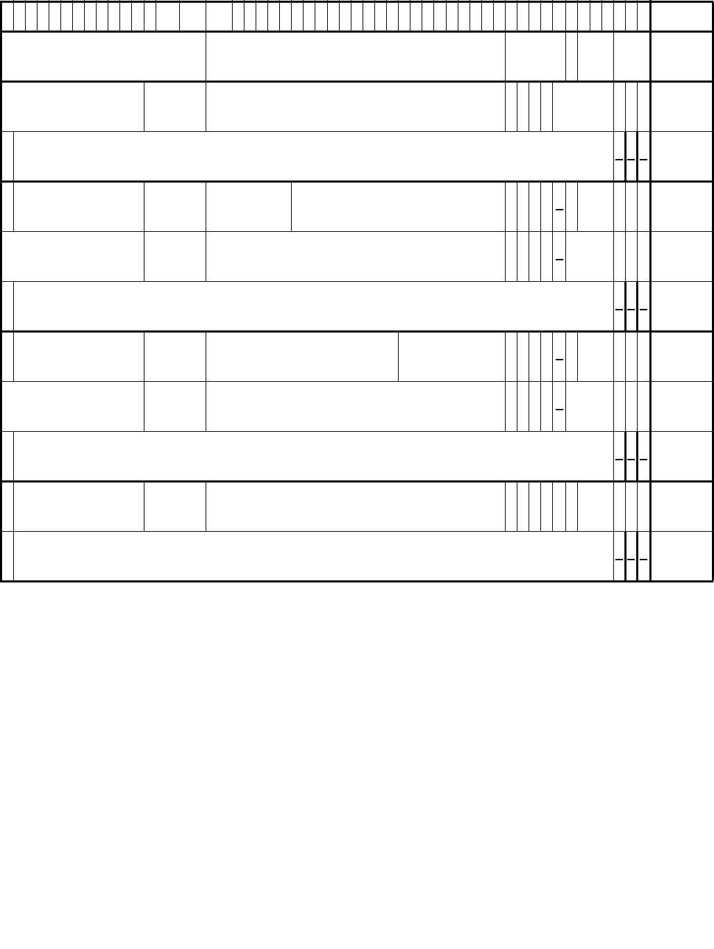
Vol. 3C 28-11
VMX SUPPORT FOR ADDRESS TRANSLATION
•The access is a data write, for any byte to be written, bit 1 (write access) was clear in any of the EPT paging-
structure entries used to translate the guest-physical address of the byte. Writes by the logical processor to
guest paging structures to update accessed and dirty flags are considered to be data writes.
If bit 6 of the EPT pointer (EPTP) is 1 (enabling accessed and dirty flags for EPT), processor accesses to guest
paging-structure entries are treated as writes with regard to EPT violations. Thus, if bit 1 is clear in any of the
6
3
6
2
6
1
6
0
5
9
5
8
5
7
5
6
5
5
5
4
5
3
5
2
5
1M1M-1 3
2
3
1
3
0
2
9
2
8
2
7
2
6
2
5
2
4
2
3
2
2
2
1
2
0
1
9
1
8
1
7
1
6
1
5
1
4
1
3
1
2
1
1
1
09876543210
Reserved Address of EPT PML4 table Rsvd.
A
/
D
EPT
PWL–
1
EPT
PS
MT
EPTP2
Ignored Rsvd. Address of EPT page-directory-pointer table Ig
n.
X
U
3
Ig
n. A Reserved X
4WR PML4E:
present5
S
V
E6
Ignored 0 0 0
PML4E:
not
present
S
V
E
Ignored Rsvd.
Physical
address of
1GB page
Reserved Ig
n.
X
UDA1
I
P
A
T
EPT
MT XWR
PDPTE:
1GB
page
Ignored Rsvd. Address of EPT page directory Ig
n.
X
U
Ig
n. A0Rsvd. X W R
PDPTE:
page
directory
S
V
E
Ignored 0 0 0
PDTPE:
not
present
S
V
E
Ignored Rsvd. Physical address
of 2MB page Reserved Ig
n.
X
UDA1
I
P
A
T
EPT
MT XWR
PDE:
2MB
page
Ignored Rsvd. Address of EPT page table Ig
n.
X
U
Ig
n. A0Rsvd. X W R
PDE:
page
table
S
V
E
Ignored 0 0 0
PDE:
not
present
S
V
E
Ignored Rsvd. Physical address of 4KB page Ig
n.
X
UDA
I
g
n
I
P
A
T
EPT
MT XWR
PTE:
4KB
page
S
V
E
Ignored 0 0 0
PTE:
not
present
Figure 28-1. Formats of EPTP and EPT Paging-Structure Entries
NOTES:
1. M is an abbreviation for MAXPHYADDR.
2. See Section 24.6.11 for details of the EPTP.
3. Execute access for user-mode linear addresses. If the “mode-based execute control for EPT” VM-execution control is 0, this bit is
ignored.
4. Execute access. If the “mode-based execute control for EPT” VM-execution control is 1, this bit controls execute access for supervi-
sor-mode linear addresses.
5. If the “mode-based execute control for EPT” VM-execution control is 1, an EPT paging-structure entry is present if any of bits 2:0 or
bit 10 is 1. This table does not comprehend that fact.
6. Suppress #VE. If the “EPT-violation #VE” VM-execution control is 0, this bit is ignored.

28-12 Vol. 3C
VMX SUPPORT FOR ADDRESS TRANSLATION
EPT paging-structure entries used to translate the guest-physical address of a guest paging-structure entry, an
attempt to use that entry to translate a linear address causes an EPT violation.
(This does not apply to loads of the PDPTE registers by the MOV to CR instruction for PAE paging; see Section
4.4.1. Those loads of guest PDPTEs are treated as reads and do not cause EPT violations due to a guest-physical
address not being writable.)
•The access is an instruction fetch and the EPT paging structures prevent execute access to any of the bytes
being fetched. Whether this occurs depends upon the setting of the “mode-based execute control for EPT” VM-
execution control:
— If the control is 0, an instruction fetch from a byte is prevented if bit 2 (execute access) was clear in any of
the EPT paging-structure entries used to translate the guest-physical address of the byte.
— If the control is 1, an instruction fetch from a byte is prevented in either of the following cases:
•Paging maps the linear address of the byte as a supervisor-mode address and bit 2 (execute access for
supervisor-mode linear addresses) was clear in any of the EPT paging-structure entries used to
translate the guest-physical address of the byte.
Paging maps a linear address as a supervisor-mode address if the U/S flag (bit 2) is 0 in at least one of
the paging-structure entries controlling the translation of the linear address.
•Paging maps the linear address of the byte as a user-mode address and bit 10 (execute access for user-
mode linear addresses) was clear in any of the EPT paging-structure entries used to translate the guest-
physical address of the byte.
Paging maps a linear address as a user-mode address if the U/S flag is 1 in all of the paging-structure
entries controlling the translation of the linear address. If paging is disabled (CR0.PG = 0), every linear
address is a user-mode address.
28.2.3.3 Prioritization of EPT Misconfigurations and EPT Violations
The translation of a linear address to a physical address requires one or more translations of guest-physical
addresses using EPT (see Section 28.2.1). This section specifies the relative priority of EPT-induced VM exits with
respect to each other and to other events that may be encountered when accessing memory using a linear address.
For an access to a guest-physical address, determination of whether an EPT misconfiguration or an EPT violation
occurs is based on an iterative process:1
1. An EPT paging-structure entry is read (initially, this is an EPT PML4 entry):
a. If the entry is not present (see Section 28.2.2), an EPT violation occurs.
b. If the entry is present but its contents are not configured properly (see Section 28.2.3.1), an EPT miscon-
figuration occurs.
c. If the entry is present and its contents are configured properly, operation depends on whether the entry
references another EPT paging structure (whether it is an EPT PDE with bit 7 set to 1 or an EPT PTE):
i) If the entry does reference another EPT paging structure, an entry from that structure is accessed;
step 1 is executed for that other entry.
ii) Otherwise, the entry is used to produce the ultimate physical address (the translation of the original
guest-physical address); step 2 is executed.
2. Once the ultimate physical address is determined, the privileges determined by the EPT paging-structure
entries are evaluated:
a. If the access to the guest-physical address is not allowed by these privileges (see Section 28.2.3.2), an EPT
violation occurs.
b. If the access to the guest-physical address is allowed by these privileges, memory is accessed using the
ultimate physical address.
If CR0.PG = 1, the translation of a linear address is also an iterative process, with the processor first accessing an
entry in the guest paging structure referenced by the guest-physical address in CR3 (or, if PAE paging is in use, the
1. This is a simplification of the more detailed description given in Section 28.2.2.

Vol. 3C 28-13
VMX SUPPORT FOR ADDRESS TRANSLATION
guest-physical address in the appropriate PDPTE register), then accessing an entry in another guest paging struc-
ture referenced by the guest-physical address in the first guest paging-structure entry, etc. Each guest-physical
address is itself translated using EPT and may cause an EPT-induced VM exit. The following items detail how page
faults and EPT-induced VM exits are recognized during this iterative process:
1. An attempt is made to access a guest paging-structure entry with a guest-physical address (initially, the
address in CR3 or PDPTE register).
a. If the access fails because of an EPT misconfiguration or an EPT violation (see above), an EPT-induced
VM exit occurs.
b. If the access does not cause an EPT-induced VM exit, bit 0 (the present flag) of the entry is consulted:
i) If the present flag is 0 or any reserved bit is set, a page fault occurs.
ii) If the present flag is 1, no reserved bit is set, operation depends on whether the entry references
another guest paging structure (whether it is a guest PDE with PS = 1 or a guest PTE):
•If the entry does reference another guest paging structure, an entry from that structure is
accessed; step 1 is executed for that other entry.
•Otherwise, the entry is used to produce the ultimate guest-physical address (the translation of the
original linear address); step 2 is executed.
2. Once the ultimate guest-physical address is determined, the privileges determined by the guest paging-
structure entries are evaluated:
a. If the access to the linear address is not allowed by these privileges (e.g., it was a write to a read-only
page), a page fault occurs.
b. If the access to the linear address is allowed by these privileges, an attempt is made to access memory at
the ultimate guest-physical address:
i) If the access fails because of an EPT misconfiguration or an EPT violation (see above), an EPT-induced
VM exit occurs.
ii) If the access does not cause an EPT-induced VM exit, memory is accessed using the ultimate physical
address (the translation, using EPT, of the ultimate guest-physical address).
If CR0.PG = 0, a linear address is treated as a guest-physical address and is translated using EPT (see above). This
process, if it completes without an EPT violation or EPT misconfiguration, produces a physical address and deter-
mines the privileges allowed by the EPT paging-structure entries. If these privileges do not allow the access to the
physical address (see Section 28.2.3.2), an EPT violation occurs. Otherwise, memory is accessed using the phys-
ical address.
28.2.4 Accessed and Dirty Flags for EPT
The Intel 64 architecture supports accessed and dirty flags in ordinary paging-structure entries (see Section
4.8). Some processors also support corresponding flags in EPT paging-structure entries. Software should read the
VMX capability MSR IA32_VMX_EPT_VPID_CAP (see Appendix A.10) to determine whether the processor supports
this feature.
Software can enable accessed and dirty flags for EPT using bit 6 of the extended-page-table pointer (EPTP), a VM-
execution control field (see Table 24-8 in Section 24.6.11). If this bit is 1, the processor will set the accessed and
dirty flags for EPT as described below. In addition, setting this flag causes processor accesses to guest paging-
structure entries to be treated as writes (see below and Section 28.2.3.2).
For any EPT paging-structure entry that is used during guest-physical-address translation, bit 8 is the accessed
flag. For a EPT paging-structure entry that maps a page (as opposed to referencing another EPT paging structure),
bit 9 is the dirty flag.
Whenever the processor uses an EPT paging-structure entry as part of guest-physical-address translation, it sets
the accessed flag in that entry (if it is not already set).
Whenever there is a write to a guest-physical address, the processor sets the dirty flag (if it is not already set) in
the EPT paging-structure entry that identifies the final physical address for the guest-physical address (either an
EPT PTE or an EPT paging-structure entry in which bit 7 is 1).

28-14 Vol. 3C
VMX SUPPORT FOR ADDRESS TRANSLATION
When accessed and dirty flags for EPT are enabled, processor accesses to guest paging-structure entries are
treated as writes (see Section 28.2.3.2). Thus, such an access will cause the processor to set the dirty flag in the
EPT paging-structure entry that identifies the final physical address of the guest paging-structure entry.
(This does not apply to loads of the PDPTE registers for PAE paging by the MOV to CR instruction; see Section 4.4.1.
Those loads of guest PDPTEs are treated as reads and do not cause the processor to set the dirty flag in any EPT
paging-structure entry.)
These flags are “sticky,” meaning that, once set, the processor does not clear them; only software can clear them.
A processor may cache information from the EPT paging-structure entries in TLBs and paging-structure caches (see
Section 28.3). This fact implies that, if software changes an accessed flag or a dirty flag from 1 to 0, the processor
might not set the corresponding bit in memory on a subsequent access using an affected guest-physical address.
28.2.5 Page-Modification Logging
When accessed and dirty flags for EPT are enabled, software can track writes to guest-physical addresses using a
feature called page-modification logging.
Software can enable page-modification logging by setting the “enable PML” VM-execution control (see Table 24-7
in Section 24.6.2). When this control is 1, the processor adds entries to the page-modification log as described
below. The page-modification log is a 4-KByte region of memory located at the physical address in the PML address
VM-execution control field. The page-modification log consists of 512 64-bit entries; the PML index VM-execution
control field indicates the next entry to use.
Before allowing a guest-physical access, the processor may determine that it first needs to set an accessed or dirty
flag for EPT (see Section 28.2.4). When this happens, the processor examines the PML index. If the PML index is
not in the range 0–511, there is a page-modification log-full event and a VM exit occurs. In this case, the
accessed or dirty flag is not set, and the guest-physical access that triggered the event does not occur.
If instead the PML index is in the range 0–511, the processor proceeds to update accessed or dirty flags for EPT as
described in Section 28.2.4. If the processor updated a dirty flag for EPT (changing it from 0 to 1), it then operates
as follows:
1. The guest-physical address of the access is written to the page-modification log. Specifically, the guest-physical
address is written to physical address determined by adding 8 times the PML index to the PML address.
Bits 11:0 of the value written are always 0 (the guest-physical address written is thus 4-KByte aligned).
2. The PML index is decremented by 1 (this may cause the value to transition from 0 to FFFFH).
Because the processor decrements the PML index with each log entry, the value may transition from 0 to FFFFH. At
that point, no further logging will occur, as the processor will determine that the PML index is not in the range 0–
511 and will generate a page-modification log-full event (see above).
28.2.6 EPT and Memory Typing
This section specifies how a logical processor determines the memory type use for a memory access while EPT is in
use. (See Chapter 11, “Memory Cache Control” of Intel® 64 and IA-32 Architectures Software Developer’s Manual,
Volume 3A for details of memory typing in the Intel 64 architecture.) Section 28.2.6.1 explains how the memory
type is determined for accesses to the EPT paging structures. Section 28.2.6.2 explains how the memory type is
determined for an access using a guest-physical address that is translated using EPT.
28.2.6.1 Memory Type Used for Accessing EPT Paging Structures
This section explains how the memory type is determined for accesses to the EPT paging structures. The determi-
nation is based first on the value of bit 30 (cache disable—CD) in control register CR0:
•If CR0.CD = 0, the memory type used for any such reference is the EPT paging-structure memory type, which
is specified in bits 2:0 of the extended-page-table pointer (EPTP), a VM-execution control field (see Section
24.6.11). A value of 0 indicates the uncacheable type (UC), while a value of 6 indicates the write-back type
(WB). Other values are reserved.
•If CR0.CD = 1, the memory type used for any such reference is uncacheable (UC).

Vol. 3C 28-15
VMX SUPPORT FOR ADDRESS TRANSLATION
The MTRRs have no effect on the memory type used for an access to an EPT paging structure.
28.2.6.2 Memory Type Used for Translated Guest-Physical Addresses
The effective memory type of a memory access using a guest-physical address (an access that is translated
using EPT) is the memory type that is used to access memory. The effective memory type is based on the value of
bit 30 (cache disable—CD) in control register CR0; the last EPT paging-structure entry used to translate the guest-
physical address (either an EPT PDE with bit 7 set to 1 or an EPT PTE); and the PAT memory type (see below):
•The PAT memory type depends on the value of CR0.PG:
— If CR0.PG = 0, the PAT memory type is WB (writeback).1
— If CR0.PG = 1, the PAT memory type is the memory type selected from the IA32_PAT MSR as specified in
Section 11.12.3, “Selecting a Memory Type from the PAT”.2
•The EPT memory type is specified in bits 5:3 of the last EPT paging-structure entry: 0 = UC; 1 = WC; 4 =
WT; 5 = WP; and 6 = WB. Other values are reserved and cause EPT misconfigurations (see Section 28.2.3).
•If CR0.CD = 0, the effective memory type depends upon the value of bit 6 of the last EPT paging-structure
entry:
— If the value is 0, the effective memory type is the combination of the EPT memory type and the PAT
memory type specified in Table 11-7 in Section 11.5.2.2, using the EPT memory type in place of the MTRR
memory type.
— If the value is 1, the memory type used for the access is the EPT memory type. The PAT memory type is
ignored.
•If CR0.CD = 1, the effective memory type is UC.
The MTRRs have no effect on the memory type used for an access to a guest-physical address.
28.3 CACHING TRANSLATION INFORMATION
Processors supporting Intel®64 and IA-32 architectures may accelerate the address-translation process by
caching on the processor data from the structures in memory that control that process. Such caching is discussed
in Section 4.10, “Caching Translation Information” in the Intel® 64 and IA-32 Architectures Software Developer’s
Manual, Volume 3A. The current section describes how this caching interacts with the VMX architecture.
The VPID and EPT features of the architecture for VMX operation augment this caching architecture. EPT defines
the guest-physical address space and defines translations to that address space (from the linear-address space)
and from that address space (to the physical-address space). Both features control the ways in which a logical
processor may create and use information cached from the paging structures.
Section 28.3.1 describes the different kinds of information that may be cached. Section 28.3.2 specifies when such
information may be cached and how it may be used. Section 28.3.3 details how software can invalidate cached
information.
28.3.1 Information That May Be Cached
Section 4.10, “Caching Translation Information” in Intel® 64 and IA-32 Architectures Software Developer’s
Manual, Volume 3A identifies two kinds of translation-related information that may be cached by a logical
1. If the capability MSR IA32_VMX_CR0_FIXED0 reports that CR0.PG must be 1 in VMX operation, CR0.PG can be 0 in VMX non-root
operation only if the “unrestricted guest” VM-execution control and bit 31 of the primary processor-based VM-execution controls
are both 1.
2. Table 11-11 in Section 11.12.3, “Selecting a Memory Type from the PAT” illustrates how the PAT memory type is selected based on
the values of the PAT, PCD, and PWT bits in a page-table entry (or page-directory entry with PS = 1). For accesses to a guest paging-
structure entry X, the PAT memory type is selected from the table by using a value of 0 for the PAT bit with the values of PCD and
PWT from the paging-structure entry Y that references X (or from CR3 if X is in the root paging structure). With PAE paging, the PAT
memory type for accesses to the PDPTEs is WB.

28-16 Vol. 3C
VMX SUPPORT FOR ADDRESS TRANSLATION
processor: translations, which are mappings from linear page numbers to physical page frames, and paging-
structure caches, which map the upper bits of a linear page number to information from the paging-structure
entries used to translate linear addresses matching those upper bits.
The same kinds of information may be cached when VPIDs and EPT are in use. A logical processor may cache and
use such information based on its function. Information with different functionality is identified as follows:
•Linear mappings.1 There are two kinds:
— Linear translations. Each of these is a mapping from a linear page number to the physical page frame to
which it translates, along with information about access privileges and memory typing.
— Linear paging-structure-cache entries. Each of these is a mapping from the upper portion of a linear
address to the physical address of the paging structure used to translate the corresponding region of the
linear-address space, along with information about access privileges. For example, bits 47:39 of a linear
address would map to the address of the relevant page-directory-pointer table.
Linear mappings do not contain information from any EPT paging structure.
•Guest-physical mappings.2 There are two kinds:
— Guest-physical translations. Each of these is a mapping from a guest-physical page number to the physical
page frame to which it translates, along with information about access privileges and memory typing.
— Guest-physical paging-structure-cache entries. Each of these is a mapping from the upper portion of a
guest-physical address to the physical address of the EPT paging structure used to translate the corre-
sponding region of the guest-physical address space, along with information about access privileges.
The information in guest-physical mappings about access privileges and memory typing is derived from EPT
paging structures.
•Combined mappings.3 There are two kinds:
— Combined translations. Each of these is a mapping from a linear page number to the physical page frame to
which it translates, along with information about access privileges and memory typing.
— Combined paging-structure-cache entries. Each of these is a mapping from the upper portion of a linear
address to the physical address of the paging structure used to translate the corresponding region of the
linear-address space, along with information about access privileges.
The information in combined mappings about access privileges and memory typing is derived from both guest
paging structures and EPT paging structures.
28.3.2 Creating and Using Cached Translation Information
The following items detail the creation of the mappings described in the previous section:4
•The following items describe the creation of mappings while EPT is not in use (including execution outside VMX
non-root operation):
— Linear mappings may be created. They are derived from the paging structures referenced (directly or
indirectly) by the current value of CR3 and are associated with the current VPID and the current PCID.
— No linear mappings are created with information derived from paging-structure entries that are not present
(bit 0 is 0) or that set reserved bits. For example, if a PTE is not present, no linear mapping are created for
any linear page number whose translation would use that PTE.
— No guest-physical or combined mappings are created while EPT is not in use.
•The following items describe the creation of mappings while EPT is in use:
1. Earlier versions of this manual used the term “VPID-tagged” to identify linear mappings.
2. Earlier versions of this manual used the term “EPTP-tagged” to identify guest-physical mappings.
3. Earlier versions of this manual used the term “dual-tagged” to identify combined mappings.
4. This section associated cached information with the current VPID and PCID. If PCIDs are not supported or are not being used (e.g.,
because CR4.PCIDE = 0), all the information is implicitly associated with PCID 000H; see Section 4.10.1, “Process-Context Identifiers
(PCIDs),” in Intel® 64 and IA-32 Architectures Software Developer’s Manual, Volume 3A.

Vol. 3C 28-17
VMX SUPPORT FOR ADDRESS TRANSLATION
— Guest-physical mappings may be created. They are derived from the EPT paging structures referenced
(directly or indirectly) by bits 51:12 of the current EPTP. These 40 bits contain the address of the EPT-PML4-
table. (the notation EP4TA refers to those 40 bits). Newly created guest-physical mappings are associated
with the current EP4TA.
— Combined mappings may be created. They are derived from the EPT paging structures referenced (directly
or indirectly) by the current EP4TA. If CR0.PG = 1, they are also derived from the paging structures
referenced (directly or indirectly) by the current value of CR3. They are associated with the current VPID,
the current PCID, and the current EP4TA.1 No combined paging-structure-cache entries are created if
CR0.PG = 0.2
— No guest-physical mappings or combined mappings are created with information derived from EPT paging-
structure entries that are not present (see Section 28.2.2) or that are misconfigured (see Section
28.2.3.1).
— No combined mappings are created with information derived from guest paging-structure entries that are
not present or that set reserved bits.
— No linear mappings are created while EPT is in use.
The following items detail the use of the various mappings:
•If EPT is not in use (e.g., when outside VMX non-root operation), a logical processor may use cached mappings
as follows:
— For accesses using linear addresses, it may use linear mappings associated with the current VPID and the
current PCID. It may also use global TLB entries (linear mappings) associated with the current VPID and
any PCID.
— No guest-physical or combined mappings are used while EPT is not in use.
•If EPT is in use, a logical processor may use cached mappings as follows:
— For accesses using linear addresses, it may use combined mappings associated with the current VPID, the
current PCID, and the current EP4TA. It may also use global TLB entries (combined mappings) associated
with the current VPID, the current EP4TA, and any PCID.
— For accesses using guest-physical addresses, it may use guest-physical mappings associated with the
current EP4TA.
— No linear mappings are used while EPT is in use.
28.3.3 Invalidating Cached Translation Information
Software modifications of paging structures (including EPT paging structures) may result in inconsistencies
between those structures and the mappings cached by a logical processor. Certain operations invalidate informa-
tion cached by a logical processor and can be used to eliminate such inconsistencies.
28.3.3.1 Operations that Invalidate Cached Mappings
The following operations invalidate cached mappings as indicated:
•Operations that architecturally invalidate entries in the TLBs or paging-structure caches independent of VMX
operation (e.g., the INVLPG and INVPCID instructions) invalidate linear mappings and combined mappings.3
They are required to do so only for the current VPID (but, for combined mappings, all EP4TAs). Linear
1. At any given time, a logical processor may be caching combined mappings for a VPID and a PCID that are associated with different
EP4TAs. Similarly, it may be caching combined mappings for an EP4TA that are associated with different VPIDs and PCIDs.
2. If the capability MSR IA32_VMX_CR0_FIXED0 reports that CR0.PG must be 1 in VMX operation, CR0.PG can be 0 in VMX non-root
operation only if the “unrestricted guest” VM-execution control and bit 31 of the primary processor-based VM-execution controls
are both 1.
3. See Section 4.10.4, “Invalidation of TLBs and Paging-Structure Caches,” in the Intel® 64 and IA-32 Architectures Software Devel-
oper’s Manual, Volume 3A for an enumeration of operations that architecturally invalidate entries in the TLBs and paging-structure
caches independent of VMX operation.

28-18 Vol. 3C
VMX SUPPORT FOR ADDRESS TRANSLATION
mappings for the current VPID are invalidated even if EPT is in use.1 Combined mappings for the current
VPID are invalidated even if EPT is not in use.2
•An EPT violation invalidates any guest-physical mappings (associated with the current EP4TA) that would be
used to translate the guest-physical address that caused the EPT violation. If that guest-physical address was
the translation of a linear address, the EPT violation also invalidates any combined mappings for that linear
address associated with the current PCID, the current VPID and the current EP4TA.
•If the “enable VPID” VM-execution control is 0, VM entries and VM exits invalidate linear mappings and
combined mappings associated with VPID 0000H (for all PCIDs). Combined mappings for VPID 0000H are
invalidated for all EP4TAs.
•Execution of the INVVPID instruction invalidates linear mappings and combined mappings. Invalidation is based
on instruction operands, called the INVVPID type and the INVVPID descriptor. Four INVVPID types are currently
defined:
—Individual-address. If the INVVPID type is 0, the logical processor invalidates linear mappings and
combined mappings associated with the VPID specified in the INVVPID descriptor and that would be used
to translate the linear address specified in of the INVVPID descriptor. Linear mappings and combined
mappings for that VPID and linear address are invalidated for all PCIDs and, for combined mappings, all
EP4TAs. (The instruction may also invalidate mappings associated with other VPIDs and for other linear
addresses.)
—Single-context. If the INVVPID type is 1, the logical processor invalidates all linear mappings and
combined mappings associated with the VPID specified in the INVVPID descriptor. Linear mappings and
combined mappings for that VPID are invalidated for all PCIDs and, for combined mappings, all EP4TAs.
(The instruction may also invalidate mappings associated with other VPIDs.)
—All-context. If the INVVPID type is 2, the logical processor invalidates linear mappings and combined
mappings associated with all VPIDs except VPID 0000H and with all PCIDs. (The instruction may also
invalidate linear mappings with VPID 0000H.) Combined mappings are invalidated for all EP4TAs.
—Single-context-retaining-globals. If the INVVPID type is 3, the logical processor invalidates linear
mappings and combined mappings associated with the VPID specified in the INVVPID descriptor. Linear
mappings and combined mappings for that VPID are invalidated for all PCIDs and, for combined mappings,
all EP4TAs. The logical processor is not required to invalidate information that was used for global transla-
tions (although it may do so). See Section 4.10, “Caching Translation Information” for details regarding
global translations. (The instruction may also invalidate mappings associated with other VPIDs.)
See Chapter 30 for details of the INVVPID instruction. See Section 28.3.3.3 for guidelines regarding use of this
instruction.
•Execution of the INVEPT instruction invalidates guest-physical mappings and combined mappings. Invalidation
is based on instruction operands, called the INVEPT type and the INVEPT descriptor. Two INVEPT types are
currently defined:
—Single-context. If the INVEPT type is 1, the logical processor invalidates all guest-physical mappings and
combined mappings associated with the EP4TA specified in the INVEPT descriptor. Combined mappings for
that EP4TA are invalidated for all VPIDs and all PCIDs. (The instruction may invalidate mappings associated
with other EP4TAs.)
—All-context. If the INVEPT type is 2, the logical processor invalidates guest-physical mappings and
combined mappings associated with all EP4TAs (and, for combined mappings, for all VPIDs and PCIDs).
See Chapter 30 for details of the INVEPT instruction. See Section 28.3.3.4 for guidelines regarding use of this
instruction.
•A power-up or a reset invalidates all linear mappings, guest-physical mappings, and combined mappings.
1. While no linear mappings are created while EPT is in use, a logical processor may retain, while EPT is in use, linear mappings (for the
same VPID as the current one) there were created earlier, when EPT was not in use.
2. While no combined mappings are created while EPT is not in use, a logical processor may retain, while EPT is in not use, combined
mappings (for the same VPID as the current one) there were created earlier, when EPT was in use.

Vol. 3C 28-19
VMX SUPPORT FOR ADDRESS TRANSLATION
28.3.3.2 Operations that Need Not Invalidate Cached Mappings
The following items detail cases of operations that are not required to invalidate certain cached mappings:
•Operations that architecturally invalidate entries in the TLBs or paging-structure caches independent of VMX
operation are not required to invalidate any guest-physical mappings.
•The INVVPID instruction is not required to invalidate any guest-physical mappings.
•The INVEPT instruction is not required to invalidate any linear mappings.
•VMX transitions are not required to invalidate any guest-physical mappings. If the “enable VPID” VM-execution
control is 1, VMX transitions are not required to invalidate any linear mappings or combined mappings.
•The VMXOFF and VMXON instructions are not required to invalidate any linear mappings, guest-physical
mappings, or combined mappings.
A logical processor may invalidate any cached mappings at any time. For this reason, the operations identified
above may invalidate the indicated mappings despite the fact that doing so is not required.
28.3.3.3 Guidelines for Use of the INVVPID Instruction
The need for VMM software to use the INVVPID instruction depends on how that software is virtualizing memory
(e.g., see Section 32.3, “Memory Virtualization”).
If EPT is not in use, it is likely that the VMM is virtualizing the guest paging structures. Such a VMM may configure
the VMCS so that all or some of the operations that invalidate entries the TLBs and the paging-structure caches
(e.g., the INVLPG instruction) cause VM exits. If VMM software is emulating these operations, it may be necessary
to use the INVVPID instruction to ensure that the logical processor’s TLBs and the paging-structure caches are
appropriately invalidated.
Requirements of when software should use the INVVPID instruction depend on the specific algorithm being used for
page-table virtualization. The following items provide guidelines for software developers:
•Emulation of the INVLPG instruction may require execution of the INVVPID instruction as follows:
— The INVVPID type is individual-address (0).
— The VPID in the INVVPID descriptor is the one assigned to the virtual processor whose execution is being
emulated.
— The linear address in the INVVPID descriptor is that of the operand of the INVLPG instruction being
emulated.
•Some instructions invalidate all entries in the TLBs and paging-structure caches—except for global translations.
An example is the MOV to CR3 instruction. (See Section 4.10, “Caching Translation Information” in the Intel®
64 and IA-32 Architectures Software Developer’s Manual, Volume 3A for details regarding global translations.)
Emulation of such an instruction may require execution of the INVVPID instruction as follows:
— The INVVPID type is single-context-retaining-globals (3).
— The VPID in the INVVPID descriptor is the one assigned to the virtual processor whose execution is being
emulated.
•Some instructions invalidate all entries in the TLBs and paging-structure caches—including for global transla-
tions. An example is the MOV to CR4 instruction if the value of value of bit 4 (page global enable—PGE) is
changing. Emulation of such an instruction may require execution of the INVVPID instruction as follows:
— The INVVPID type is single-context (1).
— The VPID in the INVVPID descriptor is the one assigned to the virtual processor whose execution is being
emulated.
If EPT is not in use, the logical processor associates all mappings it creates with the current VPID, and it will use
such mappings to translate linear addresses. For that reason, a VMM should not use the same VPID for different
non-EPT guests that use different page tables. Doing so may result in one guest using translations that pertain to
the other.
If EPT is in use, the instructions enumerated above might not be configured to cause VM exits and the VMM might
not be emulating them. In that case, executions of the instructions by guest software properly invalidate the

28-20 Vol. 3C
VMX SUPPORT FOR ADDRESS TRANSLATION
required entries in the TLBs and paging-structure caches (see Section 28.3.3.1); execution of the INVVPID instruc-
tion is not required.
If EPT is in use, the logical processor associates all mappings it creates with the value of bits 51:12 of current EPTP.
If a VMM uses different EPTP values for different guests, it may use the same VPID for those guests. Doing so
cannot result in one guest using translations that pertain to the other.
The following guidelines apply more generally and are appropriate even if EPT is in use:
•As detailed in Section 29.4.5, an access to the APIC-access page might not cause an APIC-access VM exit if
software does not properly invalidate information that may be cached from the paging structures. If, at one
time, the current VPID on a logical processor was a non-zero value X, it is recommended that software use the
INVVPID instruction with the “single-context” INVVPID type and with VPID X in the INVVPID descriptor before
a VM entry on the same logical processor that establishes VPID X and either (a) the “virtualize APIC accesses”
VM-execution control was changed from 0 to 1; or (b) the value of the APIC-access address was changed.
•Software can use the INVVPID instruction with the “all-context” INVVPID type immediately after execution of
the VMXON instruction or immediately prior to execution of the VMXOFF instruction. Either prevents potentially
undesired retention of information cached from paging structures between separate uses of VMX operation.
28.3.3.4 Guidelines for Use of the INVEPT Instruction
The following items provide guidelines for use of the INVEPT instruction to invalidate information cached from the
EPT paging structures.
•Software should use the INVEPT instruction with the “single-context” INVEPT type after making any of the
following changes to an EPT paging-structure entry (the INVEPT descriptor should contain an EPTP value that
references — directly or indirectly — the modified EPT paging structure):
— Changing any of the privilege bits 2:0 from 1 to 0.1
— Changing the physical address in bits 51:12.
— Clearing bit 8 (the accessed flag) if accessed and dirty flags for EPT will be enabled.
— For an EPT PDPTE or an EPT PDE, changing bit 7 (which determines whether the entry maps a page).
—For the last EPT paging-structure entry used to translate a guest-physical address (an EPT PDPTE with bit 7
set to 1, an EPT PDE with bit 7 set to 1, or an EPT PTE), changing either bits 5:3 or bit 6. (These bits
determine the effective memory type of accesses using that EPT paging-structure entry; see Section
28.2.6.)
—For the last EPT paging-structure entry used to translate a guest-physical address (an EPT PDPTE with bit 7
set to 1, an EPT PDE with bit 7 set to 1, or an EPT PTE), clearing bit 9 (the dirty flag) if accessed and dirty
flags for EPT will be enabled.
•Software should use the INVEPT instruction with the “single-context” INVEPT type before a VM entry with an
EPTP value X such that X[6] = 1 (accessed and dirty flags for EPT are enabled) if the logical processor had
earlier been in VMX non-root operation with an EPTP value Y such that Y[6] = 0 (accessed and dirty flags for
EPT are not enabled) and Y[51:12] = X[51:12].
•Software may use the INVEPT instruction after modifying a present EPT paging-structure entry (see Section
28.2.2) to change any of the privilege bits 2:0 from 0 to 1.2 Failure to do so may cause an EPT violation that
would not otherwise occur. Because an EPT violation invalidates any mappings that would be used by the access
that caused the EPT violation (see Section 28.3.3.1), an EPT violation will not recur if the original access is
performed again, even if the INVEPT instruction is not executed.
•Because a logical processor does not cache any information derived from EPT paging-structure entries that are
not present (see Section 28.2.2) or misconfigured (see Section 28.2.3.1), it is not necessary to execute INVEPT
following modification of an EPT paging-structure entry that had been not present or misconfigured.
1. If the “mode-based execute control for EPT” VM-execution control is 1, software should use the INVEPT instruction after changing
privilege bit 10 from 1 to 0.
2. If the “mode-based execute control for EPT” VM-execution control is 1, software may use the INVEPT instruction after modifying a
present EPT paging-structure entry to change privilege bit 10 from 0 to 1.

Vol. 3C 28-21
VMX SUPPORT FOR ADDRESS TRANSLATION
•As detailed in Section 29.4.5, an access to the APIC-access page might not cause an APIC-access VM exit if
software does not properly invalidate information that may be cached from the EPT paging structures. If EPT
was in use on a logical processor at one time with EPTP X, it is recommended that software use the INVEPT
instruction with the “single-context” INVEPT type and with EPTP X in the INVEPT descriptor before a VM entry
on the same logical processor that enables EPT with EPTP X and either (a) the “virtualize APIC accesses” VM-
execution control was changed from 0 to 1; or (b) the value of the APIC-access address was changed.
•Software can use the INVEPT instruction with the “all-context” INVEPT type immediately after execution of the
VMXON instruction or immediately prior to execution of the VMXOFF instruction. Either prevents potentially
undesired retention of information cached from EPT paging structures between separate uses of VMX
operation.
In a system containing more than one logical processor, software must account for the fact that information from
an EPT paging-structure entry may be cached on logical processors other than the one that modifies that entry. The
process of propagating the changes to a paging-structure entry is commonly referred to as “TLB shootdown.” A
discussion of TLB shootdown appears in Section 4.10.5, “Propagation of Paging-Structure Changes to Multiple
Processors,” in the Intel® 64 and IA-32 Architectures Software Developer’s Manual, Volume 3A.

28-22 Vol. 3C
VMX SUPPORT FOR ADDRESS TRANSLATION

Vol. 3C 29-1
CHAPTER 29
APIC VIRTUALIZATION AND VIRTUAL INTERRUPTS
The VMCS includes controls that enable the virtualization of interrupts and the Advanced Programmable Interrupt
Controller (APIC).
When these controls are used, the processor will emulate many accesses to the APIC, track the state of the virtual
APIC, and deliver virtual interrupts — all in VMX non-root operation with out a VM exit.1
The processor tracks the state of the virtual APIC using a virtual-APIC page identified by the virtual-machine
monitor (VMM). Section 29.1 discusses the virtual-APIC page and how the processor uses it to track the state of the
virtual APIC.
The following are the VM-execution controls relevant to APIC virtualization and virtual interrupts (see Section 24.6
for information about the locations of these controls):
•Virtual-interrupt delivery. This controls enables the evaluation and delivery of pending virtual interrupts
(Section 29.2). It also enables the emulation of writes (memory-mapped or MSR-based, as enabled) to the
APIC registers that control interrupt prioritization.
•Use TPR shadow. This control enables emulation of accesses to the APIC’s task-priority register (TPR) via CR8
(Section 29.3) and, if enabled, via the memory-mapped or MSR-based interfaces.
•Virtualize APIC accesses. This control enables virtualization of memory-mapped accesses to the APIC
(Section 29.4) by causing VM exits on accesses to a VMM-specified APIC-access page. Some of the other
controls, if set, may cause some of these accesses to be emulated rather than causing VM exits.
•Virtualize x2APIC mode. This control enables virtualization of MSR-based accesses to the APIC (Section
29.5).
•APIC-register virtualization. This control allows memory-mapped and MSR-based reads of most APIC
registers (as enabled) by satisfying them from the virtual-APIC page. It directs memory-mapped writes to the
APIC-access page to the virtual-APIC page, following them by VM exits for VMM emulation.
•Process posted interrupts. This control allows software to post virtual interrupts in a data structure and send
a notification to another logical processor; upon receipt of the notification, the target processor will process the
posted interrupts by copying them into the virtual-APIC page (Section 29.6).
“Virtualize APIC accesses”, “virtualize x2APIC mode”, “virtual-interrupt delivery”, and “APIC-register virtualization”
are all secondary processor-based VM-execution controls. If bit 31 of the primary processor-based VM-execution
controls is 0, the processor operates as if these controls were all 0. See Section 24.6.2.
29.1 VIRTUAL APIC STATE
The virtual-APIC page is a 4-KByte region of memory that the processor uses to virtualize certain accesses to
APIC registers and to manage virtual interrupts. The physical address of the virtual-APIC page is the virtual-APIC
address, a 64-bit VM-execution control field in the VMCS (see Section 24.6.8).
Depending on the settings of certain VM-execution controls, the processor may virtualize certain fields on the
virtual-APIC page with functionality analogous to that performed by the local APIC. Section 29.1.1 identifies and
defines these fields. Section 29.1.2, Section 29.1.3, Section 29.1.4, and Section 29.1.5 detail the actions taken to
virtualize updates to some of these fields.
29.1.1 Virtualized APIC Registers
Depending on the setting of certain VM-execution controls, a logical processor may virtualize certain accesses to
APIC registers using the following fields on the virtual-APIC page:
•Virtual task-priority register (VTPR): the 32-bit field located at offset 080H on the virtual-APIC page.
1. In most cases, it is not necessary for a virtual-machine monitor (VMM) to inject virtual interrupts as part of VM entry.

29-2 Vol. 3C
APIC VIRTUALIZATION AND VIRTUAL INTERRUPTS
•Virtual processor-priority register (VPPR): the 32-bit field located at offset 0A0H on the virtual-APIC
page.
•Virtual end-of-interrupt register (VEOI): the 32-bit field located at offset 0B0H on the virtual-APIC page.
•Virtual interrupt-service register (VISR): the 256-bit value comprising eight non-contiguous 32-bit fields
at offsets 100H, 110H, 120H, 130H, 140H, 150H, 160H, and 170H on the virtual-APIC page. Bit x of the VISR
is at bit position (x & 1FH) at offset (100H | ((x & E0H) » 1)). The processor uses only the low 4 bytes of each
of the 16-byte fields at offsets 100H, 110H, 120H, 130H, 140H, 150H, 160H, and 170H.
•Virtual interrupt-request register (VIRR): the 256-bit value comprising eight non-contiguous 32-bit fields
at offsets 200H, 210H, 220H, 230H, 240H, 250H, 260H, and 270H on the virtual-APIC page. Bit x of the VIRR
is at bit position (x & 1FH) at offset (200H | ((x & E0H) » 1)). The processor uses only the low 4 bytes of each
of the 16-Byte fields at offsets 200H, 210H, 220H, 230H, 240H, 250H, 260H, and 270H.
•Virtual interrupt-command register (VICR_LO): the 32-bit field located at offset 300H on the virtual-APIC
page
•Virtual interrupt-command register (VICR_HI): the 32-bit field located at offset 310H on the virtual-APIC
page.
29.1.2 TPR Virtualization
The processor performs TPR virtualization in response to the following operations: (1) virtualization of the MOV
to CR8 instruction; (2) virtualization of a write to offset 080H on the APIC-access page; and (3) virtualization of the
WRMSR instruction with ECX = 808H. See Section 29.3, Section 29.4.3, and Section 29.5 for details of when TPR
virtualization is performed.
The following pseudocode details the behavior of TPR virtualization:
IF “virtual-interrupt delivery” is 0
THEN
IF VTPR[7:4] < TPR threshold (see Section 24.6.8)
THEN cause VM exit due to TPR below threshold;
FI;
ELSE
perform PPR virtualization (see Section 29.1.3);
evaluate pending virtual interrupts (see Section 29.2.1);
FI;
Any VM exit caused by TPR virtualization is trap-like: the instruction causing TPR virtualization completes before
the VM exit occurs (for example, the value of CS:RIP saved in the guest-state area of the VMCS references the next
instruction).
29.1.3 PPR Virtualization
The processor performs PPR virtualization in response to the following operations: (1) VM entry; (2) TPR virtu-
alization; and (3) EOI virtualization. See Section 26.3.2.5, Section 29.1.2, and Section 29.1.4 for details of when
PPR virtualization is performed.
PPR virtualization uses the guest interrupt status (specifically, SVI; see Section 24.4.2) and VTPR. The following
pseudocode details the behavior of PPR virtualization:
IF VTPR[7:4] ≥ SVI[7:4]
THEN VPPR ← VTPR & FFH;
ELSE VPPR ← SVI & F0H;
FI;
PPR virtualization always clears bytes 3:1 of VPPR.
PPR virtualization is caused only by TPR virtualization, EOI virtualization, and VM entry. Delivery of a virtual inter-
rupt also modifies VPPR, but in a different way (see Section 29.2.2). No other operations modify VPPR, even if they
modify SVI, VISR, or VTPR.

Vol. 3C 29-3
APIC VIRTUALIZATION AND VIRTUAL INTERRUPTS
29.1.4 EOI Virtualization
The processor performs EOI virtualization in response to the following operations: (1) virtualization of a write to
offset 0B0H on the APIC-access page; and (2) virtualization of the WRMSR instruction with ECX = 80BH. See
Section 29.4.3 and Section 29.5 for details of when EOI virtualization is performed. EOI virtualization occurs only
if the “virtual-interrupt delivery” VM-execution control is 1.
EOI virtualization uses and updates the guest interrupt status (specifically, SVI; see Section 24.4.2). The following
pseudocode details the behavior of EOI virtualization:
Vector ← SVI;
VISR[Vector] ← 0; (see Section 29.1.1 for definition of VISR)
IF any bits set in VISR
THEN SVI ← highest index of bit set in VISR
ELSE SVI ← 0;
FI;
perform PPR virtualiation (see Section 29.1.3);
IF EOI_exit_bitmap[Vector] = 1 (see Section 24.6.8 for definition of EOI_exit_bitmap)
THEN cause EOI-induced VM exit with Vector as exit qualification;
ELSE evaluate pending virtual interrupts; (see Section 29.2.1)
FI;
Any VM exit caused by EOI virtualization is trap-like: the instruction causing EOI virtualization completes before
the VM exit occurs (for example, the value of CS:RIP saved in the guest-state area of the VMCS references the next
instruction).
29.1.5 Self-IPI Virtualization
The processor performs self-IPI virtualization in response to the following operations: (1) virtualization of a
write to offset 300H on the APIC-access page; and (2) virtualization of the WRMSR instruction with ECX = 83FH.
See Section 29.4.3 and Section 29.5 for details of when self-IPI virtualization is performed. Self-IPI virtualization
occurs only if the “virtual-interrupt delivery” VM-execution control is 1.
Each operation that leads to self-IPI virtualization provides an 8-bit vector (see Section 29.4.3 and Section 29.5).
Self-IPI virtualization updates the guest interrupt status (specifically, RVI; see Section 24.4.2). The following
pseudocode details the behavior of self-IPI virtualization:
VIRR[Vector] ← 1; (see Section 29.1.1 for definition of VIRR)
RVI ← max{RVI,Vector};
evaluate pending virtual interrupts; (see Section 29.2.1)
29.2 EVALUATION AND DELIVERY OF VIRTUAL INTERRUPTS
If the “virtual-interrupt delivery” VM-execution control is 1, certain actions in VMX non-root operation or during
VM entry cause the processor to evaluate and deliver virtual interrupts.
Evaluation of virtual interrupts is triggered by certain actions change the state of the virtual-APIC page and is
described in Section 29.2.1. This evaluation may result in recognition of a virtual interrupt. Once a virtual interrupt
is recognized, the processor may deliver it within VMX non-root operation without a VM exit. Virtual-interrupt
delivery is described in Section 29.2.2.
29.2.1 Evaluation of Pending Virtual Interrupts
If the “virtual-interrupt delivery” VM-execution control is 1, certain actions cause a logical processor to evaluate
pending virtual interrupts.
The following actions cause the evaluation of pending virtual interrupts: VM entry; TPR virtualization; EOI virtual-
ization; self-IPI virtualization; and posted-interrupt processing. See Section 26.3.2.5, Section 29.1.2, Section

29-4 Vol. 3C
APIC VIRTUALIZATION AND VIRTUAL INTERRUPTS
29.1.4, Section 29.1.5, and Section 29.6 for details of when evaluation of pending virtual interrupts is performed.
No other operations cause the evaluation of pending virtual interrupts, even if they modify RVI or VPPR.
Evaluation of pending virtual interrupts uses the guest interrupt status (specifically, RVI; see Section 24.4.2). The
following pseudocode details the evaluation of pending virtual interrupts:
IF “interrupt-window exiting” is 0 AND
RVI[7:4] > VPPR[7:4] (see Section 29.1.1 for definition of VPPR)
THEN recognize a pending virtual interrupt;
ELSE
do not recognize a pending virtual interrupt;
FI;
Once recognized, a virtual interrupt may be delivered in VMX non-root operation; see Section 29.2.2.
Evaluation of pending virtual interrupts is caused only by VM entry, TPR virtualization, EOI virtualization, self-IPI
virtualization, and posted-interrupt processing. No other operations do so, even if they modify RVI or VPPR. The
logical processor ceases recognition of a pending virtual interrupt following the delivery of a virtual interrupt.
29.2.2 Virtual-Interrupt Delivery
If a virtual interrupt has been recognized (see Section 29.2.1), it is delivered at an instruction boundary when the
following conditions all hold: (1) RFLAGS.IF = 1; (2) there is no blocking by STI; (3) there is no blocking by MOV
SS or by POP SS; and (4) the “interrupt-window exiting” VM-execution control is 0.
Virtual-interrupt delivery has the same priority as that of VM exits due to the 1-setting of the “interrupt-window
exiting” VM-execution control.2 Thus, non-maskable interrupts (NMIs) and higher priority events take priority over
delivery of a virtual interrupt; delivery of a virtual interrupt takes priority over external interrupts and lower priority
events.
Virtual-interrupt delivery wakes a logical processor from the same inactive activity states as would an external
interrupt. Specifically, it wakes a logical processor from the states entered using the HLT and MWAIT instructions.
It does not wake a logical processor in the shutdown state or in the wait-for-SIPI state.
Virtual-interrupt delivery updates the guest interrupt status (both RVI and SVI; see Section 24.4.2) and delivers an
event within VMX non-root operation without a VM exit. The following pseudocode details the behavior of virtual-
interrupt delivery (see Section 29.1.1 for definition of VISR, VIRR, and VPPR):
Vector ← RVI;
VISR[Vector] ← 1;
SVI ← Vector;
VPPR ← Vector & F0H;
VIRR[Vector] ← 0;
IF any bits set in VIRR
THEN RVI ← highest index of bit set in VIRR
ELSE RVI ← 0;
FI;
deliver interrupt with Vector through IDT;
cease recognition of any pending virtual interrupt;
If a logical processor is in enclave mode, an Asynchronous Enclave Exit (AEX) occurs before delivery of a virtual
interrupt (see Chapter 39, “Enclave Exiting Events”).
2. A logical processor never recognizes or delivers a virtual interrupt if the “interrupt-window exiting” VM-execution control is 1.
Because of this, the relative priority of virtual-interrupt delivery and VM exits due to the 1-setting of that control is not defined.

Vol. 3C 29-5
APIC VIRTUALIZATION AND VIRTUAL INTERRUPTS
29.3 VIRTUALIZING CR8-BASED TPR ACCESSES
In 64-bit mode, software can access the local APIC’s task-priority register (TPR) through CR8. Specifically, software
uses the MOV from CR8 and MOV to CR8 instructions (see Section 10.8.6, “Task Priority in IA-32e Mode”). This
section describes how these accesses can be virtualized.
A virtual-machine monitor can virtualize these CR8-based APIC accesses by setting the “CR8-load exiting” and
“CR8-store exiting” VM-execution controls, ensuring that the accesses cause VM exits (see Section 25.1.3). Alter-
natively, there are methods for virtualizing some CR8-based APIC accesses without VM exits.
Normally, an execution of MOV from CR8 or MOV to CR8 that does not fault or cause a VM exit accesses the APIC’s
TPR. However, such an execution are treated specially if the “use TPR shadow” VM-execution control is 1. The
following items provide details:
•MOV from CR8. The instruction loads bits 3:0 of its destination operand with bits 7:4 of VTPR (see Section
29.1.1). Bits 63:4 of the destination operand are cleared.
•MOV to CR8. The instruction stores bits 3:0 of its source operand into bits 7:4 of VTPR; the remainder of VTPR
(bits 3:0 and bits 31:8) are cleared. Following this, the processor performs TPR virtualization (see Section
29.1.2).
29.4 VIRTUALIZING MEMORY-MAPPED APIC ACCESSES
When the local APIC is in xAPIC mode, software accesses the local APIC’s control registers using a memory-
mapped interface. Specifically, software uses linear addresses that translate to physical addresses on page frame
indicated by the base address in the IA32_APIC_BASE MSR (see Section 10.4.4, “Local APIC Status and Location”).
This section describes how these accesses can be virtualized.
A virtual-machine monitor (VMM) can virtualize these memory-mapped APIC accesses by ensuring that any access
to a linear address that would access the local APIC instead causes a VM exit. This could be done using paging or
the extended page-table mechanism (EPT). Another way is by using the 1-setting of the “virtualize APIC accesses”
VM-execution control.
If the “virtualize APIC accesses” VM-execution control is 1, the logical processor treats specially memory accesses
using linear addresses that translate to physical addresses in the 4-KByte APIC-access page.3 (The APIC-access
page is identified by the APIC-access address, a field in the VMCS; see Section 24.6.8.)
In general, an access to the APIC-access page causes an APIC-access VM exit. APIC-access VM exits provide a
VMM with information about the access causing the VM exit. Section 29.4.1 discusses the priority of APIC-access
VM exits.
Certain VM-execution controls enable the processor to virtualize certain accesses to the APIC-access page without
a VM exit. In general, this virtualization causes these accesses to be made to the virtual-APIC page instead of the
APIC-access page.
NOTES
Unless stated otherwise, this section characterizes only linear accesses to the APIC-access page;
an access to the APIC-access page is a linear access if (1) it results from a memory access using a
linear address; and (2) the access’s physical address is the translation of that linear address.
Section 29.4.6 discusses accesses to the APIC-access page that are not linear accesses.
The distinction between the APIC-access page and the virtual-APIC page allows a VMM to share
paging structures or EPT paging structures among the virtual processors of a virtual machine (the
shared paging structures referencing the same APIC-access address, which appears in the VMCS of
3. Even when addresses are translated using EPT (see Section 28.2), the determination of whether an APIC-access VM exit occurs
depends on an access’s physical address, not its guest-physical address. Even when CR0.PG = 0, ordinary memory accesses by soft-
ware use linear addresses; the fact that CR0.PG = 0 means only that the identity translation is used to convert linear addresses to
physical (or guest-physical) addresses.

29-6 Vol. 3C
APIC VIRTUALIZATION AND VIRTUAL INTERRUPTS
all the virtual processors) while giving each virtual processor its own virtual APIC (the VMCS of each
virtual processor will have a unique virtual-APIC address).
Section 29.4.2 discusses when and how the processor may virtualize read accesses from the APIC-access page.
Section 29.4.3 does the same for write accesses. When virtualizing a write to the APIC-access page, the processor
typically takes actions in addition to passing the write through to the virtual-APIC page.
The discussion in those sections uses the concept of an operation within which these memory accesses may occur.
For those discussions, an “operation” can be an iteration of a REP-prefixed string instruction, an execution of any
other instruction, or delivery of an event through the IDT.
The 1-setting of the “virtualize APIC accesses” VM-execution control may also affect accesses to the APIC-access
page that do not result directly from linear addresses. This is discussed in Section 29.4.6.
Special treatment may apply to Intel SGX instructions or if the logical processor is in enclave mode. See Section
41.5.3 for details.
29.4.1 Priority of APIC-Access VM Exits
The following items specify the priority of APIC-access VM exits relative to other events.
•The priority of an APIC-access VM exit due to a memory access is below that of any page fault or EPT violation
that that access may incur. That is, an access does not cause an APIC-access VM exit if it would cause a page
fault or an EPT violation.
•A memory access does not cause an APIC-access VM exit until after the accessed flags are set in the paging
structures (including EPT paging structures, if enabled).
•A write access does not cause an APIC-access VM exit until after the dirty flags are set in the appropriate paging
structure and EPT paging structure (if enabled).
•With respect to all other events, any APIC-access VM exit due to a memory access has the same priority as any
page fault or EPT violation that the access could cause. (This item applies to other events that the access may
generate as well as events that may be generated by other accesses by the same operation.)
These principles imply, among other things, that an APIC-access VM exit may occur during the execution of a
repeated string instruction (including INS and OUTS). Suppose, for example, that the first n iterations (n may be
0) of such an instruction do not access the APIC-access page and that the next iteration does access that page. As
a result, the first n iterations may complete and be followed by an APIC-access VM exit. The instruction pointer
saved in the VMCS references the repeated string instruction and the values of the general-purpose registers
reflect the completion of n iterations.
29.4.2 Virtualizing Reads from the APIC-Access Page
A read access from the APIC-access page causes an APIC-access VM exit if any of the following are true:
•The “use TPR shadow” VM-execution control is 0.
•The access is for an instruction fetch.
•The access is more than 32 bits in size.
•The access is part of an operation for which the processor has already virtualized a write to the APIC-access
page.
•The access is not entirely contained within the low 4 bytes of a naturally aligned 16-byte region. That is, bits
3:2 of the access’s address are 0, and the same is true of the address of the highest byte accessed.
If none of the above are true, whether a read access is virtualized depends on the setting of the “APIC-register
virtualization” VM-execution control:
•If “APIC-register virtualization” is 0, a read access is virtualized if its page offset is 080H (task priority);
otherwise, the access causes an APIC-access VM exit.
•If “APIC-register virtualization” is 1, a read access is virtualized if it is entirely within one the following ranges
of offsets:

Vol. 3C 29-7
APIC VIRTUALIZATION AND VIRTUAL INTERRUPTS
— 020H–023H (local APIC ID);
— 030H–033H (local APIC version);
— 080H–083H (task priority);
— 0B0H–0B3H (end of interrupt);
— 0D0H–0D3H (logical destination);
— 0E0H–0E3H (destination format);
— 0F0H–0F3H (spurious-interrupt vector);
— 100H–103H, 110H–113H, 120H–123H, 130H–133H, 140H–143H, 150H–153H, 160H–163H, or 170H–
173H (in-service);
— 180H–183H, 190H–193H, 1A0H–1A3H, 1B0H–1B3H, 1C0H–1C3H, 1D0H–1D3H, 1E0H–1E3H, or 1F0H–
1F3H (trigger mode);
— 200H–203H, 210H–213H, 220H–223H, 230H–233H, 240H–243H, 250H–253H, 260H–263H, or 270H–
273H (interrupt request);
— 280H–283H (error status);
— 300H–303H or 310H–313H (interrupt command);
— 320H–323H, 330H–333H, 340H–343H, 350H–353H, 360H–363H, or 370H–373H (LVT entries);
— 380H–383H (initial count); or
— 3E0H–3E3H (divide configuration).
In all other cases, the access causes an APIC-access VM exit.
A read access from the APIC-access page that is virtualized returns data from the corresponding page offset on the
virtual-APIC page.4
29.4.3 Virtualizing Writes to the APIC-Access Page
Whether a write access to the APIC-access page is virtualized depends on the settings of the VM-execution controls
and the page offset of the access. Section 29.4.3.1 details when APIC-write virtualization occurs.
Unlike reads, writes to the local APIC have side effects; because of this, virtualization of writes to the APIC-access
page may require emulation specific to the access’s page offset (which identifies the APIC register being accessed).
Section 29.4.3.2 describes this APIC-write emulation.
For some page offsets, it is necessary for software to complete the virtualization after a write completes. In these
cases, the processor causes an APIC-write VM exit to invoke VMM software. Section 29.4.3.3 discusses APIC-
write VM exits.
29.4.3.1 Determining Whether a Write Access is Virtualized
A write access to the APIC-access page causes an APIC-access VM exit if any of the following are true:
•The “use TPR shadow” VM-execution control is 0.
•The access is more than 32 bits in size.
•The access is part of an operation for which the processor has already virtualized a write (with a different page
offset or a different size) to the APIC-access page.
•The access is not entirely contained within the low 4 bytes of a naturally aligned 16-byte region. That is, bits
3:2 of the access’s address are 0, and the same is true of the address of the highest byte accessed.
If none of the above are true, whether a write access is virtualized depends on the settings of the “APIC-register
virtualization” and “virtual-interrupt delivery” VM-execution controls:
4. The memory type used for accesses that read from the virtual-APIC page is reported in bits 53:50 of the IA32_VMX_BASIC MSR
(see Appendix A.1).

29-8 Vol. 3C
APIC VIRTUALIZATION AND VIRTUAL INTERRUPTS
•If the “APIC-register virtualization” and “virtual-interrupt delivery” VM-execution controls are both 0, a write
access is virtualized if its page offset is 080H; otherwise, the access causes an APIC-access VM exit.
•If the “APIC-register virtualization” VM-execution control is 0 and the “virtual-interrupt delivery” VM-execution
control is 1, a write access is virtualized if its page offset is 080H (task priority), 0B0H (end of interrupt), and
300H (interrupt command — low); otherwise, the access causes an APIC-access VM exit.
•If the “APIC-register virtualization” VM-execution control is 1, a write access is virtualized if it is entirely within
one the following ranges of offsets:
— 020H–023H (local APIC ID);
— 080H–083H (task priority);
— 0B0H–0B3H (end of interrupt);
— 0D0H–0D3H (logical destination);
— 0E0H–0E3H (destination format);
— 0F0H–0F3H (spurious-interrupt vector);
— 280H–283H (error status);
— 300H–303H or 310H–313H (interrupt command);
— 320H–323H, 330H–333H, 340H–343H, 350H–353H, 360H–363H, or 370H–373H (LVT entries);
— 380H–383H (initial count); or
— 3E0H–3E3H (divide configuration).
In all other cases, the access causes an APIC-access VM exit.
The processor virtualizes a write access to the APIC-access page by writing data to the corresponding page offset
on the virtual-APIC page.5 Following this, the processor performs certain actions after completion of the operation
of which the access was a part.6 APIC-write emulation is described in Section 29.4.3.2.
29.4.3.2 APIC-Write Emulation
If the processor virtualizes a write access to the APIC-access page, it performs additional actions after completion
of an operation of which the access was a part. These actions are called APIC-write emulation.
The details of APIC-write emulation depend upon the page offset of the virtualized write access:7
•080H (task priority). The processor clears bytes 3:1 of VTPR and then causes TPR virtualization (Section
29.1.2).
•0B0H (end of interrupt). If the “virtual-interrupt delivery” VM-execution control is 1, the processor clears VEOI
and then causes EOI virtualization (Section 29.1.4); otherwise, the processor causes an APIC-write VM exit
(Section 29.4.3.3).
•300H (interrupt command — low). If the “virtual-interrupt delivery” VM-execution control is 1, the processor
checks the value of VICR_LO to determine whether the following are all true:
— Reserved bits (31:20, 17:16, 13) and bit 12 (delivery status) are all 0.
— Bits 19:18 (destination shorthand) are 01B (self).
— Bit 15 (trigger mode) is 0 (edge).
— Bits 10:8 (delivery mode) are 000B (fixed).
— Bits 7:4 (the upper half of the vector) are not 0000B.
5. The memory type used for accesses that write to the virtual-APIC page is reported in bits 53:50 of the IA32_VMX_BASIC MSR (see
Appendix A.1).
6. Recall that, for the purposes of this discussion, an operation is an iteration of a REP-prefixed string instruction, an execution of any
other instruction, or delivery of an event through the IDT.
7. For any operation, there can be only one page offset for which a write access was virtualized. This is because a write access is not
virtualized if the processor has already virtualized a write access for the same operation with a different page offset.

Vol. 3C 29-9
APIC VIRTUALIZATION AND VIRTUAL INTERRUPTS
If all of the items above are true, the processor performs self-IPI virtualization using the 8-bit vector in byte 0
of VICR_LO (Section 29.1.5).
If the “virtual-interrupt delivery” VM-execution control is 0, or if any of the items above are false, the
processor causes an APIC-write VM exit (Section 29.4.3.3).
•310H–313H (interrupt command — high). The processor clears bytes 2:0 of VICR_HI. No other virtualization or
VM exit occurs.
•Any other page offset. The processor causes an APIC-write VM exit (Section 29.4.3.3).
APIC-write emulation takes priority over system-management interrupts (SMIs), INIT signals, and lower priority
events. APIC-write emulation is not blocked if RFLAGS.IF = 0 or by the MOV SS, POP SS, or STI instructions.
If an operation causes a fault after a write access to the APIC-access page and before APIC-write emulation, and
that fault is delivered without a VM exit, APIC-write emulation occurs after the fault is delivered and before the fault
handler can execute. If an operation causes a VM exit (perhaps due to a fault) after a write access to the APIC-
access page and before APIC-write emulation, the APIC-write emulation does not occur.
29.4.3.3 APIC-Write VM Exits
In certain cases, VMM software must be invoked to complete the virtualization of a write access to the APIC-access
page. In this case, APIC-write emulation causes an APIC-write VM exit. (Section 29.4.3.2 details the cases that
causes APIC-write VM exits.)
APIC-write VM exits are invoked by APIC-write emulation, and APIC-write emulation occurs after an operation that
performs a write access to the APIC-access page. Because of this, every APIC-write VM exit is trap-like: it occurs
after completion of the operation containing the write access that caused the VM exit (for example, the value of
CS:RIP saved in the guest-state area of the VMCS references the next instruction).
The basic exit reason for an APIC-write VM exit is “APIC write.” The exit qualification is the page offset of the write
access that led to the VM exit.
As noted in Section 29.5, execution of WRMSR with ECX = 83FH (self-IPI MSR) can lead to an APIC-write VM exit if
the “virtual-interrupt delivery” VM-execution control is 1. The exit qualification for such an APIC-write VM exit is
3F0H.
29.4.4 Instruction-Specific Considerations
Certain instructions that use linear address may cause page faults even though they do not use those addresses to
access memory. The APIC-virtualization features may affect these instructions as well:
•CLFLUSH, CLFLUSHOPT. With regard to faulting, the processor operates as if each of these instructions reads
from the linear address in its source operand. If that address translates to one on the APIC-access page, the
instruction may cause an APIC-access VM exit. If it does not, it will flush the corresponding cache line on the
virtual-APIC page instead of the APIC-access page.
•ENTER. With regard to faulting, the processor operates if ENTER writes to the byte referenced by the final
value of the stack pointer (even though it does not if its size operand is non-zero). If that value translates to an
address on the APIC-access page, the instruction may cause an APIC-access VM exit. If it does not, it will cause
the APIC-write emulation appropriate to the address’s page offset.
•MASKMOVQ and MAKSMOVDQU. Even if the instruction’s mask is zero, the processor may operate with
regard to faulting as if MASKMOVQ or MASKMOVDQU writes to memory (the behavior is implementation-
specific). In such a situation, an APIC-access VM exit may occur.
•MONITOR. With regard to faulting, the processor operates as if MONITOR reads from the effective address in
RAX. If the resulting linear address translates to one on the APIC-access page, the instruction may cause an
APIC-access VM exit.8 If it does not, it will monitor the corresponding address on the virtual-APIC page instead
of the APIC-access page.
8. This chapter uses the notation RAX, RIP, RSP, RFLAGS, etc. for processor registers because most processors that support VMX oper-
ation also support Intel 64 architecture. For IA-32 processors, this notation refers to the 32-bit forms of those registers (EAX, EIP,
ESP, EFLAGS, etc.). In a few places, notation such as EAX is used to refer specifically to lower 32 bits of the indicated register.

29-10 Vol. 3C
APIC VIRTUALIZATION AND VIRTUAL INTERRUPTS
•PREFETCH. An execution of the PREFETCH instruction that would result in an access to the APIC-access page
does not cause an APIC-access VM exit. Such an access may prefetch data; if so, it is from the corresponding
address on the virtual-APIC page.
Virtualization of accesses to the APIC-access page is principally intended for basic instructions such as AND, MOV,
OR, TEST, XCHG, and XOR. Use of an instruction that normally operates on floating-point, SSE, AVX, or AVX-512
registers may cause an APIC-access VM exit unconditionally regardless of the page offset it accesses on the APIC-
access page.
29.4.5 Issues Pertaining to Page Size and TLB Management
The 1-setting of the “virtualize APIC accesses” VM-execution is guaranteed to apply only if translations to the APIC-
access address use a 4-KByte page. The following items provide details:
•If EPT is not in use, any linear address that translates to an address on the APIC-access page should use a 4-
KByte page. Any access to a linear address that translates to the APIC-access page using a larger page may
operate as if the “virtualize APIC accesses” VM-execution control were 0.
•If EPT is in use, any guest-physical address that translates to an address on the APIC-access page should use a
4-KByte page. Any access to a linear address that translates to a guest-physical address that in turn translates
to the APIC-access page using a larger page may operate as if the “virtualize APIC accesses” VM-execution
control were 0. (This is true also for guest-physical accesses to the APIC-access page; see Section 29.4.6.1.)
In addition, software should perform appropriate TLB invalidation when making changes that may affect APIC-
virtualization. The specifics depend on whether VPIDs or EPT is being used:
•VPIDs being used but EPT not being used. Suppose that there is a VPID that has been used before and that
software has since made either of the following changes: (1) set the “virtualize APIC accesses” VM-execution
control when it had previously been 0; or (2) changed the paging structures so that some linear address
translates to the APIC-access address when it previously did not. In that case, software should execute
INVVPID (see “INVVPID— Invalidate Translations Based on VPID” in Section 30.3) before performing on the
same logical processor and with the same VPID.9
•EPT being used. Suppose that there is an EPTP value that has been used before and that software has since
made either of the following changes: (1) set the “virtualize APIC accesses” VM-execution control when it had
previously been 0; or (2) changed the EPT paging structures so that some guest-physical address translates to
the APIC-access address when it previously did not. In that case, software should execute INVEPT (see
“INVEPT— Invalidate Translations Derived from EPT” in Section 30.3) before performing on the same logical
processor and with the same EPTP value.10
•Neither VPIDs nor EPT being used. No invalidation is required.
Failure to perform the appropriate TLB invalidation may result in the logical processor operating as if the “virtualize
APIC accesses” VM-execution control were 0 in responses to accesses to the affected address. (No invalidation is
necessary if neither VPIDs nor EPT is being used.)
29.4.6 APIC Accesses Not Directly Resulting From Linear Addresses
Section 29.4 has described the treatment of accesses that use linear addresses that translate to addresses on the
APIC-access page. This section considers memory accesses that do not result directly from linear addresses.
•An access is called a guest-physical access if (1) CR0.PG = 1;11 (2) the “enable EPT” VM-execution control
is 1;12 (3) the access’s physical address is the result of an EPT translation; and (4) either (a) the access was
not generated by a linear address; or (b) the access’s guest-physical address is not the translation of the
9. INVVPID should use either (1) the all-contexts INVVPID type; (2) the single-context INVVPID type with the VPID in the INVVPID
descriptor; or (3) the individual-address INVVPID type with the linear address and the VPID in the INVVPID descriptor.
10. INVEPT should use either (1) the global INVEPT type; or (2) the single-context INVEPT type with the EPTP value in the INVEPT
descriptor.
11. If the capability MSR IA32_VMX_CR0_FIXED0 reports that CR0.PG must be 1 in VMX operation, CR0.PG must be 1 unless the “unre-
stricted guest” VM-execution control and bit 31 of the primary processor-based VM-execution controls are both 1.

Vol. 3C 29-11
APIC VIRTUALIZATION AND VIRTUAL INTERRUPTS
access’s linear address. Section 29.4.6.1 discusses the treatment of guest-physical accesses to the APIC-
access page.
•An access is called a physical access if (1) either (a) the “enable EPT” VM-execution control is 0; or (b) the
access’s physical address is not the result of a translation through the EPT paging structures; and (2) either
(a) the access is not generated by a linear address; or (b) the access’s physical address is not the translation
of its linear address. Section 29.4.6.2 discusses the treatment of physical accesses to the APIC-access page.
29.4.6.1 Guest-Physical Accesses to the APIC-Access Page
Guest-physical accesses include the following when guest-physical addresses are being translated using EPT:
•Reads from the guest paging structures when translating a linear address (such an access uses a guest-
physical address that is not the translation of that linear address).
•Loads of the page-directory-pointer-table entries by MOV to CR when the logical processor is using (or that
causes the logical processor to use) PAE paging (see Section 4.4).
•Updates to the accessed and dirty flags in the guest paging structures when using a linear address (such an
access uses a guest-physical address that is not the translation of that linear address).
Every guest-physical access to an address on the APIC-access page causes an APIC-access VM exit. Such accesses
are never virtualized regardless of the page offset.
The following items specify the priority relative to other events of APIC-access VM exits caused by guest-physical
accesses to the APIC-access page.
•The priority of an APIC-access VM exit caused by a guest-physical access to memory is below that of any EPT
violation that that access may incur. That is, a guest-physical access does not cause an APIC-access VM exit if
it would cause an EPT violation.
•With respect to all other events, any APIC-access VM exit caused by a guest-physical access has the same
priority as any EPT violation that the guest-physical access could cause.
29.4.6.2 Physical Accesses to the APIC-Access Page
Physical accesses include the following:
•If the “enable EPT” VM-execution control is 0:
— Reads from the paging structures when translating a linear address.
— Loads of the page-directory-pointer-table entries by MOV to CR when the logical processor is using (or that
causes the logical processor to use) PAE paging (see Section 4.4).
— Updates to the accessed and dirty flags in the paging structures.
•If the “enable EPT” VM-execution control is 1, accesses to the EPT paging structures (including updates to the
accessed and dirty flags for EPT).
•Any of the following accesses made by the processor to support VMX non-root operation:
— Accesses to the VMCS region.
— Accesses to data structures referenced (directly or indirectly) by physical addresses in VM-execution
control fields in the VMCS. These include the I/O bitmaps, the MSR bitmaps, and the virtual-APIC page.
•Accesses that effect transitions into and out of SMM.13 These include the following:
— Accesses to SMRAM during SMI delivery and during execution of RSM.
— Accesses during SMM VM exits (including accesses to MSEG) and during VM entries that return from SMM.
12. “Enable EPT” is a secondary processor-based VM-execution control. If bit 31 of the primary processor-based VM-execution controls
is 0, VMX non-root operation functions as if the “enable EPT” VM-execution control were 0. See Section 24.6.2.
13. Technically, these accesses do not occur in VMX non-root operation. They are included here for clarity.

29-12 Vol. 3C
APIC VIRTUALIZATION AND VIRTUAL INTERRUPTS
A physical access to the APIC-access page may or may not cause an APIC-access VM exit. If it does not cause an
APIC-access VM exit, it may access the APIC-access page or the virtual-APIC page. Physical write accesses to the
APIC-access page may or may not cause APIC-write emulation or APIC-write VM exits.
The priority of an APIC-access VM exit caused by physical access is not defined relative to other events that the
access may cause.
It is recommended that software not set the APIC-access address to any of the addresses used by physical memory
accesses (identified above). For example, it should not set the APIC-access address to the physical address of any
of the active paging structures if the “enable EPT” VM-execution control is 0.
29.5 VIRTUALIZING MSR-BASED APIC ACCESSES
When the local APIC is in x2APIC mode, software accesses the local APIC’s control registers using the MSR inter-
face. Specifically, software uses the RDMSR and WRMSR instructions, setting ECX (identifying the MSR being
accessed) to values in the range 800H–8FFH (see Section 10.12, “Extended XAPIC (x2APIC)”). This section
describes how these accesses can be virtualized.
A virtual-machine monitor can virtualize these MSR-based APIC accesses by configuring the MSR bitmaps (see
Section 24.6.9) to ensure that the accesses cause VM exits (see Section 25.1.3). Alternatively, there are methods
for virtualizing some MSR-based APIC accesses without VM exits.
Normally, an execution of RDMSR or WRMSR that does not fault or cause a VM exit accesses the MSR indicated in
ECX. However, such an execution treats some values of ECX in the range 800H–8FFH specially if the “virtualize
x2APIC mode” VM-execution control is 1. The following items provide details:
•RDMSR. The instruction’s behavior depends on the setting of the “APIC-register virtualization” VM-execution
control.
— If the “APIC-register virtualization” VM-execution control is 0, behavior depends upon the value of ECX.
•If ECX contains 808H (indicating the TPR MSR), the instruction reads the 8 bytes from offset 080H on
the virtual-APIC page (VTPR and the 4 bytes above it) into EDX:EAX. This occurs even if the local APIC
is not in x2APIC mode (no general-protection fault occurs because the local APIC is not x2APIC mode).
•If ECX contains any other value in the range 800H–8FFH, the instruction operates normally. If the local
APIC is in x2APIC mode and ECX indicates a readable APIC register, EDX and EAX are loaded with the
value of that register. If the local APIC is not in x2APIC mode or ECX does not indicate a readable APIC
register, a general-protection fault occurs.
— If “APIC-register virtualization” is 1 and ECX contains a value in the range 800H–8FFH, the instruction reads
the 8 bytes from offset X on the virtual-APIC page into EDX:EAX, where X = (ECX & FFH) « 4. This occurs
even if the local APIC is not in x2APIC mode (no general-protection fault occurs because the local APIC is
not in x2APIC mode).
•WRMSR. The instruction’s behavior depends on the value of ECX and the setting of the “virtual-interrupt
delivery” VM-execution control.
Special processing applies in the following cases: (1) ECX contains 808H (indicating the TPR MSR); (2) ECX
contains 80BH (indicating the EOI MSR) and the “virtual-interrupt delivery” VM-execution control is 1; and
(3) ECX contains 83FH (indicating the self-IPI MSR) and the “virtual-interrupt delivery” VM-execution control
is 1.
If special processing applies, no general-protection exception is produced due to the fact that the local APIC is
in xAPIC mode. However, WRMSR does perform the normal reserved-bit checking:
— If ECX contains 808H or 83FH, a general-protection fault occurs if either EDX or EAX[31:8] is non-zero.
— If ECX contains 80BH, a general-protection fault occurs if either EDX or EAX is non-zero.
If there is no fault, WRMSR stores EDX:EAX at offset X on the virtual-APIC page, where X = (ECX & FFH) « 4.
Following this, the processor performs an operation depending on the value of ECX:
— If ECX contains 808H, the processor performs TPR virtualization (see Section 29.1.2).
— If ECX contains 80BH, the processor performs EOI virtualization (see Section 29.1.4).
— If ECX contains 83FH, the processor then checks the value of EAX[7:4] and proceeds as follows:

Vol. 3C 29-13
APIC VIRTUALIZATION AND VIRTUAL INTERRUPTS
•If the value is non-zero, the logical processor performs self-IPI virtualization with the 8-bit vector in
EAX[7:0] (see Section 29.1.5).
•If the value is zero, the logical processor causes an APIC-write VM exit as if there had been a write
access to page offset 3F0H on the APIC-access page (see Section 29.4.3.3).
If special processing does not apply, the instruction operates normally. If the local APIC is in x2APIC mode
and ECX indicates a writable APIC register, the value in EDX:EAX is written to that register. If the local APIC is
not in x2APIC mode or ECX does not indicate a writable APIC register, a general-protection fault occurs.
29.6 POSTED-INTERRUPT PROCESSING
Posted-interrupt processing is a feature by which a processor processes the virtual interrupts by recording them as
pending on the virtual-APIC page.
Posted-interrupt processing is enabled by setting the “process posted interrupts” VM-execution control. The
processing is performed in response to the arrival of an interrupt with the posted-interrupt notification vector.
In response to such an interrupt, the processor processes virtual interrupts recorded in a data structure called a
posted-interrupt descriptor. The posted-interrupt notification vector and the address of the posted-interrupt
descriptor are fields in the VMCS; see Section 24.6.8.
If the “process posted interrupts” VM-execution control is 1, a logical processor uses a 64-byte posted-interrupt
descriptor located at the posted-interrupt descriptor address. The posted-interrupt descriptor has the following
format:
The notation PIR (posted-interrupt requests) refers to the 256 posted-interrupt bits in the posted-interrupt
descriptor.
Use of the posted-interrupt descriptor differs from that of other data structures that are referenced by pointers in
a VMCS. There is a general requirement that software ensure that each such data structure is modified only when
no logical processor with a current VMCS that references it is in VMX non-root operation. That requirement does
not apply to the posted-interrupt descriptor. There is a requirement, however, that such modifications be done
using locked read-modify-write instructions.
If the “external-interrupt exiting” VM-execution control is 1, any unmasked external interrupt causes a VM exit
(see Section 25.2). If the “process posted interrupts” VM-execution control is also 1, this behavior is changed and
the processor handles an external interrupt as follows:14
1. The local APIC is acknowledged; this provides the processor core with an interrupt vector, called here the
physical vector.
2. If the physical vector equals the posted-interrupt notification vector, the logical processor continues to the next
step. Otherwise, a VM exit occurs as it would normally due to an external interrupt; the vector is saved in the
VM-exit interruption-information field.
3. The processor clears the outstanding-notification bit in the posted-interrupt descriptor. This is done atomically
so as to leave the remainder of the descriptor unmodified (e.g., with a locked AND operation).
Table 29-1. Format of Posted-Interrupt Descriptor
Bit
Position(s)
Name Description
255:0 Posted-interrupt requests One bit for each interrupt vector. There is a posted-interrupt request for a vector if
the corresponding bit is 1
256 Outstanding notification If this bit is set, there is a notification outstanding for one or more posted interrupts
in bits 255:0
511:257 Reserved for software and
other agents
These bits may be used by software and by other agents in the system (e.g.,
chipset). The processor does not modify these bits.
14. VM entry ensures that the “process posted interrupts” VM-execution control is 1 only if the “external-interrupt exiting” VM-execu-
tion control is also 1. SeeSection 26.2.1.1.

29-14 Vol. 3C
APIC VIRTUALIZATION AND VIRTUAL INTERRUPTS
4. The processor writes zero to the EOI register in the local APIC; this dismisses the interrupt with the posted-
interrupt notification vector from the local APIC.
5. The logical processor performs a logical-OR of PIR into VIRR and clears PIR. No other agent can read or write a
PIR bit (or group of bits) between the time it is read (to determine what to OR into VIRR) and when it is cleared.
6. The logical processor sets RVI to be the maximum of the old value of RVI and the highest index of all bits that
were set in PIR; if no bit was set in PIR, RVI is left unmodified.
7. The logical processor evaluates pending virtual interrupts as described in Section 29.2.1.
The logical processor performs the steps above in an uninterruptible manner. If step #7 leads to recognition of a
virtual interrupt, the processor may deliver that interrupt immediately.
Steps #1 to #7 above occur when the interrupt controller delivers an unmasked external interrupt to the CPU core.
The following items consider certain cases of interrupt delivery:
•Interrupt delivery can occur between iterations of a REP-prefixed instruction (after at least one iteration has
completed but before all iterations have completed). If this occurs, the following items characterize processor
state after posted-interrupt processing completes and before guest execution resumes:
— RIP references the REP-prefixed instruction;
— RCX, RSI, and RDI are updated to reflect the iterations completed; and
—RFLAGS.RF = 1.
•Interrupt delivery can occur when the logical processor is in the active, HLT, or MWAIT states. If the logical
processor had been in the active or MWAIT state before the arrival of the interrupt, it is in the active state
following completion of step #7; if it had been in the HLT state, it returns to the HLT state after step #7 (if a
pending virtual interrupt was recognized, the logical processor may immediately wake from the HLT state).
•Interrupt delivery can occur while the logical processor is in enclave mode. If the logical processor had been in
enclave mode before the arrival of the interrupt, an Asynchronous Enclave Exit (AEX) may occur before the
steps #1 to #7 (see Chapter 39, “Enclave Exiting Events”). If no AEX occurs before step #1 and a VM exit
occurs at step #2, an AEX occurs before the VM exit is delivered.

Vol. 3C 30-1
CHAPTER 30
VMX INSTRUCTION REFERENCE
NOTE
This chapter was previously located in the Intel® 64 and IA-32 Architectures Software Developer’s
Manual, Volume 2B as chapter 5.
30.1 OVERVIEW
This chapter describes the virtual-machine extensions (VMX) for the Intel 64 and IA-32 architectures. VMX is
intended to support virtualization of processor hardware and a system software layer acting as a host to multiple
guest software environments. The virtual-machine extensions (VMX) includes five instructions that manage the
virtual-machine control structure (VMCS), four instructions that manage VMX operation, two TLB-management
instructions, and two instructions for use by guest software. Additional details of VMX are described in Chapter 23
through Chapter 29.
The behavior of the VMCS-maintenance instructions is summarized below:
•VMPTRLD — This instruction takes a single 64-bit source operand that is in memory. It makes the referenced
VMCS active and current, loading the current-VMCS pointer with this operand and establishes the current VMCS
based on the contents of VMCS-data area in the referenced VMCS region. Because this makes the referenced
VMCS active, a logical processor may start maintaining on the processor some of the VMCS data for the VMCS.
•VMPTRST — This instruction takes a single 64-bit destination operand that is in memory. The current-VMCS
pointer is stored into the destination operand.
•VMCLEAR — This instruction takes a single 64-bit operand that is in memory. The instruction sets the launch
state of the VMCS referenced by the operand to “clear”, renders that VMCS inactive, and ensures that data for
the VMCS have been written to the VMCS-data area in the referenced VMCS region. If the operand is the same
as the current-VMCS pointer, that pointer is made invalid.
•VMREAD — This instruction reads a component from a VMCS (the encoding of that field is given in a register
operand) and stores it into a destination operand that may be a register or in memory.
•VMWRITE — This instruction writes a component to a VMCS (the encoding of that field is given in a register
operand) from a source operand that may be a register or in memory.
The behavior of the VMX management instructions is summarized below:
•VMLAUNCH — This instruction launches a virtual machine managed by the VMCS. A VM entry occurs, trans-
ferring control to the VM.
•VMRESUME — This instruction resumes a virtual machine managed by the VMCS. A VM entry occurs, trans-
ferring control to the VM.
•VMXOFF — This instruction causes the processor to leave VMX operation.
•VMXON — This instruction takes a single 64-bit source operand that is in memory. It causes a logical processor
to enter VMX root operation and to use the memory referenced by the operand to support VMX operation.
The behavior of the VMX-specific TLB-management instructions is summarized below:
•INVEPT — This instruction invalidates entries in the TLBs and paging-structure caches that were derived from
extended page tables (EPT).
•INVVPID — This instruction invalidates entries in the TLBs and paging-structure caches based on a Virtual-
Processor Identifier (VPID).
None of the instructions above can be executed in compatibility mode; they generate invalid-opcode exceptions if
executed in compatibility mode.
The behavior of the guest-available instructions is summarized below:
•VMCALL — This instruction allows software in VMX non-root operation to call the VMM for service. A VM exit
occurs, transferring control to the VMM.

30-2 Vol. 3C
VMX INSTRUCTION REFERENCE
•VMFUNC — This instruction allows software in VMX non-root operation to invoke a VM function (processor
functionality enabled and configured by software in VMX root operation) without a VM exit.
30.2 CONVENTIONS
The operation sections for the VMX instructions in Section 30.3 use the pseudo-function VMexit, which indicates
that the logical processor performs a VM exit.
The operation sections also use the pseudo-functions VMsucceed, VMfail, VMfailInvalid, and VMfailValid. These
pseudo-functions signal instruction success or failure by setting or clearing bits in RFLAGS and, in some cases, by
writing the VM-instruction error field. The following pseudocode fragments detail these functions:
VMsucceed:
CF ← 0;
PF ← 0;
AF ← 0;
ZF ← 0;
SF ← 0;
OF ← 0;
VMfail(ErrorNumber):
IF VMCS pointer is valid
THEN VMfailValid(ErrorNumber);
ELSE VMfailInvalid;
FI;
VMfailInvalid:
CF ← 1;
PF ← 0;
AF ← 0;
ZF ← 0;
SF ← 0;
OF ← 0;
VMfailValid(ErrorNumber):// executed only if there is a current VMCS
CF ← 0;
PF ← 0;
AF ← 0;
ZF ← 1;
SF ← 0;
OF ← 0;
Set the VM-instruction error field to ErrorNumber;
The different VM-instruction error numbers are enumerated in Section 30.4, “VM Instruction Error Numbers”.
30.3 VMX INSTRUCTIONS
This section provides detailed descriptions of the VMX instructions.

Vol. 3C 30-3
VMX INSTRUCTION REFERENCE
INVEPT— Invalidate Translations Derived from EPT
Description
Invalidates mappings in the translation lookaside buffers (TLBs) and paging-structure caches that were derived
from extended page tables (EPT). (See Chapter 28, “VMX Support for Address Translation”.) Invalidation is based
on the INVEPT type specified in the register operand and the INVEPT descriptor specified in the memory
operand.
Outside IA-32e mode, the register operand is always 32 bits, regardless of the value of CS.D; in 64-bit mode, the
register operand has 64 bits (the instruction cannot be executed in compatibility mode).
The INVEPT types supported by a logical processors are reported in the IA32_VMX_EPT_VPID_CAP MSR (see
Appendix A, “VMX Capability Reporting Facility”). There are two INVEPT types currently defined:
•Single-context invalidation. If the INVEPT type is 1, the logical processor invalidates all mappings associated
with bits 51:12 of the EPT pointer (EPTP) specified in the INVEPT descriptor. It may invalidate other mappings
as well.
•Global invalidation: If the INVEPT type is 2, the logical processor invalidates mappings associated with all
EPTPs.
If an unsupported INVEPT type is specified, the instruction fails.
INVEPT invalidates all the specified mappings for the indicated EPTP(s) regardless of the VPID and PCID values with
which those mappings may be associated.
The INVEPT descriptor comprises 128 bits and contains a 64-bit EPTP value in bits 63:0 (see Figure 30-1).
Operation
IF (not in VMX operation) or (CR0.PE = 0) or (RFLAGS.VM = 1) or (IA32_EFER.LMA = 1 and CS.L = 0)
THEN #UD;
ELSIF in VMX non-root operation
THEN VM exit;
ELSIF CPL > 0
THEN #GP(0);
ELSE
INVEPT_TYPE ← value of register operand;
IF IA32_VMX_EPT_VPID_CAP MSR indicates that processor does not support INVEPT_TYPE
THEN VMfail(Invalid operand to INVEPT/INVVPID);
ELSE // INVEPT_TYPE must be 1 or 2
INVEPT_DESC ← value of memory operand;
EPTP ← INVEPT_DESC[63:0];
Opcode Instruction Description
66 0F 38 80 INVEPT r64, m128 Invalidates EPT-derived entries in the TLBs and paging-structure caches (in 64-
bit mode)
66 0F 38 80 INVEPT r32, m128 Invalidates EPT-derived entries in the TLBs and paging-structure caches (outside
64-bit mode)
Figure 30-1. INVEPT Descriptor
127 64 63 0
Reserved (must be zero) EPT pointer (EPTP)

30-4 Vol. 3C
VMX INSTRUCTION REFERENCE
CASE INVEPT_TYPE OF
1: // single-context invalidation
IF VM entry with the “enable EPT“ VM execution control set to 1
would fail due to the EPTP value
THEN VMfail(Invalid operand to INVEPT/INVVPID);
ELSE
Invalidate mappings associated with EPTP[51:12];
VMsucceed;
FI;
BREAK;
2: // global invalidation
Invalidate mappings associated with all EPTPs;
VMsucceed;
BREAK;
ESAC;
FI;
FI;
Flags Affected
See the operation section and Section 30.2.
Protected Mode Exceptions
#GP(0) If the current privilege level is not 0.
If the memory operand effective address is outside the CS, DS, ES, FS, or GS segment limit.
If the DS, ES, FS, or GS register contains an unusable segment.
If the source operand is located in an execute-only code segment.
#PF(fault-code) If a page fault occurs in accessing the memory operand.
#SS(0) If the memory operand effective address is outside the SS segment limit.
If the SS register contains an unusable segment.
#UD If not in VMX operation.
If the logical processor does not support EPT (IA32_VMX_PROCBASED_CTLS2[33]=0).
If the logical processor supports EPT (IA32_VMX_PROCBASED_CTLS2[33]=1) but does not
support the INVEPT instruction (IA32_VMX_EPT_VPID_CAP[20]=0).
Real-Address Mode Exceptions
#UD The INVEPT instruction is not recognized in real-address mode.
Virtual-8086 Mode Exceptions
#UD The INVEPT instruction is not recognized in virtual-8086 mode.
Compatibility Mode Exceptions
#UD The INVEPT instruction is not recognized in compatibility mode.
64-Bit Mode Exceptions
#GP(0) If the current privilege level is not 0.
If the memory operand is in the CS, DS, ES, FS, or GS segments and the memory address is
in a non-canonical form.
#PF(fault-code) If a page fault occurs in accessing the memory operand.
#SS(0) If the memory operand is in the SS segment and the memory address is in a non-canonical
form.

Vol. 3C 30-5
VMX INSTRUCTION REFERENCE
#UD If not in VMX operation.
If the logical processor does not support EPT (IA32_VMX_PROCBASED_CTLS2[33]=0).
If the logical processor supports EPT (IA32_VMX_PROCBASED_CTLS2[33]=1) but does not
support the INVEPT instruction (IA32_VMX_EPT_VPID_CAP[20]=0).

30-6 Vol. 3C
VMX INSTRUCTION REFERENCE
INVVPID— Invalidate Translations Based on VPID
Description
Invalidates mappings in the translation lookaside buffers (TLBs) and paging-structure caches based on virtual-
processor identifier (VPID). (See Chapter 28, “VMX Support for Address Translation”.) Invalidation is based on
the INVVPID type specified in the register operand and the INVVPID descriptor specified in the memory
operand.
Outside IA-32e mode, the register operand is always 32 bits, regardless of the value of CS.D; in 64-bit mode, the
register operand has 64 bits (the instruction cannot be executed in compatibility mode).
The INVVPID types supported by a logical processors are reported in the IA32_VMX_EPT_VPID_CAP MSR (see
Appendix A, “VMX Capability Reporting Facility”). There are four INVVPID types currently defined:
•Individual-address invalidation: If the INVVPID type is 0, the logical processor invalidates mappings for the
linear address and VPID specified in the INVVPID descriptor. In some cases, it may invalidate mappings for
other linear addresses (or other VPIDs) as well.
•Single-context invalidation: If the INVVPID type is 1, the logical processor invalidates all mappings tagged with
the VPID specified in the INVVPID descriptor. In some cases, it may invalidate mappings for other VPIDs as
well.
•All-contexts invalidation: If the INVVPID type is 2, the logical processor invalidates all mappings tagged with all
VPIDs except VPID 0000H. In some cases, it may invalidate translations with VPID 0000H as well.
•Single-context invalidation, retaining global translations: If the INVVPID type is 3, the logical processor
invalidates all mappings tagged with the VPID specified in the INVVPID descriptor except global translations. In
some cases, it may invalidate global translations (and mappings with other VPIDs) as well. See the “Caching
Translation Information” section in Chapter 4 of the IA-32 Intel Architecture Software Developer’s Manual,
Volumes 3A for information about global translations.
If an unsupported INVVPID type is specified, the instruction fails.
INVVPID invalidates all the specified mappings for the indicated VPID(s) regardless of the EPTP and PCID values
with which those mappings may be associated.
The INVVPID descriptor comprises 128 bits and consists of a VPID and a linear address as shown in Figure 30-2.
Opcode Instruction Description
66 0F 38 81 INVVPID r64, m128 Invalidates entries in the TLBs and paging-structure caches based on VPID (in
64-bit mode)
66 0F 38 81 INVVPID r32, m128 Invalidates entries in the TLBs and paging-structure caches based on VPID
(outside 64-bit mode)
Figure 30-2. INVVPID Descriptor
127 64 63 01516
Reserved (must be zero)Linear Address VPID

Vol. 3C 30-7
VMX INSTRUCTION REFERENCE
Operation
IF (not in VMX operation) or (CR0.PE = 0) or (RFLAGS.VM = 1) or (IA32_EFER.LMA = 1 and CS.L = 0)
THEN #UD;
ELSIF in VMX non-root operation
THEN VM exit;
ELSIF CPL > 0
THEN #GP(0);
ELSE
INVVPID_TYPE ← value of register operand;
IF IA32_VMX_EPT_VPID_CAP MSR indicates that processor does not support
INVVPID_TYPE
THEN VMfail(Invalid operand to INVEPT/INVVPID);
ELSE // INVVPID_TYPE must be in the range 0–3
INVVPID_DESC ← value of memory operand;
IF INVVPID_DESC[63:16] ≠ 0
THEN VMfail(Invalid operand to INVEPT/INVVPID);
ELSE
CASE INVVPID_TYPE OF
0: // individual-address invalidation
VPID ← INVVPID_DESC[15:0];
IF VPID = 0
THEN VMfail(Invalid operand to INVEPT/INVVPID);
ELSE
GL_ADDR ← INVVPID_DESC[127:64];
IF (GL_ADDR is not in a canonical form)
THEN
VMfail(Invalid operand to INVEPT/INVVPID);
ELSE
Invalidate mappings for GL_ADDR tagged with VPID;
VMsucceed;
FI;
FI;
BREAK;
1: // single-context invalidation
VPID ← INVVPID_DESC[15:0];
IF VPID = 0
THEN VMfail(Invalid operand to INVEPT/INVVPID);
ELSE
Invalidate all mappings tagged with VPID;
VMsucceed;
FI;
BREAK;
2: // all-context invalidation
Invalidate all mappings tagged with all non-zero VPIDs;
VMsucceed;
BREAK;
3: // single-context invalidation retaining globals
VPID ← INVVPID_DESC[15:0];
IF VPID = 0
THEN VMfail(Invalid operand to INVEPT/INVVPID);
ELSE
Invalidate all mappings tagged with VPID except global translations;
VMsucceed;

30-8 Vol. 3C
VMX INSTRUCTION REFERENCE
FI;
BREAK;
ESAC;
FI;
FI;
FI;
Flags Affected
See the operation section and Section 30.2.
Protected Mode Exceptions
#GP(0) If the current privilege level is not 0.
If the memory operand effective address is outside the CS, DS, ES, FS, or GS segment limit.
If the DS, ES, FS, or GS register contains an unusable segment.
If the source operand is located in an execute-only code segment.
#PF(fault-code) If a page fault occurs in accessing the memory operand.
#SS(0) If the memory operand effective address is outside the SS segment limit.
If the SS register contains an unusable segment.
#UD If not in VMX operation.
If the logical processor does not support VPIDs (IA32_VMX_PROCBASED_CTLS2[37]=0).
If the logical processor supports VPIDs (IA32_VMX_PROCBASED_CTLS2[37]=1) but does not
support the INVVPID instruction (IA32_VMX_EPT_VPID_CAP[32]=0).
Real-Address Mode Exceptions
#UD The INVVPID instruction is not recognized in real-address mode.
Virtual-8086 Mode Exceptions
#UD The INVVPID instruction is not recognized in virtual-8086 mode.
Compatibility Mode Exceptions
#UD The INVVPID instruction is not recognized in compatibility mode.
64-Bit Mode Exceptions
#GP(0) If the current privilege level is not 0.
If the memory operand is in the CS, DS, ES, FS, or GS segments and the memory address is
in a non-canonical form.
#PF(fault-code) If a page fault occurs in accessing the memory operand.
#SS(0) If the memory destination operand is in the SS segment and the memory address is in a non-
canonical form.
#UD If not in VMX operation.
If the logical processor does not support VPIDs (IA32_VMX_PROCBASED_CTLS2[37]=0).
If the logical processor supports VPIDs (IA32_VMX_PROCBASED_CTLS2[37]=1) but does not
support the INVVPID instruction (IA32_VMX_EPT_VPID_CAP[32]=0).

Vol. 3C 30-9
VMX INSTRUCTION REFERENCE
VMCALL—Call to VM Monitor
Description
This instruction allows guest software can make a call for service into an underlying VM monitor. The details of the
programming interface for such calls are VMM-specific; this instruction does nothing more than cause a VM exit,
registering the appropriate exit reason.
Use of this instruction in VMX root operation invokes an SMM monitor (see Section 34.15.2). This invocation will acti-
vate the dual-monitor treatment of system-management interrupts (SMIs) and system-management mode (SMM)
if it is not already active (see Section 34.15.6).
Operation
IF not in VMX operation
THEN #UD;
ELSIF in VMX non-root operation
THEN VM exit;
ELSIF (RFLAGS.VM = 1) or (IA32_EFER.LMA = 1 and CS.L = 0)
THEN #UD;
ELSIF CPL > 0
THEN #GP(0);
ELSIF in SMM or the logical processor does not support the dual-monitor treatment of SMIs and SMM or the valid bit in the
IA32_SMM_MONITOR_CTL MSR is clear
THEN VMfail (VMCALL executed in VMX root operation);
ELSIF dual-monitor treatment of SMIs and SMM is active
THEN perform an SMM VM exit (see Section 34.15.2);
ELSIF current-VMCS pointer is not valid
THEN VMfailInvalid;
ELSIF launch state of current VMCS is not clear
THEN VMfailValid(VMCALL with non-clear VMCS);
ELSIF VM-exit control fields are not valid (see Section 34.15.6.1)
THEN VMfailValid (VMCALL with invalid VM-exit control fields);
ELSE
enter SMM;
read revision identifier in MSEG;
IF revision identifier does not match that supported by processor
THEN
leave SMM;
VMfailValid(VMCALL with incorrect MSEG revision identifier);
ELSE
read SMM-monitor features field in MSEG (see Section 34.15.6.1);
IF features field is invalid
THEN
leave SMM;
VMfailValid(VMCALL with invalid SMM-monitor features);
ELSE activate dual-monitor treatment of SMIs and SMM (see Section 34.15.6);
FI;
FI;
FI;
Opcode Instruction Description
0F 01 C1 VMCALL Call to VM monitor by causing VM exit.

30-10 Vol. 3C
VMX INSTRUCTION REFERENCE
Flags Affected
See the operation section and Section 30.2.
Protected Mode Exceptions
#GP(0) If the current privilege level is not 0 and the logical processor is in VMX root operation.
#UD If executed outside VMX operation.
Real-Address Mode Exceptions
#UD If executed outside VMX operation.
Virtual-8086 Mode Exceptions
#UD If executed outside VMX non-root operation.
Compatibility Mode Exceptions
#UD If executed outside VMX non-root operation.
64-Bit Mode Exceptions
#UD If executed outside VMX operation.

Vol. 3C 30-11
VMX INSTRUCTION REFERENCE
VMCLEAR—Clear Virtual-Machine Control Structure
Description
This instruction applies to the VMCS whose VMCS region resides at the physical address contained in the instruction
operand. The instruction ensures that VMCS data for that VMCS (some of these data may be currently maintained
on the processor) are copied to the VMCS region in memory. It also initializes parts of the VMCS region (for
example, it sets the launch state of that VMCS to clear). See Chapter 24, “Virtual-Machine Control Structures”.
The operand of this instruction is always 64 bits and is always in memory. If the operand is the current-VMCS
pointer, then that pointer is made invalid (set to FFFFFFFF_FFFFFFFFH).
Note that the VMCLEAR instruction might not explicitly write any VMCS data to memory; the data may be already
resident in memory before the VMCLEAR is executed.
Operation
IF (register operand) or (not in VMX operation) or (CR0.PE = 0) or (RFLAGS.VM = 1) or (IA32_EFER.LMA = 1 and CS.L = 0)
THEN #UD;
ELSIF in VMX non-root operation
THEN VM exit;
ELSIF CPL > 0
THEN #GP(0);
ELSE
addr ← contents of 64-bit in-memory operand;
IF addr is not 4KB-aligned OR
addr sets any bits beyond the physical-address width1
THEN VMfail(VMCLEAR with invalid physical address);
ELSIF addr = VMXON pointer
THEN VMfail(VMCLEAR with VMXON pointer);
ELSE
ensure that data for VMCS referenced by the operand is in memory;
initialize implementation-specific data in VMCS region;
launch state of VMCS referenced by the operand ← “clear”
IF operand addr = current-VMCS pointer
THEN current-VMCS pointer ← FFFFFFFF_FFFFFFFFH;
FI;
VMsucceed;
FI;
FI;
Flags Affected
See the operation section and Section 30.2.
Protected Mode Exceptions
#GP(0) If the current privilege level is not 0.
If the memory operand effective address is outside the CS, DS, ES, FS, or GS segment limit.
If the DS, ES, FS, or GS register contains an unusable segment.
If the operand is located in an execute-only code segment.
Opcode Instruction Description
66 0F C7 /6 VMCLEAR m64 Copy VMCS data to VMCS region in memory.
1. If IA32_VMX_BASIC[48] is read as 1, VMfail occurs if addr sets any bits in the range 63:32; see Appendix A.1.

30-12 Vol. 3C
VMX INSTRUCTION REFERENCE
#PF(fault-code) If a page fault occurs in accessing the memory operand.
#SS(0) If the memory operand effective address is outside the SS segment limit.
If the SS register contains an unusable segment.
#UD If operand is a register.
If not in VMX operation.
Real-Address Mode Exceptions
#UD The VMCLEAR instruction is not recognized in real-address mode.
Virtual-8086 Mode Exceptions
#UD The VMCLEAR instruction is not recognized in virtual-8086 mode.
Compatibility Mode Exceptions
#UD The VMCLEAR instruction is not recognized in compatibility mode.
64-Bit Mode Exceptions
#GP(0) If the current privilege level is not 0.
If the source operand is in the CS, DS, ES, FS, or GS segments and the memory address is in
a non-canonical form.
#PF(fault-code) If a page fault occurs in accessing the memory operand.
#SS(0) If the source operand is in the SS segment and the memory address is in a non-canonical
form.
#UD If operand is a register.
If not in VMX operation.

Vol. 3C 30-13
VMX INSTRUCTION REFERENCE
VMFUNC—Invoke VM function
Description
This instruction allows software in VMX non-root operation to invoke a VM function, which is processor functionality
enabled and configured by software in VMX root operation. The value of EAX selects the specific VM function being
invoked.
The behavior of each VM function (including any additional fault checking) is specified in Section 25.5.5,
“VM Functions”.
Operation
Perform functionality of the VM function specified in EAX;
Flags Affected
Depends on the VM function specified in EAX. See Section 25.5.5, “VM Functions”.
Protected Mode Exceptions (not including those defined by specific VM functions)
#UD If executed outside VMX non-root operation.
If “enable VM functions” VM-execution control is 0.
If EAX ≥ 64.
Real-Address Mode Exceptions
Same exceptions as in protected mode.
Virtual-8086 Exceptions
Same exceptions as in protected mode.
Compatibility Mode Exceptions
Same exceptions as in protected mode.
64-Bit Mode Exceptions
Same exceptions as in protected mode.
Opcode Instruction Description
NP 0F 01 D4 VMFUNC Invoke VM function specified in EAX.

30-14 Vol. 3C
VMX INSTRUCTION REFERENCE
VMLAUNCH/VMRESUME—Launch/Resume Virtual Machine
Description
Effects a VM entry managed by the current VMCS.
•VMLAUNCH fails if the launch state of current VMCS is not “clear”. If the instruction is successful, it sets the
launch state to “launched.”
•VMRESUME fails if the launch state of the current VMCS is not “launched.”
If VM entry is attempted, the logical processor performs a series of consistency checks as detailed in Chapter 26,
“VM Entries”. Failure to pass checks on the VMX controls or on the host-state area passes control to the instruction
following the VMLAUNCH or VMRESUME instruction. If these pass but checks on the guest-state area fail, the logical
processor loads state from the host-state area of the VMCS, passing control to the instruction referenced by the RIP
field in the host-state area.
VM entry is not allowed when events are blocked by MOV SS or POP SS. Neither VMLAUNCH nor VMRESUME should
be used immediately after either MOV to SS or POP to SS.
Operation
IF (not in VMX operation) or (CR0.PE = 0) or (RFLAGS.VM = 1) or (IA32_EFER.LMA = 1 and CS.L = 0)
THEN #UD;
ELSIF in VMX non-root operation
THEN VMexit;
ELSIF CPL > 0
THEN #GP(0);
ELSIF current-VMCS pointer is not valid
THEN VMfailInvalid;
ELSIF events are being blocked by MOV SS
THEN VMfailValid(VM entry with events blocked by MOV SS);
ELSIF (VMLAUNCH and launch state of current VMCS is not “clear”)
THEN VMfailValid(VMLAUNCH with non-clear VMCS);
ELSIF (VMRESUME and launch state of current VMCS is not “launched”)
THEN VMfailValid(VMRESUME with non-launched VMCS);
ELSE
Check settings of VMX controls and host-state area;
IF invalid settings
THEN VMfailValid(VM entry with invalid VMX-control field(s)) or
VMfailValid(VM entry with invalid host-state field(s)) or
VMfailValid(VM entry with invalid executive-VMCS pointer)) or
VMfailValid(VM entry with non-launched executive VMCS) or
VMfailValid(VM entry with executive-VMCS pointer not VMXON pointer) or
VMfailValid(VM entry with invalid VM-execution control fields in executive
VMCS)
as appropriate;
ELSE
Attempt to load guest state and PDPTRs as appropriate;
clear address-range monitoring;
IF failure in checking guest state or PDPTRs
THEN VM entry fails (see Section 26.7);
Opcode Instruction Description
0F 01 C2 VMLAUNCH Launch virtual machine managed by current VMCS.
0F 01 C3 VMRESUME Resume virtual machine managed by current VMCS.

Vol. 3C 30-15
VMX INSTRUCTION REFERENCE
ELSE
Attempt to load MSRs from VM-entry MSR-load area;
IF failure
THEN VM entry fails
(see Section 26.7);
ELSE
IF VMLAUNCH
THEN launch state of VMCS ← “launched”;
FI;
IF in SMM and “entry to SMM” VM-entry control is 0
THEN
IF “deactivate dual-monitor treatment” VM-entry
control is 0
THEN SMM-transfer VMCS pointer ←
current-VMCS pointer;
FI;
IF executive-VMCS pointer is VMXON pointer
THEN current-VMCS pointer ←
VMCS-link pointer;
ELSE current-VMCS pointer ←
executive-VMCS pointer;
FI;
leave SMM;
FI;
VM entry succeeds;
FI;
FI;
FI;
FI;
Further details of the operation of the VM-entry appear in Chapter 26.
Flags Affected
See the operation section and Section 30.2.
Protected Mode Exceptions
#GP(0) If the current privilege level is not 0.
#UD If executed outside VMX operation.
Real-Address Mode Exceptions
#UD The VMLAUNCH and VMRESUME instructions are not recognized in real-address mode.
Virtual-8086 Mode Exceptions
#UD The VMLAUNCH and VMRESUME instructions are not recognized in virtual-8086 mode.
Compatibility Mode Exceptions
#UD The VMLAUNCH and VMRESUME instructions are not recognized in compatibility mode.
64-Bit Mode Exceptions
#GP(0) If the current privilege level is not 0.
#UD If executed outside VMX operation.

30-16 Vol. 3C
VMX INSTRUCTION REFERENCE
VMPTRLD—Load Pointer to Virtual-Machine Control Structure
Description
Marks the current-VMCS pointer valid and loads it with the physical address in the instruction operand. The instruc-
tion fails if its operand is not properly aligned, sets unsupported physical-address bits, or is equal to the VMXON
pointer. In addition, the instruction fails if the 32 bits in memory referenced by the operand do not match the VMCS
revision identifier supported by this processor.1
The operand of this instruction is always 64 bits and is always in memory.
Operation
IF (register operand) or (not in VMX operation) or (CR0.PE = 0) or (RFLAGS.VM = 1) or (IA32_EFER.LMA = 1 and CS.L = 0)
THEN #UD;
ELSIF in VMX non-root operation
THEN VMexit;
ELSIF CPL > 0
THEN #GP(0);
ELSE
addr ← contents of 64-bit in-memory source operand;
IF addr is not 4KB-aligned OR
addr sets any bits beyond the physical-address width2
THEN VMfail(VMPTRLD with invalid physical address);
ELSIF addr = VMXON pointer
THEN VMfail(VMPTRLD with VMXON pointer);
ELSE
rev ← 32 bits located at physical address addr;
IF rev[30:0] ≠ VMCS revision identifier supported by processor OR
rev[31] = 1 AND processor does not support 1-setting of “VMCS shadowing”
THEN VMfail(VMPTRLD with incorrect VMCS revision identifier);
ELSE
current-VMCS pointer ← addr;
VMsucceed;
FI;
FI;
FI;
Flags Affected
See the operation section and Section 30.2.
Protected Mode Exceptions
#GP(0) If the current privilege level is not 0.
If the memory source operand effective address is outside the CS, DS, ES, FS, or GS segment
limit.
If the DS, ES, FS, or GS register contains an unusable segment.
Opcode Instruction Description
NP 0F C7 /6 VMPTRLD m64 Loads the current VMCS pointer from memory.
1. Software should consult the VMX capability MSR VMX_BASIC to discover the VMCS revision identifier supported by this processor
(see Appendix A, “VMX Capability Reporting Facility”).
2. If IA32_VMX_BASIC[48] is read as 1, VMfail occurs if addr sets any bits in the range 63:32; see Appendix A.1.

Vol. 3C 30-17
VMX INSTRUCTION REFERENCE
If the source operand is located in an execute-only code segment.
#PF(fault-code) If a page fault occurs in accessing the memory source operand.
#SS(0) If the memory source operand effective address is outside the SS segment limit.
If the SS register contains an unusable segment.
#UD If operand is a register.
If not in VMX operation.
Real-Address Mode Exceptions
#UD The VMPTRLD instruction is not recognized in real-address mode.
Virtual-8086 Mode Exceptions
#UD The VMPTRLD instruction is not recognized in virtual-8086 mode.
Compatibility Mode Exceptions
#UD The VMPTRLD instruction is not recognized in compatibility mode.
64-Bit Mode Exceptions
#GP(0) If the current privilege level is not 0.
If the source operand is in the CS, DS, ES, FS, or GS segments and the memory address is in
a non-canonical form.
#PF(fault-code) If a page fault occurs in accessing the memory source operand.
#SS(0) If the source operand is in the SS segment and the memory address is in a non-canonical
form.
#UD If operand is a register.
If not in VMX operation.

30-18 Vol. 3C
VMX INSTRUCTION REFERENCE
VMPTRST—Store Pointer to Virtual-Machine Control Structure
Description
Stores the current-VMCS pointer into a specified memory address. The operand of this instruction is always 64 bits
and is always in memory.
Operation
IF (register operand) or (not in VMX operation) or (CR0.PE = 0) or (RFLAGS.VM = 1) or (IA32_EFER.LMA = 1 and CS.L = 0)
THEN #UD;
ELSIF in VMX non-root operation
THEN VMexit;
ELSIF CPL > 0
THEN #GP(0);
ELSE
64-bit in-memory destination operand ← current-VMCS pointer;
VMsucceed;
FI;
Flags Affected
See the operation section and Section 30.2.
Protected Mode Exceptions
#GP(0) If the current privilege level is not 0.
If the memory destination operand effective address is outside the CS, DS, ES, FS, or GS
segment limit.
If the DS, ES, FS, or GS register contains an unusable segment.
If the destination operand is located in a read-only data segment or any code segment.
#PF(fault-code) If a page fault occurs in accessing the memory destination operand.
#SS(0) If the memory destination operand effective address is outside the SS segment limit.
If the SS register contains an unusable segment.
#UD If operand is a register.
If not in VMX operation.
Real-Address Mode Exceptions
#UD The VMPTRST instruction is not recognized in real-address mode.
Virtual-8086 Mode Exceptions
#UD The VMPTRST instruction is not recognized in virtual-8086 mode.
Compatibility Mode Exceptions
#UD The VMPTRST instruction is not recognized in compatibility mode.
Opcode Instruction Description
NP 0F C7 /7 VMPTRST m64 Stores the current VMCS pointer into memory.

Vol. 3C 30-19
VMX INSTRUCTION REFERENCE
64-Bit Mode Exceptions
#GP(0) If the current privilege level is not 0.
If the destination operand is in the CS, DS, ES, FS, or GS segments and the memory address
is in a non-canonical form.
#PF(fault-code) If a page fault occurs in accessing the memory destination operand.
#SS(0) If the destination operand is in the SS segment and the memory address is in a non-canonical
form.
#UD If operand is a register.
If not in VMX operation.

30-20 Vol. 3C
VMX INSTRUCTION REFERENCE
VMREAD—Read Field from Virtual-Machine Control Structure
Description
Reads a specified field from a VMCS and stores it into a specified destination operand (register or memory). In VMX
root operation, the instruction reads from the current VMCS. If executed in VMX non-root operation, the instruction
reads from the VMCS referenced by the VMCS link pointer field in the current VMCS.
The VMCS field is specified by the VMCS-field encoding contained in the register source operand. Outside IA-32e
mode, the source operand has 32 bits, regardless of the value of CS.D. In 64-bit mode, the source operand has 64
bits.
The effective size of the destination operand, which may be a register or in memory, is always 32 bits outside IA-
32e mode (the setting of CS.D is ignored with respect to operand size) and 64 bits in 64-bit mode. If the VMCS field
specified by the source operand is shorter than this effective operand size, the high bits of the destination operand
are cleared to 0. If the VMCS field is longer, then the high bits of the field are not read.
Note that any faults resulting from accessing a memory destination operand can occur only after determining, in
the operation section below, that the relevant VMCS pointer is valid and that the specified VMCS field is supported.
Operation
IF (not in VMX operation) or (CR0.PE = 0) or (RFLAGS.VM = 1) or (IA32_EFER.LMA = 1 and CS.L = 0)
THEN #UD;
ELSIF in VMX non-root operation AND (“VMCS shadowing” is 0 OR source operand sets bits in range 63:15 OR
VMREAD bit corresponding to bits 14:0 of source operand is 1)1
THEN VMexit;
ELSIF CPL > 0
THEN #GP(0);
ELSIF (in VMX root operation AND current-VMCS pointer is not valid) OR
(in VMX non-root operation AND VMCS link pointer is not valid)
THEN VMfailInvalid;
ELSIF source operand does not correspond to any VMCS field
THEN VMfailValid(VMREAD/VMWRITE from/to unsupported VMCS component);
ELSE
IF in VMX root operation
THEN destination operand ← contents of field indexed by source operand in current VMCS;
ELSE destination operand ← contents of field indexed by source operand in VMCS referenced by VMCS link pointer;
FI;
VMsucceed;
FI;
Flags Affected
See the operation section and Section 30.2.
Protected Mode Exceptions
#GP(0) If the current privilege level is not 0.
Opcode Instruction Description
NP 0F 78 VMREAD r/m64, r64 Reads a specified VMCS field (in 64-bit mode).
NP 0F 78 VMREAD r/m32, r32 Reads a specified VMCS field (outside 64-bit mode).
1. The VMREAD bit for a source operand is defined as follows. Let x be the value of bits 14:0 of the source operand and let addr be the
VMREAD-bitmap address. The corresponding VMREAD bit is in bit position x& 7 of the byte at physical address addr | (x » 3).

Vol. 3C 30-21
VMX INSTRUCTION REFERENCE
If a memory destination operand effective address is outside the CS, DS, ES, FS, or GS
segment limit.
If the DS, ES, FS, or GS register contains an unusable segment.
If the destination operand is located in a read-only data segment or any code segment.
#PF(fault-code) If a page fault occurs in accessing a memory destination operand.
#SS(0) If a memory destination operand effective address is outside the SS segment limit.
If the SS register contains an unusable segment.
#UD If not in VMX operation.
Real-Address Mode Exceptions
#UD The VMREAD instruction is not recognized in real-address mode.
Virtual-8086 Mode Exceptions
#UD The VMREAD instruction is not recognized in virtual-8086 mode.
Compatibility Mode Exceptions
#UD The VMREAD instruction is not recognized in compatibility mode.
64-Bit Mode Exceptions
#GP(0) If the current privilege level is not 0.
If the memory destination operand is in the CS, DS, ES, FS, or GS segments and the memory
address is in a non-canonical form.
#PF(fault-code) If a page fault occurs in accessing a memory destination operand.
#SS(0) If the memory destination operand is in the SS segment and the memory address is in a non-
canonical form.
#UD If not in VMX operation.

30-22 Vol. 3C
VMX INSTRUCTION REFERENCE
VMRESUME—Resume Virtual Machine
See VMLAUNCH/VMRESUME—Launch/Resume Virtual Machine.

Vol. 3C 30-23
VMX INSTRUCTION REFERENCE
VMWRITE—Write Field to Virtual-Machine Control Structure
Description
Writes the contents of a primary source operand (register or memory) to a specified field in a VMCS. In VMX root
operation, the instruction writes to the current VMCS. If executed in VMX non-root operation, the instruction writes
to the VMCS referenced by the VMCS link pointer field in the current VMCS.
The VMCS field is specified by the VMCS-field encoding contained in the register secondary source operand.
Outside IA-32e mode, the secondary source operand is always 32 bits, regardless of the value of CS.D. In 64-bit
mode, the secondary source operand has 64 bits.
The effective size of the primary source operand, which may be a register or in memory, is always 32 bits outside
IA-32e mode (the setting of CS.D is ignored with respect to operand size) and 64 bits in 64-bit mode. If the VMCS
field specified by the secondary source operand is shorter than this effective operand size, the high bits of the
primary source operand are ignored. If the VMCS field is longer, then the high bits of the field are cleared to 0.
Note that any faults resulting from accessing a memory source operand occur after determining, in the operation
section below, that the relevant VMCS pointer is valid but before determining if the destination VMCS field is
supported.
Operation
IF (not in VMX operation) or (CR0.PE = 0) or (RFLAGS.VM = 1) or (IA32_EFER.LMA = 1 and CS.L = 0)
THEN #UD;
ELSIF in VMX non-root operation AND (“VMCS shadowing” is 0 OR secondary source operand sets bits in range 63:15 OR
VMWRITE bit corresponding to bits 14:0 of secondary source operand is 1)1
THEN VMexit;
ELSIF CPL > 0
THEN #GP(0);
ELSIF (in VMX root operation AND current-VMCS pointer is not valid) OR
(in VMX non-root operation AND VMCS-link pointer is not valid)
THEN VMfailInvalid;
ELSIF secondary source operand does not correspond to any VMCS field
THEN VMfailValid(VMREAD/VMWRITE from/to unsupported VMCS component);
ELSIF VMCS field indexed by secondary source operand is a VM-exit information field AND
processor does not support writing to such fields2
THEN VMfailValid(VMWRITE to read-only VMCS component);
ELSE
IF in VMX root operation
THEN field indexed by secondary source operand in current VMCS ← primary source operand;
ELSE field indexed by secondary source operand in VMCS referenced by VMCS link pointer ← primary source operand;
FI;
VMsucceed;
FI;
Opcode Instruction Description
NP 0F 79 VMWRITE r64, r/m64 Writes a specified VMCS field (in 64-bit mode)
NP 0F 79 VMWRITE r32, r/m32 Writes a specified VMCS field (outside 64-bit mode)
1. The VMWRITE bit for a secondary source operand is defined as follows. Let x be the value of bits 14:0 of the secondary source oper-
and and let addr be the VMWRITE-bitmap address. The corresponding VMWRITE bit is in bit position x& 7 of the byte at physical
address addr | (x » 3).
2. Software can discover whether these fields can be written by reading the VMX capability MSR IA32_VMX_MISC (see Appendix A.6).

30-24 Vol. 3C
VMX INSTRUCTION REFERENCE
Flags Affected
See the operation section and Section 30.2.
Protected Mode Exceptions
#GP(0) If the current privilege level is not 0.
If a memory source operand effective address is outside the CS, DS, ES, FS, or GS segment
limit.
If the DS, ES, FS, or GS register contains an unusable segment.
If the source operand is located in an execute-only code segment.
#PF(fault-code) If a page fault occurs in accessing a memory source operand.
#SS(0) If a memory source operand effective address is outside the SS segment limit.
If the SS register contains an unusable segment.
#UD If not in VMX operation.
Real-Address Mode Exceptions
#UD The VMWRITE instruction is not recognized in real-address mode.
Virtual-8086 Mode Exceptions
#UD The VMWRITE instruction is not recognized in virtual-8086 mode.
Compatibility Mode Exceptions
#UD The VMWRITE instruction is not recognized in compatibility mode.
64-Bit Mode Exceptions
#GP(0) If the current privilege level is not 0.
If the memory source operand is in the CS, DS, ES, FS, or GS segments and the memory
address is in a non-canonical form.
#PF(fault-code) If a page fault occurs in accessing a memory source operand.
#SS(0) If the memory source operand is in the SS segment and the memory address is in a non-
canonical form.
#UD If not in VMX operation.

Vol. 3C 30-25
VMX INSTRUCTION REFERENCE
VMXOFF—Leave VMX Operation
Description
Takes the logical processor out of VMX operation, unblocks INIT signals, conditionally re-enables A20M, and clears
any address-range monitoring.1
Operation
IF (not in VMX operation) or (CR0.PE = 0) or (RFLAGS.VM = 1) or (IA32_EFER.LMA = 1 and CS.L = 0)
THEN #UD;
ELSIF in VMX non-root operation
THEN VMexit;
ELSIF CPL > 0
THEN #GP(0);
ELSIF dual-monitor treatment of SMIs and SMM is active
THEN VMfail(VMXOFF under dual-monitor treatment of SMIs and SMM);
ELSE
leave VMX operation;
unblock INIT;
IF IA32_SMM_MONITOR_CTL[2] = 02
THEN unblock SMIs;
IF outside SMX operation3
THEN unblock and enable A20M;
FI;
clear address-range monitoring;
VMsucceed;
FI;
Flags Affected
See the operation section and Section 30.2.
Protected Mode Exceptions
#GP(0) If executed in VMX root operation with CPL > 0.
#UD If executed outside VMX operation.
Real-Address Mode Exceptions
#UD The VMXOFF instruction is not recognized in real-address mode.
Virtual-8086 Mode Exceptions
#UD The VMXOFF instruction is not recognized in virtual-8086 mode.
Opcode Instruction Description
0F 01 C4 VMXOFF Leaves VMX operation.
1. See the information on MONITOR/MWAIT in Chapter 8, “Multiple-Processor Management,” of the Intel® 64 and IA-32 Architectures
Software Developer’s Manual, Volume 3A.
2. Setting IA32_SMM_MONITOR_CTL[bit 2] to 1 prevents VMXOFF from unblocking SMIs regardless of the value of the register’s value
bit (bit 0). Not all processors allow this bit to be set to 1. Software should consult the VMX capability MSR IA32_VMX_MISC (see
Appendix A.6) to determine whether this is allowed.
3. A logical processor is outside SMX operation if GETSEC[SENTER] has not been executed or if GETSEC[SEXIT] was executed after the
last execution of GETSEC[SENTER]. See Chapter 6, “Safer Mode Extensions Reference.”

30-26 Vol. 3C
VMX INSTRUCTION REFERENCE
Compatibility Mode Exceptions
#UD The VMXOFF instruction is not recognized in compatibility mode.
64-Bit Mode Exceptions
#GP(0) If executed in VMX root operation with CPL > 0.
#UD If executed outside VMX operation.

Vol. 3C 30-27
VMX INSTRUCTION REFERENCE
VMXON—Enter VMX Operation
Description
Puts the logical processor in VMX operation with no current VMCS, blocks INIT signals, disables A20M, and clears
any address-range monitoring established by the MONITOR instruction.1
The operand of this instruction is a 4KB-aligned physical address (the VMXON pointer) that references the VMXON
region, which the logical processor may use to support VMX operation. This operand is always 64 bits and is always
in memory.
Operation
IF (register operand) or (CR0.PE = 0) or (CR4.VMXE = 0) or (RFLAGS.VM = 1) or (IA32_EFER.LMA = 1 and CS.L = 0)
THEN #UD;
ELSIF not in VMX operation
THEN
IF (CPL > 0) or (in A20M mode) or
(the values of CR0 and CR4 are not supported in VMX operation; see Section 23.8) or
(bit 0 (lock bit) of IA32_FEATURE_CONTROL MSR is clear) or
(in SMX operation2 and bit 1 of IA32_FEATURE_CONTROL MSR is clear) or
(outside SMX operation and bit 2 of IA32_FEATURE_CONTROL MSR is clear)
THEN #GP(0);
ELSE
addr ← contents of 64-bit in-memory source operand;
IF addr is not 4KB-aligned or
addr sets any bits beyond the physical-address width3
THEN VMfailInvalid;
ELSE
rev ← 32 bits located at physical address addr;
IF rev[30:0] ≠ VMCS revision identifier supported by processor OR rev[31] = 1
THEN VMfailInvalid;
ELSE
current-VMCS pointer ← FFFFFFFF_FFFFFFFFH;
enter VMX operation;
block INIT signals;
block and disable A20M;
clear address-range monitoring;
IF the processor supports Intel PT but does not allow it to be used in VMX operation4
THEN IA32_RTIT_CTL.TraceEn ← 0;
FI;
VMsucceed;
Opcode Instruction Description
F3 0F C7 /6 VMXON m64 Enter VMX root operation.
1. See the information on MONITOR/MWAIT in Chapter 8, “Multiple-Processor Management,” of the Intel® 64 and IA-32 Architectures
Software Developer’s Manual, Volume 3A.
2. A logical processor is in SMX operation if GETSEC[SEXIT] has not been executed since the last execution of GETSEC[SENTER]. A logi-
cal processor is outside SMX operation if GETSEC[SENTER] has not been executed or if GETSEC[SEXIT] was executed after the last
execution of GETSEC[SENTER]. See Chapter 6, “Safer Mode Extensions Reference.”
3. If IA32_VMX_BASIC[48] is read as 1, VMfailInvalid occurs if addr sets any bits in the range 63:32; see Appendix A.1.
4. Software should read the VMX capability MSR IA32_VMX_MISC to determine whether the processor allows Intel PT to be used in
VMX operation (see Appendix A.6).

30-28 Vol. 3C
VMX INSTRUCTION REFERENCE
FI;
FI;
FI;
ELSIF in VMX non-root operation
THEN VMexit;
ELSIF CPL > 0
THEN #GP(0);
ELSE VMfail(“VMXON executed in VMX root operation”);
FI;
Flags Affected
See the operation section and Section 30.2.
Protected Mode Exceptions
#GP(0) If executed outside VMX operation with CPL>0 or with invalid CR0 or CR4 fixed bits.
If executed in A20M mode.
If the memory source operand effective address is outside the CS, DS, ES, FS, or GS segment
limit.
If the DS, ES, FS, or GS register contains an unusable segment.
If the source operand is located in an execute-only code segment.
If the value of the IA32_FEATURE_CONTROL MSR does not support entry to VMX operation in
the current processor mode.
#PF(fault-code) If a page fault occurs in accessing the memory source operand.
#SS(0) If the memory source operand effective address is outside the SS segment limit.
If the SS register contains an unusable segment.
#UD If operand is a register.
If executed with CR4.VMXE = 0.
Real-Address Mode Exceptions
#UD The VMXON instruction is not recognized in real-address mode.
Virtual-8086 Mode Exceptions
#UD The VMXON instruction is not recognized in virtual-8086 mode.
Compatibility Mode Exceptions
#UD The VMXON instruction is not recognized in compatibility mode.
64-Bit Mode Exceptions
#GP(0) If executed outside VMX operation with CPL > 0 or with invalid CR0 or CR4 fixed bits.
If executed in A20M mode.
If the source operand is in the CS, DS, ES, FS, or GS segments and the memory address is in
a non-canonical form.
If the value of the IA32_FEATURE_CONTROL MSR does not support entry to VMX operation in
the current processor mode.
#PF(fault-code) If a page fault occurs in accessing the memory source operand.
#SS(0) If the source operand is in the SS segment and the memory address is in a non-canonical
form.
#UD If operand is a register.
If executed with CR4.VMXE = 0.

Vol. 3C 30-29
VMX INSTRUCTION REFERENCE
30.4 VM INSTRUCTION ERROR NUMBERS
For certain error conditions, the VM-instruction error field is loaded with an error number to indicate the source of
the error. Table 30-1 lists VM-instruction error numbers.
Table 30-1. VM-Instruction Error Numbers
Error
Number Description
1 VMCALL executed in VMX root operation
2 VMCLEAR with invalid physical address
3 VMCLEAR with VMXON pointer
4 VMLAUNCH with non-clear VMCS
5 VMRESUME with non-launched VMCS
6 VMRESUME after VMXOFF (VMXOFF and VMXON between VMLAUNCH and VMRESUME)a
NOTES:
a. Earlier versions of this manual described this error as “VMRESUME with a corrupted VMCS”.
7 VM entry with invalid control field(s)b,c
b. VM-entry checks on control fields and host-state fields may be performed in any order. Thus, an indication by error number of one
cause does not imply that there are not also other errors. Different processors may give different error numbers for the same VMCS.
c. Error number 7 is not used for VM entries that return from SMM that fail due to invalid VM-execution control fields in the executive
VMCS. Error number 25 is used for these cases.
8 VM entry with invalid host-state field(s)b
9 VMPTRLD with invalid physical address
10 VMPTRLD with VMXON pointer
11 VMPTRLD with incorrect VMCS revision identifier
12 VMREAD/VMWRITE from/to unsupported VMCS component
13 VMWRITE to read-only VMCS component
15 VMXON executed in VMX root operation
16 VM entry with invalid executive-VMCS pointerb
17 VM entry with non-launched executive VMCSb
18 VM entry with executive-VMCS pointer not VMXON pointer (when attempting to deactivate the dual-monitor treatment of
SMIs and SMM)b
19 VMCALL with non-clear VMCS (when attempting to activate the dual-monitor treatment of SMIs and SMM)
20 VMCALL with invalid VM-exit control fields
22 VMCALL with incorrect MSEG revision identifier (when attempting to activate the dual-monitor treatment of SMIs and SMM)
23 VMXOFF under dual-monitor treatment of SMIs and SMM
24 VMCALL with invalid SMM-monitor features (when attempting to activate the dual-monitor treatment of SMIs and SMM)
25 VM entry with invalid VM-execution control fields in executive VMCS (when attempting to return from SMM)b,c
26 VM entry with events blocked by MOV SS.
28 Invalid operand to INVEPT/INVVPID.

30-30 Vol. 3C
VMX INSTRUCTION REFERENCE

Vol. 3C 31-1
CHAPTER 31
VIRTUAL-MACHINE MONITOR PROGRAMMING CONSIDERATIONS
31.1 VMX SYSTEM PROGRAMMING OVERVIEW
The Virtual Machine Monitor (VMM) is a software class used to manage virtual machines (VM). This chapter
describes programming considerations for VMMs.
Each VM behaves like a complete physical machine and can run operating system (OS) and applications. The VMM
software layer runs at the most privileged level and has complete ownership of the underlying system hardware.
The VMM controls creation of a VM, transfers control to a VM, and manages situations that can cause transitions
between the guest VMs and host VMM. The VMM allows the VMs to share the underlying hardware and yet provides
isolation between the VMs. The guest software executing in a VM is unaware of any transitions that might have
occurred between the VM and its host.
31.2 SUPPORTING PROCESSOR OPERATING MODES IN GUEST ENVIRONMENTS
Typically, VMMs transfer control to a VM using VMX transitions referred to as VM entries. The boundary conditions
that define what a VM is allowed to execute in isolation are specified in a virtual-machine control structure (VMCS).
As noted in Section 23.8, processors may fix certain bits in CR0 and CR4 to specific values and not support other
values. The first processors to support VMX operation require that CR0.PE and CR0.PG be 1 in VMX operation. Thus,
a VM entry is allowed only to guests with paging enabled that are in protected mode or in virtual-8086 mode. Guest
execution in other processor operating modes need to be specially handled by the VMM.
One example of such a condition is guest execution in real-mode. A VMM could support guest real-mode execution
using at least two approaches:
•By using a fast instruction set emulator in the VMM.
•By using the similarity between real-mode and virtual-8086 mode to support real-mode guest execution in a
virtual-8086 container. The virtual-8086 container may be implemented as a virtual-8086 container task within
a monitor that emulates real-mode guest state and instructions, or by running the guest VM as the virtual-8086
container (by entering the guest with RFLAGS.VM1 set). Attempts by real-mode code to access privileged state
outside the virtual-8086 container would trap to the VMM and would also need to be emulated.
Another example of such a condition is guest execution in protected mode with paging disabled. A VMM could
support such guest execution by using “identity” page tables to emulate unpaged protected mode.
31.2.1 Using Unrestricted Guest Mode
Processors which support the “unrestricted guest” VM-execution control allow VM software to run in real-address
mode and unpaged protected mode. Since these modes do not use paging, VMM software must virtualize guest
memory using EPT.
Special notes for 64-bit VMM software using the 1-setting of the “unrestricted guest” VM-execution control:
•It is recommended that 64-bit VMM software use the 1-settings of the "load IA32_EFER" VM entry control and
the "save IA32_EFER" VM-exit control. If VM entry is establishing CR0.PG=0 and if the "IA-32e mode guest"
and "load IA32_EFER" VM entry controls are both 0, VM entry leaves IA32_EFER.LME unmodified (i.e., the host
value will persist in the guest).
•It is not necessary for VMM software to track guest transitions into and out of IA-32e mode for the purpose of
maintaining the correct setting of the "IA-32e mode guest" VM entry control. This is because VM exits on
1. This chapter uses the notation RAX, RIP, RSP, RFLAGS, etc. for processor registers because most processors that support VMX oper-
ation also support Intel 64 architecture. For processors that do not support Intel 64 architecture, this notation refers to the 32-bit
forms of those registers (EAX, EIP, ESP, EFLAGS, etc.).

31-2 Vol. 3C
VIRTUAL-MACHINE MONITOR PROGRAMMING CONSIDERATIONS
processors supporting the 1-setting of the "unrestricted guest" VM-execution control save the (guest) value of
IA32_EFER.LMA into the "IA-32e mode guest" VM entry control.
31.3 MANAGING VMCS REGIONS AND POINTERS
A VMM must observe necessary procedures when working with a VMCS, the associated VMCS pointer, and the
VMCS region. It must also not assume the state of persistency for VMCS regions in memory or cache.
Before entering VMX operation, the host VMM allocates a VMXON region. A VMM can host several virtual machines
and have many VMCSs active under its management. A unique VMCS region is required for each virtual machine;
a VMXON region is required for the VMM itself.
A VMM determines the VMCS region size by reading IA32_VMX_BASIC MSR; it creates VMCS regions of this size
using a 4-KByte-aligned area of physical memory. Each VMCS region needs to be initialized with a VMCS revision
identifier (at byte offset 0) identical to the revision reported by the processor in the VMX capability MSR.
NOTE
Software must not read or write directly to the VMCS data region as the format is not architecturally
defined. Consequently, Intel recommends that the VMM remove any linear-address mappings to
VMCS regions before loading.
System software does not need to do special preparation to the VMXON region before entering into VMX operation.
The address of the VMXON region for the VMM is provided as an operand to VMXON instruction. Once in VMX root
operation, the VMM needs to prepare data fields in the VMCS that control the execution of a VM upon a VM entry.
The VMM can make a VMCS the current VMCS by using the VMPTRLD instruction. VMCS data fields must be read or
written only through VMREAD and VMWRITE commands respectively.
Every component of the VMCS is identified by a 32-bit encoding that is provided as an operand to VMREAD and
VMWRITE. Appendix B provides the encodings. A VMM must properly initialize all fields in a VMCS before using the
current VMCS for VM entry.
A VMCS is referred to as a controlling VMCS if it is the current VMCS on a logical processor in VMX non-root opera-
tion. A current VMCS for controlling a logical processor in VMX non-root operation may be referred to as a working
VMCS if the logical processor is not in VMX non-root operation. The relationship of active, current (i.e. working) and
controlling VMCS during VMX operation is shown in Figure 31-1.
NOTE
As noted in Section 24.1, the processor may optimize VMX operation by maintaining the state of an
active VMCS (one for which VMPTRLD has been executed) on the processor. Before relinquishing
control to other system software that may, without informing the VMM, remove power from the
processor (e.g., for transitions to S3 or S4) or leave VMX operation, a VMM must VMCLEAR all active
VMCSs. This ensures that all VMCS data cached by the processor are flushed to memory and that
no other software can corrupt the current VMM’s VMCS data. It is also recommended that the VMM
execute VMXOFF after such executions of VMCLEAR.
The VMX capability MSR IA32_VMX_BASIC reports the memory type used by the processor for accessing a VMCS
or any data structures referenced through pointers in the VMCS. Software must maintain the VMCS structures in
cache-coherent memory. Software must always map the regions hosting the I/O bitmaps, MSR bitmaps, VM-exit
MSR-store area, VM-exit MSR-load area, and VM-entry MSR-load area to the write-back (WB) memory type.
Mapping these regions to uncacheable (UC) memory type is supported, but strongly discouraged due to negative
impact on performance.
31.4 USING VMX INSTRUCTIONS
VMX instructions are allowed only in VMX root operation. An attempt to execute a VMX instruction in VMX non-root
operation causes a VM exit.
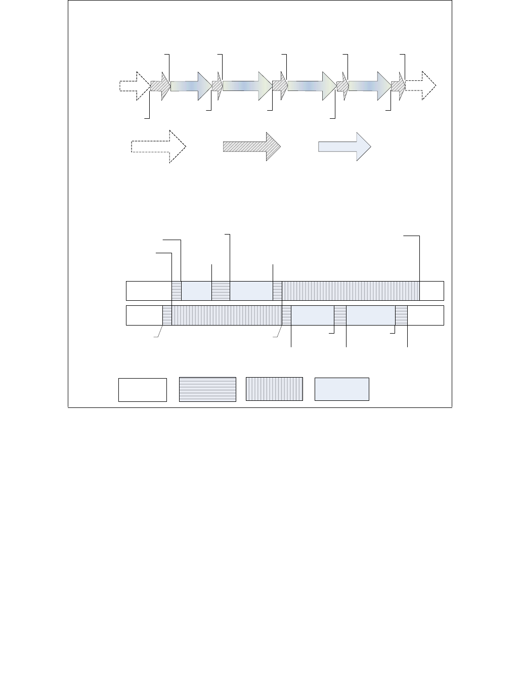
Vol. 3C 31-3
VIRTUAL-MACHINE MONITOR PROGRAMMING CONSIDERATIONS
Processors perform various checks while executing any VMX instruction. They follow well-defined error handling on
failures. VMX instruction execution failures detected before loading of a guest state are handled by the processor
as follows:
•If the working-VMCS pointer is not valid, the instruction fails by setting RFLAGS.CF to 1.
•If the working-VMCS pointer is valid, RFLAGS.ZF is set to 1 and the proper error-code is saved in the VM-
instruction error field of the working-VMCS.
Software is required to check RFLAGS.CF and RFLAGS.ZF to determine the success or failure of VMX instruction
executions.
The following items provide details regarding use of the VM-entry instructions (VMLAUNCH and VMRESUME):
•If the working-VMCS pointer is valid, the state of the working VMCS may cause the VM-entry instruction to fail.
RFLAGS.ZF is set to 1 and one of the following values is saved in the VM-instruction error field:
— 4: VMLAUNCH with non-clear VMCS.
If this error occurs, software can avoid the error by executing VMRESUME.
— 5: VMRESUME with non-launched VMCS.
If this error occurs, software can avoid the error by executing VMLAUNCH.
Figure 31-1. VMX Transitions and States of VMCS in a Logical Processor
(a) VMX Operation and VMX Transitions
(b) State of VMCS and VMX Operation
Processor
Operation
VMXON
VM Entry VM Entry VM Entry VM Entry
VM Exit VM Exit
VM Exit
VM Exit
VMXOFF
Outside
VMX
Operation
VMX Root
Operation
VMX
Non-Root
Operation
Legend:
Legend: Inactive
VMCS
Current VMCS
(working)
Active VMCS
(not current)
Current VMCS
(controlling)
VMCS B
VMCS A
VMLAUNCH VMRESUME
VMPTRLD B
VMCLEAR B
VM Exit VM Exit
VMPTRLD A VMPTRLD A
VMCLEAR A
VM Exit VM Exit
VMLAUNCH VMRESUME

31-4 Vol. 3C
VIRTUAL-MACHINE MONITOR PROGRAMMING CONSIDERATIONS
— 6: VMRESUME after VMXOFF.1
If this error occurs, software can avoid the error by executing the following sequence of instructions:
VMPTRST working-VMCS pointer
VMCLEAR working-VMCS pointer
VMPTRLD working-VMCS pointer
VMLAUNCH
(VMPTRST may not be necessary is software already knows the working-VMCS pointer.)
•If none of the above errors occur, the processor checks on the VMX controls and host-state area. If any of these
checks fail, the VM-entry instruction fails. RFLAGS.ZF is set to 1 and either 7 (VM entry with invalid control
field(s)) or 8 (VM entry with invalid host-state field(s)) is saved in the VM-instruction error field.
•After a VM-entry instruction (VMRESUME or VMLAUNCH) successfully completes the general checks and checks
on VMX controls and the host-state area (see Section 26.2), any errors encountered while loading of guest-
state (due to bad guest-state or bad MSR loading) causes the processor to load state from the host-state area
of the working VMCS as if a VM exit had occurred (see Section 31.7).
This failure behavior differs from that of VM exits in that no guest-state is saved to the guest-state area. A VMM
can detect its VM-exit handler was invoked by such a failure by checking bit 31 (for 1) in the exit reason field of
the working VMCS and further identify the failure by using the exit qualification field.
See Chapter 26 for more details about the VM-entry instructions.
31.5 VMM SETUP & TEAR DOWN
VMMs need to ensure that the processor is running in protected mode with paging before entering VMX operation.
The following list describes the minimal steps required to enter VMX root operation with a VMM running at CPL = 0.
•Check VMX support in processor using CPUID.
•Determine the VMX capabilities supported by the processor through the VMX capability MSRs. See Section
31.5.1 and Appendix A.
•Create a VMXON region in non-pageable memory of a size specified by IA32_VMX_BASIC MSR and aligned to a
4-KByte boundary. Software should read the capability MSRs to determine width of the physical addresses that
may be used for the VMXON region and ensure the entire VMXON region can be addressed by addresses with
that width. Also, software must ensure that the VMXON region is hosted in cache-coherent memory.
•Initialize the version identifier in the VMXON region (the first 31 bits) with the VMCS revision identifier reported
by capability MSRs. Clear bit 31 of the first 4 bytes of the VMXON region.
•Ensure the current processor operating mode meets the required CR0 fixed bits (CR0.PE = 1, CR0.PG = 1).
Other required CR0 fixed bits can be detected through the IA32_VMX_CR0_FIXED0 and
IA32_VMX_CR0_FIXED1 MSRs.
•Enable VMX operation by setting CR4.VMXE = 1. Ensure the resultant CR4 value supports all the CR4 fixed bits
reported in the IA32_VMX_CR4_FIXED0 and IA32_VMX_CR4_FIXED1 MSRs.
•Ensure that the IA32_FEATURE_CONTROL MSR (MSR index 3AH) has been properly programmed and that its
lock bit is set (Bit 0 = 1). This MSR is generally configured by the BIOS using WRMSR.
•Execute VMXON with the physical address of the VMXON region as the operand. Check successful execution of
VMXON by checking if RFLAGS.CF = 0.
Upon successful execution of the steps above, the processor is in VMX root operation.
A VMM executing in VMX root operation and CPL = 0 leaves VMX operation by executing VMXOFF and verifies
successful execution by checking if RFLAGS.CF = 0 and RFLAGS.ZF = 0.
If an SMM monitor has been configured to service SMIs while in VMX operation (see Section 34.15), the SMM
monitor needs to be torn down before the executive monitor can leave VMX operation (see Section 34.15.7).
VMXOFF fails for the executive monitor (a VMM that entered VMX operation by way of issuing VMXON) if SMM
monitor is configured.
1. Earlier versions of this manual described this error as “VMRESUME with a corrupted VMCS”.

Vol. 3C 31-5
VIRTUAL-MACHINE MONITOR PROGRAMMING CONSIDERATIONS
31.5.1 Algorithms for Determining VMX Capabilities
As noted earlier, a VMM should determine the VMX capabilities supported by the processor by reading the VMX
capability MSRs. The architecture for these MSRs is detailed in Appendix A.
As noted in Chapter 26, “VM Entries”, certain VMX controls are reserved and must be set to a specific value (0 or
1) determined by the processor. The specific value to which a reserved control must be set is its default setting.
Most controls have a default setting of 0; Appendix A.2 identifies those controls that have a default setting of 1. The
term default1 describes the class of controls whose default setting is 1. The are controls in this class from the pin-
based VM-execution controls, the primary processor-based VM-execution controls, the VM-exit controls, and the
VM-entry controls. There are no secondary processor-based VM-execution controls in the default1 class.
Future processors may define new functionality for one or more reserved controls. Such processors would allow
each newly defined control to be set either to 0 or to 1. Software that does not desire a control’s new functionality
should set the control to its default setting.
The capability MSRs IA32_VMX_PINBASED_CTLS, IA32_VMX_PROCBASED_CTLS, IA32_VMX_EXIT_CTLS, and
IA32_VMX_ENTRY_CTLS report, respectively, on the allowed settings of most of the pin-based VM-execution
controls, the primary processor-based VM-execution controls, the VM-exit controls, and the VM-entry controls.
However, they will always report that any control in the default1 class must be 1. If a logical processor allows any
control in the default1 class to be 0, it indicates this fact by returning 1 for the value of bit 55 of the
IA32_VMX_BASIC MSR. If this bit is 1, the logical processor supports the capability MSRs
IA32_VMX_TRUE_PINBASED_CTLS, IA32_VMX_TRUE_PROCBASED_CTLS, IA32_VMX_TRUE_EXIT_CTLS, and
IA32_VMX_TRUE_ENTRY_CTLS. These capability MSRs report, respectively, on the allowed settings of all of the
pin-based VM-execution controls, the primary processor-based VM-execution controls, the VM-exit controls, and
the VM-entry controls.
Software may use one of the following high-level algorithms to determine the correct default control settings:1
1. The following algorithm does not use the details given in Appendix A.2:
a. Ignore bit 55 of the IA32_VMX_BASIC MSR.
b. Using RDMSR, read the VMX capability MSRs IA32_VMX_PINBASED_CTLS, IA32_VMX_PROCBASED_CTLS,
IA32_VMX_EXIT_CTLS, and IA32_VMX_ENTRY_CTLS.
c. Set the VMX controls as follows:
i) If the relevant VMX capability MSR reports that a control has a single setting, use that setting.
ii) If (1) the relevant VMX capability MSR reports that a control can be set to 0 or 1; and (2) the control’s
meaning is known to the VMM; then set the control based on functionality desired.
iii) If (1) the relevant VMX capability MSR reports that a control can be set to 0 or 1; and (2) the control’s
meaning is not known to the VMM; then set the control to 0.
A VMM using this algorithm will set to 1 all controls in the default1 class (in step (c)(i)). It will operate
correctly even on processors that allow some controls in the default1 class to be 0. However, such a VMM will
not be able to use the new features enabled by the 0-setting of such controls. For that reason, this algorithm
is not recommended.
2. The following algorithm uses the details given in Appendix A.2. This algorithm requires software to know the
identity of the controls in the default1 class:
a. Using RDMSR, read the IA32_VMX_BASIC MSR.
b. Use bit 55 of that MSR as follows:
i) If bit 55 is 0, use RDMSR to read the VMX capability MSRs IA32_VMX_PINBASED_CTLS,
IA32_VMX_PROCBASED_CTLS, IA32_VMX_EXIT_CTLS, and IA32_VMX_ENTRY_CTLS.
ii) If bit 55 is 1, use RDMSR to read the VMX capability MSRs IA32_VMX_TRUE_PINBASED_CTLS,
IA32_VMX_TRUE_PROCBASED_CTLS, IA32_VMX_TRUE_EXIT_CTLS, and
IA32_VMX_TRUE_ENTRY_CTLS.
1. These algorithms apply only to the pin-based VM-execution controls, the primary processor-based VM-execution controls, the VM-
exit controls, and the VM-entry controls. Because there are no secondary processor-based VM-execution controls in the default1
class, a VMM can always set to 0 any such control whose meaning is unknown to it.

31-6 Vol. 3C
VIRTUAL-MACHINE MONITOR PROGRAMMING CONSIDERATIONS
c. Set the VMX controls as follows:
i) If the relevant VMX capability MSR reports that a control has a single setting, use that setting.
ii) If (1) the relevant VMX capability MSR reports that a control can be set to 0 or 1; and (2) the control’s
meaning is known to the VMM; then set the control based on functionality desired.
iii) If (1) the relevant VMX capability MSR reports that a control can be set to 0 or 1; (2) the control’s
meaning is not known to the VMM; and (3) the control is not in the default1 class; then set the control
to 0.
iv) If (1) the relevant VMX capability MSR reports that a control can be set to 0 or 1; (2) the control’s
meaning is not known to the VMM; and (3) the control is in the default1 class; then set the control to 1.
A VMM using this algorithm will set to 1 all controls in default1 class whose meaning it does not know (either
in step (c)(i) or step (c)(iv)). It will operate correctly even on processors that allow some controls in the
default1 class to be 0. Unlike a VMM using Algorithm 1, a VMM using Algorithm 2 will be able to use the new
features enabled by the 0-setting of such controls.
3. The following algorithm uses the details given in Appendix A.2. This algorithm does not require software to
know the identity of the controls in the default1 class:
a. Using RDMSR, read the VMX capability MSRs IA32_VMX_BASIC, IA32_VMX_PINBASED_CTLS,
IA32_VMX_PROCBASED_CTLS, IA32_VMX_EXIT_CTLS, and IA32_VMX_ENTRY_CTLS.
b. If bit 55 of the IA32_VMX_BASIC MSR is 0, set the VMX controls as follows:
i) If the relevant VMX capability MSR reports that a control has a single setting, use that setting.
ii) If (1) the relevant VMX capability MSR reports that a control can be set to 0 or 1; and (2) the control’s
meaning is known to the VMM; then set the control based on functionality desired.
iii) If (1) the relevant VMX capability MSR reports that a control can be set to 0 or 1; and (2) the control’s
meaning is not known to the VMM; then set the control to 0.
c. If bit 55 of the IA32_VMX_BASIC MSR is 1, use RDMSR to read the VMX capability MSRs
IA32_VMX_TRUE_PINBASED_CTLS, IA32_VMX_TRUE_PROCBASED_CTLS, IA32_VMX_TRUE_EXIT_CTLS,
and IA32_VMX_TRUE_ENTRY_CTLS. Set the VMX controls as follows:
i) If the relevant VMX capability MSR just read reports that a control has a single setting, use that
setting.
ii) If (1) the relevant VMX capability MSR just read reports that a control can be set to 0 or 1; and (2) the
control’s meaning is known to the VMM; then set the control based on functionality desired.
iii) If (1) the relevant VMX capability MSR just read reports that a control can be set to 0 or 1; (2) the
control’s meaning is not known to the VMM; and (3) the relevant VMX capability MSR as read in step (a)
reports that a control can be set to 0; then set the control to 0.
iv) If (1) the relevant VMX capability MSR just read reports that a control can be set to 0 or 1; (2) the
control’s meaning is not known to the VMM; and (3) the relevant VMX capability MSR as read in step (a)
reports that a control must be 1; then set the control to 1.
A VMM using this algorithm will set to 1 all controls in the default1 class whose meaning it does not know (in
step (b)(i), step (c)(i), or step (c)(iv)). It will operate correctly even on processors that allow some controls in
the default1 class to be 0. Unlike a VMM using Algorithm 1, a VMM using Algorithm 3 will be able to use the
new features enabled by the 0-setting of such controls. Unlike a VMM using Algorithm 2, a VMM using
Algorithm 3 need not know the identities of the controls in the default1 class.
31.6 PREPARATION AND LAUNCHING A VIRTUAL MACHINE
The following list describes the minimal steps required by the VMM to set up and launch a guest VM.
•Create a VMCS region in non-pageable memory of size specified by the VMX capability MSR IA32_VMX_BASIC
and aligned to 4-KBytes. Software should read the capability MSRs to determine width of the physical
addresses that may be used for a VMCS region and ensure the entire VMCS region can be addressed by

Vol. 3C 31-7
VIRTUAL-MACHINE MONITOR PROGRAMMING CONSIDERATIONS
addresses with that width. The term “guest-VMCS address” refers to the physical address of the new VMCS
region for the following steps.
•Initialize the version identifier in the VMCS (first 31 bits) with the VMCS revision identifier reported by the VMX
capability MSR IA32_VMX_BASIC. Clear bit 31 of the first 4 bytes of the VMCS region.
•Execute the VMCLEAR instruction by supplying the guest-VMCS address. This will initialize the new VMCS
region in memory and set the launch state of the VMCS to “clear”. This action also invalidates the working-
VMCS pointer register to FFFFFFFF_FFFFFFFFH. Software should verify successful execution of VMCLEAR by
checking if RFLAGS.CF = 0 and RFLAGS.ZF = 0.
•Execute the VMPTRLD instruction by supplying the guest-VMCS address. This initializes the working-VMCS
pointer with the new VMCS region’s physical address.
•Issue a sequence of VMWRITEs to initialize various host-state area fields in the working VMCS. The initialization
sets up the context and entry-points to the VMM upon subsequent VM exits from the guest. Host-state fields
include control registers (CR0, CR3 and CR4), selector fields for the segment registers (CS, SS, DS, ES, FS, GS
and TR), and base-address fields (for FS, GS, TR, GDTR and IDTR; RSP, RIP and the MSRs that control fast
system calls).
Chapter 27 describes the host-state consistency checking done by the processor for VM entries. The VMM is
required to set up host-state that comply with these consistency checks. For example, VMX requires the host-
area to have a task register (TR) selector with TI and RPL fields set to 0 and pointing to a valid TSS.
•Use VMWRITEs to set up the various VM-exit control fields, VM-entry control fields, and VM-execution control
fields in the VMCS. Care should be taken to make sure the settings of individual fields match the allowed 0 and
1 settings for the respective controls as reported by the VMX capability MSRs (see Appendix A). Any settings
inconsistent with the settings reported by the capability MSRs will cause VM entries to fail.
•Use VMWRITE to initialize various guest-state area fields in the working VMCS. This sets up the context and
entry-point for guest execution upon VM entry. Chapter 27 describes the guest-state loading and checking
done by the processor for VM entries to protected and virtual-8086 guest execution.
•The VMM is required to set up guest-state that complies with these consistency checks:
— If the VMM design requires the initial VM launch to cause guest software (typically the guest virtual BIOS)
execution from the guest’s reset vector, it may need to initialize the guest execution state to reflect the
state of a physical processor at power-on reset (described in Chapter 9, Intel® 64 and IA-32 Architectures
Software Developer’s Manual, Volume 3A).
— The VMM may need to initialize additional guest execution state that is not captured in the VMCS guest-
state area by loading them directly on the respective processor registers. Examples include general
purpose registers, the CR2 control register, debug registers, floating point registers and so forth. VMM may
support lazy loading of FPU, MMX, SSE, and SSE2 states with CR0.TS = 1 (described in Intel® 64 and IA-32
Architectures Software Developer’s Manual, Volume 3A).
•Execute VMLAUNCH to launch the guest VM. If VMLAUNCH fails due to any consistency checks before guest-
state loading, RFLAGS.CF or RFLAGS.ZF will be set and the VM-instruction error field (see Section 24.9.5) will
contain the error-code. If guest-state consistency checks fail upon guest-state loading, the processor loads
state from the host-state area as if a VM exit had occurred (see Section 31.6).
VMLAUNCH updates the controlling-VMCS pointer with the working-VMCS pointer and saves the old value of
controlling-VMCS as the parent pointer. In addition, the launch state of the guest VMCS is changed to “launched”
from “clear”. Any programmed exit conditions will cause the guest to VM exit to the VMM. The VMM should execute
VMRESUME instruction for subsequent VM entries to guests in a “launched” state.
31.7 HANDLING OF VM EXITS
This section provides examples of software steps involved in a VMM’s handling of VM-exit conditions:
•Determine the exit reason through a VMREAD of the exit-reason field in the working-VMCS. Appendix C
describes exit reasons and their encodings.
•VMREAD the exit-qualification from the VMCS if the exit-reason field provides a valid qualification. The exit-
qualification field provides additional details on the VM-exit condition. For example, in case of page faults, the
exit-qualification field provides the guest linear address that caused the page fault.

31-8 Vol. 3C
VIRTUAL-MACHINE MONITOR PROGRAMMING CONSIDERATIONS
•Depending on the exit reason, fetch other relevant fields from the VMCS. Appendix C lists the various exit
reasons.
•Handle the VM-exit condition appropriately in the VMM. This may involve the VMM emulating one or more guest
instructions, programming the underlying host hardware resources, and then re-entering the VM to continue
execution.
31.7.1 Handling VM Exits Due to Exceptions
As noted in Section 25.2, an exception causes a VM exit if the bit corresponding to the exception’s vector is set in
the exception bitmap. (For page faults, the error code also determines whether a VM exit occurs.) This section
provide some guidelines of how a VMM might handle such exceptions.
Exceptions result when a logical processor encounters an unusual condition that software may not have expected.
When guest software encounters an exception, it may be the case that the condition was caused by the guest soft-
ware. For example, a guest application may attempt to access a page that is restricted to supervisor access. Alter-
natively, the condition causing the exception may have been established by the VMM. For example, a guest OS may
attempt to access a page that the VMM has chosen to make not present.
When the condition causing an exception was established by guest software, the VMM may choose to reflect the
exception to guest software. When the condition was established by the VMM itself, the VMM may choose to
resume guest software after removing the condition.
31.7.1.1 Reflecting Exceptions to Guest Software
If the VMM determines that a VM exit was caused by an exception due to a condition established by guest software,
it may reflect that exception to guest software. The VMM would cause the exception to be delivered to guest soft-
ware, where it can be handled as it would be if the guest were running on a physical machine. This section describes
how that may be done.
In general, the VMM can deliver the exception to guest software using VM-entry event injection as described in
Section 26.5. The VMM can copy (using VMREAD and VMWRITE) the contents of the VM-exit interruption-informa-
tion field (which is valid, since the VM exit was caused by an exception) to the VM-entry interruption-information
field (which, if valid, will cause the exception to be delivered as part of the next VM entry). The VMM would also
copy the contents of the VM-exit interruption error-code field to the VM-entry exception error-code field; this need
not be done if bit 11 (error code valid) is clear in the VM-exit interruption-information field. After this, the VMM can
execute VMRESUME.
The following items provide details that may qualify the general approach:
•Care should be taken to ensure that reserved bits 30:12 in the VM-entry interruption-information field are 0. In
particular, some VM exits may set bit 12 in the VM-exit interruption-information field to indicate NMI
unblocking due to IRET. If this bit is copied as 1 into the VM-entry interruption-information field, the next
VM entry will fail because that bit should be 0.
•Bit 31 (valid) of the IDT-vectoring information field indicates, if set, that the exception causing the VM exit
occurred while another event was being delivered to guest software. If this is the case, it may not be
appropriate simply to reflect that exception to guest software. To provide proper virtualization of the exception
architecture, a VMM should handle nested events as a physical processor would. Processor handling is
described in Chapter 6, “Interrupt 8—Double Fault Exception (#DF)” in Intel® 64 and IA-32 Architectures
Software Developer’s Manual, Volume 3A.
— The VMM should reflect the exception causing the VM exit to guest software in any of the following cases:
•The value of bits 10:8 (interruption type) of the IDT-vectoring information field is anything other than 3
(hardware exception).
•The value of bits 7:0 (vector) of the IDT-vectoring information field indicates a benign exception (1, 2,
3, 4, 5, 6, 7, 9, 16, 17, 18, or 19).
•The value of bits 7:0 (vector) of the VM-exit interruption-information field indicates a benign exception.

Vol. 3C 31-9
VIRTUAL-MACHINE MONITOR PROGRAMMING CONSIDERATIONS
•The value of bits 7:0 of the IDT-vectoring information field indicates a contributory exception (0, 10,
11, 12, or 13) and the value of bits 7:0 of the VM-exit interruption-information field indicates a page
fault (14).
— If the value of bits 10:8 of the IDT-vectoring information field is 3 (hardware exception), the VMM should
reflect a double-fault exception to guest software in any of the following cases:
•The value of bits 7:0 of the IDT-vectoring information field and the value of bits 7:0 of the VM-exit
interruption-information field each indicates a contributory exception.
•The value of bits 7:0 of the IDT-vectoring information field indicates a page fault and the value of
bits 7:0 of the VM-exit interruption-information field indicates either a contributory exception or a page
fault.
A VMM can reflect a double-fault exception to guest software by setting the VM-entry interruption-
information and VM-entry exception error-code fields as follows:
•Set bits 7:0 (vector) of the VM-entry interruption-information field to 8 (#DF).
•Set bits 10:8 (interruption type) of the VM-entry interruption-information field to 3 (hardware
exception).
•Set bit 11 (deliver error code) of the VM-entry interruption-information field to 1.
•Clear bits 30:12 (reserved) of VM-entry interruption-information field.
•Set bit 31 (valid) of VM-entry interruption-information field.
•Set the VM-entry exception error-code field to zero.
— If the value of bits 10:8 of the IDT-vectoring information field is 3 (hardware exception) and the value of
bits 7:0 is 8 (#DF), guest software would have encountered a triple fault. Event injection should not be
used in this case. The VMM may choose to terminate the guest, or it might choose to enter the guest in the
shutdown activity state.
31.7.1.2 Resuming Guest Software after Handling an Exception
If the VMM determines that a VM exit was caused by an exception due to a condition established by the VMM itself,
it may choose to resume guest software after removing the condition. The approach for removing the condition
may be specific to the VMM’s software architecture. and algorithms This section describes how guest software may
be resumed after removing the condition.
In general, the VMM can resume guest software simply by executing VMRESUME. The following items provide
details of cases that may require special handling:
•If the “NMI exiting” VM-execution control is 0, bit 12 of the VM-exit interruption-information field indicates that
the VM exit was due to a fault encountered during an execution of the IRET instruction that unblocked non-
maskable interrupts (NMIs). In particular, it provides this indication if the following are both true:
— Bit 31 (valid) in the IDT-vectoring information field is 0.
— The value of bits 7:0 (vector) of the VM-exit interruption-information field is not 8 (the VM exit is not due
to a double-fault exception).
If both are true and bit 12 of the VM-exit interruption-information field is 1, NMIs were blocked before guest
software executed the IRET instruction that caused the fault that caused the VM exit. The VMM should set bit 3
(blocking by NMI) in the interruptibility-state field (using VMREAD and VMWRITE) before resuming guest
software.
•If the “virtual NMIs” VM-execution control is 1, bit 12 of the VM-exit interruption-information field indicates
that the VM exit was due to a fault encountered during an execution of the IRET instruction that removed
virtual-NMI blocking. In particular, it provides this indication if the following are both true:
— Bit 31 (valid) in the IDT-vectoring information field is 0.
— The value of bits 7:0 (vector) of the VM-exit interruption-information field is not 8 (the VM exit is not due
to a double-fault exception).
If both are true and bit 12 of the VM-exit interruption-information field is 1, there was virtual-NMI blocking
before guest software executed the IRET instruction that caused the fault that caused the VM exit. The VMM

31-10 Vol. 3C
VIRTUAL-MACHINE MONITOR PROGRAMMING CONSIDERATIONS
should set bit 3 (blocking by NMI) in the interruptibility-state field (using VMREAD and VMWRITE) before
resuming guest software.
•Bit 31 (valid) of the IDT-vectoring information field indicates, if set, that the exception causing the VM exit
occurred while another event was being delivered to guest software. The VMM should ensure that the other
event is delivered when guest software is resumed. It can do so using the VM-entry event injection described
in Section 26.5 and detailed in the following paragraphs:
— The VMM can copy (using VMREAD and VMWRITE) the contents of the IDT-vectoring information field
(which is presumed valid) to the VM-entry interruption-information field (which, if valid, will cause the
exception to be delivered as part of the next VM entry).
•The VMM should ensure that reserved bits 30:12 in the VM-entry interruption-information field are 0. In
particular, the value of bit 12 in the IDT-vectoring information field is undefined after all VM exits. If this
bit is copied as 1 into the VM-entry interruption-information field, the next VM entry will fail because the
bit should be 0.
•If the “virtual NMIs” VM-execution control is 1 and the value of bits 10:8 (interruption type) in the IDT-
vectoring information field is 2 (indicating NMI), the VM exit occurred during delivery of an NMI that had
been injected as part of the previous VM entry. In this case, bit 3 (blocking by NMI) will be 1 in the inter-
ruptibility-state field in the VMCS. The VMM should clear this bit; otherwise, the next VM entry will fail
(see Section 26.3.1.5).
— The VMM can also copy the contents of the IDT-vectoring error-code field to the VM-entry exception error-
code field. This need not be done if bit 11 (error code valid) is clear in the IDT-vectoring information field.
— The VMM can also copy the contents of the VM-exit instruction-length field to the VM-entry instruction-
length field. This need be done only if bits 10:8 (interruption type) in the IDT-vectoring information field
indicate either software interrupt, privileged software exception, or software exception.
31.8 MULTI-PROCESSOR CONSIDERATIONS
The most common VMM design will be the symmetric VMM. This type of VMM runs the same VMM binary on all
logical processors. Like a symmetric operating system, the symmetric VMM is written to ensure all critical data is
updated by only one processor at a time, IO devices are accessed sequentially, and so forth. Asymmetric VMM
designs are possible. For example, an asymmetric VMM may run its scheduler on one processor and run just
enough of the VMM on other processors to allow the correct execution of guest VMs. The remainder of this section
focuses on the multi-processor considerations for a symmetric VMM.
A symmetric VMM design does not preclude asymmetry in its operations. For example, a symmetric VMM can
support asymmetric allocation of logical processor resources to guests. Multiple logical processors can be brought
into a single guest environment to support an MP-aware guest OS. Because an active VMCS can not control more
than one logical processor simultaneously, a symmetric VMM must make copies of its VMCS to control the VM allo-
cated to support an MP-aware guest OS. Care must be taken when accessing data structures shared between these
VMCSs. See Section 31.8.4.
Although it may be easier to develop a VMM that assumes a fully-symmetric view of hardware capabilities (with all
processors supporting the same processor feature sets, including the same revision of VMX), there are advantages
in developing a VMM that comprehends different levels of VMX capability (reported by VMX capability MSRs). One
possible advantage of such an approach could be that an existing software installation (VMM and guest software
stack) could continue to run without requiring software upgrades to the VMM, when the software installation is
upgraded to run on hardware with enhancements in the processor’s VMX capabilities. Another advantage could be
that a single software installation image, consisting of a VMM and guests, could be deployed to multiple hardware
platforms with varying VMX capabilities. In such cases, the VMM could fall back to a common subset of VMX
features supported by all VMX revisions, or choose to understand the asymmetry of the VMX capabilities and assign
VMs accordingly.
This section outlines some of the considerations to keep in mind when developing an MP-aware VMM.

Vol. 3C 31-11
VIRTUAL-MACHINE MONITOR PROGRAMMING CONSIDERATIONS
31.8.1 Initialization
Before enabling VMX, an MP-aware VMM must check to make sure that all processors in the system are compatible
and support features required. This can be done by:
•Checking the CPUID on each logical processor to ensure VMX is supported and that the overall feature set of
each logical processor is compatible.
•Checking VMCS revision identifiers on each logical processor.
•Checking each of the “allowed-1” or “allowed-0” fields of the VMX capability MSR’s on each processor.
31.8.2 Moving a VMCS Between Processors
An MP-aware VMM is free to assign any logical processor to a VM. But for performance considerations, moving a
guest VMCS to another logical processor is slower than resuming that guest VMCS on the same logical processor.
Certain VMX performance features (such as caching of portions of the VMCS in the processor) are optimized for a
guest VMCS that runs on the same logical processor.
The reasons are:
•To restart a guest on the same logical processor, a VMM can use VMRESUME. VMRESUME is expected to be
faster than VMLAUNCH in general.
•To migrate a VMCS to another logical processor, a VMM must use the sequence of VMCLEAR, VMPTRLD and
VMLAUNCH.
•Operations involving VMCLEAR can impact performance negatively. See
Section 24.11.3.
A VMM scheduler should make an effort to schedule a guest VMCS to run on the logical processor where it last ran.
Such a scheduler might also benefit from doing lazy VMCLEARs (that is: performing a VMCLEAR on a VMCS only
when the scheduler knows the VMCS is being moved to a new logical processor). The remainder of this section
describes the steps a VMM must take to move a VMCS from one processor to another.
A VMM must check the VMCS revision identifier in the VMX capability MSR IA32_VMX_BASIC to determine if the
VMCS regions are identical between all logical processors. If the VMCS regions are identical (same revision ID) the
following sequence can be used to move or copy the VMCS from one logical processor to another:
•Perform a VMCLEAR operation on the source logical processor. This ensures that all VMCS data that may be
cached by the processor are flushed to memory.
•Copy the VMCS region from one memory location to another location. This is an optional step assuming the
VMM wishes to relocate the VMCS or move the VMCS to another system.
•Perform a VMPTRLD of the physical address of VMCS region on the destination processor to establish its current
VMCS pointer.
If the revision identifiers are different, each field must be copied to an intermediate structure using individual reads
(VMREAD) from the source fields and writes (VMWRITE) to destination fields. Care must be taken on fields that are
hard-wired to certain values on some processor implementations.
31.8.3 Paired Index-Data Registers
A VMM may need to virtualize hardware that is visible to software using paired index-data registers. Paired index-
data register interfaces, such as those used in PCI (CF8, CFC), require special treatment in cases where a VM
performing writes to these pairs can be moved during execution. In this case, the index (e.g. CF8) should be part
of the virtualized state. If the VM is moved during execution, writes to the index should be redone so subsequent
data reads/writes go to the right location.
31.8.4 External Data Structures
Certain fields in the VMCS point to external data structures (for example: the MSR bitmap, the I/O bitmaps). If a
logical processor is in VMX non-root operation, none of the external structures referenced by that logical

31-12 Vol. 3C
VIRTUAL-MACHINE MONITOR PROGRAMMING CONSIDERATIONS
processor's current VMCS should be modified by any logical processor or DMA. Before updating one of these struc-
tures, the VMM must ensure that no logical processor whose current VMCS references the structure is in VMX non-
root operation.
If a VMM uses multiple VMCS with each VMCS using separate external structures, and these structures must be
kept synchronized, the VMM must apply the same care to updating these structures.
31.8.5 CPUID Emulation
CPUID reports information that is used by OS and applications to detect hardware features. It also provides multi-
threading/multi-core configuration information. For example, MP-aware OSs rely on data reported by CPUID to
discover the topology of logical processors in a platform (see Section 8.9, “Programming Considerations for Hard-
ware Multi-Threading Capable Processors,” in the Intel® 64 and IA-32 Architectures Software Developer’s Manual,
Volume 3A).
If a VMM is to support asymmetric allocation of logical processor resources to guest OSs that are MP aware, then
the VMM must emulate CPUID for its guests. The emulation of CPUID by the VMM must ensure the guest’s view of
CPUID leaves are consistent with the logical processor allocation committed by the VMM to each guest OS.
31.9 32-BIT AND 64-BIT GUEST ENVIRONMENTS
For the most part, extensions provided by VMX to support virtualization are orthogonal to the extensions provided
by Intel 64 architecture. There are considerations that impact VMM designs. These are described in the following
subsections.
31.9.1 Operating Modes of Guest Environments
For Intel 64 processors, VMX operation supports host and guest environments that run in IA-32e mode or without
IA-32e mode. VMX operation also supports host and guest environments on IA-32 processors.
A VMM entering VMX operation while IA-32e mode is active is considered to be an IA-32e mode host. A VMM
entering VMX operation while IA-32e mode is not activated or not available is referred to as a 32-bit VMM. The type
of guest operations such VMMs support are summarized in Table 31-1.
A VM exit may occur to an IA-32e mode guest in either 64-bit sub-mode or compatibility sub-mode of IA-32e
mode. VMMs may resume guests in either mode. The sub-mode in which an IA-32e mode guest resumes VMX non-
root operation is determined by the attributes of the code segment which experienced the VM exit. If CS.L = 1, the
guest is executing in 64-bit mode; if CS.L = 0, the guest is executing in compatibility mode (see Section 31.9.5).
Not all of an IA-32e mode VMM must run in 64-bit mode. While some parts of an IA-32e mode VMM must run in 64-
bit mode, there are only a few restrictions preventing a VMM from executing in compatibility mode. The most
notable restriction is that most VMX instructions cause exceptions when executed in compatibility mode.
31.9.2 Handling Widths of VMCS Fields
Individual VMCS control fields must be accessed using VMREAD or VMWRITE instructions. Outside of 64-Bit mode,
VMREAD and VMWRITE operate on 32 bits of data. The widths of VMCS control fields may vary depending on
whether a processor supports Intel 64 architecture.
Table 31-1. Operating Modes for Host and Guest Environments
Capability Guest Operation
in IA-32e mode
Guest Operation
Not Requiring IA-32e Mode
IA-32e mode VMM Yes Yes
32-bit VMM Not supported Yes

Vol. 3C 31-13
VIRTUAL-MACHINE MONITOR PROGRAMMING CONSIDERATIONS
Many VMCS fields are architected to extend transparently on processors supporting Intel 64 architecture (64 bits
on processors that support Intel 64 architecture, 32 bits on processors that do not). Some VMCS fields are 64-bits
wide regardless of whether the processor supports Intel 64 architecture or is in IA-32e mode.
31.9.2.1 Natural-Width VMCS Fields
Many VMCS fields operate using natural width. Such fields return (on reads) and set (on writes) 32-bits when oper-
ating in 32-bit mode and 64-bits when operating in 64-bit mode. For the most part, these fields return the naturally
expected data widths. The “Guest RIP” field in the VMCS guest-state area is an example of this type of field.
31.9.2.2 64-Bit VMCS Fields
Unlike natural width fields, these fields are fixed to 64-bit width on all processors. When in 64-bit mode, reads of
these fields return 64-bit wide data and writes to these fields write 64-bits. When outside of 64-bit mode, reads of
these fields return the low 32-bits and writes to these fields write the low 32-bits and zero the upper 32-bits.
Should a non-IA-32e mode host require access to the upper 32-bits of these fields, a separate VMCS encoding is
used when issuing VMREAD/VMWRITE instructions.
The VMCS control field “MSR bitmap address” (which contains the physical address of a region of memory which
specifies which MSR accesses should generate VM-exits) is an example of this type of field. Specifying encoding
00002004H to VMREAD returns the lower 32-bits to non-IA-32e mode hosts and returns 64-bits to 64-bit hosts.
The separate encoding 00002005H returns only the upper 32-bits.
31.9.3 IA-32e Mode Hosts
An IA-32e mode host is required to support 64-bit guest environments. Because activating IA-32e mode currently
requires that paging be disabled temporarily and VMX entry requires paging to be enabled, IA-32e mode must be
enabled before entering VMX operation. For this reason, it is not possible to toggle in and out of IA-32e mode in a
VMM.
Section 31.5 describes the steps required to launch a VMM. An IA-32e mode host is also required to set the “host
address-space size” VMCS VM-exit control to 1. The value of this control is then loaded in the IA32_EFER.LME/LMA
and CS.L bits on each VM exit. This establishes a 64-bit host environment as execution transfers to the VMM entry
point. At a minimum, the entry point is required to be in a 64-bit code segment. Subsequently, the VMM can, if it
chooses, switch to 32-bit compatibility mode on a code-segment basis (see Section 31.9.1). Note, however, that
VMX instructions other than VMCALL and VMFUNC are not supported in compatibility mode; they generate an
invalid opcode exception if used.
The following VMCS controls determine the value of IA32_EFER when a VM exit occurs: the “host address-space
size” control (described above), the “load IA32_EFER” VM-exit control, the “VM-exit MSR-load count,” and the “VM-
exit MSR-load address” (see Section 27.3).
If the “load IA32_EFER” VM-exit control is 1, the value of the LME and LMA bits in the IA32_EFER field in the host-
state area must be the value of the “host address-space size” VM-exit control.
The loading of IA32_EFER.LME/LMA and CS.L bits established by the “host address-space size” control precede any
loading of the IA32_EFER MSR due from the VM-exit MSR-load area. If IA32_EFER is specified in the VM-exit MSR-
load area, the value of the LME bit in the load image of IA32_EFER should match the setting of the “host address-
space size” control. Otherwise the attempt to modify the LME bit (while paging is enabled) will lead to a VMX-abort.
However, IA32_EFER.LMA is always set by the processor to equal IA32_EFER.LME & CR0.PG; the value specified
for LMA in the load image of the IA32_EFER MSR is ignored. For these and performance reasons, VMM writers may
choose to not use the VM-exit/entry MSR-load/save areas for IA32_EFER.
On a VMM teardown, VMX operation should be exited before deactivating IA-32e mode if the latter is required.
31.9.4 IA-32e Mode Guests
A 32-bit guest can be launched by either IA-32e-mode hosts or non-IA-32e-mode hosts. A 64-bit guests can only
be launched by a IA-32e-mode host.

31-14 Vol. 3C
VIRTUAL-MACHINE MONITOR PROGRAMMING CONSIDERATIONS
In addition to the steps outlined in Section 31.6, VMM writers need to:
•Set the “IA-32e-mode guest” VM-entry control to 1 in the VMCS to assure VM-entry (VMLAUNCH or
VMRESUME) will establish a 64-bit (or 32-bit compatible) guest operating environment.
•Enable paging (CR0.PG) and PAE mode (CR4.PAE) to assure VM-entry to a 64-bit guest will succeed.
•Ensure that the host to be in IA-32e mode (the IA32_EFER.LMA must be set to 1) and the setting of the VM-exit
“host address-space size” control bit in the VMCS must also be set to 1.
If each of the above conditions holds true, then VM-entry will copy the value of the VM-entry “IA-32e-mode guest”
control bit into the guests IA32_EFER.LME bit, which will result in subsequent activation of IA-32e mode. If any of
the above conditions is false, the VM-entry will fail and load state from the host-state area of the working VMCS as
if a VM exit had occurred (see Section 26.7).
The following VMCS controls determine the value of IA32_EFER on a VM entry: the “IA-32e-mode guest” VM-entry
control (described above), the “load IA32_EFER” VM-entry control, the “VM-entry MSR-load count,” and the “VM-
entry MSR-load address” (see Section 26.4).
If the “load IA32_EFER” VM-entry control is 1, the value of the LME and LMA bits in the IA32_EFER field in the
guest-state area must be the value of the “IA-32e-mode guest” VM-entry control. Otherwise, the VM entry fails.
The loading of IA32_EFER.LME bit (described above) precedes any loading of the IA32_EFER MSR from the VM-
entry MSR-load area of the VMCS. If loading of IA32_EFER is specified in the VM-entry MSR-load area, the value of
the LME bit in the load image should be match the setting of the “IA-32e-mode guest” VM-entry control. Otherwise,
the attempt to modify the LME bit (while paging is enabled) results in a failed VM entry. However, IA32_EFER.LMA
is always set by the processor to equal IA32_EFER.LME & CR0.PG; the value specified for LMA in the load image of
the IA32_EFER MSR is ignored. For these and performance reasons, VMM writers may choose to not use the VM-
exit/entry MSR-load/save areas for IA32_EFER MSR.
Note that the VMM can control the processor’s architectural state when transferring control to a VM. VMM writers
may choose to launch guests in protected mode and subsequently allow the guest to activate IA-32e mode or they
may allow guests to toggle in and out of IA-32e mode. In this case, the VMM should require VM exit on accesses to
the IA32_EFER MSR to detect changes in the operating mode and modify the VM-entry “IA-32e-mode guest”
control accordingly.
A VMM should save/restore the extended (full 64-bit) contents of the guest general-purpose registers, the new
general-purpose registers (R8-R15) and the SIMD registers introduced in 64-bit mode should it need to modify
these upon VM exit.
31.9.5 32-Bit Guests
To launch or resume a 32-bit guest, VMM writers can follow the steps outlined in Section 31.6, making sure that the
“IA-32e-mode guest” VM-entry control bit is set to 0. Then the “IA-32e-mode guest” control bit is copied into the
guest IA32_EFER.LME bit, establishing IA32_EFER.LMA as 0.
31.10 HANDLING MODEL SPECIFIC REGISTERS
Model specific registers (MSR) provide a wide range of functionality. They affect processor features, control the
programming interfaces, or are used in conjunction with specific instructions. As part of processor virtualization, a
VMM may wish to protect some or all MSR resources from direct guest access.
VMX operation provides the following features to virtualize processor MSRs.
31.10.1 Using VM-Execution Controls
Processor-based VM-execution controls provide two levels of support for handling guest access to processor MSRs
using RDMSR and WRMSR:
•MSR bitmaps: In VMX implementations that support a 1-setting (see Appendix A) of the user-MSR-bitmaps
execution control bit, MSR bitmaps can be used to provide flexibility in managing guest MSR accesses. The

Vol. 3C 31-15
VIRTUAL-MACHINE MONITOR PROGRAMMING CONSIDERATIONS
MSR-bitmap-address in the guest VMCS can be programmed by VMM to point to a bitmap region which
specifies VM-exit behavior when reading and writing individual MSRs.
MSR bitmaps form a 4-KByte region in physical memory and are required to be aligned to a 4-KByte boundary.
The first 1-KByte region manages read control of MSRs in the range 00000000H-00001FFFH; the second 1-
KByte region covers read control of MSR addresses in the range C0000000H-C0001FFFH. The bitmaps for write
control of these MSRs are located in the 2-KByte region immediately following the read control bitmaps. While
the MSR bitmap address is part of VMCS, the MSR bitmaps themselves are not. This implies MSR bitmaps are
not accessible through VMREAD and VMWRITE instructions but rather by using ordinary memory writes. Also,
they are not specially cached by the processor and may be placed in normal cache-coherent memory by the
VMM.
When MSR bitmap addresses are properly programmed and the use-MSR-bitmap control (see Section 24.6.2)
is set, the processor consults the associated bit in the appropriate bitmap on guest MSR accesses to the corre-
sponding MSR and causes a VM exit if the bit in the bitmap is set. Otherwise, the access is permitted to
proceed. This level of protection may be utilized by VMMs to selectively allow guest access to some MSRs while
virtualizing others.
•Default MSR protection: If the use-MSR-bitmap control is not set, an attempt by a guest to access any MSR
causes a VM exit. This also occurs for any attempt to access an MSR outside the ranges identified above (even
if the use-MSR-bitmap control is set).
VM exits due to guest MSR accesses may be identified by the VMM through VM-exit reason codes. The MSR-read
exit reason implies guest software attempted to read an MSR protected either by default or through MSR bitmaps.
The MSR-write exit reason implies guest software attempting to write a MSR protected through the VM-execution
controls. Upon VM exits caused by MSR accesses, the VMM may virtualize the guest MSR access through emulation
of RDMSR/WRMSR.
31.10.2 Using VM-Exit Controls for MSRs
If a VMM allows its guest to access MSRs directly, the VMM may need to store guest MSR values and load host MSR
values for these MSRs on VM exits. This is especially true if the VMM uses the same MSRs while in VMX root oper-
ation.
A VMM can use the VM-exit MSR-store-address and the VM-exit MSR-store-count exit control fields (see Section
24.7.2) to manage how MSRs are stored on VM exits. The VM-exit MSR-store-address field contains the physical
address (16-byte aligned) of the VM-exit MSR-store area (a table of entries with 16 bytes per entry). Each table
entry specifies an MSR whose value needs to be stored on VM exits. The VM-exit MSR-store-count contains the
number of entries in the table.
Similarly the VM-exit MSR-load-address and VM-exit MSR-load-count fields point to the location and size of the VM-
exit MSR load area. The entries in the VM-exit MSR-load area contain the host expected values of specific MSRs
when a VM exit occurs.
Upon VM-exit, bits 127:64 of each entry in the VM-exit MSR-store area is updated with the contents of the MSR
indexed by bits 31:0. Also, bits 127:64 of each entry in the VM-exit MSR-load area is updated by loading with
values from bits 127:64 the contents of the MSR indexed by bits 31:0.
31.10.3 Using VM-Entry Controls for MSRs
A VMM may require specific MSRs to be loaded explicitly on VM entries while launching or resuming guest execu-
tion. The VM-entry MSR-load-address and VM-entry MSR-load-count entry control fields determine how MSRs are
loaded on VM-entries. The VM-entry MSR-load-address and count fields are similar in structure and function to the
VM-exit MSR-load address and count fields, except the MSR loading is done on VM-entries.
31.10.4 Handling Special-Case MSRs and Instructions
A number of instructions make use of designated MSRs in their operation. The VMM may need to consider saving
the states of those MSRs. Instructions that merit such consideration include SYSENTER/SYSEXIT,
SYSCALL/SYSRET, SWAPGS.

31-16 Vol. 3C
VIRTUAL-MACHINE MONITOR PROGRAMMING CONSIDERATIONS
31.10.4.1 Handling IA32_EFER MSR
The IA32_EFER MSR includes bit fields that allow system software to enable processor features. For example: the
SCE bit enables SYSCALL/SYSRET and the NXE bit enables the execute-disable bits in the paging-structure entries.
VMX provides hardware support to load the IA32_EFER MSR on VMX transitions and to save it on VM exits. Because
of this, VMM software need not use the RDMSR and WRMSR instruction to give the register different values during
host and guest execution.
31.10.4.2 Handling the SYSENTER and SYSEXIT Instructions
The SYSENTER and SYSEXIT instructions use three dedicated MSRs (IA32_SYSENTER_CS, IA32_SYSENTER_ESP
and IA32_SYSENTER_EIP) to manage fast system calls. These MSRs may be utilized by both the VMM and the
guest OS to manage system calls in VMX root operation and VMX non-root operation respectively.
VM entries load these MSRs from fields in the guest-state area of the VMCS. VM exits save the values of these MSRs
into those fields and loads the MSRs from fields in the host-state area.
31.10.4.3 Handling the SYSCALL and SYSRET Instructions
The SYSCALL/SYSRET instructions are similar to SYSENTER/SYSEXIT but are designed to operate within the
context of a 64-bit flat code segment. They are available only in 64-bit mode and only when the SCE bit of the
IA32_EFER MSR is set. SYSCALL/SYSRET invocations can occur from either 32-bit compatibility mode application
code or from 64-bit application code. Three related MSR registers (IA32_STAR, IA32_LSTAR, IA32_FMASK) are
used in conjunction with fast system calls/returns that use these instructions.
64-Bit hosts which make use of these instructions in the VMM environment will need to save the guest state of the
above registers on VM exit, load the host state, and restore the guest state on VM entry. One possible approach is
to use the VM-exit MSR-save and MSR-load areas and the VM-entry MSR-load area defined by controls in the VMCS.
A disadvantage to this approach, however, is that the approach results in the unconditional saving, loading, and
restoring of MSR registers on each VM exit or VM entry.
Depending on the design of the VMM, it is likely that many VM-exits will require no fast system call support but the
VMM will be burdened with the additional overhead of saving and restoring MSRs if the VMM chooses to support fast
system call uniformly. Further, even if the host intends to support fast system calls during a VM-exit, some of the
MSR values (such as the setting of the SCE bit in IA32_EFER) may not require modification as they may already be
set to the appropriate value in the guest.
For performance reasons, a VMM may perform lazy save, load, and restore of these MSR values on certain VM exits
when it is determined that this is acceptable. The lazy-save-load-restore operation can be carried out “manually”
using RDMSR and WRMSR.
31.10.4.4 Handling the SWAPGS Instruction
The SWAPGS instruction is available only in 64-bit mode. It swaps the contents of two specific MSRs
(IA32_GS_BASE and IA32_KERNEL_GS_BASE). The IA32_GS_BASE MSR shadows the base address portion of the
GS descriptor register; the IA32_KERNEL_GS_BASE MSR holds the base address of the GS segment used by the
kernel (typically it houses kernel structures). SWAPGS is intended for use with fast system calls when in 64-bit
mode to allow immediate access to kernel structures on transition to kernel mode.
Similar to SYSCALL/SYSRET, IA-32e mode hosts which use fast system calls may need to save, load, and restore
these MSR registers on VM exit and VM entry using the guidelines discussed in previous paragraphs.
31.10.4.5 Implementation Specific Behavior on Writing to Certain MSRs
As noted in Section 26.4 and Section 27.4, a processor may prevent writing to certain MSRs when loading guest
states on VM entries or storing guest states on VM exits. This is done to ensure consistent operation. The subset
and number of MSRs subject to restrictions are implementation specific. For initial VMX implementations, there are
two MSRs: IA32_BIOS_UPDT_TRIG and IA32_BIOS_SIGN_ID (see Chapter 2, “Model-Specific Registers (MSRs)” in
the Intel® 64 and IA-32 Architectures Software Developer’s Manual, Volume 4).

Vol. 3C 31-17
VIRTUAL-MACHINE MONITOR PROGRAMMING CONSIDERATIONS
31.10.5 Handling Accesses to Reserved MSR Addresses
Privileged software (either a VMM or a guest OS) can access a model specific register by specifying addresses in
MSR address space. VMMs, however, must prevent a guest from accessing reserved MSR addresses in MSR address
space.
Consult Chapter 2, “Model-Specific Registers (MSRs)” in the Intel® 64 and IA-32 Architectures Software Devel-
oper’s Manual, Volume 4 for lists of supported MSRs and their usage. Use the MSR bitmap control to cause a VM
exit when a guest attempts to access a reserved MSR address. The response to such a VM exit should be to reflect
#GP(0) back to the guest.
31.11 HANDLING ACCESSES TO CONTROL REGISTERS
Bit fields in control registers (CR0, CR4) control various aspects of processor operation. The VMM must prevent
guests from modifying bits in CR0 or CR4 that are reserved at the time the VMM is written.
Guest/host masks should be used by the VMM to cause VM exits when a guest attempts to modify reserved bits.
Read shadows should be used to ensure that the guest always reads the reserved value (usually 0) for such bits.
The VMM response to VM exits due to attempts from a guest to modify reserved bits should be to emulate the
response which the processor would have normally produced (usually a #GP(0)).
31.12 PERFORMANCE CONSIDERATIONS
VMX provides hardware features that may be used for improving processor virtualization performance. VMMs must
be designed to use this support properly. The basic idea behind most of these performance optimizations of the
VMM is to reduce the number of VM exits while executing a guest VM.
This section lists ways that VMMs can take advantage of the performance enhancing features in VMX.
•Read Access to Control Registers. Analysis of common client workloads with common PC operating systems
in a virtual machine shows a large number of VM-exits are caused by control register read accesses (particu-
larly CR0). Reads of CR0 and CR4 does not cause VM exits. Instead, they return values from the CR0/CR4 read-
shadows configured by the VMM in the guest controlling-VMCS with the guest-expected values.
•Write Access to Control Registers. Most VMM designs require only certain bits of the control registers to be
protected from direct guest access. Write access to CR0/CR4 registers can be reduced by defining the host-
owned and guest-owned bits in them through the CR0/CR4 host/guest masks in the VMCS. CR0/CR4 write
values by the guest are qualified with the mask bits. If they change only guest-owned bits, they are allowed
without causing VM exits. Any write that cause changes to host-owned bits cause VM exits and need to be
handled by the VMM.
•Access Rights based Page Table protection. For VMM that implement access-rights-based page table
protection, the VMCS provides a CR3 target value list that can be consulted by the processor to determine if a
VM exit is required. Loading of CR3 with a value matching an entry in the CR3 target-list are allowed to proceed
without VM exits. The VMM can utilize the CR3 target-list to save page-table hierarchies whose state is
previously verified by the VMM.
•Page-fault handling. Another common cause for a VM exit is due to page-faults induced by guest address
remapping done through virtual memory virtualization. VMX provides page-fault error-code mask and match
fields in the VMCS to filter VM exits due to page-faults based on their cause (reflected in the error-code).
31.13 USE OF THE VMX-PREEMPTION TIMER
The VMX-preemption timer allows VMM software to preempt guest VM execution after a specified amount of time.
Typical VMX-preemption timer usage is to program the initial VM quantum into the timer, save the timer value on
each successive VM-exit (using the VM-exit control “save preemption timer value”) and run the VM until the timer
expires.

31-18 Vol. 3C
VIRTUAL-MACHINE MONITOR PROGRAMMING CONSIDERATIONS
In an alternative scenario, the VMM may use another timer (e.g. the TSC) to track the amount of time the VM has
run while still using the VMX-preemption timer for VM preemption. In this scenario the VMM would not save the
VMX-preemption timer on each VM-exit but instead would reload the VMX-preemption timer with initial VM
quantum less the time the VM has already run. This scenario includes all the VM-entry and VM-exit latencies in the
VM run time.
In both scenarios, on each successive VM-entry the VMX-preemption timer contains a smaller value until the VM
quantum ends. If the VMX-preemption timer is loaded with a value smaller than the VM-entry latency then the VM
will not execute any instructions before the timer expires. The VMM must ensure the initial VM quantum is greater
than the VM-entry latency; otherwise the VM will make no forward progress.

Vol. 3C 32-1
CHAPTER 32
VIRTUALIZATION OF SYSTEM RESOURCES
32.1 OVERVIEW
When a VMM is hosting multiple guest environments (VMs), it must monitor potential interactions between soft-
ware components using the same system resources. These interactions can require the virtualization of resources.
This chapter describes the virtualization of system resources. These include: debugging facilities, address transla-
tion, physical memory, and microcode update facilities.
32.2 VIRTUALIZATION SUPPORT FOR DEBUGGING FACILITIES
The Intel 64 and IA-32 debugging facilities (see Chapter 17) provide breakpoint instructions, exception conditions,
register flags, debug registers, control registers and storage buffers for functions related to debugging system and
application software. In VMX operation, a VMM can support debugging system and application software from within
virtual machines if the VMM properly virtualizes debugging facilities. The following list describes features relevant
to virtualizing these facilities.
•The VMM can program the exception-bitmap (see Section 24.6.3) to ensure it gets control on debug functions
(like breakpoint exceptions occurring while executing guest code such as INT3 instructions). Normally, debug
exceptions modify debug registers (such as DR6, DR7, IA32_DEBUGCTL). However, if debug exceptions cause
VM exits, exiting occurs before register modification.
•The VMM may utilize the VM-entry event injection facilities described in Section 26.5 to inject debug or
breakpoint exceptions to the guest. See Section 32.2.1 for a more detailed discussion.
•The MOV-DR exiting control bit in the processor-based VM-execution control field (see Section 24.6.2) can be
enabled by the VMM to cause VM exits on explicit guest access of various processor debug registers (for
example, MOV to/from DR0-DR7). These exits would always occur on guest access of DR0-DR7 registers
regardless of the values in CPL, DR4.DE or DR7.GD. Since all guest task switches cause VM exits, a VMM can
control any indirect guest access or modification of debug registers during guest task switches.
•Guest software access to debug-related model-specific registers (such as IA32_DEBUGCTL MSR) can be
trapped by the VMM through MSR access control features (such as the MSR-bitmaps that are part of processor-
based VM-execution controls). See Section 31.10 for details on MSR virtualization.
•Debug registers such as DR7 and the IA32_DEBUGCTL MSR may be explicitly modified by the guest (through
MOV-DR or WRMSR instructions) or modified implicitly by the processor as part of generating debug
exceptions. The current values of DR7 and the IA32_DEBUGCTL MSR are saved to guest-state area of VMCS on
every VM exit. Pending debug exceptions are debug exceptions that are recognized by the processor but not yet
delivered. See Section 26.6.3 for details on pending debug exceptions.
•DR7 and the IA32-DEBUGCTL MSR are loaded from values in the guest-state area of the VMCS on every VM
entry. This allows the VMM to properly virtualize debug registers when injecting debug exceptions to guest.
Similarly, the RFLAGS1 register is loaded on every VM entry (or pushed to stack if injecting a virtual event) from
guest-state area of the VMCS. Pending debug exceptions are also loaded from guest-state area of VMCS so that
they may be delivered after VM entry is completed.
32.2.1 Debug Exceptions
If a VMM emulates a guest instruction that would encounter a debug trap (single step or data or I/O breakpoint), it
should cause that trap to be delivered. The VMM should not inject the debug exception using VM-entry event injec-
tion, but should set the appropriate bits in the pending debug exceptions field. This method will give the trap the
1. This chapter uses the notation RAX, RIP, RSP, RFLAGS, etc. for processor registers because most processors that support VMX oper-
ation also support Intel 64 architecture. For processors that do not support Intel 64 architecture, this notation refers to the 32-bit
forms of those registers (EAX, EIP, ESP, EFLAGS, etc.).

32-2 Vol. 3C
VIRTUALIZATION OF SYSTEM RESOURCES
right priority with respect to other events. (If the exception bitmap was programmed to cause VM exits on debug
exceptions, the debug trap will cause a VM exit. At this point, the trap can be injected during VM entry with the
proper priority.)
There is a valid pending debug exception if the BS bit (see Table 24-4) is set, regardless of the values of RFLAGS.TF
or IA32_DEBUGCTL.BTF. The values of these bits do not impact the delivery of pending debug exceptions.
VMMs should exercise care when emulating a guest write (attempted using WRMSR) to IA32_DEBUGCTL to modify
BTF if this is occurring with RFLAGS.TF = 1 and after a MOV SS or POP SS instruction (for example: while debug
exceptions are blocked). Note the following:
•Normally, if WRMSR clears BTF while RFLAGS.TF = 1 and with debug exceptions blocked, a single-step trap will
occur after WRMSR. A VMM emulating such an instruction should set the BS bit (see Table 24-4) in the pending
debug exceptions field before VM entry.
•Normally, if WRMSR sets BTF while RFLAGS.TF = 1 and with debug exceptions blocked, neither a single-step
trap nor a taken-branch trap can occur after WRMSR. A VMM emulating such an instruction should clear the BS
bit (see Table 24-4) in the pending debug exceptions field before VM entry.
32.3 MEMORY VIRTUALIZATION
VMMs must control physical memory to ensure VM isolation and to remap guest physical addresses in host physical
address space for virtualization. Memory virtualization allows the VMM to enforce control of physical memory and
yet support guest OSs’ expectation to manage memory address translation.
32.3.1 Processor Operating Modes & Memory Virtualization
Memory virtualization is required to support guest execution in various processor operating modes. This includes:
protected mode with paging, protected mode with no paging, real-mode and any other transient execution modes.
VMX allows guest operation in protected-mode with paging enabled and in virtual-8086 mode (with paging
enabled) to support guest real-mode execution. Guest execution in transient operating modes (such as in real
mode with one or more segment limits greater than 64-KByte) must be emulated by the VMM.
Since VMX operation requires processor execution in protected mode with paging (through CR0 and CR4 fixed bits),
the VMM may utilize paging structures to support memory virtualization. To support guest real-mode execution,
the VMM may establish a simple flat page table for guest linear to host physical address mapping. Memory virtual-
ization algorithms may also need to capture other guest operating conditions (such as guest performing A20M#
address masking) to map the resulting 20-bit effective guest physical addresses.
32.3.2 Guest & Host Physical Address Spaces
Memory virtualization provides guest software with contiguous guest physical address space starting zero and
extending to the maximum address supported by the guest virtual processor’s physical address width. The VMM
utilizes guest physical to host physical address mapping to locate all or portions of the guest physical address space
in host memory. The VMM is responsible for the policies and algorithms for this mapping which may take into
account the host system physical memory map and the virtualized physical memory map exposed to a guest by the
VMM. The memory virtualization algorithm needs to accommodate various guest memory uses (such as: accessing
DRAM, accessing memory-mapped registers of virtual devices or core logic functions and so forth). For example:
•To support guest DRAM access, the VMM needs to map DRAM-backed guest physical addresses to host-DRAM
regions. The VMM also requires the guest to host memory mapping to be at page granularity.
•Virtual devices (I/O devices or platform core logic) emulated by the VMM may claim specific regions in the guest
physical address space to locate memory-mapped registers. Guest access to these virtual registers may be
configured to cause page-fault induced VM-exits by marking these regions as always not present. The VMM
may handle these VM exits by invoking appropriate virtual device emulation code.

Vol. 3C 32-3
VIRTUALIZATION OF SYSTEM RESOURCES
32.3.3 Virtualizing Virtual Memory by Brute Force
VMX provides the hardware features required to fully virtualize guest virtual memory accesses. VMX allows the
VMM to trap guest accesses to the PAT (Page Attribute Table) MSR and the MTRR (Memory Type Range Registers).
This control allows the VMM to virtualize the specific memory type of a guest memory. The VMM may control
caching by controlling the guest CR0.CRD and CR0.NW bits, as well as by trapping guest execution of the INVD
instruction. The VMM can trap guest CR3 loads and stores, and it may trap guest execution of INVLPG.
Because a VMM must retain control of physical memory, it must also retain control over the processor’s address-
translation mechanisms. Specifically, this means that only the VMM can access CR3 (which contains the base of the
page directory) and can execute INVLPG (the only other instruction that directly manipulates the TLB).
At the same time that the VMM controls address translation, a guest operating system will also expect to perform
normal memory management functions. It will access CR3, execute INVLPG, and modify (what it believes to be)
page directories and page tables. Virtualization of address translation must tolerate and support guest attempts to
control address translation.
A simple-minded way to do this would be to ensure that all guest attempts to access address-translation hardware
trap to the VMM where such operations can be properly emulated. It must ensure that accesses to page directories
and page tables also get trapped. This may be done by protecting these in-memory structures with conventional
page-based protection. The VMM can do this because it can locate the page directory because its base address is
in CR3 and the VMM receives control on any change to CR3; it can locate the page tables because their base
addresses are in the page directory.
Such a straightforward approach is not necessarily desirable. Protection of the in-memory translation structures
may be cumbersome. The VMM may maintain these structures with different values (e.g., different page base
addresses) than guest software. This means that there must be traps on guest attempt to read these structures
and that the VMM must maintain, in auxiliary data structures, the values to return to these reads. There must also
be traps on modifications to these structures even if the translations they effect are never used. All this implies
considerable overhead that should be avoided.
32.3.4 Alternate Approach to Memory Virtualization
Guest software is allowed to freely modify the guest page-table hierarchy without causing traps to the VMM.
Because of this, the active page-table hierarchy might not always be consistent with the guest hierarchy. Any
potential problems arising from inconsistencies can be solved using techniques analogous to those used by the
processor and its TLB.
This section describes an alternative approach that allows guest software to freely access page directories and
page tables. Traps occur on CR3 accesses and executions of INVLPG. They also occur when necessary to ensure
that guest modifications to the translation structures actually take effect. The software mechanisms to support this
approach are collectively called virtual TLB. This is because they emulate the functionality of the processor’s phys-
ical translation look-aside buffer (TLB).
The basic idea behind the virtual TLB is similar to that behind the processor TLB. While the page-table hierarchy
defines the relationship between physical to linear address, it does not directly control the address translation of
each memory access. Instead, translation is controlled by the TLB, which is occasionally filled by the processor with
translations derived from the page-table hierarchy. With a virtual TLB, the page-table hierarchy established by
guest software (specifically, the guest operating system) does not control translation, either directly or indirectly.
Instead, translation is controlled by the processor (through its TLB) and by the VMM (through a page-table hier-
archy that it maintains).
Specifically, the VMM maintains an alternative page-table hierarchy that effectively caches translations derived
from the hierarchy maintained by guest software. The remainder of this document refers to the former as the
active page-table hierarchy (because it is referenced by CR3 and may be used by the processor to load its TLB) and
the latter as the guest page-table hierarchy (because it is maintained by guest software). The entries in the active
hierarchy may resemble the corresponding entries in the guest hierarchy in some ways and may differ in others.
Guest software is allowed to freely modify the guest page-table hierarchy without causing VM exits to the VMM.
Because of this, the active page-table hierarchy might not always be consistent with the guest hierarchy. Any
potential problems arising from any inconsistencies can be solved using techniques analogous to those used by the
processor and its TLB. Note the following:

32-4 Vol. 3C
VIRTUALIZATION OF SYSTEM RESOURCES
•Suppose the guest page-table hierarchy allows more access than active hierarchy (for example: there is a
translation for a linear address in the guest hierarchy but not in the active hierarchy); this is analogous to a
situation in which the TLB allows less access than the page-table hierarchy. If an access occurs that would be
allowed by the guest hierarchy but not the active one, a page fault occurs; this is analogous to a TLB miss. The
VMM gains control (as it handles all page faults) and can update the active page-table hierarchy appropriately;
this corresponds to a TLB fill.
•Suppose the guest page-table hierarchy allows less access than the active hierarchy; this is analogous to a
situation in which the TLB allows more access than the page-table hierarchy. This situation can occur only if the
guest operating system has modified a page-table entry to reduce access (for example: by marking it not-
present). Because the older, more permissive translation may have been cached in the TLB, the processor is
architecturally permitted to use the older translation and allow more access. Thus, the VMM may (through the
active page-table hierarchy) also allow greater access. For the new, less permissive translation to take effect,
guest software should flush any older translations from the TLB either by executing INVLPG or by loading CR3.
Because both these operations will cause a trap to the VMM, the VMM will gain control and can remove from the
active page-table hierarchy the translations indicated by guest software (the translation of a specific linear
address for INVLPG or all translations for a load of CR3).
As noted previously, the processor reads the page-table hierarchy to cache translations in the TLB. It also writes to
the hierarchy to main the accessed (A) and dirty (D) bits in the PDEs and PTEs. The virtual TLB emulates this
behavior as follows:
•When a page is accessed by guest software, the A bit in the corresponding PTE (or PDE for a 4-MByte page) in
the active page-table hierarchy will be set by the processor (the same is true for PDEs when active page tables
are accessed by the processor). For guest software to operate properly, the VMM should update the A bit in the
guest entry at this time. It can do this reliably if it keeps the active PTE (or PDE) marked not-present until it has
set the A bit in the guest entry.
•When a page is written by guest software, the D bit in the corresponding PTE (or PDE for a 4-MByte page) in
the active page-table hierarchy will be set by the processor. For guest software to operate properly, the VMM
should update the D bit in the guest entry at this time. It can do this reliably if it keeps the active PTE (or PDE)
marked read-only until it has set the D bit in the guest entry. This solution is valid for guest software running at
privilege level 3; support for more privileged guest software is described in Section 32.3.5.
32.3.5 Details of Virtual TLB Operation
This section describes in more detail how a VMM could support a virtual TLB. It explains how an active page-table
hierarchy is initialized and how it is maintained in response to page faults, uses of INVLPG, and accesses to CR3.
The mechanisms described here are the minimum necessary. They may not result in the best performance.
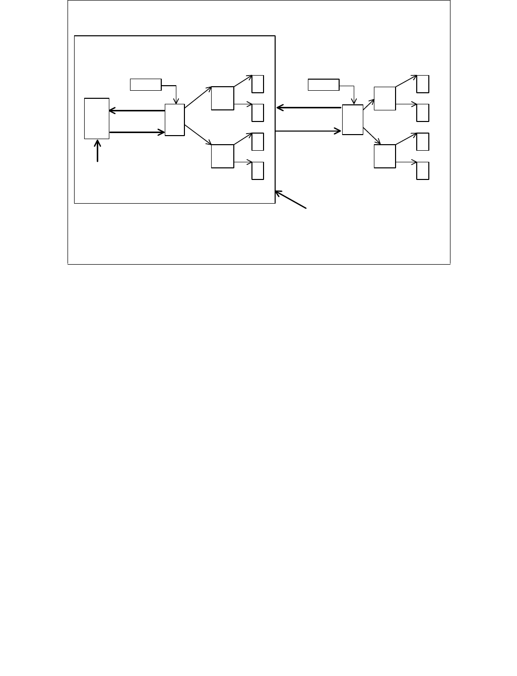
Vol. 3C 32-5
VIRTUALIZATION OF SYSTEM RESOURCES
As noted above, the VMM maintains an active page-table hierarchy for each virtual machine that it supports. It also
maintains, for each machine, values that the machine expects for control registers CR0, CR2, CR3, and CR4 (they
control address translation). These values are called the guest control registers.
In general, the VMM selects the physical-address space that is allocated to guest software. The term guest address
refers to an address installed by guest software in the guest CR3, in a guest PDE (as a page table base address or
a page base address), or in a guest PTE (as a page base address). While guest software considers these to be
specific physical addresses, the VMM may map them differently.
32.3.5.1 Initialization of Virtual TLB
To enable the Virtual TLB scheme, the VMCS must be set up to trigger VM exits on:
•All writes to CR3 (the CR3-target count should be 0) or the paging-mode bits in CR0 and CR4 (using the CR0
and CR4 guest/host masks)
•Page-fault (#PF) exceptions
•Execution of INVLPG
When guest software first enables paging, the VMM creates an aligned 4-KByte active page directory that is invalid
(all entries marked not-present). This invalid directory is analogous to an empty TLB.
32.3.5.2 Response to Page Faults
Page faults can occur for a variety of reasons. In some cases, the page fault alerts the VMM to an inconsistency
between the active and guest page-table hierarchy. In such cases, the VMM can update the former and re-execute
the faulting instruction. In other cases, the hierarchies are already consistent and the fault should be handled by
the guest operating system. The VMM can detect this and use an established mechanism for raising a page fault to
guest software.
The VMM can handle a page fault by following these steps (The steps below assume the guest is operating in a
paging mode without PAE. Analogous steps to handle address translation using PAE or four-level paging mecha-
Figure 32-1. Virtual TLB Scheme
refill on
TLB miss
CR3
PD
PT
PT
F
F
F
F
PD
"Virtual TLB"
Active Guest
INVLPG
MOV to CR3
task switch
refill on
page fault
set accessed
and dirty bits
TLB
PD = page directory
PT = page table
F = page frame
INVLPG
MOV to
CR3
task switch
Active Page-Table Hierarchy Guest Page-Table Hierarchy
PT
PT
F
F
F
F
CR3
set dirty
accessed
OM19040

32-6 Vol. 3C
VIRTUALIZATION OF SYSTEM RESOURCES
nisms can be derived by VMM developers according to the paging behavior defined in Chapter 3 of the Intel® 64
and IA-32 Architectures Software Developer’s Manual, Volume 3A):
1. First consult the active PDE, which can be located using the upper 10 bits of the faulting address and the current
value of CR3. The active PDE is the source of the fault if it is marked not present or if its R/W bit and U/S bits
are inconsistent with the attempted guest access (the guest privilege level and the values of CR0.WP and
CR4.SMEP should also be taken into account).
2. If the active PDE is the source of the fault, consult the corresponding guest PDE using the same 10 bits from the
faulting address and the physical address that corresponds to the guest address in the guest CR3. If the guest
PDE would cause a page fault (for example: it is marked not present), then raise a page fault to the guest
operating system.
The following steps assume that the guest PDE would not have caused a page fault.
3. If the active PDE is the source of the fault and the guest PDE contains, as page-table base address (if PS = 0)
or page base address (PS = 1), a guest address that the VMM has chosen not to support; then raise a machine
check (or some other abort) to the guest operating system.
The following steps assume that the guest address in the guest PDE is supported for the virtual machine.
4. If the active PDE is marked not-present, then set the active PDE to correspond to guest PDE as follows:
a. If the active PDE contains a page-table base address (if PS = 0), then allocate an aligned 4-KByte active
page table marked completely invalid and set the page-table base address in the active PDE to be the
physical address of the newly allocated page table.
b. If the active PDE contains a page base address (if PS = 1), then set the page base address in the active PDE
to be the physical page base address that corresponds to the guest address in the guest PDE.
c. Set the P, U/S, and PS bits in the active PDE to be identical to those in the guest PDE.
d. Set the PWT, PCD, and G bits according to the policy of the VMM.
e. Set A = 1 in the guest PDE.
f. If D = 1 in the guest PDE or PS = 0 (meaning that this PDE refers to a page table), then set the R/W bit in
the active PDE as in the guest PDE.
g. If D = 0 in the guest PDE, PS = 1 (this is a 4-MByte page), and the attempted access is a write; then set
R/W in the active PDE as in the guest PDE and set D = 1 in the guest PDE.
h. If D = 0 in the guest PDE, PS = 1, and the attempted access is not a write; then set R/W = 0 in the active
PDE.
i. After modifying the active PDE, re-execute the faulting instruction.
The remaining steps assume that the active PDE is already marked present.
5. If the active PDE is the source of the fault, the active PDE refers to a 4-MByte page (PS = 1), the attempted
access is a write; D = 0 in the guest PDE, and the active PDE has caused a fault solely because it has R/W = 0;
then set R/W in the active PDE as in the guest PDE; set D = 1 in the guest PDE, and re-execute the faulting
instruction.
6. If the active PDE is the source of the fault and none of the above cases apply, then raise a page fault of the
guest operating system.
The remaining steps assume that the source of the original page fault is not the active PDE.
NOTE
It is possible that the active PDE might be causing a fault even though the guest PDE would not.
However, this can happen only if the guest operating system increased access in the guest PDE and
did not take action to ensure that older translations were flushed from the TLB. Such translations
might have caused a page fault if the guest software were running on bare hardware.
7. If the active PDE refers to a 4-MByte page (PS = 1) but is not the source of the fault, then the fault resulted
from an inconsistency between the active page-table hierarchy and the processor’s TLB. Since the transition to

Vol. 3C 32-7
VIRTUALIZATION OF SYSTEM RESOURCES
the VMM caused an address-space change and flushed the processor’s TLB, the VMM can simply re-execute the
faulting instruction.
The remaining steps assume that PS = 0 in the active and guest PDEs.
8. Consult the active PTE, which can be located using the next 10 bits of the faulting address (bits 21–12) and the
physical page-table base address in the active PDE. The active PTE is the source of the fault if it is marked not-
present or if its R/W bit and U/S bits are inconsistent with the attempted guest access (the guest privilege level
and the values of CR0.WP and CR4.SMEP should also be taken into account).
9. If the active PTE is not the source of the fault, then the fault has resulted from an inconsistency between the
active page-table hierarchy and the processor’s TLB. Since the transition to the VMM caused an address-space
change and flushed the processor’s TLB, the VMM simply re-executes the faulting instruction.
The remaining steps assume that the active PTE is the source of the fault.
10. Consult the corresponding guest PTE using the same 10 bits from the faulting address and the physical address
that correspond to the guest page-table base address in the guest PDE. If the guest PTE would cause a page
fault (it is marked not-present), the raise a page fault to the guest operating system.
The following steps assume that the guest PTE would not have caused a page fault.
11. If the guest PTE contains, as page base address, a physical address that is not valid for the virtual machine
being supported; then raise a machine check (or some other abort) to the guest operating system.
The following steps assume that the address in the guest PTE is valid for the virtual machine.
12. If the active PTE is marked not-present, then set the active PTE to correspond to guest PTE:
a. Set the page base address in the active PTE to be the physical address that corresponds to the guest page
base address in the guest PTE.
b. Set the P, U/S, and PS bits in the active PTE to be identical to those in the guest PTE.
c. Set the PWT, PCD, and G bits according to the policy of the VMM.
d. Set A = 1 in the guest PTE.
e. If D = 1 in the guest PTE, then set the R/W bit in the active PTE as in the guest PTE.
f. If D = 0 in the guest PTE and the attempted access is a write, then set R/W in the active PTE as in the guest
PTE and set D = 1 in the guest PTE.
g. If D = 0 in the guest PTE and the attempted access is not a write, then set R/W = 0 in the active PTE.
h. After modifying the active PTE, re-execute the faulting instruction.
The remaining steps assume that the active PTE is already marked present.
13. If the attempted access is a write, D = 0 (not dirty) in the guest PTE and the active PTE has caused a fault
solely because it has R/W = 0 (read-only); then set R/W in the active PTE as in the guest PTE, set D = 1 in the
guest PTE and re-execute the faulting instruction.
14. If none of the above cases apply, then raise a page fault of the guest operating system.
32.3.5.3 Response to Uses of INVLPG
Operating-systems can use INVLPG to flush entries from the TLB. This instruction takes a linear address as an
operand and software expects any cached translations for the address to be flushed. A VMM should set the
processor-based VM-execution control “INVLPG exiting” to 1 so that any attempts by a privileged guest to execute
INVLPG will trap to the VMM. The VMM can then modify the active page-table hierarchy to emulate the desired
effect of the INVLPG.
The following steps are performed. Note that these steps are performed only if the guest invocation of INVLPG
would not fault and only if the guest software is running at privilege level 0:
1. Locate the relevant active PDE using the upper 10 bits of the operand address and the current value of CR3. If
the PDE refers to a 4-MByte page (PS = 1), then set P = 0 in the PDE.
2. If the PDE is marked present and refers to a page table (PS = 0), locate the relevant active PTE using the next
10 bits of the operand address (bits 21–12) and the page-table base address in the PDE. Set P = 0 in the PTE.

32-8 Vol. 3C
VIRTUALIZATION OF SYSTEM RESOURCES
Examine all PTEs in the page table; if they are now all marked not-present, de-allocate the page table and set
P = 0 in the PDE (this step may be optional).
32.3.5.4 Response to CR3 Writes
A guest operating system may attempt to write to CR3. Any write to CR3 implies a TLB flush and a possible page
table change. The following steps are performed:
1. The VMM notes the new CR3 value (used later to walk guest page tables) and emulates the write.
2. The VMM allocates a new PD page, with all invalid entries.
3. The VMM sets actual processor CR3 register to point to the new PD page.
The VMM may, at this point, speculatively fill in VTLB mappings for performance reasons.
32.4 MICROCODE UPDATE FACILITY
The microcode code update facility may be invoked at various points during the operation of a platform. Typically,
the BIOS invokes the facility on all processors during the BIOS boot process. This is sufficient to boot the BIOS and
operating system. As a microcode update more current than the system BIOS may be available, system software
should provide another mechanism for invoking the microcode update facility. The implications of the microcode
update mechanism on the design of the VMM are described in this section.
NOTE
Microcode updates must not be performed during VMX non-root operation. Updates performed in
VMX non-root operation may result in unpredictable system behavior.
32.4.1 Early Load of Microcode Updates
The microcode update facility may be invoked early in the VMM or guest OS boot process. Loading the microcode
update early provides the opportunity to correct errata affecting the boot process but the technique generally
requires a reboot of the software.
A microcode update may be loaded from the OS or VMM image loader. Typically, such image loaders do not run on
every logical processor, so this method effects only one logical processor. Later in the VMM or OS boot process,
after bringing all application processors on-line, the VMM or OS needs to invoke the microcode update facility for all
application processors.
Depending on the order of the VMM and the guest OS boot, the microcode update facility may be invoked by the
VMM or the guest OS. For example, if the guest OS boots first and then loads the VMM, the guest OS may invoke
the microcode update facility on all the logical processors. If a VMM boots before its guests, then the VMM may
invoke the microcode update facility during its boot process. In both cases, the VMM or OS should invoke the micro-
code update facilities soon after performing the multiprocessor startup.
In the early load scenario, microcode updates may be contained in the VMM or OS image or, the VMM or OS may
manage a separate database or file of microcode updates. Maintaining a separate microcode update image data-
base has the advantage of reducing the number of required VMM or OS releases as a result of microcode update
releases.
32.4.2 Late Load of Microcode Updates
A microcode update may be loaded during normal system operation. This allows system software to activate the
microcode update at anytime without requiring a system reboot. This scenario does not allow the microcode update
to correct errata which affect the processor’s boot process but does allow high-availability systems to activate
microcode updates without interrupting the availability of the system. In this late load scenario, either the VMM or
a designated guest may load the microcode update. If the guest is loading the microcode update, the VMM must

Vol. 3C 32-9
VIRTUALIZATION OF SYSTEM RESOURCES
make sure that the entire guest memory buffer (which contains the microcode update image) will not cause a page
fault when accessed.
If the VMM loads the microcode update, then the VMM must have access to the current set of microcode updates.
These updates could be part of the VMM image or could be contained in a separate microcode update image data-
base (for example: a database file on disk or in memory). Again, maintaining a separate microcode update image
database has the advantage of reducing the number of required VMM or OS releases as a result of microcode
update releases.
The VMM may wish to prevent a guest from loading a microcode update or may wish to support the microcode
update requested by a guest using emulation (without actually loading the microcode update). To prevent micro-
code update loading, the VMM may return a microcode update signature value greater than the value of
IA32_BIOS_SIGN_ID MSR. A well behaved guest will not attempt to load an older microcode update. The VMM may
also drop the guest attempts to write to IA32_BIOS_UPDT_TRIG MSR, preventing the guest from loading any
microcode updates. Later, when the guest queries IA32_BIOS_SIGN_ID MSR, the VMM could emulate the micro-
code update signature that the guest expects.
In general, loading a microcode update later will limit guest software’s visibility of features that may be enhanced
by a microcode update.

32-10 Vol. 3C
VIRTUALIZATION OF SYSTEM RESOURCES

Vol. 3C 33-1
CHAPTER 33
HANDLING BOUNDARY CONDITIONS IN A VIRTUAL MACHINE MONITOR
33.1 OVERVIEW
This chapter describes what a VMM must consider when handling exceptions, interrupts, error conditions, and tran-
sitions between activity states.
33.2 INTERRUPT HANDLING IN VMX OPERATION
The following bullets summarize VMX support for handling interrupts:
•Control of processor exceptions. The VMM can get control on specific guest exceptions through the
exception-bitmap in the guest controlling VMCS. The exception bitmap is a 32-bit field that allows the VMM to
specify processor behavior on specific exceptions (including traps, faults, and aborts). Setting a specific bit in
the exception bitmap implies VM exits will be generated when the corresponding exception occurs. Any
exceptions that are programmed not to cause VM exits are delivered directly to the guest through the guest
IDT. The exception bitmap also controls execution of relevant instructions such as BOUND, INTO and INT3. VM
exits on page-faults are treated in such a way the page-fault error code is qualified through the page-fault-
error-code mask and match fields in the VMCS.
•Control over triple faults. If a fault occurs while attempting to call a double-fault handler in the guest and
that fault is not configured to cause a VM exit in the exception bitmap, the resulting triple fault causes a
VM exit.
•Control of external interrupts. VMX allows both host and guest control of external interrupts through the
“external-interrupt exiting” VM execution control. If the control is 0, external-interrupts do not cause VM exits
and the interrupt delivery is masked by the guest programmed RFLAGS.IF value.1 If the control is 1, external-
interrupts causes VM exits and are not masked by RFLAGS.IF. The VMM can identify VM exits due to external
interrupts by checking the exit reason for an “external interrupt” (value = 1).
•Control of other events. There is a pin-based VM-execution control that controls system behavior (exit or no-
exit) for NMI events. Most VMM usages will need handling of NMI external events in the VMM and hence will
specify host control of these events.
Some processors also support a pin-based VM-execution control called “virtual NMIs.” When this control is set,
NMIs cause VM exits, but the processor tracks guest readiness for virtual NMIs. This control interacts with the
“NMI-window exiting” VM-execution control (see below).
INIT and SIPI events always cause VM exits.
•Acknowledge interrupt on exit. The “acknowledge interrupt on exit” VM-exit control in the controlling VMCS
controls processor behavior for external interrupt acknowledgement. If the control is 1, the processor acknowl-
edges the interrupt controller to acquire the interrupt vector upon VM exit, and stores the vector in the VM-exit
interruption-information field. If the control is 0, the external interrupt is not acknowledged during VM exit.
Since RFLAGS.IF is automatically cleared on VM exits due to external interrupts, VMM re-enabling of interrupts
(setting RFLAGS.IF = 1) initiates the external interrupt acknowledgement and vectoring of the external
interrupt through the monitor/host IDT.
•Event-masking Support. VMX captures the masking conditions of specific events while in VMX non-root
operation through the interruptibility-state field in the guest-state area of the VMCS.
This feature allows proper virtualization of various interrupt blocking states, such as: (a) blocking of external
interrupts for the instruction following STI; (b) blocking of interrupts for the instruction following a MOV-SS or
POP-SS instruction; (c) SMI blocking of subsequent SMIs until the next execution of RSM; and (d) NMI/SMI
blocking of NMIs until the next execution of IRET or RSM.
1. This chapter uses the notation RAX, RIP, RSP, RFLAGS, etc. for processor registers because most processors that support VMX oper-
ation also support Intel 64 architecture. For processors that do not support Intel 64 architecture, this notation refers to the 32-bit
forms of those registers (EAX, EIP, ESP, EFLAGS, etc.).

33-2 Vol. 3C
HANDLING BOUNDARY CONDITIONS IN A VIRTUAL MACHINE MONITOR
INIT and SIPI events are treated specially. INIT assertions are always blocked in VMX root operation and while
in SMM, and unblocked otherwise. SIPI events are always blocked in VMX root operation.
The interruptibility state is loaded from the VMCS guest-state area on every VM entry and saved into the VMCS
on every VM exit.
•Event injection. VMX operation allows injecting interruptions to a guest virtual machine through the use of
VM-entry interrupt-information field in VMCS. Injectable interruptions include external interrupts, NMI,
processor exceptions, software generated interrupts, and software traps. If the interrupt-information field
indicates a valid interrupt, exception or trap event upon the next VM entry; the processor will use the
information in the field to vector a virtual interruption through the guest IDT after all guest state and MSRs are
loaded. Delivery through the guest IDT emulates vectoring in non-VMX operation by doing the normal privilege
checks and pushing appropriate entries to the guest stack (entries may include RFLAGS, EIP and exception
error code). A VMM with host control of NMI and external interrupts can use the event-injection facility to
forward virtual interruptions to various guest virtual machines.
•Interrupt-window exiting. When set to 1, the “interrupt-window exiting” VM-execution control (Section
24.6.2) causes VM exits when guest RFLAGS.IF is 1 and no other conditions block external interrupts. A VM exit
occurs at the beginning of any instruction at which RFLAGS.IF = 1 and on which the interruptibility state of the
guest would allow delivery of an interrupt. For example: when the guest executes an STI instruction,
RFLAGS = 1, and if at the completion of next instruction the interruptibility state masking due to STI is
removed; a VM exit occurs if the “interrupt-window exiting” VM-execution control is 1. This feature allows a
VMM to queue a virtual interrupt to the guest when the guest is not in an interruptible state. The VMM can set
the “interrupt-window exiting” VM-execution control for the guest and depend on a VM exit to know when the
guest becomes interruptible (and, therefore, when it can inject a virtual interrupt). The VMM can detect such
VM exits by checking for the basic exit reason “interrupt-window” (value = 7). If this feature is not used, the
VMM will need to poll and check the interruptibility state of the guest to deliver virtual interrupts.
•NMI-window exiting. If the “virtual NMIs” VM-execution is set, the processor tracks virtual-NMI blocking.
The “NMI-window exiting” VM-execution control (Section 24.6.2) causes VM exits when there is no virtual-NMI
blocking. For example, after execution of the IRET instruction, a VM exit occurs if the “NMI-window exiting” VM-
execution control is 1. This feature allows a VMM to queue a virtual NMI to a guest when the guest is not ready
to receive NMIs. The VMM can set the “NMI-window exiting” VM-execution control for the guest and depend on
a VM exit to know when the guest becomes ready for NMIs (and, therefore, when it can inject a virtual NMI).
The VMM can detect such VM exits by checking for the basic exit reason “NMI window” (value = 8). If this
feature is not used, the VMM will need to poll and check the interruptibility state of the guest to deliver virtual
NMIs.
•VM-exit information. The VM-exit information fields provide details on VM exits due to exceptions and
interrupts. This information is provided through the exit-qualification, VM-exit-interruption-information,
instruction-length and interruption-error-code fields. Also, for VM exits that occur in the course of vectoring
through the guest IDT, information about the event that was being vectored through the guest IDT is provided
in the IDT-vectoring-information and IDT-vectoring-error-code fields. These information fields allow the VMM to
identify the exception cause and to handle it properly.
33.3 EXTERNAL INTERRUPT VIRTUALIZATION
VMX operation allows both host and guest control of external interrupts. While guest control of external interrupts
might be suitable for partitioned usages (different CPU cores/threads and I/O devices partitioned to independent
virtual machines), most VMMs built upon VMX are expected to utilize host control of external interrupts. The rest of
this section describes a general host-controlled interrupt virtualization architecture for standard PC platforms
through the use of VMX supported features.
With host control of external interrupts, the VMM (or the host OS in a hosted VMM model) manages the physical
interrupt controllers in the platform and the interrupts generated through them. The VMM exposes software-
emulated virtual interrupt controller devices (such as PIC and APIC) to each guest virtual machine instance.

Vol. 3C 33-3
HANDLING BOUNDARY CONDITIONS IN A VIRTUAL MACHINE MONITOR
33.3.1 Virtualization of Interrupt Vector Space
The Intel 64 and IA-32 architectures use 8-bit vectors of which 224 (20H – FFH) are available for external inter-
rupts. Vectors are used to select the appropriate entry in the interrupt descriptor table (IDT). VMX operation allows
each guest to control its own IDT. Host vectors refer to vectors delivered by the platform to the processor during
the interrupt acknowledgement cycle. Guest vectors refer to vectors programmed by a guest to select an entry in
its guest IDT. Depending on the I/O resource management models supported by the VMM design, the guest vector
space may or may not overlap with the underlying host vector space.
•Interrupts from virtual devices: Guest vector numbers for virtual interrupts delivered to guests on behalf of
emulated virtual devices have no direct relation to the host vector numbers of interrupts from physical devices
on which they are emulated. A guest-vector assigned for a virtual device by the guest operating environment
is saved by the VMM and utilized when injecting virtual interrupts on behalf of the virtual device.
•Interrupts from assigned physical devices: Hardware support for I/O device assignment allows physical I/O
devices in the host platform to be assigned (direct-mapped) to VMs. Guest vectors for interrupts from direct-
mapped physical devices take up equivalent space from the host vector space, and require the VMM to perform
host-vector to guest-vector mapping for interrupts.
Figure 33-1 illustrates the functional relationship between host external interrupts and guest virtual external inter-
rupts. Device A is owned by the host and generates external interrupts with host vector X. The host IDT is set up
such that the interrupt service routine (ISR) for device driver A is hooked to host vector X as normal. VMM
emulates (over device A) virtual device C in software which generates virtual interrupts to the VM with guest
expected vector P. Device B is assigned to a VM and generates external interrupts with host vector Y. The host IDT
is programmed to hook the VMM interrupt service routine (ISR) for assigned devices for vector Y, and the VMM
handler injects virtual interrupt with guest vector Q to the VM. The guest operating system programs the guest to
hook appropriate guest driver’s ISR to vectors P and Q.
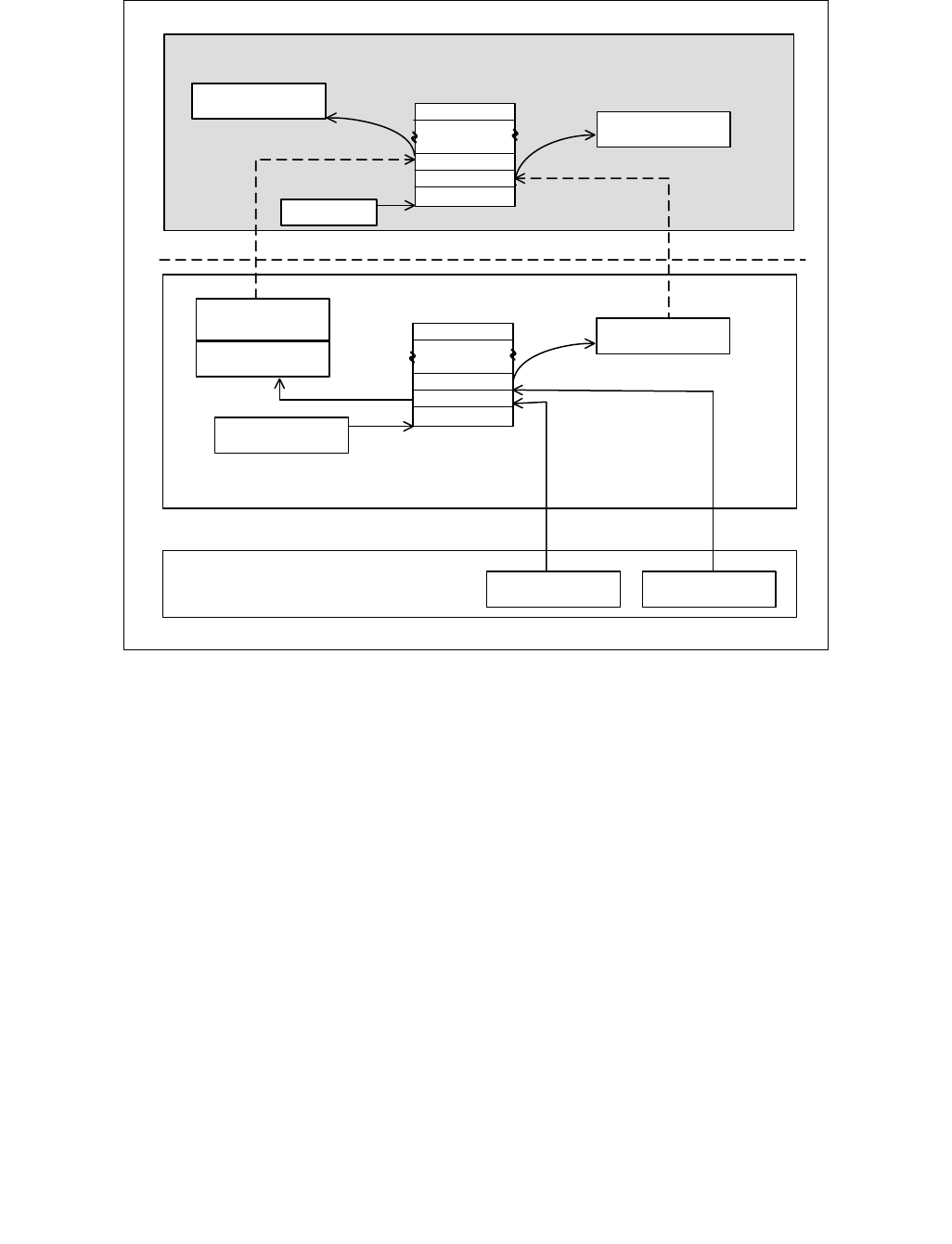
33-4 Vol. 3C
HANDLING BOUNDARY CONDITIONS IN A VIRTUAL MACHINE MONITOR
33.3.2 Control of Platform Interrupts
To meet the interrupt virtualization requirements, the VMM needs to take ownership of the physical interrupts and
the various interrupt controllers in the platform. VMM control of physical interrupts may be enabled through the
host-control settings of the “external-interrupt exiting” VM-execution control. To take ownership of the platform
interrupt controllers, the VMM needs to expose the virtual interrupt controller devices to the virtual machines and
restrict guest access to the platform interrupt controllers.
Intel 64 and IA-32 platforms can support three types of external interrupt control mechanisms: Programmable
Interrupt Controllers (PIC), Advanced Programmable Interrupt Controllers (APIC), and Message Signaled Inter-
rupts (MSI). The following sections provide information on the virtualization of each of these mechanisms.
33.3.2.1 PIC Virtualization
Typical PIC-enabled platform implementations support dual 8259 interrupt controllers cascaded as master and
slave controllers. They supporting up to 15 possible interrupt inputs. The 8259 controllers are programmed
through initialization command words (ICWx) and operation command words (OCWx) accessed through specific
I/O ports. The various interrupt line states are captured in the PIC through interrupt requests, interrupt service
routines and interrupt mask registers.
Guest access to the PIC I/O ports can be restricted by activating I/O bitmaps in the guest controlling-VMCS (acti-
vate-I/O-bitmap bit in VM-execution control field set to 1) and pointing the I/O-bitmap physical addresses to valid
Figure 33-1. Host External Interrupts and Guest Virtual Interrupts
Device Driver B
Device Driver C
Virtual Device C
Emulation
Device Driver A
Monitor Handler
Host IDTR
Device A Device B
Hardware
Platform Interrupt Platform Interrupt
Virtual Machine Monitor (VMM)
Host IDT
Host
Host
Vector X
Vector Y
Guest IDTR
Guest IDT
Guest
Vector P
VM
Virtual Interrupt Virtual Interrupt
Guest
Vector Q
OM19041

Vol. 3C 33-5
HANDLING BOUNDARY CONDITIONS IN A VIRTUAL MACHINE MONITOR
bitmap regions. Bits corresponding to the PIC I/O ports can be cleared to cause a VM exit on guest access to these
ports.
If the VMM is not supporting direct access to any I/O ports from a guest, it can set the unconditional-I/O-exiting in
the VM-execution control field instead of activating I/O bitmaps. The exit-reason field in VM-exit information allows
identification of VM exits due to I/O access and can provide an exit-qualification to identify details about the guest
I/O operation that caused the VM exit.
The VMM PIC virtualization needs to emulate the platform PIC functionality including interrupt priority, mask,
request and service states, and specific guest programmed modes of PIC operation.
33.3.2.2 xAPIC Virtualization
Most modern Intel 64 and IA-32 platforms include support for an APIC. While the standard PIC is intended for use
on uniprocessor systems, APIC can be used in either uniprocessor or multi-processor systems.
APIC based interrupt control consists of two physical components: the interrupt acceptance unit (Local APIC) which
is integrated with the processor, and the interrupt delivery unit (I/O APIC) which is part of the I/O subsystem. APIC
virtualization involves protecting the platform’s local and I/O APICs and emulating them for the guest.
33.3.2.3 Local APIC Virtualization
The local APIC is responsible for the local interrupt sources, interrupt acceptance, dispensing interrupts to the
logical processor, and generating inter-processor interrupts. Software interacts with the local APIC by reading and
writing its memory-mapped registers residing within a 4-KByte uncached memory region with base address stored
in the IA32_APIC_BASE MSR. Since the local APIC registers are memory-mapped, the VMM can utilize memory
virtualization techniques (such as page-table virtualization) to trap guest accesses to the page frame hosting the
virtual local APIC registers.
Local APIC virtualization in the VMM needs to emulate the various local APIC operations and registers, such as:
APIC identification/format registers, the local vector table (LVT), the interrupt command register (ICR), interrupt
capture registers (TMR, IRR and ISR), task and processor priority registers (TPR, PPR), the EOI register and the
APIC-timer register. Since local APICs are designed to operate with non-specific EOI, local APIC emulation also
needs to emulate broadcast of EOI to the guest’s virtual I/O APICs for level triggered virtual interrupts.
A local APIC allows interrupt masking at two levels: (1) mask bit in the local vector table entry for local interrupts
and (2) raising processor priority through the TPR registers for masking lower priority external interrupts. The VMM
needs to comprehend these virtual local APIC mask settings as programmed by the guest in addition to the guest
virtual processor interruptibility state (when injecting APIC routed external virtual interrupts to a guest VM).
VMX provides several features which help the VMM to virtualize the local APIC. These features allow many of guest
TPR accesses (using CR8 only) to occur without VM exits to the VMM:
•The VMCS contains a “virtual-APIC address” field. This 64-bit field is the physical address of the 4-KByte virtual
APIC page (4-KByte aligned). The virtual-APIC page contains a TPR shadow, which is accessed by the MOV CR8
instruction. The TPR shadow comprises bits 7:4 in byte 80H of the virtual-APIC page.
•The TPR threshold: bits 3:0 of this 32-bit field determine the threshold below which the TPR shadow cannot fall.
A VM exit will occur after an execution of MOV CR8 that reduces the TPR shadow below this value.
•The processor-based VM-execution controls field contains a “use TPR shadow” bit and a “CR8-store exiting” bit.
If the “use TPR shadow” VM-execution control is 1 and the “CR8-store exiting” VM-execution control is 0, then
a MOV from CR8 reads from the TPR shadow. If the “CR8-store exiting” VM-execution control is 1, then MOV
from CR8 causes a VM exit; the “use TPR shadow” VM-execution control is ignored in this case.
•The processor-based VM-execution controls field contains a “CR8-load exiting” bit. If the “use TPR shadow” VM-
execution control is set and the “CR8-load exiting” VM-execution control is clear, then MOV to CR8 writes to the
“TPR shadow”. A VM exit will occur after this write if the value written is below the TPR threshold. If the “CR8-
load exiting” VM-execution control is set, then MOV to CR8 causes a VM exit; the “use TPR shadow” VM-
execution control is ignored in this case.

33-6 Vol. 3C
HANDLING BOUNDARY CONDITIONS IN A VIRTUAL MACHINE MONITOR
33.3.2.4 I/O APIC Virtualization
The I/O APIC registers are typically mapped to a 1 MByte region where each I/O APIC is allocated a 4K address
window within this range. The VMM may utilize physical memory virtualization to trap guest accesses to the virtual
I/O APIC memory-mapped registers. The I/O APIC virtualization needs to emulate the various I/O APIC operations
and registers such as identification/version registers, indirect-I/O-access registers, EOI register, and the I/O redi-
rection table. I/O APIC virtualization also need to emulate various redirection table entry settings such as delivery
mode, destination mode, delivery status, polarity, masking, and trigger mode programmed by the guest and track
remote-IRR state on guest EOI writes to various virtual local APICs.
33.3.2.5 Virtualization of Message Signaled Interrupts
The PCI Local Bus Specification (Rev. 2.2) introduces the concept of message signaled interrupts (MSI). MSI enable
PCI devices to request service by writing a system-specified message to a system specified address. The transac-
tion address specifies the message destination while the transaction data specifies the interrupt vector, trigger
mode and delivery mode. System software is expected to configure the message data and address during MSI
device configuration, allocating one or more no-shared messages to MSI capable devices. Chapter 10, “Advanced
Programmable Interrupt Controller (APIC),” specifies the MSI message address and data register formats to be
followed on Intel 64 and IA-32 platforms. While MSI is optional for conventional PCI devices, it is the preferred
interrupt mechanism for PCI-Express devices.
Since the MSI address and data are configured through PCI configuration space, to control these physical interrupts
the VMM needs to assume ownership of PCI configuration space. This allows the VMM to capture the guest config-
uration of message address and data for MSI-capable virtual and assigned guest devices. PCI configuration trans-
actions on PC-compatible systems are generated by software through two different methods:
1. The standard CONFIG_ADDRESS/CONFIG_DATA register mechanism (CFCH/CF8H ports) as defined in the PCI
Local Bus Specification.
2. The enhanced flat memory-mapped (MEMCFG) configuration mechanism as defined in the PCI-Express Base
Specification (Rev. 1.0a.).
The CFCH/CF8H configuration access from guests can be trapped by the VMM through use of I/O-bitmap VM-
execution controls. The memory-mapped PCI-Express MEMCFG guest configuration accesses can be trapped by
VMM through physical memory virtualization.
33.3.3 Examples of Handling of External Interrupts
The following sections illustrate interrupt processing in a VMM (when used to support the external interrupt virtu-
alization requirements).
33.3.3.1 Guest Setup
The VMM sets up the guest to cause a VM exit to the VMM on external interrupts. This is done by setting the
“external-interrupt exiting” VM-execution control in the guest controlling-VMCS.
33.3.3.2 Processor Treatment of External Interrupt
Interrupts are automatically masked by hardware in the processor on VM exit by clearing RFLAGS.IF. The exit-
reason field in VMCS is set to 1 to indicate an external interrupt as the exit reason.
If the VMM is utilizing the acknowledge-on-exit feature (by setting the “acknowledge interrupt on exit” VM-exit
control), the processor acknowledges the interrupt, retrieves the host vector, and saves the interrupt in the VM-
exit-interruption-information field (in the VM-exit information region of the VMCS) before transitioning control to
the VMM.

Vol. 3C 33-7
HANDLING BOUNDARY CONDITIONS IN A VIRTUAL MACHINE MONITOR
33.3.3.3 Processing of External Interrupts by VMM
Upon VM exit, the VMM can determine the exit cause of an external interrupt by checking the exit-reason field
(value = 1) in VMCS. If the acknowledge-interrupt-on-exit control (see Section 24.7.1) is enabled, the VMM can
use the saved host vector (in the exit-interruption-information field) to switch to the appropriate interrupt handler.
If the “acknowledge interrupt on exit” VM-exit control is 0, the VMM may re-enable interrupts (by setting
RFLAGS.IF) to allow vectoring of external interrupts through the monitor/host IDT.
The following steps may need to be performed by the VMM to process an external interrupt:
•Host Owned I/O Devices: For host-owned I/O devices, the interrupting device is owned by the VMM (or
hos ting O S in a h osted VM M). In this mod el, the interr upt service routine in the VMM/host driver is invoked and,
upon ISR completion, the appropriate write sequences (TPR updates, EOI etc.) to respective interrupt
controllers are performed as normal. If the work completion indicated by the driver implies virtual device
activity, the VMM runs the virtual device emulation. Depending on the device class, physical device activity
could imply activity by multiple virtual devices mapped over the device. For each affected virtual device, the
VMM injects a virtual external interrupt event to respective guest virtual machines. The guest driver interacts
with the emulated virtual device to process the virtual interrupt. The interrupt controller emulation in the VMM
supports various guest accesses to the VMM’s virtual interrupt controller.
•Guest Assigned I/O Devices: For assigned I/O devices, either the VMM uses a software proxy or it can
directly map the physical device to the assigned VM. In both cases, servicing of the interrupt condition on the
physical device is initiated by the driver running inside the guest VM. With host control of external interrupts,
interrupts from assigned physical devices cause VM exits to the VMM and vectoring through the host IDT to the
registered VMM interrupt handler. To unblock delivery of other low priority platform interrupts, the VMM
interrupt handler must mask the interrupt source (for level triggered interrupts) and issue the appropriate EOI
write sequences.
Once the physical interrupt source is masked and the platform EOI generated, the VMM can map the host vector to
its corresponding guest vector to inject the virtual interrupt into the assigned VM. The guest software does EOI
write sequences to its virtual interrupt controller after completing interrupt processing. For level triggered inter-
rupts, these EOI writes to the virtual interrupt controller may be trapped by the VMM which may in turn unmask
the previously masked interrupt source.
33.3.3.4 Generation of Virtual Interrupt Events by VMM
The following provides some of the general steps that need to be taken by VMM designs when generating virtual
interrupts:
1. Check virtual processor interruptibility state. The virtual processor interruptibility state is reflected in the guest
RFLAGS.IF flag and the processor interruptibility-state saved in the guest state area of the controlling-VMCS. If
RFLAGS.IF is set and the interruptibility state indicates readiness to take external interrupts (STI-masking and
MOV-SS/POP-SS-masking bits are clear), the guest virtual processor is ready to take external interrupts. If the
VMM design supports non-active guest sleep states, the VMM needs to make sure the current guest sleep state
allows injection of external interrupt events.
2. If the guest virtual processor state is currently not interruptible, a VMM may utilize the “interrupt-window
exiting” VM-execution to notify the VMM (through a VM exit) when the virtual processor state changes to inter-
ruptible state.
3. Check the virtual interrupt controller state. If the guest VM exposes a virtual local APIC, the current value of its
processor priority register specifies if guest software allows dispensing an external virtual interrupt with a
specific priority to the virtual processor. If the virtual interrupt is routed through the local vector table (LVT)
entry of the local APIC, the mask bits in the corresponding LVT entry specifies if the interrupt is currently
masked. Similarly, the virtual interrupt controller’s current mask (IO-APIC or PIC) and priority settings reflect
guest state to accept specific external interrupts. The VMM needs to check both the virtual processor and
interrupt controller states to verify its guest interruptibility state. If the guest is currently interruptible, the
VMM can inject the virtual interrupt. If the current guest state does not allow injecting a virtual interrupt, the
interrupt needs to be queued by the VMM until it can be delivered.
4. Prioritize the use of VM-entry event injection. A VMM may use VM-entry event injection to deliver various
virtual events (such as external interrupts, exceptions, traps, and so forth). VMM designs may prioritize use of
virtual-interrupt injection between these event types. Since each VM entry allows injection of one event,

33-8 Vol. 3C
HANDLING BOUNDARY CONDITIONS IN A VIRTUAL MACHINE MONITOR
depending on the VMM event priority policies, the VMM may need to queue the external virtual interrupt if a
higher priority event is to be delivered on the next VM entry. Since the VMM has masked this particular interrupt
source (if it was level triggered) and done EOI to the platform interrupt controller, other platform interrupts can
be serviced while this virtual interrupt event is queued for later delivery to the VM.
5. Update the virtual interrupt controller state. When the above checks have passed, before generating the virtual
interrupt to the guest, the VMM updates the virtual interrupt controller state (Local-APIC, IO-APIC and/or PIC)
to reflect assertion of the virtual interrupt. This involves updating the various interrupt capture registers, and
priority registers as done by the respective hardware interrupt controllers. Updating the virtual interrupt
controller state is required for proper interrupt event processing by guest software.
6. Inject the virtual interrupt on VM entry. To inject an external virtual interrupt to a guest VM, the VMM sets up
the VM-entry interruption-information field in the guest controlling-VMCS before entry to guest using
VMRESUME. Upon VM entry, the processor will use this vector to access the gate in guest’s IDT and the value of
RFLAGS and EIP in guest-state area of controlling-VMCS is pushed on the guest stack. If the guest RFLAGS.IF
is clear, the STI-masking bit is set, or the MOV- SS/POP-SS-masking bit is set, the VM entry will fail and the
processor will load state from the host-state area of the working VMCS as if a VM exit had occurred (see Section
26.7).
33.4 ERROR HANDLING BY VMM
Error conditions may occur during VM entries and VM exits and a few other situations. This section describes how
VMM should handle these error conditions, including triple faults and machine-check exceptions.
33.4.1 VM-Exit Failures
All VM exits load processor state from the host-state area of the VMCS that was the controlling VMCS before the VM
exit. This state is checked for consistency while being loaded. Because the host-state is checked on VM entry, these
checks will generally succeed. Failure is possible only if host software is incorrect or if VMCS data in the VMCS
region in memory has been written by guest software (or by I/O DMA) since the last VM entry. VM exits may fail for
the following reasons:
•There was a failure on storing guest MSRs.
•There was failure in loading a PDPTR.
•The controlling VMCS has been corrupted (through writes to the corresponding VMCS region) in such a way that
the implementation cannot complete the VM exit.
•There was a failure on loading host MSRs.
•A machine-check event occurred.
If one of these problems occurs on a VM exit, a VMX abort results.
33.4.2 Machine-Check Considerations
The following sequence determine how machine-check events are handled during VMXON, VMXOFF, VM entries,
and VM exits:
•VMXOFF and VMXON:
If a machine-check event occurs during VMXOFF or VMXON and CR4.MCE = 1, a machine-check exception
(#MC) is generated. If CR4.MCE = 0, the processor goes to shutdown state.
•VM entry:
If a machine-check event occurs during VM entry, one of the following three treatments must occur:
a. Normal delivery before VM entry. If CR4.MCE = 1 before VM entry, delivery of a machine-check exception
(#MC) through the host IDT occurs. If CR4.MCE = 0, the processor goes to shutdown state.

Vol. 3C 33-9
HANDLING BOUNDARY CONDITIONS IN A VIRTUAL MACHINE MONITOR
b. Normal delivery after VM entry. If CR4.MCE = 1 after VM entry, delivery of a machine-check exception
(#MC) through the guest IDT occurs (alternatively, this exception may cause a VM exit). If CR4.MCE = 0,
the processor goes to shutdown state.
c. Load state from the host-state area of the working VMCS as if a VM exit had occurred (see Section 26.7).
The basic exit reason will be “VM-entry failure due to machine-check event.”
If the machine-check event occurs after any guest state has been loaded, option a above will not be used; it
may be used if the machine-check event occurs while checking host state and VMX controls (or while reporting
a failure due to such checks). An implementation may use option b only if all guest state has been loaded
properly.
•VM exit:
If a machine-check event occurs during VM exit, one of the following three treatments must occur:
a. Normal delivery before VM exit. If CR4.MCE = 1 before the VM exit, delivery of a machine-check exception
(#MC) through the guest IDT (alternatively, this may cause a VM exit). If CR4.MCE = 0, the processor goes
to shutdown state.
b. Normal delivery after VM exit. If CR4.MCE = 1 after the VM exit, delivery of a machine-check exception
(#MC) through the host IDT. If CR4.MCE = 0, the processor goes to shutdown state.
c. Fail the VM exit. If the VM exit is to VMX root operation, a VMX abort will result; it will block events as done
normally in VMX abort. The VMX abort indicator will show that a machine-check event induced the abort
operation.
If a machine-check event is induced by an action in VMX non-root operation before any determination is made
that the inducing action may cause a VM exit, that machine-check event should be considered as happening
during guest execution in VMX non-root operation. This is the case even if the part of the action that caused the
machine-check event was VMX-specific (for example, the processor’s consulting an I/O bitmap). If a machine-
check exception occurs and if bit 12H of the exception bitmap is cleared to 0, the exception is delivered to the
guest through gate 12H of its IDT; if the bit is set to 1, the machine-check exception causes a VM exit.
NOTE
The state saved in the guest-state area on VM exits due to machine-check exceptions should be
considered suspect. A VMM should consult the RIPV and EIPV bits in the IA32_MCG_STATUS MSR
before resuming a guest that caused a VM exit due to a machine-check exception.
33.4.3 MCA Error Handling Guidelines for VMM
Section 33.4.2 covers general requirements for VMMs to handle machine-check exceptions, when normal operation
of the guest machine and/or the VMM is no longer possible. enhancements of machine-check architecture in newer
processors may support software recovery of uncorrected MC errors (UCR) signaled through either machine-check
exceptions or corrected machine-check interrupt (CMCI). Section 15.5 and Section 15.6 describes details of these
more recent enhancements of machine-check architecture.
In general, Virtual Machine Monitor (VMM) error handling should follow the recommendations for OS error handling
described in Section 15.3, Section 15.6, Section 15.9, and Section 15.10. This section describes additional guide-
lines for hosted and native hypervisor-based VMM implementations to support corrected MC errors and recoverable
uncorrected MC errors.
Because a hosted VMM provides virtualization services in the context of an existing standard host OS, the host OS
controls platform hardware through the host OS services such as the standard OS device drivers. In hosted VMMs.
MCA errors will be handled by the host OS error handling software.
In native VMMs, the hypervisor runs on the hardware directly, and may provide only a limited set of platform
services for guest VMs. Most platform services may instead be provided by a “control OS”. In hypervisor-based
VMMs, MCA errors will either be delivered directly to the VMM MCA handler (when the error is signaled while in the
VMM context) or cause by a VM exit from a guest VM or be delivered to the MCA intercept handler. There are two
general approaches the hypervisor can use to handle the MCA error: either within the hypervisor itself or by
forwarding the error to the control OS.

33-10 Vol. 3C
HANDLING BOUNDARY CONDITIONS IN A VIRTUAL MACHINE MONITOR
33.4.3.1 VMM Error Handling Strategies
Broadly speaking, there are two strategies that VMMs may take for error handling:
•Basic error handling: in this approach the guest VM is treated as any other thread of execution. If the error
recovery action does not support restarting the thread after handling the error, the guest VM should be
terminated.
•MCA virtualization: in this approach, the VMM virtualizes the MCA events and hardware. This enables the VMM
to intercept MCA events and inject an MCA into the guest VM. The guest VM then has the opportunity to attempt
error recovery actions, rather than being terminated by the VMM.
Details of these approaches and implementation considerations for hosted and native VMMs are discussed below.
33.4.3.2 Basic VMM MCA error recovery handling
The simplest approach is for the VMM to treat the guest VM as any other thread of execution:
•MCE's that occur outside the stream of execution of a virtual machine guest will cause an MCE abort and may
be handled by the MCA error handler following the recovery actions and guidelines described in Section 15.9,
and Section 15.10. This includes logging the error and taking appropriate recovery actions when necessary. The
VMM must not resume the interrupted thread of execution or another VM until it has taken the appropriate
recovery action or, in the case of fatal MCAs, reset the system.
•MCE's that occur while executing in the context of a virtual machine will be intercepted by the VMM. The MCA
intercept handler may follow the error handling guidelines listed in Section 15.9 and Section 15.10 for SRAO
and SRAR errors. For SRAR errors, terminating the thread of execution will involve terminating the affected
guest VM. For fatal errors the MCA handler should log the error and reset the system -- the VMM should not
resume execution of the interrupted VM.
33.4.3.3 Implementation Considerations for the Basic Model
For hosted VMMs, the host OS MCA error handling code will perform error analysis and initiate the appropriate
recovery actions. For the basic model this flow does not change when terminating a guest VM although the specific
actions needed to terminate a guest VM may be different than terminating an application or user process.
For native, hypervisor-based VMMs, MCA errors will either be delivered directly to the VMM MCA handler (when the
error is signaled while in the VMM context) or cause a VM exit from a guest VM or be delivered to the MCA intercept
handler. There are two general approaches the hypervisor can use to handle the MCA error: either by forwarding
the error to the control OS or within the hypervisor itself. These approaches are described in the following para-
graphs.
The hypervisor may forward the error to the control OS for handling errors. This approach simplifies the hypervisor
error handling since it relies on the control OS to implement the basic error handling model. The control OS error
handling code will be similar to the error handling code in the hosted VMM. Errors can be forwarded to the control
OS via an OS callback or by injecting an MCE event into the control OS. Injecting an MCE will cause the control OS
MCA error handler to be invoked. The control OS is responsible for terminating the affected guest VM, if necessary,
which may require cooperation from the hypervisor.
Alternatively, the error may be handled completely in the hypervisor. The hypervisor error handler is enhanced to
implement the basic error handling model and the hypervisor error handler has the capability to fully analyze the
error information and take recovery actions based on the guidelines. In this case error handling steps in the hyper-
visor are similar to those for the hosted VMM described above (where the hypervisor replaces the host OS actions).
The hypervisor is responsible for terminating the affected guest VM, if necessary.
In all cases, if a fatal error is detected the VMM error handler should log the error and reset the system. The VMM
error handler must ensure that guest VMs are not resumed after a fatal error is detected to ensure error contain-
ment is maintained.
33.4.3.4 MCA Virtualization
A more sophisticated approach for handling errors is to virtualize the MCA. This involves virtualizing the MCA hard-
ware and intercepting the MCA event in the VMM when a guest VM is interrupted by an MCA. After analyzing the

Vol. 3C 33-11
HANDLING BOUNDARY CONDITIONS IN A VIRTUAL MACHINE MONITOR
error, the VMM error handler may then decide to inject an MCE abort into the guest VM for attempted guest VM
error recovery. This would enable the guest OS the opportunity to take recovery actions specific to that guest.
For MCA virtualization, the VMM must provide the guest physical address for memory errors instead of the system
physical address when reporting the errors to the guest VM. To compute the guest physical address, the VMM
needs to maintain a reverse mapping of system physical page addresses to guest physical page addresses.
When the MCE is injected into the guest VM, the guest OS MCA handler would be invoked. The guest OS imple-
ments the MCA handling guidelines and it could potentially terminate the interrupted thread of execution within the
guest instead of terminating the VM. The guest OS may also disable use of the affected page by the guest. When
disabling the page the VMM error handler may handle the case where a page is shared by the VMM and a guest or
by two guests. In these cases the page use must be disabled in both contexts to ensure no subsequent consump-
tion errors are generated.
33.4.3.5 Implementation Considerations for the MCA Virtualization Model
MCA virtualization may be done in either hosted VMMs or hypervisor-based VMMs. The error handling flow is
similar to the flow described in the basic handling case. The major difference is that the recovery action includes
injecting the MCE abort into the guest VM to enable recovery by the guest OS when the MCA interrupts the execu-
tion of a guest VM.
33.5 HANDLING ACTIVITY STATES BY VMM
A VMM might place a logic processor in the wait-for-SIPI activity state if supporting certain guest operating system
using the multi-processor (MP) start-up algorithm. A guest with direct access to the physical local APIC and using
the MP start-up algorithm sends an INIT-SIPI-SIPI IPI sequence to start the application processor. In order to trap
the SIPIs, the VMM must start the logic processor which is the target of the SIPIs in wait-for-SIPI mode.

33-12 Vol. 3C
HANDLING BOUNDARY CONDITIONS IN A VIRTUAL MACHINE MONITOR

Vol. 3C 34-1
CHAPTER 34
SYSTEM MANAGEMENT MODE
This chapter describes aspects of IA-64 and IA-32 architecture used in system management mode (SMM).
SMM provides an alternate operating environment that can be used to monitor and manage various system
resources for more efficient energy usage, to control system hardware, and/or to run proprietary code. It was
introduced into the IA-32 architecture in the Intel386 SL processor (a mobile specialized version of the Intel386
processor). It is also available in the Pentium M, Pentium 4, Intel Xeon, P6 family, and Pentium and Intel486
processors (beginning with the enhanced versions of the Intel486 SL and Intel486 processors).
34.1 SYSTEM MANAGEMENT MODE OVERVIEW
SMM is a special-purpose operating mode provided for handling system-wide functions like power management,
system hardware control, or proprietary OEM-designed code. It is intended for use only by system firmware, not by
applications software or general-purpose systems software. The main benefit of SMM is that it offers a distinct and
easily isolated processor environment that operates transparently to the operating system or executive and soft-
ware applications.
When SMM is invoked through a system management interrupt (SMI), the processor saves the current state of the
processor (the processor’s context), then switches to a separate operating environment defined by a new address
space. The system management software executive (SMI handler) starts execution in that environment, and the
critical code and data of the SMI handler reside in a physical memory region (SMRAM) within that address space.
While in SMM, the processor executes SMI handler code to perform operations such as powering down unused disk
drives or monitors, executing proprietary code, or placing the whole system in a suspended state. When the SMI
handler has completed its operations, it executes a resume (RSM) instruction. This instruction causes the processor
to reload the saved context of the processor, switch back to protected or real mode, and resume executing the
interrupted application or operating-system program or task.
The following SMM mechanisms make it transparent to applications programs and operating systems:
•The only way to enter SMM is by means of an SMI.
•The processor executes SMM code in a separate address space that can be made inaccessible from the other
operating modes.
•Upon entering SMM, the processor saves the context of the interrupted program or task.
•All interrupts normally handled by the operating system are disabled upon entry into SMM.
•The RSM instruction can be executed only in SMM.
Section 34.3 describes transitions into and out of SMM. The execution environment after entering SMM is in real-
address mode with paging disabled (CR0.PE = CR0.PG = 0). In this initial execution environment, the SMI handler
can address up to 4 GBytes of memory and can execute all I/O and system instructions. Section 34.5 describes in
detail the initial SMM execution environment for an SMI handler and operation within that environment. The SMI
handler may subsequently switch to other operating modes while remaining in SMM.
NOTES
Software developers should be aware that, even if a logical processor was using the physical-
address extension (PAE) mechanism (introduced in the P6 family processors) or was in IA-32e
mode before an SMI, this will not be the case after the SMI is delivered. This is because delivery of
an SMI disables paging (see Table 34-4). (This does not apply if the dual-monitor treatment of
SMIs and SMM is active; see Section 34.15.)
34.1.1 System Management Mode and VMX Operation
Traditionally, SMM services system management interrupts and then resumes program execution (back to the soft-
ware stack consisting of executive and application software; see Section 34.2 through Section 34.13).

34-2 Vol. 3C
SYSTEM MANAGEMENT MODE
A virtual machine monitor (VMM) using VMX can act as a host to multiple virtual machines and each virtual machine
can support its own software stack of executive and application software. On processors that support VMX, virtual-
machine extensions may use system-management interrupts (SMIs) and system-management mode (SMM) in one
of two ways:
•Default treatment. System firmware handles SMIs. The processor saves architectural states and critical
states relevant to VMX operation upon entering SMM. When the firmware completes servicing SMIs, it uses
RSM to resume VMX operation.
•Dual-monitor treatment. Two VM monitors collaborate to control the servicing of SMIs: one VMM operates
outside of SMM to provide basic virtualization in support for guests; the other VMM operates inside SMM (while
in VMX operation) to support system-management functions. The former is referred to as executive monitor,
the latter SMM-transfer monitor (STM).1
The default treatment is described in Section 34.14, “Default Treatment of SMIs and SMM with VMX Operation and
SMX Operation”. Dual-monitor treatment of SMM is described in Section 34.15, “Dual-Monitor Treatment of SMIs
and SMM”.
34.2 SYSTEM MANAGEMENT INTERRUPT (SMI)
The only way to enter SMM is by signaling an SMI through the SMI# pin on the processor or through an SMI
message received through the APIC bus. The SMI is a nonmaskable external interrupt that operates independently
from the processor’s interrupt- and exception-handling mechanism and the local APIC. The SMI takes precedence
over an NMI and a maskable interrupt. SMM is non-reentrant; that is, the SMI is disabled while the processor is in
SMM.
NOTES
In the Pentium 4, Intel Xeon, and P6 family processors, when a processor that is designated as an
application processor during an MP initialization sequence is waiting for a startup IPI (SIPI), it is in
a mode where SMIs are masked. However if a SMI is received while an application processor is in
the wait for SIPI mode, the SMI will be pended. The processor then responds on receipt of a SIPI by
immediately servicing the pended SMI and going into SMM before handling the SIPI.
An SMI may be blocked for one instruction following execution of STI, MOV to SS, or POP into SS.
34.3 SWITCHING BETWEEN SMM AND THE OTHER
PROCESSOR OPERATING MODES
Figure 2-3 shows how the processor moves between SMM and the other processor operating modes (protected,
real-address, and virtual-8086). Signaling an SMI while the processor is in real-address, protected, or virtual-8086
modes always causes the processor to switch to SMM. Upon execution of the RSM instruction, the processor always
returns to the mode it was in when the SMI occurred.
34.3.1 Entering SMM
The processor always handles an SMI on an architecturally defined “interruptible” point in program execution
(which is commonly at an IA-32 architecture instruction boundary). When the processor receives an SMI, it waits
for all instructions to retire and for all stores to complete. The processor then saves its current context in SMRAM
(see Section 34.4), enters SMM, and begins to execute the SMI handler.
Upon entering SMM, the processor signals external hardware that SMI handling has begun. The signaling mecha-
nism used is implementation dependent. For the P6 family processors, an SMI acknowledge transaction is gener-
1. The dual-monitor treatment may not be supported by all processors. Software should consult the VMX capability MSR
IA32_VMX_BASIC (see Appendix A.1) to determine whether it is supported.

Vol. 3C 34-3
SYSTEM MANAGEMENT MODE
ated on the system bus and the multiplexed status signal EXF4 is asserted each time a bus transaction is generated
while the processor is in SMM. For the Pentium and Intel486 processors, the SMIACT# pin is asserted.
An SMI has a greater priority than debug exceptions and external interrupts. Thus, if an NMI, maskable hardware
interrupt, or a debug exception occurs at an instruction boundary along with an SMI, only the SMI is handled.
Subsequent SMI requests are not acknowledged while the processor is in SMM. The first SMI interrupt request that
occurs while the processor is in SMM (that is, after SMM has been acknowledged to external hardware) is latched
and serviced when the processor exits SMM with the RSM instruction. The processor will latch only one SMI while
in SMM.
See Section 34.5 for a detailed description of the execution environment when in SMM.
34.3.2 Exiting From SMM
The only way to exit SMM is to execute the RSM instruction. The RSM instruction is only available to the SMI
handler; if the processor is not in SMM, attempts to execute the RSM instruction result in an invalid-opcode excep-
tion (#UD) being generated.
The RSM instruction restores the processor’s context by loading the state save image from SMRAM back into the
processor’s registers. The processor then returns an SMIACK transaction on the system bus and returns program
control back to the interrupted program.
Upon successful completion of the RSM instruction, the processor signals external hardware that SMM has been
exited. For the P6 family processors, an SMI acknowledge transaction is generated on the system bus and the
multiplexed status signal EXF4 is no longer generated on bus cycles. For the Pentium and Intel486 processors, the
SMIACT# pin is deserted.
If the processor detects invalid state information saved in the SMRAM, it enters the shutdown state and generates
a special bus cycle to indicate it has entered shutdown state. Shutdown happens only in the following situations:
•A reserved bit in control register CR4 is set to 1 on a write to CR4. This error should not happen unless SMI
handler code modifies reserved areas of the SMRAM saved state map (see Section 34.4.1). CR4 is saved in the
state map in a reserved location and cannot be read or modified in its saved state.
•An illegal combination of bits is written to control register CR0, in particular PG set to 1 and PE set to 0, or NW
set to 1 and CD set to 0.
•CR4.PCIDE would be set to 1 and IA32_EFER.LMA to 0.
•(For the Pentium and Intel486 processors only.) If the address stored in the SMBASE register when an RSM
instruction is executed is not aligned on a 32-KByte boundary. This restriction does not apply to the P6 family
processors.
In the shutdown state, Intel processors stop executing instructions until a RESET#, INIT# or NMI# is asserted.
While Pentium family processors recognize the SMI# signal in shutdown state, P6 family and Intel486 processors
do not. Intel does not support using SMI# to recover from shutdown states for any processor family; the response
of processors in this circumstance is not well defined. On Pentium 4 and later processors, shutdown will inhibit INTR
and A20M but will not change any of the other inhibits. On these processors, NMIs will be inhibited if no action is
taken in the SMI handler to uninhibit them (see Section 34.8).
If the processor is in the HALT state when the SMI is received, the processor handles the return from SMM slightly
differently (see Section 34.10). Also, the SMBASE address can be changed on a return from SMM (see Section
34.11).
34.4 SMRAM
Upon entering SMM, the processor switches to a new address space. Because paging is disabled upon entering
SMM, this initial address space maps all memory accesses to the low 4 GBytes of the processor's physical address
space. The SMI handler's critical code and data reside in a memory region referred to as system-management RAM
(SMRAM). The processor uses a pre-defined region within SMRAM to save the processor's pre-SMI context. SMRAM
can also be used to store system management information (such as the system configuration and specific informa-
tion about powered-down devices) and OEM-specific information.

34-4 Vol. 3C
SYSTEM MANAGEMENT MODE
The default SMRAM size is 64 KBytes beginning at a base physical address in physical memory called the SMBASE
(see Figure 34-1). The SMBASE default value following a hardware reset is 30000H. The processor looks for the
first instruction of the SMI handler at the address [SMBASE + 8000H]. It stores the processor’s state in the area
from [SMBASE + FE00H] to [SMBASE + FFFFH]. See Section 34.4.1 for a description of the mapping of the state
save area.
The system logic is minimally required to decode the physical address range for the SMRAM from [SMBASE +
8000H] to [SMBASE + FFFFH]. A larger area can be decoded if needed. The size of this SMRAM can be between 32
KBytes and 4 GBytes.
The location of the SMRAM can be changed by changing the SMBASE value (see Section 34.11). It should be noted
that all processors in a multiple-processor system are initialized with the same SMBASE value (30000H). Initializa-
tion software must sequentially place each processor in SMM and change its SMBASE so that it does not overlap
those of other processors.
The actual physical location of the SMRAM can be in system memory or in a separate RAM memory. The processor
generates an SMI acknowledge transaction (P6 family processors) or asserts the SMIACT# pin (Pentium and
Intel486 processors) when the processor receives an SMI (see Section 34.3.1).
System logic can use the SMI acknowledge transaction or the assertion of the SMIACT# pin to decode accesses to
the SMRAM and redirect them (if desired) to specific SMRAM memory. If a separate RAM memory is used for
SMRAM, system logic should provide a programmable method of mapping the SMRAM into system memory space
when the processor is not in SMM. This mechanism will enable start-up procedures to initialize the SMRAM space
(that is, load the SMI handler) before executing the SMI handler during SMM.
34.4.1 SMRAM State Save Map
When an IA-32 processor that does not support Intel 64 architecture initially enters SMM, it writes its state to the
state save area of the SMRAM. The state save area begins at [SMBASE + 8000H + 7FFFH] and extends down to
[SMBASE + 8000H + 7E00H]. Table 34-1 shows the state save map. The offset in column 1 is relative to the
SMBASE value plus 8000H. Reserved spaces should not be used by software.
Some of the registers in the SMRAM state save area (marked YES in column 3) may be read and changed by the
SMI handler, with the changed values restored to the processor registers by the RSM instruction. Some register
images are read-only, and must not be modified (modifying these registers will result in unpredictable behavior).
An SMI handler should not rely on any values stored in an area that is marked as reserved.
Figure 34-1. SMRAM Usage
Start of State Save Area
SMBASE + FFFFH
SMBASE
SMBASE + 8000H
SMRAM
SMI Handler Entry Point

Vol. 3C 34-5
SYSTEM MANAGEMENT MODE
The following registers are saved (but not readable) and restored upon exiting SMM:
•Control register CR4. (This register is cleared to all 0s when entering SMM).
•The hidden segment descriptor information stored in segment registers CS, DS, ES, FS, GS, and SS.
If an SMI request is issued for the purpose of powering down the processor, the values of all reserved locations in
the SMM state save must be saved to nonvolatile memory.
The following state is not automatically saved and restored following an SMI and the RSM instruction, respectively:
Table 34-1. SMRAM State Save Map
Offset
(Added to SMBASE + 8000H)
Register Writable?
7FFCH CR0 No
7FF8H CR3 No
7FF4H EFLAGS Yes
7FF0H EIP Yes
7FECH EDI Yes
7FE8H ESI Yes
7FE4H EBP Yes
7FE0H ESP Yes
7FDCH EBX Yes
7FD8H EDX Yes
7FD4H ECX Yes
7FD0H EAX Yes
7FCCH DR6 No
7FC8H DR7 No
7FC4H TR1No
7FC0H Reserved No
7FBCH GS1No
7FB8H FS1No
7FB4H DS1No
7FB0H SS1No
7FACH CS1No
7FA8H ES1No
7FA4H I/O State Field, see Section 34.7 No
7FA0H I/O Memory Address Field, see Section 34.7 No
7F9FH-7F03H Reserved No
7F02H Auto HALT Restart Field (Word) Yes
7F00H I/O Instruction Restart Field (Word) Yes
7EFCH SMM Revision Identifier Field (Doubleword) No
7EF8H SMBASE Field (Doubleword) Yes
7EF7H - 7E00H Reserved No
NOTE:
1. The two most significant bytes are reserved.

34-6 Vol. 3C
SYSTEM MANAGEMENT MODE
•Debug registers DR0 through DR3.
•The x87 FPU registers.
•The MTRRs.
•Control register CR2.
•The model-specific registers (for the P6 family and Pentium processors) or test registers TR3 through TR7 (for
the Pentium and Intel486 processors).
•The state of the trap controller.
•The machine-check architecture registers.
•The APIC internal interrupt state (ISR, IRR, etc.).
•The microcode update state.
If an SMI is used to power down the processor, a power-on reset will be required before returning to SMM, which
will reset much of this state back to its default values. So an SMI handler that is going to trigger power down should
first read these registers listed above directly, and save them (along with the rest of RAM) to nonvolatile storage.
After the power-on reset, the continuation of the SMI handler should restore these values, along with the rest of
the system's state. Anytime the SMI handler changes these registers in the processor, it must also save and restore
them.
NOTES
A small subset of the MSRs (such as, the time-stamp counter and performance-monitoring
counters) are not arbitrarily writable and therefore cannot be saved and restored. SMM-based
power-down and restoration should only be performed with operating systems that do not use or
rely on the values of these registers.
Operating system developers should be aware of this fact and insure that their operating-system
assisted power-down and restoration software is immune to unexpected changes in these register
values.
34.4.1.1 SMRAM State Save Map and Intel 64 Architecture
When the processor initially enters SMM, it writes its state to the state save area of the SMRAM. The state save area
on an Intel 64 processor at [SMBASE + 8000H + 7FFFH] and extends to [SMBASE + 8000H + 7C00H].
Support for Intel 64 architecture is reported by CPUID.80000001:EDX[29] = 1. The layout of the SMRAM state save
map is shown in Table 34-3.
Additionally, the SMRAM state save map shown in Table 34-3 also applies to processors with the following CPUID
signatures listed in Table 34-2, irrespective of the value in CPUID.80000001:EDX[29].
Table 34-2. Processor Signatures and 64-bit SMRAM State Save Map Format
DisplayFamily_DisplayModel Processor Families/Processor Number Series
06_17H Intel Xeon Processor 5200, 5400 series, Intel Core 2 Quad processor Q9xxx, Intel Core 2 Duo
processors E8000, T9000,
06_0FH Intel Xeon Processor 3000, 3200, 5100, 5300, 7300 series, Intel Core 2 Quad, Intel Core 2 Extreme,
Intel Core 2 Duo processors, Intel Pentium dual-core processors
06_1CH 45 nm Intel® Atom™ processors

Vol. 3C 34-7
SYSTEM MANAGEMENT MODE
Table 34-3. SMRAM State Save Map for Intel 64 Architecture
Offset
(Added to SMBASE + 8000H)
Register Writable?
7FF8H CR0 No
7FF0H CR3 No
7FE8H RFLAGS Yes
7FE0H IA32_EFER Yes
7FD8H RIP Yes
7FD0H DR6 No
7FC8H DR7 No
7FC4H TR SEL1No
7FC0H LDTR SEL1No
7FBCH GS SEL1No
7FB8H FS SEL1No
7FB4H DS SEL1No
7FB0H SS SEL1No
7FACH CS SEL1No
7FA8H ES SEL1No
7FA4H IO_MISC No
7F9CH IO_MEM_ADDR No
7F94H RDI Yes
7F8CH RSI Yes
7F84H RBP Yes
7F7CH RSP Yes
7F74H RBX Yes
7F6CH RDX Yes
7F64H RCX Yes
7F5CH RAX Yes
7F54H R8 Yes
7F4CH R9 Yes
7F44H R10 Yes
7F3CH R11 Yes
7F34H R12 Yes
7F2CH R13 Yes
7F24H R14 Yes
7F1CH R15 Yes
7F1BH-7F04H Reserved No
7F02H Auto HALT Restart Field (Word) Yes
7F00H I/O Instruction Restart Field (Word) Yes
7EFCH SMM Revision Identifier Field (Doubleword) No
7EF8H SMBASE Field (Doubleword) Yes

34-8 Vol. 3C
SYSTEM MANAGEMENT MODE
34.4.2 SMRAM Caching
An IA-32 processor does not automatically write back and invalidate its caches before entering SMM or before
exiting SMM. Because of this behavior, care must be taken in the placement of the SMRAM in system memory and
in the caching of the SMRAM to prevent cache incoherence when switching back and forth between SMM and
protected mode operation. Any of the following three methods of locating the SMRAM in system memory will guar-
antee cache coherency.
•Place the SMRAM in a dedicated section of system memory that the operating system and applications are
prevented from accessing. Here, the SMRAM can be designated as cacheable (WB, WT, or WC) for optimum
processor performance, without risking cache incoherence when entering or exiting SMM.
•Place the SMRAM in a section of memory that overlaps an area used by the operating system (such as the video
memory), but designate the SMRAM as uncacheable (UC). This method prevents cache access when in SMM to
maintain cache coherency, but the use of uncacheable memory reduces the performance of SMM code.
•Place the SMRAM in a section of system memory that overlaps an area used by the operating system and/or
application code, but explicitly flush (write back and invalidate) the caches upon entering and exiting SMM
mode. This method maintains cache coherency, but incurs the overhead of two complete cache flushes.
For Pentium 4, Intel Xeon, and P6 family processors, a combination of the first two methods of locating the SMRAM
is recommended. Here the SMRAM is split between an overlapping and a dedicated region of memory. Upon
entering SMM, the SMRAM space that is accessed overlaps video memory (typically located in low memory). This
SMRAM section is designated as UC memory. The initial SMM code then jumps to a second SMRAM section that is
located in a dedicated region of system memory (typically in high memory). This SMRAM section can be cached for
optimum processor performance.
7EF7H - 7EE4H Reserved No
7EE0H Setting of “enable EPT” VM-execution control No
7ED8H Value of EPTP VM-execution control field No
7ED7H - 7EA0H Reserved No
7E9CH LDT Base (lower 32 bits) No
7E98H Reserved No
7E94H IDT Base (lower 32 bits) No
7E90H Reserved No
7E8CH GDT Base (lower 32 bits) No
7E8BH - 7E44H Reserved No
7E40H CR4 No
7E3FH - 7DF0H Reserved No
7DE8H IO_RIP Yes
7DE7H - 7DDCH Reserved No
7DD8H IDT Base (Upper 32 bits) No
7DD4H LDT Base (Upper 32 bits) No
7DD0H GDT Base (Upper 32 bits) No
7DCFH - 7C00H Reserved No
NOTE:
1. The two most significant bytes are reserved.
Table 34-3. SMRAM State Save Map for Intel 64 Architecture (Contd.)
Offset
(Added to SMBASE + 8000H)
Register Writable?

Vol. 3C 34-9
SYSTEM MANAGEMENT MODE
For systems that explicitly flush the caches upon entering SMM (the third method described above), the cache flush
can be accomplished by asserting the FLUSH# pin at the same time as the request to enter SMM (generally initi-
ated by asserting the SMI# pin). The priorities of the FLUSH# and SMI# pins are such that the FLUSH# is serviced
first. To guarantee this behavior, the processor requires that the following constraints on the interaction of FLUSH#
and SMI# be met. In a system where the FLUSH# and SMI# pins are synchronous and the set up and hold times
are met, then the FLUSH# and SMI# pins may be asserted in the same clock. In asynchronous systems, the
FLUSH# pin must be asserted at least one clock before the SMI# pin to guarantee that the FLUSH# pin is serviced
first.
Upon leaving SMM (for systems that explicitly flush the caches), the WBINVD instruction should be executed prior
to leaving SMM to flush the caches.
NOTES
In systems based on the Pentium processor that use the FLUSH# pin to write back and invalidate
cache contents before entering SMM, the processor will prefetch at least one cache line in between
when the Flush Acknowledge cycle is run and the subsequent recognition of SMI# and the assertion
of SMIACT#.
It is the obligation of the system to ensure that these lines are not cached by returning KEN#
inactive to the Pentium processor.
34.4.2.1 System Management Range Registers (SMRR)
SMI handler code and data stored by SMM code resides in SMRAM. The SMRR interface is an enhancement in Intel
64 architecture to limit cacheable reference of addresses in SMRAM to code running in SMM. The SMRR interface
can be configured only by code running in SMM. Details of SMRR is described in Section 11.11.2.4.
34.5 SMI HANDLER EXECUTION ENVIRONMENT
Section 34.5.1 describes the initial execution environment for an SMI handler. An SMI handler may re-configure its
execution environment to other supported operating modes. Section 34.5.2 discusses modifications an SMI
handler can make to its execution environment.
34.5.1 Initial SMM Execution Environment
After saving the current context of the processor, the processor initializes its core registers to the values shown in
Table 34-4. Upon entering SMM, the PE and PG flags in control register CR0 are cleared, which places the processor
in an environment similar to real-address mode. The differences between the SMM execution environment and the
real-address mode execution environment are as follows:
•The addressable address space ranges from 0 to FFFFFFFFH (4 GBytes).
•The normal 64-KByte segment limit for real-address mode is increased to 4 GBytes.
•The default operand and address sizes are set to 16 bits, which restricts the addressable SMRAM address space
to the 1-MByte real-address mode limit for native real-address-mode code. However, operand-size and
address-size override prefixes can be used to access the address space beyond the 1-MByte.
Table 34-4. Processor Register Initialization in SMM
Register Contents
General-purpose registers Undefined
EFLAGS 00000002H
EIP 00008000H
CS selector SMM Base shifted right 4 bits (default 3000H)
CS base SMM Base (default 30000H)
DS, ES, FS, GS, SS Selectors 0000H

34-10 Vol. 3C
SYSTEM MANAGEMENT MODE
•Near jumps and calls can be made to anywhere in the 4-GByte address space if a 32-bit operand-size override
prefix is used. Due to the real-address-mode style of base-address formation, a far call or jump cannot transfer
control to a segment with a base address of more than 20 bits (1 MByte). However, since the segment limit in
SMM is 4 GBytes, offsets into a segment that go beyond the 1-MByte limit are allowed when using 32-bit
operand-size override prefixes. Any program control transfer that does not have a 32-bit operand-size override
prefix truncates the EIP value to the 16 low-order bits.
•Data and the stack can be located anywhere in the 4-GByte address space, but can be accessed only with a 32-
bit address-size override if they are located above 1 MByte. As with the code segment, the base address for a
data or stack segment cannot be more than 20 bits.
The value in segment register CS is automatically set to the default of 30000H for the SMBASE shifted 4 bits to the
right; that is, 3000H. The EIP register is set to 8000H. When the EIP value is added to shifted CS value (the
SMBASE), the resulting linear address points to the first instruction of the SMI handler.
The other segment registers (DS, SS, ES, FS, and GS) are cleared to 0 and their segment limits are set to 4 GBytes.
In this state, the SMRAM address space may be treated as a single flat 4-GByte linear address space. If a segment
register is loaded with a 16-bit value, that value is then shifted left by 4 bits and loaded into the segment base
(hidden part of the segment register). The limits and attributes are not modified.
Maskable hardware interrupts, exceptions, NMI interrupts, SMI interrupts, A20M interrupts, single-step traps,
breakpoint traps, and INIT operations are inhibited when the processor enters SMM. Maskable hardware interrupts,
exceptions, single-step traps, and breakpoint traps can be enabled in SMM if the SMM execution environment
provides and initializes an interrupt table and the necessary interrupt and exception handlers (see Section 34.6).
34.5.2 SMI Handler Operating Mode Switching
Within SMM, an SMI handler may change the processor's operating mode (e.g., to enable PAE paging, enter 64-bit
mode, etc.) after it has made proper preparation and initialization to do so. For example, if switching to 32-bit
protected mode, the SMI handler should follow the guidelines provided in Chapter 9, “Processor Management and
Initialization”. If the SMI handler does wish to change operating mode, it is responsible for executing the appro-
priate mode-transition code after each SMI.
It is recommended that the SMI handler make use of all means available to protect the integrity of its critical code
and data. In particular, it should use the system-management range register (SMRR) interface if it is available (see
Section 11.11.2.4). The SMRR interface can protect only the first 4 GBytes of the physical address space. The SMI
handler should take that fact into account if it uses operating modes that allow access to physical addresses beyond
that 4-GByte limit (e.g. PAE paging or 64-bit mode).
Execution of the RSM instruction restores the pre-SMI processor state from the SMRAM state-state map (see
Section 34.4.1) into which it was stored when the processor entered SMM. (The SMBASE field in the SMRAM state-
save map does not determine the state following RSM but rather the initial environment following the next entry to
SMM.) Any required change to operating mode is performed by the RSM instruction; there is no need for the SMI
handler to change modes explicitly prior to executing RSM.
34.6 EXCEPTIONS AND INTERRUPTS WITHIN SMM
When the processor enters SMM, all hardware interrupts are disabled in the following manner:
DS, ES, FS, GS, SS Bases 000000000H
DS, ES, FS, GS, SS Limits 0FFFFFFFFH
CR0 PE, EM, TS, and PG flags set to 0; others unmodified
CR4 Cleared to zero
DR6 Undefined
DR7 00000400H
Table 34-4. Processor Register Initialization in SMM

Vol. 3C 34-11
SYSTEM MANAGEMENT MODE
•The IF flag in the EFLAGS register is cleared, which inhibits maskable hardware interrupts from being
generated.
•The TF flag in the EFLAGS register is cleared, which disables single-step traps.
•Debug register DR7 is cleared, which disables breakpoint traps. (This action prevents a debugger from acciden-
tally breaking into an SMI handler if a debug breakpoint is set in normal address space that overlays code or
data in SMRAM.)
•NMI, SMI, and A20M interrupts are blocked by internal SMM logic. (See Section 34.8 for more information
about how NMIs are handled in SMM.)
Software-invoked interrupts and exceptions can still occur, and maskable hardware interrupts can be enabled by
setting the IF flag. Intel recommends that SMM code be written in so that it does not invoke software interrupts
(with the INT n, INTO, INT1, INT3, or BOUND instructions) or generate exceptions.
If the SMI handler requires interrupt and exception handling, an SMM interrupt table and the necessary exception
and interrupt handlers must be created and initialized from within SMM. Until the interrupt table is correctly initial-
ized (using the LIDT instruction), exceptions and software interrupts will result in unpredictable processor
behavior.
The following restrictions apply when designing SMM interrupt and exception-handling facilities:
•The interrupt table should be located at linear address 0 and must contain real-address mode style interrupt
vectors (4 bytes containing CS and IP).
•Due to the real-address mode style of base address formation, an interrupt or exception cannot transfer control
to a segment with a base address of more that 20 bits.
•An interrupt or exception cannot transfer control to a segment offset of more than 16 bits (64 KBytes).
•When an exception or interrupt occurs, only the 16 least-significant bits of the return address (EIP) are pushed
onto the stack. If the offset of the interrupted procedure is greater than 64 KBytes, it is not possible for the
interrupt/exception handler to return control to that procedure. (One solution to this problem is for a handler
to adjust the return address on the stack.)
•The SMBASE relocation feature affects the way the processor will return from an interrupt or exception
generated while the SMI handler is executing. For example, if the SMBASE is relocated to above 1 MByte, but
the exception handlers are below 1 MByte, a normal return to the SMI handler is not possible. One solution is
to provide the exception handler with a mechanism for calculating a return address above 1 MByte from the 16-
bit return address on the stack, then use a 32-bit far call to return to the interrupted procedure.
•If an SMI handler needs access to the debug trap facilities, it must insure that an SMM accessible debug handler
is available and save the current contents of debug registers DR0 through DR3 (for later restoration). Debug
registers DR0 through DR3 and DR7 must then be initialized with the appropriate values.
•If an SMI handler needs access to the single-step mechanism, it must insure that an SMM accessible single-
step handler is available, and then set the TF flag in the EFLAGS register.
•If the SMI design requires the processor to respond to maskable hardware interrupts or software-generated
interrupts while in SMM, it must ensure that SMM accessible interrupt handlers are available and then set the
IF flag in the EFLAGS register (using the STI instruction). Software interrupts are not blocked upon entry to
SMM, so they do not need to be enabled.
34.7 MANAGING SYNCHRONOUS AND ASYNCHRONOUS
SYSTEM MANAGEMENT INTERRUPTS
When coding for a multiprocessor system or a system with Intel HT Technology, it was not always possible for an
SMI handler to distinguish between a synchronous SMI (triggered during an I/O instruction) and an asynchronous
SMI. To facilitate the discrimination of these two events, incremental state information has been added to the SMM
state save map.
Processors that have an SMM revision ID of 30004H or higher have the incremental state information described
below.

34-12 Vol. 3C
SYSTEM MANAGEMENT MODE
34.7.1 I/O State Implementation
Within the extended SMM state save map, a bit (IO_SMI) is provided that is set only when an SMI is either taken
immediately after a successful I/O instruction or is taken after a successful iteration of a REP I/O instruction (the
successful notion pertains to the processor point of view; not necessarily to the corresponding platform function).
When set, the IO_SMI bit provides a strong indication that the corresponding SMI was synchronous. In this case,
the SMM State Save Map also supplies the port address of the I/O operation. The IO_SMI bit and the I/O Port
Address may be used in conjunction with the information logged by the platform to confirm that the SMI was
indeed synchronous.
The IO_SMI bit by itself is a strong indication, not a guarantee, that the SMI is synchronous. This is because an
asynchronous SMI might coincidentally be taken after an I/O instruction. In such a case, the IO_SMI bit would still
be set in the SMM state save map.
Information characterizing the I/O instruction is saved in two locations in the SMM State Save Map (Table 34-5).
The IO_SMI bit also serves as a valid bit for the rest of the I/O information fields. The contents of these I/O infor-
mation fields are not defined when the IO_SMI bit is not set.
When IO_SMI is set, the other fields may be interpreted as follows:
•I/O length:
•001 – Byte
•010 – Word
•100 – Dword
•I/O instruction type (Table 34-6)
Table 34-5. I/O Instruction Information in the SMM State Save Map
State (SMM Rev. ID: 30004H or higher) Format
31 16 15 874310
I/0 State Field
SMRAM offset 7FA4
I/O Port
Reserved
I/O Type
I/O Length
IO_SMI
31 0
I/O Memory Address Field
SMRAM offset 7FA0
I/O Memory Address
Table 34-6. I/O Instruction Type Encodings
Instruction Encoding
IN Immediate 1001
IN DX 0001
OUT Immediate 1000
OUT DX 0000
INS 0011
OUTS 0010
REP INS 0111
REP OUTS 0110
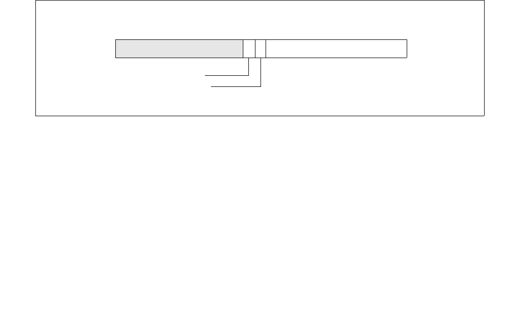
Vol. 3C 34-13
SYSTEM MANAGEMENT MODE
34.8 NMI HANDLING WHILE IN SMM
NMI interrupts are blocked upon entry to the SMI handler. If an NMI request occurs during the SMI handler, it is
latched and serviced after the processor exits SMM. Only one NMI request will be latched during the SMI handler.
If an NMI request is pending when the processor executes the RSM instruction, the NMI is serviced before the next
instruction of the interrupted code sequence. This assumes that NMIs were not blocked before the SMI occurred. If
NMIs were blocked before the SMI occurred, they are blocked after execution of RSM.
Although NMI requests are blocked when the processor enters SMM, they may be enabled through software by
executing an IRET instruction. If the SMI handler requires the use of NMI interrupts, it should invoke a dummy
interrupt service routine for the purpose of executing an IRET instruction. Once an IRET instruction is executed,
NMI interrupt requests are serviced in the same “real mode” manner in which they are handled outside of SMM.
A special case can occur if an SMI handler nests inside an NMI handler and then another NMI occurs. During NMI
interrupt handling, NMI interrupts are disabled, so normally NMI interrupts are serviced and completed with an
IRET instruction one at a time. When the processor enters SMM while executing an NMI handler, the processor
saves the SMRAM state save map but does not save the attribute to keep NMI interrupts disabled. Potentially, an
NMI could be latched (while in SMM or upon exit) and serviced upon exit of SMM even though the previous NMI
handler has still not completed. One or more NMIs could thus be nested inside the first NMI handler. The NMI inter-
rupt handler should take this possibility into consideration.
Also, for the Pentium processor, exceptions that invoke a trap or fault handler will enable NMI interrupts from inside
of SMM. This behavior is implementation specific for the Pentium processor and is not part of the IA-32 architec-
ture.
34.9 SMM REVISION IDENTIFIER
The SMM revision identifier field is used to indicate the version of SMM and the SMM extensions that are supported
by the processor (see Figure 34-2). The SMM revision identifier is written during SMM entry and can be examined
in SMRAM space at offset 7EFCH. The lower word of the SMM revision identifier refers to the version of the base
SMM architecture.
The upper word of the SMM revision identifier refers to the extensions available. If the I/O instruction restart flag
(bit 16) is set, the processor supports the I/O instruction restart (see Section 34.12); if the SMBASE relocation flag
(bit 17) is set, SMRAM base address relocation is supported (see Section 34.11).
34.10 AUTO HALT RESTART
If the processor is in a HALT state (due to the prior execution of a HLT instruction) when it receives an SMI, the
processor records the fact in the auto HALT restart flag in the saved processor state (see Figure 34-3). (This flag is
located at offset 7F02H and bit 0 in the state save area of the SMRAM.)
If the processor sets the auto HALT restart flag upon entering SMM (indicating that the SMI occurred when the
processor was in the HALT state), the SMI handler has two options:
Figure 34-2. SMM Revision Identifier
SMM Revision Identifier
I/O Instruction Restart
SMBASE Relocation
Register Offset
7EFCH
31 0
Reserved
18 17 16 15

34-14 Vol. 3C
SYSTEM MANAGEMENT MODE
•It can leave the auto HALT restart flag set, which instructs the RSM instruction to return program control to the
HLT instruction. This option in effect causes the processor to re-enter the HALT state after handling the SMI.
(This is the default operation.)
•It can clear the auto HALT restart flag, which instructs the RSM instruction to return program control to the
instruction following the HLT instruction.
These options are summarized in Table 34-7. If the processor was not in a HALT state when the SMI was received
(the auto HALT restart flag is cleared), setting the flag to 1 will cause unpredictable behavior when the RSM instruc-
tion is executed.
If the HLT instruction is restarted, the processor will generate a memory access to fetch the HLT instruction (if it is
not in the internal cache), and execute a HLT bus transaction. This behavior results in multiple HLT bus transactions
for the same HLT instruction.
34.10.1 Executing the HLT Instruction in SMM
The HLT instruction should not be executed during SMM, unless interrupts have been enabled by setting the IF flag
in the EFLAGS register. If the processor is halted in SMM, the only event that can remove the processor from this
state is a maskable hardware interrupt or a hardware reset.
34.11 SMBASE RELOCATION
The default base address for the SMRAM is 30000H. This value is contained in an internal processor register called
the SMBASE register. The operating system or executive can relocate the SMRAM by setting the SMBASE field in the
saved state map (at offset 7EF8H) to a new value (see Figure 34-4). The RSM instruction reloads the internal
SMBASE register with the value in the SMBASE field each time it exits SMM. All subsequent SMI requests will use
the new SMBASE value to find the starting address for the SMI handler (at SMBASE + 8000H) and the SMRAM state
save area (from SMBASE + FE00H to SMBASE + FFFFH). (The processor resets the value in its internal SMBASE
register to 30000H on a RESET, but does not change it on an INIT.)
Figure 34-3. Auto HALT Restart Field
Table 34-7. Auto HALT Restart Flag Values
Value of Flag After
Entry to SMM
Value of Flag When
Exiting SMM
Action of Processor When Exiting SMM
0
0
1
1
0
1
0
1
Returns to next instruction in interrupted program or task.
Unpredictable.
Returns to next instruction after HLT instruction.
Returns to HALT state.
Auto HALT Restart
015
Reserved Register Offset
7F02H
1

Vol. 3C 34-15
SYSTEM MANAGEMENT MODE
In multiple-processor systems, initialization software must adjust the SMBASE value for each processor so that the
SMRAM state save areas for each processor do not overlap. (For Pentium and Intel486 processors, the SMBASE
values must be aligned on a 32-KByte boundary or the processor will enter shutdown state during the execution of
a RSM instruction.)
If the SMBASE relocation flag in the SMM revision identifier field is set, it indicates the ability to relocate the
SMBASE (see Section 34.9).
34.12 I/O INSTRUCTION RESTART
If the I/O instruction restart flag in the SMM revision identifier field is set (see Section 34.9), the I/O instruction
restart mechanism is present on the processor. This mechanism allows an interrupted I/O instruction to be re-
executed upon returning from SMM mode. For example, if an I/O instruction is used to access a powered-down I/O
device, a chip set supporting this device can intercept the access and respond by asserting SMI#. This action
invokes the SMI handler to power-up the device. Upon returning from the SMI handler, the I/O instruction restart
mechanism can be used to re-execute the I/O instruction that caused the SMI.
The I/O instruction restart field (at offset 7F00H in the SMM state-save area, see Figure 34-5) controls I/O instruc-
tion restart. When an RSM instruction is executed, if this field contains the value FFH, then the EIP register is modi-
fied to point to the I/O instruction that received the SMI request. The processor will then automatically re-execute
the I/O instruction that the SMI trapped. (The processor saves the necessary machine state to insure that re-
execution of the instruction is handled coherently.)
If the I/O instruction restart field contains the value 00H when the RSM instruction is executed, then the processor
begins program execution with the instruction following the I/O instruction. (When a repeat prefix is being used,
the next instruction may be the next I/O instruction in the repeat loop.) Not re-executing the interrupted I/O
instruction is the default behavior; the processor automatically initializes the I/O instruction restart field to 00H
upon entering SMM. Table 34-8 summarizes the states of the I/O instruction restart field.
The I/O instruction restart mechanism does not indicate the cause of the SMI. It is the responsibility of the SMI
handler to examine the state of the processor to determine the cause of the SMI and to determine if an I/O instruc-
tion was interrupted and should be restarted upon exiting SMM. If an SMI interrupt is signaled on a non-I/O
instruction boundary, setting the I/O instruction restart field to FFH prior to executing the RSM instruction will likely
result in a program error.
Figure 34-4. SMBASE Relocation Field
Figure 34-5. I/O Instruction Restart Field
Table 34-8. I/O Instruction Restart Field Values
Value of Flag After
Entry to SMM
Value of Flag When
Exiting SMM
Action of Processor When Exiting SMM
00H
00H
00H
FFH
Does not re-execute trapped I/O instruction.
Re-executes trapped I/O instruction.
031
SMM Base Register Offset
7EF8H
015
I/O Instruction Restart Field Register Offset
7F00H

34-16 Vol. 3C
SYSTEM MANAGEMENT MODE
34.12.1 Back-to-Back SMI Interrupts When I/O Instruction Restart Is Being Used
If an SMI interrupt is signaled while the processor is servicing an SMI interrupt that occurred on an I/O instruction
boundary, the processor will service the new SMI request before restarting the originally interrupted I/O instruc-
tion. If the I/O instruction restart field is set to FFH prior to returning from the second SMI handler, the EIP will point
to an address different from the originally interrupted I/O instruction, which will likely lead to a program error. To
avoid this situation, the SMI handler must be able to recognize the occurrence of back-to-back SMI interrupts when
I/O instruction restart is being used and insure that the handler sets the I/O instruction restart field to 00H prior to
returning from the second invocation of the SMI handler.
34.13 SMM MULTIPLE-PROCESSOR CONSIDERATIONS
The following should be noted when designing multiple-processor systems:
•Any processor in a multiprocessor system can respond to an SMM.
•Each processor needs its own SMRAM space. This space can be in system memory or in a separate RAM.
•The SMRAMs for different processors can be overlapped in the same memory space. The only stipulation is that
each processor needs its own state save area and its own dynamic data storage area. (Also, for the Pentium
and Intel486 processors, the SMBASE address must be located on a 32-KByte boundary.) Code and static data
can be shared among processors. Overlapping SMRAM spaces can be done more efficiently with the P6 family
processors because they do not require that the SMBASE address be on a 32-KByte boundary.
•The SMI handler will need to initialize the SMBASE for each processor.
•Processors can respond to local SMIs through their SMI# pins or to SMIs received through the APIC interface.
The APIC interface can distribute SMIs to different processors.
•Two or more processors can be executing in SMM at the same time.
•When operating Pentium processors in dual processing (DP) mode, the SMIACT# pin is driven only by the MRM
processor and should be sampled with ADS#. For additional details, see Chapter 14 of the Pentium Processor
Family User’s Manual, Volume 1.
SMM is not re-entrant, because the SMRAM State Save Map is fixed relative to the SMBASE. If there is a need to
support two or more processors in SMM mode at the same time then each processor should have dedicated SMRAM
spaces. This can be done by using the SMBASE Relocation feature (see Section 34.11).
34.14 DEFAULT TREATMENT OF SMIS AND SMM WITH VMX OPERATION AND
SMX OPERATION
Under the default treatment, the interactions of SMIs and SMM with VMX operation are few. This section details
those interactions. It also explains how this treatment affects SMX operation.
34.14.1 Default Treatment of SMI Delivery
Ordinary SMI delivery saves processor state into SMRAM and then loads state based on architectural definitions.
Under the default treatment, processors that support VMX operation perform SMI delivery as follows:
enter SMM;
save the following internal to the processor:
CR4.VMXE
an indication of whether the logical processor was in VMX operation (root or non-root)
IF the logical processor is in VMX operation
THEN
save current VMCS pointer internal to the processor;
leave VMX operation;
save VMX-critical state defined below;

Vol. 3C 34-17
SYSTEM MANAGEMENT MODE
FI;
IF the logical processor supports SMX operation
THEN
save internal to the logical processor an indication of whether the Intel® TXT private space is locked;
IF the TXT private space is unlocked
THEN lock the TXT private space;
FI;
FI;
CR4.VMXE ← 0;
perform ordinary SMI delivery:
save processor state in SMRAM;
set processor state to standard SMM values;1
invalidate linear mappings and combined mappings associated with VPID 0000H (for all PCIDs); combined mappings for VPID 0000H
are invalidated for all EP4TA values (EP4TA is the value of bits 51:12 of EPTP; see Section 28.3);
The pseudocode above makes reference to the saving of VMX-critical state. This state consists of the following:
(1) SS.DPL (the current privilege level); (2) RFLAGS.VM2; (3) the state of blocking by STI and by MOV SS (see
Table 24-3 in Section 24.4.2); (4) the state of virtual-NMI blocking (only if the processor is in VMX non-root oper-
ation and the “virtual NMIs” VM-execution control is 1); and (5) an indication of whether an MTF VM exit is pending
(see Section 25.5.2). These data may be saved internal to the processor or in the VMCS region of the current
VMCS. Processors that do not support SMI recognition while there is blocking by STI or by MOV SS need not save
the state of such blocking.
If the logical processor supports the 1-setting of the “enable EPT” VM-execution control and the logical processor
was in VMX non-root operation at the time of an SMI, it saves the value of that control into bit 0 of the 32-bit field
at offset SMBASE + 8000H + 7EE0H (SMBASE + FEE0H; see Table 34-3).3 If the logical processor was not in VMX
non-root operation at the time of the SMI, it saves 0 into that bit. If the logical processor saves 1 into that bit (it
was in VMX non-root operation and the “enable EPT” VM-execution control was 1), it saves the value of the EPT
pointer (EPTP) into the 64-bit field at offset SMBASE + 8000H + 7ED8H (SMBASE + FED8H).
Because SMI delivery causes a logical processor to leave VMX operation, all the controls associated with VMX non-
root operation are disabled in SMM and thus cannot cause VM exits while the logical processor in SMM.
34.14.2 Default Treatment of RSM
Ordinary execution of RSM restores processor state from SMRAM. Under the default treatment, processors that
support VMX operation perform RSM as follows:
IF VMXE = 1 in CR4 image in SMRAM
THEN fail and enter shutdown state;
ELSE
restore state normally from SMRAM;
invalidate linear mappings and combined mappings associated with all VPIDs and all PCIDs; combined mappings are invalidated
for all EP4TA values (EP4TA is the value of bits 51:12 of EPTP; see Section 28.3);
IF the logical processor supports SMX operation andthe Intel® TXT private space was unlocked at the time of the last SMI (as
saved)
THEN unlock the TXT private space;
FI;
CR4.VMXE ← value stored internally;
1. This causes the logical processor to block INIT signals, NMIs, and SMIs.
2. Section 34.14 and Section 34.15 use the notation RAX, RIP, RSP, RFLAGS, etc. for processor registers because most processors that
support VMX operation also support Intel 64 architecture. For processors that do not support Intel 64 architecture, this notation
refers to the 32-bit forms of these registers (EAX, EIP, ESP, EFLAGS, etc.). In a few places, notation such as EAX is used to refer spe-
cifically to the lower 32 bits of the register.
3. “Enable EPT” is a secondary processor-based VM-execution control. If bit 31 of the primary processor-based VM-execution controls
is 0, SMI functions as the “enable EPT” VM-execution control were 0. See Section 24.6.2.

34-18 Vol. 3C
SYSTEM MANAGEMENT MODE
IF internal storage indicates that the logical processor
had been in VMX operation (root or non-root)
THEN
enter VMX operation (root or non-root);
restore VMX-critical state as defined in Section 34.14.1;
set to their fixed values any bits in CR0 and CR4 whose values must be fixed in VMX operation (see Section 23.8);1
IF RFLAGS.VM = 0 AND (in VMX root operation OR the “unrestricted guest” VM-execution control is 0)2
THEN
CS.RPL ← SS.DPL;
SS.RPL ← SS.DPL;
FI;
restore current VMCS pointer;
FI;
leave SMM;
IF logical processor will be in VMX operation or in SMX operation after RSM
THEN block A20M and leave A20M mode;
FI;
FI;
RSM unblocks SMIs. It restores the state of blocking by NMI (see Table 24-3 in Section 24.4.2) as follows:
•If the RSM is not to VMX non-root operation or if the “virtual NMIs” VM-execution control will be 0, the state of
NMI blocking is restored normally.
•If the RSM is to VMX non-root operation and the “virtual NMIs” VM-execution control will be 1, NMIs are not
blocked after RSM. The state of virtual-NMI blocking is restored as part of VMX-critical state.
INIT signals are blocked after RSM if and only if the logical processor will be in VMX root operation.
If RSM returns a logical processor to VMX non-root operation, it re-establishes the controls associated with the
current VMCS. If the “interrupt-window exiting” VM-execution control is 1, a VM exit occurs immediately after RSM
if the enabling conditions apply. The same is true for the “NMI-window exiting” VM-execution control. Such
VM exits occur with their normal priority. See Section 25.2.
If an MTF VM exit was pending at the time of the previous SMI, an MTF VM exit is pending on the instruction
boundary following execution of RSM. The following items detail the treatment of MTF VM exits that may be
pending following RSM:
•System-management interrupts (SMIs), INIT signals, and higher priority events take priority over these MTF
VM exits. These MTF VM exits take priority over debug-trap exceptions and lower priority events.
•These MTF VM exits wake the logical processor if RSM caused the logical processor to enter the HLT state (see
Section 34.10). They do not occur if the logical processor just entered the shutdown state.
34.14.3 Protection of CR4.VMXE in SMM
Under the default treatment, CR4.VMXE is treated as a reserved bit while a logical processor is in SMM. Any
attempt by software running in SMM to set this bit causes a general-protection exception. In addition, software
cannot use VMX instructions or enter VMX operation while in SMM.
34.14.4 VMXOFF and SMI Unblocking
The VMXOFF instruction can be executed only with the default treatment (see Section 34.15.1) and only outside
SMM. If SMIs are blocked when VMXOFF is executed, VMXOFF unblocks them unless
1. If the RSM is to VMX non-root operation and both the “unrestricted guest” VM-execution control and bit 31 of the primary proces-
sor-based VM-execution controls will be 1, CR0.PE and CR0.PG retain the values that were loaded from SMRAM regardless of what is
reported in the capability MSR IA32_VMX_CR0_FIXED0.
2. “Unrestricted guest” is a secondary processor-based VM-execution control. If bit 31 of the primary processor-based VM-execution
controls is 0, VM entry functions as if the “unrestricted guest” VM-execution control were 0. See Section 24.6.2.

Vol. 3C 34-19
SYSTEM MANAGEMENT MODE
IA32_SMM_MONITOR_CTL[bit 2] is 1 (see Section 34.15.5 for details regarding this MSR).1 Section 34.15.7 iden-
tifies a case in which SMIs may be blocked when VMXOFF is executed.
Not all processors allow this bit to be set to 1. Software should consult the VMX capability MSR IA32_VMX_MISC
(see Appendix A.6) to determine whether this is allowed.
34.15 DUAL-MONITOR TREATMENT OF SMIs AND SMM
Dual-monitor treatment is activated through the cooperation of the executive monitor (the VMM that operates
outside of SMM to provide basic virtualization) and the SMM-transfer monitor (STM; the VMM that operates
inside SMM—while in VMX operation—to support system-management functions). Control is transferred to the STM
through VM exits; VM entries are used to return from SMM.
The dual-monitor treatment may not be supported by all processors. Software should consult the VMX capability
MSR IA32_VMX_BASIC (see Appendix A.1) to determine whether it is supported.
34.15.1 Dual-Monitor Treatment Overview
The dual-monitor treatment uses an executive monitor and an SMM-transfer monitor (STM). Transitions from the
executive monitor or its guests to the STM are called SMM VM exits and are discussed in Section 34.15.2. SMM
VM exits are caused by SMIs as well as executions of VMCALL in VMX root operation. The latter allow the executive
monitor to call the STM for service.
The STM runs in VMX root operation and uses VMX instructions to establish a VMCS and perform VM entries to its
own guests. This is done all inside SMM (see Section 34.15.3). The STM returns from SMM, not by using the RSM
instruction, but by using a VM entry that returns from SMM. Such VM entries are described in Section 34.15.4.
Initially, there is no STM and the default treatment (Section 34.14) is used. The dual-monitor treatment is not used
until it is enabled and activated. The steps to do this are described in Section 34.15.5 and Section 34.15.6.
It is not possible to leave VMX operation under the dual-monitor treatment; VMXOFF will fail if executed. The dual-
monitor treatment must be deactivated first. The STM deactivates dual-monitor treatment using a VM entry that
returns from SMM with the “deactivate dual-monitor treatment” VM-entry control set to 1 (see Section 34.15.7).
The executive monitor configures any VMCS that it uses for VM exits to the executive monitor. SMM VM exits, which
transfer control to the STM, use a different VMCS. Under the dual-monitor treatment, each logical processor uses
a separate VMCS called the SMM-transfer VMCS. When the dual-monitor treatment is active, the logical
processor maintains another VMCS pointer called the SMM-transfer VMCS pointer. The SMM-transfer VMCS
pointer is established when the dual-monitor treatment is activated.
34.15.2 SMM VM Exits
An SMM VM exit is a VM exit that begins outside SMM and that ends in SMM.
Unlike other VM exits, SMM VM exits can begin in VMX root operation. SMM VM exits result from the arrival of an
SMI outside SMM or from execution of VMCALL in VMX root operation outside SMM. Execution of VMCALL in VMX
root operation causes an SMM VM exit only if the valid bit is set in the IA32_SMM_MONITOR_CTL MSR (see Section
34.15.5).
Execution of VMCALL in VMX root operation causes an SMM VM exit even under the default treatment. This SMM
VM exit activates the dual-monitor treatment (see Section 34.15.6).
Differences between SMM VM exits and other VM exits are detailed in Sections 34.15.2.1 through 34.15.2.5.
Differences between SMM VM exits that activate the dual-monitor treatment and other SMM VM exits are described
in Section 34.15.6.
1. Setting IA32_SMM_MONITOR_CTL[bit 2] to 1 prevents VMXOFF from unblocking SMIs regardless of the value of the register’s valid
bit (bit 0).

34-20 Vol. 3C
SYSTEM MANAGEMENT MODE
34.15.2.1 Architectural State Before a VM Exit
System-management interrupts (SMIs) that cause SMM VM exits always do so directly. They do not save state to
SMRAM as they do under the default treatment.
34.15.2.2 Updating the Current-VMCS and Executive-VMCS Pointers
SMM VM exits begin by performing the following steps:
1. The executive-VMCS pointer field in the SMM-transfer VMCS is loaded as follows:
— If the SMM VM exit commenced in VMX non-root operation, it receives the current-VMCS pointer.
— If the SMM VM exit commenced in VMX root operation, it receives the VMXON pointer.
2. The current-VMCS pointer is loaded with the value of the SMM-transfer VMCS pointer.
The last step ensures that the current VMCS is the SMM-transfer VMCS. VM-exit information is recorded in that
VMCS, and VM-entry control fields in that VMCS are updated. State is saved into the guest-state area of that VMCS.
The VM-exit controls and host-state area of that VMCS determine how the VM exit operates.
34.15.2.3 Recording VM-Exit Information
SMM VM exits differ from other VM exit with regard to the way they record VM-exit information. The differences
follow.
•Exit reason.
— Bits 15:0 of this field contain the basic exit reason. The field is loaded with the reason for the SMM VM exit:
I/O SMI (an SMI arrived immediately after retirement of an I/O instruction), other SMI, or VMCALL. See
Appendix C, “VMX Basic Exit Reasons”.
— SMM VM exits are the only VM exits that may occur in VMX root operation. Because the SMM-transfer
monitor may need to know whether it was invoked from VMX root or VMX non-root operation, this
information is stored in bit 29 of the exit-reason field (see Table 24-14 in Section 24.9.1). The bit is set by
SMM VM exits from VMX root operation.
— If the SMM VM exit occurred in VMX non-root operation and an MTF VM exit was pending, bit 28 of the exit-
reason field is set; otherwise, it is cleared.
— Bits 27:16 and bits 31:30 are cleared.
•Exit qualification. For an SMM VM exit due an SMI that arrives immediately after the retirement of an I/O
instruction, the exit qualification contains information about the I/O instruction that retired immediately before
the SMI. It has the format given in Table 34-9.
Table 34-9. Exit Qualification for SMIs That Arrive Immediately After the Retirement of an I/O Instruction
Bit Position(s) Contents
2:0 Size of access:
0= 1-byte
1= 2-byte
3= 4-byte
Other values not used.
3 Direction of the attempted access (0 = OUT, 1 = IN)
4 String instruction (0 = not string; 1 = string)
5 REP prefixed (0 = not REP; 1 = REP)
6 Operand encoding (0 = DX, 1 = immediate)

Vol. 3C 34-21
SYSTEM MANAGEMENT MODE
•Guest linear address. This field is used for VM exits due to SMIs that arrive immediately after the retirement
of an INS or OUTS instruction for which the relevant segment (ES for INS; DS for OUTS unless overridden by
an instruction prefix) is usable. The field receives the value of the linear address generated by ES:(E)DI (for
INS) or segment:(E)SI (for OUTS; the default segment is DS but can be overridden by a segment override
prefix) at the time the instruction started. If the relevant segment is not usable, the value is undefined. On
processors that support Intel 64 architecture, bits 63:32 are clear if the logical processor was not in 64-bit
mode before the VM exit.
•I/O RCX, I/O RSI, I/O RDI, and I/O RIP. For an SMM VM exit due an SMI that arrives immediately after
the retirement of an I/O instruction, these fields receive the values that were in RCX, RSI, RDI, and RIP, respec-
tively, before the I/O instruction executed. Thus, the value saved for I/O RIP addresses the I/O instruction.
34.15.2.4 Saving Guest State
SMM VM exits save the contents of the SMBASE register into the corresponding field in the guest-state area.
The value of the VMX-preemption timer is saved into the corresponding field in the guest-state area if the “save
VMX-preemption timer value” VM-exit control is 1. That field becomes undefined if, in addition, either the SMM
VM exit is from VMX root operation or the SMM VM exit is from VMX non-root operation and the “activate VMX-
preemption timer” VM-execution control is 0.
34.15.2.5 Updating Non-Register State
SMM VM exits affect the non-register state of a logical processor as follows:
•SMM VM exits cause non-maskable interrupts (NMIs) to be blocked; they may be unblocked through execution
of IRET or through a VM entry (depending on the value loaded for the interruptibility state and the setting of
the “virtual NMIs” VM-execution control).
•SMM VM exits cause SMIs to be blocked; they may be unblocked by a VM entry that returns from SMM (see
Section 34.15.4).
SMM VM exits invalidate linear mappings and combined mappings associated with VPID 0000H for all PCIDs.
Combined mappings for VPID 0000H are invalidated for all EP4TA values (EP4TA is the value of bits 51:12 of EPTP;
see Section 28.3). (Ordinary VM exits are not required to perform such invalidation if the “enable VPID” VM-execu-
tion control is 1; see Section 27.5.5.)
34.15.3 Operation of the SMM-Transfer Monitor
Once invoked, the SMM-transfer monitor (STM) is in VMX root operation and can use VMX instructions to configure
VMCSs and to cause VM entries to virtual machines supported by those structures. As noted in Section 34.15.1, the
VMXOFF instruction cannot be used under the dual-monitor treatment and thus cannot be used by the STM.
The RSM instruction also cannot be used under the dual-monitor treatment. As noted in Section 25.1.3, it causes
a VM exit if executed in SMM in VMX non-root operation. If executed in VMX root operation, it causes an invalid-
opcode exception. The STM uses VM entries to return from SMM (see Section 34.15.4).
15:7 Reserved (cleared to 0)
31:16 Port number (as specified in the I/O instruction)
63:32 Reserved (cleared to 0). These bits exist only on processors
that support Intel 64 architecture.
Table 34-9. Exit Qualification for SMIs That Arrive Immediately After the Retirement of an I/O Instruction (Contd.)
Bit Position(s) Contents

34-22 Vol. 3C
SYSTEM MANAGEMENT MODE
34.15.4 VM Entries that Return from SMM
The SMM-transfer monitor (STM) returns from SMM using a VM entry with the “entry to SMM” VM-entry control
clear. VM entries that return from SMM reverse the effects of an SMM VM exit (see Section 34.15.2).
VM entries that return from SMM may differ from other VM entries in that they do not necessarily enter VMX non-
root operation. If the executive-VMCS pointer field in the current VMCS contains the VMXON pointer, the logical
processor remains in VMX root operation after VM entry.
For differences between VM entries that return from SMM and other VM entries see Sections 34.15.4.1 through
34.15.4.10.
34.15.4.1 Checks on the Executive-VMCS Pointer Field
VM entries that return from SMM perform the following checks on the executive-VMCS pointer field in the current
VMCS:
•Bits 11:0 must be 0.
•The pointer must not set any bits beyond the processor’s physical-address width.1,2
•The 32 bits located in memory referenced by the physical address in the pointer must contain the processor’s
VMCS revision identifier (see Section 24.2).
The checks above are performed before the checks described in Section 34.15.4.2 and before any of the following
checks:
•'If the “deactivate dual-monitor treatment” VM-entry control is 0 and the executive-VMCS pointer field does not
contain the VMXON pointer, the launch state of the executive VMCS (the VMCS referenced by the executive-
VMCS pointer field) must be launched (see Section 24.11.3).
•If the “deactivate dual-monitor treatment” VM-entry control is 1, the executive-VMCS pointer field must
contain the VMXON pointer (see Section 34.15.7).3
34.15.4.2 Checks on VM-Execution Control Fields
VM entries that return from SMM differ from other VM entries with regard to the checks performed on the VM-
execution control fields specified in Section 26.2.1.1. They do not apply the checks to the current VMCS. Instead,
VM-entry behavior depends on whether the executive-VMCS pointer field contains the VMXON pointer:
•If the executive-VMCS pointer field contains the VMXON pointer (the VM entry remains in VMX root operation),
the checks are not performed at all.
•If the executive-VMCS pointer field does not contain the VMXON pointer (the VM entry enters VMX non-root
operation), the checks are performed on the VM-execution control fields in the executive VMCS (the VMCS
referenced by the executive-VMCS pointer field in the current VMCS). These checks are performed after
checking the executive-VMCS pointer field itself (for proper alignment).
Other VM entries ensure that, if “activate VMX-preemption timer” VM-execution control is 0, the “save VMX-
preemption timer value” VM-exit control is also 0. This check is not performed by VM entries that return from SMM.
34.15.4.3 Checks on VM-Entry Control Fields
VM entries that return from SMM differ from other VM entries with regard to the checks performed on the VM-entry
control fields specified in Section 26.2.1.3.
1. Software can determine a processor’s physical-address width by executing CPUID with 80000008H in EAX. The physical-address
width is returned in bits 7:0 of EAX.
2. If IA32_VMX_BASIC[48] is read as 1, this pointer must not set any bits in the range 63:32; see Appendix A.1.
3. The STM can determine the VMXON pointer by reading the executive-VMCS pointer field in the current VMCS after the SMM VM exit
that activates the dual-monitor treatment.

Vol. 3C 34-23
SYSTEM MANAGEMENT MODE
Specifically, if the executive-VMCS pointer field contains the VMXON pointer (the VM entry remains in VMX root
operation), the VM-entry interruption-information field must not indicate injection of a pending MTF VM exit (see
Section 26.5.2). Specifically, the following cannot all be true for that field:
•the valid bit (bit 31) is 1
•the interruption type (bits 10:8) is 7 (other event); and
•the vector (bits 7:0) is 0 (pending MTF VM exit).
34.15.4.4 Checks on the Guest State Area
Section 26.3.1 specifies checks performed on fields in the guest-state area of the VMCS. Some of these checks are
conditioned on the settings of certain VM-execution controls (e.g., “virtual NMIs” or “unrestricted guest”).
VM entries that return from SMM modify these checks based on whether the executive-VMCS pointer field contains
the VMXON pointer:1
•If the executive-VMCS pointer field contains the VMXON pointer (the VM entry remains in VMX root operation),
the checks are performed as all relevant VM-execution controls were 0. (As a result, some checks may not be
performed at all.)
•If the executive-VMCS pointer field does not contain the VMXON pointer (the VM entry enters VMX non-root
operation), this check is performed based on the settings of the VM-execution controls in the executive VMCS
(the VMCS referenced by the executive-VMCS pointer field in the current VMCS).
For VM entries that return from SMM, the activity-state field must not indicate the wait-for-SIPI state if the execu-
tive-VMCS pointer field contains the VMXON pointer (the VM entry is to VMX root operation).
34.15.4.5 Loading Guest State
VM entries that return from SMM load the SMBASE register from the SMBASE field.
VM entries that return from SMM invalidate linear mappings and combined mappings associated with all VPIDs.
Combined mappings are invalidated for all EP4TA values (EP4TA is the value of bits 51:12 of EPTP; see Section
28.3). (Ordinary VM entries are required to perform such invalidation only for VPID 0000H and are not required to
do even that if the “enable VPID” VM-execution control is 1; see Section 26.3.2.5.)
34.15.4.6 VMX-Preemption Timer
A VM entry that returns from SMM activates the VMX-preemption timer only if the executive-VMCS pointer field
does not contain the VMXON pointer (the VM entry enters VMX non-root operation) and the “activate VMX-preemp-
tion timer” VM-execution control is 1 in the executive VMCS (the VMCS referenced by the executive-VMCS pointer
field). In this case, VM entry starts the VMX-preemption timer with the value in the VMX-preemption timer-value
field in the current VMCS.
34.15.4.7 Updating the Current-VMCS and SMM-Transfer VMCS Pointers
Successful VM entries (returning from SMM) load the SMM-transfer VMCS pointer with the current-VMCS pointer.
Following this, they load the current-VMCS pointer from a field in the current VMCS:
•If the executive-VMCS pointer field contains the VMXON pointer (the VM entry remains in VMX root operation),
the current-VMCS pointer is loaded from the VMCS-link pointer field.
•If the executive-VMCS pointer field does not contain the VMXON pointer (the VM entry enters VMX non-root
operation), the current-VMCS pointer is loaded with the value of the executive-VMCS pointer field.
If the VM entry successfully enters VMX non-root operation, the VM-execution controls in effect after the VM entry
are those from the new current VMCS. This includes any structures external to the VMCS referenced by VM-execu-
tion control fields.
1. The STM can determine the VMXON pointer by reading the executive-VMCS pointer field in the current VMCS after the SMM VM exit
that activates the dual-monitor treatment.

34-24 Vol. 3C
SYSTEM MANAGEMENT MODE
The updating of these VMCS pointers occurs before event injection. Event injection is determined, however, by the
VM-entry control fields in the VMCS that was current when the VM entry commenced.
34.15.4.8 VM Exits Induced by VM Entry
Section 26.5.1.2 describes how the event-delivery process invoked by event injection may lead to a VM exit.
Section 26.6.3 to Section 26.6.7 describe other situations that may cause a VM exit to occur immediately after a
VM entry.
Whether these VM exits occur is determined by the VM-execution control fields in the current VMCS. For VM entries
that return from SMM, they can occur only if the executive-VMCS pointer field does not contain the VMXON pointer
(the VM entry enters VMX non-root operation).
In this case, determination is based on the VM-execution control fields in the VMCS that is current after the
VM entry. This is the VMCS referenced by the value of the executive-VMCS pointer field at the time of the VM entry
(see Section 34.15.4.7). This VMCS also controls the delivery of such VM exits. Thus, VM exits induced by a
VM entry returning from SMM are to the executive monitor and not to the STM.
34.15.4.9 SMI Blocking
VM entries that return from SMM determine the blocking of system-management interrupts (SMIs) as follows:
•If the “deactivate dual-monitor treatment” VM-entry control is 0, SMIs are blocked after VM entry if and only if
the bit 2 in the interruptibility-state field is 1.
•If the “deactivate dual-monitor treatment” VM-entry control is 1, the blocking of SMIs depends on whether the
logical processor is in SMX operation:1
— If the logical processor is in SMX operation, SMIs are blocked after VM entry.
— If the logical processor is outside SMX operation, SMIs are unblocked after VM entry.
VM entries that return from SMM and that do not deactivate the dual-monitor treatment may leave SMIs blocked.
This feature exists to allow the STM to invoke functionality outside of SMM without unblocking SMIs.
34.15.4.10 Failures of VM Entries That Return from SMM
Section 26.7 describes the treatment of VM entries that fail during or after loading guest state. Such failures record
information in the VM-exit information fields and load processor state as would be done on a VM exit. The VMCS
used is the one that was current before the VM entry commenced. Control is thus transferred to the STM and the
logical processor remains in SMM.
34.15.5 Enabling the Dual-Monitor Treatment
Code and data for the SMM-transfer monitor (STM) reside in a region of SMRAM called the monitor segment
(MSEG). Code running in SMM determines the location of MSEG and establishes its content. This code is also
responsible for enabling the dual-monitor treatment.
SMM code enables the dual-monitor treatment and specifies the location of MSEG by writing to the
IA32_SMM_MONITOR_CTL MSR (index 9BH). The MSR has the following format:
•Bit 0 is the register’s valid bit. The STM may be invoked using VMCALL only if this bit is 1. Because VMCALL is
used to activate the dual-monitor treatment (see Section 34.15.6), the dual-monitor treatment cannot be
activated if the bit is 0. This bit is cleared when the logical processor is reset.
•Bit 1 is reserved.
1. A logical processor is in SMX operation if GETSEC[SEXIT] has not been executed since the last execution of GETSEC[SENTER]. A logi-
cal processor is outside SMX operation if GETSEC[SENTER] has not been executed or if GETSEC[SEXIT] was executed after the last
execution of GETSEC[SENTER]. See Chapter 6, “Safer Mode Extensions Reference‚” in the Intel® 64 and IA-32 Architectures Soft-
ware Developer’s Manual, Volume 2D.

Vol. 3C 34-25
SYSTEM MANAGEMENT MODE
•Bit 2 determines whether executions of VMXOFF unblock SMIs under the default treatment of SMIs and SMM.
Executions of VMXOFF unblock SMIs unless bit 2 is 1 (the value of bit 0 is irrelevant). See Section 34.14.4.
Certain leaf functions of the GETSEC instruction clear this bit (see Chapter 6, “Safer Mode Extensions
Reference,” in Intel® 64 and IA-32 Architectures Software Developer’s Manual, Volume 2D).
•Bits 11:3 are reserved.
•Bits 31:12 contain a value that, when shifted left 12 bits, is the physical address of MSEG (the MSEG base
address).
•Bits 63:32 are reserved.
The following items detail use of this MSR:
•The IA32_SMM_MONITOR_CTL MSR is supported only on processors that support the dual-monitor treatment.1
On other processors, accesses to the MSR using RDMSR or WRMSR generate a general-protection fault
(#GP(0)).
•A write to the IA32_SMM_MONITOR_CTL MSR using WRMSR generates a general-protection fault (#GP(0)) if
executed outside of SMM or if an attempt is made to set any reserved bit. An attempt to write to the
IA32_SMM_MONITOR_CTL MSR fails if made as part of a VM exit that does not end in SMM or part of a
VM entry that does not begin in SMM.
•Reads from the IA32_SMM_MONITOR_CTL MSR using RDMSR are allowed any time RDMSR is allowed. The
MSR may be read as part of any VM exit.
•The dual-monitor treatment can be activated only if the valid bit in the MSR is set to 1.
The 32 bytes located at the MSEG base address are called the MSEG header. The format of the MSEG header is
given in Table 34-10 (each field is 32 bits).
To ensure proper behavior in VMX operation, software should maintain the MSEG header in writeback cacheable
memory. Future implementations may allow or require a different memory type.2 Software should consult the VMX
capability MSR IA32_VMX_BASIC (see Appendix A.1).
SMM code should enable the dual-monitor treatment (by setting the valid bit in IA32_SMM_MONITOR_CTL MSR)
only after establishing the content of the MSEG header as follows:
1. Software should consult the VMX capability MSR IA32_VMX_BASIC (see Appendix A.1) to determine whether the dual-monitor
treatment is supported.
Table 34-10. Format of MSEG Header
Byte Offset Field
0 MSEG-header revision identifier
4 SMM-transfer monitor features
8GDTR limit
12 GDTR base offset
16 CS selector
20 EIP offset
24 ESP offset
28 CR3 offset
2. Alternatively, software may map the MSEG header with the UC memory type; this may be necessary, depending on how memory is
organized. Doing so is strongly discouraged unless necessary as it will cause the performance of transitions using those structures
to suffer significantly. In addition, the processor will continue to use the memory type reported in the VMX capability MSR
IA32_VMX_BASIC with exceptions noted in Appendix A.1.

34-26 Vol. 3C
SYSTEM MANAGEMENT MODE
•Bytes 3:0 contain the MSEG revision identifier. Different processors may use different MSEG revision identi-
fiers. These identifiers enable software to avoid using an MSEG header formatted for one processor on a
processor that uses a different format. Software can discover the MSEG revision identifier that a processor uses
by reading the VMX capability MSR IA32_VMX_MISC (see Appendix A.6).
•Bytes 7:4 contain the SMM-transfer monitor features field. Bits 31:1 of this field are reserved and must be
zero. Bit 0 of the field is the IA-32e mode SMM feature bit. It indicates whether the logical processor will be
in IA-32e mode after the STM is activated (see Section 34.15.6).
•Bytes 31:8 contain fields that determine how processor state is loaded when the STM is activated (see Section
34.15.6.5). SMM code should establish these fields so that activating of the STM invokes the STM’s initialization
code.
34.15.6 Activating the Dual-Monitor Treatment
The dual-monitor treatment may be enabled by SMM code as described in Section 34.15.5. The dual-monitor treat-
ment is activated only if it is enabled and only by the executive monitor. The executive monitor activates the dual-
monitor treatment by executing VMCALL in VMX root operation.
When VMCALL activates the dual-monitor treatment, it causes an SMM VM exit. Differences between this SMM
VM exit and other SMM VM exits are discussed in Sections 34.15.6.1 through 34.15.6.6. See also “VMCALL—Call to
VM Monitor” in Chapter 30.
34.15.6.1 Initial Checks
An execution of VMCALL attempts to activate the dual-monitor treatment if (1) the processor supports the dual-
monitor treatment;1 (2) the logical processor is in VMX root operation; (3) the logical processor is outside SMM and
the valid bit is set in the IA32_SMM_MONITOR_CTL MSR; (4) the logical processor is not in virtual-8086 mode and
not in compatibility mode; (5) CPL = 0; and (6) the dual-monitor treatment is not active.
Such an execution of VMCALL begins with some initial checks. These checks are performed before updating the
current-VMCS pointer and the executive-VMCS pointer field (see Section 34.15.2.2).
The VMCS that manages SMM VM exit caused by this VMCALL is the current VMCS established by the executive
monitor. The VMCALL performs the following checks on the current VMCS in the order indicated:
1. There must be a current VMCS pointer.
2. The launch state of the current VMCS must be clear.
3. Reserved bits in the VM-exit controls in the current VMCS must be set properly. Software may consult the VMX
capability MSR IA32_VMX_EXIT_CTLS to determine the proper settings (see Appendix A.4).
If any of these checks fail, subsequent checks are skipped and VMCALL fails. If all these checks succeed, the logical
processor uses the IA32_SMM_MONITOR_CTL MSR to determine the base address of MSEG. The following checks
are performed in the order indicated:
1. The logical processor reads the 32 bits at the base of MSEG and compares them to the processor’s MSEG
revision identifier.
2. The logical processor reads the SMM-transfer monitor features field:
— Bit 0 of the field is the IA-32e mode SMM feature bit, and it indicates whether the logical processor will be
in IA-32e mode after the SMM-transfer monitor (STM) is activated.
•If the VMCALL is executed on a processor that does not support Intel 64 architecture, the IA-32e mode
SMM feature bit must be 0.
•If the VMCALL is executed in 64-bit mode, the IA-32e mode SMM feature bit must be 1.
— Bits 31:1 of this field are currently reserved and must be zero.
If any of these checks fail, subsequent checks are skipped and the VMCALL fails.
1. Software should consult the VMX capability MSR IA32_VMX_BASIC (see Appendix A.1) to determine whether the dual-monitor
treatment is supported.

Vol. 3C 34-27
SYSTEM MANAGEMENT MODE
34.15.6.2 Updating the Current-VMCS and Executive-VMCS Pointers
Before performing the steps in Section 34.15.2.2, SMM VM exits that activate the dual-monitor treatment begin by
loading the SMM-transfer VMCS pointer with the value of the current-VMCS pointer.
34.15.6.3 Saving Guest State
As noted in Section 34.15.2.4, SMM VM exits save the contents of the SMBASE register into the corresponding field
in the guest-state area. While this is true also for SMM VM exits that activate the dual-monitor treatment, the
VMCS used for those VM exits exists outside SMRAM.
The SMM-transfer monitor (STM) can also discover the current value of the SMBASE register by using the RDMSR
instruction to read the IA32_SMBASE MSR (MSR address 9EH). The following items detail use of this MSR:
•The MSR is supported only if IA32_VMX_MISC[15] = 1 (see Appendix A.6).
•A write to the IA32_SMBASE MSR using WRMSR generates a general-protection fault (#GP(0)). An attempt to
write to the IA32_SMBASE MSR fails if made as part of a VM exit or part of a VM entry.
•A read from the IA32_SMBASE MSR using RDMSR generates a general-protection fault (#GP(0)) if executed
outside of SMM. An attempt to read from the IA32_SMBASE MSR fails if made as part of a VM exit that does not
end in SMM.
34.15.6.4 Saving MSRs
The VM-exit MSR-store area is not used by SMM VM exits that activate the dual-monitor treatment. No MSRs are
saved into that area.
34.15.6.5 Loading Host State
The VMCS that is current during an SMM VM exit that activates the dual-monitor treatment was established by the
executive monitor. It does not contain the VM-exit controls and host state required to initialize the STM. For this
reason, such SMM VM exits do not load processor state as described in Section 27.5. Instead, state is set to fixed
values or loaded based on the content of the MSEG header (see Table 34-10):
•CR0 is set to as follows:
— PG, NE, ET, MP, and PE are all set to 1.
— CD and NW are left unchanged.
— All other bits are cleared to 0.
•CR3 is set as follows:
— Bits 63:32 are cleared on processors that support IA-32e mode.
— Bits 31:12 are set to bits 31:12 of the sum of the MSEG base address and the CR3-offset field in the MSEG
header.
— Bits 11:5 and bits 2:0 are cleared (the corresponding bits in the CR3-offset field in the MSEG header are
ignored).
— Bits 4:3 are set to bits 4:3 of the CR3-offset field in the MSEG header.
•CR4 is set as follows:
— MCE, PGE, and PCIDE are cleared.
— PAE is set to the value of the IA-32e mode SMM feature bit.
— If the IA-32e mode SMM feature bit is clear, PSE is set to 1 if supported by the processor; if the bit is set,
PSE is cleared.
— All other bits are unchanged.
•DR7 is set to 400H.
•The IA32_DEBUGCTL MSR is cleared to 00000000_00000000H.

34-28 Vol. 3C
SYSTEM MANAGEMENT MODE
•The registers CS, SS, DS, ES, FS, and GS are loaded as follows:
— All registers are usable.
— CS.selector is loaded from the corresponding field in the MSEG header (the high 16 bits are ignored), with
bits 2:0 cleared to 0. If the result is 0000H, CS.selector is set to 0008H.
— The selectors for SS, DS, ES, FS, and GS are set to CS.selector+0008H. If the result is 0000H (if the CS
selector was FFF8H), these selectors are instead set to 0008H.
— The base addresses of all registers are cleared to zero.
— The segment limits for all registers are set to FFFFFFFFH.
— The AR bytes for the registers are set as follows:
•CS.Type is set to 11 (execute/read, accessed, non-conforming code segment).
•For SS, DS, ES, FS, and GS, the Type is set to 3 (read/write, accessed, expand-up data segment).
•The S bits for all registers are set to 1.
•The DPL for each register is set to 0.
•The P bits for all registers are set to 1.
•On processors that support Intel 64 architecture, CS.L is loaded with the value of the IA-32e mode SMM
feature bit.
•CS.D is loaded with the inverse of the value of the IA-32e mode SMM feature bit.
•For each of SS, DS, ES, FS, and GS, the D/B bit is set to 1.
•The G bits for all registers are set to 1.
•LDTR is unusable. The LDTR selector is cleared to 0000H, and the register is otherwise undefined (although the
base address is always canonical)
•GDTR.base is set to the sum of the MSEG base address and the GDTR base-offset field in the MSEG header
(bits 63:32 are always cleared on processors that support IA-32e mode). GDTR.limit is set to the corresponding
field in the MSEG header (the high 16 bits are ignored).
•IDTR.base is unchanged. IDTR.limit is cleared to 0000H.
•RIP is set to the sum of the MSEG base address and the value of the RIP-offset field in the MSEG header
(bits 63:32 are always cleared on logical processors that support IA-32e mode).
•RSP is set to the sum of the MSEG base address and the value of the RSP-offset field in the MSEG header
(bits 63:32 are always cleared on logical processor that supports IA-32e mode).
•RFLAGS is cleared, except bit 1, which is always set.
•The logical processor is left in the active state.
•Event blocking after the SMM VM exit is as follows:
— There is no blocking by STI or by MOV SS.
— There is blocking by non-maskable interrupts (NMIs) and by SMIs.
•There are no pending debug exceptions after the SMM VM exit.
•For processors that support IA-32e mode, the IA32_EFER MSR is modified so that LME and LMA both contain
the value of the IA-32e mode SMM feature bit.
If any of CR3[63:5], CR4.PAE, CR4.PSE, or IA32_EFER.LMA is changing, the TLBs are updated so that, after
VM exit, the logical processor does not use translations that were cached before the transition. This is not neces-
sary for changes that would not affect paging due to the settings of other bits (for example, changes to CR4.PSE if
IA32_EFER.LMA was 1 before and after the transition).
34.15.6.6 Loading MSRs
The VM-exit MSR-load area is not used by SMM VM exits that activate the dual-monitor treatment. No MSRs are
loaded from that area.

Vol. 3C 34-29
SYSTEM MANAGEMENT MODE
34.15.7 Deactivating the Dual-Monitor Treatment
The SMM-transfer monitor may deactivate the dual-monitor treatment and return the processor to default treat-
ment of SMIs and SMM (see Section 34.14). It does this by executing a VM entry with the “deactivate dual-monitor
treatment” VM-entry control set to 1.
As noted in Section 26.2.1.3 and Section 34.15.4.1, an attempt to deactivate the dual-monitor treatment fails in
the following situations: (1) the processor is not in SMM; (2) the “entry to SMM” VM-entry control is 1; or (3) the
executive-VMCS pointer does not contain the VMXON pointer (the VM entry is to VMX non-root operation).
As noted in Section 34.15.4.9, VM entries that deactivate the dual-monitor treatment ignore the SMI bit in the
interruptibility-state field of the guest-state area. Instead, the blocking of SMIs following such a VM entry depends
on whether the logical processor is in SMX operation:1
•If the logical processor is in SMX operation, SMIs are blocked after VM entry. SMIs may later be unblocked by
the VMXOFF instruction (see Section 34.14.4) or by certain leaf functions of the GETSEC instruction (see
Chapter 6, “Safer Mode Extensions Reference,” in Intel® 64 and IA-32 Architectures Software Developer’s
Manual, Volume 2D).
•If the logical processor is outside SMX operation, SMIs are unblocked after VM entry.
34.16 SMI AND PROCESSOR EXTENDED STATE MANAGEMENT
On processors that support processor extended states using XSAVE/XRSTOR (see Chapter 13, “Managing State
Using the XSAVE Feature Set” of the Intel® 64 and IA-32 Architectures Software Developer’s Manual, Volume 1),
the processor does not save any XSAVE/XRSTOR related state on an SMI. It is the responsibility of the SMI handler
code to properly preserve the state information (including CR4.OSXSAVE, XCR0, and possibly processor extended
states using XSAVE/XRSTOR). Therefore, the SMI handler must follow the rules described in Chapter 13,
“Managing State Using the XSAVE Feature Set” of the Intel® 64 and IA-32 Architectures Software Developer’s
Manual, Volume 1.
34.17 MODEL-SPECIFIC SYSTEM MANAGEMENT ENHANCEMENT
This section describes enhancement of system management features that apply only to the 4th generation Intel
Core processors. These features are model-specific. BIOS and SMM handler must use CPUID to enumerate
DisplayFamily_DisplayModel signature when programming with these interfaces.
34.17.1 SMM Handler Code Access Control
The BIOS may choose to restrict the address ranges of code that SMM handler executes. When SMM handler code
execution check is enabled, an attempt by the SMM handler to execute outside the ranges specified by SMRR (see
Section 34.4.2.1) will cause the assertion of an unrecoverable machine check exception (MCE).
The interface to enable SMM handler code access check resides in a per-package scope model-specific register
MSR_SMM_FEATURE_CONTROL at address 4E0H. An attempt to access MSR_SMM_FEATURE_CONTROL outside of
SMM will cause a #GP. Writes to MSR_SMM_FEATURE_CONTROL is further protected by configuration interface of
MSR_SMM_MCA_CAP at address 17DH.
Details of the interface of MSR_SMM_FEATURE_CONTROL and MSR_SMM_MCA_CAP are described in Table 2-28 in
Chapter 2, “Model-Specific Registers (MSRs)” of the Intel® 64 and IA-32 Architectures Software Developer’s
Manual, Volume 4.
1. A logical processor is in SMX operation if GETSEC[SEXIT] has not been executed since the last execution of GETSEC[SENTER]. A logi-
cal processor is outside SMX operation if GETSEC[SENTER] has not been executed or if GETSEC[SEXIT] was executed after the last
execution of GETSEC[SENTER]. See Chapter 6, “Safer Mode Extensions Reference,” in Intel® 64 and IA-32 Architectures Software
Developer’s Manual, Volume 2B.

34-30 Vol. 3C
SYSTEM MANAGEMENT MODE
34.17.2 SMI Delivery Delay Reporting
Entry into the system management mode occurs at instruction boundary. In situations where a logical processor is
executing an instruction involving a long flow of internal operations, servicing an SMI by that logical processor will
be delayed. Delayed servicing of SMI of each logical processor due to executing long flows of internal operation in
a physical processor can be queried via a package-scope register MSR_SMM_DELAYED at address 4E2H.
The interface to enable reporting of SMI delivery delay due to long internal flows resides in a per-package scope
model-specific register MSR_SMM_DELAYED. An attempt to access MSR_SMM_DELAYED outside of SMM will cause
a #GP. Availability to MSR_SMM_DELAYED is protected by configuration interface of MSR_SMM_MCA_CAP at
address 17DH.
Details of the interface of MSR_SMM_DELAYED and MSR_SMM_MCA_CAP are described in Table 2-28 in Chapter 2,
“Model-Specific Registers (MSRs)” of the Intel® 64 and IA-32 Architectures Software Developer’s Manual, Volume
4.
34.17.3 Blocked SMI Reporting
A logical processor may have entered into a state and blocked from servicing other interrupts (including SMI).
Logical processors in a physical processor that are blocked in serving SMI can be queried in a package-scope
register MSR_SMM_BLOCKED at address 4E3H. An attempt to access MSR_SMM_BLOCKED outside of SMM will
cause a #GP.
Details of the interface of MSR_SMM_BLOCKED is described in Table 2-28 in Chapter 2, “Model-Specific Registers
(MSRs)” of the Intel® 64 and IA-32 Architectures Software Developer’s Manual, Volume 4.

Vol. 3C 35-1
INTEL® PROCESSOR TRACE
CHAPTER 35
INTEL® PROCESSOR TRACE
35.1 OVERVIEW
Intel® Processor Trace (Intel PT) is an extension of Intel® Architecture that captures information about software
execution using dedicated hardware facilities that cause only minimal performance perturbation to the software
being traced. This information is collected in data packets. The initial implementations of Intel PT offer control
flow tracing, which generates a variety of packets to be processed by a software decoder. The packets include
timing, program flow information (e.g. branch targets, branch taken/not taken indications) and program-induced
mode related information (e.g. Intel TSX state transitions, CR3 changes). These packets may be buffered internally
before being sent to the memory subsystem or other output mechanism available in the platform. Debug software
can process the trace data and reconstruct the program flow.
Later generations include additional trace sources, including software trace instrumentation using PTWRITE, and
Power Event tracing.
35.1.1 Features and Capabilities
Intel PT’s control flow trace generates a variety of packets that, when combined with the binaries of a program by
a post-processing tool, can be used to produce an exact execution trace. The packets record flow information such
as instruction pointers (IP), indirect branch targets, and directions of conditional branches within contiguous code
regions (basic blocks).
Intel PT can also be configured to log software-generated packets using PTWRITE, and packets describing
processor power management events.
In addition, the packets record other contextual, timing, and bookkeeping information that enables both functional
and performance debugging of applications. Intel PT has several control and filtering capabilities available to
customize the tracing information collected and to append other processor state and timing information to enable
debugging. For example, there are modes that allow packets to be filtered based on the current privilege level
(CPL) or the value of CR3.
Configuration of the packet generation and filtering capabilities are programmed via a set of MSRs. The MSRs
generally follow the naming convention of IA32_RTIT_*. The capability provided by these configuration MSRs are
enumerated by CPUID, see Section 35.3. Details of the MSRs for configuring Intel PT are described in Section
35.2.7.
35.1.1.1 Packet Summary
After a tracing tool has enabled and configured the appropriate MSRs, the processor will collect and generate trace
information in the following categories of packets (for more details on the packets, see Section 35.4):
•Packets about basic information on program execution; these include:
— Packet Stream Boundary (PSB) packets: PSB packets act as ‘heartbeats’ that are generated at regular
intervals (e.g., every 4K trace packet bytes). These packets allow the packet decoder to find the packet
boundaries within the output data stream; a PSB packet should be the first packet that a decoder looks for
when beginning to decode a trace.
— Paging Information Packet (PIP): PIPs record modifications made to the CR3 register. This information,
along with information from the operating system on the CR3 value of each process, allows the debugger
to attribute linear addresses to their correct application source.
— Time-Stamp Counter (TSC) packets: TSC packets aid in tracking wall-clock time, and contain some portion
of the software-visible time-stamp counter.
— Core Bus Ratio (CBR) packets: CBR packets contain the core:bus clock ratio.

35-2 Vol. 3C
INTEL® PROCESSOR TRACE
—Overflow (OVF) packets: OVF packets are sent when the processor experiences an internal buffer overflow,
resulting in packets being dropped. This packet notifies the decoder of the loss and can help the decoder to
respond to this situation.
•Packets about control flow information:
—Taken Not-Taken (TNT) packets: TNT packets track the “direction” of direct conditional branches (taken or
not taken).
—Target IP (TIP) packets: TIP packets record the target IP of indirect branches, exceptions, interrupts, and
other branches or events. These packets can contain the IP, although that IP value may be compressed by
eliminating upper bytes that match the last IP. There are various types of TIP packets; they are covered in
more detail in Section 35.4.2.2.
— Flow Update Packets (FUP): FUPs provide the source IP addresses for asynchronous events (interrupt and
exceptions), as well as other cases where the source address cannot be determined from the binary.
—MODE packets: These packets provide the decoder with important processor execution information so that
it can properly interpret the dis-assembled binary and trace log. MODE packets have a variety of formats
that indicate details such as the execution mode (16-bit, 32-bit, or 64-bit).
•Packets inserted by software:
— PTWRITE (PTW) packets: includes the value of the operand passed to the PTWRITE instruction (see
“PTWRITE - Write Data to a Processor Trace Packet” in Intel® 64 and IA-32 Architectures Software
Developer’s Manual, Volume 2B).
•Packets about processor power management events:
— MWAIT packets: Indicate successful completion of an MWAIT operation to a C-state deeper than C0.0.
— Power State Entry (PWRE) packets: Indicate entry to a C-state deeper than C0.0.
— Power State Exit (PWRX) packets: Indicate exit from a C-state deeper than C0.0, returning to C0.
— Execution Stopped (EXSTOP) packets: Indicate that software execution has stopped, due to events such as
P-state change, C-state change, or thermal throttling.
35.2 INTEL® PROCESSOR TRACE OPERATIONAL MODEL
This section describes the overall Intel Processor Trace mechanism and the essential concepts relevant to how it
operates.
35.2.1 Change of Flow Instruction (COFI) Tracing
A basic program block is a section of code where no jumps or branches occur. The instruction pointers (IPs) in this
block of code need not be traced, as the processor will execute them from start to end without redirecting code
flow. Instructions such as branches, and events such as exceptions or interrupts, can change the program flow.
These instructions and events that change program flow are called Change of Flow Instructions (COFI). There are
three categories of COFI:
•Direct transfer COFI.
•Indirect transfer COFI.
•Far transfer COFI.
The following subsections describe the COFI events that result in trace packet generation. Table 35-1 lists branch
instruction by COFI types. For detailed description of specific instructions, see Intel® 64 and IA-32 Architectures
Software Developer’s Manual.
Table 35-1. COFI Type for Branch Instructions
COFI Type Instructions
Conditional Branch JA, JAE, JB, JBE, JC, JCXZ, JECXZ, JRCXZ, JE, JG, JGE, JL, JLE, JNA, JNAE, JNB, JNBE, JNC, JNE, JNG, JNGE, JNL,
JNLE, JNO, JNP, JNS, JNZ, JO, JP, JPE, JPO, JS, JZ, LOOP, LOOPE, LOOPNE, LOOPNZ, LOOPZ

Vol. 3C 35-3
INTEL® PROCESSOR TRACE
35.2.1.1 Direct Transfer COFI
Direct Transfer COFI are relative branches. This means that their target is an IP whose offset from the current IP is
embedded in the instruction bytes. It is not necessary to indicate target of these instructions in the trace output
since it can be obtained through the source disassembly. Conditional branches need to indicate only whether the
branch is taken or not. Unconditional branches do not need any recording in the trace output. There are two sub-
categories:
•Conditional Branch (Jcc, J*CXZ) and LOOP
To track this type of instruction, the processor encodes a single bit (taken or not taken — TNT) to indicate the
program flow after the instruction.
Jcc, J*CXZ, and LOOP can be traced with TNT bits. To improve the trace packet output efficiency, the processor
will compact several TNT bits into a single packet.
•Unconditional Direct Jumps
There is no trace output required for direct unconditional jumps (like JMP near relative or CALL near relative)
since they can be directly inferred from the application assembly. Direct unconditional jumps do not generate a
TNT bit or a Target IP packet, though TIP.PGD and TIP.PGE packets can be generated by unconditional direct
jumps that toggle Intel PT enables (see Section 35.2.5).
35.2.1.2 Indirect Transfer COFI
Indirect transfer instructions involve updating the IP from a register or memory location. Since the register or
memory contents can vary at any time during execution, there is no way to know the target of the indirect transfer
until the register or memory contents are read. As a result, the disassembled code is not sufficient to determine the
target of this type of COFI. Therefore, tracing hardware must send out the destination IP in the trace packet for
debug software to determine the target address of the COFI. Note that this IP may be a linear or effective address
(see Section 35.3.1.1).
An indirect transfer instruction generates a Target IP Packet (TIP) that contains the target address of the branch.
There are two sub-categories:
•Near JMP Indirect and Near Call Indirect
As previously mentioned, the target of an indirect COFI resides in the contents of either a register or memory
location. Therefore, the processor must generate a packet that includes this target address to allow the
decoder to determine the program flow.
•Near RET
When a CALL instruction executes, it pushes onto the stack the address of the next instruction following the
CALL. Upon completion of the call procedure, the RET instruction is often used to pop the return address off of
the call stack and redirect code flow back to the instruction following the CALL.
A RET instruction simply transfers program flow to the address it popped off the stack. Because a called
procedure may change the return address on the stack before executing the RET instruction, debug software
can be misled if it assumes that code flow will return to the instruction following the last CALL. Therefore,
even for near RET, a Target IP Packet may be sent.
—RET Compression
A special case is applied if the target of the RET is consistent with what would be expected from tracking the
CALL stack. If it is assured that the decoder has seen the corresponding CALL (with “corresponding” defined
Unconditional Direct Branch JMP (E9 xx, EB xx), CALL (E8 xx)
Indirect Branch JMP (FF /4), CALL (FF /2)
Near Ret RET (C3, C2 xx)
Far Transfers INT1, INT3, INT n, INTO, IRET, IRETD, IRETQ, JMP (EA xx, FF /5), CALL (9A xx, FF /3), RET (CB, CA xx),
SYSCALL, SYSRET, SYSENTER, SYSEXIT, VMLAUNCH, VMRESUME
Table 35-1. COFI Type for Branch Instructions
COFI Type Instructions

35-4 Vol. 3C
INTEL® PROCESSOR TRACE
as the CALL with matching stack depth), and the RET target is the instruction after that CALL, the RET
target may be “compressed”. In this case, only a single TNT bit of “taken” is generated instead of a Target
IP Packet. To ensure that the decoder will not be confused in cases of RET compression, only RETs that
correspond to CALLs which have been seen since the last PSB packet may be compressed in a given logical
processor. For details, see “Indirect Transfer Compression for Returns (RET)” in Section 35.4.2.2.
35.2.1.3 Far Transfer COFI
All operations that change the instruction pointer and are not near jumps are “far transfers”. This includes excep-
tions, interrupts, traps, TSX aborts, and instructions that do far transfers.
All far transfers will produce a Target IP (TIP) packet, which provides the destination IP address. For those far
transfers that cannot be inferred from the binary source (e.g., asynchronous events such as exceptions and inter-
rupts), the TIP will be preceded by a Flow Update packet (FUP), which provides the source IP address at which the
event was taken. Table 35-23 indicates exactly which IP will be included in the FUP generated by a far transfer.
35.2.2 Software Trace Instrumentation with PTWRITE
PTWRITE provides a mechanism by which software can instrument the Intel PT trace. PTWRITE is a ring3-acces-
sible instruction that can be passed to a register or memory variable, see “PTWRITE - Write Data to a Processor
Trac e Packe t ” i n Intel® 64 and IA-32 Architectures Software Developer’s Manual, Volume 2B for details. The
contents of that variable will be used as the payload for the PTW packet (see Table 35-40 “PTW Packet Definition”),
inserted at the time of PTWRITE retirement, assuming PTWRITE is enabled and all other filtering conditions are
met. Decode and analysis software will then be able to determine the meaning of the PTWRITE packet based on the
IP of the associated PTWRITE instruction.
PTWRITE is enabled via IA32_RTIT_CTL.PTWEn[12] (see Table 35-6). Optionally, the user can use
IA32_RTIT_CTL.FUPonPTW[5] to enable PTW packets to be followed by FUP packets containing the IP of the asso-
ciated PTWRITE instruction. Support for PTWRITE is introduced in Intel® Atom™ processors based on the Goldmont
Plus microarchitecture.
35.2.3 Power Event Tracing
Power Event Trace is a capability that exposes core- and thread-level sleep state and power down transition infor-
mation. When this capability is enabled, the trace will expose information about:
— Scenarios where software execution stops.
•Due to sleep state entry, frequency change, or other powerdown.
•Includes the IP, when in the tracing context.
— The requested and resolved hardware thread C-state.
•Including indication of hardware autonomous C-state entry.
— The last and deepest core C-state achieved during a sleep session.
— The reason for C-state wake.
This information is in addition to the bus ratio (CBR) information provided by default after any powerdown, and the
timing information (TSC, TMA, MTC, CYC) provided during or after a powerdown state.
Power Event Trace is enabled via IA32_RTIT_CTL.PwrEvtEn[4]. Support for Power Event Tracing is introduced in
Intel® Atom™ processors based on the Goldmont Plus microarchitecture.
35.2.4 Trace Filtering
Intel Processor Trace provides filtering capabilities, by which the debug/profile tool can control what code is traced.

Vol. 3C 35-5
INTEL® PROCESSOR TRACE
35.2.4.1 Filtering by Current Privilege Level (CPL)
Intel PT provides the ability to configure a logical processor to generate trace packets only when CPL = 0, when
CPL > 0, or regardless of CPL.
CPL filtering ensures that no IPs or other architectural state information associated with the filtered CPL can be
seen in the log. For example, if the processor is configured to trace only when CPL > 0, and software executes
SYSCALL (changing the CPL to 0), the destination IP of the SYSCALL will be suppressed from the generated packet
(see the discussion of TIP.PGD in Section 35.4.2.5).
It should be noted that CPL is always 0 in real-address mode and that CPL is always 3 in virtual-8086 mode. To
trace code in these modes, filtering should be configured accordingly.
When software is executing in a non-enabled CPL, ContextEn is cleared. See Section 35.2.5.1 for details.
35.2.4.2 Filtering by CR3
Intel PT supports a CR3-filtering mechanism by which the generation of packets containing architectural states can
be enabled or disabled based on the value of CR3. A debugger can use CR3 filtering to trace only a single applica-
tion without context switching the state of the RTIT MSRs. For the reconstruction of traces from software with
multiple threads, debug software may wish to context-switch for the state of the RTIT MSRs (if the operating
system does not provide context-switch support) to separate the output for the different threads (see Section
35.3.5, “Context Switch Consideration”).
To trace for only a single CR3 value, software can write that value to the IA32_RTIT_CR3_MATCH MSR, and set
IA32_RTIT_CTL.CR3Filter. When CR3 value does not match IA32_RTIT_CR3_MATCH and IA32_RTIT_CTL.CR3Filter
is 1, ContextEn is forced to 0, and packets containing architectural states will not be generated. Some other
packets can be generated when ContextEn is 0; see Section 35.2.5.3 for details. When CR3 does match
IA32_RTIT_CR3_MATCH (or when IA32_RTIT_CTL.CR3Filter is 0), CR3 filtering does not force ContextEn to 0
(although it could be 0 due to other filters or modes).
CR3 matches IA32_RTIT_CR3_MATCH if the two registers are identical for bits 63:12, or 63:5 when in PAE paging
mode; the lower 5 bits of CR3 and IA32_RTIT_CR3_MATCH are ignored. CR3 filtering is independent of the value
of CR0.PG.
When CR3 filtering is in use, PIP packets may still be seen in the log if the processor is configured to trace when
CPL = 0 (IA32_RTIT_CTL.OS = 1). If not, no PIP packets will be seen.
35.2.4.3 Filtering by IP
Trace packet generation with configurable filtering by IP is supported if CPUID.(EAX=14H, ECX=0):EBX[bit 2] = 1.
Intel PT can be configured to enable the generation of packets containing architectural states only when the
processor is executing code within certain IP ranges. If the IP is outside of these ranges, generation of some
packets is blocked.
IP filtering is enabled using the ADDRn_CFG fields in the IA32_RTIT_CTL MSR (Section 35.2.7.2), where the digit
'n' is a zero-based number that selects which address range is being configured. Each ADDRn_CFG field configures
the use of the register pair IA32_RTIT_ADDRn_A and IA32_RTIT_ADDRn_B (Section 35.2.7.5).
IA32_RTIT_ADDRn_A defines the base and IA32_RTIT_ADDRn_B specifies the limit of the range in which tracing is
enabled. Thus each range, referred to as the ADDRn range, is defined by [IA32_RTIT_ADDRn_A,
IA32_RTIT_ADDRn_B]. There can be multiple such ranges, software can query CPUID (Section 35.3.1) for the
number of ranges supported on a processor.
Default behavior (ADDRn_CFG=0) defines no IP filter range, meaning FilterEn is always set. In this case code at
any IP can be traced, though other filters, such as CR3 or CPL, could limit tracing. When ADDRn_CFG is set to
enable IP filtering (see Section 35.3.1), tracing will commence when a taken branch or event is seen whose target
address is in the ADDRn range.
While inside a tracing region and with FilterEn is set, leaving the tracing region may only be detected once a taken
branch or event with a target outside the range is retired. If an ADDRn range is entered or exited by executing the
next sequential instruction, rather than by a control flow transfer, FilterEn may not toggle immediately. See Section
35.2.5.5 for more details on FilterEn.
Note that these address range base and limit values are inclusive, such that the range includes the first and last
instruction whose first instruction byte is in the ADDRn range.

35-6 Vol. 3C
INTEL® PROCESSOR TRACE
Depending upon processor implementation, IP filtering may be based on linear or effective address. This can cause
different behavior between implementations if CSbase is not equal to zero or in real mode. See Section 35.3.1.1 for
details. Software can query CPUID to determine filters are based on linear or effective address (Section 35.3.1).
Note that some packets, such as MTC (Section 35.3.7) and other timing packets, do not depend on FilterEn. For
details on which packets depend on FilterEn, and hence are impacted by IP filtering, see Section 35.4.1.
TraceStop
The ADDRn ranges can also be configured to cause tracing to be disabled upon entry to the specified region. This is
intended for cases where unexpected code is executed, and the user wishes to immediately stop generating
packets in order to avoid overwriting previously written packets.
The TraceStop mechanism works much the same way that IP filtering does, and uses the same address comparison
logic. The TraceStop region base and limit values are programmed into one or more ADDRn ranges, but
IA32_RTIT_CTL.ADDRn_CFG is configured with the TraceStop encoding. Like FilterEn, TraceStop is detected when
a taken branch or event lands in a TraceStop region.
Further, TraceStop requires that TriggerEn=1 at the beginning of the branch/event, and ContextEn=1 upon
completion of the branch/event. When this happens, the CPU will set IA32_RTIT_STATUS.Stopped, thereby
clearing TriggerEn and hence disabling packet generation. This may generate a TIP.PGD packet with the target IP
of the branch or event that entered the TraceStop region. Finally, a TraceStop packet will be inserted, to indicate
that the condition was hit.
If a TraceStop condition is encountered during buffer overflow (Section 35.3.8), it will not be dropped, but will
instead be signaled once the overflow has resolved.
Note that a TraceStop event does not guarantee that all internally buffered packets are flushed out of internal
buffers. To ensure that this has occurred, the user should clear TraceEn.
To resume tracing after a TraceStop event, the user must first disable Intel PT by clearing IA32_RTIT_CTL.TraceEn
before the IA32_RTIT_STATUS.Stopped bit can be cleared. At this point Intel PT can be reconfigured, and tracing
resumed.
Note that the IA32_RTIT_STATUS.Stopped bit can also be set using the ToPA STOP bit. See Section 35.2.6.2.
IP Filtering Example
The following table gives an example of IP filtering behavior. Assume that IA32_RTIT_ADDRn_A = the IP of Range-
Base, and that IA32_RTIT_ADDRn_B = the IP of RangeLimit, while IA32_RTIT_CTL.ADDRn_CFG = 0x1 (enable
ADDRn range as a FilterEn range).
IP Filtering and TraceStop
It is possible for the user to configure IP filter range(s) and TraceStop range(s) that overlap. In this case, code
executing in the non-overlapping portion of either range will behave as would be expected from that range. Code
executing in the overlapping range will get TraceStop behavior.
Table 35-2. IP Filtering Packet Example
Code Flow Packets
Bar:
jmp RangeBase // jump into filter range
RangeBase:
jcc Foo // not taken
add eax, 1
Foo:
jmp RangeLimit+1 // jump out of filter range
RangeLimit:
nop
jcc Bar
TIP.PGE(RangeBase)
TNT(0)
TIP.PGD(RangeLimit+1)

Vol. 3C 35-7
INTEL® PROCESSOR TRACE
35.2.5 Packet Generation Enable Controls
Intel Processor Trace includes a variety of controls that determine whether a packet is generated. In general, most
packets are sent only if Packet Enable (PacketEn) is set. PacketEn is an internal state maintained in hardware in
response to software configurable enable controls, PacketEn is not visible to software directly. The relationship of
PacketEn to the software-visible controls in the configuration MSRs is described in this section.
35.2.5.1 Packet Enable (PacketEn)
When PacketEn is set, the processor is in the mode that Intel PT is monitoring and all packets can be generated to
log what is being executed. PacketEn is composed of other states according to this relationship:
PacketEn TriggerEn AND ContextEn AND FilterEn AND BranchEn
These constituent controls are detailed in the following subsections.
PacketEn ultimately determines when the processor is tracing. When PacketEn is set, all control flow packets are
enabled. When PacketEn is clear, no control flow packets are generated, though other packets (timing and book-
keeping packets) may still be sent. See Section 35.2.6 for details of PacketEn and packet generation.
Note that, on processors that do not support IP filtering (i.e., CPUID.(EAX=14H,
ECX=0):EBX.IPFILT_WRSTPRSV[bit 2] = 0), FilterEn is treated as always set.
35.2.5.2 Trigger Enable (TriggerEn)
Trigger Enable (TriggerEn) is the primary indicator that trace packet generation is active. TriggerEn is set when
IA32_RTIT_CTL.TraceEn is set, and cleared by any of the following conditions:
•TraceEn is cleared by software.
•A TraceStop condition is encountered and IA32_RTIT_STATUS.Stopped is set.
•IA32_RTIT_STATUS.Error is set due to an operational error (see Section 35.3.9).
Software can discover the current TriggerEn value by reading the IA32_RTIT_STATUS.TriggerEn bit. When Trig-
gerEn is clear, tracing is inactive and no packets are generated.
35.2.5.3 Context Enable (ContextEn)
Context Enable (ContextEn) indicates whether the processor is in the state or mode that software configured
hardware to trace. For example, if execution with CPL = 0 code is not being traced (IA32_RTIT_CTL.OS = 0), then
ContextEn will be 0 when the processor is in CPL0.
Software can discover the current ContextEn value by reading the IA32_RTIT_STATUS.ContextEn bit. ContextEn is
defined as follows:
ContextEn = !((IA32_RTIT_CTL.OS = 0 AND CPL = 0) OR
(IA32_RTIT_CTL.USER = 0 AND CPL > 0) OR (IS_IN_A_PRODUCTION_ENCLAVE1) OR
(IA32_RTIT_CTL.CR3Filter = 1 AND IA32_RTIT_CR3_MATCH does not match CR3)
If the clearing of ContextEn causes PacketEn to be cleared, a Packet Generation Disable (TIP.PGD) packet is gener-
ated, but its IP payload is suppressed. If the setting of ContextEn causes PacketEn to be set, a Packet Generation
Enable (TIP.PGE) packet is generated.
When ContextEn is 0, control flow packets (TNT, FUP, TIP.*, MODE.*) are not generated, and no Linear Instruction
Pointers (LIPs) are exposed. However, some packets, such as MTC and PSB (see Section 35.4.2.16 and Section
35.4.2.17), may still be generated while ContextEn is 0. For details of which packets are generated only when
ContextEn is set, see Section 35.4.1.
The processor does not update ContextEn when TriggerEn = 0.
The value of ContextEn will toggle only when TriggerEn = 1.
1. Trace packets generation is disabled in a production enclave, see Section 35.2.8.5. See Intel® Software Guard
Extensions Programming Reference about differences between a production enclave and a debug enclave.

35-8 Vol. 3C
INTEL® PROCESSOR TRACE
35.2.5.4 Branch Enable (BranchEn)
This value is based purely on the IA32_RTIT_CTL.BranchEn value. If BranchEn is not set, then relevant COFI
packets (TNT, TIP*, FUP, MODE.*) are suppressed. Other packets related to timing (TSC, TMA, MTC, CYC), as well
as PSB, will be generated normally regardless. Further, PIP and VMCS continue to be generated, as indicators of
what software is running.
35.2.5.5 Filter Enable (FilterEn)
Filter Enable indicates that the Instruction Pointer (IP) is within the range of IPs that Intel PT is configured to watch.
Software can get the state of Filter Enable by a RDMSR of IA32_RTIT_STATUS.FilterEn. For details on configuration
and use of IP filtering, see Section 35.2.4.3.
On clearing of FilterEn that also clears PacketEn, a Packet Generation Disable (TIP.PGD) will be generated, but
unlike the ContextEn case, the IP payload may not be suppressed. For direct, unconditional branches, as well as for
indirect branches (including RETs), the PGD generated by leaving the tracing region and clearing FilterEn will
contain the target IP. This means that IPs from outside the configured range can be exposed in the trace, as long
as they are within context.
When FilterEn is 0, control flow packets are not generated (e.g., TNT, TIP). However, some packets, such as PIP,
MTC, and PSB, may still be generated while FilterEn is clear. For details on packet enable dependencies, see Section
35.4.1.
After TraceEn is set, FilterEn is set to 1 at all times if there is no IP filter range configured by software
(IA32_RTIT_CTL.ADDRn_CFG != 1, for all n), or if the processor does not support IP filtering (i.e.,
CPUID.(EAX=14H, ECX=0):EBX.IPFILT_WRSTPRSV[bit 2] = 0). FilterEn will toggle only when TraceEn=1 and
ContextEn=1, and when at least one range is configured for IP filtering.
35.2.6 Trace Output
Intel PT output should be viewed independently from trace content and filtering mechanisms. The options available
for trace output can vary across processor generations and platforms.
Trace output is written out using one of the following output schemes, as configured by the ToPA and FabricEn bit
fields of IA32_RTIT_CTL (see Section 35.2.7.2):
•A single, contiguous region of physical address space.
•A collection of variable-sized regions of physical memory. These regions are linked together by tables of
pointers to those regions, referred to as Table of Physical Addresses (ToPA). The trace output stores bypass
the caches and the TLBs, but are not serializing. This is intended to minimize the performance impact of the
output.
•A platform-specific trace transport subsystem.
Regardless of the output scheme chosen, Intel PT stores bypass the processor caches by default. This ensures that
they don't consume precious cache space, but they do not have the serializing aspects associated with un-cache-
able (UC) stores. Software should avoid using MTRRs to mark any portion of the Intel PT output region as UC, as
this may override the behavior described above and force Intel PT stores to UC, thereby incurring severe perfor-
mance impact.
There is no guarantee that a packet will be written to memory or other trace endpoint after some fixed number of
cycles after a packet-producing instruction executes. The only way to assure that all packets generated have
reached their endpoint is to clear TraceEn and follow that with a store, fence, or serializing instruction; doing so
ensures that all buffered packets are flushed out of the processor.
35.2.6.1 Single Range Output
When IA32_RTIT_CTL.ToPA and IA32_RTIT_CTL.FabricEn bits are clear, trace packet output is sent to a single,
contiguous memory (or MMIO if DRAM is not available) range defined by a base address in
IA32_RTIT_OUTPUT_BASE (Section 35.2.7.7) and mask value in IA32_RTIT_OUTPUT_MASK_PTRS (Section
35.2.7.8). The current write pointer in this range is also stored in IA32_RTIT_OUTPUT_MASK_PTRS. This output
range is circular, meaning that when the writes wrap around the end of the buffer they begin again at the base
address.

Vol. 3C 35-9
INTEL® PROCESSOR TRACE
This output method is best suited for cases where Intel PT output is either:
•Configured to be directed to a sufficiently large contiguous region of DRAM.
•Configured to go to an MMIO debug port, in order to route Intel PT output to a platform-specific trace endpoint
(e.g., JTAG). In this scenario, a specific range of addresses is written in a circular manner, and SoC will intercept
these writes and direct them to the proper device. Repeated writes to the same address do not overwrite each
other, but are accumulated by the debugger, and hence no data is lost by the circular nature of the buffer.
The processor will determine the address to which to write the next trace packet output byte as follows:
OutputBase[63:0] IA32_RTIT_OUTPUT_BASE[63:0]
OutputMask[63:0] ZeroExtend64(IA32_RTIT_OUTPUT_MASK_PTRS[31:0])
OutputOffset[63:0] ZeroExtend64(IA32_RTIT_OUTPUT_MASK_PTRS[63:32])
trace_store_phys_addr (OutputBase & ~OutputMask) + (OutputOffset & OutputMask)
Single-Range Output Errors
If the output base and mask are not properly configured by software, an operational error (see Section 35.3.9) will
be signaled, and tracing disabled. Error scenarios with single-range output are:
•Mask value is non-contiguous.
IA32_RTIT_OUTPUT_MASK_PTRS.MaskOrTablePointer value has a 0 in a less significant bit position than the
most significant bit containing a 1.
•Base address and Mask are mis-aligned, and have overlapping bits set.
IA32_RTIT_OUTPUT_BASE && IA32_RTIT_OUTPUT_MASK_PTRS[31:0] > 0.
•Illegal Output Offset
IA32_RTIT_OUTPUT_MASK_PTRS.OutputOffset is greater than the mask value
IA32_RTIT_OUTPUT_MASK_PTRS[31:0].
Also note that errors can be signaled due to trace packet output overlapping with restricted memory, see Section
35.2.6.4.
35.2.6.2 Table of Physical Addresses (ToPA)
When IA32_RTIT_CTL.ToPA is set and IA32_RTIT_CTL.FabricEn is clear, the ToPA output mechanism is utilized. The
ToPA mechanism uses a linked list of tables; see Figure 35-1 for an illustrative example. Each entry in the table
contains some attribute bits, a pointer to an output region, and the size of the region. The last entry in the table
may hold a pointer to the next table. This pointer can either point to the top of the current table (for circular array)
or to the base of another table. The table size is not fixed, since the link to the next table can exist at any entry.
The processor treats the various output regions referenced by the ToPA table(s) as a unified buffer. This means that
a single packet may span the boundary between one output region and the next.
The ToPA mechanism is controlled by three values maintained by the processor:
•proc_trace_table_base.
This is the physical address of the base of the current ToPA table. When tracing is enabled, the processor loads
this value from the IA32_RTIT_OUTPUT_BASE MSR. While tracing is enabled, the processor updates the
IA32_RTIT_OUTPUT_BASE MSR with changes to proc_trace_table_base, but these updates may not be
synchronous to software execution. When tracing is disabled, the processor ensures that the MSR contains the
latest value of proc_trace_table_base.
•proc_trace_table_offset.
This indicates the entry of the current table that is currently in use. (This entry contains the address of the
current output region.) When tracing is enabled, the processor loads the value from bits 31:7 (MaskOrT-
ableOffset) of the IA32_RTIT_OUTPUT_MASK_PTRS into bits 27:3 of proc_trace_table_offset. While tracing is
enabled, the processor updates IA32_RTIT_OUTPUT_MASK_PTRS.MaskOrTableOffset with changes to
proc_trace_table_offset, but these updates may not be synchronous to software execution. When tracing is
disabled, the processor ensures that the MSR contains the latest value of proc_trace_table_offset.
•proc_trace_output_offset.
This a pointer into the current output region and indicates the location of the next write. When tracing is
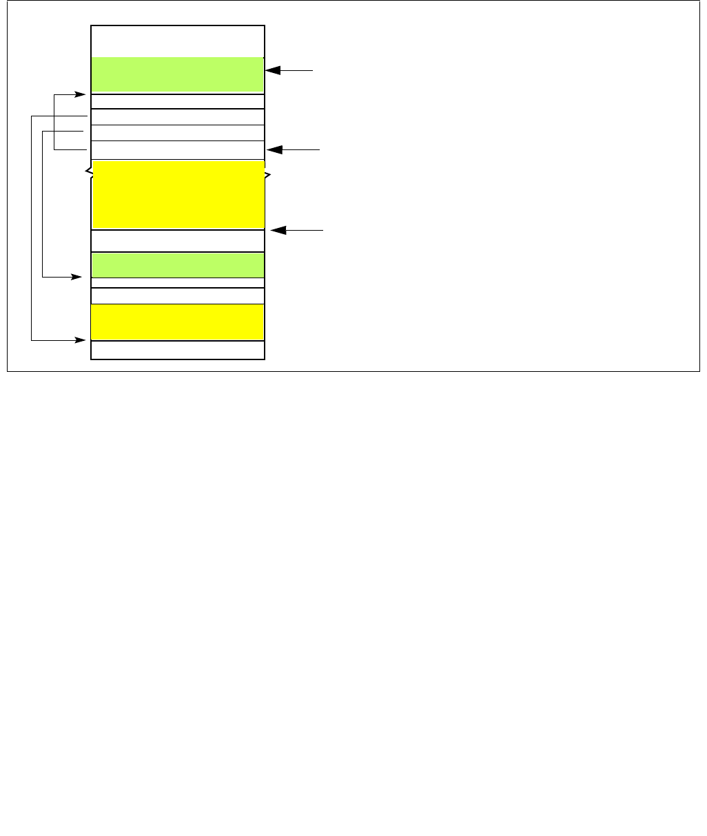
35-10 Vol. 3C
INTEL® PROCESSOR TRACE
enabled, the processor loads this value from bits 63:32 (OutputOffset) of the
IA32_RTIT_OUTPUT_MASK_PTRS. While tracing is enabled, the processor updates
IA32_RTIT_OUTPUT_MASK_PTRS.OutputOffset with changes to proc_trace_output_offset, but these updates
may not be synchronous to software execution. When tracing is disabled, the processor ensures that the MSR
contains the latest value of proc_trace_output_offset.
Figure 35-1 provides an illustration (not to scale) of the table and associated pointers.
With the ToPA mechanism, the processor writes packets to the current output region (identified by
proc_trace_table_base and the proc_trace_table_offset). The offset within that region to which the next byte will
be written is identified by proc_trace_output_offset. When that region is filled with packet output (thus
proc_trace_output_offset = RegionSize–1), proc_trace_table_offset is moved to the next ToPA entry,
proc_trace_output_offset is set to 0, and packet writes begin filling the new output region specified by
proc_trace_table_offset.
As packets are written out, each store derives its physical address as follows:
trace_store_phys_addr Base address from current ToPA table entry +
proc_trace_output_offset
Eventually, the regions represented by all entries in the table may become full, and the final entry of the table is
reached. An entry can be identified as the final entry because it has either the END or STOP attribute. The END
attribute indicates that the address in the entry does not point to another output region, but rather to another ToPA
table. The STOP attribute indicates that tracing will be disabled once the corresponding region is filled. See Table
35-3 and the section that follows for details on STOP.
When an END entry is reached, the processor loads proc_trace_table_base with the base address held in this END
entry, thereby moving the current table pointer to this new table. The proc_trace_table_offset is reset to 0, as is
the proc_trace_output_offset, and packet writes will resume at the base address indicated in the first entry.
If the table has no STOP or END entry, and trace-packet generation remains enabled, eventually the maximum
table size will be reached (proc_trace_table_offset = 0FFFFFF8H). In this case, the proc_trace_table_offset and
proc_trace_output_offset are reset to 0 (wrapping back to the beginning of the current table) once the last output
region is filled.
Figure 35-1. ToPA Memory Illustration
0FF_FFFF _FFFFH
STOP=1
proc_trace_output_offset: IA32_RTIT_OUTPUT_MASK_PTRS.OutputOffset
proc_trace_table_offset:
proc_trace_table_base: IA32_RTIT_OUTPUT_BASE
0
ToPA Table B
Physical Memory
64K OutputBaseX
4K OutputBaseY
END=1 TableBaseB
ToPA Tabl e A
OutputRegionY
OutputRegionX
IA32_RTIT_OUTPUT_MASK_PRS.MaskOrTableOffset<<3
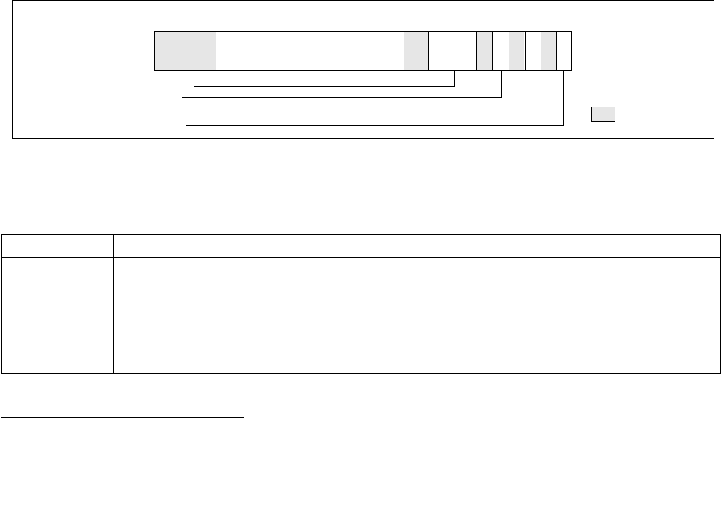
Vol. 3C 35-11
INTEL® PROCESSOR TRACE
It is important to note that processor updates to the IA32_RTIT_OUTPUT_BASE and
IA32_RTIT_OUTPUT_MASK_PTRS MSRs are asynchronous to instruction execution. Thus, reads of these MSRs
while Intel PT is enabled may return stale values. Like all IA32_RTIT_* MSRs, the values of these MSRs should not
be trusted or saved unless trace packet generation is first disabled by clearing IA32_RTIT_CTL.TraceEn. This
ensures that the output MSR values account for all packets generated to that point, after which the processor will
cease updating the output MSR values until tracing resumes. 1
The processor may cache internally any number of entries from the current table or from tables that it references
(directly or indirectly). If tracing is enabled, the processor may ignore or delay detection of modifications to these
tables. To ensure that table changes are detected by the processor in a predictable manner, software should clear
TraceEn before modifying the current table (or tables that it references) and only then re-enable packet genera-
tion.
Single Output Region ToPA Implementation
The first processor generation to implement Intel PT supports only ToPA configurations with a single ToPA entry
followed by an END entry that points back to the first entry (creating one circular output buffer). Such processors
enumerate CPUID.(EAX=14H,ECX=0):ECX.MENTRY[bit 1] = 0 and CPUID.(EAX=14H,ECX=0):ECX.TOPAOUT[bit
0] = 1.
If CPUID.(EAX=14H,ECX=0):ECX.MENTRY[bit 1] = 0, ToPA tables can hold only one output entry, which must be
followed by an END=1 entry which points back to the base of the table. Hence only one contiguous block can be
used as output.
The lone output entry can have INT or STOP set, but nonetheless must be followed by an END entry as described
above. Note that, if INT=1, the PMI will actually be delivered before the region is filled.
ToPA Table Entry Format
The format of ToPA table entries is shown in Figure 35-2. The size of the address field is determined by the
processor’s physical-address width (MAXPHYADDR) in bits, as reported in CPUID.80000008H:EAX[7:0].
Table 35-3 describes the details of the ToPA table entry fields. If reserved bits are set to 1, an error is signaled.
1. Although WRMSR is a serializing instruction, the execution of WRMSR that forces packet writes by clearing TraceEn does not itself
cause these writes to be globally observed.
Figure 35-2. Layout of ToPA Table Entry
Table 35-3. ToPA Table Entry Fields
ToPA Entry Field Description
Output Region
Base Physical
Address
If END=0, this is the base physical address of the output region specified by this entry. Note that all regions
must be aligned based on their size. Thus a 2M region must have bits 20:12 clear. If the region is not properly
aligned, an operational error will be signaled when the entry is reached.
If END=1, this is the 4K-aligned base physical address of the next ToPA table (which may be the base of the cur-
rent table, or the first table in the linked list if a circular buffer is desired). If the processor supports only a single
ToPA output region (see above), this address must be the value currently in the IA32_RTIT_OUTPUT_BASE
MSR.
11 9
1012
MAXPHYADDR–1
9:6 Size
65 0
4 : STOP
2 : INT
0 : END
Output Region Base Physical Address
4132
Reserved
63

35-12 Vol. 3C
INTEL® PROCESSOR TRACE
ToPA STOP
Each ToPA entry has a STOP bit. If this bit is set, the processor will set the IA32_RTIT_STATUS.Stopped bit when
the corresponding trace output region is filled. This will clear TriggerEn and thereby cease packet generation. See
Section 35.2.7.4 for details on IA32_RTIT_STATUS.Stopped. This sequence is known as “ToPA Stop”.
No TIP.PGD packet will be seen in the output when the ToPA stop occurs, since the disable happens only when the
region is already full. When this occurs, output ceases after the last byte of the region is filled, which may mean
that a packet is cut off in the middle. Any packets remaining in internal buffers are lost and cannot be recovered.
When ToPA stop occurs, the IA32_RTIT_OUTPUT_BASE MSR will hold the base address of the table whose entry
had STOP=1. IA32_RTIT_OUTPUT_MASK_PTRS.MaskOrTableOffset will hold the index value for that entry, and the
IA32_RTIT_OUTPUT_MASK_PTRS.OutputOffset should be set to the size of the region.
Note that this means the offset pointer is pointing to the next byte after the end of the region, a configuration that
would produce an operational error if the configuration remained when tracing is re-enabled with
IA32_RTIT_STATUS.Stopped cleared.
ToPA PMI
Each ToPA entry has an INT bit. If this bit is set, the processor will signal a performance-monitoring interrupt (PMI)
when the corresponding trace output region is filled. This interrupt is not precise, and it is thus likely that writes to
the next region will occur by the time the interrupt is taken.
The following steps should be taken to configure this interrupt:
1. Enable PMI via the LVT Performance Monitor register (at MMIO offset 340H in xAPIC mode; via MSR 834H in
x2APIC mode). See Intel® 64 and IA-32 Architectures Software Developer’s Manual, Volume 3B for more
details on this register. For ToPA PMI, set all fields to 0, save for the interrupt vector, which can be selected by
software.
2. Set up an interrupt handler to service the interrupt vector that a ToPA PMI can raise.
3. Set the interrupt flag by executing STI.
4. Set the INT bit in the ToPA entry of interest and enable packet generation, using the ToPA output option. Thus,
TraceEn=ToPA=1 in the IA32_RTIT_CTL MSR.
Once the INT region has been filled with packet output data, the interrupt will be signaled. This PMI can be distin-
guished from others by checking bit 55 (Trace_ToPA_PMI) of the IA32_PERF_GLOBAL_STATUS MSR (MSR 38EH).
Once the ToPA PMI handler has serviced the relevant buffer, writing 1 to bit 55 of the MSR at 390H
(IA32_GLOBAL_STATUS_RESET) clears IA32_PERF_GLOBAL_STATUS.Trace_ToPA_PMI.
Size Indicates the size of the associated output region. Encodings are:
0: 4K, 1: 8K, 2: 16K, 3: 32K, 4: 64K, 5: 128K, 6: 256K, 7: 512K,
8: 1M, 9: 2M, 10: 4M, 11: 8M, 12: 16M, 13: 32M, 14: 64M, 15: 128M
This field is ignored if END=1.
STOP When the output region indicated by this entry is filled, software should disable packet generation. This will be
accomplished by setting IA32_RTIT_STATUS.Stopped, which clears TriggerEn. This bit must be 0 if END=1; oth-
erwise it is treated as reserved bit violation (see ToPA Errors).
INT When the output region indicated by this entry is filled, signal Perfmon LVT interrupt.
Note that if both INT and STOP are set in the same entry, the STOP will happen before the INT. Thus the inter-
rupt handler should expect that the IA32_RTIT_STATUS.Stopped bit will be set, and will need to be reset before
tracing can be resumed.
This bit must be 0 if END=1; otherwise it is treated as reserved bit violation (see ToPA Errors).
END If set, indicates that this is an END entry, and thus the address field points to a table base rather than an output
region base.
If END=1, INT and STOP must be set to 0; otherwise it is treated as reserved bit violation (see ToPA Errors). The
Size field is ignored in this case.
If the processor supports only a single ToPA output region (see above), END must be set in the second table
entry.
Table 35-3. ToPA Table Entry Fields (Contd.)
ToPA Entry Field Description

Vol. 3C 35-13
INTEL® PROCESSOR TRACE
Intel PT is not frozen on PMI, and thus the interrupt handler will be traced (though filtering can prevent this). The
Freeze_Perfmon_on_PMI and Freeze_LBRs_on_PMI settings in IA32_DEBUGCTL will be applied on ToPA PMI just as
on other PMIs, and hence Perfmon counters are frozen.
Assuming the PMI handler wishes to read any buffered packets for persistent output, or wishes to modify any Intel
PT MSRs, software should first disable packet generation by clearing TraceEn. This ensures that all buffered packets
are written to memory and avoids tracing of the PMI handler. The configuration MSRs can then be used to deter-
mine where tracing has stopped. If packet generation is disabled by the handler, it should then be manually re-
enabled before the IRET if continued tracing is desired.
In rare cases, it may be possible to trigger a second ToPA PMI before the first is handled. This can happen if another
ToPA region with INT=1 is filled before, or shortly after, the first PMI is taken, perhaps due to EFLAGS.IF being
cleared for an extended period of time. This can manifest in two ways: either the second PMI is triggered before the
first is taken, and hence only one PMI is taken, or the second is triggered after the first is taken, and thus will be
taken when the handler for the first completes. Software can minimize the likelihood of the second case by clearing
TraceEn at the beginning of the PMI handler. Further, it can detect such cases by then checking the Interrupt
Request Register (IRR) for PMI pending, and checking the ToPA table base and off-set pointers (in
IA32_RTIT_OUTPUT_BASE and IA32_RTIT_OUTPUT_MASK_PTRS) to see if multiple entries with INT=1 have been
filled.
When IA32_RTIT_CTL.InjectPsbPmiOnEnable[56] = 1, the PMI handler should take the following actions:
1. Ignore ToPA PMIs that are taken when TraceEn = 0, because the Intel PT MSR state may have already been
saved by XSAVES, and because the PMI will be re-injected when Intel PT is re-enabled.
2. Clear the new IA32_RTIT_STATUS.PendTopaPMI[7] bit once the PMI has been handled. This bit should not be
cleared in cases where a PMI is ignored due to TraceEn = 0.
ToPA PMI and Single Output Region ToPA Implementation
A processor that supports only a single ToPA output region implementation (such that only one output region is
supported; see above) will attempt to signal a ToPA PMI interrupt before the output wraps and overwrites the top
of the buffer. To support this functionality, the PMI handler should disable packet generation as soon as possible.
Due to PMI skid, it is possible that, in rare cases, the wrap will have occurred before the PMI is delivered. Software
can avoid this by setting the STOP bit in the ToPA entry (see Table 35-3); this will disable tracing once the region
is filled, and no wrap will occur. This approach has the downside of disabling packet generation so that some of the
instructions that led up to the PMI will not be traced. If the PMI skid is significant enough to cause the region to fill
and tracing to be disabled, the PMI handler will need to clear the IA32_RTIT_STATUS.Stopped indication before
tracing can resume.
ToPA PMI and XSAVES/XRSTORS State Handling
In some cases the ToPA PMI may be taken after completion of an XSAVES instruction that switches Intel PT state,
and in such cases any modification of Intel PT MSRs within the PMI handler will not persist when the saved Intel PT
context is later restored with XRSTORS. To account for such a scenario, it is recommended that the Intel PT output
configuration be modified by altering the ToPA tables themselves, rather than the Intel PT output MSRs. On proces-
sors that support PMI preservation (CPUID.(EAX=14H, ECX=0):EBX.INJECTPSBPMI[6] = 1), setting
IA32_RTIT_CTL.InjectPsbPmiOnEnable[56] = 1 will ensure that a PMI that is pending at the time PT is disabled will
be recorded by setting IA32_RTIT_STATUS.PendTopaPMI[7] = 1. A PMI will then be pended when the saved PT
context is later restored.
Table 35-4 depicts a recommended PMI handler algorithm for managing multi-region ToPA output and handling
ToPA PMIs that may arrive between XSAVES and XRSTORS. This algorithm is flexible to allow software to choose
between adding entries to the current ToPA table, adding a new ToPA table, or using the current ToPA table as a
circular buffer. It assumes that the ToPA entry that triggers the PMI is not the last entry in the table, which is the
recommended treatment.

35-14 Vol. 3C
INTEL® PROCESSOR TRACE
ToPA Errors
When a malformed ToPA entry is found, an operational error results (see Section 35.3.9). A malformed entry can
be any of the following:
1. ToPA entry reserved bit violation.
This describes cases where a bit marked as reserved in Section 35.2.6.2 above is set to 1.
2. ToPA alignment violation.
This includes cases where illegal ToPA entry base address bits are set to 1:
a. ToPA table base address is not 4KB-aligned. The table base can be from a WRMSR to
IA32_RTIT_OUTPUT_BASE, or from a ToPA entry with END=1.
b. ToPA entry base address is not aligned to the ToPA entry size (e.g., a 2MB region with base address[20:12]
not equal to 0), for ToPA entries with END=0.
c. ToPA entry base address sets upper physical address bits not supported by the processor.
3. Illegal ToPA Output Offset.
IA32_RTIT_OUTPUT_MASK_PTRS.OutputOffset is greater than or equal to the size of the current ToPA output
region size.
4. ToPA rules violations.
These are similar to ToPA entry reserved bit violations; they are cases when a ToPA entry is encountered with
illegal field combinations. They include the following:
a. Setting the STOP or INT bit on an entry with END=1.
b. Setting the END bit in entry 0 of a ToPA table.
c. On processors that support only a single ToPA entry (see above), two additional illegal settings apply:
i) ToPA table entry 1 with END=0.
ii) ToPA table entry 1 with base address not matching the table base.
Table 35-4. Algorithm to Manage Intel PT ToPA PMI and XSAVES/XRSTORS
Pseudo Code Flow
IF (IA32_PERF_GLOBAL_STATUS.ToPA)
Save IA32_RTIT_CTL value;
IF ( IA32_RTIT_CTL.TraceEN )
Disable Intel PT by clearing TraceEn;
FI;
IF ( there is space available to grow the current ToPA table )
Add one or more ToPA entries after the last entry in the ToPA table;
Point new ToPA entry address field(s) to new output region base(s);
ELSE
Modify an upcoming ToPA entry in the current table to have END=1;
IF (output should transition to a new ToPA table )
Point the address of the “END=1” entry of the current table to the new table base;
ELSE
/* Continue to use the current ToPA table, make a circular. */
Point the address of the “END=1”l entry to the base of the current table;
Modify the ToPA entry address fields for filled output regions to point to new, unused output regions;
/* Filled regions are those with index in the range of 0 to (IA32_RTIT_MASK_PTRS.MaskOrTableOffset -1). */
FI;
FI;
Restore saved IA32_RTIT_CTL.value;
FI;

Vol. 3C 35-15
INTEL® PROCESSOR TRACE
In all cases, the error will be logged by setting IA32_RTIT_STATUS.Error, thereby disabling tracing when the prob-
lematic ToPA entry is reached (when proc_trace_table_offset points to the entry containing the error). Any packet
bytes that are internally buffered when the error is detected may be lost.
Note that operational errors may also be signaled due to attempts to access restricted memory. See Section
35.2.6.4 for details.
A tracing software have a range of flexibility using ToPA to manage the interaction of Intel PT with application
buffers, see Section 35.5.
35.2.6.3 Trace Transport Subsystem
When IA32_RTIT_CTL.FabricEn is set, the IA32_RTIT_CTL.ToPA bit is ignored, and trace output is written to the
trace transport subsystem. The endpoints of this transport are platform-specific, and details of configuration
options should refer to the specific platform documentation. The FabricEn bit is available to be set if
CPUID(EAX=14H,ECX=0):EBX[bit 3] = 1.
35.2.6.4 Restricted Memory Access
Packet output cannot be directed to any regions of memory that are restricted by the platform. In particular, all
memory accesses on behalf of packet output are checked against the SMRR regions. If there is any overlap with
these regions, trace data collection will not function properly. Exact processor behavior is implementation-depen-
dent; Table 35-5 summarizes several scenarios.
It should also be noted that packet output should not be routed to the 4KB APIC MMIO region, as defined by the
IA32_APIC_BASE MSR. For details about the APIC, refer to Intel® 64 and IA-32 Architectures Software Devel-
oper’s Manual, Volume 3A. No error is signaled for this case.
Modifications to Restricted Memory Regions
It is recommended that software disable packet generation before modifying the SMRRs to change the scope of the
SMRR regions. This is because the processor reserves the right to cache any number of ToPA table entries inter-
nally, after checking them against restricted memory ranges. Once cached, the entries will not be checked again,
meaning one could potentially route packet output to a newly restricted region. Software can ensure that any
cached entries are written to memory by clearing IA32_RTIT_CTL.TraceEn.
35.2.7 Enabling and Configuration MSRs
35.2.7.1 General Considerations
Trace packet generation is enabled and configured by a collection of model-specific registers (MSRs), which are
detailed below. Some notes on the configuration MSR behavior:
•If Intel Processor Trace is not supported by the processor (see Section 35.3.1), RDMSR or WRMSR of the
IA32_RTIT_* MSRs will cause #GP.
•A WRMSR to any of these configuration MSRs that begins and ends with IA32_RTIT_CTL.TraceEn set will #GP
fault. Packet generation must be disabled before the configuration MSRs can be changed.
Table 35-5. Behavior on Restricted Memory Access
Scenario Description
ToPA output region
overlaps with
SMRR
Stores to the restricted memory region will be dropped, and that packet data will be lost. Any attempt to read
from that restricted region will return all 1s. The processor also may signal an error (Section 35.3.9) and disable
tracing when the output pointer reaches the restricted region. If packet generation remains enabled, then
packet output may continue once stores are no longer directed to restricted memory (on wrap, or if the output
region is larger than the restricted memory region).
ToPA table overlaps
with SMRR
The processor will signal an error (Section 35.3.9) and disable tracing when the ToPA write pointer
(IA32_RTIT_OUTPUT_BASE + proc_trace_table_offset) enters the restricted region.

35-16 Vol. 3C
INTEL® PROCESSOR TRACE
Note: Software may write the same value back to IA32_RTIT_CTL without #GP, even if TraceEn=1.
•All configuration MSRs for Intel PT are duplicated per logical processor
•For each configuration MSR, any MSR write that attempts to change bits marked reserved, or utilize encodings
marked reserved, will cause a #GP fault.
•All configuration MSRs for Intel PT are cleared on a cold RESET.
— If CPUID.(EAX=14H, ECX=0):EBX.IPFILT_WRSTPRSV[bit 2] = 1, only the TraceEn bit is cleared on warm
RESET; though this may have the impact of clearing other bits in IA32_RTIT_STATUS. Other MSR values of
the trace configuration MSRs are preserved on warm RESET.
•The semantics of MSR writes to trace configuration MSRs in this chapter generally apply to explicit WRMSR to
these registers, using VM-exit or VM-entry MSR load list to these MSRs, XRSTORS with requested feature bit
map including XSAVE map component of state_8 (corresponding to IA32_XSS[bit 8]), and the write to
IA32_RTIT_CTL.TraceEn by XSAVES (Section 35.3.5.2).
35.2.7.2 IA32_RTIT_CTL MSR
IA32_RTIT_CTL, at address 570H, is the primary enable and control MSR for trace packet generation. Bit positions
are listed in Table 35-6.
Table 35-6. IA32_RTIT_CTL MSR
Position Bit Name At Reset Bit Description
0TraceEn 0 If 1, enables tracing; else tracing is disabled.
When this bit transitions from 1 to 0, all buffered packets are flushed out of internal buffers.
A further store, fence, or architecturally serializing instruction may be required to ensure that
packet data can be observed at the trace endpoint. See Section 35.2.7.3 for details of
enabling and disabling packet generation.
Note that the processor will clear this bit on #SMI (Section ) and warm reset. Other MSR bits
of IA32_RTIT_CTL (and other trace configuration MSRs) are not impacted by these events.
1 CYCEn 0 0: Disables CYC Packet (see Section 35.4.2.14).
1: Enables CYC Packet.
This bit is reserved if CPUID.(EAX=14H, ECX=0):EBX.CPSB_CAM[bit 1] = 0.
2 OS 0 0: Packet generation is disabled when CPL = 0.
1: Packet generation may be enabled when CPL = 0.
3 User 0 0: Packet generation is disabled when CPL > 0.
1: Packet generation may be enabled when CPL > 0.
4 PwrEvtEn 0 0: Power Event Trace packets are disabled.
1: Power Event Trace packets are enabled (see Section 35.2.3, “Power Event Tracing”).
5 FUPonPTW 0 0: PTW packets are not followed by FUPs.
1: PTW packets are followed by FUPs.
6 FabricEn 0 0: Trace output is directed to the memory subsystem, mechanism depends on
IA32_RTIT_CTL.ToPA.
1: Trace output is directed to the trace transport subsystem, IA32_RTIT_CTL.ToPA is ignored.
This bit is reserved if CPUID.(EAX=14H, ECX=0):ECX[bit 3] = 0.
7 CR3Filter 0 0: Disables CR3 filtering.
1: Enables CR3 filtering.

Vol. 3C 35-17
INTEL® PROCESSOR TRACE
8 ToPA 0 0: Single-range output scheme enabled if CPUID.(EAX=14H, ECX=0):ECX.SNGLRGNOUT[bit 2]
= 1 and IA32_RTIT_CTL.FabricEn=0.
1: ToPA output scheme enabled (see Section 35.2.6.2) if CPUID.(EAX=14H,
ECX=0):ECX.TOPA[bit 0] = 1, and IA32_RTIT_CTL.FabricEn=0.
Note: WRMSR to IA32_RTIT_CTL that sets TraceEn but clears this bit and FabricEn would
cause #GP, if CPUID.(EAX=14H, ECX=0):ECX.SNGLRGNOUT[bit 2] = 0.
WRMSR to IA32_RTIT_CTL that sets this bit causes #GP, if CPUID.(EAX=14H,
ECX=0):ECX.TOPA[bit 0] = 0.
9 MTCEn 0 0: Disables MTC Packet (see Section 35.4.2.16).
1: Enables MTC Packet.
This bit is reserved if CPUID.(EAX=14H, ECX=0):EBX.MTC[bit 3] = 0.
10 TSCEn 0 0: Disable TSC packets.
1: Enable TSC packets (see Section 35.4.2.11).
11 DisRETC 0 0: Enable RET compression.
1: Disable RET compression (see Section 35.2.1.2).
12 PTWEn 0 0: PTWRITE packet generation disabled.
1: PTWRITE packet generation enabled (see Table 35-40 “PTW Packet Definition”).
13 BranchEn 0 0: Disable COFI-based packets.
1: Enable COFI-based packets: FUP, TIP, TIP.PGE, TIP.PGD, TNT, MODE.Exec, MODE.TSX.
See Section 35.2.5.4 for details on BranchEn.
17:14 MTCFreq 0 Defines MTC packet Frequency, which is based on the core crystal clock, or Always Running
Timer (ART). MTC will be sent each time the selected ART bit toggles. The following Encodings
are defined:
0: ART(0), 1: ART(1), 2: ART(2), 3: ART(3), 4: ART(4), 5: ART(5), 6: ART(6), 7: ART(7),
8: ART(8), 9: ART(9), 10: ART(10), 11: ART(11), 12: ART(12), 13: ART(13), 14: ART(14), 15:
ART(15)
Software must use CPUID to query the supported encodings in the processor, see Section
35.3.1. Use of unsupported encodings will result in a #GP fault. This field is reserved if
CPUID.(EAX=14H, ECX=0):EBX.MTC[bit 3] = 0.
18 Reserved 0 Must be 0.
22:19 CycThresh 0 CYC packet threshold, see Section 35.3.6 for details. CYC packets will be sent with the first
eligible packet after N cycles have passed since the last CYC packet. If CycThresh is 0 then
N=0, otherwise N is defined as 2(CycThresh-1). The following Encodings are defined:
0: 0, 1: 1, 2: 2, 3: 4, 4: 8, 5: 16, 6: 32, 7: 64,
8: 128, 9: 256, 10: 512, 11: 1024, 12: 2048, 13: 4096, 14: 8192, 15: 16384
Software must use CPUID to query the supported encodings in the processor, see Section
35.3.1. Use of unsupported encodings will result in a #GP fault. This field is reserved if
CPUID.(EAX=14H, ECX=0):EBX.CPSB_CAM[bit 1] = 0.
23 Reserved 0 Must be 0.
Table 35-6. IA32_RTIT_CTL MSR (Contd.)
Position Bit Name At Reset Bit Description

35-18 Vol. 3C
INTEL® PROCESSOR TRACE
27:24 PSBFreq 0 Indicates the frequency of PSB packets. PSB packet frequency is based on the number of Intel
PT packet bytes output, so this field allows the user to determine the increment of
IA32_IA32_RTIT_STATUS.PacketByteCnt that should cause a PSB to be generated. Note that
PSB insertion is not precise, but the average output bytes per PSB should approximate the
SW selected period. The following Encodings are defined:
0: 2K, 1: 4K, 2: 8K, 3: 16K, 4: 32K, 5: 64K, 6: 128K, 7: 256K,
8: 512K, 9: 1M, 10: 2M, 11: 4M, 12: 8M, 13: 16M, 14: 32M, 15: 64M
Software must use CPUID to query the supported encodings in the processor, see Section
35.3.1. Use of unsupported encodings will result in a #GP fault. This field is reserved if
CPUID.(EAX=14H, ECX=0):EBX.CPSB_CAM[bit 1] = 0.
31:28 Reserved 0 Must be 0.
35:32 ADDR0_CFG 0 Configures the base/limit register pair IA32_RTIT_ADDR0_A/B based on the following
encodings:
0: ADDR0 range unused.
1: The [IA32_RTIT_ADDR0_A..IA32_RTIT_ADDR0_B] range defines a FilterEn range. FilterEn
will only be set when the IP is within this range, though other FilterEn ranges can additionally
be used. See Section 35.2.4.3 for details on IP filtering.
2: The [IA32_RTIT_ADDR0_A..IA32_RTIT_ADDR0_B] range defines a TraceStop range.
TraceStop will be asserted if code branches into this range. See 4.2.8 for details on TraceStop.
3..15: Reserved (#GP).
This field is reserved if CPUID.(EAX=14H, ECX=1):EBX.RANGECNT[2:0] >= 0.
39:36 ADDR1_CFG 0 Configures the base/limit register pair IA32_RTIT_ADDR1_A/B based on the following
encodings:
0: ADDR1 range unused.
1: The [IA32_RTIT_ADDR1_A..IA32_RTIT_ADDR1_B] range defines a FilterEn range. FilterEn
will only be set when the IP is within this range, though other FilterEn ranges can additionally
be used. See Section 35.2.4.3 for details on IP filtering.
2: The [IA32_RTIT_ADDR1_A..IA32_RTIT_ADDR1_B] range defines a TraceStop range.
TraceStop will be asserted if code branches into this range. See Section 35.4.2.10 for details
on TraceStop.
3..15: Reserved (#GP).
This field is reserved if CPUID.(EAX=14H, ECX=1):EBX.RANGECNT[2:0] < 2.
43:40 ADDR2_CFG 0 Configures the base/limit register pair IA32_RTIT_ADDR2_A/B based on the following
encodings:
0: ADDR2 range unused.
1: The [IA32_RTIT_ADDR2_A..IA32_RTIT_ADDR2_B] range defines a FilterEn range. FilterEn
will only be set when the IP is within this range, though other FilterEn ranges can additionally
be used. See Section 35.2.4.3 for details on IP filtering.
2: The [IA32_RTIT_ADDR2_A..IA32_RTIT_ADDR2_B] range defines a TraceStop range.
TraceStop will be asserted if code branches into this range. See Section 35.4.2.10 for details
on TraceStop.
3..15: Reserved (#GP).
This field is reserved if CPUID.(EAX=14H, ECX=1):EBX.RANGECNT[2:0] < 3.
Table 35-6. IA32_RTIT_CTL MSR (Contd.)
Position Bit Name At Reset Bit Description

Vol. 3C 35-19
INTEL® PROCESSOR TRACE
35.2.7.3 Enabling and Disabling Packet Generation with TraceEn
When TraceEn transitions from 0 to 1, Intel Processor Trace is enabled, and a series of packets may be generated.
These packets help ensure that the decoder is aware of the state of the processor when the trace begins, and that
it can keep track of any timing or state changes that may have occurred while packet generation was disabled. A
full PSB+ (see Section 35.4.2.17) will be generated if IA32_RTIT_STATUS.PacketByteCnt=0, and may be gener-
ated in other cases as well. Otherwise, timing packets will be generated, including TSC, TMA, and CBR (see Section
35.4.2).
In addition to the packets discussed above, if and when PacketEn (Section 35.2.5.1) transitions from 0 to 1 (which
may happen immediately, depending on filtering settings), a TIP.PGE packet (Section 35.4.2.3) will be generated.
When TraceEn is set, the processor may read ToPA entries from memory and cache them internally. For this reason,
software should disable packet generation before making modifications to the ToPA tables (or changing the config-
uration of restricted memory regions). See Section 35.7 for more details of packets that may be generated with
modifications to TraceEn.
Disabling Packet Generation
Clearing TraceEn causes any packet data buffered within the logical processor to be flushed out, after which the
output MSRs (IA32_RTIT_OUTPUT_BASE and IA32_RTIT_OUTPUT_MASK_PTRS) will have stable values. When
output is directed to memory, a store, fence, or architecturally serializing instruction may be required to ensure
that the packet data is globally observed. No special packets are generated by disabling packet generation, though
a TIP.PGD may result if PacketEn=1 at the time of disable.
Other Writes to IA32_RTIT_CTL
Any attempt to modify IA32_RTIT_CTL while TraceEn is set will result in a general-protection fault (#GP) unless the
same write also clears TraceEn. However, writes to IA32_RTIT_CTL that do not modify any bits will not cause a
#GP, even if TraceEn remains set.
47:44 ADDR3_CFG 0 Configures the base/limit register pair IA32_RTIT_ADDR3_A/B based on the following
encodings:
0: ADDR3 range unused.
1: The [IA32_RTIT_ADDR3_A..IA32_RTIT_ADDR3_B] range defines a FilterEn range. FilterEn
will only be set when the IP is within this range, though other FilterEn ranges can additionally
be used. See Section 35.2.4.3 for details on IP filtering.
2: The [IA32_RTIT_ADDR3_A..IA32_RTIT_ADDR3_B] range defines a TraceStop range.
TraceStop will be asserted if code branches into this range. See Section 35.4.2.10 for details
on TraceStop.
3..15: Reserved (#GP).
This field is reserved if CPUID.(EAX=14H, ECX=1):EBX.RANGECNT[2:0] < 4.
55:48 Reserved 0 Reserved only for future trace content enables, or address filtering configuration enables.
Must be 0.
56 InjectPsbPmi
OnEnable
0 1: Enables use of IA32_RTIT_STATUS bits PendPSB[6] and PendTopaPMI[7], see Section
35.2.7.4, “IA32_RTIT_STATUS MSR” for behavior of these bits.
0: IA32_RTIT_STATUS bits 6 and 7 are ignored.
This field is reserved if CPUID.(EAX=14H, ECX=0):EBX.INJECTPSBPMI[6] = 0.
59:57 Reserved 0 Reserved only for future trace content enables, or address filtering configuration enables.
Must be 0.
63:60 Reserved 0 Must be 0.
Table 35-6. IA32_RTIT_CTL MSR (Contd.)
Position Bit Name At Reset Bit Description

35-20 Vol. 3C
INTEL® PROCESSOR TRACE
35.2.7.4 IA32_RTIT_STATUS MSR
The IA32_RTIT_STATUS MSR is readable and writable by software, but some bits (ContextEn, TriggerEn) are read-
only and cannot be directly modified. The WRMSR instruction ignores these bits in the source operand (attempts to
modify these bits are ignored and do not cause WRMSR to fault).
This MSR can only be written when IA32_RTIT_CTL.TraceEn is 0; otherwise WRMSR causes a general-protection
fault (#GP). The processor does not modify the value of this MSR while TraceEn is 0 (software can modify it with
WRMSR).
Table 35-7. IA32_RTIT_STATUS MSR
Position Bit Name At Reset Bit Description
0 FilterEn 0 This bit is written by the processor, and indicates that tracing is allowed for the current IP,
see Section 35.2.5.5. Writes are ignored.
1 ContextEn 0 The processor sets this bit to indicate that tracing is allowed for the current context. See
Section 35.2.5.3. Writes are ignored.
2 TriggerEn 0 The processor sets this bit to indicate that tracing is enabled. See Section 35.2.5.2. Writes are
ignored.
3Reserved 0 Must be 0.
4 Error 0 The processor sets this bit to indicate that an operational error has been encountered. When
this bit is set, TriggerEn is cleared to 0 and packet generation is disabled. For details, see
“ToPA Errors” in Section 35.2.6.2.
When TraceEn is cleared, software can write this bit. Once it is set, only software can clear it.
It is not recommended that software ever set this bit, except in cases where it is restoring a
prior saved state.
5 Stopped 0 The processor sets this bit to indicate that a ToPA Stop condition has been encountered.
When this bit is set, TriggerEn is cleared to 0 and packet generation is disabled. For details,
see “ToPA STOP” in Section 35.2.6.2.
When TraceEn is cleared, software can write this bit. Once it is set, only software can clear it.
It is not recommended that software ever set this bit, except in cases where it is restoring a
prior saved state.
6 PendPSB 0 If IA32_RTIT_CTL.InjectPsbPmiOnEnable[56] = 1, the processor sets this bit when the
threshold for a PSB+ to be inserted has been reached. The processor will clear this bit when
the PSB+ has been inserted into the trace. If PendPSB = 1 and InjectPsbPmiOnEnable = 1
when IA32_RTIT_CTL.TraceEn[0] transitions from 0 to 1, a PSB+ will be inserted into the
trace.
This field is reserved if CPUID.(EAX=14H, ECX=0):EBX.INJECTPSBPMI[6] = 1.
7 PendTopaPMI 0 If IA32_RTIT_CTL.InjectPsbPmiOnEnable[56] = 1, the processor sets this bit when the
threshold for a ToPA PMI to be inserted has been reached. Software should clear this bit once
the ToPA PMI has been handled, see “ToPA PMI” for details. If PendTopaPMI = 1 and
InjectPsbPmiOnEnable = 1 when IA32_RTIT_CTL.TraceEn[0] transitions from 0 to 1, a PMI will
be pended.
This field is reserved if CPUID.(EAX=14H, ECX=0):EBX.INJECTPSBPMI[6] = 1.
31:8 Reserved 0 Must be 0.
48:32 PacketByteCnt 0 This field is written by the processor, and holds a count of packet bytes that have been sent
out. The processor also uses this field to determine when the next PSB packet should be
inserted. Note that the processor may clear or modify this field at any time while
IA32_RTIT_CTL.TraceEn=1. It will have a stable value when IA32_RTIT_CTL.TraceEn=0.
See Section 35.4.2.17 for details.
63:49 Reserved 0 Must be 0.

Vol. 3C 35-21
INTEL® PROCESSOR TRACE
35.2.7.5 IA32_RTIT_ADDRn_A and IA32_RTIT_ADDRn_B MSRs
The role of the IA32_RTIT_ADDRn_A/B register pairs, for each n, is determined by the corresponding ADDRn_CFG
fields in IA32_RTIT_CTL (see Section 35.2.7.2). The number of these register pairs is enumerated by
CPUID.(EAX=14H, ECX=1):EAX.RANGECNT[2:0].
•Processors that enumerate support for 1 range support:
IA32_RTIT_ADDR0_A, IA32_RTIT_ADDR0_B
•Processors that enumerate support for 2 ranges support:
IA32_RTIT_ADDR0_A, IA32_RTIT_ADDR0_B
IA32_RTIT_ADDR1_A, IA32_RTIT_ADDR1_B
•Processors that enumerate support for 3 ranges support:
IA32_RTIT_ADDR0_A, IA32_RTIT_ADDR0_B
IA32_RTIT_ADDR1_A, IA32_RTIT_ADDR1_B
IA32_RTIT_ADDR2_A, IA32_RTIT_ADDR2_B
•Processors that enumerate support for 4 ranges support:
IA32_RTIT_ADDR0_A, IA32_RTIT_ADDR0_B
IA32_RTIT_ADDR1_A, IA32_RTIT_ADDR1_B
IA32_RTIT_ADDR2_A, IA32_RTIT_ADDR2_B
IA32_RTIT_ADDR3_A, IA32_RTIT_ADDR3_B
Each register has a single 64-bit field that holds a linear address value. Writes must ensure that the address is in
canonical form, otherwise a #GP fault will result.
35.2.7.6 IA32_RTIT_CR3_MATCH MSR
The IA32_RTIT_CR3_MATCH register is compared against CR3 when IA32_RTIT_CTL.CR3Filter is 1. Bits 63:5 hold
the CR3 address value to match, bits 4:0 are reserved to 0. For more details on CR3 filtering and the treatment of
this register, see Section 35.2.4.2.
This MSR can be written only when IA32_RTIT_CTL.TraceEn is 0; otherwise WRMSR causes a general-protection
fault (#GP). IA32_RTIT_CR3_MATCH[4:0] are reserved and must be 0; an attempt to set those bits using WRMSR
causes a #GP.
35.2.7.7 IA32_RTIT_OUTPUT_BASE MSR
This MSR is used to configure the trace output destination, when output is directed to memory
(IA32_RTIT_CTL.FabricEn = 0). The size of the address field is determined by the maximum physical address width
(MAXPHYADDR), as reported by CPUID.80000008H:EAX[7:0].
When the ToPA output scheme is used, the processor may update this MSR when packet generation is enabled, and
those updates are asynchronous to instruction execution. Therefore, the values in this MSR should be considered
unreliable unless packet generation is disabled (IA32_RTIT_CTL.TraceEn = 0).
Accesses to this MSR are supported only if Intel PT output to memory is supported, hence when either
CPUID.(EAX=14H, ECX=0):ECX[bit 0] or CPUID.(EAX=14H, ECX=0):ECX[bit 2] are set. Otherwise WRMSR or
RDMSR cause a general-protection fault (#GP). If supported, this MSR can be written only when
IA32_RTIT_CTL.TraceEn is 0; otherwise WRMSR causes a general-protection fault (#GP).

35-22 Vol. 3C
INTEL® PROCESSOR TRACE
35.2.7.8 IA32_RTIT_OUTPUT_MASK_PTRS MSR
This MSR holds any mask or pointer values needed to indicate where the next byte of trace output should be
written. The meaning of the values held in this MSR depend on whether the ToPA output mechanism is in use. See
Section 35.2.6.2 for details.
The processor updates this MSR while when packet generation is enabled, and those updates are asynchronous to
instruction execution. Therefore, the values in this MSR should be considered unreliable unless packet generation
is disabled (IA32_RTIT_CTL.TraceEn = 0).
Accesses to this MSR are supported only if Intel PT output to memory is supported, hence when either
CPUID.(EAX=14H, ECX=0):ECX[bit 0] or CPUID.(EAX=14H, ECX=0):ECX[bit 2] are set. Otherwise WRMSR or
RDMSR cause a general-protection fault (#GP). If supported, this MSR can be written only when
IA32_RTIT_CTL.TraceEn is 0; otherwise WRMSR causes a general-protection fault (#GP).
Table 35-8. IA32_RTIT_OUTPUT_BASE MSR
Position Bit Name At Reset Bit Description
6:0 Reserved 0 Must be 0.
MAXPHYADDR-1:7 BasePhysAddr 0 The base physical address. How this address is used depends on the value of
IA32_RTIT_CTL.ToPA:
0: This is the base physical address of a single, contiguous physical output region.
This could be mapped to DRAM or to MMIO, depending on the value.
The base address should be aligned with the size of the region, such that none of
the 1s in the mask value(Section 35.2.7.8) overlap with 1s in the base address. If
the base is not aligned, an operational error will result (see Section 35.3.9).
1: The base physical address of the current ToPA table. The address must be 4K
aligned. Writing an address in which bits 11:7 are non-zero will not cause a #GP, but
an operational error will be signaled once TraceEn is set. See “ToPA Errors” in
Section 35.2.6.2 as well as Section 35.3.9.
63:MAXPHYADDR Reserved 0 Must be 0.
Table 35-9. IA32_RTIT_OUTPUT_MASK_PTRS MSR
Position Bit Name At Reset Bit Description
6:0 LowerMask 7FH Forced to 1, writes are ignored.
31:7 MaskOrTableO
ffset
0 The use of this field depends on the value of IA32_RTIT_CTL.ToPA:
0: This field holds bits 31:7 of the mask value for the single, contiguous physical output
region. The size of this field indicates that regions can be of size 128B up to 4GB. This value
(combined with the lower 7 bits, which are reserved to 1) will be ANDed with the
OutputOffset field to determine the next write address. All 1s in this field should be
consecutive and starting at bit 7, otherwise the region will not be contiguous, and an
operational error (Section 35.3.9) will be signaled when TraceEn is set.
1: This field holds bits 27:3 of the offset pointer into the current ToPA table. This value can
be added to the IA32_RTIT_OUTPUT_BASE value to produce a pointer to the current ToPA
table entry, which itself is a pointer to the current output region. In this scenario, the lower 7
reserved bits are ignored. This field supports tables up to 256 MBytes in size.

Vol. 3C 35-23
INTEL® PROCESSOR TRACE
35.2.8 Interaction of Intel® Processor Trace and Other Processor Features
35.2.8.1 Intel® Transactional Synchronization Extensions (Intel® TSX)
The operation of Intel TSX is described in Chapter 14 of the Intel® 64 and IA-32 Architectures Software Devel-
oper’s Manual, Volume 1. For tracing purpose, packet generation does not distinguish between hardware lock
elision (HLE) and restricted transactional memory (RTM), but speculative execution does have impacts on the trace
output. Specifically, packets are generated as instructions complete, even for instructions in a transactional region
that is later aborted. For this reason, debugging software will need indication of the beginning and end of a trans-
actional region; this will allow software to understand when instructions are part of a transactional region and
whether that region has been committed.
To enable this, TSX information is included in a MODE packet leaf. The mode bits in the leaf are:
•InTX: Set to 1 on an TSX transaction begin, and cleared on transaction commit or abort.
•TXAbort: Set to 1 only when InTX transitions from 1 to 0 on an abort. Cleared otherwise.
If BranchEn=1, this MODE packet will be sent each time the transaction status changes. See Table 35-10 for
details.
The CurrentIP listed above is the IP of the associated instruction. The TargetIP is the IP of the next instruction to
be executed; for HLE, this is the XACQUIRE lock; for RTM, this is the fallback handler.
Intel PT stores are non-transactional, and thus packet writes are not rolled back on TSX abort.
63:32 OutputOffset 0 The use of this field depends on the value of IA32_RTIT_CTL.ToPA:
0: This is bits 31:0 of the offset pointer into the single, contiguous physical output region.
This value will be added to the IA32_RTIT_OUTPUT_BASE value to form the physical address
at which the next byte of packet output data will be written. This value must be less than or
equal to the MaskOrTableOffset field, otherwise an operational error (Section 35.3.9) will be
signaled when TraceEn is set.
1: This field holds bits 31:0 of the offset pointer into the current ToPA output region. This
value will be added to the output region base field, found in the current ToPA table entry, to
form the physical address at which the next byte of trace output data will be written.
This value must be less than the ToPA entry size, otherwise an operational error (Section
35.3.9) will be signaled when TraceEn is set.
Table 35-10. TSX Packet Scenarios
TSX Event Instruction Packets
Transaction Begin Either XBEGIN or XACQUIRE lock (the latter if executed
transactionally)
MODE(TXAbort=0, InTX=1), FUP(CurrentIP)
Transaction
Commit
Either XEND or XRELEASE lock, if transactional execution
ends. This happens only on the outermost commit
MODE(TXAbort=0, InTX=0), FUP(CurrentIP)
Transaction Abort XABORT or other transactional abort MODE(TXAbort=1, InTX=0), FUP(CurrentIP),
TIP(TargetIP)
Other One of the following:
• Nested XBEGIN or XACQUIRE lock
• An outer XACQUIRE lock that doesn’t begin a transaction
(InTX not set)
• Non-outermost XEND or XRELEASE lock
None. No change to TSX mode bits for these
cases.
Table 35-9. IA32_RTIT_OUTPUT_MASK_PTRS MSR (Contd.)
Position Bit Name At Reset Bit Description

35-24 Vol. 3C
INTEL® PROCESSOR TRACE
35.2.8.2 TSX and IP Filtering
A complication with tracking transactions is handling transactions that start or end outside of the tracing region.
Transactions can’t span across a change in ContextEn, because CPL changes and CR3 changes each cause aborts.
But a transaction can start within the IP filter region and end outside it.
To assist the decoder handling this situation, MODE.TSX packets can be sent even if FilterEn=0, though there will
be no FUP attached. Instead, they will merely serve to indicate to the decoder when transactions are active and
when they are not. When tracing resumes (due to PacketEn=1), the last MODE.TSX preceding the TIP.PGE will indi-
cate the current transaction status.
35.2.8.3 System Management Mode (SMM)
SMM code has special privileges that non-SMM code does not have. Intel Processor Trace can be used to trace SMM
code, but special care is taken to ensure that SMM handler context is not exposed in any non-SMM trace collection.
Additionally, packet output from tracing non-SMM code cannot be written into memory space that is either
protected by SMRR or used by the SMM handler.
SMM is entered via a system management interrupt (SMI). SMI delivery saves the value of IA32_RTIT_CTL.TraceEn
into SMRAM and then clears it, thereby disabling packet generation.
The saving and clearing of IA32_RTIT_CTL.TraceEn ensures two things:
1. All internally buffered packet data is flushed before entering SMM (see Section 35.2.7.2).
2. Packet generation ceases before entering SMM, so any tracing that was configured outside SMM does not
continue into SMM. No SMM instruction pointers or other state will be exposed in the non-SMM trace.
When the RSM instruction is executed to return from SMM, the TraceEn value that was saved by SMI delivery is
restored, allowing tracing to be resumed. As is done any time packet generation is enabled, ContextEn is re-evalu-
ated, based on the values of CPL, CR3, etc., established by RSM.
Like other interrupts, delivery of an SMI produces a FUP containing the IP of the next instruction to execute. By
toggling TraceEn, SMI and RSM can produce TIP.PGD and TIP.PGE packets, respectively, indicating that tracing was
disabled or re-enabled. See Table 35.7 for more information about packets entering and leaving SMM.
Although #SMI and RSM change CR3, PIP packets are not generated in these cases. With #SMI tracing is disabled
before the CR3 change; with RSM TraceEn is restored after CR3 is written.
TraceEn must be cleared before executing RSM, otherwise it will cause a shutdown. Further, on processors that
restrict use of Intel PT with LBRs (see Section 35.3.1.2), any RSM that results in enabling of both will cause a shut-
down.
Intel PT can support tracing of System Transfer Monitor operating in SMM, see Section 35.6.
35.2.8.4 Virtual-Machine Extensions (VMX)
Initial implementations of Intel Processor Trace do not support tracing in VMX operation. Such processors indicate
this by returning 0 for IA32_VMX_MISC[bit 14]. On these processors, execution of the VMXON instruction clears
IA32_RTIT_CTL.TraceEn and any attempt to write IA32_RTIT_CTL in VMX operation causes a general-protection
exception (#GP).
Processors that support Intel Processor Trace in VMX operation return 1 for IA32_VMX_MISC[bit 14]. Details of
tracing in VMX operation are described in Section 35.5.
35.2.8.5 Intel® Software Guard Extensions (Intel® SGX)
Intel SGX provides an application with the ability to instantiate a protective container (an enclave) with confidenti-
ality and integrity (see the Intel® Software Guard Extensions Programming Reference). On a processor with both
Intel PT and Intel SGX enabled, when executing code within a production enclave, no control flow packets are
produced by Intel PT. An enclave entry will clear ContextEn, thereby blocking control flow packet generation. A
TIP.PGD packet will be generated if PacketEn=1 at the time of the entry.
Upon enclave exit, ContextEn will no longer be forced to 0. If other enables are set at the time, a TIP.PGE may be
generated to indicate that tracing is resumed.

Vol. 3C 35-25
INTEL® PROCESSOR TRACE
During the enclave execution, Intel PT remains enabled, and periodic or timing packets such as PSB, TSC, MTC, or
CBR can still be generated. No IPs or other architectural state will be exposed.
For packet generation examples on enclave entry or exit, see Section 35.7.
Debug Enclaves
Intel SGX allows an enclave to be configured with relaxed protection of confidentiality for debug purposes, see the
Intel® Software Guard Extensions Programming Reference. In a debug enclave, Intel PT continues to function
normally. Specifically, ContextEn is not impacted by an enclave entry or exit. Hence, the generation of ContextEn-
dependent packets within a debug enclave is allowed.
35.2.8.6 SENTER/ENTERACCS and ACM
GETSEC[SENTER] and GETSEC[ENTERACCS] instructions clear TraceEn, and it is not restored when those instruc-
tion complete. SENTER also causes TraceEn to be cleared on other logical processors when they rendezvous and
enter the SENTER sleep state. In these two cases, the disabling of packet generation is not guaranteed to flush
internally buffered packets. Some packets may be dropped.
When executing an authenticated code module (ACM), packet generation is silently disabled during ACRAM setup.
TraceEn will be cleared, but no TIP.PGD packet is generated. After completion of the module, the TraceEn value will
be restored. There will be no TIP.PGE packet, but timing packets, like TSC and CBR, may be produced.
35.2.8.7 Intel® Memory Protection Extensions (Intel® MPX)
Bounds exceptions (#BR) caused by Intel MPX are treated like other exceptions, producing FUP and TIP packets
that indicate the source and destination IPs.
35.3 CONFIGURATION AND PROGRAMMING GUIDELINE
35.3.1 Detection of Intel Processor Trace and Capability Enumeration
Processor support for Intel Processor Trace is indicated by CPUID.(EAX=07H,ECX=0H):EBX[bit 25] = 1. CPUID
function 14H is dedicated to enumerate the resource and capability of processors that report
CPUID.(EAX=07H,ECX=0H):EBX[bit 25] = 1. Different processor generations may have architecturally-defined
variation in capabilities. Table 35-11 describes details of the enumerable capabilities that software must use across
generations of processors that support Intel Processor Trace.

35-26 Vol. 3C
INTEL® PROCESSOR TRACE
Table 35-11. CPUID Leaf 14H Enumeration of Intel Processor Trace Capabilities
CPUID.(EAX=14H,ECX=0) Name Description Behavior
Register Bits
EAX 31:0 Maximum valid sub-leaf Index Specifies the index of the maximum valid sub-leaf for this CPUID leaf
EBX
0 CR3 Filtering Support 1: Indicates that IA32_RTIT_CTL.CR3Filter can be set to 1, and that
IA32_RTIT_CR3_MATCH MSR can be accessed. See Section 35.2.7.
0: Indicates that writes that set IA32_RTIT_CTL.CR3Filter to 1, or any
access to IA32_RTIT_CR3_MATCH, will #GP fault.
1 Configurable PSB and Cycle-
Accurate Mode Supported
1: (a) IA32_RTIT_CTL.PSBFreq can be set to a non-zero value, in order to
select the preferred PSB frequency (see below for allowed values). (b)
IA32_RTIT_STATUS.PacketByteCnt can be set to a non-zero value, and
will be incremented by the processor when tracing to indicate progress
towards the next PSB. If trace packet generation is enabled by setting
TraceEn, a PSB will only be generated if PacketByteCnt=0. (c)
IA32_RTIT_CTL.CYCEn can be set to 1 to enable Cycle-Accurate Mode.
See Section 35.2.7.
0: (a) Any attempt to set IA32_RTIT_CTL.PSBFreq, to set
IA32_RTIT_CTL.CYCEn, or write a non-zero value to
IA32_RTIT_STATUS.PacketByteCnt any access to
IA32_RTIT_CR3_MATCH, will #GP fault. (b) If trace packet generation is
enabled by setting TraceEn, a PSB is always generated. (c) Any attempt
to set IA32_RTIT_CTL.CYCEn will #GP fault.
2 IP Filtering and TraceStop
supported, and Preserve Intel
PT MSRs across warm reset
1: (a) IA32_RTIT_CTL provides at one or more ADDRn_CFG field to
configure the corresponding address range MSRs for IP Filtering or IP
TraceStop. Each ADDRn_CFG field accepts a value in the range of 0:2
inclusive. The number of ADDRn_CFG fields is reported by
CPUID.(EAX=14H, ECX=1):EAX.RANGECNT[2:0]. (b) At least one register
pair IA32_RTIT_ADDRn_A and IA32_RTIT_ADDRn_B are provided to
configure address ranges for IP filtering or IP TraceStop. (c) On warm
reset, all Intel PT MSRs will retain their pre-reset values, though
IA32_RTIT_CTL.TraceEn will be cleared. The Intel PT MSRs are listed in
Section 35.2.7.
0: (a) An Attempt to write IA32_RTIT_CTL.ADDRn_CFG with non-zero
encoding values will cause #GP. (b) Any access to IA32_RTIT_ADDRn_A
and IA32_RTIT_ADDRn_B, will #GP fault. (c) On warm reset, all Intel PT
MSRs will be cleared.
3 MTC Supported 1: IA32_RTIT_CTL.MTCEn can be set to 1, and MTC packets will be
generated. See Section 35.2.7.
0: An attempt to set IA32_RTIT_CTL.MTCEn or IA32_RTIT_CTL.MTCFreq
to a non-zero value will #GP fault.
4 PTWRITE Supported 1: Writes can set IA32_RTIT_CTL[12] (PTWEn) and IA32_RTIT_CTL[5]
(FUPonPTW), and PTWRITE can generate packets.
0: Writes that set IA32_RTIT_CTL[12] or IA32_RTIT_CTL[5] will #GP,
and PTWRITE will #UD fault.
5 Power Event Trace Supported 1: Writes can set IA32_RTIT_CTL[4] (PwrEvtEn), enabling Power Event
Trace packet generation.
0: Writes that set IA32_RTIT_CTL[4] will #GP.
31:6 Reserved

Vol. 3C 35-27
INTEL® PROCESSOR TRACE
If CPUID.(EAX=14H, ECX=0):EAX reports a non-zero value, additional capabilities of Intel Processor Trace are
described in the sub-leaves of CPUID leaf 14H.
ECX
0 ToPA Output Supported 1: Tracing can be enabled with IA32_RTIT_CTL.ToPA = 1, hence utilizing
the ToPA output scheme (Section 35.2.6.2) IA32_RTIT_OUTPUT_BASE
and IA32_RTIT_OUTPUT_MASK_PTRS MSRs can be accessed.
0: Unless CPUID.(EAX=14H, ECX=0):ECX.SNGLRNGOUT[bit 2] = 1. writes
to IA32_RTIT_OUTPUT_BASE or IA32_RTIT_OUTPUT_MASK_PTRS.
MSRs will #GP fault.
1 ToPA Tables Allow Multiple
Output Entries
1: ToPA tables can hold any number of output entries, up to the
maximum allowed by the MaskOrTableOffset field of
IA32_RTIT_OUTPUT_MASK_PTRS.
0: ToPA tables can hold only one output entry, which must be followed
by an END=1 entry which points back to the base of the table.
Further, ToPA PMIs will be delivered before the region is filled. See ToPA
PMI in Section 35.2.6.2.
If there is more than one output entry before the END entry, or if the
END entry has the wrong base address, an operational error will be
signaled (see “ToPA Errors” in Section 35.2.6.2).
2Single-Range Output
Supported
1: Enabling tracing (TraceEn=1) with IA32_RTIT_CTL.ToPA=0 is
supported.
0: Unless CPUID.(EAX=14H, ECX=0):ECX.TOPAOUT[bit 0] = 1. writes to
IA32_RTIT_OUTPUT_BASE or IA32_RTIT_OUTPUT_MASK_PTRS. MSRs
will #GP fault.
3 Output to Trace Transport
Subsystem Supported
1: Setting IA32_RTIT_CTL.FabricEn to 1 is supported.
0: IA32_RTIT_CTL.FabricEn is reserved. Write 1 to
IA32_RTIT_CTL.FabricEn will #GP fault.
30:4 Reserved
31 IP Payloads are LIP 1: Generated packets which contain IP payloads have LIP values, which
include the CS base component.
0: Generated packets which contain IP payloads have RIP values, which
are the offset from CS base.
EDX 31:0 Reserved
Table 35-11. CPUID Leaf 14H Enumeration of Intel Processor Trace Capabilities (Contd.)
CPUID.(EAX=14H,ECX=0) Name Description Behavior
Register Bits

35-28 Vol. 3C
INTEL® PROCESSOR TRACE
Table 35-12. CPUID Leaf 14H, sub-leaf 1H Enumeration of Intel Processor Trace Capabilities
CPUID.(EAX=14H,ECX=1) Name Description Behavior
Register Bits
EAX 2:0 Number of Address Ranges A non-zero value specifies the number ADDRn_CFG field supported in
IA32_RTIT_CTL and the number of register pair
IA32_RTIT_ADDRn_A/IA32_RTIT_ADDRn_B supported for IP filtering
and IP TraceStop.
NOTE: Currently, no processors support more than 4 address ranges.
15:3 Reserved
31:16 Bitmap of supported MTC
Period Encodings
The non-zero bit positions indicate the map of supported encoding
values for the IA32_RTIT_CTL.MTCFreq field. This applies only if
CPUID.(EAX=14H, ECX=0):EBX.MTC[bit 3] = 1 (MTC Packet generation is
supported), otherwise the MTCFreq field is reserved to 0.
Each bit position in this field represents 1 encoding value in the 4-bit
MTCFreq field (ie, bit 0 is associated with encoding value 0). For each
bit:
1: MTCFreq can be assigned the associated encoding value.
0: MTCFreq cannot be assigned to the associated encoding value. A
write to IA32_RTIT_CTLMTCFreq with unsupported encoding will cause
#GP fault.
EBX 15:0 Bitmap of supported Cycle
Threshold values
The non-zero bit positions indicate the map of supported encoding for
the IA32_RTIT_CTL.CycThresh field. This applies only if
CPUID.(EAX=14H, ECX=0):EBX.CPSB_CAM[bit 1] = 1 (Cycle-Accurate
Mode is Supported), otherwise the CycThresh field is reserved to 0. See
Section 35.2.7.
Each bit position in this field represents 1 encoding value in the 4-bit
CycThresh field (ie, bit 0 is associated with encoding value 0). For each
bit:
1: CycThresh can be assigned the associated encoding value.
0: CycThresh cannot be assigned to the associated encoding value. A
write to CycThresh with unsupported encoding will cause #GP fault.
31:16 Bitmap of supported
Configurable PSB Frequency
encoding
The non-zero bit positions indicate the map of supported encoding for
the IA32_RTIT_CTL.PSBFreq field. This applies only if
CPUID.(EAX=14H, ECX=0):EBX.CPSB_CAM[bit 1] = 1 (Configurable PSB
is supported), otherwise the PSBFreq field is reserved to 0. See
Section 35.2.7.
Each bit position in this field represents 1 encoding value in the 4-bit
PSBFreq field (ie, bit 0 is associated with encoding value 0). For each
bit:
1: PSBFreq can be assigned the associated encoding value.
0: PSBFreq cannot be assigned to the associated encoding value. A
write to PSBFreq with unsupported encoding will cause #GP fault.
ECX 31:0 Reserved
EDX 31:0 Reserved

Vol. 3C 35-29
INTEL® PROCESSOR TRACE
35.3.1.1 Packet Decoding of RIP versus LIP
FUP, TIP, TIP.PGE, and TIP.PGE packets can contain an instruction pointer (IP) payload. On some processor gener-
ations, this payload will be an effective address (RIP), while on others this will be a linear address (LIP). In the
former case, the payload is the offset from the current CS base address, while in the latter it is the sum of the offset
and the CS base address (Note that in real mode, the CS base address is the value of CS<<4, while in protected
mode the CS base address is the base linear address of the segment indicated by the CS register.). Which IP type
is in use is indicated by enumeration (see CPUID.(EAX=14H, ECX=0):ECX.LIP[bit 31] in Table 35-11).
For software that executes while the CS base address is 0 (including all software executing in 64-bit mode), the
difference is indistinguishable. A trace decoder must account for cases where the CS base address is not 0 and the
resolved LIP will not be evident in a trace generated on a CPU that enumerates use of RIP. This is likely to cause
problems when attempting to link the trace with the associated binaries.
Note that IP comparison logic, for IP filtering and TraceStop range calculation, is based on the same IP type as
these IP packets. For processors that output RIP, the IP comparison mechanism is also based on RIP, and hence on
those processors RIP values should be written to IA32_RTIT_ADDRn_[AB] MSRs. This can produce differing
behavior if the same trace configuration setting is run on processors reporting different IP types, i.e.
CPUID.(EAX=14H, ECX=0):ECX.LIP[bit 31]. Care should be taken to check CPUID when configuring IP filters.
35.3.1.2 Model Specific Capability Restrictions
Some processor generations impose restrictions that prevent use of LBRs/BTS/BTM/LERs when software has
enabled tracing with Intel Processor Trace. On these processors, when TraceEn is set, updates of LBR, BTS, BTM,
LERs are suspended but the states of the corresponding IA32_DEBUGCTL control fields remained unchanged as if
it were still enabled. When TraceEn is cleared, the LBR array is reset, and LBR/BTS/BTM/LERs updates will resume.
Further, reads of these registers will return 0, and writes will be dropped.
The list of MSRs whose updates/accesses are restricted follows.
•MSR_LASTBRANCH_x_TO_IP, MSR_LASTBRANCH_x_FROM_IP, MSR_LBR_INFO_x, MSR_LASTBRANCH_TOS
•MSR_LER_FROM_LIP, MSR_LER_TO_LIP
•MSR_LBR_SELECT
For processor with CPUID DisplayFamily_DisplayModel signature of 06_3DH, 06_47H, 06_4EH, 06_4FH, 06_56H
and 06_5EH, the use of Intel PT and LBRs are mutually exclusive.
35.3.2 Enabling and Configuration of Trace Packet Generation
To configure trace packets, enable packet generation, and capture packets, software starts with using CPUID
instruction to detect its feature flag, CPUID.(EAX=07H,ECX=0H):EBX[bit 25] = 1; followed by enumerating the
capabilities described in Section 35.3.1.
Based on the capability queried from Section 35.3.1, software must configure a number of model-specific regis-
ters. This section describes programming considerations related to those MSRs.
35.3.2.1 Enabling Packet Generation
When configuring and enabling packet generation, the IA32_RTIT_CTL MSR should be written after any other Intel
PT MSRs have been written, since writes to the other configuration MSRs cause a general-protection fault (#GP) if
TraceEn = 1. If a prior trace collection context is not being restored, then software should first clear
IA32_RTIT_STATUS. This is important since the Stopped, and Error fields are writable; clearing the MSR clears any
values that may have persisted from prior trace packet collection contexts. See Section 35.2.7.2 for details of
packets generated by setting TraceEn to 1.
If setting TraceEn to 1 causes an operational error (see Section 35.3.9), there may be a delay after the WRMSR
completes before the error is signaled in the IA32_RTIT_STATUS MSR.
While packet generation is enabled, the values of some configuration MSRs (e.g., IA32_RTIT_STATUS and
IA32_RTIT_OUTPUT_*) are transient, and reads may return values that are out of date. Only after packet genera-
tion is disabled (by clearing TraceEn) do reads of these MSRs return reliable values.

35-30 Vol. 3C
INTEL® PROCESSOR TRACE
35.3.2.2 Disabling Packet Generation
After disabling packet generation by clearing IA32_RTIT_CTL, it is advisable to read the IA32_RTIT_STATUS MSR
(Section 35.2.7.4):
•If the Error bit is set, an operational error was encountered, and the trace is most likely compromised. Software
should check the source of the error (by examining the output MSR values), correct the source of the problem,
and then attempt to gather the trace again. For details on operational errors, see Section 35.3.9. Software
should clear IA32_RTIT_STATUS.Error before re-enabling packet generation.
•If the Stopped bit is set, software execution encountered an IP TraceStop (see Section 35.2.4.3) or the ToPA
Stop condition (see “ToPA STOP” in Section 35.2.6.2) before packet generation was disabled.
35.3.3 Flushing Trace Output
Packets are first buffered internally and then written out asynchronously. To collect packet output for post-
processing, a collector needs first to ensure that all packet data has been flushed from internal buffers. Software
can ensure this by stopping packet generation by clearing IA32_RTIT_CTL.TraceEn (see “Disabling Packet Genera-
tion” in Section 35.2.7.2).
When software clears IA32_RTIT_CTL.TraceEn to flush out internally buffered packets, the logical processor issues
an SFENCE operation which ensures that WC trace output stores will be ordered with respect to the next store, or
serializing operation. A subsequent read from the same logical processor will see the flushed trace data, while a
read from another logical processor should be preceded by a store, fence, or architecturally serializing operation on
the tracing logical processor.
When the flush operations complete, the IA32_RTIT_OUTPUT_* MSR values indicate where the trace ended. While
TraceEn is set, these MSRs may hold stale values. Further, if a ToPA region with INT=1 is filled, meaning a ToPA PMI
has been triggered, IA32_PERF_GLOBAL_STATUS.Trace_ToPA_PMI[55] will be set by the time the flush completes.
35.3.4 Warm Reset
The MSRs software uses to program Intel Processor Trace are cleared after a power-on RESET (or cold RESET). On
a warm RESET, the contents of those MSRs can retain their values from before the warm RESET with the exception
that IA32_RTIT_CTL.TraceEn will be cleared (which may have the side effect of clearing some bits in
IA32_RTIT_STATUS).
35.3.5 Context Switch Consideration
To facilitate construction of instruction execution traces at the granularity of a software process or thread context,
software can save and restore the states of the trace configuration MSRs across the process or thread context
switch boundary. The principle is the same as saving and restoring the typical architectural processor states across
context switches.
35.3.5.1 Manual Trace Configuration Context Switch
The configuration can be saved and restored through a sequence of instructions of RDMSR, management of MSR
content and WRMSR. To stop tracing and to ensure that all configuration MSRs contain stable values, software must
clear IA32_RTIT_CTL.TraceEn before reading any other trace configuration MSRs. The recommended method for
saving trace configuration context manually follows:
1. RDMSR IA32_RTIT_CTL, save value to memory
2. WRMSR IA32_RTIT_CTL with saved value from RDMSR above and TraceEn cleared
3. RDMSR all other configuration MSRs whose values had changed from previous saved value, save changed
values to memory

Vol. 3C 35-31
INTEL® PROCESSOR TRACE
When restoring the trace configuration context, IA32_RTIT_CTL should be restored last:
1. Read saved configuration MSR values, aside from IA32_RTIT_CTL, from memory, and restore them with
WRMSR
2. Read saved IA32_RTIT_CTL value from memory, and restore with WRMSR.
35.3.5.2 Trace Configuration Context Switch Using XSAVES/XRSTORS
On processors whose XSAVE feature set supports XSAVES and XRSTORS, the Trace configuration state can be
saved using XSAVES and restored by XRSTORS, in conjunction with the bit field associated with supervisory state
component in IA32_XSS. See Chapter 13, “Managing State Using the XSAVE Feature Set” of Intel® 64 and IA-32
Architectures Software Developer’s Manual, Volume 1.
The layout of the trace configuration component state in the XSAVE area is shown in Table 35-13.1
The IA32_XSS MSR is zero coming out of RESET. Once IA32_XSS[bit 8] is set, system software operating at CPL=
0 can use XSAVES/XRSTORS with the appropriate requested-feature bitmap (RFBM) to manage supervisor state
components in the XSAVE map. See Chapter 13, “Managing State Using the XSAVE Feature Set” of Intel® 64 and
IA-32 Architectures Software Developer’s Manual, Volume 1.
35.3.6 Cycle-Accurate Mode
Intel PT can be run in a cycle-accurate mode which enables CYC packets (see Section 35.4.2.14) that provide low-
level information in the processor core clock domain. This cycle counter data in CYC packets can be used to
compute IPC (Instructions Per Cycle), or to track wall-clock time on a fine-grain level.
To enable cycle-accurate mode packet generation, software should set IA32_RTIT_CTL.CYCEn=1. It is recom-
mended that software also set TSCEn=1 anytime cycle-accurate mode is in use. With this, all CYC-eligible packets
will be preceded by a CYC packet, the payload of which indicates the number of core clock cycles since the last CYC
packet. In cases where multiple CYC-eligible packets are generated in a single cycle, only a single CYC will be
generated before the CYC-eligible packets, otherwise each CYC-eligible packet will be preceded by its own CYC. The
CYC-eligible packets are:
•TNT, TIP, TIP.PGE, TIP.PGD, MODE.EXEC, MODE.TSX, PIP, VMCS, OVF, MTC, TSC, PTWRITE, EXSTOP
TSC packets are generated when there is insufficient information to reconstruct wall-clock time, due to tracing
being disabled (TriggerEn=0), or power down scenarios like a transition to a deep-sleep MWAIT C-state. In this
case, the CYC that is generated along with the TSC will indicate the number of cycles actively tracing (those
powered up, with TriggerEn=1) executed between the last CYC packet and the TSC packet. And hence the amount
of time spent while tracing is inactive can be inferred from the difference in time between that expected based on
the CYC value, and the actual time indicated by the TSC.
Additional CYC packets may be sent stand-alone, so that the processor can ensure that the decoder is aware of the
number of cycles that have passed before the internal hardware counter wraps, or is reset due to other micro-
architectural condition. There is no guarantee at what intervals these standalone CYC packets will be sent, except
that they will be sent before the wrap occurs. An illustration is given below.
1. Table 35-13 documents support for the MSRs defining address ranges 0 and 1. Processors that provide XSAVE support for Intel Processor
Trace support only those address ranges.
Table 35-13. Memory Layout of the Trace Configuration State Component
Offset within
Component Area
Field Offset within
Component Area
Field
0H IA32_RTIT_CTL 08H IA32_RTIT_OUTPUT_BASE
10H IA32_RTIT_OUTPUT_MASK_PTRS 18H IA32_RTIT_STATUS
20H IA32_RTIT_CR3_MATCH 28H IA32_RTIT_ADDR0_A
30H IA32_RTIT_ADDR0_B 38H IA32_RTIT_ADDR1_A
40H IA32_RTIT_ADDR1_B 48H–End Reserved

35-32 Vol. 3C
INTEL® PROCESSOR TRACE
35.3.6.1 Cycle Counter
The cycle counter is implemented in hardware (independent of the time stamp counter or performance monitoring
counters), and is a simple incrementing counter that does not saturate, but rather wraps. The size of the counter is
implementation specific.
The cycle counter is reset to zero any time that TriggerEn is cleared, and when a CYC packet is sent. The cycle
counter will continue to count when ContextEn or FilterEn are cleared, and cycle packets will still be generated. It
will not count during sleep states that result in Intel PT logic being powered-down, but will count up to the point
where clocks are disabled, and resume counting once they are re-enabled.
35.3.6.2 Cycle Packet Semantics
Cycle-accurate mode adheres to the following protocol:
•All packets that precede a CYC packet represent instructions or events that took place before the CYC time.
•All packets that follow a CYC packet represent instructions or events that took place at the same time as, or
after, the CYC time.
•The CYC-eligible packet that immediately follows a CYC packet represents an instruction or event that took
place at the same time as the CYC time.
These items above give the decoder a means to apply CYC packets to a specific instruction in the assembly stream.
Most packets represent a single instruction or event, and hence the CYC packet that precedes each of those packets
represents the retirement time of that instruction or event. In the case of TNT packets, up to 6 conditional branches
and/or compressed RETs may be contained in the packet. In this case, the preceding CYC packet provides the
retirement time of the first branch in the packet. It is possible that multiple branches retired in the same cycle as
that first branch in the TNT, but the protocol will not make that obvious. Also note that a MTC packet could be
generated in the same cycle as the first JCC in the TNT packet. In this case, the CYC would precede both the MTC
and the TNT, and apply to both.
Note that there are times when the cycle counter will stop counting, though cycle-accurate mode is enabled. After
any such scenario, a CYC packet followed by TSC packet will be sent. See Section 35.8.3.2 to understand how to
interpret the payload values
Multi-packet Instructions or Events
Some operations, such as interrupts or task switches, generate multiple packets. In these cases, multiple CYC
packets may be sent for the operation, preceding each CYC-eligible packet in the operation. An example, using a
task switch on a software interrupt, is shown below.
Example 35-1. An Illustrative CYC Packet Example
Time (cycles) Instruction Snapshot Generated Packets Comment
x call %eax CYC(?), TIP ?Elapsed cycles from the previous CYC unknown
x + 2 call %ebx CYC(2), TIP 1 byte CYC packet; 2 cycles elapsed from the previous CYC
x + 8 jnz Foo (not taken) CYC(6) 1 byte CYC packet
x + 9 ret (compressed)
x + 12 jnz Bar (taken)
x + 16 ret (uncompressed) TNT, CYC(8), TIP 1 byte CYC packet
x + 4111 CYC(4095) 2 byte CYC packet
x + 12305 CYC(8194) 3 byte CYC packet
x + 16332 mov cr3, %ebx CYC(4027), PIP 2 byte CYC packet

Vol. 3C 35-33
INTEL® PROCESSOR TRACE
35.3.6.3 Cycle Thresholds
Software can opt to reduce the frequency of cycle packets, a trade-off to save bandwidth and intrusion at the
expense of precision. This is done by utilizing a cycle threshold (see Section 35.2.7.2).
IA32_RTIT_CTL.CycThresh indicates to the processor the minimum number of cycles that must pass before the
next CYC packet should be sent. If this value is 0, no threshold is used, and CYC packets can be sent every cycle in
which a CYC-eligible packet is generated. If this value is greater than 0, the hardware will wait until the associated
number of cycles have passed since the last CYC packet before sending another. CPUID provides the threshold
options for CycThresh, see Section 35.3.1.
Note that the cycle threshold does not dictate how frequently a CYC packet will be posted, it merely assigns the
maximum frequency. If the cycle threshold is 16, a CYC packet can be posted no more frequently than every 16
cycles. However, once that threshold of 16 cycles has passed, it still requires a new CYC-eligible packet to be gener-
ated before a CYC will be inserted. Table 35-14 illustrates the threshold behavior.
35.3.7 Decoder Synchronization (PSB+)
The PSB packet (Section 35.4.2.17) serves as a synchronization point for a trace-packet decoder. It is a pattern in
the trace log for which the decoder can quickly scan to align packet boundaries. No legal packet combination can
result in such a byte sequence. As such, it serves as the starting point for packet decode. To decode a trace log
properly, the decoder needs more than simply to be aligned: it needs to know some state and potentially some
timing information as well. The decoder should never need to retain any information (e.g., LastIP, call stack,
compound packet event) across a PSB; all compound packet events will be completed before a PSB, and any
compression state will be reset.
When a PSB packet is generated, it is followed by a PSBEND packet (Section 35.4.2.18). One or more packets may
be generated in between those two packets, and these inform the decoder of the current state of the processor.
These packets, known collectively as PSB+, should be interpreted as “status only”, since they do not imply any
change of state at the time of the PSB, nor are they associated directly with any instruction or event. Thus, the
Example 35-2. An Example of CYC in the Presence of Multi-Packet Operations
Time (cycles) Instruction Snapshot Generated Packets
x jnz Foo (not taken) CYC(?),
x + 2 ret (compressed)
x + 8 jnz Bar (taken)
x + 9 jmp %eax TNT, CYC(9), TIP
x + 12 jnz Bar (not taken) CYC(3)
x + 32 int3 (task gate) TNT, FUP, CYC(10), PIP, CYC(20), MODE.Exec, TIP
Table 35-14. An Illustrative CYC Packet Example
Time (cycles) Instruction Snapshot Threshold
0 163264
x jmp %eax CYC, TIP CYC, TIP CYC, TIP CYC, TIP
x + 9 call %ebx CYC, TIP TIP TIP TIP
x + 15 call %ecx CYC, TIP TIP TIP TIP
x + 30 jmp %edx CYC, TIP CYC, TIP TIP TIP
x + 38 mov cr3, %eax CYC, PIP PIP CYC, PIP PIP
x + 46 jmp [%eax] CYC, TIP CYC, TIP TIP TIP
x + 64 call %edx CYC, TIP CYC, TIP TIP CYC,TIP
x + 71 jmp %edx CYC, TIP TIP CYC,TIP TIP

35-34 Vol. 3C
INTEL® PROCESSOR TRACE
normal binding and ordering rules that apply to these packets outside of PSB+ can be ignored when these packets
are between a PSB and PSBEND. They inform the decoder of the state of the processor at the time of the PSB.
PSB+ can include:
•Timestamp (TSC), if IA32_RTIT_CTL.TSCEn=1.
•Timestamp-MTC Align (TMA), if IA32_RTIT_CTL.TSCEn=1 && IA32_RTIT_CTL.MTCEn=1.
•Paging Information Packet (PIP), if ContextEn=1 and IA32_RTIT_CTL.OS=1. The non-root bit (NR) is set if the
logical processor is in VMX non-root operation and the “conceal VMX from PT” VM-execution control is 0.
•VMCS packet, if either the logical is in VMX root operation or the logical processor is in VMX non-root operation
and the “conceal VMX from PT” VM-execution control is 0.
•Core Bus Ratio (CBR).
•MODE.TSX, if ContextEn=1 and BranchEn = 1.
•MODE.Exec, if PacketEn=1.
•Flow Update Packet (FUP), if PacketEn=1.
PSB is generated only when TriggerEn=1; hence PSB+ has the same dependencies. The ordering of packets within
PSB+ is not fixed. Timing packets such as CYC and MTC may be generated between PSB and PSBEND, and their
meanings are the same as outside PSB+.
A PSB+ can be lost in some scenarios. If IA32_RTIT_STATUS.TriggerEn is cleared just as the PSB threshold is
reached, the PSB+ may not be generated. TriggerEn can be cleared by a WRMSR that clears
IA32_RTIT_CTL.TraceEn, a VM-exit that clears IA32_RTIT_CTL.TraceEn, an #SMI, or any time that either
IA32_RTIT_STATUS.Stopped is set (e.g., by a TraceStop or ToPA stop condition) or IA32_RTIT_STATUS.Error is set
(e.g., by an Intel PT output error).
Note that an overflow can occur during PSB+, and this could cause the PSBEND packet to be lost. For this reason,
the OVF packet should also be viewed as terminating PSB+. If IA32_RTIT_STATUS.TriggerEn is cleared just as the
PSB threshold is reached, the PSB+ may not be generated. TriggerEn can be cleared by a WRMSR that clears
IA32_RTIT_CTL.TraceEn, a VM-exit that clears IA32_RTIT_CTL.TraceEn, an #SMI, or any time that either
IA32_RTIT_STATUS.Stopped is set (e.g., by a TraceStop or ToPA stop condition) or IA32_RTIT_STATUS.Error is set
(e.g., by an Intel PT output error). On processors that support PSB preservation (CPUID.(EAX=14H,
ECX=0):EBX.INJECTPSBPMI[6] = 1), setting IA32_RTIT_CTL.InjectPsbPmiOnEnable[56] = 1 will ensure that a
PSB+ that is pending at the time PT is disabled will be recorded by setting IA32_RTIT_STATUS.PendPSB[6] = 1. A
PSB will then be pended when the saved PT context is later restored.
35.3.8 Internal Buffer Overflow
In the rare circumstances when new packets need to be generated but the processor’s dedicated internal buffers
are all full, an “internal buffer overflow” occurs. On such an overflow packet generation ceases (as packets would
need to enter the processor’s internal buffer) until the overflow resolves. Once resolved, packet generation
resumes.
When the buffer overflow is cleared, an OVF packet (Section 35.4.2.16) is generated, and the processor ensures
that packets which follow the OVF are not compressed (IP compression or RET compression) against packets that
were lost.
If IA32_RTIT_CTL.BranchEn = 1, the OVF packet will be followed by a FUP if the overflow resolves while Pack-
etEn=1. If the overflow resolves while PacketEn = 0 no packet is generated, but a TIP.PGE will naturally be gener-
ated later, once PacketEn = 1. The payload of the FUP or TIP.PGE will be the Current IP of the first instruction upon
which tracing resumes after the overflow is cleared. If the overflow resolves while PacketEn=1, only timing packets
may come between the OVF and the FUP. If the overflow resolves while PacketEn=0, any other packets that are not
dependent on PacketEn may come between the OVF and the TIP.PGE.
35.3.8.1 Overflow Impact on Enables
The address comparisons to ADDRn ranges, for IP filtering and TraceStop (Section 35.2.4.3), continue during a
buffer overflow, and TriggerEn, ContextEn, and FilterEn may change during a buffer overflow. Like other packets,
h o w e v e r, a n y T I P. P G E o r T I P. P G D p a c k e t s t h a t w o u l d have been generated will be lost. Further,
IA32_RTIT_STATUS.PacketByteCnt will not increment, since it is only incremented when packets are generated.

Vol. 3C 35-35
INTEL® PROCESSOR TRACE
If a TraceStop event occurs during the buffer overflow, IA32_RTIT_STATUS.Stopped will still be set, tracing will
cease as a result. However, the TraceStop packet, and any TIP.PGD that result from the TraceStop, may be
dropped.
35.3.8.2 Overflow Impact on Timing Packets
Any timing packets that are generated during a buffer overflow will be dropped. If only a few MTC packets are
dropped, a decoder should be able to detect this by noticing that the time value in the first MTC packet after the
buffer overflow incremented by more than one. If the buffer overflow lasted long enough that 256 MTC packets are
lost (and thus the MTC packet ‘wraps’ its 8-bit CTC value), then the decoder may be unable to properly understand
the trace. This is not an expected scenario. No CYC packets are generated during overflow, even if the cycle counter
wraps.
Note that, if cycle-accurate mode is enabled, the OVF packet will generate a CYC packet. Because the cycle counter
counts during overflows, this CYC packet can provide the duration of the overflow. However, there is a risk that the
cycle counter wrapped during the overflow, which could render this CYC misleading.
35.3.9 Operational Errors
Errors are detected as a result of packet output configuration problems, which can include output alignment issues,
ToPA reserved bit violations, or overlapping packet output with restricted memory. See “ToPA Errors” in Section
35.2.6.2 for details on ToPA errors, and Section 35.2.6.4 for details on restricted memory errors. Operational
errors are only detected and signaled when TraceEn=1.
When an operational error is detected, tracing is disabled and the error is logged. Specifically,
IA32_RTIT_STATUS.Error is set, which will cause IA32_RTIT_STATUS.TriggerEn to be 0. This will disable genera-
tion of all packets. Some causes of operational errors may lead to packet bytes being dropped.
It should be noted that the timing of error detection may not be predictable. Errors are signaled when the
processor encounters the problematic configuration. This could be as soon as packet generation is enabled but
could also be later when the problematic entry or field needs to be used.
Once an error is signaled, software should disable packet generation by clearing TraceEn, diagnose and fix the error
condition, and clear IA32_RTIT_STATUS.Error. At this point, packet generation can be re-enabled.
35.4 TRACE PACKETS AND DATA TYPES
This section details the data packets generated by Intel Processor Trace. It is useful for developers writing the
interpretation code that will decode the data packets and apply it to the traced source code.
35.4.1 Packet Relationships and Ordering
This section introduces the concept of packet “binding”, which involves determining the IP in a binary disassembly
at which the change indicated by a given packet applies. Some packets have the associated IP as the payload (FUP,
TIP), while for others the decoder need only search for the next instance of a particular instruction (or instructions)
to bind the packet (TNT). However, in many cases, the decoder will need to consider the relationship between
packets, and to use this packet context to determine how to bind the packet.
Section 35.4.2 below provides detailed descriptions of the packets, including how packets bind to IPs in the disas-
sembly, to other packets, or to nothing at all. Many packets listed are simple to bind, because they are generated
in only a few scenarios. Those that require more consideration are typically part of “compound packet events”, such
as interrupts, exceptions, and some instructions, where multiple packets are generated by a single operation
(instruction or event). These compound packet events frequently begin with a FUP to indicate the source address
(if it is not clear from the disassembly), and are concluded by a TIP or TIP.PGD packet that indicates the destination
address (if one is provided). In this scenario, the FUP is said to be “coupled” with the TIP packet.
Other packets could be in between the coupled FUP and TIP packet. Timing packets, such as TSC, MTC, CYC, or
CBR, could arrive at any time, and hence could intercede in a compound packet event. If an operation changes CR3
or the processor’s mode of execution, a state update packet (i.e., PIP or MODE) is generated. The state changes
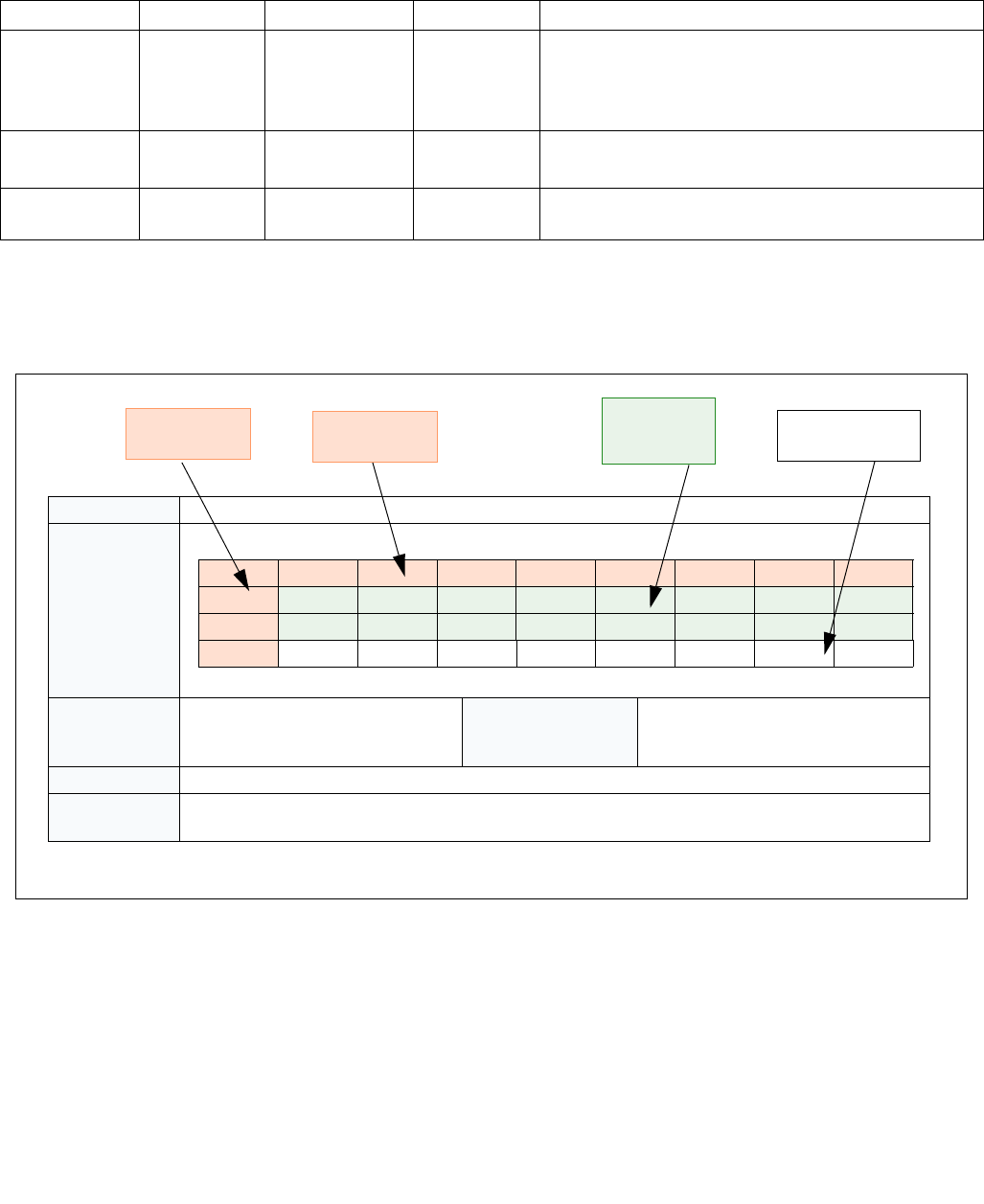
35-36 Vol. 3C
INTEL® PROCESSOR TRACE
indicated by these intermediate packets should be applied at the IP of the TIP* packet. A summary of compound
packet events is provided in Table 35-15; see Section 35.4.2 for more per-packet details and Section 35.7 for more
detailed packet generation examples.
35.4.2 Packet Definitions
The following description of packet definitions are in tabular format. Figure 35-3 explains how to interpret them.
Packet bits listed as “RSVD” are not guaranteed to be 0.
Table 35-15. Compound Packet Event Summary
Event Type Beginning Middle End Comment
Unconditional,
uncompressed
control-flow
transfer
FUP or none Any combination
of PIP, VMCS,
MODE.Exec, or
none
TIP or TIP.PGD FUP only for asynchronous events. Order of middle packets
may vary.
PIP/VMCS/MODE only if the operation modifies the state
tracked by these respective packets.
TSX Update MODE.TSX, and
(FUP or none)
None TIP, TIP.PGD, or
none
FUP
TIP/TIP.PGD only for TSX abort cases.
Overflow OVF PSB, PSBEND, or
none
FUP or TIP.PGE FUP if overflow resolves while ContextEn=1, else TIP.PGE.
Figure 35-3. Interpreting Tabular Definition of Packet Format
Name Packet name
Packet Format
Description of fields
Dependencies Depends on packet generation con-
figuration enable controls or other
bits (Section 35.2.5).
Generation Scenario Which instructions, events, or other
scenarios can cause this packet to be
generated.
Description Description of the packet, including the purpose it serves, meaning of the information or payload, etc
Application How a decoder should apply this packet. It may bind to a specific instruction from the binary, or to
another packet in the stream, or have other implications on decode
76543210
001010101
111000110
201000110
Byte Number Payload in White
Header bits
in Green
Bit Number

Vol. 3C 35-37
INTEL® PROCESSOR TRACE
35.4.2.1 Taken/Not-taken (TNT) Packet
Table 35-16. TNT Packet Definition
Name Taken/Not-taken (TNT) Packet
Packet Format
B1…BN represent the last N conditional branch or compressed RET (Section 35.4.2.2) results, such that B1 is oldest
and BN is youngest. The short TNT packet can contain from 1 to 6 TNT bits. The long TNT packet can contain from
1 to 47 TNT bits.
Irrespective of how many TNT bits is in a packet, the last valid TNT bit is followed by a trailing 1, or Stop bit, as
shown above. If the TNT packet is not full (fewer than 6 TNT bits for the Short TNT, or fewer than 47 TNT bits for
the Long TNT), the Stop bit moves up, and the trailing bits of the packet are filled with 0s. Examples of these
“partial TNTs” are shown below.
Dependencies PacketEn Generation
Scenario
On a conditional branch or compressed RET, if it fills the TNT.
Also, partial TNTs may be generated at any time, as a result of
other packets being generated,
or certain micro-architectural conditions occurring, before the
TNT is full.
76543210
01B
1B2B3B4B5B60Short TNT
76543210
000000010Long TNT
110100011
2B
40 B41 B42 B43 B44 B45 B46 B47
3B
32 B33 B34 B35 B36 B37 B38 B39
4B
24 B25 B26 B27 B28 B29 B30 B31
5B
16 B17 B18 B19 B20 B21 B22 B23
6B
8B9B10 B11 B12 B13 B14 B15
71B
1B2B3B4B5B6B7
76543210
0001B
1B2B3B40 Short TNT
76543210
000000010Long TNT
110100011
2B
24 B25 B26 B27 B28 B29 B30 B31
3B
16 B17 B18 B19 B20 B21 B22 B23
4B
8B9B10 B11 B12 B13 B14 B15
51B
1B2B3B4B5B6B7
600000000
700000000
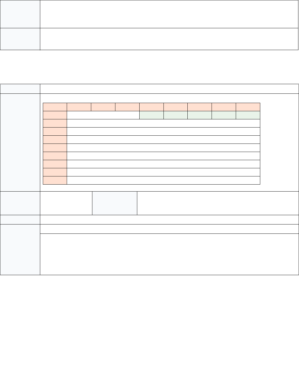
35-38 Vol. 3C
INTEL® PROCESSOR TRACE
35.4.2.2 Target IP (TIP) Packet
IP Compression
The IP payload in a TIP. FUP, TIP.PGE, or TIP.PGD packet can vary in size, based on the mode of execution, and the
use of IP compression. IP compression is an optional compression technique the processor may choose to employ
to reduce bandwidth. With IP compression, the IP to be represented in the payload is compared with the last IP sent
out, via any of FUP, TIP, TIP.PGE, or TIP.PGD. If that previous IP had the same upper (most significant) address
bytes, those matching bytes may be suppressed in the current packet. The processor maintains an internal state of
the “Last IP” that was encoded in trace packets, thus the decoder will need to keep track of the “Last IP” state in
software, to match fidelity with packets generated by hardware. “Last IP” is initialized to zero, hence if the first IP
in the trace may be compressed if the upper bytes are zeroes.
Description Provides the taken/not-taken results for the last 1–N conditional branches (Jcc, J*CXZ, or LOOP) or compressed RETs
(Section 35.4.2.2). The TNT payload bits should be interpreted as follows:
• 1 indicates a taken conditional branch, or a compressed RET
• 0 indicates a not-taken conditional branch
Application Each valid payload bit (that is, bits between the header bits and the trailing Stop bit) applies to an upcoming condi-
tional branch or RET instruction. Once a decoder consumes a TNT packet with N valid payload bits, these bits should
be applied to (and hence provide the destination for) the next N conditional branches or RETs
Table 35-17. IP Packet Definition
Name Target IP (TIP) Packet
Packet Format
Dependencies PacketEn Generation Sce-
nario
Indirect branch (including un-compressed RET), far branch, interrupt,
exception, INIT, SIPI, VM exit, VM entry, TSX abort, EENTER, EEXIT, ERE-
SUME, AEX1.
NOTES:
1. EENTER, EEXIT, ERESUME, AEX would be possible only for a debug enclave.
Description Provides the target for some control flow transfers
Application Anytime a TIP is encountered, it indicates that control was transferred to the IP provided in the payload.
The source of this control flow change, and hence the IP or instruction to which it binds, depends on the packets
that precede the TIP. If a TIP is encountered and all preceding packets have already been bound, then the TIP will
apply to the upcoming indirect branch, far branch, or VMRESUME. However, if there was a preceding FUP that
remains unbound, it will bind to the TIP. Here, the TIP provides the target of an asynchronous event or TSX abort
that occurred at the IP given in the FUP payload. Note that there may be other packets, in addition to the FUP, which
will bind to the TIP packet. See the packet application descriptions for other packets for details.
Table 35-16. TNT Packet Definition (Contd.)
76543210
0IPBytes 01101
1 TargetIP[7:0]
2TargetIP[15:8]
3 TargetIP[23:16]
4 TargetIP[31:24]
5 TargetIP[39:32]
6 TargetIP[47:40]
7 TargetIP[55:48]
8 TargetIP[63:56]

Vol. 3C 35-39
INTEL® PROCESSOR TRACE
The “IPBytes” field of the IP packets (FUP, TIP, TIP.PGE, TIP.PGD) serves to indicate how many bytes of payload are
provided, and how the decoder should fill in any suppressed bytes. The algorithm for reconstructing the IP for a
TIP/FUP packet is shown in the table below.
The processor-internal Last IP state is guaranteed to be reset to zero when a PSB is sent out. This means that the
IP that follows the PSB with either be un-compressed (011b or 110b, see Table 35-18), or compressed against
zero.
At times, “IPbytes” will have a value of 0. As shown above, this does not mean that the IP payload matches the full
address of the last IP, but rather that the IP for this packet was suppressed. This is used for cases where the IP that
applies to the packet is out of context. An example is the TIP.PGD sent on a SYSCALL, when tracing only USR code.
In that case, no TargetIP will be included in the packet, since that would expose an instruction point at CPL = 0.
When the IP payload is suppressed in this manner, Last IP is not cleared, and instead refers to the last IP packet
with a non-zero IPBytes field.
On processors that support a maximum linear address size of 32 bits, IP payloads may never exceed 32 bits
(IPBytes <= 010b).
Indirect Transfer Compression for Returns (RET)
In addition to IP compression, TIP packets for near return (RET) instructions can also be compressed. If the RET
target matches the next IP of the corresponding CALL, then the TIP packet is unneeded, since the decoder can
deduce the target IP by maintaining a CALL/RET stack of its own.
A CALL/RET stack can be maintained by the decoder by doing the following:
1. Allocate space to store 64 RET targets.
2. For near CALLs, push the Next IP onto the stack. Once the stack is full, new CALLs will force the oldest entry off
the end of the stack, such that only the youngest 64 entries are stored. Note that this excludes zero-length
CALLs, which are direct near CALLs with displacement zero (to the next IP). These CALLs typically don’t have
matching RETs.
3. For near RETs, pop the top (youngest) entry off the stack. This will be the target of the RET.
In cases where the RET is compressed, the target is guaranteed to match the value produced in 2) above. If the
target is not compressed, a TIP packet will be generated with the RET target, which may differ from 2).
The hardware ensure that packets read by the decoder will always have seen the CALL that corresponds to any
compressed RET. The processor will never compress a RET across a PSB, a buffer overflow, or scenario where Pack-
etEn=0. This means that a RET whose corresponding CALL executed while PacketEn=0, or before the last PSB, etc.,
will not be compressed.
If the CALL/RET stack is manipulated or corrupted by software, and thereby causes a RET to transfer control to a
target that is inconsistent with the CALL/RET stack, then the RET will not be compressed, and will produce a TIP
packet. This can happen, for example, if software executes a PUSH instruction to push a target onto the stack, and
a later RET uses this target.
Table 35-18. FUP/TIP IP Reconstruction
IPBytes Uncompressed IP Value
63:56 55:48 47:40 39:32 31:24 23:16 15:8 7:0
000b None, IP is out of context
001b Last IP[63:16] IP Payload[15:0]
010b Last IP[63:32] IP Payload[31:0]
011b IP Payload[47] extended IP Payload[47:0]
100b Last IP [63:48] IP Payload[47:0]
101b Reserved
110b IP Payload[63:0]
111b Reserved

35-40 Vol. 3C
INTEL® PROCESSOR TRACE
When a RET is compressed, a Taken indication is added to the TNT buffer. Because it sends no TIP packet, it also
does not update the internal Last IP value, and thus the decoder should treat it the same way. If the RET is not
compressed, it will generate a TIP packet (just like when RET compression is disabled, via
IA32_RTIT_CTL.DisRETC). For processors that employ deferred TIPs (Section 35.4.2.3), an uncompressed RET will
not be deferred, and hence will force out any accumulated TNTs or TIPs. This serves to avoid ambiguity, and make
clear to the decoder whether the near RET was compressed, and hence a bit in the in-progress TNT should be
consumed, or uncompressed, in which case there will be no in-progress TNT and thus a TIP should be consumed.
Note that in the unlikely case that a RET executes in a different execution mode than the associated CALL, the
decoder will need to model the same behavior with its CALL stack. For instance, if a CALL executes in 64-bit mode,
a 64-bit IP value will be pushed onto the software stack. If the corresponding RET executes in 32-bit mode, then
only the lower 32 target bits will be popped off of the stack, which may mean that the RET does not go to the CALL’s
Next IP. This is architecturally correct behavior, and this RET could be compressed, thus the decoder should match
this behavior
35.4.2.3 Deferred TIPs
The processor may opt to defer sending out the TNT when TIPs are generated. Thus, rather than sending a partial
TNT followed by a TIP, both packets will be deferred while the TNT accumulates more Jcc/RET results. Any number
of TIP packets may be accumulated this way, such that only once the TNT is filled, or once another packet (e.g.,
FUP) is generated, the TNT will be sent, followed by all the deferred TIP packets, and finally terminated by the other
packet(s) that forced out the TNT and TIP packets. Generation of many other packets (see list below) will force out
the TNT and any accumulated TIP packets. This is an optional optimization in hardware to reduce the bandwidth
consumption, and hence the performance impact, incurred by tracing.
Table 35-19. TNT Examples with Deferred TIPs
Code Flow Packets, Non-Deferred TIPS Packets, Deferred TIPS
0x1000 cmp %rcx, 0
0x1004 jnz Foo // not-taken
0x1008 jmp %rdx TNT(0b0), TIP(0x1308)
0x1308 cmp %rcx, 1
0x130c jnz Bar // not-taken
0x1310 cmp %rcx, 2
0x1314 jnz Baz // taken
0x1500 cmp %eax, 7
0x1504 jg Exit // not-taken
0x1508 jmp %r15
TNT(0b010), TIP(0x1100)
0x1100 cmp %rbx, 1
0x1104 jg Start // not-taken
0x1108 add %rcx, %eax
0x110c … // an asynchronous Interrupt arrives
INThandler:
0xcc00 pop %rdx
TNT(0b0), FUP(0x110c),
TIP(0xcc00)
TNT(0b00100), TIP(0x1308),
TIP(0x1100), FUP(0x110c),
TIP(0xcc00)
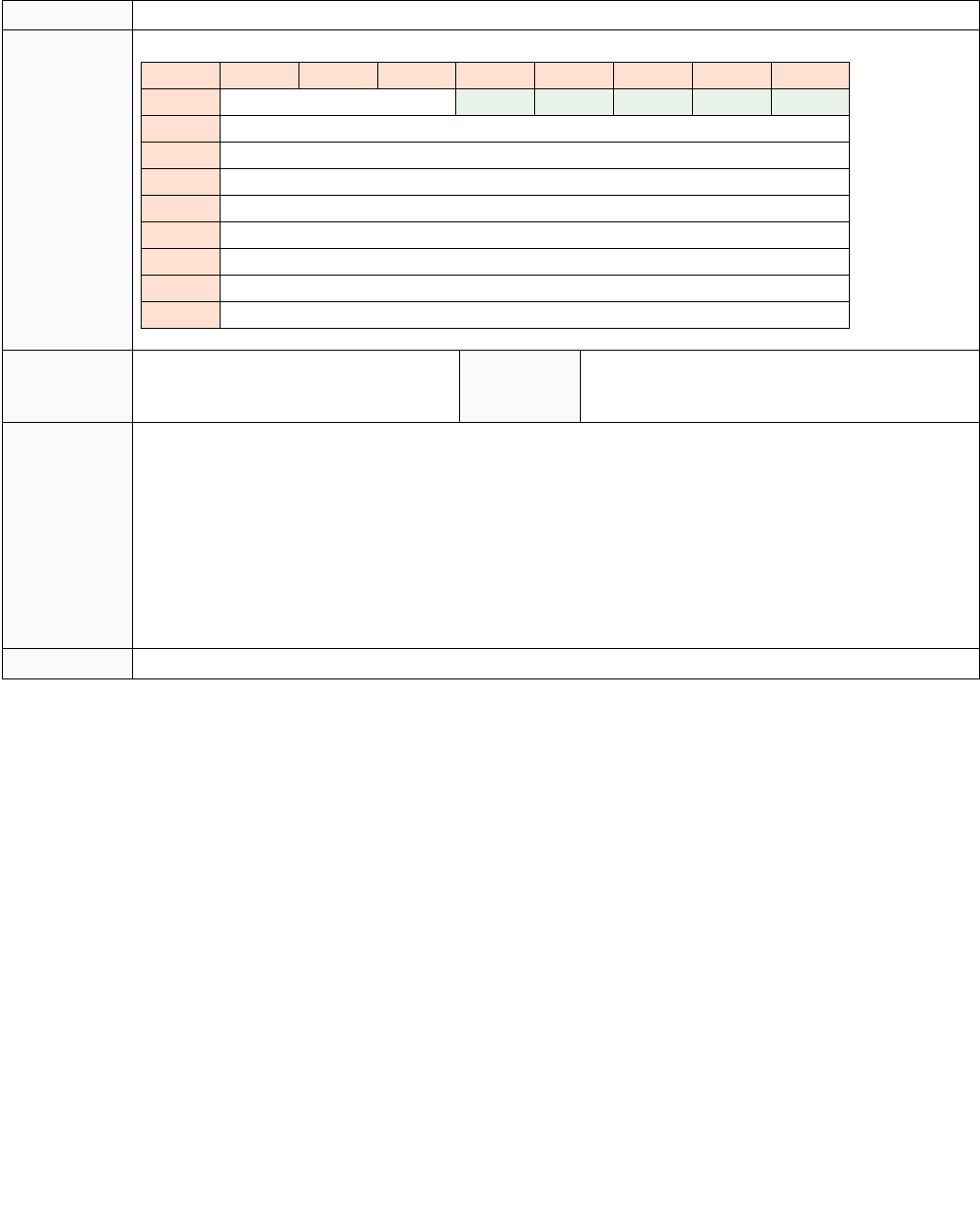
Vol. 3C 35-41
INTEL® PROCESSOR TRACE
35.4.2.4 Packet Generation Enable (TIP.PGE) Packet
Table 35-20. TIP.PGE Packet Definition
Name Target IP - Packet Generation Enable (TIP.PGE) Packet
Packet Format
Dependencies PacketEn transitions to 1 Generation
Scenario
Any branch instruction, control flow transfer, or MOV
CR3 that sets PacketEn, a WRMSR that enables
packet generation and sets PacketEn
Description Indicates that PacketEn has transitioned to 1. It provides the IP at which the tracing begins.
This can occur due to any of the enables that comprise PacketEn transitioning from 0 to 1, as long as all the others
are asserted. Examples:
• TriggerEn: This is set on software write to set IA32_RTIT_CTL.TraceEn as long as the Stopped and Error bits in
IA32_RTIT_STATUS are clear. The IP payload will be the Next IP of the WRMSR.
• FilterEn: This is set when software jumps into the tracing region. This region is defined by enabling IP filtering in
IA32_RTIT_CTL.ADDRn_CFG, and defining the range in IA32_RTIT_ADDRn_[AB], see. Section 35.2.4.3. The
IP payload will be the target of the branch.
• ContextEn: This is set on a CPL change, a CR3 write or any other means of changing ContextEn. The IP payload
will be the Next IP of the instruction that changes context if it is not a branch, otherwise it will be the target of
the branch.
Application TIP.PGE packets bind to the instruction at the IP given in the payload.
76543210
0IPBytes 10001
1 TargetIP[7:0]
2 TargetIP[15:8]
3 TargetIP[23:16]
4 TargetIP[31:24]
5 TargetIP[39:32]
6 TargetIP[47:40]
7 TargetIP[55:48]
8 TargetIP[63:56]

35-42 Vol. 3C
INTEL® PROCESSOR TRACE
35.4.2.5 Packet Generation Disable (TIP.PGD) Packet
Table 35-21. TIP.PGD Packet Definition
Name Target IP - Packet Generation Disable (TIP.PGD) Packet
Packet Format
Dependencies PacketEn transitions to
0
Generation
Scenario
Any branch instruction, control flow transfer, or MOV CR3 that clears
PacketEn, a WRMSR that disables packet generation and clears PacketEn
Description Indicates that PacketEn has transitioned to 0. It will include the IP at which the tracing ends, unless ContextEn= 0 or
TraceEn=0 at the conclusion of the instruction or event that cleared PacketEn.
PacketEn can be cleared due to any of the enables that comprise PacketEn transitioning from 1 to 0. Examples:
• TriggerEn: This is cleared on software write to clear IA32_RTIT_CTL.TraceEn, or when
IA32_RTIT_STATUS.Stopped is set, or on operational error. The IP payload will be suppressed in this case, and the
“IPBytes” field will have the value 0.
• FilterEn: This is cleared when software jumps out of the tracing region. This region is defined by enabling IP
filtering in IA32_RTIT_CTL.ADDRn_CFG, and defining the range in IA32_RTIT_ADDRn_[AB], see. Section 35.2.4.3.
The IP payload will depend on the type of the branch. For conditional branches, the payload is suppressed
(IPBytes = 0), and in this case the destination can be inferred from the disassembly. For any other type of branch,
the IP payload will be the target of the branch.
• ContextEn: This can happen on a CPL change, a CR3 write or any other means of changing ContextEn. See
Section 35.2.4.3 for details. In this case, when ContextEn is cleared, there will be no IP payload. The “IPBytes”
field will have value 0.
Note that, in cases where a branch that would normally produce a TIP packet (i.e., far transfer, indirect branch, inter-
rupt, etc) or TNT update (conditional branch or compressed RT) causes PacketEn to transition from 1 to 0, the TIP or
TNT bit will be replaced with TIP.PGD. The payload of the TIP.PGD will be the target of the branch, unless the result
of the instruction causes TraceEn or ContextEn to be cleared (ie, SYSCALL when IA32_RTIT_CTL.OS=0, In the case
where a conditional branch clears FilterEn and hence PacketEn, there will be no TNT bit for this branch, replaced
instead by the TIP.PGD.
Application TIP.PGD can be produced by any branch instructions, as well as some non-branch instructions, that clear PacketEn.
When produced by a branch, it replaces any TIP or TNT update that the branch would normally produce.
In cases where there is an unbound FUP preceding the TIP.PGD, then the TIP.PGD is part of compound operation (i.e.,
asynchronous event or TSX abort) which cleared PacketEn. For most such cases, the TIP.PGD is simply replacing a
TIP, and should be treated the same way. The TIP.PGD may or may not have an IP payload, depending on whether
the operation cleared ContextEn.
If there is not an associated FUP, the binding will depend on whether there is an IP payload. If there is an IP payload,
then the TIP.PGD should be applied to either the next direct branch whose target matches the TIP.PGD payload, or
the next branch that would normally generate a TIP or TNT packet. If there is no IP payload, then the TIP.PGD should
apply to the next branch or MOV CR3 instruction.
76543210
0IPBytes 00001
1 TargetIP[7:0]
2TargetIP[15:8]
3 TargetIP[23:16]
4 TargetIP[31:24]
5 TargetIP[39:32]
6 TargetIP[47:40]
7 TargetIP[55:48]
8 TargetIP[63:56]
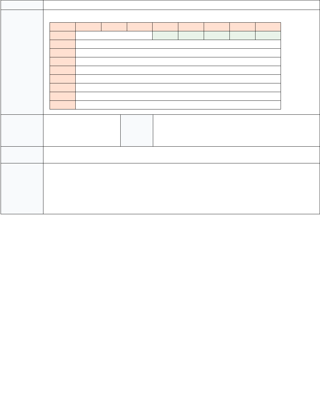
Vol. 3C 35-43
INTEL® PROCESSOR TRACE
35.4.2.6 Flow Update (FUP) Packet
Table 35-22. FUP Packet Definition
Name Flow Update (FUP) Packet
Packet Format
Dependencies TriggerEn & ContextEn.
(Typically depends on
BranchEn and FilterEn as well,
see Section 35.2.4 for details.)
Generation
Scenario
Asynchronous Events (interrupts, exceptions, INIT, SIPI, SMI, VM exit,
#MC), XBEGIN, XEND, XABORT, XACQUIRE, XRELEASE, EENTER,
EEXIT, ERESUME, EEE, AEX,1, INTO, INT1, INT3, INT n, a WRMSR that
disables packet generation.
NOTES:
1. EENTER, EEXIT, ERESUME, EEE, AEX apply only if Intel Software Guard Extensions is supported.
Description Provides the source address for asynchronous events, and some other instructions. Is never sent alone, always sent
with an associated TIP or MODE packet, and potentially others.
Application FUP packets provide the IP to which they bind. However, they are never standalone, but are coupled with other
packets.
In TSX cases, the FUP is immediately preceded by a MODE.TSX, which binds to the same IP. A TIP will follow only in
the case of TSX aborts, see Section 35.4.2.8 for details.
Otherwise, FUPs are part of compound packet events (see Section 35.4.1). In these compound cases, the FUP pro-
vides the source IP for an instruction or event, while a following TIP (or TIP.PGD) packet will provide the destination
IP. Other packets may be included in the compound event between the FUP and TIP.
76543210
0IPBytes 11101
1 IP[7:0]
2IP[15:8]
3 IP[23:16]
4 IP[31:24]
5 IP[39:32]
6 IP[47:40]
7 IP[55:48]
8 IP[63:56]

35-44 Vol. 3C
INTEL® PROCESSOR TRACE
FUP IP Payload
Flow Update Packet gives the source address of an instruction when it is needed. In general, branch instructions do
not need a FUP, because the source address is clear from the disassembly. For asynchronous events, however, the
source address cannot be inferred from the source, and hence a FUP will be sent. Table 35-23 illustrates cases
where FUPs are sent, and which IP can be expected in those cases.
On a canonical fault due to sequentially fetching an instruction in non-canonical space (as opposed to jumping to
non-canonical space), the IP of the fault (and thus the payload of the FUP) will be a non-canonical address. This is
consistent with what is pushed on the stack for such faulting cases.
If there are post-commit task switch faults, the IP value of the FUP will be the original IP when the task switch
started. This is the same value as would be seen in the LBR_FROM field. But it is a different value as is saved on the
stack or VMCS.
Table 35-23. FUP Cases and IP Payload
Event Flow Update IP Comment
External Interrupt, NMI/SMI, Traps,
Machine Check (trap-like), INIT/SIPI
Address of next instruction (Next IP) that
would have been executed
Functionally, this matches the LBR FROM field
value and also the EIP value which is saved onto
the stack.
Exceptions/Faults, Machine check
(fault-like)
Address of the instruction which took the
exception/fault (Current IP)
This matches the similar functionality of LBR
FROM field value and also the EIP value which is
saved onto the stack.
Software Interrupt Address of the software interrupt instruction
(Current IP)
This matches the similar functionality of LBR
FROM field value, but does not match the EIP
value which is saved onto the stack (Next
Linear Instruction Pointer - NLIP).
EENTER, EEXIT, ERESUME, Enclave
Exiting Event (EEE), AEX1
NOTES:
1. Information on EENTER, EEXIT, ERESUME, EEE, Asynchronous Enclave eXit (AEX) can be found in Intel® Soft-
ware Guard Extensions Programming Reference.
Current IP of the instruction This matches the LBR FROM field value and also
the EIP value which is saved onto the stack.
XACQUIRE Address of the X* instruction
XRELEASE, XBEGIN, XEND,
XABORT, other transactional abort
Current IP
#SMI IP that is saved into SMRAM
WRMSR that clears TraceEn Current IP

Vol. 3C 35-45
INTEL® PROCESSOR TRACE
35.4.2.7 Paging Information (PIP) Packet
Table 35-24. PIP Packet Definition
Name Paging Information (PIP) Packet
Packet Format
Dependencies TriggerEn && ContextEn &&
IA32_RTIT_CTL.OS
Generation
Scenario
MOV CR3, Task switch, INIT, SIPI, PSB+, VM exit,
VM entry
Description The CR3 payload shown includes only the address portion of the CR3 value. For PAE paging, CR3[11:5] are thus
included. For other paging modes (32-bit and 4-level paging1), these bits are 0.
This packet holds the CR3 address value. It will be generated on operations that modify CR3:
•MOV CR3 operation
•Task Switch
•INIT and SIPI
• VM exit, if “conceal VMX from PT” VM-exit control is 0 (see Section 35.5.1)
•VMentry, if “conceal VMX from PT” VM-entry control is 0
PIPs are not generated, despite changes to CR3, on SMI and RSM. This is due to the special behavior on these oper-
ations, see Section 35.2.8.3 for details. Note that, for some cases of task switch where CR3 is not modified, no PIP
will be produced.
The purpose of the PIP is to indicate to the decoder which application is running, so that it can apply the proper
binaries to the linear addresses that are being traced.
The PIP packet contains the new CR3 value when CR3 is written.
PIPs generated by VM entries set the NR bit. PIPs generated in VMX non-root operation set the NR bit if the “con-
ceal VMX from PT” VM-execution control is 0 (see Section 35.5.1). All other PIPs clear the NR bit.
NOTES:
1. Earlier versions of this manual used the term “IA-32e paging” to identify 4-level paging.
Application The purpose of the PIP packet is to help the decoder uniquely identify what software is running at any given time.
When a PIP is encountered, a decoder should do the following:
1) If there was a prior unbound FUP (that is, a FUP not preceded by a packet such as MODE.TSX that consumes it,
and it hence pairs with a TIP that has not yet been seen), then this PIP is part of a compound packet event (Section
35.4.1). Find the ending TIP and apply the new CR3/NR values to the TIP payload IP.
2) Otherwise, look for the next MOV CR3, far branch, or VMRESUME/VMLAUNCH in the disassembly, and apply the
new CR3 to the next (or target) IP.
For examples of the packets generated by these flows, see Section 35.7.
76543210
000000010
101000011
2 CR3[11:5] or 0 RSVD/NR
3 CR3[19:12]
4 CR3[27:20]
5 CR3[35:28]
6 CR3[43:36]
7 CR3[51:44]
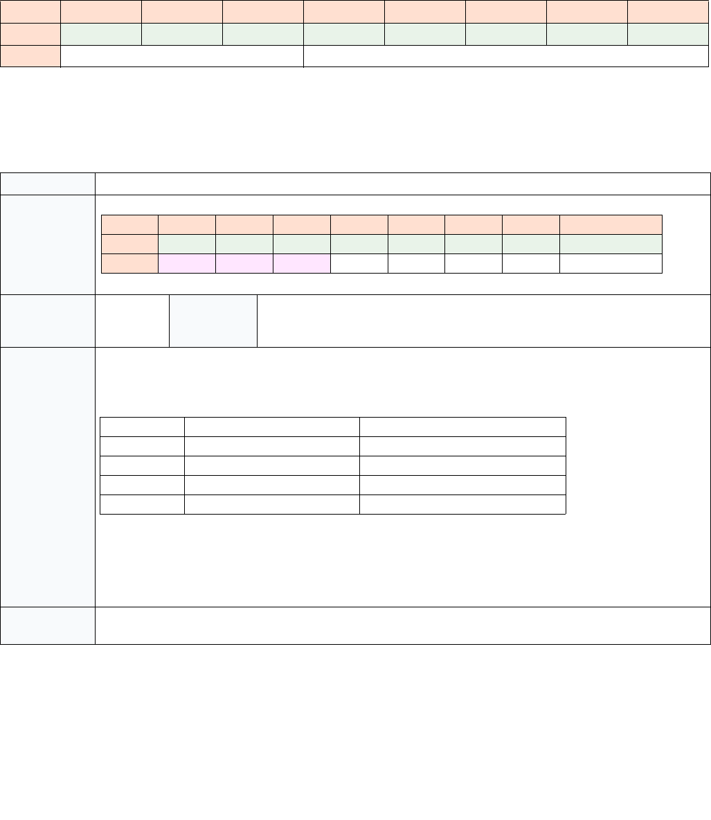
35-46 Vol. 3C
INTEL® PROCESSOR TRACE
35.4.2.8 MODE Packets
MODE packets keep the decoder informed of various processor modes about which it needs to know in order to
properly manage the packet output, or to properly disassemble the associated binaries. MODE packets include a
header and a mode byte, as shown below.
The MODE Leaf ID indicates which set of mode bits are held in the lower bits.
MODE.Exec Packet
Table 35-25. General Form of MODE Packets
7 6 5 4 3 2 1 0
0 1 0 0 1 1 0 0 1
1Leaf ID Mode
Table 35-26. MODE.Exec Packet Definition
Name MODE.Exec Packet
Packet Format
Dependencies PacketEn Generation
Scenario
Far branch, interrupt, exception, VM exit, and VM entry, if the mode changes.
PSB+, and any scenario that can generate a TIP.PGE, such that the mode may have
changed since the last MODE.Exec.
Description Indicates whether software is in 16, 32, or 64-bit mode, by providing the CS.D and (CS.L & IA32_EFER.LMA) values.
Essential for the decoder to properly disassemble the associated binary.
MODE.Exec is sent at the time of a mode change, if PacketEn=1 at the time, or when tracing resumes, if necessary.
In the former case, the MODE.Exec packet is generated along with other packets that result from the far transfer
operation that changes the mode. In cases where the mode changes while PacketEn=0, the processor will send out
a MODE.Exec along with the TIP.PGE when tracing resumes. The processor may opt to suppress the MODE.Exec
when tracing resumes if the mode matches that from the last MODE.Exec packet, if there was no PSB in between.
Application MODE.Exec always immediately precedes a TIP or TIP.PGE. The mode change applies to the IP address in the payload
of the next TIP or TIP.PGE.
76543210
010011001
1000000CS.D(CS.L & LMA)
CS.D (CS.L & IA32_EFER.LMA) Addressing Mode
11 N/A
01 64-bit mode
10 32-bit mode
00 16-bit mode
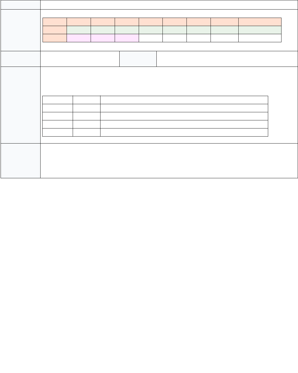
Vol. 3C 35-47
INTEL® PROCESSOR TRACE
MODE.TSX Packet
Table 35-27. MODE.TSX Packet Definition
Name MODE.TSX Packet
Packet Format
Dependencies TriggerEn and ContextEn Generation
Scenario
XBEGIN, XEND, XABORT, XACQUIRE, XRELEASE, if InTX
changes, Asynchronous TSX Abort, PSB+
Description Indicates when a TSX transaction (either HLE or RTM) begins, commits, or aborts. Instructions executed transaction-
ally will be “rolled back” if the transaction is aborted.
Application If PacketEn=1, MODE.TSX always immediately precedes a FUP. If the TXAbort bit is zero, then the mode change
applies to the IP address in the payload of the FUP. If TXAbort=1, then the FUP will be followed by a TIP, and the
mode change will apply to the IP address in the payload of the TIP.
MODE.TSX packets may be generated when PacketEn=0, due to FilterEn=0. In this case, only the last MODE.TSX
generated before TIP.PGE need be applied.
7654321 0
01001100 1
1001000TXAbortInTX
TXAbort InTX Implication
11N/A
0 1 Transaction begins, or executing transactionally
1 0 Transaction aborted
0 0 Transaction committed, or not executing transactionally
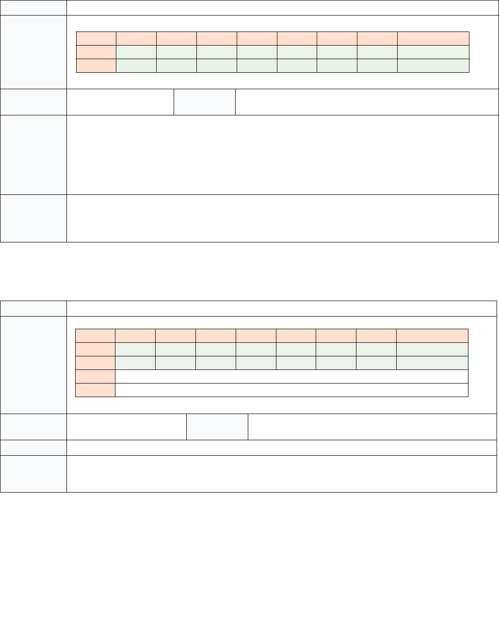
35-48 Vol. 3C
INTEL® PROCESSOR TRACE
35.4.2.9 TraceStop Packet
35.4.2.10 Core:Bus Ratio (CBR) Packet
Table 35-28. TraceStop Packet Definition
Name TraceStop Packet
Packet Format
Dependencies TriggerEn && ContextEn Generation
Scenario
Taken branch with target in TraceStop IP region, MOV CR3 in TraceS-
top IP region, or WRMSR that sets TraceEn in TraceStop IP region.
Description Indicates when software has entered a user-configured TraceStop region.
When the IP matches a TraceStop range while ContextEn and TriggerEn are set, a TraceStop action occurs. This dis-
ables tracing by setting IA32_RTIT_STATUS.Stopped, thereby clearing TriggerEn, and causes a TraceStop
packet to be generated.
The TraceStop action also forces FilterEn to 0. Note that TraceStop may not force a flush of internally buffered
packets, and thus trace packet generation should still be manually disabled by clearing IA32_RTIT_CTL.TraceEn
before examining output. See Section 35.2.4.3 for more details.
Application If TraceStop follows a TIP.PGD (before the next TIP.PGE), then it was triggered either by the instruction that cleared
PacketEn, or it was triggered by some later instruction that executed while FilterEn=0. In either case, the TraceStop
can be applied at the IP of the TIP.PGD (if any).
If TraceStop follows a TIP.PGE (before the next TIP.PGD), it should be applied at the last known IP.
Table 35-29. CBR Packet Definition
Name Core:Bus Ratio (CBR) Packet
Packet Format
Dependencies TriggerEn Generation
Scenario
After any frequency change, on C-state wake up, PSB+, and after
enabling trace packet generation.
Description Indicates the core:bus ratio of the processor core. Useful for correlating wall-clock time and cycle time.
Application The CBR packet indicates the point in the trace when a frequency transition has occurred. On some implementa-
tions, software execution will continue during transitions to a new frequency, while on others software execution
ceases during frequency transitions. There is not a precise IP provided, to which to bind the CBR packet.
76543210
000000010
110000011
76543210
000000010
100000011
2Core:Bus Ratio
3 Reserved

Vol. 3C 35-49
INTEL® PROCESSOR TRACE
35.4.2.11 Timestamp Counter (TSC) Packet
Table 35-30. TSC Packet Definition
Name Timestamp Counter (TSC) Packet
Packet Format
Dependencies IA32_RTIT_CTL.TSCEn &&
TriggerEn
Generation
Scenario
Sent after any event that causes the processor clocks or Intel PT timing
packets (such as MTC or CYC) to stop, This may include P-state changes,
wake from C-state, or clock modulation. Also on transition of TraceEn
from 0 to 1.
Description When enabled by software, a TSC packet provides the lower 7 bytes of the current TSC value, as returned by the
RDTSC instruction. This may be useful for tracking wall-clock time, and synchronizing the packets in the log with
other timestamped logs.
Application TSC packet provides a wall-clock proxy of the event which generated it (packet generation enable, sleep state wake,
etc). In all cases, TSC does not precisely indicate the time of any control flow packets; however, all preceding packets
represent instructions that executed before the indicated TSC time, and all subsequent packets represent instruc-
tions that executed after it. There is not a precise IP to which to bind the TSC packet.
76543210
000011001
1 SW TSC[7:0]
2SW TSC[15:8]
3 SW TSC[23:16]
4 SW TSC[31:24]
5 SW TSC[39:32]
6 SW TSC[47:40]
7 SW TSC[55:48]

35-50 Vol. 3C
INTEL® PROCESSOR TRACE
35.4.2.12 Mini Time Counter (MTC) Packet
Table 35-31. MTC Packet Definition
Name Mini time Counter (MTC) Packet
Packet Format
Dependencies IA32_RTIT_CTL.MTCEn &&
TriggerEn
Generation
Scenario
Periodic, based on the core crystal clock, or Always Running Timer
(ART).
Description When enabled by software, an MTC packet provides a periodic indication of wall-clock time. The 8-bit CTC (Common
Timestamp Copy) payload value is set to (ART >> N) & FFH. The frequency of the ART is related to the Maximum
Non-Turbo frequency, and the ratio can be determined from CPUID leaf 15H, as described in Section 35.8.3.
Software can select the threshold N, which determines the MTC frequency by setting the IA32_RTIT_CTL.MTCFreq
field (see Section 35.2.7.2) to a supported value using the lookup enumerated by CPUID (see Section 35.3.1).
See Section 35.8.3 for details on how to use the MTC payload to track TSC time.
MTC provides 8 bits from the ART, starting with the bit selected by MTCFreq to dictate the frequency of the packet.
Whenever that 8-bit range being watched changes, an MTC packet will be sent out with the new value of that 8-bit
range. This allows the decoder to keep track of how much wall-clock time has elapsed since the last TSC packet was
sent, by keeping track of how many MTC packets were sent and what their value was. The decoder can infer the
truncated bits, CTC[N-1:0], are 0 at the time of the MTC packet.
There are cases in which MTC packet can be dropped, due to overflow or other micro-architectural conditions. The
decoder should be able to recover from such cases by checking the 8-bit payload of the next MTC packet, to deter-
mine how many MTC packets were dropped. It is not expected that >256 consecutive MTC packets should ever be
dropped.
Application MTC does not precisely indicate the time of any other packet, nor does it bind to any IP. However, all preceding pack-
ets represent instructions or events that executed before the indicated ART time, and all subsequent packets repre-
sent instructions that executed after, or at the same time as, the ART time.
76543210
001011001
1CTC[N+7:N]
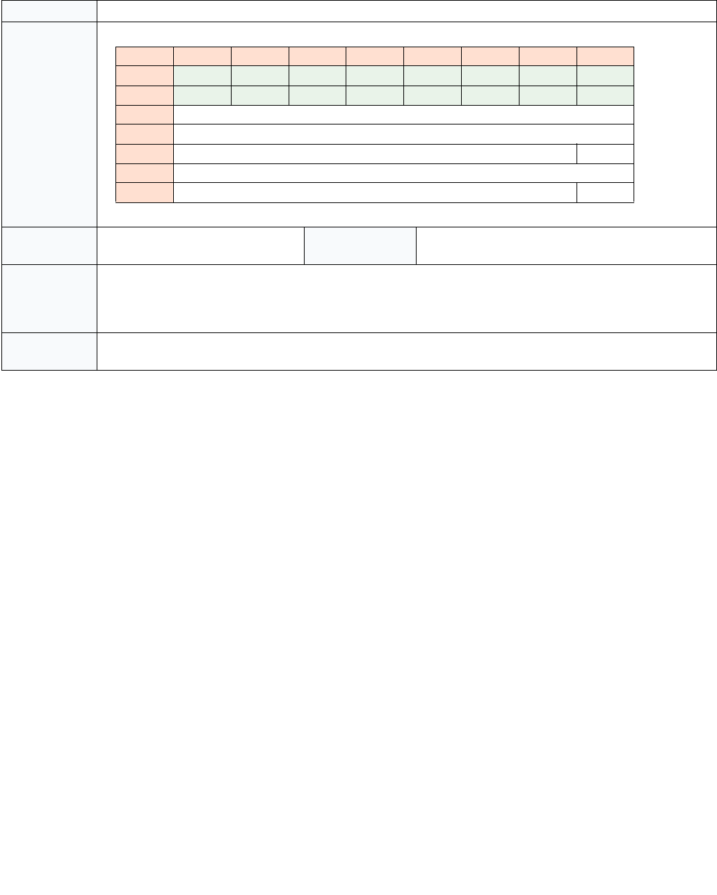
Vol. 3C 35-51
INTEL® PROCESSOR TRACE
35.4.2.13 TSC/MTC Alignment (TMA) Packet
Table 35-32. TMA Packet Definition
Name TSC/MTC Alignment (TMA) Packet
Packet Format
Dependencies IA32_RTIT_CTL.MTCEn &&
IA32_RTIT_CTL.TSCEn && TriggerEn
Generation Sce-
nario
Sent with any TSC packet.
Description The TMA packet serves to provide the information needed to allow the decoder to correlate MTC packets with TSC
packets. With this packet, when a MTC packet is encountered, the decoder can determine how many timestamp
counter ticks have passed since the last TSC or MTC packet. See Section 35.8.3.2 for details on how to make this cal-
culation.
Application TMA is always sent immediately following a TSC packet, and the payload values are consistent with the TSC payload
value. Thus the application of TMA matches that of TSC.
76543210
000000010
101110011
2CTC[7:0]
3 CTC[15:8]
4 Reserved 0
5FastCounter[7:0]
6 Reserved FC[8]

35-52 Vol. 3C
INTEL® PROCESSOR TRACE
35.4.2.14 Cycle Count (CYC) Packet
Table 35-33. Cycle Count Packet Definition
Name Cycle Count (CYC) Packet
Packet Format
Dependencies IA32_RTIT_CTL.CYCEn &&
TriggerEn
Generation Sce-
nario
Can be sent at any time, though a maximum of one CYC packet is
sent per core clock cycle. See Section 35.3.6 for CYC-eligible packets.
Description The Cycle Counter field increments at the same rate as the processor core clock ticks, but with a variable length for-
mat (using a trailing EXP bit field) and a range-capped byte length.
If the CYC value is less than 32, a 1-byte CYC will be generated, with Exp=0. If the CYC value is between 32 and
4095 inclusive, a 2-byte CYC will be generated, with byte 0 Exp=1 and byte 1 Exp=0. And so on.
CYC provides the number of core clocks that have passed since the last CYC packet. CYC can be configured to be
sent in every cycle in which an eligible packet is generated, or software can opt to use a threshold to limit the num-
ber of CYC packets, at the expense of some precision. These settings are configured using the
IA32_RTIT_CTL.CycThresh field (see Section 35.2.7.2). For details on Cycle-Accurate Mode, IPC calculation, etc, see
Section 35.3.6.
When CycThresh=0, and hence no threshold is in use, then a CYC packet will be generated in any cycle in which any
CYC-eligible packet is generated. The CYC packet will precede the other packets generated in the cycle, and provides
the precise cycle time of the packets that follow.
In addition to these CYC packets generated with other packets, CYC packets can be sent stand-alone. These packets
serve simply to update the decoder with the number of cycles passed, and are used to ensure that a wrap of the
processor’s internal cycle counter doesn’t cause cycle information to be lost. These stand-alone CYC packets do not
indicate the cycle time of any other packet or operation, and will be followed by another CYC packet before any
other CYC-eligible packet is seen.
When CycThresh>0, CYC packets are generated only after a minimum number of cycles have passed since the last
CYC packet. Once this threshold has passed, the behavior above resumes, where CYC will either be sent in the next
cycle that produces other CYC-eligible packets, or could be sent stand-alone.
When using CYC thresholds, only the cycle time of the operation (instruction or event) that generates the CYC
packet is truly known. Other operations simply have their execution time bounded: they completed at or after the
last CYC time, and before the next CYC time.
Application CYC provides the offset cycle time (since the last CYC packet) for the CYC-eligible packet that follows. If another CYC
is encountered before the next CYC-eligible packet, the cycle values should be accumulated and applied to the next
CYC-eligible packet.
If a CYC packet is generated by a TNT, note that the cycle time provided by the CYC packet applies to the first
branch in the TNT packet.
76543210
0 Cycle Counter[4:0] Exp 1 1
1Cycle Counter[11:5] Exp
2 Cycle Counter[18:12] Exp
... ... (if Exp = 1 in the previous byte)

Vol. 3C 35-53
INTEL® PROCESSOR TRACE
35.4.2.15 VMCS Packet
Table 35-34. VMCS Packet Definition
Name VMCS Packet
Packet Format
Dependencies TriggerEn && ContextEn;
Also in VMX operation.
Generation Scenario Generated on successful VMPTRLD, and optionally on SMM
VM exits and VM entries that return from SMM (see Section 35.5).
Description The VMCS packet provides a VMCS pointer for a decoder to determine the transition of code contexts:
•On a successful VMPTRLD (i.e., a VMPTRLD that doesn’t fault, fail, or VM exit), the VMCS packet contains the
logical processor’s VMCS pointer established by VMPTRLD (for subsequent execution of a VM guest context).
•An SMM VM exit loads the logical processor’s VMCS pointer with the SMM-transfer VMCS pointer. If the “conceal
VMX from PT” VM-exit control is 0 (see Section 35.5.1), a VMCS packet provides this pointer. See Section 35.6 on
tracing inside and outside STM.
•A VM entry that returns from SMM loads the logical processor’s VMCS pointer from a field in the SMM-transfer
VMCS. If the “conceal VMX from PT” VM-entry control is 0, a VMCS packet provides this pointer. Whether the
VM entry is to VMX root operation or VMX non-root operation is indicated by the PIP.NR bit.
A VMCS packet generated before a VMCS pointer has been loaded, or after the VMCS pointer has been cleared will
set all 64 bits in the VMCS pointer field.
VMCS packets will not be seen on processors with IA32_VMX_MISC[bit 14]=0, as these processors do not allow
TraceEn to be set in VMX operation.
Application The purpose of the VMCS packet is to help the decoder uniquely identify changes in the executing software context
in situations that CR3 may not be unique.
When a VMCS packet is encountered, a decoder should do the following:
• If there was a prior unbound FUP (that is, a FUP not preceded by a packet such as MODE.TSX that consumes it, and
it hence pairs with a TIP that has not yet been seen), then this VMCS is part of a compound packet event (Section
35.4.1). Find the ending TIP and apply the new VMCS base pointer value to the TIP payload IP.
• Otherwise, look for the next VMPTRLD, VMRESUME, or VMLAUNCH in the disassembly, and apply the new VMCS
base pointer on the next VM entry.
For examples of the packets generated by these flows, see Section 35.7.
76543210
000000010
111001000
2 VMCS pointer [19:12]
3 VMCS pointer [27:20]
4 VMCS pointer [35:28]
5 VMCS pointer [43:36]
6 VMCS pointer [51:44]

35-54 Vol. 3C
INTEL® PROCESSOR TRACE
35.4.2.16 Overflow (OVF) Packet
35.4.2.17 Packet Stream Boundary (PSB) Packet
Table 35-35. OVF Packet Definition
Name Overflow (OVF) Packet
Packet Format
Dependencies TriggerEn Generation
Scenario
On resolution of internal buffer overflow
Description OVF simply indicates to the decoder that an internal buffer overflow occurred, and packets were likely lost. If
BranchEN= 1, OVF is followed by a FUP or TIP.PGE which will provide the IP at which packet generation resumes. See
Section 35.3.8.
Application When an OVF packet is encountered, the decoder should skip to the IP given in the subsequent FUP or TIP.PGE. The
cycle counter for the CYC packet will be reset at the time the OVF packet is sent.
Software should reset its call stack depth on overflow, since no RET compression is allowed across an overflow. Sim-
ilarly, any IP compression that follows the OVF is guaranteed to use as a reference LastIP the IP payload of an IP
packet that preceded the overflow.
Table 35-36. PSB Packet Definition
Name Packet Stream Boundary (PSB) Packet
Packet Format
76543210
000000010
111110011
76543210
000000010
110000010
200000010
310000010
400000010
510000010
600000010
710000010
800000010
910000010
10 00000010
11 10000010
12 00000010
13 10000010
14 00000010
15 10000010
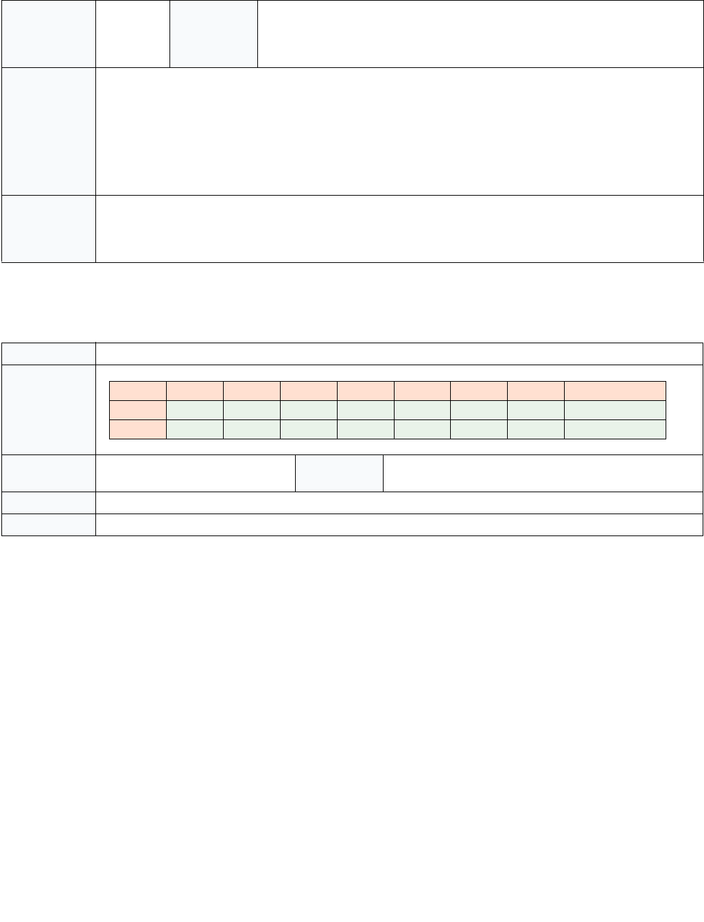
Vol. 3C 35-55
INTEL® PROCESSOR TRACE
35.4.2.18 PSBEND Packet
Dependencies TriggerEn Generation
Scenario
Periodic, based on the number of output bytes generated while tracing. PSB is sent
when IA32_RTIT_STATUS.PacketByteCnt=0, and each time it crosses the software
selected threshold after that. May be sent for other micro-architectural conditions
as well.
Description PSB is a unique pattern in the packet output log, and hence serves as a sync point for the decoder. It is a pattern
that the decoder can search for in order to get aligned on packet boundaries. This packet is periodic, based on the
number of output bytes, as indicated by IA32_RTIT_STATUS.PacketByteCnt. The period is chosen by software, via
IA32_RTIT_CTL.PSBFreq (see Section 35.2.7.2). Note, however, that the PSB period is not precise, it simply reflects
the average number of output bytes that should pass between PSBs. The processor will make a best effort to
insert PSB as quickly after the selected threshold is reached as possible. The processor also may send extra
PSB packets for some micro-architectural conditions.
PSB also serves as the leading packet for a set of “status-only” packets collectively known as PSB+ (Section 35.3.7).
Application When a PSB is seen, the decoder should interpret all following packets as “status only”, until either a PSBEND or
OVF packet is encountered. “Status only” implies that the binding and ordering rules to which these packets nor-
mally adhere are ignored, and the state they carry can instead be applied to the IP payload in the FUP packet that is
included.
Table 35-37. PSBEND Packet Definition
Name PSBEND Packet
Packet Format
Dependencies TriggerEn Generation
Scenario
Always follows PSB packet, separated by PSB+ packets
Description PSBEND is simply a terminator for the series of “status only” (PSB+) packets that follow PSB (Section 35.3.7).
Application When a PSBEND packet is seen, the decoder should cease to treat packets as “status only”.
Table 35-36. PSB Packet Definition (Contd.)
76543210
000000010
100100011
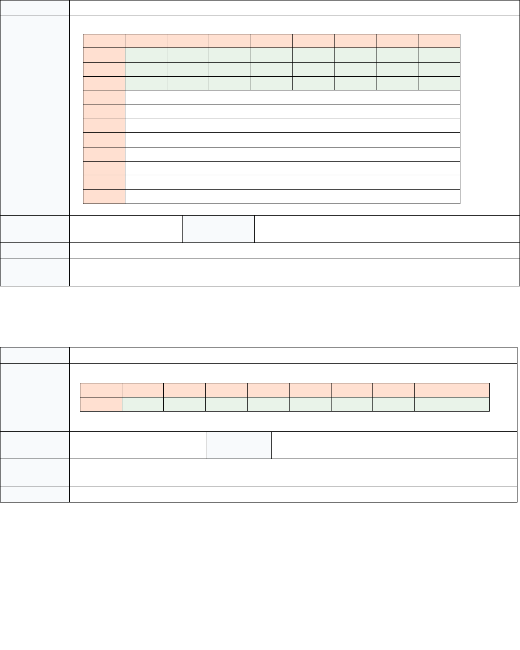
35-56 Vol. 3C
INTEL® PROCESSOR TRACE
35.4.2.19 Maintenance (MNT) Packet
35.4.2.20 PAD Packet
Table 35-38. MNT Packet Definition
Name Maintenance (MNT) Packet
Packet Format
Dependencies TriggerEn Generation Sce-
nario
Implementation specific.
Description This packet is generated by hardware, the payload meaning is model-specific.
Application Unless a decoder has been extended for a particular family/model/stepping to interpret MNT packet payloads, this
packet should simply be ignored. It does not bind to any IP.
Table 35-39. PAD Packet Definition
Name PAD Packet
Packet Format
Dependencies TriggerEn Generation
Scenario
Implementation specific
Description PAD is simply a NOP packet. Processor implementations may choose to add pad packets to improve packet align-
ment or for implementation-specific reasons.
Application Ignore PAD packets.
76543210
000000010
111000011
210001000
3 Payload[7:0]
4 Payload[15:8]
5 Payload[23:16]
6 Payload[31:24]
7 Payload[39:32]
8 Payload[47:40]
9 Payload[55:48]
10 Payload[63:56]
76543210
000000000

Vol. 3C 35-57
INTEL® PROCESSOR TRACE
35.4.2.21 PTWRITE (PTW) Packet
Table 35-40. PTW Packet Definition
Name PTW Packet
Packet Format
The PayloadBytes field indicates the number of bytes of payload that follow the header bytes. Encodings are as fol-
lows:
IP bit indicates if a FUP, whose payload will be the IP of the PTWRITE instruction, will follow.
Dependencies TriggerEn & ContextEn & FilterEn
& PTWEn
Generation
Scenario
PTWRITE Instruction
Description Contains the value held in the PTWRITE operand.
This packet is CYC-eligible, and hence will generate a CYC packet if IA32_RTIT_CTL.CYCEn=1 and any CYC Threshold
has been reached.
Application Binds to the associated PTWRITE instruction. The IP of the PTWRITE will be provided by a following FUP, when
PTW.IP=1.
76543210
000000010
1IP PayloadBytes 10010
2 Payload[7:0]
3 Payload[15:8]
4 Payload[23:16]
5 Payload[31:24]
6 Payload[39:32]
7 Payload[47:40]
8 Payload[55:48]
9 Payload[63:56]
PayloadBytes Bytes of Payload
‘00 4
‘01 8
‘10 Reserved
‘11 Reserved

35-58 Vol. 3C
INTEL® PROCESSOR TRACE
35.4.2.22 Execution Stop (EXSTOP) Packet
Table 35-41. EXSTOP Packet Definition
Name EXSTOP Packet
Packet Format
Dependencies TriggerEn & PwrEvtEn Generation
Scenario
C-state entry, P-state change, or other processor clock power-
down. Includes :
• Entry to C-state deeper than C0.0
•TM1/2
•STPCLK#
• Frequency change due to IA32_CLOCK_MODULATION, Turbo
Description This packet indicates that software execution has stopped due to processor clock powerdown. Later packets will
indicate when execution resumes.
If EXSTOP is generated while ContextEn is set, the IP bit will be set, and EXSTOP will be followed by a FUP packet
containing the IP at which execution stopped. More precisely, this will be the IP of the oldest instruction that has
not yet completed.
This packet is CYC-eligible, and hence will generate a CYC packet if IA32_RTIT_CTL.CYCEn=1 and any CYC Threshold
has been reached.
Application If a FUP follows EXSTOP (hence IP bit set), the EXSTOP can be bound to the FUP IP. Otherwise the IP is not known.
Time of powerdown can be inferred from the preceding CYC, if CYCEn=1. Combined with the TSC at the time of
wake (if TSCEn=1), this can be used to determine the duration of the powerdown.
IP bit indicates if a FUP will follow.
76543210
000000010
1IP 1100010
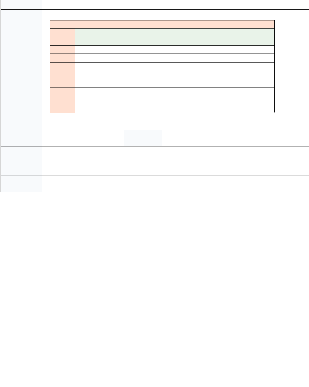
Vol. 3C 35-59
INTEL® PROCESSOR TRACE
35.4.2.23 MWAIT Packet
Table 35-42. MWAIT Packet Definition
Name MWAIT Packet
Packet Format
Dependencies TriggerEn & PwrEvtEn & Contex-
tEn
Generation
Scenario
MWAIT instruction, or I/O redirection to MWAIT, that complete
without fault or VMexit.
Description Indicates that an MWAIT operation to C-state deeper than C0.0 completed. The MWAIT hints and extensions passed
in by software are exposed in the payload.
This packet is CYC-eligible, and hence will generate a CYC packet if IA32_RTIT_CTL.CYCEn=1 and any CYC Threshold
has been reached.
Application The MWAIT packet should bind to the IP of the next FUP, which will be the IP of the instruction that caused the
MWAIT. This FUP will be shared with EXSTOP.
76543210
000000010
111000010
2MWAIT Hints[7:0]
3 Reserved
4 Reserved
5 Reserved
6 Reserved EXT[1:0]
7 Reserved
8 Reserved
9 Reserved

35-60 Vol. 3C
INTEL® PROCESSOR TRACE
35.4.2.24 Power Entry (PWRE) Packet
Table 35-43. PWRE Packet Definition
Name PWRE Packet
Packet Format
Dependencies TriggerEn & PwrEvtEn Generation
Scenario
Transition to a C-state deeper than C0.0.
Description Indicates processor entry to the resolved thread C-state and sub C-state indicated. The processor will remain in this
C-state until either another PWRE indicates the processor has moved to a C-state deeper than C0.0, or a PWRX
packet indicates a return to C0.
Note that some CPUs may allow MWAIT to request a deeper C-state than is supported by the core. These deeper C-
states may have platform-level implications that differentiate them. However, the PWRE packet will provide only
the resolved thread C-state, which will not exceed that supported by the core.
If the C-state entry was initiated by hardware, rather than a direct software request (such as MWAIT, HLT, or shut-
down), the HW bit will be set to indicate this. Hardware Duty Cycling (see Section 14.5, “Hardware Duty Cycling
(HDC)” in the Intel® 64 and IA-32 Architectures Software Developer’s Manual, Volume 3B) is an example of such a
case.
Application When transitioning from C0.0 to a deeper C-state, the PWRE packet will be followed by an EXSTOP. If that EXSTOP
packet has the IP bit set, then the following FUP will provide the IP at which the C-state entry occurred. Subsequent
PWRE packets generated before the next PWRX should bind to the same IP.
76543210
000000010
100100010
2HWReserved
3 Resolved Thread C-State Resolved Thread Sub C-State
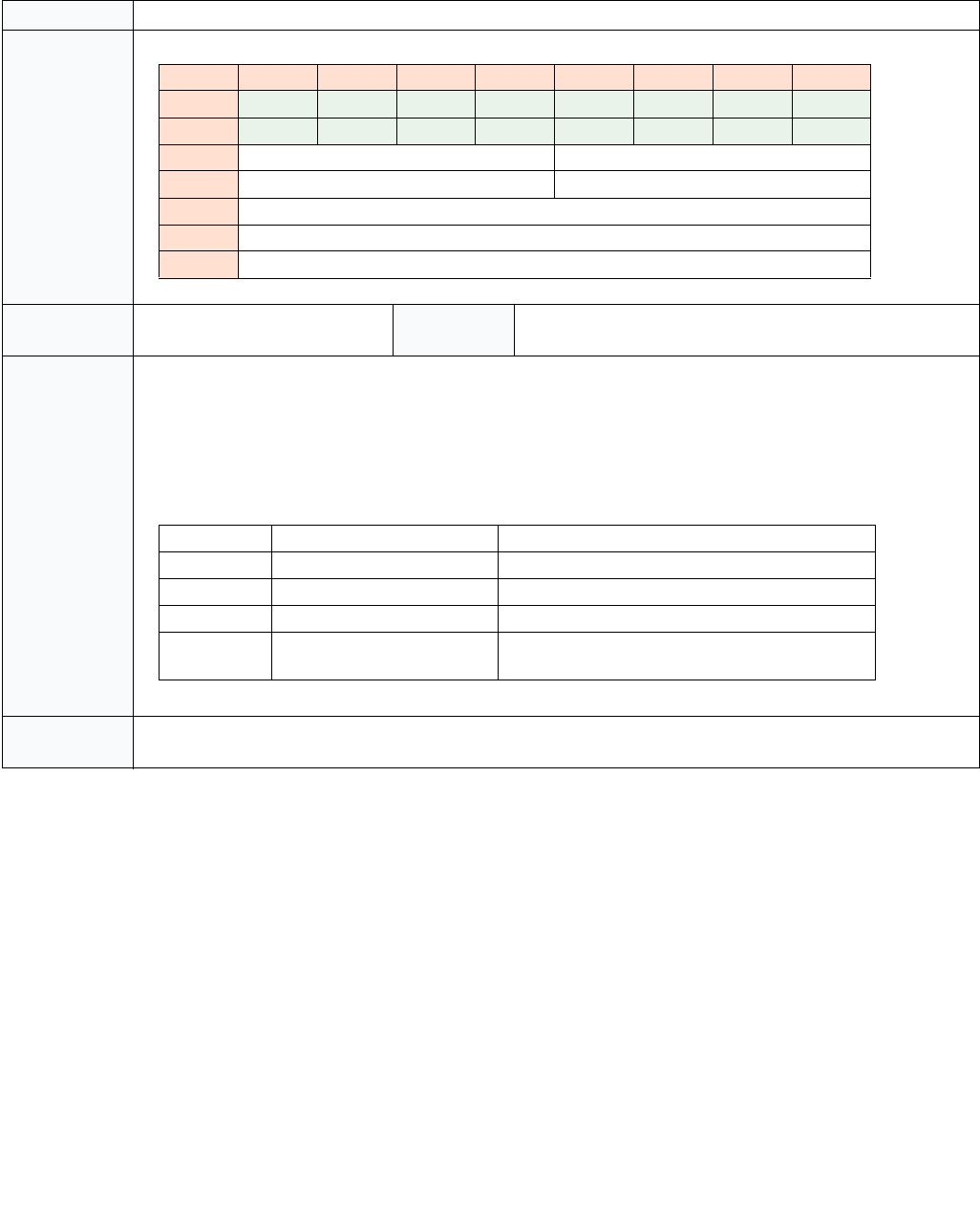
Vol. 3C 35-61
INTEL® PROCESSOR TRACE
35.4.2.25 Power Exit (PWRX) Packet
35.5 TRACING IN VMX OPERATION
On processors that IA32_VMX_MISC[bit 14] reports 1, TraceEn can be set in VMX operation. A series of mecha-
nisms exist to allow the VMM to configure tracing based on the desired trace domain, and on the consumer of the
trace output. The VMM can configure specific VMX controls to control what virtualization-specific data are included
within the trace packets (see Section 35.5.1 for details). The MSR-load areas used by VMX transitions can be
employed by the VMM to restrict tracing to the desired context (see Section 35.5.2 for details). These configuration
options are summarized in Table 35-45. Table 35-45 covers common Intel PT usages while SMIs are handled by the
default SMM treatment. Tracing with SMM Transfer Monitor is described in Section 35.6.
Table 35-44. PWRX Packet Definition
Name PWRX Packet
Packet Format
Dependencies TriggerEn & PwrEvtEn Generation
Scenario
Transition from a C-state deeper than C0.0 to C0.
Description Indicates processor return to thread C0 from a C-state deeper than C0.0.
The Last Core C-State field provides the MWAIT encoding for the core C-state at the time of the wake. The Deepest
Core C-State provides the MWAIT encoding for the deepest core C-state achieved during the sleep session, or since
leaving thread C0. MWAIT encodings for C-states can be found in Table 4-11 in the Intel® 64 and IA-32 Architec-
tures Software Developer’s Manual, Volume 2B. Note that these values reflect only the core C-state, and hence will
not exceed the maximum supported core C-state, even if deeper C-states can be requested.
The Wake Reason field is one-hot, encoded as follows:
Application PWRX will always apply to the same IP as the PWRE. The time of wake can be discerned from (optional) timing pack-
ets that precede PWRX.
76543210
000000010
110100010
2 Last Core C-State Deepest Core C-State
3 Reserved Wake Reason
4 Reserved
5 Reserved
6 Reserved
Bit Field Meaning
0 Interrupt Wake due to external interrupt received.
1 Reserved
2 Store to Monitored Address Wake due to store to monitored address.
3 HW Wake Wake due to hardware autonomous condition,
such as HDC.

35-62 Vol. 3C
INTEL® PROCESSOR TRACE
35.5.1 VMX-Specific Packets and VMCS Controls
In all of the usages of VMX and Intel PT, a decoder in the host or VMM context can identify the occurrences of VMX
transitions with the aid of VMX-specific packets. There are two kinds of packets relevant to VMX:
•VMCS packet. The VMX transitions of individual VMs can be distinguished by a decoder using the VMCS-
pointer field in a VMCS packet. A VMCS packet is sent on a successful execution of VMPTRLD, and its VMCS-
pointer field stores the VMCS pointer loaded by that execution. See Section 35.4.2.15 for details.
•The NR (non-root) bit in a PIP packet. Normally, the NR bit is set in any PIP packet generated in VMX non-
root operation. In addition, PIP packets are generated with each VM entry and VM exit. Thus a transition of the
NR bit from 0 to 1 indicates the occurrence of a VM entry, and a transition of 1 to 0 indicates the occurrence of
a VM exit.
There are VMX controls that a VMM can set to conceal some of this VMX-specific information (by suppressing its
recording) and thereby prevent it from leaking across virtualization boundaries. There is one of these controls
(each of which is called “conceal VMX from PT”) of each type of VMX control.
Table 35-45. Common Usages of Intel PT and VMX
Target Domain Output
Consumer
Virtualize
Output
Configure VMX
Controls
TraceEN Configuration Save/Restore MSR states
of Trace Configuration
System-Wide
(VMM + VMs)
Host N/A Default setting
(no suppression)
WRMSR or XRSTORS by Host N/A
VMM Only Intel PT Aware
VMM
N/A Enable
suppression
Use VMX MSR-load areas to
disable tracing in VM, enable
tracing on VM exits
N/A
VM Only Intel PT Aware
VMM
N/A Enable
suppression
Use VMX MSR-load areas to
enable tracing in VM, disable
tracing on VM exits
N/A
Intel PT Aware
Guest(s)
Per Guest VMM adds
trace output
virtualization
Enable
suppression
Use VMX MSR-load areas to
enable tracing in VM, disable
tracing on VM exits
VMM updates guest state
on VM exits due to
XRSTORS
Table 35-46. VMX Controls For Intel Processor Trace
Type of VMX
Control
Bit
Position1
NOTES:
1. These are the positions of the control bits in the relevant VMX control fields.
Value Behavior
Secondary
processor-based
VM-execution
control
19 0 Each PIP generated in VM non-root operation will set the NR bit.
PSB+ in VMX non-root operation will include the VMCS packet, to ensure that the decoder
knows which guest is currently in use.
1 Each PIP generated in VMX non-root operation will clear the NR bit.
PSB+ in VMX non-root operation will not include the VMCS packet.
VM-exit control 24 0 Each VM exit generates a PIP in which the NR bit is clear.
In addition, SMM VM exits generate VMCS packets.
1 VM exits do not generate PIPs, and no VMCS packets are generated on SMM VM exits.
VM-entry control 17 0 Each VM entry generates a PIP in which the NR bit is set (except VM entries that return
from SMM to VMX root operation).
In addition, VM entries that return from SMM generate VMCS packets.
1 VM entries do not generate PIPs, and no VMCS packets are generated on VM entries that
return from SMM.

Vol. 3C 35-63
INTEL® PROCESSOR TRACE
The 0-settings of these VMX controls enable all VMX-specific packet information. The scenarios that would use
these default settings also do not require the VMM to use VMX MSR-load areas to enable and disable trace-packet
generation across VMX transitions.
If IA32_VMX_MISC[bit 14] reports 0, the 1-settings of the VMX controls in Table 35-46 are not supported, and
VM entry will fail on any attempt to set them.
35.5.2 Managing Trace Packet Generation Across VMX Transitions
In tracing scenarios that collect packets for both VMX root operation and VMX non-root operation, a host executive
can manage the MSRs associated with trace packet generation directly. The states of these MSRs need not be
modified using MSR load areas across VMX transitions.
For tracing scenarios that collect packets only within VMX root operation or only within VMX non-root operation, the
VMM can use the MSR load areas to toggle IA32_RTIT_CTL.TraceEn.
35.5.2.1 System-Wide Tracing
When a host or VMM configures Intel PT to collect trace packets of the entire system, it can leave the relevant VMX
controls clear to allow VMX-specific packets to provide information across VMX transitions. The VMX MSR-load
areas need not be used to load Intel PT MSRs on VM exits or VM entries.
The decoder will desire to identify the occurrence of VMX transitions. The packets of interests to a decoder are
shown in Table 35-47.
Since the VMX controls that suppress packet generation are cleared, a VMCS packet will be included in all PSB+ for
this usage scenario. Additionally, VMPTRLD will generate such a packet. Thus the decoder can distinguish the
execution context of different VMs.
When the host VMM configures a system to collect trace packets in this scenario, it should emulate CPUID to report
CPUID.(EAX=07H, ECX=0):EBX[bit 26] as 0 to guests, indicating to guests that Intel PT is not available.
VMX TSC Manipulation
The TSC packets generated while in VMX non-root operation will include any changes resulting from the use of a
VMM’s use of the TSC offsetting or TSC scaling VMX controls (see Chapter 25, “VMX Non-Root Operation”). In this
system-wide usage model, the decoder may need to account for the effect of per-VM adjustments in the TSC
Table 35-47. Packets on VMX Transitions (System-Wide Tracing)
Event Packets Description
VM exit FUP(GuestIP) The FUP indicates at which point in the guest flow the VM exit occurred. This is important,
since VM exit can be an asynchronous event. The IP will match that written into the VMCS.
PIP(HostCR3, NR=0) The PIP packet provides the new host CR3 value, as well as indication that the logical processor
is entering VMX root operation. This allows the decoder to identify the change of executing
context from guest to host and load the appropriate set of binaries to continue decode.
TIP(HostIP) The TIP indicates the destination IP, the IP of the first instruction to be executed in VMX root
operation.
Note, this packet could be preceded by a MODE.Exec packet (Section 35.4.2.8). This is
generated only in cases where CS.D or (CS.L & EFER.LMA) change during the transition.
VM entry PIP(GuestCR3, NR=1) The PIP packet provides the new guest CR3 value, as well as indication that the logical
processor is entering VMX non-root operation. This allows the decoder to identify the change
of executing context from host to guest and load the appropriate set of binaries to continue
decode.
TIP(GuestIP) The TIP indicates the destination IP, the IP of the first instruction to be executed in VMX non-
root operation. This should match the RIP loaded from the VMCS.
Note, this packet could be preceded by a MODE.Exec packet (Section 35.4.2.8). This is
generated only in cases where CS.D or (CS.L & EFER.LMA) change during the transition.

35-64 Vol. 3C
INTEL® PROCESSOR TRACE
packets generated in VMX non-root operation and the absence of TSC adjustments in TSC packets generated in
VMX root operation. The VMM can supply this information to the decoder.
35.5.2.2 Host-Only Tracing
When trace packets in VMX non-root operation are not desired, the VMM can use the VM-entry MSR-load area to
load IA32_RTIT_CTL (clearing TraceEn) to disable trace-packet generation in guests, and use the VM-exit MSR-load
area to load IA32_RTIT_CTL to set TraceEn.
When tracing only the host, the decoder does not need information about the guests, and the VMX controls for
suppressing VMX-specific packets can be set to reduce the packets generated. VMCS packets will still be generated
on execution of VMPTRLD and in PSB+ generated in the host, but these will be unused by the decoder.
The packets of interests to a decoder when trace packets are collected for host-only tracing are shown in Table 35-
48.
35.5.2.3 Guest-Only Tracing
A VMM can configure trace-packet generation while in VMX non-root operation for guests executing normally. This
is accomplished by utilizing the VMX MSR-load areas on VM exits (see Section 24.7.2, “VM-Exit Controls for
MSRs”) and VM entries (see Section 24.8.2, “VM-Entry Controls for MSRs”) to limit trace-packet generation to the
guest environment.
For this usage, the VM-entry MSR load area is programmed to enable trace packet generation; the VM-exit MSR
load area is used to clear IA32_RTIT_CTL.TraceEn so as to disable trace-packet generation in the host. Further, if
it is preferred that the guest packet stream contain no indication that execution was in VMX non-root operation,
the VMM should set to 1 all the VMX controls enumerated in Table 35-46.
35.5.2.4 Virtualization of Guest Output Packet Streams
Each Intel PT aware guest OS can produce one or more output packet streams to destination addresses specified
as guest physical address using by context-switching IA32_RTIT_OUTPUT_BASE within the guest. The processor
generates trace packets to the physical address specified in IA32_RTIT_OUTPUT_BASE, and those specified in the
ToPA tables. Thus, a VMM that supports Intel PT aware guest OS may wish to virtualize the output configurations of
IA32_RTIT_OUTPUT_BASE and ToPA for each trace configuration state of all the guests.
35.5.2.5 Emulation of Intel PT Traced State
If a VMM emulates an element of processor state by taking a VM exit on reads and/or writes to that piece of state,
and the state element impacts Intel PT packet generation or values, it may be incumbent upon the VMM to insert
or modify the output trace data.
If a VM exit is taken on a guest write to CR3 (including “MOV CR3” as well as task switches), the PIP packet
normally generated on the CR3 write will be missing.
To avoid decoder confusion when the guest trace is decoded, the VMM should emulate the missing PIP by writing it
into the guest output buffer. If the guest CR3 value is manipulated, the VMM may also need to manipulate the
IA32_RTIT_CR3_MATCH value, in order to ensure the trace behavior matches the guest's expectation.
Similarly, if a VMM emulates the TSC value by taking a VM exit on RDTSC, the TSC packets generated in the trace
may mismatch the TSC values returned by the VMM on RDTSC. To ensure that the trace can be properly aligned
Table 35-48. Packets on VMX Transitions (Host-Only Tracing)
Event Packets Description
VM exit TIP.PGE(HostIP) The TIP.PGE indicates that trace packet generation is enabled and gives the IP of the first
instruction to be executed in VMX root operation.
Note, this packet could be preceded by a MODE.Exec packet (Section 35.4.2.8). This is
generated only in cases where CS.D or (CS.L & EFER.LMA) change during the transition.
VM entry TIP.PGD() The TIP indicates that trace packet generation was disabled. This ensure that all buffered
packets are flushed out.

Vol. 3C 35-65
INTEL® PROCESSOR TRACE
with software logs based on RDTSC, the VMM should either make corresponding modifications to the TSC packet
values in the guest trace, or use mechanisms such as TSC offsetting or TSC scaling in place of exiting.
35.5.2.6 TSC Scaling
When TSC scaling is enabled for a guest using Intel PT, the VMM should ensure that the value of Maximum Non-
Turbo Ratio[15:8] in MSR_PLATFORM_INFO (MSR 0CEH) and the TSC/”core crystal clock” ratio (EBX/EAX) in
CPUID leaf 15H are set in a manner consistent with the resulting TSC rate that will be visible to the VM. This will
allow the decoder to properly apply TSC packets, MTC packets (based on the core crystal clock or ART, whose
frequency is indicated by CPUID leaf 15H), and CBR packets (which indicate the ratio of the processor frequency to
the Max Non-Turbo frequency). Absent this, or separate indication of the scaling factor, the decoder will be unable
to properly track time in the trace. See Section 35.8.3 for details on tracking time within an Intel PT trace.
35.5.2.7 Failed VM Entry
The packets generated by a failed VM entry depend both on the VMCS configuration, as well as on the type of
failure. The results to expect are summarized in the table below. Note that packets in italics may or may not be
generated, depending on implementation choice, and the point of failure.
35.5.2.8 VMX Abort
VMX abort conditions take the processor into a shutdown state. On a VM exit that leads to VMX abort, some
packets (FUP, PIP) may be generated, but any expected TIP, TIP.PGE, or TIP.PGD may be dropped.
35.6 TRACING AND SMM TRANSFER MONITOR (STM)
The SMM-transfer monitor (STM) is a VMM that operates inside SMM while in VMX root operation. An STM operates
in conjunction with an executive monitor. The latter operates outside SMM and in VMX root operation. Transitions
from the executive monitor or its VMs to the STM are called SMM VM exits. The STM returns from SMM via a
VM entry to the VM in VMX non-root operation or the executive monitor in VMX root operation.
Intel PT supports tracing in an STM similar to tracing support for VMX operation as described above in Section 35.5.
As a result, on a SMM VM exit resulting from #SMI, TraceEn is not saved and then cleared. Software can save the
state of the trace configuration MSRs and clear TraceEn using the MSR load/save lists.
35.7 PACKET GENERATION SCENARIOS
Table 35-50 and Table 35-52 illustrate the packets generated in various scenarios. In the heading row, PacketEn is
abbreviated as PktEn, ContextEn as CntxEn. Note that this assumes that TraceEn=1 in IA32_RTIT_CTL, while Trig-
gerEn=1 and Error=0 in IA32_RTIT_STATUS, unless otherwise specified. Entries that do not matter in packet
generation are marked “D.C.” Packets followed by a “?” imply that these packets depend on additional factors,
which are listed in the “Other Dependencies” column.
Table 35-49. Packets on a Failed VM Entry
Usage Model Entry Configuration Early Failure (fall
through to next IP)
Late Failure (VM-exit like)
System-Wide No use of VM-entry
MSR-load area
TIP (NextIP) PIP(Guest CR3, NR=1), TraceEn 0->1 Packets (See Section
35.2.7.3), PIP(HostCR3, NR=0), TIP(HostIP)
VMM Only VM-entry MSR-load
area used to clear
TraceEn
TIP (NextIP) TraceEn 0->1 Packets (See Section 35.2.7.3), TIP(HostIP)
VM Only VM-entry MSR-load
area used to set
TraceEn
None None

35-66 Vol. 3C
INTEL® PROCESSOR TRACE
The following acronyms are used in the packet examples below:
•CLIP - Current LIP
•NLIP - Next Sequential LIP
•BLIP - Branch Target LIP
In Table 35-50, PktEn is evaluated based on TiggerEn & ContextEn & FilterEn & BranchEn.
Table 35-50. Packet Generation under Different Enable Conditions
Case Operation PktEn
Before
PktEn
After
CntxEn
After
Other Dependencies Packets Output
1a Normal non-jump operation 0 0 D.C. None
1b Normal non-jump operation 1 1 1 None
2a WRMSR/XRSTORS/RSM that changes
TraceEn 0 -> 1, with PacketByteCnt >0
0 0 D.C. *TSC if TSCEn=1;
*TMA if TSCEn=MTCEn=1
TSC?, TMA?, CBR
2b WRMSR/XRSTORS/RSM that changes
TraceEn 0 -> 1, with PacketByteCnt =0
0 0 D.C. *TSC if TSCEn=1;
*TMA if TSCEn=MTCEn=1
PSB, PSBEND (see Sec-
tion 35.4.2.17)
2d WRMSR/XRSTORS/RSM that changes
TraceEn 0 -> 1, with PacketByteCnt >0
0 1 1 TSC if TSCEn=1;
TMA if TSCEn=MTCEn=1
TSC?, TMA?, CBR,
MODE.Exec, TIP.PGE(NLIP)
2e WRMSR/XRSTORS/RSM that changes
TraceEn 0 -> 1, with PacketByteCnt =0
0 1 1 MODE.Exec,
TIP.PGE(NLIP), PSB,
PSBEND (see Section
35.4.2.8, 35.4.2.7,
35.4.2.13,35.4.2.15,
35.4.2.17)
3a WRMSR that changes TraceEn 1 -> 0 0 0 D.C. None
3b WRMSR that changes TraceEn 1 -> 0 1 0 D.C. FUP(CLIP), TIP.PGD()
5a MOV to CR3 0 0 0 None
5f MOV to CR3 0 0 1 TraceStop if executed in a
TraceStop region
PIP(NewCR3,NR?), Trace-
Stop?
5b MOV to CR3 0 1 1 *PIP.NR=1 if not in root
operation and the “conceal
VMX from PT” VM-execu-
tion control is 0
*MODE.Exec if the mode has
changed since the last
MODE.Exec, or if no
MODE.Exec since last PSB
PIP(NewCR3, NR?),
MODE.Exec?,
TIP.PGE(NLIP)
5c MOV to CR3 1 0 0 TIP.PGD()
5e MOV to CR3 1 0 1 *PIP.NR=1 if not in root
operation and the “conceal
VMX from PT” VM-execu-
tion control is 0
*TraceStop if executed in a
TraceStop region
PIP(NewCR3, NR?),
TIP.PGD(NLIP), TraceStop?
5d MOV to CR3 1 1 1 *PIP.NR=1 if not in root
operation and the “conceal
VMX from PT” VM-execu-
tion control is 0
PIP(NewCR3, NR?)
6a Unconditional direct near jump 0 0 D.C. None
6b Unconditional direct near jump 1 0 1 TraceStop if BLIP is in a
TraceStop region
TIP.PGD(BLIP), TraceStop?

Vol. 3C 35-67
INTEL® PROCESSOR TRACE
6c Unconditional direct near jump 0 1 1 MODE.Exec if the mode has
changed since the last
MODE.Exec, or if no
MODE.Exec since last PSB
MODE.Exec?,
TIP.PGE(BLIP)
6d Unconditional direct near jump 1 1 1 None
7a Conditional taken jump or compressed
RET that does not fill up the internal
TNT buffer
00D.C. None
7b Conditional taken jump or compressed
RET
0 1 1 MODE.Exec if the mode has
changed since the last
MODE.Exec, or if no
MODE.Exec since last PSB
MODE.Exec?,
TIP.PGE(BLIP)
7e Conditional taken jump or compressed
RET, with empty TNT buffer
1 0 1 TraceStop if BLIP is in a
TraceStop region
TIP.PGD(), TraceStop?
7f Conditional taken jump or compressed
RET, with non-empty TNT buffer
1 0 1 TraceStop if BLIP is in a
TraceStop region
TNT, TIP.PGD(), TraceS-
top?
7d Conditional taken jump or compressed
RET that fills up the internal TNT buf-
fer
111 TNT
8a Conditional non-taken jump 0 0 D.C. None
8d Conditional not-taken jump that fills up
the internal TNT buffer
111 TNT
9a Near indirect jump (JMP, CALL, or
uncompressed RET)
00D.C. None
9b Near indirect jump (JMP, CALL, or
uncompressed RET)
0 1 1 MODE.Exec if the mode has
changed since the last
MODE.Exec, or if no
MODE.Exec since last PSB
MODE.Exec?,
TIP.PGE(BLIP)
9c Near indirect jump (JMP, CALL, or
uncompressed RET)
1 0 1 TraceStop if BLIP is in a
TraceStop region
TIP.PGD(BLIP), TraceStop?
9d Near indirect jump (JMP, CALL, or
uncompressed RET)
111 TIP(BLIP)
10a Far Branch (CALL/JMP/RET) 0 0 0 None
10f Far Branch (CALL/JMP/RET) 0 0 1 *PIP if CR3 is updated (i.e.,
task switch), and OS=1;
*PIP.NR=1 if destination is
not root operation and the
“conceal VMX from PT” VM-
execution control is 0;
*TraceStop if BLIP is in a
TraceStop region
PIP(new CR3, NR?), Trace-
Stop?
Table 35-50. Packet Generation under Different Enable Conditions (Contd.)
Case Operation PktEn
Before
PktEn
After
CntxEn
After
Other Dependencies Packets Output

35-68 Vol. 3C
INTEL® PROCESSOR TRACE
10b Far Branch (CALL/JMP/RET) 0 1 1 *PIP if CR3 is updated (i.e.,
task switch), and OS=1;
*PIP.NR=1 if destination is
not root operation and the
“conceal VMX from PT” VM-
execution control is 0;
*MODE.Exec if the mode has
changed since the last
MODE.Exec, or if no
MODE.Exec since last PSB
PIP(new CR3, NR?),
MODE.Exec?,
TIP.PGE(BLIP)
10c Far Branch (CALL/JMP/RET) 1 0 0 TIP.PGD()
10d Far Branch (CALL/JMP/RET) 1 0 1 *PIP if CR3 is updated (i.e.,
task switch), and OS=1;
*PIP.NR=1 if destination is
not root operation and the
“conceal VMX from PT” VM-
execution control is 0;
*TraceStop if BLIP is in a
TraceStop region
PIP(new CR3, NR?),
TIP.PGD(BLIP), TraceStop?
10e Far Branch (CALL/JMP/RET) 1 1 1 *PIP if CR3 is updated (i.e.,
task switch), and OS=1
*PIP.NR=1 if destination is
not root operation and the
“conceal VMX from PT” VM-
execution control is 0;
* MODE.Exec if the opera-
tion changes CS.L/D or
IA32_EFER.LMA
PIP(NewCR3, NR?)?,
MODE.Exec?, TIP(BLIP)
11a HW Interrupt 0 0 0 None
11f HW Interrupt 0 0 1 *PIP if CR3 is updated (i.e.,
task switch), and OS=1;
*PIP.NR=1 if destination is
not root operation and the
“conceal VMX from PT” VM-
execution control is 0;
*TraceStop if BLIP is in a
TraceStop region
PIP(new CR3, NR?), Trace-
Stop?
11b HW Interrupt 0 1 1 *PIP if CR3 is updated (i.e.,
task switch), and OS=1;
*PIP.NR=1 if destination is
not root operation and the
“conceal VMX from PT” VM-
execution control is 0;
* MODE.Exec if the mode
has changed since the last
MODE.Exec, or if no
MODE.Exec since last PSB
PIP(new CR3, NR?),
MODE.Exec?,
TIP.PGE(BLIP)
11c HW Interrupt 1 0 0 FUP(NLIP), TIP.PGD()
Table 35-50. Packet Generation under Different Enable Conditions (Contd.)
Case Operation PktEn
Before
PktEn
After
CntxEn
After
Other Dependencies Packets Output

Vol. 3C 35-69
INTEL® PROCESSOR TRACE
11d HW Interrupt 1 0 1 * PIP if CR3 is updated (i.e.,
task switch), and OS=1
*PIP.NR=1 if destination is
not root operation and the
“conceal VMX from PT” VM-
execution control is 0;
*TraceStop if BLIP is in a
TraceStop region
FUP(NLIP), PIP(NewCR3,
NR?)?, TIP.PGD(BLIP),
TraceStop?
11e HW Interrupt 1 1 1 * PIP if CR3 is updated (i.e.,
task switch), and OS=1
*PIP.NR=1 if destination is
not root operation and the
“conceal VMX from PT” VM-
execution control is 0;
* MODE.Exec if the opera-
tion changes CS.L/D or
IA32_EFER.LMA
FUP(NLIP), PIP(NewCR3,
NR?)?, MODE.Exec?,
TIP(BLIP)
12a SW Interrupt 0 0 0 None
12f SW Interrupt 0 0 1 * PIP if CR3 is updated (i.e.,
task switch), and OS=1
*PIP.NR=1 if destination is
not root operation and the
“conceal VMX from PT” VM-
execution control is 0;
*TraceStop if BLIP is in a
TraceStop region
PIP(NewCR3, NR?)?,
TraceStop?
12b SW Interrupt 0 1 1 * PIP if CR3 is updated (i.e.,
task switch), and OS=1
*PIP.NR=1 if destination is
not root operation and the
“conceal VMX from PT” VM-
execution control is 0;
*MODE.Exec if the mode has
changed since the last
MODE.Exec, or if no
MODE.Exec since last PSB
PIP(NewCR3, NR?)?,
MODE.Exec?,
TIP.PGE(BLIP)
12c SW Interrupt 1 0 0 FUP(CLIP), TIP.PGD()
12d SW Interrupt 1 0 1 * PIP if CR3 is updated (i.e.,
task switch), and OS=1
*PIP.NR=1 if destination is
not root operation and the
“conceal VMX from PT” VM-
execution control is 0;
*TraceStop if BLIP is in a
TraceStop region
FUP(CLIP), PIP(NewCR3,
NR?)?, TIP.PGD(BLIP),
TraceStop?
Table 35-50. Packet Generation under Different Enable Conditions (Contd.)
Case Operation PktEn
Before
PktEn
After
CntxEn
After
Other Dependencies Packets Output

35-70 Vol. 3C
INTEL® PROCESSOR TRACE
12e SW Interrupt 1 1 1 * PIP if CR3 is updated (i.e.,
task switch), and OS=1
*PIP.NR=1 if destination is
not root operation and the
“conceal VMX from PT” VM-
execution control is 0;
* MODE.Exec if the opera-
tion changes CS.L/D or
IA32_EFER.LMA
FUP(CLIP), PIP(NewCR3,
NR?)?, MODE.Exec?,
TIP(BLIP)
13a Exception/Fault 0 0 0 None
13f Exception/Fault 0 0 1 * PIP if CR3 is updated (i.e.,
task switch), and OS=1
*PIP.NR=1 if destination is
not root operation and the
“conceal VMX from PT” VM-
execution control is 0;
*TraceStop if BLIP is in a
TraceStop region
PIP(NewCR3, NR?)?,
TraceStop?
13b Exception/Fault 0 1 1 * PIP if CR3 is updated (i.e.,
task switch), and OS=1
*PIP.NR=1 if destination is
not root operation and the
“conceal VMX from PT” VM-
execution control is 0;
*MODE.Exec if the mode has
changed since the last
MODE.Exec, or if no
MODE.Exec since last PSB
PIP(NewCR3, NR?)?,
MODE.Exec?,
TIP.PGE(BLIP)
13c Exception/Fault 1 0 0 FUP(CLIP), TIP.PGD()
13d Exception/Fault 1 0 1 * PIP if CR3 is updated (i.e.,
task switch), and OS=1
*PIP.NR=1 if destination is
not root operation and the
“conceal VMX from PT” VM-
execution control is 0;
*TraceStop if BLIP is in a
TraceStop region
FUP(CLIP), PIP(NewCR3,
NR?)?, TIP.PGD(BLIP),
TraceStop?
13e Exception/Fault 1 1 1 * PIP if CR3 is updated (i.e.,
task switch), and OS=1
*PIP.NR=1 if destination is
not root operation and the
“conceal VMX from PT” VM-
execution control is 0;
* MODE.Exec if the opera-
tion changes CS.L/D or
IA32_EFER.LMA
FUP(CLIP), PIP(NewCR3,
NR?)?, MODE.Exec?,
TIP(BLIP)
14a SMI (TraceEn cleared) 0 0 D.C. None
14b SMI (TraceEn cleared) 1 0 0 FUP(SMRAM.LIP),
TIP.PGD()
14f SMI (TraceEn cleared) 1 0 1 NA
Table 35-50. Packet Generation under Different Enable Conditions (Contd.)
Case Operation PktEn
Before
PktEn
After
CntxEn
After
Other Dependencies Packets Output

Vol. 3C 35-71
INTEL® PROCESSOR TRACE
14c SMI (TraceEn cleared) 1 1 1 NA
15a RSM, TraceEn restored to 0 0 0 0 None
15b RSM, TraceEn restored to 1 0 0 D.C. See WRMSR cases for
packets on enable
15c RSM, TraceEn restored to 1 0 1 1 See WRMSR cases for
packets on enable.
FUP/TIP.PGE IP is
SMRAM.LIP
15e RSM (TraceEn=1, goes to shutdown) 1 0 0 None
15f RSM (TraceEn=1, goes to shutdown) 1 0 1 None
15d RSM (TraceEn=1, goes to shutdown) 1 1 1 None
16i VM exit 0 0 0 None
16a VM exit 0 0 1 *PIP if OF=1 and the “con-
ceal VMX from PT” VM-exit
control is 0;
*TraceStop if VMCSh.LIP is
in a TraceStop region
PIP(HostCR3, NR=0)?,
TraceStop?
16b VM exit, MSR list sets TraceEn=1 0 0 0 See WRMSR cases for
packets on enable. FUP IP
is VMCSh.LIP
16c VM exit, MSR list sets TraceEn=1 0 1 1 See WRMSR cases for
packets on enable.
FUP/TIP.PGE IP is
VMCSh.LIP
16e VM exit 0 1 1 *PIP if OF=1 and the “con-
ceal VMX from PT” VM-exit
control is 0;
*MODE.Exec if the value is
different, since last TIP.PGD
PIP(HostCR3, NR=0)?,
MODE.Exec?,
TIP.PGE(VMCSh.LIP)
16f VM exit, MSR list clears TraceEn=01 0 0 *PIP if OF=1 and the “con-
ceal VMX from PT” VM-exit
control is 0;
FUP(VMCSg.LIP),
PIP(HostCR3, NR=0)?,
TIP.PGD
16j VM exit, ContextEN 1->0 1 0 0 FUP(VMCSg.LIP), TIP.PGD
16g VM exit 1 0 1 *PIP if OF=1 and the “con-
ceal VMX from PT” VM-exit
control is 0;
*TraceStop if VMCSh.LIP is
in a TraceStop region
FUP(VMCSg.LIP),
PIP(HostCR3, NR=0)?,
TIP.PGD(VMCSh.LIP),
TraceStop?
16h VM exit 1 1 1 *PIP if OF=1 and the “con-
ceal VMX from PT” VM-exit
control is 0;
*MODE.Exec if the value is
different, since last TIP.PGD
FUP(VMCSg.LIP),
PIP(HostCR3, NR=0)?,
MODE.Exec,
TIP(VMCSh.LIP)
17a VM entry 0 0 0 None
Table 35-50. Packet Generation under Different Enable Conditions (Contd.)
Case Operation PktEn
Before
PktEn
After
CntxEn
After
Other Dependencies Packets Output

35-72 Vol. 3C
INTEL® PROCESSOR TRACE
17b VM entry 0 0 1 *PIP if OF=1 and the “con-
ceal VMX from PT” VM-
entry control is 0;
*TraceStop if VMCSg.LIP is
in a TraceStop region
PIP(GuestCR3, NR=1)?,
TraceStop?
17c VM entry, MSR load list sets
TraceEn=1
001 See WRMSR cases for
packets on enable. FUP IP
is VMCSg.LIP
17d VM entry, MSR load list sets
TraceEn=1
011 See WRMSR cases for
packets on enable.
FUP/TIP.PGE IP is
VMCSg.LIP
17f VM entry, FilterEN 0->1 0 1 1 *PIP if OF=1 and the “con-
ceal VMX from PT” VM-
entry control is 0;
*MODE.Exec if the value is
different, since last TIP.PGD
PIP(GuestCR3, NR=1)?,
MODE.Exec?,
TIP.PGE(VMCSg.LIP)
17j VM entry, ContextEN 0->1 0 1 1 *MODE.Exec if the value is
different, since last TIP.PGD
MODE.Exec,
TIP.PGE(VMCSg.LIP)
17g VM entry, MSR list clears TraceEn=0 1 0 0 *PIP if OF=1 and the “con-
ceal VMX from PT” VM-
entry control is 0;
PIP(GuestCR3, NR=1)?,
TIP.PGD
17h VM entry 1 0 1 *PIP if OF=1 and the “con-
ceal VMX from PT” VM-
entry control is 0;
*TraceStop if VMCSg.LIP is
in a TraceStop region
PIP(GuestCR3, NR=1)?,
TIP.PGD(VMCSg.LIP),
TraceStop?
17i VM entry 1 1 1 *PIP if OF=1 and the “con-
ceal VMX from PT” VM-
entry control is 0;
*MODE.Exec if the value is
different, since last TIP.PGD
PIP(GuestCR3, NR=1)?,
MODE.Exec,
TIP(VMCSg.LIP)
20a EENTER/ERESUME to non-debug
enclave
000 None
20c EENTER/ERESUME to non-debug
enclave
100 FUP(CLIP), TIP.PGD()
21a EEXIT from non-debug enclave 0 0 D.C. None
21b EEXIT from non-debug enclave 0 1 1 *MODE.Exec if the value is
different, since last TIP.PGD
MODE.Exec?,
TIP.PGE(BLIP)
22a AEX/EEE from non-debug enclave 0 0 D.C. None
22b AEX/EEE from non-debug enclave 0 1 1 *MODE.Exec if the value is
different, since last TIP.PGD
MODE.Exec?,
TIP.PGE(AEP.LIP)
23a EENTER/ERESUME to debug enclave 0 0 D.C. None
23b EENTER/ERESUME to debug enclave 0 1 1 *MODE.Exec if the value is
different, since last TIP.PGD
MODE.Exec?,
TIP.PGE(BLIP)
23c EENTER/ERESUME to debug enclave 1 0 0 FUP(CLIP), TIP.PGD()
Table 35-50. Packet Generation under Different Enable Conditions (Contd.)
Case Operation PktEn
Before
PktEn
After
CntxEn
After
Other Dependencies Packets Output

Vol. 3C 35-73
INTEL® PROCESSOR TRACE
23d EENTER/ERESUME to debug enclave 0 0 1 *TraceStop if BLIP is in a
TraceStop region
FUP(CLIP), TIP.PGD(BLIP),
TraceStop?
23e EENTER/ERESUME to debug enclave 1 1 1 FUP(CLIP), TIP(BLIP)
24f EEXIT from debug enclave 0 0 D.C. None
24b EEXIT from debug enclave 0 1 1 *MODE.Exec if the value is
different, since last TIP.PGD
MODE.Exec?,
TIP.PGE(BLIP)
24d EEXIT from debug enclave 1 0 1 *TraceStop if BLIP is in a
TraceStop region
FUP(CLIP), TIP.PGD(BLIP),
TraceStop?
24e EEXIT from debug enclave 1 1 1 FUP(CLIP), TIP(BLIP)
25a AEX/EEE from debug enclave 0 0 D.C. None
25b AEX/EEE from debug enclave 0 1 1 *MODE.Exec if the value is
different, since last TIP.PGD
MODE.Exec?,
TIP.PGE(AEP.LIP)
25d AEX/EEE from debug enclave 1 0 1 *For AEX, FUP IP could be
NLIP, for trap-like events
FUP(CLIP),
TIP.PGD(AEP.LIP)
25e AEX/EEE from debug enclave 1 1 1 *MODE.Exec if the value is
different, since last TIP.PGD
*For AEX, FUP IP could be
NLIP, for trap-like events
FUP(CLIP), MODE.Exec?,
TIP(AEP.LIP)
26a XBEGIN/XACQUIRE 0 0 D.C. None
26d XBEGIN/XACQUIRE that does not set
InTX
111 None
26e XBEGIN/XACQUIRE that sets InTX 1 1 1 MODE.TSX(InTX=1,
TXAbort=0), FUP(CLIP)
27a XEND/XRELEASE 0 0 D.C. None
27d XEND/XRELEASE that does not clear
InTX
111 None
27e XEND/XRELEASE that clears InTX 1 1 1 MODE.TSX(InTX=0,
TXAbort=0), FUP(CLIP)
28a XABORT(Async XAbort, or other) 0 0 0 None
28e XABORT(Async XAbort, or other) 0 0 1 *TraceStop if BLIP is in a
TraceStop region
MODE.TSX(InTX=0,
TXAbort=1), TraceStop?
28b XABORT(Async XAbort, or other) 0 1 1 MODE.TSX(InTX=0,
TXAbort=1),
TIP.PGE(BLIP)
28c XABORT(Async XAbort, or other) 1 0 1 *TraceStop if BLIP is in a
TraceStop region
MODE.TSX(InTX=0,
TXAbort=1), TIP.PGD
(BLIP), TraceStop?
28d XABORT(Async XAbort, or other) 1 1 1 MODE.TSX(InTX=0,
TXAbort=1), FUP(CLIP),
TIP(BLIP)
30a INIT (BSP) 0 0 0 None
30b INIT (BSP) 0 0 1 *TraceStop if RESET.LIP is in
a TraceStop region
PIP(0), TraceStop?
Table 35-50. Packet Generation under Different Enable Conditions (Contd.)
Case Operation PktEn
Before
PktEn
After
CntxEn
After
Other Dependencies Packets Output

35-74 Vol. 3C
INTEL® PROCESSOR TRACE
In Table 35-52, PktEn is evaluated based on (TiggerEn & ContextEn & FilterEn & BranchEn & PwrEvtEn).
30c INIT (BSP) 0 1 1 * MODE.Exec if the value is
different, since last TIP.PGD
MODE.Exec?, PIP(0),
TIP.PGE(ResetLIP)
30d INIT (BSP) 1 0 0 FUP(NLIP), TIP.PGD()
30e INIT (BSP) 1 0 1 * PIP if OS=1
*TraceStop if RESET.LIP is in
a TraceStop region
FUP(NLIP), PIP(0),
TIP.PGD, TraceStop?
30f INIT (BSP) 1 1 1 * MODE.Exec if the mode
has changed since the last
MODE.Exec, or if no
MODE.Exec since last PSB
* PIP if OS=1
FUP(NLIP), PIP(0)?,
MODE.Exec?,
TIP(ResetLIP)
31a INIT (AP, goes to wait-for-SIPI) 0 D.C. D.C. None
31b INIT (AP, goes to wait-for-SIPI) 1 D.C. D.C. * PIP if OS=1 FUP(NLIP), PIP(0)
32a SIPI 0 0 0 None
32c SIPI 0 1 1 * MODE.Exec if the mode
has changed since the last
MODE.Exec, or if no
MODE.Exec since last PSB
MODE.Exec?, TIP.PGE(SIPI-
LIP)
32d SIPI 1 0 0 TIP.PGD
32e SIPI 1 0 1 *TraceStop if SIPI LIP is in a
TraceStop region
TIP.PGD(SIPILIP); TraceS-
top?
32f SIPI 1 1 1 * MODE.Exec if the mode
has changed since the last
MODE.Exec, or if no
MODE.Exec since last PSB
MODE.Exec?, TIP(SIPILIP)
33a MWAIT (to C0) D.C. D.C. D.C. None
33b MWAIT (to higher-numbered C-State,
packet sent on wake)
D.C. D.C. D.C. *TSC if TSCEn=1
*TMA if TSCEn=MTCEn=1
TSC?, TMA?, CBR
Table 35-51. PwrEvtEn and PTWEn Packet Generation under Different Enable Conditions
Case Operation PktEn
Before
PktEn
After
CntxEn
After
Other Dependencies Packets Output
16.1 MWAIT or I/O redir to MWAIT, gets
#UD or #GP fault
D.C. D.C. D.C. None
16.2 MWAIT or I/O redir to MWAIT,
VM exits
D.C. D.C. D.C. See VM exit examples
(16[a-z] in Table 35-50)
for BranchEn packets.
16.3 MWAIT or I/O redir to MWAIT,
requests C0, or monitor not armed,
or VMX virtual-interrupt delivery
D.C. D.C. D.C. None
16.4a MWAIT(X) or I/O redir to MWAIT,
goes to C-state Y (Y>0)
D.C. 0 0 PWRE(Cx), EXSTOP
Table 35-50. Packet Generation under Different Enable Conditions (Contd.)
Case Operation PktEn
Before
PktEn
After
CntxEn
After
Other Dependencies Packets Output

Vol. 3C 35-75
INTEL® PROCESSOR TRACE
16.4b MWAIT(X) or I/O redir to MWAIT,
goes to C-state Y (Y>0)
D.C. D.C. 1 MWAIT(Cy), PWRE(Cx),
EXSTOP(IP), FUP(CLIP)
16.5a MWAIT(X) or I/O redir to MWAIT,
Pending event after resolving to go
to C-state Y (Y>0)
D.C. 0 0 * TSC if TSCEn=1
* TMA if TSCEn=MTCEn=1
PWRE(Cx), EXSTOP, TSC?,
TMA?, CBR, PWRX(LCC,
DCC, 0)
16.5b MWAIT(X) or I/O redir to MWAIT,
Pending event after resolving to go
to C-state Y (Y>0)
D.C. D.C. 1 * TSC if TSCEn=1
* TMA if TSCEn=MTCEn=1
PWRE(Cx), EXSTOP(IP),
FUP(CLIP), TSC?, TMA?,
CBR, PWRX(LCC, DCC, 0)
16.6a MWAIT(5) or I/O redir to MWAIT,
other thread(s) in core in C0/C1
D.C. 0 0 PWRE(C1), EXSTOP
16.6b MWAIT(5) or I/O redir to MWAIT,
other thread(s) in core in C0/C1
D.C. D.C. 1 MWAIT(5), PWRE(C1),
EXSTOP(IP), FUP(CLIP)
16.9a HLT, Triple-fault shutdown, #MC
with CR4.MCE=0, RSM to Cx (x>0)
D.C. 0 0 PWRE(C1), EXSTOP
16.9b HLT, Triple-fault shutdown, #MC
with CR4.MCE=1, RSM to Cx (x>0)
D.C. D.C. PWRE(C1), EXSTOP(IP),
FUP(CLIP)
16.10a VMX abort D.C. 0 0 See “VMX Abort” (cases
16* and 18* in Table 35-
50) for BranchEn packets
that precede
PWRE(C1), EXSTOP
16.10b VMX abort D.C. D.C. 1 See “VMX Abort” (cases
16* and 18* in Table 35-
50) for BranchEn packets
that precede
PWRE(C1), EXSTOP(IP),
FUP(CLIP)
16.11a RSM to Shutdown D.C. 0 0 See “RSM to Shutdown”
(cases 15[def] in Table
35-50) for BranchEn
packets that precede
PWRE(C1), EXSTOP
16.11b RSM to Shutdown D.C. D.C. 1 See “RSM to Shutdown”
(cases 15[def] in Table
35-50) for BranchEn
packets that precede
PWRE(C1), EXSTOP(IP),
FUP(CLIP)
16.12a INIT (BSP) D.C. 0 0 See “INIT (BSP)” (cases
30[a-z] in Table 35-50)
for BranchEn packets that
precede
PWRE(C1), EXSTOP
Table 35-51. PwrEvtEn and PTWEn Packet Generation under Different Enable Conditions (Contd.)
Case Operation PktEn
Before
PktEn
After
CntxEn
After
Other Dependencies Packets Output

35-76 Vol. 3C
INTEL® PROCESSOR TRACE
16.12b INIT (BSP) D.C. D.C. 1 See “INIT (BSP)” (cases
30[a-z] in Table 35-50)
for BranchEn packets that
precede
PWRE(C1), EXSTOP(IP),
FUP(NLIP)
16.13a INIT (AP, goes to Wait-for-SIPI) D.C. 0 0 See “INIT (AP, goes to
Wait-for-SIPI)” (cases
31[a-z] in Table 35-50)
for BranchEn packets that
precede
PWRE(C1), EXSTOP
16.13b INIT (AP, goes to Wait-for-SIPI) D.C. D.C. 1 See “INIT (AP, goes to
Wait-for-SIPI)” (cases
31[a-z] in Table 35-50)
for BranchEn packets that
precede
PWRE(C1), EXSTOP(IP),
FUP(NLIP)
16.14a Hardware Duty Cycling (HDC) D.C. 0 0 * TSC if TSCEn=1
* TMA if TSCEn=MTCEn=1
PWRE(HW, C6), EXSTOP,
TSC?, TMA?, CBR,
PWRX(CC6, CC6, 0x8)
16.14b Hardware Duty Cycling (HDC) D.C. D.C. 1 * TSC if TSCEn=1
* TMA if TSCEn=MTCEn=1
PWRE(HW, C6), EXS-
TOP(IP), FUP(NLIP), TSC?,
TMA?, CBR, PWRX(CC6,
CC6, 0x8)
16.15a VM entry to HLT or Shutdown D.C. 0 0 See “VM entry” (cases
17[a-z] in Table 35-50)
for BranchEn packets that
precede
PWRE(C1), EXSTOP
16.15b VM entry to HLT or Shutdown D.C. D.C. 1 See “VM entry” (cases
17[a-z] in Table 35-50)
for BranchEn packets that
precede
PWRE(C1), EXSTOP(IP),
FUP(CLIP)
16.16a EIST in C0, S1/TM1/TM2, or STP-
CLK#
D.C. 0 0 * TSC if TSCEn=1
* TMA if TSCEn=MTCEn=1
EXSTOP, TSC?, TMA?, CBR
16.16b EIST in C0, S1/TM1/TM2, or STP-
CLK#
D.C. D.C. 1 * TSC if TSCEn=1
* TMA if TSCEn=MTCEn=1
EXSTOP(IP), FUP(NLIP),
TSC?, TMA?, CBR
16.17 EIST in Cx (x>0) D.C. D.C. D.C. None
Table 35-51. PwrEvtEn and PTWEn Packet Generation under Different Enable Conditions (Contd.)
Case Operation PktEn
Before
PktEn
After
CntxEn
After
Other Dependencies Packets Output

Vol. 3C 35-77
INTEL® PROCESSOR TRACE
In Table 35-52, PktEn is evaluated based on (TiggerEn & ContextEn & FilterEn & BranchEn & PTWEn).
16.18 INTR during Cx (x>0) D.C. D.C. D.C. * TSC if TSCEn=1
* TMA if TSCEn=MTCEn=1
TSC?, TMA?, CBR,
PWRX(LCC, DCC, 0x1)
See “HW Interrupt” (cases
11[a-z] in Table 35-50)
for BranchEn packets that
follow.
16.18 SMI during Cx (x>0) D.C. D.C. D.C. * TSC if TSCEn=1
* TMA if TSCEn=MTCEn=1
TSC?, TMA?, CBR,
PWRX(LCC, DCC, 0)
See “HW Interrupt” (cases
14[a-z] in Table 35-50)
for BranchEn packets that
follow.
16.19 NMI during Cx (x>0) D.C. D.C. D.C. * TSC if TSCEn=1
* TMA if TSCEn=MTCEn=1
TSC?, TMA?, CBR,
PWRX(LCC, DCC, 0)
See “HW Interrupt” (cases
11[a-z] in Table 35-50)
for BranchEn packets that
follow.
16.20 Store to monitored address during
Cx (x>0)
D.C. D.C. D.C. * TSC if TSCEn=1
* TMA if TSCEn=MTCEn=1
TSC?, TMA?, CBR,
PWRX(LCC, DCC, 0x4)
16.22 #MC, IERR, TSC deadline timer
expiration, or APIC counter under-
flow during Cx (x>0)
D.C. D.C. D.C. * TSC if TSCEn=1
* TMA if TSCEn=MTCEn=1
TSC?, TMA?, CBR,
PWRX(LCC, DCC, 0)
Table 35-52. PwrEvtEn and PTWEn Packet Generation under Different Enable Conditions
Case Operation PktEn
Before
PktEn
After
CntxEn
After
Other Dependencies Packets Output
16.24a PTWRITE rm32/64, no fault D.C. D.C. D.C. None
16.24b PTWRITE rm32/64, no fault D.C. 0 0 None
16.24d PTWRITE rm32, no fault D.C. 1 1 * FUP, IP=1 if FUPonPTW=1 PTW(IP=1?, 4B,
rm32_value), FUP(CLIP)?
16.24e PTWRITE rm64, no fault D.C. 1 1 * FUP, IP=1 if FUPonPTW=1 PTW(IP=1?, 8B,
rm64_value), FUP(CLIP)?
16.25a PTWRITE mem32/64, fault D.C. D.C. D.C. See “Exception/fault”
(cases 13[a-z] in Table
35-50) for BranchEn
packets.
Table 35-51. PwrEvtEn and PTWEn Packet Generation under Different Enable Conditions (Contd.)
Case Operation PktEn
Before
PktEn
After
CntxEn
After
Other Dependencies Packets Output

35-78 Vol. 3C
INTEL® PROCESSOR TRACE
35.8 SOFTWARE CONSIDERATIONS
35.8.1 Tracing SMM Code
Nothing prevents an SMM handler from configuring and enabling packet generation for its own use. As described in
Section Section 35.2.8.3, SMI will always clear TraceEn, so the SMM handler would have to set TraceEn in order to
enable tracing. There are some unique aspects and guidelines involved with tracing SMM code, which follow:
1. SMM should save away the existing values of any configuration MSRs that SMM intends to modify for tracing.
This will allow the non-SMM tracing context to be restored before RSM.
2. It is recommended that SMM wait until it sets CSbase to 0 before enabling packet generation, to avoid possible
LIP vs RIP confusion.
3. Packet output cannot be directed to SMRR memory, even while tracing in SMM.
4. Before performing RSM, SMM should take care to restore modified configuration MSRs to the values they had
immediately after #SMI. This involves first disabling packet generation by clearing TraceEn, then restoring any
other configuration MSRs that were modified.
5. RSM
— Software must ensure that TraceEn=0 at the time of RSM. Tracing RSM is not a supported usage model, and
the packets generated by RSM are undefined.
— For processors on which Intel PT and LBR use are mutually exclusive (see Section 35.3.1.2), any RSM
during which TraceEn is restored to 1 will suspend any LBR or BTS logging.
35.8.2 Cooperative Transition of Multiple Trace Collection Agents
A third-party trace-collection tool should take into consideration the fact that it may be deployed on a processor
that supports Intel PT but may run under any operating system.
In such a deployment scenario, Intel recommends that tool agents follow similar principles of cooperative transition
of single-use hardware resources, similar to how performance monitoring tools handle performance monitoring
hardware:
•Respect the “in-use” ownership of an agent who already configured the trace configuration MSRs, see architec-
tural MSRs with the prefix “IA32_RTIT_” in Chapter 2, “Model-Specific Registers (MSRs)” in the Intel® 64 and
IA-32 Architectures Software Developer’s Manual, Volume 4, where “in-use” can be determined by reading the
“enable bits” in the configuration MSRs.
•Relinquish ownership of the trace configuration MSRs by clearing the “enabled bits” of those configuration
MSRs.
35.8.3 Tracking Time
This section describes the relationships of several clock counters whose update frequencies reside in different
domains that feed into the timing packets. To track time, the decoder also needs to know the regularity or irregu-
larity of the occurrences of various timing packets that store those clock counters.
Intel PT provides time information for three different but related domains:
•Processor timestamp counter
This counter increments at the max non-turbo or P1 frequency, and its value is returned on a RDTSC. Its
frequency is fixed. The TSC packet holds the lower 7 bytes of the timestamp counter value. The TSC packet
occurs occasionally and are much less frequent than the frequency of the time stamp counter. The timestamp
counter will continue to increment when the processor is in deep C-States, with the exception of processors
reporting CPUID.80000007H:EDX.InvariantTSC[bit 8] =0.
•Core crystal clock
The ratio of the core crystal clock to timestamp counter frequency is known as P, and can be calculated as
CPUID.15H:EBX[31:0] / CPUID.15H:EAX[31:0]. The frequency of the core crystal clock is fixed and lower than

Vol. 3C 35-79
INTEL® PROCESSOR TRACE
that of the timestamp counter. The periodic MTC packet is generated based on software-selected multiples of
the crystal clock frequency. The MTC packet is expected to occur more frequently than the TSC packet.
•Processor core clock
The processor core clock frequency can vary due to P-state and thermal conditions. The CYC packet provides
elapsed time as measured in processor core clock cycles relative to the last CYC packet.
A decoder can use all or some combination of these packets to track time at different resolutions throughout the
trace packets.
35.8.3.1 Time Domain Relationships
The three domains are related by the following formula:
TimeStampValue = (CoreCrystalClockValue * P) + AdjustedProcessorCycles + Software_Offset;
The CoreCrystalClockValue can provide the coarse-grained component of the TSC value. P, or the TSC/”core crystal
clock” ratio, can be derived from CPUID leaf 15H, as described in Section 35.8.3.
The AdjustedProcessorCycles component provides the fine-grained distance from the rising edge of the last core
crystal clock. Specifically, it is a cycle count in the same frequency as the timestamp counter from the last crystal
clock rising edge. The value is adjusted based on the ratio of the processor core clock frequency to the Maximum
Non-Turbo (or P1) frequency.
The Software_Offsets component includes software offsets that are factored into the timestamp value, such as
IA32_TSC_ADJUST.
35.8.3.2 Estimating TSC within Intel PT
For many usages, it may be useful to have an estimated timestamp value for all points in the trace. The formula
provided in Section 35.8.3.1 above provides the framework for how such an estimate can be calculated from the
various timing packets present in the trace.
The TSC packet provides the precise timestamp value at the time it is generated; however, TSC packets are infre-
quent, and estimates of the current timestamp value based purely on TSC packets are likely to be very inaccurate
for this reason. In order to get more precise timing information between TSC packets, CYC packets and/or MTC
packets should be enabled.
MTC packets provide incremental updates of the CoreCrystalClockValue. On processors that support CPUID leaf
15H, the frequency of the timestamp counter and the core crystal clock is fixed, thus MTC packets provide a means
to update the running timestamp estimate. Between two MTC packets A and B, the number of crystal clock cycles
passed is calculated from the 8-bit payloads of respective MTC packets:
(CTCB - CTCA), where CTCi = MTCi[15:8] << IA32_RTIT_CTL.MTCFreq and i = A, B.
The time from a TSC packet to the subsequent MTC packet can be calculated using the TMA packet that follows the
TSC packet. The TMA packet provides both the crystal clock value (lower 16 bits, in the CTC field) and the Adjust-
edProcessorCycles value (in the FastCounter field) that can be used in the calculation of the corresponding core
crystal clock value of the TSC packet.
When the next MTC after a pair of TSC/TMA is seen, the number of crystal clocks passed since the TSC packet can
be calculated by subtracting the TMA.CTC value from the time indicated by the MTCNext packet by
CTCDelta[15:0] = (CTCNext[15:0] - TMA.CTC[15:0]), where CTCNext = MTCPayload << IA32_RTIT_CTL.MTCFreq.
The TMA.FastCounter field provides the fractional component of the TSC packet into the next crystal clock cycle.
CYC packets can provide further precision of an estimated timestamp value to many non-timing packets, by
providing an indication of the time passed between other timing packets (MTCs or TSCs).
When enabled, CYC packets are sent preceding each CYC-eligible packet, and provide the number of processor
core clock cycles that have passed since the last CYC packet. Thus between MTCs and TSCs, the accumulated CYC
values can be used to estimate the adjusted_processor_cycles component of the timestamp value. The accumu-
lated CPU cycles will have to be adjusted to account for the difference in frequency between the processor core
clock and the P1 frequency. The necessary adjustment can be estimated using the core:bus ratio value given in the
CBR packet, by multiplying the accumulated cycle count value by P1/CBRpayload.

35-80 Vol. 3C
INTEL® PROCESSOR TRACE
Note that stand-alone TSC packets (that is, TSC packets that are not a part of a PSB+) are typically generated only
when generation of other timing packets (MTCs and CYCs) has ceased for a period of time. Example scenarios
include when Intel PT is re-enabled, or on wake after a sleep state. Thus any calculation of ART or cycle time
leading up to a TSC packet will likely result in a discrepancy, which the TSC packet serves to correct.
A greater level of precision may be achieved by calculating the CPU clock frequency, see Section 35.8.3.4 below for
a method to do so using Intel PT packets.
CYCs can be used to estimate time between TSCs even without MTCs, though this will likely result in a reduction in
estimated TSC precision.
35.8.3.3 VMX TSC Manipulation
When software executes in non-Root operation, additional offset and scaling factors may be applied to the TSC
value. These are optional, but may be enabled via VMCS controls on a per-VM basis. See Chapter 25, “VMX Non-
Root Operation” for details on VMX TSC offsetting and TSC scaling.
Like the value returned by RDTSC, TSC packets will include these adjustments, but other timing packets (such as
MTC, CYC, and CBR) are not impacted. In order to use the algorithm above to estimate the TSC value when TSC
scaling is in use, it will be necessary for software to account for the scaling factor. See Section 35.5.2.6 for details.
35.8.3.4 Calculating Frequency with Intel PT
Because Intel PT can provide both wall-clock time and processor clock cycle time, it can be used to measure the
processor core clock frequency. Either TSC or MTC packets can be used to track the wall-clock time. By using CYC
packets to count the number of processor core cycles that pass in between a pair of wall-clock time packets, the
ratio between processor core clock frequency and TSC frequency can be derived. If the P1 frequency is known, it
can be applied to determine the CPU frequency. See Section 35.8.3.1 above for details on the relationship between
TSC, MTC, and CYC.
