3300_Checklist CDX 480 3300 Gc Checklist
User Manual: CDX 480
Open the PDF directly: View PDF ![]() .
.
Page Count: 4

Schindler 3300
Traction elevator installation checklist
Schindler Passenger Elevators

2Schindler 3300 Checklist
Schindler 3300
Traction elevator installation checklist
Delivery of equipment
Prior to elevator equipment delivery, an enclosed dry
hoistway, a ready machinery space and temporary or
permanent three-phase power must be available.
General Contractor
– Provide adequate, rollable access for delivery and
material unloading, and a dry place for storage of
equipment located near hoistway.
– Refer to elevator layout. Please verify hoistway finished
clear width and depth, pit depth, floor-to-floor heights,
and clear overhead.
– Build a clear, plumb, legal hoistway in accordance with
applicable code from top to bottom with variations not
to exceed 1” (25.4 mm) per 100’ (2540 mm).
– Provide attachment points for elevator rail brackets.
Locate per layout.
– Provide a temporary work platform at the top floor of
each hoistway for elevator construction; see Detail A.
– Vent at the top of hoistway to be located on side
opposite of the machine. Check local codes for
ventilation requirements. Refer also to Ventilation
Requirements.
– Supply hoist beam for elevator construction and service
work. Beam to run across the width of the elevator
shaft. Loads and location per elevator layout.
Hoistway walls
– Masonry: Provide opening of +8” (203 mm) on each
side and +4” (102 mm) on top of clear opening for
installation of door frames and sills by Schindler.
– Dry wall: Walls at entrance to be built after door sills
and frames are set in place.
– Grout entrances and sills after installation by Schindler.
– No conduit, duct or piping allowed in the hoistway that
is not related to the elevator equipment.
– Pit and hoistway must be dry at all times.
– If job requires cutting and patching of walls, floors, etc.,
and removal of such obstruction for proper installation
of the elevator as well as pockets or blockouts for signal
fixtures, it is to be done by General Contractor. Refer to
elevator layout. Seal all wall penetrations with material
approved by code to maintain fire rating.
– OSHA-approved barricades must be installed with kick
board at each opening.
– Attachment points for elevator rail bracket supports
(inserts, steel or concrete) are needed at all floor
levels and in the overhead at 8’-2” above top landing.
Supports between floors may be necessary per code if
span is excessive. Coordinate locations with Schindler.
– Bevel all hoistway projections and recesses in
accordance with applicable codes.
– Divider beams are required between adjacent elevators
at all floor levels and at 8’-2” above top landing. Locate
per layout.
Pit
– Provide drain or sump hole in pit as required by
governing local code. Cover for sump shall be level with
pit floor. Drains connected directly to sewers shall not
be installed in elevator pits. Location to be coordinated
with Schindler. Pit must be dry at all times.
– Pit ladder may be supplied by Schindler if a collapsible
pit ladder is necessary.
Machinery space
– Temperature of machinery spaces must be maintained as
follows for proper operation of equipment.
– Hoistway: Between 32° F (0° C) & 110° F (43° C)
– Top Landing: Between 32° F (0° C) & 104° F (40° C)
– No conduit, duct or piping allowed in machinery spaces
that is not related to the elevator equipment.
– Provide fire extinguisher (type ABC) within sight of top
landing entrance.
– Provide live analog phone line.
C1
C2
C3
C4
C5
C6
C7
Top
Floor
Typical
Floor
Pit
C1
C2
E1
E3
E2
C6
C4
C3
E4
C5
C7
E5

3
Schindler 3300 Checklist
Electrical Contractor
– Must immediately confirm the type of three-phase
power to the elevator equipment room (208 volt, 460
volt, 480 volt, 575 volt or 600 volt) and provide before
work can begin. Refer to Schindler power data sheet for
approval.
– Provide a non-fused, enclosed, externally-operable
motor circuit switch capable of being locked in the
open position as a means to disconnect power from the
machine in the hoistway overhead. This switch is to be
in line of sight of the motor controller located on the
front wall of the hoistway.
– Provide a fused, heavy duty, three-phase, lockable
disconnect or shunt trip breaker in a machinery space
accessible from outside of the hoistway with feeder
branch wiring to the non-fused switch in the hoistway.
Disconnect size to suit elevator contractor’s equipment
requirements. All work must be per National Electric
Code and ASME A17.1 and any local codes. Locate
per layout.
– Where transformers are necessary to provide the proper
voltage to the operation controller or motor controller.
Locate per layout.
– Provide a 110V single-phase lockable disconnect (for
car lighting and fan) in the machinery space accessible
from outside of the hoistway with feeder branch wiring
to elevator controller. Disconnect size to suit elevator
contractor’s equipment requirements. All work must be
per National Electric Code, ASME A17.1 and any local
codes. Locate per layout.
– Provide a 110V single-phase lockable disconnect
(for top hoistway machinery space lighting) in the
machinery space accessible from outside of the hoistway
with feeder branch wiring to elevator controller.
Disconnect size to suit elevator contractor’s equipment
requirements. All work must be per National Electric
Code, ASME A17.1 and any local codes. Locate per
layout.
– Provide a 110V single-phase lockable disconnect (for
hoistway pit lighting) in the machinery space accessible
from outside of the hoistway with feeder branch wiring
to elevator controller. Disconnect size to suit elevator
contractor’s equipment requirements. All work must be
per National Electric Code, ASME A17.1 and any local
codes. Locate per layout.
– If sprinklers are required, provide smoke-sensing devices
at elevator lobbies and/or at top of elevator shaft, with
electrical conductors terminating at elevator controller in
machinery space for automatic elevator recall system in
the event of a fire.
– Shunt trip breaker required if sprinkler in pit, hoistway or
machine room.
– Provide adequate lighting and receptacle in machinery
spaces. Locate per layout.
– Per the latest National Electrical Code, all receptacles
installed in machinery spaces and pits must have Ground
Fault Circuit Interrupter Protection (GFCI).
– Provide a light and receptacle in elevator pit. Locate
per layout.
Schindler Elevator Corporation
– Supplies telephone in car and travel cable to car.
Machine space considerations
All wiring (including analog phone line) to machinery space
supplied by owner.
Local codes may vary. Consult with your architect/
engineer and local Schindler representative.
Sound suppression
The following guidelines are to be followed to reduce noise
to acceptable levels:
1. The surrounding walls, floor, and ceiling assembly
should have a substantial STC (Sound Transmission
Class) rating. The higher the STC rating, the better. If
noise-sensitive areas are nearby, STC 50 or 55 should be
used as the design criteria for the surrounding structure.
Concrete block walls will provide STC 42. Two layers
of gypsum board on each side of 3 5/8” steel studs at
standard spacing (total of four layers, two on each side)
with fiberglass batt in the cavity will provide STC 56. All
cracks and gaps around the perimeter must be copiously
filled with the appropriate acoustical caulking. Wood
studs should be avoided, but if they are used, attach
drywall with resilient channel or use a staggered stud
arrangement.
2. In situations where noise-sensitive areas are not
an issue, two layers of drywall (four total) are still
recommended and sufficient caulk around the perimeter.
Double-layer drywall with staggered seams works best.
3. Penetrations into the hoistway must be kept to a
minimum. When conduits pass through the walls,
they must be sealed with mortar or the appropriate
acoustical sealant to prevent noise
leaks. A heavy, solid
material must be used. Do not use fiberglass.
4. If the walls are concrete block, do not paint them.
Unpainted block has about 33% absorption, which is
lost with a coat of paint.
E1
E2
E3
E3
E3
E4
E5
Schindler 3300
Traction elevator installation checklist
CMN-1203 L1005 © Schindler Elevator Corporation
Ventilation requirements
These guidelines are to be followed to maintain acceptable
elevator equipment room temperatures.
1. Temperature of machinery spaces must be maintained
as follows for proper operation of equipment.
– Hoistway: Between 32° F (0° C) and 110° F (43° C)
– Top Landing: Between 32° F (0° C) and 104° F (40° C)
2. Minimum machinery space ventilation requirements for
Schindler 3300 elevators:
Rated HP BTU/hr CFM*
5.2 [FMB130-4M576-NA] 5050 258
5.2 [FMB130-4M256-NA] 5160 263
7.8 [FMB130-4M464-NA] 5120 261
7.8 [FMB130-4M192-NA] 5540 283
7.1 [FMB150-6D540-NA] 3880 198
7.1 [FMB150-6D234-NA] 4100 209
10.6 [FMB150-6D396-NA] 4330 220
10.6 [FMB150-6D162-NA] 5240 267
* Minimum air at 70° F to be moved in and out of the machine room.
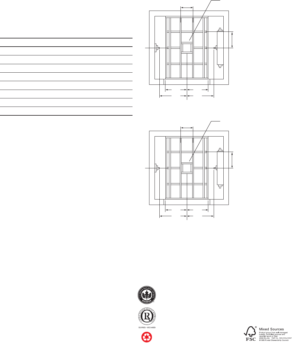
Detail A
Temporary work platform
2100 lb capacity car
2x8 studs as shown, spacing
not to exceed 16” at any time
center of car platform
2’-6” 2’-6”
3’-0” 3’-0”
2x8 studs as shown, spacing
not to exceed 16” at any time
2x8 studs as shown, spacing
not to exceed 16” at any time
2x8 studs as shown, spacing
not to exceed 16” at any time
center of rail
12” x 12” square cutout
12” x 12” square cutout
center of car platform
3’-0” 3’-0”
3’-6” 3’-6”
center of rail
2500 lb, 3000 lb and 3500 lb capacity cars
Notes:
1. All 2x8s to be grade 2, Douglas Fir, free of knots.
2. Platform to be covered by .75’ plywood.
3. Plywood decking to be .75’ thick CDX grade, tongue and groove.
4. Platform mounting to hold load of 1500 lb.
For further information, including location of
the Schindler offi ce nearest you, please contact:
U.S. Headquarters. Morristown, New Jersey
Tel. 973.397.6500
www.us.schindler.com
Canada Headquarters. Scarborough, Ontario
Tel. 416.332.8280
www.ca.schindler.com
Schindler has received renewal to ISO 14001:2004
and ISO 9001:2008 certifi cates.
Schindler is a member organization of the
U.S. Green Building Council.
Schindler prints with vegetable-based ink on
paper containing post-consumer waste fi ber.
