3330 DDC.ib.Rev6 DDC_ib_Rev6 DDC Ib Rev6
User Manual: 3330-DDC_ib_Rev6
Open the PDF directly: View PDF ![]() .
.
Page Count: 12

3330-ddc.ib.rev6.doc page 1 of 10 17/10/2007
IRT Eurocard
Type DDC-3330
ASI to SPI Converter
Designed and manufactured in Australia
IRT can be found on the Internet at:
http://www.irtelectronics.com
I R T Electronics Pty Ltd A.B.N. 35 000 832 575
26 Hotham Parade, ARTARMON N.S.W. 2064 AUSTRALIA
National: Phone: (02) 9439 3744 Fax: (02) 9439 7439
International: +61 2 9439 3744 +61 2 9439 7439
Email: sales@irtelectronics.com
Web: www.irtelectronics.com

3330-ddc.ib.rev6.doc page 2 of 10 17/10/2007
IRT Eurocard
Types DDC-3330
ASI to SPI Converter
Instruction Book
Table of Contents
Section Page
Operational Safety 2
General description 3
Technical specifications 4
Technical description 5
Internal adjustments 6
Configuration 6
Installation 6
Connections - ASI & SPI 7
ASI 7
SPI 7
Front & rear panel connector diagrams 8
Maintenance & storage 9
Warranty & service 9
Equipment return 9
Drawing index 10
This instruction book applies to units later than S/N 9907000.
Operational Safety:
WARNING
Operation of electronic equipment involves the use of voltages and currents that
may be dangerous to human life. Note that under certain conditions dangerous
potentials may exist in some circuits when power controls are in the OFF position.
Maintenance personnel should observe all safety regulations.
Do not make any adjustments inside equipment with power ON unless proper
precautions are observed. All internal adjustments should only be made by suitably
qualified personnel. All operational adjustments are available externally without the
need for removing covers or use of extender cards.
3330-ddc.ib.rev6.doc page 3 of 10 17/10/2007
General description
The DDC-3330 series is part of a family of data transcoders for converting between the MPEG2 Transport Stream
formats commonly used in the broadcast industry for program distribution.
Equipment is built to perform a specific task and is provided with inputs and outputs suitable to performing that
task. As systems are built from individual pieces of equipment the need arises to provide interfaces between the
various formats. The DDC-3330 provides conversion from ASI to SPI and conversely, the DDC-3340 provides
conversion from SPI to ASI.
ASI:
ASI MPEG data is transported in a 270 Mb/s signal regardless of the underlying data rate. It is a convenient and
relatively inexpensive way of transporting data. ASI signals may be transported over good quality 75 Ohm coaxial
cable for distances of up to 300 m, but it is recommended that in actual practice cable lengths be kept to less than
100 m.
Where greater distances are involved, distribution amplifiers may be used to re-equalise the signal at intervals along
the path.
Alternatively, consideration should be given to using the IRT DVT-3210 / DVR-3210 fibre optic link, which will
transport ASI signals over single mode fibre optic cable for distances up to 60 Km (dependent on fibre losses).
SPI:
The SPI interface is a ten bit wide parallel interface with a synchronous clock signal. Each of the eleven signals is
sent using LVDS drivers (Low Voltage Differential Signalling). This results in a word (or byte) parallel signal at
less than a 1/10th the bit rate of ASI, making it ideal for processing, but is not suitable for use with anything other
than very short cable connections. For practical purposes 5 metres is suggested as a maximum. Where longer
distances are involved, the SPI signal should be converted to ASI and run using coaxial cable or fibre links.
The DDC-3330 module should therefore be located as close as possible to the connected SPI equipment, rather than
the ASI equipment.
The DDC-3330 does not perform any signal correction or alter the format of the MPEG2 transport stream. It only
decodes and de-serialises the ASI input and monitors the signal for MPEG2 transport stream sync errors.
Standard features:
• Transparent ASI to SPI conversion.
• One module covers data rates from 1.5 Mb/s to 50 Mb/s.
• Block length indication (188/204).
Related equipment:-
FRU-3000 Eurocard module mounting frame Mounts up to 12 Eurocard modules and one PT-700
Dual AC power supply side by side in 134 mm of
standard rack space (3 Rack Units).
FRU-1030 1 RU chassis conversion/PSU Converts Eurocards to a 1 rack unit format. The
FRU-1030 can be fitted with either one or two
Eurocards in a horizontal side by side format. A
single AC power supply is included to power the
cards.
TME-6 Eurocard extender board.
3330-ddc.ib.rev6.doc page 4 of 10 17/10/2007
Technical specifications
IRT Eurocard module
Type DDC-3330
MPEG:
Input:
Type 1 x ASI-C.(EN50083-9)
Input impedance 75Ω.
Signal level 800 mVp-p.
MPEG data rate From 2 to 50 Mb/s.
Cable compensation Automatic; better than 300 metres at 270 Mb/s for Belden 8281 or PSF1/2 cable.
Connector BNC.
Outputs:
SPI 1 x SPI (EN50083-9)
Connector 25 pin 'D' female.( to EN50083-9 Table 1)
Indicators:
Power LED (green) for +5 V.
Input LED (red).
Sync LED (red).
188 LED (green).
204 LED (Green).
Power Requirements 28 Vac CT (14-0-14) or ± 16 Vdc.
Power consumption <7 VA.
Other:
Temperature range 0 - 50° C ambient
Mechanical Mounts in IRT FRU-1030 19" 1 RU frame with input and output connections on
the rear panel.
Finish: Front panel Grey enamel, silk-screened black lettering & red IRT logo
Rear assembly Detachable silk-screened PCB with direct mount connectors
to Eurocard and external signals
Dimensions 6 HP x 3 U x 220 mm IRT Eurocard
Supplied accessories Rear connector assembly including matching connector for alarm output.
Related products DDC-3340 – SPI to ASI 1.5 to 50 Mb/s
DDC-3460 - G.703 to SPI & ASI.
DDC-3470 - SPI to G.703 & ASI with encode & decode processing.
DDC-3475 - SPI to G.703 & ASI without processing.
3330-ddc.ib.rev6.doc page 5 of 10 17/10/2007
Technical description
LED Indicators.
INPUT Illuminates red if 8B/10B coding errors are detected in ASI stream.
SYNC Indicates a FIFO underflow or overflow.
188 Indicates that the last four P_syncs were 188 byte apart.
204 Indicates that the last four P_syncs were 204 byte apart
Data Valid (D_val) .
D_val output is always high for 188 byte packets and for 204 byte packets it is high except for bytes 189 to
204 – regardless of the content of these 16 bytes.
Output Clock Jitter.
Minimum clock jitter is achieved when the P_syncs in the ASI stream are linearly distributed. As the output
clock phase is determined by P_syncs only the distribution of the other bytes is immaterial.
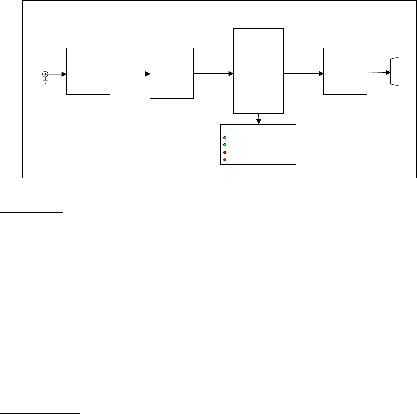
DDC-3330 ASI to SPI Converter
Input
Equaliser
Serial
to
Parallel
Output
Drivers
Sync
Detection
and
P_clock
generation
Alarms & indications
188 BYTE BLOCK
204 BYTE BLOCK
SYNC ERROR
INPUT LOSS
SPI
Output
ASI
(270 Mb/s) coax
Input

3330-ddc.ib.rev6.doc page 6 of 10 17/10/2007
Internal adjustments
The following adjustable resistors are factory set.
They must not be adjusted by the user. Adjustment requires specialised equipment and procedures that are not
possible outside the factory.
RV 1 Not fitted
RV 2 Phase lock integrator
RV 3 P_Clock symmetry
Configuration
The DDC-3330 has no user configurable adjustments.
Installation
Operational Safety:
WARNING
Operation of electronic equipment involves the use of voltages and currents that
may be dangerous to human life. Note that under certain conditions dangerous
potentials may exist in some circuits when power controls are in the OFF position.
Maintenance personnel should observe all safety regulations.
Do not make any adjustments inside equipment with power ON unless proper
precautions are observed. All internal adjustments should only be made by suitably
qualified personnel. All operational adjustments are available externally without the
need for removing covers or use of extender cards.
Pre-installation:
Handling:
This equipment may contain or be connected to static sensitive devices and proper static free handling precautions
should be observed.
Where individual circuit cards are stored, they should be placed in antistatic bags. Proper antistatic procedures
should be followed when inserting or removing cards from these bags.
Power:
AC mains supply: Ensure that operating voltage of unit and local supply voltage match and that correct
rating fuse is installed for local supply.
DC supply: Ensure that the correct polarity is observed and that DC supply voltage is maintained within
the operating range specified.
Earthing:
The earth path is dependent on the type of frame selected. In every case particular care should be taken to ensure
that the frame is connected to earth for safety reasons. See frame manual for details.
Signal earth: For safety reasons a connection is made between signal earth and chassis earth. No attempt should be
made to break this connection.
3330-ddc.ib.rev6.doc page 7 of 10 17/10/2007
Installation in frame or chassis:
See details in separate manual for selected frame type.
Connections:
ASI:
ASI MPEG data is transported in a 270 Mb/s signal regardless of the underlying data rate. Therefore, all cabling and
connectors should be of high quality and have a true 75 Ohm characteristic impedance.
ASI signals may be transported over good quality 75 Ohm coaxial cable for distances of up to 300 m, but again it is
recommended that in actual practice cable lengths be kept to less than 100 m.
Where greater distances are involved, distribution amplifiers may be used to re-equalise the signal at intervals along
the path.
Alternatively, consideration should be given to using the IRT DVT-3210 / DVR-3210 fibre optic link, which will
transport ASI signals over single mode fibre optic cable for distances up to 60 Km (dependent on fibre losses).
Electrical characteristics ASI:
Transmitter output characteristics:
Output voltage 800 mVp-p ±10%.
Deterministic jitter <10% p-p.
Random jitter <8% p-p.
Rise/fall time (20-80%) <1.2 ns.
Receiver input characteristics:
Minimum sensitivity (D21.5 idle pattern) 200 mV
Maximum input voltage 880 mVp-p
s11 (range: 0.1 to 1.0 x bit rate) -17 dB
Minimum discrete connector return loss 15 dB (5 MHz - 270 MHz)
Coaxial link:
Impedance 75 Ohm.
Equipment connector BNC female.
(Electrical measurements made with 75 Ohm resistive termination.)
SPI:
The SPI interface is a ten bit wide parallel interface with a synchronous clock signal. Each signal is sent using
LVDS drivers (Low Voltage Differential Signalling).
This means that a balanced pair is required for each signal, entailing a total of twenty two signal wires plus at least
one ground connection. A twenty five pin ‘D’ connector is standard for this system.
The SPI interface is not suitable for use with anything other than very short cable connections. For practical
purposes 5 metres is suggested as a maximum. Where longer distances are involved, the SPI signal should be
converted to ASI and run using coaxial cable or fibre links.
The DDC-3330 module should therefore be located as close as possible to the connected SPI equipment, rather than
the ASI equipment.
Good quality cable and connectors must be used. For EMC it is necessary to use only ‘D’ connectors with full metal
shells and the cable outer screen should be properly connected to the shell. Unshielded cables must not be used at
all.
The ‘D’ connectors should have their securing screws firmly screwed down to ensure a continuous earth shroud is
maintained. These screws are not simply to ensure that the connector does not become unplugged, they are an
integral part of the EMC screening and signal connection.
Electrical characteristics SPI:
Line Driver Characteristics (Source)
Output impedance 100 Ω maximum
Common mode voltage 1.125 V to 1.375 V
Signal amplitude 247 mV to 454 mV
Rise and fall times < T/7, measured between the 20% and 80% amplitude points, with a 100 Ω resistive load.
The difference between rise and fall times shall not exceed T/20.
Line Receiver Characteristics (Destination)
Input impedance 90 Ω to 132 Ω
Maximum input signal 2.0 Vp-p
Minimum input signal 100 mVp-p
3330-ddc.ib.rev6.doc page 8 of 10 17/10/2007
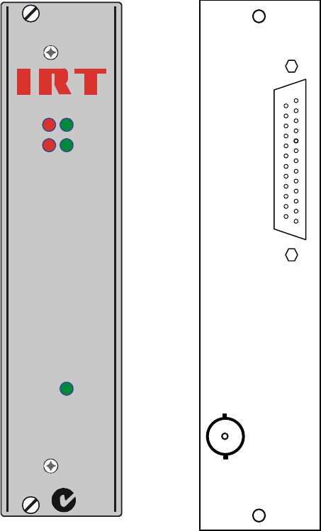
Front & rear panel connector diagrams
The following front panel and rear assembly drawings are not to scale and are intended to show relative positions of
connectors, indicators and controls only.
INPUT
SYNC 204
188
DC
DDC-3330
N140
3330
25
1
SPI OUT
A
SI IN
3330-ddc.ib.rev6.doc page 9 of 10 17/10/2007
Maintenance & storage
Maintenance:
No regular maintenance is required.
Care however should be taken to ensure that all connectors are kept clean and free from contamination of any kind.
This is especially important in fibre optic equipment where cleanliness of optical connections is critical to
performance.
Storage:
If the equipment is not to be used for an extended period, it is recommended the whole unit be placed in a sealed
plastic bag to prevent dust contamination. In areas of high humidity a suitably sized bag of silica gel should be
included to deter corrosion.
Where individual circuit cards are stored, they should be placed in antistatic bags. Proper antistatic procedures
should be followed when inserting or removing cards from these bags.
Warranty & Service
Equipment is covered by a limited warranty period of three years from date of first delivery unless contrary
conditions apply under a particular contract of supply. For situations when “No Fault Found” for repairs, a
minimum charge of 1 hour’s labour, at IRT’s current labour charge rate, will apply, whether the equipment is within
the warranty period or not.
Equipment warranty is limited to faults attributable to defects in original design or manufacture. Warranty on
components shall be extended by IRT only to the extent obtainable from the component supplier.
Equipment return:
Before arranging service, ensure that the fault is in the unit to be serviced and not in associated equipment. If
possible, confirm this by substitution.
Before returning equipment contact should be made with IRT or your local agent to determine whether the
equipment can be serviced in the field or should be returned for repair.
The equipment should be properly packed for return observing antistatic procedures.
The following information should accompany the unit to be returned:
1. A fault report should be included indicating the nature of the fault
2. The operating conditions under which the fault initially occurred.
3. Any additional information, which may be of assistance in fault location and remedy.
4. A contact name and telephone and fax numbers.
5. Details of payment method for items not covered by warranty.
6. Full return address.
7. For situations when “No Fault Found” for repairs, a minimum charge of 1 hour’s labour will apply,
whether the equipment is within the warranty period or not. Contact IRT for current hourly rate.
Please note that all freight charges are the responsibility of the customer.
The equipment should be returned to the agent who originally supplied the equipment or, where this is not
possible, to IRT direct as follows.
Equipment Service
IRT Electronics Pty Ltd
26 Hotham Parade
ARTARMON
N.S.W. 2064
AUSTRALIA
Phone: 61 2 9439 3744 Fax: 61 2 9439 7439
Email: service@irtelectronics.com
3330-ddc.ib.rev6.doc page 10 of 10 17/10/2007
Drawing index
Drawing # Sheet # Description
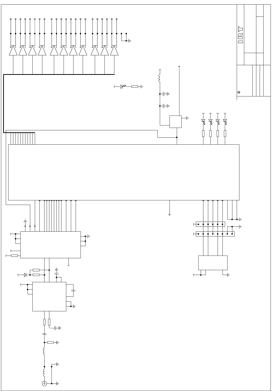
804211 1 DDC-3330 signal processing diagram
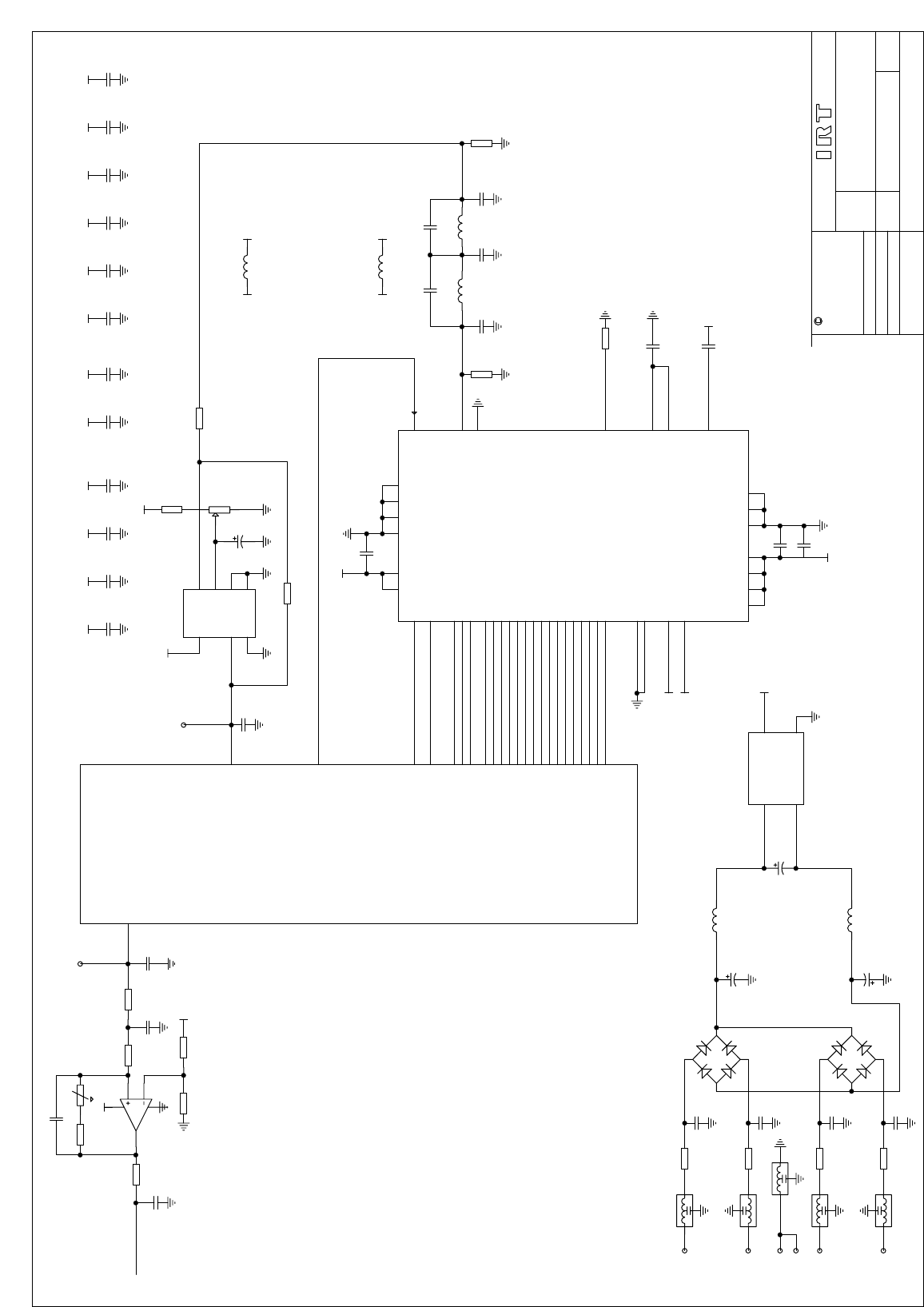
804211 2 DDC-3330 clock circuit schematic
TITLE
SCALE
SIZE
SHEET
DRAWN
CHECKED
ENG. APP.
CONTRACT No.
DO NOT COPY NOR
DISCLOSE TO ANY
THIRD PARTY
WITHOUT WRITTEN
CONSENT
OF12
IRT Electronics Pty. Ltd.
804211DRAWING No.
COPYRIGHT
ARTARMON NSW AUSTRALIA 2064
A3
1 10/6/1995
RVS
D0
D1
D2
D3
D4
D5
D6
D7
REFCLK
23 4 2124 9
6820
26
25
5
7
18
17
16
15
14
13
12
11
19
10
22
2
1
13
14
124
8
9
11 10 6 7
12
5
DATA0
DATA1
DATA2
DATA3
DATA4
DATA5
DATA6
DATA7
CLOCK
DVALID
PSYNC
10
23
9
22
8
21
7
20
6
19
5
18
4
17
3
16
11
24
12
25
27MHz
OSC
14
7
+5
+5
+5
+5
9
1
2
3
4
5
6
10
1
3
4
2
8
7
5
EPC1441
DCLK
ConfDone
nConf
nStatus
DATA0
mSel0
mSel1
nCE
CLC014
CY7B933
55
EPF10K10
DS90C031TM
7
1
9
15
13
14
11
10
3
2
5
6
VCC = 16
GND = 8
EN = 4,12
28
27
3
8
8
8
7
7
7
7
6
6
6
8
8
6
5
2
3
10
11
14
13
2
3
10
11
14
13
7
1
9
15
1
9
15
61
62
73
71
72
70
69
66
67
65
64 10b
10a
9b
9a
8b
8a
7b
7a
6b
6a
5b
5a
4b
4a
3b
3a
1b
1a
11b
11a
12b
12a
31a,b
1Psync
1Dvalid
1Clock
1data0
1data7
Mclock
Arf
ArdyNot
AscNotD
Ackr
13
76
34
12
31
32
14
84 plcc
GND = 26,41,46,68,82
U1
U2
A/!B
-
+
59
58
44
47
48
49
50
51
52
53
42
54
43
1
U5
BB1 RP2
U12
39
79
80
81
83
XTAL1
+5
32a,b
TP1 78
13a
13b
Svdd
Svdd
Svdd
Svdd Svdd
Dvdd Dvdd Dvdd
Dvdd = 4,20,33,40,45,63
+5
1
14
1K
1 FROM SH2
= VCC
DDC-3330
ASI TO SPI CONVERTER
+5
L1
IND R1
75
C1
100n R2
100
R3
100
C2
100n
21
D1
D
C4
100n
C3
100p
21
LED1
21
LED3
21
LED4
21
LED2
L9
IND
R5
75
R4
75
R6
4K7
CD12
100n
CD11
10uF
SK2
R27
560
R12 470
R13 470
R14 470
R15 470
21
LED5
LED
L2
IND
TITLE
SCALE
SIZE
SHEET
DRAWN
CHECKED
ENG. APP.
CONTRACT No.
DO NOT COPY NOR
DISCLOSE TO ANY
THIRD PARTY
WITHOUT WRITTEN
CONSENT
OF22
IRT Electronics Pty. Ltd.
804211DRAWING No.
COPYRIGHT
ARTARMON NSW AUSTRALIA 2064
A3
FSEL
!WR
A0
A1
A2
D0
D1
D2
D3
D4
D5
D6
D7
D8
D9
D10
D11
D12
D13
D14
D15
PSEL0
PSEL1
!SLEEP
!RESET
Avdd
Iout
FS ADJ
REFOUT
REFIN
COMP
MCLK
Avdd
38 43 36 39 41 46
4 5 9 25 6 13 29
AD9830
1
2
3
7
8
10
11
12
14
15
16
17
18
19
20
21
22
23
24
26
27
28
30
31
32
33
34
ST-48
21a,b
22a,b
23a,b
24a,b
25a,b
26a,b
ZS1
DDSFsel
1wrNot
DDSA0
DDSA1
DDSA2
DDSdata
U5
U9
29
30
3
5
6
7
8
9
10
11
16
17
18
19
21
22
23
24
25
27
28
44
45
47
48
35
+5
Avdd
Dvdd
Dvdd
+5
+5Dvdd
Avdd
Svdd Svdd Svdd Svdd Svdd SvddDvddDvdd DvddDvdd Dvdd Dvdd
AVdd
AVdd
Dvdd
7
4
6
2
3
38
35
2
2 28/10/98
TO SHT 1
Phase
DDSclock
Dclockin
4
3
2
18
5
6
7
Q
+
-
Dvdd
MAX961
Tdata
Tclk
39
37
U10
DDC-3330
ASI TP SPI CONVERTER
DCLK
PH
3 20/09/00
ECR1131
1 3
2
FL1
1 3
2
FL3
1 3
2
FL4
FS1
R
FS2
R
FS3
R
FS4
R
DB1
DB2
L2
IND
L3
IND
1 3
2
FL2
1 3
2
FL5
CD2
C
CD3
C
CD4
C
CD5
C
CD6
C
CD13
C
CD24
C
CD25
C
CD26
C
CD27
C
L8
IND
L7
IND
CD21
10uF
CD1
100n
CD7
100n
CD9
100n
CD10
100n
C22
CP
C23
CP
C24
CP
C15
100n
C14
100n
C18
100n
U11
MC33201
C9
220p
L4
3u3
C10
39p
C11
390p
C12
100p
L5
2u7
C13
270p
C20
CP
R7 18K
C21
100p
CD14
CD15
CD16
CD17
R22 10K
R21
22K
R20 10K R19 10K
R24 10K
R23 10K
R25
100R
R26
220
R3
500R
R16
100
R17
1K
R18
1K
RV2
10K
C17
56p
R35
470p
