33 846 01_VTG_400_label_Rev A_101204_ VTG 400/400D 01 A VTG400 101504
User Manual: VTG 400/400D
Open the PDF directly: View PDF ![]() .
.
Page Count: 1
VTG 400, VTG 400D
Extron Electronics, USA
1230 South Lewis Street
Anaheim, CA 92805
USA
714.491.1500
Fax 714.491.1517
Extron Electronics, Europe
Beeldschermweg 6C
3821 AH Amersfoort
The Netherlands
+31.33.453.4040
Fax +31.33.453.4050
Extron Electronics, Asia
135 Joo Seng Road, #04-01
PM Industrial Building
Singapore 368363
+65.6383.4400
Fax +65.6383.4664
Extron Electronics, Japan
Daisan DMJ Building 6F
3-9-1 Kudan Minami
Chiyoda-ku, Tokyo 102-0074 Japan
+81.3.3511.7655
Fax +81.3.3511.7656
www.extron.com
33-846-01
Rev. A
10 04
Printed in USA
Quick Select Preset Buttons
Scope Trigger Adjustments
Up to four video and/or audio settings can
be saved by pressing one of the four Quick
Select buttons for about 2 seconds until the
Quick Select setup menu appears.
1. Press the and on-screen
buttons to select Audio settings, Video
settings, or All settings (Audio and Video).
2. Press to save the setting(s) to
the Quick Select button or press
to cancel the operation and not save the
setting(s) to the Quick Select button.
Recalling a Preset
Press the desired Quick Select button to
recall the stored settings.
Audio Setup menu
• Audio level units: dBu or dBv
• Output 2 enable: left & right
channel output, left output, or
right output
• Burst interval (cycles per
interval): from 00001 to 65535
• Burst on (cycles per burst): from
00001 to 65535, must be < or =
to burst interval
• Frequency sweep start freq.:
20.0 Hz to 19.0 kHz
• Frequency sweep ending (stop)
frequency (21.2 Hz to 20.0 kHz)
• Frequency sweep format:
logarithmic (default) or linear
• Frequency sweep direction:
low- to-high (start freq. to stop
freq.) (default) or high-to-low
(stop to start)
• Audio mute: on or off (default)
• Square wave automatic
attenuation: on (autoattenuate
to -40 dBu) or off (default)
Video Setup menu
• RGB sync format: RGBHV (de-
fault), RGBS, RGsB, or RsGsBs
Scope trigger cursor buttons
Press the and selection buttons to
move the trigger point between lines
(y-axis) and press the and selection
buttons to move the trigger point between
pixels (x-axis) on the current line.
Scope trigger shape button
Press the Shape button to toggle the on-
screen cursor’s shape between crosshairs
(useful for locating the cursor on the display
screen) and single pixel (useful for locating
the cursor on the oscilloscope screen).
Scope trigger hide button
Press the Hide button to toggle the cursor
on (visible) and off (hidden).
SAVE
CANCEL
Button Lock Mode
Press and hold the Signal Type
and
Test Pattern buttons simul-
taneously
for 2 seconds to enable/
disable the top panel buttons.
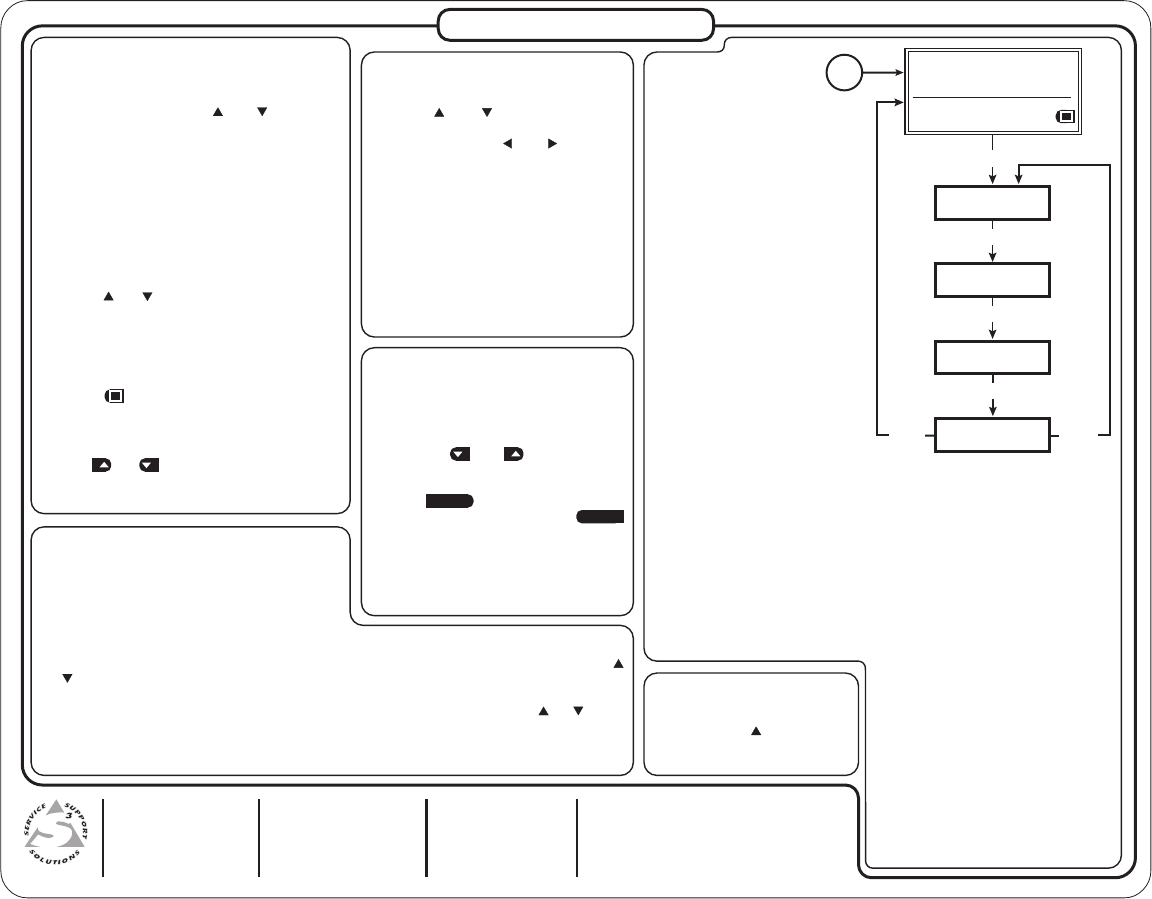
Menu
Adjustments
Press the Menu and Next buttons
to navigate through the menus.
Use the four arrow selection
buttons adjacent to the LCD to
make changes to the settings.
• Raster border: 1-pixel white border on
or off (default)
• On-screen display: on or off (default)
• Autosequence mode: on or off
(default)
• Autosequence interval (display period
per test pattern): 15 sec. (default), 30
sec., 60 sec.
• RGB color channel enable: enable (on)
or disable (off) red, green, and/or blue
channels (default = all channels on)
Advanced Setup menu
• Timeout interval (for screensaver): 5
(default), 10, 15, or 30 minutes, or
never
• Screensaver mode: blank (black
screen, default), or cycle (through test
patterns in 4-second intervals)
• LCD display contrast: level 000
through 063
• System reset (to default settings): yes
or no; if yes is selected, a confirmation
menu appears. Custom rates are not
affected or overwritten during reset.
Video Adjustments
Test pattern selection buttons
Depending on the currently selected video rate,
press the Video Test Pattern and selection
buttons to select from up to 28 different video test
patterns. The LCD displays the newly selected test
pattern’s name for 3 seconds before returning to
the previous menu. Refer to the test pattern chart
in Appendix A of the user’s manual for the table of
available test patterns and their features.
Video output range button
Press the Video Range button to select from
among eight output range categories.
Video output rate buttons
Press the and Video Rate buttons to select an
output rate for the chosen output range. The output
rates are displayed two-at-a-time on the LCD. After
choosing the desired rate, press the Select button
to activate the highlighted rate.
Test pattern invert
/
special function button
Press the button to toggle the selected test
pattern between normal and inverted (special)
state (when available).
Video level adjustment buttons
Use the and buttons (next to pattern name)
to adjust the test pattern’s video level between 0%
(0 IRE) and 100% (100 IRE), when available.
Audio Adjustments
Signal type selection button
The VTG 400/400D can selectively output seven
different audio signal formats: pink noise, white
noise, sine wave, square wave, frequency sweep,
polarity test, and sine burst.
Audio level selection buttons
The RMS audio output level for each audio signal type is selected from a range of values using the
or Level buttons.
Audio frequency selection buttons
The frequency for each audio signal type is selected from a range of values using the or Audio
Frequency buttons. The following frequency adjustments are available for the signal types below:
• Sine wave and sine burst: 20 Hz - 20 kHz in 1/12 octave steps
• Square wave: 20 Hz - 5 kHz in 1/12 octave steps • Frequency sweep speed: 1 - 120 seconds
AUDIO
SETUP
MENU
MENU
VIDEO
SETUP
MENU
ADVANCED
SETUP
MENU
NEXT
MENU
EXIT MENU
Press "NEXT" button
Power
on
RES: VGA 640x480
FRQ: 31.50kHz 60.00Hz
PAT: Fine Crosshatch
SIG: Pink noise FRQ: N/A
LEV: -10 dBu 245mV
