3494 Maintenance Procedures Tape Library Magstar
User Manual: Tape Library Magstar 3494
Open the PDF directly: View PDF ![]() .
.
Page Count: 29
Maintenance Procedures Version 1.1 29 September 2004 Page 1 of 29
Copyright Total RISC Technology Pty Ltd. 2004
IBM Magstar 3494 Tape Library
Maintenance Procedures

Maintenance Procedures Version 1.1 29 September 2004 Page 2 of 29
Copyright Total RISC Technology Pty Ltd. 2004
Contents
1 Introduction ............................................................................................................... 3
1.1 Overview....................................................................................................................... 3
1.2 Education...................................................................................................................... 3
2 Safety and Inspection ............................................................................................... 4
2.1 General Information....................................................................................................... 4
2.2 Preparation ................................................................................................................... 4
2.3 Branch Circuit CB Switched Off Check.......................................................................... 5
2.4 Branch Circuit CB Switched On Check................................ ................................ .......... 6
2.5 Safety Labels and AC Grounds................................................................ ..................... 7
2.6 Safety Labels and Grounds for the Model L1x............................................................... 7
2.7 Safety Labels and Grounds for the Model D1x.............................................................. 8
2.8 Safety Labels and Grounds for the Model S10.............................................................. 8
2.9 Safety Engineering Changes................................ ................................ ......................... 9
2.10 Safety Checks................................ ................................ ................................ ............... 9
2.11 Completion Report and Signature ................................................................ ............... 10
2.11.1 Safety Hazards.................................................................................................................................10
3 Library Information Tables ..................................................................................... 11
3.1 General Information..................................................................................................... 11
3.2 ARTIC Port Assignments – Figure 272........................................................................ 12
3.3 Teach Configuration – Figure 284 ................................ ................................ ............... 13
3.4 General Library Information – Figure 285................................ ................................ .... 15
3.5 Device Attachment Configuration ................................................................ ................ 17
3.6 Remote Support Information – Figure 286................................ ................................ ... 18
3.7 LAN Information – Figure 287 ................................ ..................................................... 19
4 Library Verification Checklist................................................................................. 20
4.1 General Information..................................................................................................... 20
5 Preventive Maintenance (PM)................................................................................. 22
5.1 General Information..................................................................................................... 22
5.2 Supplies needed ................................................................................................ ......... 22
5.3 Procedure ................................................................................................................... 22
5.4 Operational Logs................................................................ ......................................... 24
5.4.1 Error Logs ........................................................................................................................................ 24
6 Appendix A – ECAs ................................................................................................. 25
6.1 Engineering Change Announcements (Sept-2004) ..................................................... 25
7 Appendix B – SMs ................................................................................................... 28
7.1 Safety Service Memorandums (Sept-2004)................................ ................................ . 28

Maintenance Procedures Version 1.1 29 September 2004 Page 3 of 29
Copyright Total RISC Technology Pty Ltd. 2004
1 Introduction
1.1 Overview
The procedures in this document ensure that a 3494 not under a TRT maintenance agreement has
the necessary prerequisites installed and available to ensure a transparent transition and an
uninterrupted maintenance service during the period of the TRT maintenance agreement.
1.2 Education
All service personnel must be trained on the general maintenance agreement qualification, tailored
maintenance agreement qualification, and changed machine safety inspection procedures as part of
becoming a TRT Technical Service Representative (TSR). In addition, service personnel must also
be trained on the 3494 prior to servicing the equipment.

Maintenance Procedures Version 1.1 29 September 2004 Page 4 of 29
Copyright Total RISC Technology Pty Ltd. 2004
2 Safety and Inspection
2.1 General Information
The safety checklist procedures in this topic ensure that a 3494 not under a TRT maintenance
agreement has the necessary safety items installed and that no changes made it unsafe. Each 3494,
as designed and assembled, has safety items installed to protect operators and service personnel
from injury. These checklist procedures verify only these items.
The safety checklist procedures must be performed before the normal inspection for a maintenance
agreement. The 3494 must be considered unsafe until the presence and condition of all checklist
items are verified. If any unsafe conditions are present, you must decide how serious the hazard is
and whether you can continue without first correcting the problem.
When performing the safety checklist procedures, consider the following conditions and the potential
safety hazards they present:
• Electrical, especially primary power. For example, an electrically charged frame can cause
serious or lethal electrical shock.
• Explosive. For example, damaged or expanding capacitors can cause serious injury.
• Mechanical hazards, such as missing safety covers, can cause injury to service personnel.
2.2 Preparation
The following reference items are useful during the inspection:
• The LOC section of the 3494 Maintenance Information manual
• Copies of safety service memorandums (SMs) (see Appendix B) and engineering change
announcements (ECAs) (see Appendix A) for this machine type
• Parts catalog
• 3494 history
• Electrical Safety for TRT Technical Service Representatives

Maintenance Procedures Version 1.1 29 September 2004 Page 5 of 29
Copyright Total RISC Technology Pty Ltd. 2004
2.3 Branch Circuit CB Switched Off Check
Task Date Owner ü / û
1. Locate and switch off the circuit breaker (CB) for the 3494
branch circuit that supplies voltage to each receptacle TRT /
Customer
2. Perform one of the following for each receptacle:
Note: There is a line cord for each control unit frame and drive
unit frame in the library.
• If this is a metal clad connector, perform the
“Safe-to-Handle Check” and the Disconnect
Precautions” procedures in Electrical Safety for
TRT Technical Service Representatives. (These
procedures are described under “Miscellaneous
Safety Tips.”)
• If the power cord has an insulated plug, grip the
plug without touching any metal parts, and
remove the plug from the customer power
receptacle
TRT /
Customer
3. Perform the “Power Receptacle Safety Check” in Electrical
Safety for TRT Technical Service Representatives TRT
4. DANGER Hazardous voltages are present. Do not touch
the internal parts (pins and sockets) of the outlet.
• Measure the phase-to-ground voltage at each
receptacle
• If a neutral is present, measure the phase-to-
neutral voltage, phase-to-ground voltage, and the
neutral-to-ground voltage
• If all voltage values are not less than 1.0 V ac,
have an electrician check the circuit
TRT

Maintenance Procedures Version 1.1 29 September 2004 Page 6 of 29
Copyright Total RISC Technology Pty Ltd. 2004
2.4 Branch Circuit CB Switched On Check
Task Date Owner ü / û
1. Switch on the CB that supplies voltage to each receptacle
for the library TRT /
Customer
2. DANGER Hazardous voltages are present. Do not touch
the internal parts (pins and sockets) of the outlet.
• Measure the phase-to-ground voltage at each
receptacle
• If a neutral is present, measure the phase-to-
neutral voltage, phase-to-ground voltage, and the
neutral-to-ground voltage
• Record the voltages for future reference in the
checklist shown in the following table
TRT
3. Switch off the branch circuit CB before connecting the
machine power cord into the outlet TRT /
Customer
Voltage Checklist
Date Description of circuits
checked Voltage
Values Comments TSR

Maintenance Procedures Version 1.1 29 September 2004 Page 7 of 29
Copyright Total RISC Technology Pty Ltd. 2004
2.5 Safety Labels and AC Grounds
Understand the meaning of the safety labels before beginning any repair of a component with a
label.
Check that the labels are located where shown in following figures. Make any necessary corrections.
See IBM 3494 Tape Library Dataserver Parts Catalog for part numbers of labels in the various
languages.
2.6 Safety Labels and Grounds for the Model L1x
Maintenance Procedures Version 1.1 29 September 2004 Page 8 of 29
Copyright Total RISC Technology Pty Ltd. 2004
2.7 Safety Labels and Grounds for the Model D1x
Use the previous figure keys 6 through 8 and 10 through 12 for the locations of the safety labels and
grounds in the drive unit frame.
2.8 Safety Labels and Grounds for the Model S10
The storage unit frame does not contain any safety labels or grounds.

Maintenance Procedures Version 1.1 29 September 2004 Page 9 of 29
Copyright Total RISC Technology Pty Ltd. 2004
2.9 Safety Engineering Changes
Task Date Owner ü / û
1. All safety engineering changes (ECs) have been installed
correctly TRT
2. The location or list of engineering change announcements
(ECAs) is accessible TRT
2.10 Safety Checks
The 3494 must be powered off with the power cable disconnected.
Task Date Owner ü / û
1. All hinges and latches are in acceptable operating condition
and are not broken or corroded TRT
2. All door interlocks and safety switches are operating and
are not bypassed with jumpers or taped closed TRT
3. All ac line cords are not frayed or damaged TRT
4. All ac line cords have the correct part number
Note: See IBM 3494 Tape Library Dataserver Parts Catalog for
the correct part number for the power cables. See also IBM 3494
Tape Library Dataserver Introduction and Planning Guide
TRT
5. All ground jumpers (normally green and yellow) are tightly
attached. Check that all covers, housings, and metal box
sides have proper ground continuity (less than 0.1 ohm)
TRT
6. All ground connections are tightly attached TRT
7. Check from the library manager chassis to the control unit
frame for proper ground continuity (less than 0.1 ohm) TRT
8. The resistance from the library manager line cord ground
pin to the frame and to the power supply covers must not
be more than 0.1 ohm. For the ground connection
locations, see Figure 211 on page INSP-7
TRT
9. All safety covers (operator and service areas) are in place
including those protecting mechanical devices and hot
surfaces. No sharp corners or edges should be
unprotected. All access covers must be in place
TRT
10. The customer’s circuit breakers and circuit panels for the
3494 frames are identified as 3494 branch circuits TRT
11. All ac output safety covers are installed TRT
12. No obvious non-IBM changes have been made TRT
13. No metal filings, dirt, contaminants, water, or other fluids
are present TRT
14. There are no marks from earlier smoke or burning TRT
15. The ac power supplies are attached tightly in place TRT
16. The ac line cords have no frayed or damaged wiring at the
PCCs TRT
17. The resistance from the line cord ground pins and
housings to all frames and to all power assembly grounds
are:
• Line cord ground pin to frame ground resistance
TRT
Maintenance Procedures Version 1.1 29 September 2004 Page 10 of 29
Copyright Total RISC Technology Pty Ltd. 2004
must not be more than 0.1 ohm
• Line cord housing to frame ground resistance
must not be more than 0.1 ohm
18. All power wiring does not have frayed or damaged wires TRT
19. The dc power supplies are attached tightly in place TRT
20. All circuit breakers are the correct size. See IBM 3494
Tape Library Dataserver Parts Catalog TRT
21. All cables, connections, and plugs do not have frayed or
damaged wiring TRT
22. All latches or clamps are in acceptable condition TRT
2.11 Completion Report and Signature
• Safety inspection for machine type 3494
• General safety inspection
• Maintenance agreement qualification
After the inspection, sign and date the checklist and store it with the maintenance job paperwork.
Name Date
2.11.1 Safety Hazards
List all safety hazards, if there are none, write none.
1.
2.
3.
4.
5.
6.
7.
8.
9.
10.
11.
12.

Maintenance Procedures Version 1.1 29 September 2004 Page 11 of 29
Copyright Total RISC Technology Pty Ltd. 2004
3 Library Information Tables
3.1 General Information
The following library information tables are provided to record vital library information for new
maintenance agreements or new TSRs that may not be familiar with this account.
Complete the following general information tables for this library and place the following sheets (or a
copy) in the clear plastic envelope P/N 1470207 located inside the Model L1x rear door on the top of
the display compartment along with any appropriate local information:
• ARTIC Port Assignments. See Figure 272 or INST-98
• Teach Configuration. See Figure 284 or INST-124
• General Library Information. See Figure 285 or INST-135
• Device Attachment Configuration. DIAG-6
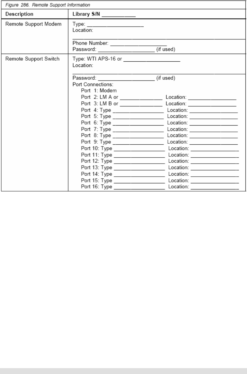
• Remote Support Information. See Figure 286 or INST-137
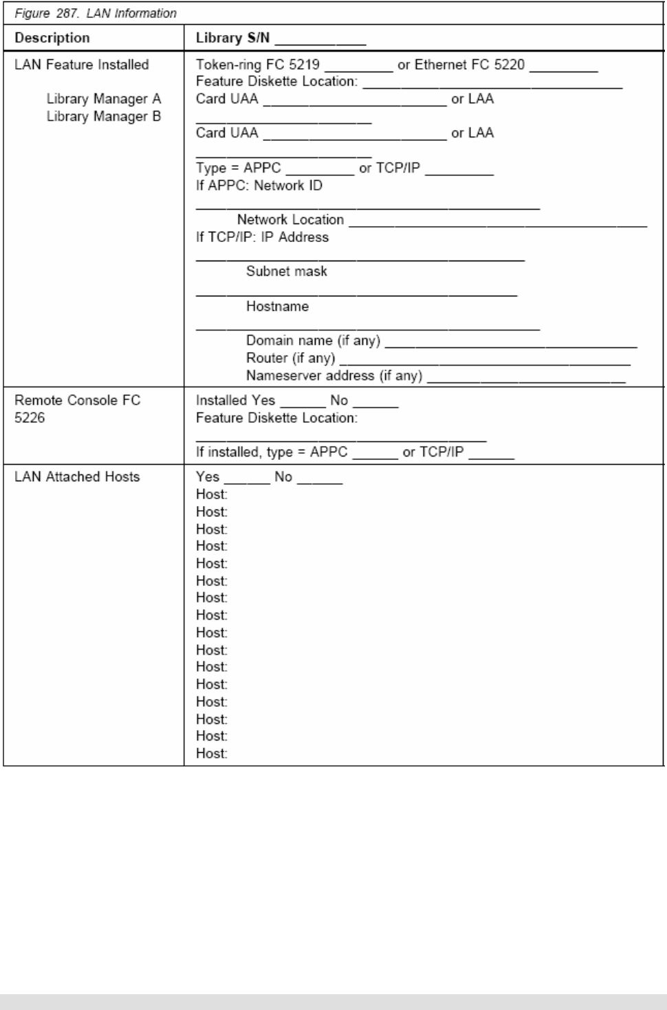
• LAN Information. See Figure 287 or INST-139

Maintenance Procedures Version 1.1 29 September 2004 Page 12 of 29
Copyright Total RISC Technology Pty Ltd. 2004
3.2 ARTIC Port Assignments – Figure 272

Maintenance Procedures Version 1.1 29 September 2004 Page 13 of 29
Copyright Total RISC Technology Pty Ltd. 2004
3.3 Teach Configuration – Figure 284
Maintenance Procedures Version 1.1 29 September 2004 Page 14 of 29
Copyright Total RISC Technology Pty Ltd. 2004

Maintenance Procedures Version 1.1 29 September 2004 Page 15 of 29
Copyright Total RISC Technology Pty Ltd. 2004
3.4 General Library Information – Figure 285
Figure 285. General Library Information
Description Library S/N ______________
LM Hardware Configuration: MT____________
Model_____________
Processor___________________ (chkfins)
Memory____________________ (qphymem)
Disk_______________________ (chkdsk)
Disk_______________________ (chkdsk)
Disk_______________________ (chkdsk)
Disk_______________________ (chkdsk)
Optional LM Features: FC 5050, Dual Active Accessor --------- Yes____ No____
FC 5214, 2nd Disk Drive for LM ----- Yes____ No____
FC 5219, Token Ring Adapter ---------- Yes____ No____ (lancheck)
FC 5220, Ethernet Adapter -------------- Yes____ No____ (lancheck)
FC 5226, LM Remote Console -------- Yes____ No____
FC 5229, Expansion Attachment Card - Yes____ No____
FC _____
FC _____
FC _____
3494 Manuals/Tools:
3494 Operator's Guide
3494 LIC
3494 MI
3494 VTS MI
3494 Tool Kits
3490 _____ MI
3490 _____ MI
3590 _____ MI
3590 _____ MI
Location:
________________________________________________________
Location:
________________________________________________________
Location:
________________________________________________________
Location:
________________________________________________________
Location:
________________________________________________________
Location:
________________________________________________________
Location:
________________________________________________________
Location:
________________________________________________________
Location:
________________________________________________________
ECA’s Installed: ECA ______ Date __________ Comments:
ECA ______ Date __________ Comments:
ECA ______ Date __________ Comments:
ECA ______ Date __________ Comments:
ECA ______ Date __________ Comments:
ECA ______ Date __________ Comments:
ECA ______ Date __________ Comments:
ECA ______ Date __________ Comments:
ECA ______ Date __________ Comments:
ECA ______ Date __________ Comments:
ECA ______ Date __________ Comments:
ECA ______ Date __________ Comments:
ECA ______ Date __________ Comments:
ECA ______ Date __________ Comments:
ECA ______ Date __________ Comments:
ECA ______ Date __________ Comments:
ECA ______ Date __________ Comments:
ECA ______ Date __________ Comments:
ECA ______ Date __________ Comments:
ECA ______ Date __________ Comments:
ECA ______ Date __________ Comments:

Maintenance Procedures Version 1.1 29 September 2004 Page 16 of 29
Copyright Total RISC Technology Pty Ltd. 2004
LM code level: OS/2_________ (syslevel)
LM___________ (chkfins)
Drive code level:
Model _______-_____ Code___________ Location____________
Comments:
Model _______-_____ Code___________ Location____________
Comments:
Model _______-_____ Code___________ Location____________
Comments:
Model _______-_____ Code___________ Location____________
Comments:
Model _______-_____ Code___________ Location____________
Comments:
Model _______-_____ Code___________ Location____________
Comments:
Model _______-_____ Code___________ Location____________
Comments:
Model _______-_____ Code___________ Location____________
Comments:
Model _______-_____ Code___________ Location____________
Comments:
Model _______-_____ Code___________ Location____________
Comments:
Model _______-_____ Code___________ Location____________
Comments:
Model _______-_____ Code___________ Location____________
Comments:
Model _______-_____ Code___________ Location____________
Comments:
Model _______-_____ Code___________ Location____________
Comments:
Model _______-_____ Code___________ Location____________
Comments:
Model _______-_____ Code___________ Location____________
Comments:
Model _______-_____ Code___________ Location____________
Comments:
Model _______-_____ Code___________ Location____________
Comments:
Model _______-_____ Code___________ Location____________
Comments:
Model _______-_____ Code___________ Location____________
Comments:
Model _______-_____ Code___________ Location____________
Comments:
Model _______-_____ Code___________ Location____________
Comments:
Model _______-_____ Code___________ Location____________
Comments:
Model _______-_____ Code___________ Location____________
Comments:
Model _______-_____ Code___________ Location____________
Comments:
Model _______-_____ Code___________ Location____________
Comments:
Model _______-_____ Code___________ Location____________
Comments:
Model _______-_____ Code___________ Location____________
Comments:
Model _______-_____ Code___________ Location____________
Comments:

Maintenance Procedures Version 1.1 29 September 2004 Page 17 of 29
Copyright Total RISC Technology Pty Ltd. 2004
3.5 Device Attachment Configuration
Select Device Attachment Configuration on the Teach Pull-down for the ARTIC port assignments
for the library. Detail the configuration in the space provided below.
Maintenance Procedures Version 1.1 29 September 2004 Page 18 of 29
Copyright Total RISC Technology Pty Ltd. 2004
3.6 Remote Support Information – Figure 286
Maintenance Procedures Version 1.1 29 September 2004 Page 19 of 29
Copyright Total RISC Technology Pty Ltd. 2004
3.7 LAN Information – Figure 287

Maintenance Procedures Version 1.1 29 September 2004 Page 20 of 29
Copyright Total RISC Technology Pty Ltd. 2004
4 Library Verification Checklist
4.1 General Information
Use the following checklist to verify that the library is installed correctly and ready for TRT
maintenance.
Task Date Owner ü / û
1. All leveling pads are snug against the floor TRT
2. The X-rail in each frame is aligned vertically and
horizontally TRT
3. The X-rail is straight and level within 3 mm over 4 frames TRT
4. The X-rail upper and lower bearing rods on each frame are
touching the previous rods TRT
5. The rear aisle frame member of the end frames is plumb
within 4 mm TRT
6. Four frame attach brackets are installed between each
expansion frame TRT
7. All frame spacer bolts are installed between each
expansion frame TRT
8. The upper rail in each frame is locked and aligned from
side-to-side TRT
9. The center upper rail rollers do not touch the rail in any
frame TRT
10. The accessor can reach the last column of cartridges on
each side without touching the X-axis bumper TRT
11. The accessor moves freely and quietly along the length of
the library TRT
12. The lower and middle storage arrays are sitting down tight
against the support bracket or drive sleeve TRT
13. The upper storage arrays are sitting down tight against
the lower storage array (or bracket) TRT
14. There is no gap between the upper and lower storage
array side brackets on either side TRT
15. The storage array cells in each frame are not damaged or
nicked and all empty cell labels are present TRT
16. If the library has a dual gripper, storage inserts are
installed and fully seated in the upper and lower two rows
of each frame
TRT
17. All screw heads behind the storage array fiducials are
covered with a black plastic sleeve TRT
18. The door pin (if adjustable) touches the door support
bracket on each frame when the door is closed. All doors
should open and close freely
TRT
19. Each door latch is adjusted so the door is tight against the
frame when the door is locked TRT
20. If your library has an X cable with a metal band, ensure
the X-axis cable tracks correctly without touching the drive
covers, cable trough edge, or X-rail
TRT
21. Each 3490 CxA deck is pulled forward in the sleeve and
the retaining screws are tight TRT

Maintenance Procedures Version 1.1 29 September 2004 Page 21 of 29
Copyright Total RISC Technology Pty Ltd. 2004
22. Each 3490 CxA drive sleeve has a retaining screw
installed in the rack at the rear of the sleeve TRT
23. Each 3490 F1A drive has both slide retaining screws
installed TRT
24. Each 3590 drive has a slide retaining screw installed at
the rear of the drive TRT
25. Verify that the distance between the front of the picker
reach platform and the cartridge label surface is 35 mm or
less on each frame at the drive unload point and at the
storage rack
TRT
26. All screw heads behind the 3490 drive fiducials are black TRT
27. All fiducials were located successfully during the Teach
operation TRT
28. The library manager microcode and all microcode in the
3490 and/or 3590 tape subsystems is at the latest
released level
TRT
29. The Verify Installation tests ran successfully on each new
frame and drive TRT
30. If the customer does not need the library immediately, run
10 cycles of the Frames Alignment test with all new
frames selected and 5 cycles of the Drive Get/Put test
with all new drives selected. Check the logs for errors
after each test completes
TRT
31. Check the customer has sufficient cleaning cartridges that
were shipped with the library TRT
32. Ensure that the Licensed Internal Code (LIC) backup
diskettes and library manager diagnostic diskettes are
stored in the supplied binder SA37-0300
TRT
33. Ensure the front and rear door keys, 3494 tools and books
are close to the library for service activity TRT
34. If external surfaces of the library require cleaning, use a
mild detergent solution. Do not use abrasives, solvents, or
alcohol based cleaners
TRT

Maintenance Procedures Version 1.1 29 September 2004 Page 22 of 29
Copyright Total RISC Technology Pty Ltd. 2004
5 Preventive Maintenance (PM)
5.1 General Information
Wash your hands after applying the lubricants to avoid any possible adverse reaction to one of the
lubricants. Refer to the chemical safety data sheet with each lubricant for more information.
If cleaning of the external surfaces of the 3494 is required, it is recommended that you use a mild
detergent solution. Do not use abrasives, solvents, or alcohol based cleaners.
5.2 Supplies needed
P/N 0223980 - IBM Lubricant #6
P/N 0435682 – Lubriplate
P/N 1706205 - Swabs (foam tipped)
P/N 34G9329 - Reach Belt
P/N 34G9342 - Pivot Belt
P/N 34G9629 - Y-Axis Drive Belt
P/N 62G1424 - IBM 3495 Track Cable Lubricant (only for leadscrew w/o teflon)
P/N 65F5228 - Krytox Lubricant
Lint-free cloth
5.3 Procedure
Perform the following procedure once a year (or as needed) during a service call. For a high-usage
library, perform PM every 500,000 meters traveled on the Y-axis. Select View usage information on
the Service Pull-down for the current Y-axis usage.

Maintenance Procedures Version 1.1 29 September 2004 Page 23 of 29
Copyright Total RISC Technology Pty Ltd. 2004
Task Date Owner ü / û
1. Lubricate the 8 wiper pads 1, 4 and 6 on the X-axis (2 top
and 2 bottom) and Y-axis (2 front and 2 back) with IBM
Lubricant #6
TRT
2. Put a few drops of IBM Lubricant #6 on a cloth and wipe the
top and bottom X-rail rods 5 and the front and back Y-rail
rods 3
TRT
3. Move the grip assembly 7 to the middle of the shafts and
apply Krytox lubricant to the shaft 2 on each side of the
bearings by using foam-tipped swabs
TRT
4. Move the grip assembly back and forth on the shafts to load
the bearings with lubricant. Wipe off the excessive
lubricant on the shafts by using a clean lint-free cloth
TRT
5. If the library has a teflon-coated (black) leadscrew, DO NOT
lubricate the leadscrew. Go to step 7 TRT
6. If your library DOES NOT have a teflon-coated leadscrew,
lubricate the leadscrew as follows:
• With the picker assembly at the bottom, wipe the
Y-axis leadscrew with a clean lint-free cloth
• Soak a clean lint-free cloth with IBM 3495 Track
Cable Lubricant and apply the lubricant to the
exposed length of the leadscrew threads above
the leadscrew nut 8. You should see small
beads of lubricant on the leadscrew after you
have applied it
• Move the picker assembly up and down the Y-
axis to load the leadscrew nut with lubricant
TRT
7. Apply a thin coat of Lubriplate grease to the front door
bracket and pin. The bracket is mounted on the door and
the pin is mounted on the frame near the top of the door
opening
TRT
8. If you have a 6 to 8 frame library with the metal band X-axis
cable, apply a small amount of Lubriplate grease with a
toothpick to the plastic roller shaft of each X-axis long
cable support. The long cable supports are located
between frames 5 and 6 and between frames 6 and 7
TRT
9. Replace the pivot belt, reach belt, and Y-axis drive belt.
Refer to “Pivot Belt” on page CARR-31“Reach Belt” on
page CARR-42, and “Y-Axis Drive Belt” on page CARR-
66
TRT
10. Record the date and Y-axis meters traveled for this PM in
log book in the clear plastic envelope P/N 1470207
located inside the Model L1x rear door on the top of the
display compartment. (See View usage information on
the Service Pull-down)
Meters Travelled Date

Maintenance Procedures Version 1.1 29 September 2004 Page 24 of 29
Copyright Total RISC Technology Pty Ltd. 2004
5.4 Operational Logs
The logs of the 3494 capture error and transaction data. This data is used for error recovery, for
debugging software, and for aiding in the development and support of the product. Of these logs, the
service representative uses only the error log and, to some extent, the transaction log. Logs are
rotated by using a push-down method. The most current log is at the top of the log group of the
Service menu. When the log is full, it is pushed down, and the oldest log in the stack is overwritten
and rotated to the top of the stack to become the new current log. View the transaction and error logs
by selecting View Logs from the Utilities menu of the library manager.
5.4.1 Error Logs
To display an error log, select Analyze Error Log from the Service pull-down. Select this option to
analyze the library manager error log entries. This selection identifies the record group for an event,
separates the information records, and displays the error code for the most important error record.
The last five error records are displayed. Please record all recent errors are there details.
Error Logs
Date / Time Component ECOD – ERPC – LMM Optional Message TSR
04.123 14:04 EH21 8604 – 75E0 – 00110 ERP CHECK1 is being processed. CS
Refer to REPORTS-10 for further information in analyzing the error log entries.

Maintenance Procedures Version 1.1 29 September 2004 Page 25 of 29
Copyright Total RISC Technology Pty Ltd. 2004
6 Appendix A – ECAs
6.1 Engineering Change Announcements (Sept-2004)
ECA EC NUMBER B/M # DATE TIME DESCRIPTION
___ _________ _______ MM-YY ____ ____________
001 C88489 *** OBSOLETE 06-94 1.0 LM50A.09
002 C88494 *** OBSOLETE 06-94 0.5 LM BACKUP DISKETTES
003 C88711 05H1968 07-94 1.0 MIC CARD FUSES
004 C88708 *** OBSOLETE 07-94 0.2 MI UPDATE/PARTS CATALO
005 C88491 *** OBSOLETE 09-94 1.0 LM50C.00
006 C88722 *** OBSOLETE 09-94 0.2 AIX DRIVER
007 C88746 *** OBSOLETE 01-95 0.2 UPDATE MI TO -02 LVL
008 C88492A *** OBSOLETE 04-95 4.0 UPDATE OS2 2.1-LM50D03
009 C88496 *** OBSOLETE 04-95 1.0 OS2 2.11 49 DAY FIX
010 C88693 *** OBSOLETE 04-95 0.2 ***obsoleted by eca015
011 C88694 *** OBSOLETE 05-95 0.5 UPDATE AS400 LAN DDRV
012 C34939 *** OBSOLETE 09-95 0.2 ***obsoleted by eca026
013 c34952 05h7608 09-95 0.5 line cord safety check
014 c34962 05h7622 12-95 3.0 leadscrew replacement
015 c34966 *** OBSOLETE 11-95 0.2 Risc Lan Dev Drvr
016 c88758 *** OBSOLETE 12-95 *** Upgrade to LM50f03
017 d19118 05h7700 12-95 0.5 3590 code update >3494
018 c34974 05h7725 04-96 2.0 clips/insp barcode/gri
019 c88739a 05h7726 04-96 2.0 replace barcode reader
020 C88675A 05H7706 04-96 1.5 replace GRI gripper cd
021 c88592a 05h4800 03-96 0.3 Jap/German User's gds
022 c88846 05h7700 06-96 0.5 Update 3590 code 3f2
023 c34994 05h3944 06-96 0.2 Device Driver lan risc
024 c88760 *** OBSOLETE 06-96 5.0 mcode lm511.05
025 c34997 05h7757 07-96 1.3 barcode module eeprom
026 c35056 05h8189 02-97 0.2 replace mi >> 5th edit
027 c35091 *** OBSOLETE 07-97 4.2 hw hardening fixes
028 c70576 05h9290 08-97 0.5 30 CTG IO SENSOR FIX
029 OBSOLETE *** OBSOLETE OBSOLETE
030 d19291 05h7249 10-97 0.6 insp cable trough spcr
031 c34970 05h7193 10-97 2.5 rmt lm code/ii's
032 c88764 05h7135 10-97 1.5 lm code 51405/db2 csd
033 C35078A 05h4047 11-97 0.5 B16 MI UPDATE
034 C70608B ------- ----- -.- dummy ec xcable 5-8frm
035 C70671 05H8637 03-98 1.3 inbay magnet repl ha1
036 F23117 *** OBSOLETE 06-98 1.6 insp repl 7133 fan+pwr
037 F23153 05H8810 07-98 2.6 amex x+pivot flex cabl
038 F23117A *** OBSOLETE 08-98 1.6 fan pwr sup repl7133
039 F23185 *** OBSOLETE 08-98 2.5 lm 51802 warp 4 fix ha
040 F23216 08L6129 08-98 0.7 ha1 door inlk cbl fr89
041 ECA041 obsolete ****************** obsoleted by eca042
042 F23190C 05H8871 10-98 2.0 pga3 vts 518 os2 mims
043 F23158 05H8800 11-98 2.3 ha1 repl mic3 w mic4
044 F23227A 08L5910 11-98 3.0 ha1 enable on b18
045 F23299 08L6052 01-99 3.0 Mem upgrade ha1 lm prf
046 D19270B 08L6020 11-98 2.5 Replace rear and side
black covers w/white
047 D19270B 08L6020 11-98 2.5 Replace rear black
covers w/white
048 F23223A 35L0573 10-99 1.5/12.5 LM_CU_DRV Code plus
049 F24227A 09L5297 08-99 2.0/3.0 Relace Pivot Cam Asm
050 F24350 35L0162 10-99 0.5 Power cord inspection
051 F24350A 35L0207 10-99 1.5 Power cord replace US
35L0208 10-99 1.5 Power cord replace WT

Maintenance Procedures Version 1.1 29 September 2004 Page 26 of 29
Copyright Total RISC Technology Pty Ltd. 2004
052 CANCELLED
053 CANCELLED
054 CANCELLED
055 F23223C 35L0819 01-00 2.8 LM/B16/Axx/B1A/E1A
35L0820 to code
09L5135 8.8
09L5136
09L5137
056 D19426 35L1630 03-00 1.5 3590 sars code library
A_429 B_7B2 C_747
057 H27341 19P0546 07-00 1.5 Disable SCSI term on
A60 D14 Adjacent Frame
058 H27357B 19P1055 10-00 0.3 Replace CE null modem
cable
059 H27392 19P0716 10-00 1.5 Replace 8M SCSI cable
adjacent frame 6M
060 H27739 19P2753 03-01 5.7 Install VTS code
2.22.19.1 B18 AX0
061 H27497 19P1385 05-01 5.7 VTS 2.17.22.3
Note: If VTS code is currently below LM 523.01 + EF .18
2.17.14.X and AIX 4.3.2, this OS2 Version 3
EC will enable VTS CALLHOME AIX 4.3.2 + FixPak 6
062 H27497A 19P2109 05-01 5.7 Same as ECA061
(w code 2.17.14.5 up to 2.21.12.1)
063 H27493A 19P2943 06-01 2.0 7588 > 400Mhz
> 256 meg mem
064 H27689B *** OBSOLETE 10-01 2.0 Install HW
memory,Hard drv,NIC
065 H27924 19P3939 10-01 4.5 B18 2.22.25.2 code
9.5 PtP
066 H28056 19P4724 11-01 0.8 B10 IO drawer rails
missed in mfg
067 H27452C 19P4852 12-01 1.0 Resize D: f: drives
-3.5 optimize dump +logging
068 H80030 19P5442 03-02 2.0 Replaces ECA064
Install hw
memory,Hard Drv,nic
070 H80001A 18P6421 08-02 0.1 Update VTS MI and in
some cases ESCON card
071 CANCELED
072 CANCELED
073 H80001D Multiple 12-02 8.5 VTS to 2.23.36.0
or higher
074 H80001D Multiple 12-02 8.5 VTS PtP to 2.23.36.0
or higher
075 H80070 18P7184 05-03 1.5 A50 Code 1.10.10.3
A60 Code 1.15.14.6
076 H80486 18P7635 04-03 6.0 VTS replaces early
2.26.x levels with
2.26.26.0
077 H80450 18P7678 04-03 3.0 LM527.15 to solve
49.7 day hang
079 H80118B 24R0290 02-04 0.5 3590 E1A/H1A Code
Time is per drive
080 H80743A Multiple 04-04 1.5 LM/CU/Drive code
8.0 for 3592 support.
*** See IIs for actual
times.
081 H80911 24R0912 04-04 0.5 D22 service panel
mounting hardware
replacement/move.
500 H80001 None 05-02 N/A Used for reporting
install of VTS code
2.23.31.88 shipped
from PFE

Maintenance Procedures Version 1.1 29 September 2004 Page 27 of 29
Copyright Total RISC Technology Pty Ltd. 2004
501 H80486 None 03-03 N/A Used for reporting
install of VTS code
2.26.26.0 shipped
from PFE
502 H80450 None 03-03 N/A Used for reporting
install of LM527.15
code shipped from PFE
503 None None 10-03 N/A Used for reporting
inst of AIX Fixpack 11
for VTS 2.26 or 2.27
504 None None 11-03 N/A Used for reporting
inst of R7 for memory
leak problem corrected
in fixpack 11.
733 None None 08-00 N/A Used for PFE Hardware
action plan
910 Pseudo None 10-03 N/A Used for PFE directed
code load to fix mach
problem.
Includes leveling all
machines in one acct.
920 Pseudo None 10-03 N/A Used when code load is
required/recommended
during new machine
install.
930 Pseudo None 10-03 N/A Used when 3494 code
update is required
for add/alteration
of another mach type
in library.
Example:3590/3592
upgrade which requires
3494 LM code update.
940 Pseudo None 10-03 N/A Used when code has
to be updated for
FRU usage.
Example:PFE_Execs or
fixlevel required for
SSA Pdisk FRU.

Maintenance Procedures Version 1.1 29 September 2004 Page 28 of 29
Copyright Total RISC Technology Pty Ltd. 2004
7 Appendix B – SMs
7.1 Safety Service Memorandums (Sept-2004)
Abstract: SAFETY 3494 L1X AND D1X LINE CORD CONNECTOR INSPECTION
***** SAFETY ****
TEXT: A potential line cord safety exposure exists on
frames with single-phase line cords.
Subject: Potential Safety Exposure on 3494 Machines
*************************************************
* This is a "compliance to safety standards" *
* alert which requires mandatory action. This *
* action needs to be completed within 90 days. *
*************************************************
Machine Types: 3494
Models Affected: L10, L12, L14
Problem:
-------
A defect may exist with the ground pin in the plug of the input power cord for
the models listed above. This power plug can be recognized by the Russellstoll
3750DP designation on the plug end. The Russellstoll 3750DP plug has three
pins. On a normal (non-defective) plug, the ground pin has a larger diameter
than the two phase pins. On a defective plug all three pins have the same
"small" diameter.
With all of the pins being the same size, the "keying" mechanism that would
normally ensure correct "phase-to-phase" and "ground-to-ground" connections is
defeated.
Defect Impact:
1) If a defective plug is connected in the CORRECT
orientation, the safety ground may not be making a
proper connection.
2) If a defective plug is connected in the WRONG
orientation, the machine will NOT power-on.
However, it is possible for the machine frame to be
at a HAZARDOUS VOLTAGE LEVEL.
*************************************************************
* The following inspection procedure MUST be performed: *
* * Prior to powering-on ANY newly-installed or *
* relocated machines. *
* * For ALL machines already installed. *
*************************************************************
Time and materials associated with this inspection and the correction of any
defect can be accounted for by using ECA029.
Maintenance Procedures Version 1.1 29 September 2004 Page 29 of 29
Copyright Total RISC Technology Pty Ltd. 2004
