3604 4185 13 Acsi Hard+install Guide
User Manual:
Open the PDF directly: View PDF ![]() .
.
Page Count: 41
- Safety Symbols
- Product Overview
- Environment, Dimensions & Mounting
- CD & USB Cable
- ACSI Drive Setup
- Connections & Cables
- Specifications & Wiring
- I / O Timing Diagrams
- Move Select Logic
- LED Codes and Faults
- Troubleshooting
- Appendix 1
- Appendix 1
- Appendix 2
- Figure 2-1: ACSI Motor/Drive/Controller Dimensions
- Figure 2-2: ACSI may be mounted in any orientation
- Figure 2-3: It is important that airflow to the ACSI is unrestricted
- Figure 4-1: ACSI Motor/Drive/Controller – Basic Setup
- Figure 5-1: Input Power Connection
- Figure 5-3: I/O Connection Pinout
- Figure 5-4: USB 2.0 Connection
- Figure 5-6: Ethernet cable pinouts and connections
- Figure 5-7 Cable routing loops for top and side facing connectors
- Figure 6-1: Digital Input Circuit
- Figure 6-2: Input Source (switched) Connection
- Figure 6-3: Input Source (PNP) Connection
- Figure 6-4: Input Sink (switched) Connection
- Figure 6-5: Input Sink (NPN) Connection
- Figure 6-7: Digital Output Sinking Connection
- Figure 6-8: Digital Output Sourcing Connections
- Figure 6-9: Analog Input Equivalent Circuit
- Figure 6-10: Analog Output Equivalent Circuit
- Figure 6-11: Brake output wiring diagram
- Figure 6-13: Keep Alive wiring diagram
- Figure 6-14: Unregulated Power Supply Configuration with Shunt Regulator
- Figure 7-1: Input Requirement
-  Figure 7-2: System Startup Timing
-  Figure 7-3: Jog Move Timing
- Figure 7-4: Absolute & Incremental Move Timing
- Figure 7-5: Brake Subsystem Timing
- Table 2-1: ACSI operating conditions
- Table 3-1: It may be convenient to order the CD and USB cable.
- Table 6-7: Input Power pinouts
- Table 5-1: I/O Connection Pinout
- Table 6-1: Controller specifications
- Table 6-2: Opto-Isolated digital input specifications
- Table 6-3: Digital Output Specifications
- Table 6-4: Analog Input Specifications
- Table 6-5: Analog Output Specifications
- Table 6-6: Brake Output Specifications
- Table 6-8: ACSI Internal Drive Specifications
- Table 6-9: Software Faults Trigger Values
- Table 6-10: ACSI Internal Drive Specifications
- Table 8-1: 4 Move Commands Mode Logic
- Table 9-1: LED Indicators
- Table 9-2: Safety Faults
- Table 9-3: Critical Faults
- Table 10-1: Troubleshooting Descriptions
- Table A-1: Tolomatic ACSI Motor Specifications
- Table A-2: Tolomatic ACSI Cables
- Table A-3: Tolomatic ACSI Power Supplies
- Table A-4: Tolomatic ACSI Accessories
- Table A-5: Tolomatic ACSI motors with brakes & gearboxes
ACSI – Actuator Control Solutions
Integrated Servo Drive/Motor
Models: ACSI23-1Q1
ACSI34-1Q1
HARDWARE &
INSTALLATION GUIDE
ACSI Servo
LINEAR SOLUTIONS MADE EASY
3604-4185_13_ACSI-Hard+Install-Guide
Tolomatic reserves the right to change the design or
operation of the equipment described herein and any
associated motion products without notice. Information
in this document is subject to change without notice.
Copyright © 2018 Tolomatic, Inc. All rights Reserved.
All brand and product names are trademarks of their
respective owners. Information in this document is
believed to be accurate at time of publication.
201812171222

Tolomatic Hardware & Installation Guide: ACSI Motor / Drive / Controller
• 3 •
Contents
Safety Symbols ................................................................................................... 7
EMC Wiring Guidelines ........................................................................................ 7
Proper and Safe Use of Product ........................................................................... 8
Handling and Unpacking ...................................................................................... 8
Product Warnings ............................................................................................... 8
Product Overview .......................................................................... 9
1.1 The ACSI Motor/Drive/Controller .................................................................... 9
1.2 Capabilities ACSI Motor/Drive/Controller: ........................................................ 9
1.3 Additional Capabilities ACSI Motor/Drive/Controller: ....................................... 10
1.4 Optional Accessories: .................................................................................. 10
Environment, Dimensions & Mounting ..................................... 11
2.1 Operating Environment ................................................................................ 11
ACSI Operating Conditions .......................................................................... 11
2.2 ACSI Motor/Drive/Controller Dimensions ....................................................... 11
2.3 Mounting the ACSI Motor/Drive/Controller .................................................... 12
CD & USB Cable .......................................................................... 13
3.1 CD & USB Cable ......................................................................................... 13
ACSI Drive Setup ......................................................................... 14
4.1 ACSI Motor/Drive/Controller Basic Setup ...................................................... 14
Connections & Cables ................................................................ 15
5.1 Connections and Cables Overview ............................................................... 15
5.2 Connecting Cables to Motor ........................................................................ 16
5.3 I/O Connections and Cables ........................................................................ 17
5.4 USB 2.0 Connection .................................................................................... 17
5.5 Ethernet Connection .................................................................................... 18
5.6 Cable Routing ............................................................................................. 18
Specifications & Wiring ............................................................... 20
6.1 Digital Inputs .............................................................................................. 20
Opto-isolated Digital Input Specifications ..................................................... 20
6.2 Digital Outputs ............................................................................................ 22
6.3 Analog Input ............................................................................................... 23
6.4 Analog Output............................................................................................. 24
6.5 Brake Output .............................................................................................. 25
6.6 Input Power ................................................................................................ 26

Tolomatic Hardware & Installation Guide: ACSI Motor / Drive / Controller
• 4 •
CONTENTS
I / O Timing Diagrams .................................................................. 30
7.1 I/O Timing Diagrams .................................................................................. 30
Move Select Logic ....................................................................... 32
8.1 Move Select Logic Table ............................................................................. 32
4 Move Commands Mode Logic Table ......................................................... 32
LED Codes and Faults ................................................................ 33
9.1 LED Codes ................................................................................................ 33
LED Indicators ........................................................................................... 33
9.2 Fault Descriptions and Recovery ................................................................. 33
Safety Faults Table ..................................................................................... 33
Critical Faults Table .................................................................................... 34
Troubleshooting ........................................................................... 35
10.1 Troubleshooting ........................................................................................ 35
Troubleshooting Table ................................................................................. 35
Appendix 1 ................................................................................... 37
Motor Specs ................................................................................................. 37
Tolomatic Motor Specifications .......................................................................... 37
Accessory Parts ................................................................................................ 37
Tolomatic ACSI Cables ....................................................................................... 37
ACSI Power Supplies ......................................................................................... 38
ACSI Accessories .............................................................................................. 38
Appendix 1 ................................................................................... 38
Appendix 2 ................................................................................... 39
Product Warranty ............................................................................................. 39
CE COMPLIANCE ............................................................................................. 39

Tolomatic Hardware & Installation Guide: ACSI Motor / Drive / Controller
• 5 •
List of Figures
Figure 2-1: ACSI Motor/Drive/Controller Dimensions ........................................... 11
Figure 2-2: ACSI may be mounted in any orientation .......................................... 12
Figure 2-3: It is important that airflow to the ACSI is unrestricted ........................ 12
Figure 4-1: ACSI Motor/Drive/Controller – Basic Setup ........................................ 14
Figure 5-1: Input Power Connection ................................................................... 16
Figure 5-2: Shielded wire diagram ..................................................................... 16
Figure 5-3: I/O Connection Pinout ...................................................................... 17
Figure 5-4: USB 2.0 Connection ........................................................................ 17
Figure 5-5: Ethernet Connection for ACSI ........................................................... 18
Figure 5-6: Ethernet cable pinouts and connections ............................................ 18
Figure 5-7 Cable routing loops for top and side facing connectors ...................... 18
Figure 6-1: Digital Input Circuit .......................................................................... 20
Figure 6-2: Input Source (switched) Connection .................................................. 21
Figure 6-3: Input Source (PNP) Connection ........................................................ 21
Figure 6-4: Input Sink (switched) Connection ...................................................... 21
Figure 6-5: Input Sink (NPN) Connection ............................................................ 21
Figure 6-7: Digital Output Sinking Connection .................................................... 22
Figure 6-8: Digital Output Sourcing Connections................................................. 22
Figure 6-9: Analog Input Equivalent Circuit ......................................................... 23
Figure 6-10: Analog Output Equivalent Circuit .................................................... 24
Figure 6-11: Brake output wiring diagram .......................................................... 25
Figure 6-13: Keep Alive wiring diagram .............................................................. 26
Figure 6-14: Unregulated Power Supply Configuration with Shunt Regulator ........ 29
Figure 7-1: Input Requirement ........................................................................... 30
Figure 7-2: System Startup Timing ..................................................................... 30
Figure 7-3: Jog Move Timing ............................................................................. 30
Figure 7-4: Absolute & Incremental Move Timing ................................................ 31
Figure 7-5: Brake Subsystem Timing ................................................................. 31

Tolomatic Hardware & Installation Guide: ACSI Motor / Drive / Controller
• 6 •
List of Tables
Table 2-1: ACSI operating conditions .................................................................. 11
Table 3-1: ACSI Servo Drive Accessories ........................................................... 13
Table 6-7: Input Power pinouts ......................................................................... 16
Table 5-1: I/O Connection Pinout ...................................................................... 17
Table 6-1: Controller specifications .................................................................... 20
Table 6-2: Opto-Isolated digital input specifications ............................................ 20
Table 6-3: Digital Output Specifications .............................................................. 22
Table 6-4: Analog Input Specifications ................................................................ 23
Table 6-5: Analog Output Specifications ............................................................. 24
Table 6-6: Brake Output Specifications .............................................................. 25
Table 6-8: ACSI Internal Drive Specifications ...................................................... 25
Table 6-9: Software Faults Trigger Values ........................................................... 26
Table 6-10: ACSI Internal Drive Specifications .................................................... 28
Table 8-1: 4 Move Commands Mode Logic ........................................................ 32
Table 9-1: LED Indicators .................................................................................. 33
Table 9-2: Safety Faults .................................................................................... 34
Table 9-3: Critical Faults ................................................................................... 34
Table 10-1: Troubleshooting Descriptions ........................................................... 36
Table A-1: Tolomatic ACSI Motor Specifications ................................................... 37
Table A-2: Tolomatic ACSI Cables ....................................................................... 37
Table A-3: Tolomatic ACSI Power Supplies .......................................................... 38
Table A-4: Tolomatic ACSI Accessories ............................................................... 38
Table A-5: Tolomatic ACSI motors with brakes & gearboxes ................................. 38

Tolomatic Hardware & Installation Guide: ACSI Motor / Drive / Controller
• 7 •
Health & Safety Regulations
Read through the applicable sections of the manual before the equipment is unpacked, installed or operated.
Pay attention to all of the dangers, warnings, cautions and notes stated in the manual.
Serious injury to persons or damage to the equipment may result if the information in the manual is not
followed.
Safety Symbols
Items that are specifically marked DANGER!, WARNING!, CAUTION! or NOTE! are arranged in a hierarchical
system and have the following meaning:
DANGER!
Indicates a very hazardous situation which, if not avoided, could result in
death or serious injury
. This
signal word is limited to the most extreme situations.
WARNING!
Indicates a potentially hazardous situation which, if not avoided, could result in
death or serious injury
.
CAUTION!
Indicates a potentially hazardous situation which, if not avoided, may result in property damage, minor or
moderate injury.
CAUTION!
Indicates hot surfaces. Avoid contact.
NOTE!
Information that requires special attention is stated here.
WARNING!
The manufacturer takes no responsibility whatsoever if the equipment is modified or if the
equipment is used in any way beyond performance specifications. Unauthorized modifications
or changes to the equipment are strictly forbidden and void all warranties.
EMC Wiring Guidelines
Cable routing
It is recommended that the power and signal cables for the ACSI Motor/Drive/Controller be routed as far
apart as possible to minimize system noise.
NOTE! The standard cables from Tolomatic are not flex rated and have a minimum bend radii of 3.75
inches. Any repeated flexing or excessive bending can result in broken conductors and intermittent faults.

Tolomatic Hardware & Installation Guide: ACSI Motor / Drive / Controller
• 8 •
HEALTH & SAFETY REGULATIONS
Shielding and grounding
When cabling the system, high quality braided or foil with braided shielded cables are recommended. The
standard cables provided by Tolomatic have a braided shield with drain wires. To minimize EMI and ensure
system reliability, all shield drain wires from all cables should be tied to a common earth ground.
Proper and Safe Use of Product
Protection circuits and external fuses
A fuse should be added to the input power line to protect the drive/controller and power supply from any
potential over current conditions that may occur. (See Section 6: Specifications & Wiring)
Fail Safe Emergency Stop Recommendations
A means for a fail safe e-stop is highly recommended to ensure equipment and personal safety. The e-stop
should provide a means to remove main power from the actuator to cease and prevent any unwanted
motion.
Device Damage Prevention
To prevent permanent damage to the device, proper care should be taken not to exceed published voltage,
current, temperature, and load ratings. In addition, proper wiring should be verified and safety measures
checked before applying power. Cables should be de-energized before plugging into the motor to prevent
“hot plugging” the cables.
Personal Safety
During normal operation the motor can become hot. It is highly recommended to display proper safety
notices and implement proper safety measures to prevent contact with hot surfaces.
CAUTION!
Proper ESD measures should be taken to avoid static electricity from contacting
the signal and power lines of the integrated motor.
Handling and Unpacking
When unpacking and handling, care should be taken not to drop the drive/controller as this can damage the
motor, connectors and internal electronics.
Product Warnings
The following precautions should be observed to prevent erratic behavior or damage:
• Do not reverse bias the drive power.
• Do not apply voltages above the maximum rated voltage.
• Do not expose drive to excessive pressure wash or excessive temperature.
• Do not disassemble or modify the drive/controller.
• Do not plug and unplug cables while the drive is energized.
Tolomatic Hardware & Installation Guide: ACSI Motor / Drive / Controller
• 9 •
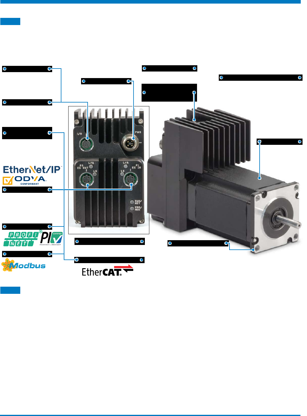
1.1 The ACSI Motor/Drive/Controller
The ACSI is an all-in-one solution (motor/drive/controller) for cost-effective servo control. Mount to a
Tolomatic (or any) electric actuator for a complete motion system. The ACSI can be controlled with simple
digital I/O, analog input or robust industrial ethernet.
Features:
Protected against dust
and low pressure water
jets, limited ingress
• Each ACSI is performance tested at Tolomatic
before shipping
• Mounted, configured and tested on Tolomatic
electric actuators
VIBRATION TESTED
• 0 - 500 Hz, 2 G, 3 - Axis, 1 - hour
M12 CONNECTORS
• Industry standard connectors
INPUT SUPPLY
• 10 VDC to 60 VDC
• Logic & Drive Power
NEMA 23 & NEMA 34
• Industry standard NEMA frame
sizes
ETHERNET/IP
• AOP: Add on profile
• AOI: Add on Instructions
• DLR: Device Level Ring
DUAL ETHERNET
PORTS
• Supports Star, Daisy Chain
and Ring Topologies
ANALOG IN
/
OUT
• 0-10VDC or
• 4-20 mA
DIGITAL I
/
O
• 24 VDC Digital I/O control for
flexible easy operating modes
• Opto-isolated
DIGITAL I/O M12 CONNECTORS
INPUT SUPPLY
ANALOG IN/OUT
ETHERNET/IP
PROFINET
MODBUS TCP
ETHERCAT
VIBRATION TESTED
IP65
QUALITY TESTED
DUAL ETHERNET
PORTS
USB
CONFIGURATION
PORT
NEMA 23 & NEMA 34
1.2 Capabilities ACSI Motor/Drive/Controller:
Modes of Operation:
EtherNet/IP, PROFINET, EtherCAT and ModbusTCP – Ethernet based protocols allow controllers to
command infinite positioning. Dual Ethernet ports with integral switch for daisy-chaining.
Analog Control – one analog input sets motion for a position or velocity move. Configurable for 0-10Vdc or
4-20mA. One analog output gives feedback for the actuator’s position or velocity.
Pneumatic – replaces pneumatic valve logic for simple motion using 1-3 digital inputs.
Index Move – up to 4 moves selectable with 2 digital inputs. Absolute, force, incremental, jog, velocity, and
home move types available.
Product Overview
1
Tolomatic Hardware & Installation Guide: ACSI Motor / Drive / Controller
• 10 •
1 : PRODUCT OVERVIEW
1.3 Additional Capabilities ACSI Motor/Drive/Controller:
Rotary Actuator setup allows velocity moves and infinite moves in one direction
Adjustable motion profile parameters (velocity, accel/decel, force) independently configurable for each move.
Zone digital output based on position
Force limiting capability
Configurable Digital I/O (24Vdc Opto-Isolated, sinking or sourcing)
Brake output logic - controlled by drive (low current, 20mA)
Ethernet status lights visible for network setup.
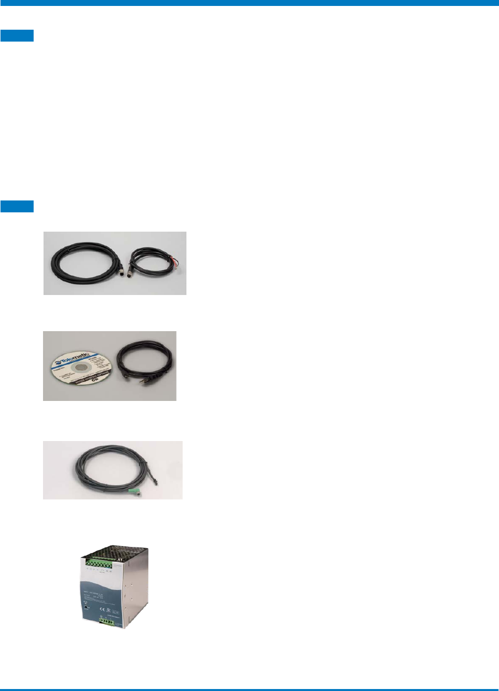
1.4 Optional Accessories:
Cable Options
Tolomatic offers power, I/O, and ethernet cables with circular
M12 style connectors. Cables are available in either 3 m, 5 m
or 10 meter lengths.
Disc and Cable
Tolomatic software is always available online at www.
tolomatic.com. For your convenience a software CD and
optional USB computer connections are available:
Tolomatic Motion Interface Software CD (3604-9526) and a 2
meter USB Type micro-B cable (3604-2145)
Brake Cable
Tolomatic offers a 10 meter brake power cable with drive and
brake mating connectors
Power Supply
Tolomatic offers 2.5, 5 and 10 Amp 48 Vdc power supplies
Tolomatic Hardware & Installation Guide: ACSI Motor / Drive / Controller
• 11 •
2
Environment, Dimensions & Mounting
2.1 Operating Environment
WARNING!
Do not expose the drive to pressurized wash-downs or exceed
temperature ratings.
The ACSI Motor/Drive/Controller is designed to be operated in ambient conditions from 0° – 40°C
(32° – 104°F), and humidity from 0 – 90% non-condensing.
ACSI Operating Conditions
Ambient Temperature 77° F, 25° C Nominal
Operating Temperature 32°-104° F, 0°-40° C Non Freezing
Storage Temperature 32°-158° F, 0°-70° C
Humidity 0-90% non-condensing
Vibration 0 - 500 Hz, 2G, 3-axis, 1-hour
Table 2-1: ACSI operating conditions
NOTE!
In order to maintain IP65 rating on motor/drive the protective sealing cover must
be used on all unused connections.
For connections that are used, the cable must be properly be torqued down to
0.6 Nm (5.31 in-lbs) to provide sealing. If the cable can be removed by hand with
no tools the cable connection is not properly connected at the proper torque.
All caps must be present and properly installed for unused ports
to maintain IP65 rating.
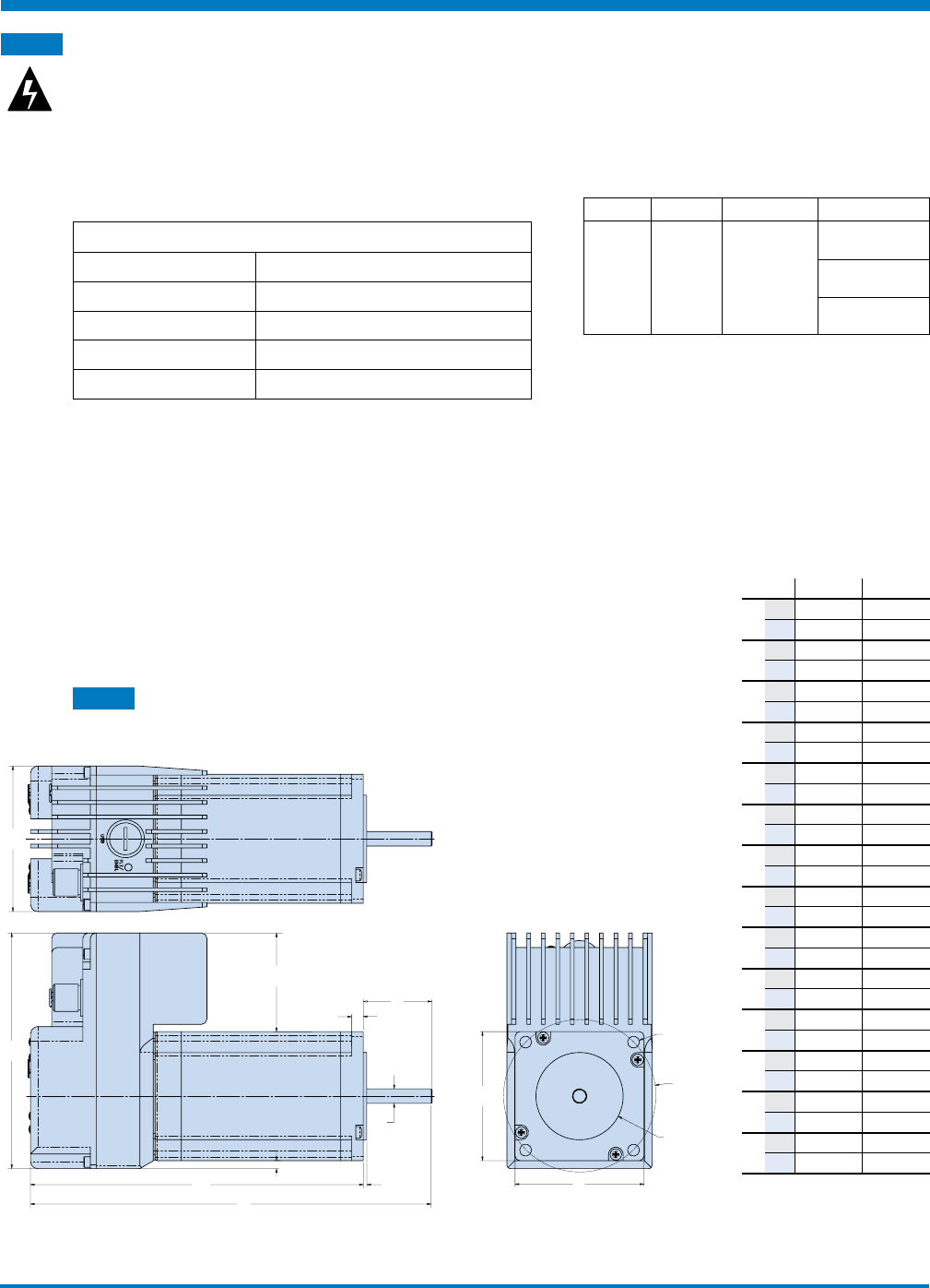
2.2 ACSI Motor/Drive/Controller Dimensions
B
A
DE
H
M
NH
G
C
P
F L
K
B.C.
J (4)
Figure 2-1: ACSI Motor/Drive/Controller Dimensions
ACSI23 ACSI34
Ain 2.50 2.50
mm 63.5 63.5
Bin 4.05 4.49
mm 102.8 113.9
Cin 5.73 5.92
mm 145.4 150.4
Din 0.20 0.39
mm 5.2 10.0
Ein 0.900 1.25
mm 22.86 31.8
Fin Ø.2500 Ø.5000
mm 6.350 12.700
Gin 0.059 0.063
mm 1.50 1.60
Hin 2.22 3.38
mm 56.3 85.8
Jin Ø.20 Ø.22
mm
5.2 5.5
Kin Ø2.625 Ø3.875
mm
66.68 98.43
Lin Ø1.500 Ø2.875
mm
38.10 73.03
Min 1.70 1.11
mm
43.1 28.3
Nin 0.14 0.00
mm
3.5 0.0
Pin 6.63 7.17
mm
168.26 182.20
IP Rating Protection Description Test Method
IP65
Enclosures
Able to
protect
against
water jets
Water projected
by a nozzle
(6.3 mm) against
enclosure from
any direction
shall have no
harmful effects.
Test duration: at
least 15 minutes
Water volume: 12.5
litres per minute
Pressure: 30 kPa at
distance of 3 m
Tolomatic Hardware & Installation Guide: ACSI Motor / Drive / Controller
• 12 •
2 : ENVIRONMENT, DIMENSIONS & MOUNTING
2.3 Mounting the ACSI Motor/Drive/Controller
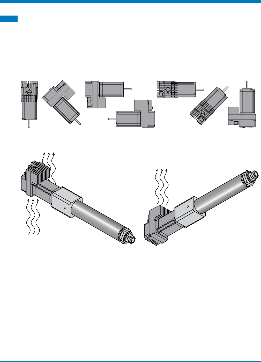
The ACSI Motor/Drive/Controller can handle mounting in any orientation. Avoid mounting multiple ACSI
units with reduced motor-to-motor spacing, airflow may be reduced causing over-temperature conditions. A
2-inch head space is recommended from the drive vents to another surface to ensure the proper ambient
temperature ratings are maintained.
It is recommended to have a minimum of 1-inch spacing between ACSI motors. This spacing may be relaxed
provided the ambient temperature is kept within limits and the motor is mounted to a metal surface suitable
enough to heat sink the motor.
Figure 2-2: ACSI may be mounted in any orientation
Figure 2-3: It is important that airflow to the ACSI is unrestricted
Tolomatic Hardware & Installation Guide: ACSI Motor / Drive / Controller
• 13 •
3
CD & USB Cable
3.1 CD & USB Cable
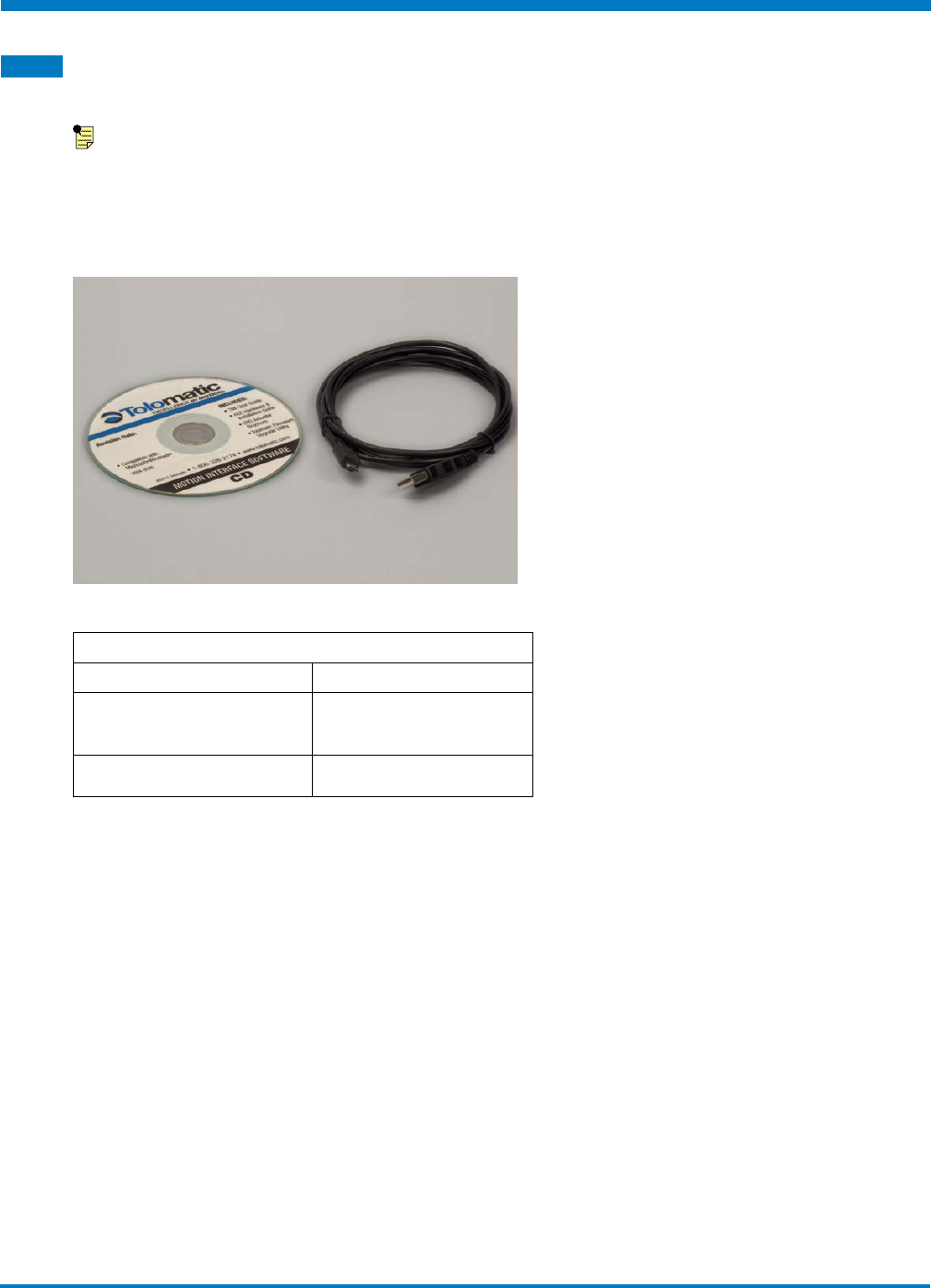
NOTE: The most current version of software and firmware is always available
at www.tolomatic.com
Tolomatic offers a CD with Tolomatic Motion Interface software, drive firmware and firmware upgrade utility.
A USB type A to micro B cable is also available for connecting your computer to the ACSI drive.
ACS Servo Drive Accessories
ITEM TOLOMATIC PART NUMBER
Tolomatic Motion Interface
Software CD 3604-9526
2 meter USB Cable 3604-2145
Table 3-1: It may be convenient to order the CD and USB cable.
Tolomatic Hardware & Installation Guide: ACSI Motor / Drive / Controller
• 14 •
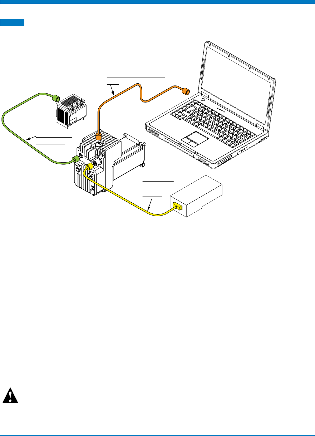
4.1 ACSI Motor/Drive/Controller Basic Setup
Figure 4-1 shows the simple setup of the ACSI Drive and the necessary cables and power source.
POWER SOURCE
10 - 60 VDC
USB Type Micro B Cable
to PC
Power Cable
to Power Input
on Drive
I/O Cable from
Drive to PLC
Figure 4-1: ACSI Motor/Drive/Controller – Basic Setup
Please refer to the following sections for cable part numbers and wiring specifications:
Power Cable: Section 5
USB Cable: Section 5
I/O Cable: Section 5
Ethernet Cable: Section 5
For recommended power supplies: Section 6
Setup Procedures
1. Install drive/controller and actuator into appropriate fixtures.
2. Wire the 10-60 VDC power supply to the drive. See Section 6: Power Supply Selection.
3. Wire input and output signals to the desired logic device. See Section 5: Connections and Cables.
4. Attach USB programming cable and install the Tolomatic Motion Interface software.
5. Configure ACSI Drive.
6. Program the logic device.
CAUTION!
Motor tuning is required based on the attached load, the default inertia setting is for a medium size load.
Running the motor with no load attached requires tuning.
4
ACSI Drive Setup
Tolomatic Hardware & Installation Guide: ACSI Motor / Drive / Controller
• 15 •
5.1 Connections and Cables Overview
All cables for the ACSI Motor/Drive/Controller can be ordered through Tolomatic. When using cables other
than those provided by Tolomatic, reference the cable mating connector style to ensure the proper cabling is
supplied.
WARNING: Cables should be hand tightened only. Do not use tools during installation or over torque
cables to connectors. Visually align keys before inserting cable into connector. Maximum install torque
allowed is 0.79 N-m (7 in-lbs).
5
Connections & Cables
I/O Cable
Circular M12,
A-Code, 12 pin to
flying leads:
• 3604-2089, 3m
• 3604-2090, 5m
• 3604-2091, 10m
Analog I/O
• 1 analog input
• 1 analog output
• 0-10Vdc or
4-20mA
• 12 bit resolution
USB Micro B for
configuration
• 3604-2145
Power Cable
Circular M12,
T-Code, 4 pin to
flying leads:
• 3604-2100, 3m
• 3604-2101, 5m
• 3604-2102, 10m
Ethernet Cable
Circular M12, D Code
to RJ45
• 3604-2092, 3m
• 3604-2093, 5m
• 3604-2094, 10m
Circular M12, D Code
to M12, D Code
• 3604-2109, 1m
• 3604-2095, 3m
• 3604-2096, 5m
• 3604-2097, 10m
Tolomatic Hardware & Installation Guide: ACSI Motor / Drive / Controller
• 16 •
5 : CONNECTIONS & CABLES
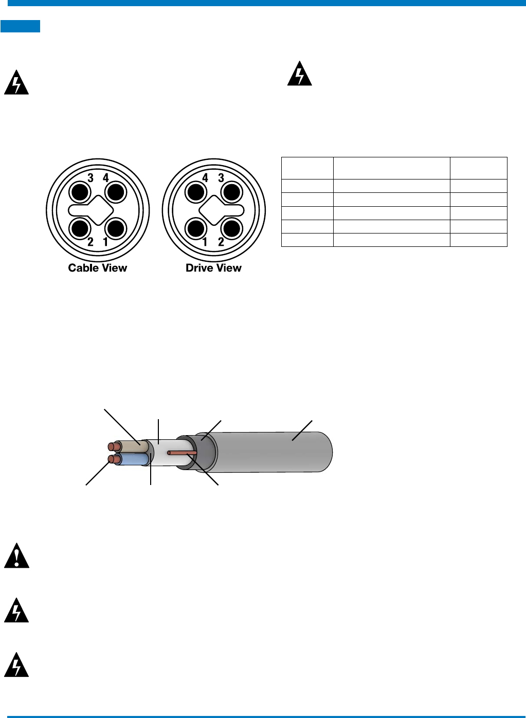
5.2 Connecting Cables to Motor
When coupling the cables (Power, I/O, & Ethernet) the key must be aligned. Do not apply force and rotate to
align connector to the key.
WARNING!
Damage may occur to device if force
is applied while rotating to align
connector to key on the motor.
PIN
NUMBERS SIGNAL CABLE WIRE
COLOR
1Main Power 10 to 60 VDC Brown
2Keep Alive 10 to 60 VDC White
3 NC Blue
4 Ground Black
Drain Wire Earth Ground Bare
Table 6-7: Input Power pinouts
Figure 5-1: Input Power Connection
To take advantage of Keep Alive, and not be required to re-home after power up, a second supply is required
that is a minimum of 10 VDC with 200mA current capability connected between pin 2 and 4.
Mating connector type is M12, T-Code, 4 Position, Female pin
NOTE!
Keep Alive voltage is not required for the drive to function and may be left disconnected.
OUTER
JACKET
BRAIDED WIRE
SHIELD
FOIL
WRAP
CONDUCTOR
JACKET
COPPER
CONDUCTOR CORE
INSULATION DRAIN
WIRE
Figure 5-2: Shielded wire diagram
CAUTION!
Voltage above the absolute maximum can result in permanent damage to the
ACSI internal drive components.
WARNING!
Do not reverse bias the power inputs. Doing so will result in instant permanent
damage to the drive.
WARNING!
Do not connect or disconnect power cable while drive or power supply is
energized. Doing so may cause damage to the drive.
WARNING: Cables should be hand
tightened only. Do not use tools during
installation or over torque cables to
connectors. Visually align keys before inserting
cable into connector. Maximum install torque
allowed is 0.79 N-m (7 in-lbs)
Tolomatic Hardware & Installation Guide: ACSI Motor / Drive / Controller
• 17 •
5 : CONNECTIONS & CABLES
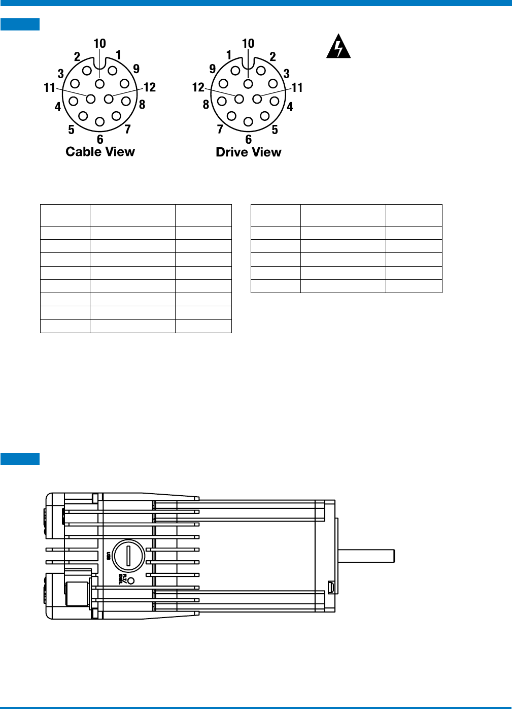
5.3 I/O Connections and Cables
Figure 5-3: I/O Connection Pinout
PIN
NUMBERS SIGNAL CABLE WIRE
COLOR
1Input ISO 1 Blue
2Input ISO 2 Orange
3Input ISO 3 Green
4Input ISO 4 Brown
5ISO COM Grey
6Analog In White
7Analog Out Red
8Output 1+ Black
PIN
NUMBERS SIGNAL CABLE WIRE
COLOR
9Output 1- Yellow
10 Output 2+ Purple
11 Output 2- Pink
12 *Analog GND Light Blue
Shell Braid Bare
Table 5-1: I/O Connection Pinout
Mating connector type is M12, A-Code, 12 Position, Male pin
NOTE!
The analog GND is shared with the power cable GND internal to the ACSI, it should be connected to a high
impedance or isolated source. Failing to do so will sink current from the motor driver potentially causing a
noisy signal.
5.4 USB 2.0 Connection
The USB port connector is a standard micro B type connector.
Figure 5-4: USB 2.0 Connection
NOTE!
If access to this connector is limited in the application environment a 90° angle connector can be used for
USB micro B.
WARNING: Cables should be
hand tightened only. Do not
use tools during installation or
over torque cables to connectors.
Visually align keys before inserting
cable into connector. Maximum
install torque allowed is 0.79 N-m
(7 in-lbs)

Tolomatic Hardware & Installation Guide: ACSI Motor / Drive / Controller
• 18 •
5 : CONNECTIONS & CABLES
NOTE!
To maintain IP65 rating, always replace the protective cover when the micro USB connector is not in use.
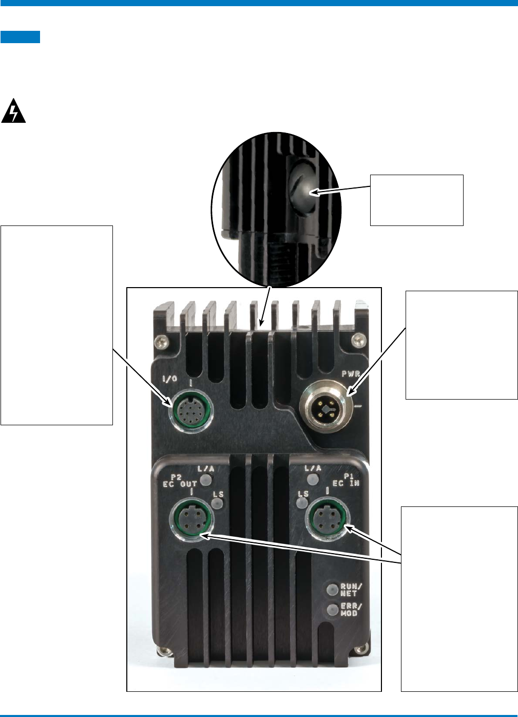
5.5 Ethernet Connection
The following parts have two Ethernet ports with
a built-in switch to be used for daisy chaining.
ACSI Servo Drive/Controller, EtherNet/IP (AMI3)
ACSI Servo Drive/Controller, Modbus TCP (AMI4)
ACSI Servo Drive/Controller, PROFINET (AMI6)
ACSI Servo Drive/Controller, EtherCAT (AMI5)
Figure 5-5: Ethernet Connection for ACSI
NOTE!
LED functions are described in section 9.1 LED codes and also in the EtherNet/IP guide (3600-4168), PROFINET
guide (3600-4196) and Modbus TCP guide (3600-4169).
DRIVE VIEW PIN
NUMBER FUNCTION
1Transmit Port (+) Data Terminal
2RX (+)
3Data Terminal TX (-)
4RX (-)
Figure 5-6: Ethernet cable pinouts and connections
Mating connector type is M12, D-Code, 4 Position, Male pin
NOTE: Internal testing has shown that unmanaged switches are unreliable in PROFINET topologies. Tolomatic
recommends only using managed switches when required.
5.6 Cable Routing
Over time, liquid contaminants such as oil and cleaning solutions may accumulate on the cables and in the
connectors if they are an exposed type. To minimize the introduction of contaminants into the connector,
route the cables so that there is a loop in the cable just prior to its attachment to the connector.

Tolomatic Hardware & Installation Guide: ACSI Motor / Drive / Controller
• 19 •
5 : CONNECTIONS & CABLES
In Figure 5-7 proper cable looping is shown for connectors located on the top or side of the unit. Units
mounted with connectors on the bottom surface require no cable looping.
Side
Mount
Loop
Bottom
Mount
No Loop
Required
Top
Mount
Loop
Figure 5-7 Cable routing loops for top and side facing connectors
Ethernet Cable
The selection of cables has a profound impact on network performance and reliability. Selecting the correct
cable requires an understanding of the environment where the cable is installed.
Due to high data rate and reliability considerations, at the minimum, Cat5e cables should be used with the
ACSI Drive. If the cables are made on site, they must be tested to meet performance criteria set according to
TIA/EIA -568-B standard. This cable definition is the general cable requirements for copper and fiber cabling
installations.
Ethernet Cable Length
The following information regarding cable length is from commercial building telecommunications cabling
standard ANSI/TIA/EIA-568-B.1. The maximum length of a cable segment is 100 meters (328 ft). Category
5e cable is capable of transmitting data at speeds up to 1000 Mbps – 1Gbps (ACSI has a maximum speed
of 100 Mbps). The specifications for 10BASE-T networking specify a 100-meter length between active
devices. This allows for 90 meters of fixed cabling, two connectors, and two patch leads of 5 meters, one at
each end.
Tolomatic Hardware & Installation Guide: ACSI Motor / Drive / Controller
• 20 •
MOTOR CONTROL SECTION
Commutation Method Field Oriented Commutation
PWM Mode Centered
PWM Efficiency >90%
PWM Switching Frequency 12 KHz
PWM Ripple Frequency 24 KHz
Minimum PWM pulse duration 4.16uS
Dead Band 50ns - 500ns
Velocity Loop Frequency 1.2 KHz
ENCODER SECTION
Type Magnetic
Counts 4096
COMMUNICATION SECTION
Communication ports USB
Ethernet
USB Type USB device only
USB Speed USB Full Speed
Ethernet Speed 10/100M (Auto Negotiate)
Ethernet Duplex Full/Half-Duplex (Auto
Negotiate)
Table 6-1: Controller specifications
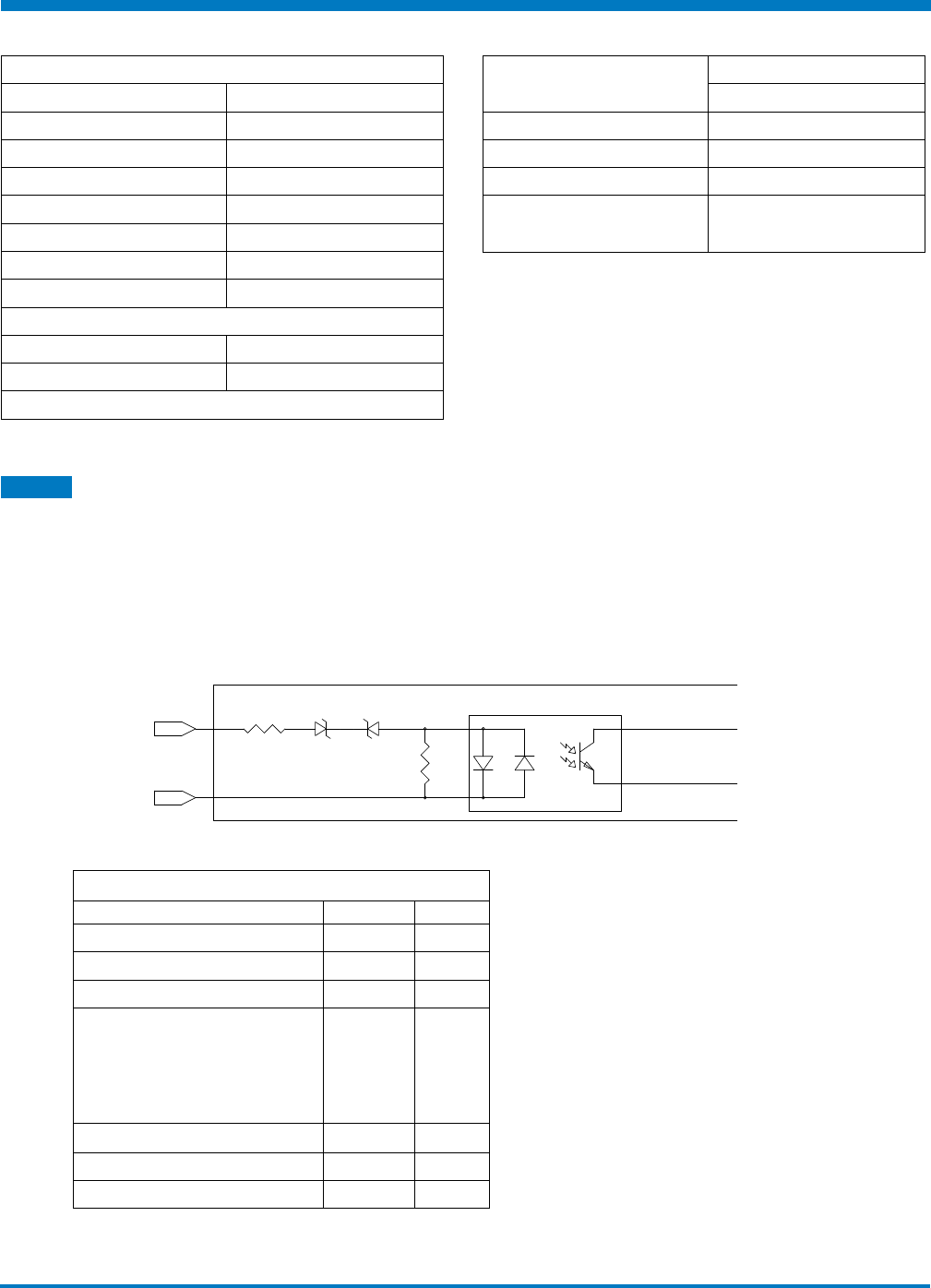
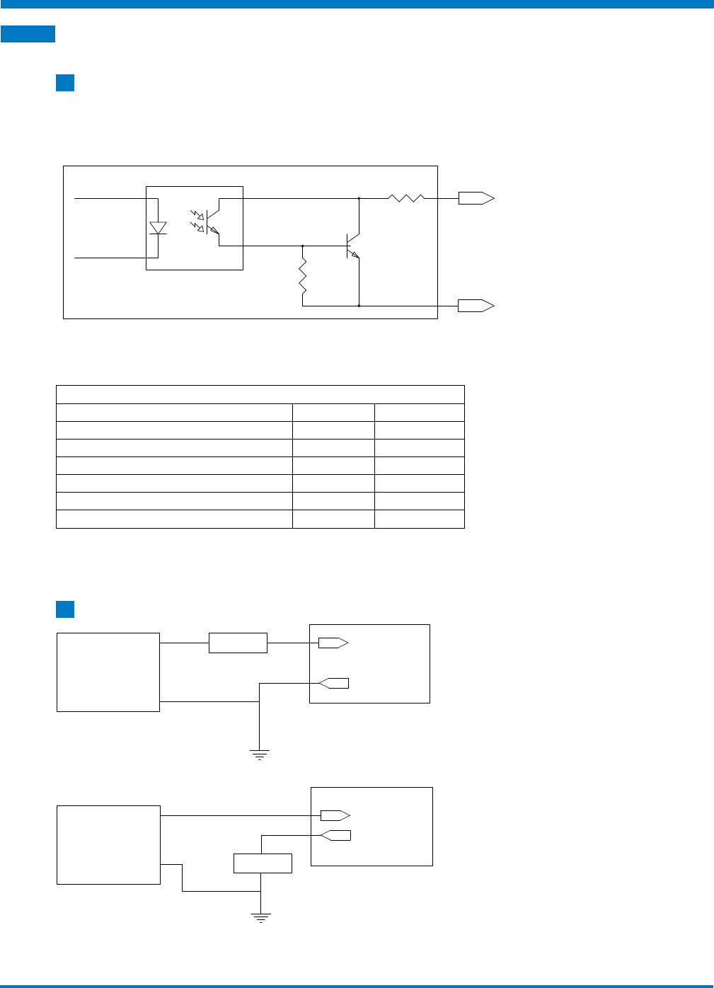
6.1 Digital Inputs
Specifications
The ACSI Motor/Drive/Controller has a total of 4 opto-isolated digital inputs. These digital inputs are opto-
isolated from the controller’s drive circuitry and can be wired either as sinking or sourcing. All of the digital
inputs have a common return.
NOTE: ACSI supports configuration of a digital input as a limit switch. This configuration requires the use of
‘Normally Open’ switches
5K
2K
INPUT
INPUT COMMON
INPUT CIRCUIT DIAGRAM
ACS DRIVE
Figure 6-1: Digital Input Circuit
Opto-isolated Digital Input Specifications
Parameter Value Units
Input Voltage Range 0 to 28 VDC
On State Voltage Range 16 to 28 VDC
Off State Voltage Range 0 to 5 VDC
On State Current:
16VDC (minimum)
24VDC (nominal)
28VDC (maximum)
1.9
3.4
4.2
mA
Nominal Input Impedance (24V) 7KΩ
Off State Current (maximum) 0.4 mA
Update Rate (maximum) 2 ms
Table 6-2: Opto-Isolated digital input specifications
6
Specifications & Wiring
ACSI DRIVE
Tolomatic Hardware & Installation Guide: ACSI Motor / Drive / Controller
• 21 •
6 : SPECIFICATIONS & WIRING
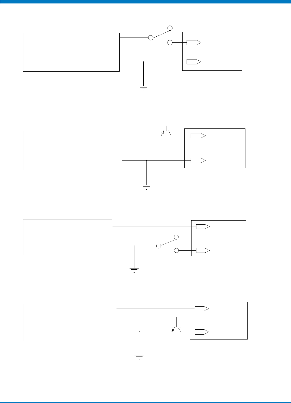
Typical Wiring Diagrams
INPUT
INPUT COMMON
24V POWER SUPPLY
+
-
ACSI
DRIVE
Figure 6-2: Input Source (switched) Connection
INPUT
INPUT COMMON
24V POWER SUPPLY
+
-
ACSI
DRIVE
Figure 6-3: Input Source (PNP) Connection
INPUT
INPUT COMMON
24V POWER SUPPLY
+
-
ACSI
DRIVE
Figure 6-4: Input Sink (switched) Connection
INPUT
INPUT COMMON
24V POWER SUPPLY
+
-
ACSI
DRIVE
Figure 6-5: Input Sink (NPN) Connection
Tolomatic Hardware & Installation Guide: ACSI Motor / Drive / Controller
• 22 •
6 : SPECIFICATIONS & WIRING
6.2 Digital Outputs
6.2.1 Specifications
The ACSI Drive has two digital outputs. These digital outputs are opto-isolated from the drive circuitry and
can be configured for sinking or sourcing. The outputs are protected against over current and short circuit
conditions. If an over current condition is present, the output current is limited to 80 mA.
33
OUT
+
OUT
-
OUTPUT CIRCUIT
ACS DRIVE
Figure 6-6: Output Circuit
Digital Output Specifications
Parameter Value Units
Switched Voltage (nominal) 24 V
Output Voltage drop (20mA) 2 V
Continuous Current (max) 20 mA
Fold Back Current 80 mA
Update Rate (10KOhm Load) 2 ms
Output Leakage Current 30 uA
Table 6-3: Digital Output Specifications
6.2.2 Typical Wiring Diagrams
OUTPUT
+
OUTPUT
-
ACSI
DRIVE
24V POWER SUPPLY
LOAD
+
-
Figure 6-7: Digital Output Sinking Connection
OUTPUT
+
OUTPUT
-
ACSI
DRIVE
24V POWER SUPPLY
LOAD
+
-
Figure 6-8: Digital Output Sourcing Connections
ACSI DRIVE
Tolomatic Hardware & Installation Guide: ACSI Motor / Drive / Controller
• 23 •
6 : SPECIFICATIONS & WIRING
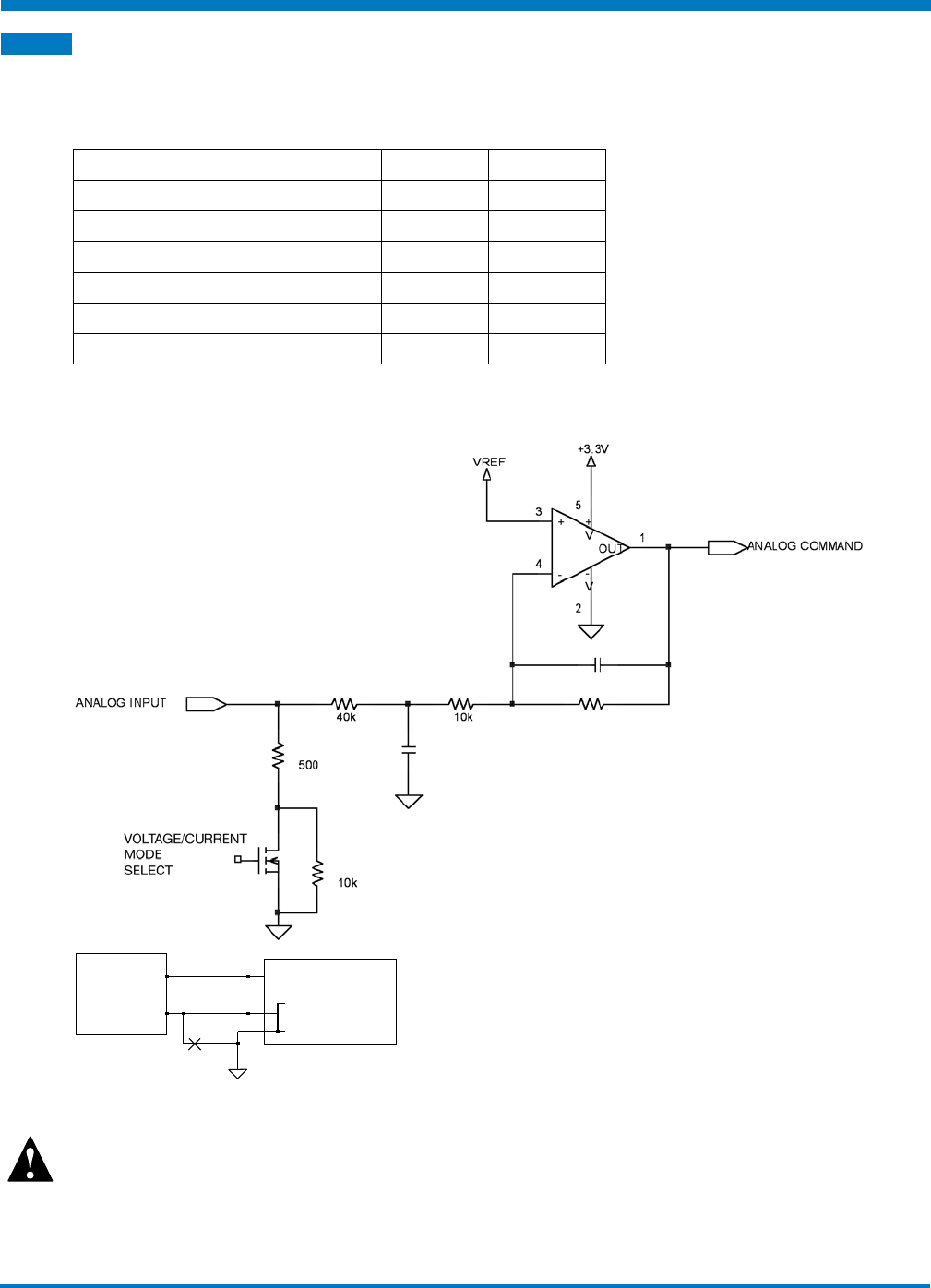
6.3 Analog Input
Specifications
The ACSI Drive comes with one analog input. The input is configurable through software to be 0-10V or
4-20mA input. The analog input is referenced to the analog ground pin.
Parameter Value Units
Voltage Mode Input Voltage (min) 0 V
Voltage Mode Input Voltage (max) 10 V
Current Mode Input Current (min) 0 mA
Current Mode Input Current (max) 25 mA
Current Mode Input impedance (nom) 500 Ohm
Resolution 12 Bits
Table 6-4: Analog Input Specifications
Equivalent Circuit
ANALOG
DEVICE
ANALOG INPUT
ANALOG GND
POWER CABLE GND
DO NOT CONNECT TO
POWER GND TO
REDUCE SIGNAL NOISE
+
-
Figure 6-9: Analog Input Equivalent Circuit
IMPORTANT!
Devices sharing analog inputs and outputs must have their grounds connected
together for proper and reliable operation.
Tolomatic Hardware & Installation Guide: ACSI Motor / Drive / Controller
• 24 •
6 : SPECIFICATIONS & WIRING
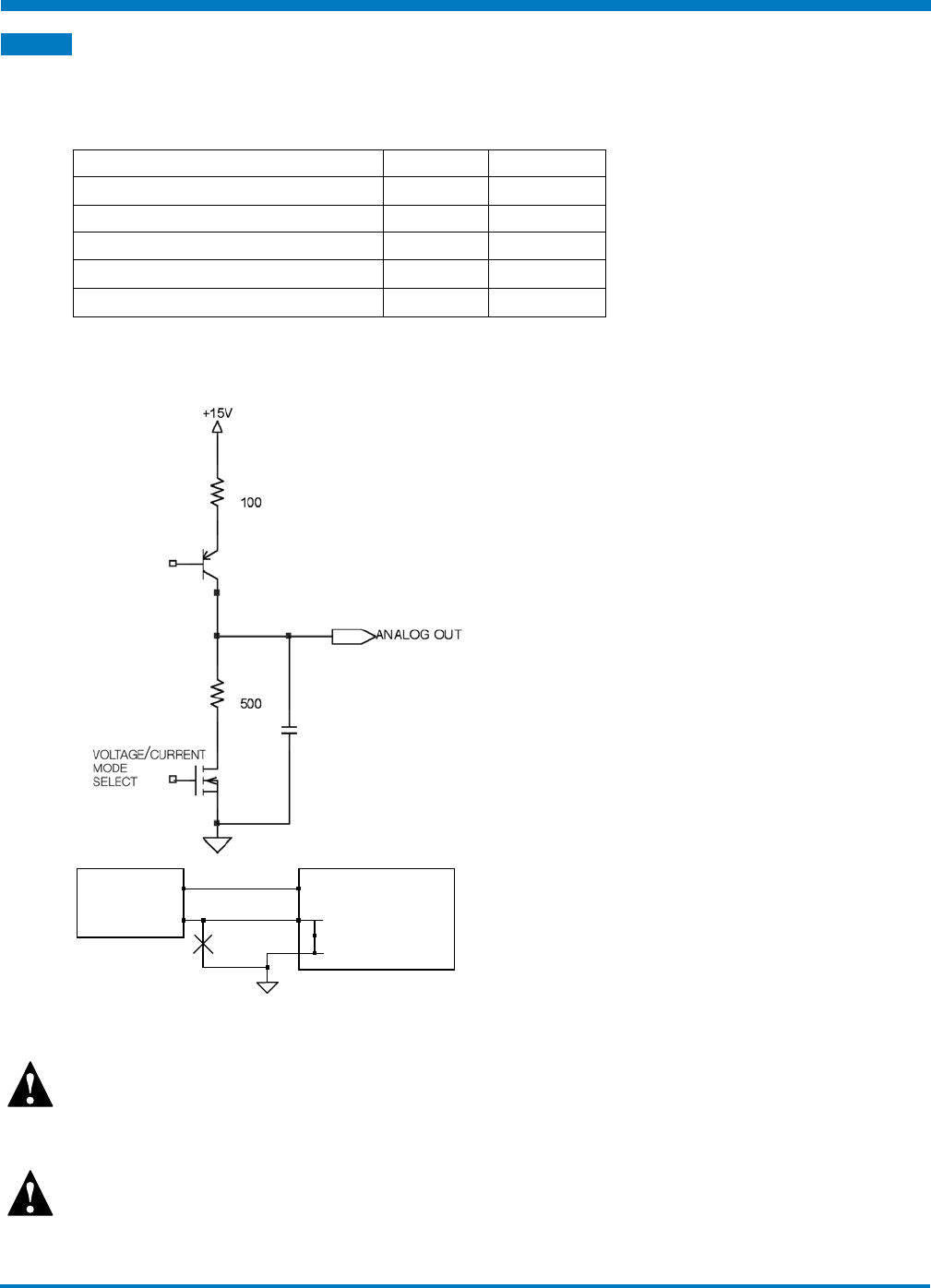
6.4 Analog Output
Specifications
The ACS Drive can have one analog output capable of 0-10V or 4-20mA operation (on selected models).
The analog output is referenced to the analog ground pin.
Parameter Value Units
Output Voltage (min) 0 V
Output Voltage (max) 10 V
Output Current (min) 0 mA
Output Current (max) 20 mA
Resolution 12 Bits
Table 6-5: Analog Output Specifications
Equivalent Circuit
ANALOG
DEVICE
ANALOG OUTPUT
ANALOG GND
POWER CABLE GND
+
-
Figure 6-10: Analog Output Equivalent Circuit
IMPORTANT!
Devices sharing analog inputs and outputs must be referenced to the analog GND pin for proper and
reliable operation
.
IMPORTANT!
The analog GND is shared with the power cable GND internal to ACSI it should be connected to a high
impedance or isolated source or else it will sink current from the motor driver potentially causing a noisy signal.
Tolomatic Hardware & Installation Guide: ACSI Motor / Drive / Controller
• 25 •
6 : SPECIFICATIONS & WIRING
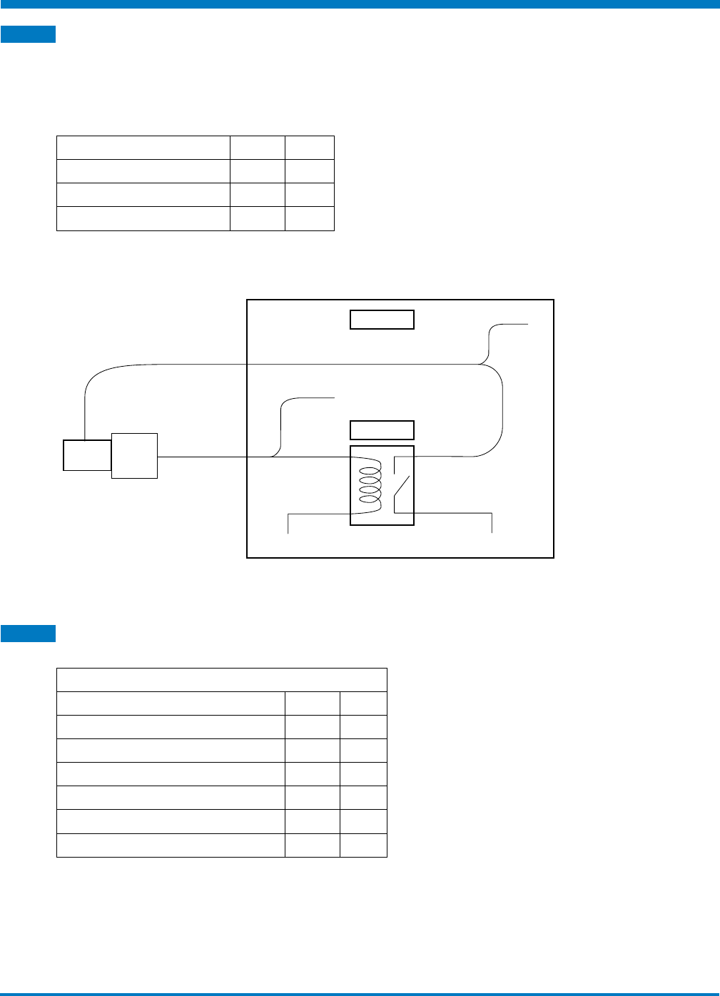
6.5 Brake Output
The brake output is a 20mA low current output with braking logic controlled by the drive. It obeys the timing
configured using Tolomatic Motion Interface Software. The brake output requires hardware to interface it to
the higher currents required to operate a brake.
Specifications
Parameter Value Units
Input Voltage 24 V
Continuous Current (max.) 20 mA
Output Voltage Drop (20 mA) 2 V
Table 6-6: Brake Output Specifications
Brake Output Wiring Diagram
BRAKE CABLE
BRAKE ACSI I / O CABLE
(20 mA max)
CABINET Brake +
Out +
RELAY
Out -
24V
Brake -
24V, > 500 mA
0 V
0 V
24V
24V
Figure 6-11: Brake output wiring diagram
6.6 Input Power
Drive Specifications
ACSI Internal Drive Specifications
Parameter Value Units
Current - Continuous (max) 10 APK
Current - Peak (max) 20 APK
Over Voltage165 V
Under Voltage29 V
Maximum Operating Voltage160 V
Logic Current Draw Maximum (24V) 200 mA
Table 6-8: ACSI Internal Drive Specifications
1 Drive will fault at 65V; any voltage above the absolute max voltage can result in permanent
damage.
2 Drive will fault below 9V.
Tolomatic Hardware & Installation Guide: ACSI Motor / Drive / Controller
• 26 •
6 : SPECIFICATIONS & WIRING
Software Fault - Overvoltage and Undervoltage Trigger Values
Configured Motor Voltage Undervoltage Trigger Value Overvoltage Trigger Value
12 *10 18
24 14.4 36
36 21.6 54
48 28.8 *65
*NOTE: The absolute minimum/maximum voltage will over-ride the calculated voltage
threshold of 0.6x for undervoltage and 1.5 for overvoltage
Table 6-9: Software Faults Trigger Values
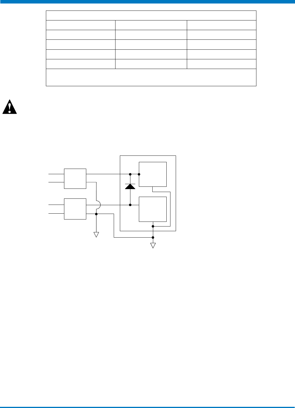
Keep Alive not required
Providing 10 to 60Vdc to keep alive maintains the drive logic memory when main
power is de-energized; which stops all motion; the drive keeps all control logic
active and position information.
Keep Alive Wiring Diagram
MAIN
POWER
AC
AC
+
-
KEEP
ALIVE
10 - 60
10 - 60
+
-
DIGITAL
CIRCUITRY
& LOGIC
MOTOR
DRIVE
Figure 6-13: Keep Alive wiring diagram
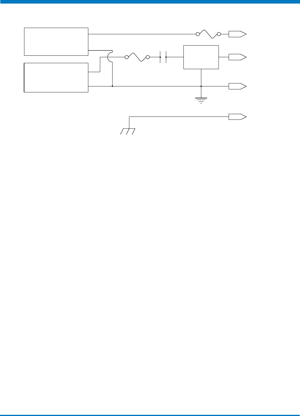
Power Supply Sizing Guidelines
Both unregulated and regulated power supply can be used to power the ACSI Drive.
Unregulated supply can be a better choice depending on the application as they have a larger output
capacitance. This characteristic makes an unregulated power supply a better energy absorption source.
Unregulated power supply is a good choice for applications that require aggressive acceleration it can
provide peak currents without faulting and will not trip on high voltage. However, unregulated power
supply does not have over voltage protection and care must be taken not to exceed the
maximum voltage of the actuator by using a shunt regulator and proper fusing to prevent
excessive loading of the supply.
Regulated supply can be used to power the ACSI drive, but additional measures may need to be taken.
To prevent regenerative energy from reaching the supply, a blocking diode and capacitor,
appropriately sized for the application, should be installed. In addition, a shunt regulator may be
needed to dissipate excess energy. A shunt regulator is available Part Number 2180-1163.
The ACSI Drive is intended to run off of an isolated DC power source. The power supply required will depend
on the application. A 48V supply will allow the actuator to operate at maximum speed. A 24V supply will

Tolomatic Hardware & Installation Guide: ACSI Motor / Drive / Controller
• 27 •
6 : SPECIFICATIONS & WIRING
result in approximately half the rated velocity. Input current will depend on the actuator power needed in
the installation. If operating more than one actuator on the same power supply, add the required power
supply rating for each actuator. Use the following tables to find the required power for a supply. These are
measured values, please add 15 - 25% margin for implementation.
ACSI Nema 23 - Input Power Supply WATTS
SPEED
(RPM)
TORQUE (in-lb)
1.7 3.5 5.2 6.9 8.6 10.4 12.1 13.8
200 11 20 36 58 77 106 137 173
400 15 29 49 72 96 125 168 202
600 23 42 66 93 125 158 206 250
800 26 49 77 108 144 182 230 288
1000 31 58 91 126 168 206 262 322
1200 37 69 106 145 189 235 293 341
1400 42 77 118 163 211 264 326 384
1600 46 86 132 180 233 293 355 418
1800 54 99 149 197 259 312 389 456
2000 60 108 163 221 284 348 418 490
2200 62 115 173 235 300 370 451 528
2400 69 127 192 255 326 403 490 566
2600 76 134 197 269 346 427 514 600
2800 80 144 216 293 374 456 552 634
3000 90 157 230 307 389 480 590
3200 100 165 240 331 418 514
3400 102 173 254 360
3600 108 197 269
3800 130
SPEED
(RPM)
0.19 0.40 0.59 0.78 0.97 1.18 1.37 1.56
TORQUE (N-m)
ACSI Nema 34 - Input Power Supply WATTS
SPEED
(RPM)
TORQUE (in-lb)
3 6 9 12 15 18 21 24
200 19 29 48 67 82 110 139 182
400 26 48 72 101 120 158 197 254
600 38 62 96 139 163 211 259 322
800 48 82 120 163 206 254 312 374
1000 58 96 149 202 250 302 374 446
1200 72 120 182 235 293 370 437 542
1400 82 139 206 274 348 427 504 590
1600 96 154 230 307 394 451
1800 110 173 269
SPEED
(RPM)
0.34 0.68 1.02 1.36 1.69 2.03 2.37 2.71
TORQUE (N-m)
Calculating Wattage of Power Supply
Watts = I(amps-rms) x V(volts) / Motor Efficiency

Tolomatic Hardware & Installation Guide: ACSI Motor / Drive / Controller
• 28 •
6 : SPECIFICATIONS & WIRING
Where
I = Peak Application Torque (in-lbs) / Kt (in-lbl/Arms)
And
V = Ke(V/krpm) x Peak Application Speed(rpm) / 1000
Motor Efficiency ~= 0.7
Watts = (Peak Application Torque / Kt) x (Ke x Peak Application Speed) / (1000 x 0.7)
Tolomatic
Part Number
Motor
Config. Code
Max Speed Peak Torque Kt Ke Max Peak
Supply
Power*RPM in-lbs in-lb/amp-rms Vp/krpm
3604-9740
3604-9746
3604-9752
AMI2C1A1
AMI3C1A1
AMI4C1A1
3850 13.8 0.836 10 825
3604-9770
3604-9776
3604-9782
AMI2D1A1
AMI3D1A1
AMI4D1A1
2050 25.0 1.39 16.55 744
*Calculation uses peak torque and rated speed
Table 6-10: ACSI Internal Drive Specifications
Example: If we size a power supply for an AMI2C1A1 motor where the max application speed is 2000rpm
and max torque reached in the application is 7 in-lbs, we can calculate the power supply watts needed:
Watts = (7/0.836)x(10x2000)/(1000*0.7) = 239W
It is never a good idea to buy a power supply that just meets the drive’s wattage requirements. To avoid
nuisance over-current shut downs a power supply power rating should be at least 25% greater than the
calculated value.
WARNING!
All installations should provide a means for a hardware emergency stop
that removes power from the drive in an emergency condition. The drive
emergency stop function should not be relied on when safety is required. It is
recommended to disconnect only the + bus power and keep the power ground
line connected.
Suggested Power Supplies:
Switching Power Supply:
Manufacturer
Tolomatic
Part No. Specs
Meanwell 3604-2147 48V, 2.5A, 120 W
3604-2148 48V, 5A, 240 W
3604-2149 48V, 10A, 480 W
Unregulated Power Supply: International Power IP500U48
Bus Fuse: 15 Amp, 125V or equivalent or sized for application
Logic Power Fuse: 2 Amp, 125V or equivalent
Tolomatic Hardware & Installation Guide: ACSI Motor / Drive / Controller
• 29 •
6 : SPECIFICATIONS & WIRING
A shunt regulator (#2180-1163) may be needed to dissipate excess energy.
+24-48VDC POWER
POWER GROUND
MOTOR FLANGE OR
CABLE SHIELD
/ SHIELD GROUND
UNREGULATED
POWER SUPPLY
24 to 48VDC
SHUNT
REGULATOR
FUSE E-STOP
+
-
KEEP ALIVE
POWER SUPPLY
KEEP ALIVE +
-
FUSE
Figure 6-14: Unregulated Power Supply Configuration with Shunt Regulator

Tolomatic Hardware & Installation Guide: ACSI Motor / Drive / Controller
• 30 •
6 : SPECIFICATIONS & WIRING
Tolomatic Hardware & Installation Guide: ACSI Motor / Drive / Controller
• 31 •
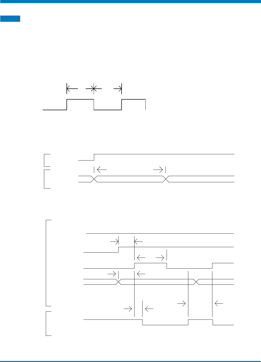
7.1 I/O Timing Diagrams
The opto-isolated digital inputs require a minimum of 2ms of time to guarantee that the input signal is
registered by the drive. This is an important consideration to take into account, especially if limit switches
are used. If limit switches are used, careful consideration should be used to prevent missed triggering
due to high velocities. Output timing assumes 10K Ω load. Additional software filtering of digital inputs as
configured by TMI will increase response time.
INPUT
1.15ms Avg 1.15ms Avg
INPUT REQUIREMENT
Figure 7-1: Input Requirement
INPUT MAIN POWER
SYSTEM
STATUS SYSTEM STARTUP SYSTEM READY
2.67s max
SYSTEM STARTUP TIMING
Figure 7-2: System Startup Timing
INPUT
SOFTWARE
- STOP
ENABLE
H
L
1.49 ms
START
MOTION
MOTION SELECT
LINES
MOTION
COMPLETE
OUTPUT
JOG TIMING
1.15 ms Avg
1.15 ms Avg
1.15 ms Avg
1.15 ms Avg
Figure 7-3: Jog Move Timing
7
I / O Timing Diagrams
Tolomatic Hardware & Installation Guide: ACSI Motor / Drive / Controller
• 32 •
7 : I / O TIMING DIAGRAMS
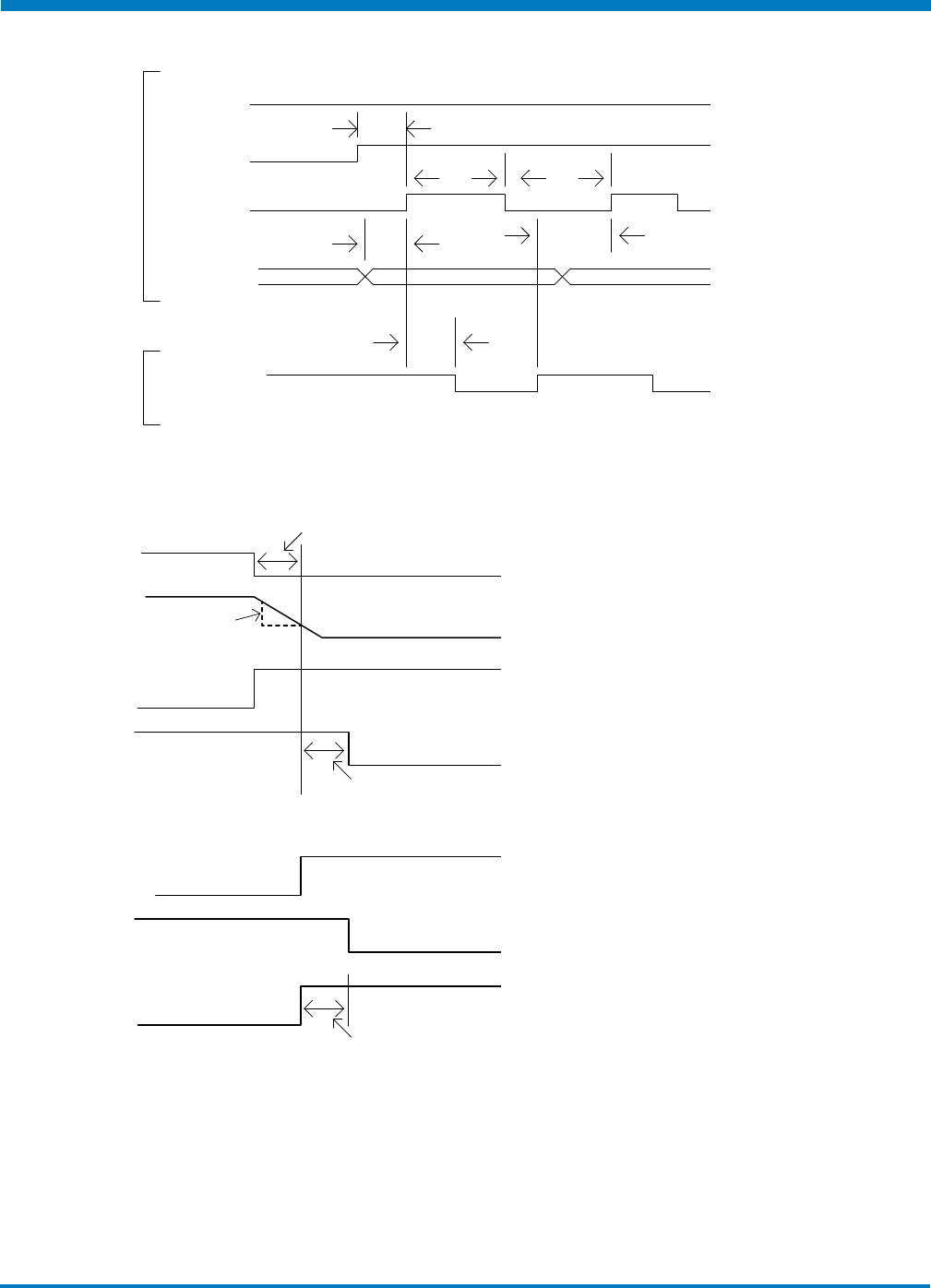
INPUT
H
L
ENABLE
START
MOTION
1.15 ms Avg
1.15 ms Avg 1.15 ms Avg
1.15 ms Avg
1.15 ms Avg
1.15 ms Avg
MOTION SELECT
LINES
OUTPUT
MOTION COMPLETE
START MOTION TIMING
SOFTWARE
- STOP
Figure 7-4: Absolute & Incremental Move Timing
DISABLE
DETECTED
VELOCITY
BRAKE
ENABLED
OUTPUT
MOTOR
ENABLED
ENABLE
DETECTED
BRAKE
ENABLED
OUTPUT
MOTOR
ENABLED
DRIVE DISABLED
DRIVE ENABLED
Max. Brake Delay
Max. Decel. Max. Brake Velocity
Enable Brake
Response Delay
Max. Brake Delay
Disable Brake
Response Delay
Figure 7-5: Brake Subsystem Timing
Move Timing Rules
1. While the Motion Complete signal is low, the drive will ignore Start Motion pulses and Motion
Selection lines.
2. If the enable signal is low or Software Stop signal is high, the drive will ignore start motion pulses.

Tolomatic Hardware & Installation Guide: ACSI Motor / Drive / Controller
• 33 •
8.1 Move Select Logic Table
The Index Move Mode require digital inputs to select the desired move for execution. The digital inputs are
called Move Select 1 and Move Select 2 in the digital input map. To select the desired move command refer
to the logic table below.
NOTE 1: MS# stands for Move Select #
NOTE 2: 1 = On; 0 = Off
4 Move Commands Mode Logic Table
MOVE MS1 MS2
100
210
301
411
Table 8-1: 4 Move Commands Mode Logic
8
Move Select Logic
Tolomatic Hardware & Installation Guide: ACSI Motor / Drive / Controller
• 34 •
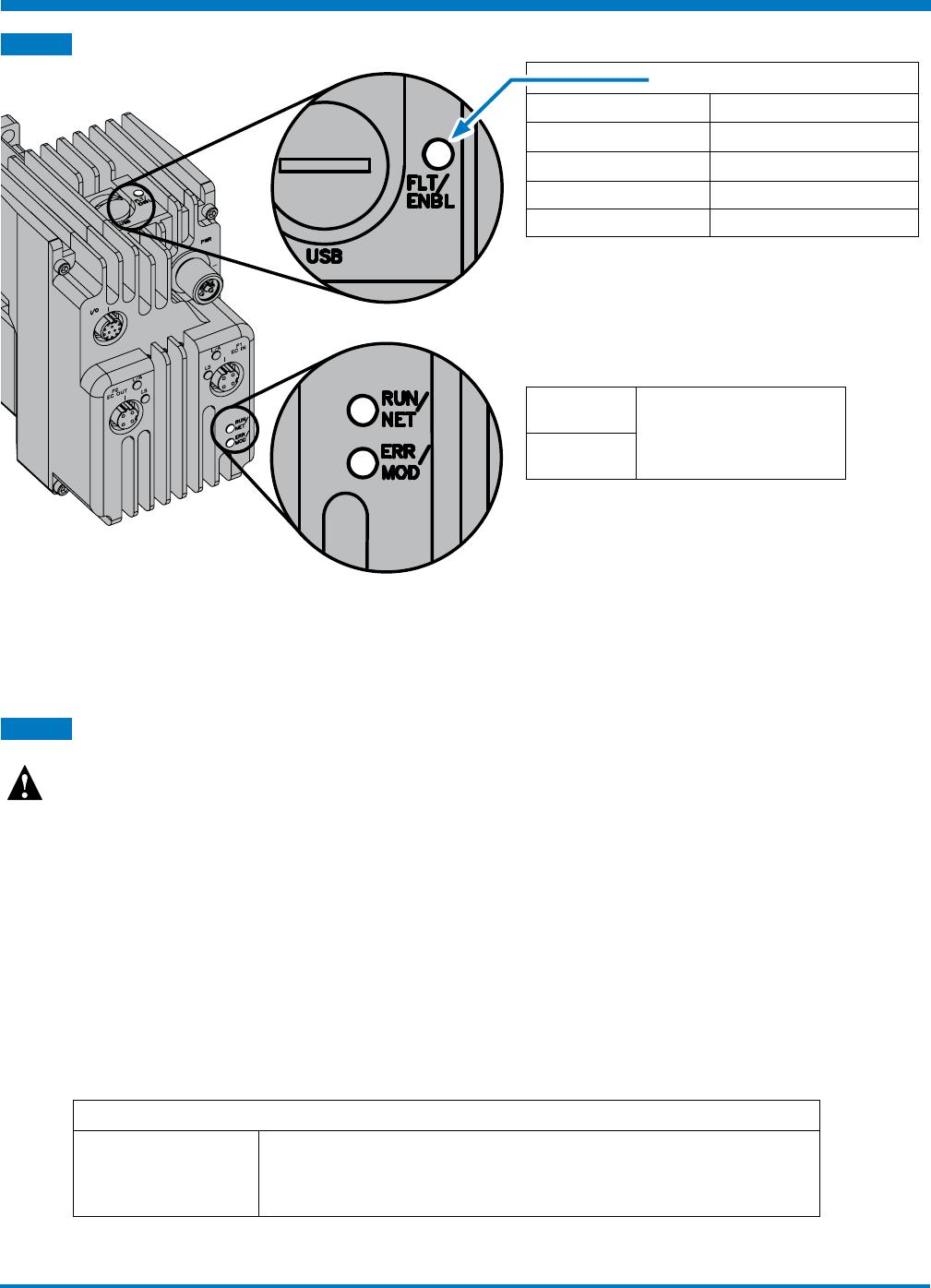
9.1 LED Codes
LED Indicators
Off Motor is not powered
Green, On Motor is powered
Red, On and Solid A critical fault has occurred
Red, On and Blinking A safety fault has occurred
Green / Red toggling Firmware Upgrade Mode
Table 9-1: LED Indicators
RUN / NET Protocol Specific. Information
can be found in protocol user
guides
ERR / MOD
To clear a fault, the enable input needs to be lowered, and then raised. Faults can also be cleared by the PC
software. Faults that result in a blinking red LED indicator, are cleared automatically once the fault condition
is no longer present.
9.2 Fault Descriptions and Recovery
Faults are divided into Safety Faults and Critical Faults.
Note:
To clear faults; PLC needs to lower/raise the enable digital input or TMI
software user must press the Enable button on the motion manager
Safety Faults are configurable. If the fault is configured as a stop motion, the fault will be cleared
automatically once the fault condition is no longer present. If a safety fault is enabled and configured for
disable motor, the fault will be latched until it is cleared in the same manner as the critical faults described
at left.
All Critical Faults will disable the motor when they occur. To clear these faults, the fault condition cannot be
present and the enable input line must be lowered and then raised to proceed with motion.
Safety Faults Table
Positive Limit Switch Positive limit switch has been reached. If configured to stop motion, motion will
be allowed in the reverse direction. The fault will be cleared once the positive limit
switch input is no longer active and there is motion in the negative direction.
LED Codes and Faults
9

Tolomatic Hardware & Installation Guide: ACSI Motor / Drive / Controller
• 35 •
9 : LED INDICATORS & FAULTS
Safety Faults Table
Negative Limit Switch The negative limit switch has been reached. If configured as stop motion, motion
will be allowed in the positive direction. The fault will be cleared once the negative
limit switch input is no longer active and there is motion in the positive direction.
Position Error If an encoder is present, the position error fault can be enabled. If encoder position
and commanded position differ by a larger magnitude than the defined position
error, the position error fault will be activated. If fault is configured as a stop
motion, fault will be cleared on next move command.
Software Stop If an input is configured as an Software Stop and fault is enabled, this fault will be
activated when the signal level on the pin is high. This fault is configured as a stop
motion, it will be cleared once the Software Stop input is lowered. Motion will not
be allowed until Software Stop has been cleared.
I2T Limit Drive power usage greater than max allowed
Table 9-2: Safety Faults
Critical Faults Table
Feedback Error Feedback device is malfunctioning.
Over Current If a short circuit occurs from output to ground, this fault will be triggered.
Drive Over Temp Drive temperature is greater than the maximum allowed temperature (75˚C).
Drive Over Voltage Main power voltage exceeds the threshold defined in hardware manual: “Input
Power” section..
Drive Under Voltage Main power voltage below the threshold defined in hardware manual: “Input
Power” section.
Flash Error Flash memory checksum error or firmware version mismatch
Short Circuit Short circuit to ground condition on motor
Watchdog Timeout Firmware did not respond in time
Table 9-3: Critical Faults

Tolomatic Hardware & Installation Guide: ACSI Motor / Drive / Controller
• 36 •
10.1 Troubleshooting
Troubleshooting the ACSI Motor / Drive / Controller
Troubleshooting Table
SYMPTOM / TROUBLE POSSIBLE CAUSE / RESOLUTION
No communication to drive 1. Check power connection.
2. Verify that the communication cable is plugged in securely.
3. Verify that USB drivers are up-to-date. (TMI → Help → Install Drivers)
4. Try a different computer.
5. If communication fails when enabling the motor, then the motor tuning needs
to be adjusted.
Actuator cannot move load 1. The load is too large.
2. There is too much friction.
3. Side load is excessive.
4. Power supply does not have enough current capability.
5. Current limits are set too low.
Drive is overheating 1. Ambient temperature is too high.
2. Cooling is insufficient.
3. Operating point is above where it was sized in Tolomatic sizing software.
I2T Fault 1. Graph I2T accumulator value using the TMI scoping tool.
2. Graph actual current using TMI scoping tool.
3. Adjust acceleration, deceleration and velocity of move curing spikes in I2T
accumulator and actual current.
4. Adjust dwells between moves to allow for I2T accumulator to reset to 0.
Actuator is operating erratically 1. Determine if power supply has enough current.
2. Check to see if any faults are being generated, controller logic may be
powering through faults.
3. Verify that the drive has been configured properly for the actuator.
4. Adjust tuning (bus voltage and inertia slider bar).
No response from drive in I/O
mode
1. Verify the enable signal is on.
2. Verify that all of the I/O are configured properly.
3. Verify wiring to the actuator and drive.
4. Disconnect from software or select digital input controlled radio button on
mode setup tab.
Red and Green LEDs blink
alternately
1. Cycle power to drive.
2. Verify Firmware Upgrade completed without interruption.
No Network Communication 1. Check Network cables.
2. Verify Network cable is plugged in securely.
3. Incorrect combination of IP address, subnet mask & gateway. Check with
your network administrator.
10
Troubleshooting

Tolomatic Hardware & Installation Guide: ACSI Motor / Drive / Controller
• 37 •
Troubleshooting Table
SYMPTOM / TROUBLE POSSIBLE CAUSE / RESOLUTION
Audible noise from motor
when TMI is connected over
USB
1. Running TMI and connecting using a virtual server has been known to
cause USB connection issues. It is not recommended to control ACS
drives using a virtual machine
2. Check different USB ports.
3. Check different computers.
4. Check different USB cables.
Drive fails to connect to PLC 1. Verify no unmanaged switch in topology.
2. Try daisy-chaining drives instead of star topology.
3. Switch Ethernet ports on drive that is failing to connect.
Table 10-1: Troubleshooting Descriptions
10 : TROUBLESHOOTING

Tolomatic Hardware & Installation Guide: ACSI Motor / Drive / Controller
• 38 •
Appendix 1
Motor Specs
There are currently 2 different motor frame sizes (Nema 23, and Nema 34) available from Tolomatic for the
ACSI Motor / Drive / Controller, each available in 2 torque ratings. Each motor has an integrated 1024 line
(4096 count) encoder with A/B, index and hall signals.
Tolomatic Motor Specifications
ACSI N23 ACSI N23 ACSI N34 ACSI N34
Description Ethernet Basic Ethernet Basic
Motor Codes AMI3C1A1 AMI3D1A1
AMI4C1A1 AMI2C1A1 AMI4D1A1 AMI2D1A1
Holding Torque in-lbs 6.5 7.8 15.6 17.9
Peak Torque in-lbs 13.8 13.8 25.0 25.0
No Load Speed, 48V RPM 3850 3850 2050 2050
Rated Torque in-lbs 4.9 5.4 12.0 13.6
Rated Speed RPM 3500 3500 1750 1750
KT in-lbs/A 0.836 0.836 1.39 1.39
KE V/kRPM 10 10 16.55 16.55
Rotor inertia lb-in20.075 0.075 0.546 0.546
Motor poles 8888
Table A-1: Tolomatic ACSI Motor Specifications
Accessory Parts
Tolomatic ACSI Cables
PART NUMBER DESCRIPTION LENGTH CONNECTOR 1 CONNECTOR 2
3604-2089 CABLE, 3M, M12 A Code 12P/M, Digital I/O 3 Meter M12, 12 Pin Flying leads
3604-2090 CABLE, 5M, M12 A Code 12P/M, Digital I/O 5 Meter M12, 12 Pin Flying leads
3604-2091 CABLE, 10M, M12 A Code 12P/M, Digital I/O 10 Meter M12, 12 Pin Flying leads
3604-2092 CABLE, 3M, M12 D Code 4P/M TO ETHERNET RJ45 3 Meter M12, Ethernet RJ45, Ethernet
3604-2093 CABLE, 5M, M12 D Code 4P/M TO ETHERNET RJ45 5 Meter M12, Ethernet RJ45, Ethernet
3604-2094 CABLE, 10M, M12 D Code 4P/M TO ETHERNET RJ45 10 Meter M12, Ethernet RJ45, Ethernet
3604-2109 CABLE, 1M, M12 D Code 4P/M TO ETHERNET M12 1 Meter M12, Ethernet M12, Ethernet
3604-2095 CABLE, 3M, M12 D Code 4P/M TO ETHERNET M12 3 Meter M12, Ethernet M12, Ethernet
3604-2096 CABLE, 5M, M12 D Code 4P/M TO ETHERNET M12 5 Meter M12, Ethernet M12, Ethernet
3604-2097 CABLE, 10M, M12 D Code 4P/M TO ETHERNET M12 10 Meter M12, Ethernet M12, Ethernet
3604-2100 CABLE, 3M, M12 T Code 4P/F, POWER 3 Meter M12, 4 Pin Flying leads
3604-2101 CABLE, 5M, M12 T Code 4P/F, POWER 5 Meter M12, 4 Pin Flying leads
3604-2102 CABLE, 10M, M12 T Code 4P/F, POWER 10 Meter M12, 4 Pin Flying leads
Table A-2: Tolomatic ACSI Cables

Tolomatic Hardware & Installation Guide: ACSI Motor / Drive / Controller
• 39 •
Appendix 1
ACSI Power Supplies
PART NUMBER DESCRIPTION VOLTAGE
3604-2147 POWER SUPPLY,48VDC,120W,2.5A 48VDC
3604-2148 POWER SUPPLY,48VDC,240W,5A 48VDC
3604-2149 POWER SUPPLY,48VDC,480W,10A 48VDC
Table A-3: Tolomatic ACSI Power Supplies
ACSI Accessories
PART NUMBER DESCRIPTION
2180-1163 SHUNT REGULATOR 50W, 24-80VDC
3604-2157 10 M BRAKE CABLE
3604-2145 CABLE,USB,2M,A MALE-MICRO B MALE
Table A-4: Tolomatic ACSI Accessories
TOLOMATIC
MOTOR PROTOCOL FRAME
SIZE
ENCODER
/ BRAKE GEARHEAD
CODE AM I2 3 4 5 6 C1 D1 A B 1 2 3 4 5 6 7
DESCRIPTION
Drive / Controller
Integrated Servo
Basic (I/O only)
EtherNet/IP DLR
Modbus/TCP
EtherCAT
Profinet I/O
Nema 23
Nema 34
Incremental encoder
Incremental encoder,
inline brake
No redcution
5:1 Gearhead
10:1 Gearhead
5:1 Gearhead,
23 frame output
10:1 Gearhead,
23 frame output
3:1 Gearhead
3:1 Gearhead,
23 frame output
Table A-5: Tolomatic ACSI motors with brakes & gearboxes

Tolomatic Hardware & Installation Guide: ACSI Motor / Drive / Controller
• 40 •
Appendix 2
Product Warranty
Tolomatic, Inc. warrants all products manufactured by Tolomatic to be free from defects in material and
workmanship for a period of one year from date of shipment by Tolomatic. If, within this period, any
product is proven to be defective by Tolomatic, the product will either be repaired or replaced at Tolomatic’s
discretion.
This warranty shall not apply to:
1. Products not manufactured by Tolomatic. Warranty of these products will conform and be limited to the
warranty actually extended to Tolomatic by its supplier.
2. Damage to the product caused by circumstances beyond the control of Tolomatic, such as negligence,
improper maintenance, or storage.
3. This warranty shall be void in the case of: any repairs or alterations made to the product by parties
other than Tolomatic.
The foregoing warranties are exclusive and in lieu of all other express and implied warranties. Tolomatic is
not subject to any other obligations or liabilities for consequential damages.
CE COMPLIANCE
The ACSI Motor/Drive/Controller is certified to meet CE emission standard
EN 55011:2009/A1:2010
Industrial, scientific and medical equipment - Radio-frequency disturbance characteristics - Limits and
methods of measurement.
CE immunity standard
EN 61000-6-1:2007
Electromagnetic compatibility (EMC) -- Part 6-1: Generic standards - Immunity for residential, commercial
and light-industrial environments.
The above emission and immunity standards can only be guaranteed if high quality shielded cables are
used and proper grounding techniques are applied to the installation. Tolomatic recommends that only
trained and qualified personnel familiar with sound industrial wiring techniques perform the installation. If
the ACSI Motor/Drive/Controller is to be included in a system that intends to have emissions and immunity
certification, Tolomatic recommends that ferrite suppression cores such the Fair-Rite 0431164281 (or
similar) be attached to all cables leading to and from the ACSI Motor/Drive/Controller.

Tolomatic Hardware & Installation Guide: ACSI Motor / Drive / Controller
• 41 •
Visit www.tolomatic.com for the most up-to-date technical information
201812171222
3604-4185_13_ACSI-HARD+INSTALL-GUIDE
Also Consider These Other Tolomatic Products:
The Tolomatic Difference Expect More From the Industry Leader:
All brand and product names are trademarks or registered
trademarks of their respective owners. Information in this docu-
ment is believed accurate at time of printing. However, Tolomatic
assumes no responsibility for its use or for any errors that may
appear in this document. Tolomatic reserves the right to change
the design or operation of the equipment described herein and
any associated motion products without notice. Information in
this document is subject to change without notice.
USA
3800 County Road 116
Hamel, MN 55340, USA
Phone: (763) 478-8000
Fax: (763) 478-8080
Toll-Free: 1-800-328-2174
sales@tolomatic.com
www.tolomatic.com
Visit www.tolomatic.com for the most up-to-date technical information
Pneumatic Products
Rodless Cylinders: Band Cylinders,
Cable Cylinders, Magnetically
Coupled Cylinders/Slides; Guided
Rod Cylinder Slides
“Foldout” Brochure #9900-9075
Electric Products
Rod & Guided Rod Style Actuators,
High Thrust Actuators, Screw & Belt
Drive Rodless Actuators, Motors,
Drives and Controllers
“Foldout” Brochure #9900-9074
Power Transmission Products
Gearboxes: Float-A-Shaft®, Slide-Rite®;
Disc Cone Clutch; Caliper Disc Brakes
“Foldout” Brochure #9900-9076
EUROPE
Tolomatic Europe GmbH
Elisabethenstr. 4 & 8
D-65428 Rüsselsheim
Germany
Phone: +49 6142 17604-0
EuropeSales@tolomatic.com
INNOVATIVE
PRODUCTS
Tolomatic designs
and builds the
best standard
products, modified
products & unique
custom products
for your challenging
applications.
FAST
DELIVERY
The fastest delivery
of catalog products...
Electric products
are built-to-order
in 15 or 20 days;
Pneumatic & Power
Transmission
products in 5 days.
ACTUATOR
SIZING
Online sizing that
is easy to use,
accurate and always
up-to-date. Find a
Tolomatic electric
actuator to meet
your requirements.
YOUR MOTOR
HERE
Match your motor
with compatible
mounting plates
that ship with any
Tolomatic electric
actuator.
LIBRARY
Easy to access CAD
files available in
the most popular
formats to place
directly into your
assembly.
SUPERIOR
SERVICE
Our people make
the difference!
Expect prompt,
courteous replies
to all of your
application and
product questions.
Certified site: Hamel, MN
CHINA
Tolomatic Automation Products
(Suzhou) Co. Ltd.
(ServoWeld® inquiries only)
No. 60 Chuangye Street, Building 2
Huqiu District, SND Suzhou
Jiangsu 215011 - P.R. China
Phone: +86 (512) 6750-8506
Fax: +86 (512) 6750-8507
ServoWeldChina@tolomatic.com
20181113_BackCover-Bro.indd 1 11/14/18 7:54 AM
EtherCAT® is registered trademark and patented technology, licensed by Beckhoff Automation GmbH, Germany. http://www.beckhoff.com
All product names are trademarks or registered trademarks of their respective owners
