AIR COOLED CONDENSING UNIT 38EH 38AH
User Manual: AIR COOLED CONDENSING UNIT 38EH
Open the PDF directly: View PDF ![]() .
.
Page Count: 108 [warning: Documents this large are best viewed by clicking the View PDF Link!]
This catalog describes the full range
of versatile 38AH condensing units.
For 38AH sizes 024-034, this catalog
also describes matching Carrier
40RM air handlers, and gives
combined ratings for these 38AH/
40RM systems. All 38AH condensing
units can also be matched to
Carrier’s 39 Series air handlers. Use
Carrier’s exclusive AHU (Air-Handling
Unit) selection program to select
these matching indoor units.
Features/Benefits
• Up to 4 compressors and 2
independent refrigerant cir-
cuits provide design flexibil-
ity; size 044-134 condensing
units can supply one or 2 air
handlers
• Efficient 38AH Series units
save energy
• Variable air volume units
operate at as low as 8% of
nominal capacity without the
use of energy-inefficient hot
gas bypass.
• Constant volume units oper-
ate at as low as 16% of nomi-
nal capacity (standard) or
8% of nominal capacity (with
accessory unloader)
• Weatherized steel cabinet
ensures corrosion protection
• Protection against high
discharge and low suction
refrigerant pressure, and low
oil pressure ensure com-
pressor reliability
• Timed bypass of low pres-
sure switch on start-up of
024-034 size units.
• Crankcase heaters prevent
oil dilution and ensure
compressor lubrication
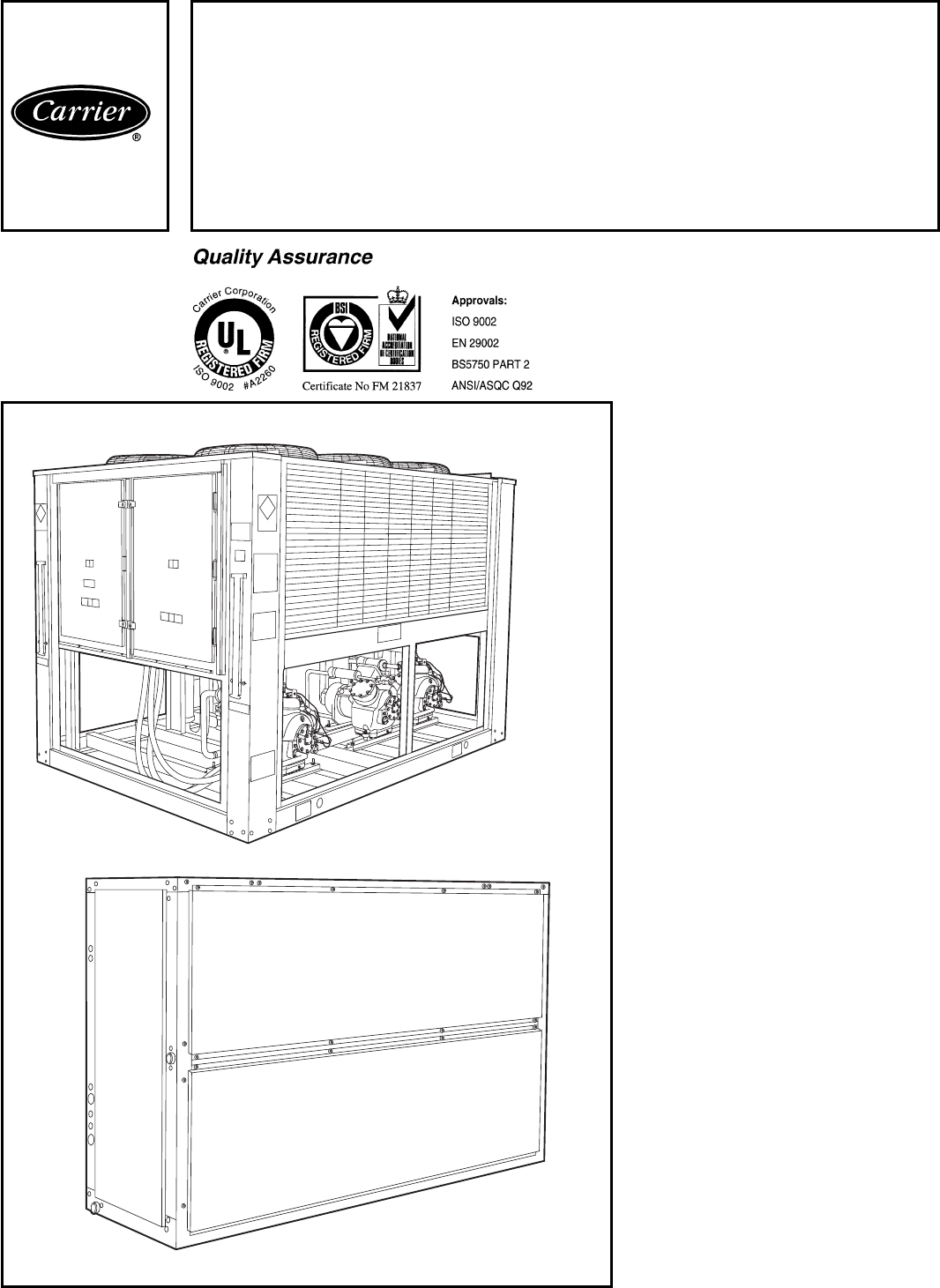
38AH CONDENSING UNIT
40RM016-034
Product
Data
38AH024-134
With 40RM016-034
Commercial Air-Cooled
Split Systems
50 Hz
63 to 390 Nominal kW (18 to 111 Tons)
Copyright 1998 Carrier Corporation Form 38AH-C4PD

The 38AH condensing unit offers the
utmost in system configuration and
control adaptability. Its premium-
quality standard components ensure
durable, efficient and reliable
operation.
Versatility
38AH Series condensing units feature
up to 4 compressors and 2 refriger-
ant circuits, and can be matched with
a wide variety of air-handling units.
All condensing unit circuits can supply
a single air handler; size 044-134
units can supply 2 separate air
handlers.
Standard units have constant vol-
ume control. A variable air volume
(VAV) option is available. The VAV
units have electric unloaders on the
compressors to closely match building
loads. The VAV option requires only
a simple connection to the Carrier
ModuPanel™ discharge air controller,
thereby saving installation time and
cost. (NOTE: Unit sizes 024-034
require field supplied and installed
accumulator.)
Durable construction
All 38AH units have weatherized cabi-
nets constructed of heavy-duty galva-
nized steel prepainted with corrosion-
resistant baked enamel. Inside and
outside surfaces are protected to en-
sure long life and good looks. The
durable, galvanized steel, prepainted
components exceed the requirements
of the 500-hour salt spray test per
ASTM B117.
The unit’s coils have aluminum fins
mechanically bonded to copper tubes
for long-term reliability and improved
heat transfer. An inert epoxy bar-
rier is available on precoated fins to
provide improved durability in mildly
corrosive coastal environments. Cop-
per fins on copper tubes are avail-
able for harsh industrial or coastal
conditions.
Reliability
The 38AH condensing units feature
time-proven, highly reliable 06D and
06E semi-hermetic compressors.
Unloading capability is a standard fea-
ture on the lead compressor of each
circuit. Each compressor has vibration
isolators to provide quiet operation
and reduced component stress.
Because 38AH units have 2 inde-
pendent circuits, they provide inherent
backup capability. Each circuit is also
protected by the following safety
features:
• Time Guardtanti-short-cycling
device
• low oil pressure safety switch
• low refrigerant pressure switch
(suction)
• high refrigerant pressure switch
(discharge)
• calibrated circuit breakers for com-
pressors and outdoor fans
Easier installation and service
38AH units are equipped with hinged
control-box access doors, liquid line
shutoff valves, and service valves
on the compressors.
Larger 38AH124 and 134 size
units are shipped as 2 modules for
easier handling and rigging.
Table of contents Page
Features/Benefits .............................................. 1-3
Model Number Nomenclature — 38AH024-034 ................... 4
Model Number Nomenclature — 40RM ........................... 5
Ratings Summary — 38AH024-034/40RM ........................ 5
Options and Accessories — 38AH024-034/40RM ................. 6-8
Physical Data — 38AH024-034 .................................. 9,10
Physical Data — 40RM .........................................11,12
Dimensions — 38AH024-034 ................................... 13
Dimensions — 40RM ...........................................14,15
Selection Procedure — 38AH024-034/40RM .....................16,17
Performance Data — 38AH024-034/40RM .......................18-31
Typical Piping and Wiring — 38AH024-034 .......................32,33
Electrical Data — 38AH024-034/40RM ..........................34-36
Controls — 38AH024-034 ...................................... 37
Typical Control Wiring Schematic — 38AH024-034 ................ 38
Application Data — 38AH024-034 ...............................39,40
Application Data — 40RM ......................................41-43
Model Number Nomenclature — 38AH044-134 ................... 44
Ratings Summary — 38AH044-134 .............................. 44
Options and Accessories — 38AH044-134 ........................45,46
Physical Data — 38AH044-134 ..................................47-50
Dimensions — 38AH044-134 ...................................51-57
Selection Procedure, 2-Circuit Units — 38AH044-134 .............. 58
Selection Procedure, Single-Circuit Units — 38AH044-084 Only ..... 58
Performance Data — 38AH044-134 .............................59-84
Typical Piping and Wiring — 38AH044-134 .......................85,86
Electrical Data — 38AH044-134 .................................87,88
Controls — 38AH044-084 ...................................... 89
Controls — 38AH094-134 ...................................... 90
Typical Control Wiring Schematic — 38AH044-134 ................91-93
Application Data — 38AH044-134 ..............................94-100
Guide Specifications — 38AH024-034 ..........................101-103
Guide Specifications — 40RM ..................................104,105
Guide Specifications — 38AH044-134 ..........................106-108
2

Feature/Benefits (cont)
Innovative Carrier 40RM air-
handling units in sizes 016-
034: ideal matches for
38AH024-034 condensing
units
The 40RM Series has excellent fan
performance, efficient direct-expansion
(DX) coils, a unique combination of
indoor air quality features, and easy
installation. Its versatility and state-of-
the-art features help to ensure that
your split system provides economical
performance now and in the future.
Indoor-air quality (IAQ)
features
The unique combination of IAQ
features in the 40RM Series air
handlers helps to make sure that only
clean, fresh, conditioned air is deliv-
ered to the occupied space.
Direct-expansion (DX) cooling coils
prevent the build-up of humidity in the
room, even during part-load condi-
tions. The 016-034 sizes feature dual-
circuit coils.
Standard 51-mm (2-in.) disposable
filters remove dust and airborne
particles from the occupied space.
Thermal insulation contains an
immobilized anti-microbial agent to
inhibit the growth of bacteria and
fungi. The anti-microbial agent is reg-
istered with the U.S. Environmental
Protection Agency (EPA).
The pitched PVC drain pan can be
adjusted for a right- or left-hand con-
nection to provide positive drainage
and to prevent standing condensate.
The 40RM accessory economizer
can provide ventilation air to improve
indoor-air quality. When used with
CO2sensors, the economizer admits
fresh outdoor air to replace stale,
recirculated indoor air. Includes 24-v
controls.
Economy
The 40RM Series packaged air
handlers save money by providing
reduced installation expense and
energy-efficient performance.
Quick installation is ensured by the
multiposition design. Units can be
installed in either the horizontal or
vertical (upflow) configuration without
modifications. All units have drain-
pan connections on both sides, and
pans can be pitched for right- or left-
hand operation with a simple ad-
justment. Fan motors and contactors
are prewired and thermostatic ex-
pansion valves (TXVs) are factory-
installed on all 40RM models.
High efficiency, precision-balanced
fans minimize air turbulence, surg-
ing, and unbalanced operation, cutting
operating expenses.
The economizer accessory precisely
controls the blend of outdoor air and
room air to achieve comfort levels.
When the outside air enthalpy is suit-
able, outside air dampers can fully
open to provide ‘‘free’’ cooling.
Rugged dependability
40RM units are made to last. The
die-formed galvanized steel panels
ensure structural integrity under all
operating conditions. Galvanized steel
fan housings are securely mounted
to a die-formed galvanized steel deck.
Mechanically bonded coil fins pro-
vide improved heat transfer. Rugged
pillow-block bearings are securely fas-
tened to the solid steel fan shaft
with split collets and clamp locking
devices.
Coil flexibility
Model 40RM direct-expansion coils
have galvanized steel tube sheets; inlet
and outlet connections are on the
same end. The coils are designed for
use with Refrigerant 22 and have cop-
per tubes mechanically bonded to
aluminum sine-wave fins. The coils
include matched, factory-installed
TXVs with matching distributor
nozzles. Accessory hot water and
steam coils and electric heaters are
also available.
Easier installation and service
The multiposition design and com-
ponent layout help you to get the unit
installed and running quickly. The
DX coils have factory-installed TXVs
with matching distributor nozzles.
Units can be converted from horizon-
tal to vertical operation by simply
repositioning the unit. Drain pan con-
nections are duplicated on both sides
of the unit. The filters, motor drive,
TXVs, and coil connections are all
easily accessed by removing a single
side panel.
3
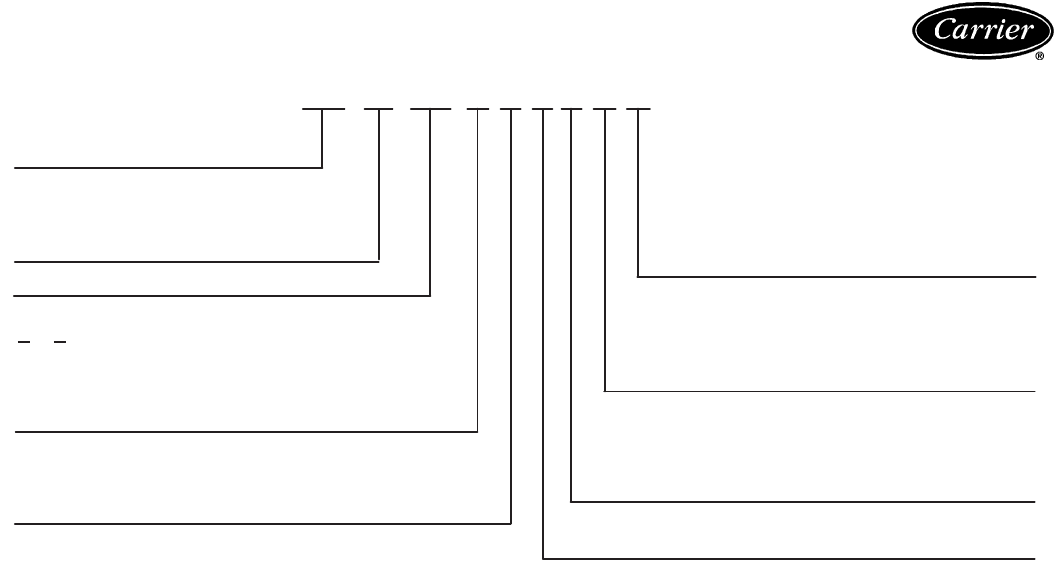
Model number nomenclature — 38AH024-034
SO—Special Order
UL — Underwriters’ Laboratories (U.S.A.)
38AH 024 — — — 9 1 3 A A
38AH — Commercial Air-Cooled Compressors
Condensing Unit A—Standard Compressors — One Suction
Pressure-Actuated Unloader on Lead
Nominal Capacity — kW (Tons) Compressor
024 — 63 (18) C—Variable Air Volume (VAV) Option —
028 — 73 (21) Includes 2 Electric Unloaders on Lead
034 — 87 (25) Compressor and Control Box
Modifications
Not Used Fan Motors and Labels
Condenser Coil Fin Material A — Standard Condenser Fan Motors
Aluminum (Standard) and Labels
C— Copper (Optional) B—Class F Fan Motors (Export Only) —
K— Precoated Aluminum (Optional) Not UL Approved
SO — Post-Coated Aluminum (Contact Factory)
SO — Post-Coated Copper (Contact Factory) Packaging
1—Standard Domestic Packaging —
Voltage Designation Bottom Skid
3—346-3-50 3—Export Packaging — Top and Bottom
8—230-3-50 Skid
9—400-3-50 Revision Number
1—Current Revision
4
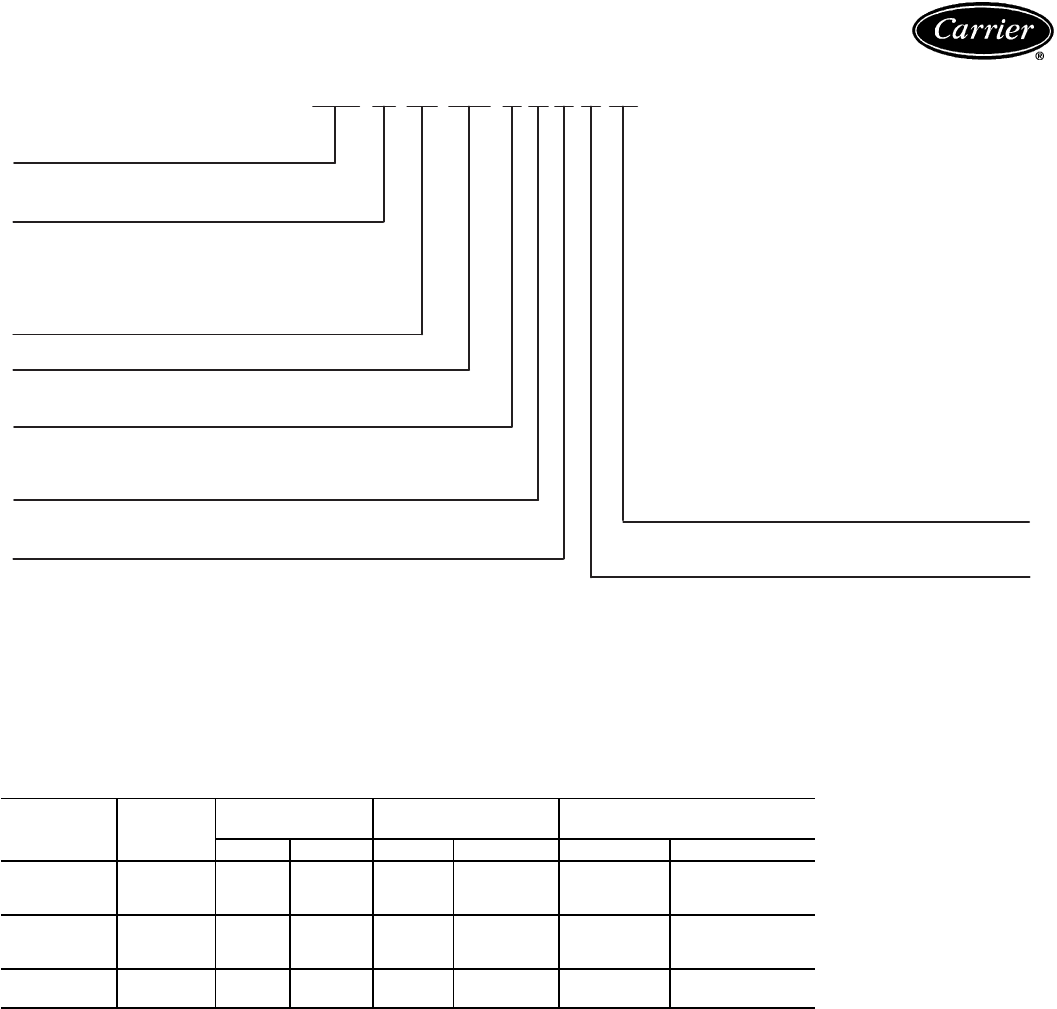
Model number nomenclature — 40RM
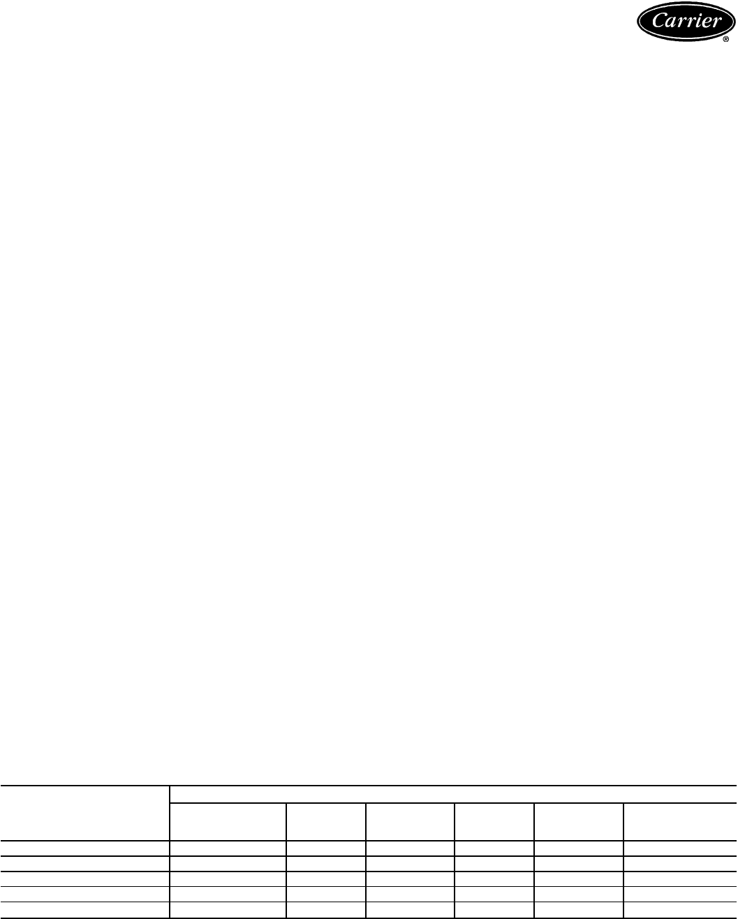
Ratings summary — 38AH024-034/40RM
OUTDOOR
UNIT
38AH
INDOOR
UNIT
40RM
AIRFLOW SYSTEM GROSS
CAPACITY CONDENSING UNIT ONLY
GROSS CAPACITY*
L/s Cfm kW† Btuh** kW Btuh
024 016 2,800 6,000 57.3 195,000 63 216,000024 3,800 8,000 62.5 214,000
028 4,700 10,000 66.3 227,000
028 024 3,800 8,000 68.9 236,000 73 250,000028 4,700 10,000 73.5 251,000
034 5,650 12,000 77.6 265,000
034 028 4,700 10,000 82.6 283,000 87 297,000
034 5,650 12,000 87.7 300,000
*Condensing unit only ratings are at 7.2 C (45 F) saturated suction temperature and 36 C (95 F) entering-air
temperature.
†Total gross system capacity (kW) is based on 20 C wet bulb and 26.7 C dry bulb air entering indoor unit, and
36 C dry bulb air entering outdoor unit.
**Total gross system capacity (Btuh) is based on 67 F wet bulb and 80 F dry bulb air entering indoor unit, and
95 F dry bulb air entering outdoor unit.
40RM — 016 — — B 9 0 3 GC
40RM — Commercial Packaged Factory-Installed Options
Air Handler GC — Unpainted, Standard Motor, and
Standard Drive
Cooling Coil HC — Unpainted, Standard Motor, and
——Direct Expansion Medium-Static Drive
(Not available for sizes 016-028)
Nominal Capacity — kW (Tons) TC — Unpainted, Alternate Motor, and
016 — 52 (15) Medium-Static Drive
024 — 70 (20) (sizes 016-028)
028 — 87 (25) YC — Unpainted, Alternate Motor, and
034 — 105 (30) High-Static Drive*
ED — Painted, Standard Motor, and
Not Used Standard Drive
FD — Painted, Standard Motor, and
Expansion Device Medium-Static Drive
B—Thermostatic Expansion Valve (Not available for sizes 016-028)
RD — Painted, Alternate Motor, and
Voltage Designation (V-Ph-Hz) Medium-Static Drive
8—230-3-50 (sizes 016-028)
9—400-3-50 WD — Painted, Alternate Motor, and
High Static Drive*
Revision Number
0—Original Model Packaging
3—Export Packaging
*YC and WD option codes for all 034 size units designate standard motor and high-static drive.
5
Options and accessories —
38AH024-034/40RM
38AH024-034 factory-installed options
VAV option provides unit with 2 electric unloaders and
control box modifications necessary to connect to a field-
installed ModuPanel™ control.
Class F fan motors provide additional motor insulation
for high ambient temperature environments.
Condenser coil options are available to match coil con-
struction to site conditions for the best corrosion durability.
Pre-coated coils provide protection in mild coastal environ-
ments. All copper coils are best suited for moderate coastal
applications, while post-coated coils provide superior pro-
tection in severe coastal and industrial applications.
38AH024-034 field-installed accessories
Pressure-operated unloading allows compressors to be
unloaded in response to compressor suction pressure.
Electric unloader conversion package includes hard-
ware and solenoid valve to convert a pressure-operated
unloader to electric unloading.
Electric unloading package provides an additional step
of electric unloading.
−29 C (−20 F) low-ambient temperature kit (Motor-
mastertIII) controls outdoor-fan motor operation to main-
tain the correct head pressure at low outdoor ambient tem-
peratures. Only one low ambient temperature kit is required
per unit.
Gage panel package provides a suction and a discharge
pressure gage for one refrigerant circuit.
ModuPanel control box allows 38AH system to operate
VAV system. Includes microprocessor satellite sequencer,
4 status lights, 5-hour bypass timer, and locked enclosure.
Requires field-installed accumulator.
Carrier’s line of thermostats provide both program-
mable and non-programmable capability with the new
Debonair™ line of commercial programmable thermo-
stats, the TEMP System controls offer communication
capability with staged heating and cooling, the Commer-
cial Electronic thermostats provide 7-day programmable
capability for economical applications, while the non-
programmable thermostats offer a multitude of staged
heating and cooling subbase options.
40RM factory-installed options
Prepainted steel units are available from the factory for
applications that require painted units. Units are painted
with American Sterling Gray color. (Check availability and
lead times.)
Alternate fan motors and drives are available to pro-
vide the widest possible range of performance.
40RM field-installed accessories
Discharge plenum directs the air discharge directly into
the occupied space; integral horizontal and vertical louvers
enable redirection of airflow. Accessory is available un-
painted or painted. Field assembly required.
Two-row hot water coils have 5.9-mm (
5
⁄
8
-in.) diameter
copper tubes mechanically bonded to aluminum plate fins.
Coils have non-ferrous headers.
One-row steam coil has 25.4-mm (1-in.) OD copper tube
and aluminum fins. The Inner Distributing Tube (IDT)
design provides uniform temperatures across the coil face.
The steam coil has a broad operating pressure range; up to
1207 kPag at 204.4 C (175 psig at 400 F) and up to
2069 kPag at 148.9 C (300 psig at 300 F). IDT steam coils
are especially suited to applications where sub-freezing air
enters the unit.
Electric resistance heaters have a one- or two-stage,
open-wire design and are mounted in a rigid frame. Safety
cutouts for high temperature conditions are standard. Heat-
ers also feature single-point power connection.
Economizer (enthalpy controlled) provides ventilation
air and ‘‘free’’ cooling if outside ambient temperature and
humidity are suitable. Can also be used with CO
2
sensors
to help meet indoor air quality requirements. Economizer
comes complete with 24 v controls.
Return-air grille provides a protective barrier over
the return-air opening and gives a finished appearance to
units installed in the occupied space. Accessory is available
unpainted or painted.
Subbase provides a stable, raised platform and room
for condensate drain connection for floor-mounted units.
Accessory is available unpainted or painted. Field assembly
required.
CONDENSER COIL PROTECTION APPLICATIONS
DESCRIPTION
(
Enviro-Shield™
Option)
ENVIRONMENT*
Standard,
Non-Corrosive Mild
Coastal Moderate
Coastal Severe
Coastal Industrial Combined
Coastal
and Industrial
Standard, Al/Cu X
Pre-Coated Al/Cu X
Cu/Cu X
Post-Coated Al/Cu X
Post-Coated Cu/Cu XX
LEGEND
Al/Cu — Aluminum Fin with Copper Tube Coil
Cu/Cu — Copper Fin with Copper Tube Coil
Enviro-Shield
—Family of Coil Protection Options
Post-Coated — Organic Coating applied to Entire Coil Assembly
Pre-Coated — Epoxy Coating Applied to Fin Stock Material
*See ‘‘Selection Guide: Environmental Corrosion Protection’’ Catalog No. 811-839 for more information.
6
Overhead suspension brackets support units in hori-
zontal ceiling installations.
Carrier’s line of thermostats provide both program-
mable and non-programmable capability with the new
Debonair™ line of commercial programmable thermo-
stats, the TEMP System controls offer communication
capability with staged heating and cooling, the Commer-
cial Electronic thermostats provide 7-day programmable
capability for economical applications, while the non-
programmable thermostats offer a multitude of staged
heating and cooling subbase options.
CO
2
sensors can be used in conjunction with the econo-
mizer accessory to help meet indoor air quality require-
ments. The sensor signals the economizer to open when
the CO
2
level in the space exceeds the set point. A Carrier
Comfort System programmable thermostat can be used to
override the sensor if the outside-air temperature is too high
or too low.
CO
2
sensors can be connected to the Carrier Comfort
System relay pack or to the economizer accessory. Con-
nection to the economizer requires field-supplied and in-
stalled Honeywell dc adapter no. Q769C1004.
Condensate drain trap includesanoverflowshutoff switch
than can be wired to turn off the unit if the trap becomes
plugged. The kit also includes a wire harness that can be
connected to an alarm if desired. The transparent trap is
designed for easy service and maintenance.
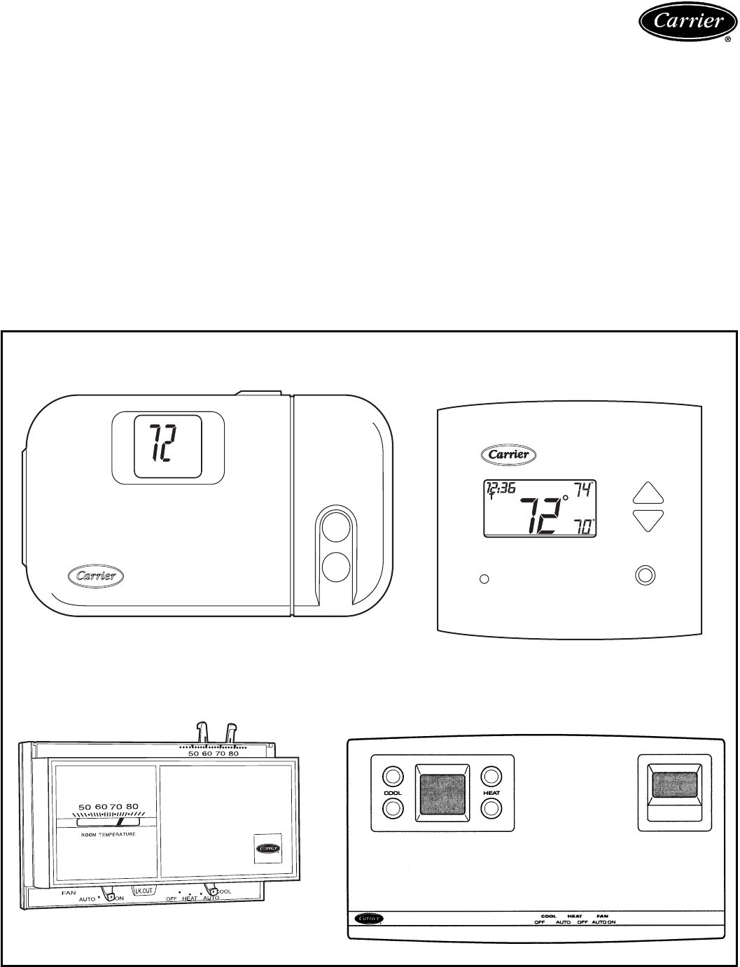
CARRIER THERMOSTATS
COMMERCIAL ELECTRONIC THERMOSTAT
NON-PROGRAMMABLE THERMOSTAT
H
C
DEBONAIR™ COMMERCIAL PROGRAMMABLE
THERMOSTAT
AUTO
Pm
COOL
HEAT
Carrier®
TEMP SYSTEM THERMOSTAT
WITH TIMECLOCK
7
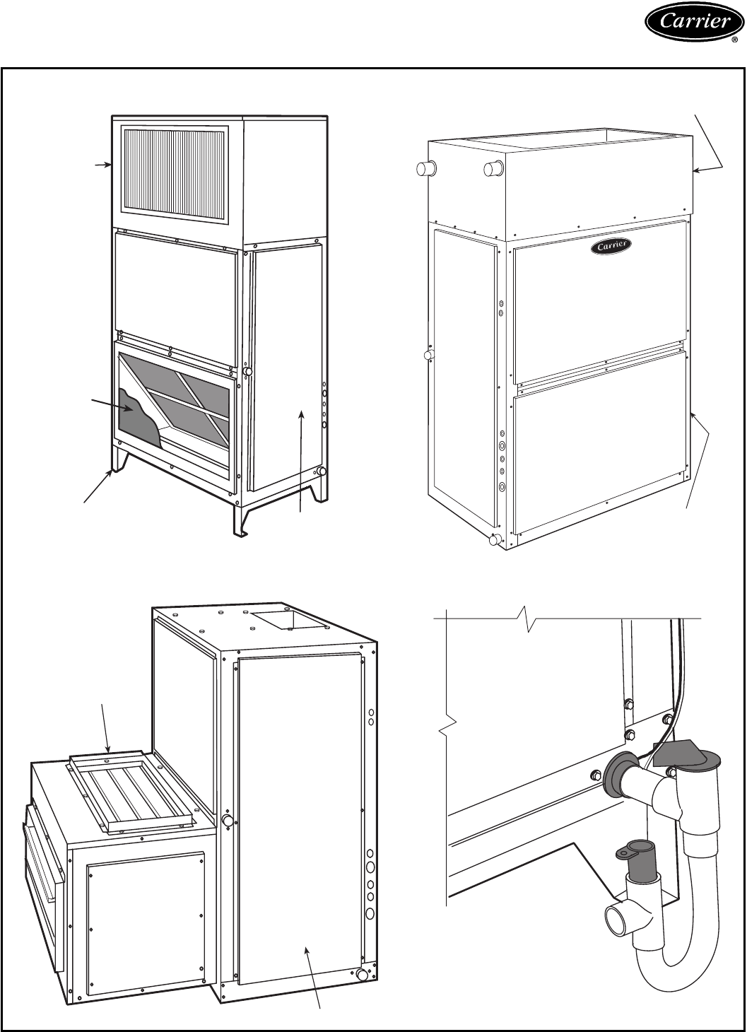
Options and accessories —
38AH024-034/40RM (cont)
40RM WITH DISCHARGE PLENUM, RETURN
GRILLE, AND SUBBASE
DISCHARGE
PLENUM
RETURN-AIR
GRILLE
SUBBASE
FAN
COIL
UNIT
40RM WITH ECONOMIZER
ECONOMIZER
FAN COIL UNIT
40RM WITH HOT WATER OR STEAM COIL
FAN COIL
UNIT
HOT WATER OR
STEAM COIL
40RM WITH CONDENSATE DRAIN TRAP
8
Physical data — 38AH024-034
38AH024-034 UNITS — SI
UNIT 38AH 024 028 034
Circuit 1 Circuit 2 Circuit 1 Circuit 2 Circuit 1 Circuit 2
NOMINAL CAPACITY (kW) 63 73 87
OPERATING WEIGHT (kg)
With Aluminum-Fin Coil 798.3 825.6 853.0
With Copper-Fin Coil 872.3 899.0 951.2
COMPRESSOR Reciprocating Semi-Hermetic
Type 06DH824 06DA824 06DH328 06DA328 06DH328 06DA537
Quantity Cylinders (ea) 666666
Speed (r/s) 24.3 24.3 24.3 24.3 24.3 24.3
Capacity Steps
(FIOP or Acy) — % 100 100 100 100 100 100
—% 67* — 67* — 67* —
—% 33† — 33† — 33† —
Unloader Setting (kPa) Factory Installed
— Load 524 — 524 — 524 —
— Unload 400 — 400 — 400 —
OIL CHARGE PER CIRCUIT (L) 4.73
REFRIGERANT R-22
Shipping Charge (kg)** 1.36 1.36 1.36 1.36 1.36 1.36
Operating Charge, Typical (kg)** 9.1 9.1 9.1 9.1 11.4 11.4
CONDENSER FANS Propeller Type — Direct Driven
Quantity...Dia (mm) 2...762 2...762 2...762
Nominal Hp 1.0 1.0 1.0
Nominal Airflow (L/s) 7870 7870 7400
Speed (r/s) 16
Watts (total) 3100
CONDENSER COIL Enhanced Copper Tubes, Aluminum Lanced Fin
Rows...Fins/m 2...748 2...748 3...670
Total Face Area (sq m) 3.64 3.64 3.64
Storage Cap. (kg)†† 17.4 17.4 26.0
CONTROLS
Pressurestat (kPa)
High Pressure
Cutout 2937 648
Cut-in 2206 6138
Low Pressure
Cutout 186 621
Cut-in 303 634
Oil Pressure Manual Reset
Cutout (Diff) 41.4
Cut-in (Diff) 60.7
FAN CYCLING CONTROLS
No. 2 Fan:
Temp Close (C) 21.1 61.6
Temp Open (C) 15.6 61.6
PRESSURE RELIEF Fusible Plug
Location Liquid Line, Suction Line, Compressor
Temp (C) 99
CONNECTIONS (Sweat) (ea ckt)
Suction — in. OD 1
3
⁄
8
Liquid — in. OD
5
⁄
8
LEGEND
Diff — Differential
FIOP — Factory-Installed Option
VAV — Variable Air Volume
*Standard unit — single pressure-actuated suction unloader on com-
pressor no. 1.
†VAV FIOP — double electrically actuated unloaders on compressor
no. 1.
**With 7.6 m of interconnecting piping.
††Condenser 80% full of liquid R-22 at 48.8 C.
9
Physical data — 38AH024-034 (cont)
38AH024-034 UNITS — ENGLISH
UNIT 38AH 024 028 034
Circuit 1 Circuit 2 Circuit 1 Circuit 2 Circuit 1 Circuit 2
NOMINAL CAPACITY (Tons) 18 21 25
OPERATING WEIGHT (lb)
With Aluminum-Fin Coil 1760 1820 1880
With Copper-Fin Coil 1923 1982 2097
COMPRESSOR Reciprocating Semi-Hermetic
Type 06DH824 06DA824 06DH328 06DA328 06DH328 06DA537
Quantity Cylinders (ea) 666666
Speed (rpm) 1450 1450 1450 1450 1450 1450
Capacity Steps
(FIOP or Acy) — % 100 100 100 100 100 100
—% 67* — 67* — 67* —
—% 33† — 33† — 33† —
Unloader Setting (psig) Factory Installed
— Load 76—76—76—
— Unload 58—58—58—
OIL CHARGE PER CIRCUIT (Pt) 10
REFRIGERANT R-22
Shipping Charge (lb)** 333333
Operating Charge, Typical (lb)** 20 20 20 20 25 25
CONDENSER FANS Propeller Type — Direct Driven
Quantity...Dia (in.) 2...30 2...30 2...30
Nominal Hp 1.0 1.0 1.0
Nominal Airflow (cfm) 16,700 16,700 15,700
Speed (rpm) 950
Watts (total) 3100
CONDENSER COIL Enhanced Copper Tubes, Aluminum Lanced Fin
Rows...Fins/in. 2...19 2...19 3...17
Total Face Area (sq ft) 39.20 39.20 39.20
Storage Cap. (lb)†† 37.7 37.7 56.6
CONTROLS
Pressurestat (psig)
High Pressure
Cutout 426 67
Cut-in 320 620
Low Pressure
Cutout 27 63
Cut-in 44 65
Oil Pressure Manual Reset
Cutout (Diff) 6.0
Cut-in (Diff) 8.8
FAN CYCLING CONTROLS
No. 2 Fan:
Temp Close (F) 70 63
Temp Open (F) 60 63
PRESSURE RELIEF Fusible Plug
Location Liquid Line, Suction Line, Compressor
Temp (F) 210
CONNECTIONS (Sweat) (ea ckt)
Suction — in. OD 1
3
⁄
8
Liquid — in. OD
5
⁄
8
LEGEND
Diff — Differential
FIOP — Factory-Installed Option
VAV — Variable Air Volume
*Standard unit — single pressure-actuated suction unloader on com-
pressor no. 1.
†VAV FIOP — double electrically actuated unloaders on compressor
no. 1.
**With 25 ft of interconnecting piping.
††Condenser 80% full of liquid R-22 at 120 F.
10

Physical data — 40RM
40RM — SI
UNIT 40RM 016 024 028 034
NOMINAL CAPACITY (kW) 52 70 87 105
OPERATING WEIGHT (kg)
Base Unit with TXV 311 313 463 467
Plenum 63 63 82 82
FANS
Qty...Diam. (mm) 2...381 2...381 2...457 2...457
Nominal Airflow (L/s) 2831 3775 4719 5663
Airflow Range (L/s) 2124-3539 2831-4719 3539-5899 4247-7079
Nominal Motor kW (Standard Motor)
230-3-50, 400-3-50 2.16 3.73 5.60 7.46
Motor Speed (r/s)
230-3-50, 400-3-50 23.8 23.8 23.8 23.8
REFRIGERANT R-22
Operating charge (kg)
(approx per circuit)* 1.13/1.13 1.59/1.59 2.04/2.04 2.27/2.27
DIRECT-EXPANSION COIL Enhanced Copper Tubes, Aluminum Sine-Wave Fins
Max Working Pressure (kPag) 2999
Face Area (sq m) 1.64 1.85 2.30 2.77
No. of Splits 2222
No. of Circuits per Split 12 13 15 18
Split Type...Percentage Face...50/50
Rows...Fins/m 3...591 3...670 3...591 3...591
STEAM COIL
Max Working Pressure (kPag at 204.4 C) 1207
Total Face Area (sq m) 1.24 1.24 1.39 1.39
Rows...Fins/m 1...394 1...394 1...394 1...394
HOT WATER COIL
Max Working Pressure (kPag) 1034
Total Face Area (sq m) 1.24 1.24 1.39 1.39
Rows...Fins/m 2...335 2...335 2...493 2...493
Water Volume
(L) 52.6 54.1
(m
3
)0.052 0.054
PIPING CONNECTIONS,
Quantity...Size (in.)
DX Coil — Suction (ODF) 2...1
1
⁄
8
2...1
1
⁄
8
2...1
3
⁄
8
2...1
3
⁄
8
DX Coil — Liquid Refrigerant (ODF) 2...
5
⁄
8
Steam Coil, In (MPT) 1...2
1
⁄
2
Steam Coil, Out (MPT) 1...2
1
⁄
2
Hot Water Coil, In (MPT) 1...2
Hot Water Coil, Out (MPT) 1...2
Condensate (PVC) 1...1
1
⁄
4
ODM/1 IDF
FILTERS Throwaway — Factory Supplied
Quantity...Size 4...406 × 508 × 51
4...406 × 610 × 51 4...508 x 610 x 51
4...508 x 635 x 51
Access Location Right or Left Side
LEGEND
DX — Direct Expansion
TXV — Thermostatic Expansion Valve
*Units are shipped without refrigerant charge.
11
Physical data — 40RM (cont)
40RM — ENGLISH
UNIT 40RM 016 024 028 034
NOMINAL CAPACITY (Tons) 15 20 25 30
OPERATING WEIGHT (lb)
Base Unit with TXV 685 690 1020 1030
Plenum 140 140 180 180
FANS
Qty...Diam. (in.) 2...15 2...15 2...18 2...18
Nominal Airflow (cfm) 6000 8000 10,000 12,000
Airflow Range (cfm) 4500-7500 6000-10,000 7500-12,500 9000-15,000
Nominal Motor Hp (Standard Motor)
230-3-50, 400-3-50 2.9 5.0 7.5 10.0
Motor Speed (rpm)
230-3-50, 400-3-50 1425
REFRIGERANT R-22
Operating charge (lb)
(approx per circuit)* 2.5/2.5 3.5/3.5 4.5/4.5 5.0/5.0
DIRECT-EXPANSION COIL Enhanced Copper Tubes, Aluminum Sine-Wave Fins
Max Working Pressure (psig) 435
Face Area (sq ft) 17.67 19.88 24.86 29.83
No. of Splits 2222
Split Type...Percentage Face...50/50
No. of Circuits per Split 12 13 15 18
Rows...Fins/in. 3...15 3...17 3...15 3...15
STEAM COIL
Max Working Pressure (psig at 400 F) 175
Total Face Area (sq ft) 13.33 13.33 15.0 15.0
Rows...Fins/in. 1...10 1...10 1...10 1...10
HOT WATER COIL
Max Working Pressure (psig) 150
Total Face Area (sq ft) 13.33 13.33 15.0 15.0
Rows...Fins/in. 2...8.5 2...8.5 2...12.5 2...12.5
Water Volume
(gal) 13.9 14.3
(ft
3
)1.85 1.90
PIPING CONNECTIONS,
Quantity...Size (in.)
DX Coil — Suction (ODF) 2...1
1
⁄
8
2...1
1
⁄
8
2...1
3
⁄
8
2...1
3
⁄
8
DX Coil — Liquid Refrigerant (ODF) 2...
5
⁄
8
Steam Coil, In (MPT) 1...2
1
⁄
2
Steam Coil, Out (MPT) 1...2
1
⁄
2
Hot Water Coil, In (MPT) 1...2
Hot Water Coil, Out (MPT) 1...2
Condensate (PVC) 1...1
1
⁄
4
ODM/1 IDF
FILTERS Throwaway — Factory Supplied
Quantity...Size (in.) 4...16 × 20 × 2
4...16 × 24 × 2 4...20 x 24 x 2
4...20 x 25 x 2
Access Location Right or Left Side
LEGEND
DX — Direct Expansion
TXV — Thermostatic Expansion Valve
*Units are shipped without refrigerant charge.
12
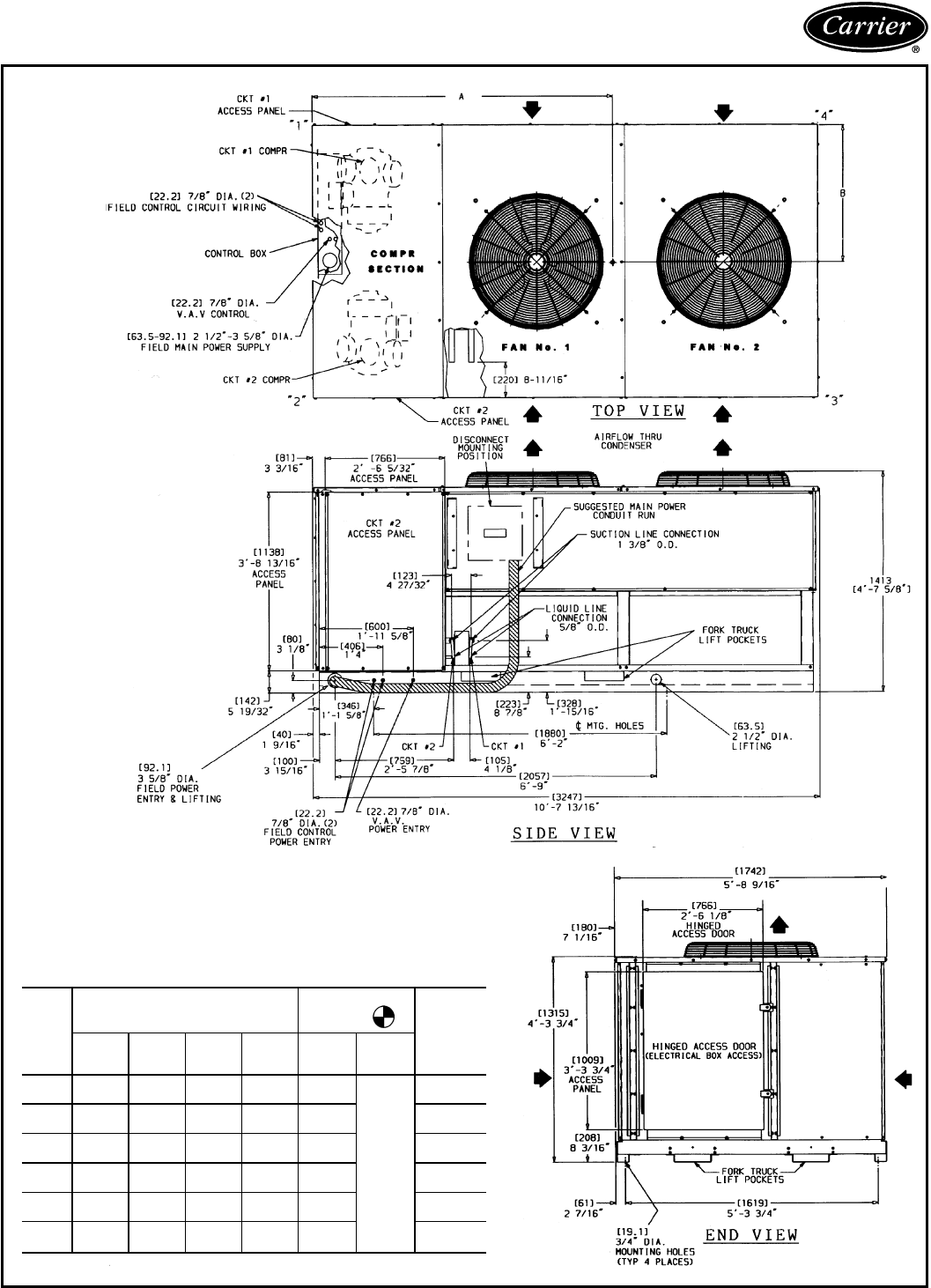
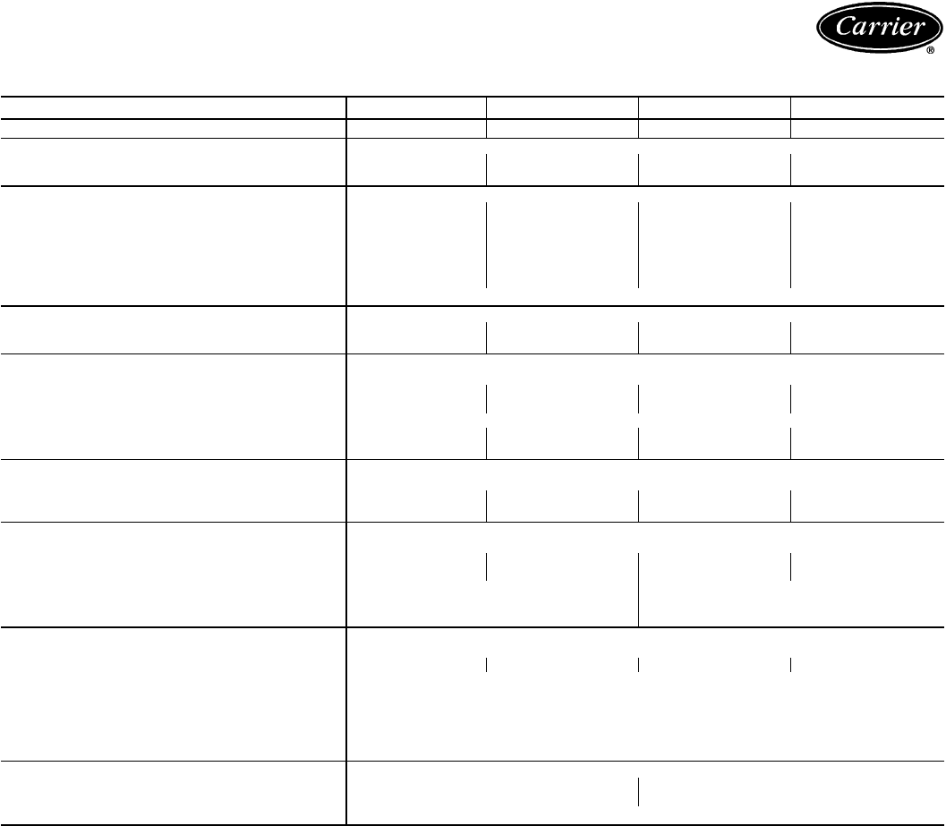
Dimensions — 38AH024-034
NOTES:
1. There must be 4 ft [1220 mm] for service and for unrestricted airflow on all
sides of unit.
2. There must be minimum 8 ft [2440 mm] clear air space above unit.
3. ‘‘C’’ in the package number indicates copper coils.
4. Dimensions in [ ] are in millimeters.
5. The approximate operating weight of the unit is shown below.
6. Certified dimensional drawing is available on request.
UNIT
38AH
CORNER WEIGHT — lbs [kg] CENTER OF
GRAVITY TOTAL
UNIT WT
lb [kg]
‘‘1’’ ‘‘2’’ ‘‘3’’ ‘‘4’’ A Dim.
in.
[mm]
B Dim.
in.
[mm]
024 631.6
[286.5] 577.6
[262.0] 263.1
[119.3] 287.7
[130.5] 40.00
[1016]
32.75
[832]
1760
[798.3]
024C 666.5
[302.3] 609.5
[276.5] 309.0
[140.2] 337.9
[153.3] 43.00
[1092] 1923
[872.3]
028 658.7
[298.8] 602.4
[273.3] 267.0
[121.1] 291.9
[132.4] 39.25
[997] 1820
[825.6]
028C 693.0
[314.3] 633.8
[287.5] 313.0
[142.0] 342.2
[155.2] 42.25
[1073] 1982
[899.0]
034 667.0
[302.5] 610.0
[276.7] 288.0
[130.7] 315.0
[142.9] 41.00
[1041] 1880
[853.0]
034C 718.3
[325.8] 656.8
[297.9] 344.8
[156.4] 377.0
[171.0] 44.00
[1117] 2097
[951.2]
13
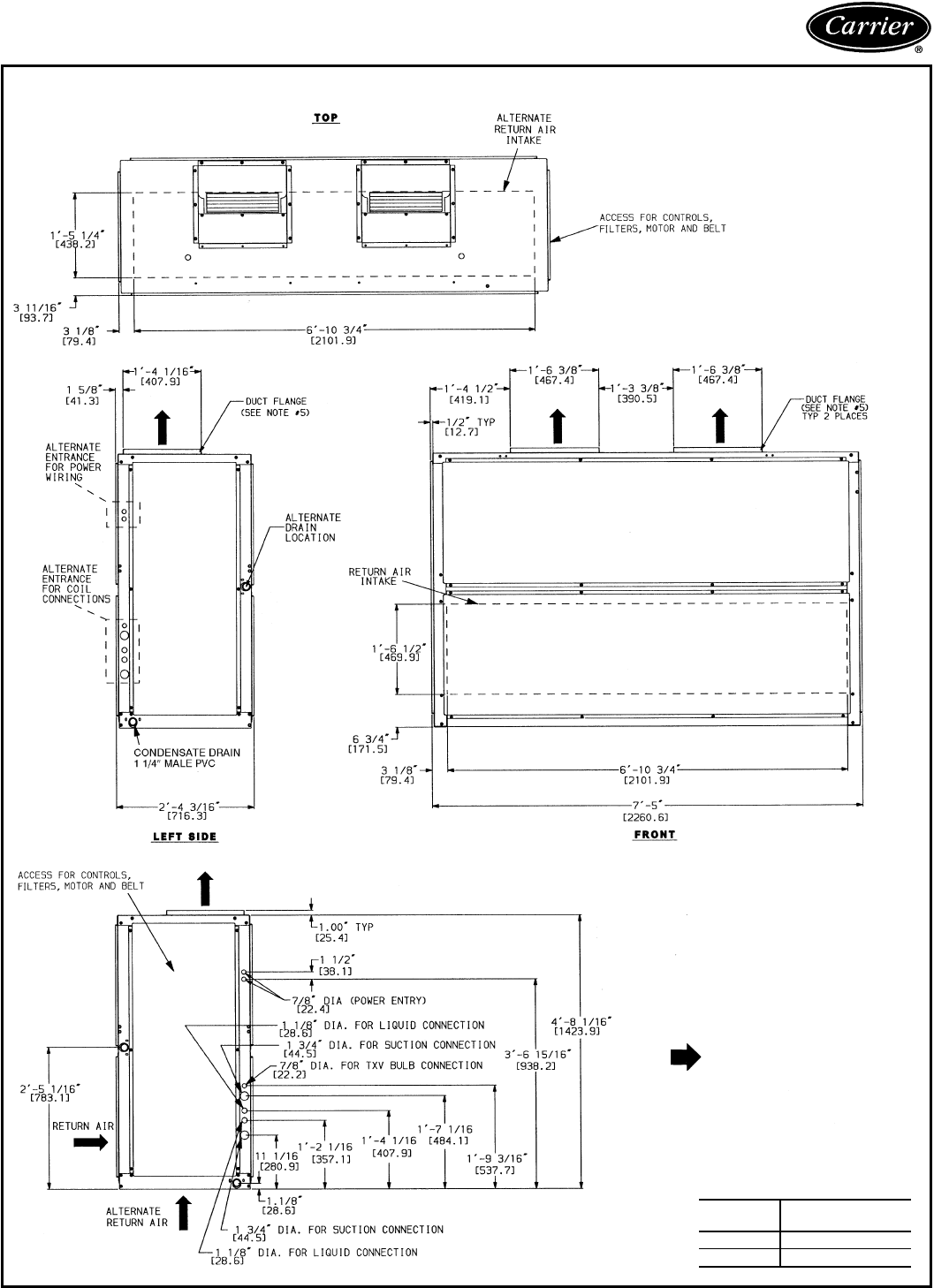
Dimensions — 40RM
40RM016,024
TXV — Thermostatic Expansion Valve
NOTES:
1. Dimensions in [ ] are in millimeters.
2. Direction of airflow.
3. Recommended clearance:
• Rear: 76 mm (3 in.)
• Front: 762 mm (2 ft, 6 in.)
• Right side: 762 mm (2 ft, 6 in.)
• Left side: 762 mm (2 ft, 6 in.)
• Local codes or jurisdiction may prevail.
4. Liquid piping not supplied by Carrier.
5. Duct flange is factory supplied and field
installed.
UNIT
40RM UNIT WEIGHT
lb (kg)
016 685 (311)
024 690 (313)
14
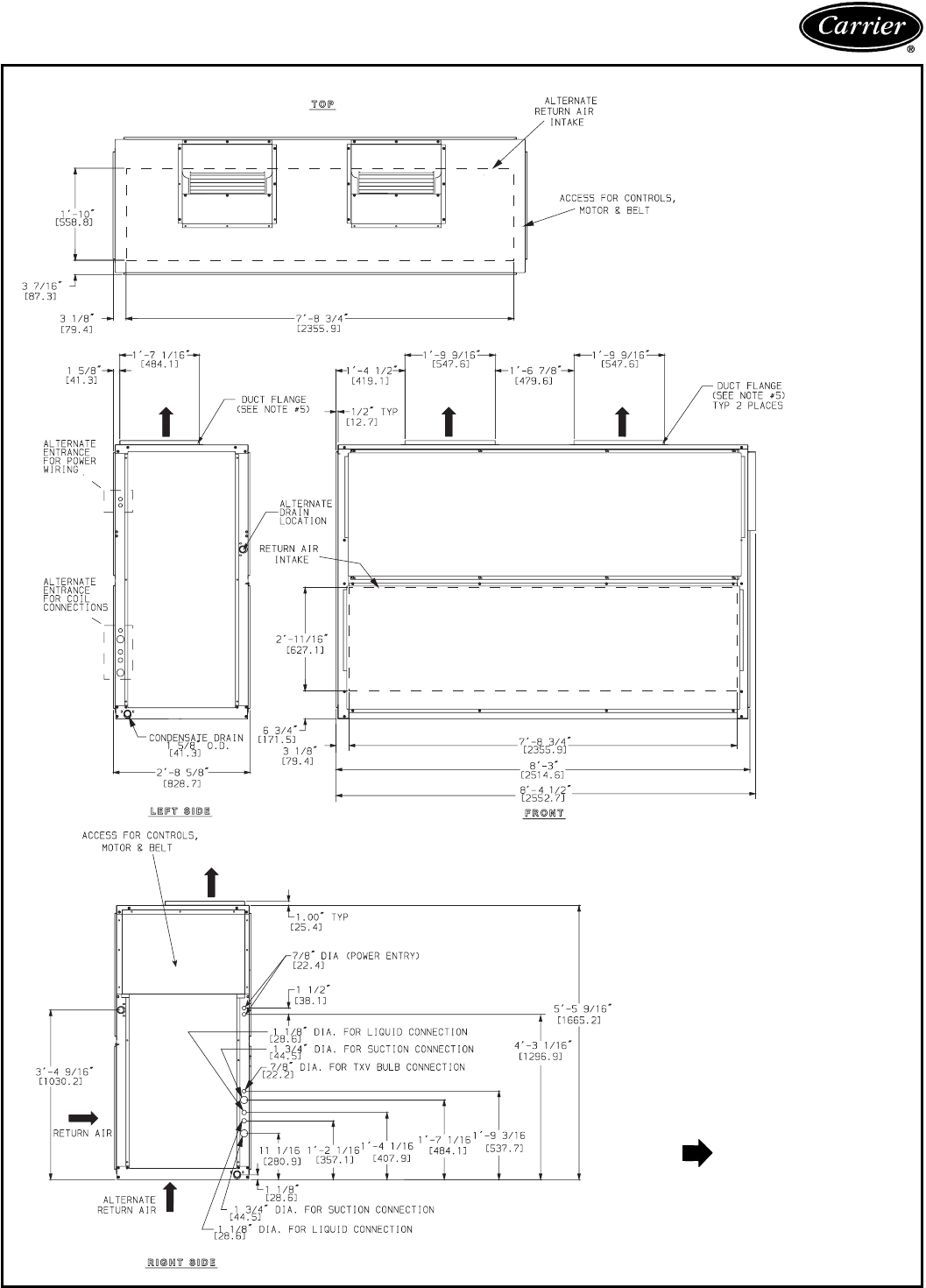
40RM028,034
TXV — Thermostatic Expansion Valve
NOTES:
1. Dimensions in [ ] are in millimeters.
2. Direction of airflow.
3. Recommended clearance:
• Rear: 76 mm (3 in.)
• Front: 762 mm (2 ft, 6 in.)
• Right side: 762 mm (2 ft, 6 in.)
• Left side: 762 mm (2 ft, 6 in.)
• Local codes or jurisdiction may prevail.
4. Liquid piping not supplied by Carrier.
5. Duct flange is factory supplied and field
installed.
15

Selection procedure —
38AH024-034/40RM — SI
NOTE: Pages 22 and 23 contain combination ratings
for 38AH024-034 units and matching 40RM air hand-
lers. If the 38AH units are matched with 39L or 39NX air
handlers, use the Carrier AHU (Air-Handling Unit) selec-
tion program software package for combination ratings. If
TotalinetP702 water coolers are used, determine the per-
formanceby cross-plotting the condensing unit performance
found in this book against the P702 performance in the
P702 product data book. If the 38AH condensing units are
matched with 2 independent 40RM units, cross-plot for per-
formance ratings or contact Carrier Application Engineer-
ing for assistance.
I Determine cooling load, evaporator-air tempera-
ture and quantity.
Given:
Total Cooling Capacity
Required (TC) .........................60kW
Sensible Heat Capacity
Required (SHC) .......................48kW
Temperature Air Entering
Condenser (Edb) ........................36C
Temperature Air Entering
Evaporator (db/wb) ........26.7 C db, 20 C wb
Evaporator Air Quantity ...............3800 L/s
External Static Pressure ..................150Pa
Length of Interconnecting
Refrigerant Piping ...............18m(Linear)
II Select condensing unit air-handler combination.
For this example, select a 38AH024 matched with a
40RM024. (See Combination Ratings table, page 22)
This 38AH024/40RM024 condensing unit-air hand-
ler combination provides 62.5 kW of total cooling
capacity and 49.2 kW of sensible capacity at the given
conditions. If other temperatures or airflow values are
required, interpolate the values from the combination
ratings.
III Determine sizes of liquid and suction lines.
Enter the Refrigerant Pipe Sizes table (page 40). The
sizes shown are based on an equivalent length of pipe.
This equivalent length is equal to the linear length
of pipe indicated at the top of each sizing column, plus
a 50% allowance for fitting losses. (For a more accu-
rate determination of actual equivalent length in place
of using the estimated 50% value, refer to Carrier
System Design Manual.) For this example, note in the
linear length column that the proper pipe size is
5
⁄
8
in.
for the liquid lines and 1
3
⁄
8
in. for the suction lines.
IV Determine fan rpm and bhp (brake horsepower).
At the Air Handler Fan Performance table (page 27),
enter the 40RM024 section at 3800 L/s and move to
the External Static Pressure (ESP) column. Note that
the conditions require 14.30 r/s at 2.64 kW.
V Determine motor and drive.
Enter the Fan Motor Data tables on page 41, and find
that the standard motor for a 40RM024 unit is rated
at 3.73. Since the kW required is 2.64, a standard
motor satisfies the requirement and should be used.
Next, find the type of drive that satisfies the 14.30 r/s
requirement in the Drive Data tables on page 42. For
a 40RM024 unit, the Standard Drive table shows an
r/s range of 11.9 to 14.6. Since the r/s required is
14.30, the standard drive satisfies the requirement and
should be used. Select the standard motor and stand-
ard drive combination (option code GC or ED).
16

Selection procedure —
38AH024-034/40RM — English
NOTE: Pages 24 and 25 contain combination ratings for
38AH024-034 units and matching 40RM air handlers. If
the 38AH units are matched with 39L or 39NX air
handlers, use the Carrier AHU (Air-Handling Unit) selection
program software package for combination ratings. If
TotalinetP702 water coolers are used, determine the per-
formanceby cross-plotting the condensing unit performance
found in this book against the P702 performance in the
P702 product data book. If the 38AH condensing units are
matched with 2 independent 40RM units, cross-plot for per-
formance ratings or contact Carrier Application Engineer-
ing for assistance.
I Determine cooling load, evaporator-air tempera-
ture and quantity.
Given:
Total Cooling Capacity
Required (TC) ..................210,000 Btuh
Sensible Heat Capacity
Required (SHC) .................175,000 Btuh
Temperature Air Entering
Condenser (Edb) ........................95F
Temperature Air Entering
Evaporator (db/wb) ...........80Fdb,67Fwb
Evaporator Air Quantity ...............8000 cfm
External Static Pressure ...............1.0in.wg
Length of Interconnecting
Refrigerant Piping ................30ft(Linear)
II Select condensing unit air-handler combination.
For this example, select a 38AH024 matched with a
40RM024. (See Combination Ratings table, page 24.)
This 38AH024/40RM024 condensing unit-air hand-
ler combination provides 214,500 Btuh of total cool-
ing capacity and 179,000 Btuh of sensible capacity at
the given conditions. If other temperatures or airflow
valuesare required, interpolatethe values from the com-
bination ratings.
III Determine sizes of liquid and suction lines.
Enter the Refrigerant Pipe Sizes table (page 40). The
sizes shown are based on an equivalent length of pipe.
This equivalent length is equal to the linear length of
pipe indicated at the top of each sizing column, plus a
50% allowance for fitting losses. (For a more accurate
determination of actual equivalent length in place of
using the estimated 50% value, refer to Carrier
System Design Manual.) For this example, note in the
linear length column that the proper pipe size is
5
⁄
8
in.
for the liquid lines and 1
3
⁄
8
in. for the suction lines.
IV Determine fan rpm and bhp (brake horsepower).
At the Air Handler Fan Performance table (page 29),
enter the 40RM024 section at 8000 cfm and move to
the External Static Pressure (ESP) column. Note that
the conditions require 954 rpm at 4.23 bhp.
V Determine motor and drive.
Enter the Fan Motor Data tables on page 41, and find
that the alternate motor for a 40RM024 unit is rated
at 7.5 hp. Since the bhp required is 4.23, an alternate
motor satisfies the requirement and should be used.
Next, find the type of drive that satisfies the 954 rpm
requirement in the Drive Data tables on pages 42 and
43.For a 40RM024 unit, the Medium-Static Drive table
shows an rpm range of 814 to 1018 . Since the rpm
required is 954, the medium-static drive satisfies the
requirement and should be used. Select the alternate
motor and medium-static drive combination (option
code TC or RD).
17
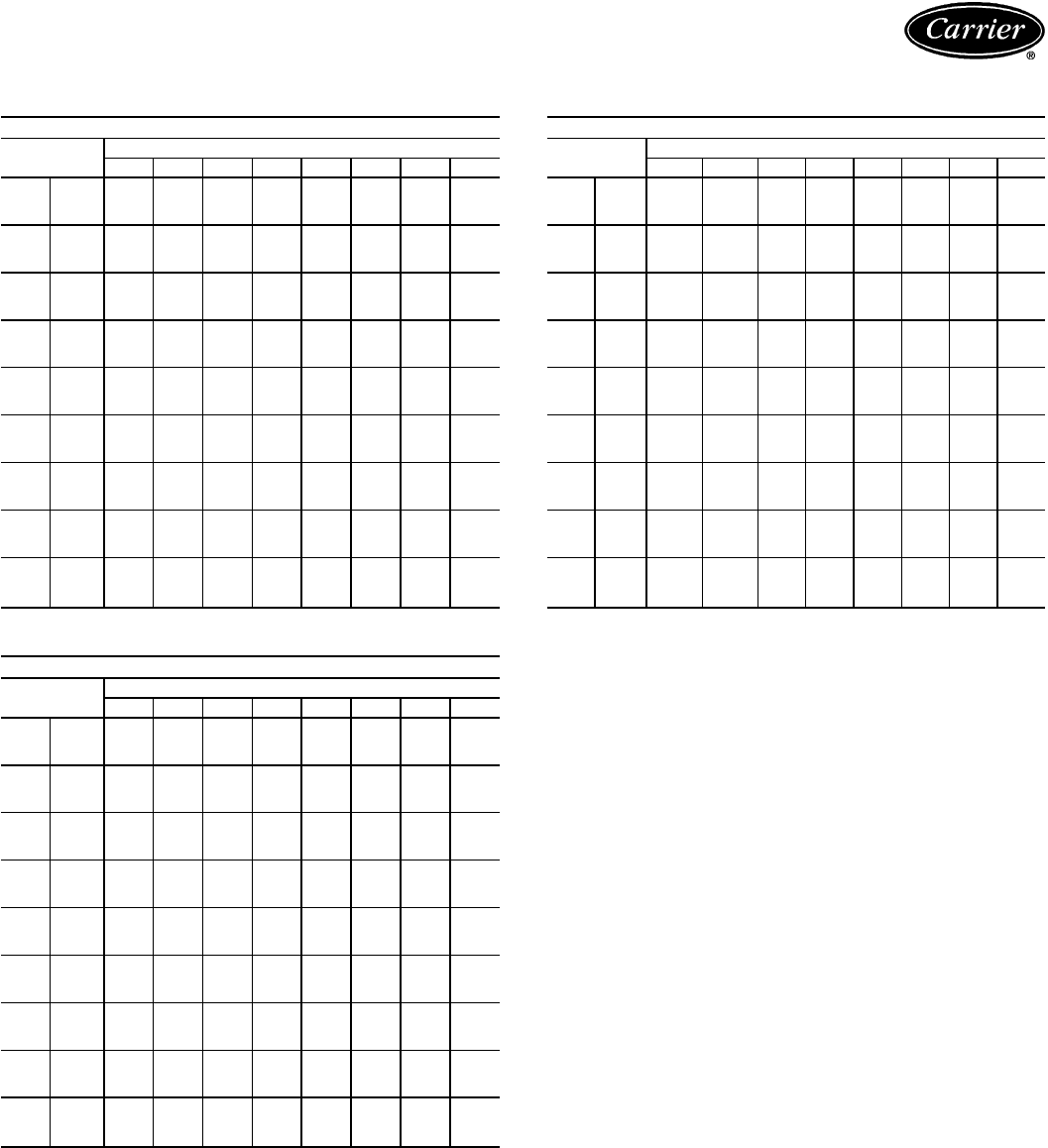
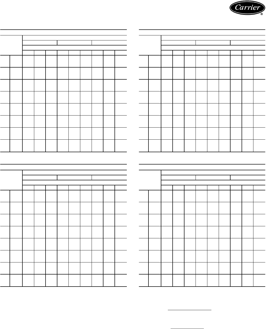
Performance data — 38AH024-034/40RM
CONDENSING UNIT RATINGS — SI
38AH024
SST
(C) Air Temperature Entering Condenser (C)
24 28 32 36 40 44 48 52
−6 TCG 42.9 40.6 38.0 35.6 33.0 30.6 28.2 25.7
CMP 11.3 11.6 12.1 12.6 13.0 13.4 13.7 14.2
SDT 35.2 39.2 43.2 47.1 51.1 55.2 59.2 63.2
−4 TCG 47.0 44.6 41.8 39.2 36.6 34.0 31.4 28.8
CMP 11.5 11.9 12.5 13.0 13.5 13.9 14.3 14.9
SDT 35.2 39.2 43.2 47.2 51.2 55.2 59.2 63.2
−2 TCG 51.4 48.6 45.8 43.0 40.2 37.4 34.8 31.8
CMP 11.7 12.1 12.8 13.4 14.0 14.5 15.0 15.6
SDT 35.2 39.2 43.2 47.2 51.2 55.2 59.2 63.2
0TCG 55.5 52.8 49.8 47.0 44.0 41.2 38.4 35.5
CMP 11.9 12.4 13.1 13.8 14.5 15.0 15.6 16.3
SDT 35.6 39.6 43.5 47.4 51.3 55.3 59.2 63.2
2TCG 59.9 57.0 54.0 51.0 48.2 45.2 42.2 39.3
CMP 12.1 12.7 13.5 14.2 14.9 15.5 16.1 16.9
SDT 36.2 40.1 43.9 47.8 51.6 55.5 59.3 63.2
4TCG 64.3 61.4 58.2 55.2 52.2 49.0 46.0 42.9
CMP 12.3 13.0 13.8 14.6 15.4 16.0 16.7 17.5
SDT 36.9 40.7 44.4 48.1 51.9 55.6 59.4 63.1
6TCG 69.2 66.0 62.8 59.6 56.4 53.2 50.0 46.8
CMP 12.5 13.3 14.1 15.0 15.8 16.5 17.3 18.1
SDT 37.7 41.4 45.1 48.8 52.4 56.2 59.9 63.6
8TCG 74.1 70.8 67.4 64.0 60.8 57.4 54.0 50.7
CMP 12.8 13.6 14.5 15.4 16.3 17.1 17.8 18.8
SDT 38.5 42.1 45.8 49.4 53.1 56.8 60.4 64.1
10 TCG 78.9 75.6 72.0 68.6 65.2 61.6 58.2 54.7
CMP 13.0 13.8 14.8 15.8 16.7 17.6 18.4 19.4
SDT 39.2 42.9 46.5 50.1 53.8 57.4 61.0 64.7
38AH028
SST
(C) Air Temperature Entering Condenser (C)
24 28 32 36 40 44 48 52
−6 TCG 51.1 48.6 46.0 43.4 40.8 38.4 36.0 33.3
CMP 13.4 14.0 14.7 15.3 15.9 16.5 17.1 17.7
SDT 35.4 39.3 43.3 47.3 51.2 55.2 59.1 63.1
−4 TCG 55.2 52.8 50.0 47.4 44.8 42.2 39.6 37.0
CMP 13.8 14.3 15.1 15.8 16.5 17.1 17.7 18.4
SDT 36.0 39.8 43.7 47.6 51.4 55.3 59.2 63.0
−2 TCG 59.7 57.0 54.2 51.4 48.6 46.0 43.2 40.5
CMP 14.1 14.7 15.5 16.3 17.0 17.7 18.3 19.1
SDT 36.5 40.3 44.1 47.8 51.6 55.5 59.3 63.1
0TCG 64.5 61.6 58.6 55.6 52.8 49.8 47.0 43.9
CMP 14.4 15.1 15.9 16.8 17.5 18.3 19.0 19.8
SDT 37.1 40.9 44.6 48.4 52.1 55.9 59.6 63.4
2TCG 69.3 66.2 63.2 60.0 57.0 54.0 51.0 47.9
CMP 14.7 15.5 16.4 17.3 18.1 18.9 19.7 20.6
SDT 37.8 41.7 45.3 49.0 52.7 56.5 60.2 64.0
4TCG 74.0 71.0 67.6 64.4 61.2 58.0 54.8 51.6
CMP 15.0 15.9 16.8 17.8 18.7 19.5 20.4 21.3
SDT 38.8 42.4 46.1 49.7 53.4 57.1 60.7 64.4
6TCG 79.4 76.2 72.6 69.2 65.8 62.4 59.2 55.6
CMP 15.3 16.3 17.3 18.3 19.2 20.2 21.0 22.2
SDT 39.6 43.3 46.9 50.5 54.1 57.8 61.4 65.1
8TCG 85.0 81.6 77.8 74.2 70.6 67.0 63.4 59.8
CMP 15.7 16.6 17.7 18.8 19.8 20.8 21.8 22.9
SDT 40.5 44.1 47.7 51.3 54.9 58.5 62.2 65.7
10 TCG 90.6 86.8 83.0 79.0 75.2 71.6 67.8 64.0
CMP 16.0 17.0 18.2 19.3 20.4 21.4 22.4 23.6
SDT 41.5 45.0 48.6 52.1 55.7 59.3 62.9 66.4
38AH034
SST
(C) Air Temperature Entering Condenser (C)
24 28 32 36 40 44 48 52
−6 TCG 59.8 57.1 54.0 51.1 48.1 45.3 42.4 39.5
CMP 16.6 17.3 18.1 18.9 19.7 20.4 21.0 21.8
SDT 35.9 40.0 43.9 47.9 51.9 55.9 59.9 63.8
−4 TCG 65.5 62.2 59.2 56.0 52.9 49.8 46.8 43.5
CMP 17.0 17.7 18.6 19.5 20.3 21.0 21.8 22.7
SDT 36.1 40.1 44.0 48.0 51.9 55.9 59.9 63.8
−2 TCG 70.8 67.5 64.2 60.8 57.5 54.3 51.0 47.7
CMP 17.3 18.1 19.1 20.0 21.0 21.7 22.6 23.5
SDT 36.2 40.3 44.1 48.1 52.0 56.0 59.9 63.9
0TCG 76.4 73.0 69.5 66.0 62.5 59.1 55.7 52.2
CMP 17.6 18.6 19.5 20.6 21.6 22.5 23.4 24.5
SDT 36.8 40.7 44.5 48.4 52.2 56.1 60.1 63.8
2TCG 82.2 78.7 75.0 71.4 67.7 64.2 60.6 57.0
CMP 18.0 19.0 20.1 21.2 22.2 23.2 24.1 25.3
SDT 37.5 41.3 45.1 48.8 52.7 56.4 60.3 64.0
4TCG 88.0 84.3 80.5 76.8 72.9 69.2 65.5 61.7
CMP 18.4 19.5 20.7 21.8 22.9 24.0 24.9 26.2
SDT 38.2 42.0 45.6 49.3 53.0 56.8 60.5 64.2
6TCG 94.4 90.4 86.5 82.4 78.5 74.6 70.6 66.7
CMP 18.9 20.0 21.2 22.5 23.6 24.7 25.8 27.1
SDT 39.0 42.8 46.4 50.0 53.7 57.4 61.1 64.8
8TCG 100.8 96.7 92.5 88.2 84.1 80.0 75.8 71.7
CMP 19.4 20.5 21.8 23.1 24.3 25.5 26.6 28.0
SDT 39.9 43.7 47.2 50.8 54.5 58.1 61.7 65.4
10 TCG 107.3 102.9 98.6 94.1 89.7 85.5 81.1 76.8
CMP 19.6 20.9 22.3 23.7 25.1 26.3 27.5 29.0
SDT 40.9 44.5 48.1 51.7 55.3 58.9 62.4 66.0
LEGEND
CMP — Compressor Power, kW
SDT — Saturated Discharge Temperature (leaving compressor) (C)
SST — Saturated Suction Temperature (entering condensing unit)
TCG — Total Cooling Capacity, Gross (kW)
NOTES:
1. Ratings are based on 8.3 C superheat and use of R-22 refrigerant.
2. Ratings include suction line losses due to an accumulator.
18
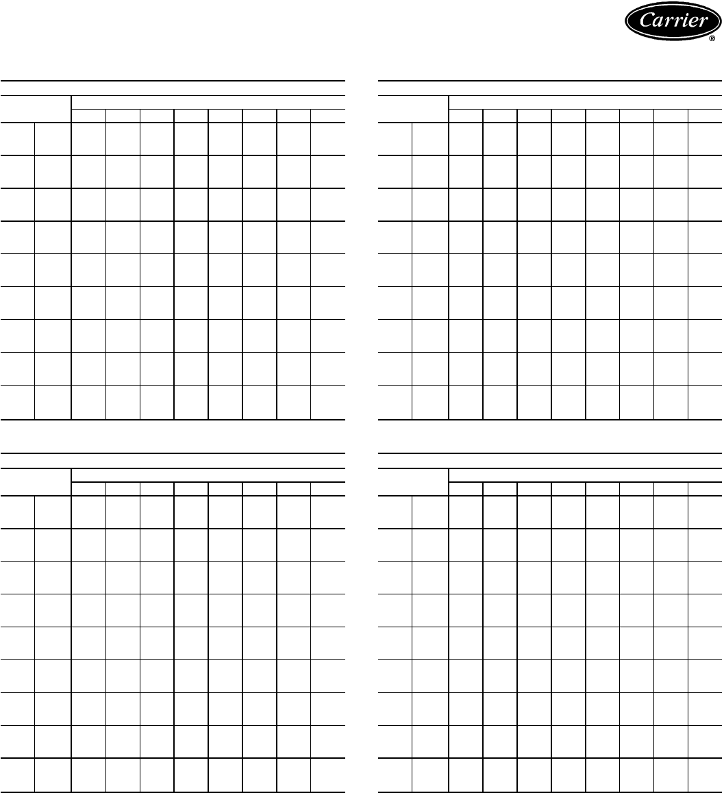
CONDENSING UNIT CIRCUIT RATINGS — SI
38AH024 CIRCUIT NO. 1 OR 2
SST
(C) Air Temperature Entering Condenser (C)
24 28 32 36 40 44 48 52
−6 TCG 21.5 20.3 19.0 17.8 16.5 15.3 14.1 12.8
CMP 5.6 5.8 6.1 6.3 6.5 6.7 6.9 7.1
SDT 35.2 39.2 43.2 47.1 51.1 55.2 59.2 63.2
−4 TCG 23.5 22.3 20.9 19.6 18.3 17.0 15.7 14.4
CMP 5.7 5.9 6.2 6.5 6.8 7.0 7.2 7.5
SDT 35.2 39.2 43.2 47.2 51.2 55.2 59.2 63.2
−2 TCG 25.7 24.3 22.9 21.5 20.1 18.7 17.4 15.9
CMP 5.8 6.1 6.4 6.7 7.0 7.3 7.5 7.8
SDT 35.2 39.2 43.2 47.2 51.2 55.2 59.2 63.2
0TCG 27.8 26.4 24.9 23.5 22.0 20.6 19.2 17.7
CMP 5.9 6.2 6.6 6.9 7.2 7.5 7.8 8.2
SDT 35.6 39.6 43.5 47.4 51.3 55.3 59.2 63.2
2TCG 29.9 28.5 27.0 25.5 24.1 22.6 21.1 19.7
CMP 6.1 6.4 6.7 7.1 7.5 7.8 8.1 8.5
SDT 36.2 40.1 43.9 47.8 51.6 55.5 59.3 63.2
4TCG 32.2 30.7 29.1 27.6 26.1 24.5 23.0 21.4
CMP 6.2 6.5 6.9 7.3 7.7 8.0 8.4 8.8
SDT 36.9 40.7 44.4 48.1 51.9 55.6 59.4 63.1
6TCG 34.6 33.0 31.4 29.8 28.2 26.6 25.0 23.4
CMP 6.3 6.6 7.1 7.5 7.9 8.3 8.6 9.1
SDT 37.7 41.4 45.1 48.8 52.4 56.2 59.9 63.6
8TCG 37.0 35.4 33.7 32.0 30.4 28.7 27.0 25.4
CMP 6.4 6.8 7.2 7.7 8.1 8.5 8.9 9.4
SDT 38.5 42.1 45.8 49.4 53.1 56.8 60.4 64.1
10 TCG 39.5 37.8 36.0 34.3 32.6 30.8 29.1 27.3
CMP 6.5 6.9 7.4 7.9 8.4 8.8 9.2 9.7
SDT 39.2 42.9 46.5 50.1 53.8 57.4 61.0 64.7
38AH028 CIRCUIT NO. 1 OR 2
SST
(C) Air Temperature Entering Condenser (C)
24 28 32 36 40 44 48 52
−6 TCG 25.5 24.3 23.0 21.7 20.4 19.2 18.0 16.7
CMP 6.7 7.0 7.3 7.7 8.0 8.3 8.5 8.9
SDT 35.4 39.3 43.3 47.3 51.2 55.2 59.1 63.1
−4 TCG 27.6 26.4 25.0 23.7 22.4 21.1 19.8 18.5
CMP 6.9 7.2 7.5 7.9 8.2 8.5 8.9 9.2
SDT 36.0 39.8 43.7 47.6 51.4 55.3 59.2 63.0
−2 TCG 29.8 28.5 27.1 25.7 24.3 23.0 21.6 20.3
CMP 7.0 7.4 7.8 8.1 8.5 8.8 9.2 9.5
SDT 36.5 40.3 44.1 47.8 51.6 55.5 59.3 63.1
0TCG 32.2 30.8 29.3 27.8 26.4 24.9 23.5 22.0
CMP 7.2 7.6 8.0 8.4 8.8 9.1 9.5 9.9
SDT 37.1 40.9 44.6 48.4 52.1 55.9 59.6 63.4
2TCG 34.7 33.1 31.6 30.0 28.5 27.0 25.5 23.9
CMP 7.4 7.8 8.2 8.6 9.1 9.5 9.8 10.3
SDT 37.8 41.7 45.3 49.0 52.7 56.5 60.2 64.0
4TCG 37.0 35.5 33.8 32.2 30.6 29.0 27.4 25.8
CMP 7.5 7.9 8.4 8.9 9.3 9.8 10.2 10.7
SDT 38.8 42.4 46.1 49.7 53.4 57.1 60.7 64.4
6TCG 39.7 38.1 36.3 34.6 32.9 31.2 29.6 27.8
CMP 7.7 8.1 8.6 9.2 9.6 10.1 10.5 11.1
SDT 39.6 43.3 46.9 50.5 54.1 57.8 61.4 65.1
8TCG 42.5 40.8 38.9 37.1 35.3 33.5 31.7 29.9
CMP 7.8 8.3 8.9 9.4 9.9 10.4 10.9 11.4
SDT 40.5 44.1 47.7 51.3 54.9 58.5 62.2 65.7
10 TCG 45.3 43.4 41.5 39.5 37.6 35.8 33.9 32.0
CMP 8.0 8.5 9.1 9.7 10.2 10.7 11.2 11.8
SDT 41.5 45.0 48.6 52.1 55.7 59.3 62.9 66.4
LEGEND
CMP — Compressor Power, kW
SDT — Saturated Discharge Temperature (leaving compressor) (C)
SST — Saturated Suction Temperature (entering condensing unit)
TCG — Total Cooling Capacity, Gross (kW)
38AH034 CIRCUIT NO. 1
SST
(C) Air Temperature Entering Condenser (C)
24 28 32 36 40 44 48 52
−6 TCG 25.0 23.7 22.3 21.0 19.6 18.3 17.0 15.6
CMP 6.7 7.0 7.3 7.7 8.0 8.3 8.5 8.9
SDT 35.2 39.2 43.2 47.2 51.2 55.2 59.3 63.2
−4 TCG 27.5 26.0 24.6 23.1 21.7 20.3 18.9 17.4
CMP 6.8 7.1 7.5 7.9 8.2 8.5 8.9 9.2
SDT 35.2 39.2 43.2 47.2 51.2 55.2 59.3 63.2
−2 TCG 29.9 28.4 26.8 25.2 23.7 22.2 20.7 19.1
CMP 6.9 7.2 7.7 8.1 8.5 8.8 9.2 9.6
SDT 35.1 39.2 43.2 47.3 51.3 55.3 59.3 63.4
0TCG 32.4 30.8 29.2 27.6 25.9 24.4 22.8 21.2
CMP 7.0 7.4 7.8 8.3 8.7 9.1 9.5 9.9
SDT 35.5 39.5 43.4 47.4 51.3 55.3 59.3 63.2
2TCG 35.0 33.4 31.7 30.0 28.3 26.7 25.0 23.4
CMP 7.1 7.5 8.0 8.5 8.9 9.3 9.7 10.2
SDT 36.1 39.9 43.8 47.6 51.5 55.3 59.2 63.0
4TCG 37.7 35.9 34.2 32.5 30.7 29.0 27.3 25.5
CMP 7.2 7.7 8.2 8.7 9.1 9.6 10.0 10.5
SDT 36.6 40.4 44.1 47.8 51.6 55.4 59.2 62.9
6TCG 40.6 38.7 36.9 35.0 33.2 31.4 29.6 27.7
CMP 7.3 7.8 8.3 8.9 9.4 9.8 10.3 10.9
SDT 37.2 41.1 44.7 48.4 52.1 55.9 59.6 63.4
8TCG 43.5 41.5 39.6 37.6 35.7 33.8 31.9 29.9
CMP 7.5 8.0 8.5 9.1 9.6 10.1 10.6 11.2
SDT 38.2 41.9 45.5 49.1 52.8 56.5 60.1 63.8
10 TCG 46.3 44.3 42.3 40.2 38.2 36.3 34.3 32.3
CMP 7.6 8.1 8.7 9.3 9.9 10.4 10.9 11.5
SDT 39.1 42.7 46.3 49.9 53.5 57.1 60.7 64.3
38AH034 CIRCUIT NO. 2
SST
(C) Air Temperature Entering Condenser (C)
24 28 32 36 40 44 48 52
−6 TCG 34.8 33.4 31.7 30.1 28.5 27.0 25.4 23.9
CMP 9.9 10.3 10.8 11.2 11.7 12.1 12.5 13.0
SDT 36.7 40.7 44.6 48.6 52.6 56.5 60.5 64.4
−4 TCG 38.0 36.2 34.6 32.9 31.2 29.5 27.9 26.1
CMP 10.2 10.6 11.1 11.6 12.1 12.5 12.9 13.4
SDT 36.9 41.0 44.8 48.7 52.6 56.6 60.5 64.5
−2 TCG 40.9 39.1 37.4 35.6 33.8 32.1 30.3 28.6
CMP 10.4 10.9 11.4 11.9 12.5 12.9 13.4 13.9
SDT 37.3 41.3 45.0 48.8 52.7 56.6 60.5 64.3
0TCG 44.0 42.2 40.3 38.4 36.6 34.7 32.9 31.0
CMP 10.6 11.2 11.7 12.3 12.9 13.4 13.9 14.5
SDT 38.1 41.8 45.6 49.3 53.1 56.9 60.8 64.4
2TCG 47.2 45.3 43.3 41.4 39.4 37.5 35.6 33.6
CMP 10.9 11.5 12.1 12.7 13.3 13.9 14.4 15.1
SDT 38.8 42.7 46.3 50.0 53.8 57.5 61.3 65.0
4TCG 50.4 48.4 46.3 44.3 42.2 40.2 38.2 36.1
CMP 11.2 11.8 12.5 13.1 13.8 14.4 14.9 15.7
SDT 39.8 43.5 47.1 50.8 54.4 58.1 61.8 65.4
6TCG 53.9 51.7 49.6 47.4 45.3 43.2 41.0 38.9
CMP 11.6 12.2 12.9 13.6 14.2 14.9 15.5 16.2
SDT 40.7 44.4 48.0 51.6 55.2 58.9 62.5 66.2
8TCG 57.4 55.2 52.9 50.6 48.4 46.2 43.9 41.7
CMP 11.9 12.5 13.3 14.0 14.7 15.4 16.0 16.8
SDT 41.7 45.4 48.9 52.5 56.1 59.7 63.3 66.9
10 TCG 61.0 58.6 56.3 53.9 51.5 49.2 46.8 44.5
CMP 12.1 12.8 13.6 14.4 15.2 15.9 16.6 17.4
SDT 42.8 46.3 49.9 53.4 57.0 60.6 64.1 67.7
NOTES:
1. Ratings are based on 8.3 C superheat and use of R-22 refrigerant.
2. Ratings include suction line losses due to an accumulator.
19
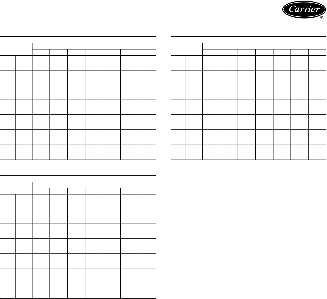
Performance data — 38AH024-034/40RM (cont)
CONDENSING UNIT RATINGS — ENGLISH
38AH024
SST
(F) Air Temperature Entering Condenser (F)
75 85 95 100 105 115 125
20 TCG 141.8 130.6 119.0 113.2 107.4 96.2 84.8
CMP 11.4 11.7 12.4 12.7 12.9 13.3 13.8
SDT 95.0 105.0 115.0 120.0 125.0 135.0 145.0
25 TCG 161.6 149.4 136.8 130.6 124.4 112.0 99.6
CMP 11.7 12.1 12.9 13.3 13.6 14.2 14.8
SDT 95.0 105.0 115.0 120.0 125.0 135.0 145.0
30 TCG 181.6 168.2 154.8 148.0 141.4 128.0 114.6
CMP 11.9 12.5 13.5 13.9 14.3 15.0 15.8
SDT 95.0 105.0 115.0 120.0 125.0 135.0 145.0
35 TCG 202.4 188.4 174.4 167.4 160.4 146.4 132.4
CMP 12.2 12.9 14.0 14.5 14.9 15.8 16.6
SDT 97.0 107.0 116.0 121.0 126.0 135.0 145.0
40 TCG 223.0 208.0 194.0 186.8 179.6 165.0 150.5
CMP 12.5 13.4 14.5 15.0 15.6 16.5 17.5
SDT 98.0 108.0 117.0 122.0 126.0 136.0 146.0
45 TCG 247.6 232.0 216.0 208.0 200.0 184.4 168.6
CMP 12.8 13.8 15.0 15.6 16.2 17.3 18.4
SDT 101.0 110.0 119.0 123.0 128.0 137.0 146.0
50 TCG 268.0 254.0 236.0 228.0 220.0 204.0 188.0
CMP 13.1 14.2 15.6 16.2 16.8 18.0 19.3
SDT 103.0 112.0 121.0 125.0 130.0 139.0 148.0
38AH028
SST
(F) Air Temperature Entering Condenser (F)
75 85 95 100 105 115 125
20 TCG 168.4 157.6 145.6 139.8 134.0 122.8 111.4
CMP 13.5 14.1 15.0 15.4 15.8 16.6 17.4
SDT 95.0 105.0 115.0 120.0 125.0 135.0 145.0
25 TCG 189.0 177.4 164.6 158.4 152.2 140.2 128.0
CMP 13.9 14.6 15.7 16.1 16.6 17.4 18.3
SDT 97.0 106.0 116.0 121.0 126.0 135.0 145.0
30 TCG 210.2 197.4 183.8 177.2 170.6 157.4 144.2
CMP 14.3 15.2 16.3 16.8 17.3 18.3 19.3
SDT 98.0 107.0 117.0 121.0 126.0 136.0 146.0
35 TCG 231.6 220.0 204.0 197.6 190.4 176.4 162.6
CMP 14.8 15.7 17.0 17.6 18.1 19.2 20.3
SDT 99.0 109.0 118.0 123.0 128.0 137.0 147.0
40 TCG 256.8 242.0 226.0 218.0 210.0 195.2 179.8
CMP 15.1 16.3 17.7 18.3 18.9 20.2 21.5
SDT 102.0 111.0 120.0 125.0 129.0 138.0 147.0
45 TCG 284.0 266.0 250.0 242.0 232.0 216.0 199.0
CMP 15.7 16.9 18.3 19.0 19.7 21.0 22.3
SDT 104.0 113.0 122.0 127.0 131.0 140.0 149.0
50 TCG 306.0 292.0 272.0 264.0 256.0 238.0 221.0
CMP 16.0 17.4 19.0 19.8 20.6 22.0 23.5
SDT 106.0 115.0 124.0 129.0 133.0 142.0 151.0
38AH034
SST
(F) Air Temperature Entering Condenser (F)
75 85 95 100 105 115 125
20 TCG 198.0 185.5 171.2 164.4 157.6 144.4 131.0
CMP 16.6 17.4 18.5 19.0 19.5 20.4 21.4
SDT 97.0 107.0 117.0 122.0 127.0 137.0 147.0
25 TCG 223.5 209.4 194.4 187.0 179.6 165.3 150.8
CMP 17.1 18.1 19.3 19.8 20.5 21.5 22.6
SDT 97.0 107.0 117.0 122.0 127.0 137.0 147.0
30 TCG 249.4 234.3 217.7 210.0 202.3 186.0 170.2
CMP 17.6 18.7 20.1 20.7 21.3 22.5 23.8
SDT 97.0 107.0 117.0 122.0 127.0 137.0 147.0
35 TCG 276.2 260.0 243.0 235.5 226.5 209.8 193.2
CMP 18.0 19.4 20.8 21.5 22.2 23.6 25.0
SDT 99.0 109.0 118.0 123.0 128.0 137.0 147.0
40 TCG 304.5 287.0 269.0 260.0 251.0 233.5 215.8
CMP 18.7 20.0 21.7 22.4 23.2 24.7 26.2
SDT 101.0 110.0 119.0 124.0 129.0 138.0 147.0
45 TCG 335.0 316.0 297.0 287.0 278.0 259.0 240.0
CMP 19.3 20.7 22.6 23.3 24.2 25.8 27.4
SDT 103.0 112.0 121.0 126.0 130.0 140.0 149.0
50 TCG 367.0 346.0 325.0 314.0 305.0 283.0 262.0
CMP 19.7 21.4 23.4 24.3 25.2 27.0 28.8
SDT 106.0 115.0 124.0 128.0 133.0 141.0 150.0
LEGEND
CMP — Compressor Power, kW
SDT — Saturated Discharge Temperature (leaving compressor) (F)
SST — Saturated Suction Temperature (entering condensing unit)
TCG — Total Cooling Capacity, Gross (1000 Btuh)
NOTES:
1. Ratings are based on 15 F superheat and use of R-22 refrigerant.
2. Ratings include suction line losses due to an accumulator.
20
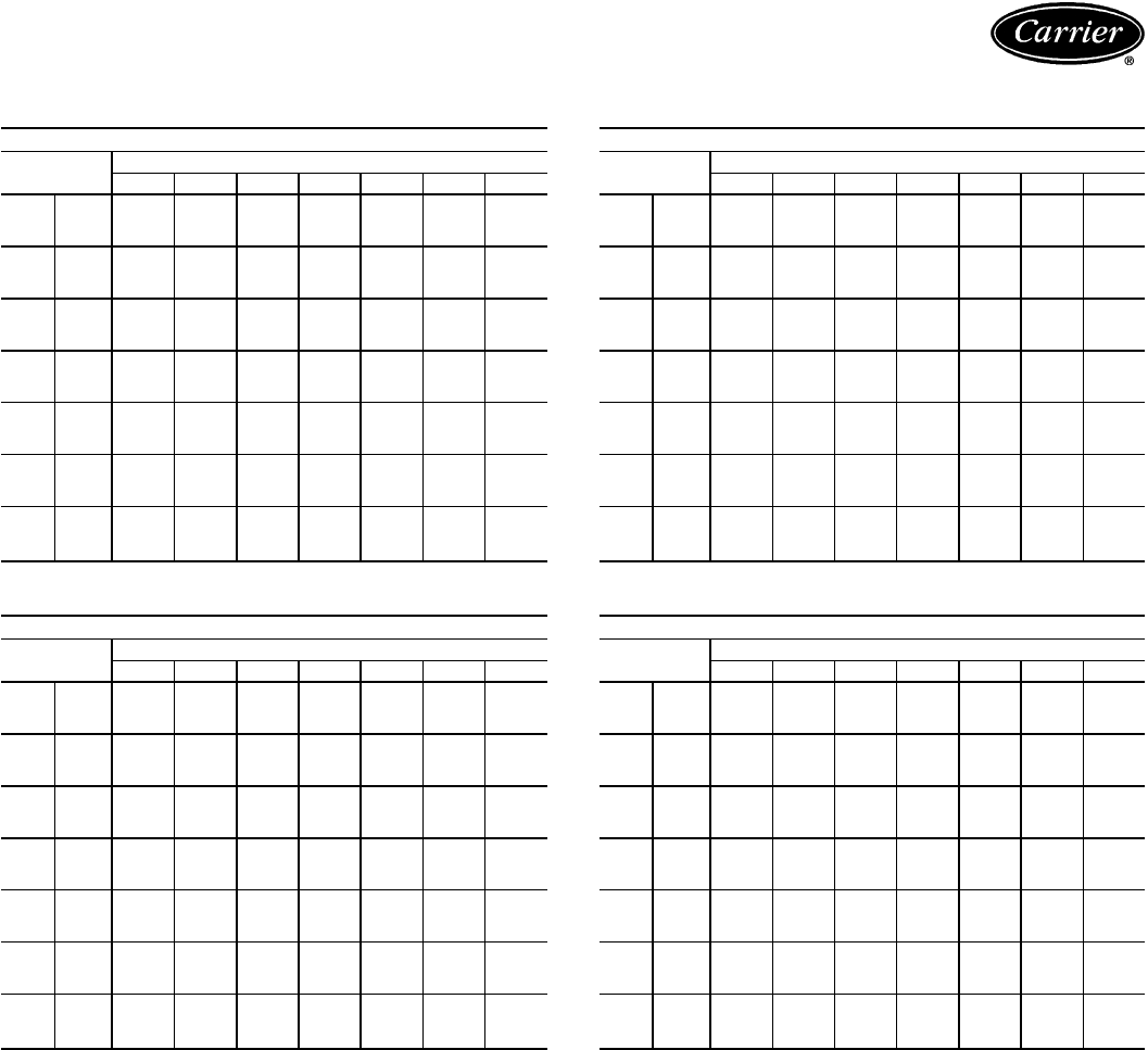
CONDENSING UNIT CIRCUIT RATINGS — ENGLISH
38AH024 CIRCUIT NO. 1 OR 2
SST
(F) Air Temperature Entering Condenser (F)
75 85 95 100 105 115 125
20 TCG 70.9 65.3 59.5 56.6 53.7 48.1 42.4
CMP 5.7 5.9 6.2 6.3 6.5 6.7 6.9
SDT 95.0 105.0 115.0 120.0 125.0 135.0 145.0
25 TCG 80.8 74.7 68.4 65.3 62.2 56.0 49.8
CMP 5.8 6.1 6.5 6.7 6.8 7.1 7.4
SDT 95.0 105.0 115.0 120.0 125.0 135.0 145.0
30 TCG 90.8 84.1 77.4 74.0 70.7 64.0 57.3
CMP 6.0 6.3 6.7 7.0 7.2 7.5 7.9
SDT 95.0 105.0 115.0 120.0 125.0 135.0 145.0
35 TCG 101.2 94.2 87.2 83.7 80.2 73.2 66.2
CMP 6.1 6.5 7.0 7.2 7.5 7.9 8.3
SDT 97.0 107.0 116.0 121.0 126.0 135.0 145.0
40 TCG 111.5 104.0 97.0 93.4 89.8 82.5 75.3
CMP 6.3 6.7 7.3 7.5 7.8 8.3 8.8
SDT 98.0 108.0 117.0 122.0 126.0 136.0 146.0
45 TCG 123.8 116.0 108.0 104.0 100.0 92.2 84.3
CMP 6.4 6.9 7.5 7.8 8.1 8.6 9.2
SDT 101.0 110.0 119.0 123.0 128.0 137.0 146.0
50 TCG 134.0 127.0 118.0 114.0 110.0 102.0 94.0
CMP 6.6 7.1 7.8 8.1 8.4 9.0 9.6
SDT 103.0 112.0 121.0 125.0 130.0 139.0 148.0
38AH028 CIRCUIT NO. 1 OR 2
SST
(F) Air Temperature Entering Condenser (F)
75 85 95 100 105 115 125
20 TCG 84.2 78.8 72.8 69.9 67.0 61.4 55.7
CMP 6.7 7.0 7.5 7.7 7.9 8.3 8.7
SDT 95.0 105.0 115.0 120.0 125.0 135.0 145.0
25 TCG 94.5 88.7 82.3 79.2 76.1 70.1 64.0
CMP 6.9 7.3 7.8 8.1 8.3 8.7 9.2
SDT 97.0 106.0 116.0 121.0 126.0 135.0 145.0
30 TCG 105.1 98.7 91.9 88.6 85.3 78.7 72.1
CMP 7.2 7.6 8.2 8.4 8.7 9.2 9.7
SDT 98.0 107.0 117.0 121.0 126.0 136.0 146.0
35 TCG 115.8 110.0 102.0 98.8 95.2 88.2 81.3
CMP 7.4 7.9 8.5 8.8 9.1 9.6 10.2
SDT 99.0 109.0 118.0 123.0 128.0 137.0 147.0
40 TCG 128.4 121.0 113.0 109.0 105.0 97.6 89.9
CMP 7.6 8.2 8.8 9.2 9.5 10.1 10.7
SDT 102.0 111.0 120.0 125.0 129.0 138.0 147.0
45 TCG 142.0 133.0 125.0 121.0 116.0 108.0 99.5
CMP 7.8 8.4 9.2 9.5 9.9 10.5 11.2
SDT 104.0 113.0 122.0 127.0 131.0 140.0 149.0
50 TCG 153.0 146.0 136.0 132.0 128.0 119.0 110.5
CMP 8.0 8.7 9.5 9.9 10.3 11.0 11.8
SDT 106.0 115.0 124.0 129.0 133.0 142.0 151.0
LEGEND
CMP — Compressor Power, kW
SDT — Saturated Discharge Temperature (leaving compressor) (F)
SST — Saturated Suction Temperature (entering condensing unit)
TCG — Total Cooling Capacity, Gross (1000 Btuh)
38AH034 CIRCUIT NO. 1
SST
(F) Air Temperature Entering Condenser (F)
75 85 95 100 105 115 125
20 TCG 82.4 76.5 70.2 67.1 64.0 58.0 51.9
CMP 6.7 7.0 7.5 7.7 7.9 8.3 8.7
SDT 95.0 105.0 115.0 120.0 125.0 135.0 145.0
25 TCG 93.8 87.4 80.4 77.0 73.6 67.0 60.3
CMP 6.9 7.3 7.8 8.0 8.3 8.7 9.2
SDT 95.0 105.0 115.0 120.0 125.0 135.0 145.0
30 TCG 105.4 98.3 90.7 87.0 83.3 76.0 68.7
CMP 7.0 7.5 8.1 8.4 8.6 9.1 9.7
SDT 95.0 105.0 115.0 120.0 125.0 135.0 145.0
35 TCG 117.2 110.0 102.0 98.5 94.5 86.8 79.2
CMP 7.1 7.7 8.3 8.6 8.9 9.5 10.1
SDT 97.0 106.0 116.0 121.0 126.0 135.0 145.0
40 TCG 130.5 122.0 114.0 110.0 106.0 97.5 89.3
CMP 7.3 7.9 8.6 8.9 9.2 9.9 10.5
SDT 97.0 107.0 116.0 121.0 126.0 135.0 145.0
45 TCG 145.0 135.0 127.0 122.0 118.0 109.0 100.0
CMP 7.4 8.1 8.9 9.2 9.6 10.3 11.0
SDT 99.0 109.0 118.0 123.0 127.0 137.0 147.0
50 TCG 158.0 149.0 139.0 134.0 130.0 120.0 110.5
CMP 7.6 8.3 9.2 9.5 9.9 10.7 11.5
SDT 102.0 111.0 120.0 125.0 129.0 138.0 147.0
38AH034 CIRCUIT NO. 2
SST
(F) Air Temperature Entering Condenser (F)
75 85 95 100 105 115 125
20 TCG 115.6 109.0 101.0 97.3 93.6 86.4 79.1
CMP 9.9 10.4 11.0 11.3 11.6 12.1 12.7
SDT 98.0 108.0 118.0 123.0 128.0 138.0 148.0
25 TCG 129.7 122.0 114.0 110.0 106.0 98.3 90.5
CMP 10.2 10.8 11.5 11.8 12.2 12.8 13.5
SDT 98.0 108.0 118.0 123.0 128.0 138.0 148.0
30 TCG 144.0 136.0 127.0 123.0 119.0 110.0 101.5
CMP 10.6 11.2 12.0 12.3 12.7 13.4 14.1
SDT 98.0 109.0 118.0 123.0 128.0 138.0 148.0
35 TCG 159.0 150.0 141.0 137.0 132.0 123.0 114.0
CMP 10.9 11.7 12.5 12.9 13.3 14.1 14.9
SDT 101.0 111.0 120.0 125.0 129.0 139.0 149.0
40 TCG 174.0 165.0 155.0 150.0 145.0 136.0 126.5
CMP 11.4 12.1 13.1 13.5 14.0 14.8 15.7
SDT 104.0 113.0 122.0 127.0 131.0 140.0 149.0
45 TCG 190.0 181.0 170.0 165.0 160.0 150.0 140.0
CMP 11.9 12.6 13.7 14.1 14.6 15.5 16.4
SDT 106.0 115.0 124.0 129.0 133.0 142.0 151.0
50 TCG 209.0 197.0 186.0 180.0 175.0 163.0 151.5
CMP 12.1 13.1 14.2 14.8 15.3 16.3 17.4
SDT 110.0 118.0 127.0 131.0 136.0 144.0 153.0
NOTES:
1. Ratings are based on 15 F superheat and use of R-22 refrigerant.
2. Ratings include suction line losses due to an accumulator.
21

Performance data — 38AH024-034/40RM (cont)
COMBINATION RATINGS — SI
38AH024 AND 40RM016
Temp (C)
Air
Entering
Condenser
Evaporator Air — L/s/BF
2100/0.06 2800/0.10 3500/0.12
Evaporator Air — Ewb (C)
22 20 16 22 20 16 22 20 16
24 TC 63.9 59.4 53.2 67.3 62.9 56.9 69.8 64.9 59.2
SHC 32.7 37.7 53.2 36.4 43.2 56.9 40.1 48.3 59.2
kW 12.18 11.90 11.52 12.39 12.11 11.75 12.54 12.24 11.89
28 TC 62.2 57.6 51.7 65.4 61.0 55.3 67.8 63.0 57.6
SHC 32.0 36.9 51.7 35.7 42.4 55.3 39.4 47.3 57.6
kW 13.06 12.78 12.40 13.26 12.99 12.63 13.41 13.11 12.77
32 TC 60.4 56.0 50.3 63.5 59.2 53.7 65.8 61.1 56.0
SHC 31.4 36.2 50.3 35.0 41.5 53.7 38.7 46.3 56.0
kW 13.89 13.51 13.01 14.16 13.79 13.31 14.36 13.95 13.51
36 TC 58.6 54.2 48.8 61.5 57.3 52.1 63.7 59.1 54.4
SHC 30.7 35.4 48.8 34.2 40.6 52.1 38.0 45.3 54.4
kW 14.91 14.51 14.02 15.17 14.79 14.32 15.37 14.96 14.52
40 TC 56.7 52.3 47.0 59.5 55.2 50.3 61.7 57.1 52.5
SHC 30.0 34.6 47.0 33.5 39.7 50.3 37.3 44.3 52.5
kW 15.84 15.34 14.74 16.15 15.67 15.10 16.40 15.88 15.36
44 TC 54.8 50.5 45.5 57.3 53.2 48.6 59.5 55.0 50.8
SHC 29.2 33.8 45.5 32.8 38.8 48.6 36.5 43.2 50.8
kW 16.73 16.11 15.40 17.09 16.50 15.84 17.40 16.76 16.16
48 TC 52.8 48.6 43.8 55.1 51.1 46.8 57.2 52.9 49.0
SHC 28.5 32.9 43.8 32.0 37.8 46.8 35.7 42.1 49.0
kW 17.72 17.09 16.38 18.07 17.47 16.82 18.39 17.73 17.15
52 TC 50.8 46.6 42.1 53.0 49.0 44.9 55.0 50.7 47.1
SHC 27.7 32.1 42.1 31.2 36.9 44.9 35.0 41.0 47.1
kW 18.71 18.07 17.37 19.05 18.44 17.81 19.37 18.70 18.14
38AH024 AND 40RM024
Temp (C)
Air
Entering
Condenser
Evaporator Air — L/s/BF
2900/0.06 3800/0.10 4700/0.12
Evaporator Air — Ewb (C)
22 20 16 22 20 16 22 20 16
24 TC 71.3 66.0 59.9 74.4 68.9 63.5 76.4 71.3 66.3
SHC 38.0 45.1 59.9 43.1 52.1 63.5 47.6 58.3 66.3
kW 12.63 12.31 11.93 12.82 12.48 12.15 12.94 12.63 12.32
28 TC 69.2 64.0 58.1 72.2 66.9 61.7 74.1 69.2 64.5
SHC 37.2 44.3 58.1 42.3 51.2 61.7 46.8 57.3 64.5
kW 13.50 13.18 12.81 13.69 13.35 13.03 13.81 13.50 13.20
32 TC 67.1 62.0 56.4 69.9 64.7 59.9 71.7 66.9 62.6
SHC 36.3 43.5 56.4 41.5 50.2 59.9 45.9 56.2 62.6
kW 14.48 14.03 13.55 14.72 14.27 13.84 14.87 14.46 14.08
36 TC 65.0 59.9 54.7 67.5 62.5 58.0 69.2 64.6 60.7
SHC 35.5 42.6 54.7 40.6 49.2 58.0 45.1 55.2 60.7
kW 15.49 15.03 14.55 15.72 15.27 14.86 15.87 15.46 15.10
40 TC 62.9 57.8 52.7 65.4 60.4 56.1 67.0 62.4 58.7
SHC 34.7 41.8 52.7 39.8 48.3 56.1 44.3 54.2 58.7
kW 16.54 15.96 15.38 16.82 16.26 15.76 17.00 16.49 16.06
44 TC 60.6 55.6 50.9 62.9 58.1 54.1 64.4 60.0 56.7
SHC 33.8 40.9 50.9 39.0 47.3 54.1 43.4 53.1 56.7
kW 17.56 16.84 16.17 17.89 17.20 16.63 18.10 17.47 17.00
48 TC 58.2 53.4 48.9 60.4 55.8 52.1 61.8 57.5 54.6
SHC 32.8 40.0 48.9 38.0 46.2 52.1 42.5 21.9 54.6
kW 18.54 17.80 17.14 18.86 18.17 17.61 19.07 18.43 17.99
52 TC 56.0 51.1 46.9 58.0 53.5 50.0 59.3 55.1 52.5
SHC 31.9 39.0 46.9 37.2 45.2 50.0 41.6 50.8 52.5
kW 19.51 18.76 18.12 19.82 19.12 18.60 20.02 19.38 18.97
38AH024 AND 40RM028
Temp (C)
Air
Entering
Condenser
Evaporator Air — L/s/BF
3500/0.06 4700/0.10 5900/0.12
Evaporator Air — Ewb (C)
22 20 16 22 20 16 22 20 16
24 TC 77.3 70.6 65.0 79.7 73.4 68.9 81.2 76.1 72.2
SHC 43.2 51.6 65.0 49.3 60.1 68.9 55.2 67.6 72.2
kW 13.00 12.58 12.24 13.14 12.76 12.48 13.24 12.92 12.68
28 TC 75.1 68.1 63.1 77.4 71.1 67.0 78.8 73.7 70.2
SHC 42.4 50.9 63.1 48.5 59.1 67.0 54.4 66.6 70.2
kW 13.87 13.43 13.12 14.01 13.62 13.36 14.10 13.78 13.56
32 TC 72.8 65.5 61.1 74.8 68.7 65.0 76.1 71.2 68.1
SHC 41.5 50.2 61.1 47.6 58.1 65.0 53.5 65.5 68.1
kW 14.97 14.34 13.96 15.15 14.62 14.29 15.26 14.83 14.56
36 TC 70.4 62.9 59.1 72.2 66.3 62.9 73.4 68.7 66.0
SHC 40.6 49.5 59.1 46.7 57.0 62.9 52.5 64.3 66.0
kW 15.98 15.30 14.96 16.15 15.61 15.30 16.26 15.83 15.58
40 TC 68.3 60.4 57.1 69.9 64.0 60.9 71.1 66.4 64.0
SHC 39.9 48.8 57.1 45.9 56.0 60.9 51.8 63.3 64.0
kW 17.15 16.25 15.88 17.34 16.66 16.31 17.47 16.94 16.66
44 TC 65.8 57.7 55.0 67.2 61.4 58.7 68.3 63.7 61.7
SHC 38.9 48.0 55.0 44.9 54.9 58.7 50.8 62.1 61.7
kW 18.30 17.14 16.76 18.50 17.67 17.28 18.65 18.00 17.72
48 TC 63.2 55.0 52.8 64.4 58.8 56.4 65.4 61.0 59.4
SHC 38.0 47.2 52.8 43.9 53.8 56.4 49.8 60.9 59.4
kW 19.28 18.04 17.72 19.46 18.62 18.26 19.60 18.95 18.71
52 TC 60.8 52.3 50.7 61.8 56.3 54.2 62.7 58.4 57.1
SHC 37.1 46.5 50.7 43.0 52.7 54.2 48.9 58.1 57.1
kW 20.25 18.94 18.69 20.41 19.55 19.24 20.54 19.89 19.69
38AH028 AND 40RM024
Temp (C)
Air
Entering
Condenser
Evaporator Air — L/s/BF
2900/0.06 3800/0.10 4700/0.12
Evaporator Air — Ewb (C)
22 20 16 22 20 16 22 20 16
24 TC 77.4 71.9 64.7 81.1 75.1 68.6 83.5 77.9 71.6
SHC 40.4 47.5 64.7 45.5 54.9 68.6 50.1 61.3 71.6
kW 15.16 14.77 14.25 15.42 14.99 14.53 15.59 15.20 14.75
28 TC 75.6 70.1 63.2 79.1 73.2 67.0 81.3 75.9 70.0
SHC 39.7 46.8 63.2 44.8 54.0 67.0 49.3 60.4 70.0
kW 16.26 15.96 15.58 16.46 16.14 15.79 16.59 16.28 15.96
32 TC 73.4 68.1 61.6 76.7 71.1 65.3 78.8 73.6 68.2
SHC 38.8 45.9 61.6 43.9 53.1 65.3 48.4 59.3 68.2
kW 17.36 16.95 16.44 17.62 17.18 16.72 17.79 17.38 16.95
36 TC 71.3 66.0 59.8 74.4 68.9 63.4 76.4 71.4 66.3
SHC 38.0 45.1 59.8 43.1 52.1 63.4 47.6 58.3 66.3
kW 18.51 17.98 17.36 18.82 18.27 17.72 19.02 18.52 18.01
40 TC 69.1 63.9 58.0 72.1 66.7 61.5 74.0 69.0 64.3
SHC 37.1 44.2 58.0 42.2 51.1 61.5 46.7 57.2 64.3
kW 19.61 18.96 18.23 19.98 19.32 18.67 20.22 19.60 19.02
44 TC 66.9 61.7 56.2 69.6 64.5 59.6 71.4 66.7 62.4
SHC 36.2 43.4 56.2 41.4 50.1 59.6 45.8 56.1 62.4
kW 20.78 20.11 19.39 21.15 20.47 19.84 21.38 20.76 20.19
48 TC 64.7 59.6 54.4 67.3 62.3 57.8 68.9 64.3 60.4
SHC 35.4 42.5 54.4 40.5 49.1 57.8 45.0 21.9 60.4
kW 21.75 21.06 20.35 22.10 21.42 20.80 22.33 21.70 21.17
52 TC 62.0 57.2 52.4 64.3 59.6 55.6 65.7 61.5 58.1
SHC 34.3 41.5 52.4 39.4 47.9 55.6 43.9 53.7 58.1
kW 23.63 22.55 21.49 24.15 23.10 22.20 24.48 23.52 22.76
LEGEND
BF — Bypass Factor
Edb — Entering Dry Bulb
Ewb — Entering Wet-Bulb
kW — Compressor Motor Power Input
Ldb — Leaving Dry Bulb
Lwb — Leaving Wet Bulb
SHC — Sensible Heating Capacity (kW)
TC — Total Capacity (kW)
NOTES:
1. All combination ratings are based on refrigerant R-22.
2. Direct interpolation is permissible. Do not extrapolate.
3. The SHC is based on 26.7 C db temperature of air entering the indoor unit. At
any other temperature, correct the SHC reading from the table of cooling ca-
pacities as follows:
Correction factor = 1.23 x 10
-3
x (1 − BF) x (db − 26.7)
Above 26.7 C, add SHC correction to SHC. Below 26.7 C, subtract SHC cor-
rection from SHC.
4. Gross capacities shown do not include a deduction for evaporator-fan motor
heat.
5. Formulas (cooling)
sensible heat capacity (kW)
tldb =t
edb −1.23 x 10
−3
x (L/s)
tlwb = wet-bulb temperature corresponding to enthalpy of air leaving
evaporator coil (hlwb)
total capacity (kW)
hlwb =h
ewb −1.20 x 10
−3
x (L/s)
where hewb = enthalpy of air entering evaporator coil (kJ/kg).
6. Combination ratings are based on a 1.1° C line loss. For a close-coupled sys-
tem (less than 4.5 m),
add 2%
to ratings. Piping sizes in Refrigerant Pipe Sizes
table on page 40 are based on 1.1° C line loss.
22
COMBINATION RATINGS — SI (cont)
38AH028 AND 40RM028
Temp (C)
Air
Entering
Condenser
Evaporator Air — L/s/BF
3500/0.06 4700/0.10 5900/0.12
Evaporator Air — Ewb (C)
22 20 16 22 20 16 22 20 16
24 TC 84.1 78.3 70.6 87.3 80.6 74.8 89.3 83.5 78.2
SHC 45.8 53.8 70.6 52.0 63.2 74.8 57.9 70.9 78.2
kW 15.64 15.22 14.67 15.87 15.39 14.97 16.01 15.60 15.22
28 TC 82.1 75.9 68.9 85.0 78.4 73.0 86.9 81.3 76.4
SHC 45.0 53.1 68.9 51.2 62.3 73.0 57.1 69.9 76.4
kW 16.63 16.28 15.89 16.79 16.42 16.12 16.89 16.58 16.31
32 TC 79.6 73.2 67.0 82.3 75.9 70.9 83.9 78.6 74.3
SHC 44.1 52.3 67.0 50.2 61.2 70.9 56.1 68.7 74.3
kW 17.85 17.35 16.86 18.06 17.56 17.17 18.19 17.77 17.43
36 TC 77.4 70.6 65.0 79.9 73.5 68.9 81.4 76.2 72.2
SHC 43.3 51.6 65.0 49.4 60.1 68.9 55.2 67.7 72.2
kW 19.12 18.44 17.88 19.37 18.73 18.27 19.52 19.00 18.60
40 TC 75.0 67.9 63.0 77.2 71.0 66.8 78.7 73.6 70.1
SHC 42.4 50.9 63.0 48.4 59.1 66.8 54.3 66.5 70.1
kW 20.35 19.46 18.84 20.63 19.85 19.33 20.81 20.18 19.74
44 TC 72.5 65.2 60.9 74.5 68.5 64.7 75.9 71.0 67.9
SHC 41.4 50.1 60.9 47.5 58.0 64.7 53.4 65.3 67.9
kW 21.52 20.56 20.00 21.78 20.99 20.50 21.96 21.32 20.92
48 TC 70.1 62.6 58.9 71.9 66.0 62.6 73.1 68.4 65.7
SHC 40.6 49.4 58.9 46.6 56.9 62.6 52.4 64.2 65.7
kW 22.49 21.46 20.96 22.73 21.92 21.47 22.90 22.25 21.89
52 TC 67.0 59.4 56.5 68.5 62.9 60.1 69.5 65.1 63.0
SHC 39.4 48.5 56.5 45.4 55.6 60.1 51.2 62.8 63.0
kW 24.77 23.07 22.41 25.10 23.84 23.21 25.33 24.34 23.87
38AH028 AND 40RM034
Temp (C)
Air
Entering
Condenser
Evaporator Air — L/s/BF
4250/0.06 5650/0.10 7050/0.12
Evaporator Air — Ewb (C)
22 20 16 22 20 16 22 20 16
24 TC 90.2 81.9 75.9 92.7 85.5 80.5 94.4 88.5 84.3
SHC 50.5 61.0 75.9 58.3 70.8 80.5 65.4 79.8 84.3
kW 16.07 15.48 15.05 16.25 15.73 15.38 16.37 15.95 15.63
28 TC 87.8 79.6 73.9 90.2 83.1 78.5 91.7 86.0 82.2
SHC 49.6 60.0 73.9 57.4 69.7 78.5 64.5 78.7 82.2
kW 16.95 16.49 16.17 17.08 16.68 16.43 17.16 16.84 16.63
32 TC 85.0 76.9 71.7 87.1 80.2 76.1 88.5 82.9 79.7
SHC 48.5 58.9 71.7 56.3 68.4 76.1 63.4 77.4 79.7
kW 18.27 17.64 17.23 18.43 17.89 17.58 18.55 18.11 17.86
36 TC 82.5 74.4 69.5 84.4 77.6 73.9 85.8 80.3 77.5
SHC 47.6 57.9 69.5 55.4 67.3 73.9 62.5 76.2 77.5
kW 19.63 18.82 18.33 19.82 19.14 18.77 19.96 19.41 19.13
40 TC 79.9 71.7 67.3 81.5 74.9 71.6 82.7 77.5 75.1
SHC 46.5 56.8 67.3 54.4 66.1 71.6 61.5 74.9 75.1
kW 20.96 19.94 19.38 21.17 20.33 19.92 21.32 20.66 20.36
44 TC 77.1 69.0 65.0 78.6 72.1 69.2 79.7 74.6 72.6
SHC 45.5 55.6 65.0 53.3 64.9 69.2 60.5 73.6 72.6
kW 22.12 21.07 20.53 22.31 21.46 21.08 22.45 21.79 21.53
48 TC 74.4 66.4 62.7 75.7 69.4 66.8 76.7 71.8 70.1
SHC 44.4 54.6 62.7 52.3 63.7 66.8 59.5 72.4 70.1
kW 23.08 21.99 21.48 23.25 22.39 22.04 23.38 22.72 22.49
52 TC 70.9 63.2 60.0 71.8 65.9 63.8 72.6 68.1 67.0
SHC 43.1 53.2 60.0 51.0 62.2 63.8 58.2 68.1 67.0
kW 25.63 23.91 23.19 25.85 24.51 24.05 26.03 25.02 24.76
38AH034 AND 40RM028
Temp (C)
Air
Entering
Condenser
Evaporator Air — L/s/BF
3500/0.06 4700/0.10 5900/0.12
Evaporator Air — Ewb (C)
22 20 16 22 20 16 22 20 16
24 TC 93.1 88.9 78.1 97.3 90.2 82.5 99.8 93.5 86.2
SHC 49.1 56.8 78.1 55.5 67.3 82.5 61.4 75.3 86.2
kW 18.80 18.47 17.63 19.13 18.57 17.97 19.32 18.83 18.26
28 TC 90.8 86.1 76.1 94.8 87.7 80.4 97.2 90.9 84.1
SHC 48.2 56.0 76.1 54.6 66.2 80.4 60.5 74.2 84.1
kW 20.03 19.66 18.86 20.35 19.79 19.21 20.54 20.04 19.50
32 TC 88.5 83.4 74.2 92.2 85.3 78.5 94.4 88.3 82.1
SHC 47.4 55.2 74.2 53.7 65.2 78.5 59.6 73.1 82.1
kW 21.40 20.89 19.97 21.77 21.08 20.40 21.99 21.38 20.76
36 TC 86.0 80.5 72.1 89.4 82.6 76.4 91.5 85.6 79.9
SHC 46.5 54.4 72.1 52.7 64.0 76.4 58.6 71.9 79.9
kW 22.88 22.30 21.44 23.23 22.52 21.87 23.44 22.83 22.24
40 TC 83.6 77.6 70.1 86.7 80.0 74.2 88.7 82.9 77.7
SHC 45.6 53.6 70.1 51.8 62.9 74.2 57.7 70.7 77.7
kW 24.24 23.49 22.55 24.63 23.79 23.07 24.87 24.15 23.50
44 TC 81.1 74.7 67.9 84.0 77.3 72.1 85.8 80.2 75.5
SHC 44.6 52.8 67.9 50.8 61.8 72.1 56.7 69.5 75.5
kW 25.66 24.72 23.71 26.09 25.11 24.32 26.35 25.53 24.83
48 TC 78.4 71.7 65.7 80.9 74.5 69.8 82.6 77.2 73.1
SHC 43.6 51.9 65.7 49.7 60.6 69.8 55.6 68.1 73.1
kW 27.17 25.99 24.94 27.62 26.49 25.65 27.91 26.97 26.24
52 TC 75.8 68.7 63.4 78.2 71.8 67.4 79.7 74.5 70.7
SHC 42.7 51.1 63.4 48.8 59.4 67.4 54.7 66.9 70.7
kW 28.74 27.45 26.51 29.16 28.01 27.23 29.44 28.50 27.83
38AH034 AND 40RM034
Temp (C)
Air
Entering
Condenser
Evaporator Air — L/s/BF
4250/0.06 5650/0.10 7050/0.12
Evaporator Air — Ewb (C)
22 20 16 22 20 16 22 20 16
24 TC 100.3 92.2 84.4 103.9 96.2 89.4 106.2 99.5 93.4
SHC 54.4 65.3 84.4 62.2 75.4 89.4 69.3 84.8 93.4
kW 19.36 18.73 18.12 19.65 19.04 18.51 19.82 19.30 18.82
28 TC 97.8 89.6 82.1 101.2 93.4 87.1 103.3 96.7 91.1
SHC 53.4 64.2 82.1 61.2 74.2 87.1 68.3 83.5 91.1
kW 20.59 19.93 19.34 20.86 20.24 19.74 21.02 20.50 20.06
32 TC 95.1 86.9 80.0 98.2 90.7 84.8 100.1 93.8 88.8
SHC 52.4 63.1 80.0 60.2 73.0 84.8 67.3 82.2 88.8
kW 22.06 21.24 20.55 22.37 21.62 21.03 22.56 21.93 21.43
36 TC 92.3 84.1 77.6 95.1 87.7 82.4 96.9 90.8 86.2
SHC 51.3 61.9 77.6 59.1 71.7 82.4 66.2 80.9 86.2
kW 23.53 22.67 22.01 23.82 23.05 22.50 24.00 23.37 22.90
40 TC 89.6 81.3 75.3 92.1 84.8 80.0 93.8 87.8 83.8
SHC 50.3 60.7 75.3 58.1 70.5 80.0 65.2 79.5 83.8
kW 24.99 23.95 23.20 25.30 24.39 23.78 25.51 24.77 24.26
44 TC 86.8 78.5 72.9 89.1 81.9 77.5 90.6 84.8 81.2
SHC 49.2 59.6 72.9 57.0 69.2 77.5 64.1 78.2 81.2
kW 26.50 25.28 24.45 26.84 25.78 25.13 27.07 26.21 25.68
48 TC 83.7 75.5 70.4 85.6 78.7 74.9 87.0 81.5 78.5
SHC 48.0 58.3 70.4 55.8 67.8 74.9 62.9 76.7 78.5
kW 28.11 26.66 25.77 28.45 27.24 26.55 28.70 27.72 27.19
52 TC 80.9 72.6 67.9 82.6 75.8 72.3 83.9 78.5 75.9
SHC 46.9 57.1 67.9 54.7 66.5 72.3 61.9 75.4 75.9
kW 29.65 28.16 27.31 29.97 28.74 28.11 30.20 29.22 28.75
LEGEND
BF — Bypass Factor
Edb — Entering Dry Bulb
Ewb — Entering Wet-Bulb
kW — Compressor Motor Power Input
Ldb — Leaving Dry Bulb
Lwb — Leaving Wet Bulb
SHC — Sensible Heating Capacity (kW)
TC — Total Capacity (kW)
NOTES:
1. All combination ratings are based on refrigerant R-22.
2. Direct interpolation is permissible. Do not extrapolate.
3. The SHC is based on 26.7 C db temperature of air entering the indoor unit. At
any other temperature, correct the SHC reading from the table of cooling ca-
pacities as follows:
Correction factor = 1.23 x 10
-3
x (1 − BF) x (db − 26.7)
Above 26.7 C, add SHC correction to SHC. Below 26.7 C, subtract SHC cor-
rection from SHC.
4. Gross capacities shown do not include a deduction for evaporator-fan motor
heat.
5. Formulas (cooling)
sensible heat capacity (kW)
tldb =t
edb −1.23 x 10
−3
x (L/s)
tlwb = wet-bulb temperature corresponding to enthalpy of air leaving
evaporator coil (hlwb)
total capacity (kW)
hlwb =h
ewb −1.20 x 10
−3
x (L/s)
where hewb = enthalpy of air entering evaporator coil (kJ/kg).
6. Combination ratings are based on a 1.1° C line loss. For a close-coupled sys-
tem (less than 4.5 m),
add 2%
to ratings. Piping sizes in Refrigerant Pipe Sizes
table on page 40 are based on 1.1° C line loss.
23

Performance data — 38AH024-034/40RM (cont)
COMBINATION RATINGS — ENGLISH
38AH024 AND 40RM016
Temp (F)
Air
Entering
Condenser
Evaporator Air — Cfm/BF
4500/0.03 6000/0.05 7500/0.08
Evaporator Air — Ewb (F)
72 67 62 72 67 62 72 67 62
85 TC 211.3 191.6 173.6 221.7 203.6 186.3 229.2 211.4 195.4
SHC 106.1 131.1 166.6 118.5 151.3 186.3 130.3 169.2 195.4
kW 13.46 13.13 12.83 13.63 13.33 13.04 13.75 13.46 13.19
95 TC 202.6 184.4 167.6 211.9 195.4 179.6 218.9 202.5 188.3
SHC 103.0 127.9 161.4 114.9 147.4 179.6 126.6 164.7 188.3
kW 14.70 14.28 13.90 14.91 14.53 14.17 15.06 14.69 14.37
100 TC 198.0 180.5 164.3 206.8 191.0 175.8 213.5 197.8 184.4
SHC 101.4 126.1 158.5 112.9 145.2 175.8 124.7 162.4 184.4
kW 15.32 14.82 14.36 15.57 15.12 14.69 15.75 15.31 14.93
105 TC 193.2 176.4 160.8 201.5 186.4 172.0 208.0 192.9 180.3
SHC 99.7 124.3 155.4 111.0 143.0 172.0 122.7 160.0 180.3
kW 16.00 15.51 15.05 16.25 15.80 15.38 16.43 15.99 15.62
115 TC 183.5 167.7 153.1 191.0 177.0 163.7 197.0 183.0 171.8
SHC 96.3 120.4 148.6 107.0 138.5 163.7 118.8 155.0 171.8
kW 17.26 16.61 16.01 17.57 17.00 16.45 17.82 17.24 16.78
125 TC 173.2 158.7 145.1 179.8 167.2 155.1 185.4 172.5 162.9
SHC 92.7 116.3 141.6 102.8 133.7 155.1 114.6 149.8 162.9
kW 18.63 17.91 17.23 18.96 18.33 17.73 19.23 18.60 18.11
38AH024 AND 40RM024
Temp (F)
Air
Entering
Condenser
Evaporator Air — Cfm/BF
6,000/0.03 8,000/0.06 10,000/0.07
Evaporator Air — Ewb (F)
72 67 62 72 67 62 72 67 62
85 TC 234.5 214.7 196.5 244.6 224.8 209.7 249.6 232.7 220.2
SHC 123.6 158.1 191.1 140.2 183.3 209.7 154.6 206.1 220.2
kW 13.84 13.51 13.21 14.01 13.68 13.43 14.09 13.81 13.60
95 TC 223.9 205.4 188.9 233.0 214.5 201.4 237.2 221.8 211.5
SHC 119.5 154.3 184.5 136.0 179.0 201.4 150.2 201.1 211.5
kW 15.18 14.76 14.38 15.39 14.96 14.67 15.48 15.13 14.90
100 TC 218.4 200.4 184.7 227.0 209.1 196.9 230.9 216.2 206.8
SHC 117.4 152.2 180.9 133.9 176.7 196.9 148.0 198.6 206.8
kW 15.89 15.39 14.94 16.14 15.63 15.29 16.25 15.83 15.57
105 TC 212.7 195.4 180.4 220.9 203.5 192.4 224.4 210.4 202.0
SHC 115.3 150.2 177.1 131.7 174.4 192.4 145.7 195.9 202.0
kW 16.57 16.06 15.62 16.82 16.30 15.98 16.92 16.51 16.26
115 TC 201.6 185.1 171.4 209.2 192.5 183.0 212.1 199.1 192.3
SHC 111.0 145.9 169.3 127.4 169.7 183.0 141.4 190.8 192.3
kW 18.01 17.33 16.76 18.32 17.63 17.24 18.44 17.91 17.63
125 TC 189.8 174.3 162.0 196.6 180.8 173.1 198.9 187.1 182.0
SHC 106.5 141.5 161.1 122.8 164.8 173.1 136.7 185.3 182.0
kW 19.45 18.68 18.07 19.79 19.01 18.62 19.90 19.32 19.07
38AH024 AND 40RM028
Temp (F)
Air
Entering
Condenser
Evaporator Air — Cfm/BF
7500/0.04 10,000/0.06 12,500/0.08
Evaporator Air — Ewb (F)
72 67 62 72 67 62 72 67 62
85 TC 252.4 229.4 214.3 261.8 239.0 229.0 266.4 248.1 241.2
SHC 140.1 181.8 212.5 160.6 212.9 229.0 180.5 240.6 241.2
kW 14.14 13.76 13.50 14.30 13.92 13.75 14.37 14.07 13.95
95 TC 240.2 218.3 205.3 248.7 227.1 219.4 252.6 235.7 230.9
SHC 135.6 177.3 204.2 155.9 208.0 219.4 175.9 235.2 230.9
kW 15.55 15.05 14.76 15.74 15.25 15.08 15.83 15.45 15.34
100 TC 234.0 212.6 200.5 242.1 221.0 214.3 245.7 229.4 225.6
SHC 133.3 175.0 199.9 153.6 205.5 214.3 173.6 229.4 225.6
kW 16.34 15.73 15.39 16.56 15.97 15.78 16.67 16.21 16.10
105 TC 227.7 206.7 195.6 235.3 214.8 209.1 238.6 223.0 220.1
SHC 131.0 172.6 195.3 151.2 202.9 209.1 171.2 223.0 220.1
kW 17.01 16.40 16.07 17.24 16.63 16.47 17.34 16.88 16.79
115 TC 215.5 195.1 185.6 222.6 202.6 198.8 225.4 210.6 209.5
SHC 126.6 167.9 186.2 146.8 197.9 198.8 166.8 210.6 209.5
kW 18.58 17.74 17.35 18.87 18.05 17.89 18.99 18.38 18.33
125 TC 202.4 182.9 175.0 208.8 189.8 187.7 211.2 197.4 197.9
SHC 121.8 163.0 176.5 141.9 189.8 187.7 162.1 197.4 197.9
kW 20.08 19.11 18.72 20.40 19.45 19.35 20.52 19.83 19.86
38AH028 AND 40RM024
Temp (F)
Air
Entering
Condenser
Evaporator Air — Cfm/BF
6,000/0.03 8,000/0.06 10,000/0.07
Evaporator Air — Ewb (F)
72 67 62 72 67 62 72 67 62
85 TC 256.2 235.7 215.7 267.1 247.0 228.8 273.1 255.0 239.4
SHC 131.8 166.7 207.8 148.3 192.7 228.8 162.9 216.3 239.4
kW 16.65 16.14 15.64 16.93 16.42 15.97 17.08 16.63 16.24
95 TC 246.0 225.8 206.6 256.5 236.5 219.8 262.0 244.5 230.4
SHC 127.9 162.6 200.0 144.5 188.3 219.8 159.0 211.5 230.4
kW 18.20 17.70 17.22 18.46 17.96 17.54 18.60 18.16 17.81
100 TC 240.9 220.9 202.1 251.2 231.3 215.3 256.5 239.3 225.9
SHC 126.0 160.6 196.1 142.6 186.1 215.3 157.0 209.1 225.9
kW 18.97 18.38 17.84 19.27 18.69 18.22 19.42 18.92 18.53
105 TC 234.4 215.6 198.2 243.9 225.2 210.7 248.5 232.6 220.8
SHC 123.5 158.5 192.7 139.9 183.5 210.7 154.2 206.1 220.8
kW 19.79 19.10 18.47 20.13 19.45 18.93 20.30 19.72 19.29
115 TC 223.6 205.8 189.8 232.3 214.5 201.9 236.3 221.6 211.6
SHC 119.4 154.4 185.3 135.8 179.0 201.9 149.9 201.0 211.6
kW 21.29 20.61 19.99 21.63 20.94 20.46 21.78 21.22 20.83
125 TC 196.6 180.3 167.0 203.9 187.4 178.6 206.6 193.9 187.8
SHC 109.1 144.0 165.5 125.5 167.5 178.6 139.4 188.4 187.8
kW 23.11 22.43 21.88 23.41 22.72 22.36 23.52 23.00 22.74
LEGEND
BF — Bypass Factor
Edb — Entering Dry Bulb
Ewb — Entering Wet-Bulb
kW — Compressor Motor Power Input
Ldb — Leaving Dry Bulb
Lwb — Leaving Wet Bulb
SHC — Sensible Heating Capacity (1000 Btuh)
TC — Total Capacity (1000 Btuh)
NOTES:
1. All combination ratings are based on refrigerant R-22.
2. Direct interpolation is permissible. Do not extrapolate.
3. The SHC is based on 80 F dry-bulb temperature of air entering the evaporator
coil.
Below 80 F dry-bulb, subtract (correction factor × cfm) from SHC.
Above 80 F dry bulb, add (correction factor × cfm) to SHC.
BYPASS
FACTOR
ENTERING-AIR DRY-BULB TEMP (F)
79 78 77 76 75 under 75
81 82 83 84 85 over 85
Correction Factor
0.10 0.99 1.98 2.97 3.96 4.95 Use formula
shown below.
0.20 0.88 1.76 2.64 3.52 4.40
0.30 0.77 1.54 2.31 3.08 3.85
Interpolation is permissible.
Correction Factor = 1.1 x (1 − BF) x (db − 80).
4. Gross capacities shown do not include a deduction for evaporator-fan motor
heat.
5. Formulas
sensible heat capacity (Btuh)
tldb =t
edb −1.1 x cfm
tlwb = wet-bulb temperature corresponding to enthalpy of air leaving
evaporator coil (hlwb)
total capacity (Btuh)
hlwb =h
ewb −4.5 cfm
where hewb = enthalpy of air entering evaporator coil
6. Combination ratings are based on a 2° F line loss. For a close-coupled system
(less than 15 ft),
add 2%
to ratings. Piping sizes in Refrigerant Pipe Sizes table
on page 40 are based on 2° F line loss.
24
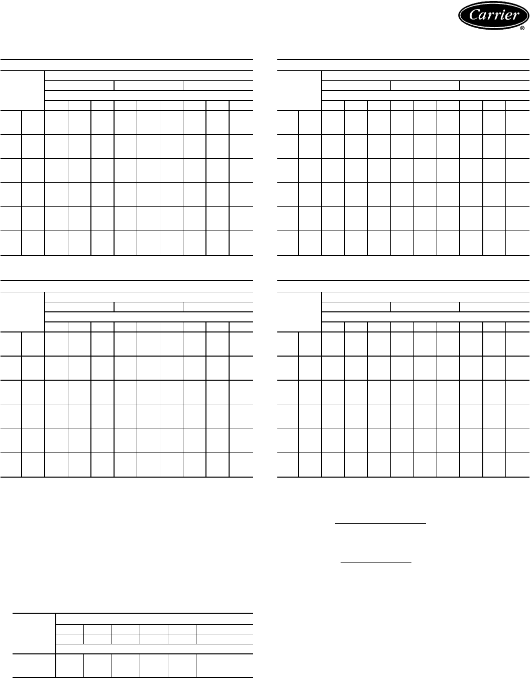
COMBINATION RATINGS — ENGLISH (cont)
38AH028 AND 40RM028
Temp (F)
Air
Entering
Condenser
Evaporator Air — Cfm/BF
7,500/0.04 10,000/0.06 12,500/0.08
Evaporator Air — Ewb (F)
72 67 62 72 67 62 72 67 62
85 TC 275.2 252.7 234.7 285.3 262.8 249.2 290.6 271.7 261.4
SHC 148.5 191.1 231.2 168.8 222.6 249.2 188.5 250.9 261.4
kW 17.13 16.57 16.12 17.38 16.82 16.48 17.52 17.04 16.78
95 TC 264.5 241.8 225.1 274.3 251.6 239.7 279.2 260.6 251.9
SHC 144.5 186.7 222.4 164.9 218.0 239.7 184.7 246.1 251.9
kW 18.66 18.09 17.68 18.91 18.34 18.04 19.03 18.56 18.35
100 TC 259.1 236.3 220.3 268.7 246.0 235.0 273.5 255.0 247.2
SHC 142.6 184.5 218.0 163.0 215.7 235.0 182.8 243.6 247.2
kW 19.50 18.83 18.37 19.78 19.12 18.79 19.92 19.38 19.15
105 TC 251.2 229.6 215.2 260.0 238.6 229.2 264.3 247.1 240.8
SHC 139.7 181.8 213.4 159.9 212.7 229.2 179.8 240.2 240.8
kW 20.40 19.61 19.09 20.72 19.94 19.60 20.87 20.25 20.02
115 TC 239.3 218.3 205.6 247.4 226.7 219.2 251.1 234.9 230.4
SHC 135.3 177.2 204.6 155.5 207.8 219.2 175.4 234.8 230.4
kW 21.89 21.09 20.60 22.21 21.41 21.12 22.35 21.73 21.55
115 TC 210.1 189.8 180.9 217.0 197.1 194.0 219.6 205.1 204.6
SHC 124.6 165.7 181.9 144.8 195.7 194.0 164.9 221.8 204.6
kW 23.67 22.82 22.45 23.96 23.13 23.00 24.07 23.46 23.44
38AH028 AND 40RM034
Temp (F)
Air
Entering
Condenser
Evaporator Air — Cfm/BF
9,000/0.04 12,000/0.06 15,000/0.08
Evaporator Air — Ewb (F)
72 67 62 72 67 62 72 67 62
85 TC 291.7 266.7 251.6 300.7 276.9 267.5 305.2 286.3 280.5
SHC 162.4 214.9 249.7 189.9 251.2 267.5 211.7 283.4 280.5
kW 17.54 16.92 16.54 17.77 17.17 16.94 17.88 17.41 17.26
95 TC 280.4 255.1 241.3 289.1 265.1 257.4 293.2 274.5 270.3
SHC 158.1 210.3 240.4 186.0 246.5 257.4 207.7 274.5 270.3
kW 19.06 18.43 18.08 19.28 18.68 18.48 19.38 18.91 18.81
100 TC 274.7 249.3 236.2 283.2 259.2 252.3 287.2 268.7 265.2
SHC 156.0 208.0 235.8 184.0 244.1 252.3 205.7 268.7 265.2
kW 19.95 19.21 18.83 20.20 19.50 19.30 20.32 19.78 19.68
105 TC 265.5 241.5 229.9 273.2 250.6 245.1 276.7 259.5 257.4
SHC 152.5 204.9 230.1 180.6 240.6 245.1 202.2 259.5 257.4
kW 20.92 20.04 19.62 21.20 20.38 20.18 21.32 20.70 20.62
115 TC 252.4 229.1 219.2 259.4 237.6 234.0 262.4 246.2 245.8
SHC 147.5 200.0 220.4 175.9 235.4 234.0 197.5 246.2 245.8
kW 22.40 21.50 21.12 22.67 21.83 21.69 22.78 22.16 22.14
125 TC 221.1 198.5 192.2 226.8 206.2 206.4 228.9 214.4 217.6
SHC 135.6 187.9 195.9 164.9 206.2 206.4 186.3 214.4 217.6
kW 24.13 23.19 22.92 24.37 23.51 23.52 24.45 23.85 23.98
38AH034 AND 40RM028
Temp (F)
Air
Entering
Condenser
Evaporator Air — Cfm/BF
7,500/0.04 10,000/0.06 12,500/0.08
Evaporator Air — Ewb (F)
72 67 62 72 67 62 72 67 62
85 TC 307.8 283.0 258.8 320.5 295.3 274.6 327.8 305.2 288.2
SHC 160.5 203.4 253.3 181.2 236.0 274.6 200.9 265.5 288.2
kW 20.50 19.90 19.32 20.81 20.20 19.70 20.99 20.44 20.03
95 TC 295.9 271.4 249.2 307.9 283.1 264.9 314.6 292.9 278.2
SHC 156.1 198.7 244.5 176.8 231.0 264.9 196.5 260.2 278.2
kW 22.57 21.78 21.06 22.95 22.15 21.57 23.17 22.47 22.00
100 TC 289.5 265.4 244.4 301.0 276.7 259.9 307.3 286.3 272.9
SHC 153.7 196.3 240.2 174.3 228.3 259.9 194.1 257.3 272.9
kW 23.38 22.58 21.88 23.77 22.96 22.40 23.98 23.28 22.83
105 TC 283.7 259.5 239.3 295.0 270.6 254.8 301.0 280.3 267.8
SHC 151.6 193.9 235.4 172.2 225.8 254.8 192.0 254.6 267.8
kW 24.41 23.52 22.77 24.83 23.93 23.34 25.05 24.28 23.82
115 TC 271.0 247.4 229.4 281.4 257.8 244.5 286.8 267.2 257.2
SHC 146.9 189.0 226.4 167.5 220.6 244.5 187.3 248.9 257.2
kW 26.32 25.30 24.52 26.77 25.75 25.18 27.00 26.15 25.72
125 TC 257.9 234.9 219.0 267.5 244.6 233.7 272.3 253.7 246.0
SHC 142.1 184.0 216.8 162.6 215.2 233.7 182.4 243.1 246.0
kW 28.29 27.15 26.36 28.76 27.63 27.09 29.00 28.08 27.70
38AH034 AND 40RM034
Temp (F)
Air
Entering
Condenser
Evaporator Air — Cfm/BF
9,000/0.04 12,000/0.06 15,000/0.08
Evaporator Air — Ewb (F)
72 67 62 72 67 62 72 67 62
85 TC 328.6 301.1 279.6 340.3 313.3 297.3 346.7 324.0 311.8
SHC 176.4 228.6 275.2 203.3 265.9 297.3 225.6 300.0 311.8
kW 21.00 20.34 19.82 21.29 20.64 20.25 21.44 20.89 20.60
95 TC 315.5 288.3 268.9 326.5 300.0 286.3 332.2 310.4 300.5
SHC 171.4 223.5 265.4 198.6 260.5 286.3 220.7 294.0 300.5
kW 23.19 22.32 21.70 23.55 22.70 22.26 23.73 23.03 22.71
100 TC 308.2 281.5 263.3 318.6 292.8 280.4 324.0 303.0 294.4
SHC 168.7 220.8 260.4 196.0 257.6 280.4 218.0 290.8 294.0
kW 24.01 23.12 22.51 24.35 23.49 23.08 24.53 23.83 23.55
105 TC 302.1 275.2 257.8 312.3 286.4 275.0 317.5 296.6 288.9
SHC 166.3 218.3 255.4 193.9 255.0 275.0 215.8 287.9 288.9
kW 25.09 24.10 23.45 25.47 24.51 24.09 25.66 24.89 24.60
115 TC 287.9 261.8 246.6 297.3 272.3 263.2 301.8 282.1 276.7
SHC 161.0 213.0 245.2 188.8 249.4 263.2 210.6 281.6 276.7
kW 27.05 25.92 25.26 27.45 26.37 25.98 27.65 26.80 26.56
125 TC 273.5 247.9 234.8 282.0 257.8 251.1 — 267.4 264.1
SHC 155.5 207.5 234.6 183.6 243.5 251.1 — 267.4 264.1
kW 29.06 27.79 27.14 29.48 28.28 27.95 — 28.76 28.59
LEGEND
BF — Bypass Factor
Edb — Entering Dry Bulb
Ewb — Entering Wet-Bulb
kW — Compressor Motor Power Input
Ldb — Leaving Dry Bulb
Lwb — Leaving Wet Bulb
SHC — Sensible Heating Capacity (1000 Btuh)
TC — Total Capacity (1000 Btuh)
NOTES:
1. All combination ratings are based on refrigerant R-22.
2. Direct interpolation is permissible. Do not extrapolate.
3. The SHC is based on 80 F dry-bulb temperature of air entering the evaporator
coil.
Below 80 F dry-bulb, subtract (correction factor × cfm) from SHC.
Above 80 F dry bulb, add (correction factor × cfm) to SHC.
BYPASS
FACTOR
ENTERING-AIR DRY-BULB TEMP (F)
79 78 77 76 75 under 75
81 82 83 84 85 over 85
Correction Factor
0.10 0.99 1.98 2.97 3.96 4.95 Use formula
shown below.
0.20 0.88 1.76 2.64 3.52 4.40
0.30 0.77 1.54 2.31 3.08 3.85
Interpolation is permissible.
Correction Factor = 1.1 x (1 − BF) x (db − 80).
4. Gross capacities shown do not include a deduction for evaporator-fan motor
heat.
5. Formulas
sensible heat capacity (Btuh)
tldb =t
edb −1.1 x cfm
tlwb = wet-bulb temperature corresponding to enthalpy of air leaving
evaporator coil (hlwb)
total capacity (Btuh)
hlwb =h
ewb −4.5 cfm
where hewb = enthalpy of air entering evaporator coil
6. Combination ratings are based on a 2° F line loss. For a close-coupled system
(less than 15 ft),
add 2%
to ratings. Piping sizes in Refrigerant Pipe Sizes table
on page 40 are based on 2° F line loss.
25
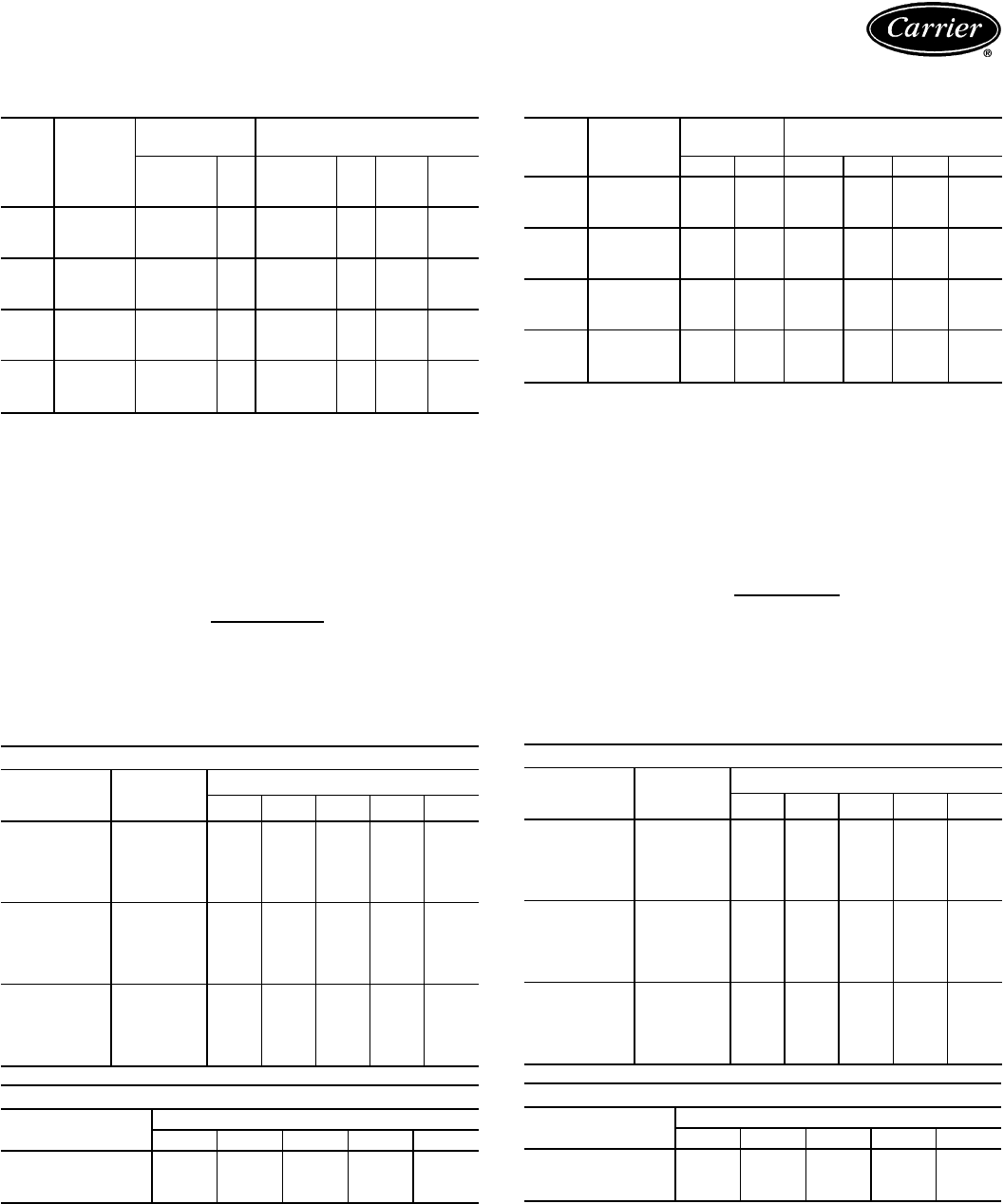
Performance data — 38AH024-034/40RM (cont)
40RM COIL ACCESSORY HEATING CAPACITIES —
SI
UNIT
40RM AIRFLOW
(L/s)
1-ROW
STEAM* 2-ROW
HOT WATER COIL†
Cap. (kW) Ldb Cap. (kW) Ldb Water
Flow
(L/s)
PD
(kPa)
016 2100
2800
3500
117
129
140
61
53
48
120
137
154
62
55
51
2.6
3.0
3.3
13.3
16.2
19.5
024 2900
3800
4700
135
140
146
53
46
41
150
170
191
58
52
49
3.3
3.7
4.1
15.6
18.6
22.3
028 3500
4700
5900
149
166
183
50
44
41
189
218
247
60
53
50
4.1
4.7
5.4
16.9
20.8
25.4
034 4250
5650
7050
164
180
196
47
41
38
215
247
278
57
51
48
4.7
5.4
6.0
18.5
22.8
27.7
LEGEND
Cap. — Capacity (kW)
Ldb — Leaving-Air Dry-Bulb Temp (C)
PD — Pressure Drop (kPa)
*Based on 34.5 kPag steam, 15.6 C entering-air temperature. All steam
coils are non-freeze type.
†Based on 93.3 C entering-water temperature, 11.1 C water tempera-
ture drop, 15.6 C entering-air temperature.
NOTES:
1. Maximum operating limit for heating coils: 1207 kPag at 204.4 C.
Capacity (kW)
2. Leaving db = ent db (C) + 1.23 x 10
-3
x L/s
3. See Heating Correction Factors table.
40RM HEATING CORRECTION FACTORS —
SI
HOT WATER COIL
Water Temp
Drop
(C)
Ent Water
Temp
(C)
Entering-Air Temp (C)
4 10162025
5
60 0.72 0.64 0.55 0.50 0.43
70 0.87 0.79 0.71 0.65 0.58
80 1.02 0.94 0.86 0.80 0.73
90 1.17 1.09 1.01 0.95 0.89
100 1.32 1.24 1.16 1.10 1.04
11
60 0.65 0.56 0.48 0.42 0.35
70 0.80 0.72 0.63 0.58 0.51
80 0.95 0.87 0.79 0.73 0.66
90 1.10 1.02 0.94 0.89 0.82
100 1.26 1.18 1.09 1.04 0.97
16
60 0.56 0.48 0.39 0.33 0.26
70 0.72 0.63 0.55 0.49 0.42
80 0.87 0.79 0.70 0.65 0.58
90 1.02 0.94 0.86 0.81 0.74
100 1.18 1.10 1.02 0.97 0.90
STEAM COIL
Steam Pressure
(kPag) Entering-Air Temp (C)
4 10162025
01.07 0.99 0.91 0.86 0.80
14 1.10 1.02 0.95 0.90 0.84
35 1.14 1.07 0.99 0.95 0.89
NOTE: Multiply capacity given in the Coil Accessory Heating Capacities
table by the correction factor for conditions at which unit is actually
operating. Correct leaving-air temperature using formula in Note 2 of
Coil Accessory Heating Capacities table.
40RM COIL ACCESSORY HEATING CAPACITIES —
ENGLISH
UNIT
40RM AIRFLOW
(Cfm)
1-ROW
STEAM* 2-ROW
HOT WATER COIL†
Cap. Ldb Cap. Ldb Gpm PD
016 4,500
6,000
7,500
402
458
479
141
129
118
412.0
471.0
529.0
145
133
125
41.2
47.1
52.9
4.5
5.5
6.6
024 6,000
8,000
10,000
458
487
499
129
115
105
506.0
584.0
652.0
138
128
120
50.6
58.4
65.2
5.1
6.3
7.5
028 7,500
10,000
12,500
511
575
626
122
112
106
649.0
752.0
842.0
140
130
122
64.9
75.2
84.2
5.7
7.1
8.5
034 9,000
12,000
15,000
560
621
670
117
107
101
735.0
850.0
950.0
136
126
119
73.5
85.0
95.0
6.2
7.8
9.3
LEGEND
Cap. — Capacity (Btuh in thousands)
Ldb — Leaving-Air Dry-Bulb Temp (F)
PD — Pressure Drop (ft water)
*Based on 5 psig steam, 60 F entering-air temperature. All steam coils
are non-freeze type.
†Based on 200 F entering water, 20 F water temperature drop, 60 F
entering-air temperature.
NOTES:
1. Maximum operating limit for heating coils: 175 psig at 400 F.
Capacity (Btuh)
2. Leaving db = ent db (F) + 1.1 x cfm
3. See Heating Correction Factors table.
40RM HEATING CORRECTION FACTORS —
ENGLISH
HOT WATER COIL
Water Temp
Drop
(F)
Ent Water
Temp
(F)
Entering-Air Temp (F)
40 50 60 70 80
10
140 0.72 0.64 0.57 0.49 0.41
160 0.89 0.81 0.74 0.66 0.58
180 1.06 0.98 0.90 0.83 0.75
200 1.22 1.15 1.07 1.00 0.92
220 1.39 1.32 1.24 1.17 1.09
20
140 0.64 0.57 0.49 0.41 0.33
160 0.81 0.74 0.66 0.58 0.51
180 0.98 0.91 0.83 0.75 0.68
200 1.15 1.08 1.00 0.93 0.85
220 1.32 1.25 1.17 1.10 1.02
30
140 0.56 0.49 0.41 0.33 0.24
160 0.74 0.66 0.58 0.51 0.43
180 0.91 0.83 0.76 0.68 0.60
200 1.08 1.00 0.93 0.85 0.78
220 1.25 1.18 1.10 1.03 0.95
STEAM COIL
Steam Pressure
(psig) Entering-Air Temp (F)
40 50 60 70 80
01.06 0.98 0.91 0.85 0.78
21.09 1.02 0.95 0.89 0.82
51.13 1.06 1.00 0.93 0.87
NOTE: Multiply capacity given in the Coil Accessory Heating Capacities
table by the correction factor for conditions at which unit is actually
operating. Correct leaving-air temperature using formula in Note 2 of
Coil Accessory Heating Capacities table.
26
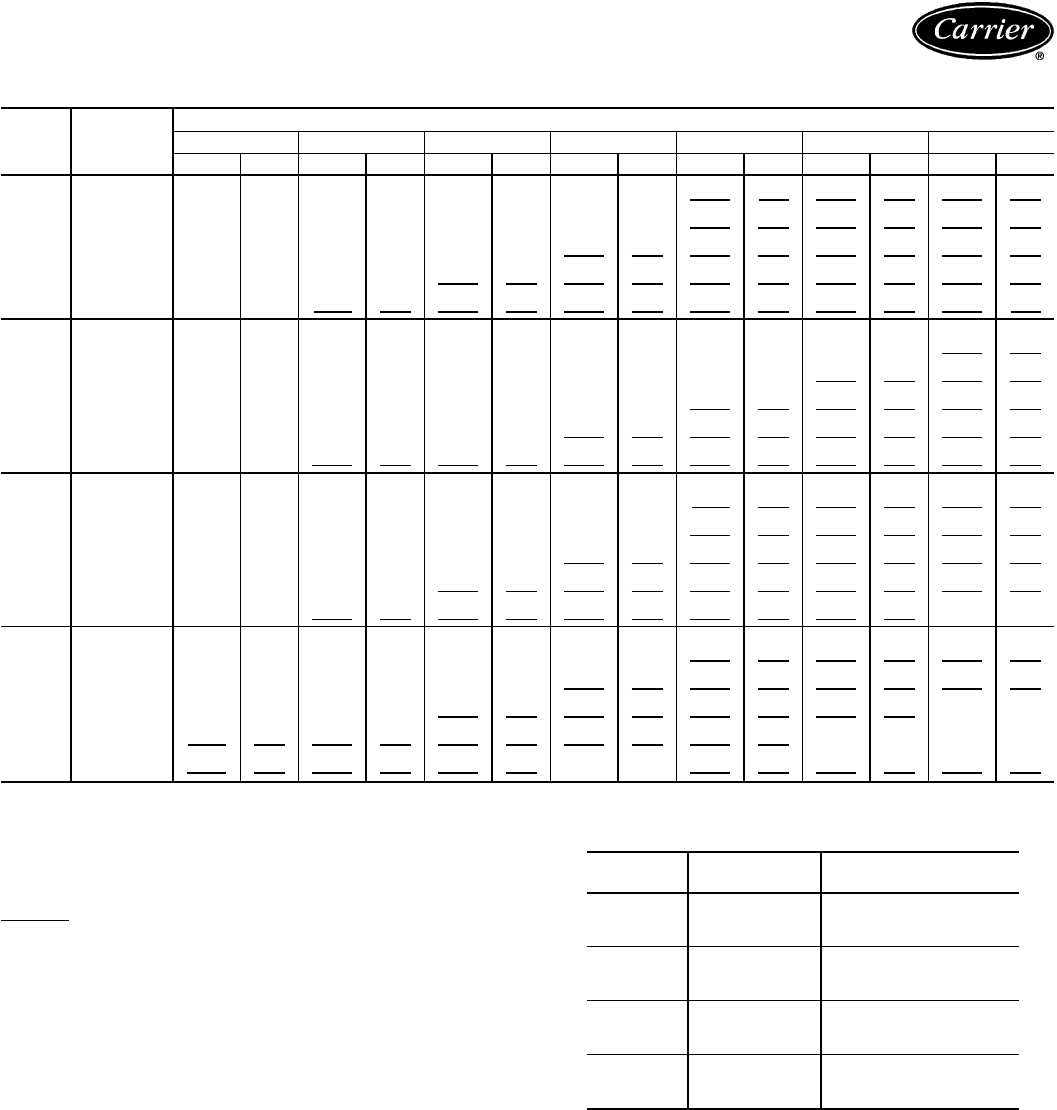
40RM FAN PERFORMANCE DATA — 0-300 Pa ESP — SI
UNIT
40RM AIRFLOW
(L/s)
EXTERNAL STATIC PRESSURE (Pa)
0 50 100 150 200 250 300
r/s kW r/s kW r/s kW r/s kW r/s kW r/s kW r/s kW
016
2100
6.43 0.37 8.19 0.55
9.65 0.73 10.90 0.92 12.10 1.11 13.10 1.30 14.10 1.50
2450
7.51 0.57
9.06 0.77 10.40 0.97 11.60 1.18 12.70 1.39 13.70 1.60 14.60 1.81
2800
8.58 0.82
9.96 1.05 11.20 1.27 12.30 1.49 13.30 1.72 14.30 1.95 15.10 2.18
3150 9.65 1.14 10.90 1.38 12.00 1.63 13.10 1.87 14.00 2.12 14.90 2.36 15.80 2.61
3500 10.70 1.52 11.90 1.78 12.90 2.05 13.90 2.31 14.80 2.58 15.60 2.84 16.40 3.11
024
2900
8.58 0.86 9.96 1.09 11.20 1.32
12.30 1.55 13.30 1.78 14.20 2.01 15.10 2.25
3350
9.91 1.28 11.10 1.53
12.20 1.79 13.20 2.04 14.20 2.30 15.10 2.55 15.90 2.81
3800
11.30 1.81
12.30 2.09 13.30 2.37 14.30 2.64 15.10 2.93 16.00 3.21 16.80 3.49
4250 12.60 2.46 13.60 2.76 14.50 3.07 15.30 3.37 16.10 3.67 16.90 3.98 17.70 4.28
4700 13.90 3.24 14.80 3.57 15.60 3.90 16.40 4.22 17.20 4.55 17.90 4.88 18.60 5.21
028
3500
6.79 0.84 8.14 1.12
9.42 1.47 10.70 1.89 11.80 2.39 12.90 2.96 14.00 3.61
4100
7.95 1.29 9.12 1.60
10.20 1.96 11.30 2.38 12.40 2.86 13.40 3.40 14.30 4.00
4700
9.12 1.88
10.10 2.21 11.10 2.59 12.10 3.02 13.00 3.49 13.90 4.02 14.80 4.60
5300 10.30 2.62 11.20 3.00 12.10 3.37 12.90 3.81 13.80 4.29 14.60 4.82 15.40 5.38
5900 11.40 3.52 12.30 3.90 13.10 4.32 13.90 4.77 14.60 5.26 15.40 5.79
16.10 6.35
034
4250
7.86 1.33 8.99 1.63
10.10 1.97 11.10 2.37 12.20 2.83 13.20 3.34 14.10 3.92
4950
9.15 2.03
10.10 2.35 11.10 2.72 12.00 3.12 12.90 3.58 13.80 4.08 14.70 4.62
5650 10.40 2.92 11.30 3.27 12.20 3.66 13.00 4.08 13.80 4.54 14.60 5.04 1
5.40 5.57
6350 11.70 4.02 12.50 4.40 13.30 4.81 14.00 5.25 14.70 5.72
15.50 6.23 16.20 6.77
7050 13.00 5.37 13.70 5.77 14.40 6.21
15.10 6.66
15.70 7.15 16.40 7.67 17.10 8.21
LEGEND
ESP — External Static Pressure
Bold
indicates field-supplied drive required.
Plain type indicates standard motor and standard drive.
Underline indicates a different motor and drive combination is required.
Refer to fan motor and drive tables, pages 41-43, to complete the
selection.
NOTES:
1. Maximum allowable fan speed is 18.3 r/s for unit sizes 028 and 034;
20 r/s for all other sizes.
2. Fan performance is based on deductions for wet coil, clean 51-mm
filters, and unit casing. See right for factory-supplied filter pressure
drop.
3. The standard motor and medium-static drive combination is not avail-
able for 40RM016-028 units. Use the alternate motor if the medium-
static drive is required for these sizes.
40RM FACTORY-SUPPLIED FILTER
PRESSURE DROP — SI
UNIT
40RM AIRFLOW
(L/s) PRESSURE DROP
(Pa)
016 2100
2800
3500
20
30
42
024 2900
3800
4700
32
47
64
028 3500
4700
5900
36
55
76
034 4250
5650
7050
47
71
98
27
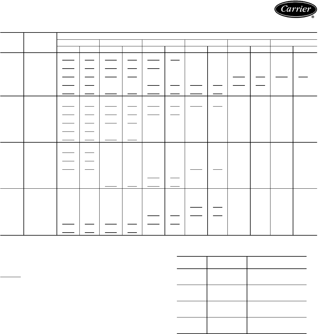
Performance data — 38AH024-034/40RM (cont)
40RM FAN PERFORMANCE DATA — 350-600 Pa ESP — SI
UNIT
40RM AIRFLOW
(L/s)
EXTERNAL STATIC PRESSURE (Pa)
350 400 450 500 550 600
r/s kW r/s kW r/s kW r/s kW r/s kW r/s kW
016
2100 15.00 1.70 15.80 1.90 16.70 2.11
17.40 2.32 18.20 2.53 18.90 2.74
2450 15.50 2.03 16.30 2.25 17.10 2.47
17.80 2.70 18.60 2.93 19.30 3.16
2800 16.00 2.42 16.80 2.66
17.60 2.90 18.30 3.14
19.00 3.38 19.70 3.63
3150 16.60 2.87
17.40 3.12
18.10 3.38 18.80 3.64 19.50 3.90 ——
3500 17.20 3.38 18.00 3.65 18.70 3.93 19.40 4.20 ——— —
024
2900 16.00 2.49 16.80 2.73 17.50 2.97 18.30 3.22
19.00 3.47 19.70 3.72
3350 16.70 3.08 17.50 3.34 18.20 3.61
18.90 3.87 19.60 4.14
——
3800 17.50 3.77 18.20 4.06
18.90 4.35 19.60 4.64
——— —
4250 18.40 4.59
19.10 4.90 19.80 5.21
————— —
4700 19.30 5.54 20.00 5.87 ——————— —
028
3500 15.10 4.33
16.10 5.12 17.10 5.98 18.00 6.92
——— —
4100 15.30 4.67
16.20 5.39 17.10 6.18 18.00 7.02
——— —
4700 15.70 5.23
16.50 5.91 17.40 6.64
18.20 7.43 ——— —
5300
16.20 5.99 17.00 6.65
17.80 7.35 ————— —
5900
16.90 6.95
17.60 7.59 18.30 8.27 ————— —
034
4250
15.00 4.55 16.00 5.24 16.80 5.99 17.70 6.79
——— —
4950
15.50 5.22 16.30 5.86 17.10 6.56
17.90 7.30 ——— —
5650
16.10 6.16 16.90 6.77
17.60 7.43 18.30 8.13 ——— —
6350 16.90 7.34 17.50 7.94 18.20 8.58 ————— —
7050 17.70 8.79 18.30 9.39 ——————— —
LEGEND
ESP — External Static Pressure
Bold
indicates field-supplied drive required.
Plain type indicates standard motor and standard drive.
Underline indicates a different motor and drive combination is required.
Refer to fan motor and drive tables, pages 41-43, to complete the
selection.
NOTES:
1. Maximum allowable fan speed is 18.3 r/s for unit sizes 028 and 034;
20 r/s for all other sizes.
2. Fan performance is based on deductions for wet coil, clean 51-mm
filters, and unit casing. See right for factory-supplied filter pressure
drop.
3. The standard motor and medium-static drive combination is not avail-
able for 40RM016-028 units. Use the alternate motor if the medium-
static drive is required for these sizes.
40RM FACTORY-SUPPLIED FILTER
PRESSURE DROP — SI
UNIT
40RM AIRFLOW
(L/s) PRESSURE DROP
(Pa)
016 2100
2800
3500
20
30
42
024 2900
3800
4700
32
47
64
028 3500
4700
5900
36
55
76
034 4250
5650
7050
47
71
98
28
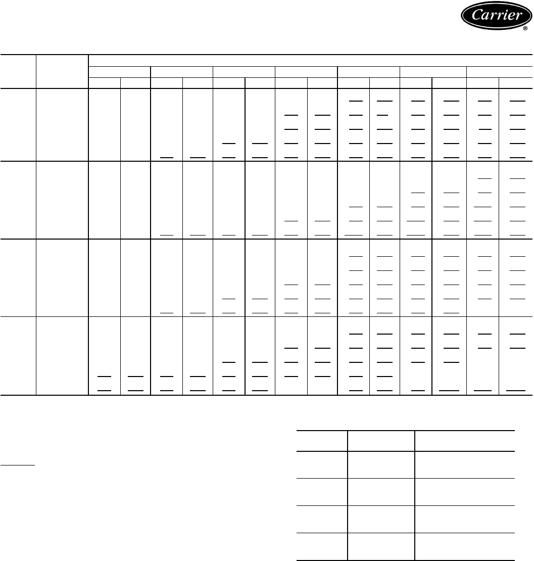
40RM FAN PERFORMANCE DATA — 0.0-1.2 in. wg ESP — ENGLISH
UNIT
40RM AIRFLOW
(Cfm)
EXTERNAL STATIC PRESSURE (in. wg)
0.0 0.2 0.4 0.6 0.8 1.0 1.2
Rpm Bhp Rpm Bhp Rpm Bhp Rpm Bhp Rpm Bhp Rpm Bhp Rpm Bhp
016
4,500
391 0.51 495 0.75
581 1.00 657 1.25 725 1.50 787 1.76 845 2.02
5,300
460 0.80
551 1.08 629 1.35 700 1.63 764 1.91 823 2.20 878 2.48
6,000
521 1.13
602 1.43 675 1.73 741 2.04 801 2.34 858 2.65 911 2.96
6,800 590 1.60 663 1.93 730 2.26 791 2.59 847 2.92 901 3.26 951 3.60
7,500 651 2.10 718 2.45 779 2.81 837 3.16 890 3.52 941 3.88 990 4.24
024
6,000
503 1.07 587 1.37 661 1.67
727 1.97 789 2.28 846 2.59 900 2.90
7,000
586 1.64 660 1.98
726 2.31 787 2.65 844 2.99 898 3.33 948 3.67
8,000
670 2.37
735 2.74 795 3.12 851 3.49 904 3.86 954 4.23 1001 4.61
9,000 754 3.28 812 3.69 867 4.09 918 4.50 967 4.90 1014 5.31 1059 5.72
10,000 838 4.39 891 4.83 941 5.27 988 5.70 1034 6.14 1077 6.85 1120 7.02
028
7,500
412 1.15 492 1.53
568 2.00 640 2.56 710 3.22 776 3.98 840 4.83
8,750
481 1.76 550 2.17
616 2.66 680 3.22 742 3.86 802 4.58 860 5.38
10,000
549 2.55
610 2.99 669 3.50 726 4.07 782 4.70 836 5.40 889 6.17
11,250 618 3.52 672 4.00 725 4.53 777 5.12 827 5.76 876 6.45 925 7.21
12,500 687 4.71 735 5.22 783 5.78 830 6.38 876 7.04 922 7.74
966 8.49
034
9,000
471 1.78 539 2.17
604 2.63 667 3.17 728 3.78 788 4.46 845 5.22
10,500
550 2.72
608 3.15 665 3.64 720 4.18 774 4.79 827 5.45 878 6.18
12,000 628 3.93 679 4.40 730 4.92 779 5.48 827 6.09 874 6.76
921 7.47
13,500 707 5.44 752 5.94 797 6.49 841 7.08 885 7.71
928 8.38 970 9.10
15,000 785 7.27 826 7.81 867 8.39
907 9.01
947 9.66 986 10.35 1024 11.07
LEGEND
ESP — External Static Pressure
Bold
indicates field-supplied drive required.
Plain type indicates standard motor and standard drive.
Underline indicates a different motor and drive combination is required.
Refer to fan motor and drive tables, pages 41-43, to complete the
selection.
NOTES:
1. Maximum allowable fan speed is 1100 rpm for unit sizes 028 and
034; 1200 rpm for all other sizes.
2. Fan performance is based on deductions for wet coil, clean 2-in.
filters, and unit casing. See right for factory-supplied filter pressure
drop.
3. The standard motor and medium-static drive combination is not avail-
able for 40RM016-028 units. Use the alternate motor if the medium-
static drive is required for these sizes.
40RM FACTORY-SUPPLIED FILTER
PRESSURE DROP — ENGLISH
UNIT
40RM AIRFLOW
(Cfm) PRESSURE DROP
(in. wg)
016 4,500
6,000
7,500
0.08
0.12
0.17
024 6,000
8,000
10,000
0.12
0.19
0.26
028 7,500
10,000
12,500
0.15
0.22
0.30
034 9,000
12,000
15,000
0.19
0.29
0.40
29
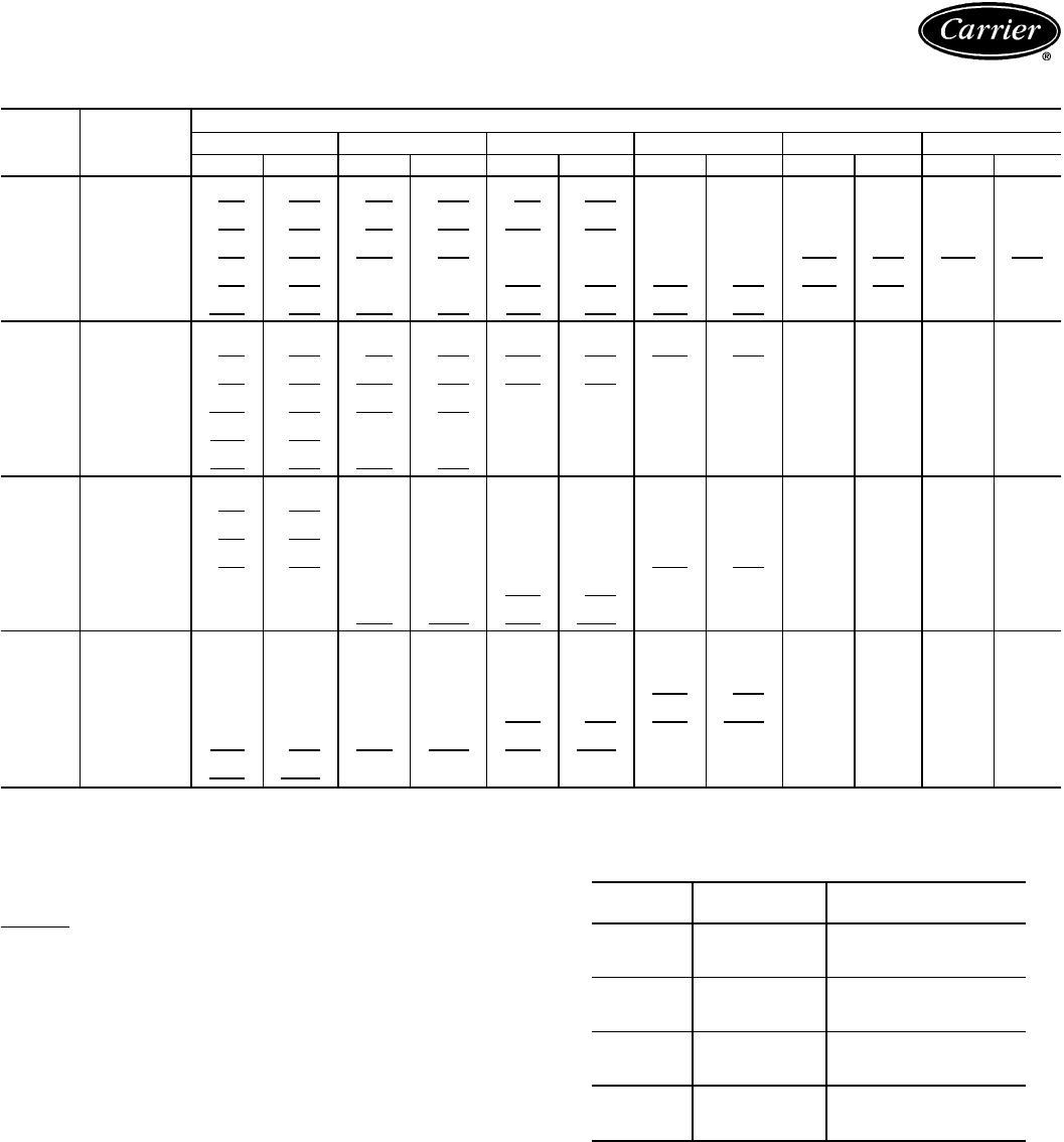
Performance data — 38AH024-034/40RM (cont)
FAN PERFORMANCE DATA — 1.4-2.4 in. wg ESP — ENGLISH
UNIT
40RM AIRFLOW
(Cfm)
EXTERNAL STATIC PRESSURE (in. wg)
1.4 1.6 1.8 2.0 2.2 2.4
Rpm Bhp Rpm Bhp Rpm Bhp Rpm Bhp Rpm Bhp Rpm Bhp
016
4,500 899 2.29 951 2.56 999 2.84
1046 3.12 1091 3.41 1133 3.70
5,300 930 2.78 980 3.08 1027 3.38
1072 3.68 1116 3.99 1157 4.30
6,000 961 3.28 1009 3.60
1055 3.92 1098 4.24
1141 4.57 1181 4.91
6,800 999 3.94
1045 4.28
1089 4.63 1132 4.98 1173 5.33 ——
7,500 1036 4.60 1080 4.97 1123 5.34 1164 5.71 ————
024
6,000 950 3.21 999 3.53 1045 3.85 1089 4.17
1131 4.50 1172 4.83
7,000 996 4.02 1042 4.37 1086 4.72
1129 5.07 1169 5.43
——
8,000 1047 4.99 1091 5.37
1133 5.75 1173 6.13
————
9,000 1102 6.13
1143 6.54 1183 6.96
——————
10,000 1160 7.46 1200 7.91 ————————
028
7,500 903 5.79
963 6.83 1021 7.98 1078 9.21
————
8,750 917 6.26
972 7.22 1025 8.26 1078 9.38
————
10,000 941 7.01
991 7.91 1040 8.89
1089 9.93 ————
11,250
972 8.02 1019 8.89
1064 9.83 ——————
12,500
1010 9.29
1053 10.15 1095 11.05 ——————
034
9,000
901 6.07 955 6.98 1008 7.98 1060 9.05
————
10,500
928 6.98 978 7.84 1026 8.76
1073 9.74 ————
12,000
966 8.24 1011 9.07
1055 9.95 1098 10.88 ————
13,500 1011 9.86 1052 10.67 1092 11.52 ——————
15,000 1062 11.84 ——————————
LEGEND
ESP — External Static Pressure
Bold
indicates field-supplied drive required.
Plain type indicates standard motor and standard drive.
Underline indicates a different motor and drive combination is required.
Refer to fan motor and drive tables, pages 41-43, to complete the
selection.
NOTES:
1. Maximum allowable fan speed is 1100 rpm for unit sizes 028 and
034; 1200 rpm for all other sizes.
2. Fan performance is based on deductions for wet coil, clean 2-in.
filters, and unit casing. See right for factory-supplied filter pressure
drop.
3. The standard motor and medium-static drive combination is not avail-
able for 40RM016-028 units. Use the alternate motor if the medium-
static drive is required for these sizes.
40RM FACTORY-SUPPLIED FILTER
PRESSURE DROP — ENGLISH
UNIT
40RM AIRFLOW
(Cfm) PRESSURE DROP
(in. wg)
016 4,500
6,000
7,500
0.08
0.12
0.17
024 6,000
8,000
10,000
0.12
0.19
0.26
028 7,500
10,000
12,500
0.15
0.22
0.30
034 9,000
12,000
15,000
0.19
0.29
0.40
30
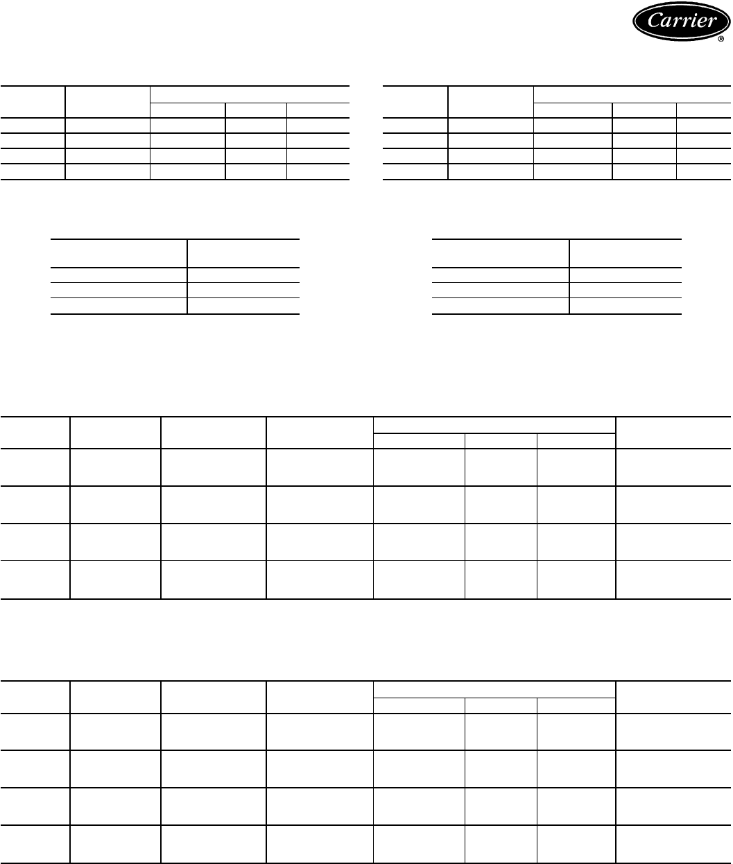
40RM PLENUM ACCESSORY AIR THROW DATA — SI
(m)
UNIT
40RM AIRFLOW
(L/s) VANE DEFLECTION
Straight 22
1
⁄
2
° 45°
016 2800 15.41 13.25 9.55
024 3800 18.17 15.44 11.20
028 4700 23.26 19.89 14.38
034 5650 25.97 22.00 15.89
NOTE: Throw distances shown are for 0.381 m/sec terminal velocity.
Use the following multipliers to determine throw values for other termi-
nal velocities.
TERMINAL VELOCITY
(m/sec) THROW FACTOR
0.254 X 1.50
0.508 X 0.75
0.762 X 0.50
40RM PLENUM ACCESSORY AIR THROW DATA —
ENGLISH (Ft)
UNIT
40RM AIRFLOW
(Cfm) VANE DEFLECTION
Straight 22
1
⁄
2
° 45°
016 6,000 50 43 31
024 8,000 60 51 37
028 10,000 76 65 47
034 12,000 85 72 52
NOTE: Throw distances shown are for 75 fpm terminal velocity. Use
the following multipliers to determine throw values for other terminal
velocities.
TERMINAL VELOCITY
(Fpm) THROW FACTOR
50 X 1.50
100 X 0.75
150 X 0.50
40RM ACCESSORY PRESSURE DROP — SI
(Pa)
UNIT
40RM AIRFLOW
(L/s) DISCHARGE
PLENUM RETURN AIR
GRILLE HEATING COILS ECONOMIZER
Hot Water Steam Electric
016 2100
2800
3500
24
39
56
2
5
7
36
57
82
36
57
82
14
24
37
15
22
37
024 2900
3800
4700
41
64
91
5
10
15
60
93
132
60
93
132
26
43
65
23
43
69
028 3500
4700
5900
37
59
86
5
7
12
67
109
157
67
109
157
22
39
60
15
22
35
034 4250
5650
7050
50
80
114
7
12
17
92
147
210
92
147
210
32
56
85
20
35
52
40RM ACCESSORY PRESSURE DROP — ENGLISH
(in. wg)
UNIT
40RM AIRFLOW
(Cfm) DISCHARGE
PLENUM RETURN AIR
GRILLE HEATING COILS ECONOMIZER
Hot Water Steam Electric
016 4,500
6,000
7,500
0.10
0.16
0.23
0.01
0.02
0.03
0.15
0.23
0.33
0.15
0.23
0.33
0.06
0.10
0.15
0.06
0.09
0.15
024 6,000
8,000
10,000
0.16
0.26
0.37
0.02
0.04
0.06
0.23
0.37
0.53
0.23
0.37
0.53
0.10
0.17
0.26
0.09
0.17
0.28
028 7,500
10,000
12,500
0.15
0.24
0.34
0.02
0.03
0.05
0.28
0.44
0.63
0.28
0.44
0.63
0.09
0.16
0.24
0.06
0.09
0.14
034 9,000
12,000
15,000
0.20
0.32
0.46
0.03
0.05
0.07
0.37
0.59
0.85
0.37
0.59
0.85
0.13
0.22
0.34
0.08
0.14
0.21
31
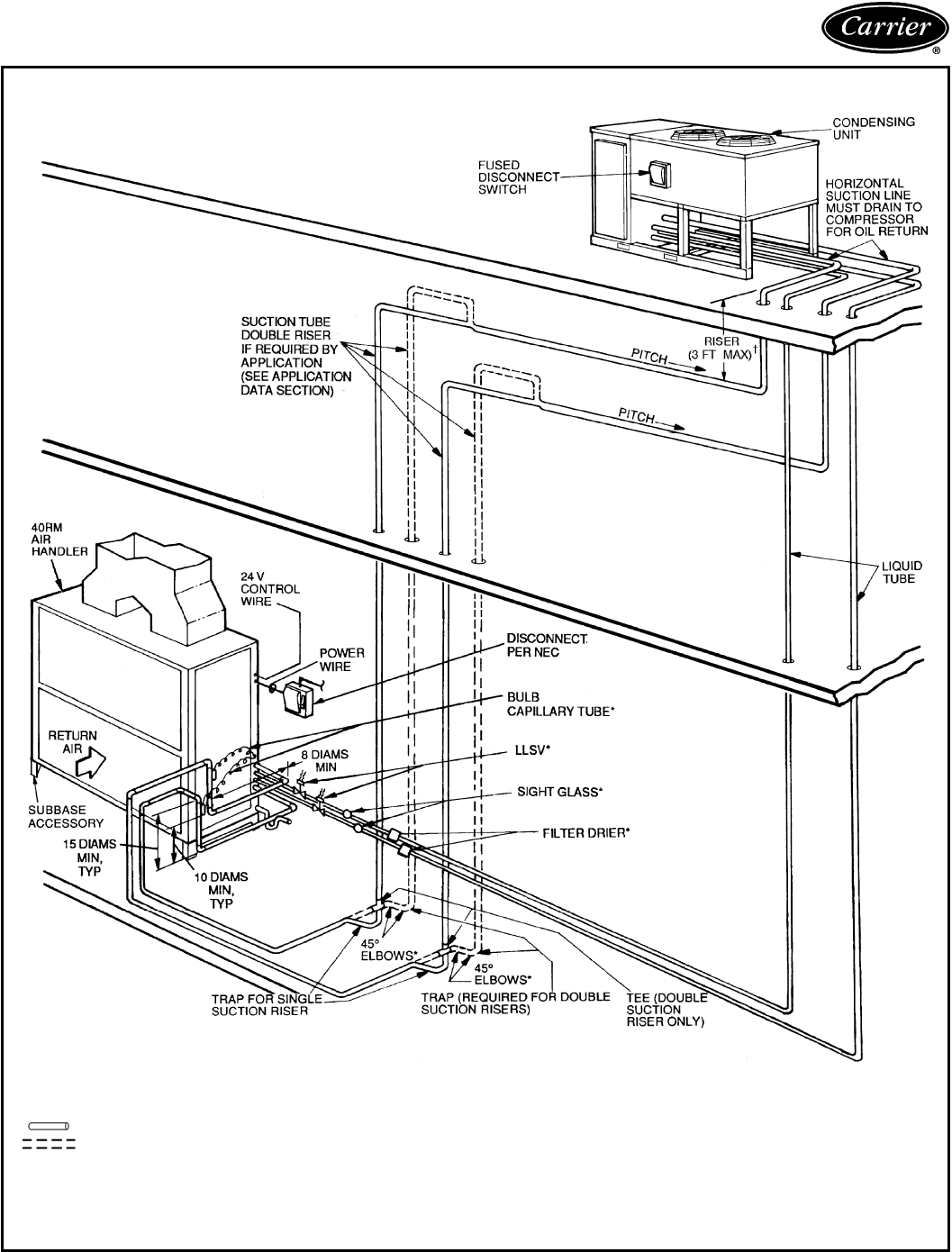
Typical piping and wiring — 38AH024-034
ROOFTOP INSTALLATION
LEGEND
TXV — Thermostatic Expansion Valve
Piping
Double Riser Piping (If Required)
*Field supplied.
†If double suction riser is required for piping sys-
tem, size pipe diameter of 3 ft (maximum) riser
according to application data on page 40.
NOTES:
1. All piping must follow standard refrigerant piping techniques. Refer to
Carrier System Design Manual for details.
2. All wiring must comply with the applicable local and national codes.
3. Wiring and piping shown are general points-of-connection guides only and are
not intended for, or to include all details for, a specific installation.
4. Liquid line solenoid valve (solenoid drop control) is recommended to prevent
refrigerant migration to the compressor.
5. Internal factory-supplied TXVs not shown.
32
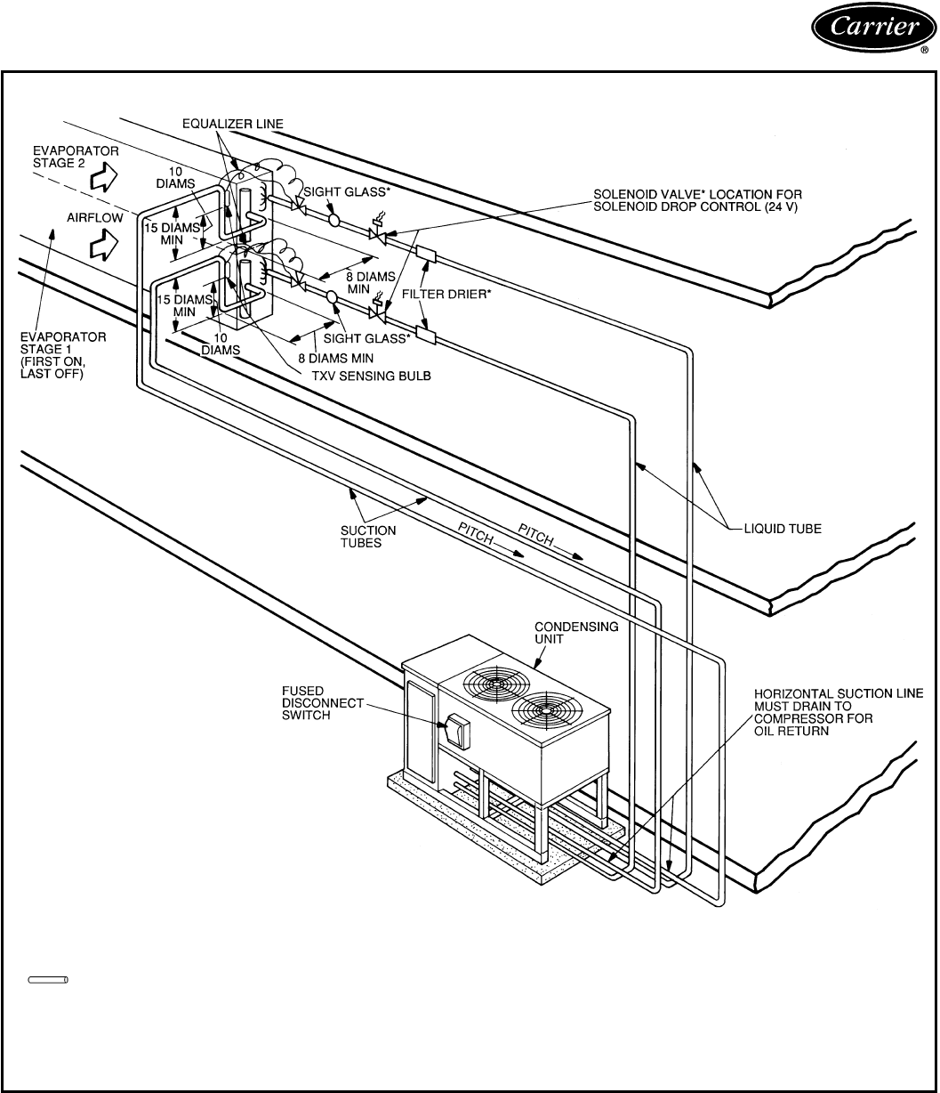
GROUND LEVEL INSTALLATION
LEGEND
TXV — Thermostatic Expansion Valve
Piping
*Field supplied.
NOTES:
1. All piping must follow standard refrigerant piping techniques. Refer to
Carrier System Design Manual for details.
2. All wiring must comply with the applicable local and national codes.
3. Wiring and piping shown are general points-of-connection guides only and are
not intended for, or to include all details for, a specific installation.
4. Liquid line solenoid valve (solenoid drop control) is recommended to prevent
refrigerant migration to the compressor.
33
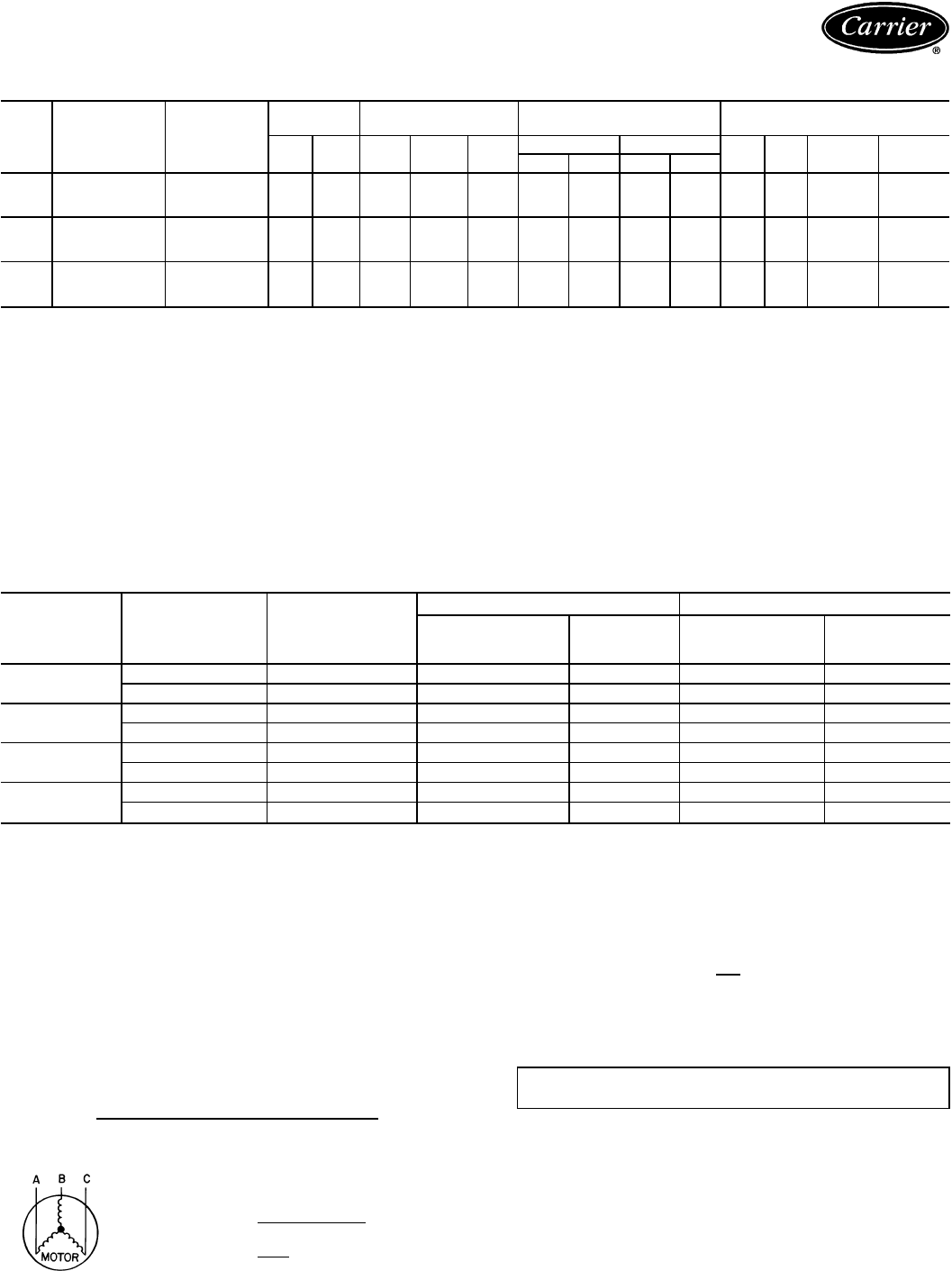
Electrical data — 38AH024-034/40RM
38AH024-034
UNIT
38AH VOLTAGE
DESIGNATION
NAMEPLATE
VOLTAGE
(3 Ph, 50 Hz)
SUPPLY
VOLTAGE* POWER SUPPLY COMPRESSOR FAN MOTORS†
Min Max MCA MOCP ICF RLA LRA QTY FLA
(ea) Nominal
Hp Nominal
kW
Ckt 1 Ckt 2 Ckt 1 Ckt 2
024 803 230 198 254 101.2 125 268.8 39.3 39.3 128 128 2 6.4 1 0.75903 400 342 400 46.5 60 204.0 18.0 18.0 99 99 2 3.0
303 346 311 380 62.8 80 194.8 24.0 24.0 93 93 2 4.4
028 803 230 198 254 110.9 150 298.8 43.6 43.6 143 143 2 6.4 1 0.75903 400 342 400 55.7 70 234.0 22.1 22.1 114 114 2 3.0
303 346 311 380 68.2 90 216.8 26.4 26.4 104 104 2 4.4
034 803 230 198 254 135.9 175 355.8 43.6 63.6 143 200 2 6.4 1 0.75903 400 342 400 65.1 90 240.0 22.1 30.0 114 120 2 3.0
303 346 311 380 78.1 110 257.8 26.4 34.3 104 145 2 4.4
LEGEND
FLA — Full Load Amps
ICF — Maximum Instantaneous Current Flow During Starting. (The
point in the starting sequence where the sum of the LRA
for the starting compressor, plus the total RLA for all run-
ning compressors, plus the total FLA for all running fan
motors is maximum.)
LRA — Locked Rotor Amps
MCA — Minimum Circuit Amps (complies with National Electrical
Code [NEC] Section 430-24) (U.S.A. Standard)
MOCP — Maximum Overcurrent Protection
RLA — Rated Load Amps
*Units are suitable for use on electrical systems where voltage supplied
to unit terminals is not below or above listed minimum and maximum.
†All fans are protected by a single circuit breaker.
40RM STANDARD MOTORS
UNIT
40RM V*-PH-HZ VOLTAGE
LIMITS
FAN MOTOR POWER SUPPLY
kW (Hp) FLA Minimum
Circuit
Amps MOCP
016 230-3-50 207-253 2.16 (2.9) 7.5 9.4 15
400-3-50 360-440 2.16 (2.9) 3.4 4.3 15
024 230-3-50 207-253 3.73 (5.0) 15.2 19.0 30
400-3-60 360-440 3.73 (5.0) 7.6 9.5 15
028 230-3-50 207-253 5.59 (7.5) 22.8 28.5 50
400-3-50 360-440 5.59 (7.5) 11.4 14.3 25
034 230-3-50 207-253 7.46 (10.0) 32.2 40.3 70
400-3-50 360-440 7.46 (10.0) 16.1 20.1 30
LEGEND
FLA — Full Load Amps
MOCP — Maximum Overcurrent Protection
*Motors are designed for satisfactory operation within 10% of nominal
voltages shown. Voltages should not exceed the limits shown in the
Voltage Limits column.
NOTES:
1. Minimum circuit amp and MOCP values are calculated in accordance
with NEC (National Electrical Code) (U.S.A. standard), Article 440.
2. Motor FLA values are established in accordance with UL (Under-
writers’ Laboratories) Standard 1995 (U.S.A. standard).
3. Unbalanced 3-Phase Supply Voltage
Never operate a motor where a phase imbalance in supply voltage is
greater than 2%.
Use the following formula to determine the percent-
age of voltage imbalance.
% Voltage Imbalance
max voltage deviation from average voltage
= 100 x average voltage
EXAMPLE: Supply voltage is 400-3-50.
AB = 393 v
BC = 403 v
AC = 396 v 393 + 403 + 396
Average Voltage = 3
1192
=3
= 397
Determine maximum deviation from average voltage.
(AB) 397 − 393 = 4 v
(BC) 403 − 397 = 6 v
(AC) 397 − 396 = 1 v
Maximum deviation is 6 v.
Determine percent voltage imbalance.
6
% Voltage Imbalance = 100 x 397
= 1.5%
This amount of phase imbalance is satisfactory as it is below the
maximum allowable 2%.
IMPORTANT: If the supply voltage phase imbalance is more than
2%, contact your local electric utility company immediately.
34
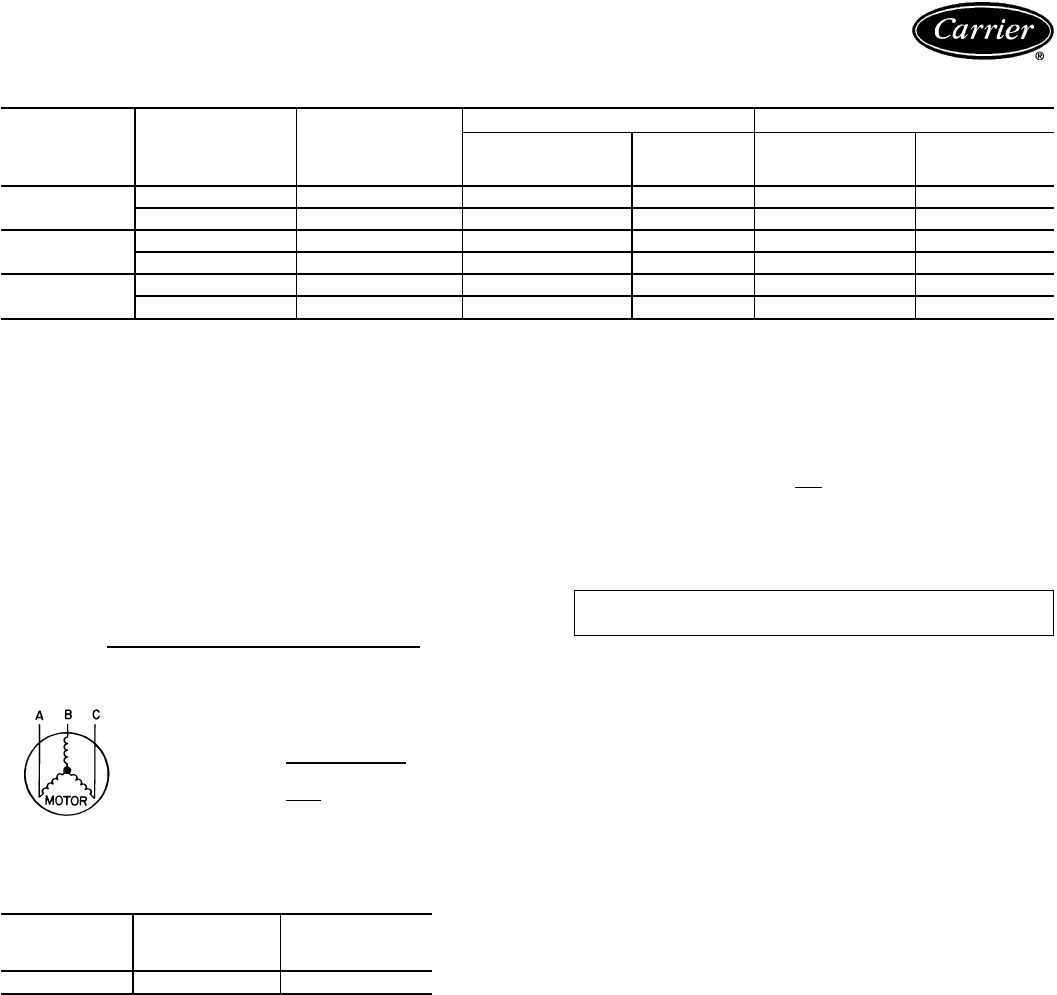
40RM ALTERNATE MOTORS
UNIT
40RM V*-PH-HZ VOLTAGE
LIMITS
FAN MOTOR POWER SUPPLY
kW (Hp) FLA Minimum
Circuit
Amps MOCP
016 230-3-50 207-253 3.73 (5.0) 15.2 19.0 30
400-3-50 360-440 3.73 (5.0) 7.6 9.5 15
024 230-3-50 207-253 5.59 (7.5) 22.8 28.5 50
400-3-50 360-440 5.59 (7.5) 11.4 14.3 25
028 230-3-50 207-253 7.46 (10.0) 32.2 40.3 60
400-3-50 360-440 7.46 (10.0) 16.1 20.1 30
LEGEND
FLA — Full Load Amps
MOCP — Maximum Overcurrent Protection
*Motors are designed for satisfactory operation within 10% of nominal
voltages shown. Voltages should not exceed the limits shown in the
Voltage Limits column.
NOTES:
1. Minimum circuit amp and MOCP values are calculated in accordance
with NEC (National Electrical Code) (U.S.A. standard), Article 440.
2. Motor FLA values are established in accordance with UL (Under-
writers’ Laboratories) Standard 1995 (U.S.A. standard).
3. Unbalanced 3-Phase Supply Voltage
Never operate a motor where a phase imbalance in supply voltage is
greater than 2%.
Use the following formula to determine the percent-
age of voltage imbalance.
% Voltage Imbalance
max voltage deviation from average voltage
= 100 x average voltage
EXAMPLE: Supply voltage is 400-3-50.
AB = 393 v
BC = 403 v
AC = 396 v 393 + 403 + 396
Average Voltage = 3
1192
=3
= 397
Determine maximum deviation from average voltage.
(AB) 397 − 393 = 4 v
(BC) 403 − 397 = 6 v
(AC) 397 − 396 = 1 v
Maximum deviation is 6 v.
Determine percent voltage imbalance.
6
% Voltage Imbalance = 100 x 397
= 1.5%
This amount of phase imbalance is satisfactory as it is below the
maximum allowable 2%.
IMPORTANT: If the supply voltage phase imbalance is more than
2%, contact your local electric utility company immediately.
40RM FAN CONTACTOR COIL
UNIT
40RM VOLTAGE
(vac)
MAXIMUM
HOLDING
VA
016-034 24 10
35
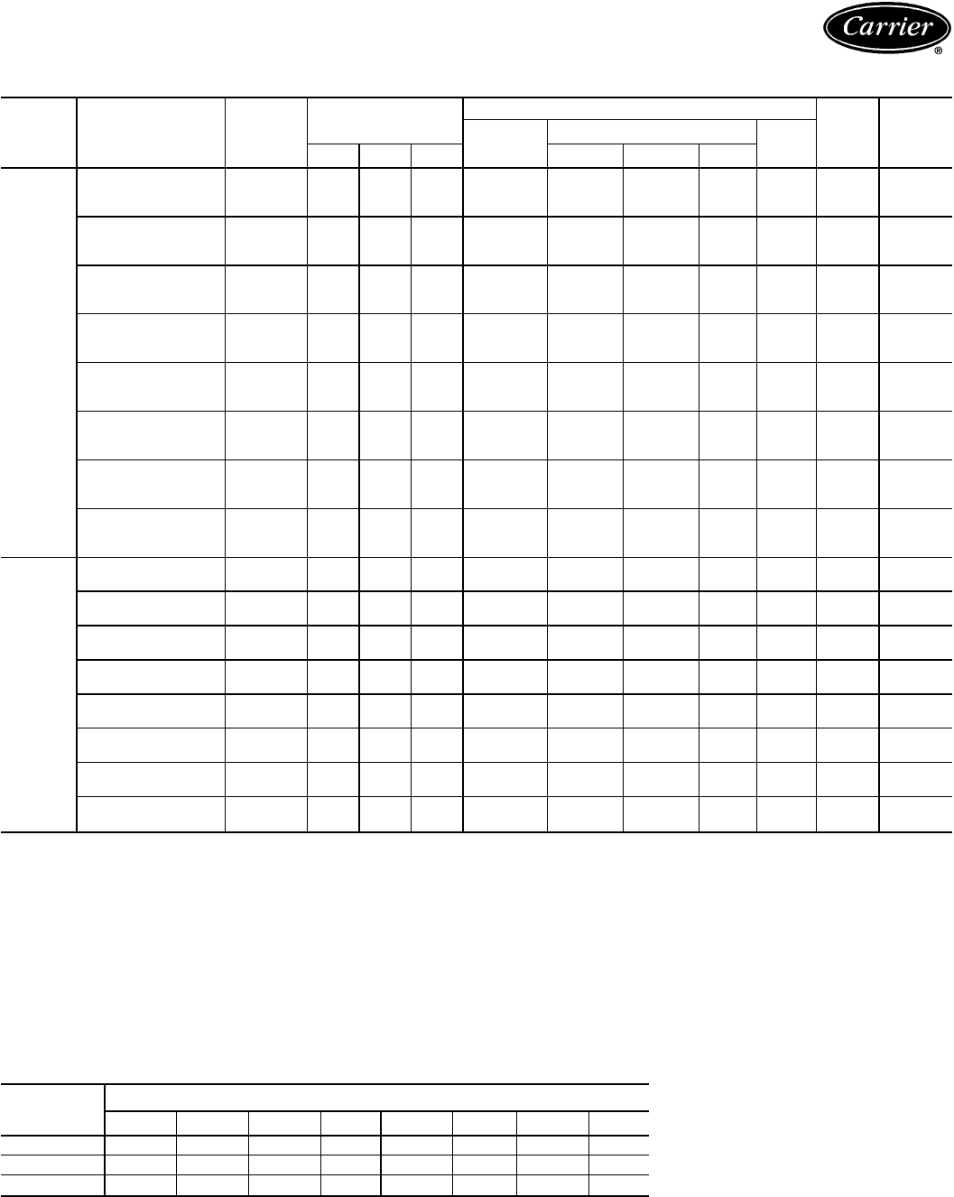
Electrical data — 38AH024-034/40RM (cont)
40RM ELECTRIC HEATER ACCESSORY DATA
UNIT
40RM HEATER
PART NO. V-PH-Hz FAN MOTOR ELECTRIC HEATERS(S)
MCA* MOCP*
Nominal
Capacity
(kW)
Actual Capacity (kW) FLA
Hp kW FLA Stage 1 Stage 2 Total
016,024
CAELHEAT016A00 240-3-50 2.9 2.16 7.5 10 10.0 — 10.0 24.1 39.4 40
5.0 3.73 15.2 10 10.0 — 10.0 24.1 49.1 50
7.5 5.59 22.8 10 10.0 — 10.0 24.1 58.6 70
CAELHEAT017A00 400-3-50 2.9 2.16 3.4 10 6.9 — 6.9 10.0 16.8 20
5.0 3.73 7.6 10 6.9 — 6.9 10.0 22.0 25
7.5 5.59 11.4 10 6.9 — 6.9 10.0 26.8 35
CAELHEAT019A00 240-3-50 2.9 2.16 7.5 20 20.0 — 20.0 48.1 69.5 70
5.0 3.73 15.2 20 20.0 — 20.0 48.1 79.1 80
7.5 5.59 22.8 20 20.0 — 20.0 48.1 86.4 90
CAELHEAT020A00 400-3-50 2.9 2.16 3.4 20 13.9 — 13.9 20.0 29.3 30
5.0 3.73 7.6 20 13.9 — 13.9 20.0 45.1 50
7.5 5.59 11.4 20 13.9 — 13.9 20.0 49.2 50
CAELHEAT022A00 240-3-50 2.9 2.16 7.5 30 20.0 10.0 30.0 72.2 99.6 100
5.0 3.73 15.2 30 20.0 10.0 30.0 72.2 109.2 110
7.5 5.59 22.8 30 20.0 10.0 30.0 72.2 118.7 125
CAELHEAT023A00 400-3-50 2.9 2.16 3.4 30 13.9 6.9 20.8 30.1 41.8 50
5.0 3.73 7.6 30 13.9 7.9 20.8 30.1 47.1 50
7.5 5.59 11.4 30 13.9 7.9 20.8 30.1 51.8 60
CAELHEAT025A00 240-3-50 2.9 2.16 7.5 50 30.0 20.0 50.0 120.3 159.7 175
5.0 3.73 15.2 50 30.0 20.0 50.0 120.3 169.4 175
7.5 5.59 22.8 50 30.0 20.0 50.0 120.3 178.9 200
CAELHEAT026A00 400-3-50 2.9 2.16 3.4 50 20.8 13.9 34.7 50.1 66.9 70
5.0 3.73 7.6 50 20.8 13.9 34.7 50.1 72.1 80
7.5 5.59 11.4 50 20.8 13.9 34.7 50.1 76.9 80
028,034
CAELHEAT028A00 240-3-50 7.5 5.59 22.8 20 20.0 — 20.0 48.1 88.6 90
10.0 7.46 32.2 20 20.0 — 20.0 48.1 100.4 110
CAELHEAT029A00 400-3-50 7.5 5.59 11.4 20 13.9 — 13.9 20.0 39.3 40
10.0 7.46 16.1 20 13.9 — 13.9 20.0 45.2 50
CAELHEAT031A00 240-3-50 7.5 5.59 22.8 40 20.0 20.0 40.0 96.2 148.8 150
10.0 7.46 32.2 40 20.0 20.0 40.0 96.2 160.5 175
CAELHEAT032A00 400-3-50 7.5 5.59 11.4 40 13.9 13.9 27.8 40.1 64.4 70
10.0 7.46 16.1 40 13.9 13.9 27.8 40.1 70.2 80
CAELHEAT034A00 240-3-50 7.5 5.59 22.8 50 30.0 20.0 50.0 120.3 178.9 200
10.0 7.46 32.2 50 30.0 20.0 50.0 120.3 190.6 200
CAELHEAT035A00 400-3-50 7.5 5.59 11.4 50 20.8 13.9 34.7 50.1 76.9 80
10.0 7.46 16.1 50 20.8 13.9 34.7 50.1 82.8 90
CAELHEAT037A00 240-3-50 7.5 5.59 22.8 70 40.0 30.0 70.0 168.4 196.9 200
10.0 7.46 32.2 70 40.0 30.0 70.0 168.4 208.6 225
CAELHEAT038A00 400-3-50 7.5 5.59 11.4 70 27.8 20.8 48.6 70.2 84.4 90
10.0 7.46 16.1 70 27.8 20.8 48.6 70.2 90.3 100
LEGEND
FLA — Full Load Amps
Hp — Horsepower
MCA — Minimum Circuit Amps
MOCP — Maximum Overcurrent Protection (Amps)
*Values shown are for single-point connection of electric heat acces-
sory and air handler.
†Single-phase motors. All other motors are 3-phase.
NOTES:
1. Electrical resistance heaters are rated at 240 v, or 480 v. To deter-
mine heater capacity (kW) at unit nameplate multiply the 240-v, or
480-v, capacity (kW) by the factor shown in the table below for the
unit voltage.
2. The following equation converts kW of heat energy to Btuh:
kW x 3,412 = Btuh.
3. Heater contactor coils are 24 v and require 8 va holding current.
4. Electric heaters are tested and ETL approved at maximum total
external static pressure of 1.9 in. wg.
5. MCA and MOCP values apply to both standard and alternate factory-
supplied motors.
HEATER
RATING
VOLTAGE
ACTUAL HEATER VOLTAGE
200 208 230 240 400 440 460 480
240 0.694 0.751 0.918 1 — — — —
480 — — — — 0.694 0.84 0.918 1
575 ———————
36

Controls — 38AH024-034
Operating sequence
Within 6 seconds to 5 minutes (depending on timing logic)
from a thermostat call for the first stage of cooling, com-
pressor no. 1 and the condenser fans start. The no. 2 fan
only starts if the outdoor ambient temperature is above
21.1 C (70 F). The oil pressure switch and the low pressure
switch are bypassed for the first 2 minutes. If either the low
pressure switch or oil pressure switch remain open after
2minutes, the unit shuts down and goes into a lockout mode.
Theevaporator-fanmotorstarts immediatelywhenever there
is a call for cooling. If a liquid line solenoid valve has been
installed (for refrigerant control during the off cycle), then
the solenoid valve for compressor no. 1 opens immediately
upon a call for cooling.
On standard units, compressor no. 1 operates either fully
loaded or at one step of unloading, depending on the suc-
tion pressure, which is dependent on the evaporator load
conditions.
As the cooling demand increases, the thermostat calls for
the second stage of cooling. Within 6 seconds to 5 minutes
(depending on timing logic) from a call for the second stage
of cooling, compressor no. 2 starts. The oil switch and low
pressure switch for circuit no. 2 are bypassed for the first
two minutes.
As the cooling load is satisfied, the thermostat stops the call
for the second stage of cooling, which in turn deenergizes
compressor no. 2, closes the no. 2 liquid line solenoid (if
installed) and energizes the compressor no. 2 crankcase
heater.
If the space temperature continues to decrease, then the
thermostat stops the call for the first stage of cooling, which
then deenergizes compressor no. 1 and the condenser fans,
closes the no. 1 liquid line solenoid valve (if installed), and
energizes the compressor no. 1 crankcase heater.
The unit controls prevent both compressors from reener-
gizing within 5 minutes from a previous call for operation.
If the unit safeties trip during operation, then the compres-
sor remains locked out from further operation. To reset the
lockout mode, the thermostat must be forced to stop call-
ing for cooling by resetting the thermostat setting above the
space temperature and then back to the desired set point.
NOTE: If the thermostat fan switch is in the auto position,
the evaporator fan cycles on and off as the thermostat calls
for cooling (or heating). If the switch is in the continuous
position, the fan runs when the condensing unit is powered.
37
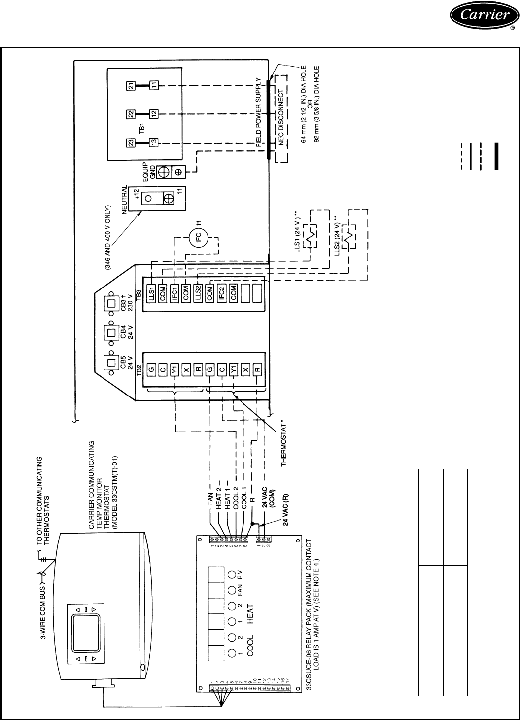
Typical control wiring schematic —
38AH024-034
38AH024-034 UNITS WITH SINGLE AIR HANDLER
*Use thermostat wiring shown here for single air-handler applications.
†CB3 protects control circuit at the following unit voltages:
CONTROL CIRCUIT
PROTECTED AT:
(V-Ph-Hz)
UNIT
(V-Ph-Hz)
230-1-50 230-3-50
346-3-50
400-3-50
**For a single air handler, LLS valve 1 is to be used on the lower (no. 1)
evaporator circuit. The LLS valve 2 is to be used on the upper (no. 2) evapo-
rator circuit.
††Only one indoor-fan contactor is required on single air-handler applications.
Use Carrier accessory part no. 40RR900181 for indoor-fan contactor.
LEGEND
CB — Circuit Breaker
COM — Common
IFC — Indoor-Fan Contactor
LLS — Liquid Line Solenoid
NEC — National Electrical Code
RV — Reversing Valve
TB — Terminal Block
Field Control Wiring
Factory Wiring
Field Power Wiring
Indicates Common
Potential; Does Not
Indicate Wiring
NOTES:
1. CB4 protects TB3 circuit; CB5 protects TB2 circuits.
2. LLS1 and LLS2 are field supplied.
3. TB2 and TB3 are in 24-v circuits.
4. On the 33CSUCE-06 Relay Pack, the outside-air sensor, supply-air sen-
sor, and direct expansion coil sensor are available as options.
38
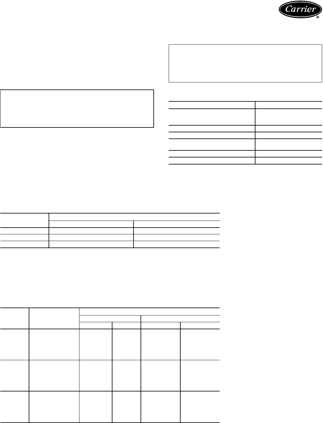
Application data — 38AH024-034
Installation
Select equipment to match or to be slightly less than peak
load. This provides better humidity control, less unit cycling,
and less part-load operation.
When selecting vapor line sizes, oil return must be evalu-
ated, particularly at part-load conditions.
The indoor fan must always be operating when outdoor
unit is operating.
IMPORTANT: When application is in a VAV (variable
air volume) system, total building load is not the sum
of the individual peak loads. If individual peak loads
are summed, the equipment tends to be oversized for
the load.
To minimize return-air temperature extremes, use the
equipmentroomasareturn-airplenumwhenapplyingVVTt
(variable volume temperature) systems with supply-to-return
air recycle as used with Carrier VVT control systems.
Ductwork should be sized according to unit size, not
building load.
To minimize the possibility of air recirculation, avoid the
use of concentric supply/return grilles.
Indoor equipment should be selected at no less than
40 L/s per kW (300 cfm/ton).
IMPORTANT: Condensing units applied in VVT or
VAV systems must have field-supplied and installed
accumulators. Order 2 part number --KH--73LZ-001
from Service Parts (1 required for each refrigerant
circuit).
OPERATING LIMITS
Maximum Outdoor Ambient 52C (125 F)
Minimum Outdoor Ambient See Minimum Outdoor-
Air Operating Temperature
table below.
Minimum Return-Air Temperature 12.8 C (55 F)
Maximum Return-Air Temperature 35 C (95 F)
Normal Acceptable Saturation −6.6 to 10.0 C (20 to 50 F)
Suction Temperature Range
Maximum Discharge Temperature 135.0 C (275 F)
Minimum Discharge Superheat 15.6 C (60 F)
UNLOADING SEQUENCES
UNIT
38AH CAPACITY/STAGE (%)
CV Units (Standard)* VAV Units (Optional)
024 100, 83, 50, 33 100, 83, 67, 50, 33, 17
028 100, 83, 50, 33 100, 83, 67, 50, 33, 17
034 100, 85, 43, 28 100, 85, 77, 43, 28, 14
LEGEND
CV — Constant Volume
VAV — Variable Air Volume
*Additional unloading available with field-installed accessory unloader.
NOTE: Capacities are based on 7.2 C (45 F) saturated suction temperature and 35 C (95 F) outdoor
air temperature.
MINIMUM OUTDOOR-AIR OPERATING
TEMPERATURE AND UNLOADING SEQUENCES
UNIT
38AH SYSTEM
CAPACITY (%)
MINIMUM OUTDOOR-AIR TEMP
Standard Unit Low Ambient Control
CF C F
024
100
11.7 53
−29 −20
83 −29 −20
67† * *
50 −29 −20
33 −29 −20
17† * *
028
100
10.0 50
−29 −20
83 −29 −20
67† * *
50 −29 −20
33 −29 −20
17† * *
034
100
9.4 49
−29 −20
81 −29 −20
62† * *
43 −29 −20
29 −29 −20
14† * *
*MotormasterTIII cannot be used with 2 unloaders.
†VAV or accessory unloader on Circuit 1.
NOTE: Minimum outdoor-air operating temperature is based on 32 C (90 F) saturated condensing
temperature and 100% capacity.
39
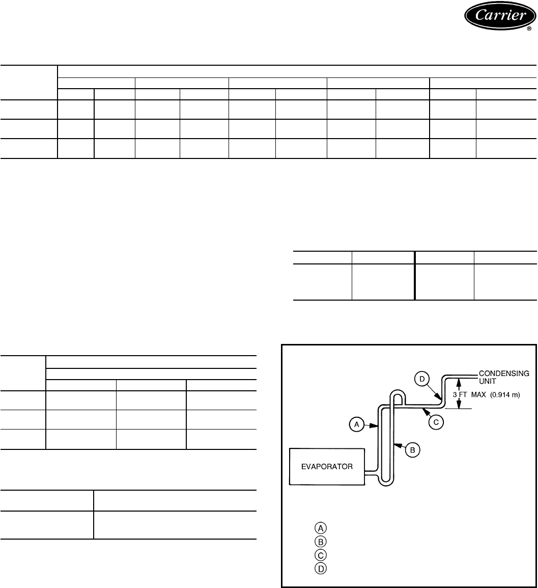
Application data — 38AH024-034 (cont)
REFRIGERANT PIPE SIZES
SINGLE SUCTION RISERS
UNIT
38AH
LENGTH OF INTERCONNECTING PIPING, FOR EACH CIRCUIT — FT (M)
0-25 (0-7.6) 25-50 (7.6-15.2) 50-75 (15.2-22.9) 75-100 (22.9-30.5) 100-200 (30.5-61.0)
LS L S L S L S L S
024 Ckt 1
1
⁄
2
1
1
⁄
85
⁄
8
1
1
⁄
85
⁄
8
1
3
⁄
85
⁄
8
1
3
⁄
87
⁄
8
1
5
⁄
8
*†
Ckt 2
1
⁄
2
1
1
⁄
85
⁄
8
1
1
⁄
85
⁄
8
1
3
⁄
85
⁄
8
1
3
⁄
87
⁄
8
1
5
⁄
8
*†
028 Ckt 1
1
⁄
2
1
1
⁄
85
⁄
8
1
3
⁄
85
⁄
8
1
3
⁄
85
⁄
8
1
3
⁄
87
⁄
8
1
5
⁄
8
*†
Ckt 2
1
⁄
2
1
1
⁄
85
⁄
8
1
3
⁄
85
⁄
8
1
3
⁄
85
⁄
8
1
3
⁄
87
⁄
8
1
5
⁄
8
*†
034 Ckt 1
1
⁄
2
1
1
⁄
85
⁄
8
1
3
⁄
85
⁄
8
1
3
⁄
85
⁄
8
1
3
⁄
87
⁄
8
1
5
⁄
8
*†
Ckt 2
5
⁄
8
1
3
⁄
85
⁄
8
1
5
⁄
85
⁄
8
1
5
⁄
87
⁄
8
1
5
⁄
87
⁄
8
2
1
⁄
8
*†
LEGEND
L—Liquid Line
S—Suction Line
*Double suction riser required if evaporator is below condensing unit
and 2 unloaders are used on that circuit.
†Double suction riser required if evaporator is below condensing unit
and compressor is equipped with 2 unloaders. Note the only time
circuit no. 2 may be equipped with 2 unloaders is if it is serving its
own air handler and the unit does not require low ambient operation
(MotormasterTIII control).
NOTES:
1. All line sizes are inches OD.
2. Standard unit comes with one pressure-operated unloader on circuit
no. 1. If unit serves one air handler, an additional unloader may be
field installed on circuit no. 1 compressor only. If the unit serves
2 separate air handlers and low ambient operation is required (Motor-
master III control), each circuit’s compressor may only be equipped
with
one
unloader.
3. Equivalent line sizes in mm follow:
in. mm in. mm
1
⁄
2
12.7 1
3
⁄
8
34.9
5
⁄
8
15.9 1
5
⁄
8
41.3
7
⁄
8
22.2 2
1
⁄
8
54.0
1
1
⁄
8
28.6
DOUBLE SUCTION RISERS
UNIT
38AH
LENGTH OF INTERCONNECTING PIPING — Ft (M)
100-200 (30.5-61.0)
ABC
024 Ckt 1 1
1
⁄
8
1
3
⁄
8
1
5
⁄
8
Ckt 2 1
3
⁄
8
1
3
⁄
8
1
5
⁄
8
028 Ckt 1 1
1
⁄
8
1
3
⁄
8
1
5
⁄
8
Ckt 2 1
1
⁄
8
1
3
⁄
8
1
5
⁄
8
034 Ckt 1 1
1
⁄
8
1
3
⁄
8
1
5
⁄
8
Ckt 2 1
3
⁄
8
1
5
⁄
8
2
1
⁄
8
MAXIMUM LIQUID LIFT
UNIT
38AH MAXIMUM LIQUID LIFT
PER CIRCUIT — M (Ft)
024 23.2 (76)
028 22.3 (73)
034 30.5 (100)
LEGEND
—Suction Riser without Trap
—Suction Riser with Trap
—Suction Line to Condensing Unit
—Pipe Diameter to be Same Size as Riser A
40
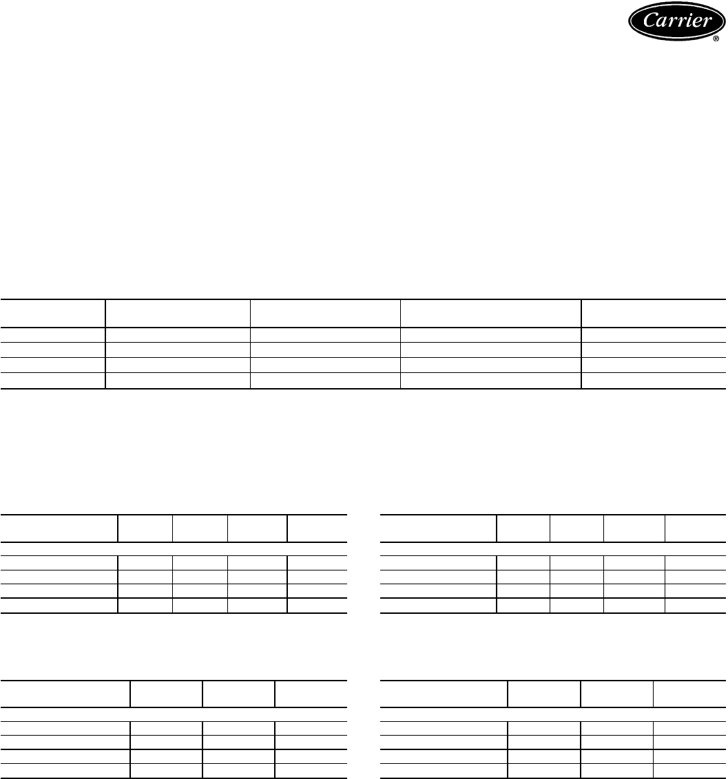
Application data — 40RM
Operating limits
Maximum fan speed —
40RM016,024 ..................20r/s(1200 rpm)
Maximum fan speed —
40RM028,034 ................18.3 r/s (1100 rpm)
General
Select equipment to match or to be slightly less than peak
load. This provides better humidity control, less unit cycling,
and less part-load operation. Equipment should be selected
to perform at no less than 40 L/s per kW (300 cfm/ton).
The air handler fan must always be operating when the
condensing unit is operating.
Ductwork should be sized according to unit size, not
building load. For larger units with two fans, a split duct
transition is recommended at the fan outlets, but a plenum
can be used with slight reduction in external static pressure
capability.
For variable air volume (VAV) systems with supply-to-
return air recycling, use the equipment room as a return air
plenum.
FACTORY-INSTALLED NOZZLE AND DISTRIBUTOR DATA
UNIT
40RM TXV
Qty...Part No. DISTRIBUTOR
Qty...Part No. FEEDER TUBES
PER DISTRIBUTOR* NOZZLE
Qty...Part No.
016 2...XVE-8 2...1116 12 2...E6
024 2...XVE-10 2...1116 13 2...E8
028 2...EBSVE-11 2...1126 15 2...C10
034 2...SVE-15 2...1126 18 2...C12
*Feeder tube size is 6.35 mm (
1
⁄
4
in.).
NOTE: Hot gas bypass applications require field-supplied auxiliary side connector.
40RM FAN MOTOR DATA
STANDARD MOTOR — SI
UNIT
40RM 016 024 028 034
230-3-50 and 400-3-50
Speed (r/s) 23.75 23.75 23.75 23.75
Shaft kW 2.16 3.73 5.59 7.46
Frame (NEMA) 56Y 184T S213T S215T
Shaft Dia (mm) 22.2 28.6 34.9 34.9
NEMA — National Electrical Manufacturers Association (U.S.A.)
ALTERNATE MOTOR — SI
UNIT
40RM 016 024 028
230-3-50 and 400-3-50
Speed (r/s) 23.75 23.75 23.75
Shaft kW 3.73 5.59 7.46
Frame (NEMA) S184T S213T S215T
Shaft Dia (mm) 28.6 34.9 34.9
NEMA — National Electrical Manufacturers Association (U.S.A.)
STANDARD MOTOR — ENGLISH
UNIT
40RM 016 024 028 034
230-3-50 and 400-3-50
Speed (rpm) 1425 1425 1425 1425
Hp 2.9 5.0 7.5 10.0
Frame (NEMA) 56Y 184T S213T S215T
Shaft Dia (in.)
7
⁄
8
1
1
⁄
8
1
3
⁄
8
1
3
⁄
8
NEMA — National Electrical Manufacturers Association (U.S.A.)
ALTERNATE MOTOR — ENGLISH
UNIT
40RM 016 024 028
230-3-50 and 400-3-50
Speed (rpm) 1425 1425 1425
Hp 5.0 7.5 10.0
Frame (NEMA) S184T S213T S215T
Shaft Dia (in.) 1
1
⁄
8
1
3
⁄
8
1
3
⁄
8
NEMA — National Electrical Manufacturers Association (U.S.A.)
41
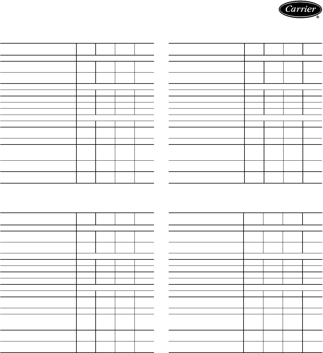
Application data — 40RM (cont)
40RM DRIVE DATA
STANDARD DRIVE — SI
UNIT
40RM 016 024 028 034
MOTOR DRIVE
Motor Pulley Pitch Diameter
(mm) 86.4-
111.8 109.2-
134.6 109.2-
134.6 109.2-
134.6
Pulley Factory Setting
Full Turns Open 2.5 3.0 3.0 3.0
FAN DRIVE
Pulley Pitch Dia (mm) 229 218 279 279
Pulley Bore (mm) 36.5 36.5 49.2 49.2
Belt No. — Section 1—A 1—B 2—B 2—B
Belt Pitch (mm) 1074 1062 1113 1113
FAN SPEEDS (r/s)
Factory Setting 10.3 13.3 10.4 10.4
Range 9.0-
11.6 11.9-
14.6 9.3-
11.5 9.3-
11.5
Max Allowable Speed (r/s) 20.0 20.0 18.3 18.3
Change per
1
⁄
2
Turn of
Moveable Motor Pulley
Flange 0.265 0.230 0.180 0.180
MAX FULL TURNS FROM
CLOSED POSITION 5666
SHAFTS CENTER DISTANCE
(mm) 265-
313 232-
279 169-
240 169-
240
MEDIUM-STATIC DRIVE — SI
UNIT
40RM 016 024 028 034
MOTOR DRIVE
Motor Pulley Pitch Diameter
(mm) 94.0-
119.4 101.6-
127.0 109.2-
134.6 109.2-
134.6
Pulley Factory Setting
Full Turns Open 3.0 2.5 3.0 3.0
FAN DRIVE
Pulley Pitch Dia (mm) 201 178 239 239
Pulley Bore (mm) 36.5 36.5 49.2 49.2
Belt No. — Section 1—B 2—A 2—B 2—B
Belt Pitch (mm) 1011 922 1011 1011
FAN SPEEDS (r/s)
Factory Setting 12.6 15.3 12.1 12.1
Range 11.1-
14.1 13.6-
17.0 10.9-
13.4 10.9-
13.4
Max Allowable Speed (r/s) 20.0 20.0 18.3 18.3
Change per
1
⁄
2
Turn of
Moveable Motor Pulley
Flange 0.252 0.340 0.210 0.210
MAX FULL TURNS FROM
CLOSED POSITION 6566
SHAFTS CENTER DISTANCE
(mm) 232-
279 232-
279 169-
240 169-
240
HIGH-STATIC DRIVE — SI
UNIT
40RM 016 024 028 034
MOTOR DRIVE
Motor Pulley Pitch Diameter
(mm) 101.6-
127.0 101.6-
127.0 109.2-
134.6 109.2-
134.6
Pulley Factory Setting
Full Turns Open 3.0 3.0 3.0 3.0
FAN DRIVE
Pulley Pitch Dia (mm) 178 163 203 218
Pulley Bore (mm) 36.5 36.5 49.2 49.2
Belt No. — Section 2—A 2—A 2—B 2—B
Belt Pitch (mm) 998 871 935 960
FAN SPEEDS (r/s)
Factory Setting 15.3 16.7 14.3 13.3
Range 13.6-
17.0 14.9-
18.6 12.8-
15.7 11.9-
14.6
Max Allowable Speed (r/s) 20.0 20.0 18.3 18.3
Change per
1
⁄
2
Turn of
Moveable Motor Pulley
Flange 0.283 0.308 0.247 0.230
MAX FULL TURNS FROM
CLOSED POSITION 6666
SHAFTS CENTER DISTANCE
(mm) 232-
279 207-
255 169-
240 169-
240
STANDARD DRIVE — ENGLISH
UNIT
40RM 016 024 028 034
MOTOR DRIVE
Motor Pulley Pitch Diameter
(in.) 3.4-4.4 4.3-5.3 4.3-5.3 4.3-5.3
Pulley Factory Setting
Full Turns Open 2.5 3.0 3.0 3.0
FAN DRIVE
Pulley Pitch Dia (in.) 9.0 8.6 11.0 11.0
Pulley Bore (in.) 1
7
⁄
16
1
7
⁄
16
1
15
⁄
16
1
15
⁄
16
Belt No. — Section 1—A 1—B 2—B 2—B
Belt Pitch (in.) 42.3 41.8 43.8 43.8
FAN SPEEDS (rpm)
Factory Setting 618 795 622 622
Range 538-
697 713-
878 557-
687 557-
687
Max Allowable Speed (rpm) 1200 1200 1100 1100
Change per
1
⁄
2
Turn of
Moveable Motor Pulley
Flange 15.9 13.8 10.8 10.8
MAX FULL TURNS FROM
CLOSED POSITION 5666
SHAFTS CENTER DISTANCE
(in.) 10.44-
12.32 9.12-
10.99 6.67-
9.43 6.67-
9.43
42
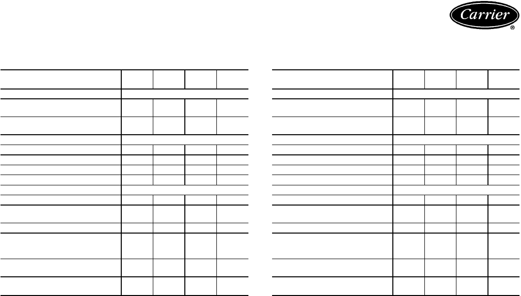
40RM DRIVE DATA (cont)
MEDIUM-STATIC DRIVE — ENGLISH
UNIT
40RM 016 024 028 034
MOTOR DRIVE
Motor Pulley Pitch Diameter
(in.) 3.7-4.7 4.0-5.0 4.3-5.3 4.3-5.3
Pulley Factory Setting
Full Turns Open 3.0 2.5 3.0 3.0
FAN DRIVE
Pulley Pitch Dia (in.) 7.9 7.0 9.4 9.4
Pulley Bore (in.) 1
7
⁄
16
1
7
⁄
16
1
15
⁄
16
1
15
⁄
16
Belt No. — Section 1—B 2—A 2—B 2—B
Belt Pitch (in.) 39.8 36.8 39.8 39.8
FAN SPEEDS (rpm)
Factory Setting 756 916 728 728
Range 667-
848 814-
1018 652-
803 652-
803
Max Allowable Speed (rpm) 1200 1200 1100 1100
Change per
1
⁄
2
Turn of
Moveable Motor Pulley
Flange 15.1 20.4 12.6 12.6
MAX FULL TURNS FROM
CLOSED POSITION 6566
SHAFTS CENTER DISTANCE
(in.) 9.16-
10.99 9.16-
10.99 6.67-
9.43 6.67-
9.43
HIGH-STATIC DRIVE —ENGLISH
UNIT
40RM 016 024 028 034
MOTOR DRIVE
Motor Pulley Pitch Diameter
(in.) 4.0-5.0 4.0-5.0 4.3-5.3 4.3-5.3
Pulley Factory Setting
Full Turns Open 3.0 3.0 3.0 3.0
FAN DRIVE
Pulley Pitch Dia (in.) 7.0 6.4 8.0 8.6
Pulley Bore (in.) 1
7
⁄
16
1
7
⁄
16
1
15
⁄
16
1
15
⁄
16
Belt No. — Section 2—A 2—A 2—B 2—B
Belt Pitch (in.) 39.3 34.3 36.8 37.8
FAN SPEEDS (rpm)
Factory Setting 916 1002 855 795
Range 814-
1018 891-
1113 766-
944 713-
878
Max Allowable Speed (rpm) 1200 1200 1100 1100
Change per
1
⁄
2
Turn of
Moveable Motor Pulley
Flange 17.0 18.5 14.8 13.8
MAX FULL TURNS FROM
CLOSED POSITION 6666
SHAFTS CENTER DISTANCE
(in.) 9.16-
10.99 8.16-
10.02 6.67-
9.43 6.67-
9.43
43
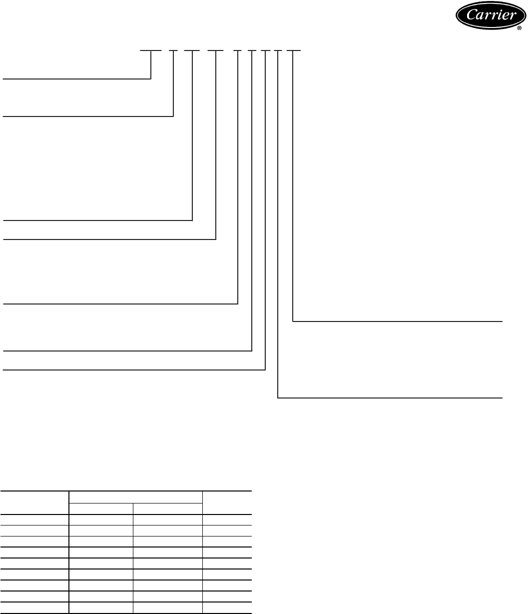
Model number nomenclature — 38AH044-134
Ratings summary — 38AH044-134
UNIT SIZE NOMINAL CAPACITY EER*
kW Tons
044 123 35 10.8
054 144 41 10.7
064 175 50 10.8
074 214 61 10.3
084 242 69 10.6
094 274 78 10.6
104 305 87 10.9
124 351 100 10.8
134 390 111 10.6
LEGEND
EER — Energy Efficiency Ratio
*Rated in accordance with ARI (Air Conditioning & Refrigeration
Institute) standard 365-87 (U.S.A.).
NOTE: Ratings are based on 7.2 C (45 F) suction temperature and
35 C (95 F) outside-air temperature, and include suction line losses.
38AH — 094 — — — 9 0 3 AA
38AH — Split System Factory-Installed Options
Condensing Unit 044-084:
– – — Standard Unit
Start Options AA — Class F Fan Motors
–—Across-the-Line Start BA — VAV Control Box Modification
P—Part-Wind Start and Electric Unloaders
CA — VAV Modifications and
Nominal Capacity Class F Fan Motors
044 — 123 kW (35 Tons) DA — Single-Circuit Piping
054 — 144 kW (41 Tons) EA — Single-Circuit Piping with
064 — 175 kW (50 Tons) Class F Fan Motors
074 — 214 kW (61 Tons) FA — Single-Circuit Piping and VAV
084 — 242 kW (69 Tons) Modifications
094 — 274 kW (78 Tons) GA — Single-Circuit Piping, VAV
104 — 305 kW (87 Tons) Modifications, and Class F
124 — 351 kW (100 Tons) Fan Motors
134 — 390 kW (111 Tons) 094,104:
– – — Standard Unit
Not Used AA — Class F Fan Motors
BA — VAV (Variable Air Volume) Modifications
Condenser Fin Material CA — Class F Fan Motors with VAV
–—Aluminum (Standard) Modifications
C—Copper (Optional) 124,134:
K—Pre-Coated Aluminum (Optional) DA — Standard Unit
SO — Post-Coated Aluminum (Contact Factory) EA — Class F Fan Motors
SO — Post-Coated Copper (Contact Factory) FA — VAV Modifications
GA — Class F Fan Motors with VAV
Voltage Designation Modifications
3—346-3-50 (Part Wind)
8—230-3-50 (Part-Wind, 044 Size) Packaging
9—380/415-3-50 2— Coil Protection Only (For Closed Container
Shipments)
Revision Number 3— Standard Export (Top and Bottom Skid,
Coil Protector and Full Plastic Bag
Enclosure)
4— Optional Export (Full Export Box)
SO—Special Order
44

Options and accessories — 38AH044-134
Factory-installed options
VAV (Variable Air Volume) Control Box Modification
makesthe condensing unit compatible with the ModuPanel™
VAV controller. Includes factory-installed accumulator. Also
includes electric unloaders on compressors as follows:
1 — 38AH044
2 — 38AH054-084,104
3 — 38AH094
4 — 38AH124,134 (2 per module)
Single-Circuit Modification (Sizes 38AH044-084
Only) includes factory-installed accumulator and all piping
and wiring modifications required to make the unit single
circuit.
Single-Circuit Modification with VAV(Sizes38AH044-
084 Only) includes piping, wiring, and electric unloaders
on compressors (one on 38AH044 and 2 on 38AH054-
084) to make the unit single circuit, VAV-ready. Also in-
cludes factory-installed accumulator.
Class F Fan Motors provide additional motor insulation
for high ambient temperature environments.
Condenser coil options are available to match coil con-
struction to site conditions for the best corrosion durability.
Pre-coated coils provide protection in mild coastal environ-
ments. All copper coils are best suited for moderate coastal
applications, while post-coated coils provide superior pro-
tection in severe coastal and industrial applications.
Field-installed accessories
Transformer relay package for remote-control (24-v)
thermostat. One 2-stage thermostat is required for use with
the relay package.
Additional electric unloader package includes hard-
ware to add an additional step of unloading (coil not
included).
Additional pressure unloader package includes all
unloader valves and hardware.
Gage panel package contains panel-mounted suction and
discharge pressure gages.
Hail guard package protects coils against damage from
hail and airborne debris.
ModuPanel control provides 10-step microprocessor-
based control for VAV applications.
MotormastertIII control maintains correct condensing
pressure at low ambient temperatures.
Sound-reduction kit provides a specially designed system
of fan propellers and stacks that lower noise without reduc-
ing unit performance; compatible with the Motormaster III
accessory.
Unloader conversion kit allows you to convert factory-
installed pressure unloaders to electric unloading.
Compressor grille package protects thecompressor area
after the unit is installed.
Condenser coil grille package protects the condenser
area after the unit is installed.
Carrier’s line of thermostats provide both program-
mable and non-programmable capability with the new
Debonair™ line of commercial programmable thermo-
stats, the TEMP System controls offer communication
capability with staged heating and cooling, the Commer-
cial Electronic thermostats provide 7-day programmable
capability for economical applications, while the non-
programmable thermostats offer a multitude of staged
heating and cooling subbase options.
CONDENSER COIL PROTECTION APPLICATIONS
DESCRIPTION
(
Enviro-Shield™
Option)
ENVIRONMENT*
Standard,
Non-Corrosive Mild
Coastal Moderate
Coastal Severe
Coastal Industrial Combined
Coastal
and Industrial
Standard, Al/Cu X
Pre-Coated Al/Cu X
Cu/Cu X
Post-Coated Al/Cu X
Post-Coated Cu/Cu XX
LEGEND
Al/Cu — Aluminum Fin with Copper Tube Coil
Cu/Cu — Copper Fin with Copper Tube Coil
Enviro-Shield
—Family of Coil Protection Options
Post-Coated — Organic Coating applied to Entire Coil Assembly
Pre-Coated — Epoxy Coating Applied to Fin Stock Material
*See ‘‘Selection Guide: Environmental Corrosion Protection’’ Catalog No. 811-839 for more information.
45
Options and accessories —
38AH044-134 (cont)
CARRIER THERMOSTATS
COMMERCIAL ELECTRONIC THERMOSTAT
NON-PROGRAMMABLE THERMOSTAT
H
C
DEBONAIR™ COMMERCIAL PROGRAMMABLE
THERMOSTAT
AUTO
Pm
COOL
HEAT
Carrier®
TEMP SYSTEM THERMOSTAT
WITH TIMECLOCK
46
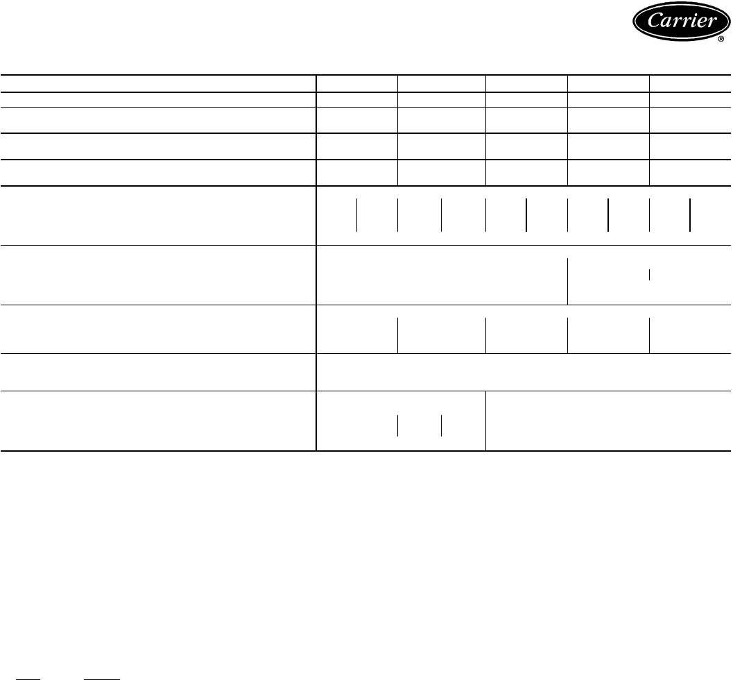
Physical data — 38AH044-134
SI
38AH 044 054 064 074 084
NOMINAL CAPACITY (kW) 123 144 175 214 242
OPERATING WEIGHT WITH Cu-Al Coils 1480 1501 1617 1729 1840
REFRIGERANT (kg) (Approx.) Cu-Cu Coils 1609 1632 1813 1918 2148
SHIPPING WEIGHT WITH Cu-Al Coils 1474 1492 1601 1715 1814
COIL PROTECTION ONLY (kg) (Approx.) Cu-Cu Coils 1605 1623 1798 1904 2122
TYPICAL OPERATING REFRIGERANT
CHARGE (kg, approx.) R-22 28.1 32.7 39.9 47.2 58.9
COMPRESSOR Type...r/s Reciprocating Semi-Hermetic...24.3 @ 50 Hz
(Qty Cylinder)* Circuit† (4) A (4) B (4) A (6) B (6) A (6) B (6) A (6) B (6) A (6) B
Model No. 06E- 250 250 250 265 265 275 275 299 299 299
Oil Charge (L) 8.0 8.0 8.0 9.9 9.9 9.9 9.9 9.0 9.0 9.0
Capacity Control Steps** 4
CONDENSER FANS (6 Blade)
Qty...Dia (mm) 4...762 6...762
Airflow (L/s) 16 500 24 500 24 100
Speed (r/s) 15.8 15.8
Total Power (kW) 6.2 9.3
CONDENSER COIL Enhanced Copper Tubes, Lanced Aluminum Fins
Row...Fins per m 2...669 2...669 3...669 2...782 3...669
Face Area (m
2
)7.48 7.48 7.48 10.84 10.84
Storage Capacity (kg per circuit, approx.) at 48.9 C 16 16 25 25 36
FAN CYCLING CONTROLS ††
Close (kPa) 1758 ± 69
Open (kPa) 1103±69
CONNECTIONS
Suction, ODF (in.)|2
1
⁄
8
2
1
⁄
8
Liquid, ODF (in.)|
5
⁄
8
5
⁄
8
Ckt A
7
⁄
8
Ckt B
7
⁄
8
Hot Gas Bypass, ODF (in.)
5
⁄
85
⁄
8
LEGEND
Cu-Al — Copper Tube, Aluminum Fin
Cu-Cu — Copper Tube, Copper Fin
ODF — Outside Diameter, Female
*06E250 compressors have 4 cylinders; all others have 6.
†Circuit A compressor is lead on standard units; circuit B compressor is lead on optional single-circuit
units.
**Capacity control steps listed are for constant volume units with no accessories. Refer to Minimum
Outdoor-Air Operating Temperature and Unloading Sequences tables, pages 94-96, for additional
system capacity information.
††On all 044-134 units, fan no. 3 and 4; also on 38AH074,084 (dual-circuit units only) and 38AH094,104,
fans no. 5 and 6.
\For single-circuit units, suction ODF is 2
5
⁄
8
in. and liquid ODF is 1
1
⁄
8
inches. Single circuit units
have a factory-installed manifold; no field modification is required.
NOTES:
1. Certified dimensional drawings available on request.
2. Equivalent connection values in mm are as follows:
in. mm
5
⁄
8
15.9
7
⁄
8
22.2
1
1
⁄
8
28.6
2
1
⁄
8
54.0
2
5
⁄
8
66.7
47
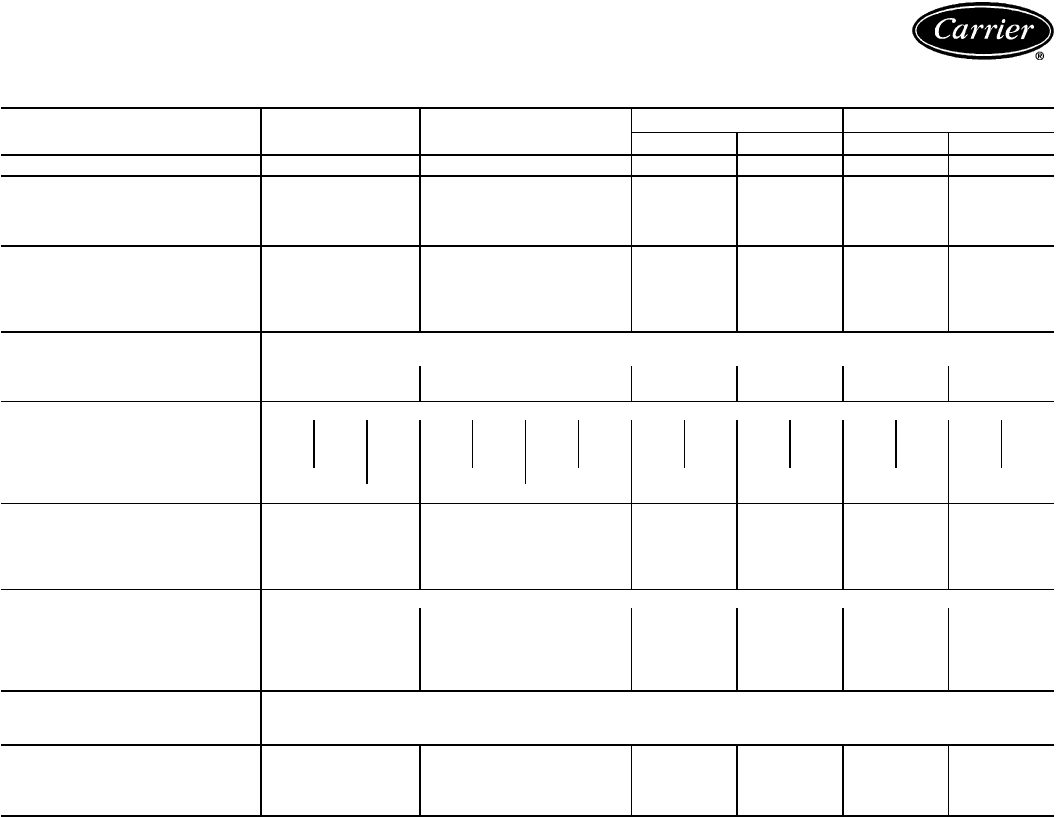
Physical data — 38AH044-134 (cont)
SI (cont)
38AH 094 104 124 134
124A 124B 134A 134B
NOMINAL CAPACITY (kW) 274 305 175.5 175.5 175.5 214.5
OPERATING WEIGHT WITH
REFRIGERANT (Approx.) (kg)
Cu-Al 2308 2465 1647* 1647* 1647* 1759*
Cu-Cu 2637 2794 1843* 1843* 1843* 1843*
SHIPPING WEIGHT WITH
COIL PROTECTION AND SKID
(Approx.) (kg)
Cu-Al 2554 2717 1860* 1860* 1860* 1851
Cu-Cu 2883 3046 1968* 1968* 1968* 2040
TYPICAL OPERATING
REFRIGERANT R-22
Charge (Approx.) (kg) 67.1 61.2 39.9 39.9 39.9 47.2
Qty of Circuits 2 2 1111
COMPRESSOR Type...R/s Reciprocating Semi-Hermetic...24.3
(Qty Cylinder)/Compressor† (6)A1 (4)A2 (6)B1 (6)A1 (4)A2 (6)B1 (6)B2 (6)A1 (6)A2 (6)A1 (6)A2 (6)A1 (6)A2 (6)A1 (6)A2
Model No. 06E −275 −250 −299 −265 −250 −265 −265 −275 −265 −275 −265 −275 −265 −299 −275
Oil Charge (L) 10 8 9 10 8 1010101010101010 9 10
Circuit Capacity (%) (Approx.) 55 45 47 53 50 50 45 55
Capacity Control Steps** 6 8 4444
CONDENSER FANS (6 Blade)
Qty...Dia (mm) 6...762 6...762 4...762 4...762 4...762 6...762
Airflow (L/s) 24 544 24 544 16 520 16 520 16 520 24 544
Speed (R/s) 15.8 15.8 15.8 15.8 15.8 15.8
Total Power (kW) 9.4 9.5 6.4 6.4 6.4 9.2
CONDENSER COIL Enhanced Copper Tubes, Lanced Aluminum Fins
Rows...Fins per m 3...669.3 3...669.3 3...669.3 3...669.3 3...669.3 2...781.6
Face Area (sq m) 11.9 11.9 7.5 7.5 7.5 10.8
Storage Capacity 81 81 50 50 50 50(kg per circuit, approx.)
at 49 C
FAN CYCLING CONTROLS ††
Close (kPa) 1758 ± 69
Open (kPa) 1103±69
CONNECTIONS
Suction, ODF (in.) 2
1
⁄
8
2
1
⁄
8
2
5
⁄
8
2
5
⁄
8
2
5
⁄
8
2
5
⁄
8
Liquid, ODF (in.)
7
⁄
87
⁄
8
1
1
⁄
8
1
1
⁄
8
1
1
⁄
8
1
1
⁄
8
Hot Gas Bypass, ODF (in.)
5
⁄
85
⁄
85
⁄
85
⁄
85
⁄
85
⁄
8
LEGEND
Cu-Al — Copper Tube, Aluminum Fin
Cu-Cu — Copper Tube, Copper Fin
ODF — Outside Diameter, Female
VAV — Variable Air Volume
*Includes piping and trim kit.
†Compressor A1 is lead compressor on all circuits except circuit B on units 38AH094 and 104. Com-
pressor B1 is lead on circuit B on units 38AH094 and 104. Compressors are shipped with minimum
oil charge.
**Capacity control steps listed are for constant volume units with no accessories. Refer to Minimum
Outdoor-Air Operating Temperature and Unloading Sequences tables, pages 94-96, for additional
system capacity information.
††On all 044-134 units, fan no. 3 and 4; also on 38AH074,084 (dual-circuit units only) and 38AH094,104,
fans no. 5 and 6.
NOTES:
1. Unit 38AH124 consists of one 124A module and one 124B module. Unit 38AH134 consists of one
134A module and one 134B module.
2. Certified dimensional drawings available on request.
48
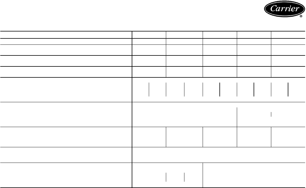
ENGLISH
38AH 044 054 064 074 084
NOMINAL CAPACITY (Tons) 35 41 50 61 69
OPERATING WEIGHT WITH Cu-Al Coils 3259 3309 3565 3812 4057
REFRIGERANT (lb) (Approx.) Cu-Cu Coils 3547 3597 3998 4229 4735
SHIPPING WEIGHT WITH Cu-Al Coils 3250 3290 3530 3780 4000
COIL PROTECTION ONLY (lb) (Approx.) Cu-Cu Coils 3538 3578 3963 4197 4678
TYPICAL OPERATING REFRIGERANT
CHARGE (lb, approx.) R-22 62 72 88 104 130
COMPRESSOR Type...Rpm Reciprocating Semi-Hermetic...1458 @ 50 Hz
(Qty Cylinder)* Circuit† (4) A (4) B (4) A (6) B (6) A (6) B (6) A (6) B (6) A (6) B
Model No. 06E- 250 250 250 265 265 275 275 299 299 299
Oil Charge (pt) 17 17 17 21 21 21 21 19 19 19
Capacity Control Steps** 4
CONDENSER FANS (6 Blade)
Qty...Dia (in.) 4...30 6...30
Airflow (cfm) 35,000 52,000 51,000
Speed (rpm) 950 950
Total Power (kW) 6.2 9.3
CONDENSER COIL — Rows 22323
Fins per...in. 17 17 17 19 17
Face Area (ft
2
)80.5 80.5 80.5 116.7 116.7
Storage Capacity (lb per circuit, approx.) at 120 F 35 35 55 55 80
FAN CYCLING CONTROLS ††
Close (psig) 255±10
Open (psig) 160±10
CONNECTIONS
Suction, ODF (in.)†† 2
1
⁄
8
2
1
⁄
8
Liquid, ODF (in.)††
5
⁄
8
5
⁄
8
Ckt A
7
⁄
8
Ckt B
7
⁄
8
Hot Gas Bypass, ODF (in.)
5
⁄
85
⁄
8
LEGEND
Cu-Al — Copper Tube, Aluminum Fn
Cu-Cu — Copper Tube, Copper Fn
ODF — Outside Diameter, Female
*06E250 compressors have 4 cylinders; all others have 6.
†Circuit A compressor is lead on standard units; circuit B compressor is lead on optional single-circuit
units.
**Capacity control steps listed are for constant volume units with no accessories. Refer to Minimum
Outdoor-Air Operating Temperature and Unloading Sequences tables, pages 94-96, for additional
system capacity information.
††On all 044-134 units, fan no. 3 and 4; also on 38AH074,084 (dual-circuit units only) and 38AH094,104,
fans no. 5 and 6.
\For single-circuit units, suction ODF is 2
5
⁄
8
in. and liquid ODF is 1
1
⁄
8
inches. Single circuit units
have a factory-installed manifold; no field modification is required.
NOTE: Certified dimensional drawings available on request.
49

Physical data — 38AH044-134 (cont)
ENGLISH (cont)
38AH 094 104 124 134
124A 124B 134A 134B
NOMINAL CAPACITY (Tons) 78 87 50 50 50 61
OPERATING WEIGHT WITH
REFRIGERANT (Approx.) (lb)
Cu-Al 5088 5435 3630* 3630* 3630* 3877*
Cu-Cu 5813 6160 4063* 4063* 4063* 4294*
SHIPPING WEIGHT WITH
COIL PROTECTION AND SKID
(Approx.) (lb)
Cu-Al 5630 5990 3907* 3907* 3907* 4080
Cu-Cu 6355 6715 4340* 4340* 4340* 4497
TYPICAL OPERATING
REFRIGERANT R-22
Charge (Approx.) (lb) 148 135 88 88 88 104
Qty of Circuits 2 2 1111
COMPRESSOR Type...Rpm Reciprocating Semi-Hermetic...1450
(Qty Cylinder)/Compressor† (6)A1 (4)A2 (6)B1 (6)A1 (4)A2 (6)B1 (6)B2 (6)A1 (6)A2 (6)A1 (6)A2 (6)A1 (6)A2 (6)A1 (6)A2
Model No. 06E −275 −250 −299 −265 −250 −265 −265 −275 −265 −275 −265 −275 −265 −299 −275
Oil Charge (pt) 21 17 19 21 17 21 21 21 21 21 21 21 21 19 21
Circuit Capacity (%) (Approx.) 55 45 47 53 50 50 45 55
Capacity Control Steps** 6 8 4444
CONDENSER FANS (6 Blade)
Qty...Dia (in.) 6...30 6...30 4...30 4...30 4...30 6...30
Airflow (cfm) 52,000 52,000 35,000 35,000 35,000 52,000
Speed (rpm) 950 950 950 950 950 950
Total Power (kW) 9.4 9.5 6.4 6.4 6.4 9.2
CONDENSER COIL Enhanced Copper Tubes, Lanced Aluminum Fin
Rows...Fins per in. 3...17 3...17 3...17 3...17 3...17 2...19
Face Area (sq ft) 128.3 128.3 80.5 80.5 80.5 116.7
Storage Capacity 178 178 110 110 110 110(lb per ckt, approx.)
at 120 F
FAN CYCLING CONTROLS ††
Close (psig) 255±10
Open (psig) 160±10
CONNECTIONS
Suction, ODF (in.) 2
1
⁄
8
2
1
⁄
8
2
5
⁄
8
2
5
⁄
8
2
5
⁄
8
2
5
⁄
8
Liquid, ODF (in.)
7
⁄
87
⁄
8
1
1
⁄
8
1
1
⁄
8
1
1
⁄
8
1
1
⁄
8
Hot Gas Bypass, ODF (in.)
5
⁄
85
⁄
85
⁄
85
⁄
85
⁄
85
⁄
8
LEGEND
Cu-Al — Copper Tube, Aluminum Fin
Cu-Cu — Copper Tube, Copper Fin
ODF — Outside Diameter, Female
VAV — Variable Air Volume
*Includes piping and trim kit.
†Compressor A1 is lead compressor on all circuits except circuit B on units 38AH094 and 104. Com-
pressor B1 is lead on circuit B on units 38AH094 and 104. Compressors are shipped with minimum
oil charge.
**Capacity control steps listed are for constant volume units with no accessories. Refer to Minimum
Outdoor-Air Operating Temperature and Unloading Sequences tables, pages 94-96, for additional
system capacity information.
††On all 044-134 units, fan no. 3 and 4; also on 38AH074,084 (dual-circuit units only) and 38AH094,104,
fans no. 5 and 6.
NOTES:
1. Unit 38AH124 consists of one 124A module and one 124B module. Unit 38AH134 consists of one
134A module and one 134B module.
2. Certified dimensional drawings available on request.
50
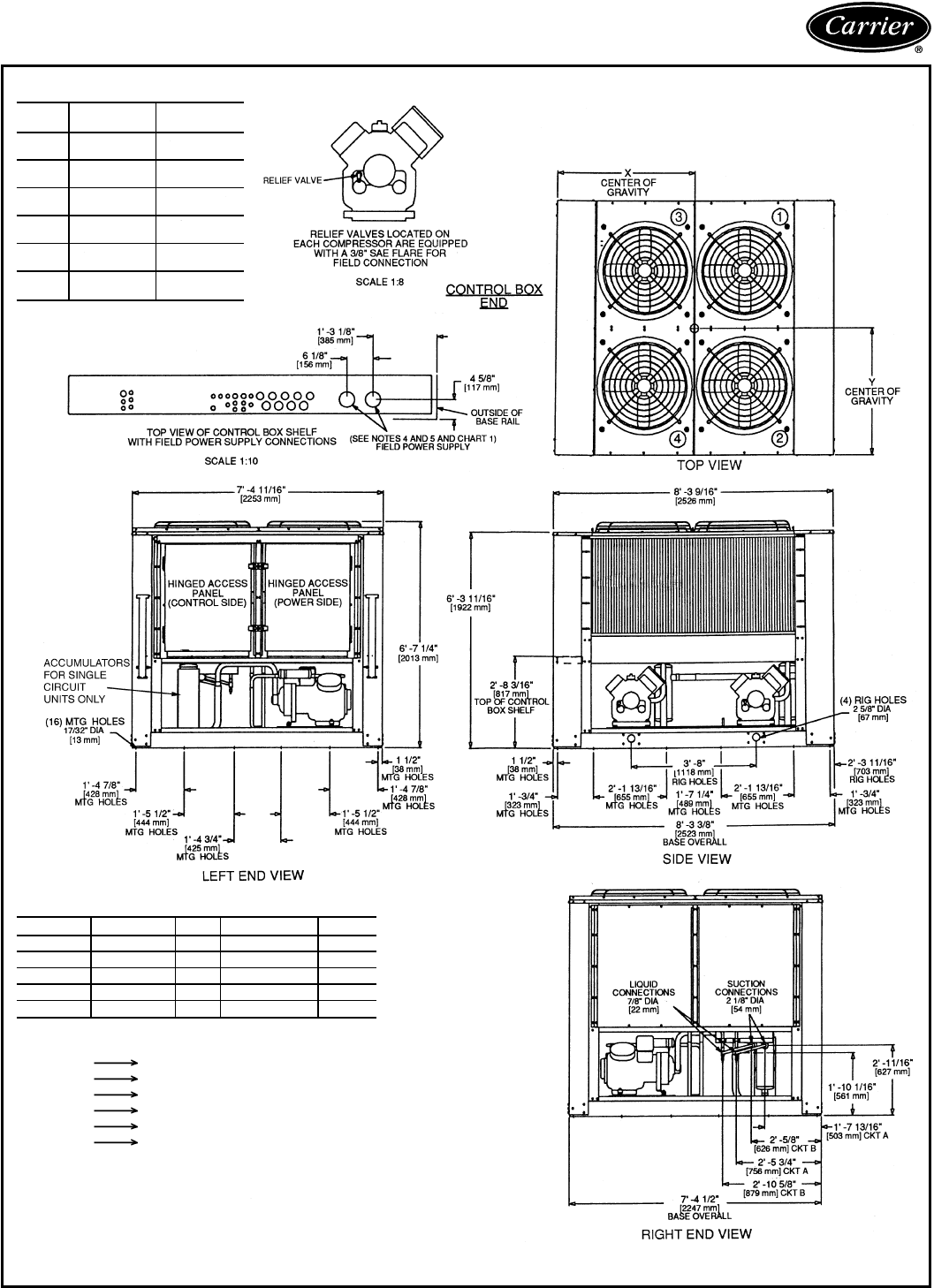
Dimensions — 38AH044-134
UNIT
38AH DIMENSION
YDIMENSION
X
044 38-2
3
⁄
4
9
[984 mm] 48-
1
⁄
2
9
[1232 mm]
044C 38-3
1
⁄
8
9
[994 mm] 48-
9
⁄
16
9
[1234 mm]
054 38-2
1
⁄
2
9
[978 mm] 48-
3
⁄
16
9
[1224 mm]
054C 38-39
[991 mm] 48-
3
⁄
8
9
[1229 mm]
064 38-2
1
⁄
2
9
[978 mm] 48-
1
⁄
2
9
[1232 mm]
064C 38-3
3
⁄
16
9
[995 mm] 48-
5
⁄
8
9
[1235 mm]
LEGEND
C—Copper Fin Coils
MTG — Mounting
SAE — Society of Automotive Engineers
SIZES 044-064 (See Page 53 for Corner Weights)
CHART 1, FIELD POWER SUPPLY CONNECTIONS
UNIT VOLTAGE Hz DIAMETER QTY.
044 230 50 3
5
⁄
8
9[92 mm] 1
044,054 346 50 2
1
⁄
2
9[63 mm] 1
064 346 50 3
5
⁄
8
9[92 mm] 1
044,054 380/415 50 2
1
⁄
2
9[63 mm] 1
064 380/415 50 3
5
⁄
8
9[92 mm] 1
NOTES:
1. The approximate operating weight of the unit is:
38AH044 3259 lb (1480 kg)
38AH044C 3547 lb (1609 kg)
38AH054 3309 lb (1501 kg)
38AH054C 3597 lb (1632 kg)
38AH064 3565 lb (1617 kg)
38AH064C 3998 lb (1813 kg)
2. Unit must have clearances for airflow as follows:
Top — Do not restrict in any way.
Ends—5ft[153 cm]
Sides—6ft[183 cm]
3. Mounting holes may be used to mount unit to concrete pad. They are not recommended for
mounting unit to spring isolators.
4. Two 51 mm (2 in.) dia holes are recommended for parallel conductors on 044 (230-V) units.
5. Circled numerals in Top View refer to condenser fans; refer to Electrical Data section, Fans
table, page 88 and Wiring Diagram book.
6. If spring isolators are used, a perimeter support channel between the unit and the isolators is
recommended.
51
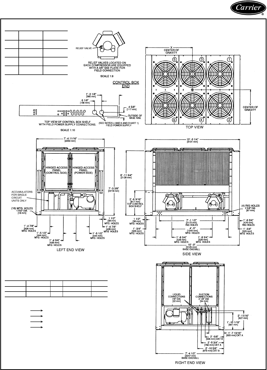
Dimensions — 38AH044-134 (cont)
SIZES 074, 084 (See Page 53 for Corner Weights)
UNIT
38AH DIMENSION
YDIMENSION
X
074 38-3
1
⁄
8
9
[994 mm] 48-8
13
⁄
16
88
[1443 mm]
074C 38-3
5
⁄
8
9
[1006 mm] 48-8
1
⁄
8
9
[1425 mm]
084 38-39
[991 mm] 48-99
[1448 mm]
084C 38-3
11
⁄
16
9
[1008 mm] 48-89
[1422 mm]
LEGEND
C—Copper Fin Coils
MTG — Mounting
SAE — Society of Automotive
Engineers
CHART 1, FIELD POWER SUPPLY CONNECTIONS
UNIT VOLTAGE Hz DIAMETER QTY.
074,084 346 50 3
5
⁄
8
9[92 mm] 1
074,084 380/415 50 3
5
⁄
8
9[92 mm] 1
NOTES:
1. The approximate operating weight of the unit is:
38AH074 3812 lb (1729 kg)
38AH074C 4229 lb (1918 kg)
38AH084 4057 lb (1840 kg)
38AH084C 4735 lb (2148 kg)
2. Unit must have clearances for airflow as follows:
Top — Do not restrict in any way.
Ends—5ft[153 cm]
Sides—6ft[183 cm]
3. Mounting holes may be used to mount unit to concrete pad. They are not
recommended for mounting unit to spring isolators.
4. Circled numerals in Top View refer to condenser fans; refer to Electrical
Data section, Fans table, page 88 and Wiring Diagram book.
5. If spring isolators are used, a perimeter support channel between the unit
and the isolators is recommended.
52
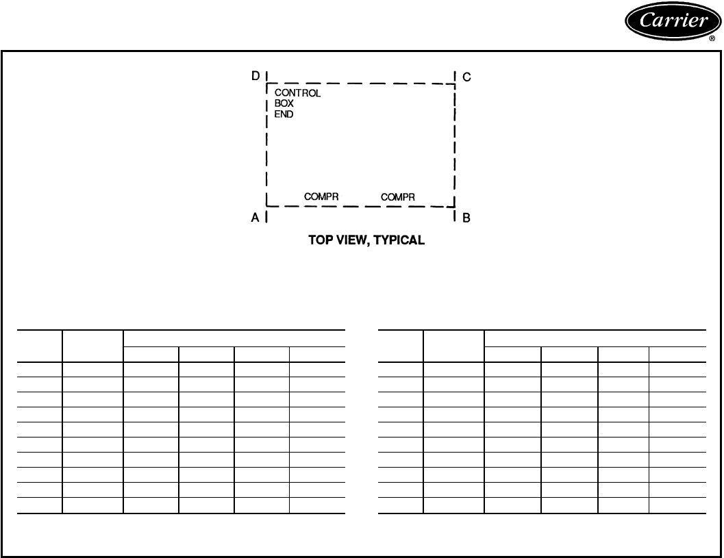
OPERATIONAL CORNER WEIGHTS WITH
REFRIGERANT CHARGE (Approximate) — Kg
UNIT
38AH TOTAL
WEIGHT OPERATIONAL CORNER WEIGHT
ABCD
044 1480 426 405 316 332
044C 1609 460 438 347 364
054 1501 437 411 316 337
054C 1632 469 444 350 369
064 1617 462 459 347 350
064C 1813 510 508 397 399
074 1729 520 447 352 410
074C 1918 577 481 391 470
084 1840 553 476 375 436
084C 2148 646 538 438 526
C—Copper Fin Coils
OPERATIONAL CORNER WEIGHTS WITH
REFRIGERANT CHARGE (Approximate) — Lb
UNIT
38AH TOTAL
WEIGHT OPERATIONAL CORNER WEIGHT
ABCD
044 3259 939 893 695 732
044C 3547 1013 967 765 802
054 3309 964 905 697 742
054C 3597 1034 978 771 814
064 3565 1018 1011 765 771
064C 3998 1125 1117 874 879
074 3812 1146 986 777 903
074C 4229 1272 1059 862 1035
084 4057 1220 1049 827 961
084C 4735 1425 1186 965 1159
C—Copper Fin Coils
53
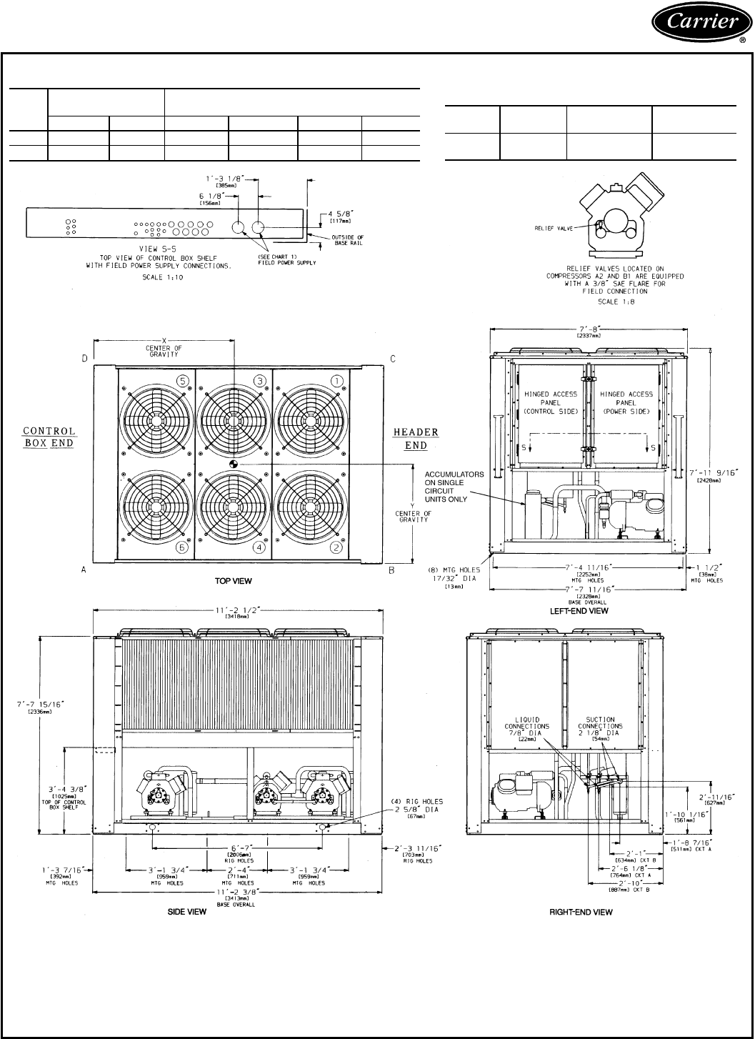
Dimensions — 38AH044-134 (cont)
UNIT 38AH094
UNIT
38AH
DIMENSIONS
ft-in. [mm] OPERATIONAL CORNER
WEIGHTS — lb [kg]
XYABCD
094 5-6 [1676] 2-7 [787] 1114 [505] 2192 [994] 1182 [536] 601 [273]
094C 5-6 [1676] 2-7 [787] 1273 [577] 2504 [1136] 1350 [612] 686 [311]
CHART 1, FIELD POWER SUPPLY CONNECTIONS
UNIT
38AH VOLT-
AGE DIAMETER
in. [mm] QUANTITY
094 346
380/415 3
5
⁄
8
92] 1
LEGEND
C—Copper Fin Coils
MTG — Mounting
SAE — Society of Automotive
Engineers
NOTES:
1. The approximate operating weight of the unit is:
38AH094 — 5088 lb [2308 Kg]
38AH094C — 5813 lb [2637 Kg]
2. Unit must have clearances for airflow as follows:
Top — Do not restrict in any way.
Ends—5ft[153 cm]
Sides—6ft[183 cm]
3. Mounting holes may be used to mount unit to
concrete pad. They are not recommended for
mounting unit to spring isolators.
4. Circled numerals in Top View refer to condenser
fans; refer to Electrical Data section, Fans table,
page 88 and Wiring Diagram book.
5. If spring isolators are used, a perimeter support
channel between the unit and the isolators is
recommended.
54
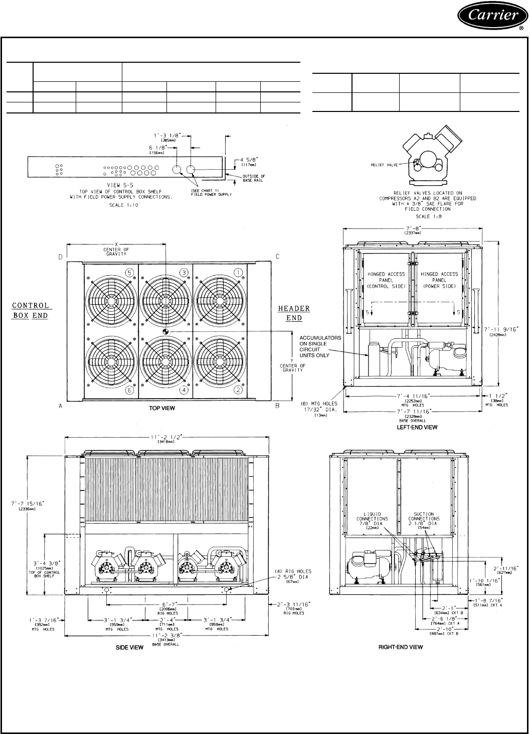
UNIT 38AH104
UNIT
38AH
DIMENSIONS
ft-in. [mm] OPERATIONAL CORNER
WEIGHTS — lb [kg]
XYA B CD
104 5-3 [1600] 2-9
1
⁄
2
[851] 1240 [562] 2138 [970] 1302 [591] 755 [342]
104C 5-3 [1600] 2-9
1
⁄
2
[851] 1405 [637] 2423 [1099] 1476 [670] 856 [388]
CHART 1, FIELD POWER SUPPLY CONNECTIONS
UNIT
38AH VOLT-
AGE DIAMETER
in. [mm] QUANTITY
104 346
380/415 3
5
⁄
8
[92] 1
LEGEND
C—Copper Fin Coils
MTG — Mounting
SAE — Society of Automotive
Engineers
NOTES:
1. The approximate operating weight of the unit is:
38AH104 — 5435 lb [2465 Kg]
38AH104C — 6160 lb [2794 Kg]
2. Unit must have clearances for airflow as follows:
Top — Do not restrict in any way.
Ends—5ft[153 cm]
Sides—6ft[183 cm]
3. Mounting holes may be used to mount unit to concrete
pad. They are not recommended for mounting unit to
spring isolators.
4. Circled numerals in Top View refer to condenser fans;
refer to Electrical Data section, Fans table, page 88
and Wiring Diagram book.
5. If spring isolators are used, a perimeter support chan-
nel between the unit and the isolators is recommended.
55
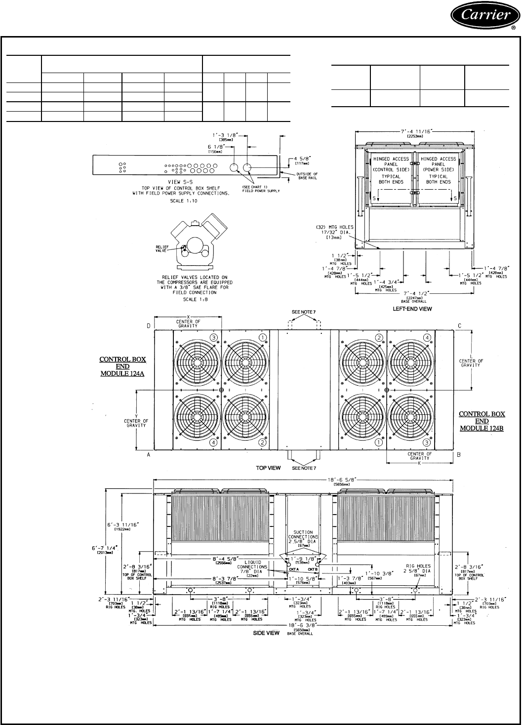
Dimensions — 38AH044-134 (cont)
UNIT 38AH124
UNIT
38AH
MODULE
DIMENSIONS
ft-in. [mm] OPERATIONAL CORNER
WEIGHTS — lb [kg]
X Y K L ABCD
124A 4-1
5
⁄
8
[1260] 3-2
1
⁄
8
[968] — — 1037
[470] 1030
[467] 779
[353] 785
[356]
124B — — 4-1
5
⁄
8
[1260] 3-2
1
⁄
8
[968]
124A-C 4-1
5
⁄
8
[1260] 3-2
7
⁄
8
[987] — — 1144
[519] 1137
[516] 889
[403] 894
[406]
124B-C — — 4-1
5
⁄
8
[1260] 3-2
7
⁄
8
[987]
CHART 1, FIELD POWER SUPPLY CONNECTIONS
UNIT
38AH
MODULE VOLTAGE DIAMETER
in. [mm] QUANTITY
124A
124B 346, 380/415 3
5
⁄
8
[92] 1
LEGEND
C—Copper Fin Coils
MTG — Mounting
SAE — Society of Automotive
Engineers
NOTES:
1. The approximate operating weight of the unit is:
38AH124 — 7260 lb [3293 Kg]
38AH124C — 8126 lb [3686 Kg]
2. Unit must have clearances for airflow as follows:
Top — Do not restrict in any way.
Ends—5ft[153 cm]
Sides—6ft[183 cm]
3. Mounting holes may be used to mount unit to concrete
pad. They are not recommended for mounting unit to
spring isolators.
4. Circled numerals in Top View refer to condenser fans; refer to
Electrical Data section, Fans table, page 88 and Wiring Diagram
book.
5. If spring isolators are used, a perimeter support channel between
the assembled unit and the isolators is required. Do not support
each module separately.
6. Each module must be rigged into position separately. The unit
must not be rigged after modules have been connected.
7. Suction and liquid connections can exit on either side of the unit.
8. Field power supply connections are required for each module.
56
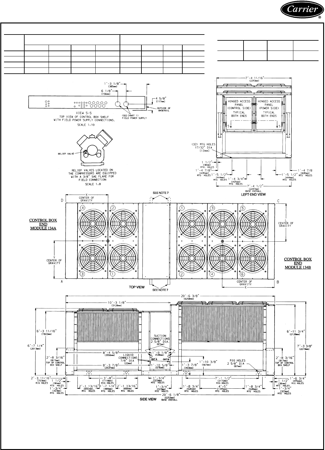
UNIT
38AH
MODULE
DIMENSIONS
ft-in. [mm] OPERATIONAL CORNER
WEIGHTS — lb [kg]
XYK LABCD
134A 4-1
5
⁄
8
[1260] 3-2
1
⁄
8
[968] — — 1037 [470] 1030 [467] 779 [353] 785 [356]
134B — — 4-8
7
⁄
8
[1445] 3-3
1
⁄
8
[994] 1167 [529] 997 [452] 789 [358] 924 [419]
134A-C 4-1
5
⁄
8
[1260] 3-2
7
⁄
8
[987] — — 1144 [519] 1137 [516] 889 [403] 894 [406]
134B-C — — 4-8
1
⁄
8
[1426] 3-3
3
⁄
4
[1010] 1293 [587] 1080 [490] 874 [396] 1047 [475]
CHART 1, FIELD POWER SUPPLY CONNECTIONS
UNIT 38AH
MODULE VOLTAGE DIAMETER
in. [mm] QUANTITY
134A
134B 346
380/415 3
5
⁄
8
[92] 1
UNIT 38AH134
LEGEND
C—Copper Fin Coils
MTG — Mounting
SAE — Society of Automotive
Engineers
NOTES:
1. The approximate operating weight of the unit is:
38AH134 — 7507 lb [3405 Kg]
38AH134C — 8357 lb [3791 Kg]
2. Unit must have clearances for airflow as follows:
Top — Do not restrict in any way.
Ends—5ft[153 cm]
Sides—6ft[183 cm]
3. Mounting holes may be used to mount unit to concrete pad. They are
not recommended for mounting unit to spring isolators.
4. Circled numerals in Top View refer to condenser fans; refer to Electrical Data section, Fans
table, page 88 and Wiring Diagram book.
5. If spring isolators are used, a perimeter support channel between the assembled unit and the
isolators is required. Do not support each module separately.
6. Each module must be rigged into position separately. The unit must not be rigged after mod-
ules have been connected.
7. Suction and liquid connections can exit on either side of the unit.
8. Field power supply connections are required for each module.
57
Selection procedure, 2-circuit units —
38AH044-134
SI
I Determine required cooling capacity of each
circuit, saturated suction temperature (SST) for
each circuit, and the temperature of the air
entering the condensing unit.
Given: Circuit A Circuit B
Cooling Load .................78kW... 86kW
Saturated suction
temperature ...................6C......6C
Entering-air temperature .........35C.....35C
II Enter the Condensing Unit Circuit and Module
Ratings tables for each circuit at the given suc-
tion temperatures and entering-air tempera-
tures; select a unit that satisfies the requirements
of each circuit.
The 38AH064 unit has a cooling capacity of 79.5 kW
at 6 C SST for circuit A, and a cooling capacity of
88.6 kW at 6 C SST for circuit B, both at an entering-
air temperature of 35 C. The unit meets requirements
according to the given conditions.
ENGLISH
I Determine required cooling capacity of each cir-
cuit, saturated suction temperature (SST) for
each circuit, and the temperature of the air en-
tering the condensing unit.
Given: Circuit A Circuit B
Cooling Load ....252,000 Btuh ... 281,000 Btuh
Saturated suction
temperature ............40F...........40F
Entering-air temperature . . . 95 F ...........95F
II Enter the Condensing Unit Circuit and Module
Ratings tables for each circuit at the given suc-
tion temperatures and entering-air tempera-
tures; select a unit that satisfies the requirements
of each circuit.
The 38AH064 unit has a cooling capacity of
256,000 Btuh at 40 F SST for circuit A, and a
cooling capacity of 286,000 Btuh at 40 F SST for
circuit B, both at an entering-air temperature of 95 F.
The unit meets requirements according to the given
conditions.
Selection procedure, single-circuit units —
38AH044-084 only
SI
I Determine required capacity, saturated suction
temperature (SST) at the compressors, and the
temperature of the air entering the condensing
unit.
Given:
Cooling Load ..........................156kW
Saturated suction temperature ..............4.0C
Entering-air temperature ...................35C
II Enter the Condensing Unit Ratings table at the
given suction temperature and entering-air tem-
perature for the required cooling capacity.
The 38AH064 unit has a cooling capacity of
156.1 kW at 4 C SST and 35 C entering-air tempera-
ture;the unitmeets requirementsaccording tothe given
conditions.
ENGLISH
I Determine required capacity, saturated suction
temperature (SST) at the compressors, and the
temperature of the air entering the condensing
unit.
Given:
Cooling Load .....................535,000 Btuh
Saturated suction temperature ...............40F
Entering-air temperature ...................95F
II Enter the Condensing Unit Ratings table at the
given suction temperature and entering-air tem-
perature for the required cooling capacity.
The 38AH064 unit has a cooling capacity of
542,000 Btuh at 40 F SST and 95 F entering-air
temperature; the unit meets requirements according to
the given conditions.
58

Performance data — 38AH044-134
CONDENSING UNIT RATINGS — SI
38AH044
SST
(C) Air Temperature Entering Condenser (C)
21 27 30 32 35 38 41 43 46 49 52
−2 TCG 105.5 96.9 92.6 89.6 85.1 80.6 76.1 73.1 68.4 63.8 59.2
CMP 24.2 26.3 27.3 27.9 28.8 29.4 30.1 30.4 30.9 31.2 31.3
SDT 33.3 39.2 42.1 44.0 46.9 49.9 52.8 54.8 57.7 60.7 63.6
0TCG 114.2 105.4 100.8 97.8 93.2 88.6 83.9 80.7 75.9 71.1 66.4
CMP 24.7 27.0 28.2 28.8 29.8 30.6 31.4 31.8 32.4 32.9 33.1
SDT 33.7 39.5 42.4 44.3 47.2 50.2 53.0 55.0 57.9 60.9 63.7
2TCG 123.6 114.3 109.6 106.5 101.7 96.9 92.1 88.8 83.9 78.9 73.9
CMP 25.1 27.7 28.9 29.7 30.8 31.8 32.6 33.1 33.8 34.4 34.9
SDT 34.2 39.9 42.8 44.8 47.7 50.5 53.4 55.3 58.3 61.1 64.0
4TCG 133.1 123.6 118.7 115.4 110.4 105.5 100.4 97.1 92.0 86.8 81.7
CMP 25.6 28.4 29.7 30.5 31.7 32.8 33.8 34.4 35.3 36.0 36.6
SDT 34.7 40.5 43.3 45.2 48.1 51.0 53.8 55.7 58.6 61.5 64.4
6TCG 143.1 133.1 128.0 124.7 119.5 114.4 109.1 105.6 100.4 95.1 89.7
CMP 26.1 29.0 30.5 31.4 32.7 33.9 35.0 35.7 36.7 37.5 38.3
SDT 35.3 41.0 43.9 45.7 48.6 51.4 54.3 56.2 59.0 61.9 64.8
8TCG 153.5 143.1 137.9 134.3 128.9 123.6 118.2 114.5 109.1 103.5 98.0*
CMP 26.6 29.7 31.2 32.2 33.6 34.9 36.1 36.9 38.0 39.0 39.9*
SDT 35.9 41.6 44.5 46.4 49.2 52.0 54.8 56.7 59.6 62.4 65.3*
10 TCG 164.1 153.3 147.9 144.2 138.6 133.0 127.3 123.6 117.9 112.2 106.5*
CMP 27.0 30.4 31.9 32.9 34.5 36.0 37.2 38.1 39.3 40.5 41.5*
SDT 36.6 42.3 45.1 47.0 49.8 52.6 55.4 57.3 60.1 62.9 65.8*
38AH054
SST
(C) Air Temperature Entering Condenser (C)
21 27 30 32 35 38 41 43 46 49 52
−2 TCG 123.0 113.2 108.1 104.9 100.0 95.1 90.2 87.0 82.2 77.4 72.6*
CMP 29.5 32.0 33.0 33.7 34.6 35.5 36.2 36.7 37.3 37.6 38.0*
SDT 35.7 41.6 44.5 46.5 49.5 52.4 55.4 57.4 60.3 63.3 66.3*
0TCG 133.3 123.0 117.8 114.3 109.1 104.0 98.9 95.6 90.4 85.4 80.4*
CMP 30.2 32.9 34.2 34.9 36.0 37.0 37.8 38.3 39.1 39.6 40.1*
SDT 36.0 41.8 44.8 46.7 49.6 52.6 55.5 57.5 60.5 63.5 66.4*
2TCG 144.2 133.4 128.0 124.4 119.0 113.6 108.3 104.8 99.4 94.1 88.8*
CMP 30.9 33.8 35.1 36.0 37.2 38.3 39.3 39.9 40.7 41.5 42.2*
SDT 36.5 42.2 45.2 47.1 50.0 52.9 55.8 57.8 60.7 63.6 66.6*
4TCG 155.4 144.2 138.5 134.7 129.1 123.5 117.9 114.1 108.5 103.0 97.4*
CMP 31.6 34.7 36.2 37.1 38.5 39.6 40.8 41.5 42.4 43.4 44.1*
SDT 36.5 42.7 45.5 47.5 50.3 53.3 56.1 58.1 61.0 63.9 66.9*
6TCG 167.0 155.3 149.4 145.5 139.6 133.8 127.9 124.0 118.1 112.3 106.5*
CMP 32.5 35.7 37.2 38.3 39.7 41.0 42.3 43.0 44.2 45.1 46.1*
SDT 37.6 43.3 46.1 48.0 50.8 53.7 56.5 58.5 61.3 64.2 67.2*
8TCG 178.9 166.8 160.7 156.6 150.5 144.4 138.3 134.2 128.2 122.0 116.0*
CMP 33.2 36.6 38.3 39.4 41.0 42.4 43.7 44.6 45.9 47.0 48.0*
SDT 38.4 44.0 46.7 48.6 51.4 54.2 57.0 59.0 61.8 64.7 67.5*
10 TCG 191.2 179.0 172.2 168.0 161.6 155.2 148.8 144.6 138.3 132.0* 125.5*
CMP 33.9 37.6 39.3 40.5 42.2 43.7 45.2 46.1 47.5 48.8* 50.0*
SDT 39.2 44.7 47.4 49.3 52.0 54.8 57.6 59.5 62.3 65.2* 68.0*
38AH064
SST
(C) Air Temperature Entering Condenser (C)
21 27 30 32 35 38 41 43 46 49 52
−2 TCG 148.5 137.2 131.7 127.9 122.4 116.9 111.4 107.8 102.3 97.0 91.6
CMP 35.7 38.6 40.0 40.8 42.0 43.1 44.0 44.6 45.4 46.0 46.5
SDT 34.7 40.5 43.5 45.5 48.3 51.3 54.2 56.2 59.2 62.1 65.1
0TCG 160.3 148.6 142.8 138.9 133.1 127.3 121.6 117.8 112.1 106.4 100.7
CMP 36.6 39.8 41.3 42.3 43.5 44.8 45.8 46.4 47.4 48.2 48.9
SDT 35.1 40.9 43.8 45.7 48.6 51.6 54.5 56.4 59.3 62.3 65.2
2TCG 172.9 160.7 154.6 150.5 144.4 138.4 132.4 128.4 122.4 116.4 110.5
CMP 37.5 41.0 42.6 43.6 45.0 46.4 47.6 48.3 49.5 50.4 51.2
SDT 35.7 41.5 44.3 46.3 49.1 52.0 54.9 56.9 59.8 62.7 65.6
4TCG 185.8 173.1 166.6 162.4 156.1 149.8 143.4 139.2 133.0 126.7 120.5
CMP 38.4 42.2 43.9 45.0 46.6 48.1 49.4 50.2 51.5 52.6 53.5
SDT 36.4 42.1 44.9 46.8 49.7 52.6 55.4 57.3 60.2 63.1 66.0
6TCG 199.4 185.9 179.2 174.7 168.1 161.4 154.8 150.5 143.8 137.3 130.8*
CMP 39.3 43.4 45.3 46.4 48.2 49.7 51.2 52.2 53.5 54.7 55.9*
SDT 37.2 42.8 45.6 47.5 50.3 53.2 56.0 57.9 60.7 63.6 66.4*
8TCG 213.0 198.9 192.4 187.5 180.6 173.7 166.7 162.2 155.2 148.4 141.6*
CMP 40.2 44.5 46.5 47.8 49.7 51.4 53.1 54.1 55.6 57.0 58.2*
SDT 38.0 43.6 46.4 48.2 51.1 53.9 56.7 58.5 61.4 64.2 67.0*
10 TCG 227.0 213.0 205.8 200.3 193.7 186.0 178.9 174.0 166.8 159.6 152.5*
CMP 41.1 45.7 47.9 49.3 51.3 53.2 54.9 56.0 57.6 59.1 60.5*
SDT 38.9 44.4 47.2 49.1 51.8 54.6 57.4 59.3 62.0 64.8 67.6*
LEGEND
CMP — Compressor Power, kW
SDT — Saturated Discharge Temperature (leaving compressor) (C)
SST — Saturated Suction Temperature (entering condensing unit)
TCG — Total Cooling Capacity, Gross (kW)
*May require replacement of the high-pressure cutout switches with switches of a
higher setting.
NOTES:
1. Ratings are based on 8.3 C superheat and use of R-22 refrigerant.
2. Ratings include suction line losses due to an accumulator.
59

Performance data — 38AH044-134 (cont)
CONDENSING UNIT RATINGS — SI (cont)
38AH074
SST
(C) Air Temperature Entering Condenser (C)
21 27 30 32 35 38 41 43 46 49 52
−2 TCG 181.6 169.2 163.2 159.1 153.1 147.1 141.0 137.0 131.0 125.0 118.9
CMP 45.2 48.7 50.2 51.1 52.4 53.8 54.9 55.6 56.6 57.4 58.1
SDT 34.1 39.8 42.8 44.7 47.6 50.5 53.5 55.4 58.4 61.3 64.3
0TCG 194.7 182.1 176.1 171.9 165.6 159.3 153.0 148.8 142.5 136.2 129.8
CMP 46.5 50.2 51.9 53.0 54.5 55.9 57.2 57.9 59.1 60.1 61.0
SDT 34.6 40.3 43.2 45.0 47.9 50.8 53.7 55.6 58.5 61.4 64.4
2TCG 209.1 196.3 189.3 185.3 178.4 172.1 165.5 161.2 154.6 148.1 141.4
CMP 47.8 51.8 53.7 54.8 56.5 58.1 59.5 60.4 61.6 62.8 63.8
SDT 35.3 41.0 43.8 45.7 48.5 51.3 54.1 56.1 58.9 61.8 64.7
4TCG 224.6 210.5 203.5 199.4 192.4 185.2 178.1 173.8 166.9 160.1 153.2
CMP 49.1 53.4 55.4 56.7 58.4 60.2 61.7 62.7 64.2 65.4 66.6
SDT 36.0 41.6 44.4 46.3 49.1 51.9 54.7 56.6 59.4 62.2 65.1
6TCG 239.0 225.1 217.9 212.8 205.6 198.3 192.1 186.9 179.6 172.5 165.3
CMP 50.4 55.0 57.2 58.5 60.5 62.4 64.0 65.1 66.7 68.1 69.5
SDT 36.8 42.4 45.2 47.0 49.8 52.6 55.4 57.3 60.0 62.8 65.6
8TCG 257.0 241.0 234.0 228.4 221.0 212.6 205.2 200.0 192.5 185.1 177.6*
CMP 51.6 56.6 59.0 60.4 62.6 64.5 66.5 67.6 69.4 71.0 72.4*
SDT 37.6 43.2 45.9 47.8 50.6 53.3 56.1 57.9 60.7 63.5 66.2*
10 TCG 273.0 257.0 248.0 243.0 236.0 227.1 219.5 214.1 206.6 198.0 190.4*
CMP 52.8 58.3 60.7 62.3 64.6 66.8 68.8 70.1 71.9 73.7 75.3*
SDT 38.5 44.0 46.8 48.6 51.4 54.1 56.9 58.7 61.5 64.2 66.9*
38AH084
SST
(C) Air Temperature Entering Condenser (C)
21 27 30 32 35 38 41 43 46 49 52
−2 TCG 204.0 190.6 183.9 179.3 172.7 166.1 159.6 155.3 148.9 142.5 136.2*
CMP 54.1 57.9 59.5 60.6 62.1 63.4 64.8 65.5 66.6 67.7 68.6*
SDT 36.2 42.2 45.2 47.2 50.2 53.1 56.2 58.2 61.2 64.2 67.2*
0TCG 221.0 206.0 198.9 194.2 187.1 180.1 173.2 168.6 161.7 154.9 148.2*
CMP 55.6 59.7 61.5 62.7 64.4 65.9 67.3 68.2 69.6 70.8 71.8*
SDT 36.3 42.3 45.3 47.3 50.3 53.2 56.2 58.2 61.2 64.2 67.2*
2TCG 238.0 223.0 215.0 210.0 203.0 195.3 187.9 183.1 175.7 168.5 161.3*
CMP 57.0 61.5 63.5 64.9 66.7 68.3 69.9 70.9 72.4 73.8 75.0*
SDT 36.7 42.6 45.5 47.5 50.4 53.4 56.4 58.4 61.4 64.3 67.3*
4TCG 256.0 240.0 232.0 226.0 219.0 211.0 203.0 197.9 190.1 182.5 174.9*
CMP 58.5 63.3 65.5 66.9 68.9 70.9 72.7 73.7 75.3 76.9 78.2*
SDT 37.1 42.9 45.8 47.8 50.7 53.6 56.6 58.6 61.5 63.5 67.4*
6TCG 274.0 258.0 250.0 244.0 236.0 227.0 219.0 214.0 205.0 197.0 189.0*
CMP 60.0 65.1 67.5 69.1 71.3 73.3 75.3 76.5 78.3 79.9 81.5*
SDT 37.7 43.4 46.3 48.2 51.1 54.1 57.0 58.9 61.9 64.8 67.7*
8TCG 294.0 276.0 268.0 262.0 252.0 244.0 236.0 230.0 221.0 212.0 204.0*
CMP 61.6 67.1 69.7 71.3 73.7 75.9 78.0 79.3 81.3 83.1 84.8*
SDT 38.4 44.1 46.9 48.8 51.7 54.5 57.4 59.4 62.3 65.2 68.1*
10 TCG 314.0 294.0 286.0 280.0 270.0 261.0 252.0 246.0 236.0 228.0 219.0*
CMP 63.2 69.1 71.7 73.5 76.1 78.5 80.7 82.1 84.3 86.3 88.1*
SDT 39.2 44.8 47.6 49.5 52.3 55.2 58.0 59.9 62.7 65.6 68.5*
LEGEND
CMP — Compressor Power, kW
SDT — Saturated Discharge Temperature (leaving compressor) (C)
SST — Saturated Suction Temperature (entering condensing unit)
TCG — Total Cooling Capacity, Gross (kW)
*May require replacement of the high-pressure cutout switches with switches of a
higher setting.
NOTES:
1. Ratings are based on 8.3 C superheat and use of R-22 refrigerant.
2. Ratings include suction line losses due to an accumulator.
60
CONDENSING UNIT RATINGS — SI (cont)
38AH094
SST
(C) Air Temperature Entering Condenser (C)
21 27 30 32 35 38 41 43 46 49 52
−2
TCG 233.0 216.5 209.1 202.9 195.6 187.3 178.7 173.1 164.8 156.5 148.2
CMP 58.1 62.3 64.3 65.6 67.4 68.9 70.3 71.1 72.2 73.2 73.9
SDT(A) 35.5 41.2 44.0 45.9 48.8 51.6 54.5 56.5 59.4 62.3 65.3
SDT(B) 33.8 39.6 42.5 44.5 47.4 50.4 53.4 55.4 58.3 61.3 64.3
SCT(A) 33.6 39.7 42.8 44.8 47.8 50.8 53.9 55.9 58.9 61.9 64.9
SCT(B) 32.3 38.5 41.5 43.6 46.7 49.7 52.8 54.8 57.9 60.9 63.9
0
TCG 251.0 234.0 226.0 220.2 211.7 203.3 194.8 188.5 180.0 171.4 162.7
CMP 59.7 64.3 66.6 67.9 69.9 71.7 73.3 74.2 75.6 76.7 77.7
SDT(A) 36.2 41.8 44.5 46.4 49.2 52.0 54.9 56.8 59.6 62.5 65.4
SDT(B) 34.2 39.9 42.8 44.8 47.7 50.6 53.5 55.5 58.4 61.4 64.4
SCT(A) 34.0 40.1 43.1 45.1 48.1 51.1 54.1 56.0 59.0 62.0 64.9
SCT(B) 32.4 38.6 41.7 43.7 46.8 49.8 52.8 54.8 57.9 60.9 63.9
2
TCG 269.0 252.0 243.0 237.0 228.0 219.6 211.0 204.6 196.0 186.4 177.9
CMP 61.5 66.5 68.9 70.4 72.5 74.4 76.2 77.4 78.9 80.2 81.5
SDT(A) 37.1 42.6 45.3 47.2 49.9 52.7 55.5 57.4 60.2 63.0 65.8
SDT(B) 34.9 40.5 43.4 45.3 48.2 51.0 53.9 55.9 58.8 61.7 64.6
SCT(A) 34.6 40.6 43.7 45.7 48.6 51.6 54.5 56.5 59.4 62.3 65.3
SCT(B) 32.8 39.0 42.0 44.0 47.1 50.1 53.1 55.1 58.1 61.1 64.1
4
TCG 289.0 270.0 261.0 255.0 246.0 237.0 227.0 221.7 211.9 202.2 193.4
CMP 63.3 68.6 71.3 72.9 75.2 77.2 79.3 80.5 82.3 83.8 85.2
SDT(A) 38.0 43.5 46.2 48.0 50.7 53.4 56.2 58.0 60.8 63.5 66.3
SDT(B) 35.6 41.2 44.0 45.9 48.7 51.5 54.4 56.3 59.2 62.1 65.0
SCT(A) 35.2 41.2 44.3 46.3 49.2 52.1 55.0 57.0 59.9 62.7 65.6
SCT(B) 33.3 39.4 42.4 44.4 47.4 50.4 53.4 55.4 58.4 61.3 64.3
6
TCG 309.0 290.0 279.0 274.0 264.0 254.0 245.0 238.0 228.0 219.2 209.3
CMP 65.1 70.8 73.6 75.4 77.9 80.2 82.4 83.7 85.6 87.5 89.1
SDT(A) 39.0 44.4 47.1 48.9 51.6 54.3 57.0 58.8 61.5 64.2 66.9
SDT(B) 36.4 41.9 44.7 46.5 49.3 52.1 55.0 56.9 59.7 62.5 65.4
SCT(A) 35.8 41.9 44.9 46.9 49.9 52.8 55.7 57.6 60.5 63.3 66.2
SCT(B) 33.8 39.9 42.9 44.9 47.9 50.9 53.8 55.8 58.8 61.7 64.7
8
TCG 329.0 309.0 299.0 292.0 282.0 273.0 263.0 256.0 246.0 235.0 225.0
CMP 66.9 73.0 76.0 77.9 80.6 83.1 85.5 87.0 89.1 91.0 92.9
SDT(A) 40.1 45.4 48.0 49.8 52.5 55.2 57.9 59.6 62.3 65.0 67.7*
SDT(B) 37.3 42.7 45.5 47.3 50.1 52.9 55.7 57.5 60.3 63.1 66.0
SCT(A) 36.5 42.6 45.6 47.6 50.6 53.5 56.4 58.3 61.1 64.0 66.8
SCT(B) 34.3 40.4 43.5 45.5 48.4 51.4 54.4 56.3 59.3 62.2 65.1
10
TCG 350.0 329.0 319.0 312.0 301.0 291.0 281.0 274.0 263.0 253.0 242.0
CMP 68.7 75.2 78.4 80.5 83.3 86.0 88.7 90.3 92.5 94.7 96.8
SDT(A) 41.1 46.4 49.1 50.8 53.5 56.2 58.8 60.5 63.2 65.9 68.5*
SDT(B) 38.2 43.6 46.3 48.2 50.9 53.7 56.4 58.3 61.0 63.8 66.6
SCT(A) 37.2 43.3 46.4 48.4 51.3 54.2 57.1 59.0 61.8 64.7 67.5*
SCT(B) 34.9 41.0 44.1 46.1 49.0 52.0 54.9 56.9 59.8 62.7 65.6
LEGEND
CMP — Compressor Power (kW)
SCT(A) — Saturated Condensing Temperature (C) for Circuit A (38AH094,104),
or Module 38AH124A or 134A
SCT(B) — Saturated Condensing Temperature (C) for Circuit B (38AH094,104),
or Module 38AH124B or 134B
SDT(A) — Saturated Discharge Temperature (C) for Circuit A (38AH094,104),
or Module 38AH124A or 134A
SDT(B) — Saturated Discharge Temperature (C) for Circuit B (38AH094,104),
or Module 38AH124B or 134B
SST — Saturated Suction Temperature Entering Condensing Unit
TCG — Gross Cooling Capacity (kW)
*May require replacement of the high-pressure cutout switches with switches of a
higher setting.
NOTES:
1. Ratings are based on 8.3 C superheat and use of R-22 refrigerant.
2. Ratings include suction line losses due to an accumulator.
61

Performance data — 38AH044-134 (cont)
CONDENSING UNIT RATINGS — SI (cont)
38AH104
SST
(C) Air Temperature Entering Condenser (C)
21 27 30 32 35 38 41 43 46 49 52
−2
TCG 265.0 245.0 235.0 229.0 219.0 209.3 199.6 192.4 183.1 173.6 164.2
CMP 62.8 67.7 70.1 71.6 73.6 75.5 77.2 78.3 79.7 81.0 82.1
SDT(A) 34.4 40.0 42.8 44.7 47.5 50.4 53.3 55.2 58.1 61.1 64.0
SDT(B) 35.7 41.2 43.9 45.8 48.6 51.4 54.3 56.2 59.1 61.9 64.9
SCT(A) 32.6 38.6 41.7 43.7 46.7 49.7 52.7 54.6 57.7 60.7 63.7
SCT(B) 33.5 39.5 42.6 44.5 47.5 50.5 53.5 55.5 58.5 61.4 64.4
0
TCG 285.0 264.0 254.0 247.0 237.0 227.0 217.0 209.8 199.8 190.0 180.1
CMP 64.9 70.1 72.6 74.3 76.5 78.6 80.5 81.8 83.4 84.9 86.2
SDT(A) 35.1 40.6 43.4 45.2 48.0 50.8 53.6 55.5 58.4 61.3 64.1
SDT(B) 36.5 41.9 44.7 46.5 49.2 52.0 54.8 56.7 59.5 62.3 65.2
SCT(A) 33.1 39.1 42.1 44.0 47.0 49.9 52.9 54.9 57.8 60.8 63.7
SCT(B) 34.0 40.0 43.1 45.0 48.0 50.9 53.9 55.8 58.8 61.7 64.6
2
TCG 307.0 285.0 273.0 267.0 256.0 246.0 235.0 228.0 217.0 207.3 197.2
CMP 66.9 72.6 75.3 77.0 79.5 81.7 84.0 85.3 87.1 88.8 90.4
SDT(A) 36.0 41.4 44.1 46.0 48.7 51.5 54.3 56.1 58.9 61.7 64.6
SDT(B) 37.5 42.9 45.5 47.3 50.0 52.8 55.5 57.4 60.1 62.9 65.7
SCT(A) 33.6 39.6 42.6 44.6 47.5 50.4 53.3 55.3 58.2 61.1 64.0
SCT(B) 34.7 40.7 43.7 45.7 48.6 51.5 54.4 56.4 59.3 62.2 65.1
4
TCG 328.0 306.0 294.0 287.0 275.0 265.0 254.0 246.0 235.0 225.0 213.4
CMP 68.9 75.0 78.0 79.8 82.5 85.0 87.3 88.8 90.9 92.8 94.5
SDT(A) 36.9 42.3 44.9 46.7 49.5 52.2 54.9 56.7 59.5 62.3 65.1
SDT(B) 38.5 43.8 46.4 48.2 50.9 53.6 56.3 58.1 60.8 63.6 66.3
SCT(A) 34.2 40.2 43.2 45.1 48.1 51.0 53.9 55.8 58.7 61.5 64.4
SCT(B) 35.3 41.4 44.4 46.3 49.3 52.2 55.1 57.0 59.8 62.7 65.6
6
TCG 351.0 328.0 316.0 308.0 296.0 285.0 273.0 265.0 254.0 242.0 231.0
CMP 71.0 77.5 80.7 82.7 85.6 88.3 90.8 92.4 94.7 96.8 98.8
SDT(A) 37.9 43.2 45.8 47.6 50.3 53.0 55.7 57.5 60.2 63.0 65.7
SDT(B) 39.6 44.8 47.4 49.2 51.8 54.5 57.2 59.0 61.7 64.4 67.1*
SCT(A) 34.8 40.8 43.8 45.8 48.7 51.6 54.5 56.4 59.2 62.1 64.9
SCT(B) 36.0 42.1 45.1 47.1 50.0 52.9 55.7 57.7 60.5 63.4 66.2
8
TCG 375.0 351.0 338.0 330.0 317.0 305.0 294.0 285.0 273.0 261.0 250.0
CMP 73.1 80.0 83.5 85.6 88.6 91.5 94.3 96.1 98.6 100.8 103.0
SDT(A) 38.9 44.1 46.8 48.6 51.2 53.9 56.6 58.4 61.0 63.7 66.4
SDT(B) 40.7 45.9 48.5 50.2 52.8 55.5 58.1 59.9 62.6 65.2 67.9*
SCT(A) 35.5 41.5 44.5 46.5 49.4 52.3 55.1 57.1 59.9 62.7 65.5
SCT(B) 36.7 42.8 45.8 47.8 50.7 53.6 56.5 58.4 61.2 64.1 66.9
10
TCG 400.0 374.0 361.0 353.0 340.0 327.0 313.0 305.0 292.0 281.0 268.0
CMP 75.4 82.6 86.3 88.5 91.7 94.9 97.8 99.7 102.4 105.0 107.4
SDT(A) 39.9 45.2 47.8 49.5 52.2 54.8 57.4 59.2 61.9 64.5 67.2
SDT(B) 41.9 47.0 49.5 51.3 53.9 56.5 59.1 60.8 63.5 66.1 68.7*
SCT(A) 36.2 42.2 45.2 47.2 50.1 53.0 55.8 57.8 60.6 63.4 66.2
SCT(B) 37.5 43.6 46.6 48.6 51.5 54.4 57.3 59.2 62.0 64.8 67.6*
LEGEND
CMP — Compressor Power (kW)
SCT(A) — Saturated Condensing Temperature (C) for Circuit A (38AH094,104),
or Module 38AH124A or 134A
SCT(B) — Saturated Condensing Temperature (C) for Circuit B (38AH094,104),
or Module 38AH124B or 134B
SDT(A) — Saturated Discharge Temperature (C) for Circuit A (38AH094,104),
or Module 38AH124A or 134A
SDT(B) — Saturated Discharge Temperature (C) for Circuit B (38AH094,104),
or Module 38AH124B or 134B
SST — Saturated Suction Temperature Entering Condensing Unit
TCG — Gross Cooling Capacity (kW)
*May require replacement of the high-pressure cutout switches with switches of a
higher setting.
NOTES:
1. Ratings are based on 8.3 C superheat and use of R-22 refrigerant.
2. Ratings include suction line losses due to an accumulator.
62

CONDENSING UNIT RATINGS — SI (cont)
38AH124
SST
(C) Air Temperature Entering Condenser (C)
21 27 30 32 35 38 41 43 46 49 52
−2
TCG 298.0 276.0 264.0 258.0 246.0 236.0 224.0 218.0 206.0 195.6 185.0
CMP 71.4 77.2 80.0 81.6 84.0 86.2 88.0 89.0 90.8 92.0 93.2
SDT(A OR (B) 34.7 40.5 43.4 45.4 48.3 51.3 54.2 56.2 59.1 62.1 65.1
SCT(A) OR (B) 33.9 39.9 42.9 44.9 47.9 50.9 53.8 55.9 58.9 61.9 64.8
0
TCG 322.0 298.0 286.0 280.0 268.0 256.0 244.0 238.0 226.0 214.0 204.0
CMP 73.4 79.6 82.6 84.4 87.2 89.4 91.6 92.8 94.8 96.4 97.8
SDT(A) OR (B) 35.2 40.9 43.8 45.8 48.7 51.6 54.4 56.4 59.4 62.3 65.2
SCT(A) OR (B) 34.3 40.2 43.2 45.2 48.1 51.1 54.0 56.0 59.0 62.0 65.0
2
TCG 346.0 322.0 310.0 302.0 290.0 278.0 266.0 258.0 246.0 234.0 222.0
CMP 75.2 82.0 85.2 87.4 90.2 92.8 95.2 96.8 99.0 100.8 102.4
SDT(A) OR (B) 35.8 41.5 44.4 46.3 49.2 52.0 54.9 56.8 59.7 62.7 65.6
SCT(A) OR (B) 34.7 40.7 43.6 45.6 48.5 51.5 54.4 56.4 59.3 62.3 65.2
4
TCG 372.0 348.0 334.0 326.0 314.0 300.0 288.0 280.0 268.0 254.0 242.0
CMP 77.0 84.2 88.0 90.2 93.2 96.2 99.0 100.6 103.0 105.2 107.2
SDT(A) OR (B) 36.5 42.1 45.0 46.9 49.7 52.6 55.4 57.3 60.2 63.1 65.9
SCT(A) OR (B) 35.3 41.2 44.1 46.1 49.0 51.9 54.8 56.8 59.7 62.6 65.5
6
TCG 400.0 372.0 360.0 350.0 338.0 324.0 310.0 302.0 290.0 276.0 264.0
CMP 78.8 86.6 90.6 93.0 96.4 99.6 102.6 104.4 107.2 109.6 111.8
SDT(A) OR (B) 37.2 42.9 45.7 47.6 50.4 53.2 56.0 57.9 60.7 63.6 66.4
SCT(A) OR (B) 35.9 41.8 44.7 46.6 49.5 52.5 55.4 57.3 60.2 63.1 66.0
8
TCG 428.0 400.0 386.0 376.0 362.0 348.0 334.0 326.0 312.0 298.0 284.0
CMP 80.6 89.2 93.2 95.8 99.6 103.0 106.2 108.2 111.2 114.0 116.4
SDT(A) OR (B) 38.1 43.7 46.5 48.3 51.1 53.9 56.7 58.6 61.4 64.2 67.0
SCT(A) OR (B) 36.6 42.4 45.3 47.3 50.2 53.1 55.9 57.9 60.7 63.6 66.5
10
TCG 456.0 426.0 412.0 402.0 388.0 374.0 358.0 350.0 334.0 320.0 306.0
CMP 82.6 91.6 96.0 98.8 102.6 106.4 110.0 112.2 115.4 118.4 121.2
SDT(A) OR (B) 39.0 44.5 47.3 49.1 51.9 54.7 57.4 59.3 62.1 64.8 67.6
SCT(A) OR (B) 37.3 43.1 46.0 48.0 50.8 53.7 56.6 58.5 61.3 64.2 67.0
LEGEND
CMP — Compressor Power (kW)
SCT(A) — Saturated Condensing Temperature (C) for Circuit A (38AH094,104),
or Module 38AH124A or 134A
SCT(B) — Saturated Condensing Temperature (C) for Circuit B (38AH094,104),
or Module 38AH124B or 134B
SDT(A) — Saturated Discharge Temperature (C) for Circuit A (38AH094,104),
or Module 38AH124A or 134A
SDT(B) — Saturated Discharge Temperature (C) for Circuit B (38AH094,104),
or Module 38AH124B or 134B
SST — Saturated Suction Temperature Entering Condensing Unit
TCG — Gross Cooling Capacity (kW)
*May require replacement of the high-pressure cutout switches with switches of a
higher setting.
NOTES:
1. Ratings are based on 8.3 C superheat and use of R-22 refrigerant.
2. Ratings include suction line losses due to an accumulator.
63
Performance data — 38AH044-134 (cont)
CONDENSING UNIT RATINGS — SI (cont)
38AH134
SST
(C) Air Temperature Entering Condenser (C)
21 27 30 32 35 38 41 43 46 49 52
−2
TCG 330.0 307.0 295.0 288.0 276.0 265.0 253.0 246.0 234.0 222.8 211.5
CMP 80.9 87.2 90.1 91.9 94.5 96.9 98.9 100.1 102.0 103.4 104.8
SDT(A) 34.7 40.5 43.4 45.4 48.3 51.3 54.2 56.2 59.1 62.1 65.1
SDT(B) 34.0 39.8 42.7 44.6 47.5 50.4 53.4 55.4 58.3 61.3 64.3
SCT(A) 33.9 39.9 42.9 44.9 47.9 50.9 53.8 55.9 58.9 61.9 64.8
SCT(B) 31.9 37.7 40.7 42.6 45.5 48.5 51.4 53.4 56.3 59.3 62.2
0
TCG 356.0 331.0 319.0 312.0 300.0 287.0 275.0 268.0 256.0 243.0 232.0
CMP 83.2 90.0 93.1 95.1 98.0 100.5 102.9 104.3 106.5 108.3 109.9
SDT(A) 35.2 40.9 43.8 45.8 48.7 51.6 54.4 56.4 59.4 62.3 65.2
SDT(B) 34.5 40.2 43.1 45.0 47.8 50.7 53.6 55.5 58.4 61.4 64.3
SCT(A) 34.3 40.2 43.2 45.2 48.1 51.1 54.0 56.0 59.0 62.0 65.0
SCT(B) 32.4 38.2 41.2 43.1 46.0 48.9 51.7 53.6 56.5 59.4 62.4
2
TCG 383.0 357.0 345.0 336.0 324.0 311.0 299.0 290.0 278.0 265.0 253.0
CMP 85.4 92.8 96.2 98.5 101.5 104.4 107.0 108.7 111.1 113.1 114.9
SDT(A) 35.8 41.5 44.4 46.3 49.2 52.0 54.9 56.8 59.7 62.7 65.6
SDT(B) 35.2 40.9 43.7 45.6 48.4 51.3 54.1 56.0 58.9 61.8 64.6
SCT(A) 34.7 40.7 43.6 45.6 48.5 51.5 54.4 56.4 59.3 62.3 65.2
SCT(B) 33.0 38.8 41.7 43.7 46.5 49.4 52.3 54.2 57.0 59.9 62.7
4
TCG 410.0 385.0 371.0 362.0 349.0 335.0 323.0 314.0 301.0 287.0 274.0
CMP 87.5 95.5 99.4 101.7 105.1 108.2 111.2 113.0 115.6 118.0 120.1
SDT(A) 36.5 42.1 45.0 46.9 49.7 52.6 55.4 57.3 60.2 63.1 65.9
SDT(B) 36.0 41.6 44.4 46.3 49.1 51.9 54.7 56.5 59.3 62.2 65.0
SCT(A) 35.3 41.2 44.1 46.1 49.0 51.9 54.8 56.8 59.7 62.6 65.5
SCT(B) 33.6 39.5 42.3 44.3 47.1 50.0 52.8 54.7 57.5 60.3 63.1
6
TCG 440.0 412.0 398.0 388.0 375.0 361.0 347.0 338.0 325.0 311.0 297.0
CMP 89.7 98.3 102.4 105.0 108.7 112.1 115.4 117.3 120.3 122.9 125.3
SDT(A) 37.2 42.9 45.7 47.6 50.4 53.2 56.0 57.9 60.7 63.6 66.4
SDT(B) 36.7 42.3 45.1 47.0 49.8 52.6 55.3 57.2 60.0 62.8 65.5
SCT(A) 35.9 41.8 44.7 46.6 49.5 52.5 55.4 57.3 60.2 63.1 66.0
SCT(B) 34.3 40.1 43.0 44.9 47.7 50.6 53.4 55.3 58.1 60.9 63.7
8
TCG 470.0 441.0 426.0 416.0 402.0 387.0 373.0 364.0 349.0 335.0 320.0
CMP 91.8 101.2 105.5 108.3 112.3 116.0 119.5 121.7 124.9 127.9 130.6
SDT(A) 38.1 43.7 46.5 48.3 51.1 53.9 56.7 58.6 61.4 64.2 67.0
SDT(B) 37.6 43.1 45.9 47.8 50.5 53.3 56.1 57.9 60.7 63.4 66.2
SCT(A) 36.6 42.4 45.3 47.3 50.2 53.1 55.9 57.9 60.7 63.6 66.5
SCT(B) 34.9 40.7 43.6 45.5 48.4 51.2 54.0 55.9 58.7 61.5 64.2
10
TCG 501.0 470.0 455.0 445.0 430.0 415.0 399.0 390.0 374.0 359.0 344.0
CMP 94.1 104.0 108.7 111.6 115.9 119.9 123.8 126.1 129.6 132.9 135.9
SDT(A) 39.0 44.5 47.3 49.1 51.9 54.7 57.4 59.3 62.1 64.8 67.6*
SDT(B) 38.4 44.0 46.7 48.6 51.3 54.1 56.8 58.7 61.4 64.2 66.9
SCT(A) 37.3 43.1 46.0 48.0 50.8 53.7 56.6 58.5 61.3 64.2 67.0
SCT(B) 35.6 41.4 44.3 46.2 49.0 51.8 54.7 56.5 59.3 62.1 64.8
LEGEND
CMP — Compressor Power (kW)
SCT(A) — Saturated Condensing Temperature (C) for Circuit A (38AH094,104),
or Module 38AH124A or 134A
SCT(B) — Saturated Condensing Temperature (C) for Circuit B (38AH094,104),
or Module 38AH124B or 134B
SDT(A) — Saturated Discharge Temperature (C) for Circuit A (38AH094,104),
or Module 38AH124A or 134A
SDT(B) — Saturated Discharge Temperature (C) for Circuit B (38AH094,104),
or Module 38AH124B or 134B
SST — Saturated Suction Temperature Entering Condensing Unit
TCG — Gross Cooling Capacity (kW)
*May require replacement of the high-pressure cutout switches with switches of a
higher setting.
NOTES:
1. Ratings are based on 8.3 C superheat and use of R-22 refrigerant.
2. Ratings include suction line losses due to an accumulator.
64
CONDENSING UNIT CIRCUIT AND MODULE RATINGS — SI
38AH044 CIRCUIT A
SST
(C) Air Temperature Entering Condenser (C)
21 27 30 32 35 38 41 43 46 49 52
−2 TCG 52.7 48.5 46.4 44.9 42.7 40.5 38.3 36.8 34.5 32.2 29.9
CMP 12.0 13.0 13.5 13.8 14.3 14.6 15.0 15.1 15.4 15.6 15.6
SDT 32.8 38.5 41.3 43.2 46.1 49.0 51.9 53.8 56.7 59.7 62.6
0TCG 56.9 52.6 50.4 48.9 46.7 44.4 42.1 40.5 38.2 35.8 33.5
CMP 12.3 13.4 14.0 14.3 14.8 15.2 15.6 15.8 16.1 16.4 16.5
SDT 33.4 39.0 41.8 43.7 46.5 49.4 52.2 54.2 57.0 59.9 62.7
2TCG 61.4 56.9 54.6 53.1 50.8 48.4 46.1 44.5 42.1 39.6 37.2
CMP 12.5 13.8 14.4 14.8 15.3 15.8 16.2 16.5 16.8 17.1 17.4
SDT 34.0 39.6 42.4 44.3 47.1 49.9 52.7 54.6 57.5 60.3 63.1
4TCG 66.0 61.4 59.0 57.4 55.0 52.6 50.1 48.5 46.0 43.5 41.0
CMP 12.8 14.2 14.8 15.2 15.8 16.3 16.8 17.1 17.6 17.9 18.2
SDT 34.7 40.3 43.0 44.9 47.7 50.5 53.3 55.1 57.9 60.8 63.6
6SCG 70.8 66.0 63.5 61.9 59.4 56.9 54.3 52.6 50.1 47.5 44.9
CMP 13.1 14.5 15.2 15.7 16.3 16.9 17.4 17.8 18.3 18.7 19.1
SDT 35.5 41.0 43.8 45.6 48.4 51.1 53.9 55.8 58.5 61.3 64.1
8TCG 75.8 70.8 68.3 66.5 63.9 61.3 58.7 56.9 54.3 51.6 48.9*
CMP 13.4 14.9 15.6 16.1 16.8 17.4 18.0 18.4 18.9 19.4 19.9*
SDT 36.3 41.8 44.5 46.4 49.1 51.8 54.6 56.4 59.2 61.9 64.7*
10 TCG 80.9 75.7 73.1 71.3 68.6 65.9 63.1 61.3 58.5 55.8 53.0*
CMP 13.7 15.3 16.0 16.5 17.3 18.0 18.6 19.0 19.6 20.2 20.7*
SDT 37.1 42.6 45.3 47.1 49.9 52.6 55.3 57.1 59.9 62.6 65.3*
38AH054 CIRCUIT A
SST
(C) Air Temperature Entering Condenser (C)
21 27 30 32 35 38 41 43 46 49 52
−2 TCG 53.0 48.7 46.4 44.9 42.7 40.4 38.1 36.5 34.2 31.9 29.5*
CMP 12.4 13.5 13.9 14.2 14.6 15.0 15.2 15.4 15.6 15.6 15.6*
SDT 35.0 41.0 44.0 46.0 49.0 52.0 55.0 57.0 60.0 63.0 66.0*
0TCG 57.6 53.1 50.8 49.2 46.8 44.5 42.1 40.5 38.0 35.6 33.2*
CMP 12.6 13.8 14.4 14.7 15.2 15.6 15.9 16.1 16.4 16.5 16.6*
SDT 35.1 41.0 44.1 46.0 49.0 52.0 55.0 57.0 60.0 63.0 66.0*
2TCG 62.5 57.8 55.4 53.8 51.4 48.9 46.4 44.8 42.2 39.7 37.2*
CMP 12.8 14.1 14.7 15.1 15.6 16.1 16.5 16.8 17.1 17.4 17.6*
SDT 35.3 41.2 44.2 46.1 49.1 52.1 55.1 57.1 60.0 63.0 66.0*
4TCG 67.5 62.7 60.2 58.5 56.0 53.5 50.9 49.1 46.5 43.9 41.2*
CMP 13.0 14.4 15.1 15.5 16.1 16.6 17.1 17.4 17.8 18.2 18.4*
SDT 35.6 41.4 44.3 46.3 49.2 52.2 55.1 57.1 60.1 63.1 66.1*
6TDG 72.6 67.7 65.1 63.4 60.8 58.2 55.5 53.7 51.0 48.3 45.5*
CMP 13.3 14.7 15.4 15.9 16.5 17.1 17.7 18.0 18.5 18.9 19.3*
SDT 36.0 41.8 44.7 46.6 49.5 52.4 55.3 57.3 60.2 63.2 66.2*
8TCG 77.9 72.8 70.2 68.4 65.7 63.0 60.3 58.4 55.7 52.8 50.0*
CMP 13.5 15.0 15.8 16.3 17.0 17.6 18.2 18.6 19.2 19.7 20.1*
SDT 36.6 42.3 45.1 47.0 49.9 52.7 55.6 57.6 60.5 63.4 66.3*
10 TCG 83.2 78.0 75.3 73.5 70.8 68.0 65.1 63.2 60.4 57.5* 54.5*
CMP 13.7 15.3 16.1 16.6 17.4 18.1 18.8 19.2 19.8 20.4* 20.9*
SDT 37.3 42.8 45.6 47.5 50.3 53.2 56.0 57.9 60.8 63.7* 66.5*
38AH064 CIRCUIT A
SST
(C) Air Temperature Entering Condenser (C)
21 27 30 32 35 38 41 43 46 49 52
−2 TCG 70.7 65.0 62.3 60.4 57.7 55.1 52.5 50.8 48.2 45.8 43.3
CMP 16.7 18.1 18.8 19.2 19.8 20.3 20.8 21.1 21.5 21.9 22.2
SDT 34.9 40.7 43.6 45.5 48.4 51.4 54.3 56.3 59.2 62.2 65.1
0TCG 76.4 70.5 67.5 65.7 62.8 60.0 57.3 55.5 52.8 50.1 47.5
CMP 17.2 18.7 19.4 19.9 20.5 21.1 21.6 21.9 22.4 22.9 23.3
SDT 35.4 41.1 44.0 45.9 48.8 51.7 54.6 56.5 59.4 62.5 65.3
2TCG 82.5 76.3 73.2 71.2 68.2 65.3 62.4 60.5 57.6 54.8 52.1
CMP 17.7 19.3 20.1 20.5 21.2 21.9 22.5 22.8 23.4 23.9 24.3
SDT 36.1 41.7 44.6 46.5 49.3 52.2 55.1 57.0 59.9 62.8 65.7
4TCG 88.8 82.3 79.0 76.9 73.8 70.7 67.6 65.6 62.6 59.6 56.7
CMP 18.1 19.9 20.7 21.2 22.0 22.7 23.3 23.7 24.4 24.9 25.4
SDT 36.8 42.4 45.2 47.1 49.9 52.8 55.6 57.5 60.3 63.2 66.1
6TCG 95.4 88.5 85.1 82.8 79.5 76.2 73.0 70.9 67.7 64.6 61.5*
CMP 18.6 20.5 21.4 21.9 22.8 23.5 24.2 24.7 25.3 25.9 26.5*
SDT 37.7 43.2 46.0 47.8 50.6 53.4 56.2 58.1 60.9 63.8 66.6*
8TCG 102.0 94.9 91.4 89.0 85.5 82.1 78.7 76.5 73.1 69.8 66.6*
CMP 19.1 21.1 22.0 22.6 23.5 24.3 25.1 25.6 26.3 27.0 27.6*
SDT 38.6 44.1 46.8 48.6 51.4 54.2 57.0 58.8 61.6 64.4 67.2*
10 TCG 109.0 102.0 97.8 95.3 91.7 88.0 84.5 82.1 78.6 75.1 71.7*
CMP 19.6 21.7 22.7 23.4 24.3 25.2 26.0 26.5 27.3 28.0 28.7*
SDT 39.5 44.9 47.7 49.5 52.2 55.0 57.7 59.6 62.3 65.1 67.9*
LEGEND
CMP — Compressor Power, kW
SDT — Saturated Discharge Temperature (leaving compressor) (C)
SST — Saturated Suction Temperature (entering condensing unit)
TCG — Total Cooling Capacity, Gross (kW)
*May require replacement of the high-pressure cutout switches with switches of a
higher setting.
NOTES:
1. Ratings are based on 8.3 C superheat and use of R-22 refrigerant.
2. Ratings include suction line losses due to an accumulator.
65
Performance data — 38AH044-134 (cont)
CONDENSING UNIT CIRCUIT AND MODULE RATINGS — SI (cont)
38AH044 CIRCUIT B
SST
(C) Air Temperature Entering Condenser (C)
21 27 30 32 35 38 41 43 46 49 52
−2 TCG 52.8 48.4 46.2 44.7 42.4 40.1 37.8 36.3 33.9 31.6 29.3
CMP 12.2 13.3 13.8 14.1 14.5 14.8 15.1 15.3 15.5 15.6 15.7
SDT 33.8 39.8 42.8 44.8 47.7 50.7 53.7 55.7 58.7 61.6 64.6
0TCG 57.3 52.8 50.4 48.9 46.5 44.2 41.8 40.2 37.7 35.3 32.9
CMP 12.4 13.6 14.2 14.5 15.0 15.4 15.8 16.0 16.3 16.5 16.6
SDT 34.0 40.0 42.9 44.9 47.9 50.9 53.8 55.8 58.8 61.8 64.7
2TCG 62.2 57.4 55.0 53.4 50.9 48.5 46.0 44.3 41.8 39.3 36.7
CMP 12.6 13.9 14.5 14.9 15.5 16.0 16.4 16.6 17.0 17.3 17.5
SDT 34.3 40.2 43.2 45.2 48.2 51.1 54.0 56.0 59.0 61.9 64.9
4TCG 67.1 62.2 59.7 58.0 55.4 52.9 50.3 48.6 46.0 43.3 40.7
CMP 12.8 14.2 14.9 15.3 15.9 16.5 17.0 17.3 17.7 18.1 18.4
SDT 34.7 40.6 43.5 45.5 48.4 51.4 54.3 56.3 59.2 62.2 65.1
6TCG 72.3 67.1 64.5 62.8 60.1 57.5 54.8 53.0 50.3 47.6 44.8
CMP 13.0 14.5 15.3 15.7 16.4 17.0 17.6 17.9 18.4 18.8 19.2
SDT 35.1 41.0 43.9 45.8 48.8 51.7 54.6 56.6 59.5 62.5 65.4
8TCG 77.7 72.3 69.6 67.8 65.0 62.3 59.5 57.6 54.8 51.9 49.1*
CMP 13.2 14.8 15.6 16.1 16.8 17.5 18.1 18.5 19.1 19.6 20.0*
SDT 35.5 41.4 44.4 46.3 49.2 52.1 55.0 57.0 59.9 62.8 65.8*
10 TCG 83.2 77.6 74.8 72.9 70.0 67.1 64.2 62.3 59.4 56.4 53.5*
CMP 13.3 15.1 15.9 16.4 17.2 18.0 18.6 19.1 19.7 20.3 20.8*
SDT 36.0 41.9 44.8 46.8 49.7 52.6 55.5 57.4 60.3 63.2 66.1*
38AH054 CIRCUIT B
SST
(C) Air Temperature Entering Condenser (C)
21 27 30 32 35 38 41 43 46 49 52
−2 TCG 70.0 64.5 61.7 60.0 57.3 54.7 52.1 50.5 48.0 45.5 43.1*
CMP 17.1 18.5 19.1 19.5 20.0 20.5 21.0 21.3 21.7 22.0 22.4*
SDT 36.4 42.1 45.0 47.0 49.9 52.8 55.7 57.7 60.6 63.6 66.5*
0TCG 75.7 69.9 67.0 65.1 62.3 59.5 56.8 55.1 52.4 49.8 47.2*
CMP 17.6 19.1 19.8 20.2 20.8 21.4 21.9 22.2 22.7 23.1 23.5*
SDT 36.9 42.6 45.5 47.4 50.2 53.1 56.0 58.0 60.9 63.9 66.8*
2TCG 81.7 75.6 72.6 70.6 67.6 64.7 61.9 60.0 57.2 54.4 51.6*
CMP 18.1 19.7 20.4 20.9 21.6 22.2 22.8 23.1 23.6 24.1 24.6*
SDT 37.6 43.2 46.1 48.0 50.8 53.7 56.5 58.5 61.3 64.2 67.2*
4TCG 87.9 81.5 78.3 76.2 73.1 70.0 67.0 65.0 62.0 59.1 56.2
CMP 18.6 20.3 21.1 21.6 22.4 23.0 23.7 24.1 24.6 25.2 25.7*
SDT 38.4 43.9 46.7 48.6 51.4 54.3 57.1 59.0 61.8 64.7 67.6*
6TCG 94.4 87.6 84.3 82.1 78.8 75.6 72.4 70.3 67.1 64.0 61.0*
CMP 19.2 21.0 21.8 22.4 23.2 23.9 24.6 25.0 25.7 26.2 26.8*
SDT 39.2 44.7 47.5 49.3 52.1 54.9 57.7 59.6 62.4 65.2 68.1
8TCG 101.0 94.0 90.5 88.2 84.8 81.4 78.0 75.8 72.5 69.2 66.0*
CMP 19.7 21.6 22.5 23.1 24.0 24.8 25.5 26.0 26.7 27.3 27.9*
SDT 40.2 45.6 48.3 50.1 52.9 55.7 58.4 60.3 63.1 65.9 68.7*
10 TCG 108.0 101.0 96.9 94.5 90.8 87.2 83.7 81.4 77.9 74.5* 71.0*
CMP 20.2 22.3 23.2 23.9 24.8 25.6 26.4 26.9 27.7 28.4* 29.1*
SDT 41.1 46.5 49.2 51.0 53.7 56.4 59.2 61.0 63.8 66.6* 69.4*
38AH064 CIRCUIT B
SST
(C) Air Temperature Entering Condenser (C)
21 27 30 32 35 38 41 43 46 49 52
−2 TCG 77.8 72.2 69.4 67.5 64.7 61.8 58.9 57.0 54.1 51.2 48.3
CMP 19.0 20.5 21.2 21.6 22.2 22.8 23.2 23.5 23.9 24.1 24.3
SDT 34.5 40.3 43.3 45.3 48.2 51.2 54.1 56.1 59.1 62.0 65.0
0TCG 83.9 78.1 75.2 73.2 70.3 67.3 64.3 62.3 59.3 56.3 53.2
CMP 19.4 21.1 21.9 22.4 23.0 23.7 24.2 24.5 25.0 25.3 25.6
SDT 34.8 40.7 43.6 45.5 48.4 51.4 54.3 56.3 59.2 62.2 65.1
2TCG 90.4 84.4 81.4 79.3 76.2 73.1 70.0 67.9 64.8 61.6 58.4
CMP 19.8 21.7 22.5 23.1 23.8 24.5 25.1 25.5 26.1 26.5 26.9
SDT 35.3 41.2 44.0 46.0 48.9 51.8 54.7 56.7 59.6 62.5 65.4
4TCG 97.0 90.8 87.6 85.5 82.3 79.1 75.8 73.6 70.4 67.1 63.8
CMP 20.3 22.3 23.2 23.8 24.6 25.4 26.1 26.5 27.1 27.7 28.1
SDT 35.9 41.7 44.6 46.5 49.4 52.3 55.2 57.1 60.0 62.9 65.8
6TCG 104.0 97.4 94.1 91.9 88.6 85.2 81.8 79.6 76.1 72.7 69.3*
CMP 20.7 22.9 23.9 24.5 25.4 26.2 27.0 27.5 28.2 28.8 29.4*
SDT 36.6 42.4 45.2 47.1 50.0 52.9 55.7 57.6 60.4 63.3 66.2*
8TCG 111.0 104.0 101.0 98.5 95.1 91.6 88.0 85.7 82.1 78.6 75.0*
CMP 21.1 23.4 24.5 25.2 26.2 27.1 28.0 28.5 29.3 30.0 30.6*
SDT 37.4 43.1 45.9 47.8 50.7 53.5 56.3 58.2 61.1 63.9 66.7*
10 TCG 118.0 111.0 108.0 105.0 102.0 98.0 94.4 91.9 88.2 84.5 80.8*
CMP 21.5 24.0 25.2 25.9 27.0 28.0 28.9 29.5 30.3 31.1 31.8*
SDT 38.2 43.9 46.7 48.6 51.4 54.2 57.0 58.9 61.7 64.5 67.3*
LEGEND
CMP — Compressor Power, kW
SDT — Saturated Discharge Temperature (leaving compressor) (C)
SST — Saturated Suction Temperature (entering condensing unit)
TCG — Total Cooling Capacity, Gross (kW)
*May require replacement of the high-pressure cutout switches with switches of a
higher setting.
NOTES:
1. Ratings are based on 8.3 C superheat and use of R-22 refrigerant.
2. Ratings include suction line losses due to an accumulator.
66
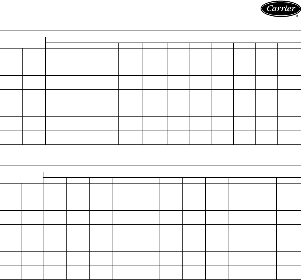
CONDENSING UNIT CIRCUIT AND MODULE RATINGS — SI (cont)
38AH074 CIRCUIT A
SST
(C) Air Temperature Entering Condenser (C)
21 27 30 32 35 38 41 43 46 49 52
−2 TCG 78.6 73.2 70.5 68.6 65.8 63.0 60.1 58.2 55.3 52.4 49.5
CMP 18.8 20.4 21.1 21.5 22.1 22.7 23.1 23.4 23.8 24.1 24.3
SDT 33.9 39.7 42.7 44.6 47.6 50.5 53.5 55.5 58.5 61.4 64.4
0TCG 84.7 79.1 76.3 74.4 71.5 68.6 65.6 63.6 60.6 57.6 54.5
CMP 19.3 20.9 21.7 22.2 22.9 23.5 24.1 24.4 24.9 25.3 25.6
SDT 34.4 40.1 43.0 44.8 47.7 50.7 53.6 55.5 58.5 61.4 64.4
2TCG 91.1 85.3 82.3 80.3 77.4 74.3 71.3 69.3 66.2 63.1 59.9
CMP 19.7 21.5 22.4 22.9 23.7 24.4 25.0 25.4 25.9 26.4 26.8
SDT 35.0 40.7 43.5 45.4 48.2 51.1 53.9 55.9 58.7 61.6 64.6
4TCG 97.6 91.5 88.5 86.4 83.4 80.2 77.1 75.0 71.8 68.6 65.4
CMP 20.2 22.1 23.0 23.6 24.4 25.2 25.9 26.3 27.0 27.5 28.0
SDT 35.7 41.3 44.1 46.0 48.8 51.6 54.4 56.3 59.1 61.9 64.8
6TCG 104.0 98.1 94.9 92.8 89.6 86.3 83.1 80.9 77.6 74.3 70.9
CMP 20.6 22.7 23.7 24.3 25.2 26.1 26.8 27.3 28.0 28.6 29.2
SDT 36.4 42.0 44.8 46.6 49.4 52.2 55.0 56.9 59.6 62.4 65.3
8TCG 112.0 105.0 102.0 99.4 96.0 92.6 89.2 87.0 83.5 80.1 76.6*
CMP 21.0 23.3 24.4 25.0 26.0 26.9 27.8 28.3 29.1 29.8 30.4*
SDT 37.2 42.7 45.5 47.4 50.2 52.9 55.7 57.5 60.3 63.0 65.8*
10 TCG 119.0 112.0 108.0 106.0 103.0 99.1 95.5 93.1 89.6 86.0 82.4*
CMP 21.4 23.9 25.0 25.7 26.8 27.8 28.7 29.3 30.1 30.9 31.6*
SDT 38.0 43.5 46.3 48.1 50.9 53.6 56.4 58.2 61.0 63.7 66.4*
38AH084 CIRCUIT A
SST
(C) Air Temperature Entering Condenser (C)
21 27 30 32 35 38 41 43 46 49 52
−2 TCG 102.0 95.0 91.7 89.4 86.1 82.8 79.5 77.4 74.2 71.0 67.8*
CMP 27.2 29.1 29.9 30.4 31.2 31.8 32.5 32.9 33.4 33.9 34.4*
SDT 36.7 42.7 45.7 47.7 50.7 53.6 56.7 58.7 61.7 64.7 67.7*
0TCG 110.0 103.0 99.2 96.8 93.3 89.8 86.3 84.0 80.6 77.2 73.8*
CMP 28.0 30.0 30.9 31.5 32.3 33.1 33.8 34.2 34.9 35.5 36.0*
SDT 36.8 42.8 45.8 47.8 50.8 53.7 56.7 58.7 61.7 64.7 67.7*
2TCG 119.0 111.0 107.0 105.0 101.0 97.4 93.7 91.3 87.6 84.0 80.4*
CMP 28.7 30.9 31.9 32.6 33.5 34.3 35.1 35.6 36.3 37.0 37.6*
SDT 37.1 43.0 46.0 48.0 50.9 53.9 56.9 58.9 61.9 64.8 67.8*
4TCG 128.0 120.0 116.0 113.0 109.0 105.0 101.0 98.7 94.8 91.0 87.2*
CMP 29.4 31.8 32.9 33.6 34.6 35.6 36.5 37.0 37.8 38.6 39.2*
SDT 37.5 43.3 46.2 48.2 51.2 54.1 57.1 59.1 62.0 65.0 67.9*
6TCG 137.0 129.0 125.0 122.0 118.0 113.0 109.0 107.0 102.0 98.3 94.3*
CMP 30.2 32.7 33.9 34.7 35.8 36.8 37.8 38.4 39.3 40.1 40.9*
SDT 38.0 43.8 46.7 48.6 51.5 54.5 57.4 59.4 62.3 65.2 68.2*
8TCG 147.0 138.0 134.0 131.0 126.0 122.0 118.0 115.0 110.0 106.0 102.0*
CMP 31.0 33.7 35.0 35.8 37.0 38.1 39.1 39.8 40.8 41.7 42.5*
SDT 38.7 44.4 47.3 49.2 52.0 54.9 57.8 59.8 62.7 65.6 68.5*
10 TCG 157.0 147.0 143.0 140.0 135.0 130.0 126.0 123.0 118.0 114.0* 109.0*
CMP 31.8 34.7 36.0 36.9 38.2 39.4 40.5 41.2 42.3 43.3* 44.2*
SDT 39.5 45.1 47.9 49.8 52.6 55.5 58.3 60.3 63.1 66.0* 68.9*
LEGEND
CMP — Compressor Power, kW
SDT — Saturated Discharge Temperature (leaving compressor) (C)
SST — Saturated Suction Temperature (entering condensing unit)
TCG — Total Cooling Capacity, Gross (kW)
*May require replacement of the high-pressure cutout switches with switches of a
higher setting.
NOTES:
1. Ratings are based on 8.3 C superheat and use of R-22 refrigerant.
2. Ratings include suction line losses due to an accumulator.
67

Performance data — 38AH044-134 (cont)
CONDENSING UNIT CIRCUIT AND MODULE RATINGS — SI (cont)
38AH074 CIRCUIT B
SST
(C) Air Temperature Entering Condenser (C)
21 27 30 32 35 38 41 43 46 49 52
−2 TCG 103.0 96.0 92.7 90.5 87.3 84.1 80.9 78.8 75.7 72.6 69.4
CMP 26.4 28.3 29.1 29.6 30.4 31.1 31.8 32.2 32.8 33.3 33.8
SDT 34.2 39.9 42.8 44.7 47.6 50.5 53.4 55.3 58.2 61.2 64.1
0TCG 110.0 103.0 99.8 97.5 94.1 90.7 87.4 85.2 81.9 78.6 75.3
CMP 27.2 29.3 30.2 30.8 31.6 32.4 33.1 33.5 34.2 34.8 35.4
SDT 34.8 40.5 43.3 45.2 48.0 50.9 53.7 55.7 58.5 61.4 64.3
2TCG 118.0 111.0 107.0 105.0 101.0 97.8 94.2 91.9 88.4 85.0 81.5
CMP 28.1 30.3 31.3 31.9 32.8 33.7 34.5 35.0 35.7 36.4 37.0
SDT 35.6 41.2 44.0 45.9 48.7 51.5 54.3 56.2 59.1 61.9 64.8
4TCG 127.0 119.0 115.0 113.0 109.0 105.0 101.0 98.8 95.1 91.5 87.8
CMP 28.9 31.3 32.4 33.1 34.0 35.0 35.8 36.4 37.2 37.9 38.6
SDT 36.3 41.9 44.7 46.6 49.4 52.2 55.0 56.9 59.7 62.5 65.3
6TCG 135.0 127.0 123.0 120.0 116.0 112.0 109.0 106.0 102.0 98.2 94.4
CMP 29.8 32.3 33.5 34.2 35.3 36.3 37.2 37.8 38.7 39.5 40.3
SDT 37.1 42.7 45.5 47.4 50.2 52.9 55.7 57.6 60.4 63.1 65.9
8TCG 145.0 136.0 132.0 129.0 125.0 120.0 116.0 113.0 109.0 105.0 101.0*
CMP 30.6 33.3 34.6 35.4 36.6 37.6 38.7 39.3 40.3 41.2 42.0*
SDT 38.0 43.6 46.3 48.2 51.0 53.7 56.5 58.3 61.1 63.9 66.6*
10 TCG 154.0 145.0 140.0 137.0 133.0 128.0 124.0 121.0 117.0 112.0 108.0*
CMP 31.4 34.4 35.7 36.6 37.8 39.0 40.1 40.8 41.8 42.8 43.7*
SDT 38.9 44.4 47.2 49.0 51.8 54.5 57.3 59.1 61.9 64.6 67.4*
38AH084 CIRCUIT B
SST
(C) Air Temperature Entering Condenser (C)
21 27 30 32 35 38 41 43 46 49 52
−2 TCG 102.0 95.6 92.2 89.9 86.6 83.3 80.1 77.9 74.7 71.5 68.4*
CMP 26.9 28.8 29.6 30.2 30.9 31.6 32.3 32.6 33.2 33.8 34.2*
SDT 35.7 41.6 44.6 46.6 49.6 52.6 55.6 57.6 60.6 63.6 66.6*
0TCG 111.0 103.0 99.7 97.4 93.8 90.3 86.9 84.6 81.1 77.7 74.4*
CMP 27.6 29.7 30.6 31.2 32.1 32.8 33.5 34.0 34.7 35.3 35.8*
SDT 35.8 41.8 44.7 46.7 49.7 52.7 55.6 57.6 60.6 63.6 66.6*
2TCG 119.0 112.0 108.0 105.0 102.0 97.9 94.2 91.8 88.1 84.5 80.8*
CMP 28.3 30.6 31.6 32.3 33.2 34.0 34.8 35.3 36.1 36.8 37.4*
SDT 36.2 42.1 45.0 47.0 49.9 52.9 55.8 57.8 60.8 63.7 66.7*
4TCG 128.0 120.0 116.0 113.0 110.0 106.0 102.0 99.2 95.3 91.5 87.7*
CMP 29.1 31.5 32.6 33.3 34.3 35.3 36.2 36.7 37.5 38.3 39.0*
SDT 36.7 42.5 45.4 47.3 50.2 53.1 56.1 58.1 61.0 63.9 66.9*
6TCG 137.0 129.0 125.0 122.0 118.0 114.0 110.0 107.0 103.0 98.7 94.7*
CMP 29.8 32.4 33.6 34.4 35.5 36.5 37.5 38.1 39.0 39.8 40.6*
SDT 37.3 43.0 45.9 47.8 50.7 53.6 56.5 58.4 61.4 64.3 67.2*
8TCG 147.0 138.0 134.0 131.0 126.0 122.0 118.0 115.0 111.0 106.0 102.0*
CMP 30.6 33.4 34.7 35.5 36.7 37.8 38.9 39.5 40.5 41.4 42.3*
SDT 38.1 43.7 46.5 48.4 51.3 54.1 57.0 58.9 61.8 64.7 67.6*
10 TCG 157.0 147.0 143.0 140.0 135.0 131.0 126.0 123.0 118.0 114.0 110.0*
CMP 31.4 34.4 35.7 36.6 37.9 39.1 40.2 40.9 42.0 43.0 43.9*
SDT 38.9 44.5 47.3 49.1 51.9 54.8 57.6 59.5 62.3 65.2 68.1*
LEGEND
CMP — Compressor Power, kW
SDT — Saturated Discharge Temperature (leaving compressor) (C)
SST — Saturated Suction Temperature (entering condensing unit)
TCG — Total Cooling Capacity, Gross (kW)
*May require replacement of the high-pressure cutout switches with switches of a
higher setting.
NOTES:
1. Ratings are based on 8.3 C superheat and use of R-22 refrigerant.
2. Ratings include suction line losses due to an accumulator.
68
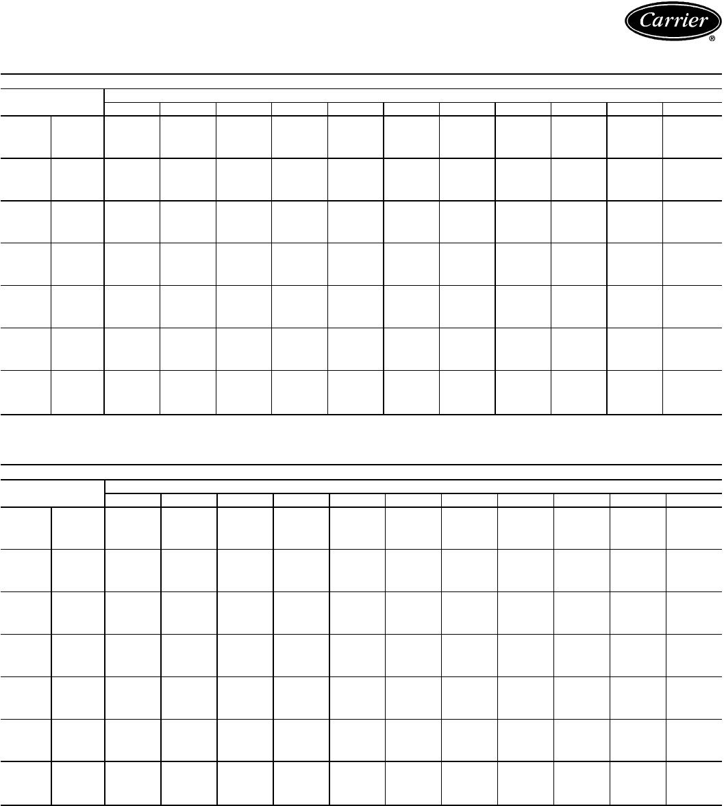
CONDENSING UNIT CIRCUIT AND MODULE RATINGS — SI (cont)
38AH094 CIRCUIT A
SST
(C) Air Temperature Entering Condenser (C)
21 27 30 32 35 38 41 43 46 49 52
−2
TCG 130.0 120.0 116.0 112.0 108.0 103.0 97.6 94.2 89.1 84.0 78.8
CMP 31.8 34.2 35.3 36.0 37.0 37.8 38.5 38.9 39.4 39.8 40.0
SDT 35.5 41.2 44.0 45.9 48.8 51.6 54.5 56.5 59.4 62.3 65.3
SCT 33.6 39.7 42.8 44.8 47.8 50.8 53.9 55.9 58.9 61.9 64.9
0
TCG 140.0 130.0 125.0 122.0 117.0 112.0 107.0 103.0 97.9 92.6 87.3
CMP 32.7 35.3 36.6 37.3 38.4 39.4 40.2 40.7 41.4 41.9 42.3
SDT 36.2 41.8 44.5 46.4 49.2 52.0 54.9 56.8 59.6 62.5 65.4
SCT 34.0 40.1 43.1 45.1 48.1 51.1 54.1 56.0 59.0 62.0 64.9
2
TCG 150.0 140.0 135.0 131.0 126.0 121.0 116.0 112.0 107.0 101.0 96.0
CMP 33.7 36.5 37.9 38.7 39.9 40.9 41.9 42.5 43.3 43.9 44.5
SDT 37.1 42.6 45.3 47.2 49.9 52.7 55.5 57.4 60.2 63.0 65.8
SCT 34.6 40.6 43.7 45.7 48.6 51.6 54.5 56.5 59.4 62.3 65.3
4
TCG 161.0 150.0 145.0 141.0 136.0 131.0 125.0 122.0 116.0 110.0 105.0
CMP 34.7 37.7 39.2 40.1 41.4 42.5 43.6 44.3 45.2 46.0 46.7
SDT 38.0 43.5 46.2 48.0 50.7 53.4 56.2 58.0 60.8 63.5 66.3
SCT 35.2 41.2 44.3 46.3 49.2 52.1 55.0 57.0 59.9 62.7 65.6
6
TCG 172.0 161.0 155.0 152.0 146.0 140.0 135.0 131.0 125.0 120.0 114.0
CMP 35.7 38.9 40.5 41.5 42.9 44.2 45.4 46.1 47.1 48.1 48.9
SDT 39.0 44.4 47.1 48.9 51.6 54.3 57.0 58.8 61.5 64.2 66.9
SCT 35.8 41.9 44.9 46.9 49.9 52.8 55.7 57.6 60.5 63.3 66.2
8
TCG 183.0 172.0 166.0 162.0 156.0 151.0 145.0 141.0 135.0 129.0 123.0
CMP 36.7 40.1 41.8 42.9 44.4 45.8 47.1 47.9 49.1 50.1 51.1
SDT 40.1 45.4 48.0 49.8 52.5 55.2 57.9 59.6 62.3 65.0 67.7
SCT 36.5 42.6 45.6 47.6 50.6 53.5 56.4 58.3 61.1 64.0 66.8
10
TCG 195.0 183.0 177.0 173.0 167.0 161.0 155.0 151.0 145.0 139.0 132.0
CMP 37.7 41.3 43.1 44.3 45.9 47.4 48.9 49.8 51.0 52.2 53.3
SDT 41.1 46.4 49.1 50.8 53.5 56.2 58.8 60.5 63.2 65.9 68.5*
SCT 37.2 43.3 46.4 48.4 51.3 54.2 57.1 59.0 61.8 64.7 67.5
38AH104 CIRCUIT A
SST
(C) Air Temperature Entering Condenser (C)
21 27 30 32 35 38 41 43 46 49 52
−2
TCG 124.0 115.0 110.0 107.0 102.0 97.3 92.6 89.4 84.7 80.0 75.3
CMP 28.9 31.2 32.4 33.1 34.0 34.9 35.7 36.2 36.8 37.3 37.7
SDT 34.4 40.0 42.8 44.7 47.5 50.4 53.3 55.2 58.1 61.1 64.0
SCT 32.6 38.6 41.7 43.7 46.7 49.7 52.7 54.6 57.7 60.7 63.7
0
TCG 134.0 124.0 119.0 116.0 111.0 106.0 101.0 97.8 92.8 88.0 83.1
CMP 29.8 32.3 33.5 34.3 35.3 36.3 37.2 37.8 38.5 39.2 39.7
SDT 35.1 40.6 43.4 45.2 48.0 50.8 53.6 55.5 58.4 61.3 64.1
SCT 33.1 39.1 42.1 44.0 47.0 49.9 52.9 54.9 57.8 60.8 63.7
2
TCG 144.0 134.0 128.0 125.0 120.0 115.0 110.0 106.0 101.0 96.3 91.2
CMP 30.7 33.4 34.7 35.5 36.7 37.7 38.8 39.4 40.2 41.0 41.7
SDT 36.0 41.4 44.1 46.0 48.7 51.5 54.3 56.1 58.9 61.7 64.6
SCT 33.6 39.6 42.6 44.6 47.5 50.4 53.3 55.3 58.2 61.1 64.0
4
TCG 154.0 144.0 138.0 135.0 129.0 124.0 119.0 115.0 110.0 105.0 99.4
CMP 31.5 34.4 35.9 36.7 38.0 39.2 40.3 41.0 42.0 42.8 43.6
SDT 36.9 42.3 44.9 46.7 49.5 52.2 54.9 56.7 59.5 62.3 65.1
SCT 34.2 40.2 43.2 45.1 48.1 51.0 53.9 55.8 58.7 61.5 64.4
6
TCG 165.0 154.0 148.0 145.0 139.0 134.0 128.0 124.0 119.0 113.0 108.0
CMP 32.4 35.5 37.1 38.0 39.4 40.7 41.9 42.6 43.7 44.7 45.6
SDT 37.9 43.2 45.8 47.6 50.3 53.0 55.7 57.5 60.2 63.0 65.7
SCT 34.8 40.8 43.8 45.8 48.7 51.6 54.5 56.4 59.2 62.1 64.9
8
TCG 176.0 165.0 159.0 155.0 149.0 143.0 138.0 134.0 128.0 122.0 117.0
CMP 33.3 36.6 38.3 39.3 40.7 42.1 43.4 44.3 45.5 46.5 47.5
SDT 38.9 44.1 46.8 48.6 51.2 53.9 56.6 58.4 61.0 63.7 66.4
SCT 35.5 41.5 44.5 46.5 49.4 52.3 55.1 57.1 59.9 62.7 65.5
10
TCG 188.0 176.0 170.0 166.0 160.0 154.0 147.0 143.0 137.0 132.0 126.0
CMP 34.3 37.7 39.5 40.6 42.1 43.6 45.0 45.9 47.2 48.4 49.5
SDT 39.9 45.2 47.8 49.5 52.2 54.8 57.4 59.2 61.9 64.5 67.2
SCT 36.2 42.2 45.2 47.2 50.1 53.0 55.8 57.8 60.6 63.4 66.2
LEGEND
CMP — Compressor Power, kW
SCT — Saturated Condensing Temperature (C)
SDT — Saturated Discharge Temperature (leaving compressor) (C)
SST — Saturated Suction Temperature (entering condensing unit)
TCG — Total Cooling Capacity, Gross (kW)
*May require replacement of the high-pressure cutout switches with switches of a
higher setting.
NOTES:
1. Ratings are based on 8.3 C superheat and use of R-22 refrigerant.
2. Ratings include suction line losses due to an accumulator.
69

Performance data — 38AH044-134 (cont)
CONDENSING UNIT CIRCUIT AND MODULE RATINGS — SI (cont)
38AH094 CIRCUIT B
SST
(C) Air Temperature Entering Condenser (C)
21 27 30 32 35 38 41 43 46 49 52
−2
TCG 103.0 96.5 93.1 90.9 87.6 84.3 81.1 78.9 75.7 72.5 69.4
CMP 26.3 28.1 29.0 29.6 30.4 31.1 31.8 32.2 32.8 33.4 33.9
SDT 33.8 39.6 42.5 44.5 47.4 50.4 53.4 55.4 58.3 61.3 64.3
SCT 32.3 38.5 41.5 43.6 46.7 49.7 52.8 54.8 57.9 60.9 63.9
0
TCG 111.0 104.0 101.0 98.2 94.7 91.3 87.8 85.5 82.1 78.8 75.4
CMP 27.0 29.0 30.0 30.6 31.5 32.3 33.1 33.5 34.2 34.8 35.4
SDT 34.2 39.9 42.8 44.8 47.7 50.6 53.5 55.5 58.4 61.4 64.4
SCT 32.4 38.6 41.7 43.7 46.8 49.8 52.8 54.8 57.9 60.9 63.9
2
TCG 119.0 112.0 108.0 106.0 102.0 98.6 95.0 92.6 89.0 85.4 81.9
CMP 27.8 30.0 31.0 31.7 32.6 33.5 34.3 34.9 35.6 36.3 37.0
SDT 34.9 40.5 43.4 45.3 48.2 51.0 53.9 55.9 58.8 61.7 64.6
SCT 32.8 39.0 42.0 44.0 47.1 50.1 53.1 55.1 58.1 61.1 64.1
4
TCG 128.0 120.0 116.0 114.0 110.0 106.0 102.0 99.7 95.9 92.2 88.4
CMP 28.6 30.9 32.1 32.8 33.8 34.7 35.7 36.2 37.1 37.8 38.5
SDT 35.6 41.2 44.0 45.9 48.7 51.5 54.4 56.3 59.2 62.1 65.0
SCT 33.3 39.4 42.4 44.4 47.4 50.4 53.4 55.4 58.4 61.3 64.3
6
TCG 137.0 129.0 124.0 122.0 118.0 114.0 110.0 107.0 103.0 99.2 95.3
CMP 29.4 31.9 33.1 33.9 35.0 36.0 37.0 37.6 38.5 39.4 40.2
SDT 36.4 41.9 44.7 46.5 49.3 52.1 55.0 56.9 59.7 62.5 65.4
SCT 33.8 39.9 42.9 44.9 47.9 50.9 53.8 55.8 58.8 61.7 64.7
8
TCG 146.0 137.0 133.0 130.0 126.0 122.0 118.0 115.0 111.0 106.0 102.0
CMP 30.2 32.9 34.2 35.0 36.2 37.3 38.4 39.1 40.0 40.9 41.8
SDT 37.3 42.7 45.5 47.3 50.1 52.9 55.7 57.5 60.3 63.1 66.0
SCT 34.3 40.4 43.5 45.5 48.4 51.4 54.4 56.3 59.3 62.2 65.1
10
TCG 155.0 146.0 142.0 139.0 134.0 130.0 126.0 123.0 118.0 114.0 110.0
CMP 31.0 33.9 35.3 36.2 37.4 38.6 39.8 40.5 41.5 42.5 43.5
SDT 38.2 43.6 46.3 48.2 50.9 53.7 56.4 58.3 61.0 63.8 66.6
SCT 34.9 41.0 44.1 46.1 49.0 52.0 54.9 56.9 59.8 62.7 65.6
38AH104 CIRCUIT B
SST
(C) Air Temperature Entering Condenser (C)
21 27 30 32 35 38 41 43 46 49 52
−2
TCG 141.0 130.0 125.0 122.0 117.0 112.0 107.0 103.0 98.4 93.6 88.9
CMP 33.9 36.5 37.7 38.5 39.6 40.6 41.5 42.1 42.9 43.7 44.4
SDT 35.7 41.2 43.9 45.8 48.6 51.4 54.3 56.2 59.1 61.9 64.9
SCT 33.5 39.5 42.6 44.5 47.5 50.5 53.5 55.5 58.5 61.4 64.4
0
TCG 151.0 140.0 135.0 131.0 126.0 121.0 116.0 112.0 107.0 102.0 97.0
CMP 35.1 37.8 39.1 40.0 41.2 42.3 43.3 44.0 44.9 45.7 46.5
SDT 36.5 41.9 44.7 46.5 49.2 52.0 54.8 56.7 59.5 62.3 65.2
SCT 34.0 40.0 43.1 45.0 48.0 50.9 53.9 55.8 58.8 61.7 64.6
2
TCG 163.0 151.0 145.0 142.0 136.0 131.0 125.0 122.0 116.0 111.0 106.0
CMP 36.2 39.2 40.6 41.5 42.8 44.0 45.2 45.9 46.9 47.8 48.7
SDT 37.5 42.9 45.5 47.3 50.0 52.8 55.5 57.4 60.1 62.9 65.7
SCT 34.7 40.7 43.7 45.7 48.6 51.5 54.4 56.4 59.3 62.2 65.1
4
TCG 174.0 162.0 156.0 152.0 146.0 141.0 135.0 131.0 125.0 120.0 114.0
CMP 37.4 40.6 42.1 43.1 44.5 45.8 47.0 47.8 48.9 50.0 50.9
SDT 38.5 43.8 46.4 48.2 50.9 53.6 56.3 58.1 60.8 63.6 66.3
SCT 35.3 41.4 44.4 46.3 49.3 52.2 55.1 57.0 59.8 62.7 65.6
6
TCG 186.0 174.0 168.0 163.0 157.0 151.0 145.0 141.0 135.0 129.0 123.0
CMP 38.6 42.0 43.6 44.7 46.2 47.6 48.9 49.8 51.0 52.1 53.2
SDT 39.6 44.8 47.4 49.2 51.8 54.5 57.2 59.0 61.7 64.4 67.1
SCT 36.0 42.1 45.1 47.1 50.0 52.9 55.7 57.7 60.5 63.4 66.2
8
TCG 199.0 186.0 179.0 175.0 168.0 162.0 156.0 151.0 145.0 139.0 133.0
CMP 39.8 43.4 45.2 46.3 47.9 49.4 50.9 51.8 53.1 54.3 55.5
SDT 40.7 45.9 48.5 50.2 52.8 55.5 58.1 59.9 62.6 65.2 67.9
SCT 36.7 42.8 45.8 47.8 50.7 53.6 56.5 58.4 61.2 64.1 66.9
10
TCG 212.0 198.0 191.0 187.0 180.0 173.0 166.0 162.0 155.0 149.0 142.0
CMP 41.1 44.9 46.8 47.9 49.6 51.3 52.8 53.8 55.2 56.6 57.9
SDT 41.9 47.0 49.5 51.3 53.9 56.5 59.1 60.8 63.5 66.1 68.7*
SCT 37.5 43.6 46.6 48.6 51.5 54.4 57.3 59.2 62.0 64.8 67.6
LEGEND
CMP — Compressor Power, kW
SCT — Saturated Condensing Temperature (C)
SDT — Saturated Discharge Temperature (leaving compressor) (C)
SST — Saturated Suction Temperature (entering condensing unit)
TCG — Total Cooling Capacity, Gross (kW)
*May require replacement of the high-pressure cutout switches with switches of a
higher setting.
NOTES:
1. Ratings are based on 8.3 C superheat and use of R-22 refrigerant.
2. Ratings include suction line losses due to an accumulator.
70

CONDENSING UNIT CIRCUIT AND MODULE RATINGS — SI (cont)
38AH124 MODULE 124A OR 124B; 38AH134 MODULE 134A
SST
(C) Air Temperature Entering Condenser (C)
21 27 30 32 35 38 41 43 46 49 52
−2
TCG 149.0 138.0 132.0 129.0 123.0 118.0 112.0 109.0 103.0 97.8 92.5
CMP 35.7 38.6 40.0 40.8 42.0 43.1 44.0 44.5 45.4 46.0 46.6
SDT 34.7 40.5 43.4 45.4 48.3 51.3 54.2 56.2 59.1 62.1 65.1
SCT 33.9 39.9 42.9 44.9 47.9 50.9 53.8 55.9 58.9 61.9 64.8
0
TCG 161.0 149.0 143.0 140.0 134.0 128.0 122.0 119.0 113.0 107.0 102.0
CMP 36.7 39.8 41.3 42.2 43.6 44.7 45.8 46.4 47.4 48.2 48.9
SDT 35.2 40.9 43.8 45.8 48.7 51.6 54.4 56.4 59.4 62.3 65.2
SCT 34.3 40.2 43.2 45.2 48.1 51.1 54.0 56.0 59.0 62.0 65.0
2
TCG 173.0 161.0 155.0 151.0 145.0 139.0 133.0 129.0 123.0 117.0 111.0
CMP 37.6 41.0 42.6 43.7 45.1 46.4 47.6 48.4 49.5 50.4 51.2
SDT 35.8 41.5 44.4 46.3 49.2 52.0 54.9 56.8 59.7 62.7 65.6
SCT 34.7 40.7 43.6 45.6 48.5 51.5 54.4 56.4 59.3 62.3 65.2
4
TCG 186.0 174.0 167.0 163.0 157.0 150.0 144.0 140.0 134.0 127.0 121.0
CMP 38.5 42.1 44.0 45.1 46.6 48.1 49.5 50.3 51.5 52.6 53.5
SDT 36.5 42.1 45.0 46.9 49.7 52.6 55.4 57.3 60.2 63.1 65.9
SCT 35.3 41.2 44.1 46.1 49.0 51.9 54.8 56.8 59.7 62.6 65.5
6
TCG 200.0 186.0 180.0 175.0 169.0 162.0 155.0 151.0 145.0 138.0 132.0
CMP 39.4 43.3 45.3 46.5 48.2 49.8 51.3 52.2 53.6 54.8 55.9
SDT 37.2 42.9 45.7 47.6 50.4 53.2 56.0 57.9 60.7 63.6 66.4
SCT 35.9 41.8 44.7 46.6 49.5 52.5 55.4 57.3 60.2 63.1 66.0
8
TCG 214.0 200.0 193.0 188.0 181.0 174.0 167.0 163.0 156.0 149.0 142.0
CMP 40.3 44.6 46.6 47.9 49.8 51.5 53.1 54.1 55.6 57.0 58.2
SDT 38.1 43.7 46.5 48.3 51.1 53.9 56.7 58.6 61.4 64.2 67.0
SCT 36.6 42.4 45.3 47.3 50.2 53.1 55.9 57.9 60.7 63.6 66.5
10
TCG 228.0 213.0 206.0 201.0 194.0 187.0 179.0 175.0 167.0 160.0 153.0
CMP 41.3 45.8 48.0 49.4 51.3 53.2 55.0 56.1 57.7 59.2 60.6
SDT 39.0 44.5 47.3 49.1 51.9 54.7 57.4 59.3 62.1 64.8 67.6*
SCT 37.3 43.1 46.0 48.0 50.8 53.7 56.6 58.5 61.3 64.2 67.0
38AH134 MODULE 134B
SST
(C) Air Temperature Entering Condenser (C)
21 27 30 32 35 38 41 43 46 49 52
−2
TCG 181.0 169.0 163.0 159.0 153.0 147.0 141.0 137.0 131.0 125.0 119.0
CMP 45.2 48.6 50.1 51.1 52.5 53.8 54.9 55.6 56.6 57.4 58.2
SDT 34.0 39.8 42.7 44.6 47.5 50.4 53.4 55.4 58.3 61.3 64.3
SCT 31.9 37.7 40.7 42.6 45.5 48.5 51.4 53.4 56.3 59.3 62.2
0
TCG 195.0 182.0 176.0 172.0 166.0 159.0 153.0 149.0 143.0 136.0 130.0
CMP 46.5 50.2 51.8 52.9 54.4 55.8 57.1 57.9 59.1 60.1 61.0
SDT 34.5 40.2 43.1 45.0 47.8 50.7 53.6 55.5 58.4 61.4 64.3
SCT 32.4 38.2 41.2 43.1 46.0 48.9 51.7 53.6 56.5 59.4 62.4
2
TCG 210.0 196.0 190.0 185.0 179.0 172.0 166.0 161.0 155.0 148.0 142.0
CMP 47.8 51.8 53.6 54.8 56.4 58.0 59.4 60.3 61.6 62.7 63.7
SDT 35.2 40.9 43.7 45.6 48.4 51.3 54.1 56.0 58.9 61.8 64.6
SCT 33.0 38.8 41.7 43.7 46.5 49.4 52.3 54.2 57.0 59.9 62.7
4
TCG 224.0 211.0 204.0 199.0 192.0 185.0 179.0 174.0 167.0 160.0 153.0
CMP 49.0 53.4 55.4 56.6 58.5 60.1 61.7 62.7 64.1 65.4 66.6
SDT 36.0 41.6 44.4 46.3 49.1 51.9 54.7 56.5 59.3 62.2 65.0
SCT 33.6 39.5 42.3 44.3 47.1 50.0 52.8 54.7 57.5 60.3 63.1
6
TCG 240.0 226.0 218.0 213.0 206.0 199.0 192.0 187.0 180.0 173.0 165.0
CMP 50.3 55.0 57.1 58.5 60.5 62.3 64.1 65.1 66.7 68.1 69.4
SDT 36.7 42.3 45.1 47.0 49.8 52.6 55.3 57.2 60.0 62.8 65.5
SCT 34.3 40.1 43.0 44.9 47.7 50.6 53.4 55.3 58.1 60.9 63.7
8
TCG 256.0 241.0 233.0 228.0 221.0 213.0 206.0 201.0 193.0 186.0 178.0
CMP 51.5 56.6 58.9 60.4 62.5 64.5 66.4 67.6 69.3 70.9 72.4
SDT 37.6 43.1 45.9 47.8 50.5 53.3 56.1 57.9 60.7 63.4 66.2
SCT 34.9 40.7 43.6 45.5 48.4 51.2 54.0 55.9 58.7 61.5 64.2
10
TCG 273.0 257.0 249.0 244.0 236.0 228.0 220.0 215.0 207.0 199.0 191.0
CMP 52.8 58.2 60.7 62.2 64.6 66.7 68.8 70.0 71.9 73.7 75.3
SDT 38.4 44.0 46.7 48.6 51.3 54.1 56.8 58.7 61.4 64.2 66.9
SCT 35.6 41.4 44.3 46.2 49.0 51.8 54.7 56.5 59.3 62.1 64.8
LEGEND
CMP — Compressor Power, kW
SCT — Saturated Condensing Temperature (C)
SDT — Saturated Discharge Temperature (leaving compressor) (C)
SST — Saturated Suction Temperature (entering condensing unit)
TCG — Total Cooling Capacity, Gross (kW)
*May require replacement of the high-pressure cutout switches with switches of a
higher setting.
NOTES:
1. Ratings are based on 8.3 C superheat and use of R-22 refrigerant.
2. Ratings include suction line losses due to an accumulator.
71
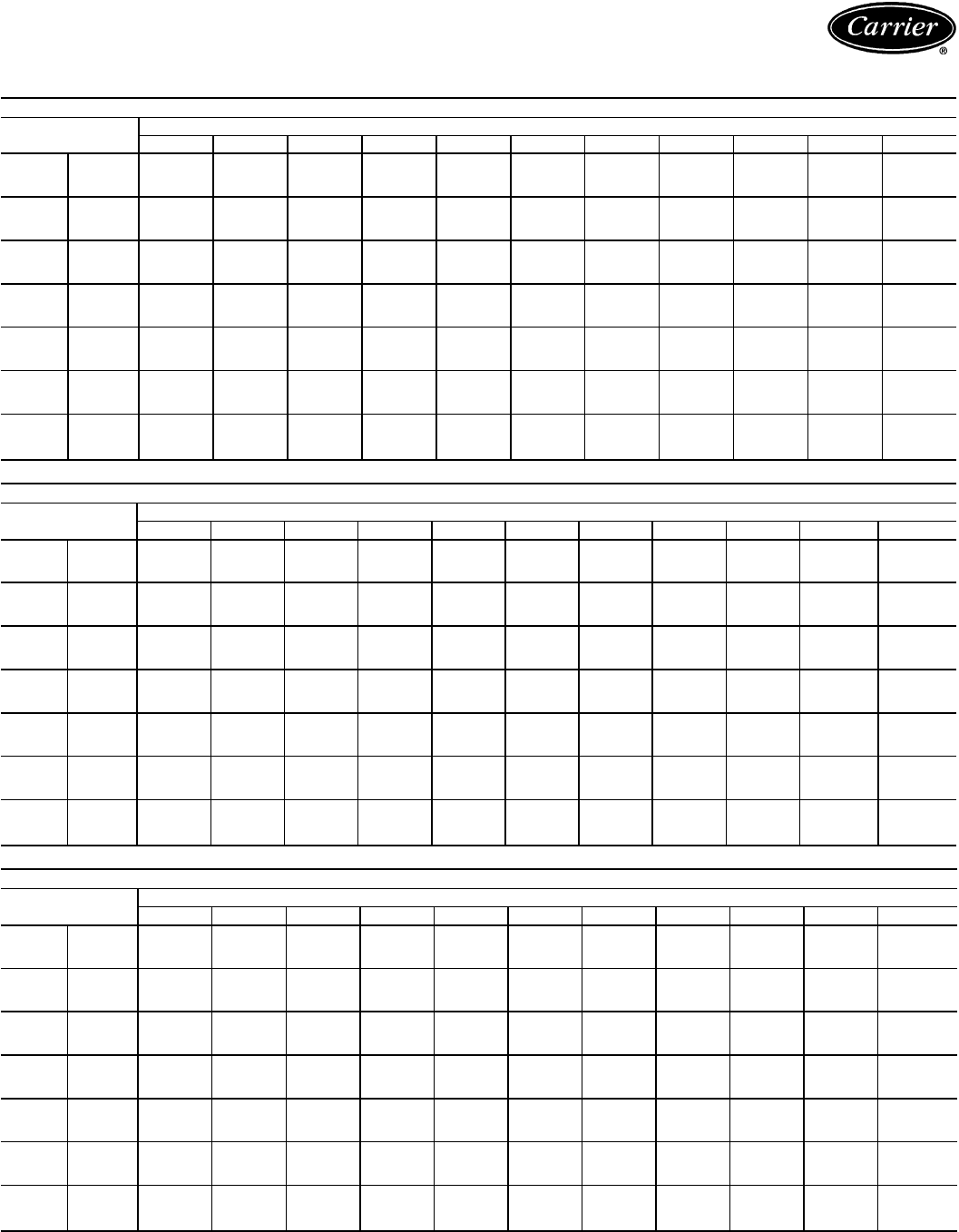
Performance data — 38AH044-134 (cont)
CONDENSING UNIT RATINGS — ENGLISH
38AH044
SST
(F) Air Temperature Entering Condenser (F)
70 80 85 90 95 100 105 110 115 120 125
20 TCG 293.0 268.0 255.0 242.0 230.0 216.0 202.0 189.3 175.9 162.6 149.1
CMP 22.9 24.4 25.1 25.8 26.2 26.6 26.9 27.0 27.1 27.0 26.7
SDT 91.0 102.0 106.0 111.0 116.0 121.0 125.5 131.0 135.5 140.5 145.5
25 TCG 332.0 305.0 292.0 279.0 265.0 251.0 238.0 224.0 210.0 195.1 180.8
CMP 23.7 25.5 26.3 27.1 27.8 28.4 28.8 29.1 29.4 29.6 29.5
SDT 91.6 101.5 106.5 111.5 116.0 121.0 126.0 131.0 136.0 141.0 146.0
30 TCG 373.0 345.0 331.0 317.0 303.0 289.0 274.0 259.0 244.0 230.0 214.0
CMP 24.4 26.5 27.5 28.4 29.2 30.0 30.6 31.1 31.6 31.9 32.1
SDT 92.4 102.0 107.0 112.0 116.5 121.5 126.5 131.5 136.5 141.0 146.0
35 TCG 416.0 387.0 372.0 357.0 342.0 328.0 312.0 297.0 281.0 265.0 250.0
CMP 25.1 27.5 28.6 29.6 30.6 31.4 32.3 33.0 33.6 34.1 34.5
SDT 93.6 103.5 108.0 113.0 118.0 122.5 127.0 132.5 136.5 141.5 146.5
40 TCG 462.0 431.0 415.0 400.0 384.0 368.0 351.0 336.0 320.0 303.0 287.0
CMP 25.8 28.4 29.7 30.9 31.9 33.0 34.0 34.8 35.6 36.3 36.9
SDT 94.9 104.5 109.5 113.5 118.5 123.5 128.0 133.0 138.0 142.5 147.5
45 TCG 509.0 477.0 460.0 444.0 427.0 411.0 394.0 376.0 359.0 343.0 325.0
CMP 26.4 29.3 30.6 32.0 33.2 34.4 35.5 36.5 37.5 38.4 39.2
SDT 96.4 106.0 111.0 115.0 120.0 124.5 129.5 134.5 139.0 144.0 148.5
50 TCG 560.0 525.0 508.0 491.0 473.0 455.0 438.0 419.0 401.0 384.0 366.0
CMP 27.0 30.2 31.7 33.1 34.5 35.8 37.1 38.2 39.3 40.4 41.3
SDT 98.0 107.5 112.5 117.0 121.5 126.0 131.0 135.5 140.5 145.5 149.5
38AH054
SST
(F) Air Temperature Entering Condenser (F)
70 80 85 90 95 100 105 110 115 120 125
20 TCG 341.0 313.0 299.0 286.0 272.0 259.0 245.0 231.2 217.6 204.9 191.2*
CMP 27.8 29.5 30.2 30.9 31.5 32.0 32.4 32.6 32.9 33.0 33.0*
SDT 95.5 105.5 110.5 115.5 120.5 125.5 130.5 135.5 140.5 145.5 150.5*
25 TCG 387.0 357.0 342.0 327.0 312.0 297.0 282.0 268.0 253.0 239.2 225.1*
CMP 28.9 30.9 31.8 32.6 33.4 34.1 34.7 35.1 35.6 35.9 36.0*
SDT 96.0 105.5 110.5 115.5 120.5 125.5 130.5 135.5 140.5 145.5 150.5*
30 TCG 435.0 403.0 386.0 371.0 355.0 340.0 323.0 308.0 292.0 277.0 261.0*
CMP 29.9 32.3 33.3 34.3 35.3 36.1 36.8 37.4 38.0 38.5 38.9*
SDT 96.7 106.5 111.0 116.0 121.0 126.0 131.0 136.0 141.0 145.5 150.5*
35 TCG 485.0 451.0 434.0 417.0 401.0 384.0 367.0 350.0 333.0 316.0 300.0*
CMP 30.9 33.5 34.8 35.9 37.0 38.0 38.9 39.7 40.5 41.1 41.7*
SDT 97.7 107.0 112.0 117.0 121.5 126.5 131.5 136.5 141.0 146.0 151.0*
40 TCG 538.0 503.0 485.0 467.0 449.0 431.0 412.0 395.0 377.0 359.0 341.0*
CMP 31.9 34.8 36.1 37.5 38.7 39.9 41.0 41.9 42.9 43.7 44.5*
SDT 99.2 108.5 113.0 118.0 123.0 128.0 132.5 137.0 142.0 146.5 151.5*
45 TCG 593.0 555.0 537.0 518.0 499.0 480.0 461.0 442.0 423.0 403.0 385.0*
CMP 32.9 36.1 37.6 39.1 40.4 41.8 43.0 44.1 45.2 46.3 47.1*
SDT 100.9 110.0 114.5 119.5 124.0 128.5 133.5 138.5 143.0 148.0 153.0*
50 TCG 652.0 611.0 592.0 571.0 551.0 532.0 511.0 491.0 471.0 450.0* 431.0*
CMP 34.0 37.4 39.1 40.6 42.2 43.7 45.0 46.3 47.5 48.8* 49.8*
SDT 102.7 112.0 116.5 121.0 126.0 130.0 135.0 139.5 144.5 149.0* 153.5*
38AH064
SST
(F) Air Temperature Entering Condenser (F)
70 80 85 90 95 100 105 110 115 120 125
20 TCG 415.0 383.0 368.0 352.0 337.0 321.0 306.0 290.0 275.0 261.0 246.0
CMP 33.6 35.7 36.7 37.5 38.3 39.0 39.6 40.1 40.5 40.8 41.0
SDT 93.4 103.0 108.0 113.0 118.0 123.0 128.0 133.0 138.0 143.0 148.0
25 TCG 468.0 434.0 417.0 401.0 384.0 367.0 350.0 335.0 318.0 302.0 285.0
CMP 34.9 37.4 38.6 39.6 40.6 41.4 42.2 42.8 43.4 43.9 44.3
SDT 94.0 104.0 109.0 113.5 118.5 123.5 128.5 133.5 138.0 143.0 148.0
30 TCG 523.0 487.0 469.0 451.0 434.0 416.0 399.0 380.0 363.0 346.0 328.0
CMP 36.2 39.0 40.3 41.5 42.7 43.7 44.7 45.5 46.3 47.0 47.5
SDT 95.0 104.5 109.5 114.5 119.0 124.0 129.0 134.0 139.0 144.0 149.0
35 TCG 582.0 544.0 525.0 505.0 487.0 467.0 448.0 429.0 410.0 393.0 374.0
CMP 37.4 40.6 42.1 43.5 44.8 46.0 47.2 48.2 49.2 50.0 50.7
SDT 96.3 105.5 110.5 115.5 120.5 125.0 130.0 134.5 139.5 144.5 149.5
40 TCG 644.0 603.0 582.0 562.0 542.0 521.0 501.0 481.0 461.0 442.0 421.0*
CMP 38.7 42.2 43.9 45.5 47.0 48.3 49.6 50.8 52.0 53.0 54.0*
SDT 98.0 107.5 112.5 116.5 121.5 126.5 131.5 136.0 140.5 145.5 150.5*
45 TCG 708.0 664.0 642.0 620.0 600.0 578.0 556.0 535.0 514.0 493.0 471.0*
CMP 40.0 43.9 45.7 47.4 49.1 50.7 52.2 53.5 54.9 56.1 57.1*
SDT 100.0 109.0 114.0 118.5 123.5 128.0 132.5 137.5 142.5 146.6 151.5*
50 TCG 776.0 729.0 706.0 682.0 660.0 636.0 614.0 591.0 569.0 546.0 523.0*
CMP 41.2 45.5 47.5 49.4 51.3 53.0 54.7 56.2 57.7 59.1 60.3*
SDT 102.0 111.0 116.0 120.5 125.0 130.0 134.5 139.5 143.5 148.5 153.5*
LEGEND
CMP — Compressor Power, kW
SDT — Saturated Discharge Temperature (leaving compressor) (F)
SST — Saturated Suction Temperature (entering condensing unit)
TCG — Total Cooling Capacity, Gross (1000 Btuh)
*May require replacement of the high-pressure cutout switches with switches of a
higher setting.
NOTES:
1. Ratings are based on 15 F superheat and use of R-22 refrigerant.
2. Ratings include suction line losses due to an accumulator.
72
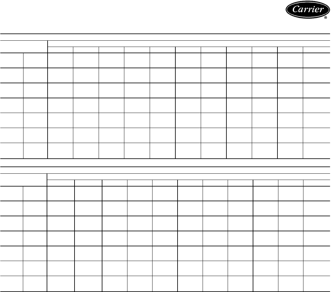
CONDENSING UNIT RATINGS ENGLISH (cont)
38AH074
SST
(F) Air Temperature Entering Condenser (F)
70 80 85 90 95 100 105 110 115 120 125
20 TCG 513.0 478.0 461.0 444.0 427.0 410.0 393.0 376.0 360.0 342.0 326.0
CMP 42.4 44.9 46.0 47.1 48.1 48.9 49.6 50.2 50.8 51.2 51.6
SDT 92.1 102.0 107.0 112.0 117.0 122.0 126.5 131.5 136.5 142.0 147.0
25 TCG 574.0 538.0 520.0 501.0 482.0 465.0 446.0 428.0 410.0 392.0 373.0
CMP 44.1 47.0 48.3 49.6 50.7 51.7 52.7 53.5 54.3 54.9 55.4
SDT 92.7 102.5 107.0 112.0 117.0 122.0 127.0 132.0 137.0 142.0 147.0
30 TCG 638.0 600.0 580.0 561.0 541.0 522.0 503.0 483.0 463.0 444.0 425.0
CMP 45.8 49.1 50.6 52.1 53.4 54.6 55.8 56.8 57.8 58.6 59.3
SDT 93.9 103.5 108.0 113.0 118.0 123.0 128.0 132.5 137.0 142.0 147.0
35 TCG 706.0 664.0 643.0 623.0 603.0 581.0 561.0 540.0 520.0 499.0 479.0
CMP 47.7 51.3 53.0 54.6 56.1 57.6 58.8 60.1 61.3 62.3 63.2
SDT 95.5 104.5 109.5 114.5 119.0 123.5 128.5 133.5 138.0 143.0 148.0
40 TCG 776.0 731.0 710.0 688.0 666.0 644.0 622.0 600.0 578.0 557.0 534.0
CMP 49.5 53.6 55.4 57.2 58.9 60.5 62.0 63.4 64.8 66.0 67.1
SDT 97.3 106.5 111.5 116.0 120.5 125.5 130.0 134.5 139.5 144.0 148.5
45 TCG 850.0 803.0 780.0 756.0 733.0 709.0 686.0 662.0 640.0 616.0 593.0*
CMP 51.2 55.8 57.8 59.8 61.8 63.5 65.3 66.8 68.4 69.8 71.1*
SDT 99.3 108.5 113.0 118.0 122.5 127.0 131.5 136.5 141.0 145.5 150.0*
50 TCG 930.0 879.0 853.0 828.0 803.0 778.0 753.0 727.0 703.0 678.0 653.0*
CMP 53.0 57.9 60.3 62.5 64.6 66.6 68.6 70.3 72.1 73.7 75.1*
SDT 101.5 110.5 115.0 120.0 124.5 129.0 133.5 138.0 143.0 147.0 152.0*
38AH084
SST
(F) Air Temperature Entering Condenser (F)
70 80 85 90 95 100 105 110 115 120 125
20 TCG 574.0 536.0 518.0 500.0 482.0 464.0 446.0 429.0 412.0 395.0 378.0*
CMP 50.7 53.3 54.5 55.6 56.6 57.6 58.4 59.2 59.9 60.6 61.1*
SDT 97.1 107.0 112.0 117.0 122.0 127.0 132.0 137.0 142.0 147.0 152.0*
25 TCG 644.0 604.0 584.0 564.0 544.0 524.0 505.0 486.0 467.0 448.0 430.0*
CMP 52.9 55.9 57.3 58.7 59.9 61.0 62.1 63.0 64.0 64.8 65.5*
SDT 97.2 107.0 112.0 117.0 122.0 127.0 132.0 137.0 142.0 147.0 152.0*
30 TCG 721.0 676.0 654.0 632.0 611.0 590.0 568.0 548.0 526.0 506.0 486.0*
CMP 54.9 58.5 60.1 61.7 63.1 64.5 65.7 66.8 68.0 69.0 69.9*
SDT 97.4 107.0 112.0 117.0 122.0 127.0 132.0 137.0 142.0 147.0 152.0*
35 TCG 802.0 754.0 730.0 706.0 683.0 660.0 636.0 614.0 590.0 568.0 546.0*
CMP 56.9 60.9 62.9 64.7 66.3 67.9 69.3 70.7 72.0 73.2 74.4*
SDT 98.1 108.0 113.0 118.0 123.0 128.0 133.0 138.0 143.0 147.0 152.0*
40 TCG 887.0 835.0 809.0 785.0 759.0 734.0 709.0 684.0 659.0 634.0 610.0*
CMP 58.9 63.5 65.5 67.5 69.5 71.3 72.9 74.5 76.1 77.5 78.8*
SDT 99.2 109.0 113.5 118.5 123.5 128.0 133.0 138.0 143.0 148.0 153.0*
45 TCG 976.0 920.0 893.0 866.0 839.0 811.0 785.0 758.0 731.0 705.0 679.0*
CMP 61.1 66.1 68.3 70.6 72.7 74.7 76.7 78.5 80.2 81.8 83.3*
SDT 100.5 110.5 115.0 119.5 124.5 129.5 134.0 139.0 144.0 149.0 154.0*
50 TCG 1067.0 1009.0 980.0 950.0 922.0 892.0 864.0 836.0 807.0 779.0 750.0*
CMP 63.3 68.7 71.3 73.7 76.1 78.3 80.5 82.4 84.4 86.2 87.9*
SDT 102.5 112.0 116.5 121.5 126.0 130.5 135.5 140.5 145.0 150.0 154.5*
LEGEND
CMP — Compressor Power, kW
SDT — Saturated Discharge Temperature (leaving compressor) (F)
SST — Saturated Suction Temperature (entering condensing unit)
TCG — Total Cooling Capacity, Gross (1000 Btuh)
*May require replacement of the high-pressure cutout switches with switches of a
higher setting.
NOTES:
1. Ratings are based on 15 F superheat and use of R-22 refrigerant.
2. Ratings include suction line losses due to an accumulator.
73
Performance data — 38AH044-134 (cont)
CONDENSING UNIT RATINGS — ENGLISH (cont)
38AH094
SST
(F) Air Temperature Entering Condenser (F)
70 80 85 90 95 100 105 110 115 120 125
20
TCG 657.0 611.0 588.0 564.0 540.0 517.0 494.0 470.0 446.0 423.0 400.0
CMP 54.3 57.4 59.0 60.2 61.4 62.4 63.2 63.9 64.4 64.7 64.8
SDT(A) 93.9 104.0 109.0 114.0 119.0 124.0 129.0 134.0 139.0 144.0 149.0
SDT(B) 92.1 102.0 107.0 112.0 117.0 122.0 127.0 132.0 137.0 142.0 147.0
SCT(A) 91.7 102.0 107.0 113.0 118.0 123.0 128.0 133.0 138.0 143.0 148.0
SCT(B) 90.4 101.0 106.0 111.0 116.0 121.0 126.0 131.0 136.0 142.0 147.0
25
TCG 738.0 689.0 663.0 638.0 614.0 589.0 564.0 538.0 514.0 488.0 463.0
CMP 56.5 60.2 62.0 63.5 64.9 66.2 67.3 68.3 69.1 69.8 70.2
SDT(A) 95.0 105.0 109.0 114.0 119.0 124.0 129.0 134.0 139.0 144.0 149.0
SDT(B) 92.4 102.0 107.0 112.0 117.0 122.0 127.0 132.0 137.0 142.0 147.0
SCT(A) 92.1 102.0 108.0 113.0 118.0 123.0 128.0 133.0 138.0 143.0 148.0
SCT(B) 90.2 100.0 106.0 111.0 116.0 121.0 126.0 131.0 136.0 141.0 146.0
30
TCG 821.0 769.0 743.0 716.0 691.0 664.0 638.0 611.0 585.0 557.0 531.0
CMP 58.8 62.9 65.0 66.8 68.5 70.0 71.5 72.7 73.8 74.7 75.5
SDT(A) 96.7 106.0 111.0 115.0 120.0 125.0 130.0 134.0 139.0 144.0 149.0
SDT(B) 93.3 103.0 108.0 113.0 118.0 123.0 127.0 132.0 137.0 142.0 147.0
SCT(A) 93.0 103.0 108.0 113.0 118.0 123.0 128.0 133.0 138.0 143.0 148.0
SCT(B) 90.5 101.0 106.0 111.0 116.0 121.0 126.0 131.0 136.0 141.0 146.0
35
TCG 907.0 853.0 825.0 798.0 771.0 742.0 714.0 686.0 658.0 630.0 602.0
CMP 61.3 65.8 68.1 70.2 72.0 73.8 75.5 77.0 78.4 79.6 80.7
SDT(A) 98.7 108.0 112.0 117.0 122.0 126.0 131.0 136.0 140.0 145.0 150.0
SDT(B) 94.7 104.0 109.0 114.0 119.0 123.0 128.0 133.0 138.0 143.0 148.0
SCT(A) 94.3 104.0 109.0 114.0 119.0 124.0 129.0 134.0 139.0 144.0 149.0
SCT(B) 91.2 101.0 107.0 112.0 117.0 122.0 127.0 132.0 137.0 142.0 147.0
40
TCG 999.0 940.0 911.0 882.0 853.0 824.0 793.0 764.0 734.0 704.0 675.0
CMP 63.8 68.8 71.3 73.6 75.8 77.8 79.7 81.4 83.1 84.5 85.9
SDT(A) 101.0 110.0 115.0 119.0 124.0 128.0 133.0 137.0 142.0 146.0 151.0
SDT(B) 96.5 106.0 111.0 115.0 120.0 125.0 129.0 134.0 139.0 144.0 149.0
SCT(A) 95.7 106.0 111.0 116.0 121.0 126.0 131.0 135.0 140.0 145.0 150.0
SCT(B) 92.3 102.0 108.0 113.0 118.0 122.0 127.0 132.0 137.0 142.0 147.0
45
TCG 1093.0 1031.0 1001.0 970.0 939.0 908.0 877.0 845.0 814.0 782.0 751.0
CMP 66.3 71.8 74.6 77.1 79.5 81.8 83.9 86.0 87.9 89.6 91.2
SDT(A) 104.0 112.0 117.0 121.0 126.0 130.0 135.0 139.0 144.0 148.0 153.0
SDT(B) 98.6 108.0 112.0 117.0 122.0 126.0 131.0 136.0 140.0 145.0 150.0
SCT(A) 97.4 108.0 113.0 118.0 123.0 127.0 132.0 137.0 142.0 146.0 151.0
SCT(B) 93.6 104.0 109.0 114.0 119.0 124.0 129.0 134.0 138.0 143.0 148.0
50
TCG 1193.0 1127.0 1095.0 1062.0 1029.0 996.0 963.0 929.0 896.0 862.0 829.0
CMP 68.9 74.8 77.8 80.7 83.3 85.8 88.3 90.5 92.7 94.7 96.6
SDT(A) 106.0 115.0 119.0 124.0 128.0 133.0 137.0 142.0 146.0 150.0 155.0*
SDT(B) 101.0 110.0 114.0 119.0 124.0 128.0 133.0 137.0 142.0 147.0 151.0
SCT(A) 99.1 109.0 114.0 119.0 124.0 129.0 134.0 139.0 143.0 148.0 153.0
SCT(B) 95.1 105.0 110.0 115.0 120.0 125.0 130.0 135.0 140.0 145.0 149.0
LEGEND
CMP — Compressor Power (kW)
SCT(A) — Saturated Condensing Temperature (F) for Circuit A (38AH094,104),
or Module 38AH124A or 134A
SCT(B) — Saturated Condensing Temperature (F) for Circuit B (38AH094,104),
or Module 38AH124B or 134B
SDT(A) — Saturated Discharge Temperature (F) for Circuit A (38AH094,104),
or Module 38AH124A or 134A
SDT(B) — Saturated Discharge Temperature (F) for Circuit B (38AH094,104),
or Module 38AH124B or 134B
SST — Saturated Suction Temperature Entering Condensing Unit
TCG — Gross Cooling Capacity (1000 Btuh)
*May require replacement of the high-pressure cutout switches with switches of a
higher setting.
NOTES:
1. Ratings are based on 15 F superheat and use of R-22 refrigerant.
2. Ratings include suction line losses due to an accumulator.
74
CONDENSING UNIT RATINGS — ENGLISH (cont)
38AH104
SST
(F) Air Temperature Entering Condenser (F)
70 80 85 90 95 100 105 110 115 120 125
20
TCG 747.0 689.0 661.0 633.0 604.0 577.0 549.0 523.0 495.0 469.0 443.0
CMP 58.4 62.2 63.9 65.6 67.0 68.3 69.5 70.5 71.3 71.9 72.4
SDT(A) 91.9 102.0 107.0 112.0 116.0 121.0 126.0 131.0 136.0 141.0 146.0
SDT(B) 93.5 103.0 108.0 113.0 118.0 123.0 128.0 133.0 138.0 142.0 147.0
SCT(A) 89.8 100.0 105.0 110.0 116.0 121.0 126.0 131.0 136.0 141.0 146.0
SCT(B) 90.9 101.0 106.0 111.0 116.0 122.0 127.0 132.0 137.0 142.0 147.0
25
TCG 837.0 777.0 747.0 718.0 687.0 658.0 628.0 599.0 571.0 541.0 513.0
CMP 61.0 65.2 67.3 69.2 70.9 72.6 74.0 75.2 76.4 77.4 78.1
SDT(A) 93.0 102.0 107.0 112.0 117.0 122.0 127.0 132.0 137.0 141.0 146.0
SDT(B) 95.1 104.0 109.0 114.0 119.0 123.0 128.0 133.0 138.0 143.0 148.0
SCT(A) 90.2 100.0 105.0 111.0 116.0 121.0 126.0 131.0 136.0 141.0 146.0
SCT(B) 91.7 102.0 107.0 112.0 117.0 122.0 127.0 132.0 137.0 142.0 147.0
30
TCG 932.0 869.0 837.0 805.0 773.0 742.0 711.0 680.0 649.0 619.0 588.0
CMP 63.8 68.5 70.8 72.9 74.9 76.8 78.5 80.0 81.4 82.7 83.8
SDT(A) 94.7 104.0 109.0 113.0 118.0 123.0 127.0 132.0 137.0 142.0 147.0
SDT(B) 97.1 106.0 111.0 115.0 120.0 125.0 129.0 134.0 139.0 144.0 148.0
SCT(A) 91.2 101.0 106.0 111.0 116.0 121.0 126.0 131.0 136.0 141.0 146.0
SCT(B) 92.9 103.0 108.0 113.0 118.0 123.0 128.0 133.0 138.0 143.0 148.0
35
TCG 1032.0 964.0 930.0 896.0 863.0 829.0 796.0 763.0 731.0 698.0 665.0
CMP 66.7 71.8 74.4 76.8 78.9 81.0 83.1 84.9 86.6 88.1 89.5
SDT(A) 96.7 106.0 110.0 115.0 119.0 124.0 129.0 133.0 138.0 143.0 148.0
SDT(B) 99.4 108.0 113.0 117.0 122.0 126.0 131.0 136.0 140.0 145.0 150.0
SCT(A) 92.5 103.0 108.0 112.0 117.0 122.0 127.0 132.0 137.0 142.0 147.0
SCT(B) 94.4 104.0 109.0 114.0 119.0 124.0 129.0 134.0 139.0 144.0 148.0
40
TCG 1137.0 1065.0 1029.0 993.0 957.0 921.0 886.0 851.0 816.0 781.0 747.0
CMP 69.5 75.2 78.1 80.7 83.2 85.5 87.8 89.9 91.8 93.6 95.3
SDT(A) 98.9 108.0 112.0 117.0 121.0 126.0 130.0 135.0 140.0 144.0 149.0
SDT(B) 102.0 111.0 115.0 120.0 124.0 128.0 133.0 137.0 142.0 147.0 151.0
SCT(A) 94.0 104.0 109.0 114.0 119.0 124.0 128.0 133.0 138.0 143.0 148.0
SCT(B) 96.0 106.0 111.0 116.0 121.0 126.0 131.0 135.0 140.0 145.0 150.0
45
TCG 1247.0 1170.0 1132.0 1094.0 1054.0 1017.0 980.0 942.0 905.0 868.0 831.0
CMP 72.4 78.7 81.8 84.7 87.4 90.1 92.5 94.9 97.1 99.2 101.2
SDT(A) 101.0 110.0 115.0 119.0 124.0 128.0 132.0 137.0 141.0 146.0 150.0
SDT(B) 105.0 113.0 118.0 122.0 126.0 131.0 135.0 140.0 144.0 149.0 153.0
SCT(A) 95.6 106.0 111.0 116.0 120.0 125.0 130.0 135.0 140.0 144.0 149.0
SCT(B) 97.8 108.0 113.0 118.0 123.0 128.0 132.0 137.0 142.0 147.0 151.0
50
TCG 1363.0 1281.0 1240.0 1199.0 1158.0 1117.0 1077.0 1037.0 998.0 958.0 919.0
CMP 75.5 82.2 85.6 88.8 91.7 94.7 97.4 100.1 102.6 104.9 107.1
SDT(A) 104.0 113.0 117.0 122.0 126.0 130.0 135.0 139.0 144.0 148.0 152.0
SDT(B) 108.0 116.0 120.0 125.0 129.0 133.0 138.0 142.0 146.0 151.0 155.0*
SCT(A) 97.3 107.0 112.0 117.0 122.0 127.0 132.0 137.0 141.0 146.0 151.0
SCT(B) 99.6 110.0 115.0 120.0 125.0 130.0 134.0 139.0 144.0 148.0 153.0
LEGEND
CMP — Compressor Power (kW)
SCT(A) — Saturated Condensing Temperature (F) for Circuit A (38AH094,104),
or Module 38AH124A or 134A
SCT(B) — Saturated Condensing Temperature (F) for Circuit B (38AH094,104),
or Module 38AH124B or 134B
SDT(A) — Saturated Discharge Temperature (F) for Circuit A (38AH094,104),
or Module 38AH124A or 134A
SDT(B) — Saturated Discharge Temperature (F) for Circuit B (38AH094,104),
or Module 38AH124B or 134B
SST — Saturated Suction Temperature Entering Condensing Unit
TCG — Gross Cooling Capacity (1000 Btuh)
*May require replacement of the high-pressure cutout switches with switches of a
higher setting.
NOTES:
1. Ratings are based on 15 F superheat and use of R-22 refrigerant.
2. Ratings include suction line losses due to an accumulator.
75
Performance data — 38AH044-134 (cont)
CONDENSING UNIT RATINGS — ENGLISH (cont)
38AH124
SST
(F) Air Temperature Entering Condenser (F)
70 80 85 90 95 100 105 110 115 120 125
20
TCG 834.0 772.0 740.0 710.0 678.0 648.0 618.0 588.0 558.0 528.0 498.0
CMP 67.2 71.4 73.4 75.2 76.8 78.0 79.2 80.2 81.0 81.6 82.0
SDT(A) OR (B) 93.3 103.0 108.0 113.0 118.0 123.0 128.0 133.0 138.0 143.0 148.0
SCT(A) OR (B) 92.4 103.0 108.0 113.0 118.0 123.0 128.0 133.0 138.0 143.0 148.0
25
TCG 940.0 872.0 840.0 806.0 772.0 740.0 708.0 674.0 642.0 610.0 578.0
CMP 69.8 74.6 77.0 79.2 81.0 82.8 84.4 85.6 86.8 87.8 88.6
SDT(A) OR (B) 94.0 104.0 109.0 114.0 119.0 123.0 128.0 133.0 138.0 143.0 148.0
SCT(A) OR (B) 92.8 103.0 108.0 113.0 118.0 123.0 128.0 133.0 138.0 143.0 148.0
30
TCG 1050.0 980.0 944.0 908.0 872.0 838.0 802.0 768.0 732.0 698.0 662.0
CMP 72.4 78.0 80.6 83.2 85.4 87.4 89.4 91.0 92.6 94.0 95.0
SDT(A) OR (B) 95.0 105.0 110.0 114.0 119.0 124.0 129.0 134.0 139.0 144.0 149.0
SCT(A) OR (B) 93.5 103.0 108.0 113.0 118.0 123.0 128.0 133.0 138.0 143.0 148.0
35
TCG 1168.0 1092.0 1052.0 1014.0 978.0 940.0 902.0 864.0 828.0 790.0 752.0
CMP 75.0 81.2 84.2 87.0 89.6 92.0 94.4 96.4 98.4 100.0 101.4
SDT(A) OR (B) 96.4 106.0 111.0 116.0 120.0 125.0 130.0 135.0 140.0 144.0 149.0
SCT(A) OR (B) 94.6 104.0 109.0 114.0 119.0 124.0 129.0 134.0 139.0 144.0 149.0
40
TCG 1290.0 1208.0 1168.0 1126.0 1086.0 1046.0 1006.0 966.0 926.0 888.0 848.0
CMP 77.6 84.4 87.8 91.0 94.0 96.8 99.4 101.6 104.0 106.0 108.0
SDT(A) OR (B) 98.1 108.0 112.0 117.0 122.0 126.0 131.0 136.0 141.0 146.0 150.0
SCT(A) OR (B) 95.9 106.0 111.0 116.0 120.0 125.0 130.0 135.0 140.0 145.0 150.0
45
TCG 1418.0 1332.0 1288.0 1244.0 1202.0 1158.0 1116.0 1074.0 1032.0 988.0 946.0
CMP 80.0 87.8 91.6 95.0 98.2 101.4 104.4 107.0 109.8 112.2 114.4
SDT(A) OR (B) 100.0 109.0 114.0 119.0 123.0 128.0 133.0 138.0 142.0 147.0 152.0
SCT(A) OR (B) 97.5 107.0 112.0 117.0 122.0 127.0 131.0 136.0 141.0 146.0 151.0
50
TCG 1552.0 1460.0 1414.0 1368.0 1322.0 1276.0 1232.0 1186.0 1140.0 1096.0 1050.0
CMP 82.6 91.0 95.2 99.0 102.6 106.2 109.4 112.4 115.6 118.2 120.8
SDT(A) OR (B) 102.0 112.0 116.0 121.0 125.0 130.0 135.0 139.0 144.0 149.0 153.0
SCT(A) OR (B) 99.3 109.0 114.0 119.0 123.0 128.0 133.0 138.0 143.0 147.0 152.0
LEGEND
CMP — Compressor Power (kW)
SCT(A) — Saturated Condensing Temperature (F) for Circuit A (38AH094,104),
or Module 38AH124A or 134A
SCT(B) — Saturated Condensing Temperature (F) for Circuit B (38AH094,104),
or Module 38AH124B or 134B
SDT(A) — Saturated Discharge Temperature (F) for Circuit A (38AH094,104),
or Module 38AH124A or 134A
SDT(B) — Saturated Discharge Temperature (F) for Circuit B (38AH094,104),
or Module 38AH124B or 134B
SST — Saturated Suction Temperature Entering Condensing Unit
TCG — Gross Cooling Capacity (1000 Btuh)
*May require replacement of the high-pressure cutout switches with switches of a
higher setting.
NOTES:
1. Ratings are based on 15 F superheat and use of R-22 refrigerant.
2. Ratings include suction line losses due to an accumulator.
76
CONDENSING UNIT RATINGS — ENGLISH (cont)
38AH134
SST
(F) Air Temperature Entering Condenser (F)
70 80 85 90 95 100 105 110 115 120 125
20
TCG 930.0 864.0 831.0 799.0 766.0 734.0 702.0 670.0 638.0 606.0 575.0
CMP 76.0 80.6 82.8 84.7 86.4 87.9 89.2 90.3 91.3 92.1 92.6
SDT(A) 93.3 103.0 108.0 113.0 118.0 123.0 128.0 133.0 138.0 143.0 148.0
SDT(B) 92.0 102.0 107.0 112.0 117.0 122.0 127.0 132.0 137.0 142.0 147.0
SCT(A) 92.4 103.0 108.0 113.0 118.0 123.0 128.0 133.0 138.0 143.0 148.0
SCT(B) 87.6 97.7 103.0 108.0 113.0 118.0 123.0 128.0 133.0 138.0 143.0
25
TCG 1045.0 974.0 940.0 905.0 869.0 835.0 801.0 765.0 731.0 697.0 663.0
CMP 79.0 84.3 86.8 89.1 91.2 93.1 94.9 96.3 97.7 98.8 99.8
SDT(A) 94.0 104.0 109.0 114.0 119.0 123.0 128.0 133.0 138.0 143.0 148.0
SDT(B) 92.7 102.0 107.0 112.0 117.0 122.0 127.0 132.0 137.0 142.0 147.0
SCT(A) 92.8 103.0 108.0 113.0 118.0 123.0 128.0 133.0 138.0 143.0 148.0
SCT(B) 88.6 98.5 103.0 108.0 113.0 118.0 123.0 128.0 133.0 138.0 143.0
30
TCG 1164.0 1090.0 1052.0 1015.0 978.0 941.0 904.0 868.0 830.0 794.0 756.0
CMP 82.0 88.1 90.9 93.6 96.1 98.3 100.4 102.2 104.0 105.6 106.8
SDT(A) 95.0 105.0 110.0 114.0 119.0 124.0 129.0 134.0 139.0 144.0 149.0
SDT(B) 93.8 103.0 108.0 113.0 118.0 123.0 127.0 132.0 137.0 142.0 147.0
SCT(A) 93.5 103.0 108.0 113.0 118.0 123.0 128.0 133.0 138.0 143.0 148.0
SCT(B) 90.0 99.7 105.0 109.0 114.0 119.0 124.0 129.0 134.0 139.0 144.0
35
TCG 1290.0 1211.0 1170.0 1130.0 1092.0 1052.0 1013.0 973.0 934.0 895.0 855.0
CMP 85.1 91.9 95.1 98.1 100.9 103.5 106.0 108.2 110.4 112.2 113.9
SDT(A) 96.4 106.0 111.0 116.0 120.0 125.0 130.0 135.0 140.0 144.0 149.0
SDT(B) 95.4 105.0 110.0 114.0 119.0 124.0 128.0 133.0 138.0 143.0 148.0
SCT(A) 94.6 104.0 109.0 114.0 119.0 124.0 129.0 134.0 139.0 144.0 149.0
SCT(B) 91.5 101.0 106.0 111.0 116.0 120.0 125.0 130.0 135.0 139.0 144.0
40
TCG 1422.0 1337.0 1294.0 1252.0 1210.0 1168.0 1126.0 1084.0 1042.0 1001.0 959.0
CMP 88.2 95.7 99.3 102.7 105.9 108.9 111.7 114.2 116.7 119.0 121.1
SDT(A) 98.1 108.0 112.0 117.0 122.0 126.0 131.0 136.0 141.0 146.0 150.0
SDT(B) 97.2 107.0 111.0 116.0 121.0 125.0 130.0 135.0 139.0 144.0 149.0
SCT(A) 95.9 106.0 111.0 116.0 120.0 125.0 130.0 135.0 140.0 145.0 150.0
SCT(B) 93.0 103.0 107.0 112.0 117.0 122.0 127.0 131.0 136.0 141.0 145.0
45
TCG 1561.0 1470.0 1425.0 1379.0 1335.0 1289.0 1245.0 1200.0 1156.0 1111.0 1066.0
CMP 91.2 99.6 103.6 107.3 110.8 114.2 117.4 120.3 123.2 125.8 128.3
SDT(A) 100.0 109.0 114.0 119.0 123.0 128.0 133.0 138.0 142.0 147.0 152.0
SDT(B) 99.2 109.0 113.0 118.0 122.0 127.0 132.0 136.0 141.0 145.0 150.0
SCT(A) 97.5 107.0 112.0 117.0 122.0 127.0 131.0 136.0 141.0 145.0 150.0
SCT(B) 94.6 104.0 109.0 114.0 119.0 123.0 128.0 133.0 137.0 142.0 147.0
50
TCG 1707.0 1610.0 1562.0 1513.0 1465.0 1417.0 1370.0 1322.0 1274.0 1227.0 1179.0
CMP 94.2 103.4 107.8 111.9 115.9 119.7 123.2 126.5 129.8 132.7 135.5
SDT(A) 102.0 112.0 116.0 121.0 125.0 130.0 135.0 139.0 144.0 149.0 153.0
SDT(B) 101.0 111.0 115.0 120.0 124.0 129.0 134.0 138.0 143.0 147.0 152.0
SCT(A) 99.3 109.0 114.0 119.0 123.0 128.0 133.0 138.0 143.0 147.0 152.0
SCT(B) 96.3 106.0 111.0 116.0 120.0 125.0 130.0 134.0 139.0 144.0 148.0
LEGEND
CMP — Compressor Power (kW)
SCT(A) — Saturated Condensing Temperature (F) for Circuit A (38AH094,104),
or Module 38AH124A or 134A
SCT(B) — Saturated Condensing Temperature (F) for Circuit B (38AH094,104),
or Module 38AH124B or 134B
SDT(A) — Saturated Discharge Temperature (F) for Circuit A (38AH094,104),
or Module 38AH124A or 134A
SDT(B) — Saturated Discharge Temperature (F) for Circuit B (38AH094,104),
or Module 38AH124B or 134B
SST — Saturated Suction Temperature Entering Condensing Unit
TCG — Gross Cooling Capacity (1000 Btuh)
*May require replacement of the high-pressure cutout switches with switches of a
higher setting.
NOTES:
1. Ratings are based on 15 F superheat and use of R-22 refrigerant.
2. Ratings include suction line losses due to an accumulator.
77

Performance data — 38AH044-134 (cont)
CONDENSING UNIT CIRCUIT AND MODULE RATINGS — ENGLISH
38AH044 CIRCUIT A
SST
(F) Air Temperature Entering Condenser (F)
70 80 85 90 95 100 105 110 115 120 125
20 TCG 147.0 135.0 128.0 122.0 116.0 109.0 102.0 95.6 88.9 82.2 75.5
CMP 11.3 12.1 12.4 12.8 13.0 13.2 13.4 13.5 13.6 13.5 13.4
SDT 89.4 99.1 104.0 109.0 114.0 119.0 124.0 129.0 134.0 139.0 144.0
25 TCG 166.0 153.0 147.0 140.0 133.0 126.0 120.0 113.0 106.0 98.6 91.5
CMP 11.7 12.6 13.0 13.4 13.8 14.1 14.3 14.5 14.7 14.8 14.8
SDT 90.3 99.9 105.0 110.0 114.0 119.0 124.0 129.0 134.0 139.0 144.0
30 TCG 186.0 172.0 166.1 159.0 152.0 145.0 138.0 130.0 123.0 116.0 108.0
CMP 12.1 13.1 13.6 14.1 144.5 14.9 15.2 15.5 15.7 15.9 16.0
SDT 91.6 101.0 106.0 111.0 115.0 120.0 125.0 130.0 135.0 139.0 144.0
35 TCG 207.0 193.0 185.0 178.0 171.0 164.0 156.0 149.0 141.0 133.0 126.0
CMP 12.5 13.7 14.2 14.7 15.2 15.6 16.1 16.4 16.7 17.0 17.2
SDT 93.2 103.0 107.0 112.0 117.0 121.0 126.0 131.0 135.0 140.0 145.0
40 TCG 229.0 214.0 206.0 199.0 191.0 183.0 175.0 168.0 160.0 152.0 144.0
CMP 12.9 14.2 14.8 15.4 15.9 16.4 16.9 17.3 17.7 18.1 18.4
SDT 95.0 104.0 109.0 113.0 118.0 123.0 127.0 132.0 137.0 141.0 146.0
45 TCG 252.0 236.0 228.0 220.0 212.0 204.0 196.0 187.0 179.0 171.0 162.0
CMP 13.3 14.7 15.3 16.0 16.6 17.2 17.7 18.2 18.7 19.1 19.5
SDT 96.9 106.0 111.0 115.0 120.0 124.0 129.0 134.0 138.0 143.0 147.0
50 TCG 276.0 259.0 251.0 243.0 234.0 225.0 217.0 208.0 199.0 191.0 182.0
CMP 13.7 15.2 15.9 16.6 17.3 17.9 18.5 19.1 19.6 20.1 20.6
SDT 99.0 108.0 113.0 117.0 122.0 126.0 131.0 135.0 140.0 145.0 149.0
38AH054 CIRCUIT A
SST
(F) Air Temperature Entering Condenser (F)
70 80 85 90 95 100 105 110 115 120 125
20 TCG 146.0 133.0 127.0 121.0 114.0 108.0 101.0 94.2 87.6 80.9 74.2*
CMP 11.8 12.5 12.8 13.1 13.3 13.4 13.5 13.5 13.5 13.4 13.2*
SDT 95.1 105.0 110.0 115.0 120.0 125.0 130.0 135.0 140.0 145.0 150.0*
25 TCG 166.0 153.0 146.0 139.0 132.0 125.0 118.0 111.0 104.0 97.2 90.1*
CMP 12.2 13.1 13.5 13.8 14.1 14.4 14.6 14.7 14.8 14.8 14.7*
SDT 95.1 105.0 110.0 115.0 120.0 125.0 130.0 135.0 140.0 145.0 150.0*
30 TCG 188.0 174.0 166.0 159.0 152.0 145.0 137.0 130.0 122.0 115.0 107.0*
CMP 12.5 13.6 14.0 14.5 14.9 15.2 15.5 15.7 15.9 16.0 16.1*
SDT 95.3 105.0 110.0 115.0 120.0 125.0 130.0 135.0 140.0 145.0 150.0*
35 TCG 210.0 195.0 188.0 180.0 173.0 165.0 157.0 149.0 141.0 133.0 125.0*
CMP 12.8 14.0 14.6 15.1 15.6 16.0 16.4 16.7 17.0 17.2 17.4*
SDT 95.7 105.0 110.0 115.0 120.0 125.0 130.0 135.0 140.0 145.0 150.0*
40 TCG 234.0 219.0 211.0 203.0 195.0 187.0 178.0 170.0 162.0 153.0 145.0*
CMP 13.1 14.4 15.0 15.6 16.2 16.7 17.2 17.6 18.0 18.3 18.6*
SDT 96.4 106.0 111.0 116.0 121.0 126.0 131.0 135.0 140.0 145.0 150.0*
45 TCG 258.0 242.0 234.0 226.0 218.0 209.0 201.0 192.0 183.0 174.0 166.0*
CMP 13.4 14.8 15.5 16.2 16.8 17.4 17.9 18.4 18.9 19.4 19.7*
SDT 97.7 107.0 112.0 117.0 121.0 126.0 131.0 136.0 141.0 146.0 151.0*
50 TCG 284.0 267.0 259.0 250.0 241.0 233.0 224.0 215.0 206.0 196.0* 187.0*
CMP 13.7 15.2 16.0 16.7 17.4 18.1 18.7 19.3 19.8 20.4* 20.8*
SDT 99.3 109.0 113.0 118.0 123.0 127.0 132.0 137.0 142.0 146.0* 151.0*
38AH064 CIRCUIT A
SST
(F) Air Temperature Entering Condenser (F)
70 80 85 90 95 100 105 110 115 120 125
20 TCG 197.0 181.0 174.0 166.0 159.0 151.0 144.0 137.0 130.0 124.0 117.0
CMP 15.7 16.7 17.2 17.6 18.0 18.4 18.7 19.0 19.3 19.5 19.7
SDT 93.5 103.0 108.0 113.0 118.0 123.0 128.0 133.0 138.0 143.0 148.0
25 TCG 222.0 205.0 197.0 189.0 181.0 173.0 165.0 158.0 150.0 143.0 135.0
CMP 16.3 17.5 18.1 18.6 19.1 19.5 19.9 20.3 20.6 20.9 21.2
SDT 94.2 104.0 109.0 114.0 119.0 124.0 129.0 134.0 138.0 143.0 148.0
30 TCG 249.0 231.0 222.0 213.0 205.0 196.0 188.0 179.0 171.0 163.0 155.0
CMP 17.0 18.3 18.9 19.5 20.1 20.6 21.1 21.6 21.9 22.3 22.6
SDT 95.4 105.0 110.0 115.0 119.0 124.0 129.0 134.0 139.0 144.0 149.0
35 TCG 278.0 258.0 249.0 239.0 230.0 220.0 211.0 202.0 193.0 185.0 176.0
CMP 17.6 19.1 19.8 20.5 21.1 21.7 22.3 22.8 23.3 23.7 24.1
SDT 96.9 106.0 111.0 116.0 121.0 125.0 130.0 135.0 140.0 145.0 150.0
40 TCG 308.0 287.0 276.0 266.0 256.0 246.0 236.0 227.0 217.0 208.0 198.0*
CMP 18.3 19.9 20.7 21.5 22.2 22.8 23.4 24.0 24.6 25.1 25.6*
SDT 98.8 108.0 113.0 117.0 122.0 127.0 132.0 136.0 141.0 146.0 151.0*
45 TCG 339.0 316.0 305.0 294.0 284.0 273.0 262.0 252.0 242.0 232.0 221.0*
CMP 19.0 20.8 21.6 22.4 23.2 24.0 24.7 25.3 26.0 26.6 27.1*
SDT 101.0 110.0 115.0 119.0 124.0 129.0 133.0 138.0 143.0 147.0 152.0*
50 TCG 372.0 348.0 336.0 324.0 313.0 301.0 290.0 279.0 268.0 257.0 246.0*
CMP 19.6 21.6 22.5 23.4 24.3 25.1 25.9 26.6 27.3 28.0 28.6*
SDT 103.0 112.0 117.0 121.0 126.0 131.0 135.0 140.0 144.0 149.0 154.0*
LEGEND
CMP — Compressor Power, kW
SDT — Saturated Discharge Temperature (leaving compressor) (F)
SST — Saturated Suction Temperature (entering condensing unit)
TCG — Total Cooling Capacity, Gross (1000 Btuh)
*May require replacement of the high-pressure cutout switches with switches of a
higher setting.
NOTES:
1. Ratings are based on 15 F superheat and use of R-22 refrigerant.
2. Ratings include suction line losses due to an accumulator.
78
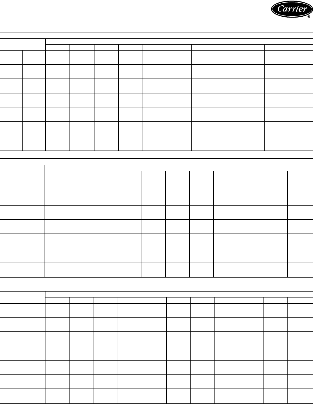
CONDENSING UNIT CIRCUIT AND MODULE RATINGS — ENGLISH (cont)
38AH044 CIRCUIT B
SST
(F) Air Temperature Entering Condenser (F)
70 80 85 90 95 100 105 110 115 120 125
20 TCG 146.0 133.0 127.0 120.0 114.0 107.0 100.0 93.7 87.0 80.4 73.6
CMP 11.6 12.3 12.7 13.0 13.2 13.4 13.5 13.5 13.5 13.5 13.3
SDT 92.6 103.0 108.0 113.0 118.0 123.0 127.0 132.0 137.0 142.0 147.0
25 TCG 166.0 152.0 145.0 139.0 132.0 125.0 118.0 111.0 104.0 96.5 89.3
CMP 12.0 12.9 13.3 13.7 14.0 14.3 14.5 14.6 14.7 14.8 14.7
SDT 92.9 103.0 108.0 113.0 118.0 123.0 128.0 133.0 138.0 143.0 148.0
30 TCG 187.0 173.0 165.0 158.0 151.0 144.0 136.0 129.0 121.0 114.0 106.0
CMP 12.3 13.4 13.9 14.3 14.7 15.1 15.4 15.6 15.9 16.0 16.1
SDT 93.2 103.0 108.0 113.0 118.0 123.0 128.0 133.0 138.0 143.0 148.0
35 TCG 209.0 194.0 187.0 179.0 171.0 164.0 156.0 148.0 140.0 132.0 124.0
CMP 12.6 13.8 14.4 14.9 15.4 15.8 16.2 16.6 16.9 17.1 17.3
SDT 93.9 104.0 109.0 114.0 119.0 124.0 128.0 133.0 138.0 143.0 148.0
40 TCG 233.0 217.0 209.0 201.0 193.0 185.0 176.0 168.0 160.0 151.0 143.0
CMP 12.9 14.2 14.9 15.5 16.0 16.6 17.1 17.4 17.9 18.2 18.5
SDT 94.7 105.0 110.0 114.0 119.0 124.0 129.0 134.0 139.0 144.0 149.0
45 TCG 257.0 241.0 232.0 224.0 215.0 207.0 198.0 189.0 180.0 172.0 163.0
CMP 13.1 14.6 15.3 16.0 16.6 17.2 17.8 18.3 18.8 19.3 19.7
SDT 95.8 106.0 111.0 115.0 120.0 125.0 130.0 135.0 140.0 145.0 150.0
50 TCG 284.0 266.0 257.0 248.0 239.0 230.0 221.0 211.0 202.0 193.0 184.0
CMP 13.3 15.0 15.8 16.5 17.2 17.9 18.6 19.1 19.7 20.3 20.7
SDT 97.0 107.0 112.0 117.0 121.0 126.0 131.0 136.0 141.0 146.0 150.0
38AH054 CIRCUIT B
SST
(F) Air Temperature Entering Condenser (F)
70 80 85 90 95 100 105 110 115 120 125
20 TCG 195.0 180.0 172.0 165.0 158.0 151.0 144.0 137.0 130.0 124.0 117.0*
CMP 16.0 17.0 17.4 17.8 18.2 18.6 18.9 19.1 19.4 19.6 19.8*
SDT 96.0 106.0 111.0 116.0 121.0 126.0 131.0 136.0 141.0 146.0 151.0*
25 TCG 221.0 204.0 196.0 188.0 180.0 172.0 164.0 157.0 149.0 142.0 135.0*
CMP 16.7 17.8 18.3 18.8 19.3 19.7 20.1 20.4 20.8 21.1 21.3*
SDT 96.8 106.0 111.0 116.0 121.0 126.0 131.0 136.0 141.0 146.0 151.0*
30 TCG 247.0 229.0 220.0 212.0 203.0 195.0 186.0 178.0 170.0 162.0 154.0*
CMP 17.4 18.7 19.3 19.8 20.4 20.9 21.3 21.7 22.1 22.5 22.8*
SDT 98.1 108.0 112.0 117.0 122.0 127.0 132.0 137.0 142.0 146.0 151.0*
35 TCG 275.0 256.0 246.0 237.0 228.0 219.0 210.0 201.0 192.0 183.0 175.0*
CMP 18.1 19.5 20.2 20.8 21.4 22.0 22.5 23.0 23.5 23.9 24.3*
SDT 99.7 109.0 114.0 119.0 123.0 128.0 133.0 138.0 142.0 147.0 152.0*
40 TCG 304.0 284.0 274.0 264.0 254.0 244.0 234.0 225.0 215.0 206.0 196.0*
CMP 18.8 20.4 21.1 21.9 22.5 23.2 23.8 24.3 24.9 25.4 25.9*
SDT 102.0 111.0 115.0 120.0 125.0 130.0 134.0 139.0 144.0 148.0 153.0*
45 TCG 335.0 313.0 303.0 292.0 281.0 271.0 260.0 250.0 240.0 229.0 219.0*
CMP 19.5 21.3 22.1 22.9 23.6 24.4 25.1 25.7 26.3 26.9 27.4*
SDT 104.0 113.0 117.0 122.0 127.0 131.0 136.0 141.0 145.0 150.0 155.0*
50 TCG 368.0 344.0 333.0 321.0 310.0 299.0 287.0 276.0 265.0 254.0* 244.0*
CMP 20.3 22.2 23.1 23.9 24.8 25.6 26.3 27.0 27.7 28.4* 29.0*
SDT 106.0 115.0 120.0 124.0 129.0 133.0 138.0 142.0 147.0 152.0* 156.0*
38AH064 CIRCUIT B
SST
(F) Air Temperature Entering Condenser (F)
70 80 85 90 95 100 105 110 115 120 125
20 TCG 218.0 202.0 194.0 186.0 178.0 170.0 162.0 153.0 145.0 137.0 129.0
CMP 17.9 19.0 19.5 19.9 20.3 20.6 20.9 21.1 21.2 21.3 21.3
SDT 93.2 103.0 108.0 113.0 118.0 123.0 128.0 133.0 138.0 143.0 148.0
25 TCG 246.0 229.0 220.0 212.0 203.0 194.0 185.0 177.0 168.0 159.0 150.0
CMP 18.6 19.9 20.5 21.0 21.5 21.9 22.3 22.5 22.8 23.0 23.1
SDT 93.7 104.0 109.0 113.0 118.0 123.0 128.0 133.0 138.0 143.0 148.0
30 TCG 274.0 256.0 247.0 238.0 229.0 220.0 211.0 201.0 192.0 183.0 173.0
CMP 19.2 20.7 21.4 22.0 22.6 23.1 23.6 24.0 24.4 24.7 24.9
SDT 94.5 104.0 109.0 114.0 119.0 124.0 129.0 134.0 139.0 144.0 149.0
35 TCG 304.0 286.0 276.0 266.0 257.0 247.0 237.0 227.0 217.0 208.0 198.0
CMP 19.8 21.5 22.3 23.0 23.7 24.3 24.9 25.4 25.9 26.3 26.6
SDT 95.7 105.0 110.0 115.0 120.0 125.0 130.0 134.0 139.0 144.0 149.0
40 TCG 336.0 316.0 306.0 296.0 286.0 275.0 265.0 254.0 244.0 234.0 223.0*
CMP 20.4 22.3 23.2 24.0 24.8 25.5 26.2 26.8 27.4 27.9 28.4*
SDT 97.1 107.0 112.0 116.0 121.0 126.0 131.0 136.0 140.0 145.0 150.0*
45 TCG 369.0 348.0 337.0 326.0 316.0 305.0 294.0 283.0 272.0 261.0 250.0*
CMP 21.0 23.1 24.1 25.0 25.9 26.7 27.5 28.2 28.9 29.5 30.0*
SDT 98.9 108.0 113.0 118.0 123.0 127.0 132.0 137.0 142.0 146.0 151.0*
50 TCG 404.0 381.0 370.0 358.0 347.0 335.0 324.0 312.0 301.0 289.0 277.0*
CMP 21.6 23.9 25.0 26.0 27.0 27.9 28.8 29.6 30.4 31.1 31.7*
SDT 101.0 110.0 115.0 120.0 124.0 129.0 134.0 139.0 143.0 148.0 153.0*
LEGEND
CMP — Compressor Power, kW
SDT — Saturated Discharge Temperature (leaving compressor) (F)
SST — Saturated Suction Temperature (entering condensing unit)
TCG — Total Cooling Capacity, Gross (1000 Btuh)
*May require replacement of the high-pressure cutout switches with switches of a
higher setting.
NOTES:
1. Ratings are based on 15 F superheat and use of R-22 refrigerant.
2. Ratings include suction line losses due to an accumulator.
79
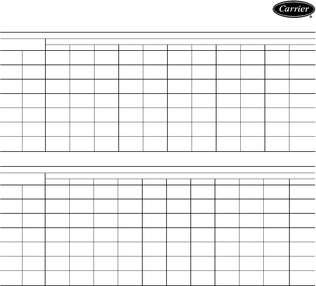
Performance data — 38AH044-134 (cont)
CONDENSING UNIT CIRCUIT AND MODULE RATINGS — ENGLISH (cont)
38AH074 CIRCUIT A
SST
(F) Air Temperature Entering Condenser (F)
70 80 85 90 95 100 105 110 115 120 125
20 TCG 221.0 205.0 197.0 189.0 181.0 173.0 165.0 157.0 149.0 140.0 132.0
CMP 17.8 18.9 19.4 19.9 20.3 20.6 20.9 21.0 21.2 21.3 21.3
SDT 92.4 102.0 107.0 112.0 117.0 122.0 127.0 132.0 137.0 142.0 147.0
25 TCG 249.0 232.0 224.0 215.0 206.0 198.0 189.0 180.0 172.0 163.0 154.0
CMP 18.4 19.7 20.3 20.9 21.4 21.8 22.2 22.5 22.8 23.0 23.1
SDT 92.7 103.0 107.0 112.0 117.0 122.0 127.0 132.0 137.0 142.0 147.0
30 TCG 277.0 260.0 251.0 242.0 233.0 224.0 215.0 206.0 196.0 187.0 178.0
CMP 19.0 20.5 21.2 21.9 22.5 23.0 23.5 23.9 24.3 24.6 24.8
SDT 93.6 103.0 108.0 113.0 118.0 123.0 128.0 133.0 137.0 142.0 147.0
35 TCG 307.0 288.0 279.0 270.0 261.0 251.0 242.0 232.0 222.0 212.0 203.0
CMP 19.7 21.3 22.1 22.8 23.5 24.2 24.7 25.3 25.8 26.2 26.5
SDT 95.0 104.0 109.0 114.0 119.0 123.0 128.0 133.0 138.0 143.0 148.0
40 TCG 338.0 318.0 309.0 299.0 289.0 279.0 269.0 259.0 249.0 239.0 228.0
CMP 20.3 22.2 23.0 23.8 24.6 25.3 26.0 26.6 27.2 27.7 28.2
SDT 96.7 106.0 111.0 115.0 120.0 125.0 129.0 134.0 139.0 143.0 148.0
45 TCG 370.0 350.0 340.0 329.0 319.0 308.0 298.0 287.0 277.0 266.0 255.0*
CMP 20.9 23.0 23.9 24.8 25.7 26.5 27.3 28.0 28.7 29.3 29.9*
SDT 98.6 108.0 112.0 117.0 122.0 126.0 131.0 136.0 140.0 145.0 149.0*
50 TCG 405.0 383.0 372.0 361.0 350.0 339.0 328.0 316.0 305.0 294.0 282.0*
CMP 21.5 23.7 24.8 25.8 26.8 27.7 28.6 29.4 30.2 30.9 31.5*
SDT 101.0 110.0 114.0 119.0 124.0 128.0 133.0 137.0 142.0 146.0 151.0*
38AH084 CIRCUIT A
SST
(F) Air Temperature Entering Condenser (F)
70 80 85 90 95 100 105 110 115 120 125
20 TCG 286.0 267.0 258.0 249.0 240.0 231.0 222.0 214.0 205.0 197.0 188.0*
CMP 25.5 26.8 27.4 27.9 28.4 28.9 29.3 29.7 30.0 30.4 30.6*
SDT 98.1 108.0 113.0 118.0 123.0 128.0 133.0 138.0 143.0 148.0 153.0*
25 TCG 321.0 301.0 291.0 281.0 271.0 261.0 252.0 242.0 233.0 223.0 214.0*
CMP 26.6 28.1 28.8 29.5 30.1 30.6 31.2 31.6 32.1 32.5 32.8*
SDT 98.1 108.0 113.0 118.0 123.0 128.0 133.0 138.0 143.0 148.0 153.0*
30 TCG 360.0 337.0 326.0 315.0 305.0 294.0 283.0 273.0 262.0 252.0 242.0*
CMP 27.6 29.4 30.2 31.0 31.7 32.4 33.0 33.5 34.1 34.6 35.0*
SDT 98.3 108.0 113.0 118.0 123.0 128.0 133.0 138.0 143.0 148.0 153.0*
35 TCG 400.0 376.0 364.0 352.0 341.0 329.0 317.0 306.0 294.0 283.0 272.0*
CMP 28.6 30.6 31.6 32.5 33.3 34.1 34.8 35.5 36.1 36.7 37.3*
SDT 98.9 109.0 114.0 119.0 124.0 129.0 134.0 139.0 144.0 148.0 153.0*
40 TCG 443.0 417.0 404.0 392.0 379.0 366.0 354.0 341.0 329.0 316.0 304.0*
CMP 29.6 31.9 32.9 33.9 34.9 35.8 36.6 37.4 38.2 38.9 39.5*
SDT 99.9 110.0 114.0 119.0 124.0 129.0 134.0 139.0 144.0 149.0 154.0*
45 TCG 488.0 460.0 446.0 433.0 419.0 405.0 392.0 379.0 365.0 352.0 339.0*
CMP 30.7 33.2 34.3 35.5 36.5 37.5 38.5 39.4 40.2 41.0 41.8*
SDT 101.0 111.0 116.0 120.0 125.0 130.0 135.0 140.0 145.0 150.0 155.0*
50 TCG 534.0 505.0 490.0 475.0 461.0 446.0 432.0 418.0 403.0 389.0* 375.0*
CMP 31.8 34.5 35.8 37.0 38.2 39.3 40.4 41.3 42.3 43.2* 44.1*
SDT 103.0 113.0 117.0 122.0 127.0 131.0 136.0 141.0 146.0 151.0* 155.0*
LEGEND
CMP — Compressor Power, kW
SDT — Saturated Discharge Temperature (leaving compressor) (F)
SST — Saturated Suction Temperature (entering condensing unit)
TCG — Total Cooling Capacity, Gross (1000 Btuh)
*May require replacement of the high-pressure cutout switches with switches of a
higher setting.
NOTES:
1. Ratings are based on 15 F superheat and use of R-22 refrigerant.
2. Ratings include suction line losses due to an accumulator.
80
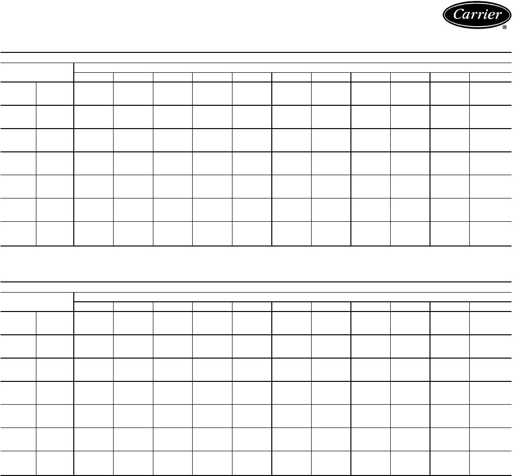
CONDENSING UNIT CIRCUIT AND MODULE RATINGS — ENGLISH (cont)
38AH074 CIRCUIT B
SST
(F) Air Temperature Entering Condenser (F)
70 80 85 90 95 100 105 110 115 120 125
20 TCG 292.0 273.0 264.0 255.0 246.0 237.0 228.0 219.0 211.0 202.0 194.0
CMP 24.6 26.0 26.6 27.2 27.8 28.3 28.7 29.2 29.6 29.9 30.3
SDT 91.7 102.0 107.0 112.0 117.0 122.0 126.0 131.0 136.0 142.0 147.0
25 TCG 325.0 306.0 296.0 286.0 276.0 267.0 257.0 248.0 238.0 229.0 219.0
CMP 25.7 27.3 28.0 28.7 29.3 29.9 30.5 31.0 31.5 31.9 32.3
SDT 92.7 102.0 107.0 112.0 117.0 122.0 127.0 132.0 137.0 142.0 147.0
30 TCG 361.0 340.0 329.0 319.0 308.0 298.0 288.0 277.0 267.0 257.0 247.0
CMP 26.8 28.6 29.4 30.2 30.9 31.6 32.3 32.9 33.5 34.0 34.5
SDT 94.2 104.0 108.0 113.0 118.0 123.0 128.0 132.0 137.0 142.0 147.0
35 TCG 399.0 376.0 364.0 353.0 342.0 330.0 319.0 308.0 298.0 287.0 276.0
CMP 28.0 30.0 30.9 31.8 32.6 33.4 34.1 34.8 35.5 36.1 36.7
SDT 96.0 105.0 110.0 115.0 119.0 124.0 129.0 134.0 138.0 143.0 148.0
40 TCG 438.0 413.0 401.0 389.0 377.0 365.0 353.0 341.0 329.0 318.0 306.0
CMP 29.2 31.4 32.4 33.4 34.3 35.2 36.0 36.8 37.6 38.3 38.9
SDT 97.9 107.0 112.0 117.0 121.0 126.0 131.0 135.0 140.0 145.0 149.0
45 TCG 480.0 453.0 440.0 427.0 414.0 401.0 388.0 375.0 363.0 350.0 338.0*
CMP 30.3 32.8 33.9 35.0 36.1 37.0 38.0 38.8 39.7 40.5 41.2*
SDT 100.0 109.0 114.0 119.0 123.0 128.0 132.0 137.0 142.0 146.0 151.0*
50 TCG 525.0 496.0 481.0 467.0 453.0 439.0 425.0 411.0 398.0 384.0 371.0*
CMP 31.5 34.2 35.5 36.7 37.8 38.9 40.0 40.9 41.9 42.8 43.6*
SDT 102.0 111.0 116.0 121.0 125.0 130.0 134.0 139.0 144.0 148.0 153.0*
38AH084 CIRCUIT B
SST
(F) Air Temperature Entering Condenser (F)
70 80 85 90 95 100 105 110 115 120 125
20 TCG 288.0 269.0 260.0 251.0 242.0 233.0 224.0 215.0 207.0 198.0 190.0*
CMP 25.2 26.5 27.1 27.7 28.2 28.7 29.1 29.5 29.9 30.2 30.5*
SDT 96.1 106.0 111.0 116.0 121.0 126.0 131.0 136.0 141.0 146.0 151.0*
25 TCG 323.0 303.0 293.0 283.0 273.0 263.0 253.0 244.0 234.0 225.0 216.0*
CMP 26.3 27.8 28.5 29.2 29.8 30.4 30.9 31.4 31.9 32.3 32.7*
SDT 96.2 106.0 111.0 116.0 121.0 126.0 131.0 136.0 141.0 146.0 151.0*
30 TCG 361.0 339.0 328.0 317.0 306.0 296.0 285.0 275.0 264.0 254.0 244.0*
CMP 27.3 29.1 29.9 30.7 31.4 32.1 32.7 33.3 33.9 34.4 34.9*
SDT 96.5 106.0 111.0 116.0 121.0 126.0 131.0 136.0 141.0 146.0 151.0*
35 TCG 402.0 378.0 366.0 354.0 342.0 331.0 319.0 308.0 296.0 285.0 274.0*
CMP 28.3 30.3 31.3 32.2 33.0 33.8 34.5 35.2 35.9 36.5 37.1*
SDT 97.3 107.0 112.0 117.0 122.0 127.0 132.0 137.0 142.0 146.0 151.0*
40 TCG 444.0 418.0 405.0 393.0 380.0 368.0 355.0 343.0 330.0 318.0 306.0*
CMP 29.3 31.6 32.6 33.6 34.6 35.5 36.3 37.1 37.9 38.6 39.3*
SDT 98.5 108.0 113.0 118.0 123.0 127.0 132.0 137.0 142.0 147.0 152.0*
45 TCG 488.0 460.0 447.0 433.0 420.0 406.0 393.0 379.0 366.0 353.0 340.0*
CMP 30.4 32.9 34.0 35.1 36.2 37.2 38.2 39.1 40.0 40.8 41.5*
SDT 100.0 110.0 114.0 119.0 124.0 129.0 133.0 138.0 143.0 148.0 153.0*
50 TCG 533.0 504.0 490.0 475.0 461.0 446.0 432.0 418.0 404.0 390.0 375.0*
CMP 31.5 34.2 35.5 36.7 37.9 39.0 40.1 41.1 42.1 43.0 43.8*
SDT 102.0 111.0 116.0 121.0 125.0 130.0 135.0 140.0 144.0 149.0 154.0*
LEGEND
CMP — Compressor Power, kW
SDT — Saturated Discharge Temperature (leaving compressor) (F)
SST — Saturated Suction Temperature (entering condensing unit)
TCG — Total Cooling Capacity, Gross (1000 Btuh)
*May require replacement of the high-pressure cutout switches with switches of a
higher setting.
NOTES:
1. Ratings are based on 15 F superheat and use of R-22 refrigerant.
2. Ratings include suction line losses due to an accumulator.
81
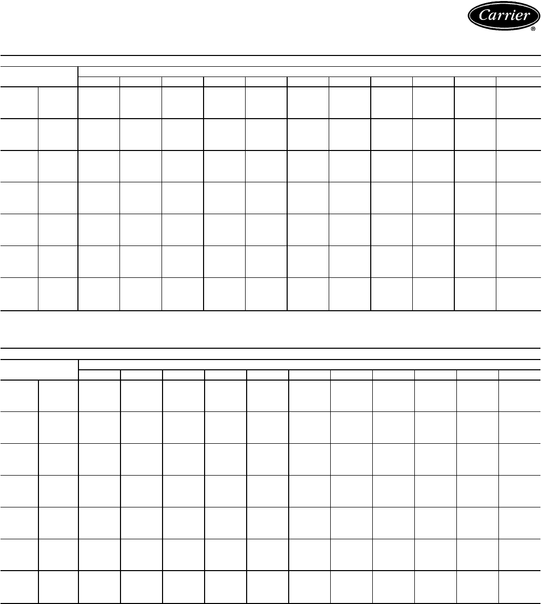
Performance data — 38AH044-134 (cont)
CONDENSING UNIT CIRCUIT AND MODULE RATINGS — ENGLISH (cont)
38AH094 CIRCUIT A
SST
(F) Air Temperature Entering Condenser (F)
70 80 85 90 95 100 105 110 115 120 125
20
TCG 366.0 338.0 324.0 310.0 295.0 281.0 266.0 251.0 236.0 221.0 207.0
CMP 29.7 31.4 32.3 33.0 33.6 34.1 34.4 34.7 34.8 34.7 34.5
SDT 93.9 104.0 109.0 114.0 119.0 124.0 129.0 134.0 139.0 144.0 149.0
SCT 91.7 102.0 107.0 113.0 118.0 123.0 128.0 133.0 138.0 143.0 148.0
25
TCG 411.0 382.0 367.0 352.0 337.0 322.0 307.0 291.0 276.0 260.0 244.0
CMP 30.9 33.0 34.0 34.8 35.6 36.3 36.8 37.3 37.6 37.8 37.8
SDT 95.0 105.0 109.0 114.0 119.0 124.0 129.0 134.0 139.0 144.0 149.0
SCT 92.1 102.0 108.0 113.0 118.0 123.0 128.0 133.0 138.0 143.0 148.0
30
TCG 457.0 427.0 412.0 396.0 381.0 365.0 349.0 333.0 317.0 300.0 284.0
CMP 32.2 34.5 35.7 36.7 37.6 38.4 39.2 39.8 40.3 40.7 41.0
SDT 96.7 106.0 111.0 115.0 120.0 125.0 130.0 134.0 139.0 144.0 149.0
SCT 93.0 103.0 108.0 113.0 118.0 123.0 128.0 133.0 138.0 143.0 148.0
35
TCG 505.0 474.0 458.0 442.0 426.0 409.0 392.0 376.0 359.0 342.0 325.0
CMP 33.6 36.1 37.4 38.6 39.6 40.6 41.5 42.3 43.0 43.6 44.1
SDT 98.7 108.0 112.0 117.0 122.0 126.0 131.0 136.0 140.0 145.0 150.0
SCT 94.3 104.0 109.0 114.0 119.0 124.0 129.0 134.0 139.0 144.0 149.0
40
TCG 556.0 522.0 506.0 489.0 472.0 455.0 437.0 420.0 402.0 384.0 367.0
CMP 35.0 37.8 39.2 40.5 41.7 42.8 43.9 44.8 45.7 46.4 47.1
SDT 101.0 110.0 115.0 119.0 124.0 128.0 133.0 137.0 142.0 146.0 151.0
SCT 95.7 106.0 111.0 116.0 121.0 126.0 131.0 135.0 140.0 145.0 150.0
45
TCG 608.0 573.0 556.0 538.0 520.0 502.0 484.0 465.0 447.0 428.0 410.0
CMP 36.4 39.4 41.0 42.4 43.8 45.1 46.2 47.4 48.4 49.3 50.1
SDT 104.0 112.0 117.0 121.0 126.0 130.0 135.0 139.0 144.0 148.0 153.0
SCT 97.4 108.0 113.0 118.0 123.0 127.0 132.0 137.0 142.0 146.0 151.0
50
TCG 663.0 626.0 608.0 589.0 570.0 551.0 532.0 512.0 493.0 473.0 454.0
CMP 37.8 41.1 42.8 44.4 45.9 47.3 48.7 49.9 51.1 52.2 53.2
SDT 106.0 115.0 119.0 124.0 128.0 133.0 137.0 142.0 146.0 150.0 155.0*
SCT 99.1 109.0 114.0 119.0 124.0 129.0 134.0 139.0 143.0 148.0 153.0
38AH104 CIRCUIT A
SST
(F) Air Temperature Entering Condenser (F)
70 80 85 90 95 100 105 110 115 120 125
20
TCG 349.0 321.0 308.0 294.0 280.0 267.0 253.0 240.0 226.0 213.0 200.0
CMP 27.0 28.8 29.6 30.4 31.0 31.6 32.1 32.5 32.8 32.9 33.0
SDT 91.9 102.0 107.0 112.0 116.0 121.0 126.0 131.0 136.0 141.0 146.0
SCT 89.8 100.0 105.0 110.0 116.0 121.0 126.0 131.0 136.0 141.0 146.0
25
TCG 392.0 363.0 349.0 335.0 320.0 306.0 291.0 277.0 263.0 248.0 234.0
CMP 28.1 30.1 31.1 32.0 32.8 33.6 34.2 34.7 35.2 35.6 35.8
SDT 93.0 102.0 107.0 112.0 117.0 122.0 127.0 132.0 137.0 141.0 146.0
SCT 90.2 100.0 105.0 111.0 116.0 121.0 126.0 131.0 136.0 141.0 146.0
30
TCG 437.0 407.0 392.0 377.0 361.0 346.0 331.0 316.0 301.0 286.0 271.0
CMP 29.3 31.6 32.7 33.7 34.6 35.5 36.3 37.0 37.6 38.1 38.6
SDT 94.7 104.0 109.0 113.0 118.0 123.0 127.0 132.0 137.0 142.0 147.0
SCT 91.2 101.0 106.0 111.0 116.0 121.0 126.0 131.0 136.0 141.0 146.0
35
TCG 484.0 452.0 436.0 420.0 404.0 388.0 372.0 356.0 340.0 324.0 308.0
CMP 30.6 33.0 34.3 35.4 36.4 37.4 38.4 39.2 40.0 40.7 41.3
SDT 96.7 106.0 110.0 115.0 119.0 124.0 129.0 133.0 138.0 143.0 148.0
SCT 92.5 103.0 108.0 112.0 117.0 122.0 127.0 132.0 137.0 142.0 147.0
40
TCG 534.0 500.0 483.0 466.0 449.0 432.0 415.0 398.0 381.0 364.0 348.0
CMP 38.1 34.5 35.9 37.1 38.3 39.4 40.5 41.5 42.4 43.2 44.0
SDT 98.9 108.0 112.0 117.0 121.0 126.0 130.0 135.0 140.0 144.0 149.0
SCT 94.0 104.0 109.0 114.0 119.0 124.0 128.0 133.0 138.0 143.0 148.0
45
TCG 586.0 550.0 532.0 514.0 495.0 478.0 460.0 442.0 424.0 406.0 388.0
CMP 33.0 36.0 37.5 38.9 40.2 41.5 42.6 43.8 44.8 45.8 46.7
SDT 101.0 110.0 115.0 119.0 124.0 128.0 132.0 137.0 141.0 146.0 150.0
SCT 95.6 106.0 111.0 116.0 120.0 125.0 130.0 135.0 140.0 144.0 149.0
50
TCG 640.0 602.0 583.0 564.0 544.0 525.0 506.0 487.0 468.0 449.0 431.0
CMP 34.3 37.5 39.2 40.7 42.1 43.5 44.8 46.1 47.3 48.4 49.4
SDT 104.0 113.0 117.0 122.0 126.0 130.0 135.0 139.0 144.0 148.0 152.0
SCT 97.3 107.0 112.0 117.0 122.0 127.0 132.0 137.0 141.0 146.0 151.0
LEGEND
CMP — Compressor Power, kW
SCT — Saturated Condensing Temperature (F)
SDT — Saturated Discharge Temperature (leaving compressor) (F)
SST — Saturated Suction Temperature (entering condensing unit)
TCG — Total Cooling Capacity, Gross (1000 Btuh)
*May require replacement of the high-pressure cutout switches with switches of a
higher setting.
NOTES:
1. Ratings are based on 15 F superheat and use of R-22 refrigerant.
2. Ratings include suction line losses due to an accumulator.
82

CONDENSING UNIT CIRCUIT AND MODULE RATINGS — ENGLISH (cont)
38AH094 CIRCUIT B
SST
(F) Air Temperature Entering Condenser (F)
70 80 85 90 95 100 105 110 115 120 125
20
TCG 291.0 273.0 264.0 254.0 245.0 236.0 228.0 219.0 210.0 202.0 193.0
CMP 24.6 26.0 26.7 27.2 27.8 28.3 28.8 29.2 29.6 30.0 30.3
SDT 92.1 102.0 107.0 112.0 117.0 122.0 127.0 132.0 137.0 142.0 147.0
SCT 90.4 101.0 106.0 111.0 116.0 121.0 126.0 131.0 136.0 142.0 147.0
25
TCG 327.0 307.0 296.0 286.0 277.0 267.0 257.0 247.0 238.0 228.0 219.0
CMP 25.6 27.2 28.0 28.7 29.3 29.9 30.5 31.0 31.5 32.0 32.4
SDT 92.4 102.0 107.0 112.0 117.0 122.0 127.0 132.0 137.0 142.0 147.0
SCT 90.2 100.0 106.0 111.0 116.0 121.0 126.0 131.0 136.0 141.0 146.0
30
TCG 364.0 342.0 331.0 320.0 310.0 299.0 289.0 278.0 268.0 257.0 247.0
CMP 26.6 28.4 29.3 30.1 30.9 31.6 32.3 32.9 33.5 34.0 34.5
SDT 93.3 103.0 108.0 113.0 118.0 123.0 127.0 132.0 137.0 142.0 147.0
SCT 90.5 101.0 106.0 111.0 116.0 121.0 126.0 131.0 136.0 141.0 146.0
35
TCG 402.0 379.0 367.0 356.0 345.0 333.0 322.0 310.0 299.0 288.0 277.0
CMP 27.7 29.7 30.7 31.6 32.4 33.2 34.0 34.7 35.4 36.0 36.6
SDT 94.7 104.0 109.0 114.0 119.0 123.0 128.0 133.0 138.0 143.0 148.0
SCT 91.2 101.0 107.0 112.0 117.0 122.0 127.0 132.0 137.0 142.0 147.0
40
TCG 443.0 418.0 405.0 393.0 381.0 369.0 356.0 344.0 332.0 320.0 308.0
CMP 28.8 31.0 32.1 33.1 34.1 35.0 35.8 36.6 37.4 38.1 38.8
SDT 96.5 106.0 111.0 115.0 120.0 125.0 129.0 134.0 139.0 144.0 149.0
SCT 92.3 102.0 108.0 113.0 118.0 122.0 127.0 132.0 137.0 142.0 147.0
45
TCG 485.0 458.0 445.0 432.0 419.0 406.0 393.0 380.0 367.0 354.0 341.0
CMP 29.9 32.4 33.6 34.7 35.7 36.7 37.7 38.6 39.5 40.3 41.1
SDT 98.6 108.0 112.0 117.0 122.0 126.0 131.0 136.0 140.0 145.0 150.0
SCT 93.6 104.0 109.0 114.0 119.0 124.0 129.0 134.0 138.0 143.0 148.0
50
TCG 530.0 501.0 487.0 473.0 459.0 445.0 431.0 417.0 403.0 389.0 375.0
CMP 31.1 33.7 35.0 36.3 37.4 38.5 39.6 40.6 41.6 42.5 43.4
SDT 101.0 110.0 114.0 119.0 124.0 128.0 133.0 137.0 142.0 147.0 151.0
SCT 95.1 105.0 110.0 115.0 120.0 125.0 130.0 135.0 140.0 145.0 149.0
38AH104 CIRCUIT B
SST
(F) Air Temperature Entering Condenser (F)
70 80 85 90 95 100 105 110 115 120 125
20
TCG 398.0 368.0 353.0 339.0 324.0 310.0 296.0 283.0 269.0 256.0 243.0
CMP 31.4 33.4 34.3 35.2 36.0 36.7 37.4 38.0 38.5 39.0 39.4
SDT 93.5 103.0 108.0 113.0 118.0 123.0 128.0 133.0 138.0 142.0 147.0
SCT 90.9 101.0 106.0 111.0 116.0 122.0 127.0 132.0 137.0 142.0 147.0
25
TCG 445.0 414.0 398.0 383.0 367.0 352.0 337.0 322.0 308.0 293.0 279.0
CMP 32.9 35.1 36.2 37.2 38.1 39.0 39.8 40.5 41.2 41.8 42.3
SDT 95.1 104.0 109.0 114.0 119.0 123.0 128.0 133.0 138.0 143.0 148.0
SCT 91.7 102.0 107.0 112.0 117.0 122.0 127.0 132.0 137.0 142.0 147.0
30
TCG 495.0 462.0 445.0 428.0 412.0 396.0 380.0 364.0 348.0 333.0 317.0
CMP 34.5 36.9 38.1 39.2 40.3 41.3 42.2 43.0 43.8 44.6 45.2
SDT 97.1 106.0 111.0 115.0 120.0 125.0 129.0 134.0 139.0 144.0 148.0
SCT 92.9 103.0 108.0 113.0 118.0 123.0 128.0 133.0 138.0 143.0 148.0
35
TCG 548.0 512.0 494.0 476.0 459.0 441.0 424.0 407.0 391.0 374.0 357.0
CMP 36.1 38.8 40.1 41.4 42.5 43.6 44.7 45.7 46.6 47.4 48.2
SDT 99.4 108.0 113.0 117.0 122.0 126.0 131.0 136.0 140.0 145.0 150.0
SCT 94.4 104.0 109.0 114.0 119.0 124.0 129.0 134.0 139.0 144.0 148.0
40
TCG 603.0 565.0 546.0 527.0 508.0 489.0 471.0 453.0 435.0 417.0 399.0
CMP 37.7 40.7 42.2 43.6 44.9 46.1 47.3 48.4 49.4 50.4 51.3
SDT 102.0 111.0 115.0 120.0 124.0 128.0 133.0 137.0 142.0 147.0 151.0
SCT 96.0 106.0 111.0 116.0 121.0 126.0 131.0 135.0 140.0 145.0 150.0
45
TCG 661.0 620.0 600.0 580.0 559.0 539.0 520.0 500.0 481.0 462.0 443.0
CMP 39.4 42.7 44.3 45.8 47.2 48.6 49.9 51.1 52.3 53.4 54.5
SDT 105.0 113.0 118.0 122.0 126.0 131.0 135.0 140.0 144.0 149.0 153.0
SCT 97.8 108.0 113.0 118.0 123.0 128.0 132.0 137.0 142.0 147.0 151.0
50
TCG 723.0 679.0 657.0 635.0 614.0 592.0 571.0 550.0 530.0 509.0 488.0
CMP 41.2 44.7 46.4 48.1 49.6 51.2 52.6 54.0 55.3 56.5 57.7
SDT 108.0 116.0 120.0 125.0 129.0 133.0 138.0 142.0 146.0 151.0 155.0*
SCT 99.6 110.0 115.0 120.0 125.0 130.0 134.0 139.0 144.0 148.0 153.0
LEGEND
CMP — Compressor Power, kW
SCT — Saturated Condensing Temperature (F)
SDT — Saturated Discharge Temperature (leaving compressor) (F)
SST — Saturated Suction Temperature (entering condensing unit)
TCG — Total Cooling Capacity, Gross (1000 Btuh)
*May require replacement of the high-pressure cutout switches with switches of a
higher setting.
NOTES:
1. Ratings are based on 15 F superheat and use of R-22 refrigerant.
2. Ratings include suction line losses due to an accumulator.
83
Performance data — 38AH044-134 (cont)
CONDENSING UNIT CIRCUIT AND MODULE RATINGS — ENGLISH (cont)
38AH124 MODULE 124A OR 124B; 38AH134 MODULE 134A
SST
(F) Air Temperature Entering Condenser (F)
70 80 85 90 95 100 105 110 115 120 125
20
TCG 417.0 386.0 370.0 355.0 339.0 324.0 309.0 294.0 279.0 264.0 249.0
CMP 33.6 35.7 36.7 37.6 38.4 39.0 39.6 40.1 40.5 40.8 41.0
SDT 93.3 103.0 108.0 113.0 118.0 123.0 128.0 133.0 138.0 143.0 148.0
SCT 92.4 103.0 108.0 113.0 118.0 123.0 128.0 133.0 138.0 143.0 148.0
25
TCG 470.0 436.0 420.0 403.0 386.0 370.0 354.0 337.0 321.0 305.0 289.0
CMP 34.9 37.3 38.5 39.6 40.5 41.4 42.2 42.8 43.4 43.9 44.3
SDT 94.0 104.0 109.0 114.0 119.0 123.0 128.0 133.0 138.0 143.0 148.0
SCT 92.8 103.0 108.0 113.0 118.0 123.0 128.0 133.0 138.0 143.0 148.0
30
TCG 525.0 490.0 472.0 454.0 436.0 419.0 401.0 384.0 366.0 349.0 331.0
CMP 36.2 39.0 40.3 41.6 42.7 43.7 44.7 45.5 46.3 47.0 47.5
SDT 95.0 105.0 110.0 114.0 119.0 124.0 129.0 134.0 139.0 144.0 149.0
SCT 93.5 103.0 108.0 113.0 118.0 123.0 128.0 133.0 138.0 143.0 148.0
35
TCG 584.0 546.0 526.0 507.0 489.0 470.0 451.0 432.0 414.0 395.0 376.0
CMP 37.5 40.6 42.1 43.5 44.8 46.0 47.2 48.2 49.2 50.0 50.7
SDT 96.4 106.0 111.0 116.0 120.0 125.0 130.0 135.0 140.0 144.0 149.0
SCT 94.6 104.0 109.0 114.0 119.0 124.0 129.0 134.0 139.0 144.0 149.0
40
TCG 645.0 604.0 584.0 563.0 543.0 523.0 503.0 483.0 463.0 444.0 424.0
CMP 38.8 42.2 43.9 45.5 47.0 48.4 49.7 50.8 52.0 53.0 54.0
SDT 98.1 108.0 112.0 117.0 122.0 126.0 131.0 136.0 141.0 146.0 150.0
SCT 95.9 106.0 111.0 116.0 120.0 125.0 130.0 135.0 140.0 145.0 150.0
45
TCG 709.0 666.0 644.0 622.0 601.0 579.0 558.0 537.0 516.0 494.0 473.0
CMP 40.0 43.9 45.8 47.5 49.1 50.7 52.2 53.5 54.9 56.1 57.2
SDT 100.0 109.0 114.0 119.0 123.0 128.0 133.0 138.0 142.0 147.0 152.0
SCT 97.5 107.0 112.0 117.0 122.0 127.0 131.0 136.0 141.0 146.0 151.0
50
TCG 776.0 730.0 707.0 684.0 661.0 638.0 616.0 593.0 570.0 548.0 525.0
CMP 41.3 45.5 47.6 49.5 51.3 53.1 54.7 56.2 57.8 59.1 60.4
SDT 102.0 112.0 116.0 121.0 125.0 130.0 135.0 139.0 144.0 149.0 153.0
SCT 99.3 109.0 114.0 119.0 123.0 128.0 133.0 138.0 143.0 147.0 152.0
38AH134 MODULE 134B
SST
(F) Air Temperature Entering Condenser (F)
70 80 85 90 95 100 105 110 115 120 125
20
TCG 513.0 478.0 461.0 444.0 427.0 410.0 393.0 376.0 359.0 342.0 326.0
CMP 42.4 44.9 46.1 47.1 48.0 48.9 49.6 50.2 50.8 51.3 51.6
SDT 92.0 102.0 107.0 112.0 117.0 122.0 127.0 132.0 137.0 142.0 147.0
SCT 87.6 97.7 103.0 108.0 113.0 118.0 123.0 128.0 133.0 138.0 143.0
25
TCG 575.0 538.0 520.0 502.0 483.0 465.0 447.0 428.0 410.0 392.0 374.0
CMP 44.1 47.0 48.3 49.5 50.7 51.7 52.7 53.5 54.3 54.9 55.5
SDT 92.7 102.0 107.0 112.0 117.0 122.0 127.0 132.0 137.0 142.0 147.0
SCT 88.6 98.5 103.0 108.0 113.0 118.0 123.0 128.0 133.0 138.0 143.0
30
TCG 639.0 600.0 580.0 561.0 542.0 522.0 503.0 484.0 464.0 445.0 425.0
CMP 45.8 49.1 50.6 52.0 53.4 54.6 55.7 56.7 57.7 58.6 59.3
SDT 93.8 103.0 108.0 113.0 118.0 123.0 127.0 132.0 137.0 142.0 147.0
SCT 90.0 99.7 105.0 109.0 114.0 119.0 124.0 129.0 134.0 139.0 144.0
35
TCG 706.0 665.0 644.0 623.0 603.0 582.0 562.0 541.0 520.0 500.0 479.0
CMP 47.6 51.3 53.0 54.6 56.1 57.5 58.8 60.0 61.2 62.2 63.2
SDT 95.4 105.0 110.0 114.0 119.0 124.0 128.0 133.0 138.0 143.0 148.0
SCT 91.5 101.0 106.0 111.0 116.0 120.0 125.0 130.0 135.0 139.0 144.0
40
TCG 777.0 733.0 710.0 689.0 667.0 645.0 623.0 601.0 579.0 557.0 535.0
CMP 49.4 53.5 55.4 57.2 58.9 60.5 62.0 63.4 64.7 66.0 67.1
SDT 97.2 107.0 111.0 116.0 121.0 125.0 130.0 135.0 139.0 144.0 149.0
SCT 93.0 103.0 107.0 112.0 117.0 122.0 127.0 131.0 136.0 141.0 145.0
45
TCG 852.0 804.0 781.0 757.0 734.0 710.0 687.0 663.0 640.0 617.0 593.0
CMP 51.2 55.7 57.8 59.8 61.7 63.5 65.2 66.8 68.3 69.7 71.1
SDT 99.2 109.0 113.0 118.0 122.0 127.0 132.0 136.0 141.0 145.0 150.0
SCT 94.6 104.0 109.0 114.0 119.0 123.0 128.0 133.0 137.0 142.0 147.0
50
TCG 931.0 880.0 855.0 829.0 804.0 779.0 754.0 729.0 704.0 679.0 654.0
CMP 52.9 57.9 60.2 62.4 64.6 66.6 68.5 70.3 72.0 73.6 75.1
SDT 101.0 111.0 115.0 120.0 124.0 129.0 134.0 138.0 143.0 147.0 152.0
SCT 96.3 106.0 111.0 116.0 120.0 125.0 130.0 134.0 139.0 144.0 148.0
LEGEND
CMP — Compressor Power, kW
SCT — Saturated Condensing Temperature (F)
SDT — Saturated Discharge Temperature (leaving compressor) (F)
SST — Saturated Suction Temperature (entering condensing unit)
TCG — Total Cooling Capacity, Gross (1000 Btuh)
*May require replacement of the high-pressure cutout switches with switches of a
higher setting.
NOTES:
1. Ratings are based on 15 F superheat and use of R-22 refrigerant.
2. Ratings include suction line losses due to an accumulator.
84
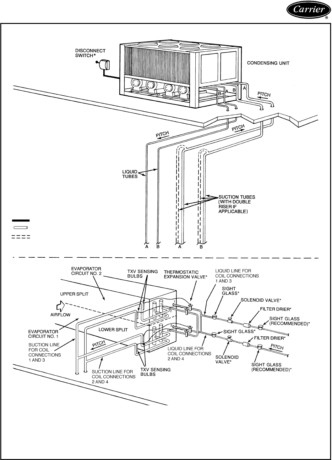
Typical piping and wiring — 38AH044-134
ROOFTOP INSTALLATION — UNIT 38AH104 WITH SINGLE AIR HANDLER SHOWN
LEGEND
TXV — Thermostatic Expansion Valve
Line Voltage
Piping
Double Riser Piping
(If Required)
*Field supplied.
NOTES:
1. All piping must follow standard refrigerant piping techniques. Refer to Carrier System Design Manual
for details.
2. All wiring must comply with the applicable local and national codes.
3. Wiring and piping shown are general points-of-connection guides only and are not intended for, or to
include all details for, a specific installation. Face-split connection shown; row-split connection also
possible.
4. Liquid line solenoid valve (solenoid drop control) is required to minimize refrigerant migration to the
compressor.
85
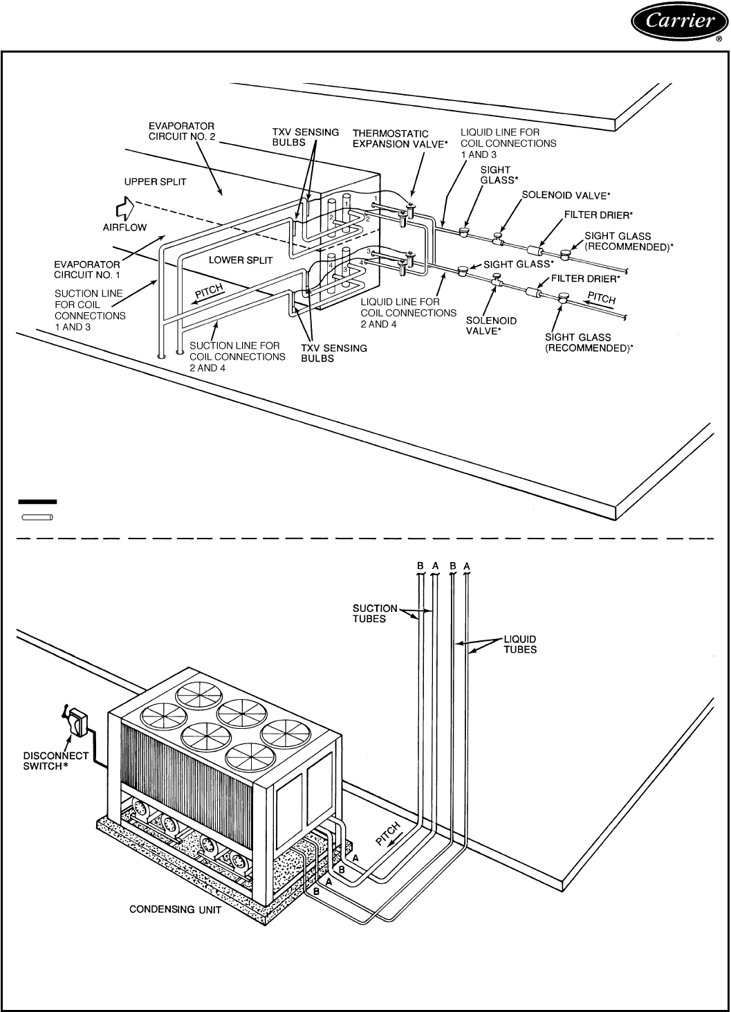
Typical piping and wiring — 38AH044-134 (cont)
GROUND-LEVEL INSTALLATION — UNIT 38AH104 WITH SINGLE AIR HANDLER SHOWN
LEGEND
TXV — Thermostatic Expansion Valve
Line Voltage
Piping
*Field supplied.
NOTES:
1. All piping must follow standard refrigerant piping techniques. Refer to Carrier System Design Manual for details.
2. All wiring must comply with the applicable local and national codes.
3. Wiring and piping shown are general points-of-connection guides only and are not intended for, or to include all
details for, a specific installation. Face-split connection shown; row-split connection also possible.
4. Liquid line solenoid valve (solenoid drop control) is required to minimize refrigerant migration to the compressor.
86
Electrical data — 38AH044-134
38AH044-084
UNIT
38AH VOLTAGE
DESIGNATION
COMPRESSOR
MODEL
(A/B DUAL-CIRCUIT)
(A1/A2 SINGLE-CIRCUIT)
NAMEPLATE
VOLTS-PH-Hz
SUPPLY
VOLTAGE* POWER SUPPLY COMPRESSOR†
Min Max MCA MOCP ICF AB
RLA LRA RLA LRA
044 800 (PW) 06E-250/250 230-3-50 198 254 174.6 225 296.7 67.9 207 67.9 207
900 380/415-3-50 348 440 100.0 100 219.6 34.6 173 34.6 173
300 (PW) 346-3-50 325 367 100.0 125 165.9 33.3 115 33.3 115
054 900 06E-250/265 380/415-3-50 342 440 101.1 125 269.6 34.6 173 43.6 223
300 (PW) 346-3-50 325 367 107.0 150 198.9 33.3 115 44.9 148
064 900 06E-265/275 380/415-3-50 342 440 114.1 150 335.6 43.6 223 46.8 280
300 (PW) 346-3-50 325 367 129.8 175 230.5 44.9 148 53.8 168
074 900 06E-275/299 380/415-3-50 342 440 140.6 200 403.8 46.8 280 65.4 345
300 (PW) 346-3-50 325 367 170.8 250 300.4 53.8 168 79.5 229
084 900 06E-299/299 380/415-3-50 342 440 165.2 225 428.4 65.4 345 65.4 345
300 (PW) 346-3-50 325 367 205.3 250 334.9 79.5 229 79.5 229
38AH094,104
UNIT
38AH VOLTAGE
DESIGNATION
COMPRESSOR
A1/A2/B1/B2
MODEL NO.
NAMEPLATE
VOLTS-PH-Hz
SUPPLY
VOLTAGE* POWER SUPPLY COMPRESSOR†
Min Max MCA MOCP ICF A1 A2 B1 B2
RLA LRA RLA LRA RLA LRA RLA LRA
094 300 (PW) 06E-275/250/
299/— 346-3-50 325 380 212.9 250 343 53.8 168 33.3 115 79.5 229 — —
900 380/415-3-50 342 440 181.2 225 444 46.8 280 34.6 173 65.4 345 — —
104 300 (PW) 06E-265/250/
265/265 346-3-50 325 380 205.6 250 298 44.9 148 33.3 229 44.9 148 49.9 148
900 380/415-3-50 342 440 194.3 225 363 43.6 223 34.6 173 43.6 223 43.6 223
38AH124,134
UNIT
38AH
MODULE
VOLTAGE
DESIGNATION
COMPRESSOR
A1/A2
MODEL NO.
NAMEPLATE
VOLTS-PH-Hz
SUPPLY
VOLTAGE* POWER SUPPLY** COMPRESSOR†
Min Max MCA MOCP ICF A1 A2
RLA LRA RLA LRA
124A
124B
134A
300 (PW) 06E-275/265 346-3-50 325 367 129.8 175 231 53.8 168 44.9 148
900 380/415-3-50 342 440 114.1 150 336 46.8 280 43.6 223
134B 300 (PW) 06E-299/275 346-3-50 325 367 170.8 250 300 79.5 229 53.8 168
900 380/415-3-50 342 440 140.6 200 404 65.4 345 46.8 280
See Legend and Notes on page 88.
87
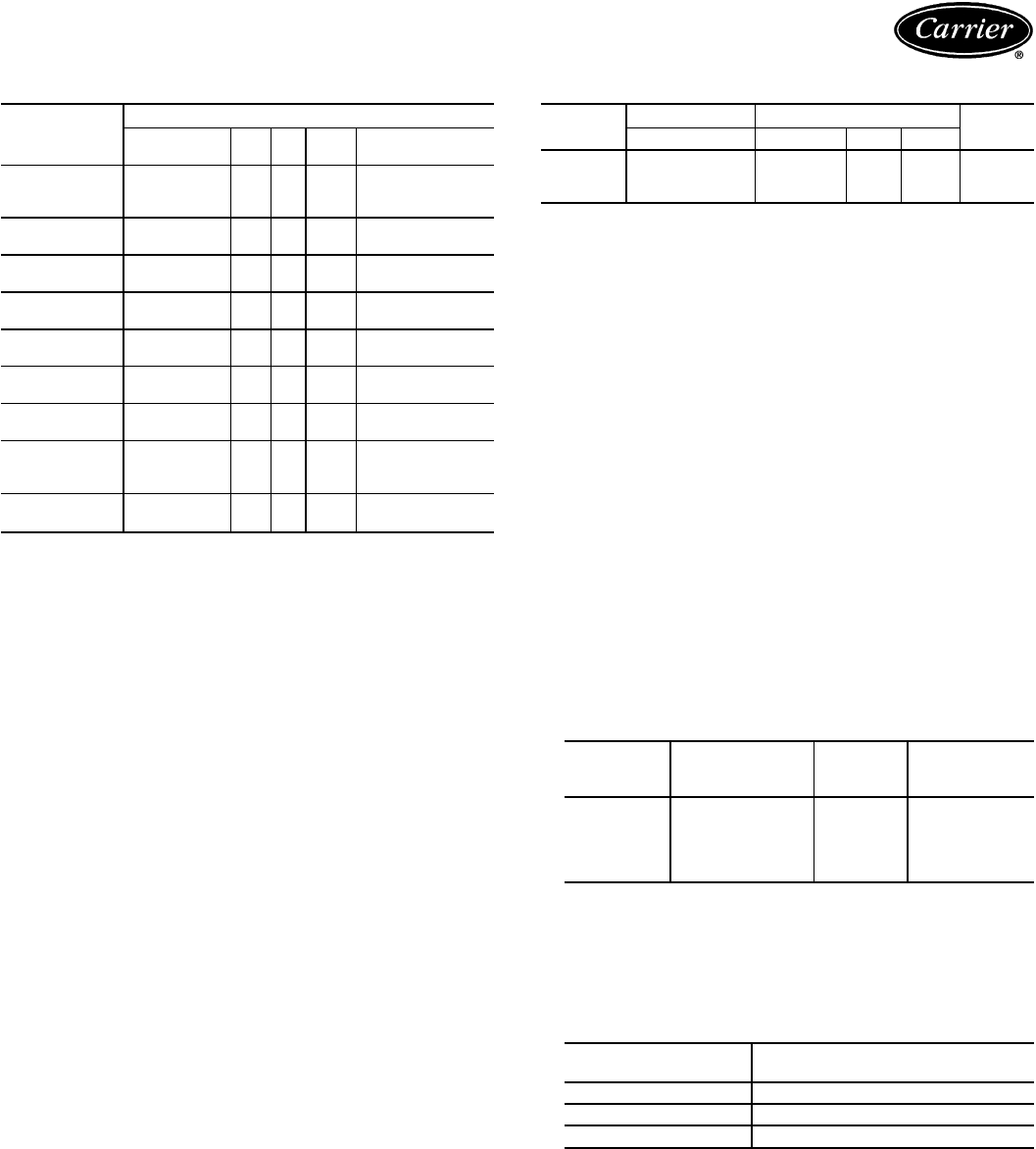
Electrical Data — 38AH044-134 (cont)
FANS
UNIT/MODULE
38AH
CONDENSER FAN MOTORS
Nameplate Qty Hp Total (No.) FLA Each
Volts-Ph-Hz kW
044 230-3-50 4 1 6.2 (1,2) 5.5 (3,4) 5.4
380/415-3-50 (1-4) 3.0
346-3-50 (1-4) 4.4
054 380/415-3-50 4 1 6.2 (1-4) 3.0
346-3-50 (1-4) 4.4
064 380/415-3-50 4 1 6.2 (1-4) 3.0
346-3-50 (1-4) 4.4
074 380/415-3-50 6 1 9.3 (1-6) 3.0
346-3-50 (1-6) 4.4
084 380/415-3-50 6 1 9.3 (1-6) 3.0
346-3-50 (1-6) 4.4
094 380/415-3-50 6 1 9.4 (1-6) 4.4
346-3-50 (1-6) 3.0
104 380/415-3-50 6 1 9.5 (1-6) 4.4
346-3-50 (1-6) 3.0
124A
124B
134A
380/415-3-50
346-3-50 4 1 6.4 (1-4) 4.4
(1-4) 3.0
134B 380/415-3-50 6 1 9.2 (1-6) 4.4
346-3-50 (1-6) 3.0
CONTROL CIRCUIT
38AH
044-134 UNIT POWER CONTROL POWER AMPS
V-Ph-Hz V-Ph-Hz Min Max
-800 230-3-50 230-1-50 207 253 2.0
-300 346-3-50 200-1-50 180 220 2.4
-900 380/415-3-50 230-1-50 207 253 2.0
LEGEND (for pages 87 and 88)
AWG — American Wire Gage
FLA — Full Load Amps
ICF — Maximum Instantaneous Current Flow During Starting.
(The point in the starting sequence where the sum of the
LRA for the starting compressors, plus the total RLA for all
running compressors plus the FLA for all running fan
motors is maximum.)
IFC — Indoor-Fan Contactor
kcmil — Thousand Circular Mils
LLS — Liquid Line Solenoid
LRA — Locked Rotor Amps
MCA — Minimum Circuit Amps (used for sizing; complies with
National Electrical Code [NEC] section 430-24, U.S.A.)
MOCP — Maximum Overcurrent Protection (used for sizing discon-
nect; complies with NEC Article 440-22, U.S.A.)
PW — Part Wind
RLA — Rated Load Amps
*Units are suitable for use on electrical systems where voltage supplied
to unit terminals is within listed minimum to maximum limits.
†Compressors are across-the-line start unless voltage designation shows
(PW).
**
38AH124 and 134 units require a separate power supply for each unit
module.
NOTES:
1. Maximum allowable phase imbalance:
Voltage — 2%
Amps — 10%
2. Maximum incoming wire size for terminal block is 500 kcmil.
3. Wiring for field power supply must be rated 75 C minimum. Use cop-
per, copper-clad aluminum, or aluminum conductors. Maximum in-
coming wire size for each terminal block is 500 kcmil.
4. Terminal blocks TB3 and TB4 are for external field control connec-
tions. Control connections are to be class 1 wiring.
5. Field-supplied components (IFC, LLS-A, and LLS-B) must have a
maximum sealed coil rating of 30 va each or less (0.13 amp at
230 vac). Thermostats must have a minimum pilot duty rating as
follows:
38AH VA
(Each Stage) AMPS CONTROL
CIRCUIT
VOLTAGE
044-084 300 1.30
240
094 275 1.15
104 325 1.35
124 300 1.30
134 300 1.30
6. Units have the following va of power available for field-installed
accessories:
38AH044-084 — 175 va
38AH094 — 140 va
38AH104 — 130 va
38AH124,134 — 175 va each module
7. To minimize voltage drop, the following wire sizes are recommended:
LENGTH (Ft) INSULATED WIRE — AWG
(35 C Minimum)
Up to 50 No. 18
50-75 No. 16
More Than 75 No. 14
8. Unit 38AH124 consists of Modules 124A and 124B. Unit 38AH134
consists of Modules 134A and 134B. Each module has a control box.
9. All fans are protected by a single circuit breaker.
88

Controls — 38AH044-084
Operating sequence
Circuits A1 and B1 are controlled by independent circuitry.
It is therefore possible to maintain partial cooling capability
even if one compressor is inoperable.
NOTE: Single-circuit units do not have independent con-
trol circuitry.
On a call for cooling, the first-stage cooling thermostat
TC1 closes, energizing the first stage of the condenser fans
and timer motor TM-A (TM for single-circuit units). After
12 seconds, the timer energizes lead compressor contactor
C-A1 and the lead compressor starts. (Circuit A compres-
sor is the lead on dual-circuit units, and compressor A1 is
the lead on single-circuit units.) At the same time, solenoid
drop relay SDR2 energizes and closes its contacts, which
energizes andopens liquid linesolenoid valve LLS-A(LLS-A1
for single-circuit units). Circuit A (compressor A1 for single-
circuit units) is now operational.
A set of bypass contacts in timer TM-A allows the
circuit A compressor (compressor A1 for single-circuit units)
40 seconds to build sufficient oil pressure. If the oil pres-
sure is insufficient after 40 seconds, circuit A (compressor
A1 for single-circuit units) shuts down and must be reset
manually.
A second set of bypass contacts in timer TM-A (TM for
single-circuit units) allows the refrigerant circuit 2
1
⁄
2
minutes
to build sufficient low-side pressure. This time delay is a
start-up feature for low ambient conditions; no accessory is
required. If refrigerant circuit pressure is insufficient to close
the low-pressure switch after 2
1
⁄
2
minutes, the circuit A com-
pressor (compressor A1 for single-circuit units) shuts down
for 5
1
⁄
2
minutes and then automatically attempts to restart.
No manual reset is required.
Dual-circuit units — If circuit A is insufficient for the cool-
ing requirements, second-stage thermostat TC2 closes to
bring circuit B on line. Circuit B follows the same sequence
of operation as circuit A, except a relay delays circuit B
compressor start-up for 40 seconds after a call for cooling.
Because circuit A has a 12-second delay after TC1 closes,
and circuit B has a 40-second delay after TC2 closes, the
two compressors cannot start at the same time.
Optional single-circuit units — If compressor A1 is in-
sufficient for the cooling requirements, second-stage ther-
mostat TC2 closes, which opens liquid line solenoid valve
LLS-A2. Compressor A2 starts only after the D-D2 con-
tacts in timer TM close (approximately 2
1
⁄
2
minutes after
compressor A1 is energized) and the suction pressure is suf-
ficient to close capacity control pressure switches CCPS1
and CCPS2.
All units — When the fan switch on the thermostat is set
for automatic operation (AUTO), the field-supplied indoor-
fan contactor (IFC) is cycled with the lead compressor. If the
fan switch is set at the continuous position (CONT), the IFC
is energized as long as the unit power is on.
NOTE: Liquid line solenoid valves must be field-supplied
and installed at the evaporator for both dual- and optional
single-circuit units.
89

Controls — 38AH094-134
Operating sequence
Units are controlled with electromechanical components.
Eachrefrigeration circuit isoperated byan independent timer
motor which controls the operation sequence of each cir-
cuit. It is possible to maintain partial cooling capability even
if one circuit is inoperable.
On a call for cooling, first stage cooling thermostat TC1
closes. Condenser fans and timer motor (TM) are ener-
gized. After approximately 7 seconds, timer contacts E-E1
close. Approximately 12 seconds after TC1 closes, nor-
mally open timer contacts B-B1 close for 1 second. This
energizes compressor A1 contacts CA1 and starts the com-
pressor. At the same time, solenoid drop relays (SDRs) and
liquid line solenoid valve no. 1 (LLS-A1) open, and timer
relay no. 1 (TR1) is energized. Normally open TR1 con-
tacts close, completing a circuit around B-B1 and through
compressor A1 contactors to maintain compressor opera-
tionwhen B-B1 contacts open. Contacts E-E1 remain closed
for approximately 40 seconds to bypass the oil pressure
switch.If oil pressureis insufficientwhen contacts E-E1open,
the compressor stops, the timer cycles off, and the control
circuit locks out. At start-up, timer motor contacts D-D1 are
closed, bypassing low-pressure relay contacts LPR-A for
2
1
⁄
2
minutes. This provides a winter start-up feature.
Approximately 2
1
⁄
2
minutes after TC1 closes, timer con-
tacts D-D1 open and D-D2 close. If pressure is insufficient
to close the low-pressure switch, the low-pressure switch
relay remains open, the compressor shuts down, and the
Time Guardtcontrol is initiated. Time Guard control pre-
vents compressor from restarting for 5 minutes after the
demand for cooling is satisfied.
Units 38AH094 and 104 — If circuit A operation is
insufficient for the cooling requirements, the thermostat sec-
ond stage TC2 closes to bring circuit B on-line for cooling.
This circuit follows the same sequence of operation as the
lead circuit, except a 60-second time-delay relay (TDR)
delays compressor start-up for 60 seconds after the call for
cooling.
Modules 124A, 124B, 134A, and 134B — If com-
pressor A1 is insufficient for the cooling requirements, the
thermostat second stage closes, which opens the liquid line
solenoid valve LLS-A2. Compressor A2 starts only after
D-D2 contacts in the timer close and the suction pressure is
sufficient to close the capacity control switches.
All units — Whenthe fan switch is set for automatic(AUTO)
operation, the indoor-fan contactor (IFC) is cycled with the
lead compressor. If the fan switch is set for continuous
(CONT), the IFC is energized as long as the unit power is
on.
Restart after stoppage by safety control — The high-
pressure switch, compressor discharge gas thermostats, and
the oil pressure switch must be reset manually by breaking
the control power supply at any of the following points:
Control circuit fuse, fan motor circuit breaker, or ther-
mostat. Restart follows the Time Guardtcontrol 5-minute
delay.Stoppage by low-pressureswitchresults in Time Guard
control 5-minute delay, then unit attempts to restart.
The compressor motor overcurrent protectors are
manual-reset circuit breakers. Reset of control circuit may
also be necessary.
90
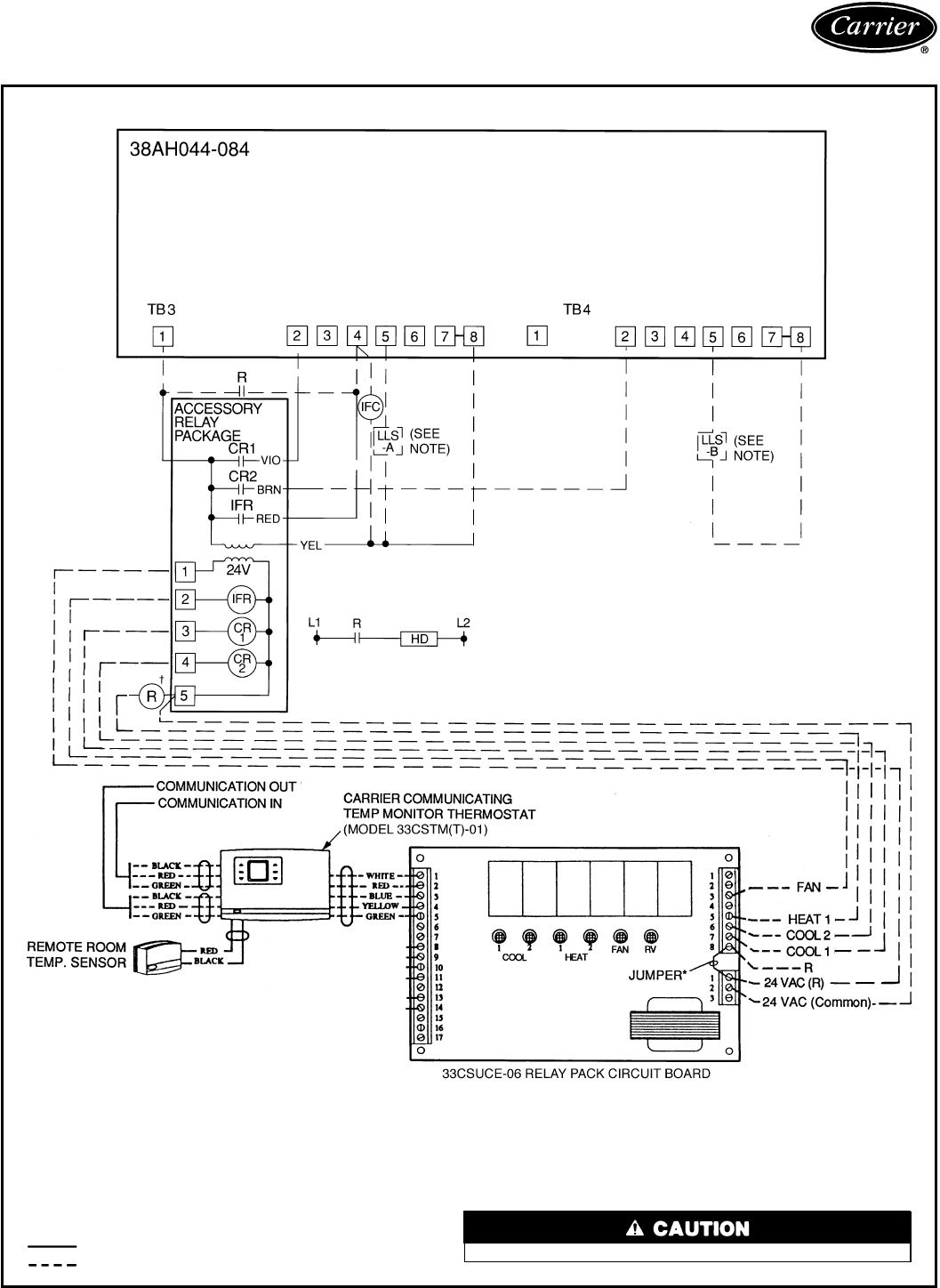
Typical control wiring schematic —
38AH044-134
24-V THERMOSTAT CONTROL WIRING — DUAL-CIRCUIT UNITS 38AH044-084
LEGEND
CR — Control Relay
HD — Heating Device
IFC — Indoor Fan Contactor
IFR — Indoor-Fan Relay
kcmil — Thousand Circular Mils
LLS — Liquid Line Solenoid
R—Heating Relay (field-
supplied 24-v sealed coil,
10 va maximum rating)
RV — Reversing Valve
TB — Terminal Block
Factory Wiring
Field Wiring
*Jumper removed only when separate 24-v transformer power source
is used to power the 33CSUCE-06 relay pack.
†To control heating device and provide automatic indoor-fan operation
on heating.
NOTE: Field-supplied liquid line solenoid valves installed at the evapo-
rator are required on all units.
Internal 33CSUCE-06 relay contacts are rated for 1 amp/24 vac.
91
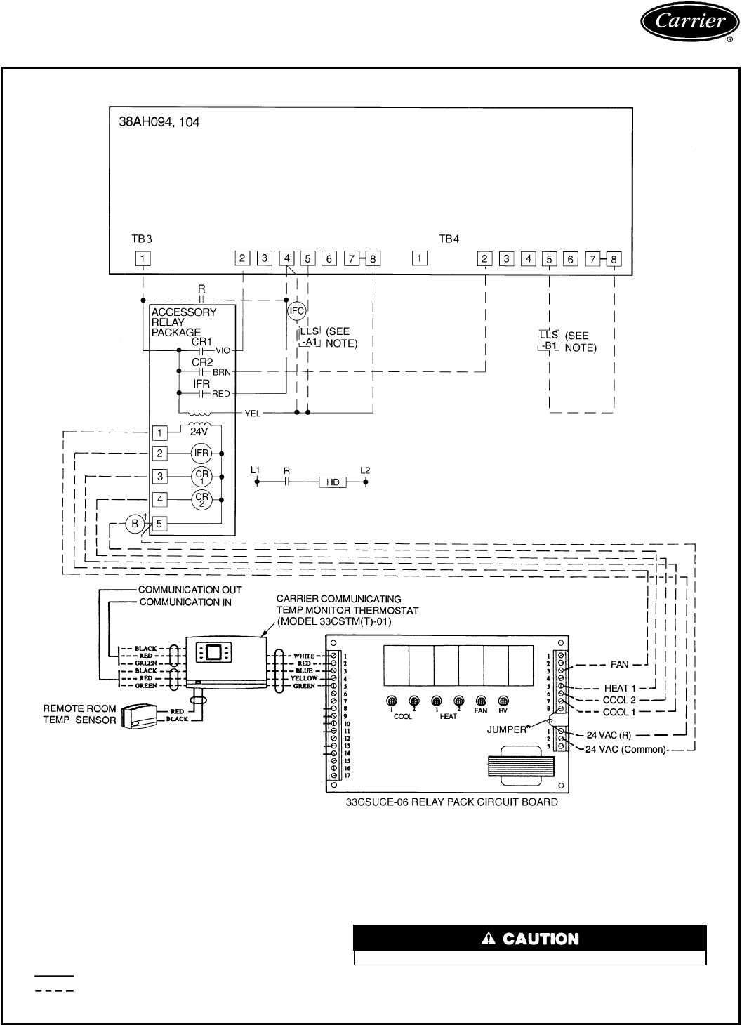
Typical control wiring schematic —
38AH044-134 (cont)
24-V THERMOSTAT CONTROL WIRING — UNITS 38AH094 AND 104
LEGEND
CR — Control Relay
HD — Heating Device
IFC — Indoor Fan Contactor
IFR — Indoor-Fan Relay
LLS — Liquid Line Solenoid
R—Heating Relay (field-
supplied 24-v sealed coil,
10 va maximum rating)
RV — Reversing Valve
TB — Terminal Block
Factory Wiring
Field Wiring
*Jumper removed only when separate 24-v transformer power source
is used to power the 33CSUCE-06 relay pack.
†To control heating device and provide automatic indoor-fan operation
on heating.
NOTE: Field-supplied liquid line solenoid valves installed at the evapo-
rator are required on all units.
Internal 33CSUCE-06 relay contacts are rated for 1 amp/24 vac.
92
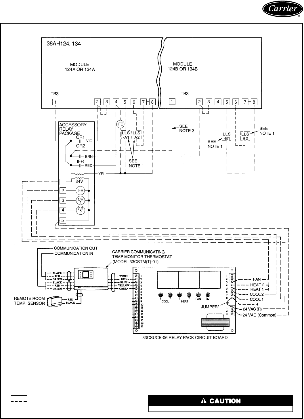
24-V THERMOSTAT CONTROL WIRING — UNITS 38AH124 AND 134
LEGEND
CR — Control Relay
HD — Heating Device
IFC — Indoor Fan Contactor
IFR — Indoor-Fan Relay
LLS — Liquid Line Solenoid
R—Heating Relay (field-
supplied 24-v sealed coil,
10 va maximum rating)
RV — Reversing Valve
TB — Terminal Block
Factory Wiring
Field Wiring
*Jumper removed only when separate 24-v transformer power source
is used to power the 33CSUCE-06 relay pack.
†To control heating device and provide automatic indoor-fan operation
on heating.
NOTES:
1. Field-supplied liquid line solenoid valves installed at the evaporator
are required on all units.
2. Disconnect black wire from CR2 terminal 6; cap loose end and se-
cure. Connect new field-supplied wire from CR2 terminal 6 to TB3
terminal 1 on module 124B or 134B.
Internal 33CSUCE-06 relay contacts are rated for 1 amp/24 vac.
93
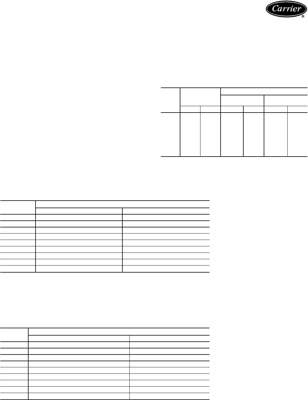
Application data — 38AH044-134
Operating limits
Maximum cooling load ................51.7 C (125 F)
Minimum return-air temperature .........12.8 C (55 F)
Maximum return-air temperature ........35.0 C (95 F)
Range of acceptable saturation
suction temperature ......−6.7 to 10.0 C (20 to 50 F)
Maximum discharge temperature ......135.0 C (275 F)
Minimum discharge superheat ...........15.6 C (60 F)
NOTES:
1. Select indoor equipment at no less than 40 L/s/kW
(300 cfm/ton) nominal condensing unit capacity.
2. Total combined draw of the 2 field-supplied liquid line
solenoid valves and one air handler fan contactor must
not exceed 90 volt-amperes (va). If the specified volt-
amperes must be exceeded, use a remote relay to con-
trol the load.
3. Select equipment to match or to be slightly less than
peak load.
4. Evaluate oil return when selecting vapor line sizes, es-
pecially for partial load conditions.
5. Indoor fan must operate when outdoor unit is
operating.
6. For VAV systems, the total building load is NOT the sum
of the individual peak loads. Equipment selected for the
sum of the individual peak loads will be oversized.
7. For VAV systems with supply- to return-air recycling, use
the equipment room as a return-air plenum.
8. To minimize air recirculation, do not use concentric sup-
ply and return grilles.
LIQUID LINE DATA
UNIT
38AH
MAXIMUM
ALLOWABLE
LIQUID LIFT
LIQUID LINE
Max Allowable
Pressure Drop Max Allowable
Temp Loss
m ft kPa Psi C F
044 17.5 57.5
48.3 7 1.1 2
054 23.0 75.0
064 19.8 65.0
074 11.4 37.5
084 23.0 75.0
094 14.0 46.0
104 12.8 42.0
124 19.8 65.0
134 11.4 37.5
NOTE: Values shown are for units operating at 7.2 C (45 F) saturated
suction at condensing unit and 35 C (95 F) entering outdoor air.
UNLOADING SEQUENCES — STANDARD CONSTANT VOLUME
(CV) UNITS*
UNIT
38AH CAPACITY/STAGE (%)
Standard Dual-Circuit Units Optional Single-Circuit Units
044 100, 75, 50, 25 100, 75, 50, 25
054 100, 79, 42, 21 100, 80, 56, 37
064 100, 84, 48, 32 100, 82, 55, 36
074 100, 86, 43, 29 100, 81, 57, 38
084 100, 83, 50, 33 100, 83, 50, 33
094 100, 85, 55, 44, 33, 22 —
104 100, 91, 74, 65, 47, 38, 26, 17 —
124 100, 91, 77, 68, 50, 41, 27, 18 —
134 100, 90, 76, 66, 45, 37, 25, 16 —
*Additional unloading available with field-installed accessory unloader.
NOTES:
1. Capacities are based on 7.2 C (45 F) saturated suction temperature and 35 C (95 F) outdoor-air
temperature.
2. Single-circuit option available for sizes 044-084 only.
UNLOADING SEQUENCES — OPTIONAL VARIABLE AIR VOLUME
(VAV) UNITS
UNIT
38AH CAPACITY/STAGE (%)
Standard Dual-Circuit Units Optional Single-Circuit Units
044 100, 75, 50, 25 100, 75, 50, 25
054 100, 79, 58, 42, 21 100, 80, 61, 56, 37
064 100, 84, 69, 48, 32, 16 100, 82, 64, 55, 36, 18
074 100, 86, 71, 43, 29, 14 100, 81, 62, 57, 38, 19
084 100, 83, 67, 50, 33, 17 100, 83, 67, 50, 33, 17
094 100, 85, 70, 55, 44, 33, 22 —
104 100, 91, 74, 65, 47, 38, 26, 17 —
124 100, 91, 82, 77, 68, 50, 41, 32, 27, 18, 9 —
134 100, 90, 79, 76, 66, 45, 37, 28, 25, 16, 8 —
NOTES:
1. Capacities are based on 7.2 C (45 F) saturated suction temperature and 35 C (95 F) outdoor-air
temperature.
2. Single-circuit option available for sizes 044-084 only.
94
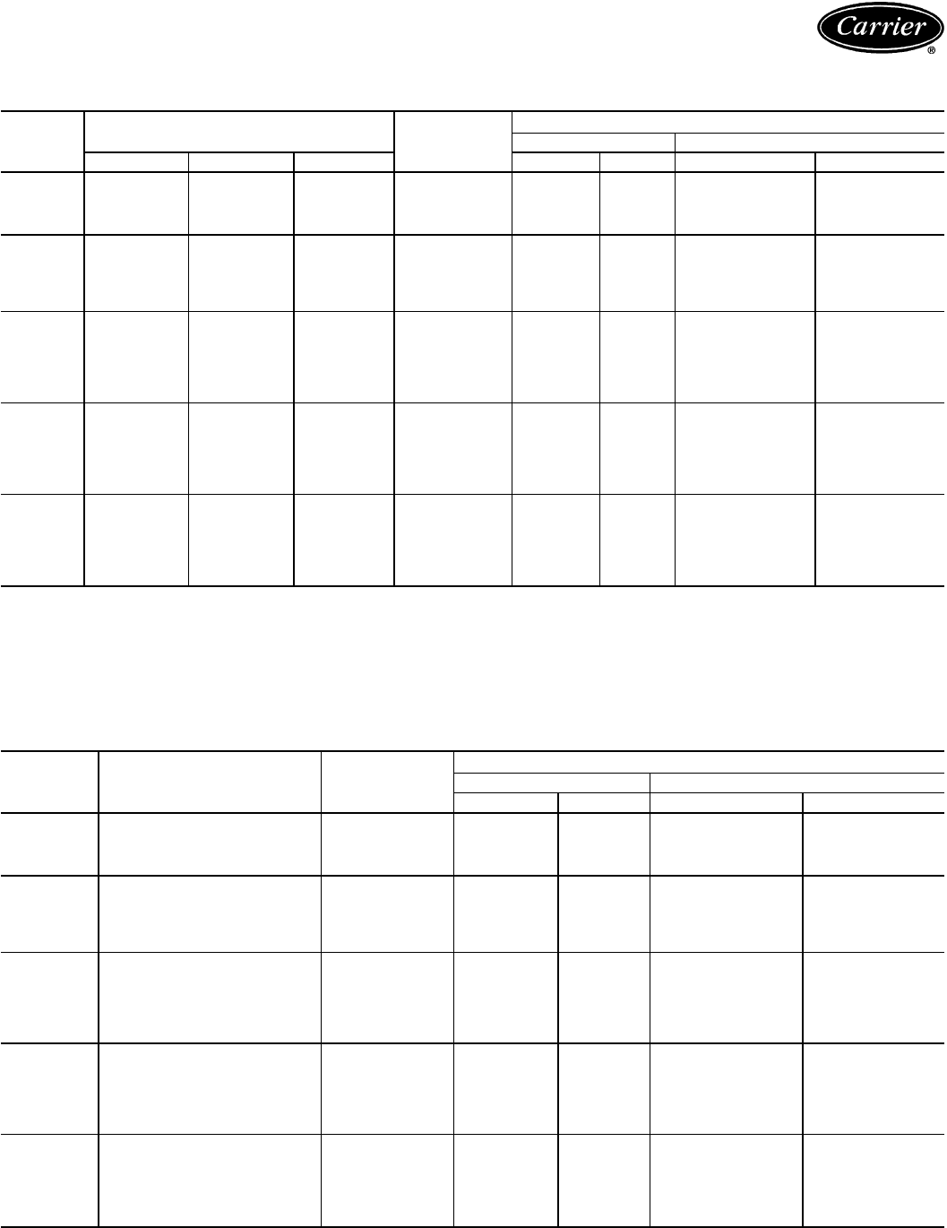
MINIMUM OUTDOOR-AIR OPERATING TEMPERATURE AND UNLOADING SEQUENCES —
38AH044-084 DUAL-CIRCUIT UNITS
UNIT
38AH
QUANTITY OF LOADED
COMPRESSOR CYLINDERS SYSTEM
CAPACITY
(%)
MINIMUM OUTDOOR OPERATING TEMP
w/Std Fans w/MotormasterTIII Control
Ckt A Ckt B Total C F C F
044
4 4 8 100
10.0 50 −28.9 −20
24675
40450
20225
054
4 6 10 100
8.9 48 −28.9 −20
26879
2 4 6* 58*
40442
20221
064
6 6 12 100
3.9 39 −28.9 −20
4 6 10 84
2 6 8* 69*
60648
40432
2 0 2* 16*
074
6 6 12 100
−0.6 31 −28.9 −20
4 6 10 86
2 6 8* 71*
60643
40429
2 0 2* 14*
084
6 6 12 100
−6.7 20 −28.9 −20
4 6 10 83
2 6 8* 67*
60650
40433
2 0 2* 17*
*Requires units with VAV (variable air volume) factory-supplied option.
NOTES:
1. Units have 2 independent refrigeration circuits. Circuit A is lead
circuit.
2. Minimum operating temperature is the higher outdoor temperature of
the 2 circuits.
3. Minimum outdoor-air operating temperature is based on 32 C (90 F)
saturated condensing temperature and 100% capacity.
MINIMUM OUTDOOR-AIR OPERATING TEMPERATURE AND UNLOADING SEQUENCES —
38AH044-084 SINGLE-CIRCUIT UNITS
UNIT
38AH QUANTITY OF LOADED
CYLINDERS
SYSTEM
CAPACITY
(%)
MINIMUM OUTDOOR OPERATING TEMP
w/Std Fans w/Motormaster III Control
CF C F
044
8 100
8.3 47 −28.9 −20
675
450
225
054
10 100
5.0 41 −28.9 −20
880
6* 61*
656
437
064
12 100
3.3 38 −28.9 −20
10 82
8* 64*
655
436
2* 18*
074
12 100
−5.6 22 −28.9 −20
10 81
8* 62*
657
438
2* 19*
084
12 100
−6.7 20 −28.9 −20
10 83
8* 67*
650
433
2* 17*
*Requires VAV (variable air volume) factory-supplied option or
accessory unloader. NOTE: Minimum outdoor-air operating temperature is based on 32 C
(90 F) saturated condensing temperature and 100% capacity.
95
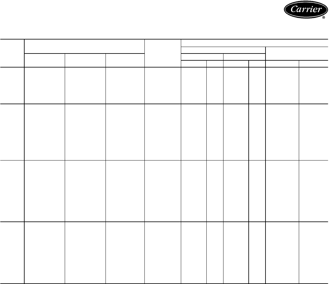
Application data — 38AH044-134 (cont)
MINIMUM OUTDOOR-AIR OPERATING TEMPERATURE AND UNLOADING SEQUENCES —
38AH094-134 DUAL CIRCUIT UNITS
UNIT
38AH
QUANTITY OF LOADED COMPRESSOR
CYLINDERS SYSTEM
CAPACITY
(%)
MINIMUM OUTDOOR OPERATING TEMP
W/Std Fans w/MotormasterTIII
Control
Ckt A Ckt B Total Ckt A Ckt B
CFCF C F
094
10 6 16 100
−13.9 7 −3.9 25 −28.9 −20
10 4 14 85
10 2* 12 70*
10 0 10 55
80 844
60 633
40 422
104
10 12 22 100
−10.0 14 −15.0 5 −28.9 −20
10 10 20 91
10 8† 18 82†
10 6 16 74
10 4 14 65
10 2† 12 56†
10 0 10 47
80 838
60 626
40 417
2† 0 2 9†
124
12 12 24 100
3.3 38 3.3 38 −28.9 −20
12 10 22 91
12 8† 20 82*
12 6 18 77
12 4 16 68
12 2† 14 59†
12 0 12 50
10 0 10 41
8 0 8 32*
60 627
40 418
2* 0 2 9*
134
12 12 24 100
3.3 38 −5.6 22 −28.9 −20
12 10 22 90
12 8 20 79*
12 6 18 76
12 4 16 66
12 2† 14 56†
12 0 12 45
10 0 10 37
8 0 8 28*
60 625
40 416
2* 0 2 8*
*Requires VAV (variable air volume) unit or accessory unloader(s) field
installed on circuit lead compressor. Lead compressor is identified in
Physical Data section, pages 47-50.
†Requires field-installed accessory unloader on circuit lead compressor.
Lead compressor is identified in Physical Data section, pages 47-50.
NOTES:
1. Temperatures calculated with the minimum number of fans operating
per circuit.
2. For 38AH124 and 134 units, circuit A is Module 38AH124A or 134A.
Circuit B is Module 38AH124B or 134B.
3. Minimum outdoor-air operating temperature is based on 32 C (90 F)
saturated condensing temperature and 100% capacity.
96
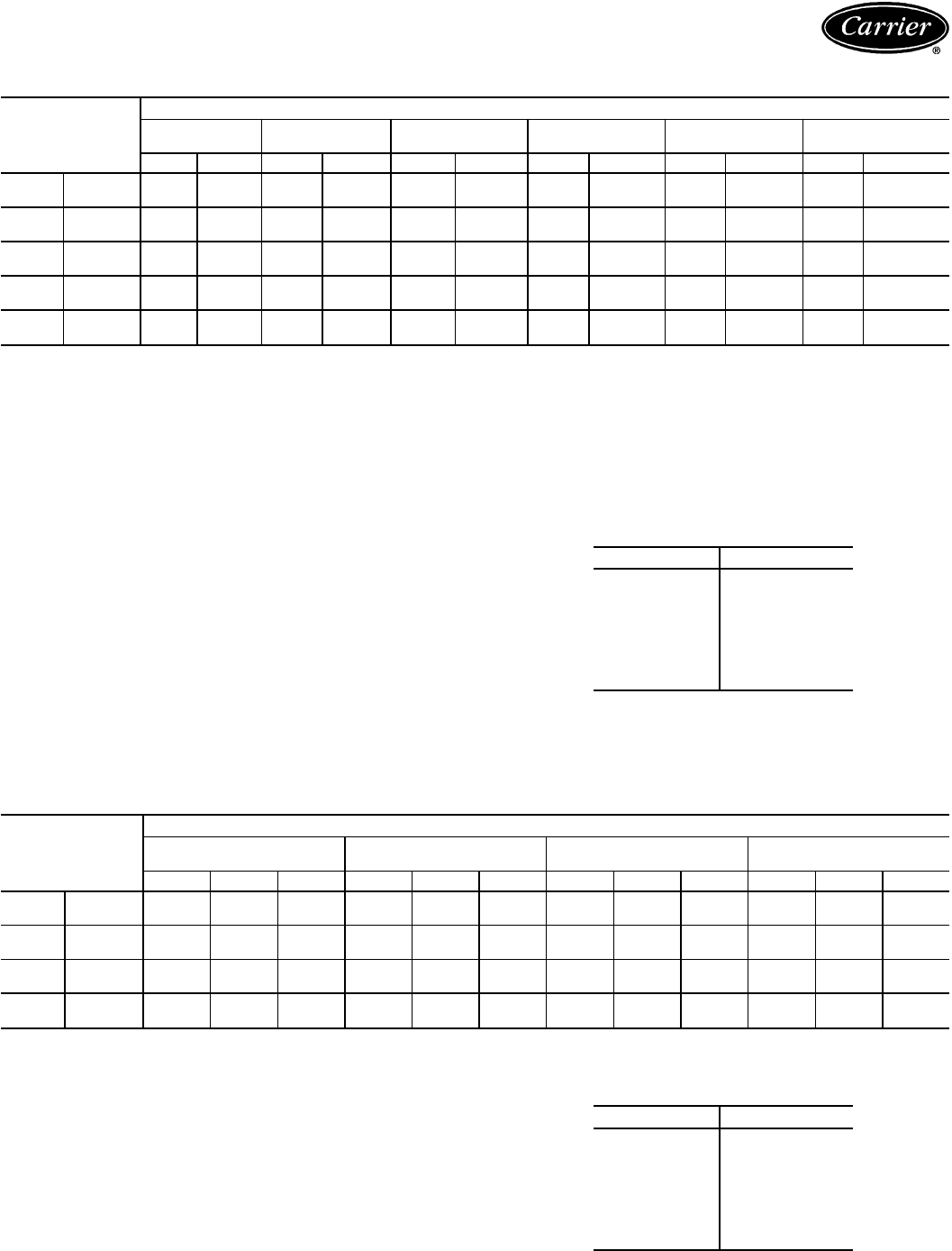
REFRIGERANT PIPING REQUIREMENTS 38AH044-084 DUAL-CIRCUIT UNITS
UNIT
38AH
TOTAL LINEAR LENGTH OF INTERCONNECTING PIPE — FT (M)
15-25
(4.6-7.6) 25-50
(7.6-15.2) 50-75
(15.2-22.9) 75-100
(22.9-30.5) 100-150
(30.5-45.7) 150-200
(45.7-61.0)
LSLSLSLSLSL S
044 Ckt A
5
⁄
8
1
3
⁄
87
⁄
8
1
5
⁄
87
⁄
8
1
5
⁄
87
⁄
8
2
1
⁄
87
⁄
8
2
1
⁄
87
⁄
8
2
1
⁄
8
Ckt B
5
⁄
8
1
3
⁄
87
⁄
8
1
5
⁄
87
⁄
8
1
5
⁄
87
⁄
8
2
1
⁄
87
⁄
8
2
1
⁄
87
⁄
8
2
1
⁄
8
054 Ckt A
5
⁄
8
1
3
⁄
87
⁄
8
1
5
⁄
87
⁄
8
1
5
⁄
87
⁄
8
2
1
⁄
87
⁄
8
2
1
⁄
87
⁄
8
2
1
⁄
8
Ckt B
7
⁄
8
1
5
⁄
87
⁄
8
1
5
⁄
87
⁄
8
2
1
⁄
87
⁄
8
2
1
⁄
8
1
1
⁄
8
2
1
⁄
8
1
1
⁄
8
2
5
⁄
8
*†
064 Ckt A
7
⁄
8
1
5
⁄
87
⁄
8
1
5
⁄
87
⁄
8
2
1
⁄
8
†
7
⁄
8
2
1
⁄
8
†1
1
⁄
8
2
1
⁄
8
†1
1
⁄
8
2
5
⁄
8
**
Ckt B
7
⁄
8
1
5
⁄
87
⁄
8
2
1
⁄
87
⁄
8
2
1
⁄
87
⁄
8
2
1
⁄
8
1
1
⁄
8
2
5
⁄
8
*1
1
⁄
8
2
5
⁄
8
*
074 Ckt A
7
⁄
8
1
5
⁄
87
⁄
8
2
1
⁄
87
⁄
8
2
1
⁄
87
⁄
8
2
1
⁄
8
1
1
⁄
8
2
5
⁄
8
†1
1
⁄
8
2
5
⁄
8
†
Ckt B
7
⁄
8
2
1
⁄
87
⁄
8
2
1
⁄
8
1
1
⁄
8
2
1
⁄
8
1
1
⁄
8
2
5
⁄
8
1
1
⁄
8
2
5
⁄
8
1
1
⁄
8
2
5
⁄
8
084 Ckt A
7
⁄
8
2
1
⁄
87
⁄
8
2
1
⁄
8
1
1
⁄
8
2
1
⁄
8
1
1
⁄
8
2
5
⁄
8
†1
1
⁄
8
2
5
⁄
8
†1
1
⁄
8
2
5
⁄
8
†
Ckt B
7
⁄
8
2
1
⁄
87
⁄
8
2
1
⁄
8
1
1
⁄
8
2
1
⁄
8
1
1
⁄
8
2
5
⁄
8
1
1
⁄
8
2
5
⁄
8
1
1
⁄
8
2
5
⁄
8
LEGEND
L—Liquid Line
S—Suction Line
*Double suction riser required on units with field installed unloader on
circuit B compressor if condensing unit is elevated above
evaporator.
†Double suction riser required on units with field installed unloader on
circuit B compressor if condensing unit is elevated above
evaporator.
**Double suction riser required on all unit configurations if condensing
unit is elevated above evaporator.
NOTES:
1. Addition of 2 unloaders to circuit B compressor is not
recommended.
2. 38AH094 and 38AH104 piping sizes apply only to factory supplied
unit configurations. They do NOT take into account any field installed
unloaders.
3. Piping sizes are based on unit operation above 40 F (4.4 C) satu-
rated suction temperature (SST). When operating below 40 F
(4.4 C), refer to Carrier System Design Manual, E20-IITpiping
design program, or ASHRAE Handbook to select proper line sizes.
4. Pipe sizes are based on the total linear length shown for each col-
umn, plus a 50% allowance for fittings.
5. Suction and liquid line sizing is based on pressure drop equivalent to
2 F (1.1 C) at nominal rating conditions. Higher pressure drop design
criteria may allow selection of smaller pipe sizes, but at a penalty of
decreased system capacity and efficiency.
6. Double suction risers may be required if condensing unit is
elevated above the evaporator. See footnotes and double suction
riser table below.
7. Refer to Carrier System Design Manual or to E20-II design
programs for further information on selecting pipe sizes for split sys-
tems.
8. All pipe sizes are OD inches. Equivalent sizes in millimeters
follow:
in. mm
5
⁄
8
15.9
7
⁄
8
22.2
1
1
⁄
8
28.6
1
3
⁄
8
34.9
1
5
⁄
8
41.3
2
1
⁄
8
54.0
2
5
⁄
8
66.7
3
1
⁄
8
79.4
REFRIGERANT PIPING REQUIREMENTS FOR DOUBLE SUCTION RISERS,
38AH054-104 DUAL-CIRCUIT UNITS
UNIT
38AH
TOTAL LINEAR LENGTH OF INTERCONNECTING PIPE — FT (M)
50-75
(15.2-22.9) 75-100
(22.9-30.5) 100-150
(30.5-45.7) 150-200
(45.7-61.0)
ABCABCABCABC
054 Ckt A ————— ———————
Ckt B ————— ————1
5
⁄
8
2
1
⁄
8
2
5
⁄
8
064 Ckt A 1
3
⁄
8
1
5
⁄
8
2
1
⁄
8
1
3
⁄
8
1
5
⁄
8
2
1
⁄
8
1
5
⁄
8
1
5
⁄
8
2
1
⁄
8
1
5
⁄
8
2
1
⁄
8
2
5
⁄
8
Ckt B ————— —1
5
⁄
8
2
1
⁄
8
2
5
⁄
8
1
5
⁄
8
2
1
⁄
8
2
5
⁄
8
074 Ckt A ————— —1
5
⁄
8
2
1
⁄
8
2
5
⁄
8
1
5
⁄
8
2
1
⁄
8
2
5
⁄
8
Ckt B ————— ———————
084 Ckt A ———1
5
⁄
8
2
1
⁄
8
2
5
⁄
8
1
5
⁄
8
2
1
⁄
8
2
5
⁄
8
1
5
⁄
8
2
1
⁄
8
2
5
⁄
8
Ckt B ————— ———————
LEGEND
——Not Required
Pipe A — Suction Riser Without Trap
Pipe B — Suction Riser With Trap
Pipe C — Suction Line to Condensing Unit
NOTES:
1. See Refrigerant Piping Requirements table at top of page to
determine need for double suction risers.
2. Pipe sizes are based on the total linear length, shown for each col-
umn, plus a 50% allowance for fittings.
3. Suction and liquid line sizing is based on pressure drop equivalent to
2 F (1.1 C) at nominal rating conditions. Higher design pressure drop
criteria may allow selection of smaller pipe sizes but at a penalty of
decreased system capacity and efficiency.
4. Refer to Carrier System Design Manual or to E20-II design programs
for further information on selecting pipe sizes for split systems.
5. All pipe sizes are OD inches. Equivalent sizes in millimeters follows:
in. mm
5
⁄
8
15.9
7
⁄
8
22.2
1
1
⁄
8
28.6
1
3
⁄
8
34.9
1
5
⁄
8
41.3
2
1
⁄
8
54.0
2
5
⁄
8
66.7
3
1
⁄
8
79.4
97
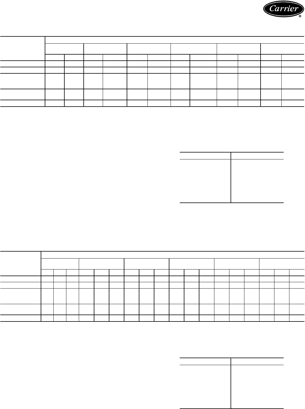
Application data — 38AH044-134 (cont)
38AH044-084 OPTIONAL SINGLE-CIRCUIT UNITS; 38AH124,134
MODULAR UNITS (DUAL-CIRCUIT)
UNIT
38AH
TOTAL LINEAR LENGTH OF INTERCONNECTING PIPE — FT (M)
15-20
(4.6-6.1) 20-50
(6.1-15.2) 50-75
(15.2-22.9) 75-100
(22.9-30.5) 100-150
(30.5-45.7) 150-200
(45.7-61.0)
LSLSLSL S LSLS
044
7
⁄
8
2
1
⁄
87
⁄
8
2
1
⁄
8
1
1
⁄
8
2
1
⁄
8
1
1
⁄
8
2
5
⁄
8
*1
1
⁄
8
2
5
⁄
8
*1
3
⁄
8
2
5
⁄
8
*
054
7
⁄
8
2
1
⁄
8
1
1
⁄
8
2
1
⁄
8
1
1
⁄
8
2
5
⁄
8
*1
1
⁄
8
2
5
⁄
8
*1
1
⁄
8
2
5
⁄
8
*1
3
⁄
8
3
1
⁄
8
*
064;
Modules 124A,
124B, 134A
7
⁄
8
2
1
⁄
8
1
1
⁄
8
2
5
⁄
8
†1
1
⁄
8
2
5
⁄
8
†1
1
⁄
8
2
5
⁄
8
†1
3
⁄
8
3
1
⁄
8
*1
3
⁄
8
3
1
⁄
8
*
074;
Module 134B
7
⁄
8
2
1
⁄
8
1
1
⁄
8
2
5
⁄
8
†1
1
⁄
8
2
5
⁄
8
†1
3
⁄
8
3
1
⁄
8
*1
3
⁄
8
3
1
⁄
8
*1
3
⁄
8
3
1
⁄
8
*
084 1
1
⁄
8
2
1
⁄
8
1
1
⁄
8
2
5
⁄
8
†1
3
⁄
8
3
1
⁄
8
*1
3
⁄
8
3
1
⁄
8
*1
3
⁄
8
3
1
⁄
8
*1
5
⁄
8
3
5
⁄
8
*
LEGEND
CV — Constant Volume
L—Liquid Line
S—Suction Line
VAV — Variable Air Volume
*Double suction riser required on all units configurations if condensing
unit is elevated above evaporator.
†Double suction riser required on units with factory installed VAV option
or CV units with additional field installed unloader on circuit A1 (lead)
compressor if condensing unit is elevated above evaporator.
NOTES:
1. Double risers are required if condensing unit is elevated above evapo-
rator.
See footnotes and double suction riser table below.
2. Pipe sizes are based on the total linear length, shown for each col-
umn, plus a 50% allowance for fittings.
3. Suction line sizing is based on 1.1 C (2 F) pressure drop at nominal
rating conditions. Liquid line sizing is based on 1.1 C (2 F) pressure
drop. Higher design pressure drop criteria may allow selection of
smaller pipe sizes but at a penalty of decreased system capacity and
efficiency.
4. Suction line sizing is based on using the same diameter tube from
the evaporator riser outlet to the condensing unit.
5. Suction line riser selections are based on using maximum possible
unloaders.
6. Refer to Carrier System Design Manual or to E20-IITdesign pro-
grams for further information on selecting pipe sizes for split systems.
7. All pipe sizes are OD inches; equivalent sizes in millimeters follow:
in. mm
5
⁄
8
15.9
7
⁄
8
22.2
1
1
⁄
8
28.6
1
3
⁄
8
34.9
1
5
⁄
8
41.3
2
1
⁄
8
54.0
2
5
⁄
8
66.7
3
1
⁄
8
79.4
3
5
⁄
8
92.1
38AH044-084 OPTIONAL SINGLE-CIRCUIT UNITS; 38AH124,134
MODULAR UNITS (DUAL-CIRCUIT) —
DOUBLE SUCTION RISER
UNIT
38AH
TOTAL LINEAR LENGTH OF INTERCONNECTING PIPE — FT (M)
15-20
(4.6-6.1) 20-50
(6.1-15.2) 50-75
(15.2-22.9) 75-100
(22.9-30.5) 100-150
(30.5-45.7) 150-200
(45.7-61.0)
ABCABCABCABCABCABC
044 —————————1
5
⁄
8
2
1
⁄
8
2
5
⁄
8
1
5
⁄
8
2
5
⁄
8
2
5
⁄
8
1
5
⁄
8
2
5
⁄
8
2
5
⁄
8
054 ——————1
5
⁄
8
2
1
⁄
8
2
5
⁄
8
1
5
⁄
8
2
1
⁄
8
2
5
⁄
8
1
5
⁄
8
2
1
⁄
8
2
5
⁄
8
1
5
⁄
8
2
5
⁄
8
3
1
⁄
8
064;
Modules 124A,
124B, 134A ———1
5
⁄
8
2
1
⁄
8
2
5
⁄
8
1
5
⁄
8
2
1
⁄
8
2
5
⁄
8
1
5
⁄
8
2
1
⁄
8
2
5
⁄
8
1
5
⁄
8
2
5
⁄
8
3
1
⁄
8
1
5
⁄
8
2
5
⁄
8
3
1
⁄
8
074;
Module 134B ———1
5
⁄
8
2
1
⁄
8
2
5
⁄
8
1
5
⁄
8
2
1
⁄
8
2
5
⁄
8
1
5
⁄
8
2
5
⁄
8
3
1
⁄
8
1
5
⁄
8
2
5
⁄
8
3
1
⁄
8
1
5
⁄
8
3
1
⁄
8
3
5
⁄
8
084 ———1
5
⁄
8
2
1
⁄
8
2
5
⁄
8
1
5
⁄
8
2
5
⁄
8
3
1
⁄
8
1
5
⁄
8
2
5
⁄
8
3
1
⁄
8
1
5
⁄
8
2
5
⁄
8
3
1
⁄
8
1
5
⁄
8
3
1
⁄
8
3
5
⁄
8
LEGEND
——Not Required
Pipe A — Suction Riser Without Trap
Pipe B — Suction Riser With Trap
Pipe C — Suction Line to Condensing Unit
NOTES:
1. See Refrigerant Piping Requirements table at top of page to deter-
mine need for double suction risers.
2. Pipe sizes are based on the total linear length, shown for each col-
umn, plus a 50% allowance for fittings.
3. Suction line sizing is based on 1.1 C (2 F) pressure drop at nominal
rating conditions. Liquid line sizing is based on 1.1 C (2 F) pressure
drop. Higher design pressure drop criteria may allow selection of
smaller pipe sizes but at a penalty of decreased system capacity and
efficiency.
4. Suction line sizing is based on using the same diameter tube from
the evaporator riser outlet to the condensing unit.
5. Suction line riser selections are based on using maximum possible
unloaders.
6. Refer to Carrier System Design Manual or to E20-II design programs
for further information on selecting pipe sizes for split systems.
7. All pipe sizes are OD inches; equivalent sizes in millimeters follow:
in. mm
5
⁄
8
15.9
7
⁄
8
22.2
1
1
⁄
8
28.6
1
3
⁄
8
34.9
1
5
⁄
8
41.3
2
1
⁄
8
54.0
2
5
⁄
8
66.7
3
1
⁄
8
79.4
3
5
⁄
8
92.1
98
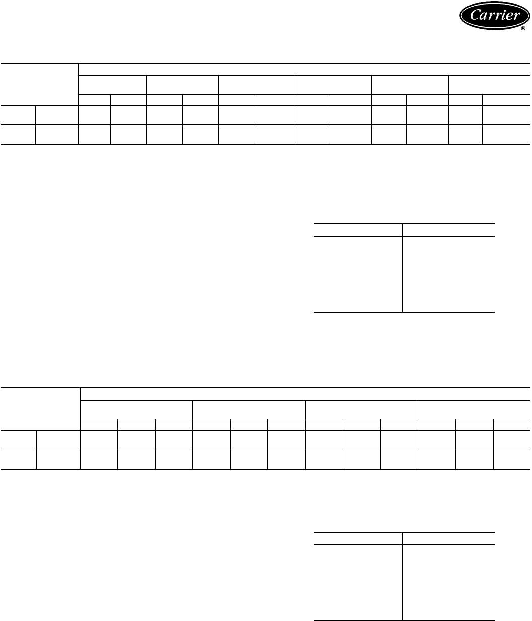
REFRIGERANT PIPING REQUIREMENTS 38AH094,104
DUAL-CIRCUIT UNITS
UNIT
38AH
TOTAL LINEAR LENGTH OF INTERCONNECTING PIPE - FT (M)
15-25
(4.6-7.6) 25-50
(7.6-15.2) 50-75
(15.2-22.9) 75-100
(22.9-30.5) 100-150
(30.5-45.7) 150-200
(45.7-61.0)
LSLSLSLSLSL S
094 Ckt A
7
⁄
8
2
1
⁄
8
1
1
⁄
8
2
1
⁄
8
1
1
⁄
8
2
5
⁄
8
** 1
1
⁄
8
2
5
⁄
8
** 1
1
⁄
8
2
5
⁄
8
** 1
3
⁄
8
3
1
⁄
8
**
Ckt B
7
⁄
8
2
1
⁄
87
⁄
8
2
1
⁄
8
1
1
⁄
8
2
1
⁄
8
1
1
⁄
8
2
5
⁄
8
*† 1
1
⁄
8
2
5
⁄
8
*† 1
1
⁄
8
2
5
⁄
8
*†
104 Ckt A
7
⁄
8
2
1
⁄
87
⁄
8
2
1
⁄
8
1
1
⁄
8
2
1
⁄
8
1
1
⁄
8
2
5
⁄
8
** 1
1
⁄
8
2
5
⁄
8
** 1
3
⁄
8
3
1
⁄
8
**
Ckt B
7
⁄
8
2
1
⁄
8
1
1
⁄
8
2
1
⁄
8
1
1
⁄
8
2
5
⁄
8
1
1
⁄
8
2
5
⁄
8
1
3
⁄
8
2
5
⁄
8
1
3
⁄
8
3
1
⁄
8
**
LEGEND
L—Liquid Line
S—Suction Line
*Double suction riser required on units with field installed unloader on
circuit B compressor if condensing unit is elevated above
evaporator.
†Double suction riser required on units with field installed unloader on
circuit B compressor if condensing unit is elevated above
evaporator.
**Double suction riser required on all unit configurations if condensing
unit is elevated above evaporator.
NOTES:
1. Double risers are required if condensing unit is elevated above evapo-
rator.
See footnotes and double suction riser table below.
2. Pipe sizes are based on the total linear length, shown for each col-
umn, plus a 50% allowance for fittings.
3. Suction line sizing is based on 1.1 C (2 F) pressure drop at nominal
rating conditions. Liquid line sizing is based on 1.1 C (2 F) pressure
drop. Higher design pressure drop criteria may allow selection of
smaller pipe sizes but at a penalty of decreased system capacity and
efficiency.
4. Suction line sizing is based on using the same diameter tube from
the evaporator riser outlet to the condensing unit.
5. Suction line riser selections are based on using maximum possible
unloaders.
6. Refer to Carrier System Design Manual or to E20-II design programs
for further information on selecting pipe sizes for split systems.
7. All pipe sizes are OD inches; equivalent sizes in millimeters follow:
in. mm
5
⁄
8
15.9
7
⁄
8
22.2
1
1
⁄
8
28.6
1
3
⁄
8
34.9
1
5
⁄
8
41.3
2
1
⁄
8
54.0
2
5
⁄
8
66.7
3
1
⁄
8
79.4
3
5
⁄
8
92.1
38AH094,104 DUAL-CIRCUIT UNITS, DOUBLE SUCTION RISER
UNIT
38AH
TOTAL LINEAR LENGTH OF INTERCONNECTING PIPE — FT (M)
50-75
(15.2-22.9) 75-100
(22.9-30.5) 100-150
(30.5-45.7) 150-200
(45.7-61.0)
ABCABCABCABC
094 Ckt A 1
3
⁄
8
2
1
⁄
8
2
5
⁄
8
1
3
⁄
8
2
1
⁄
8
2
5
⁄
8
1
5
⁄
8
2
1
⁄
8
2
5
⁄
8
1
5
⁄
8
2
5
⁄
8
3
1
⁄
8
Ckt B ———1
3
⁄
8
2
1
⁄
8
2
5
⁄
8
1
5
⁄
8
2
1
⁄
8
2
5
⁄
8
1
5
⁄
8
2
1
⁄
8
2
5
⁄
8
104 Ckt A ———1
3
⁄
8
2
1
⁄
8
2
5
⁄
8
1
5
⁄
8
2
1
⁄
8
2
5
⁄
8
1
5
⁄
8
2
5
⁄
8
3
1
⁄
8
Ckt B —————————1
5
⁄
8
2
5
⁄
8
3
1
⁄
8
LEGEND
——Not Required
Pipe A — Suction Riser Without Trap
Pipe B — Suction Riser With Trap
Pipe C — Suction Line to Condensing Unit
NOTES:
1. See Refrigerant Piping Requirements table at top of page to deter-
mine need for double suction risers.
2. Pipe sizes are based on the total linear length, shown for each col-
umn, plus a 50% allowance for fittings.
3. Suction line sizing is based on 1.1 C (2 F) pressure drop at nominal
rating conditions. Liquid line sizing is based on 1.1 C (2 F) pressure
drop. Higher design pressure drop criteria may allow selection of
smaller pipe sizes but at a penalty of decreased system capacity and
efficiency.
4. Suction line sizing is based on using the same diameter tube from
the evaporator riser outlet to the condensing unit.
5. Suction line riser selections are based on using maximum possible
unloaders.
6. Refer to Carrier System Design Manual or to E20-II design programs
for further information on selecting pipe sizes for split systems.
7. All pipe sizes are OD inches; equivalent sizes in millimeters follow:
in. mm
5
⁄
8
15.9
7
⁄
8
22.2
1
1
⁄
8
28.6
1
3
⁄
8
34.9
1
5
⁄
8
41.3
2
1
⁄
8
54.0
2
5
⁄
8
66.7
3
1
⁄
8
79.4
3
5
⁄
8
92.1
99
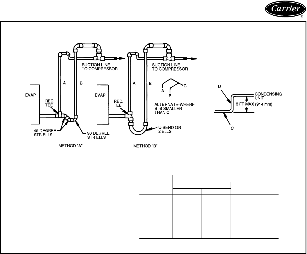
Application data — 38AH044-134 (cont)
REFRIGERANT PIPING REQUIREMENTS
DOUBLE SUCTION RISER CONSTRUCTION
LEGEND
A—Pipe A, Suction Riser, Lower Trap
B—Pipe B, Suction Riser with Trap
C—Suction Line to Condensing Unit
D—Pipe D, Suction Riser Short Lift
RED. — Reducer
STR — Street
NOTE: Short riser, pipe D, is used when routing suction line to con-
densing unit connection. See table below:
UNIT
38AH
PIPE D DIAMETER*
Dual Circuit Single Circuit
AB
044 1
5
⁄
8
1
5
⁄
8
2
1
⁄
8
054 1
5
⁄
8
1
5
⁄
8
2
1
⁄
8
064 1
5
⁄
8
2
1
⁄
8
2
1
⁄
8
074 2
1
⁄
8
2
1
⁄
8
2
1
⁄
8
084 2
1
⁄
8
2
1
⁄
8
2
5
⁄
8
094 2
1
⁄
8
2
1
⁄
8
—
104 2
1
⁄
8
2
1
⁄
8
—
124A,B 2
1
⁄
8
2
1
⁄
8
—
134A,B 2
1
⁄
8
2
1
⁄
8
—
*Maximum length of riser is 3 ft (914 mm).
100

Guide specifications — 38AH024-034
Commercial Air-Cooled Condensing Units
HVAC Guide Specifications
Size Range: 63 to 87 kW (18 to 25 Tons), Nominal
Carrier Model Number: 38AH
Part 1 — General
1.01 SYSTEM DESCRIPTION
Outdoor-mounted, air-cooled condensing unit suit-
able for on-the-ground or rooftop installation. Unit
shallhave 2 independentrefrigeration circuitsand shall
consist of dual semi-hermetic reciprocating compres-
sors, air-cooled coils, propeller-type condenser fans,
and a control box. Unit shall discharge supply air up-
ward as shown on contract drawings. Unit shall be
used in refrigeration circuit matched with a packaged
fan-coil unit or direct-expansion cooler.
1.02 QUALITY ASSURANCE
A. Unit shall be rated in accordance with ARI Standard
365, latest edition (U.S.A. standard).
B. Unit construction shall comply with latest edition of
ANSI/ASHRAE and with NEC (U.S.A. standard).
C. Unit shall be manufactured in a facility registered to
ISO(InternationalStandardsOrganization) 9002 manu-
facturing quality standard.
D. Unitshall be constructed in accordance with ULstand-
ards (U.S.A.).
E. Unit cabinet shall be capable of withstanding
500-hoursalt-sprayexposure per ASTMB117 (U.S.A)
(scribed specimen).
F. Air-cooled condenser coils shall be leak tested at
1034 kPa (150 psig) and pressure tested at 3310 kPa
(480 psig).
1.03 DELIVERY, STORAGE, AND HANDLING
Unit shall be shipped as single package only, and
shall be stored and handled per unit manufacturer’s
recommendations.
1.04 WARRANTY
For inclusion by specifying engineer.
Part2—Products
2.01 EQUIPMENT
A. General:
Factory assembled, single-piece, air-cooled condens-
ing unit. Contained within the unit enclosure shall be
all factory wiring, piping, controls, compressors, hold-
ing charge, and special features required prior to field
start-up.
B. Unit Cabinet:
1. Unitcabinet shall beconstructed of galvanizedsteel,
bonderized and coated with a prepainted, baked
enamel finish.
2. Unit access panels shall be hinged for control box
service access.
3. Lifting holes shall be provided to facilitate rigging.
C. Fans:
1. Condenser fans shall be direct-drive propeller type,
discharging air vertically upward.
2. Condenser fan motors shall be 3-phase type
with class B insulation and permanently lubricated
bearings. Class F fan motors shall be available as
a factory-installed option.
3. Shafts shall have inherent corrosion resistance.
4. Fan blades shall be statically and dynamically
balanced.
5. Condenser fan openings shall be equipped with
PVC-coated steel wire safety guards.
D. Compressors:
1. Compressors shall be manufactured by the con-
densing unit manufacturer, and shall be service-
able, reciprocating, semi-hermetic type.
2. Compressors shall be equipped with an automa-
tically reversible oil pump, operating oil charge,
suction and discharge shutoff valves, and an insert-
type factory-sized crankcase heater to control oil
dilution.
3. Compressors shall be mounted on spring vibra-
tion isolators with an isolation efficiency of no less
than 95%.
4. Compressor speed shall not exceed 24.3 r/s
(1460 rpm).
5. Lead compressor shall unload using suction cutoff
unloading (electrical solenoid unloading shall be
available as an accessory).
E. Condenser Coils:
1. Condenser coils shall be air cooled, circuited for
integral subcooler.
2. Coil shall be constructed of aluminum fins me-
chanically bonded to internally grooved, seamless
copper tubes which are then cleaned, dehydrated,
and sealed. Copper fins and precoated aluminum
fins shall be available as options.
F. Refrigeration Components:
Refrigeration circuit components shall include hot gas
muffler,high-side pressure reliefdevice, liquid line shut-
off valve, suction and discharge shutoff valves, hold-
ing charge, and compressor oil.
101
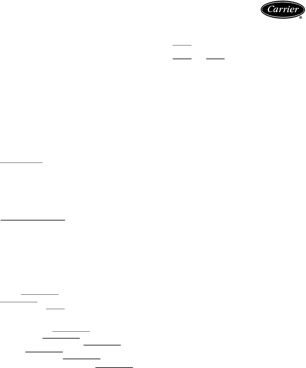
Guide specifications — 38AH024-034 (cont)
G. Controls and Safeties:
1. Minimum control functions shall include:
a. Power and control terminal blocks.
b. Five-minute Time Guardtprotection to pre-
vent compressor short-cycling.
c. Lockout on auto-reset safety until reset from
thermostat.
d. Capacitycontrol on the lead compressor shall
be by suction cutoff unloaders in response
to compressor suction pressure. Electric
solenoid unloading shall be available as an
accessory.
e. Head pressure control for mild ambient tem-
perature operation by fan cycling. One con-
denser fan shall be cycled by ambient tem-
perature to maintain proper head pressure.
2. Minimum safety devices shall include:
Automatic reset (after resetting first at thermostat)
a. High discharge-temperature cutout.
b. Low suction-pressure cutout.
c. Condenser fan motors to beprotected against
overloads or single-phase condition by inter-
nal overloads.
d. Low oil-pressure cutout.
Manual reset at the unit
a. Electrical overload protection through the use
of definite-purpose contactors and calibrated,
ambient compensated, magnetic trip circuit
breakers. Circuit breakers shall open all 3
phases in the event of an overload in any one
of the phases or a single-phase condition.
b. High discharge-pressure cutout.
H. Operating Characteristics:
1. The capacity of the condensing unit shall meet or
exceed at a suction temperature of
.Thepower consumption atfull load
shall not exceed kW.
2. The combination of the condensing unit and the
evaporator or fan coil unit shall have a total net
cooling capacity of or greater at an
airflow rate of , entering-air tem-
perature at the evaporator at wet
bulb and dry bulb, and air entering
the condensing unit at .
3. The system shall have an EER of
or greater at standard ARI conditions.
I. Electrical Requirements:
1. Nominal unit electrical characteristics shall be
v, 3-ph, 50 Hz. The unit shall be capable
of satisfactory operation within voltage limits of
vto v.
2. Unit electrical power shall be single point
connection.
3. Unit control circuit shall be 230 v for 380/415 v
and 230 v units, or 200 v for 346 v units.
J. Special Features:
Certain standard features are not applicable when the
features designated * are specified. For assistance in
amending the specifications, your local Carrier Sales
Office should be contacted.
* 1. Unloader Conversion Kit:
Unloader valve, piston, and hardware shall be
supplied to convert any pressure-operated com-
pressor unloader to electrical unloading.
AccessoryModuPanel™orfield-supplied step con-
troller shall be provided for electrical unloading.
* 2. Gage Panel:
A gage panel package shall be provided which
includes a suction and discharge pressure gage
for each refrigerant circuit.
3. Thermostat Controls:
a. Debonair™ programmable multi-stage ther-
mostat with 7-day clock, holiday scheduling,
large Thermoglow™ display, remote sensor
capability, and Title 24 compliance.
b. TEMP System programmable communi-
cating multi-stage thermostat with fan switch,
timeclock, LCD display, °F/°C capability,
and CCN (Carrier Comfort Network)
compatibility.
c. Commercial Electronic Thermostatwith7-day
timeclock, auto-changeover, multi-stage ca-
pability, and large LCD temperature display.
d. Non-programmable thermostat with fan switch
subbase.
4. Electric Unloader Package:
Electric unloader shall provide an additional step
of electric unloading.
5. Pressure Unloader Package:
Pressure unloader shall provide an additional step
of pressure unloading.
102

* 6. ModuPanel™ Control:
Control shall provide 10-step microprocessor-
based control for variable air volume
applications.
* 7. MotormastertIII Control:
Control shall maintain correct condensing pres-
sure at low ambient temperatures.
* 8. VAV (Variable Air Volume) Modification:
Unit shall be supplied from the factory with nec-
essary wiring modifications for connection to a
field-supplied ModuPanel discharge air control-
ler. The VAV modification shall include 2 electric
unloaders on the lead compressor.
9. Optional Condenser Coil Materials:
a. Pre-Coated Aluminum-Fin Coils:
Shall have a durable epoxy-phenolic coating
toprovideprotectioninmildlycorrosivecoastal
environments. Coating shall be applied to the
aluminum fin stock prior to the fin stamping
process to create an inert barrier between the
aluminumfinandcoppertube.Epoxy-phenolic
barriershall minimize galvanic action between
dissimilar metals.
b. Copper-Fin Coils:
Shall be constructed of copper fins mechan-
ically bonded to copper tubes. All copper
construction shall provide protection in mod-
erate coastal applications.
c. Post-Coated Aluminum-Fin Coils:
Shallhave a durableorganiccoatinguniformly
applied over all coil surfaces. Coating shall
be deep brown color applied by a dip and
bake process to ensure complete encapsula-
tion of all coil surfaces. Coated coil shall with-
stand1,000-hour salt spraytest inaccordance
with ASTM B117. Coil construction shall be
aluminum fins mechanically bonded to cop-
per tubes.
d. Post-Coated Copper-Fin Coils:
Shallhave a durableorganiccoatinguniformly
applied over all coil surfaces. Coating shall
be deep brown color applied by a dip and
bake process to ensure complete encapsula-
tion of all coil surfaces. Coated coil shall with-
stand1,000-hour salt spraytest inaccordance
with ASTM B117. Coil construction shall be
copper fins mechanically bonded to copper
tubes.
10. Class F Motors:
Shallprovide additional motor insulation for high-
ambient temperature environments.
103

Guide specifications — 40RM
Commercial Packaged Air-Handling Unit
HVAC Guide Specifications
SizeRange: 2831 to 5663 L/s (6000 to 12,000 Cfm),
Nominal Airflow
52 to 105 kW (15 to 30 Tons),
Nominal Cooling
Carrier Model Number: 40RM
Part 1 — General
1.01 SYSTEM DESCRIPTION
A. Indoor, packaged air-handling unit for use in commer-
cial split systems. Unit shall have a multiposition
design and shall be capable of horizontal or vertical
(upflow) installation on a floor or in a ceiling, with or
without ductwork. (Only vertical units are to be
applied without ductwork).
B. Unit shall be used in a refrigerant circuit with a match-
ing air-cooled condensing unit.
1.02 QUALITY ASSURANCE
A. Coils shall be designed and tested in accordance with
ASHRAE 15 Safety Code for Mechanical Refrig-
eration (U.S.A.), latest edition.
B. Unit shall be constructed in accordance with ETL
(U.S.A.) and ETL, Canada standards.
C. Unit insulation and adhesive shall comply with NFPA
90A(U.S.A.)requirements for flamespread and smoke
generation. Insulation shall contain a U.S.A. EPA-
registered immobilized antimicrobial agent to effec-
tively resist the growth of bacteria and fungi as proven
by tests in accordance with ASTM standards G21 and
22 (U.S.A.).
D. Unit shall be manufactured in a facility registered to
the ISO 9002/BS5750, Part 2 manufacturing qual-
ity standard.
E. Direct-expansion coils shall be burst tested at
2999 kPag (435 psig) and leak tested at 1034 kPag
(150 psig).
1.03 DELIVERY AND STORAGE
Units shall be stored and handled per manufacturer’s
recommendations.
Part2—Products
2.01 EQUIPMENT
Indoor mounted, draw-thru, packaged air-handling
unit that can be used in a suspended horizontal con-
figuration or vertical (upflow) configuration. Unit shall
consist of forward-curved belt-driven centrifugal fan(s),
motor and drive assembly, prewired fan motor con-
tactor, factory-installed refrigerant metering devices,
cooling coil, 51 mm (2-in.) disposable air filters, and
condensate drain pans for vertical or horizontal
configurations.
A. Base Unit:
1. Cabinetshall be constructedof mill-galvanized steel.
2. Cabinet panels shall be fully insulated with
12.7-mm (
1
⁄
2
-in.) fire-retardant material. Insula-
tion shall contain a U.S.A. EPA-registered immo-
bilized antimicrobial agent to effectively resist the
growth of bacteria and fungi as proven by tests in
accordance with ASTM standards G21 and 22
(U.S.A.).
3. Unit shall contain PVC condensate drain pans for
both vertical and horizontal applications. Drain
pans shall have connections on right and left sides
of unit to facilitate field connection. Drain pans
shall have the ability to be sloped toward the right
or left side of the unit to prevent standing water
from accumulating in pans.
4. Unit shall have factory-supplied 51-mm (2-in.)
throwaway-type filters installed upstream from the
cooling coil. Filter access shall be from either the
right or left side of the unit.
B. Coils:
Coils shall consist of 3 rows of copper tubes with sine-
wave aluminum fins bonded to the tubes by mechani-
cal expansion. Coil tubing shall be internally rifled to
maximize heat transfer. Suction and liquid line con-
nections or supply and discharge connections shall be
made on the same side of the coil.
Direct-expansion coils shall feature factory-installed
thermostatic expansion valves (TXVs) for refrigerant
control. The TXVs shall be capable of external
adjustment.
C. Operating Characteristics:
Unit shall be capable of providing L/s (cfm)
airflow at an external static pressure of kPag
(in. wg).
D. Motor:
Fan motor of the size and electrical characteristics
specified on the equipment schedule shall be factory
supplied and installed.
E. Factory-Installed Options:
1. Alternate Motor and Drive:
An alternate motor and/or medium- or high-static
drive shall be available to meet the airflow and ex-
ternal static pressure requirements specified on the
equipment schedule.
2. Painted Cabinet:
Where conditions require, units shall be painted
with an American Sterling Gray finish.
104

F. Field-Installed Accessories:
1. Hot Water Coil:
Coil shall be 2-row, U-bend coil with copper
tubes and aluminum plate fans bonded to the
tubes by mechanical expansion. Coil shall be
mounted in a galvanized steel housing that shall
be fastened to the unit’s fan deck for blow-thru
heatingoperation.Coilshall have maximumwork-
ing pressure of 1034 kPag (150 psig).
2. Steam Distributing Coil:
Coil shall consist of 1 row of copper tubes with
aluminum plate fins, and shall have inner steam
distributing tubes. Coil shall be mounted in a gal-
vanized steel housing that shall be fastened to the
unit’s fan deck for blow-thru heating operation.
Coil shall have maximum working pressure of
1207 kPag at 204.4 C (175 psig at 400 F).
3. Electric Heaters:
Heaters for nominal 230 or 400-volt, 3-phase
power supply shall be factory-supplied for field
installation as shown on the equipment draw-
ings. Electric heat assembly shall be ETL (U.S.A.)
and ETL, Canada agency approved, and shall
have single-point power wiring. Heater assem-
bly shall include contactors with 24-v coils, power
wiring, 24-v control wiring terminal blocks, and
a hinged access panel. Electric heaters shall not
be used with discharge plenum.
4. Air Discharge Plenum:
Plenum shall be provided to provide free-blow air
distribution for vertical floor-mounted units. A
grille with moveable vanes for horizontal or ver-
tical airflow adjustment shall be included. Plenum
shall be field-assembled and field-installed on the
unit’s fan deck for blow-thru air distribution. Ple-
num shall not be used with electric heaters.
5. Return-Air Grille:
Grille shall be factory supplied for field installa-
tion on the unit’s return air opening.
6. Unit Subbase:
Subbase assembly shall be factory supplied for
field installation. Subbase shall elevate floor-
mounted vertical units to provide access for cor-
rect condensate drain connection.
7. Economizer:
Economizer for ventilation or ‘‘free’’ cooling shall
be factory provided for field installation. For free
cooling applications, economizer shall be com-
patible with factory-supplied thermostat; econo-
mizer dampers shall open when outdoor air en-
thalpyissuitable for freecooling. Economizer shall
be compatible with separate CO
2
sensor acces-
sory; economizer dampers shall open when in-
door CO
2
level rises above predetermined set
point. Economizer shall include enthalpy control
and damper actuator with controls.
8. Thermostat Controls:
a. Debonair™ programmable multi-stage ther-
mostat with 7-day clock, holiday scheduling,
large Thermoglow™ display, remote sensor
capability, and Title 24 compliance.
b. TEMP System programmable communi-
cating multi-stage thermostat with fan
switch, timeclock, LCD display, °F/°C capa-
bility, and CCN (Carrier Comfort Network)
compatibility.
c. Commercial Electronic Thermostatwith7-day
timeclock, auto-changeover, multi-stage ca-
pability, and large LCD temperature display.
d. Non-programmable thermostat with fan switch
subbase.
9. Overhead Suspension Brackets:
Package shall include necessary brackets to sup-
port units in a horizontal ceiling installation.
10. CO
2
Sensor:
Sensorshallprovide the abilityto signal the econo-
mizer to open when the space CO
2
level exceeds
the predetermined set point. Sensor shall have
the capability of being connected to comfort sys-
tem relay pack or to economizer using field-
supplied and installed Honeywell dc adapter no.
Q769C1004.
11. Condensate Drain Trap:
Trap shall have transparent, serviceable design
for easy cleaning. Kit shall include overflow shut-
off switch and wiring harness for connection to
an alarm if desired.
105

Guide specifications — 38AH044-134
Commercial Air-Cooled Condensing Units
HVAC Guide Specifications
Size Range: 123 to 390 kW (35 to 111 Tons),
Nominal
Carrier Model Number: 38AH
Part 1 — General
1.01 SYSTEM DESCRIPTION
Outdoor-mounted, air-cooled condensing unit suit-
able for on-the-ground or rooftop installation. Unit
shallhave 2 independentrefrigeration circuitsand shall
consist of 2, 3, or 4 semi-hermetic reciprocating com-
pressors, air-cooled coils, propeller-type condenser
fans, and a control box. Unit shall discharge supply
air upward as shown on contract drawings. Unit shall
be used in refrigeration circuit matched with a pack-
aged air-handling unit or direct-expansion coils.
1.02 QUALITY ASSURANCE
A. Unit performance shall be rated in accordance with
ARI Standard 365 (U.S.A.), latest edition.
B. Unit construction shall comply with latest edition of
ASHRAE and (U.S.A. Standards) NEC.
C. Unit shall be manufactured in a facility registered to
ISO 9002 manufacturing quality standard.
D. Unit cabinet shall be capable of withstanding
500-hoursalt-sprayexposureperASTMB117(U.S.A.)
(scribed specimen).
E. Air-cooled condenser coils shall be leak tested at
1034 kPa (150 psig) and pressure tested at 3310 kPa
(450 psig).
1.03 DELIVERY, STORAGE, AND HANDLING
Unit shall be shipped as single package or 2-container
package, and shall be stored and handled per unit
manufacturer’s recommendations.
1.04 WARRANTY
For inclusion by specifying engineer.
Part2—Products
2.01 EQUIPMENT
A. General:
Factory assembled, single-piece or 2-piece, air-cooled
condensing unit. Contained within the unit enclosure
shall be all factory wiring, piping, controls, compres-
sors, holding charge (R-22), and special features re-
quired prior to field start-up.
B. Unit Cabinet:
1. Unitcabinet shall beconstructed of galvanizedsteel,
bonderized, and coated with a prepainted, baked
enamel finish.
2. Unit access panels shall be hinged for control box
service access.
3. Lifting holes shall be provided to facilitate rigging.
C. Fans:
1. Condenser fans shall be direct-drive propeller type,
discharging air vertically upward.
2. Condenser fan motors shall be 3-phase type
with class B insulation and permanently lubricated
bearings. Motors shall be drip proof with sealed
bearings. Class F fan motors shall be available as
a factory-installed option.
3. Shafts shall have inherent corrosion resistance.
4. Fan blades shall be statically and dynamically
balanced.
5. Condenser-fan openings shall be equipped with
PVC-coated steel wire safety guards.
D. Compressors:
1. Compressors shall be manufactured by the con-
densing unit manufacturer, and shall be service-
able, reciprocating, semi-hermetic type.
2. Compressors shall be equipped with an automa-
tically reversible oil pump, operating oil charge,
suction and discharge shutoff valves, and an insert-
type factory-sized crankcase heater to control oil
dilution.
3. Compressors shall be mounted on spring vibra-
tion isolators with an isolation efficiency of no less
than 95%.
4. Compressor speed shall not exceed 24.3 r/s
(1460 rpm).
5. Lead compressors on each circuit shall unload us-
ing suction cutoff unloading (electric solenoid un-
loading shall be available as an accessory).
E. Condenser Coils:
1. Condenser coils shall be air cooled and circuited
for integral subcooler.
2. Coil shall be constructed of aluminum fins me-
chanically bonded to internally grooved, seamless
copper tubes which are then cleaned, dehydrated,
and sealed. Copper fins and precoated aluminum
fins shall be available as options.
F. Refrigeration Components:
Refrigeration circuit components shall include hot gas
muffler, suction line accumulator, hot gas bypass stub
tubes, high-side pressure relief device, liquid line shut-
off valve, suction and discharge shutoff valves, hold-
ing charge of refrigerant R-22, and compressor oil.
38AH094-134 and all 38AH044-084 single-circuit
units shall have suction line accumulators. The VAV
units shall also have suction line accumulators.
106
G. Controls and Safeties:
1. Minimum control functions shall include:
a. Power and control terminal blocks.
b. Five-minute time delay protection to prevent
compressor short-cycling.
c. Lockout on auto-reset safety until reset from
thermostat.
d. Capacitycontrol on the lead compressor shall
be by suction cutoff unloaders in response
to compressor suction pressure. Electric
solenoid unloading shall be available as an
accessory.
e. Head pressure control for mild ambient tem-
perature operation through fan cycling. Con-
denser fans (except fans 1 and 2) shall be
cycledbydischargepressuretomaintainproper
head pressure.
f. Winter start control to prevent nuisance trip-
outs at low ambient temperatures.
2. Minimum safety devices shall include:
Automatic reset (after resetting first at
thermostat)
a. Low suction pressure cutout.
b. Condenser-fanmotorsprotected against over-
loads or single-phase condition by internal
overloads.
c. Low oil pressure cutout.
Manual reset at the unit
a. Electrical overload protection through the use
of definite-purpose contactors and calibrated,
ambient compensated, magnetic trip circuit
breakers. Circuit breakers shall open all 3
phases in the event of an overload in any one
of the phases or a single-phase condition.
b. High discharge-pressure cutout.
H. Operating Characteristics:
1. The capacity of the condensing unit shall meet
or exceed at a suction temperature of
. The power consumption at full load shall
not exceed kW.
2. The combination of the condensing unit and the
evaporator or air handling unit shall have a total
net cooling capacity of or greater at con-
ditions of entering-air temperature at the
evaporator at wet bulb and dry bulb,
and air entering the condensing unit at .
3. The system shall have an Energy Efficiency Ratio
(EER) of or greater at standard ARI
conditions.
I. Electrical Requirements:
1. Nominal unit electrical characteristics shall be
v, 3-ph, 50 Hz. The unit shall be capable
of satisfactory operation within voltage limits of
vto v.
2. Unit or module electrical power shall be single-
point connection.
3. Unit control circuit shall be 230 v for 230 and
380/415 v units, and 200 v for 346 v units.
J. Special Features:
1. Unloader Conversion Kit:
Unloader valve, piston, and hardware shall be
supplied to convert any pressure-operated com-
pressor unloader to electrical unloading. Acces-
sory ModuPanel™ control or field-supplied step
controllershallbe required forelectricalunloading.
2. Gage Panel:
A gage panel package shall be provided which
includes a suction and discharge pressure gage
for each refrigerant circuit.
3. Accessory Transformer Relay Package:
Relay shall be provided for use with a remote-
control 24-v thermostat.
4. Electric Unloader Package:
Electric unloader shall provide an additional step
of electric unloading.
5. Pressure Unloader Package:
Pressure unloader shall provide an additional step
of pressure unloading.
6. ModuPanel Control:
Indoor mounted control shall provide 10-step
microprocessor-based control for variable air
volume (VAV) applications.
7. Low-Ambient MotormastertIII Control:
Control shall maintain correct condensing pres-
sure at low ambient temperatures.
8. Optional Condenser Coil Materials:
a. Pre-Coated Aluminum-Fin Coils:
Shall have a durable epoxy-phenolic coating
toprovideprotectioninmildlycorrosivecoastal
environments. Coating shall be applied to the
aluminum fin stock prior to the fin stamping
process to create an inert barrier between the
aluminumfinandcoppertube.Epoxy-phenolic
barriershall minimize galvanic action between
dissimilar metals.
b. Copper-Fin Coils:
Shall be constructed of copper fins mechan-
ically bonded to copper tubes. All copper
construction shall provide protection in mod-
erate coastal applications.
107
Guide specifications — 38AH044-134 (cont)
c. Post-Coated Aluminum-Fin Coils:
Shallhave a durableorganiccoatinguniformly
applied over all coil surfaces. Coating shall
be deep brown color applied by a dip and
bake process to ensure complete encapsula-
tion of all coil surfaces. Coated coil shall with-
stand1,000-hour salt spraytest inaccordance
with ASTM (U.S.A.) B117. Coil construction
shall be aluminum fins mechanically bonded
to copper tubes.
d. Post-Coated Copper-Fin Coils:
Shallhave a durableorganiccoatinguniformly
applied over all coil surfaces. Coating shall
be deep brown color applied by a dip and
bake process to ensure complete encapsula-
tion of all coil surfaces. Coated coil shall with-
stand1,000-hour salt spraytest inaccordance
with ASTM (U.S.A.) B117. Coil construction
shall be copper fins mechanically bonded to
copper tubes.
9. Thermostat Controls:
a. Debonair™ programmable multi-stage ther-
mostat with 7-day clock, holiday scheduling,
large Thermoglow™ display, remote sensor
capability, and Title 24 compliance.
b. TEMP System programmable communi-
cating multi-stage thermostat with fan
switch, timeclock, LCD display, °F/°C capa-
bility, and CCN (Carrier Comfort Network)
compatibility.
c. Commercial Electronic Thermostatwith7-day
timeclock, auto-changeover, multi-stage ca-
pability, and large LCD temperature display.
d. Non-programmable thermostat with fan switch
subbase.
10. Hail Guard:
Unit shall be equipped with louvered conden-
ser coil hail guard protection and installation
hardware.
11. Security Grilles:
A set of PVC-coated metal grilles complete with
support retainers and fasteners shall be provided
for the protection of the condensing coils, com-
pressors, or both.
12. Sound Reduction Package Kit:
This field-installed accessory kit shall consist of a
specially designed fan system containing fans and
orifices for reducing system noise without com-
promisingunitperformance.Nofanmotorchange
shall be required for accessory installation.
13. VAV Control Box:
Modification shall include electric unloaders on
compressors (1 for 38AH044; 2 for 38AH054-
084 and 104; 3 for 38AH094; and 4 for
38AH124,134) to make condensing unit com-
patible with ModuPanel™ VAV controller. Unit
shall include factory-installed accumulator.
14. Single-Circuit Modification (sizes 044-084 only)
Modification shall include all piping and wiring
to make unit single circuit. Unit shall include
factory-installed accumulator.
15. Single-Circuit Modification with VAV:
Modificationshall include piping, wiring, and elec-
tricunloaders on compressors (one on 38AH044
and 2 on 38AH054-084) to make unit single cir-
cuit, VAV ready.
16. Class F Motors:
Shallprovide additional motor insulation for high-
ambient temperature environments.
Carrier Corporation • Syracuse, New York 13221 11-98
Manufacturer reserves the right to discontinue, or change at any time, specifications or designs without notice and without incurring obligations.
Book 1 2
Tab 3a 1a
Page 108 Catalog No. 003-829 Printed in U.S.A. Printed in U.S.A. Form 38AH-C4PD
Replaces: 38AH-C3PD
