38a C5pd 38AKS028 044 38AKS
User Manual: 38AKS028-044
Open the PDF directly: View PDF ![]() .
.
Page Count: 108 [warning: Documents this large are best viewed by clicking the View PDF Link!]
Copyright 2001 Carrier Corporation Form 38A-C5PD
Features/Benefits
These dependable split sys-
tems match Carrier’s indoor-
air handlers with outdoor
condensing units for a wide
selection of commercial
cooling solutions.
Constructed for long life
Model 38AK (hermetic compressor
units) and 38AKS (semi-hermetic com-
pressor) units are designed and built to
last. The copper tube-aluminum fin
outdoor coil construction provides
years of trouble-free operation. Where
conditions require them, copper fin
coils are also available. Cabinets are
constructed of prepainted galvanized
steel, delivering unparalleled protection
from the environment. Inside and out-
side surfaces are protected to ensure
long life, good looks, and reliable oper-
ation. Safety controls are used for en-
hanced system protection and
reliability.
Efficient operation
Building owners will appreciate the
high unit EERs (Energy Efficiency Ra-
tios) offered by the 38AK and 38AKS
units. These units provide greater effi-
ciency than similar units in the market-
place, which translates into year-round
operating savings.
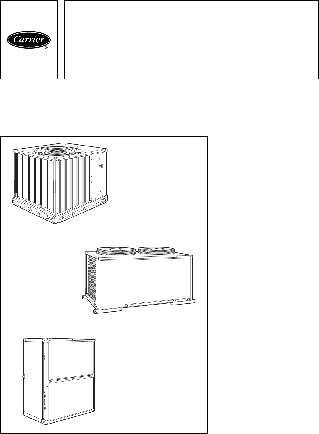
38AK007-012
38AKS008-044
with 40RM007-034
Commercial Air-Cooled
Split Systems
50 Hz
Nominal: 19.0 to 127.0 kW (5.3 to 35.8 Tons)
Product
Data
38AK007,008,012
38AKS008,009,012
38AKS013-024
40RM007-012

2
Controls for performance
dependability
The 38AK and 38AKS condensing
units offer the building owner operat-
ing controls and components designed
for performance dependability. The
highly efficient hermetic and semi-
hermetic compressors are engineered
for long life and durability. The com-
pressors include overload protection
and vibration isolation for enhance-
ment of quiet operation. The high-
pressure switch protects the entire re-
frigeration system from abnormally
high operating pressures. A low-
pressure switch protects the system
from low-pressure conditions, includ-
ing loss of charge.
The 38AK007-012 and
38AKS008-012 units include Cycle-
LOC™ anti-short-cycling protection
which helps to protect the units against
compressor failure. The 38AKS013-
044 units include a compressor recycle
delay timer to prevent short-cycling.
The 24-v control circuit transformer
permits quick, easy wiring of standard
and programmable 24-v thermostats.
The 38AK012 and 38AKS008-044
units include a crankcase heater to
eliminate liquid slugging at start-up.
Units with semi-hermetic compressors
are also equipped with an oil-level sight
glass.
Latest safety standards for 38AK
and 38AKS units are assured through
UL (Underwriters’ Laboratories)
(U.S.A. standard) and CSA (Canadian
Standards Association) listings.
Innovative Carrier 40RM pack-
aged air handlers are custom
matched to 38AK and 38AKS
condensing units
The 40RM Series has excellent fan
performance, efficient direct-
expansion (DX) coils, a unique combi-
nation of indoor-air quality features,
and easy installation. Its versatility and
state-of-the-art features help to ensure
that your split system provides eco-
nomical performance now and in the
future.
Indoor-air quality (IAQ) fea-
tures — The unique combination of
IAQ features in the 40RM Series air
handlers help to ensure that only
clean, fresh, conditioned air is deliv-
ered to the occupied space.
Direct-expansion (DX) cooling coils
prevent the build-up of humidity in
the room, even during part-load
conditions. Unit sizes 012 and above
feature dual-circuit coils for improved
temperature control.
Standard 51-mm (2-in.) disposable
filters remove dust and airborne parti-
cles from the occupied space.
Thermal insulation contains an im-
mobilized anti-microbial agent to inhib-
it the growth of bacteria and fungi. The
anti-microbial agent is registered with
the U.S.A. Environmental Protection
Agency (EPA).
The pitched PVC drain pan can be
adjusted for a right- or left-hand
connection to suit many applications
and provide positive drainage, and
prevent standing condensate.
The 40RM accessory economizer
can provide ventilation air to improve
indoor air quality. When used in con-
junction with CO2 sensors, the econo-
mizer admits fresh outdoor air to re-
place stale, recirculated indoor air.
Economy — The 40RM Series pack-
aged air handlers have low initial costs,
and they continue to save money by
providing reduced installation expense
and energy-efficient performance.
Quick installation is ensured by the
multipoise design. Units can be in-
stalled in either the horizontal or verti-
cal (upflow) configuration without mod-
ifications. Fan motors and contactors
are prewired and thermostatic
expansion valves (TXVs) are factory-
installed on all 40RM models.
High efficiency, precision-balanced
fans minimize air turbulence, surging,
and unbalanced operation, cutting op-
eration expenses.
The economizer accessory precisely
controls the blend of outdoor air and
room air to achieve comfort levels.
When the outside air enthalpy is suit-
able, outside air dampers can fully
open to provide “free” cooling without
energizing mechanical cooling.
Rugged dependability — 40RM
units are made to last. The die-formed
galvanized steel panels ensure structur-
al integrity under all operating condi-
tions. Galvanized steel fan housings are
securely mounted to a die-formed gal-
vanized steel fan deck.
Rugged pillow-block bearings
(40RM014-034) are securely fastened
to the solid steel fan shaft with split
collets and clamp locking devices.
Smaller unit sizes have spider-type
bearings.
Coil flexibility — Model 40RM
direct-expansion coils have galvanized
steel casings; inlet and outlet connec-
tions are on the same end. The
coils are designed for use with
Refrigerant 22 and have copper tubes
mechanically bonded to aluminum
sine-wave fins. The coils include
matched, factory-installed TXVs with
matching distributor nozzles.
Easier installation and service —
The multipoise design and component
layout help you to get the unit installed
and running quickly. Units can be con-
verted from horizontal to vertical oper-
ation by simply repositioning the unit.
Drain pan connections are duplicated
on both sides of the unit. The filters,
motor, drive, TXVs, and coil connec-
tions are all easily accessed by remov-
ing a single side panel.
3
Page
Features/Benefits . . . . . . . . . . . . . . . . . . . . . . . . . . . . . . . . . . . . . . . . . . .1,2
Model Number Nomenclature — 38AK Units . . . . . . . . . . . . . . . . . . . . . . . . 3
Model Number Nomenclature — 38AKS Units . . . . . . . . . . . . . . . . . . . . . . . 4
Model Number Nomenclature — 40RM Units. . . . . . . . . . . . . . . . . . . . . . . . 5
Capacity Summary . . . . . . . . . . . . . . . . . . . . . . . . . . . . . . . . . . . . . . . . . . . 6
Options and Accessories . . . . . . . . . . . . . . . . . . . . . . . . . . . . . . . . . . . . .7-10
Physical Data . . . . . . . . . . . . . . . . . . . . . . . . . . . . . . . . . . . . . . . . . . . .11-18
Dimensions . . . . . . . . . . . . . . . . . . . . . . . . . . . . . . . . . . . . . . . . . . . . .19-26
Selection Procedure . . . . . . . . . . . . . . . . . . . . . . . . . . . . . . . . . . . . . . . . . 27
Performance Data . . . . . . . . . . . . . . . . . . . . . . . . . . . . . . . . . . . . . . . .28-74
Typical Piping and Wiring . . . . . . . . . . . . . . . . . . . . . . . . . . . . . . . . . . .75-79
Electrical Data . . . . . . . . . . . . . . . . . . . . . . . . . . . . . . . . . . . . . . . . . . .80-83
Controls . . . . . . . . . . . . . . . . . . . . . . . . . . . . . . . . . . . . . . . . . . . . . . . . . 84
Typical Control Wiring . . . . . . . . . . . . . . . . . . . . . . . . . . . . . . . . . . . . .85-87
Application Data — 38AK007-012, 38AKS008-012 . . . . . . . . . . . . . . . . . 88
Application Data — 38AKS013-024 . . . . . . . . . . . . . . . . . . . . . . . . . . .89-91
Application Data — 38AKS028-044 . . . . . . . . . . . . . . . . . . . . . . . . . . .92,93
Application Data — 40RM . . . . . . . . . . . . . . . . . . . . . . . . . . . . . . . . . .94-98
Guide Specifications — 38AK007-012, 38AKS008-012 . . . . . . . . . . .99,100
Guide Specifications — 38AKS013-024 . . . . . . . . . . . . . . . . . . . . . .101,102
Guide Specifications — 38AKS028-044 . . . . . . . . . . . . . . . . . . . . . .103-105
Guide Specifications — 40RM. . . . . . . . . . . . . . . . . . . . . . . . . . . . . .106-108
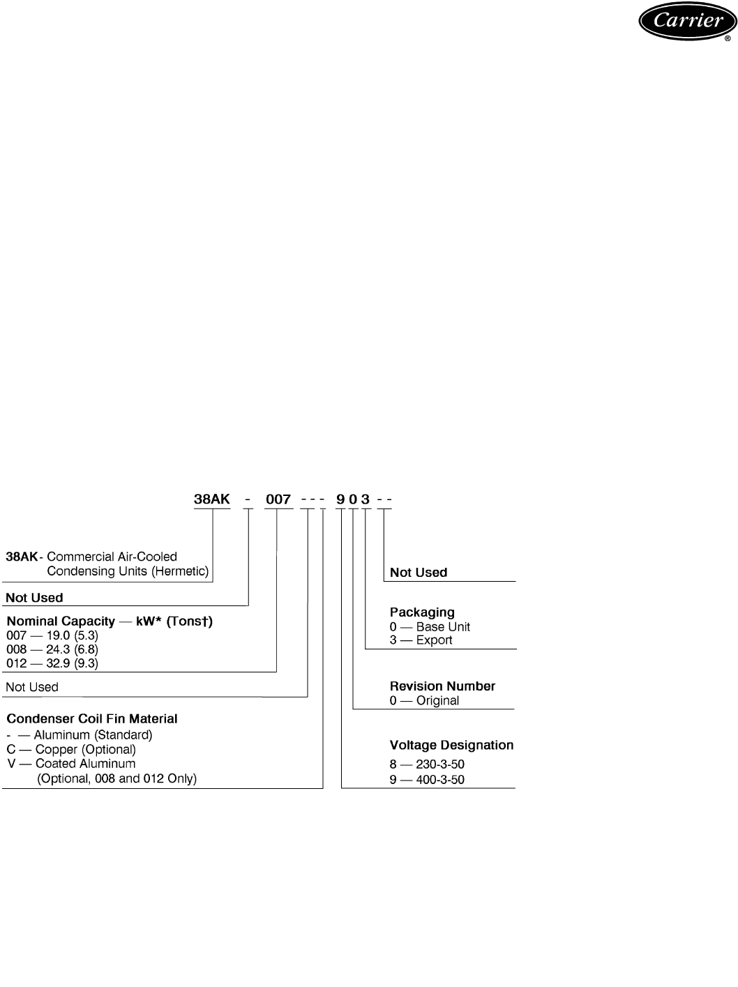
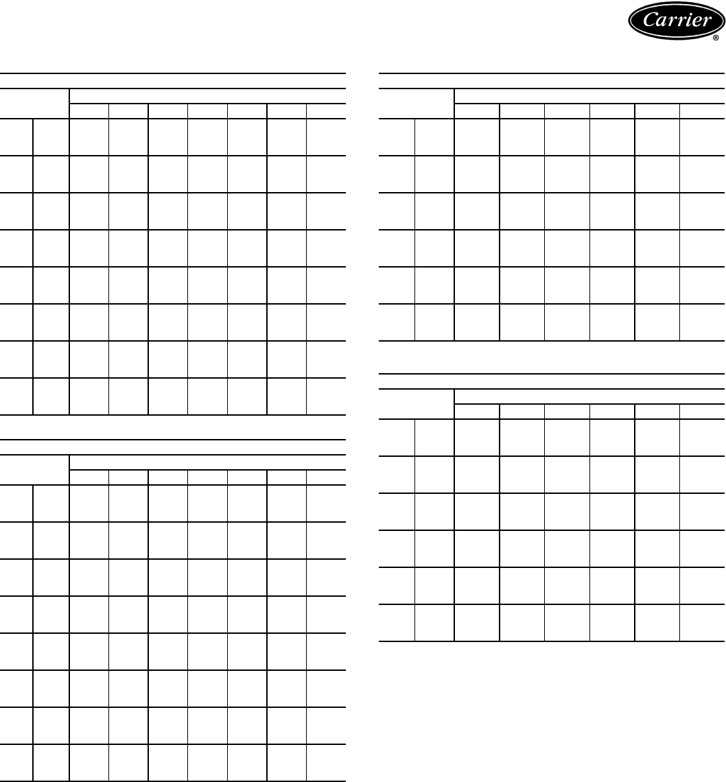
Model number nomenclature — 38AK units
Table of contents
*Gross capacity based on 36 C air temperature entering condenser and 8 C saturated suction temperature.
†Gross capacity based on 95 F air temperature entering condenser and 45 F saturated suction temperature.
4
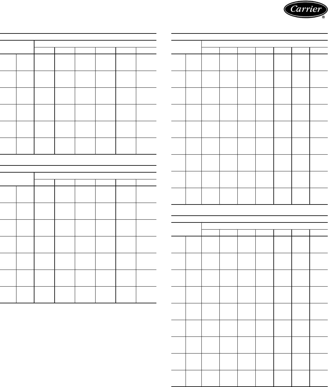
Model number nomenclature — 38AKS units
Nominal Capacity – kW* (Tons†)
008 –24.3 (6.8) 016 –45.7 (12.8)
009 –29.9 (8.4) 024 –64.3 (18.0)
012 –29.5 (8.3) 028 –82.8 (23.4)
013 –30.4 (8.5) 034 –94.5 (26.7)
014 –36.6 (10.3) 044 –127.0 (35.8)
Packaging
0 – Base Unit
3–Export
38AKS 008 – – – 9 0 3 – –
38AKS – Commercial Air-Cooled
Condensing Units (Semi-Hermetic)
Not Used
Condenser Coil Fin Material
–– Aluminum (Standard)
C–Copper (Optional)
K–Pre-Coated Aluminum (Optional, 013-044 Only)
V –Pre-Coated Aluminum (Optional, 008-012 Only)
SO –Post-Coated Aluminum (Contact Factory)
SO –Post-Coated Copper (Contact Factory)
Not Used
Revision Number
0 – Original
Voltage Designation
3 – 346-3-50**
8–230-3-50
9–400-3-50
LEGEND
SO — Special Order
*Gross capacity based on 36 C air temperature entering condenser and 8 C saturated suction temperature.
†Gross capacity based on 95 F air temperature entering condenser and 45 F saturated suction temperature.
**024-044 only.
38AKS013-044 UNITS
38AK, 38AKS008-012 UNITS
5
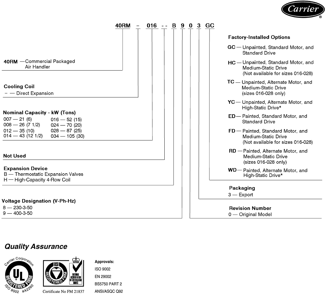
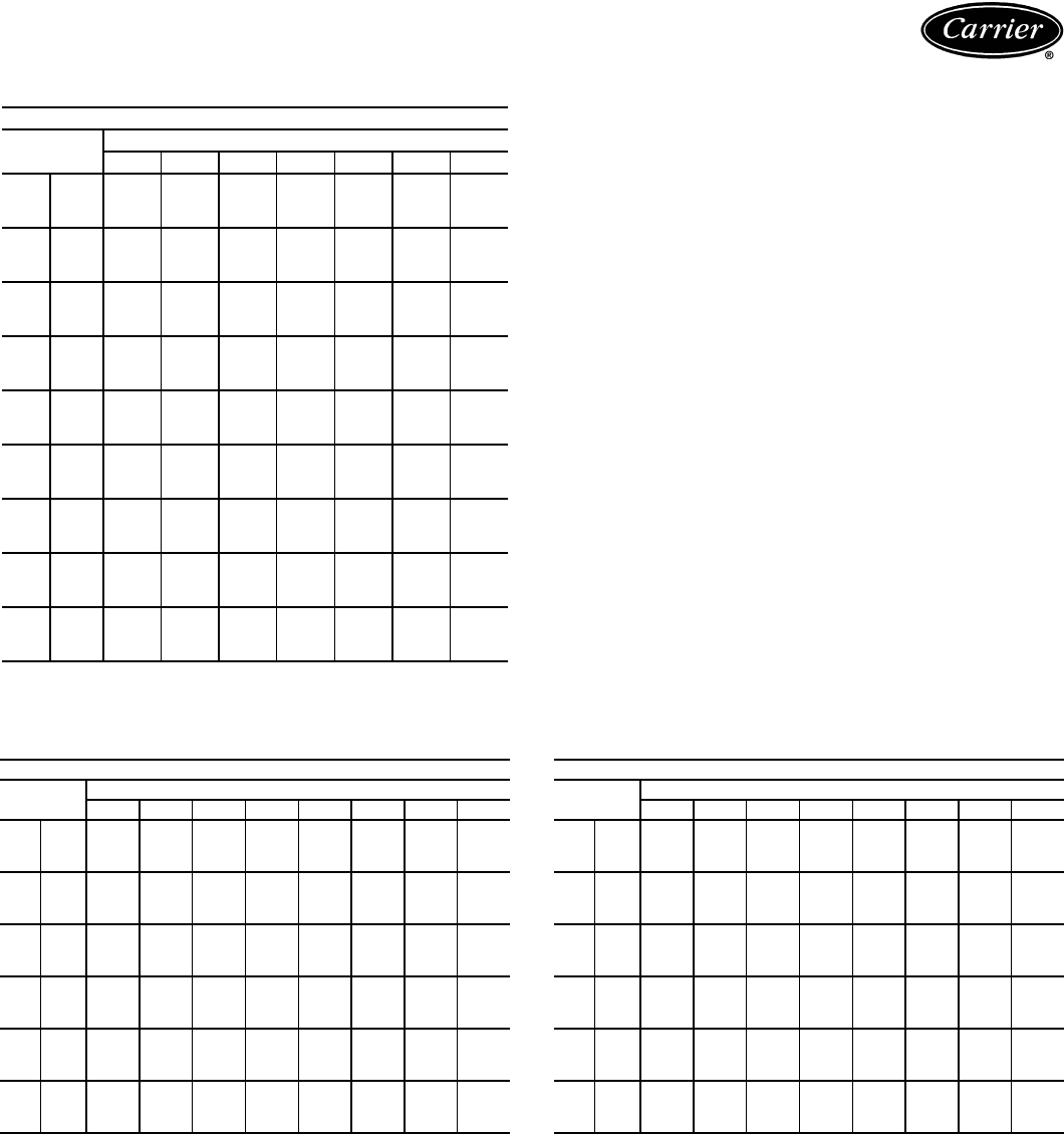
Model number nomenclature — 40RM units
*The YC and WD option codes for all 034 size units designate standard motor and high-static drive.
40RM UNITS
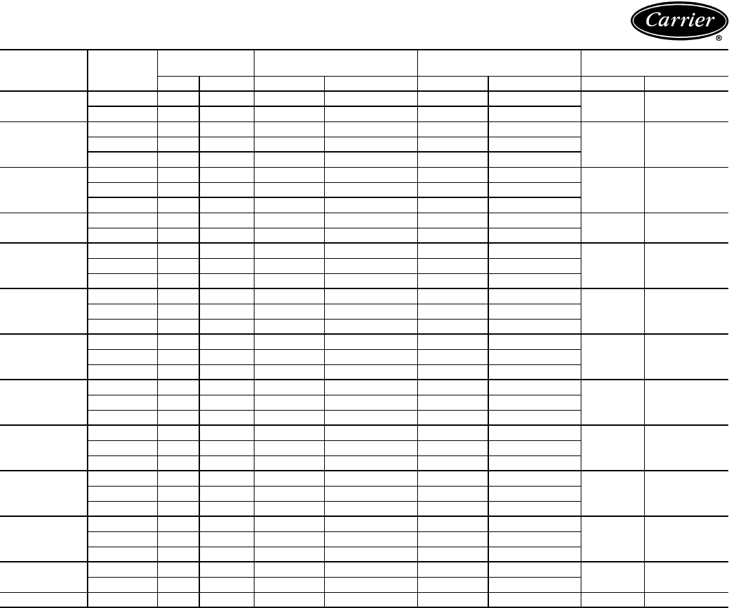
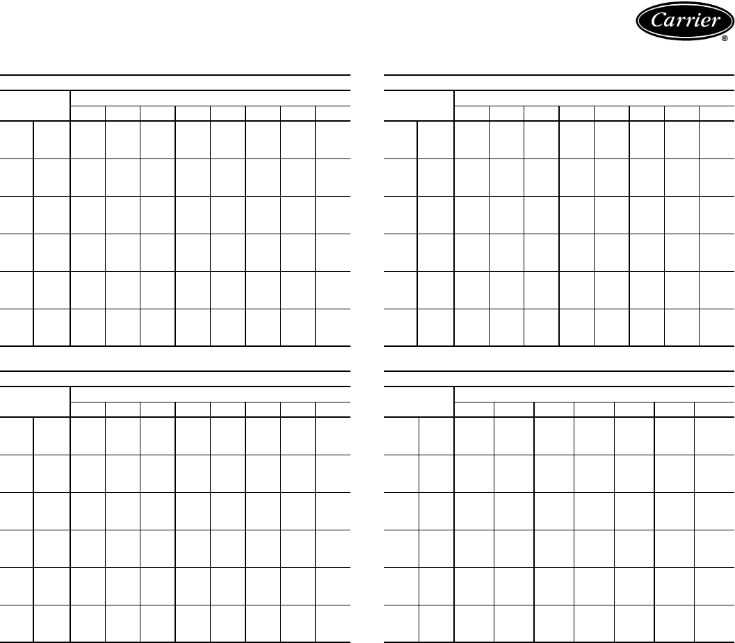
6
LEGEND
*System gross capacities are rated according to indoor unit airflow, 35 C air temperature entering
condenser, and 20 C wb air temperature entering evaporator.
†System gross capacities are rated according to indoor unit airflow, 95 F air temperature entering
condenser, and 67 F wb air temperature entering evaporator.
**Condensing unit gross capacity based on 36 C air temperature entering condenser and 8 C SST.
††Condensing unit gross capacity based on 95 F air temperature entering condenser and
45 F SST.
CONDENSING
UNIT
AIR-
HANDLING
UNIT
AIR-HANDLING
UNIT AIRFLOW
SYSTEM GROSS CAPACITY
(Standard 3-Row Coil)
SYSTEM GROSS CAPACITY
(High-Capacity 4-Row Coil)
CONDENSING UNIT
ONLY GROSS CAPACITY
L/s Cfm kW* Btuh†kW* Btuh†kW** Btuh††
38AK007 40RM007 1150 2,400 17.8 60,800 19.7 67,100 19.0 64,000
40RM008 1400 3,000 19.9 68,000 20.8 71,000
38AK008
40RM007 1150 2,400 21.0 71,700 23.7 80,900
24.2 81,50040RM008 1400 3,000 22.7 77,500 25.2 86,100
40RM012 1900 4,000 25.2 86,000 27.0 92,000
38AKS008
40RM007 1150 2,400 22.6 77,000 23.2 79,000
24.3 81,70040RM008 1400 3,000 24.2 82,000 24.7 84,300
40RM012 1900 4,000 26.3 89,000 26.5 90,500
38AKS009 40RM008 1400 3,000 28.0 95,000 28.8 98,100 29.9 101,000
40RM012 1900 4,000 30.6 104,000 31.1 106,200
38AK012
40RM008 1400 3,000 28.7 98,000 30.4 103,600
31.9 108,00040RM012 1900 4,000 30.5 104,000 33.1 112,900
40RM014 2350 5,000 31.6 108,000 34.8 118,700
38AKS012
40RM008 1400 3,000 27.7 94,000 28.8 98,100
29.5 99,20040RM012 1900 4,000 30.3 103,000 31.1 106,200
40RM014 2350 5,000 31.5 107,000 32.9 112,400
38AKS013
40RM008 1400 3,000 28.3 96,000 30.0 102,400
30.4 102,00040RM012 1900 4,000 31.0 105,000 32.4 110,600
40RM014 2350 5,000 32.2 109,000 34.3 117,000
38AKS014
40RM012 1900 4,000 35.2 120,000 37.0 126,100
36.6 123,00040RM014 2350 5,000 36.8 125,000 39.0 133,000
40RM016 2800 6,000 39.1 133,000 41.9 143,000
38AKS016
40RM014 2350 5,000 43.1 146,000 48.4 165,000
45.7 154,00040RM016 2800 6,000 46.2 157,000 51.2 174,600
40RM024 3800 8,000 49.6 167,000 54.7 186,500
38AKS024
40RM016 2800 6,000 58.0 197,000 59.5 203,100
64.3 216,00040RM024 3800 8,000 63.3 215,000 65.7 224,100
40RM028 4700 10,000 67.0 226,000 69.3 236,300
38AKS028
40RM024 3800 8,000 75.6 256,000 83.8 285,800
82.8 281,00040RM028 4700 10,000 80.4 273,000 84.3 287,700
40RM034 5650 12,000 84.6 288,000 88.7 302,800
38AKS034 40RM028 4700 10,000 88.2 298,000 89.9 306,800 94.5 320,000
40RM034 5650 12,000 93.1 316,000 94.8 323,500
38AKS044 40RM034 5650 12,000 113.8 385,000 111.8 381,600 127.0 429,000
db —Dry Bulb
wb —Wet Bulb
SST —Saturated Suction Temperature
Capacity summary
7
38AK, 38AKS options
Condenser coil options are available to match coil
construction to site conditions for the best corrosion
durability. Pre-coated coils provide protection in mild
coastal environments. All copper coils are best suited for
moderate coastal applications, while post-coated coils pro-
vide superior protection in severe coastal and industrial
applications.
38AK, 38AKS accessories
Electric unloader package (38AKS012-044) in-
cludes hardware and solenoid valve to convert a pressure-
operated unloader to electric unloading.
–20 F low-ambient temperature kit (Motormaster® I
— 38AK007, 38AKS013-044; Motormaster III —
38AK008,012, 38AKS008-012) controls outdoor-fan
motor operation to maintain the correct head pressure at
low outdoor ambient temperatures. Only one low ambient
temperature kit is required per unit.
Gage panel package provides a suction and a discharge
pressure gage for the refrigerant circuit.
Carrier’s line of thermostats provide both program-
mable and non-programmable capability with the new
Debonair® line of commercial programmable thermo-
stats. The TEMP System controls offer communication
capability with staged heating and cooling, the Commer-
cial Electronic thermostats provide 7-day programmable
capability for economical applications, while the
non-programmable thermostats offer a multitude of
staged heating and cooling subbase options.
Winter start package (38AK007-012, 38AKS008-
024) bypasses the low-pressure switch to permit unit
start-up at low ambient temperatures.
Hail guard package (38AK007-012, 38AKS008-
012) protects coils against damage from flying debris and
hail.
ModuPanel™ control box allows 38AKS028-044 sys-
tems to operate as VAV (variable air volume) systems. In-
cludes microprocessor, satellite sequencer, 4 status lights,
5-hour bypass timer, and locked enclosure.
Hot-gas bypass kit (38AKS028-044) prevents the in-
door coil from freezing up during low airflow or low
return-air temperature applications by maintaining mini-
mum suction pressure.
Condenser coil grille package (38AK007-012,
38AKS008-024) protects condensing unit coil from im-
pact by large objects and vandalism.
Part-winding-start timing relay (38AKS028-044)
reduces inrush current and locked rotor amps on start-up.
The 220-v and 346-v units have part-winding start as a
standard feature. All 400-v units require a special order to
change circuit breakers, contactors, and compressor be-
fore timing relay can be added for part-winding start.
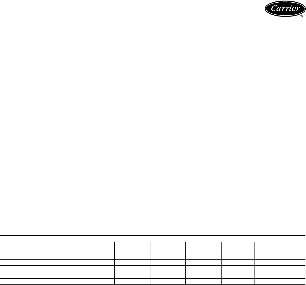
CONDENSER COIL PROTECTION APPLICATIONS
LEGEND
*See “Selection Guide: Environmental Corrosion Protection” Catalog No. 811-217 for more information.
DESCRIPTION
(Enviro-Shield™ Option)
ENVIRONMENT*
Standard
Non-Corrosive
Mild
Coastal
Moderate
Coastal
Severe
Coastal Industrial Combined Coastal
and Industrial
Standard, Al/Cu X
Pre-Coated Al/Cu X
Cu/Cu X
Post-Coated Al/Cu X
Post-Coated Cu/Cu XX
Al/Cu —Aluminum Fin with Copper Tube Coil
Cu/Cu —Copper Fin with Copper Tube Coil
Enviro-Shield —Family of Coil Protection Options
Post-Coated —Organic Coating Applied to Entire Coil Assembly
Pre-Coated —Epoxy Coating Applied to Fin Stock Material
Options and accessories

8
40RM factory-installed options
Alternate fan motors and drives are available to pro-
vide the widest possible range of performance.
High-capacity 4-row coils are available to provide in-
creased latent and sensible capacities (40RM only).
Prepainted steel units are available from the factory for
applications that require painted units. Units are painted
with American Sterling Gray color.
40RM field-installed accessories
Two-row hot water coils have copper tubes mechani-
cally bonded to aluminum plate fins and non-ferrous
headers.
One-row steam coil has copper tubes and aluminum
fins. The Inner Distributing Tube (IDT) design provides
uniform temperatures across the coil face. The steam coil
has a broad operating pressure range; up to 175 psig
(1207 kPag) at 400 F (204.4 C) and up to 300 psig
(2069 kPag) at 300 F (148.9 C). The IDT steam coils are
especially suited to applications where sub-freezing air en-
ters the unit.
Electric resistance heat coils have an open-wire design
and are mounted in a rigid frame. Safety cutouts for high
temperature conditions are standard. Terminal block for
single-point power connection is included.
Economizer (enthalpy controlled) provides ventilation
air and “free” cooling if outside ambient temperature and
humidity are suitable. Can also be used with CO2 sensors
to help meet indoor air quality requirements.
Discharge plenum directs the air discharge directly into
the occupied space; integral horizontal and vertical louvers
enable redirection of airflow. Accessory is available un-
painted or painted. Field assembly required.
Return-air grille provides a protective barrier over the
return-air opening and gives a finished appearance to units
installed in the occupied space. Accessory is available un-
painted or painted.
Subbase provides a stable, raised platform and room for
condensate drain trap connection for vertical floor-mounted
units. Accessory is available unpainted or painted.
Overhead suspension package includes necessary
brackets to support units in horizontal ceiling installations.
CO2 sensors can be used in conjunction with the econ-
omizer accessory to help meet indoor air quality require-
ments. The sensor signals the economizer to open when
the CO2 level in the space exceeds the set point. A Carrier
Comfort System programmable thermostat can be used to
override the sensor if the outside air temperature is too
high or too low.
Carrier’s line of thermostats provide both programma-
ble and non-programmable capability with the new
Debonair® line of commercial programmable thermo-
stats, the TEMP System controls offer communication ca-
pability with staged heating and cooling, the Commercial
Electronic thermostats provide 7-day programmable
capability for economical applications, while the Non-
Programmable thermostats offer a multitude of staged
heating and cooling subbase options.
Condensate drain trap includes an overflow shutoff
switch that can be wired to turn off the unit if the trap be-
comes plugged. Kit also includes a wire harness that can be
connected to an alarm if desired. The transparent trap is
designed for easy service and maintenance.
UV-C germicidal lamps kill mold and fungus, which may
grow on evaporator coil and condensate pan surfaces. The
use of UV-C germicidal lamps eliminates the foul odors
that result from this growth of mold and fungus. It also pro-
vides a self-cleaning function for the evaporator coil and
drain pan.
Options and accessories (cont)
9
AUTO
Pm
COOL
HEAT
Carrier
®
H
C
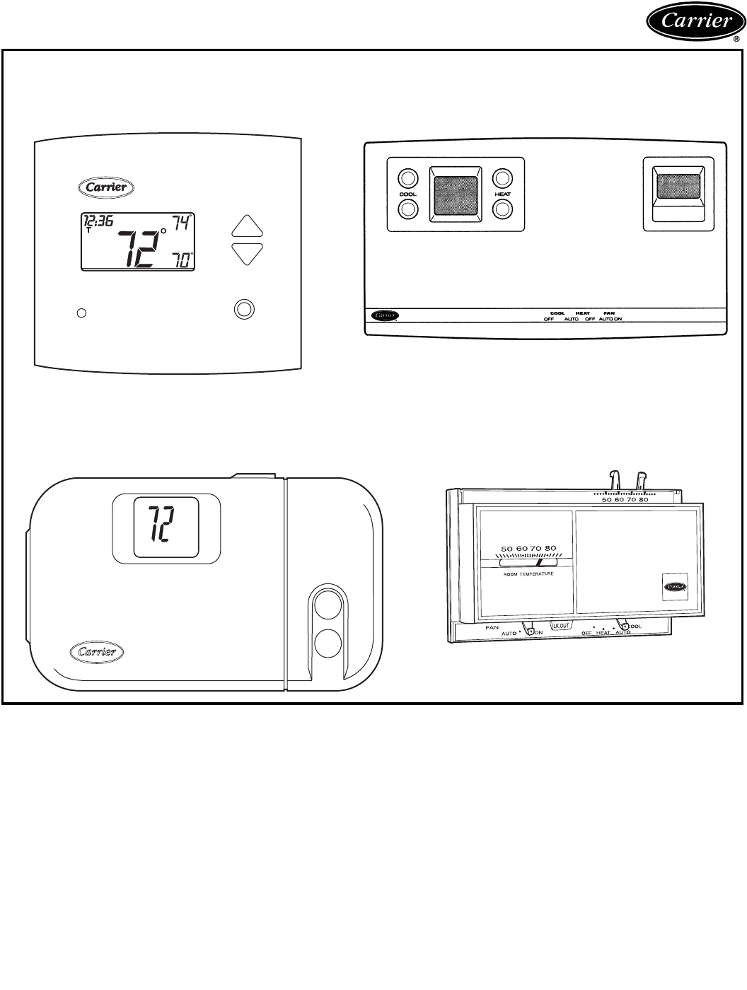
CARRIER THERMOSTATS
DEBONAIR® COMMERCIAL PROGRAMMABLE
THERMOSTAT TEMP SYSTEM THERMOSTAT
WITH TIMECLOCK
COMMERCIAL ELECTRONIC THERMOSTAT NON-PROGRAMMABLE THERMOSTAT
10
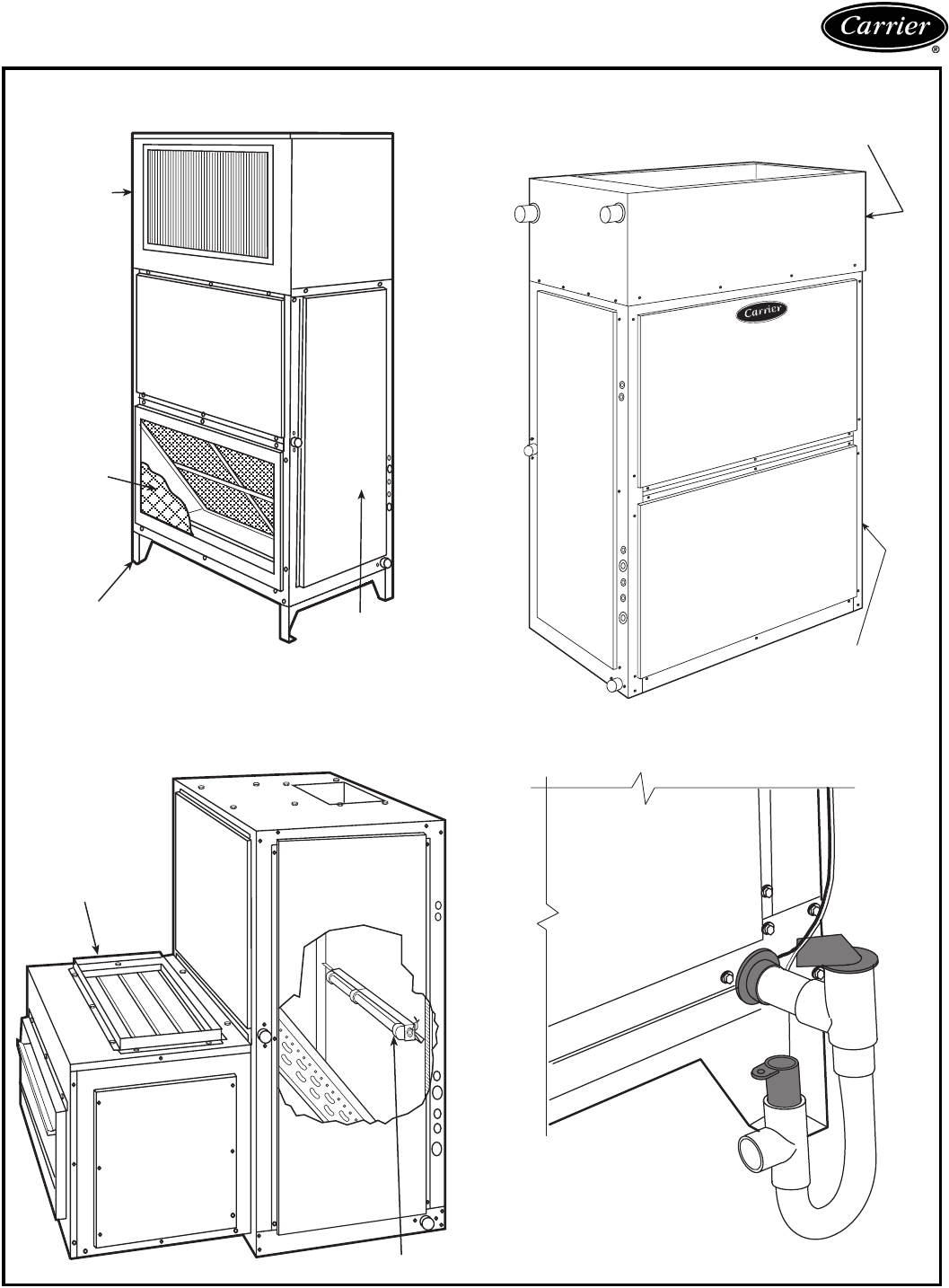
Options and accessories (cont)
DISCHARGE
PLENUM
RETURN-AIR
GRILLE
SUBBASE
FAN
COIL
UNIT FAN COIL
UNIT
HOT WATER OR
STEAM COIL
40RM WITH DISCHARGE PLENUM, RETURN
GRILLE, AND SUBBASE 40RM WITH HOT WATER OR STEAM COIL
40RM WITH CONDENSATE TRAP
ECONOMIZER
UV-C GERMICIDAL LAMPS
40RM WITH ECONOMIZER
AND UV-C GERMICIDAL LAMPS
11
38AK007-012, 38AKS008-012
LEGEND
NEMA — National Electrical Manufacturers Association (U.S.A. Standard)
*Based on operation at 8 C saturated suction temperature and 36 C outdoor ambient
temperature.
†Unit is factory supplied with holding charge only.
**Typical operating charge with 7.6 m of interconnecting piping.
NOTE: Unit 38AKS012 has one step of unloading. Full load is 100% of capacity, and one
step of unloading is 67% capacity. Unit 38AKS012 has the following unloader settings:
Load is 483 kPa ± 6.9 kPa and unload is 414 kPa ± 13.8 kPa.
UNIT 38 AK007 AK008 AK012 AKS008 AKS009 AKS012
NOMINAL CAPACITY (kW)* 19.0 24.3 32.9 24.3 29.9 29.5
OPERATING WEIGHT (kg)
Aluminum-Fin Coils (Standard) 154 178 193 231 256 256
Copper-Fin Coils (Optional) 175 208 228 262 287 287
RIGGING WEIGHT (kg)
Aluminum-Fin Coils (Standard) 176 200 215 254 279 279
Copper-Fin Coils (Optional) 198 228 250 285 309 309
REFRIGERANT†R-22
Operating Charge, Typical (kg)** 5.17 6.17 7.48 6.49 7.44 7.44
Shipping Charge (kg) 0.91 0.91 0.91 0.91 0.91 0.91
COMPRESSOR Reciprocating,
Hermetic Scroll Hermetic Reciprocating, Semi-Hermetic
Model H26A72Q ZR94KC ZR125KC 06DA818 06DA824 06DH824
(See Note)
No. Cylinders (ea) 2—— 466
Speed (r/s) 48.4 48.4 48.4 24.2 24.2 24.2
Oil Charge (L) (ea) 1.92 2.51 3.25 2.60 3.78 3.78
CONDENSER FAN Propeller; Direct Drive
Qty...r/s 1...16.0
Diameter (mm) 660
Motor kW (NEMA) 0.25
Nominal Airflow (L/s) 1490 2550 2750 2550 2550 2550
CONDENSER COIL Enhanced Copper Tubes, Aluminum Lanced Fins
Rows...Fins/m 2...670
Face Area (m2)1.14 1.67 1.90 1.67 1.67 1.67
Storage Capacity (kg) 5.1 7.5 8.6 7.5 7.5 7.5
CONTROLS
Pressurestat Settings (kPa)
High Cutout 2937 ± 48
Cut-in 2206 ± 138
Low Cutout 48 ± 20
Cut-in 151 ± 34
PIPING CONNECTIONS (Sweat)
Suction (in.) 11/811/811/811/811/811/8
Liquid (in.) 1/21/25/81/25/85/8
Physical data — SI
12
38AKS013-024
*Based on operation at 8 C saturated suction temperature and 36 C outdoor ambient
temperature.
†Unit is factory-supplied with holding charge only.
**With 7.6 m of interconnecting piping. Operating charge is approximate for maximum
system capacity.
††Indicates capacity step (%) with electric unloader accessory.
||Storage capacity is measured at liquid saturated temperatures of 51.7 C for
38AKS013, 50.6 C for 38AKS014, and 54.4 C for 38AKS016 and 024.
UNIT 38AKS 013 014 016 024
NOMINAL CAPACITY (kW)* 30.4 36.6 45.7 64.3
OPERATING WEIGHT (kg)
With Aluminum-Fin Coil 332 353 358 408
With Copper-Fin Coil 374 417 421 472
REFRIGERANT†R-22
Operating Charge, Typical (kg)** 10.0 10.4 10.4 12.7
Shipping Charge (kg) 0.95 1.40 1.40 1.40
COMPRESSOR Reciprocating, Semi-Hermetic
Model 06DD824 06DD328 06DD537 06E4250
No. Cylinders 6664
Speed (r/s) 24.2
Oil Charge (L) 4.73 4.73 4.73 7.33
Capacity Steps (%)
Accessory 33††, 66, 100 33††, 66, 100 33††, 66, 100 —
Standard 66, 100 66, 100 66, 100 50, 100
Unloader Settings (kPa)
Load 483 ± 6.9
Unload 414 ± 13.8
Crankcase Heater Watts 125
CONDENSER FANS Axial Flow, Direct Drive
Qty...r/s 2...15.0
Diameter (mm) 660
Nominal kW 0.37
Nominal Airflow (L/s Total) 4660
Watts (total) 1050
CONDENSER COIL Copper Tubes, Aluminum Fins
Rows...Fins/m 2...590 3...590 3...590 3...590
Face Area (sq m) 2.71 2.71 2.71 2.71
Storage Capacity (kg)|| 12.3 18.3 18.1 18.1
CONTROLS
Pressurestat (kPa)
High Pressure
Cutout 2724 ± 69
Cut-in 2034 ± 138
Low-Pressure
Cutout 186 ± 28
Cut-in 462 ± 48
FAN CYCLING CONTROLS
Operating Pressure (kPa)
No. 2 Fan, Close 1758 ± 69
Open 1103 ± 69
PRESSURE RELIEF Fusible Plug
Location Compressor Compressor Compressor Liquid Line
Temperature (C) 93.3 93.3 93.3 98.9
PIPING CONNECTIONS (in. ODM)
Suction 11/813/813/815/8
Liquid 5/8
Hot Gas Stub 3/8
Physical data — SI (cont)
13
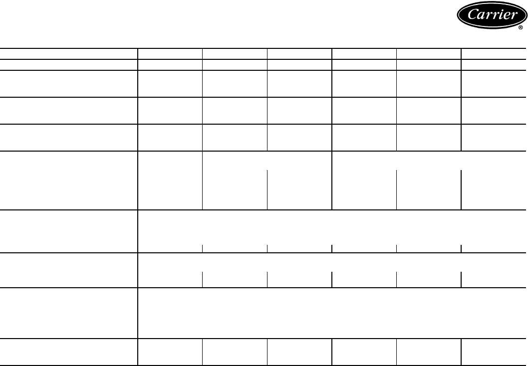
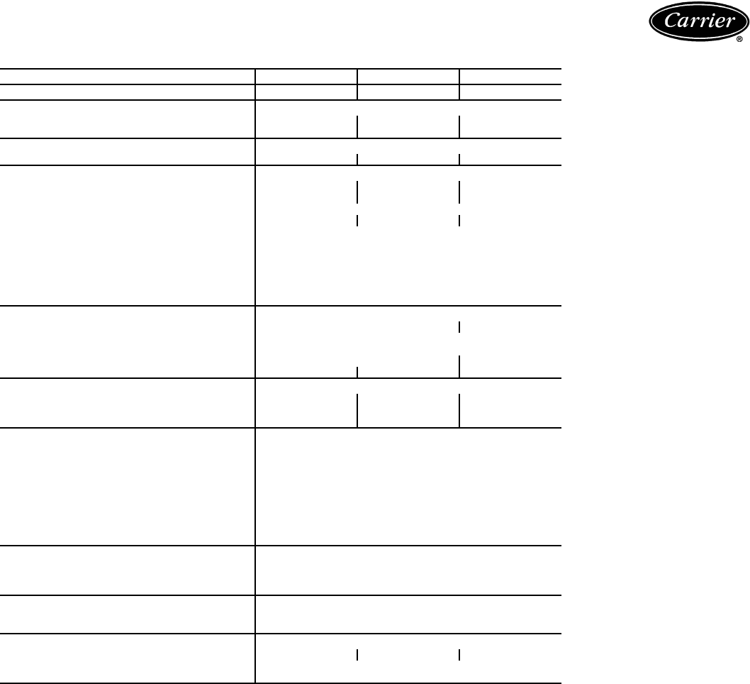
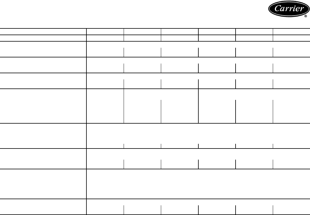
38AKS028-044
*Based on operation at 8 C saturated suction temperature and 36 C outdoor ambient temperature.
UNIT 38AKS 028 034 044
NOMINAL CAPACITY (kW)* 82.8 94.5 127.0
OPERATING WEIGHTS (kg)
With Aluminum-Fin Coils 748 818 1106
With Copper-Fin Coils 818 911 1246
REFRIGERANT R-22
Operating Charge, Typical (kg) 13.8 19.7 29.5
COMPRESSOR Reciprocating, Semi-hermetic
Model 06E9265 06E9275 06E9299
No. Cylinders (ea) 666
Speed (r/s) 24.2
Oil (L) 8.99 8.99 9.46
Capacity Steps 100%, 66%, 33%
Unloader Settings (kPag)
No. 1 Load 524
Unload 400
No. 2 Load 538
Unload 414
Crankcase Heater Watts 180
CONDENSER FANS Propeller Type — Direct Drive
Qty...r/s 2...15.8 3...15.8
Diameter (mm) 762
Nominal kW 0.75
Nominal Airflow (L/s) 7400 11,180
Watts (Total) 1490 1750 1520
CONDENSER COIL Enhanced Copper Tubes, Lanced Aluminum Fins
Rows...Fins/m 2...748 3...670 3...670
Face Area (sq m) 3.64 3.64 5.43
Storage Capacity (kg) — 80% Full at 51.7 C 17.1 25.7 38.3
CONTROLS
High-Pressure Switch (kPag)
Cutout 2937 ± 48
Cut-in 2206 ± 138
Low-Pressure Switch (kPag)
Cutout 186 ± 21
Cut-in 303 ± 34
Oil Pressure Switch (kPag)
Close on Rise 62
Open on Fall 43
FAN CYCLING CONTROLS
Operating Pressure (kPag)
No. 2 Fan, Close 1758 ± 69
Open 1103 ± 69
PRESSURE RELIEF Fusible Plug
Location Liquid and Suction Line
Temperature (C) 98.9
PIPING CONNECTIONS (in. OD)
Suction 15/821/821/8
Liquid 7/8
Hot Gas Stub 5/8
14
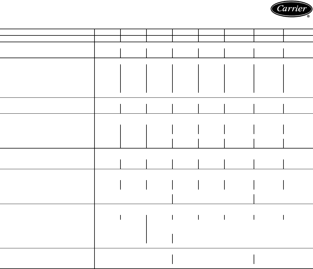
40RM
LEGEND
*Units are shipped without refrigerant charge.
UNIT 40RM 007 008 012 014 016 024 028 034
NOMINAL CAPACITY (kW) 21 26 35 43 52 70 87 105
OPERATING WEIGHT (kg)
Base Unit with TXV (3-Row/4-Row) 173/181 175/183 184/193 304/315 311/323 313/331 463/470 467/482
Plenum 80 80 80 102 102 102 148 148
FANS
Qty...Diam. (mm) 1...381 1...381 1...381 2...381 2...381 2...381 2...457 2...457
Nominal Airflow (L/s) 1133 1604 1888 2360 2831 3775 4719 5663
Airflow Range (L/s) 850-1416 1203-2006 1416-2360 1770-2949 2124-3539 2831-4719 3539-5899 4247-7079
Nominal Motor kW (Standard Motor)
230-3-50, 400-3-50 1.79 1.79 2.16 2.16 2.16 3.73 5.60 7.46
Motor Speed (r/s)
230-3-50, 400-3-50 23.8 23.8 23.8 23.8 23.8 23.8 23.8 23.8
REFRIGERANT R-22
Operating charge (kg)
(approx per circuit)* 1.36 1.36 0.68/0.68 0.90/0.90 1.13/1.13 1.59/1.59 2.04/2.04 2.27/2.27
DIRECT-EXPANSION COIL Enhanced Copper Tubes, Aluminum Sine-Wave Fins
Max Working Pressure (kPag) 2999
Face Area (sq m) 0.62 0.77 0.93 0.93 1.64 1.85 2.30 2.77
No. of Splits 11222222
No. of Circuits per Split (3-Row/4-Row) 12/12 15/15 9/9 9/16 12/16 13/18 15/20 18/24
Split Type...Percentage —— Face...50/50
Fins/m 591 591 670 591 591 670 591 591
STEAM COIL
Max Working Pressure
(kPag at 204.4 C) 1207
Total Face Area (sq m) 0.62 0.62 0.62 1.24 1.24 1.24 1.39 1.39
Rows...Fins/m 1...355 1...355 1...355 1...394 1...394 1...394 1...394 1...394
HOT WATER COIL
Max Working Pressure (kPag) 1034
Total Face Area (sq m) 0.62 0.62 0.62 1.24 1.24 1.24 1.39 1.39
Rows...Fins/m 2...335 2...335 2...335 2...335 2...335 2...335 2...493 2...493
Water Volume
(L) 31.4 52.6 54.1
(m3)0.031 0.052 0.054
PIPING CONNECTIONS,
Quantity...Size (in.)
DX Coil — Suction (ODF) 1...11/81...11/82...11/82...11/82...11/82...11/82...13/82...13/8
DX Coil — Liquid Refrigerant (ODF) 1... 5/82...5/8
Steam Coil, In (MPT) 1...21/21...21/2
Steam Coil, Out (MPT) 1...11/21...21/2
Hot Water Coil, In (MPT) 1...11/21...11/21...2
Hot Water Coil, Out (MPT) 1...11/21...11/21...2
Condensate (Male PVC) 1...11/4
FILTERS Throwaway — Factory Supplied
Quantity...Size (mm) 4...406 x 610 x 51 4...406 x 508 x 51
4...406 x 610 x 51
4...508 x 610 x 51
4...508 x 635 x 51
Access Location Right or Left Side
DX —Direct Expansion
TXV —Thermostatic Expansion Valve
Physical data — SI (cont)
15
38AK007-012, 38AKS008-012
LEGEND
*Based on operation at 45 F saturated suction temperature and 95 F outdoor ambient.
†Unit is factory supplied with holding charge only.
**Typical operating charge with 25 ft of interconnecting piping.
NOTE: Unit 38AKS012 has one step of unloading. Full load is 100% of capacity, and one
step of unloading is 67% capacity. Unit 38AKS012 has the following unloader settings: Load
is 70 ± 1 psig and unload is 60 ± 2 psig.
UNIT 38 AK007 AK008 AK012 AKS008 AKS009 AKS012
NOMINAL CAPACITY (tons)* 5.3 6.8 9.3 6.8 8.4 8.3
OPERATING WEIGHT (lb)
Aluminum Coils (Standard) 340 392 426 510 564 564
Copper Coils (Optional) 386 460 503 578 632 632
RIGGING WEIGHT (lb)
Aluminum Fin Coils (Standard) 390 442 476 560 614 614
Copper Fin Coils (Optional) 436 510 553 628 682 682
REFRIGERANT†R-22
Operating Charge, Typical (lb)** 11.4 13.6 16.5 14.3 16.4 16.4
Shipping Charge (lb) 2.0 2.0 2.0 2.0 2.0 2.0
COMPRESSOR Reciprocating,
Hermetic Scroll Hermetic Reciprocating, Semi-Hermetic
Model H26A72Q ZR94KC ZR125KC 06DA818 06DA824 06DH824
(See Note)
No. Cylinders (ea) 2—— 466
Speed (rpm) 3500 3500 3500 1460 1460 1460
Oil Charge (oz) (ea) 65 85 110 88 128 128
CONDENSER FAN Propeller; Direct Drive
Qty...Rpm 1...960
Diameter (in.) 26
Motor Hp (NEMA) 1/3
Nominal Airflow (Cfm) 3800 6500 7000 6500 6500 6500
CONDENSER COIL Enhanced Copper Tubes, Aluminum Lanced Fins
Rows...Fins/in. 2...17
Face Area (sq ft) 12.24 18.0 20.50 18.0 18.0 18.0
Storage Capacity (lb) 11.26 16.56 18.87 16.56 16.56 16.56
CONTROLS
Pressurestat Settings (psig)
High Cutout 426 ± 7
Cut-in 320 ± 20
Low Cutout 7 ± 3
Cut-in 22 ± 5
PIPING CONNECTIONS (Sweat)
Suction (in.) 11/811/811/811/811/811/8
Liquid (in.) 1/21/25/81/25/85/8
NEMA —National Electrical Manufacturers Association
Physical data — English
16
38AKS013-024
*Based on operation at 45 F saturated suction temperature and 95 F outdoor ambient.
†Unit is factory-supplied with holding charge only.
**With 25 ft of interconnecting piping. Operating charge is approximate for maximum
system capacity.
††Indicates capacity step (%) with electric unloader accessory.
||Storage capacity is measured at liquid saturated temperatures of 125 F for 38AKS013,
123 F for 38AKS014, and 130 F for 38AKS016 and 024.
UNIT 38AKS 013 014 016 024
NOMINAL CAPACITY (tons)* 8.5 10.3 12.8 18.0
OPERATING WEIGHTS (lb)
With Aluminum-Fin Coil 732 779 789 900
With Copper-Fin Coil 825 919 929 1040
REFRIGERANT†R-22
Operating Charge, Typical (lb)** 22 23 23 28
Shipping Charge (lb) 2.1 3.1 3.1 3.1
COMPRESSOR Reciprocating, Semi-Hermetic
Model 06DD824 06DD328 06DD537 06E4250
No. Cylinders 6664
Speed (rpm) 1450
Oil Charge (pt) 10 10 10 15.5
Capacity Steps
Accessory 33††, 66, 100 33††, 66, 100 33††, 66, 100 —
Standard 66, 100 66, 100 66, 100 50, 100
Unloader Setting (psig)
Load 70 ± 1
Unload 60 ± 2
Crankcase Heater Watts 125
CONDENSER FANS Axial Flow, Direct Drive
Qty...Rpm 2...900
Diameter (in.) 26
Nominal Hp 1/2
Nominal Airflow (cfm, total) 9210
Watts (total) 1050
CONDENSER COIL Copper Tubes, Aluminum Fins
Rows...Fins/in. 2...15 3...15 3...15 3...15
Face Area (sq ft) 29.2 29.2 29.2 29.2
Storage Capacity (lb)|| 27.2 40.0 39.8 39.8
CONTROLS
Pressurestat (psig)
High Pressure
Cutout 395 ± 10
Cut-in 295 ± 20
Low Pressure
Cutout 27 ± 4
Cut-in 67 ± 7
FAN CYCLING CONTROLS
Operating Pressure (psig)
No. 2 Fan, Close (psig) 255 ± 10
Open (psig) 160 ± 10
PRESSURE RELIEF Fusible Plug
Location Compressor Compressor Compressor Liquid Line
Temperature (F) 200 200 200 210
PIPING CONNECTIONS (in. ODM)
Suction 11/813/813/815/8
Liquid 5/8
Hot Gas Stub 3/8
Physical data — English (cont)

17
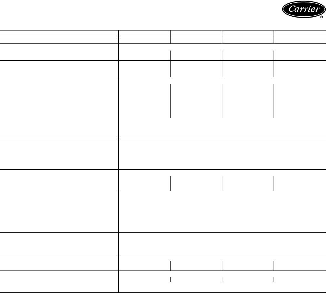
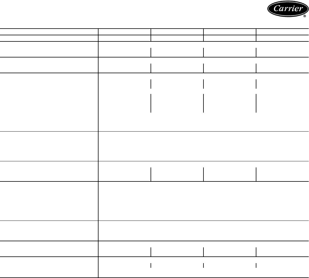
38AKS028-044
*Based on operation at 45 F saturated suction temperature and 95 F outdoor ambient.
UNIT 38AKS 028 034 044
NOMINAL CAPACITY (tons)* 23.4 26.7 35.8
OPERATING WEIGHTS (lb)
With Aluminum-Fin Coils 1650 1803 2437
With Copper-Fin Coils 1804 2009 2745
REFRIGERANT R-22
Operating Charge, Typical (lb) 30.5 43.5 65.0
COMPRESSOR Reciprocating, Semi-Hermetic
Model 06E9265 06E9275 06E9299
No. Cylinders (ea) 666
Speed (rpm) 1450
Oil (pt) 20.0 20.0 19.0
Capacity Steps 100%, 66%, 33%
Unloader Setting (psig)
No. 1 Load 76
Unload 58
No. 2 Load 78
Unload 60
Crankcase Heater Watts 180
CONDENSER FANS Propeller Type — Direct Drive
Qty...Rpm 2...950 3...950
Diameter (in.) 30
Nominal Hp 1.0
Nominal Airflow (cfm) 15,700 23,700
Watts (Total) 1490 1750 1520
CONDENSER COIL Enhanced Copper Tubes, Lanced Aluminum Fins
Rows...Fins/in. 2...19 3...17 3...17
Face Area (sq ft) 39.2 39.2 58.4
Storage Capacity (lb) — 80% Full at 125 F 37.7 56.6 84.4
CONTROLS
High-Pressure Switch (psig)
Cutout 426 ± 7
Cut-in 320 ± 20
Low-Pressure Switch (psig)
Cutout 27 ± 3
Cut-in 44 ± 5
Oil Pressure Switch (psig)
Close on Rise 9.0
Open on Fall 6.2
FAN CYCLING CONTROLS
Operating Pressure (psig)
No. 2 Fan, Close 255 ± 10
Open 160 ± 10
PRESSURE RELIEF Fusible Plug
Location Liquid and Suction Line
Temperature (F) 210
PIPING CONNECTIONS (in. OD)
Suction 15/821/821/8
Liquid 7/8
Hot Gas Stub 5/8
18
40RM
LEGEND
*Units are shipped without refrigerant charge.
UNIT 40RM 007 008 012 014 016 024 028 034
NOMINAL CAPACITY (Tons) 67
1/210 121/215 20 25 30
OPERATING WEIGHT (lb)
Base Unit with TXV (3-Row/4-Row) 381/399 385/404 405/425 670/695 685/713 690/730 1020/1050 1030/1062
Plenum 175 175 175 225 225 225 325 325
FANS
Qty...Diam. (in.) 1...15 1...15 1...15 2...15 2...15 2...15 2...18 2...18
Nominal Airflow (cfm) 2400 3000 4000 5000 6000 8000 10,000 12,000
Airflow Range (cfm) 1800-3000 2250-3750 3000-5000 3750-6250 4500-7500 6000-10,000 7500-12,500 9000-15,000
Nominal Motor Hp (Standard Motor)
230-3-50, 400-3-50 2.4 2.4 2.9 2.9 2.9 5.0 7.5 10.0
Motor Speed (rpm)
230-3-50, 400-3-50 1425
REFRIGERANT R-22
Operating charge (lb)
(approx per circuit)* 3.0 3.0 1.5/1.5 2.0/2.0 2.5/2.5 3.5/3.5 4.5/4.5 5.0/5.0
DIRECT-EXPANSION COIL Enhanced Copper Tubes, Aluminum Sine-Wave Fins
Max Working Pressure (psig) 435
Face Area (sq ft) 6.67 8.33 10.0 13.25 17.67 19.88 24.86 29.83
No. of Splits 11222 2 2 2
Split Type...Percentage —— Face...50/50
No. of Circuits per Split (3-Row/4-Row) 12/12 15/15 9/9 9/12 12/16 13/18 15/20 18/24
Fins/in. 15 15 17 15 15 17 15 15
STEAM COIL
Max Working Pressure (psig at 400 F) 175
Total Face Area (sq ft) 6.67 6.67 6.67 13.33 13.33 13.33 15.0 15.0
Rows...Fins/in. 1...9 1...9 1...9 1...10 1...10 1...10 1...10 1...10
HOT WATER COIL
Max Working Pressure (psig) 150
Total Face Area (sq ft) 6.67 6.67 6.67 13.33 13.33 13.33 15.0 15.0
Rows...Fins/in. 2...8.5 2...8.5 2...8.5 2...8.5 2...8.5 2...8.5 2...12.5 2...12.5
Water Volume
(gal) 8.3 13.9 14.3
(ft3)1.1 1.85 1.90
PIPING CONNECTIONS,
Quantity...Size (in.)
DX Coil — Suction (ODF) 1...11/81...11/82...11/82...11/82...11/82...11/82...13/82...13/8
DX Coil — Liquid Refrigerant (ODF) 1...5/81...5/8
Steam Coil, In (MPT) 1...21/21...21/2
Steam Coil, Out (MPT) 1...11/21...21/2
Hot Water Coil, In (MPT) 1...11/21...11/21...2
Hot Water Coil, Out (MPT) 1...11/21...11/21...2
Condensate (Male PVC) 1...11/4
FILTERS Throwaway — Factory Supplied
Quantity...Size (in.) 4...16 x 24 x 2 4...16 x 20 x 2
4...16 x 24 x 2
4...20 x 24 x 2
4...20 x 25 x 2
Access Location Right or Left Side
TXV —Thermostatic Expansion Valve
Physical data — English (cont)
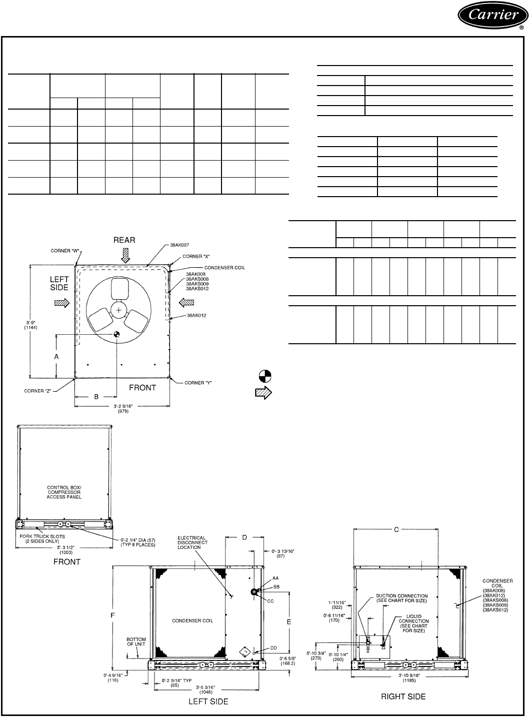
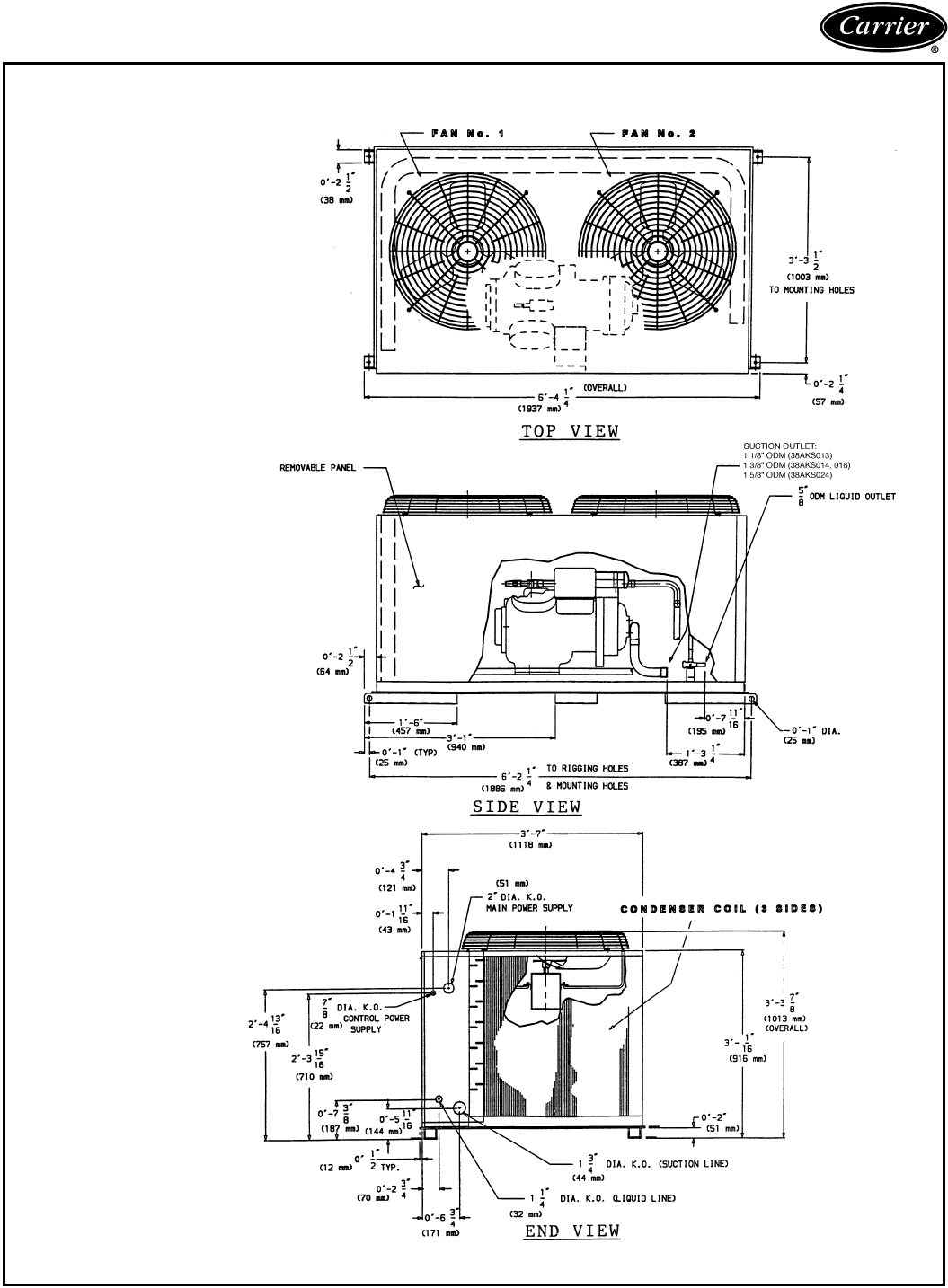
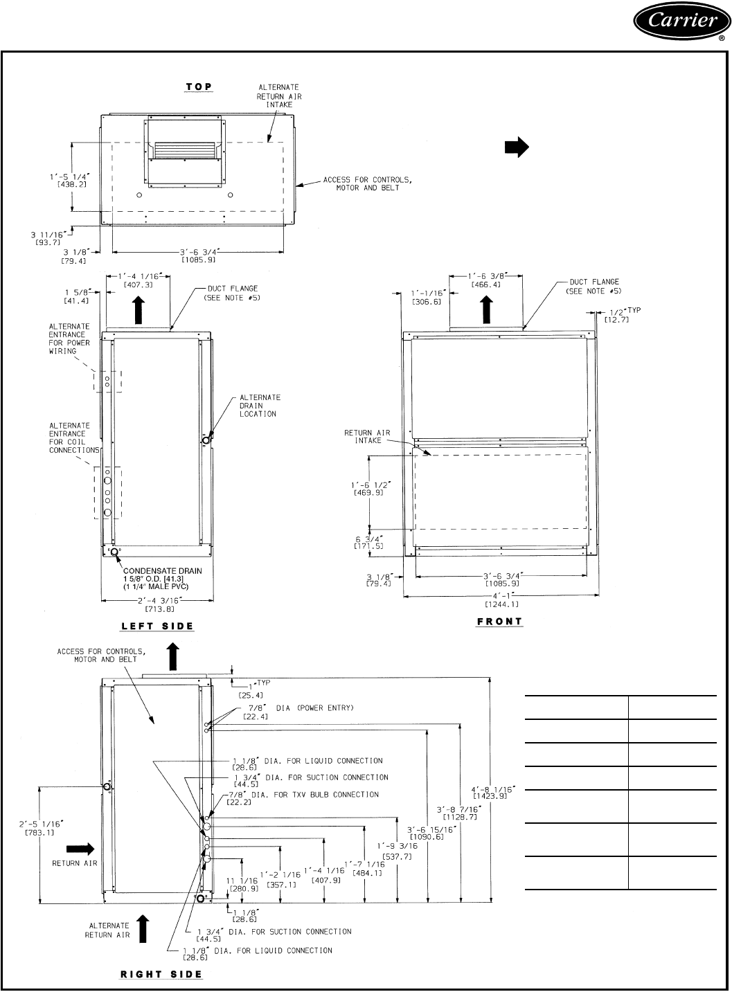
19
Dimensions
38AK007-012, 38AKS008-012
DIMENSION CHART
UNIT
38AK
UNIT W/
ALUMINUM
COIL
UNIT W/
COPPER COIL DIM. C DIM. D DIM. E DIM. F
DIM. A DIM. B DIM. A DIM. B
007 1′-61/2″1′-23/4″1′-8″1′-3″—1′-21/4″1′-45/16″2′-95/16″
[470] [375] [508] [381] [362] [415] [847]
008 1′-8″1′-61/2″1′-91/2″1′-6″2′-913/16″1′-3″2′-5/16″3′-57/16″
[508] [470] [546] [457] [859] [381] [613] [1053]
012 1′-9″1′-8″1′-10″1′-7″2′-0″1′-3″2′-5/16″3′-57/16″
[533] [508] [559] [482] [610] [381] [613] [1053]
S008 1′-6″1′-43/4″1′-71/2″1′-41/2″2′-913/16″1′-3″2′-5/16″3′-57/16″
[457] [426] [495] [419] [859] [381] [613] [1053]
S009,S012 1′-7″1′-5″1′-71/2″1′-4″2′-913/16″1′-3″2′-5/16″3′-57/16″
[483] [432] [495] [406] [859] [381] [613] [1053]
ELECTRICAL CONNECTIONS
CONNECTION SIZES
AA 13/8″ Dia [35] Field Power Supply Hole
BB 2″ Dia [51] Power Supply Knockout
CC 21/2″ Dia [64] Power Supply Knockout
DD 7/8″ Dia [22] Field Control Wiring Hole
SERVICE VALVE CONNECTIONS
UNIT 38AK SUCTION LIQUID
007 11/8″ [28.6] 1/2″ [12.7]
008 11/8″ [28.6] 1/2″ [12.7]
012 11/8″ [28.6] 5/8″ [15.9]
S008 11/8″ [28.6] 1/2″ [12.7]
S009,012 11/8″ [28.6] 5/8″ [15.9]
WEIGHT DISTRIBUTION
UNIT
38AK
STD
UNIT
CORNER
W
CORNER
X
CORNER
Y
CORNER
Z
Kg Lb Kg Lb Kg Lb Kg Lb Kg Lb
With Aluminum Coil
007 154 340 39 86 24 53 35 77 86 124
008 178 392 41 91 38 84 48 105 51 113
012 193 426 44 96 45 99 53 117 51 113
S008 2315105211440 896013378173
S009,S012 2565646013344 976414188193
With Copper Coil
007 1753864810630 6537 8260133
008 209 460 54 120 45 100 51 113 58 127
012 228 503 57 126 57 126 51 113 58 127
S008 262 578 65 143 48 106 78 173 85 187
S009,S012 287 632 73 161 52 114 88 193 94 207
NOTES:
1. Dimensions in [ ] are in millimeters.
2. Center of Gravity. See chart for dimensions.
3. Direction of airflow.
4. Minimum clearance shall be as follows: (local codes or jurisdiction may prevail)
a. Bottom to combustible surfaces, 0 in. [0 mm].
b. Either left or rear side of condensing unit must have 36-in. [914] clearance for
proper airflow; the remaining side(s) must have 12-in. [305] clearance each.
c. Overhead, 60 in. [1524], to assure proper condenser fan operation.
d. Between units, control box side, 42 in. [1067] per NEC (National Electrical Code)
(U.S.A. Standard) or equivalent local electrical code.
e. Between unit and ungrounded surfaces, control box side, 36 in.[914] per NEC or
equivalent local electrical code.
f. Between unit and block or concrete walls and other grounded surfaces: control box
side, 42 in. [1067] per NEC or equivalent local electrical code.
5. With the exception of the clearance for the condenser coil as stated in note 4b, a
removable fence or barricade requires no clearance.
6. Units may be installed on combustible floors made from wood or Class A, B, or C roof
covering material.
7. Certified dimension drawings available on request.
20
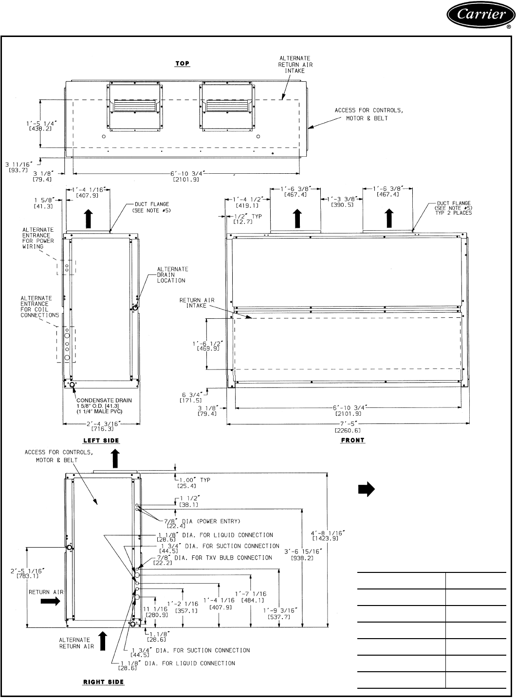
Dimensions (cont)
NOTES:
1. Service clearances are as follows:
Side (compressor) — 31/2 ft (1067 mm)
Side (opposite compressor) — 3 ft (914 mm)
Ends — 2 ft (610 mm)
Top — 5 ft (1524 mm)
2. See page 21 for corner weights and unit center of
gravity.
38AKS013-024
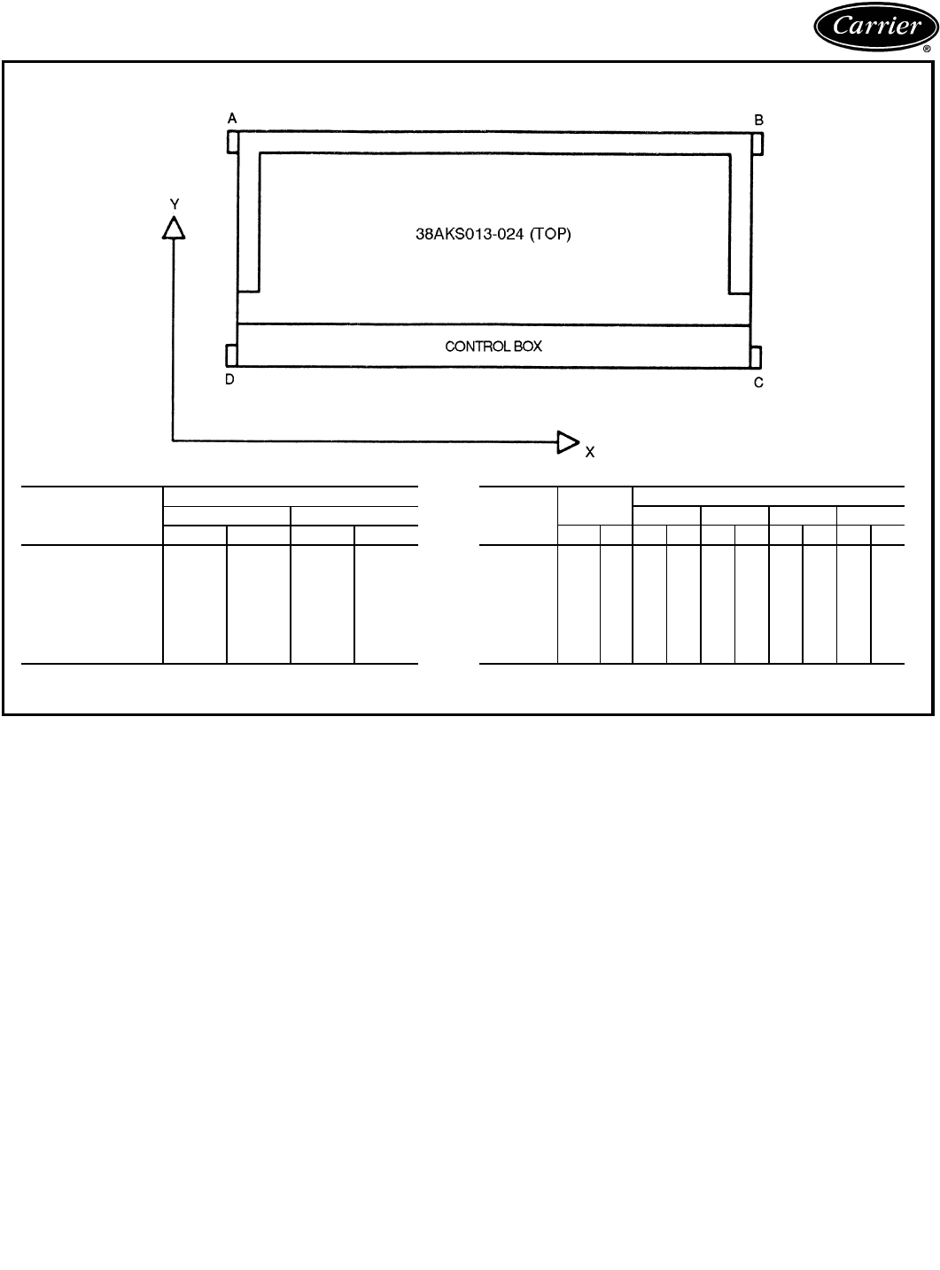
21
38AKS013-024 (cont)
LEGEND
C — Copper Fin Coils
UNIT
38AKS
CENTER OF GRAVITY (in.)
XY
in. mm in. mm
013 38 965 17 432
013C 38 965 19 483
014 38 965 16 406
014C 38 965 18 457
016 38 965 16 406
016C 38 965 18 457
024 37 940 17 432
024C 37 940 19 483
UNIT
38AKS
TOTAL
WEIGHT
OPERATIONAL CORNER WEIGHTS
ABCD
lb kg lb kg lb kg lb kg lb kg
013 732 332 142 64 138 63 225 102 227 103
013C 825 374 178 81 172 78 236 107 239 108
014 779 353 143 65 140 64 247 112 249 113
014C 919 417 197 89 191 87 264 120 267 121
016 789 358 143 65 143 65 250 113 253 115
016C 929 421 197 89 194 88 267 121 271 123
024 900 409 178 81 168 76 269 122 285 129
024C 1040 472 232 105 219 99 286 130 303 137
22
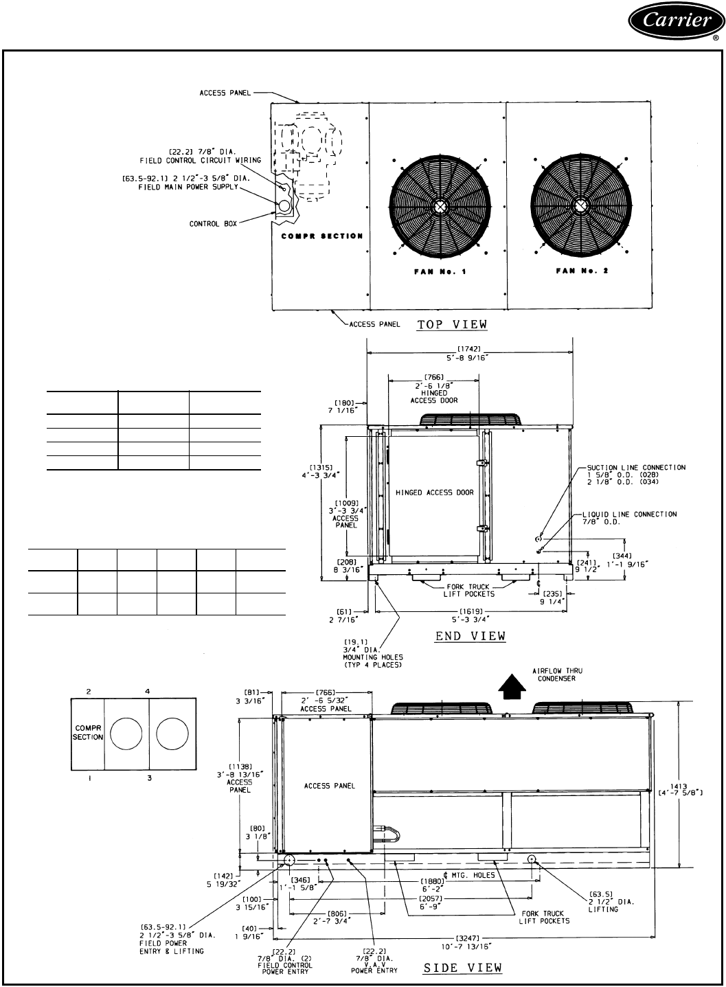
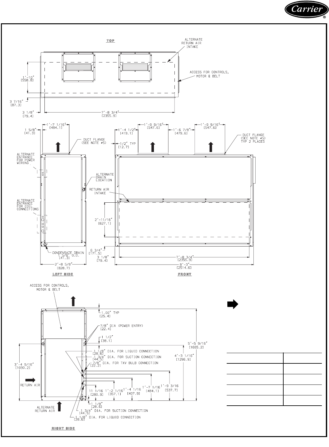
Dimensions (cont)
38AKS028, 034
NOTES:
1. There must be 4 ft [1220 mm] for service and for unre-
stricted airflow on all sides of unit.
2. There must be minimum 8 ft [2440 mm] clear air space
above unit.
3. The approximate operating weight of the unit is:
NOTE: A “C” in model number indicates unit has optional
factory-installed copper-fin coil.
4. Dimensions in [ ] are millimeters.
APPROXIMATE OPERATING WEIGHT*
AT SUPPORT POINTS — LB (KG)*
*Standard copper tube aluminum-fin coil.
UNIT
38AKS
WEIGHT
(lb)
WEIGHT
(kg)
028 1650 748
028C 1804 818
034 1803 818
034C 2009 911
UNIT
38AKS 1234TOTAL
028 418
(189.6)
626
(284.0)
242
(109.8)
364
(165.1)
1650
(748.4)
034 459
(208.2)
673
(305.3)
272
(123.4)
399
(181.0)
1803
(817.8)
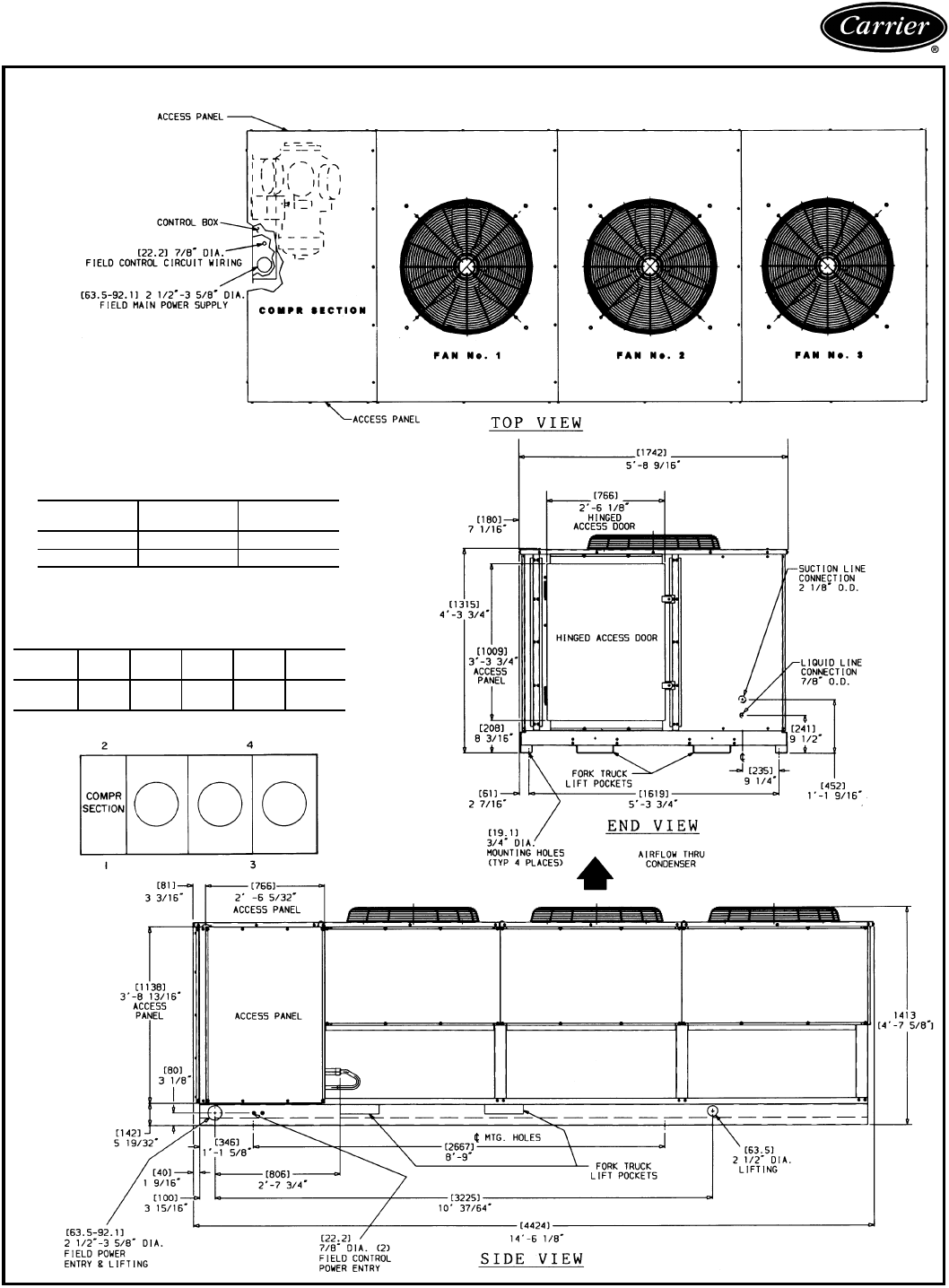
23
38AKS044
NOTES:
1. There must be 4 ft [1220 mm] for service and for unre-
stricted airflow on all sides of unit.
2. There must be minimum 8 ft [2440 mm] clear air space
above unit.
3. The approximate operating weight of the unit is:
NOTE: A “C” in model number indicates unit has
optional factory-installed copper-fin coil.
APPROX. OPER. WT*
AT LIFTING HOLES — LB (KG)*
*Standard copper tube aluminum-fin coil.
UNIT
38AKS
WEIGHT
(lb)
WEIGHT
(kg)
044 2437 1106
044C 2745 1246
UNIT
38AKS 1234TOTAL
044 864
(391.9)
1077
(488.5)
221
(100.2)
275
(124.7)
2437
(1106)
24
Dimensions (cont)
40RM007-012
LEGEND
TXV — Thermostatic Expansion Valve
NOTES:
1. Dimensions in [ ] are in millimeters.
2. Direction of airflow.
3. Recommended clearance:
•Rear: 76 mm (3 in.), 762 mm (2′-6″) with elec-
tric heat accessory
•Front: 762 mm (2′-6″)
•Right Side: 762 mm (2′-6″)
•Left Side: 762 mm (2′-6″)
•Local codes or jurisdiction may prevail.
4. Liquid piping not supplied by Carrier.
5. Duct flange is factory supplied and field installed.
UNIT
40RM
UNIT WEIGHT —
LB (KG)
007
Standard 3-Row Coil 381 (173)
008
Standard 3-Row Coil 385 (175)
012
Standard 3-Row Coil 405 (184)
007
High-Capacity
4-Row Coil
399 (181)
008
High-Capacity
4-Row Coil
404 (184)
012
High-Capacity
4-Row Coil
425 (193)
25
40RM014-024
LEGEND
TXV — Thermostatic Expansion Valve
NOTES:
1. Dimensions in [ ] are in millimeters.
2. Direction of airflow.
3. Recommended clearance:
•Rear: 76 mm (3 in.), 762 mm (2′-6″) with elec-
tric heat accessory
•Front: 762 mm (2′-6″)
•Right Side: 762 mm (2′-6″)
•Left Side: 762 mm (2′-6″)
•Local codes or jurisdiction may prevail.
4. Liquid piping not supplied by Carrier.
5. Duct flange is factory supplied and field
installed.
UNIT
40RM
UNIT WEIGHT —
LB (KG)
014
Standard 3-Row Coil 670 (304)
016
Standard 3-Row Coil 685 (311)
024
Standard 3-Row Coil 690 (313)
014
High-Capacity 4-Row Coil 695 (315)
016
High-Capacity 4-Row Coil 713 (323)
024
High-Capacity 4-Row Coil 730 (331)
26
Dimensions (cont)
40RM028, 034
LEGEND
TXV — Thermostatic Expansion Valve
NOTES:
1. Dimensions in [ ] are in millimeters.
2. Direction of airflow.
3. Recommended clearance:
•Rear: 76 mm (3 in.), 762 mm (2′-6″) with electric
heat accessory
•Front: 762 mm (2′-6″)
•Right Side: 762 mm (2′-6″)
•Left Side: 762 mm (2′-6″)
•Local codes or jurisdiction may prevail.
4. Liquid piping not supplied by Carrier.
5. Duct flange is factory supplied and field installed.
UNIT
40RM
UNIT WEIGHT —
LB (KG)
028
Standard 3-Row Coil 1020 (463)
034
Standard 3-Row Coil 1030 (467)
028
High-Capacity 4-Row Coil 1050 (470)
034
High-Capacity 4-Row Coil 1062 (482)

27
NOTE: Pages 35-43 and 52-57 contain combination rat-
ings for the 38AK and 38AKS units matched with 40RM
Series air handlers.
I Determine cooling load, evaporator-air temper-
ature, and quantity.
Given:
Total Cooling Capacity
Required (TC) . . . . . . . . . . . . . . . . . . . . . 62 kW
Sensible Heat Capacity
Required (SHC) . . . . . . . . . . . . . . . . . . . . 48 kW
Temperature Air Entering Condenser (Edb) . . . 36 C
Temperature Air Entering
Evaporator (db/wb) . . . . . . . 26.7 C db, 20 C wb
Evaporator Air Quantity . . . . . . . . . . . . . . 3800 L/s
External Static Pressure . . . . . . . . . . . . . . . .100 Pa
Length of Interconnecting
Refrigerant Piping . . . . . . . . . . . . . . 8 m (Linear)
II Select condensing unit air-handler combination.
For this example, select a 38AKS024 matched with a
40RM024. (See Combination Ratings table, page 41.)
This 38AKS024/40RM024 condensing unit-air
handler combination provides 62.7 kW of total cooling
capacity and 49.3 kW of sensible capacity at the given
conditions. If other temperatures or airflow values are
required, interpolate the values from the combination
ratings.
III Determine sizes of liquid and suction lines.
Enter Refrigerant Piping Sizes table (page 90). The
sizes shown are based on an equivalent length of pipe.
This equivalent length is equal to the linear length of
pipe indicated at the top of each sizing column, plus a
50% allowance for fitting losses. (For a more accurate
determination of actual equivalent length in place of
using the estimated 50% value, refer to Carrier System
Design Manual.) For this example, note in the linear
length column that the proper pipe size is 5/8 in. for
the liquid line and 15/8 in. for the suction line.
IV Determine fan rpm and bhp (brake
horsepower).
At the Air Handler Fan Performance table (page 64),
enter the 40RM024 section at 3800 L/s and move to
the 100 Pa External Static Pressure (ESP) column.
Note that the conditions require 12.84 r/s at 2.52 kW.
V Determine motor and drive.
For the 40RM024 units, find the type of drive that sat-
isfies the 12.84 r/s requirement in the 40RM Drive
Data tables on pages 95 and 96. The Standard Drive
— SI table shows an r/s range of 11.9 to 14.6 for the
40RM024 unit, which satisfies the r/s requirement for
the example described.
Next, enter the 40RM Fan Motor Data tables on
page 94, and find that for the 40RM024 unit, an stan-
dard motor has a motor kW of 3.73 which satisfies the
bhp requirement for the example described. Select the
standard motor and standard drive combination (option
code GC or ED).
Selection procedure — English
NOTE: Pages 44-51 and 58-63 contain combination rat-
ings for the 38AK and 38AKS units matched with 40RM
Series air handlers.
I Determine cooling load, evaporator-air temper-
ature, and quantity.
Given:
Total Cooling Capacity
Required (TC) . . . . . . . . . . . . . . . .210,000 Btuh
Sensible Heat Capacity
Required (SHC) . . . . . . . . . . . . . . .175,000 Btuh
Temperature Air Entering Condenser (Edb) . . . .95 F
Temperature Air Entering
Evaporator (db/wb) . . . . . . . . . 80 F db, 67 F wb
Evaporator Air Quantity . . . . . . . . . . . . . . 8000 cfm
External Static Pressure . . . . . . . . . . . . . .0.8 in. wg
Length of Interconnecting
Refrigerant Piping . . . . . . . . . . . . . .40 ft (Linear)
II Select condensing unit air-handler combination.
For this example, select a 38AKS024 matched with a
40RM024. (See Combination Ratings table, page 49.)
This 38AKS024/40RM024 condensing unit-air
handler combination provides 214,600 Btuh of total
cooling capacity and 179,000 Btuh of sensible capac-
ity at the given conditions. If other temperatures or air-
flow values are required, interpolate the values from the
combination ratings.
III Determine sizes of liquid and suction lines.
Enter Refrigerant Piping Sizes table (page 90). The
sizes shown are based on an equivalent length of pipe.
This equivalent length is equal to the linear length of
pipe indicated at the top of each sizing column, plus a
50% allowance for fitting losses. (For a more accurate
determination of actual equivalent length in place of
using the estimated 50% value, refer to Carrier System
Design Manual.) For this example, note in the linear
length column that the proper pipe size is 5/8 in. for
the liquid line and 15/8 in. for the suction line.
IV Determine fan rpm and bhp (brake
horsepower).
At the Air Handler Fan Performance table (page 66),
enter the 40RM024 section at 8000 cfm and move to
the 0.80 in. wg External Static Pressure (ESP) column.
Note that the conditions require 876 rpm at 4.21 bhp.
V Determine motor and drive.
For the 40RM024 units, find the type of drive that sat-
isfies the 876 rpm requirement in the 40RM Drive
Data tables on pages 97 and 98. The Medium-Static
Drive — English table shows an rpm range of 814 to
1018 for the 40RM024 unit, which satisfies the rpm
requirement for the example described.
Next, enter the 40RM Fan Motor Data tables on
page 95, and find that for the 40RM024 unit, an alter-
nate motor has a motor hp of 7.5 which satisfies the
bhp requirement for the example described. Select the
alternate motor and medium-static drive combination
(option code TC or RD).
Selection procedure — SI
28
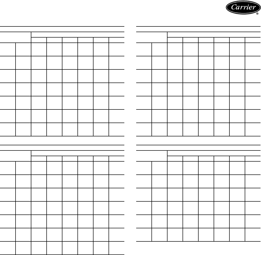
CONDENSING UNIT RATINGS — SI
LEGEND
38AK007
SST
(C)
Air Temperature Entering Condenser (C)
28 32 36 40 44 48 52
–4
TC 13.4 12.5 11.7 10.9 10.0 9.20 8.36
kW 4.33 4.45 4.56 4.67 4.78 4.89 5.00
CDT 39.6 43.4 47.3 51.2 55.0 58.9 62.8
–2
TC 14.5 13.7 12.9 12.0 11.2 10.4 9.51
kW 4.48 4.61 4.73 4.86 4.98 5.11 5.23
CDT 40.2 43.9 47.7 51.4 55.1 58.8 62.6
0
TC 15.7 14.9 14.1 13.2 12.3 11.5 10.6
kW 4.63 4.77 4.91 5.05 5.19 5.32 5.46
CDT 40.9 44.5 48.2 51.8 55.5 59.1 62.7
2
TC 17.0 16.1 15.2 14.4 13.5 12.6 11.8
kW 4.78 4.93 5.09 5.24 5.39 5.55 5.70
CDT 41.7 45.3 48.9 52.5 56.1 59.7 63.3
4
TC 18.2 17.4 16.5 15.6 14.7 13.8 12.9
kW 4.93 5.10 5.27 5.44 5.60 5.77 5.94
CDT 42.5 46.1 49.6 53.2 56.8 60.4 63.9
6
TC 19.5 18.7 17.7 16.8 15.9 15.0 14.1
kW 5.08 5.27 5.45 5.63 5.82 6.00 6.18
CDT 43.4 46.9 50.5 54.0 57.6 61.1 64.7
8
TC 20.9 20.0 19.0 18.1 17.2 16.3 15.3
kW 5.23 5.44 5.63 5.83 6.03 6.23 6.42
CDT 44.3 47.8 51.3 54.9 58.4 61.9 65.4
10
TC 22.3 21.3 20.4 19.4 18.5 17.5 16.6
kW 5.39 5.61 5.82 6.03 6.24 6.46 6.67
CDT 45.2 48.7 52.2 55.7 59.2 62.7 66.2
38AK008
SST
(C)
Air Temperature Entering Condenser (C)
28 32 36 40 44 48 52
–4
TC 17.9 17.1 16.3 15.5 14.7 13.8 12.9
kW 5.40 5.69 5.99 6.30 6.62 6.93 7.25
CDT 40.0 43.9 47.8 51.8 55.7 59.6 63.5
–2
TC 19.1 18.3 17.5 16.7 15.8 14.9 14.0
kW 5.48 5.76 6.06 6.37 6.69 7.01 7.33
CDT 40.5 44.3 48.2 52.1 56.0 59.9 63.8
0
TC 20.4 19.6 18.7 17.9 16.9 16.0 15.1
kW 5.56 5.84 6.14 6.44 6.76 7.08 7.40
CDT 41.0 44.9 48.7 52.5 56.4 60.2 64.1
2
TC 21.8 20.9 20.0 19.1 18.1 17.2 16.2
kW 5.65 5.93 6.22 6.53 6.84 7.16 7.48
CDT 41.6 45.4 49.2 53.0 56.8 60.7 64.5
4
TC 23.2 22.3 21.4 20.4 19.4 18.4 17.3
kW 5.75 6.03 6.33 6.63 6.94 7.26 7.57
CDT 42.2 46.0 49.8 53.6 57.4 61.1 64.9
6
TC 24.6 23.7 22.8 21.7 20.7 19.6 18.6
kW 5.85 6.14 6.44 6.74 7.05 7.36 7.68
CDT 42.9 46.7 50.5 54.2 58.0 61.7 65.4
8
TC 26.1 25.2 24.2 23.1 22.0 20.9 19.8
kW 5.96 6.25 6.55 6.86 7.17 7.48 7.79
CDT 43.6 47.4 51.1 54.9 58.6 62.3 66.0
10
TC 27.7 26.7 25.7 24.6 23.4 22.3 21.1
kW 6.07 6.37 6.67 6.98 7.29 7.61 7.92
CDT 44.4 48.1 51.9 55.6 59.3 62.9 66.6
——
Out of Range
CDT —Saturated Discharge Temperature at Compressor (C)
kW —Compressor Power
SST —Saturated Suction Temperature (C)
TC —Gross Cooling Capacity (kW)
38AK012
SST
(C)
Air Temperature Entering Condenser (C)
28 32 36 40 44 48 52
–4
TC 23.9 23.0 22.1 21.2 20.2 19.3 18.3
kW 7.96 8.40 8.87 9.37 9.90 10.4 11.0
CDT 39.7 43.5 47.4 51.3 55.3 59.2 63.2
–2
TC 25.5 24.5 23.6 22.6 21.6 20.6 19.6
kW 8.11 8.54 8.99 9.47 9.99 10.5 11.0
CDT 40.3 44.0 47.8 51.7 55.5 59.4 63.3
0
TC 27.1 26.1 25.1 24.1 23.1 22.0 20.9
kW 8.27 8.69 9.12 9.59 10.1 10.6 11.1
CDT 40.9 44.6 48.3 52.1 55.9 59.7 63.5
2
TC 28.8 27.8 26.7 25.6 24.5 23.4 22.3
kW 8.45 8.86 9.29 9.74 10.2 10.7 11.2
CDT 41.6 45.2 48.9 52.6 56.4 60.1 63.8
4
TC 30.5 29.5 28.4 27.2 26.1 24.9 23.7
kW 8.64 9.05 9.47 9.92 10.4 10.9 11.3
CDT 42.3 46.0 49.6 53.2 56.9 60.6 64.3
6
TC 32.3 31.2 30.1 28.9 27.7 26.4 25.2
kW 8.84 9.26 9.68 10.1 10.6 11.0 11.5
CDT 43.1 46.7 50.3 53.9 57.6 61.2 64.9
8
TC 34.2 33.1 31.9 30.7 29.4 28.1 26.8
kW 9.06 9.47 9.89 10.3 10.8 11.2 11.7
CDT 43.9 47.5 51.1 54.6 58.2 61.9 65.5
10
TC 36.1 35.0 33.8 32.5 31.1 29.7 28.4
kW 9.28 9.70 10.1 10.6 11.0 11.5 11.9
CDT 44.8 48.3 51.8 55.4 59.0 62.5 66.1
38AKS008
SST
(C)
Air Temperature Entering Condenser (C)
28 32 36 40 44 48 52
–4
TC 16.5 15.6 14.7 13.8 12.9 11.9 11.0
kW 4.79 5.01 5.22 5.40 5.55 5.70 5.84
CDT 39.3 43.0 46.7 50.5 54.2 58.0 61.8
–2
TC 18.2 17.3 16.3 15.3 14.4 13.4 12.4
kW 4.92 5.17 5.40 5.61 5.78 5.95 6.12
CDT 40.1 43.8 47.5 51.3 55.0 58.7 62.5
0
TC 19.9 18.9 17.9 16.9 15.8 14.8 13.8
kW 5.05 5.32 5.58 5.81 6.01 6.21 6.40
CDT 41.0 44.7 48.4 52.1 55.8 59.5 63.2
2
TC 21.6 20.5 19.5 18.4 17.3 16.3 15.2
kW 5.18 5.48 5.76 6.02 6.24 6.46 6.68
CDT 41.8 45.5 49.2 52.9 56.5 60.2 63.9
4
TC 23.3 22.2 21.1 20.0 18.8 17.7 16.6
kW 5.31 5.63 5.94 6.22 6.47 6.72 6.96
CDT 42.7 46.4 50.0 53.7 57.3 61.0 64.6
6
TC 25.0 23.8 22.7 21.5 20.3 19.1 18.0
kW 5.44 5.79 6.12 6.43 6.70 6.97 7.24
CDT 43.6 47.2 50.8 54.5 58.1 61.7 65.3
8
TC 26.7 25.5 24.3 23.1 21.8 20.6 19.4
kW 5.58 5.94 6.30 6.63 6.93 7.23 7.52
CDT 44.5 48.1 51.7 55.3 58.9 62.5 66.1
10
TC 28.5 27.2 26.0 24.7 23.4 22.1 20.8
kW 5.71 6.10 6.48 6.83 7.16 7.48 7.80
CDT 45.4 49.0 52.6 56.1 59.7 63.3 66.8
Performance data
29
CONDENSING UNIT RATINGS — SI (cont)
LEGEND
38AKS009
SST
(C)
Air Temperature Entering Condenser (C)
28 32 36 40 44 48 52
–4
TC 20.7 19.5 18.3 17.1 15.9 14.7 13.5
kW 6.30 6.56 6.80 7.02 7.19 7.36 7.52
CDT 41.5 45.1 48.7 52.3 55.9 59.5 63.0
–2
TC 22.7 21.5 20.2 19.0 17.7 16.4 15.2
kW 6.54 6.83 7.10 7.34 7.54 7.73 7.93
CDT 42.7 46.2 49.8 53.4 56.9 60.4 64.0
0
TC 24.8 23.5 22.1 20.8 19.5 18.2 16.8
kW 6.78 7.09 7.39 7.66 7.89 8.11 8.33
CDT 43.8 47.3 50.8 54.4 57.9 61.4 64.9
2
TC 26.9 25.5 24.1 22.7 21.3 19.9 18.5
kW 7.02 7.36 7.68 7.98 8.23 8.48 8.73
CDT 44.9 48.4 51.9 55.4 58.9 62.4 65.8
4
TC 29.0 27.5 26.0 24.6 23.1 21.6 20.2
kW 7.27 7.63 7.98 8.30 8.58 8.86 9.14
CDT 46.0 49.5 52.9 56.4 59.9 63.3 66.8
6
TC 31.0 29.5 27.9 26.4 24.9 23.4 21.8
kW 7.51 7.90 8.27 8.62 8.93 9.23 9.54
CDT 47.1 50.5 54.0 57.4 60.9 64.3 67.7
8
TC 33.1 31.5 29.9 28.3 26.7 25.1 23.5
kW 7.75 8.17 8.57 8.94 9.28 9.61 9.95
CDT 48.2 51.6 55.1 58.5 61.9 65.3 68.7
10
TC 35.3 33.6 31.9 30.3 28.6 26.9 —
kW 8.00 8.44 8.87 9.26 9.63 9.99 —
CDT 49.4 52.8 56.2 59.6 62.9 66.3 —
38AKS012
SST
(C)
Air Temperature Entering Condenser (C)
28 32 36 40 44 48 52
–4
TC 20.3 19.2 18.0 16.8 15.6 14.4 13.3
kW 6.28 6.55 6.80 7.01 7.19 7.33 7.46
CDT 41.3 44.9 48.6 52.1 55.7 59.3 62.9
–2
TC 22.4 21.1 19.9 18.6 17.4 16.2 14.9
kW 6.52 6.81 7.09 7.33 7.53 7.71 7.86
CDT 42.4 46.0 49.6 53.1 56.7 60.2 63.8
0
TC 24.4 23.1 21.8 20.5 19.2 17.9 16.6
kW 6.75 7.07 7.38 7.64 7.87 8.08 8.26
CDT 43.5 47.0 50.6 54.1 57.7 61.2 64.7
2
TC 26.4 25.1 23.7 22.3 21.0 19.6 18.2
kW 6.99 7.34 7.66 7.96 8.22 8.45 8.66
CDT 44.6 48.1 51.6 55.1 58.6 62.2 65.7
4
TC 28.5 27.1 25.6 24.2 22.7 21.3 19.9
kW 7.23 7.60 7.95 8.27 8.56 8.82 9.06
CDT 45.7 49.1 52.6 56.1 59.6 63.1 66.6
6
TC 30.5 29.0 27.5 26.0 24.5 23.0 21.5
kW 7.46 7.86 8.24 8.59 8.90 9.19 9.46
CDT 46.8 50.2 53.7 57.1 60.6 64.1 67.5
8
TC 32.6 31.0 29.5 27.9 26.3 24.8 23.2
kW 7.70 8.12 8.53 8.90 9.25 9.57 9.86
CDT 47.9 51.3 54.7 58.1 61.6 65.0 68.5
10
TC 34.8 33.1 31.5 29.8 28.2 26.5 24.9
kW 7.94 8.39 8.82 9.22 9.59 9.94 10.3
CDT 49.0 52.4 55.8 59.2 62.6 66.0 69.4
——
Out of Range
CDT —Saturated Discharge Temperature at Compressor (C)
kW —Compressor Power
SST —Saturated Suction Temperature (C)
TC —Gross Cooling Capacity (kW)
38AKS013
SST
(C)
Air Temperature Entering Condenser (C)
20 30 35 40 46 52
–8
TC 20.7 18.2 17.0 15.7 14.3 12.9
kW 5.6 6.3 6.5 6.8 7.0 7.2
CDT 31.1 40.2 44.8 49.3 54.8 60.3
–4
TC 24.1 21.3 20.0 18.6 17.0 15.4
kW 5.9 6.7 7.1 7.4 7.7 8.0
CDT 32.7 41.8 46.2 50.8 56.3 61.7
0
TC 27.9 24.8 23.2 21.7 19.9 18.2
kW 6.3 7.2 7.6 8.0 8.4 8.7
CDT 34.4 43.4 47.9 52.4 57.8 63.2
4
TC 32.1 28.6 26.8 25.2 23.2 21.2
kW 6.6 7.7 8.2 8.6 9.1 9.5
CDT 36.3 45.2 49.7 54.1 59.5 64.8
8
TC 36.6 32.7 30.8 28.9 27.7 24.5
kW 6.9 8.2 8.7 9.3 9.8 10.3
CDT 38.3 47.2 51.6 56.0 61.3 66.5
12
TC 41.4 37.1 35.0 33.0 30.5 28.1
kW 7.3 8.7 9.3 9.9 10.6 11.1
CDT 40.6 49.3 53.6 58.0 63.2 68.4
38AKS014
SST
(C)
Air Temperature Entering Condenser (C)
20 30 35 40 46 52
–8
TC 25.0 22.0 20.6 19.2 17.6 16.0
kW 6.6 7.5 7.9 8.2 8.7 9.0
CDT 31.1 40.3 44.9 49.5 55.1 60.6
–4
TC 29.1 25.8 24.2 22.6 20.7 19.0
kW 7.0 8.0 8.5 8.9 9.4 9.9
CDT 32.7 41.8 46.4 50.9 56.4 61.9
0
TC 33.6 29.9 28.1 26.3 24.2 22.2
kW 7.5 8.6 9.1 9.6 10.2 10.8
CDT 34.5 43.5 48.0 52.5 58.0 63.4
4
TC 38.6 34.4 32.4 30.4 28.0 25.8
kW 7.9 9.2 9.8 10.4 11.0 11.7
CDT 36.4 45.3 49.8 54.2 60.0 65.0
8
TC 44.0 39.3 37.0 34.8 32.2 29.7
kW 8.4 9.8 10.5 11.1 11.9 12.6
CDT 38.4 47.3 51.7 56.1 61.4 66.7
12
TC 49.7 44.6 42.1 39.6 36.7 —
kW 8.9 10.5 11.2 11.9 12.7 —
CDT 40.7 49.4 53.7 58.1 63.3 —
30
CONDENSING UNIT RATINGS — SI (cont)
LEGEND
38AKS016
SST
(C)
Air Temperature Entering Condenser (C)
20 30 35 40 46 52
–8
TC 31.7 27.9 26.0 24.2 22.1 20.2
kW 9.4 10.3 10.7 11.1 11.4 11.7
CDT 33.7 42.7 47.2 51.7 57.1 62.5
–4
TC 36.8 32.5 30.5 28.4 26.1 23.8
kW 10.1 11.2 11.7 12.2 12.6 13.0
CDT 35.7 44.6 49.0 53.5 58.8 64.1
0
TC 42.5 37.6 35.3 33.0 30.4 —
kW 10.9 12.2 12.8 13.3 13.9 —
CDT 37.8 46.6 51.0 55.4 60.7 —
4
TC 48.6 43.2 40.6 38.0 35.1 —
kW 11.7 13.2 13.9 14.5 15.1 —
CDT 40.2 48.8 53.1 57.5 62.7 —
8
TC 55.1 49.2 46.3 43.5 40.1 —
kW 12.6 14.3 15.0 15.7 16.5 —
CDT 42.7 51.2 55.4 59.7 64.8 —
12
TC 62.2 55.6 52.4 49.3 ——
kW 13.4 15.3 16.2 17.0 ——
CDT 45.3 53.7 57.9 62.1 ——
38AKS024
SST
(C)
Air Temperature Entering Condenser (C)
20 30 35 40 46 52
–2
TC 53.4 46.8 43.4 39.9 35.7 31.4
kW 12.6 14.2 14.9 15.4 15.9 16.4
CDT 34.3 43.3 47.7 52.2 57.4 62.7
0
TC 58.2 51.3 47.7 44.1 39.7 35.2
kW 13.1 14.8 15.5 16.2 16.8 17.3
CDT 35.6 44.5 48.9 53.3 58.5 63.7
2
TC 63.0 55.8 52.1 48.3 43.7 39.1
kW 13.5 15.4 16.2 16.9 17.6 18.3
CDT 36.9 45.7 50.0 54.4 59.6 64.7
4
TC 67.9 60.3 56.4 52.5 47.7 42.9
kW 14.0 16.0 16.9 17.6 18.4 19.2
CDT 38.2 46.9 51.2 55.5 60.6 65.8
6
TC 72.7 64.8 60.8 56.7 51.7 46.7
kW 14.5 16.6 17.5 18.4 19.3 20.1
CDT 39.6 48.1 52.4 56.6 61.7 66.8
8
TC 77.5 69.3 65.1 60.9 55.7 50.6
kW 15.0 17.2 18.2 19.1 20.1 21.0
CDT 40.9 49.3 53.5 57.7 62.8 67.8
10
TC 82.4 73.8 69.5 65.1 59.7 54.4
kW 15.5 17.8 18.9 19.9 20.9 22.0
CDT 42.2 50.5 54.7 58.8 63.8 68.8
——
Out of Range
CDT —Saturated Discharge Temperature at Compressor (C)
kW —Compressor Power
SST —Saturated Suction Temperature (C)
TC —Gross Cooling Capacity (kW)
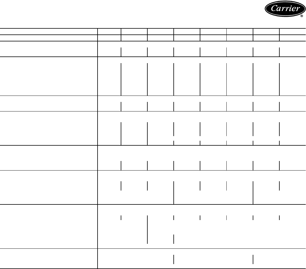
38AKS028
SST
(C)
Air Temperature Entering Condenser (C)
28 32 36 40 44 48 52
–6
TC 55.3 52.4 49.5 46.6 43.8 41.0 38.3
kW 17.4 18.0 18.6 19.1 19.6 20.0 20.4
CDT 41.2 44.8 48.5 52.1 55.8 59.6 63.3
–4
TC 60.4 57.3 54.2 51.1 48.1 45.2 42.3
kW 18.2 18.9 19.5 20.1 20.6 21.1 21.5
CDT 42.1 45.7 49.3 52.9 56.5 60.2 63.8
–2
TC 64.4 61.1 57.8 54.7 51.5 48.5 45.4
kW 18.8 19.5 20.3 20.9 21.5 22.0 22.4
CDT 42.9 46.4 50.0 53.6 57.1 60.7 64.4
0
TC 69.9 66.4 62.9 59.6 56.3 53.0 49.7
kW 19.6 20.4 21.2 21.9 22.6 23.1 23.7
CDT 43.9 47.4 50.9 54.5 58.0 61.6 65.1
2
TC 75.6 71.9 68.3 64.7 61.2 57.7 54.3
kW 20.5 21.3 22.2 23.0 23.7 24.3 24.9
CDT 45.0 48.5 52.0 55.4 59.0 62.5 66.0
4
TC 80.2 76.3 72.5 68.7 65.0 61.4 57.8
kW 21.1 22.0 22.9 23.8 24.5 25.2 25.9
CDT 45.9 49.3 52.8 56.2 59.7 63.2 66.7
6
TC 86.4 82.3 78.3 74.3 70.3 66.5 62.7
kW 22.0 23.0 23.9 24.8 25.7 26.5 27.2
CDT 47.1 50.5 53.9 57.3 60.8 64.2 67.7
8
TC 91.2 87.0 82.8 78.6 74.5 70.5 66.5
kW 22.6 23.7 24.7 25.7 26.6 27.4 28.2
CDT 48.0 51.4 54.8 58.2 61.6 65.0 68.4
10
TC 97.9 93.5 89.0 84.6 80.3 76.0 71.7
kW 23.5 24.6 25.7 26.8 27.8 28.7 29.5
CDT 49.3 52.7 56.0 59.4 62.8 66.1 69.5
38AKS034
SST
(C)
Air Temperature Entering Condenser (C)
28 32 36 40 44 48 52
–6
TC 62.4 58.9 55.3 51.7 48.1 44.5 40.8
kW 20.0 20.6 21.2 21.6 21.9 22.2 22.2
CDT 42.1 46.0 50.0 54.1 58.0 62.0 66.1
–4
TC 68.7 65.0 61.3 57.6 53.7 49.9 46.1
kW 20.7 21.4 22.2 22.7 23.2 23.5 23.7
CDT 42.2 46.1 50.1 54.1 58.1 62.1 66.1
–2
TC 73.3 69.7 66.0 62.1 58.2 54.3 50.3
kW 21.3 22.1 22.9 23.5 24.1 24.5 24.8
CDT 42.7 46.4 50.2 54.1 58.1 62.0 66.1
0
TC 79.5 75.8 72.1 68.3 64.3 60.3 56.1
kW 22.1 23.0 23.9 24.6 25.2 25.8 26.2
CDT 43.6 47.2 50.8 54.5 58.3 62.1 66.1
2
TC 85.9 82.1 78.2 74.3 70.3 66.3 62.1
kW 23.0 24.0 24.9 25.7 26.4 27.1 27.6
CDT 44.6 48.1 51.7 55.2 58.9 62.5 66.2
4
TC 90.9 87.0 83.0 79.0 74.9 70.8 66.6
kW 23.7 24.7 25.7 26.6 27.4 28.1 28.7
CDT 45.4 48.9 52.5 56.0 59.5 63.1 66.6
6
TC 97.8 93.6 89.5 85.3 81.0 76.8 72.4
kW 24.6 25.7 26.8 27.8 28.6 29.4 30.1
CDT 46.6 50.1 53.5 57.0 60.5 64.0 67.5
8
TC 103.0 98.8 94.5 90.2 85.8 81.4 76.9
kW 25.2 26.4 27.6 28.6 29.6 30.5 31.2
CDT 47.5 50.9 54.4 57.8 61.3 64.7 68.2
10
TC 110.0 106.0 101.0 96.9 92.3 87.7 83.0
kW 26.2 27.4 28.7 29.8 30.9 31.9 32.7
CDT 48.8 52.2 55.6 59.0 62.4 65.8 69.2
Performance data (cont)
31
CONDENSING UNIT RATINGS — SI (cont)
LEGEND
CONDENSING UNIT RATINGS — ENGLISH
LEGEND
38AKS044
SST
(C)
Air Temperature Entering Condenser (C)
28 32 36 40 44 48 52
–6
TC 82.8 78.8 74.8 70.9 67.1 63.3 59.5
kW 27.3 28.1 29.0 29.7 30.4 31.0 31.5
CDT 41.4 45.3 49.3 53.3 57.3 61.3 65.3
–4
TC 90.9 86.5 82.3 78.0 73.9 69.8 65.7
kW 28.3 29.3 30.3 31.1 31.9 32.6 33.2
CDT 41.3 45.3 49.3 53.3 57.3 61.3 65.3
–2
TC 97.3 92.7 88.2 83.7 79.4 75.0 70.7
kW 29.0 30.1 31.2 32.2 33.0 33.8 34.5
CDT 41.4 45.3 49.3 53.3 57.3 61.3 65.3
0
TC 106.0 101.0 96.5 91.7 87.1 82.4 77.8
kW 30.0 31.2 32.4 33.5 34.5 35.4 36.2
CDT 41.8 45.6 49.4 53.4 57.3 61.3 65.3
2
TC 115.0 110.0 105.0 99.9 95.1 90.2 85.3
kW 31.2 32.5 33.7 34.9 36.0 37.0 37.9
CDT 42.5 46.2 50.0 53.7 57.5 61.4 65.4
4
TC 121.0 116.0 111.0 106.0 101.0 96.1 91.1
kW 32.1 33.5 34.8 36.0 37.2 38.2 39.2
CDT 43.2 46.9 50.5 54.2 58.0 61.7 65.5
6
TC 130.0 125.0 120.0 114.0 109.0 104.0 98.8
kW 33.3 34.8 36.2 37.6 38.8 40.0 41.1
CDT 44.2 47.8 51.5 55.1 58.7 62.4 66.1
8
TC 138.0 132.0 127.0 121.0 116.0 110.0 105.0
kW 34.2 35.8 37.3 38.8 40.1 41.3 42.5
CDT 45.0 48.6 52.2 55.8 59.4 63.0 66.7
10
TC 148.0 142.0 136.0 130.0 124.0 118.0 113.0
kW 35.5 37.2 38.8 40.4 41.8 43.2 44.4
CDT 46.1 49.7 53.2 56.8 60.4 64.0 67.6
——
Out of Range
CDT —Saturated Discharge Temperature at Compressor (C)
kW —Compressor Power
SST —Saturated Suction Temperature (C)
TC —Gross Cooling Capacity (kW)
38AK007
SST
(F)
Air Temperature Entering Condenser (F)
80 85 95 100 105 115 120 125
25
TC 46.8 44.9 40.9 38.9 36.9 32.9 31.0 29.0
kW 4.30 4.39 4.54 4.62 4.70 4.85 4.93 5.01
CDT 101 106 115 120 125 135 140 144
30
TC 52.3 50.4 46.4 44.4 42.4 38.4 36.4 34.4
kW 4.50 4.60 4.78 4.87 4.96 5.14 5.23 5.32
CDT 103 107 116 121 126 135 139 144
35
TC 58.1 56.2 52.1 50.0 48.0 43.8 41.8 39.7
kW 4.69 4.81 5.02 5.12 5.23 5.44 5.54 5.65
CDT 105 109 118 123 127 136 141 145
40
TC 64.1 62.1 57.9 55.8 53.7 49.5 47.4 45.2
kW 4.90 5.03 5.26 5.38 5.50 5.74 5.86 5.98
CDT 107 111 120 125 129 138 142 147
45
TC 70.4 68.4 64.0 61.8 59.6 55.3 53.1 50.9
kW 5.10 5.25 5.51 5.65 5.78 6.05 6.18 6.31
CDT 109 113 122 127 131 140 144 149
50
TC 77.0 74.9 70.4 68.1 65.8 61.3 59.0 56.7
kW 5.32 5.47 5.77 5.91 6.06 6.36 6.50 6.65
CDT 111 116 124 129 133 142 146 151
——
Out of Range
CDT —Saturated Discharge Temperature at Compressor (F)
kW —Compressor Power
SST —Saturated Suction Temperature (F)
TC —Gross Cooling Capacity (1000 Btuh)
38AK008
SST
(F)
Air Temperature Entering Condenser (F)
80 85 95 100 105 115 120 125
25
TC 62.0 60.3 56.6 54.7 52.8 48.7 46.6 44.6
kW 5.31 5.50 5.91 6.13 6.35 6.79 7.01 7.23
CDT 102 107 116 121 126 136 141 146
30
TC 68.1 66.2 62.3 60.3 58.2 54.0 51.9 49.7
kW 5.42 5.61 6.01 6.22 6.44 6.89 7.11 7.34
CDT 103 108 117 122 127 137 142 146
35
TC 74.5 72.5 68.3 66.2 63.9 59.4 57.2 54.9
kW 5.54 5.73 6.13 6.34 6.55 7.00 7.22 7.44
CDT 104 109 119 123 128 138 143 147
40
TC 81.1 79.1 74.7 72.4 70.1 65.2 62.8 60.3
kW 5.67 5.87 6.27 6.48 6.69 7.13 7.35 7.57
CDT 106 111 120 125 130 139 144 148
45
TC 88.1 86.1 81.5 79.1 76.5 71.3 68.7 66.1
kW 5.82 6.02 6.43 6.64 6.85 7.28 7.50 7.72
CDT 108 112 122 127 131 141 145 150
50
TC 95.4 93.3 88.6 86.0 83.4 77.8 75.1 72.3
kW 5.97 6.18 6.60 6.81 7.02 7.46 7.58 7.89
CDT 110 114 124 128 133 142 147 151
32
CONDENSING UNIT RATINGS — ENGLISH (cont)
LEGEND
38AK012
SST
(F)
Air Temperature Entering Condenser (F)
80 85 95 100 105 115 120 125
25
TC 82.7 80.7 76.5 74.4 72.2 67.6 65.3 62.9
kW 7.83 8.12 8.75 9.09 9.45 10.2 10.6 10.9
CDT 101 106 116 121 125 135 140 145
30
TC 90.3 88.1 83.6 81.3 78.9 74.1 71.7 69.2
kW 8.04 8.32 8.92 9.24 9.58 10.3 10.7 11.0
CDT 103 107 117 121 126 136 141 145
35
TC 98.2 95.9 91.1 88.6 86.0 80.8 78.2 75.5
kW 8.28 8.56 9.14 9.45 9.78 10.5 10.8 11.1
CDT 104 109 118 123 127 137 142 146
40
TC 107 104 99.1 96.3 93.6 87.9 85.1 82.2
kW 8.55 8.83 9.40 9.70 10.0 10.7 11.0 11.3
CDT 106 111 120 124 129 138 143 147
45
TC 115 113 108 105 102 95.6 92.6 89.5
kW 8.84 9.12 9.70 10.0 10.3 10.9 11.3 11.6
CDT 108 113 122 126 131 140 144 149
50
TC 124 122 116 113 110 104 100 97.2
kW 9.15 9.43 10.0 10.3 10.6 11.2 11.6 11.9
CDT 111 115 124 128 133 142 146 150
38AKS008
SST
(F)
Air Temperature Entering Condenser (F)
80 85 95 100 105 115 120 125
25
TC 57.8 55.6 51.2 49.1 46.9 42.5 40.3 38.1
kW 4.72 4.88 5.18 5.32 5.44 5.64 5.74 5.84
CDT 101 105 114 119 124 133 138 143
30
TC 65.9 63.5 58.9 56.5 54.2 49.4 47.1 44.7
kW 4.89 5.08 5.43 5.58 5.73 5.98 6.10 6.23
CDT 103 107 117 121 126 135 140 144
35
TC 74.0 71.5 66.5 63.9 61.4 56.4 53.8 51.3
kW 5.06 5.27 5.67 5.85 6.02 6.32 6.47 6.62
CDT 105 109 119 123 128 137 142 146
40
TC 82.1 79.4 74.1 71.4 68.7 63.3 60.6 57.9
kW 5.23 5.47 5.91 6.11 6.31 6.65 6.83 7.00
CDT 107 112 121 125 130 139 144 148
45
TC 90.2 87.4 81.7 78.8 76.0 70.3 67.4 64.5
kW 5.40 5.66 6.15 6.38 6.59 6.99 7.19 7.39
CDT 109 114 123 127 132 141 145 150
50
TC 98.7 95.8 89.7 86.7 83.6 77.5 74.5 71.4
kW 5.57 5.85 6.39 6.64 6.88 7.33 7.55 7.77
CDT 112 116 125 129 134 143 147 152
——
Out of Range
CDT —Saturated Discharge Temperature at Compressor (F)
kW —Compressor Power
SST —Saturated Suction Temperature (F)
TC —Gross Cooling Capacity (1000 Btuh)
38AKS009
SST
(F)
Air Temperature Entering Condenser (F)
80 85 95 100 105 115 120 125
25
TC 72.3 69.5 63.7 61.0 58.2 52.4 49.6 46.7
kW 6.22 6.41 6.76 6.92 7.07 7.30 7.41 7.53
CDT 105 109 118 123 127 136 141 145
30
TC 82.2 79.1 73.0 70.0 66.9 60.8 57.7 54.6
kW 6.54 6.76 7.16 7.35 7.52 7.80 7.94 8.09
CDT 108 112 121 125 130 139 143 147
35
TC 92.1 88.8 82.2 79.0 75.7 69.1 65.8 62.6
kW 6.87 7.11 7.56 7.77 7.96 8.30 8.48 8.65
CDT 110 115 123 128 132 141 145 150
40
TC 102 98.5 91.5 88.0 84.5 77.5 74.0 70.5
kW 7.19 7.46 7.96 8.19 8.41 8.81 9.01 9.20
CDT 113 117 126 130 135 143 148 152
45
TC 112 108 101 97.0 93.2 85.8 82.1 78.4
kW 7.51 7.81 8.36 8.62 8.86 9.31 9.54 9.76
CDT 116 120 129 133 137 146 150 154
50
TC 122 118 110 106 102 94.6 90.7 —
kW 7.85 8.16 8.76 9.05 9.32 9.82 10.1 —
CDT 119 123 132 136 140 149 153 —
38AKS012
SST
(F)
Air Temperature Entering Condenser (F)
80 85 95 100 105 115 125
25
TC 71.0 68.2 62.8 60.0 57.1 51.5 45.9
kW 6.20 6.40 6.76 6.91 7.06 7.30 7.47
CDT 104 109 118 122 127 136 145
30
TC 80.8 77.8 71.9 68.8 65.8 59.8 53.8
kW 6.51 6.74 7.15 7.33 7.50 7.79 8.02
CDT 107 111 120 125 129 138 147
35
TC 90.6 87.4 81.0 77.7 74.5 68.0 61.7
kW 6.83 7.08 7.54 7.75 7.94 8.29 8.58
CDT 110 114 123 127 132 141 149
40
TC 100 97.0 90.1 86.6 83.1 76.3 69.5
kW 7.15 7.42 7.93 8.16 8.38 8.79 9.13
CDT 113 117 126 130 134 143 152
45
TC 110 107 99.2 95.5 91.8 84.6 77.4
kW 7.47 7.76 8.32 8.58 8.83 9.28 9.68
CDT 115 120 128 132 137 145 154
50
TC 121 117 109 105 101 93.2 85.5
kW 7.79 8.11 8.72 9.00 9.28 9.79 10.2
CDT 118 122 131 135 139 148 156
Performance data (cont)
33
CONDENSING UNIT RATINGS — ENGLISH (cont)
LEGEND
38AKS013
SST
(F)
Air Temperature Entering Condenser (F)
70 85 95 100 115 125
20
TC 73 66 61 59 52 47
kW 5.8 6.4 6.7 6.9 7.3 7.5
CDT 91 104 113 118 132 141
25
TC 82 74 68 66 58 53
kW 6.0 6.7 7.1 7.3 7.7 8.0
CDT 93 106 115 120 134 143
30
TC 90 82 76 73 65 60
kW 6.3 7.0 7.5 7.7 8.2 8.5
CDT 95 108 117 122 135 144
35
TC 1009084817267
kW 6.5 7.4 7.9 8.1 8.7 9.1
CDT 97 111 120 124 137 146
40
TC 110 100 93 90 80 74
kW 6.8 7.7 8.3 8.5 9.2 9.6
CDT 99 113 122 126 140 148
45
TC 120 109 102 99 89 82
kW 7.0 8.0 8.6 8.9 9.7 10.2
CDT 102 115 124 128 142 151
50
TC 131 120 112 108 97 90
kW 7.3 8.4 9.0 9.3 10.2 10.7
CDT 105 118 127 131 144 153
38AKS014
SST
(F)
Air Temperature Entering Condenser (F)
70 85 95 100 115 125
20
TC 89 80 74 71 63 58
kW 6.8 7.6 8.1 8.3 8.9 9.3
CDT 91 105 114 118 132 141
25
TC 98 89 83 80 71 65
kW 7.2 8.0 8.5 8.8 9.5 9.9
CDT 93 106 116 120 134 143
30
TC 1099992897973
kW 7.5 8.4 9.0 9.2 10.0 10.5
CDT 95 109 118 122 136 145
35
TC 120 109 102 98 88 81
kW 7.8 8.8 9.4 9.7 10.6 11.1
CDT 97 111 120 124 138 147
40
TC 132 120 112 108 97 90
kW 8.1 9.2 9.9 10.2 11.1 11.7
CDT 100 113 122 126 140 149
45
TC 145 132 123 119 107 99
kW 8.5 9.6 10.4 10.7 11.7 12.4
CDT 102 115 124 129 142 151
50
TC 158 144 135 130 117 109
kW 8.8 10.1 10.8 11.2 12.3 13.0
CDT 105 118 127 131 144 153
——
Out of Range
CDT —Saturated Discharge Temperature at Compressor (F)
kW —Compressor Power
SST —Saturated Suction Temperature (F)
TC —Gross Cooling Capacity (1000 Btuh)
38AKS016
SST
(F)
Air Temperature Entering Condenser (F)
70 85 95 100 115 125
20
TC 112 101 94 90 80 73
kW 9.7 10.6 11.0 11.3 11.8 12.1
CDT 96 109 118 122 136 145
25
TC 125 112 104 101 89 82
kW 10.3 11.2 11.8 12.0 12.7 13.0
CDT 98 111 120 125 138 149
30
TC 138 124 116 112 99 91
kW 10.8 11.9 12.5 12.8 13.5 13.9
CDT 101 114 123 127 140 147
35
TC 152 137 128 123 110 —
kW 11.4 12.5 13.2 13.5 14.4 —
CDT 103 117 125 130 143 —
40
TC 166 151 141 136 121 —
kW 12.0 13.2 14.0 14.4 15.3 —
CDT 107 119 128 132 145 —
45
TC 181 165 154 149 133 —
kW 12.6 14.0 14.8 15.2 16.2 —
CDT 110 122 131 135 148 —
50
TC 198 180 168 163 ——
kW 13.2 14.7 15.6 16.0 ——
CDT 113 126 134 138 ——
38AKS024
SST
(F)
Air Temperature Entering Condenser (F)
80 85 95 100 115 125
25
TC 152 146 134 128 122 109
kW 13.1 13.5 14.2 14.5 14.8 15.2
CDT 102 107 116 120 125 134
30
TC 174 168 155 148 141 128
kW 13.9 14.3 15.1 15.5 15.8 16.3
CDT 106 110 119 123 128 136
35
TC 196 189 175 168 161 147
kW 14.7 15.2 16.1 16.5 16.9 17.5
CDT 109 113 122 126 130 139
40
TC 218 211 196 188 181 166
kW 15.4 16.0 17.0 17.5 17.9 18.6
CDT 112 116 125 129 133 142
45
TC 240 232 216 209 201 184
kW 16.2 16.8 17.9 18.4 18.9 19.8
CDT 115 119 128 132 136 144
50
TC 262 254 237 229 220 203
kW 17.0 17.6 18.9 19.4 20.0 20.9
CDT 118 122 130 135 139 147
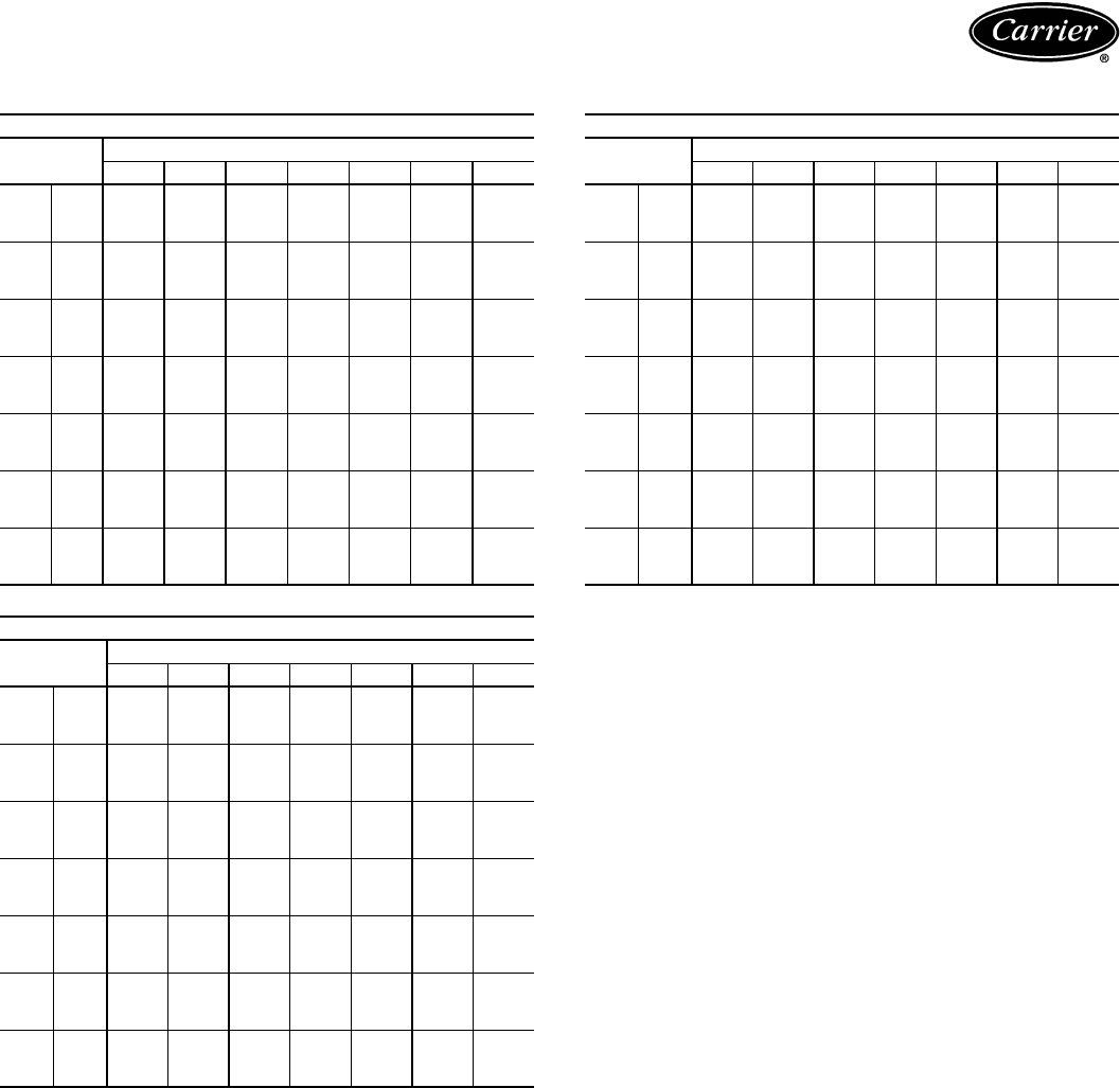
34
CONDENSING UNIT RATINGS (cont)
LEGEND
38AKS028
SST
(F)
Air Temperature Entering Condenser (F)
85 95 100 105 115 120 125
20
TC 181.0 167.0 161.0 154.0 141.0 134.0 128.0
kW 17.4 18.3 18.6 19.0 19.6 19.8 20.0
CDT 108.0 117.0 122.0 126.0 136.0 141.0 145.0
25
TC 202.0 187.0 180.0 173.0 159.0 152.0 145.0
kW 18.5 19.4 19.8 20.2 20.9 21.2 21.5
CDT 110.0 119.0 124.0 128.0 137.0 142.0 146.0
30
TC 225.0 209.0 201.0 193.0 178.0 171.0 163.0
kW 19.5 20.6 21.0 21.5 22.3 22.7 23.0
CDT 112.0 121.0 126.0 130.0 139.0 143.0 148.0
35
TC 249.0 231.0 223.0 215.0 198.0 190.0 182.0
kW 20.6 21.7 22.3 22.8 23.7 24.2 24.6
CDT 115.0 123.0 128.0 132.0 141.0 145.0 150.0
40
TC 274.0 256.0 246.0 237.0 220.0 211.0 202.0
kW 21.6 23.0 23.6 24.1 25.2 25.7 26.2
CDT 117.0 126.0 130.0 135.0 143.0 148.0 152.0
45
TC 301.0 281.0 271.0 261.0 242.0 233.0 224.0
kW 22.8 24.2 24.9 25.5 26.7 27.3 27.8
CDT 120.0 129.0 133.0 137.0 146.0 150.0 154.0
50
TC 329.0 307.0 297.0 287.0 266.0 256.0 246.0
kW 23.9 25.5 26.2 26.9 28.3 28.9 29.5
CDT 123.0 131.0 136.0 140.0 148.0 152.0 157.0
38AKS034
SST
(F)
Air Temperature Entering Condenser (F)
85 95 100 105 115 120 125
20
TC 203.0 187.0 178.0 170.0 153.0 145.0 136.0
kW 20.0 20.8 21.1 21.4 21.8 21.8 21.8
CDT 110.0 120.0 125.0 130.0 140.0 145.0 150.0
25
TC 230.0 212.0 204.0 195.0 176.0 167.0 158.0
kW 21.0 22.0 22.4 22.8 23.4 23.6 23.7
CDT 110.0 120.0 125.0 130.0 140.0 145.0 150.0
30
TC 256.0 239.0 230.0 221.0 202.0 192.0 182.0
kW 22.0 23.2 23.7 24.1 24.9 25.3 25.5
CDT 112.0 121.0 126.0 130.0 140.0 145.0 150.0
35
TC 283.0 265.0 256.0 247.0 228.0 218.0 208.0
kW 23.1 24.4 25.0 25.5 26.5 26.9 27.2
CDT 114.0 123.0 127.0 132.0 141.0 146.0 150.0
40
TC 311.0 292.0 282.0 273.0 253.0 243.0 233.0
kW 24.3 25.7 26.4 27.0 28.1 28.6 29.0
CDT 117.0 125.0 130.0 134.0 143.0 147.0 152.0
45
TC 340.0 320.0 310.0 300.0 279.0 269.0 259.0
kW 25.4 27.0 27.8 28.5 29.7 30.3 30.8
CDT 119.0 128.0 132.0 136.0 145.0 149.0 154.0
50
TC 371.0 350.0 339.0 328.0 307.0 296.0 285.0
kW 26.6 28.4 29.2 30.0 31.4 32.1 32.7
CDT 122.0 130.0 135.0 139.0 148.0 152.0 156.0
38AKS044
SST
(F)
Air Temperature Entering Condenser (F)
85 95 100 105 115 120 125
20
TC 271.0 252.0 243.0 234.0 216.0 208.0 199.0
kW 27.3 28.5 29.0 29.5 30.3 30.7 31.0
CDT 109.0 119.0 124.0 129.0 139.0 144.0 149.0
25
TC 305.0 284.0 274.0 264.0 245.0 235.0 225.0
kW 28.6 30.0 30.7 31.3 32.3 32.8 33.2
CDT 109.0 119.0 124.0 129.0 139.0 144.0 149.0
30
TC 341.0 319.0 308.0 297.0 275.0 265.0 254.0
kW 29.9 31.5 32.3 33.0 34.2 34.8 35.3
CDT 109.0 119.0 124.0 129.0 139.0 144.0 149.0
35
TC 377.0 355.0 343.0 332.0 309.0 297.0 286.0
kW 31.3 33.1 33.9 34.7 36.1 36.8 37.4
CDT 111.0 120.0 125.0 129.0 139.0 144.0 149.0
40
TC 415.0 391.0 379.0 367.0 343.0 331.0 319.0
kW 32.9 34.8 35.7 36.6 38.2 38.9 39.6
CDT 113.0 122.0 126.0 131.0 140.0 145.0 150.0
45
TC 455.0 429.0 416.0 403.0 377.0 365.0 352.0
kW 34.5 36.6 37.6 38.6 40.3 41.1 41.9
CDT 115.0 124.0 128.0 133.0 142.0 147.0 151.0
50
TC 497.0 468.0 455.0 441.0 413.0 400.0 386.0
kW 36.1 38.4 39.5 40.6 42.5 43.5 44.3
CDT 117.0 126.0 131.0 135.0 144.0 149.0 153.0
——
Out of Range
CDT —Saturated Discharge Temperature at Compressor (F)
kW —Compressor Power
SST —Saturated Suction Temperature (F)
TC —Gross Cooling Capacity (1000 Btuh)
Performance data (cont)

35
COMBINATION RATINGS — SI
LEGEND
NOTES:
1. Direct interpolation is permissible. Do not extrapolate.
2. SHC is based on 26.7 C db air entering indoor coil.
3. Formulas:
Lwb = wet-bulb temperature corresponding to enthalpy air leaving
indoor coil (hlwb)
where hewb = enthalpy of air entering evaporator coil (kj/kg).
4. Capacities are based on 7.6 actual m (12.2 equivalent m) of inter-
connecting piping sized to the outdoor unit field connections. (Equiv-
alent length is equal to the actual length plus a 50% allowance for
fitting losses.) For other equivalent lengths, refer to the Carrier
System Design Manual, Part 3, for line losses.
38AK007/40RM007 WITH STANDARD 3-ROW COIL
Temp (C)
Air Ent
Cond
(Edb)
Evaporator Air — L/s
850 1150 1450
Evaporator Air — Ewb (C)
22 20 16 22 20 16 22 20 16
32
TC 19.0 17.8 15.7 19.8 18.7 16.8 20.4 19.2 17.9
SHC 10.1 11.9 15.4 11.4 13.7 16.8 12.5 15.4 17.9
kW 5.12 4.98 4.72 5.23 5.08 4.85 5.29 5.15 4.99
36
TC 18.4 17.2 15.1 19.2 18.0 16.3 19.7 18.6 17.4
SHC 9.86 11.7 15.1 11.1 13.5 16.3 12.3 15.1 17.4
kW 5.37 5.21 4.92 5.47 5.31 5.08 5.54 5.38 5.23
40
TC 17.8 16.6 14.5 18.5 17.3 15.8 19.0 17.9 16.9
SHC 9.62 11.4 14.5 10.9 13.2 15.8 12.1 14.8 16.9
kW 5.60 5.42 5.13 5.71 5.54 5.30 5.78 5.61 5.47
44
TC 17.1 15.9 14.0 17.8 16.6 15.2 18.2 17.1 16.3
SHC 9.37 11.2 14.0 10.7 13.0 15.2 11.8 14.5 16.3
kW 5.82 5.64 5.32 5.94 5.75 5.53 6.01 5.84 5.69
48
TC 16.3 15.2 13.4 17.0 15.9 14.7 17.4 16.4 15.7
SHC 9.12 10.9 13.4 10.4 12.7 14.7 11.6 14.2 15.7
kW 6.04 5.84 5.51 6.16 5.96 5.75 6.24 6.05 5.92
52
TC 15.6 14.5 12.8 16.2 15.2 14.1 16.6 15.6 15.1
SHC 8.85 10.6 12.8 10.1 12.4 14.1 11.3 13.9 15.1
kW 6.24 6.03 5.69 6.37 6.16 5.96 6.45 6.25 6.15
38AK007/40RM008 WITH STANDARD 3-ROW COIL
Temp (C)
Air Ent
Cond
(Edb)
Evaporator Air — L/s
1000 1400 1800
Evaporator Air — Ewb (C)
22 20 16 22 20 16 22 20 16
32
TC 21.2 19.9 17.7 22.0 20.8 19.4 22.5 21.4 20.6
SHC 11.7 14.0 17.7 13.5 16.5 19.4 15.1 18.7 20.6
kW 5.43 5.27 5.01 5.53 5.38 5.21 5.60 5.45 5.36
36
TC 20.5 19.2 17.1 21.3 20.1 18.8 21.8 20.7 20.0
SHC 11.4 13.7 17.1 13.2 16.2 18.8 14.9 18.3 20.0
kW 5.69 5.52 5.24 5.79 5.63 5.46 5.86 5.71 5.63
40
TC 19.8 18.5 16.5 20.5 19.3 18.2 21.0 19.9 19.4
SHC 11.2 13.5 16.5 13.0 15.9 18.2 14.6 18.0 19.4
kW 5.94 5.75 5.46 6.05 5.87 5.71 6.12 5.96 5.88
44
TC 19.0 17.7 16.0 19.7 18.5 17.6 20.1 19.1 18.7
SHC 10.9 13.2 16.0 12.7 15.6 17.6 14.3 17.5 18.7
kW 6.17 5.97 5.69 6.29 6.10 5.95 6.36 6.19 6.13
48
TC 18.2 17.0 15.4 18.8 17.7 17.0 19.3 18.3 18.0
SHC 10.6 12.9 15.4 12.4 15.3 17.0 14.0 17.1 18.0
kW 6.40 6.19 5.91 6.52 6.33 6.19 6.60 6.43 6.38
52
TC 17.3 16.2 14.8 18.0 16.9 16.3 18.4 17.5 17.3
SHC 10.4 12.6 14.8 12.1 14.9 16.3 13.7 16.5 17.3
kW 6.63 6.40 6.13 6.74 6.54 6.42 6.83 6.66 6.61
——
Out of Range
Edb —Entering Dry Bulb
Ewb —Entering Wet Bulb
kW —Compressor Motor Power Input
SHC —Sensible Heat Capacity (kW) Gross
TC —Total Capacity (kW) Gross
38AK008/40RM007 WITH STANDARD 3-ROW COIL
Temp (C)
Air Ent
Cond
(Edb)
Evaporator Air — L/s
850 1150 1450
Evaporator Air — Ewb (C)
22 20 16 22 20 16 22 20 16
32
TC 22.1 20.8 18.5 23.1 21.8 19.6 23.8 22.5 20.5
SHC 11.2 13.1 16.7 12.4 14.8 19.4 13.6 16.5 20.5
kW 6.00 5.88 5.67 6.10 5.98 5.77 6.16 6.04 5.86
36
TC 21.5 20.3 18.0 22.4 21.2 19.1 23.1 21.9 19.9
SHC 11.0 12.8 16.4 12.2 14.6 19.0 13.4 16.2 19.9
kW 6.36 6.24 6.02 6.46 6.34 6.13 6.52 6.40 6.21
40
TC 20.8 19.6 17.4 21.8 20.6 18.5 22.4 21.2 19.4
SHC 10.7 12.6 16.1 12.0 14.3 18.5 13.1 16.0 19.4
kW 6.73 6.61 6.39 6.84 6.71 6.50 6.90 6.77 6.58
44
TC 19.9 18.8 16.7 20.8 19.7 17.7 21.4 20.2 18.7
SHC 10.4 12.2 15.8 11.6 14.0 17.7 12.8 15.6 18.7
kW 7.21 7.09 6.87 7.31 7.18 6.98 7.38 7.25 7.08
48
TC 19.4 18.3 16.3 20.2 19.1 17.3 20.8 19.6 18.2
SHC 10.2 12.0 15.5 11.4 13.8 17.3 12.5 15.4 18.2
kW 7.1 7.39 7.17 7.61 7.48 7.28 7.67 7.54 7.38
52
TC 18.7 17.6 15.6 19.4 18.3 16.6 19.9 18.8 17.6
SHC 9.89 11.7 15.2 11.1 13.5 16.6 12.2 15.1 17.6
kW 7.91 7.79 7.57 8.01 7.88 7.68 8.07 7.94 7.79
38AK008/40RM008 WITH STANDARD 3-ROW COIL
Temp (C)
Air Ent
Cond
(Edb)
Evaporator Air — L/s
1000 1400 1800
Evaporator Air — Ewb (C)
22 20 16 22 20 16 22 20 16
32
TC 23.8 22.5 20.1 24.8 23.5 21.4 25.5 24.2 22.7
SHC 12.5 14.7 19.2 14.1 17.1 21.4 15.7 19.3 22.7
kW 6.13 6.01 5.78 6.22 6.10 5.91 6.28 6.16 6.02
36
TC 23.2 21.9 19.5 24.1 22.9 20.9 24.7 23.5 22.2
SHC 12.2 14.5 18.9 13.9 16.9 20.9 15.5 19.1 22.2
kW 6.49 6.37 6.14 6.59 6.46 6.26 6.65 6.52 6.39
40
TC 22.5 21.2 18.9 23.4 22.1 20.3 23.9 22.7 21.6
SHC 11.9 14.2 18.6 13.6 16.6 20.3 15.2 18.7 21.6
kW 6.86 6.73 6.50 6.96 6.83 6.64 7.03 6.90 6.77
44
TC 21.7 20.5 18.3 22.5 21.3 19.7 23.1 21.9 20.9
SHC 11.7 13.9 18.3 13.3 16.3 19.7 14.9 18.4 20.9
kW 7.25 7.12 6.88 7.34 7.21 7.03 7.41 7.27 7.17
48
TC 20.9 19.7 17.6 21.7 20.5 19.1 22.2 21.1 20.3
SHC 11.4 13.6 17.6 13.0 16.0 19.1 14.6 18.0 20.3
kW 7.64 7.51 7.28 7.73 7.60 7.43 7.79 7.66 7.57
52
TC 20.0 18.9 16.9 20.8 19.7 18.4 21.2 20.2 19.5
SHC 11.1 13.3 16.9 12.7 15.6 18.4 14.3 17.7 19.5
kW 8.04 7.90 7.67 8.13 8.00 7.84 8.19 8.06 7.98
Ldb C = Edb C –SHCkW x 1000
1.23 x L/s
Ldb C: hlwb = hewb –TCkW x 1000
1.20 x L/s
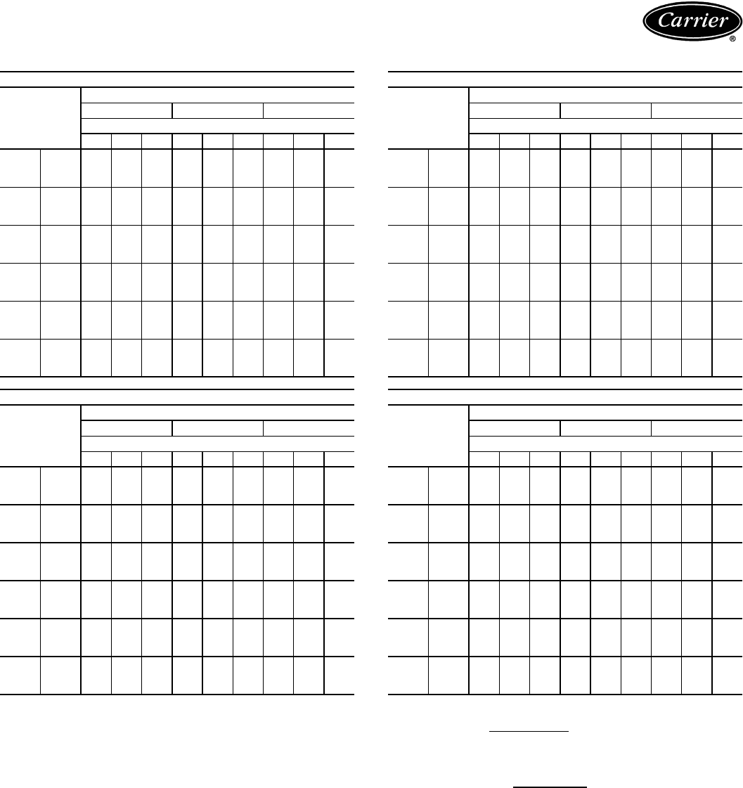
36
COMBINATION RATINGS — SI (cont)
LEGEND
NOTES:
1. Direct interpolation is permissible. Do not extrapolate.
2. SHC is based on 26.7 C db air entering indoor coil.
3. Formulas:
Lwb = wet-bulb temperature corresponding to enthalpy air leaving
indoor coil (hlwb)
where hewb = enthalpy of air entering evaporator coil (kj/kg).
4. Capacities are based on 7.6 actual m (12.2 equivalent m) of inter-
connecting piping sized to the outdoor unit field connections. (Equiv-
alent length is equal to the actual length plus a 50% allowance for
fitting losses.) For other equivalent lengths, refer to the Carrier
System Design Manual, Part 3, for line losses.
38AK008/40RM012 WITH STANDARD 3-ROW COIL
Temp (C)
Air Entering
Condenser
(Edb)
Evaporator Air — L/s
1450 1900 2350
Evaporator Air — Ewb (C)
22 20 16 22 20 16 22 20 16
32
TC 26.8 25.4 23.3 27.4 26.1 24.9 27.9 26.7 26.0
SHC 15.5 18.9 23.3 17.5 21.6 24.9 19.2 23.8 26.0
kW 6.97 6.84 6.64 7.04 6.91 6.79 7.08 6.96 6.90
36
TC 26.0 24.6 22.7 26.6 25.4 24.3 27.1 25.9 25.3
SHC 15.3 18.6 22.7 17.2 21.2 24.3 19.0 2.34 25.3
kW 7.38 7.24 7.04 7.45 7.32 7.20 7.49 7.37 7.31
40
TC 25.2 23.9 22.1 25.8 24.6 23.6 26.2 25.1 24.6
SHC 15.0 18.3 22.1 16.9 20.9 23.6 18.7 23.0 24.6
kW 7.80 7.66 7.46 7.87 7.73 7.63 7.92 7.79 7.74
44
TC 24.3 23.0 21.4 24.9 23.7 22.9 25.2 24.2 23.8
SHC 14.7 17.9 21.4 16.6 20.5 22.9 18.3 22.4 23.8
kW 8.23 8.08 7.90 8.30 8.16 8.07 8.34 8.22 8.18
48
TC 23.3 22.1 20.7 23.9 22.8 22.1 24.2 23.3 23.0
SHC 14.3 17.6 20.7 16.2 20.1 22.1 18.0 21.8 23.0
kW 8.66 8.51 8.35 8.73 8.60 8.51 8.78 8.66 8.62
52
TC 22.4 21.2 20.0 22.9 21.8 21.3 23.2 22.4 22.1
SHC 14.0 17.2 20.0 15.9 19.6 21.3 17.6 21.1 22.1
kW 9.10 8.96 8.81 9.17 9.04 8.97 9.22 9.10 9.08
38AKS008/40RM007 WITH STANDARD 3-ROW COIL
Temp (C)
Air Entering
Condenser
(Edb)
Evaporator Air — L/s
850 1150 1450
Evaporator Air — Ewb (C)
22 20 16 22 20 16 22 20 16
32
TC 23.6 21.9 19.8 24.8 23.1 21.1 25.5 23.9 21.9
SHC 12.2 14.2 19.8 13.6 16.4 21.1 15.4 17.9 21.9
kW 5.77 5.62 5.43 5.88 5.72 5.55 5.94 5.80 5.63
36
TC 22.9 21.3 19.3 24.0 22.4 20.5 24.7 23.2 21.3
SHC 11.9 13.9 19.3 13.3 16.1 20.5 15.1 17.6 21.3
kW 6.15 5.96 5.73 6.27 6.08 5.87 6.34 6.17 5.97
40
TC 22.2 20.5 18.5 23.3 21.6 19.7 23.9 22.3 20.6
SHC 11.6 13.6 18.5 13.0 15.7 19.7 14.8 17.2 20.6
kW 6.52 6.31 6.06 6.65 6.44 6.21 6.73 6.53 6.32
44
TC 21.4 19.8 17.9 22.4 20.8 19.1 22.9 21.5 19.9
SHC 11.3 13.2 17.9 12.6 15.3 19.1 14.5 16.7 19.9
kW 6.87 6.62 6.34 7.02 6.77 6.51 7.10 6.88 6.63
48
TC 20.6 19.0 17.2 21.6 20.0 18.3 22.1 20.6 19.1
SHC 11.0 12.9 17.2 12.3 14.9 18.3 14.2 16.3 19.1
kW 7.24 6.96 6.64 7.40 7.12 6.83 7.49 7.23 6.97
52
TC 19.9 18.3 16.6 20.7 19.2 17.6 21.2 19.8 18.4
SHC 10.7 12.5 16.6 11.9 14.5 17.6 13.9 15.9 18.4
kW 7.61 7.30 6.96 7.78 7.47 7.17 7.87 7.59 7.31
——
Out of Range
Edb —Entering Dry Bulb
Ewb —Entering Wet Bulb
kW —Compressor Motor Power Input
SHC —Sensible Heat Capacity (kW) Gross
TC —Total Capacity (kW) Gross
38AKS008/40RM008 WITH STANDARD 3-ROW COIL
Temp (C)
Air Entering
Condenser
(Edb)
Evaporator Air — L/s
1000 1400 1800
Evaporator Air — Ewb (C)
22 20 16 22 20 16 22 20 16
32
TC 25.7 23.7 21.6 26.6 24.9 22.9 27.3 25.6 23.8
SHC 13.7 16.0 21.6 15.9 18.2 22.9 17.7 20.3 23.8
kW 5.95 5.78 5.60 6.04 5.88 5.71 6.10 5.95 5.79
36
TC 24.8 23.0 21.0 25.7 24.0 22.2 26.3 24.7 23.1
SHC 13.3 15.6 21.0 15.5 17.8 22.2 17.4 19.9 23.1
kW 6.36 6.15 5.93 6.46 6.27 6.06 6.53 6.35 6.16
40
TC 24.0 22.2 20.2 24.9 23.2 21.4 25.5 23.8 22.3
SHC 13.0 15.2 20.2 15.2 17.4 21.4 17.1 19.5 22.3
kW 6.75 6.52 6.27 6.85 6.64 6.42 6.93 6.72 6.52
44
TC 23.1 21.3 19.4 23.9 22.3 20.6 24.4 22.8 21.4
SHC 12.6 14.8 19.4 14.9 16.9 20.6 16.7 19.0 21.4
kW 7.13 6.86 6.57 7.25 7.00 6.74 7.33 7.09 6.87
48
TC 22.3 20.5 18.6 23.0 21.4 19.8 23.5 21.9 20.6
SHC 12.3 14.4 18.6 14.6 16.5 19.8 16.4 18.6 20.6
kW 7.52 7.21 6.89 7.64 7.37 7.09 7.73 7.46 7.23
52
TC 21.4 19.7 17.9 22.0 20.5 19.0 22.5 21.0 19.7
SHC 11.9 14.0 17.9 14.2 16.0 19.0 16.0 18.1 19.7
kW 7.92 7.58 7.22 8.04 7.74 7.43 8.13 7.84 7.59
38AKS008/40RM012 WITH STANDARD 3-ROW COIL
Temp (C)
Air Entering
Condenser
(Edb)
Evaporator Air — L/s
1450 1900 2350
Evaporator Air — Ewb (C)
22 20 16 22 20 16 22 20 16
32
TC 28.0 26.0 23.9 —27.0 25.2 —27.5 26.3
SHC 16.6 19.2 23.9 —22.0 25.2 —24.9 26.3
kW 6.16 5.98 5.80 —6.07 5.91 —6.12 6.01
36
TC —25.1 23.1 —26.0 24.4 —26.5 25.4
SHC —18.8 23.1 —21.6 24.4 —24.4 25.4
kW —6.39 6.16 —6.49 6.31 —6.54 6.42
40
TC —24.2 22.2 —25.1 23.5 —25.5 24.5
SHC —18.4 22.2 —21.2 23.5 —24.0 24.5
kW —6.77 6.52 —6.88 6.68 —6.93 6.81
44
TC —23.2 21.3 —24.0 22.5 —24.4 23.5
SHC —17.9 21.3 —20.7 22.5 —23.4 23.5
kW —7.14 6.86 —7.26 7.04 —7.33 7.19
48
TC —22.3 20.5 —23.0 21.6 ———
SHC —17.5 20.5 —20.3 21.6 ———
kW —7.52 7.21 —7.65 7.41 ———
52
TC —21.3 19.6 ——————
SHC —17.1 19.6 ——————
kW —7.89 7.56 ——————
Ldb C = Edb C –SHCkW x 1000
1.23 x L/s
Ldb C: hlwb = hewb –TCkW x 1000
1.20 x L/s
Performance data (cont)

37
COMBINATION RATINGS — SI (cont)
LEGEND
NOTES:
1. Direct interpolation is permissible. Do not extrapolate.
2. SHC is based on 26.7 C db air entering indoor coil.
3. Formulas:
Lwb = wet-bulb temperature corresponding to enthalpy air leaving indoor coil
(hlwb)
where hewb = enthalpy of air entering evaporator coil (kj/kg).
4. Capacities are based on 7.6 actual m (12.2 equivalent m) of interconnecting
piping sized to the outdoor unit field connections. (Equivalent length is equal to
the actual length plus a 50% allowance for fitting losses.) For other equivalent
lengths, refer to the Carrier System Design Manual, Part 3, for line losses.
38AKS009/40RM008 WITH STANDARD 3-ROW COIL
Temp (C)
Air Entering
Condenser
(Edb)
Evaporator Air — L/s
1000 1400 1800
Evaporator Air — Ewb (C)
22 20 16 22 20 16 22 20 16
32
TC 29.4 27.2 24.8 30.7 28.7 26.3 31.6 29 7 27.3
SHC 15.2 17.7 24.8 17.4 20.1 26.3 19.1 22.2 27.3
kW 7.88 7.60 7.27 8.06 7.79 7.47 8.18 7.93 7.61
36
TC 28.4 26.3 23.9 29.6 27.7 25.4 30.5 28.6 26.3
SHC 14.8 17.2 23.9 17.0 19.6 25.4 18.8 21.7 26.3
kW 8.34 8.02 7.67 8.53 8.24 7.89 8.66 8.38 8.04
40
TC 27.4 25.4 23.1 28.6 26.7 24.5 29.4 27.6 25.4
SHC 14.4 16.7 23.1 16.6 19.1 24.5 18.4 21.2 25.4
kW 8.79 8.45 8.06 8.99 8.67 8.30 9.12 8.81 8.46
44
TC 26.4 24.4 22.2 27.5 25.7 23.6 28.2 26.4 24.5
SHC 14.0 16.3 22.2 16.2 18.6 23.6 18.0 20.7 24.5
kW 9.23 8.84 8.41 9.43 9.08 8.67 9.57 9.23 8.85
48
TC 25.4 23.5 21.4 26.3 24.6 22.6 27.0 25.3 23.5
SHC 13.5 15.8 21.4 15.8 18.1 22.6 17.6 20.2 23.5
kW 9.68 9.24 8.78 9.89 9.50 9.06 10.04 9.66 9.26
52
TC —22.4 20.4 —23.4 21.6 —24.1 22.5
SHC —15.3 20.4 —17.5 21.6 —19.6 22.5
kW —9.69 9.19 —9.94 9.49 —10.11 9.71
38AKS009/40RM012 WITH STANDARD 3-ROW COIL
Temp (C)
Air Entering
Condenser
(Edb)
Evaporator Air — L/s
1450 1900 2350
Evaporator Air — Ewb (C)
22 20 16 22 20 16 22 20 16
32
TC 32.5 30.2 27.6 33.7 31.5 29.2 —32.2 30.4
SHC 18.1 21.0 27.6 20.2 24.1 29.2 —27.0 30.4
kW 8.30 7.99 7.65 8.47 8.16 7.86 —8.26 8.02
36
TC 31.4 29.1 26.6 32.6 30.3 28.1 —31.0 29.3
SHC 17.7 20.5 26.6 19.8 23.5 28.1 —26.5 29.3
kW 8.79 8.45 8.07 8.97 8.63 8.31 —8.74 8.48
40
TC 30.2 28.0 25.6 31.3 29.1 27.1 —29.8 28.3
SHC 17.3 20.1 25.6 19.3 23.0 27.1 —25.9 28.3
kW 9.26 8.89 8.49 9.45 9.08 8.74 —9.19 8.93
44
TC 29.0 26.9 24.6 30.0 27.9 26.0 —28.5 27.1
SHC 16.9 19.6 24.6 18.9 22.5 26.0 —25.3 27.1
kW 9.72 9.31 8.88 9.93 9.51 9.15 —9.63 9.37
48
TC 27.7 25.7 23.6 —27.6 24.9 —27.2 26.0
SHC 16.5 19.0 23.6 —21.9 24.9 —24.7 26.0
kW 10.20 9.74 9.27 —9.96 9.57 —10.08 9.81
52
TC —24.4 22.5 —25.3 23.7 —25.8 24.7
SHC —18.5 22.5 —21.3 23.7 —21.9 24.7
kW —10.19 9.70 —10.41 10.02 —10.53 10.28
——
Out of Range
Edb —Entering Dry Bulb
Ewb —Entering Wet Bulb
kW —Compressor Motor Power Input
SHC —Sensible Heat Capacity (kW) Gross
TC —Total Capacity (kW) Gross
38AK012/40RM008 WITH STANDARD 3-ROW COIL
Temp (C)
Air Entering
Condenser
(Edb)
Evaporator Air — L/s
1000 1400 1800
Evaporator Air — Ewb (C)
22 20 16 22 20 16 22 20 16
32
TC 29.8 28.2 25.1 31.3 29.7 26.8 32.3 30.7 28.2
SHC 14.9 17.3 22.0 16.8 20.0 26.2 18.6 22.6 28.2
kW 7.33 7.16 6.85 7.50 7.32 7.02 7.60 7.43 7.16
36
TC 29.1 27.5 24.5 30.5 28.9 26.1 31.5 29.9 27.5
SHC 14.6 17.0 21.7 16.5 19.7 25.9 18.3 22.3 27.5
kW 7.74 7.56 7.25 7.90 7.72 7.42 8.01 7.83 7.57
40
TC 28.3 26.7 23.8 29.6 28.1 25.4 30.5 29.0 26.8
SHC 14.3 16.6 21.3 16.2 19.4 25.4 18.0 21.9 26.8
kW 8.16 7.99 7.69 8.32 8.14 7.85 8.43 8.25 8.00
44
TC 27.4 25.9 23.1 28.7 27.2 24.6 29.5 28.0 26.1
SHC 13.9 16.3 21.0 15.8 19.0 24.6 17.6 21.6 26.1
kW 8.61 8.44 8.16 8.76 8.58 8.31 8.86 8.68 8.47
48
TC 26.5 25.0 22.3 27.7 26.2 23.9 28.5 27.1 25.4
SHC 13.6 15.9 20.6 15.5 18.6 23.9 17.3 21.2 25.4
kW 9.07 8.91 8.64 9.21 9.04 8.78 9.31 9.14 8.94
52
TC 25.6 24.2 21.6 26.7 25.3 23.1 27.4 26.0 24.6
SHC 13.2 15.6 20.2 15.1 18.3 23.1 16.9 20.8 24.6
kW 9.54 9.38 9.13 9.68 9.51 9.27 9.77 9.60 9.43
38AK012/40RM012 WITH STANDARD 3-ROW COIL
Temp (C)
Air Entering
Condenser
(Edb)
Evaporator Air — L/s
1450 1900 2350
Evaporator Air — Ewb (C)
22 20 16 22 20 16 22 20 16
32
TC 32.1 30.5 27.6 33.2 31.5 29.2 33.8 32.2 30.7
SHC 17.4 20.8 27.2 19.5 23.7 29.2 21.4 26.4 30.7
kW 8.79 8.58 8.23 8.92 8.71 8.42 9.00 8.80 8.61
36
TC 31.3 29.7 26.9 32.3 30.7 28.5 32.9 31.4 30.0
SHC 17.1 20.5 26.8 19.1 23.4 28.5 21.1 26.1 30.0
kW 9.26 9.05 8.70 9.39 9.18 8.90 9.47 9.27 9.09
40
TC 30.4 28.8 26.1 31.3 29.8 27.8 31.9 30.4 29.2
SHC 16.7 20.1 26.1 18.8 23.0 27.8 20.8 25.7 29.2
kW 9.75 9.55 9.21 9.88 9.67 9.41 9.96 9.76 9.60
44
TC 29.4 27.9 25.3 30.3 28.8 27.0 30.8 29.4 28.4
SHC 16.4 19.8 25.3 18.5 22.6 27.0 20.4 25.2 28.4
kW 10.3 10.1 9.74 10.4 10.2 9.95 10.5 10.3 10.1
48
TC 28.4 26.9 24.5 29.2 27.8 26.2 29.7 28.4 27.5
SHC 16.0 19.4 24.5 18.1 22.2 26.2 20.0 24.8 27.5
kW 10.8 10.6 10.3 10.9 10.7 10.5 11.0 10.8 10.7
52
TC 27.4 25.9 23.8 28.1 26.7 25.4 28.6 27.3 26.6
SHC 15.7 19.0 23.8 17.7 21.8 25.4 19.7 24.3 26.6
kW 11.3 11.1 10.9 11.4 11.3 11.1 11.5 11.3 11.2
Ldb C = Edb C –SHCkW x 1000
1.23 x L/s
Ldb C: hlwb = hewb –TCkW x 1000
1.20 x L/s

38
COMBINATION RATINGS — SI (cont)
LEGEND
NOTES:
1. Direct interpolation is permissible. Do not extrapolate.
2. SHC is based on 26.7 C db air entering indoor coil.
3. Formulas:
Lwb = wet-bulb temperature corresponding to enthalpy air leaving indoor coil
(hlwb)
where hewb = enthalpy of air entering evaporator coil (kj/kg).
4. Capacities are based on 7.6 actual m (12.2 equivalent m) of interconnecting
piping sized to the outdoor unit field connections. (Equivalent length is equal to
the actual length plus a 50% allowance for fitting losses.) For other equivalent
lengths, refer to the Carrier System Design Manual, Part 3, for line losses.
38AK012/40RM014 WITH STANDARD 3-ROW COIL
Temp (C)
Air Entering
Condenser
(Edb)
Evaporator Air — L/s
1750 2350 2950
Evaporator Air — Ewb (C)
22 20 16 22 20 16 22 20 16
32
TC 33.5 31.8 28.9 34.5 32.8 30.9 35.1 33.5 32.5
SHC 18.9 22.8 28.9 21.4 26.3 30.9 23.7 29.3 32.5
kW 7.41 7.23 6.95 7.51 7.34 7.14 7.57 7.41 7.30
36
TC 32.7 31.0 28.2 33.6 31.9 30.2 34.2 32.6 31.7
SHC 18.6 22.5 28.2 21.1 25.9 30.2 23.3 28.8 31.7
kW 7.80 7.63 7.35 7.90 7.73 7.55 7.97 7.80 7.70
40
TC 31.7 30.1 27.5 32.6 31.0 29.5 33.1 31.7 30.9
SHC 18.2 22.1 27.5 20.7 25.5 29.5 23.0 28.4 30.9
kW 8.22 8.04 7.78 8.31 8.14 7.98 8.38 8.22 8.13
44
TC 30.7 29.1 26.7 31.5 30.0 28.6 32.0 30.6 30.0
SHC 17.9 21.8 26.7 20.3 25.1 28.6 22.6 27.8 30.0
kW 8.65 8.48 8.23 8.74 8.57 8.43 8.80 8.65 8.57
48
TC 29.6 28.1 25.9 30.4 28.9 27.8 30.9 29.6 29.0
SHC 17.5 21.4 25.9 20.0 24.7 27.8 22.2 27.2 29.0
kW 9.10 8.93 8.71 9.18 9.02 8.90 9.24 9.09 9.03
52
TC 28.5 27.1 25.2 29.2 27.9 26.9 29.7 28.5 28.1
SHC 17.1 21.0 25.2 19.6 24.2 26.9 21.8 26.6 28.1
kW 9.55 9.39 9.21 9.64 9.48 9.38 9.68 9.55 9.51
38AKS012/40RM008 WITH STANDARD 3-ROW COIL
Temp (C)
Air Entering
Condenser
(Edb)
Evaporator Air — L/s
1000 1400 1800
Evaporator Air — Ewb (C)
22 20 16 22 20 16 22 20 16
32
TC 29.1 26.9 24.5 30.4 28.4 26.0 31.3 29.4 27.0
SHC 15.1 17.5 24.5 17.2 20.0 26.0 19.0 22.1 27.0
kW 7.87 7.59 7.28 8.04 7.78 7.47 8.15 7.91 7.60
36
TC 28.1 26.0 23.6 29.4 27.4 25.1 30.2 28.3 26.1
SHC 14.7 17.1 23.6 16.9 19.5 25.1 18.7 21.6 26.1
kW 8.33 8.02 7.68 8.51 8.23 7.89 8.64 8.36 8.04
40
TC 27.2 25.1 22.8 28.3 26.4 24.2 29.1 27.3 25.2
SHC 14.3 16.6 22.8 16.5 19.0 24.2 18.3 21.1 25.2
kW 8.78 8.44 8.07 8.97 8.66 8.30 9.10 8.80 8.46
44
TC 26.2 24.2 22.0 27.2 25.4 23.3 27.9 26.2 24.3
SHC 13.9 16.2 22.0 16.1 18.5 23.3 17.9 20.6 24.3
kW 9.23 8.84 8.41 9.43 9.07 8.67 9.57 9.22 8.85
48
TC 25.2 23.2 21.0 26.2 24.4 22.4 26.9 25.1 23.3
SHC 13.5 15.7 21.0 15.7 18.0 22.4 17.5 20.1 23.3
kW 9.66 9.23 8.78 9.86 9.48 9.06 10.01 9.63 9.25
52
TC —22.2 20.2 —23.2 21.4 —23.8 22.3
SHC —15.2 20.2 —17.4 21.4 —19.5 22.3
kW —9.63 9.13 —9.89 9.44 —10.05 9.65
——
Out of Range
Edb —Entering Dry Bulb
Ewb —Entering Wet Bulb
kW —Compressor Motor Power Input
SHC —Sensible Heat Capacity (kW) Gross
TC —Total Capacity (kW) Gross
38AKS012/40RM012 WITH STANDARD 3-ROW COIL
Temp (C)
Air Entering
Condenser
(Edb)
Evaporator Air — L/s
1450 1900 2350
Evaporator Air — Ewb (C)
22 20 16 22 20 16 22 20 16
32
TC 32.1 29.8 27.3 33.4 31.1 28.9 —31.8 30.1
SHC 18.0 20.9 27.3 20.1 23.9 28.9 —26.8 30.1
kW 8.26 7.97 7.64 8.43 8.13 7.85 —8.23 8.00
36
TC 31.1 28.8 26.3 32.3 30.0 27.9 —30.7 29.1
SHC 17.6 20.4 26.3 19.7 23.4 27.9 —26.3 29.1
kW 8.76 8.43 8.07 8.93 8.60 8.29 —8.71 8.47
40
TC 29.9 27.7 25.4 —28.8 26.8 —29.5 28.0
SHC 17.2 19.9 25.4 —22.9 26.8 —25.8 28.0
kW 9.23 8.87 8.48 —9.05 8.73 —9.16 8.91
44
TC 28.7 26.6 24.4 —27.6 25.8 —28.2 26.9
SHC 16.9 19.4 24.4 —22.3 25.8 —25.2 26.9
kW 9.72 9.30 8.87 —9.51 9.14 —9.62 9.36
48
TC 27.6 25.5 23.3 —26.5 24.7 —27.1 25.8
SHC 16.5 19.0 23.3 —21.8 24.7 —24.7 25.8
kW 10.17 9.72 9.26 —9.93 9.55 —10.05 9.79
52
TC —————————
SHC —————————
kW —————————
38AKS012/40RM014 WITH STANDARD 3-ROW COIL
Temp (C)
Air Entering
Condenser
(Edb)
Evaporator Air — L/s
1750 2350 2950
Evaporator Air — Ewb (C)
22 20 16 22 20 16 22 20 16
32
TC 34.0 31.1 28.9 —32.3 30.6 —33.3 31.9
SHC 19.8 23.1 28.9 —27.1 30.6 —30.6 31.9
kW 8.51 8.13 7.85 —8.29 8.07 —8.42 8.24
36
TC 32.9 30.0 27.9 —31.2 29.6 —32.2 30.9
SHC 19.4 22.6 27.9 —26.6 29.6 —30.0 30.9
kW 9.02 8.60 8.30 —8.77 8.54 —8.92 8.73
40
TC 31.6 28.8 26.8 —29.9 28.5 —30.8 29.7
SHC 18.9 22.1 26.8 —26.0 28.5 —29.4 29.7
kW 9.51 9.04 8.73 —9.23 8.99 —9.38 9.20
44
TC 30.3 27.5 25.8 —28.6 27.3 —29.5 28.5
SHC 18.4 21.5 25.8 —25.4 27.3 —28.8 28.5
kW 10.03 9.49 9.14 —9.69 9.45 —9.87 9.68
48
TC —26.4 24.7 —27.4 26.3 —28.3 27.5
SHC —21.0 24.7 —24.9 26.3 —28.2 27.5
kW —9.91 9.55 —10.13 9.88 —10.32 10.14
52
TC —————————
SHC —————————
kW —————————
Ldb C = Edb C –SHCkW x 1000
1.23 x L/s
Ldb C: hlwb = hewb –TCkW x 1000
1.20 x L/s
Performance data (cont)
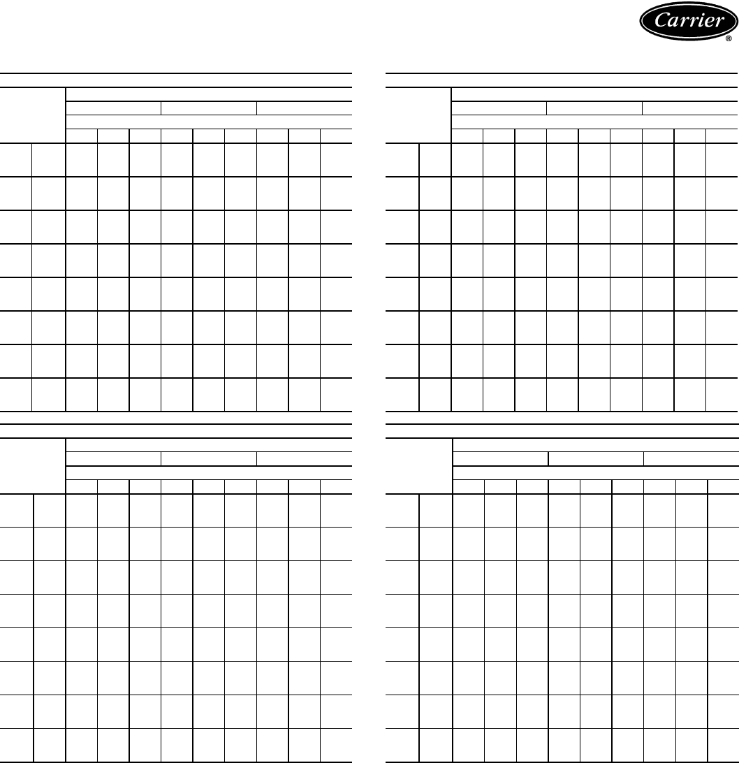
39
COMBINATION RATINGS — SI (cont)
See Legend and Notes on page 43.
38AKS013/40RM008 WITH STANDARD 3-ROW COIL
Temp (C)
Air Entering
Condenser
(Edb)
Evaporator Air — L/s
1000/ 1400 1800
Evaporator Air — Ewb (C)
22 20 16 22 20 16 22 20 16
20
TC 32.2 30.0 27.3 33.9 31.7 29.0 35.0 32.9 30.0
SHC 16.4 19.0 27.3 18.5 21.7 29.0 20.3 23.8 30.0
kW 6.61 6.46 6.28 6.72 6.57 6.39 6.79 6.65 6.46
28
TC 30.5 28.3 25.8 32.0 29.9 27.4 32.9 31.0 28.4
SHC 15.7 18.2 25.8 17.8 20.8 27.4 19.6 22.9 28.4
kW 7.61 7.37 7.10 7.77 7.55 7.27 7.88 7.67 7.38
32
TC 29.6 27.5 25.0 31.0 29.0 26.6 31.9 30.0 27.6
SHC 15.3 17.8 25.0 17.5 20.3 26.6 19.2 22.4 27.6
kW 8.12 7.85 7.55 8.28 8.03 7.74 8.40 8.16 7.86
36
TC 28.7 26.6 24.2 30.0 28.0 25.7 30.9 29.0 26.7
SHC 14.9 17.4 24.2 17.1 19.8 25.7 18.9 21.9 26.7
kW 8.67 8.49 8.29 8.78 8.61 8.41 8.86 8.70 8.50
40
TC 27.8 25.8 23.5 29.0 27.1 24.9 29.8 28.0 25.9
SHC 14.6 17.0 23.5 16.7 19.3 24.9 18.5 21.4 25.9
kW 9.10 8.71 8.28 9.31 8.96 8.55 9.47 9.13 8.73
44
TC 27.3 25.0 22.6 28.5 26.4 24.1 29.3 27.4 25.1
SHC 14.3 16.6 22.6 16.5 19.0 24.1 18.4 21.1 25.1
kW 9.49 9.13 8.72 9.69 9.36 8.97 9.84 9.51 9.14
48
TC 26.4 24.2 21.8 27.5 25.5 23.3 28.3 26.4 24.3
SHC 13.9 16.2 21.8 16.2 18.5 23.3 18.0 20.7 24.3
kW 9.92 9.53 9.11 10.12 9.77 9.37 10.27 9.92 9.55
52
TC 25.0 23.1 21.0 25.9 24.2 22.3 26.5 24.9 23.2
SHC 13.4 15.7 21.0 15.6 17.9 22.3 17.4 19.9 23.2
kW 10.42 9.96 9.46 10.64 10.22 9.77 10.79 10.39 9.98
38AKS013/40RM012 WITH STANDARD 3-ROW COIL
Temp (C)
Air Entering
Condenser
(Edb)
Evaporator Air — L/s
1450 1900 2350
Evaporator Air — Ewb (C)
22 20 16 22 20 16 22 20 16
20
TC 35.9 33.5 30.6 37.4 35.0 32.4 38.3 35.9 33.6
SHC 19.2 22.5 30.6 21.6 25.7 32.4 24.0 28.7 33.6
kW 6.85 6.69 6.50 6.95 6.79 6.62 7.01 6.86 6.70
28
TC 33.8 31.5 28.8 35.2 32.9 30.5 36.0 33.7 31.7
SHC 18.5 21.6 28.8 20.8 24.7 30.5 23.2 27.7 31.7
kW 7.98 7.72 7.43 8.13 7.87 7.61 8.21 7.96 7.74
32
TC 32.8 30.5 27.9 34.1 31.8 29.5 34.8 32.5 30.7
SHC 18.2 21.1 27.9 20.3 24.2 29.5 22.8 27.2 30.7
kW 8.50 8.22 7.90 8.66 8.38 8.10 8.75 8.47 8.25
36
TC 31.7 29.4 27.0 32.9 30.7 28.5 33.6 31.4 29.7
SHC 17.8 20.7 27.0 19.9 23.7 28.5 22.4 26.6 29.7
kW 8.93 8.74 8.52 9.04 8.84 8.66 9.10 8.90 8.76
40
TC 30.6 28.4 26.1 31.7 29.5 27.5 32.3 30.2 28.7
SHC 17.5 20.2 26.1 19.5 23.2 27.5 22.0 26.1 28.7
kW 9.62 9.21 8.77 9.83 9.42 9.04 9.95 9.55 9.26
44
TC 30.2 27.8 25.3 31.4 29.0 26.9 32.1 29.8 28.1
SHC 17.3 20.0 25.3 19.4 23.0 26.9 21.9 25.9 28.1
kW 9.98 9.59 9.17 10.18 9.79 9.43 10.29 9.91 9.64
48
TC 29.2 26.8 24.4 30.3 28.0 25.9 30.9 28.6 27.1
SHC 17.0 19.5 24.4 19.0 22.5 25.9 21.5 21.9 27.1
kW 10.42 10.00 9.57 10.62 10.21 9.84 10.74 10.32 10.06
52
TC 27.3 25.2 23.2 28.2 26.2 24.5 28.6 26.7 25.6
SHC 16.4 18.8 23.2 18.2 21.7 24.5 20.7 24.5 25.6
kW 10.97 10.48 9.99 11.19 10.70 10.30 11.31 10.83 10.56
38AKS013/40RM014 WITH STANDARD 3-ROW COIL
Temp (C)
Air Entering
Condenser
(Edb)
Evaporator Air — L/s
1750 2350 2950
Evaporator Air — Ewb (C)
22 20 16 22 20 16 22 20 26
20
TC 38.1 35.1 32.4 39.4 36.5 34.2 40.2 37.6 35.7
SHC 21.3 24.9 32.4 24.3 29.1 34.2 27.3 32.6 35.7
kW 7.00 6.80 6.62 7.09 6.89 6.74 7.14 6.97 6.84
28
TC 35.8 32.9 30.5 37.0 34.2 32.2 37.7 35.2 33.6
SHC 20.5 23.9 30.5 23.4 28.0 32.2 26.4 31.5 33.6
kW 8.20 7.87 7.61 8.32 8.02 7.80 8.40 8.13 7.95
32
TC 34.7 31.8 29.5 35.8 33.0 31.2 36.4 34.0 32.6
SHC 20.0 23.4 29.5 22.9 27.5 31.2 26.0 30.9 32.6
kW 8.74 8.38 8.10 8.87 8.53 8.31 8.95 8.66 8.48
36
TC 33.5 30.6 28.5 34.5 31.9 30.2 35.2 32.8 31.5
SHC 19.6 22.9 28.5 22.5 26.9 30.2 25.6 30.3 31.5
kW 9.09 8.84 8.66 9.18 8.94 8.80 9.23 9.03 8.91
40
TC 32.3 29.5 27.6 33.2 30.6 29.2 33.8 31.5 30.4
SHC 19.1 22.4 27.6 22.0 26.4 29.2 25.1 29.7 30.4
kW 9.94 9.41 9.05 10.12 9.63 9.35 10.23 9.80 9.58
44
TC 32.1 29.0 26.9 33.1 30.2 28.6 33.7 31.2 30.0
SHC 19.0 22.2 26.9 22.0 26.2 28.6 25.1 29.6 30.0
kW 10.29 9.78 9.43 10.46 9.98 9.72 10.56 10.15 9.95
48
TC 30.9 27.9 25.9 31.9 29.1 27.6 32.5 30.1 29.0
SHC 18.6 21.7 25.9 21.6 25.7 27.6 24.7 29.0 29.0
kW 10.74 10.19 9.84 10.91 10.40 10.15 11.01 10.58 10.38
52
TC 28.7 26.1 24.5 29.4 27.0 26.0 29.9 27.9 27.1
SHC 17.8 20.9 24.5 20.7 24.7 26.0 23.8 27.9 27.1
kW 11.32 10.68 10.30 11.50 10.91 10.65 11.61 11.12 10.93
38AKS014/40RM012 WITH STANDARD 3-ROW COIL
Temp (C)
Air Entering
Condenser
(Edb)
Evaporator Air — L/s
1450 1900 2350
Evaporator Air — Ewb (C)
22 20 16 22 20 16 22 20 16
20
TC 40.4 37.7 34.2 42.3 39.6 36.3 43.5 40.9 37.7
SHC 20.6 24.3 34.2 23.4 27.8 36.3 25.8 31.0 37.7
kW 8.07 7.81 7.49 8.25 7.99 7.69 8.36 8.11 7.82
28
TC 38.2 35.6 32.4 39.9 37.3 34.3 41.0 38.4 35.6
SHC 19.9 23.4 32.4 22.5 26.7 34.3 24.9 29.9 35.6
kW 9.28 8.98 8.61 9.48 9.18 8.83 9.60 9.31 8.99
32
TC 37.0 34.5 31.4 38.7 36.1 33.3 39.6 37.2 34.6
SHC 19.6 22.9 31.4 22.0 26.2 33.3 24.5 29.3 34.6
kW 9.90 9.56 9.15 10.12 9.78 9.40 10.25 9.92 9.57
36
TC 35.9 33.4 30.5 37.4 34.9 32.3 38.3 35.9 33.5
SHC 19.2 22.4 30.5 21.6 25.6 32.3 24.0 28.7 33.5
kW 10.51 10.13 9.69 10.75 10.37 9.96 10.89 10.52 10.16
40
TC 34.7 32.3 29.5 36.2 33.8 31.2 37.0 34.6 32.5
SHC 18.8 22.0 29.5 21.1 25.1 31.2 23.6 28.1 32.5
kW 11.09 10.70 10.26 11.32 10.93 10.53 11.46 11.07 10.73
44
TC 33.6 31.2 28.5 34.9 32.6 30.2 35.7 33.4 31.4
SHC 18.4 21.5 28.5 20.7 24.6 30.2 23.1 27.6 31.4
kW 11.73 11.26 10.74 11.99 11.53 11.07 12.15 11.69 11.30
48
TC 32.4 30.1 27.5 33.7 31.4 29.1 34.4 32.1 30.3
SHC 18.0 21.0 27.5 20.2 24.0 29.1 22.7 21.9 30.3
kW 12.36 11.85 11.28 12.64 12.13 11.64 12.80 12.30 11.90
52
TC —25.2 23.2 —26.2 24.5 —26.7 25.6
SHC —18.8 23.2 —21.7 24.5 —24.5 25.6
kW —10.48 9.99 —10.70 10.30 —10.83 10.56

40
COMBINATION RATINGS — SI (cont)
See Legend and Notes on page 43.
38AKS014/40RM014 WITH STANDARD 3-ROW COIL
Temp (C)
Air Entering
Condenser
(Edb)
Evaporator Air — L/s
1750 2350 2950
Evaporator Air — Ewb (C)
22 20 16 22 20 16 22 20 16
20
TC 43.0 39.8 36.4 44.8 41.6 38.5 45.9 42.8 40.1
SHC 23.2 27.1 36.4 26.2 31.4 38.5 29.2 35.1 40.1
kW 8.31 8.01 7.70 8.47 8.18 7.89 8.57 8.29 8.04
28
TC 40.6 37.4 34.4 42.1 39.1 36.4 43.1 40.2 37.9
SHC 22.3 26.0 34.4 25.2 30.2 36.4 28.3 33.8 37.9
kW 9.56 9.20 8.84 9.74 9.39 9.07 9.85 9.52 9.25
32
TC 39.3 36.2 33.4 40.8 37.8 35.3 41.7 38.9 36.8
SHC 21.8 25.5 33.4 24.7 29.6 35.3 27.8 33.2 36.8
kW 10.21 9.79 9.41 10.40 10.00 9.66 10.52 10.15 9.86
36
TC 38.0 35.0 32.3 39.4 36.5 34.2 40.2 37.6 35.6
SHC 21.3 24.9 32.3 24.3 29.0 34.2 27.3 32.6 35.6
kW 10.85 10.38 9.97 11.05 10.61 10.26 11.18 10.77 10.48
40
TC 36.8 33.8 31.3 38.0 35.2 33.1 38.8 36.2 34.5
SHC 20.8 24.4 31.3 23.8 28.5 33.1 26.8 32.0 34.5
kW 11.42 10.94 10.54 11.62 11.16 10.83 11.74 11.33 11.05
44
TC 35.5 32.6 30.2 36.7 33.9 32.0 37.4 34.9 33.3
SHC 20.4 23.8 30.2 23.3 27.9 32.0 26.4 31.3 33.3
kW 12.12 11.54 11.07 12.35 11.80 11.42 12.49 12.00 11.69
48
TC 34.3 31.3 29.1 35.4 32.6 30.8 —33.6 32.2
SHC 19.9 23.3 29.1 22.8 27.3 30.8 —30.7 32.2
kW 12.77 12.13 11.64 13.01 12.41 12.02 —12.62 12.31
52
TC —26.1 24.5 ——26.0 ———
SHC —20.9 24.5 ——26.0 ———
kW —10.68 10.30 ——10.65 ———
38AKS014/40RM016 WITH STANDARD 3-ROW COIL
Temp (C)
Air Entering
Condenser
(Edb)
Evaporator Air — L/s
2100 2800 3500
Evaporator Air — Ewb (C)
22 20 16 22 20 16 22 20 16
20
TC 46.1 42.8 39.4 47.6 44.5 41.5 49.1 45.8 43.3
SHC 25.9 30.4 39.4 29.2 34.8 41.5 32.9 38.4 43.3
kW 8.59 8.29 7.97 8.73 8.44 8.17 8.88 8.56 8.33
28
TC 43.3 40.1 37.0 44.6 41.6 39.0 46.0 42.8 40.7
SHC 24.9 29.2 37.0 28.1 33.5 39.0 31.9 36.9 40.7
kW 9.87 9.51 9.15 10.02 9.68 9.38 10.19 9.82 9.57
32
TC 41.8 38.8 35.9 43.0 40.2 37.8 44.4 41.3 39.4
SHC 24.3 28.6 35.9 27.6 32.8 37.8 31.3 36.1 39.4
kW 10.54 10.13 9.74 10.70 10.32 10.00 10.89 10.48 10.21
36
TC 40.4 37.4 34.7 41.5 38.7 36.5 42.8 39.8 38.0
SHC 23.8 28.0 34.7 27.0 32.1 36.5 30.8 35.4 38.0
kW 11.21 10.75 10.33 11.37 10.95 10.60 11.58 11.12 10.84
40
TC 39.0 36.1 33.5 40.0 37.3 35.2 41.3 38.4 36.7
SHC 23.3 27.4 33.5 26.5 31.5 35.2 30.2 34.6 36.7
kW 11.76 11.30 10.89 11.93 11.50 11.16 12.14 11.67 11.40
44
TC 37.6 34.7 32.2 38.5 35.9 33.9 39.8 36.9 35.4
SHC 22.7 26.8 32.2 25.9 30.8 33.9 29.7 33.9 35.4
kW 12.52 11.96 11.47 12.70 12.19 11.80 12.95 12.39 12.09
48
TC —33.4 31.0 —34.5 32.6 ——34.1
SHC —26.2 31.0 —30.2 32.6 ——34.1
kW —12.58 12.06 —12.82 12.41 ——12.73
52
TC ——25.8 ——————
SHC ——25.8 ——————
kW ——10.62 ——————
38AKS016/40RM014 WITH STANDARD 3-ROW COIL
Temp (C)
Air Entering
Condenser
(Edb)
Evaporator Air — L/s
1750 2350 2950
Evaporator Air — Ewb (C)
22 20 16 22 20 16 22 20 16
20
TC 49.6 46.3 41.8 51.9 48.5 44.1 53.4 49.9 45.9
SHC 25.7 30.0 41.8 28.8 34.6 44.1 31.7 38.4 45.9
kW 11.84 11.38 10.76 12.16 11.69 11.08 12.36 11.88 11.33
28
TC 46.9 43.6 39.6 49.0 45.7 41.8 50.3 47.0 43.5
SHC 24.6 28.8 39.6 27.7 33.2 41.8 30.7 37.0 43.5
kW 13.35 12.78 12.08 13.71 13.14 12.47 13.95 13.37 12.77
32
TC 45.5 42.2 38.4 47.5 44.2 40.6 48.7 45.5 42.3
SHC 24.1 28.1 38.4 27.2 32.6 40.6 30.1 36.3 42.3
kW 14.10 13.49 12.78 14.47 13.86 13.18 14.71 14.10 13.50
36
TC 44.1 40.8 37.3 45.9 42.7 39.4 47.1 44.0 41.0
SHC 23.6 27.5 37.3 26.6 31.9 39.4 29.6 35.6 41.0
kW 14.81 14.17 13.46 15.18 14.54 13.88 15.41 14.79 14.21
40
TC 42.7 39.4 36.0 44.4 41.2 38.1 45.5 42.5 39.7
SHC 23.1 26.9 36.0 26.1 31.2 38.1 29.1 34.9 39.7
kW 15.52 14.81 14.07 15.90 15.21 14.52 16.15 15.48 14.88
44
TC 41.2 38.1 34.9 42.8 39.7 36.9 43.9 40.9 38.5
SHC 22.5 26.3 34.9 25.5 30.5 36.9 28.5 34.2 38.5
kW 16.23 15.41 14.60 16.65 15.85 15.11 16.91 16.15 15.52
48
TC —31.3 29.1 —32.6 30.8 ——32.2
SHC —23.3 29.1 —27.3 30.8 ——32.2
kW —12.13 11.64 —12.41 12.02 ——12.31
52
TC —————————
SHC —————————
kW —————————
38AKS016/40RM016 WITH STANDARD 3-ROW COIL
Temp (C)
Air Entering
Condenser
(Edb)
Evaporator Air — L/s
2100 2800 3500
Evaporator Air — Ewb (C)
22 20 16 22 20 16 22 20 16
20
TC 53.7 50.0 45.7 55.8 52.3 48.4 57.6 53.8 50.3
SHC 28.8 33.6 45.7 32.2 38.4 48.4 35.8 42.6 50.3
kW 12.40 11.89 11.30 12.69 12.21 11.67 12.94 12.42 11.93
28
TC 50.5 47.0 43.1 52.4 49.1 45.5 54.1 50.5 47.4
SHC 27.6 32.2 43.1 31.0 36.9 45.5 34.7 40.8 47.4
kW 13.99 13.37 12.69 14.31 13.73 13.12 14.61 13.98 13.44
32 TC 49.0 45.5 41.7 50.7 47.4 44.1 52.4 48.8 45.9
SHC 27.0 31.6 41.7 30.3 36.1 44.1 34.0 40.0 45.9
kW 14.75 14.10 13.40 15.07 14.46 13.84 15.39 14.72 14.18
36
TC 47.3 43.9 40.4 49.0 45.8 42.6 50.6 47.1 44.4
SHC 26.4 30.9 40.4 29.7 35.4 42.6 33.4 39.1 44.4
kW 15.46 14.78 14.08 15.78 15.14 14.53 16.10 15.41 14.88
40
TC 45.8 42.4 39.0 47.3 44.1 41.2 48.8 45.4 42.9
SHC 25.8 30.2 39.0 29.1 34.6 41.2 32.8 38.2 42.9
kW 16.19 15.46 14.72 16.52 15.84 15.19 16.87 16.12 15.57
44
TC 44.1 40.8 37.6 —42.4 39.7 —43.6 41.4
SHC 25.2 29.5 37.6 —33.8 39.7 —37.3 41.4
kW 16.96 16.13 15.31 —16.54 15.84 —16.86 16.27
48
TC —33.4 31.0 ——32.6 ———
SHC —26.2 31.0 ——32.6 ———
kW —12.58 12.06 ——12.41 ———
52
TC —————————
SHC —————————
kW —————————
Performance data (cont)
41
COMBINATION RATINGS — SI (cont)
See Legend and Notes on page 43.
38AKS016/40RM024 WITH STANDARD 3-ROW COIL
Temp (C)
Air Entering
Condenser
(Edb)
Evaporator Air — L/s
2900 3800 4700
Evaporator Air — Ewb (C)
22 20 16 22 20 16 22 20 16
20 TC 58.5 54.2 50.3 60.3 56.3 53.1 61.5 57.9 55.2
SHC 32.9 40.3 50.3 38.0 46.5 53.1 42.4 52.1 55.2
kW 13.07 12.48 11.94 13.32 12.77 12.32 13.49 12.98 12.62
28
TC 54.9 50.8 47.3 56.5 52.8 49.9 57.6 54.2 52.0
SHC 31.5 38.9 47.3 36.7 44.9 49.9 41.0 50.4 52.0
kW 14.75 14.03 13.42 15.03 14.38 13.88 15.21 14.62 14.24
32
TC 53.1 49.0 45.7 54.6 51.0 48.3 55.6 52.3 50.3
SHC 30.8 38.2 45.7 36.0 44.0 48.3 40.3 49.5 50.3
kW 15.52 14.77 14.15 15.81 15.13 14.63 15.99 15.37 15.01
36
TC 51.2 47.3 44.2 52.7 49.1 46.7 53.6 50.4 48.6
SHC 30.0 37.5 44.2 35.3 43.2 46.7 39.6 48.6 48.6
kW 16.23 15.45 14.83 16.51 15.81 15.32 16.69 16.06 15.71
40
TC 49.5 45.6 42.6 50.8 47.4 45.1 51.7 48.5 47.0
SHC 29.3 36.8 42.6 34.6 42.4 45.1 38.9 47.8 47.0
kW 17.00 16.15 15.51 17.29 16.54 16.04 17.48 16.80 16.46
44
TC —43.7 41.0 —45.4 43.3 ———
SHC —36.0 41.0 —41.6 43.3 ———
kW —16.88 16.18 —17.32 16.78 ———
48
TC ——33.5 ——————
SHC ——33.5 ——————
kW ——12.60 ——————
52
TC —————————
SHC —————————
kW —————————
38AKS024/40RM016 WITH STANDARD 3-ROW COIL
Temp (C)
Air Entering
Condenser
(Edb)
Evaporator Air — L/s
2100 2800 3500
Evaporator Air — Ewb (C)
22 20 16 22 20 16 22 20 16
20
TC 66.0 61.5 55.2 69.5 65.1 59.0 71.9 67.1 61.3
SHC 33.5 38.7 55.2 37.1 44.2 59.0 40.8 49.4 61.3
kW 13.80 13.33 12.68 14.16 13.71 13.07 14.42 13.92 13.31
28
TC 62.5 58.1 52.3 65.7 61.4 55.8 68.0 63.3 58.0
SHC 32.1 37.2 52.3 35.8 42.5 55.8 39.4 47.5 58.0
kW 15.69 15.13 14.38 16.09 15.55 14.83 16.39 15.79 15.12
32
TC 60.7 56.4 50.7 63.7 59.5 54.2 66.0 61.4 56.4
SHC 31.5 36.4 50.7 35.1 41.7 54.2 38.7 46.5 56.4
kW 16.60 15.97 15.16 17.03 16.43 15.65 17.36 16.70 15.97
36
TC 58.8 54.5 49.2 61.7 57.5 52.5 63.9 59.4 54.7
SHC 30.8 35.6 49.2 34.3 40.8 52.5 38.0 45.4 54.7
kW 17.49 16.79 15.91 17.96 17.28 16.45 18.32 17.58 16.81
40
TC 56.9 52.6 47.4 59.6 55.5 50.6 61.7 57.3 52.8
SHC 30.0 34.7 47.4 33.6 39.8 50.6 37.3 44.4 52.8
kW 18.43 17.72 16.86 18.88 18.20 17.39 19.24 18.50 17.75
44
TC 54.9 50.6 45.7 57.4 53.3 48.8 59.5 55.1 50.9
SHC 29.3 33.9 45.7 32.8 38.8 48.8 36.5 43.2 50.9
kW 19.28 18.49 17.56 19.75 18.99 18.13 20.16 19.33 18.54
48
TC 52.8 48.6 43.9 55.1 51.2 46.9 57.2 52.9 49.0
SHC 28.5 33.0 43.9 31.9 37.8 46.9 35.7 42.1 49.0
kW 20.20 19.24 18.17 20.73 19.82 18.84 21.20 20.21 19.33
52
TC 50.6 46.6 42.1 52.8 48.9 44.9 —50.6 47.0
SHC 27.7 32.0 42.1 31.1 36.8 44.9 —40.9 47.0
kW 21.03 20.06 19.01 21.55 20.63 19.67 —21.02 20.17
38AKS024/40RM024 WITH STANDARD 3-ROW COIL
Temp (C)
Air Entering
Condenser
(Edb)
Evaporator Air — L/s
2900 3800 4700
Evaporator Air — Ewb (C)
22 20 16 22 20 16 22 20 16
20
TC 73.4 68.3 62.0 76.6 71.2 65.6 78.6 73.6 68.4
SHC 38.8 46.0 62.0 43.9 53.1 65.6 48.4 59.3 68.4
kW 14.57 14.04 13.39 14.91 14.34 13.76 15.12 14.60 14.05
28
TC 69.4 64.3 58.6 72.3 67.1 62.0 74.1 69.3 64.7
SHC 37.2 44.4 58.6 42.3 51.3 62.0 46.8 57.3 64.7
kW 16.56 15.92 15.19 16.93 16.27 15.62 17.16 16.55 15.97
32
TC 67.3 62.3 56.8 70.0 64.9 60.2 71.7 67.1 62.8
SHC 36.4 43.6 56.8 41.5 50.3 60.2 46.0 56.3 62.8
kW 17.55 16.83 16.04 17.94 17.21 16.52 18.20 17.52 16.91
36
TC 65.1 60.2 55.0 67.7 62.7 58.3 69.3 64.8 60.9
SHC 35.5 42.7 55.0 40.7 49.3 58.3 45.1 55.2 60.9
kW 18.52 17.71 16.86 18.94 18.13 17.40 19.20 18.47 17.83
40
TC 62.9 58.0 53.0 65.3 60.5 56.3 66.9 62.4 58.8
SHC 34.7 41.8 53.0 39.8 48.3 56.3 44.3 54.2 58.8
kW 19.43 18.61 17.79 19.84 19.03 18.33 20.10 19.36 18.76
44
TC 60.6 55.7 51.0 62.8 58.1 54.2 64.3 60.0 56.7
SHC 33.7 40.9 51.0 38.9 47.3 54.2 43.3 53.0 56.7
kW 20.36 19.43 18.56 20.78 19.90 19.16 21.06 20.25 19.63
48
TC 58.2 53.3 49.0 60.3 55.7 52.1 61.7 57.5 54.6
SHC 32.8 39.9 49.0 38.0 46.2 52.1 42.4 21.9 54.6
kW 21.43 20.32 19.32 21.91 20.87 20.03 22.23 21.27 20.60
52
TC —50.9 46.9 —53.3 49.9 ——52.3
SHC —39.0 46.9 —45.1 49.9 ——52.3
kW —21.11 20.14 —21.66 20.86 ——21.43
38AKS024/40RM028 WITH STANDARD 3-ROW COIL
Temp (C)
Air Entering
Condenser
(Edb)
Evaporator Air — L/s
3500 4700 5900
Evaporator Air — Ewb (C)
22 20 16 22 20 16 22 20 16
20
TC 79.4 73.2 67.2 82.0 75.8 71.1 83.5 78.4 74.3
SHC 44.0 52.4 67.2 50.1 61.1 71.1 56.0 68.7 74.3
kW 15.20 14.56 13.9 15.46 14.82 14.33 15.63 15.10 14.66
28
TC 75.1 68.3 63.4 77.2 71.2 67.2 78.6 73.7 70.3
SHC 42.4 51.0 63.4 48.4 59.2 67.2 54.3 66.6 70.3
kW 17.29 16.42 15.80 17.56 16.80 16.28 17.74 17.12 16.68
32
TC 72.8 65.7 61.4 74.8 68.9 65.2 76.1 71.3 68.2
SHC 41.5 50.3 61.4 47.6 58.1 65.2 53.4 65.5 68.2
kW 18.35 17.33 16.71 18.64 17.78 17.24 18.82 18.13 17.69
36
TC 70.5 63.1 59.4 72.2 66.4 63.1 73.4 68.8 66.1
SHC 40.7 49.5 59.4 46.7 57.1 63.1 52.5 64.4 66.1
kW 19.39 18.19 17.48 19.68 18.73 18.18 19.88 19.12 18.68
40
TC 68.1 60.5 57.3 69.7 63.9 60.9 70.8 66.3 63.9
SHC 39.8 48.8 57.3 45.8 56.0 60.9 51.7 63.3 63.9
kW 20.31 19.03 18.50 20.57 19.61 19.10 20.75 20.00 19.61
44
TC 65.6 57.7 55.1 67.0 61.3 58.7 68.0 63.6 61.6
SHC 38.9 48.0 55.1 44.9 54.9 58.7 50.7 62.1 61.6
kW 21.31 19.82 19.32 21.58 20.50 20.00 21.76 20.93 20.56
48
TC —54.9 52.8 —58.7 56.4 ——59.3
SHC —47.2 52.8 —53.7 56.4 ——59.3
kW —20.68 20.20 —21.55 21.01 ——21.69
52
TC —52.1 50.5 —56.0 54.0 ———
SHC —46.4 50.5 —52.6 54.0 ———
kW —21.37 21.00 —22.30 21.83 ———
42
COMBINATION RATINGS — SI (cont)
See Legend and Notes on page 43.
38AKS028/40RM024 WITH STANDARD 3-ROW COIL
Temp (C)
Air Entering
Condenser
(Edb)
Evaporator Air — L/s
2900 3800 4700
Evaporator Air — Ewb (C)
22 20 16 22 20 16 22 20 16
20
TC 86.6 81.7 73.9 90.6 84.8 77.6 93.1 87.7 80.5
SHC 44.0 51.5 73.9 48.9 59.2 77.6 53.4 65.8 80.5
kW 19.70 19.31 18.70 20.01 19.55 18.99 20.20 19.78 19.22
28
TC 81.9 77.1 70.0 85.6 80.0 73.6 87.8 82.7 76.4
SHC 42.2 49.6 70.0 47.1 57.1 73.6 51.6 63.5 76.4
kW 21.44 20.84 19.95 21.90 21.20 20.39 22.18 21.54 20.75
32
TC 79.4 74.6 67.8 82.9 77.5 71.3 85.0 80.0 74.1
SHC 41.2 48.6 67.8 46.1 55.9 71.3 50.6 62.2 74.1
kW 22.57 21.85 20.84 23.09 22.28 21.36 23.41 22.66 21.78
36
TC 77.0 72.2 65.8 80.2 74.9 69.2 82.2 77.4 71.9
SHC 40.2 47.6 65.8 45.2 54.8 69.2 49.6 61.0 71.9
kW 23.66 22.81 21.67 24.23 23.30 22.28 24.59 23.74 22.76
40
TC 74.4 69.7 63.7 77.4 72.4 67.0 79.3 74.7 69.6
SHC 39.2 46.6 63.7 44.2 53.6 67.0 48.6 59.8 69.6
kW 24.82 23.84 22.58 25.45 24.39 23.27 25.84 24.87 23.82
44
TC 71.8 67.1 61.4 74.6 69.7 64.6 76.4 71.9 67.2
SHC 38.2 45.5 61.4 43.2 52.4 64.6 47.6 58.5 67.2
kW 26.02 25.01 23.79 26.63 25.57 24.49 27.01 26.04 25.04
48
TC 69.7 64.3 58.1 72.8 67.2 61.8 74.8 69.6 64.7
SHC 37.3 44.4 58.1 42.5 51.3 61.8 47.0 21.9 64.7
kW 27.31 25.93 24.73 28.10 26.68 25.30 28.61 27.30 26.04
52
TC —61.9 56.1 —64.8 59.7 ——62.5
SHC —43.4 56.1 —50.2 59.7 ——62.5
kW —26.99 25.46 —27.74 26.40 ——27.15
38AKS028/40RM028 WITH STANDARD 3-ROW COIL
Temp (C)
Air Entering
Condenser
(Edb)
Evaporator Air — L/s
3500 4700 5900
Evaporator Air — Ewb (C)
22 20 16 22 20 16 22 20 16
20
TC 93.2 89.7 80.1 96.9 90.7 83.9 99.0 93.5 87.1
SHC 49.1 57.0 80.1 55.3 67.5 83.9 61.2 75.4 87.1
kW 20.21 19.94 19.18 20.50 20.02 19.48 20.67 20.24 19.74
28
TC 88.2 83.8 75.7 91.4 85.4 79.4 93.2 88.0 82.6
SHC 47.3 55.3 75.7 53.4 65.2 79.4 59.2 72.9 82.6
kW 22.22 21.68 20.65 22.62 21.87 21.13 22.85 22.20 21.52
32
TC 85.5 80.7 73.3 88.5 82.5 77.0 90.2 85.1 80.1
SHC 46.3 54.4 73.3 52.4 64.0 77.0 58.2 71.6 80.1
kW 23.48 22.76 21.66 23.92 23.03 22.21 24.18 23.42 22.68
36
TC 82.8 77.6 71.0 85.5 79.7 74.6 87.1 82.2 77.7
SHC 45.3 53.6 71.0 51.3 62.8 74.6 57.1 70.3 77.7
kW 24.70 23.77 22.60 25.18 24.14 23.25 25.46 24.59 23.79
40
TC 80.0 74.5 68.6 82.4 76.7 72.2 83.9 79.2 75.2
SHC 44.2 52.7 68.6 50.2 61.5 72.2 56.1 69.0 75.2
kW 26.00 24.83 23.61 26.50 25.31 24.36 26.81 25.82 24.98
44
TC 77.3 71.3 66.1 79.4 73.8 69.7 80.8 76.2 72.6
SHC 43.2 51.8 66.1 49.2 60.3 69.7 55.0 67.7 72.6
kW 27.19 25.91 24.80 27.66 26.45 25.56 27.95 26.96 26.20
48
TC —68.5 63.3 —71.7 67.3 ——70.7
SHC —51.0 63.3 —59.4 67.3 ——70.7
kW —27.02 25.68 —27.83 26.71 ——27.56
52
TC —65.6 61.0 ——65.0 ———
SHC —50.2 61.0 ——65.0 ———
kW —27.96 26.75 ——27.81 ———
38AKS028/40RM034 WITH STANDARD 3-ROW COIL
Temp (C)
Air Entering
Condenser
(Edb)
Evaporator Air — L/s
4250 5650 7050
Evaporator Air — Ewb (C)
22 20 16 22 20 16 22 20 16
20
TC 99.5 92.5 85.7 102.5 95.8 90.0 104.3 98.7 93.5
SHC 54.0 65.4 85.7 61.7 75.3 90.0 68.7 84.4 93.5
kW 20.71 20.16 19.62 20.94 20.42 19.96 21.09 20.54 20.24
28
TC 93.9 86.8 80.8 96.4 90.0 85.0 98.0 92.7 88.4
SHC 51.9 63.0 80.8 59.6 72.7 85.0 66.6 81.7 88.4
kW 22.94 22.05 21.30 23.25 22.45 21.82 23.45 22.78 22.25
32
TC 91.0 83.8 78.2 93.3 86.9 82.3 94.8 89.5 85.7
SHC 50.8 61.8 78.2 58.5 71.4 82.3 65.5 80.3 85.7
kW 24.29 23.22 22.38 24.64 23.68 23.00 24.86 24.08 23.51
36
TC 87.9 80.8 75.6 90.0 83.8 79.6 91.4 86.3 83.0
SHC 49.6 60.5 75.6 57.3 70.0 79.6 64.4 78.9 83.0
kW 25.61 24.34 23.42 25.98 24.87 24.14 26.22 25.32 24.73
40
TC 84.8 77.7 73.0 86.6 80.6 76.9 87.9 83.0 80.1
SHC 48.4 59.2 73.0 56.1 68.6 76.9 63.2 77.4 80.1
kW 27.00 25.50 24.52 27.38 26.11 25.34 27.64 26.62 26.02
44
TC 81.8 74.6 70.2 —77.4 74.1 —79.8 77.3
SHC 47.3 57.9 70.2 —67.2 74.1 —76.0 77.3
kW 28.17 26.62 25.68 —27.23 26.52 —27.74 27.20
48
TC —72.5 67.8 ——72.2 —— —
SHC —57.1 67.8 ——72.2 —— —
kW —28.03 26.82 ——27.96 —— —
52
TC ——65.3 ————— —
SHC ——65.3 ————— —
kW ——27.88 ————— —
38AKS034/40RM028 WITH STANDARD 3-ROW COIL
Temp (C)
Air Entering
Condenser
(Edb)
Evaporator Air — L/s
3500 4700 5900
Evaporator Air — Ewb (C)
22 20 16 22 20 16 22 20 16
20
TC 100.5 98.5 86.7 104.9 98.6 90.5 107.4 101.6 93.8
SHC 51.9 59.4 86.7 58.1 71.0 90.5 64.0 78.9 93.8
kW 22.37 22.22 21.34 22.69 22.23 21.63 22.88 22.45 21.87
28
TC 95.4 92.3 82.0 99.2 93.0 85.8 101.5 95.9 89.1
SHC 49.9 57.7 82.0 56.1 68.6 85.8 62.0 76.4 89.1
kW 24.32 23.96 22.78 24.77 24.05 23.22 25.02 24.38 23.59
32
TC 92.8 89.1 79.5 96.4 90.2 83.4 98.6 93.0 86.6
SHC 49.0 55.8 79.5 55.2 67.3 83.4 61.0 75.1 86.6
kW 25.59 25.09 23.80 26.08 25.24 24.32 26.37 25.62 24.76
36
TC 90.2 86.1 77.3 93.6 87.5 81.1 95.6 90.2 84.3
SHC 48.0 56.0 77.3 54.2 66.1 81.1 60.0 73.9 84.3
kW 26.91 25.25 24.85 27.45 26.57 25.46 27.77 26.91 25.97
40
TC 87.5 82.9 74.9 90.7 84.6 78.7 92.5 87.3 81.9
SHC 47.0 55.1 74.9 53.1 64.9 78.7 59.0 72.6 81.9
kW 28.16 27.41 26.10 26.68 27.68 26.72 28.98 28.12 27.24
44
TC 84.7 79.6 72.4 87.7 81.6 76.1 89.4 84.2 79.3
SHC 46.0 54.2 72.4 52.1 63.6 76.1 57.9 71.2 79.3
kW 29.38 28.32 26.80 29.99 28.72 27.59 30.35 29.28 28.25
48
TC 82.8 76.3 68.8 86.0 79.0 73.1 88.0 82.0 76.8
SHC 45.3 53.2 68.8 51.5 62.5 73.1 57.5 70.3 76.8
kW 30.70 29.30 27.66 31.40 29.87 28.60 31.83 30.53 29.39
52
TC 80.1 73.1 66.4 83.0 76.0 70.7 84.9 79.0 74.3
SHC 44.3 52.3 66.4 50.5 61.2 70.7 56.4 68.9 74.3
kW 31.95 30.27 28.65 32.65 30.98 29.69 33.11 31.70 30.56
Performance data (cont)
43
COMBINATION RATINGS — SI (cont)
LEGEND
NOTES:
1. Direct interpolation is permissible. Do not extrapolate.
2. SHC is based on 26.7 C db air entering indoor coil.
3. Formulas:
Lwb = wet-bulb temperature corresponding to enthalpy air leaving indoor coil
(hlwb)
where hewb = enthalpy of air entering evaporator coil (kj/kg).
4. Capacities are based on 7.6 actual m (12.2 equivalent m) of interconnecting
piping sized to the outdoor unit field connections. (Equivalent length is equal to
the actual length plus a 50% allowance for fitting losses.) For other equivalent
lengths, refer to the Carrier System Design Manual, Part 3, for line losses.
38AKS034/40RM034 WITH STANDARD 3-ROW COIL
Temp (C)
Air Entering
Condenser
(Edb)
Evaporator Air — L/s
4250 5650 7050
Evaporator Air — Ewb (C)
22 20 16 22 20 16 22 20 16
20
TC 107.5 100.9 92.9 111.2 104.4 97.3 113.4 107.4 100.9
SHC 57.1 68.9 92.9 64.7 79.0 97.3 71.7 88.3 100.9
kW 22.89 22.40 21.81 23.16 22.66 22.13 23.33 22.88 22.40
28
TC 101.9 95.0 87.8 105.1 98.4 92.1 107.0 101.3 95.7
SHC 55.0 66.4 87.8 62.6 76.4 92.1 69.6 85.5 95.7
kW 25.07 24.27 23.44 25.44 24.66 23.94 25.66 25.00 24.36
32
TC 99.1 92.0 85.1 102.1 95.3 89.5 104.0 98.2 93.0
SHC 53.9 65.2 85.1 61.5 75.1 89.5 68.6 84.2 93.0
kW 26.44 25.48 24.56 26.85 25.94 25.14 27.10 26.32 25.62
36
TC 96.2 89.0 82.7 98.9 92.3 86.9 100.7 95.1 90.4
SHC 52.8 64.0 82.7 60.4 73.8 86.9 67.5 82.8 90.4
kW 27.87 26.73 25.71 28.31 27.25 26.39 28.59 27.70 26.95
40
TC 93.3 86.0 80.0 95.8 89.2 84.2 97.4 92.0 87.7
SHC 51.7 62.7 80.0 59.3 72.4 84.2 66.4 81.4 87.7
kW 29.10 27.91 26.94 29.51 28.44 27.63 29.78 28.89 28.19
44
TC 90.2 82.8 77.3 92.5 86.0 81.5 94.0 88.7 84.9
SHC 50.5 61.4 77.3 58.2 71.0 81.5 65.3 79.9 84.9
kW 30.52 28.98 27.82 31.00 29.64 28.70 31.31 30.20 29.41
48
TC 89.0 80.3 74.1 91.6 84.0 79.0 93.4 87.1 83.0
SHC 50.0 60.3 74.1 57.9 70.1 79.0 65.0 79.2 83.0
kW 32.05 30.15 28.82 32.61 30.96 29.88 32.99 32.64 30.74
52
TC —77.2 71.5 —80.8 76.3 —83.8 80.2
SHC —59.0 71.5 —68.7 76.3 —77.7 80.2
kW —31.25 29.88 — 32.12 31.04 —32.85 31.98
——
Out of Range
Edb —Entering Dry Bulb
Ewb —Entering Wet Bulb
kW —Compressor Motor Power Input
SHC —Sensible Heat Capacity (kW) Gross
TC —Total Capacity (kW) Gross
38AKS044/40RM034 WITH STANDARD 3-ROW COIL
Temp (C)
Air Entering
Condenser
(Edb)
Evaporator Air — L/s
4250 5650 7050
Evaporator Air — Ewb (C)
22 20 16 22 20 16 22 20 16
20
TC 125.9 118.7 105.4 132.8 123.7 111.1 136.7 128.1 115.8
SHC 64.2 76.3 105.4 72.2 87.5 111.1 79.4 97.5 115.8
kW 29.60 29.04 28.01 30.14 29.43 28.45 30.44 29.77 28.82
28
TC 121.1 114.0 102.1 127.1 118.6 107.5 130.6 122.6 112.0
SHC 62.4 74.3 102.1 70.3 85.2 107.5 77.4 95.1 112.0
kW 32.30 31.50 30.16 32.98 32.02 30.77 33.36 32.47 31.27
32
TC 118.8 112.0 101.3 124.2 116.3 106.3 127.2 119.9 110.4
SHC 61.5 73.5 101.3 69.2 84.2 106.3 76.2 93.9 110.4
kW 33.92 32.94 31.41 34.68 33.55 32.13 35.12 34.08 32.72
36
TC 115.9 108.8 98.4 120.9 113.0 103.5 123.9 116.7 107.7
SHC 60.3 72.1 98.4 68.1 82.8 103.5 75.2 92.4 107.7
kW 35.55 34.43 32.81 36.35 35.10 33.61 36.81 35.68 34.26
40
TC 112.3 104.9 95.0 117.1 109.1 100.1 119.9 112.7 104.3
SHC 59.0 70.5 95.0 66.8 81.1 100.1 73.8 90.6 104.3
kW 37.31 36.03 34.35 38.13 36.75 35.22 38.61 37.38 35.94
44
TC 109.3 101.6 92.2 113.9 105.8 97.3 116.6 109.4 101.5
SHC 57.8 69.2 92.2 65.7 79.6 97.3 72.7 89.2 101.5
kW 38.86 37.43 35.68 39.71 38.21 36.63 40.21 38.88 37.41
48
TC 106.5 97.9 88.3 111.2 102.4 93.9 114.0 106.3 98.4
SHC 56.8 67.6 88.3 64.7 78.2 93.9 71.9 87.8 98.4
kW 40.58 38.61 36.43 41.64 39.64 37.69 42.28 40.53 38.72
52
TC 103.5 94.7 85.7 107.9 99.2 91.2 110.5 103.0 95.7
SHC 55.6 66.3 85.7 63.6 76.7 91.2 70.7 86.3 95.7
kW 42.27 40.10 37.87 43.34 41.19 39.22 43.99 42.13 40.33
Ldb C = Edb C –SHCkW x 1000
1.23 x L/s
Ldb C: hlwb = hewb –TCkW x 1000
1.20 x L/s

44
COMBINATION RATINGS — ENGLISH
LEGEND
NOTES:
1. Direct interpolation is permissible. Do not extrapolate.
2. SHC is based on 80 F db air entering indoor coil.
3. Formulas:
Lwb = wet-bulb temperature corresponding to enthalpy air leaving indoor coil
(hlwb)
where hewb = enthalpy of air entering evaporator coil (Btuh/lb).
4. Capacities are based on 25 actual ft (40 equivalent ft) of interconnecting piping
sized to the outdoor unit field connections. (Equivalent length is equal to the
actual length plus a 50% allowance for fitting losses.) For other equivalent
lengths, refer to the Carrier System Design Manual, Part 3, for line losses.
38AK007/40RM007 WITH STANDARD 3-ROW COIL
Temp (F)
Air Entering
Condenser
(Edb)
Evaporator Air — Cfm
1800 2400 3000
Evaporator Air — Ewb (F)
72 67 62 72 67 62 72 67 62
85
TC 66.7 61.0 55.9 69.4 63.8 59.4 71.2 65.6 62.5
SHC 34.2 42.9 51.1 38.2 49.3 58.5 41.7 55.0 62.5
kW 4.98 4.79 4.62 5.08 4.88 4.73 5.14 4.95 4.84
95
TC 63.8 58.2 53.2 66.4 60.8 56.8 68.0 62.6 60.0
SHC 33.2 41.7 49.7 37.1 48.1 56.6 40.7 53.8 60.0
kW 5.33 5.11 2.94 5.43 5.21 5.05 5.49 5.28 5.18
100
TC 62.3 56.7 51.9 64.8 59.3 55.5 66.3 61.0 58.7
SHC 32.6 41.1 49.0 36.6 47.5 55.5 40.2 53.1 58.7
kW 5.49 5.26 5.06 5.60 5.37 5.21 5.66 5.43 5.34
105
TC 60.7 55.2 50.5 63.1 57.7 54.2 64.6 59.4 57.4
SHC 32.0 40.5 48.2 36.0 46.9 54.2 39.6 52.4 57.4
kW 5.65 5.41 5.20 5.76 5.52 5.36 5.83 5.59 5.50
115
TC 57.4 52.0 47.6 59.6 54.3 51.5 61.0 56.0 54.5
SHC 30.8 39.3 46.6 34.8 45.5 51.5 38.4 51.0 54.5
kW 5.96 5.69 5.47 6.08 5.81 5.67 6.15 5.89 5.81
125
TC 53.9 48.6 44.8 55.9 50.8 48.7 57.2 52.4 51.5
SHC 29.6 37.9 44.6 33.5 44.1 48.7 37.2 49.2 51.5
kW 6.25 5.95 5.73 6.37 6.08 5.96 6.45 6.17 6.12
38AK007/40RM008 WITH STANDARD 3-ROW COIL
Temp (F)
Air Entering
Condenser
(Edb)
Evaporator Air — Cfm
2250 3000 3750
Evaporator Air — Ewb (F)
72 67 62 72 67 62 72 67 62
85
TC 74.7 68.6 63.7 77.2 71.3 68.3 78.8 73.2 71.7
SHC 40.5 52.0 62.1 45.6 60.2 68.3 50.4 67.2 71.7
kW 5.30 5.09 4.93 5.38 5.18 5.08 5.44 5.25 5.20
95
TC 71.4 65.4 60.9 73.8 68.0 65.5 75.2 69.9 68.8
SHC 39.3 50.7 60.3 44.4 58.8 65.5 49.2 65.6 68.8
kW 5.66 5.43 5.26 5.75 5.53 5.43 5.81 5.60 5.56
100
TC 69.7 63.8 59.4 72.0 66.3 64.1 73.4 68.2 67.3
SHC 38.7 50.0 59.2 43.8 58.1 64.1 48.6 64.7 67.3
kW 5.84 5.59 5.41 5.93 5.70 5.61 5.99 5.77 5.74
105
TC 67.9 62.1 58.0 70.1 64.5 62.6 71.4 66.4 65.7
SHC 38.1 49.3 58.0 43.2 57.3 62.6 48.0 63.8 65.7
kW 6.01 5.75 5.58 6.11 5.86 5.78 6.17 5.94 5.91
115
TC 64.1 58.4 55.1 66.1 60.8 59.5 67.4 62.7 62.4
SHC 36.8 47.9 55.1 42.0 55.7 59.5 46.7 61.6 62.4
kW 6.34 6.06 5.89 6.45 6.18 6.11 6.50 6.26 6.25
125
TC 60.2 54.7 52.1 62.0 57.0 56.2 63.1 59.0 58.9
SHC 35.4 46.4 52.1 40.6 53.9 56.2 45.4 58.9 58.9
kW 6.65 6.34 6.19 6.75 6.47 6.42 6.82 6.58 6.58
——
Out of Range
Edb —Entering Dry Bulb
Ewb —Entering Wet Bulb
kW —Compressor Motor Power Input
SHC —Sensible Heat Capacity (1000 Btuh) Gross
TC —Total Capacity (1000 Btuh) Gross
38AK008/40RM007 WITH STANDARD 3-ROW COIL
Temp (F)
Air Entering
Condenser
(Edb)
Evaporator Air — Cfm
1800 2400 3000
Evaporator Air — Ewb (F)
72 67 62 72 67 62 72 67 62
85
TC 77.0 71.1 65.5 80.5 74.5 69.2 82.7 76.7 71.9
SHC 38.0 46.8 55.5 41.8 53.1 63.7 45.3 58.9 70.3
kW 5.78 5.63 5.48 5.88 5.72 5.58 5.93 5.77 5.65
95
TC 74.2 68.5 63.0 77.5 71.7 66.6 79.6 73.8 69.3
SHC 36.9 45.7 54.2 40.7 51.9 62.4 44.2 57.7 68.6
kW 6.28 6.12 5.97 6.38 6.21 6.06 6.43 6.27 6.14
100
TC 72.7 67. 61.8 75.9 70.2 65.2 77.9 72.2 67.9
SHC 36.3 45.1 53.6 40.2 51.3 61.6 43.7 57.1 67.5
kW 6.54 6.37 6.22 6.64 6.46 6.32 6.69 6.52 6.39
105
TC 71.2 65.6 60.4 74.2 68.6 63.8 76.2 70.5 66.5
SHC 35.7 44.4 52.9 39.6 50.7 60.8 43.1 56.4 66.4
kW 6.80 6.63 6.48 6.90 6.72 6.58 6.96 6.78 6.66
115
TC 67.8 62.5 57.6 70.6 65.2 60.8 72.4 67.0 63.6
SHC 34.4 43.1 51.5 38.2 49.3 59.1 41.7 55.0 63.6
kW 7.33 7.16 7.02 7.43 7.25 7.12 7.49 7.31 7.20
125
TC 64.3 59.2 54.6 66.8 61.7 57.7 68.4 63.3 60.6
SHC 33.1 41.8 50.0 36.9 47.9 57.1 40.4 53.4 60.6
kW 7.89 7.72 7.57 7.98 7.81 7.67 8.04 7.86 7.77
38AK008/40RM008 WITH STANDARD 3-ROW COIL
Temp (F)
Air Entering
Condenser
(Edb)
Evaporator Air — Cfm
2250 3000 3750
Evaporator Air — Ewb (F)
72 67 62 72 67 62 72 67 62
85
TC 83.8 77.5 71.9 86.8 80.6 75.8 88.8 82.7 79.2
SHC 43.0 54.3 65.1 47.8 62.2 74.5 52.4 69.4 79.2
kW 5.92 5.76 5.61 6.00 5.84 5.71 6.06 5.89 5.80
95
TC 80.7 74.6 69.1 83.6 77.5 73.0 85.4 79.5 76.6
SHC 41.9 53.1 63.7 46.7 61.0 72.5 51.2 68.1 76.6
kW 6.43 6.25 6.10 6.51 6.33 6.21 6.57 6.39 6.31
100
TC 79.0 73.0 67.7 81.8 75.8 71.5 83.6 77.7 75.1
SHC 41.2 52.4 63.0 46.1 60.3 71.4 50.6 67.3 75.1
kW 6.68 6.51 6.35 6.77 6.59 6.46 6.82 6.65 6.57
105
TC 77.2 71.3 66.2 79.9 74.0 70.1 81.6 75.9 73.6
SHC 40.6 51.7 62.2 45.5 59.6 70.0 50.0 66.6 73.6
kW 6.95 6.76 6.61 7.03 6.85 6.73 7.09 6.91 6.83
115
TC 73.5 67.8 63.1 75.9 70.3 67.0 77.5 72.0 70.3
SHC 39.3 50.3 60.5 44.1 58.1 67.0 48.6 64.8 70.3
kW 7.48 7.30 7.15 7.57 7.38 7.27 7.62 7.43 7.38
125
TC 69.4 64.1 59.8 71.6 66.4 63.8 73.0 68.0 66.8
SHC 37.8 48.8 58.5 42.6 56.5 63.8 47.1 63.0 66.8
kW 8.03 7.84 7.70 8.12 7.93 7.84 8.17 7.98 7.94
Ldb F = Edb F –SHCBtuh
1.10 x cfm
Ldb F: hlwb = hewb –TCBtuh
4.5 x cfm
Performance data (cont)
45
COMBINATION RATINGS — ENGLISH (cont)
LEGEND
NOTES:
1. Direct interpolation is permissible. Do not extrapolate.
2. SHC is based on 80 F db air entering indoor coil.
3. Formulas:
Lwb = wet-bulb temperature corresponding to enthalpy air leaving indoor coil
(hlwb)
where hewb = enthalpy of air entering evaporator coil (Btuh/lb).
4. Capacities are based on 25 actual ft (40 equivalent ft) of interconnecting piping
sized to the outdoor unit field connections. (Equivalent length is equal to the
actual length plus a 50% allowance for fitting losses.) For other equivalent
lengths, refer to the Carrier System Design Manual, Part 3, for line losses.
38AK008/40RM012 WITH STANDARD 3-ROW COIL
Temp (F)
Air Entering
Condenser
(Edb)
Evaporator Air — Cfm
3000 4000 5000
Evaporator Air — Ewb (F)
72 67 62 72 67 62 72 67 62
85
TC 93.2 86.6 81.6 95.7 89.4 86.8 97.3 91.5 90.4
SHC 51.8 67.4 80.7 58.5 77.9 86.8 64.6 86.4 90.4
kW 6.72 6.54 6.40 6.79 6.62 6.54 6.84 6.67 6.64
95
TC 89.7 83.3 78.7 92.1 86.0 83.8 93.5 88.0 87.3
SHC 50.6 66.1 78.5 57.2 76.4 83.8 63.3 84.6 87.3
kW 7.29 7.09 6.96 7.36 7.18 7.11 7.40 7.24 7.21
100
TC 87.8 81.4 77.2 90.1 84.1 82.2 91.5 86.2 85.6
SHC 49.9 65.4 77.1 56.5 75.6 82.2 62.7 83.6 85.6
kW 7.58 7.38 7.24 7.65 7.46 7.40 7.70 7.53 7.51
105
TC 85.8 79.6 75.6 88.0 82.2 80.5 89.3 84.2 83.8
SHC 49.2 64.6 75.6 55.9 74.7 80.5 62.0 82.3 83.8
kW 7.87 7.67 7.54 7.95 7.75 7.70 7.99 7.82 7.81
115
TC 81.5 75.5 72.3 83.5 78.0 76.9 84.7 80.1 79.9
SHC 47.7 63.0 72.3 54.4 72.8 76.9 60.5 79.5 79.9
kW 8.46 8.25 8.15 8.54 8.35 8.31 8.58 8.42 8.41
125
TC 76.9 71.3 68.8 78.6 73.7 73.0 79.8 75.8 75.8
SHC 46.2 61.3 68.8 52.8 70.6 73.0 58.9 75.8 75.8
kW 9.08 8.87 8.78 9.15 8.96 8.94 9.19 9.04 9.04
38AKS008/40RM007 WITH STANDARD 3-ROW COIL
Temp (F)
Air Entering
Condenser
(Edb)
Evaporator Air — Cfm
1800 2400 3000
Evaporator Air — Ewb (F)
72 67 62 72 67 62 72 67 62
85
TC 82.6 76.3 69.4 86.5 80.3 73.4 88.8 83.1 76.5
SHC 41.5 50.9 65.1 45.9 59.7 73.4 51.6 66.2 76.5
kW 5.55 5.40 5.23 5.64 5.49 5.33 5.69 5.56 5.40
95
TC 79.1 73.1 66.6 82.7 76.7 70.4 84.8 79.4 73.4
SHC 40.0 49.6 62.8 44.5 58.3 70.4 50.3 64.8 73.4
kW 6.07 5.88 5.67 6.18 5.99 5.79 6.25 5.08 5.89
100
TC 77.2 71.4 65.1 80.7 74.9 68.9 82.7 77.4 71.8
SHC 39.2 49.0 61.6 43.8 57.5 68.8 49.6 64.0 71.8
kW 6.32 6.11 5.88 6.45 6.24 6.02 6.52 6.33 6.13
105
TC 75.4 69.6 63.5 78.7 73.0 67.3 80.6 75.5 70.2
SHC 38.5 48.3 60.3 43.0 56.8 67.2 48.9 63.3 70.2
kW 6.57 6.35 6.11 6.69 6.47 6.25 6.77 6.57 6.37
115
TC 71.6 66.1 60.3 74.7 69.2 64.0 76.4 71.6 66.9
SHC 36.8 47.0 57.7 41.5 55.3 64.0 47.5 61.8 66.9
kW 7.05 6.79 6.51 7.20 6.94 6.68 7.29 7.05 6.82
125
TC 67.6 62.4 57.1 70.4 65.2 60.6 —67.4 63.4
SHC 35.1 45.5 55.0 39.9 53.7 60.6 —60.3 63.5
kW 7.57 7.27 6.95 7.74 7.43 7.16 —7.56 7.32
——
Out of Range
Edb —Entering Dry Bulb
Ewb —Entering Wet Bulb
kW —Compressor Motor Power Input
SHC —Sensible Heat Capacity (1000 Btuh) Gross
TC —Total Capacity (1000 Btuh) Gross
38AKS008/40RM008 WITH STANDARD 3-ROW COIL
Temp (F)
Air Entering
Condenser
(Edb)
Evaporator Air — Cfm
2250 3000 3750
Evaporator Air — Ewb (F)
72 67 62 72 67 62 72 67 62
85
TC 89.3 82.5 75.7 92.2 86.3 80.2 94.4 89.0 83.6
SHC 46.0 58.8 73.1 53.7 67.9 80.2 58.7 76.6 83.6
kW 5.70 5.54 5.38 5.77 5.63 5.49 5.83 5.70 5.57
95
TC 85.3 78.8 72.4 87.8 82.3 76.7 89.8 84.8 80.0
SHC 44.3 57.2 70.2 52.3 66.2 76.7 57.1 74.9 80.0
kW 6.26 6.06 5.86 6.34 6.17 5.99 6.41 6.26 6.10
100
TC 83.2 76.9 70.7 85.6 80.2 74.9 87.5 82.7 78.1
SHC 43.5 56.4 68.7 51.5 65.3 74.9 56.3 74.1 78.1
kW 6.54 6.31 6.08 6.63 6.53 6.24 6.70 6.52 6.36
105
TC 81.2 75.0 68.9 83.4 78.2 73.1 85.3 80.6 76.3
SHC 42.7 55.6 67.2 50.8 64.4 73.1 55.5 73.2 76.3
kW 6.79 6.55 6.32 6.87 6.67 6.48 6.95 6.77 6.60
115
TC 77.0 71.0 65.3 78.9 73.9 69.4 80.6 76.2 72.5
SHC 40.9 53.8 64.1 49.3 62.6 69.4 53.9 71.5 72.5
kW 7.31 7.03 6.75 7.41 7.17 6.95 7.49 7.28 7.10
125
TC 72.5 66.9 61.6 74.1 69.5 65.5 75.6 71.6 68.5
SHC 39.1 52.0 60.9 47.7 60.8 65.5 52.1 69.6 68.5
kW 7.86 7.53 7.22 7.96 7.68 7.45 8.05 7.81 7.62
38AKS008/40RM012 WITH STANDARD 3-ROW COIL
Temp (F)
Air Entering
Condenser
(Edb)
Evaporator Air — Cfm
3000 4000 5000
Evaporator Air — Ewb (F)
72 67 62 72 67 62 72 67 62
85
TC 97.3 90.2 83.8 —93.6 88.7 101.6 95.5 93.0
SHC 52.8 70.9 82.8 —81.4 88.7 69.8 94.1 93.0
kW 5.89 5.73 5.57 —5.81 5.69 6.00 5.85 5.79
95
TC 92.7 85.9 79.9 —89.0 84.7 96.5 90.7 88.9
SHC 50.9 69.1 79.6 —79.3 84.7 68.0 92.2 88.9
kW 6.50 6.28 6.09 —6.38 6.24 6.62 6.43 6.38
100
TC —83.7 77.9 —86.7 82.6 93.9 88.3 86.7
SHC —68.2 77.9 —78.2 82.6 67.1 91.2 86.7
kW —6.56 6.35 —6.67 6.52 6.93 6.72 6.67
105
TC —81.6 75.9 —84.5 80.5 91.5 85.9 84.7
SHC —67.2 76.3 —77.2 80.5 66.3 90.2 84.7
kW —6.80 6.59 —6.91 6.76 7.18 6.97 6.92
115
TC —77.1 71.8 —79.3 76.3 ———
SHC —65.3 72.8 —75.0 76.3 ———
kW —7.32 7.06 —7.45 7.28 ———
125
TC —72.4 67.5 ——————
SHC —63.3 69.3 ——————
kW —7.86 7.57 ——————
Ldb F = Edb F –SHCBtuh
1.10 x cfm
Ldb F: hlwb = hewb –TCBtuh
4.5 x cfm
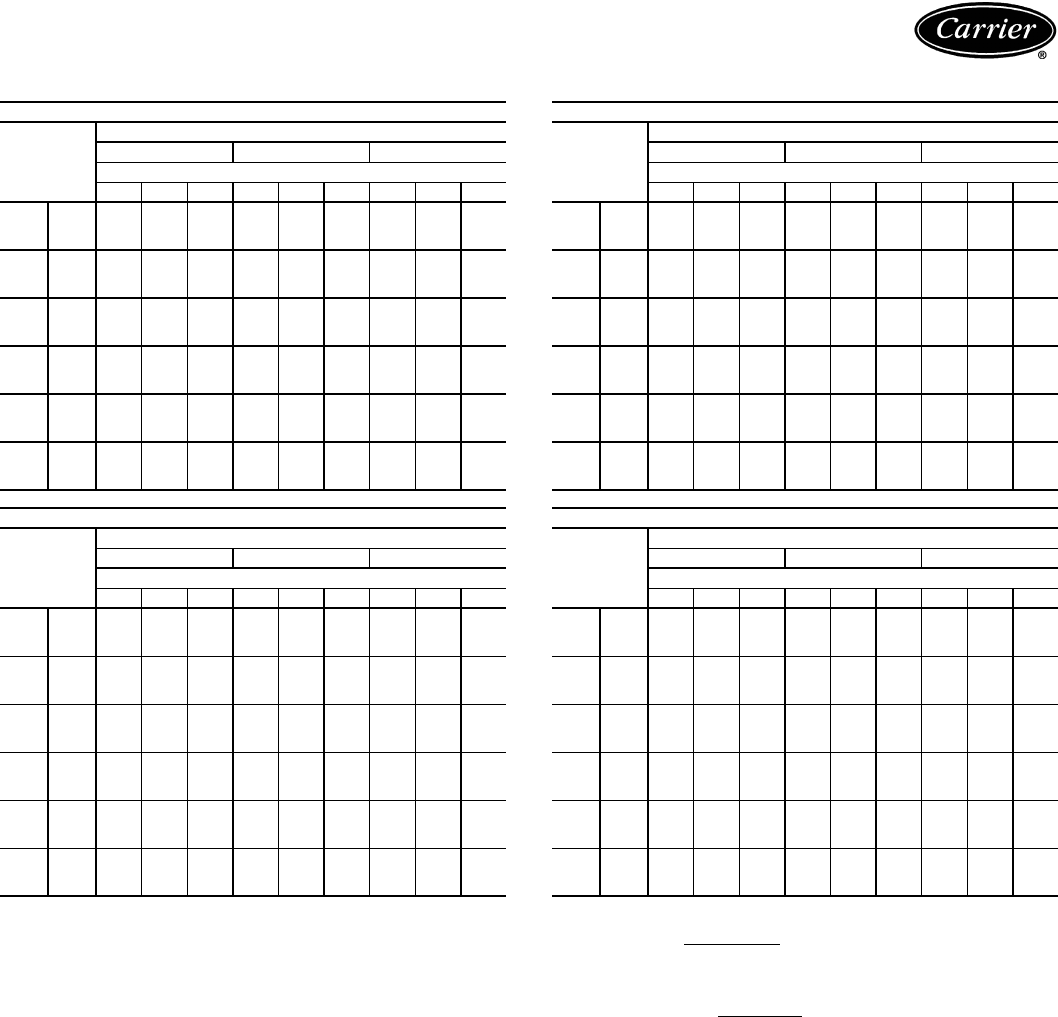
46
COMBINATION RATINGS — ENGLISH (cont)
LEGEND
NOTES:
1. Direct interpolation is permissible. Do not extrapolate.
2. SHC is based on 80 F db air entering indoor coil.
3. Formulas:
Lwb = wet-bulb temperature corresponding to enthalpy air leaving indoor coil
(hlwb)
where hewb = enthalpy of air entering evaporator coil (Btuh/lb).
4. Capacities are based on 25 actual ft (40 equivalent ft) of interconnecting piping
sized to the outdoor unit field connections. (Equivalent length is equal to the
actual length plus a 50% allowance for fitting losses.) For other equivalent
lengths, refer to the Carrier System Design Manual, Part 3, for line losses.
38AKS009/40RM008 WITH STANDARD 3-ROW COIL
Temp (F)
Air Entering
Condenser
(Edb)
Evaporator Air — Cfm
2250 3000 3750
Evaporator Air — Ewb (F)
72 67 62 72 67 62 72 67 62
85
TC 102.7 94.9 86.7 107.0 99.9 91.7 109.9 103.2 95.4
SHC 51.5 64.2 82.5 58.7 73.6 91.6 64.1 82.3 95.4
kW 7.62 7.33 7.03 7.77 7.51 7.21 7.88 7.63 7.35
95
TC 98.2 90.5 82.5 102.2 95.3 87.5 104.9 98.5 91.2
SHC 49.7 62.3 78.9 57.0 71.6 87.5 62.3 80.4 91.2
kW 8.24 7.92 7.58 8.41 8.12 7.79 8.53 8.25 7.95
100
TC 95.7 88.3 80.7 99.3 92.7 85.5 101.9 95.8 89.1
SHC 48.6 61.4 77.3 56.1 70.6 85.5 61.3 79.3 89.1
kW 8.56 8.20 7.84 8.73 8.42 8.07 8.85 8.56 8.24
105
TC 93.2 96.0 78.7 96.6 90.2 83.4 99.0 93.2 86.9
SHC 47.6 60.4 75.6 55.2 69.5 83.4 60.3 78.3 86.9
kW 8.86 8.49 8.11 9.03 8.71 8.35 9.16 8.86 8.54
115
TC 88.2 81.3 74.5 91.2 85.2 79.0 93.4 87.9 82.5
SHC 45.6 58.3 72.0 53.4 67.4 79.0 58.3 76.2 82.5
kW 9.46 9.04 8.63 9.63 9.27 8.90 9.77 9.44 9.11
125
TC —76.5 70.1 —80.0 74.5 —82.6 77.8
SHC —56.2 68.2 —65.2 74.5 —74.0 77.8
kW —9.63 9.17 —9.87 9.48 —10.05 9.72
38AKS009/40RM012 WITH STANDARD 3-ROW COIL
Temp (F)
Air Entering
Condenser
(Edb)
Evaporator Air — Cfm
3000 4000 5000
Evaporator Air — Ewb (F)
72 67 62 72 67 62 72 67 62
85
TC 113.0 104.8 96.9 116.9 109.2 102.4 119.1 111.8 106.9
SHC 59.2 77.2 93.7 67.1 88.5 102.4 75.8 100.8 106.9
kW 7.99 7.69 7.40 8.14 7.85 7.60 8.22 7.95 7.77
95
TC 108.1 99.9 92.3 111.8 104.2 97.8 —106.7 102.4
SHC 57.2 75.1 89.9 65.1 86.2 97.8 —98.7 102.4
kW 8.66 8.32 7.99 8.81 8.49 8.22 —8.60 8.42
100
TC 105.0 97.2 89.9 108.4 101.2 95.2 —103.4 99.8
SHC 55.9 73.9 87.9 63.8 84.8 95.2 —97.4 99.7
kW 9.00 8.63 8.28 9.16 8.82 8.54 —8.93 8.75
105
TC 102.1 94.5 87.5 105.2 98.3 92.7 —100.4 97.2
SHC 54.7 72.8 85.9 62.6 83.5 92.7 —96.1 97.2
kW 9.32 8.93 8.57 9.48 9.12 8.83 —9.23 9.07
115
TC 96.4 89.1 82.6 —92.6 87.7 —94.5 92.1
SHC 52.4 70.5 81.9 —80.9 87.7 —93.7 92.1
kW 9.95 9.51 9.12 —9.72 9.42 —9.83 9.69
125
TC —83.6 77.6 —86.8 82.5 —88.4 86.8
SHC —68.1 77.7 —78.2 82.5 —91.3 86.8
kW —10.13 9.70 —10.35 10.05 —10.47 10.36
——
Out of Range
Edb —Entering Dry Bulb
Ewb —Entering Wet Bulb
kW —Compressor Motor Power Input
SHC —Sensible Heat Capacity (1000 Btuh) Gross
TC —Total Capacity (1000 Btuh) Gross
38AK012/40RM008 WITH STANDARD 3-ROW COIL
Temp (F)
Air Entering
Condenser
(Edb)
Evaporator Air — Cfm
2250 3000 3750
Evaporator Air — Ewb (F)
72 67 62 72 67 62 72 67 62
85
TC 105 96.9 89.7 110 102 94.9 112 105 98.8
SHC 51.5 63.5 75.1 56.9 72.4 87.3 62.2 80.9 97.3
kW 7.12 6.88 6.67 7.27 7.02 6.81 7.36 7.12 6.93
95
TC 101 93.5 86.6 106 98.0 91.6 108 101 95.5
SHC 50.1 61.9 73.6 55.6 70.9 85.6 60.8 79.4 95.0
kW 7.68 7.43 7.22 7.82 7.57 7.37 7.92 7.67 7.49
100
TC 99.3 91.8 85.1 104 96.1 89.8 106 98.9 93.8
SHC 49.3 61.2 72.8 54.8 70.2 84.7 60.0 78.6 93.7
kW 7.97 7.73 7.52 8.11 7.86 7.55 8.20 7.95 7.78
105
TC 97.4 90.0 83.3 101 94.1 88.0 104 96.8 92.0
SHC 48.6 60.4 72.0 54.0 69.3 83.8 59.3 77.7 92.0
kW 8.27 8.03 7.83 8.41 8.16 7.97 8.50 8.25 8.09
115
TC 93.2 86.1 79.7 96.9 89.8 84.2 99.2 92.3 88.3
SHC 47.0 58.7 70.2 52.4 67.6 81.7 57.6 75.9 88.3
kW 8.89 8.66 8.47 9.02 8.78 8.60 9.10 8.86 8.73
125
TC 88.6 82.0 76.0 92.0 85.3 80.3 94.1 87.7 84.5
SHC 45.3 57.0 68.4 50.7 65.8 79.3 55.9 74.1 84.5
kW 9.54 9.32 9.15 9.66 9.44 9.27 9.74 9.51 9.41
38AK012/40RM012 WITH STANDARD 3-ROW COIL
Temp (F)
Air Entering
Condenser
(Edb)
Evaporator Air — Cfm
3000 4000 5000
Evaporator Air — Ewb (F)
72 67 62 72 67 62 72 67 62
85
TC 112 104 96.9 116 108 102 118 110 107
SHC 58.2 74.0 89.1 65.2 85.4 102 72.0 95.8 107
kW 8.50 8.22 7.98 8.64 8.36 8.16 8.73 8.45 8.33
95
TC 108 100 93.5 111 104 98.9 114 106 104
SHC 56.7 72.4 87.4 63.8 83.8 98.9 70.6 94.1 104
kW 9.15 8.86 8.62 9.29 9.00 8.82 9.37 9.09 8.99
100
TC 106 98.1 91.8 109 102 97.2 111 104 102
SHC 56.0 71.6 86.5 63.0 83.0 97.2 69.8 93.2 102
kW 9.49 9.20 8.96 9.63 9.34 9.16 9.71 9.43 9.34
105
TC 104 96.1 89.9 107 99.5 95.4 109 102 99.9
SHC 55.2 70.8 85.5 62.3 82.1 95.4 69.0 92.2 99.9
kW 9.84 9.55 9.32 9.97 9.68 9.51 10.0 9.77 9.69
115
TC 99.0 91.8 86.0 102 95.0 91.6 104 97.3 95.8
SHC 53.5 69.1 83.4 60.6 80.3 91.6 67.3 90.1 95.8
kW 10.6 10.3 10.1 10.7 10.4 10.3 10.8 10.5 10.4
125
TC 94.0 87.2 82.1 96.6 90.2 87.5 98.3 92.3 91.4
SHC 51.8 67.3 81.0 58.8 78.3 87.5 65.5 87.7 91.4
kW 11.3 11.0 10.9 11.4 11.2 11.0 11.5 11.2 11.2
Ldb F = Edb F –SHCBtuh
1.10 x cfm
Ldb F: hlwb = hewb –TCBtuh
4.5 x cfm
Performance data (cont)

47
COMBINATION RATINGS — ENGLISH (cont)
LEGEND
NOTES:
1. Direct interpolation is permissible. Do not extrapolate.
2. SHC is based on 80 F db air entering indoor coil.
3. Formulas:
Lwb = wet-bulb temperature corresponding to enthalpy air leaving indoor coil
(hlwb)
where hewb = enthalpy of air entering evaporator coil (Btuh/lb).
4. Capacities are based on 25 actual ft (40 equivalent ft) of interconnecting piping
sized to the outdoor unit field connections. (Equivalent length is equal to the
actual length plus a 50% allowance for fitting losses.) For other equivalent
lengths, refer to the Carrier System Design Manual, Part 3, for line losses.
38AK012/40RM014 WITH STANDARD 3-ROW COIL
Temp (F)
Air Entering
Condenser
(Edb)
Evaporator Air — Cfm
3750 5000 6250
Evaporator Air — Ewb (F)
72 67 62 72 67 62 72 67 62
85
TC 117 109 102 120 112 108 122 115 113
SHC 63.9 82.7 99.4 71.8 95.3 108 79.3 106 113
kW 7.18 6.94 7.18 7.28 7.04 6.92 7.34 7.11 7.05
95
TC 113 105 98.6 116 108 105 118 111 109
SHC 62.5 81.2 97.1 70.4 93.6 105 77.8 104 109
kW 7.72 7.48 7.30 7.82 7.58 7.47 7.88 7.66 7.61
100
TC 111 103 96.8 114 106 103 116 108 107
SHC 61.6 80.3 95.9 69.6 92.7 103 77.0 103 107
kW 8.01 7.76 7.59 8.10 7.86 7.77 8.16 7.94 8.90
105
TC 108 101 94.9 111 104 101 113 106 105
SHC 60.8 79.4 94.5 68.8 91.7 101 76.2 102 105
kW 8.30 8.05 7.88 8.39 8.15 8.06 8.45 8.23 8.20
115
TC 103 96.0 91.1 106 98.9 96.8 108 101 101
SHC 59.1 77.6 91.1 67.0 89.6 96.8 74.4 98.9 101
kW 8.90 8.66 8.52 8.99 8.76 8.69 9.04 8.83 8.81
125
TC 98.2 91.3 87.3 101 94.1 92.6 102 96.4 96.2
SHC 57.3 75.7 87.3 65.3 87.3 92.6 72.6 95.6 96.2
kW 9.53 9.31 9.20 9.623 9.40 9.35 9.66 9.47 9.47
38AKS012/40RM008 WITH STANDARD 3-ROW COIL
Temp (F)
Air Entering
Condenser
(Edb)
Evaporator Air — Cfm
2250 3000 3750
Evaporator Air — Ewb (F)
72 67 62 72 67 62 72 67 62
85
TC 101.9 93.8 85.5 106.3 99.0 90.6 109.3 102.4 94.4
SHC 51.2 63.8 81.4 58.4 73.2 90.6 63.8 81.9 94.4
kW 7.59 7.31 7.03 7.73 7.49 7.20 7.84 7.60 7.33
95
TC 97.1 89.6 81.9 100.9 94.2 86.7 103.5 97.3 90.4
SHC 49.2 61.9 78.4 56.6 71.2 86.7 61.8 79.9 90.4
kW 8.23 7.91 7.58 8.39 8.11 7.79 8.51 8.24 7.94
100
TC 94.7 87.4 79.9 98.2 91.7 84.6 —94.8 88.2
SHC 48.2 61.0 76.6 55.7 70.2 84.6 —78.9 88.2
kW 8.54 8.20 7.84 8.71 8.40 8.07 —8.54 8.24
105
TC 92.3 85.1 77.8 95.6 89.3 82.5 —92.2 86.1
SHC 47.2 60.0 74.9 54.9 69.1 82.5 —77.9 86.1
kW 8.86 8.48 8.11 9.03 8.70 8.35 —8.85 8.53
115
TC 87.4 80.5 73.7 90.3 84.3 78.3 —87.1 81.7
SHC 45.2 58.0 71.3 53.1 67.0 78.3 —75.8 81.7
kW 9.45 9.04 8.64 9.62 9.26 8.91 —9.43 9.11
125
TC —75.9 69.4 —79.3 73.8 ——77.2
SHC —55.9 67.7 —64.9 73.8 ——77.2
kW —9.57 9.13 —9.81 9.43 ——9.67
38AKS012/40RM012 WITH STANDARD 3-ROW COIL
Temp (F)
Air Entering
Condenser
(Edb)
Evaporator Air — Cfm
3000 4000 5000
Evaporator Air — Ewb (F)
72 67 62 72 67 62 72 67 62
85
TC 112.5 104.0 95.8 116.5 108.5 101.5 118.8 111.2 106.2
SHC 59.0 76.8 92.9 67.0 88.2 101.5 75.7 100.5 106.2
kW 7.95 7.66 7.38 8.08 7.81 7.57 8.16 7.90 7.73
95
TC 106.6 98.7 91.3 110.1 102.8 96.7 —105.1 101.2
SHC 56.6 74.6 89.1 64.5 85.6 96.7 —98.1 101.2
kW 8.64 8.30 7.98 8.79 8.47 8.21 —8.57 8.41
100
TC 103.8 96.1 89.4 107.1 100.0 94.2 —102.2 98.7
SHC 55.5 73.5 87.1 63.4 84.3 94.2 —96.9 98.7
kW 8.97 8.61 8.27 9.13 8.79 8.52 —8.90 8.73
105
TC 101.1 93.5 86.6 —97.2 91.8 —99.3 96.2
SHC 54.3 72.4 85.1 —83.0 91.8 —95.7 96.2
kW 9.31 8.92 8.56 —9.11 8.83 —9.22 9.06
115
TC 95.5 88.3 81.8 —91.7 86.8 —93.6 91.3
SHC 52.1 70.1 81.2 —80.5 86.8 —93.3 91.3
kW 9.92 9.50 9.11 —9.70 9.41 —9.81 9.67
125
TC —————————
SHC —————————
kW —————————
——
Out of Range
Edb —Entering Dry Bulb
Ewb —Entering Wet Bulb
kW —Compressor Motor Power Input
SHC —Sensible Heat Capacity (1000 Btuh) Gross
TC —Total Capacity (1000 Btuh) Gross
38AKS012/40RM014 WITH STANDARD 3-ROW COIL
Temp (F)
Air Entering
Condenser
(Edb)
Evaporator Air — Cfm
3750 5000 6250
Evaporator Air — Ewb (F)
72 67 62 72 67 62 72 67 62
85
TC 118.3 108.5 101.8 121.8 113.1 108.0 —115.9 113.0
SHC 66.1 85.6 100.6 75.6 101.3 108.0 —113.7 113.0
kW 8.14 7.81 7.58 8.26 7.97 7.79 —8.06 7.96
95
TC 111.8 102.7 96.7 —106.8 102.6 —109.3 107.3
SHC 63.6 82.9 96.3 —98.6 102.6 —110.6 107.3
kW 8.86 8.47 8.21 —8.64 8.47 —8.75 8.67
100
TC 108.8 99.9 94.2 —103.8 100.0 —106.3 104.6
SHC 62.5 81.6 94.2 —97.4 100.0 —109.2 104.6
kW 9.21 8.79 8.52 —8.97 8.79 —9.09 9.01
105
TC 105.8 97.0 91.6 —100.9 97.3 —103.2 101.9
SHC 61.3 80.3 92.0 —96.1 97.3 —107.8 101.9
kW 9.55 9.10 8.82 —9.30 9.12 —9.42 9.35
115
TC —91.4 86.6 —95.0 92.1 —97.2 96.4
SHC —77.7 87.7 —93.6 92.1 —105.0 96.4
kW —9.68 9.40 —9.89 9.72 —10.02 9.98
125
TC ————89.0 86.7 ———
SHC ————91.0 86.7 ———
kW ————10.49 10.32 ———
38AKS013/40RM008 WITH STANDARD 3-ROW COIL
Temp (F)
Air Entering
Condenser
(Edb)
Evaporator Air — Cfm
2250 3000 3750
Evaporator Air — Ewb (F)
72 67 62 72 67 62 72 67 62
85
TC 103.5 95.9 88.0 107.7 100.9 92.8 110.5 104.1 96.4
SHC 51.9 64.7 83.6 58.9 74.0 92.8 64.3 82.6 96.4
kW 7.82 7.56 7.30 7.96 7.73 7.46 8.05 7.84 7.58
95
TC 99.0 91.5 83.7 102.8 96.1 88.5 105.5 99.2 92.2
SHC 50.0 62.8 79.9 57.3 72.0 88.5 62.5 80.7 92.2
kW 8.50 8.25 7.99 8.63 8.40 8.15 8.72 8.51 8.27
100
TC 97.0 89.5 81.9 100.7 94.1 86.7 103.4 97.2 90.3
SHC 49.2 61.9 78.4 56.6 71.1 86.7 61.8 79.9 90.3
kW 8.81 8.48 8.14 8.98 8.68 8.35 9.09 8.82 8.51
105
TC 94.8 87.4 79.9 98.4 91.8 84.7 101.0 94.9 88.3
SHC 48.3 61.0 76.6 55.8 70.2 84.7 60.9 78.9 88.3
kW 9.13 8.77 8.41 9.30 8.98 8.64 9.42 9.13 8.81
115
TC 90.5 83.1 75.8 93.7 87.3 80.6 96.2 90.3 84.2
SHC 46.5 59.1 73.1 54.2 68.3 80.6 59.3 77.1 84.2
kW 9.78 9.37 8.97 9.96 9.61 9.23 10.10 9.77 9.44
125
TC 85.6 78.9 72.3 88.3 82.5 76.7 90.4 85.2 80.1
SHC 44.5 57.3 70.1 52.4 66.3 76.7 57.3 75.1 80.1
kW 10.47 9.97 9.47 10.67 10.24 9.81 10.83 10.44 10.06
Ldb F = Edb F –SHCBtuh
1.10 x cfm
Ldb F: hlwb = hewb –TCBtuh
4.5 x cfm
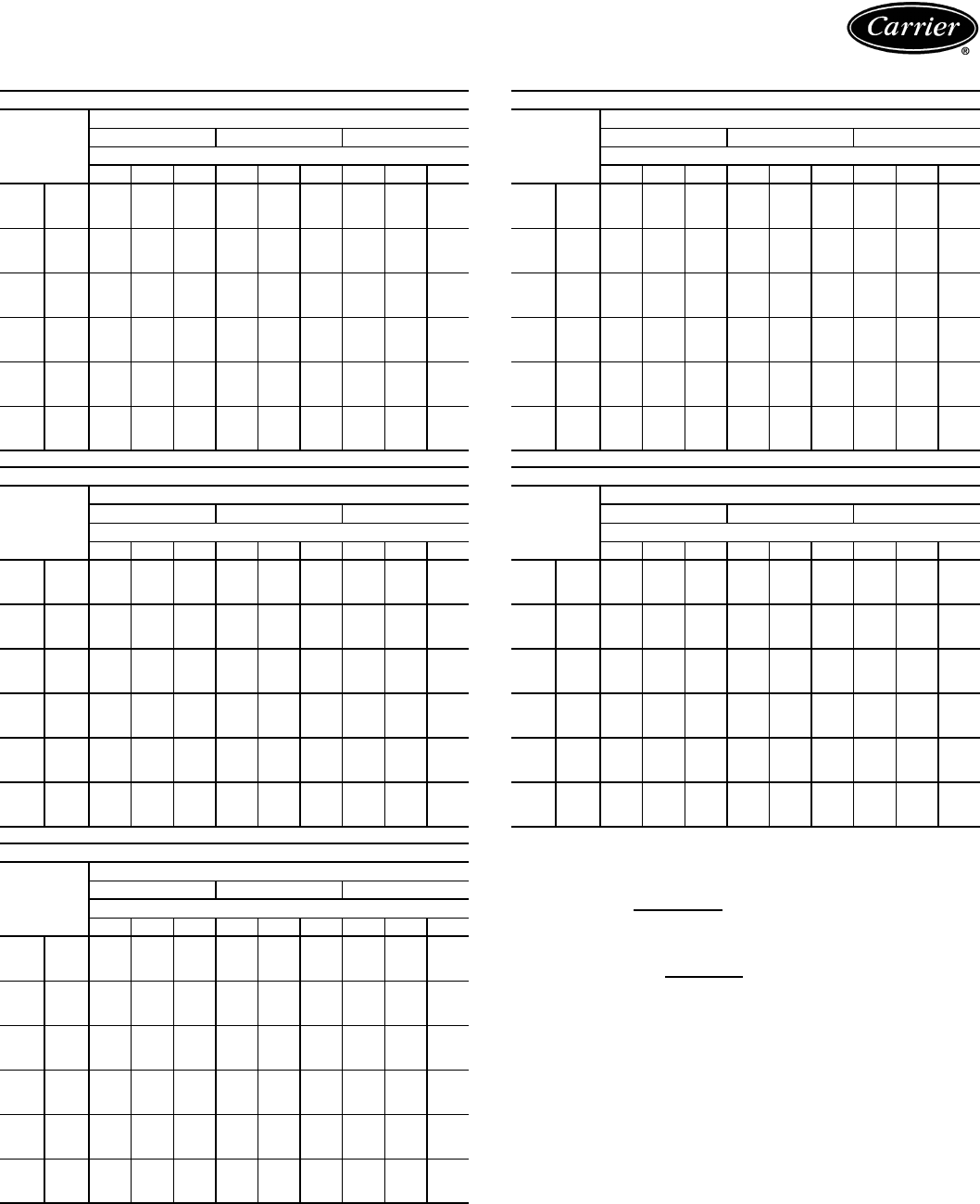
48
COMBINATION RATINGS — ENGLISH (cont)
LEGEND
NOTES:
1. Direct interpolation is permissible. Do not extrapolate.
2. SHC is based on 80 F db air entering indoor coil.
3. Formulas:
Lwb = wet-bulb temperature corresponding to enthalpy air leaving indoor coil
(hlwb)
where hewb = enthalpy of air entering evaporator coil (Btuh/lb).
4. Capacities are based on 25 actual ft (40 equivalent ft) of interconnecting piping
sized to the outdoor unit field connections. (Equivalent length is equal to the
actual length plus a 50% allowance for fitting losses.) For other equivalent
lengths, refer to the Carrier System Design Manual, Part 3, for line losses.
38AKS013/40RM012 WITH STANDARD 3-ROW COIL
Temp (F)
Air Entering
Condenser
(Edb)
Evaporator Air — Cfm
3000 4000 5000
Evaporator Air — Ewb (F)
72 67 62 72 67 62 72 67 62
85
TC 113.5 105.6 97.9 117.3 109.9 103.2 119.4 112.4 107.6
SHC 59.4 77.5 94.6 67.3 88.8 103.2 75.9 101.0 107.6
kW 8.15 7.89 7.63 8.28 8.03 7.81 8.35 8.11 7.95
95
TC 108.5 100.7 93.2 112.1 104.8 98.6 114.1 107.2 103.0
SHC 57.4 75.4 90.7 65.3 86.5 98.6 74.1 98.9 103.0
kW 8.82 8.56 8.31 8.94 8.69 8.49 9.00 8.77 8.63
100
TC 106.4 98.6 91.2 109.8 102.6 96.6 111.8 104.9 101.1
SHC 56.5 74.5 89.0 64.4 85.5 96.6 73.3 98.0 101.1
kW 9.23 8.88 8.56 9.38 9.06 8.79 9.47 9.16 8.99
105
TC 104.0 96.2 89.0 107.4 100.2 94.3 109.3 102.4 98.9
SHC 55.6 73.5 87.2 63.4 84.4 94.3 72.4 97.0 98.9
kW 9.57 9.19 8.85 9.73 9.38 9.10 9.82 9.49 9.32
115
TC 99.3 91.6 84.6 102.4 95.3 89.9 104.2 97.4 94.5
SHC 53.6 71.5 83.5 61.5 82.2 89.9 70.6 94.9 94.5
kW 10.27 9.84 9.45 10.45 10.05 9.75 10.54 10.17 10.01
125
TC 93.3 86.3 80.1 95.9 89.6 85.0 97.4 91.3 89.3
SHC 51.2 69.3 79.7 59.0 79.5 85.0 68.3 92.4 89.3
kW 11.05 10.52 10.06 11.24 10.77 10.42 11.35 10.90 10.75
38AKS013/40RM014 WITH STANDARD 3-ROW COIL
Temp (F)
Air Entering
Condenser
(Edb)
Evaporator Air — Cfm
3750 5000 6250
Evaporator Air — Ewb (F)
72 67 62 72 67 62 72 67 62
85
TC 118.9 109.9 103.5 122.2 114.1 109.3 124.6 116.8 114.0
SHC 66.4 86.3 102.1 75.8 101.8 109.3 85.8 114.1 114.0
kW 8.33 8.03 7.82 8.44 8.17 8.01 8.52 8.26 8.17
95
TC 113.7 104.7 98.7 116.8 108.8 104.5 119.1 111.4 109.1
SHC 64.4 83.9 98.0 73.8 99.5 104.5 83.9 111.6 109.1
kW 8.99 8.69 8.49 9.09 8.83 8.68 9.17 8.91 8.84
100
TC 111.5 102.5 96.6 114.5 106.6 102.4 116.8 109.1 107.1
SHC 63.5 82.8 96.2 73.0 98.5 102.4 83.1 110.5 107.1
kW 9.46 9.05 8.79 9.59 9.24 9.05 9.69 9.35 9.26
105
TC 109.0 100.0 94.3 111.9 104.0 100.1 114.2 106.5 104.8
SHC 62.6 81.7 94.3 72.0 97.4 100.1 82.2 109.3 104.8
kW 9.81 9.38 9.10 9.95 9.57 9.38 10.06 9.69 9.60
115
TC 104.1 95.1 89.7 106.8 99.0 95.5 109.0 101.4 100.2
SHC 60.6 79.4 89.7 70.1 95.3 95.5 80.4 106.9 100.2
kW 10.54 10.04 9.74 10.69 10.26 10.06 10.81 10.39 10.32
125
TC 97.4 89.2 84.7 99.7 92.7 90.0 101.6 94.8 94.3
SHC 58.1 76.7 84.6 67.6 92.6 90.0 77.9 103.8 94.3
kW 11.36 10.74 10.40 11.53 11.00 10.80 11.67 11.16 11.12
38AKS014/40RM012 WITH STANDARD 3-ROW COIL
Temp (F)
Air Entering
Condenser
(Edb)
Evaporator Air — Cfm
3000 4000 5000
Evaporator Air — Ewb (F)
72 67 62 72 67 62 72 67 62
85
TC 129.3 119.5 109.5 134.9 125.4 115.9 138.2 129.1 120.8
SHC 65.9 83.5 104.2 74.0 95.9 115.9 82.4 107.8 120.8
kW 9.51 9.18 8.85 9.70 9.38 9.06 9.81 9.50 9.23
95
TC 123.5 114.3 105.1 128.4 119.6 111.1 131.3 122.9 115.9
SHC 63.5 81.3 100.6 71.5 93.3 111.1 80.0 105.3 115.9
kW 10.42 10.00 9.58 10.65 10.25 9.86 10.78 10.40 10.08
100
TC 120.8 111.6 102.6 125.6 116.9 108.6 128.4 120.1 113.5
SHC 62.4 80.1 98.5 70.5 92.0 108.6 79.0 104.1 113.5
kW 10.78 10.37 9.95 11.00 10.60 10.23 11.13 10.75 10.45
105
TC 118.1 109.1 100.4 122.6 114.1 106.3 125.2 117.2 111.1
SHC 61.3 79.1 96.7 69.3 90.8 106.3 77.9 103.0 111.1
kW 11.19 10.74 10.30 11.41 10.99 10.60 11.55 11.14 10.84
115
TC 112.5 104.0 95.8 116.5 108.5 101.5 118.8 111.2 106.2
SHC 59.0 76.8 92.9 67.0 88.2 101.5 75.7 100.5 106.2
kW 12.03 11.52 11.03 12.27 11.79 11.37 12.41 11.95 11.65
125
TC —98.6 91.2 —102.6 96.6 —104.9 101.1
SHC —74.5 89.0 —85.5 96.6 —98.0 101.1
kW —12.37 11.80 —12.68 12.21 —12.86 12.56
——
Out of Range
Edb —Entering Dry Bulb
Ewb —Entering Wet Bulb
kW —Compressor Motor Power Input
SHC —Sensible Heat Capacity (1000 Btuh) Gross
TC —Total Capacity (1000 Btuh) Gross
38AKS014/40RM014 WITH STANDARD 3-ROW COIL
Temp (F)
Air Entering
Condenser
(Edb)
Evaporator Air — Cfm
3750 5000 6250
Evaporator Air — Ewb (F)
72 67 62 72 67 62 72 67 62
85
TC 136.9 125.9 116.7 141.7 131.4 123.8 145.1 135.1 129.4
SHC 73.3 93.6 113.3 83.0 109.2 123.8 92.8 122.6 129.4
kW 9.76 9.40 9.09 9.92 9.58 9.33 10.04 9.70 9.51
95
TC 130.3 119.9 111.7 134.5 125.0 118.4 137.6 128.3 123.7
SHC 70.7 90.0 109.1 80.3 106.4 118.4 90.2 119.5 123.7
kW 10.73 10.26 9.89 10.92 10.49 10.19 11.06 10.64 10.43
100
TC 127.5 117.1 109.2 131.6 122.1 115.8 134.6 125.4 121.1
SHC 69.7 89.6 106.9 79.3 105.2 115.8 89.2 118.1 121.1
kW 11.09 10.61 10.25 11.27 10.84 10.56 11.41 10.99 10.80
105
TC 124.5 114.3 106.8 128.4 119.2 113.3 131.3 122.3 118.5
SHC 68.5 88.3 104.8 78.1 103.9 113.3 88.1 116.7 118.5
kW 11.51 11.00 10.62 11.70 11.24 10.95 11.85 11.40 11.21
115
TC 118.3 108.5 101.8 121.8 113.1 108.0 124.4 115.9 113.0
SHC 66.1 85.6 100.6 75.6 101.3 108.0 85.7 113.7 113.0
kW 12.38 11.79 11.39 12.59 12.06 11.76 12.74 12.24 12.06
125
TC —102.5 96.6 —106.6 102.4 ———
SHC —82.8 96.2 —98.5 102.4 ———
kW —12.67 12.21 — 12.99 12.67 ———
38AKS014/40RM016 WITH STANDARD 3-ROW COIL
Temp (F)
Air Entering
Condenser
(Edb)
Evaporator Air — Cfm
4500 6000 7500
Evaporator Air — Ewb (F)
72 67 62 72 67 62 72 67 62
85
TC 145.0 135.2 125.7 148.7 140.7 132.9 152.5 144.1 138.9
SHC 82.7 105.8 124.6 91.2 120.8 132.9 102.9 135.5 138.9
kW 10.03 9.71 9.39 10.16 9.89 9.63 10.28 10.00 9.83
95
TC 137.4 128.4 119.8 140.6 133.4 126.4 144.0 136.4 132.1
SHC 80.0 102.8 119.4 88.1 117.3 126.4 99.9 131.7 132.1
kW 11.06 10.65 10.26 11.20 10.87 10.56 11.36 11.01 10.81
100
TC 134.4 125.5 117.1 137.5 130.4 123.6 140.9 133.4 129.2
SHC 79.0 101.5 116.9 86.9 115.8 123.6 98.7 130.2 129.2
kW 11.40 11.00 10.61 11.54 11.22 10.91 11.69 11.35 11.16
105
TC 131.0 122.5 114.3 133.9 127.1 120.6 137.1 129.9 126.1
SHC 77.8 100.1 114.3 85.6 114.3 120.6 97.4 128.5 126.1
kW 11.83 11.41 11.00 11.98 11.64 11.31 12.14 11.78 11.59
115
TC 124.0 116.2 108.6 126.5 120.4 114.5 —123.0 119.8
SHC 75.3 97.3 108.6 82.8 111.0 114.5 —125.0 119.8
kW 12.72 12.25 11.80 12.87 12.50 12.15 —12.66 12.47
125
TC —————————
SHC —————————
kW —————————
Ldb F = Edb F –SHCBtuh
1.10 x cfm
Ldb F: hlwb = hewb –TCBtuh
4.5 x cfm
Performance data (cont)

49
COMBINATION RATINGS — ENGLISH (cont)
LEGEND
NOTES:
1. Direct interpolation is permissible. Do not extrapolate.
2. SHC is based on 80 F db air entering indoor coil.
3. Formulas:
Lwb = wet-bulb temperature corresponding to enthalpy air leaving indoor coil
(hlwb)
where hewb = enthalpy of air entering evaporator coil (Btuh/lb).
4. Capacities are based on 25 actual ft (40 equivalent ft) of interconnecting piping
sized to the outdoor unit field connections. (Equivalent length is equal to the
actual length plus a 50% allowance for fitting losses.) For other equivalent
lengths, refer to the Carrier System Design Manual, Part 3, for line losses.
38AKS016/40RM014 WITH STANDARD 3-ROW COIL
Temp (F)
Air Entering
Condenser
(Edb)
Evaporator Air — Cfm
3750 5000 6250
Evaporator Air — Ewb (F)
72 67 62 72 67 62 72 67 62
85
TC 158.9 146.6 134.6 165.3 153.4 142.4 169.6 157.9 148.5
SHC 81.7 103.2 128.5 91.6 118.6 142.4 101.2 133.3 148.5
kW 13.65 12.95 12.27 14.02 13.34 12.71 14.26 13.59 13.06
95
TC 151.9 140.2 129.3 157.6 146.4 136.7 161.5 150.6 142.6
SHC 79.0 100.2 124.0 88.8 115.6 136.7 98.5 129.9 142.6
kW 14.67 13.95 13.28 15.02 14.33 13.74 15.26 14.59 14.10
100
TC 148.5 136.9 126.3 154.1 143.0 133.7 158.0 147.1 139.5
SHC 77.7 98.7 121.4 87.5 114.1 133.7 97.2 128.2 139.5
kW 15.17 14.45 13.80 15.52 14.83 14.26 15.75 15.08 14.62
105
TC 145.0 133.5 123.4 150.3 139.4 130.6 154.0 143.4 136.4
SHC 76.4 97.1 119.0 86.1 112.6 130.6 95.9 126.5 136.4
kW 15.62 14.86 14.20 15.97 15.26 14.68 16.21 15.51 15.06
115
TC 137.6 126.5 117.4 —132.1 124.4 —135.8 130.0
SHC 73.5 93.9 113.9 —109.5 124.4 —123.0 130.0
kW 16.55 15.72 15.03 —16.14 15.56 —16.41 15.97
125
TC —116.6 109.7 —120.9 115.5 ———
SHC —89.4 107.4 —104.7 115.5 ———
kW —16.46 15.77 —16.89 16.35 ———
38AKS016/40RM016 WITH STANDARD 3-ROW COIL
Temp (F)
Air Entering
Condenser
(Edb)
Evaporator Air — Cfm
4500 6000 7500
Evaporator Air — Ewb (F)
72 67 62 72 67 62 72 67 62
85
TC 170.0 157.8 146.2 175.3 164.9 154.7 179.8 169.3 161.3
SHC 91.5 115.9 142.6 101.1 132.6 154.7 112.7 148.2 161.3
kW 14.28 13.59 12.93 14.59 13.99 13.41 14.85 14.25 13.79
95
TC 161.7 150.5 139.9 166.4 157.0 147.8 170.6 161.0 154.1
SHC 88.6 112.7 137.0 97.8 128.7 147.8 109.4 144.0 154.1
kW 15.28 14.59 13.93 15.56 14.98 14.42 15.82 15.23 14.81
100
TC 158.1 147.1 136.8 162.6 153.4 144.4 166.8 157.3 150.7
SHC 87.3 111.1 134.1 96.4 127.0 144.4 108.0 142.2 150.7
kW 15.76 15.08 14.44 16.04 15.47 14.92 16.30 15.71 15.31
105
TC 154.1 143.4 133.2 158.3 149.4 140.9 162.4 153.2 147.1
SHC 85.9 109.5 131.2 94.7 125.1 140.9 106.4 140.1 147.1
kW 16.22 15.52 14.85 16.50 15.91 15.35 16.76 16.16 15.76
115
TC —135.9 126.4 —141.4 133.6 ———
SHC —106.1 125.2 —121.2 133.6 ———
kW —16.41 15.71 —16.83 16.24 ———
125
TC ——116.6 ——————
SHC ——116.5 ——————
kW ——16.46 ——————
38AKS016/40RM024 WITH STANDARD 3-ROW COIL
Temp (F)
Air Entering
Condenser
(Edb)
Evaporator Air — Cfm
6000 8000 10,000
Evaporator Air — Ewb (F)
72 67 62 72 67 62 72 67 62
85
TC 183.5 170.7 160.5 188.9 176.0 169.9 190.6 181.1 177.5
SHC 104.1 140.0 159.8 120.1 162.7 169.9 133.8 182.5 177.5
kW 15.06 14.33 13.74 15.37 14.63 14.28 15.46 14.92 14.71
95
TC 174.1 162.1 153.0 179.0 166.8 161.9 180.2 171.6 169.1
SHC 100.6 136.5 153.0 116.5 158.9 161.9 130.2 178.2 169.1
kW 16.04 15.30 14.74 16.34 15.59 15.29 16.41 15.88 15.73
100
TC 170.3 158.4 149.5 175.0 163.0 158.4 176.2 167.7 165.6
SHC 99.1 135.0 149.4 115.1 157.2 158.4 128.8 176.4 165.6
kW 16.51 15.78 15.23 16.80 16.06 15.78 16.87 16.35 16.22
105
TC 165.7 154.2 145.7 170.3 158.5 154.4 171.3 163.2 161.5
SHC 97.4 133.3 145.6 113.3 155.4 154.4 127.0 174.4 161.5
kW 16.99 16.22 15.67 17.29 16.51 16.24 17.35 16.82 16.70
115
TC —145.6 137.9 ——146.3 ———
SHC —129.7 137.9 ——146.3 ———
kW —17.14 16.57 ——17.20 ———
125
TC —————————
SHC —————————
kW —————————
——
Out of Range
Edb —Entering Dry Bulb
Ewb —Entering Wet Bulb
kW —Compressor Motor Power Input
SHC —Sensible Heat Capacity (1000 Btuh) Gross
TC —Total Capacity (1000 Btuh) Gross
38AKS024/40RM016 WITH STANDARD 3-ROW COIL
Temp (F)
Air Entering
Condenser
(Edb)
Evaporator Air — Cfm
4500 6000 7500
Evaporator Air — Ewb (F)
72 67 62 72 67 62 72 67 62
85
TC 212.9 194.5 177.5 222.6 205.8 189.5 229.4 213.0 198.0
SHC 106.7 132.4 170.1 118.8 152.4 189.5 130.4 170.0 198.0
kW 16.07 15.37 14.72 16.44 15.80 15.18 16.70 16.08 15.51
95
TC 203.4 186.1 170.1 212.2 196.6 181.5 218.7 203.3 189.7
SHC 103.3 128.6 163.6 114.9 147.9 181.5 126.5 165.1 189.7
kW 17.33 16.56 15.83 17.73 17.03 16.35 18.02 17.33 16.72
100
TC 198.7 181.2 165.0 207.5 191.7 176.6 214.1 198.5 185.1
SHC 101.7 126.4 159.1 113.2 145.6 176.6 124.9 162.7 185.1
kW 17.96 17.21 16.52 18.33 17.66 17.01 18.62 17.95 17.37
105
TC 197.1 179.9 164.0 205.7 190.2 175.4 212.3 196.9 183.8
SHC 101.1 125.8 158.2 112.5 144.9 175.3 124.2 161.9 183.8
kW 18.15 17.37 16.65 18.54 17.84 17.17 18.83 18.18 17.55
115
TC 194.0 177.2 161.7 202.2 187.2 172.9 208.5 193.6 181.1
SHC 100.0 124.7 156.3 111.2 143.4 172.9 122.9 160.3 181.1
kW 18.55 17.71 16.94 18.96 18.21 17.49 19.28 18.53 17.91
125
TC 183.3 168.2 154.1 190.4 177.1 164.4 196.1 182.8 172.1
SHC 96.2 120.6 149.6 106.8 138.5 164.3 118.5 154.9 172.1
kW 19.75 18.75 17.81 20.23 19.34 18.49 20.61 19.72 19.01
38AKS024/40RM024 WITH STANDARD 3-ROW COIL
Temp (F)
Air Entering
Condenser
(Edb)
Evaporator Air — Cfm
6000 8000 10,000
Evaporator Air — Ewb (F)
72 67 62 72 67 62 72 67 62
85
TC 234.3 216.1 199.2 243.5 225.4 211.3 248.0 232.6 221.1
SHC 123.5 158.7 193.5 139.8 183.6 211.3 154.0 206.1 221.1
kW 16.89 16.19 15.55 17.24 16.55 16.01 17.14 16.82 16.39
95
TC 223.4 206.1 190.4 231.9 214.6 202.2 235.8 221.5 211.7
SHC 119.3 154.5 185.8 135.6 179.0 202.2 149.7 201.0 211.7
kW 18.23 17.45 16.75 18.61 17.83 17.28 18.79 18.15 17.71
100
TC 218.0 201.1 185.4 227.6 209.7 197.6 231.4 216.8 207.4
SHC 117.7 152.5 181.5 134.1 177.0 197.6 148.2 198.9 207.4
kW 18.83 18.06 17.39 19.20 18.43 17.91 19.36 18.74 18.33
105
TC 217.1 199.5 184.1 225.5 207.9 196.1 229.3 214.9 205.8
SHC 116.9 151.8 180.3 133.3 176.2 196.1 147.4 198.0 205.8
kW 19.05 18.26 17.56 19.43 18.64 18.11 19.60 18.95 18.54
115
TC 213.2 196.1 181.3 221.4 204.2 193.1 224.8 211.0 202.6
SHC 115.5 150.4 177.9 131.8 174.6 193.1 145.9 196.2 202.6
kW 19.51 18.65 17.91 19.92 19.06 18.50 20.09 19.40 18.98
125
TC 200.5 184.8 171.8 207.6 191.8 182.8 210.3 198.1 191.7
SHC 110.6 145.8 169.6 126.8 169.4 182.8 140.7 190.3 191.7
kW 20.90 19.85 18.98 11.37 20.32 19.72 21.55 20.74 20.32
Ldb F = Edb F –SHCBtuh
1.10 x cfm
Ldb F: hlwb = hewb –TCBtuh
4.5 x cfm
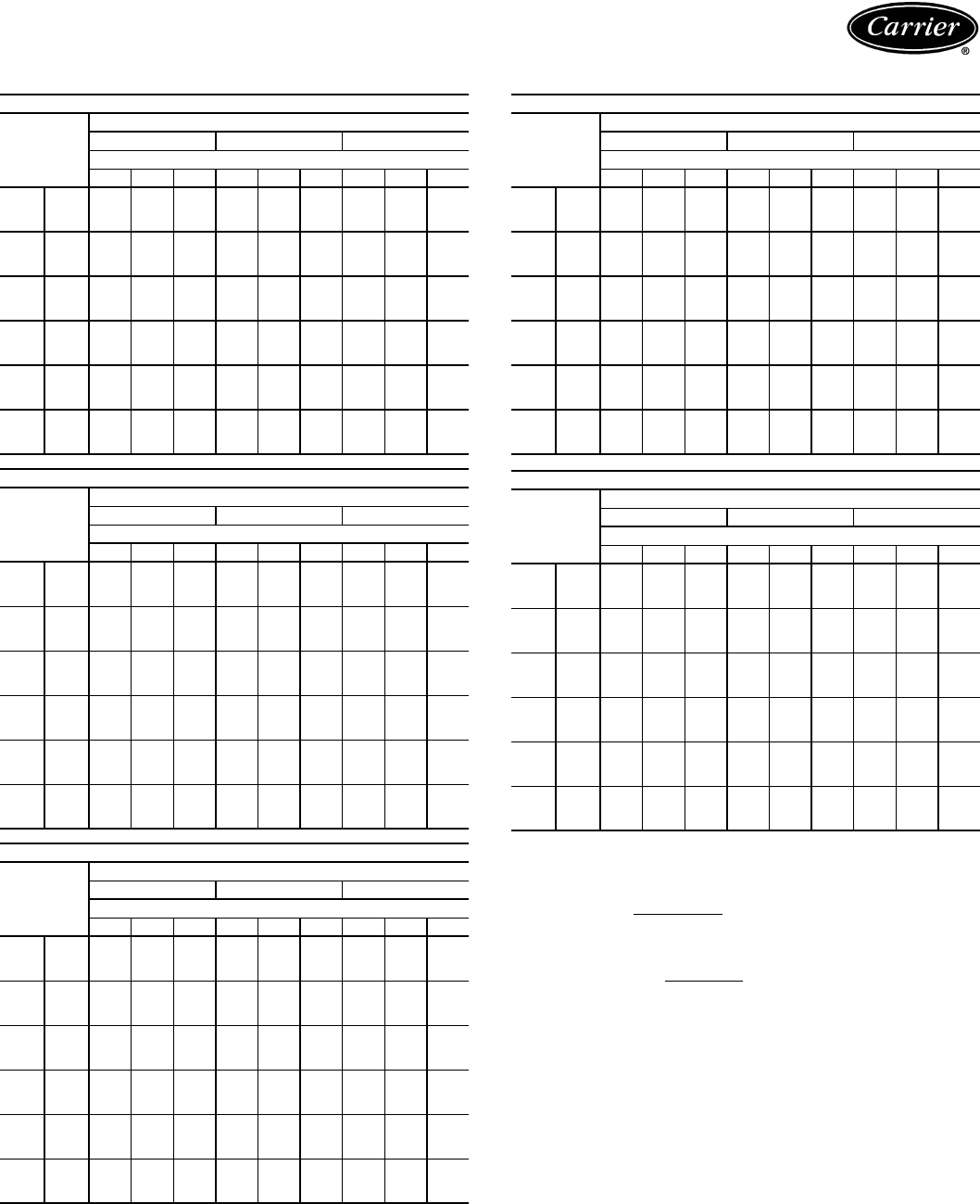
50
COMBINATION RATINGS — ENGLISH (cont)
LEGEND
NOTES:
1. Direct interpolation is permissible. Do not extrapolate.
2. SHC is based on 80 F db air entering indoor coil.
3. Formulas:
Lwb = wet-bulb temperature corresponding to enthalpy air leaving indoor coil
(hlwb)
where hewb = enthalpy of air entering evaporator coil (Btuh/lb).
4. Capacities are based on 25 actual ft (40 equivalent ft) of interconnecting piping
sized to the outdoor unit field connections. (Equivalent length is equal to the
actual length plus a 50% allowance for fitting losses.) For other equivalent
lengths, refer to the Carrier System Design Manual, Part 3, for line losses.
38AKS024/40RM028 WITH STANDARD 3-ROW COIL
Temp (F)
Air Entering
Condenser
(Edb)
Evaporator Air — Cfm
7500 10,000 12,500
Evaporator Air — Ewb (F)
72 67 62 72 67 62 72 67 62
85
TC 250.6 229.7 215.7 259.1 238.4 229.3 263.2 246.6 240.5
SHC 139.5 181.8 213.8 159.6 212.6 229.3 179.4 240.0 240.5
kW 17.51 16.71 16.18 17.83 17.04 16.70 17.99 17.36 17.12
95
TC 238.6 218.2 205.9 246.5 226.4 219.2 250.1 234.4 230.1
SHC 135.0 177.2 204.8 155.2 207.7 219.2 175.0 234.6 230.1
kW 18.92 18.00 17.45 19.27 19.37 18.04 19.43 18.73 18.53
100
TC 234.5 213.3 201.2 242.6 221.6 214.9 246.1 230.0 226.1
SHC 133.5 175.2 200.5 153.8 205.7 214.9 173.7 232.7 226.1
kW 19.49 18.58 18.06 19.84 18.94 18.65 19.99 19.30 19.13
105
TC 232.4 211.3 199.5 240.3 219.5 213.2 243.7 227.8 224.3
SHC 132.7 174.4 199.0 153.0 204.9 213.2 172.9 231.7 224.3
kW 19.74 18.79 18.26 20.10 19.16 18.87 20.26 19.54 19.38
115
TC 228.0 207.4 196.3 235.6 215.3 209.6 238.8 223.4 220.5
SHC 131.1 172.8 196.0 151.3 203.1 209.6 171.3 229.8 220.5
kW 20.25 19.22 18.66 20.63 19.61 19.33 20.79 20.02 18.99
125
TC —194.3 185.2 —201.4 197.8 ——208.0
SHC —167.5 185.2 —197.4 197.8 ——208.0
kW —20.48 19.88 —20.96 20.72 ——21.40
38AKS028/40RM024 WITH STANDARD 3-ROW COIL
Temp (F)
Air Entering
Condenser
(Edb)
Evaporator Air — Cfm
6000 8000 10,000
Evaporator Air — Ewb (F)
72 67 62 72 67 62 72 67 62
85
TC 276.7 254.2 231.0 289.4 267.4 245.0 297.0 276.2 256.3
SHC 139.7 174.3 221.2 156.4 201.3 245.0 171.3 226.0 256.3
kW 21.72 20.72 19.69 22.28 21.30 20.31 22.62 21.70 20.81
95
TC 265.3 244.1 222.8 276.9 256.1 236.3 283.6 264.4 247.1
SHC 135.3 170.1 214.1 151.9 196.6 236.3 166.5 220.6 247.1
kW 23.45 22.43 21.41 24.00 23.00 22.05 24.32 23.41 22.57
100
TC 259.0 238.0 217.3 270.4 249.7 230.7 276.7 258.0 241.6
SHC 132.9 167.6 209.2 149.5 193.8 230.7 164.1 217.6 241.6
kW 24.28 23.18 22.11 24.87 23.79 22.81 25.20 24.22 23.37
105
TC 253.0 232.6 212.8 263.8 243.7 226.0 269.7 251.7 236.6
SHC 130.6 165.4 205.4 147.1 191.3 226.0 161.6 214.8 236.6
kW 25.03 23.85 22.69 25.66 24.49 23.46 26.01 24.96 24.08
115
TC 240.9 222.0 204.1 250.7 231.9 216.6 255.6 239.4 226.7
SHC 126.0 161.1 197.7 142.4 186.3 216.6 156.7 209.2 226.7
kW 26.63 25.34 24.11 27.29 26.01 24.97 27.63 26.52 25.65
125
TC —210.5 193.6 —219.8 206.1 ——216.1
SHC —156.4 188.6 —181.2 206.1 ——216.1
kW —26.82 25.59 —27.50 26.50 ——27.23
38AKS028/40RM028 WITH STANDARD 3-ROW COIL
Temp (F)
Air Entering
Condenser
(Edb)
Evaporator Air — Cfm
7500 10,000 12,500
Evaporator Air — Ewb (F)
72 67 62 72 67 62 72 67 62
85
TC 298.5 274.6 252.4 310.3 286.1 267.8 316.9 295.7 280.8
SHC 157.1 200.0 247.5 177.6 232.2 267.8 197.3 261.4 280.8
kW 22.69 21.63 20.64 23.21 22.14 21.32 23.51 22.56 21.90
95
TC 285.4 262.5 242.8 296.2 273.1 257.5 302.0 282.2 270.0
SHC 152.2 195.1 238.6 172.6 226.9 257.5 192.3 255.5 270.0
kW 24.41 23.31 22.36 24.93 23.82 23.07 25.21 24.26 23.67
100
TC 278.8 255.7 236.9 289.3 266.2 251.7 294.9 275.3 264.2
SHC 149.8 192.4 233.2 170.2 224.0 251.7 190.0 252.5 264.2
kW 25.31 24.10 23.13 25.85 24.65 23.90 26.14 25.13 24.55
105
TC 271.9 249.3 231.7 281.9 259.3 246.2 287.1 268.2 258.4
SHC 147.3 189.8 228.5 167.6 221.2 246.2 187.4 249.4 258.4
kW 26.13 24.82 23.79 26.72 25.40 24.64 27.02 25.92 25.35
115
TC 258.1 236.6 221.4 267.2 245.8 235.3 271.6 254.2 246.9
SHC 142.2 184.7 219.0 162.4 215.6 235.3 182.2 243.3 246.9
kW 27.80 26.33 25.30 28.41 26.96 26.24 28.72 27.53 27.03
125
TC —224.0 210.2 ——224.3 ———
SHC —179.5 208.8 ——224.3 ———
kW —27.80 26.80 ——27.82 ———
——
Out of Range
Edb —Entering Dry Bulb
Ewb —Entering Wet Bulb
kW —Compressor Motor Power Input
SHC —Sensible Heat Capacity (1000 Btuh) Gross
TC —Total Capacity (1000 Btuh) Gross
38AKS028/40RM034 WITH STANDARD 3-ROW COIL
Temp (F)
Air Entering
Condenser
(Edb)
Evaporator Air — Cfm
9000 12,000 15,000
Evaporator Air — Ewb (F)
72 67 62 72 67 62 72 67 62
85
TC 317.8 291.3 271.9 328.5 302.8 289.0 334.2 312.9 302.9
SHC 172.3 224.7 268.2 199.4 261.6 289.0 221.4 295.1 302.9
kW 23.55 22.37 21.51 24.02 22.88 22.27 24.28 23.33 22.88
95
TC 302.9 277.5 260.7 312.6 288.1 277.0 317.6 297.8 290.3
SHC 166.7 219.2 258.0 194.0 255.7 277.0 215.9 288.5 290.3
kW 25.25 24.03 23.22 25.72 24.54 24.01 25.95 25.01 24.64
100
TC 295.9 270.3 254.3 305.4 280.8 270.7 310.1 290.5 284.0
SHC 164.0 216.4 252.3 191.5 252.8 270.7 213.4 285.3 284.0
kW 26.20 24.86 24.03 26.69 25.41 24.89 26.93 25.92 25.58
105
TC 288.2 263.1 248.3 297.1 273.2 264.4 301.5 282.6 277.3
SHC 161.1 213.5 246.8 188.7 249.7 264.4 210.5 281.8 277.3
kW 27.08 25.62 24.76 27.61 26.21 25.70 27.86 26.76 26.45
115
TC —248.9 236.5 —258.1 251.7 ——263.9
SHC —207.9 236.1 —243.6 251.7 ——263.9
kW —27.17 26.32 —27.80 27.36 ——28.20
125
TC ——224.6 ——————
SHC ——224.5 ——————
kW ——27.84 ——————
38AKS034/40RM028 WITH STANDARD 3-ROW COIL
Temp (F)
Air Entering
Condenser
(Edb)
Evaporator Air — Cfm
7500 10,000 12,500
Evaporator Air — Ewb (F)
72 67 62 72 67 62 72 67 62
85
TC 322.9 298.4 272.1 336.1 311.1 287.8 344.0 321.0 301.3
SHC 166.0 209.6 265.5 186.7 242.5 287.8 206.3 272.4 301.3
kW 24.75 23.82 22.82 25.25 24.30 23.42 25.55 24.68 23.93
95
TC 310.6 286.4 262.1 323.0 298.4 277.7 330.3 308.1 291.0
SHC 161.5 204.7 256.4 182.1 237.3 277.6 201.8 266.8 291.0
kW 26.56 25.44 24.31 27.14 26.00 25.03 27.48 26.45 25.65
100
TC 304.2 279.9 256.5 316.5 291.8 272.1 323.5 301.5 285.4
SHC 159.1 202.1 251.2 179.8 234.5 272.1 199.5 263.9 285.4
kW 27.51 26.29 25.12 28.12 26.89 25.90 28.47 27.38 26.57
105
TC 297.9 274.0 251.9 309.6 285.5 267.2 316.2 295.0 280.3
SHC 156.8 199.7 247.0 177.4 231.9 267.2 197.1 261.1 280.3
kW 28.38 27.06 25.83 29.03 27.69 26.68 29.40 28.22 27.40
115
TC 284.2 260.6 204.7 295.2 271.5 255.9 301.2 280.9 268.6
SHC 151.8 194.4 236.7 172.3 226.2 255.9 192.1 254.9 268.6
kW 30.02 28.57 27.34 30.70 29.34 28.28 31.06 29.82 29.06
125
TC 271.2 247.3 229.1 281.7 257.8 244.4 287.2 267.3 257.2
SHC 147.0 189.0 226.1 167.6 220.6 244.4 187.4 249.0 257.2
kW 31.64 29.99 28.73 32.37 30.72 29.79 32.75 31.37 30.67
Ldb F = Edb F –SHCBtuh
1.10 x cfm
Ldb F: hlwb = hewb –TCBtuh
4.5 x cfm
Performance data (cont)
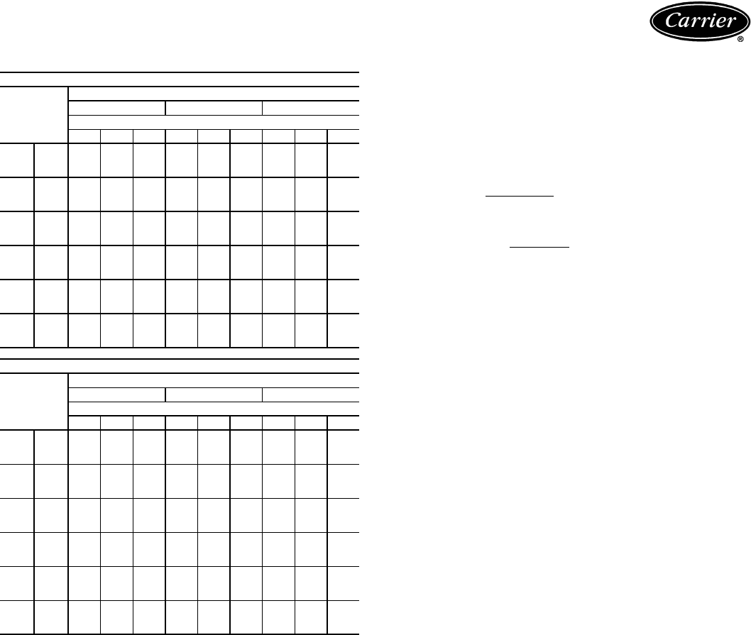
51
COMBINATION RATINGS — ENGLISH (cont)
LEGEND
1. Direct interpolation is permissible. Do not extrapolate.
2. SHC is based on 80 F db air entering indoor coil.
3. Formulas:
Lwb = wet-bulb temperature corresponding to enthalpy air leaving indoor coil
(hlwb)
where hewb = enthalpy of air entering evaporator coil (Btuh/lb).
4. Capacities are based on 25 actual ft (40 equivalent ft) of interconnecting piping
sized to the outdoor unit field connections. (Equivalent length is equal to the
actual length plus a 50% allowance for fitting losses.) For other equivalent
lengths, refer to the Carrier System Design Manual, Part 3, for line losses.
38AKS034/40RM034 WITH STANDARD 3-ROW COIL
Temp (F)
Air Entering
Condenser
(Edb)
Evaporator Air — Cfm
9000 12,000 15,000
Evaporator Air — Ewb (F)
72 67 62 72 67 62 72 67 62
85
TC 344.6 317.4 294.0 256.9 330.1 311.5 363.8 340.6 326.0
SHC 182.5 235.1 288.2 209.0 272.7 311.5 231.3 307.3 326.0
kW 25.57 24.55 23.65 26.04 25.02 24.32 26.30 25.42 24.87
95
TC 331.0 304.2 282.8 342.5 316.2 300.1 348.8 326.6 314.3
SHC 177.3 229.8 278.1 204.1 267.1 300.1 226.3 301.1 314.3
kW 27.51 26.27 25.27 28.05 26.82 26.08 28.34 27.31 26.74
100
TC 324.3 297.3 276.8 335.5 309.2 294.1 341.6 319.6 308.3
SHC 174.8 227.1 272.6 201.7 264.2 294.1 223.9 298.0 308.3
kW 28.51 27.16 26.14 29.08 27.76 27.00 29.38 28.28 27.72
105
TC 317.1 290.6 271.3 327.8 302.1 288.4 333.5 312.2 302.3
SHC 172.0 224.4 267.7 199.1 261.4 288.4 221.2 294.8 302.3
kW 29.45 27.98 26.91 30.05 28.62 27.85 30.36 29.18 28.63
115
TC 302.2 276.0 258.9 312.1 286.9 275.7 317.2 296.8 289.3
SHC 166.4 218.6 256.4 193.8 255.2 275.6 215.7 288.0 289.3
kW 31.12 29.51 28.46 31.74 30.19 29.49 32.05 30.80 30.33
125
TC 288.3 261.8 246.5 —272.5 263.3 —282.5 276.9
SHC 161.1 213.0 245.1 —249.4 263.3 —281.7 276.9
kW 32.83 30.99 29.93 —31.73 31.10 —32.43 32.04
38AKS044/40RM034 WITH STANDARD 3-ROW COIL
Temp (F)
Air Entering
Condenser
(Edb)
Evaporator Air — Cfm
9000 12,000 15,000
Evaporator Air — Ewb (F)
72 67 62 72 67 62 72 67 62
85
TC 413.7 382.6 344.5 432.1 399.8 364.9 443.5 412.4 382.2
SHC 208.7 260.9 334.0 234.4 300.7 364.9 257.8 338.8 382.2
kW 32.85 31.60 30.08 33.58 32.29 30.89 34.04 32.80 31.59
95
TC 399.2 368.7 333.6 416.4 384.9 353.6 426.9 397.2 370.5
SHC 203.2 255.4 324.2 229.1 294.7 353.6 252.3 332.2 370.5
kW 35.19 33.74 32.08 36.00 34.51 33.03 36.50 35.10 33.83
100
TC 391.8 361.5 328.0 408.3 377.3 347.7 418.3 389.4 364.4
SHC 200.4 252.5 319.0 226.4 291.7 347.7 249.4 328.7 364.4
kW 36.36 34.80 33.08 37.21 35.61 34.09 37.72 36.24 34.95
105
TC 384.2 354.1 322.2 400.1 369.5 341.7 409.6 381.5 358.2
SHC 197.5 249.6 313.8 223.6 288.5 341.7 246.5 325.2 358.2
kW 37.55 35.88 34.11 38.44 36.74 35.20 38.97 37.41 36.11
115
TC 368.5 339.0 310.2 383.1 353.5 329.2 391.7 365.1 345.2
SHC 191.5 243.6 302.9 217.8 282.1 329.2 240.6 318.1 345.2
kW 39.77 37.95 36.17 40.68 38.85 37.35 41.21 39.57 38.33
125
TC 352.6 323.3 297.2 366.4 337.2 316.0 374.3 348.7 331.7
SHC 185.5 237.4 291.1 212.2 275.5 316.0 234.8 310.8 331.7
kW 41.94 39.90 38.08 42.91 40.87 39.39 43.45 41.67 40.48
——
Out of Range
Edb —Entering Dry Bulb
Ewb —Entering Wet Bulb
kW —Compressor Motor Power Input
SHC —Sensible Heat Capacity (1000 Btuh) Gross
TC —Total Capacity (1000 Btuh) Gross
Ldb F = Edb F –SHCBtuh
1.10 x cfm
Ldb F: hlwb = hewb –TCBtuh
4.5 x cfm
52
COMBINATION RATINGS — 4-ROW HIGH-CAPACITY COILS — SI
See Legend and Notes on page 57.
38AK007/40RM007 WITH 4-ROW HIGH-CAPACITY COILS
Temp (C)
Air Entering
Condenser
(Edb)
Evaporator Air — L/s
850 1130 1420
Evaporator Air — Ewb (C)
17 19 22 17 19 22 17 19 22
29
TC 18.1 19.7 21.5 19.0 20.6 22.4 20.1 21.2 23.0
SHC 16.3 13.6 10.7 19.0 15.6 12.0 20.1 17.5 13.2
kW 4.93 5.16 5.40 5.06 5.29 5.53 5.21 5.37 5.61
35
TC 17.2 18.8 20.5 18.2 19.6 21.4 19.5 20.2 22.0
SHC 15.9 13.2 10.4 18.2 15.2 11.6 19.5 17.1 12.8
kW 5.19 5.45 5.72 5.35 5.58 5.85 5.69 5.67 5.94
38
TC 16.7 18.3 20.0 17.8 19.1 20.9 18.8 19.7 21.4
SHC 15.6 13.0 10.2 17.8 15.0 11.5 18.8 16.9 12.6
kW 5.31 5.59 5.87 5.49 5.72 6.00 5.67 5.82 6.09
41
TC 16.3 17.8 19.5 17.4 18.6 20.3 18.4 19.2 20.8
SHC 15.4 12.8 10.0 17.4 14.8 11.3 18.4 16.7 12.4
kW 5.44 5.73 6.02 5.64 5.87 6.16 5.82 5.96 6.25
46
TC 15.4 16.8 18.5 16.5 17.6 19.2 17.5 18.0 19.6
SHC 14.9 12.4 9.6 16.5 14.4 10.9 17.5 16.2 12.0
kW 5.69 5.99 6.31 5.93 6.14 6.46 6.12 6.23 6.55
38AK007/40RM008 WITH 4-ROW HIGH-CAPACITY COILS
Temp (C)
Air Entering
Condenser
(Edb)
Evaporator Air — L/s
1060 1420 1770
Evaporator Air — Ewb (C)
17 19 22 17 19 22 17 19 22
29
TC 19.3 21.0 22.9 20.6 21.8 23.7 21.7 22.4 24.2
SHC 18.7 15.5 12.0 20.6 18.0 13.6 21.7 20.2 15.0
kW 5.11 5.35 5.60 5.29 5.47 5.72 5.43 5.54 5.79
35
TC 18.3 20.0 21.8 19.8 20.8 22.6 20.8 21.3 23.1
SHC 18.3 15.1 11.6 19.8 17.6 13.2 20.8 19.7 14.6
kW 5.39 5.65 5.92 5.61 5.77 6.05 5.77 5.85 6.12
38
TC 17.9 19.5 21.3 19.4 20.3 22.0 20.4 20.7 22.5
SHC 17.9 14.9 11.5 19.4 17.4 13.0 20.4 19.5 14.4
kW 5.53 5.79 6.08 5.77 5.92 6.21 5.93 5.99 6.28
41
TC 17.5 19.0 20.7 18.9 19.7 21.4 19.9 20.2 21.9
SHC 17.5 14.7 11.3 18.9 17.2 12.8 19.9 19.2 14.2
kW 5.68 5.94 6.24 5.93 6.07 6.37 6.09 6.14 6.44
46
TC 16.7 17.9 17.9 18.0 18.5 18.5 18.9 19.0 19.0
SHC 16.7 14.3 14.3 18.0 16.7 16.7 18.9 18.7 18.7
kW 5.97 6.22 6.22 6.24 6.34 6.34 6.41 6.43 6.43
38AK008/40RM007 WITH 4-ROW HIGH-CAPACITY COILS
Temp (C)
Air Entering
Condenser
(Edb)
Evaporator Air — L/s
850 1130 1420
Evaporator Air — Ewb (C)
17 19 22 17 19 22 17 19 22
29
TC 21.6 23.5 25.4 22.8 24.7 26.7 23.6 25.5 27.5
SHC 18.0 15.2 12.3 20.8 17.2 13.5 23.2 19.1 14.7
kW 6.01 6.18 6.35 6.11 6.29 6.47 6.19 6.36 6.55
35
TC 20.8 22.6 24.5 21.9 23.7 25.6 22.6 24.4 26.4
SHC 17.6 14.8 11.9 20.3 16.8 13.1 22.6 18.7 14.3
kW 6.49 6.67 6.85 6.60 6.77 6.97 6.67 6.85 7.05
38
TC 20.3 22.1 24.0 21.4 23.2 25.1 22.2 23.9 25.8
SHC 17.4 14.6 11.7 20.1 16.6 12.9 22.2 18.5 14.1
kW 6.73 6.91 7.10 6.85 7.02 7.22 6.92 7.10 7.30
41
TC 19.8 21.6 23.4 20.9 22.6 24.5 21.7 23.3 25.2
SHC 17.1 14.4 11.5 19.8 16.4 12.7 21.7 18.3 13.9
kW 6.99 7.17 7.35 7.10 7.28 7.47 7.18 7.35 7.55
46
TC 18.9 20.5 22.3 19.9 21.5 23.3 20.8 22.1 23.9
SHC 16.7 13.9 11.0 19.3 16.0 12.3 20.8 17.8 13.5
kW 7.54 7.71 7.90 7.64 7.82 8.02 7.74 7.88 8.08
38AK008/40RM008 WITH 4-ROW HIGH-CAPACITY COILS
Temp (C)
Air Entering
Condenser
(Edb)
Evaporator Air — L/s
1060 1420 1770
Evaporator Air — Ewb (C)
17 19 22 17 19 22 17 19 22
29
TC 23.2 25.2 27.3 24.4 26.3 28.4 25.5 27.0 29.1
SHC 20.7 17.2 13.5 23.8 19.7 15.1 25.5 22.0 16.5
kW 6.18 6.36 6.55 6.28 6.47 6.66 6.39 6.53 6.72
35
TC 22.3 24.2 26.2 23.4 25.2 27.2 24.6 25.9 27.9
SHC 20.2 16.8 13.2 23.4 19.3 14.7 24.6 21.6 16.1
kW 6.68 6.86 7.06 6.77 6.96 7.17 6.90 7.02 7.24
38
TC 21.8 23.7 25.7 22.9 24.6 26.6 24.1 25.3 27.3
SHC 20.0 16.6 12.9 22.9 19.1 14.5 24.1 21.4 15.9
kW 6.93 7.11 7.31 7.03 7.21 7.42 7.15 7.28 7.49
41
TC 21.3 23.1 25.1 22.4 24.0 26.0 23.6 24.7 26.6
SHC 19.7 16.3 12.7 22.4 18.8 14.3 23.6 21.1 15.7
kW 7.19 7.37 7.57 7.29 7.46 7.67 7.41 7.53 7.74
46
TC 20.2 22.0 23.8 21.5 22.8 24.7 22.6 23.4 25.2
SHC 19.3 15.9 12.3 21.5 18.4 13.8 22.6 20.6 15.2
kW 7.73 7.91 8.12 7.86 8.01 8.21 7.97 8.08 8.29
38AK008/40RM012 WITH 4-ROW HIGH-CAPACITY COILS
Temp (C)
Air Entering
Condenser
(Edb)
Evaporator Air — L/s
1416 1888 2360
Evaporator Air — Ewb (C)
17 19 22 17 19 22 17 19 22
29
TC 25.6 27.2 29.4 27.3 28.1 30.1 28.5 28.8 30.7
SHC 25.5 20.8 15.8 27.3 24.1 17.8 28.5 27.0 19.7
kW 6.44 6.58 6.79 6.59 6.67 6.86 6.71 6.73 6.91
35
TC 24.7 26.1 28.1 26.3 27.0 28.9 27.4 27.6 29.4
SHC 24.7 20.4 15.4 26.3 23.6 17.4 27.4 26.4 19.3
kW 6.96 7.08 7.29 7.11 7.17 7.37 7.22 7.23 7.42
38
TC 24.2 25.5 27.5 25.8 26.3 28.2 26.8 27.0 28.7
SHC 24.2 20.2 15.2 25.8 23.4 17.2 26.8 26.2 19.1
kW 7.20 7.33 7.55 7.37 7.42 7.62 7.47 7.49 7.67
41
TC 23.7 24.9 26.8 25.2 25.7 27.5 26.2 26.3 28.0
SHC 23.7 20.0 15.0 25.2 23.1 16.9 26.2 25.8 18.9
kW 7.47 7.59 7.81 7.63 7.68 7.87 7.74 7.75 7.92
46
TC 22.6 23.6 25.4 24.1 24.3 26.0 25.0 25.0 26.4
SHC 22.6 19.5 14.5 24.1 22.6 16.5 25.0 25.0 18.4
kW 8.03 8.14 8.36 8.19 8.22 8.42 8.30 8.30 8.46
38AK012/40RM008 WITH 4-ROW HIGH-CAPACITY COILS
Temp (C)
Air Entering
Condenser
(Edb)
Evaporator Air — L/s
1060 1420 1770
Evaporator Air — Ewb (C)
17 19 22 17 19 22 17 19 22
29
TC 27.5 29.9 32.5 29.1 31.5 34.1 30.2 32.6 35.1
SHC 22.7 19.1 15.3 26.3 21.7 16.9 29.4 24.2 18.5
kW 7.78 8.04 8.32 7.95 8.22 8.51 8.07 8.34 8.63
35
TC 26.6 28.9 31.3 28.0 30.3 32.8 29.0 31.3 33.8
SHC 22.2 18.6 14.8 25.8 21.2 16.5 29.0 23.7 18.0
kW 8.40 8.66 8.95 8.56 8.83 9.13 8.68 8.95 9.25
38
TC 26.1 28.3 30.7 27.4 29.7 32.1 28.4 30.6 33.1
SHC 22.0 18.4 14.6 25.5 21.0 16.2 28.4 23.4 17.7
kW 8.73 8.98 9.27 8.87 9.14 9.44 9.00 9.26 9.56
41
TC 25.5 27.9 30.1 26.9 29.1 31.4 27.9 30.0 32.4
SHC 21.8 18.2 14.4 25.2 20.7 16.0 27.9 23.2 17.5
kW 9.05 9.41 9.59 9.20 9.46 9.76 9.32 9.58 9.88
46
TC 24.4 26.5 28.7 25.7 27.7 30.3 26.8 28.5 30.8
SHC 21.2 17.6 13.8 24.7 20.2 15.6 26.8 22.7 17.0
kW 9.77 10.00 10.27 9.92 10.16 10.71 10.03 10.26 10.55
Performance data (cont)
53
COMBINATION RATINGS — 4-ROW HIGH-CAPACITY COILS — SI (cont)
See Legend and Notes on page 57.
38AK012/40RM012 WITH 4-ROW HIGH-CAPACITY COILS
Temp (C)
Air Entering
Condenser
(Edb)
Evaporator Air — L/s
1420 1890 2360
Evaporator Air — Ewb (C)
17 19 22 17 19 22 17 19 22
29
TC 30.9 33.2 35.9 32.5 34.4 37.1 33.4 35.3 37.9
SHC 28.1 23.1 17.9 32.5 26.4 20.0 33.4 29.7 22.0
kW 7.92 8.18 8.47 8.10 8.32 8.62 7.55 8.41 8.70
35
TC 29.7 31.9 34.5 31.4 33.0 35.6 32.9 33.9 36.4
SHC 27.5 22.6 17.4 31.4 26.0 19.5 32.9 29.1 21.5
kW 8.53 8.77 9.08 8.71 8.90 9.21 8.89 9.00 9.30
38
TC 29.1 31.3 33.8 30.8 32.3 34.8 32.3 33.1 35.6
SHC 27.2 22.3 17.2 30.8 25.7 19.2 32.3 28.9 21.2
kW 8.83 9.08 9.38 9.03 9.20 9.51 9.20 9.30 9.60
41
TC 28.5 30.6 33.0 30.4 31.6 34.0 31.6 32.4 34.7
SHC 26.9 22.0 16.9 30.4 25.4 18.9 31.6 28.5 20.9
kW 9.14 9.39 9.69 9.47 9.50 9.81 9.51 9.60 9.90
46
TC 27.2 29.1 31.9 29.0 30.1 32.3 30.3 30.8 33.0
SHC 26.3 21.5 16.5 29.0 24.8 18.4 30.3 27.9 20.4
kW 9.83 10.05 10.63 10.04 10.17 10.46 10.20 10.27 10.54
38AK012/40RM014 WITH 4-ROW HIGH-CAPACITY COILS
Temp (C)
Air Entering
Condenser
(Edb)
Evaporator Air — L/s
1770 2360 2950
Evaporator Air — Ewb (C)
17 19 22 17 19 22 17 19 22
29
TC 32.4 34.9 37.7 34.4 36.2 38.9 36.0 37.0 39.7
SHC 31.3 25.8 19.8 34.4 29.9 22.3 36.0 33.6 24.7
kW 8.06 8.35 8.66 8.28 8.49 8.80 8.46 8.59 8.89
35
TC 31.1 33.6 36.2 33.2 34.7 37.4 34.8 35.5 38.1
SHC 30.6 25.3 19.3 33.2 29.3 21.8 34.8 32.9 24.1
kW 8.65 8.94 9.26 8.89 9.08 9.40 9.08 9.17 9.50
38
TC 30.5 32.8 35.5 32.6 34.0 36.6 34.1 34.7 37.3
SHC 30.5 25.0 19.1 32.6 29.0 21.6 34.1 32.5 23.9
kW 8.96 9.24 9.56 9.20 9.38 9.71 9.39 9.47 9.80
41
TC 30.1 32.1 34.6 32.1 33.2 35.7 33.4 33.9 36.4
SHC 30.1 24.7 18.7 32.1 28.7 21.3 33.4 32.1 23.6
kW 9.41 9.55 9.87 9.67 9.69 10.01 9.71 9.77 10.10
46
TC 28.7 30.6 33.0 30.6 31.6 33.9 31.9 32.2 34.5
SHC 28.7 24.1 18.2 30.6 28.0 20.7 31.9 31.3 23.0
kW 9.99 10.23 10.53 10.22 10.35 10.67 10.39 10.43 10.74
38AKS008/40RM007 WITH 4-ROW HIGH-CAPACITY COILS
Temp (C)
Air Entering
Condenser
(Edb)
Evaporator Air — L/s
850 1130 1420
Evaporator Air — Ewb (C)
17 19 22 17 19 22 17 19 22
29
TC 20.9 23.0 25.1 22.2 24.2 26.4 23.0 25.1 27.2
SHC 17.7 14.9 12.1 20.4 17.0 13.4 23.0 19.0 14.6
kW 5.40 5.60 5.79 5.53 5.72 5.90 5.61 5.80 5.98
35
TC 20.0 21.9 24.0 21.2 23.1 25.2 22.1 23.9 26.0
SHC 17.2 14.5 11.7 20.0 16.6 13.0 22.1 18.5 14.2
kW 5.82 6.06 6.29 5.97 6.20 6.42 6.07 6.28 6.51
38
TC 19.5 21.4 23.4 20.7 22.6 24.6 21.6 23.3 25.4
SHC 17.0 14.3 11.5 19.7 16.4 12.8 21.6 18.3 14.0
kW 6.02 6.28 6.53 6.18 6.43 6.67 6.30 6.51 6.76
41
TC 19.1 20.9 22.9 20.2 22.0 24.0 21.1 22.7 24.7
SHC 16.8 14.1 11.2 19.5 16.2 12.5 21.1 18.1 13.7
kW 6.22 6.49 6.76 6.38 6.65 6.91 6.52 6.74 7.00
46
TC 18.1 19.8 21.7 19.1 20.8 22.7 20.2 21.5 23.4
SHC 16.3 13.6 10.8 19.1 15.7 12.1 20.2 17.6 13.3
kW 6.63 6.93 7.23 6.79 7.09 7.40 6.99 7.20 7.49
38AKS008/40RM008 WITH 4-ROW HIGH-CAPACITY COILS
Temp (C)
Air Entering
Condenser
(Edb)
Evaporator Air — L/s
1060 1420 1770
Evaporator Air — Ewb (C)
17 19 22 17 19 22 17 19 22
29
TC 22.6 24.7 27.0 23.8 25.9 28.2 25.2 26.7 29.0
SHC 20.4 17.0 13.4 23.8 19.6 15.0 25.2 21.9 16.5
kW 5.61 5.81 6.00 5.72 5.92 6.11 5.84 5.98 6.17
35
TC 21.6 23.7 25.8 22.8 24.7 26.9 24.2 25.4 27.6
SHC 19.9 16.5 13.0 22.8 19.1 14.6 24.2 21.4 16.0
kW 6.06 6.30 6.53 6.20 6.41 6.65 6.35 6.49 6.72
38
TC 21.1 23.1 25.2 22.4 24.1 26.2 23.6 24.8 26.9
SHC 19.6 16.3 12.8 22.4 18.8 14.3 23.6 21.2 15.8
kW 6.27 6.53 6.79 6.43 6.65 6.90 6.59 6.74 6.98
41
TC 20.5 22.5 24.6 21.9 23.5 25.6 23.1 24.1 26.2
SHC 19.4 16.1 12.6 21.9 18.6 14.1 23.1 20.9 15.6
kW 6.48 6.75 7.03 6.67 6.88 7.15 6.83 6.97 7.24
46
TC 19.4 21.3 23.3 20.9 22.2 24.2 22.0 22.8 24.8
SHC 18.8 15.6 12.1 20.9 18.1 13.7 22.0 20.4 15.1
kW 6.90 7.21 7.52 7.14 7.36 7.66 7.33 7.45 7.76
38AKS008/40RM012 WITH 4-ROW HIGH-CAPACITY COILS
Temp (C)
Air Entering
Condenser
(Edb)
Evaporator Air — L/s
1420 1890 2360
Evaporator Air — Ewb (C)
17 19 22 17 19 22 17 19 22
29
TC 25.2 26.8 29.2 27.0 27.8 30.0 28.3 28.6 30.7
SHC 25.2 20.7 15.8 27.0 23.9 17.7 28.3 26.9 19.7
kW 5.88 6.03 6.22 6.04 6.11 6.28 6.15 6.17 6.33
35
TC 24.2 25.6 27.8 25.9 26.5 28.6 27.0 27.2 29.1
SHC 24.2 20.2 15.3 25.9 23.4 17.3 27.0 26.3 19.2
kW 6.38 6.54 6.77 6.57 6.64 6.85 6.69 6.71 6.90
38
TC 23.7 25.0 27.1 25.3 25.8 27.9 26.4 26.5 28.4
SHC 23.7 20.0 15.0 25.3 23.2 17.0 26.4 25.9 19.0
kW 6.62 6.78 7.03 6.83 6.88 7.11 6.95 6.96 7.16
41
TC 23.1 24.3 26.4 24.7 25.2 27.1 25.8 25.9 27.6
SHC 23.1 19.7 14.8 24.7 22.9 16.8 25.8 25.6 18.8
kW 6.86 7.02 7.29 7.08 7.12 7.37 7.21 7.22 7.42
46
TC 22.1 23.0 25.0 23.5 23.8 25.6 24.6 24.6 26.0
SHC 22.1 19.2 14.3 23.5 22.3 16.3 24.6 24.6 18.3
kW 7.35 7.50 7.81 7.58 7.62 7.89 7.74 7.74 7.95
38AKS009/40RM008 WITH 4-ROW HIGH-CAPACITY COILS
Temp (C)
Air Entering
Condenser
(Edb)
Evaporator Air — L/s
1060 1420 1770
Evaporator Air — Ewb (C)
17 19 22 17 19 22 17 19 22
29
TC 26.1 28.6 31.3 27.6 30.2 32.9 28.7 31.2 33.9
SHC 22.0 18.6 15.1 25.5 21.2 16.7 28.7 23.7 18.2
kW 7.21 7.52 7.82 7.40 7.70 8.01 7.54 7.83 8.13
35
TC 24.9 27.3 29.8 26.3 28.7 31.3 27.4 29.7 32.3
SHC 21.4 18.0 14.5 24.9 20.7 16.1 27.4 23.1 17.6
kW 7.73 8.08 8.43 7.94 8.28 8.62 8.10 8.42 8.76
38
TC 24.2 26.6 29.1 25.7 28.0 30.5 26.8 28.9 31.5
SHC 21.1 17.8 14.2 24.6 20.4 15.8 26.8 22.8 17.4
kW 7.98 8.35 8.72 8.21 8.56 8.93 8.38 8.70 9.07
41
TC 23.6 25.9 28.4 25.0 27.3 29.8 26.2 28.1 30.7
SHC 20.8 17.5 13.9 24.2 20.1 15.6 26.2 22.5 17.0
kW 8.24 8.63 9.02 8.48 8.86 9.24 8.67 8.99 9.37
46
TC 22.4 24.5 26.9 23.6 25.8 28.1 25.0 26.5 28.9
SHC 20.2 16.9 13.4 23.6 19.5 15.0 25.0 21.9 16.5
kW 8.75 9.17 9.60 8.99 9.40 9.84 9.26 9.54 9.98

54
COMBINATION RATINGS — 4-ROW HIGH-CAPACITY COILS — SI (cont)
See Legend and Notes on page 57.
38AKS009/40RM012 WITH 4-ROW HIGH-CAPACITY COILS
Temp (C)
Air Entering
Condenser
(Edb)
Evaporator Air — L/s
1420 1890 2360
Evaporator Air — Ewb (C)
17 19 22 17 19 22 17 19 22
29
TC 29.1 31.5 34.3 31.0 32.7 35.6 32.6 33.7 36.4
SHC 27.2 22.5 17.4 31.0 25.8 19.5 32.6 28.9 21.5
kW 7.75 8.04 8.36 7.97 8.17 8.49 8.17 8.27 8.57
35
TC 27.7 30.0 32.7 29.7 31.1 33.8 31.2 32.0 34.6
SHC 26.5 21.8 16.9 29.7 25.2 18.9 31.2 28.3 20.9
kW 8.30 8.62 8.99 8.58 8.76 9.12 8.78 8.89 9.22
38
TC 27.0 29.2 31.9 29.0 30.3 32.9 30.5 31.2 33.6
SHC 26.2 21.5 16.6 29.0 24.9 18.6 30.5 28.0 20.6
kW 8.58 8.91 9.30 8.88 9.06 9.44 9.10 9.20 9.54
41
TC 26.4 28.4 31.0 28.3 29.5 32.0 29.8 30.4 32.7
SHC 25.8 21.2 16.3 28.3 24.6 18.3 29.8 27.6 20.3
kW 8.87 9.20 9.61 9.19 9.37 9.76 9.42 9.51 9.86
46
TC 25.1 26.8 29.3 27.0 27.9 30.2 28.3 28.7 30.9
SHC 25.1 20.6 15.7 27.0 23.9 17.7 28.3 26.9 19.7
kW 9.43 9.75 10.20 9.78 9.95 10.36 10.03 10.09 10.48
38AKS012/40RM008 WITH 4-ROW HIGH-CAPACITY COILS
Temp (C)
Air Entering
Condenser
(Edb)
Evaporator Air — L/s
1060 1420 1770
Evaporator Air — Ewb (C)
17 19 22 17 19 22 17 19 22
29
TC 26.1 28.6 31.3 27.6 30.2 32.9 28.7 31.2 33.9
SHC 22.0 18.6 15.1 25.5 21.2 16.7 28.7 23.7 18.2
kW 7.21 7.52 7.82 7.40 7.70 8.01 7.54 7.83 8.13
35
TC 24.9 27.3 29.8 26.3 28.7 31.3 27.4 29.7 32.3
SHC 21.4 18.0 14.5 24.9 20.7 16.1 27.4 23.1 17.6
kW 7.73 8.08 8.43 7.94 8.28 8.62 8.10 8.42 8.76
38
TC 24.2 26.6 29.1 25.7 28.0 30.5 26.8 28.9 31.5
SHC 21.1 17.8 14.2 24.6 20.4 15.8 26.8 22.8 17.4
kW 7.98 8.35 8.72 8.21 8.56 8.93 8.38 8.70 9.07
41
TC 23.6 25.9 28.4 25.0 27.3 29.8 26.2 28.1 30.7
SHC 20.8 17.5 13.9 24.2 20.1 15.6 26.2 22.5 17.0
kW 8.24 8.63 9.02 8.48 8.86 9.24 8.67 8.99 9.37
46
TC 22.4 24.5 26.9 23.6 25.8 28.1 25.0 26.5 28.9
SHC 20.2 16.9 13.4 23.6 19.5 15.0 25.0 21.9 16.5
kW 8.75 9.17 9.60 8.99 9.40 9.84 9.26 9.54 9.98
38AKS012/40RM012 WITH 4-ROW HIGH-CAPACITY COILS
Temp (C)
Air Entering
Condenser
(Edb)
Evaporator Air — L/s
1420 1890 2360
Evaporator Air — Ewb (C)
17 19 22 17 19 22 17 19 22
29
TC 29.1 31.5 34.3 31.0 32.7 35.6 32.6 33.7 36.4
SHC 27.2 22.5 17.4 31.0 25.8 19.5 32.6 28.9 21.5
kW 7.75 8.04 8.36 7.97 8.17 8.49 8.17 8.27 8.57
35
TC 27.7 30.0 32.7 29.7 31.1 33.8 31.2 32.0 34.6
SHC 26.5 21.8 16.9 29.7 25.2 18.9 31.2 28.3 20.9
kW 8.30 8.62 8.99 8.58 8.76 9.12 8.78 8.89 9.22
38
TC 27.0 29.2 31.9 29.0 30.3 32.9 30.5 31.2 33.6
SHC 26.2 21.5 16.6 29.0 24.9 18.6 30.5 28.0 20.6
kW 8.58 8.91 9.30 8.88 9.06 9.44 9.10 9.20 9.54
41
TC 26.4 28.4 31.0 28.3 29.5 32.0 29.8 30.4 32.7
SHC 25.8 21.2 16.3 28.3 24.6 18.3 29.8 27.6 20.3
kW 8.87 9.20 9.61 9.19 9.37 9.76 9.42 9.51 9.86
46
TC 25.1 26.8 29.3 27.0 27.9 30.2 28.3 28.7 30.9
SHC 25.1 20.6 15.7 27.0 23.9 17.7 28.3 26.9 19.7
kW 9.43 9.75 10.20 9.78 9.95 10.36 10.03 10.09 10.48
38AKS012/40RM014 WITH 4-ROW HIGH-CAPACITY COILS
Temp (C)
Air Entering
Condenser
(Edb)
Evaporator Air — L/s
1770 2360 2950
Evaporator Air — Ewb (C)
17 19 22 17 19 22 17 19 22
29
TC 30.7 33.4 36.4 33.0 34.7 37.6 34.7 35.5 38.5
SHC 30.4 26.4 22.0 33.0 30.1 24.3 34.7 33.3 26.5
kW 7.84 8.16 8.48 8.10 8.31 8.64 8.30 8.41 8.74
35
TC 29.3 31.7 34.6 31.6 32.9 35.8 33.2 33.7 36.5
SHC 29.3 25.6 21.2 31.6 29.2 23.5 33.2 32.3 25.6
kW 8.43 8.78 9.14 8.75 8.95 9.31 8.96 9.04 9.41
38
TC 28.7 30.9 33.7 30.9 32.0 34.8 32.4 32.8 35.5
SHC 28.7 25.2 20.8 30.9 28.8 23.1 32.4 31.8 25.2
kW 8.75 9.09 9.48 9.07 9.26 9.65 9.29 9.35 9.74
41
TC 28.0 30.0 32.8 30.2 31.1 33.8 31.6 31.8 34.5
SHC 28.0 24.8 20.4 30.2 28.4 22.7 31.6 31.2 24.8
kW 9.06 9.40 9.81 9.40 9.57 9.98 9.63 9.67 10.08
46
TC 26.7 28.3 30.9 28.6 29.3 31.9 30.0 30.1 32.5
SHC 26.7 24.0 19.6 28.6 27.5 21.8 30.0 30.1 23.9
kW 9.65 9.98 10.45 10.02 10.15 10.61 10.26 10.27 10.71
38AKS013/40RM008 WITH 4-ROW HIGH-CAPACITY COILS
Temp (C)
Air Entering
Condenser
(Edb)
Evaporator Air — L/s
1060 1420 1770
Evaporator Air — Ewb (C)
17 19 22 17 19 22 17 19 22
29
TC 27.1 29.7 32.5 28.8 31.5 34.3 29.9 32.6 35.5
SHC 22.5 19.1 15.6 26.1 21.8 17.2 29.1 24.2 18.8
kW 6.81 7.06 7.30 6.97 7.21 7.45 7.08 7.31 7.54
35
TC 25.8 28.4 31.1 27.4 30.0 32.7 28.5 31.1 33.9
SHC 21.9 18.5 15.0 25.4 21.2 16.7 28.5 23.6 18.2
kW 7.37 7.66 7.95 7.55 7.83 8.12 7.67 7.95 8.23
38
TC 25.2 27.7 30.3 26.7 29.2 31.9 27.8 30.2 33.0
SHC 21.6 18.2 14.7 25.1 20.9 16.4 27.8 23.3 17.9
kW 7.64 7.96 8.26 7.84 8.14 8.44 7.97 8.26 8.57
41
TC 24.5 27.0 29.6 26.0 28.5 31.1 27.2 29.4 32.1
SHC 21.3 17.9 14.4 24.7 20.6 16.1 27.2 23.0 17.6
kW 7.90 8.24 8.57 8.11 8.44 8.76 8.26 8.55 8.88
46
TC 23.2 25.5 28.0 24.6 26.9 29.4 25.9 27.7 30.3
SHC 20.6 17.3 13.8 24.0 20.0 15.5 25.9 22.3 17.0
kW 8.44 8.82 9.19 8.66 9.03 9.40 8.87 9.15 9.52
38AKS013/40RM012 WITH 4-ROW HIGH-CAPACITY COILS
Temp (C)
Air Entering
Condenser
(Edb)
Evaporator Air — L/s
1420 1890 2360
Evaporator Air — Ewb (C)
17 19 22 17 19 22 17 19 22
29
TC 30.2 32.8 35.7 32.0 34.1 37.1 33.8 35.1 38.0
SHC 27.7 22.9 18.0 32.0 26.3 20.0 33.8 29.5 22.0
kW 7.08 7.30 7.54 7.23 7.40 7.64 7.38 7.48 7.70
35
TC 28.8 31.2 34.1 30.7 32.4 35.2 32.4 33.4 36.0
SHC 27.0 22.3 17.3 30.7 25.7 19.4 32.4 28.9 21.4
kW 7.68 7.94 8.23 7.89 8.06 8.33 8.05 8.15 8.41
38
TC 28.1 30.4 33.2 30.0 31.6 34.3 31.6 32.5 35.1
SHC 26.7 22.0 17.0 30.0 25.4 19.1 31.6 28.5 21.0
kW 7.98 8.25 8.56 8.21 8.38 8.67 8.38 8.48 8.76
41
TC 27.3 29.6 32.3 29.3 30.7 33.3 30.9 31.6 34.1
SHC 26.3 21.7 16.7 29.3 25.1 18.7 30.9 28.1 20.7
kW 8.27 8.55 8.88 8.53 8.69 9.00 8.71 8.80 9.09
46
TC 25.9 27.9 30.4 27.9 29.0 31.4 29.3 29.8 32.1
SHC 25.6 21.0 16.1 27.9 24.4 18.1 29.3 27.5 20.1
kW 8.86 9.15 9.52 9.16 9.31 9.65 9.37 9.43 9.75
Performance data (cont)
55
COMBINATION RATINGS — 4-ROW HIGH-CAPACITY COILS — SI (cont)
See Legend and Notes on page 57.
38AKS013/40RM014 WITH 4-ROW HIGH-CAPACITY COILS
Temp (C)
Air Entering
Condenser
(Edb)
Evaporator Air — L/s
1770 2360 2950
Evaporator Air — Ewb (C)
17 19 22 17 19 22 17 19 22
29
TC 31.9 34.7 37.8 34.1 36.1 39.2 35.9 37.0 40.1
SHC 31.0 25.8 19.9 34.1 29.9 22.5 35.9 33.5 24.9
kW 7.23 7.47 7.71 7.42 7.59 7.82 7.57 7.66 7.89
35
TC 30.3 33.0 35.9 32.7 34.2 37.2 34.3 35.9 38.0
SHC 30.3 25.1 19.3 32.7 29.1 21.8 34.3 33.4 24.2
kW 7.87 8.14 8.43 8.10 8.28 8.56 8.28 8.69 8.63
38
TC 29.6 32.1 35.0 31.9 33.3 36.2 33.5 34.1 36.9
SHC 29.6 24.7 18.9 31.9 28.8 21.5 33.5 32.3 23.8
kW 8.19 8.47 8.78 8.44 8.61 8.91 8.62 8.69 8.98
41
TC 28.9 31.2 34.0 31.2 32.4 35.2 32.7 33.2 35.9
SHC 28.9 24.4 18.6 31.2 28.4 21.1 32.7 31.8 23.5
kW 8.50 8.79 9.13 8.78 8.93 9.26 8.96 9.02 9.33
46
TC 27.5 29.4 32.1 29.6 30.4 33.1 31.0 31.2 33.8
SHC 27.5 23.7 17.9 29.6 27.6 20.4 31.0 30.8 22.8
kW 9.13 9.42 9.80 9.44 9.56 9.93 9.64 9.67 10.02
38AKS014/40RM012 WITH 4-ROW HIGH-CAPACITY COILS
Temp (C)
Air Entering
Condenser
(Edb)
Evaporator Air — L/s
1420 1890 2360
Evaporator Air — Ewb (C)
17 19 22 17 19 22 17 19 22
29
TC 33.9 37.0 40.4 35.9 38.7 42.1 37.7 39.9 43.4
SHC 29.5 24.7 19.7 34.2 28.1 21.8 37.7 31.4 23.8
kW 8.27 8.50 8.75 8.43 8.62 8.86 8.55 8.71 8.94
35
TC 32.4 35.3 38.6 34.4 36.9 40.2 36.2 38.1 41.3
SHC 28.8 24.0 19.0 33.3 27.4 21.1 36.2 30.8 23.1
kW 9.03 9.31 9.60 9.22 9.46 9.74 9.39 9.55 9.84
38
TC 31.7 34.5 37.7 33.6 36.0 39.2 35.4 37.1 40.3
SHC 28.4 23.6 18.7 33.0 27.0 20.8 35.4 30.4 22.8
kW 9.40 9.70 10.02 9.61 9.86 10.18 9.80 9.97 10.27
41
TC 31.0 33.7 36.8 32.8 35.1 38.3 34.7 36.5 39.3
SHC 28.1 23.3 18.3 32.8 26.7 20.4 34.7 30.2 22.4
kW 9.77 10.09 10.44 9.98 10.25 10.60 10.21 10.51 10.70
46
TC 29.5 32.0 35.0 31.4 33.3 36.3 33.1 34.3 37.2
SHC 27.4 22.6 17.7 31.4 26.0 19.7 33.1 29.2 21.8
kW 10.49 10.86 11.26 10.77 11.03 11.42 11.01 11.17 11.53
38AKS014/40RM014 WITH 4-ROW HIGH-CAPACITY COILS
Temp (C)
Air Entering
Condenser
(Edb)
Evaporator Air — L/s
1770 2360 2950
Evaporator Air — Ewb (C)
17 19 22 17 19 22 17 19 22
29
TC 36.0 39.4 42.8 38.0 41.0 44.7 40.2 42.2 45.9
SHC 33.2 27.5 21.6 38.0 31.7 24.2 40.2 35.6 26.7
kW 8.36 8.59 8.81 8.50 8.70 8.92 8.64 8.77 8.98
35
TC 34.2 38.0 41.4 36.4 38.9 42.3 38.3 40.0 43.4
SHC 32.3 27.0 21.1 36.4 30.8 23.4 38.3 34.8 25.8
kW 9.16 9.72 10.01 9.36 9.57 9.85 9.52 9.67 9.93
38
TC 33.4 36.4 39.7 35.6 37.9 41.2 37.5 39.0 42.6
SHC 31.8 26.3 20.5 35.6 30.5 23.0 37.5 34.2 25.5
kW 9.55 9.86 10.17 9.78 10.00 10.30 9.96 10.10 10.59
41
TC 32.8 35.5 38.7 35.0 37.2 40.1 36.9 38.2 41.1
SHC 31.6 25.9 20.1 35.0 30.2 22.7 36.9 34.2 25.0
kW 10.09 10.27 10.60 10.34 10.57 10.75 10.55 10.70 10.85
46
TC 30.9 33.6 36.6 33.2 34.9 37.9 34.9 35.7 38.8
SHC 30.5 25.2 19.3 33.2 29.3 21.9 34.9 32.9 24.3
kW 10.69 11.06 11.45 11.01 11.24 11.62 11.25 11.34 11.72
38AKS014/40RM016 WITH 4-ROW HIGH-CAPACITY COILS
Temp (C)
Air Entering
Condenser
(Edb)
Evaporator Air — L/s
2120 2830 3540
Evaporator Air — Ewb (C)
17 19 22 17 19 22 17 19 22
29
TC 38.6 42.2 46.1 41.3 44.0 47.9 43.6 45.2 49.2
SHC 36.8 29.0 20.1 41.3 34.5 23.5 43.6 39.5 26.7
kW 8.46 8.68 8.89 8.63 8.79 8.98 8.76 8.85 9.04
35
TC 36.9 40.2 43.9 39.6 41.9 45.6 41.8 42.9 46.7
SHC 36.0 28.4 19.6 39.6 33.8 23.0 41.8 38.7 26.2
kW 9.31 9.57 9.85 9.52 9.70 9.97 9.69 9.77 10.04
38
TC 36.0 39.2 42.8 38.8 40.8 44.5 40.9 42.2 45.5
SHC 36.0 28.1 19.3 38.8 33.7 22.7 40.9 38.8 25.9
kW 9.72 10.00 10.31 9.96 10.14 10.45 10.14 10.42 10.52
41
TC 35.5 38.2 41.8 38.0 39.7 43.3 40.0 40.7 44.3
SHC 35.5 27.9 19.1 38.0 33.3 22.5 40.0 37.9 25.7
kW 10.30 10.43 10.76 10.40 10.57 10.90 10.59 10.66 10.98
46
TC 33.6 36.2 39.6 36.3 37.6 41.0 38.1 38.5 41.9
SHC 33.6 27.3 18.6 36.3 32.6 22.0 38.1 36.9 25.2
kW 10.93 11.26 11.65 11.26 11.41 11.80 11.47 11.51 11.89
38AKS016/40RM014 WITH 4-ROW HIGH-CAPACITY COILS
Temp (C)
Air Entering
Condenser
(Edb)
Evaporator Air — L/s
1770 2360 2950
Evaporator Air — Ewb (C)
17 19 22 17 19 22 17 19 22
29
TC 43.8 47.9 52.2 46.3 50.4 54.8 48.0 52.2 56.6
SHC 35.5 28.0 20.3 41.9 32.6 23.0 48.0 37.0 25.6
kW 11.96 12.41 12.86 12.23 12.67 13.13 12.42 12.86 13.31
35
TC 42.0 45.9 50.1 44.3 48.3 53.2 46.1 49.9 54.1
SHC 34.8 27.3 19.7 41.0 32.0 22.6 46.1 36.4 25.0
kW 12.95 13.48 14.01 13.27 13.78 14.82 13.51 14.00 14.52
38
TC 41.1 44.9 49.3 43.4 47.2 51.4 45.2 48.8 52.9
SHC 34.4 27.0 19.5 40.7 31.7 22.1 45.2 36.1 24.7
kW 13.43 14.00 14.80 13.78 14.33 14.89 14.04 14.54 15.11
41
TC 40.2 43.9 47.9 42.4 46.2 50.2 44.3 47.9 51.7
SHC 34.1 26.7 19.1 40.3 31.4 21.8 44.3 35.9 24.5
kW 13.91 14.52 15.12 14.29 14.87 15.46 14.57 15.30 15.68
46
TC 38.3 41.9 45.7 40.4 43.9 47.8 42.5 45.2 49.1
SHC 33.4 26.1 18.5 39.4 30.7 21.3 42.5 35.1 23.9
kW 14.90 15.56 16.23 15.29 15.94 16.61 15.67 16.16 16.82
38AKS016/40RM016 WITH 4-ROW HIGH-CAPACITY COILS
Temp (C)
Air Entering
Condenser
(Edb)
Evaporator Air — L/s
2120 2830 3540
Evaporator Air — Ewb (C)
17 19 22 17 19 22 17 19 22
29
TC 46.6 50.9 55.3 49.2 53.5 58.0 51.5 55.0 59.7
SHC 41.3 34.5 27.4 47.6 39.7 30.6 51.5 44.4 33.6
kW 12.23 12.68 13.15 12.51 12.96 13.41 12.74 13.11 13.57
35
TC 44.7 48.8 53.0 47.1 51.1 54.9 49.6 52.6 57.0
SHC 40.3 33.6 26.5 46.3 38.8 29.5 49.6 43.4 32.7
kW 13.28 13.80 14.34 13.60 14.10 14.64 13.92 14.28 14.81
38
TC 43.7 47.7 51.9 46.0 49.9 54.5 48.7 51.3 55.7
SHC 39.8 33.2 26.1 46.0 38.3 29.4 48.7 42.9 32.2
kW 13.79 14.36 14.92 14.12 14.65 15.48 14.49 14.84 15.42
41
TC 42.8 46.7 51.1 45.1 49.1 52.9 47.9 50.1 54.3
SHC 39.4 32.8 25.8 45.1 38.1 28.8 47.9 42.5 31.8
kW 14.29 14.90 15.67 14.66 15.43 15.80 15.20 15.40 16.01
46
TC 40.7 45.1 48.4 43.2 46.3 50.3 45.6 47.6 51.6
SHC 38.4 32.2 24.8 43.2 36.9 27.9 45.6 41.4 30.9
kW 15.30 16.42 16.65 15.76 16.30 16.96 16.18 16.52 17.19

56
COMBINATION RATINGS — 4-ROW HIGH-CAPACITY COILS — SI (cont)
See Legend and Notes on page 57.
38AKS016/40RM024 WITH 4-ROW HIGH-CAPACITY COILS
Temp (C)
Air Entering
Condenser
(Edb)
Evaporator Air — L/s
2830 3780 4720
Evaporator Air — Ewb (C)
17 19 22 17 19 22 17 19 22
29
TC 50.5 55.0 59.7 54.0 57.1 61.9 56.7 58.5 63.3
SHC 48.7 38.0 26.1 54.0 45.2 30.5 56.7 51.8 34.7
kW 12.79 13.27 13.75 13.17 13.48 13.97 13.44 13.64 14.12
35
TC 48.4 53.4 57.2 52.0 54.6 59.2 54.6 55.9 60.6
SHC 48.4 37.7 25.6 52.0 44.6 30.0 54.6 51.0 34.1
kW 13.89 14.99 14.99 14.35 14.69 15.24 14.68 14.85 15.41
38
TC 47.3 51.4 56.3 51.0 53.3 57.8 53.6 54.6 59.6
SHC 47.3 37.1 25.4 51.0 44.3 29.7 53.6 50.6 34.1
kW 14.43 15.00 15.87 14.93 15.27 15.85 15.30 15.43 16.32
41
TC 46.3 50.2 54.6 50.0 52.1 56.5 52.4 53.3 57.6
SHC 46.3 36.8 25.0 50.0 44.0 29.4 52.4 50.2 33.5
kW 14.96 15.55 16.19 15.51 15.84 16.46 15.89 16.01 16.62
46
TC 44.6 48.5 52.0 47.9 50.2 53.7 50.1 50.5 54.7
SHC 44.6 36.6 24.4 47.9 44.0 28.8 50.1 49.1 33.0
kW 16.13 17.08 17.39 16.70 17.38 17.68 17.08 17.15 17.84
38AKS024/40RM016 WITH 4-ROW HIGH-CAPACITY COILS
Temp (C)
Air Entering
Condenser
(Edb)
Evaporator Air — L/s
2120 2830 3540
Evaporator Air — Ewb (C)
17 19 22 17 19 22 17 19 22
29
TC 53.8 58.8 64.2 57.2 62.3 67.6 59.5 64.6 69.9
SHC 43.1 34.1 25.0 50.9 39.9 28.2 57.3 45.2 31.3
kW 16.04 16.76 17.54 16.52 17.27 18.03 16.85 17.59 18.35
35
TC 51.6 57.2 61.4 54.5 59.5 64.6 56.7 61.6 66.7
SHC 42.2 33.7 24.2 49.8 39.0 27.4 56.6 44.4 30.6
kW 17.29 18.60 18.92 17.78 18.59 19.43 18.14 18.95 19.77
38
TC 50.3 55.1 60.0 53.3 58.1 63.1 55.5 60.1 65.1
SHC 41.7 32.9 23.7 49.3 38.6 27.0 55.5 43.9 30.2
kW 17.88 18.74 19.60 18.41 19.25 20.13 18.79 19.62 20.48
41
TC 49.1 53.7 58.6 52.0 56.6 61.5 54.2 58.6 63.5
SHC 41.3 32.5 23.3 48.7 38.2 26.6 54.2 43.5 29.8
kW 18.50 19.39 20.30 19.06 19.92 20.83 19.47 20.29 21.21
46
TC 46.7 51.1 55.7 49.3 53.7 58.4 51.7 55.4 60.1
SHC 40.4 31.6 22.5 47.5 37.4 25.9 51.7 42.6 29.1
kW 19.76 20.72 21.70 20.35 21.30 22.27 20.86 21.64 22.64
38AKS024/40RM024 WITH 4-ROW HIGH-CAPACITY COILS
Temp (C)
Air Entering
Condenser
(Edb)
Evaporator Air — L/s
2830 3780 4720
Evaporator Air — Ewb (C)
17 19 22 17 19 22 17 19 22
29
TC 60.2 65.7 71.5 63.3 68.8 74.8 66.7 70.8 76.8
SHC 54.1 45.0 35.5 62.1 51.8 39.8 66.7 57.9 43.6
kW 17.00 17.77 18.58 17.43 18.21 19.04 17.89 18.48 19.32
35
TC 57.6 62.9 69.5 60.6 65.6 71.3 64.1 67.4 73.1
SHC 52.7 43.8 34.9 60.6 50.5 38.6 64.1 56.6 42.4
kW 18.19 19.03 20.65 18.66 19.46 20.37 19.22 19.75 20.66
38
TC 56.8 61.4 66.9 59.3 64.0 69.6 62.7 65.8 71.3
SHC 52.5 43.2 33.8 59.3 49.9 38.0 62.7 56.0 41.8
kW 19.05 19.64 20.56 19.27 20.07 21.01 19.85 20.37 21.32
41
TC 54.8 59.9 65.3 58.1 62.4 67.8 61.3 64.1 69.5
SHC 51.4 42.6 33.2 58.1 49.3 37.4 61.3 55.2 41.2
kW 19.31 20.26 21.22 19.92 20.70 21.67 20.50 21.00 21.99
46
TC 52.1 56.8 62.0 55.6 59.1 64.3 59.4 60.8 65.9
SHC 50.1 41.4 32.1 55.6 48.0 36.2 59.4 53.9 40.0
kW 20.49 21.48 22.53 21.23 21.96 23.00 22.45 22.29 23.32
38AKS024/40RM028 WITH 4-ROW HIGH-CAPACITY COILS
Temp (C)
Air Entering
Condenser
(Edb)
Evaporator Air — L/s
3540 4720 5900
Evaporator Air — Ewb (C)
17 19 22 17 19 22 17 19 22
29
TC 64.1 69.9 76.1 68.6 72.6 78.8 72.2 74.5 80.7
SHC 62.1 51.6 39.9 68.6 59.8 45.0 72.2 67.2 49.8
kW 17.96 18.80 19.69 18.60 19.20 20.09 19.11 19.49 20.37
35
TC 62.2 66.6 72.5 65.9 69.2 75.1 69.3 70.8 76.8
SHC 62.0 50.3 38.7 65.9 58.4 43.8 69.3 65.6 48.5
kW 19.94 20.08 21.05 19.95 20.52 21.46 20.49 20.76 21.77
38
TC 60.0 65.4 70.8 64.5 67.5 73.3 67.8 69.0 74.9
SHC 60.0 50.0 38.1 64.5 57.8 43.2 67.8 64.9 47.9
kW 19.82 20.92 21.72 20.61 21.16 22.17 21.19 21.41 22.43
41
TC 58.5 63.4 69.1 63.1 65.8 71.5 66.3 67.3 72.9
SHC 58.5 49.1 37.5 63.1 57.2 42.6 66.3 64.1 47.3
kW 20.43 21.38 22.41 21.30 21.83 22.87 21.90 22.09 23.14
46
TC 56.8 60.1 65.5 60.3 62.2 68.9 63.2 63.6 68.9
SHC 56.8 47.8 36.3 60.3 55.8 41.7 63.2 62.3 46.1
kW 22.37 22.62 23.74 22.65 23.07 24.94 23.25 23.34 24.44
38AKS028/40RM024 WITH 4-ROW HIGH-CAPACITY COILS
Temp (C)
Air Entering
Condenser
(Edb)
Evaporator Air — L/s
2830 3780 4720
Evaporator Air — Ewb (C)
17 19 22 17 19 22 17 19 22
29
TC 75.4 82.6 90.3 80.3 87.6 95.4 83.4 90.9 98.8
SHC 60.2 48.3 36.1 71.3 56.2 40.6 80.6 63.7 45.0
kW 21.83 22.91 24.02 22.58 23.64 24.76 23.05 24.14 25.26
35
TC 72.0 79.0 86.4 76.6 83.7 91.1 79.6 86.6 94.1
SHC 58.9 47.0 34.9 69.8 55.0 39.5 79.6 62.5 44.0
kW 23.31 24.51 25.75 24.13 25.32 26.55 24.63 25.80 27.05
38
TC 70.3 77.2 84.4 74.6 81.7 89.0 77.7 84.4 91.8
SHC 58.2 46.4 34.4 69.0 54.4 39.0 77.7 61.9 43.4
kW 24.04 25.28 26.58 24.85 26.12 27.40 25.39 26.60 27.92
41
TC 68.6 75.3 82.4 72.8 79.6 86.8 76.2 82.2 89.5
SHC 57.6 45.8 33.8 68.4 53.8 38.4 76.2 61.2 42.9
kW 24.80 26.11 27.46 25.62 26.96 28.31 26.27 27.46 28.81
46
TC 65.2 71.6 78.3 69.1 75.4 82.2 72.8 77.8 84.7
SHC 56.3 44.7 32.6 66.8 52.6 37.3 72.8 60.0 41.7
kW 26.26 27.68 29.15 27.11 28.52 29.99 27.95 29.06 30.52
38AKS028/40RM028 WITH 4-ROW HIGH-CAPACITY COILS
Temp (C)
Air Entering
Condenser
(Edb)
Evaporator Air — L/s
3540 4720 5900
Evaporator Air — Ewb (C)
17 19 22 17 19 22 17 19 22
29
TC 77.1 84.3 91.7 81.3 88.3 95.8 85.2 91.0 98.6
SHC 67.1 53.1 38.5 78.8 62.1 43.8 85.2 70.6 48.9
kW 22.01 23.07 24.15 22.65 23.67 24.75 23.20 24.06 25.15
35
TC 73.7 80.4 87.6 77.5 84.2 91.4 81.8 86.6 93.8
SHC 65.8 51.8 37.4 77.5 60.9 42.8 81.8 69.4 47.9
kW 23.52 24.68 25.87 24.18 25.34 26.51 24.90 25.71 26.92
38
TC 71.9 78.6 85.5 75.7 82.1 89.2 80.1 84.4 91.4
SHC 65.1 51.3 36.9 75.7 60.3 42.3 80.1 68.7 47.4
kW 24.25 25.47 26.71 24.94 26.12 27.39 25.75 26.52 27.77
41
TC 70.2 76.6 83.4 74.1 80.0 86.8 78.3 82.1 89.0
SHC 64.4 50.7 36.3 74.1 59.7 41.7 78.3 68.1 46.8
kW 25.01 26.27 27.57 25.76 26.93 28.24 26.61 27.34 28.65
46
TC 66.5 72.7 79.1 70.8 75.7 82.2 74.7 77.7 84.2
SHC 63.0 49.5 35.3 70.8 58.5 40.7 74.7 66.8 45.7
kW 26.45 27.84 29.26 27.41 28.49 29.92 28.27 28.94 30.35
Performance data (cont)

57
COMBINATION RATINGS — 4-ROW HIGH-CAPACITY COILS — SI (cont)
LEGEND
NOTES:
1. Direct interpolation is permissible. Do not extrapolate.
2. SHC is based on 26.7 C db air entering indoor coil.
3. Formulas:
Lwb = wet-bulb temperature corresponding to enthalpy air leaving indoor coil
(hlwb)
where hewb = enthalpy of air entering evaporator coil (kj/kg).
4. Capacities are based on 7.6 actual m (12.2 equivalent m) of interconnecting
piping sized to the outdoor unit field connections. (Equivalent length is equal to
the actual length plus a 50% allowance for fitting losses.) For other equivalent
lengths, refer to the Carrier System Design Manual, Part 3, for line losses.
38AKS028/40RM034 WITH 4-ROW HIGH-CAPACITY COILS
Temp (C)
Air Entering
Condenser
(Edb)
Evaporator Air — L/s
4250 5660 7080
Evaporator Air — Ewb (C)
17 19 22 17 19 22 17 19 22
29
TC 81.9 89.4 97.2 86.8 93.1 101.0 91.6 95.6 103.4
SHC 76.0 60.0 42.9 86.8 70.8 49.3 91.6 80.7 55.3
kW 22.84 23.92 25.03 23.51 24.46 25.57 24.21 24.82 25.92
35
TC 78.2 85.3 92.8 83.4 88.7 96.2 87.8 91.0 98.5
SHC 74.8 58.8 41.8 83.4 69.5 48.1 87.8 79.4 54.3
kW 24.40 25.59 26.84 25.26 26.15 27.39 25.98 26.54 27.76
38
TC 76.2 83.1 90.6 81.7 86.4 93.8 85.9 88.7 96.0
SHC 73.8 58.2 41.3 81.7 68.9 47.6 85.9 78.7 53.7
kW 25.14 26.38 27.70 26.10 26.97 28.27 26.84 27.38 28.66
41
TC 74.3 81.0 88.2 79.9 84.2 91.4 84.0 86.3 93.5
SHC 72.7 57.6 40.7 79.9 68.3 47.1 84.0 77.9 53.2
kW 25.92 27.22 28.58 26.99 27.83 29.18 27.77 28.24 29.59
46
TC 70.6 76.7 83.6 76.2 79.7 86.5 80.1 81.5 88.4
SHC 70.6 56.3 39.6 76.2 67.0 46.0 80.1 76.4 52.1
kW 27.44 28.82 30.28 28.68 29.46 30.91 29.54 29.85 31.32
38AKS034/40RM028 WITH 4-ROW HIGH-CAPACITY COILS
Temp (C)
Air Entering
Condenser
(Edb)
Evaporator Air — L/s
3540 4720 5900
Evaporator Air — Ewb (C)
17 19 22 17 19 22 17 19 22
29
TC 82.0 89.5 97.4 86.3 93.9 101.8 89.9 96.9 104.8
SHC 69.0 54.8 40.1 81.1 63.7 45.3 89.9 72.3 50.4
kW 23.75 24.89 26.04 24.40 25.54 26.70 24.96 25.98 27.15
35
TC 78.5 85.7 93.3 82.7 89.8 97.4 86.5 92.6 100.2
SHC 67.6 53.5 39.0 79.6 62.5 44.2 86.5 71.1 49.3
kW 25.19 26.45 27.75 25.93 27.17 28.43 26.59 27.65 28.90
38
TC 76.7 83.8 91.1 80.8 87.8 95.2 84.8 90.4 97.8
SHC 66.9 52.9 38.4 78.7 62.0 43.7 84.8 70.5 48.8
kW 25.88 27.20 28.55 26.67 27.94 29.27 27.39 28.43 29.76
41
TC 74.9 81.8 88.9 78.7 85.6 92.9 83.0 88.1 95.4
SHC 66.3 52.3 37.8 78.7 61.4 43.1 83.0 69.8 48.3
kW 26.61 27.98 29.38 27.39 28.74 30.13 28.22 29.23 30.63
46
TC 71.2 77.7 84.5 75.0 81.2 88.2 79.4 83.4 90.4
SHC 64.9 51.0 36.7 75.0 60.1 42.1 79.4 68.5 47.1
kW 27.99 29.48 31.00 28.88 30.27 31.81 29.86 30.76 32.29
——
Out of Range
Edb —Entering Dry Bulb
Ewb —Entering Wet Bulb
kW —Compressor Motor Power Input
SHC —Sensible Heat Capacity (kW) Gross
TC —Total Capacity (kW) Gross
38AKS034/40RM034 WITH 4-ROW HIGH-CAPACITY COILS
Temp (C)
Air Entering
Condenser
(Edb)
Evaporator Air — L/s
4250 5660 7080
Evaporator Air — Ewb (C)
17 19 22 17 19 22 17 19 22
29
TC 87.2 95.0 103.1 91.6 99.2 107.4 96.6 101.8 110.0
SHC 78.5 61.7 44.4 91.6 72.5 50.8 96.6 82.6 56.8
kW 24.55 25.70 26.90 25.21 26.34 27.53 25.95 26.72 27.91
35
TC 83.4 90.9 98.7 88.1 94.7 102.6 93.0 97.2 105.1
SHC 76.9 60.5 43.3 88.1 71.3 49.7 93.0 81.2 55.7
kW 26.07 27.35 28.66 26.87 27.99 29.32 27.72 28.39 29.73
38
TC 81.5 88.9 96.5 86.4 92.5 100.2 91.1 94.8 102.6
SHC 76.2 59.9 42.7 86.4 70.6 49.1 91.1 80.6 55.2
kW 26.88 28.15 29.51 27.69 28.80 30.17 28.56 29.21 30.58
41
TC 79.6 86.7 94.2 84.6 90.1 97.7 89.1 92.4 100.0
SHC 75.4 59.3 42.1 84.6 70.0 48.6 89.1 79.9 54.6
kW 27.57 28.97 30.40 28.55 29.63 31.06 29.42 30.06 31.49
46
TC 75.5 82.2 89.5 81.0 85.4 92.6 85.1 87.6 94.8
SHC 73.5 58.0 41.0 81.0 68.7 47.4 85.1 78.4 53.5
kW 28.99 30.49 32.08 30.21 31.18 32.75 31.11 31.66 33.21
38AKS044/40RM034 WITH 4-ROW HIGH-CAPACITY COILS
Temp (C)
Air Entering
Condenser
(Edb)
Evaporator Air — L/s
4250 5660 7080
Evaporator Air — Ewb (C)
17 19 22 17 19 22 17 19 22
29
TC 101.8 110.9 120.4 107.5 116.6 126.2 111.3 120.2 129.9
SHC 84.1 66.8 49.1 99.1 77.7 55.4 111.3 87.8 61.4
kW 33.03 34.90 36.81 34.20 36.06 38.02 34.97 36.77 38.73
35
TC 97.8 106.5 115.7 102.9 111.7 120.9 107.1 115.1 124.3
SHC 82.6 65.4 47.8 97.1 76.2 54.1 107.1 86.4 60.1
kW 34.80 36.76 38.83 35.94 37.95 40.03 36.90 38.70 40.79
38
TC 95.8 104.3 113.2 100.7 109.3 118.2 105.2 112.5 121.4
SHC 81.8 64.7 47.2 96.2 75.5 53.4 105.2 85.7 59.5
kW 35.71 37.74 39.87 36.87 38.91 41.05 37.96 39.69 41.83
41
TC 93.7 102.1 110.8 98.6 106.8 115.5 103.1 109.9 118.6
SHC 81.0 64.0 46.5 95.2 74.8 52.8 103.1 85.0 58.8
kW 36.56 38.69 40.89 37.78 39.85 42.05 38.93 40.65 42.84
46
TC 89.4 97.3 105.6 93.8 101.7 109.9 98.8 104.6 112.8
SHC 79.4 62.5 45.1 93.8 73.3 51.4 98.8 83.5 57.5
kW 38.19 40.43 42.74 39.46 41.63 43.95 40.85 42.46 44.79
Ldb C = Edb C –SHCkW x 1000
1.23 x L/s
Ldb C: hlwb = hewb –TCkW x 1000
1.20 x L/s
58
COMBINATION RATINGS — 4-ROW HIGH-CAPACITY COILS — ENGLISH
See Legend and Notes on page 63.
38AK007/40RM007 WITH 4-ROW HIGH-CAPACITY COILS
Temp (F)
Air Entering
Condenser
(Edb)
Evaporator Air — Cfm
1800 2400 3000
Evaporator Air — Ewb (F)
62 67 72 62 67 72 62 67 72
85
TC 61.7 67.4 73.4 64.9 70.5 76.6 68.5 72.5 78.6
SHC 55.6 46.4 36.7 64.7 53.4 41.0 68.5 59.8 45.0
kW 4.93 5.16 5.40 5.06 5.29 5.53 5.21 5.37 5.61
95
TC 58.6 64.3 70.2 62.1 67.1 73.1 66.8 69.0 75.0
SHC 54.2 45.1 35.5 62.1 52.0 39.7 66.8 58.4 43.7
kW 5.19 5.45 5.72 5.35 5.58 5.85 5.69 5.67 5.94
100
TC 57.2 62.6 68.5 60.8 65.4 71.2 64.2 67.3 73.1
SHC 53.4 44.5 34.8 60.8 51.4 39.1 64.2 57.7 43.1
kW 5.31 5.59 5.87 5.49 5.72 6.00 5.67 5.82 6.09
105
TC 55.6 61.0 66.7 59.4 63.6 69.4 62.7 65.5 71.1
SHC 52.7 43.8 34.2 59.4 50.7 38.5 62.7 57.0 42.4
kW 5.44 5.73 6.02 5.64 5.87 6.16 5.82 5.96 6.25
115
TC 52.5 57.5 63.0 56.5 60.0 65.5 59.7 61.6 67.1
SHC 51.0 42.4 32.9 56.5 49.3 37.2 59.7 55.3 41.1
kW 5.69 5.99 6.31 5.93 6.14 6.46 6.12 6.23 6.55
38AK007/40RM008 WITH 4-ROW HIGH-CAPACITY COILS
Temp (F)
Air Entering
Condenser
(Edb)
Evaporator Air — Cfm
2250 3000 3750
Evaporator Air — Ewb (F)
62 67 72 62 67 72 62 67 72
85
TC 65.8 71.7 78.1 70.5 74.6 80.9 74.1 76.4 82.8
SHC 63.8 53.0 41.0 70.5 61.5 46.3 74.1 69.1 51.2
kW 5.11 5.35 5.60 5.29 5.47 5.72 5.43 5.54 5.79
95
TC 62.7 68.3 74.5 67.6 71.0 77.2 71.2 72.7 78.8
SHC 62.7 51.7 39.7 67.6 60.2 45.0 71.2 67.4 49.9
kW 5.39 5.65 5.92 5.61 5.77 6.05 5.77 5.85 6.12
100
TC 61.3 66.6 72.6 66.2 69.2 75.2 69.6 70.8 76.8
SHC 61.3 51.0 39.1 66.2 59.4 44.4 69.6 66.7 49.2
kW 5.53 5.79 6.08 5.77 5.92 6.21 5.93 5.99 6.28
105
TC 59.9 64.8 70.7 64.6 67.2 73.2 67.9 68.8 74.6
SHC 59.9 50.3 38.5 64.6 58.7 43.7 67.9 65.7 48.5
kW 5.68 5.94 6.24 5.93 6.07 6.37 6.09 6.14 6.44
115
TC 57.0 61.1 61.1 61.5 63.3 63.3 64.5 64.9 64.9
SHC 57.0 49.0 49.0 61.5 57.1 57.1 64.5 63.7 63.7
kW 5.97 6.22 6.22 6.24 6.34 6.34 6.41 6.43 6.43
38AK008/40RM007 WITH 4-ROW HIGH-CAPACITY COILS
Temp (F)
Air Entering
Condenser
(Edb)
Evaporator Air — Cfm
1800 2400 3000
Evaporator Air — Ewb (F)
62 67 72 62 67 72 62 67 72
85
TC 73.8 80.2 86.9 77.8 84.3 91.1 80.6 87.0 93.8
SHC 61.4 51.8 41.9 70.9 58.9 46.2 79.1 65.4 50.2
kW 6.01 6.18 6.35 6.11 6.29 6.47 6.19 6.36 6.55
95
TC 70.9 77.1 83.6 74.6 80.9 87.5 77.3 83.5 90.1
SHC 60.0 50.5 40.6 69.3 57.5 44.9 77.3 64.0 48.9
kW 6.49 6.67 6.85 6.60 6.77 6.97 6.67 6.85 7.05
100
TC 69.3 75.4 81.9 73.1 79.1 85.6 75.8 81.5 88.1
SHC 59.3 49.8 40.0 68.5 56.8 44.2 75.8 63.2 48.2
kW 6.73 6.91 7.10 6.85 7.02 7.22 6.92 7.10 7.30
105
TC 67.8 73.7 79.9 71.4 77.3 83.6 74.2 79.6 86.0
SHC 58.5 49.1 39.2 67.7 56.1 43.5 74.2 62.5 47.5
kW 6.99 7.17 7.35 7.10 7.28 7.47 7.18 7.35 7.55
115
TC 64.5 70.2 76.1 67.8 73.4 79.5 71.0 75.4 81.5
SHC 57.0 47.6 37.7 65.9 54.5 42.0 71.0 60.9 46.0
kW 7.54 7.71 7.90 7.64 7.82 8.02 7.74 7.88 8.08
38AK008/40RM008 WITH 4-ROW HIGH-CAPACITY COILS
Temp (F)
Air Entering
Condenser
(Edb)
Evaporator Air — Cfm
2250 3000 3750
Evaporator Air — Ewb (F)
62 67 72 62 67 72 62 67 72
85
TC 79.3 86.0 93.1 83.3 89.8 97.0 87.2 92.2 99.4
SHC 70.5 58.7 46.3 81.4 67.3 51.6 87.2 75.3 56.5
kW 6.18 6.36 6.55 6.28 6.47 6.66 6.39 6.53 6.72
95
TC 76.2 82.7 89.5 79.8 86.1 93.0 84.1 88.3 95.3
SHC 69.1 57.3 44.9 79.8 65.9 50.2 84.1 73.7 55.1
kW 6.68 6.86 7.06 6.77 6.96 7.17 6.90 7.02 7.24
100
TC 74.5 80.9 87.6 78.3 84.1 91.0 82.5 86.3 93.1
SHC 68.2 56.6 44.2 78.3 65.1 49.5 82.5 73.1 54.4
kW 6.93 7.11 7.31 7.03 7.21 7.42 7.15 7.28 7.49
105
TC 72.7 79.0 85.6 76.7 82.1 88.8 80.7 84.2 90.9
SHC 67.4 55.8 43.5 76.7 64.3 48.7 80.7 72.2 53.6
kW 7.19 7.37 7.57 7.29 7.46 7.67 7.41 7.53 7.74
115
TC 69.1 75.0 81.3 73.4 77.9 84.2 77.1 79.9 86.2
SHC 65.8 54.2 41.9 73.4 62.7 47.2 77.1 70.4 52.1
kW 7.73 7.91 8.12 7.86 8.01 8.21 7.97 8.08 8.29
38AK008/40RM012 WITH 4-ROW HIGH-CAPACITY COILS
Temp (F)
Air Entering
Condenser
(Edb)
Evaporator Air — Cfm
3000 4000 5000
Evaporator Air — Ewb (F)
62 67 72 62 67 72 62 67 72
85
TC 87.5 92.9 100.3 93.2 96.1 102.9 97.3 98.3 104.8
SHC 87.0 71.2 54.1 93.2 82.2 60.8 97.3 92.1 67.4
kW 6.44 6.58 6.79 6.59 6.67 6.86 6.71 6.73 6.91
95
TC 84.3 89.1 96.1 89.9 92.0 98.6 93.6 94.3 100.4
SHC 84.3 69.7 52.6 89.9 80.7 59.4 93.6 90.1 66.0
kW 6.96 7.08 7.29 7.11 7.17 7.37 7.22 7.23 7.42
100
TC 82.6 87.1 93.9 88.1 89.9 96.4 91.7 92.1 98.0
SHC 82.6 69.0 51.9 88.1 79.8 58.6 91.7 89.3 65.2
kW 7.20 7.33 7.55 7.37 7.42 7.62 7.47 7.49 7.67
105
TC 80.9 85.0 91.6 86.2 87.7 94.0 89.6 89.9 95.5
SHC 80.9 68.2 51.1 86.2 78.9 57.8 89.6 88.3 64.5
kW 7.47 7.59 7.81 7.63 7.68 7.87 7.74 7.75 7.92
115
TC 77.3 80.6 86.9 82.1 83.1 88.9 85.4 85.4 90.3
SHC 77.3 66.5 49.5 82.1 77.2 56.2 85.4 85.4 62.8
kW 8.03 8.14 8.36 8.19 8.22 8.42 8.30 8.30 8.46
38AK012/40RM008 WITH 4-ROW HIGH-CAPACITY COILS
Temp (F)
Air Entering
Condenser
(Edb)
Evaporator Air — Cfm
2250 3000 3750
Evaporator Air — Ewb (F)
62 67 72 62 67 72 62 67 72
85
TC 94.1 102.3 111.0 99.4 107.7 116.4 103.0 111.2 120.0
SHC 77.7 65.1 52.3 89.8 74.2 57.8 100.3 82.6 63.0
kW 7.78 8.04 8.32 7.95 8.22 8.51 8.07 8.34 8.63
95
TC 90.8 98.7 107.0 95.6 103.6 112.1 99.0 106.9 115.4
SHC 76.0 63.5 50.7 88.0 72.6 56.2 99.0 80.9 61.4
kW 8.40 8.66 8.95 8.56 8.83 9.13 8.68 8.95 9.25
100
TC 89.1 96.8 104.9 93.7 101.5 109.7 97.1 104.7 113.0
SHC 75.2 62.7 49.9 87.1 71.7 55.4 97.1 80.1 60.6
kW 8.73 8.98 9.27 8.87 9.14 9.44 9.00 9.26 9.56
105
TC 87.2 95.2 102.7 91.7 99.3 107.3 95.2 102.3 110.5
SHC 74.3 62.1 49.1 86.2 70.8 54.5 95.2 79.2 59.8
kW 9.05 9.41 9.59 9.20 9.46 9.76 9.32 9.58 9.88
115
TC 83.4 90.5 98.0 87.7 94.7 103.6 91.4 97.4 105.2
SHC 72.5 60.1 47.2 84.3 69.1 53.4 91.4 77.4 58.0
kW 9.77 10.00 10.27 9.92 10.16 10.71 10.03 10.26 10.55
Performance data (cont)

59
COMBINATION RATINGS — 4-ROW HIGH-CAPACITY COILS — ENGLISH (cont)
See Legend and Notes on page 63.
38AK012/40RM012 WITH 4-ROW HIGH-CAPACITY COILS
Temp (F)
Air Entering
Condenser
(Edb)
Evaporator Air — Cfm
3000 4000 5000
Evaporator Air — Ewb (F)
62 67 72 62 67 72 62 67 72
85
TC 105.4 113.4 122.5 110.9 117.6 126.7 113.9 120.5 129.4
SHC 95.9 78.8 61.3 110.9 90.3 68.3 113.9 101.3 75.1
kW 7.92 8.18 8.47 8.10 8.32 8.62 7.55 8.41 8.70
95
TC 101.5 109.1 117.9 107.2 112.9 121.7 112.5 115.7 124.2
SHC 94.0 77.1 59.6 107.2 88.6 66.6 112.5 99.3 73.4
kW 8.53 8.77 9.08 8.71 8.90 9.21 8.89 9.00 9.30
100
TC 99.4 106.8 115.4 105.3 110.4 118.9 110.3 113.2 121.4
SHC 93.0 76.2 58.7 105.3 87.7 65.6 110.3 98.5 72.5
kW 8.83 9.08 9.38 9.03 9.20 9.51 9.20 9.30 9.60
105
TC 97.3 104.4 112.8 103.8 107.8 116.2 108.1 110.6 118.6
SHC 91.9 75.2 57.7 103.8 86.9 64.7 108.1 97.4 71.5
kW 9.14 9.39 9.69 9.47 9.50 9.81 9.51 9.60 9.90
115
TC 92.9 99.4 108.8 99.0 102.6 110.4 103.4 105.3 112.6
SHC 89.8 73.3 56.5 99.0 84.8 62.8 103.4 95.2 69.6
kW 9.83 10.05 10.63 10.04 10.17 10.46 10.20 10.27 10.54
38AK012/40RM014 WITH 4-ROW HIGH-CAPACITY COILS
Temp (F)
Air Entering
Condenser
(Edb)
Evaporator Air — Cfm
3750 5000 6250
Evaporator Air — Ewb (F)
62 67 72 62 67 72 62 67 72
85
TC 110.7 119.4 128.8 117.5 123.5 132.9 122.9 126.5 135.7
SHC 107.1 88.2 67.8 117.5 102.0 76.3 122.9 114.8 84.3
kW 8.06 8.35 8.66 8.28 8.49 8.80 8.46 8.59 8.89
95
TC 106.4 114.7 123.7 113.4 118.7 127.7 118.7 121.2 130.2
SHC 104.5 86.3 66.0 113.4 100.1 74.5 118.7 112.2 82.5
kW 8.65 8.94 9.26 8.89 9.08 9.40 9.08 9.17 9.50
100
TC 104.1 112.2 121.1 111.3 116.1 124.9 116.5 118.5 127.3
SHC 104.1 85.3 65.1 111.3 99.1 73.6 116.5 111.1 81.5
kW 8.96 9.24 9.56 9.20 9.38 9.71 9.39 9.47 9.80
105
TC 102.7 109.7 118.3 109.6 113.5 122.0 114.1 115.8 124.3
SHC 102.7 84.3 64.0 109.6 98.0 72.7 114.1 109.8 80.6
kW 9.41 9.55 9.87 9.67 9.69 10.01 9.71 9.77 10.10
115
TC 97.9 104.4 112.7 104.5 107.8 115.9 109.0 109.9 118.0
SHC 97.9 82.3 62.1 104.5 95.7 70.6 109.0 106.9 78.5
kW 9.99 10.23 10.53 10.22 10.35 10.67 10.39 10.43 10.74
38AKS008/40RM007 WITH 4-ROW HIGH-CAPACITY COILS
Temp (F)
Air Entering
Condenser
(Edb)
Evaporator Air — Cfm
1800 2400 3000
Evaporator Air — Ewb (F)
62 67 72 62 67 72 62 67 72
85
TC 71.5 78.4 85.6 75.7 82.7 90.0 78.6 85.6 93.0
SHC 60.3 51.0 41.4 69.8 58.2 45.8 78.6 64.8 49.9
kW 5.40 5.60 5.79 5.53 5.72 5.90 5.61 5.80 5.98
95
TC 68.3 74.9 81.9 72.4 79.0 86.0 75.3 81.6 88.8
SHC 58.8 49.5 39.9 68.2 56.7 44.3 75.3 63.3 48.4
kW 5.82 6.06 6.29 5.97 6.20 6.42 6.07 6.28 6.51
100
TC 66.7 73.2 80.0 70.6 77.1 84.0 73.7 79.5 86.6
SHC 58.0 48.8 39.1 67.4 55.9 43.6 73.7 62.4 47.7
kW 6.02 6.28 6.53 6.18 6.43 6.67 6.30 6.51 6.76
105
TC 65.1 71.4 78.1 68.9 75.2 81.9 72.2 77.5 84.4
SHC 57.2 48.0 38.4 66.5 55.2 42.9 72.2 61.7 46.9
kW 6.22 6.49 6.76 6.38 6.65 6.91 6.52 6.74 7.00
115
TC 61.8 67.8 74.2 65.1 71.1 77.7 69.0 73.3 79.9
SHC 55.6 46.5 36.9 65.1 53.6 41.4 69.0 60.0 45.3
kW 6.63 6.93 7.23 6.79 7.09 7.40 6.99 7.20 7.49
38AKS008/40RM008 WITH 4-ROW HIGH-CAPACITY COILS
Temp (F)
Air Entering
Condenser
(Edb)
Evaporator Air — Cfm
2250 3000 3750
Evaporator Air — Ewb (F)
62 67 72 62 67 72 62 67 72
85
TC 77.3 84.5 92.1 81.3 88.5 96.3 86.0 91.1 98.9
SHC 69.6 58.0 45.9 81.3 66.8 51.4 86.0 74.8 56.3
kW 5.61 5.81 6.00 5.72 5.92 6.11 5.84 5.98 6.17
95
TC 73.7 80.8 88.2 78.0 84.3 91.8 82.5 86.7 94.3
SHC 67.9 56.5 44.4 78.0 65.2 49.8 82.5 73.1 54.8
kW 6.06 6.30 6.53 6.20 6.41 6.65 6.35 6.49 6.72
100
TC 72.0 78.8 86.1 76.3 82.2 89.6 80.7 84.6 91.9
SHC 67.0 55.7 43.7 76.3 64.4 49.0 80.7 72.3 54.0
kW 6.27 6.53 6.79 6.43 6.65 6.90 6.59 6.74 6.98
105
TC 70.1 76.8 84.0 74.7 80.1 87.3 78.9 82.4 89.5
SHC 66.2 54.9 42.9 74.7 63.5 48.2 78.9 71.4 53.2
kW 6.48 6.75 7.03 6.67 6.88 7.15 6.83 6.97 7.24
115
TC 66.4 72.7 79.6 71.3 75.8 82.7 75.3 77.8 84.7
SHC 64.3 53.3 41.3 71.3 61.9 46.6 75.3 69.5 51.6
kW 6.90 7.21 7.52 7.14 7.36 7.66 7.33 7.45 7.76
38AKS008/40RM012 WITH 4-ROW HIGH-CAPACITY COILS
Temp (F)
Air Entering
Condenser
(Edb)
Evaporator Air — Cfm
3000 4000 5000
Evaporator Air — Ewb (F)
62 67 72 62 67 72 62 67 72
85
TC 85.9 91.7 99.6 92.2 95.0 102.6 96.5 97.5 104.7
SHC 85.9 70.7 53.8 92.2 81.7 60.6 96.5 91.7 67.3
kW 5.88 6.03 6.22 6.04 6.11 6.28 6.15 6.17 6.33
95
TC 82.5 87.4 95.0 88.4 90.5 97.6 92.4 92.9 99.5
SHC 82.5 69.1 52.1 88.4 80.0 59.0 92.4 89.8 65.7
kW 6.38 6.54 6.77 6.57 6.64 6.85 6.69 6.71 6.90
100
TC 80.8 85.2 92.6 86.5 88.2 95.2 90.3 90.6 96.9
SHC 80.8 68.3 51.3 86.5 79.1 58.2 90.3 88.5 64.8
kW 6.62 6.78 7.03 6.83 6.88 7.11 6.95 6.96 7.16
105
TC 79.0 83.1 90.2 84.5 85.9 92.6 88.2 88.4 94.3
SHC 79.0 67.4 50.5 84.5 78.0 57.4 88.2 87.4 64.0
kW 6.86 7.02 7.29 7.08 7.12 7.37 7.21 7.22 7.42
115
TC 75.3 78.5 85.3 80.4 81.3 87.4 83.9 83.9 88.9
SHC 75.3 65.6 48.9 80.4 76.3 55.7 83.9 83.9 62.4
kW 7.35 7.50 7.81 7.58 7.62 7.89 7.74 7.74 7.95
38AKS009/40RM008 WITH 4-ROW HIGH-CAPACITY COILS
Temp (F)
Air Entering
Condenser
(Edb)
Evaporator Air — Cfm
2250 3000 3750
Evaporator Air — Ewb (F)
62 67 72 62 67 72 62 67 72
85
TC 89.1 97.7 106.7 94.2 103.0 112.2 98.0 106.7 115.9
SHC 75.2 63.5 51.5 87.1 72.6 57.0 98.0 80.8 62.1
kW 7.21 7.52 7.82 7.40 7.70 8.01 7.54 7.83 8.13
95
TC 84.9 93.2 101.9 89.9 98.1 107.0 93.7 101.4 110.4
SHC 73.2 61.6 49.5 85.0 70.6 55.1 93.7 78.8 60.2
kW 7.73 8.08 8.43 7.94 8.28 8.62 8.10 8.42 8.76
100
TC 82.7 90.9 99.4 87.6 95.7 104.3 91.6 98.8 107.6
SHC 72.1 60.7 48.6 83.9 69.6 54.1 91.6 77.8 59.3
kW 7.98 8.35 8.72 8.21 8.56 8.93 8.38 8.70 9.07
105
TC 80.6 88.5 96.9 85.3 93.2 101.7 89.6 96.1 104.7
SHC 71.1 59.7 47.6 82.6 68.6 53.2 89.6 76.7 58.2
kW 8.24 8.63 9.02 8.48 8.86 9.24 8.67 8.99 9.37
115
TC 76.3 83.8 91.8 80.6 88.0 96.1 85.4 90.6 98.8
SHC 69.1 57.7 45.7 80.6 66.6 51.2 85.4 74.7 56.2
kW 8.75 9.17 9.60 8.99 9.40 9.84 9.26 9.54 9.98

60
COMBINATION RATINGS — 4-ROW HIGH-CAPACITY COILS — ENGLISH (cont)
See Legend and Notes on page 63.
38AKS009/40RM012 WITH 4-ROW HIGH-CAPACITY COILS
Temp (F)
Air Entering
Condenser
(Edb)
Evaporator Air — Cfm
3000 4000 5000
Evaporator Air — Ewb (F)
62 67 72 62 67 72 62 67 72
85
TC 99.3 107.5 117.3 105.8 111.8 121.5 111.5 115.0 124.2
SHC 92.8 76.7 59.6 105.8 88.2 66.6 111.5 98.8 73.4
kW 7.75 8.04 8.36 7.97 8.17 8.49 8.17 8.27 8.57
95
TC 94.6 102.4 111.8 101.5 106.2 115.4 106.6 109.3 118.0
SHC 90.5 74.5 57.6 101.5 86.2 64.5 106.6 96.6 71.3
kW 8.30 8.62 8.99 8.58 8.76 9.12 8.78 8.89 9.22
100
TC 92.3 99.7 108.9 99.1 103.5 112.3 104.2 106.6 114.9
SHC 89.4 73.5 56.6 99.1 85.0 63.5 104.2 95.5 70.3
kW 8.58 8.91 9.30 8.88 9.06 9.44 9.10 9.20 9.54
105
TC 90.0 97.0 105.9 96.8 100.7 109.3 101.8 103.7 111.7
SHC 88.2 72.6 55.5 96.8 83.9 62.5 101.8 94.3 69.2
kW 8.87 9.20 9.61 9.19 9.37 9.76 9.42 9.51 9.86
115
TC 85.6 91.6 100.0 92.1 95.1 103.1 96.7 97.9 105.4
SHC 85.6 70.4 53.5 92.1 81.7 60.3 96.7 91.9 67.3
kW 9.43 9.75 10.20 9.78 9.95 10.36 10.03 10.09 10.48
38AKS012/40RM008 WITH 4-ROW HIGH-CAPACITY COILS
Temp (F)
Air Entering
Condenser
(Edb)
Evaporator Air — Cfm
2250 3000 3750
Evaporator Air — Ewb (F)
62 67 72 62 67 72 62 67 72
85
TC 89.1 97.7 106.7 94.2 103.0 112.2 98.0 106.7 115.9
SHC 75.2 63.5 51.5 87.1 72.6 57.0 98.0 80.8 62.1
kW 7.21 7.52 7.82 7.40 7.70 8.01 7.54 7.83 8.13
95
TC 84.9 93.2 101.9 89.9 98.1 107.0 93.7 101.4 110.4
SHC 73.2 61.6 49.5 85.0 70.6 55.1 93.7 78.8 60.2
kW 7.73 8.08 8.43 7.94 8.28 8.62 8.10 8.42 8.76
100
TC 82.7 90.9 99.4 87.6 95.7 104.3 91.6 98.8 107.6
SHC 72.1 60.7 48.6 83.9 69.6 54.1 91.6 77.8 59.3
kW 7.98 8.35 8.72 8.21 8.56 8.93 8.38 8.70 9.07
105
TC 80.6 88.5 96.9 85.3 93.2 101.7 89.6 96.1 104.7
SHC 71.1 59.7 47.6 82.6 68.6 53.2 89.6 76.7 58.2
kW 8.24 8.63 9.02 8.48 8.86 9.24 8.67 8.99 9.37
115
TC 76.3 83.8 91.8 80.6 88.0 96.1 85.4 90.6 98.8
SHC 69.1 57.7 45.7 80.6 66.6 51.2 85.4 74.7 56.2
kW 8.75 9.17 9.60 8.99 9.40 9.84 9.26 9.54 9.98
38AKS012/40RM012 WITH 4-ROW HIGH-CAPACITY COILS
Temp (F)
Air Entering
Condenser
(Edb)
Evaporator Air — Cfm
3000 4000 5000
Evaporator Air — Ewb (F)
62 67 72 62 67 72 62 67 72
85
TC 99.3 107.5 117.3 105.8 111.8 121.5 111.5 115.0 124.2
SHC 92.8 76.7 59.6 105.8 88.2 66.6 111.5 98.8 73.4
kW 7.75 8.04 8.36 7.97 8.17 8.49 8.17 8.27 8.57
95
TC 94.6 102.4 111.8 101.5 106.2 115.4 106.6 109.3 118.0
SHC 90.5 74.5 57.6 101.5 86.2 64.5 106.6 96.6 71.3
kW 8.30 8.62 8.99 8.58 8.76 9.12 8.78 8.89 9.22
100
TC 92.3 99.7 108.9 99.1 103.5 112.3 104.2 106.6 114.9
SHC 89.4 73.5 56.6 99.1 85.0 63.5 104.2 95.5 70.3
kW 8.58 8.91 9.30 8.88 9.06 9.44 9.10 9.20 9.54
105
TC 90.0 97.0 105.9 96.8 100.7 109.3 101.8 103.7 111.7
SHC 88.2 72.6 55.5 96.8 83.9 62.5 101.8 94.3 69.2
kW 8.87 9.20 9.61 9.19 9.37 9.76 9.42 9.51 9.86
115
TC 85.6 91.6 100.0 92.1 95.1 103.1 96.7 97.9 105.4
SHC 85.6 70.4 53.5 92.1 81.7 60.3 96.7 91.9 67.3
kW 9.43 9.75 10.20 9.78 9.95 10.36 10.03 10.09 10.48
38AKS012/40RM014 WITH 4-ROW HIGH-CAPACITY COILS
Temp (F)
Air Entering
Condenser
(Edb)
Evaporator Air — Cfm
3750 5000 6250
Evaporator Air — Ewb (F)
62 67 72 62 67 72 62 67 72
85
TC 104.9 113.9 124.2 112.7 118.4 128.5 118.6 121.2 131.4
SHC 103.9 90.2 75.1 112.7 102.7 83.2 118.6 113.6 90.3
kW 7.84 8.16 8.48 8.10 8.31 8.64 8.30 8.41 8.74
95
TC 100.1 108.3 118.0 107.9 112.4 122.1 113.3 115.1 124.7
SHC 100.1 87.4 72.3 107.9 99.9 80.3 113.3 110.4 87.5
kW 8.43 8.78 9.14 8.75 8.95 9.31 8.96 9.04 9.41
100
TC 97.9 105.4 115.0 105.5 109.4 118.9 110.6 111.9 121.3
SHC 97.9 86.1 71.0 105.5 98.4 78.9 110.6 108.6 86.0
kW 8.75 9.09 9.48 9.07 9.26 9.65 9.29 9.35 9.74
105
TC 95.6 102.6 111.9 103.0 106.3 115.6 108.0 108.7 117.9
SHC 95.6 84.8 69.6 103.0 96.9 77.4 108.0 106.7 84.6
kW 9.06 9.40 9.81 9.40 9.57 9.98 9.63 9.67 10.08
115
TC 91.1 96.7 105.6 97.8 100.0 108.8 102.5 102.7 110.9
SHC 91.1 82.0 66.9 97.8 93.8 74.6 102.5 102.7 81.6
kW 9.65 9.98 10.45 10.02 10.15 10.61 10.26 10.27 10.71
38AKS013/40RM008 WITH 4-ROW HIGH-CAPACITY COILS
Temp (F)
Air Entering
Condenser
(Edb)
Evaporator Air — Cfm
2250 3000 3750
Evaporator Air — Ewb (F)
62 67 72 62 67 72 62 67 72
85
TC 92.5 101.5 111.1 98.2 107.4 117.2 102.3 111.4 121.3
SHC 76.9 65.3 53.3 89.1 74.4 58.9 99.5 82.7 64.1
kW 6.81 7.06 7.30 6.97 7.21 7.45 7.08 7.31 7.54
95
TC 88.1 96.9 106.2 93.5 102.4 111.7 97.2 106.1 115.6
SHC 74.8 63.3 51.3 86.7 72.3 56.9 97.2 80.6 62.1
kW 7.37 7.66 7.95 7.55 7.83 8.12 7.67 7.95 8.23
100
TC 86.0 94.5 103.6 91.2 99.8 109.0 95.0 103.3 112.7
SHC 73.8 62.3 50.3 85.7 71.3 55.9 95.0 79.5 61.1
kW 7.64 7.96 8.26 7.84 8.14 8.44 7.97 8.26 8.57
105
TC 83.7 92.1 101.0 88.8 97.3 106.3 92.8 100.4 109.6
SHC 72.7 61.2 49.3 84.5 70.3 54.9 92.8 78.5 60.0
kW 7.90 8.24 8.57 8.11 8.44 8.76 8.26 8.55 8.88
115
TC 79.3 87.2 95.7 83.9 91.8 100.5 88.5 94.7 103.5
SHC 70.5 59.2 47.2 81.9 68.2 52.9 88.5 76.3 57.9
kW 8.44 8.82 9.19 8.66 9.03 9.40 8.87 9.15 9.52
38AKS013/40RM012 WITH 4-ROW HIGH-CAPACITY COILS
Temp (F)
Air Entering
Condenser
(Edb)
Evaporator Air — Cfm
3000 4000 5000
Evaporator Air — Ewb (F)
62 67 72 62 67 72 62 67 72
85
TC 103.3 112.0 122.1 109.4 116.5 126.6 115.5 119.9 129.6
SHC 94.8 78.3 61.3 109.4 89.8 68.4 115.5 100.9 75.2
kW 7.08 7.30 7.54 7.23 7.40 7.64 7.38 7.48 7.70
95
TC 98.3 106.6 116.3 105.0 110.6 120.3 110.5 113.9 123.1
SHC 92.3 76.1 59.2 105.0 87.8 66.2 110.5 98.5 72.9
kW 7.68 7.94 8.23 7.89 8.06 8.33 8.05 8.15 8.41
100
TC 95.9 103.8 113.3 102.6 107.8 117.1 108.0 111.0 119.8
SHC 91.3 75.1 58.1 102.6 86.8 65.1 108.0 97.4 71.9
kW 7.98 8.25 8.56 8.21 8.38 8.67 8.38 8.48 8.76
105
TC 93.4 101.0 110.3 100.2 104.9 113.9 105.4 108.0 116.5
SHC 90.0 74.0 57.1 100.2 85.6 64.0 105.4 96.1 70.8
kW 8.27 8.55 8.88 8.53 8.69 9.00 8.71 8.80 9.09
115
TC 88.6 95.2 104.0 95.3 99.0 107.3 100.2 101.7 109.7
SHC 87.3 71.8 54.9 95.3 83.2 61.8 100.2 93.8 68.6
kW 8.86 9.15 9.52 9.16 9.31 9.65 9.37 9.43 9.75
Performance data (cont)
61
COMBINATION RATINGS — 4-ROW HIGH-CAPACITY COILS — ENGLISH (cont)
See Legend and Notes on page 63.
38AKS013/40RM014 WITH 4-ROW HIGH-CAPACITY COILS
Temp (F)
Air Entering
Condenser
(Edb)
Evaporator Air — Cfm
3750 5000 6250
Evaporator Air — Ewb (F)
62 67 72 62 67 72 62 67 72
85
TC 108.9 118.5 129.0 116.5 123.3 133.8 122.7 126.4 136.8
SHC 106.0 88.0 68.1 116.5 101.9 76.8 122.7 114.5 84.9
kW 7.23 7.47 7.71 7.42 7.59 7.82 7.57 7.66 7.89
95
TC 103.6 112.6 122.7 111.5 117.0 127.1 117.3 122.5 129.7
SHC 103.6 85.6 65.8 111.5 99.5 74.6 117.3 114.1 82.5
kW 7.87 8.14 8.43 8.10 8.28 8.56 8.28 8.69 8.63
100
TC 101.1 109.7 119.5 109.0 113.8 123.6 114.5 116.5 126.2
SHC 101.1 84.5 64.7 109.0 98.3 73.4 114.5 110.2 81.3
kW 8.19 8.47 8.78 8.44 8.61 8.91 8.62 8.69 8.98
105
TC 98.7 106.7 116.3 106.5 110.6 120.1 111.7 113.2 122.6
SHC 98.7 83.4 63.6 106.5 97.0 72.2 111.7 108.7 80.2
kW 8.50 8.79 9.13 8.78 8.93 9.26 8.96 9.02 9.33
115
TC 94.0 100.5 109.7 101.2 103.9 113.0 106.0 106.6 115.3
SHC 94.0 81.0 61.3 101.2 94.3 69.8 106.0 105.1 77.9
kW 9.13 9.42 9.80 9.44 9.56 9.93 9.64 9.67 10.02
38AKS014/40RM012 WITH 4-ROW HIGH-CAPACITY COILS
Temp (F)
Air Entering
Condenser
(Edb)
Evaporator Air — Cfm
3000 4000 5000
Evaporator Air — Ewb (F)
62 67 72 62 67 72 62 67 72
85
TC 115.8 126.3 137.9 122.7 132.1 143.8 128.7 136.4 148.2
SHC 100.7 84.2 67.3 116.7 95.9 74.4 128.7 107.2 81.4
kW 8.27 8.50 8.75 8.43 8.62 8.86 8.55 8.71 8.94
95
TC 110.8 120.7 131.8 117.3 126.1 137.2 123.6 130.0 141.2
SHC 98.3 81.9 64.9 113.6 93.5 72.0 123.6 105.2 79.1
kW 9.03 9.31 9.60 9.22 9.46 9.74 9.39 9.55 9.84
100
TC 108.3 117.9 128.7 114.6 123.1 134.0 121.1 126.8 137.7
SHC 97.2 80.7 63.8 112.5 92.2 70.9 121.1 103.9 77.8
kW 9.40 9.70 10.02 9.61 9.86 10.18 9.80 9.97 10.27
105
TC 105.8 115.0 125.6 111.9 119.9 130.7 118.5 124.5 134.1
SHC 96.0 79.5 62.6 111.9 91.0 69.8 118.5 103.2 76.6
kW 9.77 10.09 10.44 9.98 10.25 10.60 10.21 10.51 10.70
115
TC 100.6 109.3 119.4 107.2 113.8 123.9 113.2 117.2 126.9
SHC 93.5 77.1 60.4 107.2 88.8 67.4 113.2 99.8 74.3
kW 10.49 10.86 11.26 10.77 11.03 11.42 11.01 11.17 11.53
38AKS014/40RM014 WITH 4-ROW HIGH-CAPACITY COILS
Temp (F)
Air Entering
Condenser
(Edb)
Evaporator Air — Cfm
3750 5000 6250
Evaporator Air — Ewb (F)
62 67 72 62 67 72 62 67 72
85
TC 123.1 134.4 146.3 129.9 140.1 152.8 137.4 144.0 156.7
SHC 113.3 94.1 73.8 129.9 108.4 82.8 137.4 121.6 91.0
kW 8.36 8.59 8.81 8.50 8.70 8.92 8.64 8.77 8.98
95
TC 116.8 129.8 141.5 124.2 133.0 144.5 130.9 136.7 148.1
SHC 110.4 92.1 72.0 124.2 105.3 80.1 130.9 119.0 88.1
kW 9.16 9.72 10.01 9.36 9.57 9.85 9.52 9.67 9.93
100
TC 114.0 124.4 135.6 121.5 129.5 140.7 128.0 133.0 145.4
SHC 108.7 89.8 69.9 121.5 104.2 78.6 128.0 116.9 87.2
kW 9.55 9.86 10.17 9.78 10.00 10.30 9.96 10.10 10.59
105
TC 112.0 121.1 132.0 119.5 127.2 137.0 125.9 130.5 140.3
SHC 107.9 88.6 68.6 119.5 103.1 77.4 125.9 116.6 85.5
kW 10.09 10.27 10.60 10.34 10.57 10.75 10.55 10.70 10.85
115
TC 105.4 114.6 125.0 113.3 119.3 129.5 119.3 122.0 132.4
SHC 104.2 86.1 66.1 113.3 100.2 74.8 119.3 112.4 82.9
kW 10.69 11.06 11.45 11.01 11.24 11.62 11.25 11.34 11.72
38AKS014/40RM016 WITH 4-ROW HIGH-CAPACITY COILS
Temp (F)
Air Entering
Condenser
(Edb)
Evaporator Air — Cfm
4500 6000 7500
Evaporator Air — Ewb (F)
62 67 72 62 67 72 62 67 72
85
TC 131.8 144.1 157.3 140.9 150.2 163.6 148.8 154.3 167.9
SHC 125.8 99.0 68.6 140.9 117.9 80.1 148.8 134.9 91.2
kW 8.46 8.68 8.89 8.63 8.79 8.98 8.76 8.85 9.04
95
TC 125.9 137.3 150.0 135.4 143.0 155.8 142.8 146.6 159.6
SHC 122.9 97.1 66.9 135.4 115.6 78.4 142.8 132.2 89.5
kW 9.31 9.57 9.85 9.52 9.70 9.97 9.69 9.77 10.04
100
TC 122.9 134.0 146.3 132.6 139.4 151.9 139.6 144.3 155.4
SHC 122.9 96.1 66.0 132.6 115.0 77.6 139.6 132.5 88.5
kW 9.72 10.00 10.31 9.96 10.14 10.45 10.14 10.42 10.52
105
TC 121.2 130.6 142.7 129.7 135.6 147.9 136.4 139.0 151.2
SHC 121.2 95.2 65.2 129.7 113.8 76.7 136.4 129.5 87.7
kW 10.30 10.43 10.76 10.40 10.57 10.90 10.59 10.66 10.98
115
TC 114.7 123.8 135.3 123.9 128.3 139.9 130.2 131.5 142.9
SHC 114.7 93.3 63.5 123.9 111.5 75.0 130.2 126.1 86.0
kW 10.93 11.26 11.65 11.26 11.41 11.80 11.47 11.51 11.89
38AKS016/40RM014 WITH 4-ROW HIGH-CAPACITY COILS
Temp (F)
Air Entering
Condenser
(Edb)
Evaporator Air — Cfm
3750 5000 6250
Evaporator Air — Ewb (F)
62 67 72 62 67 72 62 67 72
85
TC 149.6 163.5 178.2 158.2 172.3 187.2 163.9 178.1 193.3
SHC 121.1 95.5 69.3 143.1 111.4 78.5 163.9 126.3 87.4
kW 11.96 12.41 12.86 12.23 12.67 13.13 12.42 12.86 13.31
95
TC 143.5 156.9 171.0 151.4 165.0 181.8 157.6 170.5 184.8
SHC 118.7 93.3 67.3 140.1 109.2 77.2 157.6 124.2 85.5
kW 12.95 13.48 14.01 13.27 13.78 14.82 13.51 14.00 14.52
100
TC 140.3 153.4 168.4 148.2 161.4 175.4 154.3 166.5 180.8
SHC 117.6 92.2 66.7 139.0 108.1 75.5 154.3 123.1 84.5
kW 13.43 14.00 14.80 13.78 14.33 14.89 14.04 14.54 15.11
105
TC 137.2 150.0 163.6 144.9 157.7 171.4 151.3 163.7 176.5
SHC 116.4 91.1 65.2 137.7 107.1 74.6 151.3 122.5 83.5
kW 13.91 14.52 15.12 14.29 14.87 15.46 14.57 15.30 15.68
115
TC 131.0 143.2 156.0 138.0 150.1 163.3 145.2 154.5 167.7
SHC 114.1 89.0 63.2 134.7 105.0 72.7 145.2 119.9 81.5
kW 14.90 15.56 16.23 15.29 15.94 16.61 15.67 16.16 16.82
38AKS016/40RM016 WITH 4-ROW HIGH-CAPACITY COILS
Temp (F)
Air Entering
Condenser
(Edb)
Evaporator Air — Cfm
4500 6000 7500
Evaporator Air — Ewb (F)
62 67 72 62 67 72 62 67 72
85
TC 159.3 173.7 189.0 168.0 182.7 198.1 175.8 188.0 203.7
SHC 140.9 117.7 93.4 162.6 135.5 104.5 175.8 151.6 114.6
kW 12.23 12.68 13.15 12.51 12.96 13.41 12.74 13.11 13.57
95
TC 152.6 166.6 181.1 161.0 174.6 187.6 169.5 179.5 194.7
SHC 137.6 114.7 90.5 158.0 132.4 100.9 169.5 148.2 111.6
kW 13.28 13.80 14.34 13.60 14.10 14.64 13.92 14.28 14.81
100
TC 149.3 163.0 177.3 157.3 170.5 186.2 166.2 175.4 190.1
SHC 135.9 113.3 89.1 157.3 130.8 100.4 166.2 146.6 110.0
kW 13.79 14.36 14.92 14.12 14.65 15.48 14.49 14.84 15.42
105
TC 146.0 159.4 174.5 154.1 167.6 180.7 163.6 171.1 185.5
SHC 134.4 111.9 88.1 154.1 130.1 98.5 163.6 145.1 108.5
kW 14.29 14.90 15.67 14.66 15.43 15.80 15.20 15.40 16.01
115
TC 139.0 154.0 165.2 147.7 158.2 171.8 155.8 162.6 176.2
SHC 131.1 109.9 84.7 147.7 126.0 95.4 155.8 141.6 105.4
kW 15.30 16.42 16.65 15.76 16.30 16.96 16.18 16.52 17.19

62
COMBINATION RATINGS — 4-ROW HIGH-CAPACITY COILS — ENGLISH (cont)
See Legend and Notes on page 63.
38AKS016/40RM024 WITH 4-ROW HIGH-CAPACITY COILS
Temp (F)
Air Entering
Condenser
(Edb)
Evaporator Air — Cfm
6,000 8,000 10,000
Evaporator Air — Ewb (F)
62 67 72 62 67 72 62 67 72
85
TC 172.3 187.7 204.0 184.4 194.8 211.4 193.7 199.7 216.3
SHC 166.3 129.9 89.3 184.4 154.5 104.2 193.7 176.8 118.4
kW 12.79 13.27 13.75 13.17 13.48 13.97 13.44 13.64 14.12
95
TC 165.3 182.3 195.4 177.6 186.5 202.2 186.6 190.9 206.8
SHC 165.3 128.6 87.3 177.6 152.3 102.3 186.6 174.1 116.5
kW 13.89 14.99 14.99 14.35 14.69 15.24 14.68 14.85 15.41
100
TC 161.7 175.5 192.3 174.1 182.2 197.5 183.0 186.4 203.5
SHC 161.7 126.7 86.8 174.1 151.3 101.3 183.0 172.7 116.3
kW 14.43 15.00 15.87 14.93 15.27 15.85 15.30 15.43 16.32
105
TC 158.2 171.5 186.5 170.7 177.9 192.9 179.1 181.9 196.9
SHC 158.2 125.6 85.3 170.7 150.2 100.3 179.1 171.3 114.5
kW 14.96 15.55 16.19 15.51 15.84 16.46 15.89 16.01 16.62
115
TC 152.4 165.6 177.5 163.6 171.5 183.3 171.3 172.6 186.8
SHC 152.4 125.0 83.2 163.6 150.3 98.3 171.3 167.6 112.6
kW 16.13 17.08 17.39 16.70 17.38 17.68 17.08 17.15 17.84
38AKS024/40RM016 WITH 4-ROW HIGH-CAPACITY COILS
Temp (F)
Air Entering
Condenser
(Edb)
Evaporator Air — Cfm
4500 6000 7500
Evaporator Air — Ewb (F)
62 67 72 62 67 72 62 67 72
85
TC 183.9 201.0 219.3 195.2 212.8 231.0 203.0 220.5 238.8
SHC 147.1 116.6 85.3 173.8 136.1 96.3 195.6 154.4 106.9
kW 16.04 16.76 17.54 16.52 17.27 18.03 16.85 17.59 18.35
95
TC 176.1 195.4 209.8 186.3 203.1 220.6 193.7 210.5 228.0
SHC 144.2 115.1 82.7 169.9 133.2 93.5 193.3 151.7 104.4
kW 17.29 18.60 18.92 17.78 18.59 19.43 18.14 18.95 19.77
100
TC 171.8 188.0 205.0 181.9 198.3 215.3 189.4 205.2 222.4
SHC 142.4 112.3 80.9 168.2 131.7 92.2 189.4 150.0 103.1
kW 17.88 18.74 19.60 18.41 19.25 20.13 18.79 19.62 20.48
105
TC 167.8 183.4 200.2 177.5 193.4 210.0 185.1 200.0 216.9
SHC 141.1 110.9 79.6 166.3 130.3 90.9 185.1 148.7 101.8
kW 18.50 19.39 20.30 19.06 19.92 20.83 19.47 20.29 21.21
115
TC 159.4 174.4 190.2 168.5 183.5 199.3 176.5 189.2 205.3
SHC 137.8 108.1 76.9 162.1 127.6 88.4 176.5 145.6 99.3
kW 19.76 20.72 21.70 20.35 21.30 22.27 20.86 21.64 22.64
38AKS024/40RM024 WITH 4-ROW HIGH-CAPACITY COILS
Temp (F)
Air Entering
Condenser
(Edb)
Evaporator Air — Cfm
6,000 8,000 10,000
Evaporator Air — Ewb (F)
62 67 72 62 67 72 62 67 72
85
TC 205.7 224.5 244.3 216.1 235.1 255.4 227.7 241.6 262.2
SHC 184.9 153.8 121.3 212.2 176.8 135.8 227.7 197.7 149.0
kW 17.00 17.77 18.58 17.43 18.21 19.04 17.89 18.48 19.32
95
TC 196.8 214.7 237.4 206.9 224.1 243.6 218.8 230.2 249.8
SHC 180.1 149.7 119.0 206.9 172.6 131.7 218.8 193.3 144.8
kW 18.19 19.03 20.65 18.66 19.46 20.37 19.22 19.75 20.66
100
TC 193.8 209.7 228.4 202.6 218.5 237.6 214.1 224.7 243.6
SHC 179.4 147.6 115.5 202.6 170.3 129.6 214.1 191.3 142.7
kW 19.05 19.64 20.56 19.27 20.07 21.01 19.85 20.37 21.32
105
TC 187.1 204.6 222.9 198.5 213.0 231.7 209.5 218.8 237.5
SHC 175.7 145.6 113.5 198.5 168.3 127.6 209.5 188.6 140.8
kW 19.31 20.26 21.22 19.92 20.70 21.67 20.50 21.00 21.99
115
TC 177.9 194.1 211.6 190.0 202.0 219.7 202.9 207.5 225.1
SHC 171.0 141.5 109.5 190.0 164.0 123.5 202.9 184.2 136.7
kW 20.49 21.48 22.53 21.23 21.96 23.00 22.45 22.29 23.32
38AKS024/40RM028 WITH 4-ROW HIGH-CAPACITY COILS
Temp (F)
Air Entering
Condenser
(Edb)
Evaporator Air — Cfm
7,500 10,000 12,500
Evaporator Air — Ewb (F)
62 67 72 62 67 72 62 67 72
85
TC 219.1 238.8 259.8 234.2 248.0 269.2 246.5 254.5 275.5
SHC 212.0 176.1 136.4 234.2 204.1 153.7 246.5 229.5 170.0
kW 17.96 18.80 19.69 18.60 19.20 20.09 19.11 19.49 20.37
95
TC 212.5 227.5 247.7 224.9 236.3 256.6 236.6 241.7 262.2
SHC 211.7 171.8 132.0 224.9 199.4 149.6 236.6 224.0 165.8
kW 19.94 20.08 21.05 19.95 20.52 21.46 20.49 20.76 21.77
100
TC 205.0 223.4 241.9 220.4 230.6 250.5 231.6 235.8 255.7
SHC 205.0 170.8 130.1 220.4 197.5 147.7 231.6 221.6 163.6
kW 19.82 20.92 21.72 20.61 21.16 22.17 21.19 21.41 22.43
105
TC 199.7 216.6 235.9 215.6 224.7 244.1 226.3 229.8 249.1
SHC 199.7 167.7 128.0 215.6 195.3 145.5 226.3 219.0 161.6
kW 20.43 21.38 22.41 21.30 21.83 22.87 21.90 22.09 23.14
115
TC 194.0 205.4 223.7 206.1 212.6 235.2 215.7 217.3 235.4
SHC 194.0 163.3 123.9 206.1 190.4 142.5 215.7 212.8 157.4
kW 22.37 22.62 23.74 22.65 23.07 24.94 23.25 23.34 24.44
38AKS028/40RM024 WITH 4-ROW HIGH-CAPACITY COILS
Temp (F)
Air Entering
Condenser
(Edb)
Evaporator Air — Cfm
6,000 8,000 10,000
Evaporator Air — Ewb (F)
62 67 72 62 67 72 62 67 72
85
TC 257.4 282.2 308.4 274.1 299.2 325.8 284.9 310.4 337.3
SHC 205.5 164.8 123.1 243.4 191.9 138.8 275.4 217.4 153.8
kW 21.83 22.91 24.02 22.58 23.64 24.76 23.05 24.14 25.26
95
TC 245.9 269.7 295.2 261.5 285.8 311.3 272.0 295.7 321.5
SHC 201.1 160.7 119.4 238.5 188.0 135.0 272.0 213.4 150.2
kW 23.31 24.51 25.75 24.13 25.32 26.55 24.63 25.80 27.05
100
TC 240.1 263.5 288.4 254.7 278.9 303.9 265.3 288.3 313.7
SHC 198.8 158.6 117.4 235.6 185.9 133.2 265.3 211.4 148.3
kW 24.04 25.28 26.58 24.85 26.12 27.40 25.39 26.60 27.92
105
TC 234.4 257.2 281.4 248.5 271.8 296.3 260.1 280.8 305.5
SHC 196.7 156.6 115.5 233.7 183.9 131.2 260.1 209.2 146.4
kW 24.80 26.11 27.46 25.62 26.96 28.31 26.27 27.46 28.81
115
TC 222.7 244.6 267.5 235.9 257.4 280.9 248.8 265.9 289.4
SHC 192.3 152.5 111.5 228.2 179.7 127.5 248.8 204.9 142.6
kW 26.26 27.68 29.15 27.11 28.52 29.99 27.95 29.06 30.52
38AKS028/40RM028 WITH 4-ROW HIGH-CAPACITY COILS
Temp (F)
Air Entering
Condenser
(Edb)
Evaporator Air — Cfm
7,500 10,000 12,500
Evaporator Air — Ewb (F)
62 67 72 62 67 72 62 67 72
85
TC 263.5 287.8 313.2 277.6 301.7 327.2 290.9 310.7 336.6
SHC 229.3 181.2 131.6 269.1 212.1 149.7 290.9 241.2 167.2
kW 22.01 23.07 24.15 22.65 23.67 24.75 23.20 24.06 25.15
95
TC 251.6 274.7 299.0 264.8 287.7 312.1 279.3 295.6 320.4
SHC 224.7 177.1 127.8 264.8 208.0 146.1 279.3 236.9 163.5
kW 23.52 24.68 25.87 24.18 25.34 26.51 24.90 25.71 26.92
100
TC 245.7 268.3 292.0 258.5 280.4 304.7 273.5 288.1 312.3
SHC 222.5 175.1 126.0 258.5 206.1 144.4 273.5 234.7 161.7
kW 24.25 25.47 26.71 24.94 26.12 27.39 25.75 26.52 27.77
105
TC 239.6 261.6 284.7 253.0 273.0 296.6 267.5 280.4 304.1
SHC 220.0 173.1 124.1 253.0 204.1 142.6 267.5 232.5 159.7
kW 25.01 26.27 27.57 25.76 26.93 28.24 26.61 27.34 28.65
115
TC 227.1 248.2 270.3 241.9 258.4 280.7 255.1 265.3 287.7
SHC 215.1 169.0 120.5 241.9 199.8 138.9 255.1 228.1 156.2
kW 26.45 27.84 29.26 27.41 28.49 29.92 28.27 28.94 30.35
Performance data (cont)

63
COMBINATION RATINGS — 4-ROW HIGH-CAPACITY COILS — ENGLISH (cont)
LEGEND
1. Direct interpolation is permissible. Do not extrapolate.
2. SHC is based on 80 F db air entering indoor coil.
3. Formulas:
Lwb = wet-bulb temperature corresponding to enthalpy air leaving indoor coil
(hlwb)
where hewb = enthalpy of air entering evaporator coil (Btuh/lb).
4. Capacities are based on 25 actual ft (40 equivalent ft) of interconnecting piping
sized to the outdoor unit field connections. (Equivalent length is equal to the
actual length plus a 50% allowance for fitting losses.) For other equivalent
lengths, refer to the Carrier System Design Manual, Part 3, for line losses.
38AKS028/40RM034 WITH 4-ROW HIGH-CAPACITY COILS
Temp (F)
Air Entering
Condenser
(Edb)
Evaporator Air — Cfm
9,000 12,000 15,000
Evaporator Air — Ewb (F)
62 67 72 62 67 72 62 67 72
85
TC 279.7 305.5 332.1 296.4 318.0 345.0 312.8 326.3 353.3
SHC 259.7 204.9 146.4 296.4 241.8 168.3 312.8 275.6 189.0
kW 22.84 23.92 25.03 23.51 24.46 25.57 24.21 24.82 25.92
95
TC 267.2 291.2 317.0 284.9 302.8 328.6 299.8 310.6 336.3
SHC 255.4 200.8 142.6 284.9 237.5 164.4 299.8 271.3 185.4
kW 24.40 25.59 26.84 25.26 26.15 27.39 25.98 26.54 27.76
100
TC 260.4 284.0 309.4 278.9 295.1 320.4 293.4 302.8 327.9
SHC 252.0 198.9 140.9 278.9 235.3 162.6 293.4 268.8 183.6
kW 25.14 26.38 27.70 26.10 26.97 28.27 26.84 27.38 28.66
105
TC 253.7 276.7 301.3 272.8 287.5 312.1 286.8 294.6 319.3
SHC 248.4 196.7 139.0 272.8 233.2 160.9 286.8 266.0 181.8
kW 25.92 27.22 28.58 26.99 27.83 29.18 27.77 28.24 29.59
115
TC 241.1 262.0 285.5 260.3 272.1 295.5 273.6 278.4 301.9
SHC 241.1 192.4 135.2 260.3 228.8 157.2 273.6 260.8 177.9
kW 27.44 28.82 30.28 28.68 29.46 30.91 29.54 29.85 31.32
38AKS034/40RM028 WITH 4-ROW HIGH-CAPACITY COILS
Temp (F)
Air Entering
Condenser
(Edb)
Evaporator Air — Cfm
7,500 10,000 12,500
Evaporator Air — Ewb (F)
62 67 72 62 67 72 62 67 72
85
TC 280.1 305.6 332.5 294.8 320.8 347.7 307.1 331.0 357.9
SHC 235.6 187.1 137.0 276.9 217.7 154.8 307.1 246.9 172.1
kW 23.75 24.89 26.04 24.40 25.54 26.70 24.96 25.98 27.15
95
TC 267.9 292.7 318.7 282.5 306.8 332.7 295.4 316.4 342.2
SHC 230.9 182.8 133.3 271.9 213.6 151.0 295.4 242.9 168.4
kW 25.19 26.45 27.75 25.93 27.17 28.43 26.59 27.65 28.90
100
TC 261.8 286.0 311.1 276.0 299.7 325.0 289.5 308.7 334.2
SHC 228.6 180.6 131.1 268.8 211.6 149.2 289.5 240.7 166.7
kW 25.88 27.20 28.55 26.67 27.94 29.27 27.39 28.43 29.76
105
TC 255.7 279.2 303.7 268.8 292.5 317.1 283.4 300.9 325.8
SHC 226.3 178.5 129.1 268.8 209.5 147.4 283.4 238.5 164.8
kW 26.61 27.98 29.38 27.39 28.74 30.13 28.22 29.23 30.63
115
TC 243.0 265.3 288.7 256.2 277.4 301.1 271.0 285.0 308.7
SHC 221.5 174.2 125.2 256.2 205.3 143.6 271.0 234.0 160.8
kW 27.99 29.48 31.00 28.88 30.27 31.81 29.86 30.76 32.29
——
Out of Range
Edb —Entering Dry Bulb
Ewb —Entering Wet Bulb
kW —Compressor Motor Power Input
SHC —Sensible Heat Capacity (1000 Btuh) Gross
TC —Total Capacity (1000 Btuh) Gross
38AKS034/40RM034 WITH 4-ROW HIGH-CAPACITY COILS
Temp (F)
Air Entering
Condenser
(Edb)
Evaporator Air — Cfm
9,000 12,000 15,000
Evaporator Air — Ewb (F)
62 67 72 62 67 72 62 67 72
85
TC 297.9 324.3 352.1 312.9 338.8 366.7 330.1 347.7 375.8
SHC 267.9 210.7 151.5 312.9 247.8 173.3 330.1 282.1 194.1
kW 24.55 25.70 26.90 25.21 26.34 27.53 25.95 26.72 27.91
95
TC 284.9 310.5 337.1 300.9 323.5 350.5 317.7 331.8 358.8
SHC 262.5 206.5 147.7 300.9 243.5 169.7 317.7 277.4 190.2
kW 26.07 27.35 28.66 26.87 27.99 29.32 27.72 28.39 29.73
100
TC 278.3 303.5 329.5 295.0 315.7 342.2 311.0 323.8 350.3
SHC 260.2 204.5 145.9 295.0 241.3 167.8 311.0 275.1 188.5
kW 26.81 28.15 29.51 27.69 28.80 30.17 28.56 29.21 30.58
105
TC 271.7 296.2 321.7 289.0 307.8 333.7 304.3 315.7 341.5
SHC 257.6 202.4 143.9 289.0 239.1 165.8 304.3 272.9 186.6
kW 27.57 28.97 30.40 28.55 29.63 31.06 29.42 30.06 31.49
115
TC 257.9 280.9 305.5 276.5 291.8 316.4 290.6 299.1 323.6
SHC 251.0 198.0 139.9 276.5 234.5 161.9 290.6 267.7 182.7
kW 28.99 30.49 32.08 30.21 31.18 32.75 31.11 31.66 33.21
38AKS044/40RM034 WITH 4-ROW HIGH-CAPACITY COILS
Temp (F)
Air Entering
Condenser
(Edb)
Evaporator Air — Cfm
9,000 12,000 15,000
Evaporator Air — Ewb (F)
62 67 72 62 67 72 62 67 72
85
TC 347.6 378.8 411.3 367.0 398.3 431.0 380.2 410.6 443.5
SHC 287.1 228.1 167.7 338.3 265.2 189.3 380.2 300.0 209.8
kW 33.03 34.90 36.81 34.20 36.06 38.02 34.97 36.77 38.73
95
TC 334.0 363.8 395.1 351.4 381.6 412.9 365.8 393.1 424.4
SHC 282.2 223.4 163.4 331.7 260.3 184.7 365.8 295.2 205.3
kW 34.80 36.76 38.83 35.94 37.95 40.03 36.90 38.70 40.79
100
TC 327.2 356.3 386.8 344.0 373.1 403.6 359.2 384.3 414.8
SHC 279.4 221.0 161.2 328.7 257.8 182.5 359.2 292.8 203.2
kW 35.71 37.74 39.87 36.87 38.91 41.05 37.96 39.69 41.83
105
TC 319.9 348.7 378.4 336.6 364.6 394.3 352.0 375.4 405.0
SHC 276.5 218.5 159.0 325.2 255.4 180.2 352.0 290.3 201.0
kW 36.56 38.69 40.89 37.78 39.85 42.05 38.93 40.65 42.84
115
TC 305.3 332.4 360.5 320.5 347.2 375.3 337.6 357.2 385.3
SHC 271.1 213.5 153.9 320.5 250.4 175.6 337.6 285.1 196.5
kW 38.19 40.43 42.74 39.46 41.63 43.95 40.85 42.46 44.79
Ldb F = Edb F –SHCBtuh
1.10 x cfm
Ldb F: hlwb = hewb –TCBtuh
4.5 x cfm
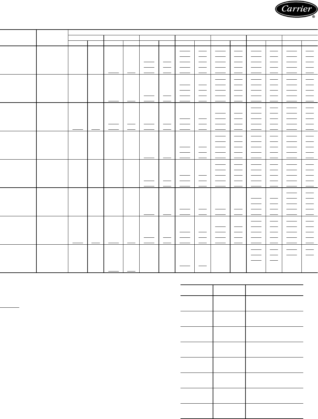
64
40RM WITH STANDARD COIL FAN PERFORMANCE DATA — 0-300 Pa ESP — SI
LEGEND
ESP — External Static Pressure
Bold indicates field-supplied drive is required.
Plain type indicates standard motor and standard drive.
Underline indicates a different motor and drive combination is required.
Refer to fan motor and drive tables, pages 94-98, to complete the selection.
NOTES:
1. Maximum allowable fan speed is 1100 rpm (18.3 r/s) for unit sizes 028
and 034; 1200 rpm (20 r/s) for all other sizes.
2. Fan performance is based on deductions for wet coil, clean 51 mm (2-in.)
filters, and unit casing. See right for factory-supplied filter pressure drop.
3. The medium-static drive and standard motor combination is NOT AVAIL-
ABLE for 40RM016-028 units. Use the alternate motor if medium-static
drive is required for these sizes.
40RM FACTORY-SUPPLIED FILTER PRESSURE DROP — SI
UNIT
(Standard
3-Row Coil)
AIRFLOW
(L/s)
EXTERNAL STATIC PRESSURE (Pa)
0 50 100 150 200 250 300
r/s kW r/s kW r/s kW r/s kW r/s kW r/s kW r/s kW
40RM
007
850 6.64 0.14 7.56 0.18 9.13 0.26 10.56 0.35 11.88 0.45 13.08 0.55 14.16 0.66
990 7.43 0.21 8.28 0.25 9.71 0.34 11.00 0.44 12.22 0.54 13.37 0.66 14.44 0.78
1130 8.30 0.30 9.02 0.35 10.36 0.45 11.55 0.55 12.67 0.66 13.73 0.78 14.76 0.91
1270 9.06 0.41 9.79 0.47 11.06 0.58 12.17 0.69 13.20 0.81 14.19 0.94 15.14 1.07
1420 9.91 0.55 10.58 0.61 11.78 0.74 12.83 0.86 13.80 0.99 14.72 1.12 15.61 1.26
40RM
008
1060 4.55 0.06 8.21 0.27 9.67 0.37 10.93 0.46 12.11 0.57 13.23 0.68 14.30 0.81
1230 5.37 0.11 8.99 0.38 10.37 0.49 11.55 0.60 12.62 0.71 13.65 0.84 14.64 0.96
1420 9.21 0.48 9.92 0.55 11.22 0.67 12.33 0.80 13.33 0.92 14.27 1.05 15.17 1.19
1600 10.25 0.68 10.89 0.75 12.09 0.90 13.15 1.04 14.10 1.18 14.99 1.33 15.83 1.47
1770 11.18 0.90 11.76 0.98 12.88 1.14 13.90 1.30 14.82 1.45 15.67 1.61 16.46 1.77
40RM
012
1420 6.65 0.22 9.55 0.51 10.89 0.64 12.04 0.77 13.06 0.89 14.02 1.02 14.93 1.15
1650 10.06 0.68 10.69 0.76 11.90 0.91 13.00 1.06 13.97 1.20 14.86 1.35 15.70 1.50
1890 11.33 0.99 11.88 1.08 12.96 1.25 13.99 1.43 14.93 1.59 15.78 1.76 16.58 1.92
2120 12.61 1.38 13.11 1.49 14.08 1.68 15.02 1.88 15.92 2.07 16.74 2.26 17.51 2.44
2360 13.90 1.87 14.36 1.99 15.23 2.21 16.10 2.42 16.94 2.64 17.73 2.85 18.48 3.06
40RM
014
1770 6.57 0.30 7.54 0.39 9.31 0.60 10.72 0.82 11.95 1.04 13.09 1.27 14.13 1.52
2030 7.27 0.43 8.11 0.52 9.76 0.75 11.16 1.00 12.36 1.25 13.44 1.50 14.45 1.76
2360 8.20 0.64 8.92 0.74 10.38 0.98 11.73 1.26 12.91 1.55 13.97 1.84 14.93 2.13
2690 9.16 0.92 9.79 1.02 11.07 1.27 12.33 1.58 13.48 1.90 14.53 2.23 15.48 2.56
2950 9.93 1.18 10.50 1.30 11.66 1.56 12.83 1.87 13.95 2.22 14.98 2.58 15.92 2.94
40RM
016
2120 7.13 0.44 7.91 0.52 9.50 0.74 10.94 0.99 12.17 1.25 13.26 1.51 14.26 1.77
2500 8.13 0.68 8.80 0.78 10.15 1.00 11.48 1.27 12.70 1.57 13.78 1.87 14.76 2.18
2830 9.03 0.96 9.63 1.07 10.81 1.30 12.01 1.58 13.18 1.90 14.25 2.24 15.23 2.58
3210 10.07 1.37 10.62 1.48 11.66 1.73 12.71 2.01 13.77 2.35 14.80 2.71 15.76 3.09
3540 10.99 1.81 11.50 1.93 12.45 2.20 13.40 2.49 14.35 2.83 15.31 3.20 16.24 3.60
40RM
024
2830 8.86 0.94 9.48 1.04 10.65 1.26 11.84 1.53 13.01 1.85 14.10 2.19 15.08 2.53
3300 10.14 1.44 10.69 1.56 11.70 1.81 12.71 2.08 13.73 2.41 14.74 2.77 15.71 3.15
3780 11.43 2.11 11.93 2.25 12.84 2.52 13.71 2.81 14.60 3.14 15.49 3.51 16.39 3.91
4250 12.74 2.96 13.19 3.12 14.02 3.43 14.81 3.74 15.59 4.08 16.37 4.45 17.17 4.85
4720 14.05 4.01 14.47 4.19 15.23 4.54 15.96 4.88 16.66 5.24 17.36 5.62 18.07 6.03
40RM
028
3540 7.60 0.96 8.16 1.09 9.27 1.38 10.34 1.68 11.30 1.97 12.15 2.28 12.97 2.68
4130 8.68 1.47 9.18 1.62 10.13 1.94 11.07 2.29 11.99 2.63 12.84 2.97 13.60 3.32
4720 9.78 2.15 10.23 2.32 11.07 2.67 11.89 3.05 12.72 3.45 13.53 3.84 14.29 4.23
5310 10.89 3.01 11.30 3.20 12.06 3.59 12.80 4.00 13.53 4.43 14.27 4.88 14.99 5.33
5900 12.00 4.07 12.38 4.29 13.09 4.72 13.75 5.17 14.41 5.63 15.07 6.11 15.74 6.61
40RM
034
4250 8.68 1.48 9.17 1.68 10.27 2.07 11.27 2.41 12.19 2.77 13.03 3.13 13.81 3.50
4960 9.93 2.35 10.38 2.53 11.21 2.90 11.99 3.28 12.78 3.68 13.56 4.10 14.32 4.51
5660 11.21 3.45 11.63 3.66 12.38 4.07 13.08 4.49 13.76 4.93 14.45 5.39 15.14 5.87
6370 12.51 4.85 12.89 5.08 13.58 5.54 14.22 6.01 14.83 6.49 15.44 6.99 16.05 7.51
7080 13.82 6.59 14.17 6.85 14.81 7.36 15.40 7.88 15.97 8.40 16.52 8.94 17.06 9.49
UNIT
40RM
AIRFLOW
(L/s)
PRESSURE DROP
(Pa)
007
850 13
1150 20
1450 28
008
1000 17
1400 27
1800 38
012
1450 28
1900 42
2350 56
014
1750 15
2350 24
2950 33
016
2100 20
2800 30
3500 42
024
2900 32
3800 47
4700 64
028
3500 36
4700 55
5900 76
034
4250 47
5650 71
7050 98
Performance data (cont)
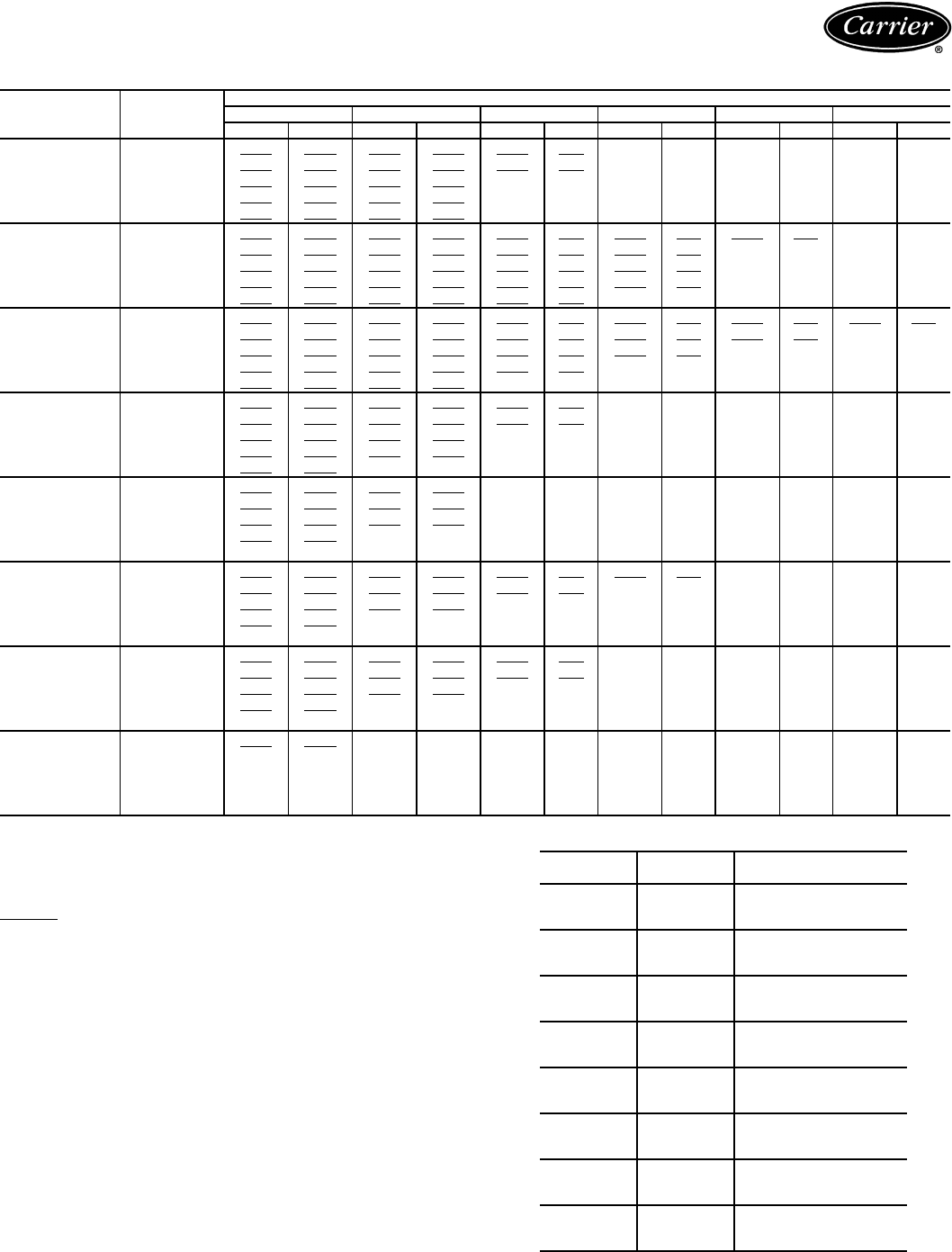
65
40RM WITH STANDARD COIL FAN PERFORMANCE DATA — 350-600 Pa ESP — SI
LEGEND
ESP — External Static Pressure
Bold indicates field-supplied drive is required.
Plain type indicates standard motor and standard drive.
Underline indicates a different motor and drive combination is required.
Refer to fan motor and drive tables, pages 94-98, to complete the selection.
NOTES:
1. Maximum allowable fan speed is 1100 rpm (18.3 r/s) for unit sizes 028
and 034; 1200 rpm (20 r/s) for all other sizes.
2. Fan performance is based on deductions for wet coil, clean 51 mm (2-in.)
filters, and unit casing. See right for factory-supplied filter pressure drop.
3. The medium-static drive and standard motor combination is NOT AVAIL-
ABLE for 40RM016-028 units. Use the alternate motor if medium-static
drive is required for these sizes.
40RM FACTORY-SUPPLIED FILTER PRESSURE DROP — SI
UNIT
(Standard
3-Row Coil)
AIRFLOW
(L/s)
EXTERNAL STATIC PRESSURE (Pa)
350 400 450 500 550 600
r/s kW r/s kW r/s kW r/s kW r/s kW r/s kW
40RM
007
850 15.16 0.78 16.08 0.89 16.94 1.01 17.74 1.13 18.51 1.26 19.25 1.39
990 15.44 0.90 16.38 1.03 17.25 1.16 18.07 1.30 18.84 1.43 19.58 1.57
1130 15.73 1.05 16.65 1.19 17.53 1.33 18.36 1.48 19.14 1.62 19.89 1.77
1270 16.07 1.21 16.96 1.36 17.82 1.51 18.64 1.67 19.42 1.83 ——
1420 16.48 1.41 17.32 1.56 18.14 1.72 18.94 1.89 19.71 2.06 ——
40RM
008
1060 15.31 0.94 16.25 1.07 17.14 1.20 17.98 1.34 18.77 1.48 19.53 1.63
1230 15.60 1.10 16.51 1.24 17.39 1.39 18.23 1.54 19.03 1.70 19.80 1.86
1420 16.05 1.33 16.90 1.48 17.74 1.64 18.54 1.80 19.32 1.97 ——
1600 16.64 1.62 17.42 1.78 18.20 1.94 18.95 2.11 19.69 2.29 ——
1770 17.23 1.93 17.97 2.09 18.70 2.26 19.41 2.44 ————
40RM
012
1420 15.81 1.29 16.67 1.44 17.51 1.60 18.32 1.76 19.11 1.92 19.87 2.09
1650 16.51 1.65 17.29 1.80 18.05 1.97 18.80 2.13 19.53 2.31 ——
1890 17.34 2.09 18.06 2.26 18.77 2.43 19.45 2.61 ————
2120 18.24 2.63 18.93 2.82 19.59 3.00 ——————
2360 19.18 3.27 19.85 3.48 ————————
40RM
014
1770 15.15 1.77 16.13 2.04 17.10 2.33 18.00 2.62 18.85 2.92 19.68 3.22
2030 15.41 2.04 16.34 2.32 17.24 2.62 18.07 2.92 18.92 3.24 19.73 3.56
2360 15.84 2.43 16.70 2.74 17.54 3.05 18.35 3.38 19.14 3.71 19.83 4.06
2690 16.36 2.89 17.19 3.23 17.98 3.57 18.75 3.92 19.49 4.27 ——
2950 16.79 3.30 17.61 3.66 18.39 4.03 19.13 4.40 19.84 4.77 ——
40RM
016
2120 15.20 2.05 16.12 2.33 16.98 2.62 17.83 2.92 18.67 3.24 19.47 3.57
2500 15.67 2.49 16.53 2.80 17.35 3.12 18.13 3.44 18.90 3.77 19.65 4.12
2830 16.13 2.92 16.97 3.27 17.77 3.62 18.53 3.97 19.26 4.33 19.97 4.69
3210 16.66 3.48 17.50 3.87 18.29 4.26 19.03 4.65 19.75 5.04 ——
3540 17.13 4.02 17.97 4.45 18.75 4.88 19.50 5.30 ————
40RM
024
2830 15.90 2.86 16.75 3.18 17.53 3.52 18.30 3.89 19.03 4.23 ——
3300 16.50 3.53 17.33 3.91 18.17 4.32 18.92 4.70 19.60 5.10 ——
3780 17.13 4.32 17.97 4.76 18.83 5.22 19.55 5.67 ————
4250 17.88 5.30 18.67 5.76 19.48 6.24 ——————
4720 18.77 6.52 19.43 6.99 ————————
40RM
028
3540 13.85 3.29 14.50 3.80 15.22 4.40 15.83 5.13 16.42 5.74 ——
4130 14.31 3.71 15.01 4.17 15.74 4.79 16.33 5.37 17.00 6.04 ——
4720 14.99 4.62 15.65 5.02 16.27 5.46 16.88 5.97 17.50 6.57 ——
5310 15.68 5.77 16.34 6.20 16.95 6.64 17.53 7.09 18.09 7.58 ——
5900 16.39 7.10 17.03 7.60 17.64 8.08 18.22 8.57 ————
40RM
034
4250 14.43 3.88 14.98 4.36 15.84 4.96 16.48 5.50 17.16 6.21 17.96 7.26
4960 15.04 4.92 15.71 5.32 16.33 5.74 16.93 6.20 17.51 6.70 18.09 7.29
5660 15.81 6.34 16.47 6.81 17.10 7.28 17.69 7.74 18.26 8.21 ——
6370 16.66 8.04 17.27 8.57 17.88 9.10 ——————
7080 17.61 10.06 18.16 10.64 ————————
UNIT
40RM
AIRFLOW
(L/s)
PRESSURE DROP
(Pa)
007
850 13
1150 20
1450 28
008
1000 17
1400 27
1800 38
012
1450 28
1900 42
2350 56
014
1750 15
2350 24
2950 33
016
2100 20
2800 30
3500 42
024
2900 32
3800 47
4700 64
028
3500 36
4700 55
5900 76
034
4250 47
5650 71
7050 98
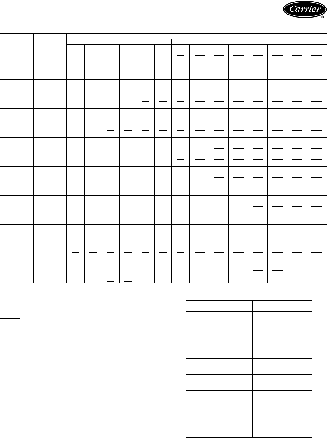
66
40RM WITH STANDARD COIL FAN PERFORMANCE DATA — 0.0-1.2 in. wg ESP — ENGLISH
LEGEND
ESP — External Static Pressure
Bold indicates field-supplied drive is required.
Plain type indicates standard motor and standard drive.
Underline indicates a different motor and drive combination is required.
Refer to fan motor and drive tables, pages 94-98, to complete the selection.
NOTES:
1. Maximum allowable fan speed is 1100 rpm (18.3 r/s) for unit sizes 028
and 034; 1200 rpm (20 r/s) for all other sizes.
2. Fan performance is based on deductions for wet coil, clean 51 mm (2-in.)
filters, and unit casing. See right for factory-supplied filter pressure drop.
3. The medium-static drive and standard motor combination is NOT AVAIL-
ABLE for 40RM016-028 units. Use the alternate motor if medium-static
drive is required for these sizes.
40RM FACTORY-SUPPLIED FILTER PRESSURE DROP —
ENGLISH
UNIT
(Standard
3-Row Coil)
AIRFLOW
(Cfm)
EXTERNAL STATIC PRESSURE (in. wg)
0.0 0.2 0.4 0.6 0.8 1.0 1.2
Rpm Bhp Rpm Bhp Rpm Bhp Rpm Bhp Rpm Bhp Rpm Bhp Rpm Bhp
40RM
007
1,800 399 0.19 454 0.24 548 0.35 634 0.47 713 0.60 785 0.74 850 0.89
2,100 446 0.28 497 0.34 583 0.46 660 0.59 733 0.73 802 0.88 867 1.05
2,400 498 0.40 541 0.47 622 0.60 693 0.74 760 0.89 824 1.05 885 1.22
2,700 544 0.55 588 0.63 663 0.78 730 0.93 792 1.09 851 1.26 909 1.44
3,000 594 0.73 635 0.82 707 0.99 770 1.15 828 1.32 883 1.50 937 1.69
40RM
008
2,250 273 0.08 493 0.37 580 0.49 656 0.62 727 0.76 794 0.92 858 1.08
2,600 322 0.15 540 0.52 622 0.66 693 0.81 757 0.96 819 1.12 878 1.29
3,000 552 0.65 595 0.73 673 0.91 740 1.07 800 1.24 856 1.41 910 1.60
3,400 615 0.91 653 1.01 726 1.21 789 1.40 846 1.59 899 1.78 950 1.97
3,750 671 1.20 706 1.31 773 1.53 834 1.74 889 1.95 940 2.16 988 2.37
40RM
012
3,000 399 0.29 573 0.69 654 0.86 722 1.03 784 1.19 841 1.37 896 1.55
3,500 604 0.92 641 1.02 714 1.22 780 1.42 838 1.61 892 1.81 942 2.01
4,000 680 1.33 713 1.45 778 1.68 839 1.91 896 2.14 947 2.36 995 2.58
4,500 756 1.86 787 1.99 845 2.26 901 2.52 955 2.78 1005 3.03 1051 3.28
5,000 834 2.51 861 2.67 914 2.96 966 3.25 1016 3.54 1064 3.82 1109 4.11
40RM
014
3,750 394 0.40 453 0.52 558 0.80 643 1.10 717 1.39 785 1.71 848 2.04
4,300 436 0.57 487 0.70 586 1.00 670 1.34 742 1.67 806 2.01 867 2.36
5,000 492 0.86 535 0.99 6231.31704 1.69 775 2.08 838 2.47 896 2.86
5,700 550 1.23 587 1.37 664 1.71 740 2.11 809 2.55 872 2.99 929 3.43
6,250 596 1.59 630 1.74 700 2.09 770 2.51 837 2.97 899 3.45 955 3.94
40RM
016
4,500 428 0.59 475 0.70 570 0.99 656 1.33 730 1.68 796 2.02 856 2.38
5,300 488 0.92 528 1.04 609 1.34 689 1.71 762 2.11 827 2.51 886 2.92
6,000 542 1.29 578 1.43 649 1.74 721 2.11 791 2.55 855 3.00 914 3.46
6,800 604 1.83 637 1.99 700 2.32 763 2.70 826 3.15 888 3.64 946 4.15
7,500 660 2.42 690 2.59 747 2.95 804 3.34 861 3.79 919 4.29 975 4.83
40RM
024
6,000 532 1.25 569 1.39 639 1.69 711 2.06 781 2.48 846 2.93 905 3.39
7,000 608 1.93 641 2.09 702 2.42 763 2.80 824 3.23 885 3.71 943 4.23
8,000 686 2.83 716 3.01 770 3.38 823 3.77 876 4.21 930 4.70 983 5.24
9,000 764 3.97 791 4.18 841 4.59 888 5.02 935 5.47 982 5.96 1030 6.51
10,000 843 5.38 868 5.62 914 6.09 957 6.55 1000 7.02 1042 7.53 1084 8.08
40RM
028
7,500 456 1.29 490 1.47 556 1.85 621 2.25 678 2.64 729 3.06 778 3.60
8,750 521 1.98 551 2.18 608 2.61 664 3.07 720 3.53 770 3.99 816 4.45
10,000 587 2.88 614 3.11 664 3.59 714 4.09 763 4.62 812 5.15 857 5.68
11,250 653 4.03 678 4.29 724 4.82 768 5.37 812 5.95 856 6.54 899 7.14
12,500 720 5.46 743 5.75 785 6.33 825 6.93 865 7.55 904 8.20 944 8.86
40RM
034
9,000 521 1.99 550 2.25 616 2.77 676 3.23 731 3.72 782 4.20 829 4.70
10,500 596 3.16 623 3.40 672 3.89 720 4.40 767 4.94 814 5.50 859 6.05
12,000 673 4.63 698 4.90 743 5.45 785 6.02 826 6.62 867 7.23 908 7.87
13,500 751 6.51 773 6.82 815 7.44 853 8.06 890 8.71 927 9.38 963 10.07
15,000 829 8.84 850 9.19 888 9.88 924 10.57 958 11.27 991 11.99 1024 12.73
UNIT
40RM
AIRFLOW
(Cfm)
PRESSURE DROP
(in. wg)
007
1,800 0.05
2,400 0.08
3,000 0.11
008
2,250 0.07
3,000 0.11
3,750 0.15
012
3,000 0.11
4,000 0.17
5,000 0.23
014
3,750 0.06
5,000 0.10
6,250 0.13
016
4,500 0.08
6,000 0.12
7,500 0.17
024
6,000 0.12
8,000 0.19
10,000 0.26
028
7,500 0.15
10 000 0.22
12,500 0.30
034
9,000 0.19
12,000 0.29
15,000 0.40
Performance data (cont)
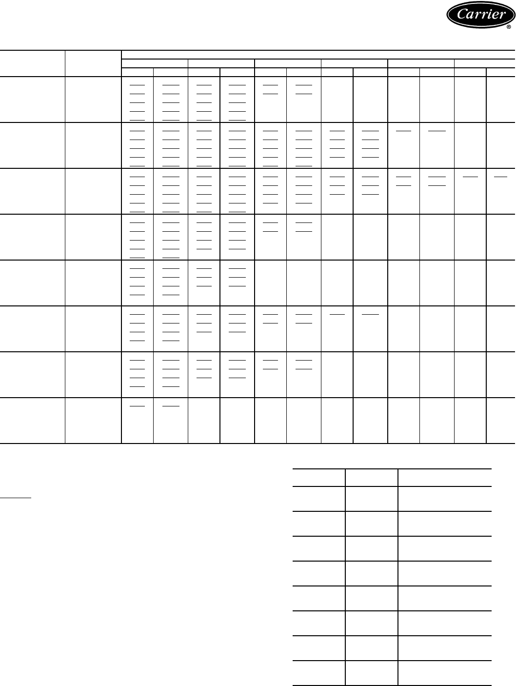
67
40RM WITH STANDARD COIL FAN PERFORMANCE DATA — 1.4-2.4 in. wg ESP — ENGLISH
LEGEND
ESP — External Static Pressure
Bold indicates field-supplied drive is required.
Plain type indicates standard motor and standard drive.
Underline indicates a different motor and drive combination is required.
Refer to fan motor and drive tables, pages 94-98, to complete the selection.
NOTES:
1. Maximum allowable fan speed is 1100 rpm (18.3 r/s) for unit sizes 028
and 034; 1200 rpm (20 r/s) for all other sizes.
2. Fan performance is based on deductions for wet coil, clean 51 mm (2-in.)
filters, and unit casing. See right for factory-supplied filter pressure drop.
3. The medium-static drive and standard motor combination is NOT AVAIL-
ABLE for 40RM016-028 units. Use the alternate motor if medium-static
drive is required for these sizes.
40RM FACTORY-SUPPLIED FILTER PRESSURE DROP —
ENGLISH
UNIT
(Standard
3-Row Coil)
AIRFLOW
(Cfm)
EXTERNAL STATIC PRESSURE (in. wg)
1.4 1.6 1.8 2.0 2.2 2.4
Rpm Bhp Rpm Bhp Rpm Bhp Rpm Bhp Rpm Bhp Rpm Bhp
40RM
007
1,800 910 1.04 965 1.20 1016 1.36 1065 1.52 1111 1.69 1155 1.86
2,100 927 1.21 983 1.38 1035 1.56 1084 1.74 1131 1.92 1175 2.11
2,400 944 1.41 999 1.59 1052 1.78 1101 1.98 1149 2.18 1193 2.38
2,700 964 1.63 1018 1.82 1069 2.03 1118 2.24 1165 2.45 ——
3,000 989 1.89 1039 2.10 1089 2.31 1136 2.53 1183 2.76 ——
40RM
008
2,250 918 1.26 975 1.43 1029 1.62 1079 1.80 1126 1.99 1172 2.18
2,600 936 1.48 991 1.67 1044 1.87 1094 2.07 1142 2.28 1188 2.49
3,000 963 1.79 1014 1.99 1064 2.20 1113 2.42 1159 2.64 ——
3,400 998 2.18 1045 2.39 1092 2.61 1137 2.83 1182 3.07 ——
3,750 1034 2.58 1078 2.80 1122 3.03 1164 3.27 ————
40RM
012
3,000 949 1.74 1000 1.93 1050 2.14 1099 2.36 1147 2.58 1192 2.81
3,500 990 2.21 1037 2.42 1083 2.64 1128 2.86 1172 3.10 ——
4,000 1040 2.80 1084 3.03 1126 3.26 1167 3.50 ————
4,500 1094 3.53 1136 3.78 1176 4.03 ——————
5,000 1151 4.39 1191 4.66 ————————
40RM
014
3,750 909 2.37 968 2.74 1026 3.12 1080 3.51 1131 3.92 1181 4.32
4,300 925 2.73 980 3.11 1034 3.52 1084 3.92 1135 4.35 1184 4.78
5,000 950 3.26 1002 3.67 1052 4.09 1101 4.53 1148 4.98 1190 5.44
5,700 981 3.88 1031 4.33 1079 4.79 1125 5.25 1169 5.73 ——
6,250 1007 4.42 1057 4.91 1103 5.40 1148 5.90 1191 6.40 ——
40RM
016
4,500 912 2.75 967 3.13 1019 3.52 1070 3.92 1120 4.35 1168 4.79
5,300 940 3.33 992 3.75 1041 4.18 1088 4.61 1134 5.06 1179 5.52
6,000 968 3.92 1018 4.38 1066 4.85 1112 5.32 1156 5.80 1198 6.29
6,800 1000 4.67 1050 5.19 1097 5.71 1142 6.23 1185 6.76 ——
7,500 1028 5.39 1078 5.97 1125 6.54 1170 7.11 ————
40RM
024
6,000 954 3.83 1005 4.27 1052 4.72 1098 5.22 1142 5.67 ——
7,000 990 4.74 1040 5.24 1090 5.80 1135 6.30 1176 6.84 ——
8,000 1028 5.79 1078 6.38 1130 7.00 1173 7.60 ————
9,000 1073 7.11 1120 7.72 1169 8.37 ——————
10,000 1126 8.75 1166 9.37 ————————
40RM
028
7,500 831 4.41 870 5.10 913 5.90 950 6.88 985 7.70 ——
8,750 859 4.97 901 5.59 944 6.42 980 7.20 1020 8.10 ——
10,000 900 6.20 939 6.74 976 7.33 1013 8.00 1050 8.82 ——
11,250 941 7.73 980 8.32 1017 8.90 1052 9.51 1086 10.16 ——
12,500 984 9.53 1022 10.19 1058 10.84 1093 11.49 ————
40RM
034
9,000 866 5.20 899 5.85 950 6.65 989 7.38 1029 8.32 1077 9.74
10,500 902 6.60 942 7.14 980 7.70 1016 8.31 1051 8.99 1085 9.77
12,000 949 8.50 988 9.14 1026 9.76 1062 10.38 1095 11.01 ——
13,500 1000 10.78 1036 11.49 1073 12.21 ——————
15,000 1057 13.49 1090 14.28 ————————
UNIT
40RM
AIRFLOW
(Cfm)
PRESSURE DROP
(in. wg)
007
1,800 0.05
2,400 0.08
3,000 0.11
008
2,250 0.07
3,000 0.11
3,750 0.15
012
3,000 0.11
4,000 0.17
5,000 0.23
014
3,750 0.06
5,000 0.10
6,250 0.13
016
4,500 0.08
6,000 0.12
7,500 0.17
024
6,000 0.12
8,000 0.19
10,000 0.26
028
7,500 0.15
10 000 0.22
12,500 0.30
034
9,000 0.19
12,000 0.29
15,000 0.40
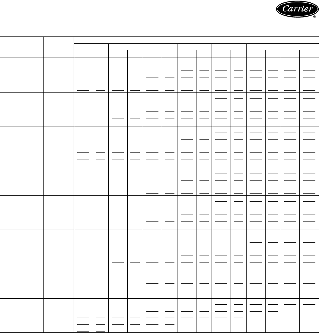
68
FAN PERFORMANCE DATA — 40RM WITH HIGH-CAPACITY COIL —
0-300 Pa ESP — 50 Hz, SI
See Legend and Notes on page 72.
UNIT
40RM
(High-Capacity
4-Row Coil)
AIRFLOW
(L/s)
EXTERNAL STATIC PRESSURE (Pa)
0 50 100 150 200 250 300
r/skWr/skWr/skWr/skWr/skWr/skWr/s kW
007
850 6.98 0.16 7.86 0.19 9.40 0.27 10.81 0.37 12.11 0.47 13.29 0.57 14.36 0.69
990 7.84 0.23 8.64 0.27 10.03 0.36 11.31 0.46 12.52 0.57 13.65 0.69 14.71 0.81
1130 8.73 0.33 9.46 0.38 10.75 0.48 11.91 0.59 13.01 0.70 14.07 0.83 15.08 0.96
1270 9.63 0.45 10.31 0.51 11.51 0.62 12.58 0.74 13.60 0.86 14.58 0.99 15.53 1.13
1420 10.55 0.61 11.18 0.67 12.30 0.80 13.31 0.92 14.26 1.05 15.17 1.19 16.05 1.33
008
1060 4.83 0.07 8.50 0.29 9.91 0.38 11.15 0.48 12.32 0.59 13.44 0.71 14.50 0.83
1230 5.81 0.14 9.35 0.41 10.67 0.52 11.81 0.63 12.88 0.74 13.90 0.87 14.89 1.00
1420 9.65 0.52 10.35 0.59 11.59 0.71 12.66 0.84 13.64 0.97 14.57 1.10 15.47 1.24
1600 10.76 0.74 11.39 0.81 12.54 0.96 13.55 1.10 14.48 1.24 15.34 1.39 16.17 1.53
1770 11.74 0.97 12.32 1.06 13.40 1.22 14.37 1.38 15.25 1.53 16.07 1.69 16.86 1.85
012
1420 7.02 0.26 9.86 0.54 11.17 0.67 12.28 0.79 13.29 0.92 14.23 1.05 15.14 1.19
1650 10.44 0.73 11.06 0.80 12.25 0.96 13.31 1.10 14.25 1.25 15.13 1.39 15.96 1.54
1890 11.76 1.06 12.31 1.15 13.38 1.32 14.37 1.49 15.28 1.66 16.11 1.83 16.89 1.99
2120 13.10 1.48 13.59 1.58 14.55 1.78 15.48 1.97 16.34 2.17 17.14 2.35 17.89 2.54
2360 14.45 2.01 14.89 2.12 15.76 2.34 16.62 2.56 17.43 2.77 18.20 2.98 18.92 3.19
014
1770 6.84 0.32 7.78 0.41 9.46 0.62 10.82 0.83 12.02 1.05 13.13 1.28 14.19 1.53
2030 7.58 0.46 8.40 0.55 9.98 0.78 11.31 1.03 12.47 1.27 13.52 1.52 14.51 1.78
2360 8.57 0.69 9.27 0.79 10.68 1.04 11.96 1.31 13.09 1.60 14.11 1.88 15.05 2.17
2690 9.59 0.99 10.20 1.10 11.44 1.36 12.64 1.66 13.74 1.98 14.74 2.30 15.65 2.63
2950 10.40 1.28 10.96 1.39 12.09 1.67 13.21 1.98 14.27 2.33 15.25 2.68 16.15 3.03
016
2120 7.28 0.45 8.05 0.54 9.60 0.75 11.00 1.00 12.21 1.26 13.28 1.51 14.27 1.78
2500 8.32 0.71 8.97 0.80 10.29 1.02 11.59 1.30 12.78 1.59 13.84 1.89 14.80 2.19
2830 9.25 1.00 9.83 1.10 10.99 1.33 12.16 1.62 13.29 1.93 14.34 2.27 15.30 2.60
3210 10.33 1.42 10.85 1.54 11.87 1.78 12.90 2.07 13.93 2.40 14.93 2.76 15.87 3.14
3540 11.29 1.88 11.77 2.01 12.69 2.27 13.62 2.56 14.56 2.90 15.49 3.27 16.40 3.67
024
2830 9.03 0.96 9.62 1.06 10.77 1.29 11.94 1.56 13.08 1.87 14.15 2.20 15.12 2.54
3300 10.34 1.48 10.86 1.60 11.85 1.85 12.84 2.12 13.85 2.45 14.84 2.80 15.78 3.18
3780 11.67 2.17 12.14 2.31 13.02 2.58 13.88 2.87 14.75 3.20 15.63 3.56 16.50 3.96
4250 13.01 3.05 13.44 3.21 14.23 3.51 15.00 3.82 15.77 4.16 16.54 4.53 17.32 4.94
4720 14.36 4.15 14.75 4.32 15.48 4.66 16.18 4.99 16.87 5.35 17.56 5.73 18.26 6.14
028
3540 7.94 1.04 8.51 1.18 9.65 1.48 10.73 1.79 11.68 2.10 12.53 2.46 13.40 2.95
4130 9.08 1.59 9.57 1.75 10.55 2.10 11.52 2.46 12.45 2.81 13.28 3.17 14.04 3.55
4720 10.24 2.33 10.68 2.51 11.53 2.88 12.39 3.29 13.24 3.70 14.05 4.11 14.80 4.51
5310 11.42 3.26 11.81 3.46 12.57 3.88 13.33 4.32 14.09 4.77 14.85 5.24 15.58 5.70
5900 12.60 4.42 12.96 4.64 13.65 5.09 14.33 5.57 15.01 6.07 15.70 6.58 16.38 7.10
034
4250 8.99 1.62 9.49 1.78 10.44 2.12 11.39 2.49 12.32 2.86 13.18 3.22 13.95 3.59
4960 10.33 2.51 10.77 2.70 11.59 3.08 12.40 3.49 13.22 3.92 14.03 4.35 14.79 4.78
5660 11.68 3.68 12.07 3.90 12.81 4.33 13.52 4.77 14.23 5.25 14.95 5.74 15.66 6.23
6370 13.04 5.18 13.40 5.42 14.07 5.90 14.71 6.39 15.34 6.90 15.97 7.44 16.61 7.98
7080 14.42 7.05 14.74 7.31 15.36 7.84 15.94 8.38 16.51 8.93 17.08 9.51 17.65 10.10
Performance data (cont)
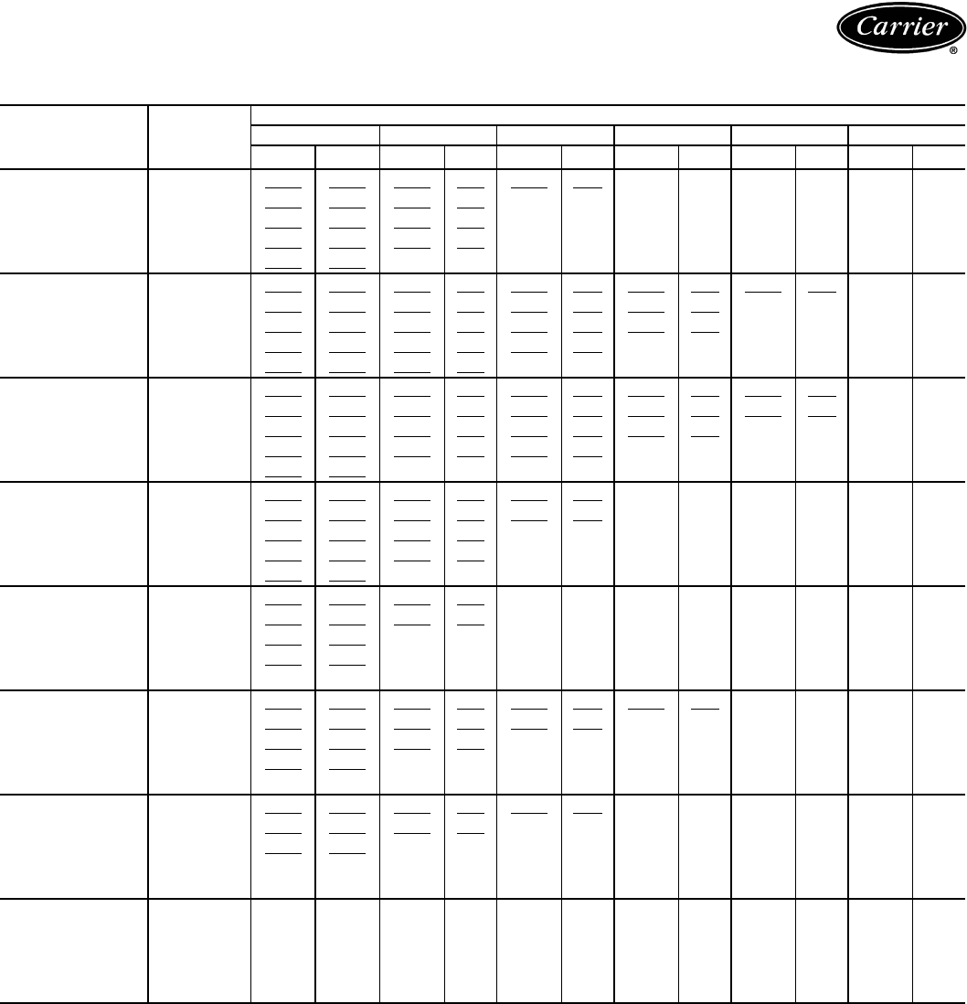
69
FAN PERFORMANCE DATA — 40RM WITH HIGH-CAPACITY COIL —
350-600 Pa ESP — 50 Hz, SI
See Legend and Notes on page 72.
UNIT
40RM
(High-Capacity
4-Row Coil)
AIRFLOW
(L/s)
EXTERNAL STATIC PRESSURE (Pa)
350 400 450 500 550 600
r/s kW r/s kW r/s kW r/s kW r/s kW r/s kW
007
850 15.34 0.80 16.25 0.92 17.10 1.03 17.90 1.16 18.66 1.28 19.39 1.41
850 15.69 0.94 16.61 1.07 17.47 1.20 18.28 1.33 19.04 1.47 19.77 1.61
1130 16.04 1.09 16.95 1.23 17.81 1.38 18.63 1.53 19.40 1.67 ——
1270 16.44 1.27 17.32 1.42 18.17 1.58 18.97 1.74 19.75 1.90 ——
1420 16.91 1.49 17.75 1.64 18.56 1.81 19.34 1.97 ————
008
1060 15.50 0.96 16.43 1.10 17.31 1.23 18.14 1.37 18.93 1.51 19.68 1.66
1230 15.84 1.14 16.75 1.28 17.62 1.43 18.45 1.58 19.24 1.74 ——
1420 16.34 1.38 17.19 1.54 18.01 1.70 18.81 1.86 19.59 2.03 ——
1600 16.97 1.69 17.76 1.85 18.52 2.02 19.27 2.19 ————
1770 17.61 2.01 18.35 2.18 19.07 2.35 19.77 2.53 ————
012
1420 16.02 1.33 16.87 1.48 17.71 1.64 18.52 1.80 19.30 1.97 ——
1650 16.76 1.70 17.53 1.85 18.29 2.02 19.04 2.19 19.77 2.37 ——
1890 17.64 2.16 18.35 2.33 19.05 2.51 19.74 2.69 ————
2120 18.60 2.73 19.28 2.91 19.93 3.10 ——————
2360 19.61 3.40 ——————————
014
1770 15.21 1.78 16.19 2.06 17.13 2.34 18.04 2.64 18.91 2.94 19.75 3.25
2030 15.46 2.05 16.37 2.33 17.26 2.63 18.12 2.94 18.96 3.26 19.78 3.59
2360 15.94 2.46 16.78 2.77 17.60 3.08 18.40 3.40 19.18 3.73 19.94 4.07
2690 16.51 2.95 17.32 3.28 18.09 3.62 18.84 3.96 19.57 4.31 ——
2950 16.99 3.39 17.78 3.74 18.54 4.10 19.26 4.47 19.96 4.84 ——
016
2120 15.21 2.05 16.11 2.33 16.98 2.62 17.83 2.93 18.66 3.24 19.47 3.57
2500 15.69 2.49 16.54 2.80 17.35 3.12 18.14 3.44 18.90 3.77 19.64 4.11
2830 16.18 2.94 17.01 3.28 17.79 3.63 18.54 3.97 19.27 4.33 19.97 4.69
3210 16.75 3.52 17.57 3.90 18.34 4.29 19.08 4.67 19.78 5.06 ——
3540 17.26 4.09 18.07 4.50 18.84 4.93 19.57 5.35 ————
024
2830 16.01 2.88 16.85 3.22 17.64 3.56 18.39 3.91 19.12 4.26 ——
3300 16.67 3.57 17.50 3.96 18.28 4.36 19.03 4.75 19.73 5.15 ——
3780 17.35 4.39 18.17 4.82 18.95 5.27 19.68 5.72 ————
4250 18.11 5.37 18.88 5.83 19.63 6.31 ——————
4720 18.96 6.58 19.67 7.05 ————————
028
3540 14.57 3.97 14.95 4.41 15.67 5.07 16.50 5.59 ————
4130 14.76 3.99 15.51 4.57 16.36 5.46 17.00 6.04 ————
4720 15.49 4.92 16.15 5.37 16.78 5.88 17.42 6.50 ————
5310 16.26 6.15 16.91 6.61 17.51 7.08 18.10 7.58 ————
5900 17.04 7.61 17.68 8.11 18.28 8.62 ——————
034
4250 14.68 4.00 15.38 4.49 16.12 5.14 17.00 6.15 ————
4960 15.51 5.20 16.17 5.63 16.80 6.09 17.41 6.61 ————
5660 16.35 6.72 17.01 7.21 17.64 7.69 18.23 8.18 ————
6370 17.24 8.54 17.87 9.10 ————————
7080 18.22 10.70 ——————————
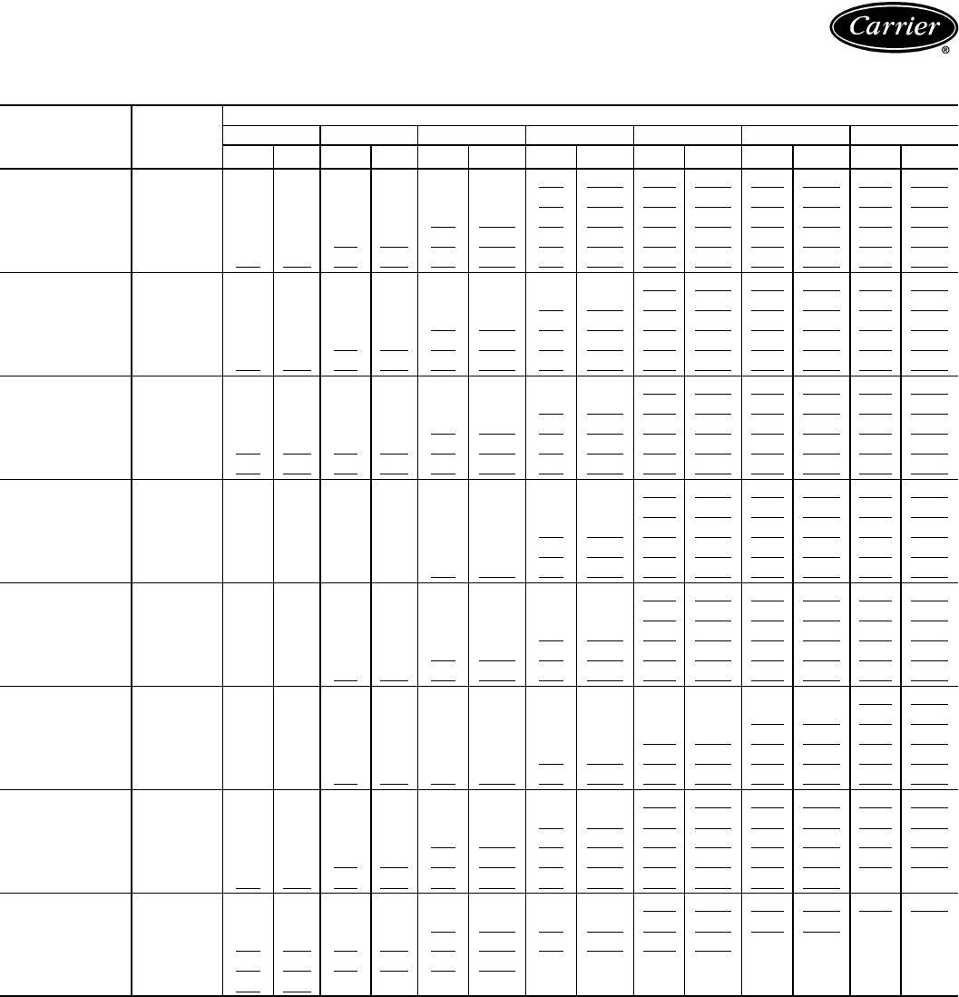
70
FAN PERFORMANCE DATA — 40RM WITH HIGH-CAPACITY COIL —
0.0-1.2 in. wg ESP — 50 Hz, ENGLISH
See Legend and Notes on page 72.
UNIT
40RM
(High-Capacity
4-Row Coil)
AIRFLOW
(Cfm)
EXTERNAL STATIC PRESSURE (in. wg)
0.0 0.2 0.4 0.6 0.8 1.0 1.2
Rpm Bhp Rpm Bhp Rpm Bhp Rpm Bhp Rpm Bhp Rpm Bhp Rpm Bhp
007
1,800 419 0.21 471 0.26 564 0.37 649 0.49 727 0.63 797 0.77 862 0.92
2,100 471 0.31 519 0.37 602 0.49 679 0.62 751 0.77 819 0.92 882 1.09
2,400 524 0.44 568 0.51 645 0.64 715 0.79 781 0.94 844 1.11 905 1.28
2,700 578 0.61 619 0.69 690 0.84 755 0.99 816 1.15 875 1.33 932 1.51
3,000 633 0.81 671 0.90 738 1.07 799 1.24 856 1.41 910 1.60 963 1.79
008
2,250 290 0.10 510 0.39 594 0.51 669 0.65 739 0.79 806 0.95 870 1.12
2,600 349 0.19 561 0.55 640 0.70 709 0.84 773 1.00 834 1.16 893 1.34
3,000 579 0.70 621 0.79 695 0.96 759 1.12 818 1.30 874 1.47 928 1.66
3,400 646 0.99 683 1.09 752 1.29 813 1.48 869 1.67 920 1.86 970 2.06
3,750 705 1.31 739 1.42 804 1.63 862 1.85 915 2.05 964 2.26 1011 2.48
012
3,000 421 0.35 592 0.73 670 0.90 737 1.06 797 1.23 854 1.41 908 1.59
3,500 626 0.98 664 1.08 735 1.28 798 1.48 855 1.67 908 1.87 958 2.07
4,000 706 1.42 738 1.54 803 1.77 862 2.00 917 2.23 967 2.45 1014 2.67
4,500 786 1.99 815 2.12 873 2.39 929 2.65 980 2.90 1028 3.16 1073 3.41
5,000 867 2.70 893 2.84 946 3.14 997 3.43 1046 3.72 1092 4.00 1135 4.28
014
3,750 410 0.43 467 0.55 567 0.83 649 1.12 721 1.41 788 1.72 851 2.05
4,300 455 0.62 504 0.74 599 1.05 679 1.38 748 1.70 811 2.04 871 2.39
5,000 514 0.92 556 1.06 641 1.39 718 1.76 786 2.14 847 2.52 903 2.91
5,700 575 1.32 612 1.47 686 1.82 759 2.23 825 2.66 884 3.09 939 3.52
6,250 624 1.71 657 1.87 725 2.24 793 2.66 856 3.12 915 3.59 969 4.06
016
4,500 437 0.61 483 0.72 576 1.01 660 1.35 732 1.69 797 2.03 856 2.38
5,300 499 0.95 538 1.07 617 1.37 696 1.74 767 2.13 830 2.53 888 2.94
6,000 555 1.34 590 1.48 659 1.79 730 2.17 798 2.59 860 3.04 918 3.49
6,800 620 1.91 651 2.06 712 2.39 774 2.78 836 3.22 896 3.71 952 4.21
7,500 677 2.52 706 2.69 761 3.04 817 3.44 873 3.89 929 4.39 984 4.93
024
6,000 542 1.29 577 1.42 646 1.72 716 2.09 785 2.51 849 2.95 907 3.40
7,000 620 1.99 652 2.15 711 2.48 771 2.85 831 3.28 890 3.76 947 4.27
8,000 700 2.92 728 3.10 781 3.46 833 3.85 885 4.29 938 4.78 990 5.32
9,000 781 4.10 806 4.30 854 4.71 900 5.13 946 5.58 993 6.08 1039 6.62
10,000 862 5.56 885 5.79 929 6.24 971 6.70 1012 7.18 1054 7.69 1096 8.24
028
7,500 476 1.39 510 1.58 579 1.99 644 2.40 701 2.81 752 3.29 804 3.96
8,750 545 2.14 574 2.35 633 2.81 691 3.29 747 3.77 797 4.25 842 4.76
10,000 615 3.12 641 3.36 692 3.87 743 4.41 794 4.96 843 5.51 888 6.05
11,250 685 4.37 709 4.64 754 5.20 800 5.79 845 6.40 891 7.02 935 7.64
12,500 756 5.92 778 6.22 819 6.83 860 7.47 901 8.14 942 8.83 983 9.52
034
9,000 539 2.18 569 2.39 626 2.85 683 3.34 739 3.83 791 4.32 837 4.82
10,500 620 3.37 646 3.62 695 4.13 744 4.68 793 5.25 842 5.83 888 6.41
12,000 701 4.94 724 5.22 769 5.80 811 6.40 854 7.04 897 7.69 940 8.36
13,500 783 6.95 804 7.27 844 7.91 883 8.57 920 9.26 958 9.97 996 10.71
15,000 865 9.45 884 9.81 921 10.52 956 11.24 991 11.98 1025 12.75 1059 13.54
Performance data (cont)
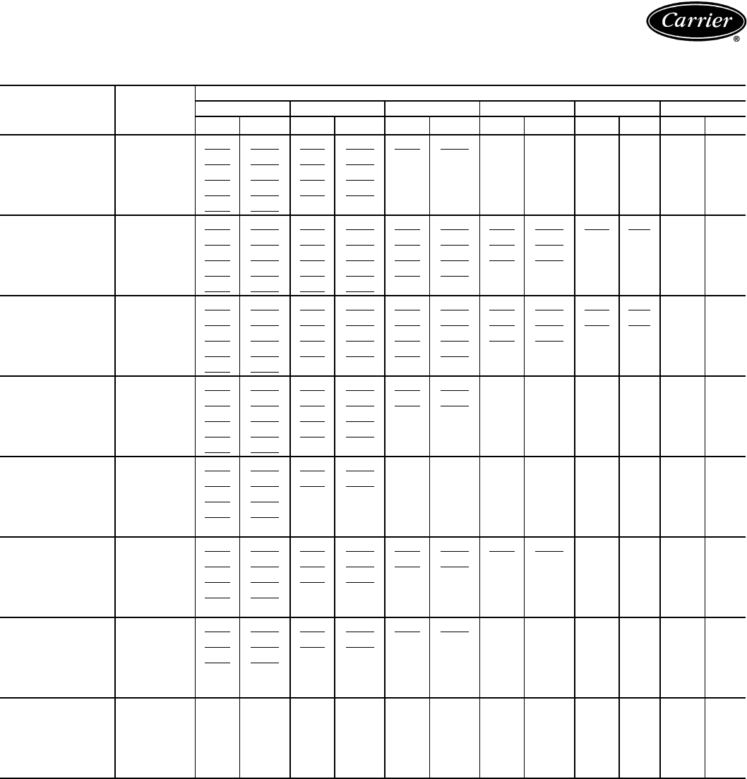
71
FAN PERFORMANCE DATA — 40RM WITH HIGH-CAPACITY COIL —
1.4-2.4 in. wg ESP — 50 Hz, ENGLISH
See Legend and Notes on page 72.
UNIT
40RM
(High-Capacity
4-Row Coil)
AIRFLOW
(Cfm)
EXTERNAL STATIC PRESSURE (in. wg)
1.4 1.6 1.8 2.0 2.2 2.4
Rpm Bhp Rpm Bhp Rpm Bhp Rpm Bhp Rpm Bhp Rpm Bhp
007
1,800 921 1.07 975 1.23 1026 1.39 1074 1.55 1120 1.72 1164 1.90
2,100 942 1.26 997 1.43 1048 1.61 1097 1.79 1143 1.97 1186 2.16
2,400 963 1.47 1017 1.66 1069 1.85 1118 2.05 1164 2.25 ——
2,700 987 1.71 1039 1.91 1090 2.12 1138 2.33 1185 2.55 ——
3,000 1015 1.99 1065 2.20 1113 2.42 1161 2.65 ————
008
2,250 930 1.29 986 1.47 1039 1.65 1089 1.84 1136 2.03 1181 2.22
2,600 950 1.53 1005 1.72 1057 1.92 1107 2.13 1154 2.33 ——
3,000 980 1.86 1031 2.06 1081 2.27 1129 2.49 1175 2.72 ——
3,400 1018 2.26 1065 2.48 1111 2.70 1156 2.93 ————
3,750 1057 2.69 1101 2.92 1144 3.15 1186 3.39 ————
012
3,000 961 1.78 1012 1.98 1062 2.19 1111 2.41 1158 2.64 ——
3,500 1005 2.27 1052 2.49 1098 2.71 1142 2.94 1186 3.18 ——
4,000 1058 2.90 1101 3.13 1143 3.36 1184 3.60 ————
4,500 1116 3.66 1157 3.91 1196 4.16 ——————
5,000 1176 4.56 ——————————
014
3,750 912 2.39 971 2.76 1028 3.14 1083 3.54 1135 3.95 1185 4.36
4,300 928 2.75 982 3.13 1036 3.53 1087 3.94 1138 4.37 1187 4.81
5,000 956 3.30 1007 3.71 1056 4.13 1104 4.56 1151 5.00 1196 5.46
5,700 990 3.96 1039 4.40 1086 4.85 1130 5.31 1174 5.78 ——
6,250 1019 4.54 1067 5.02 1112 5.50 1156 5.99 1198 6.49 ——
016
4,500 912 2.75 967 3.12 1019 3.52 1070 3.92 1120 4.35 1168 4.79
5,300 942 3.34 992 3.76 1041 4.18 1088 4.61 1134 5.06 1179 5.52
6,000 971 3.95 1020 4.40 1067 4.86 1112 5.33 1156 5.81 1198 6.29
6,800 1005 4.72 1054 5.23 1101 5.75 1145 6.27 1187 6.79 ——
7,500 1036 5.48 1084 6.04 1131 6.61 1174 7.17 ————
024
6,000 961 3.86 1011 4.31 1058 4.77 1104 5.24 1147 5.71 ——
7,000 1000 4.79 1050 5.32 1097 5.85 1142 6.38 1184 6.91 ——
8,000 1041 5.88 1090 6.47 1137 7.07 1181 7.67 ————
9,000 1086 7.21 1133 7.82 1178 8.47 ——————
10,000 1138 8.83 1180 9.46 ————————
028
7,500 874 5.33 897 5.91 940 6.80 990 7.50 ————
8,750 886 5.36 930 6.13 982 7.32 1020 8.10 ————
10,000 930 6.60 969 7.20 1007 7.89 1045 8.71 ————
11,250 976 8.25 1014 8.86 1051 9.49 1086 10.17 ————
12,500 1023 10.20 1061 10.88 1097 11.56 ——————
034
9,000 881 5.37 923 6.03 967 6.89 1020 8.25 ————
10,500 930 6.97 970 7.55 1008 8.17 1045 8.86 ————
12,000 981 9.02 1021 9.67 1058 10.32 1094 10.97 ————
13,500 1035 11.45 1072 12.20 ————————
15,000 1093 14.35 ——————————
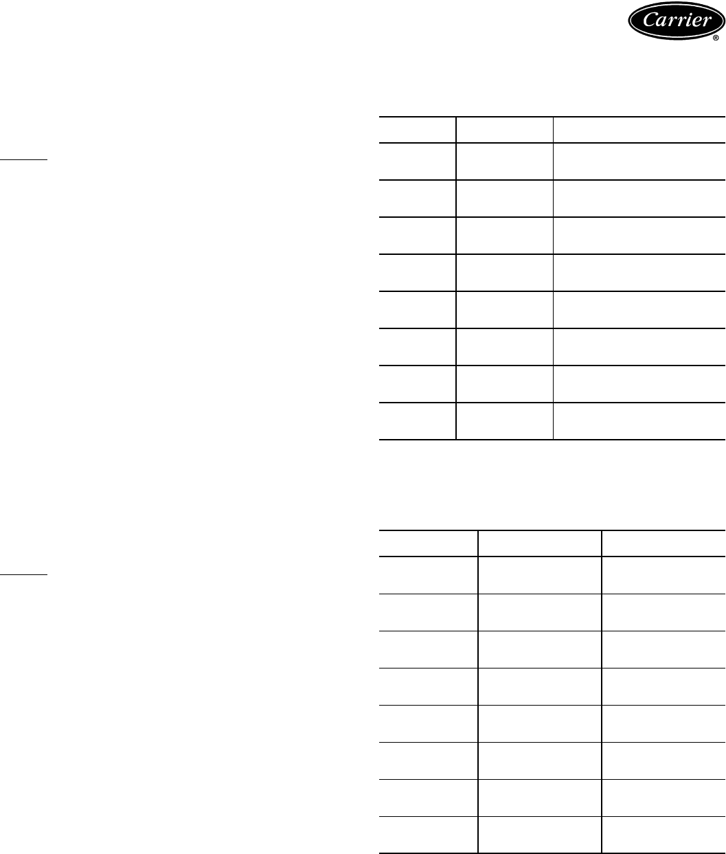
72
LEGEND AND NOTES FOR STANDARD AND HIGH-CAPACITY COIL
FAN PERFORMANCE DATA TABLES (English)
LEGEND
Bold indicates field-supplied drive is required.
Plain type indicates standard motor and standard drive.
Underline indicates a different motor and drive combination other than
the standard motor and standard drive combination is required. Refer to
fan motor and drive tables, pages 94-98, to complete selection.
NOTES:
1. Maximum allowable fan speed is 1100 rpm for unit sizes 028 and
034; 1200 rpm for all other sizes.
2. Fan performance is based on deductions for wet coil, clean
2-in. filters, and unit casing. See table at right for factory-supplied
filter pressure drop.
3. For 50 Hz units, the medium-static drive and standard motor com-
bination is not available for 016-028 sizes. Use alternate motor if
medium-static drive is required for these sizes.
FACTORY-SUPPLIED FILTER PRESSURE DROP
— ENGLISH
LEGEND AND NOTES FOR STANDARD AND HIGH CAPACITY COIL
FAN PERFORMANCE DATA TABLES (SI)
LEGEND
Bold indicates field-supplied drive is required.
Plain type indicates standard motor and standard drive.
Underline indicates a different motor and drive combination other than
the standard motor and standard drive combination is required. Refer to
fan motor and drive tables, pages 94-98, to complete the selection.
NOTES:
1. Maximum allowable fan speed is 18.3 r/s for unit sizes 028 and
034; 20 r/s for all other sizes.
2. Fan performance is based on deductions for wet coil, clean
51-mm filters, and unit casing. See table at right for factory-sup-
plied filter pressure drop.
3. For 50 Hz units, the medium-static drive and standard motor com-
bination is not available for 016-028 sizes. Use alternate motor if
medium-static drive is required for these sizes.
FACTORY-SUPPLIED FILTER PRESSURE DROP — SI
Bhp —Brake Horsepower Input to Fan
ESP —External Static Pressure
UNIT
40RM
AIRFLOW
(Cfm)
PRESSURE DROP
(in. wg)
007
1,800
2,400
3,000
0.05
0.08
0.11
008
2,250
3,000
3,750
0.07
0.11
0.15
012
3,000
4,000
5,000
0.11
0.17
0.23
014
3,750
5,000
6,250
0.06
0.10
0.13
016
4,500
6,000
7,500
0.08
0.12
0.17
024
6,000
8,000
10,000
0.12
0.19
0.26
028
7,500
10,000
12,500
0.15
0.22
0.30
034
9,000
12,000
15,000
0.19
0.29
0.40
ESP —External Static Pressure UNIT
40RM
AIRFLOW
(L/s)
PRESSURE DROP
(Pa)
007
850
1150
1450
13
20
28
008
1000
1400
1800
17
27
38
012
1450
1900
2350
28
42
56
014
1750
2350
2950
15
24
33
016
2100
2800
3500
20
30
42
024
2900
3800
4700
32
47
64
028
3500
4700
5900
36
55
76
034
4250
5650
7050
47
71
98
Performance data (cont)

73
40RM ACCESSORY PLENUM AIR THROW DATA — SI
(m)
NOTE: Throw distances shown are for 0.381 m/sec terminal velocity. Use the fol-
lowing multipliers to determine throw values for other terminal velocities.
40RM ACCESSORY PLENUM AIR THROW DATA —
ENGLISH (Ft)
NOTE: Throw distances shown are for 75 fpm terminal velocity. Use the following
multipliers to determine throw values for other terminal velocities.
40RM ACCESSORY PRESSURE DROP — SI (Pa)
40RM ACCESSORY PRESSURE DROP — ENGLISH (in. wg)
UNIT
40RM
AIRFLOW
(L/s)
VANE DEFLECTION
Straight 221/2°45°
007 1150 11.71 9.91 7.20
008 1400 13.87 11.71 8.63
012 1900 16.65 13.93 9.99
014 2350 13.77 11.63 8.57
016 2800 15.41 13.25 9.55
024 3800 18.17 15.44 11.20
028 4700 23.26 19.89 14.38
034 5650 25.97 22.00 15.89
TERMINAL VELOCITY
(m/sec) THROW FACTOR
0.254 X 1.50
0.508 X 0.75
0.762 X 0.50
UNIT
40RM
AIRFLOW
(Cfm)
VANE DEFLECTION
Straight 221/2°45°
007 2,400 39 33 24
008 3,000 45 38 28
012 4,000 55 46 33
014 5,000 45 38 28
016 6,000 50 43 31
024 8,000 60 51 37
028 10,000 76 65 47
034 12,000 85 72 52
TERMINAL VELOCITY
(Fpm) THROW FACTOR
50 X 1.50
100 X 0.75
150 X 0.50
UNIT
40RM
AIRFLOW
(L/s)
DISCHARGE
PLENUM
RETURN AIR
GRILLE
HEATING COILS ECONOMIZER
Hot Water Steam Electric
007
850 1522525912
1150 25 3 41411618
1450 36 5 60602623
008
1000 20 2 33331213
1400 34 5 57572422
1800 51 8 85853939
012
1450 36 5 60602623
1900 56 10 93 93 43 43
2350 79 15 132 132 65 69
014
1750 18 2 26261012
2350 29 5 43431717
2950 43 5 62622627
016
2100 24 2 36361415
2800 39 5 57572422
3500 56 7 82823737
024
2900 41 5 60602623
3800 64 10 93 93 43 43
4700 91 15 132 132 65 69
028
3500 37 5 67672215
4700 59 7 109 109 39 22
5900 86 12 157 157 60 35
034
4250 50 7 92923220
5650 80 12 147 147 56 35
7050 114 17 210 210 85 52
UNIT
40RM
AIRFLOW
(Cfm)
DISCHARGE
PLENUM
RETURN AIR
GRILLE
HEATING COILS ECONOMIZER
Hot Water Steam Electric
007
1,800 0.06 0.01 0.10 0.10 0.04 0.05
2,400 0.10 0.01 0.16 0.16 0.06 0.07
3,000 0.14 0.02 0.23 0.23 0.10 0.09
008
2,250 0.09 0.01 0.15 0.15 0.06 0.06
3,000 0.14 0.02 0.23 0.23 0.10 0.09
3,750 0.21 0.03 0.35 0.35 0.15 0.15
012
3,000 0.14 0.02 0.23 0.23 0.10 0.09
4,000 0.22 0.04 0.37 0.37 0.17 0.17
5,000 0.32 0.06 0.53 0.53 0.26 0.28
014
3,750 0.07 0.01 0.11 0.11 0.04 0.05
5,000 0.12 0.02 0.17 0.17 0.07 0.07
6,250 0.17 0.02 0.25 0.25 0.11 0.11
016
4,500 0.10 0.01 0.15 0.15 0.06 0.06
6,000 0.16 0.02 0.23 0.23 0.10 0.09
7,500 0.23 0.03 0.33 0.33 0.15 0.15
024
6,000 0.16 0.02 0.23 0.23 0.10 0.09
8,000 0.26 0.04 0.37 0.37 0.17 0.17
10,000 0.37 0.06 0.53 0.53 0.26 0.28
028
7,500 0.15 0.02 0.28 0.28 0.09 0.06
10,000 0.24 0.03 0.44 0.44 0.16 0.09
12,500 0.34 0.05 0.63 0.63 0.24 0.14
034
9,000 0.20 0.03 0.37 0.37 0.13 0.08
12,000 0.32 0.05 0.59 0.59 0.22 0.14
15,000 0.46 0.07 0.85 0.85 0.34 0.21
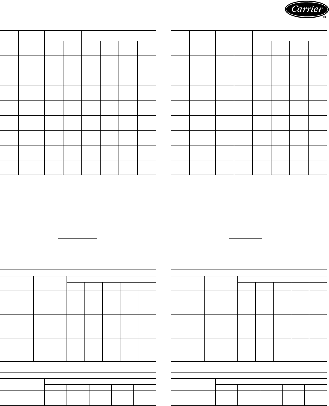
74
40RM HYDRONIC HEATING CAPACITIES — SI
LEGEND
*Based on 34.5 kPag steam, 15.6 C entering-air temperature. All steam coils are
non-freeze type.
†Based on 93.3 C entering-water temperature, 11.1 C water temperature drop,
15.6 C entering-air temperature.
NOTES:
1. Maximum operating limits for heating coils: 1207 kPag at 204.4 C.
3. See Heating Correction Factors table.
40RM HEATING CORRECTION FACTORS — SI
NOTE: Multiply capacity given in the Hydronic Heating Capacities table by the cor-
rection factor for conditions at which unit is actually operating. Correct leaving-air
temperature using formula in Note 2 of Hydronic Heating Capacities table.
40RM HYDRONIC HEATING CAPACITIES — ENGLISH
LEGEND
*Based on 5 psig steam, 60 F entering-air temperature. All steam coils are non-
freeze type.
†Based on 200 F entering-water temperature, 20 F water temperature drop, 60 F
entering-air temperature.
NOTES:
1. Maximum operating limits for heating coils: 175 psig at 400 F.
3. See Heating Correction Factors table.
40RM HEATING CORRECTION FACTORS — ENGLISH
NOTE: Multiply capacity given in the Hydronic Heating Capacities table by the cor-
rection factor for conditions at which unit is actually operating. Correct leaving-air
temperature using formula in Note 2 of Hydronic Heating Capacities table.
UNIT
40RM
AIRFLOW
(L/s)
1-ROW
STEAM*
2-ROW
HOT WATER COIL†
Cap. Ldb Cap. Ldb
Water
Flow
(L/s)
PD
007
850 43 57 46 59 1.0 10.2
1150 53 53 53 53 1.2 12.8
1450 62 51 61 50 1.3 16.0
008
1000 48 55 50 56 1.1 11.5
1400 59 50 60 50 1.3 15.3
1800 71 47 70 47 1.5 19.5
012
1450 62 50 88 65 1.9 15.0
1900 72 46 90 54 2.0 24.7
2350 82 44 93 48 2.0 24.5
014
1750 108 66 106 65 2.3 12.4
2350 122 58 120 57 2.6 15.2
2950 136 53 134 52 2.9 17.9
016
2100 117 61 120 62 2.6 13.3
2800 129 53 137 55 3.0 16.2
3500 140 48 154 51 3.3 19.5
024
2900 135 53 150 58 3.3 15.6
3800 140 46 170 52 3.7 18.6
4700 146 41 191 49 4.1 22.3
028
3500 149 50 189 60 4.1 16.9
4700 166 44 218 53 4.7 20.8
5900 183 41 247 50 5.4 25.4
034
4250 164 47 215 57 4.7 18.5
5650 180 41 247 51 5.4 22.8
7050 196 38 278 48 6.0 27.7
Cap. —Capacity (kW)
Ldb —Leaving-Air Dry-Bulb Temp (C)
PD —Pressure Drop (kPa)
2. Leaving db = ent db (C) + Capacity (kW)
1.23 x 10⁻³ x L/s
HOT WATER COIL
Water Temp
Drop
(C)
Ent Water
Temp
(C)
Entering-Air Temp (C)
4 10162025
5
60 0.72 0.64 0.55 0.50 0.43
70 0.87 0.79 0.71 0.65 0.58
80 1.02 0.94 0.86 0.80 0.73
90 1.17 1.09 1.01 0.95 0.89
100 1.321.241.161.101.04
11
60 0.65 0.56 0.48 0.42 0.35
70 0.80 0.72 0.63 0.58 0.51
80 0.95 0.87 0.79 0.73 0.66
90 1.10 1.02 0.94 0.89 0.82
100 1.261.181.091.040.97
16
60 0.56 0.48 0.39 0.33 0.26
70 0.72 0.63 0.55 0.49 0.42
80 0.87 0.79 0.70 0.65 0.58
90 1.02 0.94 0.86 0.81 0.74
100 1.181.101.020.970.90
STEAM COIL
Steam Pressure
(kPag)
Entering-Air Temp (C)
4 10162025
01.07 0.99 0.91 0.86 0.80
14 1.10 1.02 0.95 0.90 0.84
35 1.14 1.07 0.99 0.95 0.89
UNIT
40RM
AIRFLOW
(Cfm)
1-ROW
STEAM*
2-ROW
HOT WATER COIL†
Cap. Ldb Cap. Ldb
Water
Flow
(Gpm)
PD
007
1,800 146 134 156.0 140 15.6 3.4
2,400 173 126 183.0 131 18.3 4.3
3,000 209 123 206.0 124 20.6 5.2
008
2,250 168 129 174.0 133 17.4 4.0
3,000 209 123 206.0 124 20.6 5.2
3,750 240 117 238.0 118 23.8 6.5
012
3,000 209 123 299.0 152 29.9 5.0
4,000 243 115 275.0 124 27.5 6.6
5,000 279 111 316.0 119 31.6 8.2
014
3,750 370 150 362.0 149 36.2 4.2
5,000 425 137 409.0 136 40.9 5.1
6,250 465 128 456.0 128 45.6 6.0
016
4,500 402 141 412.0 145 41.2 4.5
6,000 458 129 471.0 133 47.1 5.5
7,500 479 118 529.0 125 52.9 6.6
024
6,000 458 129 506.0 138 50.6 5.1
8,000 487 115 584.0 128 58.4 6.3
10,000 499 105 652.0 120 65.2 7.5
028
7,500 511 122 649.0 140 64.9 5.7
10,000 575 112 752.0 130 75.2 7.1
12,500 626 106 842.0 122 84.2 8.5
034
9,000 560 117 735.0 136 73.5 6.2
12,000 621 107 850.0 126 85.0 7.8
15,000 670 101 950.0 119 95.0 9.3
Cap. —Capacity (Btuh in thousands)
Ldb —Leaving-Air Dry-Bulb Temp (F)
PD —Pressure Drop (ft water)
2. Leaving db = ent db (F) + Capacity (Btuh)
1.1 x cfm
HOT WATER COIL
Water Temp
Drop
(F)
Ent Water
Temp
(F)
Entering-Air Temp (F)
40 50 60 70 80
10
140 0.72 0.64 0.57 0.49 0.41
160 0.89 0.81 0.74 0.66 0.58
180 1.06 0.98 0.90 0.83 0.75
200 1.22 1.15 1.07 1.00 0.92
220 1.39 1.32 1.24 1.17 1.09
20
140 0.64 0.57 0.49 0.41 0.33
160 0.81 0.74 0.66 0.58 0.51
180 0.98 0.91 0.83 0.75 0.68
200 1.15 1.08 1.00 0.93 0.85
220 1.32 1.25 1.17 1.10 1.02
30
140 0.56 0.49 0.41 0.33 0.24
160 0.74 0.66 0.58 0.51 0.43
180 0.91 0.83 0.76 0.68 0.60
200 1.08 1.00 0.93 0.85 0.78
220 1.25 1.18 1.10 1.03 0.95
STEAM COIL
Steam Pressure
(kPag)
Entering-Air Temp (F)
40 50 60 70 80
01.06 0.98 0.91 0.85 0.78
21.09 1.02 0.95 0.89 0.82
51.13 1.06 1.00 0.93 0.87
Performance data (cont)
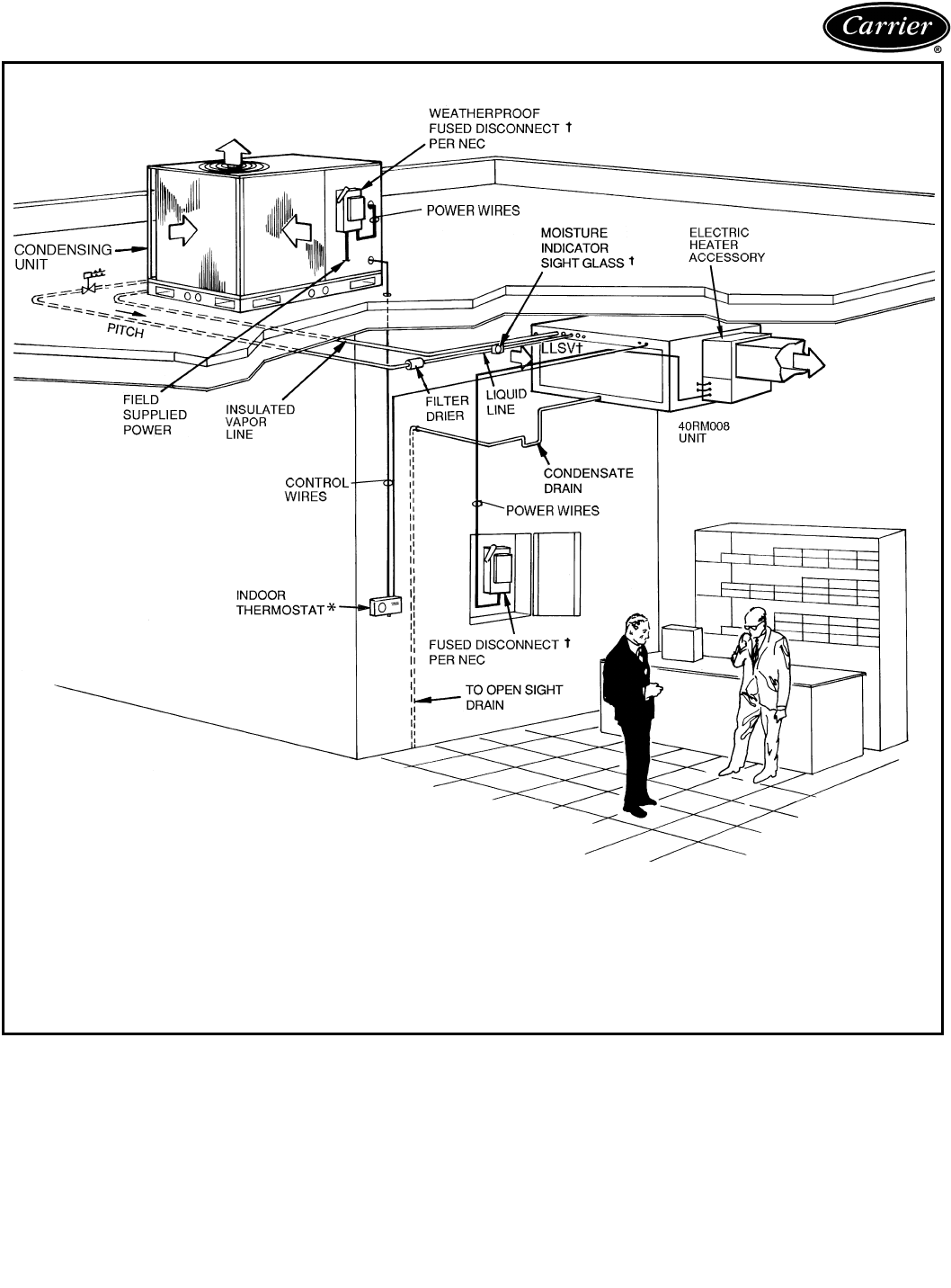
75
Typical piping and wiring
ROOFTOP INSTALLATION — 38AK007-012, 38AKS008-012
LEGEND
*Accessory item.
†Field supplied.
LLSV —Liquid Line Solenoid Valve
NEC —National Electrical Code
TXV —Thermostatic Expansion Valve
NOTES:
1. All piping must follow standard refrigerant piping techniques. Refer to Carrier System
Design Manual for details.
2. All wiring must comply with the applicable local and national codes.
3. Wiring and piping shown are general points-of-connection guides only and are not
intended for, or to include all details for, a specific installation.
4. Liquid line solenoid valve (solenoid drop control) is recommended to prevent refriger-
ant migration to the compressor.
5. Internal factory-supplied TXVs not shown.
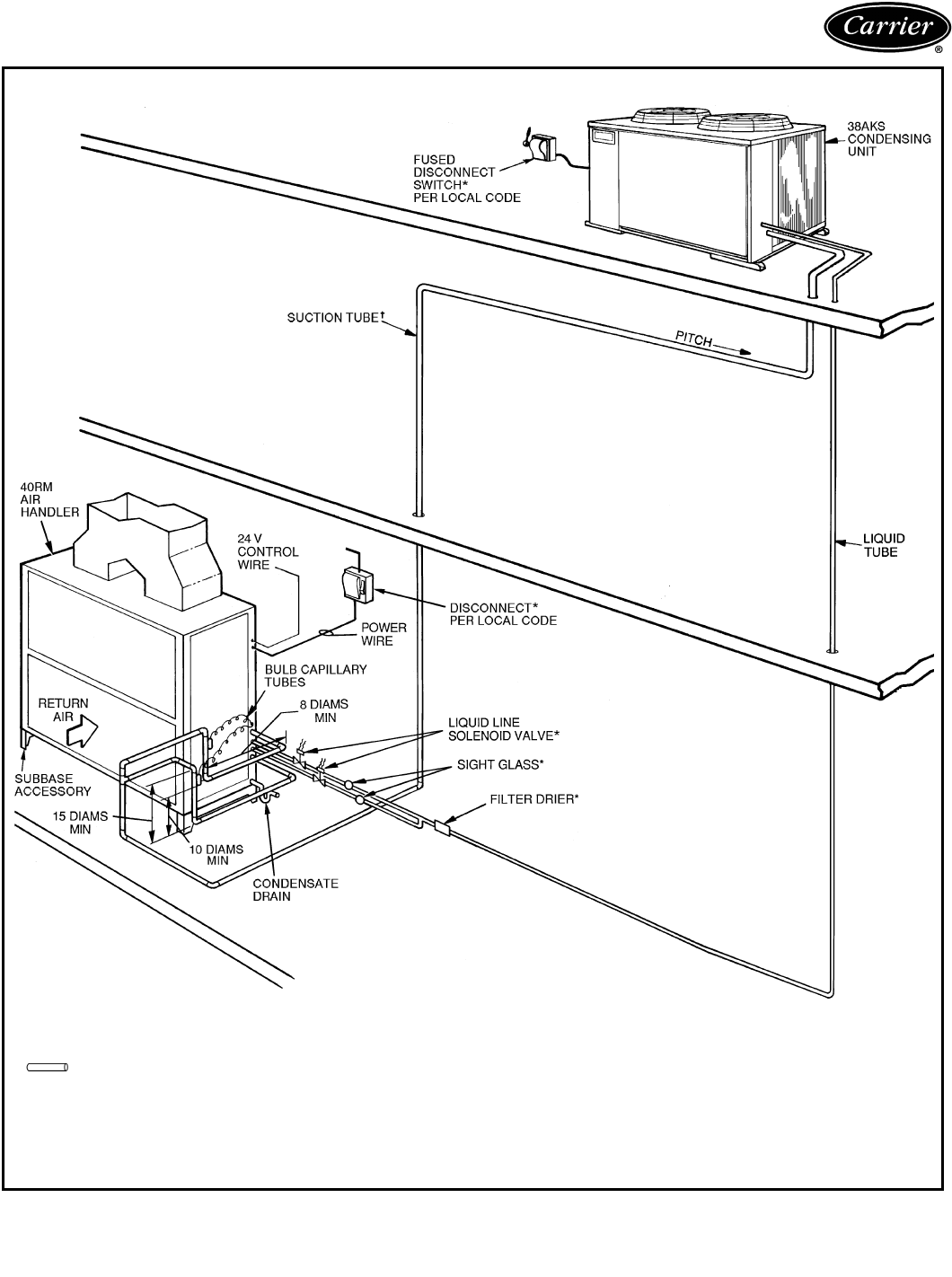
76
Typical piping and wiring (cont)
ROOFTOP INSTALLATION — 38AKS013-024
LEGEND
*Field supplied.
†Double riser may be required. See Application Data,
page 90.
TXV —Thermostatic Expansion Valve
Piping
NOTES:
1. All piping must follow standard refrigerant piping techniques. Refer
to Carrier System Design Manual for details.
2. All wiring must comply with the applicable local and national
codes.
3. Wiring and piping shown are general points-of-connection guides
only and are not intended for, or to include all details for, a specific
installation.
4. Liquid line solenoid valve (solenoid drop control) is recommended
to prevent refrigerant migration to the compressor.
5. Internal factory-supplied TXVs not shown.
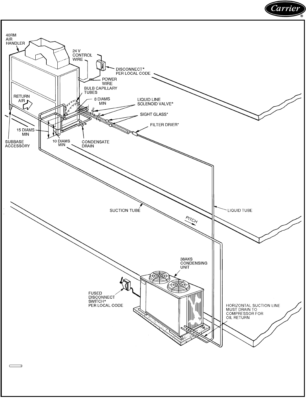
77
GROUND LEVEL INSTALLATION — 38AKS013-024
LEGEND
*Field supplied.
TXV —Thermostatic Expansion Valve
Piping
NOTES:
1. All piping must follow standard refrigerant piping techniques. Refer to Carrier System
Design Manual for details.
2. All wiring must comply with the applicable local and national codes.
3. Wiring and piping shown are general points-of-connection guides only and are not
intended for, or to include all details for, a specific installation.
4. Liquid line solenoid valve (solenoid drop control) is recommended to prevent refrigerant
migration to the compressor.
5. Internal factory-supplied TXVs not shown.
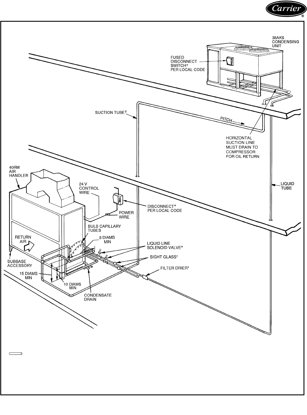
78
Typical piping and wiring (cont)
ROOFTOP INSTALLATION — 38AKS028-044
LEGEND
*Field supplied.
†Double riser may be required. See Application Data on page 93.
TXV —Thermostatic Expansion Valve
Piping
NOTES:
1. All piping must follow standard refrigerant piping techniques.
Refer to Carrier System Design Manual for details.
2. All wiring must comply with the applicable local and national
codes.
3. Wiring and piping shown are general points-of-connection
guides only and are not intended for, or to include all details for,
a specific installation.
4. Liquid line solenoid valve (solenoid drop control) is recom-
mended to prevent refrigerant migration to the compressor.
5. Internal factory-supplied TXVs not shown.
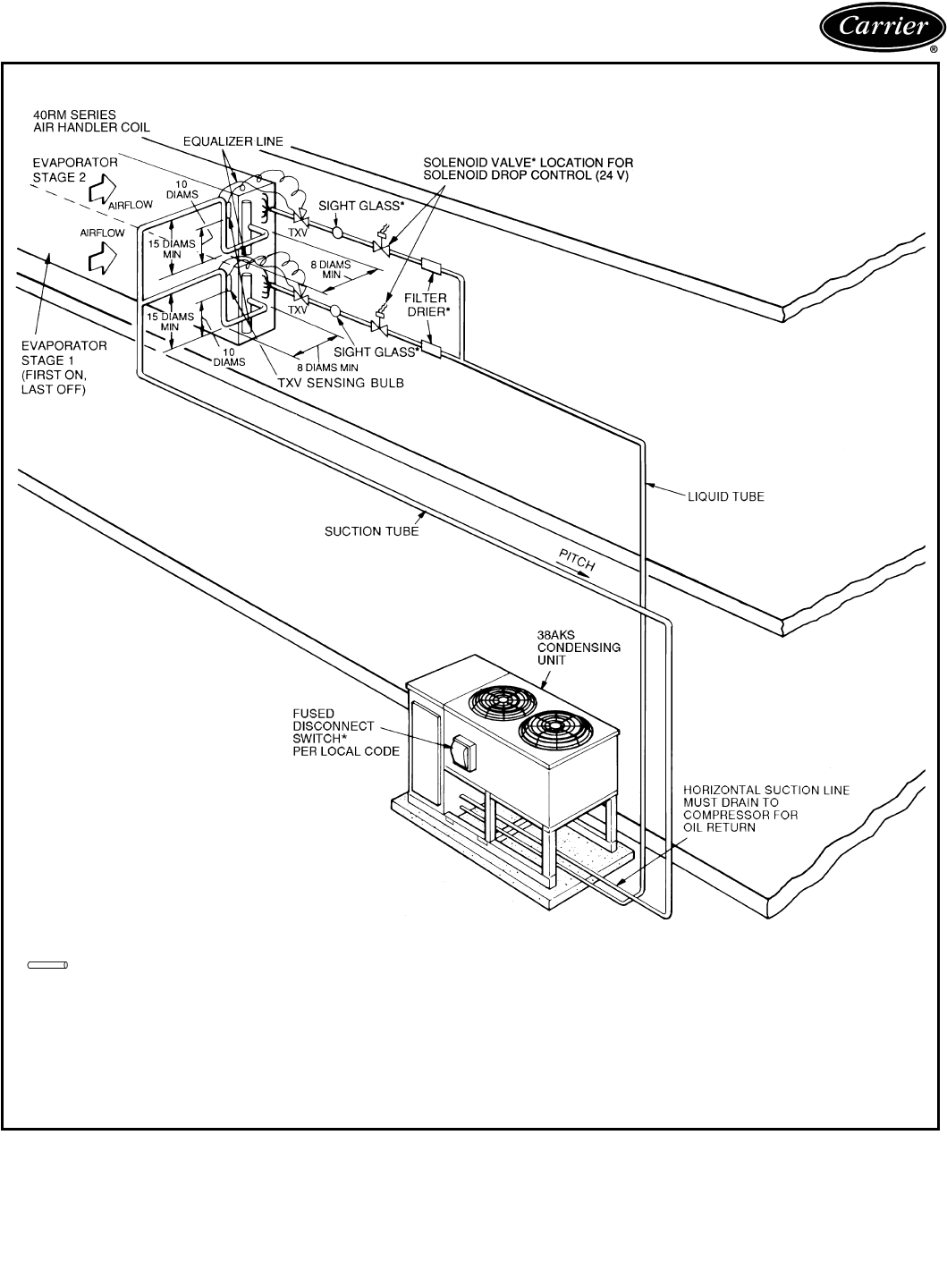
79
GROUND-LEVEL INSTALLATION — 38AKS028-044
LEGEND
*Field supplied.
NOTES:
1. All piping must follow standard refrigerant piping techniques. Refer to Carrier System
Design Manual for details.
2. All wiring must comply with the applicable local and national codes.
3. Wiring and piping shown are general points-of-connection guides only and are not
intended for, or to include all details for, a specific installation.
4. Liquid line solenoid valve (solenoid drop control) is recommended to prevent refriger-
ant migration to the compressor.
TXV —Thermostatic Expansion Valve
Piping
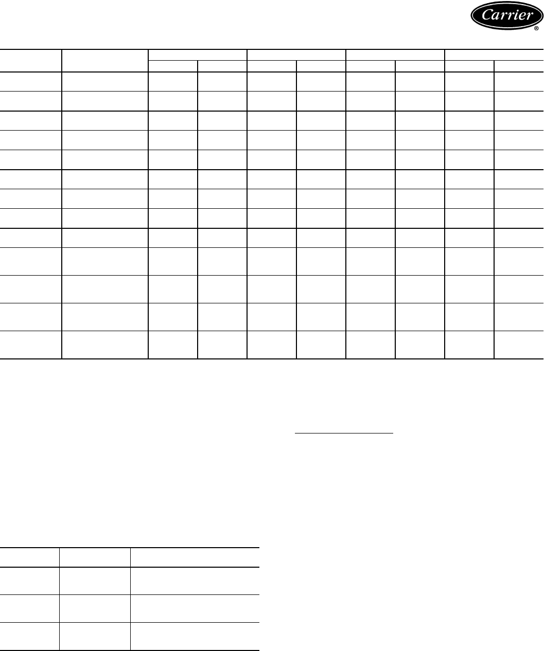
80
38AK007-012, 38AKS008-044
LEGEND
*Permissible limits of the voltage range at which unit will operate
satisfactorily.
†Value in parenthesis ( ) is FLA of second fan motor.
**Fuse or HACR circuit breaker.
NOTES:
1. Control circuit is 24 v on all units and requires an external power
source.
2. MCA and MOCP values are calculated in accordance with NEC
(National Electric Code) (U.S.A. Standard), Article 440.
3. Motor FLA and RLA values are established in accordance with UL
(Underwriters’ Laboratories) Standard 1995 (U.S.A. standard).
4. 38AKS028-044 Units Only:
220-v and 346-v units are part-wind-start units; the value under com-
pressor LRA is for the first winding energized. The 400-v units are
across-the-line-start units; value shown is for all windings energized.
FIELD POWER WIRE SIZE
LEGEND
UNIT
38AK
NOMINAL VOLTAGE
(V-Ph-Hz)
VOLTAGE RANGE* COMPRESSOR OFM POWER SUPPLY
Min Max RLA LRA Qty FLA (ea)†MCA MOCP**
007 230-3-50 198 242 21.8 158 1 1.5 28.8 35
400-3-50 360 440 10.0 79 1 1.5 14.0 20
008 230-3-50 198 242 28.8 195 1 1.5 37.5 45
400-3-50 360 440 14.7 95 1 1.5 19.9 25
012 230-3-50 198 242 37.8 239 1 1.5 48.8 60
400-3-50 360 440 17.2 125 1 1.5 23.0 30
S008 230-3-50 198 253 31.5 160 1 1.5 40.9 50
400-3-50 342 460 15.7 80 1 1.5 21.1 25
S009 230-3-50 198 253 39.7 198 1 1.5 51.1 60
400-3-50 342 460 19.9 99 1 1.5 26.4 30
S012 230-3-50 198 253 39.7 198 1 1.5 52.7 60
400-3-50 342 460 19.9 99 1 1.5 26.3 30
S013 230-3-50 198 264 32.9 128 2 3.5 (2.9) 47.5 80
400-3-50 342 457 20.0 74 2 3.5 (2.9) 31.4 50
S014 230-3-50 198 264 35.7 143 2 3.5 (2.9) 51.0 80
400-3-50 342 457 22.1 83 2 3.5 (2.9) 34.0 50
S016 230-3-50 198 264 47.9 200 2 3.5 (2.9) 66.9 100
400-3-50 342 457 29.3 115 2 3.5 (2.9) 43.0 70
S024 346-3-50 311 380 33.3 115 2 3.5 (2.9) 50.5 80
230-3-50 198 254 67.9 207 2 3.5 (2.9) 88.1 150
400-3-50 342 440 34.6 173 2 3.5 (2.9) 49.3 80
S028 346-3-50 311 380 44.9 155 2 4.4 64.9 100
230-3-50 198 254 76.9 205 2 6.4 109.0 175
400-3-50 342 440 43.6 223 2 3.0 60.5 100
S034 346-3-50 311 380 53.9 176 2 4.4 76.1 125
230-3-50 198 254 85.9 220 2 6.4 120.2 200
400-3-50 342 440 50.0 253 2 3.0 68.5 110
S044
346-3-50 311 380 79.5 240 3 4.4 112.6 175
230-3-50 198 254 105.1 327 3 6.4 150.6 250
400-3-50 342 440 65.4 345 3 3.0 90.8 150
FLA —Full Load Amps
HACR —Heating, Air Conditioning, Refrigeration
LRA —Locked Rotor Amps
MCA —Minimum Circuit Amps per NEC Section 430-24
MOCP—Maximum Overcurrent Protection
NEC —National Electrical Code (U.S.A. Standard)
OFM —Outdoor-Fan Motor
RLA —Rated Load Amps (Compressor)
UNIT
38AKS
VOLTAGE
(3 Ph, 50 Hz)
FIELD POWER WIRE SIZE
TB1 WILL ACCEPT
028
346 14 to 2/0 AWG
230
400
034
346 14 to 2/0 AWG
230 6 AWG to 350 kcmil
400 14 to 2/0 AWG
044
346 14 to 2/0 AWG
230 6 AWG to 350 kcmil
400 14 to 2/0 AWG
AWG —American Wire Gage
kcmil —Thousand circular mils (formerly MCM)
TB —Terminal Block
Electrical data
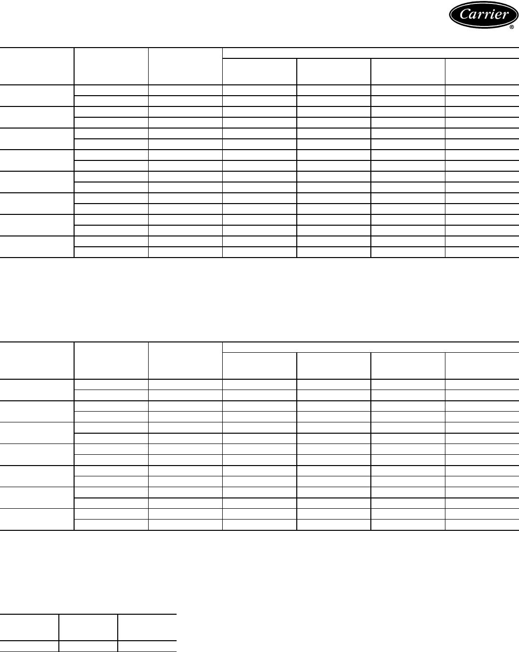
81
40RM STANDARD MOTORS
LEGEND *Motors are designed for satisfactory operation within 10% of nominal
voltages shown. Voltages should not exceed the limits shown in the
Voltage Limits column.
40RM ALTERNATE MOTORS
LEGEND *Motors are designed for satisfactory operation within 10% of nominal
voltages shown. Voltages should not exceed the limits shown in the
Voltage Limits column.
40RM FAN CONTACTOR COIL
UNIT
40RM V*-PH-Hz VOLTAGE
LIMITS
FAN MOTOR POWER SUPPLY
kW (Hp) FLA
Minimum
Circuit
Amps
MOCP
007 230-3-50 207-253 1.79 (2.4) 5.2 6.5 15
400-3-50 360-440 1.79 (2.4) 2.6 3.3 15
008 230-3-50 207-253 1.79 (2.4) 5.2 6.5 15
400-3-50 360-440 1.79 (2.4) 2.6 3.3 15
012 230-3-50 207-253 2.16 (2.9) 7.5 9.4 15
400-3-50 360-440 2.16 (2.9) 3.4 4.3 15
014 230-3-50 207-253 2.16 (2.9) 7.5 9.4 15
400-3-50 360-440 2.16 (2.9) 3.4 4.3 15
016 230-3-50 207-253 2.16 (2.9) 7.5 9.4 15
400-3-50 360-440 2.16 (2.9) 3.4 4.3 15
024 230-3-50 207-253 3.73 (5.0) 13.2 16.5 25
400-3-50 360-440 3.73 (5.0) 7.6 9.5 15
028 230-3-50 207-253 5.59 (7.5) 19.8 24.8 40
400-3-50 360-440 5.59 (7.5) 11.4 14.3 25
034 230-3-50 207-253 7.46 (10.0) 28.0 35.0 60
400-3-50 360-440 7.46 (10.0) 16.1 20.1 30
FLA —Full Load Amps
MOCP—Maximum Overcurrent Protection
UNIT
40RM V*-PH-Hz VOLTAGE
LIMITS
FAN MOTOR POWER SUPPLY
kW (Hp) FLA
Minimum
Circuit
Amps
MOCP
007 230-3-50 207-253 1.79 (2.4) 5.2 6.5 15
400-3-50 360-440 1.79 (2.4) 2.6 3.3 15
008 230-3-50 207-253 2.16 (2.9) 7.5 9.4 15
400-3-50 360-440 2.16 (2.9) 3.4 4.3 15
012 230-3-50 207-253 3.73 (5.0) 13.2 16.5 25
400-3-50 360-440 3.73 (5.0) 7.6 9.5 15
014 230-3-50 207-253 3.73 (5.0) 15.2 19.0 30
400-3-50 360-440 3.73 (5.0) 7.6 9.5 15
016 230-3-50 207-253 3.73 (5.0) 13.2 16.5 25
400-3-50 360-440 3.73 (5.0) 7.6 9.5 15
024 230-3-50 207-253 5.59 (7.5) 19.8 24.8 40
400-3-50 360-440 5.59 (7.5) 11.4 14.3 25
028 230-3-50 207-253 7.46 (10.0) 28.0 35.0 60
400-3-50 360-440 7.46 (10.0) 16.1 20.1 30
FLA —Full Load Amps
MOCP—Maximum Overcurrent Protection
UNIT
40RM
VOLTAGE
(vac)
MAXIMUM
HOLDING
VA
007-034 24 10
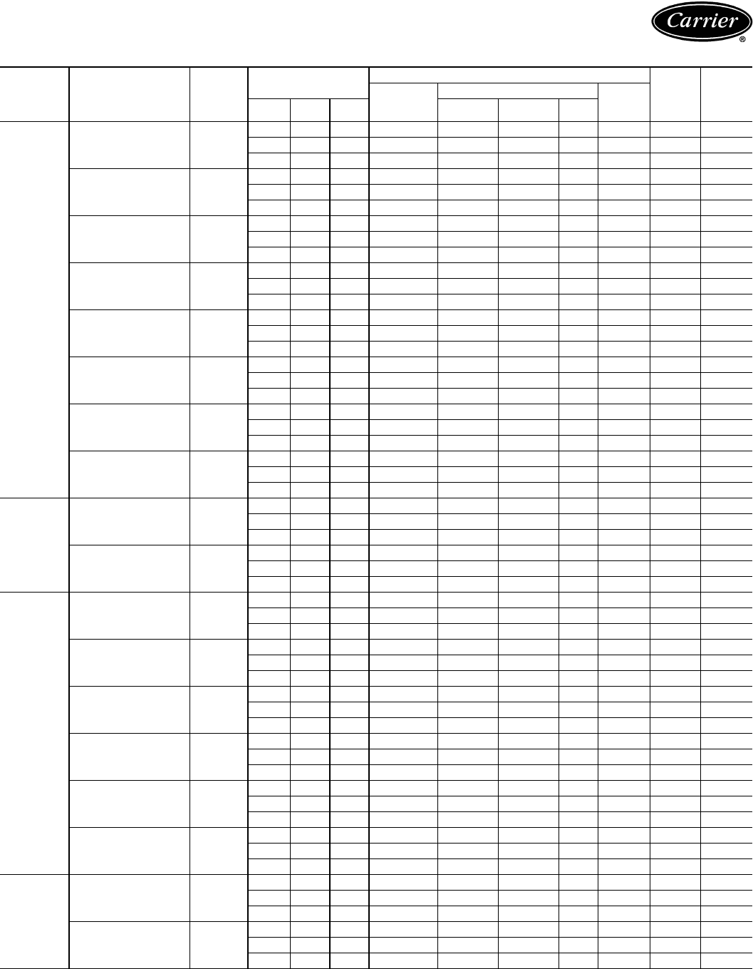
82
40RM ELECTRIC HEATER DATA
UNIT
40RM
HEATER
PA R T N O. V- PH-H z
FAN MOTOR ELECTRIC HEATER(S)
MCA* MOCP*
Nominal
Capacity
(kW)
Actual Capacity (kW)
FLA
Hp kW FLA Stage 1 Stage 2 Total
007-012
CAELHEAT001A00 240-3-50
2.4 1.79 5.2 5 5.0 —5.0 12.0 21.5 25
2.9 2.16 7.5 5 5.0 —5.0 12.0 24.4 25
5.0 3.73 15.2 5 5.0 —5.0 12.0 34.0 40
CAELHEAT002A00 400-3-50
2.4 1.79 2.6 5 3.5 —3.5 5.00 9.5 15
2.9 2.16 3.4 5 3.5 —3.5 5.00 10.5 15
5.0 3.73 7.6 5 3.5 —3.5 5.00 15.8 20
CAELHEAT004A00 240-3-50
2.4 1.79 5.2 10 10.0 —10.0 24.1 36.6 40
2.9 2.16 7.5 10 10.0 —10.0 24.1 39.4 40
5.0 3.73 15.2 10 10.0 —10.0 24.1 49.2 50
CAELHEAT005A00 400-3-50
2.4 1.79 2.6 10 6.9 —6.9 10.0 15.8 20
2.9 2.16 3.4 10 6.9 —6.9 10.0 16.8 20
5.0 3.73 7.6 10 6.9 —6.9 10.0 22.0 25
CAELHEAT007A00 240-3-50
2.4 1.79 5.2 15 15.0 —15.0 36.1 51.6 60
2.9 2.16 7.5 15 15.0 —15.0 36.1 54.5 60
5.0 3.73 15.2 15 15.0 —15.0 36.1 64.1 70
CAELHEAT008A00 400-3-50
2.4 1.79 2.6 15 10.4 —10.4 15.0 22.0 25
2.9 2.16 3.4 15 10.4 —10.4 15.0 23.0 25
5.0 3.73 7.6 15 10.4 —10.4 15.0 28.3 30
CAELHEAT010A00 240-3-50
2.4 1.79 5.2 25 15.0 10.0 25.0 60.1 81.7 90
2.9 2.16 7.5 25 15.0 10.0 25.0 60.1 84.6 90
5.0 3.73 15.2 25 15.0 10.0 25.0 60.1 94.2 100
CAELHEAT011A00 400-3-50
2.4 1.79 2.6 25 10.4 6.9 17.4 25.1 34.6 25
2.9 2.16 3.4 25 10.4 6.9 17.4 25.1 35.6 40
5.0 3.73 7.6 25 10.4 6.9 17.4 25.1 40.8 50
008-012
CAELHEAT013A00 240-3-50
2.4 1.79 5.2 35 20.0 15.0 35.0 84.2 111.7 125
2.9 2.16 7.5 35 20.0 15.0 35.0 84.2 114.6 125
5.0 3.73 15.2 35 20.0 15.0 35.0 84.2 124.2 125
CAELHEAT014A00 400-3-50
2.4 1.79 2.6 35 13.9 10.4 24.3 35.1 47.1 50
2.9 2.16 3.4 35 13.9 10.4 24.3 35.1 48.1 50
5.0 3.73 7.6 35 13.9 10.4 24.3 35.1 53.4 60
014-024
CAELHEAT016A00 240-3-50
2.9 2.16 7.5 10 10.0 —10.0 24.1 39.4 40
5.0 3.73 13.2 10 10.0 —10.0 24.1 46.6 50
7.5 5.59 19.8 10 10.0 —10.0 24.1 54.8 60
CAELHEAT017A00 400-3-50
2.9 2.16 3.4 10 6.9 —6.9 10.0 16.8 20
5.0 3.73 7.6 10 6.9 —6.9 10.0 22.0 25
7.5 5.59 11.4 10 6.9 —6.9 10.0 26.8 35
CAELHEAT019A00 240-3-50
2.9 2.16 7.5 20 19.9 —19.9 47.9 69.2 70
5.0 3.73 15.2 20 19.9 —19.9 47.9 76.3 80
7.5 5.59 22.8 20 19.9 —19.9 47.9 84.6 90
CAELHEAT020A00 400-3-50
2.9 2.16 3.4 20 13.9 —13.9 20.0 29.3 30
5.0 3.73 7.6 20 13.9 —13.9 20.0 45.1 50
7.5 5.59 11.4 20 13.9 —13.9 20.0 49.2 50
CAELHEAT022A00 240-3-50
2.9 2.16 7.5 30 20.0 10.0 30.0 72.2 99.6 100
5.0 3.73 15.2 30 20.0 10.0 30.0 72.2 106.7 110
7.5 5.59 22.8 30 20.0 10.0 30.0 72.2 115.0 125
CAELHEAT023A00 400-3-50
2.9 2.16 3.4 30 13.9 6.9 20.8 30.1 41.8 50
5.0 3.73 7.6 30 13.9 6.9 20.8 30.1 47.1 50
7.5 5.59 11.4 30 13.9 6.9 20.8 30.1 51.8 60
016-024
CAELHEAT025A00 240-3-50
2.9 2.16 7.5 50 30.0 20.0 50.0 120.3 159.7 175
5.0 3.73 13.2 50 30.0 20.0 50.0 120.3 166.9 175
7.5 5.59 19.8 50 30.0 20.0 50.0 120.3 175.1 200
CAELHEAT026A00 400-3-50
2.9 2.16 3.4 50 20.8 13.9 34.7 50.1 66.9 70
5.0 3.73 7.6 50 20.8 13.9 34.7 50.1 72.1 80
7.5 5.59 11.4 50 20.8 13.9 34.7 50.1 76.9 80
Electrical data (cont)
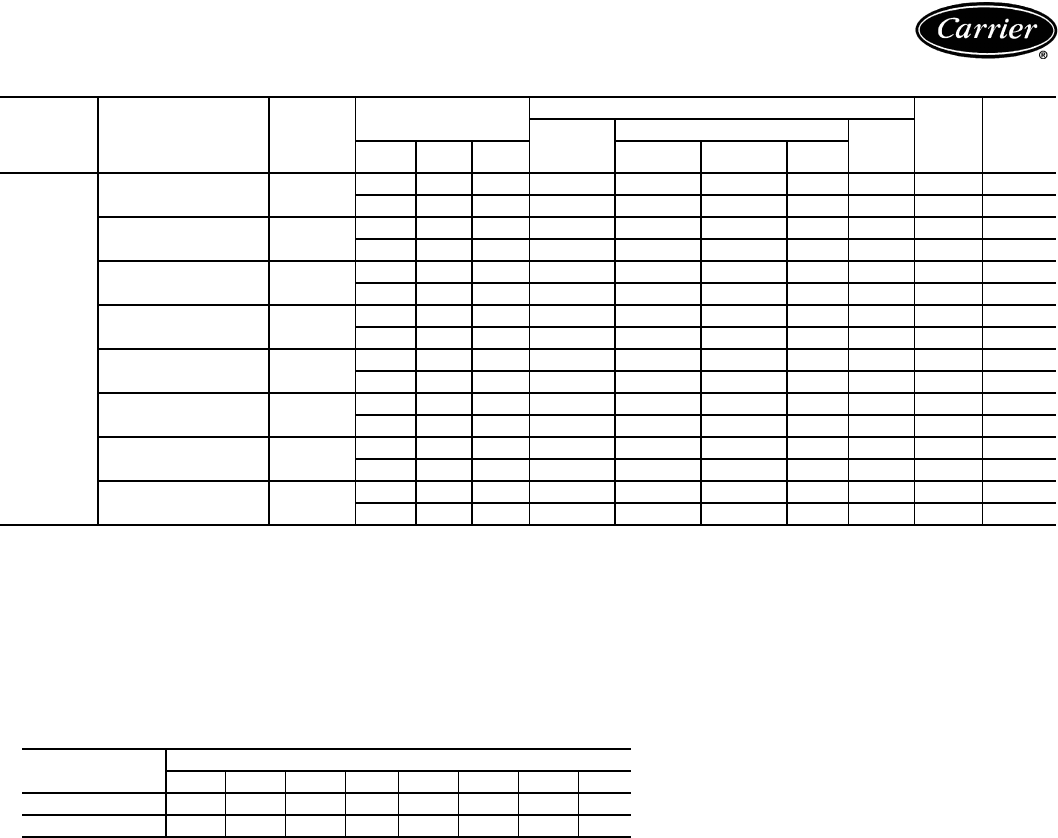
83
40RM ELECTRIC HEATER DATA (cont)
LEGEND
*Values shown are for single-point connection of electric heat accessory and air handler.
NOTES:
1. MCA and MOCP values apply to both standard and alternate factory-supplied motors.
2. Electric resistance heaters are rated at 240 v and 480 v. To determine heater capacity
(kW) at unit nameplate multiply the 240-v or 480-v capacity (kW) by the multipliers
shown in the table below.
3. Heater coils are 24 v and require 8 va holding current.
4. The following equation converts kW of heat energy to Btuh:
kW x 3,412 = Btuh.
5. Approximate shipping weights:
CAELHEAT001A00 – 014A00 = 55 lbs each
CAELHEAT016A00 – 026A00 = 60 lbs each
CAELHEAT028A00 – 038A00 = 75 lbs each
UNIT
40RM
HEATER
PART NO. V-PH-H z
FAN MOTOR ELECTRIC HEATER(S)
MCA* MOCP*
Nominal
Capacity
(kW)
Actual Capacity (kW)
FLA
Hp kW FLA Stage 1 Stage 2 Total
028,034
CAELHEAT028A00 240-3-50 7.5 5.59 19.8 20 19.9 —19.9 47.9 84.6 90
10.0 7.46 28.0 20 19.9 —19.9 47.9 94.8 110
CAELHEAT029A00 400-3-50 7.5 5.59 11.4 20 13.9 —13.9 20.0 39.3 40
10.0 7.46 16.1 20 13.9 —13.9 20.0 45.2 50
CAELHEAT031A00 240-3-50 7.5 5.59 19.8 40 20.0 20.0 40.0 96.2 145.0 150
10.0 7.46 22.8 40 20.0 20.0 40.0 96.2 155.3 175
CAELHEAT032A00 400-3-50 7.5 5.59 11.4 40 13.8 13.8 27.8 39.9 64.1 70
10.0 7.46 16.1 40 13.8 13.8 27.8 39.9 70.0 80
CAELHEAT034A00 240-3-50 7.5 5.59 22.8 50 30.0 20.0 50.0 120.3 175.1 200
10.0 7.46 32.2 50 30.0 20.0 50.0 120.3 185.4 200
CAELHEAT035A00 400-3-50 7.5 5.59 11.4 50 20.8 13.9 34.7 50.1 76.9 80
10.0 7.46 16.1 50 20.8 13.9 34.7 50.1 82.8 90
CAELHEAT037A00 240-3-50 7.5 5.59 19.8 70 40.0 30.0 70.0 168.4 193.1 200
10.0 7.46 28.8 70 40.0 30.0 70.0 168.4 208.4 225
CAELHEAT038A00 400-3-50 7.5 5.59 11.4 70 27.8 20.8 48.6 70.2 84.4 90
10.0 7.46 16.1 70 27.8 20.8 48.6 70.2 90.3 100
FLA —Full Load Amps
Hp —Horsepower
MCA —Minimum Circuit Amps
MOCP —Maximum Overcurrent Protection
HEATER RATING
VOLTAGE
AC T UAL H E AT E R VO LTAG E AT SITE
200 208 230 240 400 440 460 480
240 0.694 0.751 0.918 1.0 ————
480 ————0.694 0.840 0.918 1.0

84
Operating sequence — 38AK007-012,
38AKS008-012
At start-up, the thermostat calls for cooling. With all safety
devices satisfied, the compressor contactor and fan con-
tactor energize, causing the compressor and outdoor-fan
motor to operate. Contacts energize, allowing the field-
supplied and -installed indoor-fan contactor to function. A
field-supplied and -installed liquid line valve also opens,
allowing the system to function in Cooling mode. As cool-
ing demand is satisfied, the thermostat contacts break,
deenergizing the contactor and causing the system to shut
off. The liquid line solenoid valve closes, minimizing the
potential for refrigerant migration. The compressor does
not restart until the thermostat again calls for cooling. If a
demand for cooling occurs within 5 minutes after the ther-
mostat is satisfied, the system will not restart because of
the Time Guard® II device. After the 5-minute time period,
the system will restart as normal on thermostat demand.
The system is protected with a Cycle-LOC™ device so that
the compressor will not start if a high-pressure or low-
pressure fault occurs. To reset the Cycle-LOC device, set
the thermostat to eliminate the cooling demand, then
return to original set point. This should be done only once,
and if system shuts down due to the same fault, determine
the problem before attempting to reset the Cycle-LOC
device.
Operating sequence — 38AKS013-024
When the first stage of cooling thermostat closes, the timer
starts. After approximately 3 seconds, the timer activates
the compressor and fan motor no. 1 contactors. When
the liquid pressure builds to approximately 1772 kPag
(257 psig), fan motor no. 2 is energized.
On demand for additional cooling capacity, the second
stage of the cooling thermostat closes, energizing a field-
supplied liquid line solenoid (LLS) valve, which opens. This
increases the suction pressure, causing the compressor to
operate at higher capacity (compressor loads).
When the fan switch is set at AUTO, the indoor-air fan
cycles with the compressor. When the switch is set at
CONT, the indoor-air fan runs continuously.
At shutdown, the Time Guard II timer prevents the com-
pressor from restarting for approximately 5 minutes.
In addition, a field-supplied solenoid valve wired in paral-
lel with the compressor contactor coil shuts off the liquid
line to prevent refrigerant migration back to the compres-
sor during the off cycle.
Operating sequence — 38AKS028-044
When space thermostat calls for cooling, the no. 1 con-
denser fan and compressor starts after control module
(CM) initial time delay of 3 (+2/-1) seconds. If an optional
airflow switch is used, compressor and no. 1 condensing
fan will not start until sufficient indoor airflow has closed
the switch. After 3 seconds the compressor starts and the
liquid line solenoid valve (for solenoid drop control) opens.
The crankcase heater is deenergized. If the head pressure
reaches 1793 kPag (260 psig), the second condenser fan
starts.
If cooling demand is low, suction pressure at the com-
pressor drops. As the pressure drops, the compressor
unloads 2 banks of cylinders as required. If cooling demand
is high and 2-stage operation is used, the second step of
the thermostat activates the capacity control liquid line
solenoid which activates the second stage evaporator coil.
The compressor cylinders load or unload in response to
compressor suction pressure to meet evaporator load.
Two minutes after the compressor starts, the bypass
relay (BPR) timer is deenergized and the low-pressure
switch (LPS) bypass is deactivated. If the LPS trips during
the first 2 minutes of operation, the compressor remains
operational. If a high-pressure switch (HPS) trips at any
time, or the LPS trips after 2 minutes, the compressor can-
not restart until the control circuit power is interrupted due
to the CM lockout feature.
As the space cooling load is satisfied, the second stage of
the thermostat opens, and closes the field-supplied capac-
ity control liquid line solenoid valve to deactivate the sec-
ond stage coil. The compressor adjusts the number of
active cylinders to meet the new load. When the space
temperature is satisfied, the first stage of the thermostat
opens and the control relay and the BPR open. This closes
the solenoid drop control valve. The compressor stops and
the crankcase heater is energized, preventing refrigerant
from migrating to the compressor during the off cycle
(solenoid drop refrigerant control). The CM anti-short-
cycling timer is energized and runs for approximately
5 minutes. During this time, the compressor is not able to
restart.
Controls
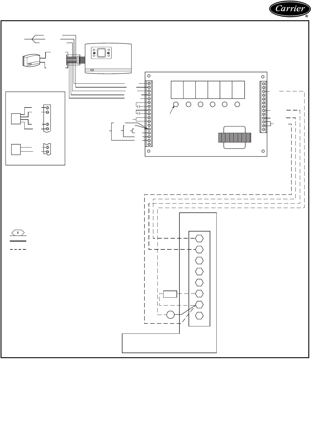
85
Typical control wiring
FAN
COOL*
24 VAC
COMMON
24 VAC
CONNECTION
BOARD (TB)
R
1
2
Y1
Y2
3
W1
W2
5
G
6
C
X
7
8
IFC †
LLSV†
4
38AK,AKS CONDENSING UNIT
WHT
RED
BLUE
YEL
GRN
6
7
8
9
10
11
12
13
14
15
16
17
ECON
FAN
H2
H1 (NC)
H1 (NO)
HT COM
C2
C1
COOL COM
24 VAC
CHRS
1212FAN ECON
LEDS COOL HEAT
J3
SINGLE ZONE RELAY PACK CIRCUIT BOARD
WHITE
RED
BLUE
YELLOW
GREEN
IAQ SWITCH
FAN STATUS SWITCH
SEE “A”
DX
OAT SAT
BLACK BLACK
BLACK
RED
RED
RED
BLACK (-)
RED (+)
GREEN (GRD)
NETWORK
RED (-)
BLACK (+)
REMOTE ROOM
TEMP. SENSOR
WHT
RED
GRN
BLK
GRN
BLK
WHT
RED
10
11
10
11
FILTER STATUS SWITCH
FIG. “A”
HUMIDITY SENSOR
HS
FSS
TEMP SYSTEM APPLICATIONS — 38AK007-012, 38AKS008-012
LEGEND
*Single zone relay pack requires 10 va.
†Field-supplied.
NOTE: Humidity Sensor and filter status switch
cannot be wired at the same time.
DX —Direct Expansion Coil Sensor
FSS —Filter Status Switch
HS —Humidity Sensor
IAQ —Indoor Air Quality
IFC —Indoor-Fan Contactor
LED —Light-Emitting Diode
LLSV —Liquid Line Solenoid Valve
OAT —Outdoor Air Temperature Sensor
SAT —Supply Air Temperature Sensor
TB —Terminal Block
Marked Terminal
Factory Wiring
Field Control Wiring
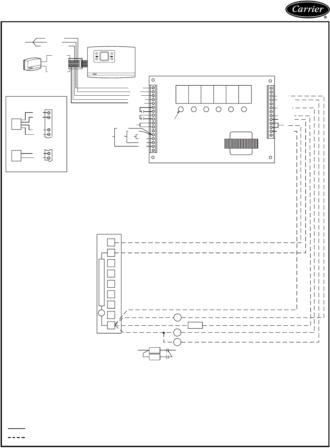
86
Typical control wiring (cont)
HD1
HD2
R1
R2
L1
L2
R2
R1
LLSV*
IFC
1
2
3
4
5
6
7
8
9
TIME GUARD CIRCUIT
®
c
NOTE 1
FAN
R
COOL 1
COOL 2
HEAT 1
HEAT 2
24 VAC
COMMON
WHT
RED
BLUE
YEL
GRN
6
7
8
9
10
11
12
13
14
15
16
17
ECON
FAN
H2
H1 (NC)
H1 (NO)
HT COM
C2
C1
COOL COM
24 VAC
CHRS
1212FAN ECON
LEDS COOL HEAT
J3
SINGLE ZONE RELAY PACK CIRCUIT BOARD
WHITE
RED
BLUE
YELLOW
GREEN
IAQ SWITCH
FAN STATUS SWITCH
SEE “A”
DX
OAT SAT
BLACK BLACK
BLACK
RED
RED
RED
BLACK (-)
RED (+)
GREEN (GRD)
NETWORK
RED (-)
BLACK (+)
REMOTE ROOM
TEMP. SENSOR
WHT
RED
GRN
BLK
GRN
BLK
WHT
RED
10
11
10
11
FILTER STATUS SWITCH
FIG. “A”
HUMIDITY SENSOR
HS
FSS
NOTE 2
TERMINAL BLOCK (TB2)
IN CONTROL BOX
TEMP SYSTEM APPLICATIONS — 38AKS013-024
*Field supplied.
NOTES:
1. Combination LLSV plus IFC VA should not exceed 30 VA.
2. Do not exceed 5 VA (24 VAC) per coil.
3. If the VA values in Notes 1 and 2 must be exceeded, use accessory
relay-transformer package 38AE900001.
4. Wiring diagrams are general guides only and are not intended for a
specific installation. Refer to individual product installation and wiring
literature.
5. Humidity Sensor and filter status switch cannot be wired at the same
time.
LEGEND
C—Compressor Contactor
DX —Direct Expansion Coil Sensor
FSS —Filter Status Switch
HD —Heating Device
HS —Humidity Sensor
IAQ —Indoor Air Quality
IFC —Indoor Fan Contactor
LED —Light-Emitting Diode
LLSV —Liquid Line Solenoid Valve
OAT —Outdoor Air Temperature Sensor
R—Heat Control Relay (field-supplied, 24-volt
seated coil, 10-va max rating)
SAT —Supply Air Temperature Sensor
Factory Wiring
Field Control Wiring
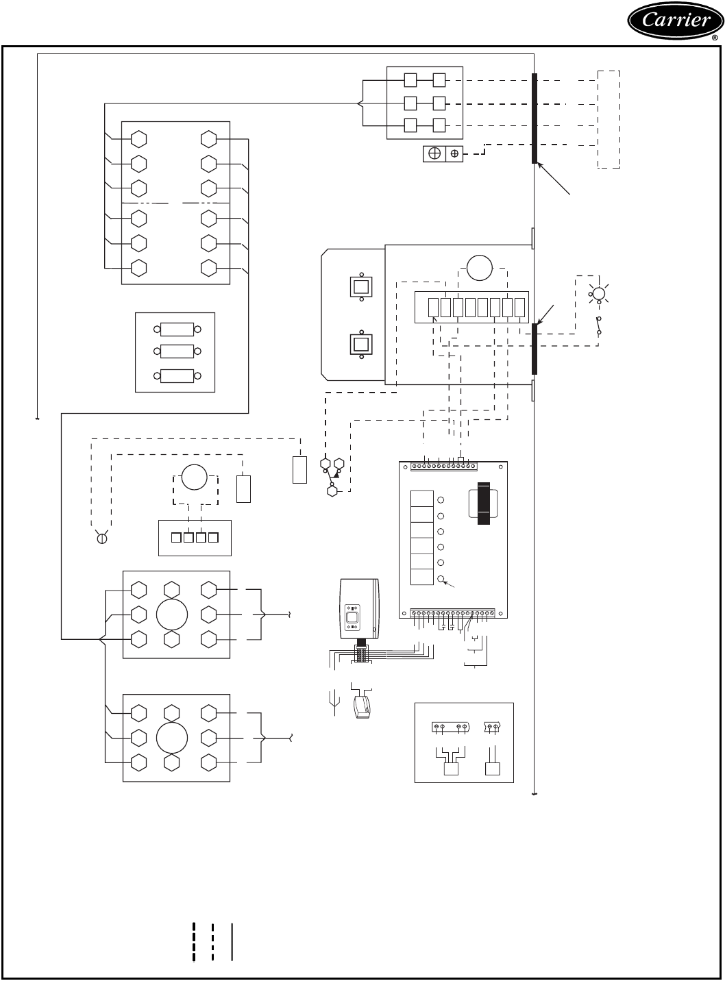
87
11 12 13
C1 C2
C1
22
21 23
11 12 13
C1 C2
C1A
22
21 23
11 12 13
22
21 23
14 15 16
25
24 26
CB1
FU1
208/230V ONLY
+
+TB2
1
2
3
4
GND
GND
RED ORN
BRN
YEL BLUBLK
TO COMPRESSORTO COMPRESSOR
EQUIP GND
(LLSV)
RY
W
AFS
LLS1*
LLS2*
1/R
2/Y1
3/Y2
4/W1
5/W2
6/G
7/C
8/X
TB3
CB1
115V
CB1
24V
CB2
A
ALARM
SHUT-OFF
SWITCH
ALARM
OR
LIGHT
FIELD SUPPLIED
[22.2] 7/8” DIA. HOLE
[63.5] 2 1/2”
OR
[92.1] 3 5/8”
DIA. HOLE
23 22 21
13 12 11
TB1
FIELD POWER SUPPLY
FUSED
NEC DISCONNECT
SINGLE ZONE RELAY PACK CIRCUIT BOARD
FAN
R
COOL 1
24 VAC
COMMON
COOL 2
HEAT 1
HEAT 2
WHT
RED
BLUE
YEL
GRN
6
7
8
9
10
11
12
13
14
15
16
17
ECON
FAN
H2
H1 (NC)
H1 (NO)
HT COM
C2
C1
COOL COM
24 VAC
CHRS
1212FAN ECON
LEDS COOL HEAT
J3
WHITE
RED
BLUE
YELLOW
GREEN
IAQ SWITCH
FAN STATUS SWITCH
SEE “A”
DX
OAT SAT
BLACK
BLACK
BLACK
RED
RED
RED
BLACK (-)
RED (+)
GREEN (GRD)
NETWORK
RED (-)
BLACK (+)
REMOTE ROOM
TEMP. SENSOR
WHT
RED
GRN
BLK
GRN
BLK
WHT
RED
FILTER STATUS SWITCH
FIG. “A”
HUMIDITY SENSOR
HS
FSS
10
11
10
11
EQUIP GND
TEMP SYSTEM APPLICATIONS — 38AKS028-044
LEGEND
*Field-supplied.
AFS —Airflow Switch
CB —Circuit Breaker
EQUIP —Equipment
FU —Fuse
GND —Ground
LLS1 —Liquid Line Solenoid for
Solenoid Drop Control
LLS2 —Liquid Line Solenoid for
Capacity Control
LLSV —Liquid Line Solenoid Valve
NEC —National Electrical Code
TB —Terminal Block
Field Power Wiring
Field Control Wiring
Factory-Installed Wiring
NOTES:
1. Factory wiring in accordance with
NEC. Any field modifications or
additions must be in compliance
with all applicable codes.
2. All field interlock contacts must
have minimum rating of 180-va
pilot duty plus capacity required
for field-installed equipment. All
field interlock contacts in the 24-v
control circuit must have mini-
mum rating of 70-va pilot duty
plus capacity required for field-
installed equipment.
3. For internal unit wiring, reference
wiring book or unit wiring label
diagram. TB2 is 115-1-60, TB3 is
24-1-60.
4. The following components are
not located in the 38AKS unit
control box: LLS1, LLS2, field
control thermostat, AFS, alarm
shut-off switch, and alarm or
light.
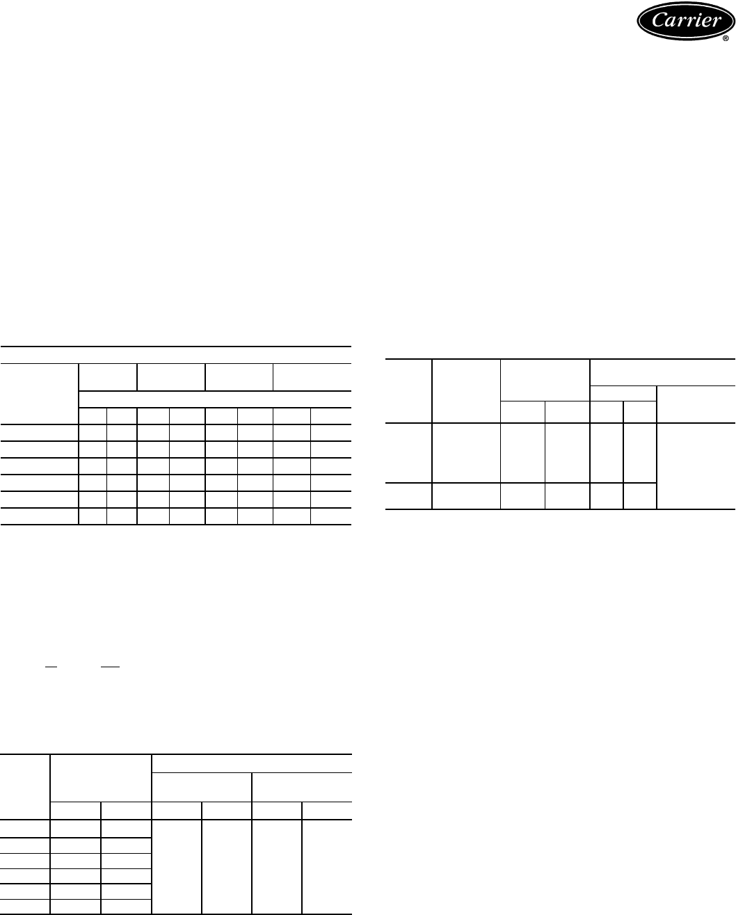
88
Operating limits — SI
Maximum outdoor ambient . . . . . . . . . . . . . . . . . . 52 C
Minimum return-air temperature . . . . . . . . . . . . . . 13 C
Maximum return-air temperature . . . . . . . . . . . . . . 35 C
Range of acceptable saturation
suction temperature. . . . . . . . . . . . . . . . . . –4 to 13 C
Maximum discharge temperature . . . . . . . . . . . . . 135 C
Minimum discharge superheat . . . . . . . . . . . . . . . .33° C
NOTES:
1. Select air handler at no less than 40 L/s per kW
(nominal condensing unit capacity).
2. Total combined draw of the field-supplied liquid line
solenoid valve and air handler fan contactor must not
exceed 20 volt-amperes (va). If the specified volt-
amperes must be exceeded, use a remote relay to
control the load.
REFRIGERANT PIPING SIZES
LEGEND
L — Liquid Line S — Suction Line
NOTES:
1. Pipe sizes are based on a 1° C (2° F) loss for liquid and suction
lines.
2. Pipe sizes are based on the maximum linear length, shown for each
column, plus a 50% allowance for fittings.
3. Charge units with R-22 in accordance with unit installation
instructions.
4. Line size conversion to mm:
in. mm
1/212.7
5/815.9
11/828.6
13/834.9
LIQUID LINE DATA
NOTE: Values shown are for units operating at 7.2 C (45 F) saturated
suction and 35 C (95 F) entering air.
Operating limits — English
Maximum outdoor ambient . . . . . . . . . . . . . . . . . .125 F
Minimum return-air temperature . . . . . . . . . . . . . . . 55 F
Maximum return-air temperature . . . . . . . . . . . . . . .95 F
Range of acceptable saturation
suction temperature . . . . . . . . . . . . . . . . . 25 to 55 F
Maximum discharge temperature . . . . . . . . . . . . .275 F
Minimum discharge superheat . . . . . . . . . . . . . . . . 60° F
NOTES:
1. Select air handler at no less than 300 cfm/ton (nominal
condensing unit capacity).
2. Total combined draw of the field-supplied liquid line
solenoid valve and air handler fan contactor must not
exceed 20 volt-amperes (va). If the specified volt-
amperes must be exceeded, use a remote relay to con-
trol the load.
MINIMUM OUTDOOR-AIR OPERATING
TEMPERATURE
*Unit has one step of unloading.
†38AK007 — Motormaster® I Control only. 38AK008, 38AK012,
38AKS008, 38AKS009, 38AKS012 — Motormaster III Control only.
(Motor change required on 38AK007.)
LINEAR LENGTH OF PIPING — m (ft)
UNIT
38AK
0-7.6
(0-25)
7.6-15.2
(25-50)
15.2-22.9
(50-75)
22.9-30.5
(75-100)
Line Size (in. OD)
LSLSLS L S
007 1/211/81/211/81/211/81/211/8
008 1/211/81/211/85/813/85/813/8
012 1/211/85/813/85/813/85/813/8
S008 1/211/81/211/85/813/85/813/8
S009 1/211/85/811/85/813/85/813/8
S012 1/211/85/811/85/813/85/813/8
UNIT
38AK
MAX
ALLOWABLE
LIQUID LIFT
LIQUID LINE
Max Allowable
Pressure Drop
Max Allowable
Temp Loss
MFt
kPa psi C F
007 23.2 76
48.3 7 1 2
008 15.2 50
012 17.4 57
S008 15.2 50
S009 15.8 52
S012 15.8 52
UNIT
38AK
COM-
PRESSOR
CAPACITY
(%)
SATURATED
CONDENSING
TEMP
MINIMUM
OUTDOOR TEMP
Base Unit With
Low Ambient
Control†
CFCF
007 100 32 90 12 53
–29 (–20)
008 100 32 90 15 60
012 100 32 90 11 52
S008 100 32 90 15 60
S009 100 32 90 12 53
S012* 100 32 90 9 48
67 27 60 11 52
Application data — 38AK007-012, 38AKS008-012
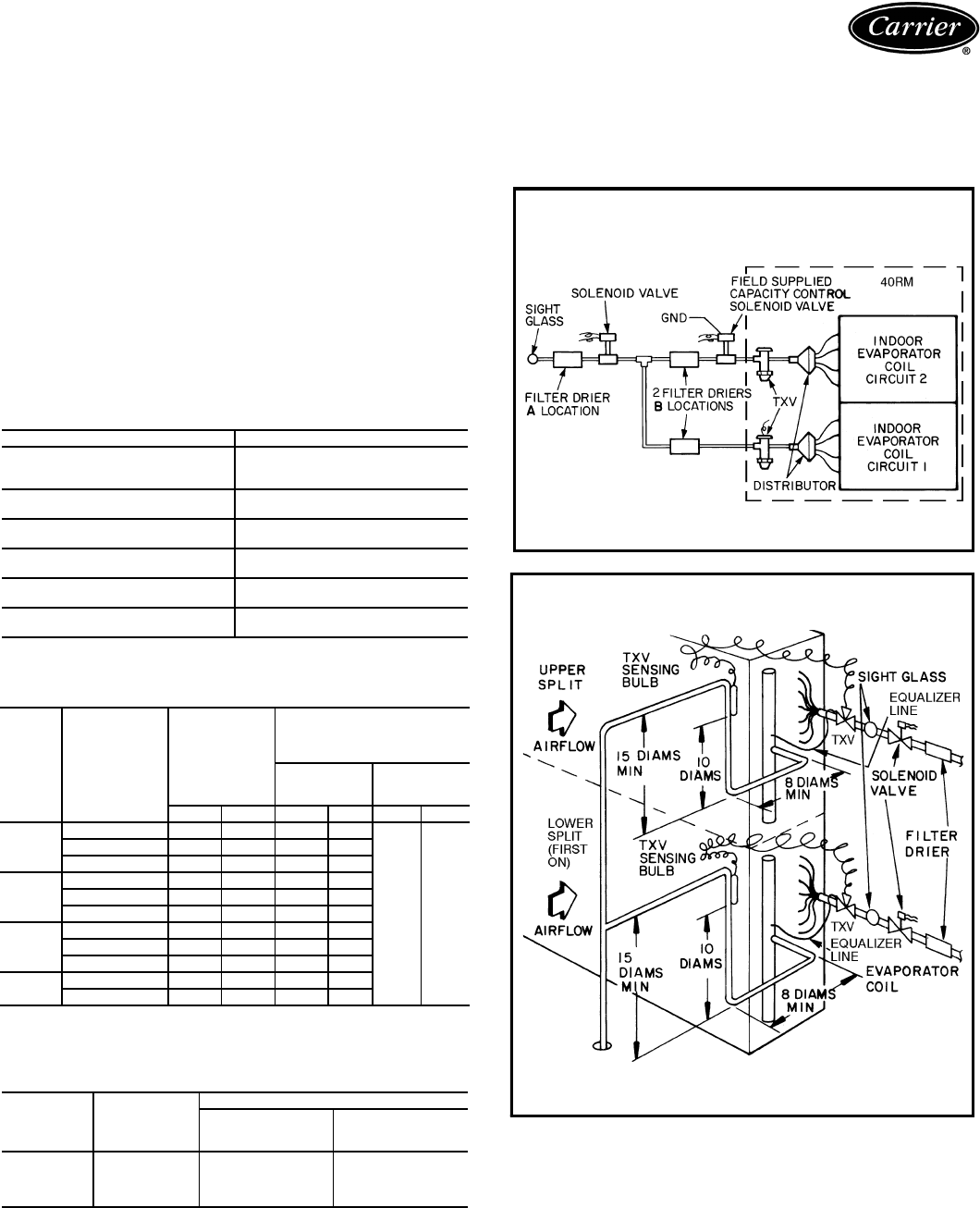
89
Installation
Select equipment to match or to be slightly less than peak
load. This provides better humidity control, less unit
cycling, and less part-load operation.
When selecting vapor line sizes, oil return must be evalu-
ated, particularly at part-load conditions.
The indoor fan must always be operating when outdoor
unit is operating.
Ductwork should be sized according to unit size, not
building load.
To minimize the possibility of air recirculation, avoid the
use of concentric supply/return grilles.
Indoor equipment should be selected at no less than
40 L/s per kW (300 cfm/ton).
OPERATING LIMITS
MINIMUM OUTDOOR-AIR OPERATING
TEMPERATURE
*Requires field-installed unloader.
†Motormaster® I control — 38AKS013-024.
LIQUID LINE DATA
NOTE: Data above is for units operating at 8 C (45 F) saturated suction and 35 C
(95 F) entering air.
Use of liquid line solenoid valves
A liquid line solenoid valve is recommended.
For dual coil applications, a single liquid line solenoid
valve is required to deactivate upper second-stage coil.
Maximum Outdoor Ambient 52 C (125 F)
Minimum Outdoor Ambient See Minimum Outdoor-Air
Operating Temperature
table below.
Minimum Return-Air
Temperature 12.8 C (55 F)
Maximum Return-Air
Temperature 35 C (95 F)
Normal Acceptable Saturation
Suction Temperature Range –3.9 to 12.8 C (25 to 55 F)
Maximum Discharge
Temperature 135 C (275 F)
Minimum Discharge
Superheat 15.6 C (60 F)
UNIT
38AKS
COMPRESSOR
CAPACITY
(%)
SATURATED
CONDENSING
TEMP
MINIMUM
OUTDOOR-AIR
OPERATING
TEMPERATURE
Base
Unit
With
Low-Ambient
Control†
C F CFCF
013
100 32 90 1.7 35
–29 –20
67 27 80 7.2 45
33* 21 70 12.8 55
014
100 32 90 2.8 37
67 27 80 8.9 48
33* 21 70 13.9 57
016
100 32 90 –5.0 23
67 27 80 2.2 36
33* 21 70 10.0 50
024 100 32 90 –9.4 15
50 27 80 –6.7 20
UNIT
38AKS
MAX
ALLOW.
LIFT —
m (ft)
LIQUID LINE
Max Allow.
Pressure Drop —
kPa (psi)
Max Allow.
Temp Loss —
C (°
°°
°F)
013 15.8 (52)
48 (7) 1 (2)
014 20.4 (67)
016 25.0 (82)
024 26.5 (87)
Application data — 38AKS013-024
LOCATION OF ONE LIQUID LINE SOLENOID
VALVE SERVING 2 COIL CIRCUITS
(Solenoid Drop Control)
LEGEND
TXV — Thermostatic Expansion Valve
FACE-SPLIT COIL SUCTION AND
LIQUID LINE PIPING
LEGEND
TXV — Thermostatic Expansion Valve
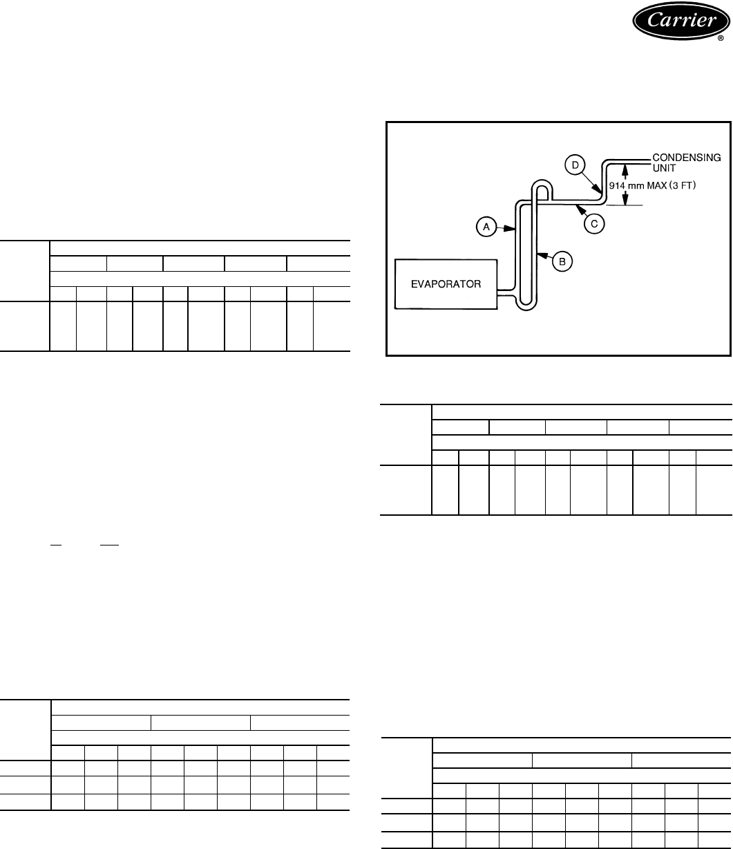
90
Oil return
Condensing units with multiple-step unloading may
require double suction risers to assure proper oil return at
minimum load operating conditions. Reduction of evapora-
tor coil surface should be analyzed to provide sufficient
refrigerant velocity to return oil to the compressor. Liquid
line solenoid valves may be used in certain situations to
accomplish this. Hot gas bypass, if used, should be intro-
duced before the evaporator. Consult Carrier System
Design manual.
REFRIGERANT PIPING SIZES — SI
*Requires a double suction riser if 2 unloaders are used and the evapo-
rator is below the condensing unit. See Refrigerant Piping Sizes —
Double Suction Risers table below and Suction Line Piping figure at
right for more information.
NOTES:
1. Pipe sizes are based on a 1.1 C max loss for liquid lines and 0.8 C
max loss for suction lines, selected at maximum length for each
interval and for matched systems at nominal rating conditions
nominal airflow.
2. Pipe sizes are based on an equivalent length equal to the maxi-
mum length of interconnecting piping plus 50% for fittings. A more
accurate estimate may result in smaller sizes.
3. Units must be charged in accordance with the unit installation
instructions.
4. Line size conversion to mm:
in. mm
1/212.7
5/815.9
7/822.2
11/828.6
13/834.9
15/841.3
21/854.0
25/866.7
31/879.4
REFRIGERANT PIPING SIZES —
DOUBLE SUCTION RISERS — SI
NOTES:
1. See Suction Line Piping figure for “A,” “B,” and “C” dimensions.
2. No double suction risers are needed for unit size 024.
Insulation
Refrigerant suction piping should be insulated in
accordance with guidelines set forth in the Carrier System
Design Manual.
REFRIGERANT PIPING SIZES — ENGLISH
*Requires a double suction riser if 2 unloaders are used and the evapo-
rator is below the condensing unit. See Refrigerant Piping Sizes —
Double Suction Risers table and Suction Line Piping figure above for
more information.
NOTES:
1. Pipe sizes are based on a 2 F max loss for liquid lines and a 1.5 F
max loss for suction lines, selected at maximum length for each
interval and for matched systems at nominal rating conditions,
nominal airflow.
2. Pipe sizes are based on an equivalent length equal to the maxi-
mum length of interconnecting piping plus 50% for fittings. A more
accurate estimate may result in smaller sizes.
3. Units must be charged in accordance with the unit installation
instructions.
REFRIGERANT PIPING SIZES —
DOUBLE SUCTION RISERS — ENGLISH
NOTES:
1. See Suction Line Piping figure above for “A,” “B,” and “C”
dimensions.
2. No double suction risers are needed for unit size 024.
COND
UNIT
38AKS
LENGTH OF INTERCONNECTING PIPING (m)
0-4.5 4.5-7.5 7.5-15 15-23 23-30
Line Size (in. OD)
LSLSL S L S L S
013 1/211/81/211/85/813/85/813/85/813/8*
014 1/211/85/813/85/813/87/815/8*7/815/8*
016 5/813/85/813/85/815/8*7/815/8*7/815/8*
024 5/813/85/813/85/815/87/815/87/815/8
COND
UNIT
38AKS
LENGTH OF INTERCONNECTING PIPING (m)
7.5-15 18-23 23-30
Line Size (in. OD)
ABCABCABC
013 ——————11/813/815/8
014 ———
11/813/815/811/813/815/8
016 11/813/815/811/813/815/811/813/815/8
COND
UNIT
38AKS
LENGTH OF INTERCONNECTING PIPING (FT)
0-15 16-25 25-50 50-75 75-100
Line Size (in. OD)
LSLSL S L S L S
013 1/211/81/211/85/813/85/813/85/813/8*
014 1/211/85/813/85/813/87/815/8*7/815/8*
016 5/813/85/813/85/815/8*7/815/8*7/815/8*
024 5/813/85/813/85/815/87/815/87/815/8
COND
UNIT
38AKS
LENGTH OF INTERCONNECTING PIPING (FT)
25-50 50-75 75-100
Line Size (in. OD)
ABCABCABC
013 ——————11/813/815/8
014 ———
11/813/815/811/813/815/8
016 11/813/815/811/813/815/811/813/815/8
Application data — 38AKS013-024 (cont)
SUCTION LINE PIPING
LEGEND
A —Suction riser without trap
B —Suction riser with trap
C —Horizontal suction line to
condensing unit
D —Short vertical riser:
38AKS028 — 15/8 in. OD
38AKS034,044 — 21/8 in. OD
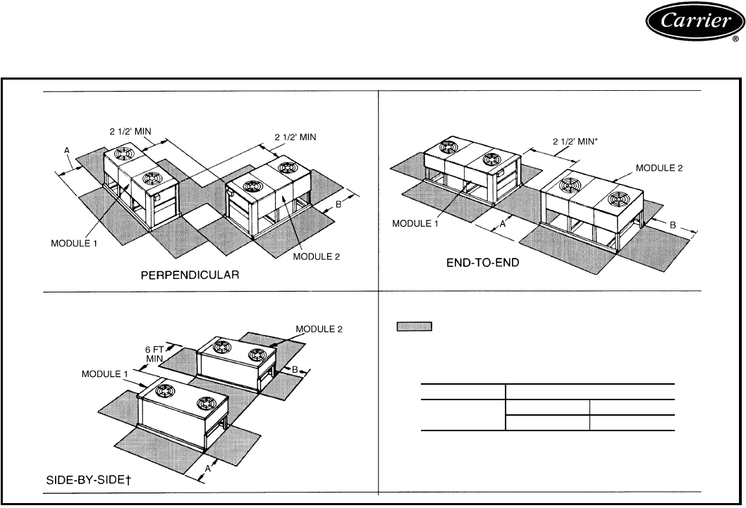
91
Multiple condensing unit arrangements*
38AKS013-024
38AKS013-024
38AKS013-024
Space for Service and Airflow
*For clearances between controls and grounded surfaces,
check local codes.
†Observe minimum recommended space requirements.
38AKS DIMENSIONS (ft)
013-028 AB
44
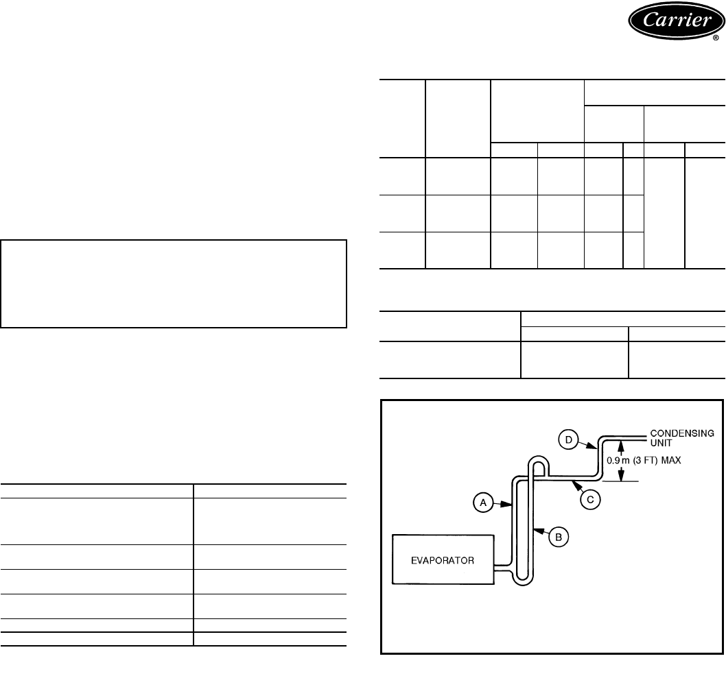
92
Installation
Select equipment to match or to be slightly less than peak
load. This provides better humidity control, less unit cy-
cling, and less part-load operation.
When selecting vapor line sizes, oil return should be
evaluated, particularly at part-load conditions.
The evaporator fan must always be operating when out-
door fan is operating.
Unit cycles should be limited to 3 or less.
Multiple outdoor units may be used with a single indoor
unit. This involves multiple refrigeration circuits.
To minimize return-air temperature extremes, use the
equipment room as a return-air plenum when applying
VAV systems with supply-to-return air recycle as used with
Carrier VVT® (variable volume and temperature) Control
Systems.
Indoor equipment should be selected at no less than
40 L/s per kW (300 cfm/ton).
OPERATING LIMITS
MINIMUM OUTDOOR-AIR OPERATING
TEMPERATURE
MAXIMUM LIQUID LIFT
IMPORTANT: When application is in a variable air vol-
ume (VAV) system, total building load is not the sum of
the individual peak loads. If individual peak loads are
summed, the equipment tends to be oversized for the
load.
Maximum Cooling Load 46 C (115 F)
Minimum Cooling Load Additional head pressure
control may be required
below 1.7 C (35 F) outdoor
ambient.
Minimum Return-Air
Temperature 12.8 C (55 F)
Maximum Return-Air
Temperature 35 C (95 F)
Normal Acceptable Saturation
Suction Temperature Range 1.1 to 12.8 C (30 to 55 F)
Maximum Discharge Temperature 146 C (295 F)
Minimum Discharge Superheat 15.6 C (60 F)
UNIT
38AKS
COM-
PRESSOR
CAPACITY
(%)
SATURATED
CONDENSING
TEMPERATURE
MIN OUTDOOR
TEMPERATURE
Base
Unit
With
Low Ambient
Control
CFCFCF
028
100 32 90 –631
–29 –20
67 27 80 1.7 35
33 21 70 1 34
034
100 32 90 –130
67 27 80 1 34
33 21 70 5.5 42
044
100 32 90 –3.9 25
67 27 80 –130
33 21 70 1.7 35
UNIT 38AKS MAXIMUM LIQUID LIFT
mft
028 23 76
034 20 67
044 23 76
Application data — 38AKS028-044
SUCTION LINE PIPING
LEGEND
A —Suction riser without trap
B —Suction riser with trap
C —Suction line to condensing unit
D —Short vertical riser:
38AKS028 — 15/8 in. OD
38AKS034,044 — 21/8 in. OD
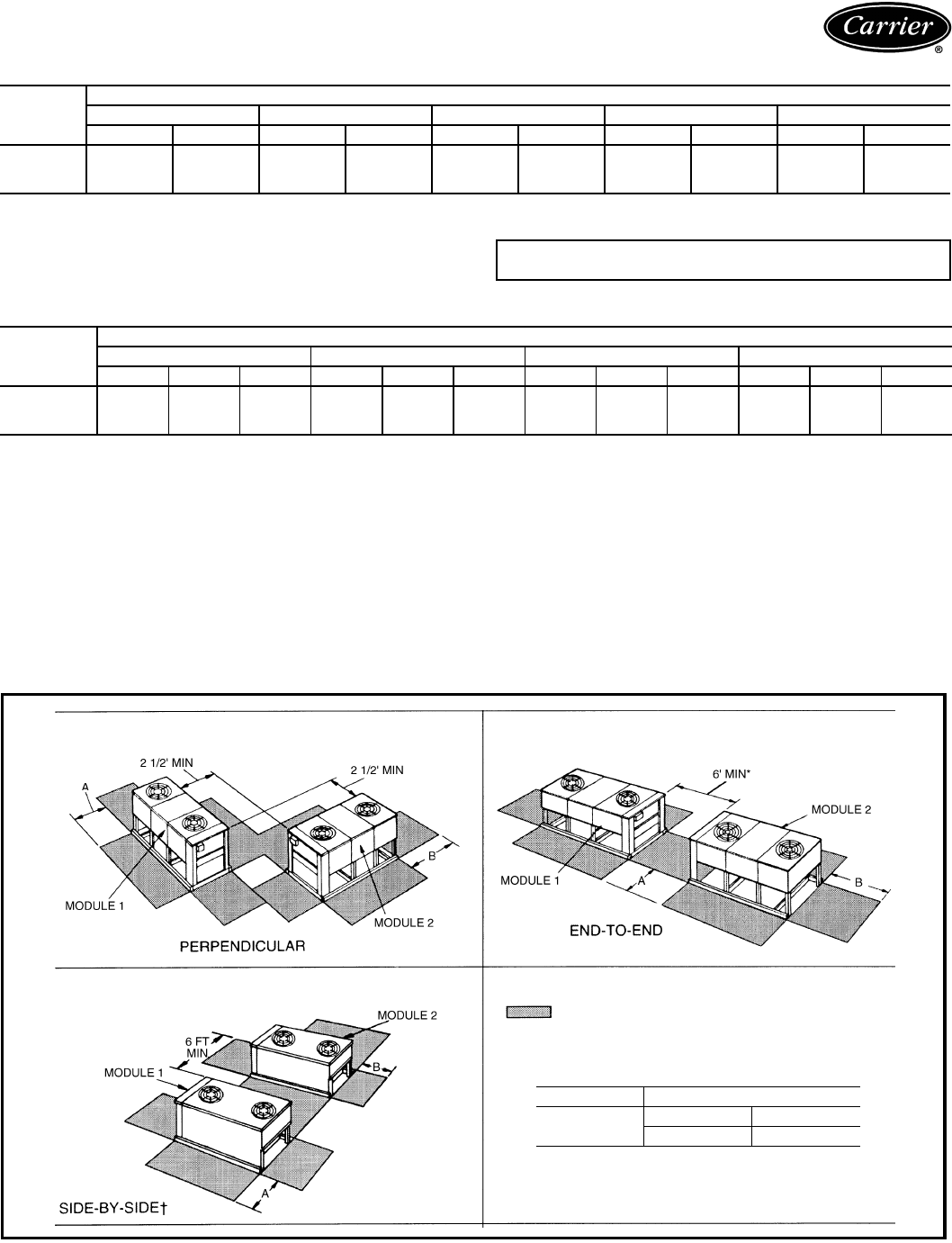
93
REFRIGERANT PIPE SIZES (Single Suction Risers)
LEGEND NOTE: All line sizes are inches OD. See notes on page 73 for metric
conversions.
REFRIGERANT PIPING SIZES (Double Suction Risers)
NOTE: A, B, C dimensions relate to reference diagram.
Multiple condensing unit arrangements*
UNIT
38AKS
LENGTH OF INTERCONNECTING PIPING — m (ft)
4.9-7.6 (16-25) 7.9-15.2 (26-50) 15.5-22.8 (51-75) 23.2-30.5 (76-100) 30.8-60.9 (101-200)
LSLSLSLSLS
028 7/815/87/821/8*7/821/8*7/821/8*7/821/8*
034 7/821/87/821/87/821/811/821/811/825/8*
044 7/821/87/821/811/825/8*1
1/825/8*1
1/831/8*
L—Liquid Line
S—Suction Line *IMPORTANT — If condensing unit is above air handler, a double
suction riser is required. See table below for sizing.
UNIT
38AKS
LENGTH OF INTERCONNECTING PIPING — m (ft)
7.9-15.2 (26-50) 15.5-22.8 (51-75) 23.2-30.5 (76-100) 30.8-60.9 (101-200)
ABCABCABCABC
028 15/815/821/815/815/821/815/815/821/815/815/821/8
034 —————————15/821/825/8
044 ———15/821/825/815/821/825/815/821/825/8
38AKS028-044
38AKS028-044 ONLY
38AKS028-044
Space for Service and Airflow
*For clearances between controls and grounded surfaces,
check local codes.
†Observe minimum recommended space requirements.
38AKS DIMENSIONS (ft)
028-044 AB
44
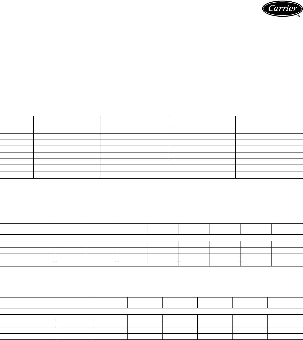
94
Operating limits
Maximum fan speed —
40RM007-024 . . . . . . . . . . . . . . . .20 r/s (1200 rpm)
Maximum fan speed —
40RM028,034 . . . . . . . . . . . . . . 18.3 r/s (1100 rpm)
General
Select equipment to match or to be slightly less than peak
load. This provides better humidity control, less unit cycling,
and less part-load operation. Equipment should be selected
to perform at no less than 40 L/s per kW (300 cfm/ton).
The air handler fan must always be operating when the
condensing unit is operating.
Ductwork should be sized according to unit size, not build-
ing load. For larger units with two fans, a split duct transition
is recommended at the fan outlets, but a plenum can be used
with slight reduction in external static pressure capability.
For variable air volume (VAV) systems with supply-to-
return air recycling, use the equipment room as a return air
plenum.
40RM FACTORY-INSTALLED NOZZLE AND DISTRIBUTOR DATA
*Feeder tube size is 6.35 mm (1/4 in.)
NOTE: Hot gas bypass applications require field-supplied auxiliary side connector.
40RM FAN MOTOR DATA
STANDARD MOTOR — SI
LEGEND
NEMA — National Electrical Manufacturers Association (U.S.A.)
ALTERNATE MOTOR — SI
LEGEND
NEMA — National Electrical Manufacturers Association (U.S.A.)
UNIT
40RM
TXV
Qty...Part No.
DISTRIBUTOR
Qty...Part No.
FEEDER TUBES
PER DISTRIBUTOR*
NOZZLE
Qty...Part No.
007 TDEBX8 1...1116 12 1...E5
008 TDEBX8 1...1126 15 1...C6
012 TDEBX6 2...1115 9 2...E4
014 TDEBX8 2...1115 9 2...E5
016 TDEBX8 2...1116 12 2...E6
024 TDEBXE11 2...1116 13 2...E8
028 TDEBX11 2...1126 15 2...C10
034 TDEBX16 2...1126 18 2...C12
UNIT
40RM 007 008 012 014 016 024 028 034
230-3-50 and 400-3-50
Speed (r/s) 23.75 23.75 23.75 23.75 23.75 23.75 23.75 23.75
Shaft kW 1.79 1.79 2.16 2.16 2.16 3.73 5.60 7.46
Frame (NEMA) 56Y 56Y 56Y 56Y 56Y 184T S213T S215T
Shaft Dia (mm) 15.9 15.9 22.2 22.2 22.2 28.6 34.9 34.9
UNIT
40RM 007 008 012 014 016 024 028
230-3-50 and 400-3-50
Speed (r/s) 23.75 23.75 23.75 23.75 23.75 23.75 23.75
Shaft kW 1.79 2.16 3.73 3.73 3.73 5.60 7.46
Frame (NEMA) 56Y 56Y S184T S184T S184T S213T S215T
Shaft Dia (mm) 15.9 22.2 22.2 28.6 28.6 34.9 34.9
Application data — 40RM
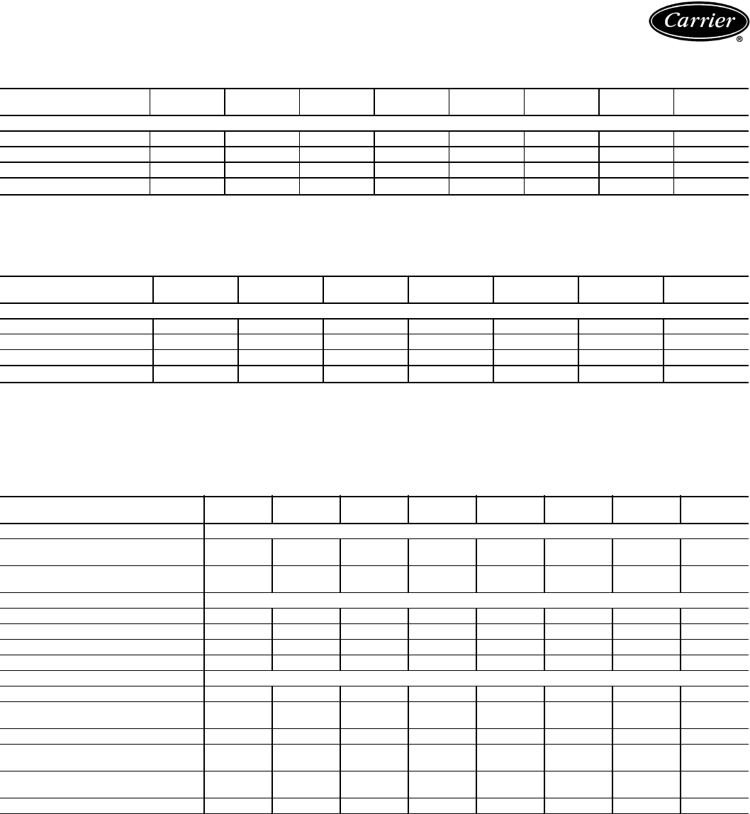
95
40RM FAN MOTOR DATA (cont)
STANDARD MOTOR — ENGLISH
LEGEND
NEMA — National Electrical Manufacturers Association (U.S.A.)
ALTERNATE MOTOR — ENGLISH
LEGEND
NEMA — National Electrical Manufacturers Association (U.S.A.)
40RM DRIVE DATA
STANDARD DRIVE — SI
UNIT
40RM 007 008 012 014 016 024 028 034
230-3-50 and 400-3-50
Speed (rpm) 1425 1425 1425 1425 1425 1425 1425 1425
Hp 2.4 2.4 2.9 2.9 2.9 5.0 7.5 10.0
Frame (NEMA) 56Y 56Y 56Y 56Y 56Y 184T S213T S215T
Shaft Dia (in.) 5/85/87/87/87/811/813/813/8
UNIT
40RM 007 008 012 014 016 024 028
230-3-50 and 400-3-50
Speed (rpm) 1425 1425 1425 1425 1425 1425 1425
Hp 2.4 2.9 5.0 5.0 5.0 7.5 10.0
Frame (NEMA) 56Y 56Y S184T S184T S184T S213T S215T
Shaft Dia (in.) 5/87/87/811/811/813/813/8
UNIT
40RM 007 008 012 014 016 024 028 034
MOTOR DRIVE
Motor Pulley Pitch Diameter (mm) 61.0-
86.4
71.1-
96.5
86.4-
111.8
86.4-
111.8
86.4-
111.8
109.2-
134.6
109.2-
134.6
109.2-
134.6
Pulley Factory Setting
Full Turns Open 2.5 2.5 2.5 2.5 2.5 3.0 3.0 3.0
FAN DRIVE
Pulley Pitch Dia (mm) 203 203 203 229 229 218 279 279
Pulley Bore (mm) 25.4 25.4 25.4 36.5 36.5 36.5 49.2 49.2
Belt No. — Section 1—A1—A1—A1—A1—A1—B2—B2—B
Belt Pitch (mm) 998 998 1024 1074 1074 1062 1113 1113
FAN SPEEDS (r/s)
Factory Setting 8.6 9.8 11.6 10.3 10.3 13.3 10.4 10.4
Range 7.1-
10.1
8.3-
11.3
10.1-
13.1
9.0-
11.6
9.0-
11.6
11.9-
14.6
9.3-
11.5
9.3-
11.5
Max Allowable Speed (r/s) 20.0 20.0 20.0 20.0 20.0 20.0 18.3 18.3
Change per 1/2 Turn of
Moveable Motor Pulley Flange 0.297 0.297 0.297 0.265 0.265 0.230 0.180 0.180
MAX FULL TURNS FROM
CLOSED POSITION 55555666
SHAFTS CENTER DISTANCE (mm) 265-313 265-313 265-313 265-313 265-313 232-279 169-240 169-240
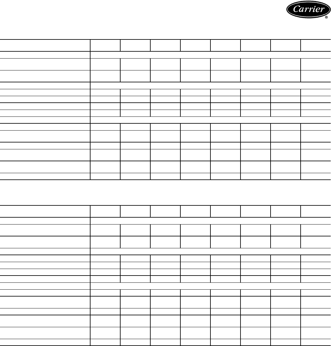
96
40RM DRIVE DATA (cont)
MEDIUM-STATIC DRIVE — SI
HIGH-STATIC DRIVE — SI
*It is possible to adjust drive so that fan speed exceeds maximum allowable. DO NOT exceed 20 r/s.
UNIT
40RM 007 008 012 014 016 024 028 034
MOTOR DRIVE
Motor Pulley Pitch Diameter (mm) 86.4-
111.8
86.4-
111.8
86.4-
111.8
86.4-
111.8
94.0-
119.4
101.6-
127.0
109.2-
134.6
109.2-
134.6
Pulley Factory Setting
Full Turns Open 2.5 2.5 2.5 2.5 3.0 2.5 3.0 3.0
FAN DRIVE
Pulley Pitch Dia (mm) 203 178 152 191 201 178 239 239
Pulley Bore (mm) 25.4 25.4 25.4 36.5 36.5 36.5 49.2 49.2
Belt No. — Section 1—A1—A1—A1—A1—B2—A2—B2—B
Belt Pitch (mm) 1024 1049 947 998 1011 922 1011 1011
FAN SPEEDS (r/s)
Factory Setting 11.6 13.2 15.4 12.4 12.6 15.3 12.1 12.1
Range 10.1-
13.1
11.5-
14.9
13.5-
17.4
10.8-
13.9
11.1-
14.1
13.6-
17.0
10.9-
13.4
10.9-
13.4
Max Allowable Speed (r/s) 20.0 20.0 20.0 20.0 20.0 20.0 18.3 18.3
Change per 1/2 Turn of Moveable
Motor Pulley Flange 0.297 0.340 0.395 0.317 0.252 0.340 0.210 0.210
MAX FULL TURNS FROM
CLOSED POSITION 55556566
SHAFTS CENTER DISTANCE (mm) 265-313 265-313 265-313 265-313 232-279 232-279 169-240 169-240
UNIT
40RM 007 008 012 014 016 024 028 034
MOTOR DRIVE
Motor Pulley Pitch Diameter (mm) 86.4-
111.8
86.4-
111.8
101.6-
127.0
86.4-
111.8
101.6-
127.0
101.6-
127.0
109.2-
134.6
109.2-
134.6
Pulley Factory Setting
Full Turns Open 2.5 2.5 3.0 2.5 3.0 3.0 3.0 3.0
FAN DRIVE
Pulley Pitch Dia (mm) 152 140 140 152 178 163 203 218
Pulley Bore (mm) 25.4 25.4 25.4 36.5 36.5 36.5 49.2 49.2
Belt No. — Section 1—A1—A1—A2—A2—A2—A2—B2—B
Belt Pitch (mm) 947 947 922 922 998 871 935 960
FAN SPEEDS (r/s)
Factory Setting 15.4 16.8 19.4 15.4 15.3 16.7 14.3 13.3
Range 13.5-
17.4
14.7-
19.0
17.3-
20.0*
13.5-
17.4
13.6-
17.0
14.9-
18.6
12.8-
15.7
11.9-
14.6
Max Allowable Speed (r/s) 20.0 20.0 20.0 20.0 20.0 20.0 18.3 18.3
Change per 1/2 Turn of Moveable
Motor Pulley Flange 0.395 0.432 0.360 0.395 0.283 0.308 0.247 0.230
MAX FULL TURNS FROM
CLOSED POSITION 55656666
SHAFTS CENTER DISTANCE (mm) 265-313 265-313 234-279 232-279 232-279 207-255 169-240 169-240
Application data — 40RM (cont)

97
40RM DRIVE DATA (cont)
STANDARD DRIVE — ENGLISH
MEDIUM-STATIC DRIVE — ENGLISH
UNIT 40RM 007 008 012 014 016 024 028 034
MOTOR DRIVE
Motor Pulley Pitch Diameter (in.) 2.4-3.4 2.8-3.8 3.4-4.4 3.4-4.4 3.4-4.4 4.3-5.3 4.3-5.3 4.3-5.3
Pulley Factory Setting
Full Turns Open 2.5 2.5 2.5 2.5 2.5 3.0 3.0 3.0
FAN DRIVE
Pulley Pitch Dia (in.) 8.0 8.0 8.0 9.0 9.0 8.6 11.0 11.0
Pulley Bore (in.) 1111
7/16 17/16 17/16 115/16 115/16
Belt No. — Section 1—A1—A1—A1—A1—A1—B2—B2—B
Belt Pitch (in.) 39.3 39.3 40.3 42.3 42.3 41.8 43.8 43.8
FAN SPEEDS (rpm)
Factory Setting 517 588 695 618 18 795 622 622
Range 428-606 499-677 606-784 538-697 538-697 713-878 557-687 557-687
Max Allowable Speed (rpm) 1200 1200 1200 1200 1200 1200 1100 1100
Change per 1/2 Turn of Moveable
Motor Pulley Flange 17.8 17.8 17.8 15.9 15.9 13.8 10.8 10.8
MAX FULL TURNS FROM
CLOSED POSITION 55555666
SHAFTS CENTER DISTANCE (in.) 10.44-
12.32
10.44-
12.32
10.44-
12.32
10.44-
12.32
10.44-
12.32
9.12-
10.99
6.67-
9.43
6.67-
9.43
UNIT 40RM 007 008 012 014 016 024 028 034
MOTOR DRIVE
Motor Pulley Pitch Diameter (in.) 3.4-4.4 3.4-4.4 3.4-4.4 3.4-4.4 3.7-4.7 4.0-5.0 4.3-5.3 4.3-5.3
Pulley Factory Setting
Full Turns Open 2.5 2.5 2.5 2.5 3.0 2.5 3.0 3.0
FAN DRIVE
Pulley Pitch Dia (in.) 8.0 7.0 6.0 7.5 7.9 7.0 9.4 9.4
Pulley Bore (in.) 1111
7/16 17/16 17/16 115/16 115/16
Belt No. — Section 1—A1—A1—A1—A1—B2—A2—B2—B
Belt Pitch (in.) 40.3 41.3 37.3 39.3 39.8 36.8 39.8 39.8
FAN SPEEDS (rpm)
Factory Setting 695 794 926 741 756 916 728 728
Range 606-784 692-896 808-1045 646-836 667-848 814-1018 652-803 652-803
Max Allowable Speed (rpm) 1200 1200 1200 1200 1200 1200 1100 1100
Change per 1/2 Turn of Moveable
Motor Pulley Flange 17.8 20.4 23.7 19.0 15.1 20.4 12.6 12.6
MAX FULL TURNS FROM
CLOSED POSITION 55556666
SHAFTS CENTER DISTANCE (in.) 10.44-
12.32
10.44-
12.32
10.44-
12.32
10.44-
12.32
9.16-
10.99
9.16-
10.99
6.67-
9.43
6.67-
9.43
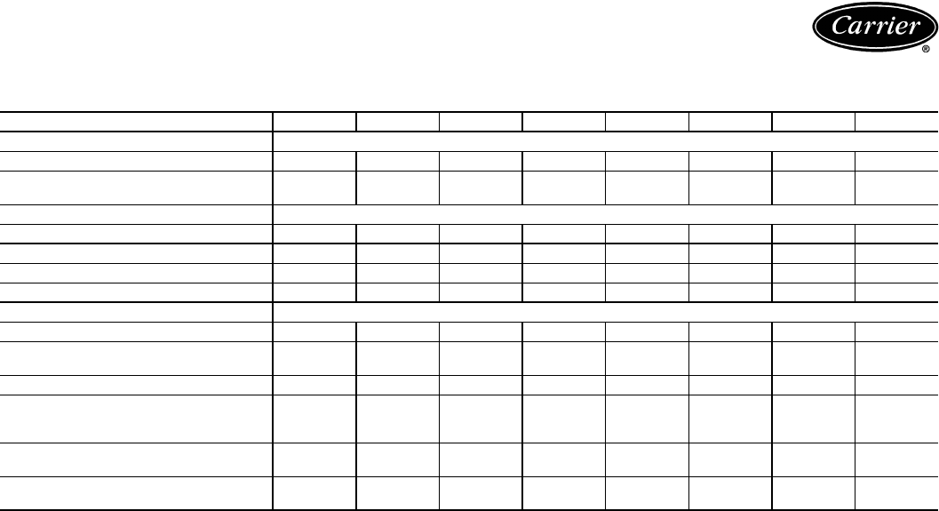
98
40RM DRIVE DATA (cont)
HIGH-STATIC DRIVE DATA
*It is possible to adjust drive so that fan speed exceeds maximum allowable. DO NOT exceed 1200 rpm.
UNIT 40RM 007 008 012 014 016 024 028 034
MOTOR DRIVE
Motor Pulley Pitch Diameter (in.) 3.4-4.4 3.4-4.4 4.0-5.0 3.4-4.4 4.0-5.0 4.0-5.0 4.3-5.3 4.3-5.3
Pulley Factory Setting
Full Turns Open 2.5 2.5 3.0 2.5 3.0 3.0 3.0 3.0
FAN DRIVE
Pulley Pitch Dia (in.) 6.0 5.5 5.5 6.0 7.0 6.4 8.0 8.6
Pulley Bore (in.) 1111
7/16 17/16 17/16 115/16 115/16
Belt No. — Section 1—A1—A1—A2—A2—A2—A2—B2—B
Belt Pitch (in.) 37.3 37.3 36.3 36.3 39.3 34.3 36.8 37.8
FAN SPEEDS (rpm)
Factory Setting 926 1010 1166 926 916 1002 855 795
Range 808-1045 881-1140 1036-
1200* 808-1045 814-1018 891-1113 766-944 713-878
Max Allowable Speed (rpm) 1200 1200 1200 1200 1200 1200 1100 1100
Change per 1/2 Tu rn o f
Moveable Motor Pulley
Flange
23.7 25.9 21.6 23.7 17.0 18.5 14.8 13.8
MAX FULL TURNS FROM
CLOSED POSITION 55656666
SHAFTS CENTER DISTANCE
(in.)
10.44-
12.32
10.44-
12.32
9.16-
10.99
9.16-
10.99
9.16-
10.99
8.16-
10.02
6.67-
9.43
6.67-
9.43
Application data — 40RM (cont)
99
Commercial Air-Cooled Condensing Units
HVAC Guide Specifications
Size Range: 19.0 to 32.9 kW (5.4 to 9.4 Tons)
Nominal
Carrier Model Numbers: 38AK, Sizes 007 to 012
38AKS, Sizes 008 to 012
Part 1 — General
1.01 SYSTEM DESCRIPTION
Outdoor-mounted, air-cooled condensing unit suitable
for on-the-ground or rooftop installation. Unit shall
consist of a reciprocating air-conditioning compressor
assembly, an air-cooled coil, propeller-type condenser
fan, and a control box. Unit shall discharge supply air
upward as shown on contract drawings. Unit shall be
used in a refrigeration circuit matched with a pack-
aged air-handling unit.
1.02 QUALITY ASSURANCE
A. Unit shall be rated in accordance with ARI Stand-
ard 210/240-89 and 270-84 (U.S.A. standards).
B. Unit shall be manufactured in a facility registered to
ISO 9001 manufacturing quality standard.
C. Unit construction shall comply with ASHRAE 15
(U.S.A. standard) safety code latest revision and com-
ply with NEC (U.S.A. standard).
D. Unit cabinet shall be capable of withstanding
500-hour salt spray exposure per ASTM B117
(U.S.A.) (scribed specimen).
E. Air-cooled condenser coils for semi-hermetic
compressor units (38AKS) shall be leak tested at
1034 kPag (150 psig) and pressure tested at
3309 kPag (480 psig). Air-cooled condenser coils for
hermetic compressor units (38AK) shall be leak tested
at 1379 kPag (200 psig), and pressure tested at
2951 kPag (428 psig).
1.03 DELIVERY, STORAGE, AND HANDLING
Unit shall be shipped as single package only, and
shall be stored and handled according to unit manu-
facturer’s recommendations.
1.04 WARRANTY (FOR INCLUSION BY SPECIFYING
ENGINEER.)
Part 2 — Products
2.01 EQUIPMENT
A. General:
Factory-assembled, single piece, air-cooled condens-
ing unit. Contained within the unit enclosure shall be
all factory wiring, piping, controls, compressor, hold-
ing charge (R-22), and special features required prior
to field start-up.
B. Unit Cabinet:
1. Unit cabinet shall be constructed of galvanized
steel, bonderized and coated with a prepainted
baked enamel finish.
2. A heavy-gage roll-formed perimeter base rail
with forklift slots and lifting holes shall be pro-
vided to facilitate rigging.
C. Fans:
1. Condenser fans shall be direct driven, propeller-
type, discharging air vertically upward.
2. Fan blades shall be balanced.
3. Condenser fan discharge openings shall be
equipped with PVC-coated steel wire safety
guards.
4. Condenser fan and motor shaft shall be corro-
sion resistant.
D. Compressor:
1. Compressor shall be of the hermetic type (AK)
or semi-hermetic reciprocating type (AKS).
2. Compressor shall be mounted on vibration
isolators.
3. Semi-hermetic compressors (AKS units) shall
have crankcase heaters, oil level sight glasses,
discharge service valve, and a totally reversible
positive displacement oil pump.
4. Unloader (33% reduction) shall be standard (on
38AKS012 units only).
5. Compressors shall include overload protection.
6. The 38AK012 unit shall have a crankcase
heater.
E. Condenser Coil:
1. Condenser coil shall be air-cooled and circuited
for integral subcooler.
2. Coil shall be constructed of aluminum fins (cop-
per fins optional) mechanically bonded to inter-
nally grooved seamless copper tubes which are
then cleaned, dehydrated, and sealed.
F. Refrigeration Components:
Refrigeration circuit components shall include liquid
line service valve, suction line service valve, liquid fil-
ter drier, a full charge of compressor oil, and a hold-
ing charge of refrigerant. Unit 38AK012 shall include
an accumulator.
G. Controls and Safeties:
1. Minimum control functions shall include:
a. Power and control terminal blocks.
b. Compressor lockout on auto-reset safety until
reset from thermostat.
2. Minimum safety devices which are equipped with
automatic reset (after resetting first at thermo-
stat), shall include:
a. High discharge pressure cutout.
b. Low suction pressure cutout.
H. Operating Characteristics:
1. The capacity of the condensing unit shall meet
or exceed Btuh at a suction temperature of
. The power consumption at full load shall
not exceed kW.
Guide specifications —
38AKS007-012, 38AKS008-012
100
2. The combination of the condensing unit and the
evaporator or fan coil unit shall have a total net
cooling capacity of or greater at condi-
tions of entering-air temperature at the
evaporator at wet bulb and
dry bulb, and air entering the condens-
ing unit at .
I. Electrical Requirements:
1. Nominal unit electrical characteristics shall be
v, 3-ph, 50 Hz. The unit shall be capable
of satisfactory operation within voltage limits of
v to v.
2. Unit electrical power shall be single-point
connection.
3. Unit control circuit shall contain a 24-v trans-
former for unit control.
J. Special Features:
1. Low-Ambient Temperature Control Accessory:
Low-ambient control shall regulate speed of
condenser-fan motor in response to the satu-
rated condensing temperature of the unit. The
control shall maintain correct condensing pres-
sure at outdoor temperatures down to –29 C
(–20 F). (Motor change required.)
2. Gage Panel Package:
Gage panel package shall include a suction and
discharge pressure gage.
3. Optional Condenser Coil Materials:
a. Pre-Coated Aluminum-Fin Coils:
Shall have a durable epoxy-phenolic coating
to provide protection in mildly corrosive
coastal environments. Coating shall be
applied to the aluminum fin stock prior to the
fin stamping process to create an inert barrier
between the aluminum fin and copper tube.
Epoxy-phenolic barrier shall minimize gal-
vanic action between dissimilar metals.
b. Copper-Fin Coils:
Shall be constructed of copper-fins mechani-
cally bonded to copper-tubes. All copper con-
struction shall provide protection in moderate
coastal environments.
c. Post-Coated Aluminum-Fin Coils:
Shall have a durable organic coating uni-
formly applied over all coil surfaces. Coating
shall be deep brown color applied by a dip
and bake process to ensure complete encap-
sulation of all coil surfaces. Coated coil shall
withstand 1,000-hour salt spray test in
accordance with ASTM B117 (U.S.A.). Coil
construction shall be aluminum fins mechani-
cally bonded to copper tubes.
d. Post-Coated Copper-Fin Coils:
Shall have a durable organic coating uni-
formly applied over all coil surfaces. Coating
shall be deep brown color applied by a dip
and bake process to ensure complete encap-
sulation of all coil surfaces. Coated coil shall
withstand 1,000-hour salt spray test in accor-
dance with ASTM B117 (U.S.A.). Coil con-
struction shall be copper fins mechanically
bonded to copper tubes.
4. Thermostat Controls:
a. Debonair® programmable multi-stage ther-
mostat with 7-day clock, holiday scheduling,
large Thermoglow™ display, remote sensor
capability, and Title 24 compliance.
b. TEMP System programmable communicat-
ing multi-stage thermostat with fan switch,
timeclock, LCD display, °F/°C capability,
and CCN (Carrier Comfort Network)
compatibility.
c. Commercial Electronic Thermostat with
7-day timeclock, auto-changeover, multi-
stage capability, and large LCD temperature
display.
d. Non-programmable thermostat with fan
switch subbase.
5. Hail Guard Package:
Hail guard package shall protect coils against
damage from hail and other flying debris.
6. Winter Start Package:
Package shall provide a timed bypass of low-
pressure switch on start-up at low-ambient
temperatures.
7. Condenser Coil Grille:
Grille shall add decorative appearance to unit
and protect condenser coil after installation.
8. Electric Solenoid Unloader:
Electric unloader valve piston, coil, and hardware
shall be supplied to convert the pressure-
operated compressor unloader to electric
unloading (38AKS012 only).
Guide specifications —
38AKS007-012, 38AKS008-012 (cont)

101
Commercial Air-Cooled Condensing Units
HVAC Guide Specifications
Size Range: 30.4 to 64.3 kW (8.5 to 18.0 Tons),
Nominal
Carrier Model Number: 38AKS, Sizes 013-024
Part 1 — General
1.01 SYSTEM DESCRIPTION
Outdoor-mounted, air-cooled condensing unit suitable
for on-the-ground or rooftop installation. Unit shall
consist of a semi-hermetic reciprocating compressor,
an air-cooled coil, propeller-type condenser fans, and
a control box. Unit shall discharge supply air upward
as shown on contract drawings. Unit shall be used in
a refrigeration circuit to match a packaged air-
handling unit.
1.02 QUALITY ASSURANCE
A. Unit shall be rated in accordance with ARI Standard
360 (U.S.A. standard), latest edition.
B. Unit shall be manufactured in a facility registered to
ISO 9002 manufacturing quality standard.
C. Unit construction shall comply with latest edition of
ANSI/ASHRAE and with NEC (U.S.A. standard).
D. Unit cabinet shall be capable of withstanding
500-hour salt spray exposure per ASTM B117
(U.S.A. standards) (scribed specimen).
E. Air-cooled condenser coils shall be leak tested
at 1034 kPag (150 psig) and pressure tested at
3310 kPag (480 psig).
1.03 DELIVERY, STORAGE, AND HANDLING
Unit shall be shipped as a single package only, and
shall be stored and handled per manufacturer’s
recommendations.
1.04 WARRANTY (FOR INCLUSION BY SPECIFYING
ENGINEER.)
Part 2 — Products
2.01 EQUIPMENT
A. General:
Factory assembled, single piece, air-cooled condens-
ing unit. Contained within the unit enclosure shall be
all factory wiring, piping, controls, compressor, hold-
ing charge (R-22), and special features required prior
to field start-up.
B. Unit Cabinet:
Unit cabinet shall be constructed of galvanized steel,
bonderized and coated with a prepainted, baked
enamel finish.
C. Fans:
1. Condenser fans shall be direct-drive propeller
type, discharging air vertically upward.
2. Condenser fan motor no. 1 shall be ball bearing
type compatible with accessory Motormaster® I
low-ambient control.
3. Shafts shall have inherent corrosion resistance.
4. Fan blades shall be statically and dynamically
balanced.
5. Condenser fan openings shall be equipped with
PVC-coated steel wire safety guards.
D. Compressor:
1. Compressor shall be serviceable, reciprocating,
semi-hermetic type.
2. Compressor shall be equipped with an automati-
cally reversible oil pump, operating oil charge,
suction and discharge shutoff valves, and an
insert-type, factory-sized crankcase heater to
control oil dilution.
3. Compressor shall be mounted on spring vibra-
tion isolators with an isolation efficiency of no
less than 95%.
4. Compressor speed shall not exceed 24.2 r/s
(1450 rpm).
5. Compressor shall unload using suction cutoff
unloading (electrical solenoid unloading shall be
available as an accessory).
E. Condenser Coil:
1. Condenser coil shall be air cooled, circuited for
integral subcooler.
2. Coil shall be constructed of aluminum fins
mechanically bonded to copper tubes which are
then cleaned, dehydrated, and sealed. Aluminum
fins with an epoxy phenolic coating and copper
fins shall be available as options.
F. Refrigeration Components:
Refrigeration circuit components shall include hot gas
muffler, high-side pressure relief device, liquid line
shutoff valve, suction and discharge shutoff valves,
holding charge of refrigerant R-22, and compressor
oil.
G. Controls and Safeties:
1. Minimum control functions shall include:
a. Power and control terminal blocks.
b. Five-minute Time Guard® II protection to
prevent compressor short-cycling.
c. Capacity control on the compressor shall be
by suction cutoff unloader in response to
compressor suction pressure. Electric sole-
noid unloading shall be available as an
accessory.
d. Head pressure control to –9.4 C (15 F) by fan
cycling. One condenser fan shall be cycled by
discharge pressure to maintain proper head
pressure.
2. Minimum safety devices shall include:
Automatic reset (after resetting first at
thermostat)
a. High discharge-pressure cutout.
b. Low suction pressure cutout.
Guide specifications — 38AKS013-024
102
c. Condenser fan motors to be protected
against overload condition by internal
overloads.
Manual reset at the unit
Electrical overload protection through the use of
definite-purpose contactors and calibrated, ambi-
ent compensated, magnetic trip circuit breakers.
Circuit breakers shall open all 3 phases in the
event of an overload in any one of the phases or
a single-phase condition.
H. Operating Characteristics:
1. The capacity of the condensing unit shall meet
or exceed at a suction temperature of
. The power consumption at full load shall
not exceed kW.
2. The combination of the condensing unit and the
evaporator or fan coil unit shall have a total net
cooling capacity of or greater at condi-
tions of entering-air temperature at the
evaporator at wet bulb and dry
bulb, and air entering the condensing unit at
.
I. Electrical Requirements:
1. Nominal unit electrical characteristics shall be
v, 3-ph, 50 Hz. The unit shall be capable
of satisfactory operation within voltage limits of
v to v.
2. Unit electrical power shall be single point
connection.
3. Unit control circuit shall contain a 24-v trans-
former for unit control, with capacity to operate
an indoor fan interlock.
J. Special Features:
1. Low-Ambient Control:
Control shall regulate fan motor speed in
response to the saturated condensing tempera-
ture of the unit. The control shall allow the unit
to operate down to an ambient temperature of
–29 C (–20 F).
2. Electric Solenoid Unloader:
Unloader valve piston, coil, and hardware shall
be supplied to convert the pressure-operated
compressor unloader to electric unloading.
3. Winter Start:
A winter start control shall be provided to
prevent nuisance tripouts at low ambient
temperatures.
4. Condenser Coil Grille Package:
Grilles shall protect the condenser coils after unit
installation.
5. Gage Panel Package:
Gage panel package shall include a suction and
discharge pressure gage.
6. Optional Condenser Coil Materials:
a. Pre-Coated Aluminum-Fin Coils:
Shall have a durable epoxy-phenolic coating
to provide protection in mildly corrosive
coastal environments. Coating shall be
applied to the aluminum fin stock prior to the
fin stamping process to create an inert barrier
between the aluminum fin and copper tube.
Epoxy-phenolic barrier shall minimize gal-
vanic action between dissimilar metals.
b. Copper-Fin Coils:
Shall be constructed of copper-fins mechani-
cally bonded to copper-tubes. All copper con-
struction shall provide protection in moderate
coastal applicationss.
c. Post-Coated Aluminum-Fin Coils:
Shall have a durable organic coating uni-
formly applied to all coil surfaces. Coating
shall be deep brown color applied by a dip
and bake process to ensure complete encap-
sulation of all coil surfaces. Coated coil shall
withstand 1,000-hour salt spray test in
accordance with ASTM B117 (U.S.A.). Coil
construction shall be aluminum fins mechani-
cally bonded to copper tubes.
d. Post-Coated Copper-Fin Coils:
Shall have a durable organic coating uni-
formly applied to all coil surfaces. Coating
shall be deep brown color applied by a dip
and bake process to ensure complete encap-
sulation of all coil surfaces. Coated coil shall
withstand 1,000-hour salt spray test in
accordance with ASTM B117 (U.S.A.). Coil
construction shall be copper fins mechanically
bonded to copper tubes.
7. Thermostat Controls:
a. Debonair® programmable multi-stage ther-
mostat with 7-day clock, holiday scheduling,
large Thermoglow™ display, remote sensor
capability, and Title 24 compliance.
b. TEMP System programmable communicat-
ing multi-stage thermostat with fan switch,
timeclock, LCD display, °F/°C capability,
and CCN (Carrier Comfort Network)
compatibility.
c. Commercial Electronic Thermostat with 7-day
timeclock, auto-changeover, multi-stage capa-
bility, and large LCD temperature display.
d. Non-programmable thermostat with fan
switch subbase.
Guide specifications — 38AKS013-024 (cont)

103
Commercial Air-Cooled Condensing Units
HVAC Guide Specifications
Size Range: 82.8 to 127.0 kW (23.5 to 35.8 Tons),
Nominal
Carrier Model Number: 38AKS, Sizes 028-044
Part 1 — General
1.01 SYSTEM DESCRIPTION
Outdoor-mounted, air-cooled condensing unit suitable
for on-the-ground or rooftop installation. Unit shall
consist of a semi-hermetic reciprocating compressor,
an air-cooled coil, propeller-type condenser fans, and
a control box. Unit shall discharge supply air upward
as shown on contract drawings. Unit shall be used in
a refrigeration circuit to match a packaged air-
handling unit.
1.02 QUALITY ASSURANCE
A. Unit shall be rated in accordance with ARI Standard
360 (U.S.A. standard), latest edition.
B. Unit shall be manufactured in a facility registered to
ISO 9002 manufacturing quality standard.
C. Unit construction shall comply with ANSI/ASHRAE
15 latest revision safety code and comply with NEC
(U.S.A. standards).
D. Unit shall be constructed in accordance with UL
standards (U.S.A.).
E. Unit cabinet shall be capable of withstanding
500-hour salt spray exposure per ASTM B117
(U.S.A.) (scribed specimen).
F. Air-cooled condenser coils shall be leak tested at
1034 kPa (150 psig) and pressure tested at 3310 kPa
(480 psig).
1.03 DELIVERY, STORAGE AND HANDLING
Unit shall be shipped as single package only, and
shall be stored and handled per unit manufacturer’s
recommendations.
1.04 WARRANTY (FOR INCLUSION BY SPECIFYING
ENGINEER.)
Part 2 — Products
2.01 EQUIPMENT
A. General:
Factory assembled, single piece, air-cooled condens-
ing unit. Contained within the unit enclosure shall be
all factory wiring, piping, controls, compressor, hold-
ing charge (R-22), and special features required prior
to field start-up.
B. Unit Cabinet:
1. Unit cabinet shall be constructed of galvanized
steel, bonderized and coated with a prepainted,
baked enamel finish.
2. End unit access panel shall be hinged for com-
pressor and control box service access.
3. Lifting holes shall be provided to facilitate
rigging.
C. Fans:
1. Condenser fans shall be direct-driven propeller
type, discharging air vertically upward.
2. Condenser fan motors shall be totally enclosed,
3-phase type with class B insulation and with
permanently lubricated bearings.
3. Shafts shall have inherent corrosion resistance.
4. Fan blades shall be statically and dynamically
balanced.
5. Condenser fan openings shall be equipped with
PVC-coated steel wire safety guards.
D. Compressor:
1. Compressor shall be reciprocating, serviceable,
semi-hermetic type.
2. Compressor shall be equipped with an automati-
cally reversible oil pump, operating oil charge,
suction and discharge shutoff valves, and an
insert-type, factory-sized crankcase heater to
control oil dilution.
3. Compressor shall be mounted on spring vibra-
tion isolators with an isolation efficiency of no
less than 95%.
4. Compressor speed shall not exceed 24.2 r/s
(1450 rpm).
5. Compressor shall unload using suction cutoff
unloading (electrical solenoid unloading shall be
available as an accessory).
E. Condenser Coil:
1. Condenser coil shall be air cooled, circuited for
integral subcooler.
2. Coil shall be constructed of aluminum fins
mechanically bonded to internally grooved,
seamless copper tubes which are then cleaned,
dehydrated, and sealed. Epoxy phenolic fin coat-
ing shall be available as an option.
3. Coil shall be protected by a sheet metal casing to
eliminate the need for wind baffles for low ambi-
ent temperature operation.
4. Coil shall be protected to avoid damage due to
the elements and vandalism.
F. Refrigeration Components:
Refrigeration circuit components shall include hot gas
muffler, high-side pressure relief device, liquid line shut-
off valve, suction and discharge shutoff valves, holding
charge of refrigerant R-22, and compressor oil.
G. Controls and Safeties:
1. Minimum control functions shall include:
a. Power and control terminal blocks.
b. Five-minute recycle protection to prevent
compressor short-cycling.
c. Lockout on auto-reset safety until reset from
thermostat.
d. Capacity control on the compressor shall be
by suction cutoff unloaders in response to
compressor suction pressure. Electric
Guide specifications — 38AKS028-044

104
solenoid unloading shall be available as an
accessory.
e. A solenoid valve shall be provided for sole-
noid drop control.
f. Head pressure control to –6 C (31 F) by fan
cycling. One condenser fan shall be cycled by
discharge pressure to maintain proper head
pressure.
g. Winter start control to prevent nuisance trip-
outs at low ambient temperatures.
2. Minimum safety devices shall include:
Automatic reset (after resetting first at control cir-
cuit power supply)
a. High discharge-pressure cutout.
b. Low suction-pressure cutout.
c. Condenser fan motors to be protected
against overload or single-phase condition by
internal overloads.
Manual reset at the unit
a. Low oil-pressure cutout.
b. Compressor electrical overload protection
through the use of definite-purpose contac-
tors and calibrated, ambient-compensated,
magnetic-trip circuit breakers. Circuit break-
ers shall open all 3 phases in the event of an
overload in any one of the phases or a
single-phase condition.
H. Operating Characteristics:
1. The capacity of the condensing unit shall meet
or exceed at a suction temperature of
. The power consumption at full load shall
not exceed kW.
2. The combination of the condensing unit and the
evaporator or fan coil unit shall have a total net
cooling capacity of or greater at condi-
tions of: entering-air temperature at the
evaporator at wet bulb and dry
bulb, and air entering the condensing unit at
.
I. Electrical Requirements:
1. Nominal unit electrical characteristics shall be
v, 3-ph, 50 Hz. The unit shall be capable
of satisfactory operation within voltage limits of
v to v.
2. Unit electrical power shall be single point
connection.
3. Unit control circuit shall contain a 24-v trans-
former for unit control, with capacity to operate
an indoor fan interlock.
J. Special Features:
1. Low-Ambient Control:
Control shall regulate fan motor speed in
response to the saturated condensing tempera-
ture of the unit. The control shall be capable of
maintaining a condensing temperature of
37.8 C (100 F) ± 5.6 C (10° F) with outdoor
temperatures at –28 C (–20 F). (Motor change
required.)
2. Electric Solenoid Unloader:
Unloader valve piston, coil, and hardware shall
be supplied to convert any pressure-operated
compressor unloader to 220-v electric unload-
ing. Accessory ModuPanel™ control box or field-
supplied step controller shall be provided for
electrical unloading.
3. Hot-Gas Bypass:
A hot-gas bypass valve and a pilot line solenoid
valve shall be provided for low-load operation of
the refrigeration system.
4. Part-Winding Start:
Part-winding start shall be provided to reduce
inrush current and locked rotor amps on
start-up.
5. Gage Panel:
A gage panel package shall be provided which
includes a suction and discharge pressure gage
for the refrigerant circuit.
6. ModuPanel Control Box:
Control box shall be provided to allow system to
operate as a VAV (variable air volume) system.
7. Optional Condenser Coil Materials:
a. Pre-Coated Aluminum-Fin Coils:
Shall have a durable epoxy-phenolic coating
to provide protection in mildly corrosive
coastal environments. Coating shall be
applied to the aluminum fin stock prior to the
fin stamping process to create an inert barrier
between the aluminum fin and copper tube.
Epoxy-phenolic barrier shall minimize gal-
vanic action between dissimilar metals.
b. Copper-Fin Coils:
Shall be constructed of copper-fins mechani-
cally bonded to copper-tubes All copper con-
struction shall provide protection in moderate
coastal environments.
c. Post-Coated Aluminum-Fin Coils:
Shall have a durable organic coating uni-
formly applied to all coil surfaces. Coating
shall be deep brown color applied by a dip
and bake process to ensure complete encap-
sulation of all coil surfaces. Coated coil shall
withstand 1,000-hour salt spray test in
accordance with ASTM B117 (U.S.A.). Coil
construction shall be aluminum fins mechani-
cally bonded to copper tubes.
Guide specifications — 38AKS028-044 (cont)

105
d. Post-Coated Copper-Fin Coils:
Shall have a durable organic coating uni-
formly applied to all coil surfaces. Coating
shall be deep brown color applied by a dip
and bake process to ensure complete encap-
sulation of all coil surfaces. Coated coil shall
withstand 1,000-hour salt spray test in
accordance with ASTM B117 (U.S.A.). Coil
construction shall be copper fins mechanically
bonded to copper tubes.
8. Thermostat Controls:
a. Debonair® programmable multi-stage ther-
mostat with 7-day clock, holiday scheduling,
large Thermoglow™ display, remote sensor
capability, and Title 24 compliance.
b. TEMP System programmable communicat-
ing multi-stage thermostat with fan switch,
timeclock, LCD display, °F/°C capability,
and CCN (Carrier Comfort Network)
compatibility.
c. Commercial Electronic Thermostat with
7-day timeclock, auto-changeover, multi-
stage capability, and large LCD temperature
display.
d. Non-programmable thermostat with fan
switch subbase.

106
Commercial Packaged Air-Handling Unit
HVAC Guide Specifications
Size Range: 1150 to 5650 L/s (2400 to 12,000 Cfm)
Nominal Airflow
21 to 105 kW (6 to 30 Tons)
Nominal Cooling
Carrier Model Number: 40RM
Part 1 — General
1.01 SYSTEM DESCRIPTION
A. Indoor, packaged air-handling unit for use in commer-
cial split systems. Unit shall have a multiposition
design and shall be capable of horizontal or vertical
(upflow) installation on a floor or in a ceiling, with or
without ductwork. (Only vertical units are to be
applied without ductwork.)
B. Unit shall be used in a refrigerant circuit with a
matching air-cooled condensing unit.
1.02 QUALITY ASSURANCE
A. Coils shall be designed and tested in accordance with
ASHRAE 15 Safety Code for Mechanical Refrigera-
tion (U.S.A.), latest edition.
B. Unit shall be constructed in accordance with ETL
(U.S.A.) and ETL, Canada standards.
C. Unit insulation and adhesive shall comply with NFPA
90A (U.S.A.) requirements for flame spread and
smoke generation. Insulation shall contain an EPA-
registered immobilized anti-microbial agent to effec-
tively resist the growth of bacteria and fungi as
proven by tests in accordance with ASTM standards
G21 and 22 (U.S.A.).
D. Unit shall be manufactured in a facility registered to
the ISO 9002/BS 5750, Part 2 manufacturing qual-
ity standard.
E. Direct-expansion and chilled water coils shall be burst
tested at 2999 kPag (435 psig) and leak tested at
1034 kPag (150 psig).
1.03 DELIVERY AND STORAGE
Units shall be stored and handled per manufacturer’s
recommendations.
1.04 WARRANTY (FOR INCLUSION BY SPECIFYING
ENGINEER)
Part 2 — Products
2.01 EQUIPMENT
Indoor mounted, draw-thru, packaged air-handling
unit that can be used in a suspended horizontal con-
figuration or vertical (upflow) configuration. Unit shall
consist of forward-curved belt-driven centrifugal fan(s),
motor and drive assembly, prewired fan motor con-
tactor, factory-installed refrigerant metering devices,
cooling coil, 51-mm (2-in.) disposable air filters, and
condensate drain pans for vertical or horizontal
configurations.
A. Base Unit:
1. Cabinet shall be constructed of mill-galvanized
steel.
2. Cabinet panels shall be fully insulated with
12.7-mm (1/2-in.) fire-retardant material. Insula-
tion shall contain an U.S.A. EPA-registered
immobilized anti-microbial agent to effectively
resist the growth of bacteria and fungi as proven
by tests in accordance with ASTM standards
G21 and 22 (U.S.A.).
3. Unit shall contain PVC condensate drain pans
for both vertical and horizontal applications.
Drain pans shall have connections on right and
left sides of unit to facilitate field connection.
Drain pans shall have the ability to be sloped
toward the right or left side of the unit to prevent
standing water from accumulating in pans.
4. Unit shall have factory-supplied 51-mm (2-in.)
throwaway-type filters installed upstream from the
cooling coil. Filter access shall be from either the
right or left side of the unit.
B. Coils:
Coils shall consist of 3 rows of copper tubes with
sine-wave aluminum fins bonded to the tubes by
mechanical expansion. Coil tubing shall be internally
rifled to maximize heat transfer. Suction and liquid
line connections or supply and discharge connections
shall be made on the same side of the coil.
Direct-expansion coils shall feature factory-installed
thermostatic expansion valves (TXVs) for refrigerant
control. The TXVs shall be capable of external
adjustment.
C. Operating Characteristics:
Unit shall be capable of providing L/s (cfm)
airflow at an external static pressure of kPag
(in. wg).
D. Motor:
Fan motor of the size and electrical characteristics
specified on the equipment schedule shall be factory
supplied and installed.
E. Factory-Installed Options:
1. High Capacity Coil:
The high capacity coil consists of 4 rows of
3/8-in. copper tubes with sine-wave aluminum
fins bonded to the tubes by mechanical expan-
sion. Coil tubing shall be internally rifled to maxi-
mize heat transfer. Suction and liquid line
connections shall be made on the same side of
the coil. Direct-expansion coils shall feature fac-
tory-installed thermostatic expansion valves
(TXVs) for refrigerant control. The TXVs shall be
capable of external adjustment.
Guide specifications — 40RM

107
2. Alternate Motor and Drive:
An alternate motor and/or medium- or high-
static drive shall be available to meet the airflow
and external static pressure requirements speci-
fied on the equipment schedule.
3. External Paint:
Where conditions require, units shall be painted
with an American Sterling Gray finish.
F. Field-Installed Accessories:
1. Hot Water Coil:
Coil shall be 2-row, U-bend coil with copper
tubes and aluminum plate fins bonded to the
tubes by mechanical expansion. Coil shall be
mounted in a galvanized steel housing that shall
be fastened to the unit’s fan deck for blow-thru
heating operation. Coil shall have maximum
working pressure of 1034 kPag (150 psig).
2. Steam Distributing Coil:
Coil shall consist of one row of copper tubes
with aluminum plate fins, and shall have inner
steam distributing tubes. Coil shall be mounted in
a galvanized steel housing and shall be fastened
to the unit’s fan deck for blow-thru heating oper-
ation. Coil shall have maximum working pres-
sure of 1207 kPag at 204.4 C (175 psig at
400 F).
3. Electric Heaters:
Heaters for nominal 230 or 400-volt, 3-phase
power supply shall be factory-supplied for field
installation as shown on the equipment draw-
ings. Electric heat assembly shall be ETL (U.S.A)
and ETL Canada agency approved, and shall
have single-point power wiring. Heater assembly
shall include contactors with 24-v coils, power
wiring, 24-v control wiring terminal blocks, and
a hinged access panel. Electric heaters shall not
be used with air discharge plenum.
4. Air Discharge Plenum:
Plenum shall be factory supplied to provide free-
blow air distribution for vertical floor-mounted
units. A grille with moveable vanes for horizontal
or vertical airflow adjustment shall be included.
Plenum shall be field-assembled and field-
installed on the unit’s fan deck for blow-thru air
distribution. Plenum shall not be used with elec-
tric heaters.
5. Return-Air Grille:
Grille shall be factory supplied for field installa-
tion on the unit’s return air opening.
6. Unit Subbase:
Subbase assembly shall be factory supplied for
field installation. Subbase shall elevate floor-
mounted vertical units to provide access for cor-
rect condensate drain connection.
7. Economizer:
Economizer for ventilation or “free” cooling shall
be factory provided for field installation. For free
cooling applications, economizer shall be com-
patible with factory-supplied thermostat; econo-
mizer dampers shall open when outdoor air
enthalpy is suitable for free cooling. Economizer
shall be compatible with separate CO2 sensor
accessory; economizer dampers shall open when
indoor CO2 level rises above predetermined set
point. Economizer shall include enthalpy control
and damper actuator.
8. Thermostat Controls:
a. Debonair® programmable multi-stage ther-
mostat with 7-day clock, holiday scheduling,
large Thermoglow™ display, remote sensor
capability, and Title 24 compliance.
b. TEMP System programmable communicating
multistage thermostat with fan switch, time-
clock, LCD display, °F/°C capability, and
CCN (Carrier Comfort Network) compatibility.
c. Commercial Electronic Thermostat with
7-day timeclock, auto-changeover, multi-stage
capability, and large LCD temperature
display.
d. Non-programmable thermostat with fan
switch subbase.
9. Overhead Suspension Package:
Package shall include necessary brackets to sup-
port units in a horizontal ceiling installation.
10. CO2 Sensor:
Sensor shall provide the ability to signal the
economizer to open when the space CO2 level
exceeds the predetermined set point. Sensor
shall have the capability of being directly con-
nected to Comfort System relay pack or to econ-
omizer using field- supplied and -installed
Honeywell dc adapter no. Q769C1004.
11. Condensate Drain Trap:
Trap accessory shall include an integral overflow
switch that shall cause the air conditioning sys-
tem to shut down if the trap fails to drain.
12. UV-C Germicidal Lamps:
a. UV-C emitters and fixtures shall be specifi-
cally designed for use inside an HVAC sys-
tem. An ASME nozzled test apparatus using
a 45 F (7.2 C) airstream moving at not less
than 400 fpm (189 liters/sec.) shall measure
individual lamp output. Lamp output at
253.7 nm shall not be less than 10µW/cm2
per inch of arc length measured at a distance
of one meter.
b. UV-C power supplies shall be high effi-
ciency, electric type which are matched to
the emitters and are capable of producing
the specified output intensity with an input
power no more than 80 watts.
Manufacturer reserves the right to discontinue, or change at any time, specifications or designs without notice and without incurring obligations.
New Pg 108 Catalog No. 013-823 Printed in U.S.A. Form 38A-C5PD
Replaces: 38A-C4PD
Book 1 2 4
Tab 3a1a2a
Carrier Corporation • Syracuse, New York 13221 2-01
Book 2
Ta b A C 2
c. Emitters and fixtures shall be installed in
sufficient quantity and arranged so as to
provide an equal distribution of UV-C
energy on the coil and drain pan.
d. The minimum UV-C energy striking the
leading edge of the coil fins shall be not
less than 820 µW/cm2 at the closest point
and through placement, not less than
60% of that value at the farthest point.
Equal amounts are to strike the drain pan,
either directly or indirectly through reflec-
tion.
e. Emitters and fixtures shall be installed at
right angles to the conforming lines of the
coil fins, such that through incident angle
reflection, UV-C energy strikes all target
surfaces of the coil, drain pan, and the
available line of sight airstream.
Guide specifications — 40RM (cont)
