Feeder Technician Manual 7 26 07 39030 0C_IP_Feeder_Technician_Manual 0C IP
User Manual: 39030-0C_IP_Feeder_Technician_Manual
Open the PDF directly: View PDF ![]() .
.
Page Count: 260 [warning: Documents this large are best viewed by clicking the View PDF Link!]
IP Feeder
Technician Manual
P/N 39030-0C
Software Rev 4.2.XX © 2007
Multifeeder Technology, Inc. 4821 White Bear Parkway, St. Paul, MN 55110
Phone 651-407-3100 Fax 651-407-3199
www.multifeeder.com

READ FIRST
This equipment requires operation at all times by properly trained
personnel in accordance with all the applicable operation and maintenance
manuals using approved procedures and product.

Customer Reference and Contact Log
Reference Information
Model Number
Serial Number
Software Ver.
Contact information
Multifeeder Technology, Inc.
4821 White Bear Parkway
St. Paul, MN 55110
Phone 651-407-3100 Fax 651-407-3199
www.multifeeder.com
Contact Log
Date Spoke with at MFT About

Table of Contents
Reference Information 3
Personal Safety Warnings 10
Equipment Precautions 11
Installation and Setup 12
Installation and Setup 15
Controls and Key Pad 21
Key Pad Controls 21
Power Up Screen 26
Ready Screen 27
Main Menu Screen 28
Settings Screen 1 29
Product Length 29
Maximum Jog Speed 30
Signal Delay 31
Signal Period 32
Program Menu Screen 33
Save Current Program 34
Load Program 35
Save Across All Programs 36
Setup Screen 37
Reports Screen 38
Identification Screen 39
Diagnostic Screen 1 of 4 40
Light Test 41
Product Sensor Test 42
Line Speed Encoder Test 43
Cycle Start/Low Product Inputs Test 44
Low Product Output Test. 45
Auto ON/OFF Output Test 46
Diagnostic Screen 2 of 4 47
On Toggles DM Output Test 48
Cycle Complete Output Test 49
C3 Output Test 50
Red Light Output Test 51
IO Ready Output Test 52
APL Enable Output Test 53
Diagnostic Screen 3 of 4 54
DD Status Test 55
APL Status Test 56
ADT Status Test 57
Motor Encoder Test 58

Table of Contents
Height Adjustment 59
Keypad Test 60
IO Card Inputs Test 62
IO Card Outputs Test 63
Main Menu Screen 2 of 2 64
Demo Mode 65
Technician Settings Screen 1 of 3 66
Technician Settings Screen 1 of 3 – Motor Settings 67
Motor Gains Setting 67
Motor Acceleration Setting 68
Motor Deccel Setting 69
Motor Timeout Setting 70
Motor Gains Setting 71
Gearing Setting 72
Trajectory Setting 73
Technician Settings Screen 1 of 3 – Feeding Settings 74
Suppressed Starts Setting 74
Auto On/Off Setting 75
MPD Thickness Disabled Setting 76
MPD Accumulate Setting 77
No Product Faults Setting 78
MPD Faults Setting 79
Minor Jam Faults Setting 80
Slow Speed Setting 81
Technician Settings Screen 1 of 3 – Debounce Settings 82
Standard LSE Setting 82
Advanced PStart Setting 83
PStart Debounce Setting 84
PStart Debounce Setting 85
Minimum Product Length Setting 86
Product Separation Length Setting 87
Pulse Window Setting 88
Distance Window Setting 89
Line Speed Encoder Delay Setting 90
No Product Limit Setting 91
Signal Delay Setting 92
Signal Period Setting 93
Technician Settings Screen 1 of 3 – Advanced Settings 94
Product Separation Length Setting 94
Watch Dog No Product Setting 95
Minor Jam Faults Setting 96
Pulse Window Setting 97
Distance Window Setting 98
Early Cycle Complete Setting 99
Settings Screen 1 100
Product Length 100
Maximum Jog Speed Setting 101

Table of Contents
Signal Delay Setting 102
Signal Period Setting 103
Digital I/O Screen 1 of 3 104
Digital I/O Screen 1 of 3 – Standard I/O Signals 105
Infeed Output Setting 105
Cycle Complete Setting 106
MPD I/O Ready Setting 107
Jam IO Ready Setting 108
I/O Card Low Product Output Setting 109
I/O Card Output Faults Setting 110
J1-E Signal Setting 111
Invert J1-E Signal Setting 112
AND Gate Output Port Setting 113
OR Gate Output Port Setting 114
LSE Use Motor Encoder Setting 115
Conveyor Stopped Output Setting 116
Guarding 1 Setting 117
Guarding 2 Setting 118
RS232 Port Setting 119
Digital I/O Screen 1 of 3 – Duplicate Signals 120
I/O Card Cycle Complete Setting 120
I/O Card Red Light Setting 121
I/O Card I/O Ready Setting 122
Advanced PStart Setting 123
Offline Output Setting 124
Advanced LSE Setting 125
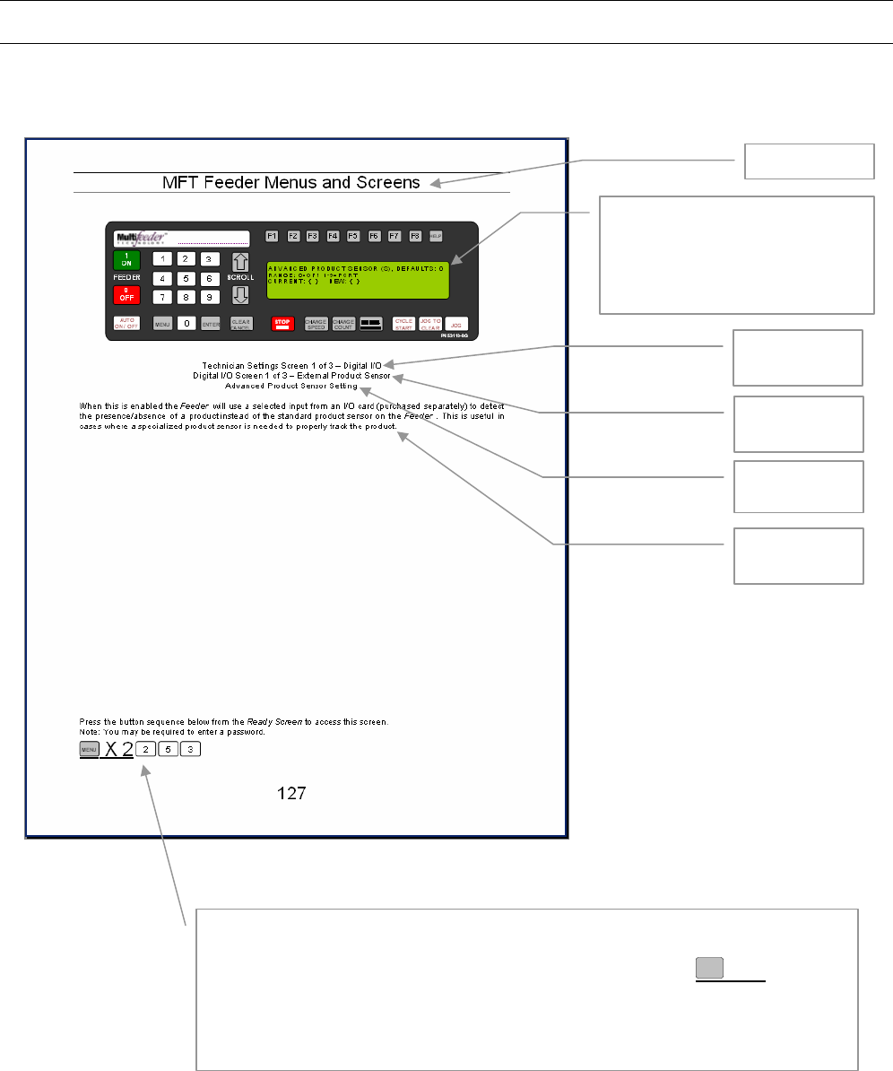
Advanced Product Sensor Setting 126
Digital I/O Screen 2 of 3 - Pre-Feed Signals 127
Pre-Feed Solenoid Fire Time 127
Pre-Feed Solenoid Wait Time 129
Post-Feed Solenoid Fire Time 130
Post-Feed Solenoid Port 131
Post-Feed Solenoid Pre-Wait Time 132
Post-Feed Solenoid Post-Wait Time 133
Post-Feed Solenoid Use Screen 134
Digital I/O Screen 2 of 3 – Digital I/O Wizards 1 of 3 135
Digital I/O Screen 2 of 3 – Digital I/O Wizards 2 of 3 136
Digital I/O Screen 2 of 3 – Digital I/O Wizards 3 of 3 137
Digital I/O Screen 3 of 3 138
Digital I/O Screen 3 of 3 - Reject on Error Signals 139
IO Card Reject-on-Error. 139
Low Product Input 140
Digital I/O Screen 3 of 3 – Invert Inputs 141
Invert Input 1 141
Invert Input 2 142
Invert Input 3 143

Table of Contents
Invert Input 4 144
Invert Input 5 145
Invert Input 6 146
Invert Input 7 147
Invert Input 8 148
Invert Output 1 149
Invert Output 2 150
Invert Output 3 151
Invert Output 4 152
Invert Output 5 153
Invert Output 6 154
Invert Output 7 155
Invert Output 8 156
Invert Output 9 157
Invert Output 10 158
Wizards 1 of 4 159
Wizards 2 of 4 160
Wizards 3 of 4 161
Wizards 4 of 4 162
Technician Settings Screen 2 of 3 163
LCD Refresh Rate 164
Menu Item Timer 165
Operator Password 168
Technician Password 169
Edit Non-Defaults Screen 170
Reset to Defaults 171
Multiple Languages 172
Technician Settings Screen 3 of 3 173
1st Height Adjustment 174
2nd Height Adjustment 175
Operator Password 176
Technician Password 177
Feeder On 178
Auto On 179
Set Product Thickness 180
Cycle Start 181
Jog To Clear 182
FCT Key 1 183
FCT Key 2 184
FCT Key 3 185
FCT Key 4 186
FCT Key 5 187
FCT Key 6 188
FCT Key 7 189
FCT Key 8 190
LSE Update Period 191
Technician Settings Screen 3 of 3 – Advanced Demo Mode Setting 192

Table of Contents
Advanced Demo Mode 192
Demo Mode Override 193
Technician Settings Screen 3 of 3 – Date/Time Setting 194
Edit Date Setting 194
Edit Time Setting 195
Technician Settings Screen 3 of 3 – Machine Modes 196
Machine Modes Setting 1 of 5 196
Machine Modes Setting 2 of 5 197
Machine Modes Setting 3 of 5 198
Machine Modes Setting 4 of 5 199
Machine Modes Setting 5 of 5 200
Password and Warning Screens 201
Password Screen 201
Clearing Fault Screen 202
Safety Relay Tripped Warning Screen 203
Illegal Entry Warning Screen 204
Table of Contents 205
Electrical Schematics 206
Overview 206
External Connections 208
Jack 1 - Start/Status 208
Jack 2 APL Interface 210
Jack 3 - the Low Product 211
Jack 4 - RS 232 (COM 1) 212
Jack 5 - Power Entry 212
Jack 6 - Product Sensor 213
Jack 22 – Signal Light 213
Jack 23 - Line Speed Encoder 214
Jack 24 - Feeder Interlock 214
Internal Connections 215
Motherboard - Plug 3 215
Motherboard - Plug 216
Motherboard - Plug 6 217
Motherboard - Plug 7 218
Motherboard - Plug 9 219
Motherboard - Plug 10 220
Motherboard - Plug 11 221
Motherboard - Plug 12 222
Motherboard - Plug 13 223
Motherboard - Plug 14 224
Motherboard - Plug 15 225
Motherboard - Plug 16 226
Motherboard - Plug 17 227
Motherboard - Plug 18 228
Motherboard - Plug 19 229
Motherboard - Plug 20 230

Table of Contents
Troubleshooting 231
Basic Mechanical Troubleshooting 233
Advanced Electrical Troubleshooting 237
Maintenance 239
Bearing Maintenance 243
CE Compliance 244

EQUIPMENT SAFETY WARNINGS
10
All equipment from Multifeeder Technology (MTF) is designed with safety in mind. However, in
order to ensure your safety and the safety of others around you, common sense must always be
used when operating this machine. Please read this section of the manual carefully before
installing or operating your MTF System.
Personal Safety Warnings
These warnings are given
to help you avoid personal
injury
Do not install or operate your MFT Feeder without first reading this
manual completely.
This Feeder operates on 110 or 220 VAC. Contact with this voltage can
lead to serious injury, or death.
A
lways properly shut down and disconnect the power cord before
removing any housing covers for service or inspection.
A
lways properly shut down and disconnect the main power cord before
working with any electrical components.
Always properly shut down and disconnect the power cord before
reaching into the any area of the Feeder to perform maintenance tasks.
Make sure loose jewelry, clothing, long hair, neckties, etc. is properly
secured before you operate the system.
Do not operate the Feeder, make mechanical adjustments, or perform
maintenance tasks while under the influence of drugs or alcohol.
Keep hands away from moving parts at all times while the Feeder is
operating.
Always properly shut down the Feeder before reaching into moving area
of the machine to perform setup tasks, make mechanical adjustments, or
clear jams.
Be aware of the location of the STOP MOTOR button. In case of an
emergency, this may be depressed at any time to instantly stop the
motor.
Use proper lifting techniques when moving this machine.
Be aware of static electricity build up on products being fed.

EQUIPMENT SAFETY WARNINGS
11
Equipment Precautions
These precautions are
given to avoid damage to
the MFT Friction Feeder
Do not install or operate your Feeder without first reading this manual
completely.
A
lways properly shut down and disconnect the power cord before
removing any housing covers for service or inspection.
When moving the Feeder, do not lift by the discharge table or shafts.
Make sure the Feeder components are securely mounted before enabling
the operation.
Use only fuses of the correct type, voltage, and current ratings.
To turn off any control boxes, always press the red OFF button on the
membrane keypad before turning off the machine with the mechanical
switch if so equipped.
Do not stack items on the machine when it is not in use.
A
lways properly shut down and disconnect the power cord before
performing any setup tasks or making mechanical adjustments.
Perform regular maintenance as prescribed in manual. Failure to do so
may result in injury and/or damage to the machinery.
Maintenance tasks and mechanical adjustments should be performed
according to the methods described in this manual by properly trained
personnel.
This system should be operated within the following environmental range:
Temperature 10-35oC (50-95oF), the recommended relative humidity range
is 30% to 60% with 80% maximum, non-condensing.
This system should be operated in a well-lit area.
All power and signal cables should be secured before operating the
Feeder.
A
ll loose tools and material should be removed from the equipment before
operating the Feeder.

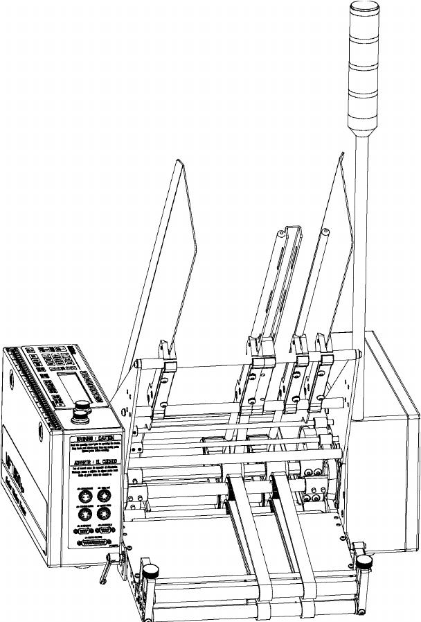
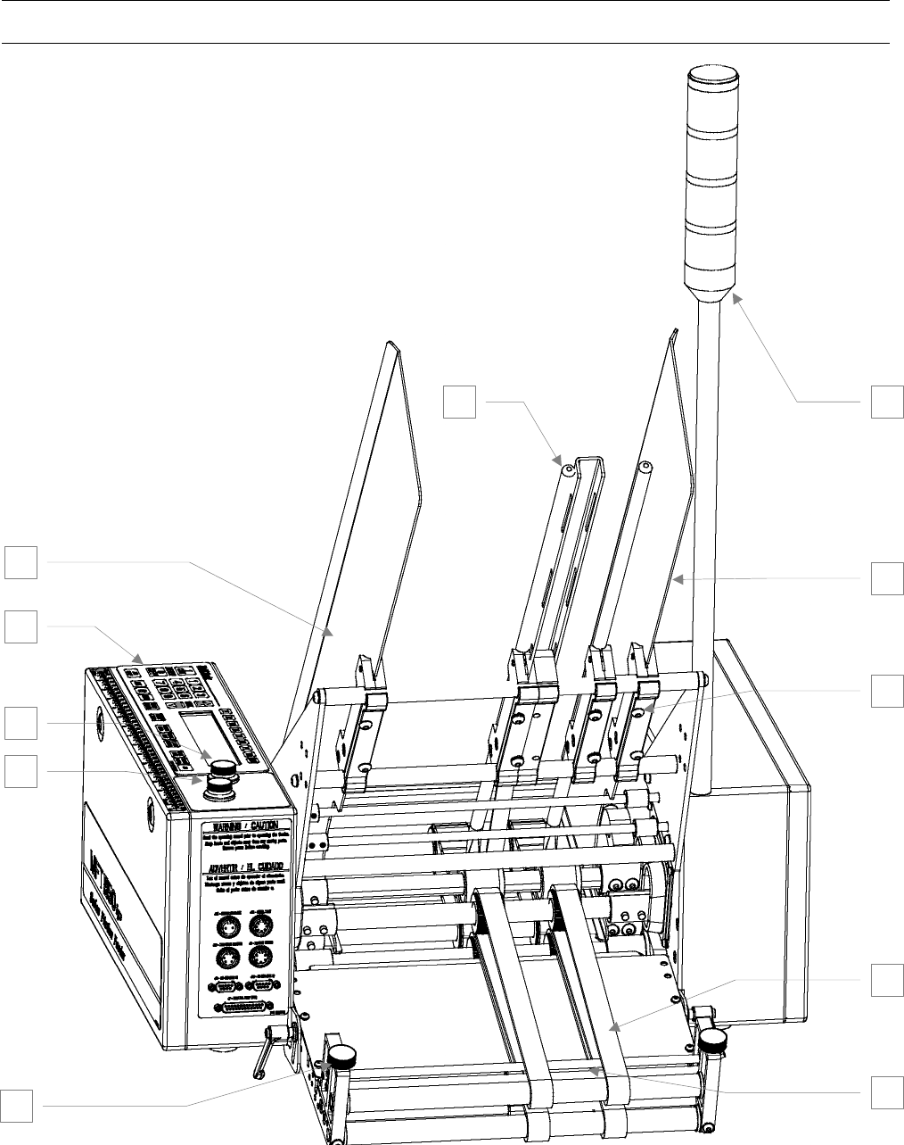
Feeder Installation and Setup
12
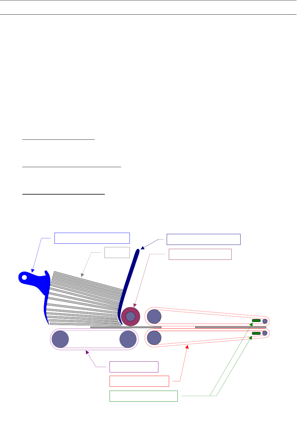
Installation and Setup
1 Signal Light
2 Product Support Curve (see Figure 4)
3 Product Rod
4 Magazine Side Plate
5 Magazine Side Plate
6 Magazine Side Plate Screw (Knob)
7 Feed Belt
8 Discharge Belt
9 Stripper Wheel
10 Stripper Wheel Height Adjustment Knob
11 Discharge Height Adjustment Knob
12 Product Sensor Pair (Not Visible)
13 Keypad
14 Discharge Height Adjustment Knob
Feeder Installation and Setup
13
Rear View of MFT Friction Feeder
Figure 1
1 3
4
5
11
13
9 7
8
10
Feeder Installation and Setup
14
Front View of MFT Friction Feeder
Figure 2
1
4
6
8
12
11
10
13
5
3
14

Feeder Installation and Setup
15
Installation and Setup
NOTE! Before installing the Feeder, check your packing slip to make sure your shipment contains all items as
specified. If your shipment is missing any items, please contact MFT. If items have been damaged during
shipment, contact the shipper or trucking company immediately.
MFT Feeder Installation
The numbers in parentheses refer to the items in Figure 1 (a rear view of the Feeder) and Figure 2 (a front view
of the Feeder). The numbers on each figure are identical.
1. Using appropriate means of lifting carefully remove the Feeder assembly from its box and place it in its
correct operating position and direction.
2. Use a Multifeeder Technology Stand-On-Rollers and compatible mounting hardware or mounting provided
by the user to securely mount the friction Feeder.
3. Install the Product Support Curve (2, Figure 4). Product Support Curve (2) should be placed on the top of
the slotted housing frame bracket for small products and on the back of the housing frame bracket for large
products.
4. Install the Product Support Rod(s) (3). Each Product Support Rod(s) (3) should be mounted as shown in
Figure 4. Position the Product Support Rod (3) so that the curved sharpened tip faces inward and is
aligned with the center line of the Feed Belt (7) and that it does not touch either the Stripper Wheel (9) or
Feed Belt (7). If two or more Product Support Curves (2) are used, they should be positioned at identical
heights and locations with respect to the Stripper Wheels (9) and Feed Belts (7).
5. Install the Magazine Side Plate (4) and (5). Place one Magazine Side Plate (4) and (5) on the outside of the
far right Feed Belt (7) assembly and one on the outside of the far left Feed Belt (7) assembly.
NOTE! The magazine plate lips should funnel inward towards the feed belts.
6. If ordered, install the Low Product Sensor (not pictured). Plug the Low Product Sensor into the J3-Low
Product connector located on the back of the electrical Feeder housing.
7. If ordered, install the Photo-Optic / Proximity Start Sensor (not pictured). Plug the start sensor into the J1-
start status connector located on the back of the electrical Feeder housing.
Feeder Installation and Setup
16
MFT Feeder Setup
Before you begin the setup procedure, be certain that the Feeder motor is disabled. This can be accomplished
either by turning the power off on the main power switch or by pressing the FEEDER OFF key on the
membrane keypad. (The LCD display remains ON in this mode but displays FEEDER OFF - PRESS ON TO
ENABLE). The numbers in parentheses () refer to the items in Figure 1 and Figure 2. Figure 1 is a rear view of
the Feeder and Figure 2 is a front view of the Feeder. The numbers on each figure are identical.
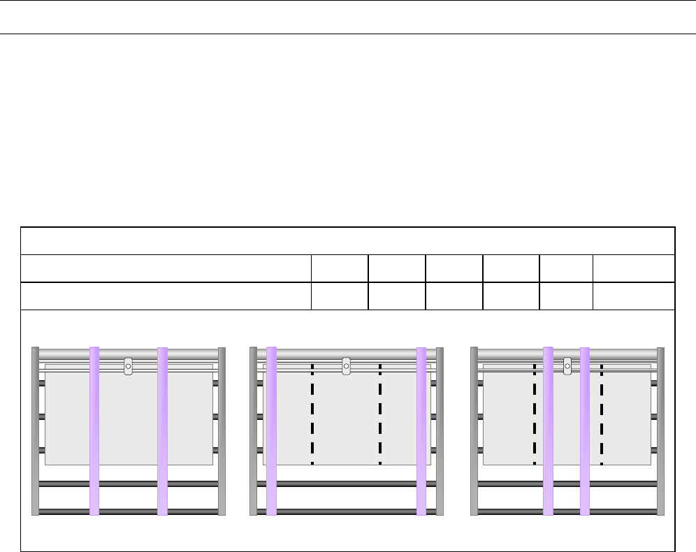
Feed and Discharge Belt Location
Position the Feed Belts (7) and Discharge Belts (8) according to the following table
Equal belt spacing ensures a uniform product discharge. If the product discharge is non-uniform, the user
needs to consider the non-uniformities inherent in belt placement. For example, if a raised portion exists on the
product, MFT recommends not positioning belts over the raised portion. For a uniform product requiring two
belts, the following configuration is recommended: testing will help determine the best configuration for belt
placement.
1. To position the belts, first locate the setscrews on the discharge pulleys and the main feed belt pulleys. Use
a 2.5 mm metric Allen wrench to loosen the setscrews on the pulleys.
2. After the setscrews are loose, position the discharge pulleys, the main feed belt pulleys, and the free-
floating pulleys according to the instructions above.
3. Position the Stripper Wheels (9) such that they are directly above each of the feed belts. To move the
Stripper Wheels (9), first locate the setscrews. Insert a 2.5mm metric Allen wrench into the set screw heads
and turn counterclockwise to loosen.
4. Position the Product Support Rod (3) so that products can pass between the bottom of the Product Support
Rod (3) and the Feed Belts (7) as follows:
a) For very thin products (0.05mm - 0.25mm): Adjust the height of the Product Support Rod (3) so that the
distance between the Feed Belt (7) and the sharpened tip of the Product Support Rod (3) equals a
stack of 10-20 products, approximately 2-5 mm.
b) For medium products (0.25mm - 2mm): Allow a distance of 6-15 products, approximately 3mm - 8mm.
Feed belt & Discharge Belt Settings
Number of Feed Belt Assemblies 1 2 3 4 5 6
Fold product into 2 3 4 5 6 7
Below is an example of belt placement on a feeder with two belts. Center the belts on the fold
represented by the dotted lines in the illustration below.
Correct Incorrect Incorrect

Feeder Installation and Setup
17
Flow
Acceptable position for
the Product Sensor Pair.Unacceptable position for
the Product Sensor Pair.
Product Sensor Pair
Figure 3
Hole
c) For medium thick products (2mm - 4mm): Allow a distance of 3-10 products, approximately 5-10 mm.
d) For thick products (4mm - 6.25mm): Allow a distance of 2-5 products, approximately 8-15 mm.
e) For very thick products (6.25mm - 26mm): Allow a distance of 1 product, approximately 15mm - 30mm.
Note: Depending on your familiarity with the feeder setup it may be advantageous to remove the Magazine Side
Plate (5) closest to the control panel by loosening the Twist Knobs (6) in Figure 1 for easier viewing of set up.
5. Use the Stripper Wheel Height Knob (10) to adjust the Stripper Wheel (9) height allowing one product
between the Stripper Wheels (9) and the Feed Belts (7). Adjust the Stripper Wheel (9) for slight resistance
as you slide the product between the Stripper Wheels (9) and the Feed Belts (7). The product should be
moveable using only two fingers and yet have noticeable resistance to pulling.
a) If the gap between the Stripper Wheels (9) and the Feed Belts (7) is too tight, rotate the Stripper Wheel
Height Knob (10) clockwise to reduce the pressure.
b) If the gap between the Stripper Wheels (9) and the Feed Belts (7) is too loose, rotate the Stripper
Wheel Height Adjustment Knob (10) counter clockwise to increase the pressure.
6. Insert one product between the top and bottom Discharge Belts (8) in the entrance of the discharge section.
Use the Discharge Height Adjustment Knob (11) to adjust the height of the top discharge belts using the
same procedure described in step 6. Ideally, the grip on the product in the discharge section will be slightly
looser than that in the stripper wheel section.
7. Insert one product between the top and bottom discharge belts at the discharge exit area. Use the
Discharge Height Adjustment Knob (14) at the end of the discharge table to adjust the product pressure as
you did in steps 6 and 7. The pressure on the product at the discharge exit should be the same as the
pressure at the discharge entrance (step 7). It is very important that the pressures on the left and right
sides of the product are equal. In other words, the discharge exit roller shaft must be level. You can check
that the pressures are equal by dragging the product by its left and right tip until you feel equal pressure.
Note: If the product skews as it feeds, there is too much pressure on the product.
8. Position the Product Sensor Pair
(12) to properly and reliably read the
product as it passes through the
Feeder. It is very important that the
emitter and receiver of the Product
Sensor Pair (12) are inline with one
another. This simply means that the
emitter and receiver are vertically
aligned. A good position requires
that the emitter and receiver not be
too close to an edge or near a place
on the product with slots, clear
areas or holes. For example: In
Figure 3 the Product Sensor Pair
(12) placed in the center of the
product and avoids the “Hole” as the
product flows through the Feeder.

Feeder Installation and Setup
18
9. Press the FEEDER ON (see p. 21) hot key to enable the Feeder.
10. Once at the ready screen access the Feeder’s menu options by pressing the MENU key on the membrane
Keypad (13). Select the Product Feeding Length menu by pressing the “1” key. Measure the length of the
product being fed and enter the value. Refer to p.29 for further information on how to enter the product
feeding length.
11. Press the CHANGE SPEED hot key and enter a value of 100.
12. Press the CHANGE COUNT hot key and enter a value of 1.
13. Take a small stack of products (6-10 products) and place it in the product magazine with the front end of the
bottom product lying on the Feed Belts (7) facing the Stripper Wheels (9). Adjust the Product Support Curve
assembly (2) to support the products similar to the illustration in Figure 4. Note that for larger products the
product stack may only be resting on the product support curve tip and its shoulder. Note also that for
larger products the Product Support Curve (2) assembly can be mounted on the back of the housing frame
bracket.
14. Press JOG and observe the spacing between the products as they exit the Feeder. To fine-tune the
stripper wheel adjustment, check the product spacing by the Product Sensor Pair.
a) < 12mm (1/2"): Decrease the height of the Stripper Wheels with respect to the Feed Belts by rotating
the thickness adjuster knob (10) counter clockwise.
b) > 50mm (2"): Increase the height of the Stripper Wheels with respect to the feed belt by rotating the
thickness adjuster knob (10) clockwise.
15. Position the Product Support Curves (2) so that the distance from the Product Support Rods (3) is slightly
more than the product length (see Figure 4). The product support curves should be positioned to lift some
of the weight off the Feed Belts (7) while they guide the product. Be careful not to let the Product Support
Curves Touch (7) the Feed Belts (9). This will lead to premature feed belt wear.
16. Add approximately 50mm (2in) of additional product to the initial stack.
17. Press the JOG key to observe that the product properly and consistently falls onto the Feed Belts (7) and
that the product feeds correctly. Adjust the Product Support Curve (2) if necessary to improve the
performance.
18. Press the JOG key to position one product between the Product Sensor Pair (12).
19. Press the SET PROD THICKNESS hot key to store the product thickness in the Feeder’s memory.
20. Reinstall the Magazine Side Plate (5) if remove. The Magazine Side Plate (4) and (5) should be
symmetrical with respect to the center of the Feeder and allow approximately 3mm (1/8") on each side of
the product stack. This enables the product to pass downward freely.
21. Load magazine with product and press the JOG key to observe the distance between the products as they
are fed.
a) < 12mm (1/2"): Rotate or increase the height of the Product Support Curve (2) to decrease the weight
of the product on the Feed Belts (7). It may also be necessary to slightly decrease the height of the
Stripper Wheels (9) with respect to the Feed Belts (7).
b) > 50mm (2"): Rotate or decrease the height of the Product Support Curve (2) to increase the weight of
the product on the Feed Belts (7). It may also be necessary to slightly increase the height of the
Stripper Wheels (9) with respect to the Feed Belts (7).
Feeder Installation and Setup
19
22. Press the JOG TO CLEAR key to test feeding. Check to be sure the product is coming out straight and that
there is approximately 12mm (1/2") to 50mm (2") of space between products when they are between the
Product Sensor Pair (12).
23. Use the CHANGE SPEED hot key to enter the production speed and the CHANGE COUNT hot key to enter
the production count.
24. Press the JOG TO CLEAR key to test feeding again. Once more, check to be sure that the product is
coming out straight and that there is approximately 12mm (1/2") to 50mm (2") of space between products
when they are between the Product Sensor Pair (12).
25. If using a product sensor to trigger the feed cycle, set the Feeder to Auto On with the AUTO ON/OFF key or
press CYCLE START to begin feeding without a product sensor.
Feeder Tips
1. Product Support Curve (2): The support curve should be placed as shown in the drawing for most
products. When working with products that are difficult to feed, the support curve can be raised to
reduce the product weight on the feed belts. Let the products feed with low stripper wheel pressure.
2. Clean Stripper Wheels (9) Regularly: Clean at the start of each shift. Dip a clean rag in isopropyl
alcohol. Press firmly and wipe the surface of each stripper wheel from side to side all the way around
each wheel.
3. Adjusting Stripper Wheels (9): Adjust the height of the stripper wheel shaft until you feel slight
resistance as you slide one product between the Stripper Wheels and the Feed Belts. When the
Feeder is loaded with a stack of product, the stripper wheel setting can be checked by rotating the
stripper wheel shaft. If the wheels turn freely the pressure is too light. If the shaft cannot be turned with
slight resistance, the pressure is too high. Do not over tighten the Stripper Wheels.
Stripper Wheel (9)
Feed Belts (7)
Product Support Curve (2) Product Support Rod (3)
Discharge Belt (8)
Product
Side View Sketch of the MFT Friction Feeding Principle
Figure 4
Product Sensor Pair
How To Use This Manual
20
Note:
Values can be displayed in meters, feet or revolutions per minute. Examples in this manual are in meters.
Section Title
Main Menu
Heading
Sub Menu
Heading
Setting Title
(When Applicable)
Use the button sequence to arrive at the screen depicted at the top of the page.
Note: Repetitive button depressions are represented by “
MENU
X 2”. This in
indicates to press the underlined button the amount of times after the “X”.
Screen Shot of Control Box
Note: “{ }” are used to display
variable values of the actual
screen.
Setting Details
2
Feeder Menu Matrix
21
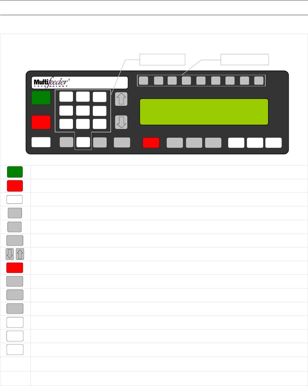
Controls and Key Pad
Key Pad Controls
Used to start up control box software after mechanical power switch is turned on.
Used to shut down control box software before mechanical power switch is turned off.
Used to enable/disable external triggering.
Used to enter and navigate menu options.
Used to enter menu and value choices.
Used to clear errors or cancel functions
Used to navigate menu options.
Used to stop motor functions.
Used to change motor speed.
Used to change count value.
Used to set product thickness of the sensor pair.
Used to start a cycle.
Used to automatically position a product under the sensor pair.
Used to jog the motor.
Number
Keys Used to input values and for menu navigation.
Function
Keys Used as direct access key for frequently used menus.
F1 F2 F3 F4 F5 F6 F7 F8 HELP
1
ON
0
OFF
AUTO
ON / OFF CLEAR
CANCEL
1
4
7
2 3
6
9
MENU 0 ENTER STOP
MOTOR CYCLE
START
SET PROD.
THICKNESS
CHANGE
COUNT
CH
A
NGE
SPEED JOG TO
CLEAR JOG
.........................................
FEEDER SCROLL
PN 53110-0G
STATUS OFF
PRESS ON TO ENABLE EQUIPMENT
MODE: TURRET
F1 – TECHNICIAN F2 - FACTORY
5
8
Number Keys Function Keys
1
ON
0
O
FF
AUTO
ON / OFF
MENU
ENTER
CLEAR
CANCEL
STOP
MOTOR
CHANGE
SPEED
CHANGE
COUNT
SET PROD.
THICKNESS
CYCLE
START
JOG TO
CLEAR
JOG

Feeder Menu Matrix
22
Diagnostic Screen 1 of 4
1 4 2 3 65
Settings Program Setup Reports Identification
Settings Screen
1 of 2
Product Length
Max Jog Speed
Signal Delay
Save Current
Pro
g
ram
Save Across all
Pro
g
rams
Load Program
Signal Period
1 4
2
3 6
5
View Summary
Lo
g
View Detail Log
Reset Log
Print Summary
Lo
g
Print Detail Log
Print Settings
14
2
3 6
5
Stack Light
Product Sensor
Line Speed Enc
Pstart/Low-P
In
p
ut
Low Product
Out
p
ut
Auto On
Out
p
ut
Diagnostic Screen 3 of 4
14
2
3 6
5
DD Status
APL Test
ADT Test
Motor Encoder
Height
Ad
j
ustment
Keypad Test
Diagnostic Screen 4 of 4
1
2
IO Card Inputs
IO Card Outputs
Diagnostic Screen 2 of 4
14
2
3 6
5
Demo Mode
Out
p
ut
Cycle Complete
C3 Output
Red Light
Out
p
ut
IO Ready
Out
p
ut
APL Enable
Out
p
ut
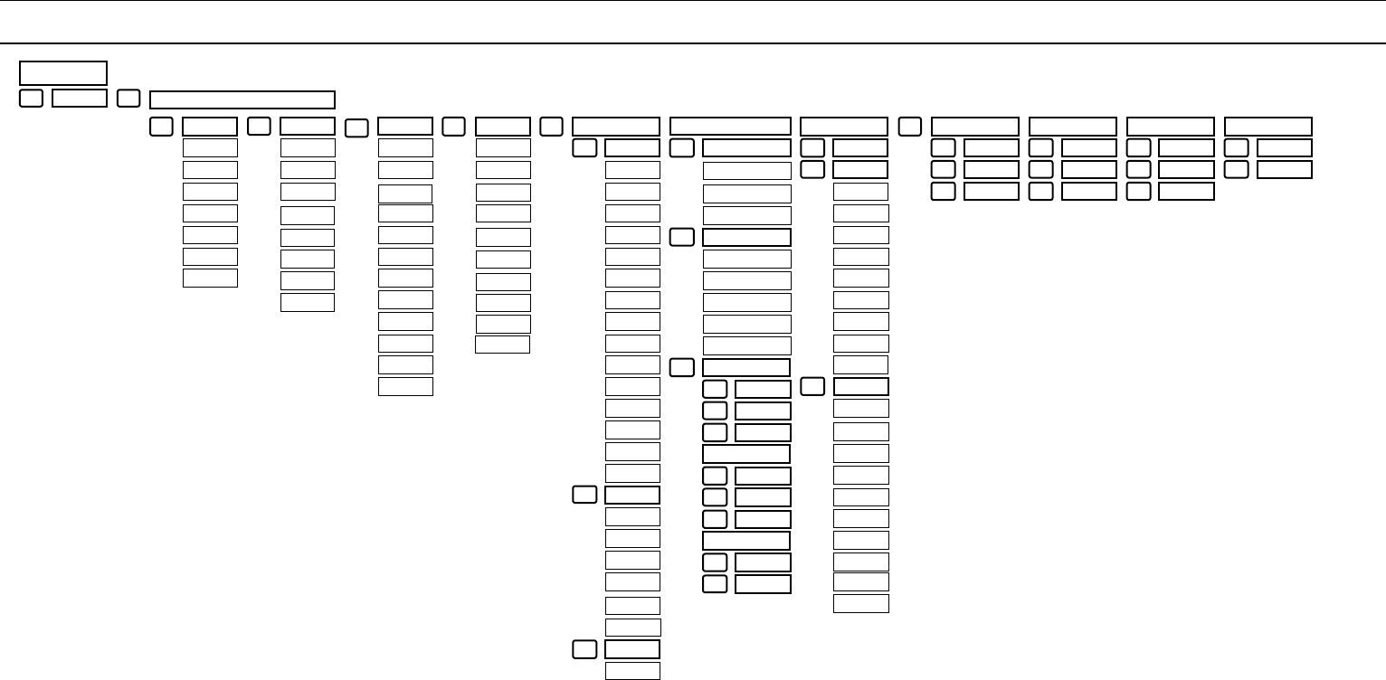
Feeder Menu Matrix
23
1 2
Demo
Settings Screen
2 of 2
Technician Screen 1 of 3
1 4 2 3 5
Motor Feeding Debounce Advanced
Settin
g
sDigital IO
1 of 3
Motor Gains
Accel
Decel
Motor Timeout
Motor Gains
Adjustment
Gearing
Trajectory
Suppressed
Starts
Auto
On/Off
MPD Thickness
Disabled
Standard LSE
Package
Infeed Output
Cycle Complete
MPD IO
Jam IO
Advanced
PStart
PStart
Debounce
PStart
Debounce Value
Min Product
Length
Product
Separation Len
Pulse Window
Product
Separation Length
Watch Dog No
Product
IO Card Low
Product Output
IO Card
Output Faults
J1-E Signal
Invert J1-E
Signal
AND Gate
Output Port
OR Gate
Output Port
LSE Use Motor
Encoder
Conveyor
Stopped Output
Guarding 1
Pulse Window
Guarding 2
RS232 Port
IO Cycle
Complete
IO Card
Red Light
IO Card
IO Ready
Standard IO
Si
g
nals
Duplicate
Si
g
nals
External
Product Senso
r
Advanced
PStart
Offline Output
1
2
3
Digital IO
2 of 3
Pre-feed Signals
Post Feed Signals
Digital IO Wizards
1of3
1
2
3
Digital Input
Wizard
(
J3 Port
)
Digital Input
Wizard A
(
IO
Digital Input
Wizard B
(
IO
1
2
3
Advanced
Product Sensor
Digital IO Wizards
2 of 3
Digital Input
Wizard C
(
IO
Digital Input
Wizard C
(
IO
Simple Input
Wizard
1
2
3
Digital IO Wizards
3 of 3
Jogger Wizard
Signal Fault
Out
p
ut Wizard
1
2
Digital IO
3 of 3
Reject on Errors
Si
g
nals
Invert Inputs
Invert Output 9
1
2
3
Invert Output 1
Invert Output 2
Invert Output 3
Invert Output 4
Invert Output 5
Invert Output 6
Invert Output 7
Invert Output 8
Low Product
Input
Invert Input 1
Invert Input 2
Invert Input 3
Invert Input 4
Invert Input 5
Invert Input 6
Invert Input 7
6 Wizards
1 of 4
Advanced LSE
Invert Input 8
Wizards
2 of 4 Wizards
3 of 4 Wizards
4 of 4
Gluer
Inte
g
ration
Two Sensor
Timin
g
Com
p
1
2
Advanced
Warnin
g
Control
AccuTipping
Encoder Timing
Com
p
ensation
1
2
3
Remote Keypad
Height
Ad
j
ustment
Function Key
Setu
p
1
2
3
Barcode Setup
Serial Count
Encoder Speed
Com
p
ensation
1
2
3
Invert Output 10
Invert Output
Distance
Window
No Product
Limit
Signal Delay
Signal Period
Line Speed
Encoded Delay
Pre-Feed Solenoid
Fire Time
Post-Feed Solenoid
Fire Time
Minor Jam
Faults
MPD
Accumulate
No Product
Faults
MPD Faults
Minor Jam
Faults
Slow Speed
Distance
Window
Early Cycle
Complete
Max Jog Speed
Product Length
Signal Period
Signal delay
Pre-Feed Solenoid
Port
Pre-Feed Solenoid
Wait Time
Post-Feed Solenoid
Port
Post-Feed Solenoid
Pre-Wait Time
Post-Feed Solenoid
Post-Wait Time
Post-Feed Solenoid
Use

Feeder Menu Matrix
24
Technician Screen 2 of 3
1 4 2 3 5 Display Backup/Restore Passwords Edit
Non-Defaults Reset To
Defaults 6 Language
LCD Refresh
Rate
Menu Item
Time
r
Backup Data
Restore Data
Operator
Passwords
Technician
Passwords
Multiple
Lan
g
ua
g
es
{Note}
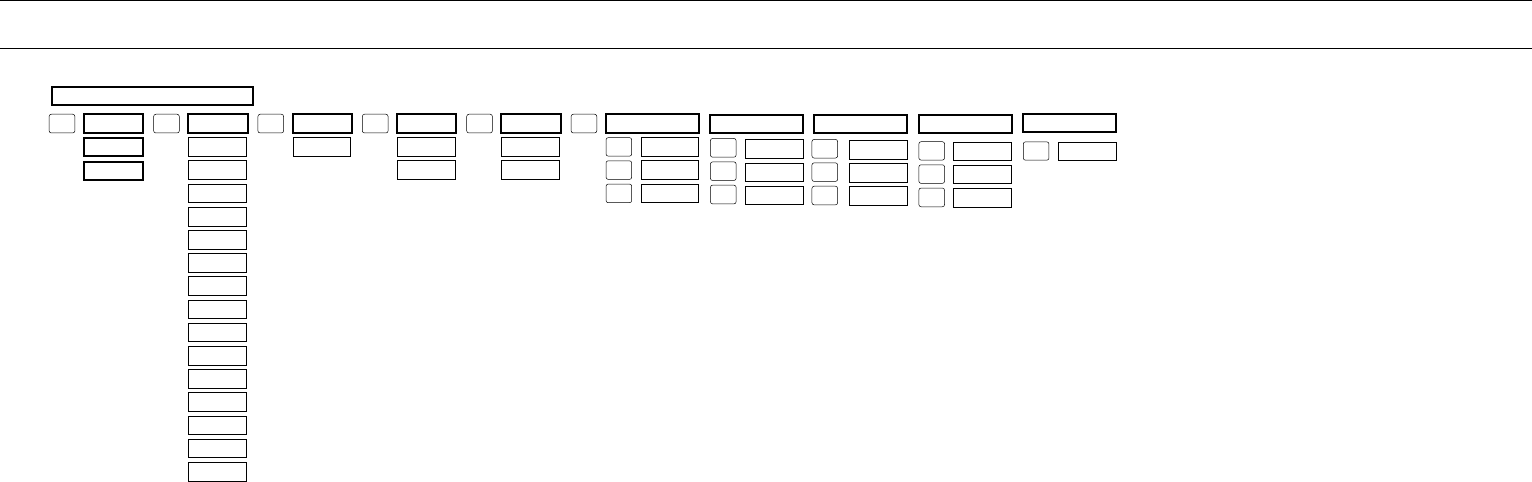
Feeder Menu Matrix
25
Technician Screen 3 of 3
Height
Adjustment
Lockdown Limits Advanced
Demo Mode
Date Time Machine modes 1 of 5
Operator
Password
Technician
Password
Feeder On
Auto On
Set Product
Thickness
Cycle Start
Jog To clear
FCT Key 1
FCT Key 2
FCT Key 3
FCT Key 4
FCT Key 5
FCT Key 6
FCT Key 7
FCT Key 8
Basic Count
Advance Count
Basic Tipping
Advanced
Tipping
Basic Conveyor
Advanced
Conve
y
o
r
AccuTipping
Speed match
AccuTipping
Re
p
eatin
g
Linear Motor
Table
Burn In
Continuous
Mode
Card Line
Turret
LSE Update
Period Advanced
Demo Mode
Demo Mode
Override
Edit Date
Edit Time
1
2
3
1 2 3 4 5 6
1
2
3
Machine modes 2 of 5
1
2
3
1
2
3
1
Machine modes 3 of 5 Machine modes 3 of 5 Machine modes 5 of 5
1st Height
2nd Height
MFT Feeder Menus and Screens
26
Power Up Screen
The Power Up Screen is displayed after the switch on the power enter module is turned on and after the
software loads. There are three options on the Power Up Screen.
1. Pressing the button advances to the Ready Screen.
2. Pressing the button advances to the Technician Settings Screen.
3. Pressing the button advances to the Factory Settings Screen.
Note: A password is required to access menu screens.
F1 F2 F3 F4 F5 F6 F7 F8 HELP
1
ON
0
OFF
AUTO
ON / OFF CLEAR
CANCEL
1
4
7
23
6
9
MENU 0 ENTER STOP
MOTOR CYCLE
START
SET PROD.
THICKNESS
CHANGE
COUNT
CHANGE
SPEED JOG TO
CLEAR JOG
.........................................
FEEDER SCROLL
PN 53110-0G
STATUS OFF
PRESS ON TO ENABLE EQUIPMENT
MODE: TURRET
F1 – TECHNICIAN F2 - FACTORY
5
8
1
ON
F2

MFT Feeder Menus and Screens
27
Ready Screen
The Ready Screen is displayed when the control box is ready to be to be run.
Note: The third line down may toggle between three states.
1. PROGRAM {NUMBER}
2. SPEED {XXX} MPM [ XXFPM]
3. LOW PRODUCT
Press the button sequence below from the Ready Screen to access this screen.
Power on switch +
F1 F2 F3 F4 F5 F6 F7 F8 HELP
1
ON
0
OFF
AUTO
ON / OFF CLEAR
CANCEL
1
4
7
23
6
9
MENU 0 ENTER STOP
MOTOR CYCLE
START
SET PROD.
THICKNESS
CHANGE
COUNT
CHANGE
SPEED JOG TO
CLEAR JOG
.........................................
FEEDER SCROLL
PN 53110-0G
MODE: BASIC MODE AUTO OFF
STATUS: READY
PROGRAM 1
5
8
1
ON

MFT Feeder Menus and Screens
28
Main Menu Screen
1 of 2
The Main Menu Screen is displayed when the MENU button is pressed. Use the number keys on the keypad
to advance to corresponding setting.
1. SETTINGS 4. REPORTS
2. PROGRAMS 5. IDENTIFICATION
3. SET UP 6. DIAGNOSTICS
Press the button sequence below from the Ready Screen to access this screen.
Note: You may be required to enter a password.
F1 F2 F3 F4 F5 F6 F7 F8 HELP
1
ON
0
OFF
AUTO
ON / OFF CLEAR
CANCEL
1
4
7
23
6
9
MENU 0 ENTER STOP
MOTOR CYCLE
START
SET PROD.
THICKNESS
CHANGE
COUNT
CHANGE
SPEED JOG TO
CLEAR JOG
.........................................
FEEDER SCROLL
PN 53110-0G
MAIN MENU 1/2 : MENU KEY FOR NEXT
1. SETTINGS 4. REPORTS
2. PROGRAMS 5. IDENTIFICATION
3. SET UP 6. DIAGNOSTICS
5
8
MENU

MFT Feeder Menus and Screens
29
Settings Screen 1
Product Length
Menu 1 allows the user to store, in the computer's memory, the length of the product being fed. The
computer then checks for product jams and multiple product feeds. Menu 1 may be selected by pressing the
“1” key while any of the MENU option screens are shown. When Menu 1 is selected, the program displays
the allowable product length range (25mm-1500mm), the current product length, and prompts the user to
enter the new product length as shown in the figure above. For your convenience, a ruler has been placed on
the Feeder housing directly below the membrane keypad. Please note that the product length must be
entered in millimeters (25mm = 1in).
Press the button sequence below from the Ready Screen to access this screen.
Note: You may be required to enter a password.
X
1
MENU
F1 F2 F3 F4 F5 F6 F7 F8 HELP
1
ON
0
OFF
AUTO
ON / OFF CLEAR
CANCEL
1
4
7
23
6
9
MENU 0 ENTER STOP
MOTOR CYCLE
START
SET PROD.
THICKNESS
CHANGE
COUNT
CHANGE
SPEED JOG TO
CLEAR JOG
.........................................
FEEDER SCROLL
PN 53110-0G
PRODUCT LENGTH (M-F3), DEFAULT: 210
RANGE 25-1500 mm
CURRENT: { } NEW: { }
5
8

MFT Feeder Menus and Screens
30
Settings Screen 1
Maximum Jog Speed
The Max Jog Speed screen allows the user to control the maximum speed at which the Feeder will operate
when used in the JOG mode. This function is particularly useful when the “operating” speed is set very high
and the user would like the option to jog at a lower speed. However, it is important to note that this function
controls the maximum jog speed. In other words, when the operating speed is set at a lower speed than the
Max Jog Speed, the Feeder will jog at the operating speed. The Max Jog Speed screen shows the allowable
Max Jog Speed range (1-100 MPM), the current Max Jog Speed value, and prompts the user to enter a new
value. The recommended Max Jog Speed is 20 MPM.
Press the button sequence below from the Ready Screen to access this screen.
Note: You may be required to enter a password.
X
MENU
1
MENU
F1 F2 F3 F4 F5 F6 F7 F8 HELP
1
ON
0
OFF
AUTO
ON / OFF CLEAR
CANCEL
1
4
7
23
6
9
MENU 0 ENTER STOP
MOTOR CYCLE
START
SET PROD.
THICKNESS
CHANGE
COUNT
CHANGE
SPEED JOG TO
CLEAR JOG
.........................................
FEEDER SCROLL
PN 53110-0G
MAX JOG SPEED (S), DEFAULT: 20
RANGE 1-1000 MPM
CURRENT: { } NEW: { }
5
8

MFT Feeder Menus and Screens
31
Settings Screen 1
Signal Delay
The Signal Delay screen gives the user the option of delaying the acknowledgment of the start
pulse at the start connector. This function is used primarily when the Feeder is integrated with
another machine. The signal may be delayed from 0 milliseconds to 1000 milliseconds (1 second).
When the delay is set to 0 the start pulse will be acknowledged immediately.
Press the button sequence below from the Ready Screen to access this screen.
Note: You may be required to enter a password.
X 2
MENU
1
MENU
F1 F2 F3 F4 F5 F6 F7 F8 HELP
1
ON
0
OFF
AUTO
ON / OFF CLEAR
CANCEL
1
4
7
23
6
9
MENU 0 ENTER STOP
MOTOR CYCLE
START
SET PROD.
THICKNESS
CHANGE
COUNT
CHANGE
SPEED JOG TO
CLEAR JOG
.........................................
FEEDER SCROLL
PN 53110-0G
SIGNAL DELAY (M-F3), DEFUALT: 0
RANGE: 1-30000ms
CURRENT: { } NEW: { }
5
8

MFT Feeder Menus and Screens
32
Settings Screen 1
Signal Period
The Signal Period screen gives the user the option of ignoring from 1 to 10,000 start pulses between
accepted start pulses. Again, this function is used primarily when the Feeder is integrated with another
machine. If the Signal Period is set to 0 each start pulse will be accepted.
Press the button sequence below from the Ready Screen to access this screen.
Note: You may be required to enter a password.
X 3
MENU
1
MENU
F1 F2 F3 F4 F5 F6 F7 F8 HELP
1
ON
0
OFF
AUTO
ON / OFF CLEAR
CANCEL
1
4
7
23
6
9
MENU 0 ENTER STOP
MOTOR CYCLE
START
SET PROD.
THICKNESS
CHANGE
COUNT
CHANGE
SPEED JOG TO
CLEAR JOG
.........................................
FEEDER SCROLL
PN 53110-0G
SIGNAL DELAY (M-F3), DEFUALT: 0
RANGE: 1-30000ms
CURRENT: { } NEW: { }
5
8

MFT Feeder Menus and Screens
33
Program Menu Screen
The screen is the Program Menu Screen. Use the number keys on the keypad to advance to corresponding
setting.
1. SAVE CURRENT PROGRAM
2. LOAD NEW PROGRAM
3. SAVE ACROSS ALL PROGRAMS
Press the button sequence below from the Ready Screen to access this screen.
Note: You may be required to enter a password..
X 3
2
MENU
F1 F2 F3 F4 F5 F6 F7 F8 HELP
1
ON
0
OFF
AUTO
ON / OFF CLEAR
CANCEL
1
4
7
23
6
9
MENU 0 ENTER STOP
MOTOR CYCLE
START
SET PROD.
THICKNESS
CHANGE
COUNT
CHANGE
SPEED JOG TO
CLEAR JOG
.........................................
FEEDER SCROLL
PN 53110-0G
PROGRAM
1. SAVE CURRENT PROGRAM
2. LOAD NEW PROGRAM
3. SAVE ACROSS ALL PROGRAMS
5
8

MFT Feeder Menus and Screens
34
Program Menu Screen
Save Current Program
The screen is the Save Current Program Menu Screen. Use the number keys on the keypad to select the
program number the settings will be saved to.
This screen allows the user to save the current Feeder settings, including Product Feeding Length, Speed,
Product Count, Product Thickness, and Watch Dog Length as a feeding program. The settings unique to a
specific product may then be easily recalled at any time. This is particularly useful if several different
products are run on the same machine.
Press the button sequence below from the Ready Screen to access this screen.
Note: You may be required to enter a password.
X
1 2
MENU
F1 F2 F3 F4 F5 F6 F7 F8 HELP
1
ON
0
OFF
AUTO
ON / OFF CLEAR
CANCEL
1
4
7
23
6
9
MENU 0 ENTER STOP
MOTOR CYCLE
START
SET PROD.
THICKNESS
CHANGE
COUNT
CHANGE
SPEED JOG TO
CLEAR JOG
.........................................
FEEDER SCROLL
PN 53110-0G
CHOOSE PROGRAM: 1-10
SAVE CURRENT SETTINGS IN PROGRAM # XX
5
8

MFT Feeder Menus and Screens
35
Program Menu Screen
Load Program
The screen is the Load Program Menu Screen. Use the number keys on the keypad and press enter to load
a different program.
Press the button sequence below from the Ready Screen to access this screen.
Note: You may be required to enter a password.
X
2 2
MENU
F1 F2 F3 F4 F5 F6 F7 F8 HELP
1
ON
0
OFF
AUTO
ON / OFF CLEAR
CANCEL
1
4
7
23
6
9
MENU 0 ENTER STOP
MOTOR CYCLE
START
SET PROD.
THICKNESS
CHANGE
COUNT
CHANGE
SPEED JOG TO
CLEAR JOG
.........................................
FEEDER SCROLL
PN 53110-0G
LOAD PROGRAM: 1-10
CURRENT PROGRAM XX – NEW PROGRAM XX
5
8

MFT Feeder Menus and Screens
36
Program Menu Screen
Save Across All Programs
The screen is the Save Across All Programs Screen. Use this screen to copy current setting to all programs.
Press the button sequence below from the Ready Screen to access this screen.
Note: You may be required to enter a password.
X
3 2
MENU
F1 F2 F3 F4 F5 F6 F7 F8 HELP
1
ON
0
OFF
AUTO
ON / OFF CLEAR
CANCEL
1
4
7
23
6
9
MENU 0 ENTER STOP
MOTOR CYCLE
START
SET PROD.
THICKNESS
CHANGE
COUNT
CHANGE
SPEED JOG TO
CLEAR JOG
.........................................
FEEDER SCROLL
PN 53110-0G
PRESS 1 TO SAVE CURRENT SETTINGS ACROSS
ALL PROGRAMS- PRESS CANCEL TO EXIT
5
8

MFT Feeder Menus and Screens
37
Setup Screen
The Setup Screen indicates the current running mode and all the available modes. This screen will differ
depending on the optional modes selected in the Set Machine Modes menu. The “X” indicates the current
running mode.
Press the button sequence below from the Ready Screen to access this screen.
Note: You may be required to enter a password.
X
3
MENU
F1 F2 F3 F4 F5 F6 F7 F8 HELP
1
ON
0
OFF
AUTO
ON / OFF CLEAR
CANCEL
1
4
7
23
6
9
MENU 0 ENTER STOP
MOTOR CYCLE
START
SET PROD.
THICKNESS
CHANGE
COUNT
CHANGE
SPEED JOG TO
CLEAR JOG
.........................................
FEEDER SCROLL
PN 53110-0G
SETUP : MENU KEY FOR NEXT
1. X BASIC COUNT
2. ADVANCED COUNT
3. BASIC TIPPING
5
8

MFT Feeder Menus and Screens
38
Reports Screen
1
The Reports Screen can be used to view and print log files and settings.
1. VIEW SUMMARY LOG 4. PRINT SUMMARY LOG
2. VIEW DETAIL LOG 5. PRINT DETAIL LOG
3. RESET LOG 6. PRINT SETTINGS
The Reports Screen is divided into 6 subheadings that allow the user to access different areas of the Feeder’s
log. In this menu, errors are identified and time stamped, and total production count is kept. The information
found in the Reports Screen may either be viewed on the LCD display or downloaded to a printer.
1. The View Summary Log screen allows the user to view a summary of the production run information, start
and stop dates and times, the number of faults that occurred during periods of operation, and a pack per
minute (PPM) product count.
2. The detail log provides a detailed summary account of Feeder activity. The information given includes a
summary of the production run, start and stop dates and times, the time and type of faults that occurred during
production runs, and the time and types of warnings that occurred during production runs.
3. The Reset Log option. NOTE! When this option is selected, all entries currently stored in the
production log will immediately be emptied. When this occurs, a screen declaring Figure 0-3 is shown
before the program returns to the previous menu
4. To print a Summary Log, Detail Log or Setting Log, first attach a computer or laptop (running Microsoft
Windows 95 or later with Microsoft Internet Explorer installed) to the Feeder via a NULL modem cable. On
the computer side open up HyperTerminal: Start->Programs->Accessories->Communication->HyperTerminal
Connect using COM1 at 19200 bps, 8 data bits, parity none, 1 stop bit, flow control hardware. Next go to the
menu Transfer->Capture Text… and call the file something like: summary, detail, or setting.htm.
Press the button sequence below from the Ready Screen to access this screen.
Note: You may be required to enter a password.
X
4
MENU
F1 F2 F3 F4 F5 F6 F7 F8 HELP
1
ON
0
OFF
AUTO
ON / OFF CLE
A
R
CANCEL
1
4
7
23
6
9
MENU 0 ENTER STOP
MOTOR CYCLE
START
SET PROD.
THICKNESS
CHANGE
COUNT
CHANGE
SPEED JOG TO
CLEAR JOG
.........................................
FEEDER SCROLL
PN 53110-0G
REPORTS
1. VIEW SUMMARY LOG 4. PRINT SUMMARY LOG
2. VIEW DETAIL LOG 5. PRINT DETAIL LOG
3. RESET LOG 6. PRINT SETTINGS
5
8

MFT Feeder Menus and Screens
39
Identification Screen
1
The Identification Screen provides information about the Feeder model number, serial number and program
versions.
Press the button sequence below from the Ready Screen to access this screen.
Note: You may be required to enter a password.
X
5
MENU
F1 F2 F3 F4 F5 F6 F7 F8 HELP
1
ON
0
OFF
AUTO
ON / OFF CLEAR
CANCEL
1
4
7
23
6
9
MENU 0 ENTER STOP
MOTOR CYCLE
START
SET PROD.
THICKNESS
CHANGE
COUNT
CHANGE
SPEED JOG TO
CLEAR JOG
.........................................
FEEDER SCROLL
PN 53110-0G
VERSION INFORMATION
MODEL MFT 350 SERIAL NUMBER XXXX-XXXXX
VER X.X.XXX-X-X COPYRIGHT © 1997-2007
AMP XX.X COPYRIGHT © 2002-2007
5
8

MFT Feeder Menus and Screens
40
Diagnostic Screen 1 of 4
1
The diagnostics function reviews the electronics of the Feeder when diagnosing potential hardware issues
and/or potential machine interfacing problems. There are a total of 20 different diagnostics menus. Each menu
allows the operator the choice to run the diagnostic. To run the diagnostic use the keypad to choose the
specific diagnostic to be run and press the ENTER key to start the test. To advance to a different diagnostic,
press the CLEAR/CANCEL key to return to the Diagnostic Menu Screen. To exit the System Diagnostics,
press the CLEAR/CANCEL key.
Press the button sequence below from the Ready Screen to access this screen.
Note: You may be required to enter a password.
X
6
MENU
F1 F2 F3 F4 F5 F6 F7 F8 HELP
1
ON
0
OFF
AUTO
ON / OFF CLEAR
CANCEL
1
4
7
23
6
9
MENU 0 ENTER STOP
MOTOR CYCLE
START
SET PROD.
THICKNESS
CHANGE
COUNT
CHANGE
SPEED JOG TO
CLEAR JOG
.........................................
FEEDER SCROLL
PN 53110-0G
SYSTEM DIAGNOSTICS 1/4 : MENU FOR NEXT
1. STACK LIGHT 4. PSTART/LOW-P INPUT
2. PRODUCT SENSOR 5. LOW PRODUCT OUTPUT
3. LINE SPEED ENC 6. AUTO ON OUTPUT
5
8

MFT Feeder Menus and Screens
41
Diagnostic Screen 1 of 4
Light Test
The Light Test diagnostic tests the red, yellow, and green lights on the stack light. Enabling this test will toggle
each light in secession. Press ENTER to start the test and press CLEAR/CANCEL to end the test.
Press the button sequence below from the Ready Screen to access this screen.
Note: You may be required to enter a password..
X
1 6
MENU
F1 F2 F3 F4 F5 F6 F7 F8 HELP
1
ON
0
OFF
AUTO
ON / OFF CLEAR
CANCEL
1
4
7
23
6
9
MENU 0 ENTER STOP
MOTOR CYCLE
START
SET PROD.
THICKNESS
CHANGE
COUNT
CHANGE
SPEED JOG TO
CLEAR JOG
.........................................
FEEDER SCROLL
PN 53110-0G
SYSTEM DIAGNOSTIC ITEM 1 OF 20
STACK LIGHT
LIGHT TEST: { } LIGHT
5
8

MFT Feeder Menus and Screens
42
Diagnostic Screen 1 of 4
Product Sensor Test
This diagnostic tests the Feeder’s product sensor across all four of its drives. If the operator presses keys
ONE through FOUR they will select a single product sensor drive to retrieve data. Pressing the ZERO key
returns to testing all four drives simultaneously. Press CLEAR/CANCEL to end the test.
Press the button sequence below from the Ready Screen to access this screen.
Note: You may be required to enter a password.
X
2 6
MENU
F1 F2 F3 F4 F5 F6 F7 F8 HELP
1
ON
0
OFF
AUTO
ON / OFF CLEAR
CANCEL
1
4
7
23
6
9
MENU 0 ENTER STOP
MOTOR CYCLE
START
SET PROD.
THICKNESS
CHANGE
COUNT
CHANGE
SPEED JOG TO
CLEAR JOG
.........................................
FEEDER SCROLL
PN 53110-0G
SYSTEM DIAGNOSTIC ITEM 2 OF 20
PRODUCT SENSOR
1-4 SELECTIONS ({ }):1={ },2={ },3={ },4={ }
5
8

MFT Feeder Menus and Screens
43
Diagnostic Screen 1 of 4
Line Speed Encoder Test
This diagnostic tests the Feeder’s line speed encoder interface. “C” refers to the encoder count. If a line speed
encoder is properly setup on a conveyor, the count should go up as the line goes forward. “VEL” refers to the
computed inverse velocity of the conveyor. This value should go down as the speed of the conveyor
increases. The line speed encoder must be operating while the diagnostic software is running.
Press the button sequence below from the Ready Screen to access this screen.
Note: You may be required to enter a password.
X
3 6
MENU
F1 F2 F3 F4 F5 F6 F7 F8 HELP
1
ON
0
OFF
AUTO
ON / OFF CLEAR
CANCEL
1
4
7
23
6
9
MENU 0 ENTER STOP
MOTOR CYCLE
START
SET PROD.
THICKNESS
CHANGE
COUNT
CHANGE
SPEED JOG TO
CLEAR JOG
.........................................
FEEDER SCROLL
PN 53110-0G
SYSTEM DIAGNOSTIC ITEM 3 OF 20
LINE SPEED ENCODER
LSE:C={ },VEL={ } M/MIN,{ }
5
8

MFT Feeder Menus and Screens
44
Diagnostic Screen 1 of 4
Cycle Start/Low Product Inputs Test
This diagnostic will test the Cycle Start Input and the Low Product input (also known as the discrete input).
When a new signal goes into the Cycle Start Input a new timestamp will be displayed on the screen. Each
input will display the current status of either 1 (ON) or 0 (OFF).
Press the button sequence below from the Ready Screen to access this screen.
Note: You may be required to enter a password.
X
4 6
MENU
F1 F2 F3 F4 F5 F6 F7 F8 HELP
1
ON
0
OFF
AUTO
ON / OFF CLEAR
CANCEL
1
4
7
23
6
9
MENU 0 ENTER STOP
MOTOR CYCLE
START
SET PROD.
THICKNESS
CHANGE
COUNT
CHANGE
SPEED JOG TO
CLEAR JOG
.........................................
FEEDER SCROLL
PN 53110-0G
SYSTEM DIAGNOSTIC ITEM 4 OF 20
CS/LP INPUTS
S={ } PSTART={ } L={ } LOWP={ }
5
8

MFT Feeder Menus and Screens
45
Diagnostic Screen 1 of 4
Low Product Output Test.
This diagnostic tests the Feeder’s low product output. When the ON key is pressed the output will toggle
between 1 (ON) or 0 (OFF).
Press the button sequence below from the Ready Screen to access this screen.
Note: You may be required to enter a password.
X
5 6
MENU
F1 F2 F3 F4 F5 F6 F7 F8 HELP
1
ON
0
OFF
AUTO
ON / OFF CLEAR
CANCEL
1
4
7
23
6
9
MENU 0 ENTER STOP
MOTOR CYCLE
START
SET PROD.
THICKNESS
CHANGE
COUNT
CHANGE
SPEED JOG TO
CLEAR JOG
.........................................
FEEDER SCROLL
PN 53110-0G
SYSTEM DIAGNOSTIC ITEM 5 OF 20
TOGGLES LOW PRODUCT OUTPUT
LOW PRODUCT OUTPUT VALUE ={ }
5
8

MFT Feeder Menus and Screens
46
Diagnostic Screen 1 of 4
Auto ON/OFF Output Test
This diagnostic tests the Feeder’s AUTO ON/OFF output. When the ON key is pressed the output will toggle
between 1 (ON) or 0 (OFF).
Press the button sequence below from the Ready Screen to access this screen.
Note: You may be required to enter a password.
X
6 6
MENU
F1 F2 F3 F4 F5 F6 F7 F8 HELP
1
ON
0
OFF
AUTO
ON / OFF CLEAR
CANCEL
1
4
7
23
6
9
MENU 0 ENTER STOP
MOTOR CYCLE
START
SET PROD.
THICKNESS
CHANGE
COUNT
CHANGE
SPEED JOG TO
CLEAR JOG
.........................................
FEEDER SCROLL
PN 53110-0G
SYSTEM DIAGNOSTIC ITEM 6 OF 20
ON TOGGLES AUTO OUTPUT
AUTO ON/OFF OUTPUT VALUE={ }
5
8

MFT Feeder Menus and Screens
47
Diagnostic Screen 2 of 4
1
Press the button sequence below from the Ready Screen to access this screen.
Note: You may be required to enter a password.
X
6 MENU MENU
F1 F2 F3 F4 F5 F6 F7 F8 HELP
1
ON
0
OFF
AUTO
ON / OFF CLEAR
CANCEL
1
4
7
23
6
9
MENU 0 ENTER STOP
MOTOR CYCLE
START
SET PROD.
THICKNESS
CHANGE
COUNT
CHANGE
SPEED JOG TO
CLEAR JOG
.........................................
FEEDER SCROLL
PN 53110-0G
SYSTEM DIAGNOSTICS 2/4 : MENU FOR NEXT
1. DEMO MODE OUTPUT 4. RED LIGHT OUTPUT
2. CYCLECOMPLETE 5. IO READY OUTPUT
3. C3 OUTPUT 6. APL ENABLE OUTPUT
5
8

MFT Feeder Menus and Screens
48
Diagnostic Screen 2 of 4
On Toggles DM Output Test
This diagnostic tests the Feeder’s demo mode output. When the ON key is pressed the output will toggle
between 1 (ON) or 0 (OFF).
Press the button sequence below from the Ready Screen to access this screen.
Note: You may be required to enter a password.
X
1
MENU
6
MENU
F1 F2 F3 F4 F5 F6 F7 F8 HELP
1
ON
0
OFF
AUTO
ON / OFF CLEAR
CANCEL
1
4
7
23
6
9
MENU 0 ENTER STOP
MOTOR CYCLE
START
SET PROD.
THICKNESS
CHANGE
COUNT
CHANGE
SPEED JOG TO
CLEAR JOG
.........................................
FEEDER SCROLL
PN 53110-0G
SYSTEM DIAGNOSTIC ITEM 7 OF 20
ON TOGGLES DM OUTPUT
DEMO MODE VALUE={ }
5
8

MFT Feeder Menus and Screens
49
Diagnostic Screen 2 of 4
Cycle Complete Output Test
This diagnostic tests the Feeder’s cycle complete output. When the ON key is pressed the output will toggle
between 1 (ON) or 0 (OFF).
Press the button sequence below from the Ready Screen to access this screen.
Note: You may be required to enter a password.
X
2
MENU
6
MENU
F1 F2 F3 F4 F5 F6 F7 F8 HELP
1
ON
0
OFF
AUTO
ON / OFF CLEAR
CANCEL
1
4
7
23
6
9
MENU 0 ENTER STOP
MOTOR CYCLE
START
SET PROD.
THICKNESS
CHANGE
COUNT
CHANGE
SPEED JOG TO
CLEAR JOG
.........................................
FEEDER SCROLL
PN 53110-0G
SYSTEM DIAGNOSTIC ITEM 8 OF 20
ON TOGGLES CC OUTPUT
CYCLE COMPLETE OUTPUT VALUE={ }
5
8

MFT Feeder Menus and Screens
50
Diagnostic Screen 2 of 4
C3 Output Test
This diagnostic tests the Feeder’s C 3 output. When the ON key is pressed the output will toggle between 1
(ON) or 0 (OFF).
Press the button sequence below from the Ready Screen to access this screen.
Note: You may be required to enter a password.
X
3
MENU
6
MENU
F1 F2 F3 F4 F5 F6 F7 F8 HELP
1
ON
0
OFF
AUTO
ON / OFF CLEAR
CANCEL
1
4
7
23
6
9
MENU 0 ENTER STOP
MOTOR CYCLE
START
SET PROD.
THICKNESS
CHANGE
COUNT
CHANGE
SPEED JOG TO
CLEAR JOG
.........................................
FEEDER SCROLL
PN 53110-0G
SYSTEM DIAGNOSTIC ITEM 9 OF 20
ON TOGGLES C3 OUTPUT
C3 OUTPUT VALUE={ }
5
8

MFT Feeder Menus and Screens
51
Diagnostic Screen 2 of 4
Red Light Output Test
This diagnostic tests the Feeder ’s red light output. When the ON key is pressed the output will toggle between
1 (ON) or 0 (OFF).
Press the button sequence below from the Ready Screen to access this screen.
Note: You may be required to enter a password.
X
4
MENU
6
MENU
F1 F2 F3 F4 F5 F6 F7 F8 HELP
1
ON
0
OFF
AUTO
ON / OFF CLEAR
CANCEL
1
4
7
23
6
9
MENU 0 ENTER STOP
MOTOR CYCLE
START
SET PROD.
THICKNESS
CHANGE
COUNT
CHANGE
SPEED JOG TO
CLEAR JOG
.........................................
FEEDER SCROLL
PN 53110-0G
SYSTEM DIAGNOSTIC ITEM 10 OF 20
ON TOGGLES RED LIGHT OUTP
RED LIGHT OUTPUT VALUE={ }
5
8

MFT Feeder Menus and Screens
52
Diagnostic Screen 2 of 4
IO Ready Output Test
This diagnostic tests the Feeder ’s IO ready output. When the ON key is pressed the output will toggle
between 1 (ON) or 0 (OFF).
Press the button sequence below from the Ready Screen to access this screen.
Note: You may be required to enter a password.
X
5
MENU
6
MENU
F1 F2 F3 F4 F5 F6 F7 F8 HELP
1
ON
0
OFF
AUTO
ON / OFF CLEAR
CANCEL
1
4
7
23
6
9
MENU 0 ENTER STOP
MOTOR CYCLE
START
SET PROD.
THICKNESS
CHANGE
COUNT
CHANGE
SPEED JOG TO
CLEAR JOG
.........................................
FEEDER SCROLL
PN 53110-0G
SYSTEM DIAGNOSTIC ITEM 11 OF 20
ON TOGGLES IO READY OUTP
IO READY OUTPUT VALUE={ }
5
8

MFT Feeder Menus and Screens
53
Diagnostic Screen 2 of 4
APL Enable Output Test
This diagnostic tests the Feeder ’s cycle complete output. When the ON key is pressed the output will toggle
between 1 (ON) or 0 (OFF).
Press the button sequence below from the Ready Screen to access this screen.
Note: You may be required to enter a password.
X
6
MENU
6
MENU
F1 F2 F3 F4 F5 F6 F7 F8 HELP
1
ON
0
OFF
AUTO
ON / OFF CLEAR
CANCEL
1
4
7
23
6
9
MENU 0 ENTER STOP
MOTOR CYCLE
START
SET PROD.
THICKNESS
CHANGE
COUNT
CHANGE
SPEED JOG TO
CLEAR JOG
.........................................
FEEDER SCROLL
PN 53110-0G
SYSTEM DIAGNOSTIC ITEM 12 OF 20
ON TOGGLES APL ENABLE OUTP- ENTER STARTS
C3 OUTPUT VALUE={ }
5
8

MFT Feeder Menus and Screens
54
Diagnostic Screen 3 of 4
1
Press the button sequence below from the Ready Screen to access this screen.
Note: You may be required to enter a password.
X 2
MENU
6
MENU
F1 F2 F3 F4 F5 F6 F7 F8 HELP
1
ON
0
OFF
AUTO
ON / OFF CLEAR
CANCEL
1
4
7
23
6
9
MENU 0 ENTER STOP
MOTOR CYCLE
START
SET PROD.
THICKNESS
CHANGE
COUNT
CHANGE
SPEED JOG TO
CLEAR JOG
.........................................
FEEDER SCROLL
PN 53110-0G
SYSTEM DIAGNOSTICS 3/4 : MENU FOR NEXT
1. DD STATUS 4. MOTOR ENCODER
2. APL TEST 5. HEIGHT ADJUSTMENT
3. ADT TEST 6. KEYPAD TEST
5
8

MFT Feeder Menus and Screens
55
Diagnostic Screen 3 of 4
DD Status Test
This diagnostic tests the cycle start input and the Low Product input (also known as the discrete input). When
a new signal goes into the cycle start input a new timestamp will be displayed on the screen. The discrete
input will display the current status of either 1 (ON) or 0 (OFF).
Press the button sequence below from the Ready Screen to access this screen.
Note: You may be required to enter a password.
X 2
1
MENU
6
MENU
F1 F2 F3 F4 F5 F6 F7 F8 HELP
1
ON
0
OFF
AUTO
ON / OFF CLEAR
CANCEL
1
4
7
23
6
9
MENU 0 ENTER STOP
MOTOR CYCLE
START
SET PROD.
THICKNESS
CHANGE
COUNT
CHANGE
SPEED JOG TO
CLEAR JOG
.........................................
FEEDER SCROLL
PN 53110-0G
SYSTEM DIAGNOSTIC ITEM 13 OF 20
DD STATUS={ }
5
8

MFT Feeder Menus and Screens
56
Diagnostic Screen 3 of 4
APL Status Test
This diagnostic tests the Automatic Product Loader (APL) interface. The output will be 1 (ON) or 0 (OFF).
Press the button sequence below from the Ready Screen to access this screen.
Note: You may be required to enter a password.
X 2
2
MENU
6
MENU
F1 F2 F3 F4 F5 F6 F7 F8 HELP
1
ON
0
OFF
AUTO
ON / OFF CLEAR
CANCEL
1
4
7
23
6
9
MENU 0 ENTER STOP
MOTOR CYCLE
START
SET PROD.
THICKNESS
CHANGE
COUNT
CHANGE
SPEED JOG TO
CLEAR JOG
.........................................
FEEDER SCROLL
PN 53110-0G
SYSTEM DIAGNOSTIC ITEM 14 OF 20
APL TEST
APL PRESENT={ } APL READY={ }
5
8

MFT Feeder Menus and Screens
57
Diagnostic Screen 3 of 4
ADT Status Test
This diagnostic tests the Automatic Drop Table (ADT) interface. The output will be 1 (ON) or 0 (OFF).
Press the button sequence below from the Ready Screen to access this screen.
Note: You may be required to enter a password.
X 2
MENU 6 MENU 3
F1 F2 F3 F4 F5 F6 F7 F8 HELP
1
ON
0
OFF
AUTO
ON / OFF CLEAR
CANCEL
1
4
7
23
6
9
MENU 0 ENTER STOP
MOTOR CYCLE
START
SET PROD.
THICKNESS
CHANGE
COUNT
CHANGE
SPEED JOG TO
CLEAR JOG
.........................................
FEEDER SCROLL
PN 53110-0G
SYSTEM DIAGNOSTIC ITEM 15 OF 20
ADT TEST
ADT PRESENT={ } ADT READY={ }
5
8

MFT Feeder Menus and Screens
58
Diagnostic Screen 3 of 4
Motor Encoder Test
This diagnostic tests the system’s ability to read the motor encoder. The output should increasing and
consistent.
Press the button sequence below from the Ready Screen to access this screen.
Note: You may be required to enter a password.
X 2
MENU 6 MENU 4
F1 F2 F3 F4 F5 F6 F7 F8 HELP
1
ON
0
OFF
AUTO
ON / OFF CLEAR
CANCEL
1
4
7
23
6
9
MENU 0 ENTER STOP
MOTOR CYCLE
START
SET PROD.
THICKNESS
CHANGE
COUNT
CHANGE
SPEED JOG TO
CLEAR JOG
.........................................
FEEDER SCROLL
PN 53110-0G
SYSTEM DIAGNOSTIC ITEM 16 OF 20
MOTOR ENCODER={ }
5
8

MFT Feeder Menus and Screens
59
Diagnostic Screen 3 of 4
Height Adjustment
This diagnostic tests the values from the height adjustments. If you move the height adjustments up and down
the numbers on this screen should increase and decrease accordingly.
Press the button sequence below from the Ready Screen to access this screen.
Note: You may be required to enter a password.
X 2
MENU 6 MENU 5
F1 F2 F3 F4 F5 F6 F7 F8 HELP
1
ON
0
OFF
AUTO
ON / OFF CLEAR
CANCEL
1
4
7
23
6
9
MENU 0 ENTER STOP
MOTOR CYCLE
START
SET PROD.
THICKNESS
CHANGE
COUNT
CHANGE
SPEED JOG TO
CLEAR JOG
.........................................
FEEDER SCROLL
PN 53110-0G
SYSTEM DIAGNOSTIC ITEM 17 OF 20
HEIGHT ADJUSTMENT
ADJ ONE={ } ADJ TWO={ }
5
8

MFT Feeder Menus and Screens
60
Diagnostic Screen 3 of 4
Keypad Test
This diagnostic tests the HCRM’s membrane keypad. Pressing the key will display name of the key on the
display for three seconds. The CLEAR/CANCEL key should be the last key tested on this screen. After the
CLEAR/CANCEL key has been pressed, Diagnostics will be exited.
Press the button sequence below from the Ready Screen to access this screen.
Note: You may be required to enter a password.
X 2
MENU 6 MENU 6
F1 F2 F3 F4 F5 F6 F7 F8 HELP
1
ON
0
OFF
AUTO
ON / OFF CLEAR
CANCEL
1
4
7
23
6
9
MENU 0 ENTER STOP
MOTOR CYCLE
START
SET PROD.
THICKNESS
CHANGE
COUNT
CHANGE
SPEED JOG TO
CLEAR JOG
.........................................
FEEDER SCROLL
PN 53110-0G
SYSTEM DIAGNOSTIC ITEM 18 OF 20
KEYPAD TEST
5
8

MFT Feeder Menus and Screens
61
Diagnostic Screen 4 of 4
1
Press the button sequence below from the Ready Screen to access this screen.
Note: You may be required to enter a password.
X 3
MENU 6 MENU
F1 F2 F3 F4 F5 F6 F7 F8 HELP
1
ON
0
OFF
AUTO
ON / OFF CLEAR
CANCEL
1
4
7
23
6
9
MENU 0 ENTER STOP
MOTOR CYCLE
START
SET PROD.
THICKNESS
CHANGE
COUNT
CHANGE
SPEED JOG TO
CLEAR JOG
.........................................
FEEDER SCROLL
PN 53110-0G
SYSTEM DIAGNOSTICS 4/4: MENU FOR NEXT
1. IO CARD INPUTS
2. IO CARD OUTPUTS
5
8

MFT Feeder Menus and Screens
62
Diagnostic Screen 4 of 4
IO Card Inputs Test
This diagnostic will test the inputs on the optional I/O Card if installed on the Feeder. It will be displayed
similarly to this: A= 10001001, where 1=(ON) and 0= (OFF).
Press the button sequence below from the Ready Screen to access this screen.
X 3
MENU 6 MENU 1
F1 F2 F3 F4 F5 F6 F7 F8 HELP
1
ON
0
OFF
AUTO
ON / OFF CLEAR
CANCEL
1
4
7
23
6
9
MENU 0 ENTER STOP
MOTOR CYCLE
START
SET PROD.
THICKNESS
CHANGE
COUNT
CHANGE
SPEED JOG TO
CLEAR JOG
.........................................
FEEDER SCROLL
PN 53110-0G
SYSTEM DIAGNOSTIC ITEM 19 OF 20
TEST INPUTS
A={ } B={ }
5
8

MFT Feeder Menus and Screens
63
Diagnostic Screen 4 of 4
IO Card Outputs Test
This diagnostic will test the outputs on the optional I/O Card if installed on the Feeder. Pressing the
corresponding number key on the keypad will toggle that output.
Press the button sequence below from the Ready Screen to access this screen.
Note: You may be required to enter a password.
X 3
MENU 6 MENU 2
F1 F2 F3 F4 F5 F6 F7 F8 HELP
1
ON
0
OFF
AUTO
ON / OFF CLEAR
CANCEL
1
4
7
23
6
9
MENU 0 ENTER STOP
MOTOR CYCLE
START
SET PROD.
THICKNESS
CHANGE
COUNT
CHANGE
SPEED JOG TO
CLEAR JOG
.........................................
FEEDER SCROLL
PN 53110-0G
SYSTEM DIAGNOSTIC ITEM 20 OF 20
KEYS 1-8 FIRE OUTPUTS
5
8

MFT Feeder Menus and Screens
64
Main Menu Screen 2 of 2
1
The screen is a continuation of the Main Menu Screen. Use the number keys on the keypad to advance to
corresponding setting.
1. DEMO MODE 4. LANGUAGE
2. TECHNICIAN
3. FACTORY
Press the button sequence below from the Ready Screen to access this screen.
Note: You may be required to enter a password.
X 2
MENU
F1 F2 F3 F4 F5 F6 F7 F8 HELP
1
ON
0
OFF
AUTO
ON / OFF CLEAR
CANCEL
1
4
7
23
6
9
MENU 0 ENTER STOP
MOTOR CYCLE
START
SET PROD.
THICKNESS
CHANGE
COUNT
CHANGE
SPEED JOG TO
CLEAR JOG
.........................................
FEEDER SCROLL
PN 53110-0G
MAIN MENU 2/2 : MENU KEY FOR NEXT
1. DEMO MODE 4. LANGUAGE
2. TECHNICIAN
3. FACTORY
5
8

MFT Feeder Menus and Screens
65
Main Menu Screen 2 of 2
Demo Mode
The Demo Mode tests Feeder settings while the machine is off-line of a larger system. This mode is
especially useful for testing the Feeder settings of a new product before production is started. The Demo
Mode screen prompts you to enter the number of cycles per minute to be fed. The product count will be the
same as that previously set with the CHANGE COUNT hot key.
Press the button sequence below from the Ready Screen to access this screen.
Note: You may be required to enter a password.
X 2 X
MENU 1
F1 F2 F3 F4 F5 F6 F7 F8 HELP
1
ON
0
OFF
AUTO
ON / OFF CLEAR
CANCEL
1
4
7
23
6
9
MENU 0 ENTER STOP
MOTOR CYCLE
START
SET PROD.
THICKNESS
CHANGE
COUNT
CHANGE
SPEED JOG TO
CLEAR JOG
.........................................
FEEDER SCROLL
PN 53110-0G
CYCLES PER MIN (M-F3), DEFUALT: { }
RANGE: 1-25
CURRENT: { } NEW { }
5
8

MFT Feeder Menus and Screens
66
Technician Settings Screen 1 of 3
1
Press the button sequence below from the Ready Screen to access this screen.
Note: You may be required to enter a password.
X 2 X
MENU 2
F1 F2 F3 F4 F5 F6 F7 F8 HELP
1
ON
0
OFF
AUTO
ON / OFF CLEAR
CANCEL
1
4
7
23
6
9
MENU 0 ENTER STOP
MOTOR CYCLE
START
SET PROD.
THICKNESS
CHANGE
COUNT
CHANGE
SPEED JOG TO
CLEAR JOG
.........................................
FEEDER SCROLL
PN 53110-0G
TECHNICIAN 1/3 : MENU KEY FOR NEXT
1. MOTOR 4. ADVANCED SETTINGS
2. FEEDING 5. DIGITAL IO
3. DEBOUNCE 6. WIZARDS
5
8

MFT Feeder Menus and Screens
67
Technician Settings Screen 1 of 3 – Motor Settings
Motor Gains Setting
The motor gains’ setting determines the amount of power and error correction used by the motion controller
to run the Feeder . There are 4 different load settings available:
1. High
2. Medium
3. Low
4. Very Low
The customer will use a setting of HIGH for tight product placement or negligible load on the Feeder . A
setting of MEDIUM is the most common and should work for most cases. A setting of VERY LOW represents
a heavy stack of products or a large load on the Feeder .
Press the button sequence below from the Ready Screen to access this screen.
Note: You may be required to enter a password.
X 2 X
MENU 1 2
F1 F2 F3 F4 F5 F6 F7 F8 HELP
1
ON
0
OFF
AUTO
ON / OFF CLEAR
CANCEL
1
4
7
23
6
9
MENU 0 ENTER STOP
MOTOR CYCLE
START
SET PROD.
THICKNESS
CHANGE
COUNT
CHANGE
SPEED JOG TO
CLEAR JOG
.........................................
FEEDER SCROLL
PN 53110-0G
MOTOR GAINS (M-F3), DEFAULT: 2
RANGE: 1=HIGH, 2=MED, 3=LOW, 4=V.LOW
CURRENT: { } NEW: { }
5
8

MFT Feeder Menus and Screens
68
Technician Settings Screen 1 of 3 – Motor Settings
Motor Acceleration Setting
The Feeder acceleration determines how quickly the Feeder accelerates to the SPEED setting from rest.
The default acceleration range depends upon whether the Feeder is equipped with the high performance
package. If the high performance package is not equipped then the effective range of acceleration values is
between 1000 and 20000. If the high performance package is equipped then the effective range is between
1000 and 30000.
Press the button sequence below from the Ready Screen to access this screen.
Note: You may be required to enter a password.
X 2 X
MENU MENU
1 2
F1 F2 F3 F4 F5 F6 F7 F8 HELP
1
ON
0
OFF
AUTO
ON / OFF CLEAR
CANCEL
1
4
7
23
6
9
MENU 0 ENTER STOP
MOTOR CYCLE
START
SET PROD.
THICKNESS
CHANGE
COUNT
CHANGE
SPEED JOG TO
CLEAR JOG
.........................................
FEEDER SCROLL
PN 53110-0G
ACCEL (S), DEFAULT: 250
RANGE: 1-30000 mm/sec^2
CURRENT: { } NEW: { }
5
8

MFT Feeder Menus and Screens
69
Technician Settings Screen 1 of 3 – Motor Settings
Motor Deccel Setting
The Feeder deceleration is used to determine how quickly the Feeder decelerates from the SPEED setting
to rest. The default acceleration range depends upon whether the Feeder is equipped with the high
performance package. If the high performance package is not equipped then the effective range of
acceleration values is between 1 and 20000. If the high performance package is equipped then the effective
range is between 1 and 30000.
Press the button sequence below from the Ready Screen to access this screen.
Note: You may be required to enter a password.
X 2 X 2
MENU MENU
1 2
F1 F2 F3 F4 F5 F6 F7 F8 HELP
1
ON
0
OFF
AUTO
ON / OFF CLEAR
CANCEL
1
4
7
23
6
9
MENU 0 ENTER STOP
MOTOR CYCLE
START
SET PROD.
THICKNESS
CHANGE
COUNT
CHANGE
SPEED JOG TO
CLEAR JOG
.........................................
FEEDER SCROLL
PN 53110-0G
DECCEL (S), DEFAULT: 125
RANGE: 1-30000 mm/sec^2
CURRENT: { } NEW: { }
5
8

MFT Feeder Menus and Screens
70
Technician Settings Screen 1 of 3 – Motor Settings
Motor Timeout Setting
The motor timeout setting determines how long the Feeder will wait for the motor to move before timing out
and declaring a MAJOR PRODUCT JAM. This prevents the motor and amplifier from being damaged when
the Feeder is overloaded or jammed. If the Feeder isn’t jammed but MAJOR PRODUCT JAM is declared
several times, then raising the timeout value may be beneficial. The default timeout is 500 ms which is
adequate for most purposes.
Press the button sequence below from the Ready Screen to access this screen.
Note: You may be required to enter a password.
X 2 X 3
MENU 2 1 MENU
F1 F2 F3 F4 F5 F6 F7 F8 HELP
1
ON
0
OFF
AUTO
ON / OFF CLEAR
CANCEL
1
4
7
23
6
9
MENU 0 ENTER STOP
MOTOR CYCLE
START
SET PROD.
THICKNESS
CHANGE
COUNT
CHANGE
SPEED JOG TO
CLEAR JOG
.........................................
FEEDER SCROLL
PN 53110-0G
MOTOR TIMEOUT (M-F3), DEFAULT: 500
RANGE: 1-10000ms
CURRENT: { } NEW: { }
5
8

MFT Feeder Menus and Screens
71
Technician Settings Screen 1 of 3 – Motor Settings
Motor Gains Setting
This setting scales motor gains used in the system up or down. The default is 100% which is adequate for
most purposes. However when using AccuTipping this value should be sett to 300%.
Press the button sequence below from the Ready Screen to access this screen.
Note: You may be required to enter a password.
X 2 X 4
MENU 2 1 MENU
F1 F2 F3 F4 F5 F6 F7 F8 HELP
1
ON
0
OFF
AUTO
ON / OFF CLEAR
CANCEL
1
4
7
23
6
9
MENU 0 ENTER STOP
MOTOR CYCLE
START
SET PROD.
THICKNESS
CHANGE
COUNT
CHANGE
SPEED JOG TO
CLEAR JOG
.........................................
FEEDER SCROLL
PN 53110-0G
MOTOR GAINS ADJUSTMENT PCT (M-F3)
RANGE: 5-2000 DEFAULT: 100
CURRENT: { } NEW: { }
5
8

MFT Feeder Menus and Screens
72
Technician Settings Screen 1 of 3 – Motor Settings
Gearing Setting
Press the button sequence below from the Ready Screen to access this screen.
X 2 X 5
MENU 2 1 MENU
F1 F2 F3 F4 F5 F6 F7 F8 HELP
1
ON
0
OFF
AUTO
ON / OFF CLEAR
CANCEL
1
4
7
23
6
9
MENU 0 ENTER STOP
MOTOR CYCLE
START
SET PROD.
THICKNESS
CHANGE
COUNT
CHANGE
SPEED JOG TO
CLEAR JOG
.........................................
FEEDER SCROLL
PN 53110-0G
GEARING (S), DEFAULT: 0
RANGE: 0=OFF,1=LOW, MEDIUM, 3=HIGH
CURRENT: { } NEW: { }
5
8

MFT Feeder Menus and Screens
73
Technician Settings Screen 1 of 3 – Motor Settings
Trajectory Setting
The trajectory adjustment setting affects the manner in which the HCRM calculates stop position. Increasing
the value causes the HCRM to calculate the stop position more conservatively, which may result in slower
run time and shorter stop position. Conversely, decreasing the value causes the HCRM to calculate the stop
position less conservatively, and may result in faster run time and a longer stop position. The default setting
is 50, and should not be changed under normal operating conditions.
Press the button sequence below from the Ready Screen to access this screen.
Note: You may be required to enter a password.
X 2 X 6
MENU 2 1 MENU
F1 F2 F3 F4 F5 F6 F7 F8 HELP
1
ON
0
OFF
AUTO
ON / OFF CLEAR
CANCEL
1
4
7
23
6
9
MENU 0 ENTER STOP
MOTOR CYCLE
START
SET PROD.
THICKNESS
CHANGE
COUNT
CHANGE
SPEED JOG TO
CLEAR JOG
.........................................
FEEDER SCROLL
PN 53110-0G
TRAJECTORY ADJUSTMENT (S), DEFAULT: 50
RANGE: 10-2000
CURRENT: { } NEW: { }
5
8

MFT Feeder Menus and Screens
74
Technician Settings Screen 1 of 3 – Feeding Settings
Suppressed Starts Setting
When the suppress starts setting is activated the Feeder will not feed as long as the selected input signal is
active. This pertains to feeding occurring through the start sensor as well as feeding occurring in Demo
Mode.
Press the button sequence below from the Ready Screen to access this screen.
Note: You may be required to enter a password.
X 2 X
MENU 2 2
F1 F2 F3 F4 F5 F6 F7 F8 HELP
1
ON
0
OFF
AUTO
ON / OFF CLEAR
CANCEL
1
4
7
23
6
9
MENU 0 ENTER STOP
MOTOR CYCLE
START
SET PROD.
THICKNESS
CHANGE
COUNT
CHANGE
SPEED JOG TO
CLEAR JOG
.........................................
FEEDER SCROLL
PN 53110-0G
SUPRESSED STARTS ENABLE (M-F3)
RANGE: 0=OFF, 1=ON, DEFAULT: 0
CURRENT: { } NEW: { }
5
8

MFT Feeder Menus and Screens
75
Technician Settings Screen 1 of 3 – Feeding Settings
Auto On/Off Setting
The Auto On/Off option controls whether or not the Feeder automatically switches to Auto Off when a fault
occurs. The ability to control this function is particularly useful when several machines are integrated into a
large system. The setting is determined by system requirements and system integration. The Auto On/Off
screen shows the current Auto On/Off setting and gives the user the option of switching the setting.
When 1 (Fault Switch) is selected the Feeder will automatically switch to Auto Off when a fault is detected.
You must then manually press the AUTO ON hot key before the Feeder will acknowledge a start signal from
the host machine. When 0 (NO) is selected the Feeder will remain in the Auto On condition when a Feeder
fault occurs. The Feeder comes standard with a default setting of 1.
Press the button sequence below from the Ready Screen to access this screen.
Note: You may be required to enter a password.
X 2 X
MENU 2 2 MENU
F1 F2 F3 F4 F5 F6 F7 F8 HELP
1
ON
0
OFF
AUTO
ON / OFF CLEAR
CANCEL
1
4
7
23
6
9
MENU 0 ENTER STOP
MOTOR CYCLE
START
SET PROD.
THICKNESS
CHANGE
COUNT
CHANGE
SPEED JOG TO
CLEAR JOG
.........................................
FEEDER SCROLL
PN 53110-0G
AUTO ON/OFF (M-F3), DEFAULT: 1
RANGE: 0=NOT, 1= FUALT SWITCH
CURRENT: { } NEW: { }
5
8

MFT Feeder Menus and Screens
76
Technician Settings Screen 1 of 3 – Feeding Settings
MPD Thickness Disabled Setting
The MPD thickness setting allows the operator to change the sensor level at which the Feeder determines
that it is looking at multiple products instead of a single product. Raising the sensor level allows an increased
number of sensor values to be flagged as multiple product values (thick values). Lowering the sensor level
decreases the number of sensor values flagged (thereby reducing the multiple product values). The default
value for this setting is 65.
Press the button sequence below from the Ready Screen to access this screen.
Note: You may be required to enter a password.
X 2 X 2
MENU 2 2 MENU
F1 F2 F3 F4 F5 F6 F7 F8 HELP
1
ON
0
OFF
AUTO
ON / OFF CLEAR
CANCEL
1
4
7
23
6
9
MENU 0 ENTER STOP
MOTOR CYCLE
START
SET PROD.
THICKNESS
CHANGE
COUNT
CHANGE
SPEED JOG TO
CLEAR JOG
.........................................
FEEDER SCROLL
PN 53110-0G
MPD THICKNESS DISABLED (M-F3),
RANGE: 1-100, - DEFAULT: 65
CURRENT: { } NEW: { }
5
8

MFT Feeder Menus and Screens
77
Technician Settings Screen 1 of 3 – Feeding Settings
MPD Accumulate Setting
The MPD accumulate setting allows the Feeder to collect information concerning multiple product status.
The information is gathered across the entire product and added together. This allows the Feeder to
determine whether a product is stacked or not. If the setting is turned OFF, the Feeder uses uninterrupted
overlapped thick areas to determine if a multiple product instance occurs. MPD accumulate is especially
useful when used on products with holes.
Press the button sequence below from the Ready Screen to access this screen.
Note: You may be required to enter a password.
X 2 X 3
MENU 2 2 MENU
F1 F2 F3 F4 F5 F6 F7 F8 HELP
1
ON
0
OFF
AUTO
ON / OFF CLEAR
CANCEL
1
4
7
23
6
9
MENU 0 ENTER STOP
MOTOR CYCLE
START
SET PROD.
THICKNESS
CHANGE
COUNT
CHANGE
SPEED JOG TO
CLEAR JOG
.........................................
FEEDER SCROLL
PN 53110-0G
MPD ACCUMULATE (M-F3), DEFAULT: 0
RANGE: 0=OFF, 1=ON
CURRENT: { } NEW: { }
5
8

MFT Feeder Menus and Screens
78
Technician Settings Screen 1 of 3 – Feeding Settings
No Product Faults Setting
Press the button sequence below from the Ready Screen to access this screen.
Note: You may be required to enter a password.
X 2 X 4
MENU 2 2 MENU
F1 F2 F3 F4 F5 F6 F7 F8 HELP
1
ON
0
OFF
AUTO
ON / OFF CLEAR
CANCEL
1
4
7
23
6
9
MENU 0 ENTER STOP
MOTOR CYCLE
START
SET PROD.
THICKNESS
CHANGE
COUNT
CHANGE
SPEED JOG TO
CLEAR JOG
.........................................
FEEDER SCROLL
PN 53110-0G
NO PRODUCT FAULTS (M-F3), DEFAULT: 1
RANGE: 0=OFF, 1=ON
CURRENT: { } NEW: { }
5
8

MFT Feeder Menus and Screens
79
Technician Settings Screen 1 of 3 – Feeding Settings
MPD Faults Setting
This setting allows the Feeder to enable/disable MPD (Multiple Product Detection) faults. MPD faults are
caused by the Feeder detecting overlapping product over a specified proportion of the product length.
Press the button sequence below from the Ready Screen to access this screen.
Note: You may be required to enter a password.
X 2 X 5
MENU 2 2 MENU
F1 F2 F3 F4 F5 F6 F7 F8 HELP
1
ON
0
OFF
AUTO
ON / OFF CLEAR
CANCEL
1
4
7
23
6
9
MENU 0 ENTER STOP
MOTOR CYCLE
START
SET PROD.
THICKNESS
CHANGE
COUNT
CHANGE
SPEED JOG TO
CLEAR JOG
.........................................
FEEDER SCROLL
PN 53110-0G
MPD FAULTS (M-F3), DEFAULT: 1
RANGE: 0=OFF, 1=ON
CURRENT: { } NEW: { }
5
8

MFT Feeder Menus and Screens
80
Technician Settings Screen 1 of 3 – Feeding Settings
Minor Jam Faults Setting
This setting allows the Feeder to enable/disable minor jam faults. Minor jam faults are caused by product
that is slightly overlapping but is not overlapping far enough to cause an MPD fault.
Press the button sequence below from the Ready Screen to access this screen.
Note: You may be required to enter a password.
X 2 X 6
MENU 2 2 MENU
F1 F2 F3 F4 F5 F6 F7 F8 HELP
1
ON
0
OFF
AUTO
ON / OFF CLEAR
CANCEL
1
4
7
23
6
9
MENU 0 ENTER STOP
MOTOR CYCLE
START
SET PROD.
THICKNESS
CHANGE
COUNT
CHANGE
SPEED JOG TO
CLEAR JOG
.........................................
FEEDER SCROLL
PN 53110-0G
MINOR JAM FAULTS (M-F3), DEFAULT: 1
RANGE: 0=OFF, 1=ON
CURRENT: { } NEW: { }
5
8

MFT Feeder Menus and Screens
81
Technician Settings Screen 1 of 3 – Feeding Settings
Slow Speed Setting
The Slow Speed setting allows the Feeder to rotate between two Feeder speeds. In Count Mode, the feeder
will use this value when feeding the last product in the count. When this value is set to zero (0), the feeder
will determine the Slow Speed setting.
Press the button sequence below from the Ready Screen to access this screen.
Note: You may be required to enter a password.
X 2 X 7
MENU 2 2 MENU
F1 F2 F3 F4 F5 F6 F7 F8 HELP
1
ON
0
OFF
AUTO
ON / OFF CLEAR
CANCEL
1
4
7
23
6
9
MENU 0 ENTER STOP
MOTOR CYCLE
START
SET PROD.
THICKNESS
CHANGE
COUNT
CHANGE
SPEED JOG TO
CLEAR JOG
.........................................
FEEDER SCROLL
PN 53110-0G
SLOW SPEED (M-F3), DEFAULT: 10
RANGE: 0-1000 MPM
CURRENT: { } NEW: { }
5
8

MFT Feeder Menus and Screens
82
Technician Settings Screen 1 of 3 – Debounce Settings
Standard LSE Setting
When the Standard LSE Package is enabled the Feeder assumes that the standard encoder and encoder
wheel are being used.
Note: You must verify proper encoder counts are entered at the Line Speed Encoder Delay Setting (p90)
Press the button sequence below from the Ready Screen to access this screen.
Note: You may be required to enter a password.
X 2 X
MENU 3 2
F1 F2 F3 F4 F5 F6 F7 F8 HELP
1
ON
0
OFF
AUTO
ON / OFF CLEAR
CANCEL
1
4
7
23
6
9
MENU 0 ENTER STOP
MOTOR CYCLE
START
SET PROD.
THICKNESS
CHANGE
COUNT
CHANGE
SPEED JOG TO
CLEAR JOG
.........................................
FEEDER SCROLL
PN 53110-0G
STANDARD LSE PACKAGE (S), DEFAULT: 1
RANGE: 0=NO, 1=YES
CURRENT: { } NEW: { }
5
8

MFT Feeder Menus and Screens
83
Technician Settings Screen 1 of 3 – Debounce Settings
Advanced PStart Setting
This screen allows you to select the port to use with an external start sensor. Ports one (1) though EIGHT (8)
are available with the optional I/O Card, J-1 is a standard Pstart port on the Feeder. Enabling this setting will
prompt the next two screens (PStart Debounce and PStart Debounce Value) providing advance control over
the input signal.
Pres Press the button sequence below from the Ready Screen to access this screen.
Note: You may be required to enter a password.
X 2 X
MENU MENU
3 2
F1 F2 F3 F4 F5 F6 F7 F8 HELP
1
ON
0
OFF
AUTO
ON / OFF CLEAR
CANCEL
1
4
7
23
6
9
MENU 0 ENTER STOP
MOTOR CYCLE
START
SET PROD.
THICKNESS
CHANGE
COUNT
CHANGE
SPEED JOG TO
CLEAR JOG
.........................................
FEEDER SCROLL
PN 53110-0G
ADVANCED PSTART (S), DEFAULT: 0
RANGE: 0=OFF, 1-8=PORT, 9=J1
CURRENT: { } NEW: { }
5
8

MFT Feeder Menus and Screens
84
Technician Settings Screen 1 of 3 – Debounce Settings
PStart Debounce Setting
When this is enabled the Feeder will enable de-bouncing of the PSTART signal of the Feeder . This de-
bounce can be either distance, if a line speed encoder is installed, or time. In addition the Feeder can also
use a selected input from an I/O card (purchased separately) to use as the start signal to the Feeder .
Pres Press the button sequence below from the Ready Screen to access this screen.
Note: You may be required to enter a password.
X 2 X 2
MENU MENU
3 2
F1 F2 F3 F4 F5 F6 F7 F8 HELP
1
ON
0
OFF
AUTO
ON / OFF CLEAR
CANCEL
1
4
7
23
6
9
MENU 0 ENTER STOP
MOTOR CYCLE
START
SET PROD.
THICKNESS
CHANGE
COUNT
CHANGE
SPEED JOG TO
CLEAR JOG
.........................................
FEEDER SCROLL
PN 53110-0G
PSTART DEBOUNCE (S), DEFAULT: 0
RANGE: 0=OFF,1=LEN,2=TIME
CURRENT: { } NEW: { }
5
8

MFT Feeder Menus and Screens
85
Technician Settings Screen 1 of 3 – Debounce Settings
PStart Debounce Setting
When this is enabled the Feeder will enable de-bouncing of the PSTART signal of the Feeder. This de-
bounce can be either distance, if a line speed encoder is installed, or time. In addition the Feeder can also
use a selected input from an I/O card (purchased separately) to use as the start signal to the Feeder.
Pres Press the button sequence below from the Ready Screen to access this screen.
Note: You may be required to enter a password.
X 2 X 2
MENU MENU
3 2
F1 F2 F3 F4 F5 F6 F7 F8 HELP
1
ON
0
OFF
AUTO
ON / OFF CLEAR
CANCEL
1
4
7
23
6
9
MENU 0 ENTER STOP
MOTOR CYCLE
START
SET PROD.
THICKNESS
CHANGE
COUNT
CHANGE
SPEED JOG TO
CLEAR JOG
.........................................
FEEDER SCROLL
PN 53110-0G
PSTART DEBOUNCE VALUE (S), DEFAULT: 0
RANGE: 1-10000 ms
CURRENT: { } NEW: { }
5
8

MFT Feeder Menus and Screens
86
Technician Settings Screen 1 of 3 – Debounce Settings
Minimum Product Length Setting
The min product length setting is the minimum amount of product needed for the Feeder to determine that a
new product is present. If the Feeder is in an exceptionally noisy environment it is sometimes helpful to set
the minimum product length so that there is extra de-bounce available for finding the next product.
Increasing this setting will also increase the stop position.
Press the button sequence below from the Ready Screen to access this screen.
Note: You may be required to enter a password.
X 2 X 2
MENU 2 3 MENU
F1 F2 F3 F4 F5 F6 F7 F8 HELP
1
ON
0
OFF
AUTO
ON / OFF CLEAR
CANCEL
1
4
7
23
6
9
MENU 0 ENTER STOP
MOTOR CYCLE
START
SET PROD.
THICKNESS
CHANGE
COUNT
CHANGE
SPEED JOG TO
CLEAR JOG
.........................................
FEEDER SCROLL
PN 53110-0G
MIN PRODUCT LENGTH (M-F3), DEFAULT: 0
RANGE: 1-200mm
CURRENT: { } NEW: { }
5
8

MFT Feeder Menus and Screens
87
Technician Settings Screen 1 of 3 – Debounce Settings
Product Separation Length Setting
The new Product Separation Length is the minimum amount of space between products for Feeder to
determine that there is a gap. If a product with holes is being fed, the Product Separation Length should be
greater then the maximum hole size.
Press the button sequence below from the Ready Screen to access this screen.
Note: You may be required to enter a password.
X 2 X 3
MENU 2 3 MENU
F1 F2 F3 F4 F5 F6 F7 F8 HELP
1
ON
0
OFF
AUTO
ON / OFF CLEAR
CANCEL
1
4
7
23
6
9
MENU 0 ENTER STOP
MOTOR CYCLE
START
SET PROD.
THICKNESS
CHANGE
COUNT
CHANGE
SPEED JOG TO
CLEAR JOG
.........................................
FEEDER SCROLL
PN 53110-0G
PRODUCT SEPARATION LENGTH (M-F3),
RANGE: 1-1000, DEFAULT: 5
CURRENT: { } NEW: { }
5
8

MFT Feeder Menus and Screens
88
Technician Settings Screen 1 of 3 – Debounce Settings
Pulse Window Setting
The Pulse Window screen gives the user the option of ignoring start pulses occurring between 0 and 30000
milliseconds after the last good start pulse was accepted. This shields the Feeder from spurious pulses
which may occur during feeding. If the Pulse Window is set to 0 each start pulse will be accepted. This
function is not available when using AccuTipping. When using AccuTipping, de-bounce is added to the start
pulse through the ADVANCED PSTART settings on p83.
To determine the Pulse Window, a quick calculation must be performed. First, determine the current running
speed of the host line in cycles per millisecond. Take the inverse of this number (1/cycles per millisecond) to
get our first variable, TIME1. Next, access Demo Mode (Menu 5) to determine the cycles per minute.
Convert this value to cycles per millisecond (divide by 60000). Take the inverse of this number to get our
second variable, TIME2. Your Pulse Window should be set to TIME1-TIME2. Please note that the time it
takes the Feeder to dispense one product does not change for different line speeds, unless any parameters
are changed or speed compensation is enabled. Then the Pulse Window strictly becomes a function of the
line speed.
Press the button sequence below from the Ready Screen to access this screen.
Note: You may be required to enter a password.
X 2 X 4
MENU 2 3 MENU
F1 F2 F3 F4 F5 F6 F7 F8 HELP
1
ON
0
OFF
AUTO
ON / OFF CLEAR
CANCEL
1
4
7
23
6
9
MENU 0 ENTER STOP
MOTOR CYCLE
START
SET PROD.
THICKNESS
CHANGE
COUNT
CHANGE
SPEED JOG TO
CLEAR JOG
.........................................
FEEDER SCROLL
PN 53110-0G
PULSE WINDOW (M-F3), DEFAULT: 0
RANGE: 1-30000ms
CURRENT: { } NEW: { }
5
8

MFT Feeder Menus and Screens
89
Technician Settings Screen 1 of 3 – Debounce Settings
Distance Window Setting
The Distance Window screen gives the user the option of ignoring start pulses which occur between 1 to
10000mm after the last good start pulse was accepted. This shields the Feeder from spurious pulses which
may occur during feeding.
Press the button sequence below from the Ready Screen to access this screen.
Note: You may be required to enter a password.
X 2 X 5
MENU 2 3 MENU
F1 F2 F3 F4 F5 F6 F7 F8 HELP
1
ON
0
OFF
AUTO
ON / OFF CLEAR
CANCEL
1
4
7
23
6
9
MENU 0 ENTER STOP
MOTOR CYCLE
START
SET PROD.
THICKNESS
CHANGE
COUNT
CHANGE
SPEED JOG TO
CLEAR JOG
.........................................
FEEDER SCROLL
PN 53110-0G
DISTANCE WINDOW (M-F3), DEFAULT: 0
RANGE: 1-10000mm
CURRENT: { } NEW: { }
5
8

MFT Feeder Menus and Screens
90
Technician Settings Screen 1 of 3 – Debounce Settings
Line Speed Encoder Delay Setting
This setting requires that a line speed encoder has been installed, and will delay feeding the product until the
line speed encoder delay distance has passed.
Press the button sequence below from the Ready Screen to access this screen.
Note: You may be required to enter a password.
X 2 X 6
MENU 2 3 MENU
F1 F2 F3 F4 F5 F6 F7 F8 HELP
1
ON
0
OFF
AUTO
ON / OFF CLEAR
CANCEL
1
4
7
23
6
9
MENU 0 ENTER STOP
MOTOR CYCLE
START
SET PROD.
THICKNESS
CHANGE
COUNT
CHANGE
SPEED JOG TO
CLEAR JOG
.........................................
FEEDER SCROLL
PN 53110-0G
LINE SPEED ENCODER DELAY (M-F3),
RANGE: 1-10000mm DEFAULT: 0
CURRENT: { } NEW: { }
5
8

MFT Feeder Menus and Screens
91
Technician Settings Screen 1 of 3 – Debounce Settings
No Product Limit Setting
When the product sensor value is greater then this setting the computer will determine that there is no
product beneath the sensor.
Press the button sequence below from the Ready Screen to access this screen.
Note: You may be required to enter a password.
X 2 X 7
MENU 2 3 MENU
F1 F2 F3 F4 F5 F6 F7 F8 HELP
1
ON
0
OFF
AUTO
ON / OFF CLEAR
CANCEL
1
4
7
23
6
9
MENU 0 ENTER STOP
MOTOR CYCLE
START
SET PROD.
THICKNESS
CHANGE
COUNT
CHANGE
SPEED JOG TO
CLEAR JOG
.........................................
FEEDER SCROLL
PN 53110-0G
NO PRODUCT LIMIT (M-F3), DEFAULT: 240
RANGE: 240-255
CURRENT: { } NEW: { }
5
8

MFT Feeder Menus and Screens
92
Technician Settings Screen 1 of 3 – Debounce Settings
Signal Delay Setting
The Signal Delay screen gives the user the option of delaying the acknowledgment of the start pulse at the
start connector. This function is used primarily when the Feeder is integrated with another machine. The
signal may be delayed from 1 to 30000 milliseconds (30 seconds). When the delay is set to 0 the start pulse
will be acknowledged immediately.
Press the button sequence below from the Ready Screen to access this screen.
Note: You may be required to enter a password.
X 2 X 8
MENU 2 3 MENU
F1 F2 F3 F4 F5 F6 F7 F8 HELP
1
ON
0
OFF
AUTO
ON / OFF CLEAR
CANCEL
1
4
7
23
6
9
MENU 0 ENTER STOP
MOTOR CYCLE
START
SET PROD.
THICKNESS
CHANGE
COUNT
CHANGE
SPEED JOG TO
CLEAR JOG
.........................................
FEEDER SCROLL
PN 53110-0G
SIGNAL DELAY (M-F3), DEFAULT: 0
RANGE: 1-30000ms
CURRENT: { } NEW: { }
5
8

MFT Feeder Menus and Screens
93
Technician Settings Screen 1 of 3 – Debounce Settings
Signal Period Setting
The Signal Period screen gives the user the option of ignoring from 1 to 10,000 start pulses between
accepted start pulses. Again, this function is used primarily when the Feeder is integrated with another
machine. If the Signal Period is set to 0 each start pulse will be accepted.
Press the button sequence below from the Ready Screen to access this screen.
Note: You may be required to enter a password.
X 2 X 9
MENU 2 3 MENU
F1 F2 F3 F4 F5 F6 F7 F8 HELP
1
ON
0
OFF
AUTO
ON / OFF CLEAR
CANCEL
1
4
7
23
6
9
MENU 0 ENTER STOP
MOTOR CYCLE
START
SET PROD.
THICKNESS
CHANGE
COUNT
CHANGE
SPEED JOG TO
CLEAR JOG
.........................................
FEEDER SCROLL
PN 53110-0G
SIGNAL PERIOD (M-F3), DEFAULT: 0
RANGE: 1-10000
CURRENT: { } NEW: { }
5
8

MFT Feeder Menus and Screens
94
Technician Settings Screen 1 of 3 – Advanced Settings
Product Separation Length Setting
The Product Separation Length is the minimum amount of space between products for Feeder to determine
that there is a gap. If a product with holes is being fed, the Product Separation Length should be greater then
the maximum hole size.
Press the button sequence below from the Ready Screen to access this screen.
Note: You may be required to enter a password.
X 2 X
MENU 2 4
F1 F2 F3 F4 F5 F6 F7 F8 HELP
1
ON
0
OFF
AUTO
ON / OFF CLEAR
CANCEL
1
4
7
23
6
9
MENU 0 ENTER STOP
MOTOR CYCLE
START
SET PROD.
THICKNESS
CHANGE
COUNT
CHANGE
SPEED JOG TO
CLEAR JOG
.........................................
FEEDER SCROLL
PN 53110-0G
PRODUCT SEPARATION LENGTH (M-F3)
RANGE: 1-10000, DEFAULT: 0
CURRENT: { } NEW: { }
5
8

MFT Feeder Menus and Screens
95
Technician Settings Screen 1 of 3 – Advanced Settings
Watch Dog No Product Setting
A Watch Dog No Product fault occurs when the emitter-receiver pair sees that the discharge belts have
traveled more than the allowed distance with no product. The Watch Dog No Product setting allows the user
to set that distance. This function prevents the Feeder from continuing to run when it is empty. To function
properly, the current product length must be stored in the computer's memory, see p29.
Press the button sequence below from the Ready Screen to access this screen.
Note: You may be required to enter a password.
X 2 X
MENU 2 4 MENU
F1 F2 F3 F4 F5 F6 F7 F8 HELP
1
ON
0
OFF
AUTO
ON / OFF CLEAR
CANCEL
1
4
7
23
6
9
MENU 0 ENTER STOP
MOTOR CYCLE
START
SET PROD.
THICKNESS
CHANGE
COUNT
CHANGE
SPEED JOG TO
CLEAR JOG
.........................................
FEEDER SCROLL
PN 53110-0G
WATCH DOG NO PRODUCT (M-F3),
RANGE: 100-10000, DEFAULT: 1500
CURRENT: { } NEW: { }
5
8

MFT Feeder Menus and Screens
96
Technician Settings Screen 1 of 3 – Advanced Settings
Minor Jam Faults Setting
This setting allows the Feeder to enable/disable minor jam faults. Minor jam faults are caused by product
that is slightly overlapping but is not overlapping far enough to cause an MPD fault.
Press the button sequence below from the Ready Screen to access this screen.
Note: You may be required to enter a password.
X 2 X 2
MENU 2 4 MENU
F1 F2 F3 F4 F5 F6 F7 F8 HELP
1
ON
0
OFF
AUTO
ON / OFF CLEAR
CANCEL
1
4
7
23
6
9
MENU 0 ENTER STOP
MOTOR CYCLE
START
SET PROD.
THICKNESS
CH
A
NGE
COUNT
CHANGE
SPEED JOG TO
CLEAR JOG
.........................................
FEEDER SCROLL
PN 53110-0G
WATCH DOG NO PRODUCT (M-F3),
RANGE: 100-10000, DEFAULT: 1500
CURRENT: { } NEW: { }
5
8

MFT Feeder Menus and Screens
97
Technician Settings Screen 1 of 3 – Debounce Settings
Pulse Window Setting
The Pulse Window screen gives the user the option of ignoring start pulses occurring between 0 and 30000
milliseconds after the last good start pulse was accepted. This shields the Feeder from spurious pulses
which may occur during feeding. If the Pulse Window is set to 0 each start pulse will be accepted. This
function is not available when using AccuTipping. When using AccuTipping, de-bounce is added to the start
pulse through the ADVANCED PSTART settings on p83.
To determine the Pulse Window, a quick calculation must be performed. First, determine the current running
speed of the host line in cycles per millisecond. Take the inverse of this number (1/cycles per millisecond) to
get our first variable, TIME1. Next, access Demo Mode (Menu 5) to determine the cycles per minute.
Convert this value to cycles per millisecond (divide by 60000). Take the inverse of this number to get our
second variable, TIME2. Your Pulse Window should be set to TIME1-TIME2. Please note that the time it
takes the Feeder to dispense one product does not change for different line speeds, unless any parameters
are changed or speed compensation is enabled. Then the Pulse Window strictly becomes a function of the
line speed.
Press the button sequence below from the Ready Screen to access this screen.
Note: You may be required to enter a password.
X 2 X 3
MENU 2 4 MENU
F1 F2 F3 F4 F5 F6 F7 F8 HELP
1
ON
0
OFF
AUTO
ON / OFF CLEAR
CANCEL
1
4
7
23
6
9
MENU 0 ENTER STOP
MOTOR CYCLE
START
SET PROD.
THICKNESS
CHANGE
COUNT
CHANGE
SPEED JOG TO
CLEAR JOG
.........................................
FEEDER SCROLL
PN 53110-0G
PULSE WINDOW (M-F3), DEFAULT: 0
RANGE: 1-30000ms
CURRENT: { } NEW: { }
5
8

MFT Feeder Menus and Screens
98
Technician Settings Screen 1 of 3 – Advanced Settings
Distance Window Setting
The Distance Window screen gives the user the option of ignoring start pulses which occur between 1 to
10000mm after the last good start pulse was accepted. This shields the Feeder from spurious pulses which
may occur during feeding.
Press the button sequence below from the Ready Screen to access this screen.
Note: You may be required to enter a password.
X 2 X 4
MENU 2 4 MENU
F1 F2 F3 F4 F5 F6 F7 F8 HELP
1
ON
0
OFF
AUTO
ON / OFF CLEAR
CANCEL
1
4
7
23
6
9
MENU 0 ENTER STOP
MOTOR CYCLE
START
SET PROD.
THICKNESS
CHANGE
COUNT
CHANGE
SPEED JOG TO
CLEAR JOG
.........................................
FEEDER SCROLL
PN 53110-0G
DISTANCE WINDOW (M-F3), DEFAULT: 0
RANGE: 1-10000mm
CURRENT: { } NEW: { }
5
8

MFT Feeder Menus and Screens
99
Technician Settings Screen 1 of 3 – Advanced Settings
Early Cycle Complete Setting
When early cycle complete is enabled the cycle complete signal will switch after the last product passes
under the product sensor. Normally the cycle complete signal will not switch after the Feeder stops on the
product, starting the next batch of products.
Press the button sequence below from the Ready Screen to access this screen.
Note: You may be required to enter a password.
X 2 X 5
MENU 2 4 MENU
F1 F2 F3 F4 F5 F6 F7 F8 HELP
1
ON
0
OFF
AUTO
ON / OFF CLEAR
CANCEL
1
4
7
23
6
9
MENU 0 ENTER STOP
MOTOR CYCLE
START
SET PROD.
THICKNESS
CHANGE
COUNT
CHANGE
SPEED JOG TO
CLEAR JOG
.........................................
FEEDER SCROLL
PN 53110-0G
EARLY CYCLE COMPLETE (M-F3), DEFAULT: 0
RANGE: 0=OFF 1=ON
CURRENT: { } NEW: { }
5
8

MFT Feeder Menus and Screens
100
Settings Screen 1
Product Length
Product Length allows the user to store, in the computer's memory, the length of the product being fed. The
computer then checks for product jams and multiple product feeds. When Product Length is selected, the
program displays the allowable product length range (25mm-1500mm), the current product length, and
prompts the user to enter the new product length as shown in the figure above. For your convenience, a ruler
has been placed on the Feeder housing directly below the membrane keypad. Please note that the product
length must be entered in millimeters (25mm = 1in).
Press the button sequence below from the Ready Screen to access this screen.
Note: You may be required to enter a password.
X 2 X 6
MENU 2 4 MENU
F1 F2 F3 F4 F5 F6 F7 F8 HELP
1
ON
0
OFF
AUTO
ON / OFF CLEAR
CANCEL
1
4
7
23
6
9
MENU 0 ENTER STOP
MOTOR CYCLE
START
SET PROD.
THICKNESS
CHANGE
COUNT
CHANGE
SPEED JOG TO
CLEAR JOG
.........................................
FEEDER SCROLL
PN 53110-0G
PRODUCT LENGTH (M-F3), DEFAULT: 210
RANGE 25-1500 mm
CURRENT: { } NEW: { }
5
8

MFT Feeder Menus and Screens
101
Technician Settings Screen 1 of 3 – Advanced Settings
Maximum Jog Speed Setting
The Max Jog Speed screen allows the user to control the maximum speed at which the Feeder will operate
when used in the JOG mode. This function is particularly useful when the “operating” speed is set very high
and the user would like the option to jog at a lower speed. However, it is important to note that this function
controls the maximum jog speed. In other words, when the operating speed is set at a lower speed than the
Max Jog Speed, the Feeder will jog at the operating speed. The Max Jog Speed screen shows the allowable
Max Jog Speed range (1-100 MPM), the current Max Jog Speed value, and prompts the user to enter a new
value. The recommended Max Jog Speed is 20 MPM.
Press the button sequence below from the Ready Screen to access this screen.
Note: You may be required to enter a password.
X 2 X 7
MENU 2 4 MENU
F1 F2 F3 F4 F5 F6 F7 F8 HELP
1
ON
0
OFF
AUTO
ON / OFF CLEAR
CANCEL
1
4
7
23
6
9
MENU 0 ENTER STOP
MOTOR CYCLE
START
SET PROD.
THICKNESS
CHANGE
COUNT
CHANGE
SPEED JOG TO
CLEAR JOG
.........................................
FEEDER SCROLL
PN 53110-0G
MAX JOG SPEED (S), DEFAULT: 6
RANGE: 1-100
CURRENT: { } NEW: { }
5
8

MFT Feeder Menus and Screens
102
Technician Settings Screen 1 of 3 – Advanced Settings
Signal Delay Setting
The Signal Delay screen gives the user the option of delaying the acknowledgment of the start pulse at the
start connector. This function is used primarily when the Feeder is integrated with another machine. The
signal may be delayed from 1 to 30000 milliseconds (30 seconds). When the delay is set to 0 the start pulse
will be acknowledged immediately.
Press the button sequence below from the Ready Screen to access this screen.
Note: You may be required to enter a password.
X 2 X 8
MENU 2 4 MENU
F1 F2 F3 F4 F5 F6 F7 F8 HELP
1
ON
0
OFF
AUTO
ON / OFF CLEAR
CANCEL
1
4
7
23
6
9
MENU 0 ENTER STOP
MOTOR CYCLE
START
SET PROD.
THICKNESS
CHANGE
COUNT
CHANGE
SPEED JOG TO
CLEAR JOG
.........................................
FEEDER SCROLL
PN 53110-0G
SIGNAL DELAY (M-F3), DEFAULT: 0
RANGE: 1-30000ms
CURRENT: { } NEW: { }
5
8

MFT Feeder Menus and Screens
103
Technician Settings Screen 1 of 3 – Advanced Settings
Signal Period Setting
The Signal Period screen gives the user the option of ignoring from 1 to 10,000 start pulses between
accepted start pulses. Again, this function is used primarily when the Feeder is integrated with another
machine. If the Signal Period is set to 0 each start pulse will be accepted.
Press the button sequence below from the Ready Screen to access this screen.
Note: You may be required to enter a password.
X 2 X 9
MENU 2 4 MENU
F1 F2 F3 F4 F5 F6 F7 F8 HELP
1
ON
0
OFF
AUTO
ON / OFF CLEAR
CANCEL
1
4
7
23
6
9
MENU 0 ENTER STOP
MOTOR CYCLE
START
SET PROD.
THICKNESS
CHANGE
COUNT
CHANGE
SPEED JOG TO
CLEAR JOG
.........................................
FEEDER SCROLL
PN 53110-0G
SIGNAL PERIOD (M-F3), DEFAULT: 0
RANGE: 1-10000
CURRENT: { } NEW: { }
5
8

MFT Feeder Menus and Screens
104
Technician Settings Screen 1 of 3
Digital I/O Screen 1 of 3
Press the button sequence below from the Ready Screen to access this screen.
Note: You may be required to enter a password.
X 2
MENU 5 2
F1 F2 F3 F4 F5 F6 F7 F8 HELP
1
ON
0
OFF
AUTO
ON / OFF CLEAR
CANCEL
1
4
7
23
6
9
MENU 0 ENTER STOP
MOTOR CYCLE
START
SET PROD.
THICKNESS
CHANGE
COUNT
CHANGE
SPEED JOG TO
CLEAR JOG
.........................................
FEEDER SCROLL
PN 53110-0G
DIGITAL I/O 1/3: MENU KEY FOR NEXT
1. STANDARD I/O SIGNALING
2. DUPLICATE SIGNALS
3. EXTERNAL PRODUCT SENSOR
5
8

MFT Feeder Menus and Screens
105
Technician Settings Screen 1 of 3 – Digital I/O
Digital I/O Screen 1 of 3 – Standard I/O Signals
Infeed Output Setting
When this is enabled the Feeder will toggle the selected output on an I/O card (purchased separately) while
the Feeder belts are moving.
Press the button sequence below from the Ready Screen to access this screen.
Note: You may be required to enter a password.
X 2
MENU 1 5 2
F1 F2 F3 F4 F5 F6 F7 F8 HELP
1
ON
0
OFF
AUTO
ON / OFF CLEAR
CANCEL
1
4
7
23
6
9
MENU 0 ENTER STOP
MOTOR CYCLE
START
SET PROD.
THICKNESS
CHANGE
COUNT
CHANGE
SPEED JOG TO
CLEAR JOG
.........................................
FEEDER SCROLL
PN 53110-0G
INFEED OUTPUT (S), DEFAULTS: 0
RANGE: 0=OFF, 1-10=PORT
CURRENT: { } NEW: { }
5
8

MFT Feeder Menus and Screens
106
Technician Settings Screen 1 of 3 – Digital I/O
Digital I/O Screen 1 of 3 – Standard I/O Signals
Cycle Complete Setting
When this is enabled the Feeder will set the selected output on an I/O card (purchased separately) to match
the Cycle Complete signal of the J1 connector.
Press the button sequence below from the Ready Screen to access this screen.
Note: You may be required to enter a password.
X 2
MENU MENU
1 5 2
F1 F2 F3 F4 F5 F6 F7 F8 HELP
1
ON
0
OFF
AUTO
ON / OFF CLEAR
CANCEL
1
4
7
23
6
9
MENU 0 ENTER STOP
MOTOR CYCLE
START
SET PROD.
THICKNESS
CHANGE
COUNT
CHANGE
SPEED JOG TO
CLEAR JOG
.........................................
FEEDER SCROLL
PN 53110-0G
CYCLE COMPLETE (S), DEFAULTS: 1
RANGE: NORMAL=1,
CURRENT: { } NEW: { }
5
8

MFT Feeder Menus and Screens
107
Technician Settings Screen 1 of 3 – Digital I/O
Digital I/O Screen 1 of 3 – Standard I/O Signals
MPD I/O Ready Setting
In applications where multiple product feed errors are to be handled by a portion of the system external to the
Feeder, the MPD I/O Ready feature will provide the signal. With MPD I/O Ready enabled (set to 1) the
Feeder will signal a multiple product detection by switching the voltage level on P1-J (RDY) from high to low.
The Feeder will stay in this condition until the next feed cycle is started. The MPD allowed per hour will
override this feature; this will allow the technician to set a breakpoint at which the Feeder will stop feeding
multiples.
Press the button sequence below from the Ready Screen to access this screen.
Note: You may be required to enter a password.
X 2 X 2
MENU MENU
1 5 2
F1 F2 F3 F4 F5 F6 F7 F8 HELP
1
ON
0
OFF
AUTO
ON / OFF CLEAR
CANCEL
1
4
7
23
6
9
MENU 0 ENTER STOP
MOTOR CYCLE
START
SET PROD.
THICKNESS
CHANGE
COUNT
CHANGE
SPEED JOG TO
CLEAR JOG
.........................................
FEEDER SCROLL
PN 53110-0G
MPD IO READY (M-F3), DEFAULTS: 0
RANGE: 0=OFF, 1=ON
CURRENT: { } NEW: { }
5
8

MFT Feeder Menus and Screens
108
Technician Settings Screen 1 of 3 – Digital I/O
Digital I/O Screen 1 of 3 – Standard I/O Signals
Jam IO Ready Setting
In applications where the response to jammed products is handled by a portion of the system external to the
Feeder, the JAM I/O Ready feature provides the indicator signal. With JAM I/O Ready enabled (set to 1) the
Feeder will signal a minor jam by turning the voltage level on P1-J (RDY) from high to low. The Feeder will
stay in this condition until the next feed cycle is started.
Press the button sequence below from the Ready Screen to access this screen.
Note: You may be required to enter a password.
X 2 X 3
MENU 2 5 1 MENU
F1 F2 F3 F4 F5 F6 F7 F8 HELP
1
ON
0
OFF
AUTO
ON / OFF CLEAR
CANCEL
1
4
7
23
6
9
MENU 0 ENTER STOP
MOTOR CYCLE
START
SET PROD.
THICKNESS
CHANGE
COUNT
CHANGE
SPEED JOG TO
CLEAR JOG
.........................................
FEEDER SCROLL
PN 53110-0G
JAM IO READY (M-F3), DEFAULTS: 0
RANGE: 0=OFF, 1=ON
CURRENT: { } NEW: { }
5
8

MFT Feeder Menus and Screens
109
Technician Settings Screen 1 of 3 – Digital I/O
Digital I/O Screen 1 of 3 – Standard I/O Signals
I/O Card Low Product Output Setting
Enabling this setting provides a Low Product signal output though the optional I/O Card.
Press the button sequence below from the Ready Screen to access this screen.
Note: You may be required to enter a password.
X 2 X 4
MENU 2 5 1 MENU
F1 F2 F3 F4 F5 F6 F7 F8 HELP
1
ON
0
OFF
AUTO
ON / OFF CLEAR
CANCEL
1
4
7
23
6
9
MENU 0 ENTER STOP
MOTOR CYCLE
START
SET PROD.
THICKNESS
CHANGE
COUNT
CHANGE
SPEED JOG TO
CLEAR JOG
.........................................
FEEDER SCROLL
PN 53110-0G
IOCARD LOW PRODUCT OUTPUT (S)
RANGE: 0=OFF, 1=ON DEFAULTS: 0
CURRENT: { } NEW: { }
5
8

MFT Feeder Menus and Screens
110
Technician Settings Screen 1 of 3 – Digital I/O
Digital I/O Screen 1 of 3 – Standard I/O Signals
I/O Card Output Faults Setting
Enabling this setting provides a Fault signal output though the optional I/O Card.
Press the button sequence below from the Ready Screen to access this screen.
Note: You may be required to enter a password.
X 2 X 5
MENU 2 5 1 MENU
F1 F2 F3 F4 F5 F6 F7 F8 HELP
1
ON
0
OFF
AUTO
ON / OFF CLEAR
CANCEL
1
4
7
23
6
9
MENU 0 ENTER STOP
MOTOR CYCLE
START
SET PROD.
THICKNESS
CHANGE
COUNT
CH
A
NGE
SPEED JOG TO
CLEAR JOG
.........................................
FEEDER SCROLL
PN 53110-0G
IO CARD OUTPUT FAULTS (S), DEFAULTS: 0
RANGE: 0=OFF, 1=ON
CURRENT: { } NEW: { }
5
8

MFT Feeder Menus and Screens
111
Technician Settings Screen 1 of 3 – Digital I/O
Digital I/O Screen 1 of 3 – Standard I/O Signals
J1-E Signal Setting
When in READY mode, the J1-E signal follows the RED/GREEN light state. When in FAULT mode, the J1-E
signal is set active during Feeder faults. When the fault is cleared the signal is set to in-active.
Press the button sequence below from the Ready Screen to access this screen.
Note: You may be required to enter a password.
X 2 X 6
MENU 2 5 1 MENU
F1 F2 F3 F4 F5 F6 F7 F8 HELP
1
ON
0
OFF
AUTO
ON / OFF CLEAR
CANCEL
1
4
7
23
6
9
MENU 0 ENTER STOP
MOTOR CYCLE
START
SET PROD.
THICKNESS
CHANGE
COUNT
CHANGE
SPEED JOG TO
CLEAR JOG
.........................................
FEEDER SCROLL
PN 53110-0G
J1-E SIGNAL (S), DEFAULTS: 1
RANGE: 0=READY, 1=IN-FAULT, 2=OFF
CURRENT: { } NEW: { }
5
8

MFT Feeder Menus and Screens
112
Technician Settings Screen 1 of 3 – Digital I/O
Digital I/O Screen 1 of 3 – Standard I/O Signals
Invert J1-E Signal Setting
This setting inverts the J1-E signal state.
Press the button sequence below from the Ready Screen to access this screen.
Note: You may be required to enter a password.
X 2 X 7
MENU 2 5 1 MENU
F1 F2 F3 F4 F5 F6 F7 F8 HELP
1
ON
0
OFF
AUTO
ON / OFF CLEAR
CANCEL
1
4
7
23
6
9
MENU 0 ENTER STOP
MOTOR CYCLE
START
SET PROD.
THICKNESS
CHANGE
COUNT
CHANGE
SPEED JOG TO
CLEAR JOG
.........................................
FEEDER SCROLL
PN 53110-0G
INVERT J1-E SIGNAL (S), DEFAULTS: 1
RANGE: 0=OFF, 1=ON
CURRENT: { } NEW: { }
5
8

MFT Feeder Menus and Screens
113
Technician Settings Screen 1 of 3 – Digital I/O
Digital I/O Screen 1 of 3 – Standard I/O Signals
AND Gate Output Port Setting
If a Feeder has an I/O card (purchased separately) it can use two of the Digital Input Wizards (purchased
separately) as an AND gate where the result is output using the selected port.
Press the button sequence below from the Ready Screen to access this screen.
Note: You may be required to enter a password.
X 2 X 8
MENU 2 5 1 MENU
F1 F2 F3 F4 F5 F6 F7 F8 HELP
1
ON
0
OFF
AUTO
ON / OFF CLEAR
CANCEL
1
4
7
23
6
9
MENU 0 ENTER STOP
MOTOR CYCLE
START
SET PROD.
THICKNESS
CHANGE
COUNT
CHANGE
SPEED JOG TO
CLEAR JOG
.........................................
FEEDER SCROLL
PN 53110-0G
AND GATE OUTPUT PORT (S), DEFAULTS: 0
RANGE: 0=OFF, 1-8=PORT
CURRENT: { } NEW: { }
5
8

MFT Feeder Menus and Screens
114
Technician Settings Screen 1 of 3 – Digital I/O
Digital I/O Screen 1 of 3 – Standard I/O Signals
OR Gate Output Port Setting
If a Feeder has an I/O card (purchased separately) it can use two of the Digital Input Wizards (purchased
separately) as an OR gate where the result is output using the selected port.
Press the button sequence below from the Ready Screen to access this screen.
Note: You may be required to enter a password.
X 2 X 9
MENU 2 5 1 MENU
F1 F2 F3 F4 F5 F6 F7 F8 HELP
1
ON
0
OFF
AUTO
ON / OFF CLEAR
CANCEL
1
4
7
23
6
9
MENU 0 ENTER STOP
MOTOR CYCLE
START
SET PROD.
THICKNESS
CHANGE
COUNT
CHANGE
SPEED JOG TO
CLEAR JOG
.........................................
FEEDER SCROLL
PN 53110-0G
OR GATE OUTPUT PORT (S), DEFAULTS: 0
RANGE: 0=OFF, 1-8=PORT
CURRENT: { } NEW: { }
5
8

MFT Feeder Menus and Screens
115
Technician Settings Screen 1 of 3 – Digital I/O
Digital I/O Screen 1 of 3 – Standard I/O Signals
LSE Use Motor Encoder Setting
When this is enabled the Feeder will use its own motor encoder as a line speed encoder for its calculations.
This is useful for applications where a sensor is triggering off of products on the discharge and de-bounce
based off of distance is required.
Press the button sequence below from the Ready Screen to access this screen.
Note: You may be required to enter a password.
X 2 X 10
MENU 2 5 1 MENU
F1 F2 F3 F4 F5 F6 F7 F8 HELP
1
ON
0
OFF
AUTO
ON / OFF CLEAR
CANCEL
1
4
7
23
6
9
MENU 0 ENTER STOP
MOTOR CYCLE
START
SET PROD.
THICKNESS
CHANGE
COUNT
CHANGE
SPEED JOG TO
CLEAR JOG
.........................................
FEEDER SCROLL
PN 53110-0G
LSE USE MOTOR ENCODER (S), DEFAULTS: 0
RANGE: 0=NO, 1=YES
CURRENT: { } NEW: { }
5
8

MFT Feeder Menus and Screens
116
Technician Settings Screen 1 of 3 – Digital I/O
Digital I/O Screen 1 of 3 – Standard I/O Signals
Conveyor Stopped Output Setting
When this is enabled the Feeder will toggle an output on an I/O card (purchased separately) to signal that
the conveyor (using its Line Speed Encoder input) has stopped moving.
Press the button sequence below from the Ready Screen to access this screen.
Note: You may be required to enter a password.
X 2 X 11
MENU 2 5 1 MENU
F1 F2 F3 F4 F5 F6 F7 F8 HELP
1
ON
0
OFF
AUTO
ON / OFF CLEAR
CANCEL
1
4
7
23
6
9
MENU 0 ENTER STOP
MOTOR CYCLE
START
SET PROD.
THICKNESS
CHANGE
COUNT
CHANGE
SPEED JOG TO
CLEAR JOG
.........................................
FEEDER SCROLL
PN 53110-0G
CONVEYOR STOPPED OUTPUT (M-F3)
RANGE: 0=OFF, 1-10=PORT, DEFAULTS: 0
CURRENT: { } NEW: { }
5
8
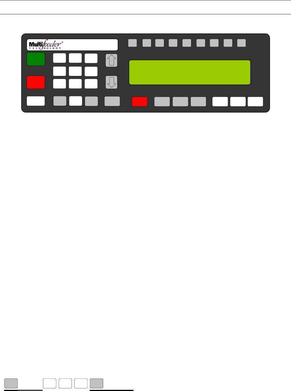
MFT Feeder Menus and Screens
117
Technician Settings Screen 1 of 3 – Digital I/O
Digital I/O Screen 1 of 3 – Standard I/O Signals
Guarding 1 Setting
This setting allows the technician to set which port will be used to indicate when a Guard interlock has been
triggered.
Press the button sequence below from the Ready Screen to access this screen.
Note: You may be required to enter a password.
X 2 X 12
MENU 2 5 1 MENU
F1 F2 F3 F4 F5 F6 F7 F8 HELP
1
ON
0
OFF
AUTO
ON / OFF CLEAR
CANCEL
1
4
7
23
6
9
MENU 0 ENTER STOP
MOTOR CYCLE
START
SET PROD.
THICKNESS
CHANGE
COUNT
CHANGE
SPEED JOG TO
CLEAR JOG
.........................................
FEEDER SCROLL
PN 53110-0G
GUARDING 1 (S), DEFAULTS: 0
RANGE: 0=OFF, 1-8=PORTS
CURRENT: { } NEW: { }
5
8

MFT Feeder Menus and Screens
118
Technician Settings Screen 1 of 3 – Digital I/O
Digital I/O Screen 1 of 3 – Standard I/O Signals
Guarding 2 Setting
This setting allows the technician to set which port will be used to indicate when a Guard interlock has been
triggered.
Press the button sequence below from the Ready Screen to access this screen.
Note: You may be required to enter a password.
X 2 X 13
MENU MENU
1 5 2
F1 F2 F3 F4 F5 F6 F7 F8 HELP
1
ON
0
OFF
AUTO
ON / OFF CLEAR
CANCEL
1
4
7
23
6
9
MENU 0 ENTER STOP
MOTOR CYCLE
START
SET PROD.
THICKNESS
CHANGE
COUNT
CHANGE
SPEED JOG TO
CLEAR JOG
.........................................
FEEDER SCROLL
PN 53110-0G
GUARDING 2 (S), DEFAULTS: 0
RANGE: 0=OFF, 1-8=PORTS
CURRENT: { } NEW: { }
5
8

MFT Feeder Menus and Screens
119
Technician Settings Screen 1 of 3 – Digital I/O
Digital I/O Screen 1 of 3 – Standard I/O Signals
RS232 Port Setting
This setting assings the RS-232 comport setting.
Press the button sequence below from the Ready Screen to access this screen.
Note: You may be required to enter a password.
X 2 X 14
MENU MENU
1 5 2
F1 F2 F3 F4 F5 F6 F7 F8 HELP
1
ON
0
OFF
AUTO
ON / OFF CLEAR
CANCEL
1
4
7
23
6
9
MENU 0 ENTER STOP
MOTOR CYCLE
START
SET PROD.
THICKNESS
CHANGE
COUNT
CHANGE
SPEED JOG TO
CLEAR JOG
.........................................
FEEDER SCROLL
PN 53110-0G
RS232 PORT (S), DEFAULTS: 1
RANGE: 0=COM1,1=COM2,2=COM3
CURRENT: { } NEW: { }
5
8

MFT Feeder Menus and Screens
120
Technician Settings Screen 1 of 3 – Digital I/O
Digital I/O Screen 1 of 3 – Duplicate Signals
I/O Card Cycle Complete Setting
This screen sets the port of the Cycle Complete output signal on the optional I/O Card.
Press the button sequence below from the Ready Screen to access this screen.
Note: You may be required to enter a password.
X 2 X
MENU 2 5 2
F1 F2 F3 F4 F5 F6 F7 F8 HELP
1
ON
0
OFF
AUTO
ON / OFF CLEAR
CANCEL
1
4
7
23
6
9
MENU 0 ENTER STOP
MOTOR CYCLE
START
SET PROD.
THICKNESS
CHANGE
COUNT
CHANGE
SPEED JOG TO
CLEAR JOG
.........................................
FEEDER SCROLL
PN 53110-0G
IOCARD CYCLE COMPLETE (S), DEFAULTS: 0
RANGE: 0=OFF, 1-8=PORT
CURRENT: { } NEW: { }
5
8

MFT Feeder Menus and Screens
121
Technician Settings Screen 1 of 3 – Digital I/O
Digital I/O Screen 1 of 3 – Duplicate Signals
I/O Card Red Light Setting
This screen sets the port of the Red Light output signal on the optional I/O Card.
Press the button sequence below from the Ready Screen to access this screen.
Note: You may be required to enter a password.
X 2 X
MENU MENU
2 5 2
F1 F2 F3 F4 F5 F6 F7 F8 HELP
1
ON
0
OFF
AUTO
ON / OFF CLEAR
CANCEL
1
4
7
23
6
9
MENU 0 ENTER STOP
MOTOR CYCLE
START
SET PROD.
THICKNESS
CHANGE
COUNT
CHANGE
SPEED JOG TO
CLEAR JOG
.........................................
FEEDER SCROLL
PN 53110-0G
IOCARD RED LIGHT (S), DEFAULTS: 0
RANGE: 0=OFF, 1-8=PORT
CURRENT: { } NEW: { }
5
8

MFT Feeder Menus and Screens
122
Technician Settings Screen 1 of 3 – Digital I/O
Digital I/O Screen 1 of 3 – Duplicate Signals
I/O Card I/O Ready Setting
This screen sets the port of the I/O Ready output signal on the optional I/O Card.
Press the button sequence below from the Ready Screen to access this screen.
Note: You may be required to enter a password.
X 2 X 2
MENU MENU
2 5 2
F1 F2 F3 F4 F5 F6 F7 F8 HELP
1
ON
0
OFF
AUTO
ON / OFF CLEAR
CANCEL
1
4
7
23
6
9
MENU 0 ENTER STOP
MOTOR CYCLE
START
SET PROD.
THICKNESS
CHANGE
COUNT
CHANGE
SPEED JOG TO
CLEAR JOG
.........................................
FEEDER SCROLL
PN 53110-0G
IOCARD IO READY (S), DEFAULTS: 0
RANGE: 0=OFF, 1-8=PORT
CURRENT: { } NEW: { }
5
8

MFT Feeder Menus and Screens
123
Technician Settings Screen 1 of 3 – Digital I/O
Digital I/O Screen 1 of 3 – Duplicate Signals
Advanced PStart Setting
This screen sets the port of the Advanced PStart output signal on the IO Card (purchased separately).
Press the button sequence below from the Ready Screen to access this screen.
Note: You may be required to enter a password.
X 2 X 3
MENU MENU
2 5 2
F1 F2 F3 F4 F5 F6 F7 F8 HELP
1
ON
0
OFF
AUTO
ON / OFF CLE
A
R
CANCEL
1
4
7
23
6
9
MENU 0 ENTER STOP
MOTOR CYCLE
START
SET PROD.
THICKNESS
CHANGE
COUNT
CHANGE
SPEED JOG TO
CLEAR JOG
.........................................
FEEDER SCROLL
PN 53110-0G
ADVANCED PSTART (S), DEFAULTS: 0
RANGE: 0=OFF, 1-8=PORT, 9=J1
CURRENT: { } NEW: { }
5
8

MFT Feeder Menus and Screens
124
Technician Settings Screen 1 of 3 – Digital I/O
Digital I/O Screen 1 of 3 – Duplicate Signals
Offline Output Setting
This screen sets the port of the Feeder Offline output signal on the IO Card (purchased separately).
Press the button sequence below from the Ready Screen to access this screen.
Note: You may be required to enter a password.
X 2 X 6
MENU MENU
2 5 2
F1 F2 F3 F4 F5 F6 F7 F8 HELP
1
ON
0
OFF
AUTO
ON / OFF CLEAR
CANCEL
1
4
7
23
6
9
MENU 0 ENTER STOP
MOTOR CYCLE
START
SET PROD.
THICKNESS
CHANGE
COUNT
CHANGE
SPEED JOG TO
CLEAR JOG
.........................................
FEEDER SCROLL
PN 53110-0G
OFFLINE OUTPUT (S), DEFAULTS: 0
RANGE: 0=OFF, 1-10=PORT
CURRENT: { } NEW: { }
5
8

MFT Feeder Menus and Screens
125
Technician Settings Screen 1 of 3 – Digital I/O
Digital I/O Screen 1 of 3 – Duplicate Signals
Advanced LSE Setting
This screen sets the port of the Advanced LSE (Line Speed Encoder) output signal on the IO Card
(purchased separately).
Press the button sequence below from the Ready Screen to access this screen.
Note: You may be required to enter a password.
X 2 X 7
MENU MENU
2 5 2
F1 F2 F3 F4 F5 F6 F7 F8 HELP
1
ON
0
OFF
AUTO
ON / OFF CLEAR
CANCEL
1
4
7
23
6
9
MENU 0 ENTER STOP
MOTOR CYCLE
START
SET PROD.
THICKNESS
CHANGE
COUNT
CHANGE
SPEED JOG TO
CLEAR JOG
.........................................
FEEDER SCROLL
PN 53110-0G
ADVANCED LSE (S), DEFAULTS: 0
RANGE: 0=OFF, 1-8=PORT, 9=LSE
CURRENT: { } NEW: { }
5
8

MFT Feeder Menus and Screens
126
Technician Settings Screen 1 of 3 – Digital I/O
Digital I/O Screen 1 of 3 – External Product Sensor
Advanced Product Sensor Setting
When this is enabled the Feeder will use a selected input from an I/O card (purchased separately) to detect
the presence/absence of a product instead of the standard product sensor on the Feeder . This is useful in
cases where a specialized product sensor is needed to properly track the product.
Press the button sequence below from the Ready Screen to access this screen.
Note: You may be required to enter a password.
X 2 X
MENU 3 5 2
F1 F2 F3 F4 F5 F6 F7 F8 HELP
1
ON
0
OFF
AUTO
ON / OFF CLEAR
CANCEL
1
4
7
23
6
9
MENU 0 ENTER STOP
MOTOR CYCLE
START
SET PROD.
THICKNESS
CHANGE
COUNT
CHANGE
SPEED JOG TO
CLEAR JOG
.........................................
FEEDER SCROLL
PN 53110-0G
ADVANCED PRODUCT SENSOR (S), DEFAULTS: 0
RANGE: 0=OFF 1-9=PORT
CURRENT: { } NEW: { }
5
8
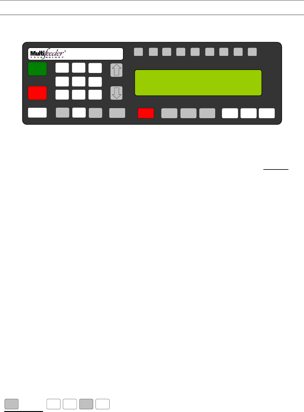
MFT Feeder Menus and Screens
127
Technician Settings Screen 1 of 3 – Digital I/O
Digital I/O Screen 2 of 3 - Pre-Feed Signals
Pre-Feed Solenoid Fire Time
The Pre-Feed Solenoid Fire Time is a signal that can be output from the optional I/O Card BEFORE the
Feeder starts a feed cycle.
Press the button sequence below from the Ready Screen to access this screen.
Note: You may be required to enter a password.
X 2 X
MENU 1
MENU
5 2
F1 F2 F3 F4 F5 F6 F7 F8 HELP
1
ON
0
OFF
AUTO
ON / OFF CLEAR
CANCEL
1
4
7
23
6
9
MENU 0 ENTER STOP
MOTOR CYCLE
START
SET PROD.
THICKNESS
CHANGE
COUNT
CHANGE
SPEED JOG TO
CLEAR JOG
.........................................
FEEDER SCROLL
PN 53110-0G
PRE-FEED SOLENOID FIRE TIME (M-F3)
RANGE: 0-10000ms, DEFAULT: 0
CURRENT: { } NEW: { }
5
8

MFT Feeder Menus and Screens
128
Technician Settings Screen 1 of 3 – Digital I/O
Digital I/O Screen 2 of 3 - Pre-Feed Signals
Pre-Feed Solenoid Port
This screen is available if the Pre-Feed Solenoid Fire Time value is greater than 0ms. This screen sets the
Pre-Feed Solenoid output port.
Press the button sequence below from the Ready Screen to access this screen.
Note: You may be required to enter a password.
X 2 X
MENU MENU
1
MENU
5 2
F1 F2 F3 F4 F5 F6 F7 F8 HELP
1
ON
0
OFF
AUTO
ON / OFF CLEAR
CANCEL
1
4
7
23
6
9
MENU 0 ENTER STOP
MOTOR CYCLE
START
SET PROD.
THICKNESS
CHANGE
COUNT
CHANGE
SPEED JOG TO
CLEAR JOG
.........................................
FEEDER SCROLL
PN 53110-0G
PRE-FEED SOLENOID PORT (S) DEFAULT: 0
RANGE: 1-10
CURRENT: { } NEW: { }
5
8

MFT Feeder Menus and Screens
129
Technician Settings Screen 1 of 3 – Digital I/O
Digital I/O Screen 2 of 3 - Pre-Feed Signals
Pre-Feed Solenoid Wait Time
This screen is available if the Pre-Feed Solenoid Fire Time value is greater than 0ms. This screen sets the
delay time for the Pre-Feed Solenoid output signal.
Press the button sequence below from the Ready Screen to access this screen.
Note: You may be required to enter a password.
X 2 X 2
MENU MENU
1
MENU
5 2
F1 F2 F3 F4 F5 F6 F7 F8 HELP
1
ON
0
OFF
AUTO
ON / OFF CLEAR
CANCEL
1
4
7
23
6
9
MENU 0 ENTER STOP
MOTOR CYCLE
START
SET PROD.
THICKNESS
CHANGE
COUNT
CHANGE
SPEED JOG TO
CLEAR JOG
.........................................
FEEDER SCROLL
PN 53110-0G
PRE-FEED SOLENOID WAIT TIME (M-F3)
RANGE: 0-10000ms, DEFAULT: 0
CURRENT: { } NEW: { }
5
8

MFT Feeder Menus and Screens
130
Technician Settings Screen 1 of 3 – Digital I/O
Digital I/O Screen 2 of 3 – Post-Feed Signals
Post-Feed Solenoid Fire Time
The Post Feed Solenoid Fire Time is a signal that can be output from the optional I/O Card AFTER the
Feeder completes a feed cycle.
Press the button sequence below from the Ready Screen to access this screen.
Note: You may be required to enter a password.
X 2 X
MENU MENU 2 5 2
F1 F2 F3 F4 F5 F6 F7 F8 HELP
1
ON
0
OFF
AUTO
ON / OFF CLEAR
CANCEL
1
4
7
23
6
9
MENU 0 ENTER STOP
MOTOR CYCLE
START
SET PROD.
THICKNESS
CHANGE
COUNT
CHANGE
SPEED JOG TO
CLEAR JOG
.........................................
FEEDER SCROLL
PN 53110-0G
POST-FEED SOLENOID FIRE TIME (M-F3)
RANGE: 0-10000ms, DEFAULT: 0
CURRENT: { } NEW: { }
5
8

MFT Feeder Menus and Screens
131
Technician Settings Screen 1 of 3 – Digital I/O
Digital I/O Screen 2 of 3 – Post-Feed Signals
Post-Feed Solenoid Port
This screen is available if the Post-Feed Solenoid Fire Time value is greater than 0ms. This screen sets the
Post-Feed Solenoid output port.
Press the button sequence below from the Ready Screen to access this screen.
Note: You may be required to enter a password.
X 2
MENU MENUMENU 2 5 2
F1 F2 F3 F4 F5 F6 F7 F8 HELP
1
ON
0
OFF
AUTO
ON / OFF CLEAR
CANCEL
1
4
7
23
6
9
MENU 0 ENTER STOP
MOTOR CYCLE
START
SET PROD.
THICKNESS
CHANGE
COUNT
CHANGE
SPEED JOG TO
CLEAR JOG
.........................................
FEEDER SCROLL
PN 53110-0G
POST-FEED SOLENOID PORT (S) DEFAULT: 0
RANGE: 1-10
CURRENT: { } NEW: { }
5
8

MFT Feeder Menus and Screens
132
Technician Settings Screen 1 of 3 – Digital I/O
Digital I/O Screen 2 of 3 - Post-Feed Signals
Post-Feed Solenoid Pre-Wait Time
This screen is available if the Post-Feed Solenoid Fire Time value is greater than 0ms. This screen sets the
delay time for the BEFORE Post-Feed Solenoid output signal.
Press the button sequence below from the Ready Screen to access this screen.
Note: You may be required to enter a password.
X 2 X 2
MENU MENU
2
MENU
5 2
F1 F2 F3 F4 F5 F6 F7 F8 HELP
1
ON
0
OFF
AUTO
ON / OFF CLEAR
CANCEL
1
4
7
23
6
9
MENU 0 ENTER STOP
MOTOR CYCLE
START
SET PROD.
THICKNESS
CHANGE
COUNT
CHANGE
SPEED JOG TO
CLEAR JOG
.........................................
FEEDER SCROLL
PN 53110-0G
POST-FEED SOLENOID PRE-WAIT TIME (M-F3)
RANGE: 0-10000ms, DEFAULT: 0
CURRENT: { } NEW: { }
5
8

MFT Feeder Menus and Screens
133
Technician Settings Screen 1 of 3 – Digital I/O
Digital I/O Screen 2 of 3 - Post-Feed Signals
Post-Feed Solenoid Post-Wait Time
This screen is available if the Post-Feed Solenoid Fire Time value is greater than 0ms. This screen sets the
delay time for the AFTER Post-Feed Solenoid output signal.
Press the button sequence below from the Ready Screen to access this screen.
Note: You may be required to enter a password.
X 2 X 3
MENU MENU
1
MENU
5 2
F1 F2 F3 F4 F5 F6 F7 F8 HELP
1
ON
0
OFF
AUTO
ON / OFF CLEAR
CANCEL
1
4
7
23
6
9
MENU 0 ENTER STOP
MOTOR CYCLE
START
SET PROD.
THICKNESS
CHANGE
COUNT
CHANGE
SPEED JOG TO
CLEAR JOG
.........................................
FEEDER SCROLL
PN 53110-0G
POST-FEED SOLENOID POST- WAIT TIME (M-F3)
RANGE: 0-10000ms, DEFAULT: 0
CURRENT: { } NEW: { }
5
8

MFT Feeder Menus and Screens
134
Technician Settings Screen 1 of 3 – Digital I/O
Digital I/O Screen 2 of 3 - Post-Feed Signals
Post-Feed Solenoid Use Screen
This screen is available if the Pre-Feed Solenoid Fire Time value is greater than 0ms. The Post-Feed will
trigger only when the Feeder is not in a fault condition for setting 0(OK) and 2(Both). When set to 1(Faults)
the Feeder will only trigger the Pre-Feed Solenoid when in a fault condition.
Press the button sequence below from the Ready Screen to access this screen.
Note: You may be required to enter a password.
X 2 X 4
MENU 2 5 MENU 2 MENU
F1 F2 F3 F4 F5 F6 F7 F8 HELP
1
ON
0
OFF
AUTO
ON / OFF CLEAR
CANCEL
1
4
7
23
6
9
MENU 0 ENTER STOP
MOTOR CYCLE
START
SET PROD.
THICKNESS
CHANGE
COUNT
CHANGE
SPEED JOG TO
CLEAR JOG
.........................................
FEEDER SCROLL
PN 53110-0G
POST-FEED SOL. USE (M-F3), DEFAULT: 0
RANGE: 0=OK, 1=FAULT, 2=BOTH
CURRENT: { } NEW: { }
5
8

MFT Feeder Menus and Screens
135
Technician Settings Screen 1 of 3 – Digital I/O
Digital I/O Screen 2 of 3 – Digital I/O Wizards 1 of 3
Please refer to the Wizards Manual.
Press the button sequence below from the Ready Screen to access this screen.
Note: You may be required to enter a password.
X 2 X
MENU MENU 3 5 2
F1 F2 F3 F4 F5 F6 F7 F8 HELP
1
ON
0
OFF
AUTO
ON / OFF CLEAR
CANCEL
1
4
7
23
6
9
MENU 0 ENTER STOP
MOTOR CYCLE
START
SET PROD.
THICKNESS
CHANGE
COUNT
CHANGE
SPEED JOG TO
CLEAR JOG
.........................................
FEEDER SCROLL
PN 53110-0G
DIGITAL I/O WIZARDS 1/3 : MENU FOR NEXT
1. DIGITAL INPUT WIZARD (J3 PORT)
2. DIGITAL INPUT WIZARD A (IOCARD)
3. DIGITAL INPUT WIZARD B (IOCARD)
5
8

MFT Feeder Menus and Screens
136
Technician Settings Screen 1 of 3 – Digital I/O
Digital I/O Screen 2 of 3 – Digital I/O Wizards 2 of 3
Please refer to the Wizards Manual.
Press the button sequence below from the Ready Screen to access this screen.
Note: You may be required to enter a password.
X 2 X
MENU MENUMENU 3 5 2
F1 F2 F3 F4 F5 F6 F7 F8 HELP
1
ON
0
OFF
AUTO
ON / OFF CLEAR
CANCEL
1
4
7
23
6
9
MENU 0 ENTER STOP
MOTOR CYCLE
START
SET PROD.
THICKNESS
CHANGE
COUNT
CHANGE
SPEED JOG TO
CLEAR JOG
.........................................
FEEDER SCROLL
PN 53110-0G
DIGITAL I/O WIZARDS 2/3 : MENU FOR NEXT
1. DIGITAL INPUT WIZARD C (IOCARD)
2. DIGITAL INPUT WIZARD D (IOCARD)
3. SIMPLE INPUT
5
8

MFT Feeder Menus and Screens
137
Technician Settings Screen 1 of 3 – Digital I/O
Digital I/O Screen 2 of 3 – Digital I/O Wizards 3 of 3
Please refer to the Wizards Manual.
Press the button sequence below from the Ready Screen to access this screen.
Note: You may be required to enter a password.
X 2 X 2
MENU MENUMENU 3 5 2
F1 F2 F3 F4 F5 F6 F7 F8 HELP
1
ON
0
OFF
AUTO
ON / OFF CLEAR
CANCEL
1
4
7
23
6
9
MENU 0 ENTER STOP
MOTOR CYCLE
START
SET PROD.
THICKNESS
CHANGE
COUNT
CHANGE
SPEED JOG TO
CLEAR JOG
.........................................
FEEDER SCROLL
PN 53110-0G
DIGITAL I/O WIZARDS 3/3 : MENU FOR NEXT
1. JOGGER WIZARD
2. SIGNAL FAULT OUTPUT WIZARD
5
8

MFT Feeder Menus and Screens
138
Technician Settings Screen 1 of 3 – Advanced Settings
Digital I/O Screen 3 of 3
Press the button sequence below from the Ready Screen to access this screen.
Note: You may be required to enter a password.
X 2 X 2
MENU MENU
5 2
F1 F2 F3 F4 F5 F6 F7 F8 HELP
1
ON
0
OFF
AUTO
ON / OFF CLEAR
CANCEL
1
4
7
23
6
9
MENU 0 ENTER STOP
MOTOR CYCLE
START
SET PROD.
THICKNESS
CHANGE
COUNT
CHANGE
SPEED JOG TO
CLEAR JOG
.........................................
FEEDER SCROLL
PN 53110-0G
DIGITAL I/O 3/3: MENU KEY FOR NEXT
1. REJECT ON ERROR SIGNALS
2. INVERT INPUTS
3. INVERT OUTPUTS
5
8

MFT Feeder Menus and Screens
139
Technician Settings Screen 1 of 3 – Advanced Settings
Digital I/O Screen 3 of 3 - Reject on Error Signals
IO Card Reject-on-Error.
The Reject-On-Error Output can be configured to drive any one of the optically isolated outputs on the I/O
CARD (purchased separately) from the point where a Multiple Product Detect (MPD) or minor JAM is found
up until the next feed cycle is started. The Reject-On-Error signal will also go back low if the clear key, jog, or
jog-to-clear functions are run. The signal is meant to be processed by an external device capable of
removing the product as it leaves the System. If an MPD is discovered in the distance leading up to the stop
position of a product (when the System is decelerating to a stop) then the output will fire immediately
preceding the next feed cycle. It does not fire earlier since the product is not technically leaving the System
until the next feed cycle.
Press the button sequence below from the Ready Screen to access this screen.
Note: You may be required to enter a password.
X 2 X 2
MENU 1
MENU
5 2
F1 F2 F3 F4 F5 F6 F7 F8 HELP
1
ON
0
OFF
AUTO
ON / OFF CLEAR
CANCEL
1
4
7
23
6
9
MENU 0 ENTER STOP
MOTOR CYCLE
START
SET PROD.
THICKNESS
CHANGE
COUNT
CHANGE
SPEED JOG TO
CLEAR JOG
.........................................
FEEDER SCROLL
PN 53110-0G
IO CARD REJECT-ON-ERROR (S), DEFAULT: 0
RANGE: 0=OFF, 1=ON
CURRENT: { } NEW: { }
5
8

MFT Feeder Menus and Screens
140
Technician Settings Screen 1 of 3 – Advanced Settings
Digital I/O Screen 3 of 3 – Invert Inputs
Low Product Input
The Low Product Input screen allows the operator to invert the Low Product signal.
Press the button sequence below from the Ready Screen to access this screen.
Note: You may be required to enter a password.
X 2 X 2
MENU 2
MENU
5 2
F1 F2 F3 F4 F5 F6 F7 F8 HELP
1
ON
0
OFF
AUTO
ON / OFF CLEAR
CANCEL
1
4
7
23
6
9
MENU 0 ENTER STOP
MOTOR CYCLE
START
SET PROD.
THICKNESS
CHANGE
COUNT
CHANGE
SPEED JOG TO
CLEAR JOG
.........................................
FEEDER SCROLL
PN 53110-0G
LOW PRODUCT INPUT (S), DEFAULT: 0
RANGE: 0=NORMAL, 1-INVERTED
CURRENT: { } NEW: { }
5
8

MFT Feeder Menus and Screens
141
Technician Settings Screen 1 of 3 – Advanced Settings
Digital I/O Screen 3 of 3 – Invert Inputs
Invert Input 1
The Invert Input 1 screen allows the operator to invert Input 1 on the optional I/O Card.
Press the button sequence below from the Ready Screen to access this screen.
Note: You may be required to enter a password.
X 2 X 2
MENU MENU
2
MENU
5 2
F1 F2 F3 F4 F5 F6 F7 F8 HELP
1
ON
0
OFF
AUTO
ON / OFF CLEAR
CANCEL
1
4
7
23
6
9
MENU 0 ENTER STOP
MOTOR CYCLE
START
SET PROD.
THICKNESS
CHANGE
COUNT
CHANGE
SPEED JOG TO
CLEAR JOG
.........................................
FEEDER SCROLL
PN 53110-0G
INVERT INPUT 1 (S), DEFAULT: 0
RANGE: 0=OFF, 1-INVERT
CURRENT: { } NEW: { }
5
8

MFT Feeder Menus and Screens
142
Technician Settings Screen 1 of 3 – Advanced Settings
Digital I/O Screen 3 of 3 – Invert Inputs
Invert Input 2
The Invert Input 2 screen allows the operator to invert Input 2 on the optional I/O Card.
Press the button sequence below from the Ready Screen to access this screen.
Note: You may be required to enter a password.
X 2 X 2 X 2
MENU MENU
2
MENU
5 2
F1 F2 F3 F4 F5 F6 F7 F8 HELP
1
ON
0
OFF
AUTO
ON / OFF CLEAR
CANCEL
1
4
7
23
6
9
MENU 0 ENTER STOP
MOTOR CYCLE
START
SET PROD.
THICKNESS
CHANGE
COUNT
CHANGE
SPEED JOG TO
CLEAR JOG
.........................................
FEEDER SCROLL
PN 53110-0G
INVERT INPUT 2 (S), DEFAULT: 0
RANGE: 0=OFF, 1-INVERT
CURRENT: { } NEW: { }
5
8

MFT Feeder Menus and Screens
143
Technician Settings Screen 1 of 3 – Advanced Settings
Digital I/O Screen 3 of 3 – Invert Inputs
Invert Input 3
The Invert Input 3 screen allows the operator to invert Input 3 on the optional I/O Card.
Press the button sequence below from the Ready Screen to access this screen.
Note: You may be required to enter a password.
X 2 X 2 X 3
MENU MENU
2
MENU
5 2
F1 F2 F3 F4 F5 F6 F7 F8 HELP
1
ON
0
OFF
AUTO
ON / OFF CLEAR
CANCEL
1
4
7
23
6
9
MENU 0 ENTER STOP
MOTOR CYCLE
START
SET PROD.
THICKNESS
CHANGE
COUNT
CHANGE
SPEED JOG TO
CLEAR JOG
.........................................
FEEDER SCROLL
PN 53110-0G
INVERT INPUT 3 (S), DEFAULT: 0
RANGE: 0=OFF, 1-INVERT
CURRENT: { } NEW: { }
5
8

MFT Feeder Menus and Screens
144
Technician Settings Screen 1 of 3 – Advanced Settings
Digital I/O Screen 3 of 3 – Invert Inputs
Invert Input 4
The Invert Input 4 screen allows the operator to invert Input 4 on the optional I/O Card.
Press the button sequence below from the Ready Screen to access this screen.
Note: You may be required to enter a password.
X 2 X 2 X 4
MENU MENU
2
MENU
5 2
F1 F2 F3 F4 F5 F6 F7 F8 HELP
1
ON
0
OFF
AUTO
ON / OFF CLEAR
CANCEL
1
4
7
23
6
9
MENU 0 ENTER STOP
MOTOR CYCLE
START
SET PROD.
THICKNESS
CHANGE
COUNT
CHANGE
SPEED JOG TO
CLEAR JOG
.........................................
FEEDER SCROLL
PN 53110-0G
INVERT INPUT 4 (S), DEFAULT: 0
RANGE: 0=OFF, 1-INVERT
CURRENT: { } NEW: { }
5
8

MFT Feeder Menus and Screens
145
Technician Settings Screen 1 of 3 – Advanced Settings
Digital I/O Screen 3 of 3 – Invert Inputs
Invert Input 5
The Invert Input 5 screen allows the operator to invert Input 5 on the optional I/O Card.
Press the button sequence below from the Ready Screen to access this screen.
Note: You may be required to enter a password.
X 2 X 2 X 5
MENU MENU
2
MENU
5 2
F1 F2 F3 F4 F5 F6 F7 F8 HELP
1
ON
0
OFF
AUTO
ON / OFF CLEAR
CANCEL
1
4
7
23
6
9
MENU 0 ENTER STOP
MOTOR CYCLE
START
SET PROD.
THICKNESS
CHANGE
COUNT
CHANGE
SPEED JOG TO
CLEAR JOG
.........................................
FEEDER SCROLL
PN 53110-0G
INVERT INPUT 5 (S), DEFAULT: 0
RANGE: 0=OFF, 1-INVERT
CURRENT: { } NEW: { }
5
8

MFT Feeder Menus and Screens
146
Technician Settings Screen 1 of 3 – Advanced Settings
Digital I/O Screen 3 of 3 – Invert Inputs
Invert Input 6
The Invert Input 6 screen allows the operator to invert Input 6 on the optional I/O Card.
Press the button sequence below from the Ready Screen to access this screen.
Note: You may be required to enter a password.
X 2 X 2 X 6
MENU MENU
2
MENU
5 2
F1 F2 F3 F4 F5 F6 F7 F8 HELP
1
ON
0
OFF
AUTO
ON / OFF CLEAR
CANCEL
1
4
7
23
6
9
MENU 0 ENTER STOP
MOTOR CYCLE
START
SET PROD.
THICKNESS
CHANGE
COUNT
CHANGE
SPEED JOG TO
CLEAR JOG
.........................................
FEEDER SCROLL
PN 53110-0G
INVERT INPUT 6 (S), DEFAULT: 0
RANGE: 0=OFF, 1-INVERT
CURRENT: { } NEW: { }
5
8

MFT Feeder Menus and Screens
147
Technician Settings Screen 1 of 3 – Advanced Settings
Digital I/O Screen 3 of 3 – Invert Inputs
Invert Input 7
The Invert Input 7 screen allows the operator to invert Input 7 on the optional I/O Card.
Press the button sequence below from the Ready Screen to access this screen.
Note: You may be required to enter a password.
X 2 X 2 X 7
MENU MENU
2
MENU
5 2
F1 F2 F3 F4 F5 F6 F7 F8 HELP
1
ON
0
OFF
AUTO
ON / OFF CLEAR
CANCEL
1
4
7
23
6
9
MENU 0 ENTER STOP
MOTOR CYCLE
START
SET PROD.
THICKNESS
CHANGE
COUNT
CHANGE
SPEED JOG TO
CLEAR JOG
.........................................
FEEDER SCROLL
PN 53110-0G
INVERT INPUT 7 (S), DEFAULT: 0
RANGE: 0=OFF, 1-INVERT
CURRENT: { } NEW: { }
5
8

MFT Feeder Menus and Screens
148
Technician Settings Screen 1 of 3 – Advanced Settings
Digital I/O Screen 3 of 3 – Invert Inputs
Invert Input 8
The Invert Input 4 screen allows the operator to invert Input 4 on the optional I/O Card.
Press the button sequence below from the Ready Screen to access this screen.
Note: You may be required to enter a password.
X 2 X 2 X 8
MENU MENU
2
MENU
5 2
F1 F2 F3 F4 F5 F6 F7 F8 HELP
1
ON
0
OFF
AUTO
ON / OFF CLEAR
CANCEL
1
4
7
23
6
9
MENU 0 ENTER STOP
MOTOR CYCLE
START
SET PROD.
THICKNESS
CHANGE
COUNT
CHANGE
SPEED JOG TO
CLEAR JOG
.........................................
FEEDER SCROLL
PN 53110-0G
INVERT INPUT 8 (S), DEFAULT: 0
RANGE: 0=OFF, 1-INVERT
CURRENT: { } NEW: { }
5
8

MFT Feeder Menus and Screens
149
Technician Settings Screen 1 of 3 – Advanced Settings
Digital I/O Screen 3 of 3 – Output Inputs
Invert Output 1
The Invert Output 1 screen allows the operator to invert output 1 on the optional I/O Card.
Press the button sequence below from the Ready Screen to access this screen.
Note: You may be required to enter a password.
X 2 X 2
MENU 3
MENU
5 2
F1 F2 F3 F4 F5 F6 F7 F8 HELP
1
ON
0
OFF
AUTO
ON / OFF CLEAR
CANCEL
1
4
7
23
6
9
MENU 0 ENTER STOP
MOTOR CYCLE
START
SET PROD.
THICKNESS
CHANGE
COUNT
CHANGE
SPEED JOG TO
CLEAR JOG
.........................................
FEEDER SCROLL
PN 53110-0G
INVERT OUTPUT 1 (S), DEFAULT: 0
RANGE: 0=OFF, 1-INVERT
CURRENT: { } NEW: { }
5
8

MFT Feeder Menus and Screens
150
Technician Settings Screen 1 of 3 – Advanced Settings
Digital I/O Screen 3 of 3 – Invert Output
Invert Output 2
The Invert Output 2 screen allows the operator to invert output 2 on the optional I/O Card.
Press the button sequence below from the Ready Screen to access this screen.
Note: You may be required to enter a password.
X 2 X 2
MENU MENU
3
MENU
5 2
F1 F2 F3 F4 F5 F6 F7 F8 HELP
1
ON
0
OFF
AUTO
ON / OFF CLEAR
CANCEL
1
4
7
23
6
9
MENU 0 ENTER STOP
MOTOR CYCLE
START
SET PROD.
THICKNESS
CHANGE
COUNT
CHANGE
SPEED JOG TO
CLEAR JOG
.........................................
FEEDER SCROLL
PN 53110-0G
INVERT OUTPUT 2 (S), DEFAULT: 0
RANGE: 0=OFF, 1-INVERT
CURRENT: { } NEW: { }
5
8

MFT Feeder Menus and Screens
151
Technician Settings Screen 1 of 3 – Advanced Settings
Digital I/O Screen 3 of 3 – Invert Output
Invert Output 3
The Invert Output 3 screen allows the operator to invert output 3 on the optional I/O Card.
Press the button sequence below from the Ready Screen to access this screen.
Note: You may be required to enter a password.
X 2 X 2 X 2
MENU MENU
3
MENU
5 2
F1 F2 F3 F4 F5 F6 F7 F8 HELP
1
ON
0
OFF
AUTO
ON / OFF CLEAR
CANCEL
1
4
7
23
6
9
MENU 0 ENTER STOP
MOTOR CYCLE
START
SET PROD.
THICKNESS
CHANGE
COUNT
CHANGE
SPEED JOG TO
CLEAR JOG
.........................................
FEEDER SCROLL
PN 53110-0G
INVERT OUTPUT 3 (S), DEFAULT: 0
RANGE: 0=OFF, 1-INVERT
CURRENT: { } NEW: { }
5
8

MFT Feeder Menus and Screens
152
Technician Settings Screen 1 of 3 – Advanced Settings
Digital I/O Screen 3 of 3 – Invert Output
Invert Output 4
The Invert Output 4 screen allows the operator to invert output 4 on the optional I/O Card.
Press the button sequence below from the Ready Screen to access this screen.
Note: You may be required to enter a password.
X 2 X 2 X 3
MENU MENU
3
MENU
5 2
F1 F2 F3 F4 F5 F6 F7 F8 HELP
1
ON
0
OFF
AUTO
ON / OFF CLEAR
CANCEL
1
4
7
23
6
9
MENU 0 ENTER STOP
MOTOR CYCLE
START
SET PROD.
THICKNESS
CHANGE
COUNT
CHANGE
SPEED JOG TO
CLEAR JOG
.........................................
FEEDER SCROLL
PN 53110-0G
INVERT OUTPUT 4 (S), DEFAULT: 0
RANGE: 0=OFF, 1-INVERT
CURRENT: { } NEW: { }
5
8

MFT Feeder Menus and Screens
153
Technician Settings Screen 1 of 3 – Advanced Settings
Digital I/O Screen 3 of 3 – Invert Output
Invert Output 5
The Invert Output 5 screen allows the operator to invert output 5 on the optional I/O Card.
Press the button sequence below from the Ready Screen to access this screen.
Note: You may be required to enter a password.
X 2 X 2 X 4
MENU MENU
3
MENU
5 2
F1 F2 F3 F4 F5 F6 F7 F8 HELP
1
ON
0
OFF
AUTO
ON / OFF CLEAR
CANCEL
1
4
7
23
6
9
MENU 0 ENTER STOP
MOTOR CYCLE
START
SET PROD.
THICKNESS
CHANGE
COUNT
CHANGE
SPEED JOG TO
CLEAR JOG
.........................................
FEEDER SCROLL
PN 53110-0G
INVERT OUTPUT 5 (S), DEFAULT: 0
RANGE: 0=OFF, 1-INVERT
CURRENT: { } NEW: { }
5
8

MFT Feeder Menus and Screens
154
Technician Settings Screen 1 of 3 – Advanced Settings
Digital I/O Screen 3 of 3 – Invert Output
Invert Output 6
The Invert Output 6 screen allows the operator to invert output 6 on the optional I/O Card.
Press the button sequence below from the Ready Screen to access this screen.
Note: You may be required to enter a password.
X 2 X 2 X 5
MENU MENU
3
MENU
5 2
F1 F2 F3 F4 F5 F6 F7 F8 HELP
1
ON
0
OFF
AUTO
ON / OFF CLEAR
CANCEL
1
4
7
23
6
9
MENU 0 ENTER STOP
MOTOR CYCLE
START
SET PROD.
THICKNESS
CHANGE
COUNT
CHANGE
SPEED JOG TO
CLEAR JOG
.........................................
FEEDER SCROLL
PN 53110-0G
INVERT OUTPUT 6 (S), DEFAULT: 0
RANGE: 0=OFF, 1-INVERT
CURRENT: { } NEW: { }
5
8

MFT Feeder Menus and Screens
155
Technician Settings Screen 1 of 3 – Advanced Settings
Digital I/O Screen 3 of 3 – Invert Output
Invert Output 7
The Invert Output 7 screen allows the operator to invert output 7 on the optional I/O Card.
Press the button sequence below from the Ready Screen to access this screen.
Note: You may be required to enter a password.
X 2 X 2 X 6
MENU MENU
3
MENU
5 2
F1 F2 F3 F4 F5 F6 F7 F8 HELP
1
ON
0
OFF
AUTO
ON / OFF CLEAR
CANCEL
1
4
7
23
6
9
MENU 0 ENTER STOP
MOTOR CYCLE
START
SET PROD.
THICKNESS
CHANGE
COUNT
CHANGE
SPEED JOG TO
CLEAR JOG
.........................................
FEEDER SCROLL
PN 53110-0G
INVERT OUTPUT 7 (S), DEFAULT: 0
RANGE: 0=OFF, 1-INVERT
CURRENT: { } NEW: { }
5
8

MFT Feeder Menus and Screens
156
Technician Settings Screen 1 of 3 – Advanced Settings
Digital I/O Screen 3 of 3 – Invert Output
Invert Output 8
The Invert Output 8 screen allows the operator to invert output 8 on the optional I/O Card.
Press the button sequence below from the Ready Screen to access this screen.
Note: You may be required to enter a password.
X 2 X 2 X 7
MENU MENU
3
MENU
5 2
F1 F2 F3 F4 F5 F6 F7 F8 HELP
1
ON
0
OFF
AUTO
ON / OFF CLEAR
CANCEL
1
4
7
23
6
9
MENU 0 ENTER STOP
MOTOR CYCLE
START
SET PROD.
THICKNESS
CHANGE
COUNT
CHANGE
SPEED JOG TO
CLEAR JOG
.........................................
FEEDER SCROLL
PN 53110-0G
INVERT OUTPUT 8 (S), DEFAULT: 0
RANGE: 0=OFF, 1-INVERT
CURRENT: { } NEW: { }
5
8

MFT Feeder Menus and Screens
157
Technician Settings Screen 1 of 3 – Advanced Settings
Digital I/O Screen 3 of 3 – Invert Output
Invert Output 9
The Invert Output 9 screen allows the operator to invert output 9 on the optional I/O Card.
Press the button sequence below from the Ready Screen to access this screen.
Note: You may be required to enter a password.
X 2 X 2 X 8
MENU MENU
3
MENU
5 2
F1 F2 F3 F4 F5 F6 F7 F8 HELP
1
ON
0
OFF
AUTO
ON / OFF CLEAR
CANCEL
1
4
7
23
6
9
MENU 0 ENTER STOP
MOTOR CYCLE
START
SET PROD.
THICKNESS
CHANGE
COUNT
CHANGE
SPEED JOG TO
CLEAR JOG
.........................................
FEEDER SCROLL
PN 53110-0G
INVERT OUTPUT 9 (S), DEFAULT: 0
RANGE: 0=OFF, 1-INVERT
CURRENT: { } NEW: { }
5
8

MFT Feeder Menus and Screens
158
Technician Settings Screen 1 of 3 – Advanced Settings
Digital I/O Screen 3 of 3 – Invert Output
Invert Output 10
The Invert Output 10 screen allows the operator to invert output 10 on the optional I/O Card.
Press the button sequence below from the Ready Screen to access this screen.
Note: You may be required to enter a password.
X 2 X 2 X 9
MENU MENU
3
MENU
5 2
F1 F2 F3 F4 F5 F6 F7 F8 HELP
1
ON
0
OFF
AUTO
ON / OFF CLEAR
CANCEL
1
4
7
23
6
9
MENU 0 ENTER STOP
MOTOR CYCLE
START
SET PROD.
THICKNESS
CHANGE
COUNT
CHANGE
SPEED JOG TO
CLEAR JOG
.........................................
FEEDER SCROLL
PN 53110-0G
INVERT OUTPUT 10 (S), DEFAULT: 0
RANGE: 0=OFF, 1-INVERT
CURRENT: { } NEW: { }
5
8

MFT Feeder Menus and Screens
159
Technician Settings Screen 1 of 3 – Advanced Settings
Wizards 1 of 4
Please refer to the Wizards Manual.
Press the button sequence below from the Ready Screen to access this screen.
Note: You may be required to enter a password.
X 2 X
MENU 6 2
F1 F2 F3 F4 F5 F6 F7 F8 HELP
1
ON
0
OFF
AUTO
ON / OFF CLEAR
CANCEL
1
4
7
23
6
9
MENU 0 ENTER STOP
MOTOR CYCLE
START
SET PROD.
THICKNESS
CHANGE
COUNT
CHANGE
SPEED JOG TO
CLEAR JOG
.........................................
FEEDER SCROLL
PN 53110-0G
WIZARDS 1/4 : MENU FOR NEXT
1. ADVANCED WARNING CONTROL
2. ACCUTIPPING
3. ENCODER TIMING COMPENSATION
5
8

MFT Feeder Menus and Screens
160
Technician Settings Screen 1 of 3 – Advanced Settings
Wizards 2 of 4
Please refer to the Wizards Manual.
Press the button sequence below from the Ready Screen to access this screen.
Note: You may be required to enter a password.
X 2 X
MENU MENU
6 2
F1 F2 F3 F4 F5 F6 F7 F8 HELP
1
ON
0
OFF
AUTO
ON / OFF CLEAR
CANCEL
1
4
7
23
6
9
MENU 0 ENTER STOP
MOTOR CYCLE
START
SET PROD.
THICKNESS
CHANGE
COUNT
CHANGE
SPEED JOG TO
CLEAR JOG
.........................................
FEEDER SCROLL
PN 53110-0G
WIZARDS 2/4 : MENU FOR NEXT
1. REMOTE KEYPAD
2. HEIGHT ADJUSTMENT SETUP
3. FUNCTION KEY SETUP
5
8

MFT Feeder Menus and Screens
161
Technician Settings Screen 1 of 3 – Advanced Settings
Wizards 3 of 4
Please refer to the Wizards Manual.
Press the button sequence below from the Ready Screen to access this screen.
Note: You may be required to enter a password.
X 2 X 2
MENU MENU
5 2
F1 F2 F3 F4 F5 F6 F7 F8 HELP
1
ON
0
OFF
AUTO
ON / OFF CLEAR
CANCEL
1
4
7
23
6
9
MENU 0 ENTER STOP
MOTOR CYCLE
START
SET PROD.
THICKNESS
CHANGE
COUNT
CHANGE
SPEED JOG TO
CLEAR JOG
.........................................
FEEDER SCROLL
PN 53110-0G
WIZARDS 3/4 : MENU FOR NEXT
1. BARCODE SETUP
2. SERIAL COUNT
3. ENCODER SPEED COMPENSATION
5
8

MFT Feeder Menus and Screens
162
Technician Settings Screen 1 of 3 – Advanced Settings
Wizards 4 of 4
Please refer to the Wizards Manual.
Press the button sequence below from the Ready Screen to access this screen.
Note: You may be required to enter a password.
X 2 X 3
MENU MENU
5 2
F1 F2 F3 F4 F5 F6 F7 F8 HELP
1
ON
0
OFF
AUTO
ON / OFF CLEAR
CANCEL
1
4
7
23
6
9
MENU 0 ENTER STOP
MOTOR CYCLE
START
SET PROD.
THICKNESS
CHANGE
COUNT
CHANGE
SPEED JOG TO
CLEAR JOG
.........................................
FEEDER SCROLL
PN 53110-0G
WIZARDS 3/4 : MENU FOR NEXT
1. GLUER INTEGRATION
2. TWO SENSOR TIMING COMPENSATION
5
8

MFT Feeder Menus and Screens
163
Technician Settings Screen 2 of 3
Press the button sequence below from the Ready Screen to access this screen.
Note: You may be required to enter a password.
X 2 X
MENU MENU
2
F1 F2 F3 F4 F5 F6 F7 F8 HELP
1
ON
0
OFF
AUTO
ON / OFF CLEAR
CANCEL
1
4
7
23
6
9
MENU 0 ENTER STOP
MOTOR CYCLE
START
SET PROD.
THICKNESS
CHANGE
COUNT
CHANGE
SPEED JOG TO
CLEAR JOG
.........................................
FEEDER SCROLL
PN 53110-0G
TECHNICIAN 2/3 : MENU KEY FOR NEXT
1. DISPLAY 4. EDIT NON-DEFAULTS
2. BACKUP/RESTORE 5. RESET TO DEFAULTS
3. PASSWORDS 6. LANGUAGE
5
8

MFT Feeder Menus and Screens
164
Technician Settings Screen 2 of 3 – Display Setting
LCD Refresh Rate
This setting allows the technician to change how often the LCD Display refreshes without intervention.
Press the button sequence below from the Ready Screen to access this screen.
Note: You may be required to enter a password.
X 2 X
MENU 1 2 MENU
F1 F2 F3 F4 F5 F6 F7 F8 HELP
1
ON
0
OFF
AUTO
ON / OFF CLEAR
CANCEL
1
4
7
23
6
9
MENU 0 ENTER STOP
MOTOR CYCLE
START
SET PROD.
THICKNESS
CHANGE
COUNT
CHANGE
SPEED JOG TO
CLEAR JOG
.........................................
FEEDER SCROLL
PN 53110-0G
LCD REFRESH RATE (S), DEFAULT: 30
RANGE 0-600
CURRENT: { } NEW: { }
5
8

MFT Feeder Menus and Screens
165
Technician Settings Screen 2 of 3 – Display Setting
Menu Item Timer
This is the length of time that display messages will be left on the screen before they timeout.
Press the button sequence below from the Ready Screen to access this screen.
Note: You may be required to enter a password.
X 2 X
MENU MENU
2 MENU 1
F1 F2 F3 F4 F5 F6 F7 F8 HELP
1
ON
0
OFF
AUTO
ON / OFF CLEAR
CANCEL
1
4
7
23
6
9
MENU 0 ENTER STOP
MOTOR CYCLE
START
SET PROD.
THICKNESS
CHANGE
COUNT
CHANGE
SPEED JOG TO
CLEAR JOG
.........................................
FEEDER SCROLL
PN 53110-0G
MENU ITEM TIMER (S), DEFAULT: 3000
RANGE 250-5000ms
CURRENT: { } NEW: { }
5
8

MFT Feeder Menus and Screens
166
Technician Settings Screen 2 of 3 – Backup/Restore Setting
Backup Data Settings
This setting allows the technician to save the backup data.
Press the button sequence below from the Ready Screen to access this screen.
Note: You may be required to enter a password.
X 2 X
MENU 2 MENU 2
F1 F2 F3 F4 F5 F6 F7 F8 HELP
1
ON
0
OFF
AUTO
ON / OFF CLEAR
CANCEL
1
4
7
23
6
9
MENU 0 ENTER STOP
MOTOR CYCLE
START
SET PROD.
THICKNESS
CHANGE
COUNT
CHANGE
SPEED JOG TO
CLEAR JOG
.........................................
FEEDER SCROLL
PN 53110-0G
BACKUP DATA, (M-F3), DEFAULT: 0
RANGE 0=NO BACKUP, 1-10=FILE
CURRENT: { } NEW: { }
5
8

MFT Feeder Menus and Screens
167
Technician Settings Screen 2 of 3 – Display Setting
Restore Data Settings
This setting allows the technician to restore the backup data.
Press the button sequence below from the Ready Screen to access this screen.
Note: You may be required to enter a password.
X 2 X
MENU MENU
2 MENU 2
F1 F2 F3 F4 F5 F6 F7 F8 HELP
1
ON
0
OFF
AUTO
ON / OFF CLEAR
CANCEL
1
4
7
23
6
9
MENU 0 ENTER STOP
MOTOR CYCLE
START
SET PROD.
THICKNESS
CHANGE
COUNT
CHANGE
SPEED JOG TO
CLEAR JOG
.........................................
FEEDER SCROLL
PN 53110-0G
RESTORE DATA, (M-F3), DEFAULT: 0
RANGE 0=NO BACKUP, 1-10=FILE
CURRENT: { } NEW: { }
5
8

MFT Feeder Menus and Screens
168
Technician Settings Screen 2 of 3 – Password Setting
Operator Password
This setting allows the technician to change the operator password.
Press the button sequence below from the Ready Screen to access this screen.
Note: You may be required to enter a password.
X 2 X
MENU 2 MENU 3
F1 F2 F3 F4 F5 F6 F7 F8 HELP
1
ON
0
OFF
AUTO
ON / OFF CLEAR
CANCEL
1
4
7
23
6
9
MENU 0 ENTER STOP
MOTOR CYCLE
START
SET PROD.
THICKNESS
CHANGE
COUNT
CHANGE
SPEED JOG TO
CLEAR JOG
.........................................
FEEDER SCROLL
PN 53110-0G
OPERATOR PASSWORD (S), DEFAULT: 0
RANGE 0-99999
CURRENT: { } NEW: { }
5
8

MFT Feeder Menus and Screens
169
Technician Settings Screen 2 of 3 – Password Setting
Technician Password
This will reset the technician password for the system. Record the new password in a secure location prior to
changing the password.
Press the button sequence below from the Ready Screen to access this screen.
Note: You may be required to enter a password.
X 2 X
MENU MENU
2 MENU 3
F1 F2 F3 F4 F5 F6 F7 F8 HELP
1
ON
0
OFF
AUTO
ON / OFF CLEAR
CANCEL
1
4
7
23
6
9
MENU 0 ENTER STOP
MOTOR CYCLE
START
SET PROD.
THICKNESS
CHANGE
COUNT
CHANGE
SPEED JOG TO
CLEAR JOG
.........................................
FEEDER SCROLL
PN 53110-0G
TECHNICIAN PASSWORD (S), DEFAULT: XXXXX
RANGE 0-99999
CURRENT: { } NEW: { }
5
8

MFT Feeder Menus and Screens
170
Technician Settings Screen 2 of 3 – Edit Non-Defaults Setting
Edit Non-Defaults Screen
The sub-menus in this setting are settings that have been changed from default. Screens displayed for this
setting will differ to reflect your non-default settings.
Press the button sequence below from the Ready Screen to access this screen.
Note: You may be required to enter a password.
X 2 X
MENU 2 MENU 3
F1 F2 F3 F4 F5 F6 F7 F8 HELP
1
ON
0
OFF
AUTO
ON / OFF CLEAR
CANCEL
1
4
7
23
6
9
MENU 0 ENTER STOP
MOTOR CYCLE
START
SET PROD.
THICKNESS
CHANGE
COUNT
CHANGE
SPEED JOG TO
CLEAR JOG
.........................................
FEEDER SCROLL
PN 53110-0G
THIS DISPLAY WILL VARY
5
8

MFT Feeder Menus and Screens
171
Technician Settings Screen 2 of 3 – Reset to Default Setting
Reset to Defaults
This setting allows the technician to set the machine settings to default.
Press the button sequence below from the Ready Screen to access this screen.
Note: You may be required to enter a password.
X 2 X
MENU 2 MENU 5
F1 F2 F3 F4 F5 F6 F7 F8 HELP
1
ON
0
OFF
AUTO
ON / OFF CLEAR
CANCEL
1
4
7
23
6
9
MENU 0 ENTER STOP
MOTOR CYCLE
START
SET PROD.
THICKNESS
CHANGE
COUNT
CHANGE
SPEED JOG TO
CLEAR JOG
.........................................
FEEDER SCROLL
PN 53110-0G
ENTER 1 TO RESET DEFAULTS
PRESS CLEAR TO CANCEL - 0
5
8

MFT Feeder Menus and Screens
172
Technician Settings Screen 2 of 3 – Language Setting
Multiple Languages
This setting allows the technician to toggle the Multiple Languages feature on or off.
Press the button sequence below from the Ready Screen to access this screen.
Note: You may be required to enter a password.
X 2 X
MENU 2 MENU 6
F1 F2 F3 F4 F5 F6 F7 F8 HELP
1
ON
0
OFF
AUTO
ON / OFF CLEAR
CANCEL
1
4
7
23
6
9
MENU 0 ENTER STOP
MOTOR CYCLE
START
SET PROD.
THICKNESS
CHANGE
COUNT
CHANGE
SPEED JOG TO
CLEAR JOG
.........................................
FEEDER SCROLL
PN 53110-0G
MULTIPLE LANGUAGES (S), DEFAULT: 0
RANGE: 0=OFF, 1=ON
CURRENT: { } NEW: { }
5
8

MFT Feeder Menus and Screens
173
Technician Settings Screen 3 of 3
Press the button sequence below from the Ready Screen to access this screen.
Note: You may be required to enter a password.
X 2 X 2
MENU MENU
2
F1 F2 F3 F4 F5 F6 F7 F8 HELP
1
ON
0
OFF
AUTO
ON / OFF CLEAR
CANCEL
1
4
7
23
6
9
MENU 0 ENTER STOP
MOTOR CYCLE
START
SET PROD.
THICKNESS
CHANGE
COUNT
CHANGE
SPEED JOG TO
CLEAR JOG
.........................................
FEEDER SCROLL
PN 53110-0G
TECHNICIAN 3/3: MENU KEY FOR NEXT
1. HEIGHT ADJ 4. ADV DEMO MODE
2. LOCKDOWN 5. DATE/TIME
3. LIMITS 6. SET MACHINE MODELS
5
8

MFT Feeder Menus and Screens
174
Technician Settings Screen 3 of 3 - Height Adjustment Setting
1st Height Adjustment
Press the button sequence below from the Ready Screen to access this screen.
Note: You may be required to enter a password.
X 2 X 2
MENU 1
MENU
2
F1 F2 F3 F4 F5 F6 F7 F8 HELP
1
ON
0
OFF
AUTO
ON / OFF CLEAR
CANCEL
1
4
7
23
6
9
MENU 0 ENTER STOP
MOTOR CYCLE
START
SET PROD.
THICKNESS
CHANGE
COUNT
CHANGE
SPEED JOG TO
CLEAR JOG
.........................................
FEEDER SCROLL
PN 53110-0G
1ST HEIGHT ADJUSTMENT BOTTOM (M-F3)
RANGE: 0-100000, DEFAULT 215
CURRENT: { } NEW: { }
5
8

MFT Feeder Menus and Screens
175
Technician Settings Screen 3 of 3 - Height Adjustment Setting
2nd Height Adjustment
Press the button sequence below from the Ready Screen to access this screen.
Note: You may be required to enter a password.
X 2 X 2
MENU MENU
1
MENU
2
F1 F2 F3 F4 F5 F6 F7 F8 HELP
1
ON
0
OFF
AUTO
ON / OFF CLEAR
CANCEL
1
4
7
23
6
9
MENU 0 ENTER STOP
MOTOR CYCLE
START
SET PROD.
THICKNESS
CHANGE
COUNT
CHANGE
SPEED JOG TO
CLEAR JOG
.........................................
FEEDER SCROLL
PN 53110-0G
2ND HEIGHT ADJUSTMENT BOTTOM (M-F3)
RANGE: 0-100000, DEFAULT 230
CURRENT: { } NEW: { }
5
8

MFT Feeder Menus and Screens
176
Technician Settings Screen 3 of 3 – Lockdown Setting
Operator Password
This will reset the operator password for the system.
Press the button sequence below from the Ready Screen to access this screen.
Note: You may be required to enter a password.
X 2 X 2
MENU 2 MENU 2
F1 F2 F3 F4 F5 F6 F7 F8 HELP
1
ON
0
OFF
AUTO
ON / OFF CLEAR
CANCEL
1
4
7
23
6
9
MENU 0 ENTER STOP
MOTOR CYCLE
START
SET PROD.
THICKNESS
CHANGE
COUNT
CHANGE
SPEED JOG TO
CLEAR JOG
.........................................
FEEDER SCROLL
PN 53110-0G
OPERATOR PASSWORD (S), DEFAULT: 0
RANGE 0-99999
CURRENT: { } NEW: { }
5
8

MFT Feeder Menus and Screens
177
Technician Settings Screen 3 of 3 – Lockdown Setting
Technician Password
Press the button sequence below from the Ready Screen to access this screen.
Note: You may be required to enter a password.
X 2 X 2
MENU MENU
2 MENU 2
F1 F2 F3 F4 F5 F6 F7 F8 HELP
1
ON
0
OFF
AUTO
ON / OFF CLEAR
CANCEL
1
4
7
23
6
9
MENU 0 ENTER STOP
MOTOR CYCLE
START
SET PROD.
THICKNESS
CHANGE
COUNT
CHANGE
SPEED JOG TO
CLEAR JOG
.........................................
FEEDER SCROLL
PN 53110-0G
TECHNICIAN PASSWORD (S), DEFAULT: XXXXXX
RANGE 0-99999
CURRENT: { } NEW: { }
5
8

MFT Feeder Menus and Screens
178
Technician Settings Screen 3 of 3 – Lockdown Setting
Feeder On
This setting allows the technician to set a password requirement for the Feeder On button as well as the
password level.
Press the button sequence below from the Ready Screen to access this screen.
Note: You may be required to enter a password.
X 2 X 2 X 2
MENU MENU
2 MENU 2
F1 F2 F3 F4 F5 F6 F7 F8 HELP
1
ON
0
OFF
AUTO
ON / OFF CLEAR
CANCEL
1
4
7
23
6
9
MENU 0 ENTER STOP
MOTOR CYCLE
START
SET PROD.
THICKNESS
CHANGE
COUNT
CHANGE
SPEED JOG TO
CLEAR JOG
.........................................
FEEDER SCROLL
PN 53110-0G
FEEDER ON (S), DEFAULT: 0
RANGE: 0=OFF, 1=OPER, 2=TECH
CURRENT: { } NEW: { }
5
8

MFT Feeder Menus and Screens
179
Technician Settings Screen 3 of 3 – Lockdown Setting
Auto On
This setting allows the technician to set a password requirement for the Auto On button as well as the
password level.
Press the button sequence below from the Ready Screen to access this screen.
Note: You may be required to enter a password.
X 2 X 2 X 3
MENU MENU
2 MENU 2
F1 F2 F3 F4 F5 F6 F7 F8 HELP
1
ON
0
OFF
AUTO
ON / OFF CLEAR
CANCEL
1
4
7
23
6
9
MENU 0 ENTER STOP
MOTOR CYCLE
START
SET PROD.
THICKNESS
CHANGE
COUNT
CHANGE
SPEED JOG TO
CLEAR JOG
.........................................
FEEDER SCROLL
PN 53110-0G
AUTO ON (S), DEFAULT: 0
RANGE: 0=OFF, 1=OPER, 2=TECH
CURRENT: { } NEW: { }
5
8

MFT Feeder Menus and Screens
180
Technician Settings Screen 3 of 3 – Lockdown Setting
Set Product Thickness
This setting allows the technician to set a password requirement for the Set Product Thickness button as
well as the password level.
Press the button sequence below from the Ready Screen to access this screen.
Note: You may be required to enter a password.
X 2 X 2 X 4
MENU MENU
2 MENU 2
F1 F2 F3 F4 F5 F6 F7 F8 HELP
1
ON
0
OFF
AUTO
ON / OFF CLEAR
CANCEL
1
4
7
23
6
9
MENU 0 ENTER STOP
MOTOR CYCLE
START
SET PROD.
THICKNESS
CHANGE
COUNT
CHANGE
SPEED JOG TO
CLEAR JOG
.........................................
FEEDER SCROLL
PN 53110-0G
SET PROD THICKNESS (S), DEFAULT: 0
RANGE: 0=OFF, 1=OPER, 2=TECH
CURRENT: { } NEW: { }
5
8

MFT Feeder Menus and Screens
181
Technician Settings Screen 3 of 3 – Lockdown Setting
Cycle Start
This setting allows the technician to set a password requirement for the Cycle Start button as well as the
password level.
Press the button sequence below from the Ready Screen to access this screen.
Note: You may be required to enter a password.
X 2 X 2 X 5
MENU MENU
2 MENU 2
F1 F2 F3 F4 F5 F6 F7 F8 HELP
1
ON
0
OFF
AUTO
ON / OFF CLEAR
CANCEL
1
4
7
23
6
9
MENU 0 ENTER STOP
MOTOR CYCLE
START
SET PROD.
THICKNESS
CHANGE
COUNT
CHANGE
SPEED JOG TO
CLEAR JOG
.........................................
FEEDER SCROLL
PN 53110-0G
CYCLE START (S), DEFAULT: 0
RANGE: 0=OFF, 1=OPER, 2=TECH
CURRENT: { } NEW: { }
5
8

MFT Feeder Menus and Screens
182
Technician Settings Screen 3 of 3 – Lockdown Setting
Jog To Clear
This setting allows the technician to set a password requirement for the Jog To Clear button as well as the
password level.
Press the button sequence below from the Ready Screen to access this screen.
Note: You may be required to enter a password.
X 2 X 2 X 6
MENU MENU
2 MENU 2
F1 F2 F3 F4 F5 F6 F7 F8 HELP
1
ON
0
OFF
AUTO
ON / OFF CLEAR
CANCEL
1
4
7
23
6
9
MENU 0 ENTER STOP
MOTOR CYCLE
START
SET PROD.
THICKNESS
CHANGE
COUNT
CHANGE
SPEED JOG TO
CLEAR JOG
.........................................
FEEDER SCROLL
PN 53110-0G
JOG TO CLEAR (S), DEFAULT: 0
RANGE: 0=OFF, 1=OPER, 2=TECH
CURRENT: { } NEW: { }
5
8

MFT Feeder Menus and Screens
183
Technician Settings Screen 3 of 3 – Lockdown Setting
FCT Key 1
This setting allows the technician to set a password requirement for the Function Key 1 button as well as the
password level.
Press the button sequence below from the Ready Screen to access this screen.
Note: You may be required to enter a password.
X 2 X 2 X 7
MENU MENU
2 MENU 2
F1 F2 F3 F4 F5 F6 F7 F8 HELP
1
ON
0
OFF
AUTO
ON / OFF CLEAR
CANCEL
1
4
7
23
6
9
MENU 0 ENTER STOP
MOTOR CYCLE
START
SET PROD.
THICKNESS
CHANGE
COUNT
CHANGE
SPEED JOG TO
CLEAR JOG
.........................................
FEEDER SCROLL
PN 53110-0G
FCT KEY 1 (S), DEFAULT: 0
RANGE: 0=OFF, 1=OPER, 2=TECH
CURRENT: { } NEW: { }
5
8

MFT Feeder Menus and Screens
184
Technician Settings Screen 3 of 3 – Lockdown Setting
FCT Key 2
This setting allows the technician to set a password requirement for the Function Key 2 button as well as the
password level.
Press the button sequence below from the Ready Screen to access this screen.
Note: You may be required to enter a password.
X 2 X 2 X 8
MENU 2 MENU 2 MENU
F1 F2 F3 F4 F5 F6 F7 F8 HELP
1
ON
0
OFF
AUTO
ON / OFF CLEAR
CANCEL
1
4
7
23
6
9
MENU 0 ENTER STOP
MOTOR CYCLE
START
SET PROD.
THICKNESS
CHANGE
COUNT
CHANGE
SPEED JOG TO
CLEAR JOG
.........................................
FEEDER SCROLL
PN 53110-0G
FCT KEY 2 (S), DEFAULT: 0
RANGE: 0=OFF, 1=OPER, 2=TECH
CURRENT: { } NEW: { }
5
8

MFT Feeder Menus and Screens
185
Technician Settings Screen 3 of 3 – Lockdown Setting
FCT Key 3
This setting allows the technician to set a password requirement for the Function Key 3 button as well as the
password level.
Press the button sequence below from the Ready Screen to access this screen.
Note: You may be required to enter a password.
X 2 X 2 X 9
MENU 2 MENU 2 MENU
F1 F2 F3 F4 F5 F6 F7 F8 HELP
1
ON
0
OFF
AUTO
ON / OFF CLEAR
CANCEL
1
4
7
23
6
9
MENU 0 ENTER STOP
MOTOR CYCLE
START
SET PROD.
THICKNESS
CHANGE
COUNT
CHANGE
SPEED JOG TO
CLEAR JOG
.........................................
FEEDER SCROLL
PN 53110-0G
FCT KEY 3 (S), DEFAULT: 0
RANGE: 0=OFF, 1=OPER, 2=TECH
CURRENT: { } NEW: { }
5
8

MFT Feeder Menus and Screens
186
Technician Settings Screen 3 of 3 – Lockdown Setting
FCT Key 4
This setting allows the technician to set a password requirement for the Function Key 4 button as well as the
password level.
Press the button sequence below from the Ready Screen to access this screen.
Note: You may be required to enter a password.
X 2 X 2 X10
MENU 2 MENU 2 MENU
F1 F2 F3 F4 F5 F6 F7 F8 HELP
1
ON
0
OFF
AUTO
ON / OFF CLEAR
CANCEL
1
4
7
23
6
9
MENU 0 ENTER STOP
MOTOR CYCLE
START
SET PROD.
THICKNESS
CHANGE
COUNT
CHANGE
SPEED JOG TO
CLEAR JOG
.........................................
FEEDER SCROLL
PN 53110-0G
FCT KEY 4 (S), DEFAULT: 0
RANGE: 0=OFF, 1=OPER, 2=TECH
CURRENT: { } NEW: { }
5
8

MFT Feeder Menus and Screens
187
Technician Settings Screen 3 of 3 – Lockdown Setting
FCT Key 5
This setting allows the technician to set a password requirement for the Function Key 5 button as well as the
password level.
Press the button sequence below from the Ready Screen to access this screen.
Note: You may be required to enter a password.
X 2 X 2 X11
MENU 2 MENU 2 MENU
F1 F2 F3 F4 F5 F6 F7 F8 HELP
1
ON
0
OFF
AUTO
ON / OFF CLEAR
CANCEL
1
4
7
23
6
9
MENU 0 ENTER STOP
MOTOR CYCLE
START
SET PROD.
THICKNESS
CHANGE
COUNT
CHANGE
SPEED JOG TO
CLEAR JOG
.........................................
FEEDER SCROLL
PN 53110-0G
FCT KEY 5 (S), DEFAULT: 0
RANGE: 0=OFF, 1=OPER, 2=TECH
CURRENT: { } NEW: { }
5
8

MFT Feeder Menus and Screens
188
Technician Settings Screen 3 of 3 – Lockdown Setting
FCT Key 6
This setting allows the technician to set a password requirement for the Function Key 6 button as well as the
password level.
Press the button sequence below from the Ready Screen to access this screen.
Note: You may be required to enter a password.
X 2 X 2 X12
MENU 2 MENU 2 MENU
F1 F2 F3 F4 F5 F6 F7 F8 HELP
1
ON
0
OFF
AUTO
ON / OFF CLEAR
CANCEL
1
4
7
23
6
9
MENU 0 ENTER STOP
MOTOR CYCLE
START
SET PROD.
THICKNESS
CHANGE
COUNT
CHANGE
SPEED JOG TO
CLEAR JOG
.........................................
FEEDER SCROLL
PN 53110-0G
FCT KEY 6 (S), DEFAULT: 0
RANGE: 0=OFF, 1=OPER, 2=TECH
CURRENT: { } NEW: { }
5
8

MFT Feeder Menus and Screens
189
Technician Settings Screen 3 of 3 – Lockdown Setting
FCT Key 7
This setting allows the technician to set a password requirement for the Function Key 7 button as well as the
password level.
Press the button sequence below from the Ready Screen to access this screen.
Note: You may be required to enter a password.
X 2 X 2 X13
MENU 2 MENU 2 MENU
F1 F2 F3 F4 F5 F6 F7 F8 HELP
1
ON
0
OFF
AUTO
ON / OFF CLEAR
CANCEL
1
4
7
23
6
9
MENU 0 ENTER STOP
MOTOR CYCLE
START
SET PROD.
THICKNESS
CHANGE
COUNT
CHANGE
SPEED JOG TO
CLEAR JOG
.........................................
FEEDER SCROLL
PN 53110-0G
FCT KEY 7 (S), DEFAULT: 0
RANGE: 0=OFF, 1=OPER, 2=TECH
CURRENT: { } NEW: { }
5
8

MFT Feeder Menus and Screens
190
Technician Settings Screen 3 of 3 – Lockdown Setting
FCT Key 8
This setting allows the technician to set a password requirement for the Function Key 8 button as well as the
password level.
Press the button sequence below from the Ready Screen to access this screen.
Note: You may be required to enter a password.
X 2 X 2 X14
MENU 2 MENU 2 MENU
F1 F2 F3 F4 F5 F6 F7 F8 HELP
1
ON
0
OFF
AUTO
ON / OFF CLEAR
CANCEL
1
4
7
23
6
9
MENU 0 ENTER STOP
MOTOR CYCLE
START
SET PROD.
THICKNESS
CHANGE
COUNT
CHANGE
SPEED JOG TO
CLEAR JOG
.........................................
FEEDER SCROLL
PN 53110-0G
FCT KEY 8 (S), DEFAULT: 0
RANGE: 0=OFF, 1=OPER, 2=TECH
CURRENT: { } NEW: { }
5
8

MFT Feeder Menus and Screens
191
Technician Settings Screen 3 of 3 – Limits Setting
LSE Update Period
This setting allows the technician to set the Line Speed Encoder (LSE) update period.
Press the button sequence below from the Ready Screen to access this screen.
Note: You may be required to enter a password.
X 2 X 2
MENU 2 MENU 3
F1 F2 F3 F4 F5 F6 F7 F8 HELP
1
ON
0
OFF
AUTO
ON / OFF CLEAR
CANCEL
1
4
7
23
6
9
MENU 0 ENTER STOP
MOTOR CYCLE
START
SET PROD.
THICKNESS
CHANGE
COUNT
CHANGE
SPEED JOG TO
CLEAR JOG
.........................................
FEEDER SCROLL
PN 53110-0G
LSE UPDATE PERIOD (S), DEFAULT: 30
RANGE: 30-1000 ms
CURRENT: { } NEW: { }
5
8

MFT Feeder Menus and Screens
192
Technician Settings Screen 3 of 3 – Advanced Demo Mode Setting
Advanced Demo Mode
This setting allows the technician to set the operator to enable the Advanced Demo Mode feature.
Press the button sequence below from the Ready Screen to access this screen.
Note: You may be required to enter a password.
X 2 X 2
MENU 2 MENU 4
F1 F2 F3 F4 F5 F6 F7 F8 HELP
1
ON
0
OFF
AUTO
ON / OFF CLEAR
CANCEL
1
4
7
23
6
9
MENU 0 ENTER STOP
MOTOR CYCLE
START
SET PROD.
THICKNESS
CHANGE
COUNT
CHANGE
SPEED JOG TO
CLEAR JOG
.........................................
FEEDER SCROLL
PN 53110-0G
ADVANCED DEMO MODE (M-F3), DEFAULT: 0
RANGE: 0=OFF, 1=ON
CURRENT: { } NEW: { }
5
8

MFT Feeder Menus and Screens
193
Technician Settings Screen 3 of 3 – Advanced Demo Mode Setting
Demo Mode Override
This setting allows the technician to set the operator to enable the Demo Mode Override feature.
Press the button sequence below from the Ready Screen to access this screen.
Note: You may be required to enter a password.
X 2 X 2
MENU MENU
2 MENU 4
F1 F2 F3 F4 F5 F6 F7 F8 HELP
1
ON
0
OFF
AUTO
ON / OFF CLEAR
CANCEL
1
4
7
23
6
9
MENU 0 ENTER STOP
MOTOR CYCLE
START
SET PROD.
THICKNESS
CHANGE
COUNT
CHANGE
SPEED JOG TO
CLEAR JOG
.........................................
FEEDER SCROLL
PN 53110-0G
ADVANCED DEMO MODE (M-F3), DEFAULT: 0
RANGE: OFF=0, ON=1
CURRENT: { } NEW: { }
5
8

MFT Feeder Menus and Screens
194
Technician Settings Screen 3 of 3 – Date/Time Setting
Edit Date Setting
This setting allows the technician to set the date.
Press the button sequence below from the Ready Screen to access this screen.
Note: You may be required to enter a password.
X 2 X 2
MENU 2 MENU 5
F1 F2 F3 F4 F5 F6 F7 F8 HELP
1
ON
0
OFF
AUTO
ON / OFF CLEAR
CANCEL
1
4
7
23
6
9
MENU 0 ENTER STOP
MOTOR CYCLE
START
SET PROD.
THICKNESS
CHANGE
COUNT
CHANGE
SPEED JOG TO
CLEAR JOG
.........................................
FEEDER SCROLL
PN 53110-0G
EDIT DATE (S), DEFAULT: 0
RANGE: YYYYMMDD
CURRENT: { } NEW: { }
5
8

MFT Feeder Menus and Screens
195
Technician Settings Screen 3 of 3 – Date/Time Setting
Edit Time Setting
This setting allows the technician to set the time.
Press the button sequence below from the Ready Screen to access this screen.
Note: You may be required to enter a password.
X 2 X 2
MENU MENU
2 MENU 5
F1 F2 F3 F4 F5 F6 F7 F8 HELP
1
ON
0
OFF
AUTO
ON / OFF CLEAR
CANCEL
1
4
7
23
6
9
MENU 0 ENTER STOP
MOTOR CYCLE
START
SET PROD.
THICKNESS
CHANGE
COUNT
CHANGE
SPEED JOG TO
CLEAR JOG
.........................................
FEEDER SCROLL
PN 53110-0G
EDIT TIME (S), DEFAULT: 0
RANGE: HHMM
CURRENT: { } NEW: { }
5
8

MFT Feeder Menus and Screens
196
Technician Settings Screen 3 of 3 – Machine Modes
Machine Modes Setting 1 of 5
Press the button sequence below from the Ready Screen to access this screen.
Note: You may be required to enter a password.
X 2 X 2
MENU MENU 6
F1 F2 F3 F4 F5 F6 F7 F8 HELP
1
ON
0
OFF
AUTO
ON / OFF CLEAR
CANCEL
1
4
7
23
6
9
MENU 0 ENTER STOP
MOTOR CYCLE
START
SET PROD.
THICKNESS
CHANGE
COUNT
CHANGE
SPEED JOG TO
CLEAR JOG
.........................................
FEEDER SCROLL
PN 53110-0G
SETUP 1/5 : 1,2,3 TOGGLES FEATURE
1. BASIC COUNT
2. ADVANCED COUNT
3. BASIC TIPPING
5
8

MFT Feeder Menus and Screens
197
Technician Settings Screen 3 of 3 – Machine Modes
Machine Modes Setting 2 of 5
This setting allows the technician to set the Feeder’s operating mode. The enabled mode will be denoted by
an “X” next to it. Use the keypad to toggle the setting on or off.
Note : Some operating modes are optional and require a “Key” to enable.
Press the button sequence below from the Ready Screen to access this screen.
Note: You may be required to enter a password.
X 2 X 2
MENU MENU
2 MENU 6
F1 F2 F3 F4 F5 F6 F7 F8 HELP
1
ON
0
OFF
AUTO
ON / OFF CLEAR
CANCEL
1
4
7
23
6
9
MENU 0 ENTER STOP
MOTOR CYCLE
START
SET PROD.
THICKNESS
CHANGE
COUNT
CHANGE
SPEED JOG TO
CLEAR JOG
.........................................
FEEDER SCROLL
PN 53110-0G
SETUP 2/5 : 1,2,3 TOGGLES FEATURE
1. ADVANCED TIPPING
2. BASIC CONVEYOR
3. ADVANCED CONVEYOR
5
8

MFT Feeder Menus and Screens
198
Technician Settings Screen 3 of 3 – Machine Modes
Machine Modes Setting 3 of 5
This setting allows the technician to set the Feeder’s operating mode. The enabled mode will be denoted by
an “X” next to it. Use the keypad to toggle the setting on or off.
Note : Some operating modes are optional and require a “Key” to enable.
Press the button sequence below from the Ready Screen to access this screen.
Note: You may be required to enter a password.
X 2 X 2 X 2
MENU MENU
2 MENU 6
F1 F2 F3 F4 F5 F6 F7 F8 HELP
1
ON
0
OFF
AUTO
ON / OFF CLEAR
CANCEL
1
4
7
23
6
9
MENU 0 ENTER STOP
MOTOR CYCLE
START
SET PROD.
THICKNESS
CHANGE
COUNT
CHANGE
SPEED JOG TO
CLEAR JOG
.........................................
FEEDER SCROLL
PN 53110-0G
SETUP 3/5 : 1,2,3 TOGGLES FEATURE
1. ACCTIPPING SPEED MATCH
2. ACCTIPPING REPEAT
3. LINEAR MOTION TABLE
5
8

MFT Feeder Menus and Screens
199
Technician Settings Screen 3 of 3 – Machine Modes
Machine Modes Setting 4 of 5
This setting allows the technician to set the Feeder’s operating mode. The enabled mode will be denoted by
an “X” next to it. Use the keypad to toggle the setting on or off.
Note : Some operating modes are optional and require a “Key” to enable.
Press the button sequence below from the Ready Screen to access this screen.
Note: You may be required to enter a password.
X 2 X 2 X 3
MENU MENU
2 MENU 6
F1 F2 F3 F4 F5 F6 F7 F8 HELP
1
ON
0
OFF
AUTO
ON / OFF CLEAR
CANCEL
1
4
7
23
6
9
MENU 0 ENTER STOP
MOTOR CYCLE
START
SET PROD.
THICKNESS
CHANGE
COUNT
CHANGE
SPEED JOG TO
CLEAR JOG
.........................................
FEEDER SCROLL
PN 53110-0G
SETUP 4/5 : 1,2,3 TOGGLES FEATURE
1. BURN-IN
2. CONTINUOUS MODE
3. CARDLINE
5
8

MFT Feeder Menus and Screens
200
Technician Settings Screen 3 of 3 – Machine Modes
Machine Modes Setting 5 of 5
This setting allows the technician to set the Feeder’s operating mode. The enabled mode will be denoted by
an “X” next to it. Use the keypad to toggle the setting on or off.
Note : Some operating modes are optional and require a “Key” to enable.
Press the button sequence below from the Ready Screen to access this screen.
Note: You may be required to enter a password.
X 2 X 2 X 4
MENU MENU
2 MENU 6
F1 F2 F3 F4 F5 F6 F7 F8 HELP
1
ON
0
OFF
AUTO
ON / OFF CLEAR
CANCEL
1
4
7
23
6
9
MENU 0 ENTER STOP
MOTOR CYCLE
START
SET PROD.
THICKNESS
CHANGE
COUNT
CHANGE
SPEED JOG TO
CLEAR JOG
.........................................
FEEDER SCROLL
PN 53110-0G
SETUP 3/5 : 1,2,3 TOGGLES FEATURE
1. TURRET
5
8

MFT Feeder Menus and Screens
201
Password and Warning Screens
Password Screen
The Password Screen is displayed whenever a password is required for to access a menu.
This screen is prompted and not directly accessed.
F1 F2 F3 F4 F5 F6 F7 F8 HELP
1
ON
0
OFF
AUTO
ON / OFF CLEAR
CANCEL
1
4
7
23
6
9
MENU 0 ENTER STOP
MOTOR CYCLE
START
SET PROD.
THICKNESS
CHANGE
COUNT
CHANGE
SPEED JOG TO
CLEAR JOG
.........................................
FEEDER SCROLL
PN 53110-0G
MENU IS LOCKED
TYPE PASSWORD TO CONTINUE [ ]
5
8

MFT Feeder Menus and Screens
202
Clearing Fault Screen
The Clearing Fault Screen is displayed whenever the CLEAR/CANCEL button is pressed.
This screen is prompted and not directly accessed.
F1 F2 F3 F4 F5 F6 F7 F8 HELP
1
ON
0
OFF
AUTO
ON / OFF CLEAR
CANCEL
1
4
7
23
6
9
MENU 0 ENTER STOP
MOTOR CYCLE
START
SET PROD.
THICKNESS
CHANGE
COUNT
CHANGE
SPEED JOG TO
CLEAR JOG
.........................................
FEEDER SCROLL
PN 53110-0G
CLEARING FAULT
5
8
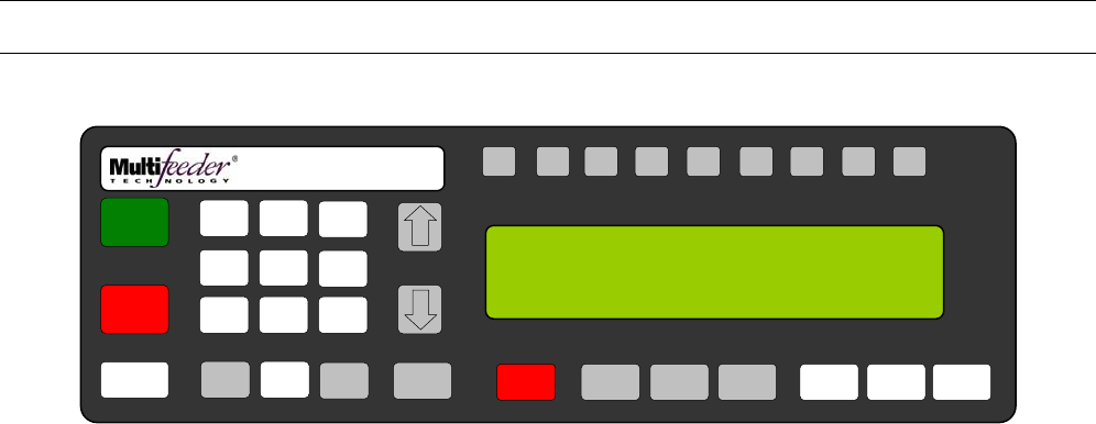
MFT Feeder Menus and Screens
203
Safety Relay Tripped Warning Screen
The Safety Relay Tripped Warning Screen is displayed whenever a safety relay is triggered.
This screen is prompted and not directly accessed.
F1 F2 F3 F4 F5 F6 F7 F8 HELP
1
ON
0
OFF
AUTO
ON / OFF CLEAR
CANCEL
1
4
7
23
6
9
MENU 0 ENTER STOP
MOTOR CYCLE
START
SET PROD.
THICKNESS
CHANGE
COUNT
CHANGE
SPEED JOG TO
CLEAR JOG
.........................................
FEEDER SCROLL
PN 53110-0G
MODE: TURRET AUTO OFF
WARNING SAFETY RELAY TRIGGERED
PRESS RESET THEN CLEAR/CANCEL
5
8

MFT Feeder Menus and Screens
204
Illegal Entry Warning Screen
The Illegal Entry Warning Screen is displayed whenever an out of range value is entered. The above example
is when an out of range program value is used.
This screen is prompted and not directly accessed.
F1 F2 F3 F4 F5 F6 F7 F8 HELP
1
ON
0
OFF
AUTO
ON / OFF CLEAR
CANCEL
1
4
7
23
6
9
MENU 0 ENTER STOP
MOTOR CYCLE
START
SET PROD.
THICKNESS
CHANGE
COUNT
CHANGE
SPEED JOG TO
CLEAR JOG
.........................................
FEEDER SCROLL
PN 53110-0G
ILLEGAL ENTRY OF XX ENTERED
PROGRAM NOT SAVED
5
8

APPENDIX
205
Table of Contents
Electrical Schematics 206
Overview 206
External Connections 208
Internal Connections 215
Troubleshooting 231
Maintenance 239
Bearing Maintenance 243
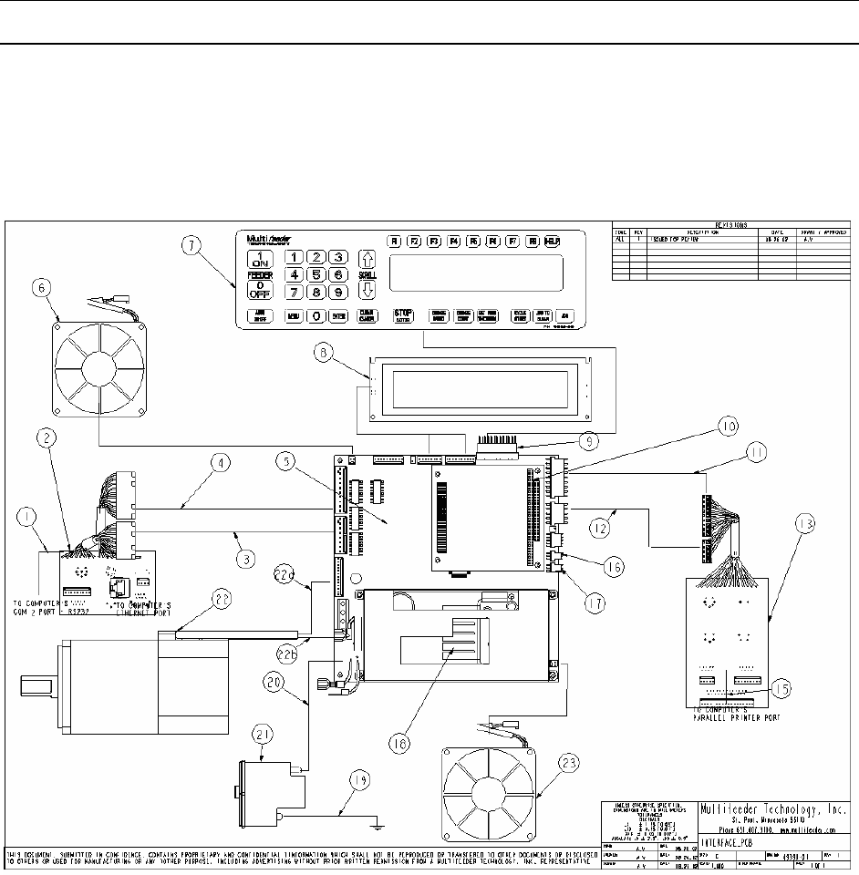
APPENDIX
206
Electrical Schematics
Overview
The internal and external electrical connections are summarized in Error! Reference source not found..
Table 0-1 gives brief descriptions of the listings shown in Error! Reference source not found.. A
comprehensive summary covering both internal and external connections follows.
Figure 0-1 Internal and External Connections
2

APPENDIX
207
Location Name Part Number Description
1 RS232 Communication IP Cable 70071-00 This cable connects the computer board to the
RS232 COM2 connector.
2 Conn PCB Feeder Rear 70483-02 Printed circuit board located at the rear of the
Feeder containing J1, J2, J3, J4, and J26A.
3 APL Interface Connections - This cable assembly connects the rear Feeder
PCB (70483-02) to the Motherboard at P10.
Contains the status signal for J2.
4 Start/Status and Low Product
Sensor Connection - This cable assembly connects the rear Feeder
PCB (70483-02) to the Motherboard at P9.
Contains the status signal for J1 and J3.
5 IP Motherboard Assembly Board 82202-0E
6 Fan 1 70187-00
This fan connects to the Motherboard at P11.
7 Membrane Keyboard 53110-0D
This keyboard connects to the Motherboard at
P6.
8 LCD IP Assembly 70018-00 This assembly consists of the LCD display
(55024-00) and a 16-pin connector (50425-00),
and connects to the Motherboard at P3 and P4.
9 13-Pin Flex Cable 53120-00 This cable connects the Motherboard to the
keyboard at P6.
10 Computer Board 70315-00
11 Traffic Light Connection - This cable assembly connects the front Feeder
PCB (70485-02) to the Motherboard at P12.
Contains the status signals for J22.
12 Product Sensor Connection - This cable assembly connects the front Feeder
PCB (70485-02) to the Motherboard at P13.
Contains the status signals for J6.
13 Conn PCB Feeder Front 70485-02 Printed circuit board located at the front of the
Feeder containing J6, J7, J22, J23, J24 and
J25.
14 N/A N/A
N/A
15 Parallel Printer Connector Cable 70085-00 This cable connects the computer utility on the
WinSystems to the RS232 and parallel printer
connections.
16 Slide Potentiometer Assembly 82121-01
(Left) This assembly connects to the upper exit shaft
linear potentiometer to the Motherboard at P18.
17 Slide Potentiometer Assembly 82121-01
(Right)
This assembly connects to the stripper wheel
shaft linear potentiometer to the Motherboard
at P17.
18 Power Supply IP 55017-00 The Power Supply connects to the
Motherboard at P20 (AC power supply output)
and P19 (Low voltage power supply).
19 Ground - -
20 Power Entry Module - AC Power
Supply 81610-00 The power entry module connects to the
Motherboard at P16 (AC power supply input).
21 Power Entry Module 81610-00 -
22 Motor - -
22a N/A
22b Motor Leads
The motor leads connect to the Motherboard at
P14
23 Fan 2 70187-00
This fan connects to the Motherboard at P15.
Table 0-1 Overview Descriptions

APPENDIX
208
External Connections
Jack 1 - Start/Status
Jack 1, the Start/Status connector, is located on the Feeder Rear PCB (70483-02). This
connector provides status information to connecting equipment, and receives a start signal for
the Feeder machine. See Table 0-2 for further information on this connector. A detailed
description of each pin follows.
Jack Number Cable Description
Pin
Number
(Color) Signal
Name Signal
Description
J1 Start/Status A (Brown) +24 VF +24 V from
Feeder
B (Tan) PSTART
Start Pulse, 24V
(10-30V), 5ms (1-
100ms)
C (Pink) LOW
PROD Low Product
D (Orange) AUTO
ON/OFF Auto On/Off
E (Violet) J1-E J1-E Output
F (Blue) CC Cycle Complete
G (Green) C3 Status Select
H (Yellow) R Red Lamp (Fault)
J (Gray) RDY Ready
K (Red) APL Automatic
Product Loader
L (White) DD
STATUS APL Status
M (Black) GND24 Ground
N (Black) GND24 Ground
O (Black) GND24 Ground
Table 0-2 J1-Start/Status
A
C L
K
B
J
N
F
H M
E G
D O

APPENDIX
209
Pin A (+24VF) may be used in the following ways:
As a power source for a sensor. When using a PNP or sourcing sensor, connect the positive terminal
to Pin A (24 Volt), the negative terminal to Pin M (Ground), and the output to Pin B (PSTART). Please
note that since a positive signal voltage is required, only a PNP sensor will work.
As a voltage to supply the PSTART. A relay can be used to create a closed contact between the 24
Volt supply and the PSTART to provide the Feeder with a start signal. Connect one leg of the relay
output to Pin A (24 Volt), and one leg to Pin B (PSTART).
Other. Other uses are not recommended without first consulting Multifeeder Technology.
Pin B (PSTART) is the start signal for the Feeder . A start is equal to 10-30V DC. This signal may be
connected to the 12V or 24V output of a PLC. The Feeder starts when the signal goes from low to high.
Pin C (LOW PROD) is an output that is normally low (0 VDC) and goes high (24 VDC) when a low
product condition has been detected.
Pin D (AUTO ON/OFF) is an output that is normally low (0 VDC) and goes high (24 VDC) when the
Feeder is in the AUTO ON condition.
Pin E (J1-E) is a Configurable output that is 24 VDC.
Pin F (CC) is the Cycle Complete signal. This signal is very useful in intermittent motion applications, as
it can be used to determine the current status of the Feeder . The host machine can provide a start signal
to the Feeder and wait for the Cycle Complete signal to go to 0V DC (low) before indexing. If a fault
occurs, the host machine will not index until the fault has been cleared and the signal is low. The Cycle
Complete signal behaves in the following way:
When the Feeder is in a ready condition but not feeding, the Cycle Complete signal is low (0V DC).
When the Feeder is busy and/or in a fault condition, the Cycle Complete signal is high (24V DC).
• If the Feeder is in the Auto Off condition, the Cycle Complete signal is high (24V DC). The Cycle
Complete signal may be inverted by selecting Option 3 in Menu 4 (Interface Signal Menu). See
Section for more information.
Pin G (C3) is the Status Select signal. This signal is used by the Feeder to determine the status of the
Automatic Product Loader or Automatic Drop Table, if present. Do not connect anything to this signal at
any time.
Pin H (R) is the Red, or Fault signal and acts in the following way:
When the Feeder is in a green condition (Ready), the signal is low (0V DC). When the Feeder is in a
red condition (Feeder Fault or Not Ready), the signal is high (24V DC).
Pin J (RDY) is the Ready signal and acts in the following way:
High unless either MPD I/O Ready or Jam I/O Ready feature are enabled and either an MPD or Jam
occurs (depending on which is enabled), it then goes low until next feed cycle is started.
Pin K (APL) is the APL Enable/Disable signal and is used to enable or disable the Automatic Product
Loader or Drop Table, if present. The signal acts in the following way:
When the Feeder is in a green condition (Ready), the signal is high.
When the Feeder is in a red condition (Feeder Fault or Not Ready), the signal is low.
Pin L (DD Status) is the APL Status signal. This signal is used to communicate the status of the
Automatic Product Loader or Automatic Drop Table, if present, back to the Feeder . Status readings
include Present, Not Present, Ready, and Not Ready.
Pin M, N and O (Ground) is the reference for all of the above signals. When connecting any of the above
signals, Pins M, N and O (Ground) must also be connected to the host machine ground.
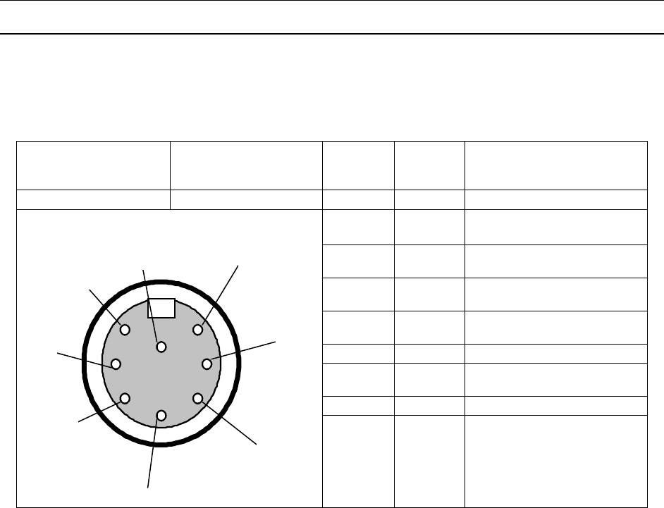
APPENDIX
210
Jack 2 APL Interface
Jack 2, the APL Interface connector, is located on the Feeder Rear PCB (70483-02). This connector is
used to transmit information between the Feeder and the Automatic Product Loader. See Table 0-3 for
further information on this connector. A detailed description of each pin follows.
Jack Number Cable Description Pin
Number
(Color)
Signal
Name Signal Description
J2 APL Interface 1 (Black) C3 Status Select
2
(Green) APL Automatic Product Loader
(Enable/Disable)
3
(White) APL
Status APL Status
4 (Red) Status
GND Ground
5
(Brown) GND24 APL Present Ground
6 (Blue) +24VF +24 Volts from Feeder
7
(Orange) +24V
APL +24 V from APL
8 OPEN Open
Table 0-3 J2-APL Interface
Pin 1 (C3) is the Status Select signal. This signal determines the status of the Automatic Product Loader
or Drop Table, if present.
Pin 2 (APL) is the APL Enable/Disable signal. It enables or disables the Automatic Product Loader or
Drop Table, if present. The signal acts in the following way:
When the Feeder is in a green condition (Ready), the signal is high (24V DC).
When the Feeder is in a red condition (Feeder Fault or Not Ready), the signal is low (0V DC).
Pin 3 (APL Status) is the APL Status signal. This signal communicates the status of the Automatic
Product Loader or Drop Table, if present, to the Feeder .
Pin 4 (Ground) is the reference for all of the above signals. When connecting any of the above signals,
Pin 4 must also be connected to the host machine ground
Pin 5. (APL Present Ground) is the APL Status Ground signal and is used by the Feeder as a reference
to the APL Status signal.
Pin 6 (24V Input from Feeder) is utilized by the APL to determine the status.
Pin 7 (24V APL) is the APL 24 Volt supply. It can be jumpered to Pins 2 and 6 to run the APL alone
without a Feeder present.
1
2
3
4
5
6
7
8

APPENDIX
211
Jack 3 - the Low Product
Jack 3, the Low Product connector, is located on Feeder Rear PCB (70483-02). This connects a photo
optic sensor that triggers the yellow light in the onboard signal light. This photo optic sensor is configured
to monitor the level of products in the magazine, and causes the yellow light to start flashing when the
product level is low. See Table 0-4 for further information on this connector.
Jack Number Cable
Description
Pin
Number
(Color)
Signal
Name Signal
Description
J3 Low
Product 1
(Black) +24 VF +24 V from
Feeder
2
(Green) Low
Product Low Product,
1=Low
3 (Red) GND24 Ground
Table 0-4 J3-Low Product
1
2
3
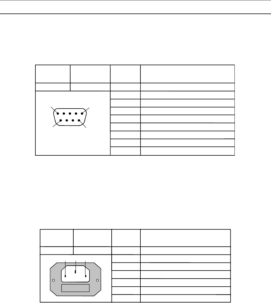
APPENDIX
212
Jack 4 - RS 232 (COM 1)
Jack 4, the RS 232 connector, is located on the Feeder Rear PCB (70483-02). This connector is the
means of serial data communication between the Feeder 's computer and other equipment. See Table
0-5 for further information on this connector.
Jack Cable Pin
S
ignal Name
Number Description Number
J4 RS 232 1
6
7
J4 Front View
8
9Ring Indicator
2
3
4
5
RTS - Request To Set
DSR - Data Set Ready
Ground
DTR - Data Terminal Ready
TX – Transmit Data
RX – Receive Data
DCD - Data Carrier Detect
CTS - Clear To Send
5
1
9
6
Table 0-5 J4 - RS 232
Jack 5 - Power Entry
Jack 5, the power entry connector, is located on the Feeder Rear PCB (70483-02). This connector is the
means of connecting power to the MFT friction Feeder . See Table 0-6 for further information on this
connector.
Jack Cable Pin Signal Name
Number Descri
p
tion Number
J5 Power Entry 1
J5 Front View
2
3
120 VAC
Earth Ground
Neutral
1 2 3
Table 0-6 J5-Power Entry
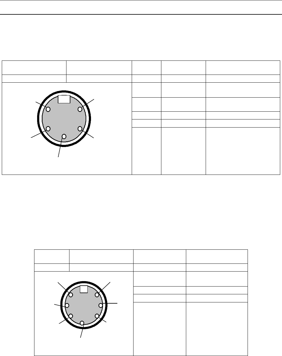
APPENDIX
213
Jack 6 - Product Sensor
Jack 6, the product sensor connector, is located on the Feeder Front PCB (70485-02). This connects the
product sensor, and the emitter and receiver pair to the MFT friction Feeder . See
Table 0-7 for further information on this connector.
Jack Number Cable Description Pin
Number Signal Name Signal Description
J6 Product Sensor 1 Emitter Drive Emitter Cathode (Tab)
2 +5VF
+5 V from Feeder Emitter
Anode
3 +5VF
+5V from Feeder
Receiver Cathode
4 Detector Receiver Anode (Tab)
5 Open Ground
Table 0-7 J6-Product Sensors
Jack 22 – Signal Light
Jack 22, the signal light, is located on the Feeder Front PCB (70485-02). This connects the signal light to
the MFT friction Feeder . See
Table 0-7 for further information on this connector.
Jack
Number Cable Description Pin Number
(Wire Color) Signal Description
J22 Signal Light 6 (Red) Red Lamp (24V)
2 (White/Yellow) Yellow Lamp (24V)
4 (Green) Green Lamp (24V)
1 (Black) GND
Table 0-8 J22-Signal Light
1
2
3
4
5
6
1
2
3
4
5
7
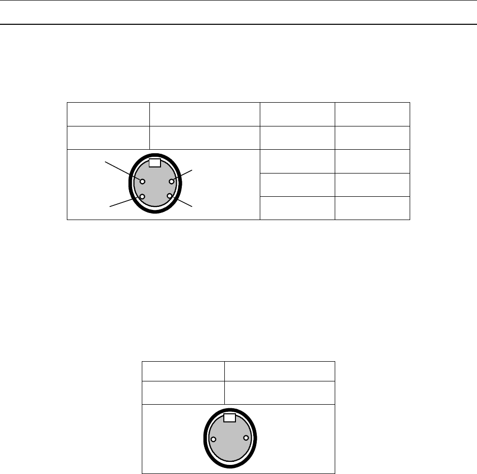
APPENDIX
214
Jack 23 - Line Speed Encoder
Jack 23, line speed encoder, is located on the Feeder Front PCB (70485-02). See Table 0-9 for further
information on this connector.
Jack Number Cable Description Pin Number Signal
Description
J23 Line Speed Encoder 4 GND
1 +24V
3 B Signal
2 A Signal
Table 0-9 J23-Line Speed Encoder
Jack 24 - Feeder Interlock
Jack 24, the Feeder interlock, is located on the Feeder Front PCB (70485-02). Table 0-10 illustrates the
two (2) pin connection of J24. A short across the pins enables the Feeder and an open across the pins
disables the Feeder. Each Feeder is shipped with a DummyPlug in J24 enabling the Feeder.
Jack Number Cable Description
J24 Feeder Interlock
Table 0-10 J24-Feeder Interlock
1
4
3 2
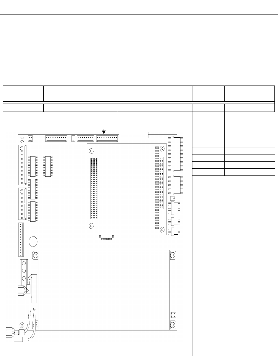
APPENDIX
215
Internal Connections
Motherboard (P/N 82202-0E) Pin Assignments
Motherboard - Plug 3
P3 is located on the Motherboard (P/N 82202-0E) and contains the output signal to the LCD display. The
output signal continues on P4.
Interconnect Location Pigtail Pin
Number
Signal
Description
P3 Motherboard 70018-00 1 DB 7
2 DB 6
3 DB 5
4 DB 4
5 DB 3
6 DB 2
7 DB 1
8 DB 0
10 R/W
9 E1
Table 0-11 P3
P3
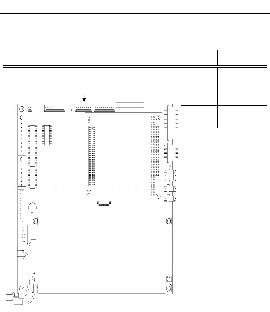
APPENDIX
216
Motherboard - Plug
P4 is located on the Motherboard (P/N 82202-0E) and contains the output signal to the LCD display. P4
is a continuation of P3.
Interconnect Location Pigtail Pin
Number
Signal
Description
P4 Motherboard 70018-00 1 RS
2 Vo
3 Vss
4 Vdd
5 E2
6 NC1
7 NC2
8 NC3
Table 0-12 P4
P4
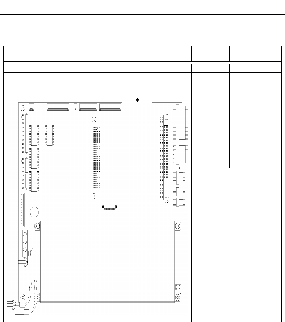
APPENDIX
217
Motherboard - Plug 6
P6 is located on the Motherboard (P/N 82202-0E) and contains the input signals from the keypad.
Interconnect Location Pigtail Pin
Number
Signal
Description
P6 Motherboard 700XX-00 1 Row1
2 Row2
3 Row3
4 Col1
5 Col2
6 Col3
7 Col4
8 Col5
9 Row4
10 Row5
11 Row6
12 Col6
13 Ground
Table 0-13 P6
P6
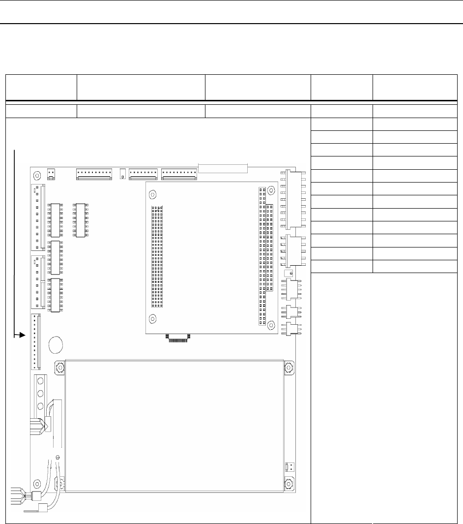
APPENDIX
218
Motherboard - Plug 7
P7 is located on the Motherboard (P/N 82202-0E) and contains the motor encoder signals.
Interconnect Location Pigtail Pin
Number
Signal
Description
P7 Motherboard 700XX-00 1 Encoder A+
2 Encoder A-
3 Encoder B+
4 Encoder B-
5 Encoder Z+
6 Hall 1+
7 Hall 1-
8 Hall 2+
9 Hall 2-
10 Hall 3+
11 Hall 3-
12 +5 VF
13 Ground
Table 0-14 P7
P7
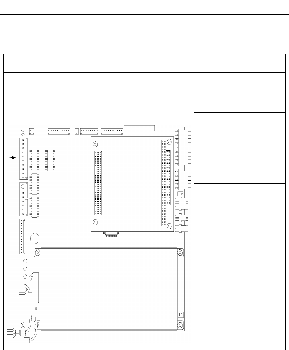
APPENDIX
219
Motherboard - Plug 9
P9 is connected to the Motherboard (P/N 82202-0E) and contains the status signals that connect to
Start/Status (J1) and Low Product (J3).
Interconnect Location Pigtail Pin
Number
Signal
Description
P9 Motherboard - 1 Ready
(Programmabl
e Output)
2 Red (Fault)
3 Status Select
4 Cycle
Complete
5 Demo Mode
Start (Prog.
Outp.)
6 Auto On/Off
(Prog. Outp.)
7 Low Product
(Prog. Outp.)
8 Start Pulse In
9 +24 V from
Feeder
10 +24 V External
Table 0-15 P9
P9
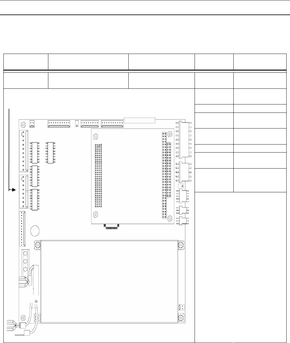
APPENDIX
220
Motherboard - Plug 10
P10 is connected to the Motherboard (P/N 82202-0E) and contains the signals that are connected to the
APL Interface (J2).
Interconnect Location Pigtail Pin
Number
Signal
Description
P10 Motherboard - 1 +24 V External
Ground
2 Motherboard
Ground
3 Open
4 +24 V from
APL
5 Low Product
Input
6 APL Status
7 Drop Device
Status
8 APL
(Enable/Disabl
e)
Table 0-16 P10
P10
APPENDIX
221
Motherboard - Plug 11
P11 of the Motherboard (P/N 82202-0E) provides DC power to drive Fan 1
Interconnect Location Pigtail Pin
Number
Signal
Description
P11 Motherboard 70187-00 1 +24 V from
Feeder
2 Ground
Table 0-17 P11
P11
APPENDIX
222
Motherboard - Plug 12
P12 is connected to the Motherboard (P/N 82202-0E) and contains the signal that is connected to the
Signal Light (J22).
Interconnect Location Pigtail Pin
Number
Signal
Description
P12 Motherboard - 1 +24V
2 +5V
3 Emitter Drive
4 Detector
5 Green
6 Red
7 Yellow
8 Blue
9 Alarm
Table 0-18 P12
P12
1
APPENDIX
223
Motherboard - Plug 13
P13 is connected to the Motherboard (P/N 82202-0E) and contains the signal that is connected to the
Product Sensor (J6).
Interconnect Location Pigtail Pin
Number
Signal
Description
P13 Motherboard - 1 LSE Encoder
A+ Ext.
2 LSE Encoder
B+ Ext.
3 N/C
4 Interlock
5 Ground
Table 0-19 P13
P13
1
APPENDIX
224
Motherboard - Plug 14
P14 is connected to the Motherboard (P/N 82202-0E) and contains the signal that is connected to the
Motor Leads.
Interconnect Location Pigtail Pin
Number
Signal
Description
P14 Motherboard 70049-00 1 C (black)
2 B (white)
3 A (red)
4 Ground/Shield
(green)
Table 0-20 P14
P14
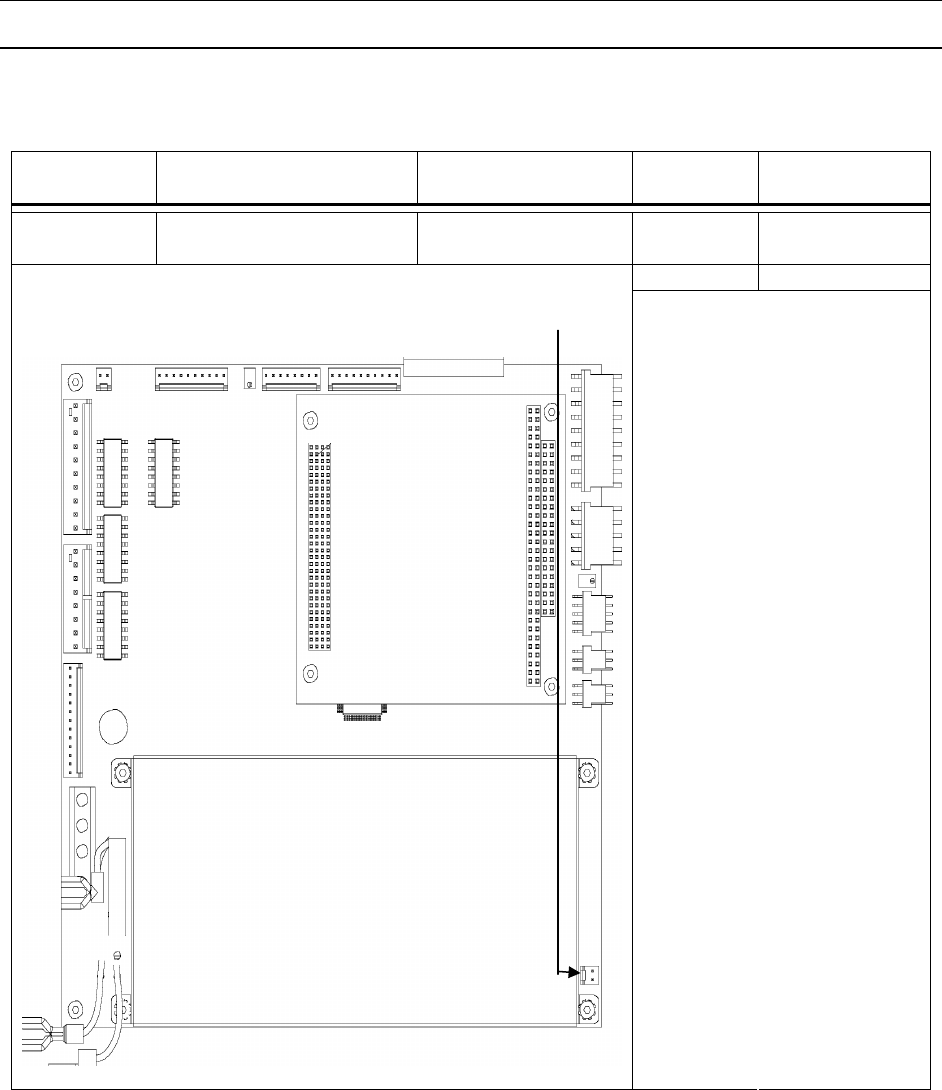
APPENDIX
225
Motherboard - Plug 15
P15 of the Motherboard (P/N 82202-0E) and provides DC power for Fan 2.
Interconnect Location Pigtail Pin
Number
Signal
Description
P15 Motherboard 70187-00 1 +24 V from
Feeder
2 Ground
Table 0-21 P15
P15
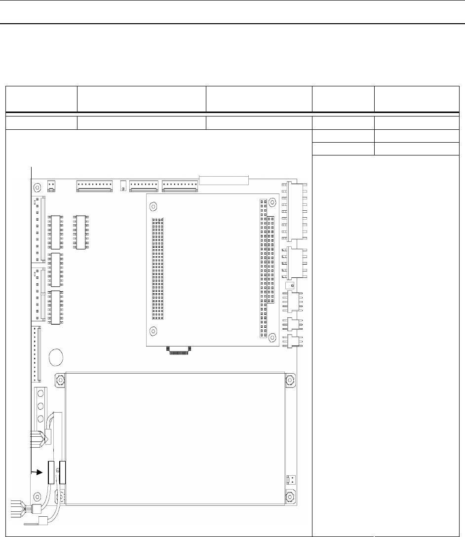
APPENDIX
226
Motherboard - Plug 16
P16 is connected to the Motherboard (P/N 82202-0E) and contains the signal that is connected to the AC
Power Supply Input from the Power Entry Block.
Interconnect Location Pigtail Pin
Number
Signal
Description
P16 Motherboard 81610-00 1 H1
2 Neutral
3 Ground
Table 0-22 P16
P16 (3 Pin)
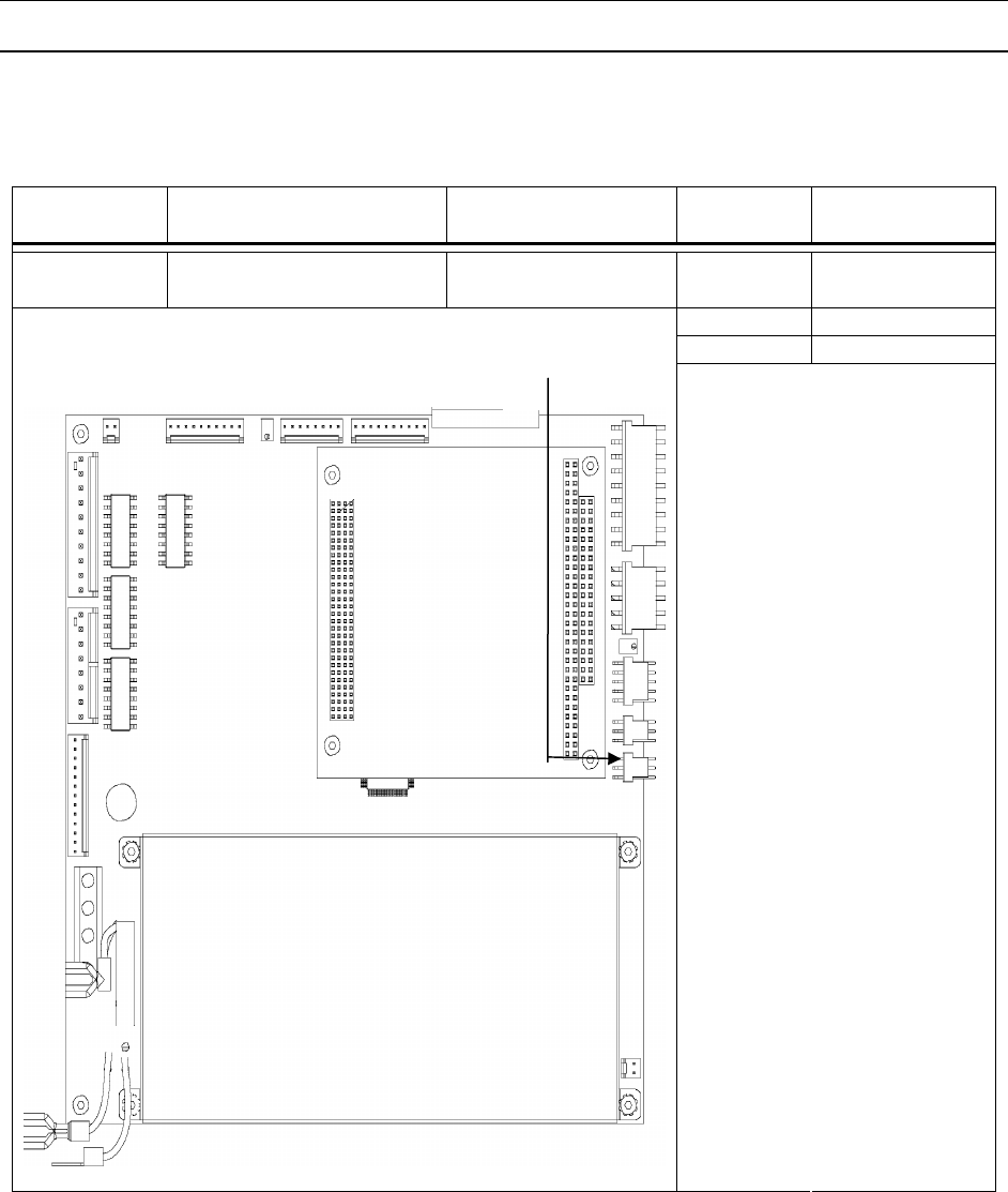
APPENDIX
227
Motherboard - Plug 17
P17 is connected to the Motherboard (P/N 82202-0E) and contains the signal that is connected to the
Stripper Wheel Shaft Linear Pot.
Interconnect Location Pigtail Pin
Number
Signal
Description
P17 Motherboard 82121-01 (Right) 1 +24 V from
Feeder
2 Wiper 2
3 Ground
Table 0-23 P17
P17

APPENDIX
228
Motherboard - Plug 18
P18 is connected to the Motherboard (P/N 82202-0E) and contains the signal that is connected to the
Upper Exit Shaft Linear Pot.
Interconnect Location Pigtail Pin
Number
Signal
Description
P18 Motherboard 82121-01 (Left) 1 +24 V from
Feeder
2 Wiper 1
3 Ground
Table 0-24 P18
P18
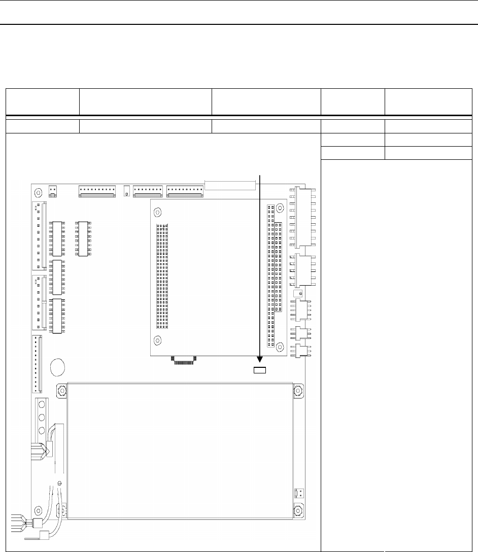
APPENDIX
229
Motherboard - Plug 19
P19 is connected to the Motherboard (P/N 82202-0E) and contains the signal that is connected to the
Low Voltage Power Supply.
Interconnect Location Pigtail Pin
Number
Signal
Description
P19 Motherboard 55017-00 1 +5 V
2 +24 V
3 Ground
Table 0-25 P19
P19 (3 Pin)

APPENDIX
230
Motherboard - Plug 20
P20 is connected to the Motherboard (P/N 82202-0E) and contains the signal that is connected to the DC
Power Supply (P/N 55017-00).
Interconnect Location Pigtail Pin
Number
Signal
Description
P20 Motherboard 55017-00 1 H1
2 Neutral
3 Ground
Table 0-26 P20
P20 (3 Pin)
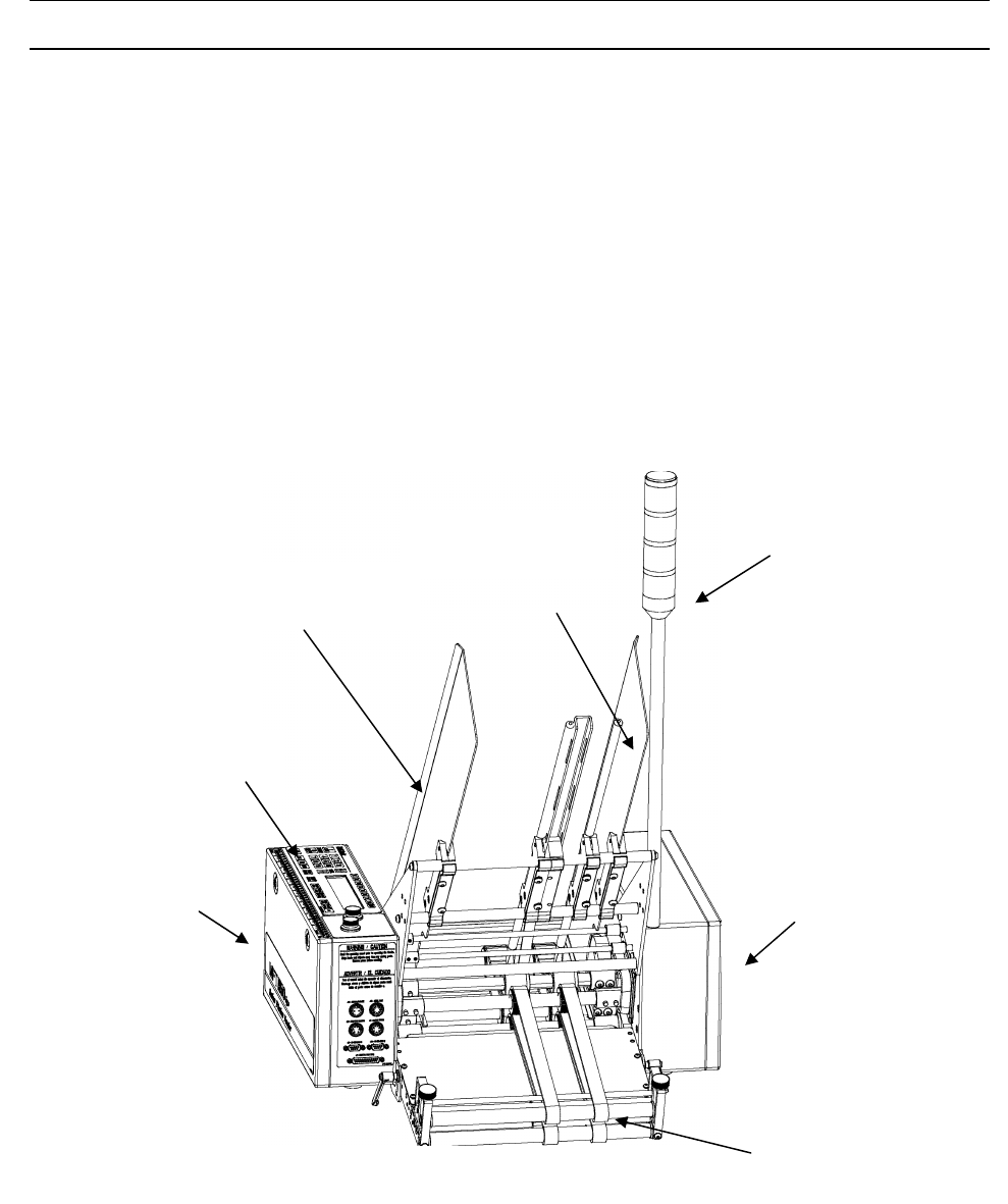
APPENDIX
231
Troubleshooting
This section of the manual provides basic troubleshooting information. The information isolates and
resolves common problems that may occur when operating the MFT Friction Feeder. Attempt only one
remedy at a time and return the setting to its original position if the remedy is not effective. For maximum
effectiveness, it is also recommended several slight adjustments are made, rather than one large
adjustment.
If you are unable to identify or resolve the problem, or if you suspect a machine malfunction, call
Multifeeder Technology at (651) 407-3100 Monday - Friday, 8 a.m. to 5 p.m. (CST). Please be near your
MFT Friction Feeder when you call.
The first troubleshooting table outlines some of the basic mechanical troubleshooting methods that can
solve common feeding problems. Figures 6-1 and 6-2 may be used as references for the terminology
used in this section.
Troubleshooting Terminology - Front View
DISCHARGE
SECTION
RIGHT FEEDER
HOUSING
CONTROL
PANEL
LEFT FEEDER
HOUSING
SIGNAL LIGHT
PRODUCT SUPPORT
PLATE
PRODUCT
SUPPORT ROD
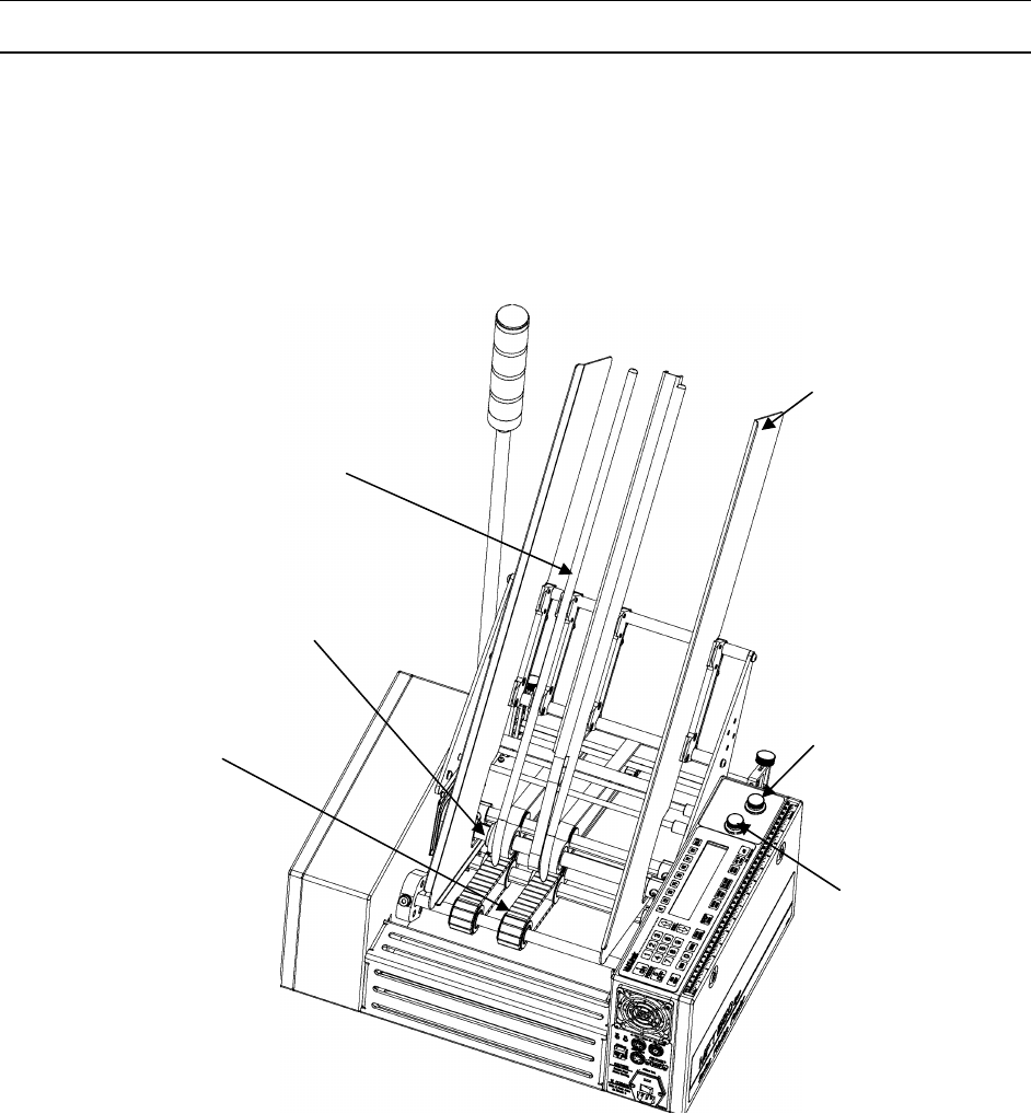
APPENDIX
232
WARNING! Before beginning any troubleshooting operations, review the safety section in the front of this
manual.
Troubleshooting Terminology - Rear View
PRODUCT SUPPORT ROD
FEEDBELT
STRIPPER WHEEL
DISCHARGE ENTRY
THICKNESS ADJUSTER
KNOB
STRIPPER WHEEL
THICKNESS
ADJUSTER KNOB
PRODUCT SUPPORT PLATE
(MAGAZINE SIDE PLATE)

APPENDIX
233
Basic Mechanical Troubleshooting
Problem Cause Solution
Product not coming out
straight
Discharge belts set too tight or too
loose at discharge exit area
Use the adjuster knobs at the end of the
discharge table to adjust the distance
between the upper and lower belts so
that one product fits snugly. Use the 2-
finger tug test to verify proper
adjustment. The operator should be able
to notice resistance using 2 fingers only
tugging at the product while adjusting,
but be able to move the product that is
properly placed between the belts.
Discharge belts at discharge exit
area are not equally tightened
Use the adjuster knobs at the end of the
discharge table to level the discharge exit
roller.
Discharge belts set too tight or too
loose at beginning of discharge Use the discharge adjuster screw to
adjust the distance between the upper
and lower belts so that one product fits
snugly.
Stripper Wheels are too tight Use the thickness adjuster knob to raise
the Stripper Wheels so there is slight
resistance when you slide one product
beneath the wheels. Use the 2-finger tug
test described above to verify.
Product support curves are not
equal in height
Adjust the height of the product support
curves so they are equally distant from
the product.
A feed belt or discharge belt pulley
is loose and slipping on the shaft
Reset the pulley and tighten the
setscrews.
Stripper Wheels are different
sizes (due to uneven wear)
Replace Stripper Wheels – Call
Multifeeder Technology.
Feeder dispenses doubles Stripper Wheels are either too
tight or too loose
Use the thickness adjuster knob to raise
the Stripper Wheels so there is slight
resistance when you slide one product
beneath the wheels. Use the 2-finger tug
test described above to verify.
Too much product weight is on the
feed belts Raise the product support curves to
reduce the amount of product in contact
with the belts.
Stripper wheel shaft does not
turn Stripper Wheels are too tight Use the thickness adjuster knob to raise
the Stripper Wheels so there is slight
resistance when you slide one product
beneath the wheels. Use the 2-finger tug
test to verify.

APPENDIX
234
Feed Belts move but discharge
belts do not The set screws on the discharge
drive belt pulley are loose Open the mechanical housing and tighten
the set screws on the discharge drive belt
pulley
Feed Belts move but product
does not feed Stripper Wheels are too tight
Use the thickness adjuster knob to raise
the Stripper Wheels so there is slight
resistance when you slide one product
beneath the wheels. Use the 2-finger tug
test to verify.
Not enough product weight is on
the feed belts
Lower the product support curves to
increase the amount of product in contact
with the belts.
Feed Belts are dirty
Clean the feed belts.
Magazine side plates are too close
together
A
djust the distance between the
magazine side plates so there is
approximately 3mm on each side of the
product stack.
Feeder feeds continuously with
no gap between products Stripper Wheels are too loose
Use the thickness adjuster knob to lower
the Stripper Wheels so there is slight
resistance when you slide one product
beneath the wheels. Use the 2-finger tug
test described above to verify.
Too much product weight is on the
feed belts
Raise the product support curves to
reduce the amount of product in contact
with the belts.
Stripper Wheels are dirty
Clean the Stripper Wheels .
Too much static on product Use a humidifier or static elimination
system to improve performance.
Feed Belts are tracking off the
pulleys Stripper Wheels are too tight
Use the thickness adjuster knob to raise
the Stripper Wheels so there is slight
resistance when you slide one product
beneath the wheels. Use the 2-finger tug
test described above to verify.
Too much product weight is on the
feed belts
Raise the product support curves to
reduce the amount of product in contact
with the belts.
Discharge belts are tracking off
the pulleys Discharge belts are set too tight
a) Use the knobs at the end of the
discharge table to adjust the distance
between the upper and lower belts so that
one product fits snugly. Use the 2-finger
tug test described above to verify.
b) Use the discharge adjuster knob to
adjust the distance between the upper
and lower belts so that one product fits
snugly.

APPENDIX
235
Top or bottom discharge shaft is
not rotating properly Open the mechanical housing and inspect
for loose drive belt pulleys. Tighten
setscrews if necessary.
Repeated misfeed faults Feeder is receiving a start pulse
while it is feeding another product a) Increase the motor speed
-or-
b) Decrease the start pulse rate
MPD fault with no MPD
present Product contains a dark area which
is read as a double product a) Move the emitter-receiver pair away
from the dark area.
-or-
b) Take a product thickness reading in the
dark area.
Repeated MPD faults Stripper Wheels are too loose Use the thickness adjuster knob to lower
the Stripper Wheels so there is slight
resistance when you slide one product
beneath the wheels. Use the 2-finger tug
test described above to verify.
Repeated ‘Watch Dog - No
Product’ faults Jams in the feeding mechanism
area are preventing products from
reaching the sensors
Clear the jams and make necessary
height adjustments. Use the 2-finger tug
test described above to verify.
Watch Dog No Product Length
setting is incorrect Check and update the Watch Dog No
Product Length setting.
Repeated ‘Watch Dog -
Product Jam’ faults There is not enough space
between products/products are
overlapping
Use the thickness adjuster knob to lower
the Stripper Wheels so there is slight
resistance when you slide one product
beneath the wheels. Use the 2-finger tug
test described above to verify.
Product length was not updated for
new product
Measure and update the product length
value.
Product separation length is too
long Reduce the ‘Product Separation Length’
value.
Gap is present but Feeder
displays ‘Watch Dog Product
Jam’ fault
Emitter-receiver pair is positioned
under a discharge belt
Relocate the emitter-receiver pair . Verify
that the emitter/receiver pair is vertically
aligned.
Product length setting is incorrect
Update the product length setting.
Emitter-receiver pair is faulty Inspect the emitter-receiver pair cable
assembly for cuts or damage.
Feeder jams during operation Stripper Wheels are too tight
Use the thickness adjuster knob to adjust
the Stripper Wheels so there is slight
resistance when you slide one product
beneath the wheels. Use the 2-finger tug
test described above to verify.

APPENDIX
236
Product was loaded incorrectly in
the Feeder
Remove product stack and reload.
Feeder does not dispense
when feed signal is activated Feeder is not in AUTO ON mode Press the AUTO ON/OFF hot key to
toggle to AUTO ON mode. Note! The
A
UTO ON/OFF key is only active in the
Feeder ready condition (green light on).
Feeder dispenses at an
incorrect time interval on host
machine
Start signal to Feeder is incorrectly
positioned
Reposition the sensor or adjust the start
signal.
Time delay setting is incorrect Adjust the time delay.

APPENDIX
237
Advanced Electrical Troubleshooting
The second troubleshooting table outlines the advanced electrical troubleshooting methods that may
solve electrical Feeder problems, should they occur.
WARNING! Advanced electrical troubleshooting should only be performed by a qualified technician. The
MFT Friction Feeder operates on 120 VAC. Contact with this voltage can lead to serious injury, or death.
Problem Cause Solution
Unit does not power up No power at Feeder Check for power to Feeder - line
voltage
Check outlet
Feeder does not power up Blown fuse
Loose connection inside Feeder With power removed, use a flat
head screwdriver to remove the
fuse from the power entry
module. Test fuse with a VOM
and replace if necessary
a) Check connections inside
Feeder and tighten if necessary
b) Check power supplies 24, 12, -
12, and 5V
Fuse is blown on power up Wrong fuse was installed Reinstall the correct type of fuse
(5x20mm, 10A, 250V)
Feeder not responding Computer is locked up
Malfunctioning computer Power down and restart machine
Call Multifeeder Technology
LCD is scrambled Loose connection
Static buildup on the product may
be discharging through product
sensor pair.
Check connection to LCD display
and tighten if necessary
Dissipate static prior to the sensor
pair. Call MTF for antistatic device
LCD has dark spots Malfunctioning LCD
Malfunctioning Motherboard Replace LCD - Call Multifeeder
Technology
Replace LCD - Call Multifeeder
Technology
LCD blank but Feeder okay Malfunctioning Computer Call Multifeeder Technology
Membrane keypad keys do
not register Loose connection
Malfunctioning membrane keypad Check connection to membrane
keypad and tighten if necessary
Replace membrane keypad - Call
Multifeeder Technology

APPENDIX
238
Membrane keypad keys
register, but motor does not
run
Loose connection
Malfunctioning motor amplifier
board
Malfunctioning motor or motor
encoder
Check connection to amplifier
board and tighten if necessary
Check bus voltage on amplifier
board
Rotate motor by hand and use an
oscilloscope to check for pulses
on A, /A, B, /B, I, and /I. If no
pulses are present replace motor
encoder.
Emitter-receiver pair does
not see product Emitter-receiver pair is damaged or
malfunctioning
Motherboard is malfunctioning
Inspect emitter-receiver pair for
damage. Replace if necessary -
Call Multifeeder Technology
Call Multifeeder Technology
Feeder runs continuously
without stopping Malfunctioning motor amplifier
board
Malfunctioning motor or motor
encoder
Malfunctioning computer board
Call Multifeeder Technology
Call Multifeeder Technology
Call Multifeeder Technology

APPENDIX
239
Maintenance
The life span of your MFT Friction Feeder is dependent on a regularly scheduled maintenance and
inspection program. Given the proper preventive maintenance care, your Feeder will perform at an
optimal level for many years. By regularly inspecting the equipment, any trouble signs that appear may
be resolved before damage occurs. A specially designed maintenance and inspection program is
described on the following pages.
WARNING! Before any maintenance tasks are performed, the power must be disconnected from the
Feeder .
Daily • Vacuum any dust and debris from the feed belt section, discharge section, and
inside edges of the Feeder housings.
• Clean the Feed Belts and Stripper Wheels . *See procedure described below
• Visually inspect the Stripper Wheels and Feed Beltsfor damage or unusual wear.
• Visually inspect the machine for loose screws, bolts, and adjustment knobs.
To clean the Feed Belts and Stripper Wheels :
1. Turn the Feeder off and disconnect the power cord from the Feeder
2. For easier access to the Stripper Wheels and feed belts, remove the magazine side plates and
support curves.
3. Dip a clean rag in isopropyl alcohol or equivalent cleaning agent.
4. Pressing firmly, wipe the tops of the Feed Belts from side to side. Be sure to clean the entire
circumference of the belts. Since the power is disconnected, you may use your hand to manually
rotate the belts.
5. Visually inspect the inner circumference of the feed belt for paper dust and dirt build up. If necessary,
clean the circumference with a dry rag or a rag dipped in a very small amount of isopropyl alcohol.
6. Pressing firmly, wipe the outer surface of the Stripper Wheels from side to side. Be sure to clean the
entire circumference of the wheels. Since the power is disconnected, you may use your hand to
manually rotate the wheels.
7. Use a dry, clean portion of the rag to wipe the Feed Belts and Stripper Wheels .
8. Reinstall the magazine side plates and support curves, and restore power to the Feeder .
Warnings:
Use only isopropyl alcohol or an equivalent cleaning agent to clean Feed Belts and Stripper Wheels .
Other cleaning agents may damage the material.
Isopropyl alcohol is very flammable! Use only in an open area away from any source of ignition, including
open flame, sparks, and cigarettes.
Be certain that the Feed Belts and Stripper Wheels are completely dry before operating the Feeder .
Damp Stripper Wheels will damage the product and damp Feed Belts may slip or track incorrectly.

APPENDIX
240
Weekly • Clean the discharge belts. *See procedure described below
• Clean the emitter-receiver sensor pair. *See procedure described below
• Clean the membrane keypad. *See procedure described below
• Clean the photo optic sensors. *See procedure described below
• Tighten, if necessary, the set screws on the feed belt pulleys and discharge belt
pulleys.
To clean the discharge belts:
1. Turn the Feeder off and disconnect the power cord from the Feeder
2. Dip a clean rag in isopropyl alcohol or equivalent cleaning agent.
3. Pressing firmly, wipe the tops and bottoms of the discharge belts from side to side. Be sure to clean
the entire circumference of the belts. Since the power is disconnected, you may use your hand to
manually rotate the belts.
4. Use a dry, clean portion of the rag to wipe the discharge belts.
Warnings:
• Use only isopropyl alcohol or equivalent cleaning agents to clean Feed Belts and Stripper Wheels .
Other cleaning agents may damage the material.
• Isopropyl alcohol is very flammable! Use only in an open area away from any source of ignition,
including open flame, sparks, and cigarettes.
• Be certain that the discharge belts are completely dry before operating the Feeder . Damp discharge
belts may slip or track incorrectly.
To clean the Emitter-Receiver sensor pair and photo optic sensors::
1. Use only a dry rag to clean the photo optic sensors. Using an abrasive cleaning agent may scratch
the surfaces and impede performance.
2. Gently wipe the glass surfaces on both the emitter and receiver.
Warning:
• Use only a dry rag to clean the emitter-receiver pair. Using an abrasive cleaning agent may scratch
the surfaces and impede performance.
To clean the Membrane Keypad:
1. Spray a clean rag with a non-solvent, nonabrasive cleaning agent. (Using a window cleaner is
recommended)
2. Gently wipe the membrane keypad and LCD display window.
Warning:
• The use of solvents or abrasive cleaning agents may damage the membrane keypad.

APPENDIX
241
Monthly • Clean the air intake filters. *See procedure described below
• Open the Feeder housing covers and drive pulley covers. Tighten, if necessary,
the setscrews on the drive pulleys.
• Thoroughly inspect all belts, pulleys, bearings, and Stripper Wheels for damage or
unusual wear.
• Check that all indicator lights (red, yellow, and green) are functional.*See
procedure described below
• Check electrical wire harness ribbon cable assemblies for damage or unusual
wear.
• Check that all cable connections are secure and tight.
• Check that the cooling fan is functional.
• Re-grease the needle bearings for the discharge pulley(s).
• Re-grease the bearings in the spanning pulley(s).
To clean the air intake filters:
1. Open the electrical housing lid and remove the gray air intake filters. Close the electrical housing lid.
2. Use a mild soap and water mixture to gently wash the filters.
3. After the filters are completely dry replace them in the electrical housing lid.
Warning!
• Make sure the air filters are completely dry before replacing them in the housing lid. Failure to do so
may result in costly damage to the machine’s electronics.
• Do not use the Feeder while the filters are being cleaned.
To check that the indicator lights are functional:
1. With the magazine full of product, check to be sure the GREEN light is illuminated while the Feeder
is feeding.
2. Continue to feed until the product level falls below the low product sensor. When this happens, check
to be sure the YELLOW light is illuminated.
3. Continue to feed until the Feeder runs out of product and stops feeding. Check to be sure the RED
light is illuminated when the Feeder stops feeding.

APPENDIX
242
Semi-
Annually
• Re-grease the stripper wheel clutch bearings.
• Check oil level inside the top and bottom discharge rollers. Rollers should be
1/3 full of oil. ( If so equipped.)
Yearly • If necessary, replace Stripper Wheels .
• If necessary, replace discharge belts.
For information on replacement parts, please call Multifeeder Technology at (651) 407-3100.

APPENDIX
243
Bearing Maintenance
In addition to the prescribed preventive maintenance schedule, it is very important to monitor the
condition of the bearings in the machine. Although the life spans of the bearings are designed to outlast
the machine itself, certain environmental factors (excessive dirt, debris, and high temperatures) may
decrease the life of the bearings. By following the maintenance regiment prescribed above, most of the
potential bearing hazards will be avoided.
If proper attention is given to the bearings, any problems that arise may be addressed and resolved
before failure and costly downtime occur. There are many advanced systems and instruments available
for monitoring bearings. However, by simply listening, feeling, and visually inspecting the bearings you
will become aware of any problems that may arise.
Listen-
When bearings are in good operating condition they make little or no noise while the machine is running.
Any grinding, squeaking, loud, intermittent, or irregular noises are signs of bearing trouble. Unfortunately,
many times when bearing damage is audible by the human ear severe damage has already occurred. A
more accurate method of detecting bearing damage is to use an electronic stethoscope.
When bearing damage is detected, you should stop the machine immediately. If possible, isolate the
malfunctioning bearing and examine it for insufficient lubrication and/or particles imbedded in the
lubrication. Call Multifeeder Technology for information on replacement bearings.
Feel-
A rise in temperature is another sign of bearing trouble. Fortunately, many times overheating is a result
of a lubrication problem - something that can easily be corrected. However, running the machine for an
extended time with bearing temperatures above 125oC will reduce the life of the bearing.
When a temperature rise is detected, you should stop the machine immediately. If possible, isolate the
overheated bearing and examine it for insufficient/excess lubrication. Call Multifeeder Technology for
information on replacement bearings. You should note that a natural rise in temperature will occur for
one or two days immediately following lubrication and re-lubrication.
Look-
It is advisable that you periodically check the outer surfaces of the bearings for unusual wear and
leakage. You should also check the conditions of the seals. If you notice a lubrication leak you should
stop the machine immediately. If possible, identify the location of the leak. Call Multifeeder Technology
for information on replacement bearings.
NOTE! During initial break in of the machine, excess grease and/or oil may sweat from sealed bearings.

APPENDIX
244
CE Compliance
Controls and Connections
Controls and
Connections
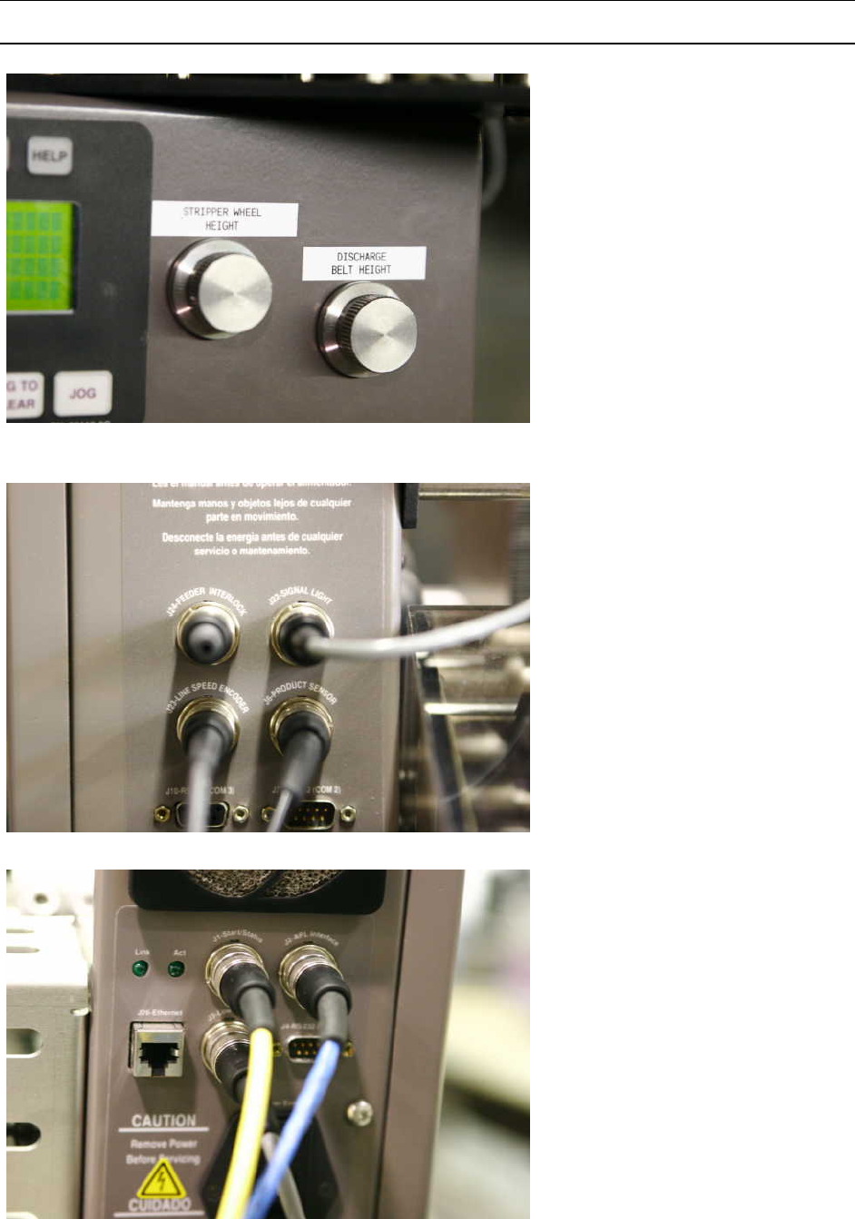
APPENDIX
245
Controls and
Connections
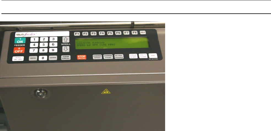
APPENDIX
246
Controls and
Connection
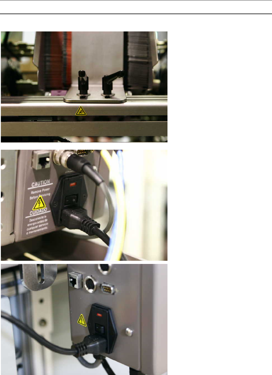
APPENDIX
247
CE Compliance – Warning Labels
Pinch Hazard
Turn off power before entering.
Shock Hazard
Disconnect power before entering
Shock Hazard
Disconnect power before entering
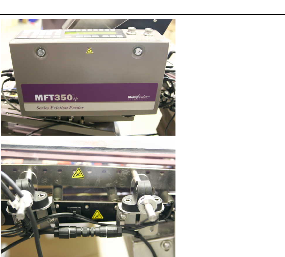
APPENDIX
248
Shock Hazard
Disconnect power before entering
Pinch Hazard
Turn off power before entering.

CREDIT APPLICATION
249
Company Name ____________________________________________
Billing Address ______________________________________________
City/State __________________________________________________
Telephone ______-______-________ Fax _____-______-________
Business Type: Corporation _______ Partnership _______ Individual _______
Federal Tax ID No. _________________ Date Company Started _____-_____-__________
Accounts Payable Contact ___________________________________________________
Is your company sales tax exempt? ______ Yes ______ No (Note, if you checked “Yes”, you must attach a
copy of the SALES TAX EXEMPTION certificate recognized by your state. If the certificate is not submitted,
sales tax will be billed.
Bank Reference:
Name ___________________________________ A/C Number _____________________
Address _________________________________ City/State ________________________
Telephone ______-______-________ Fax ______-______-________
Trade Reference:
Company Name_________________________________________________________
Address_________________________________
City/State ______________________________
Telephone ______-______-________ Fax ______-______-________
Company Name_________________________________________________________
Address_________________________________
City/State ______________________________
Telephone ______-______-________ Fax ______-______-________
Our standard terms are NET 30 from the date of the invoice with a 1-1/2% monthly charge on all past due
invoices.
I herby authorize release of information necessary to establish a line of credit.
Signed _________________________________ Title__________________ Date________

IMPORTANT
Warranty Activation Form
Multifeeder Technology Inc. • 4821 White Bear Parkway • St. Paul – MN • 55110-3325 • U.S.A.
Tel (651) 407-3100 • Fax (651) 407-3199 • info@multifeeder.com • www.multifeeder.com
Your Multifeeder equipment has a warranty that is specified in the attached terms and conditions. In
order for this warranty to become effective, you must complete the warranty registration on this page
with in 60 days of shipment of the equipment. Fax or mail (see bottom) this form to Multifeeder
Technology, Inc. Customer Service.
If you would like to establish credit for your company, please complete the credit application page and
fax or mail this form to Multifeeder Technology, Inc. Accounts Receivable.
Model_______________ Serial Number___________________________
Your Company_______________________________________________
Your Contact Name___________________________________________
Telephone _________________ Extension ________________________
E-mail address ______________________________________________
Date Warranty Signed and Sent to Multifeeder ____________________
Date Received by Customer Service at Multifeeder ___-___-______

TERMS AND CONDITIONS OF SALE OR LEASE
MULTIFEEDER TECHNOLOGY, INC. (MFT)
Multifeeder Technology Inc. • 4821 White Bear Parkway • St. Paul – MN • 55110-3325 • U.S.A.
Tel (651) 407-3100 • Fax (651) 407-3199 • info@multifeeder.com • www.multifeeder.com
MULTIFEEDER TECHNOLOGY, INC. (MFT) TERMS AND CONDITIONS
ALL SALES ARE SUBJECT TO THE FOLLOWING TERMS AND CONDITIONS.
1. Definitions.
1.1 “Accessory Products” mean spare parts purchased, at Buyer’s option, to enhance the System or
replace components within the System.
1.2 “Agreement” means this Sale Agreement.
1.3 “Buyer” means the person or entity that enters into this Agreement for the design and for
manufacture of the System, subsystem accessory products, or related services and/or Buyer’s assigns,
successor’s agents and transferees.
1.4 “Default Specifications” means the MFT Default Specifications set forth in Exhibit A, attached
hereto, which set forth the default functional and technical performance criteria for the System.
1.5 “Final Product Throughput” means the end-product as fully processed by the MFT System.
1.6 “MFT” means Multifeeder Technology, Inc.
1.7 The “Operation and Maintenance Manual” means the operative and instruction guide supplied by
Seller to Buyer, which addresses one or several of the devices, components or Subsystems within the System.
1.8 “Order” means Buyer’s order in the form of Seller’s Proposal, signed by Buyer and delivered to
Seller.
1.9 “Order Acknowledgement Form” means the written form Seller sends to Buyer indicating that Seller
is in receipt of Buyer’s Order.
1.10 “Parties” means the Buyer and Multifeeder Technology, Inc.
1.11 “Product Samples” mean Buyer-supplied components and/or material to be fed through and/or
processed by the System to create a Final Product Throughput.
1.12 “Product Schedule” means the actions undertaken by MFT to design and build the System over a
period of time.
1.13 “Production Schedule Date” means the date upon which production is scheduled for completion.
1.14 “Proposal” means Seller’s written description of the System and/or Accessory Products
1.15 “Quote” means the price quote for the System and/or Accessory Products.
1.16 “Seller” means Multifeeder Technology Inc.
1.17 “Shipment Date” means the estimated date upon which MFT anticipates shipment of the System
from the MFT facility.
1.18 “Specifications” means the functional and technical performance criteria for the System, as agreed-to
by the Parties.

TERMS AND CONDITIONS OF SALE OR LEASE
MULTIFEEDER TECHNOLOGY, INC. (MFT)
Multifeeder Technology Inc. • 4821 White Bear Parkway • St. Paul – MN • 55110-3325 • U.S.A.
Tel (651) 407-3100 • Fax (651) 407-3199 • info@multifeeder.com • www.multifeeder.com
1.19 “Subsystem” means any smaller MFT-designed system that constitutes a component of the overall
System.
1.20 “System” means the custom-designed product manufactured by Seller according to the
Specifications, which may or may not include various other Subsystems.
1.21 “System Manual” means the operative and instruction guide supplied to Buyer by Seller with the
shipment of the System, which addresses the overall System, and may or may not address each separate
device, component or Subsystem within the System
2. The System.
2.1 Purchase and Supply. Seller will sell the System and/or Accessory Products to Buyer under the
terms and conditions set forth in this Agreement.
2.2 Specifications. The System will be manufactured by Seller according to the Specifications. The
Proposal will include a Quote for each component of the System. If the Buyer does not provide specifications
prior to the Quotation process, the Default Specifications will apply. All specifications supplied by Buyer are
subject to (a) MFT’s written approval and (b) signature by a MFT-authorized representative.
2.3 Packing. Unless otherwise specified in this Agreement or Buyer’s Order,
the System and/or all Accessory Products are to be packed and identified in accordance with customary
industry practice. Seller shall mark each container with necessary lifting, loading and shipping information,
including the applicable purchase order number, date of shipment, and the name and address of Seller and
Buyer.
3. Assent to Terms and Conditions of Agreement. Unless otherwise indicated, Seller’s Proposal will
expire thirty (30) days following the date the Proposal is transmitted to Buyer. Seller’s Proposal is not binding
upon Seller until Buyer’s Order is accepted in writing by Seller on an Order Acknowledgement Form. Buyer’s
Order must be submitted within the timeframes provided herein.
4. Price, Price Adjustment & Additional Charges.
4.1 Price. The purchase price for the System will be set forth in the Quote. The pricing of Accessory
Products is subject to change from time to time.
4.2 Price Adjustment. The purchase price in the Quote may be increased to reflect increases in the cost
of materials or labor, if:
4.2.1 Shipment of the System is scheduled for a date that is more than three (3) months after the date of
Buyer’s Order;
4.2.2 Shipment of the System is delayed by Buyer to a date that is more than three (3) months after the
date of Buyer’s Order; or
4.2.3 Shipment of the System is accelerated due to an accelerated Production Schedule Date.
4.3 Delivery, Risk of Loss and Title. The System will be delivered f.o.b. Seller’s Minnesota facility.
Buyer will pay all packaging, handling and freight to Buyer’s destination. Risk of loss or damage to the System
passes to Buyer at the time of delivery to the carrier. Seller will purchase shipping insurance at Buyer’s request
and at Buyer’s expense. Transfer of title is not deemed to occur until payment in full has been received by
Seller. Shipment dates are Seller’s best estimate of when product(s) will be shipped or delivered, but the
Shipment Date is not guaranteed.

TERMS AND CONDITIONS OF SALE OR LEASE
MULTIFEEDER TECHNOLOGY, INC. (MFT)
Multifeeder Technology Inc. • 4821 White Bear Parkway • St. Paul – MN • 55110-3325 • U.S.A.
Tel (651) 407-3100 • Fax (651) 407-3199 • info@multifeeder.com • www.multifeeder.com
4.4 Taxes. Buyer will pay all duties and taxes including sales, use, property, excise, value added and
gross receipts taxes levied on the System or Accessory Products. Seller will not collect an otherwise applicable
tax if Buyer’s purchase is exempt from Seller’s collection of such tax and a valid tax exemption certificate is
furnished by Buyer to Seller.
4.5 Cancellation of Orders. Following Seller’s acceptance of Buyer’s Order, the Order can be cancelled
only with Seller’s written consent. A minimum cancellation charge of 35% of the purchase price of the System or
Accessory Products will be assessed and will vary according to the date on which the cancellation occurs in the
Production Schedule, the quantity of work and materials that are salvageable, the degree to which the System
is custom-designed, and other factors in MFT’s sole discretion.
4.6 Additional Charges. Additional work completed or time consumed by reason of Buyer’s alterations
or delays caused by Buyer, will be charged to Buyer at Seller’s current price for work or material at the time of
such alterations, changes, or delays.
5. Payment.
5.1 Payment of Purchase Price. If Seller approves Buyer for credit, the payment schedule is (a) 55% of
the purchase price in certified or other currently available funds within five (5) days following acceptance of
Buyer’s Order; (b) no later than ten (10) days before Buyer’s requested shipment date (i) 35% of the purchase
price in certified funds; and (ii) the remaining balance by Buyer’s delivery of an irrevocable letter of credit or
some other MFT-approved payment alternative, drawn on a U.S. bank in an amount equal to the remaining
balance due for the benefit of Seller or Seller’s agent. The letter of credit and/or its equivalent must be drawn
on a financial institution and in form reasonably acceptable to Seller, must be in U.S. dollars, and will expire no
earlier than 60 days after the requested shipment date. Under no circumstances will Seller be liable to Buyer
for delays in shipment caused by Buyer’s delay in payment.
If Seller does not approve Buyer for credit, payment will be disbursed to Seller within five (5) days following
acceptance of Buyer’s Order by certified or other currently available funds or by Buyer’s delivery of an
irrevocable letter of credit or some other MFT-approved payment alternative, drawn on a U.S. bank in an
amount equal to the full amount of the purchase price. The letter of credit and/or its equivalent shall provide for
interim draws in accordance with the schedule referenced in the preceding paragraph, be drawn on a financial
institution and in form reasonably acceptable to Seller, in U.S. dollars, and will expire no earlier than 60 days
after the requested shipment date.
Buyer authorizes Seller to review any and all necessary credit reports and information to assess whether Seller
will extend credit to Buyer.
5.2 Invoicing for Ongoing Services and/or Accessory Products. Seller will invoice Buyer for any
ongoing services or Accessory Products purchased separately from Buyer’s Order for the System. Invoices will
reference purchase order number, item number and description of product(s) and/or service(s), unit price of
products and/or service(s), total amounts due, and the due date. Invoices shall be due and payable within thirty
(30) days after the date of invoice. Payments will be applied to oldest invoices first. Overdue invoices will
accrue interest at a rate equal to the lesser of 18% per annum or the maximum rate allowable by law.
5.3 Non-payment of Amounts Due. Seller hereby retains a security interest in the System or Accessory
Products for any portion of the purchase price thereof unpaid by Buyer. Seller is authorized to perfect its
security interest. In addition, if payment in full is not made within sixty (60) days following delivery of the
System, or within 60 days of the invoice date for any and all additional charges accrued by Buyer, whichever
applies, Seller may at its sole discretion, activate the control software installed in the System that will disable
the System from functioning. Upon receipt of full payment, Seller will reactivate the System.
6. Performance of System and Product Samples.

TERMS AND CONDITIONS OF SALE OR LEASE
MULTIFEEDER TECHNOLOGY, INC. (MFT)
Multifeeder Technology Inc. • 4821 White Bear Parkway • St. Paul – MN • 55110-3325 • U.S.A.
Tel (651) 407-3100 • Fax (651) 407-3199 • info@multifeeder.com • www.multifeeder.com
6.1 Acceptance Criteria of System Performance. The acceptance testing shall be conducted in two (2)
phases, as set forth below:
6.1.1 Phase One Acceptance Testing. Prior to shipping the equipment from the Multifeeder Technology,
Inc. facility to the place of delivery, MFT will conduct a system performance test mutually-agreed upon with the
Buyer and reduced to a writing signed by both Parties. Buyer may, at its option, witness the Phase One
Acceptance Test in person or by electronic means supplied by MFT.
If the Parties do not agree upon an a specific test, the Parties agree that MFT will conduct a 30-minute test
demonstrating 90% uptime, after excluding any lost time or lost production due to Nonconforming Product
Samples (defined in section 3.3 of Exhibit A and all related subsections) or other factors out of MFT’s control.
MFT reserves the right to restart or continue the test until completed, or to abbreviate the test by discounting
lost time or lost production due to Nonconforming Product Samples or other factors out of MFT’s control.
It is Buyer’s responsibility to supply an adequate amount of acceptable quality test product pursuant to ¶ 6.2
below. MFT bears no responsibility if Buyer fails to provide Product Samples to MFT.
6.1.2 Phase Two Acceptance Testing. After completion of delivery of the System, assembly, and training at
the place-of-delivery, MFT personnel will conduct a second test to confirm the System’s performance (“Phase
Two Acceptance Testing”). The Phase Two Acceptance Testing will be conducted using the same Product
Samples and performance criteria specified for the Phase One Testing. If the Phase One performance criteria
are met during the Phase Two Acceptance Testing, the Parties agree that the System shall be deemed
accepted.
6.2 Acceptance of All Other Goods. For any other goods that are not subject to paragraphs 6.1.1 –
6.1.2, Buyer will have ten (10) days after receipt to reject nonconforming goods before such goods are deemed
accepted by Buyer.
6.3 Product Samples. Seller requires Buyer to supply Product Samples to MFT prior to MFT’s
submission of a Proposal to Buyer, and in sufficient quantities to (a) evaluate Product Samples for consistency
in structure and form, and (b) design the System Specifications to process the Product Samples provided. The
projected System performance, as presented in the Proposal, is valid only for Product Samples provided to
Seller prior to the date of the Proposal.
Buyer must also supply to Seller actual Product Samples to the same specification as those provided prior to
the MFT Proposal, so that MFT may conduct Acceptance Testing of the System, as set forth above in
paragraphs 6.1.1-6.1.2. MFT will estimate and advise Buyer of the quantity of Product Samples MFT requires.
If not otherwise specified by MFT, MFT requires a stack of each Product Sample, approximately 25 inches high,
for testing any System that is composed of feeders. If automatic product loaders are to be tested, a minimum of
5,000 samples are required. Product Samples should be shipped at Buyer’s cost to Seller no later than ten (10)
days after Seller’s acceptance of Buyer’s Order. Product Samples will not be returned. Seller does not
guarantee feeding performance of any specific product unless an exact Product Sample has been tested before
delivery of the System to Buyer.
LIMITED WARRANTY AND LIMITATION OF LIABILITY
To activate the warranty, Buyer must sign and return to MFT (a) the Proposal and (b) fully completed warranty
registration cards, which Buyer will receive with the System.
Seller warrants to Buyer, for a period of one year from the date of delivery of the System to Buyer or for 2000
operating hours, whichever occurs first, that the System or Accessory Product(s) will be free from defects in
material and workmanship. An extension of this Limited Warranty is available for an additional charge. OTHER
THAN THE FOREGOING, NO WARRANTY OR GUARANTEE, WHETHER STATUTORY, EXPRESS OR
IMPLIED, INCLUDING ANY WARRANTY AS TO MERCHANTABILITY OR FITNESS FOR ANY PURPOSE IS
MADE. THE EXPRESS WARRANTY SET FORTH HEREIN SHALL BE THE SOLE AND EXCLUSIVE

TERMS AND CONDITIONS OF SALE OR LEASE
MULTIFEEDER TECHNOLOGY, INC. (MFT)
Multifeeder Technology Inc. • 4821 White Bear Parkway • St. Paul – MN • 55110-3325 • U.S.A.
Tel (651) 407-3100 • Fax (651) 407-3199 • info@multifeeder.com • www.multifeeder.com
REMEDY BY THE BUYER HEREUNDER FOR ANY SYSTEM OR ACCESSORY PRODUCTS DELIVERED
TO THE BUYER WHICH ARE FOUND TO BE DEFECTIVE IN ANY MANNER, WHETHER SUCH REMEDIES
BE IN CONTRACT, TORT, STRICT LIABILITY, OR BY LAW. OTHER THAN AS SET FORTH HEREIN,
SELLER SHALL UNDER NO CIRCUMSTANCE BE DIRECTLY OR INDIRECTLY LIABLE FOR ANY LOSS OR
DAMAGE HOWSOEVER ARISING FROM SUCH MERCHANDISE, INCLUDING LOST USE, LOST
PRODUCT, LOST REVENUE, LOST PROFITS, COST OF CAPITAL, OR SPECIAL, CONSEQUENTIAL OR
INCIDENTAL DAMAGES.
If during the warranty period, the System or an Accessory Product fails to meet the Specifications, Buyer shall
notify in writing of the specific nature of the failure and all-pertinent observations related to the failure.
Seller does not represent or warrant that Systems or Accessory Products sold by it complies with OSHA or any
like state, local, or national law or regulation, and the cost of modification and responsibility for such compliance
is imposed upon Buyer. Equipment must be used in a non-condensing, low-humidity, dry environment, unless
explicitly exempted by MFT in writing.
THE TOTAL CUMULATIVE LIABILITY OF SELLER TO BUYER FOR ANY CLAIM OF ANY KIND, FOR ANY
LOSS OR DAMAGE WHATSOEVER ARISING OUT OF, CONNECTED WITH OR RESULTING FROM THE
SALE OR SERVICING OF THE PRODUCTS HEREIN, SHALL NOT EXCEED THE PURCHASE PRICE OF
THE SYSTEM OR ACCESSORY PRODUCT. BUYER AGREES TO INDEMNIFY, DEFEND AND HOLD
HARMLESS SELLER FROM ALL CLAIMS ARISING IN WHOLE OR IN PART ON ACCOUNT OF IMPROPER
USE, ABUSE, MISUSE, USE NOT IN ACCORDANCE WITH SELLER’S RECOMMENDATIONS SET FORTH
IN THE OPERATION, MAINTENANCE AND SYSTEM MANUALS SUPPLIED BY SELLER, OR BUYER’S
FAILURE TO PERFORM UNDER THIS AGREEMENT.
Warranty coverage excludes cost of delivery to and from Seller’s Minnesota facility. All units that the customer
wishes to have repaired under warranty shall be accompanied by a MFT issued Returned Material Authorization
(RMA) and must be sent to Multifeeder at Buyer’s expense. A service fee of $500.00 will be charged for
products sent to Seller for warranty repair, which are found to comply with the Specifications. Seller reserves
the right to suspend any and all warranties if the Buyer has a delinquent account.
The System and Accessory Products are sensitive. To qualify for the warranty set forth in this Agreement, the
System and Accessory Products warranted must be repaired by knowledgeable and specially trained MFT
personnel only. Accordingly, warranty coverage will be void in its entirety upon any sign or evidence of (a)
opening the System or field service conducted by individuals other than Seller’s authorized personnel, (b)
tampering or any kind of misuse of the System including Buyer’s use of belts, Stripper Wheels or other parts
not supplied by Seller, or (c) abuse of the System or Accessory Products. Non-warranty work will be completed
according to Seller’s standard rates and charges in effect at the time.
7. Confidentiality. Buyer acknowledges that Seller’s technology is confidential and agrees not to
disclose or utilize for its own commercial benefit any technology that Buyer learns through the purchase or use
of the Systems and/or Accessory Products. In no manner does this Agreement imply or authorize any form of
technology license to Buyer for any portion of Seller’s technology except for Buyer’s use of the System and
Accessory Products for their intended purpose.
8. Export Controls. Buyer agrees that it will not, without obtaining prior authorization from the U.S.
Department of Commerce:
(i) export or re-export, directly or indirectly, any technical data or products (as defined by the U.S.
Export Administration Regulations) received by Buyer under this Agreement to destinations restricted or
prohibited by U.S. law;
(ii) disclose such technical data to destinations restricted or prohibited by U.S. law; or

TERMS AND CONDITIONS OF SALE OR LEASE
MULTIFEEDER TECHNOLOGY, INC. (MFT)
Multifeeder Technology Inc. • 4821 White Bear Parkway • St. Paul – MN • 55110-3325 • U.S.A.
Tel (651) 407-3100 • Fax (651) 407-3199 • info@multifeeder.com • www.multifeeder.com
(iii) export or re-export, directly or indirectly, any direct product resulting from the technical data
received by Buyer to destinations restricted or prohibited by U.S. law.
Buyer hereby agrees to indemnify, defend and hold harmless Seller for any export, re-export or disclosure in
violation of U.S. law that results directly or indirectly from Buyer’s actions.
10. Patents. Seller warrants that it has utilized reasonable efforts to ensure that the System and/or
Accessory Products do not infringe on any patented technology belonging to any other person or entity. If
infringement is found and Buyer’s use of the System, Subsystem and/or Accessory Products is restricted, Seller
will, at its option, either (a) redesign the System, Subsystem, and/or Accessory Products to avoid the
infringement; (b) seek a license to allow the current technology to be utilized by Seller; or (c) allow Buyer to
return the System, Subsystem and/or Accessory Products for a full refund.
11. Choice of Law.
11.1 Governing Law. The laws of the State of Minnesota, United States of America and any
applicable Federal laws of the United States of America, as from time to time amended and in effect, govern all
matters arising out of or relating to this Agreement, including without limitation its validity, interpretation,
construction, performance (including the details of performance), and enforcement. The Parties agree that any
applicable conflict of law provision that results in the application of the laws of a foreign jurisdiction shall be
disregarded. Buyer and Seller expressly agree that neither this Agreement, nor any ancillary agreement,
undertaking, or performance that may be promised, performed, or executed to implement this Agreement will
not be subject to or interpreted by the United Nations Convention on Contracts for International Sale of Goods.
11.2 Foreign Corrupt Practices Act of 1977. Buyer is subject to the laws and regulations of the Foreign
Corrupt Practices Act of 1977 (FCPA), Title 15 United States Code Service section 78dd-1 and its progeny.
11.3 Prohibition on Flowdown Provisions. In no event will this Agreement be subject to any other contract
which would subject Seller to any additional terms and conditions or liability. Buyer bears all liability for all other
contracts to which Buyer is subject.
12. Forum Selection Clause. Buyer and Seller agree that all disputes, claims, controversies and
disagreements relating to or arising out of this Agreement are subject to the exclusive jurisdiction and venue of
the state and federal courts of Minnesota, of the United States of America. Buyer waives any objections to
jurisdiction or venue in any proceeding before any such court in Minnesota and hereby submits to the exclusive
jurisdiction of any such court in Minnesota. Buyer and Seller agree that the exclusive choice of forum set forth
in this section does not prohibit the enforcement of any judgment obtained in that forum or any other forum.
13. Miscellaneous.
13.1 Governing Language. The English language of this Agreement shall govern and control any
translations of the Agreement into any other language. Documents furnished by Buyer to Seller under the
terms of this Agreement shall be furnished in English or accompanied by an English translation. Seller will not
be held responsible for errors or misunderstandings that may occur due to omissions or translations to another
language. Seller reserves the right to correct all errors.
13.2 Assignment. This Agreement shall be binding upon and shall inure to the benefit of Buyer and Seller
and their respective successors and assigns, provided, however, that Buyer may not assign its rights or
delegate its duties under this Agreement without Seller’s prior written consent, which may be granted or
withheld at Seller’s sole discretion.
Buyer and its assignees and/or transferees of the System and/or Accessory Products, including all associated
proprietary and intellectual property rights, agree to the terms and conditions of the Agreement. Buyer agrees
to indemnify, defend and hold harmless Seller for any claim or loss or damage suffered as a result of any
assignee or transferee failing to abide by these terms and conditions.

TERMS AND CONDITIONS OF SALE OR LEASE
MULTIFEEDER TECHNOLOGY, INC. (MFT)
Multifeeder Technology Inc. • 4821 White Bear Parkway • St. Paul – MN • 55110-3325 • U.S.A.
Tel (651) 407-3100 • Fax (651) 407-3199 • info@multifeeder.com • www.multifeeder.com
13.3 Counterparts. This Agreement may be executed in multiple identical counterparts, all of which taken
together constitute a single agreement.
13.4 Entire Agreement. This Agreement and any exhibits attached hereto, including Multifeeder Technology,
Inc. General System Default Specifications (Exhibit A), constitute the entire agreement and understanding
between Buyer and Seller. All prior written or oral agreements, undertakings, promises, warranties, or
covenants relating to any subject matter not expressly set forth within this Agreement are hereby superseded.
13.5 Amendments and Waivers. No inconsistent, additional or modified terms or conditions, including price,
will apply unless specifically agreed to in a writing signed by Buyer and Seller. No waiver of any provision or
condition shall be valid unless set forth in a writing signed by the waiving party.
13.6 Force Majeure. Whether foreseen or unforeseen, Seller will not be liable for any failure, defect in
performance, delay in the performance of orders or in the delivery of goods, or for any damages arising from
events beyond Seller’s reasonable control, including without limitation, acts of Buyer, acts of God, accidents,
fires, floods, acts of insurrection or war, governmental interference, embargo, delays by the shipper, strikes,
labor disturbances, unavailability or shortage of supplies or raw materials, unforeseen absence of transportation
capabilities or rescheduled, postponed or cancelled transportation arrangements, changes due to export
controls or the ability to obtain an export license, or any other like cause.
13.7 Limit of Time to Bring Action. No actions or arbitrations arising out of this Agreement may be brought
by Buyer more than eighteen (18) months after the occurrence of the event giving rise to such action or
arbitration.
13.8 Attorneys Fees. Seller will be entitled to recover reasonable attorneys’ fees and costs in any
proceeding to enforce payment from Buyer.
13.9 Buyer’s right to use all of Seller’s products, systems and materials are conditioned upon Buyer’s
acceptance of these Terms and Conditions.
EXHIBIT A: MULTIFEEDER TECHNOLOGY, INC.
GENERAL SYSTEM DEFAULT SPECIFICATIONS
1.0 SCOPE. The scope of these Default Specifications is to define the equipment configuration and
performance requirements for the Custom Multifeeder Technology, Inc. System (hereinafter “System”). All
definitions set forth under the MFT Terms and Conditions apply to these Default Specifications.
2.0 APPLICABLE DOCUMENTS.
National Electric Code 1993
3.0 DEFAULT SPECIFICATIONS. The System shall be configured as specified herein (the “Default
Specifications”), unless more specifically defined in the applicable Proposal. To the extent that any of the
Default Specifications specified here are varied by the Proposal submitted to Buyer, for the purposes of creating
custom-designed product-specific or application-specific requirements, those specifications that are specially
varied will apply. Other than to the extent specifically varied in the Proposal, the Default Specifications apply.
3.1 POWER REQUIREMENTS. Each Subsystem will have 110 VAC +/-10%, 50/60 HZ or 208 VAC +/- 10%
50/60 HZ single phase power available on a circuit capable of delivering 15 amps minimum per feed station.
The power will be clean and free from power surges or power outages. The power, fusing, wiring and
disconnects will be in accordance with the applicable requirements of the National Electrical Code, as updated.

TERMS AND CONDITIONS OF SALE OR LEASE
MULTIFEEDER TECHNOLOGY, INC. (MFT)
Multifeeder Technology Inc. • 4821 White Bear Parkway • St. Paul – MN • 55110-3325 • U.S.A.
Tel (651) 407-3100 • Fax (651) 407-3199 • info@multifeeder.com • www.multifeeder.com
3.2 ENVIRONMENTAL REQUIREMENTS.
3.2.1 TEMPERATURE REQUIREMENTS. The System will be maintained and operated in a location
where the temperature range is maintained between 10 to 35 degrees Celsius (50 to 95 degrees Fahrenheit).
3.2.2 HUMIDITY REQUIREMENTS. The System will be maintained and operated in a non-condensing, dry
location with a relative humidity range of 40 to 80%.
3.3 PRODUCT SAMPLE REQUIREMENTS. This System is a customized high technology system that
depends upon strict quality standards and uniformity of Product Samples handled in order to achieve strict
quality standards and uniformity of Final Product Throughput. By way of example and without limitation, the
Product Samples to be fed and/or processed by the System will be uniform and free of defects, such as bent
corners, dog ears, warpage, tears, bends, folds, debris, contamination, any other nonconforming factor that
affects feeding and/or secondary processing, or any other nonconforming Product Sample Tolerances as
defined below. Product Samples that do not fall within the Product Sample Tolerances set forth below or within
the Proposal will be deemed “Nonconforming Product Samples.”
3.3.1 PRODUCT SAMPLE TOLERANCES.
3.3.1.1 DIMENSIONAL TOLERANCE. The dimensional tolerance of any Product Sample will exhibit no more
than a +/- 1/32 inch variance from the nominal values designated in Buyer’s Proposal.
3.3.1.2 SQUARENESS TOLERANCE. The squareness tolerance of any Product Sample will exhibit no more
than a +/- 1/32 inch variance from the nominal values designated in Buyer’s Proposal.
3.3.1.3 THICKNESS TOLERANCE. The thickness of any Product Sample will exhibit no more than a +/-10%
variance from the nominal values designated in Buyer’s Proposal.
3.3.1.4 FLATNESS TOLERANCE. The maximum warpage or curl of any Product Sample will be less than +/-
1/16 inch when measured lying on a flat surface.
3.4 OPERATOR REQUIREMENTS. Due to the customized high-technology of this System, it is imperative that
all users of the System (“operators”) adopt and practice MFT-documented operating procedures to properly
function. To ensure effective production, all equipment operators must (a) be properly trained by MFT-
authorized personnel and (b) adhere at all times to the prescribed procedures set forth in the various Operation,
Maintenance and System Manuals. All System Performance Specifications and Guarantees are conditioned
upon the adherence of all operators to the above-mentioned requirements. By way of example without
limitation, all operators must be capable of performing all equipment adjustments and product set-up
procedures in accordance with the applicable Operation, Maintenance and System Manuals, and trained to
properly load product into the Feeder magazines, perform Feeder parametric settings and to properly adjust
photo-eyes and holding apparatuses.
3.5 RELIABILIY OF PRODUCT SAMPLES SUPPLIED TO MFT. In order to design and build a System that will
assemble and/or process Final Product Throughput that is consistent in specification, the MFT System requires
consistent Product Samples. In order to accomplish this goal, the performance projected within MFT’s Proposal
is valid only for (a) those Product Samples that pass MFT’s factory testing prior to MFT’s draft Proposal; and (b)
those Product Samples that (1) conform to the MFT pre-proposal factory testing and (2) are provided to MFT
prior to MFT’s receipt of Buyer’s Order and in sufficient quantities to perform testing prior to shipment of the
equipment (“Phase One Acceptance Testing” Terms and Conditions paragraph 6.1.1).
3.6 PROCEDURES FOR ACTIVATING WARRANTY COVERAGE. The MFT General System Default
Specifications incorporate the Limited Warranty set forth under Multifeeder Technology, Inc. Terms and
Conditions. All warranties require the Buyer to return a signed copy of the signature page of the Proposal to
Multifeeder Technology, Inc. to become effective.

TERMS AND CONDITIONS OF SALE OR LEASE
MULTIFEEDER TECHNOLOGY, INC. (MFT)
Multifeeder Technology Inc. • 4821 White Bear Parkway • St. Paul – MN • 55110-3325 • U.S.A.
Tel (651) 407-3100 • Fax (651) 407-3199 • info@multifeeder.com • www.multifeeder.com
3.6.1 EQUIPMENT WARRANTY. All applicable equipment warranties require the Buyer to return a fully
completed warranty registration card to Multifeeder Technology, Inc. If the equipment requires return to MFT,
the Buyer shall call MFT in advance and request a return material authorization number (RMA), which must be
written on the outside of the shipping container.
3.6.2 PERFORMANCE WARRANTY. Upon request of the Buyer, Multifeeder Technology, Inc. will
negotiate and price into its Proposal an efficiency level (parts per minute at a to-be-determined confidence
level) for each type of Product Sample received by MFT, in sufficient quantities and with sufficient time to
perform testing on the System, provided that such Product Samples are consistent and conforming. For
purposes of calculating an efficiency level, all lost time or lost production due to Nonconforming Product
Samples or factors out of MFT’s control shall be subtracted from the production uptime, and product
changeover time is excluded.
To qualify for any applicable performance warranty the Buyer agrees to comply with the following:
a) The System will be completely installed by qualified MFT personnel and all operators will be properly
trained by qualified MFT personnel;
b) Buyer will notify MFT in writing of any deficiencies observed in the System’s performance with sufficient
detail to assist MFT in determining the source of the reported problem;
c) Product Samples are in compliance with the Product Sample requirements and tolerances specified
herein; and
d) Upon proper notification of any problem, MFT will have 30 days to repair, replace, or arrange a partial or
complete refund in exchange for returning the defective equipment. The amount of refund will depend upon the
problem, equipment condition upon return, and the assignment of responsibility. The amount of any refund will
be within the sole discretion of Multifeeder Technology, Inc
Multifeeder Technology Inc. • 4821 White Bear Parkway • St. Paul – MN • 55110-3325 • U.S.A.
Tel (651) 407-3100 • Fax (651) 407-3199 • info@multifeeder.com • www.multifeeder.com
