N9MP2075B12B1 44001102002
User Manual: N9MP2075B12B1
Open the PDF directly: View PDF ![]() .
.
Page Count: 56
International Comfort Products Corporation (USA)
Lewisburg, TN 37091 U.S.A.
FIRE OR EXPLOSION HAZARD
This furnace is not designed for use in mobile
homes, trailers or recreational vehicles.
Such use could result in death, bodily injury
and/or property damage.
!
* Denotes Brands (C, H, T)
!
Electric Shock Hazard
Turn Off All Power Before Servicing.
Failure to do so can result in death,
personal injury and/or property
damage.
INSTALLER: Affix these instructions
on or adjacent to the furnace.
CONSUMER: Retain these
instructions for future reference.
PrintedinU.S.A. 4/28/2003 440 01 1020 (02)
N9MP1 & N9MP2
*9MPD
FAN ASSISTED, DIRECT
VENT GAS FURNACE
SAFETY REQUIREMENTS
Recognizesafetyinformation. Thisisthesafety--alertsymbol !. Whenyouseethissymbolonthefurnaceandininstructionsmanualsbealertto
the potential for personal injury.
Understand the signal words DANGER, WARNING, or CAUTION. These words are used with the safety--alert symbol. DANGER identifies the
most serious hazards, those that will result in severe personal injury or death. WARNING signifies a hazard that could result in personal injury or
death. CAUTION is used to identify unsafe practices that could result in minor personal injury or product and property damage.
Installing and servicing heating equipment can be hazardous due to gas and electrical components. Only trained and qualified personnel should
install, repair, or service heating equipment.
Untrained service personnel can perform basic maintenance functions such as cleaning and replacing air filters. All other operations must be
performedbytrainedservicepersonnel. Whenworkingonheatingequipment,observeprecautionsintheliterature,ontags,andonlabelsattached
to or shipped with the unit and other safety precautions that may apply.
Follow all safety codes. In the United States, follow all safety codes including the current edition National Fuel Gas Code (NFGC) ANSI
Z223.1--2002/NFPA No.54--2002. InCanada,refertothecurrenteditionoftheNationalStandardofCanada NaturalGasandPropaneInstallation
Code (NSCNGPIC) CSA B149.1--00. Wear safety glasses and work gloves. Have fire extinguisher available during start--up and adjustment
procedures and service calls.
Theseinstructions coverminimumrequirementsandconformtoexistingnationalstandardsandsafetycodes. Insomeinstances,theseinstructions
exceedcertainlocalcodesandordinances,especiallythosethatmaynothavekeptupwithchangingresidentialconstructionpractices. Werequire
these instructions as a minimum for a safe installation.
Table of Contents
1. Safe Installation Requirements 3.................
2. Installation 4................................
3. Combustion & Ventilation Air 7..................
4. Vent & Combustion Air Piping 10................
5. Gas Supply and Piping 26......................
6. Electrical Wiring 30...........................
7. Ductwork and Filter 30........................
8. Checks and Adjustments 33....................
9. Furnace Maintenance 35.......................
10. Sequence of Operation & Diagnostics 35..........
11. Concentric Vent Termination 39.................
Tech Support and Parts 43........................
2440 01 1020 02
START--UP CHECK SHEET
For 90+ Furnace
(Keep this page for future reference)
Dealer Name:
Address:Business Card Here
City, State(Province), Zip or Postal Code:
Phone:
Owner Name:
Address:
City, State(Province), Zip or Postal Code:
Model Number:
Serial Number:
Type of Gas: Natural: LP:
Which blower speed tap is used?
(Heating) (Cooling)
Temperature of Supply Air: (°F) or(°C)
Temperature of Return Air: (°F) or(°C)
Rise (Supply Temp.--Return Temp.): (°F) or(°C)
Filter Type and Size:
Fan “Time ON” Setting:
Fan “Time OFF” Setting:
Manual Gas Shut--Off Upstream
of Furnace/Drip--Leg? YES NO
Condensate Drain Connected? YES NO
Condensate Drain Trapped? YES NO
Transition Pressure switch hose relocated for U/D/H
Application? YES NO
Blower Speed Checked? YES NO
All Electrical Connections Tight? YES NO
Gas Valve OK? YES NO
Measured Line Pressure When Firing Unit:
Calculated Firing Rate:(See Checks and Adjustments Sec-
tion).
Temperature Rise (supply--return temperature):(°F)
Measured Manifold Gas Pressure:
Static Pressure (Ducts): Supply Air Return
Date of Start--Up:
CO ?
CO2 ?
Dealer Comments:
3
440 01 1020 02
1. Safe Installation Requirements
DEATH, PERSONAL INJURY AND/OR PROPERTY
DAMAGE
Failure to carefully read and follow all instructions
in this manual can result in furnace malfunction,
death, personal injury and/or property damage.
Installation or repairs made by unqualified persons
can result in hazards to you and others. Installation
MUST conform with local codes or, in the absence
of local codes, with codes of all governmental
authorities having jurisdiction.
The information contained in this manual is
intended for use by a qualified service technician
who is experienced in such work, who is familiar
with allprecautionsandsafetyproceduresrequired
in such work, and is equipped with the proper tools
and test instruments.
!
NOTE: This furnace is design--certified by the CSA International
(formerly AGA and CGA) for installation in the United States and
Canada.Refertotheappropriatecodes,alongwiththismanual,for
proper installation.
·Use only the Type of gas approved for this furnace (see
RatingPlate onunit).Overfiringwillresultinfailure ofheat
exchanger and cause dangerous operation. (Furnaces
can be converted to L.P. gas with approved kit.)
·Install this furnaceonly in a location andposition as speci-
fied in “2. Installation” of these instructions.
·Provideadequatecombustionandventilationairtothefur-
naceas specifiedin“3.Combustionand VentilationAir” of
these instructions.
·Combustion products must be discharged outdoors. Con-
nectthisfurnaceto an approved vent systemonly, asspe-
cified in “4. Vent and Combustion Air Piping” of these
instructions.
·Never test for gas leaks with an open flame. Use a com-
mercially available soap solution made specifically for the
detection of leaks to check all connections, as specifiedin
“6. Gas Supply and Piping, Final Check” of these instruc-
tions.
·Always install furnace to operate within the furnace’s in-
tended temperature--rise range with a duct system which
hasanexternal static pressure withinthe allowablerange,
asspecifiedin“TechnicalSupportManual”oftheseinstruc-
tions.
·When a furnace is installed so that supply ducts carry air
circulated by the furnace to areas outside the space con-
tainingthefurnace,thereturnairshallalsobehandledbya
duct(s) sealed to the furnace casing and terminating out-
side the space containing the furnace.
·A gas--fired furnace for installation in a residential garage
mustbeinstalledasspecifiedin“2.Installation”ofthesein-
structions.
·This furnace is not to be used for temporary heating of
buildings or structures under construction.
·ThisfurnaceisNOTapprovedforinstallationinmobile
homes, trailers or recreation vehicles.
·Seal around supply and return air ducts.
·Install correct filter type and size.
·Unit MUST be installed so electrical components are pro-
tected from direct contact with water.
Safety Rules
Yourunitisbuilttoprovidemanyyearsofsafeanddependableser-
vice providing it is properly installed and maintained. However,
abuse and/or improper use can shorten the life of the unit and
create hazards for you, the owner.
A. The U.S. Consumer Product Safety Commission recom-
mends that users of gas--burning appliances install carbon
monoxide detectors. There can be varioussources of carbon
monoxideinabuildingordwelling.Thesourcescouldbegas--
fired clothes dryers, gas cooking stoves, water heaters, fur-
naces, gas--fired fireplaces, wood fireplaces, and several
other items.
Carbon monoxide can cause serious bodily injury and/or
death. Carbon monoxide or “CO” is a colorless and odorless
gasproducedwhenfuelisnotburnedcompletelyorwhenthe
flame does not receive sufficient oxygen.
Therefore, to help alert people of potentially dangerous car-
bon monoxide levels, you should have carbon monoxide de-
tectors that are listed by a nationally recognized agency (e.g.
UnderwritersLaboratoriesorInternationalApprovalServices)
installed and maintained in the building or dwelling (see Note
below).
B. There can benumerous sources of fireor smoke in a building
or dwelling. Fire or smoke can cause serious bodily injury,
death, and/or property damage. Therefore, in order to alert
people of potentially dangerous fire or smoke, you should
have fire extinguisher and smoke detectors listed by Under-
writersLaboratoriesinstalledandmaintainedinthebuildingor
dwelling (see Note below).
Note: The manufacturer of your furnace does not test any detec-
tors and makes no representations regarding any brand or
type of detector.
C. Toensuresafeandefficientoperationofyourunit,youshould
do the following:
1. Thoroughly read this manual and labels on the unit. This
will help you understand how your unit operates and the haz-
ards involved with gas and electricity.
2. Do not use this unit if any part has been under water. Im-
mediatelycallaqualifiedservicetechniciantoinspecttheunit
andtoreplaceanypartofthecontrolsystemandanygascon-
trol which has been under water.
3. Never obstruct the vent grilles, or any ducts that provide
air to the unit. Air must be provided for proper combustion
and ventilation of flue gases.
Frozen Water Pipe Hazard
FROZEN AND BURST WATER PIPE HAZARD
FaiIure to do so may result in burst water pipes, serious
property damage and/or personal injury.
Furnace may shut down. Do not leave your home
unattended for long periods during freezing weather
without turningoffwatersupplyanddrainingwaterpipes
or otherwise protecting against the risk of frozen pipes.
!
Your furnace is designed solely to provide a safe and comfortable
living environment. The furnace is NOT designed to ensure that
water pipes will not freeze. It is equipped with several safety de-
vices that are designed to turn the furnace off and prevent it from
restarting in the event of various potentially unsafe conditions.
4440 01 1020 02
If your furnace remains off for an extended time, the pipes in your
home could freeze and burst, resulting in serious water damage.
Watermaycreateaconditioninwhichmoldcangrowinyourhome.
Certain types of mold have been reported to cause respiratory
problemsorotherserioushealthrisks.Remedialactions,including
immediately drying all wet items, should be taken quickly to help
prevent the development of mold in your home.
If the structure will be unattended during cold weather you should
take these precautions.
1. Turnoffthewatersupplytothestructureanddrainthewater
lines if possible and add an antifreeze for potable water to
drain traps and toilet tanks. Open faucets in appropriate
areas.
-- or --
2. Have someone check the structure frequently during cold
weather to make sure it is warm enough to prevent pipes
from freezing. Instruct them on a service agency to call to
provide service, if required.
-- or --
3. Installareliableremotesensingdevicethatwillnotifysome-
body of freezing conditions within the home.
Winter Shutdown
If you go away during the wintermonths and do not leave the heat
oninyourhome,theplastictransitionboxandthecondensatetrap
on the furnace must be protected from freeze damage.(See
Figure 8 trough Figure 17)
1. Disconnect the 5/8²OD rubber hose from the vent drain fit-
tingthatislocateddownstreamofthecombustionblower.In-
sert a funnel into the hose and pour four(4) ounces of
sanitary type (RV) antifreeze into the condensate trap. Re-
connectthe5/8²ODrubberhosetothestubontheventdrain
fitting. Secure with the hose clamp.
2. Disconnect the 3/4²OD rubber hose from the condensate
trap. Insert a funnel into the hose and and pour four(4)
ouncesofsanitarytype(RV)antifreezeintotheplasticTran-
sition box. Squeeze the hose together near the end and
quicklyreconnectthe3/4²ODrubberhosetothestubonthe
condensate trap. Secure with the hose clamp.
When you return home, your furnace will be ready to start, as itis
not necessary to drain the antifreeze from the furnace.
2. Installation
CARBON MONOXIDE POISONING HAZARD
Failure to properly vent this furnace or other appliances
can result in death, personal injury and/or property
damage.
Thisfurnacecan NOTbe common ventedorconnectedto
any type B, BW or L vent or vent connector, nor to any
portion of a factory--built or masonry chimney. If this
furnace is replacing a previously common-vented
furnace, it may be necessary to resize the existing vent
andchimneyto preventoversizingproblems fortheother
remaining appliance(s). See Venting and Combustion Air
CheckinGasVentInstallationsection.ThisfurnaceMUST
be vented to the outside.
!
Location and Clearances
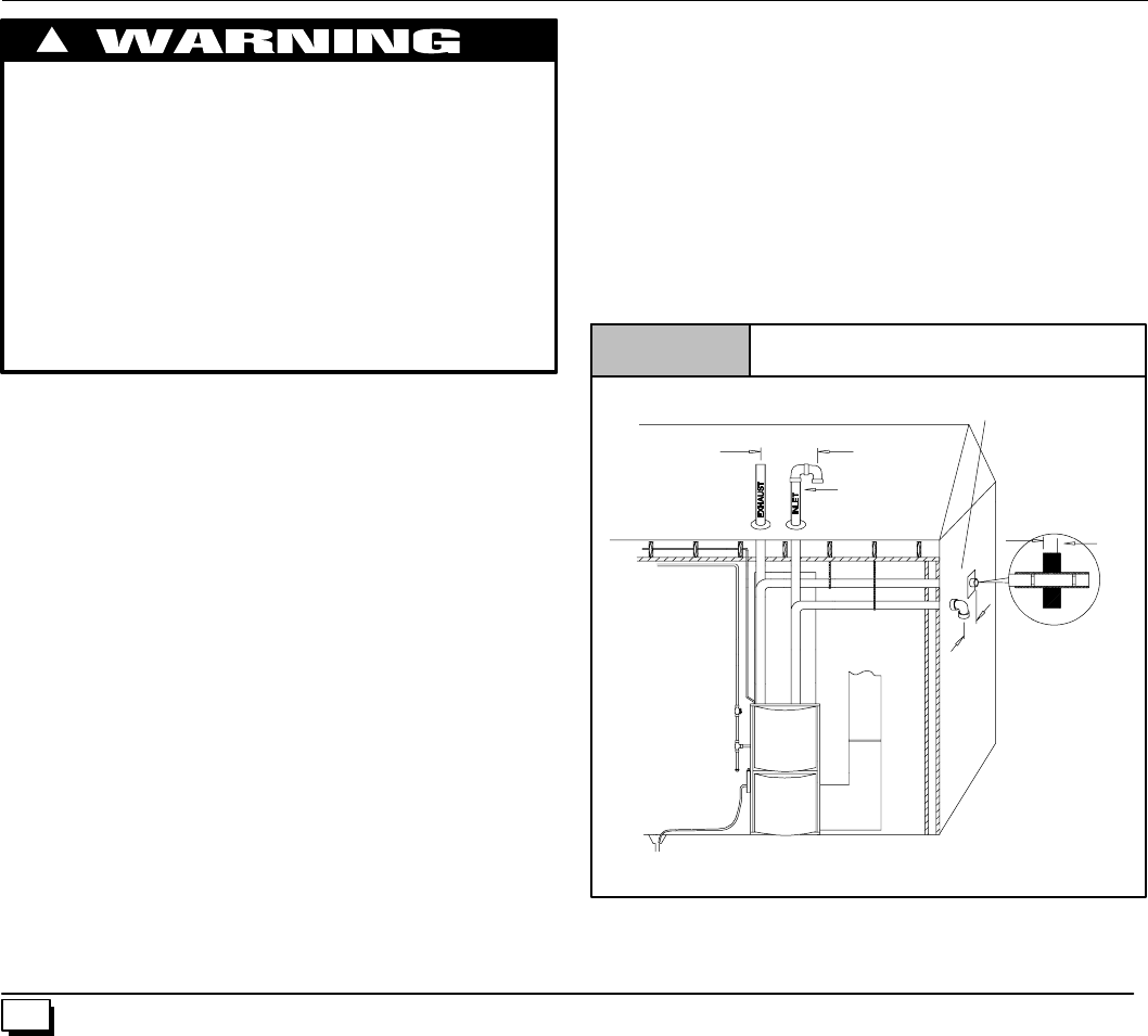
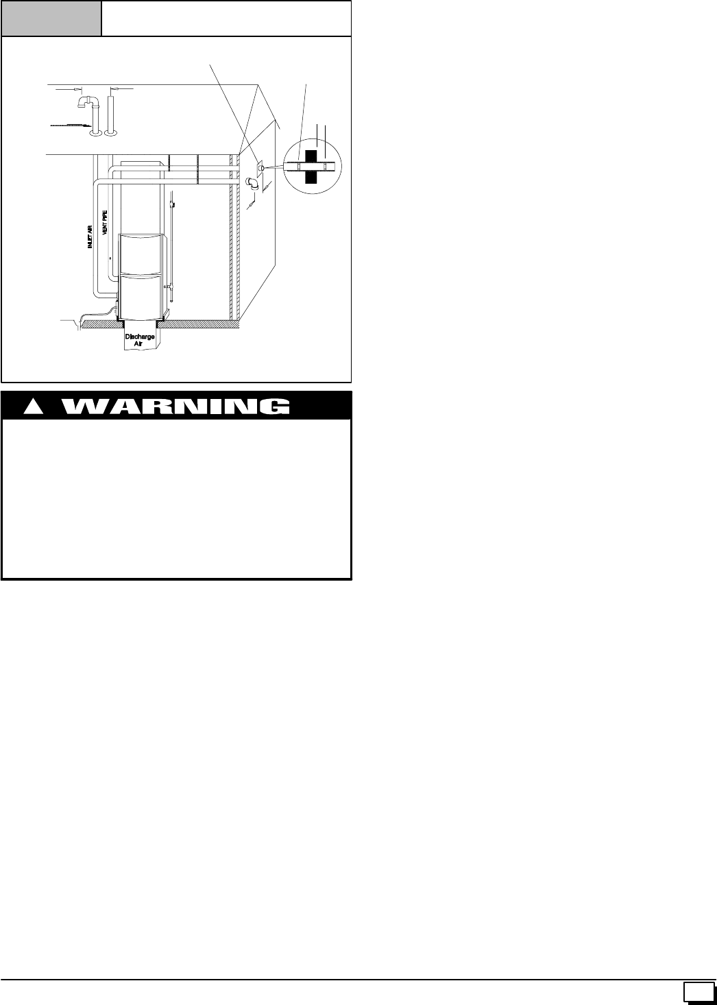
4. RefertoFigure 1 orFigure 2 fortypicalinstallationandba-
sic connecting parts required. Refer to Figure 4 for typical
horizontaldirectventinstallationandbasicconnectingparts
required. Supply and return air plenums and duct are also
required.
5. Iffurnaceisareplacement,itisusuallybesttoinstallthefur-
nace where the old one was. Choose the location or evalu-
atetheexistinglocationbasedupontheminimumclearance
and furnace dimensions (Figure 3).
CAUTION
Special precautions MUST be made if installing furnace in an
areawhichmaydropbelowfreezing.Thiscancauseimproper
operation or damage to equipment. If furnace environment
hasthepotentialoffreezing,thedrain trapand drainlinemust
be protected. The use of electric heat tape orRV antifreeze is
recommendedfortheseinstallations.(See“CondensateTrap
Freeze Protection Section”)
Do NOT operate furnace in a corrosive atmosphere
containing chlorine, fluorine or any other damaging
chemicals. Refer to Combustion & Ventilation Air section,
Contaminated Combustion Air.
Vent Pipes MUST be
supportedHorizontally
and Vertically
*8²Min.
20¢Max.
in same atmospheric
zone
*8²Min.
20¢Max.
in same
atmospheric
zone
Coupling on endsof
exhaust pipe. Total
pipe & coupling out-
side structure = 8²
Figure 1 Typical Upflow Installation
Aluminum or non-rusting shield recommended. (See
Vent Termination Shielding for dimensions).
*Increase minimum from 8²to 18²for cold climates (sustained temperatures below
0°F).
DISCHARGE AIR
25--23--33
Inlet Pipe (not
used on Single
Pipe model)
5
440 01 1020 02
*8²Min.
20¢Max.
in same
atmospheric zone
Figure 2 Typical Downflow Installation
Vent Pipes MUST be
supported Horizontally
and Vertically
*Increase minimum from 8²to 18²for cold climates (sustained temperatures
below 0°F).
See Vent Termination
Shielding inVentSection.
*8²Min.
20¢Max.
in same
atmosphericzone
8²Min.
Coupling on inside
and outside of wall
to restrain vent pipe
25--23--33a
Inlet Pipe
(not used on
Single Pipe
model)
DEATH, PERSONAL INJURY AND/OR PROPERTY
DAMAGE HAZARD.
Failureto properlyinstall thisfurnacecanresultindeath,
personal injury and/or property damage.
Do NOT operate furnace in a corrosive atmosphere
containing chlorine, fluorine or any other damaging
chemicals.
Refer to Combustion & Ventilation Air section,
Contaminated Combustion Air for combustion air
evaluation and remedy.
!
Installation Requirements
1. Install furnace level.
2. ThisfurnaceisNOTtobeusedfortemporaryheatofbuildings
or structures under construction.
3. Install the vent pipes as short as practical. (See Gas Vent
Installation section).
4. DoNOTinstallfurnacedirectlyoncarpeting,tileorothercom-
bustible material other than wood flooring.
5. Maintain clearance forfire safety and servicing. A front clear-
anceof30²isminimumforaccesstotheburner, controlsand
filter. See clearance requirements in Figure 3 or.
6. Use a raised base if the floor is damp or wet at times.
7. Residential garage installations require:
·Burnersandignitionsources installedat least18²(457mm)
above the floor.
·Furnace must be located or physically protected from pos-
sible damage by a vehicle.
8. Ifthefurnaceistobesuspendedfromthefloorjoistsinabase-
ment or a crawl space or the rafters in an attic, it is necessary
tousesteelpipestrapsoranangleironframetoattachthefur-
nace. These straps should be attached to the furnace with
sheet metal screws and to the rafters or joists with bolts. The
preferred method is to use an angle iron frame bolted to the
rafters or joists.
This furnace may be used for construction heat provided that:
·Thefurnaceispermanentlyinstalledwithallelectricalwiring,
piping, venting and ducting installed according to these
installationinstructions. Areturnairductisprovided,sealed
tothefurnacecasing,andterminatedoutsidethespacecon-
taining thefurnace. Thisprevents a negative pressure con-
dition as created by the circulating air blower, causing a
flame rollout and/or drawing combustion products into the
structure.
·Thefurnaceis controlledbyathermostat. Itmaynot be “hot
wired” to provide heat continuously to the structure without
thermostatic control.
·Cleanoutsideairisprovidedforcombustion. Thisistomini-
mize the corrosive effects of adhesives, sealers and other
construction materials. It also prevents the entrainment of
drywall dust into combustion air, which can cause fouling
and plugging of furnace components.
·The temperature of the return air to the furnace is no less
than55°F,withnoeveningsetbackorshutdown. Theuseof
the furnace while the structure is under construction is
deemed to be intermittent operation per our installation in-
structions.
·The airtemperature rise is within therated rise range on the
furnace rating plate, and the firing rate has been set to the
rating plate value.
·The filters used to clean the circulating air during the
construction process must be either changed or thoroughly
cleaned prior to occupancy.
·The furnace, ductwork and filters are cleaned as necessary
to remove drywall dust and construction debris from all
HVAC system components after construction is completed.
Installation Positions
This furnace can be installed in an upflow, horizontal (either left or
right) or downflow airflow position. DO NOT install this furnace on
its back. Forthe upflow position,the return air ductworkcan be at-
tached to either the left or right side panel and/or the bottom. For
horizontalanddownflowpositions,thereturnairductworkmustbe
attached to the bottom. The return air ductwork must never be at-
tached to the back of the furnace.
Furnace Installation Considerations
Theinstallationofthefurnaceforagivenapplicationwilldictatethe
positionofthefurnace,theairflow,ductworkconnections,ventand
combustion air piping.Consideration must be given to the follow-
ing:
Condensate Trap and Drain Lines
Thesuppliedcondensatetrapmustbeattachedtothefurnaceside
paneloneithertheleftorrightside.Forhorizontalinstallations,the
draintrapisverticallyattachedtothesidepanelbelowthefurnace.
A minimum clearance of 6²below the furnace is required for the
condensate trap. Downward slope of the condensate drain line
from the condensate trap to the drain location must be provided.
Adequatefreezeprotectionofthedraintrapandthedrainlinemust
be provided. See “Condensate Drain Trap” section for further de-
tails.
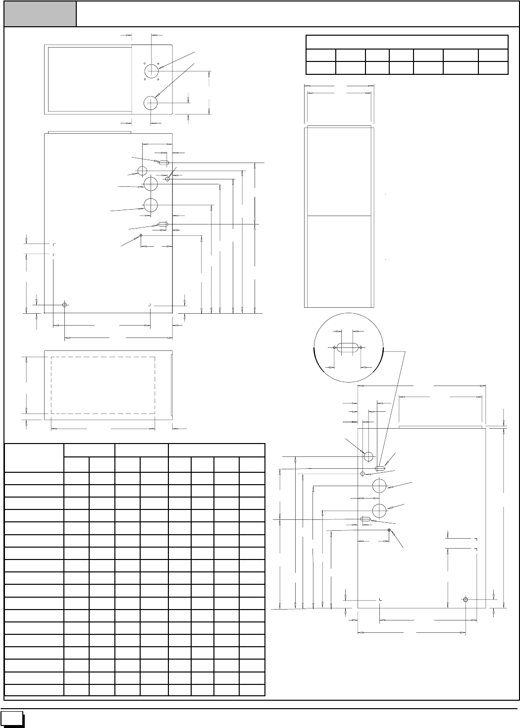
215/8
13/8
811/16
25--23--36b
Figure 3 Dimensions & Clearances
TOP
F
G
E
H
AIR INTAKE
VENT (*9MPD)
ELECTRICAL
11/4
TRAP (COUNTERFLOW)
LEFT SIDE
GAS
VENT
413/16
11/16
AIR INTAKE
(ALTERNATE)
TRAP
UPFLOW/HORIZONTAL
THERMOSTAT
111/16
175/16
241/16
283/4
297/8
3111/16
1311/16
1913/16
21/4
131/4
17/8215/824 47/8
7
FRONT
A
B
C
DBOTTOM
37/8
231/8
23/8
AIR INTAKE
(ALTERNATE)
RIGHT SIDE
TRAP (COUNTERFLOW)
ELECTRICAL
VENT
TRAP
UPFLOW/HORIZONTAL
THERMOSTAT
11/4
27/8
281/2181/21/2
TYP.
45/16
11/16
GAS
413/16
111/16
175/16
111/16
273/16
297/8
215/8
3311/16
17/8
913/16
13/16
47/8
21/4
24
40
191/4
7
6440 01 1020 02
Cabinet to Combustible Clearances
TOP BOT. RH LH BACK FRONT FLUE
1²0²0²0²0²3²0²
U
n
i
t
C
a
b
i
n
e
t
B
o
t
t
o
m
T
o
p
Unit Cabinet Bottom Top
U
n
i
t
Capacity A B C D E F G H
N9MP1050B12A 151/214 13/8125/8-- -- -- -- -- -- -- --
N9MP1075B12A 151/214 13/8125/8-- -- -- -- -- -- -- --
N9MP1080F16A 191/8175/821/8143/4-- -- -- -- -- -- -- --
N9MP1100F14A 191/8175/821/8143/4-- -- -- -- -- -- -- --
N9MP1100J20A 223/4211/4115/16 183/4-- -- -- -- -- -- -- --
N9MP1125J20A 223/4211/4115/16 183/4-- -- -- -- -- -- -- --
N9MP2050B12A 151/214 13/8125/8-- -- 41/2-- -- 73/4
N9MP2075B12A 151/214 13/8125/8-- -- 41/2-- -- 73/4
N9MP2080F16A 191/8175/821/8143/4-- -- 41/2-- -- 91/2
N9MP2100F14A 191/8175/821/8143/4-- -- 41/2-- -- 91/2
N9MP2100J20A 223/4211/4115/16 183/4-- -- 41/2-- -- 113/8
N9MP2125J20A 223/4211/4115/16 183/4-- -- 41/2-- -- 113/8
*9MPD050F12A 191/8175/821/8143/443/841/221/291/2
*9MPD075F12A 191/8175/821/8143/443/841/221/291/2
*9MPD080J16A 223/4211/4115/16 183/443/841/225/8113/8
*9MPD100J14A 223/4211/4115/16 183/443/841/225/8113/8
*9MPD100J20A 223/4211/4115/16 183/443/841/225/8113/8
*9MPD125L20A 241/223 7/16 23 43/841/221/4121/4
7
440 01 1020 02
Leveling
Proper leveling of the furnace must be provided to insure proper
drainageofthecondensatefromthefurnace.Thefurnacemustbe
leveltowithin1/4²fromfronttobackandfromsidetosideforupflow
and downflow installations or top to bottom forhorizontal installa-
tions.
Vent and Combustion Air Connections
On the Dual Certified furnace, the vent and combustion air pipes
attachtothefurnacethroughthetoppanelfortheupflowandhori-
zontal installations. For the downflow installation, the vent and
combustion air pipes attach to the furnace through the alternate
locations on the furnace side panels.
Note:OntheDirectVentfurnace,theventpipeattachestothefur-
nacethroughthesidepanels.Thecombustionairpipeattachesto
the top panel or to the alternate location on the side panel.
On the Single Pipe furnace, the vent pipe attaches to the furnace
through the furnace side panels.
Note: Repositioning of the combustion blower is required for the
vent pipe connection to the furnace through the “right side” panel.
See “Vent and Combustion Air Piping” section for further details.
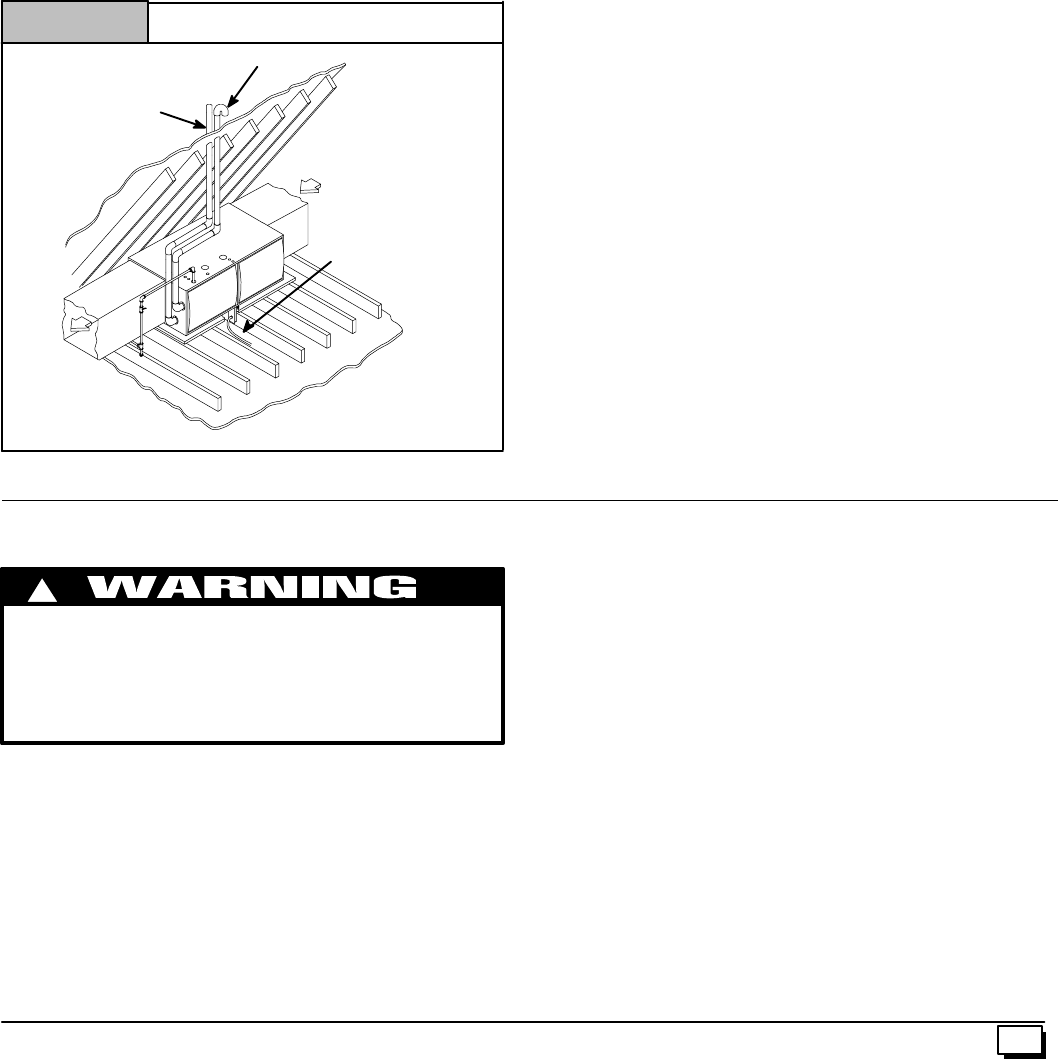
Horizontal Furnace Installation
This furnace can be installed horizontally in an attic, basement,
crawlspace,alcove,orsuspendedfromaceiling in a basementor
utility room . See Figure 4. Do not install furnace on its back or in
thereverseairflowpositionsassafetycontroloperationwillbead-
versely affected.
Inlet Pipe (not used on Single Pipe model)
Typical Horizontal Installation
Figure 4
Vent
Pipe
Condensate
Trap
NOTE: 6²
²²
²bottom clearance required for condensate trap.
25--23--34
If the furnace is to be suspended from the floor joists in a crawl
space or the rafters in an attic, it is necessary to use steel pipe
strapsoranangleironframetorigidlyattachthefurnacetoprevent
movement. These straps should be attached to the furnace with
sheet metal screws and to the rafters or joists with bolts. The pre-
ferred method is to use an angle iron frame bolted to the rafters or
joists.(Takecautiontoallowdoorpanelstoberemovedformainte-
nance)
Ifthefurnaceistobeinstalledinacrawlspace,consultlocalcodes.
A suitable concrete pad or blocks are recommended for crawl
space installation on the ground.
NOTE: 6²bottom clearance required for condensate trap.
Thirty (30) inches between the front of the furnace and adjacent
construction or other appliances MUST be maintained for service
clearance.
Keep all insulating materials clear from louvered door. Insulating
materials may be combustible.
The horizontal furnaces may be installed directly on combustible
wood flooring or supports as long as all required furnace clear-
ances are met. See Figure 4.
Thisfurnace MUSTNOTbeinstalleddirectlyoncarpetingortileor
other combustible material other than wood flooring or supports.
Forhorizontalinstallationoverafinishedlivingspace.Afieldfabri-
catedauxiliarydrainpanwithdrainpipeisrequiredtopreventdam-
age by overflow due to blocked condensate drain.
3. Combustion & Ventilation Air
For Single Pipe Installation
CARBON MONOXIDE POISONING HAZARD
Failure to provide adequate combustion and ventilation
air can result in death and/or personal injury.
Use methods described here to provide combustion and
ventilation air.
!
Furnaces require ventilation openings to provide sufficient air for
proper combustion and ventilation of flue gases. All duct or open-
ingsforsupplyingcombustionandventilationairmustcomplywith
National Fuel Gas Code, NFPA54/ANSI Z223.1, 2002 (or current
edition) and applicable provisions of local building codes.
ThisfurnacecanNOTbecommonventedorconnectedtoanytype
B, BW or L vent or vent connector, nor to any portion of a factory--
built or masonry chimney. If this furnace is replacing a previously
common-ventedfurnace,itmaybenecessarytoresizetheexisting
vent and chimney to prevent oversizing problems for the other re-
mainingappliance(s).See“VentingandCombustionAirCheck”in
this section.This furnace MUST be vented to the outside.
Air Openings and Connecting Ducts
1. TotalinputratingforallnondirectventgasappliancesMUST
be considered when determining free area of openings.
2. Connect ducts or openings directly to outside.
3. When screens are used to cover openings, they MUST be
no less than 1/4²mesh.
4. The minimum dimension of rectangular air ducts MUST
NOT be less than 3².
5. When sizing grille or louver, use the free area of opening. If
free area is NOT stamped or marked on grill or louver, as-
sume a 20% free area for wood and 60% for metal.
Confined Space Installation
NOTE: A confined space is defined as an area with less than 50
cubic feet per 1,000 BTUH input rating for all gas appliances
installed in the area.
Requirements
1. Provide confined space with sufficient air for proper com-
bustionandventilationoffluegasesusinghorizontalorverti-
cal ducts or openings.
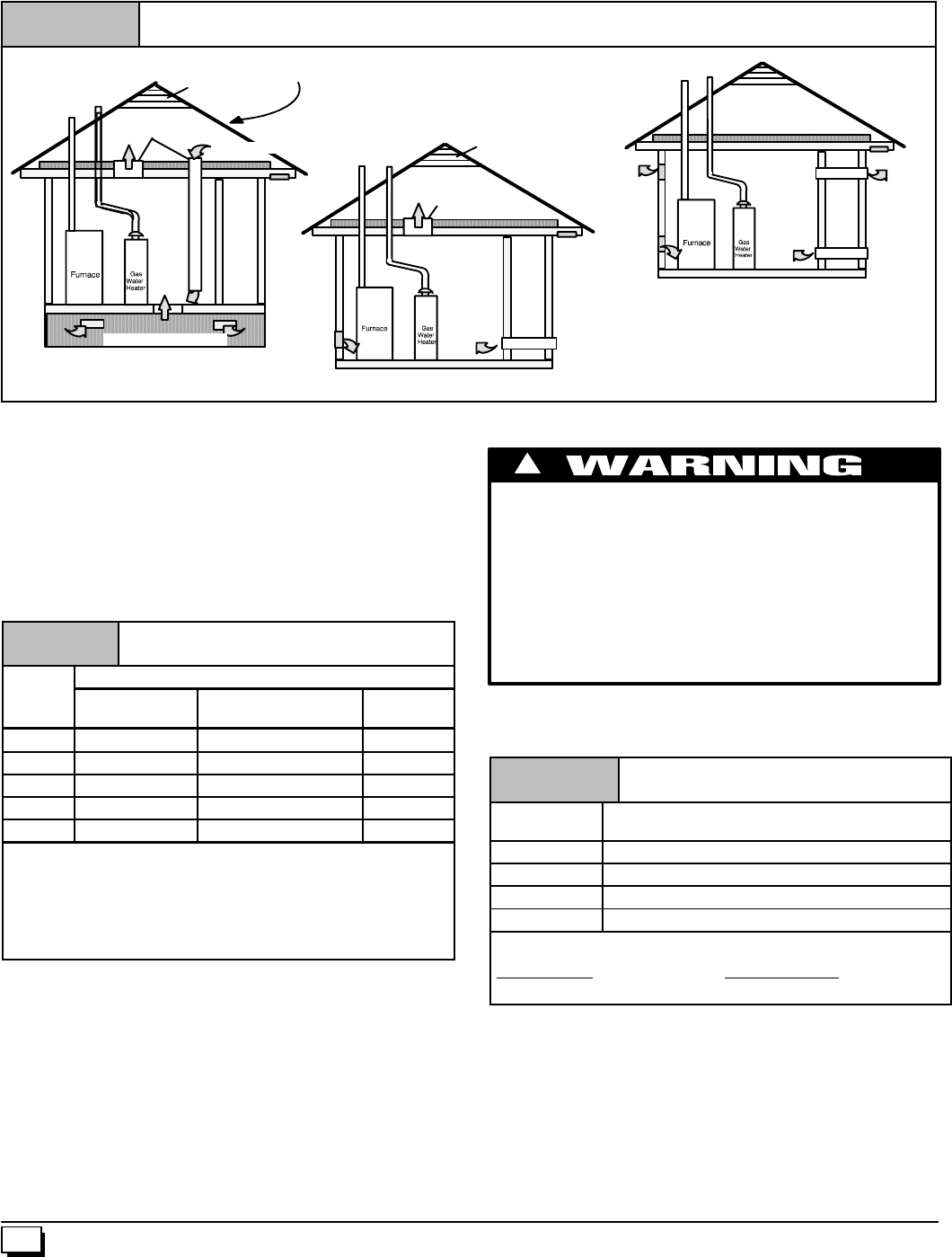
8440 01 1020 02
2. Figure 5 illustrate how to provide combustion and ventila-
tion air. A minimum of two permanent openings, one inlet
and one outlet, are required.
3. OneopeningMUSTbewithin12²ofthefloorandthesecond
opening within 12²of the ceiling.
Minimum One Inlet and One Outlet Air Supply is Required
May be in any Combination Shown
Inlet Air Opening Must be Within12²of floor
Outlet Air Opening Must be Within12²of ceiling
(1) 1 Square Inch per 4000 BTUH
(2) 1 Square Inch per 2000 BTUH
Outside Air (This is ONLY a guide. Subject to codes of country having jurisdiction.)
Figure 5
This installation NOT approved in Canada
Gas Vent Gable Vent
Ventilated Attic
Top Above Insulation
alternate Inlet Air (1)
Ventilated Crawl Space
Outlet Air (1) Soffit Vent Outlet
Air (1)
Inlet
Air (1)
Outlet
Air (2)
Inlet
Air (2)
Gas Vent
Inlet
Air (2)
Soffit Vent
Gas Vent Gable Vent
Ventilated Attic
Top Above Insulation
Inlet
Air (1)
OutletAir (1)
alternate Inlet Air (1)
4. Size openings and ducts per Table 1.
5. Horizontal duct openings require 1 square inch of free area
per 2,000 BTUH of combined inputfor all gas appliances in
area (see Table 1).
6. Vertical duct openings or openings directly to outside re-
quire 1 square inch of free area per 4,000 BTUH for com-
bined input of all gas appliances in area (see Table 1).
Table 1 Free Area
BTUH Minimum Free Area Required for Each Opening
B
T
U
H
Input
Rating Horizontal Duct
(2,000 BTUH) Vertical Duct or openings
to outside (4,000 BTUH) Round Duct
(4,000 BTUH)
50,000 25 sq. in. 12.5 sq. in. 4²
75,000 37.5 sq. in. 18.75 sq. in. 5²
100,000 50 sq. in. 25 sq. in. 6²
125,000 62.5 sq. in. 31.25 sq. in. 7²
150,000 75 sq. in. 37.5 sq. in. 7²
EXAMPLE: Determining Free Area
Appliance 1 Appliance 2 Total Input
100,000 +30,000 = (130,000 ¸4,000) = 32.5 Sq. In. Vertical
Appliance 1 Appliance 2 Total Input
100,000 +30,000 = (130,000 ¸2,000) = 65 Sq. In. Horizontal
One permanent opening, commencing within 12²of the top of the
enclosure,shallbepermittedwheretheequipmenthasclearances
of at least 1²from the sides and back and 6²from the front of the
appliance. The opening shall directly communicate with the out-
doorsorshall communicatethroughaverticalorhorizontalductto
theoutdoorsorspaces(crawlorattic)thatfreelycommunicatewith
the outdoors, and shall have a minimum free area of:
·1 sq. in per 3000 Btu per hr. of the total input rating of all
equipment located in the enclosure, and
·Notlessthanthe sum ofthe areas of all vent connectors in
the confined space.
Unconfined Space Installation
CARBON MONOXIDE POISONING HAZARD
Failure to supply additional air by means of ventilation
grilles or ducts could result in death and/or personal
injury.
An unconfined space or homes with tight construction
may not have adequate air infiltration for proper
combustion and ventilation of flue gases.
Most homes will require additional air.
!
An unconfined spaceis defined as anarea having a minimumvol-
umeof50cubicfeetper1,000Btuhtotalinputratingforallgasap-
pliances in area. Refer to Table 2 for minimum area required.
Table 2 Unconfined Space
Minimum Area in Square Feet
BTUH Input
Rating Minimum Area in Square Feet
50,000 312
78,000 490
114,000 712
155,000 968
EXAMPLE: NOTE: Square feet is based on 8 foot ceilings.
28,000 BTUH X 50CubicFt. = 1,400 = 175 Sq. Ft.
1,000 8¢Ceiling Height
NOTE: Refer to definitions in section titled Unusually Tight
Construction. If any one of the conditions apply, the space MUST
be considered confined space regardless of size.
1. Adjoining rooms can be considered part of an unconfined
area if there are openings without doors between rooms.
2. An attic or crawl space may be considered an unconfined
space provided there are adequate ventilation openingsdi-
rectly to outdoors. Openings MUST remain open and NOT
haveanymeansofbeingclosedoff.Ventilation openings to
outdoorsMUST be at least1²square of free area per 4,000
BTUH of total input rating for all gas appliances in area.
9
440 01 1020 02
3. Install air intake a minimum of 12²above maximum snow
level and clear of any obstruction. Duct or ventilation open-
ingrequiresonesquareinchof freeareaper4,000BTUHof
total input rating for all gas appliances in area.
4. Air inlet MUST be screened with not less than 1/4²mesh
screen.
Unusually Tight Construction
In unconfined spaces, infiltration may be adequate to provide air
for combustion, ventilation and dilution of flue gases. However, in
buildingswithunusuallytightconstruction,additionalairMUSTbe
provided using the methods described in section titled Confined
Space Installation:
Unusually tight construction is defined as: Construction with
1. Walls and ceilings exposed to the outside have a continu-
ous,sealedvaporbarrier.Openingsaregasketedorsealed
and
2. Doors and openable windows are weather stripped and
3. Other openings are caulked or sealed. These includejoints
around window and door frames, between sole plates and
floors, between wall--ceiling joints, between wall panels, at
penetrations for plumbing, electrical and gas lines, etc.
Ventilation Air
Some provincial codes and localmunicipalities require ventilation
or make--up air be brought into the conditioned space as replace-
mentair.Whichevermethodisused,themixedreturnairtempera-
ture across the heat exchanger MUST not fall below 60°Forflue
gaseswillcondenseintheheatexchanger.Thiswillshortenthelife
of the heat exchanger and possibly void your warranty.
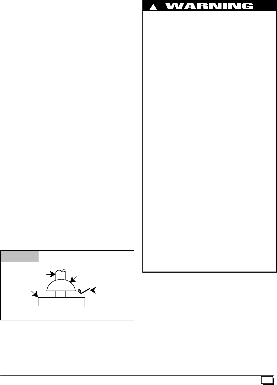
Venting and Combustion Air Check
NOTE: When an existing Category I furnace is removed or re-
placed,theoriginalventingsystemmaynolongerbesizedtoprop-
erly vent the attached appliances, and to make sure there is
adequatecombustionairforallappliances,MAKETHEFOLLOW-
ING CHECK.
Vent Check
Draft HoodVent Pipe
Match
Typical Gas
Water Heater
Figure 6
Ifflame pulls towardsdrafthood,thisindicatessufficient
venting.
CARBON MONOXIDE POISONING HAZARD
Failure to follow the steps outlined below for each
applianceconnectedtotheventingsystembeingplaced
into operation, while all other appliances connected to
the venting system are not in operation could result in
carbon monoxide poisoning or death.
The followingsteps shall be followedfor each appliance
connected to the venting system being placed into
operation, while all other appliances connected to the
venting system are not in operation:
1. Seal any unused openings in the venting system.
2. Inspect the venting system for propersize and horizontal
pitch, as required in the National Fuel Gas Code, ANSI
Z223.1/NFPA 54 or CSA B149.1, Natural Gas and Pro-
pane Installation Codes and these instructions. Deter-
minethatthereisnoblockageorrestriction,leakage,cor-
rosion and other deficiencies which could cause an un-
safe condition.
3. As far as practical, close all building doors and windows
andalldoorsbetweenthespaceinwhichtheappliance(s)
connected to the venting system are located and other
spaces of the building.
4. Close fireplace dampers.
5. Turn on clothes dryers and any appliance not connected
to the venting system. Turn on any exhaust fans, such as
range hoods and bathroom exhausts, so they willoperat-
ingatmaximumspeed.Donotoperateasummerexhaust
fan.
6. Followthelightinginstructions.Placethe appliancebeing
inspected into operation. Adjust thermostat so appliance
is operating continuously.
7. Test for spillage from draft hood equipped appliances at
thedrafthoodreliefopeningafter5minutesofmainburner
operation. Usethe flame ofa match or candle. (Figure 6)
8. If improper venting is observed, during any of the above
tests, the venting system must be corrected in accor-
dance with the National Fuel Gas Code, ANSI
Z223.1/NFPA 54 and/or CSA B149.1, Natural Gas and
Propane Installation Codes.
9. After it has been determined that each appliance con-
nected to the venting system properly vents whentested
as outlined above, return doors, windows, exhaust fans,
fireplace dampers and any other gas--fired burning ap-
pliance to their previous conditions of use.
!
For Two Pipe Installation
ThisfurnacecanNOTbecommonventedorconnectedtoanytype
B, BW or L vent or vent connector, nor to any portion of a factory--
built or masonry chimney. If this furnace is replacing a previously
common-ventedfurnace,itmaybenecessarytoresizetheexisting
vent and chimney to prevent oversizing problems for the other re-
mainingappliance(s).See“VentingandCombustionAirCheck”in
this section.ThisfurnaceMUSTbeventedtotheoutside.
10 440 01 1020 02
4. Vent and Combustion Air Piping
CARBON MONOXIDE POISONING, FIRE AND EXPLOSION
HAZARD
Failure to properly vent this furnace can result in death,
personal injury and/or property damage.
Read and follow all instructions in this section.
!
SinglePipe(N9MP1Models)
This furnace is certified as a category IV appliance. This furnace
requires ventilation openings to provide air for proper combustion
and ventilation of flue gases. All duct or openings for supplying
combustion and ventilation air must comply with the gas codes or
in absence of local codes, the applicable national codes.
Whentheinstallationiscomplete,seethe“VentingandCombus-
tion Air Check” in this manual.
Direct Vent (N9MP2 Models)
This furnace is certified as a category IV appliance. This furnace
uses outside air for combustion ONLY, it MUST be taken from the
sameatmosphericpressurezoneastheventpipe. SeeConfined
SpaceInstallationintheCombustionandVentilationAir inthis
manual.
Dual Certified (*9MPD Models)
This furnace is certified as a category IV appliance. This furnace
can be installed as a direct vent furnace using outsideair for com-
bustionorthefurnacecanuseairfrominsidethestructureforcom-
bustion. The INLET air pipe is optional. If combustion air comes
frominsidethestructure,adequatemakeupairMUSTbeprovided
tocompensateforoxygenburned.SeeConfinedSpace Installa-
tion in the Combustion and Ventilation Air chapter. If combus-
tion air is drawn from outside the structure, it MUST be taken from
the same atmospheric pressure zone as the vent pipe.
Contaminated Combustion Air
Installationsincertainareasortypesofstructureswillincreasethe
exposure to chemicals or halogens that may harm the furnace.
Thefollowingareasor typesof structures may containor haveex-
posure to the substances listed below. The installation must be
evaluatedcarefullyasitmaybenecessarytoprovideoutsideairfor
combustion.
·Commercial buildings.
·Buildings with indoor pools.
·Furnaces installed in laundry rooms.
·Furnaces installed in hobby or craft rooms.
·Furnaces installed near chemical storage areas.
·Permanent wave solutions for hair.
·Chlorinated waxes and cleaners.
·Chlorine based swimming pool chemicals.
·Water softening chemicals.
·De--icing salts or chemicals.
·Carbon tetrachloride.
·Halogen type refrigerants.
·Cleaning solvents (such as perchloroethylene).
·Printing inks, paint removers, varnishes, etc.
·Hydrochloric acid.
·Sulfuric Acid.
·Solvent cements and glues.
·Antistatic fabric softeners for clothes dryers.
·Masonry acid washing materials.
Vent and Combustion Air Piping Guidelines
ThisfurnaceisapprovedforventingwithSchedule40PVC,CPVC,
ABS, Cellular Core pipe fittings and SDR--26 PVC.
NOTE: All PVC, CPVC, ABS, and Cellular Core pipe fittings, sol-
ventcement,primersandproceduresMUSTconformtoAmerican
National Standard Institute and American Society for Testing and
Materials (ANSI/ASTM) standards.
·Pipe and Fittings -- ASTM D1785, D2241, D2466, D2661,
D2665, F--891, F--628
·PVC Primer and Solvent Cement -- ASTM D2564
·Procedure for Cementing Joints -- Ref ASTM D2855
NOTE: All vent piping MUST be installed in compliance with local
codesorordinances,theseinstructions,goodtradepractices,and
codes of country having jurisdiction.
1. Determinethebestroutingandterminationforthe ventpipe
and air inlet pipe by referring to all of the instructions and
guidelines in this Section.
2. Determine the size required for the vent pipe and air inlet
pipe.
3. Loosely assemble all venting parts without adhesive (pipe
joint cement) for correct fit before final assembly.
4. Use of vertical piping is preferred because there will be
some moisture in the flue gases that may condense as it
leavestheventpipe(SeeSpecialInstructionForHorizontal
Vents).
5. TheverticalventpipeMUSTbesupportedsothatnoweight
is allowed to rest on the combustion blower.
6. Exhaust vent piping or air inlet piping diameter MUST NOT
be reduced.
7. All exhaust vent piping from the furnace to termination
MUST slope upwards. A minimum of 1/4²per foot of run is
required to properly return condensate to the furnace drain
system.
8. Use DWV type long radius elbows whenever possible, as
they provide for the minimum slope on horizontal runs and
they provide less resistance in the vent system. If DWV el-
bows cannot be used, use two, 45°elbows when possible.
On horizontal runs the elbows can be slightly misaligned to
provide the correct slope.
9. All horizontal pipe runs MUST be supported at least every
fivefeetwithgalvanized strap orotherrust resistant materi-
al. NO sags or dips are permitted.
10. All vertical pipe runs MUST be supported every six feet
where accessible.
11. The minimum pipe run length is 2¢.
12. Thepiping canberuninthesamechaseoradjacent tosup-
ply or vent pipe for water supply or waste plumbing. It can
also be run in the same chase with a vent from another 90+
furnace.
NOTE:InNO case can the piping be run in a chase where
temperatures can exceed 140°F. or where radiated heat
from adjacent surfaces would exceed 140°F.
13. The vent outlet MUST be installed to terminate in the same
atmospheric pressure zone as the combustion air inlet.
14. Theventsystemcanbeinstalledinanexistingunusedchim-
ney provided that:
11
440 01 1020 02
·Both the exhaust vent and air intake run the length of the
chimney.
·No other gas fired appliance or fireplace (solid fuel) is
vented into the chimney.
·The top of the chimney MUST be sealed flush or crowned
uptosealagainstrainormeltingsnow so ONLY thepiping
protrudes.
·The termination clearances shown in Figure 7 are main-
tained.
15. Furnaceapplicationswithverticalventsrequiringventdiam-
eter increaser fittings must have increaser fittings installed
in vertical portion of the vent. Condensate will be trappedin
the vent if the vent diameter is increased prior to having an
elbowturnedupward.Thiscouldcausenuisancetrippingof
the pressure switch.
Piping Insulation Guidelines
NOTE:Useclosedcell,neopreneinsulationorequivalent.IfFiber-
glass orequivalent insulation is used itmust havea vapor barrier.
UseRvaluesof7 upto10¢,R--11ifexposureexceeds10¢.IfFiber-
glassinsulationisused,exteriortothestructure,thepipeMUSTbe
boxed in and sealed against moisture.
1. When the vent or combustion airpipe height above the roof
exceeds 30², or if an exteriorvertical riser is used on a hori-
zontal vent to get above snow levels, the exterior portion
MUST be insulated.
2. When combustion air inlet piping is installed above a sus-
pended ceiling, the pipe MUST be insulated with moisture
resistant insulation such as Armaflex or other equivalent
type of insulation.
3. Insulatecombustionairinletpipingwhenruninwarm,humid
spaces such as basements.
Sizing Combustion Air and Vent Pipe
Consult Table 3 or Table 4 to select the proper diameter exhaust
and combustion air piping. Exhaust and combustion air piping is
sized for each furnace Btuh size based on total lineal vent length
(on inlet or outlet side), and number of 90°elbows required. Two
45°elbows can be substituted for one 90°elbow. The elbow or el-
bowsusedforventterminationoutsidethestructureAREcounted,
including elbows needed to bring termination above expected
snow levels. The elbow inside the furnace on the *9MPD IS NOT
included in the count.
Table 3 Pipe Diameter Table
N9MP1 & *9MPD Models
50,000, 75,000 & 80,000 Btuh Furnaces
40¢& (5) 90°elbows with 2²PVC pipe or
70¢& (5) 90°elbows with 3²PVC pipe
100,000 Btuh Furnace
40¢& (5) 90°elbows with 3²PVC pipe or
70¢& (5) 90°elbows with 3²PVC pipe &
Long Vent Kit (See Tech. Manual)
125,000 Btuh Furnace
40¢& (5) 90°elbows with 3²PVC pipe
Elbows are DWV Long Radius Type for 2²and 3²vents.
If more than five elbows are required, reduce the length of
both the inlet and exhaust pipes 5¢for each additional elbow
used.
NOTE: It is allowable to use larger diameter pipe and fitting than
shown in the tables but not smaller diameters than shown.
Table 4 Pipe Diameter Table
N9MP2 Models
50,000 & 80,000 Btuh Furnaces
40¢& (5) 90°elbows with 2²PVC pipe or
70¢& (5) 90°elbows with 3²PVC pipe
75,000 Btuh Furnaces
25¢& (3) 90°elbows with 2²PVC pipe or
40¢& (5) 90°elbows with 2²PVC pipe &
Long Vent Kit (See Tech. Manual) or
70¢& (5) 90°elbows with 3²PVC pipe
100,000 Btuh Furnace
40¢& (5) 90°elbows with 3²PVC pipe or
70¢& (5) 90°elbows with 3²PVC pipe &
Long Vent Kit (See Tech. Manual)
125,000 Btuh Furnace
40¢& (5) 90°elbows with 3²PVC pipe
Elbows are DWV Long Radius Type for 2²and 3²vents.
If more than five elbows are required, reduce the length of
both the inlet and exhaust pipes 5¢for each additional elbow
used.
For “Concentric Termination Kit” Venting table, see
“Section 11” in this manual.
Vent Termination Clearances
CARBON MONOXIDE POISONING, FIRE AND EXPLOSION
HAZARD
Failure to properly vent this furnace can result in death,
personal injury and/or property damage.
Inlet and outlet pipes may NOT be vented directly above
each other.
!
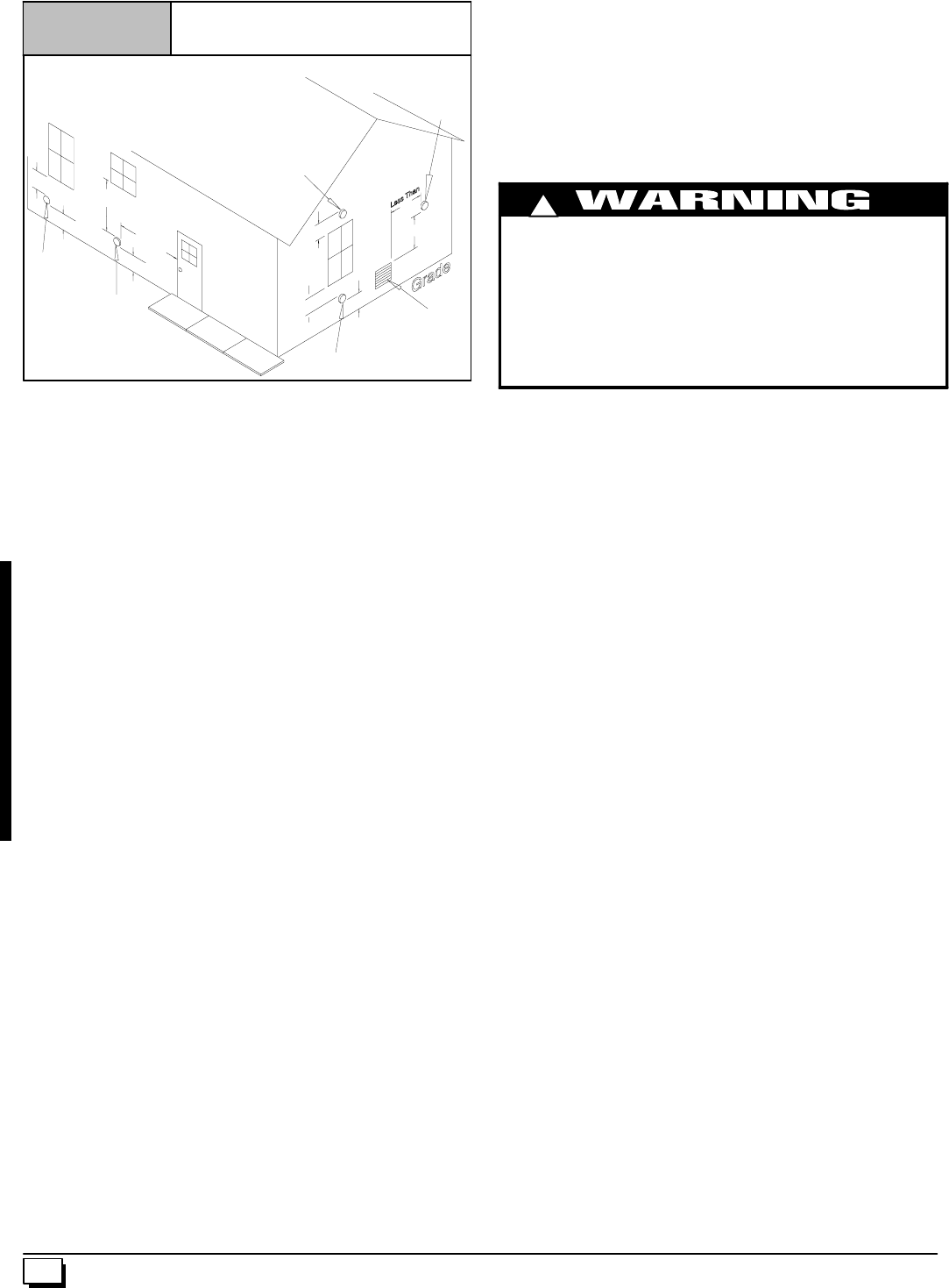
1. Determine termination locations based on clearancesspe-
cified in following steps and as shown in Figure 7,
Figure 19, through Figure 27.
For “Concentric Termination Kit” clearances, see Figure 45,
Figure 46, Figure 47, Figure 48 and Figure 49 in “Section 10”
in this manual.
2. The vent termination must be located at least 12²above
ground or normally expected snow accumulation levels.
3. DoNOTterminateoverpublicwalkways.Avoidareaswhere
condensate may cause problems such as above planters,
patios,oradjacenttowindowswheresteammaycausefog-
ging.
4. Theventterminationshall belocated atleast 4¢horizontally
from any electric meter, gas meter, regulator, and any relief
equipment. These distances apply ONLY to U.S. installa-
tions.
5. The vent termination is to be located at least 3¢above any
forced air inlet located within 10¢; and at least 10¢from a
combustion air intake of another appliance, except another
direct vent furnace intake.
6. InCanada,theCanadianFuelGasCodetakesprecedence
over the preceding termination instructions.
12 440 01 1020 02
Vent Termination Clearances
(United States Only)
Figure 7
In Canada See Canadian Fuel Gas Code
Direct Vent
Terminal
50,000 Btuh
or less Other Than
Direct Vent
Terminal
Direct Vent Terminal
More Than 50,000 Btuh
Other Than
Direct Vent
Terminal
Other Than
Direct Vent
Terminal
Forced Air
Inlet
10--11-- 36
9²
12²
²²
²
12²
²²
²
12²
²²
²
12²
²²
²
12²
²²
²
10¢
¢¢
¢
3¢
¢¢
¢
4¢
¢¢
¢
4¢
¢¢
¢
Condensate Drain Trap
Thisfurnaceremovesbothsensibleandlatentheatfromtheprod-
ucts of combustion. Removal of the latent heat results in con-
densationofthewatervapor.Thecondensateisremovedfromthe
furnace through the drains in the plastic transition and the vent fit-
ting. The drains connect to the externally mounted condensate
drain trap on the left or right side of the furnace.
The startup of a new furnace will involve a cycle or two of the fur-
nace to properly prime the condensate trap with water. Until the
trap is fully primed, some condensate will be pulled into the com-
bustionblower.Thefurnacemaycycleonthepressureswitchcon-
nected to the plastic transition box due to condensate buildup.
After thetrap is primed, thecondensate will start draining fromthe
furnace. The combustion blower will clear outany remaining con-
densateintheblowerhousingthrough theventfittingdownstream
ofthe blower.Notethatthe condensatetrapcanalsobeprimedby
pouring water into the 1/2²drain hose. Remove the1/2²ID drain
hosefromeitherthe gutterorthewhitePVCTeeTrap.Usingafun-
nelpoureight(8)ouncesofwaterinto1/2²IDdrain hose.Waterwill
flow through the drain hose and into the condensate drain trap.
Thiswillprimeboththeventandthetransitionsidesofthetrap.Re-
connectthe1/2²IDdrainhosetotheoriginalcomponent,eitherthe
gutter or the PVC Tee Trap.
The condensate drain trap supplied with the furnace MUST be
used. The drain connection on the condensate drain trap is sized
for3/4²PVCorCPVC pipe,howeveralternate1/2²CPVC(nominal
5/8²O.D.) or vinyl tubing with a minimum inner diameter (I.D.) of
5/8²may also be used, as allowed by local codes. Alternate drain
pipes and hoses may be used as allowed by local codes.
Thedrainlinemustmaintaina1/4²perfootdownwardslopetoward
thedrain.1/4²perfoot isrecommended.Installationofanoverflow
line is recommended when the 1/4²per foot slope to the conden-
sate drain cannot be maintained. See Figure 1 for proper routing
and installation of the overflow.
DONOTtrapthedrainlineinanyotherlocationthanattheconden-
sate drain trap supplied with the furnace.
FROZEN AND BURST WATER PIPE HAZARD
Failure to do so may result in burst water pipes, serious
property damage and/or personal injury.
If a condensate pump is installed, a plugged condensate
drainorafailedpumpmaycausethefurnacetoshutdown.
Donotleavethehomeunattendedduringfreezingweather
without turning off water supply and draining water pipes
or otherwise protecting against the risk of frozen pipes.
!
If possible DO NOT route the drain line where it may freeze. The
drain line must terminate at an inside drain to prevent freezing of
the condensate and possible property damage.
1. AcondensatesumppumpMUSTbeusedifrequiredbylocal
codes, or if no indoor floor drain is available. The conden-
sate pump must be approved for use with acidic conden-
sate.
2. A plugged condensate drain line or a failed condensate
pumpwillallowcondensatetospill.Ifthefurnaceisinstalled
where a condensate spill could cause damage, it is recom-
mended that an auxiliary safety switch be installed to pre-
ventoperationoftheequipmentin the eventof pumpfailure
or plugged drain line. If used, an auxiliary safety switch
should be installed in the R circuit (low voltage) ONLY.
3. If the auxiliary switch in the condensate pump is used, the
furnacemayshut downduetoablockedcondensatelineor
failed pump. To prevent frozen waterpipes see the “Frozen
Water Pipe Hazard” section on Page 4 of this manual.
Condensate Drain Trap Freeze Protection
SpecialprecautionsMUSTbemadeifinstallingfurnacein anarea
which may drop below freezing. This can cause improper opera-
tion or damage to the equipment. If the the furnace environment
has the potential of freezing, the drain trapand drain line mustbe
protected.Use3to6wattperfootat115volt,40°Fself--regulating
shielded and waterproof heat tape. Wrap the drain trap and drain
linewiththeheattapeandsecurewiththeties.Followtheheattape
manufacturer’s recommendations.
13
440 01 1020 02
AIR FLOW
Figure 8 Upflow Installations Top Vent
Street Elbow
1/2²
²²
²CPVC
(Loose parts bag)
Casing Grommet
Black Rubber
5/8²
²²
²ID
(Loose parts bag)
DrainTee
Drain Connector Black PVC
3/4²
²²
²PVC X 1/2²
²²
²CPVC
(Loose parts bag)
Drain Line Vent Tee 3/4²
²²
²PVC or
1/2²
²²
²CPVC (Field supplied)
1/2²
²²
²ID Drain
Hose & Clamps
5/8²
²²
²ID Hose & Clamps
3/16²
²²
²ID Rubber Tube
Coupling & Clamps
(Optional)
INLET
EXHAUST
25--24--42
Single Pressure Switch
Dual Pressure Switch Detail
Drain Tube (& Clamps)Black Rubber 5/8²
²²
²ID,
Cut length to fit (Loose parts bag)
On Some Models
ONLY
Yellow or black Plastic
Caps (2)
Vent Drain
&Clamps
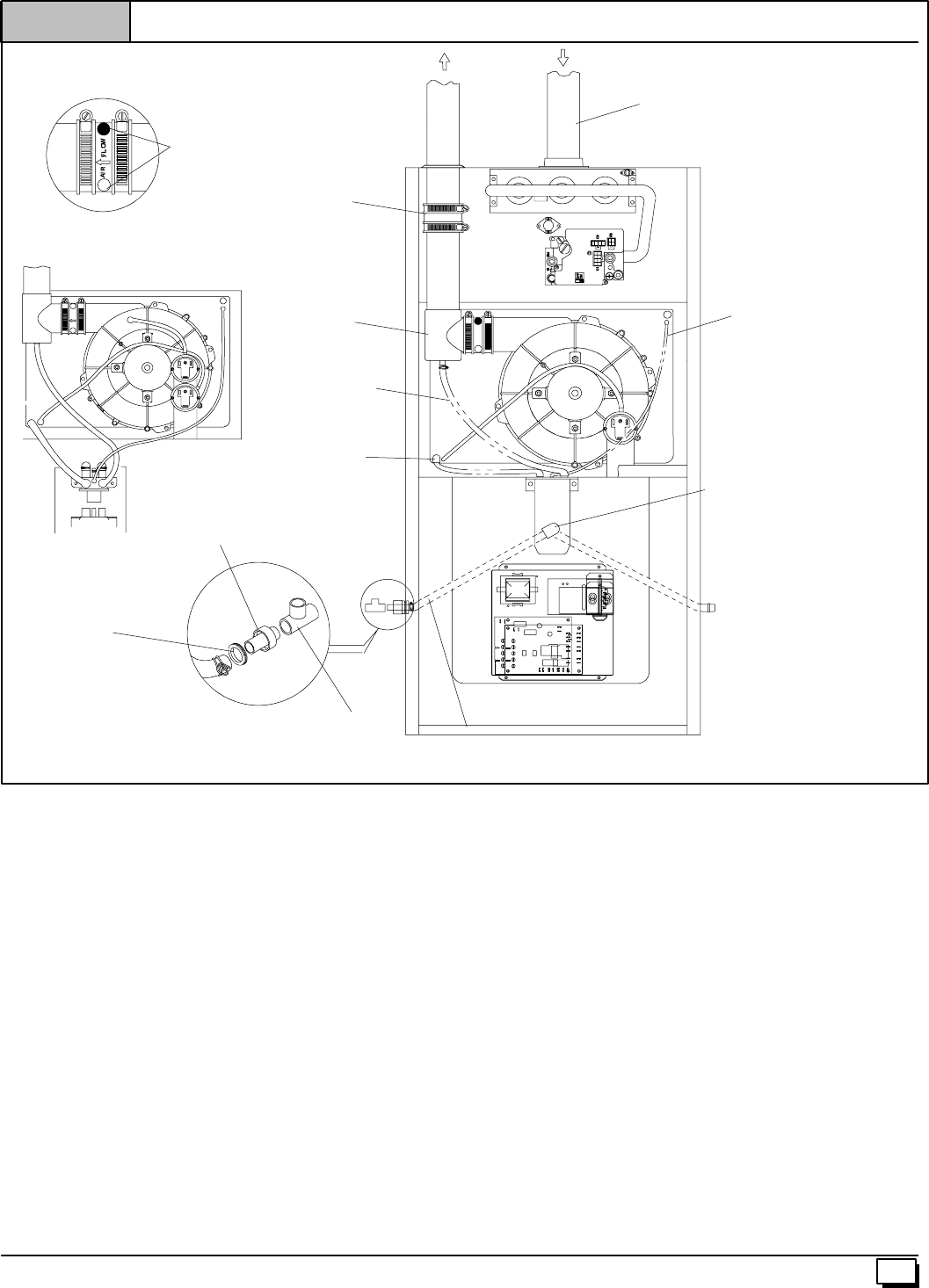
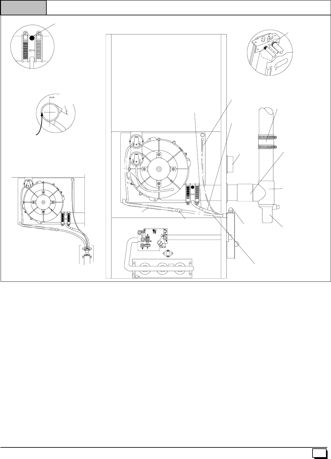
Upflow Installations Top Vent (See Figure 8)
RemoveplugfromthesideofthefurnacecasingwhereDrainTube
will exit.
Install casing grommet (black rubber 5/8²ID grommet -- in loose
parts bag)
Install the 1/2²CPVC street elbow on discharge of Trap
Install the black PVC tube connector (3/4²PVC x 1/2²CPVC from
loose parts bag) as shown in the illustration above.
Cut the black Drain Tube (5/8²ID -- in loose parts bag) to length to
fit between Trap and tube connector through grommet.
Clamp both ends of the Drain Tube using clamps provided.
GluetheCPVCstreetelbowto the Trapusingappropriatecleaner
and solvent cement.
Connect the Tee trap and the main drain line exiting the casing as
shown Figure 17.
Note: It is recommended that all PVC piping and fitting connec-
tionsbefitupandinspectedbeforefinalcementing.Trap must be
primed before operation. Verify all condensate drain connec-
tions are securely clamped. A coupling and clamps (in loose part
bag)maybeinstalledasshownforfutureservicingoftheventsys-
tem.
14 440 01 1020 02
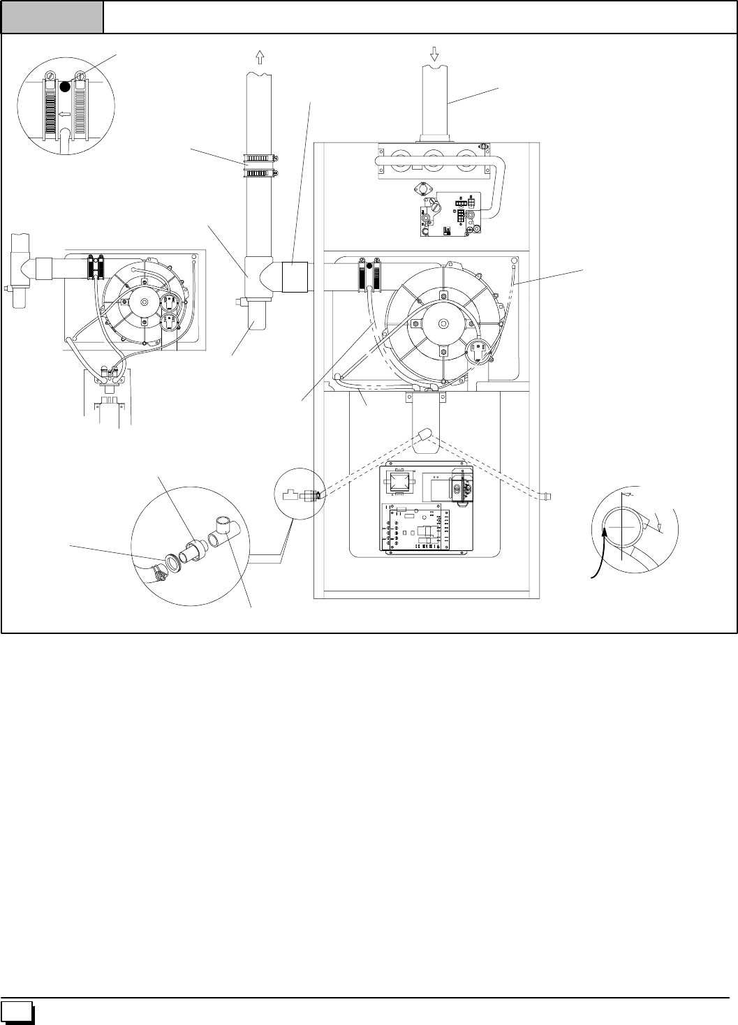
Figure 9 Upflow Installations Vent thru Left Side
Casing Grommet
Black Rubber
5/8²
²²
²ID
(Loose parts bag)
Drain Connector Black PVC
3/4²
²²
²PVC X 1/2²
²²
²CPVC
(Loose parts bag)
Drain Line Vent Tee 3/4²
²²
²PVC or 1/2²
²²
²CPVC (Field supplied)
1/2²
²²
²ID Drain Tube
Black (Move from
bottom of drain tee
if installed)
5/8²
²²
²ID Hose
&Clamps
3/16²
²²
²ID Rubber Tube
Coupling & Clamps
(Optional)
INLET
25--24--43
Single Pressure Switch
Dual Pressure Switch Detail
Tee Trap White PVC
(loose parts bag)
2²
²²
²PVC Coupling
EXHAUST
On Some Models
ONLY
Yellow or black Plastic
Cap
Vent Drain
&Clamps
Rotate downward
5°
°°
°to 10°
°°
°
NOTE: Built--in channel will
be angled 5°to 10°also.
SIDE VIEW
Either: The PVC
Drain Tee or a field
supplied 2²
²²
²PVC Tee
AIR FLOWAIR FLOW
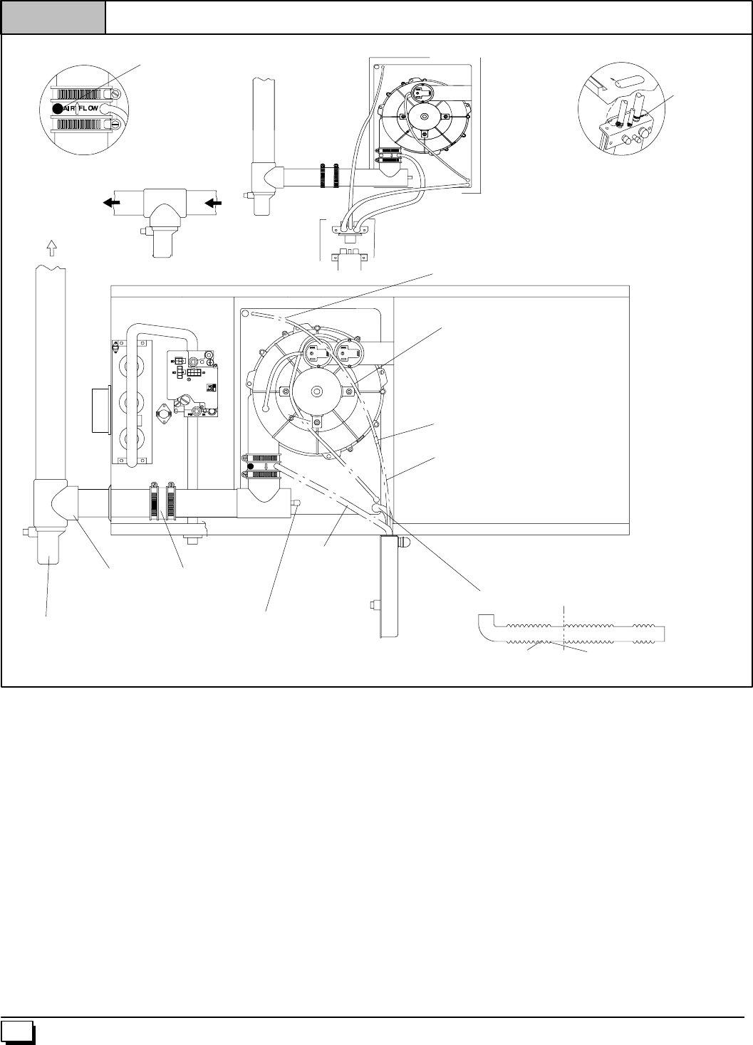
Upflow Installations Vent thru Left Side (See Figure 9)
RemoveDrainTeefrominducerdischargeandremoveblackDrain
Tube (1/2²ID) from bottom of Drain Tee. (*9MPD models only)
Install Vent Pipe grommet in side of casing.
Cut an appropriate length of 2²PVC pipe long enough to exit the
cabinet and connect the vent drain to either:
·A standard field supplied 2²PVC tee (N9MP1 and 2 models),
or
·A2²PVC coupling fastened onto the Drain Tee (*9MPD mod-
els)
Install Tee trap into bottom of tee.
Install the 1/2²CPVC street elbow on discharge of Trap
Install the black PVC drain connector (3/4²PVC x 1/2²CPVC from
loose parts bag) as shown in the illustration above.
Cut the black Drain Tube (5/8²ID -- in loose parts bag) to length to
fit between Trap and tube connector through grommet.
Clamp both ends of the Drain Tube using clamps provided.
GluetheCPVCstreetelbowto the Trapusingappropriatecleaner
and solvent cement.
Connect the Tee trap and the main drain line exiting the casing as
shown in Figure 17.
Note: It is recommended that all PVC piping and fitting connec-
tions be fit up and inspected before final cementing. Both the in-
ternal Trap and the external Tee Trap must be primed before
operation. Verify all condensate drain connections are securely
clamped. A coupling and clamps (in loose part bag) may be
installed as shown for future servicing of the vent system.
15
440 01 1020 02
AIR FLOW
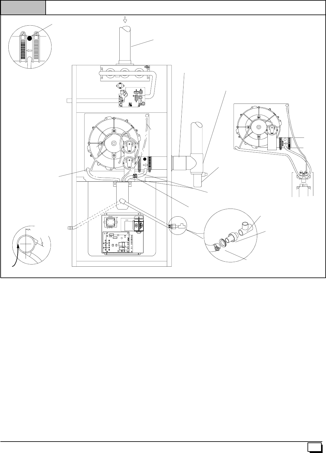
Figure 10 All Models Vent thru Right Side
Casing Grommet
Black Rubber 5/8²
²²
²CPVC
(Loose parts bag)
Drain Connector Black PVC
3/4²
²²
²PVC X 1/2²
²²
²CPVC
(Loose parts bag)
Drain Line Vent Tee 3/4²
²²
²PVC
or 1/2²
²²
²CPVC (Field supplied)
5/8²
²²
²ID Hose
&Clamps
3/16²
²²
²ID
Rubber
Tube
INLET
25--24--44
Single Pressure Switch Detain
Dual Pressure Switch
Tee Trap White PVC
(loose parts bag)
2²
²²
²PVC Coupling
Barbed Coupling, 1/2²
²²
²OD
(loose parts bag)
Elbows Tubes (2) & Clamps Black,
1/2²
²²
²ID (loose parts bag)
Rotate downward
5°
°°
°to 10°
°°
°
NOTE: Built--in channel will
be angled 5°to 10°also.
SIDE VIEW
Yellow or black Plastic
Cap
Vent Drain
&Clamps
On Some Models
ONLY
Either: The PVC
Drain Tee or a field
supplied 2²
²²
²PVC Tee
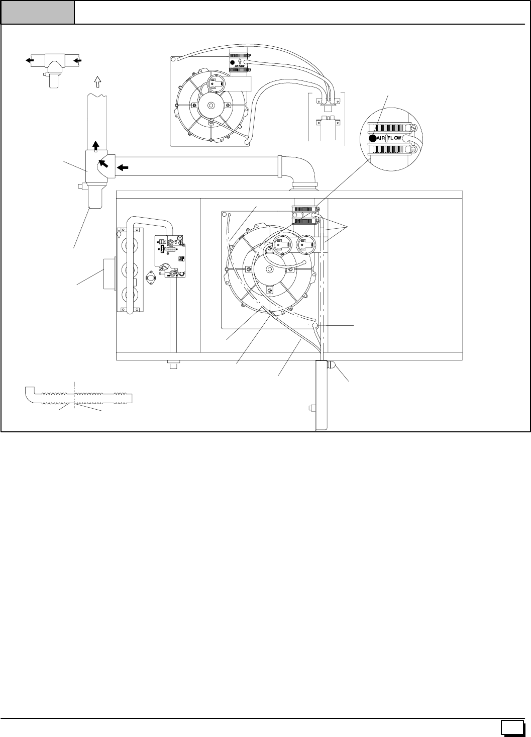
All Models Vent thru Right Side (See Figure 10)
Disconnect the black Drain Tube between the drain vent and the
Trap.
Rotate the inducer 180°for a right side vent after loosening the 4
inducer attachment screws. Reinstall and retighten the inducer
screws to 20²pounds torque.
Using the 1/2²OD barbed coupling in the loose parts bag connect
togetherwiththe2short1/2²IDelbowtubes andconnectthelower
dischargeportoftheventdraintotheTrap. Secureallconnections
with clamps.
Install the vent pipe grommet into the casing
Cut an appropriate length of 2²PVC pipe long enough to exit the
cabinet and connect the vent drain to either:
·A standard field supplied 2²PVC tee (N9MP1 and 2 mod-
els), or
·A2²PVC coupling fastened onto the Drain Tee (*9MPD
models)
Install Tee Trap into bottom section of Tee.
RemoveplugfromthesideofthefurnacecasingwhereDrainTube
will exit.
Install casing grommet (black rubber 5/8²ID grommet -- in loose
parts bag)
Install the 1/2²CPVC street elbow on discharge of Trap
Install the black PVC tube connector (3/4²PVC x 1/2²CPVC from
loose parts bag) as shown in the illustration above
Cut the black Drain Tube (5/8²ID -- in loose parts bag) to length to
fit between Trap and tube connector through grommet.
Clamp both ends of the Drain Tube using clamps provided.
GluetheCPVCstreetelbowto the Trapusingappropriatecleaner
and solvent cement.
Connect the Tee trap and the main drain line exiting the casing as
shown in Figure 17.
Note: It is recommended that all PVC piping and fitting connec-
tions be fit up and inspected before final cementing. Both the in-
ternal Trap and the external Tee Trap must be primed before
operation. Verify all condensate drain connections are securely
clamped. A coupling and clamps (in loose part bag) may be
installed as shown for future servicing of the vent system.
16 440 01 1020 02
AIR FLOW
AIR FLOW
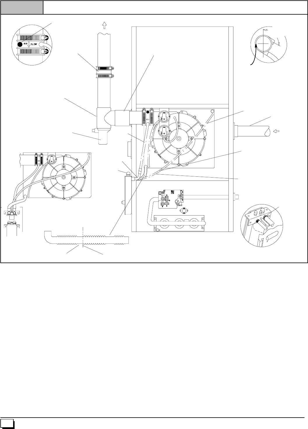
Figure 11 Downflow Left Side Vent and Trap
3/16²
²²
²ID
Rubber Tube
25--24--45
Single Pressure Switch Detail
Dual Pressure Switch
Tee Trap White PVC
(loose parts bag)
Flexible Tubing Connector,
3/16²
²²
²OD (loose parts bag)
Drain
Elbow (1)
EXHAUST
Cut Here
Drain Tube Black, 5/8²
²²
²ID Corrugated
Cut at straight section
Leave room for clamp
WARNING
Move Caps
to top of
trap
Relief Tube,
Extension Black,
3/16²
²²
²ID Cut to fit
(loose parts bag)
1/2²
²²
²ID
Drain
Hose
INLET
On Some Models
ONLY
Either: The PVC
Drain Tee or a field
supplied 2²
²²
²PVC Tee
Yellow or black Plastic
Cap
Vent Drain
&Clamps
Rotate downward
5°
°°
°to 10°
°°
°
NOTE: Built--in channel will
be angled 5°to 10°also.
SIDE VIEW
Coupling & Clamps
(Optional)
Trap Connection “Clamp ears”
PointedOUT
Preassemble&
insert into furnace
2²
²²
²PVC Coupling
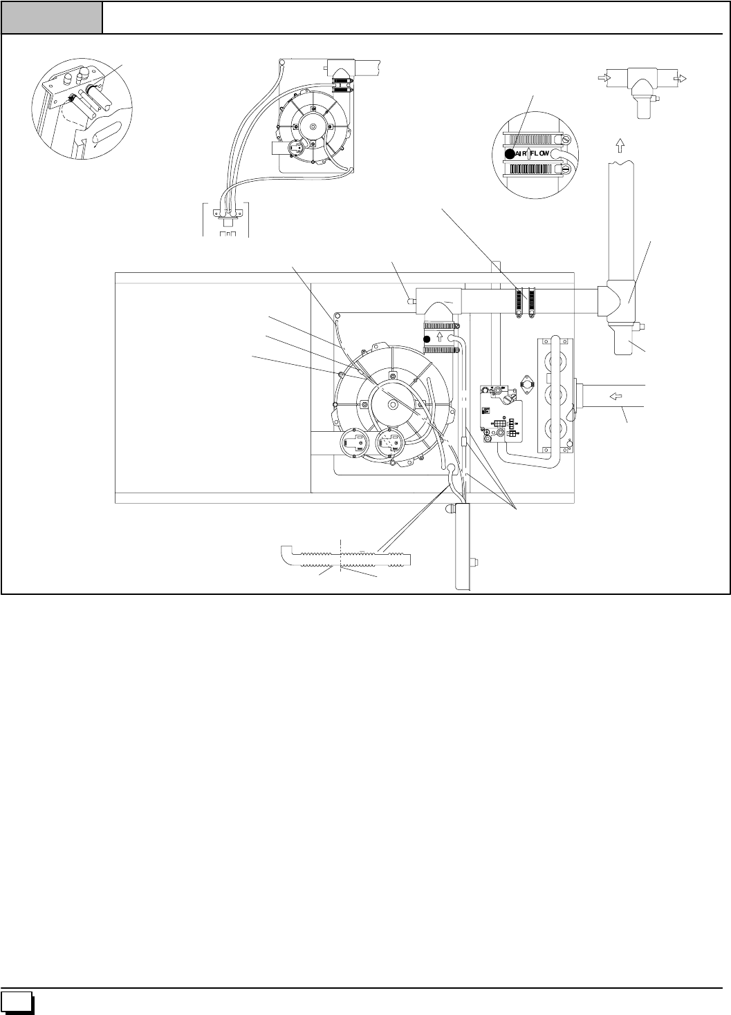
Downflow Left Side Vent and Trap (See Figure 11)
Removetheinducermountingscrews,rotatetheinducer180°and
retighten the inducer screws to 20²pounds torque.
Disconnect the hoses from the Trap assembly, and remove Trap
and Trap mounting bracket from the blower compartment. Using
cover plate and gasket provided in the loose parts bag, cover the
holefromtheburnercompartmentto theblowercompartmentand
secure with screws.
MovethecapstothetopoftheTrapandmounttheTrapexternally
to the left side of the unit using the 2 screws provided.
Cutthe5/8²IDcorrugatedhoseasshownaboveandfastenthe90°
bend end to the Trap and fasten the straight end to the transition
drain. Secure both connections with clamps.
Reconnect the 1/2²ID drain hose from the vent drain to the Trap
and secure with aclamp.. In some cases, additionallength will be
required for this hose. Use the Black plastic 1/2²OD barbed cou-
plingandasuitablesectionof1/2²IDhosetomaketheconnection.
Secure all connections with clamps
Connect the 3/16²ID relief tube from the small port on the Trap to
thetopportofthetransitionasshowninthepicture. Insomecases,
additional hose length will be needed. Use the clear plastic 3/16²
ODflexible tubingconnectorandasuitablelength ofextra 3/16²ID
hose to make this connection.
Install the vent pipe grommet into the casing
Cut an appropriate length of2²PVC pipe long , enough to exit the
cabinet and connect the vent drain to either:
·A standard field supplied 2²PVC tee (N9MP1 and 2 mod-
els), or
·A2²PVC coupling fastened onto the Drain Tee (*9MPD
models)
Install Tee Trap into bottom section of Tee.
Connect the Tee trap and the main drain line exiting the casing as
shown in Figure 17.
Note: It is recommended that all PVC piping and fitting connec-
tions be fit up and inspected before final cementing. Both the ex-
ternal Trap and the external Tee Trap must be primed before
operation. Verify all condensate drain connections are securely
clamped. A coupling and clamps (in loose part bag) may be
installed as shown for future servicing of the vent system.
17
440 01 1020 02
AIR FLOW
Figure 12 Downflow Right Side Vent and Trap
Drain Connector Black
PVC 3/4²
²²
²PVC X 1/2²
²²
²CPVC
(Loose parts bag)
3/16²
²²
²ID
Rubber Tube
Trap Connection “Clamp ears”
PointedOUT
Preassemble&
insert into furnace
25--24--46
Single Pressure Switch Detail
Dual Pressure Switch
Tee Trap White PVC
(loose parts bag)
Drain Tube Black, 5/8²
²²
²
ID Corrugated WARNING
Move Caps
to top of
trap
Drain Tube, (& Clamps)
Black, 5/8²
²²
²ID Cut to fit
(loose parts bag)
AIR FLOW
Splice Connector
Barbed 1/2²
²²
²ID
Drain Hose&
Clamps
Either: The PVC
Drain Tee or a field
supplied 2²
²²
²PVC Tee
Rotate downward
5°
°°
°to 10°
°°
°
NOTE: Built--in channel will
be angled 5°to 10°also.
SIDE VIEW
Yellow or black Plastic
Cap
Vent Drain
&Clamps
INLET
On Some
Models ONLY 2²
²²
²PVC Coupling
Coupling & Clamps
(Optional)
Downflow Right Side Vent and Trap (See Figure 12)
Remove the Drain Tee if installed.
Disconnect the hoses from the Trap assembly, and remove Trap
and Trap mounting bracket from the blower compartment. Using
cover plate and gasket provided in the loose parts bag, cover the
holefromtheburnercompartmentto theblowercompartmentand
secure with screws.
MovethecapstothetopoftheTrapandmounttheTrapexternally
to the right side of the unit using the 2 screws provided.
Connect the corrugated Drain Tube from the transition box to the
Trapasshown. Ifanextensionisrequired,usetheblackPVCtube
connectorandtheblack 5/8²ID Drain Tube in the loose partsbag.
Cut tube to length. Secure all connections with clamps.
ConnectthedrainhosefromtheVentDraintotheTrap. Ifanexten-
sion is required, use the black 1/2²OD barbed coupling, connect
ablack1/2²ID elbow tube and asuitable section of a 1/2²ID drain
tubetomakeconnection fromthe ventdraintothetrap. Secureall
connections with clamps.
Install the vent pipe grommet into the casing
Cut an appropriate length of2²PVC pipe long , enough to exit the
cabinet and connect the vent drain to either:
·A standard field supplied 2²PVC tee (N9MP1 and 2 mod-
els), or
·A2²PVC coupling fastened onto the Drain Tee (*9MPD
models)
Install Tee Trap into bottom section of Tee.
Connect the Tee trap and the main drain line exiting the casing as
shown in Figure 17.
Note: It is recommended that all PVC piping and fitting connec-
tions be fit up and inspected before final cementing. Both the ex-
ternal Trap and the external Tee Trap must be primed before
operation. Verify all condensate drain connections are securely
clamped. A coupling and clamps (in loose part bag) may be
installed as shown for future servicing of the vent system.
18 440 01 1020 02
AIR FLOW
Figure 13 Horizontal Left Thru Top
3/16²
²²
²ID
Rubber Tube
Yellow or black Plastic
Caps
Vent Drain
&Clamps Trap Connection
“Clamp ears”
PointedOUT
Preassemble&
insert into furnace
25--24--47
Single Pressure Switch Detail
Dual Pressure Switch
Tee Trap White PVC
(loose parts bag)
Cap and Clamp
Open End
3/16²
²²
²OD Flexible tubing
connector
1/2²
²²
²ID Drain
Hose &
Clamps
EXHAUST
Alternate Orienation
Field
SuppliedTee
Cut Here
Drain Tube Black, 5/8²
²²
²ID Corrugated
Cut at straight section
Leave room for clamp
Relief Tube
Relief Tube Extension
AIR FLOW
Coupling & Clamps
(Optional)
Horizontal Left--Thru Top (See Figure 13)
Disconnect the hoses from the Trap assembly, and remove Trap
and Trap mounting bracket from the blower compartment. Using
cover plate and gasket provided in the loose parts bag, cover the
holefromtheburnercompartmentto theblowercompartmentand
secure with screws.
Mount the Trap externally to the bottom side of the unit using the
2 screws provided in the location shown.
Cut the corrugated tube as shown in the illustration above. Con-
nect the corrugated hose from the transition to the Trap. Secure
connections with clamps.
Remove the black 1/2²ID Drain Tube from the Drain Tee. Install a
yellow cap and clamp over the open drain port of the Drain Tee.
Connect the black 1/2²ID Drain Tube from the Vent Drain to the
Trap. Secure connections with clamps.
Connectthe3/16²IDrelieftubeto the middleportontheTrap.Ifan
extension is required, use the 3/16²OD flexible tubing connector
and the black 3/16²ID relief tube in the loose parts bag. Cut tube
to length. Secure all connections with clamps.
Cut an appropriate length of 2²PVC pipe, long enough to exit the
cabinet and connect the vent drain to either:
·A standard field supplied 2²PVC tee (N9MP1 and 2 mod-
els), or
·A2²PVC coupling fastened onto the Drain Tee (*9MPD
models)
Install Tee Trap into bottom section of Tee.
Connect the Tee trap and the main drain line exiting the casing as
shown in Figure 17.
Note: It is recommended that all PVC piping and fitting connec-
tions be fit up and inspected before final cementing. Both the ex-
ternal Trap and the external Tee Trap must be primed before
operation. Verify all condensate drain connections are securely
clamped. A coupling and clamps (in loose part bag) may be
installed as shown for future servicing of the vent system.
19
440 01 1020 02
AIR FLOW
Figure 14 Horizontal Left--Side Vent
3/16²
²²
²ID Rubber Tube
25--24--48
Single Pressure Switch Detail
Dual Pressure Switch
Tee Trap White PVC
(loose parts bag)
WARNING
Move Caps to
top of trap
Splice Connector
1/2²
²²
²ID Drain Elbow
Drain Hose & Splice
Connector
(Cut-to-fit)
EXHAUST
Alternate Orienation
Field
SuppliedTee
Cut Here
Drain Tube Black, 5/8²
²²
²ID Corrugated
Cut at straight section
Leave room for clamp
Relief Tube
Relief Tube Extension
Yellow or black
Plastic Cap
Vent Drain
&Clamps
Drain Tube Black, 5/8²
²²
²ID
Corrugated
Level or Sloped towards Tee
INLET
On Some
Models ONLY
Horizontal Left--Side Vent (See Figure 14)
RemovetheDrainTeefromtheVentDrainifinstalled(*9MPDmod-
els only)
Rotatetheinducer180°forasideventafterlooseningthe4inducer
attachment screws. Reinstall and retighten the inducer screws to
20²pounds torque.
Disconnect the hoses from the Trap assembly, and remove Trap
and Trap mounting bracket from the blower compartment. Using
cover plate and gasket provided in the loose parts bag, cover the
holefromtheburnercompartmentto theblowercompartmentand
secure with screws.
Mount the Trap externally to the bottom side of the unit using the
2 screws provided in the location shown.
Cut the corrugated tube as shown in the illustration above. Con-
nect the corrugated hose from the transition to the Trap. Secure
connections with clamps.
Connect the black 1/2²ID Drain Tube from the Vent Drain to the
Trap. Ifanextensionisrequired,usetheblack1/2²ODflexibletub-
ing connector and the black 1/2²ID Drain Tube in the loose parts
bag. Cut tube to length. Secure connections with clamps.
Connectthe3/16²IDrelieftubeto the middleportontheTrap.Ifan
extension is required, use the 3/16²OD flexible tubing connector
and the black 3/16²ID relief tube in the loose parts bag. Cut tube
to length.
Cut an appropriate length of 2²PVC pipe, fittings and extension
pipe long enough to exit the cabinet and connect thevent drain to
either:
·A standard field supplied 2²PVC tee (N9MP1 and 2 mod-
els), or
·A2²PVC coupling fastened onto the Drain Tee (*9MPD
models)
Install Tee Trap into bottom section of Tee.
Important: The pipe to the Tee Trap must be level or sloping to-
wards the Tee Trap
Connect the Tee trap and the main drain line exiting the casing as
shown in Figure 17.
Note: It is recommended that all PVC piping and fitting connec-
tions be fit up and inspected before final cementing. Both the ex-
ternal Trap and the external Tee Trap must be primed before
operation. Verify all condensate drain connections are securely
clamped. A coupling and clamps (in loose part bag) may be
installed as shown for future servicing of the vent system.
A coupling and clamps (in loose part bag) may be installed as
shown for future servicing of the vent system.
20 440 01 1020 02
AIRFLOW
Figure 15 Horizontal Right thru Top
3/16²
²²
²ID Rubber Tube
Trap Connection “Clampears”
PointedOUT
Preassemble&
insert into furnace
25--24--49
Single Pressure Switch Detail
Dual Pressure Switch
Tee Trap
White PVC
(loose parts bag)
WARNING
Add Cap and
Clamp
Splice Connector
1/2²
²²
²ID Drain Hose & barbed
coupling (Cut-to-fit)
EXHAUST
Alternate Orienation
Field
SuppliedTee
Cut Here
Drain Tube Black, 5/8²
²²
²ID
Corrugated Cut at straight section
Leave room for clamp
Relief Tube
Relief Tube Extension
Yellow or black
Plastic Cap
Vent Drain
&Clamps
INLET
On Some Models
ONLY
Coupling & Clamps
(Optional)
Horizontal Right Thru Top(See Figure 15)
Disconnect the hoses from the Trap assembly, and remove Trap
and Trap mounting bracket from the blower compartment. Using
cover plate and gasket provided in the loose parts bag, cover the
holefromtheburnercompartmentto theblowercompartmentand
secure with screws.
Mount the Trap externally to the bottom side of the unit using the
2 screws provided in the location shown.
Cut the corrugated tube as shown in the illustration above. Con-
nect the corrugated hose from the transition to the Trap. Secure
connections with clamps.
Connect the black 1/2²ID Drain Tube from the Vent Drain to the
Trap. If an extension is required, use the black 1/2²OD barbed
coupling and the black 1/2²ID Drain Tube in the loose parts bag.
Cut tube to length. Secure connections with clamps.
Connect the 3/16²ID relief tube to the middle port on the Trap. If
anextensionisrequired,usetheclear3/16²ODflexibletubingcon-
nectorandtheblack 3/16²ID relief tubeintheloosepartsbag. Cut
tube to length.
Cut an appropriate length of 2²PVC pipe, fittings and extension
pipe long enough to exit the cabinet and connect thevent drain to
a standard field supplied 2²PVC tee
Install Tee Trap into bottom section of Tee.
Connect the Tee trap and the main drain line exiting the casing as
shown in Figure 17.
Note: It is recommended that all PVC piping and fitting connec-
tions be fit up and inspected before final cementing. Both the ex-
ternal Trap and the external Tee Trap must be primed before
operation. Verify all condensate drain connections are securely
clamped. A coupling and clamps (in loose part bag) may be
installed as shown for future servicing of the vent system.
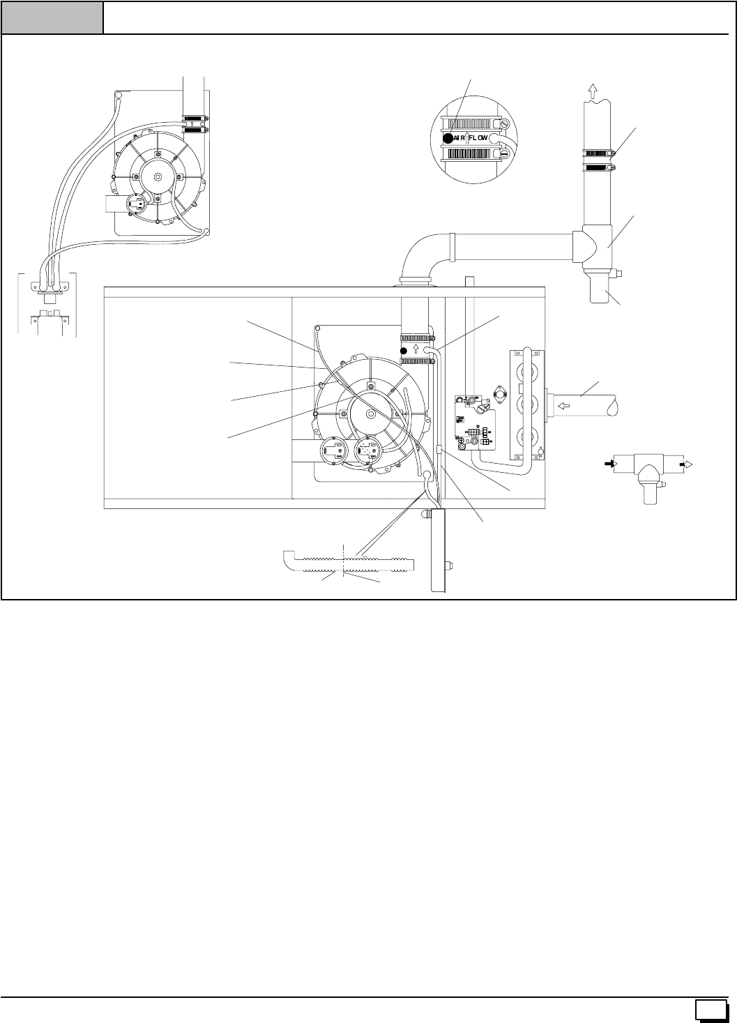
21
440 01 1020 02
AIR FLOW
Figure 16 Horizontal Right--Side Vent
3/16²
²²
²ID Rubber Tube
25--24--50
Single Pressure Switch Detail
Dual Pressure Switch
Tee Trap
White PVC
(loose parts bag)
Splice Connector
Barbed coupling
EXHAUST
Alternate Orienation
Field
SuppliedTee
Cut Here
Drain Tube Black, 5/8²
²²
²ID
Corrugated Cut at
straight section
Leave room for clamp
Relief Tube
Relief Tube Extension
Yellow or black
Plastic Cap
Vent Drain
&Clamps
Level or Sloped
towards Tee
INLET
On Some Models
ONLY
Coupling & Clamps
(Optional)
1/2²
²²
²ID Drain
Elbow
Drain Hose
(Cut-to-fit)
Horizontal Right Side Vent (See Figure 16)
Disconnect Drain Tee if installed (*9MPD models only)
Disconnect the hoses from the Trap assembly, and remove Trap
and Trap mounting bracket from the blower compartment. Using
cover plate and gasket provided in the loose parts bag, cover the
holefromtheburnercompartmentto theblowercompartmentand
secure with screws.
Mount the Trap externally to the bottom side of the unit using the
2 screws provided in the location shown.
Cut the corrugated tube as shown in the illustration above. Con-
nect the corrugated hose from the transition to the Trap. Secure
connections with clamps.
Connect the black 1/2²ID Drain Tube from the Vent Drain to the
Trap. If an extension is required, use the 1/2²ODbarbedcoupling
and the black 1/2²ID Drain Tube in the loose parts bag. Cut tube
to length. Secure connections with clamps.
Connect the 3/16²ID relief tube to the middle port on the Trap. If
an extension is required, use the clear 3/16²OD splice connector
and the black 3/16²ID relief tube in the loose parts bag. Cut tube
to length.
Cut an appropriate length of 2²PVC pipe, fittings and extension
pipe long enough to exit the cabinet and connect thevent drain to
either:
·A standard field supplied 2²PVC tee (N9MP1 and 2 mod-
els), or
·A2²PVC coupling fastened onto the Drain Tee (*9MPD
models)
Install Tee Trap into bottom section of Tee.
Important: The pipe to the Tee Trap must be level or sloping to-
wards the Tee Trap
Connect the Tee trap and the main drain line exiting the casing as
shown in Figure 17.
Note: It is recommended that all PVC piping and fitting connec-
tions be fit up and inspected before final cementing. Both the ex-
ternal Trap and the external Tee Trap must be primed before
operation. Verify all condensate drain connections are securely
clamped. A coupling and clamps (in loose part bag) may be
installed as shown for future servicing of the vent system.
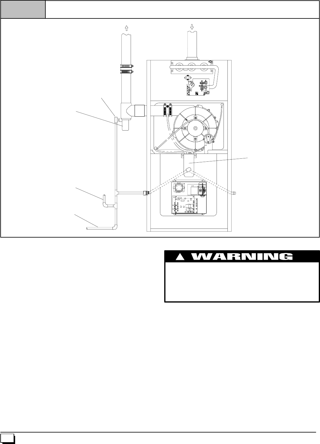
22 440 01 1020 02
25--24--41N
Figure 17 Connecting Tee Trap to Condensate Trap and Main Drain Line
Exhaust
Inlet
Open Tee
Tee Trap
Condensate
Trap
Evaporator Coil
Drain Line (Optional)
Main Drain Line
The Tee Trap must be connected to the main condensate drain
line as conceptually shown above. Different installations may
require slightly different orientations. The following steps apply
to all installations.
9. TheTeeTrapshouldbeinstalledasclosetothesideortopof
thefurnaceas practical.Minimizethedistancebetweenthe
inducer and the Tee Trap as much as possible.
10. AnopenteeistobeusedattheTeeTrapdischarge.Thetop
endoftheteeshouldbeopentotheatmospheretoeliminate
potential air lock problems.
11. ThedrainlinefromtheTeeTrapistobeconnectedtothefur-
nace condensate trap drain line as shown above.
12. Condensate drain lines from a cooling coil may be con-
nected downstream of the connection point of the TeeTrap
and Furnace Condensate Trap.
Important: Prime both traps with water before operation.
Failure to prime the traps may result in discharge of flue gases
from the condensate drain line and open tee for a period of time,
and may result in temporary lockout of the furnace upon start
up. Main drain line construction is left to the discretion of the
installer. It may be made of either ridged pipe or flexible tube.
Tube ID should NOT be less than 1/2².
Connecting Vent and Combustion Air Piping
CARBON MONOXIDE POISONING HAZARD
Failure to properly seal vent piping can result in death,
personal injury and/or property damage.
Cement or mechanically seal all joints, fittings, etc. to
prevent leakage of flue gases.
!
RefertoFigure 8throughFigure 16thatcorrespondstotheinstal-
lation position of the furnace for the application.
Preassemble the vent and combustion air piping from the furnace
totheventtermination.Do notcement thepipe joints until thepipe
preassembly process is complete.
Combustion Air Pipe Connection (Dual Certified or
Direct Vent)
Install the air intake coupling and gasket to the furnace with the
four(4) screws.
Note:Theairintakecoupling andgasketcanbeinstalledtothetop
panel to the alternate air intake locations on either the left orright
side panels of the furnace.
Fordownflowinstallation,theairintakecouplingandgasketmust
be installed to the alternate air intake location on either the left or
rightsidepanels.Removethe3²holeplugfromthesidepaneland
relocate to the air intake hole in the top panel. Use four screws to
seal the four(4) mounting holes in the top panel next to the hole
plug.Drillfour(4)7/64²diameterholesinthecasing usingtheairin-
take coupling as the template.
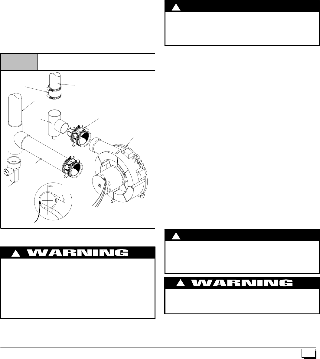
23
440 01 1020 02
The air intake coupling is sized for 2²PVC pipe.
Installthecombustionairpipe to theairintakecoupling usingRTV
sealant to provide for future serviceability.
Vent Pipe Connection
Install the vent pipe grommet to the furnace panel. Locate the
grommet in the furnace panel at a location directly away from the
ventfittingon thecombustionblower.The grommetsnapsintothe
3²hole plug from the furnace panel. NOTE: Depending on the
installation position, the vent pipe grommetwill be installed to the
toppanelortothealternatelocationonthesidepanels.Ifneeded,
removethe 3²holeplugfromthefurnacepanelandrelocatetothe
open hole in the furnace panel. (See Figure 8 or Figure 17)
Install the vent pipe to the rubber coupling, the vent fitting or the
PVCventextensionpipe.SecurelyattachusingtheclamporPVC
cement as required.
Note:TheventfittingMUSTbeinstalledwiththeairflowmark-
ing arrow pointed toward the vent pipe. (See Figure 18)
Some installations require the vent fitting to be installed with
a5°
°°
°to 10°
°°
°downward slope. (See Figure 8 thru Figure 17)
Figure 18 Proper Sealing Procedure for
Combustion Blower
Rubber Coupling
&Clamps
90°
°°
°Elbow
Combustion
Blower
Vent Fitting
&Clamps
25--24--14a
Vent Extension
Pipe (Side Panel
Exit)
Vent Pipe
(Top Panel Exit)
Vent Pipe
Rotate downward
5°
°°
°to 10°
°°
°
NOTE: Built--in channel will be angled 5°to 10°also.
SIDE VIEW
NOTE: The 90°elbow is approved
for use inside the furnace ONLY.
Tee
Joining Pipe and Fittings
FIRE HAZARD
Failuretodosomaycausepersonalinjuryand/orproperty
damage.
Observe all cautions and warnings printed on material
containers
Provide adequate ventilation and do NOT assemble near
heat source or open flame. Do NOT smoke while using
solvent cements and avoid contact with skin or eyes.
!
ThisfurnaceisapprovedforventingwithSchedule40PVC,CPVC,
ABS, Cellular Core pipe fittings and SDR--26 PVC.
NOTE: All PVC, CPVC, ABS, and Cellular Core pipe fittings, sol-
ventcement,primersandproceduresMUSTconformtoAmerican
National Standard Institute and American Society for Testing and
Materials (ANSI/ASTM) standards.
·Pipe and Fittings -- ASTM D1785, D2241, D2466, D2661,
D2665, F--891, F--628
·PVC Primer and Solvent Cement -- ASTM D2564
·Procedure for Cementing Joints -- Ref ASTM D2855
NOTE: In order to create a seal that allows future removal of pipe,
RTVsealantMUSTbeusedontheinletpipewhereitjoinstothe
furnace. PVC, CPVC, ABS, and Cellular Core pipe and cement
may be used on all other joints.
!C
A
UTION
Do NOT use solvent cement that has become curdled,
lumpy or thickened and do NOT thin. Observe
precautions printed on containers. For applications
below 32°F., use only low temperature type solvent
cement.
1. Cut pipe end square, remove ragged edges and burrs.
Chamferendofpipe,thencleanfitting,socketandpipejoint
of all dirt, grease, or moisture.
NOTE: Stirthesolventcementfrequentlywhileusing.Useanatu-
ralbristlebrushorthedaubersuppliedwiththecement.Theproper
brush size is one inch.
2. After checking pipe and socket for proper fit, wipe socket
andpipewithcleaner-primer.Applyaliberalcoatofprimerto
inside surface of socket and outside of pipe. Do NOT allow
primer to dry before applying cement.
3. Applyathincoatofcementevenlyinthesocket.Quicklyap-
ply a heavy coat of cement to the pipe end and insert pipe
into fittings with a slight twisting movement until it bottoms
out.
NOTE: Cement MUST be fluid while inserting pipe. If NOT, recoat
pipe.
4. Hold the pipe in the fitting for 30 seconds to prevent the ta-
pered socket from pushing the pipe out of the fitting.
5. Wipe all excess cement from the joint with a rag. Allow 15
minutes before handling. Cure time varies according to fit,
temperature and humidity.
Connecting Vent Pipes and Termination
NOTE: Combustion air intake and vent MUST terminate in the
sameatmosphericpressurezone.Ifinstallationisinacoldclimate
(sustained temperatures below 0°F), increase the minimum dis-
tance between vent pipe and air intake from 8²to 18².
!
Maintain a minimum of 36²between combustion air inlet
and clothes dryer vent. Terminate the combustion air
intake as far as possible from any air conditioner, heat
pump, swimming pool, swimming pool pumping,
chlorinator or filtration unit.
C
A
UTION
CARBON MONOXIDE POISONING HAZARD
Failure to properly vent this furnace can result in death,
personal injury and/or property damage.
!
1. Installallcouplings,nipplesandelbowsusingproperproce-
dures for Joining Pipe and Fittings and maintain spacing
between vent and combustion air piping as indicated in
Figure 19 through Figure 27 .
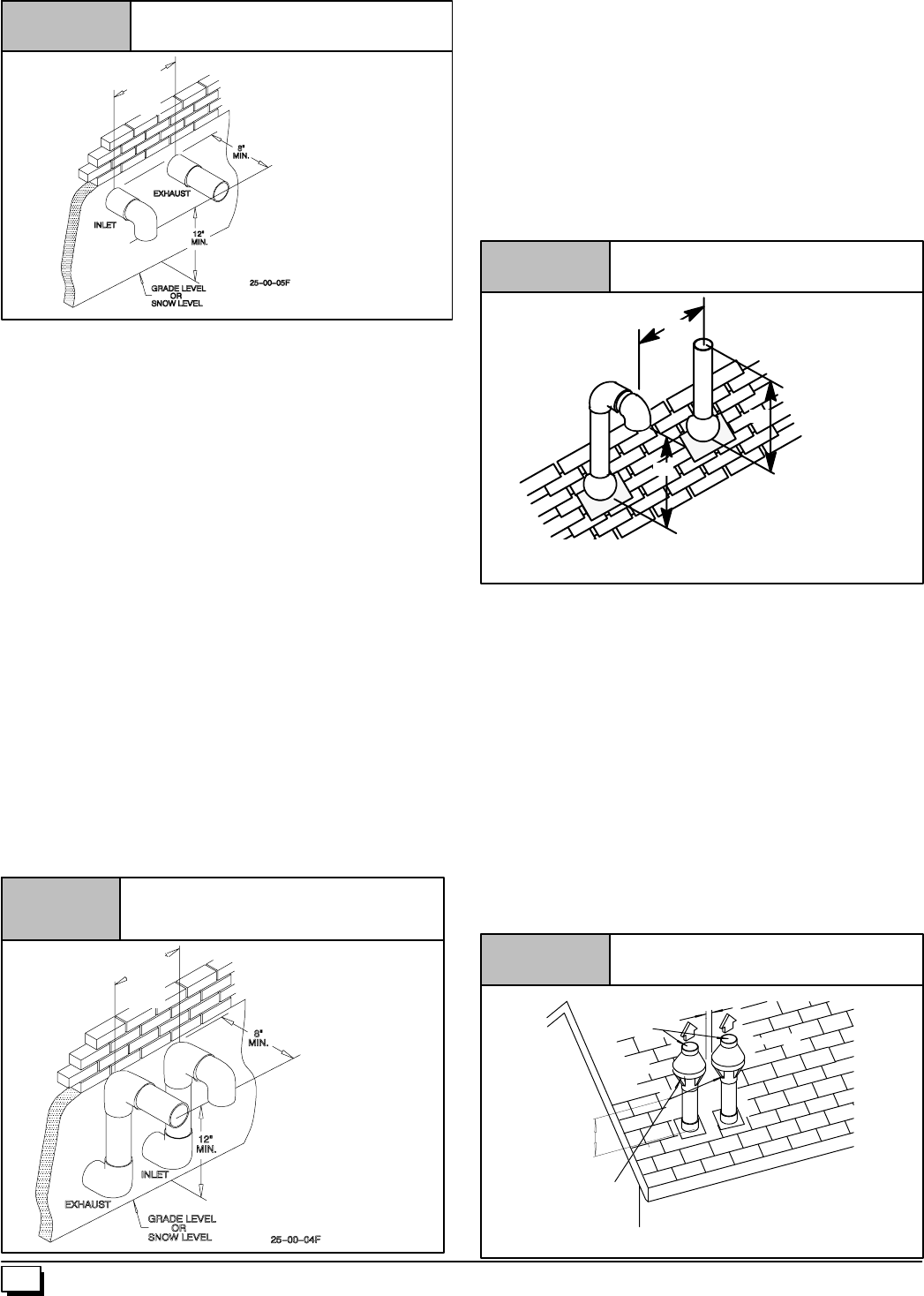
24 440 01 1020 02
Figure 19 Sidewall Termination 12²or More
Above Snow Level or Grade Level
8” *
MIN.
20’
MAX
*18²
²²
²Minimum for cold climates
(substained below 0°
°°
°F)
Horizontal Termination
1. Cut two holes. 21/2²for2²pipe, 3²for 21/2²pipe, or 31/2²for
3²pipe.DoNOT make theholes oversized, or it will be nec-
essarytoadd a sheetmetalorplywoodplateon the outside
with the correct size hole in it.
2. Check hole sizes by makingsure it is smallerthan the cou-
plings or elbows that will be installed on the outside. The
couplings or elbows MUST prevent the pipe from being
pushed back through the wall.
3. Extend vent pipe and combustion air pipe through the wall
3/4²to 1²and seal area between pipe and wall.
4. Install the couplings, nipple and termination elbows as
shownandmaintainspacingbetweenventandcombustion
air piping as indicated in Figure 19 and Figure 20.
Ametalshieldisrecommended18²x18²min.or18²min.diameter
aroundtheventterminationattheexteriorwalltoprotectthehouse
exterior materials from flue product or condensation (freezing)
damage.
Using Exterior Risers
1. Install elbowsand pipe to form riser as shown inFigure 20.
2. Secure vent pipe to wall with galvanized strap or other rust
resistant material to restrain pipe from moving.
3. InsulatepipewithArmaflexorequivalentmoistureresistant
closed cell foam insulation or Fiberglass insulation if boxed
in and sealed against moisture.
Figure 20 Sidewall Termination with Exterior
Risers to Get Above Snow Level or
Grade Level
8” *
MIN.
20’
MAX
*18²
²²
²Minimum for cold climates
(substained below 0°
°°
°F)
Vertical Termination
1. Figure 21 shows the proper installation and clearances for
vertical vent termination. The vertical roof termination
should be sealed with a plumbing roof boot or equivalent
flashing. The inlet of the intake pipe and end of the exhaust
vent must be terminated no less than 12²above the roof or
snow accumulation level, and 12²away from a vertical wall
or other protrusion.
2. If the vent system is installed in an existing chimney make
sure clearances shown in Figure 21 are maintained. Hori-
zontalsectionbeforetheterminationelbowcanbeextended
on the inlet air to provide necessary clearance.
Figure 21 Rooftop Termination
25--00--06
A
A
B
A=12²Above roof or snow accumulation level
B=8²Min., 20¢Maximum, except in areas with extreme cold temperatures
(sustained below 0°F), the 18²Min.
Vent Termination Shielding
Under certain wind conditions some building materials may be af-
fected by flue products expelled in close proximity to unprotected
surfaces.Sealingorshieldingoftheexposedsurfaceswithacorro-
sion resistant material (such as aluminum sheeting) may be re-
quiredtoprevent staining or deterioration.Theprotectivematerial
shouldbeattachedandsealed(ifnecessary)tothebuildingbefore
attaching the vent terminal.
Multi Vent Termination Clearances
When two (2) or more furnaces are vented near each other, each
furnace must be individually vented.
Two(2)ventterminationsmaybeinstalledasshowninFigure 22,
Figure 23, Figure 24, Figure 25, Figure 26 and Figure 27,but
thenextventterminationmustbeatleast36²awayfromfirst2ter-
minations.Itisimportantthatventterminationsbemadeasshown
to avoid recirculation of flue gases.
Figure 22 Concentric Vent and Combustion--
Air Roof Termination
“A”
Combustion
Air
Exhaust
12²
²²
²Min. Grade or
Snow Level
Dimension “A” is touching or 2²maximum separation.
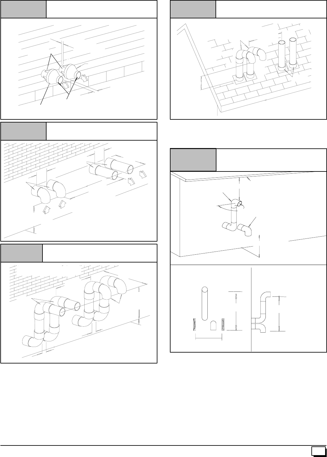
25
440 01 1020 02
Figure 23 Concentric Vent and Combustion--
Air Sidewall Termination
“A”
Vent
Dimension “A” is touching or 2²maximum separation.
25--22--02d
Vent
Combustion Air 1²
²²
²Maximum
(TYP.)
Exhaust
“A”
“A”
Inlet
Figure 24 Sidewall Inlet Vent and Exhaust--
Air Termination
Dimension “A” is touching or 2²maximum separation.
12²
²²
²Min. Grade or
Snow Level
18²
²²
²Min. for
Cold Climates
(Sustained Below 0°
°°
°F)
8²
²²
²Min.
20¢
¢¢
¢Max.
8²
²²
²Min.
Exhaust
Exhaust
8²
²²
²Min.
8²
²²
²Min.
20¢
¢¢
¢Max.
Figure 25 Sidewall Inlet Vent and Exhaust--Air
Termination with Exterior Risers
Dimension “A” is touching or 2²maximum separation.
12²
²²
²Min.
Grade or Snow
Level
18²
²²
²Min. for Cold Climates
(Sustained Below 0°
°°
°F)
Inlet
“A”
“A”
12²
²²
²Min.
Grade or Snow
Level
Exhaust
8²
²²
²Min.
20¢
¢¢
¢Max.
Figure 26 Rooftop Inlet Vent and Exhaust--
Air Termination
25--22--43
18²
²²
²Min. for Cold Climates
(Sustained Below 0°
°°
°F)
Inlet
Figure 27 Recommended Alternate
Installation for Sustained Cold
Weather (--0°
°°
°F&below)
OVERHANG
12²
²²
²MIN.
12²
²²
²MIN. Ground Level
OR Snow Level
INLET
EXHAUST
90°
°°
°
Same Joist
Space
FRONT VIEW SIDE VIEW
12²
²²
²
12²
²²
²
25-23-73
26 440 01 1020 02
5. Gas Supply and Piping
CARBON MONOXIDE POISONING, FIRE AND EX-
PLOSION HAZARD.
Failure to follow these instructions can result in
death, personal injury and/or property damage.
Models designated for Natural Gas are to be used
with Natural Gas ONLY, unless properly convertedto
use with LP gas.
!
NOTE: The rating plate is stamped with the model number, gas
type and gas input rating. In addition, models manufactured for
saleinCanadahaveorificesizeinformationstampedontherating
plate.
Alternate BTUH Input Ratings (USA Only)
The input rating of these furnaces can be changed from the stan-
dard input rating to the alternate input rating shown in Table 5, by
changing the main burner orifices. NOTE: The input rating ot
80,000BTUHmodelscannotbechangedfromthestandardinput.
Changing of burner orifices MUST be done by a qualified service
technician. See section on changing orifices or following page.
Table 5 Alternate Input Ratings, USA ONLY.
BTUH
Standard
Rating
BTUH
Alternate
Rating
Natural
Gas
Orifice
LP
Gas
Orifice
50,000 40,000 #44 #55
75,000 60,000 #44 #55
100,000 80,000 #44 #55
125,000 100,000 #44 #55
Supply Pressure
FIRE HAZARD
Failure to properly set input pressure can result in death,
personal injury and/or property damage.
DoNOTset inputratingabovethatshownon ratingplate.
!
1. Supplypressurecanbe checkedusingthe1/8²NPTporton
the supply side of the gas valve.
2. Gas input to burners MUST NOT exceed the rated input
shownonratingplate.
3. Do NOT allow minimum gas supply pressure to vary down-
ward. Doing so will decrease input to furnace. Refer to
Table 6 for normal gas supply and manifold pressures.
Table 6 Gas Pressures Below 2000¢
¢¢
¢
Gas
T
Supply Pressure Manifold
P
Type Recommended Max. Min. Pressure
Natural 7²14²4.5²3.5²
LP 11²14²11²10²
Important Note:
·With Propane gas, the rated input is obtained when the
BTU content is 2,500 BTU per cubic foot and manifold
pressure set at 10²
²²
²W.C.
·If Propane gas has a different BTU content, orifices
MUST be changed by licensed Propane installer.
·Measured input can NOT exceed rated input.
·Anymajorchangeingasflowrequireschangingburner
orifice size.
Gas Supply Pressure
Gassupplypressureshouldbewithinminimumandmaximumval-
ues listed on rating plate.Pressures are usually set by gassuppli-
ers.
Manifold Gas Pressure Adjustment
NOTE:Makeadjustmenttomanifoldpressurewithburnersoperat-
ing.
ELECTRICAL SHOCK HAZARD.
Failure to do so can result in death, personal injury
and/or property damage.
Turn OFF power to furnace before changing speed
taps.
!
1. Remove the burner compartment door.
2. With gas OFF, connect manometer to tapped opening on
gas valve. Use manometer with a 0 to 15²water column
range.
3. Turn gas ON and remove adjustment screw cover on gas
valve. Turn counterclockwise to decrease pressure and
clockwise to increase.
4. For altitudes up to 2000¢, set pressure to value shown in
Table 6,±0.3²water column.
5. Connect manometer to the tapped opening on the outlet
side of gas valve. Use manometer with a 0--15²min. water
column range.
6. TurngasON, firethefurnaceandremoveadjustmentscrew
cover on gas valve.
7. Turncounterclockwisetodecreasepressureandclockwise
to increase.
8. SetpressuretovalueshowninTable 6. Refer toImportant
Notes in Table 6. Pressure is also listed on furnace rating
plate.
9. When pressure is set, replace adjustment screw cover on
gas valve.
10. Replace the burner compartment door.
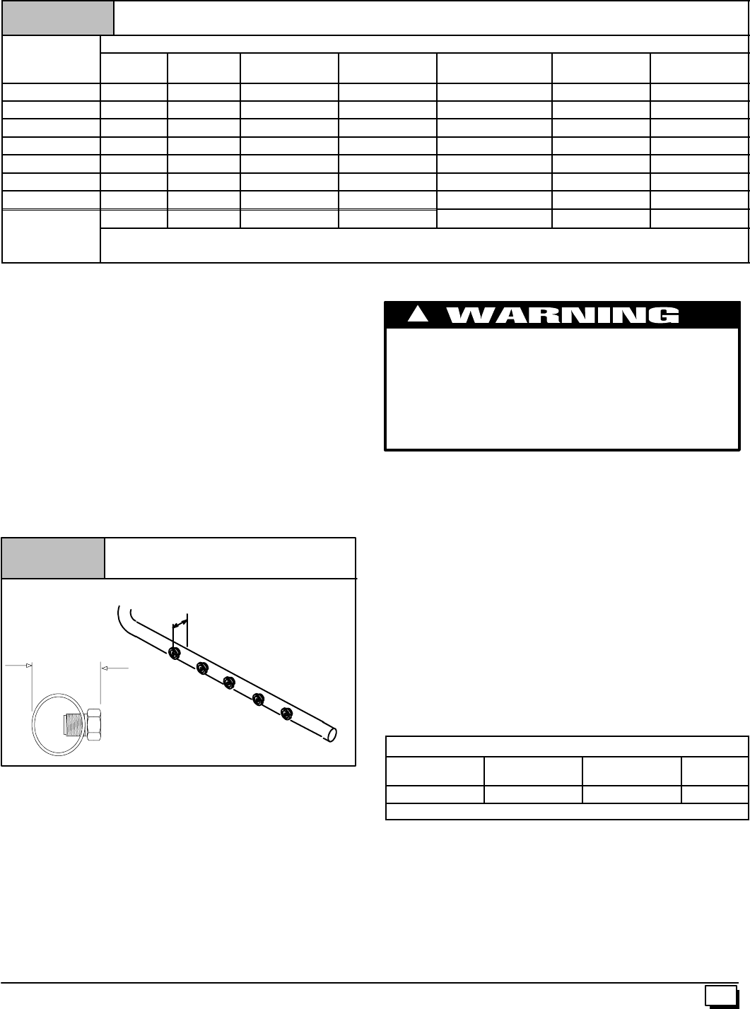
27
440 01 1020 02
MANIFOLD PRESSURE AND ORIFICE SIZE FOR HIGH ALTITUDE APPLICATIONS
Table 7 NATURAL GAS
H
e
a
t
V
a
l
u
e
Elevation Above Sea Level
H
eat
V
a
l
ue
Btu/Cu.Ft. 0--1999
(²
²²
²×
××
×wc) 2000--2999
(²
²²
²×
××
×wc) 3000--3999
(²
²²
²×
××
×wc) 4000--4999
(²
²²
²×
××
×wc) 5000--5999
(²
²²
²×
××
×wc) 6000--6999
(²
²²
²×
××
×wc) 7000--7999
(²
²²
²×
××
×wc)
800 3.5 3.5 3.5 3.5 3.5 3.5 3.5
850 3.5 3.5 3.5 3.5 3.5 3.5 3.5
900 3.5 3.5 3.5 3.5 3.5 3.5 3.4
950 3.5 3.5 3.5 3.5 3.3 3.2 3.1
1000 3.5 3.4 3.3 3.2 3.0 2.9 2.8
1050 3.2 3.1 3.0 2.9 2.7 2.6 2.5
1100 2.9 2.8 2.7 2.6 2.5 2.4 2.3
* * * * * * *
Orifice Size * #42 Orifice size for 50,000, 75,000 100,00 & 125,000 BTUH models
* #44 Orifice size for 80,000 BTUH model
General Derating Rules
1. Foroperationwithnaturalgasataltitudes above2,000¢,ori-
ficechangeand/ormanifoldpressureadjustmentmaybere-
quiredtosuitgassupplied.Checkwithgassupplier.Iforifice
sizing is needed, it should be based on reducing the input
ratingby2% (natural) or4%(LP)foreach 1,000¢abovesea
level. See Table 7 and Figure 28 for required pressure
change and/or orifice change for high altitudes.
2. ForoperationwithLPgasat altitudes above2,000¢,gasori-
fices MUST be changed and manifold pressure MUST be
maintained asperTable 6. Forthe50,000,75,000,100,000
and125,000BTUHOrificesizesare #54 for0--2000¢above
sealevel, #55for2000¢--7000¢abovesealevel,and#56for
7000¢--8000¢abovesealevel.Forthe80,000BTUHmodels,
theorifice sizeis#55for 0 -- 4,000¢abovesealleveland#56
for5,000¢-- 8,000¢above sea level. Orifices can beordered
through your distributor. (See Figure 28)
Figure 28 Changing Orifices
11/8²to 13/16²
Measure from face of orifice
to the back side of the
manifold.
NOTE: The derating of these units at 2% (Natural) and 4% (L.P.)
has been tested and approved by AGA.
High Altitude Air Pressure Switch
Altitudesover4,000¢requireadifferentairpressureswitchthanthe
oneinstalledatthefactory.Checkpartslistforpressureswitchand
consultyourdistributorforpartnumberandavailability.InCanada,
provincialcodesmaygoverninstallationofswitch.Checkwithgov-
erning authorities.
Changing Orifices for High Altitude
ELECTRICAL SHOCK, FIRE OR EXPLOSION HAZARD
Failure to properly install orifices can result in death,
personal injury and/or property damage.
TurnOFFelectricpower(atdisconnect)andgassupply
(at manual valve in gas line) when installing orifices.
Installation of orifices requires a qualified service
technician.
!
NOTE: Main burner orifices can be changed for high altitudes.
1. Disconnect gas line from gas valve.
2. Remove manifold from furnace.
3. Remove the orifices from the manifold and replace them
with properly sized orifices.
4. Tightenorificessoitisseatedandgastight.(SeeFigure 28)
5. Reinstallmanifold.EnsureburnersdoNOTbindonnewori-
fices.
Natural Gas Input Rating Check
NOTE: The gas meter can be used to measure input to furnace.
Rating is based on a natural gas BTU content of 1,000 BTU’s per
cubic meter. Check with gas supplier for actual BTU content.
1. Makesureburnercompartmentdoorisinplace beforeper-
forming the following steps.
2. Turn OFF gas supply to all appliances and start furnace.
Example
Natural Gas
BTU Content No. of Seconds
Per Hour Time Per Cubic
Foot in Seconds BTU Per
Hour
1,000 3,600 48 75,000
1,000 x 3,600 ¸48 = 75,000 BTUH
3. Timehowmanysecondsittakesthesmallestdialonthegas
meter to make one complete revolution. Refer to Example.
4. Relight all appliances and ensure all pilots are operating.
NOTE:Ifmeterusesa2cubicfootdial,divideresults(seconds)by
two.
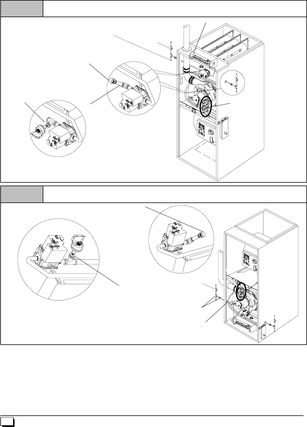
28 440 01 1020 02
Use elbows and 3²
²²
²pipe nipple to connect valve to
piping when using rightside gas pipe entry.
* Union may be installed inside the cabinet when necessary
because of clearances.
Figure 29 Typical Gas Piping for Upflow
Drip Leg and Union, Union*should be outside the
cabinet. Manual shut-off valve MUST be upstream of
dripleg, union, and furnace.
LP Low pressure
switch. Optional
on some models.
25--23--37b
GasPipeGrommet(SinglePipe)
3²
²²
²pipe
nipple Models may
have1or2
pressure
switches
Manual shut-off
valve
Use elbows and 3²
²²
²pipe nipple to connect valve
to piping when using left side gas pipe entry.
*Union may be installed inside the cabinet when necessary
because of clearances.
Figure 30 Typical Gas Piping for Downflow
Drip Leg and Union, Union* should be outside
the cabinet. Manual shut--off valve MUST be
upstream of dripleg, union, and furnace.
LP Low pressure
switch. Optional LP
conversion.
GasPipeGrommet
(Single Pipe)
25--23--39
Models may have
1 or 2 pressure
switches
Manual shut-off
valve
Gas Piping Requirements
NOTE:Thegassupply linemustbeinstalledbyaqualifiedservice
technician in accordance with all building codes, (In the state of
Massachusetts,gassupplyconnectionsMUSTbeperformedbya
licensed plumber or gas fitter).
1. Properlysizegaspipetohandlecombinedapplianceloador
rungaspipedirectlyfromgasmeterorLPgasregulator.Re-
fer to NFGC and ANSI Z223.1 for proper gas pipe size.
2. Install correct pipe size for run length and furnace rating.
3. Measure pipe length from gas meter or LP second stage
regulator.
NOTE: Refer to Figure 29 or Figure 30 for the general layout at
thefurnace.TheruleslistedapplytonaturalandLPgaspipeinstal-
lations.
NOTE: OntheDualCertifiedorDirectVent models,installthegas
pipe grommet to the furnace side panel with the gas pipe entry. If
needed, remove the 2²hole plug and relocate to the open hole in
the furnace side panel.
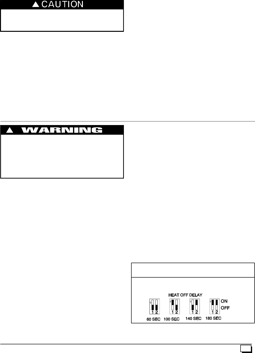
29
440 01 1020 02
If a flexible connector is required or allowed by authority
having jurisdiction, black iron pipe shall be installed at
gas valve and extended aminimum of 2²
²²
²outside furnace
casing.
!
4. Use black iron or steel pipe and fittings or other pipe ap-
proved by local code.
NOTE:TheuseofcoppertubingforgaspipingisNOTapprovedby
the state of Massachusetts.
5. Usegroundjointunionsandinstalladripleg noless than3²
long to trap dirt and moisture before it can enter gas valve.
6. Use two pipe wrenches when making connections to pre-
vent gas valve from turning.
7. Install a manual shut--off valve external to furnace casing
and tighten all joints securely.
Additional LP Connection Requirements
1. HavealicensedLPgasdealermakeallconnections atstor-
age tank and check all connections from tank to furnace.
2. Ifcoppertubingisused,itMUSTcomplywithlimitationsetin
National Fuel Gas Code or CGA codes.
3. Two--stage regulation of LP gas is recommended.
Final Check
1. Thefurnaceandthegasvalvemustbedisconnectedfromthe
gassupplypipingsystemduringanypressuretestingofthat
system at test pressures in excess of 1/2²PSIG. Close the
manual shut--off valve before testing at such pressures.
2. When installation is complete, test all pipe connections for
leaks with the gas pressure less than 1/2²PSIG to the gas
valve.
3. Apply a commercial soap solution to all joints to test for
leaks. Correct any leaks indicated by bubbles.
4. Correct even the smallest leak at once.
5. Check for leaks at gas valve and orifice connections to the
burner manifold along with the pilot tube connections to the
valve and pilot assembly while the furnace is operating.
6. Electrical Wiring
Electrical shock hazard.
Failure to do so can result in death, personal injury
and/or property damage.
Turn OFF electrical power at fuse box or service
panel before making any electrical connections
and ensure a proper ground connection is made
before connecting line voltage.
!
Power Supply Wiring
The furnace MUST be electrically wired and grounded in accor-
dance with local codes, or in the absence of local codes with the
latesteditionof The National ElectricCode,ANSINFPA 70and/or
The Canadian Electric Code CSA C22.1.
Thepowersupplytothefurnaceconnectionsmustbebetween104
VAC and 127VAC during furnace operation foracceptable perfor-
mance.
Fieldwiringconnectionsmustbemadeinsidethefurnaceconnec-
tion box. A suitable strain relief should be used at the point the
wires exit the furnace casing.
Copper conductors must be used.Linevoltagewiresshouldbe
sizedfortheinputampsstatedontheratingplate.Furnaceshould
be connected to its own separate circuit.
Thermostat
Thermostatlocationhasanimportanteffectontheoperationofthe
unit. Follow instructions included with thermostat for correct
mounting and wiring.
Low voltage connections to furnace must be made on terminal
board to fan control.
Set thermostat heat anticipator in accordance with the Technical
Support Manual.
Optional Equipment
Allwiringfromfurnace to optional equipmentMUST conform tolo-
calcodesor,intheabsenceoflocalcodeswiththelatesteditionof
The National Electric Code, ANSI NFPA 70 and/or The Canadian
Electric Code CSA C22.1. Install wiring in accordance with
manufacturer’s instructions. The wiring MUST have a minimum
temperature rating of 105°C.
Humidifier/Electronic Air Cleaner
The furnace is wired for humidifier and/or electronic air cleaner
connection. CAUTION
DoNOTexceed115V/0.8amp.maximumcurrentloadforboth
the EAC terminal and the HUM terminal combined.
NOTE: The humidifier will be powered when the furnace is fired
andthecirculating air blower comes on. Theelectronicaircleaner
will be powered anytime the air circulating blower is energized.
However, the electronic air cleaner is NOT energized during con-
tinuous fan operation controlled by the electronic fan control.
Fan Control
ThefancontrolispresetatthefactorywithafixedblowerONdelay
of 30 seconds in the heating mode. The blower OFF timing is pre-
set at 140 seconds. If desired, the fan OFF delay can be reset to
obtainthelongestdelaytimeswhilestillmaintainingcomfortlevels.
See “Furnace Wiring Diagram” .
Fan Delay DIP Switch Settings
25--23--47
COOL ON DELAY: 5 SEC.
COOL OFF DELAY: 90 SEC.
HEAT ON DELAY: 30 SEC.
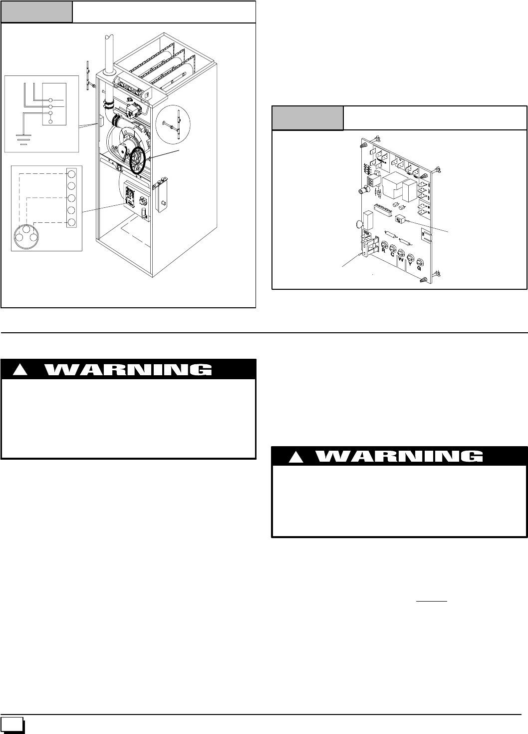
30 440 01 1020 02
Figure 31 Electrical Connections
NOTE: Junction Box can be
mounted to either the left or right
side.
25--23--42
Models may
have 1 or 2 pressure
switches
NOTE: 115 VAC/60Hz/single--phase
Operating voltage range*: 127 max, 104 min.
* Permissible limits of voltage at which unit will operate satisfactorily
115V. 60 Hz
W
W
W
Low Voltage
Terminal Board
R
R
BK
Ground
Connection
Box
G
HOT
NEUT.
G
G
Y
G
Control Center Fuse
The 24V circuit contains a 5--amp, automotive--type fuse located
on fan timer board. (See Figure 32) Any electrical shorts of 24V
wiringduringinstallation,service,ormaintenancemaycausefuse
toblow.Iffusereplacementisrequired,useonlyafuse ofidentical
size (5 amp.)
Fan Timer Connections
Figure 32
25--23--41
DIP Switch
FUSE
7. Ductwork and Filter
CARBON MONOXIDE POISONING HAZARD.
Failure to properly seal duct can result in death
and/or personal injury.
DoNOTdraw returnairfrom inside acloset orutility
room where furnace is located. Return air duct
MUST be sealed to furnace casing.
!
Installation
NOTE:DesignandinstallairdistributionsystemtocomplywithAir
Conditioning Contractors of America manuals and/or NFPA pam-
phlets90Aand90Borotherapprovedmethodsthatconform tolo-
cal codes and good trade practices.
1. When furnace supply ducts carry air outside furnace area,
sealreturnairducttofurnacecasingandterminateductout-
side furnace space .
2. Install air conditioning cooling coil (evaporator) on outlet
side of furnace.
3. For furnaces installed without a cooling coil it is recom-
mended that the outlet duct be provided with a removable
accesspanel.Thispanelshouldbeaccessiblewhenthefur-
naceisinstalledsotheexterioroftheheatexchangercanbe
viewed for inspections. The access panel MUST be sealed
to prevent leaks.
4. If separate evaporator and blower units are used, install
good sealing dampers for air flow control. Chilled air going
throughthefurnace could causecondensation and shorten
the furnace life.
NOTE:Dampers(fieldsupplied)can be eitherautomatic ormanu-
al. Manually operated dampers MUST be equipped with a means
topreventfurnaceorairconditioningoperationunlessdamperisin
the full heat or cool position.
CARBON MONOXIDE POISONING HAZARD
Thiscouldresultindeath,personalinjuryand/orproperty
damage.
Cool air passing over heat exchanger can cause
condensate to form resulting in heat exchanger failure.
!
Connections
NOTE: On upflow installations, return air can enter through either
side,both sides,orthebottom.Onhorizontalor downflowinstalla-
tionsthereturn air mustenterthroughtheknockoutopeninginthe
lowerpanelofthefurnace.Returnaircannotenterthroughrearof
the furnace. When the furnace is located in an area near or adja-
cent to the living area, the system should be carefully designed
with returns to minimize noise transmission through the return
grille. Anyblower moving ahigh volume ofair will produce audible
noisewhichcouldbeobjectionabletowhentheunitislocatedvery
closetolivingareas. Itis advisabletoroutethereturnairductsun-
der the floor or through the attic.
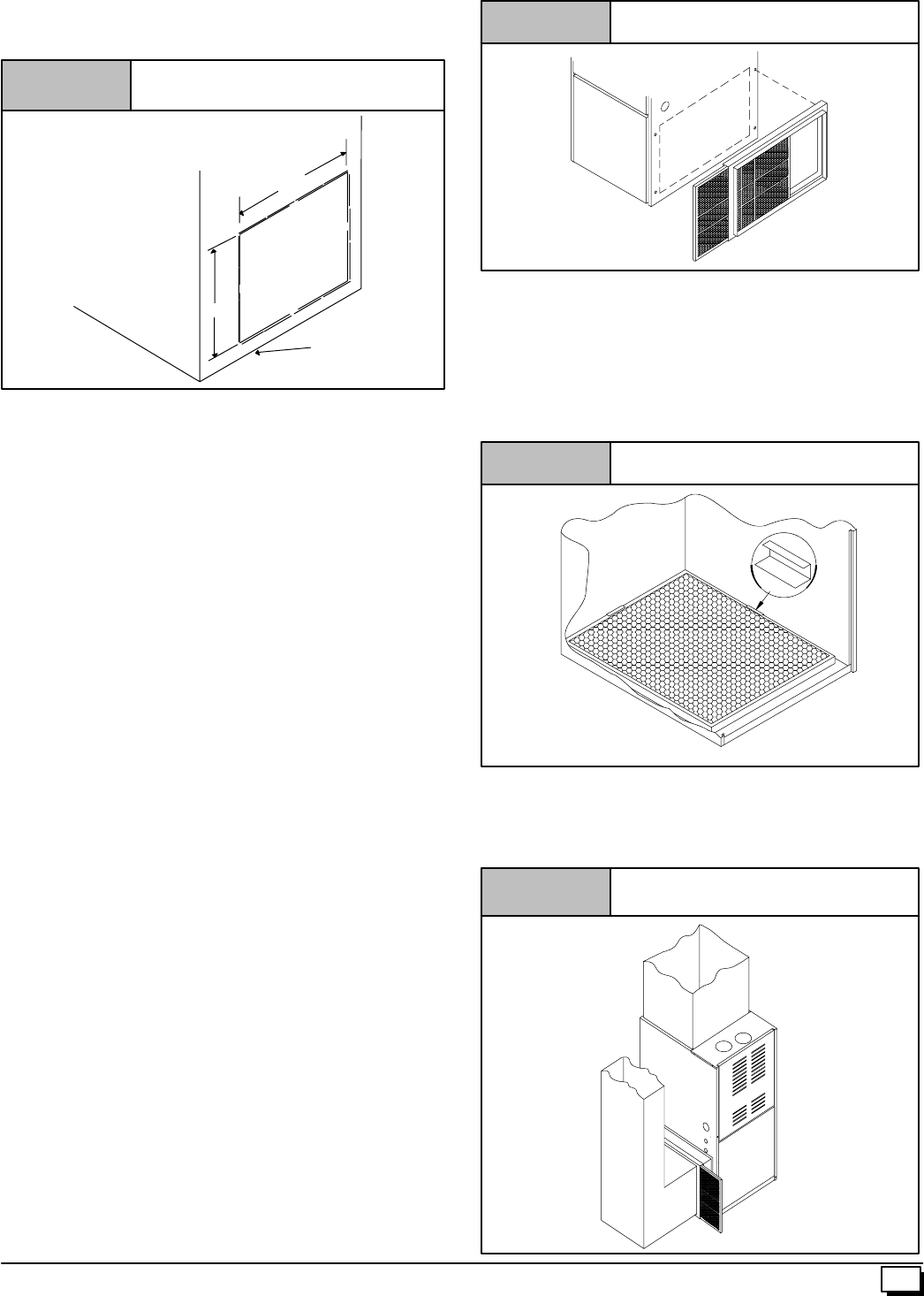
31
440 01 1020 02
1. For side connectionsusing a 16²x25²filter,cutout theem-
bossedareashowninFigure 33.Thiswillprovidea141/2²x
221/2²approximate opening.
Figure 33 Side Return Air Cutout
Embossed Area
on Side of Furnace
A=14
1/2²Height of Cutout for 16²x25²Filter
B=22
1/2²Width of Cutout for 16²x25²Filter
A
Furnace
Bottom
B
NOTE: Furnaces with 5 TONS cooling rating require two(2) side
returns or one side return with bottom return.
2. Bottomreturnscanbemadebyremovingtheknockoutpan-
elinthefurnacebase.DoNOTremoveknock-outexceptfor
a bottom return.
3. Installationoflocking-typedampersarerecommendedinall
branches,orinindividualductstobalancesystem’sairflow.
4. Non-combustible, flexible duct connectors are recom-
mended for return and supply connections to furnace.
5. If air return grille is located close to the fan inlet, install at
least one, 90°air turn between fan and inlet grille toreduce
noise.
NOTE:Tofurtherreducenoise, installacousticalairturningvanes
and/or line the inside of duct with acoustical material.
Sizing
Existing or new ductwork MUST be sized to handle the correct
amount of airflow for either heating only or heating and air condi-
tioning.
Insulation
1. Insulate ductwork installed in attics or other areasexposed
tooutsidetemperatureswithaminimumof2²insulationand
vapor barrier.
2. Insulateductworkinindoorunconditionedareaswithamini-
mum of 1²insulation with indoor type vapor barrier.
Filters
A Filter must be used:
Filtersarenotsuppliedwiththesefurnaces,butcanbepurchased
from dealer.
Use either filter type:
·Washable, high velocity filters are based on amaximum
air flow rating of 600 FPM.
·Disposable, low velocity filters are based on a maximum
air flow of 300 FPM when used with filter grille.
NOTE:Disposable,lowvelocityfiltersmaybereplacedwithwash-
able, high velocity filter providing they meet the minimum size
areas. Washable, high velocity filters can be replaced ONLY with
same type and size.
Figure 34 Side Mounted Filter Rack
25--20--90
Filter Installation using Optional Filter Rack
When installing or removing a bottommounted filter, slide thetwo
side filter clips to the back of the furnace BEFORE installing or re-
moving.Thiswillallowthefiltertoclearthefrontraisededgeofthe
furnace.Insertfilterintosideclipsfirstandpushfilterbackuntilitis
fullyengagedintobackclip.Whenfilteris inplace,slideclipsback
into place midway on filter as shown in Figure 35.
Figure 35 Bottom Mounted Filter Rack
Slide filter clips towards back before removing
25--24--18
Refer to Figure 36 and for guidelines to install filters. Furnaces
which require larger filter media and have limited clearances on
one side of furnace, require a standoff filter rack, see Figure 36,
available from your distributor.
Figure 36 Standoff Filter Rack
25--21--45a
Using Optional
Standoff Filter
Rack
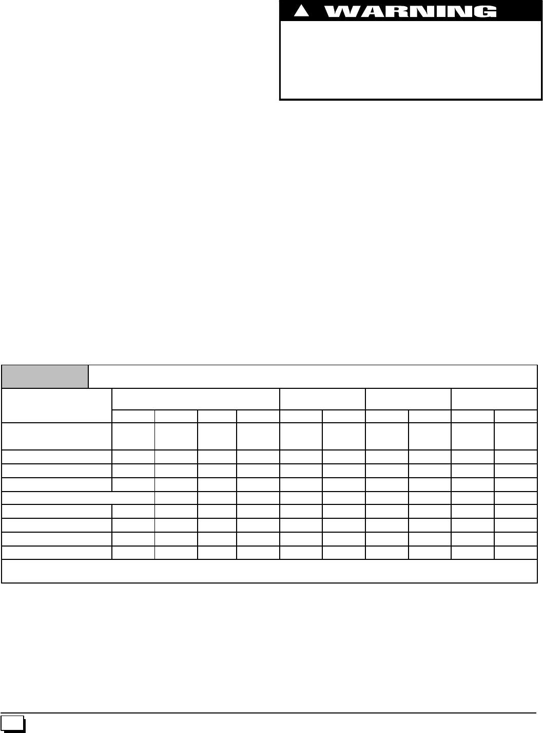
32 440 01 1020 02
CAUTION
If filters are only suitable for heating application, advise
homeowner that filter size may need to be increased if air
conditioning is added.
Addition Of Air Conditioning
Whenarefrigerationcoilisusedinconjunctionwiththisunit,itmust
beinstalledonthedischargesideoftheunittoavoidcondensation
on the heat exchanger. The coil installation instructions must be
consultedforpropercoillocationandinstallationprocedures.With
a parallel flowarrangement, dampers must be installed toprevent
chilledairfromenteringthefurnace.Ifmanuallyoperateddampers
areused,theymustbeequippedwithameanstopreventoperation
of either unit unless the damper is in full heat orfull cool position.
A3²clearanceisrequiredontherightsideofthefurnaceinorderto
runthecondensatedrainline.Copper,ironorplastictubingmaybe
used for the condensate drain line.
Downflow Furnace Installation
Non-Combustible Floor Installation
Fabricateaplenumtothe dimensions given inTable 8,forthefur-
naceoutlet.Plenumshouldbeflanged,approximately3/4²forsup-
port.
Note:Thethree(3)screwsinthetoppanelofthefurnacenexttothe
duct flange MUST be removed to provide serviceability of the pri-
mary heat exchangers in the downflow installation
1. Position plenum through the floor and set the furnace over
theopeningin the floor.If necessary, grout aroundthebase
to seal air leaks between the base and the floor.
Combustible Floor Installation
FIRE HAZARD
Failure to install unit on noncombustible subbase can
result in death, personal injury and/or property damage.
Place furnace on noncombustiblesubbase on downflow
applications, unless installing on non--combustible
flooring.
!
Subbase for Combustible Floor
NOTE: The three(3) screws in the top panel of the furnace next to
the duct flange MUST be removed to provide serviceability of the
primary heat exchangers in the downflow installation
Note: When using the subbase for combustible floors, the dis-
charge air duct flanges on the furnace MUST be broken down to
provide proper fit up to the subbase. Use duct pliers to bend the
duct flanges flat onto the furnace casing. DO NOT bend the duct
flangesinward(towardtheheatexchangers)asairflowrestrictions
may occur.
TheSubbaseforCombustibleFloorsMUSTbeusedwhenadown-
flowfurnaceissetonacombustiblefloor,evenwhenthefurnaceis
installed on a coil box.
1. CuttheopeningintheflooraccordingtoTable 8.Theholein
the floor must be cut to the dimensions listed in Table 8
sincethebaseisequippedwithlocating tabsthatcenterthe
base over the opening.
Theopeninginthebaseis11/4²shorterand11/8²narrowerthanthe
recommendedsizeoftheopeninginthefloor.Thisisdonetomain-
tain clearance between the floor and the plenum.
2. Fabricate the plenum to the dimensions given in Table 8.
Note that the dimensions given are outside dimensions.
Table 8 Subbases for Combustible Floors Dimensions
Subbase for Combustible
F
l
o
o
r
s
P
a
r
t
N
u
m
b
e
r
Subbase for Combustible
Floor Dimensions OpeningInFloor Opening In Base
For Plenum Typical Plenum
Dimensions
F
l
oors
P
art
N
um
b
er H* J* K** L M N P R S T
Furnace Subbase
NAHH001SB 1511/16 283/4149/16 16 161/4145/815 131/215 131/2
NAHH002SB 195/16 283/4183/16 16 161/4181/415 171/815 171/8
NAHH003SB 225/16 283/42113/16 16 161/4217/815 193/415 193/4
NAHH010SB 243/4283/4239/16 161/4161/4235/815 221/215 221/2
Subbase for Coil Cabinets
NAHH004SB 1511/16 209/16 149/16 161/4161/4145/815 131/215 131/2
NAHH005SB 195/16 209/16 183/16 161/4161/4181/415 171/815 171/8
NAHH006SB 23 209/16 2113/16 161/4161/4217/815 193/415 193/4
NAHH009SB 2411/16 209/16 239/16 16 161/4235/815 221/215 221/2
*Outside Dimension
** Base Spacer Side To Side
3. Set the base over the opening in the floor, centering it over
the opening. Fasten the base to the floor with screws or
nails. See Figure 37, Figure 38 and Figure 39.
4. Drop the plenum through the opening in the base. The
flange of the plenum should rest on top of the subbase.
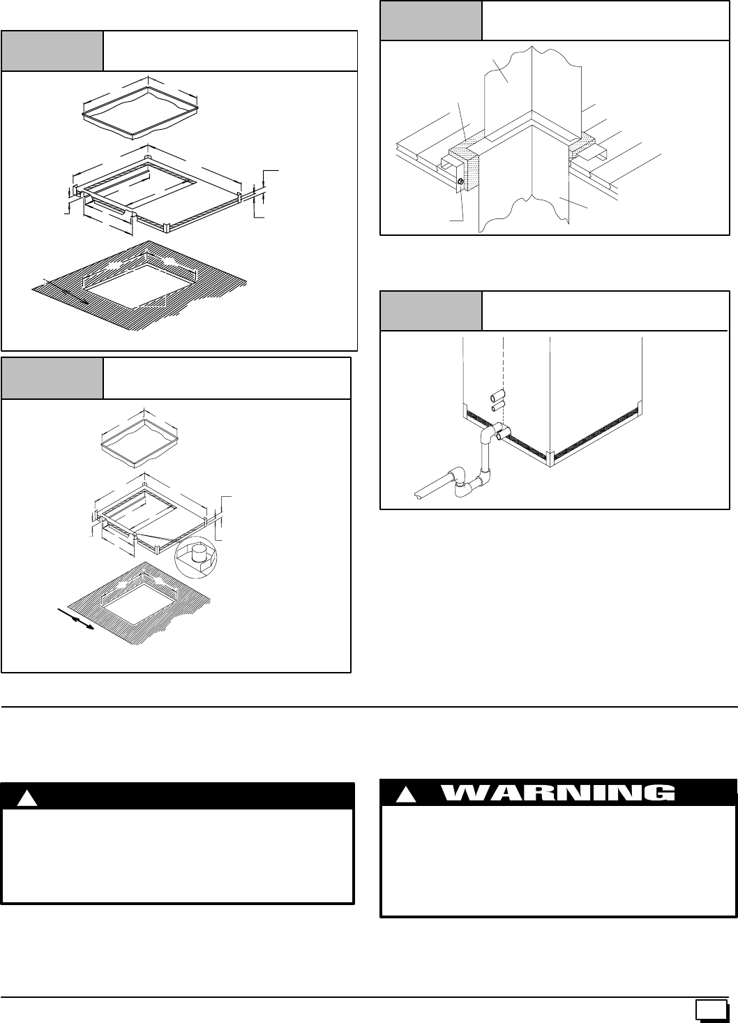
33
440 01 1020 02
5. Positionfurnaceorcoilcabinetandfurnaceonsubbasesoit
aligns between the locating tabs.
TS
HJ
1”
2”
NM
R
P
L
2”
25--20--46
Plenum
Combustible
Floor Base
Furnace Subbase
Figure 37
A
A = 4 1/4” Minimum clearance from back of hole to wall or other obstruction.
Hole
in
Floor
K
TS
HJ
1”
2”
NM
KR
P
L
2”
25--20--46b
Plenum
Figure 38 Coil Cabinet Subbase
A
A = 4 1/4” Minimum clearance from back of hole to wall or other obstruction.
Hole
in
Floor
25--20--46a
Furnace
Wood Screw Plenum
Wood Floor
Figure 39 Setting the Subbase
Installation of
Combustible
Floor Base
Thissubbaseforcombustiblefloorshasbeendesignedsothatthe
heightofthesubbaseraisesthedownflowcoiloffthefloortoallow
easy installation of the condensate drain. See Figure 40.
Condensate Line Raised by Base
Figure 40
25--20--52
8. Checks and Adjustments
Startup
NOTE:Refertothestart--upproceduresinthe“User’sInformation
Manual”ortothe“Operating Instructions Label” on the furnace.
!
If any sparks, odors or unusual noises occur,
immediately shut OFF power to furnace. Check for
wiring errors or obstruction to blower.
Failure to correct hazard could result in death,
personal injury, and/or property damage.
CAUTION
Gas Supply Pressure
Gassupplypressureshouldbewithinminimumandmaximumval-
ues listed on rating plate.Pressures are usually set by gassuppli-
ers.
Manifold Gas Pressure Adjustment
NOTE:Makeadjustmenttomanifoldpressurewithburnersoperat-
ing.
!
Fire or explosion hazard.
Failure to turn OFF gas at shut off before connecting
manometer can result in death and/or personal
injury.
Turn OFF gas at shut off before connecting
manometer.
1. Remove the burner compartment door.
2. With gas OFF, connect manometer to tapped opening on
gas valve. Use manometer with a 0 to 15²water column
range.
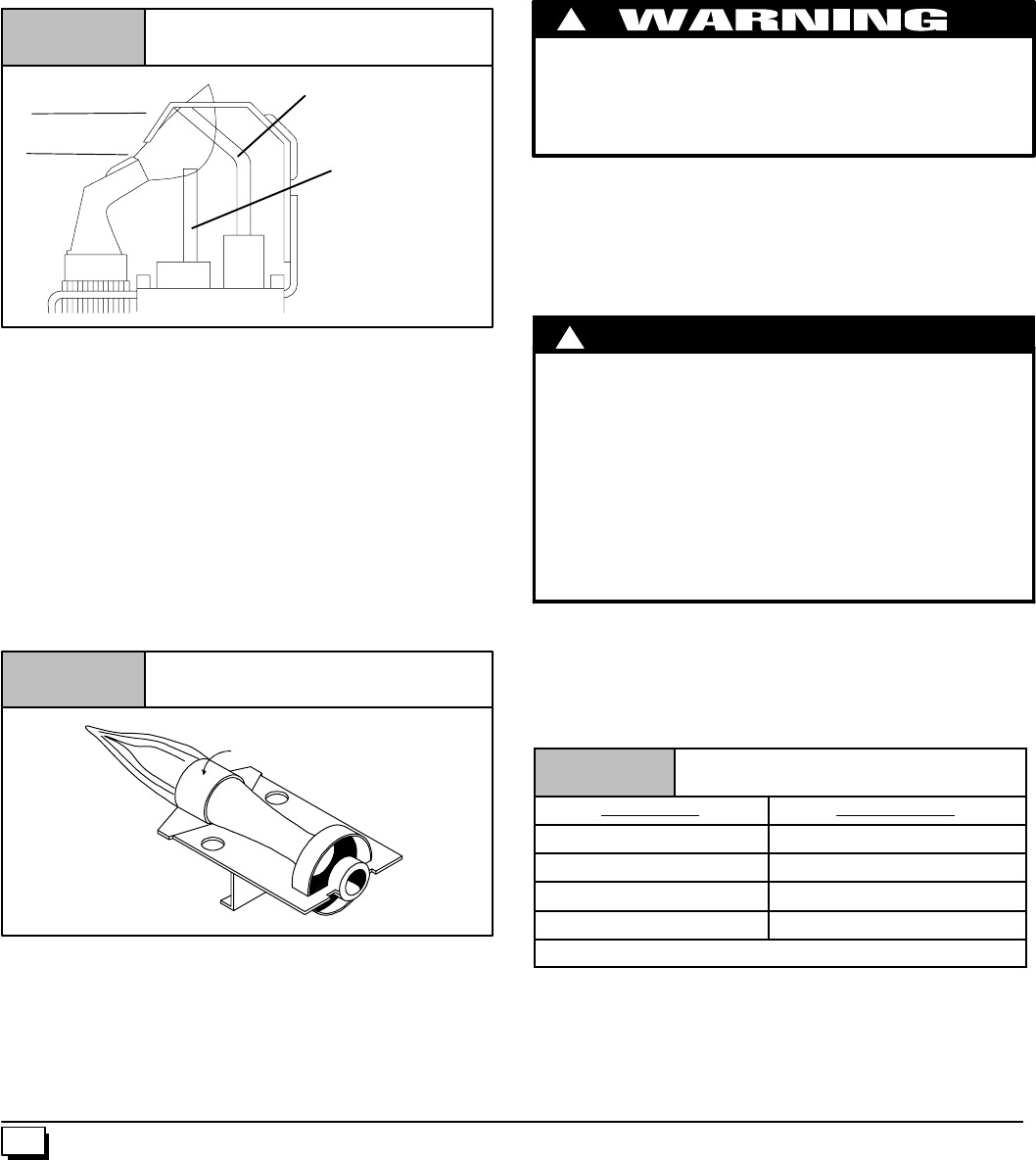
34 440 01 1020 02
3. Turn gas ON and remove adjustment screw cover on gas
valve. Turn counterclockwise to decrease pressure and
clockwise to increase.
4. For altitudes up to 2000¢, set pressure to value shown in
Table 6,±0.3²(8mm)watercolumn.Foraltitudesof2000¢to
8000¢, see Section 5 for correct pressure setting.
Adjust Pilot Burner
The furnace has a pilot flame to light the main burner. The flame
shouldsurround3/8²to1/2²oftheflamesensor.SeeFigure 41. To
adjust, remove cap from pilot adjusting screw on gas valve. Turn
screw counterclockwise to increase or clockwise to decrease
flame as required. Replace adjusting screw cap.
Pilot Burner
Figure 41
Proper Flame
Adjustment Flame Sensor
Hot Surface
Igniter
1 0 -- 11 -- 6 5
3/8²
²²
²to 1/2²
²²
²
Main Burner Flame Check
Allowthefurnacetorunapproximately10minutestheninspectthe
main burner and pilot flames. See Figure 42.
Check for the following (Figure 42):
·Stable and blue flames. Dust may cause orange tips or
wispsofyellow,butflamesMUSTNOThavesolid,yellow
tips.
·Flamesextendingdirectlyfromburnerintoheatexchang-
er.
·Flames do NOT touch sides of heat exchanger.
If any problems with main burner flames are noted, it may be nec-
essary to adjust gas pressures, or check for drafts.
Main Burner
Burner Face
10--10--78
Figure 42
Temperature Rise Check
TheblowerspeedMUST besettogivethecorrect airtemperature
rise through the furnace as marked on the rating plate. Tempera-
ture rise is the difference between supply and return air tempera-
tures.
To check temperature rise,use the following procedure:
1. Place thermometers in supply and return air registers as
close to furnace as possible, avoiding direct radiant heat
from heat exchangers.
2. Operate furnace continuously for 15 minutes with all regis-
ters and duct dampers open.
3. Take reading and compare with range specified on rating
plate.
4. Ifthecorrect amountof temperatureriseisNOT obtained,it
maybenecessarytochangeblowerspeed.Ahigherblower
speedwilllowerthetemperaturerise.Alowerblowerspeed
will increase the temperature rise.
Changing Blower Speed
ELECTRICAL SHOCK HAZARD
Failure to do so can result in death and/or personal
injury.
TurnOFFpowertofurnacebeforechangingspeedtaps.
!
NOTE:Thespeedtapsthatthemanufacturersetsfromthefactory
for this product are based on a nominal 400 CFM per ton cooling
and the basic mid range on the temperature rise for heating.
Since the manufacturer cannot establish the static pressure
that will be applied to the unit, it is the responsibility of the in-
staller dealer/contractor to select the proper speed taps for the
application when the unit is installed.
!
Failure to properly set the air temperature rise could
result in reduced furnace life.
UseONLY thefollowingblowermotorspeedtapsforsettingair
temperature rise.
Blower Motor Speed Taps Model Sizes
Hi (BLK) All
Med--Hi (O) All except 050F/J14
Med Lo (BL All except 075B/F12
and 100F/J14
Lo (RED) 050B/F12, 100J20,
and 125J/L20
C
A
UTION
If it is necessary to change speeds, refer to steps below.
1. Refer to Furnace Wiring Diagram for location of theheating
andcoolingspeedtapslocatedontheelectronicfancontrol
aswellaslocationofunusedblowermotorspeedleads.Use
thechart(Table 9)todeterminetheblowermotorspeedset-
tings.
Table 9 Blower Speed Chart
Wire Color Motor Speed
Black High
Orange*Med--High
Blue Medium
Red Low
*Med--High speed may not be provided on all models.
2. Change the heat or cool blower motor speed by removing
the motor lead from the “Heat”or“Cool” terminal and re-
placeitwiththedesiredmotorspeedleadfromthe“Unused
MotorLead”location.Connectthewirepreviouslyremoved
from the “Heat”or“Cool” terminal to the vacated “Unused
Motor Lead” terminal.

35
440 01 1020 02
3. If the same speed must be used for both heating and cool-
ing,removetheundesiredmotorspeedleadfromthe“Heat”
or “Cool” terminal and connect that lead to the open termi-
nal at “Unused Motor Lead” location. Attach a jumper be-
tween the “Heat” and “Cool” terminals and the remaining
motor speed lead.
Note:Formotorswith(4)speedleads,itwillbenecessaryto
tape off the terminal of the motor speed lead removed from
the “Heat”or“Cool” terminal with electrical tape since an
open terminal will not be available at the “Unused Motor
Lead” location.
Continuous Fan Operation
A terminal is provided on the electronic fan control located in the
circulatingblowercompartmentforoperationofthecontinuousfan
option. This connection is intended for the low speed motor tap,
and has a lower contact rating (8 amps) than the heat and cool
taps.Whenthelowspeedblowerleadisconnectedtothisterminal,
this will provide low speed blower operation whenever the other
two speeds (Heat or Cool) are not energized.
Thoroughlycheckthesystemaftermodificationtoensuretheprop-
er operation of the circulatingair blower in allmodes of operation.
Separate speed selections for Heat, Cool, and
Continuous Fan
Connectlowspeedleadfromcirculatingmotortothe“Cont.”termi-
nal at the electronic fan control. The appropriate motor leads
should already be connected to the “Heat” and “Cool”terminals.
Heating and Continuous Blower Speed the
Same
If it is necessary to operate the heating speed and continuous
blowerspeedusingthesameblowerspeed, connecta jumperbe-
tween the ”Heat” and ”Cont.” terminals on the electronic fan con-
trol.
Note: There should be only ONE motor lead going to the “Heat”
and “Cont.” terminals.
9. Furnace Maintenance
CAUTION
Itisrecommendedthatthefurnacebeinspectedandserviced
on an annual basis (before the heating season) by a qualified
service technician.
See “User’s Information Manual” and the “Service Manual”.
10. Sequence of Operation & Diagnostics
The following is the normal operating sequence for the control system.
Cooling (Y) Request:
24 VAC signals applied to Y & G terminals of EFT (electronic fan timer) control.
·Cool motor speed energized after 5 second Cool Fan On Delay time.
Y & G signals removed from EFT.
·Cool motor speed de--energized after 90 second Cool Fan Off Delay time.
Circulating Fan (G) Request:
24 VAC signals applied to G terminals of EFT control.
·Heat motor speed energized without delay.
G signal removed from EFT.
·Heat motor speed de--energized without delay.
Heating (W) Request:
24 VAC signals applied to W terminal of EFT control.
·Inducer motor turns on.
·The gas valve solenoid energizes.
·Followinga3secondprepurge delay, the pilot valve opens and the ignitor begins to warm up.
·After the pilot lights, the main burners energize and light.
·Timed from the opening of the main gas valve, the control will delay 30 seconds before switching the fan to Heat speed.
W signal removed from EFT.
·The gas valve de--energizes and the main burners go out.
·The inducer runs at its present speed for a 30 second postpurge period.
·Timed from the gas valve de--energizing, the Heat fan speed de--energizes after the selected Heat Fan Delay time expires.
Heating Request with Gas Supply Line Shut Off:
24 VAC signals applied to W terminal of EFT control.
·Inducer motor turns on.
·The gas valve solenoid energizes.
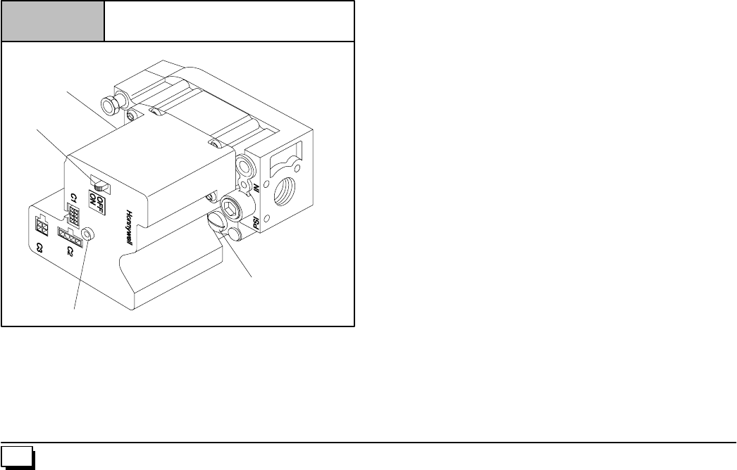
36 440 01 1020 02
·Followinga3secondprepurge delay, the pilot valve opens and the ignitor begins to warm up.
·The ignitor glows red--hot for 30 seconds, then turns off.
·The igniter stays off for 25 seconds, then begins to warm--up again.
·The igniter glows red--hot for 30 seconds, then turns off.
·The pilot valve closes 3 seconds after the igniter de--energizes.
·The inducer de--energizes 5 seconds after the pilot valve closes.
·The SmartValve proceeds to soft lockout and flashes error code 6.
·The control exits soft lockout after 5 minutes and begins
another ignition sequence.
Gas Valve Diagnostic Codes (See Figure 43)
OFF = Control not powered
Heartbeat = Normal Operation (Standby or call for heat)
1 Flash = Not used
2 Flashes = Pressure switch closed when should be open
3 Flashes = Pressure switch circuit was still sensed as open 30 seconds after the inducer was energized. System is
in 5 minute delay mode, with inducer off. After 5--minute delay, a new ignition sequence will be initiated.
(Note: SV9541M On/Off switch in off position during a call for heat will generate this diagnostic code)
4 Flashes = Limit switch string open
5 Flashes = Flame sensed out of sequence -- Flame signal still present.
6 Flashes + 1 Note 1 = Soft Lockout --Maximum retry count exceeded (failed to light within 4 trials for ignition)
6 Flashes + 2 Notes 1,2 = Soft Lockout --Maximum recycle count exceeded -- Last failure was Flame Sense Lost During Run
6 Flashes + 3 Notes 1,2 = Soft Lockout --Maximum recycle count exceeded -- Last failure was Airflow Proving Circuit Opened
During Run
6 Flashes + 4 Notes 1,2 = Soft Lockout --Maximum recycle count exceeded -- Last failure was Limit Circuit Opened During Run
7 Flashes = Soft Lockout Due to Limit Trips Taking Longer than 2 minutes to Reset; Auto Reset After 1 Hour if
Call for Heat Still Present. Reset by Cycling Call for Heat at Any Time.
NOTE1:The6+Xdesignationindicatesacombinationofflashcodes:6flashesshowsthecontrolisinsoftlockout,followedbyXflashes
toindicatethereasonthecontrolwentintosoftlockout.Whenthe6+Xcodeisflashing,theSV9541willattemptanewignitionsequence
afterafiveminutedelayperiod,ifthecallforheatisstillpresent.Resetofthethermostatwillinitiateanewignitionsequenceimmediately.
NOTE 2: Any combination of 5 ‘abnormal’ events during a single call for heat will result in soft lockout. An ‘abnormal’ event is a Flame
SenseFailureDuringRun,AirflowProvingCircuitOpenDuringRun,orLimitCircuitOpenDuringRun.Theflashcodewillindicatewhich
was the last ‘abnormal’ event that put the system into the soft lockout state based on the table above.
Typical Gas Valve Honeywell
Figure 43
dwg 25--23--31a
INLET
Manifold Pressure
Adjustment
Pilot Pressure
Adjustment (Hidden)
On\Off
Switch
Diagnostic Light
OUTLET
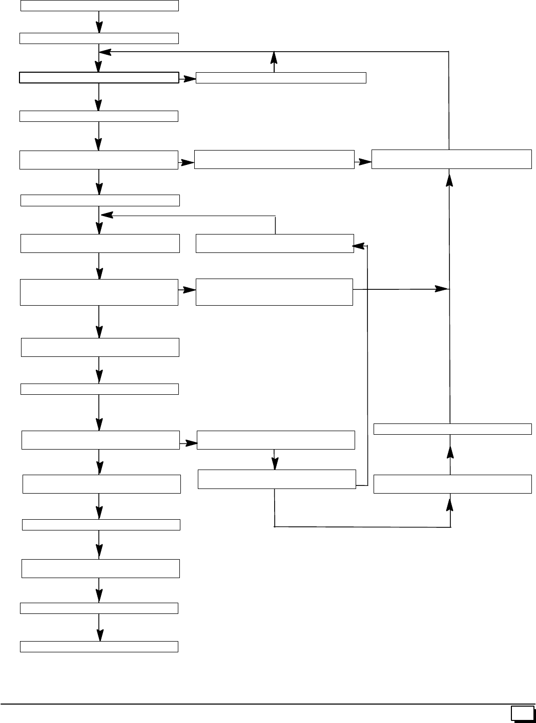
37
440 01 1020 02
HONEYWELL SV9541M “SMART VALVE” Sequence of Operation
POWER APPLIED TO APPLIANCE
THERMOSTAT CALLS FOR HEAT
COMBUSTION BLOWER ENERGIZED
PRESSURE SWITCHES CLOSED WITHIN 30 SEC-
ONDS? COMBUSTION BLOWER DE-ENERGIZED
PILOT VALVE OPENS:
IGNITOR POWERED (1) THREE SECOND FLAME
FAILURE RECYCLE DELAY
3 SECOND PRE-PURGE
FIVE MINUTE WAIT PERIOD
PILOT LIGHTS AND FLAME IS SENSED
DURING 90 SECOND TRAIL FOR
IGNITION?
PILOT VALVE CLOSES;
PILOT IGNITOR OFF
MAIN VALVE OPENS,
HEATING FAN “ON” DELAY BEGINS
AFTER DELAY: CIRCULATING BLOWER STARTS
FLAME SENSE LOST? CIRCULATING BLOWER OFF AFTER DELAY
PILOT AND MAIN VALVE CLOSE
COMBUSTION AIR BLOWER OFF AFTER POST
PURGE
FLAME SENSE LOST MORE THAN FIVE
TIMES IN THIS CALL FOR HEAT?
THERMOSTAT CALL FOR HEAT ENDS
COMBUSTION BLOWER DE-ENERGIZED AFTER 30
SECOND POST PURGE
PILOT AND MAIN VALVE CLOSE
CIRCULATING BLOWER OFF AFTER DELAY
WAIT FOR NEXT CALL FOR HEAT
PRESSURE SWITCHES PROVED OPEN? NO
NO
NO
NO
YES
YES
WAIT FOR PRESSURE SWITCHES TO OPEN
(1) Ignitor “ON” for first 30 seconds of trial for ignition, then “OFF” for next 30 seconds. If the pilot has
not lit, it turns back “ON” for the final 30 seconds. The pilot valve remains energized during the entire
90 second trial for ignition.
NOTE: If main limit string opens and takes longer than 2 minutes to close, system goes into 1 hour wait
period.
YES
NO
38 440 01 1020 02
HONEYWELL SV9541M “SMART VALVE” Trouble shooting
The6+Xdesignationindicatesacombinationofflashcodes:6flashesshowsthecontrolisinsoftlockout,followedbyXflashestoindicate
the reason the control went into soft lockout. Last status code indicates repair to address first
LED
STATUS INDICATES CHECK/REPAIR
Off No power to system control. Linevoltage inputatL1andNeutralconnectorsonST9160B FanTimer.
Low voltage (24V) power at 24 VAC and COM terminals on ST9160B
System wiring harness is in good condition and securely connected.
Heartbeat
Bright – Dim Normalindicationwheneverthesystemispowered,unlesssome
abnormal event has occurred. Not Applicable -- Normal Operation (stand by or call for heat)
2 Flashes
Pressure switches closed when it should be open
(i.e. when call for heat begins).
(Combustionblowerisnotenergizeduntilpressureswitches
opens)
Pressure switches stuck closed (system will wait for pressure switch to
open).
Pressure switches miswired or jumpered.
3 Flashes
Pressureswitches,openwhentheyshouldbeclosed(i.e.longer
than 30 seconds after combustion blower/inducer is energized).
Systemgoesinto5--minutedelayperiod,withcombustionblower/
inducer off. Atendofthe5--minutedelay,anothercyclewillbegin.
Ignition system control switch must be in the ON position.
Pressure switches operation, tubing, and wiring.
Restrictions in furnace air intake or vent piping.
4 Flashes
Main Limit or Roll Out Switch is open.
Combustion blower is energized, Circulating blower is energized
heat speed.
Main limit switch.
Manual reset burner rollout switch.
Limit and rollout switch wiring is in good condition and securely
connected.
5 Flashes Flame signal sensed out of proper sequence.
Combustion blower is energized, Circulating blower is energized
heat speed after the “ON” delay.
Flame at pilot burner.
6 Flashes +
1Flash
Soft Lockout.
Failed to light pilot during 90 sec. trial for ignition
Combustionairblowerisde--energized, Circulatingblowerisde--
energized after the “OFF” delay.
After 5--minute delay time, control system will reset andinitiate a
new ignition sequence,
Gas supply off or pressure too low or high for appliance to operate.
Damaged or broken HIS element
Line voltage HOT lead wire not connected to L1 terminal on ST9160B.
Furnace not properly earth grounded.
Flame sense rod contaminated or in incorrect position.
Pilot burner located in incorrect position.
Pilot burner lead wires are in good condition and popery connected.
Pressure switches operation, tubing, and wiring.
6 Flashes +
2 Flashes
Soft Lockout.
Last failure was Flame Sense lost during run.
Maximum recycle count exceeded
Combustion air blower is de--energized, Circulating blower is
de--energized after the “OFF” delay.
After 5--minute delay time, control system will reset andinitiate a
new ignition sequence,
Gas supply off or pressure too low or high for appliance to operate.
Line voltage HOT lead wire not connected to L1 terminal on ST9160B.
Furnace not properly earth grounded.
Flame sense rod contaminated or in incorrect position.
Pilot burner located in incorrect position.
Pilot burner lead wires are in good condition and properly connected.
Cycling, pressure switch
Condensate drain blocked
Pressure switches operation, tubing, and wiring.
39
440 01 1020 02
HONEYWELL SV9541M “SMART VALVE” Trouble shooting continued
LED
STATUS INDICATES CHECK/REPAIR
6 Flashes +
3 Flashes
Soft Lockout.
Last failure was pressure switch
Maximum recycle count exceeded
Combustionairblowerisde--energized, Circulatingblowerisde--
energized after the “OFF” delay.
After 5--minute delay time, control system will reset andinitiate a
new ignition sequence,
Ignition system control switch must be in the ON position.
Pressure switches operation, tubing, and wiring.
Restrictions in furnace air intake or vent piping.
High winds blowing against vent.
6 Flashes +
4 Flashes
Soft Lockout.
Last failure was limit circuit opened during run.
Combustion air blower is de--energized, Circulating blower is
de--energized after the “OFF” delay.
After 5--minute delay time, control system will reset andinitiate a
new ignition sequence,
Main limit switch.
Limit and rollout switch wiring is in good condition and securely
connected.
Restriction in duct work.
Dirty filter
7 Flashes
Soft Lockout.
Blower failure (typical)
Limit trip took longer than 2 minutes to reset.
System will start a new ignition sequence after 1 hour, if call for
heat still present.
Dead blower.
Blocked duct work.
11. Concentric Termination
Vent Termination Clearances
CARBON MONOXIDE POISONING, FIRE AND EXPLO-
SION HAZARD
Failure to properly vent this furnace can result in
death, personal injury and/or property damage.
Inlet and outlet pipes may NOT be vented directly
above each other (standard vent terminals).
!
1. Determine termination locations based on clearancesspe-
cified in following steps and as shown in Figure 7,
Figure 44 through Figure 49.
2. The vent termination must be located at least 12²above
ground or normally expected snow accumulation levels.
3. DoNOTterminateoverpublicwalkways.Avoidareaswhere
condensate may cause problems such as above planters,
patios,oradjacenttowindowswheresteammaycausefog-
ging.
4. Theventterminationshall belocated atleast 4¢horizontally
from any electric meter, gas meter, gas regulator, and any
relief equipment. These distances apply ONLY to U.S.
installations.
5. The vent termination is to be located at least 3¢above any
forced air inlet located within 10¢; and at least 10¢from a
combustion air intake of another appliance, except another
direct vent furnace intake.
6. InCanada,theCanadianFuelGasCodetakesprecedence
over the preceding termination instructions.
Concentric Vent Termination - Kit #
NAHA001CV & NAHA002CV
These kits arefor vertical or horizontal terminationof the combus-
tion air inlet and the exhaust vent pipes on Category IV gas--fired
condensing furnaces. The NAHA001CV kit can be used for 3²di-
ameter pipe systems. The NAHA002CVkit can be used for 2²di-
ameterpipe system.Referto Table 10 for the correctpipe size for
the furnace. Both the combustion air inlet and the exhaust vent
pipes must attach to the termination kit. The termination kit must
terminate outside the structure and must be installed per the
instructions outlined below for vertical or horizontal termination.
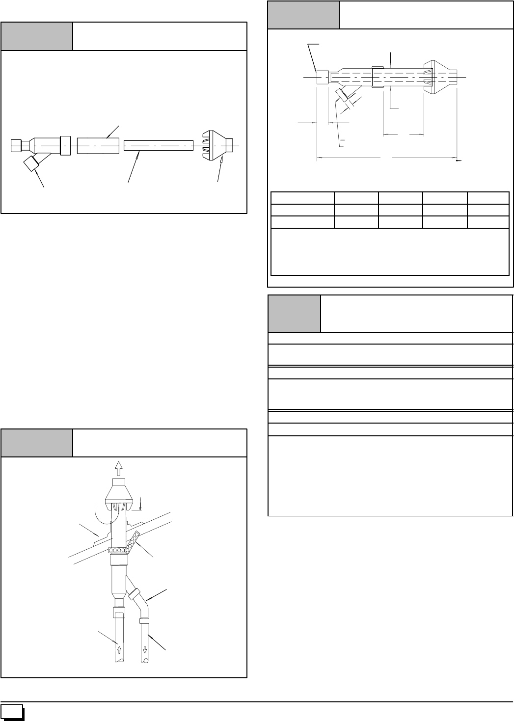
B
PVC Intake/Combustion Air
Concentric Vent Dimensional
Drawing
B PVC
Vent/Exhaust
D
A
11/2²
²²
²
13/16²
²²
²
25-22-03
C
Figure 46
40 440 01 1020 02
Verticalterminationispreferred.Fieldsuppliedpipeandfittingsare
required to complete the installation.
2or2
1/2²
²²
²Dia.
SDR-26 Pipe
Kit Components
Kit Contents:
3²
²²
²Rain Cap or 2²
²²
²Rain Cap
3²
²²
²Diameter SDR-26 Pipe, 191/2²
²²
²Long or
4²
²²
²Diameter SDR-26 Pipe, 371/8²
²²
²Long,
2²
²²
²Diameter SDR-26 Pipe, 315/8²
²²
²Long or
21/2²
²²
²Diameter SDR-26 Pipe, 24²
²²
²Long,
3²
²²
²Y Concentric Fitting or 2²
²²
²Y Concentric Fitting
2²
²²
²or 3²
²²
²Dia.
Rain Cap
3²
²²
²or 4²
²²
²Dia.
SDR-26 Pipe
2²
²²
²or 3²
²²
²Dia.
Y Concentric Fitting 25--22--03
Figure 44
Vertical & Horizontal Termination
1. Determine the pipe diameters required for the installation
from Table 10 and Table 11 and Figure 46.
2. Determine the best location for the termination kit. See
Figure 45 for vertical termination or Figure 45 and
Figure 49 for horizontal termination. Roof termination is
preferred since it is less susceptible to damage, has re-
duced intake contaminants and less visible vent vapor. For
side wall termination, consideration should be given to: 1)
possible damage from the vapors to plants/shrubs, other
equipmentandbuildingmaterials,2)possibledamagetothe
terminalfromforeignobjects,3)windeffectsthatmaycause
recirculationofflueproducts,debrisorlightsnowand4)vis-
ible vent vapor.
3. Cut one 5²diameter hole through the structure for the
NAHA001CV Kit or one 4²diameter hole for the
NAHA002CV Kit .
4. Dimension D may be lengthened to 60²max. or shortened
bycuttingthepipesto12²min.DimensionAwillchangeac-
cording to D dimension. (See Figure 46)
Maintain 12²
²²
²min. clearance above
highest anticipated snow level. Max.
of 24²
²²
²above roof.
Combustion
Air
Roof Boot/
Flashing
(Field Supplied)
Combustion
Air
Vent
Concentric Vent Roof Installation
Vent
Support
(Field Supplied)
45°
°°
°Elbow
(Field Supplied)
25--22--02
Note:
Support must be field installed to secure termination kit to structure.
Figure 45
Model A* B C D**
NAHA001CV 387/83 41/2211/8
NAHA002CV 333/82 31/2167/8
* = Dimension will change accordingly as dimension D is
lengthened or shortened.
**= Dimension D may be lengthened to 60²may also be
shortened by cutting the pipes provided in the kit to 12²
minimum
Table 10 Concentric Termination Kit
NAHA001CV & NAHA002CV Venting
Table for *9MPD Models
50,000, 75,000 & 80,000 Btuh Furnaces
NAHA002CV -- 35¢& (4) 90°elbows with 2²PVC pipe or
NAHA001CV -- 65¢& (4) 90°elbows with 3²PVC pipe
100,000 Btuh Furnace
NAHA001CV -- 35¢& (4) 90°elbows with 3²PVC pipe or
NAHA001CV -- 65¢& (4) 90°elbows with 3²PVC pipe &
Long Vent Kit (See Tech. Manual)
125,000 Btuh Furnace
NAHA001CV -- 35¢& (4) 90°elbows with 3²PVC pipe
1. Do not include the field supplied 45°elbow in the total elbow
count.
2. If more than four elbows are required, reduce the length of
both the inlet and the exhaust pipes five feet for each
additional elbow used.
3. Elbows are DWV long radius type for 2²and 3²vents.
NOTE: Feet of pipe is whichever pipe run is the longest, either
inlet or outlet side.
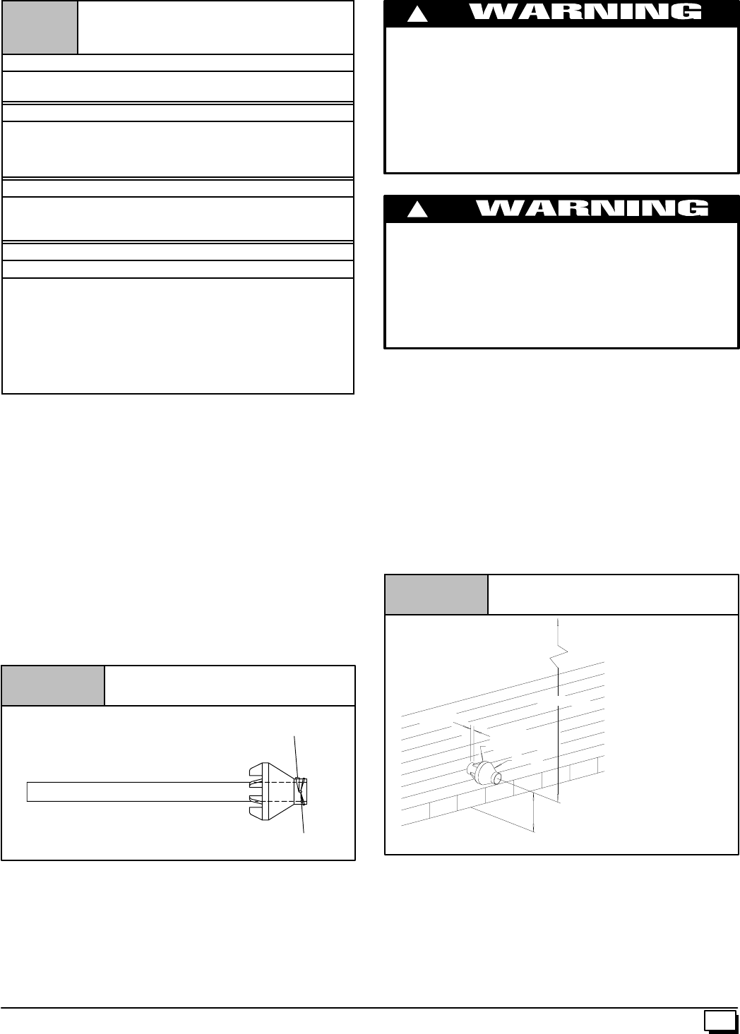
41
440 01 1020 02
Table 11 Concentric Termination Kit
NAHA001CV & NAHA002CV Venting
Table for N9MP2 Models
50,000 & 80,000 Btuh Furnaces
NAHA002CV -- 35¢& (4) 90°elbows with 2²PVC pipe or
NAHA001CV -- 65¢& (4) 90°elbows with 3²PVC pipe
75,000 Btuh Furnaces
NAHA002CV -- 20¢& (2) 90°elbows with 2²PVC pipe or
NAHA002CV -- 35¢& (4) 90°elbows with 2²PVC pipe &
Long Vent Kit (See Tech. Manual) or
NAHA001CV -- 65¢& (4) 90°elbows with 3²PVC pipe
100,000 Btuh Furnace
NAHA001CV -- 35¢& (4) 90°elbows with 3²PVC pipe or
NAHA001CV -- 65¢& (4) 90°elbows with 3²PVC pipe &
Long Vent Kit (See Tech. Manual)
125,000 Btuh Furnace
NAHA001CV -- 35¢& (4) 90°elbows with 3²PVC pipe
1. Do not include the field supplied 45°elbow in the total elbow
count.
2. If more than four elbows are required, reduce the length of
both the inlet and the exhaust pipes five feet for each
additional elbow used.
3. Elbows are DWV long radius type for 2²and 3²vents.
NOTE: Feet of pipe is whichever pipe run is the longest, either
inlet or outlet side.
Ifassemblyneedstobeextendedtomeetheightorsidewallthick-
nessrequirement,thetwopipessuppliedinthekitmaybereplaced
byusingthesamediametersolid,single(nocouplingconnections)
field supplied SDR--26 PVC (ASTM D2241) pipes. Do not extend
dimension D more than 60².(SeeFigure 46)
Do not use field supplied couplings to extend the pipes.
Airflow restriction will occur and the furnace pressure switch
may cause intermittent operation.
5. Partiallyassembletheconcentricventterminationkit.Clean
and cement the parts usingthe procedures for Joining Pipe
andFittingssectionofthemanual.A)CementtheYConcen-
tricfittingto the 4²diameterkitpipe. (SeeFigure 47) B)Ce-
ment the 3²raincaptothe2
1/2²diameter kit part. (See
Figure 47) NOTE: A field supplied stainless steel screw
maybeusedtosecuretheraincaptothepipeinsteadofce-
mentingwhenfielddisassemblyisdesiredforcleaning(See
Figure 47)
Figure 47 Rain Cap to Vent Pipe Assembly
Drill clearance hole in rain
cap and pilot hole in vent pipe.
Stainless steel screw
(Field supplied)
25--22--02
CARBON MONOXIDE POISONING HAZARD
Failure to follow this warning could result in death,
personal injury and/or property damage.
When using the alternatescrew assembly method, drill a
clearance hole in the rain cap and apilot hole in thevent
pipe for the screw size being used. Failure to drill
adequate holes may cause cracking of the PVC
components, allowing flue gases to be recirculated.
!
CARBON MONOXIDE POISONING HAZARD
Failure to follow this warning could result in death,
personal injury and/or property damage.
Do not operate the furnace with the rain cap removed as
recirulation of the flue gases may occur. Water may also
collect inside the larger combustion air pipe and flow to
the burner enclosure.
!
6. InstalltheYconcentricfittingandthepipeassemblythrough
thestructure’shole.Forverticaltermination,installtheparts
through the field supplied roof boot/flashing.NOTE: Do not
allow insulation or other materials to accumulate inside the
pipe assembly when installing through the structure’s hole.
7. SecuretheassemblytothestructureasshowninFigure 45
orFigure 49 using fieldsupplied metalstrapping orequiva-
lent material.
NOTE: Ensure the termination height is above the roof sur-
faceoranticipatedsnowlevelasshowninFigure 45forver-
tical termination. Ensure the termination location clearance
dimensions are as shown in Figure 48 and Figure 49 for
horizontal termination.
1²
²²
²max.
Maintain 12²
²²
²clearance above highest antici-
pated snow level or grade whichever is great-
er.
Figure 48 Concentric Vent and Combustion--
Air Side Termination
Combustion
Air Vent
25--22--02
12²
²²
²min.
Roof Overhang
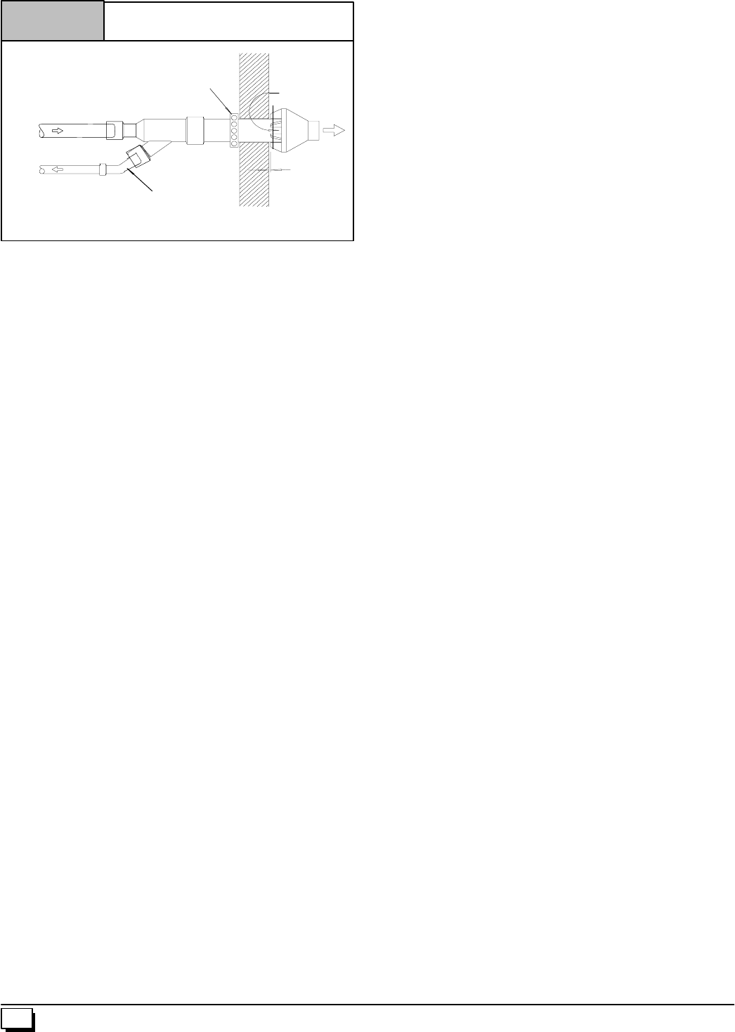
42 440 01 1020 02
Combustion
Air
Vent
Combustion
Air
Concentric Vent Sidewall
Attachment
Vent
45°
°°
°Elbow
(Field Supplied) 25--22--02
Strap
(Field Supplied)
Flush to
1²
²²
²max.
Note:
Securing strap must be field installed to prevent movement of termination kit in side wall.
Figure 49 8. Install the rain cap and the small diameter pipe assembly in
theYconcentric fitting and thelargepipeassembly.Ensure
that the small diameter pipe is bottomed out and securely
cemented in the Y concentric fitting.
9. Cement the furnace combustion air and vent pipes to the
concentric vent termination assembly. See Figure 45 or
Figure 49 for proper pipe attachment.
10. Operate the furnacethrough one heat cycle to ensurecom-
bustionairandventpipesareproperlyconnectedtothecon-
centric termination connections.
43
440 01 1020 01
Models
Single Pipe
N9MP1050B12B1
N9MP1075B12B1
N9MP1080F16B1
N9MP1100F14B1
N9MP1100J20B1
N9MP1125J20B1
or
Two Pipe
N9MP2050B12B1
N9MP2075B12B1
N9MP2080F16B1
N9MP2100F14B1
N9MP2100J20B1
N9MP2125J20B1
or
Dual Certified
*9MPD050F12B1
*9MPD075F12B1
*9MPD080J16B1
*9MPD100J14B1
*9MPD100J20B1
*9MPD125L20B1
*Denotes Brand
Save This Manual For Future Reference
Four Position Furnace
25--23--30
International Comfort Products Corporation (USA)
Lewisburg, TN 37091 USA
Fast Parts Division
615--248--8300
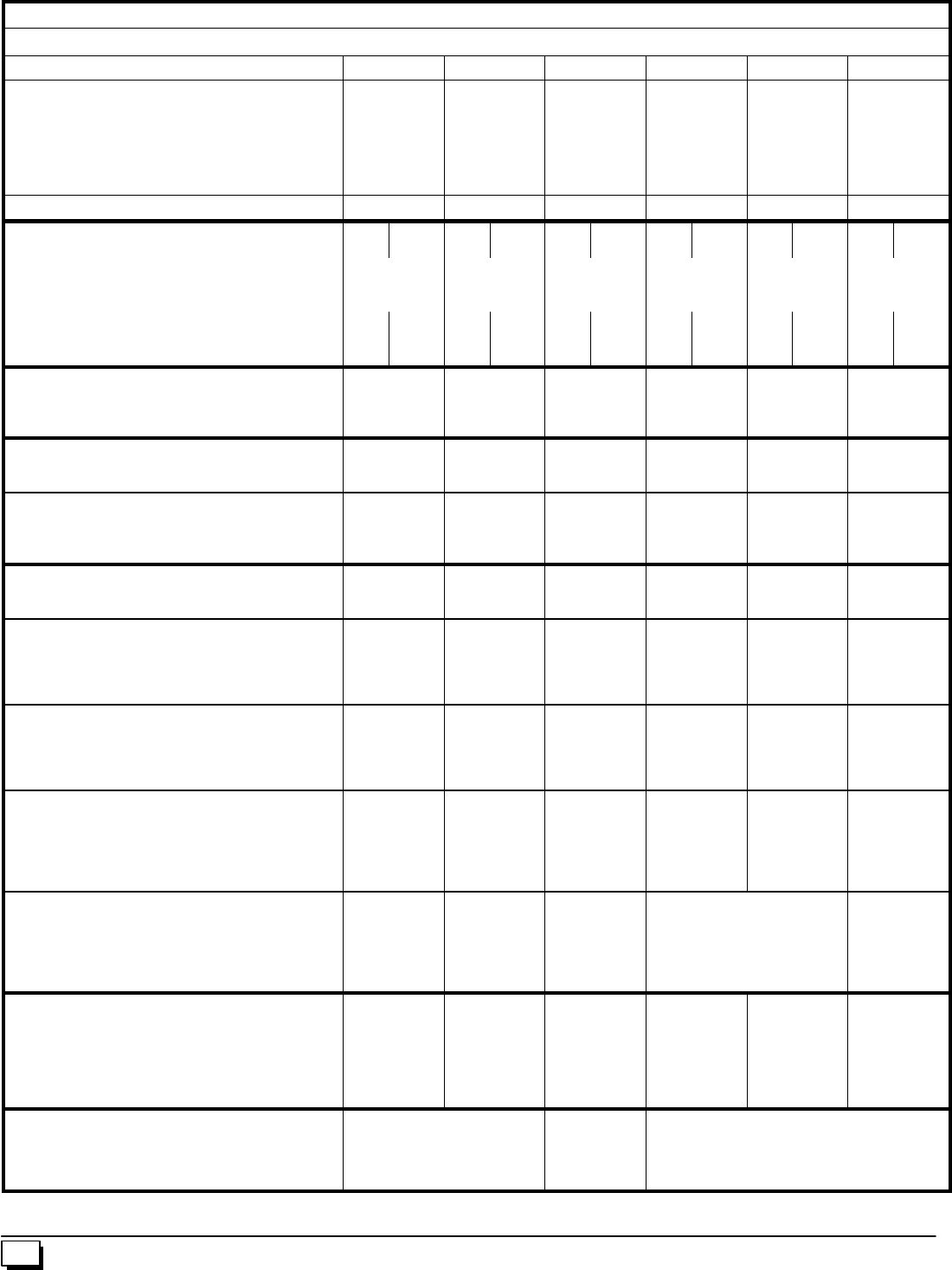
44 440 01 1020 02
Manufacturers Number (Mfr No --SeeRatingPlate) ALL Models
Specifications (N9MP1)
N9MP1050B12B N9MP1075B12B N9MP1080F16B N9MP1100F14B N9MP1100J20B N9MP1125J20B
General
GasType
Input (Btuh)
Output (Btuh)
Transformer Size (VA)
T’stat Heat Anticipator
Temp. Rise (°F)
Nat./ LP
50,000
45,500
40
.10
35--65
Nat./ LP
75,000
68,000
40
.10
40--70
Nat./ LP
80,000
72,000
40
.10
35--65
Nat./ LP
100,000
91,000
40
.10
40--70
Nat./ LP
100,000
96,500
40
.10
40--70
Nat./ LP
125,000
113,750
40
.10
40--70
Electrical (Volts/Hz/FLA) 115/60/9.8 115/60/8.9 115/60/9.0 115/60/9.0 115/60/10.5 115/60/11.2
Gas & Ignition
GasType Nat. L.P. Nat. L.P. Nat. L.P. Nat. L.P. Nat. L.P. Nat. L.P.
GasValve
Regulation Type
IgnitionType/Series
HW SV9541M
SNAP
HW HSP
HW SV9541M
SNAP
HW HSP
HW SV9541M
SNAP
HW HSP
HW SV9541M
SNAP
HW HSP
HW SV9541M
SNAP
HW HSP
HW SV9541M
SNAP
HW HSP
Manifold Press. (Inch’s WC)
Std. Main Orifices (No/Size)
Pilot Orifice Size
3.5
2/42
.018
10.0
2/54
.011
3.5
3/42
.018
10.0
3/54
.011
3.5
4/44
.018
10.0
4/55
.011
3.5
4/46
.018
10.0
4/54
.011
3.5
4/42
.018
10.0
4/54
.011
3.5
5/42
.018
10.0
5/54
.011
Fan Controls
Fan Control (Type)
Fan Control On
(Timed--secs) Off
HW ST9160
30
60,100,140,180
HW ST9160
30
60,100,140,180
HW ST9160
30
60,100,140,180
HW ST9160
30
60,100,140,180
HW ST9160
30
60,100,140,180
HW ST9160
30
60,100,140,180
Combustion
Flue Outlet Size (Inches)
Std. Outlet Temp (°5¢No Elbows) 2
<140 2
<140 2
<140 3
<140 3
<140 3
<140
Blower Pressure 5¢No Elbows (²WC)
Blower Pressure 40¢+5--90°DWV Elbows (²WC)
Transition Bx Pressure 5¢No Elbows (²WC)
Transition Bx Pressure 40¢+5--90°DWV Elbows (²WC)
-- --
-- --
-- 2. 6
-- 2. 3
-- --
-- --
-- 2. 6
-- 2. 3
-- --
-- --
-- 2. 6
-- 2. 5
-- 1. 8
-- 1. 7
-- 2. 6
-- 2. 5
-- 1. 8
-- 1. 7
-- 2. 6
-- 2. 5
-- 1. 8
-- 1. 7
-- 2. 6
-- 2. 5
Limits & Controls
Rollout Switch (°F)
Limit Control Setting (°F) 300
240 300
210 300
230 300
230 300
220 300
190
Standard Pressure Sw. (Part No)
Blower Switch Pressure (Close)(²WC)
Blower Switch Pressure (Open) (²WC)
Transition Switch Pressure (Close)(²WC)
Transition Switch Pressure (Open) (²WC)
1013802
-- --
-- --
--2.2
--2.0
1013802
-- --
-- --
--2.2
--2.0
1013811
-- --
-- --
--1.8
--1.6
1013801
-- --
-- --
--2.3
--2.1
1013802
-- --
-- --
--2.2
--2.0
1013166
--1.3
--1.1
--1.8
--1.6
High Altitude Pressure Sw. (Part No)
Blower Switch Pressure (Close)(²WC)
Blower Switch Pressure (Open) (²WC)
Transition Switch Pressure (Close)(²WC)
Transition Switch Pressure (Open) (²WC)
1013803
-- --
-- --
--2.0
--1.8
1013803
-- --
-- --
--2.0
--1.8
1013812
-- --
-- --
--1.5
--1.3
1013803
-- --
-- --
--2.0
--1.8
1013803
-- --
-- --
--2.0
--1.8
1013157
--0.9
--0.7
--1.7
--1.5
Long Vent Kit (Part No)
Pressure Switch (Part No)
Blower Switch Pressure (Close)(²WC)
Blower Switch Pressure (Open) (²WC)
Transition Switch Pressure (Close)(²WC)
Transition Switch Pressure (Open) (²WC)
-- --
-- --
-- --
-- --
-- --
-- --
-- --
-- --
-- --
-- --
-- --
-- --
-- --
-- --
-- --
-- --
-- --
-- --
NAHA001LV
1013518
--1.0
--0.8
--2.0
--1.8
NAHA002LV
1013515
--1.0
--0.8
--1.7
--1.5
-- --
-- --
-- --
-- --
-- --
-- --
High Altitude Long Vent Kit (Part No)
Pressure Switch (Part No)
Blower Switch Pressure (Close)(²WC)
Blower Switch Pressure (Open) (²WC)
Transition Switch Pressure (Close)(²WC)
Transition Switch Pressure (Open) (²WC)
-- --
-- --
-- --
-- --
-- --
-- --
-- --
-- --
-- --
-- --
-- --
-- --
-- --
-- --
-- --
-- --
-- --
-- --
NAHA003LV
1013165
--0.7
--0.6
--1.4
--1.2
-- --
-- --
-- --
-- --
-- --
-- --
Blower Data
Type & Size
Motor Amps/Rpm
Motor Type/H.p.
Cap. Mfd/Volts
Filter Type & Size (Permanent -- not supplied)
Cool Cap. (Tons) @ .5²W.C. L, ML, MHi & Hi
11--8
10/850
PSC/1/2
7.5/370
16x25x1
11/2,2,21/2,3
11--8
8.0/1050
PSC/1/2
7.5/370
16x25x1
11/2,2,21/2,3
11--10
10/1050
PSC/1/2
10/370
16x25x1
21/2,3,31/2,4
11--10
10/1050
PSC/1/2
10/370
16x25x1
11/2,2,3,31/2,
11--10
13/900
PSC/3/4
40/370
16x25x1
31/2,4,41/2,5
11--10
13/900
PSC/3/4
40/370
16x25x1
31/2,4,41/2,5
Gas Conversion Kits
Nat to LP
LP to Nat
*Order from Service Parts
NAHF002LP (*1009509)
NAHF002NG (*1009510) NAHF003LP
(*1013815)
NAHF003NG
(*1013816)
NAHF002LP (*1009509)
NAHF002NG (*1009510)
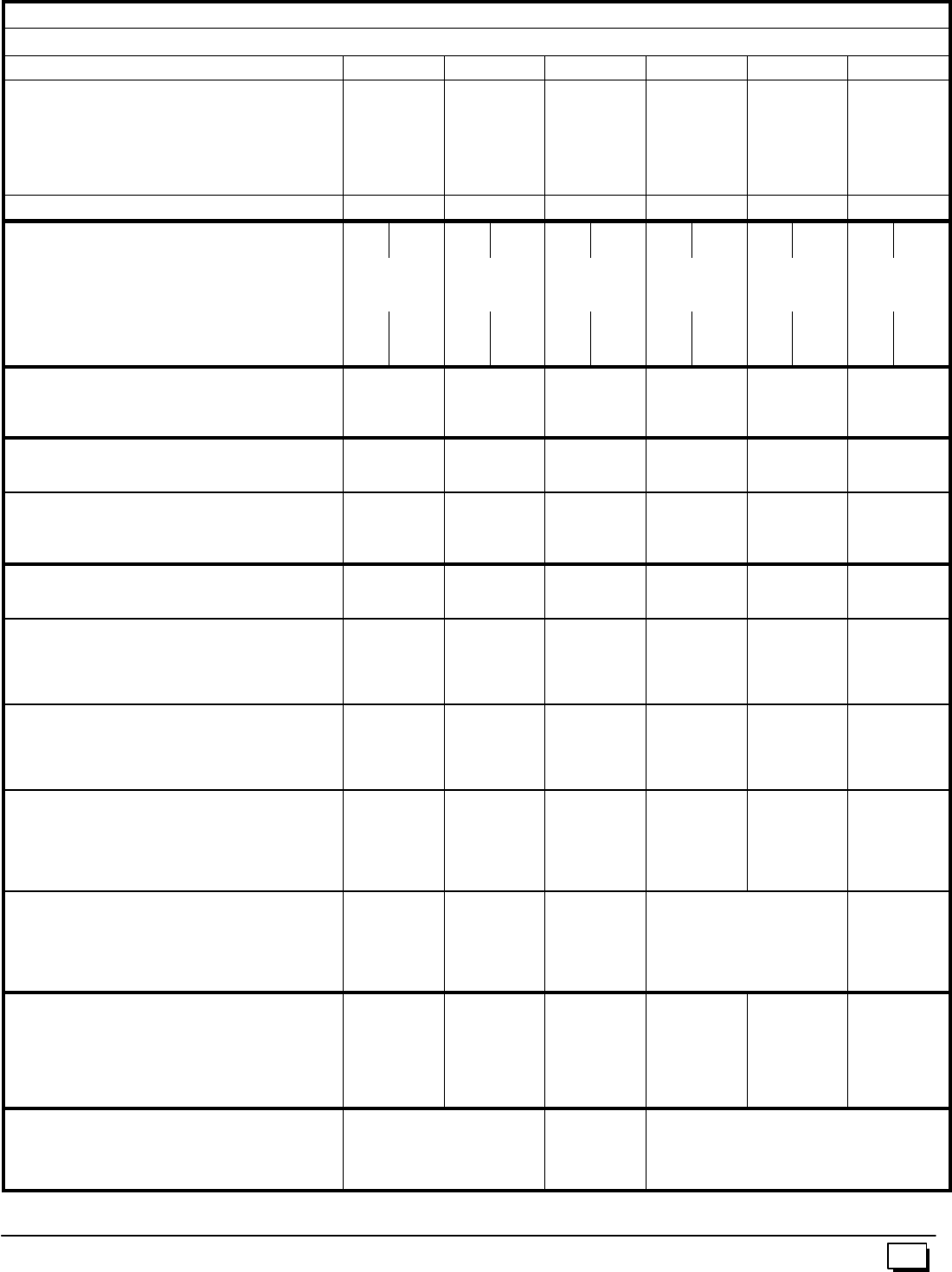
45
440 01 1020 02
Manufacturers Number (Mfr No --SeeRatingPlate) ALL Models
Specifications (N9MP2)
N9MP2050B12B N9MP2075B12B N9MP2080F16B N9MP2100F14B N9MP2100J20B N9MP2125J20B
General
GasType
Input (Btuh)
Output (Btuh)
Transformer Size (VA)
T’stat Heat Anticipator
Temp. Rise (°F)
Nat./ LP
50,000
45,500
40
.10
35--65
Nat./ LP
75,000
68,000
40
.10
40--70
Nat./ LP
80,000
72,000
40
.10
35--65
Nat./ LP
100,000
91,000
40
.10
40--70
Nat./ LP
100,000
96,500
40
.10
40--70
Nat./ LP
125,000
113,750
40
.10
40--70
Electrical (Volts/Hz/FLA) 115/60/9.8 115/60/8.9 115/60/9.0 115/60/9.0 115/60/10.5 115/60/11.2
Gas & Ignition
GasType Nat. L.P. Nat. L.P. Nat. L.P. Nat. L.P. Nat. L.P. Nat. L.P.
GasValve
Regulation Type
IgnitionType/Series
HW SV9541M
SNAP
HW HSP
HW SV9541M
SNAP
HW HSP
HW SV9541M
SNAP
HW HSP
HW SV9541M
SNAP
HW HSP
HW SV9541M
SNAP
HW HSP
HW SV9541M
SNAP
HW HSP
Manifold Press. (Inch’s WC)
Std. Main Orifices (No/Size)
Pilot Orifice Size
3.5
2/42
.018
10.0
2/54
.011
3.5
3/42
.018
10.0
3/54
.011
3.5
4/44
.018
10.0
4/55
.011
3.5
4/42
.018
10.0
4/54
.011
3.5
4/42
.018
10.0
4/54
.011
3.5
5/42
.018
10.0
5/54
.011
Fan Controls
Fan Control (Type)
Fan Control On
(Timed--secs) Off
HW ST9160
30
60,100,140,180
HW ST9160
30
60,100,140,180
HW ST9160
30
60,100,140,180
HW ST9160
30
60,100,140,180
HW ST9160
30
60,100,140,180
HW ST9160
30
60,100,140,180
Combustion
Flue Outlet Size (Inches)
Std. Outlet Temp (°5¢No Elbows) 2
<140 2
<140 2
<140 3
<140 3
<140 3
<140
Blower Pressure 5¢No Elbows (²WC)
Blower Pressure 40¢+5--90°DWV Elbows (²WC)
Transition Bx Pressure 5¢No Elbows (²WC)
Transition Bx Pressure 40¢+5--90°DWV Elbows (²WC)
-- --
-- --
-- 2. 6
-- 2. 3
-- 1. 8
-- 1. 3
-- 2. 6
-- 2. 3
-- --
-- --
-- 2. 6
-- 2. 5
-- 1. 8
-- 1. 7
-- 2. 6
-- 2. 5
-- 1. 8
-- 1. 7
-- 2. 6
-- 2. 5
-- 1. 8
-- 1. 7
-- 2. 6
-- 2. 5
Limits & Controls
Rollout Switch (°F)
Limit Control Setting (°F) 300
240 300
210 300
230 300
230 300
220 300
190
Standard Pressure Sw. (Part No)
Blower Switch Pressure (Close)(²WC)
Blower Switch Pressure (Open) (²WC)
Transition Switch Pressure (Close)(²WC)
Transition Switch Pressure (Open) (²WC)
1013802
-- --
-- --
--2.2
--2.0
1013801
-- --
-- --
--2.3
--2.1
1013811
-- --
-- --
--1.8
--1.6
1013801
-- --
-- --
--2.3
--2.1
1013802
-- --
-- --
--2.2
--2.0
1013166
--1.3
--1.1
--1.8
--1.6
High Altitude Pressure Sw. (Part No)
Blower Switch Pressure (Close)(²WC)
Blower Switch Pressure (Open) (²WC)
Transition Switch Pressure (Close)(²WC)
Transition Switch Pressure (Open) (²WC)
1013803
-- --
-- --
--2.0
--1.8
1013803
-- --
-- --
--2.0
--1.8
1013812
-- --
-- --
--1.5
--1.3
1013803
-- --
-- --
--2.0
--1.8
1013803
-- --
-- --
--2.0
--1.8
1013157
--0.9
--0.7
--1.7
--1.5
Long Vent Kit (Part No)
Pressure Switch (Part No)
Blower Switch Pressure (Close)(²WC)
Blower Switch Pressure (Open) (²WC)
Transition Switch Pressure (Close)(²WC)
Transition Switch Pressure (Open) (²WC)
-- --
-- --
-- --
-- --
-- --
-- --
NAHA001LV
1013518
--1.0
--0.8
--2.0
--1.8
-- --
-- --
-- --
-- --
-- --
-- --
NAHA001LV
1013518
--1.0
--0.8
--2.0
--1.8
NAHA002LV
1013515
--1.0
--0.8
--1.7
--1.5
-- --
-- --
-- --
-- --
-- --
-- --
High Altitude Long Vent Kit (Part No)
Pressure Switch (Part No)
Blower Switch Pressure (Close)(²WC)
Blower Switch Pressure (Open) (²WC)
Transition Switch Pressure (Close)(²WC)
Transition Switch Pressure (Open) (²WC)
-- --
-- --
-- --
-- --
-- --
-- --
NAHA003LV
1013165
--0.7
--0.6
--1.4
--1.2
-- --
-- --
-- --
-- --
-- --
-- --
NAHA003LV
1013165
--0.7
--0.6
--1.4
--1.2
-- --
-- --
-- --
-- --
-- --
-- --
Blower Data
Type & Size
Motor Amps/Rpm
Motor Type/H.p.
Cap. Mfd/Volts
Filter Type & Size (Permanent -- not supplied)
Cool Cap. (Tons) @ .5²W.C. L, ML, MHi & Hi
11--8
10/850
PSC/1/2
7.5/370
16x25x1
11/2,2,21/2,3
11--8
8.0/1050
PSC/1/2
7.5/370
16x25x1
11/2,2,21/2,3
11--10
10/1050
PSC/1/2
10/370
16x25x1
21/2,3,31/2,4
11--10
10/1050
PSC/1/2
10/370
16x25x1
11/2,2,3,31/2,
11--10
13/900
PSC/3/4
40/370
16x25x1
31/2,4,41/2,5
11--10
13/900
PSC/3/4
40/370
16x25x1
31/2,4,41/2,5
Gas Conversion Kits
Nat to LP
LP to Nat
*Order from Service Parts
NAHF002LP (*1009509)
NAHF002NG (*1009510) NAHF003LP
(*1013815)
NAHF003NG
(*1013816)
NAHF002LP (*1009509)
NAHF002NG (*1009510)
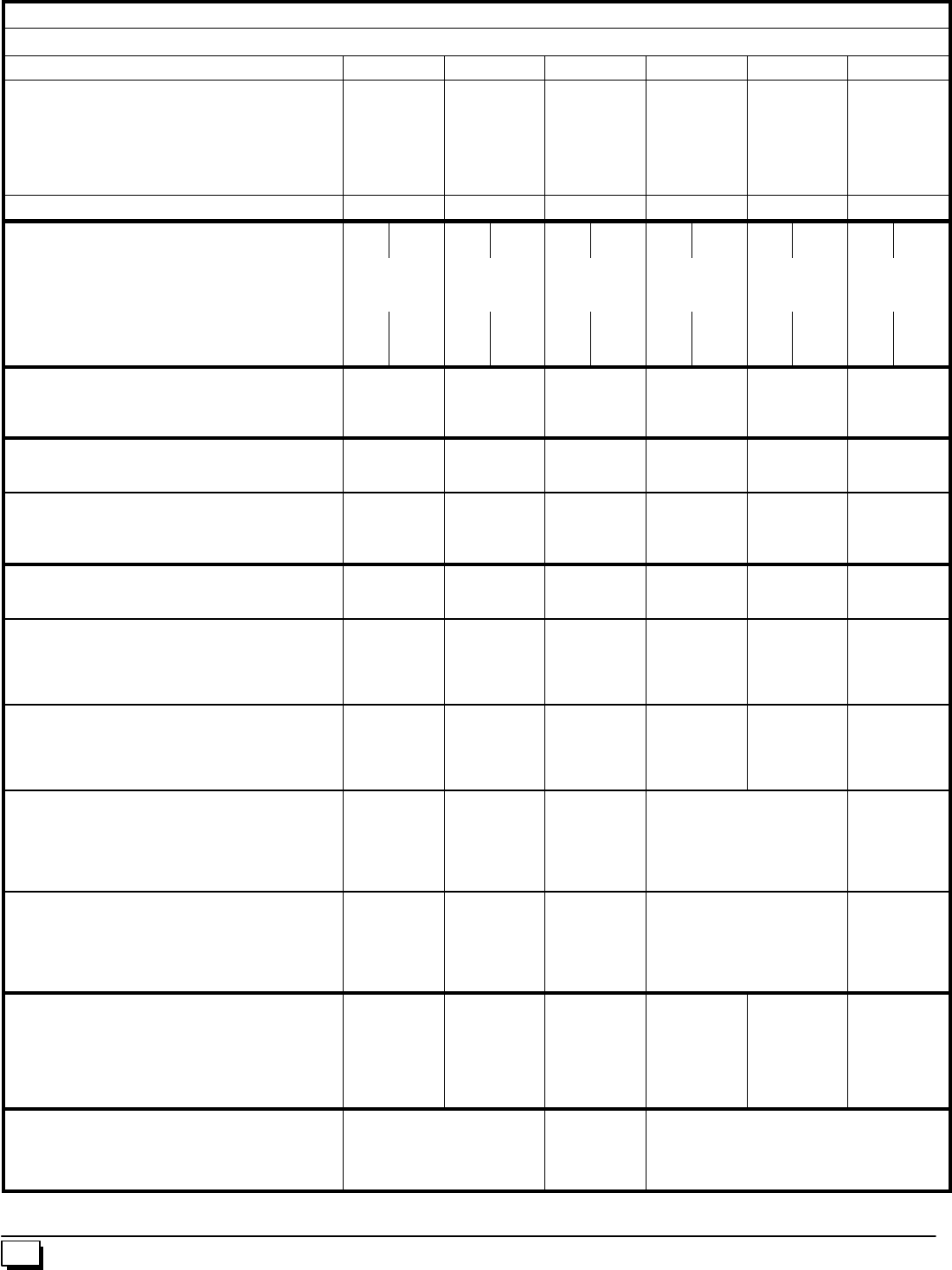
46 440 01 1020 02
Manufacturers Number (Mfr No --SeeRatingPlate) ALL Models
Specifications (*9MPD)
*9MPD050F12B *9MPD075F12B *9MPD080J16B *9MPD100J14B *9MPD100J20B *9MPD125L20B
General
GasType
Input (Btuh)
Output (Btuh)
Transformer Size (VA)
T’stat Heat Anticipator
Temp. Rise (°F)
Nat./ LP
50,000
46,000
40
.10
35--65
Nat./ LP
75,000
69,000
40
.10
40--70
Nat./ LP
80,000
73,600
40
.10
35--65
Nat./ LP
100,000
92,000
40
.10
40--70
Nat./ LP
100,000
92,000
40
.10
40--70
Nat./ LP
125,000
115,000
40
.10
40--70
Electrical (Volts/Hz/FLA) 115/60/9.8 115/60/8.9 115/60/9.0 115/60/9.0 115/60/10.5 115/60/11.2
Gas & Ignition
GasType Nat. L.P. Nat. L.P. Nat. L.P. Nat. L.P. Nat. L.P. Nat. L.P.
GasValve
Regulation Type
IgnitionType/Series
HW SV9541M
SNAP
HW HSP
HW SV9541M
SNAP
HW HSP
HW SV9541M
SNAP
HW HSP
HW SV9541M
SNAP
HW HSP
HW SV9541M
SNAP
HW HSP
HW SV9541M
SNAP
HW HSP
Manifold Press. (Inch’s WC)
Std. Main Orifices (No/Size)
Pilot Orifice Size
3.5
2/42
.018
10.0
2/54
.011
3.5
3/42
.018
10.0
3/54
.011
3.5
4/44
.018
10.0
4/55
.011
3.5
4/42
.018
10.0
4/54
.011
3.5
4/42
.018
10.0
4/54
.011
3.5
5/42
.018
10.0
5/54
.011
Fan Controls
Fan Control (Type)
Fan Control On
(Timed--secs) Off
HW ST9160
30
60,100,140,180
HW ST9160
30
60,100,140,180
HW ST9160
30
60,100,140,180
HW ST9160
30
60,100,140,180
HW ST9160
30
60,100,140,180
HW ST9160
30
60,100,140,180
Combustion
Flue Outlet Size (Inches)
Std. Outlet Temp (°5¢No Elbows) 2
<140 2
<140 2
<140 3
<140 3
<140 3
<140
Blower Pressure 5¢No Elbows (²WC)
Blower Pressure 40¢+5--90°DWV Elbows (²WC)
Transition Bx Pressure 5¢No Elbows (²WC)
Transition Bx Pressure 40¢+5--90°DWV Elbows (²WC)
-- --
-- --
-- 2. 6
-- 2. 3
-- --
-- --
-- 2. 6
-- 2. 3
-- --
-- --
-- 2. 6
-- 2. 5
-- 1. 8
-- 1. 7
-- 2. 6
-- 2. 5
-- 1. 8
-- 1. 7
-- 2. 6
-- 2. 5
-- 1. 8
-- 1. 7
-- 2. 6
-- 2. 5
Limits & Controls
Rollout Switch (°F)
Limit Control Setting (°F) 300
260 300
240 300
220 300
220 300
220 300
190
Standard Pressure Sw. (Part No)
Blower Switch Pressure (Close)(²WC)
Blower Switch Pressure (Open) (²WC)
Transition Switch Pressure (Close)(²WC)
Transition Switch Pressure (Open) (²WC)
1013802
-- --
-- --
--2.2
--2.0
1013802
-- --
-- --
--2.2
--2.0
1013812
-- --
-- --
--1.5
--1.3
1013802
-- --
-- --
--2.2
--2.0
1013802
-- --
-- --
--2.2
--2.0
1013166
--1.3
--1.1
--1.8
--1.6
High Altitude Pressure Sw. (Part No)
Blower Switch Pressure (Close)(²WC)
Blower Switch Pressure (Open) (²WC)
Transition Switch Pressure (Close)(²WC)
Transition Switch Pressure (Open) (²WC)
1013803
-- --
-- --
--2.0
--1.8
1013803
-- --
-- --
--2.0
--1.8
1013813
-- --
-- --
--1.2
--1.0
1013803
-- --
-- --
--2.0
--1.8
1013803
-- --
-- --
--2.0
--1.8
1013157
--0.9
--0.7
--1.7
--1.5
Long Vent Kit (Part No)
Pressure Switch (Part No)
Blower Switch Pressure (Close)(²WC)
Blower Switch Pressure (Open) (²WC)
Transition Switch Pressure (Close)(²WC)
Transition Switch Pressure (Open) (²WC)
-- --
-- --
-- --
-- --
-- --
-- --
-- --
-- --
-- --
-- --
-- --
-- --
-- --
-- --
-- --
-- --
-- --
-- --
NAHA002LV
1013518
--1.0
--0.8
--2.0
--1.8
-- --
-- --
-- --
-- --
-- --
-- --
High Altitude Long Vent Kit (Part No)
Pressure Switch (Part No)
Blower Switch Pressure (Close)(²WC)
Blower Switch Pressure (Open) (²WC)
Transition Switch Pressure (Close)(²WC)
Transition Switch Pressure (Open) (²WC)
-- --
-- --
-- --
-- --
-- --
-- --
-- --
-- --
-- --
-- --
-- --
-- --
-- --
-- --
-- --
-- --
-- --
-- --
NAHA003LV
1013165
--0.7
--0.6
--1.4
--1.2
-- --
-- --
-- --
-- --
-- --
-- --
Blower Data
Type & Size
Motor Amps/Rpm
Motor Type/H.p.
Cap. Mfd/Volts
Filter Type & Size (Permanent -- not supplied)
Cool Cap. (Tons) @ .5²W.C. L, ML, MHi & Hi
11--8
10/850
PSC/1/2
7.5/370
16x25x1
11/2,2,21/2,3
11--10
8.0/1050
PSC/1/2
7.5/370
16x25x1
11/2,2,21/2,3
11--10
10/1050
PSC/1/2
10/370
16x25x1
21/2,3,31/2,4
11--10
10/1050
PSC/1/2
10/370
16x25x1
11/2,2,3,31/2
11--10
13/900
PSC/3/4
40/370
16x25x1
31/2,4,41/2,5
11--10
13/900
PSC/3/4
40/370
16x25x1
31/2,4,41/2,5
Gas Conversion Kits
Nat to LP
LP to Nat
*Order from Service Parts
NAHF002LP (*1009509)
NAHF002NG (*1009510) NAHF003LP
(*1013815)
NAHF003NG
(*1013816)
NAHF002LP (*1009509)
NAHF002NG (*1009510)
--
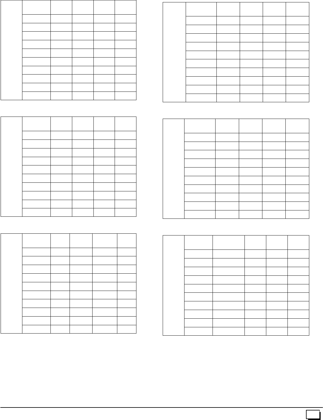
47
440 01 1020 02
CIRCULATION AIR BLOWER DATA
For 050 Models 3 Ton Units
Speed
Tap Low Med L Med H Hi
u
re
0.1 826 1083 1301 1408
e
ssu
r
C
.
0.2 804 1050 1242 1347
c
Pre
s
W
.C.
0.3 770 1028 1195 1295
t
atic
s
of
W
0.4 735 985 1153 1237
a
lSt
a
c
hes
0.5 698 952 1093 1183
e
rrna
Inc
0.6 657 909 1040 1118
Exte
r
0.7 -- -- -- 863 935 1053
E
0.8 -- -- -- -- 812 865 976
0.9 -- -- -- -- -- -- 802 887
1.0 -- -- -- -- -- -- 720 787
For 075 Models 3 Ton Units
Speed
Tap Low Med L Med H Hi
u
re
0.1 706 917 1163 1368
e
ssu
r
C
.
0.2 677 875 1120 1319
c
Pre
s
W
.C.
0.3 636 840 1076 1263
t
atic
s
of
W
0.4 595 812 1031 1202
a
lSt
a
c
hes
0.5 546 766 987 1148
e
rrna
Inc
0.6 490 702 889 1077
Exte
r
0.7 -- -- -- 630 821 989
E
0.8 -- -- -- 550 750 914
0.9 -- -- -- 462 676 833
1.0 -- -- -- -- -- -- 601 747
For 100 Models 3.5 Ton 19²
²²
²&22
3/4²
²²
²Units
Speed
Tap Low Med L Med H Hi
s
ure
0.1 700 912 1209 1550
r
ess
u
C
.
0.2 660 884 1171 1492
i
cPr
e
f
W.
C
0.3 616 843 1139 1434
S
tati
c
e
sof
0.4 575 790 1088 1378
n
al
S
n
che
s
0.5 528 735 1040 1317
t
errn
In
0.6 472 677 979 1247
Ext
e
0.7 -- -- -- 608 909 1161
0.8 -- -- -- 528 827 1058
0.9 -- -- -- -- -- -- 733 932
1.0 -- -- -- -- -- -- 624 778
For 080 Models 4 Ton 19²
²²
²&22
3/4²
²²
²Units
Speed
Tap Low Med L Med H Hi
0.1 823 1109 1527 1850
r
e
0.2 795 1087 1482 1791
s
sur
e
0.3 747 1056 1426 1720
Pres
W
.C.
0.4 677 1016 1382 1648
a
tic
P
of
W
0.5 617 970 1317 1575
a
lSta
t
hes
o
0.6 544 854 1245 1485
r
rnal
Inc
h
0.7 -- -- -- 763 1154 1401
E
xter
r
I
0.8 -- -- -- 652 1043 1284
E
x
0.9 -- -- -- -- -- -- 905 1161
1.0 -- -- -- -- -- -- 737 1028
For 100 Models 5 Ton 223/4²
²²
²Units
Speed
Tap Low Med L Med H Hi
0.1 1682 1870 2081 2263
e
0.2 1654 1826 2031 2193
s
sur
e
0.3 1597 1775 1963 2165
P
res
s
W
.C.
0.4 1547 1719 1899 2056
a
tic
P
o
fW
.
0.5 1498 1653 1825 1978
l
Sta
t
h
es
o
0.6 1428 1583 1737 1854
r
rnal
Inch
e
0.7 1355 1503 1650 1757
xter
r
I
0.8 1267 1392 1548 1644
E
x
0.9 -- -- -- 1266 1428 1515
1.0 -- -- -- -- -- -- -- -- -- 1351
For 125 Models 5 Ton Units
Speed
Tap Low Med L Med H Hi
e
0.1 1720 1910 2127 2315
s
ure
0.2 1686 1881 2087 2268
P
ress
u
.
C.
0.3 1644 1833 2024 2201
t
ic P
r
o
fW.
C
0.4 1600 1777 1961 2131
Stati
c
e
so
f
0.5 1533 1720 1891 2029
r
nal
S
nch
e
0.6 1494 1647 1804 1948
x
terr
n
I
n
0.7 1413 1571 1708 1820
Ex
t
0.8 1306 1470 1604 1730
0.9 -- -- -- -- 1349 1484 1614
1.0 -- -- -- -- -- -- -- -- 1328 1430
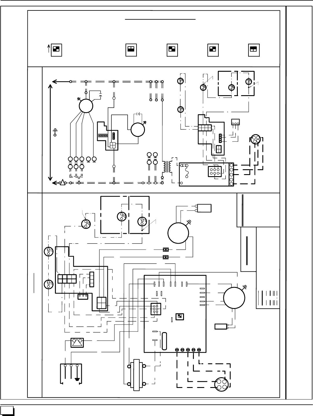
48 440 01 1020 02
1. Wiring Diagram
YG
THERMOSTAT
23
4
MAIN LIMIT
GAS
VALVE
N
N
G
N
Y
1
5
INDUCER
MOTOR
EAC
115V
ROLLOUT SWITCH
1 TO 3 IN SERIES
DEPENDING ON MODEL
3
6
4
2
TRANSFORMER
L1
HUM
L1
12
FAN CONTROL MODULE
W
Y
G
G
W
Y
W
TRANSFORMER
BLOWER
MOTOR
L1
L1
L1
C1
NEUTRAL
BL
BK
INDUCER
MOTOR
R
FURNACE
CONTROL
BK
W
ROLLOUT SWITCH
1 TO 3 IN SERIES
DEPENDING ON
MODEL
W
BL
W
BK
O
R
4
L1
CONT
COOL
1
2
EAC
3
HEAT
4
C2
4
56
24V SECONDARY
23
DATA
5A FUSE
24V
24VAC
O
BK
R
ON
115V
60HZ
HEAT ON DELAY: 30 SEC.
1014484
DISCONNECT BEFORE SERVICING
WARNING: ELECTRICAL SHOCK HAZARD
CONNECTION DIAGRAM
COOL ON DELAY: 5 SEC
COOL OFF DELAY: 90 SEC
S1
HEAT OFF DELAY
BL
GAS VALVE
R
W
BL
P
W
BK
GND
COPPER
CONDUCTORS
ONLY
6
NEUTRAL
HOT
W
5
4
3
2
8
1
7
3
C3
COM
W
24
VAC
C
Y
R
C
BL
R
W
Y
FURNACE CONTROL
G
BR
BR
CAPACITOR
Y
R
R
1
2
3
4
3
7
2
1
6
5
4
8
1
EAC
HUM
N
24
8
7
12
3
4
4
SEE MANUALS FOR ADJUSTING SPEED TAPS FOR PROPER HEATING, COOLING & CIRCULATING SPEEDS.
COLOR CODE
6
3
5
BLACK BK
BLUE BL
BROWN BR
GREEN G
ORANGE O
RED R
WHITE W
YELLOW Y
PURPLE P
1
SPEED TAP CODE
BLACK-HI BLUE-MLO
ORANGE-MHI RED-LO
*
LINE VOLTAGE FACTORY
LINE VOLTAGE FIELD
LOW VOLTAGE FACTORY
LOW VOLTAGE FIELD
INTERNAL CIRCUIT BOARD WIRING
5 A
FUSE
FACTORY
SETTING
1
2
N
N
BLOWER
MOTOR
LO (R)
M2
M1 MLO (BL)
GND.
HEAT MHI (O)
COOL HI (BK)
LADDER DIAGRAM
INTERLOCK
SWITCH
HOT 115V-60HZ NEUTRAL
IF ANY OF THE ORIGINAL WIRE AS SUPPLIED WITH THE APPLIANCE
MUST BE REPLACED, IT MUST BE REPLACED WITH TYPE
AWM - 105°C WIRE OR ITS EQUIVALENT.
GAS
VALVE
LP PRESSURE
SWITCH
(LP MODELS ONLY)
ON
INTERLOCK
SWITCH
1
MAIN LIMIT
FIELD
CONNECTION
BOX
LP PRESSURE
SWITCH
(LP MODELS ONLY)
1 2
HUM
M2
M1
115V PRIMARY
R
1
2
3
THERMOSTAT
4
12
12
60 SEC. 140 SEC. 180 SEC.
12
100 SEC.
12
1
L1
L1
COM
BL
L1
SENSOR
IGNITOR
BL
PRESSURE SWITCH
1 TO 2 IN SERIES
DEPENDING ON
MODEL
PRESSURE SWITCH
1 TO 2 IN SERIES
DEPENDING ON MODEL
BR
BR
CAPACITOR
(SOME MODELS)
CAPACITOR
(SOME MODELS)
IGNITER
SENSOR
RECTIFIED AC VOLTAGE FACTORY
NOTE:
1. MOST VOLT METERS WILL READ 13-16 VOLTS
TO CHASSIS ON BOTH SIDES OF AN OPEN LIMIT
OR PRESSURE SWITCH IN THE RECTIFIED AC
VOLTAGE CIRCUIT
2. FACTORY CONNECTED WHEN BVSS,
(CHIMNEY ADAPTER ACCESSORY KIT) OR LP
PRESSURE SWITCH IS NOT INSTALLED.
BK
CAPACITOR
BVSS
(FIELD INSTALLED)
NOTE 2
NOTE 2
BVSS
(FIELD INSTALLED)
NOTE 2
NOTE 2
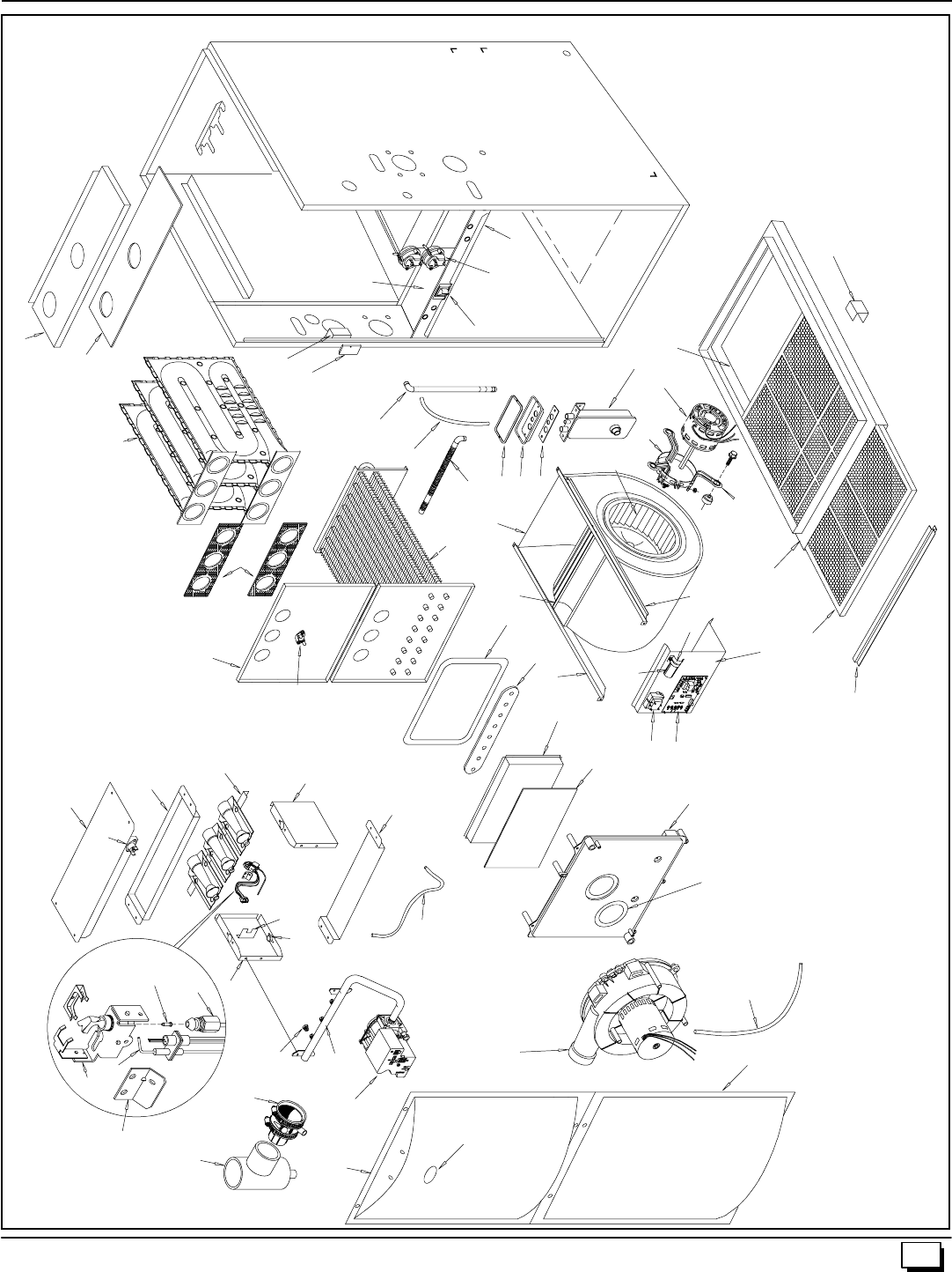
49
440 01 1020 02
2. N9MP1, N9MP2 or *9MPD
25--23--95
AA
13
14
Z
19
YY
WW
15
FF
N
LL
EE
16
Z
BB
12
16 GG
17
DD
11
CC
FF 18
V
W
R
S
T
UJ
LJJ
Q
P
Y
X
F
UU
VV
TT
SS
H
RR
QQ
KK
5
43
910
M
K
2
1
B
A
8
67
D
HH
OO
20
MM
MM
PP
K
50 440 01 1020 02
Replacement Parts - N9MP1 & N9MP2
Models -- N9MP1050B12B1, N9MP1075B12B1, N9MP1080F16B1, N9MP1100F14B1, N9MP1100J20B1 &
N9MP1125J20B1 -- N9MP2050B12B1, N9MP2075B12B1, N9MP2080F16B1, N9MP2100F14B1, N9MP2100J20B1 &
N9MP2125J20B1 (Natural Gas)
Replacement part supplied will be current active part. For parts not listed, consult place of purchase.
K
e
y
D
e
s
c
r
i
p
t
i
o
n
P
a
r
t
N9MP1 N9MP2
K
ey
No.
D
escr
i
pt
i
on
Functional
P
art
Number 050B
12B 075B
12B 080F
16B 100F
14B 100J
20B 125J
20B 050B
12B 075B
12B 080F
16B 100F
14B 100J
20B 125J
20B
1Heat Exchanger, Primary 1012847
1012851
1012855
1012856
1012859
1
--------
--
1
------
----
1
----
----
1
----
------
1
--
--------
1
1
--------
--
1
------
----
1
----
----
1
----
------
1
--
--------
1
2Heat Exchanger, Secondary 1013760
1013761
1013764
1013765
1013766
1
--------
--
1
------
----
1
----
----
1
----
------
1
--
--------
1
1
--------
--
1
------
----
1
----
----
1
----
------
1
--
--------
1
3Motor, Blower 1009052
1013341
1011906
1
----
--
1
--
1
----
--
1
--
----
1
----
1
1
----
--
1
--
1
----
--
1
--
----
1
----
1
4Mount, Motor kit 1013379
522020024 1
-- 1
-- --
1--
1--
1--
11
-- 1
-- --
1--
1--
1--
1
5Wheel, Blower 1013011
1011420 1
-- 1
-- --
1--
1--
1--
11
-- 1
-- --
1--
1--
1--
1
6Transformer 1012722 1 1 1 1 1 1 1 1 1 1 1 1
7Capacitor, 10Mfd, 370V
7.5Mfd., 370V
40Mfd., 370V
1171729
1171728
1171982
1
----
--
1
--
1
----
--
1
--
----
1
----
1
1
----
--
1
--
1
----
--
1
--
----
1
----
1
8Control, Fan Timer 1014460 1 1 1 1 1 1 1 1 1 1 1 1
9Switch, Interlock 1171981 1 1 1 1 1 1 1 1 1 1 1 1
10 Switch, Pressure 1013802
1013811
1013801
1013166
1
------
1
------
--
1
----
----
1
--
1
------
------
1
1
------
----
1
--
--
1
----
----
1
--
1
------
------
1
11 Blower, Exhaust (Jakel) 1014338
1014341 1
-- 1
-- 1
-- 1
-- 1
-- --
11
-- 1
-- 1
-- 1
-- 1
-- --
1
12 Valve, Gas HSP Nat. 1013350 1 1 1 1 1 1 1 1 1 1 1 1
13 Burner,PilotHSP 1008731 1 1 1 1 1 1 1 1 1 1 1 1
14 Igniter/Sensor HSP 1009524 1 1 1 1 1 1 1 1 1 1 1 1
15 Orifice, Burner #42 Nat.
#44 Nat. 1011351
1011352 2
-- 3
-- --
44
-- 4
-- 5
-- 2
-- 3
-- --
44
-- 4
-- 5
--
16 Switch, Limit (Rollout) 1013102 2 2 2 2 2 2 2 2 2 2 2 2
17 Burner Assembly 1008723
1008724
1008725
1008726
1
------
--
1
----
----
1
--
----
1
--
----
1
--
------
1
1
------
--
1
----
----
1
--
----
1
--
----
1
--
------
1
18 Switch, Limit (Main) 34335001
34335002
1320361
1008445
1320367
--
1
------
1
--------
----
1
----
----
1
----
--------
1
------
1
--
--
1
------
1
--------
----
1
----
----
1
----
--------
1
------
1
--
19 Orifice, Pilot .018 503211 1 1 1 1 1 1 1 1 1 1 1 1
51
440 01 1020 02
Replacement Parts - N9MP1 & N9MP2
Models -- N9MP1050B12B1, N9MP1075B12B1, N9MP1080F16B1, N9MP1100F14B1, N9MP1100J20B1 &
N9MP1125J20B1 -- N9MP2050B12B1, N9MP2075B12B1, N9MP2080F16B1, N9MP2100F14B1, N9MP2100J20B1 &
N9MP2125J20B1 (Natural Gas)
Replacement part supplied will be current active part. For parts not listed, consult place of purchase.
K
e
y
D
e
s
c
r
i
p
t
i
o
n
P
a
r
t
N9MP1 N9MP2
K
e
y
No.
D
e
s
c
r
i
p
t
i
o
n
Non--Functional
P
a
r
t
Number 050B
12B 075B
12B 080F
16B 100F
14B 100J
20B 125J
20B 050B
12B 075B
12B 080F
16B 100F
14B 100J
20B 125J
20B
APanel, Top 1012323
1012324
1012325
1012326
1012957
1012958
1012959
1
------------
--
1
----------
----
1
--------
----
1
--------
------
1
------
------
1
------
--------
1
----
--------
1
----
----------
1
--
----------
1
--
------------
1
------------
1
BGasket, Top Panel 1012602
1012603
1012604
1
----
1
----
--
1
--
--
1
--
----
1
----
1
1
----
1
----
--1
--
--1
--
----1
----1
FPartition, Blower 1171983
1171984
1171985
1172004
1172005
1172006
1
----------
1
----------
--
1
--------
--
1
--------
----
1
------
----
1
------
------
1
----
------
1
----
--------
1
--
--------
1
--
----------
1
----------
1
HHousing, Blower 1012972
1012888 1
-- 1
-- --
1--
1--
1--
11
-- 1
-- --
1--
1--
1--
1
JPanel, Blower Cutoff 721020013
721020008 1
-- 1
-- --
1--
1--
1--
11
-- 1
-- --
1--
1--
1--
1
KHanger, Blower 1012328 2 2 2 2 2 2 2 2 2 2 2 2
LDoor, Blower 1013684
1013685
1013686
1013687
1013688
1014239
1
----------
1
----------
--
1
--------
--
1
--------
----
1
------
----
1
------
------
1
----
------
1
----
--------
1
--
--------
1
--
----------
1
----------
1
MBracket, Door Filler 1013679
1013680
1013681
1
----
1
----
--
1
--
--
1
--
----
1
----
1
1
----
1
----
--
1
--
--
1
--
----
1
----
1
NDoor, Front 1014146
1014147
1014256
1014257
1014258
1014259
1
----------
1
----------
--
1
--------
--
1
--------
----
1
------
----
1
------
------
1
----
------
1
----
--------
1
--
--------
1
--
----------
1
----------
1
OStrap, Capacitor 1170643
1014315 1
-- 1
-- 1
-- 1
-- --
1--
11
-- 1
-- 1
-- 1
-- --
1--
1
PTransition Assembly 1012280
1012281
1012282
1
----
1
----
--
1
--
--
1
--
----
1
----
1
1
----
1
----
--
1
--
--
1
--
----
1
----
1
QGasket, Blower 1014425 1 1 1 1 1 1 1 1 1 1 1 1
RBoard, Insulating 1012417
1012418
1012419
1
----
1
----
--
1
--
--
1
--
----
1
----
1
1
----
1
----
--
1
--
--
1
--
----
1
----
1
SBox, Collector 1012128
1012244
1012245
1
----
1
----
--
1
--
--
1
--
----
1
----
1
1
----
1
----
--
1
--
--
1
--
----
1
----
1
TGasket, Transition 1013079
1013080
1013083
1
----
1
----
--
1
--
--
1
--
----
1
----
1
1
----
1
----
--
1
--
--
1
--
----
1
----
1
UGasket, Collector Box 1012593
1012594
1012595
1
----
1
----
--
1
--
--
1
--
----
1
----
1
1
----
1
----
--
1
--
--
1
--
----
1
----
1
VPartition,FrontHt Exchanger 1012646
1012647
1012649
1012651
1012652
1
--------
--
1
------
----
1
----
----
1
----
------
1
--
--------
1
1
--------
--
1
------
----
1
----
----
1
----
------
1
--
--------
1
52 440 01 1020 02
Replacement Parts - N9MP1 & N9MP2
Models -- N9MP1050B12B1, N9MP1075B12B1, N9MP1080F16B1, N9MP1100F14B1, N9MP1100J20B1 &
N9MP1125J20B1 -- N9MP2050B12B1, N9MP2075B12B1, N9MP2080F16B1, N9MP2100F14B1, N9MP2100J20B1 &
N9MP2125J20B1 (Natural Gas)
Replacement part supplied will be current active part. For parts not listed, consult place of purchase.
K
e
y
D
e
s
c
r
i
p
t
i
o
n
P
a
r
t
N9MP1 N9MP2
K
e
y
No.
D
e
s
c
r
i
p
t
i
o
n
Non--Functional
P
a
r
t
Number 050B
12B 075B
12B 080F
16B 100F
14B 100J
20B 125J
20B 050B
12B 075B
12B 080F
16B 100F
14B 100J
20B 125J
20B
WGasket, Attachment Plate 1012542
1012543
1012544
1012545
2
------
--
2
----
----
2
--
----
2
--
----
2
--
------
2
2
------
--
2
----
----
2
--
----
2
--
----
2
--
------
2
XCover, Junction Box 1012350 111111111111
YBox, Junction 1012349 111111111111
ZTube, Pilot 1013077
1012832
1012834
----
1
--
1
--
--
1
--
--
1
--
--
1
--
1
----
----
1
--
1
--
--
1
--
--
1
--
--
1
--
1
----
AA Bracket, Pilot 1010901 111111111111
BB Manifold 1012276
1012277
1012278
1012279
1
------
--
1
----
----
1
--
----
1
--
----
1
--
------
1
1
------
--
1
----
----
1
--
----
1
--
----
1
--
------
1
CC Bottom, Burner Box 1012334
1012335
1012336
1
----
1
----
--
1
--
--
1
--
--
1
--
----
1
1
----
1
----
--
1
--
--
1
--
--
1
--
----
1
DD Baffle, Burner Box 1012338
1012339
1012340
1
----
1
----
--
1
--
--
1
--
--
1
--
----
1
1
----
1
----
--
1
--
--
1
--
--
1
--
----
1
EE Top, Burner Box 1013702
1013703
1013704
1
----
1
----
--
1
--
--
1
--
--
1
--
----
1
1
----
1
----
--
1
--
--
1
--
--
1
--
----
1
FF Bracket, Manifold Support 1012377 222222222222
GG Bracket, Burner Box Side 1012532 222222222222
HH Bracket, Control Mounting 1013677 111111111111
JJ Tube, Sensor 1009238 111111111111
KK Trap, Drain Assembly 1171917 111111111111
LL Sightglass 1012756 -- -- -- -- -- -- 111111
QQ Gasket, Trap 1013701 111111111111
RR Bracket, Trap 1171986 111111111111
SS Gasket, Trap Bracket 1171987 111111111111
TT Tube,DrainColl.Box5/8²ID 1171988 111111111111
UU Tube, Drain Tee 1/2²ID 1171989 111111111111
VV Tube, Relief 1009238 111111111111
WW Drain Vent 1014003 111111111111
)( PART NOT ILLUSTRATED
)( Door Screws 1014488 444444222222
)( Door Screws Grommets 1171990 444444222222
)( Clamp, Hose 3/4²1012976 222222222222
)( Clamp, Hose 5/8²1012975 222222222222
)( Grommet, Vent 1012697 111111111111
)( Bushing, Strain Relief 1945287 111111111111
)( Harness, Wire 1013716
1013718
1013719
1
----
1
----
1
----
1
----
--
1
--
----
1
1
----
1
----
1
----
1
----
--
1
--
----
1
)( Trap, Drain Tee 1171916 111111111111
)( Tube,1/2²ID Drain 1171991 111111111111
)( Tube,1/2²ID Elbow 1171992 222222111111
)( Coupling, 1/2²Barbed 1171993 111111111111
)( Tubeing,5/8²ID Drain 1171994 111111111111
)( Connector,3/4²X1/2²1171995 111111111111
53
440 01 1020 02
Replacement Parts - N9MP1 & N9MP2
Models -- N9MP1050B12B1, N9MP1075B12B1, N9MP1080F16B1, N9MP1100F14B1, N9MP1100J20B1 &
N9MP1125J20B1 -- N9MP2050B12B1, N9MP2075B12B1, N9MP2080F16B1, N9MP2100F14B1, N9MP2100J20B1 &
N9MP2125J20B1 (Natural Gas)
Replacement part supplied will be current active part. For parts not listed, consult place of purchase.
K
e
y
D
e
s
c
r
i
p
t
i
o
n
P
a
r
t
N9MP1 N9MP2
K
e
y
No.
D
e
s
c
r
i
p
t
i
o
n
Non--Functional
P
a
r
t
Number 050B
12B 075B
12B 080F
16B 100F
14B 100J
20B 125J
20B 050B
12B 075B
12B 080F
16B 100F
14B 100J
20B 125J
20B
)( PART NOT ILLUSTRATED
)( Elbow,1/2²CPVC Street 1171996 111111111111
)( Grommet, Casing 1171997 111111111111
)( Tube, Releif Ext. 1009238 111111111111
)( Connector, Releif Tube 1171998 111111111111
)( Plate, Cover 1171999 111111111111
)( Gasket, Cover Plate 1172000 111111111111
)( Cap, Drain Tee 1172001 111111111111
)( Clamp, Tee Cap 1172002 111111111111
)( Coupling, Air Intake 1012284 -- -- -- -- -- -- 111111
)( Gasket, Air Intake 1012583 -- -- -- -- -- -- 111111
)( Gasket, Trap 1013701 -- -- -- -- -- -- 111111
)( Grommet, Vinyl (Gas Inlet) 1009535 -- -- -- -- -- -- 111111
)( Bushing, Strain Relief 1945287 -- -- -- -- -- -- 111111
)( Installation Manual 44001102000 111111111111
)( User’sManual 44102201000 111111111111
Gas Conversion Kits
Nat to LP NAHF002LP
LP to Nat NAHF002NG
Nat to LP NAHF003LP
LP to Nat NAHF003NG
* Order from Service Parts
*1009509
*1009510
*1013815
*1013816
1
1
----
1
1
----
----
1
1
1
1
----
1
1
----
1
1
----
1
1
----
1
1
----
----
1
1
1
1
----
1
1
----
1
1
----
Replacement Parts - *9MPD
Models -- *9MPD050F12B1, *9MPD075F12B1, *9MPD080J16B1, *9MPD100J14B1, *9MPD100J20B1 & *9MPD125L20B1
(Natural Gas)
*Denotes Brand
Replacement part supplied will be current active part. For parts not listed, consult place of purchase.
Key
N
Description
F
t
i
l
Part
N
b
*9MPD
y
No.
p
Functional Number 050F12B 075F12B 080J16B 100J14B 100J20B 125L20B
1Heat Exchanger, Primary 1012850
1012854
1012858
1012862
1
------
--
1
----
----
1
--
----
1
--
----
1
--
------
1
2Heat Exchanger, Secondary 1013762
1013763
1013765
1013767
1
------
--
1
----
----
1
--
----
1
--
----
1
--
------
1
3Motor, Blower 1009052
1013341
1011906
1
----
--
1
--
1
----
--
1
--
----
1
----
1
4Mount, Motor kit 1013379
522020024 1
-- --
1--
1--
1--
1--
1
5Wheel, Blower 1013011
1011420 1
-- --
1--
1--
1--
1--
1
6Transformer 1012722 1 1 1 1 1 1
7Capacitor, 7.5Mfd.,370V
10Mfd.,370V
40Mfd.,370V
1171928
1171929
1171982
--
1
--
1
----
--
1
--
1
----
----
1
----
1
8Control, Fan Timer 1014460 1 1 1 1 1 1
9Switch, Interlock 1171981 1 1 1 1 1 1
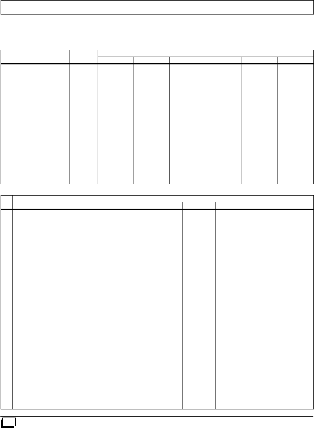
54 440 01 1020 02
Replacement Parts - *9MPD
Models -- *9MPD050F12B1, *9MPD075F12B1, *9MPD080J16B1, *9MPD100J14B1, *9MPD100J20B1 & *9MPD125L20B1
(Natural Gas)
*Denotes Brand
Replacement part supplied will be current active part. For parts not listed, consult place of purchase.
Key
N
Description
F
t
i
l
Part
N
b
*9MPD
y
No.
p
Functional Number 050F12B 075F12B 080J16B 100J14B 100J20B 125L20B
10 Switch, Pressure 1013802
1013812
1013166
1
----
1
----
--
1
--
1
----
1
----
----
1
11 Blower, Exhaust (Jakel) 1014388
1014341 1
-- 1
-- 1
-- 1
-- 1
-- --
1
12 Valve, Gas HSP Nat. 1013350 1 1 1 1 1 1
13 Burner,PilotHSP 1008731 1 1 1 1 1 1
14 Igniter/Sensor HSP 1009524 1 1 1 1 1 1
15 Orifice, Burner #42 Nat.
#44 Nat 1011351
1011352 2
-- 3
-- --
44
-- 4
-- 5
--
16 Switch, Limit (Rollout) 1013102 2 2 2 2 2 2
17 Burner Assembly 1008723
1008724
1008725
1008726
1
------
--
1
----
----
1
--
----
1
--
----
1
--
------
1
18 Switch, Limit (Main) 1320366
34335002
1008445
1320367
1
------
--
1
----
------
1
------
1
------
1
----
1
--
19 Orifice, Pilot .018 503211 1 1 1 1 1 1
K
e
y
Descri
p
tion Part *9MPD
K
e
y
No.
D
e
s
c
r
i
p
t
i
o
n
Non-Functional
P
a
r
t
Number 050F12B 075F12B 080J16B 100J14B 100J20B 125L20B
APanel, Top 1012866
1012867
1012868
1
----
1
----
--
1
--
--
1
--
--
1
--
----
1
BGasket, Top Panel 1012603
1012604
1012605
1
----
1
----
--
1
--
--
1
--
--
1
--
----
1
FPartition, Blower 1172008
1172005
1172006
1172007
1
------
--
1
----
----
1
--
----
1
--
----
1
--
------
1
HHousing, Blower 1012972
1012888 1
-- --
1--
1--
1--
1--
1
JPanel, Blower Cutoff 721020013
721020008 1
-- --
1--
1--
1--
1--
1
KHanger, Blower 1012328 222222
LDoor, Blower (Tempstar only)
(Tempstar only)
(Tempstar only)
(Comfortmaker/Keepriteonly)
(Comfortmaker/Keepriteonly)
(Comfortmaker/Keepriteonly)
(Heil/Arcoaire only)
(Heil/Arcoaire only)
(Heil/Arcoaire only)
1014155
1014170
1014192
1014152
1014167
1014189
1014262
1014263
1014264
1
----
1
----
1
----
1
----
1
----
1
----
--
1
----
1
----
1
--
--
1
----
1
----
1
--
--
1
----
1
----
1
--
----
1
----
1
--
--
1
MBracket, Door Filler 1013680
1013681
1014494
1
----
1
----
--
1
--
--
1
--
--
1
--
----
1
NDoor, Front (Tstar only)
(Tstar only)
(Tstar only)
(Cmaker/Keeprite only)
(Cmaker/Keeprite only)
(Cmaker/Keeprite only)
(Heil/Arco only)
(Heil/Arco only)
(Heil/Arco only)
1014154
1014169
1014191
1014151
1014166
1014188
1014265
1014266
1014267
1
----
1
----
1
----
1
----
1
----
1
----
--
1
----
1
----
1
--
--
1
----
1
----
1
--
--
1
----
1
----
1
--
----
1
----
1
----
1

55
440 01 1020 02
Replacement Parts - *9MPD
Models -- *9MPD050F12B1, *9MPD075F12B1, *9MPD080J16B1, *9MPD100J14B1, *9MPD100J20B1 & *9MPD125L20B1
(Natural Gas)
*Denotes Brand
Replacement part supplied will be current active part. For parts not listed, consult place of purchase.
K
e
y
Descri
p
tion Part *9MPD
K
e
y
No.
D
e
s
c
r
i
p
t
i
o
n
Non-Functional
P
a
r
t
Number 050F12B 075F12B 080J16B 100J14B 100J20B 125L20B
OClamp, Capacitor 1170643
1014315 1
-- 1
-- 1
-- 1
-- --
1--
1
PTransition Assembly 1012281
1012282
1012283
1
----
1
----
--
1
--
--
1
--
--
1
--
----
1
QGasket, Blower 1014425 111111
RBoard, Insulating 1012418
1012419
1012420
1
----
1
----
--
1
--
--
1
--
--
1
--
----
1
SBox, Collector 1012244
1012245
1012246
1
----
1
----
--
1
--
--
1
--
--
1
--
----
1
TGasket, Transition 1013263
1013080
1013083
1013084
1
------
--
1
----
----
1
--
----
1
--
----
1
--
------
1
UGasket, Collector Box 1012594
1012595
1012596
1
----
1
----
--
1
--
--
1
--
--
1
--
----
1
VPartition, Frt Ht Exchanger 1012650
1012648
1012651
1012653
1
------
--
1
----
----
1
--
----
1
--
----
1
--
------
1
WGasket, Attachment Plate 1012542
1012543
1012544
1012545
2
------
--
2
----
----
2
--
----
2
--
----
2
--
------
2
XCover, Junction Box 1012350 111111
YBox, Junction 1012349 111111
ZTube, Pilot 1012832
1013077
1012834
----
1
1
----
1
----
1
----
1
----
--
1
--
AA Bracket, Pilot 1010901 111111
BB Manifold 1012276
1012277
1012278
1012279
1
------
--
1
----
----
1
--
----
1
--
----
1
--
------
1
CC Bottom, Burner Box 1012334
1012335
1012336
1
----
1
----
--
1
--
--
1
--
--
1
--
----
1
DD Baffle, Burner Box 1012338
1012339
1012340
1
----
1
----
--
1
--
--
1
--
--
1
--
----
1
EE Top, Burner Box 1013702
1013703
1013704
1
----
1
----
--
1
--
--
1
--
--
1
--
----
1
FF Bracket, Manifold Support 1013677 222222
GG Bracket, Burner Box Side 1012532 222222
HH Bracket, Control Mounting 1013677 111111
JJ Tube, Sensor 1009238 111111
KK Trap, Drain Assembly 10171917 111111
LL Sightglass Comfortmaker & Heil
Tempstar Only 1013235
1013236 1
11
11
11
11
11
1
QQ Gasket, Trap 1013701 111111
RR Bracket, Trap 1171986 111111
SS Gasket, Trap Bracket 1171987 111111
TT Tube, Drain Coll. Box5/8²ID 1171988 111111
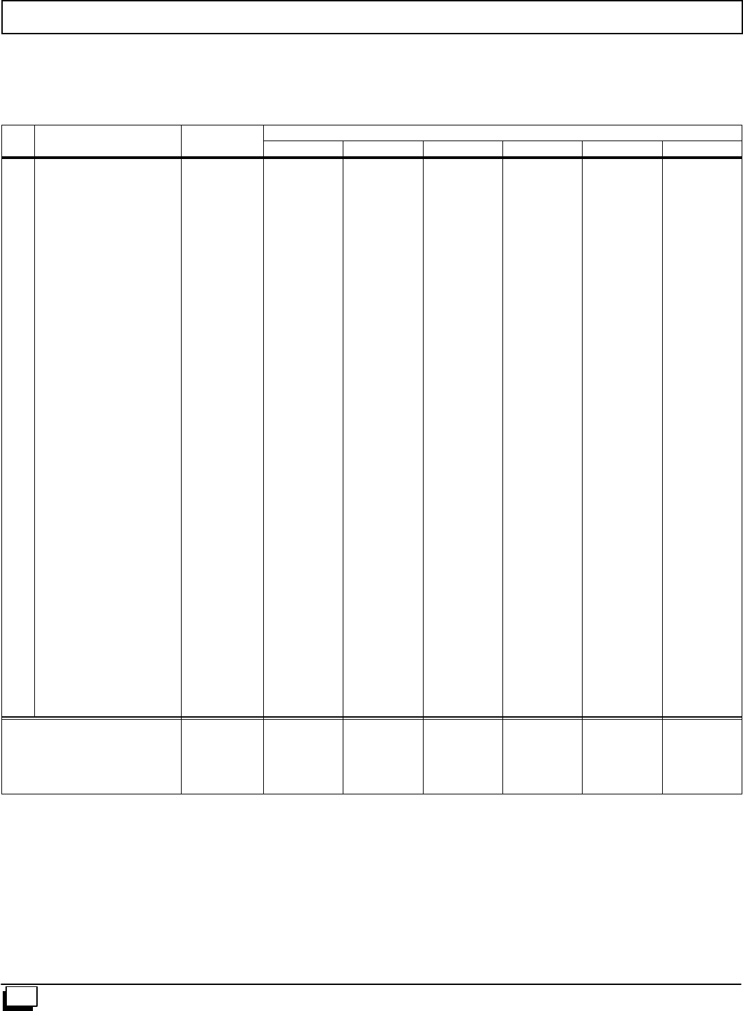
56 440 01 1020 02
Replacement Parts - *9MPD
Models -- *9MPD050F12B1, *9MPD075F12B1, *9MPD080J16B1, *9MPD100J14B1, *9MPD100J20B1 & *9MPD125L20B1
(Natural Gas)
*Denotes Brand
Replacement part supplied will be current active part. For parts not listed, consult place of purchase.
K
e
y
Descri
p
tion Part *9MPD
K
e
y
No.
D
e
s
c
r
i
p
t
i
o
n
Non-Functional
P
a
r
t
Number 050F12B 075F12B 080J16B 100J14B 100J20B 125L20B
UU Tube, Drain Tee 1/2²ID 1171989 111111
VV Tube, Relief 1009238 111111
WW Drain Vent 1014003 111111
YY Tee, Drain 1171915 111111
)( PART NOT ILLUSTRATED
)( Door Screws 1014488 444444
)( Door Screws Grommets 1171990 444444
)( Coupling, Air Intake 1012284 111111
)( Gasket, Air Intake 1012583 111111
)( Clamp, Hose 3/4²1012976 222222
)( Clamp, Hose 5/8²1012975 222222
)( Coupling, Discharge 1002522 222222
)( Clamp Hose 1013830 444444
)( Grommet, Vent 1012697 111111
)( Bushing, Strain Relief 1945287 111111
)( Grommet, Vinyl (gas Inlet) 1009535 111111
)( Harness, Wire 1013716
1013718
1013719
1
----
1
----
1
----
1
----
--
1
--
----
1
)( Trap, Drain Tee 1171916 111111
)( Tube,1/2²ID Drain 1171991 111111
)( Tube,1/2²ID Elbow 1171992 222222
)( Coupling, 1/2²Barbed 1171993 111111
)( Tubeing,5/8²ID Drain 1171994 111111
)( Connector,3/4²X1/2²1171995 111111
)( Elbow,1/2²CPVC Street 1171996 111111
)( Grommet, Casing 1171997 111111
)( Tube, Releif Ext. 1009238 111111
)( Connector, Releif Tube 1171998 111111
)( Plate, Cover 1171999 111111
)( Gasket, Cover Plate 1172000 111111
)( Cap, Drain Tee 1172001 111111
)( Clamp, Tee Cap 1172002 111111
)( Installation Manual 44001102000 111111
)( User’sManual 44102201000 111111
Gas Conversion Kits
Nat to LP NAHF002LP
LP to Nat NAHF002NG
Nat to LP NAHF003LP
LP to Nat NAHF003NG
* Order from Service Parts
*1009509
*1009510
*1013815
*1013816
1
1
----
1
1
----
----
1
1
1
1
----
1
1
----
1
1
----
