N8MPN050B12B1 44101261106
User Manual: N8MPN050B12B1
Open the PDF directly: View PDF ![]() .
.
Page Count: 57
CARBON MONOXIDE POISONING AND FIRE
HAZARD.
Failuretofollowsafetywarningsexactlycould
result in serious injury, death, and/or property
damage.
This furnace is not designed for use in mobile
homes, trailers or recreational vehicles.
!
ELECTRIC SHOCK HAZARD
Failure to follow safety warnings
exactly could result in serious
injury, death, and/or property
damage.
Turn Off All Power Before
Servicing.
!
International Comfort Products, LLC
Lewisburg, TN 37091
* Denotes Brands (C, H, T)
See section 5 for Category Idefinition.
INSTALLER: Affix these instructions
on or adjacent to the furnace.
CONSUMER: Retain these
instructions for future reference.
Portions of the text and tables are reprinted from NFPA 54 / ANSI Z223.1--2002ã, with permission of National Fire Protection Association, Quincy, MA 02269 and American Gas Association,
Washington, DC 20001. This reprinted material is not the complete and official position of the NFPA or ANSI, on the referenced subject, which is represented only by the standard in its entirety.
Ò
Ò
WARNING
WARNING
WARNING
Printed in U.S.A. 10/19/2004 441 01 2611 (06)
N8MPN&N8MPL
*8MPN&*8MPL
SAFETY REQUIREMENTS
Recognizesafetyinformation. Thisisthesafety--alertsymbol !. Whenyouseethissymbolonthefurnaceandininstructionmanualsbealert
to the potential for personal injury.
Understand thesignalwords DANGER,WARNING,or CAUTION. Thesewords areusedwiththe safety--alert symbol. DANGER identifiesthe
mostserioushazards,thosethatwillresultinseverepersonalinjuryordeath. WARNINGsignifiesahazardthatcouldresultinpersonalinjuryor
death. CAUTIONisusedtoidentify unsafepractices that couldresult inminor personal injury orproduct and property damage. Note is used to
highlight suggestions that will result in enhanced installation, reliability, or operation.
Installingandservicingheatingequipmentcanbehazardousduetogasandelectricalcomponents. Onlytrainedandqualifiedpersonnelshould
install, repair, or service heating equipment.
Untrained service personnel can perform basic maintenance functions such as cleaning and replacing air filters. All other operations must be
performed by trained service personnel. When working on heating equipment, observe precautions in the literature, on tags, and on labels at-
tached to or shipped with the furnace and other safety precautions that may apply.
Follow all safety codes. In the United States, follow all safety codes including the National Fuel Gas Code (NFGC) ANSI Z223.1--2002/NFPA
54--2002. InCanada,refertotheNationalStandardofCanada NaturalGasandPropaneInstallationCode(NSCNGPIC)CSAB149.1--00. Wear
safety glasses and work gloves. Have fire extinguisher available during start--up and adjustment procedures and service calls.
These instructions cover minimum requirements and conform to existing national standards and safety codes. In some instances, these
instructionsexceedcertainlocalcodesandordinances,especiallythosethatmaynothavekeptupwithchangingresidentialconstructionpractic-
es. We require these instructions as a minimum for a safe installation.
Table of Contents
1. Safe Installation Requirements 3...............
2. Installation 4..............................
3. Side Venting 8.............................
4. Combustion & Ventilation Air 9................
5. Gas Vent Installation 12.......................
6. Horizontal Venting 14.........................
7. Masonry Chimney Venting 16...................
8. Gas Supply and Piping 19.....................
9. Electrical Wiring 22.........................
10.Ductwork and Filter (Upflow/Horizontal) 23.......
11.Ductwork and Filter (Downflow) 25.............
12. Checks and Adjustments 29...................
13. Furnace Maintenance 33.....................
14. Sequence of Operation & Diagnostics 34.........
Tech Support and Parts 37.......................
2441 01 2611 06
START--UP CHECK SHEET
(Keep this page for future reference)
Recommended, but not required. Checklist DOES NOT apply in Canada
Dealer Name:
Address:Business Card Here
City, State(Province), Zip or Postal Code:
Phone:
Owner Name:
Address:
City, State(Province), Zip or Postal Code:
Model Number:
Serial Number:
Type of Gas: Natural: LP:
Blower Motor H.P.:
Supply Voltage:
Limit Opens at...(°F) or(°C)
Limit Closes at...(°F) or(°C)
Which blower speed tap is used?
(Heating) (Cooling)
Temperature of Supply Air: (°F) or(°C)
Temperature of Return Air: (°F) or(°C)
Rise (Supply Temp.--Return Temp.): (°F) or(°C)
Filter Type and Size:
Fan “Time ON” Setting:
Fan “Time OFF” Setting:
Manual Gas Shut--Off Upstream
of Furnace/Drip--Leg? YES NO
Drip--Leg Upstream of Gas Valve? YES NO
Blower Speed Checked? YES NO
All Electrical Connections Tight? YES NO
Gas Valve OK? YES NO
Measured Line Pressure When Firing Unit:
Calculated Firing Rate:(See Checks and Adjustments
Section).
Measured Manifold Pressure:
Thermostat OK? YES NO
Subbase Level? YES NO
Anticipator Set? YES NO Set At?:
Breaker On? YES NO
Date of Installation:
Date of Start--Up:
Dealer Comments:
3
441 01 2611 06
1. Safe Installation Requirements
FIRE, EXPLOSION, AND ASPHIXIATION HAZARD
Improper adjustment, alteration, service,
maintance or installation could cause serious
injury, death and/or property damage.
Installationorrepairsmadebyunqualifiedpersons
could result in hazards to you and others.
Installation MUST conform with local codes or, in
the absence of local codes, with codes of all
governmental authorities having jurisdiction.
The information contained in this manual is
intended for use by a qualified service agency that
is experienced in such work, is familiar with all
precautions and safety procedures required in
such work, and is equipped with the proper tools
and test instruments.
!WARNING
NOTE: This furnace is design--certified by the CSA International
(formerly AGA and CGA) for installation in the United States and
Canada. Refer to the appropriate codes, along with this manual,
for proper installation.
·Use only the Type of gas approved for this furnace (see
RatingPlateonunit).Overfiringwillresultinfailureofheat
exchanger and cause dangerous operation. (Furnaces
can be converted to LP gas with approved kit.)
·Installthisfurnaceonlyinalocationandpositionasspeci-
fied in “2. Installation” of these instructions.
·Provideadequatecombustionandventilationairtothefur-
naceasspecifiedin“4.CombustionandVentilationAir” of
these instructions.
·Combustionproducts must be discharged outdoors.Con-
nectthis furnacetoan approvedventsystemonly,asspe-
cifiedin“5.GasVentInstallation,6.HorizontalVentingand
7. Masonry Chimney Venting” of these instructions.
·Never test for gas leaks with an open flame. Use a com-
mercially available soapsolution made specifically for the
detectionofleakstocheckall connections,as specifiedin
“8. Gas Supply and Piping, Final Check” of these instruc-
tions.
·Always install furnace to operate within the furnace’s in-
tended temperature--rise range with a duct system which
hasanexternalstaticpressurewithintheallowablerange,
as specified in “Technical Support Manual” of these in-
structions.
·When a furnace is installed so that supply ducts carry air
circulated by the furnace to areas outside the space con-
tainingthefurnace,thereturnairshallalsobehandledbya
duct(s) sealed to the furnace casing and terminating out-
side the space containing the furnace.
·A gas--fired furnace for installation in a residential garage
must be installed as specified in “2. Installation” of these
instructions.
·This furnace is not to be used for temporary heating of
buildings or structures under construction.
See “2. Installation, Item 10”.
·This furnace is NOT approved for installation in mo-
bile homes, trailers or recreation vehicles.
·Seal around supply and return air ducts.
·Install correct filter type and size.
·Unit MUST be installed so electrical components are pro-
tected from direct contact with water.
Safety Rules
Your unit is built to provide many years of safe and dependable
serviceprovidingitisproperlyinstalledand maintained.However,
abuse and/or improper use can shorten the life of the unit and
create hazards for you, the owner.
A. The U.S. Consumer Product Safety Commission encourages
installation of carbon monoxide alarms. There can be various
sources of carbon monoxide in a building or dwelling. The
sources could be gas--fired clothes dryers, gas cooking
stoves, water heaters, furnaces, gas--fired fireplaces, wood
fireplaces, and several other items.
Carbon monoxide can cause serious bodily injury and/or
death. Carbon monoxide or “CO” is a colorless and odorless
gas produced when fuelis not burned completely or whenthe
flame does not receive sufficient oxygen.
Therefore,tohelpalertpeopleofpotentiallydangerouscarbon
monoxide levels, you should have a commercially available
carbon monoxide alarm that is listed by a nationally recog-
nizedtestingagencyinaccordancewithUnderwritersLabora-
tories Inc. Standard for Single and Multiple Station Carbon
Monoxide Alarms, ANSI/UL 2034 or the CSA 6.19--01 Resi-
dential Carbon Alarming Devices installed and maintained in
thebuildingordwellingconcurrentlywiththegas--firedfurnace
installation(seeNotebelow).Thealarmshouldbeinstalledas
recommended by the alarm manufacturer’s installation in-
structions.
B. There can be numerous sources of fire or smoke in a building
or dwelling. Fire or smoke can cause serious bodily injury,
death, and/or property damage. Therefore, in order to alert
peopleofpotentiallydangerousfireorsmoke,youshouldhave
fireextinguisherandsmokealarmslistedbyUnderwritersLab-
oratories installed and maintained in the building or dwelling
(see Note below).
Note: The manufacturer of your furnace does not test any alarms
and makes no representations regarding any brand or type
of alarms.
C. Toensuresafe and efficientoperationofyourunit,youshould
do the following:
1. Thoroughly read this manual and labels on the unit. This
will help you understand how your unit operates and the haz-
ards involved with gas and electricity.
2. Do not use this unit if any part has been under water. Im-
mediatelycallaqualifiedserviceagencytoinspecttheunitand
to replace any part of the control system and any gas control
which has been under water.
3. Never obstruct the vent grilles, or any ducts that provide
airtotheunit.Airmustbeprovidedforpropercombustionand
ventilation of flue gases.
4441 01 2611 06
Frozen Water Pipe Hazard
FROZEN AND BURST WATER PIPE HAZARD
FaiIure to protect against the risk of freezing could
result in property damage and/or personal injury.
Donotleaveyourhomeunattendedforlongperiods
during freezing weather without turning off water
supply and draining water pipes or otherwise
protecting against the risk of frozen pipes and
resultant damage.
!WARNING
Your furnace is designedsolely to provide a safe andcomfortable
living environment. The furnace is NOT designed to ensure that
water pipes will not freeze. It is equipped with several safety de-
vices that are designed to turn the furnace off and prevent it from
restarting in the event of various potentially unsafe conditions.
If your furnace remains off for an extended time, the pipes in your
home could freeze and burst, resulting in serious water damage.
If the structure will be unattended during cold weather you should
take these precautions.
1. Turnoffthewatersupplytothestructureanddrainthewater
lines if possible and add an antifreeze for potable water to
drain traps and toilet tanks. Open faucets in appropriate
areas.
-- or --
2. Have someone check the structure frequently during cold
weather to make sure it is warm enough to prevent pipes
from freezing. Instruct them on a service agency to call to
provide service, if required.
-- or --
3. Installareliableremotesensingdevicethatwillnotifysome-
body of freezing conditions within the home.
2. Installation
CARBON MONOXIDE POISONING HAZARD.
Failure to properly vent this furnace or other
appliances could result in death, personal injury
and/or property damage.
If this furnace is replacing a previously common-
vented furnace, it may be necessary to resize the
existing vent system to prevent oversizing
problems for the other remaining appliances(s).
SeeVentingandCombustionAirCheckinthe5.Gas
Vent Installation section of this instruction.
!WARNING
Location and Clearances
If furnace is a replacement, it is usually best to install the furnace
where the oldone was. Choose the location orevaluate the exist-
ing location based upon the minimum clearance and furnace di-
mensions (Figure 1 or Figure 2).
CARBON MONOXIDE POISONING HAZARD.
Failure to follow safety warnings could result in
serious injury, death, or property damage.
Do NOT operate furnace in a corrosive
atmosphere containing chlorine, fluorine or any
other damaging chemicals which could harm the
furnace and vent system, and permit spillage of
combustion products into an occupied space.
Refer to 4. Combustion & Ventilation Air section,
Contaminated Combustion Air for combustion air
evaluation and remedy.
!WARNING
Installation Requirements
1. Install furnace level.
2. ThisfurnaceisNOT tobeusedfortemporaryheatofbuildings
or structures under construction.
3. Install furnace as centralized as practical with respect to the
heat distribution system.
4. Install the vent pipes as short as practical. (See 5. Gas Vent
Installation section).
5. DoNOT installfurnacedirectlyoncarpeting,tileorothercom-
bustible material other than wood flooring.
6. Maintain clearance for fire safety and servicing. A front clear-
anceof30²is minimum for accessto the burner, controlsand
filter. See clearance requirements in Figure 1 or Figure 2.
7. Use a raised base if the floor is damp or wet at times.
8. Residential garage installations require:
·Burners and ignition sources installed at least 18²(457
mm) above the floor.
·Furnace must be located or physically protected from
possible damage by a vehicle.
9. Ifthefurnaceistobesuspendedfromthefloorjoistsinabase-
mentoracrawlspaceortheraftersinanattic,itisnecessaryto
use steel pipe straps or an angle iron frame to attach the fur-
nace. These straps should be attached to the furnace bottom
side with sheet metal screws and to the rafters or joists with
bolts. The preferred method is to use an angle iron frame
bolted to the rafters or joists.
10. Thisfurnacemaybeusedfor construction heat providedthat:
·The furnace is permanently installed with all electrical
wiring,piping,ventingandductinginstalledaccordingto
these installation instructions. A return air duct is pro-
vided, sealed to the furnace casing, and terminated out-
side the space containing the furnace. This prevents a
negativepressureconditionascreatedbythecirculating
air blower, causing a flame rollout and/or drawing com-
bustion products into the structure.
·The furnace is controlled by a thermostat. It may not be
“hot wired” to provide heat continuously to the structure
without thermostatic control.
·Clean outside air is provided for combustion. This is to
minimizethe corrosiveeffectsofadhesives,sealersand
otherconstructionmaterials. Italsopreventstheentrain-
mentofdrywalldustintocombustionair,whichcancause
fouling and plugging of furnace components.
·The temperature of the return air to the furnace is main-
tained between 55°F(13°C) and 80°F(27°C) , with no
evening setback or shutdown. The use of the furnace
whilethestructureisunderconstructionisdeemedtobe
intermittent operation per our installation instructions.
131/4
281/2
33/4
171/3
21/4
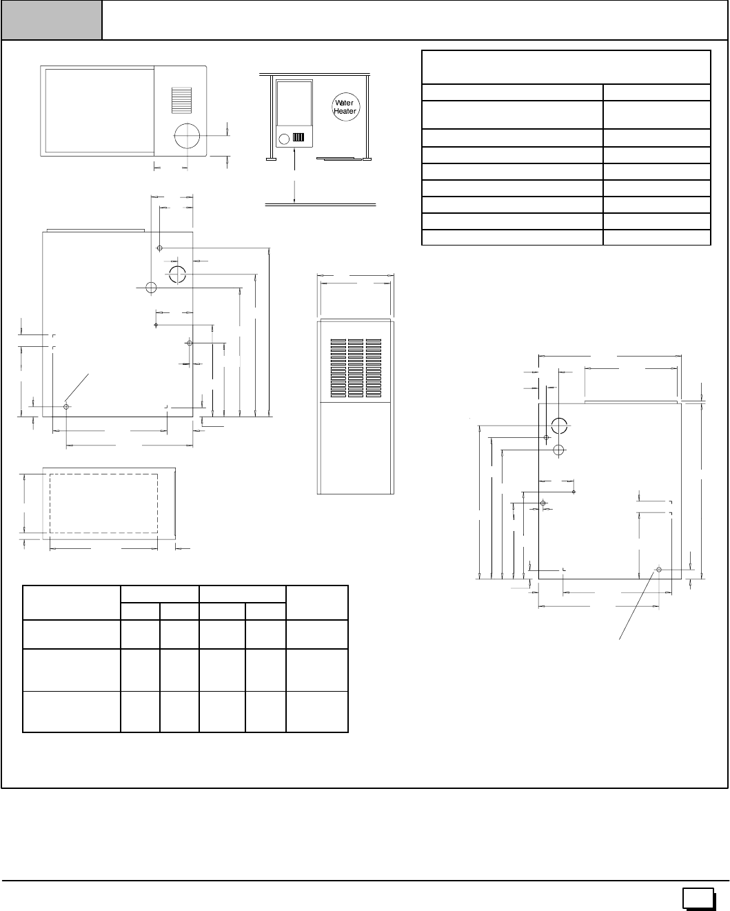
Dimensions and Clearances (N8MPN/L)
Figure 1
Drawing is representative, but some models may vary
DIMENSIONS IN INCHES
NOTE: Evaporator “A” coil drain pan dimensions may vary
from furnace duct opening size. Always consult evaporator
specifications for duct size requirements.
Furnace is designed for bottom return or side return.
Return air through back of furnace is NOT allowed.
25--23--44a1
TOP
51/3
31/4
LEFT SIDE
61/2
33/4
5
271/2
33
131/4
241/2
17/8213/4
265/8
131/4
47/811/2
7
1
RIGHT SIDE
281/2181/2
21/4
131/4
171/3
3/4
2
7
1
35
32
213/4
11/2
253/4
47/8265/817/8
FRONT
AB
30²Min.
BOTTOM
D
C231/841/16
Plugged starting
hole to cut side
duct opening
Plugged starting hole to cut
side duct opening
J
H
5
441 01 2611 06
·The air temperature rise is within the rated rise range on
thefurnaceratingplate,andthefiringratehasbeensetto
the rating plate value.
·The filters used to clean the circulating air during the
construction process must be either changed or thor-
oughly cleaned prior to occupancy.
·The furnace, ductwork and filters are cleaned as neces-
sarytoremovedrywalldustandconstructiondebrisfrom
all HVAC system components after construction is com-
pleted.
·Verifyproperfurnaceoperatingconditionsincludingigni-
tion, gas input rate, airtemperature rise, and venting ac-
cording to these installation instructions.
MINIMUM CLEARANCES TO COMBUSTIBLE
MATERIALS FOR ALL FURNACES
REAR 0
FRONT (combustion air openings
in furnace and structure) 3²
Required For Service *24²
ALL SIDES Of SUPPLY PLENUM 1²
SIDES 0
VENT
Single--Wall Vent 6²
Type B--1 Double--Wall Vent 1²
TOP OF FURNACE 1²
*30²clearance recommended for casing removal.
Horizontal position:Line contact ispermissible only between lines
formed byintersections of top and two sides of furnace jacket, and
building joists, studs or framing.
DIMENSIONAL INFORMATION
Furnace Cabinet Bottom Return Air
F
u
r
n
a
c
e
Model A B C D
R
e
t
u
r
n
A
i
r
Opening
N8MPN/L050B12
N8MPN/L075B12 151/214 13/8125/8H
N8MPN/L075F16
N8MPN100F14
N8MPN/L100F20 191/8175/821/8143/4J
N8MPN/L100J22
N8MPN/L125J20
N8MPN/L125J22 223/4211/4115/16 183/4J
NOTE: Evaporator “A” coil drain pan dimensions may
vary from furnace duct opening size. Always consult
evaporator specifications for duct size requirements.
Furnace is designed for bottom return or side return.
Return air through back of furnace is NOT allowed.
175/16
303/4
291/2
21/4
33/4
271/2
175/16
21/4
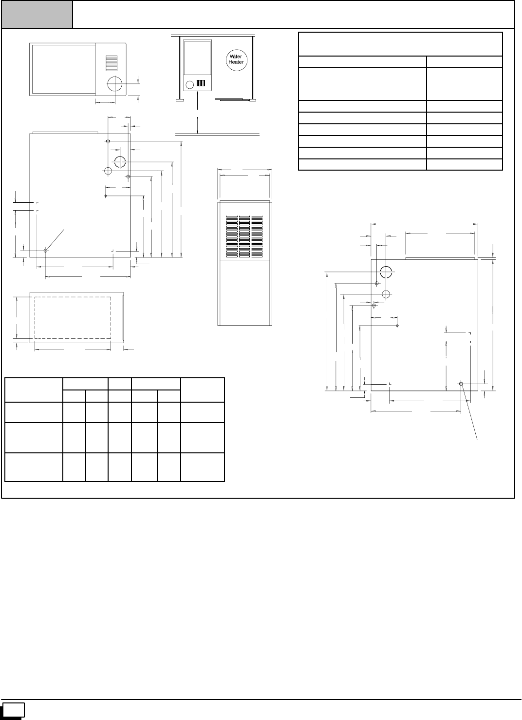
Dimensions and Clearances (*8MPN/L Models)
Figure 2
Drawing is representative some models may vary
DIMENSIONS IN INCHES
7
33
7
2
1/
2
213/4
LEFT SIDE
277/838
131/4
17/8265/8
321/2
33/4
11/2
47/8
51
51/3
TOP
FRONT
AB
F
30²Min.
131/4
RIGHT SIDE
281/2181/23/4
7
1
40
213/4
47/8265/8
17/8
11/2
37
BOTTOM
D
C231/841/16
Plugged starting
hole to cut side
duct opening
Plugged starting hole to
cut side duct opening
H
J
6441 01 2611 06
MINIMUM CLEARANCES TO COMBUSTIBLE
MATERIALS FOR ALL UNITS
REAR 0
FRONT (combustion air openings
in furnace and structure) 3²
Required For Service *24²
ALL SIDES Of SUPPLY PLENUM 1²
SIDES 0
VENT
Single--Wall Vent 6²
Type B--1 Double Wall Vent 1²
TOP OF FURNACE 1²
*30²clearance recommended for casing removal.
Horizontal position:Line contact ispermissible only between lines
formed byintersections of top and two sides of furnace jacket, and
building joists, studs or framing.
DIMENSIONAL INFORMATION
Furnace Cabinet Top Bottom Return Air
F
u
r
n
a
c
e
Model A B F C D
R
e
t
u
r
n
A
i
r
Opening
*8MPN/L050B12
*8MPN/L075B12 151/214 6 13/8125/8H
*8MPN/L075F16
*8MPN100F14
*8MPN/L100F20 191/8175/873/421/8143/4J
*8MPN/L100J20
*8MPN/L125J20
*8MPN150J20 223/4211/491/2115/16 183/4J
* Denotes Brand
Furnace Installation
Inspecttheratingplatetobecertainthemodelnumberbeginswith
“N8MP” or“*8MP”.This identifies theunitasamulti--positionfur-
naceandcanbeInstalledinaUpflow,HorizontalRight,Horizontal
Left or Downflow position.
Upflow
No modifications are required for upflow installation. (See
Figure 3)
7
441 01 2611 06
Typical Upflow Installation
Figure 3
25--23--17
VENT
SUPPLY
AIR
GAS SUPPLY
RETURN
AIR
Horizontal
If you purchased a multi--position furnace, it can be installed hori-
zontally in an attic, basement, crawl space,alcove, or suspended
from a ceiling in a basement or utility room in either a right or left
airflow position. (see Figure 4)
Horizontally installed furnaces may be vented out the top of the
unitoroutthesidefacingup.See“Sideventing”forinstructionsto
rotate the vent to the side.
The minimum clearances to combustibles MUST be maintained
between the furnace and adjacent construction, as shown in
Figure 1 andFigure 2.ONLY thecornerofthecabinet is allowed
to contact the rafters as shown in Figure 4. All other clearances
MUST be observed as shown in Figure 1 and Figure 2.
Typical Horizontal Installation
Figure 4
VENT
VENT
GAS SUPPLY
SUPPLY
AIR
RETURN
AIR
25-23-18a
OPTIONAL
VENT LOCATION
Ifthefurnaceistobesuspendedfromthefloorjoistsinabasement
orcrawlspaceortheraftersinanattic,itis necessary to use steel
pipe straps or an angle iron frame to attach the furnace. These
straps should be attached to the furnace bottom side with sheet
metal screws and to the rafters or joists with bolts. The preferred
method isto use an angle iron frame boltedto the rafters or joists.
Ifthefurnaceistobeinstalledatgroundlevelinacrawlspace,con-
sult local codes. A concrete pad 1²to 2²thick is recommended.
Thirtyinches(30²)isrequiredbetweenthefrontofthefurnaceand
adjacent construction or other appliances. This should be main-
tained for service clearance.
Keep all insulating materials clear from louvered door. Insulating
materials may be combustible.
The horizontal furnaces may be installed directly on combustible
wood flooring orsupports, however, it isrecommended for further
fireprotectioncementboardor sheet metalisplacedbetweenthe
furnace and the combustible wood floor and extend 12²beyond
the front of the furnace louver door. (This is a recommendation
only, not a requirement).
This furnace MUST NOT be installed directly on carpeting, tile or
other combustible material other than wood flooring or supports.
Downflow
FIRE HAZARD.
Failure to install unit on noncombustible subbase
couldresultin death,personalinjuryand/orproperty
damage.
Place furnace on noncombustible subbase on
downflow applications, unless installing on
noncombustible flooring.
!W
A
RNING
If you purchased a Multi--position furnace (*8MP) it may be
installed in a downflow configuration, (see Figure 5).The mini-
mumclearancestocombustionconstructionMUSTbemaintained
between the furnace and adjacent construction, as shown in
Figure 1 and Figure 2.
In addition to clearances in Figure 1 and Figure 2, clearance for
the vent pipe must be considered.
AsubbaseforcombustiblefloorsMUSTbeusedwhenthefurnace
isinstalledasadownflowoncombustiblematerial. See11.“Duct-
work and Filter” (Downflow Section). The outlet flange must be
bent flat for downflow installation.
When installing a four--position furnace in the downflow position
(not the *8DNL furnace), the logo is to be repositioned so that it is
rightside--up as follows:
T8MPN/L
1. Find the door hardware kit that is stored in the furnace and
save it.
2. Carefullyremovelogofromtheoutsideofburnercompartment
door and save it.
3. Carefullyremovetwosmallplugbuttons fromoutsideofblow-
er compartment door and save them.
4. Remove two thumbscrews from blower compartment door by
cutting apart metal retainer washers on inside of door with
smalldiagonalcuttingpliers.Theretainer washerswillnotun-
screw fromthe thumbscrews.Save the two thumbscrews and
two plastic washers.
5. Install two thumbscrews in holes at other end of blower
compartment door from where thumbscrews were removed.
a. A plastic washer should be on each of the two thumb-
screwsbefore insertingthethumbscrewsintotheblower
compartment door holes.
b. After inserting each thumbscrew into the proper hole in
the blower door, push anew metal retainer washeronto
each thumbscrew as far as it will go.
6. Install new strip ofrubber gasket on inside of blowercompart-
ment door on edge that does not already have a gasket.
7. Installlogoretainerpinsintoholesinblowercompartmentdoor
from which plug buttons were removed.
8. Installplugbuttonsintoholesinburnercompartmentdoorfrom
which logo was removed.
9. Install blower compartment door on furnace with bevel edge
and logo at top.
8441 01 2611 06
10. Installburnercompartmentdooronfurnacewithbeveledgeat
bottom.
N8MPN/L, C8MPN/L, H8MPN/L
1. Carefully remove logo from burner compartment door and
save it.
2. Turn the logo rightside--up, and install the logo retainer pins
into holes in burner compartment door.
3. New labels for rightside--up application on outside of blower
compartmentdoormaybepurchasedinakitfromyourdistrib-
utor to cover upside--down labels.
Downflow Venting: The combustion venter MUST be rotated to
ventoutthesideforalldownflowinstallations,(seeFigure 5).Bot-
tomventingisnotpermitted.See“Sideventing”forinstructionsto
rotatetheventtotheside.Inadditiontorotatingtheventtotheside
aVent Pipe Shield (NAHA002VC) is required to shield the hot
vent pipe.
!
BURN HAZARD.
Vent pipe is HOT and could cause personal injury.
Hot vent pipe is in reach of small children when
installed in downflow position.
Install vent pipe shield NAHA002VC.
WARNING
Pressure Switch Relocation
Ifthefurnaceisinstalledintheupflowposition,thepressureswitch
will remain in the sameposition as installed by the factory unless
the inducer is rotated. If the furnace is installed in an orientation
that places the pressure switch below the pressure tap on the in-
ducerhousing,thentheswitchMUST be relocated. In order tore-
locatetheswitch,locate2mountingholesordrillabovetheinducer
pressure tap. When drilling the 2 holes make sure to keep the
switch and tubing far enough away from the burners or hot sur-
facesastonotmeltthehose,switch,orwires.Topreventpossible
kinking of the pressure switch hose, trim the hose to remove ex-
cess length.
Note:Whendrillingnewholesmakesuremetalshavingsdonotfall
on or in components, as this can shorten the life of the furnace.
See side venting
for venter rotation
Typical Downflow Installation
Figure 5
VENT
GAS SUPPLY
MUST BE OPPOSITE
VENT DISCHARGE
SIDE
SUPPLY
AIR
RETURN
AIR
OPTIONAL VENT
25--23--19
Combustible floor
base outlet flange
adapter
Vent Shield
Kit
3. Side Venting
This furnace is shipped from the factory with the venter assembly
in an upflow configurations (top vent). The venter assembly can
easily be rotated to a side vent configurations for use in upflow,
horizontal--flow, or downflow application.
When using a side vent configuration (side outlet instead of top
outlet), it may be necessary to relocate the pressure switch to the
alternatepositionontheoppositesideofthetoppanel. Twoscrew
holes are provided at the alternate position. Route the pressure
switch tubing so the tubing is not kinked and not touching thehot
collector box, venter housing, or motor. It may be necessary to
shorten the length of the tubing to properly route the tubing and
eliminate kinks.
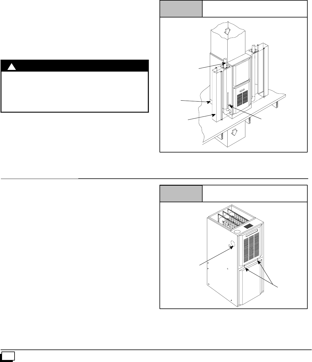
Rotating the Venter Assembly
1. If gas and electrical power have already been connected to
unitshutoffgasandremovepowerfromunit.Unscrewscrews
onburnercompartmentdoorandremoveburnercompartment
door. See Figure 6.
2. Disconnectpowerleads tothe ventermotorandhose topres-
sureswitch.Removethree(3)orfour(4)screwswhichsecure
the venter to the collector box, (see Figure 7).
3. Cut webbing with a pair of snips holding the vent plate to the
cabinetoneithertheleftorrightsideofunitdependingonright
or left venting as desired. Discard vent plate, (see Figure 6).
Figure 6
25--23--45
Screws (2)
Furnace with Screws
Vent Plate
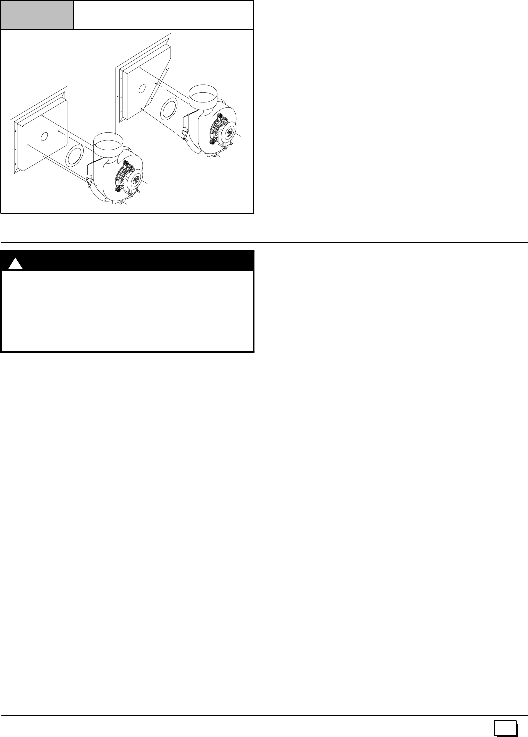
9
441 01 2611 06
Figure 7 Venter Gasket
25--23--52b
Entry
25--23--52c
Main Line
4. Replace venter gasket (part # 1013540, if needed) to venter
assembly with adhesive in the same location as the old one.
5. Rotate venter assembly 90°right or left from original location
depending on venting configurations.
6. Tighten the three (3) or four (4) screws that secure the venter
assembly to the collector box. Do tighten screws enough to
compress venter gasket.
7. Replace power leads to venter motor and reconnect hose to
pressure switch.
NOTE: Unused open vent hole must be covered. A Vent Cover is
suppliedwithVentPipeShieldKitNAHA002VC.A55/16²diameter
VentCoverisavailableseparatelyfromyourdistributor,oronecan
be fabricated with sheet metal for all side vent installations.
4. Combustion & Ventilation Air
CARBON MONOXIDE POISONING HAZARD.
Failure to provide adequate combustion and
ventilationaircouldresultindeathand/orpersonal
injury.
Use methods described here to provide
combustion and ventilation air.
!WARNING
Furnaces require ventilation openings to provide sufficient air for
proper combustion and ventilation of flue gases. All duct or open-
ingsforsupplyingcombustionandventilationairmustcomplywith
thegas codes,orintheabsenceoflocalcodes,theapplicablena-
tional codes.
Combustion and ventilation air must be supplied in accordance
with one of the following:
1. Section8.3,AirforCombustionandVentilation,oftheNational
Fuel Gas Code, (NFGC),ANSI Z223.1--2002/NFPA 54--2002
in the U.S.,
2. Sections7.2,7.3,7.5,7.6,7.7,and7.8ofNationalStandardof
Canada, Natural Gas and Propane Installation Code
(NSCNGPIC), CSA B149.1--00 in Canada,
3. Applicable provisions of the local building code.
When the installation is complete, check thatall appliances have
adequate combustion air and are venting properly. See Venting
AndCombustionAirCheck in“5. Gas VentInstallation”Sectionin
this manual.
Contaminated Combustion Air
Installationsincertainareasortypesofstructurescouldcauseex-
cessive exposure to contaminated air having chemicals or halo-
gens that will result in safety and performance related problems
and may harm the furnace. These instances must use only out-
door air for combustion.
Thefollowingareasortypesofstructuresmaycontainorhaveex-
posure to the substances listed below. The installation must be
evaluated carefully as it may benecessary to provide outdoor air
for combustion.
·Commercial buildings.
·Buildings with indoor pools.
·Furnaces installed in laundry rooms.
·Furnaces installed in hobby or craft rooms.
·Furnaces installed near chemical storage areas.
·Permanent wave solutions for hair.
·Chlorinated waxes and cleaners.
·Chlorine based swimming pool chemicals.
·Water softening chemicals.
·De--icing salts or chemicals.
·Carbon tetrachloride.
·Halogen type refrigerants.
·Cleaning solvents (such as perchloroethylene).
·Printing inks, paint removers, varnishes, etc.
·Hydrochloric acid.
·Sulfuric Acid.
·Solvent cements and glues.
·Antistatic fabric softeners for clothes dryers.
·Masonry acid washing materials.
Outdoor Combustion Air Method
Aspacehavinglessthan50cubicfeetper1,000BTUHinputrating
forallgasappliancesinstalledinthespacerequiresoutdoorairfor
combustion and ventilation.
Air Openings and Connecting Ducts
1. Total input rating for all gas appliances in the space MUST be
considered when determining free area of openings.
2. Connect ducts or openings directly to the outdoors.
3. When screens are used to cover openings, the openings
MUST be no smaller than 1/4²mesh.
4. The minimumdimension of air ducts MUST NOT be less than
3².
5. Whensizingagrille,louverorscreenusethefreeareaofopen-
ing. If free area is NOT stamped or marked on grill or louver,
assumea20%freeareaforwoodand60%formetal. Screens
shall have a mesh size not smaller than1/4².
10 441 01 2611 06
Requirements
1. Providethespacewithsufficientairforpropercombustionand
ventilation of flue gases using horizontal or vertical ducts or
openings.
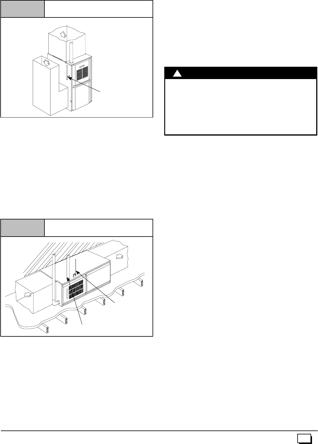
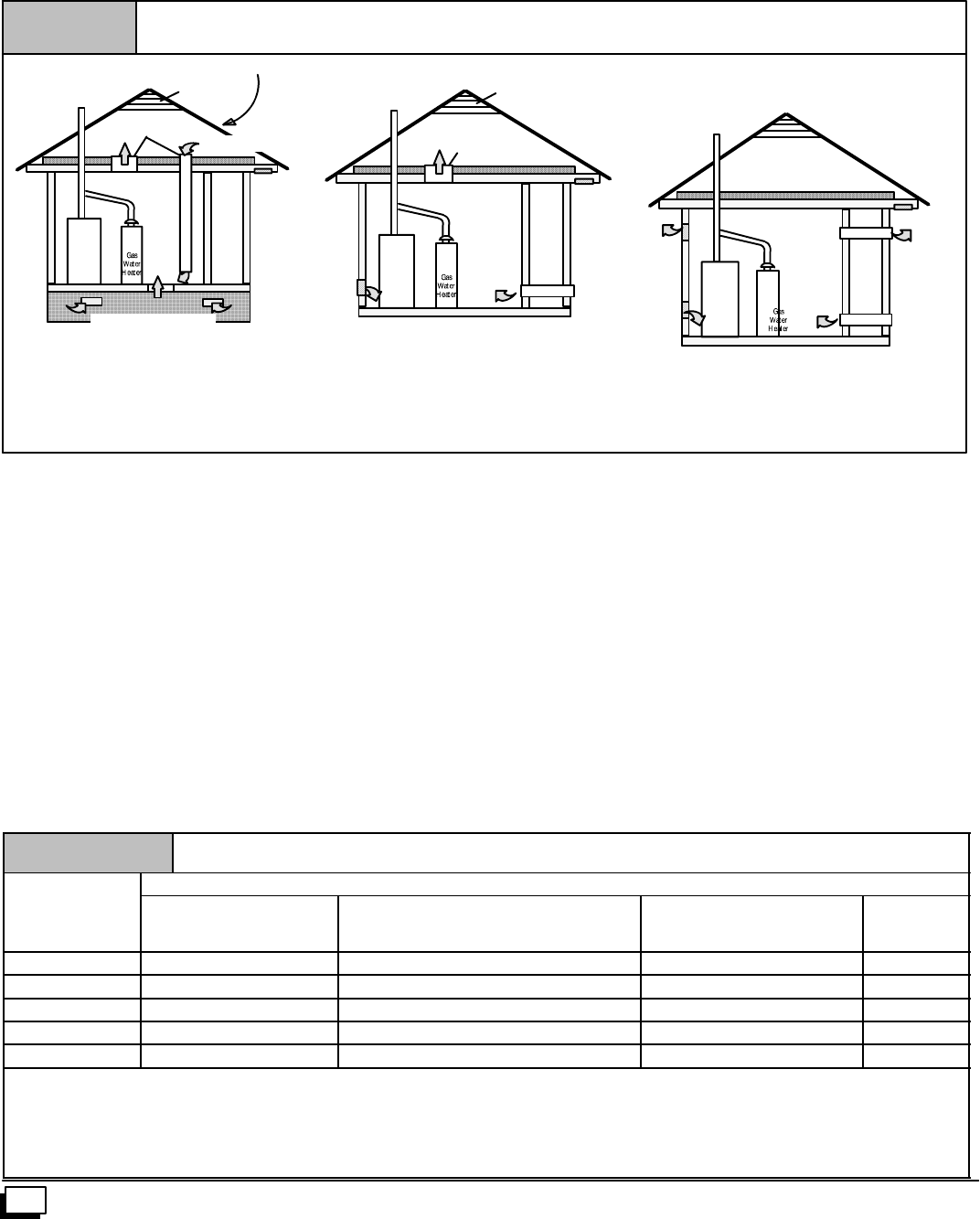
2. Figure 8illustrateshowtoprovidecombustionandventilation
airwhentwopermanentopenings,oneinletandoneoutlet,are
used.
a. One opening MUST commencewithin12²of the floor
and the second opening MUST commence within 12²of
the ceiling.
b. Size openings and ducts per Table 1.
Figure 8
Furnace
Furnace
Minimum One Inlet and One Outlet Air Supply is Required
May be in and Combination Shown
Inlet Air Opening Must be Within12²(300mm) of floor
Outlet Air Opening Must be Within12²(300mm) of ceiling
(1) 1 Square Inch (6cm2) per 4000 BTUH
(2) 1 Square Inch (6cm2) per 2000 BTUH
Outside Air (This is ONLY a guide. Subject to codes of country having jurisdiction.)
This installation NOT approved in Canada
Gas Vent
Gas Vent
Gas Vent
Gable Vent Gable Vent
Outlet
Air (1)
Outlet Air (1)
Outlet Air (1)
Furnace
Outlet
Air (2)
Optional Inlet Air (1)
Ventilated Attic Ventilated Attic
Ventilated Crawl Space
Inlet
Air (1) Inlet
Air (1) Inlet
Air (1)
Inlet
Air (2)
Inlet
Air (2)
Top Above Insulation
Top Above Insulation
Soffit Vent
Soffit Vent
c. Horizontal duct openings require 1 square inch of free
areaper2,000BTUH(1,100mm2/kW)ofcombinedinput
for all gas appliances in the space (see Table 1).
d. Verticalductopeningsoropeningsdirectlycommunicat-
ing with the outdoors require 1 square inch of free area
per 4,000 BTUH (550 mm2/kW) for combined input of all
gas appliances in the space (see Table 1).
3. When one permanent outdoor opening is used, the opening
requires:
a. 1 sq. in of free area per 3,000 BTUH (700 mm2/kW) for
combined input of all gas appliances in the space (see
Table 1) and
b. notlessthanthesumoftheareasofallventconnectorsin
the space.
The opening shall commence within 12²of the top of the enclo-
sure.Appliancesshallhaveclearancesofatleast1²fromthesides
andbackand6²fromthefront.Theopeningshalldirectlycommu-
nicatewiththeoutdoorsorshallcommunicatethroughaverticalor
horizontalducttotheoutdoorsorspaces(crawlorattic)thatfreely
communicate with the outdoors.
4. Combination of Indoor and Outdoor Air shall have:
a. Indoor openings that comply with the Indoor Combus-
tion Air Method below and
b. Outdoor openings located as required in the Outdoor
Combustion Air Method above and
c. Outdoor openings sized as follows.
1) Calculate the Ratio of all Indoor Space volume divid-
edbyrequiredvolumeforIndoorCombustionAirMeth-
od. Outdoor openings sized as follows.
2) OutdooropeningsizereductionFactoris1minusthe
Ratio in 1) above.
3) Minimum size of Outdoor openings shall be the size
required in Outdoor Combustion Air Method above
multiplied by reduction Factor.
Table 1 Free Area
B
T
U
H
Minimum Free Area Required for Each Opening orDuct to Outdoors
B
T
U
H
Input
Rating Two Horizontal Ducts
(sq. in./2,000 BTUH) Single Opening
(sq. in./3,000 BTUH) Two Vertical Ducts or Openings
(sq. in./4,000 BTUH)
Round Duct
(sq. in. /4,000
BTUH)
50,000 25 sq. in. 16.7 sq. in. 12.5 sq. in. 4²
75,000 37.5 sq. in. 25 sq. in. 18.75 sq. in. 5²
100,000 50 sq. in. 33.3 sq. in. 25 sq. in. 6²
125,000 62.50 sq. in. 41.7 sq. in. 31.25 sq. in. 7²
150,000 75 sq. in. 50 sq. in. 37.5 sq. in. 7²
EXAMPLE: Determining Free Area
Furnace
100,000
Furnace
100,000
+
+
Water Heater
30,000
Water Heater
30,000
=
=
Total Input
(130,000 ¸4,000)
Total Input
(130,000 ¸2,000)
=
=
32.5 Sq. In. Vertical
65 Sq. In. Horizontal
11
441 01 2611 06
Indoor Combustion Air
Standard and Known--Air--Infiltration Rate Methods
ãNFPA&AGA
Indoor air is permitted for combustion and ventilation, if the
Standard or Known--Air--Infiltration Rate Method is used.
!
CARBON MONOXIDE POISONING HAZARD.
Failure to supply adequate combustion air could
result in death and/or personal injury.
Mosthomeswill requireadditionalairfromoutdoors
for combustion andventilation. Aspace with atleast
50 cubic feet per 1,000 BTUH input rating or homes
with tight construction may need outdoor air to
supplement air infiltration for proper combustion
and ventilation of flue gases.
WARNING
The Standard Method may be used, if thespace has no less vol-
umethan50cubicfeet per1,000BTUHofthemaximuminputrat-
ings for all gas appliances installed in the space. The standard
method permits indoor air to be used for combustion and ventila-
tion air.
The Known Air Infiltration Rate Method shall be used if the in-
filtration rate is known to be less than 0.40 air changes per hour
(ACH) and equal to or greater than 0.10 ACH. Infiltration rates
greater than 0.60 ACH shall not be used. The minimumrequired
volume of the space varies with the number of ACH and shall be
determined per Table 2 or Equations 1 and 2. Determine the
minimum required volume for each appliance in the space, and
add the volumes together to get the total minimum required vol-
ume for the space.
T
b
l
2
MINIMUM SPACE VOLUME FOR 100% COMBUSTION AND VENTILATION AIR FROM INDOORS (ft3)
Table 2 Other Than Fan-Assisted Total
(1,000’s Btuh) Fan-assisted Total
(1,000’s Btuh)
ACH 30 40 50 50 75 100 125 150
0.60 1,050 1,400 1,750 1,250 1,875 2,500 3,125 3,750
0.50 1,260 1,680 2,100 1,500 2,250 3,000 3,750 4,500
0.40 1,575 2,100 2,625 1,875 2,813 3,750 4,688 5,625
0.30 2,100 2,800 3,500 2,500 3,750 5,000 6,250 7,500
0.20 3,150 4,200 5,250 3,750 5,625 7,500 9,375 11,250
0.10 6,300 8,400 10,500 7,500 11,250 15,000 18,750 22,500
0.00 NP NP NP NP NP NP NP NP
NP = Not Permitted
Table 2MinimumSpaceVolumesweredeterminedby usingthe
following equations from the National Fuel Gas Code ANSI
Z223.1/NFPA 54--2002, 8.3.3.2:
1. For other than fan--assisted appliances such as a draft
hood--equipped water heater,
1000 Btu / hr
21 ft3(Iother )
Volume other =ACH
2. For fan--assisted appliances such as this furnace,
1000 Btu / hr
15 ft3(Ifan )
Volume fan =ACH
If: Iother = combined input of all other than fan--assisted
appliances in Btu/hr
Ifan=combinedinputofallfan--assistedappliancesinBtu/hr
ACH = air changes per hour (ACH shall not exceed 0.60.)
The following requirements apply to the Standard Method andto
the Known Air Infiltration Rate Method.
·Adjoining rooms can be considered part of a space, if there
are no closable doors between rooms.
·Anatticorcrawlspacemaybeconsideredaspace thatfreely
communicateswiththeoutdoorsprovidedthereareadequate
ventilationopeningsdirectlytooutdoors.OpeningsMUSTre-
mainopenandNOThaveanymeansofbeingclosedoff.Ven-
tilation openings to outdoors MUST be at least 1 square inch
offree areaper4,000BTUHoftotalinputratingforallgasap-
pliances in the space.
·In spaces that use the Indoor Combustion Air Method, in-
filtration should be adequate to provide air for combustion,
ventilation and dilution of flue gases. However, in buildings
withunusually tightconstruction,additional airMUST bepro-
vided using the methods described in section titled Outdoor
Combustion Air Method:
·Unusually tight construction is defined as Construction with:
1. Walls and ceilings exposed to the outdoors have a con-
tinuous, sealed vapor barrier.Openings are gasketed or
sealed and
2. Doors and openable windows are weather stripped and
3. Other openings are caulked or sealed. These include
joints around window and door frames, between sole
plates and floors, between wall--ceiling joints, between
wall panels, at penetrations for plumbing, electrical and
gas lines, etc.
Ventilation Air
Someprovincialcodesandlocal municipalitiesrequireventilation
or make--up air be brought into the conditioned space as replace-
mentair.Whichevermethodisused,themixedreturnairtempera-
ture across the heat exchanger MUST not fall below 60°
continuously,or55°on anintermittentbasissothatflue gases will
not condense excessively in the heat exchanger. Excessive con-
densation will shorten the life of the heat exchanger and possibly
void your warranty.

12 441 01 2611 06
5. Gas Vent Installation
CARBON MONOXIDE POISONING, FIRE AND
EXPLOSION HAZARD.
Failure to properly vent this furnace could result in
death, personal injury and/or property damage.
Read and follow all instructions in this section.
!WARNING
Install the vent in compliance with codes of the country having ju-
risdiction, local codes or ordinances and these instructions.
This Category Ifurnace is fan--assisted. A fan assisted appliance
isanapplianceequippedwithanintegralmechanicalmeanstoei-
ther draw or force products of combustion through the heat ex-
changer.
Category Ifurnace definition: A central furnace which operates
with a non--positive vent static pressure and with a flue loss not
lessthan17percent. Thesefurnacesareapprovedforcommon--
venting and multi--story venting with other fan--assisted or draft
hood--equipped appliances in accordance with the NFGC or
NSCNGPIC
Category ISafe Venting Requirements
Category Ifurnace vent installations shall be in accordance with
Parts 10 and 13 of the National Fuel Gas Code (NFGC), ANSI
Z223.1--2002/NFPA54--2002;and/orSection7andAppendixCof
the CSA B149.1--00, National Standard of Canada, Natural Gas
and Propane Installation Code; the local building codes; furnace
and vent manufacturer’s instructions.
NOTE: The following instructions comply with the ANSI
Z223.1/NFPA 54 National Fuel Gas Code and CSA B149.1 Natu-
ral Gas and Propane Installation code, based on the input rateon
the furnace rating plate.
1. If a Category Ivent passes through an attic, any concealed
space or floor, use ONLY Type B or Type L double wall vent
pipe.Ifventpipepassesthroughinteriorwall,useTypeBvent
pipe with ventilated thimble ONLY.
2. Do NOT vent furnace into any chimney serving an open fire-
place or solid fuel burning appliance.
3. Use the same diameter Category Iconnector or pipe as per-
mitted by:
·the National Fuel Gas Code Code (NFGC) ANSI
Z223.1--2002 / NFPA 54--2002 sections 10 and 13 vent-
ing requirements in the United States
or
·the National Standard of Canada Natural Gas and Pro-
pane Installation Code (NSCNGPIC) CSA B149.1--00
section7andappendixCventingrequirementsinCana-
da.
4. Push the vent connector onto the furnace flue collar of the
venterassemblyuntilittouchesthebead(atleast5/8²overlap)
and fasten with at least two field--supplied, corrosion--resist-
ant, sheet metal screws located at least 140°apart.
5. Keep vertical Category Ivent pipe or vent connector runs as
short and direct as possible.
6. Vertical outdoor runs of Type--B or ANY single wall vent pipe
below the roof line are NOT permitted.
7. Slopeallhorizontalrunsupfromfurnacetotheventterminal a
minimum of 1/4²per foot (21 mm/m).
8. Rigidlysupportallhorizontalportionsoftheventingsystemev-
ery6¢or less usingproper clamps andmetal straps to prevent
sagging and ensure there is no movement after installation.
9. Checkexistinggasventorchimneytoensuretheymeetclear-
ances and local codes. See Figure 1
10. The furnace MUST be connected to a factory built chimney or
vent complying with a recognized standard, or a masonry or
concretechimneylinedwithaliningmaterialacceptabletothe
authority having jurisdiction. Venting into an unlined ma-
sonrychimneyorconcretechimneyisprohibited.Seethe
6. Masonry Chimney Venting section in these instruc-
tions.
11. Fan--assisted combustion system Category Ifurnaces shall
not be vented into single--wall metal vents.
12. Category Ifurnaces must be vented vertically or nearly verti-
cally, unless equipped with a listed mechanical venter.
13. VentconnectorsservingCategoryIfurnacesshallnotbecon-
nectedintoanyportionofmechanicaldraftsystemsoperating
under positive pressure.
A4--to--3inchreducerispermittedatthefluecollarwheninstalling
a50,000Btuhgasinputfurnace,iftheinstallationmeetsallthefol-
lowing requirements for sizing the vent connectors and vents:
1. The National Fuel Gas Code, ANSI
Z223.1/NFPA--54--2002, sections 10.5.3.1(1),
10.6.3.1(2), 10.10.3.1, 13.1.2, 13.1.10, and 13.2.21(1)
through (3) in the U.S. or
2. The Natural Gas and Propane Installation Code CSA
B149.1--00, sections 7.13.1(b), 7.13.2(b), 7.18.5(b),
and Appendix C--GVR no. 2. in Canada.
13
441 01 2611 06
Venting and Combustion Air Check
NOTE: When an existing Category I furnace is removed or re-
placed,theoriginalventingsystemmaynolongerbesizedtoprop-
erly vent the attached appliances, and to make sure there is
adequate combustion air for all appliances, MAKE THE FOL-
LOWING CHECK.
CARBON MONOXIDE POISONING HAZARD
Failure to follow the steps outlined below for each
applianceconnectedtotheventingsystembeingplaced
into operation, could result in carbon monoxide
poisoning or death:
The following steps shall be followed for each appliance
connected to the venting system being placed into
operation, while all other appliances connected to the
venting system are not in operation:
1.Seal any unused openings in the venting system.
2.Inspect the venting system for proper size and horizontal
pitch, as required in the National Fuel Gas Code, ANSI
Z223.1/NFPA 54 or CSA B149.1, Natural Gas and
Propane Installation Code and these instructions. Deter-
minethatthereisnoblockageorrestriction,leakage,cor-
rosionandotherdeficiencieswhichcouldcauseanunsafe
condition.
3.As far as practical, close all building doors and windows
andalldoorsbetweenthespaceinwhichtheappliance(s)
connected to the venting system are located and other
spaces of the building.
4.Close fireplace dampers.
5.Turnonclothesdryersandanyappliancenotconnectedto
the venting system. Turn on any exhaust fans, such as
range hoods and bathroom exhausts, so they are
operating at maximum speed. Do not operate a summer
exhaust fan.
6.Followthelightinginstructions.Placethe appliancebeing
inspected into operation. Adjust the thermostat so
appliance is operating continuously.
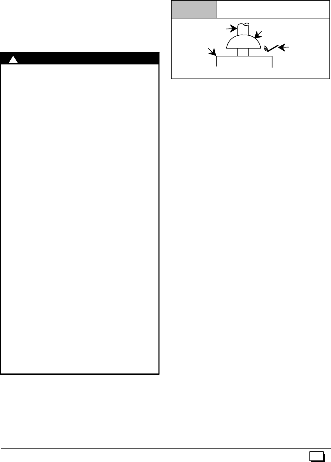
7.Test for spillage from draft hood equipped appliances at
thedrafthoodreliefopeningafter5minutesofmainburner
operation. Use the flame of a match or candle. (Figure 9)
8.If improper venting is observed, during any of the above
tests,theventingsystemmustbecorrectedinaccordance
with the National Fuel Gas Code, ANSI Z223.1/NFPA 54
and/orCSAB149.1,NaturalGasandPropaneInstallation
Code.
9.After it has been determined that each appliance con-
nected to the venting system properly vents when tested
as outlined above, return doors, windows, exhaust fans,
fireplace dampers and any other gas--fired burning
appliance to their previous conditions of use.
!WARNING
Vent Check
Draft HoodVent Pipe
Match
Typical Gas
Water Heater
Figure 9
NOTE: If flame pulls towards draft hood, this indicates
sufficient infiltration air.
Venting to Existing Masonry Chimney
Dedicated venting of one fan assisted furnace into any ma-
sonry chimney is restricted. A chimney must first be lined with
either Type B vent sized in accordance with NFGC tables 13.1 or
13.2 or a listed, metal lining system, or venting into a masonry
chimneyispermittedasoutlinedwith useofanoptionallistedma-
sonry chimney kit. (See Section 7 Masonry Chimney Venting of
these instructions.)
Listed, corrugated metallic chimney liner systems in masonry
chimneysshallbesizedbyusingNFGC tablesper13.1.7fordedi-
cated venting and per 13.2.19 for common ventingwith the maxi-
mum capacity reduced by 20% (0.80 X maximum capacity) and
theminimumcapacityasshownintheapplicabletable.InCanada,
use the NSCNGPIC, appendix C, section 10. Corrugated metal
vent systems installed with bends or offsets require additional re-
ductionof 5%oftheventcapacityforeachbendupto45°and10%
of the vent capacity for each bend from 45°up to 90°.
NOTE:Two(2)45°elbows are equivalent to one (1) 90°elbow.
Combined Venting into a Masonry Chimney
Ventingintoamasonryorconcretechimneyisonlypermitted
as outlined in the NFGC or NSCNGPIC venting tables. Follow
all safe venting requirements.
Note: See section “7. Masonry Chimney Venting”.

14 441 01 2611 06
6. Horizontal Venting
Category IFurnaces With External Power
Venters
InordertomaintainaCategoryIclassificationof fan--assistedfur-
naceswhenventedhorizontallywithsidewalltermination,apower
venter is REQUIRED to maintain a negative pressure in the vent-
ing system.
In the U.S.: Per the NFGC, a listed power venter may be used,
when approved by the authority having jurisdiction.
In Canada: Only power venters approved by the appliance
manufacturer and where allowed by the authority having jurisdic-
tion may be used
PleaseconsulttheFieldsControlsCo. orTjernlundProducts,Inc.
for power venters certified for use with our furnaces.
Vent Termination
Venting Through a Non--Combustible and
Combustible Wall
Consult External Power Venter manufacturer instructions.
Selectthepowerventertomatchthe Btuhinputofthefurnacebe-
ingvented. FollowallofthePowerVentermanufacturer’sinstalla-
tion requirements included with the power venter for:
·venting installation,
·vent terminal location,
·preventing blockage by snow,
·protectingbuildingmaterialsfromdegradationbyfluegases,
·see Figure 10 for required vent termination.
NOTE: It is the responsibility of the installer to properly terminate
theventandprovideadequateshielding. Thisisessentialinorder
to avoid water/ice damage to building, shrubs and walkways.
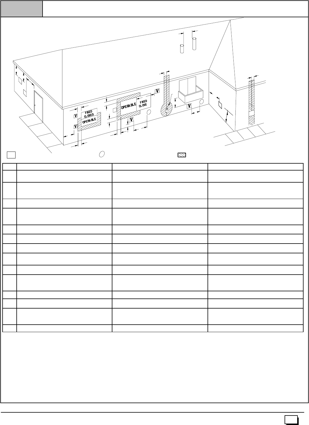
A
X
B
V
V
V
V
X
X
AIR SUPPLY INLET
VVENT TERMINAL AREA WHERE TERMINAL IS NOT PERMITED
A
B
B
B
B
B
C
D
E
F
J
I
L
HM
K
G
25--24--65--2
N
V
Other than Direct Vent Termination Clearance
Figure 10
VV
15
441 01 2611 06
Item Clearance Descriptions Canadian Installation (1) U.S. Installation (2)
AClearance above grade, veranda, porch, deck, balcony, or
anticipated snow level 12²(30cm) # 12²(30 cm)
BClearance to a window or door that may be opened 6²(15 cm) for appliances £10,000 BTUH (3kW), 12²(30
cm) for appliances > 10,000 Btuh (3 kW) and £100,000 Btuh
(30 kW), 36²(91 cm) for appliances > 100,000 Btuh (30 kW)
4¢(1.2 m) below or to the side of the opening. 1¢(30 cm)
above the opening.
CClearance to a permanently closed window * *
DVertical clearance to a ventilated soffit located above the ter-
minal within a horizontal distance of 2¢(61cm) from the cent-
erline of the terminal
* *
EClearance to an unventilated soffit * *
FClearance to an outside corner * *
GClearance to an inside corner * *
HClearance to each side of the centerline extended above elec-
trical meter or gas service regulator assembly 3¢(91 cm) within 15¢(4.5 m) above the meter/regulator
assembly 3¢(91 cm) within 15¢(4.5 m) above the meter/regulator
assembly
IClearance to service regulator vent outlet 3¢(91 cm) *
JClearance to non--mechanical air supply inlet to building or the
combustion air inlet to any other appliance 6²(15 cm) for appliances £10,000 BTUH (3kW), 12²(30
cm) for appliances > 10,000 Btuh (3 kW) and £100,000 Btuh
(30 kW), 36²(91 cm) for appliances > 100,000 Btuh (30 kW)
4¢(1.2 m) below or to the side of opening: 1¢(30 cm) above
opening.
KClearance to a mechanical air supply inlet 6¢(1.83 m) 3¢(91 cm) above if within 10¢(3m horizontally)
LClearance under a veranda, porch, deck, or balcony 12²(30 cm) + *
MClearance to each side of the centerline extended above or
below vent terminal of the furnace to a dryer or water heater
vent, or other appliance’s direct vent intake or exhaust.
* *
NClearance from a plumbing vent stack 3¢(91 cm) 3¢(91 cm)
(1.) In accordance with the current CSA B149.1, Natural Gas and Propane Installation Code
(2.) In accordance with the current ANSI Z223.1/NFPA 54, National Fuel Gas Code
#18²(46 cm) above roof surface
+ Permitted only if veranda, porch, deck, or balcony is fully open on a minimum of two sides beneath the floor.
*For clearances not specified in ANSI Z223.1/NFPA 54 or CSA B149.1, clearances shall be in accordance with local installation codes and the requirements of the gas supplier and the manufacture’s
installation instructions.
Notes:
1. The vent for this appliance shall not terminate
a. Over public walkways; or
b. Near soffit vents or crawl space vents or other areas where condensate or vapor could create a nusiance or hazard or property damage; or
c. Where condensate vapor could cause damage or could be detrimental to the operation of regulators, relief valves, or other equipment.
2. When locating vent terminations, consideration must be given to prevailing winds, location, and other conditions which may cause recirculation of the combustiob products of adjacent vents.
Recirculation can cause poor combustion, inlet condensate problems, and accelerated corrosion of the heat exchangers.
16 441 01 2611 06
7. Masonry Chimney Venting
Chimney Inspection
All masonry chimney construction must conform to Standard
ANSI/NFPA 211--2003 and to any state or local codes applicable.
The chimney must be in good condition and a complete chimney
inspectionmustbeconductedpriortofurnaceinstallation.Ifthein-
spection reveals damage or abnormal conditions, make neces-
sary repairs or seek expert help. See Figure 11 “The Chimney
Inspection Chart”. Measure inside area of tile--liner and exact
height of chimney from the top of the chimney to the highest ap-
pliance flue collar or drafthood outlet.
Connector Type
To reduce flue gas heat loss and the chance of condensate prob-
lems, the vent connector must be double--wall Type B vent.
Venting Restrictions for Chimney Types
Interior Chimney -- has no sides exposed to the outdoors below
the roofline. All installations can be single furnace or common
vented with another draft hood equipped Category Iappliance.
Exterior Chimney -- has one or more sides exposed to the out-
doors below the roof line. All installations with a 99% Winter De-
sign Temperature* below 17°F must be common vented only with
a draft hood equipped Category I appliance.
*The 99% Winter Design Dry--Bulb (db) temperatures are found in the
1993 ASHRAE Fundamentals Handbook, Chapter 24, Table 1 (United
States)and2(Canada),orusethe99.6%heatingdbtemperaturesfound
in the 1997 or 2001 ASHRAE Fundamentals Handbook, Climatic
Design Information chapter, Table 1A (United States) and 2A
(Canada).
CARBON MONOXIDE POISONING, FIRE AND
EXPLOSION HAZARD.
Failure to properly vent this furnace could result in
death, personal injury and/or property damage.
These furnaces are CSA (formerly AGA and CGA)
design--certified for venting into exterior clay
tile--lined masonry chimneys with a factory
accessory Chimney Adapter Kit. Refer to the
furnace rating plate for correct kit usage. The
Chimney Adapter Kits are for use with ONLY
furnaces having a Chimney Adapter Kit number
marked on the furnace rating plate.
!WARNING
Ifaclaytile--linedmasonrychimneyisbeingusedanditisexposed
to the outdoors below the roof line, relining might be required.
Chimneys shall conform to the Standard for Chimneys, Fire-
places, Vents, and Solid Fuel Burning Appliances ANSI/NFPA
211--2003 in the United States and to a Provincial or Territorial
Building Code in Canada (in its absence, the National Building
Code of Canada) and must be in good condition.
U.S.A.--RefertoSections13.1.9or13.2.20oftheNFGCortheau-
thorityhavingjurisdictiontodeterminewhetherreliningisrequired.
If relining is required, use a properly sized listed metal liner,
Type--B vent, or a listed alternative venting design.
NOTE: See the NFGC, 13.1.9 and 13.2.20 regarding alternative
venting design and the exception, which cover installations such
as the Chimney Adapter Kits NAHA001DH and NAHA002DH.
The Chimney Adapter Kits are listed alternative venting designs
for these furnaces. See the kit instructions for complete details.
Canada(andU.S.A.)--Thisfurnaceispermittedtobeventedintoa
clay tile--lined masonry chimney that is exposed to the outdoors
below the roof line, provided:
1. Vent connector is Type--B double--wall, and
2. This furnace is common vented with at least 1 draft hood--
equipped appliance, and
3. The combined appliance input rating is less than the maxi-
mum capacity given in Table A, and
4. Theinputratingofeachspace--heatingapplianceisgreater
than the minimuminput rating given in Table B for Masonry
Chimneys for the local 99% Winter Design Temperature.
Chimneys having internal areas greater than 38 square
inches require furnace input ratings greater than the input
ratingsofthesefurnaces. SeefootnoteatbottomofTableB,
and
5. The authority having jurisdiction approves.
If all of these conditions cannot be met, an alternative venting de-
sign shall be used, such as the listed chimney adapter kit with a
furnace listed for use with the kit, a listed chimney--lining system,
or a Type--B vent.
These furnaces are CSA design--certified for use in exterior clay
tile--lined masonry chimneys with a factory accessory Chimney
AdapterKit. Referto thefurnaceratingplateforcorrectkitusage.
The Chimney Adapter Kits are listed alternative venting designs
andareforusewithONLYfurnaceshavingaChimneyAdapterKit
number marked on the furnace rating plate.
17
441 01 2611 06
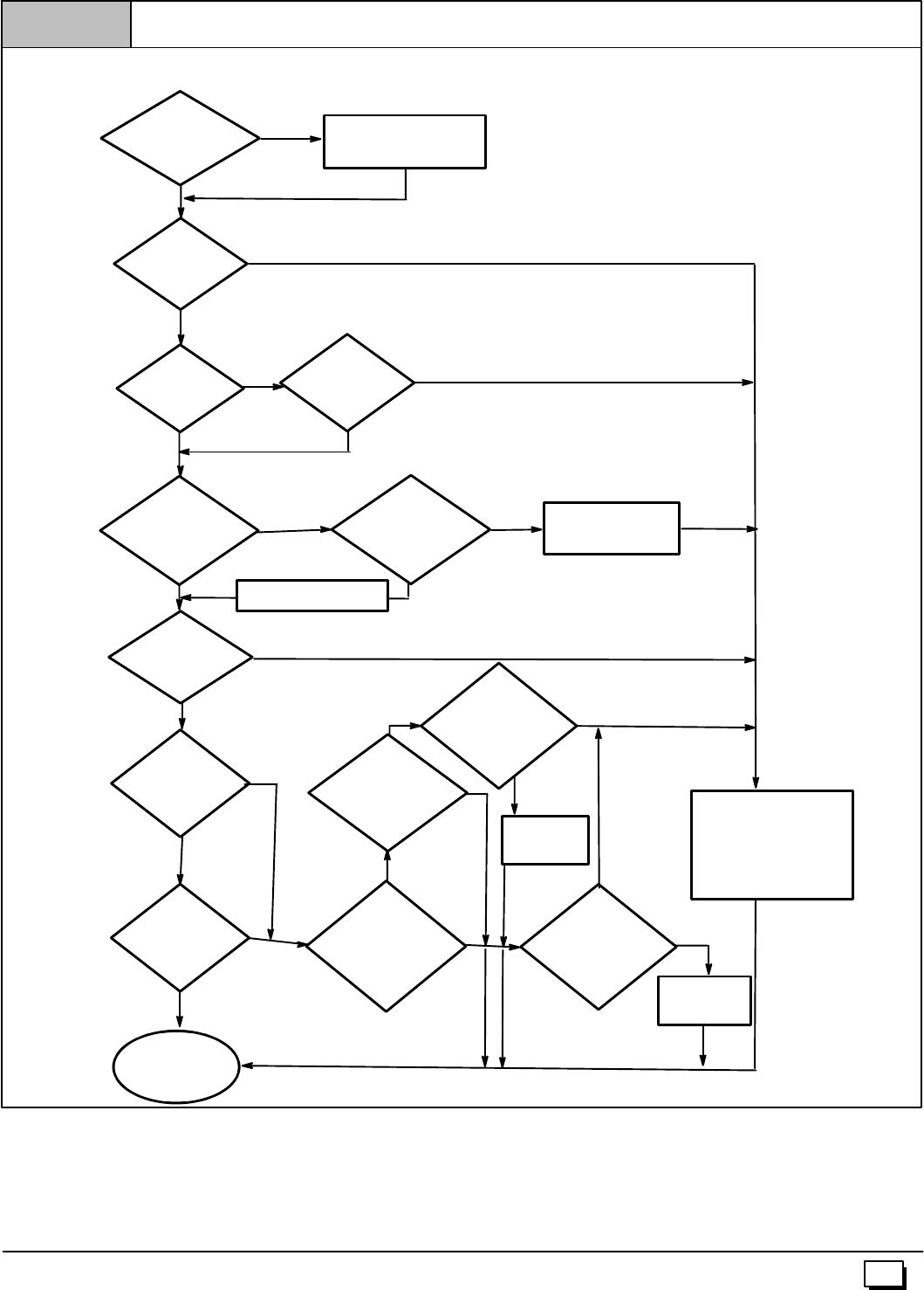
Chimney is
acceptable for use
Crown
condition:
Missingmortar
or brick?
Rebuild
crown
Is
Chimney properly lined
with clay tile
liner?
Yes
Yes
No
No
Yes
Is
liner and top
seal in good
condition
No
Debris in
cleanout? Mortar, tile,
metal vent, fuel oil
residue?
Repair
liner or top seal
or reline chimney as
necessary.
Reline
Yes Repair
Yes
No
Yes
Clay
tile misalignment,
missingsections,
gaps?
No
Is Chimney
lined with properly
sized, listed liner or
Type--B vent? Line chimney with properly
sized, listed flexible metal
liner or Type--B vent per NFGC or
NSCNGPIC Vent Sizing Tables
and liner or vent manufacturer’s
installation instructions.
CHIMNEY INSPECTION CHART
ForadditionalrequirementsrefertotheNationalFuelGasCodeNFPA54/ANSIZ223.1--2002andANSI/NFPA211--2003Chimneys,Fireplaces,Vents,andSolidFuel
Burning Appliancesin the U.S.A. or to the Canadian Installation Code CSA B149.1--00 in Canada.
Yes
No
No
Mortar or
tile debris? Yes Remove mortar
and tile debris?
No
Remove metal vent or liner.
Consult
Part B of chimney
adapter venting
instructions for
application
suitability.
Chimney
exposed to outdoors
below roof line? Is Chimney to
be dedicated to a
single furnace?
Yes Install chimney
adapter per
instructions.
Not Suitable
Not Suitable
Suitable
No
Consult
Part C of chimney
adapter venting
instructions for
application
suitability.
Suitable
Install chimney
adapter per
instructions.
No
Condensate
drainage at bottom
of chimney? Yes
Figure 11
18 441 01 2611 06
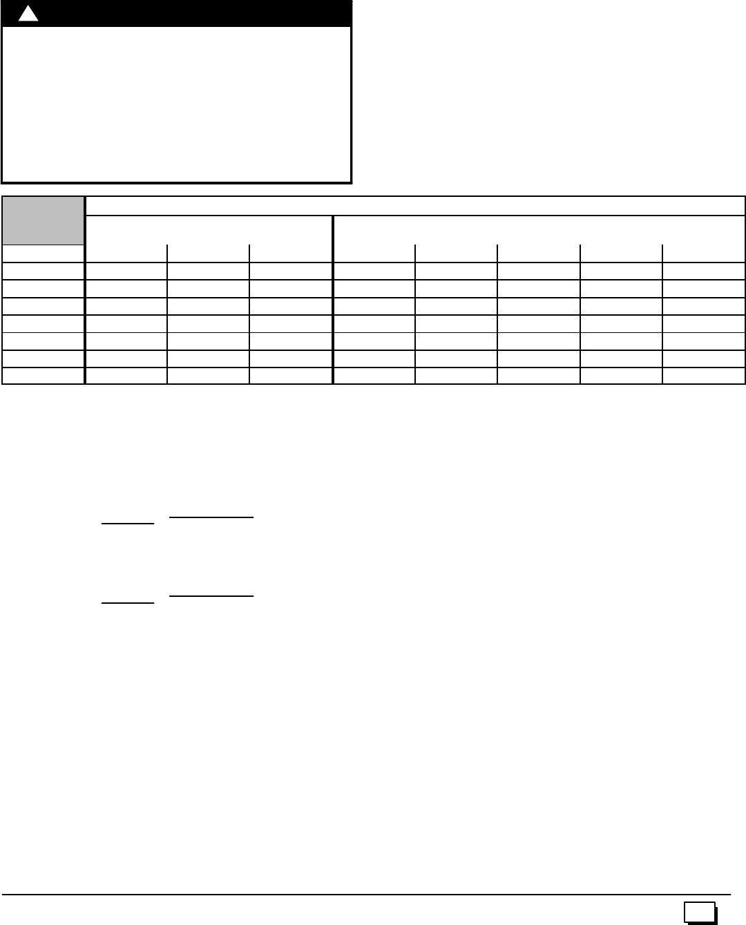
Exterior Masonry Chimney,
FAN+NAT Installations with
Type--B Double--Wall Vent Connectors
ã
ãã
ãNFPA&AGA
Table A--
Combined Appliance
Maximum Input Rating in
Thousands of Btu per Hr
VENT
HEIGHT
(
F
T
)
INTERNAL AREA OF CHIMNEY
(SQ IN.)
(FT) 12 19 28 38
674 119 178 257
880 130 193 279
10 84 138 207 299
15 NR 152 233 334
20 NR NR 250 368
30 NR NR NR 404
Table B--
Minimum Allowable Input Rating of
Space--Heating Appliance in
Thousands of Btu per Hr
VENT
HEIGHT
(
F
T
)
INTERNAL AREA OF CHIMNEY
(SQ IN.)
G
(FT) 12 19 28 38
Local 99% Winter Design Temperature: 17 to 26°
°°
°F*
F
6055 99 141
2
6°
°
°
°F
852 74 111 154
o2
6
10 NR 90 125 169
1
7t
o
15 NR NR 167 212
1
7
20 NR NR 212 258
30 NR NR NR 362
Local 99% Winter Design Temperature: 5 to 16°
°°
°F*
6NR 78 121 166
6
°
°
°
°F
8NR 94 135 182
o
16
°
°
10 NR 111 149 198
5t
o
15 NR NR 193 247
5
20 NR NR NR 293
30 NR NR NR 377
Local 99% Winter Design Temperature: --10 to 4°
°°
°F*
F
6NR NR 145 196
4°
°
°
°F
8NR NR 159 213
to
4
10 NR NR 175 231
-
-
10
t
15 NR NR NR 283
--
1
20 NR NR NR 333
30 NR NR NR NR
-- 11 °
°°
°F
or Local 99% Winter Design Temperature: --11°
°°
°For
lower*
o
r
lower Not recommended for any vent configuration
*The 99% Winter Design Dry--Bulb (db) temperatures are found in the
1993 ASHRAE Fundamentals Handbook, Chapter 24, Table 1
(United States) and 2 (Canada), or use the 99.6% heating db
temperaturesfound in the 1997 or 2001 ASHRAE Fundamentals
Handbook, Climatic Design Information chapter, Table 1A (United
States) and 2A (Canada).
Inspectionsbeforethesaleandatthetimeofinstallationwilldeter-
minetheacceptabilityofthechimney ortheneedforrepairand/or
(re)lining. Refer to the Chimney Inspection Chart to perform a
chimney inspection.
If the inspection of a previously used tile--lined chimney:
a. Showssignsofventgascondensation,thechimneyshould
be relined in accordance with local codes and the authority
having jurisdiction. The chimney should be relined with a
listed metal liner, Type--B vent, or a listed chimney adapter
kittoreducecondensation. Ifacondensatedrainisrequired
bylocalcode,refertotheNFGC,Section10.9foradditional
information on condensate drains.
b. Indicates the chimney exceeds the maximum permissible
sizeinthetables,thechimneyshouldberebuiltorrelinedto
conform to the requirements of the equipment being
installed and the authority having jurisdiction.
Achimneywithouta claytile liner,whichisotherwisein goodcon-
dition,shallberebuilttoconformtoANSI/NFPA211orbelinedwith
a UL listed (ULC listed in Canada) metal liner orUL listed Type--B
vent. Relining with a listed metal liner or Type--B vent is consid-
ered to be a vent--in--a--chase.
If a metal liner or Type--B vent is used to line a chimney, no other
appliance shall be vented into the annular space between the
chimney and the metal liner.
APPLIANCE APPLICATION REQUIREMENTS
Appliance operation has a significant impact on the performance
of the venting system. If the appliances are sized, installed, ad-
justed, and operated properly, the venting system and/or the ap-
pliances should not suffer fromcondensation and corrosion. The
ventingsystemandallappliancesshallbeinstalledinaccordance
with applicable listings, standards, and codes.
The furnace should be sized to provide 100 percent of the design
heating load requirement plus any margin that occurs because of
furnace model size capacity increments. Heating load estimates
can be made using approved methods available from Air Condi-
tioning Contractors of America (Manual J); American Society of
Heating, Refrigerating, and Air--Conditioning Engineers; or other
approved engineering methods. Excessive oversizing of the fur-
nace could cause the furnace and/or vent to fail prematurely.
Whenametalventormetallinerisused,theventorlinermustbein
goodconditionandbeinstalledinaccordancewiththeventorliner
manufacturer’s instructions.
To prevent condensation in the furnace and vent system, the fol-
lowing precautions must be observed:
1. Thereturn--airtemperaturemustbeatleast60°Fdbexcept
for briefperiods of time duringwarm--up from setback atno
lower than 55°F db or during initial start--up from a standby
condition.
2. Adjust the gas input rate per the installation instructions.
Lowgasinputratecauseslowventgastemperatures,caus-
ing condensation and corrosion in the furnace and/or vent-
ing system. Derating is permitted only for altitudes above
2000¢.
3. Adjust the air temperature rise to the midpoint of the rise
rangeorslightlyabove. Lowairtemperaturerisecancause
low vent gas temperature and potential for condensation
problems.
4. Set the thermostat heat anticipator or cycle rate to reduce
short cycling.
Air for combustion must not be contaminated by halogen com-
poundswhichincludechlorides,fluorides,bromides,andiodides.
These compounds are found in many common home products
suchasdetergent,paint,glue,aerosolspray,bleach,cleaningsol-
vent, salt, and airfreshener, and can cause corrosion offurnaces
and vents. Avoid using such products in the combustion--air sup-
ply. Furnace use during construction of the building could cause
thefurnacetobeexposedtohalogencompounds,causingprema-
ture failure of the furnace or venting system due to corrosion.
19
441 01 2611 06
Vent dampers on any appliance connected to the common vent
can cause condensationand corrosion in the ventingsystem. Do
notuse ventdamperson appliancescommonventedwiththisfur-
nace.
8. Gas Supply and Piping
CARBON MONOXIDE POISONING, FIRE AND
EXPLOSION HAZARD.
Failure to follow safety warnings exactly could
result in serious injury, death, and/or property
damage.
Models designated for Natural Gas are to be used
withNaturalGasONLY,unlessproperlyconvertedto
use with LP gas.
!WARNING
Gas Supply Requirements
·UseonlytheTypeofgasapprovedforthisfurnace.Seerating
plate for approved gas type.
·Gasinputmustnotexceedtheratedinputshownontherating
plate. Overfiring will result in failure of heat exchanger and
cause dangerous operation.
·Donotallowminimumsupplypressuretovarydownward.Do-
ing so willdecrease input to furnace. Refer to Table 3 for gas
supply. Refer to Table 7 and Table 8 for manifold pressures.
Table 3 Gas Pressures
G
a
s
T
y
p
e
Supply Pressure
G
as
T
ype Recommended Max. Min.
Natural 7²14²4.5²
Propane 11²14²11²
Gas Piping Requirements
NOTE:Thegassupplylinemustbeinstalledbyaqualifiedservice
technician in accordance with all building codes.
NOTE: In the state of Massachusetts.
a. Gas supply connections MUST be performed by a li-
censed plumber or gas fitter).
b. Whenflexibleconnectorsareused,themaximumlength
shall not exceed 36²(915 mm).
c. When lever handle type manual equipment shutoff
valves are used, they shall be T--handle valves.
d. TheuseofcoppertubingforgaspipingisNOTapproved.
1. Installgaspipinginaccordancewithlocalcodes,orintheab-
sence of local codes, the applicable national codes.
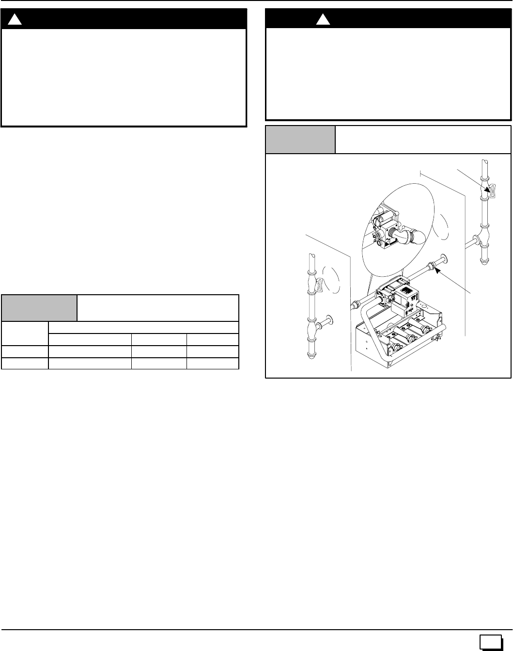
2. It is recommended that a manual equipment shutoff valve be
installed in the gas supply line outside the furnace. Locate
valveasclosetothefurnaceaspossiblewhereitisreadilyac-
cessible. Refer to Figure 12.
FIRE HAZARD
Failure to follow safety warnings exactly could
result in serious injury, death, and/or property
damage.
Use wrench to hold furnace gas control valve when
turning elbows and gas line to prevent damage to
the gas control valve and furnace.
!W
A
RNING
Typical Gas Piping (N8MP)
Figure 12
Left entry
Right entry
Dipleg&pipecap
Left side entry
Union
Manual Equipment Shutoff Valve
25--24--36
3. Useblackironorsteelpipeandfittingsorotherpipeapproved
by local code.
4. Use pipe thread compound which is resistant to natural and
LP gases.
5. Use ground joint unions and install a drip leg no less than 3²
long to trap dirt and moisture before it can enter gas control
valve inside furnace.
6. Providea1/8²NPTpluggedtappingfortestgaugeconnection
immediately up stream of gas supply connection to furnace.
7. Usetwopipewrencheswhen making connections toprevent
furnace gas control valve from turning.
NOTE:Iflocalcodes allowtheuseofa flexiblegasappliancecon-
nector,alwaysuseanewlistedconnector. Donotuseaconnector
which has previously served another gas appliance.
8. Flexible corrugated metal gas connector may NOT be used
inside the furnace or be secured or supported by the furnace
or ductwork.
9. Properly size gas pipe to handle combined appliance load or
run gas pipe directly from gas meter or LP gas regulator.
10. Install correct pipe size for run length and furnace rating.
11. MeasurepipelengthfromgasmeterorLPsecondstageregu-
lator to determine gas pipe size.
20 441 01 2611 06
Right Side Gas Supply Piping (N8MP)
Gaslinecanbeinstalleddirectlytothegas valvethroughthehole
provided in the right side of the cabinet. See Figure 12
Left Side Gas Supply Piping (N8MP)
Two(2) 90°street elbows or two(2) 90°standard elbows and
two(2) close nipples are required for left side gas supply. See
Figure 12.
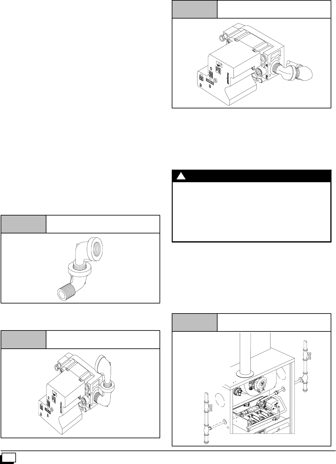
Piping with Street Elbows
1. Assembletheelbowssothattheoutletofone(1)elbowis90°
fromtheinletof theother.Theelbows shouldbetightenough
to be leak proof. An additional 1/4turn will be required at the
end of step 2, see Figure 13.
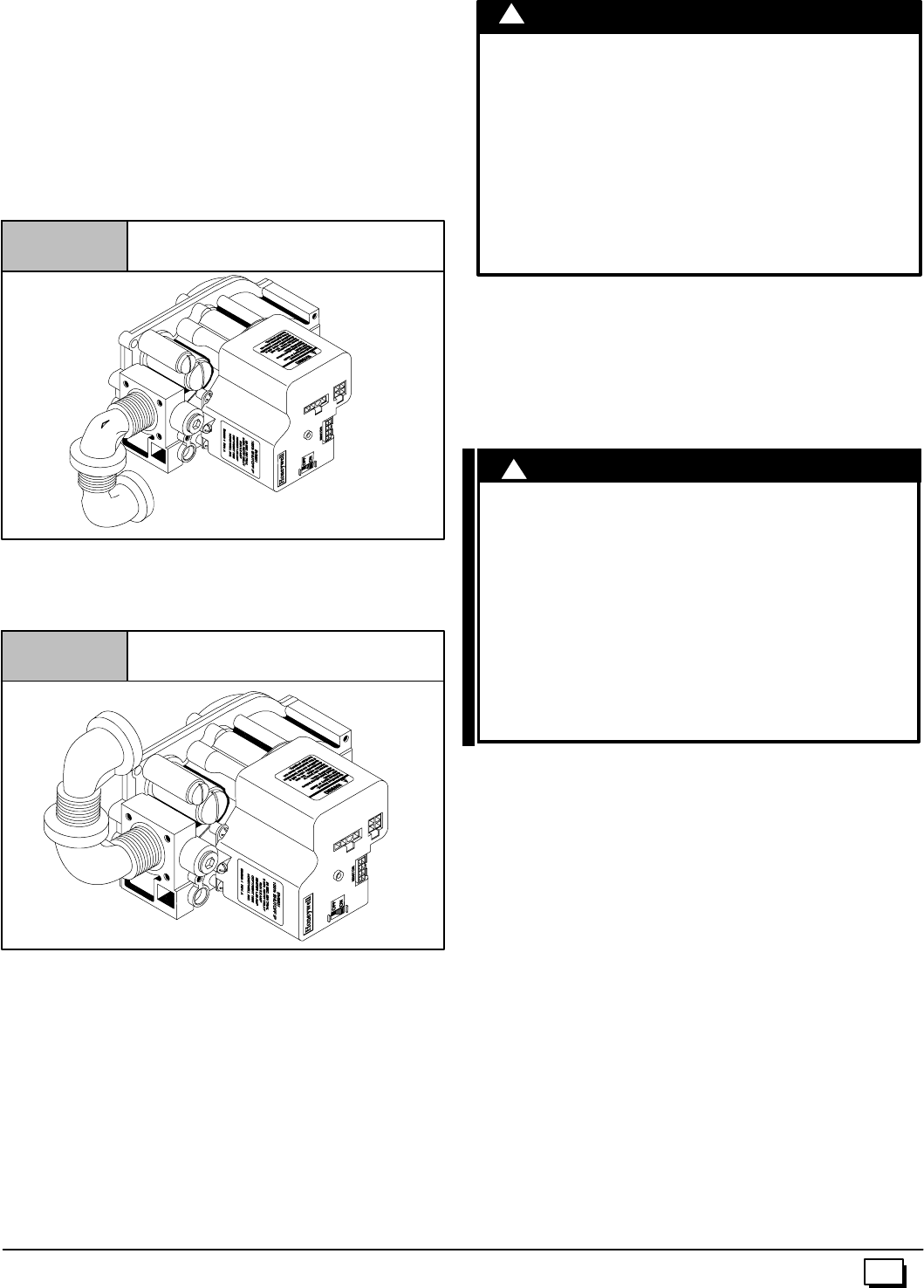
2. Screw elbow assembly into gas valve far enough to be leak
proof.Positionelbowassemblysothattheinletoftheelbowis
at the top of the gas valve. An additional 3/8turn will be re-
quired in step 3. Turn open end of inlet elbow to face the left
side of the furnace (1/4turn), see Figure 14.
3. Turn assembly an additional 3/8turn to position inlet near the
bottom back corner of the gas valve in line with gas opening
on left side of furnace, see Figure 15.
Figure 13
25--23--23c
Elbows (N8MP)
Figure 14
25--23--21a
Gas Valve with Elbows (N8MP)
Figure 15
25--23--22
Gas Valve with Elbows (N8MP)
4. Gassupplylinethencanberundirectlyintoopeningofelbow.
Piping with Close Nipples and Standard Elbows
1. Assembleelbows and nipples similar tostreet elbows shown
in Figure 13.
2. Follow steps 2 through 4 Piping with Street Elbows.
FIRE HAZARD
Failure to follow safety warnings exactly could
result in serious injury, death, and/or property
damage.
Use wrench to hold furnace gas control valve when
turning elbows and gas line to prevent damage to
the gas control valve and furnace.
!W
A
RNING
Left Side Gas Entry (*8MP) (See Figure 16)
Pipe can be run directly to gas valve through the hole provided in
the left side of the cabinet.
Right Side Gas Entry (*8MP) (See Figure 16)
Two (2) 90°street elbows or two (2) 90°standard elbows and two
(2) close nipples are required for right side gas supply,.
Typical Gas Piping (*8MP)
Figure 16
25--24--35a
21
441 01 2611 06
Piping with Street Elbows
1. Assembletheelbowssothattheoutletofone(1)elbowis90°
fromtheinletof theother.Theelbows shouldbetightenough
to be leak proof. An additional 1/4turn will be required at the
end of step 2, see Figure 13.
2. Screw elbow assembly into gas valve far enough to be leak
proof.Positionelbowassemblysothattheinletoftheelbowis
atthe bottomofthegasvalve.Anadditional1/2turnwillbere-
quired in step3. Turnopen end of inlet elbow toface the right
side of the furnace (1/4turn), see Figure 17.
Figure 17 Gas Valve with Elbows (*8MP)
25--22--25a--3
3. Turn assembly an additional 1/2turn to position inlet near the
top of the gas valve in line with gas opening on right side of
furnace, see Figure 18.
Figure 18 Gas Valve with Elbows (*8MP)
4. Gassupplylinethencanberundirectlyintoopeningofelbow.
Piping with Close Nipples and Standard Elbows
1. Assembleelbows and nipples similar tostreet elbows shown
in Figure 13.
2. Follow steps 2 through 4 Piping with Street Elbows.
FIRE OR EXPLOSION HAZARD.
Failureto properlyinstallmetalgas connectorcould
result in death, bodily injury and/or property
damage.
A flexible corrugated metal gas connector must be
properly installed, shall not extend through the side
of the furnace, and shall not be used inside the
furnace.
Black iron pipe shall be installed at the furnace gas
control valve and extend a minimum of 2²
²²
²outside
furnace.
!WARNING
Additional LP Piping Requirements
·Have a licensed LP gas dealer make all connections at stor-
age tank and check all connections from tank to furnace.
·If copper tubing is used, it MUST comply with limitation set in
Local Codes, orin the absence of local codes,the gas codes
of the country having jurisdiction.
·Two--stage regulation of LP gas is recommended.
FIRE OR EXPLOSION HAZARD.
A natural gas or LP gas leak ignited by an open
flame or spark could result in death, personal
injury and/or property damage.
Natural gas is lighter than air and will rise.
Liquefied petroleum (LP) gas is heavier than air
and will settle and remain in low areas and open
depressions.
Thoroughly ventilate area and dissipate gas. Do
NOT use a match or open flame to test for leaks,or
attempt to start up furnace before thoroughly
ventilating area.
!W
A
RNING
Final Check
·Test all pipe for leaks.
·If orifices were changed, make sure they are checked for
leaks.
·During pressure testing of gas supply piping system:
a. If test pressure does not exceed 1/2²psi, isolate the
furnace from the gas supply piping system by closing the
equipment shutoff valve.
b.Iftestpressureexceeds1/2²psi,thefurnaceanditsmanual
equipment shutoff valve must be disconnected from the gas
supply piping system.
·To check for leaks apply soap suds or a liquid detergent to
each joint. Bubbles forming indicate a leak.
·Do not use an open flame to test forgas leaks. Fire or explo-
sion could occur.
·Correct even the smallest leak at once.
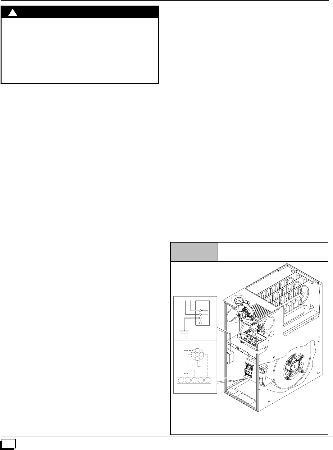
22 441 01 2611 06
9. Electrical Wiring
ELECTRICAL SHOCK HAZARD.
Failure to follow safety warnings exactly could
result in serious injury, death, and/or property
damage.
Turn OFF electrical power at fuse box or service
panel before making any electrical connections
and ensure a proper ground connection is made
before connecting line voltage.
!WARNING
Power Supply Wiring
The furnace MUST be electrically wired and grounded in accor-
dance with local codes, or in the absence of local codes, with the
NationalElectricalCode(NEC),ANSI/NFPA 70--2002 in theU.S.,
or the Canadian Electrical Code (CEC), CSA C22.1 in Canada.
The power supply to the furnace connections must be between
104 VAC and 127 VAC during furnace operation for acceptable
performance.
Fieldwiringconnectionsmustbemadeinsidethefurnaceconnec-
tion box. A suitable strain relief should be used at the point the
wires exit the furnace casing.
Copper conductors shall be used. Line voltage wires should
conform to temperature limitation of 63°F(35°C) rise. Wire and
circuitbreakersizingshallbebasedontheampacityofthefurnace
electrical components plus the amps for all installed accessories
(0.8 amps total for EAC and HUM). Ampacity can be determined
by using the NEC or CEC.
Furnace must be installed so the electrical components are pro-
tected from water and connected to its own separate circuit.
J-Box Relocation
N8MPN and N8MPL Models
TheJ--boxisinstalledinblowercompartmentonleftsideofcasing.
An alternate J--box location on right side can be used.
1. Remove bag containing two hole plugs and two self--tapping
screws from loose parts bag in blower compartment.
2. Remove and discard two screws holding J--box to casing.
3. Move large hole plug from right to left J--box location.
4. Move J--box to alternate location and attach using two self--
tapping screws from bag.
5. Apply two hole plugs from bag at left J--box location.
6. Position all wires away from sharp edges and moving parts.
Do not pinch J--box wires or other wires when reinstalling
blower compartment door.
*8MPN and *8MPL Models
The J--box is installed in the burner compartment on left side of
casing. An alternate J--box location on right side can be used:
1. Remove and save two screws holding J--box to casing.
2. Move large hole plug from right to left J--box location.
3. MoveJ--boxtoalternatelocationandattachusingtwoscrews
removed from left side location.
4. Position all wires away from hot surfaces, sharp edges, and
moving parts. Do not pinch J--box wires or other wires when
reinstalling burner compartment door.
Thermostat
Thermostatlocationhasanimportanteffectontheoperationofthe
furnace. Follow instructions included with thermostat for correct
mounting and wiring.
Low voltage connections to furnace must be made on terminal
board to fan control. (See Figure 19)
Ifcoolingisused,theYfromthethermostatmustbe connectedto
the control board Yto energize cooling blower speed.
Set thermostat heat anticipator in accordance with the Technical
Support Manual.
Optional Equipment
AllwiringfromfurnacetooptionalequipmentMUSTconformtolo-
calcodesor,intheabsenceoflocalcodes,theapplicablenational
codes. Install wiring in accordance with manufacturer’s instruc-
tions.
Humidifier/Electronic Air Cleaner
The furnace is wired for 115 VAC humidifier and/or electronic air
cleaner connection.
NOTE: Do NOT exceed 115V/0.8 amp. maximum current
load for both the EAC terminal and the HUM terminal
combined.
NOTE: The humidifier will be powered when the furnace is fired
andthecirculatingairblowercomeson.Theelectronicaircleaner
will be powered anytime the thermostat calls for air movement.
However, the electronic air cleaner is NOT energized during con-
tinuous fan operation controlled by the electronic fan control.
Figure 19 Electrical Connections
NOTE: 115 VAC/60Hz/single--phase
Operating voltage range*: 127 max, 104 min.
* Permissible limits of voltage at which unit will operate satisfactorily
115V. 60Hz.
W
BK
G
Connection
Box
Ground
HOT
NEUT.
Thermostat
Low Voltage
Terminal Board
R
G
G
YR
Y
W
W
C
25--24--33--4
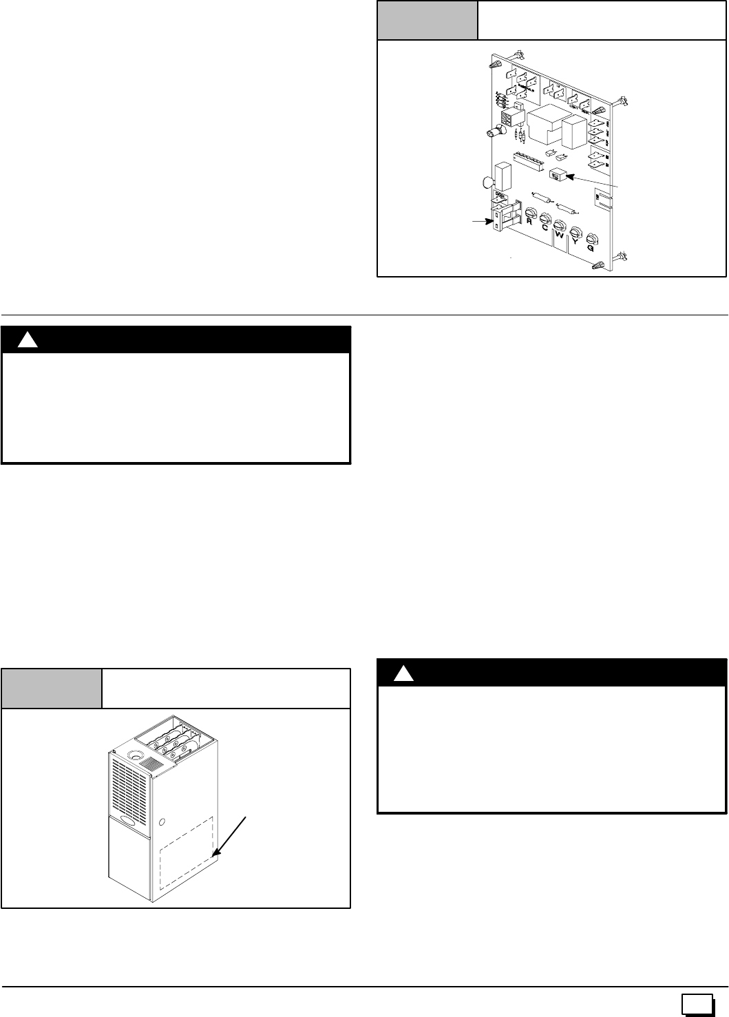
23
441 01 2611 06
Fan Control
ThefancontrolispresetatthefactorywithONdelayof30seconds
in the heating mode. The blower OFF timing is preset at 140 sec-
onds. If desired, the fanOFF delay can be resetto obtain the lon-
gest delay times while still maintaining comfort levels. See
“Furnace Wiring Diagram”.
Control Center Fuse
The 24V circuit contains a 5--amp, automotive--type fuse located
oncontrolcenter.(SeeFigure 20)Anyelectricalshortsof24Vwir-
ingduringinstallation,service,ormaintenancemaycausefuseto
blow. If fuse replacement is required, use only a fuse of identical
size (5 amp.).
Fan Timer Connections
Figure 20
DIP Switch
FUSE
25--23--41
10. Ductwork and Filter (Upflow/Horizontal)
CARBON MONOXIDE POISONING HAZARD.
Failure to properly seal duct could result in death
and/or personal injury.
DoNOT drawreturn air frominsidea closet orutility
room where furnace is located. Return air duct
MUST be sealed to furnace casing.
!WARNING
Duct Connections
This furnace may be installed in only a bottom or side return--air
duct application. Return air duct connections through the back of
the furnace is NOT permitted.
Upflow ONLY: Side return--air duct connections can be made by
cutting out the embossed area shown in Figure 21. A plugged
holeisprovidedateachfurnacesideductlocationtohelpstartcut-
tingtheopening. SideductconnectionsareNOTpermittedinhori-
zontal flow applications.
Cutting Side Return Air Opening
Figure 21
Plugged
Starting
Hole
Upflow and Horizontal Flow: Bottom return--air duct connec-
tions can be made by removing the knockout panel in thefurnace
base. Do NOT remove knock-out except for a bottom return--air
duct connection.
Duct Design
DesignandinstallairdistributionsystemtocomplywithAirCondi-
tioning Contractors of America manuals or other approved meth-
ods that conform to local codes and good trade practices.
Whenthefurnaceislocatedinanareanearoradjacenttotheliving
area,thesystemshouldbecarefullydesignedwithreturnstomini-
mize noise transmission through the return air grille. Any blower
movingahighvolumeofairwillproduceaudiblenoise,whichcould
beobjectionablewhenthefurnaceislocatedvery closetoaliving
area. It is often advisable to route the return air ducts under the
floor or through the attic.
·Refer to furnace Technical Support Manual (Blower Data)
for air flow information.
·Sizeductworktohandleairflowforheating(andaircondition-
ing if so equipped).
Duct Installation Requirements
·When a furnace is installed so that supply ducts carry air cir-
culated by the furnace to areas outside of the space contain-
ingthefurnace,thereturnairshallalsobehandledbyduct(s)
sealed to the furnace casing and terminating outside the
space containing the furnace.
CARBON MONOXIDE POISONING HAZARD.
Failure to follow safety warning exactly could
result in serious injury, death, and/or property
damage.
Install cooling coil on furnace discharge. Cool air
passing over heat exchanger could cause conden-
sate to form resulting in heat exchanger failure.
!W
A
RNING
·Whenthefurnaceisusedwithacoolingunit,thefurnaceshall
beinstalledparallelwithorontheupstreamsideofthecooling
unit to avoid condensation in the heating element.
·Withaparallelflowarrangement,thedampersorothermeans
usedtocontrolflowofair shallbe adequatetopreventchilled
airfromenteringthefurnace.Chilledairgoingthroughthefur-
nace could cause condensation and shorten furnace life.
Dampers (purchased locally) can be either automatic or
manual. Manuallyorautomatically operateddampersMUST
be equipped with a means to prevent furnace and air condi-
tioningoperation,unlessdamperisinthefullheatorcoolposi-
tion.
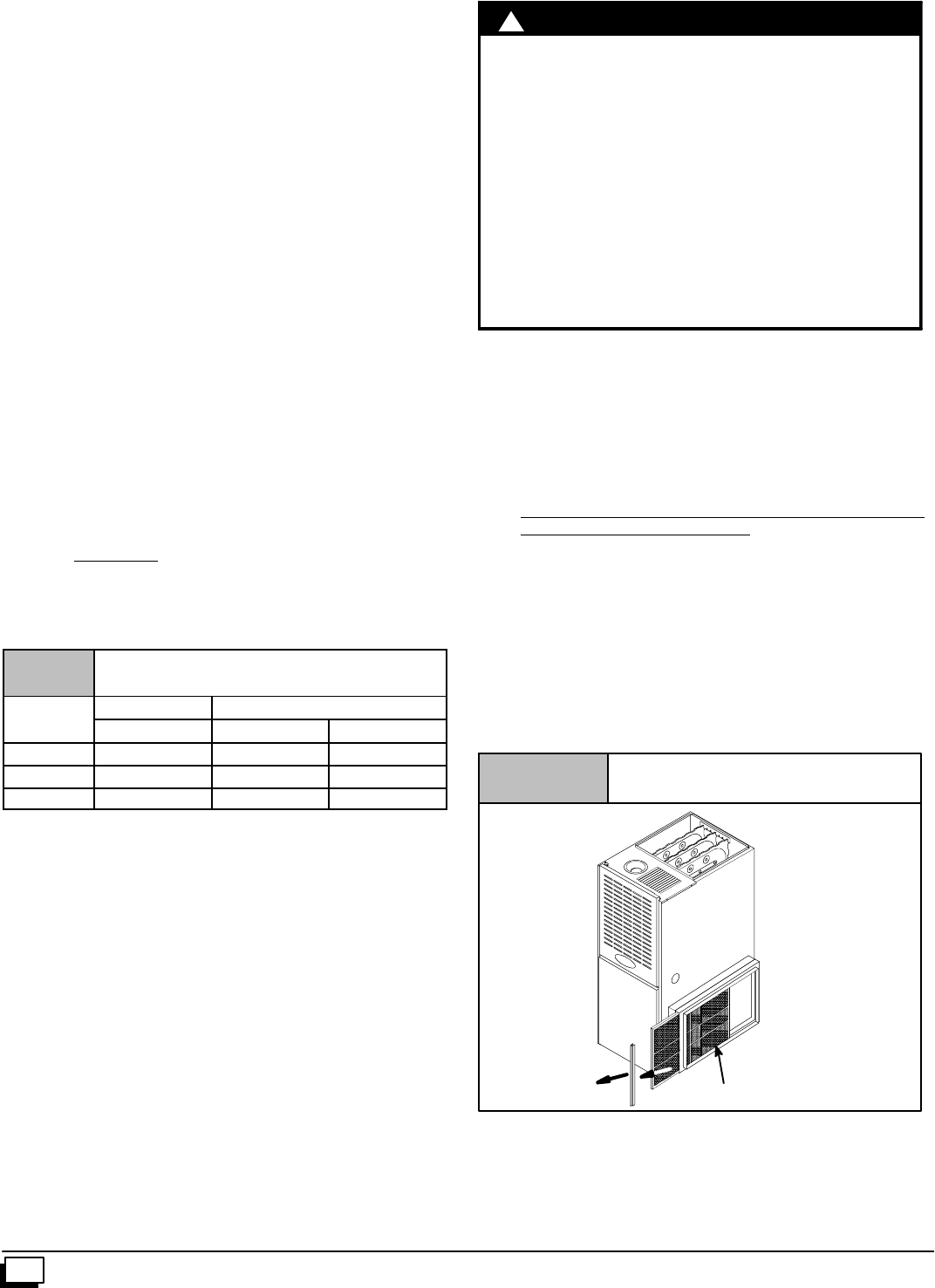
24 441 01 2611 06
·Installation of locking-type dampers is recommended in all
branches,orinindividualductstobalancesystem’sairflows.
·Non--combustible, flexible duct connectors are recom-
mended for return and supply connections to furnace.
·Ifairreturngrilleislocatedclosetothefaninlet,installatleast
one 90°air turn between fan and inlet grille to reduce noise.
·Ductworkinstalledinatticorexposedtooutsidetemperatures
requiresaminimumof2²ofinsulationwithoutdoortypevapor
barrier.
·Ductworkinstalledinanindoorunconditionedspacerequires
a minimum of 1²of insulation with indoor type vapor barrier.
Inspection Panel on some models
Forafurnacenotequippedwitha coolingcoil,theoutletductshall
beprovidedwitharemovableaccesspanel. Thisopeningshallbe
accessiblewhenthefurnaceisinstalledandshallbeofsuchasize
thattheheatexchangercanbeviewedforpossibleopeningsusing
light assistance or a probe can be inserted for sampling the air
stream. This access cover shall be attached in such a manneras
to prevent air leaks.
Filters
A filter MUST be used.
Filtersarenotsuppliedwiththesefurnaces,butcanbepurchased
from your distributor.
See Table 4 for required high--velocity filter sizes.
Table 4 High--Velocity Air Filter Sizes (max. 600 FPM)
Cabinet Internal Filter External Filter Rack
Width Bottom Bottom Side+
151/214X25 14X25 14X25 or 16X25
191/216X25* 16X25* 16X25*
223/420X25* 20X25* 16X25*
* Greater than 1600 CFM requires both (left and right) side return filter
racks in upflow position.
+Sidereturnairduct(s)isnotpermittedwithhorizontalordownflowfurnace
installation.
Use either filter type:
·Washable,high--velocityfiltersarebasedonamaximumair
flow rating of 600 FPM.
·Disposable,lowvelocityfiltersarebasedonamaximumair
flow of 300 FPM when used with external filter grille.
!
RISK OF REDUCED FURNACE LIFE
Failure to follow these Caution may result in
premature furnace component failure.
Use of excessively dirty and/or restrictive air filters
may increase furnace operating temperatures and
shorten the life of the furnace.
Filters specified for the furnace are rated at a maximum
of 600 FPM air velocity and sized for the furnace’s
airflow rate. Replacement filters must be of equivalent
type, size, and rating except as described below.
Disposable, low--velocity filters may be used to replace
washable, high--velocity filters, providing they are sized
for 300 FPM or less.
C
A
UTION
·The furnaces with 1600 or less CFM rating use a 16” x 25”
high--velocity filter. On these models the filter may be
mounted internallyfor bottom return ora filter and rack may
be mounted externally for bottom return.
·The furnaces with greater than1600 CFMrequire that both
(left and right) side returns are used. Two side return filters
andracksarerequired.Filterracks mustbemountedexter-
nally. See Figure 24.
·If return air must be on one side only, an optional 20²x25²
filterstandoffrackkitcanbeused.(SeeFigure 22.)Forbot-
tomreturn,aninternalfiltercanbeusedorafilterrackkitcan
be mounted externally.
NOTE:The20²x25²standoffsidefilterrackgivesmorefilterarea
but does not provide more air. See Figure 22. To achieve 2000
CFM 2 side returns are still needed. See Figure 24.
NOTE: Disposable low--velocity filters may be replaced with
washable,high--velocityfilters.Washable,high--velocityfilterscan
bereplacedONLYwithsametypeandsizefilterunlesslow--veloc-
ity filters meet the minimum size areas for 300 FPM or less.
Figure 22 Optional Duct Standoff
20x25Optional
Filter Rack
Filter 25--23--05--4
Optional Filter Rack Installation: Side Return
Centerthefilterrackonthesidepanel,flushwiththebottomedge
of thefurnace. Mark the fastening holes. Drill the fastening holes
inthesidepanelandfastenthefilterrackinplacewithsheetmetal
screws. See Figure 23 and Figure 24.
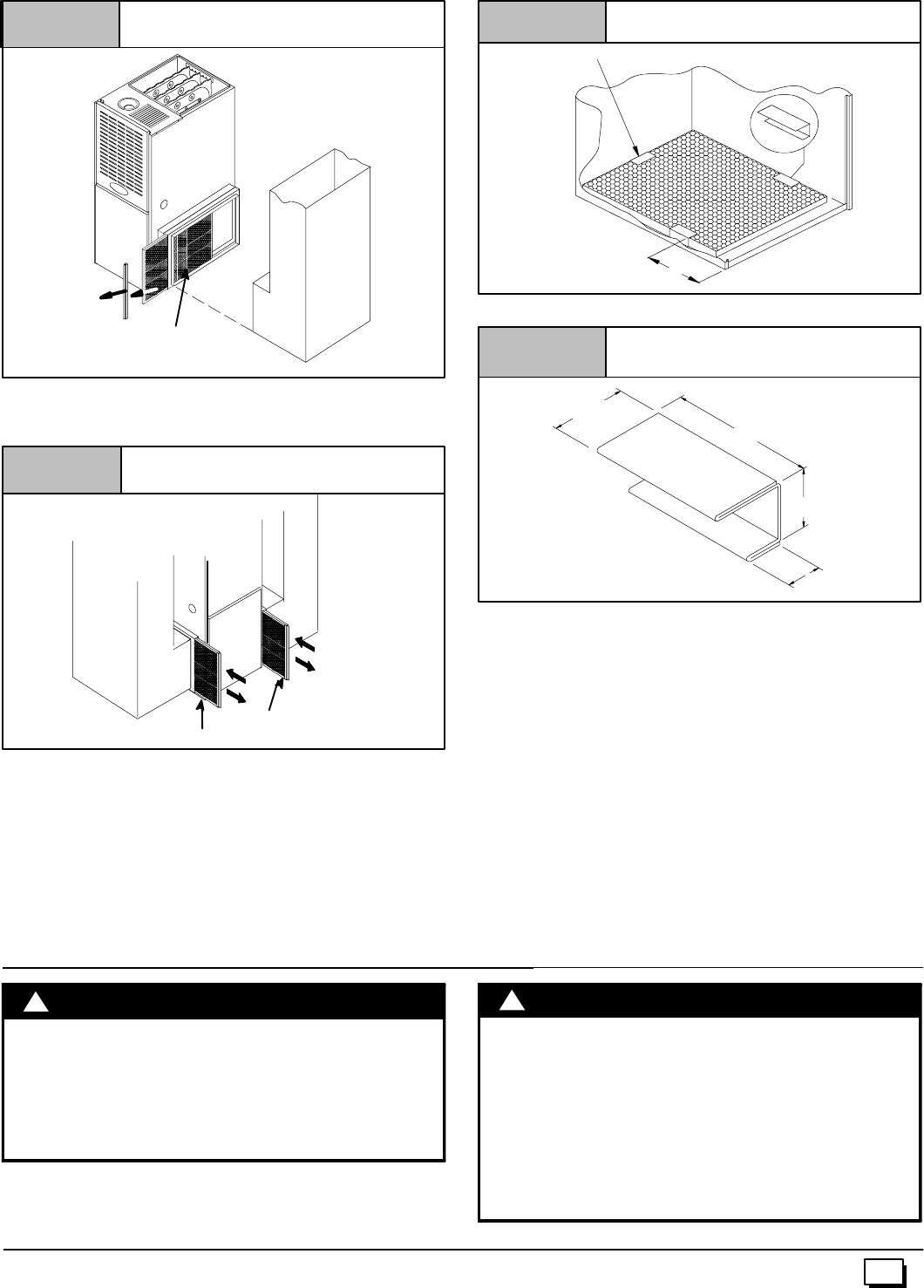
25
441 01 2611 06
Figure 23 Side Return Filter Rack
Filter 25--23--05--4a
25--23--05--3
Filter Filter
Using Two
Filter Racks
Figure 24 Filters Installed on Two Sides
Internal Filter in Bottom-Return Installation
Wheninstallinga bottom--mountedfilterinside the furnace,install
thefilterclipsontheedgeofthebottomductopeningwiththewider
end of the clips toward the blower, as shown in Figure 25. Clips
may be obtained from your distributor or fabricated from sheet
metal (Figure 26). Insert filter into side clips first and push filter
back until it is fully engaged into back clip.
Center Clip
si de -- to -- side
Figure 25 Bottom Mounted Filter
25--24--18--1
9²
Figure 26 Filter Clip Construction
3²
11/4²
11/2²
11/16²
26 Ga. Galvanized Steel
NOTE: If filters are only suitable for heating application, advise
homeowner that filter size may need to be increased if air condi-
tioning is added.
Addition Of Air Conditioning
Whenarefrigerationcoilisusedinconjunctionwiththisfurnace,it
mustbeinstalledonthedischargesideofthefurnacetoavoidcon-
densationintheheatexchanger. Thecoilinstallationinstructions
must be consulted for proper coil location and installation proce-
dures. With a parallel flow arrangement, dampers must be
installedtopreventchilledairfromenteringthefurnace. Ifmanual-
ly operated dampers are used, they must be equipped with a
means to prevent operation of either unit unless the damper is in
full heat or full cool position.
Copperorplastictubingmaybeusedforthecondensatedrainline.
11. Ductwork and Filter (Downflow)
CARBON MONOXIDE POISONING HAZARD.
Failure to properly seal duct could result in death
and/or personal injury.
Do NOT draw return air from inside a closet or
utility room where furnace is located. Return air
duct MUST be sealed to furnace casing.
!WARNING FIRE HAZARD.
Failure to connect the return air duct to the top of a
downdlow furnace could result in death, bodily
injury, and/or property damage.
Side return air duct(s) may cause excessive furnace
and/orairtemperatures,whichcouldresult indeath,
bodily injury, and/or property damage.
Return air duct is to be connected to only the top of
downflow furnace.
!W
A
RNING
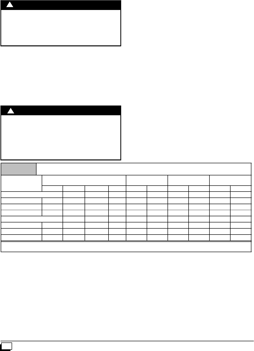
26 441 01 2611 06
BURN HAZARD.
The vent may be hot. Failure to install vent shield
properly could result in bodily injury.
Install VENT PIPE SHIELD NAHA002VC as
described below.
!WARNING
Vent Shield
Ventshieldisrequiredforalldownflowinstallations.TheventMust
exit out the side of the furnace for all downflow installations. This
placesthehotventpipe(over300°F)withinreachofchildren.Vent
shieldattachestosideoffurnacetocoverventpipe.SeeFigure 5
in “2. Installation” section.
Outlet Duct Flange
Downflow installations with cased coils require the furnace outlet
ductflangetobebentoutwardandflattomatetheoutletofthefur-
nacetothecasedcoil.
FIRE HAZARD.
Failure to install furnace on noncombustible
subbasecouldresultin death,personalinjuryand/or
property damage.
Place furnace on noncombustible subbase on
downflow applications, unless installing on
non--combustible flooring.
!WARNING
Sub--Bases for Combustible Floors -- Furnace Only
Note: When using the subbase for combustible floors, the dis-
charge air duct flanges on the furnace MUST be broken down to
provide proper fit up to the subbase. Use duct pliers to bend the
duct flanges flat onto the furnace casing. DO NOT bend the duct
flanges inward (toward the heat exchangers) as air flow restric-
tions may occur.
The Subbase for Combustible Floors MUST be used when a
downflowfurnaceissetonacombustiblefloor,evenwhenthefur-
nace is installed on a coil box.
1. Cut the opening in the floor according to the dimensions in
Table 5 because the base isequipped with locating tabs that
center the base over the opening.
The opening in the base is 11/4²shorter and 11/8²narrower
than the minimum required size of the opening in the floor.
Thisisdonetomaintaina1²clearancebetweenthe floorand
the plenum.
2. Fabricate the plenum to the dimensions given in Table 5.
Note that the dimensions given are outside dimensions.
Table 5 Sub--bases for Combustible Floors Dimensions
Sub--base for
Combustible Floors Sub--base for Combustible
Floor Dimensions OpeningInFloor Opening In
Base For Plenum Typical Plenum
Dimensions
C
o
m
b
u
s
t
i
b
l
e
F
l
o
o
r
s
Part Number H*J* K** L M N P R S T
Subbase for Furnace Only
NAHH001SB 1511/16 283/4149/16 16 161/4145/815 131/215 131/2
NAHH002SB 195/16 283/4183/16 16 161/4181/415 171/815 171/8
NAHH003SB 2215/16 283/42113/16 16 161/4217/815 193/415 193/4
Subbase for Coil Box
NAHH004SB 1511/16 209/16 149/16 16 161/4145/815 131/215 131/2
NAHH005SB 195/16 209/16 183/16 16 161/4181/415 171/815 171/8
NAHH006SB 2215/16 209/16 2113/16 16 161/4217/815 193/415 193/4
*Outside Dimension
** Base Spacer Side To Side
3. Setthebaseovertheopeninginthefloor,centeringtheopen-
inginthebaseovertheopeninginthefloor.Fastenthebaseto
the floor with screws or nails. See Figure 27 and Figure 28.
4. Droptheplenumthrough theopening in thebase.Theflange
oftheplenumshouldrestontopofthecombustiblefloorbase.
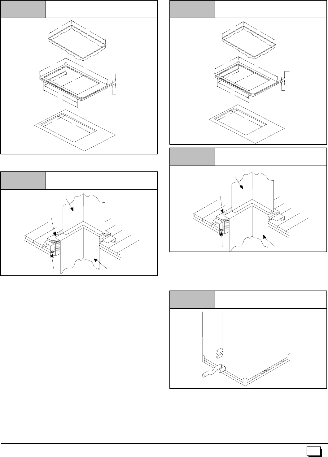
27
441 01 2611 06
Exploded View of Sub--Base for
Furnace ONLY
Figure 27
TS
Plenum
J
K
H
R
L
P1²
²²
²
2²
²²
²
Combustible
Floor Base
N
Hole in Floor
M
Setting the Base
Figure 28
Subbase
Insulation
Wood Screw Plenum
Furnace
Wood Floor
Sub--base for Combustible Floors -- Downflow Coil
Adapter Box
The subbase for combustible floors is required when a downflow
furnace, used with a downflow coil box, is set on combustible
flooring.
1. Cut the opening in the floor according to the dimensions in
Table 5 because the base isequipped with locating tabs that
center the base over the opening.
The opening in the base is 11/4²shorter and 11/8²narrower
than the minimum required size of the opening in the floor.
Thisisdoneto maintaina1”clearancebetweenthefloorand
the plenum.
2. Fabricate the plenum to the dimensions given in Table 5.
Note that the dimensions given are outside dimensions.
3. Setthebaseovertheopeninginthefloor,centeringtheopen-
ing in the base over the opening in the floor. Fasten the base
to the floor with screws or nails. See Figure 29 and
Figure 30.
4. Droptheplenumthrough theopeninginthebase. Theflange
oftheplenumshouldrestontopofthecombustiblefloorbase.
Exploded View of Sub--Base for
Downflow Cased Coil
Figure 29
TS
Plenum
J
K
H
R
L
P1²
²²
²
2²
²²
²
Combustible
Floor Base
N
Hole in Floor
M
Setting the Base
Subbase
Insulation
Figure 30
Wood Screw Plenum
Coil Box
Wood Floor
Consideration must be given to the height of the base to allowfor
easy installation of the condensate drain. See Figure 31.This
subbase for combustible floors has been designed so that the
heightofthesubbaseraisesthedownflowcoiloffthefloortoallow
easy installation of the condensate drain.
Condensate Line Raised by Base
Figure 31
25--20--52
Non--Combustible Floor
Set the furnace over the opening in the floor. If necessary, grout
around the base to seal airleaks between the base and thefloor.
Duct Connections
Inthedownflowposition,thereturn--airductmustbeconnectedto
onlythetopofthefurnace. Topreturnconnectionscanbemadeby
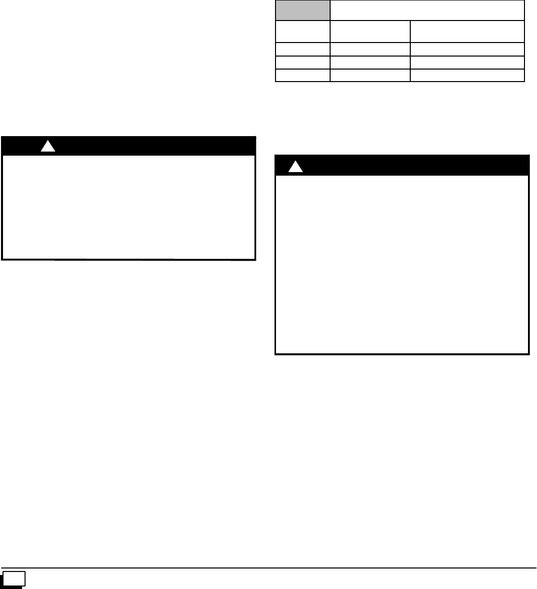
28 441 01 2611 06
removing theknockout panel in thefurnace base. Return air con-
nectionthroughtheside(s)orbackofthe furnaceis NOT allowed.
Duct Design
DesignandinstallairdistributionsystemtocomplywithAirCondi-
tioning Contractors of America manuals or other approved meth-
ods that conform to local codes and good trade practices.
Whenthefurnaceislocatedinanareanearoradjacenttotheliving
area,thesystemshouldbecarefullydesignedwithreturnstomini-
mize noise transmission through the return air grille. Any blower
movingahighvolumeofairwillproduceaudiblenoise,whichcould
beobjectionablewhenthefurnaceislocatedvery closetoaliving
area. It is often advisable to route the return air ducts under the
floor or through the attic.
·RefertofurnaceTechnicalSupportManual(BlowerData)
for air flow information.
·Size ductwork to handle air flow for heating (and air condi-
tioning, if so equipped).
Duct Installation Requirements
·Whenafurnaceisinstalledsothatsupplyductscarryaircir-
culatedbythefurnacetoareasoutsideofthespacecontain-
ing the furnace, the return air shall also be handled by
duct(s)sealedtothefurnacecasingandterminatingoutside
the space containing the furnace.
CARBON MONOXIDE POISONING HAZARD.
Failure to follow safety warning exactly could
result in serious injury, death, and/or property
damage.
Install cooling coil on furnace discharge. Cool air
passing over heat exchanger could cause
condensate to form resulting in heat exchanger
failure.
!WARNING
·Whenafurnace isusedwithacoolingunit,thefurnaceshall
beinstalledparallelwithorontheupstreamsideofthecool-
ing unit to avoid condensation in the heating element.
·With a parallel flow arrangement, the dampers or other
means used to control flow of air shall be adequate to pre-
vent chilled air from entering the furnace. Chilled air going
throughthefurnacecouldcausecondensationandshorten
furnacelife. Dampers(purchasedlocally)canbeeitherau-
tomatic or manual. Manually or automatically operated
dampers MUST be equipped with a means to prevent fur-
naceand airconditioningoperation,unlessdamperisinthe
full heat or cool position.
·Installation oflocking--type dampers is recommended in all
branches, or in individual ducts to balance system’s air
flows.
·Non--combustible, flexible duct connectors are recom-
mended for return and supply connections to furnace.
·If air return grille is located close to the fan inlet, install at
least one 90°air turn between fan and inlet grille to reduce
noise.
·Ductwork installed in attic or exposed to outside tempera-
tures requires a minimum of 2²of insulation with outdoor
type vapor barrier.
·Ductwork installed in an indoor unconditioned space re-
quires a minimum of 1²of insulation with indoor type vapor
barrier.
Filters
A filter MUST be used.
Filtersarenotsuppliedwiththesefurnaces,butcanbepurchased
from your distributor.
See Table 6 for required high--velocity filter sizes.
Table 6 High Velocity Air Filter Sizes (max. 600 FPM)
Cabinet
Width Internal Filter External Filter Rack
151/2²
²²
²14²X25²14²X25²
191/8²
²²
²16²X25²16²X25²
223/4²
²²
²20²X25²20²X25²
Use either filter type:
·Washable,high--velocityfiltersarebasedonamaximumair
flow rating of 600 FPM.
·Disposable,lowvelocityfiltersare basedonamaximumair
flow of 300 FPM when used with external filter grille.
!
REDUCED FURNACE LIFE HAZARD
Failure to follow caution instructions may result in
reduced furnace life.
Use of excessively dirty and/or restrictive air filters
may increase furnace operating
temperatures and shorten the life of the furnace.
Filters supplied with the furnace are rated at a
maximum of 600 fpm air velocity and sized for the
furnace’s airflow rate. Replacement filters must be
of equivalent type, size, and rating except as
described below.
Disposable, low--velocity filters may be used to
replace washable, high--velocity filters, providing
they are sized for 300 FPM or less.
C
A
UTION
NOTE: Disposable, low--velocity filters may be replaced with
washable, high--velocity filters. Washable, high--velocity filters
canbereplacedONLYwithsametypeandsizefilters unlesslow--
velocity filters meet the minimumsize areas for 300 FPM or less.
Internal Filter in Top Return Installation
Wheninstallingtop--mountedfilterinsidethefurnace,installthefil-
ter clips on the edge of the top duct opening with the wider endof
the clips toward the blower as shown in Figure 32. Clips may be
obtained from your distributor or fabricated from sheet metal
(Figure 33). Insertfilterintosideclipsfirstandpushfilterbackuntil
it is fully engaged into back clip.
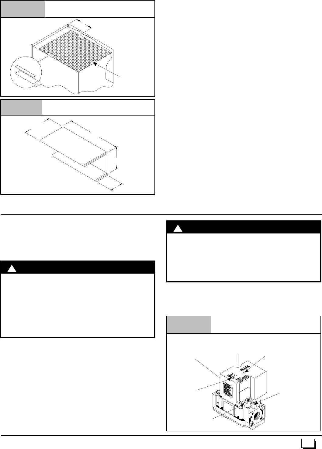
29
441 01 2611 06
Figure 32 Top Mounted Internal Filter
9²
Center Clip
si de -- to -- side
Figure 33 Filter Clip Construction
3²
11/4²
11/2²
11/16²
26 Ga. Galvanized Steel
NOTE: If filters are only suitable for heating application, ad-
visehomeownerthatfiltersizemay needtobeincreasedifair
conditioning is added.
Addition Of Air Conditioning
Whenarefrigerationcoilisusedinconjunctionwiththisfurnace,it
mustbeinstalledonthedischargesideofthefurnacetoavoidcon-
densationontheheatexchanger.Thecoilinstallationinstructions
must be consulted for proper coil location and installation
procedures. With a parallel flow arrangement, dampers must be
installedtopreventchilledairfromenteringthefurnace.Ifmanual-
ly operated dampers are used, they must be equipped with a
means to prevent operation of either unit unless the damper is in
full heat or full cool position.
Copperorplastictubingmaybeusedforthecondensatedrainline.
12. Checks and Adjustments
Startup
NOTE: Refer to startup procedures in the Users Information
Manual.
!
ELECTRICAL SHOCK, FIRE, OR EXPLOSION
HAZARD.
Failure to follow safety warnings exactly could
result in serious injury, death, and/or property
damage.
If any sparks, odors or unusual noises occur,
immediately shut OFF gas and power to furnace.
Check for wiring errors or obstruction to blower.
WARNING
Gas Supply Pressure
Gassupplypressureshouldbewithinminimumandmaximumval-
ueslistedonrating plate.Pressuresareusuallysetby gassuppli-
ers.
(See LP Gas Conversion Kit instruction manualfor furnaces con-
verted to LP gas.)
Manifold Gas Pressure Adjustment
NOTE: Make adjustment tomanifold pressurewith burners oper-
ating.
!
FIRE OR EXPLOSION HAZARD.
FailuretoturnOFFgasat shutoffbeforeconnecting
manometer could result in death and/or personal
injury.
Turn OFF gas at shut off before connecting
manometer.
W
A
RNING
1. With gas OFF, connect manometer to manifoldpressure tap
onoutletofgascontrolvalve.SeeFigure 34.Useamanome-
terwitha0²to 12²water column range.
Typical Gas Control Valve Honeywell
Figure 34
INLET
OUTLET
Diagnostic Light
(on some models)
25--22--25a
On/Off
Switch
Pilot Pressure
Adjustment
Manifold Pressure
Adjustment
(Hidden)
Manifold
Pressure
Tap
Supply Pressure
Tap (Hidden)
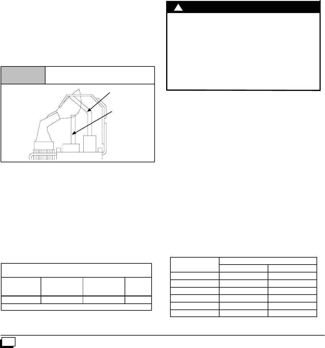
30 441 01 2611 06
2. Turn gas ON. Operate the furnace by using a jumper wire on
the R to W thermostat connections on the fan board.
3. Remove manifold pressure adjustment screw cover on fur-
nace gas control valve. Turn adjusting screw counterclock-
wise to decrease manifold pressure and clockwise to
increase pressure.
NOTE:AdjustmentscrewcoverMUSTbe replacedongascontrol
valve before reading manifold pressure and operating furnace.
4. Set manifold pressure to value shown in Table 7 or Table 8.
5. When the manifold pressure is properly set, replace the ad-
justment screw cover on the gas control valve.
6. Remove jumper wire from thermostat connection on fan
board. Remove manometer connection from manifold pres-
sure tap, and replace plug in manifold.
7. Check for leaks at plug.
Adjust Pilot Burner
The furnace has a pilot flame to light the main burner. The flame
shouldsurround3/8²to1/2²oftheflamerod.SeeFigure 35.To ad-
just, remove cap from pilot adjusting screw on gas control valve.
Turnscrewcounterclockwisetoincreaseorclockwisetodecrease
flame as required. Replace cap after adjusting screw.
Pilot Burner
Figure 35
Proper Flame
Adjustment
Flame Rod
Hot Surface
Igniter
1 0 -- 11 -- 6 5
Natural Gas Input Rating Check
The gas meter can be used to measure input to furnace.
Check with gas supplier for actual BTU content.
1. TurnOFFgassupplytoallappliancesotherthanfurnaceand
start furnace. Use jumper wire on R to W.
2. Time how many seconds it takes the smallest dial on the gas
meter to make one complete revolution.
Note: If meteruses a 2cubic foot dial, divide results (seconds) by
two.
Refer to Example. The Example is based on a natural gas BTU
content of 1,000 BTU’s per cubic foot.
Example
Natural Gas
BTU Content No. of Seconds
Per Hour
Time Per Cubic
Foot in
Seconds
BTU Per
Hour
1,000 3,600 48 75,000
1,000 x 3,600 ¸48 = 75,000 BTUH
3. Remove jumper wire from R to W1.
4. Relight all appliances and ensure all pilots are operating.
Orifice Sizing
NOTE: Factory sized orifices for natural and LP gas are listed in
the furnace Technical Support Manual.
Ensure furnace is equipped with the correctmain burner orifices.
Refer to Table 7 or Table 8 for correct orifice size and manifold
pressure for a given heating value and specific gravity for natural
and propane gas.
Operation Above 2000¢Altitude
FIRE, EXPLOSION, CARBON MONOXIDE
POISONING HAZARD.
Failure to follow these instructions exactly could
resultindeath,personalinjuryand/orpropertydam-
age.
This high--altitude gas--conversion shall be done by
a qualified service agency in accordance with the
Manufacturer’s instructions and all applicable
codes and requirements, or in the absence of local
codes, the applicable national codes.
!W
A
RNING
Thesefurnacemaybeusedatfullinputratingwheninstalledatal-
titudesupto2000¢.Wheninstalledabove2000¢,theinputmustbe
decreased2%(natural)or4%(LP)foreach1000¢abovesealevel.
This may be accomplished by a simple adjustment of manifold
pressure or an orifice change, or a combination of a pressure ad-
justmentandanorificechange.The changesrequireddependon
theinstallationaltitudeandtheheatingvalueofthefuel.Table 7 &
Table 8 showtheproperfurnacemanifoldpressureandgasorifice
sizetoachieveproperperformancebasedonelevationabovesea
level for both natural gas and propane gas.
To use the natural gas table, first consult your local gas utility for
theheatingvalueofthegassupply.Selecttheheatingvalueinthe
firstcolumnandfollowacrossthetableuntiltheappropriateeleva-
tionfortheinstallationisreached.Thevalueintheboxattheinter-
section of the altitude and heating value provides not only the
manifoldpressurebutalsotheorificesize.Inthenaturalgastables
thefactoy--shippedorificesizeisinbold(42).Othersizes mustbe
obtained from service parts.
High Altitude Input Rate =
Nameplate Sea Level Input Rate x (Multiplier)
E
l
e
v
a
t
i
o
n
High Altitude Multiplier
Ele
v
ation Natural Gas LP Gas
2001¢- 3000¢0.95 0.90
3001¢- 4000¢0.93 0.86
4001¢- 5000¢0.91 0.82
5001¢- 6000¢0.89 0.78
6001¢- 7000¢0.87 0.74
7001¢- 8000¢0.85 0.70
*Based on mid--range of elevation.
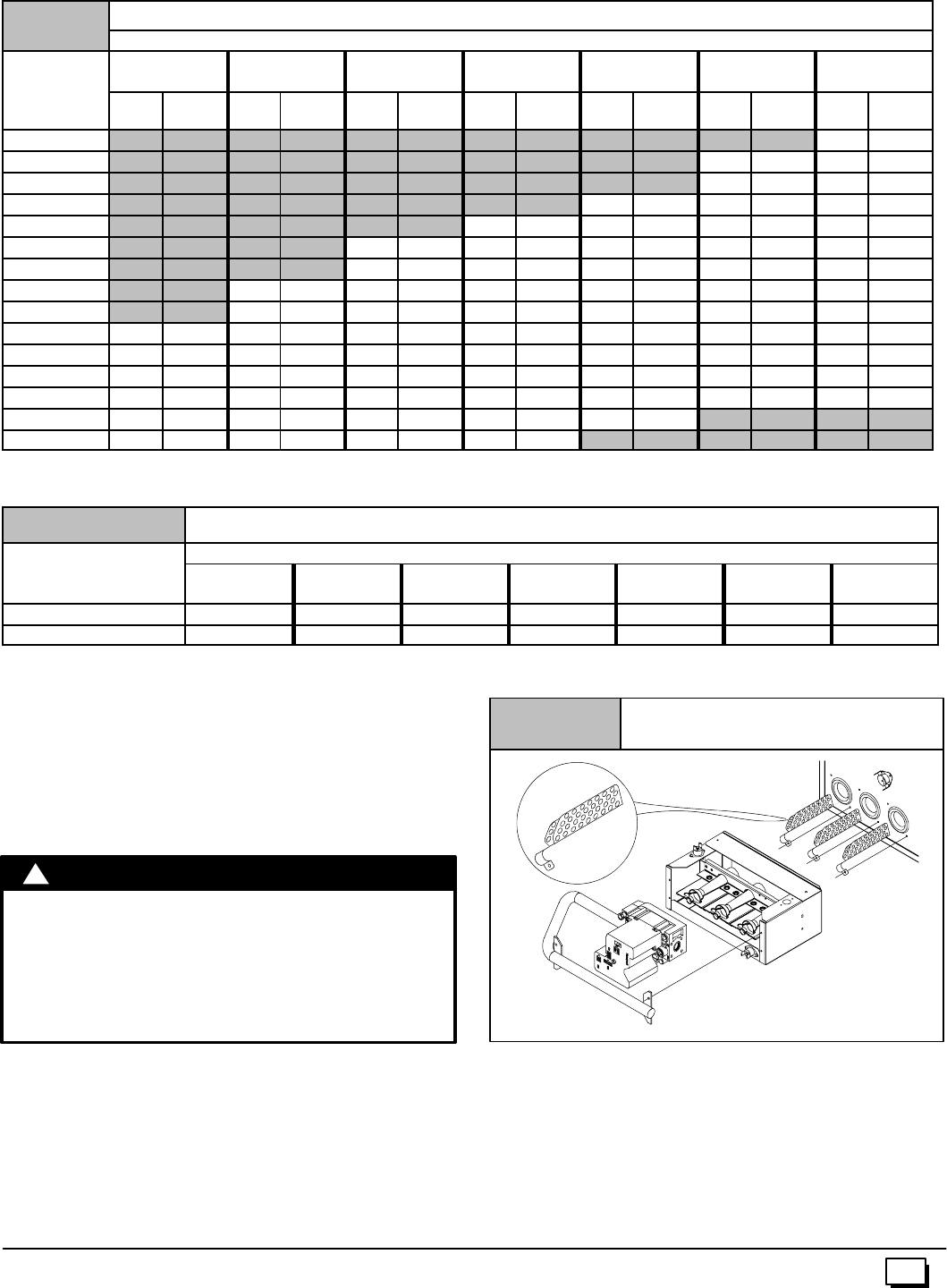
31
441 01 2611 06
MANIFOLD PRESSURE AND ORIFICE SIZE FOR HIGH ALTITUDE APPLICATIONS
T
a
b
l
e
7
NATURAL GAS MANIFOLD PRESSURE (²
²²
²w.c.)
T
a
b
l
e
7
MEAN ELEVATION FEET ABOVE SEA LEVEL
HEATING
VALUE 0to
2000 2001 to
3000 3001 to
4000 4001 to
5000 5001 to
6000 6001 to
7000 7001 to
8000
at ALTITUDE
BTU/CU. FT. Orifice
No. Manifold
Pressure Orifice
No. Manifold
Pressure Orifice
No. Manifold
Pressure Orifice
No. Manifold
Pressure Orifice
No. Manifold
Pressure Orifice
No. Manifold
Pressure Orifice
No. Manifold
Pressure
700 -- -- -- -- -- -- -- -- -- -- -- -- -- -- -- -- -- -- -- -- -- -- -- -- 41 3.7
725 -- -- -- -- -- -- -- -- -- -- -- -- -- -- -- -- -- -- -- -- 41 3.7 41 3.4
750 -- -- -- -- -- -- -- -- -- -- -- -- -- -- -- -- -- -- -- -- 41 3.5 42 3.6
775 -- -- -- -- -- -- -- -- -- -- -- -- -- -- -- -- 41 3.6 42 3.6 42 3.3
800 -- -- -- -- -- -- -- -- -- -- -- -- 41 3.6 42 3.7 42 3.4 42 3.1
825 -- -- -- -- -- -- -- -- 41 3.7 41 3.4 42 3.5 42 3.2 42 2.9
850 -- -- -- -- -- -- -- -- 41 3.5 42 3.6 42 3.3 42 3.0 42 2.8
875 -- -- -- -- 41 3.6 42 3.6 42 3.4 42 3.1 42 2.8 42 2.6
900 -- -- -- -- 42 3.7 42 3.4 42 3.2 42 2.9 42 2.7 42 2.5
925 41 3.7 42 3.5 42 3.3 42 3.0 42 2.8 42 2.5 42 2.3
950 41 3.5 42 3.3 42 3.1 42 2.9 42 2.6 42 2.4 43 2.7
975 42 3.7 42 3.2 42 2.9 42 2.7 42 2.5 42 2.3 43 2.6
1000 42 3.5 42 3.0 42 2.8 42 2.6 42 2.4 43 2.7 43 2.4
1050 42 3.2 42 2.7 42 2.5 42 2.3 43 2.6 -- -- -- -- -- -- -- --
1100 42 2.9 42 2.5 42 2.3 43 2.6 -- -- -- -- -- -- -- -- -- -- -- --
NOTE: Natural gas data is based on 0.60 specific gravity. For fuels with different specific gravity consult the National Fuel Gas Code ANSI
Z223.1--2002/NFPA 54--2002 or National Standard of Canada, Natural Gas And Propane Installation Code CSA B149.1--00.
Table 8 LPG or PROPANE GAS MANIFOLD PRESSURE (²
²²
²w.c.)
HEATING VALUE MEAN ELEVATION FEET ABOVE SEA LEVEL
at ALTITUDE
BTU/CU. FT. 0to
2000 2001 to
3000 3001 to
4000 4001 to
5000 5001 to
6000 6001 to
7000 7001 to
8000
2500 10.0 10.0 9.0 10.0 9.4 8.5 10.0
Orifice Size #54 #54 #54 #55 #55 #55 #56
NOTE:Propanedataisbasedon1.53specificgravity. ForfuelswithdifferentspecificgravityconsulttheNationalFuelGasCodeANSIZ223.1--2002/NFPA
54--2002 or National Standard Of Canada, Natural Gas And Propane Installation Code CSA B149.1--00.
NOTE: The derating of these furnaces at 2% (Natural Gas) and
4% (Propane Gas) has beentested and design--certified by CSA.
High Altitude Air Pressure Switch
The factory--installed pressure switch need NOT be changed for
anyfurnaceinstallationsfromsealevelupto and including8,000¢
altitude
CARBON MONOXIDE POISONING HAZARD.
Failure to follow this warning could result in
property damage, personal injury and/or death.
NOx inserts foruse with Natural Gas units ONLY.If
LP Gas is required, NOx inserts must be
removed.
!WARNING
Changing Orifices
1. After disconnecting power and gas supply tothe furnace, re-
move the burner compartment door, exposing the burner
compartment.
2. Disconnect gas line and pilot tubing from gas valve so man-
ifold can be removed.
3. Disconnect wiring at gas valve. Be sure to note the proper
location of all electrical wiring before being disconnected.
Figure 36 Removing NOx inserts
25--40--03
4. Remove the four (4) screws holding the manifold and gas
valve to the manifold supports. Do not discard any screws.
See Figure 37.
5. Carefully remove the manifold assembly.
6. Remove the orificesfrom the manifold andreplace them with
proper sized orifices. See Figure 38.
7. Tighten orifices so they are seated and gas--tight. See
Figure 38.
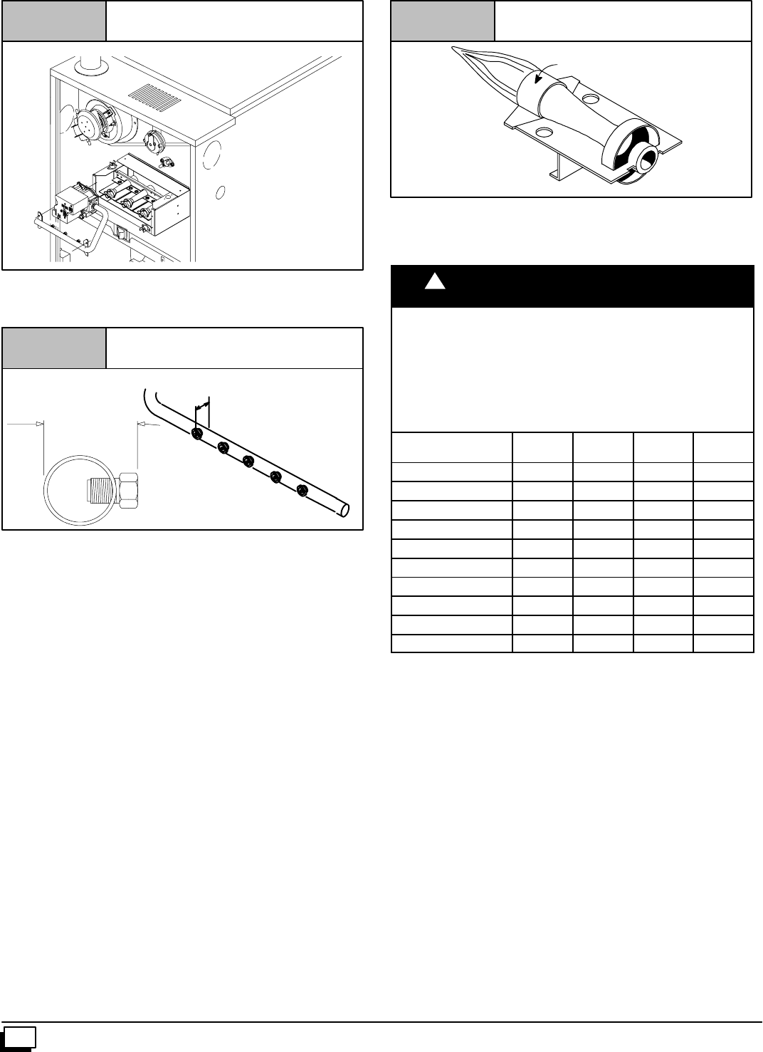
32 441 01 2611 06
Figure 37 Manifold
25--23--51z
Some Models may vary
Figure 38 Clearances
Measure from face of orifice to the
back side of the manifold.
1.21²
1.11²
29.3 mm
+1.5
-- 1. 1
8. Reassembleallpartsinreverseorderasremoved.Besureto
engagethemainburnerorificesintheproperopenings inthe
burners.
9. After reassembling, turn gas on and check all joints for gas
leaks using a soapy solution. All leaks must be repaired im-
mediately.
Main Burner Flame Check
Allow the furnace to run approximately 10 minutes. Then inspect
the main burner and pilot flames. See Figure 39.
Check for the following:
·Stable and blue flames. Dust may cause orange tips or
wisps of yellow, but flames MUST NOT have solid, yellow
tips.
·Flamesextendingdirectlyfromburnerintoheatexchanger.
·Flames do NOT touch sides of heat exchanger
If any problems with mainburnerflames are noted, it may be nec-
essary to adjust gas pressures or check for drafts.
Main Burner
Burner Face
10--10--78
Figure 39
Air Temperature Rise Check
CAUTION
!
REDUCED FURNACE LIFE HAZARD
Failure to properly set the air temperature rise may
result in reduced furnace life.
U
O
N
L
Y
t
h
b
l
t
d
t
k
d
“
Y
”
f
Use ONLY the blower motor speed taps marked “Y” for
YES for setting air temperature rise.
Blower Motor Speed Taps for
N8MPN/L and *8MPN/L Model Sizes
Model Sizes LO
RED MLO
BLUE MHI
ORN HI
BLK
050B12 N Y Y N
075B12 N Y Y Y
075F16 N N Y Y
100F14 N N Y Y
100F20 N Y Y Y
100J20 N Y Y Y
100J22 Y Y Y N
125J20 N Y Y Y
125J22+ Y Y Y Y
150J20ÖN Y Y Y
+N8MPN only Ö*8MPN only
TheblowerspeedMUSTbesettogivethecorrectairtemperature
rise through the furnace as marked on the rating plate. Tempera-
ture rise is the difference between supply and return air tempera-
tures.
To check temperature rise, use the following procedure:
1. Placethermometersinsupplyandreturnairregistersasclose
to furnace as possible, avoiding direct radiant heat fromheat
exchangers.
2. Operatefurnacefor10minuteswithall theregistersandduct
dampers open by using a jumper wire on R to W thermostat
connections on the fan board.
3. Take readings and compare with range specified on rating
plate.
4. Ifthe airtemperatureriseisnotinthecorrectrange,theblow-
er speed must be changed. A higher blower speed will lower
the temperature rise. A lower blower speed will increase the
temperature rise.
5. Remove the jumper wire after theadjustments are complete.
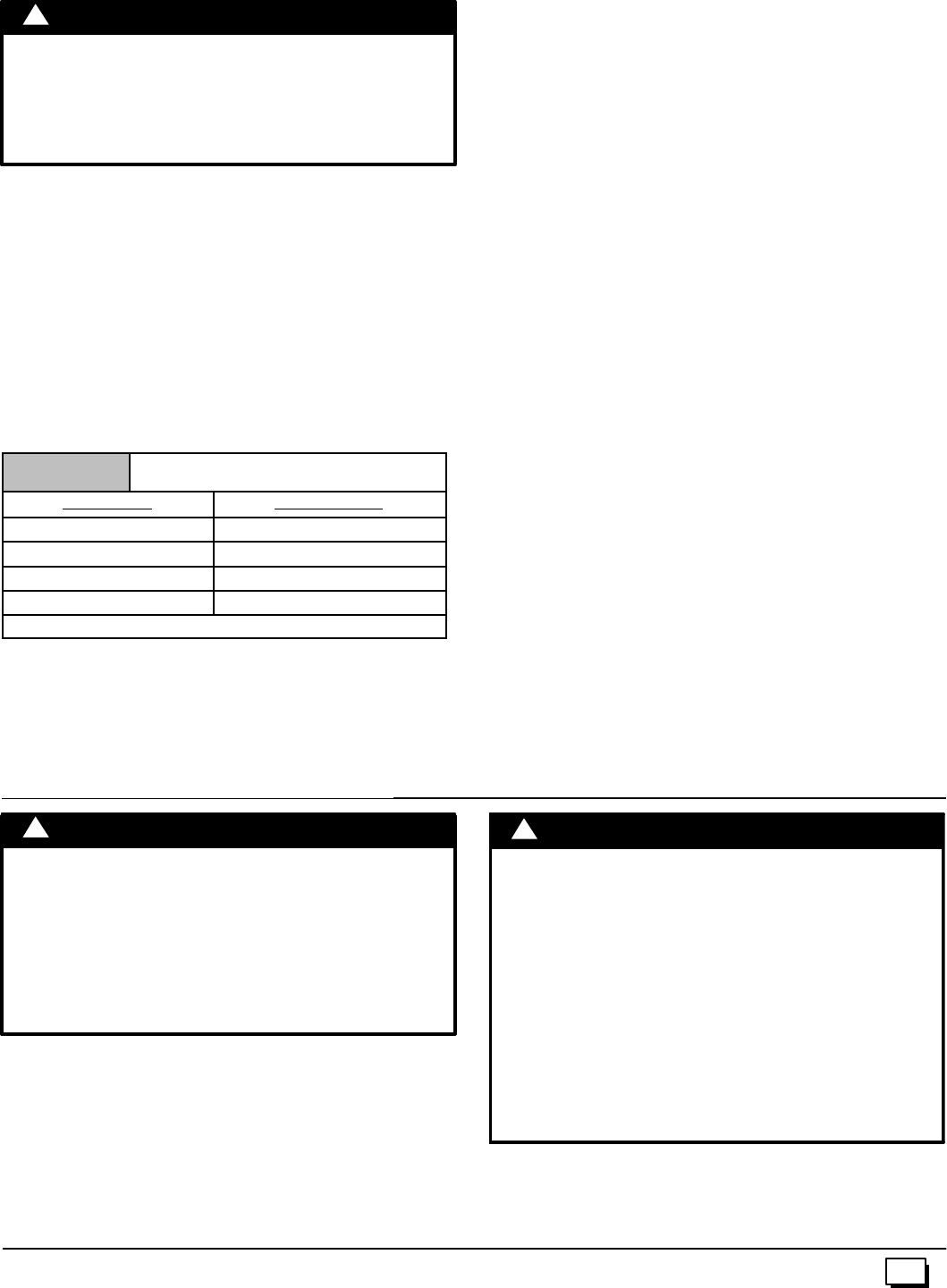
33
441 01 2611 06
Changing Blower Speed
ELECTRICAL SHOCK HAZARD.
Failure to disconnect power could result in death,
personal injury and/or property damage.
Turn OFF power to furnace before changing speed
taps.
!WARNING
NOTE: The speed taps that the manufacturer sets at the factory
for this furnace are based on a nominal 400 CFM per ton cooling
and the basic mid range on the temperature rise for heating.
Since the manufacturer cannot predict the static pressure
thatwillbeappliedtothefurnace,itistheresponsibilityofthe
installer dealer/contractor to select the proper speed tap
leads for the application when the furnace is installed.
If it is necessary to change speeds, refer to steps below.
1. Refer to Furnace Wiring Diagram for location of the heating
and cooling speed taps located on the electronic fan control
as well as location of unused blower motor speed leads. Use
thechart(Table 9 ) todetermine the blower motor speed set-
tings.
Table 9 Blower Speed Chart
Wire Color Motor Speed
Black High
Orange*Med--High
Blue Med--Low
Red Low
*Med--High speed may not be provided on all models.
2. Changetheheatorcoolblowermotorspeedbyremovingthe
motor speed lead from the “Heat”or“Cool” terminal and re-
place it with the desired motor speed lead from the “Unused
Motor Lead” location. Connect the wire previously removed
from the “Heat”or“Cool” terminal to the vacated “Unused
Motor Lead” terminal.
3. Ifthesamespeedmustbeusedforbothheatingandcooling,
remove the undesired motor speed lead from the “Heat” or
“Cool”terminalandconnectthatleadtotheopenterminalat
“Unused Motor Lead” location or tape off. Attach a jumper
betweenthe“Heat”and“Cool” terminalsandtheremaining
motor speed lead.
Note: When using the same speed on motors with (4)speed
leads,itwillbenecessarytotapeofftheterminalof themotor
speedleadremovedfromthe“Heat” or“Cool” terminalwith
electrical tape since an open terminal will not be availableat
the “Unused Motor Lead” location.
Thoroughly check the system after modification to ensure the
properoperationofthecirculatingairblowerinallmodesofopera-
tion.
Continuous--Fan Operation
A terminal is provided on the electronic fan control located in the
circulating air blower compartment for operation of the continu-
ous--fanoption. Thisconnectionisintendedforthelowspeedmo-
tor tap, and has a lower contact rating (8 amps) than the heat and
cool taps. When the low speed blower lead is connected to this
terminal, this will provide low speed blower operation whenever
the other two speeds (Heat or Cool) are not energized.
Thoroughly check the system after modification to ensure the
properoperationofthecirculatingairblowerinallmodesofopera-
tion.
Separate speed selections for Heat, Cool, and
Continuous--Fan
Connect low speed lead from circulating air motor to the “Cont”
terminalattheelectronicfancontrol. Theappropriatemotorleads
shouldalreadybeconnectedtothe“Heat”and“Cool”terminals.
Heating and Continuous--Fan Speed the Same
Ifitisnecessarytooperatetheheatingspeedandcontinuous--fan
speed using the same blower speed, connect a jumper between
the “Heat” and “Cont” terminals on the electronic fan control.
Note: There should be only ONE motor lead going to the “Heat”
and “Cont” terminals.
13. Furnace Maintenance
FIRE, EXPLOSION, OR CARBON MONOXIDE
POISONING HAZARDS
Failure to have the furnace inspected and
maintained could result in death, bodily injury,
and/or property damage.
It is recommended that the furnace be inspected
and serviced on an annual basis (before the heating
season) by a qualified service agency.
!WARNING
See “User’s Information Manual”.
ELECTRICAL SHOCK, FIRE OR EXPLOSION
HAZARD
Failure to follow safety warnings exactly could
result in dangerous operation, serious injury,
death or property damage.
Improper servicing could result in dangerous
operation, serious injury, death or property
damage.
·Before servicing, disconnect all electrical
power to furnace.
·Whenservicingcontrols,labelallwiresprior to
disconnecting. Reconnect wires correctly.
·Verify proper operation after servicing.
!W
A
RNING

34 441 01 2611 06
14. Sequence of Operation & Diagnostics
The following is the normal operating sequence.
Cooling (Y) Request:
24 VAC signals applied to Y & G terminals of EFT (electronic fan timer) control.
·Cool motor speed is energized after 5 second Cool Fan On Delay time.
Y & G signals removed from EFT.
·Cool motor speed is de--energized after 90 second Cool Fan Off Delay time.
Continuous Circulating Fan (G) Request:
24 VAC signals applied to G terminals of EFT control.
·Heat motor speed is energized without delay.
G signal removed from EFT.
·Heat motor speed is de--energized without delay.
NOTE 1) Furnace de--energizes the fan during the heat exchanger warm--up period on a call for Heating that occurs during a G
request unless a blower motor lead is connected to the Cont terminal on the EFT, in which case see NOTE 2).
NOTE 2) Heating or Cooling requests received during a Fan request cause the fan speed to change to the appropriate heat or cool
speed after the Fan On Delay time expires.The fan returns to continuous circulating speed after the selected Fan Off Delay time ex-
pires following loss of the Heating or Cooling request.
Heating (W) Request:
24 VAC signals applied to W terminal of EFT control.
·Inducer motor turns on.
·Followinga3secondprepurge delay, the pilot gas valve opens and the igniter begins to warm up.
·After the pilot lights, the gas control valve is energized and main burners light.
·Timed from the opening of the main gas control valve, the furnace control will delay blower operation for the Heat Fan On Delay
time. W signal removed from EFT.
·The gas valve de--energizes and the main burners go out.
·The inducer runs for a 30 second postpurge period.
·The fan stays at Heat speed.
·Timed from the gas valve de--energizing, the circulating fan de--energizes after the selected Heat Fan Delay time expires.
Heating Request with Gas Shut Off:
24 VAC signals applied to W1 terminal of EFT control.
·Inducer motor turns on.
·Followinga3secondprepurge delay, the pilot valve opens and the igniter begins to warm up.
·The igniter glows red--hot for 30 seconds, then turns off.
·The igniter stays off for 25 seconds, then begins to warm--up again.
·The igniter glows red--hot for 30 seconds, then turns off.
·The pilot valve closes 3 seconds after the igniter de--energizes.
·The inducer de--energizes 5 seconds after the pilot valve closes.
·The SmartValve proceeds to soft lockout and flashes error code 6.
·The control exits soft lockout after 5 minutes and begins another ignition sequence.
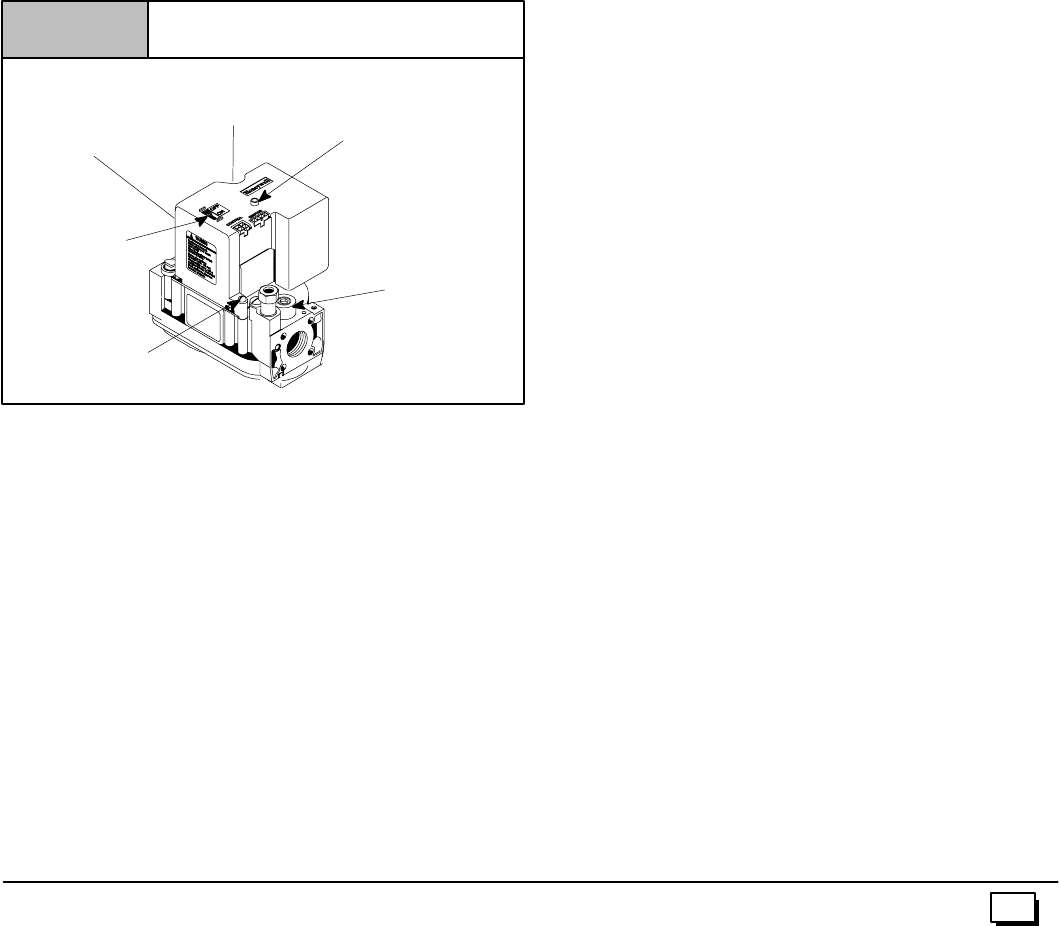
35
441 01 2611 06
Gas Control Valve Diagnostic Codes (See Figure 40)
OFF = Control not powered
Heartbeat = Normal Operation (Standby or call for heat)
1 Flash = Not used
2 Flashes = Low Pressure switch closed when should be open
3 Flashes = Low Pressureswitch circuit wasstill sensed as open 30seconds after the inducer was energized.System
is in 5 minute delay mode, with inducer off. After 5--minute delay, a new ignition sequence will be initiated.
(Note: SV9541M On/Off switch in off position during a call for heat will generate this diagnostic code)
4 Flashes = Limit switch string open
5 Flashes = Flame sensed out of sequence -- Flame signal still present.
6 Flashes + 1 Note 1 = Soft Lockout --Maximum retry count exceeded (failed to light within 4 trials for ignition)
6 Flashes + 2 Notes 1,2 = SoftLockout --Maximumrecyclecountexceeded -- LastfailurewasFlameSenseLostDuringRun,Cycling
Pressure Switch or Blocked Condensate.
6 Flashes + 3 Notes 1,2 = Soft Lockout --Maximum recycle count exceeded -- Last failure was Airflow Proving Circuit Opened
During Run
6 Flashes + 4 Notes 1,2 = Soft Lockout --Maximum recycle count exceeded -- Last failure was Limit Circuit Opened During Run
7 Flashes = Soft Lockout Due to Limit Trips Taking Longer than 2 minutes to Reset; Auto Reset After 1 Hour if
Call for Heat Still Present. Reset by Cycling Call for Heat at Any Time.
NOTE1:The6+Xdesignationindicatesacombinationofflashcodes:6flashesshowsthecontrolisinsoftlockout,followedbyXflashes
toindicatethereasonthecontrolwentintosoftlockout.Whenthe6+Xcodeisflashing,theSV9541willattemptanewignitionsequence
afterafiveminutedelayperiod,ifthecallforheatisstillpresent.Resetofthethermostatwillinitiatea newignitionsequenceimmediately.
NOTE 2: Any combination of 5 ‘abnormal’ events during a single call for heat will result in soft lockout. An ‘abnormal’ event is a Flame
SenseFailureDuringRun,AirflowProvingCircuitOpenDuringRun,orLimitCircuitOpenDuringRun.Theflash codewillindicatewhich
was the last ‘abnormal’ event that put the system into the soft lockout state based on the table above.
Typical Gas Control Valve Honeywell
Figure 40
INLET
OUTLET
Diagnostic Light
(on some models)
25--22--25a
On/Off
Switch
Pilot Pressure
Adjustment
Manifold Pressure
Adjustment
(Hidden)
Manifold
Pressure
Tap
Supply
Pressure
Tap (Hidden)

36 441 01 2611 06
37
441 01 2611 06
International Comfort Products, LLC
Lewisburg, TN 37091
Fast Parts Division
(866) 380--3278
Models
N8MPN050B12A1 N8MPL050B12A1
N8MPN075B12A1 N8MPL075B12A1
N8MPN075F16A1 N8MPL075F16A1
N8MPN100F14A1 N8MPL100F20A1
N8MPN100F20A1 N8MPL100J22A1
N8MPN100J22A1 N8MPL125J20A1
N8MPN125J20A1 N8MPL125J22A1
N8MPN125J22A1
*8MPN050B12A1 *8MPL050B12A1
*8MPN075B12A1 *8MPL075B12A1
*8MPN075F16A1 *8MPL075F16A1
*8MPN100F14A1 *8MPL100F20A1
*8MPN100F20A1 *8MPL100J20A1
*8MPN100J20A1 *8MPL125J20A1
*8MPN125J20A1
*8MPN150J20A1
* Denotes Brand
Save This Manual For Future Reference
Ò
Ò
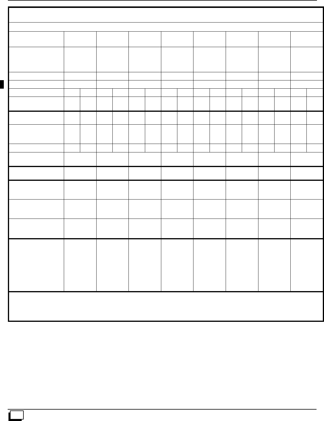
38 441 01 2611 06
THIS DATA IS SUBJECT TO CHANGE WITHOUT NOTICE
Model Specifications
Manufacturers Number (Mfr No --SeeRatingPlate)
ALL Models (N8MPN) Specifications
N8MPN
050B12 N8MPN
075B12 N8MPN
075F16 N8MPN
100F14 N8MPN
100F20 N8MPN
100J22 N8MPN
125J20 N8MPN
125J22
General
Input (Btuh)
Output (Btuh)
Temp. Rise (°F)
50,000
40,000
35--65
75,000
60,000
35--65
75,000
60,000
25--55
100,000
80,000
30--60
100,000
80,000
35--65
100,000
81,000
30--60
125,000
100,000
30--60
125,000
100,000
30--60
Electrical (Volts/Hz) 115/60 115/60 115/60 115/60 115/60 115/60 115/60 115/60
Rating Plate Amps. 8.8 9.5 10.1 9.6 13.6 12.3 13.6 11.5
GasType Nat LP Nat LP Nat LP Nat LP Nat LP Nat LP Nat LP Nat LP
Transformer Size (VA)
T’stat Heat Anticipator 40
.10 40
.10 40
.10 40
.10 40
.10 40
.10 40
.10 40
.10 40
.10 40
.10 40
.10 40
.10 40
.10 40
.10 40
.10 40
.10
Gas & Ignition
Std. Main Orifices (No/Size) 2/#42 2/#54 3/#42 3/#54 3/#42 3/#54 4/#42 4/#54 4/#42 4/#54 4/#42 4/#54 5/#42 5/#54 5/#42 5/#54
Gas Valve Honeywell SV
Regulation Type
Manifold Press. (Inch’s WC)
9541
SNAP
3.5
9541
SNAP
10.0
9541
SNAP
3.5
9541
SNAP
10.0
9541
SNAP
3.5
9541
SNAP
10.0
9541
SNAP
3.5
9541
SNAP
10.0
9541
SNAP
3.5
9541
SNAP
10.0
9541
SNAP
3.5
9541
SNAP
10.0
9541
SNAP
3.5
9541
SNAP
10.0
9541
SNAP
3.5
9541
SNAP
10.0
Pilot Orifice Size .018 .011 .018 .011 .018 .011 .018 .011 .018 .011 .018 .011 .018 .011 .018 .011
Ignition Type/Series
Lock--Out Time HW HSP
NA HW HSP
NA HW HSP
NA HW HSP
NA HW HSP
NA HW HSP
NA HW HSP
NA HW HSP
NA
Combustion
Flue OutletSize (Inches) 4444444 4
Limits & Controls
Thermal Sensor (°F)
Limit Control 300
See PartsList 300
See PartsList 300
See PartsList 300
See PartsList 300
See PartsList 300
See PartsList 300
See PartsList 300
See PartsList
Std. Pressure Sw. (Part No)
Press(Close)
Press(Open)
1013529
--0.69
--0.59
1013529
--0.69
--0.59
1013529
--0.69
--0.59
1013529
--0.69
--0.59
1013529
--0.69
--0.59
1013529
--0.69
--0.59
1013529
--0.69
--0.59
1013529
--0.69
--0.59
Fan Control (Type)
Fan Control On
(Timed--secs) Off
HW ST9160
30
60,100,140,180
HW ST9160
30
60,100,140,180
HW ST9160
30
60,100,140,180
HW ST9160
30
60,100,140,180
HW ST9160
30
60,100,140,180
HW ST9160
30
60,100,140,180
HW ST9160
30
60,100,140,180
HW ST9160
30
60,100,140,180
Blower Data
Type & Size
Motor Type/H.p.
Cap. Mfd/Volts
FilterType (600 FPM)
Filter Size (²) (Not Supplied)
1600 CFM and over#
Min. Cool Cap. (Tons)
Max. Cool Cap. (Tons)
11--8
PSC/1/2
10/370
Washable
14x25x1
-- --
1.5
3
11--8
PSC/1/2
7.5/370
Washable
14x25x1
-- --
1.5
3
11--10
PSC/1/2
10/370
Washable
16x25x1
16x25x1 (2)
3
4
11--10
PSC/1/2
7.5/370
Washable
16x25x1
-- --
2
3.5
11--10
PSC/1/2
10/370
Washable
16x25x1 (2)
16x25x1 (2)
3
5
11--10
PSC/3/4
40/370
Washable
20x25x1
16x25x1 (2)
3
5.5
11--10
PSC/1/2
10/370
Washable
20x25x1
16x25x1 (2)
3
5
11--10
PSC/3/4
40/370
Washable
20x25x1
16x25x1 (2)
3
5.5
Gas Conversion Kits
Nat to LP NAHL002LP or *1160991
LP to Nat NAHF002NG, *1009510
* Mustbe ordered from Service Parts
Note: Two side filter racks (left and right) required for upflow applications. Side returns are not permitted with downflow or horizontal furnace applica-
tions.
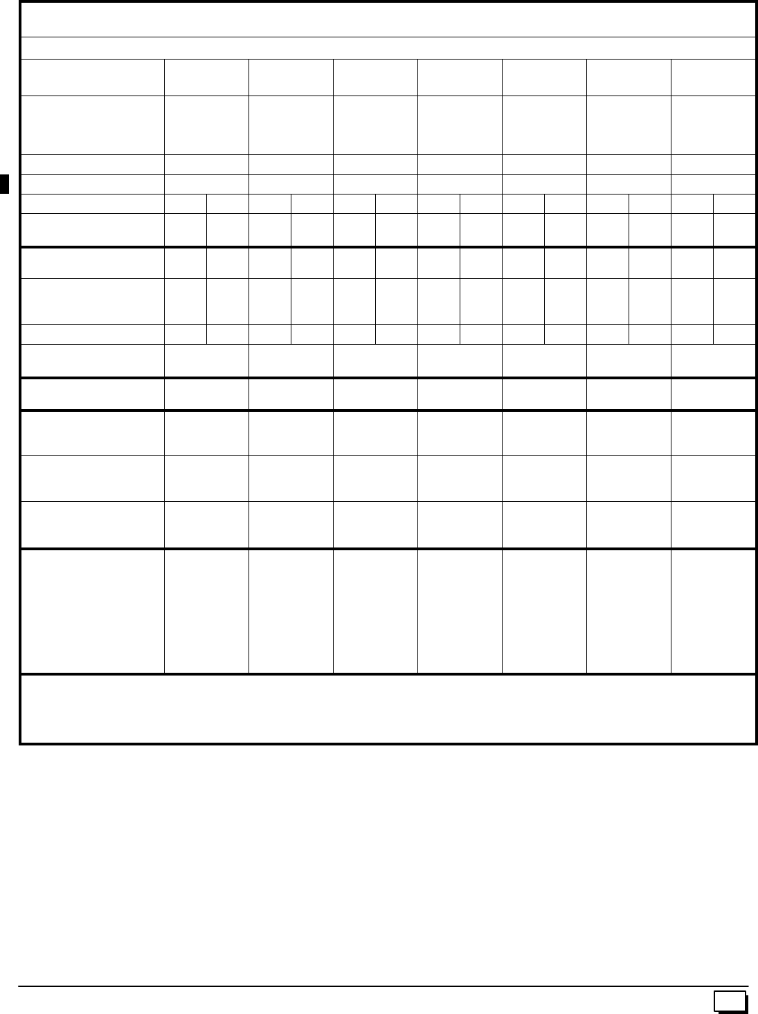
39
441 01 2611 06 THIS DATA IS SUBJECT TO CHANGE WITHOUT NOTICE
Manufacturers Number (Mfr No --SeeRatingPlate)
ALL Models (N8MPL) Specifications
N8MPL
050B12 N8MPL
075B12 N8MPL
075F16 N8MPL
100F20 N8MPL
100J22 N8MPL
125J20 N8MPL
125J22
General
Input (Btuh)
Output (Btuh)
Temp. Rise (°F)
50,000
40,000
35--65
75,000
60,000
35--65
75,000
60,000
25--55
100,000
80,000
35--65
100,000
80,000
30--60
125,000
100,000
30--60
125,000
100,000
30--60
Electrical (Volts/Hz) 115/60 115/60 115/60 115/60 115/60 115/60 115/60
Rating Plate Amps/ 8.8 9.5 10.1 13.6 12.3 13.6 11.5
GasType Nat LP Nat LP Nat LP Nat LP Nat LP Nat LP Nat LP
Transformer Size (VA)
T’stat Heat Anticipator 40
.10 40
.10 40
.10 40
.10 40
.10 40
.10 40
.10 40
.10 40
.10 40
.10 40
.10 40
.10 40
.10 40
.10
Gas & Ignition
Std. Main Orifices (No/Size) 2/#42 2/#54 3/#42 3/#54 3/#42 3/#54 4/#42 4/#54 4/#42 4/#54 5/#42 5/#54 5/#42 5/#54
Gas Valve Honeywell SV
Regulation Type
Manifold Press. (Inch’s WC)
9541
SNAP
3.5
9541
SNAP
10.0
9541
SNAP
3.5
9541
SNAP
10.0
9541
SNAP
3.5
9541
SNAP
10.0
9541
SNAP
3.5
9541
SNAP
10.0
9541
SNAP
3.5
9541
SNAP
10.0
9541
SNAP
3.5
9541
SNAP
10.0
9541
SNAP
3.5
9541
SNAP
10.0
Pilot Orifice Size .018 .011 .018 .011 .018 .011 .018 .011 .018 .011 .018 .011 .018 .011
Ignition Type/Series
Lock--Out Time HW HSP
NA HW HSP
NA HW HSP
NA HW HSP
NA HW HSP
NA HW HSP
NA HW HSP
NA
Combustion
Flue OutletSize (Inches) 444444 4
Limits & Controls
Thermal Sensor (°F)
Limit Control 300
See PartsList 300
See PartsList 300
See PartsList 300
See PartsList 300
See PartsList 300
See PartsList 300
See PartsList
Std. Pressure Sw. (Part No)
Press(Close)
Press(Open)
1013529
--0.69
--0.59
1013529
--0.69
--0.59
1013529
--0.69
--0.59
1013529
--0.69
--0.59
1013529
--0.69
--0.59
1013529
--0.69
--0.59
1013529
--0.69
--0.59
Fan Control (Type)
Fan Control On
(Timed--secs) Off
HW ST9160
30
60,100,140,180
HW ST9160
30
60,100,140,180
HW ST9160
30
60,100,140,180
HW ST9160
30
60,100,140,180
HW ST9160
30
60,100,140,180
HW ST9160
30
60,100,140,180
HW ST9160
30
60,100,140,180
Blower Data
Type & Size
Motor Type/H.p.
Cap. Mfd/Volts
FilterType (600 FPM)
Filter Size (²) (Not Supplied)
1600 CFM and over #
Min. Cool Cap. (Tons)
Max. Cool Cap. (Tons)
11--8
PSC/1/2
10/370
Washable
14x25x1
-- --
1.5
3
11--8
PSC/1/2
7.5/370
Washable
14x25x1
-- --
1.5
3
11--10
PSC/1/2
10/370
Washable
16x25x1
16x25x1 (2)
3
4
11--10
PSC/1/2
10/370
Washable
16x25x1
16x25x1 (2)
3
5
11--10
PSC/3/4
40/370
Washable
20x25x1
16x25x1 (2)
3
5.5
11--10
PSC/1/2
10/370
Washable
20x25x1
16x25x1 (2)
3
5
11--10
PSC/3/4
40/370
Washable
20x25x1
16x25x1 (2)
3
5.5
Gas Conversion Kits
Nat to LP NAHL002LP or *1160991
LP to Nat NAHF002NG, *1009510
* Mustbe ordered from Service Parts
Note: Two side filter racks (left and right) required for upflow applications. Side returns are not permitted with downflow or horizontal furnace applica-
tions.
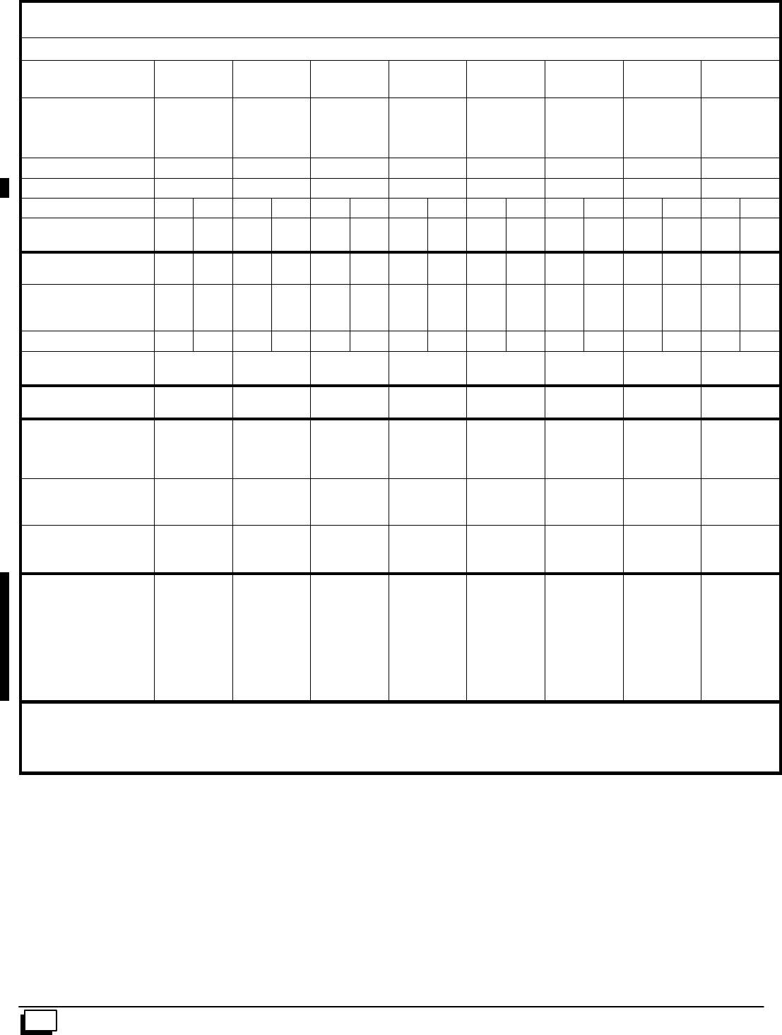
40 441 01 2611 06
THIS DATA IS SUBJECT TO CHANGE WITHOUT NOTICE
Manufacturers Number (Mfr No --SeeRatingPlate)
ALL Models (*8MPN) Specifications
*8MPN
050B12 *8MPN
075B12 *8MPN
075F16 *8MPN
100F14 *8MPN
100F20 *8MPN
100J20 *8MPN
125J20 *8MPN
150J20
General
Input (Btuh)
Output (Btuh)
Temp. Rise (°F)
50,000
40,000
35--65
75,000
60,000
30--60
75,000
60,000
30--60
100,000
81,000
35--65
100,000
81,000
35--65
100,000
81,000
35--65
125,000
101,000
35--65
150,000
121,000
35--65
Electrical (Volts/Hz) 115/60 115/60 115/60 115/60 115/60 115/60 115/60 115/60
Rating Plate Amps. 8.8 9.5 10.1 9.9 13.9 12.6 13.9 13.9
GasType Nat LP Nat LP Nat LP Nat LP Nat LP Nat LP Nat LP Nat LP
Transformer Size (VA)
T’stat Heat Anticipator 40
.30 40
.30 40
.30 40
.30 40
.30 40
.30 40
.30 40
.30 40
.30 40
.30 40
.30 40
.30 40
.30 40
.30 40
.30 40
.30
Gas & Ignition
Std. Main Orifices (No/Size) 2/#42 2/#54 3/#42 3/#54 3/#42 3/#54 4/#42 4/#54 4/#42 4/#54 4/#42 4/#54 5/#42 5/#54 6/#42 6/#54
Gas Valve Honeywell SV
Regulation Type
Manifold Press. (Inch’s WC)
9541
SNAP
3.5
9541
SNAP
10.0
9541
SNAP
3.5
9541
SNAP
10.0
9541
SNAP
3.5
9541
SNAP
10.0
9541
SNAP
3.5
9541
SNAP
10.0
9541
SNAP
3.5
9541
SNAP
10.0
9541
SNAP
3.5
9541
SNAP
10.0
9541
SNAP
3.5
9541
SNAP
10.0
9541
SNAP
3.5
9541
SNAP
10.0
Pilot Orifice Size .018 .011 .018 .011 .018 .011 .018 .011 .018 .011 .018 .011 .018 .011 .018 .011
Ignition Type/Series
Lock--Out Time HW HSP
NA HW HSP
NA HW HSP
NA HW HSP
NA HW HSP
NA HW HSP
NA HW HSP
NA HW HSP
NA
Combustion
Flue OutletSize (Inches) 4444444 4
Limits & Controls
Thermal Sensor (°F)
Limit Control
Auxiliary Limit (°F)
300
See PartsList
130
300
See PartsList
130
300
See PartsList
130
300
See PartsList
130
300
See PartsList
130
300
See PartsList
130
300
See PartsList
130
300
See PartsList
130
Std. Pressure Sw. (Part No)
Press(Close)
Press(Open)
1013529
--0.69
--0.59
1013529
--0.69
--0.59
1013529
--0.69
--0.59
1013529
--0.69
--0.59
1013529
--0.69
--0.59
1013529
--0.69
--0.59
1013529
--0.69
--0.59
1013529
--0.69
--0.59
Fan Control (Type)
Fan Control On
(Timed--secs) Off
HW ST9160
30
60,100,140,180
HW ST9160
30
60,100,140,180
HW ST9160
30
60,100,140,180
HW ST9160
30
60,100,140,180
HW ST9160
30
60,100,140,180
HW ST9160
30
60,100,140,180
HW ST9160
30
60,100,140,180
HW ST9160
30
60,100,140,180
Blower Data
Type & Size
Motor Type/H.p.
Cap. Mfd/Volts
FilterType (600 FPM)
Filter Size (²) (Not Supplies)
1600 CFM and over#
Min. Cool Cap. (Tons)
Max. Cool Cap. (Tons)
11--8
PSC/1/2
10/370
Washable
14x25x1
-- --
1.5
3
11--8
PSC/1/2
7.5/370
Washable
14x25x1
-- --
1.5
3
11--10
PSC/1/2
10/370
Washable
16x25x1
16x25x1 (2)
3
4
11--10
PSC/1/2
7.5/370
Washable
16x25x1
-- --
2
3.5
11--10
PSC/1/2
10/370
Washable
16x25x1
16x25x1 (2)
3
5
11--10
PSC/1/2
10/370
Washable
20x25x1
16x25x1 (2)
3
5
11--10
PSC/1/2
10/370
Washable
20x25x1
16x25x1 (2)
3
5
12--12
PSC/3/4
40/370
Washable
20x25x1
16x25x1 (2)
3
5
Gas Conversion Kits
Nat to LP NAHL002LP or *1160991
LP to Nat NAHF002NG, *1009510
* Mustbe ordered from Service Parts
Note: Two side filter racks (left and right) required for upflow applications. Side returns are not permitted with downflow or horizontal furnace applica-
tions.
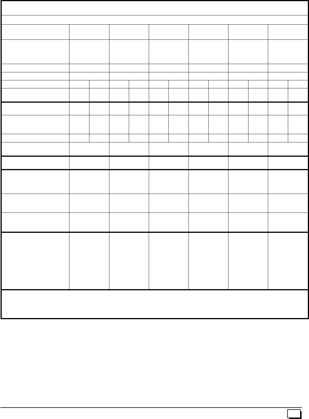
41
441 01 2611 06 THIS DATA IS SUBJECT TO CHANGE WITHOUT NOTICE
Manufacturers Number (Mfr No --SeeRatingPlate)
ALL Models (*8MPL) Specifications
*8MPL
050B12 *8MPL
075B12 *8MPL
075F16 *8MPL
100F20 *8MPL
100J20 *8MPL
125J20
General
Input (Btuh)
Output (Btuh)
Temp. Rise (°F)
50,000
40,000
35--65
75,000
60,000
30--60
75,000
60,000
30--60
100,000
81,000
35--65
100,000
81,000
35--65
125,000
101,000
35--65
Electrical (Volts/Hz) 115/60 115/60 115/60 115/60 115/60 115/60
Rating Plate Amps. 8.8 9.5 10.1 13.9 12.6 13.9
GasType Nat LP Nat LP Nat LP Nat LP Nat LP Nat LP
Transformer Size (VA)
T’stat Heat Anticipator 40
.30 40
.30 40
.30 40
.30 40
.30 40
.30 40
.30 40
.30 40
.30 40
.30 40
.30 40
.30
Gas & Ignition
Std. Main Orifices (No/Size) 2/#42 2/#54 3/#42 3/#54 3/#42 3/#54 4/#42 4/#54 4/#42 4/#54 5/#42 5/#54
Gas Valve Honeywell SV
Regulation Type
Manifold Press. (Inch’s WC)
9541
SNAP
3.5
9541
SNAP
10.0
9541
SNAP
3.5
9541
SNAP
10.0
9541
SNAP
3.5
9541
SNAP
10.0
9541
SNAP
3.5
9541
SNAP
10.0
9541
SNAP
3.5
9541
SNAP
10.0
9541
SNAP
3.5
9541
SNAP
10.0
Pilot Orifice Size .018 .011 .018 .011 .018 .011 .018 .011 .018 .011 .018 .011
Ignition Type/Series
Lock--Out Time HW HSP
NA HW HSP
NA HW HSP
NA HW HSP
NA HW HSP
NA HW HSP
NA
Combustion
Flue OutletSize (Inches) 444444
Limits & Controls
Thermal Sensor (°F)
Limit Control
Auxiliary Limit (°F)
300
See PartsList
130
300
See PartsList
130
300
See PartsList
130
300
See PartsList
130
300
See PartsList
130
300
See PartsList
130
Std. Pressure Sw. (Part No)
Press(Close)
Press(Open)
1013529
--0.69
--0.59
1013529
--0.69
--0.59
1013529
--0.69
--0.59
1013529
--0.69
--0.59
1013529
--0.69
--0.59
1013529
--0.69
--0.59
Fan Control (Type)
Fan Control On delay
(Timed--secs) Off delay
HW ST9160
30
60,100,140,180
HW ST9160
30
60,100,140,180
HW ST9160
30
60,100,140,180
HW ST9160
30
60,100,140,180
HW ST9160
30
60,100,140,180
HW ST9160
30
60,100,140,180
Blower Data
Type & Size
Motor Amps/Rpm
Motor Type/H.p.
Cap. Mfd/Volts
Filter Type
Filter Size (²) (Not Supplied)
1600 CFM and over#
Min. Cool Cap. (Tons)
Max. Cool Cap. (Tons)
11--8
10.3/1100
PSC/1/2
10/370
Washable
14x25x1
-- --
1.5
3
11--8
8/1050
PSC/1/2
7.5/370
Washable
14x25x1
-- --
1.5
3
11--10
10.3/1100
PSC/1/2
10/370
Washable
16x25x1
16x25x1 (2)
3
4
11--10
10/1050
PSC/1/2
10/370
Washable
16x25x1
16x25x1 (2)
3
5
11--10
11.9/900
PSC/1/2
10/370
Washable
20x25x1
16x25x1 (2)
3
5
11--10
10/1050
PSC/1/2
10/370
Washable
20x25x1
16x25x1 (2)
3
5
Gas Conversion Kits
Nat to LP NAHL002LP or *1160991
LP to Nat NAHF002NG, *1009510
* Mustbe ordered from Service Parts
# Two side filter racks (left and right) required for upflow applications. Side returns are not permitted with downflow or horizontal furnace applications.
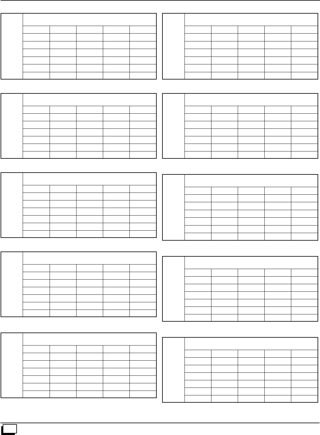
Exterrnal Static Pressure
Inches of W.C.
Exterrnal Static Pressure
Inches of W.C.
Exterrnal Static Pressure
Inches of W.C.
Exterrnal Static Pressure
Inches of W.C.
Exterrnal Static Pressure
Inches of W.C.
Exterrnal Static Pressure
Inches of W.C.
Exterrnal Static Pressure
Inches of W.C.
Exterrnal Static Pressure
Inches of W.C.
Exterrnal Static Pressure
Inches of W.C.
Exterrnal Static Pressure
Inches of W.C.
42 441 01 2611 06
THIS DATA IS SUBJECT TO CHANGE WITHOUT NOTICE
15. Circulation Air Blower Data
N8MPN/L050B12 & *8MPN/L050B12 * Denotes Brand
Air Delivery in Cubic Feet per Minute (C.F.M.)
(Furnace Rated @0.5²
²²
²WC ESP)
TAP LOW MED L MED H HIGH
.10 472 704 1167 1387
.30 365 638 1102 1288
.50 290 572 1035 1194
.70 209 522 939 1070
.90 463 443 820 937
1.00 413 370 753 858
N8MPN/L075B12 & *8MPN/L075B12 * Denotes Brand
Air Delivery in Cubic Feet per Minute (C.F.M.)
(Furnace Rated @0.5²
²²
²WC ESP)
TAP LOW MED L MED H HIGH
.10 695 963 1220 1559
.30 644 928 1183 1463
.50 588 873 1118 1361
.70 540 771 1017 1239
.90 463 675 900 1083
1.00 413 615 835 998
N8MPN/L075F16 & *8MPN/L075F16 * Denotes Brand
Air Delivery in Cubic Feet per Minute (C.F.M.)
(Furnace Rated @0.5²
²²
²WC ESP)
TAP LOW MED L MED H HIGH
.10 598 841 1427 1861
.30 400 748 1384 1770
.50 289 667 1343 1677
.70 236 582 1254 1547
.90 -- -- -- 477 1129 1360
1.00 -- -- -- 436 1016 1262
N8MPN100F14 & *8MPN100F14 * Denotes Brand
Air Delivery in Cubic Feet per Minute (C.F.M.)
(Furnace Rated @0.5²
²²
²WC ESP)
TAP LOW MED L MED H HIGH
.10 770 949 1328 1760
.30 648 873 1235 1675
.50 544 772 1115 1551
.70 457 684 1036 1404
.90 361 572 895 1215
1.00 308 507 811 1093
N8MPN/L100F20 & *8MPN/L100F20 * Denotes Brand
Air Delivery in Cubic Feet per Minute (C.F.M.)
(Furnace Rated @0.5²
²²
²WC ESP)
TAP LOW MED L MED H HIGH
.10 831 1125 1582 2216
.30 814 1123 1588 2179
.50 781 1117 1577 2074
.70 717 1053 1541 1909
.90 609 964 1373 1745
1.00 561 888 1307 1641
NOTE: 075F16 -- Reduce airflow by 5% if bottom return only
100F20 -- Reduce airflow by 10% if bottom return only
125J20 -- Reduce airflow by 5% if bottom return only
*8MPN/L100J20 * Denotes Brand
Air Delivery in Cubic Feet per Minute (C.F.M.)
(Furnace Rated @0.5²
²²
²WC ESP)
TAP LOW MED L MED H HIGH
.10 773 1045 1453 2147
.30 755 1037 1469 2128
.50 712 1020 1459 2078
.70 647 979 1424 1963
.90 554 894 1347 1795
1.00 497 828 1262 1705
N8MPN/L100J22
Air Delivery in Cubic Feet per Minute (C.F.M.)
(Furnace Rated @0.5²
²²
²WC ESP)
TAP LOW MED L MED H HIGH
.10 1785 1997 2292 2519
.30 1741 1941 2206 2410
.50 1674 1861 2097 2284
.70 1581 1749 1965 2121
.90 1428 1597 1793 1928
1.00 1326 1478 1667 1814
N8MPN/L125J20 & *8MPN/L125J20 * Denotes Brand
Air Delivery in Cubic Feet per Minute (C.F.M.)
(Furnace Rated @0.5²
²²
²WC ESP)
TAP LOW MED L MED H HIGH
.10 860 1149 1666 2147
.30 836 1158 1577 2126
.50 805 1140 1561 2148
.70 758 1081 1516 1922
.90 661 1009 1428 1767
1.00 614 925 1357 1663
N8MPN/L125J22
Air Delivery in Cubic Feet per Minute (C.F.M.)
(Furnace Rated @0.5²
²²
²WC ESP)
TAP LOW MED L MED H HIGH
.10 1901 2121 2362 2463
.30 1833 2033 2244 2385
.50 1745 1936 2100 2217
.70 1624 1773 1894 2033
.90 1442 1569 1714 1821
1.00 1329 1455 1583 1685
*8MPN150J20 * Denotes Brand
Air Delivery in Cubic Feet per Minute (C.F.M.)
(Furnace Rated @0.5²
²²
²WC ESP)
TAP LOW MED L MED H HIGH
.10 1656 1915 2168 2385
.30 1583 1787 2090 2335
.50 1507 1697 1997 2212
.70 1390 1596 1856 2085
.90 1212 1445 1654 1898
1.00 1125 1337 1561 1777
NOTE: N8MPN/L125J22 -- Reduce airflow by 10% if bottom return only
*8MPN/L150J20 -- Reduce airflow by 10% if bottom return only

43
441 01 2611 06
Wiring Diagram N8MPN/L, *8MPN/L
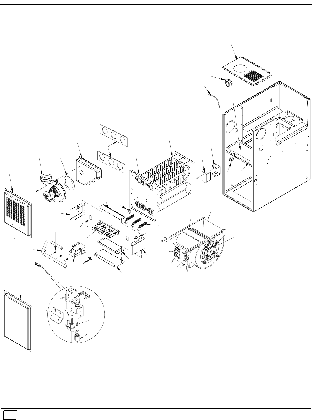
44 441 01 2611 06
Parts for N8MPN/L
25--24--32a--1
N
18 Z
X
S
14
L
9
P
1
B
C
2
A
D
E
J76
F
8
5
4
3
G
H
BB
17
16
16
W
10
V
15
U
K
13
12
11
T
S
R
DD
CC
M
AA
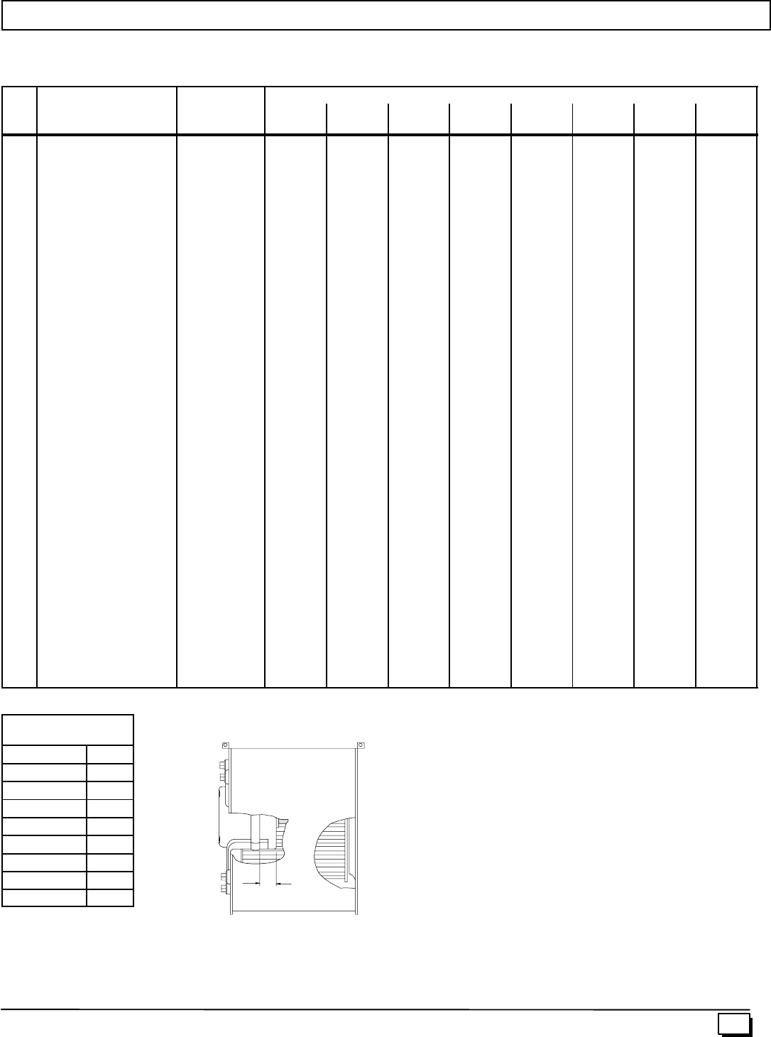
A
45
441 01 2611 06
Replacement Parts - N8MPN (Natural Gas)
Models -- N8MPN050B12A1, N8MPN075B12A1, N8MPN075F16A1, N8MPN100F14A1, N8MPN100F20A1, N8MPN100J22A1,
N8MPN125J20A1, N8MPN125J22A1
Replacement part supplied will be current active part. For parts not listed, consult place of purchase.
K
e
y
D
e
s
c
r
i
p
t
i
o
n
P
a
r
t
N8MPN
K
ey
No.
D
escr
i
pt
i
on
Functional Parts
P
art
Number 050B
12A1 075B
12A1 075F
16A1 100F
14A1 100F
20A1 100J
22A1 125J
20A1 125J
22A1
1Heat Exchanger 1013623
1013624
1013625
1013626
1013627
1013628
1
--
--
--
--
--
--
1
--
--
--
--
--
--
1
--
--
--
--
--
--
1
--
--
--
--
--
1
--
--
--
--
--
--
1
--
--
--
--
--
--
1
--
--
--
--
--
1
2Switch, Pressure 1013529 11111111
3Wheel, Blower 1013011
1011420 1
-- 1
-- --
1--
1--
1--
1--
1--
1
4Mount, Motor kit*1014824
1014823
1014822
1
--
--
1
--
--
--
--
1
--
--
1
--
1
--
--
1
--
--
1
--
--
1
--
5Mtr, Blor 1/115 1/2CCW
1/115 1/2CCW
1/115 1/2CCW
1/115 3/4CCW
1172490
1172487
1172488
1172489
1
--
--
--
--
1
--
--
1
--
--
--
--
1
--
--
--
--
1
--
--
--
--
1
--
--
1
--
--
--
--
1
6Capacitor 1014397
1014396
1014395
1
--
--
--
1
--
1
--
--
--
1
--
1
--
--
--
--
1
1
--
--
--
--
1
7Transformer 1012722 11111111
8Control, Fan Timer 1014460 11111111
9Switch, Interlock 1012351 11111111
10 Burner Assembly 1008723
1008724
1008725
1008726
1
--
--
--
--
1
--
--
--
1
--
--
--
--
1
--
--
--
1
--
--
--
1
--
--
--
--
1
--
--
--
1
11 Pilot/Igniter 1008731 11111111
12 Ignitor/Sensor w/Clip 1009524 11111111
13 Orifice, Pilot .018 503211 11111111
14 Orifice, Burner # 42 1011351 23344455
15 Valve, Gas 1013350 11111111
16 Switch, Limit (Rollout) 1013102 22222222
17 Switch, Limit (Main) 1008417
1320362
34335000
--
1
--
--
1
--
--
--
1
1
--
--
1
--
--
--
1
--
--
--
1
--
1
--
18 Blower, Combustion 1014433 11111111
*See Table below for bellyband location on motor
Bellyband Location
on Motor
Model N8MPN A(in.)
050B12A1 1.38²
075B12A1 1.38²
075F16A1 1.38²
100F14A1 1.38²
100F20A1 1.81²
100J22A1 1.65²
125J20A1 1.81²
125J22A1 1.65²
46 441 01 2611 06
Replacement Parts - N8MPN (Natural Gas)
Models -- N8MPN050B12A1, N8MPN075B12A1, N8MPN075F16A1, N8MPN100F14A1, N8MPN100F20A1, N8MPN100J22A1,
N8MPN125J20A1, N8MPN125J22A1
Replacement part supplied will be current active part. For parts not listed, consult place of purchase.
K
e
y
D
e
s
c
r
i
p
t
i
o
n
P
a
r
t
N8MPN
K
ey
No.
D
escr
i
pt
i
on
Non-Functional Parts
P
art
Number 050B
12A1 075B
12A1 075F
16A1 100F
14A1 100F
20A1 100J
22A1 125J
20A1 125J
22A1
APanel, Top 1013995
1013996
1013997
1
--
--
1
--
--
--
1
--
--
1
--
--
1
--
--
--
1
--
--
1
--
--
1
BBox, Junction 1012349 11111111
CCover, Junction box 1012350 11111111
DPartition, Blower 1014009
1014010
1014011
1
--
--
1
--
--
--
1
--
--
1
--
--
1
--
--
--
1
--
--
1
--
--
1
EHousing, Blower 1012972
1012888 1
-- 1
-- --
1--
1--
1--
1--
1--
1
FHanger, Blower 1012328 22222222
GPanel, Blower Cutoff 721020013
721020008 1
-- 1
-- --
1--
1--
1--
1--
1--
1
HClamp, Capacitor 1170643
1014315 1
-- 1
-- 1
-- 1
-- 1
-- --
11
-- --
1
JBracket, Control Mounting 1013677 11111111
KTube, Pilot 1014021
1014023
1014022
1
--
--
--
1
--
--
1
--
--
--
1
--
--
1
--
--
1
--
--
1
--
--
1
LDoor, Blower 1014380
1014381
1014382
1
--
--
1
--
--
--
1
--
--
1
--
--
1
--
--
--
1
--
--
1
--
--
1
MBracket, Door 1014271
1014272
1014273
1
--
--
1
--
--
--
--
1
--
--
1
--
--
1
--
--
1
--
--
1
--
--
1
NDoor, Louver 1014102
1014107
1014112
1
--
--
1
--
--
--
1
--
--
1
--
--
1
--
--
--
1
--
--
1
--
--
1
PManifold, Gas 1012787
1012788
1012789
1012790
1
--
--
--
--
1
--
--
--
1
--
--
--
--
1
--
--
--
1
--
--
--
1
--
--
--
--
1
--
--
--
1
RBracket, Pilot 1010901 11111111
SBracket, Manifold Support 1012377 22222222
TTop, Burner Box 1013702
1013703
1013704
1
--
--
1
--
--
1
--
--
--
1
--
--
1
--
--
1
--
--
--
1
--
--
1
UBracket, Burner Box Sides 1012532 22222222
VBaffle, Burner Box 1012338
1012339
1012340
1
--
--
1
--
--
1
--
--
--
1
--
--
1
--
--
1
--
--
--
1
--
--
1
WBottom, Burner Box 1012334
1012335
1012336
1
--
--
1
--
--
1
--
--
--
1
--
--
1
--
--
1
--
--
--
1
--
--
1
XCollector Box 1013010
1012735
1012736
1012739
1012738
1012740
1
--
--
--
--
--
--
1
--
--
--
--
--
--
1
--
--
--
--
--
--
1
--
--
--
--
--
1
--
--
--
--
--
--
1
--
--
--
--
--
--
1
--
--
--
--
--
1
ZGasket, Combustion Blower 1013540 11111111
47
441 01 2611 06
Replacement Parts - N8MPN (Natural Gas)
Models -- N8MPN050B12A1, N8MPN075B12A1, N8MPN075F16A1, N8MPN100F14A1, N8MPN100F20A1, N8MPN100J22A1,
N8MPN125J20A1, N8MPN125J22A1
Replacement part supplied will be current active part. For parts not listed, consult place of purchase.
K
e
y
D
e
s
c
r
i
p
t
i
o
n
P
a
r
t
N8MPN
K
ey
No.
D
escr
i
pt
i
on
Non-Functional Parts
P
art
Number 050B
12A1 075B
12A1 075F
16A1 100F
14A1 100F
20A1 100J
22A1 125J
20A1 125J
22A1
AA Partition, Frt Ht Exchanger 1013780
1013781
1013782
1013783
1013784
1013785
1
--
--
--
--
--
--
1
--
--
--
--
--
--
1
--
--
--
--
--
--
1
--
--
--
--
--
1
--
--
--
--
--
--
1
--
--
--
--
--
--
1
--
--
--
--
--
1
BB Gaskets, Heat Exchanger 1013991
1013992
1013993
1013994
2
--
--
--
--
2
--
--
--
2
--
--
--
--
2
--
--
--
2
--
--
--
2
--
--
--
--
2
--
--
--
2
CC Tubing, Silicone 1014519 11111111
)( Parts Not Illustrated
)( Fuse, 5 Amp 1083348 11111111
)( Harness, Wire 1013695 11111111
)( Door Screw 1014488 44444444
)( Door Screw Grommet 1171990 44444444
)( Manual, Installation & Tech 44101261105 11111111
)( Manual, Users 44102201004 11111111
A
48 441 01 2611 06
Replacement Parts - N8MPL (Natural Gas)
Models -- N8MPL050B12A1, N8MPL075B12A1, N8MPL075F16A1, N8MPL100F20A1, N8MPL100J22A1, N8MPL125J20A1,
N8MPL125J22A1
Replacement part supplied will be current active part. For parts not listed, consult place of purchase.
K
e
y
Descri
p
tion Part N8MPL
K
e
y
No.
D
e
s
c
r
i
p
t
i
o
n
Functional
P
a
r
t
Number 050B12A1 075B12A1 075F16A1 100F20A1 100J22A1 125J20A1 125J22A1
1Heat Exchanger 1014322
1014323
1014324
1014325
1014326
1014327
1
--
--
--
--
--
--
1
--
--
--
--
--
--
1
--
--
--
--
--
--
1
--
--
--
--
--
--
1
--
--
--
--
--
--
1
--
--
--
--
--
1
2Switch, Pressure 1013529 1 1 1 1 1 1 1
3Wheel, Blower 1013011
1011420 1
-- 1
-- --
1--
1--
1--
1--
1
4Mount, Motor kit*1014824
1014823
1014822
1
--
--
1
--
--
--
--
1
--
1
--
--
1
--
--
1
--
--
1
--
5Mtr, Blower 1/115 1/2CCW
1/115 1/2CCW
1/115 1/2CCW
1/115 3/4CCW
1172490
1172487
1172488
1172489
1
--
--
--
--
1
--
--
1
--
--
--
--
--
1
--
--
--
--
1
--
--
1
--
--
--
--
1
6Capacitor 1014397
1014396
1014395
1
--
--
--
1
--
1
--
--
1
--
--
--
--
1
1
--
--
--
--
1
7Transformer 1012722 1 1 1 1 1 1 1
8Control, Fan Timer 1014460 1 1 1 1 1 1 1
9Switch, Interlock 1012351 1 1 1 1 1 1 1
10 Burner Assembly 1008723
1008724
1008725
1008726
1
--
--
--
--
1
--
--
--
1
--
--
--
--
1
--
--
--
1
--
--
--
--
1
--
--
--
1
11 Pilot/Igniter 1008731 1 1 1 1 1 1 1
12 Ignitor/Sensor with Clip 1009524 1 1 1 1 1 1 1
13 Orifice, Pilot .018 503211 1 1 1 1 1 1 1
14 Orifice, Burner # 42 1011351 2 3 3 4 4 5 5
15 Valve, Gas 1013350 1 1 1 1 1 1 1
16 Switch, Limit (Rollout) 1013102 2 2 2 2 2 2 2
17 Switch, Limit (Main) 1008417
1320362
34335000
--
1
--
--
1
--
--
--
1
1
--
--
--
1
--
--
--
1
--
1
--
18 Blower, Combustion 1013517
1014433 --
1--
1--
11
-- 1
-- 1
-- 1
--
*See Table below for bellyband location on motor
Bellyband Location
on Motor
Model N8MPL A(in.)
050B12A1 1.38²
075B12A1 1.38²
075F16A1 1.38²
100F20A1 1.81²
100J22A1 1.65²
125J20A1 181²
125J22A1 1.65²
49
441 01 2611 06
Replacement Parts - N8MPL (Natural Gas)
Models -- N8MPL050B12A1, N8MPL075B12A1, N8MPL075F16A1, N8MPL100F20A1, N8MPL100J20A1, N8MPL100J22A1,
N8MPL125J20A1, N8MPL125J22A1
Replacement part supplied will be current active part. For parts not listed, consult place of purchase.
K
e
y
D
e
s
c
r
i
p
t
i
o
n
P
a
r
t
N8MPL
K
ey
No.
D
escr
i
pt
i
on
Functional
P
art
Number 050B
12A1 075B
12A1 075F
16A1 100F
20A1 100J
22A1 125J
20A1 125J
22A1
APanel, Top 1013995
1013996
1013997
1
--
--
1
--
--
--
1
--
--
1
--
--
--
1
--
--
1
--
--
1
BBox, Junction 1012349 1 1 1 1 1 1 1
CCover, Junction box 1012350 1 1 1 1 1 1 1
DPartition, Blower 1014009
1014010
1014011
1
--
--
1
--
--
--
1
--
--
1
--
--
--
1
--
--
1
--
--
1
EHousing, Blower 1012972
1012888 1
-- 1
-- --
1--
1--
1--
1--
1
FHanger, Blower 1012328 2 2 2 2 2 2 2
GPanel, Blower Cutoff 721020013
721020008 1
-- 1
-- --
1--
1--
1--
1--
1
HClamp, Capacitor 1170643
1014315 1
-- 1
-- 1
-- 1
-- --
11
-- --
1
JBracket, Control Mounting 1013677 1 1 1 1 1 1 1
KTube, Pilot 1014021
1014023
1014022
1
--
--
--
1
--
--
1
--
--
--
1
--
--
1
--
--
1
--
--
1
LDoor, Blower 1014380
1014381
1014382
1
--
--
1
--
--
--
1
--
--
1
--
--
--
1
--
--
1
--
--
1
MBracket, Door 1014271
1014272
1014273
1
--
--
1
--
--
--
1
--
--
1
--
--
--
1
--
--
1
--
--
1
NDoor, Louver 1014102
1014107
1014112
1
--
--
1
--
--
--
1
--
--
1
--
--
--
1
--
--
1
--
--
1
PManifold, Gas 1012787
1012788
1012789
1012790
1
--
--
--
--
1
--
--
--
1
--
--
--
--
1
--
--
--
1
--
--
--
--
1
--
--
--
1
RBracket, Pilot 1010901 1 1 1 1 1 1 1
SBracket, Manifold Support 1012377 2 2 2 2 2 2 2
TTop, Burner Box 1013702
1013703
1013704
1
--
--
1
--
--
1
--
--
--
1
--
--
1
--
--
--
1
--
--
1
UBracket, Burner Box Sides 1012532 2 2 2 2 2 2 2
VBaffle, Burner Box 1012338
1012339
1012340
1
--
--
1
--
--
1
--
--
--
1
--
--
1
--
--
--
1
--
--
1
WBottom, Burner Box 1012334
1012335
1012336
1
--
--
1
--
--
1
--
--
--
1
--
--
1
--
--
--
1
--
--
1
XCollector Box 1013010
1012735
1012736
1012739
1012738
1012740
1
--
--
--
--
--
--
1
--
--
--
--
--
--
1
--
--
--
--
--
--
1
--
--
--
--
--
--
1
--
--
--
--
--
--
1
--
--
--
--
--
1
ZGasket, Combustion Blower 1013540 1 1 1 1 1 1 1
50 441 01 2611 06
Replacement Parts - N8MPL (Natural Gas)
Models -- N8MPL050B12A1, N8MPL075B12A1, N8MPL075F16A1, N8MPL100F20A1, N8MPL100J20A1, N8MPL100J22A1,
N8MPL125J20A1, N8MPL125J22A1
Replacement part supplied will be current active part. For parts not listed, consult place of purchase.
K
e
y
D
e
s
c
r
i
p
t
i
o
n
P
a
r
t
N8MPL
K
ey
No.
D
escr
i
pt
i
on
Functional
P
art
Number 050B
12A1 075B
12A1 075F
16A1 100F
20A1 100J
20A1 100J
22A1 125J
20A1 125J
22A1
AA Partition, Frt Ht Exchanger 1013780
1013781
1013782
1013783
1013784
1013785
1
--
--
--
--
--
--
1
--
--
--
--
--
--
1
--
--
--
--
--
--
1
--
--
--
--
--
--
1
--
--
--
--
--
1
--
--
--
--
--
--
1
--
--
--
--
--
1
BB Gaskets, Heat Exchanger 1013991
1013992
1013993
1013994
2
--
--
--
--
2
--
--
--
2
--
--
--
--
2
--
--
--
2
--
--
--
2
--
--
--
--
2
--
--
--
2
CC Tubing, Silicone 1014519 1 1 1 1 1 1 1 1
DD Baffle, Nox 1014019 2 3 3 4 4 4 5 5
)( Part Not Illustrated
)( Fuse, 5 Amp 1083348 1 1 1 1 1 1 1 1
)( Harness, Wire 1013695 1 1 1 1 1 1 1 1
)( Door Screw 1014488 4 4 4 4 4 4 4 4
)( Door Screw Grommet 1171990 4 4 4 4 4 4 4 4
)( Manual, Installation & Tech 44101261105 1 1 1 1 1 1 1 1
)( Manual, Users 44102201004 1 1 1 1 1 1 1 1
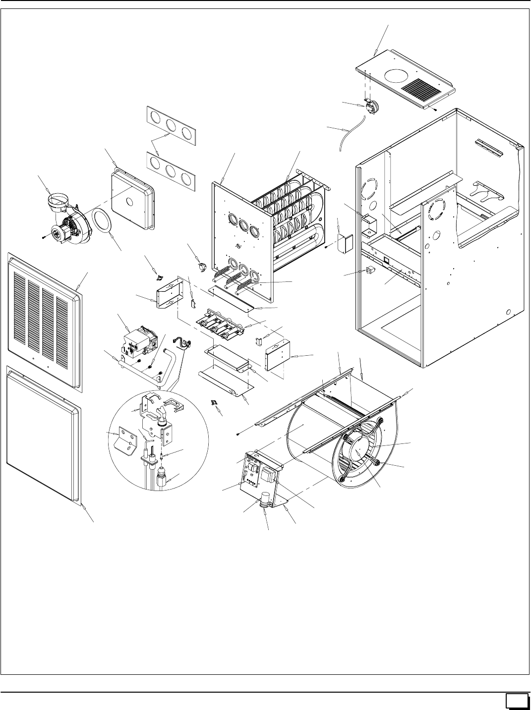
51
441 01 2611 06
Parts for *8MPN/L
13
12
11
S
14
15 W
10 U
V
16
L
R
16 17
8
7
N
6
5
4
3
K
J
H
9
B
C
A
2
1
BB AA
18
X
CC
M
D
T
S
P
Z
F
E
G
F
UDD
25--23--49a
A
52 441 01 2611 06
Replacement Parts - *8MPN (Natural Gas)
Models -- *8MPN050B12A1, *8MPN075B12A1, *8MPN075F16A1, *8MPN100F14A1, *8MPN100F20A1, *8MPN100J20A1,
*8MPN125J20A1, *8MPN150J20A1
Replacement part supplied will be current active part. For parts not listed, consult place of purchase.
K
e
y
D
e
s
c
r
i
p
t
i
o
n
P
a
r
t
*8MPN
K
ey
No.
D
escr
i
pt
i
on
Functional
P
art
Number 050B
12A1 075B
12A1 075F
16A1 100F
14A1 100F
20A1 100J
20A1 125J
20A1 150J
20A1
1Heat Exchanger 1013551
1013519
1013550
1013552
1013553
1013554
1013555
1
--
--
--
--
--
--
--
1
--
--
--
--
--
--
--
1
--
--
--
--
--
--
--
1
--
--
--
--
--
--
1
--
--
--
--
--
--
--
1
--
--
--
--
--
--
--
1
--
--
--
--
--
--
--
1
2Switch, Pressure 1013529 11111111
3Wheel, Blower 1013011
1011420
1011433
1
--
--
1
--
--
--
1
--
--
1
--
--
1
--
--
1
--
--
1
--
--
--
1
4Mount, Motor kit*1014824
1014823
1014822
1
--
--
1
--
--
--
--
1
--
--
1
--
1
--
--
1
--
--
1
--
--
--
1
5Motor, Blr 1/115 1/2CCW
1/115 1/2CCW
1/115 1/2CCW
1/115 3/4CCW
1172490
1172487
1172488
1172489
1
--
--
--
--
1
--
--
1
--
--
--
--
1
--
--
--
--
1
--
--
--
1
--
--
--
1
--
--
--
--
1
6Capacitor 1014397
1014396
1014395
1
--
--
1
--
--
1
--
--
--
1
--
--
--
1
--
--
1
--
--
1
--
--
1
7Transformer 1012722 11111111
8Control, Fan Timer 1014460 11111111
9Switch, Interlock 1012351 11111111
10 Burner Assembly 1008723
1008724
1008725
1008726
1009179
1
--
--
--
--
--
1
--
--
--
--
1
--
--
--
--
--
1
--
--
--
--
1
--
--
--
--
1
--
--
--
--
--
1
--
--
--
--
--
1
11 Pilot/Igniter 1008731 11111111
12 Ignitor/Sensor with Clip 1009524 11111111
13 Orifice, Pilot .018 503211 11111111
14 Orifice, Burner # 42 1011351 23344456
15 Valve, Gas 1013350 11111111
16 Switch, Limit (Rollout) 1013102 22222222
17 Switch, Limit (Main) 1320362
1065294
1008417
34335000
--
--
1
--
1
--
--
--
--
--
1
--
--
--
--
1
1
--
--
--
1
--
--
--
--
1
--
--
--
1
--
--
18 Blower, Combustion 1014433
1013517 1
-- 1
-- 1
-- 1
-- 1
-- 1
-- --
1--
1
*See Table below for bellyband location on motor
Bellyband Location
on Motor
Model *8MPN A(in.)
050B12A1 1.38²
075B12A1 1.38²
075F16A1 1.38²
100F14A1 1.38²
100F20A1 1.81²
100J20A1 1.81²
125J20A1 1.81²
150J20A1 1.65²

53
441 01 2611 06
Replacement Parts - *8MPN (Natural Gas)
Models -- *8MPN050B12A1, *8MPN075B12A1, *8MPN075F16A1, *8MPN100F14A1, *8MPN100F20A1, *8MPN100J20A1,
*8MPN125J20A1, *8MPN150J20A1
Replacement part supplied will be current active part. For parts not listed, consult place of purchase.
K
e
y
D
e
s
c
r
i
p
t
i
o
n
P
a
r
t
*8MPN
K
ey
No.
D
escr
i
pt
i
on
Functional
P
art
Number 050B
12A1 075B
12A1 075F
16A1 100F
14A1 100F
20A1 100J
20A1 *125J
20A1 150J
20A1
APanel, Top 1013982
1013983
1013984
1
--
--
1
--
--
--
1
--
--
1
--
--
1
--
--
--
1
--
--
1
--
--
1
BBox, Junction 1012349 11111111
CCover, Junction box 1012350 11111111
DPartition, Blower 1014009
1014010
1014011
1014013
1
--
--
--
1
--
--
--
--
1
--
--
--
1
--
--
--
1
--
--
--
--
1
--
--
--
1
--
--
--
--
1
EHousing, Blower 1012972
1012888
1012889
1
--
--
1
--
--
--
1
--
--
1
--
--
1
--
--
1
--
--
1
--
--
--
1
FHanger, Blower 1012328 22222222
GPanel, Blower Cutoff 721020013
721020008
721020015
1
--
--
1
--
--
--
1
--
--
1
--
--
1
--
--
1
--
--
1
--
--
--
1
HClamp, Capacitor 1170643
1014315 1
-- 1
-- 1
-- 1
-- --
1--
1--
1--
1
JBracket, Control Mounting 1013677 11111111
KTube, Pilot 1013596
1013597
1013598
1013599
1
--
--
--
--
1
--
--
--
1
--
--
--
--
1
--
--
--
1
--
--
--
1
--
--
--
1
--
--
--
--
1
LDoor, Blower (Heil/Arco)
(Heil/Arco)
(Heil/Arco)
(Comfortmaker Only)
(Comfortmaker Only)
(Comfortmaker Only)
(Tempstar Only)
(Tempstar Only)
(Tempstar Only)
1014001
1014375
1014376
1014079
1014349
1014352
1014058
1014068
1014073
1
--
--
1
--
--
1
--
--
1
--
--
1
--
--
1
--
--
--
1
--
--
1
--
--
1
--
--
1
--
--
1
--
--
1
--
--
1
--
--
1
--
--
1
--
--
--
1
--
--
1
--
--
1
--
--
1
--
--
1
--
--
1
--
--
1
--
--
1
--
--
1
MBracket, Door 1014271
1014272
1014273
1014274
1
--
--
--
1
--
--
--
--
1
--
--
--
1
--
--
--
1
--
--
--
--
1
--
--
--
1
--
--
--
--
1
NDoor, Louver (Heil/Arco)
(Heil/Arco)
(Heil/Arco)
(Comfortmaker Only)
(Comfortmaker Only)
(Comfortmaker Only)
(Tempstar Only)
(Tempstar Only)
(Tempstar Only)
1014088
1014091
1014094
1014078
1014081
1014085
1014057
1014067
1014072
1
--
--
1
--
--
1
--
--
1
--
--
1
--
--
1
--
--
--
1
--
--
1
--
--
1
--
--
1
--
--
1
--
--
1
--
--
1
--
--
1
--
--
1
--
--
--
1
--
--
1
--
--
1
--
--
1
--
--
1
--
--
1
--
--
1
--
--
1
--
--
1
PManifold, Gas 1013478
1013479
1013480
1013481
1013482
1
--
--
--
--
--
1
--
--
--
--
1
--
--
--
--
--
1
--
--
--
--
1
--
--
--
--
1
--
--
--
--
--
1
--
--
--
--
--
1
RBracket, Pilot 1010901 11111111
SBracket, Manifold Support 1012377 22222222
TTop, Burner Box 1013705
1013015
1013016
1013859
1
--
--
--
1
--
--
--
1
--
--
--
--
1
--
--
--
1
--
--
--
1
--
--
--
--
1
--
--
--
--
1
UBracket, Burner Box Sides 1012532 22222222
54 441 01 2611 06
Replacement Parts - *8MPN (Natural Gas)
Models -- *8MPN050B12A1, *8MPN075B12A1, *8MPN075F16A1, *8MPN100F14A1, *8MPN100F20A1, *8MPN100J20A1,
*8MPN125J20A1, *8MPN150J20A1
Replacement part supplied will be current active part. For parts not listed, consult place of purchase.
K
e
y
D
e
s
c
r
i
p
t
i
o
n
P
a
r
t
*8MPN
K
ey
No.
D
escr
i
pt
i
on
Functional
P
art
Number 050B
12A1 075B
12A1 075F
16A1 100F
14A1 100F
20A1 100J
20A1 *125J
20A1 150J
20A1
TTop, Burner Box 1013705
1013015
1013016
1013859
1
--
--
--
1
--
--
--
1
--
--
--
--
1
--
--
--
1
--
--
--
1
--
--
--
--
1
--
--
--
--
1
UBracket, Burner Box Sides 1012532 22222222
VBaffle, Burner Box 1012338
1012339
1012340
1013533
1
--
--
--
1
--
--
--
1
--
--
--
--
1
--
--
--
1
--
--
--
1
--
--
--
--
1
--
--
--
--
1
WBottom, Burner Box 1012334
1012335
1012336
1013691
1
--
--
--
1
--
--
--
1
--
--
--
--
1
--
--
--
1
--
--
--
1
--
--
--
--
1
--
--
--
--
1
XCollector Box 1014510
1014511
1014509
1014512
1013486
1
--
--
--
--
--
1
--
--
--
--
1
--
--
--
--
--
1
--
--
--
--
1
--
--
--
--
1
--
--
--
--
--
1
--
--
--
--
--
1
YRTV, Collector Box 11111111
ZGasket, Combustion Blower 1013540 11111111
AA Partition, Front Ht Exchanger 1013543
1013521
1013545
1013546
1013547
1013548
1013549
1
--
--
--
--
--
--
--
1
--
--
--
--
--
--
--
1
--
--
--
--
--
--
--
1
--
--
--
--
--
--
1
--
--
--
--
--
--
--
1
--
--
--
--
--
--
--
1
--
--
--
--
--
--
--
1
BB Gaskets, Heat Exchanger 1013991
1013992
1013993
1013994
1012546
2
--
--
--
--
--
2
--
--
--
--
2
--
--
--
--
--
2
--
--
--
--
2
--
--
--
--
2
--
--
--
--
--
2
--
--
--
--
--
2
CC Tubing, Silicone 1014520
1014521 1
-- 1
-- 1
-- 1
-- 1
-- --
1--
1--
1
)( PART NOT ILLUSTRATED
)( Fuse, 5 Amp 1083348 11111111
)( Harness, Wire 1013693 11111111
)( Door Screw 1014488 44444444
)( Door Screw Grommet 1171990 44444444
)( Manual, Installation & Tech 44101261105 11111111
)( Manual, Users 44102201004 11111111
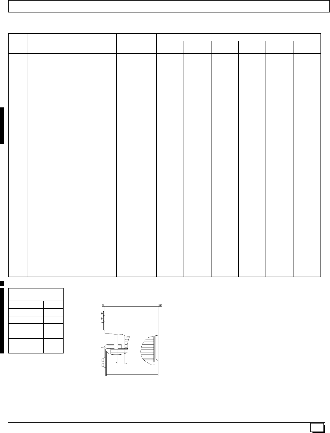
A
55
441 01 2611 06
Replacement Parts - *8MPL (Natural Gas)
Models -- *8MPL050B12A1, *8MPL075B12A1, *8MPL075F16A1, *8MPL100F20A1, *8MPL100J20A1, *8MPL125J20A1
Replacement part supplied will be current active part. For parts not listed, consult place of purchase.
K
e
y
D
e
s
c
r
i
p
t
i
o
n
P
a
r
t
*8MPL
K
ey
No.
D
escr
i
pt
i
on
Functional
P
art
Number 050B
12A1 075B
12A1 075F
16A1 100F
20A1 100J
20A1 125J
20A1
1Heat Exchanger 1014316
1014317
1014318
1014319
1014320
1014321
1
--
--
--
--
--
--
1
--
--
--
--
--
--
1
--
--
--
--
--
--
1
--
--
--
--
--
--
1
--
--
--
--
--
--
1
2Switch, Pressure 1013529 1 1 1 1 1 1
3Wheel, Blower 1013011
1011420 1
-- 1
-- --
1--
1--
1--
1
4Mount, Motor kit*1014824
1014823
1014822
1
--
--
1
--
--
--
--
1
--
1
--
--
1
--
--
1
--
5Motor, Blower 1/115 1/2CCW
1/115 1/2CCW
1/115 1/2CCW
1172490
1172487
1172488
1
--
--
--
1
--
1
--
--
--
--
1
--
--
1
--
--
1
6Capacitor 1014397
1014395 1
-- 1
-- 1
-- --
1--
1--
1
7Transformer 1012722 1 1 1 1 1 1
8Control, Fan Timer 1014460 1 1 1 1 1 1
9Switch, Interlock 1012351 1 1 1 1 1 1
10 Burner Assembly 1008723
1008724
1008725
1008726
1
--
--
--
--
1
--
--
--
1
--
--
--
--
1
--
--
--
1
--
--
--
--
1
11 Pilot/Igniter 1008731 1 1 1 1 1 1
12 Ignitor/Sensor with Clip 1009524 1 1 1 1 1 1
13 Orifice, Pilot .018 503211 1 1 1 1 1 1
14 Orifice, Burner # 42 1011351 2 3 3 4 4 5
15 Valve, Gas 1013350 1 1 1 1 1 1
16 Switch, Limit (Rollout) 1013102 2 2 2 2 2 2
17 Switch, Limit (Main) 1008417
1320362
1065294
1
--
--
--
1
--
1
--
--
--
1
--
--
1
--
--
--
1
18 Blower, Combustion 1014433
1013517 1
-- 1
-- 1
-- 1
-- 1
-- --
1
*See Table below for bellyband location on motor
Bellyband Location
on Motor
Model *8MPL “A(in.)”
050B12A1 1.38²
075B12A1 1.38²
075F16A1 1.38²
100F20A1 1.81²
100J20A1 1.81²
125J20A1 1.81²
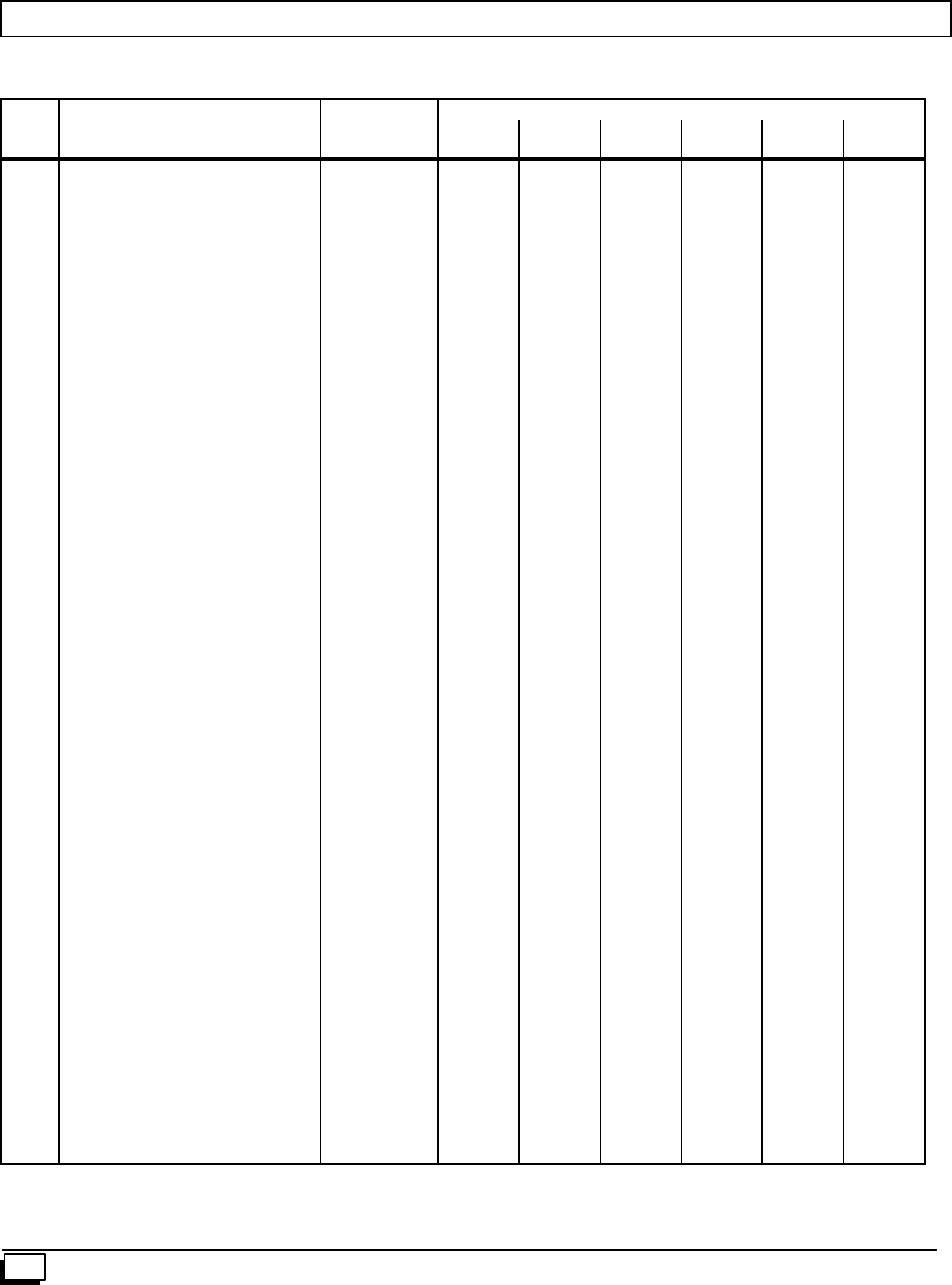
56 441 01 2611 06
Replacement Parts - *8MPL (Natural Gas)
Models -- *8MPL050B12A1, *8MPL075B12A1, *8MPL075F16A1, *8MPL100F20A1, *8MPL100J20A1, *8MPL125J20A1
Replacement part supplied will be current active part. For parts not listed, consult place of purchase.
K
e
y
D
e
s
c
r
i
p
t
i
o
n
P
a
r
t
*8MPL
K
ey
No.
D
escr
i
pt
i
on
Functional
P
art
Number 050B
12A1 *075B
12A1 075F
16A1 100F
20A1 100J
20A1 125J
20A1
APanel, Top 1013982
1013983
1013984
1
--
--
1
--
--
--
1
--
--
1
--
--
--
1
--
--
1
BBox, Junction 1012349 1 1 1 1 1 1
CCover, Junction box 1012350 1 1 1 1 1 1
DPartition, Blower 1014009
1014010
1014011
1
--
--
1
--
--
--
1
--
--
1
--
--
--
1
--
--
1
EHousing, Blower 1012972
1012888 1
-- 1
-- --
1--
1--
1--
1
FHanger, Blower 1012328 2 2 2 2 2 2
GPanel, Blower Cutoff 721020013
721020008 1
-- 1
-- --
1--
1--
1--
1
HClamp, Capacitor 1170643
1014315 1
-- 1
-- 1
-- --
1--
1--
1
JBracket, Control Mounting 1013677 1 1 1 1 1 1
KTube, Pilot 1013596
1013597
1013598
1
--
--
--
1
--
--
1
--
--
--
1
--
--
1
--
--
1
LDoor, Blower (Heil/Arco)
(Heil/Arco)
(Heil/Arco)
(Comfortmaker Only)
(Comfortmaker Only)
(Comfortmaker Only)
(Tempstar Only)
(Tempstar Only)
(Tempstar Only)
1014001
1014375
1014376
1014079
1014349
1014352
1014058
1014068
1014073
1
--
--
1
--
--
1
--
--
1
--
--
1
--
--
1
--
--
--
1
--
--
1
--
--
1
--
--
1
--
--
1
--
--
1
--
--
--
1
--
--
1
--
--
1
--
--
1
--
--
1
--
--
1
MBracket, Door 1014271
1014272
1014273
1
--
--
1
--
--
--
1
--
--
1
--
--
--
1
--
--
1
NDoor, Louver (Heil/Arco)
(Heil/Arco)
(Heil/Arco)
(Comfortmaker Only)
(Comfortmaker Only)
(Comfortmaker Only)
(Tempstar Only)
(Tempstar Only)
(Tempstar Only)
1014088
1014091
1014094
1014078
1014081
1014085
1014057
1014067
1014072
1
--
--
1
--
--
1
--
--
1
--
--
1
--
--
1
--
--
--
1
--
--
1
--
--
1
--
--
1
--
--
1
--
--
1
--
--
--
1
--
--
1
--
--
1
--
--
1
--
--
1
--
--
1
PManifold, Gas 1013478
1013479
1013480
1013481
1
--
--
--
--
1
--
--
--
1
--
--
--
--
1
--
--
--
1
--
--
--
--
1
RBracket, Pilot 1010901 1 1 1 1 1 1
SBracket, Manifold Support 1012377 2 2 2 2 2 2
TTop, Burner Box 1013705
1013015
1013016
1
--
--
1
--
--
1
--
--
--
1
--
--
1
--
--
--
1
UBracket, Burner Box Sides 1012532 2 2 2 2 2 2
VBaffle, Burner Box 1012338
1012339
1012340
1
--
--
1
--
--
1
--
--
--
1
--
--
1
--
--
--
1
WBottom, Burner Box 1012334
1012335
1012336
1
--
--
1
--
--
1
--
--
--
1
--
--
1
--
--
--
1
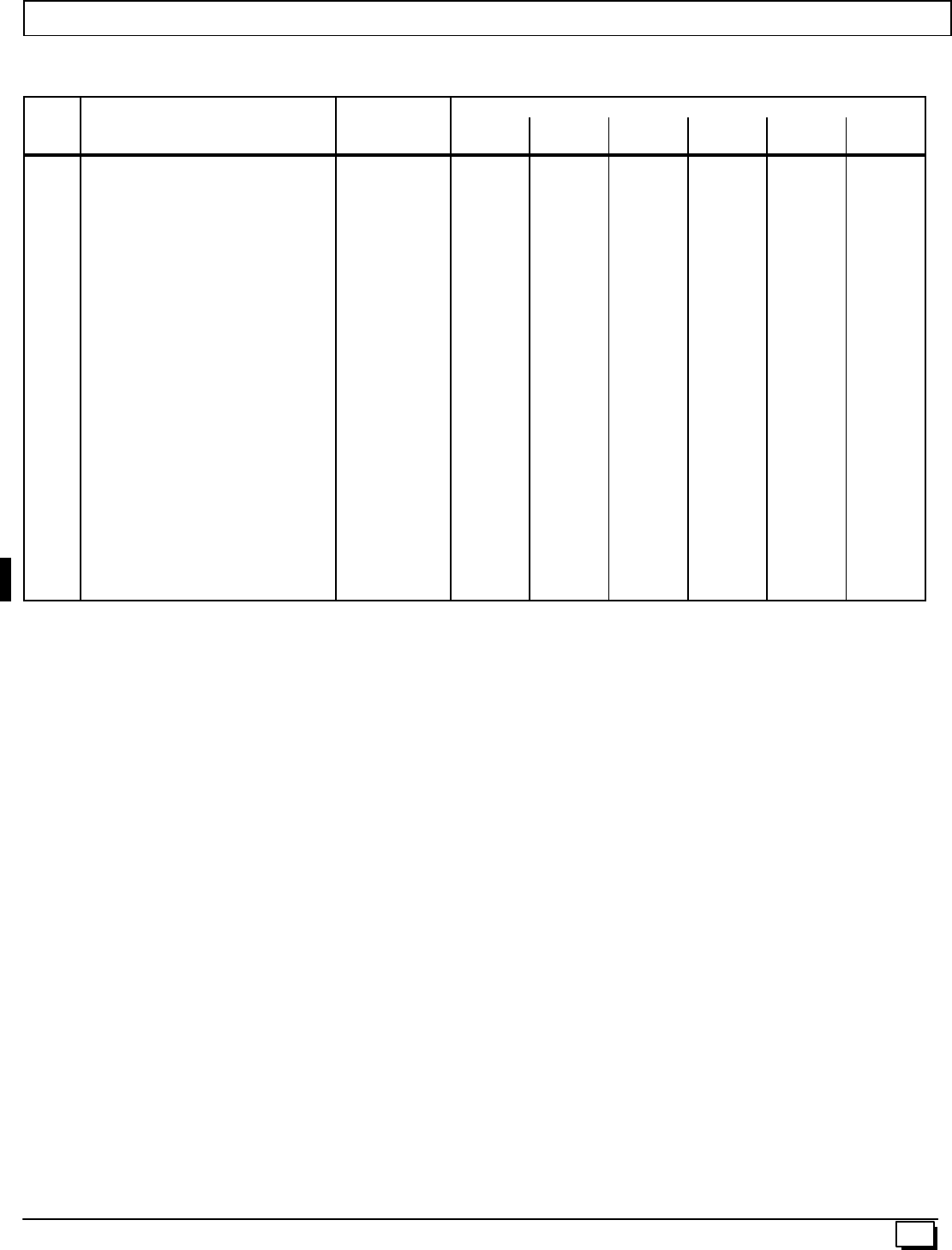
57
441 01 2611 06
Replacement Parts - *8MPL (Natural Gas)
Models -- *8MPL050B12A1, *8MPL075B12A1, *8MPL075F16A1, *8MPL100F20A1, *8MPL100J20A1, *8MPL125J20A1
Replacement part supplied will be current active part. For parts not listed, consult place of purchase.
K
e
y
D
e
s
c
r
i
p
t
i
o
n
P
a
r
t
*8MPL
K
ey
No.
D
escr
i
pt
i
on
Functional
P
art
Number 050B
12A1 *075B
12A1 075F
16A1 100F
20A1 100J
20A1 125J
20A1
XCollector Box 1014510
1014511
1014509
1014512
1
--
--
--
--
1
--
--
--
1
--
--
--
--
1
--
--
--
1
--
--
--
--
1
ZGasket, Combustion Blower 1013540 1 1 1 1 1 1
AA Partition, Front Ht Exchanger 1013543
1013521
1013545
1013546
1013547
1013548
1
--
--
--
--
--
--
1
--
--
--
--
--
--
1
--
--
--
--
--
--
1
--
--
--
--
--
--
1
--
--
--
--
--
--
1
BB Gaskets, Heat Exchanger 1013991
1013992
1013993
1013994
2
--
--
--
--
2
--
--
--
2
--
--
--
--
2
--
--
--
2
--
--
--
--
2
CC Tubing, Silicone 1014519 1 1 1 1 1 1
DD Baffle, Nox 1014019 2 3 3 4 4 5
)( PART NOT ILLUSTRATED
)( Fuse, 5 Amp 1083348 1 1 1 1 1 1
)( Harness, Wire 1013693 1 1 1 1 1 1
)( Door Screw 1014488 4 4 4 4 4 4
)( Door Screw Grommet 1171990 4 4 4 4 4 4
)( Manual, Installation & Tech 44101261105 1 1 1 1 1 1
)( Manual, Users 44102201004 1 1 1 1 1 1
