DirecDoor Installation Guide 460960001F
User Manual: 460960001F
Open the PDF directly: View PDF ![]() .
.
Page Count: 100
- Preface
- Chapter 1 Introduction
- Chapter 2 Installation Planning and Mounting
- Chapter 3 Power
- Chapter 4 DirecDoor Board
- Chapter 5 Reader Interface
- Chapter 6 DO Interface
- Chapter 7 Testing
- Chapter 8 Controller Firmware Tools
- Integrated Configuration Tool
- Requirements
- Connecting and starting the tool
- Controller setup overview
- Controller Configuration menu -> Host/Connection type
- Controller Information menu -> Controller Information
- Controller Parameters menu
- Administration menu
- Flash controller menu/Flash controller
- Logging menu
- Configuration checklist for Integrated Configuration Tool
- Setting up the DirecDoor controller in the host application
- Integrated Configuration Tool
- Chapter 9 Regulatory Information
- Chapter 10 Troubleshooting, Maintenance, and Support
- Index

DirecDoor
Installation Manual
P/N 460960001F • 17JULY12

Copyright Copyright © 2012, UTC Fire & Security. All rights reserved.
This document may not be copied or otherwise reproduced, in whole or in part, except as
specifically permitted under US and international copyright law, without the prior written
consent from UTC Fire & Security, 9 Farm Springs Road, Farmington, CT 06034-4065.
Disclaimer The information in this document is subject to change without notice. UTC Fire & Security
assumes no responsibility for inaccuracies or omissions and specifically disclaims any
liabilities, losses, or risks, personal or otherwise, incurred as a consequence, directly or
indirectly, of the use or application of any of the contents of this document. For the latest
documentation, contact your local supplier or visit us online at www.utcfireandsecurity.com.
This publication may contain examples of screen captures and reports used in daily
operations. Examples may include fictitious names of individuals and companies. Any
similarity to names and addresses of actual businesses or persons is entirely coincidental.
Trademarks and patents Trade names used in this document may be trademarks or registered trademarks of the
manufacturers or vendors of the respective products.
Intended use Use this product only for the purpose it was designed for; refer to the data sheet and user
documentation. For the latest product information, contact your local supplier or visit us online
at www.utcfireandsecuritycom.
FCC compliance This equipment has been tested and found to comply with the limits for a Class A digital
device, pursuant to part 15 of the FCC Rules. These limits are designed to provide reasonable
protection against harmful interference when the equipment is operated in a commercial
environment. This equipment generates, uses, and can radiate radio frequency energy and, if
not installed and used in accordance with the instruction manual, may cause harmful
interference to radio communications.
You are cautioned that any changes or modifications not expressly approved by the party
responsible for compliance could void the user’s authority to operate the equipment.
2002/96/EC (WEEE directive): Products marked with this symbol cannot be disposed of as
unsorted municipal waste in the European Union. For proper recycling, return this product to
your local supplier upon the purchase of equivalent new equipment, or dispose of it at
designated collection points. For more information see: www.recyclethis.info.
2004/108/EC (EMC directive): Non-European manufacturers must designate an authorized
representative in the Community. Our authorized manufacturing representative is:
UTC Fire & Security B.V., Kelvinstraat 7,6003 DH Weert, The Netherlands.
Regulatory

iii
Contents
Preface . . . . . . . . . . . . . . . . . . . . . . . . . . . . . . . . . . . . . . . . . . . . . . . . . . . . . . . . . . . . . . . . . . . . . . . . . . vii
Conventions used in this document. . . . . . . . . . . . . . . . . . . . . . . . . . . . . . . . . . . . . . . . . . . . . . . . . vii
Safety terms and symbols . . . . . . . . . . . . . . . . . . . . . . . . . . . . . . . . . . . . . . . . . . . . . . . . . . . . . . . . vii
Chapter 1. Introduction . . . . . . . . . . . . . . . . . . . . . . . . . . . . . . . . . . . . . . . . . . . . . . . . . . 1
Product overview . . . . . . . . . . . . . . . . . . . . . . . . . . . . . . . . . . . . . . . . . . . . . . . . . . . . . . . . . . . . . . . . . . 2
Specifications . . . . . . . . . . . . . . . . . . . . . . . . . . . . . . . . . . . . . . . . . . . . . . . . . . . . . . . . . . . . . . . . . . . . . 3
Chapter 2. Installation Planning and Mounting . . . . . . . . . . . . . . . . . . . . . . . . . . . . . . . 7
Getting started roadmap . . . . . . . . . . . . . . . . . . . . . . . . . . . . . . . . . . . . . . . . . . . . . . . . . . . . . . . . . . . . 8
Safety . . . . . . . . . . . . . . . . . . . . . . . . . . . . . . . . . . . . . . . . . . . . . . . . . . . . . . . . . . . . . . . . . . . . . . . . . . . . 9
Radio interference . . . . . . . . . . . . . . . . . . . . . . . . . . . . . . . . . . . . . . . . . . . . . . . . . . . . . . . . . . . . . . . 9
Electrostatic Discharge (ESD) precaution . . . . . . . . . . . . . . . . . . . . . . . . . . . . . . . . . . . . . . . . . . . . . 9
General installation rules . . . . . . . . . . . . . . . . . . . . . . . . . . . . . . . . . . . . . . . . . . . . . . . . . . . . . . . . . . . . 9
Observing noise prevention procedures . . . . . . . . . . . . . . . . . . . . . . . . . . . . . . . . . . . . . . . . . . . . . . 10
Signal transmission . . . . . . . . . . . . . . . . . . . . . . . . . . . . . . . . . . . . . . . . . . . . . . . . . . . . . . . . . . . . . 10
Cable length. . . . . . . . . . . . . . . . . . . . . . . . . . . . . . . . . . . . . . . . . . . . . . . . . . . . . . . . . . . . . . . . . . . 10
Cable routing . . . . . . . . . . . . . . . . . . . . . . . . . . . . . . . . . . . . . . . . . . . . . . . . . . . . . . . . . . . . . . . . . . 10
Mounting . . . . . . . . . . . . . . . . . . . . . . . . . . . . . . . . . . . . . . . . . . . . . . . . . . . . . . . . . . . . . . . . . . . . . . . . 11
Mounting and handling guidelines . . . . . . . . . . . . . . . . . . . . . . . . . . . . . . . . . . . . . . . . . . . . . . . . . . 11
Mounting instructions. . . . . . . . . . . . . . . . . . . . . . . . . . . . . . . . . . . . . . . . . . . . . . . . . . . . . . . . . . . . 11
Determining power requirements . . . . . . . . . . . . . . . . . . . . . . . . . . . . . . . . . . . . . . . . . . . . . . . . . . . . 14
Chapter 3. Power . . . . . . . . . . . . . . . . . . . . . . . . . . . . . . . . . . . . . . . . . . . . . . . . . . . . . . 15
Introduction . . . . . . . . . . . . . . . . . . . . . . . . . . . . . . . . . . . . . . . . . . . . . . . . . . . . . . . . . . . . . . . . . . . . . . 16
Device addressing . . . . . . . . . . . . . . . . . . . . . . . . . . . . . . . . . . . . . . . . . . . . . . . . . . . . . . . . . . . . . . . . 16
Picture Perfect . . . . . . . . . . . . . . . . . . . . . . . . . . . . . . . . . . . . . . . . . . . . . . . . . . . . . . . . . . . . . . . . . 16
Facility Commander Wnx. . . . . . . . . . . . . . . . . . . . . . . . . . . . . . . . . . . . . . . . . . . . . . . . . . . . . . . . . 16
Connector and LEDs . . . . . . . . . . . . . . . . . . . . . . . . . . . . . . . . . . . . . . . . . . . . . . . . . . . . . . . . . . . . . . 17
Connector pinouts . . . . . . . . . . . . . . . . . . . . . . . . . . . . . . . . . . . . . . . . . . . . . . . . . . . . . . . . . . . . . . 17
Power LED indicator . . . . . . . . . . . . . . . . . . . . . . . . . . . . . . . . . . . . . . . . . . . . . . . . . . . . . . . . . . . . 17
Power setup. . . . . . . . . . . . . . . . . . . . . . . . . . . . . . . . . . . . . . . . . . . . . . . . . . . . . . . . . . . . . . . . . . . . . . 17
Installing the PoE (Power over Ethernet). . . . . . . . . . . . . . . . . . . . . . . . . . . . . . . . . . . . . . . . . . . . . 17
Installing the auxiliary power supply . . . . . . . . . . . . . . . . . . . . . . . . . . . . . . . . . . . . . . . . . . . . . . . . 19
Installing the battery backup, AC fail and low battery . . . . . . . . . . . . . . . . . . . . . . . . . . . . . . . . . . . 20
Wiring tamper switch . . . . . . . . . . . . . . . . . . . . . . . . . . . . . . . . . . . . . . . . . . . . . . . . . . . . . . . . . . . . 20
Chapter 4. DirecDoor Board . . . . . . . . . . . . . . . . . . . . . . . . . . . . . . . . . . . . . . . . . . . . . 21
Introduction . . . . . . . . . . . . . . . . . . . . . . . . . . . . . . . . . . . . . . . . . . . . . . . . . . . . . . . . . . . . . . . . . . . . . . 22
Board layout . . . . . . . . . . . . . . . . . . . . . . . . . . . . . . . . . . . . . . . . . . . . . . . . . . . . . . . . . . . . . . . . . . . . . 23
Switches and jumpers . . . . . . . . . . . . . . . . . . . . . . . . . . . . . . . . . . . . . . . . . . . . . . . . . . . . . . . . . . . . . 24
Switches . . . . . . . . . . . . . . . . . . . . . . . . . . . . . . . . . . . . . . . . . . . . . . . . . . . . . . . . . . . . . . . . . . . . . 24

DirecDoor
Installation Manual
iv
Jumpers . . . . . . . . . . . . . . . . . . . . . . . . . . . . . . . . . . . . . . . . . . . . . . . . . . . . . . . . . . . . . . . . . . . . . .25
LED indicators . . . . . . . . . . . . . . . . . . . . . . . . . . . . . . . . . . . . . . . . . . . . . . . . . . . . . . . . . . . . . . . . . . . .28
LED indicators on the DirecDoor board . . . . . . . . . . . . . . . . . . . . . . . . . . . . . . . . . . . . . . . . . . . . . .28
Input LED indicators on the DirecDoor board. . . . . . . . . . . . . . . . . . . . . . . . . . . . . . . . . . . . . . . . . .32
Modem LED indicators on the DirecDoor board. . . . . . . . . . . . . . . . . . . . . . . . . . . . . . . . . . . . . . . .32
UCSIMMPlus board LED indicators on the DirecDoor board . . . . . . . . . . . . . . . . . . . . . . . . . . . . . .33
Important information for firewall users . . . . . . . . . . . . . . . . . . . . . . . . . . . . . . . . . . . . . . . . . . . . . . .33
Configuring upstream communications with the host. . . . . . . . . . . . . . . . . . . . . . . . . . . . . . . . . . . .34
By network . . . . . . . . . . . . . . . . . . . . . . . . . . . . . . . . . . . . . . . . . . . . . . . . . . . . . . . . . . . . . . . . . . . .34
By network with dial fallback. . . . . . . . . . . . . . . . . . . . . . . . . . . . . . . . . . . . . . . . . . . . . . . . . . . . . . .34
Chapter 5. Reader Interface . . . . . . . . . . . . . . . . . . . . . . . . . . . . . . . . . . . . . . . . . . . . . .35
Introduction . . . . . . . . . . . . . . . . . . . . . . . . . . . . . . . . . . . . . . . . . . . . . . . . . . . . . . . . . . . . . . . . . . . . . .36
Device addressing . . . . . . . . . . . . . . . . . . . . . . . . . . . . . . . . . . . . . . . . . . . . . . . . . . . . . . . . . . . . . . . . .36
Picture Perfect . . . . . . . . . . . . . . . . . . . . . . . . . . . . . . . . . . . . . . . . . . . . . . . . . . . . . . . . . . . . . . . . .36
Facility Commander Wnx . . . . . . . . . . . . . . . . . . . . . . . . . . . . . . . . . . . . . . . . . . . . . . . . . . . . . . . . .36
Setting the DIP switches . . . . . . . . . . . . . . . . . . . . . . . . . . . . . . . . . . . . . . . . . . . . . . . . . . . . . . . . . . . .37
Setting the jumpers . . . . . . . . . . . . . . . . . . . . . . . . . . . . . . . . . . . . . . . . . . . . . . . . . . . . . . . . . . . . . . . .38
Wiring the readers . . . . . . . . . . . . . . . . . . . . . . . . . . . . . . . . . . . . . . . . . . . . . . . . . . . . . . . . . . . . . . . . .39
Wiring the Digital Inputs (DIs). . . . . . . . . . . . . . . . . . . . . . . . . . . . . . . . . . . . . . . . . . . . . . . . . . . . . . . .43
Wiring the door strikes . . . . . . . . . . . . . . . . . . . . . . . . . . . . . . . . . . . . . . . . . . . . . . . . . . . . . . . . . . . . .44
Wiring the Fire Alarm Control Panel (FACP) . . . . . . . . . . . . . . . . . . . . . . . . . . . . . . . . . . . . . . . . . . . .46
Chapter 6. DO Interface . . . . . . . . . . . . . . . . . . . . . . . . . . . . . . . . . . . . . . . . . . . . . . . . .47
Introduction . . . . . . . . . . . . . . . . . . . . . . . . . . . . . . . . . . . . . . . . . . . . . . . . . . . . . . . . . . . . . . . . . . . . . .48
Device addressing . . . . . . . . . . . . . . . . . . . . . . . . . . . . . . . . . . . . . . . . . . . . . . . . . . . . . . . . . . . . . . . . .48
Picture Perfect . . . . . . . . . . . . . . . . . . . . . . . . . . . . . . . . . . . . . . . . . . . . . . . . . . . . . . . . . . . . . . . . .48
FCWnx . . . . . . . . . . . . . . . . . . . . . . . . . . . . . . . . . . . . . . . . . . . . . . . . . . . . . . . . . . . . . . . . . . . . . . .48
Wiring Digital Outputs (DOs) . . . . . . . . . . . . . . . . . . . . . . . . . . . . . . . . . . . . . . . . . . . . . . . . . . . . . . . .49
Chapter 7. Testing. . . . . . . . . . . . . . . . . . . . . . . . . . . . . . . . . . . . . . . . . . . . . . . . . . . . . .51
Testing . . . . . . . . . . . . . . . . . . . . . . . . . . . . . . . . . . . . . . . . . . . . . . . . . . . . . . . . . . . . . . . . . . . . . . . . . .52
Chapter 8. Controller Firmware Tools. . . . . . . . . . . . . . . . . . . . . . . . . . . . . . . . . . . . . .53
Integrated Configuration Tool . . . . . . . . . . . . . . . . . . . . . . . . . . . . . . . . . . . . . . . . . . . . . . . . . . . . . . .54
Requirements . . . . . . . . . . . . . . . . . . . . . . . . . . . . . . . . . . . . . . . . . . . . . . . . . . . . . . . . . . . . . . . . . .54
Connecting and starting the tool. . . . . . . . . . . . . . . . . . . . . . . . . . . . . . . . . . . . . . . . . . . . . . . . . . . .56
Controller setup overview . . . . . . . . . . . . . . . . . . . . . . . . . . . . . . . . . . . . . . . . . . . . . . . . . . . . . . . . .59
Controller Configuration menu -> Host/Connection type . . . . . . . . . . . . . . . . . . . . . . . . . . . . . . . . .60
Controller Information menu -> Controller Information . . . . . . . . . . . . . . . . . . . . . . . . . . . . . . . . . . .61
Controller Parameters menu . . . . . . . . . . . . . . . . . . . . . . . . . . . . . . . . . . . . . . . . . . . . . . . . . . . . . .63
Administration menu. . . . . . . . . . . . . . . . . . . . . . . . . . . . . . . . . . . . . . . . . . . . . . . . . . . . . . . . . . . . .73
Flash controller menu/Flash controller . . . . . . . . . . . . . . . . . . . . . . . . . . . . . . . . . . . . . . . . . . . . . . .74
Logging menu. . . . . . . . . . . . . . . . . . . . . . . . . . . . . . . . . . . . . . . . . . . . . . . . . . . . . . . . . . . . . . . . . .75
Configuration checklist for Integrated Configuration Tool. . . . . . . . . . . . . . . . . . . . . . . . . . . . . . . . .76
Setting up the DirecDoor controller in the host application . . . . . . . . . . . . . . . . . . . . . . . . . . . . . . .78
Facility Commander Wnx . . . . . . . . . . . . . . . . . . . . . . . . . . . . . . . . . . . . . . . . . . . . . . . . . . . . . . . . .78

v
Chapter 9. Regulatory Information . . . . . . . . . . . . . . . . . . . . . . . . . . . . . . . . . . . . . . . . 79
CE (European) and FCC compliance. . . . . . . . . . . . . . . . . . . . . . . . . . . . . . . . . . . . . . . . . . . . . . . . . . 80
CE regulatory notice. . . . . . . . . . . . . . . . . . . . . . . . . . . . . . . . . . . . . . . . . . . . . . . . . . . . . . . . . . . . . . . 82
UL compliance . . . . . . . . . . . . . . . . . . . . . . . . . . . . . . . . . . . . . . . . . . . . . . . . . . . . . . . . . . . . . . . . . . . 83
Chapter 10. Troubleshooting, Maintenance, and Support . . . . . . . . . . . . . . . . . . . . . . 85
Troubleshooting . . . . . . . . . . . . . . . . . . . . . . . . . . . . . . . . . . . . . . . . . . . . . . . . . . . . . . . . . . . . . . . . . . 86
Power problems. . . . . . . . . . . . . . . . . . . . . . . . . . . . . . . . . . . . . . . . . . . . . . . . . . . . . . . . . . . . . . . . 86
Reader problems . . . . . . . . . . . . . . . . . . . . . . . . . . . . . . . . . . . . . . . . . . . . . . . . . . . . . . . . . . . . . . . 86
Door strike problems . . . . . . . . . . . . . . . . . . . . . . . . . . . . . . . . . . . . . . . . . . . . . . . . . . . . . . . . . . . . 87
DirecDoor problems. . . . . . . . . . . . . . . . . . . . . . . . . . . . . . . . . . . . . . . . . . . . . . . . . . . . . . . . . . . . . 87
Diagnostic LED display . . . . . . . . . . . . . . . . . . . . . . . . . . . . . . . . . . . . . . . . . . . . . . . . . . . . . . . . . . 89
Maintenance . . . . . . . . . . . . . . . . . . . . . . . . . . . . . . . . . . . . . . . . . . . . . . . . . . . . . . . . . . . . . . . . . . . . . 90
Inserting and removing the UCSIMMPlus board on the DirecDoor board . . . . . . . . . . . . . . . . . . . . 90
Contacting technical support . . . . . . . . . . . . . . . . . . . . . . . . . . . . . . . . . . . . . . . . . . . . . . . . . . . . . . . 90
Index. . . . . . . . . . . . . . . . . . . . . . . . . . . . . . . . . . . . . . . . . . . . . . . . . . . . . . . . . . . . . . . . . . 91

DirecDoor
Installation Manual
vi
vii
Preface
This is the DirecDoor Installation Manual. This document includes an overview of the product and
detailed instructions explaining how to:
• Mount the cabinet;
• Install and wire the controller; and
• Configure the controller.
There is also information describing how to contact technical support if you have questions or
concerns.
Read these instructions and all supporting documentation entirely before installing or operating this
product.
A qualified service person, complying with all applicable codes, should perform all required
hardware installation.
Conventions used in this document
The following conventions are used in this document:
Safety terms and symbols
These terms may appear in this manual:
Bold Menu items and buttons.
Italic Emphasis of an instruction or point; special terms.
File names, path names, windows, panes, tabs, fields, variables, and other GUI elements.
Titles of books and various documents.
Blue italic (Electronic version) Hyperlinks to cross-references, related topics, and URL addresses.
Monospace Text that displays on the computer screen.
Programming or coding sequences.
CAUTION: Cautions identify conditions or practices that may result in damage to the equipment or other property.
WARNING: Warnings identify conditions or practices that could result in equipment damage or serious
personal injury.

DirecDoor
Installation Manual
viii

Chapter 1 Introduction
This chapter provides an overview of your DirecDoor controller along with
its technical specifications.
In this chapter:
Product overview . . . . . . . . . . . . . . . . . . . . . . . . . . . . . . . . . . . . . 2
Specifications . . . . . . . . . . . . . . . . . . . . . . . . . . . . . . . . . . . . . . . . 3

DirecDoor
Installation Manual
2
Product overview
The DirecDoor provides distributed processing for the interface of access control readers, keypads,
alarm inputs and outputs back to a host system computer. This distributed processing allows each
DirecDoor controller to operate independent of the host system computer with the majority of access
control and alarm monitoring decisions made locally at the controller. The DirecDoor provides instant
response for door control and alarm sensing in the field, while leaving the host system computer with
more processing power for quickly executing daily operations such as alarm response, database
updates and reporting.
The DirecDoor incorporates “FLASH” memory technology that provides the ability to receive its
operating system and application remotely from the host system over the already established
communications path. This allows future firmware upgrades centrally from the host system without
requiring costly service trips to each location for firmware replacement. Both the modular design and
the “FLASH” memory technology of the DirecDoor provide a simple migration path when considering
future host system upgrades.
The DirecDoor consists of the following:
• Enclosure with DirecDoor PCA mounted
• Hardware kit
- Ground terminal lug
- SEMS screws
- Protection diodes
- Metal Oxide Varistors (MOVs) surge absorbers
- Network cable ferrite
- 1K end-of-line resistors
• Mounting hole template
• Installation screwdriver
• DirecDoor Quick Installation
• DirecDoor Integrated Configuration Tool Quick Guide
• Documentation CD, which includes the following manuals in PDF format:
- DirecDoor Installation Manual (this document)
- DirecDoor Quick Installation Sheet
- DirecDoor Integrated Configuration Tool Quick Guide
The Documentation CD also includes the DirecDoor Wattage Calculator in Microsoft Excel
(XLS) format, that can be used to determine power requirements.
The items received in your shipment depend on the items ordered. Inspect the package and contents
for visible damage. If any components are damaged or missing, do not use the unit; contact the
supplier immediately. If you need to return the unit, you must ship it in the original box.

Chapter 1
Introduction
3
Specifications
For UL-compliant installations, refer to UL compliance on page 83.
Table 1. Enclosure specifications
Enclosure specifications
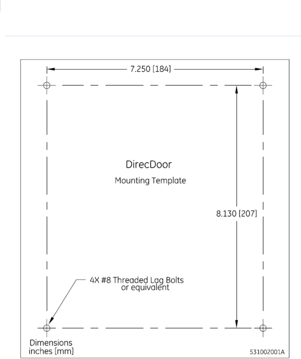
Physical dimensions 10.15 inches high x 9.15 inches wide x 3.04 inches deep
(258 mm high x 232 mm wide x 77 mm deep)
Operating environment +35°F to +122°F (+2°C to +50°C)
Humidity range 5% to 95% non-condensing
Thermal air cooling At least 6 inches (15.2 cm) of clearance is required on all four sides of the controller.
Power
Controller power input
requirements
• IEEE802.3af 16 watt Class 0 Mode A and B Power over Ethernet Power Sourcing
Equipment (PoE/PSE) on Standard Category 5 Ethernet Cable
Note: By Ethernet standards, the maximum cable length is limited to 328 ft. (100 m)
between the PoE source and the DirecDoor controller.
-Or-
• Auxiliary 24 VDC 1 A local supply (24 watts)
Cabling
Host to controller Network: Cat 5 Type A or B
Dial fallback: modems
Controller to readers Reader voltage: 12 VDC
If the cable distance is:
• Greater than 500 feet, but not greater/longer than 2000 ft, and/or current per reader
greater than 150 mA: use 20-AWG shielded cable, see Chapter 5, Reader Interface on
page 35.
• Less than 500 feet: use 22-AWG shielded cable.
We recommend using 20-AWG shielded cable for wiring reader, DOs, and DIs. Use plenum-
rated cable for applications where cable is to be run above the false (suspended) ceiling in the
air circulation space.
Recommended:
• Alpha Xtra Guard1® foil shield cable, non-plenum rated
• Belden series security and alarm cable (commercial applications shielded), plenum-rated
Controller to DIs or DOs Use any cable with the desired number of individually shielded pairs.
Devices
Readers Number supported: maximum of two (2) readers
Reader technology supported: Wiegand, F/2F and Supervised F/2F
Supports keypad only and keypad/reader technology
Output devices maximum ratings:
• Door DO (Reader LED) = 20.mA @ 12 VDC maximum
• Door strike (DO) relay = 2 A @ 28 VDC or 30 VAC maximum
DirecDoor
Installation Manual
4
Note: For output load capacity (watts) available for readers and strikes, refer to Determining power requirements on
page 14.
For readers not listed in the table below, refer to the applicable reader installation manual.
Strikes Maximum current: 390 mA per strike output.
See Table 3, Device current on page 4 for recommended strike models and associated power
requirements.
DOs Number supported: maximum 6 DOs
Output devices maximum ratings: 6 DO outputs: 20 mA @ 7.5 to 12 VDC
Regulatory information
Listings FCC Class A
UL 1076
UL 294
CE
See Chapter 9, Regulatory Information on page 79 for more information.
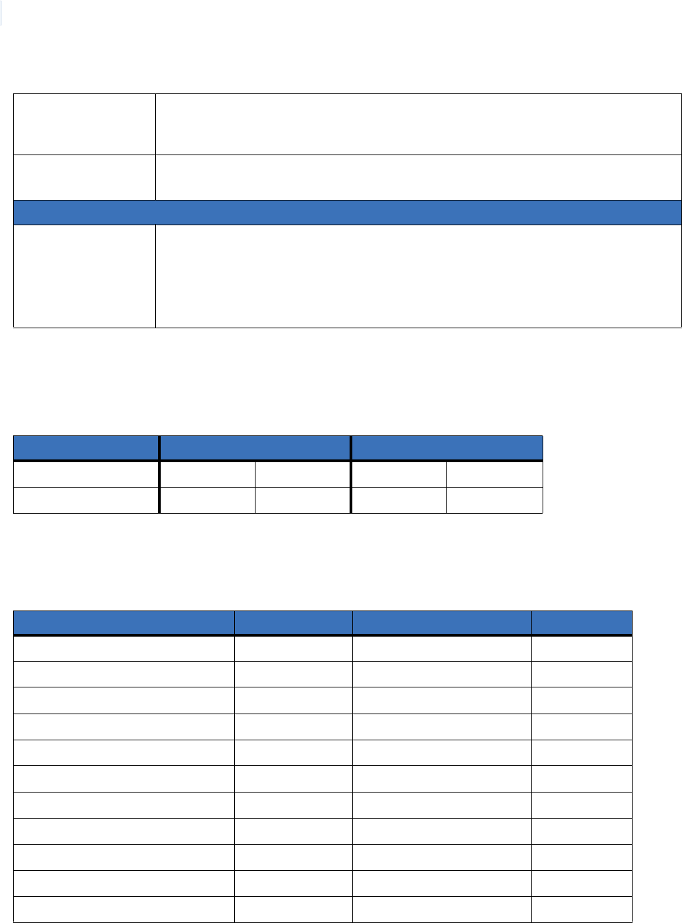
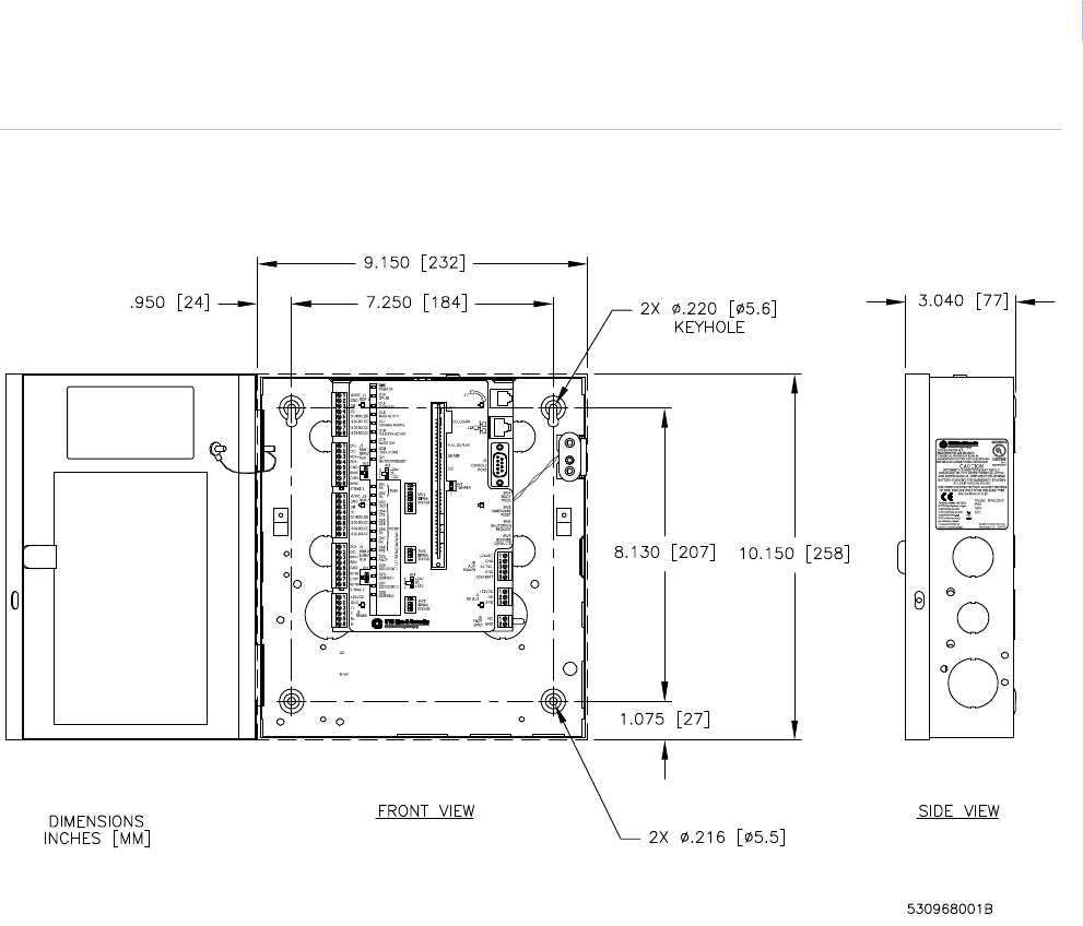
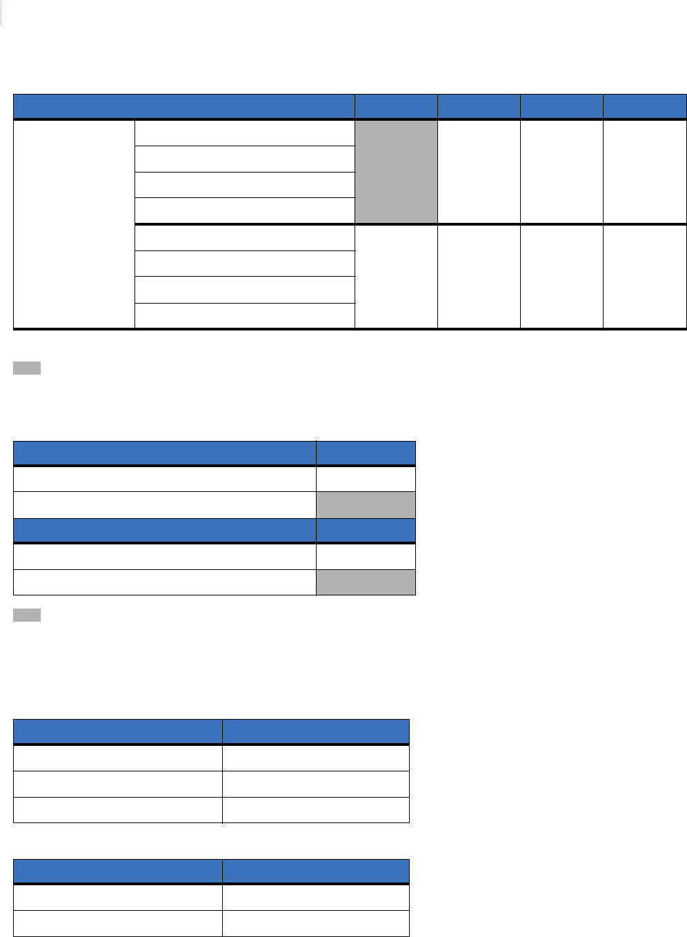
Table 2. Maximum peripheral loads
Reader/strike PoE Auxiliary Power Supply
Voltage DC 12 24 12 24
Total watts available 8 10 12 20
Table 3. Device current
Device Operating Voltage Avg. Measured Current (mA) Watts
Model T100 reader 12 55 0.66
Model T200 reader 12 55 0.66
Model T500 reader 12 95 1.14
Model T520 reader 12 105 1.26
Model T525 reader 12 140 1.68
Model T700 reader 12 75 0.90
Model T720 reader 12 75 0.90
Model T725 reader 12 110 1.32
Securitron M62 Magnalock strike* 12 240 2.88
Securitron M62 Magnalock strike* 24 140 3.36
HES, Inc 5000-12/24D strike 12 230 2.76
Table 1. Enclosure specifications (continued)
Chapter 1
Introduction
5
* When using magnetic strikes with auto-voltage select, additional power allowances must be considered due to auto-
voltage circuitry operation.
HES, Inc 5000-12/24D strike 24 115 2.76
Rutherford 4114x05x32D strike 12 190 2.28
Von Duprin 5100 3FP695 24 VDC 12 390 4.68
Von Duprin 5100 3FP695 24 VDC 24 195 4.68
RCR-REX 12 28 0.336
RCR-REX 24 17 0.408
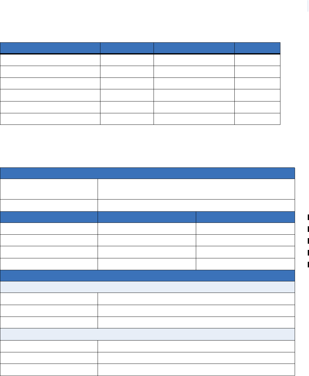
Table 4. CPU specifications
Communications interfaces
Network 10/100 MB Ethernet, on-board Ethernet RJ-45 connection, TCP/IP;
Supports Static IP, DNS, and DHCP.
Dial fallback Plug-in modem card (optional)
CPU specifications Type 2 SIMM1
1. The Type 2 SIMM supports only Mode B Power over Ethernet.
Type 3 SIMM2
2. The Type 3 SIMM supports Mode A and Mode B Power over Ethernet.
Operating system uClinux 2.6 uClinux 2.6
Processor Xilinx MicroBlaze Xilinx MicroBlaze
RAM 32 MB 64 MB
FLASH memory 32 MB 32 MB
Applications supported and capacities
Facility Commander 7.0 or later
Badge capacity 100,000
Offline badge history capacity 8,1923
3. This is a default allocation. The capacity can be re-allocated using the Integrated Configuration Tool.
Offline alarm history capacity 8,1923
Picture Perfect 4.0 or later
Badge capacity 145,000
Offline badge history capacity 5,0003
Offline alarm history capacity 2,0003
Table 3. Device current (continued)
Device Operating Voltage Avg. Measured Current (mA) Watts

DirecDoor
Installation Manual
6

Chapter 2 Installation Planning and
Mounting
This chapter provides instructions for planning your installation and
mounting your DirecDoor.
Note: We recommend that installers configure DirecDoor controllers BEFORE field
deployment. This means you should define your network addressing scheme prior
to installation, bench configure your DirecDoor controllers following the
networking scheme, and identify the DirecDoor controller externally, then proceed
with on site installation.
In this chapter:
Getting started roadmap . . . . . . . . . . . . . . . . . . . . . . . . . . . . . . . . 8
Safety . . . . . . . . . . . . . . . . . . . . . . . . . . . . . . . . . . . . . . . . . . . . . . 9
General installation rules . . . . . . . . . . . . . . . . . . . . . . . . . . . . . . . 9
Observing noise prevention procedures . . . . . . . . . . . . . . . . . . . 10
Mounting. . . . . . . . . . . . . . . . . . . . . . . . . . . . . . . . . . . . . . . . . . . .11
Determining power requirements . . . . . . . . . . . . . . . . . . . . . . . . 14

DirecDoor
Installation Manual
8
Getting started roadmap
The following is a basic outline for installing and setting up your DirecDoor system. Some steps may
have been done for you depending on what you ordered. Some steps are optional, depending on the
additional equipment you plan to use. These steps are noted.
1. Determine the cable clamps needed and obtain them prior to starting the installation.
During the installation, remember to:
- Label all connections/cables for ease of maintenance.
- Leave enough slack in the wiring so the cables can be “dressed.” This minimizes
interference during board removal or replacement.
2. Unpack your system. See Product overview on page 2.
3. Mount the enclosure. See Mounting on page 11.
4. If required, mount and install one of the following:
- PoE power supply. See Installing the PoE (Power over Ethernet) on page 17.
- Auxiliary power supply with battery backup. See Installing the auxiliary power supply on
page 19.
5. Verify that your network is up and running.
6. Install and wire up the DirecDoor board. Be sure to configure and verify the jumpers. Plug in
the network cable. Refer to Chapter 4, DirecDoor Board on page 21.
7. Wire the readers to the controller. Be sure to configure and verify the switch settings and
jumpers. Refer to Chapter 5, Reader Interface on page 35.
8. If using digital outputs, wire the digital outputs to the board. See Chapter 6, DO Interface on
page 47.
9. Test the wiring before you apply power. Refer to Chapter 7, Testing on page 51.
10. Configure your controller. Configure the controller using the Integrated Configuration Tool.
Refer to Chapter 8, Controller Firmware Tools on page 53.
CAUTION: Do not apply power to any component until the installation is complete. Damage to components may
occur if power is incorrectly applied.
Chapter 2
Installation Planning and Mounting
9
Safety
Radio interference
Electrostatic Discharge (ESD) precaution
General installation rules
The authorized installation contractor should comply with the following rules:
• Neatly label cables at both ends.
(For example, label should include: Controller Address Number/Device or Reader Number)
• Use individually shielded pairs of cables only. All wiring must comply with local, state, and
federal electrical codes and fire codes.
• Obey all national, state, and local electrical and safety codes.
• Obtain any required permits and/or inspections. Contact the local fire marshal for assistance
if necessary.
• Safety of customer personnel is the primary consideration of the installation.
• Neatly dress and tie or lace all wiring in a professional manner.
• Gather together and tape all unused conductors in multiple conductor cables.
• Shield all cabling and terminate properly.
WARNING: This is an FCC Class A product. In a domestic environment, this product may cause radio
interference, in which case, the user may be required to take adequate measures.
WARNUNG: Dies ist ein Klasse A Produkt. In Haushalten kann es zu Interferenzen kommen. Der Benutzer
ist in diesem Fall angehalten angemessene Maßnahmen auszuführen.
WARNING: Circuit board components are vulnerable to damage by electrostatic discharge (ESD). ESD can
cause immediate or subtle damage to sensitive electronic parts. An electrostatic charge can
build up on the human body and then discharge when you touch a board. A discharge can be
produced when walking across a carpet and touching a board, for example. Before handling
any board, make sure you dissipate your body’s charge by touching ground. This discharges
any static electricity build-up.
CAUTION: This equipment is to be installed, maintained and serviced by “authorized service persons only.”
ACHTUNG: Dieses Gerät darf ausschließlich von einem “autorisierten Kundendienst“ installiert, gewartet und
repariert werden.

DirecDoor
Installation Manual
10
Observing noise prevention procedures
Signal transmission
• Where practical, keep cables well separated from each other. Separate power cables from
signal cables.
• Keep the break-out at the ends of signal cables as short as possible.
• Ground all shield drain wire(s) at the DirecDoor controller using the grounding nuts provided
outside the cabinet enclosure.
Cable length
• Minimize long parallel cable runs since they increase the likelihood of interference between
signal cables and electrical interference sources.
• Avoid excess cable length between the DirecDoor and the optional equipment, such as
readers and digital outputs, to reduce signal degradation due to external effects.
Cable routing
Keep cabling at least one foot (30.5 cm) away from any power line or other AC voltage source.
Exercise caution when locating cables and DirecDoor components near any other equipment that
may cause electrical interference (noise). Examples of electrical and electro-magnetic noise sources
are:
• Fluorescent lighting and neon fixtures.
• Power distribution panels, including wiring, transformers, generators, and alternators.
• Motors that drive machinery such as air conditioners, elevators, escalators, large blowers,
and machine tools. Electromagnetic equipment such as degaussers, magnetic chucks, etc.
Control equipment (relays) for machinery and other switching devices that carry or switch
large currents.
• Radio and television receivers and transmitters. Signal generators and intercom systems.
Radar transmitting equipment.
• Arc welders, electrodischarge machinery and related equipment.
• RF induction heaters.
CAUTION: Do not ground both cable ends.
Chapter 2
Installation Planning and Mounting
11
Mounting
Be sure to read the mounting and handling guidelines below before beginning to mount the
controller.
Mounting and handling guidelines
Comply with the following guidelines:
• Locate the host computer and the DirecDoor controller in areas secure from any disruption to
data communications or tampering.
• All mounting areas must be clean and clear of corrosive gases and airborne metallic
particles. Avoid installing near photocopiers due to contamination from toner particles.
• The DirecDoor must be protected from hazardous (high) voltages.
• Mount the DirecDoor on a vertical surface with at least six inches (15.2 cm) clearance on all
four sides to support thermal air cooling.
• Locate the DirecDoor in a place that provides dedicated AC earth ground. The DirecDoor
must be earth grounded.
• Keep interior and exterior housing of all DirecDoor cabinets and other components free of
wire remnants.
• Avoid temperatures outside range specified for DirecDoor operating environment. Do not
leave boards or other components in direct sunlight.
• Do not subject printed circuit boards to electrostatic discharge.
Mounting instructions
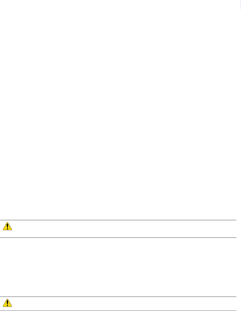
Mount the controller cabinet using the following steps, the Mounting Template (see Figure 1,
DirecDoor mounting template on page 12) and Figure 2, DirecDoor controller and components in
standard enclosure on page 13.
1. Remove enclosure from shipping container and remove any packing material.
2. Using the template provided (part number 531002001), mark and then drill the four mounting
holes.
3. Bolt the enclosure securely to the wall using four #8 thread lag bolts or equivalent.
4. The DirecDoor has standard cable knockouts on the sides, bottom and back of enclosure.
These knockouts are to be used to install cabling. Use proper size and type of cable strain
reliefs to secure cables to enclosure.
CAUTION: Do not apply power to any component during installation. Damage to components may occur if power
is incorrectly applied.
CAUTION: The DirecDoor must be earth grounded.
DirecDoor
Installation Manual
12
Figure 1. DirecDoor mounting template
Chapter 2
Installation Planning and Mounting
13
Figure 2. DirecDoor controller and components in standard enclosure
DirecDoor
Installation Manual
14
Determining power requirements
Use the worksheet below to help plan your installation. An electronic version of the DirecDoor
Wattage Calculator is available on the Documentation CD in Excel (XLS) format.
If this is a UL Listed installation, refer to Chapter 9, Regulatory Information on page 79.

Chapter 3 Power
This chapter provides information about setting the power on the
controller.
In this chapter:
Introduction. . . . . . . . . . . . . . . . . . . . . . . . . . . . . . . . . . . . . . . . . 16
Device addressing . . . . . . . . . . . . . . . . . . . . . . . . . . . . . . . . . . . 16
Connector and LEDs . . . . . . . . . . . . . . . . . . . . . . . . . . . . . . . . . 17
Power setup . . . . . . . . . . . . . . . . . . . . . . . . . . . . . . . . . . . . . . . . 17

DirecDoor
Installation Manual
16
Introduction
The DirecDoor provides two methods of connecting power:
1. Network Connector J10 as Power over Ethernet (PoE)
2. Auxiliary Power Connector J8 with 24 VDC supply and battery backup
Device addressing
Picture Perfect
Facility Commander Wnx
The following Facility Commander Wnx (also known as “FCWnx”) device addresses are created for
you by the Facility Commander Wnx software. This table is provided for your reference only. The
device address is in the format mmmm-b-pp where mmmm represents the controller number, b
represents the board number, and pp represents the point or device number.
* Only available on Facility Commander Wnx.
Table 5. Device addressing - Picture Perfect
Board 0
A/C Power Fail 0
Tam p e r 1
Table 6. Device addressing - Facility Commander Wnx
Board 0
Tam p e r mmmm-0-01
A/C Power Fail mmmm-0-02
Low Battery mmmm-0-03*
FACP mmmm-0-04*

Chapter 3
Power
17
Connector and LEDs
Connector pinouts
Power LED indicator
Power setup
Installing the PoE (Power over Ethernet)
Note: PoE is not verified for UL installations.
This section describes wiring and using a PoE.
1. Install the PoE in accordance with manufacturer’s instructions.
Note: The PoE source must meet IEEE802.3af 16 watt Class 0 Mode A and B Power over Ethernet Power
Sourcing Equipment (PoE/PSE) specifications.
2. Attach the supplied ferrite to the network cable as shown in Figure 28, Installing ferrite on
page 81.
3. Connect the network cable to J10 on the DirecDoor board.
Note: By Ethernet standards, the maximum cable length is limited to 328 ft. (100 m) between the PoE source
and the DirecDoor controller.
4. Connect the other end of the network cable to the PoE per the manufacturer’s instructions.
Table 7. J8 - Power input port
Connector J8
Pin Signal name
1 +24 VDC Auxiliary Power In
2Ground
3 AC power fail input
4 Chassis Ground (Factory Installed), Do Not Remove
5 Low battery input (Not used)
Table 8. Power LED
LED number State Description
D85 On Indicates +24 VDC is present.
DirecDoor
Installation Manual
18
Figure 3. Installing the PoE (Power over Ethernet)
Chapter 3
Power
19
Installing the auxiliary power supply
This section describes wiring and using an auxiliary power supply.
Note: 1. A readily accessible disconnect device shall be incorporated in the building installation wiring.
2. This equipment has been designed for connection to an IT power distribution system.
1. Ein leicht zugängliches Ausschaltgerät muss in die Installationsverkabelung des Gebäudes integriert werden.
2. Dieses Gerät wurde für den Anschluss an ein IT-Stromverteilungssystem entworfen.
The DirecDoor requires a 24 VDC nominal, 1 amp power supply with battery backup. (Refer to
Specifications on page 3.) All controllers, readers, and other devices should be referenced to the
same ground.
For UL-listed installations, the auxiliary power supply used must be an approved UL 294 power-
limited supply, such as the Altronix Corp. Model AL300ULM power supply.
1. Mount the power supply near the DirecDoor cabinet.
2. Run the wire through the knockout hole to J8 connector; pinouts are:
- Pin 1 = + 24 VDC
- Pin 2 = - Ground (24 VDC return)
- Pin 3 = AC fail
Note: If the polarity is reversed, the fuse blows to prevent damage. If the fuse blows, it automatically resets within
approximately 5 seconds.
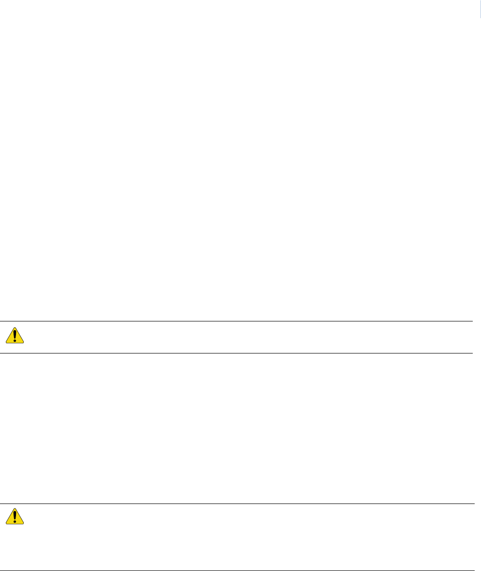
3. Install the cabinet ground, complying with the following guidelines:
- A convenient earth ground, such as an electrical box or a ground bus, must be provided
to the DirecDoor enclosure.
- The earth ground connection shall be made to the terminal lug provided. Mount terminal
lug to PEM nut on bottom of enclosure using #8-32 SEMS screw provided. (See Figure 4,
Wiring earth ground on page 20.) Use #14-18 AWG wire.
CAUTION: Do not ground both cable ends.
CAUTION: Controller earth grounding (AC grounding) is a critical element for proper operation. Test AC power
ground to ensure proper earth grounding. Using ohmmeter, measure resistance between DirecDoor
ground stud and known good earth ground (metal water pipe or building structural steel frame). If
resistance is greater than 50 ohms, it indicates poor AC ground. Good earth ground must be made
before completing installation.
DirecDoor
Installation Manual
20
Figure 4. Wiring earth ground
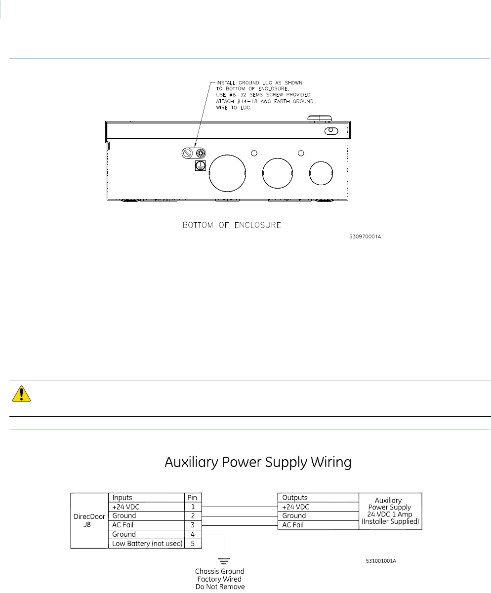
Installing the battery backup, AC fail and low battery
The battery backup acts as a temporary power supply to DirecDoor when AC power is lost. Figure 5
shows a typical wiring between a battery backup power supply and a DirecDoor controller. Refer to
the manual or insert that came with your battery backup unit for specific wiring information.
Note: The Low Battery option has not been evaluated by UL at this time.
Connect AC power fail input from a battery backup unit to connector J8 between pin 2 (Gnd) or pin 4
(Gnd) and pin 3 (AC fail). The battery backup unit must supply either normally closed dry contact or a
sense line that is low (Gnd), meaning no AC power failure.
Figure 5. Wiring auxiliary power supply with built-in relay for fault output (AC power fail)
Wiring tamper switch
The tamper switch is factory wired to W5 on the DirecDoor board. If a tamper switch is not used,
disconnect wiring from W5 and install mini-jumper across both terminals. The mini-jumper is installer
supplied.
CAUTION: Make sure AC input and battery backup power is disconnected before installing controller, reader, DIs,
and DOs.

Chapter 4 DirecDoor Board
This chapter provides information about and instructions for using the
DirecDoor board.
In this chapter:
Introduction. . . . . . . . . . . . . . . . . . . . . . . . . . . . . . . . . . . . . . . . . 22
Board layout . . . . . . . . . . . . . . . . . . . . . . . . . . . . . . . . . . . . . . . . 23
Switches and jumpers . . . . . . . . . . . . . . . . . . . . . . . . . . . . . . . . 24
LED indicators . . . . . . . . . . . . . . . . . . . . . . . . . . . . . . . . . . . . . . 28
Important information for firewall users. . . . . . . . . . . . . . . . . . . . 33
Configuring upstream communications with the host . . . . . . . . . 34

DirecDoor
Installation Manual
22
Introduction
The DirecDoor board provides network and dial fallback capabilities in one board.
The following are some product highlights:
• Supports Ethernet networks.
• Supports the following network protocols: DHCP, TCP/IP, UDP, and DNS.
• Supports an optional, integrated modem board for dial fallback.
• Provides nonvolatile storage referred to as persistent mode of operation. This means a faster
reset recovery and allows for host-less operation.
• Utilizes a 32-bit platform which provides better response times and higher capacity.
• Allows for remote diagnostics.
• Provides a browser-based configuration tool. Refer to Chapter 8, Controller Firmware Tools
on page 53.
• Works with:
- Picture Perfect 4.0 or later
- Facility Commander Wnx 7.0 or later
Refer to the appropriate user manual for configuration of this board within the software.
• Provides a tunable offline history buffer.
A layout of the DirecDoor board is shown on the following page.
Chapter 4
DirecDoor Board
23
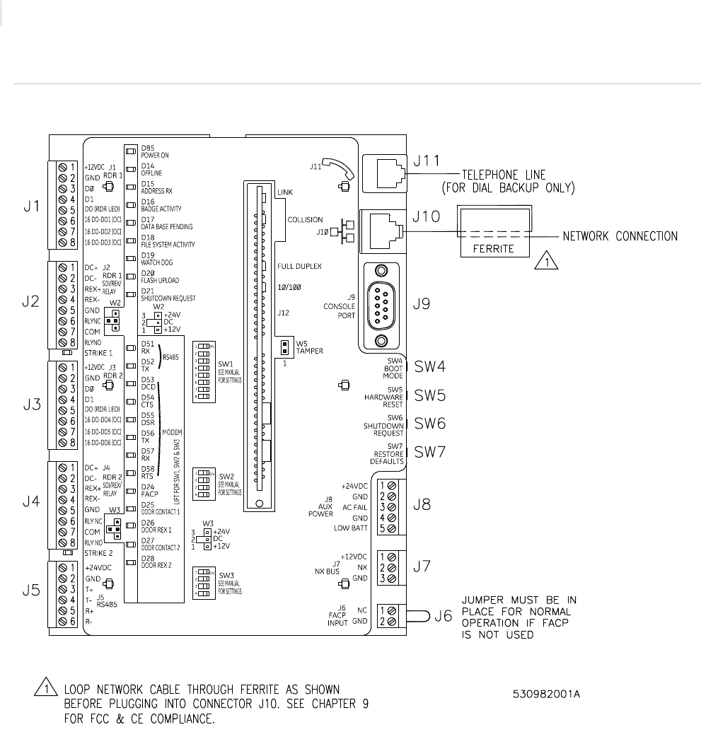
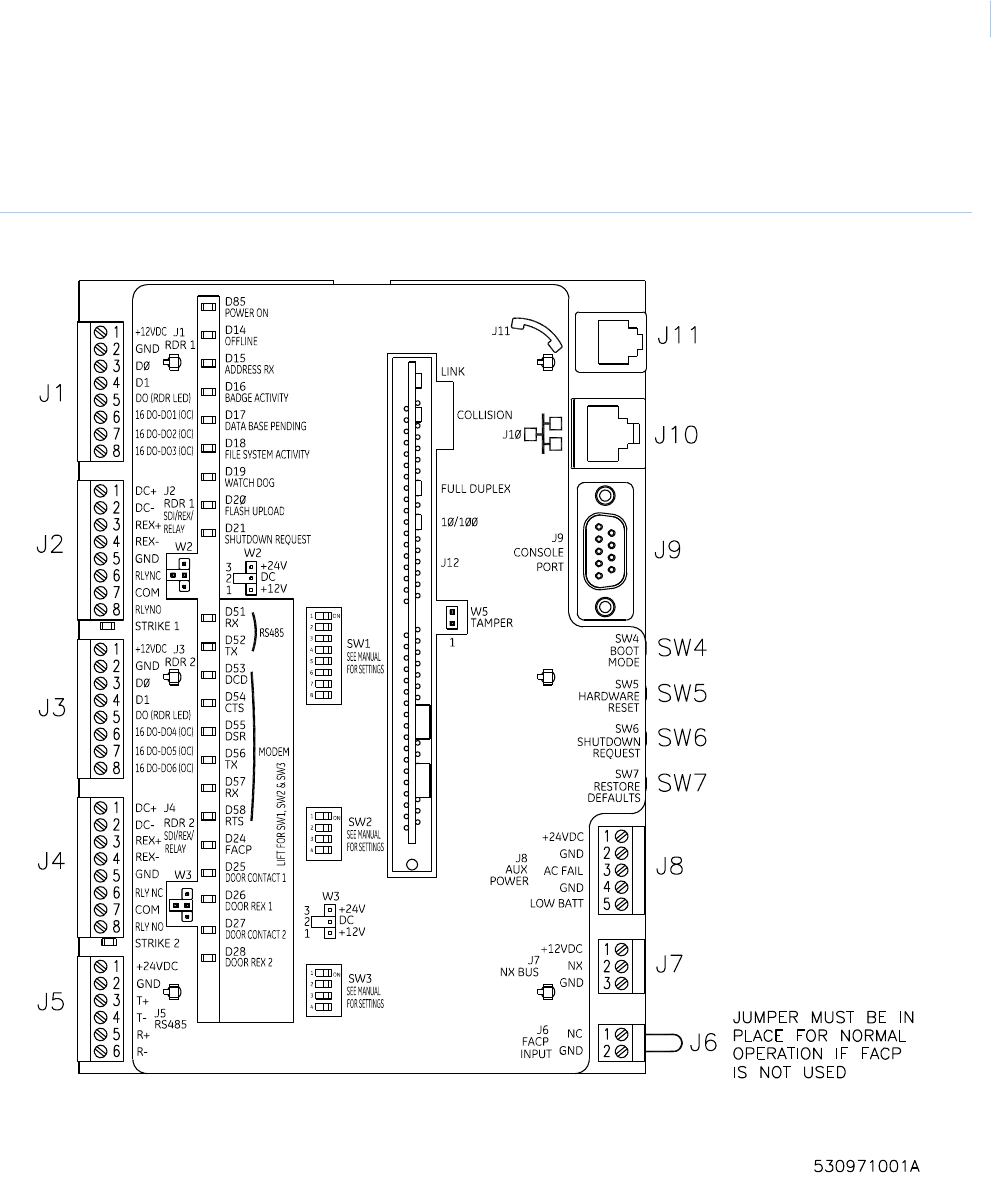
Board layout
Figure 6. DirecDoor board layout

DirecDoor
Installation Manual
24
Switches and jumpers
Switches
Table 9. Switches
Switch Purpose
SW1
Reader Technology and
Supervised DI/REX
Refer to Table 26 on page 37 and Table 27 on page 38.
SW2
4-position
Set all to OFF.
SW3
RS485 configuration
Refer to Table 10 on page 25.
Switches SW4 through SW7 are right-angle momentary contact push buttons.
SW4
Boot Mode
This function manually enables the Integrated Configuration Tool.
To enable the Integrated Configuration Tool:
• Press and hold SW4 until D19 (Watch dog LED) turns ON. Allow up to five seconds for
D19 to turn ON.
• Once D19 is ON, release SW4. D19 turns OFF once the Integrated Configuration Tool
has been manually enabled.
SW6
Shutdown Request
See Safe Shutdown Procedure for the DirecDoor Board on page 33.
SW7
Restore Defaults
Returns the configuration to the factory defaults:
•Primary Connection Type: Ethernet
•IP Address: 192.168.6.6
•Mask: 255.255.255.0
•Gateway: 192.168.6.1
Press SW7 for a minimum of five seconds, then release.
SW5
Hardware Reset
Reboots the DirecDoor board.
The switch should only be used when performing a controlled manual shutdown of the
application as indicated below or if instructed to do so by Technical Support.
To properly restart the board use both SW6 and SW5. First, press and release SW6 to
stop the application, then press and release SW5 to restart (reset) the board.

Chapter 4
DirecDoor Board
25
Jumpers
J1 through J4
Connectors J1 through J4 are pluggable screw terminal blocks. For connectors J1 through J4
pinouts, refer to: Table 30, J1/J3: Connecting T-5xx series reader on page 39 and Table 32, J2/J4:
Door and exit DI wiring on page 40.
J5
Not implemented: Connector J5 is a pluggable screw terminal block.
Not evaluated by UL at this time.
J6
Connector J6 is a pluggable screw terminal block.
For connector J6 pinouts, refer to: Table 34, J6 - FACP Input, Normally Closed on page 46.
Table 10. SW3
SW3-
120 ohms transmit pair termination 1 ON
No transmit pair termination (default) 1 OFF
120 ohms receive pair termination 2 ON
No receive pair termination (default) 2 OFF
RS485 - 4 wire (default) 3, 4 OFF
RS485 - 2 wire 3, 4 ON
Table 11. J5 - RS485 Expansion Port
Pin Signal Name
1 24 VDC Power Out
2Ground
3 485T+
4 485T-
5 485R+
6 485R-

DirecDoor
Installation Manual
26
J7
Not implemented: Connector J7 is a pluggable screw terminal block.
Not evaluated by UL at this time.
J8
Connector J8 is a pluggable screw terminal block.
Refer to Table 7, J8 - Power input port on page 17. Not evaluated by UL at this time.
J9
Connector J9 is a 9 pin female D-sub receptacle which controls the console port.
Not evaluated by UL at this time.
Table 12. J7 - NX Bus
Pin Signal Name
1 12 VDC Power Out
2 NX Bus Data
3 Ground
Table 13. J9 - Console Port
Pin Signal Name
1 No connection
2 Transmit
3 Receive
4 No connection
5 Ground
6 No connection
7 No connection
8 No connection
9 No connection

Chapter 4
DirecDoor Board
27
J10
Connector J10 is an RJ45 Standard Cat 5 jack which controls the RJ45 network connection.
J11
Connector J11 is an RJ11 standard telephone jack.
Note: Telephone connection must be dedicated to the DirecDoor controller.
W5
Table 14. J10 - Network Connection, RJ45
Pin Signal Name
1T+
2T-
3R+
4RC
5RC
6R-
7TC
8TC
Table 15. J11 - Telephone Line, RJ11
Pin Signal Name
1 No connection
2 No connection
3RING
4TIP
5 No connection
6 No connection
Table 16. W5 - Tamper
Function W5 Pins
Tamper Input 1 and 2

DirecDoor
Installation Manual
28
LED indicators
LED indicators on the DirecDoor board
The LED state depends on which state the controller is in. There are two main modes with several
substates:
•Maintenance mode: the state of the controller before any application is running. There are
two maintenance mode states:
-Boot mode (D16 On)- indicates the bootloader is running and loading, verifying and
invoking the run-time images. This is a status LED only.
-OS (operating system) maintenance mode (D15 and D16 alternate On and D20 On) -
the controller enters this mode after boot mode when it first comes up and when it is
never configured before. Holding SW6 (Shutdown request switch) will force the controller
into this mode.
•Normal operation mode: the state of the controller after the application is downloaded. Use
the Integrated Configuration Tool to select the application. During this mode, the following
additional states can occur:
-Controller offline (D14 On): the controller has lost communication with the host.
-Address received (D15 On): the controller receives a message from the host.
-Badge read OK (D16 On): the controller decoded a badge read and determined that it
was a valid badge.
-Waiting for database (D17 Flashes): the controller is waiting to receive database from
host.
-Restore defaults requested (D17 and D20 On): indicates SW7 (Restore defaults
switch) was pressed which requests that the defaults be restored. Refer to Restore
Factory Defaults on page 74.
-Shutdown requested (D17 and D21 On): indicates SW6 (Shutdown Request switch)
was pressed. This requests that the application shut down so that a hard reset can be
done.
-eFlash image save (D20 and D21 alternates On): indicates that the newly loaded
image from the eFlash transfer is being saved into the FLASH. This is an activity indicator
only.
-Persistence (D21 On): indicates that the controller is operating without a host. In this
mode, the controller is operating standalone until communication is re-established with
the host. Items to note:
• Upon restoration of communications with the host, the host automatically sets badge
status for Anti-passback to neutral for all badges on the controller.
• Unknown badges cannot be learned because the controller is not online with the host.
The Unknown badge transactions are mislabeled in the history upload as transaction
type Learn Timeout instead of Unknown Badge.

Chapter 4
DirecDoor Board
29
-Flash write (D19 Flashes): indicates that the controller is storing database records into
the Flash file system. This is an activity indicator only.
-Manual ICT Enable (D19 On): indicates SW4 (Boot mode switch) was pressed which
manually enables the Integrated Configuration Tool.
Table 18 on page 30 and Table 19 on page 31 show the LED state transitions. See Table 37,
DirecDoor board LED fault conditions on page 89 for error conditions.
See Figure 6, DirecDoor board layout on page 23for the location of the LEDs.
Table 17. Persistence mode times
Controller
Time (in minutes) for controller to go into persistence mode
Picture Perfect Facility Commander Wnx
Network/direct 3 1
Modem only 10 4
Network + modem 13 4

DirecDoor
Installation Manual
30
*. For Picture Perfect systems: D17 blinks once per second.
For Facility Commander Wnx systems: D17 blinks twice followed by a one-second delay before repeating.
= OFF
Table 18. DirecDoor board LED normal state transitions (D14 through D18)
D14 D15 D16 D17 D18
Red Red Red Red Red
Offline Address Rx Badge Activity DB Pending File System Activity
During power up
Boot maintenance mode ON
OS (Operating system)
maintenance mode
Alternates ON
with D16
Alternates ON
with D15
Normal operation mode
Controller offline ON
Address received ON
Badge read ON
Waiting for database Flashes*
Restore defaults requested ON
Shutdown requested ON
eFlash image save
Persistence
Flash write
Manual ICT Enable
Watch dog failure mode ON

Chapter 4
DirecDoor Board
31
= OFF
Table 19. DirecDoor board LED normal state transitions (D19 through D21, D51 and D52)
D19 D20 D21 D51 D52
Red Red Red Yellow Green
Watch Dog Flash Upload Shut down Request RS485 RX RS485 TX
During power up
Boot maintenance mode
OS (Operating system)
maintenance mode
ON
Normal operation mode Flashes Flashes
Controller offline
Address received
Badge read OK
Waiting for database
Restore defaults requested ON
Shutdown requested ON
eFlash image save Alternates ON with D21 Alternates ON with D20
Persistence ON
Flash write Flashes
Manual ICT Enable ON
Watch dog failure mode ON

DirecDoor
Installation Manual
32
Input LED indicators on the DirecDoor board
See Figure 6, DirecDoor board layout on page 23 for the location of the LEDs.
Modem LED indicators on the DirecDoor board
See Figure 6, DirecDoor board layout on page 23 for the location of the LEDs.
Table 20. Input LEDs on the DirecDoor board
LED number Name Description
D24 FACP Fire Alarm Connection Point
•ON - Open
•OFF - Closed
D25 Door Contact 1 Indicates physical input state.
•ON - Closed
•OFF - Open
•Flashing - Fault
D26 Door REX 1 Indicates physical input state.
•ON - Closed
•OFF - Open
•Flashing - Fault
D27 Door Contact 2 Indicates physical input state.
•ON - Closed
•OFF - Open
•Flashing - Fault
D28 Door REX 2 Indicates physical input state.
•ON - Closed
•OFF - Open
•Flashing - Fault
Table 21. Modem LEDs on the DirecDoor board
LED number Name Description
D53 DCD - Data Carrier Detect Modems are connected.
D54 CTS - Clear To Send Modem is ready to send data.
D55 DSR - Data Set Ready If a modem is present, this LED is always On.
D56 TX - Transmit Modem is sending data.
D57 RX - Receive Modem is receiving data.
D58 RTS - Request To Send Controller is ready to send data.

Chapter 4
DirecDoor Board
33
UCSIMMPlus board LED indicators on the DirecDoor board
Safe Shutdown Procedure for the DirecDoor Board
The following procedure can be performed in maintenance mode or normal operation mode.
1. Press SW6 and hold SW6 for 3 seconds until D14 through D21 turn on and stay on.
2. Wait for about 5 seconds.
At this point power to the CPU board may be removed or reset via SW5.
Note: The halt state lasts for approximately 40 to 45 seconds, after which the system will autorestart.
Important information for firewall users
If your installation requires ANY controller and its corresponding host to communicate through a
firewall, then the firewall must be configured to allow for connections through the following range of
ports: 6767 to 7800. Currently, the following ports have been designated for use:
The following is a list of products that use these ports: controller firmware installation tools, Picture
Perfect, Facility Commander Wnx, DirecDoor, Micro/5-PXN, M5PXNplus, Micro/PXN-2000,
M2000PXNplus, and M3000PXNplus.
Table 22. UCSIMMPlus board LED indicators
Color Purpose (Type 2 SIMM and Type 3 SIMM)
DS1 and DS5 Green ON - Link activity present.
OFF - No link activity present.
Flashing - Network activity detected.
DS2 and DS6 Yellow ON - 100 Mbps
OFF - 10 Mbps
DS3 and DS7 Red ON - Full duplex
OFF - Half duplex
DS4 and DS8 Red ON – Collision
Table 23. For firewall users
Port Name Description
6767 Application (Picture Perfect) Normal operation data port between controller and host.
6700-6709 Application (Facility Commander Wnx) Normal operation data port between controller and host.
6768 Key Port for exchanging DES key information.
6868 Reserved Future use port.
7777 Reserved Future use port.

DirecDoor
Installation Manual
34
Configuring upstream communications with the host
By network
1. Verify that you have a working network. If you need to configure before your network is
running, skip to step 4.
2. Loop network cable through the ferrite provided. See Figure 28, Installing ferrite on page 81.
Note: Ferrite must be installed inside of the enclosure.
3. Connect the network cable into J10, the Ethernet connector.
4. Use the Integrated Configuration Tool to set the board to network use. The default for this
board is network so you may only need minimal set up. See Chapter 8, Controller Firmware
Tools on page 53.
By network with dial fallback
Note: Dial fallback is available only using the on-board modem.
1. Install the modem board on the DirecDoor board. Refer to the document DirecDoor Modem
Board Installation Instructions.
2. Verify that you have a working network. If you need to configure before your network is
running, skip to step 5.
3. Loop network cable through the ferrite provided. See Figure 28, Installing ferrite on page 81.
Note: Ferrite must be installed inside of the enclosure.
4. Connect the network cable into J10, the Ethernet connector.
5. Use the Integrated Configuration Tool to set the board to network use with dial fallback. See
Chapter 8, Controller Firmware Tools on page 53.

Chapter 5 Reader Interface
This chapter provides information about and instructions for using the
readers on DirecDoor.
In this chapter:
Introduction. . . . . . . . . . . . . . . . . . . . . . . . . . . . . . . . . . . . . . . . . 36
Device addressing . . . . . . . . . . . . . . . . . . . . . . . . . . . . . . . . . . . 36
Setting the DIP switches. . . . . . . . . . . . . . . . . . . . . . . . . . . . . . . 37
Setting the jumpers. . . . . . . . . . . . . . . . . . . . . . . . . . . . . . . . . . . 38
Wiring the readers . . . . . . . . . . . . . . . . . . . . . . . . . . . . . . . . . . . 39
Wiring the Digital Inputs (DIs) . . . . . . . . . . . . . . . . . . . . . . . . . . . 43
Wiring the door strikes . . . . . . . . . . . . . . . . . . . . . . . . . . . . . . . . 44
Wiring the Fire Alarm Control Panel (FACP) . . . . . . . . . . . . . . . 46

DirecDoor
Installation Manual
36
Introduction
The reader interface provides four supervised Device Inputs (DI) — two alarm DIs and two exit DIs),
two reader LED outputs, and two door strike DO relays. Please note the following:
• The reader voltage is 12 VDC only.
• The reader interface is limited to only one type of reader technology: Wiegand, F/2F, and
Supervised F/2F.
• The reader interface has built-in pull-up resistors to accommodate cable lengths over
500 feet (152.40 meters). External pull-up resistors are not required for the reader interface.
• In Supervised F/2F mode, the DI (alarm point) is available at the reader or at the controller on
UTC Supervised F/2F readers that support DIs and Exit DIs.
• Each reader, DI point, and Exit DI on the reader interface is addressed differently depending
on the host system you are using.
Device addressing
Picture Perfect
Facility Commander Wnx
The following device addresses are created for you by the Facility Commander Wnx software. This
table is provided for your reference only. The device address is in the format mmmm-b-pp where
mmmm represents the controller number, b represents the board number, and pp represents the
point or device number.
Table 24. Reader device addressing - Picture Perfect
Board 1
Readers 0 and 1
Door DIs 0 and 1
Exit DIs 8 and 9
Door DOs 0 and 1
Table 25. Reader device addressing
Board 1
Readers/Door DOs mmmm-1-01
mmmm-1-02
Door DIs mmmm-1-01
mmmm-1-02
Exit DIs mmmm-1-01
mmmm-1-02

Chapter 5
Reader Interface
37
Setting the DIP switches
Set DIP switches as described in the tables below before installing and wiring readers.
Table 26. Reader technology and format (SW1-1 through SW1-4)
Reader technology and format SW1-1 SW1-2 SW1-3 SW1-4
Not Valid
Reserved ON
Reserved ON
Magstripe - Reversed Strobed ON ON
Magstripe - Water-Mark ON
Magstripe - UTC Supervised F/2F (default) ON ON
Magstripe - Strobed ON ON
Magstripe - F/2F ON ON ON
Wiegand -
3701
ON
37021
3201
ON ON
34 bit KSC
38 bit ADT
3601
3202
ON ON
4001
4401
64 bit BCD
2802
ON ON ON2804
3600
2700
ON ON
2801
32 bit Motorola Indala
75 bit PIV
2800
ON ON ON
35/37 bit Hughes
DirecDoor
Installation Manual
38
= OFF
Note: On DirecDoor controllers, the reader board address is internally set to Address 1.
= OFF
Setting the jumpers
Wiegand -
26 bit
ON ON ON
34 bit CardKey
35 bit Hughes
4002
2500
ON ON ON ON
2804
3400
3703
1. Facility Commander Wnx uses this switch setting as Custom Wiegand.
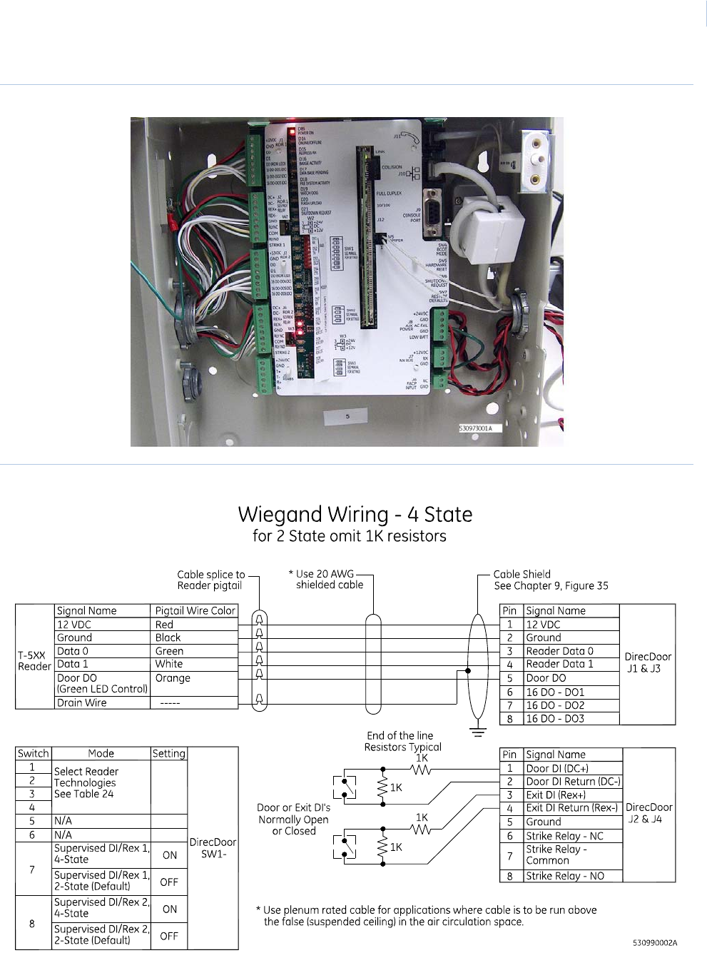
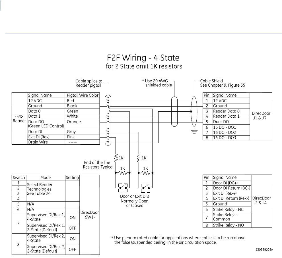
Table 27. Supervised DI/REX
SW1-7
Supervised DI/REX 1, 4-state ON
Supervised DI/REX 1, 2- state (default)
SW1-8
Supervised DI/REX 2, 4-state ON
Supervised DI/REX 2, 2-state (default)
Table 28. W2 - Reader 1, Relay Power
Function W2 Pins
+12 VDC 1 and 2
+24 VDC 2 and 3
Dry contact (default) 2
Table 29. W3 - Reader 2, Relay Power
Function W3 Pins
+12 VDC 1 and 2
+24 VDC 2 and 3
Table 26. Reader technology and format (SW1-1 through SW1-4) (continued)
Reader technology and format SW1-1 SW1-2 SW1-3 SW1-4

Chapter 5
Reader Interface
39
Wiring the readers
1. Mount the reader. Refer to the manual that came with your reader for specific mounting
instructions.
2. Run cable from the reader to the controller. Bring each reader cable through the appropriate
knockout hole in the controller enclosure. Allow some slack (service loop) wire for servicing
the cables and for plugging cable into an adjacent connector for troubleshooting. See
Figure 7, Dressing the Reader/DO/DI wiring inside of the DirecDoor enclosure on page 41.
3. Remove eight inches of insulating material from the cable. Unwrap shielding and tie all
shields together. Connect the shield wire to the grounding nuts provided outside the controller
enclosure. See Figure 8, Wiring to Wiegand readers, door contacts and exit request on
page 41.
4. Place the appropriate wires to the appropriate screw terminal on the reader interface
connectors. Refer to the reader wiring diagrams in this section.
Note: The reader interface has built-in pull-up resistors. Do not install any external pull-up resistors.
5. Label each cable end with the Controller Address Number/ Device or Reader Number.
We recommend using 20-AWG shielded cable for wiring reader, DOs, and DIs. Use plenum-
rated cable for applications where cable is to be run above the false (suspended) ceiling in
the air circulation space.
Recommended:
- Alpha Xtra Guard1® foil shield cable, non-plenum rated
- Belden series security and alarm cable (commercial applications shielded), plenum-rated
For readers not listed in the table below, refer to the applicable reader installation manual.
See Figure 8, Wiring to Wiegand readers, door contacts and exit request on page 41 and Figure 9,
Wiring to F/2F readers, door contacts and exit request on page 42.
Dry contact (default) 2
Table 30. J1/J3: Connecting T-5xx series reader
J1/J3 Pin Signal name Reader pigtail colors
1 +12 VDC Red
2 Ground Black
3 Reader Data 0 Green
4 Reader Data 1 White
5 Door DO (Reader LED) Orange
Table 29. W3 - Reader 2, Relay Power
Function W3 Pins

DirecDoor
Installation Manual
40
See Figure 13, Wiring output device to DO interface on page 49.
See Figure 8, Wiring to Wiegand readers, door contacts and exit request on page 41.
See Figure 10, Wiring door strikes - internal relay/power on page 44 and Figure 11, Wiring door
strikes - external relay/power on page 45.
Table 31. J1/J3: Connecting the DO outputs
J1/J3 Pin Signal name Cable color
6 16DO - DO (Open Collector) Blue
7 16DO - DO (Open Collector) Brown
8 16DO - DO (Open Collector) Yellow
Table 32. J2/J4: Door and exit DI wiring
Pin Signal name Cable color
1 Supervised Door DI (Alarm Point) (1K/1K) Red
2 Supervised Door DI Return Green
3 Supervised Exit DI (Exit Request) (1K/1K) Orange
4 Supervised Exit DI Return White
Table 33. J2/J4: Door strike relay wiring
Pin Signal name Cable color
5 Ground Black
6 Door Strike Relay – Normally Closed (NC) Blue
7 Door Strike Relay – Common (Com) Brown
8 Door Strike Relay – Normally Open (NO) Yellow
Chapter 5
Reader Interface
41
Figure 7. Dressing the Reader/DO/DI wiring inside of the DirecDoor enclosure
Figure 8. Wiring to Wiegand readers, door contacts and exit request
DirecDoor
Installation Manual
42
Figure 9. Wiring to F/2F readers, door contacts and exit request

Chapter 5
Reader Interface
43
Wiring the Digital Inputs (DIs)
Each reader DI port (J2/J4) has two digital inputs which are used for door status devices (door
contacts and exit request input). The inputs can be configured as supervised or non-supervised
digital inputs. When the inputs are configured as supervised digital inputs, they require end-of-line
resistors. See Table 27, Supervised DI/REX on page 38.
1. Follow the installation specifications for the device. Mount the device according to the
manufacturer’s specifications. The alarm device (door contact) should have a dry contact
which can have a normally open or normally closed type switch. A normally closed contact is
in its normal or resting position when it is closed. For example, the contact is closed when the
door is closed. The opposite is true for a normally open contact. In this case, the contact is
open when the door is closed.
2. Select the appropriate digital input for each alarm input device.
3. Configure the appropriate digital input for required operation. See Table 27, Supervised DI/
REX on page 38.
4. Ground the shields of the cable at the DirecDoor enclosure grounding studs. Insulate the
shield (with tape or shrink tubing) at the DI device end to avoid electrical noise.
5. For 4-state operation, install two end-of-line resistors. Install each resistor as close to the
door status contact as possible.
We recommend the standard 1,000 (1K) ohm, 1/4 watt, 1% tolerance, high-quality end-of-line
resistors.
- See Figure 8 on page 41 and Figure 9 on page 42 for the location of the resistors.
- See Table 27, Supervised DI/REX on page 38 for the appropriate switch settings.
6. Wire the supervised door DI between pin 1 (Door DI) and pin 2 (Door DI Return).
7. Wire the supervised exit DI between pin 3 (Exit DI) and pin 4 (Exit DI Return).
8. The contact can be normally open or normally closed.
9. Insulate resistors with tape or heat shrink tubing
10. Document how you wired the alarm input devices. Future expansion of the system and its
maintenance depend upon accurate documentation.
CAUTION: The supervision capability will be impaired if the resistors are NOT wired immediately adjacent to the
door status contact.
DirecDoor
Installation Manual
44
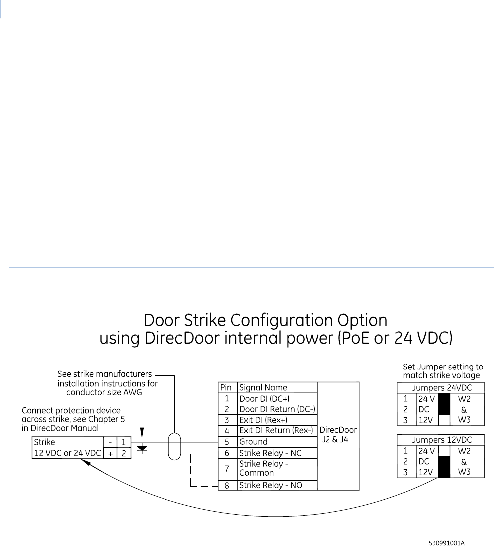
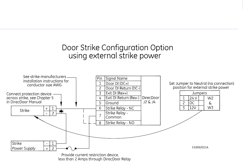
Wiring the door strikes
One door DO relay is dedicated to each reader port (J2/J4). The door DO is used for strike control,
and may implement an external relay if necessary.
1. Install the door strike (12/24 VDC) as required.
2. Wire the door strike to the door DO (internal) relay. Normally open or normally closed dry
contacts are available (pin 6 = normally closed, pin 7 = common, pin 8 = normally open).
3. Position jumper headers on W2 and W3 to select 12 VDC or 24 VDC as needed. If an
external power supply is intended to be used for powering the strike, leave the jumper off
completely. See Table 28 and Table 29 on page 38.
4. Install a protection diode. Use 1N4002, 1N4003, or 1N4004 diodes for DC door strikes and
Metal Oxide Varistors (MOV) for AC door strikes.
Note: Protection diode or MOV required at all electronic door locks.
Figure 10.Wiring door strikes - internal relay/power
Chapter 5
Reader Interface
45
Figure 11.Wiring door strikes - external relay/power
DirecDoor
Installation Manual
46
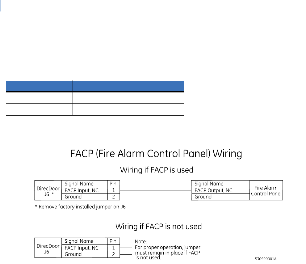
Wiring the Fire Alarm Control Panel (FACP)
Note: If a Fire Alarm Control Panel (FACP) is NOT used, the Jumper on J6 FACP Input MUST remain in place for correct
operation.
Figure 12.Wiring the Fire Alarm Control Panel (FACP)
Table 34. J6 - FACP Input, Normally Closed
Pin Signal Name
1 FACP Input
2 Ground

Chapter 6 DO Interface
This chapter provides information about and instructions for using the
digital outputs on DirecDoor.
In this chapter:
Introduction. . . . . . . . . . . . . . . . . . . . . . . . . . . . . . . . . . . . . . . . . 48
Device addressing . . . . . . . . . . . . . . . . . . . . . . . . . . . . . . . . . . . 48
Wiring Digital Outputs (DOs) . . . . . . . . . . . . . . . . . . . . . . . . . . . 49

DirecDoor
Installation Manual
48
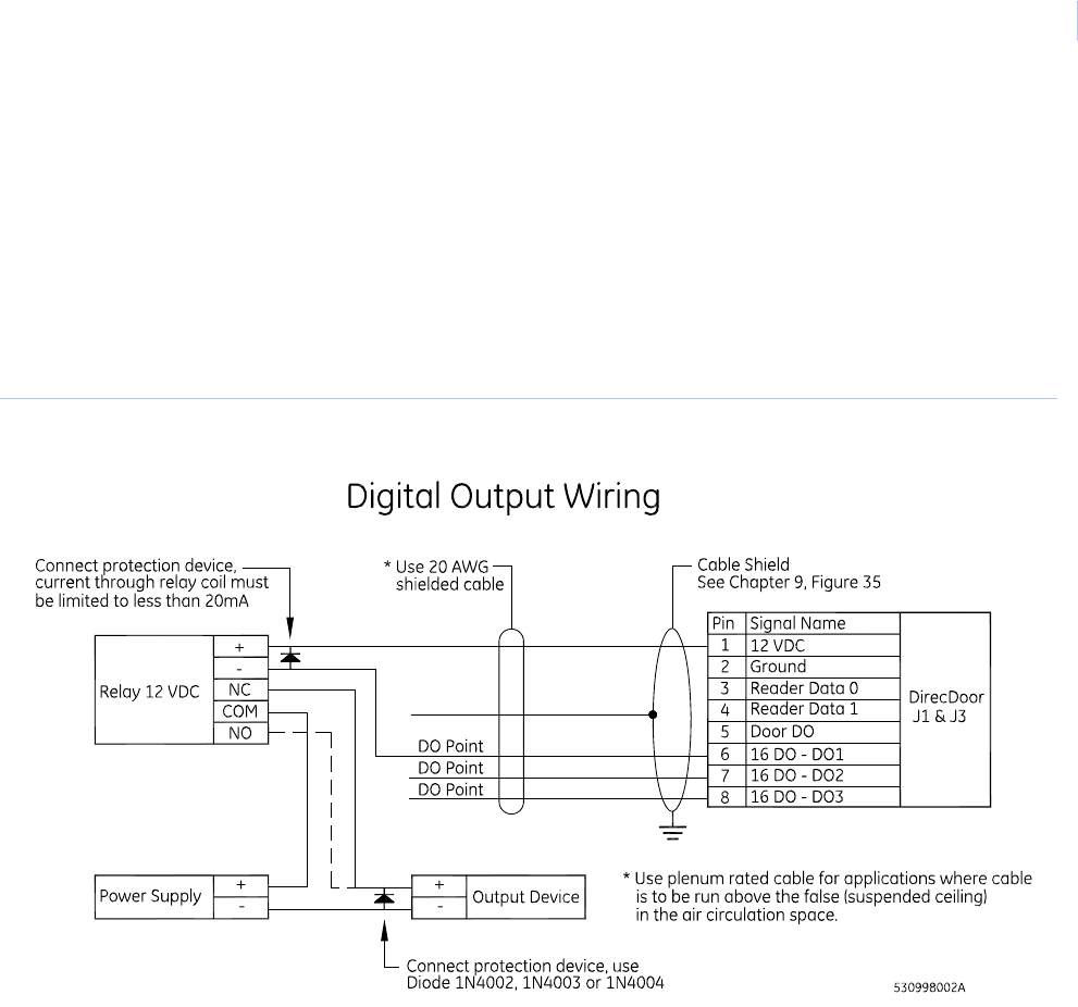
Introduction
The DO interface provides 6 digital outputs rated at 20 mA @ 12 VDC maximum per output point.
Note the following:
• The maximum allowable distance from the DirecDoor DO interface and the output device is
1,000 feet (304.80 meters).
• Two-conductor, 20-AWG shielded, stranded wire is recommended for the DO interface.
• Each DO point is addressed differently depending on the host software you are using.
Device addressing
Picture Perfect
One board can be configured with DO points from 16 to 21. Picture Perfect addresses DOs by board
number; therefore, the DO numbers are the same as the DO interface.
FCWnx
One board can be configured with DO points from 1 to 6. Addressing of DO boards follows the
format: mmmm-b-pp where mmmm represents the controller number to which this DO is associated,
b represents the board number, and pp represents the point or device number. For example:
0001-1-01 = DO on controller 1, DO board 1, DO 1
0001-1-02 = DO on controller 1, DO board 1, DO 2
Chapter 6
DO Interface
49
Wiring Digital Outputs (DOs)
Digital DOs are obtained by using unassigned reader outputs. When used as DOs, these outputs
require pull up resistors.
1. Mount the digital output device according to the manufacturer’s specifications.
2. Complete the wiring. If the DO is used to energize a relay, install a diode in parallel with the
relay coil to absorb transients when the relay is de-energized. A transient protection diode
(user supplied) is necessary on the DO interface.
Figure 13.Wiring output device to DO interface

DirecDoor
Installation Manual
50


DirecDoor
Installation Manual
52
Testing
For UL-Listed installations, refer to Chapter 9, Regulatory Information on page 79.
Follow the steps below before powering up the controller.
1. If using:
PoE supply:
Verify that the PoE power input plug at J10 is disconnected.
Auxiliary power supply:
1a. Verify that the auxiliary power input plug at J8 is disconnected.
1b. Measure the AC power being supplied to the power supply (110 VAC or 220 VAC,
depending on the power supply installed). The power supply must have a dedicated
circuit breaker. Do NOT plug into an outlet that is controlled by an on/off switch.
1c. Measure the auxiliary power supply output. The output voltage should be 24 VDC
nominal.
1d. Use a voltmeter to measure the input voltage across J8 at pin 1 and pin 2. Verify proper
polarity and voltage. (Pin 1 Power, pin 2 or pin 4 Ground). Reverse the wiring, if
necessary.
2. Test the reader/DO wiring to determine if a short circuit exists.
3. Disconnect the Reader/DO plug at position J1.
Verify the wiring going to the Reader/DO by using an ohmmeter to check the resistance
between pin 2 and all other pins.
Repeat for the Reader/DO plug at position J3.
Result: A measurement of less than 100 ohms indicates a short circuit. Correct this condition
before powering up.
4. Test the DI/strike wiring to determine if a short circuit exists.
Disconnect the DI/strike plug at position J2.
Verify the wiring going to the DI/strike by using an ohmmeter to check the resistance between
pin 5 and all other pins.
Repeat for the DI/strike plug at position J4.
Result: A measurement of 100 ohms indicates a short circuit. Correct this condition before
powering up.
5. Reconnect all disconnected plugs. DirecDoor powers up and begins its initialization
sequence.

Chapter 8 Controller Firmware Tools
This chapter provides information about and instructions for using
controller firmware tools.
In this chapter:
Integrated Configuration Tool . . . . . . . . . . . . . . . . . . . . . . . . . . . 54
Setting up the DirecDoor controller in the host application. . . . . 78
DirecDoor
Installation Manual
54
Integrated Configuration Tool
The Integrated Configuration Tool (ICT) is a browser-based utility used to configure the DirecDoor
board, update the firmware, and view the application log file.
Requirements
Software requirements
One of the following Internet browsers:
• Microsoft Internet Explorer 6.0 or later
• Netscape 7.0 or later
• Mozilla 5.0 or later
Hardware requirements
One of the following cables:
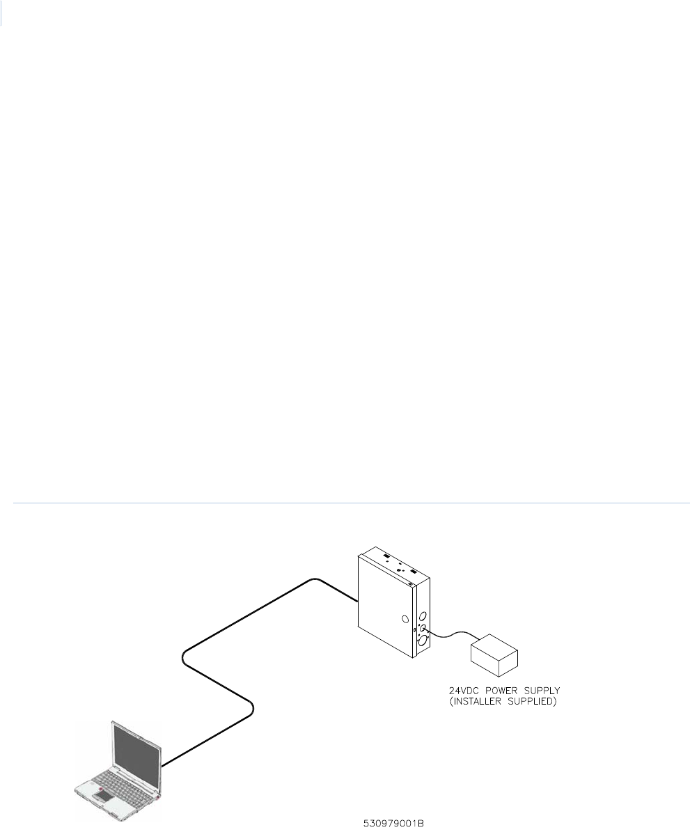
• Cat 5 cable for direct connection to a controller (see Figure 14 on page 54)
• Cat 5 cable for direct connection to a controller using Power over Ethernet (PoE) (see
Figure 15 on page 55)
• Cat 5 standard cable with network hub (see Figure 16 on page 55)
Figure 14.Connecting directly using Cat 5 cable
Chapter 8
Controller Firmware Tools
55
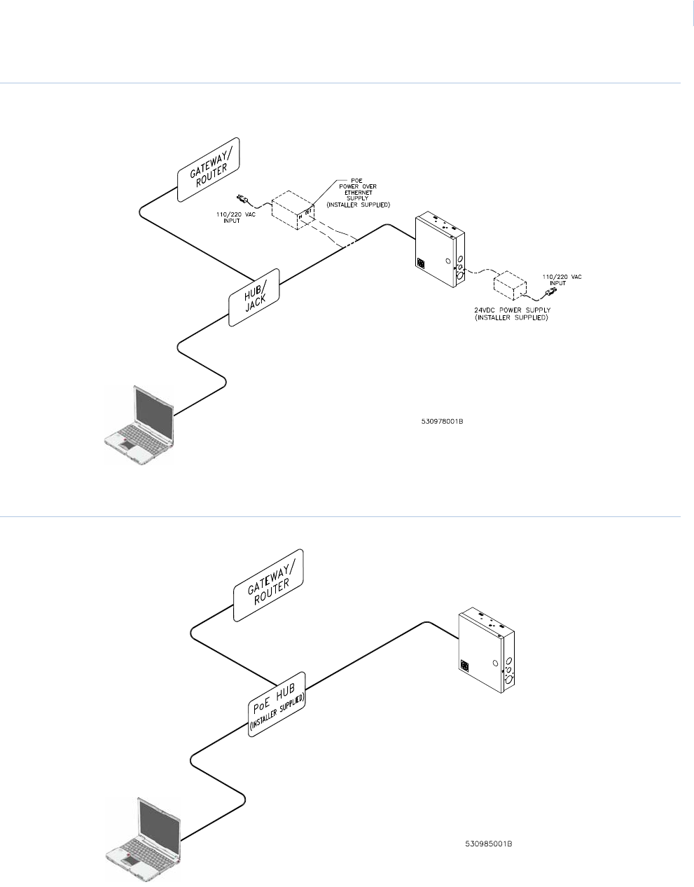
Figure 15.Connecting through network hub using PoE or auxiliary supply
Figure 16.Connecting through PoE hub

DirecDoor
Installation Manual
56
Before you continue
Answer these questions before continuing:
Is there a firewall on the computer you are using to access the Integrated Configuration
Tool? If yes, you will need to disable it in order to use the Integrated Configuration Tool.
Is your network using a proxy? If yes, you will need to disable the proxy or bypass it.
Complete the Configuration checklist for Integrated Configuration Tool on page 76 for each controller
that you will be setting up.
Connecting and starting the tool
If this is a new controller, there are special first-time configuration instructions. Refer to First-time
configuration on page 56.
Starting the tool
1. Connect the PC to the RJ45 connector on the DirecDoor board using a network hub or
“crossover” cable.
2. In the browser Address field, enter the IP address of the controller.
3. At the password screen, enter your username and password. The default is install, install.
We recommend that you change this default. See Change Username/Password on page 72.
If you need to flash the controller, see Flash controller menu/Flash controller on page 74.
First-time configuration
1. By default, the controller’s IP address is 192.168.6.6. To have your laptop/computer
communicate with the controller, you must set your laptop/computer IP address to
192.168.6.5, or similar valid IP address (192.168.6.x where x is any number between 1 and
254 except 6). The setup is different according to which version of Windows you are using.
Refer to the appropriate section.
For Windows 2000:
a. Click Start, Settings, then Network and Dial-up Connections.
b. Right-click on Local Area Connection. If the first option in the drop-down list box is:
•Disable, then the connection is enabled. Go to step c.
•Enable, then select it to enable the connection. Return to step a.
c. Select Properties from the drop-down list box.
d. In the section Components checked are used in this connection, select Internet
Protocol TCP/IP.
e. Click Properties.

Chapter 8
Controller Firmware Tools
57
f. If this laptop/computer is set for:
• DHCP, then the field Obtain an IP address automatically is already selected. Select
Use the following IP address.
• Static, write down the IP address and Subnet number. You need to reset your
computer back to these numbers once the controller configuration is complete.
g. Enter the IP address 192.168.6.5, or a similar valid IP address (192.168.6.x where x is
any number between 1 and 254 except 6).
h. Change the subnet mask to 255.255.255.0.
Note: You do not need to change the gateway.
i. Click OK until all open windows are closed.
j. Go to step 2.
For Windows XP:
a. Click Start, then Control Panel.
b. From the Control Panel window, select Network Connections.
c. Right-click on Local Area Connection. If the first option in the drop-down list box is:
•Disable, then the connection is enabled. Go to step d.
•Enable, then select it to enable the connection. Return to step a.
d. Select Properties from the drop-down list.
e. In the section This connection uses the following items:, select Internet Protocol
TCP/IP.
f. Select Properties.
g. If this laptop/computer is set for:
• DHCP, then the field Obtain an IP address automatically is already selected. Select
Use the following IP address.
• Static, write down the IP address and Subnet number. You need to reset your
computer back to these numbers once the controller configuration is complete.
h. Enter the IP address 192.168.6.5, or a similar valid IP address (192.168.6.x where x is
any number between 1 and 254 except 6).
i. Change the subnet to 255.255.255.0.
Note: You do not need to change the gateway.
j. Click OK until all open windows are closed.
k. Go to step 2.

DirecDoor
Installation Manual
58
For Windows XP:
a. Click the Start button, Control Panel, Network and Internet, and then Network and
Sharing Center.
b. In the “View your active networks” section of the form, click the Local Area Connection
link.
Note: If you are not currently connected to a network, restore the connection before continuing. Use the
Windows Network Diagnostics tools, or contact your Network Administrator for assistance.
c. In the Local Area Connection dialog box, click Properties.
d. In the Local Area Connection Properties dialog box, select either Internet Protocol
Version 4 (TCP/IPv4) or Internet Protocol Version 6 (TCP/IPv6).
e. Click Properties.
• If Obtain an IPvx /Address Automatically is already checked, select Use the
Following IPvx Address, where x is the Internet Protocol Version you are using (4 or
6).
• If the connection is static, write down the IP address and Subnet mask number. You
will need to reset your computer back to these numbers once the controller
configuration is complete.
f. Enter the IP address, 192.168.6.5, or a similar valid IP address (192.168.6.x where
x is any number between 1 and 254 except 6).
g. Change the Subnet Prefix Length value to 255.255.255.0.
Note: You do not need to change the default gateway.
h. Click OK and Close until all open windows are closed.
i. Go to step 2.
2. Connect the Cat 5 crossover cable from the Ethernet port on your laptop or computer directly
to the controller Ethernet port (no hub or switch).
3. If your controller is not yet powered up, do so now.
4. Open an Internet browser window on your computer.
5. In the browser’s Address field, enter the default static IP address of the controller:
192.168.6.6
6. The Integrated Configuration Tool starts. At the password screen, enter your username and
password. The default is install, install. We recommend that you change this default.
Refer to Change Username/Password on page 72.

Chapter 8
Controller Firmware Tools
59
Controller setup overview
In order to set up the controller, you must complete these screens:
•Controller Configuration menu->Host/Connection type: Select the software package and
network. See Controller Configuration menu -> Host/Connection type on page 60.
•Controller Information menu->Controller Information: Set the controller address.
(Required for Picture Perfect network controllers using dial fallback and all Facility
Commander Wnx controllers.) See Controller Information menu -> Controller Information on
page 61.
•Controller Parameters menu->Network Configuration: The setup depends on whether the
IP address is static or dynamic. See Network configuration on page 63.
•Controller Parameters menu->Dial Configuration: If using the optional dial fallback
feature, you must complete the Dial configuration page also. See Dial configuration on
page 65.
Saving configuration changes
Before using the Integrated Configuration Tool, note the following details about saving your changes:
• If you change any options on a form, you must click the Save button at the bottom of the form
to save your changes before switching to another form. This action saves your latest changes
to a temporary file.
• Select Apply Changes from the Administration menu after you have made all necessary
changes in the Integrated Configuration Tool. You will be prompted to restart either the
application or the controller and changes will be saved to the controller’s config file.
• If you click Save on each form, you do not need to apply changes or restart the application
until you are finished making all necessary changes.
After completing all the screens, click Apply Changes under the Administration menu and then click
Restart Application for the changes to take effect. See Table 35 on page 59 for a list of buttons
available and when to use them.
Table 35. Buttons available and when to use them
Button Usage Result
Save After making changes on any form Saves the changes to the shadow config.txt file located in the /var/tmp
directory.
Apply
Changes
After all the changes are complete Saves the changes from the shadow config.txt file to the real config.txt
file located in the /opt/config directory.
Restart
Application
After selecting Apply Changes
from the Administration menu
The application picks up the latest changes from the config.txt file and
starts again.
Restart
Controller
After selecting Apply Changes
from the Administration menu
The operating system picks up the latest changes and starts again.
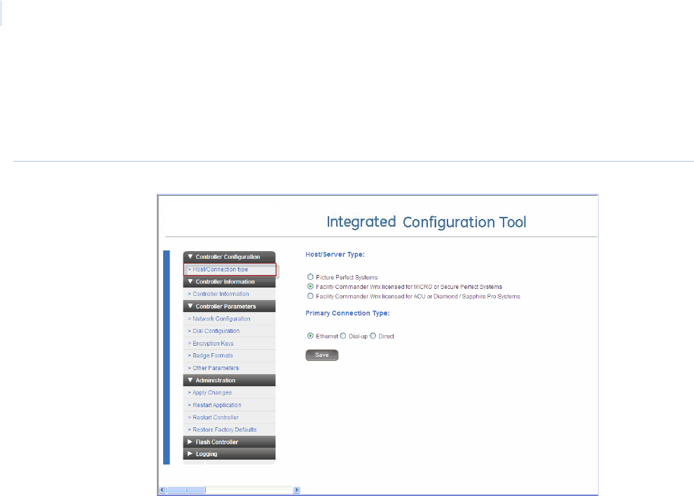
DirecDoor
Installation Manual
60
Controller Configuration menu -> Host/Connection type
Use the Host/Connection type form to select the software package and connection type used by the
computer for which you are configuring the controller.
Figure 17.Host/Connection type form
1. If you have not already done so, log on to the Integrated Configuration Tool. See Starting the
tool on page 56.
2. From the Controller Configuration menu, select Host/Connection type.
3. In the Host/Server Type field, select the software package you are using.
4. In the Primary Connection Type field, select Ethernet.
5. Click Save.
6. If this completes your controller configuration, click Apply Changes then Restart
Application now.
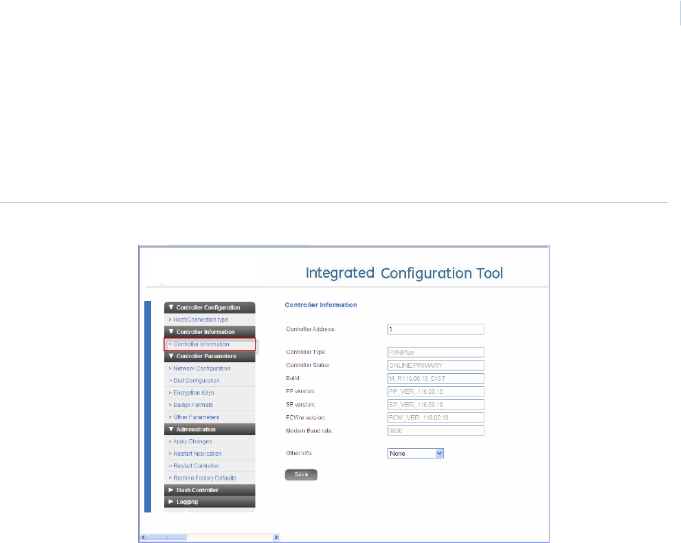
Chapter 8
Controller Firmware Tools
61
Controller Information menu -> Controller Information
Use the Controller Information form to set the controller’s address. This form also provides the
controller online/offline status, build and application versions, and modem baud rate.
Note: If this is a Picture Perfect network controller only (dial fallback is NOT used), then you do not need to set the
controller address.
Figure 18.Controller Information form
1. From the Controller Information menu, select Controller Information.
2. To set the controller address, enter the number in the Controller Address field.
3. To use the status reports in the Other Info field, see Using the Other Info field below.
4. Click Save.
5. If this completes your controller configuration, click Apply Changes then Restart
Application now.

DirecDoor
Installation Manual
62
Using the Other Info field
The Controller Information form provides access to several status reports based on uClinux
commands which are available for checking and monitoring the DirecDoor board. Call Technical
Support for assistance with these reports.
1. In the Other Info field, click the down arrow for a list of available reports.
2. Select the report you want. See Table 36 below for a brief explanation of each report.
Table 36. Controller Info reports
Report Description
Memory Usage Displays amount of memory available, both used and free.
Process Status Lists which processes are running.
Board Info Displays hardware related information, such as boot and board version.
OS Info Displays information related to the Linux operating system on the controller.
Update History Lists all updates to the firmware for the selected controller.
Runtime Logs Provides daily critical runtime information.
Uptime Shows the time since the last reboot.
DB File Info Lists persistence-related database files.
Message Info Lists data on the controller’s message queues.
Ping Host Pings the host from the controller (based on the current host IP or name).
Successful ping result:
a.2 packets transmitted, 2 packets received, 0% packet loss
Unsuccessful ping result:
b.2 packets transmitted, 0 packets received, 100% packet loss
Check Route Checks route information from the controller.
Thread Status Lists the application firmware components and whether they are currently running.
DMA Info Shows the status of the DMA IO interface.
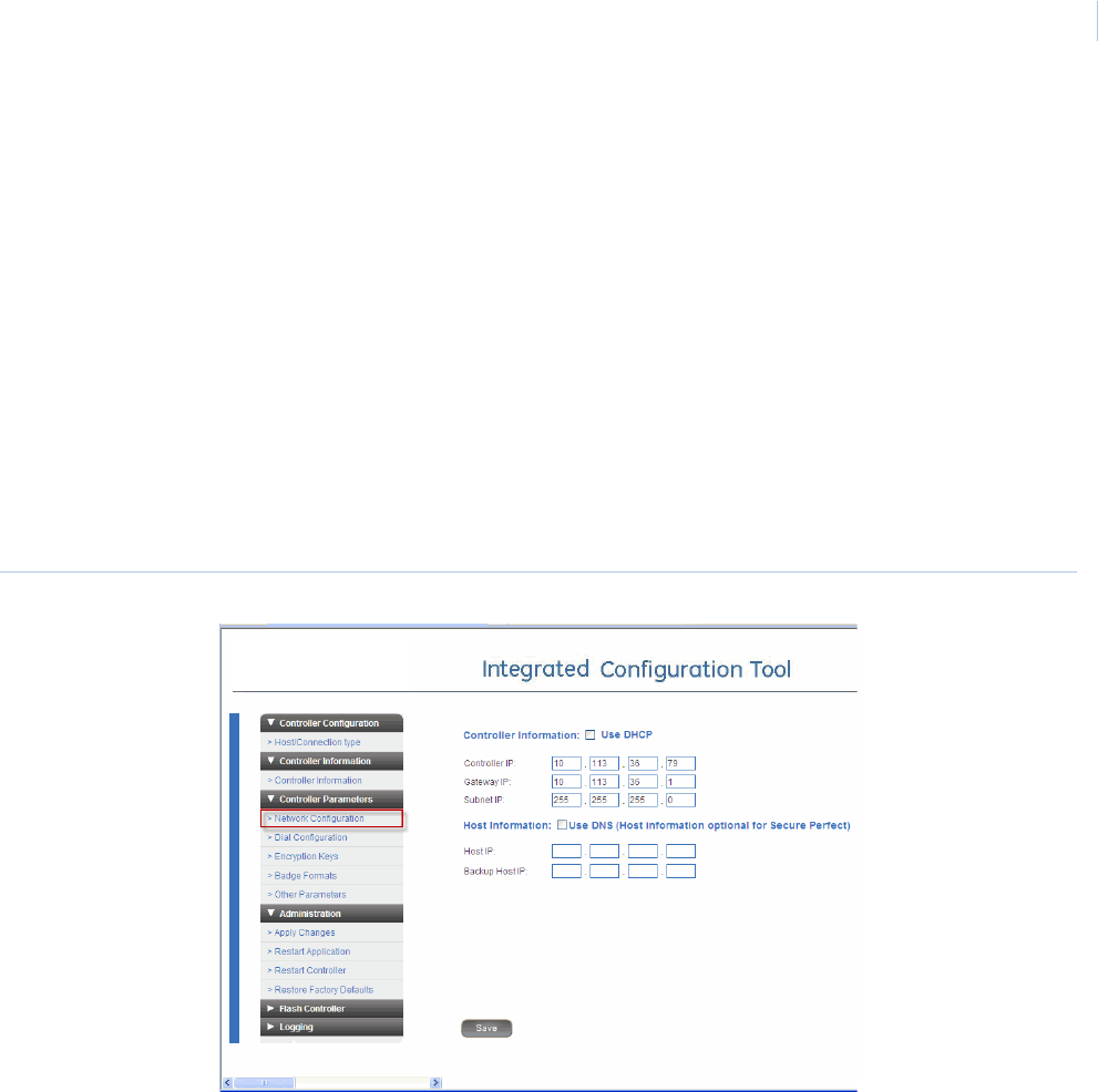
Chapter 8
Controller Firmware Tools
63
Controller Parameters menu
The menu contains the following options:
•Network configuration: configure the network settings.
•Dial configuration: configure dial-up settings. See page 65.
•Encryption Keys: set data encryption. See page 66.
•Badge Formats: set Wiegand and Magnetic Stripe formats. See page 67.
•Other Parameters: set parameters such as setting badge history and alarm history memory
allocation and changing username and password. See page 71.
Network configuration
Use this form to configure the network settings for the controller. A static or dynamic IP address can
be used.
Figure 19.Controller Parameters/Network configuration screen
1. From the Controller Parameters menu, select Network configuration.
2. In the Controller Information area of the form, set the controller name (DHCP) or address
(Static). Refer to the appropriate section that follows.
DHCP:
- For a dynamic controller IP address, select Use DHCP.
To name the controller, perform one of the following:
- Enter a fully qualified, unique domain name in the Controller name field. For example:
micro.utctest.utc.com
- Select the checkbox Use MAC address and the controller name is generated from the
Controller MAC address. (A Media Access Control (MAC) address is a unique identifier

DirecDoor
Installation Manual
64
attached to most forms of networking equipment.) The MAC address for your DirecDoor
board can be found in the Controller MAC field. This option disables the Controller name
field.
Note: Give this name or MAC address to your Network Administrator so that it can be added to the DNS
database.
Static:
- For a static controller IP address, enter the IP address of the controller given to you by
your Network Administrator in the Controller IP field.
- If using a gateway, you may accept the gateway IP generated based on the controller IP
or you may enter a gateway IP address in the Gateway IP field.
- If using a subnet mask, you may accept the subnet mask generated based on the
controller IP or you may enter a subnet mask in the Subnet field.
3. If using FCWnx, skip to step 4. If using Picture Perfect, you must set the host name (DNS) or
address (Static). Refer to the appropriate section that follows.
DNS:
- For a dynamic host IP address, select the Use DNS checkbox and enter the host name in
the Host Name field.
Note: Due to the limitation on the Picture Perfect host, the DNS/DDNS server needs to be manually updated
with the Picture Perfect host name and IP address.
If you set up a static IP address in the Controller Information section, you also need to
enter the domain for the host in the Domain field and the DNS IP address in the DNS
IP field. If DHCP was selected, this is not necessary.
- Enter the backup host name in the Backup Host Name field.
Static:
- For a static host IP address, enter the IP address in the Host IP field.
- Enter the IP address in the Backup Host IP field.
4. Click Save.
5. If this completes your controller configuration, click Apply Changes then Restart
Application now.
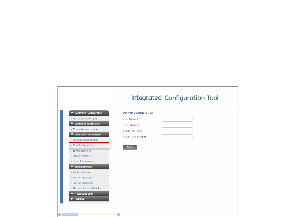
Chapter 8
Controller Firmware Tools
65
Dial configuration
Use this form to set up the dial fallback feature.
Note: The on-board modem MUST be installed on the DirecDoor board in order to use the dial fallback feature.
Figure 20.Controller Parameters/Dial Configuration form
1. From the Controller Parameters menu, then Dial configuration.
2. In the Host Phone # 1 field, enter the phone number for the host computer. Use the format:
nnn-nnn-nnnn (For example, 561-555-5555).
3. If there is an additional phone number to reach the host, enter it into the field Host Phone # 2,
otherwise, leave the field blank.
Note: The Modem Init String and Modem Deinit String fields require values only if you are experiencing
difficulties with the optional modem board.
4. Click Save.
5. If this completes your controller configuration, click Apply Changes then Restart
Application now.
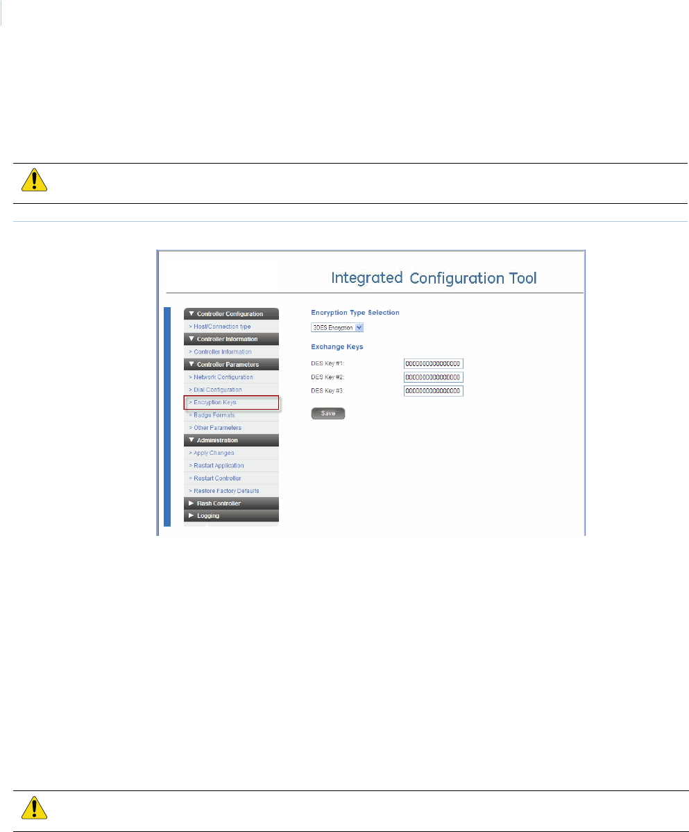
DirecDoor
Installation Manual
66
Encryption keys
In order to secure transmissions between the controller and the host, the data is encrypted using
triple DES (Data Encryption Standard) encryption. Use this form to enter keys which will create an
encryption pattern for transmission.
Figure 21.Controller Parameters/Encryption Keys form
1. If you have not already done so, log on to the Integrated Configuration Tool. See Starting the
tool on page 56.
2. Click Controller Parameters, then Encryption keys.
3. In the Encryption Type Selection field, select the type of encryption you want to use.
4. Enter a value in each DES Key field that appears, after noting the following details:
- DES keys must be exactly 16 characters.
- DES keys must be valid hexadecimal characters (digits 0—9; upper or lowercase letters
A — F).
- For security reasons, each characters entered in a DES Key field will appear as an
asterisk (*).
- No two or more DES keys can have the same value.
5. Click Save.
6. If this completes your controller configuration, click Apply Changes then Restart
Application now.
CAUTION: The host DES keys and the controller DES keys MUST match!
CAUTION: You cannot modify only one key! All keys must be changed or you will not be able to save.
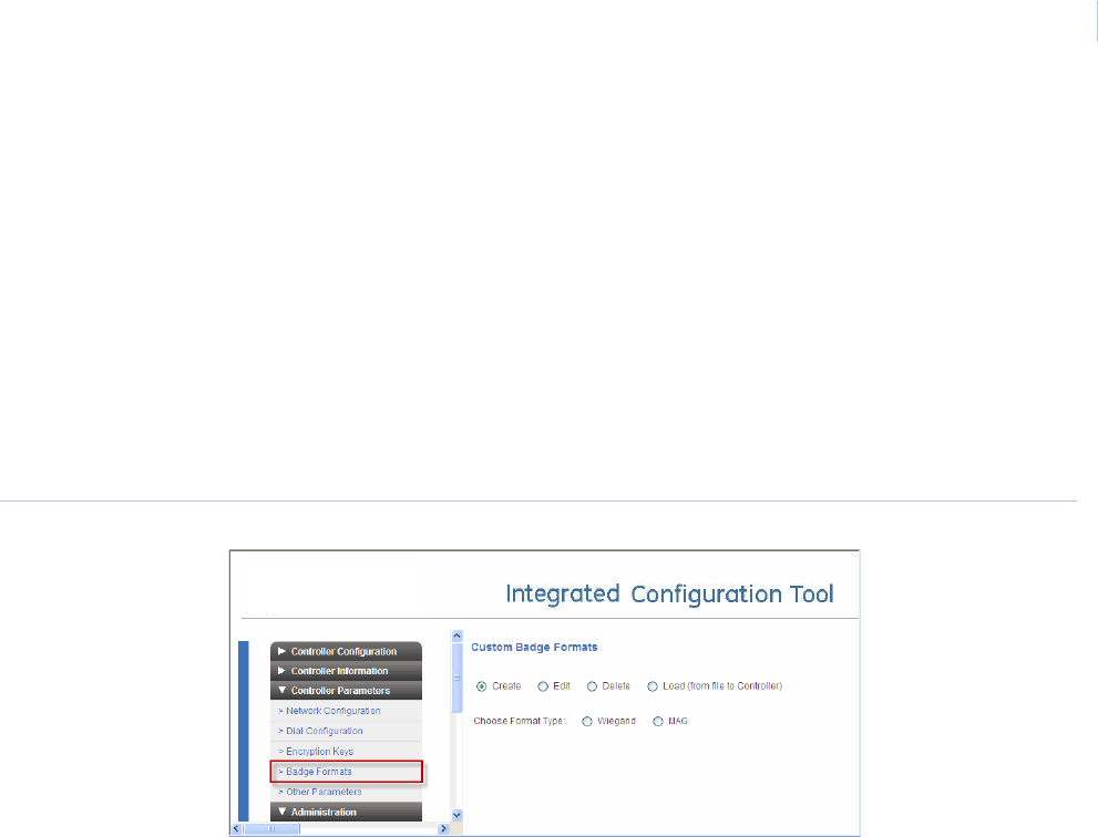
Chapter 8
Controller Firmware Tools
67
Badge Formats
Note: This section is intended for Picture Perfect users with a working knowledge of universal badge formats. FCWnx
users should use the Other Parameters form to configure badge formats.
If you are running Picture Perfect, you can use the Badge Formats form (Figure 22) to:
• Create a badge format, as described below.
• Edit a badge format (page 70)
• Delete a badge format (page 70)
• Load a badge format (page 71)
Note: Due to the complexity involved in creating a Wiegand badge format, we recommend that you contact Technical
Support for assistance before beginning those steps.
Figure 22.Controller Parameters/Badge Formats — Create badge format
Create a badge format
This section describes how to create a new badge format using either Wiegand or MAG (i.e.,
magnetic) format.
1. If you have not already done so, log on to the Integrated Configuration Tool.
2. From the Controller Parameters menu, select Badge Formats.
3. Select Create.
4. In the Choose Format Type field, select the format type:
- If you select Wiegand as the format type, you will need to specify how many total bits are
in the format, how many characters are in the actual badge data used to represent facility
bits, and how many characters will be used to encode the badge number. Continue to
step 5.
Note: Before creating a Wiegand badge format, contact Technical Support for assistance.
- If you select MAG as the format type, skip ahead to MAG badge format options on
page 69.
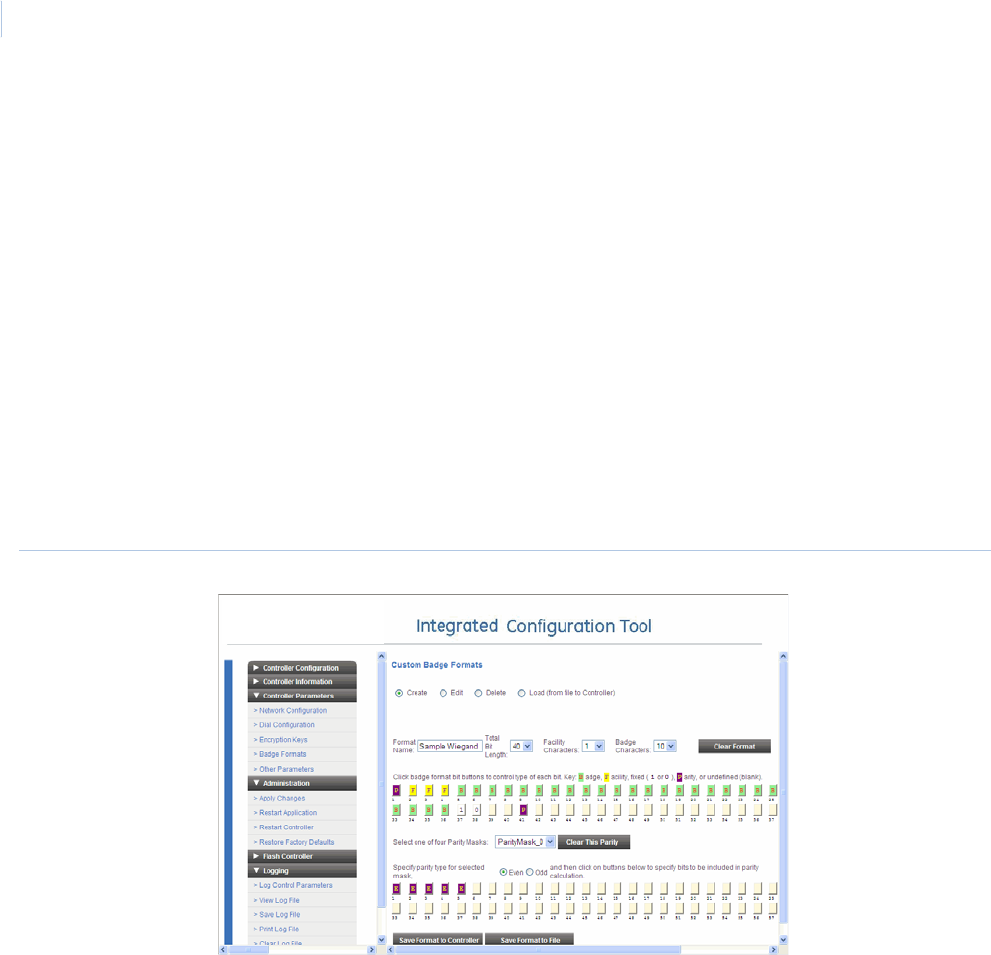
DirecDoor
Installation Manual
68
Wiegand badge format options
5. In the Format Name field, enter a unique ID for the type of badge format you are creating.
6. In the Total Bit Length field, select the number of bits required to encode and decode badge
data.
7. In the Facility Characters field, enter the number of characters required for the facility data.
8. In the Badge Characters field, enter the number of characters required for the badge data.
9. Click each button to select the role of that bit in the badge data, using any of the following
Wiegand-format options:
- B - badge
- F - facility
- 1 or 0 - fixed data
- P - parity
- - undefined (blank)
Figure 23.Controller Parameters/Badge Formats — Create Wiegand badge format (Example)
10. If you wish to select a parity mask:
a. Use the Select One of Four Parity Masks drop-down box to select a parity mask.
b. Select either the Even or the Odd radio button.
c. Click on the bits that you wish to check the parity.
11. You have two Save options for saving a Wiegand badge format:
-Click Save Format to Controller. If any errors are encountered, an alert dialog box pops
up.
-Click Save Format to File. This saves the badge format file to your local computer.
a. A confirmation message appears. Click OK to continue.
b. A screen displays with the name of your format and the option to save it on your
computer. This is actually an HTML page with your format embedded in it.
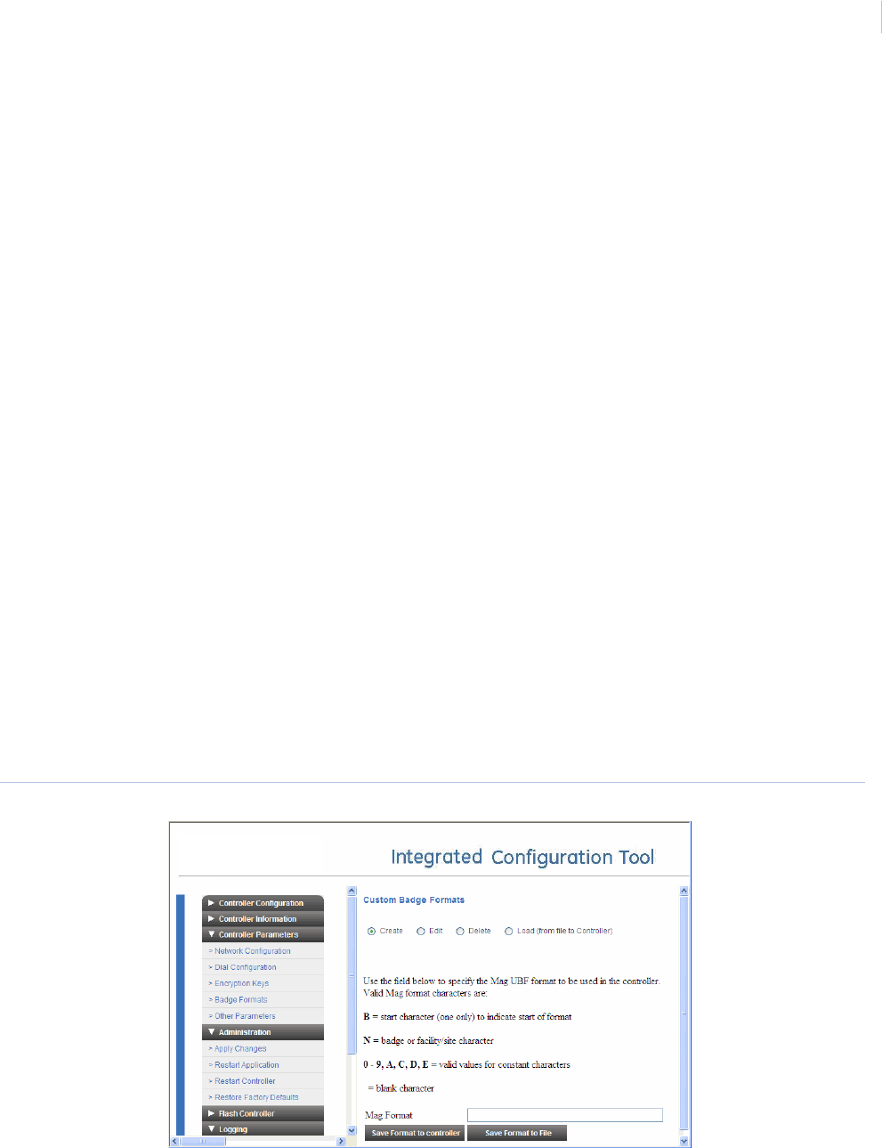
Chapter 8
Controller Firmware Tools
69
c. Click Save format to my computer. A Save dialog box displays.
d. Click Save.
Note: If you are using a Netscape or Mozilla browser, you will not be able to access the Save dialog box due to
security constraints imposed by those browsers. Instead, use the following steps as a workaround:
• Hover the mouse cursor over the Format frame, and then click the right mouse button.
• From the popup menu, select This Frame.
• From the submenu, select Save Frame As.
• A Save As dialog box displays the default file name, wiegand.html. Replace the file name with
one appropriate for your site and navigate to the directory where you to save the file.
12. If you are finished configuring the controller, select Apply Changes from the Administration
menu, and then select Restart Application.
MAG badge format options
If you selected MAG as the custom badge format in step 4, continue to step 5 (below) to specify the
start character, badge and/or facility characters, constant characters, and blank characters to be
used for the format.
5. In the Mag Format field, enter the mag badge file format you want using the following
characters:
-B = start character
-N = badge or facility/site character
-0 - 9, A, C, D, E = valid values for constant characters
- = blank character
For example: BNNNNN99ACDE
This represents a badge number with one start character, five badge or facility/site
characters, and six constant characters of “99ACDE”.
Figure 24.Other Parameters/Badge Formats — Create MAG badge format

DirecDoor
Installation Manual
70
6. You have two options for saving a MAG badge format.
-Click Save Format to Controller. If any errors are encountered, an alert dialog box pops
up.
-Click Save Format to File. This saves the badge format file to your local computer.
a. A confirmation message appears. Click OK to continue.
b. A screen displays with the name of your format and the option to save it on your
computer. This is actually an HTML page with your format embedded in it.
c. Click Save format to my computer. A Save window displays.
d. Click Save.
Note: If you are using a Netscape or Mozilla browser, you will not be able to access the Save dialog box due to
security constraints imposed by those browsers. Instead, use the following steps as a workaround:
• Hover the mouse cursor over the Format frame, and then click the right mouse button.
• From the popup menu, select This Frame.
• From the submenu, select Save Frame As.
• A Save As dialog box displays the default file name, mag.html. Replace the file name with one
appropriate for your site and navigate to the directory where you want to save the file.
7. If you are finished configuring the controller, select Apply Changes from the Administration
menu, and then select Restart Application.
Edit a badge format
1. Select Badge Formats from the Controller Parameters menu of the Integrated Configuration
Tool.
2. Select Edit.
3. In the Choose Format Type field, select a format type.
4. Edit the existing format type.
- If you selected Wiegand in step 4, select the file you want to edit then click OK. See
page 68 for details about the Wiegand format options.
- If you selected MAG in step 4, the existing MAG format options appear. See “MAG badge
format options” on page .69 for details about the MAG format options.
Note: You can create multiple Wiegand format files, but only one type of MAG format file. Any changes you
make to a MAG file will overwrite the existing MAG format file.
5. Click Save Format to Controller.
6. If you are finished configuring the controller, select Apply Changes from the Administration
menu, and then select Restart Application.
Delete a badge format
1. Select Badge Formats from the Controller Parameters menu of the Integrated Configuration
Tool.
2. Select Delete.
3. In the Choose Format Type field, select the format type.
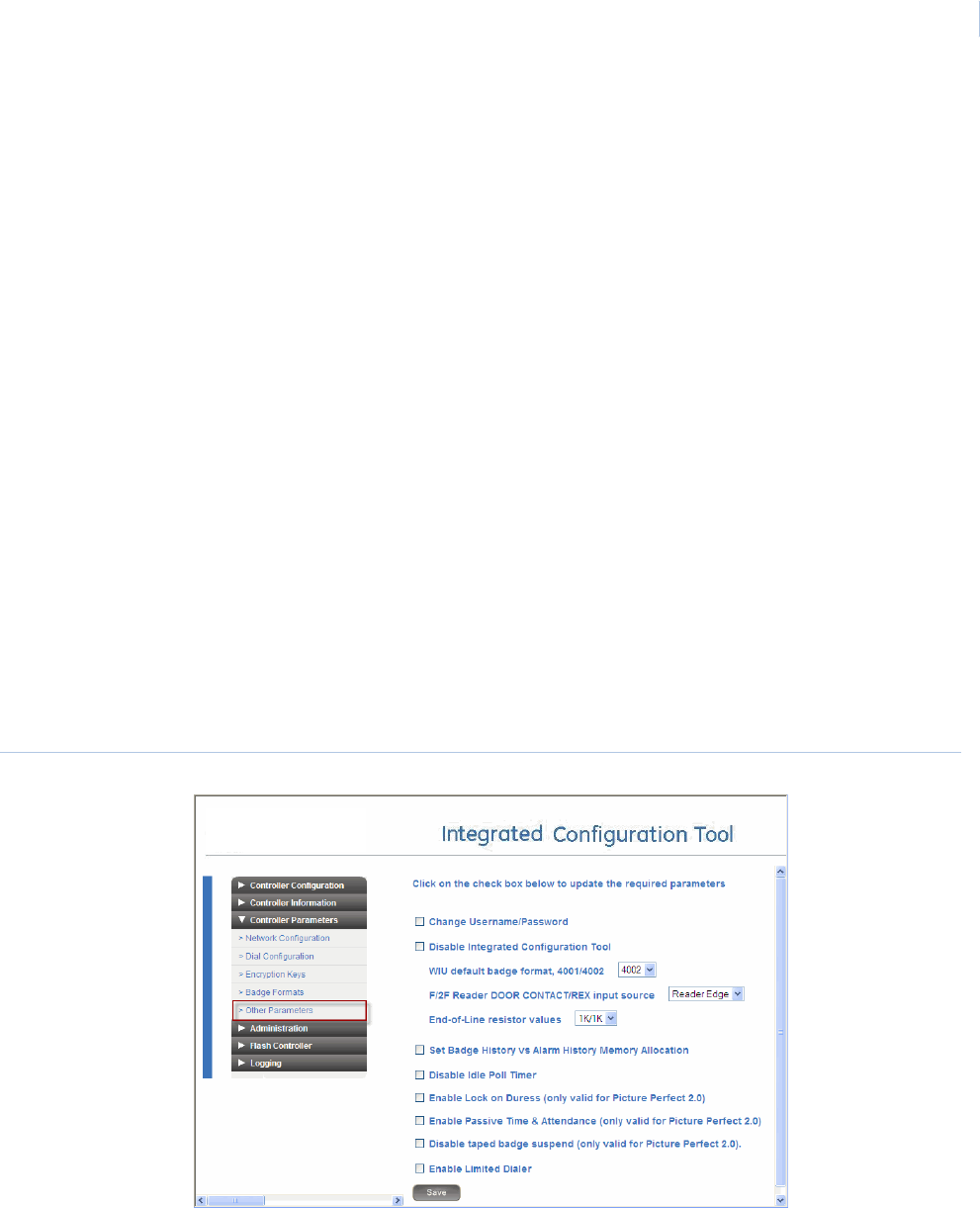
Chapter 8
Controller Firmware Tools
71
- If you select Wiegand, select the file you want to delete and then click OK to confirm the
deletion.
- If you select MAG, the single MAG format file is deleted. (Only one MAG file can exist.)
Load a badge format
You can also use the Badge Formats form to search your file system for a badge format file to send
to the controller.
1. Select Badge Formats from the Controller Parameters menu of the Integrated Configuration
Tool.
2. Select Load (from file to Controller).
3. In the Choose Format Type field, select either Wiegand or MAG.
4. Click Browse.
5. Navigate to and select the badge format file you want.
6. Click Save.
7. If you are finished configuring the controller, select Apply Changes from the Administration
menu, and then select Restart Application.
Other Parameters
Depending on the Host/Connection type being used, some or all of the following fields appear on the
Other Parameters form, which is shown in Figure 25.
Figure 25.Parameters/Other Parameters form (Example)
Note: Be sure to click Save at the bottom of the Parameters/Other Parameters form before switching to another form. If
you are finished configuring the controller, select Apply Changes and then Restart Application from the
Administration menu.

DirecDoor
Installation Manual
72
The various fields that appear on the Other Parameters form are described in the following sections.
Change Username/Password
Set the username and/or the password used to log on to the Integrated Configuration Tool. By
default, these values are set to “install, install”. For increased security, we recommend that you
change the default values.
Enable/Disable Integrated Configuration Tool
Control access to the Integrated Configuration Tool by selecting one of two options:
• Temporary allows access to the Tool until the controller resets.
• Permanent allows access until you manually disable the Tool again.
Note: Before you begin, you MUST have physical access to the controller.
To enable the Integrated Configuration Tool temporarily:
1. Verify that the controller has completed the power-up boot cycle by checking that DS7 is no
longer in the constant ON state.
2. Verify that DS6 turns ON. Allow up to five seconds for DS6 to turn ON. Once DS6 is ON,
remove the jumper and DS6 turns OFF.
3. The Integrated Configuration Tool is now enabled until the controller reboots.
To enable the Integrated Configuration Tool permanently:
1. Complete the steps to enable the tool temporarily, as listed above.
2. Log on to the Integrated Configuration Tool.
3. From the Controller Parameters menu, select Other Parameters.
4. Select Enable Integrated Configuration Tool, then click OK.
5. To make this selection permanent, click Save, Apply Changes, then Restart Controller.
The controller performs a system reboot automatically and the Integrated Configuration Tool
is permanently enabled.
To disable the Integrated Configuration Tool:
1. Log on to the Integrated Configuration Tool.
2. From the Controller Parameters menu, select Other Parameters.
3. Select Disable Integrated Configuration Tool, then click OK.
4. To make this selection permanent, click Save, Apply Changes, then Restart Controller.
The controller performs a system reboot automatically and the Integrated Configuration Tool
is permanently disabled.
WIU default badge format, 4001/4002
Set the default bit format used for a Wiegand Interface Unit (WIU).
F/2F Reader DOOR CONTACT/REX input source
Determine the edge of the door contact that will be read.

Chapter 8
Controller Firmware Tools
73
End-of-Line resistor values
Set the values used to terminate protective loops or zones.
Set Badge History vs Alarm History Memory Allocation
Determine the percentage of memory allocated for badge and alarm history, from 10 to 90 percent.
Note: This option is available for Picture Perfect only. For FCWnx, this value is fixed at 50% and is not user configurable.
Set Resistor Tolerances
Set the range in which voltage can change before a 4-state DI state is detected. After you check the Set Resistor
Tolerances check box, enter a Res Tol # 1 value.
Note: Res Tol # 2 and Res Tol # 3 are both reserved, read-only fields.
Enable/Disable Idle Poll Timer
Control network activity between the controller and the host. The poll timer guarantees that the
network connection between the controller and the host is not shut down by the network
administrator, firewall, or other device due to network inactivity.
Note: This option is available for Picture Perfect only.
Enable/Disable Lock on Duress
Control if a door will lock and signal a threatening situation when a duress PIN code is entered at a
reader.
Note: This option is available for Picture Perfect only.
Enable/Disable Passive Time & Attendance
Determine if a door will unlock regardless of a credential's IN/OUT status.
Note: This option is available for Picture Perfect only.
Enable/Disable taped badge suspend
Control how credentials are handled when an invalid PIN is entered in multiple access attempts.
Note: This option is available for Picture Perfect only.
Administration menu
The menu contains the following options:
•Apply Changes: applies new changes. See below.
•Restart Application: makes changes permanent. See below.
•Restart Controller: reboots the controller. See below.
•Restore Factory Defaults: restores factory defaults. See page 74.
Apply Changes
Click this menu item to apply any new changes made to the controller’s configuration.
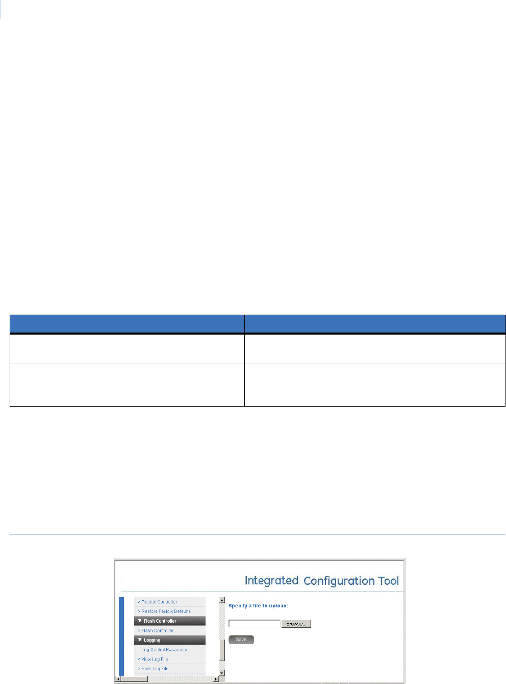
DirecDoor
Installation Manual
74
Restart Application
Click this menu item to make the changes to the controller permanent.
Restart Controller
Click this menu item to shut down and restart the controller.
Restore Factory Defaults
The DirecDoor board is shipped with the following default settings:
•Primary Connection Type: Ethernet
•IP Address: 192.168.6.6
•Mask: 255.255.255.0
•Gateway: 192.168.6.1
There are two methods to restore the factory default settings: through the Integrated Configuration
Tool and by the contact push button on the board. The table below explains when to use each
method.
Flash controller menu/Flash controller
The DirecDoor board uses a single flash file capable of supporting both Picture Perfect and FCWnx
hosts. The file is in the format: DDvvvv.efl, where vvvv is the four digit version number of the
firmware.
Note: Do not use the Integrated Configuration Tool to flash a controller if the controller version is less than
DD_DIST_R115, RC2. Instead, use the eFlash utility, as described in the DirecDoor Release Notes.
Figure 26.Flash Controller form
If you restore factory defaults by... Then...
Selecting Restore Factory Defaults from the
Administration menu.
Settings are restored to factory defaults except for the network
configuration.
Pressing SW7 (Restore Defaults switch) on the
DirecDoor board until D17 and D20 turn on. (See
DirecDoor problems on page 87.)
All settings are restored to the factory defaults.

Chapter 8
Controller Firmware Tools
75
1. If you have not already done so, log on to the Integrated Configuration Tool. See Starting the
tool on page 56.
2. From the Flash Controller menu, select Flash Controller.
3. Click Browse and locate the new flash file.
4. Click Save. The controller reboots automatically.
If the controller flash is successful, you will be prompted to restart the controller by selecting
Restart Controller from the Administration menu. A single reboot will occur. Wait 8 to 10
minutes for the controller to complete its boot sequence and install updates, then verify that
the build version is correct. (The build version appears on the Controller Information form.)
Note: If you wish to continue configuration changes, you will need to restart the Integrated Configuration tool
again.
Logging menu
The menu contains the following options:
•Log Control Parameters: select the items to track and send to the log file.
•View Log File: displays the log file.
•Save Log File: saves the log to a file.
•Print Log File: prints the log file.
•Clear Log File: clears the contents of the log file.
Log Control Parameters
Use this option to turn diagnostics on/off on different parts of the controller. The system logger
provides verification of controller operation independently from the host. Other filtering can be
applied to troubleshoot problems; contact Technical Support for assistance.
View Log File
Click this menu item to view the log file.
Save Log File
Click this menu item to save the log file.
Print Log File
Click this menu item to print the log file.
Clear Log File
Click this menu item to clear the contents of the log file.

DirecDoor
Installation Manual
76
Configuration checklist for Integrated Configuration Tool
In order to complete controller configuration using the Integrated Configuration Tool, you will need
the following information:
Facility Commander Wnx
Communication type Information needed Write your answer here
Dial fallback Controller address:
Phone number to reach host:
Secondary phone number to reach host:
Ethernet Use DHCP: NO
Use DNS: NO
Controller IP:
Gateway:
Subnet:
Host IP: (Optional)
Use DHCP:
YES
Use DNS: YES
Controller Name or Controller MAC which is provided for you:
Host Name: (Optional)
Use DHCP: NO
Use DNS: YES
Controller IP:
Gateway:
Subnet:
Host Name: (Optional)
Domain: (Optional)
DNS IP: (Optional)
Use DHCP:
YES
Use DNS: NO
Controller Name or Controller MAC which is provided for you:
Host IP: (Optional)

Chapter 8
Controller Firmware Tools
77
Picture Perfect
Communication type Information needed Write your answer here
Dial fallback Controller address:
Phone number to reach host:
Secondary phone number to reach host:
Ethernet Use DHCP: NO
Use DNS: NO
Controller IP:
Gateway:
Subnet:
Host IP:
Backup Host IP (Redundant system):
Use DHCP: YES
Use DNS: YES
Controller Name or Controller MAC which is provided for you:
Host Name:
Backup Host Name (Redundant system):
Use DHCP: NO
Use DNS: YES
Controller IP:
Gateway:
Subnet:
Host Name:
Backup Host Name (Redundant system):
Domain
DNS IP
Use DHCP: YES
Use DNS: NO
Controller Name or Controller MAC which is provided for you:
Host IP:
Backup Host IP (Redundant system):

DirecDoor
Installation Manual
78
Setting up the DirecDoor controller in the host
application
This section describes how to configure the DirecDoor controller in your Facility Commander Wnx.
Facility Commander Wnx
You must have FCWnx 7.0 with Service Pack 2 or later to use with the DirecDoor controllers.
Set up this controller as you would any other controller by using the Controller Form and selecting
DirecDoor from the drop-down list in the Controller type field. Complete this tab and the remaining
tabs as applicable for your site.

Chapter 9 Regulatory Information
This chapter lists the regulatory information for CE, FCC, and UL
compliance.
In this chapter:
CE (European) and FCC compliance . . . . . . . . . . . . . . . . . . . . . 80
CE regulatory notice . . . . . . . . . . . . . . . . . . . . . . . . . . . . . . . . . . 82
UL compliance . . . . . . . . . . . . . . . . . . . . . . . . . . . . . . . . . . . . . . 83
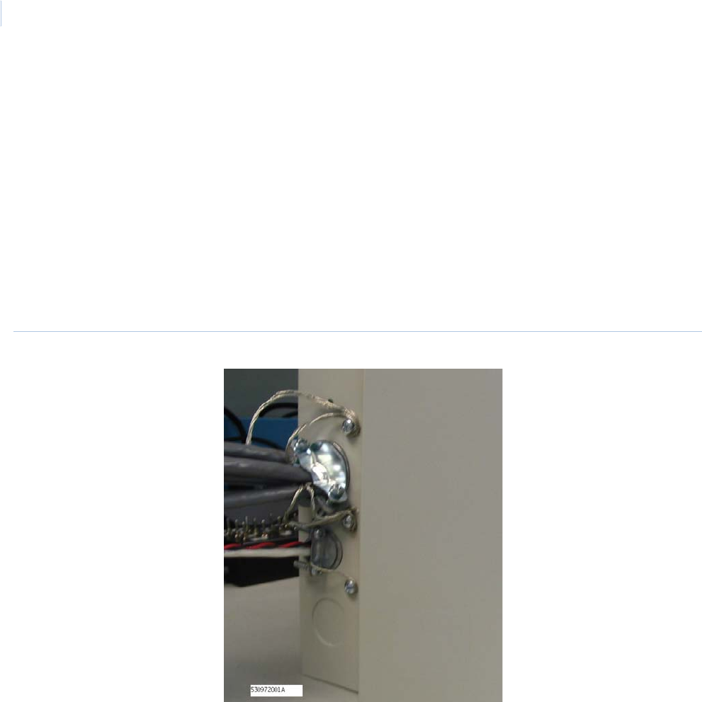
DirecDoor
Installation Manual
80
CE (European) and FCC compliance
As of January 1, 1996, all new European Union member installations MUST be CE compliant.
To make the DirecDoor installation CE and FCC compliant, the following conditions must be met:
• All cables connected to the DirecDoor must be shielded with shield terminated as shown in
Figure 27 on page 80. Use #8-32 SEMS screws provided.
• The DirecDoor enclosure must be connected to the nearest earth ground. See Figure 4,
Wiring earth ground on page 20.
• Prior to connecting the network cable to connector J10, loop the cable through Ferrite
provided as shown in Figure 28 on page 81.
Note: Ferrite must be installed inside of the enclosure.
Figure 27.Typical installation using shielded cable/drain wire
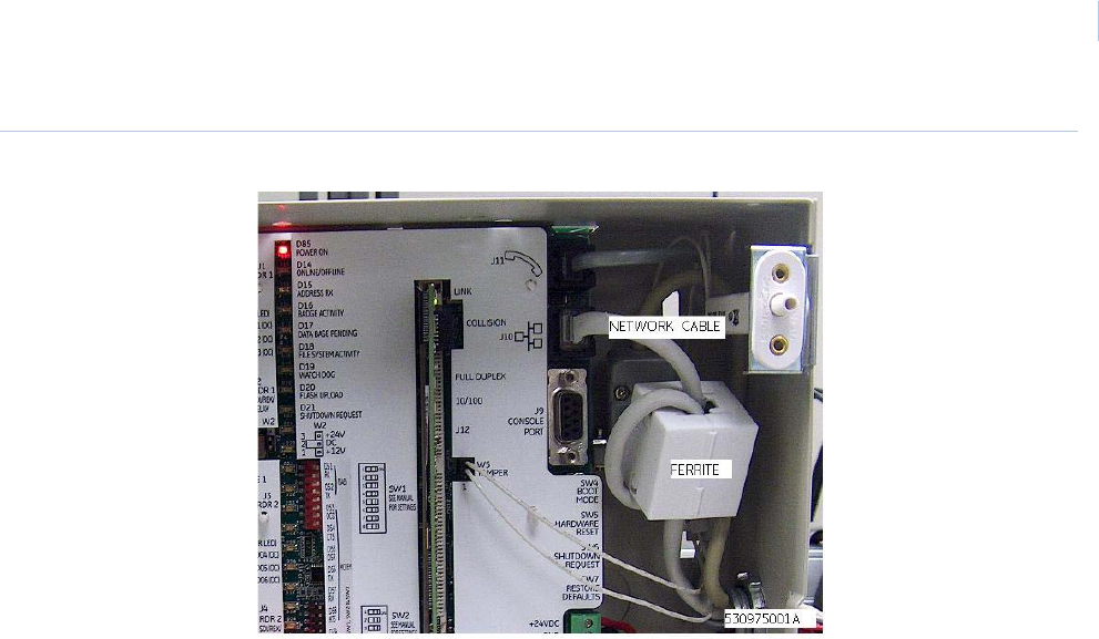
Chapter 9
Regulatory Information
81
Figure 28.Installing ferrite

DirecDoor
Installation Manual
82
CE regulatory notice

Chapter 9
Regulatory Information
83
UL compliance
Failure to install and program the DirecDoor, Picture Perfect (Unix or Linux) and Facility Commander
Wnx system in accordance with these instructions voids the listing mark of Underwriters’
Laboratories, Inc.
A clearly marked redundant system with the same configuration as the primary machine must be
available as a backup.
The monitoring equipment must be protected by a Listed Transient Voltage Surge Suppressor with a
maximum rating of 330V Listed under UL 1449. The communication circuit must be protected with a
Secondary Protector for Communication Circuits Listed under UL 497A.
The monitoring equipment must be installed in a temperature controlled environment with 24 hours
of standby power for the HVAC and computer system. In addition to the 24 hours of standby power, a
minimum of 15 minutes of standby power must be available to the computer system via a UPS
system. The UPS system must be Listed to UL 1778 or UL 1481 and must be provided with a
maintenance bypass switch.
For UL Listed installations:
• Operating environment: 32°-120°F (0°- 49°C)
• Humidity range: 85%
• PoE is not verified for UL installations.
• Auxiliary power supplied must be an approved UL 294 power-limited supply, such as the
Altronix Corp. Model AL300ULM.
• Connections to J5 (RS485), J7 (NX BUS), J9 (Console Port), and J8 (LOW BATT circuit)
have not been verified for UL installations.
• RDR 1 SDI/REX/RELAY (terminal block J2), RDR 2 SDI/REX/RELAY (terminal block J4), and
FACP INPUT (terminal block J6) terminals all need to be stated as being connected within
the protected area. These terminals include DC+, DC-, REX+, REX-, GND, RLYNC, COM,
and RLYNO since faults can cause unauthorized access.
• The DirecDoor is not intended to be installed as a stand-alone unit as neither it nor the
compatible UL Listed Altronix Corp. Model AL300ULM power supply does not incorporate a
designated AC power-on indicator visible after installation.
• PSDN (Ethernet) communication between the premise unit and monitoring station equipment
must be primary and DACT (telco) communication secondary in UL installations.
Figure 29.UL-Approved System Configuration

DirecDoor
Installation Manual
84
• The DirecDoor is UL Listed as an access control unit and a proprietary burglar alarm control
unit (UL 1076 and UL 294). It should be used with the listed Picture Perfect-Linux 4.0 or later,
or Facility Commander Wnx 7.0 or later system.
• The power supply’s AC power fail contacts must be wired to the DirecDoor as shown in
Figure 5, Wiring auxiliary power supply with built-in relay for fault output (AC power fail) on
page 20.
• Grounding must be in accordance with Article 250 of the National Electrical Code.
• The DirecDoor must be used with listed card readers.
• The exit request input circuit and initiating device must be contained within the secured area.
The exit device circuit must be connected to listed switches or exit devices.
• The DirecDoor must be mounted inside the secured area.
• The door strike power must be provided from a listed burglar alarm system power supply. If
the door strike circuit is arranged as fail secure (door remains locked upon loss of power),
listed emergency panic hardware must be provided to allow exit from the secured area. A fail-
safe configuration results in the door strike circuit unlocking in case of a power loss.
• The number of separate signals on a single channel shall be limited to 1000.
• The DirecDoor tamper switch must be wired to the Power/Communications board as shown
in Figure 5, Wiring auxiliary power supply with built-in relay for fault output (AC power fail) on
page 20.
• Alarms on Picture Perfect and Facility Commander Wnx should be set using the following
priority list with 1 being the highest priority and 7 being the lowest:
1.Fire alarm and industrial supervision
2.Hold-up or panic alarm
3.Burglar alarm
4.Watchman or guard tour
5.Fire-alarm supervision
6.Burglar-alarm supervision
7.Industrial supervision
• A clearly marked redundant system with the same configuration as the primary machine
should be available as a backup.
• In order for this product to be UL-compliant, the firmware level must be R1.05 or later.
Note: Removing all alarms from the Alarm Monitor should not be available to operators on UL Listed systems.

Chapter 10 Troubleshooting, Maintenance,
and Support
This chapter provides information to help you troubleshoot problems and
contact technical support in case you need assistance with your
equipment.
In this chapter:
Troubleshooting . . . . . . . . . . . . . . . . . . . . . . . . . . . . . . . . . . . . . 86
Maintenance . . . . . . . . . . . . . . . . . . . . . . . . . . . . . . . . . . . . . . . . 90
Contacting technical support . . . . . . . . . . . . . . . . . . . . . . . . . . . 90

DirecDoor
Installation Manual
86
Troubleshooting
This section provides information to help you diagnose and solve various problems that may arise
while configuring or using your UTC Fire & Security product and offers technical support contacts in
case you need assistance. (See Contacting technical support on page 90.)
Refer to the appropriate section:
• Power: See Power problems on page 86.
• Readers: See Reader problems on page 86.
• Door strikes: See Door strike problems on page 87.
• DirecDoor: See DirecDoor problems on page 87.
Power problems
Problem: The DirecDoor does not power up correctly.
Resolution: Verify that D85 (Power LED) is on. See Figure 5, Wiring auxiliary power supply with
built-in relay for fault output (AC power fail) on page 20. If the LED is NOT on, do the following:
1. Use a voltmeter to check the power supply output. It should read 24 VDC nominal. If there is
no output, make sure the power supply is not on a switched outlet. Be sure the circuit breaker
where the power supply is connected, is not tripped.
2. Be sure connector J8 is properly seated in the board.
3. Make sure that the wiring connections from the power supply to the board are not reversed.
4. Disconnect connector J8 from the board. Use an ohmmeter to check the resistance between
pins 1 and 2. If the resistance is less than 10K ohms, there is a short from power to ground.
Isolate the fault by removing the connectors one-by-one until the fault condition disappears.
Trace out the wiring on these connectors to find and correct the problem.
Reader problems
Consult your reader installation manual for potential problems that are not related to the DirecDoor.
Using the reader interface
Problem: The reader does not power up.
Resolution:
1. Check the wiring between the reader interface and the reader. See Chapter 5, Reader
Interface on page 35 and the reader installation manual.
2. Be sure the connector is firmly seated in the board.
Problem: The reader has power, but D16 (Badge Activity LED) on the board does not light up when
a badge is presented.

Chapter 10
Troubleshooting, Maintenance, and Support
87
Resolution:
1. Be sure that the switch settings on the board for address and reader technology/format are
correct. See Setting the DIP switches on page 37.
2. Check the wiring between the reader and the reader interface. See Chapter 5, Reader
Interface on page 35 and the reader installation manual.
Door strike problems
Problem: D16 (Badge Activity LED) lights on the board and the door reader LED lights on the
reader, but the door strike does not operate.
Resolution:
1. Check the wiring from the door strike to the reader interface. In the chapter of the appropriate
reader interface, see the section that covers wiring the door strike. Also refer to the door
strike manufacturer’s installation instructions.
2. Be sure the door strike power supply is operating properly.
DirecDoor problems
If the problem is not caused by incorrect hardware wirings or settings, check the software settings of
DirecDoor using the Integrated Configuration Tool.
Problem: I need to restore the factory default settings.
Resolution:
1. Press SW7 (Restore Defaults switch) until D16 (Badge Activity LED) turns on.
2. The controller is now offline from the host and the factory defaults have been restored. The
factory defaults are as follows:
-Host/Server Type: Picture Perfect
-Primary Connection Type: Ethernet
-IP Address: 192.168.6.6
-Mask: 255.255.255.0
-Gateway: 192.168.6.1
3. If necessary, reconfigure the controller. See Controller setup overview on page 59.
Problem: The network controller does not connect.
Resolution:
1. Verify your network settings:
- host IP address (Picture Perfect systems)
- controller IP address and controller address (Facility Commander Wnx systems)
-network mask
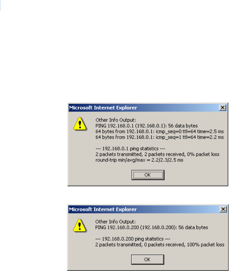
DirecDoor
Installation Manual
88
- gateway IP
- DHCP/DNS server
2. Check the connectivity by using the ping command. Use the Ping Host option in the
Integrated Configuration Tool. See Using the Other Info field on page 62 for more details.
a. In the Integrated Configuration Tool, select Controller Info.
b. From the Other Info drop-down list, select Ping Host.
Successful ping example:
Unsuccessful ping example:
Problem: The dial fallback controller does not connect.
Resolution:
1. Verify your settings:
- controller address
- modem strings
- baud rate settings
- cabling
2. Verify modem LED activity. See Table 21, Modem LEDs on the DirecDoor board on page 32.

Chapter 10
Troubleshooting, Maintenance, and Support
89
Diagnostic LED display
Built-in diagnostics enable you to quickly determine why a controller may not be working correctly.
The board LEDs D18 (File Sys. Activity LED), D19 (Watch dog LED), D20 (Flash Upload LED), and
D21 (Shut down Request LED) are used for displaying error codes.
Table 37. DirecDoor board LED fault conditions
D14 D15 D16 D17 D18 D19 D20 D21
Resolution/
Definition
Boot maintenance mode
Corrupted boot Flashes Contact Tech
Support.
Boot mode Flashes
Boot failure Flashes Flashes Flashes
Boot failure code Flashes Flashes
OS (Operating System) maintenance mode
OS mainten-ance Alternates
ON with
D16
Alternates
ON with
D15
ON
Operation state
Restore defaults
requested
ON ON Factory default
settings were
restored to the
board.
Shutdown
requested
ON ON The board properly
shut-down and may
be removed.
Watchdog failure
mode
ON ON An internal thread
failed.1
1.The failure was logged accord-ing to the log settings. The controller performs a complete reboot after this failure
DirecDoor
Installation Manual
90
Maintenance
Inserting and removing the UCSIMMPlus board on the DirecDoor board
1. To safely shut down the controller operating system, press SW6 (Shutdown Request switch)
on the DirecDoor board for approximately 5 seconds until D20 (Flash Upload LED) turns on.
D15 (Address Rx LED) and D16 (Badge Activity LED) then alternate On.
2. Disconnect power and battery backup power.
3. Locate the clips on the right and left sides of the UCSIMMPlus board. Press both clips out.
4. Pull out the UCSIMMPlus board.
5. The board fits in with the small cutout in the right corner. Insert the board at a 45 degree
angle.
6. Press down on the board until the clips engage.
Contacting technical support
For assistance installing, operating, maintaining, and troubleshooting this product, refer to this
document and any other documentation provided. If you still have questions, you may contact
technical support during normal business hours (Monday through Friday, excluding holidays,
between 8 a.m. and 7 p.m. Eastern Time).
Note: Please be ready at the equipment before calling for technical support.
CAUTION: Do NOT remove the UCSIMMPlus board unless instructed to do so by Technical Support.
CAUTION: Follow standard static prevention procedures. See Electrostatic Discharge (ESD) precaution on
page 9.
Table 38. Sales and support contact information
Pre-sales Technical support
Phone: 1 800 428 2733 1 855 536 3573
Fax: 1 561 998 6160 1 561 998 6224
E-mail: None rs-bctsupport@fs.utc.com
Website www.utcfireandsecurity.com

91
Index
A
AC power fail, wiring ............................................................................20
B
battery backup ......................................................................................20
boot mode switch (SW4).....................................................................24
C
cabling
controller to DIs or DOs ....................................................................3
controller to readers ..........................................................................3
host to controller ................................................................................3
Connector pinouts
J8........................................................................................................17
conventions .......................................................................................... vii
D
default factory settings
restore defaults switch (SW7)........................................................24
restoring ............................................................................................74
DES encryption configuration using the Integrated Configuration
Tool ................................................................66
device current table................................................................................4
digital inputs
supervised DI/REX switch (SW1-7 and SW1-8).........................38
wiring..................................................................................................43
digital outputs
maximum supported..........................................................................4
output devices maximum ratings.....................................................4
wiring..................................................................................................49
DirecDoor
board layout ......................................................................................23
configuring upstream communications.........................................34
DO output pinouts and reader connector pinouts (J1 and J3) 39, 40
door strike
troubleshooting.................................................................................87
wiring..................................................................................................44
F
factory default settings
restore defaults switch (SW7)........................................................24
restoring ............................................................................................74
Fire Alarm Control Panel (FACP) ......................................................46
flashing controllers ...............................................................................74
G
grounding
controller cabinet .......................................................................19, 80
H
hardware reset switch (SW5) .............................................................24
humidity range ........................................................................................3
I
input pinouts and relay connector pinouts (J2 and J4) ..................40
Integrated Configuration Tool
DES encryption configuration ........................................................66
factory default settings, restoring ..................................................74
first time configuration.....................................................................56
flashing controllers...........................................................................74
hardware requirements...................................................................54
MAG badge format options ............................................................69
operating system status of the DirecDoor, checking .................62
software requirements ....................................................................54
troubleshooting.................................................................................87
Integration Configuration Tool
saving changes ................................................................................59
J
Jumpers
W2......................................................................................................38
W3......................................................................................................38
J1 and J3 - reader connector pinouts and DO output pinouts 39, 40
J2 and J4 - relay connector pinouts and input pinouts...................40
J8 pinouts ..............................................................................................17
L
LED indicators ................................................................................28–33
input LEDs ........................................................................................32
modem...............................................................................................32
power .................................................................................................17
UCSIMM............................................................................................33

DirecDoor
Installation Manual
92
M
MAG badge format options.................................................................69
mounting the controller
instructions........................................................................................11
O
operating environment...........................................................................3
operating system status of the DirecDoor, checking ......................62
P
persistence mode times ......................................................................29
physical dimensions of controller cabinet...........................................3
Power input port J8 ..............................................................................17
power LED indicator ............................................................................17
Power over Ethernet (PoE)
installing ............................................................................................17
power requirements...........................................................................3
power supply, auxiliary
installing ............................................................................................19
power requirements...........................................................................3
power troubleshooting .........................................................................86
preface .................................................................................................. vii
product
overview ..............................................................................................2
R
reader connector pinouts and DO output pinouts (J1 and J3) 39, 40
reader technology switch (SW1-1 through SW1-4) ........................37
readers
maximum supported..........................................................................3
output devices maximum ratings.....................................................3
reader technology supported ...........................................................3
reader technology switch (SW1-1 through SW1-4)....................37
wiring..................................................................................................39
relay connector pinouts and input pinouts (J2 and J4) ..................40
Relay power jumper
Reader 1 (W2)..................................................................................38
Reader 2 (W3)..................................................................................38
restore defaults switch (SW7) ............................................................24
S
safety terms and symbols .................................................................. vii
shutdown request switch (SW6) ........................................................24
supervised DI/REX switch (SW1-7 and SW1-8) .............................38
switches
SW1-1 through SW1-4 - reader technology switch....................37
SW1-7 and SW1-8 - supervised DI/REX .....................................38
SW2 ...................................................................................................24
SW4 - boot mode switch.................................................................24
SW5 - hardware reset .....................................................................24
SW6 - shutdown request switch....................................................24
SW7 - restore defaults switch........................................................24
T
tamper, wiring .......................................................................................20
technical support ..................................................................................90
thermal air cooling..................................................................................3
troubleshooting .....................................................................................86
U
UCSIMM board
inserting and removing ...................................................................90
LED indicators..................................................................................33
location ..............................................................................................23
W
W2, relay power jumper reader 1 ......................................................38
W3, relay power jumper reader 2 ......................................................38
