4716man
User Manual: 4716man
Open the PDF directly: View PDF ![]() .
.
Page Count: 192 [warning: Documents this large are best viewed by clicking the View PDF Link!]
- CD-ROM Table of Contents
- Model 3095MV MultiVariable Mass Flow Transmitter
- Section 1 Introduction
- Section 2 Initial Checkout and Field Installation
- Section 3 Options and Accessories
- Section 4 Using Engineering Assistant Software
- Section 5 Troubleshooting and Maintenance
- Section 6 Specifications and Reference Data
- Appendix A HART Communicator
- Appendix B Approval Drawings
- Appendix C EA Error Message Summary
- Appendix D Critical Alarms for Previous Software Revisions
- Appendix E Compatibility Issues
- Appendix F European ATEX Directive Information
- Model 3095MV MultiVariable Mass Flow Transmitter
00809-0100-4716
English
Rev. GA
Model 3095 MV™
Multivariable™
Mass Flow Transmitter

Product Manual
Model 3095 MV™
Multivariable™Mass Flow
Transmitter
Rosemount Model 3095MV Multivariable Transmitter may be protected by one or more of the following U.S.
Patent Nos. 4,370,890; 4,612,812; 4,791,352; 4,798,089; 4,818,994; 4,833,922; 4,866,435; 4,926,340;
5,028,746. MEXICO PATENTADO NO. 154,981. May depend on model.
Other foreign patents issued and pending.
Rosemount and the Rosemount logotype are registered trademarks of Rosemount Inc.
Coplanar, Multivariable, MV, and Tri-Loop are trademarks of Rosemount Inc.
PlantWeb is a mark of the Fisher-Rosemount group of companies.
HART is a registered trademark of the HART Communication Foundation.
Hastelloy C-276 is a registered trademark of Cabot Corp.
Microsoft and Windows are registered trademarks of Microsoft Corp.
Annubar is a registered trademark of Deterich Standard Corporation.
V-Cone is a registered trademark of McCrometer.
Cover Photo: 3095Hi-3095001B.
Read this manual before working with the product. For personal and system
safety, and for optimum product performance, make sure you thoroughly
understand the contents before installing, using, or maintaining this product.
Within the United States, Rosemount Inc. has two toll-free assistance numbers.
Customer Central: 1-800-999-9307 (
7:00 a.m. to 7:00 p.m. CST)
Technical support, quoting, and order-related questions.
North American 1-800-654-7768 (
24 hours a day – Includes Canada)
Response Center: Equipment service needs.
For equipment service or support needs outside the United States, contact your
local Rosemount representative.
The products described in this document are NOT designed for nuclear-
qualified applications.
Using non-nuclear qualified products in applications that require nuclear-
qualified hardware or products may cause inaccurate readings.
For information on Rosemount nuclear-qualified products, contact your local
Rosemount Sales Representative.
SNF-0004
NOTICE
Fisher-Rosemount satisfies all obligations coming from legislation
to harmonize product requirements in the European Union.
Rosemount Inc.
8200 Market Boulevard
Chanhassen, MN 55317 USA
Tel 1-800-999-9307
Telex 4310012
Fax (612) 949-7001
© 1999 Rosemount, Inc.
P
R
I
N
T
E
D
IN
U.
S.
A.
http://www.rosemount.com
Model 3095 MV Software Revision 13
Engineering Assistant Software Revision 4.00
HART Communicator Software Revision 2.1

Table of Contents
iii
SECTION 1
Introduction
Using This Manual . . . . . . . . . . . . . . . . . . . . . . . . . . . . . . . . . . . . . . . 1-1
SECTION 2
Initial Checkout
and
Field Installation
Unpacking the Model 3095 MV . . . . . . . . . . . . . . . . . . . . . . . . . . . . . 2-2
Becoming Familiar with the Model 3095 MV . . . . . . . . . . . . . . . . . . 2-2
Initial Inspection . . . . . . . . . . . . . . . . . . . . . . . . . . . . . . . . . . . . . . . . 2-4
Bench Configuration and Calibration . . . . . . . . . . . . . . . . . . . . 2-4
Write Protect and Failure Mode Alarm Jumpers . . . . . . . . . . . 2-4
General Considerations . . . . . . . . . . . . . . . . . . . . . . . . . . . . . . . . . . . 2-5
Mechanical Considerations . . . . . . . . . . . . . . . . . . . . . . . . . . . . . . . . 2-6
Taps . . . . . . . . . . . . . . . . . . . . . . . . . . . . . . . . . . . . . . . . . . . . . . . 2-8
Impulse Piping . . . . . . . . . . . . . . . . . . . . . . . . . . . . . . . . . . . . . . . 2-9
Environmental Considerations . . . . . . . . . . . . . . . . . . . . . . . . . . . . . 2-9
Access Requirements . . . . . . . . . . . . . . . . . . . . . . . . . . . . . . . . . . 2-10
Process Considerations . . . . . . . . . . . . . . . . . . . . . . . . . . . . . . . . 2-11
Mounting Considerations . . . . . . . . . . . . . . . . . . . . . . . . . . . . . . 2-12
Bolt Installation Guidelines . . . . . . . . . . . . . . . . . . . . . . . . . . . . 2-13
Electrical Considerations . . . . . . . . . . . . . . . . . . . . . . . . . . . . . . . . . . 2-16
Power Supply . . . . . . . . . . . . . . . . . . . . . . . . . . . . . . . . . . . . . . . . 2-16
Hazardous Locations . . . . . . . . . . . . . . . . . . . . . . . . . . . . . . . . . . . . . 2-16
Field installation Equipment . . . . . . . . . . . . . . . . . . . . . . . . . . . . . . 2-17
Field Installation Procedure . . . . . . . . . . . . . . . . . . . . . . . . . . . . . . . 2-17
Review Installation Considerations . . . . . . . . . . . . . . . . . . . . . . 2-17
Mount Transmitter and Install Bolts . . . . . . . . . . . . . . . . . . . . . 2-17
Make Process Connections . . . . . . . . . . . . . . . . . . . . . . . . . . . . . 2-18
Install RTD Assembly . . . . . . . . . . . . . . . . . . . . . . . . . . . . . . . . . 2-18
Check for Leaks . . . . . . . . . . . . . . . . . . . . . . . . . . . . . . . . . . . . . . 2-19
Field Wiring
(Power and Signal) . . . . . . . . . . . . . . . . . . . . . . . . . . . . . . . . . . . . 2-19
Install Grounds . . . . . . . . . . . . . . . . . . . . . . . . . . . . . . . . . . . . . . 2-21
Replace Cover . . . . . . . . . . . . . . . . . . . . . . . . . . . . . . . . . . . . . . . . 2-21
Calibration . . . . . . . . . . . . . . . . . . . . . . . . . . . . . . . . . . . . . . . . . . . . . 2-21
SECTION 3
Options and
Accessories
LCD Meter . . . . . . . . . . . . . . . . . . . . . . . . . . . . . . . . . . . . . . . . . . . . . 3-1
Totalizer Display . . . . . . . . . . . . . . . . . . . . . . . . . . . . . . . . . . . . . 3-2
Installing the Meter . . . . . . . . . . . . . . . . . . . . . . . . . . . . . . . . . . . 3-3
SST Mounting Brackets . . . . . . . . . . . . . . . . . . . . . . . . . . . . . . . . . . . 3-5
Engineering Assistant Software . . . . . . . . . . . . . . . . . . . . . . . . . . . . 3-5
Transient Protection Terminal Block . . . . . . . . . . . . . . . . . . . . . . . . 3-5
Installation Procedure . . . . . . . . . . . . . . . . . . . . . . . . . . . . . . . . . 3-5
Custom Configuration (Option Code C2) . . . . . . . . . . . . . . . . . . . . . 3-7
Flange Adapters (Option Code DF) . . . . . . . . . . . . . . . . . . . . . . . . . . 3-7
Model 305 Integral Manifold
(Option Code S5) . . . . . . . . . . . . . . . . . . . . . . . . . . . . . . . . . . . . . . . . 3-7
Model 1195 Integral Orifice Assembly
(Option Code S4) . . . . . . . . . . . . . . . . . . . . . . . . . . . . . . . . . . . . . . . . 3-7
Annubar Assembly (Option Code S4) . . . . . . . . . . . . . . . . . . . . . . . . 3-7

iv
SECTION 4
Using the
Engineering
Assistant Software
Installing The Engineering Assistant Software . . . . . . . . . . . . . . . . 4-1
Minimum Equipment and Software . . . . . . . . . . . . . . . . . . . . . . . . . 4-1
Installation Procedure . . . . . . . . . . . . . . . . . . . . . . . . . . . . . . . . . . . . 4-2
Connecting to a Personal Computer . . . . . . . . . . . . . . . . . . . . . . . . . 4-4
Menu Structure . . . . . . . . . . . . . . . . . . . . . . . . . . . . . . . . . . . . . . . . . 4-7
Menu Categories . . . . . . . . . . . . . . . . . . . . . . . . . . . . . . . . . . . . . 4-8
Procedure Outlines . . . . . . . . . . . . . . . . . . . . . . . . . . . . . . . . . . . . . . . 4-8
Bench Configuration (Standard) . . . . . . . . . . . . . . . . . . . . . . . . . 4-8
Bench Calibration Procedure . . . . . . . . . . . . . . . . . . . . . . . . . . . 4-9
Field Calibration Procedure . . . . . . . . . . . . . . . . . . . . . . . . . . . . 4-9
Automatic Error Messages . . . . . . . . . . . . . . . . . . . . . . . . . . . . . 4-9
Engineering Assistant Software Screens . . . . . . . . . . . . . . . . . . . . . 4-10
Screen Components . . . . . . . . . . . . . . . . . . . . . . . . . . . . . . . . . . . 4-10
Status Bar Codes . . . . . . . . . . . . . . . . . . . . . . . . . . . . . . . . . . . . . 4-10
Hot Keys . . . . . . . . . . . . . . . . . . . . . . . . . . . . . . . . . . . . . . . . . . . . 4-10
Path Name Convention . . . . . . . . . . . . . . . . . . . . . . . . . . . . . . . . 4-11
Cancel Buttons . . . . . . . . . . . . . . . . . . . . . . . . . . . . . . . . . . . . . . . 4-11
Fast Keys . . . . . . . . . . . . . . . . . . . . . . . . . . . . . . . . . . . . . . . . . . . 4-11
Toolbar . . . . . . . . . . . . . . . . . . . . . . . . . . . . . . . . . . . . . . . . . . . . . 4-11
Setup Screens . . . . . . . . . . . . . . . . . . . . . . . . . . . . . . . . . . . . . . . . 4-12
Transmitter Screens . . . . . . . . . . . . . . . . . . . . . . . . . . . . . . . . . . 4-33
Maintenance Screens . . . . . . . . . . . . . . . . . . . . . . . . . . . . . . . . . . 4-43
Diagnostics Screens . . . . . . . . . . . . . . . . . . . . . . . . . . . . . . . . . . . 4-51
Miscellaneous EA Selections . . . . . . . . . . . . . . . . . . . . . . . . . . . . . . . 4-55
SECTION 5
Troubleshooting
and
Maintenance
Troubleshooting . . . . . . . . . . . . . . . . . . . . . . . . . . . . . . . . . . . . . . . . . 5-1
Alarm Abbreviations . . . . . . . . . . . . . . . . . . . . . . . . . . . . . . . . . . 5-1
EA Communication Problems . . . . . . . . . . . . . . . . . . . . . . . . . . . . . . 5-2
Revision 12 Electronics Board Alarms And Error Conditions . . . . . 5-2
LCD Display . . . . . . . . . . . . . . . . . . . . . . . . . . . . . . . . . . . . . . . . . 5-2
Critical Alarms . . . . . . . . . . . . . . . . . . . . . . . . . . . . . . . . . . . . . . 5-3
Overrange Conditions . . . . . . . . . . . . . . . . . . . . . . . . . . . . . . . . . 5-4
Sensor Limits . . . . . . . . . . . . . . . . . . . . . . . . . . . . . . . . . . . . . . . . 5-6
Unexpected Process Variable (PV) Readings . . . . . . . . . . . . . . . 5-7
Disassembly Procedures . . . . . . . . . . . . . . . . . . . . . . . . . . . . . . . . . . 5-12
Removing the Process Sensor Body . . . . . . . . . . . . . . . . . . . . . . 5-12
Removing the Electrical Housing . . . . . . . . . . . . . . . . . . . . . . . . 5-13
Removing the Electronics Board . . . . . . . . . . . . . . . . . . . . . . . . . 5-13
Removing the Sensor Module . . . . . . . . . . . . . . . . . . . . . . . . . . . 5-15
Reassembly Procedures . . . . . . . . . . . . . . . . . . . . . . . . . . . . . . . . . . . 5-16
Attaching the Sensor Module to the Electronics Housing . . . . . 5-16
Attaching the Electronics Board . . . . . . . . . . . . . . . . . . . . . . . . . 5-17
Reassembling the Process Sensor Body . . . . . . . . . . . . . . . . . . . 5-18
Return Of Materials . . . . . . . . . . . . . . . . . . . . . . . . . . . . . . . . . . . . . . 5-19
SECTION 6
Specifications and
Reference Data
Functional Specifications . . . . . . . . . . . . . . . . . . . . . . . . . . . . . . . . . . 1
Performance Specifications . . . . . . . . . . . . . . . . . . . . . . . . . . . . . . . . 5
Physical Specifications . . . . . . . . . . . . . . . . . . . . . . . . . . . . . . . . . . . . 7
Ordering InformatIon . . . . . . . . . . . . . . . . . . . . . . . . . . . . . . . . . . . 8
Options . . . . . . . . . . . . . . . . . . . . . . . . . . . . . . . . . . . . . . . . . . . . . 9
Accessories . . . . . . . . . . . . . . . . . . . . . . . . . . . . . . . . . . . . . . . . . . 10
Spare Parts . . . . . . . . . . . . . . . . . . . . . . . . . . . . . . . . . . . . . . . . . . . . . 12
Model 3095 MV
Configuration Data Sheet . . . . . . . . . . . . . . . . . . . . . . . . . . . . . . . . . 18

v
APPENDIX A
HART®
Communicator
Introduction . . . . . . . . . . . . . . . . . . . . . . . . . . . . . . . . . . . . . . . . . . . . A-1
EA Software/
Hart Communicator Comparison . . . . . . . . . . . . . . . . . . . . . . . . . . . A-1
Connections and hardware . . . . . . . . . . . . . . . . . . . . . . . . . . . . . . . . A-4
Communicator Keys . . . . . . . . . . . . . . . . . . . . . . . . . . . . . . . . . . . . . . A-6
Fast Key Sequences . . . . . . . . . . . . . . . . . . . . . . . . . . . . . . . . . . . A-8
Menus and Functions . . . . . . . . . . . . . . . . . . . . . . . . . . . . . . . . . . . . . A-8
Main Menu . . . . . . . . . . . . . . . . . . . . . . . . . . . . . . . . . . . . . . . . . . A-8
Online Menu . . . . . . . . . . . . . . . . . . . . . . . . . . . . . . . . . . . . . . . . A-9
Diagnostic Messages . . . . . . . . . . . . . . . . . . . . . . . . . . . . . . . . . . A-10
APPENDIX B
Approval
Drawings
Approval Drawings . . . . . . . . . . . . . . . . . . . . . . . . . . . . . . . . . . . . . . B-1
APPENDIX C
EA Error Message
Summary
Warning Messages . . . . . . . . . . . . . . . . . . . . . . . . . . . . . . . . . . . . . . . C-1
Error messages . . . . . . . . . . . . . . . . . . . . . . . . . . . . . . . . . . . . . . . . . . C-2
APPENDIX D
Critical Alarms for
Previous Software
Revisions
Alarm Abbreviations . . . . . . . . . . . . . . . . . . . . . . . . . . . . . . . . . . . . . D-1
Alarms and Error Conditions for Revisions 8, 9, and 10 . . . . . . . . . D-1
Critical Alarms . . . . . . . . . . . . . . . . . . . . . . . . . . . . . . . . . . . . . . D-1
Overrange Conditions . . . . . . . . . . . . . . . . . . . . . . . . . . . . . . . . . D-1
Alarms and Error Conditions for Revisions 4 and 5 . . . . . . . . . . . . D-4
Overrange Conditions . . . . . . . . . . . . . . . . . . . . . . . . . . . . . . . . . D-4
APPENDIX E
Compatibility
Issues
Overview . . . . . . . . . . . . . . . . . . . . . . . . . . . . . . . . . . . . . . . . . . . . . . . E-1
Revision Level Indicators . . . . . . . . . . . . . . . . . . . . . . . . . . . . . . . . . E-1
Electronics Board . . . . . . . . . . . . . . . . . . . . . . . . . . . . . . . . . . . . . E-1
Sensor Module . . . . . . . . . . . . . . . . . . . . . . . . . . . . . . . . . . . . . . . E-1
Sensor Limits . . . . . . . . . . . . . . . . . . . . . . . . . . . . . . . . . . . . . . . . . . . E-2
Electronics Compatibility . . . . . . . . . . . . . . . . . . . . . . . . . . . . . . . . . E-3
Hardware Compatibility . . . . . . . . . . . . . . . . . . . . . . . . . . . . . . . . . . E-3
Communication Compatibility . . . . . . . . . . . . . . . . . . . . . . . . . . . . . E-3
EA Software . . . . . . . . . . . . . . . . . . . . . . . . . . . . . . . . . . . . . . . . . E-3
HART Communicator Model 275 . . . . . . . . . . . . . . . . . . . . . . . . E-4
APPENDIX F
European ATEX
Directive Informa-
tion
European ATEX Directive Information . . . . . . . . . . . . . . . . . . . . . . . F-1
INDEX I-1

vi

Section
1-1
1Introduction
USING THIS MANUAL This manual provides installation, configuration, calibration,
troubleshooting, and maintenance instructions for the Rosemount®
Model 3095 MV™ Multivariable™ Mass Flow Transmitter and for its
operation with the Model 3095 MV Engineering Assistant Software.
This manual consists of the following sections:
Section 2: Initial Checkout and Field Installation
explains how to install the Model 3095 MV. It includes an installation
flowchart, installation considerations, and field installation procedure.
Section 3: Options and Accessories
describes options available with the Model 3095 MV: the LCD meter,
the mounting brackets, and the transient protection terminal block.
Section 4: Using the Model 3095 MV Engineering Assistant Software
explains how to use the configuration software. This includes installing
the software onto a personal computer, establishing communications
with the Model 3095 MV, configuring the transmitter, creating a
configuration file, and calibrating the flow transmitter. This section
also explains the configuration software menus.
Section 5: Troubleshooting and Maintenance
provides troubleshooting instructions for dealing with potential
mechanical or electrical difficulties.
Section 6: Theory of Operation
discusses the operating principles of the transmitter and provides
information about DP flow.
Section 7: Specifications and Reference Data
includes specification data for the Model 3095 MV and spare parts
information.
Appendix A: HART®Communicator
contains a communicator overview, a HART Communicator menu tree
for the Model 3095 MV, and a table of HART Communicator fast key
sequences. A table of diagnostic messages associated with this
communicator is also included.
Appendix B: Approval Drawings
contains Factory Mutual (FM) and Canada Standards Association
(CSA) certified drawings.
Appendix C: EA Error Message Summary
identifies possible error messages that might occur when using the
Engineering Assistant software.
Appendix D: Critical Alarms for Previous Software Revisions
contains troubleshooting information for previous electronics board and
sensor module revisions.
Appendix E: Compatibility Issues
contains compatibility information for retrofitting previous Model 3095
MV versions with new parts.

Rosemount Model 3095 MV
1-2

Section
2-1
2Initial Checkout and
Field Installation
This section contains an installation flowchart, information on the
Model 3095 MV system, installation considerations, and a field
installation procedure. The suggested sequence of Model 3095 MV
installation and wiring is shown in Figure 2-1.
A
B
B
START
A
B
Review Rosemount
drawing 03095-1025
or 03095-1024
(see Appendix B
Approval Drawings)
Review Rosemount
drawings 03095-1020
or 03095-1021
(see Appendix B
Approval Drawings)
Hazardous
Location
?
Non-
Incendive
Location
?
Unpack the Model
3095 MV
Review the Model
3095 MV Product
Manual
Bench
Configure
?
BENCH
CONFIGURE
Connect Bench
Power Supply
(see 2-16)
Connect Personal
Computer
(4-4)
Perform Bench
Configuration
Tasks (4-9)
(Optl.) Perform
Bench Calibration
Tasks (4-8)
FIELD
INSTALLATION
Review Installation
Considerations
(2-6–2-16)
Mount
Transmitter
(2-12)
Make Process
Connections
DONE
Yes
Yes
No
No
Yes
No
(Optl.) Perform
Field Calibration
Tasks (4-9)
Configuration
Performed
?
No Perform
Configuration
Tasks (4-8)
Yes
Check
for
Leaks
(Optional) Install
RTD Assembly
(2-18)
FIGURE 2-1. Model 3095 MV
Installation Flowchart.
Rosemount Model 3095 MV
2-2
UNPACKING THE MODEL
3095 MV
Depending on the system ordered, the Model 3095 MV arrives in as
many as three different shipping containers:
Model 3095 MV
This box contains the Model 3095 MV. If ordered, this package also
contains an RTD cable and optional mounting hardware. One Model
3095 MV Multivariable Transmitter Product Manual is included with
each order of transmitters.
Engineering Assistant Software Package (Accessory)
The complete Engineering Assistant Software Package includes two
installation 3.5-in. floppy disks, one HART modem and cables, and
the Model 3095 MV Multivariable Transmitter Product Manual.
Engineering Assistant components may also be ordered separately.
RTD Assembly (Optional)
This box contains the optional Series 68 or Series 78 RTD Assembly
and the Sensor Wiring Instruction Sheet.
BECOMING FAMILIAR
WITH THE MODEL 3095 MV
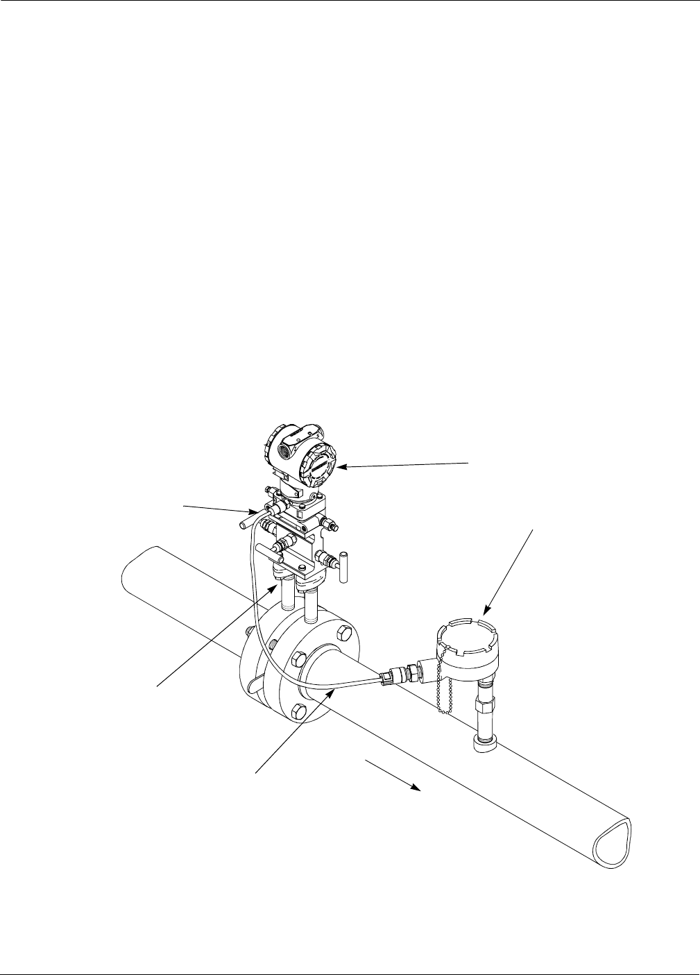
Figure 2-2 illustrates a typical Model 3095 MV installation site, and
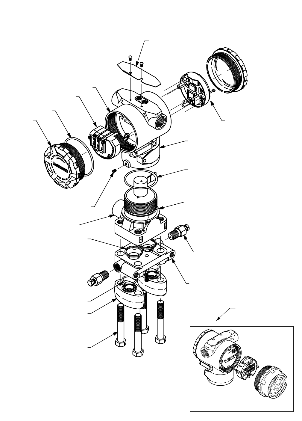
Figure 2-3 illustrates the exploded view of the Model 3095 MV. Major
components of the Model 3095 MV System and the Model 3095 MV
Multivariable Transmitter are identified in these figures.
3095-DATAE22A
FIGURE 2-2. Typical Model 3095 MV
Installation Site. Model 3095 MV
RTD Connector
Process
Connections
RTD Cable
RTD Assembly
Flow
2-3
Inital Checkout and Field Installation
FIGURE 2-3. Exploded View of Model
3095 MV Multivariable Transmitter and
LCD Meter.
Housing
O-ring
Terminal Block
Cover
Housing Locking Screw
Nameplate
Coplanar
Flange
Optional
Flange Adapters
3095-3095A08B, 3051-3031A05B
Bolts
Drain/Vent Valve
Certification
Label
Flange Adapter O-ring
LCD Meter
Electronics Board
Module O-ring
Process Adapter O-ring
RTD Connector
Sensor Module

Rosemount Model 3095 MV
2-4
INITIAL INSPECTION 1. Place the shipping containers on a secure bench and open them,
taking care not to damage the contents.
2. Review the packing list to verify that all equipment was received.
3. Inspect the equipment and report any shipping damage to the
carrier.
Bench Configuration and
Calibration
Before mounting the Model 3095 MV in the field, the Multivariable
Transmitter can be configured on the bench using a personal computer
and the Engineering Assistant (EA) Software.
The EA software provides advanced configuration capabilities,
including flow parameters such as AIChE fluid, meter tube bore,
differential producer bore, and differential producer material.
After bench configuration, the Model 3095 MV may be bench calibrated.
These procedures include absolute or gage pressure and differential
pressure sensor offset (zero) and slope (span) trim, and RTD
calibration.
For information on bench configuration and bench calibration, see
Bench Configuration (Standard) on page 4-8 and Bench
Calibration Procedure on page 4-9.
Write Protect and Failure
Mode Alarm Jumpers
Once the transmitter has been configured, the configuration data can
be protected by moving the write protect jumper. When this jumper is
installed, the transmitter does not allow any changes to its
configuration memory.
As part of its normal operation, the Model 3095 MV continuously
monitors its own operation. This automatic diagnostic routine is a
timed series of checks repeated continuously. If the diagnostic routine
detects a failure in a transmitter, the transmitter drives its output
either below 3.75 mA or above 21.75 mA depending on the position of
the failure mode jumper.
Both of these jumpers are located on the electronics board just inside
the electronics housing cover (see Figure 2-4). To avoid exposing the
transmitter electronics to the plant environment after installation, set
these jumpers during the commissioning stage on the bench.
When shipped from the factory, the write protect jumper is set to “OFF,”
and the alarm jumper is set to “High” unless specified differently by
ordering the C2 (Custom Configuration) Option Code.
Failure Mode Alarm vs.
Saturation Output Values The failure mode alarm output levels differ from the output values that
occur when applied pressure is outside the range points. When pressure
is outside the range points, the analog output continues to track the
input pressure until reaching the saturation value listed below; the
output does not exceed the listed saturation value regardless of the
applied pressure. For example, for pressures outside the 4–20 range
points, the output saturates at 3.9 mA or 20.8 mA. When the
transmitter diagnostics detect a failure, the analog output is set to a
specific alarm value that differs from the saturation value to allow for
proper troubleshooting.
Level 4–20 mA
Saturation
Value
4–20 mA
Alarm
Value
Low 3.9 mA 3.75 mA
High 20.8 mA 21.75 mA

2-5
Inital Checkout and Field Installation
NOTE
The preceding output values can be altered by an analog output
trim procedure.
Use the following steps to change the jumper settings:
1. If the transmitter is installed, secure the loop and remove power.
2. Remove the housing cover opposite the field terminal side.
3. Locate the jumper on the electronics board (see Figure 2-5), then
move the jumper to the desired setting.
4. Reattach the transmitter cover. To avoid condensation, metal to
metal contact is preferred.
5. If the transmitter is installed, reapply power.
Explosions can cause death or serious injury. Do not
remove the instrument cover in explosive atmospheres
when the circuit is alive.
Explosions can cause death or serious injury. Both
transmitter covers must be fully engaged to meet explosion-
proof requirements.
NOTE
Security jumper not installed = Not Write Protected.
Alarm jumper not installed = High Alarm.
FIGURE 2-4. Write Protect and
Alarm Jumpers.
ELECTRONICS BOARD
3095-0292a01A

Rosemount Model 3095 MV
2-6
GENERAL
CONSIDERATIONS
The accuracy of a flow or pressure measurement depends on proper
installation of the transmitter and impulse piping. The piping between
the process and the transmitter must accurately transfer the pressure
in order to obtain accurate measurements. Mount the transmitter close
to the process and use a minimum of impulse piping to achieve best
accuracy. Keep in mind, however, the need for easy access, safety of
personnel, practical field calibration, and a suitable transmitter
environment. In general, install the transmitter so as to minimize
vibration, shock, and temperature fluctuations.
The following paragraphs discuss the factors necessary for a successful
transmitter installation
MECHANICAL
CONSIDERATIONS
The Rosemount Model 3095 MV may be panel-mounted, wall-mounted,
or attached to a two-inch pipe with an optional mounting bracket.
Figure 2-5 illustrates Model 3095 MV mounting configurations, Figure
2-6 shows the transmitter dimensions, and Figure 2-7 illustrates
example installations.
FIGURE 2-5. Mounting Configurations.
6.15
(156)
2.82
(72) 4.3
(110)
7.07
(180)
1.10 (28)
2.81
(71)
4.74
(120) 3.54
(90)
6.25
(159)
NOTE
Dimensions are in inches (millimeters)
3095-3095J04B, K04A, I04B

2-7
Inital Checkout and Field Installation
FIGURE 2-6. Dimensional
Drawings of Model 3095 MV.
Meter
Cover
(Optional)
0.75 (19)
Clearance for
Cover Removal
Transmitter
Circuitry
This Side
Nameplate
Drain/Vent
Valve
6.4
(163)
½–14 NPT Conduit
Connection
(Two Places)
0.75 (19)
Clearance for
Cover Removal
Transmitter
Connections
This Side
5.0
(127)
4.3
(110) 2.15
(55)
7.07
(180)
8.17
(208)
¼–18 NPT on Coplanar Flange
for Pressure Connection without
the Use of Mounting Adapters
Certification
Label
4.09
(104)
Housing
Rotation
Set Screw
4.20
(107)
NOTE
Dimensions are in inches (millimeters)
3095-3095G05B, H05A
½–14 NPT on Optional Mounting Adapters.
Adapters Can Be Rotated to Give Connection
Centers of 2.00 (51), 2.125 (54), or 2.25 (57).

Rosemount Model 3095 MV
2-8
Taps Different measurement conditions call for different piping
configurations.
Liquid Flow For liquid flow measurement, place taps to the side of the line to
prevent sediment deposits, and mount the transmitter beside or below
these taps so gases can vent into the process line.
Gas Flow For gas flow measurement, place taps in the top or side of the line and
mount the transmitter beside or above the taps so liquid will drain into
the process line.
Steam Flow For steam flow measurement, place taps to the side of the line, with the
transmitter mounted below them to ensure that the impulse piping
stays filled with condensate.
NOTE
When the transmitter is oriented on its side, the Coplanar™ flange may
be mounted to ensure proper venting or draining. Mount the flange as
shown in Figure 2-7 so that the drain/vent connections are on the
bottom half of the flange for gas service, or on the top half of the flange
for liquid service.
In steam or other elevated temperature services, it is
important that temperatures at the coplanar process flanges
not exceed 185 °F (85 °C).
3095-3095A03A, B03A, D03A, 3031-B03B
LIQUID SERVICE
GAS SERVICE
Flow
Flow
Flow
FIGURE 2-7. Example Installations.
STEAM
SERVICE
Flow

2-9
Inital Checkout and Field Installation
NOTE
In steam service, lines should be filled with water to prevent contact of
the live steam with the transmitter. Condensate chambers are not
needed because the volumetric displacement of the transmitter
is negligible.
Impulse Piping The piping between the process and the transmitter must accurately
transfer the pressure in order to obtain accurate measurements. In this
pressure transfer, there are five possible sources of error: leaks, friction
loss (particularly if purging is used), trapped gas in a liquid line, liquid
in a gas line, and temperature-induced or other density variation
between the legs.
The best location for the transmitter in relation to the process pipe
depends on the process itself. Consider the following guidelines in
determining transmitter location and placement of impulse piping:
• Keep impulse piping as short as possible.
• Slope the impulse piping at least one inch per foot (8 centimeters
per meter) upward from the transmitter toward the process
connection for liquid.
• Slope the impulse piping at least one inch per foot (8 centimeters
per meter) downward from the transmitter toward the process
connection for gas.
• Avoid high points in liquid lines and low points in gas lines.
• Make sure both impulse legs are the same temperature.
• Use impulse piping large enough to avoid friction effects and
prevent blockage.
• Vent all gas from liquid piping legs.
• When using a sealing fluid, fill both piping legs to the same level.
• When purging is necessary, make the purge connection close to
the process taps and purge through equal lengths of the same size
pipe.
• Avoid purging through the transmitter.
• Keep corrosive or hot (above 250 °F [121 °C]) process material out
of direct contact with the sensor module and flanges.
• Prevent sediment deposits in the impulse piping.
• Keep the liquid head balanced on both legs of the impulse piping.
• Avoid conditions that might allow process fluid to freeze within
the process flange.
NOTE
For steam service, do not blow down impulse piping through the
transmitter. Flush the lines with the blocking valves closed and refill
the lines with water before resuming measurement.
ENVIRONMENTAL
CONSIDERATIONS
Mount the transmitter to minimize ambient temperature changes.
Section 6 Specifications and Reference Data lists the transmitter
temperature operating limits. Mount the transmitter to avoid vibration
and mechanical shock, and to avoid external contact with corrosive
materials.

Rosemount Model 3095 MV
2-10
Access Requirements When choosing an installation location and position, take into account
the need for access to the transmitter.
Process Flange Orientation The process flanges must be oriented so that process connections can be
made. In addition, consider the possible need for a testing or calibration
input.
Housing Rotation The electronics housing may be rotated to improve field access to the
two compartments. To rotate the housing less than 90 degrees, release
the housing rotation set screw and turn the housing not more than 90
degrees from the orientation shown in Figure 2-7 on page 2-8. To rotate
the housing greater than 180 degrees, follow steps 1–6 of the
disassembly procedure on page 5-12.
Terminal Side of
Electronics Housing • Wiring connections are made through the conduit openings on the
top side of the housing.
• The field terminal side is marked on the electronics housing.
• Mount the transmitter so that the terminal side is accessible. A
0.75-inch clearance is required for cover removal.
• Install a conduit plug in the unused conduit opening.
Circuit Side of
Electronics Housing The circuit compartment should not routinely need to be opened when
the unit is in service; however, provide 0.75 inches clearance if possible
to allow access.
Drain/vent valves must be oriented so that process fluid is
directed away from technicians when the valves are used.
Rotating the housing greater than 180 degrees without
performing the disassembly procedure may damage the
Model 3095 MV sensor module.

2-11
Inital Checkout and Field Installation
Process Considerations
Model 3095 MV process connections on the transmitter flange are 1/4–18
NPT. Flange adapter unions with 1/2–14 NPT connections are available
as options. These are Class 2 threads; use your plant-approved
lubricant or sealant when making the process connections. The process
connections on the transmitter flange are on 21/8-inch (54-mm) centers
to allow direct mounting to a three- or five-valve manifold. By rotating
one or both of the flange adapters, connection centers of 2, 21/8, or 21/4
inches (51, 54, or 57 mm) may be obtained.
When compressed, Teflon® O-rings tend to cold flow, which aids in their
sealing capabilities. Whenever flanges or adapters are removed,
visually inspect the Teflon O-rings. Replace them if there are any signs
of damage, such as nicks or cuts. If they are undamaged, they can be
reused. If the O-rings are replaced, the flange bolts may need to be
retorqued after installation to compensate for cold flow. Refer to the
process sensor body reassembly procedure on page 5-16.
Explosions can cause death or serious injury. Check
transmitter materials of construction and fill fluid for
compatibility with the intended process fluid.
Failure to install proper flange adapter O-rings can cause
process leaks, which can result in death or serious injury.
There are two styles of Rosemount flange adapters, each
requiring a unique O-ring, as shown below. Each flange
adapter is distinguished by its unique groove.
Use only the O-ring designed to seal with the corresponding
flange adapter. Refer to the Spare Parts List on page 6-12
for the correct part numbers of the flange adapters and
O-rings designed for the Model 3095 MV Multivariable
Transmitter.
Unique O-ring
Grooves
MODEL 3051/2024/3001/3095
MODEL 1151
Flange Adapter
O-ring
Flange Adapter
O-ring

Rosemount Model 3095 MV
2-12
Mounting Considerations The Model 3095 MV Multivariable Transmitter total weight varies
depending on the components ordered (see Table 2-1). This weight must
be securely supported.
TABLE 2-1. Transmitter Weight.
Mounting Brackets Optional mounting brackets available with the Model 3095 MV facilitate
mounting to a panel, wall, or 2-in. pipe. The bracket option for use with
the Coplanar flange is 316 SST with 316 SST bolts. Figure 2-8 shows
bracket dimensions and mounting configurations for this option.
When installing the transmitter to one of the mounting brackets, torque
the bolts to 125 in-lb (169 n-m).
Mounting Pressure Effect To correct for mounting position effects, the Model 3095 MV should be
field calibrated, using the field calibration procedure described on
page 4-9.
Component Weight lb (kg)
Model 3095 MV Transmitter
SST Mounting Bracket
12 ft (3.66 m) RTD Shielded Cable
12 ft (3.66 m) RTD Armored Cable
24 ft (7.32 m) RTD Shielded Cable
24 ft (7.32 m) RTD Armored Cable
75 ft (22.86 m) RTD Shielded Cable
75 ft (22.86 m) RTD Armored Cable
21 in (53 cm) RTD Armored Cable
12 ft (3.66 m) RTD CENELEC Cable
24 ft (7.32 m) RTD CENELEC Cable
75 ft (22.86 m) RTD CENELEC Cable
21 in (53 cm) RTD CENELEC Cable
6.0 (2.7)
1.0 (0.4)
0.5 (0.2)
1.1 (0.5)
1.0 (0.4)
2.2 (1.0)
1.9 (0.9)
7.2 (3.2)
0.5 (0.2)
2.1 (0.9)
3.0 (1.4)
7.1 (3.2)
1.2 (0.5)

2-13
Inital Checkout and Field Installation
Bolt Installation Guidelines The following guidelines have been established to ensure a tight flange,
adapter, or manifold seal. Use only bolts supplied with the transmitter
or sold by Rosemount Inc. as a spare part to the Model 3095 MV
transmitter.
The Model 3095 MV is shipped with the Coplanar flange installed with
four 1.75-inch flange bolts. The following bolts also are supplied to
facilitate other mounting configurations:
• Four 2.25-inch manifold/flange bolts for mounting the Coplanar
flange on a three-valve manifold. In this configuration, the 1.75-
inch bolts may be used to mount the flange adapters to the
process connection side of the manifold.
• (Optional) If flange adapters are ordered, four 2.88-inch flange/
adapter bolts for mounting the flange adapters to the Coplanar
flange.
Figure 2-8 shows the optional mounting bracket and mounting
configurations. Figure 2-9 shows mounting bolts and bolting
configuration for the Model 3095 MV with the Coplanar flange.
Stainless steel bolts supplied by Rosemount Inc. are coated with a
lubricant to ease installation. Carbon steel bolts do not require
lubrication. Do not apply additional lubricant when installing either
type of bolt. Bolts supplied by Rosemount Inc. are identified by the
following head markings:
Carbon Steel Head Markings (CS)
Stainless Steel Head Markings (SST)
B7M
316 316
RB8M STM
316 316 SW
316

Rosemount Model 3095 MV
2-14
5/16 311/2Bolts
for Panel Mounting
(Not Supplied)
2.81
(71)
3/8-16 311/4Bolts
for Mounting
to Transmitter
3.35
(85)
2-Inch U-Bolt
for Pipe Mounting
NOTE
Dimensions are in inches (millimeters).
FIGURE 2-8. Optional Mounting Bracket
and Mounting Configurations.
6.15
(156)
2.82
(72) 4.3
(110)
7.07
(180)
2.81
(71)
4.74
(120)
3.54
(90)
6.25
(159)
PIPE MOUNTING
PANEL MOUNTING
3095-3095J04B, K04A, I04B, 3031-3031I04A, J04A

2-15
Inital Checkout and Field Installation
FIGURE 2-9. Coplanar Mounting Bolts and
Bolting Configurations for Coplanar Flange.
1.75 (44) 34
1.75 (44) 34
2.25 (57) 34
TRANSMITTER WITH 3-VALVE MANIFOLD
MANIFOLD/FLANGE BOLTS
FLANGE ADAPTERS
AND FLANGE/ADAPTER BOLTS
NOTE
Dimensions are in inches (millimeters).
3095-3095E05E, 3095E05F, 3095B29C
Description Qty. Size
in. (mm)
Flange bolts
Flange/adapter bolts
Manifold/flange bolts
4
4
4
1.75 (44)
2.88 (73)
2.25 (57)
2.88 (73) 34
TRANSMITTER WITH
FLANGE BOLTS
TRANSMITTER WITH
OPTIONAL FLANGE ADAPTERS
AND FLANGE/ADAPTER BOLTS

Rosemount Model 3095 MV
2-16
ELECTRICAL
CONSIDERATIONS
The signal terminals are located in a compartment of the electronics
housing separate from the transmitter electronics. Figure 2-10
illustrates power supply load limitations for the transmitter.
Power Supply The dc power supply should provide power with less than 2% ripple.
The total resistance load is the sum of the resistance of the signal leads
and the load resistance of the controller, indicator, and related pieces.
Note that the resistance of intrinsic safety barriers, if used, must be
included.
NOTE
A loop resistance between 250–1100 ohms inclusive is required to
communicate with a personal computer. With 250 ohms of loop
resistance, a power supply voltage of at least 16.5 V dc is required. (1)
If a single power supply is used to power more than one Model 3095 MV
transmitter, the power supply used, and circuitry common to the
transmitters, should not have more than 20 ohms of impedance at 1200 Hz.
HAZARDOUS LOCATIONS The Model 3095 MV has an explosion-proof housing and circuitry
suitable for intrinsically safe and non-incendive operation. Individual
transmitters are clearly marked with a tag indicating the certifications
they carry. See Section 6 Specifications and Reference Data for specific
approval categories, and see Appendix B Approval Drawings for
installation drawings.
(1) Quick troubleshooting check: There must be at least 11.0 V dc across the transmitter
terminals.
FIGURE 2-10. Power Supply
Load Limitations.
3051-0103A
2000
250
011. 16.5
4–20 mA dc
55
Load (Ohms)
Operating Region
HART protocol communication requires a loop resistance value
between 250–1100 ohms, inclusive.
1100
35.2
HART Protocol
Conformance
Loop resistance is determined by the voltage level of the external power supply, as described by:
Max. Loop Resistance = Power Supply Voltage–11.0
0.022
Power Supply Voltage
42.4(1)
(1) For CSA approval, power supply must not exceed 42.4 V dc.

2-17
Inital Checkout and Field Installation
FIELD INSTALLATION
EQUIPMENT
The following equipment and tools are not provided with the Model
3095 MV. Be sure to review this list before field installing the
transmitter.
• Installation tools
• Field wire between the power supply and the Model 3095 MV
• Barriers or seals required for hazardous locations
•Conduit
• 2-in. mounting pipe or saddles
• Power supply
• 3- or 5-valve manifolds, unless otherwise specified
• Impulse piping
• Tie wraps
FIELD INSTALLATION
PROCEDURE
Review Installation
Considerations
1. Review the installation considerations described on pages 2-6–
2-15 to determine the location for the Model 3095 MV.
Mount Transmitter and
Install Bolts
2. Mount the Model 3095 MV in the desired location, and install
flange or flange/adaptor bolts.
a. Finger-tighten the bolts.
b. Torque the bolts to the initial torque value using a cross-
pattern (see Table 2-2).
c. Torque the bolts to the final torque value using the same cross-
pattern.
When installing the transmitter to one of the mounting brackets, torque
the mounting bracket bolts to 125 in-lb (169 n-m).
For explosion-proof installations, installation location must
be selected in accordance with Rosemount drawing 03095-
1025 or 03095-1024.
For instrinsically safe installations, installation must be
selected in accordance with Rosemount drawings
03095-1020 or 03095-1021.
Only use bolts supplied with the Model 3095 MV or sold by
Rosemount Inc. as a spare part to the Model 3095 MV.
Unauthorized parts can affect product performance and
may render the instrument dangerous.
TABLE 2-2. Bolt Installation Torque
Values. Bolt Material Initial Torque Value Final Torque Value
Carbon Steel (CS) 300 in-lb (407 n-m) 650 in-lb (881 n-m)
Stainless Steel (SST) 150 in-lb (203 n-m) 300 in-lb (407 n-m)
Rosemount Model 3095 MV
2-18
Make Process Connections 3. Connect the transmitter to the process.
Install RTD Assembly 4. (Optional) Install the Series 68 or Series 78 RTD Assembly.
NOTE
To meet ISSep/CENELEC Flameproof certification, only European
Flameproof Cable Assemblies (Process Temperature Input Codes A, B,
or C) may be used for RTD cable installation.
a. Mount the RTD Assembly in the desired location. Refer to the
appropriate differential producer standard concerning
recommended RTD installation location.
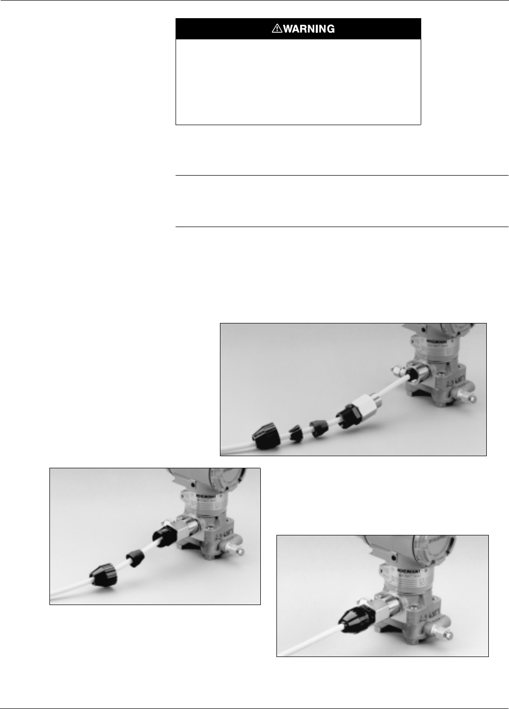
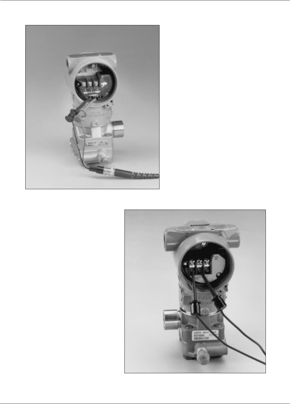
b. Connect the RTD cable to the Model 3095 MV RTD connector.
First fully engage the black cable connector, then screw
in and tighten the cable adapter until metal to metal contact
occurs (see photos).
Process leaks can cause death or serious injury. All four
flange bolts must be installed and tight before applying
pressure, or process leakage will result. When properly
installed, the flange bolts will protrude through the top of the
module housing. Attempting to remove the flange bolts
while the transmitter is in service will result in leakage of the
process fluid.
3095-069AB, 068AB, 067AB
FIRST, FULLY ENGAGE
THE BLACK CABLE
CONNECTOR
SECOND, SCREW IN AND
TIGHTEN THE CABLE ADAPTER
UNTIL METAL TO METAL
CONTACT OCCURS
THIRD, SCREW IN AND TIGHTEN
THE STRAIN RELIEF CLAMP

2-19
Inital Checkout and Field Installation
c. (Optional) If using an armored, shielded cable, install the
armored cable compression seal as illustrated below, and use a
pliers to tighten the cap onto the compression fitting.
d. Make all necessary wiring connections inside the RTD Flat
Connection Head as explained in the Sensor Wiring
Instructions included with the RTD.
Check for Leaks 5. Check all process penetrations for leaks.
Field Wiring
(Power and Signal)
6. Make field wiring connections (see Figure 2-11). These
connections provide both power and signal wiring.
NOTES
• Do not run field wiring in conduit or open trays with other power
wiring, or near heavy electrical equipment.
• Field wiring need not be shielded, but use twisted pairs for
best results.
• To ensure communication, wiring should be 24 AWG or larger
and not exceed 5,000 feet (1,500 meters).
• For connections in ambient temperatures above 140 °F (60 °C), use
wiring rated for at least 194 °F (90 °C).
Compression Fitting
Non-conductive
Rubber Bushing
(Slide stop to edge
of armored cable)
Washer Cap RTD Cable Adapter
and Connector
(Connects to Model 3095 MV)
3095-0020D01A
¾ to ½–in. NPT Adapter
(Screws into RTD Connection Head)
For explosion-proof installations, wiring connections must
be made in accordance with Rosemount drawing 03095-
1025 or 03095-1024.
For instrinsically safe installations, wiring connections must
be made in accordance with ANSI/ISA-RP12.6, and
Rosemount drawings 03095-1020 or 03095-1031.
For ALL installations, wiring connections must be made in
accordance with local or national installation codes such as
the NEC NFPA 70.
Incorrect field wiring connections may damage the Model
3095 MV. Do not connect field wiring to the “TEST +”
terminals.

Rosemount Model 3095 MV
2-20
a. Remove the cover on the side marked FIELD TERMINALS on
the electronics housing.
b. Connect the lead that originates at the positive side of the
power supply to the terminal marked “+ SIG” or “+ PWR.” Be
sure to include loop resistance.
c. Connect the lead that originates at the negative side of the
power supply to the terminal marked “–.”
Explosions can cause death or serious injury. The unused
conduit opening on the transmitter housing must be plugged
and sealed to meet explosion-proof requirements.
FIGURE 2-11. Field Wiring
Connections.
3095-1006B03C
1100 V > RL>250 V
User-Provided
Power Supply
(see page 2-16)
Signal loop may be grounded at
any point or left ungrounded
(see step 7.a).
(see step 7.b)
PREVIOUS TERMINAL BLOCK
3051-3031F02C
1100 V > RL>250 V
User-Provided
Power Supply
(see page 2-16)
Signal loop may be grounded at
any point or left ungrounded
(see step 7.a).
(see step 7.b)
IMPROVED TERMINAL BLOCK

2-21
Inital Checkout and Field Installation
d. Plug and seal unused conduit connections on the transmitter
housing to avoid moisture accumulation in the terminal side of
the housing.
NOTE
If the conduit connections are not sealed, mount the transmitter with
the electrical housing positioned downward for drainage. Conduit
should be installed with a drip loop, and the bottom of the drip loop
should be lower than the conduit connections or the transmitter
housing.
Install Grounds 7. Install field wiring ground (optional), and ground the transmitter
case (required).
Field Wiring Ground a. Field wiring may be grounded at any one point on the signal
loop, or it may be left ungrounded. The negative terminal of
the power supply is a recommended grounding point.
Ground the Transmitter Case b. The transmitter case should always be grounded in accordance
with national and local electrical codes. The most effective
transmitter case grounding method is direct connection to
earth ground with minimal impedance. Methods for grounding
the transmitter case include:
•External Ground Assembly: This assembly is included with the
transient protection terminal block. The External Ground
Assembly can also be ordered as a spare part (03031-0398-0001).
•Internal Ground Connection: Inside the FIELD TERMINALS
side of the electronics housing is the Internal Ground Connection
screw. This screw is identified by a ground symbol: .
NOTE
The transient protection terminal block does not provide transient
protection unless the transmitter case is properly grounded. Use the
above guidelines to ground the transmitter case.
Do not run the transient protection ground wire with field wiring as the
ground wire may carry excessive current if a lighting strike occurs.
Grounding the transmitter case using threaded conduit connection may
not provide sufficient ground.
Replace Cover
8. Replace the cover.
CALIBRATION After completing the installation, the Model 3095 MV can be field
calibrated. See Field Calibration Procedure on page 4-9 for
recommended field calibration procedures.
Explosions can cause death or serious injury. Both
transmitter covers must be fully engaged to meet explosion-
proof requirements.

Rosemount Model 3095 MV
2-22

Section
3-1
3Options and Accessories
Options and accessories available with the Model 3095 MV can
facilitate installation and operation or enhance the security of the
system. These items include the LCD meter, mounting brackets, custom
configuration, optional bolt materials, the transient protection terminal
block, and manifold options.
LCD METER The LCD meter provides local display of Model 3095 MV process
variables, calculations, and transmitter diagnostic messages. The meter
is located on the circuit side of the transmitter, leaving direct access to
the signal terminals. An extended cover is required to accommodate the
meter. Figure 3-1 shows the transmitter fitted with the LCD meter and
extended cover.
NOTE
A 3-in. (76 mm) clearance is required for cover removal if a meter is
installed.
The LCD Meter can be ordered factory-installed, or meters can be
ordered as spare parts to retrofit existing Model 3095 MV transmitters
already in the field.
NOTE
For compatibility issues when retrofitting spare parts, see Appendix E
Compatibility Issues.
FIGURE 3-1. Model 3095 MV with
Optional LCD Meter.
Meter
Cover
Meter Assembly
3095-3031A05A

Rosemount Model 3095 MV
3-2
The LCD meter features a liquid crystal display that provides readouts
of Model 3095 MV process variables and flow calculations. Use the
Model 3095 MV User Interface Software to change the parameters
displayed by the LCD meter (see Transmitter LCD Settings on
page 4-39). Any of the following parameters and calculations are
available for display:
LCD
Parameter Engineering
Parameter Name Name Unit/Example
Flow Rate FLOW SCFD
Differential Pressure PRESS IN_H2O
Totalized Flow TOTAL SCF
Static Pressure SP PSI
Temperature TEMP °F
Analog Output OUT MA
Percent Of Range % %
The default display time is three seconds to display user-selected
parameters. The LCD meter display time is selectable in one second
increments from two to ten seconds. The LCD scrolls through the entire
list of selected parameters before repeating the displays. The LCD
meter uses a two line display to indicate the engineering unit and
parameter name; a third value is displayed to indicate the
parameter value.
FIGURE 3-2. LCD Meter Display.
During Critical Alarm States or Overrange Conditions, the LCD display
alternates between the selected parameters and the critical alarms or
overrange conditions. For more information concerning Fatal Alarm
Messages and Critical Alarm Messages, see Revision 12 and 13
Electronics Board Alarms And Error Conditions on page 5-2.
Totalizer Display The LCD meter can display flow total as a selected variable. Depending
on the Flow Total Unit selected, the meter will display the
measurement value to a varying decimal point. Table 3-1 shows the
available flow total units and maximum displayable flow total.
The non-volatile totalizer saves flow total information to the permanent
memory of the transmitter. Time between saves to permanent memory
is less than five minutes. In the event of power loss, no more than five
minutes of flow totalization information is unretrievable.
3095-3095_7A

3-3
Options and Accessories
TABLE 3-1. Model 3095 MV Flow Total
Display.
The LCD meter will totalize flow up to a maximum value of 4.29 billion
pounds or the equivalent flow total in other units of measure, after
which it will scroll over to 0 Total Flow. Maximum total flow for
standard volume measurements can be calculated by dividing 4.29
billion pounds or 190 billion kilograms by the standard density. For
example, given a standard density for natural gas of 0.04 lbs/ft3 or
0.68 kg/m3; the maximum total flow value is:
4.29 billion lbs 4 0.04 lbs/ft3 = 107.2 billion SCF
190 billion kg 4 0.68 kg/m3 = 2.86 billion SCM
The maximum displayable value on the LCD meter of the
Model 3095MV Transmitter is the lesser of the following two numbers:
Base Volumetric Units expressed as 1.1E 12 or the flow total in Base
Volumetric Units that is equivalent to 4.29 billion pounds.
Flow Total ≤ 1.100E 12 SCF or
Flow Total ≤ 4.29 billion pounds
Installing the Meter Installing the meter on a Model 3095 MV transmitter requires a small
instrument screwdriver and the meter kit (PN 3095-0492-0001 for
Aluminum Housing, PN 3095-0492-0002 for SST Housing).
The meter kit includes:
• one LCD meter assembly
• one extended cover with cover O-ring installed
• two captive screws
• one meter connector (10-pin male-to-male)
NOTE
The LCD Meter requires a Revision 12 or higher electronics board. See
Table E-6 on page E-3 for compatibility information.
Flow Total
Unit Description LCD Display Maximum
Displayable Flow
Total on LCD Meter
Maximum Displayable
Flow Total on
275 Communicator or
EA Software
Standard Cubic Feet SCF ≤1.100E 12 SCF or(1)
≤ 4.29 billion pounds
Flow total equivalent to
4.29 billion pounds
Normal Cubic Meters NCM ≤1.100E 12 NCM or(1)
≤ 4.29 billion pounds
Flow total equivalent to
4.29 billion pounds
Standard Cubic Meters SCM ≤1.100E 12 SCM or(1)
≤ 4.29 billion pounds
Flow total equivalent to
4.29 billion pounds
Normal Liters NLT ≤1.100E 12 NLT or(1)
≤ 4.29 billion pounds
Flow total equivalent to
4.29 billion pounds
Ounces OZ 6.800E 10 OZ 6.800E 10 OZ
Pounds LB 4.290E 09 LB 4.290E 09 LB
Metric Tons MTON 1.900E 06 MTON 1.900E 06 MTON
Short Tons STON 2.100E 06 STON 2.100E 06 STON
Long Tons LTON 1.900E 06 LTON 1.900E 06 LTON
Grams GM 1.100E 12 GM 1.950E 12 GM
Kilograms KGM 1.900E 09 KGM 1.900E 09 KGM
Special Quantity Unit User Defined ≤1.100E 12 SCF or(1)
≤ 4.29 billion pounds
Flow total equivalent to
4.29 billion pounds
(1) Totalizer display will autoscale flow total reading. Standard display shows flow total to two
decimal places. As flow total increases greater than 1,000,000; the decimal place moves to the
right. At flow totals greater than 100,000,000; the flow total is displayed in exponential notation.
For example, 100,000,000 lb will be displayed as 1.000 E 08

Rosemount Model 3095 MV
3-4
Use the following steps to install the meter. See Figure 3-1 for an
illustration.
1. If the transmitter is installed in a loop, secure the loop and
disconnect power.
2. Remove the transmitter cover opposite the field terminal side.
3. Note location of security/alarm jumpers. Remove the jumpers and
discard. Insert the meter connector into the ten-pin socket on the
electronics circuit board (see Figure 3-1).
4. Remove the two circuit board captive screws. To do this, loosen
the screws to release the board, then pull out the screws until
they are stopped by the captive thread inside the circuit board
standoffs. Continue unscrewing and remove the two screws; the
circuit board remains.
5. The electronics housing may be rotated to improve field access to
the two compartments. To rotate the housing less than 180
degrees, release the housing rotation set screw and turn the
housing not more than 180 degrees from the orientation shown in
Figure 2-6. To rotate the housing greater than 180 degrees, see
Disassembly Procedures on page 5-12.
NOTE
The meter may be installed in 90-degree increments for easy viewing.
One of the four connectors on the back of the meter assembly must be
positioned to accept the meter connector.
6. Decide which direction the meter should be oriented. Insert the
long meter screws into the two holes on the meter assembly that
coincide with the holes on the circuit board.
Explosions can cause death or serious injury. Do not
remove the instrument cover in explosive atmospheres
when the circuit is alive.
The circuit board is electrostatically sensitive. Be sure to
observe handling precautions for static-sensitive
components.
Rotating the housing greater than 180 degrees without
performing the disassembly procedure may damage the
Model 3095 MV sensor module.

3-5
Options and Accessories
7. Attach the meter assembly to the circuit board by threading the
screws into captive threads and attaching the meter assembly to
the meter connector. Tighten the meter screws in the standoffs to
secure the meter assembly and electronic circuit board in place.
The meter screws are designed to be captive screws, so they must
first be tightened past the captive thread within the standoffs and
then tightened again to hold the meter/circuit board assembly to
the housing.
8. Check security and alarm jumpers for desired operation. Adjust if
necessary.
9. Attach the extended cover metal to metal.
Note the following LCD temperature limits:
Operating: –13 to 185 °F (–25 to 85 °C)
Storage: –40 to 185 °F (–40 to 85 °C)
SST MOUNTING
BRACKETS
Optional mounting brackets are available to facilitate mounting to a
panel, wall, or 2-in. pipe. The bracket option for use with the Coplanar
flange is 316 SST with 316 SST bolts. Figure 2-8 on page 2-14 shows
bracket dimensions and mounting configurations for the SST mounting
bracket option.
ENGINEERING ASSISTANT
SOFTWARE
The Engineering Assistant software package is available with or
without the HART modem and connecting cables (see Accessories on
page 6-10 for available packages). The complete package contains the
following items:
• Two 3.5-in. floppy disks containing the Model 3095 MV User
Interface Software
• One HART modem
• One set of modem cables
Two types of licenses are available for the Engineering Assistant
software: Single CPU License (for installing on one computer), and Site
License (for installing on more than one computer).
Section 4 in this manual provides information for using the
Model 3095 MV Engineering Assistant Software to configure and
calibrate the Model 3095 MV.
Explosions can cause death or serious injury. Both
transmitter covers must be fully engaged to meet explosion-
proof requirements.

Rosemount Model 3095 MV
3-6
TRANSIENT PROTECTION
TERMINAL BLOCK
The transient protection terminal block option increases the Model
3095 MV ability to withstand electrical transients induced by lightning,
welding, or heavy electrical equipment. The Model 3095 MV, with
integral transient protection installed, meets the standard performance
specifications as outlined in this product manual. In addition, the
transient protection circuitry meets IEEE Standard 587, Category B
and IEEE Standard 472, Surge Withstand Capability.
Transient protection terminal blocks can be ordered factory-installed,
or they can be ordered as a spare part to retrofit existing Model 3095
MV transmitters already in the field. The Rosemount spare part
number for the transient protection terminal block is 3095-0302-0002.
Installation Procedure The transient protection terminal block is shipped installed when
ordered at the same time as the Model 3095 MV. Use the following
procedure to install this terminal block when this option is ordered as a
spare part or retrofit.
1. Remove the cover above the side marked FIELD TERMINALS on
the Model 3095 MV electronics housing.
2. Loosen the two terminal block mounting screws and pull the
standard terminal block out.
3. If present, transfer the signal wires from the old terminal block to
the transient protection terminal block. Be sure that the + signal
wire is reconnected to the SIG + or PWR + terminal, and the –
signal wire is reconnected to the SIG – or PWR – terminal.
4. Install the terminal block by positioning the terminal block above
the post connector pins, and press into place.
5. Use the captive mounting screws on the terminal block to secure
it to the electronics housing.
6. Ground the terminal block using one of the options described on
page 2-21.
7. Replace the Model 3095 MV cover.
8. If desired, re-trim the transmitter (see Sensor Trim Procedure
(For Bench Calibration) on page 4-44 or Sensor Trim
Procedure (For Field Calibration) on page 4-46).
NOTE
Installation of the Transient Protection Terminal Block does not
provide transient protection unless the Model 3095 MV is properly
grounded. See Install Grounds on page 2-21 for grounding
information.
Explosions can cause death or serious injury. Do not
remove the instrument cover in explosive atmospheres
when the circuit is alive.
Explosions can cause death or serious injury. Both
transmitter covers must be fully engaged to meet explosion-
proof requirements.

3-7
Options and Accessories
CUSTOMCONFIGURATION
(OPTION CODE C2)
Option Code C2 allows a customer to receive a Model 3095 MV that
contains a Custom Flow Configuration for their application.
See the Configuration Data Sheet on page 6-18 for more information.
FLANGE ADAPTERS
(OPTION CODE DF)
Three types of flange adapters are available for use with the Model
3095 MV: Plated CS, SST, and Hastelloy C. Flange adapters are
illustrated in Figure 2-3 on page 2-3. When ordered with the
transmitter, the shipped flange adapters match the ordered flange
material. Option Code DF includes bolts.
MODEL 305 INTEGRAL
MANIFOLD
(OPTION CODE S5)
Model 3095 MV Transmitter and Model 305AC Integral Manifold are
fully assembled, calibrated, and seal tested by the factory. Refer to PDS
00813-0100-4733 for additional information.
MODEL 1195 INTEGRAL
ORIFICE ASSEMBLY
(OPTION CODE S4)
Model 3095 MV Transmitter and Model 1195 Integral Orifice Assembly
are fully assembled, calibrated, and seal tested by the factory.
For installation instructions, refer to the product manual for the Model
1195 (00809-0100-4686).
ANNUBAR ASSEMBLY
(OPTION CODE S4)
Model 3095 MV Transmitter and Annubar Assembly are fully
assembled, calibrated, and seal tested by the factory.
For installation instructions, refer to the Annubar product manual
(00809-0100-4760).
FIGURE 3-3. Transient Protection
Terminal Block with External
Ground Assembly.
3051-3031E02C, F02A
External
Ground
Assembly
PREVIOUS TERMINAL BLOCK IMPROVED TERMINAL BLOCK
External
Ground
Assembly

Rosemount Model 3095 MV
3-8

Section
4-1
4Using the Engineering
Assistant Software
This section explains how to use the Model 3095 MV Engineering
Assistant (EA) Software with the Model 3095 MV Mass Flow
Transmitter, and is divided into four sub-sections:
• Install the Model 3095 MV Engineering Assistant Software.
• Establish communications between a personal computer and a
Model 3095 MV.
• Procedure Outlines (page 4-8).
• Engineering Assistant Software Screens (page 4-10).
INSTALLING THE
ENGINEERING ASSISTANT
SOFTWARE
The Engineering Assistant Software package is available with or
without the HART modem and connecting cables. The complete
Engineering Assistant package contains two 3.5-in. floppy disks, one
HART modem, and a set of cables for connecting the computer to the
Model 3095 MV (see Figure 4-1).
MINIMUMEQUIPMENTAND
SOFTWARE
• DOS-based 386 computer or above
• 640K base RAM with 8 MB extended
• Mouse or other pointing device
• Color computer display
• Model 3095 MV Engineering Assistant Software, HART modem,
set of modem cables
• MS DOS® 3.1 or higher
• Microsoft® Windows® 3.1, Windows for Workgroups 3.11, or
Windows 95
NOTE
The EA software does not work with Windows NT.
NOTE
The EA software does not work with revision 4.04.9. of Phoenix BIOS.
We do not recommend installing the Engineering Assistant on
computers that use this BIOS.

Rosemount Model 3095 MV
4-2
INSTALLATION
PROCEDURE
This procedure assumes that both DOS and Windows are already
installed.
NOTE
In this manual,
return
indicates to press the return or enter key.
1. Power on the computer.
2. After completion of boot-up procedures, verify that the computer
is in Microsoft Windows. If the computer is at the DOS prompt
(for example, C:\), type win
return
to open Windows.
3. Insert the floppy disk containing the Engineering Assistant
Software into the personal computer disk drive.
4. Select File, then select Run to display the Run window.
Depending on the disk drive, enter either a: setup or b: setup,
then select OK to display the following screen:
5. If desired, change the file location, then select the Install button,
6. Decide which serial port will be assigned as the HART
communications port, then select continue.
NOTE
This screen defines the HART communications port as either COM1 or
COM 2. The HART communications port must be different than the
mouse port.
3095-30950080
3095-30950081

4-3
Using the Model 3095 MV Engineering Assistant
7. After installing files, the installation program then prompts for
CONFIG.SYS choices.
8. When finished, the installation program requests that the user
reboot their computer.
9. Push the computer reset button to reboot the computer,
or press CTL-ALT-DEL.
3095-30950083
3095-30950085
FIGURE 4-1. Model 3095
MV Engineering Assistant
Equipment.
HART Modem
Mini-Grabber Cable
Disks Containing
Engineering Assistant
Software
Laptop Computer
(not included)
9-Pin to Comm Port Connector
3095-3095MV03

Rosemount Model 3095 MV
4-4
CONNECTING TO A
PERSONAL COMPUTER
Figure 4-2 illustrates how to connect a computer to a Model 3095 MV.
1. Connect the computer to the Model 3095 MV. See Warning above,
as well as Figure 4-1 and Figure 4-2.
a. Connect one end of the 9-pin to 9-pin cable to the HART
communications port on the personal computer.
b. Connect the 9-pin HART modem cable to the 9-pin
communications port on the computer.
c. Open the cover above the side marked Field Terminals, and
connect the mini-grabbers to the two Model 3095 MV
terminals marked COMM as shown in Figure 4-2.
2. Power on the computer.
3. Type win and press
return
at the DOS prompt.
4. Double click on the EA icon.
5. If password security is enabled, the Engineering Assistant
Privileges Screen appears:
6. Enter a password and press
return
.
Explosions can cause death or serious injury. Before
making any computer connections, ensure that the Model
3095 MV area is non-hazardous.
Explosions can cause death or serious injury. Do not
remove the instrument cover in explosive atmospheres
when the circuit is alive.
Symptom Corrective Action
No Communication
between the Engineering
Assistant Software and the
Model 3095 MV
LOOP WIRING
• HART protocol communication requires a loop resistance
value between 250–1100 ohms, inclusive.
• Check for adequate voltage to the transmitter. (If the computer
is connected and 250 ohms resistance is properly in the loop,
a power supply voltage of at least 16.5 V dc is required.)
• Check for intermittent shorts, open circuits, and multiple
grounds.
• Check for capacitance across the load resistor. Capacitance
should be less than 0.1 microfarad.
ENGINEERING ASSISTANT (EA) INSTALLATION
• Verify that the install program modified the CONFIG.SYS file.
• Verify computer reboot followed EA installation.
• Verify correct COMM port selected (see page 4-2).
• Verify laptop computer is not in low energy mode
(certain laptops disable all COMM ports in low energy mode).
• Did you install EA software onto Windows NT platform?
• Check if HART driver is loaded and installed.
4-5
Using the Model 3095 MV Engineering Assistant
FIGURE 4-2. Connecting a Personal Computer to a Model 3095 MV.
3095-018AB
3095-3095MV03
PREVIOUS TERMINAL BLOCK
IMPROVED TERMINAL BLOCK

Rosemount Model 3095 MV
4-6
FIGURE 4-2. (continued).
Model 3095 MV
1100 > R>250 VUser-Provided
Power Supply
(see page 2-16)
Modem
1100 > R>250 V
Modem
User-Provided
Power Supply
(see page 2-16)
PREVIOUS TERMINAL BLOCK
IMPROVED TERMINAL BLOCK
Model 3095 MV
3095-1006A03A
3095-1006A03F

4-7
Using the Model 3095 MV Engineering Assistant
MENU STRUCTURE Figure 4-3 illustrates the menu structure for the Engineering
Assistant Software.
Model 3095 MV Engineering Assistant – Untitled
File Setup Transmitter Maintenance Diagnostics View Help
Module Info...
Identification Info...
New Config Ctrl + N
Open Config... Ctrl + O
Save Config Ctrl + S
Save Config As...
1
filename
.
mfl
Exit
Compensated Flow...
Units...
Damping...
Device Info...
EA Default Units
Privileges...
Sensor Trim...
Analog Output...
Change Passwords...
Enable/Disable Security...
Process Temperature Mode
Read Outputs...
Device Info
Test Calculation...
Loop Test...
Transmitter Master Reset
Error Info...
Toolbar
Status Bar
About Engineering Assistant
Online Manual
FIGURE 4-3. Engineering Assistant Menu Structure.
Range Values...
Output Trim...
Burst Mode...
Communication Configuration...
Connect...
Disconnect
HART Output
Units...
Damping...
Device Info...
Send Config...
Recv Config
LCD Settings
Totalizer
Flow Rate Special Units
Totalizer Special Units
DP Low Flow Cutoff
U.S. Units
SI/Metric Units

Rosemount Model 3095 MV
4-8
Menu Categories The Model 3095 MV menu bar identifies seven menu categories:
File The File category contains screens for reading and writing Model 3095
MV configuration files.
Setup The Setup category contains Model 3095 MV screens which are only
available when the Engineering Assistant is “disconnected.” These
screens also determine the contents of a configuration file, and are used
to define a Compensated Flow measurement solution.
Transmitter Except for “Disconnect” and “Recv Config,” any changes made in this
series of screens occurs immediately to the connected transmitter.
Maintenance The Maintenance screens perform typical transmitter maintenance
functions, including set the analog output, set range values, output
trim, and sensor trim. Any changes made in this series of screens occurs
immediately to the connected transmitter.
Diagnostics The Diagnostic screens provide troubleshooting and diagnostic screens.
View The View selections determine whether the toolbar and the status bar
are displayed.
Help The Help selection identifies the current EA software revision.
PROCEDURE OUTLINES These procedures only outline the major steps for each procedure. Refer
to the individual screen explanations for additional information.
Bench Configuration
(Standard)
1. (If needed) Select Transmitter, Disconnect to switch to disconnect
mode.
2. (Optional) If a configuration file is already created, select File,
Open Config to retrieve those configuration settings.
3. Select Setup, Units..., then verify the units parameters.
4. Select Setup, Damping..., then verify the damping parameters.
5. Select Setup, Device Info..., then fill in the device information screen.
6. Select Setup, Compensated Flow..., then follow the series of three
flow configuration screens, filling in the information for your flow
application. When finished, the following screen is displayed:
7. Select File to save your configuration to disk.
8. Select Transmitter, Connect to connect to a transmitter.
9. Select Transmitter, Send Config to sent the configuration.
30950086

4-9
Using the Model 3095 MV Engineering Assistant
Bench Calibration
Procedure
After a transmitter is bench configured, the transmitter can be bench
calibrated.
1. Select Maintenance, Analog Output, Range Values...
a. Select Assign Variables, then verify the process variable output
order.
b. Set the range values and units.
2. Select Maintenance, Sensor Trim..., then perform sensor trim
procedures:
a. Trim SP Offset (zero).
b. Trim SP Slope (span).
c. Trim DP Offset (zero).
d. Trim DP Slope (span).
e. Trim PT Offset (zero).
f. Trim PT Slope (span).
3. Select Maintenance, Analog Output, Output Trim..., then perform
the output trim procedures.
Field Calibration Procedure To correct for mounting position effects, field calibrate the Model 3095
MV after installation:
1. Establish communications (see page 4-4).
2. Perform a Trim DP Offset (zero).
3. (Optional) If a barometer that is three times as accurate as the
Model 3095 MV AP sensor is available, perform an SP Offset
(zero).
Automatic Error Messages Whenever the EA sends a command to a transmitter, the EA checks for
error conditions in the transmitter. If an error is found, an error
message is displayed.
To acknowledge the error, select OK.
If the error is non-critical, select the “Ignore status on next 50
commands” box, then select OK.
Appendix C identifies possible warnings and errors that might occur
when using the EA software.

Rosemount Model 3095 MV
4-10
ENGINEERING ASSISTANT
SOFTWARE SCREENS
This section illustrates each major Model 3095 MV EA screen, and
provides information about using the screen.
Screen Components The following figure shows the basic screen components:
The EA software uses standard Windows elements and tools, including
scroll bars, minimize button, maximize button, window border, mouse
pointer, and buttons. It is beyond the scope of this manual to discuss
basic Windows terminology and techniques. For additional information
concerning Windows, refer to Microsoft Windows documentation.
Status Bar Codes The status bar provides up to four status items:
• The first field in the status bar is a message field.
• Tag: indicates if a configuration file (filename.MFL) was loaded
into the EA memory. Other options:
(Uploaded Data) indicates that the current configuration
information was uploaded from a transmitter.
(Blank) indicates configuration information has not been loaded
in from a transmitter or from a configuration file.
• Security: indicates security status: disabled, low, high, medium,
or off-line.
• HART field indicates communication status: Idle or Busy.
Hot Keys An underline character in a menu selection indicates the Hot Key for
that selection. Press the character to select that menu item.
Menu Bar
Menus
Connect...
Disconnect
HART Output
Units...
Damping...
Device Info...
Send Config...
Recv Config
Burst Mode...
Communication Configuration...
Tool bar
Status Bar
30950114

4-11
Using the Model 3095 MV Engineering Assistant
Path Name Convention In this section, each heading also identifies the path name. For
example, consider the following heading:
This indicates that the menu is found under the Maintenance, Analog
Output, Range Values... path. This menu can be accessed in multiple
ways. Three examples are shown:
•Select M
aintenance, select Analog Output, select Range Values...
• Press Alt-M, A, R.
• Press Alt-M, use the arrow keys to highlight Analog Output and
press
return
, use the arrow keys to highlight Range Values and
press
return
.
Procedure Convention
Rather than explaining all of the possible ways to access a particular
screen, procedures in this manual use the term “Select” to indicate
there are multiple ways to select an option. For example, the first step
in the Sensor Trim procedure is illustrated below.
1. Select Maintenance, Sensor Trim to display the Sensor Trim
Select screen.
Cancel Buttons All EA screens that allow data entry or transmitter action contain a
Cancel button. Select Cancel to exit the screen without making any
changes.
Fast Keys Certain menu selections have fast keys assigned, and they are
indicated in the menu structure. For example, pressing Ctrl + O is the
fast way to open a configuration file.
Toolbar Another fast way to access EA screens is the tool bar (see Figure 4-4).
Simply click on the icon to access the screen.
Maintenance
Analog Output
Range Values...
FIGURE 4-4. Model 3095 MV Engineering
Assistant Toolbar.
New
Config Save
Config Connect Sensor
Trim Send
Config About
Open
Config Compensated
Flow Privileges
Set Range
Values Receive
Config
3095-30950300

Rosemount Model 3095 MV
4-12
Setup Screens The setup screens are used to define a compensated flow solution, and
to create flow configuration files for sending to a transmitter. These
screens are only available when the EA is not connected to a transmitter.
• If the fluid is a gas, use the procedure starting below.
• If the fluid is steam, use the procedure starting on page 4-17.
• If the fluid is a liquid, use the procedure starting on page 4-21.
• If the fluid is natural gas, use the procedure starting on page 4-24.
NOTE
If the Setup menu selections are grayed out, the EA is currently
connected with a Model 3095 MV transmitter. Select Transmitter,
Disconnect to disconnect the EA from a Model 3095 MV, which will then
enable the Setup menu selections.
Setup
Compensated Flow
(Gas Configuration)
The Compensated Flow selection allows you to configure the Model
3095 MV to measure flow of a particular fluid. The following screens
illustrate how to define a gas configuration. Table 4-1 lists the liquids
and gases available in the Engineering Assistant database.
TABLE 4-1. Liquids and Gases included in Engineering Assistant AIChE Physical Properties Database. (1)
Acetic Acid
Acetone
Acetonitrile
Acetylene
Acrylonitrile
Air
Allyl Alcohol
Ammonia
Argon
Benzene
Benzaldehyde
Benzyl Alcohol
Biphenyl
Carbon Dioxide
Carbon Monoxide
Carbon Tetrachloride
Chlorine
Chlorotrifluoroethylene
Chloroprene
Cycloheptane
Cyclohexane
Cyclopentane
Cyclopentene
Cyclopropane
Divinyl Ether
Ethane
Ethanol
Ethylamine
Ethylbenzene
Ethylene
Ethylene GlycolEthylene
Oxide
Fluorene
Furan
Helium–4
Hydrazine
Hydrogen
Hydrogen Chloride
Hydrogen Cyanide
Hydrogen Peroxide
Hydrogen Sulfide
Isobutane
Isobutene
Isobutyl
benzene
Isopentane
Isoprene
Isopropanol
Methane
Methanol
Methyl Acrylate
Methyl Ethyl Ketone
Methyl Vinyl Ether
m–Chloronitrobenzene
m–Dichlorobenzene
Neon
Neopentane
Nitric Acid
Nitric Oxide
Nitrobenzene
Nitroethane
Nitrogen
Nitromethane
Nitrous Oxide
n–Butane
n–Butanol
n–Butyraldehyde
n–Butyronitrile
n–Decane
n–Dodecane
n–Heptadecane
n-Heptane
n–Hexane
n–Octane
n–Pentane
Oxygen
Pentafluorothane
Phenol
Propane
Propadiene
Pyrene
Propylene
Styrene
Sulfer Dioxide
Toluene
Trichloroethylene
Vinyl Acetate
Vinyl Chloride
Vinyl Cyclohexane
Water
1–Butene
1–Decene
1–Decanal
1–Decanol
1–Dodecene
1–Dodecanol
1–Heptanol
1–Heptene
1–Hexene
1–Hexadecanol
1–Octanol
1–Octene
1–Nonanal
1–Nonanol
1–Pentadecanol
1–Pentanol
1–Pentene
1–Undecanol
1,2,4–Trichlorobenzene
1,1,2–Trichloroethane
1,1,2,2–Tetrafluoroethane
1,2–Butadiene
1,3–Butadiene
1,3,5–Trichlorobenzene
1,4–Dioxane
1,4–Hexadiene
2–Methyl–1–Pentene
2,2–Dimethylbutane
(1) This list subject to change without notice.

4-13
Using the Model 3095 MV Engineering Assistant
1. Select Gas radio button.
2. Select “Pick from database” radio button and select a Fluid Name
from the database picklist (see Table 4-1 on page 4-12 for
database options),
or
Select “Custom” radio button and enter your own fluid name.
3. Select Primary Element (see Table 4-4 on page 4-17 for primary
element options).
4. Select Next.
NOTE
This manual does not contain instructions regarding the Calibrated
Annubar Diamond II+/Mass ProBar Primary Element. For information
concerning this option, call 1-800-999-9307, and ask for Model 3095 MV
Technical Support.
3095-30950805
FIGURE 4-5. Flow Setup Screen.

Rosemount Model 3095 MV
4-14
5. Define Primary Element Information.
TABLE 4-3. Annubar Diamond II+
Sensor Series No.
Cross-Reference Table.
a. Enter Primary Element (bore or throat) Diameter and units at
reference temperature. (If Annubar Diamond II+ is selected,
enter the Sensor Series No. from Table 4-3).
b. Enter Primary Element Material.
c. Enter Meter Tube Diameter (pipe ID) and units at reference
temperature.
d. Enter Meter Tube Material.
NOTE
To be in compliance with appropriate national or international
standards, beta ratios and differential producer diameters should be
within the limits as listed in the standards.The EA software will alert
the operator if a primary element value exceeds these limits. However,
the EA will not stop the operator from proceeding with a flow
configuration because of this type of exception.
6. Enter Operating Conditions.
a. Enter Operating Pressure Range and Units.
b. Enter Operating Temperature Range and Units.
FIGURE 4-6. Flow Setup Screen
(Gas Configuration).
3095-30950755
Sensor Series No. Nominal Pipe Size in. (mm)
10 ½–2(13–51)
15,16 2–5(51–127)
25,26 5–42(127–1067)
35,36 12–72(305–1829)
45,46 24–72(610–1829)

4-15
Using the Model 3095 MV Engineering Assistant
7. (Optional) If desired, modify standard pressure and/or
temperature conditions. These values apply only if flow units are
set to: StdCuft/s, StdCuft/min, StdCuft/h, StdCuft/d, StdCum/s,
StdCum/min, StdCum/h, StdCum/d, or NmlCuft/s, NmlCuft/min,
NmlCuft/h, NmlCuft/d, NmlCum/s, NmlCum/min, NmlCum/h,
NmlCum/d.
8. Select Next.
9. If you selected an AIChE database fluid, this screen is already
populated with AIChE data. If desired, this data may be edited.
However, if a change is made to either a density or viscosity value,
the EA considers the fluid to be “Custom Fluid.”
If you entered a custom fluid, fill in the compressibility/density
column, the viscosity column, the molecular weight, the isentropic
exponent, and the standard density.
10. Select Flow Units.
11. Select Finish.
3095-30950756
FIGURE 4-7. Compressibility and
Viscosity Table (Gas configuration).
NOTE
Table values automatically convert if a
different unit of measure is selected.
All data fields can be edited.
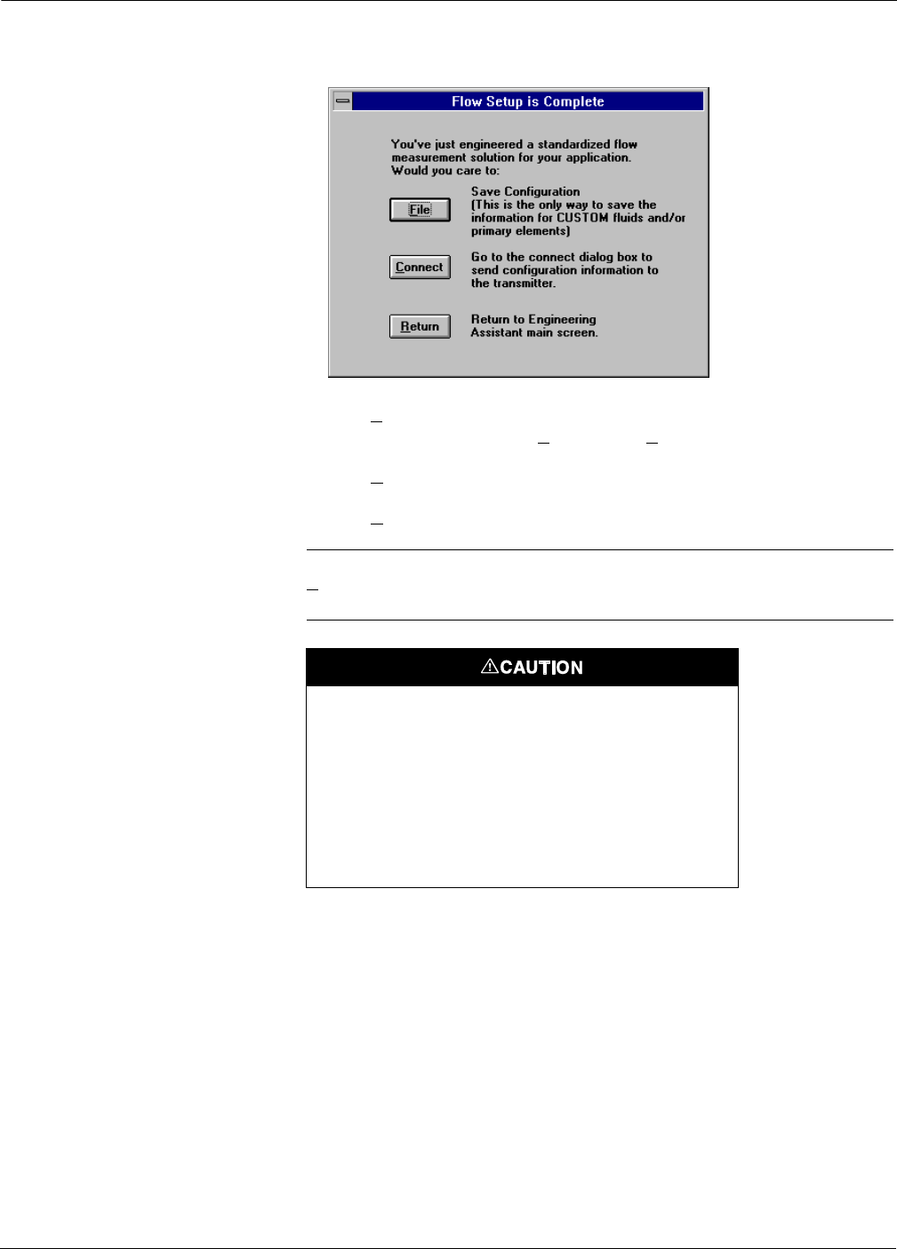
Rosemount Model 3095 MV
4-16
12. This screen has three options.
• File saves the flow information to a configuration file, which can
be sent by selecting Transmitter, Send Config... as explained on
page 4-38. (recommended).
• Connect switches to the Connect screen so that the flow
configuration can be sent to a transmitter.
• Return switches to the EA.
NOTE
File is recommended because you have an electronic record of your flow
configuration.
Table 4-4 lists the primary elements available in the Engineering
Assistant database.
3095-30950912
If you selected custom fluid, or made density or viscosity
changes to an AIChE fluid, be sure to save your information
to a configuration file so that you can modify the flow
configuration information at a later date.
Although you can read a flow configuration from a
transmitter, it is NOT possible to retrieve custom density,
custom viscosity, or custom primary element information.
Therefore, be sure to save custom fluid configurations to a
unique file.

4-17
Using the Model 3095 MV Engineering Assistant
Setup
Compensated Flow
(Steam Configuration)
The Compensated Flow selection allows you to configure the Model
3095 MV to measure steam flow. This following screens illustrates how
to define a steam configuration.
1. Select Gas radio button.
2. Select Steam radio button.
3. Select Primary Element (see Table 4-2 for primary element
options).
4. Select Next.
TABLE 4-4. Primary Element Options.
1195 Integral Orifice
Annubar®Diamond II/Mass ProBar
Annubar®Diamond II+/Mass ProBar
Calibrated Annubar®Diamond II+/Mass ProBar (see note)
Calibrated Annubar®Diamond II/Mass ProBar (see note)
Nozzle, Long Radius Wall Taps, ASME
Nozzle, Long Radius Wall Taps, ISO
Nozzle, ISA 1932, ISO
Orifice, 2½D & 8D Taps
Orifice, Corner Taps, ASME
Orifice, Corner Taps, ISO
Orifice, D & D/2 Taps, ASME
Orifice, D & D/2 Taps, ISO
Orifice, Flange Taps, AGA3
Orifice, Flange Taps, ASME
Orifice, Flange Taps, ISO
Small Bore Orifice, Flange Taps, ASME
Venturi Nozzle, ISO
Venturi, Rough Cast/Fabricated Inlet, ASME
Venturi, Rough Cast Inlet, ISO
Venturi, Machined Inlet, ASME
Venturi, Machined Inlet, ISO
Venturi, Welded Inlet, ISO
Other: (1) Primary Element Setup Options
– Calibrated Orifice: Flange, Corner or D & D/2 Taps Constant Cd, Discharge Coefficient or 20 32CalibratedDataTable
– Calibrated Orifice: 2 ½ D & 8D Taps Constant Cd, Discharge Coefficient or 20 32CalibratedDataTable
– Calibrated Nozzle Constant Cd, Discharge Coefficient or 20 32CalibratedDataTable
– Calibrated Venturi Constant Cd, Discharge Coefficient or 20 32CalibratedDataTable
– Area Averaging Meter Constant K, Flow Coefficient
– V-Cone®Constant Cf, Coefficient of Flow
(1) Selecting a primary element from the other list requires additional setup information regarding the primary element.
This information should be obtained from the primary element manufacturer or from your own test data. If the calibrated data
table is selected, a minimum of two completed rows is required.
FIGURE 4-8. Flow Setup Screen.
3095-30950757
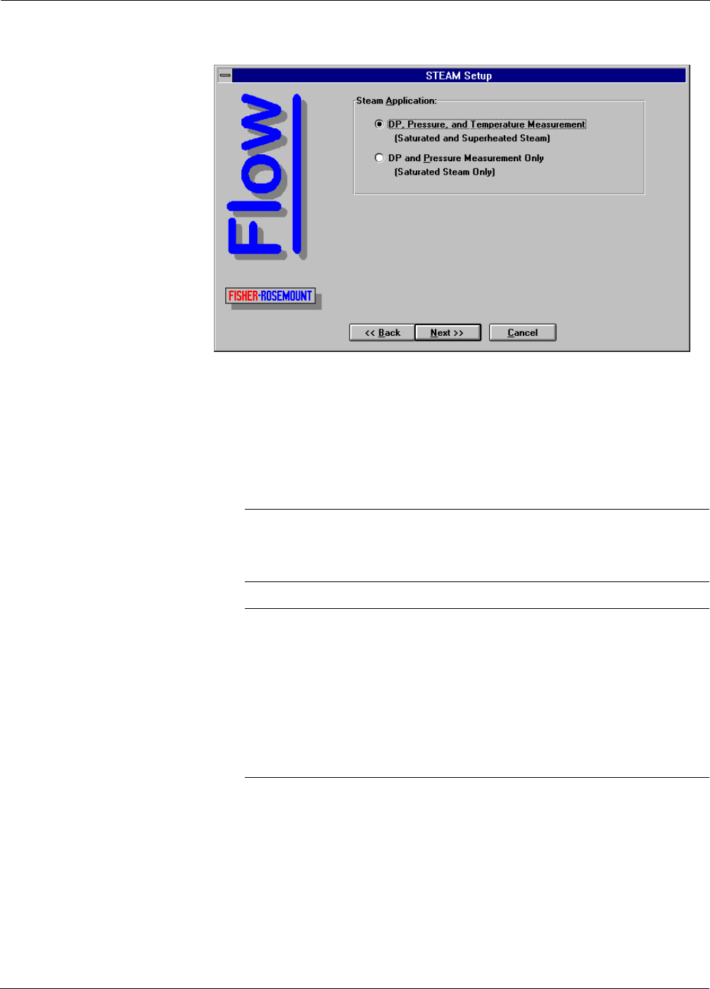
Rosemount Model 3095 MV
4-18
NOTE
Step8bisnotpartofthe“DPand
Pressure” configuration procedure.
5. Select type of steam measurement:
DP, Pressure, and Temperature compensated steam
measurement (Saturated and/or Superheated steam)
or
DP and Pressure compensated steam measurement (Saturated
Steam Only)
NOTE
DP, Pressure, and Temperature is the most common option. With this
option, the Model 3095 MV will compensate for both saturated and
superheated steam.
NOTE
DP and Pressure should be selected ONLY if the steam being measured
is always saturated. With this option, the density of the saturated
steam is based on the actual static pressure measurement. This option
also requires that the Model 3095 MV is set to fixed temperature mode.
With this option, saturated steam density is calculated based on ASME
steam tables, and dynamic temperature compensation is not performed.
If dynamic temperature compensation is desired, select the DP,
Pressure, and Temperature option.
6. Select Next.
FIGURE 4-9. Steam Selection Screen.
3095-30950758

4-19
Using the Model 3095 MV Engineering Assistant
7. Define Primary Element Information
a. Enter Primary Element (bore or throat) Diameter and units at
reference temp.
b. Enter Primary Element Material.
c. Enter Meter Tube Diameter (pipe ID) and units at reference
temperature.
d. Enter Meter Tube Material.
8. Enter Operating Conditions.
a. Enter Operating Pressure Range and Units.
b. Enter Operating Temperature Range and Units. The operating
temperature range points must be equal to or greater than the
saturation temperature at the given operating pressures.
9. (Optional) If desired, modify standard pressure and/or
temperature conditions.
10. Select Next.
11. The Steam Setup screen is automatically populated with steam
data based on the ASME steam equations.
If desired, all data fields can be edited. However, if a change is
made to either a density or viscosity value, the EA considers the
fluid to be “Custom Fluid.”
FIGURE 4-10. Steam Setup Screen.
3095-30950759
NOTE
The Operating Temperature Range
selection is not displayed if “DP and
Pressure” is selected.

Rosemount Model 3095 MV
4-20
”
12. Select Flow Units.
13. Select Finish.
14. This screen provides you three options.
• File saves the flow information to a configuration file, which can
be sent by selecting Transmitter, Send Config... as explained on
page 4-38. (recommended).
• Connect switches to the Connect screen so that the flow
configuration can be sent to a transmitter.
• Return switches to the EA.
NOTE
File is recommended because you have an electronic record of your flow
configuration.
3095-30950760
FIGURE 4-11. Compressibility and
Viscosity Table
(Steam Configuration).
NOTE
Table values automatically convert if a
different unit of measure is selected.
All data fields can be edited.
3095-30950761
If you selected custom fluid, or made density or viscosity
changes to an AIChE fluid, save your information to a
configuration file so you can modify the flow configuration
information at a later date.
Although you can read a flow configuration from a
transmitter, you CANNOT retrieve custom density, custom
viscosity, or custom primary element information. Therefore,
be sure to save custom fluid configurations to a unique file.

4-21
Using the Model 3095 MV Engineering Assistant
Setup
Compensated Flow
(Liquid Configuration)
The Compensated Flow selection enters the user into the procedure for
configuring the Model 3095 MV to measure flow of a particular fluid.
The following screens illustrate how to define a liquid configuration.
1. Select Liquid.
2. Select “Pick from database” radio button and select a Fluid Name
from the database picklist (see Table 4-1 for database options),
or
Select “Custom” radio button and enter your own fluid name.
3. Select Primary Element Information (see Table 4-4 for options).
4. Select Next.
5. Define Primary Element Information
a. Enter Primary Element (bore or throat) Diameter and units at
reference temp.
b. Enter Primary Element Material.
c. Enter Meter Tube Diameter (pipe ID) and units at reference
temperature.
d. Enter Meter Tube Material.
FIGURE 4-12. Flow Setup Screen
(Liquid Configuration).
3095-30950751
FIGURE 4-13. Flow Setup Screen
(Liquid Configuration).
3095-30950403

Rosemount Model 3095 MV
4-22
6. Enter Operating Temperature Range and Units.
7. (Optional) If desired, modify standard temperature conditions.
8. Select Next.
9. If you selected your own fluid name, fill in the density column and
the viscosity column.
If you used an AIChE database fluid, this table is already
populated with AIChE data. However, if a change is made to
either a density or viscosity value, the EA considers the fluid to be
“Custom Fluid.”
10. Select Flow Units.
11. Select Finish.
3095-30950404
FIGURE 4-14. Flow Setup
Compressibility and Viscosity Table
(Liquid Configuration).
NOTE
Table values automatically convert if a
different unit of measure is selected.
All data fields can be edited.
3095-30950086
FIGURE 4-15. Flow Setup is
Complete Screen.

4-23
Using the Model 3095 MV Engineering Assistant
12. This screen gives you three options.
• File saves the flow information to a configuration file, which can
be sent by selecting Transmitter, Send Config... as explained on
page 4-38. (recommended).
• Connect switches to the Connect screen so that the flow
configuration can be sent to a transmitter.
• Return switches to the EA.
NOTE
File is recommended because you have an electronic record of your flow
configuration.
If you selected custom fluid, or made density or viscosity
changes to an AIChE fluid, be sure to save your information
to a configuration file so that you can modify the flow
configuration information at a later date.
Although you can read a flow configuration from a
transmitter, it is NOT possible to retrieve custom density,
custom viscosity, or custom primary element information.
Therefore, be sure to save custom fluid configurations to a
unique file.

Rosemount Model 3095 MV
4-24
Setup
Compensated Flow
(Natural Gas Configuration)
Gross versus Detail Characterization
The Engineering Assistant calculates the natural gas compressibility
factor using either gross or detail characterization methods. Gross
characterization is a simplified method that is acceptable for a narrow
range of pressure, temperature, and gas composition. Detail
characterization covers all pressure, temperature, and gas composition
ranges for which A.G.A. computes compressibility factors. Table 4-6
identifies the acceptable ranges for both of these characterization
methods.
NOTE
A.G.A. Report No. 8 specifies that it is only valid for the gas phase. The
Detail Characterization method allows water, n-Hexane, n-Heptane,
n-Octone, n-Nonane, and n-Decane to be present up to the dew point.
When entering these component values, be sure that these components
have not reached their respective dew points.
TABLE 4-6. Acceptable Ranges:
Gross vs. Detail Characterization Methods.
Engineering Assistant
Variable Gross
Method Detail
Method
Pressure 0–1200 psia (1)
(1) The Model 3095 MV sensor operating limits may limit the pressure
and temperature range.
0–20,000 psia (1)
Temperature 32 to 130 °F (1) –200 to 400 °F (1)
Specific Gravity 0.554–0.87 0.07–1.52
Heating Value 477–1150
BTU/SCF
0–1800
BTU/SCF
Mole % Nitrogen 0–50.0 0–100
Mole % Carbon Dioxide 0–30.0 0–100
Mole % Hydrogen Sulfide 0–0.02 0–100
Mole % Water 0–0.05 0–Dew Point
Mole % Helium 0–0.2 0–3.0
Mole % Methane 45.0–100 0–100
Mole % Ethane 0–10.0 0–100
Mole % Propane 0–4.0 0–12
Mole % i-Butane 0–1.0 0–6 (2)
(2) The summation of i-Butane and n-Butane cannot exceed 6
percent.
Mole % n-Butane 0–1.0 0–6 (2)
Mole % i-Pentane 0–0.3 0–4 (3)
(3) The summation of i-Pentane and n-Pentane cannot exceed 4
percent.
Mole % n-Pentane 0–0.3 0–4 (3)
Mole % n-Hexane 0–0.2 0–Dew Point
Mole % n-Heptane 0–0.2 0–Dew Point
Mole % n-Octane 0–0.2 0–Dew Point
Mole % n-Nonane 0–0.2 0–Dew Point
Mole % n-Decane 0–0.2 0–Dew Point
Mole % Oxygen 0 0–21.0
Mole % Carbon Monoxide 0–3.0 0–3.0
Mole % Hydrogen 0–10.0 0–100
Mole % Argon 0 0–1.0
NOTE
Reference conditions are 14.73 psia and 60 °F for Gross Method.

4-25
Using the Model 3095 MV Engineering Assistant
Setup
Compensated Flow
(Natural Gas Flowchart)
The flowchart in Figure 4-16 illustrates the Engineering Assistant
Screens used to define a natural gas flow configuration.
FIGURE 4-16. Natural Gas
Flowchart. Main Flow Screen
Natural Gas
Selection Screen
Gross #1
Characterization Gross #2
Characterization
Detail
Characterization
Primary Element
Definition Screen
Compressibility &
Viscosity Screen
Flow Setup
Complete Screen

Rosemount Model 3095 MV
4-26
Setup
Compensated Flow
(Natural Gas Procedure)
1. Select Gas.
2. Select Natural Gas.
3. Select Primary Element Information (see Table 4-4 for options).
4. Select Next.
5. Select the desired characterization method, then select Next.
• If the Detail Method is selected, turn to page 4-26.
• If the Gross 1 Method is selected, turn to page 4-27.
• If the Gross 2 Method is selected, turn to page 4-28.
Detail Characterization Method The AGA8 Detail method allows entry of up to 21 different gas
composition mole percentages as illustrated in Figure 4-19. Table 4-6 on
page 4-24 identifies the valid range for each variable.
6. Enter a Mole% value into each of the desired Natural Gas
component fields.
• When entering numbers into the natural gas screen, the Total
Mole % field indicates the sum of all percentages entered. The
Total Mole % field must add up to 100.0000 percent for the
Engineering Assistant to accept the new values.
• To zero all 21 fields, select clear.
• The normalize button provides a method to automatically
modify all non-zero values so that they add up to 100.0000.
FIGURE 4-17. Flow Setup Screen
(Natural Gas Configuration).
3095-30950903
FIGURE 4-18. Flow Setup Screen
(Natural Gas Applications).
3095-30950904

4-27
Using the Model 3095 MV Engineering Assistant
7. After all the desired mole @ are entered, Select Next.
For additional information concerning the Detail Characterization
Method, refer to the A.G.A. Report No.8/API MPMS Chapter 14.2,
Second Printing, July 1994.
Gross Characterization
Method #1 The gross characterization method 1 requires the entry of real gas
specific gravity, heating value, and CO2 mole percent, and also allows
entry of H2 mole percent and CO mole percent. H2 and CO are typically
zero for natural gas applications.
The valid ranges for gross characterization method 1 components are:
Real gas relative density (specific gravity) at 60 °F, 14.73 psia
0.554–0.87.
Volumetric Gross Dry HeatingValueat60°F,14.73psia
477–1150 BTU/SCF.
CO2 (carbon dioxide) mole percent
0–30 percent.
H2 (hydrogen) mole percent (optional)
0–10 percent.
CO (carbon monoxide) mole percent (optional)
0–3 percent.
NOTE
See steps 1–5 on page 4-26 for the beginning of this procedure.
6. Enter a value into each of the desired Natural Gas component
fields.
FIGURE 4-19. Natural Gas Setup
Screen (Detail Characterization).
3095-30950905

Rosemount Model 3095 MV
4-28
7. After all the percentages are entered, Select Next.
Gross Characterization
Method #2 The gross characterization method 2 requires the entry of real gas
specific gravity, value, CO2 mole percent, and N2 mole percent, also
allows entry of H2 mole percent and CO mole percent. H2 and CO are
typically zero for natural gas applications.
The valid ranges for gross characterization method 2 components are:
Real gas relative density (specific gravity) at 60 °F, 14.73 psia
0.554–0.87.
CO2 (carbon dioxide) mole percent
0–30 percent.
N2 (hydrogen) mole percent
0–50 percent.
H2 (hydrogen) mole percent (optional)
0–10 percent.
CO (carbon monoxide) mole percent (optional)
0–3 percent.
NOTE
See steps 1–5 on page 4-26 for the beginning of this procedure.
6. Enter a value into each of the desired Natural Gas component
fields.
FIGURE 4-20. Natural Gas Setup
Screen (Gross Characterization
Method 1).
3095-30950907

4-29
Using the Model 3095 MV Engineering Assistant
7. After all the percentages are entered, Select Next.
NOTE
To comply with A.G.A. Report No. 3, the primary element must be
“Orifice, Flange Taps, AGA 3.”
8. Define Primary Element Information:
a. Enter Primary Element (bore or throat) Diameter and units at
reference temperature.
b. Enter Primary Element Material.
c. Enter Meter Tube Diameter (pipe ID) and units at reference
temperature.
d. Enter Meter Tube Material.
FIGURE 4-21. Natural Gas Setup
Screen (Gross Characterization
Method 2).
3095-30950909
FIGURE 4-22. Natural Gas Setup
Screen.
3095-30950910

Rosemount Model 3095 MV
4-30
9. Enter Operating Conditions.
a. Enter Operating Pressure Range and Units.
b. Enter Operating Temperature Range and Units. The operating
temperature range points should be entered for nominal
conditions.
10. (Optional) If desired, modify standard pressure and/or
temperature conditions.
11. Select Next.
12. The displayed values are calculated per A.G.A. 8.
If desired, all data fields can be edited. However, if a change is
made to either a density or viscosity value, the EA considers the
fluid to be “Custom Fluid.”
Data fields should conform to density or compressibility factor
information as published by A.G.A. 8. (A.G.A. 3 recommends
viscosity values of 6.9 3 10-6 pounds mass per foot-second or
0.010268 centipoise. Another available reference is the Gas
Orifice Flow Program published by the Gas Research Institute.
13. Select Flow Units.
14. Select Finish.
3095-30950911
FIGURE 4-23. Compressibility and
Viscosity Table (Steam
Configuration).
NOTE
Table values automatically convert if a
different unit of measure is selected.
All data fields can be edited.

4-31
Using the Model 3095 MV Engineering Assistant
15. This screen provides you three options.
• File saves the flow information to a configuration file, which can
be sent by selecting Transmitter, Send Config... as explained on
page 4-38. (recommended).
• Connect switches to the Connect screen so that the flow
configuration can be sent to a transmitter.
• Return switches to the EA.
NOTE
File is recommended because you have an electronic record of your flow
configuration.
Setup
Units This screen sets the units for the six process variables: Differential
Pressure, Absolute Pressure, Gage Pressure, Process Temperature,
Flow, and Flow Total units.
NOTE
Units can be entered off-line in Setup, Units (Flow Configuration
Information), or on-line in Transmitter, Units (Transmitter Specific
Information). If the units entered are different, the Transmitter
Specific Information overwrites the Flow Configuration Information.
3095-30950912
If you selected custom fluid, or made density or viscosity
changes to an AIChE fluid, be sure to save your information
to a configuration file so that you can modify the flow
configuration information at a later date.
Although you can read a flow configuration from a
transmitter, it is NOT possible to retrieve custom density,
custom viscosity, or custom primary element information.
Therefore, be sure to save custom fluid configurations to a
unique file.

Rosemount Model 3095 MV
4-32
Setup
Damping This screen sets the damping for four process variables: Differential
Pressure, Absolute Pressure, Gage Pressure, and Process Temperature.
NOTE
Since the Compensated Flow procedure automatically includes these
settings as the damping parameters for either a configuration file, or as
the damping values sent to the transmitter, be sure that this screen is
set correctly before performing the Compensated Flow procedure.
Setup
Device Info This screen sets the device information for a transmitter.
NOTE
Since the Compensated Flow procedure automatically includes these
settings as the device information for either a configuration file, or as
the device information sent to the transmitter, be sure that this screen
is set correctly before performing the Compensated Flow procedure.
3095-S-UNITS
FIGURE 4-24. Setup Units Screen.
3095-S-DMPG
FIGURE 4-25. Setup Damping Screen.

4-33
Using the Model 3095 MV Engineering Assistant
Setup
EA Default Units
U.S. Units
SI/Metric Units
These menu selections set the default units for the EA as either U.S.
Units, or SI/Metric units.
The selected units will be automatically selected during the next time
you restart the EA software, or the next time you select File, New
Config.
This selection does not change the units for a flow configuration that
has already been saved to a file or sent to a transmitter.
Transmitter Screens
Transmitter
Disconnect If the Setup menu selections are grayed out, this indicates that the EA
is currently on-line with a Model 3095 MV transmitter. Use this
selection to disconnect the EA from a Model 3095 MV, which will then
enable the Setup menu selections.
Transmitter
Connect The connect screen provides two functions: to change the address for
the connected Model 3095 MV transmitter, and to change the Model
3095 MV that the EA is connected to during multidrop applications.
3095-S-DVINFO
FIGURE 4-26. Setup Device Info
Screen.
3095-S-DFUNITS
FIGURE 4-27. Default Units Message
Screen.

Rosemount Model 3095 MV
4-34
When this screen is accessed, it always appears as illustrated in Figure
4-28: the address is 0, and there are no devices on-line.
Change Address Use the following procedure to change the Model 3095 MV address.
1. Select Transmitter, Connect to display the Connect screen.
2. Select Transmitters Online.
3. Select Poll.
The EA searches for all connected Model 3095 MV transmitters,
then displays found transmitters in the “Transmitters Online”
box. Devices are identified by the software tag and description
entered in the Device Information screen (see
Figure 4-20 on page 4-28).
4. Select the desired device from the Model 3095 MVs identified in
the “Transmitters Online” window.
5. Select the “Change Address” radio button appears.
6. Enter old address.
7. Enter new address, then select OK.
Change Connection During multidrop applications, the Model 3095 MV EA is connected to
one device at a time. Use the following procedure to change this
connection pointer.
1. Select Transmitter, Connect to display the Connect screen
2. Select Transmitters Online.
3. Select Poll.
The EA searches for all connected Model 3095 MV transmitters,
then displays found transmitters in the “Devices Online” box.
Devices are identified by address and software tag.
4. Select the desired device from the Model 3095 MVs identified in
the “Transmitters Online” window and select OK.
The Model 3095 MV EA is now connected to the device selected in
Step 4. If security is enabled, the EA displays the Privileges screen.
5. Enter a password for the new device, then select OK.
FIGURE 4-28. Connect Screen.
3095-30950089

4-35
Using the Model 3095 MV Engineering Assistant
Transmitter
HART Output
Burst Mode
When the Model 3095 MV is configured for burst mode, it provides
faster digital communications from the transmitter to the control
system by eliminating the time required for the control system to
request information from the transmitter.
Burst mode is compatible with use of the analog signal. Because HART
protocol features simultaneous digital and analog data transmission,
the analog value can drive other equipment in the loop while the control
system is receiving the digital information. Burst mode applies only to
the transmission of burst data (see Figure 4-29 below), and does not
affect the way other transmitter data is accessed.
Access to information other than burst data is obtained through the
normal poll/response method of HART communication. The EA or the
control system may request any of the information that is normally
available while the transmitter is in burst mode. Between each burst
message sent by the transmitter, a short pause allows the EA or control
system to initiate a request. The transmitter will receive the request,
process the response message, and then continue “bursting” the data
approximately three times per second.
Burst mode is not compatible with multidropping more than one
transmitter because there is no method to discriminate the data
communications from multiple field devices.
FIGURE 4-29. Burst Mode Screen.
3095-30950117
NOTE
Dynamic Variables and
Current (HART Cmd 3)
required if connection
to a HART Tri-Loop.
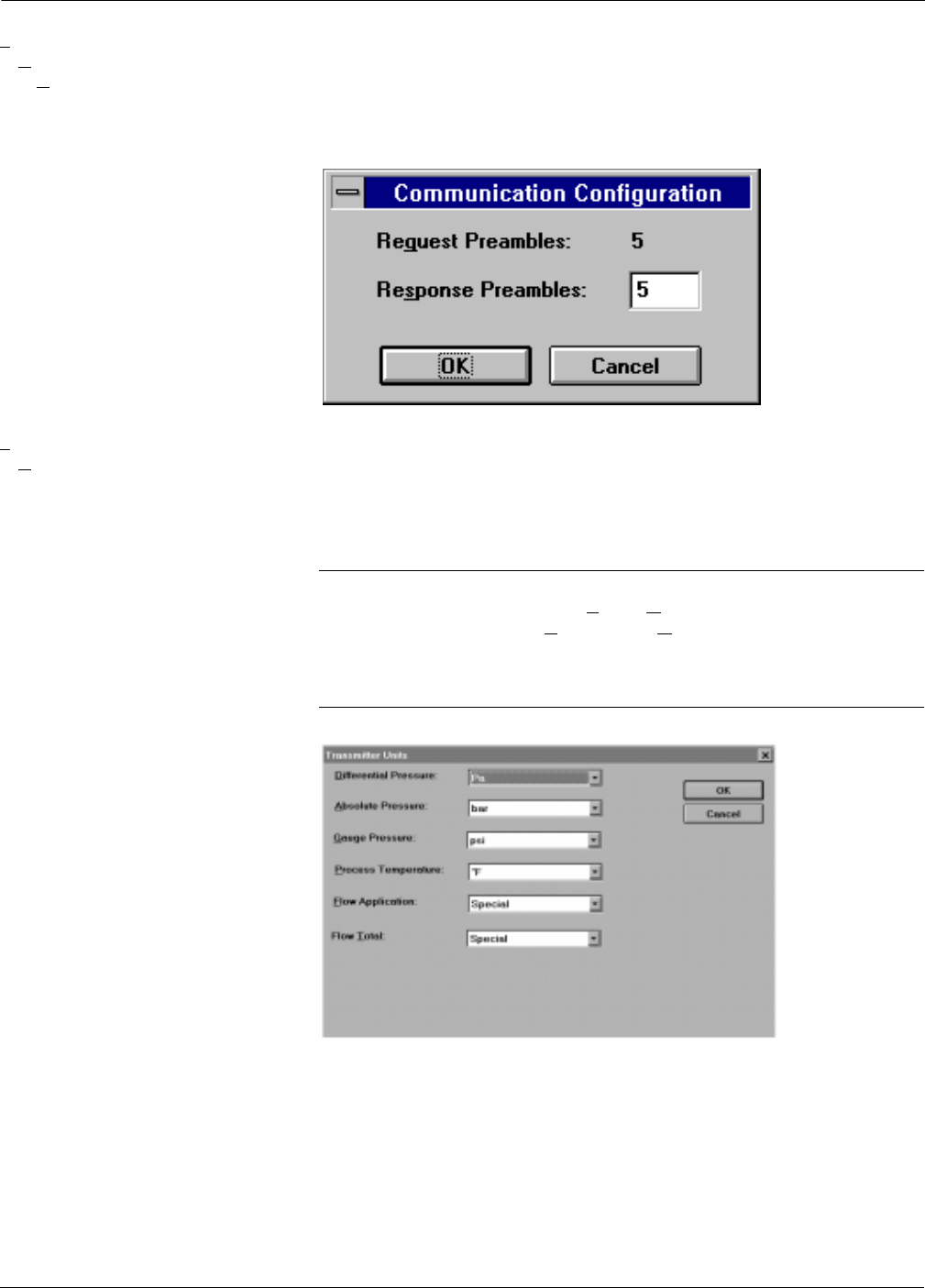
Rosemount Model 3095 MV
4-36
Transmitter
HART Output
Communication
Configuration
The communication configuration screen sets the number of response
preambles for transmitter to EA communication. The valid range for
this setting is 2–20 preambles. The default setting is five.
Typically, this value is left at five. Increase this value only if the
transmitter is installed in an electrically noisy environment.
Transmitter
Units This screen sets the units for the five process variables: Differential
Pressure, Absolute Pressure, Gage Pressure, Process Temperature,
Flow, and Flow Total units.
Modifying the information on this screen and selecting OK immediately
changes the connected transmitter.
NOTE
Units can be entered off-line in Setup, Units (Flow Configuration
Information), or on-line in Transmitter, Units (Transmitter Specific
Information). If the units entered are different, the Transmitter
Specific Information overwrites the Flow Configuration
Information.
3095-30950118
FIGURE 4-30. Communication
Configuration Screen.
FIGURE 4-31. Transmitter Units
Screen.
3095-T-UNITS

4-37
Using the Model 3095 MV Engineering Assistant
Transmitter
Damping This screen sets the damping for four process variables: Differential
Pressure, Absolute Pressure, Gage Pressure, and Process Temperature
Modifying the information on this screen and selecting OK immediately
changes the connected transmitter.
NOTE
The transmitter sets the damping value to the nearest acceptable
value. An information message is provided to the operator indicating
the new damping values.
Transmitter
Device Info This screen sets the device information for a transmitter.
Modifying the information on this screen and selecting OK immediately
changes the connected transmitter.
FIGURE 4-32. Transmitter Damping
Screen.
3095-30950093
FIGURE 4-33. Device Info Screen.
3095-30950094

Rosemount Model 3095 MV
4-38
Transmitter
Send Config This screen allows sending three different types of configuration data to
a transmitter.
• Flow Configuration information only.
• Transmitter Specific information only.
• Both Flow Configuration and Transmitter Specific information.
Figure 4-33 identifies the contents for each type of file. An “X” in the
corresponding box indicates that the listed information will be
overwritten in the transmitter.
NOTE
When the Transmitter Specific Information is sent to a transmitter, all
previous transmitter information will be overwritten
Transmitter
Recv Config This screen receives the configuration information from a transmitter.
Range Limits Note This screen verifies your 4–20 mA range values when you send a new
flow configuration to a transmitter. It shows the current values and
allows you to either confirm or change them. If you select Change, the
Range Values screen appears (see Figure 4-44 on page 4-45).
3095-30950121
FIGURE 4-34. Send Config Screen.
FIGURE 4-35. Range Limits
Note Screen.
3095-30950448

4-39
Using the Model 3095 MV Engineering Assistant
Transmitter
LCD Settings The LCD Settings screen sets the display of process variables on the
LCD meter. The following eight process variables are available:
• Absolute Pressure
• Analog Output Current
• Differential Pressure
•Flow
•Flow Total
•Gauge Pressure
• Percent of Range
• Process Temperature
Display Rate, at the bottom of the screen, sets the display time of each
parameter selected (i.e., listed in the Displayed box). Display time is
selectable in one-second increments from two to ten seconds.
In Figure 4-36 below, the variables Absolute Pressure, Differential
Pressure, Flow, Flow Total, Gauge Pressure, Percent of Range, and
Process Temperature will be displayed on the LCD meter for 5 seconds
each:
Transmitter
Totalizer The Totalizer screen displays and controls the settings for totalizing
mass flow in the connected transmitter.
The Current Total box contains the flow total and units information.
The Control of Totalizer settings box contains the totalizer settings:
• Start: Starts totalizing flow in the transmitter
• Stop: Stops totalizing flow in the transmitter
• Clear: Resets the flow total
3095-LCDSTGS
FIGURE 4-36. LCD Settings
Screen.
Display Rate

Rosemount Model 3095 MV
4-40
.
Transmitter
Flow Rate Special Units The Flow Rate Special Units screen allows the display and
measurement of units considered nonstandard by the EA.
NOTE
The Model 3095MV supports only mass or standard volume
measurements.
To select a special flow rate unit:
1. Select Transmitter, Units.
2. Select the right drop down arrow of the Flow Application box.
Select Special, then select OK.
3. Select Transmitter, Flow Rate Special Units.
4. Select the right drop down arrow of Base Flow Unit, then select
the Base Flow Unit desired.
5. Select the Conversion Factor box. Type in a conversion factor. The
conversion factor multiplied by the Base Flow Unit will equal the
Flow Rate Special Unit.
6. Select the Display As box. Type in the desired display units, for
example, GAL/M. Select OK. You can enter up to five characters
for display of special units, including all alphanumeric characters
and the forward slash (“/”) key.
FIGURE 4-37. Totalizer Screen.
3095-TTLZR

4-41
Using the Model 3095 MV Engineering Assistant
Transmitter
Totalizer Special Units The Flow Total Special Units screen allows the display and
measurement of flow total in units considered nonstandard by the EA.
NOTE
The Model 3095MV supports only mass or standard volume
measurements.
To select a special flow total unit:
1. Select Transmitter, Units.
2. Select the right drop down arrow of the Flow Total box. Select
Special, then select OK.
3. Select Transmitter, Totalizer Special Units.
4. Select the right drop down arrow of Base Quantity Unit, then
select the unit desired.
5. Select the Conversion Factor box. Type in a conversion factor. The
conversion factor multiplied by the Base Quantity Unit will equal
the Flow Total Special unit.
6. Select the Display As box. Type in the desired display units.
Select OK. You can enter up to five characters for display of
special units, including all alphanumeric characters and the
forward slash (“/”) key.
3095-FLRTSPCL
FIGURE 4-38. Flow Rate Special Units
Screen.
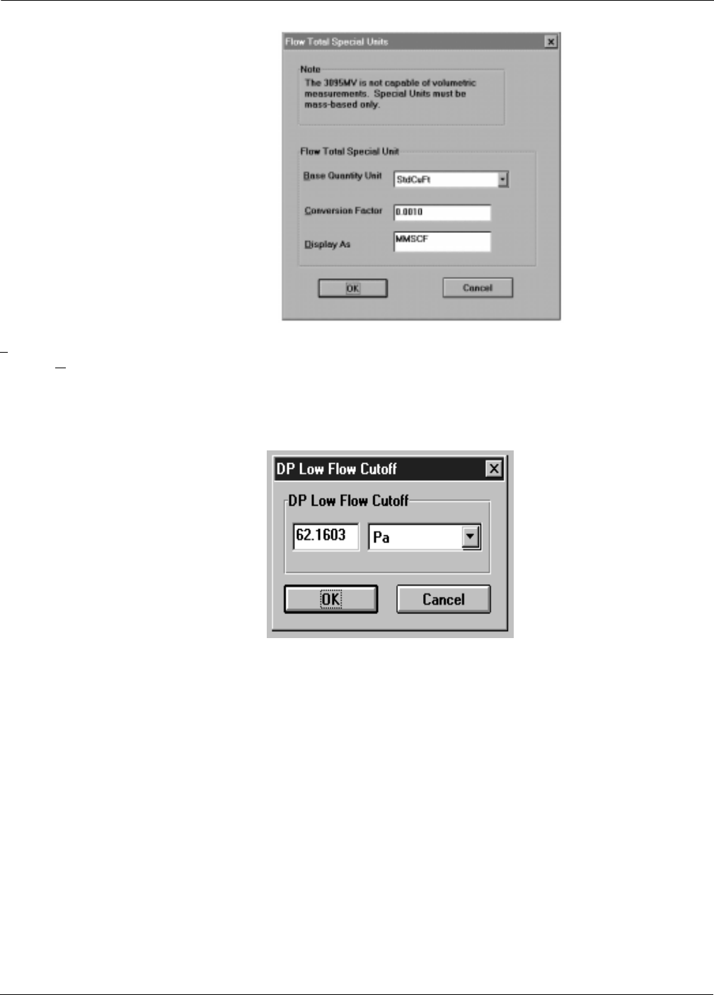
Rosemount Model 3095 MV
4-42
Transmitter
DP Low Flow Cutoff The DP Low Flow Cutoff screen controls the minimum differential
pressure (DP) limit, where flow is calculated. At DPs less than the low
flow cutoff, flow equals zero.
The lowest limit for the DP Low Flow Cutoff equals
0.02 inH20 (5 Pa).
3095-FLTLSPCL
FIGURE 4-39. Flow Total Special Units
Screen.
3095-LOFLOW
FIGURE 4-40. DP Low Flow Cutoff
Screen.

4-43
Using the Model 3095 MV Engineering Assistant
Maintenance Screens
Maintenance
Privileges This screen allows changing password security levels. For information
about passwords, see page 4-48.
Maintenance
Sensor Trim The sensor trim screens are used during bench and field calibration of
the Model 3095 MV.
In addition to the EA Software, the following equipment is required for
a sensor trim procedure:
• Model 3095 MV
•Dead-weight tester
• Power supply and load resistor
• Vacuum pump or a barometer that is at least 3 times as accurate
as the Model 3095 MV AP sensor. A barometer is preferred.
Table 4-7 identifys the LRL and URL for the
Model 3095 MV.
FIGURE 4-41. Privileges Screen.
3095-30950095
TABLE 4-7. Model 3095 MV Sensor
Limits. Sensor Range LRL URL
DP Range 1 –25 inH2O @ 68 °F 25 inH2O @ 68 °F
DP Range 2 –250 inH20at68°F 250inH
20at68°F
DP Range 3 –1,000 inH20at68°F 1,000inH
20at68°F
AP Range 3 0.5 psia 800 psia
AP Range 4 0.5 psia 3,626 psia
GP Range C 0 psig 800 psig
GP Range D 0 psig 3,626 psig
PT (1)
(1) In the fixed temperature mode, PT range is –459 to 3500 °F (–273 to 1927 °C).
–300 °F (–185 °C) 1,500 °F (815 °C)

Rosemount Model 3095 MV
4-44
Sensor Trim Procedure (For Bench Calibration)
NOTE
The EA software is capable of calibrating absolute or gauge pressure
sensors. Either “Gauge Sensor” or “Absolute Sensor” will populate the
sensor selection, depending on Assigned Variables (Figure 4-46 on page
4-47). The Gauge Pressure Sensor Trim Procedure is similar to the
Absolute Pressure Sensor Trim procedure given here.
1. Trim Absolute (or Gauge) Pressure Offset (zero).
a. Select Maintenance, Sensor Trim to display the
Sensor Trim screen.
b. Select Absolute Press, then select Offset & Slope Trim. Set
Offset Trim Point and units, set Slope Trim Point and units,
then select Trim to display the “Sensor Offset Trim” screen.
3095-30950096
FIGURE 4-42. Sensor Trim Screen.
3095-30950301
FIGURE 4-43. Sensor Offset
Trim Screen.

4-45
Using the Model 3095 MV Engineering Assistant
c. If using a vacuum pump, pull a vacuum to both the low and
high sides of the transmitter, wait for the measured value to
stabilize, then select OK. or
If using a barometer, select OK to display the Sensor Slope
Trim screen (Figure 4-44).
2. Trim Absolute (or Gauge) Pressure Slope (span).
a. Using the dead-weight tester, apply the desired high pressure
to both the low and high sides of the transmitter.
b. Wait for the Measured Value to stabilize, then select OK.
3. Trim Differential Pressure Offset (zero).
a. Select Differential Press and Offset & Slope Trim, set Offset
Trim Point and units, set Slope Trim Point and units, then
select Trim to display the “Sensor Offset Trim” screen.
b. Using the dead-weight tester, apply the desired low pressure
value to the high side of the transmitter.
NOTE
If zero is the desired low value, do not use the dead weight tester.
Instead, enter zero as the trim value, select the units, then select OK.
c. Wait for the Measured Value to stabilize, then select OK to
display the Sensor Slope Trim Screen.
4. Trim Differential Pressure Slope (span).
a. Using the dead-weight tester, apply the desired high pressure
to the high side of the transmitter.
b. Wait for the Measured Value to stabilize, then select OK.
5. Trim Process Temperature Offset (zero).
a. Select Process Temp then select Offset & Slope Trim. Set
Offset Trim Point and units, set Slope Trim Point and units,
then select Trim to display the “Sensor Offset Trim” screen.
b. Insert the RTD probe into an ice bath, wait for the Measured
Value to stabilize, then select OK to display the Sensor Slope
Trim screen.
6. Trim Process Temperature Slope (span).
a. Insert the RTD probe into a hot oil bath.
b. Wait for the Measured Value to stabilize, then select OK.
3095-30950302
FIGURE 4-44. Sensor Slope Trim
Screen.

Rosemount Model 3095 MV
4-46
Sensor Trim Procedure (For Field Calibration)
To correct mounting position effects, field calibrate the Model 3095 MV
after installation:
1. Establish communications (see Connecting to a Personal
Computer on page 4-4).
2. Perform a Trim DP Offset (zero).
a. Select Maintenance, Sensor Trim to display the Sensor Trim
Select screen.
b. Select Differential Press then select Offset Trim. Enter the low
pressure value as the Offset Trim Point, set the units, then
select Trim to display the “Sensor Offset Trim” screen.
c. Wait for the Measured Value to stabilize, then select OK.
3. (Optional) If a barometer that is at least 3 times as accurate as
the Model 3095 MV AP sensor is available, perform an SP Offset
(zero).
a. Select Maintenance, Sensor Trim to display the Sensor Trim
Select screen.
b. Select Absolute Press then select Offset Trim. Enter the
barometric pressure reading as the Offset Trim Point, set the
units, then select Trim to display the “Sensor Offset Trim”
screen.
c. Select OK.
Recall Factory Trim Settings Procedure
Use the following procedure to change trim settings to the factory
installed settings.
1. Establish communications (see Connecting to a Personal
Computer on page 4-4).
2. Enter a valid password.
3. Select the desired sensor (DP, SP, PT) and Recall Factory Trim
Settings, then select Trim.
4. Repeat step 3 above for each of the other sensors.
Maintenance
Analog Output
Range Values...
The Range Values screen sets the range values for the primary
variable, and also allows for reassigning the process variable output
order. Setting the range points involves redefining the pressure points
corresponding to the transmitter 4 and 20 mA setpoints.
NOTE
The Primary Variable (Figure 4-46) is also assigned as the 4–20 mA
analog output.
The top half of this screen provides information on the primary
variable, while the bottom half allows setting the range values.
1. Select Assign Variables, then verify that the variable order is
correct (see Figure 4-46).
2. Fill in the Range Values (4 mA Value and 20 mA Value), select the
Units, then select Set Range.

4-47
Using the Model 3095 MV Engineering Assistant
NOTE
The Process Variable output order is critical if using the Model 3095MV
transmitter in conjunction with the Model 333 Triloop HART-to-Analog
Signal Converter. The process variable order and units of the Model
3095MV must match the process variable order and units in the
Model 333 Triloop.
NOTE
Range values must be within the lower range limit, the upper range limit,
and the minimum span as indicated in the top portion of the Set Range
Values screen. The 4 and 20 mA range values cannot be equal.
FIGURE 4-45. Range Values Screen.
3095-30950097
FIGURE 4-46. Assign Variables
Screen.
3095-30950116
NOTE
This screen determines the order of
HART Burst Command 3 Variables.
This information is required if
connecting to a HART Tri-Loop.

Rosemount Model 3095 MV
4-48
Maintenance
Analog Output
Output Trim...
This screen allows the user to adjust the transmitter digital to analog
converter at the end points of the transmitter output scale to
compensate for component aging effects.
This function also allows the user to enter the endpoints and the meter
readings in an alternative scale. For example, endpoints using a 500
ohm resistor with a voltmeter would be 2 and 10 volts.
Fill in the upper and lower analog output trim points according to the
units in the measuring device, then select Start Trim.
Continue to follow the instructions as prompted by the EA.
FIGURE 4-47. Analog Output Trim
Screens.
3095-30950098
3095-30950122
3095-30950123

4-49
Using the Model 3095 MV Engineering Assistant
Maintenance
Change Passwords... Figure 4-48 illustrates the Change Passwords screen. Security must be
enabled (see page 4-50) before you can gain access to this screen.
NOTE
When shipped from the factory, all medium level passwords are
“3095MV,” and the high level password is blank. Press
return
when the
login screen appears, and High Level (System Administration) access is
granted.
Before filling in this screen, consider the following issues concerning
EA passwords:
• If a password is left blank, pressing
return
at the login screen
accesses that password level.
• If passwords are identical, the higher level access is granted.
• Passwords are up to 8 characters in length.
Once a password is entered, the title bar indicates current password
access. Each password level allows access to specific functions.
Medium Level Passwords
Provides full access except the operator cannot change passwords, or
enable or disable security.
System administrator
Provides full access for the system administrator.
NOTE
Be sure to record passwords in a safe location. If the System
Administrator password is lost or forgotten, consult the factory.
FIGURE 4-48. Change Password
Screen.
3095-30950109

Rosemount Model 3095 MV
4-50
Maintenance
Enable/Disable Security... This selection allows enabling or disabling security. You must have
System Administrator authority to enable or disable security.
NOTE
When shipped from the factory, all medium level passwords are
“3095MV,”and the high level password is blank. Press
return
when the
login screen appears, and High Level (System Administration) access is
granted.
Maintenance
Process Temperature Mode This selection specifies the process temperature (PT) mode. It allows
you to enable or disable PT input or to specify automatic backup mode.
To enable process temperature input, select Normal PT Mode. In this
mode, the transmitter uses the external RTD for automatic PT
measurement. In the event of an RTD failure, the transmitter goes into
alarm condition.
To disable process temperature input, select Fixed PT Mode, enter the
desired fixed value, then select OK.
Use the Backup PT Mode selection to specify a value to be used for
temperature in the event the RTD fails or is disconnected. Upon failure,
the transmitter will use this backup value and set a HART status bit
for PT alarm, but will not go into alarm condition. The transmitter
returns to automatic temperature sensor readings when the fail
condition no longer exists.
NOTE
The fixed and backup process temperature ranges are wider than the
actual process temperature range:
Process Temperature Range: –300 to 1500 °F (–185 to 815°C).
Fixed/Backup Temperature Range: –459 to 3500 °F (–273 to 1927 °C).
FIGURE 4-49. Enable/Disable
Security Screen.
3095-30950111
FIGURE 4-50. Process Temperature
(PT) Mode Screen.
3095-30950447

4-51
Using the Model 3095 MV Engineering Assistant
Diagnostics Screens
Diagnostics
Read Outputs... This selection displays the current process variable values as
illustrated in Figure 4-51. This screen continuously updates with
current data. To exit this screen, select OK.
Diagnostics
Device Info
Module Info...
This selection displays module information as illustrated in Figure
4-52. This is a read-only screen.
FIGURE 4-51. Read Outputs Screen.
3095-30950099
FIGURE 4-52. Module Information
Screen.
3095-3MODINFO

Rosemount Model 3095 MV
4-52
Diagnostics
Device Info
Identification Info...
This selection displays transmitter identification numbers as well as
current software and hardware revision levels. To exit this screen,
select OK.
Diagnostics
Test Calculation... The test calculations screen provides a method to view the Model 3095
MV mass flow calculations for the current process variables. Optionally,
the system administrator can enter process variable values, and then
view the calculation results.
NOTE
Since the test calculation procedure actually changes flow and output
values during the test, the control loops should be put into manual
mode and taken out of flow totalization mode for the duration of the
test.
NOTE
The test calculation results displayed by this screen are calculated in
the attached transmitter, not the EA.
Also, the calculation update time for this screen is not indicative of the
actual transmitter update rate. (The Model 3095 MV sensor update
rate is nine times per second.)
1. Select Diagnostics, Test Calculation to display the Test
Calculation screen. The initial values indicate current process
variable readings.
2. (Optional) Enter values and units for Differential Pressure, Static
Pressure, and Process Temperature process variables and units.
3. Select the Calculate button. After a short delay, the results box is
populated with calculation results.
FIGURE 4-53. Identification Info
Screen.
3095-30950100

4-53
Using the Model 3095 MV Engineering Assistant
4. If desired, the Mass Flow Rate, Density, and Viscosity results can
be displayed in different units.
5. When finished with your test calculations, select Exit.
Diagnostics
Loop Test... The loop test screen provides a method to test the transmitter analog
output.
1. Select the desired current (4 mA, 20 mA, or Other).
2. Select Set Current.
3. The analog output field will state the actual transmitter analog
output.
4. Select Close. This step returns the transmitter to normal
operation.
FIGURE 4-54. Test Calculation
Screen.
3095-30950101
FIGURE 4-55. Loop Test Screen.
3095-30950103

Rosemount Model 3095 MV
4-54
Diagnostics
Master Reset... The transmitter master reset selection reinitializes the transmitter
microprocessor. This is the equivalent of removing and then reapplying
power to the transmitter.
NOTE
This procedure does not return the transmitter to factory trim settings
(see 4-43).
Diagnostics
Error Info... The transmitter Error Info selection identifies the current error status
for the Model 3095 MV transmitter.
If there are additional errors not displayed on the original screen, the
Error Info button will be enabled. Select Error Info to view the
additional errors.
FIGURE 4-56. Error Info Screen.
3095-30950106
3095-30950303

4-55
Using the Model 3095 MV Engineering Assistant
MISCELLANEOUS EA
SELECTIONS
View
Toolbar... This selection toggles the toolbar on and off.
View
Status Bar... This selection toggles the status bar on and off.
Help This selection identifies the current EA software revision and provides
access to online help.

Rosemount Model 3095 MV
4-56

Section
5-1
5Troubleshooting and
Maintenance
This section describes troubleshooting and maintenance tasks
associated with the Model 3095 MV. These include communication and
compatibility issues, critical alarms, maintenance procedures, and field
replaceable part procedures.
NOTE
For previous software information, see Critical Alarms for Previous
Software Revisions on page D-1. For compatibility issues of previous
Model 3095 MV software, sensor modules, and hardware, see
Compatibility Issues on page E-1.
TROUBLESHOOTING If a malfunction is suspected, follow the procedures described here to
verify that transmitter hardware and process connections are in good
working order. Under each major symptom, specific suggestions are
offered for solving the problem. Always deal with the most likely and
easiest-to-check conditions first.
Alarm Abbreviations Table 5-1 shows standard alarm abbreviations used in Section 5:
TABLE 5-1. Alarm Abbreviations.
Use only the procedures and new parts specifically
referenced in this manual. Unauthorized procedures or
parts can affect product performance and the output signal
used to control a process, and may render the instrument
dangerous. Direct any questions concerning these
procedures or parts to Rosemount Inc.
Abbreviation Definition
LOL Lower Operating Limits (customer specified using the EA)
UOL Upper Operating Limits (customer specified using the EA)
LRL Lower Range Limits
URL Upper Range Limits
LRV Lower Range Value
URV Upper Range Value
URL+ URL + (10%URL)
(For example, URL+ = 250 + (0.10 3250) = 275
LRL– LRL – (10%LRL)
(For example, LRL– = –250 –[0.10 3(250)] = –275

Rosemount Model 3095 MV
5-2
EA COMMUNICATION
PROBLEMS
Table 5-2 identifies the most likely causes for communication problems
between the Engineering Assistant (EA) software and the
Model 3095 MV.
TABLE 5-2. Corrective Action for EA
Communication Problems.
REVISION 12 AND 13
ELECTRONICS BOARD
ALARMS AND ERROR
CONDITIONS
The Model 3095 MV has both analog and digital alarms. If an alarm or
error condition exists, it will be displayed during communication with
the EA, the HART Communicator, or on the LCD meter display. Some
non-flow error conditions may take up to 2 seconds to display, while
some flow error conditions may take up to 10 seconds to display. View
specific alarm conditions using the EA software.
NOTE
Alarms are not logged or archived. The alarms and error conditions
displayed on the Diagnostics, Error Info screen indicate the current
error status for the Model 3095MV transmitter.
NOTE
For a discussion of critical alarms for previous electronics board and
sensor module revisions, see Appendix D. For previous version
compatibility issues, see Appendix E.
LCD Display Critical alarms and overrange conditions are displayed as one of the
selected variables on the LCD meter. During a critical alarm or
overrange condition, the meter scrolls through all selected variables
and the error message, displaying each for a fixed amount of time, as
set by the user. See LCD Meter on page 3-1 for more information.
Symptom Corrective Action
No Communication
between the EA
Software and the
Model 3095 MV
LOOP WIRING
• HART protocol communication requires a loop resistance value between
250–1100 ohms, inclusive.
• Check for adequate voltage to the transmitter. (If the computer is
connected and 250 ohms resistance is properly in the loop, a power
supply voltage of at least 16.5 V dc is required.)
• Check for intermittent shorts, open circuits, and multiple grounds.
• Check for capacitance across the load resistor. Capacitance should be
less than 0.1 microfarad.
EA INSTALLATION
• Verify that the install program modified the CONFIG.SYS file.
• Verify computer reboot followed EA installation.
• Verify correct COMM port selected (see page 4-2).
• Verify laptop computer is not in low energy mode
(certain laptops disable all COMM ports in low energy mode).
• Did you install EA software onto Windows NT platform?
• Check if HART driver is loaded and installed.

5-3
Options and Accessories
Critical Alarms Critical alarms are the highest priority Model 3095 MV alarms, and
indicate an error that prevents accurate sensor or flow measurements.
Table 5-3 shows the LCD Display, the EA display, analog output, digital
output, and the recommended corrective for critical alarms.
TABLE 5-3. Critical Alarms.
LCD
Display EA Display
(Diagnostics, Error Info) Analog
Output Digital
Output Corrective Action
Error
“OB_FT”
Output Board EEPROM Not Initialized
Output Board EEPROM Burn Failure
Alarm in the
direction of
the alarm
jumper
NAN (1)
The output electronics have not been properly initialized at
the factory. Replace the output electronics board as
described on page 5-12. Contact your Field Service Center.
Error
“SM_FT”
SB EEProm Burn Failure
SB EEProm Not Initialized
The sensor module has not been properly initialized at the
factory. Replace the sensor module as described on page
5-12. Contact your Field Service Center.
Error
(no display)(2) Sensor Hardware is incompatible The transmitter electronics has undergone a component or
software failure. Replace the sensor module as described
on page 5-12. Contact your Field Service Center.
Error
“SM_FT”
Sensor Module is Not Updating The 10-pin ribbon cable may be disconnected, or the
transmitter electronics may have undergone a component
or software failure. Contact your Field Service Center.
Error
(no display)(2) RAM Failure Issue a master reset to the transmitter as described in
Section 4.
Error
“OB_FT”
Transmitter Self Test Failed The electronics sensor has undergone a component or
software failure. If connected to a transmitter with EA
software, institute a “self-test recovery” in EA Error Info. If
connected to a transmitter with a HART Communicator,
institute a “self-test recovery” as follows: 4 Detailed Setup–
1 Output Conditioning–2 HART Output. After a self-test
recovery, transmitter trim values need to be verified.
Error
(no display)(2) Static Pressure Sensor is Open This display means that the transmitter absolute pressure
reading exceeds its sensor limits. There are two possible
causes. Either the transmitter is overpressured, or it has a
sensor malfunction. Check the pressure input to the
transmitter. If an overpressure condition exists, correct it. If
not, replace the sensor module as described on page 5-12.
Error
(no display)(2) Process Temp Sensor is Disconnected Check the transmitter RTD connector and RTD screw
terminals to ensure the RTD cable is properly connected.
This alarm can not occur if a transmitter is set to fixed PT
mode in EA Error Info. If the transmitter is set to backup PT
mode, the transmitter will not go into alarm condition, but
“PT is disconnected” is displayed in EA Error Info.
(1) NAN indicates “Not a Number.” Distributed Control Systems and HART masters will read “7F A0 00 00h.”
(2) The LCD has no display for this error. It continues with normal unit display during this error condition.

Rosemount Model 3095 MV
5-4
Overrange Conditions Overrange conditions typically indicate an error that the sensor or flow
measurements have reached an overrange condition where substitute
values are being used.
Table 5-4 identifies actions to the analog output and digital output
during these conditions. Blank table cells indicate no action for that
condition. Table 5-5 shows recommended corrective action, and also
identifies effects on the flow calculation during these conditions.
TABLE 5-4. Overrange Conditions.
EA Display
(Diagnostics,
Error Info)
Analog Output Digital Output
Flow DP AP/GP PT Flow
Total Flow DP AP/GP PT Flow
Total
DP above URL+
Saturate in
direction of
alarm
jumper
Saturate
High (1) Saturate
in
direction
of alarm
jumper
URL+
DP below LRL–
Saturate
Low(2) Saturate
Low(2) Saturate
Low(2) zero URL– zero
AP/GP above URL+
Saturate in
direction of
alarm
jumper
Saturate in
direction of
alarm
jumper
Saturate
High(1) Saturate
in
direction
of alarm
jumper
URL+ URL+
AP/GP below LRL–
Saturate in
direction of
alarm
jumper
Saturate in
direction of
alarm
jumper
Saturate
Low (2) Saturate
in
direction
of alarm
jumper
URL– URL–
PT above URL+
Saturate in
direction of
alarm
jumper
Saturate
High(1) Saturate
in
direction
of alarm
jumper
URL+
PT below LRL–
Saturate in
direction of
alarm
jumper
Saturate
Low(2) Saturate
in
direction
of alarm
jumper
URL–
ST above URL+ Saturate in direction of alarm jumper NAN(3) NAN(3) NAN(3) NAN(3) NAN(3)
ST below LRL– Saturate in direction of alarm jumper NAN(3)) NAN(3) NAN(3) NAN(3) NAN(3)
(1) Saturate high if direct acting (URV>LRV), Saturate low if reverse acting (URV<LRV).
(2) Saturate low if direct acting (URV>LRV), Saturate high if reverse acting (URV<LRV).
(3) NAN indicates “Not a Number.” Distributed Control Systems and HART masters will read “7F A0 00 00h.”

5-5
Options and Accessories
TABLE 5-5. Corrective Action: Overrange Conditions.
EA Display
(Diagnostics, Error
Info) LCD Display
Flow Calculation
Affects (1) Corrective Action
C’ ()0.5
“DP above URL+” “DP_OL” URL+ URL+
These displays indicate that the transmitter differential pressure reading
exceeds its sensor limits by more than 10%. There are two possible causes.
Either the transmitter is overpressured (underpressured), or it has a sensor
malfunction. Check the pressure input to the transmitter. If an overpressure
(underpressure) condition exists, correct it. If not, replace the sensor
module as described on page 5-15.
“DP below LRL–” “DP_OL”
Unreliable
flow output
Unreliable
flow output
“AP/GP above URL+ “ “SP_OL” UOL URL+
These displays indicate that the transmitter absolute pressure reading
exceeds its sensor limits by more than 10%. There are two possible causes.
Either the transmitter is overpressured (underpressured), or it has a sensor
malfunction. Check the pressure input to the transmitter. If an overpressure
(underpressure) condition exists, correct it. If not, replace the sensor
module as described on page 5-10page 5-15
“AP/GP below LRL–” “SP_OL” LOL LRL–
“PT above URL+” “PT_OL” UOL URL+
Check the transmitter RTD connector and RTD screw terminals to ensure
the RTD cable is properly connected. Verify that the process temperature is
between -300F and 1500 °F. Check output board revision level to verify this
is correct process temperature range.
“PT below LRL– “ “PT_OL” LOL LRL–
“ST above URL+” no display
Unreliable
flow output
Unreliable
flow output
These displays indicate that the ambient temperature limit of the transmitter
is being exceeded. Verify that the transmitter ambient temperature is
between -40F and 185F. If transmitter temperature exceeds these limits,
correct the temperature. If transmitter temperature is within these limits,
replace the sensor module as described on page 5-15.
“ST below LRL–” no display
Unreliable
flow output
Unreliable
flow output
(1) Only the parameter causing the exception is clipped at the operating or sensor limits. The other calculation inputs are not affected.
TABLE 5-6. Model 3095 MV Flow Exceptions.
LCD Display EA Display
(Diagnostics, Error Info)
Flow Calculation Affects (1) Flow Analog
Output
Flow
Digital
Output
C’ ()
0.5
no display(2)
“AP/GP is above UOL”
UOL
no display(2)
“AP/GP is below LOL”
LOL
no display(2)
“PT is above UOL”
UOL
no display(2)
“PT is below LOL”
LOL
no display(2)
“Flow math error”
Math Error Math Error Saturate in
direction of
alarm jumper
NAN (3)
no display(2)
“–2 inH20<DP<low-flow cutoff”(4) Unreliable
flow output
Unreliable
flow output 0
no display(2)
“DP < –2 inH20”
Unreliable
flow output
Unreliable
flow output
Saturate
Low(5) zero
(1) Only the parameter causing the exception is clipped at the operating or sensor limits. The other calculation inputs are not affected.
(2) The LCD has no display for this error. It continues with normal unit display during this error condition.
(3) NAN indicates “Not a Number.” Distributed Control Systems and HART masters will read “7F A0 00 00h.”
(4) Default and minimum low-flow cutoff value = 0.02 inH
2
O.
(5) Saturate low if direct acting (URV>LRV), Saturate high if reverse acting (URV<LRV).

Rosemount Model 3095 MV
5-6
Sensor Limits Table 5-7 identifies sensor limits for Model 3095MV transmitters with
serial numbers less than 40,000.
TABLE 5-7. Model 3095 MV Sensor Limits (for transmitters with serial numbers less than 40000.)
Sensor Range LRL– (1) LRL URL URL+(2)
Flow No limit 0 op-limits calc(3) no limit
DP Range 1 –27.5 inH2O @ 68 °F –25 inH2O @ 68 °F 25 inH2O @ 68 °F 27.5 inH2O @ 68 °F
DP Range 2 –275 inH20at68°F –250inH
20 at 68 °F 250 inH20at68°F 275inH
20at68°F
DP Range 3 –1,100 inH20 at 68 °F –1,000 inH20at68°F 1,000inH
20at68°F 1,100inH
20at68°F
AP Range 3 0 psia(4) 0.5 psia 800 psia 880 psia
AP Range 4 0 psia(4) 0.5 psia 3,626 psia 3,988 psia
GP Range C –0.15 psig 0 psig 800 psig 880 psig
GP Range D –0.15 psig 0 psig 3,626 psig 3,988 psig
PT (5) –330 °F (–201 °C) –300 °F (–185 °C) 1,500 °F (815 °C) 1,550 °F (843 °C)
Sensor Temperature –47 °F (–44 °C) –40 ° F (–40 ° C) 185 °F (85 °C) 200 °F (93.5 °C)
(1) LRL– is equal to LRV and lower sensor trim limits.
(2) URL+ is equal to URV and upper sensor trim limits.
(3) The flow rate when DP=URL+, AP=UOL, and PT=LOL. This value is calculated by the EA.
(4) For output board versions below 10, LRL– is 0.45 psia.
(5) In the fixed temperature mode, PT range is –459 to 3500 °F (–273 to 1927 °C).

5-7
Options and Accessories
Unexpected Process
Variable (PV) Readings
The EA software provides a means to display the current process
variables and flow calculations.
The following performance limitations may inhibit efficient or
safe operation. Critical applications should have appropriate
diagnostic and backup systems in place.
Pressure transmitters contain an internal fill fluid. It is used
to transmit the process pressure through the isolating
diaphragms to the pressure sensing element. In rare cases,
oil loss paths in oil-filled pressure transmitters can be
created. Possible causes include: physical damage to the
isolator diaphragms, process fluid freezing, isolator
corrosion due to an incompatible process fluid, etc.
A transmitter with oil fill fluid loss may continue to perform
normally for a period of time. Sustained oil loss will
eventually cause one or more of the operating parameters
to exceed published specifications while a small drift in
operating point output continues. Symptoms of advanced oil
loss and other unrelated problems include:
• Sustained drift rate in true zero and span or operating
point output or both
• Sluggish response to increasing or decreasing pressure or
both
• Limited output rate or very nonlinear output or both
• Change in output process noise
• Noticeable drift in operating point output
• Abrupt increase in drift rate of true zero or span or both
• Unstable output
• Output saturated high or low.

Rosemount Model 3095 MV
5-8
TABLE 5-8. Unexpected Process
Variable (PV) Readings.
Symptom Corrective Action
High PV Reading DIFFERENTIAL PRODUCER
• Check for restrictions at the differential producer.
• Check the installation and condition of the differential
producer.
• Note any changes in process fluid properties that may affect
output.
IMPULSE PIPING
• Check to ensure that the pressure connection is correct.
• Check for leaks or blockage.
• Check to ensure that blocking valves are fully open.
• Check for entrapped gas in liquid lines and for liquid in gas
lines.
• Check to ensure that the density of fluid in impulse lines is
unchanged.
• Check for sediment in the transmitter process flange.
• Make sure that process fluid has not frozen within the process
flange.
POWER SUPPLY
• Check the output voltage of the power supply at the
transmitter. It should be 11 to 55 V dc with no load at the
transmitter terminals.
TRANSMITTER ELECTRONICS
• Connect a personal computer and use the EA Software to
check the sensor limits to ensure calibration adjustments are
within the sensor range and that calibration is correct for the
pressure being applied.
• Connect a personal computer and using the EA Software,
select Diagnostics, Error Info
(see page 4-54) to detect any electronic failures.
• Make sure the post connectors are clean.
• Confirm that the electronics housing is properly sealed
against moisture.
• If the electronics are still suspect, substitute new electronics.
SENSING ELEMENT
• The sensing element is not field repairable and must be
replaced if found to be defective. Check for obvious defects,
such as a punctured isolating diaphragm or fill fluid loss, and
contact your nearest Rosemount Service Center.
Do not use higher than the specified voltage to
check the loop, or damage to the transmitter
electronics may result.

5-9
Options and Accessories
TABLE 5-8. (continued).
Symptom Corrective Action
Erratic PV Reading DIFFERENTIAL PRODUCER
• Check the installation and condition of the differential
producer.
LOOP WIRING
• Check for adequate voltage to the transmitter. It should be 11
to 55 V dc with no load at the transmitter terminals.
• Check for intermittent shorts, open circuits, and multiple
grounds.
PROCESS PULSATION
• Adjust the electronic damping (see page 4-17).
TRANSMITTER ELECTRONICS
• Connect a personal computer and use the EA Software to
check the sensor limits to ensure calibration adjustments are
within the sensor range and that calibration is correct for the
pressure being applied.
• Connect a personal computer and using the EA Software,
select Diagnostics, Error Info
(see page 4-54) to detect any electronic failures.
• Make sure the post connectors are clean.
• Confirm that the electronics housing is properly sealed
against moisture.
• If the electronics are still suspect, substitute new electronics.
IMPULSE PIPING
• Check for entrapped gas in liquid lines and for liquid in gas
lines.
• Make sure that process fluid has not frozen within the process
flange.
SENSING ELEMENT
• The sensing element is not field repairable and must be
replaced if found to be defective. Check for obvious defects,
such as a punctured isolating diaphragm or fill fluid loss, and
contact your nearest Rosemount Service Center.
Do not use higher than the specified voltage to
check the loop, or damage to the transmitter
electronics may result.

Rosemount Model 3095 MV
5-10
TABLE 5-8. (continued).
Symptom Corrective Action
Low PV Reading or No PV
Reading DIFFERENTIAL PRODUCER
• Check the installation and condition of the differential
producer.
• Note any changes in process fluid properties that may affect
output.
LOOP WIRING
• Check for adequate voltage to the transmitter. It should be 11
to 55 V dc with no load at the transmitter terminals.
• Check the milliamp rating of the power supply against the total
current being drawn for all transmitters being powered.
• Check for shorts and multiple grounds.
• Check for proper polarity at the signal terminal.
• Check loop impedance.
• Check the wire insulation to detect possible shorts to ground.
IMPULSE PIPING
• Check to ensure that the pressure connection is correct.
• Check for leaks or blockage.
• Check to ensure that blocking valves are fully open and that
bypass valves are tightly closed.
• Check for entrapped gas in liquid lines and for liquid in gas
lines.
• Check for sediment in the transmitter process flange.
• Make sure that process fluid has not frozen within the process
flange.
TRANSMITTER ELECTRONICS
• Connect a personal computer and use the EA Software to
check the sensor limits to ensure calibration adjustments are
within the sensor range and that calibration is correct for the
pressure being applied.
• Connect a personal computer and using the EA Software,
select Diagnostics, Error Info
(see page 4-54) to detect any electronic failures.
• Make sure the post connectors are clean.
• Confirm that the electronics housing is properly sealed
against moisture.
• If the electronics are still suspect, substitute new electronics.
SENSING ELEMENT
• The sensing element is not field repairable and must be
replaced if found to be defective. Check for obvious defects,
such as a punctured isolating diaphragm or fill fluid loss, and
contact your nearest Rosemount Service Center.
Do not use higher than the specified voltage to
check the loop, or damage to the transmitter
electronics may result.

5-11
Options and Accessories
TABLE 5-8. (continued).
Symptom Corrective Action
Sluggish Output
Response/Drift DIFFERENTIAL PRODUCER
• Check for restrictions at the differential producer.
IMPULSE PIPING
• Check for leaks or blockage.
• Ensure that blocking valves are fully open
• Check for sediment in the transmitter process flange.
• Check for entrapped gas in liquid lines and for liquid in gas
lines.
• Ensure that the density of fluid in impulse lines is unchanged.
• Make sure that process fluid has not frozen within the process
flange.
TRANSMITTER ELECTRONICS
• Connect a personal computer and using the EA Software,
select Diagnostics, Error Info
(see page 4-54) to detect any electronic failures.
• Confirm that damping is correctly set.
• Confirm that the electronics housing is properly sealed
against moisture.
SENSING ELEMENT
• The sensing element is not field repairable and must be
replaced if found to be defective. Check for obvious defects,
such as a punctured isolating diaphragm or fill fluid loss, and
contact your nearest Rosemount Service Center.
• Confirm that the electronics housing is properly sealed
against moisture.

Rosemount Model 3095 MV
5-12
DISASSEMBLY
PROCEDURES
Read the following information carefully before disassembling a
transmitter. General information concerning the process sensor body
and electrical housing follow. Figure 2-3 on page 2-3 shows an exploded
view of the transmitter.
Removing the
Process Sensor Body
NOTE
Do not leave inoperable transmitters in service.
Be aware of the following:
• The process flange can be detached by removing the four flange
bolts and the two alignment screws that secure it.
• Isolating diaphragms can be cleaned with a soft rag, mild
cleaning solution, and clear water rinse.
• The flange adapters and process flange can be rotated or reversed
for mounting convenience.
• When removing the process flange or flange adapters, visually
inspect the Teflon O-rings. Replace the O-rings if they show any
signs of damage, such as nicks or cuts. If they are undamaged,
they can be reused.
• If the teflon sensor module O-rings have been replaced, re-torque
the flange bolts after installation to compensate for cold flow.
Explosions can result in death or serious injury.
Do not remove the instrument cover in explosive
environments.
Process should be isolated from the transmitter and vented
before the transmitter is removed from service for
disassembly.
To prevent damage which may lead to inaccurate
measurements, do not scratch, puncture, or depress the
isolating diaphragms.
To prevent damage which may lead to inaccurate
measurements, do not use any chlorine or acid solutions to
clean the diaphragms.

5-13
Options and Accessories
Removing the
Electrical Housing
Electrical connections are located in a compartment identified as
FIELD TERMINALS on the electronics housing. Unscrew the cover on
the Field Terminal side to access the signal terminal block.
Remove the signal terminal block by loosening the two small screws
located at the 9 o'clock and 4 o'clock positions, then pulling the terminal
block straight out to disconnect the block from the post connectors.
Removing the
Electronics Board
The transmitter electronics are located behind the cover opposite the
terminal side.
To remove the electronics board:
1. Remove the housing cover opposite the field terminal side.
2. Loosen the two captive screws that anchor the board.
3. Slowly pull the electronics board out of the housing. With the two
captive screws free of the transmitter housing, only the sensor
module ribbon cable holds the module to the housing.
To prevent damage to the circuit board, remove power from
the transmitter before removing the electronics cover.
Explosions can result in death or serious injury.
Do not remove the instrument cover in explosive
environments.
The circuit board is electrostatically sensitive. To prevent
damage to the circuit board, be sure to observe handling
precautions for static-sensitive components.

Rosemount Model 3095 MV
5-14
4. Disconnect the sensor module ribbon cable to release the
electronics board from the transmitter.
5. Carefully tuck the cable connector completely inside the internal
shroud. The shroud protects the cable from damage that might
occur when the housing is rotated.
Do not remove the housing until the cable connector has
been completely tucked inside the internal shroud. Damage
to the sensor module ribbon cable may occur if the
connector does not rotate with the sensor module.

5-15
Options and Accessories
Removing the
Sensor Module
6. Loosen the housing rotation set screw with a 5/64-inch hex
wrench and back off one full turn.
7. Unscrew the housing from the module, making sure the shroud
and sensor cable do not catch on the housing. Damage can occur
to the cable if the internal shroud and sensor cable rotate with
the housing. Carefully pull the shroud and sensor ribbon cable
assembly through the housing opening.
The sensing module is a complete assembly and cannot be further
disassembled.
Do not remove the housing until after you tuck the cable
connector completely inside of the internal shroud. The
shroud protects the cable from damage that can occur when
you rotate the housing.
Before removing the sensor module from the electrical
housing, disconnect the electronics board power cable from
the sensor module. This will prevent damage to the sensor
module ribbon cable.
If the Coplanar flange has been removed, take care not to
damage the isolating diaphragm after disassembly. Damage
to the isolating diaphragm may lead to inaccurate
measurements.

Rosemount Model 3095 MV
5-16
REASSEMBLY
PROCEDURES
Follow these procedures carefully to ensure proper reassembly:
Attaching the Sensor
Module to the
Electronics Housing
1. Inspect all cover and housing (non-process-wetted) O-rings and
replace if necessary. Lightly lubricate with silicone to ensure a
good seal.
2. Carefully tuck the cable connector completely inside the internal
shroud. To do this, turn the shroud and cable counterclockwise
one rotation to tighten the cable.
3. Lower the electronics housing onto the module, and guide the
internal shroud and cable through the housing and into the
external shroud.
4. Fasten the housing to the module by turning clockwise.
5. Inspect the threaded connections.
6. Tighten the housing rotation set screw.
To prevent damage to the cable connector, watch the cable
and shroud as you attach the housing to the module. Make
sure the cable connector does not slip out of the internal
shroud and begin to rotate with the housing. Reinsert the
cable connector into the shroud if it escapes before the
housing is fully fastened.
Explosions can result in death or serious injury.
The bottom of the electronic housing must be within 1/16-in.
of the sensor module to maintain explosion-proof
requirements.

5-17
Options and Accessories
Attaching the Electronics
Board
1. Remove the cable connector from its position inside the internal
shroud, and attach the cable to the electronics board.
2. Align the post-receptacle connectors with the posts inside the
electronics housing.
NOTE
If the post-receptacle connectors have a black rubber sleeve over them,
the sleeve must be removed before installing a new electronics board.
Gently grasp the sleeve between thumb and forefinger and slide it off
the connector. Discard sleeve.
3. Insert the electronics board into the housing and tighten the
captive mounting screws.
4. Replace the electronics housing cover. Metal to metal contact is
preferred.
Explosions can cause death or serious injury. Both
transmitter covers must be fully engaged to meet explosion-
proof requirements.

Rosemount Model 3095 MV
5-18
Reassembling the Process
Sensor Body
1. Inspect the Teflon sensor module O-rings. If the O-rings are
undamaged, they can be re-used. If the O-rings show signs of
damage, such as nicks or cuts, or if there is any doubt about their
sealing ability, replace them with new O-rings. Use the following
steps:
a. Remove the damaged O-rings by carefully prying them from
the O-ring grooves. Take care not to damage the surface of the
isolating diaphragm during this process.
b. Replace the damaged O-rings by fitting new O-rings into the
O-ring grooves.
2. Install the process flange on the sensor module. To hold the
process flange in place, install the two hex head alignment
screws. These screws are not pressure retaining and need only be
finger tight. Do not overtighten; this will affect the module/flange
alignment.
3. Install the appropriate flange bolts using Figure 2-9 on page 2-15
as a reference:
• For installations requiring a 1/4–18 NPT mounting, install the four
1.75-inch process flange bolts. First finger-tighten the bolts. Then
tighten the bolts incrementally in a cross pattern until they are
securely tightened to 650 in-lb (300 in-lb for stainless steel bolts).
After tightening, the bolts should protrude through the top of the
module housing.
• For installations requiring a 1/2–14 NPT mounting, hold the
optional flange adapters and flange adapter O-rings in place
while finger-tightening the four 2.88-inch process flange/adapter
bolts. Tighten the bolts in a cross pattern following the procedure
outlined above. (Use two 2.88- inch bolts and two 1.75-inch bolts
for gage pressure configurations.) After tightening, the bolts
should protrude through the top of the module housing. If the
bolts do not extend all the way through the module housing, you
have used a bolt of incorrect length. Replace the bolt with one of
the correct length, and repeat the procedure.
• For installations with a three-valve manifold, align the process
flange with the three-valve manifold. Install the four 2.25-inch
manifold flange bolts following the procedure outlined above.
After tightening, the bolts should protrude through the top of the
module housing. If the bolts do not extend all the way through the
module housing, you have used a bolt of incorrect length. Replace
the bolt with one of the correct length, and repeat the procedure.
Optional flange adapters can be installed on the process end of
the three-valve manifold using the 1.75-inch flange bolts supplied
with the transmitter.
4. If the Teflon sensor module O-rings have been replaced, the
flange bolts should be re-torqued after installation to compensate
for cold flow.
5. Follow these steps to install the drain/vent valve:
• Apply sealing tape to the threads on the seat. Starting at the base
of the valve with the threaded end pointing toward the installer,
apply two clockwise turns of the sealing tape.
• Take care to orient the opening on the valve so that process fluid
will drain toward the ground and away from personnel when the
valve is opened.
• Tighten the drain/vent valve to 250 in-lb.

5-19
Options and Accessories
RETURN OF MATERIALS To expedite the return process outside the United States, contact the
nearest Rosemount representative.
Within the United States, call the Rosemount National Response
Center using the 1-800-654-RSMT (7768) toll-free number. This center,
available 24 hours a day, will assist you with any needed information or
materials.
The center will ask for product model and serial numbers, and will
provide a Return Material Authorization (RMA) number. The center
will also ask for the name of the process material to which the product
was last exposed.
The Rosemount National Response Center will detail the additional
information and procedures necessary to return goods exposed to
hazardous substances.
People who handle products exposed to a hazardous
substance can avoid injury if they are informed and
understand the hazard. If the product being returned was
exposed to a hazardous substance as defined by OSHA, a
copy of the required Material Safety Data Sheet (MSDS) for
each hazardous substance identified must be included with
the returned goods.

Rosemount Model 3095 MV
5-20

Section
6-1
6Specifications and
Reference Data
FUNCTIONAL
SPECIFICATIONS
Service
Gas, liquid, or steam.
Differential Sensor
Ranges
Code 1: 0–0.5 to 0–25 inH2O (0–0.12 to 0–6.22 kPa).
Code 2: 0–2.5 to 0–250 inH2O (0–0.62 to 0–62.2 kPa).
Code 3: 0–10 to 0–1000 inH2O (0–2.48 to 0–248 kPa).
Limits
Code 1: –25 to 25 inH2O (–6.22 to 6.22 kPa).
Code 2: –250 to 250 inH2O (–62.2 to 62.2 kPa).
Code 3: –1000 to 1000 inH2O (–248 to 248 kPa).
Absolute Sensor
Ranges
Code 3: 0–8 to 0–800 psia (0–55.16 to 0–5515.8 kPa).
Code 4: 0–36.26 to 0–3,626 psia (0–250 to 0–25000 kPa).
Limits
Code 3: 0.5 to 800 psia (3.4 to 5515.8 kPa).
Code 4: 0.5 to 3,626 psia (3.4 to 25000 kPa).
Gage Sensor
Ranges
Code C: 0–8 to 0–800 psig (0–55.16 to 0–5515.8 kPa).
Code D: 0–36.26 to 0–3,626 psig (0–250 to
0–25000 kPa).
Limit
Code C: 0 to 800 psig (0 to 5515.8 kPa).
Code D: 0 to 3,626 psig (0 to 25000 kPa).
Temperature Sensor
Process Temperature Range
–300 to 1500 °F (–185 to 815°C)
Fixed Temperature Range
–459 to 3500 °F (–273 to 1927 °C)
Output
Two-wire 4–20 mA, user-selectable for DP, AP, GP, PT, mass flow, or
totalized flow. Digital HART protocol superimposed on 4–20 mA signal,
available to any host that conforms to the HART protocol.
Power Supply
External power supply required. Transmitter operates on terminal
voltage of 11–55 V dc.
Zero Suppression
Can be set anywhere within the sensor limits as long as the span is
greater than or equal to the minimum span, the lower range value does
not exceed the lower range limit, and the upper range value does not
exceed the upper range limit.
Humidity Limits
0–100% relative humidity.

Rosemount Model 3095 MV
6-2
Overpressure Limit
0 psia to two times the absolute pressure sensor range with a maximum
of 3,626 psia (25000 kPa).
Static Pressure Limit
Operates within specifications between static line pressures of 0.5 psia
and the URL of the absolute pressure sensor.
Load Limitations
Loop resistance is determined by the voltage level of the external power
supply, as described by:
Hazardous Locations Certifications
Factory Mutual (FM) Approvals
AExplosion Proof for Class I, Division 1, Groups B, C, and D. Dust-
Ignition Proof for Class II/Class III, Division 1, Groups E, F, and
G. Enclosure type NEMA 4X hazardous locations. Factory Sealed.
Provides nonincendive RTD connections for Class I, Division 2,
Groups A, B, C, and D. Install per Rosemount drawing 03095-
1025.
BCombination of Approval Code A and the following: Intrinsically
Safe for use in Class I, II and III, Division 1, Groups A, B, C, D, E,
F, and G hazardous outdoor (NEMA 4X) locations. Non-incendive
for Class I, Division 2, Groups A, B, C, and D. Temperature Code
T4. Factory Sealed. Install per Rosemount drawing 03095-1020.
FM Approved Entity Parameters for
Model 3095 MV(1)
(1) When connected in accordance with Rosemount drawings.
FM Approved for Class I, II, III, Division 1
and2,Groups:
VMax =40Vdc
IMax =165mA
IMax =225mA
IMax = 160 mA (Terminal Block Option Code B)
PMax =1W
Cl= 0.012 mF
Ll=20mH
Ll= 1.05 mH (Terminal Block Option Code B)
A–G
A–G
C–G
A–G
A–G
A–G
A–G
A–G
2000
250
011.0 16.5
4–20 mA dc
55
Load (Ohms)
HART protocol communication requires a loop resistance value
between 250–1100 ohms, inclusive.
1100
35.2
HART Protocol
Conformance
Max. Loop Resistance = Power Supply Voltage–11.0
0.022
Power Supply Voltage
42.4(1)
(1) For CSA approval, power supply must not exceed 42.4 V dc.
Operating Region

6-3
Options and Accessories
Canadian Standards Association (CSA) Approvals
CExplosion Proof for Class I, Division 1, Groups B, C, and D. Dust-
Ignition Proof for Class II/Class III, Division 1, Groups E, F, and
G. CSA enclosure Type 4X suitable for indoor and outdoor
hazardous locations. Provides nonincendive RTD connection for
Class I, Division 2, Groups A, B, C, and D.Factory Sealed. Install
in accordance with Rosemount Drawing 03095-1024. Approved
for Class I, Division 2, Groups A, B, C, and D.
DCombination of Approval Code C and the following: Intrinsically
Safe for Class I, Division 1, Groups A, B, C, and D when installed
in accordance with Rosemount drawing 03095-1021. Temperature
Code T3C.
BASEEFA/CENELEC Intrinsic Safety Certification
FEEx ia IIC T5 (–45 °C ≤ Tamb ≤40 °C).
EEx ia IIC T4 (–45 °C ≤ Tamb ≤70 °C).
Connection Parameters
(Power/Signal Terminals)
Ui = 30 V dc
Ii = 200 mA dc
Wi = 1.0 W
Ci = 0.012 mF
Li = 0
Temperature Sensor Connection Parameters
Uo = 30 V
Io = 19 mA
Wo = 140 mW
Ci = 0
Li = 0
Special Conditions for Safe Use with
Transient Terminal Block
Transmitters supplied with the transient
terminal block (order code B) are not capable
of withstanding the 500 volts insulation test
required by EN50 020, Clause 6.4.12 (1994).
This condition must be accounted for during
installation.
CSA Approved Barriers for
Model 3095 MV(1)
(1) When connected in accordance with Rosemount drawings.
CSA Approved for Class I, Division I and 2,
Groups:
≤ 30 V, ≥330 V;≤28 V, ≥ 300 V;
≤25 V, ≥ 200 V;≤ 22 V, ≥180 V;
≤ 30 V, ≥150 V
A–D
A–D
C–D
Connection Parameters for
Temperature Sensor Terminals Gas Group
Co=0.066mF
Co=0.560mF
Co=1.820mF
Lo=96mH
Lo= 365 mH
Lo= 696 mH
Lo/Ro=247mH/ohm
Lo/Ro=633mH/ohm
Lo/Ro= 633 mH/ohm
IIC
IIB
IIA
IIC
IIB
IIA
IIC
IIB
IIA

Rosemount Model 3095 MV
6-4
BASEEFA/CENELEC Type N Certification
GEEx nL IIC T5 (–45 °C ≤ Tamb ≤40 °C).
EEx nL IIC T4 (–45 °C ≤ Tamb ≤70 °C).
Special Conditions for Safe Use with
Transient Terminal Block
Transmitters supplied with the transient terminal block
(order code B) are not capable of withstanding the 500 volts
insulation test required by EN 50021, Clause 9.1 (1998).
This condition must be accounted for during installation.
ISSeP/CENELEC Flameproof Certification
HEEx d IIC T6 (Tamb = 40 °C).
EEx d IIC T5 (Tamb = 70 °C).
Temperature Limits
Process (at transmitter isolator flange):
Silicone fill: –40 to 250 °F (–40 to 121 °C).
Inert fill: 0 to 185 °F (–18 to 85 °C).
(Process temperatures above 185
°
F(85
°
C) require derating the ambient limits by a 1.5:1 ratio.)
Ambient:
–40 to 185 °F (–40 to 85 °C).
Storage:
–50 to 230 °F (–46 to 110 °C).
Failure Mode Alarm
If self-diagnostics detect a non-recoverable transmitter failure, the
analog signal will be driven either below 3.75 mA or above 21.75 mA to
alert the user. High or low alarm signal is user-selectable by internal
jumper.
Turn-on Time
Digital and analog measured variables will be within specifications 7–
10 seconds after power is applied to transmitter.
Digital and analog flow output will be within specifications 10–14
seconds after power is applied to transmitter.
Damping
Response to step input change can be user-selectable from 0 to 29
seconds for one time constant. This is in addition to sensor response
time of 0.2 seconds.

6-5
Options and Accessories
PERFORMANCE
SPECIFICATIONS
Performance specifications are based on these criteria: Zero-based spans, reference
conditions, silicone oil fill, 316 SST isolating diaphragms, 4–20 mA analog output.
Specification Conformance
The Model 3095 MV maintains a specification conformance of
at least 3s.
Mass Flow
Fully compensated for pressure, temperature, density, and viscosity
variances over operating range. Qm=NCdEY1d2{DP(p)}½.
Mass Flow Reference Accuracy
±1.0% of Mass Flow Rate over 8:1 flow range
(64:1 DP range) for liquids and gases.
Totalized Mass Flow Reference Accuracy
±1.0% of Total Mass Flow.
Note: Assume 64:1 DP range for liquids and gases.
(Uncalibrated differential producer (Orifice) installed per ASME MFC3M or ISO
5167-1. Uncertainties for discharge coefficient, producer bore, tube diameter, and
gas expansion factor defined in ASME MFC3M or ISO 5167-1. Density
uncertainty of 0.1%. Differential pressure spanned at up to 1/10th full scale with
DP trimmed for optimum flow accuracy/rangeability.)
Differential Pressure (DP)
Range 1: 0–0.5 to 0–25 inH2O (0–0.12 to
0–6.22 kPa) (50:1 rangeability is allowed).
Range 2: 0–2.5 to 0–250 inH2O (0–0.62 to
0–62.2 kPa) (100:1 rangeability is allowed).
Range 3: 0–10 to 0–1000 inH2O (0–2.48 to
0–248 kPa) (100:1 rangeability is allowed).
DP Reference Accuracy
(including Linearity, Hysteresis, Repeatability)
Ranges 2–3:
±0.075% of span for spans from 1:1 to 10:1 of URL.
For rangedowns greater than 10:1 of URL,
Range 1:
±0.10% of span for spans from 1:1 to 15:1 of URL.
For rangedowns greater than 15:1 of URL,
DP Ambient Temperature Effect per 50 °F (28 °C)
Ranges 2–3:
±(0.025% of URL + 0.125% of span) spans from 1:1 to 30:1.
±(0.035% of URL – 0.175% of span) spans from 30:1 to 100:1.
Range 1:
±(0.20% of URL + 0.25% of span) spans from 1:1 to 30:1.
±(0.24% of URL +0.15% of span) spans from 30:1 to 50:1.
DP Static Pressure Effects
Ranges 2–3:
Zero error = ±0.10% of URL per 1,000 psi (6894 kPa).
Span error = ±0.20% of reading per 1,000 psi (6894 kPa).
Range 1:
Zero error = ±0.10% of URL per 800 psi (5516 kPa).
Span error = ±0.40% of reading per 800 psi (5516 kPa).
Accuracy 0.025 0.005 URL
Span
------------
+%ofSpan=
Accuracy 0.025 0.005 URL
Span
------------
+%ofSpan=

Rosemount Model 3095 MV
6-6
DP Stability
Ranges 2–3:
±0.1% of URL for 12 months.
Range 1:
±0.2% of URL for 12 months.
Absolute/Gage Pressure (AP/GP)
Range 3 (absolute) /Range C (gage):
0–8 to 0–800 psia (0–55.16 to 0–5515.8 kPa)
(100:1 rangeability is allowed).
Range 4 (absolute) /Range D (gage):
0–36.26 to 0–3,626 psia (0–250 to 0–25000 kPa) (100:1 rangeability is
allowed).
AP/GP Reference Accuracy
(including Linearity, Hysteresis, Repeatability)
±0.075% of span for spans from 1:1 to 6:1 of URL.
For rangedowns greater than 6:1 of URL,
AP/GP Ambient Temperature Effect per 50 °F (28 °C)
±(0.050% of URL + 0.125% of span) spans from
1:1 to 30:1.
±(0.060% of URL – 0.175% of span) spans from 30:1 to 100:1.
AP/GP Stability
±0.1% of URL for 12 months.
Process Temperature (PT)
Specification for process temperature is for the transmitter portion
only. Sensor errors caused by the RTD are not included. The
transmitter is compatible with any PT100 RTD conforming to IEC
751 Class B, which has a nominal resistance of 100 ohms at 0 °C and
∝ = 0.00385. Examples of compatible RTDs include the Rosemount
Series 68 and 78 RTD Temperature Sensors.
RTD Range
–300 to 1500 °F (–185 to 815C).
PT Accuracy (including Linearity, Hysteresis, Repeatability)
For 12 and 24 ft. Cables:
±1.0 °F (0.56 °C) for process temperatures from –300 to 1200 °F (–185
to 649 °C).
For process temperatures above 1200 °F (649 °C), add ±1.0 °F (0.56
°C) per 100 °F (38 °C).
For 75 ft cables:
± 2.0 °F (1.12 °C) for process temperatures from –300 to 1200 °F (–185
to 649 °C).
For process temperatures above 1200 °F (649 °C), add ±1.0 °F (0.56
°C) per 100 °F (38 °C).
PT Stability
±1.0 °F (0.56 °C) for 12 months.
Accuracy 0.03 0.0075 URL
Span
------------
+%ofspan=

6-7
Options and Accessories
PHYSICAL
SPECIFICATIONS
Electrical Connections
½–14 NPT, M20 3 1.5 (CM20), PG-13.5.
Process Connections
Transmitter: ¼–18 NPT on 21/8-in. centers.
½–14 NPT on 2-, 21/8-, or 2¼-in. centers with optional flange adapters.
RTD: RTD dependent.
Process Wetted Parts
Isolating Diaphragms
316L SST or Hastelloy C-276®.
Drain/Vent Valves
316 SST or Hastelloy C®. CF-8M (last version of 316 SST, material
per ASTM-A743).
Flanges
Plated carbon steel, 316 SST, or Hastelloy C.
Wetted O-rings
Glass-Filled TFE.
Non-Wetted Parts
Electronics Housing
Low copper aluminum. NEMA 4X, CSA Enclosure Type 4X, IP 65, IP
66, IP 68.
Bolts
Plated carbon steel per ASTM A449, Grade 5;
or austenitic 316 SST.
Fill Fluid
Silicone or halocarbon inert oil.
(Inert oil only available for gage sensor modules.)
Paint (Aluminum Housing only)
Polyurethane.
O-rings
Buna-N.
Weights
Component Weight in lb (kg)
Model 3095 MV Transmitter
SST Mounting Bracket
12 ft (3.66 m) RTD Shielded Cable
12 ft (3.66 m) RTD Armored Cable
24 ft (7.32 m) RTD Shielded Cable
24 ft (7.32 m) RTD Armored Cable
75 ft (22.86 m) RTD Shielded Cable
75 ft (22.86 m) RTD Armored Cable
21 in (53 cm) RTD Armored Cable
12 ft (3.66 m) RTD CENELEC Cable
24 ft (7.32 m) RTD CENELEC Cable
75 ft (22.86 m) RTD CENELEC Cable
21 in (53 cm) RTD CENELEC Cable
6.0 (2.7)
1.0 (0.4)
0.5 (0.2)
1.1 (0.5)
1.0 (0.4)
2.2 (1.0)
1.9 (0.9)
7.2 (3.2)
0.5 (0.2)
2.1 (0.9)
3.0 (1.4)
7.1 (3.2)
1.2 (0.5)

Rosemount Model 3095 MV
6-8
ORDERING INFORMATION
Model Product Description
3095M Multivariable Meter
Code Output
A 4–20 mA with Digital Signal Based on
HART
Protocol
Code Differential Pressure Range
1(1)
2
3
0–0.5 to 0–25 inH2O (0–0.12 to 0–6.22 kPa)
0–2.5 to 0–250 inH2O (0–0.62 to 0–62.2 kPa)
0–10 to 0–1000 inH2O (0–2.48 to 0–248 kPa)
Code Static Pressure Ranges
3
4
C
D
0–8 to 0–800 psia (0–55.16 to 0–5515.8 kPa)
0–36.26 to 0–3,626 psia (0–250 to 0–25000 kPa)
0–8 to 0–800 psig (0–55.16 to 0–5515.8 kPa)
0–36.26 to 0–3.626 psig (0–250 to 0–25000 kPa)
Code Isolator Material Fill Fluid
A
B(2)
J(3)
K(2)(3)
316L SST Silicone
Hastelloy C-276
Silicone
316L SST Inert
Hastelloy C-276
Inert
Code Flange Style, Material
A
B
C
F(4)
0
Coplanar
,CS
Coplanar
, SST
Coplanar
,
Hastelloy C
Coplanar
, SST, non-vented
None (Required for Option Code S5)
Code Drain/Vent Material
A
C(2)
0
SST
Hastelloy C
None (Required for Option Code S5)
Code O-ring
1 Glass-filled TFE
Code Process Temperature Input (RTD ordered separately)
0
1
2
3
4
5(5)
7
8
A
B
C
D(5)
Fixed Process Temperature (no cable)
RTD Input with 12 ft (3.66 m) of Shielded Cable (Intended for use with conduit.)
RTD Input with 24 ft (7.32 m) of Shielded Cable (Intended for use with conduit.)
RTD Input with 12 ft (3.66 m) of Armored, Shielded Cable
RTD Input with 24 ft (7.32 m) of Armored, Shielded Cable
RTD Input with 21 in. (53 cm) of Armored, Shielded Cable
RTD Input with 75 ft (22.86 m) of Shielded Cable
RTD Input with 75 ft (22.86 m) of Armored, Shielded Cable
RTD Input with 12 ft (3.66 m) of CENELEC Flameproof Cable
RTD Input with 24 ft (7.32 m) of CENELEC Flameproof Cable
RTD Input with 75 ft (22.86 m) of CENELEC Flameproof Cable
RTD Input with 21 in. (53 cm) of CENELEC Flameproof Cable (typically ordered with Approval Code H)
Code Transmitter Housing Material Conduit Entry Size
A
B
C
J
K
L
Polyurethane-covered Aluminum ½–14 NPT
Polyurethane-covered Aluminum M20 31.5 (CM20)
Polyurethane-covered Aluminum PG 13.5
SST ½–14 NPT
SST M20 31.5 (CM20)
SST PG 13.5
Code Terminal Block
A
B
Standard
With Integral Transient Protection
Code Meter
0
1
None
LCD Meter
Code Bracket
0
1
None
Coplanar
SST Flange Bracket for 2-in. Pipe or Panel Mount, SST Bolts

6-9
Options and Accessories
Options Standard Configuration
Unless otherwise specified, transmitter is shipped as follows:
Engineering units:
Differential inH2O (all ranges)
Absolute/Gage psi (all ranges)
Process Temp. °F
Flow SCFH
Output: Linear
Flange type: Specified model code option
Flange material: Specified model code option
O-ring material: Specified model code option
Drain/vent: Specified model code option
Software tag: (Blank)
Software tag (8 characters maximum) is left blank unless specified.
In addition, transmitter is shipped as follows:
The three process variables are digitally trimmed to the specified
upper and lower range values.
For Mass Flow and Measured Variables (EMS Code B), process
variable output order is set to Flow, DP, AP/GP, PT. Flow is configured
to measure air via ISO/ASME Orifice: Flange Tap, with a primary
element minimum diameter of 0.5 in. (SST material), meter tube
diameter of 2 in. (carbon steel material), flow range configured
Code Bolts
0
1
N
CS Bolts
Austenitic 316 SST Bolts
None (Required for Option Code S5)
Code Approvals
0
A
B
C
D
F
G
H
None
Factory Mutual (FM) Explosion-Proof Approval
Factory Mutual (FM) Explosion-Proof Approval and Non-Incendive/Intrinsic Safety Approval Combination
Canadian Standards Association (CSA) Explosion-Proof Approval
Canadian Standards Association (CSA) Explosion-Proof Approval and Non-Incendive/Intrinsic Safety Approval Combination
BASEEFA/CENELEC Intrinsic Safety Certification
BASEEFA/CENELEC Type N Certification
ISSeP/CENELEC Flameproof Certification
Code Engineered Measurement Solution (EMS)
B Mass Flow and Measured Variables (DP, P, and T)
Code Options
C2
S4(6)
S5
P1
P2
Q4
Q8(7)
DF(8)
Custom Flow Configuration (Requires completed Configuration Data Sheet 00806-0100-4716.)
Factory Assembly to Rosemount Primary Element Model Annubar or Model 1195 Integral Orifice (Requires corresponding
model number – see 00813-0100-4760)
Assembly with Model 305 Integral Manifold (Requires integral manifold model number – see 00813-0100-4733)
Hydrostatic Testing
Cleaning for Special Services
Inspection Certificate for Calibration Data
Material Inspection Certificate per EN 10204 3.1B
Plated CS
Flange Adapters — Adapter Type Determined by Selected Flange Material: SST
Hastelloy C
TypicalModelNumber 3095MA23AAA13AB0110B
(1) Available only with 3 or C sensor modules and A 316L SST/silicone, Isolator/Fill Fluid option.
(2) Meets NACE material recommendations per MR 01–75.
(3) Only available with C or D Gage Sensor Modules.
(4) Requires that Drain/Vent Material Code set to 0 (none).
(5) For use with Annubars with integral RTDs.
(6) With a primary element installed, the maximum operating pressure will be the lesser of either the transmitter or the primary element.
(7) This option is available for the sensor module housing, Coplanar and Coplanar flange adapters.
(8) Not available with assembly to Model 1195 Integral Orifice Option Code S4.
{

Rosemount Model 3095 MV
6-10
from 0–8,262 SCFH, 0–100 psia operating pressure range, and
50–100 °F operating temperature range.
Fixed Process Temperature
If process temperature input code is set to 0, the desired fixed process
temperature can be specified during order entry.
Custom Configuration (Option Code C2)
If Option Code C2 is ordered, the customer specifies the custom flow
configuration parameters in addition to the standard configuration
parameters. Refer to Configuration Data Sheet 00806-0100-4716.
Tagging
Three customer tagging options are available:
1. Standard SST tag is wired to the transmitter. Tag character
height is 0.125 in. (3,18 mm), 85 characters maximum.
2. Tag may be permanently stamped on transmitter nameplate
upon request. Tag character height is 0.0625 in. (1,59 mm),
65 characters maximum.
3. Tag may be stored in transmitter memory. Software tag
(8 characters maximum) is left blank unless specified.
Accessories Model 3095 MV Engineering Assistant
Software Packages
The Model 3095 MV Engineering Assistant software package is
available with or without the HART modem and connecting cables. All
configurations are packaged separately.
For best performance of the EA Software, the following computer
hardware and software is recommended:
• DOS-based 386 personal computer or above
• 640K Base RAM memory with 8 MB extended
• Mouse or other pointing device
• 4 MB of available hard disk space
• Color computer display
•Windows
™ 3.1, Windows for Workgroups 3.11, Windows 95
• DOS 5.0 or higher Optional Model 305 Integral Manifolds
Model 3095 MV Transmitter and Model 305AC Integral Manifold are
fully assembled, calibrated, and seal tested by the factory. Refer to PDS
00813-0100-4733 for additional information.
Optional Three-Valve Manifolds
Anderson, Greenwood & Co. (Packaged Separately).
Temperature Sensors and Assemblies
Fisher-Rosemount offers many types of temperature sensors and
assemblies. Contact your Fisher-Rosemount Sales Engineer for a
product data sheet.
Model 333 HART Tri-Loop™HART-to-Analog Signal Converter
• The Model 333 HART Tri-Loop, when connected to a Model 3095
MV, can provide up to three extra 4–20 mA signals. The HART
Tri-Loop can be installed without disconnecting or disrupting
existing Model 3095 MV wiring, and the additional analog
outputs are available for monitoring or other controlling purposes
without additional penetrations into the pipe. Refer to PDS
00813-0100-4754 for additional information.

6-11
Options and Accessories
Engineering Assistant Software Packages
Code Product Description
EA Engineering Assistant Software Program
Code Diskette Type
1 2–3.5-in. Diskettes
Code Language
E English
Code HART Modem and Connecting Cables
0
H
None
HART Modem and Cables included
Code Operating Software
W Windows Version 3.1, Windows Workgroup 3.11, or Windows 95
Code License
1
2
Single PC License
Site License
Code Additional Software
0None
Typical Model Number: EA 1 E 0 W 1 0
Model 333 HART Tri-Loop™HART-to-Analog Signal Converter
Model Product Description
333 HART Tri-Loop (standard configuration)
Code Alarm Option
U
D
High Alarm
Low Alarm
Code Configuration Option
(no code)
C2
Standard Configuration
Custom Configuration. Requires a completed Configuration Data Sheet (00806-0100-4754)
Typical Model Number: 333 U
HART Tri-Loop Configurator Software Packages
Item Description Part Number
HART Tri-Loop Configurator Software Site License, HART Modem, Cables.
HART Tri-Loop Configurator Software Site License Only
HART Modem and Cables Only
03095-0821-0001
03095-0820-0002
03095-5105-0001

Rosemount Model 3095 MV
6-12
SPARE PARTS
Spare Parts List
(1) Spares Category: “A”
–
One spare part for every 25 transmitters recommended
“B” – One spare part for every 50 transmitters recommended
SENSOR MODULES Part Number Spares (1)
Category
9Silicone Fill Sensor Module
Differential: 0–0.5/25 inH2O, Range 1/Absolute: 0–8/800 psia, Range 3
316L SST
Differential: 0–2.5/250 inH2O, Range 2/Absolute: 0–8/800 psia, Range 3
316L SST
Hastelloy C-276
Differential: 0–2.5/250 inH2O, Range 2/Absolute: 0–36.26/3,626 psia, Range 4
316L SST
Hastelloy C-276
Differential: 0–10/1000 inH2O, Range 3/Absolute: 0–8/800 psia, Range 3
316L SST
Hastelloy C-276
Differential: 0–10/1000 inH2O, Range 3/Absolute: 0–36.26/3,626 psia, Range 4
316L SST
Hastelloy C-276
Differential: 0–0.5/25 inH2O, Range 1/Gage: 0–8/800 psig, Range C
316L SST
Differential: 0–2.5/250 inH2O, Range 2/Gage: 0–8/800 psig, Range C
316L SST
Hastelloy C-276
Differential: 0–2.5/250 inH2O, Range 2/Gage: 0–36.26/3.626 psig, Range D
316L SST
Hastelloy C-276
Differential: 0–10/1000 inH2O, Range 3/Gage: 0–8/800 psig, Range C
316L SST
Hastelloy C-276
Differential: 0–10/1000 inH2O, Range 3/Gage: 0–36.26/3,626 psig, Range D
316L SST
Hastelloy C-276
Halocarbon Inert Fill Sensor Module
Differential: 0–2.5/250 inH2O, Range 2/Gage: 0–8/800 psig, Range C
316L SST
Hastelloy C-276
Differential: 0–2.5/250 inH2O, Range 2/Gage: 0–36.26/3,626 psig, Range D
316L SST
Hastelloy C-276
Differential: 0–10/830 inH2O, Range 3/Gage: 0–8/800 psig, Range C
316L SST
Hastelloy C-276
Differential: 0–10/830 inH2O, Range 3/Gage: 0–36.26/3,626 psig, Range D
316L SST
Hastelloy C-276
03095-0345-1312
03095-0345-2312
03095-0345-2313
03095-0345-2412
03095-0345-2413
03095-0345-3312
03095-0345-3313
03095-0345-3412
03095-0345-3413
03095-0345-1812
03095-0345-2812
03095-0345-2813
03095-0345-2912
03095-0345-2913
03095-0345-3812
03095-0345-3813
03095-0345-3912
03095-0345-3913
03095-0345-2822
03095-0345-2823
03095-0345-2922
03095-0345-2923
03095-0345-3822
03095-0345-3823
03095-0345-3922
03095-0345-3923
B
ELECTRONICS BOARD ASSEMBLY HARDWARE Part Number Spares (1)
Category
6 Output Electronics Board, Mass Flow 03095-0303-1005 A
LCD METER Part Number Spares (1)
Category
18 LCD Meter Kit for Standard Aluminum Housing (includes meter, cover, screws, and
connector)
LCD Meter Kit for 316 SST Housing (includes meter, cover, screws, and connector)
LCD Meter (includes meter only)
LCD Meter Cover for Aluminum Housing
LCD Meter Cover for 316 SST Housing
03095-0492-0001
03095-0492-0002
03095-0492-0101
03031-0193-0002
03031-0193-0012
A

6-13
Options and Accessories
HOUSING, COVERS, TERMINAL BLOCKS Part Number Spares (1)
Category
4
1
3
3
3
4
1
Standard Aluminum Housing
Electronics Housing without Terminal Block (½–14 NPT conduit with RFI filters)
Electronics Cover
Standard Terminal Block Assembly
Transient Protection Terminal Block Assembly
External Ground Assembly
316 SST Housing
Electronics Housing without Terminal Block (½-14 NPT conduit with RFI filters)
Electronics Cover
03031-0635-0201
03031-0292-0001
03031-0332-0007
03031-0332-0008
03031-0398-0001
03031-0635-0211
03031-0292-0002
B
A
B
A
FLANGES Part Number Spares (1)
Category
11
Process Flanges
Differential
Coplanar
Flange (Figure 7-1)
Nickel-plated Carbon Steel
316L SST
Hastelloy C
Coplanar
Flange Alignment Screw
(package of 12 screws)
03031-0388-0025
03031-0388-0022
03031-0388-0023
03031-0309-0001
A
FLANGE ADAPTER UNION Part Number Spares (1)
Category
13 Nickel-plated Carbon Steel
316L SST
Hastelloy C
02024-0069-0005
02024-0069-0002
02024-0069-0003
B
DRAIN/VENT VALVE KITS Part Number Spares (1)
Category
10 Vent Valve Kits
316L SST Valve Stem and Seat Kit
Hastelloy C
Valve Stem and Seat Kit
(Each kit contains parts for one transmitter.)
01151-0028-0022
01151-0028-0023
A
O-RING PACKAGES Part Number Spares (1)
Category
2
8
15
14
Electronic Housing, Cover (Standard and Meter)
Electronics Housing, Module
Process Flange, Glass-filled
Teflon
Flange Adapter, Glass-filled
Teflon
(Each package contains 12 O-rings.)
03031-0232-0001
03031-0233-0001
03031-0234-0001
03031-0242-0001
B
B
B
B
MOUNTING BRACKETS Part Number Spares (1)
Category
Coplanar
Flange Bracket Kit (Figure 7-2)
SST Bracket, 2-in. Pipe or Panel Mount, SST Bolts 03031-0189-0003 B
Spare Parts List

Rosemount Model 3095 MV
6-14
BOLT KITS Part Number Spares (1)
Category
23
24
25
Coplanar
Flange (Figure 7-5)
Flange Bolt Kit
Carbon Steel (set of 4)
316 SST (set of 4)
Flange/Adapter Bolt Kit
Carbon Steel (set of 4)
316 SST (set of 4)
Manifold/Flange Kit
Carbon Steel (set of 4)
316 SST (set of 4)
(Each kit contains bolts for one transmitter)
Manifold
Carbon Steel
316 SST
03031-0312-0001
03031-0312-0002
03031-0306-0001
03031-0306-0002
03031-0311-0001
03031-0311-0002
Use Bolts Supplied
with Anderson
Greenwood Manifold
B
RTD Cables, Adapters and Plugs Part Number Spares (1)
Category
20
19
RTD Input with 12 ft (3.66 m) of Shielded Cable (Intended for use with conduit.)
RTD Input with 24 ft (7.32 m) of Shielded Cable (Intended for use with conduit.)
RTD Input with 12 ft (3.66 m) of Armored, Shielded Cable
RTD Input with 24 ft (7.32 m) of Armored, Shielded Cable
RTD Input with 21 in (53 cm) of Armored, Shielded Cable
RTD Input with 75 ft (22.86 m) of Shielded Cable (Intended for use with conduit.)
RTD Input with 75 ft (22.86 m) of Armored, Shielded Cable
RTD Input with 12 ft (3,66 m) of CENELEC Flameproof Cable
RTD Input with 24 ft (7,32 m) of CENELEC Flameproof Cable
RTD Input with 75 ft (22,86 m) of CENELEC Flameproof Cable
¾–14 to ½–14 NPT Adapter (conduit adapter for
Rosemount
RTD Connection Head)
Armored Cable Compression Seal
NOTE
:
The following connect to the Model 3095MV RTD Connector:
RTD Connector Plug (for transmitters without an RTD)
½–14 NPT RTD Cable Adapter
03095-0320-0011
03095-0320-0012
03095-0320-0001
03095-0320-0002
03095-0320-0003
03095-0320-0013
03095-0320-0007
03095-0320-0021
03095-0320-0022
03095-0320-0023
03095-0308-0001
03095-0325-0001
03095-0323-0001
03095-0322-0001
B
Accessories Part Number Spares (1)
Category
22
Model 3095MV Engineering Assistant Software (Figure 4)
HART Modem and Cables 03095-5105-0001
Spare Parts List

6-15
Options and Accessories
FIGURE 6-1. Model 3095MV Flow Transmitter Exploded View (with Coplanar Flange).
1 Cover
2 Cover O-ring
3 Terminal Block
4 Housing
5 Nameplate
6 Electronics Board
7 Nameplate
8 Module O-Ring
9 Sensor Module
10 Drain/Vent Valve
11 Coplanar Flange
12 Bolts
13 Flange Adapters
14 Flange Adapter O-ring
15 Process Flange O-ring
16 RTD Connector
17 Housing Rotation Set Screw
18 LCD Meter, Exploded View
1
2
3
4
5
7
10
8
12
14
9
11
6
13
15
3095-3095A08B, 3095-3031A05A
16
17
18

Rosemount Model 3095 MV
6-16
19
20
PIPE MOUNT
PANEL MOUNT
3051-3031I04B, J04B
3095-007BB, 007BC
22
21
3095-3095MV02
19 RTD Cable Adapter
20 RTD Conector Plug
21 Engineering Assistant
Software
22 HART Modem and Cables
Laptop Computer
(not included)

6-17
Options and Accessories
Transmitter with
Flange Bolts
24
Transmitter with 3-Valve Manifold, Manifold/
Flange Bolts, Optional Flange Adapters, and
Flange/Adapter Bolts
BOLTS REQUIRED FOR ASSEMBLY
Item
No. Description Qty Size
in. (mm)
23
24
25
Flange Bolts
Flange/Adapter Bolts
Manifold/Flange Bolts
4
4
4
1.75 (44)
2.88 (73)
2.25 (57)
23
25
23
Transmitter with
Optional Flange Adapters and
Flange/Adapter Bolts
FIGURE 6-2. Bolting Configurations.
3095-3095E05E, B29C, E05F

Rosemount Model 3095 MV
6-18
MODEL 3095 MV
CONFIGURATION
DATA SHEET
Complete this form to define a Custom Flow Configuration for the Model 3095 MV.
Unless specified, the Model 3095 MV will ship with the default values identified by the ★symbol.
For technical assistance in filling out this CDS, call Rosemount Customer Central at 1-800-999-9307.
NOTE: Any missing information will be processed with the indicated default values.
OPTION CODE C2
Customer: ______________________________________________________________________________
Customer P.O. No.: _____________________________________________________________________
Customer Line Item: _____________________________________________________________________
Model No.:(1) ____________________________________________________________________________
Tag Type: MSST Wire-on Tag (85 characters maximum) MStamped on Nameplate (65 characters maximum)
Tag Information: _________________________________________________________________________
TRANSMITTER INFORMATION (optional)
Software
Tag: |___|___|___|___|___|___|___|___|
(8 characters)
Descriptor: |___|___|___|___|___|___|___|___|___|___|___|___|___|___|___|___|
(16 characters)
Message: |___|___|___|___|___|___|___|___|___|___|___|___|___|___|___|___|
|___|___|___|___|___|___|___|___|___|___|___|___|___|___|___|___|
(32 characters)
Date: |___|___| |___|___|___| |___|___|
(dd) (mmm) (yy)
TRANSMITTER INFORMATION (required)
Failure Mode Alarm Direction (select one): □Alarm High ★□Alarm Low
(1) A complete model number is required before Rosemount Inc. can process this custom configuration order.
★
Indicates default value.
For RMD internal use only:
House Order No: __________________________
Line Item No: __________________________
Transmitter Serial No: __________________________
RCC Tech: __________________________
00806-0100-4716
English
Rev. AA

6-19
Options and Accessories
LCD Meter Configuration
Process Variables displayed on LCD:
MAbsolute Pressure MFlow Total
MAnalog Output Current MGauge Pressure
MDifferential Pressure M PercentofRange
MFlow MProcess Temperature
Number of seconds to display each variable:
(available ranges from 2–10 seconds, in one second increments)
FLOW CONFIGURATION (required)
Select units for each Process Variable, then enter
sensor
Lower Trim Value (LTV) and
sensor
Upper Trim Value (UTV).
Note: LTV and UTV must be within the range limits stated in the Range Limits Table (see page 6-26).
Differential Pressure:
DP Units MinH2O–68 °F★MinHg–0 °C MftH2O–68 °F MmmH2O–68 °F MmmHg–0 °C Mpsi
Mbar Mmbar Mg/SqCm MKg/SqCm MPa M kPa
Mtorr MAtm MinH2O–60 °F
Trim Values LTV: (0 ★) UTV: (URL inH2O–68 °F ★)
Static Pressure:
Static Units MinH2O–68 °F MinHg–0 °C MftH2O–68 °F MmmH2O–68 °F MmmHg–0 °C Mpsi ★
Mbar Mmbar Mg/SqCm MKg/SqCm MPa M kPa
Mtorr MAtm MMPa MinH2O–60 °F
Trim Values(2) LTV: (0 ★)UTV: (URL psi ★)
Process Temperature:
PT Units M °F ★M°C
Trim Values LTV: (–300 ★)UTV: (1500 °F ★)
Flow Rate:
Flow Units: □StdCuft/s □StdCuft/min □StdCuft/h □StdCuft/d □StdCum/h
□StdCum/d □lbs/sec □lbs/min □lbs/hour ★□ lbs/day
□grams/sec □grams/min □grams/hour □kg/sec □kg/min
□kg/hour □NmlCuM/hour □NmlCuM/day □Special (see Flow Rate Special Units)
Flow Rate Special Units (use if “Special” is checked in Flow Rate above):
NOTE: Flow Rate Special Units = Base Flow Unit multiplied by Conversion Factor.
Base Flow Units (select from above Flow Rate units): _____________________________
Conversion Factor: _____________________________
Display As: |___|___|___|___|___|
(available units A–Z, 0–9)
Flow Rate Output:
Low PV (4 mA) __________________________(0.00 ★) High PV (20 mA)______________________________

Rosemount Model 3095 MV
6-20
FLOW CONFIGURATION CONT. (required)
Flow Total:
Flow Units: □Grams □Kilograms □Metric Tons □Pounds □Short Tons
□Long Tons □Ounces □NmlCuM □Normal Liters □ StdCuM
□StdCuFt □Special (see Flow Total Special Units)
Flow Total Special Units (use this section if “Special” is checked in Flow Total above):
NOTE: Flow Rate Special Units = Base Flow Unit multiplied by Conversion Factor.
Base Flow Units (select from above Flow Total units): _____________________________
Conversion Factor: _____________________________
Display As: |___|___|___|___|___|
(available units A–Z, 0–9)
Flow Total Output:
Low PV (4 mA) __________________________(0.00 ★) High PV (20 mA)______________________________
Damping: Enter a damping value for each variable (valid range: 0.1 – 29 seconds).
(Transmitter will round to nearest available damping value.)
Differential Pressure = (0.864★)Temperature = (0.864★)
Static Pressure = (0.864★)
(2) If absolute pressure module, then lower static pressure values must be
≥
0.5 psia (3.45 kPa).
★
Indicates default value.

6-21
Options and Accessories
NOTE
The information on Pages 6-21–6-25 can be sent in on a floppy disk by creating a .MFL file with
the EA Software or EA Demo Disk. Call 1-800-999-9307 for more information.
PRIMARY ELEMENT INFORMATION
Select Differential Producer (Select One)
□1195 Integral Orifice □ Orifice, Flange Taps, AGA3
□Annubar®Diamond II+/Mass ProBar+ □ Orifice, Flange Taps, ISO
□ Nozzle, Long Radius Wall Taps, ASME □ Small Bore Orifice, Flange Taps, ASME
□ Nozzle, Long Radius Wall Taps, ISO □ Venturi Nozzle, ISO
□ Nozzle,ISA1932,ISO □ Venturi, Rough Cast/Fabricated Inlet, ASME
□ Orifice, 2½D & 8D Taps □Venturi, Rough Cast Inlet, ISO
□ Orifice, Corner Taps, ASME □Venturi, Machined Inlet, ASME
□ Orifice, Corner Taps, ISO □Venturi, Machined Inlet, ISO
□ Orifice, D & D/2 Taps, ASME □Venturi, Welded Inlet, ISO
□ Orifice, D & D/2 Taps, ISO
Selecting Area Averaging Meter or V-Cone®requires a constant value for discharge coefficient: _____________________
□Area Averaging Meter □V-Cone
Primary Element Minimum
Diameter (d) ___________________ M in. Mmm at _____________ M °F M°C in.at68
°F★
or
Diamond II Sensor Series No. _______ (see table on page 6-26)
Differential Producer
Material (Select One) □Carbon Steel □SST 304 □SST 316★□
Hastelloy C
□
Monel
Pipe Tube Diameter (Pipe ID) (D) _________________ M in. Mmm at _____________ M °F M°C in.at68
°F★
Pipe Tube Material: □Carbon Steel★□SST 304 □SST 316 □
Hastelloy C
□
Monel
PROCESS OPERATING CONDITIONS
Operating Pressure Range _____________ to ______________ Mpsia Mpsig MkPa (absolute) MkPa (gage)
Mbar
Operating Temperature Range _____________ to ______________ M°F M°C
For fixed process temperatures (Model Code = 0), enter value ________________________.
Valid range: –459 to 3500 °F (–273 to 1927 °C)
NOTE: For steam applications, temperatures must be equal to or greater than the saturation temperature
at the given pressures.
ATMOSPHERIC PRESSURE
Atmospheric Pressure = _____________ Mpsia MkPa(absolute) Mbar 14.696 psia
★
STANDARD REFERENCE CONDITIONS
NOTE: This information is only required if any of the following flow units were selected:
StdCuft/s,StdCuft/min, StdCuft/h,StdCuft/d,StdCum/h,StdCum/d
Standard Reference Conditions:
Standard Pressure = ___________________ Mpsia Mbar 14.696 psia★
(gas/steam only) MkPa(absolute)
Standard Temperature = ________________ M °F ★M°C 60 °F ★(For Steam, 212 °F ★)
★
Indicates default value.

Rosemount Model 3095 MV
6-22
FLUID TYPE (Select One)
MGas MLiquid
FLUID INFORMATION (Complete one section only)
MSteam (ASME) Saturated and/or Superheated
============================================================================================
MNatural Gas
NOTE: If you selected Natural Gas, complete the information on page 6-23.
============================================================================================
MGas or Liquid from AIChE database:CircleONE fluid name below:
============================================================================================
MCustom Gas or Liquid
Enter your custom fluid name _______________________________________
NOTE: If you are defining a custom fluid, complete the density and viscosity
information on page 6-25
.
★
Indicates default value.
Acetic Acid
Acetone
Acetonitrile
Acetylene
Acrylonitrile
Air
Allyl Alcohol
Ammonia
Argon
Benzene
Benzaldehyde
Benzyl Alcohol
Biphenyl
Carbon Dioxide
Carbon Monoxide
Carbon Tetrachloride
Chlorine
Chlorotrifluoroethylene
Chloroprene
Cycloheptane
Cyclohexane
Cyclopentane
Cyclopentene
Cyclopropane
Divinyl Ether
Ethane
Ethanol
Ethylamine
Ethylbenzene
Ethylene
Ethylene GlycolEthylene
Oxide
Fluorene
Furan
Helium–4
Hydrazine
Hydrogen
Hydrogen Chloride
Hydrogen Cyanide
Hydrogen Peroxide
Hydrogen Sulfide
Isobutane
Isobutene
Isobutylbenzene
Isopentane
Isoprene
Isopropanol
Methane
Methanol
Methyl Acrylate
Methyl Ethyl Ketone
Methyl Vinyl Ether
m–Chloronitrobenzene
m–Dichlorobenzene
Neon
Neopentane
Nitric Acid
Nitric Oxide
Nitrobenzene
Nitroethane
Nitrogen
Nitromethane
Nitrous Oxide
n–Butane
n-Butanol
n–Butyraldehyde
n–Butyronitrile
n–Decane
n–Dodecane
n–Heptadecane
n-Heptane
n–Hexane
n–Octane
n–Pentane
Oxygen
Pentafluorothane
Phenol
Propane
Propadiene
Pyrene
Propylene
Styrene
Sulfer Dioxide
Toluene
Trichloroethylene
Vinyl Acetate
Vinyl Chloride
Vinyl Cyclohexane
Water
1–Butene
1–Decene
1–Decanal
1–Decanol
1-Dodecene
1–Dodecanol
1–Heptanol
1–Heptene
1–Hexene
1–Hexadecanol
1–Octanol
1–Octene
1–Nonanal
1–Nonanol
1–Pentadecanol
1–Pentanol
1–Pentene
1–Undecanol
1,2,4–Trichlorobenzene
1,1,2–Trichloroethane
1,1,2,2–Tetrafluoroethane
1,2–Butadiene
1,3–Butadiene
1,3,5–Trichlorobenzene
1,4–Dioxane
1,4–Hexadiene
2–Methyl–1–Pentene
2,2–Dimethylbutane

6-23
Options and Accessories
NOTE
Only fill out this page if you selected natural gas.
COMPRESSIBLITY FACTOR INFORMATION:
Choose desired characterization method, and only enter values for that method:
□Detail Characterization Method, (AGA8 1992) Mole Valid Range
CH4 Methane mole percent _______________________ % 0–100 percent
N2 Nitrogen mole percent _______________________ % 0–100 percent
CO2 Carbon Dioxide mole percent _______________________ % 0–100 percent
C2H6 Ethane mole percent _______________________ % 0–100 percent
C3H8 Propane mole percent _______________________% 0–12 percent
H2O Water mole percent _______________________ % 0–Dew Point
H2S Hydrogen Sulfide mole percent _______________________ % 0–100 percent
H2 Hydrogen mole percent _______________________ % 0–100 percent
CO Carbon Monoxide mole percent _______________________ % 0–3.0 percent
O2 Oxygen mole percent _______________________ % 0–21 percent
C4H10 i-Butane mole percent _______________________ % 0–6 percent
(1)
C4H10 n-Butane mole percent _______________________ % 0–6 percent
(1)
C5H12 i-Pentane mole percent _______________________ % 0–4 percent
(2)
C5H12 n-Pentane mole percent _______________________ % 0–4 percent
(2)
C6H16 Hexane mole percent _______________________ % 0–Dew Point
C7H16 n-Heptane mole percent _______________________ % 0–Dew Point
C8H18 n-Octane mole percent _______________________ % 0–Dew Point
C9H20 n-Nonane mole percent _______________________ % 0–Dew Point
C10H22 n-Decane mole percent _______________________ % 0–Dew Point
He Helium mole percent _______________________ % 0–3.0 percent
Ar Argon mole percent _______________________ % 0–1.0 percent
(1) The summation of i-Butane and n-Butane cannot exceed 6 percent.
(2) The summation of i-Pentane and n-Pentane cannot exceed 4 percent.
□Gross Characterization Method, Option 1 (AGA8 Gr-Hv-CO2) Valid Range
Specific gravity at 14.73 psia and 60 °F_______________________ 0.554–0.87
Volumetric Gross Heating Value at Base Conditions ____________________ BTU/SCF 477–1150 BTU/SCF
Carbon dioxide mole percent _______________________ % 0–30 percent
Hydrogen mole percent _______________________ % 0–10 percent
Carbon monoxide mole percent _______________________ % 0–3 percent
□Gross Characterization Method, Option 2 (AGA8 Gr-CO2-N2) Valid Range
Specific Gravity at 14.73 psia and 60 °F_______________________ 0.554–0.87
Carbon dioxide mole percent _______________________ % 0–30 percent
Nitrogen mole percent _______________________ % 0–50 percent
Hydrogen mole percent _______________________ % 0–10 percent
Carbon monoxide mole percent _______________________ % 0–3 percent
★
Indicates default value.

Rosemount Model 3095 MV
6-24
NOTE
Only fill out this page if you selected a custom gas.
GAS COMPRESSIBLITY AND VISCOSITY INFORMATION
1. Fill in the following operating pressures and operating temperatures.
(Min and max values must match values entered on 6-21.)
Operating Pressures Operating Temperatures
(1)___________ min (5)___________ min (8)__________[1/3(max–min)]+min
(2)___________ [1/3(max–min)]+min (6)___________ [½ (max–min)]+min (9)__________[2/3(max–min)]+min
(3)___________ [2/3(max–min)]+min (7)___________ max
(4)___________ max
_____________________________________________________________________________________________
2. Transfer the values from the above section to the numbered lines below.
3. Check one Density/Compressibility box, then enter the 12 values for each pressure/temperature range.
4. Check one Viscosity box, then enter values for each temperature. (At least one viscosity value is required.)
5. Enter values for molecular weight, isentropic exponent, and standard density (or standard compressibility).
MDensity in Kg/CuM MViscosity in Centipoise
MDensity in Lbs/CuFt MViscosity in Lbs/Ft sec
Pressure Temp. MCompressibility Temp. MViscosity in Pascal sec
(1)____________ (5)_______ _____________________ (5)______ __________________________
(2)____________ (5)_______ _____________________ (8)______ __________________________
(3)____________ (5)_______ _____________________ (9)______ __________________________
(4)____________ (5)_______ _____________________ (7)______ __________________________
(1)____________ (6)_______ _____________________
(2)____________ (6)_______ _____________________ Molecular Weight _______________
(3)____________ (6)_______ _____________________
(4)____________ (6)_______ _____________________ Isentropic Exponent _____________ 1.4 ★
(1)____________ (7)_______ _____________________
(2)____________ (7)_______ _____________________
(3)____________ (7)_______ _____________________
(4)____________ (7)_______ _____________________
Standard density/compressibility _____________________
(at standard reference conditions specified on page 6-21.)
★
Indicates default value.
NOTE: Custom Gas Configuration order will be delayed if any fields on this page are left blank.

6-25
Options and Accessories
NOTE
Only fill out this page if you have selected a custom liquid.
LIQUID DENSITY AND VISCOSITY INFORMATION
1. Fill in the following operating temperatures. (Min and max values must match values entered on 6-21.)
Operating Temperatures
(a)___________ min
(b)___________ [1/3(max–min)] + min
(c)___________ [2/3(max–min)] + min
(d)___________ max
_________________________________________________________________________________________________
_
2. Transfer the values from the above section to the numbered lines below.
3. Check one Density box, then enter values for each temperature and the standard density.
4. Check one Viscosity box, then enter values for each temperature. (At least one viscosity value is required.)
MViscosity in Centipoise
MDensity in Lbs/CuFt MViscosity in Lbs/Ft sec
Temp. MDensity in Kg/CuM Temp. MViscosity in Pascal sec
(a)_______ _____________________ (a)______ __________________________
(b)_______ _____________________ (b)______ __________________________
(c)_______ _____________________ (c)______ __________________________
(d)_______ _____________________ (d)______ __________________________
Standard density _____________________
(at standard reference conditions specified on page 6-21)
Note: Custom Liquid Configuration order will be delayed if any fields on this page are left blank.
Rosemount Model 3095 MV
6-26
Units
Model 3095 MV Multivariable Transmitter Range Limits
Range 1
DP Span Range 2
DP Span Range 3
DP Span Range 3 (AP)
Range C (GP)
Span
Range 4 (AP)
Range D (GP)
Span
min max min max min max min max min max
inH2O
inHg
ftH2O
mmH2O
mmHg
psi
bar
mbar
g/cm2
kg/cm2
Pa
kPa
torr
atm
0.5
0.036712
0.041666
12.7
0.932486
0.018032
0.001244
1.243212
1.267722
.001268
124.3212
0.124322
0.932484
0.001226
25
1.8356
2.08333
635
46.6243
0.90156
0.062161
62.1606
63.3861
0.063386
6216.06
6.21606
46.6242
0.061348
2.5
0.18356
0.20833
63.5
4.66243
0.09016
0.00622
6.21606
6.33861
0.00634
621.606
.62161
4.66242
0.00613
250
18.356
20.8333
6350
466.243
9.0156
0.62161
621.606
633.861
0.63386
62160.6
62.1606
466.242
0.61348
10
0.73424
0.83333
254
18.6497
0.36063
0.02486
24.8642
25.3545
0.02535
2486.42
2.48842
18.6497
0.02454
1000
73.424
83.333
25400
1864.97
36.063
2.486
2486.42
2535.45
2.535
248642
248.842
1864.97
2.454
221.837
16.2882
18.4864
5634.66
413.72
8
0.55158
551.581
562.456
0.56246
55158.1
55.1581
413.719
0.54437
22183.7
1628.82
1848.64
563466
41372
800
55.1581
55158.1
56245.6
56.2456
5515811
5515.81
41371.9
54.4368
1005.48
73.8261
83.78961
25539.08
1875.18
36.26
2.5000
2500.04
2549.33
2.549332
250004
250.004
1875.182
2.4673
100548.5
7382.61
8378.961
2553908.
187518.
3626.
250.00
250004.
254933.
254.9332
25000400
25000.4
187518.2
246.73
DiamondII+ Sensor Series No. Nominal Pipe Size in. (mm)
10 ½–2(13–51)
15,16 2–5(51–127)
25,26 5–42(127–1067)
35,36 12–72(305–1829)
45,46 24–72(610–1829)

Appendix
A-1
AHART®Communicator
INTRODUCTION This brief appendix provides basic instructions for connecting and using
the Model 275 HART Communicator with a Model 3095 MV. For more
complete information on the HART Communicator, refer to the HART
Communicator Product Manual 00809-0100-4275.
EA SOFTWARE/
HART COMMUNICATOR
COMPARISON
Table A-1 identifies the functionality of the Model 3095 MV
Engineering Assistant and the Model 275 HART Communicator.
TABLE A-1. EA vs. HART
Communicator. Function EA HART
Compensated Flow Setup
Liquid, Gas, Steam, or Natural Gas YES NO
Differential Producer Type YES NO
Primary Element Diameter YES NO
Pipe internal Diameter YES NO
Operating Static Pressure Range YES NO
Operating Temperature Range YES NO
Pressure Standard Reference Condition YES NO
Temperature Standard Reference Condition YES NO
12 or 63 Point Density Data YES NO
4 Point Viscosity Data YES NO
Density at Standard Condition YES NO
Molecular Weight YES NO
Isentropic Exponent YES NO
RTD Fixed Mode YES YES
Transmitter Setup
Range Values (Flow, DP, AP, GP, T) YES YES
Units (Flow, DP, AP, GP, T) YES YES
Damping (DP, AP, GP, T) YES YES
Primary Variable YES YES
Device Information (tag, date, desc., etc.) YES YES
LCD Settings YES YES
Totalizer Settings YES YES
Special Units YES YES
DP Low Flow Cutoff YES YES
Burst Mode YES YES
Address YES YES
Maintenance
Change Password YES NO
Read Output YES YES
Module Info (range limits, matl, flange, etc.) YES YES
Identification Info (serial no., revisions) YES YES
Sensor Trim (DP, AP, GP, T) YES YES
Process Temperature Mode YES YES
Output Trim YES YES
Loop Test YES YES
Test Flow Calculation YES NO
Diagnostic Messages YES YES

Rosemount Model 3095 MV
A-2
FIGURE A-1. HART Communicator Menu Tree for the Model 3095 MV.
1 TEST/STATUS
2 CALIBRATION
1 Differential Pressure
2 Absolute Pressure (AP)
3 Process Temperature
4 GagePressure(GP)
5FlowRate
6FlowTotal
1 ANALOG OUPUT
2 HART OUTPUT
1 Identify Primary Var.
2 Pri. Value
3 Pri. Range
4A01
5 Change Pri. Var. Assignment
1OUTPUT
CONDITIONING
2 SIGNAL
CONDITIONING
3LCD
4TOTALIZER
5 SPECIAL UNITS
6DPLOWFLOW
CUTOFF
1 DEVICE SETUP
2PV
3PVAO
4PVLRV
5PVURV
1 PROCESS
VARIABLES
2 DIAGNOSTICS/
SERVICE
3 BASIC SETUP
4DETAILED
SETUP
5 REVIEW
1 Absolute AP
2 AP % Range
3A01
4 VIEW FIELD
DEV VARS
5VIEWOUTPUT
VARS 1 VIEW PRI. VAR -
ANALOG 1
2 VIEW SECOND VAR.
3 VIEW TERT. VAR.
4 VIEW 4TH VAR.
5 OUTPUT VAR UNITS
Online Menu
1Tag
2 XMTR Var Eng Units
3 Range Values
4 DEVICE INFO
5 CONSTRUCTION
MATERIALS
1Tag
2 Descriptor
3 Message
4Date
5 Final Assembly No.
6 Manufacturer
7 Model
8WriteProtect
9 REVISIONS
1 DP Sensor Range
2 SP Sensor Range
3 SP Type
4 Isolator Material
5 Fill Fluid
6 Flange Material
7FlangeType
8 Drain Vent Material
9 O-Ring Material
10 RS Type
11 RS Fill Fluid
12 RS Isolator Material
13 Number of Rmt Seals
1 Loop Test
2ViewStatus
3Reset
1 SENSOR TRIM
2 ANALOG TRIM
1 DP Sens Trim
2APSensTrim
3GPSensTrim
4 Temp Sens Trim
1AOAlarmType
2 Loop Test
3ANALOGTRIM
1 Universal Rev
2 Fld Dev Rev
3 Software Rev
4 Hardware Rev
5 Snsr Module sw Rev
6 Snsr Module hw Rev
1DPUnit
2APUnit
3 Process Temp Unit
4GPUnit
5FlowUnit
6 Flow Total Unit
1 Identify Secondary Var.
2 Sec. Value
3 Change Sec. Var. Assignment
1 Identify Tertiary Var.
2 Tertiary Value
3 Change Ter. Var. Assignment
1 Identify Fourth Var.
2 Fourth Value
3 Change Fourth Var. Assignment
1 Primary Var. Units
2 Secondary Var. Units
3 Tertiary Var Units
4 Fourth Var. Units
1D/ATrim
2 Scaled D/A Trim
3FactoryTrim
1 CALIBRATION
2 RTD Config
3AtmPressCnfg
4 DP Damping
5XMTRVAR
DAMPING
6XMTRVAR
ENG UNITS
1D/ATrim
2 Scaled D/A Trim
3FactoryTrim
1PollAddress
2 No. Request Pream
3 No. Response PreaM
4 BURST MODE OPER
1 Burst Option
2 Burst Mode
3XmtrVarSlotAssn
1 SENSOR TRIM
2 ANALOG TRIM
1DPSensTrim
2 AP Sens Trim
3GPSensTrim
4 Temp Sens Trim
1D/ATrim
2ScaledD/ATrim
3FactoryTrim
1 DP Damping
2 AP Damping
3 Temp Damping
4 GP Damping
1DPUnits
2APUnits
3TempUnits
4GPUnits
5FlowUnits
6 Flow Total Unit
1 Display Period
2 Local Display
1Mode
2Total
1Flow
2Total
1 Base Unit
2 Scaling Factor
3UnitString 1 Base Unit
2ScalingFactor
3UnitString
1 Burst Option
2 Burst Mode
3XmtrVarSlotAssn

A-3
Appendix A
TABLE A-2. HART Fast Key
Sequences for the Model 3095 MV.
Function HART Communicator
Fast Key Sequences Function HART Communicator
Fast Key Sequences
% rnge 1, 1, 2 GP Units 1, 3, 2, 4
% rnge 1, 1, 5, 1, 3 Gage (GP) 1, 1, 4, 4
4V is 1, 1, 5, 4, 1 Hardware rev 1, 3, 4, 9, 4
AO Alrm typ 1, 4, 1, 1, 1 Isoltr matl 1, 3, 5, 4
AO1 1,1,3 LCDSettings 1,4,3
AO1 3 Looptest 1,2,1,1
APDamping 1,4,2,5,2 Manufacturer 1,3,4,6
AP Sens Trim 1, 2, 2, 1, 2 Message 1, 3, 4, 3
AP Units 1, 3, 2, 2 Model 1, 3, 4, 7
Absolute (AP) 1, 1, 4, 2 Num remote seal 1, 3, 5, 13
Atm Press Cnfg 1, 4, 2, 3 Num req preams 1, 4, 1, 2, 2
Burstmode 1,4,1,2,4,2 Numresppreams 1,4,1,2,3
Burstoption 1,4,1,2,4,1 Oringmatl 1,3,5,9
Change PV Assgn 1, 1, 5, 1, 5 PV is 1, 1, 5, 1, 1
Change SV Assgn 1, 1, 5, 2, 3 Poll addr 1, 4, 1, 2, 1
ChangeTVAssgn 1,1,5,3,3 Processtempunit 1,3,2,3
Change4VAssgn 1,1,5,4,3 Process temp 1, 1, 4, 3
D/Atrim 1,2,2,2,1 RSfillfluid 1,3,5,11
DP Low Flow Cutoff 1, 4, 6 RS isoltr matl 1, 3, 5, 12
DP LRV 4 RS type 1, 3, 5, 10
DP Sens Trim 1, 2, 2, 1, 1 RTD Config 1, 4, 2, 2
DPSnsrRange 1,3,5,1 Rangevalues 1,3,3
DP URV 5 Reset 1, 2, 1, 3
DP unit 1, 3, 2, 1 SP Snsr Range 1, 3, 5, 2
Date 1,3,4,4 SPType 1,3,5,3
Descriptor 1, 3, 4, 2 SV is 1, 1, 5, 2, 1
Diffpresdamp 1,4,2,4 ScaledD/Atrim 1,2,2,2,2
Diffpres 1,1,1 Snsrmodulehwrev 1,3,4,9,6
Diffpres 2 Snsrmoduleswrev 1,3,4,9,5
Drain vent matl 1, 3, 5, 8 Software rev 1, 3, 4, 9, 3
FactoryTrim 1,2,2,2,3 Status group 1 1, 6
Fill fluid 1, 3, 5, 5 Totalizer 1, 4, 4
Final asmbly num 1, 3, 4, 5 Totalizer Special Units 1, 4, 5, 2
Flange type 1, 3, 5, 7 TV is 1, 1, 5, 3, 1
Flddevrev 1,3,4,9,2 Tag 1,3,1
Flnge matl 1, 3, 5, 6 Temp Sens Trim 1, 2, 2, 1, 4
Florate 1,1,4,5 Tempdamp 1,4,2,5,3
Flow Rate Special Units 1, 4, 5, 1 Universal rev 1, 3, 4, 9, 1
Flow Units 1, 3, 2, 5 View status 1, 2, 1, 2
GPDamping 1,4,2,5,4 Writeprotect 1,3,4,8
GP Sens Trim 1, 2, 2, 1, 3 Xmtr Var Slot Assn 1, 4, 1, 2, 4, 3
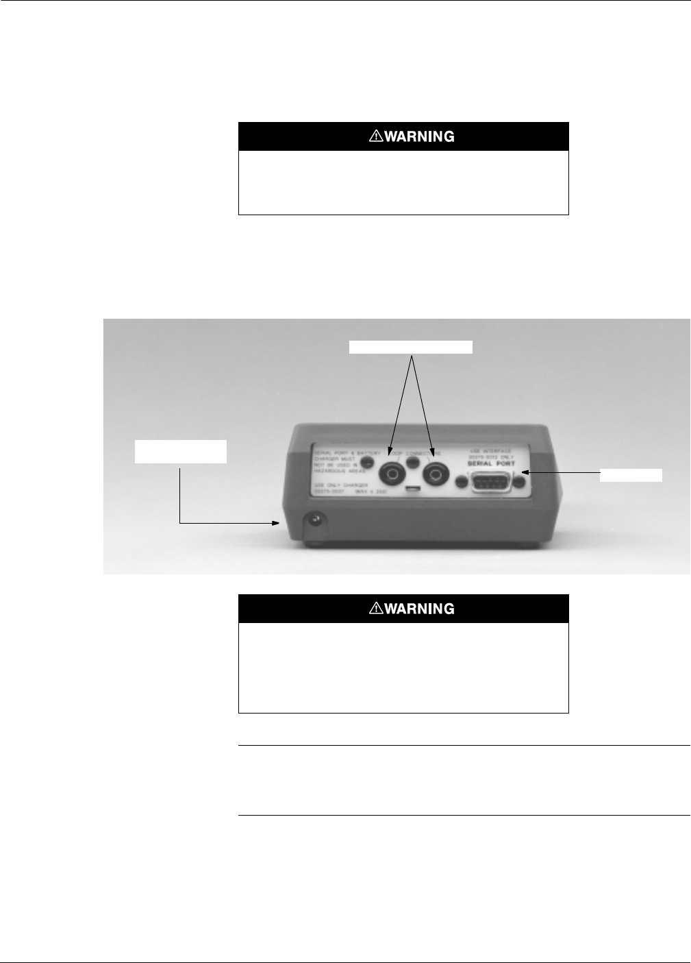
Rosemount Model 3095 MV
A-4
CONNECTIONS AND
HARDWARE
The HART Communicator Model 275 can interface with a transmitter
from the control room, the instrument site, or any wiring termination
point in the loop through the rear connection panel as shown in Figure
A-2. To communicate, connect the HART Communicator in parallel
with the instrument or load resistor. The connections are non-polarized.
FIGURE 1-2. Rear Connection Panel with
Optional NiCad Recharger Pack.
NOTE
The HART Communicator needs a minimum of 250 ohms resistance in
the loop to function properly. The HART Communicator does not
measure loop current directly.
Explosions can result in death or serious injury. Do not
make connections to the serial port or NiCad recharger jack
in an explosive atmosphere.
Explosions can result in death or serious injury. Before
connecting the HART Communicator in an explosive
atmosphere, make sure the instruments in the loop are
installed in accordance with intrinsically safe or
nonincendive field wiring practices.
Loop Connection Ports
Serial Port
Optional NiCad
Recharger Jack
275-008AB
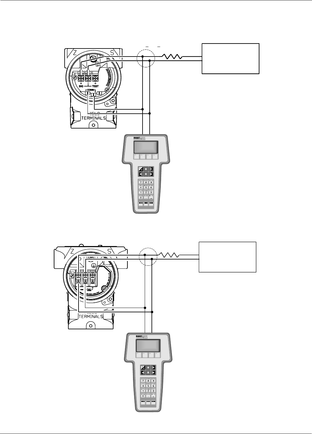
A-5
Appendix A
FIGURE A-3. Wiring Connections.
1100 V > RL>250 V
3095-1006B03A
PREVIOUS TERMINAL BLOCK
IMPROVED TERMINAL BLOCK
+
–
User-Provided
Power Supply
(see page 2-16)
+
–
User-Provided
Power Supply
(see page 2-16)
3095-1006B03A
3095-1006B03B
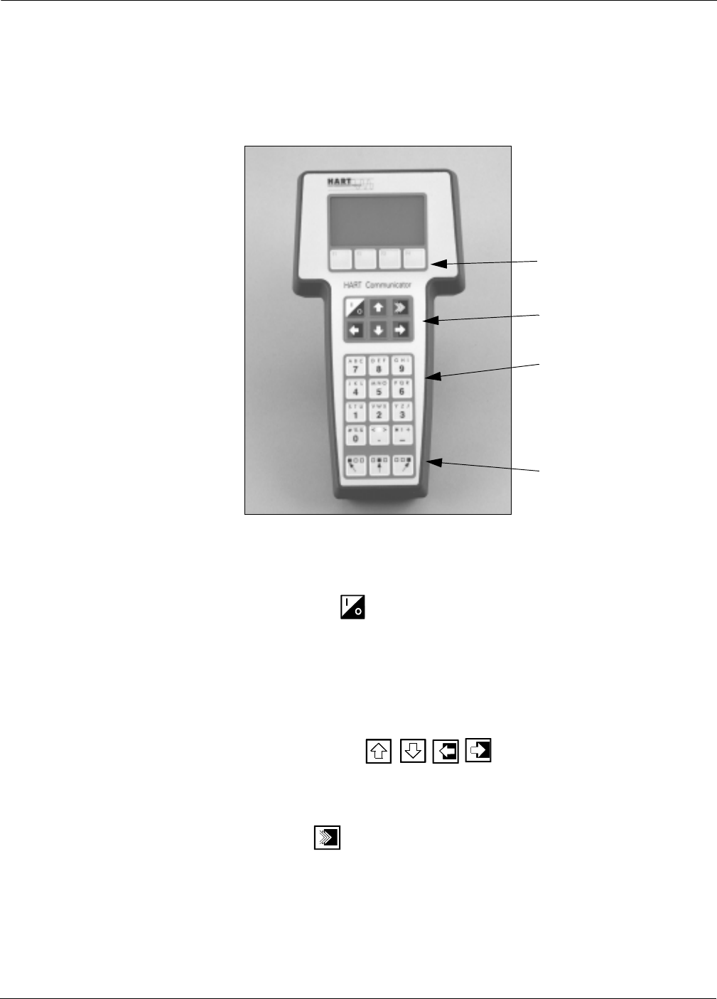
Rosemount Model 3095 MV
A-6
COMMUNICATOR KEYS The keys of the HART Commuincator include action, function,
alphanumeric, and shift keys
FIGURE A-4. The HART Communicator.
Action Keys As shown in Figure A-4, the action keys are the six blue, white, and
black keys located above the alphanumeric keys. The function of each
key is described as follows:
ON/OFF Key
Use this key to power the HART Communicator. When the
communicator is turned on, it searches for a transmitter on the 4–20
mA loop. If a device is not found, the communicator displays the
message, “No Device Found. Press OK.”
If a HART-compatible device is found, the communicator displays the
Online Menu with device ID and tag.
Directional Keys
Use these keys to move the cursor up, down, left, or right. The right
arrow key also selects menu options, and the left arrow key returns to
the previous menu.
HOT Key
Use this key to quickly access important, user-selectable options when
connected to a HART-compatible device. Pressing the Hot Key turns
the HART Communicator on and displays the Hot Key Menu.
See Customizing the Hot Key Menu in the HART Communicator
manual for more information.
Function Keys
Action Keys
Alphanumeric Keys
Shift Keys
275-011AB
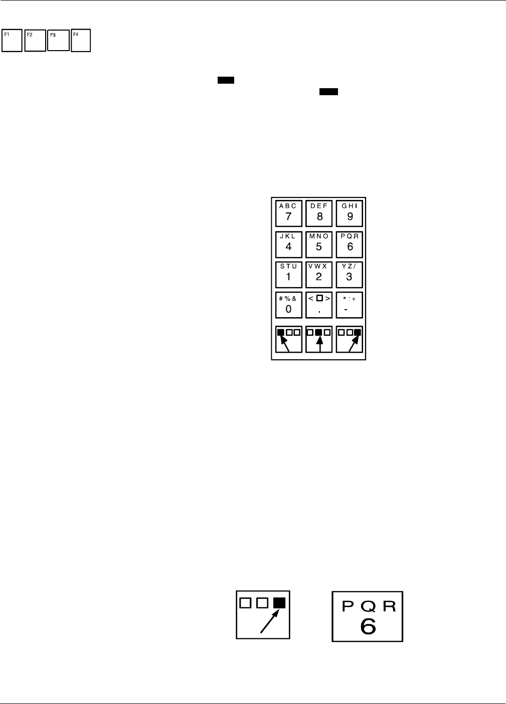
A-7
Appendix A
Function Keys Use the four software-defined function keys, located below the LCD, to
perform software functions. On any given menu, the label appearing
above a function key indicates the function of that key for the current
menu. As you move among menus, different function key labels appear
over the four keys. For example, in menus providing access to on-line
help, the label may appear above the F1 key. In menus providing
access to the Online Menu, the label may appear above the F3 key.
Simply press the key to activate the function. See your HART
Communicator manual for details on specific function key definitions.
Alphanumeric and Shift Keys The alphanumeric keys (Figure A-5) perform two functions: the fast
selection of menu options and data entry.
FIGURE A-5. HART Communicator Alphanumeric and Shift Keys.
Data Entry
Some menus require data entry. Use the alphanumeric and shift keys to
enter all alphanumeric information into the HART Communicator. If
you press an alphanumeric key alone from within an edit menu, the
bold character in the center of the key appears. These large characters
include the numbers zero through nine, the decimal point (.), and the
dash symbol (—).
To enter an alphabetic character, first press the shift key that
corresponds to the position of the letter you want on the alphanumeric
key. Then press the alphanumeric key. For example, to enter the letter
R, first press the right shift key, then the “6” key (see Figure A-6). Do
not press these keys simultaneously, but one after the other.
FIGURE A-6. Data Entry Key Sequence.
HELP
HOME

Rosemount Model 3095 MV
A-8
Fast Key Sequences HART fast key sequences provide quick on-line access to transmitter
variables and functions. Instead of stepping your way through the menu
structure using the action keys, you can press a HART fast key sequence
to move from the Online Menu to the desired variable or function. On-
screen instructions guide you through the rest of the screens.
Fast Key Sequence Conventions The fast key sequences for the Model 275 use the following conventions
for their identification:
1 through 9–Refer to the keys located directly below the dedicated
keypad.
Left Arrow–Refers to the left arrow directional key.
Fast Key Sequence Example HART fast key sequences are made up of the series of numbers
corresponding to the individual options in each step of the menu
structure. For example, from the Online Menu you can change the
Date. Following the menu structure, press 1 to reach Device Setup,
press 3 for Basic Setup, press 4 for Device Info, press 4 for Date. The
corresponding HART fast key sequence is 1, 3, 4, 4.
HART fast keys are operational only from the Online Menu. If you use
them consistently, you will need to return to the Online Menu by
pressing (F3) when it is available. If you do not start at the Online
Menu, the HART fast key sequences will not function properly.
Use Table A-2, an alphabetical listing of every on-line function, to find
the corresponding HART fast key sequences. These codes are applicable
only to Level Controller and the HART Communicator.
MENUS AND FUNCTIONS The HART Communicator is a menu driven system. Each screen
provides a menu of options that can be selected as outlined above, or
provides direction for input of data, warnings, messages, or other
instructions.
Main Menu When the HART Communicator is turned on, one of two menus will
appear. If the HART Communicator is connected to an operating loop,
the communicator will find the device and display the Online Menu (see
below). If it is not connected to a loop, the communicator will indicate
that no device was found. When you press OK (F4), it will display the
Main menu.
The Main menu provides the following options:
•Offline–The Offline option provides access to offline configuration
data and simulation functions.
•Online–The Online option checks for a device and if it finds one,
brings up the Online Menu.
•Transfer–The Transfer option provides access to options for
transferring data either from the HART Communicator (memory)
to the transmitter (device) or vice versa. Transfer is used to move
off-line data from the HART Communicator to the transmitter, or
to retrieve data from a transmitter for off-line revision.
NOTE
Online communication with the transmitter automatically loads the
current transmitter data to the HART Communicator. Changes in on-
line data are made active by pressing SEND (F2). The transfer function
is used only for off-line data retrieval and sending.
HOME

A-9
Appendix A
•Frequency Device–The Frequency Device option displays the
frequency output and corresponding pressure output of current-
to-pressure transmitters.
•Utility–The Utility option provides access to the contrast control
for the HART Communicator LCD screen and to the autopoll
setting used in multidrop applications.
Once selecting a Main menu option, the HART Communicator provides
the information you need to complete the operation. If further details
are required, consult the HART Communicator manual.
Online Menu The Online Menu can be selected from the Main menu as outlined
above, or it may appear automatically if the HART Communicator is
connected to an active loop and can detect an operating transmitter.
NOTE
The Main menu can be accessed from the Online Menu. Press the left
arrow action key to deactivate the on-line communication with the
transmitter and to activate the Main menu options.
When configuration variables are reset in the on-line mode, the new
settings are not activated until the information is sent to the
transmitter. Press SEND (F2) when it is activated to update the process
variables of the transmitter.
On-line mode is used for direct evaluation of a particular meter, re-
configuration, changing parameters, maintenance, and other functions.

Rosemount Model 3095 MV
A-10
Diagnostic Messages The following pages contain a list of messages used by the HART
Communicator (HC) and their corresponding descriptions.
Variable parameters within the text of a message are indicated with
<variable>.
Reference to the name of another message is identified by
<message>.
Message Description
Add item for ALL device
typesoronlyforthisONE
device type.
Asks the user whether the hot key item being added should be
added for all device types or only for the type of device that is
connected.
Command Not
Implemented
The connected device does not support this function.
Communication Error Either a device sends back a response indicating that the
message it received was unintelligible, or the HC cannot
understand the response from the device.
Configuration memory
not compatible with
connected device
The configuration stored in memory is incompatible with the
device to which a transfer has been requested.
Device Busy The connected device is busy performing another task.
Device Disconnected Device fails to respond to a command.
Device write protected Device is in write-protect mode. Data can not be written.
Device write protected.
Do you still want to shut
off?
Device is in write-protect mode. Press YES to turn the HC off and
lose the unsent data.
Display value of variable
on hotkey menu?
Asks whether the value of the variable should be displayed
adjacent to its label on the hotkey menu if the item being added to
the hotkey menu is a variable.
Download data from
configuration memory to
device
Prompts user to press SEND softkey to initiate a memory to device
transfer.
Exceed field width Indicates that the field width for the current arithmetic variable
exceeds the device- specified description edit format.
Exceed precision Indicates that the precision for the current arithmetic variable
exceeds the device- specified description edit format.
Ignore next 50
occurrences of status?
Asked after displaying device status. Softkey answer determines
whether next 50 occurrences of device status will be ignored or
displayed.
Illegal character An invalid character for the variable type was entered.
Illegal date The day portion of the date is invalid.
Illegal month The month portion of the date is invalid.
Illegal year The year portion of the date is invalid.
Incomplete exponent The exponent of a scientific notation floating point variable is
incomplete.
Incomplete field The value entered is not complete for the variable type.
Looking for a device Polling for multidropped devices at addresses 1–15.

A-11
Appendix A
Message Description
Mark as read only
variable on hotkey
menu?
Asks whether the user should be allowed to edit the variable from
the hotkey menu if the item being added to the hotkey menu is a
variable.
No device configuration
in configuration memory
There is no configuration saved in memory available to re-
configure off-line or transfer to a device.
No Device Found Poll of address zero fails to find a device, or poll of all addresses
fails to find a device if auto-poll is enabled.
No hotkey menu available
for this device.
There is no menu named “hotkey” defined in the device
description for this device.
No offline devices
available.
There are no device descriptions available to be used to configure
adeviceoffline.
No simulation devices
available.
There are no device descriptions available to simulate a device.
NoUPLOAD_VARIABLES
in ddl for this device
There is no menu named “upload_variables” defined in the device
description for this device. This menu is required for offline
configuration.
No Valid Items The selected menu or edit display contains no valid items.
OFF KEY DISABLED Appears when the user attempts to turn the HC off before sending
modified data or before completing a method.
Online device
disconnected with
unsent data. RETRY or
OK to lose data.
There is unsent data for a previously connected device. Press
RETRY to send data, or press OK to disconnect and lose unsent
data.
Outofmemoryforhotkey
configuration. Delete
unnecessary items.
There is no more memory available to store additional hotkey
items. Unnecessary items should be deleted to make space
available.
Overwrite existing
configuration memory
Requests permission to overwrite existing configuration either by
a device-to-memory transfer or by an offline configuration. User
answers using the softkeys.
Press OK... Press the OK softkey. This message usually appears after an error
message from the application or as a result of HART
communications.
Restore device value? The edited value that was sent to a device was not properly
implemented. Restoring the device value returns the variable to its
original value.
Save data from device to
configuration memory
Prompts user to press SAVE softkey to initiate a device-to-
memory transfer.
Saving data to
configuration memory.
Data is being transferred from a device to configuration memory.
Sending data to device. Data is being transferred from configuration memory to a device.
There are write only
variables which have not
been edited. Please edit
them.
There are write-only variables which have not been set by the
user. These variables should be set or invalid values may be sent
to the device.

Rosemount Model 3095 MV
A-12
Message Description
There is unsent data.
Send it before shutting
off?
Press YES to send unsent data and turn the HC off. Press NO to
turn the HC off and lose the unsent data.
Too few data bytes
received
Command returns fewer data bytes than expected as determined
by the device description.
Transmitter Fault Device returns a command response indicating a fault with the
connected device.
Units for <variable> has
changed. Unit must be
sent before editing, or
invalid data will be sent.
The engineering units for this variable have been edited. Send
engineering units to the device before editing this variable.
Unsent data to online
device. SEND or LOSE
data
There is unsent data for a previously connected device which must
be sent or thrown away before connecting to another device.
Use up/down arrows to
change contrast. Press
DONE when done.
Gives direction to change the contrast of the HC display.
Value out of range The user-entered value is either not within the range for the given
type and size of variable or not within the min/max specified by the
device.
<message> occurred
reading/writing
<variable>
Either a read/write command indicates too few data bytes
received, transmitter fault, invalid response code, invalid response
command, invalid reply data field, or failed pre- or post-read
method; or a response code of any class other than SUCCESS is
returned reading a particular variable.
<variable> has an
unknown value. Unit
must be sent before
editing, or invalid data
will be sent.
A variable related to this variable has been edited. Send related
variable to the device before editing this variable.

Appendix
B-1
BApproval Drawings
Approval Drawings Model 3095MV Explosion-Proof Installation Drawing,
Factory Mutual (Drawing Number 03095-1025, Rev AA) Page B-2
Index of I.S. F.M. for 3095
(Drawing Numbers 03095-1020, Rev AB) Page B-5
Model 3095MV Explosion-Proof Installation Drawing,
Canadian Standards Association
(Drawing Number 03095-1024, Rev AA) Page B-13
Index of I.S. CSA for 3095
(Drawing Number 03095-1021, Rev AB) Page B-16
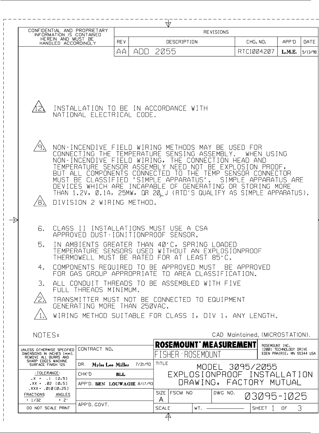
Rosemount Model 3095 MV
B-2
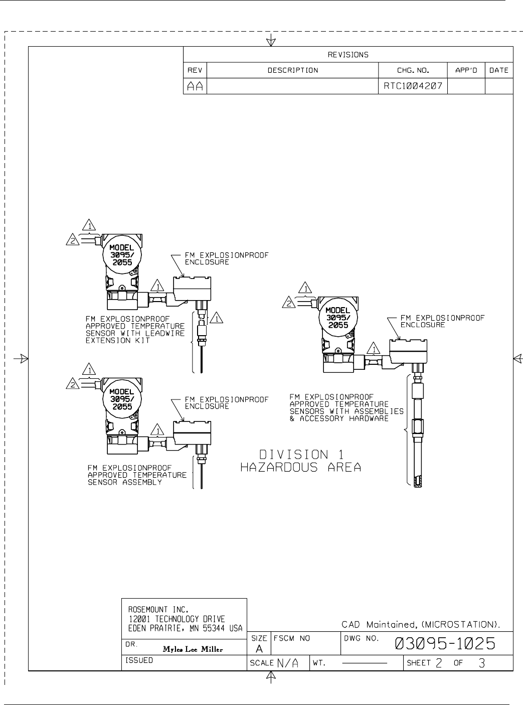
B-3
Appendix B
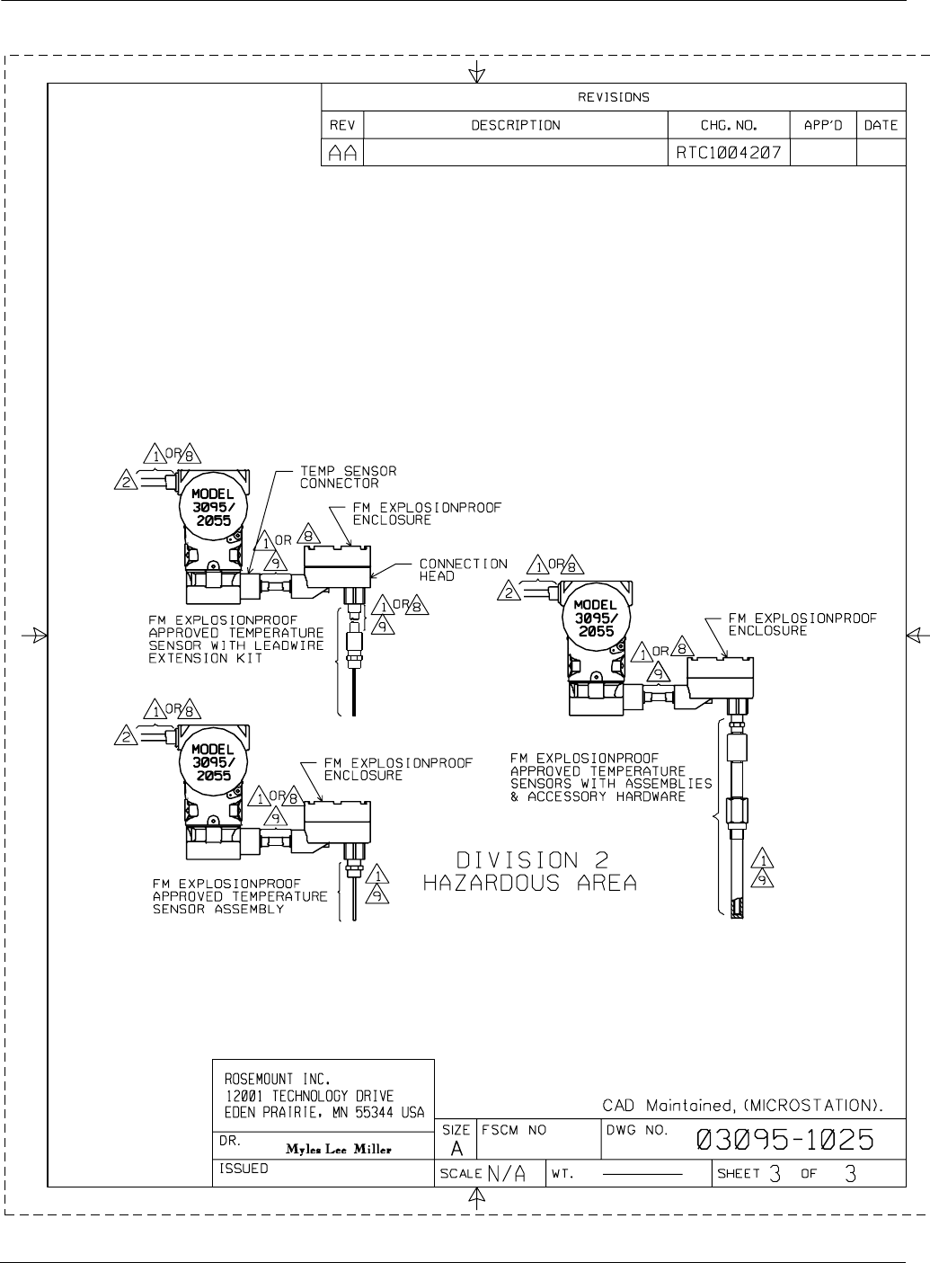
Rosemount Model 3095 MV
B-4
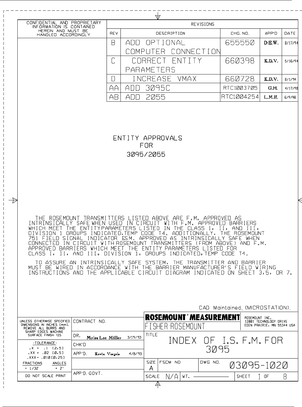
B-5
Appendix B
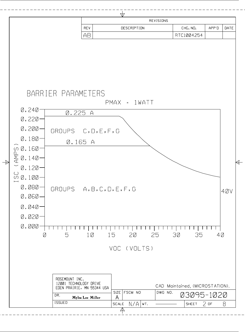
Rosemount Model 3095 MV
B-6
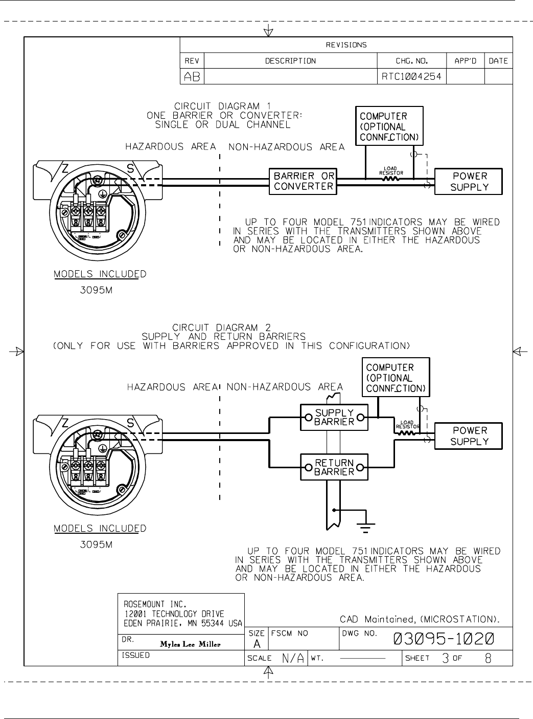
B-7
Appendix B
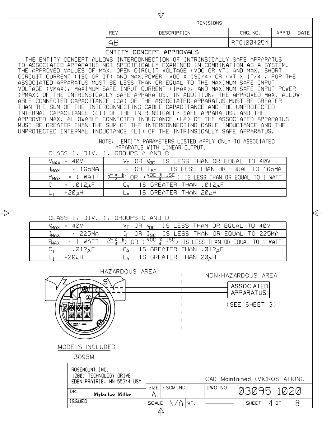
Rosemount Model 3095 MV
B-8
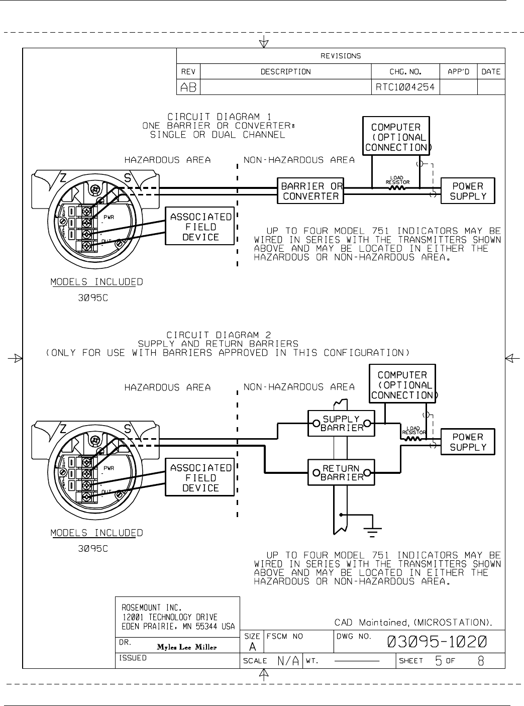
B-9
Appendix B
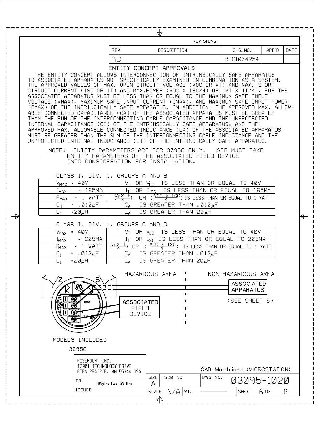
Rosemount Model 3095 MV
B-10
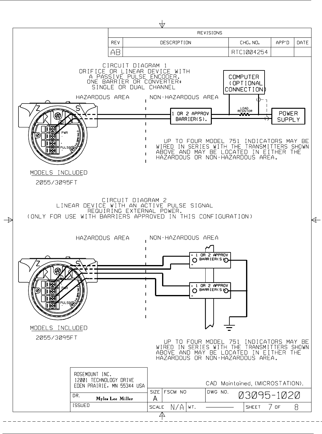
B-11
Appendix B
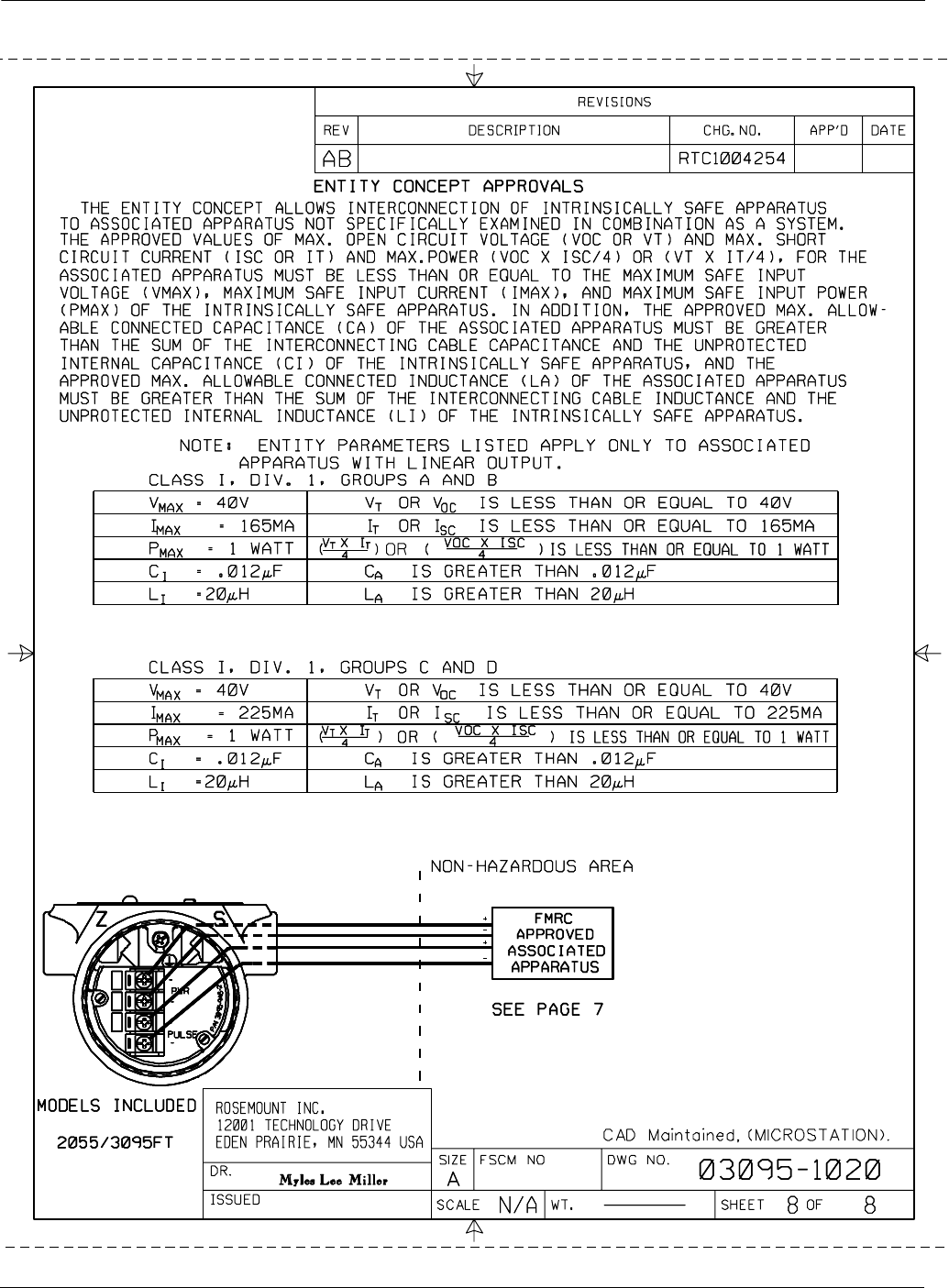
Rosemount Model 3095 MV
B-12
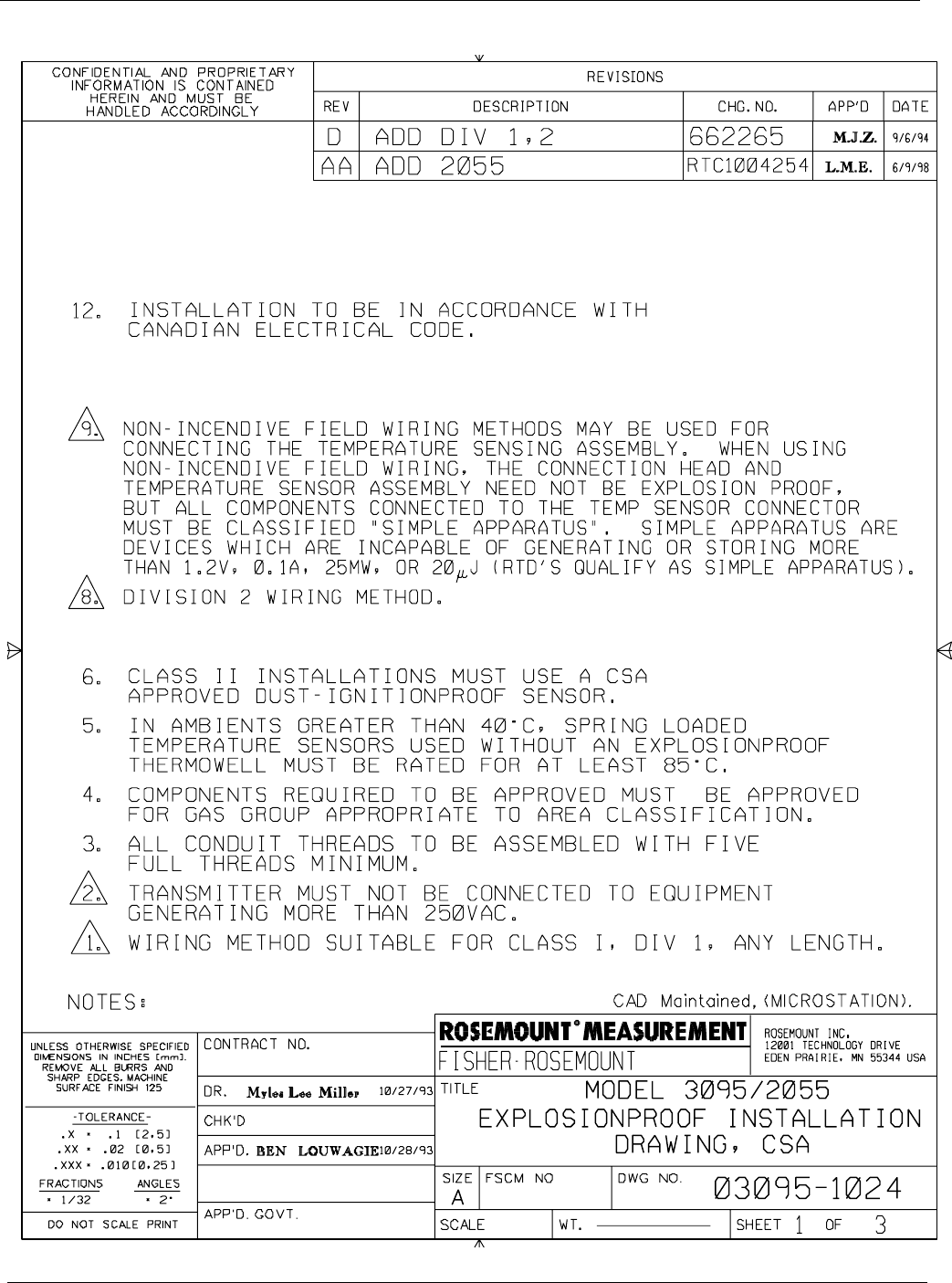
B-13
Appendix B
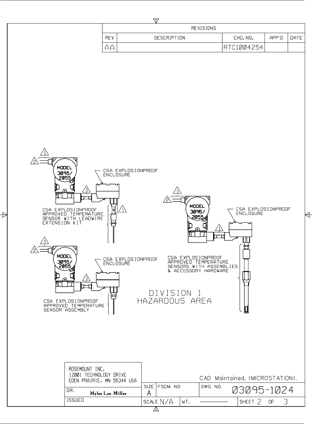
Rosemount Model 3095 MV
B-14
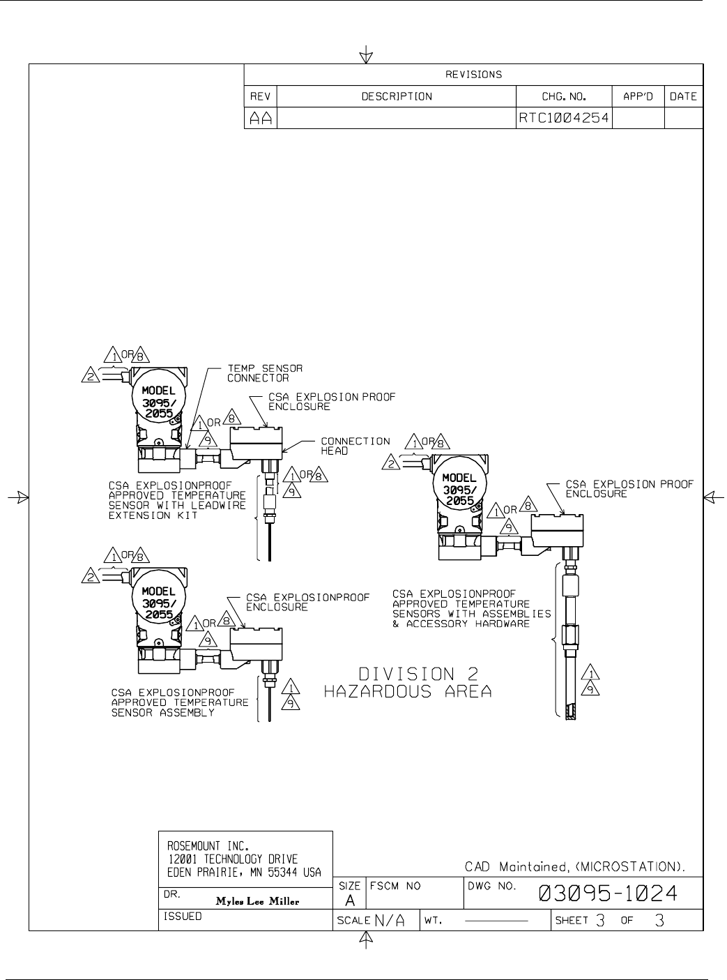
B-15
Appendix B
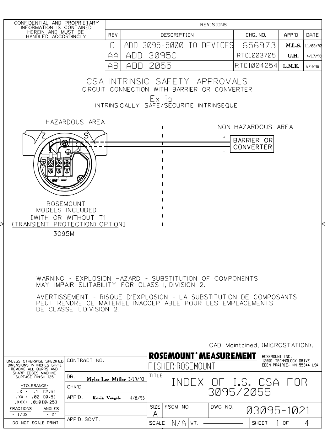
Rosemount Model 3095 MV
B-16
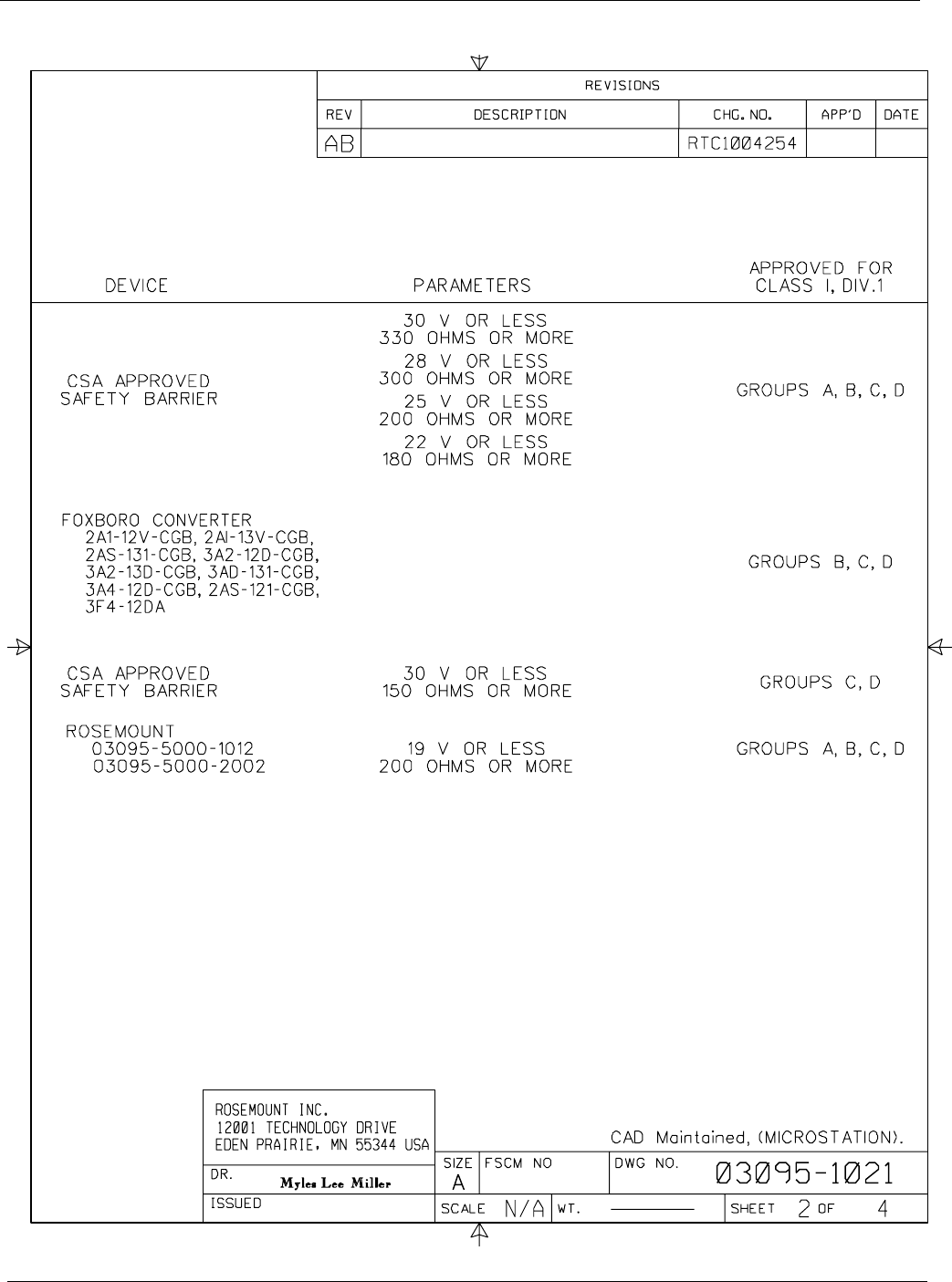
B-17
Appendix B
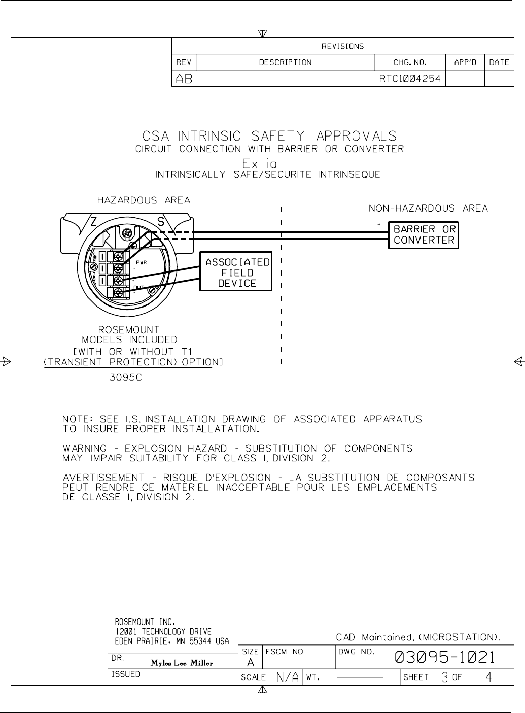
Rosemount Model 3095 MV
B-18
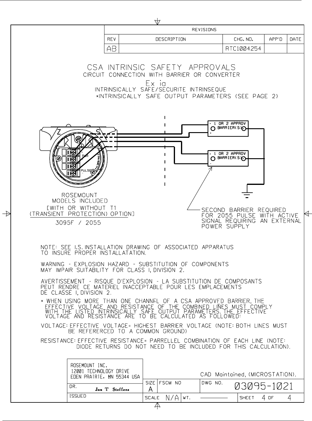
B-19
Appendix B

Rosemount Model 3095 MV
B-20
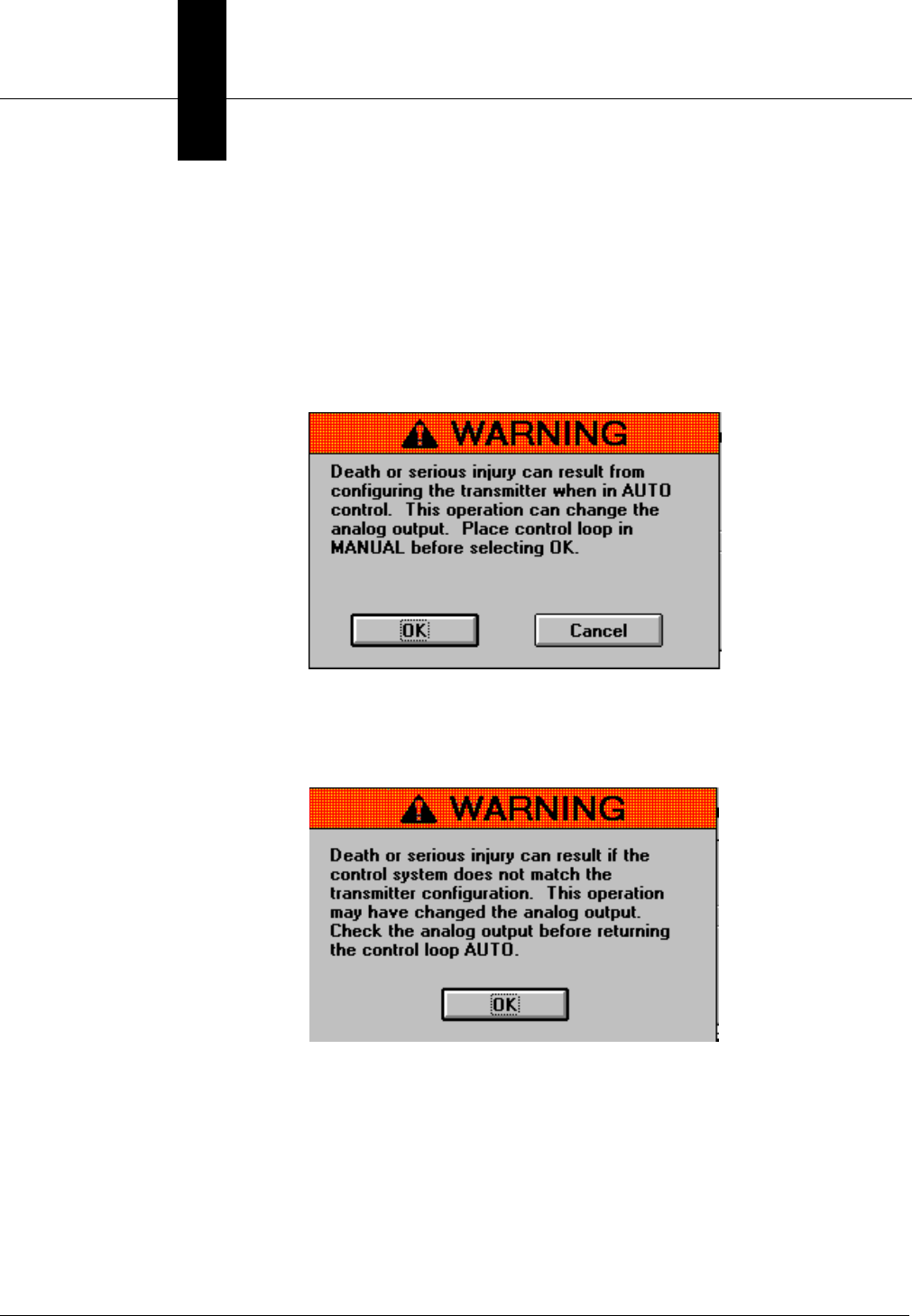
Appendix
C-1
CEA Error Message Summary
This appendix identifies errors messages that might occur while using
the Model 3095 MV Engineering Assistant Software.
WARNING MESSAGES The EA warns the operator whenever an action could change the
analog output:
The EA also warns the operator at the conclussion of an action that
may have changed the analog output:
3095-0400
3095-0401

Rosemount Model 3095 MV
C-2
ERROR
MESSAGES
TABLE C-1. EA Error
Message Summary.
Alarm text as displayed in
Diagnostics, Error Info Additional Corrective Action
(If Needed)
The transmitter and Engineering Assistant are not in communication. 1. Verify that all cables correctly attached.
2. See Table 5-2.
Communications Error: Device is in write protect mode Move the write protect (security) jumper on the
output board (see Figure 2-4).
Communications Error: Entered analog current value is too low
These messages occur when entering invalid
values. Enter a different value, and retry the
operation.
Communications Error: Number of preambles requested is too high
Communications Error: Number of preambles requested is too low
Communications Error: Requested burst command is invalid
Communications Error: Requested burst mode is invalid
Communications Error: Requested local keys control code is invalid
Communications Error: Sensor slope trim point value is too high
Communications Error: Sensor slope trim point value is too low
Communications Error: Sensor offset trim point value too high
Communications Error: Sensor offset trim point value too low
Communications Error: Excess trim correction was attempted
Communications Error: Trim span from offset to slope values too small
DP (Differential Press) is below Lower Internal Limit
SeeTable5-4
DP (Differential Press) is above Upper Internal Limit
SP (Static Press) is below Lower Internal Limit
SP (Static Press) is above Upper Internal Limit
PT (Process Temp) is below Lower Internal Limit
PT (Process Temp) is above Upper Internal Limit
ST (Sensor Temp) is below Lower Internal Limit
ST (Sensor Temp) is above Upper Internal Limit
Static Pressure Sensor is Open
SeeTable5-3.
Static Pressure Sensor is Shorted
Process Temp Sensor is Disconnected
Sensor Module is Not Updating
Sensor Module Microprocessor is Not Responding
Sensor Hardware is Incompatible
Sensor Board EEPROM Not Initialized
Sensor Board EEPROM Burn Failure
RAM Failure
Transmitter Self Test Failed
Output Board EEPROM Not Initialized
Output Board EEPROM Burn Failure
Flow Application - AP is above Upper Operating Limit
SeeTable5-4.
Flow Application - AP is below Lower Operating Limit
Flow Application - PT is above the Upper Operating Limit
Flow Application - PT is below Lower Operating Limit

Appendix
D-1
DCritical Alarms for Previous
Software Revisions
ALARM ABBREVIATIONS Standard alarm abbreviations used in this appendix are:
LOL Lower Operating Limits (customer specified using the EA)
UOL Upper Operating Limits (customer specified using the EA)
LRL Lower Range Limits
URL Upper Range Limits
LRV Lower Range Value
URV Upper Range Value
URL+ URL + (10%URL)
(For example, URL+ = 250 + (0.10 3 250) = 275
LRL– LRL – (10%LRL)
(For example, LRL– = –250 –[0.10 3 (250)] = –275
ALARMS AND ERROR
CONDITIONS FOR
REVISIONS 8, 9, AND 10
The Model 3095 MV provides both analog and digital alarms. If an
alarm or error condition exists in the Model 3095 MV, it will be
displayed during the EA communication with the transmitter and on
the LCD meter. Some non-flow error conditions may take up to 2
seconds to display, while some flow error conditions may take up to 10
seconds to display. View specific alarm conditions using the EA
software.
NOTE
Alarms are not logged or archived. The alarms and error conditions
displayed on the Diagnostics, Error Info screen indicate the alarms
present at the time of command invocation.
Critical Alarms Critical alarms are the highest priority Model 3095 MV alarms, and
indicate an error that prevents accurate sensor or flow measurements.
The analog output and the digital output respond as indicated
in Table D-1.
Overrange Conditions Overrange conditions typically indicate an error which indicates that
the sensor or flow measurements have reached an overrange condition
where substitute values are being used.
Table D-2 identifies actions to the analog output and digital output
during these conditions. Blank table cells indicate no action for that
condition. Table D-3 identifies recommended corrective action, and also
identifies affects on the flow calculation during these conditions.
Rosemount Model 3095 MV
D-2
TABLE D-1. Cr itical Alarms.
Alarm text as displayed in
Diagnostics, Error Info Analog
Output Digital
Output Corrective Action
Output Board EEPROM Not Initialized (1)
Output Board EEPROM Burn Failure (2)
Alarm in the
direction of
the alarm
jumper
NAN (3)
The output electronics has not been properly initialized at the factory.
Replace the output electronics board as described on page 5-12.
Contact your Field Service Center.
Sensor Hardware is incompatible (4) The transmitter electronics has undergone a component or software
failure. Replace the sensor module as described on page 5-12.
Contact your Field Service Center.
Sensor Module is Not Updating (4) The 10-pin ribbon cable may be disconnected, or the transmitter
electronics may have undergone a component or software failure.
Contact your Field Service Center.
Static Pressure Sensor is Shorted The sensor module has undergone a component or software failure.
Replace the sensor module as described on page 5-12.
Contact your Field Service Center.
RAM Failure Issue a master reset to the transmitter as described on page 4-54.
Transmitter Self Test Failed The transmitter electronics have undergone a component or software
failure. Sensor hardware is incompatible. Replace the sensor module
board as described on page 5-12.
Static Pressure Sensor is Open This display means that the transmitter absolute pressure reading
exceeds its sensor limits. There are two possible causes. Either the
transmitter is overpressured, or it has a sensor malfunction. Check the
pressure input to the transmitter. If an overpressure condition exists,
correct it. If not, replace the sensor module as described on page 5-12.
Process Temp Sensor is Disconnected (5) Check the transmitter RTD connector and RTD screw terminals to
ensure the RTD cable is properly connected.
Configuration incomplete (1) Connect a computer containing the EA software, and resend the
configuration to the transmitter.
(1) For Version 8 software, the analog output does not alarm and the digital output is not set to NAN. Error info (
page 4-54
) does report this error.
(2) For Version 8 software, the analog output does not alarm, but the digital output is set to NAN.
(3) NAN indicates “Not a Number.” Distributed Control Systems and HART masters will read “7F A0 00 00h.”
(4) For Version 8 software, this message is followed by 5 additional non-related errors. The analog output and digital output alarm as designed.
(5) This alarm cannot occur if a transmitter is set to fixed PT mode. If the transmitter is set to backup PT mode, an additional status bit is set
indicating PT disconnect, but the transmitter will not go into alarm condition.
TABLE D-2. Overrange Conditions.
EA Display Analog Output Digital Output
Flow DP AP/GP PT Flow DP AP/GP PT
DP above URL+
Saturate in
direction of
alarm jumper
Saturate
High (1) URL+
DP below LRL–
Saturate
Low(2)
Saturate
Low(2) zero URL–
AP/GP above URL+
Saturate in
direction of
alarm jumper
Saturate in
direction of
alarm jumper
Saturate
High(1) URL+ URL+
AP/GP below LRL–
Saturate in
direction of
alarm jumper
Saturate in
direction of
alarm jumper
Saturate
Low (2) URL– URL–
PT above URL+
Saturate in
direction of
alarm jumper
Saturate
High(1) URL+
PT below LRL–
Saturate in
direction of
alarm jumper
Saturate
Low(2) URL–
ST above URL+ Saturate in direction of alarm jumper NAN(3) NAN(3) NAN(3) NAN(3)
ST below LRL– Saturate in direction of alarm jumper NAN(3) NAN(3) NAN(3) NAN(3)
(1) Saturate high if direct acting (URV>LRV), Saturate low if reverse acting (URV<LRV).
(2) Saturate low if direct acting (URV>LRV), Saturate high if reverse acting (URV<LRV).
(3) NAN indicates “Not a Number.” Distributed Control Systems and HART masters will read “7F A0 00 00h.”
D-3
Appendix D
TABLE D-3. Corrective Action: Overrange Conditions.
EA Display
Flow Calculation
Affects (1) Corrective Action
C’ ()0.5
DP above URL+
URL+ URL+ These displays indicate that the transmitter differential pressure reading exceeds its
sensor limits by more than 10%. There are two possible causes. Either the transmitter
is overpressured (underpressured), or it has a sensor malfunction. Check the
pressure input to the transmitter. If an overpressure (underpressure) condition exists,
correct it. If not, replace the sensor module as described on page 5-12.
DP below LRL–
Unreliable
flow
output
Unreliable
flow
output
AP/GP above URL+
UOL URL+ These displays indicate that the transmitter absolute pressure reading exceeds its
sensor limits by more than 10%. There are two possible causes. Either the transmitter
is overpressured (underpressured), or it has a sensor malfunction. Check the
pressure input to the transmitter. If an overpressure (underpressure) condition exists,
correct it. If not, replace the sensor module as described on page 5-12.
AP/GP below LRL–
LOL LRL–
PT above URL+
UOL URL+ Check the transmitter RTD connector and RTD screw terminals to ensure the RTD
cable is properly connected. Verify that the process temperature is between sensor
limits. See the Sensor Limits Tables on page E-2 for more information.
PT below LRL–
LOL LRL–
ST above URL+
Unreliable
flow
output
Unreliable
flow
output
These displays indicate that the ambient temperature limit of the transmitter is being
exceeded. Verify that the transmitter ambient temperature is between -40F and 185F.
If transmitter temperature exceeds these limits, correct the temperature. If transmitter
temperature is within these limits, replace the sensor module as described on page 5-12.
ST below LRL–
Unreliable
flow
output
Unreliable
flow
output
(1) Only the parameter causing the exception is clipped at the operating or sensor limits. The other calculation inputs are not affected.
TABLE D-4. Model 3095 MV Flow Exceptions.
EA Display
Flow Calculation
Affects (1) Flow Analog Output Flow
Digital
Output
C’ ()
0.5
AP/GP is above UOL
UOL
AP/GP is below LOL
LOL
PT is above UOL
UOL
PT is below LOL
LOL
Flow math error - all errors
Math Error Math Error Saturate in direction of
alarm jumper
NAN (2)
–2 inH20<DP<low-flow cutoff(3)
Unreliable
flow output
Unreliable
flow output 0
DP < –2 inH20
Unreliable
flow output
Unreliable
flow output
Saturate Low(4) zero
(1) Only the parameter causing the exception is clipped at the operating or sensor limits. The other calculation inputs are not affected.
(2) NAN indicates “Not a Number.” Distributed Control Systems and HART masters will read “7F A0 00 00h.”
(3) Low-flow cutoff is adjustable, from minimum DP limit of 0.02 inH
2
0, to a maximum DP limit which is user selectable.
(4) Saturate low if direct acting (URV>LRV), Saturate high if reverse acting (URV<LRV).
Rosemount Model 3095 MV
D-4
ALARMS AND ERROR
CONDITIONS FOR
REVISIONS 4 AND 5
The following are for Versions 4 and 5 of the Model 3095 MV
electronics board.
Critical alarms are the highest priority Model 3095 MV alarms, and
typically indicate an error that prevents accurate sensor or flow
measurements. Regardless of which of these alarms occur, the analog
output and the digital output respond as indicated in Table D-5.
Overrange Conditions Overrange conditions typically indicate an error which indicates that
the sensor or flow measurements have reached an overrange condition
where substitute values are being used.
Table D-6 identifies actions to the analog output and digital output
during these conditions. Blank table cells indicate no action for that
condition. Table D-7 identifies recommended corrective action, and also
identifies affects on the flow calculation during these conditions.
TABLE D-5. Cr itical Alarms.
Alarm text as displayed in
Diagnostics, Error Info Analog
Output Digital
Output Corrective Action
Output Board EEPROM Not Initialized (1)
Output Board EEPROM Burn Failure (2)
Alarm in the
direction of
the alarm
jumper
NAN (3)
The output electronics has not been properly initialized at the factory.
Replace the output electronics board as described on page 5-10.
Contact your Field Service Center.
Sensor Hardware is incompatible (4) The transmitter electronics has undergone a component or software
failure. Replace the sensor module as described on page 5-10.
Contact your Field Service Center.
Sensor Module is Not Updating (4) The 10-pin ribbon cable may be disconnected, or the transmitter
electronics may have undergone a component or software failure.
Contact your Field Service Center.
Static Pressure Sensor is Shorted The sensor module has undergone a component or software failure.
Replace the sensor module as described on page 5-10.
Contact your Field Service Center.
Static Pressure Sensor is Open This display means that the transmitter absolute pressure reading
exceeds its sensor limits. There are two possible causes. Either the
transmitter is overpressured, or it has a sensor malfunction. Check the
pressure input to the transmitter. If an overpressure condition exists,
correct it. If not, replace the sensor module as described on page 5-10.
Process Temp Sensor is Disconnected Check the transmitter RTD connector and RTD screw terminals to
ensure the RTD cable is properly connected. This alarm cannot occur
if a transmitter is set to fixed RTD mode.
Configuration incomplete (1) Connect a computer containing the EA software, and resend the
configuration to the transmitter.
(1) For Version 4 software, the analog output does not alarm and the digital output is not set to NAN. Error info (page 4-54) does report this error.
(2) For Version 4 software, the analog output does not alarm, but the digital output is set to NAN.
(3) NAN indicates “Not a Number.” Distributed Control Systems and HART masters will read “7F A0 00 00h.”
(4) For Version 4 software, this message is followed by 5 additional non-related errors. The analog output and digital output alarm as designed.
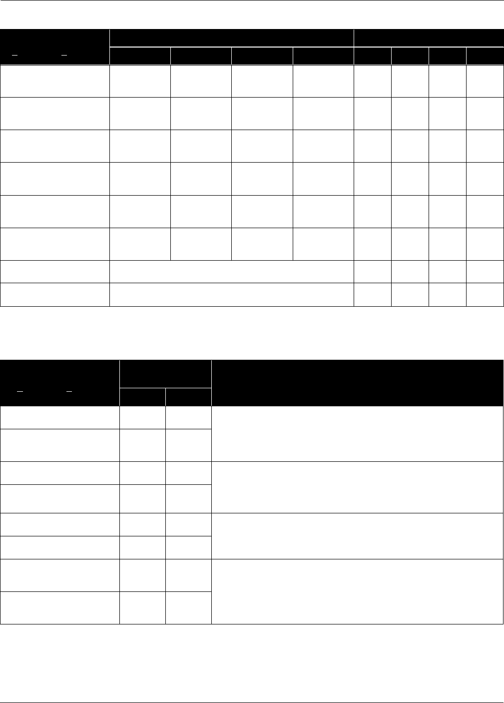
D-5
Appendix D
TABLE D-6. Overrange Conditions.
Alarm text as displayed in
Diagnostics, Error Info
Analog Output Digital Output
Flow DP AP PT Flow DP AP PT
DP above URL+
Saturate in
direction of
alarm jumper
Saturate
High (1) URL+
DP below LRL–
Saturate
Low(2)
Saturate
Low(2) NAN (3) URL–
AP above URL+
Saturate in
direction of
alarm jumper
Saturate in
direction of
alarm jumper
Saturate
High(1) URL+ URL+
AP below LRL–
Saturate in
direction of
alarm jumper
Saturate in
direction of
alarm jumper
Saturate
Low (2) URL– URL–
PT above URL+
Saturate in
direction of
alarm jumper
Saturate
High(1) URL+
PT below LRL–
Saturate in
direction of
alarm jumper
Saturate
Low(2) URL–
ST above URL+ Saturate in direction of alarm jumper NAN(3) NAN(3) NAN(3) NAN(3)
ST below LRL– Saturate in direction of alarm jumper NAN(3) NAN(3) NAN(3) NAN(3)
(1) Saturate high if direct acting (URV>LRV), Saturate low if reverse acting (URV<LRV).
(2) Saturate low if direct acting (URV>LRV), Saturate high if reverse acting (URV<LRV).
(3) NAN indicates “Not a Number.” Distributed Control Systems and HART masters will read “7F A0 00 00h.”
TABLE D-7. Corrective Action: Overrange Conditions.
Alarm text as displayed in
Diagnostics, Error Info
Flow Calculation
Affects (1) Corrective Action
C’ ()0.5
DP above URL+
URL+ URL+ These displays indicate that the transmitter differential pressure reading exceeds its
sensor limits by more than 10%. There are two possible causes. Either the transmitter
is overpressured (underpressured), or it has a sensor malfunction. Check the
pressure input to the transmitter. If an overpressure (underpressure) condition exists,
correct it. If not, replace the sensor module as described on page 5-12.
DP below LRL–
Unreliable
flow
output
Unreliable
flow
output
AP above URL+
UOL URL+ These displays indicate that the transmitter absolute pressure reading exceeds its
sensor limits by more than 10%. There are two possible causes. Either the transmitter
is overpressured (underpressured), or it has a sensor malfunction. Check the
pressure input to the transmitter. If an overpressure (underpressure) condition exists,
correct it. If not, replace the sensor module as described on page 5-12.
AP below LRL–
LOL LRL–
PT above URL+
UOL URL+
Check the transmitter RTD connector and RTD screw terminals to ensure the RTD
cable is properly connected. Verify that the process temperature is between -40F and
400F.
PT below LRL–
LOL LRL–
ST above URL+
Unreliable
flow
output
Unreliable
flow
output
These displays indicate that the ambient temperature limit of the transmitter is being
exceeded. Verify that the transmitter ambient temperature is between -40F and 185F.
If transmitter temperature exceeds these limits, correct the temperature. If transmitter
temperature is within these limits, replace the sensor module as described on page 5-12.
ST below LRL–
Unreliable
flow
output
Unreliable
flow
output
(1) Only the parameter causing the exception is clipped at the operating or sensor limits. The other calculation inputs are not affected.
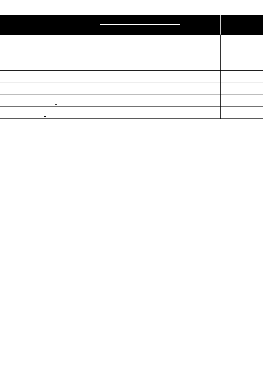
Rosemount Model 3095 MV
D-6
TABLE D-8. Flow Exceptions.
Alarm text as displayed in
Diagnostics, Error Info
Flow Calculation Affects (1) Flow Analog
Output
Flow
Digital
Output
C’ ()
0.5
AP is above UOL
UOL
AP is below LOL
LOL
PT is above UOL
UOL
PT is below LOL
LOL
Flow math error - all errors
Math Error Math Error Saturate in direction
of alarm jumper
NAN (2)
–2 inH20<DP<1inH
20
Unreliable flow
output
Unreliable flow
output 0
DP < –2 inH20
Unreliable flow
output
Unreliable flow
output
Saturate Low(3) NAN(2)
(1) Only the parameter causing the exception is clipped at the operating or sensor limits. The other calculation inputs are not affected.
(2) NAN indicates “Not a Number.” Distributed Control Systems and HART masters will read “7F A0 00 00h.”
(3) Saturate low if direct acting (URV>LRV), Saturate high if reverse acting (URV<LRV).

Appendix
E-1
ECompatibility Issues
OVERVIEW When retrofitting parts to the Model 3095 MV, it is important to
understand the compatibility issues involved. Appendix E describes
compatibility issues among the major Model 3095 MV components:
• Electronics (output) board revisions
• Sensor module software revisions
•LCD meter
• Hardware compatibility issues
Please read this section carefully if you plan to retrofit existing Model
3095 MV transmitters with new components.
REVISION LEVEL
INDICATORS
The first thing to do is determine the revision level of your Model 3095
MV transmitter electronics board and sensor module. Revision levels
can be determined with the Engineering Assistant (EA) software or the
Model 275 HART Communicator.
To determine revision levels with the EA Software:
From the Diagnostics pull down menu, select Device Info, then
Identification Info...
To determine revision levels with the HART Communicator:
1 Device Setup–3 Basic Setup–4 Device Info–9 Revisions.
Electronics Board Table E-1 lists the electronics board revisions, the serial number, and
the approximate shipment start date to help you determine which
revision you have.
Sensor Module Table E-2 lists the sensor module revisions, the transmitter serial
number, the shipment start date, and the process temperature range.
TABLE E-1. Electronics Board Revisions.
Electronics
Board
Revision
Transmitter
Serial Number Shipment Start Date
Rev. 13 32,400 and above 3/99
Rev. 12 28,600 and above 11/98
Rev. 10 20,000 and above 12/97
Rev. 9 15,600 and above 5/97
Rev. 8 10,000 and above 8/96
Rev. 5 3,675 and above 1/96
Rev. 4 2,822 and above 10/95
TABLE E-2. Sensor Module Software Revisions.
Sensor Module
Revision Transmitter
Serial Number Shipment
Start Date Process Temp. Range
149 >28,600 11/98 –300 to 1500 °F (–184 to 815 °C)
142(b) 10,000–40,000 8/96 –40 to 1200 °F (–40 to 649 °C)
142(a) 0–9,999 10/95 –40 to 400 °F (–40 to 204 °C)

Rosemount Model 3095 MV
E-2
SENSOR LIMITS Table E-3, Table E-3, and Table E-4 identify Model 3095 MV sensor
limits.
.
TABLE E-3. Sensor Limits for Sensor Module Revision 149.
Sensor Range LRL– (1) LRL URL URL+(2)
Flow No limit 0 op-limits calc(3) no limit
DP Range 1 –27.5 inH2O @ 68 °F –25 inH2O @ 68 °F 25 inH2O @ 68 °F 27.5 inH2O @ 68 °F
DP Range 2 –275 inH20at68°F –250inH
20 at 68 °F 250 inH20at68°F 275inH
20at68°F
DP Range 3 –1100 inH20 at 68 °F –1000 inH20at68°F 1000inH
20 at 68 °F 1100 inH20at68°F
AP Range 3 0 psia(4) 0.5 psia 800 psia 880 psia
AP Range 4 0 psia(4) 0.5 psia 3,626 psia 3,988 psia
GP Range C –0.15 psig 0 psig 800 psig 880 psig
GP Range D –0.15 psig 0 psig 3,626 psig 3,988 psig
PT (5) – 330 °F (–201 °C) –300 °F (–185 °C) 1500 °F (815 °C) 1550 °F (843 °C)
Sensor Temperature –47 °F (–44 °C) –40 ° F (–40 ° C) 185 °F (85 °C) 200 °F (93.5 °C)
(1) LRL– is equal to LRV and lower sensor trim limits.
(2) URL+ is equal to URV and upper sensor trim limits.
(3) The flow rate when DP=URL+, AP=UOL, and PT=LOL. This value is calculated by the EA.
(4) For output board versions below 10, LRL– is 0.45 psia.
(5) In the fixed temperature mode, PT range is –459 to 3500 °F (–273 to 1927 °C).
TABLE E-4. Sensor Limits for Sensor Module Revision 142B.
Sensor Range LRL– (1) LRL URL URL+(2)
Flow No limit 0 op-limits calc(3) no limit
DP Range 2 –275 inH20at68°F –250inH
20 at 68 °F 250 inH20at68°F 275inH
20at68°F
DP Range 3 –913 inH20at68°F –830inH
20 at 68 °F 830 inH20at68°F 913inH
20at68°F
AP Range 3 0 psia(4) 0.5 psia 800 psia 880 psia
AP Range 4 0 psia(4) 0.5 psia 3,626 psia 3,988 psia
GP Range C –0.15 psig 0 psig 800 psig 880 psig
GP Range D –0.15 psig 0 psig 3,626 psig 3,988 psig
PT (5) – 44 °F (–42 °C) –40 °F (–40 °C) 1200 °F (649 °C) 1220 °F (660 °C)
Sensor Temperature –47 °F (–44 °C) –40 ° F (–40 ° C) 185 °F (85 °C) 200 °F (93.5 °C)
(1) LRL– is equal to LRV and lower sensor trim limits.
(2) URL+ is equal to URV and upper sensor trim limits.
(3) The flow rate when DP=URL+, AP=UOL, and PT=LOL. This value is calculated by the EA.
(4) For output board versions below 10, LRL– is 0.45 psia.
(5) In the fixed temperature mode, PT range is –459 to 3500 °F (–273 to 1927 °C).
TABLE E-5. Sensor Limits for Sensor Module Revision 142A.
Sensor Range TABLE 5-5. (continued).
LRL– (1) LRL URL URL+(2)
Flow No limit 0 op-limits calc(3) no limit
DP Range 2 –275 inH20at68°F –250inH
20 at 68 °F 250 inH20at68°F 275inH
20at68°F
DP Range 3 –913 inH20at68°F –830inH
20 at 68 °F 830 inH20at68°F 913inH
20at68°F
AP Range 3 0.45 psia(4) 0.5 psia 800 psia 880 psia
AP Range 4 0.45 psia(4) 0.5 psia 3,626 psia 3,988 psia
PT (5) – 44 °F (–42 °C) –40 °F (–40 °C) 400 °F (205 °C) 440 °F (224.4 °C)
Sensor Temperature –47 °F (–44 °C) –40 ° F (–40 ° C) 185 °F (85 °C) 200 °F (93.5 °C)
(1) LRL– is equal to LRV and lower sensor trim limits.
(2) URL+ is equal to URV and upper sensor trim limits.
(3) The flow rate when DP=URL+, AP=UOL, and PT=LOL. This value is calculated by the EA.
(4) For output board versions below 10, LRL– is 0.45 psia.
(5) In the fixed temperature mode, PT range is –459 to 3500 °F (–273 to 1927 °C).
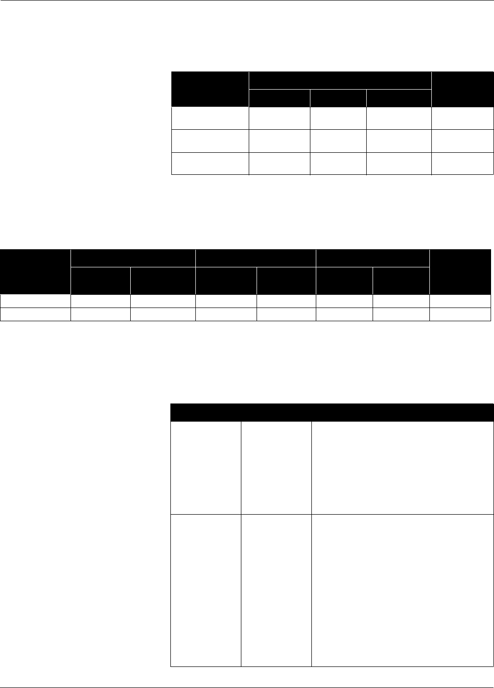
E-3
Appendix E
ELECTRONICS
COMPATIBILITY
Table E-6 lists electronics compatibility issues between the electronics
board, the sensor module, and the LCD meter.
HARDWARE
COMPATIBILITY
Table E-7 lists hardware compatibility issues between new and old
housings and the internal components.
COMMUNICATION
COMPATIBILITY
Table E-8 lists EA software revisions.
EA Software
TABLE E-6. Electronics Compatibility Table.
Electronics
Board Revision
Sensor Module LCD Meter
Rev. 142(a) Rev. 142(b) Rev. 149
Electronics Board
Rev. 4 and 5
Compatible Compatible Not Compatible Not Compatible
Electronics Board
Rev. 8, 9, and 10
Compatible Compatible Not Compatible Not Compatible
Electronics Board
Rev. 12 and 13
Compatible Compatible Compatible Compatible
TABLE E-7. Hardware Compatibility Issues.
Housing
Terminal Block Electronics Board Sensor Module
LCD Meter
New Old New
(Rev. 12 and 13) Old (Rev 10
and below) New Old
New Housing Compatible Not Compatible Compatible Compatible Compatible Compatible Compatible
Old Housing Compatible Compatible Compatible Compatible Compatible Compatible Compatible
TABLE E-8. EA Software.
EA Rev. Effectivity Date Features
Rev. 3.5 11/97
• Lowest recommended revision of EA
software. Contact your Field Service
Center to upgrade older revisions of
the EA software.
• Verifies Range Values so range
values are not overwritten if new flow
configuration is sent to the transmitter.
Rev. 4.0 11/98
• Required for LCD meter and Totalizer
setup.
• Special Units setup for Flow and Flow
Total
• Supports configurable DP Low Flow
Cutoff
• Supports Extended Process
Temperature and Range 1 DP
• Supports Annubar®Diamond II+/
Mass Probar®
• Includes On-Line manual

Rosemount Model 3095 MV
E-4
HART Communicator
Model 275
Table E-9 lists Model 275 HART Communicator revisions.
TABLE E-9. HART Communicator Revisions.
HART Rev. Effectivity Date Features
Field Device Rev.
1, DD Rev. 5
10/95
• Initial Model 3095 MV DD release
Field Device Rev.
1, DD Rev. 7
9/97
• Recognizes Gauge Pressure as a
Field Device Variable
• Compatible with Back-up Process
Temperature Mode
• Will not communicate with new Rev.
12 electronics board (11/98) if “Flow
Total” is selected as a process
variable
Field Device Rev.
2, DD Rev. 1
12/98
• Required for LCD meter and Totalizer
setup
• Special Units setup for Flow and Flow
Total
• Supports configurable DP Low Flow
Cutoff
• Supports Extended Process
Temperature and Range 1 DP
• Supports Annubar®Diamond II+/
Mass Probar®
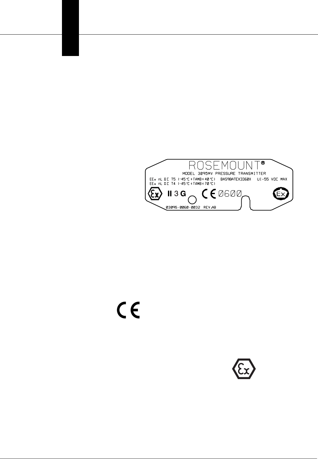
Appendix
F-1
FEuropean ATEX Directive
Information
CENELEC/BASEEFA Type N
Rosemount Model 3095MV Multivariable Mass Flow Transmitters that
have the following label attached, have been certified to comply with
Directive 94/9/EC of the European Parliament and the Council as
published in the Official Journal of the European Communities No. L
100/1 on 19 April 1994.
The following information is provided as part of the labeling of the
transmitter:
• Name and address of the manufacturer (may be any of the
following):
•Rosemount USA
•Rosemount England
•Rosemount Germany
•Rosemount Singapore
• Complete model number (see Section 6 Specifications and Reference
Data).
• The serial number of the device
• Year of construction
• Marking for explosion protection:
•EEx nL IIC T5 (–45 °C ≤ Tamb ≤ 40 °C)
•EEx nL IIC T4 (–45 °C ≤ Tamb ≤ 70 °C)
•Ui = 55 Vdc Max
•BASEEFA certificate number: BAS 98 ATEX 3360X
SPECIAL CONDITIONS FOR SAFE USE (X):
Model 3095 transmitters fitted with the transient protection terminal
block are not capable of withstanding the 500 V insulation test required
by Clause 9.1 of EN 50 021 (1998), and this must be taken into account
when installing the apparatus.
3095-006E05A
0600
II 3 G
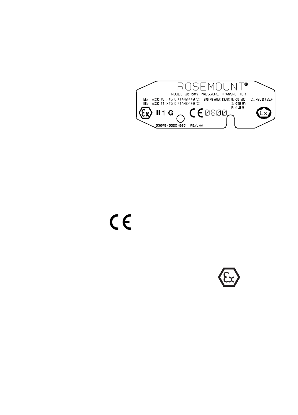
Rosemount Model 3095 MV
F-2
CENELEC/BASEEFA Intrinsic Safety
Rosemount Model 3095MV Multivariable Mass Flow Transmitters that
have the following label attached, have been certified to comply with
Directive 94/9/EC of the European Parliament and the Council as
published in the Official Journal of the European Communities No. L
100/1 on 19 April 1994.
The following information is provided as part of the labeling of the
transmitters:
• Name and address of the manufacturer (may be any of the
following):
•Rosemount USA
•Rosemount England
•Rosemount Germany
•Rosemount Singapore
• Complete model number (see Section 6 Specifications and Reference
Data)
• The serial number of the device
• Year of construction
• Marking for explosion protection:
•EEx ia IIC T5 (–45 °C ≤ Tamb ≤ 40 °C)
•EEx ia IIC T4 (–45 °C ≤ Tamb ≤ 70 °C)
•Ui = 30 Vdc Ii = 200 mA Pi = 1.0 W Ci = 0.012 mF
• BASEEFA ATEX certificate number: BAS 98 ATEX 1359X
SPECIAL CONDITIONS FOR SAFE USE (X):
Model 3095 transmitters fitted with the transient protection terminal
block are not capable of withstanding the 500 V insulation test required
by Clause 6.4.12 of EN 50 020 (1994), and this must be taken into
account when installing the apparatus.
3095-0060F05A
0600
II 1 G

I-1
Index
A
Access Requirements 2-10
Action Keys
Hot Key A-6
ON/OFF Key A-6
Up Arrow Key A-6
Alarm Jumpers 2-4
Alarm Output Values 2-4
Alarms
Failure Mode Alarm vs.
Saturation Output Values 2-4
Analog Output Range Values 4-46
Automatic Error Messages 4-9
B
Bench Calibration Outline 4-9
Bench Configuration and
Calibration 2-4
Bench Configuration Outline 4-8
Bolt Installation Guidelines 2-13
Burst Mode 4-35
C
Calibration 2-21
Calibration Outline 4-9
CDS 4716A00 18
Change Passwords 4-48
Compensated Flow (Liquid
Configuration) 4-21
Compensated Flow (Natural Gas
Configuration) 4-24
Compensated Flow (Natural Gas De-
tail Configuration) 4-26
Computer Requirements 4-1
Configuration Data Sheet 6-18
Configuration Outline 4-8
Critical Alarms 5-3, D-1
D
Damping Screen 4-32
Default Units 4-33
Device Info Screen 4-32
Differential Producer 4-14, 4-19, 4-29
E
EA Default Units 4-33
Enable/Disable Security Screen 4-50
Engineering Assistant
Change Passwords 4-48
Engineering Assistant
Analog Output Range Values 4-
46
Assign Variables Screen. 4-47
Bench Calibration Outline 4-9
Bench Configuration Outline 4-8
Burst Mode 4-35
Compensated Flow (Liquid
Configuration) 4-21
Compensated Flow (Natural Gas
Configuration) 4-24
Compensated Flow (Natural Gas
Detail Configuration) 4-26
Diagnostic Screens 4-51
Differential Producer 4-14, 4-19,
4-29
Fast Keys 4-11
Field Calibration Outline 4-9
Hot Keys 4-10
Installation Procedure 4-2
Maintenance Screens 4-43
Menu Categories 4-8
Menu Structure 4-7
MInimum Equipment and
Software 4-1
Natural Gas Properties
(Detail) 4-26
Output Trim Screens 4-48
Path Name Convention 4-11
Primary Element 4-14, 4-19, 4-
29
Procedure Outlines 4-8
Recall Factory Trim Settings
Procedure 4-46
Screen Components 4-10
Sensor Trim 4-43
Setup Screens 4-12
Single CPU License 3-5
Site License 3-5
Status Bar Codes 4-10
System Requirements 4-1
Toolbar 4-11
View Selections 4-55
Error Info Screen 4-54
European ATEX Directive Informa-
tion F-1
F
Failure Mode Alarm Jumpers 2-4
Failure Mode Alarm vs. Saturation
Output Values 2-4
Fast Keys 4-11
Field Calibration 4-46
Field Calibration Outline 4-9
Field Installation Equipment 2-17
Field Wiring 2-19
Fixed Process Temp Range 4-50
Fixed Process Temp Screen 4-50
Flange Adapter O-Rings 2-11
Function Keys
Help Key A-7
Home Key A-7
G
Gross versus Detail
Characterization 4-24
Grounding 2-21
Grounding the Transmitter
Case 2-21
H
HART Communicator
Data Entry A-7
Hazardous Locations 2-16
Hot Keys 4-10
Housing Rotation 2-10
I
Identification Info Screen 4-52
Impulse Piping 2-9
Install EA Software 4-2
Installation
Access Requirements 2-10
Bench Configuration and
Calibration 2-4
Bolt Installation Guidelines 2-13
Bolt Installation Torque
Values 2-17
Electrical Considerations 2-16
Environmental
Considerations 2-9
Example Installations 2-8
Failure Mode Alarm Jumpers
2-4
Field Installation Equipment
2-17
Field Wiring 2-19
General Considerations 2-5
Grounding 2-21
Hazardous Locations 2-16
Impulse Piping 2-9
Install RTD Assembly 2-18
Installation Flowchart 2-1
LCD Meter 3-3
Loop Resistance 2-16
Mechanical Considerations 2-6
Mounting Brackets 2-12
Mounting Configurations 2-6
Mounting Considerations 2-12
Mounting Pressure Effect 2-12

Rosemount Model 3095 MV
I-2
Power Supply 2-16
Process Considerations 2-11
Taps 2-8
Transient Protection Terminal
Block 3-5
Installation Flowchart 2-1
Integral Orifice Assembly 3-7
K
Keypad
Action Keys A-6
Hot Key A-6
L
LCD Meter 3-1
Loop Resistance 2-16
Loop Test Screen 4-53
Low Power
Alarm Values 2-4
Saturation Values 2-4
M
Maintenance
Disassembly Procedure 5-12
Master Reset Screen 4-54
Menu Categories 4-8
Menu Structure 4-7
Model 1195 Integral Orifice
Assembly 3-7
Model 305 Integral Manifolds 3-7
Module Info Screen 4-51
Mounting Brackets 2-12
Mounting Configurations 2-6
Mounting Considerations 2-12
Mounting Pressure Effect 2-12
N
Natural Gas Configuration 4-24
Natural Gas Detail
Configuration 4-26
O
ON/OFF Key A-6
Options
Custom Configuration 3-7
Flange Adapters 3-7
LCD Meter 3-1, 3-5
Model 3095MV Engineering
Assistant Software 3-5
SST Mounting Brackets 3-5
Transient Protection Terminal
Block 3-5
Output Trim Screens 4-48
P
Path Name Convention 4-11
Power Supply 2-16
Primary Element 4-14, 4-19, 4-29
Privileges Screen 4-43
Process Considerations 2-11
Process Flange Orientation 2-10
R
Read Outputs Screen 4-51
Recall Factory Trim Settings
Procedure 4-46
Recv Config Screen 4-38
Return of Materials 5-19
RMA Number 5-19
S
Saturation Output Values 2-4
Screen Components 4-10
Send Config Screen 4-38, 4-39, 4-40
Sensor Trim 4-43
Specifications
Functional Specifications 6-1
Performance Specifications 6-5
Physical Specifications 6-7
Status Bar Codes 4-10
Steam Configuration 4-17
Steam Table Values 4-17
T
Taps 2-8
Test Calculation Screen 4-52
Toolbar 4-11
Totalization 3-3, 4-39
Tri-Loop 4-47, 10
Trim 4-43
Troubleshooting
Alarm Values 2-4
Communication problems 5-2
Critical Alarms 5-3, D-1
Erratic PV Reading 5-9
Flow Exceptions 5-5, D-3
High PV Reading 5-8
Low PV Reading or No PV
Reading 5-10
Saturation Values 2-4
Sluggish Output Response/
Drift 5-11
Unexpected Process Variable
(PV) Readings 5-7
Typical Installation Site 2-2
U
Units Screen 4-31
Unpacking The Model 3095MV 2-2
V
Version 4/5 Critical Alarms. D-4
Version 4/5 Model 3095 MV Flow
Exceptions. D-6

00809-0100-4716 Rev.GA
5/99
P
R
I
N
T
E
D
IN
U.
S.
A.
http://www.rosemount.com
¢00809-0100-4716;¤
Rosemount Inc.
8200 Market Boulevard
Chanhassen, MN 55317 USA
Tel 1-800-999-9307
Telex 4310012
Fax (612) 949-7001
© 1998 Rosemount Inc.
Fisher-Rosemount Limited
Heath Place
Bognor Regis
West Sussex PO22 9SH
England
Tel 44 (1243) 863 121
Fax 44 (1243) 867 5541
Fisher-Rosemount
Singapore Pte Ltd.
1 Pandan Crescent
Singapore 128461
Tel (65) 777-8211
Fax (65) 777-0947
Tlx RS 61117 FRSPL
