BitStorm 4800 Express 4821 A1 Installation Guide A2 GN21 00
4821-A2-GN21-00 4821-A2-GN21-00
User Manual: 4821-A2-GN21-00
Open the PDF directly: View PDF ![]() .
.
Page Count: 54
- Contents
- About This Guide
- Installation
- Preparation
- Cables Required
- Unpacking the Hardware
- Package Contents
- Mounting Configurations
- Mounting Brackets
- Installing the Mounting Brackets for Rack Mounting
- Installing the BitStorm 4800 Express Into a Rack
- Installing the Mounting Brackets for Wall Mounting
- Installing the BitStorm 4800 Express on a Shelf or Desktop
- Cabling
- LEDs
- Configuration
- Connectors, Cables, and Pin Assignments
- Equipment List
- Technical Specifications
- Index

BitStorm™4800 Express
Installation Guide
Document No. 4821-A2-GN21-00
October 2003

A October 2003 4821-A2-GN21-00
Copyright © 2003 Paradyne Corporation.
All rights reserved.
Printed in U.S.A.
Notice
This publication is protected by federal copyright law. No part of this publication may be copied or distributed,
transmitted, transcribed, stored in a retrieval system, or translated into any human or computer language in any form or
by any means, electronic, mechanical, magnetic, manual or otherwise, or disclosed to third parties without the express
written permission of Paradyne Corporation, 8545 126th Ave. N., Largo, FL 33773.
Paradyne Corporation makes no representation or warranties with respect to the contents hereof and specifically
disclaims any implied warranties of merchantability or fitness for a particular purpose. Further, Paradyne Corporation
reserves the right to revise this publication and to make changes from time to time in the contents hereof without
obligation of Paradyne Corporation to notify any person of such revision or changes.
Changes and enhancements to the product and to the information herein will be documented and issued as a new
release to this manual.
Warranty, Sales, Service, and Training Information
Contact your local sales representative, service representative, or distributor directly for any help needed. For additional
information concerning warranty, sales, service, repair, installation, documentation, training, distributor locations, or
Paradyne worldwide office locations, use one of the following methods:
Internet: Visit the Paradyne World Wide Web site at www.paradyne.com. (Be sure to register your warranty at
www.paradyne.com/warranty.)
Telephone: Call our automated system to receive current information by fax or to speak with a company
representative.
— Within the U.S.A., call 1-800-870-2221
— Outside the U.S.A., call 1-727-530-2340
Document Feedback
We welcome your comments and suggestions about this document. Please mail them to Technical Publications,
Paradyne Corporation, 8545 126th Ave. N., Largo, FL 33773, or send e-mail to userdoc@paradyne.com. Include the
number and title of this document in your correspondence. Please include your name and phone number if you are
willing to provide additional clarification.
Trademarks
ACCULINK, COMSPHERE, FrameSaver, Hotwire, MVL, NextEDGE, OpenLane, Performance Wizard are registered
trademarks of Paradyne Corporation. BitStorm, EtherLoop, GrandVIEW, ReachDSL, StormPort, StormSystem,
StormTracker, and TruePut are trademarks of Paradyne Corporation. All other products and services mentioned herein
are the trademarks, service marks, registered trademarks, or registered service marks of their respective owners.

4821-A2-GN21-00 October 2003 B
Important Safety Instructions
1. Read and follow all warning notices and instructions marked on the product or included in the manual.
2. This product is intended to be used with a 3-wire grounding type plug — a plug which has a grounding pin. This is
a safety feature. Equipment grounding is vital to ensure safe operation. Do not defeat the purpose of the grounding
type plug by modifying the plug or using an adapter.
Prior to installation, use an outlet tester or a voltmeter to check the AC receptacle for the presence of earth ground.
If the receptacle is not properly grounded, the installation must not continue until a qualified electrician has
corrected the problem.
If a 3-wire grounding type power source is not available, consult a qualified electrician to determine another
method of grounding the equipment.
3. Slots and openings in the cabinet are provided for ventilation. To ensure reliable operation of the product and to
protect it from overheating, these slots and openings must not be blocked or covered.
4. Do not allow anything to rest on the power cord and do not locate the product where persons will walk on the power
cord.
5. Do not attempt to service this product yourself, as opening or removing covers may expose you to dangerous high
voltage points or other risks. Refer all servicing to qualified service personnel.
6. General purpose cables are described for use with this product. Special cables, which may be required by the
regulatory inspection authority for the installation site, are the responsibility of the customer. To reduce the risk of
fire, use a UL Listed or CSA Certified, minimum 26 AWG (0.129 mm2) telecommunication cable.
7. When installed in the final configuration, the product must comply with the applicable Safety Standards and
regulatory requirements of the country in which it is installed. If necessary, consult with the appropriate regulatory
agencies and inspection authorities to ensure compliance.
8. A rare phenomenon can create a voltage potential between the earth grounds of two or more buildings. If products
installed in separate buildings are interconnected, the voltage potential may cause a hazardous condition.
Consult a qualified electrical consultant to determine whether or not this phenomenon exists and, if necessary,
implement corrective action prior to interconnecting the products.
9. In addition, if the equipment is to be used with telecommunications circuits, take the following precautions:
— Never install telephone wiring during a lightning storm.
— Never install telephone jacks in wet locations unless the jack is specifically designed for wet locations.
— Never touch uninsulated telephone wires or terminals unless the telephone line has been disconnected at the
network interface.
— Use caution when installing or modifying telephone lines.
— Avoid using a telephone (other than a cordless type) during an electrical storm. There may be a remote risk of
electric shock from lightning.
— Do not use the telephone to report a gas leak in the vicinity of the leak.
10. Input power to the ALARM interface (located on the front panel of the enclosure) must not exceed 30V rms or
60V dc.
11. The equipment is intended for installation in a max. 50° C ambient temperature, in an environment that is free of
dust and dirt.
12. The power supply cord for countries other than North America is to be a minimum H05 V V-F type, min. 0.75 mm2,
2-conductor and earth ground terminated in an IEC 320 connector on one end, and a plug which is certified for use
in the country of installation at the other end.
13. Do not physically stack the Model 4821 units more than eight (8) units high. Physical stability has not been
evaluated for a stack higher than eight units, and a configuration higher than eight units might be unstable and
prone to tipping over. Ensure that the four (4) rubber feet provided with the product have been installed on the
bottom of each unit before stacking one atop another.
!

C October 2003 4821-A2-GN21-00
EMI Notices
UNITED STATES – EMI NOTICE:
This equipment has been tested and found to comply with the limits for a Class A digital device, pursuant
to Part 15 of the FCC rules. These limits are designed to provide reasonable protection against harmful
interference when the equipment is operated in a commercial environment. This equipment generates,
uses, and can radiate radio frequency energy and, if not installed and used in accordance with the
instruction manual, may cause harmful interference to radio communications. Operation of this equipment
in a residential area is likely to cause harmful interference in which case the user will be required to
correct the interference at his own expense.
The authority to operate this equipment is conditioned by the requirements that no modifications will be
made to the equipment unless the changes or modifications are expressly approved by Paradyne
Corporation.
CANADA – EMI NOTICE:
This Class A digital apparatus meets all requirements of the Canadian interference-causing equipment
regulations.
Cet appareil numérique de la classe A respecte toutes les exigences du réglement sur le matérial
brouilleur du Canada.
Notices to Users of the Canadian Telephone Network
NOTICE: This equipment meets the applicable Industry Canada Terminal Equipment Technical Specifications. This is
confirmed by the registration number. The abbreviation IC before the registration number signifies that registration was
performed based on a Declaration of Conformity indicating that Industry Canada technical specifications were met. It
does not imply that Industry Canada approved the equipment.
NOTICE: The Ringer Equivalence Number (REN) for this terminal equipment is labeled on the equipment and includes
the effect of the POTS splitter. The REN assigned to each terminal equipment provides an indication of the maximum
number of terminals allowed to be connected to a telephone interface. The termination on an interface may consist of
any combination of devices subject only to the requirement that the sum of the Ringer Equivalence Numbers of all the
devices does not exceed five.
Notice to Users of the United States Telephone Network
This equipment complies with Part 68 of the FCC rules and the requirements adopted by the Administrative Council for
Terminal Attachment (ACTA). On the bottom side of this equipment is a label that contains, among other information, a
product identifier in the format US:AAAEQ##TXXXX. If requested, this number must be provided to the telephone
company.
This equipment is intended to connect to the Public Switched Telephone Network through the Model 6051 POTS
splitter using a Universal Service Order Code (USOC) type RJ21X jack. Refer to the Installation Instructions for details.
The Ringer Equivalence Number (or REN) is used to determine the number of devices that may be connected to a
telephone line. Excessive RENs on a telephone line may result in the devices not ringing in response to an incoming
call. In most but not all areas, the sum of RENs should not exceed five (5.0). To be certain of the number of devices that
may be connected to a line, as determined by the total RENs, contact the local telephone company. The REN for this
product is part of the product identifier that has the format US:AAAEQ##TXXXX. The digits represented by ## are the
REN without a decimal point. For example, 03 represents a REN of 0.3.
!
!

4821-A2-GN21-00 October 2003 D
If the BitStorm 4800 causes harm to the telephone network, the telephone company will notify you in advance that
temporary discontinuance of service may be required. But if advance notice is not practical, the telephone company will
notify the customer as soon as possible. Also, you will be advised of your right to file a complaint with the FCC if you
believe it is necessary.
The telephone company may make changes in its facilities, equipment, operations or procedures that could affect the
operation of the equipment. If this happens, the telephone company will provide advance notice in order for you to make
necessary modifications to maintain uninterrupted service.
If trouble is experienced with the BitStorm 4800, refer to the repair and warranty information on Page A. If the
equipment is causing harm to the telephone network, the telephone company may request that you disconnect the
equipment until the problem is resolved.
The user may make no repairs to the equipment.
Connection to party line service is subject to state tariffs. Contact the state public utility commission, public service
commission or corporation commission for information.
If the site has specially wired alarm equipment connected to the telephone line, ensure the installation of the
BitStorm 4800 does not disable the alarm equipment. If you have questions about what will disable alarm equipment,
consult your telephone company or a qualified installer.
Supplier’s Declaration of Conformity
Place of Issue: Paradyne Corporation
8545 126th Avenue North
Largo, FL 33773-1502
USA
Date of Issue: 3/28/2002
Paradyne Corporation, located at the above address, hereby certifies that the BitStorm 4800, Model Number
4821-AX-XXX, bearing labeling identification number US:AW2HN04B4821 complies with: the Federal Communications
Commission’s (“FCC”) Rules and Regulations 47 CFR Part 68 and the Administrative Council on Terminal Attachments
(“ACTA”)-adopted technical criteria TIA/EIA/IS-968, “Telecommunications – Telephone Terminal Equipment – Technical
Requirements for Connection of Terminal Equipment To the Telephone Network, July 2001.”
Patrick Murphy
Senior Vice President, Chief Financial Officer
CE Marking
When the product is marked with the CE mark on the equipment label, a supporting Declaration of Conformity may be
downloaded from the Paradyne World Wide Web site at www.paradyne.com. Select Library → Technical Manuals →
CE Declarations of Conformity.

E October 2003 4821-A2-GN21-00
Japan
Class A ITE
This is a Class A product based on the standard of the Voluntary Control Council for interference by Information
Technology Equipment (VCCI). If this equipment is used in a domestic environment, radio disturbance may arise. When
such trouble occurs, the user may be required to take corrective actions.

4821-A2-GN21-00 4821-A2-GN21-00 i
Contents
About This Guide
Document Purpose and Intended Audience . . . . . . . . . . . . . . . . . . . . iii
Document Summary . . . . . . . . . . . . . . . . . . . . . . . . . . . . . . . . . . . . . . iii
Related Product Documents . . . . . . . . . . . . . . . . . . . . . . . . . . . . . . . . iv
Related Specifications . . . . . . . . . . . . . . . . . . . . . . . . . . . . . . . . . . . . . iv
1 Installation
Preparation. . . . . . . . . . . . . . . . . . . . . . . . . . . . . . . . . . . . . . . . . . . . . . 1-1
Cables Required . . . . . . . . . . . . . . . . . . . . . . . . . . . . . . . . . . . . . . . . . 1-2
Unpacking the Hardware . . . . . . . . . . . . . . . . . . . . . . . . . . . . . . . . . . . 1-2
Package Contents . . . . . . . . . . . . . . . . . . . . . . . . . . . . . . . . . . . . . . . . 1-3
Mounting Configurations . . . . . . . . . . . . . . . . . . . . . . . . . . . . . . . . . . . 1-5
Rack or Wall Mount Installation . . . . . . . . . . . . . . . . . . . . . . . . . . . 1-5
Shelf or Desktop Installation . . . . . . . . . . . . . . . . . . . . . . . . . . . . . 1-5
Mounting Brackets . . . . . . . . . . . . . . . . . . . . . . . . . . . . . . . . . . . . . . . . 1-6
Installing the Mounting Brackets for Rack Mounting . . . . . . . . . . . . . . 1-7
Installing the BitStorm 4800 Express Into a Rack . . . . . . . . . . . . . . . . 1-8
Installing the Mounting Brackets for Wall Mounting . . . . . . . . . . . . . . . 1-10
Installing the BitStorm 4800 Express on a Shelf or Desktop . . . . . . . . 1-12
2 Cabling
Cabling Overview . . . . . . . . . . . . . . . . . . . . . . . . . . . . . . . . . . . . . . . . . 2-1
DSL Ports. . . . . . . . . . . . . . . . . . . . . . . . . . . . . . . . . . . . . . . . . . . . . . . 2-2
Uplink Port . . . . . . . . . . . . . . . . . . . . . . . . . . . . . . . . . . . . . . . . . . . . . . 2-4
Management Port. . . . . . . . . . . . . . . . . . . . . . . . . . . . . . . . . . . . . . . . . 2-5
Console Port . . . . . . . . . . . . . . . . . . . . . . . . . . . . . . . . . . . . . . . . . . . . 2-6
Modem Port . . . . . . . . . . . . . . . . . . . . . . . . . . . . . . . . . . . . . . . . . . . . . 2-7
Alarm Port . . . . . . . . . . . . . . . . . . . . . . . . . . . . . . . . . . . . . . . . . . . . . . 2-8
Grounding Lug . . . . . . . . . . . . . . . . . . . . . . . . . . . . . . . . . . . . . . . . . . . 2-9
Power Cord . . . . . . . . . . . . . . . . . . . . . . . . . . . . . . . . . . . . . . . . . . . . . 2-10

Contents
ii July 2002 4821-A2-GN20-10
3 LEDs
LED Locations . . . . . . . . . . . . . . . . . . . . . . . . . . . . . . . . . . . . . . . . . . . 3-1
Front Panel LEDs. . . . . . . . . . . . . . . . . . . . . . . . . . . . . . . . . . . . . . . . . 3-2
System LEDs . . . . . . . . . . . . . . . . . . . . . . . . . . . . . . . . . . . . . . . . . . . . 3-3
4 Configuration
Overview . . . . . . . . . . . . . . . . . . . . . . . . . . . . . . . . . . . . . . . . . . . . . . . 4-1
Conventions Used . . . . . . . . . . . . . . . . . . . . . . . . . . . . . . . . . . . . . 4-1
Using the CLI . . . . . . . . . . . . . . . . . . . . . . . . . . . . . . . . . . . . . . . . . 4-2
Logging In to the BitStorm 4800 Express. . . . . . . . . . . . . . . . . . . . . . . 4-3
Setting the IP Address . . . . . . . . . . . . . . . . . . . . . . . . . . . . . . . . . . . . . 4-4
A Connectors, Cables, and Pin Assignments
Overview . . . . . . . . . . . . . . . . . . . . . . . . . . . . . . . . . . . . . . . . . . . . . . . A-1
Management Port Connector . . . . . . . . . . . . . . . . . . . . . . . . . . . . . . . . A-2
Uplink Connector . . . . . . . . . . . . . . . . . . . . . . . . . . . . . . . . . . . . . . . . . A-3
DSL Network Interface Cable. . . . . . . . . . . . . . . . . . . . . . . . . . . . . . . . A-4
Alarm Port . . . . . . . . . . . . . . . . . . . . . . . . . . . . . . . . . . . . . . . . . . . . . . A-5
Modem Port Connector . . . . . . . . . . . . . . . . . . . . . . . . . . . . . . . . . . . . A-6
Console Port Connector. . . . . . . . . . . . . . . . . . . . . . . . . . . . . . . . . . . . A-6
B Equipment List
C Technical Specifications
Index

4821-A2-GN21-00 October 2003 iii
About This Guide
Document Purpose and Intended Audience
This document is written for technicians who install the BitStorm 4800 Express IP
DSLAM, Model 4821-A1-447.
Document Summary
A master glossary of terms and acronyms used in Paradyne documents is
available on the World Wide Web at www.paradyne.com. Select Library →
Technical Manuals → Technical Glossary.
Section Description
Chapter 1, Installation Describes the physical installation of the BitStorm 4800
Express into a rack.
Chapter 2, Cabling Describes how to install all cables for the BitStorm 4800
Express and Management Module.
Chapter 3, LEDs Explains the meaning and usage of the front panel LEDs.
Chapter 4, Configuration Describes the minimal configuration steps required to
prepare the BitStorm 4800 Express for remote access.
Appendix A, Connectors,
Cables, and
Pin Assignments
Provides pinouts for all connectors on the BitStorm 4800
Express.
Appendix B, Equipment List Provides part numbers for the BitStorm 4800 Express and
related products.
Appendix C, Technical
Specifications
Lists the technical characteristics of the BitStorm 4800
Express.
Index Lists key terms, acronyms, concepts, and sections in
alphabetical order.

About This Guide
iv October 2003 4821-A2-GN21-00
Related Product Documents
Documentation for the BitStorm 4800 Express IP DSLAM is available on the World
Wide Web at www.paradyne.com. Select Library → Technical Manuals→
BitStorm DSL Systems.
To order a paper copy of a Paradyne document:
Within the U.S.A., call 1-800-PARADYNE (1-800-727-2396)
Outside the U.S.A., call 1-727-530-8623
Related Specifications
Document Number Document Title
4800-A2-GB20 BitStorm 4800 User’s Guide
Describes how to use the web interface, the command line
interface (CLI), and Simple Network Management Protocol
(SNMP) to configure BitStorm 4800 series DSLAMs. Lists and
explains all CLI commands.
6051-A2-GZ40 BitStorm 6051 POTS Splitter Installation Instructions
Describes how to install the POTS splitter card and chassis used
with the BitStorm 4800 series DSLAMs in North America.
Document Number Document Title
ANSI T1.413-1998 Network to Customer Installation Interfaces – Asymmetric
Digital Subscriber Line (ADSL) Metallic Interface
ANSI/EIA-310-D-1992 Cabinets, Racks, Panels, and Associated Equipment
G.992.1 Asymmetrical digital subscriber line (ADSL) transceivers
G.992.2 Splitterless asymmetric digital subscriber line (ADSL)
transceivers
IEEE 802.1D Media Access Control (MAC) Bridges
IEEE 802.1Q Virtual Bridged Local Area Networks

4821-A2-GN21-00 October 2003 1-1
1
Installation
Preparation
Consider the following before installing the BitStorm™ 4800 Express IP DSLAM:
Installation Site
Your installation site should be well ventilated, clean, and free of
environmental extremes.
Installation Options
The BitStorm 4800 Express may be:
— Mounted with the included mounting brackets in a standard 19-inch
(483 mm) or 23-inch (584 mm) rack, or, with separately purchased
mounting brackets, in a 21-inch (535 mm) ETSI or 24-inch (610 mm) EIA
rack. ETSI brackets are available from Paradyne. See Appendix B,
Equipment List.
As many BitStorm 4800 Express units may be mounted in a standard rack
as there are 1.75-inch (44.45 mm) spaces in the rack, so long as
adequate cooling is provided.
— Mounted vertically against a wall.
The standard mounting brackets provided can be fastened to the base of
the unit for wall mounting.
— Set on a shelf or desktop.
Up to eight BitStorm 4800 Express units may be stacked on a shelf or
desktop.
Power
The BitStorm 4800 operates from a standard AC power supply (90 to 264 VAC
at 47 to 63 Hz).
Other Cabling
With the exception of the power cord, no cables are provided with the
BitStorm 4800 Express. See Cables Required on page 1-2 to determine what
cables you need to procure before installation.

1. Installation
1-2 October 2003 4821-A2-GN21-00
Cables Required
Ta b l e 1 - 1 shows all the cables that may be required for your installation.
Unpacking the Hardware
HANDLING PRECAUTIONS FOR
STATIC-SENSITIVE DEVICES
This product is designed to protect sensitive components from damage
due to electrostatic discharge (ESD) during normal operation. When
performing installation procedures, however, take proper static control
precautions to prevent damage to equipment. If you are not sure of the
proper static control precautions, contact your nearest sales or service
representative.
The BitStorm 4800 Express is shipped in a cardboard shipping container.
Carefully remove the unit from its shipping container and check for physical
damage. If the unit shows signs of shipping damage, notify your sales
representative.
Table 1-1. Cable Descriptions
Connector Name Connector and Cable For Connecting . . .
DSL PORTS 1–48 50-pin RJ21X Telco-type
straight connector and
50-wire cable. Two cables
required.
Up to 24 DSL ports to Main
Distribution Frame, punchdown
block, or splitters.
UPLINK 8-position modular plug and
8-wire Category 5 or better
twisted pair cable.
TheBitStorm 4800 Express to
the Wide Area Network (WAN)
via an Ethernet switch.
MGMT 8-position modular plug and
8-wire Category 5 or better
unshielded twisted pair
(UTP) cable.
The BitStorm 4800 Express to
a Network Management
System over a Local Area
Network (LAN) employing
10BaseT or 100BaseT.
CONSOLE DB9 plug connector and
shielded cable. The other
connector depends on the
serial port on your terminal
or PC, but normally is a DB9
socket.
The Management Module to a
terminal or a PC with a
terminal emulation program.
MODEM DB9 socket connector and
shielded cable. The other
connector depends on your
modem, but normally is a
DB25 plug.
The Management Module to
an external modem. The
connector can also be used to
connect a terminal or PC.
ALARM 8-position modular plug and
8-wire cable.
The Management Module to
an alarm system.
!

1. Installation
4821-A2-GN21-00 October 2003 1-3
Package Contents
In addition to this installation guide, the BitStorm 4800 Express shipping carton
should contain:
BitStorm 4800 Express
Mounting brackets (one left and one right)
Power cord
Hardware kit (see Table 1-2, Contents of Hardware Kit Shipped with the
BitStorm 4800 Express)
If anything is missing, notify your sales representative.
Before installing the BitStorm 4800 Express, read the Important Safety
Instructions in the beginning of this document.
Be sure to register your warranty at www.paradyne.com/warranty.

1. Installation
1-4 October 2003 4821-A2-GN21-00
Table 1-2. Contents of Hardware Kit Shipped with the BitStorm 4800 Express
Appearance Description Quantity
Self-retaining nut for racks without threaded holes 5
Dress screw (12-24 x 1/2 inch) for use with
self-retaining nuts
5
Machine screw with captive starwasher
(10-32 x 1/2 inch) for use with racks with threaded
holes
5
Flat-head screw (8-32 x 1/4 inch) for attaching
mounting brackets to unit
7
Jackscrew for attaching Telco connectors with short
mounting screws
2
Rubber foot for desk-mount and stacking of units 4
Cable tie (8-inch) for strain relief and cable
management
3

1. Installation
4821-A2-GN21-00 October 2003 1-5
Mounting Configurations
Three basic installation configurations are available:
Rack mount
Wall mount
Shelf or desktop
Rack or Wall Mount Installation
The BitStorm 4800 Express is shipped with mounting brackets suitable for a
19-inch (483 mm) or 23-inch (584 mm) rack. The same brackets may be used to
attach the unit to a wall.
Brackets suitable for a 21-inch (535 mm) ETSI rack are available from Paradyne
(see Appendix B, Equipment List), and brackets suitable for a 24-inch (610 mm)
rack can be obtained from other sources.
NOTE:
In this guide, the term rack refers to any rack, cabinet, frame, or bay suitable
for mounting telecommunications equipment.
Shelf or Desktop Installation
The BitStorm 4800 Express may also be placed on a shelf or desktop. If you will
not mount the BitStorm 4800 Express in a rack or on a wall, proceed to Installing
the BitStorm 4800 Express on a Shelf or Desktop on page 1-12.

1. Installation
1-6 October 2003 4821-A2-GN21-00
Mounting Brackets
The right-angle mounting brackets have a long side and a short side.
For 19-inch (483 mm) racks, the long side of a supplied bracket is fastened to
the side of the unit.
For 23-inch (584 mm) racks, the short side of a supplied bracket is fastened to
the side of the unit.
For wall mounting, the long side of a supplied bracket is fastened to the bottom
of the unit.
The optional ETSI brackets are always installed with the short side fastened to
the BitStorm 4800 Express.
Both the supplied brackets and the optional ETSI brackets are marked LEFT SIDE
and RIGHT SIDE, with reference to the left and right sides of the BitStorm 4800
Express when viewed from the front.
For wall mounting, proceed to Installing the Mounting Brackets for Wall Mounting
on page 1-10.
For rack mounting, proceed to Installing the BitStorm 4800 Express Into a Rack on
page 1-8.

1. Installation
4821-A2-GN21-00 October 2003 1-7
Installing the Mounting Brackets for Rack Mounting
Procedure
To install the mounting brackets for rack mounting:
1. Identify the flat-head screws provided in the hardware kit. Six screws are
required for the 19-inch (483 mm) configuration, and four screws for the other
configurations.
2. Attach the brackets appropriate to your rack size. Tighten all screws firmly.
02-17067
23-inch (584 mm) Rack Mount
with Supplied Brackets
19-inch (483 mm) Rack Mount
with Supplied Brackets
21.1-inch (535 mm) Rack Mount
with Optional ETSI Brackets
1. Installation
1-8 October 2003 4821-A2-GN21-00
Installing the BitStorm 4800 Express Into a Rack
Two types of mounting screws are provided. Use:
#10-32 mounting screws for rails with threaded screw holes
#12-24 mounting screws and self-retaining nuts for rails with unthreaded
screw holes
Procedure
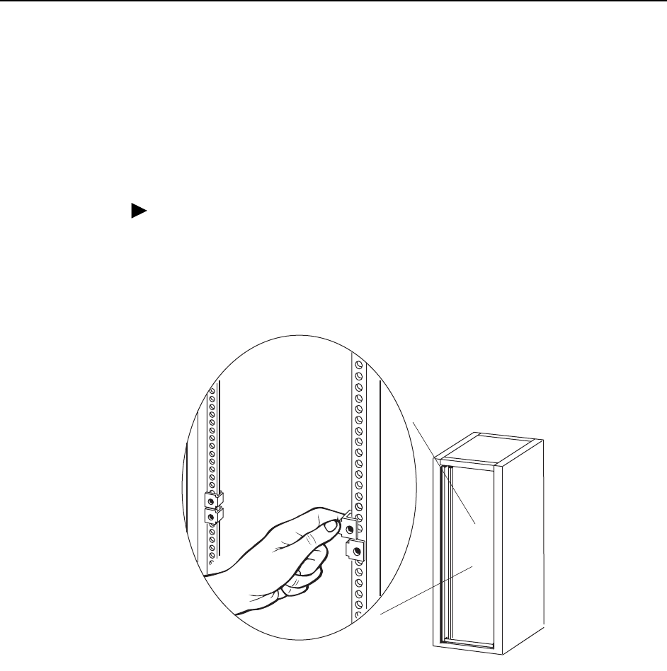
To install the BitStorm 4800 Express into a rack:
1. Determine where in the rack you will mount the BitStorm 4800 Express. If your
rack does not have threaded screw holes, slip self-retaining nuts onto the rails
where the BitStorm 4800 Express will be fastened.
02-17070
1. Installation
4821-A2-GN21-00 October 2003 1-9
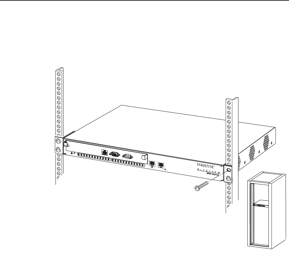
2. Place the BitStorm 4800 Express so that the brackets rest against the front of
the rails. Insert screws in the bottom screw positions and hand-tighten them.
3. Insert and tighten the screws in the top screw positions, then tighten the
bottom screws.
4. Do not plug in the unit. Proceed to Chapter 2, Cabling.
03-17468
OK
ALARM TEST
1
24681012141618202224262830323436384042444648
47
MGMT
CONSOLE
MODEM
ALARM
3571113151719
921232527293133353739414345
OK
ALARMTEST
1
21618202224262830323436384042444648
47
468
7
MGMT
CONSOLE
MODEM
ALARMUPLINK
GigE
5
15171921232527293133353739414345
4804
4821
UPLINK
10/100
1. Installation
1-10 October 2003 4821-A2-GN21-00
Installing the Mounting Brackets for Wall Mounting
Wall mounting requires two wood screws suitable for the weight of the fully cabled
unit. These are not included. Use at a minimum 0.25-inch (6 mm) diameter screws
in 0.75-inch (19 mm) plywood.
Procedure
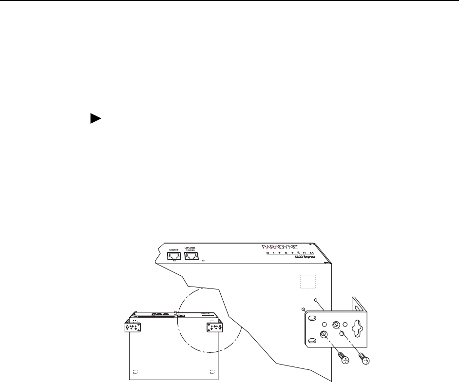
To install the mounting brackets for wall mounting:
1. Identify the flat-head screws provided in the hardware kit. Two screws are
required for each bracket.
2. Orient the unit so that the bottom is facing you and the faceplate is at the top.
3. Locate the supplied Right Side mounting bracket and fasten it to the right side
of the unit.
4. Locate the supplied Left Side mounting bracket and fasten it to the left side of
the unit.
5. Tighten all screws firmly.
03-17469
1. Installation
4821-A2-GN21-00 October 2003 1-11
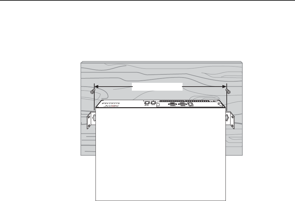
6. Install two wood screws (not provided) at the same height at least 30 inches
(760 mm) above the floor and 17.85 inches (453 mm) apart. Do not
completely tighten the screws. Leave them so their heads are about 0.25 inch
(6 mm) from the wall.
7. Hang the unit from the wood screws to verify that the screws are properly
placed. The screws should freely slide into the top of the key slots in the
brackets.
8. Do not fasten the unit to the wall until it is completely cabled and tested.
Proceed to Chapter 2, Cabling.
03-17470
17.85 in (453 mm)
1. Installation
1-12 October 2003 4821-A2-GN21-00
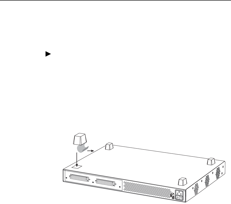
Installing the BitStorm 4800 Express on a Shelf or Desktop
If the BitStorm 4800 Express will be placed on a shelf or desktop, install the
provided rubber feet before putting the BitStorm 4800 Express in position.
Procedure
To install the BitStorm 4800 Express on a shelf or desktop, as a standalone unit or
in a stack:
1. Locate the rubber feet in the hardware kit provided with the BitStorm 4800
Express.
2. Turn the BitStorm 4800 Express upside down on a work surface. Squares
stamped into the bottom of the BitStorm 4800 Express show the proper
positions for the feet.
3. Remove the protective sheet from the bottom of each foot, then press the foot
onto a corner of the bottom of the BitStorm 4800 Express.
4. Turn the BitStorm 4800 Express right side up and place it in position on a shelf
or desktop.
If the installation includes more than one unit, one can be stacked atop
another. Up to eight units can be stacked together.
5. Do not plug in the unit. Proceed to Chapter 2, Cabling.
02-17072
DSL PORTS 25-48
DSL PORTS 1-24

4821-A2-GN21-00 October 2003 2-1
2
Cabling
Cabling Overview
The BitStorm 4800 Express has a large variety of possible cabling configurations.
This chapter describes all possible connections, not all of which are required:
DSL Ports on page 2-2
Uplink Port on page 2-4
Management Port on page 2-5
Console Port on page 2-6
Modem Port on page 2-7
Alarm Port on page 2-8
Grounding Lug on page 2-9
Power Cord on page 2-10
2. Cabling
2-2 October 2003 4821-A2-GN21-00
DSL Ports
The BitStorm 4800 Express has two DSL connectors. Each connector supports
the tip and ring connections of up to 24 DSL ports over a 50-position cable. These
must be connected to a POTS (plain old telephone service) splitter.
In North America, the BitStorm 6051 POTS Splitter must be used. (See the
BitStorm 6051 POTS Splitter Installation Instructions for information.) Elsewhere
the splitter must conform to all regional regulatory requirements.
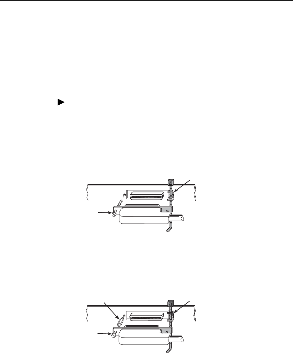
Procedure
To cable the DSL Ports:
1. Insert a cable tie (provided) through the top of the anchor mount next to the
DSL PORTS 1–24 connector.
2. If the connector for your cable has a long captive screw, attach it to the DSL
PORTS 1–24 connector and fasten it with the captive screw.
3. If the connector for your cable has a short captive screw, install the provided
jack screw in the threaded hole next to the DSL PORTS 1–24 connector.
Attach the cable to the DSL PORTS 1–24 connector and fasten it to the jack
screw with its short captive screw.
02-17082
Anchor
Mount
50-Pin
Connector
Long
Screw
Short
Screw
#4-40
Jack Screw
02-17083
Anchor
Mount
50-Pin
Connector
2. Cabling
4821-A2-GN21-00 October 2003 2-3
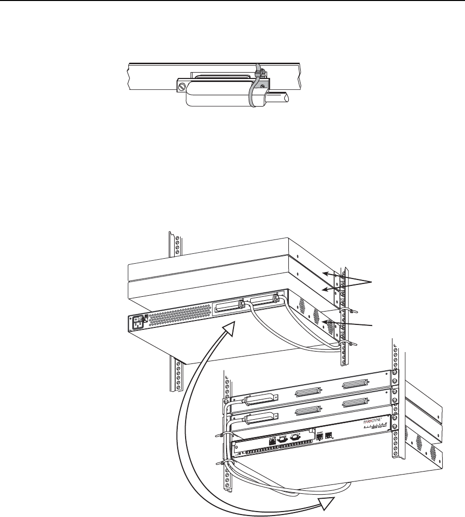
4. Tighten the cable tie around the connector and trim the excess.
5. If ports 25–48 are used, repeat Step 1 through Step 4, substituting
DSL PORTS 25–48 for DSL PORTS 1–24.
6. Connect the tip and ring connections to a POTS splitter. See the
documentation that came with your POTS splitter for more information.
7. Secure the cables as required for strain relief.
02-17084
03-17471
DSL PORTS 1-24
DSL PORTS 25-48
UPLINK
10/100
Front
Rear
POTS Splitter
Card in 1-Slot
Chassis
BitStorm 4800
2. Cabling
2-4 October 2003 4821-A2-GN21-00
Uplink Port
The Uplink port is used to connect the BitStorm 4800 Express to a WAN through
your Ethernet switch.
Either a straight-through or a crossover cable can be used. The wiring is
automatically detected and, if necessary, compensated for.
Procedure
To use the Uplink port:
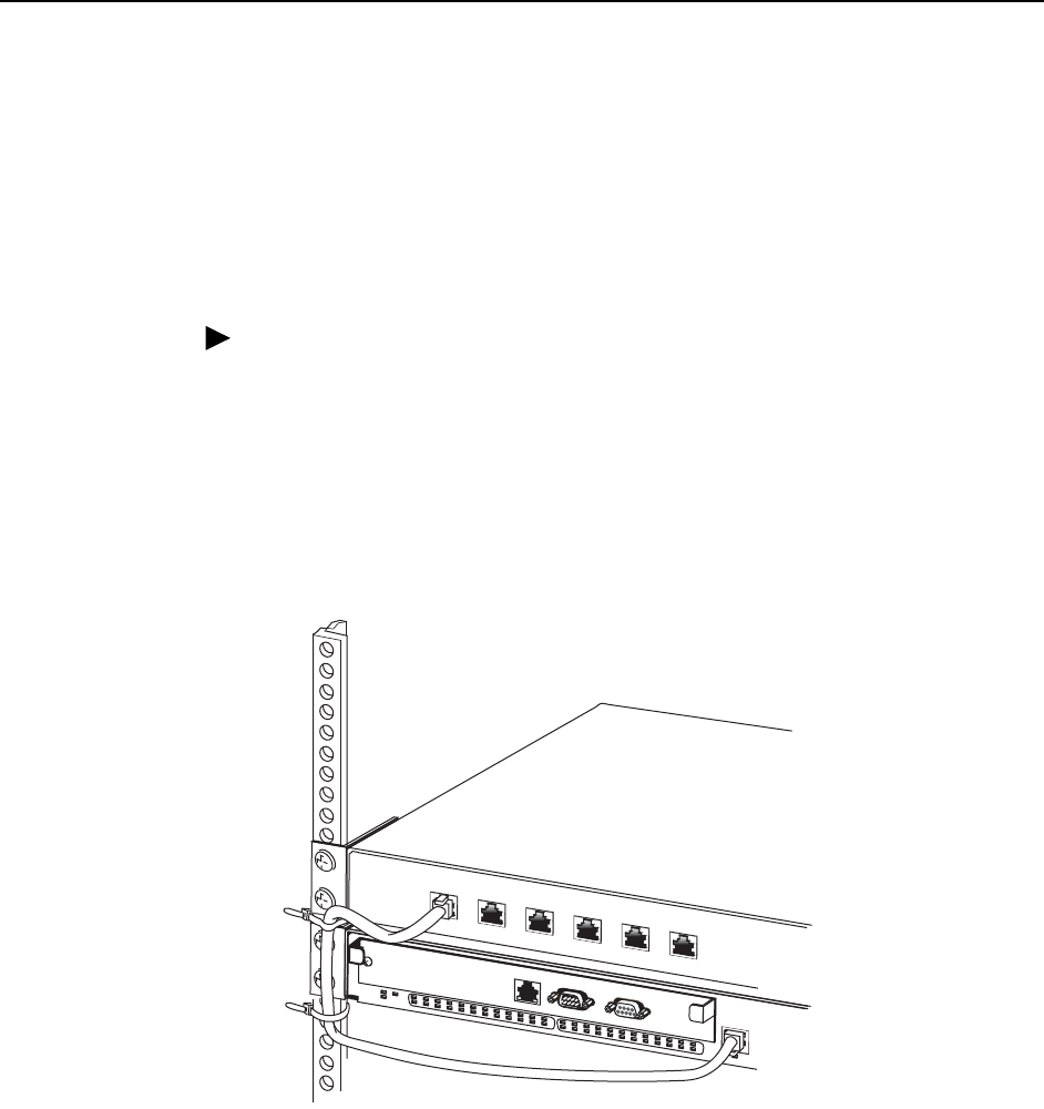
1. Connect a modular 8-pin cable to the UPLINK 10/100 port.
2. If the BitStorm 4800 Express is in a rack, fasten the cable to a rail with a cable
tie.
3. Connect the other end of the cable to your Ethernet switch.
03-17472
MGMT
UPLINK
10/100
8-Position
Modular
Plug
2. Cabling
4821-A2-GN21-00 October 2003 2-5
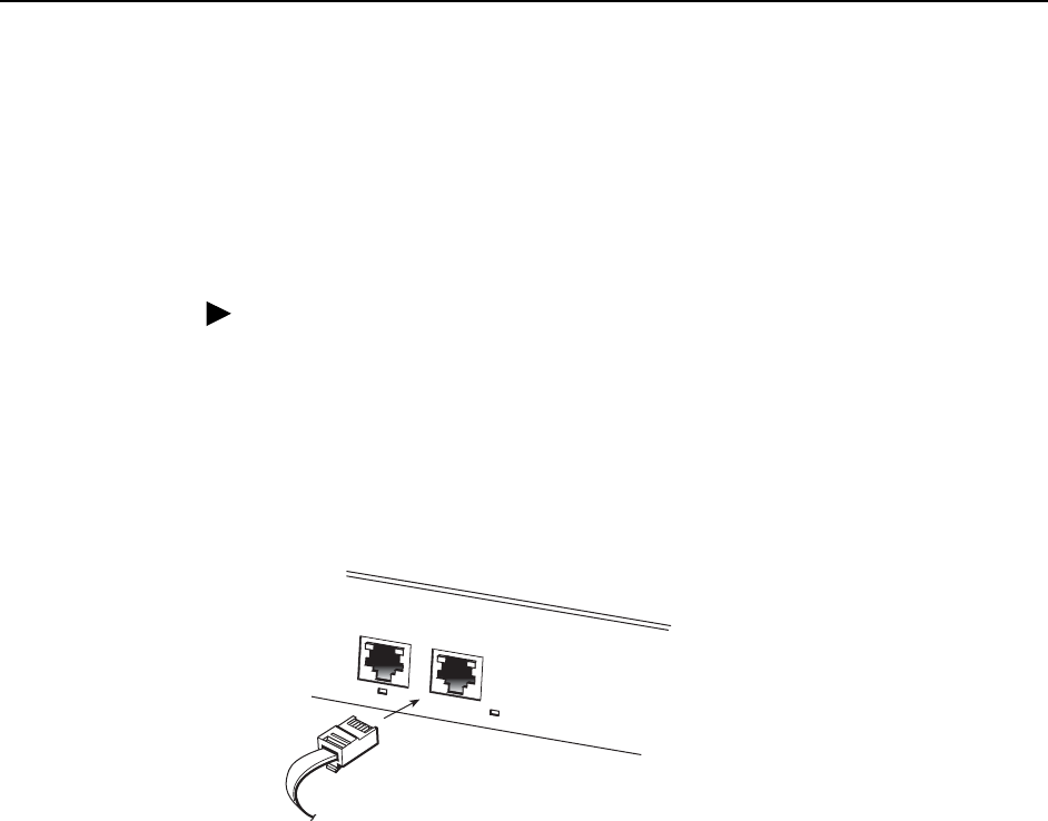
Management Port
The MGMT (management) port can be used to connect the BitStorm 4800
Express to a network management system using a 10BaseT or 100BaseT LAN.
The MGMT port is isolated and no user data is accessible over it.
Either a straight-through or a crossover cable can be used. The wiring is
automatically detected and, if necessary, compensated for.
Procedure
To use the MGMT port:
1. Connect a modular 8-pin cable to the MGMT port.
2. If the BitStorm 4800 Express is in a rack, fasten the cable to a rail with a cable
tie.
3. Connect the other end of the cable to your Ethernet hub or to a network
interface card in a PC.
03-17473
OK
ALARMTEST
1
246810 12 14 16 18 20 22 24 26 28 30 32 34 36 38 40 42 44 46 48
47
MGMT
CONSOLE
MODEM
ALARM
35711 13 15 17 19
921 23 25 27 29 31 33 35 37 39 41 43 45
Hub Device
2. Cabling
2-6 October 2003 4821-A2-GN21-00
Console Port
The CONSOLE port on the Management Module normally serves as the primary
user interface with the BitStorm 4800 Express during installation.
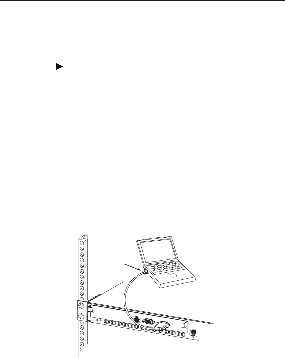
Procedure
To connect a terminal or PC to the CONSOLE port:
1. Configure the terminal or terminal emulation program to use the following
parameters:
— Maximum speed: 9600 bps
— Data bits: 8
— Parity: None
— Stop bits: 1
— Flow Control: None
2. Determine and procure the proper Data Terminal Equipment (DTE) cable type.
The CONSOLE port requires a DB9 plug connector. The other connector
depends on the serial port on your terminal or PC.
3. Connect the DB9 plug connector to the CONSOLE port socket. The
CONSOLE port is ordinarily used only during installation, so do not fasten the
connector.
4. Connect the other end of the cable to the serial port of your terminal or PC.
03-17474
OK
ALARMTEST
1
246810 12 14 16 18 20 22 24 26 28 30 32 34 36 38 40 42 44 46 48
47
MGMT
CONSOLE
MODEM
ALARM
35711 13 15 17 19
921 23 25 27 29 31 33 35 37 39 41 43 45
Serial
Port
2. Cabling
4821-A2-GN21-00 October 2003 2-7
Modem Port
The MODEM port on the Management Module can be used to attach a modem for
remote dial-in management of the BitStorm 4800 Express. The MODEM port can
also be used to attach a terminal or PC to the Management Module using a Data
Communications Equipment (DCE) cable.
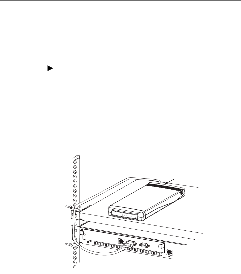
Procedure
To connect a modem to the MODEM port:
1. Determine and procure the proper DCE cable type. The MODEM port requires
a DB9 socket connector. The other connector depends on the serial port on
your modem, but normally a DB25 plug is required.
2. Connect the DB9 socket connector to the MODEM port socket.
3. If the modem will be permanently connected, fasten the connector to the
Management Module with its captive screws. If the BitStorm 4800 Express is
in a rack, dress the cable to the left and attach it to the rail with a cable tie.
4. Connect the other end of the cable to the serial port of your modem.
03-17475
OK
ALARMTEST
1
246810 12 14 16 18 20 22 24 26 28 30 32 34 36 38 40 42 44 46 48
47
MGMT
CONSOLE
MODEM
ALARM
35711 13 15 17 19
921 23 25 27 29 31 33 35 37 39 41 43 45
TSTLINE
ALM
PWRETHERNET
Serial Port
Modem
2. Cabling
2-8 October 2003 4821-A2-GN21-00
Alarm Port
The ALARM port provides a normally-on circuit and a normally-off circuit that
reverse their states in response to an alarm. This interface can be used to set off a
physical alarm.
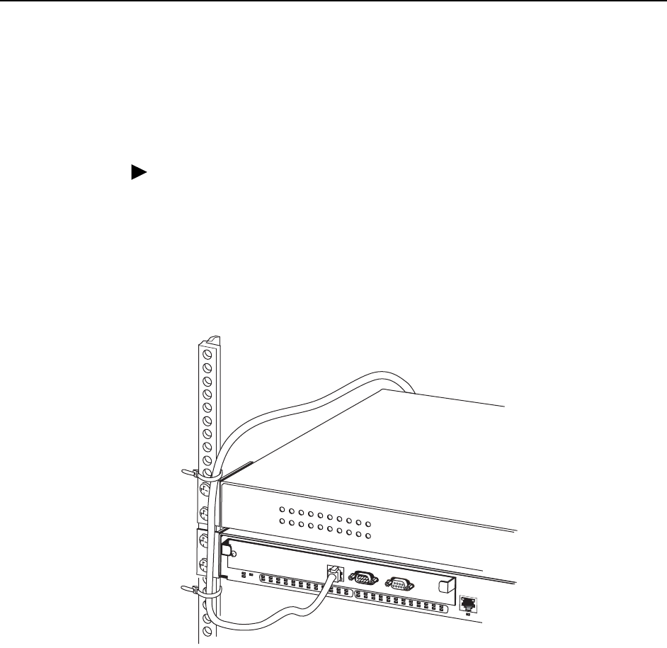
Procedure
To use the ALARM port:
1. Connect a modular 8-pin cable to the ALARM port.
2. If the BitStorm 4800 Express is in a rack, dress the cable to the left and secure
it to the rail with a cable tie.
3. Connect the other end of the cable to your alarm monitoring system.
03-17476
OK
ALARMTEST
1
246810 12 14 16 18 20 22 24 26 28 30 32 34 36 38 40 42 44 46 48
47
MGMT
CONSOLE
MODEM
ALARM
35711 13 15 17 19
921 23 25 27 29 31 33 35 37 39 41 43 45
CO Alarm
Monitoring System
2. Cabling
4821-A2-GN21-00 October 2003 2-9
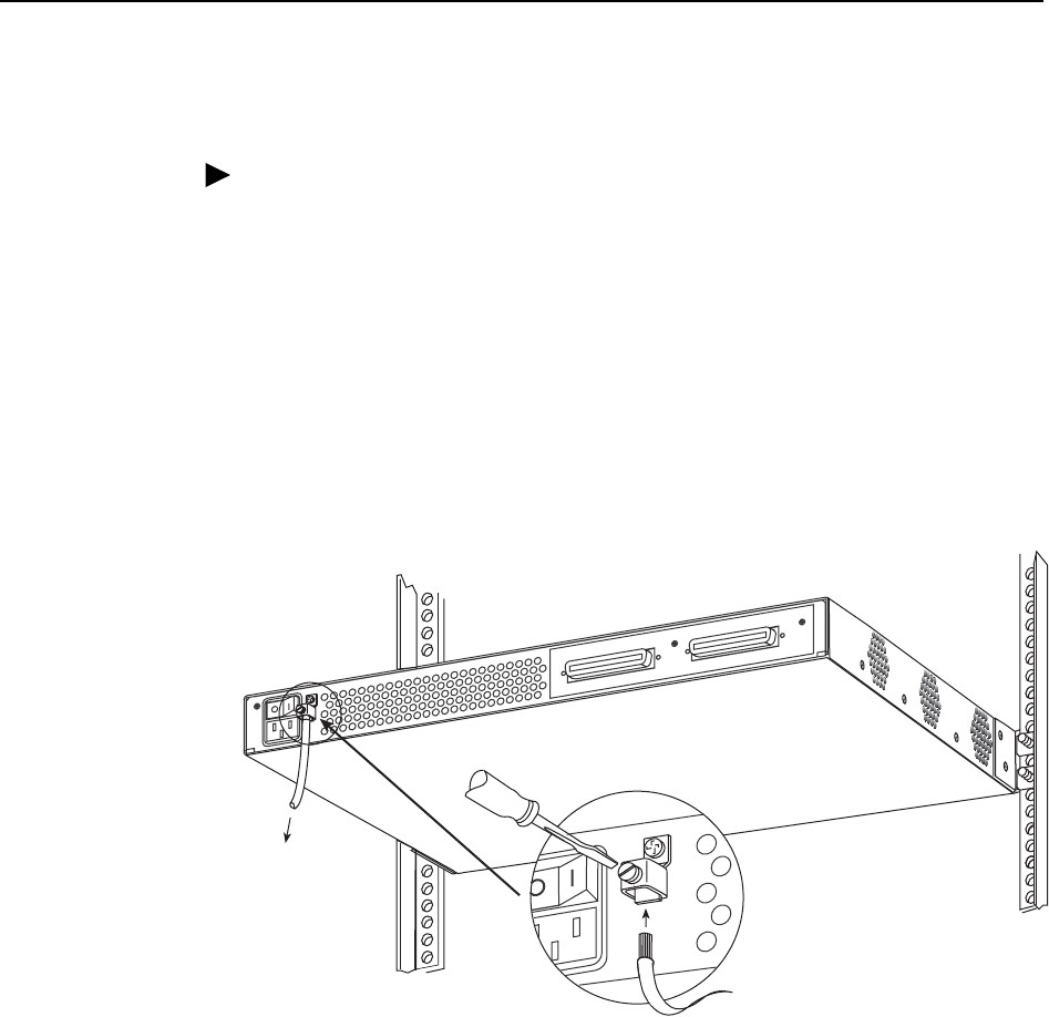
Grounding Lug
Procedure
To connect the unit to a ground:
1. Strip back the insulation approximately 5/16 in (8 mm) on 14 AWG (2.08 mm2)
copper ground wire.
2. Loosen the screw on the grounding lug located on the back panel next to the
power switch.
3. Insert the stripped end of the wire through the bottom of the grounding lug and
tighten the screw. Ensure that the screw makes contact with the stripped
portion of the wire.
4. Attach the ground wire to an earth ground.
02-17081
DSL PORTS 1-24
DSL PORTS 25-48
To
Ground
2. Cabling
2-10 October 2003 4821-A2-GN21-00
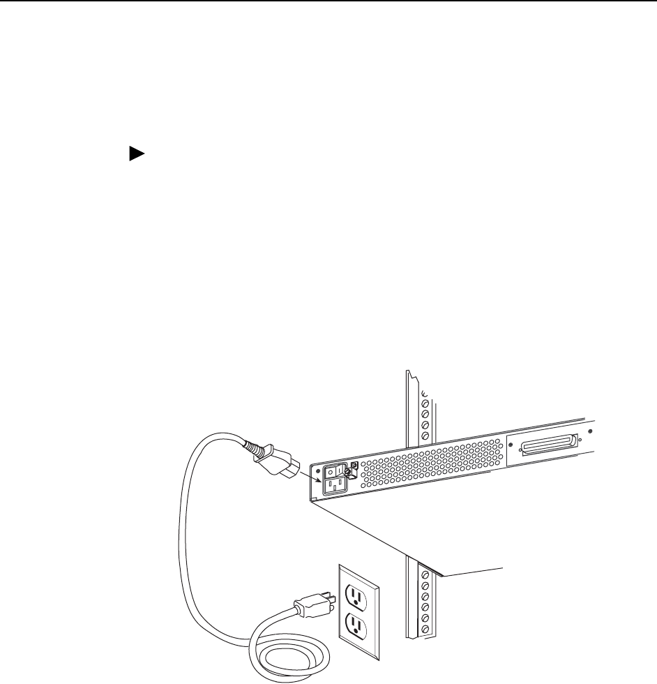
Power Cord
The BitStorm 4800 Express can be powered by any AC source providing 90 to
264 VAC at 47 to 63 Hz.
Procedure
To connect the BitStorm 4800 Express to a power source:
1. Verify that the switch on the rear panel is in the Off (0) position.
2. Insert the power cord into the socket under the switch.
3. If the BitStorm 4800 Express is in a rack, dress the power cord to the left and
fasten it to the rail with a cable tie.
4. Connect the other end of the power cord to a grounded AC power source.
5. Press the On (1) position of the switch to turn on the BitStorm 4800 Express.
When power is applied to the BitStorm 4800 Express, the front panel
Light-Emitting Diodes (LEDs) convey the state of the unit and its interfaces. See
Chapter 3, LEDs.
02-17080
DSL PORTS 1-24
4821-A2-GN21-00 October 2003 3-1
3
LEDs
LED Locations
The small black-on-white rectangles in the following illustration denote the
locations of the front panel LEDs.
Figure 3-1. Front Panel LEDs
03-17466
25
26
27
28
29
30
31
32
33
34
35
36
37
38
39
40
41
42
43
44
45
46
47
48
MODEM CONSOLE
1
2
3
4
5
6
7
8
9
10
11
12
13
14
15
16
17
18
19
20
21
22
23
24
OK
ALARM TEST
OK
ALARMTEST
1
246810 12 14 16 18 2022 24 26 28 30 32 34 36 38 40 42 4446 48
47
MGMT
CONSOLE
MODEM
ALARM
35711 13 1517 19
921 23 25 27 29 31 33 35 37 39 41 4345
4804
UPLINK
10/100
ALARM
MGMT
UPLINK
10/100

3. LEDs
3-2 October 2003 4821-A2-GN21-00
Front Panel LEDs
When power is first applied to the BitStorm 4800 Express it performs a self-test.
When this test is successfully completed, the OK LED lights. The meaning of all
the LEDs is as shown in Table 3-1, Front Panel LEDs.
Table 3-1. Front Panel LEDs
LED Color State Meaning
ALARM Amber Off
On
No Alarms.
Unit failed self-test, the Uplink port is down, the
unit has exceeded a safe temperature, or a fan
has failed.
DSL Port
(1–48)
Green Off
On
Blinking
The port is disabled or no signal is detected on
the line.
Port has successfully trained with the remote and
is active.
Port is attempting to train.
MGMT Green Off
On
The port is disabled, or no physical connection
exists.
A physical connection is detected.
OK Green Off
On
No power, or the unit has not completed
initialization.
Unit has power and has completed initialization.
TEST Amber Off
On
Normal operating mode.
At least one port is in test mode.
UPLINK Green Off
On
The port is disabled, or no physical connection
exists.
A physical connection is detected.

3. LEDs
4821-A2-GN21-00 October 2003 3-3
System LEDs
The three system LEDs, OK, TEST, and ALARM, have meaning at all times, as
shown in Table 3-2, System LEDs.
Table 3-2. System LEDs
OK ALARM TEST Description
Off Off Off Unit is powered Off.
Off Off ON Unit Failed – LEDs should never be in this state.
Notify your service representative.
Off ON Off Unit Failed – The unit has power, but never
completed its initialization process. Notify your
service representative.
Off ON ON Self-Test – The LEDs should be in this state
only during self-test, immediately after the unit is
turned on.
ON Off Off Normal Operation – Unit has successfully
passed self-test, there are no alarms in the
system, and none of the ports is in test mode.
ON Off ON Test Mode – At least one port is in test mode.
ON ON Off Alarm – Unit has failed self-test, the Uplink port
is down, or a major alarm condition exists. Verify
that the Uplink port is properly connected. If
necessary, notify your service representative.
ON ON ON Alarm – At least one port is in test mode, and a
major alarm condition exists. Notify your service
representative.

3. LEDs
3-4 October 2003 4821-A2-GN21-00

4821-A2-GN21-00 October 2003 4-1
4
Configuration
Overview
The BitStorm 4800 Express is designed to require minimal configuration before it
can be accessed by a Network Operations Center (NOC). You may need to
configure:
The IP address for the Management Module if the default address
(10.10.10.10) is not usable
The default gateway address
Initial configuration can be performed using the Command Line Interface (CLI).
The CLI is available from a terminal or PC connected to the CONSOLE port of the
Management Module.
See the BitStorm 4800 User’s Guide for detailed information about the CLI.
Conventions Used
In this book, the Enter key means whatever key you use to submit data to your
terminal or PC. It may be called the Return key on older devices.
Characters displayed on your screen, including those you type, are shown in the
Courier font in this book.

4. Configuration
4-2 October 2003 4821-A2-GN21-00
Using the CLI
You need to type only enough of a command to make it unique. For example, if you
enter:
sh man i
the CLI interprets it as:
show management ip
You can prompt expansion of a command or parameter by pressing the Tab key.
For example, if you enter:
sh man
then press the Tab key, the CLI responds:
sh management
You may then proceed with typing the rest of the command.
You can obtain help with CLI commands by typing a ? (question mark). A question
mark alone lists all commands. A command followed by a question mark lists all
usages of the command. For example, if you enter:
sh ?
the CLI lists all the possible show commands.

4. Configuration
4821-A2-GN21-00 October 2003 4-3
Logging In to the BitStorm 4800 Express
When the BitStorm 4800 Express is turned on, the following prompt is displayed
on the terminal:
Login>
Procedure
To log in to the BitStorm 4800 Express:
1. Type admin at the login prompt and press Enter. The following prompt is
displayed:
Password>
2. The default user password is null, so simply press Enter. The following prompt
is displayed:
IAC>
IAC stands for IP Access Concentrator.
3. Type privilege and press Enter to enter administrator mode. The following
prompt is displayed:
Password>
4. The default administrator password is null, so simply press Enter. The
following prompt is displayed:
IAC#
This shows that you are in administrator mode.

4. Configuration
4-4 October 2003 4821-A2-GN21-00
Setting the IP Address
The IP address of the Management Module must be set before the BitStorm 4800
Express can be remotely managed.
Procedure
To set the IP address of the Management Module:
1. At the IAC# prompt, type:
configure management address address mask gateway
Where:
—address is the IP address to be assigned to the Management Module
—mask is the IP subnet mask for the specified address
—gateway is the default gateway IP address
For example:
conf man addr 135.26.10.37 255.255.255.0 135.26.10.254
2. Press Enter. The prompt changes to IAC#! to show that the configuration
change has yet to be saved.
3. Type save and press Enter.
4. To verify that the address has been set, type:
show management ip
The CLI displays the IP address, subnet mask, and default gateway address.
4821-A2-GN21-00 October 2003 A-1
A
Connectors, Cables, and
Pin Assignments
Overview
The following sections provide pin assignments for:
Management Port Connector on page A-2
Uplink Connector on page A-3
DSL Network Interface Cable on page A-4
Alarm Port on page A-5
Modem Port Connector on page A-6
Console Port Connector on page A-6
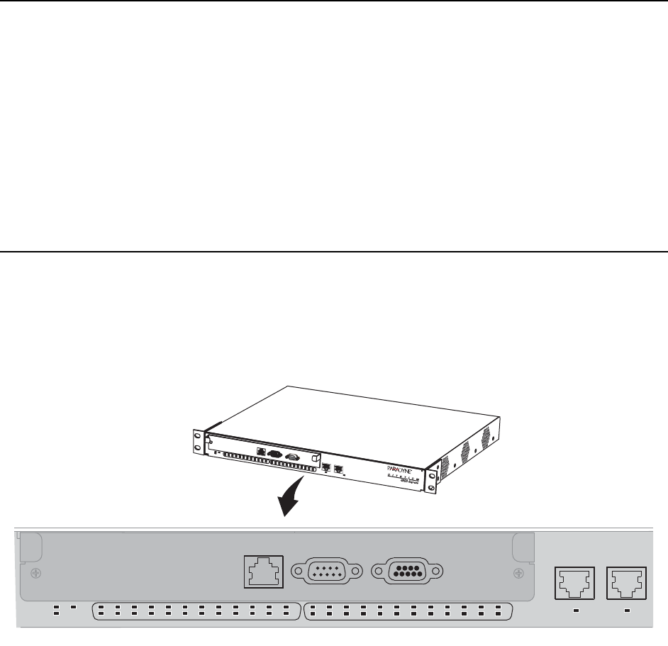
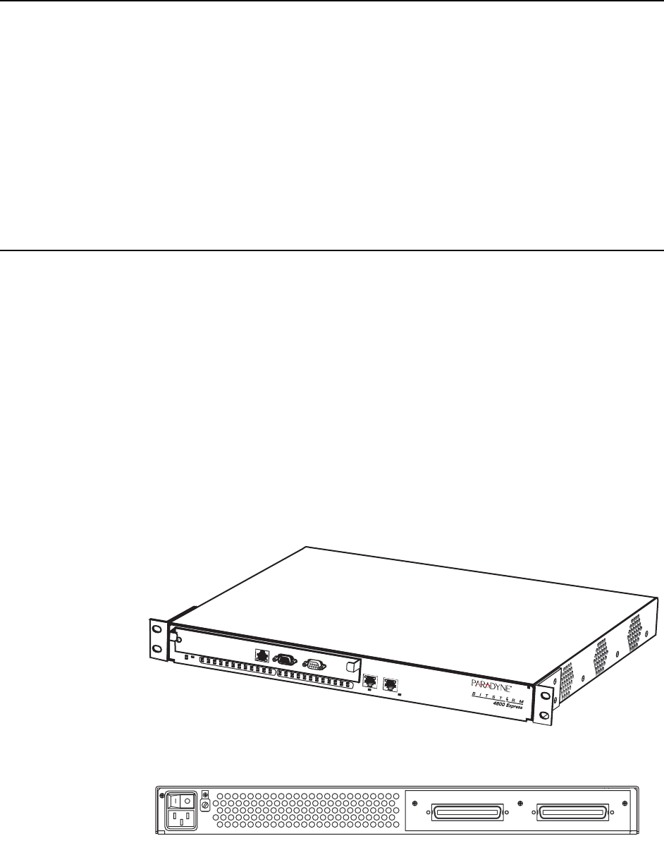
Figure A-1. BitStorm 4800 Express Front Panel
Figure A-2. BitStorm 4800 Express Rear Panel
03-17467
OK
ALARM TEST
1
24681012141618202224262830323436384042444648
47
MGMT
CONSOLE
MODEM
ALARM
3571113151719
921232527293133353739414345
4804
UPLINK
10/100
02-17066-01
DSL PORTS 25-48DSL PORTS 1-24

A. Connectors, Cables, and Pin Assignments
A-2 October 2003 4821-A2-GN21-00
Management Port Connector
The Management (MGMT) connector is an 8-pin unkeyed modular jack for a
10/100BaseT management interface. Either a straight-through or a crossover
cable can be used. The wiring is automatically detected and, if necessary,
compensated for.
Table A-1. Management Port Pinouts
Signal Pin
Transmitted Data + 1
Transmitted Data – 2
Received Data + 3
Unused 4
Unused 5
Received Data – 6
Unused 7
Unused 8
97-15449
Pin 1 Pin 8

A. Connectors, Cables, and Pin Assignments
4821-A2-GN21-00 October 2003 A-3
Uplink Connector
The UPLINK wire connector is an 8-pin unkeyed modular jack for 10/100BaseT.
Either a straight-through or a crossover cable can be used. The wiring is
automatically detected and, if necessary, compensated for.
Table A-2. Uplink Port Pinouts
Signal Pin
Transmitted Data + 1
Transmitted Data – 2
Received Data + 3
Unused 4
Unused 5
Received Data – 6
Unused 7
Unused 8
97-15449
Pin 1 Pin 8
A. Connectors, Cables, and Pin Assignments
A-4 October 2003 4821-A2-GN21-00
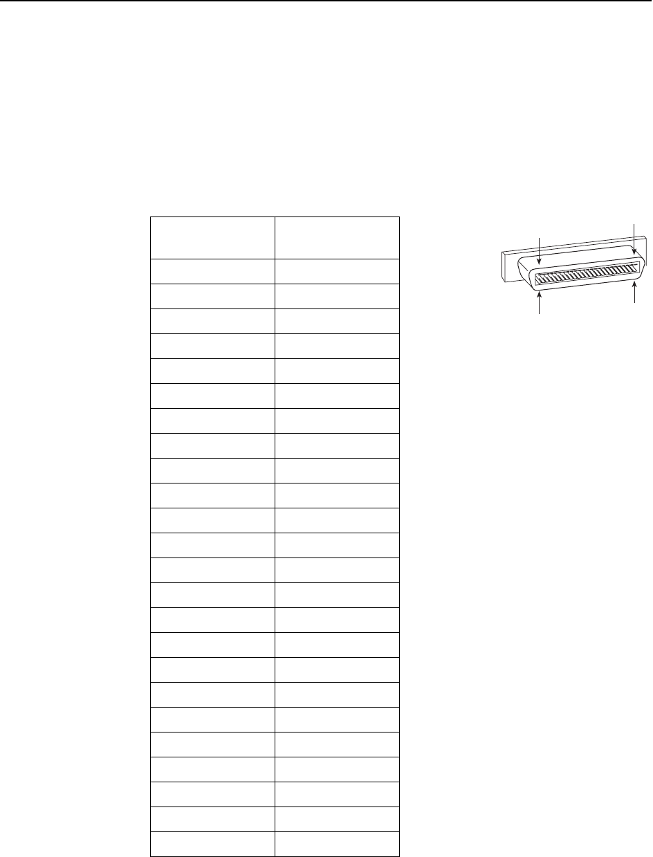
DSL Network Interface Cable
The BitStorm 4800 Express has two 50-pin RJ21X (designated CA21A in Canada)
Telco connectors on its rear panel. The connectors provide the 2-wire loop
interface from each DSL port to the demarcation point.
Table A-3, DSL Connector Pinouts, lists the pin assignments for each of these
interfaces. Note that Pins 25 and 50 are not used.
Table A-3. DSL Connector Pinouts
DSL Port
Connector Pins
(Ring, Tip)
11, 26
22, 27
33, 28
44, 29
55, 30
66, 31
77, 32
88, 33
99, 34
10 10, 35
11 11, 36
12 12, 37
13 13, 38
14 14, 39
15 15, 40
16 16, 41
17 17, 42
18 18, 43
19 19, 44
20 20, 45
21 21, 46
22 22, 47
23 23, 48
24 24, 49
25
02-17151
1
50 26

A. Connectors, Cables, and Pin Assignments
4821-A2-GN21-00 October 2003 A-5
Alarm Port
The alarm relay reports major alarms through the ALARM port on the faceplate of
the Management Module. The ALARM port is an 8-pin modular connector; only
Pins 2, 3, and 4 may be used.
Maximum ratings for the ALARM connector are:
30 VAC
60 VDC
0.5 A
Table A-4. Alarm Connector Pinouts
Signal Pin
None 1
Closed on Alarm (Normally Open) 2
Common 3
Open on Alarm (Normally Closed) 4
None 5
Future Use 6
Future Use 7
None 8

A. Connectors, Cables, and Pin Assignments
A-6 October 2003 4821-A2-GN21-00
Modem Port Connector
The MODEM port connector is a DB9 female connector on the faceplate of the
Management Module. It supports an EIA-232 circuit as shown in Table A-5,
Modem Port Connector.
Console Port Connector
The CONSOLE port connector is a DB9 male connector on the faceplate of the
Management Module. It supports an EIA-232 circuit as shown in Table A-6,
Console Port Connector.
Table A-5. Modem Port Connector
Signal Direction Pin
——1
Receive Data In 2
Transmit Data Out 3
DCE Data Terminal Ready Out 4
Ground — 5
Data Set Ready In 6
——7
——8
——9
Table A-6. Console Port Connector
Signal Direction Pin
——1
Transmit Data Out 2
ReceiveData In 3
——4
Ground — 5
——6
——7
——8
——9

4821-A2-GN21-00 October 2003 B-1
B
Equipment List
Table B-1. Equipment List
Description Model Number
Allied Data ADSL Modem – 10BaseT Ethernet and USB port CJ810
BitStorm 4800 Express
Includes BitStorm 4800 Express, mounting brackets and hardware,
and Installation Guide.
4821-A1-447
BitStorm 4800 User’s Guide (paper copy) 4800-A2-GB20
BitStorm 6051 POTS Splitter 6051-B1-001
Filter 66-Block 05-00021-01
Hospitality VBN Server 01-00159-01
In-Line Phone Filter for ADSL 05-00015-01
Mounting Brackets for ETSI 21-inch (535 mm) Rack 4800-F1-011

B. Equipment List
B-2 October 2003 4821-A2-GN21-00

4821-A2-GN21-00 October 2003 C-1
C
Technical Specifications
Technical specifications are subject to change without notice.
Table C-1. Technical Specifications (1 of 2)
Specifications Criteria
Cooling and Air
Handling
Each BitStorm 4800 Express is independently cooled with integral fans
and does not rely on vertical air flow.
Electrical Safety All interfaces are Safety Extra-Low Voltage (SELV) circuits except:
DSL ports
Power supply
These are designed in accordance with IEC 60950.
Electromagnetic
Compatibility
(EMC)
Meets the following standards:
CISPR 22, Class A
EN 50082-1
EN 55022
FCC Part 15, Class A
VCCI Class A
Network
Approvals
FCC Part 68
Industry Canada CS-03
DSL
Compatibility
The BitStorm 4800 Express supports:
G.dmt (G.992.1)
G.lite (G.992.2)
ANSI T1.413-1998
Installation
Options
The Bitstorm 4800 Express can be:
Installed on a desktop and stacked up to eight units high
Mounted with the included mounting brackets in a standard 19-inch
(483 mm) or 23-inch (584 mm) rack, or, with separately purchased
mounting brackets, in a 21-inch (535 mm) or 24-inch (610 mm) rack
Attached vertically to a wall

C. Technical Specifications
C-2 October 2003 4821-A2-GN21-00
Interfaces DSL PORTS (one for 24-port models, two for 48-port models):
50-pin RJ21X Telco-type connector
UPLINK: 8-pin modular jack (10/100BaseT)
MGMT: 8-pin modular jack (10/100BaseT)
CONSOLE: DB9 socket, EIA-232
MODEM: DB9 plug, EIA-232
ALARM: 8-pin modular jack
Operating
Environment
Ambient Temperature: 0° to 50° C (32° to 122° F)
Relative Humidity: 5% to 95% noncondensing
Storage Temperature: –40° to 70° C (–40° to 158° F)
Shock and vibration tolerance sufficient to withstand normal shipping
Physical
Dimensions
Height: 1.72 in (44.0 mm, or 1U as defined in EIA-310-C) without feet
Width: 17.32 in (440.0 mm) without mounting brackets
Depth: 16.13 in (409.7 mm)
Weight: 8.5 lb (3.85 kg)
Power 90 to 264 VAC at 47 to 63 Hz
Power
Consumption
100 VAC, 1.0A: 95W maximum
120 VAC, 0.8A: 95W maximum
240 VAC, 0.5A: 95W maximum
Table C-1. Technical Specifications (2 of 2)
Specifications Criteria

4821-A2-GN21-00 October 2003 IN-1
Index
Numerics
10/100BaseT
MGMT port pin assignments, A-2
Uplink pin assignments, A-3
50-pin connectors, A-4
A
administrator
login, 4-3
mode, 4-3
ALARM port
cabling, 2-8
description, 1-2
pin assignments, A-5
audience for this document, iii
B
brackets, installation for rack mount, 1-7
C
cables, A-1
DSL PORTS, A-4
MGMT port, A-2
required, 1-2
Uplink, A-3
cabling
DSL ports, 2-2
POTS splitter, 2-2
Uplink, 2-4
CO alarm system, 2-8
CO ground lug, 2-9
Command Line Interface (CLI)
help command, 4-2
using, 4-2
configuration, 4-1
mounting brackets, 1-5
connectors, A-1
front panel, A-1
rear panel, A-4
CONSOLE port
cabling and settings, 2-6
description, 1-2
pin assignments, A-6
cooling and air handling, C-1
D
default
gateway, 4-4
password, 4-3
desktop installation, 1-12
dimensions, C-2
document purpose, iii
documents, related, iii
DSL PORTS
cabling, 2-2
description, 1-2
pin assignments, A-4
E
earth ground, 2-9
electrical safety, C-1
Electromagnetic Compatibility (EMC), C-1
Enter key, 4-1
environment, C-2
equipment list
package contents, 1-3
part numbers, B-1
F
fasteners provided, 1-4
feature numbers, B-1
feet, 1-12
front panel (illustration), A-1
front panel LEDs, 3-2
G
gateway, 4-4
glossary URL, iii
grounding lug, 2-9
H
hardware kit contents, 1-4
I
IAC, 4-3
installation options, 1-1

Index
IN-2 October 2003 4821-A2-GN21-00
installing
feet for shelf installation, 1-12
in rack, 1-8
mounting brackets for rack mount, 1-7
mounting brackets for wall mount, 1-10
on shelf or desktop, 1-12
screws for wall mount, 1-11
self-retaining nuts, 1-8
unit into rack, 1-8
unit on wall, 1-10
interfaces, C-2
IP address, Management Module, 4-4
L
LEDs, 3-1
descriptions, 3-2
system, 3-1
login, 4-3
lug for grounding, 2-9
M
Management Module IP address, 4-4
MGMT port
cabling, 2-5
description, 1-2
pin assignments, A-2
MODEM port
cabling, 2-7
description, 1-2
pin assignments, A-6
mounting brackets
description, 1-6
positioning, 1-6
mounting configurations, 1-5
O
operating environment, C-2
optional mounting brackets, 1-5
order numbers, B-1
overview
configuration, 4-1
of book, iii
P
package contents, 1-3
part numbers, B-1
password, 4-3
PC cabling and settings, 2-6
physical dimensions, C-2
pin assignments, A-1
ALARM port, A-5
POTS splitter, 2-2
power, C-2
connecting cord, 2-10
consumption, C-2
requirements, C-2
switch, 2-10
preinstallation, 1-1
preparation, 1-1
product-related documents, iv
purpose of this document, iii
R
rack installation, 1-8
bracket installation, 1-7
example, 1-9
procedure, 1-8
rear panel (illustration), A-1
related documents, iv
related specifications, iii
requirements, 1-1
Return key, 4-1
S
save command, 4-4
screws provided, 1-4
shelf installation, 1-12
shipping carton, 1-3
show management ip, 4-4
site
preparation, 1-1
requirements, 1-1, C-2
specifications, iii
subnet mask, 4-4
synopsis of chapters, iii
system LEDs, 3-1
T
technical specifications, C-1
Telco connectors
fastening, 2-2
pin assignments, A-4
terminal cabling and settings, 2-6
troubleshooting using LEDs, 3-1–3-2
typographic conventions, 4-1
U
unpacking, 1-2
Uplink port
cabling, 2-4
description, 1-2
pin assignments, A-3


Index
IN-4 October 2003 4821-A2-GN21-00
