4Axis USBCNC Breakout Board User Manual
User Manual:
Open the PDF directly: View PDF ![]() .
.
Page Count: 31
RRraratt 请在 rrarra 这里输入您的公司名称
1
4Axis USBCNC breakout board
user manual
Changzhou RATTM Motor
Co.,Ltd
t
tt
t
Content
1 Overview...........................................................................................................1-4
1.1 Products brief introduction ........................................................................... 1
1.2 Computer system requirement...................................................................... 1
1.3 Production appearance and size.................................................................2-4
1.4 Note and warning.......................................................................................... 4
2 Detailed functional introduction.......................................................................5-9
2.1 Electrical parameters..................................................................................... 5
2.2 Function and definition of each module ....................................................5-9
3 Software installation .........................................................................................8-21
3.1 DirectX installation................................................................................ 10-11
3.2 NETFRAME3.5 installation .................................................................. 11-12
3.3 Install USBCNC ....................................................................................12-14
3.4 Install the USB driver ........................................错误
错误错误
错误!
!!
!未定义书签
未定义书签未定义书签
未定义书签。
。。
。15-17
3.5 Software registration.............................................................................. 17-21
4 Software usage .错误
错误错误
错误!
!!
!未定义书签
未定义书签未定义书签
未定义书签。
。。
。错误
错误错误
错误!
!!
!未定义书签
未定义书签未定义书签
未定义书签。
。。
。22-32 错误
错误错误
错误!
!!
!
未定义书签
未定义书签未定义书签
未定义书签。
。。
。
4.1 Common settings ...............................................错误
错误错误
错误!
!!
!未定义书签
未定义书签未定义书签
未定义书签。
。。
。22-29
4.2 Software utilization................................................................................ 30-32
1. Overview
1.1 Products brief introduction
USBCNCV4.0 is a high performance motion controller which based on PC software USBCNC control, the system
can complete the conversion from G code to connect stepper motors driver motion control signal without requiring any
additional hardware and software. This control card is compatible with most stepper driver and servo driver,it is a perfect
controller that instead of parallel Mach3 interface board.
1.2 Computer system requirement
Minimum configuration:
1) CPU:1GHz
2) Memory: 512MB
3) 500MB free disk space
4) DIRECTX9 graphics device with WDDM 1.0 or higher driver
5) USB 2.0 interface
6) Net FRAMEWORK 3.5SP1
The recommended configuration:
1) CPU:2GHz dikaryon
2) Memory: 2GB;
3) 1G free disk space
4) DIRECTX9 graphics device with WDDM 1.0 or higher driver
5) USB 2.0 interface
6) Net FRAMEWORK 3.5SP1
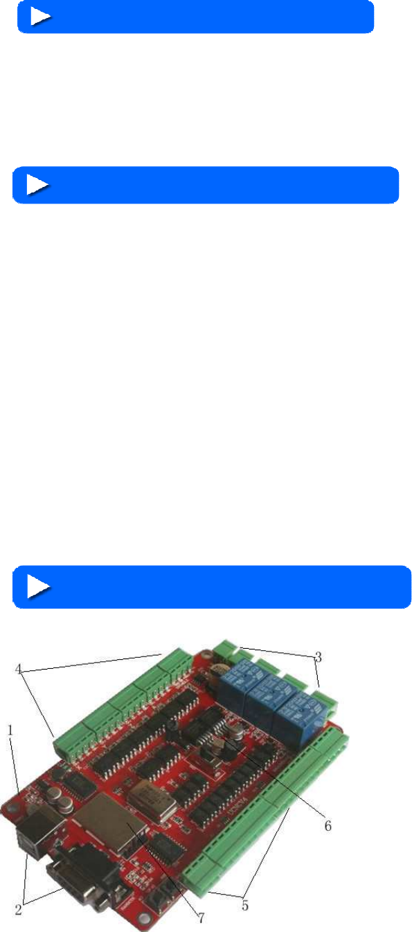
1.3 Production appearance and size
1. After the revision,V4 version using the red PCB
board, PCB size is 135.3*82.5mm.;
2. The front of the narrow edge placed with USB
communication interface and DB9 hand control interface for
the convenience of customers drawn from the case panel
directly;
3. The back-end of narrow edge is power input and
output interface and 3 relay output interface; relay is strong
interference source, relay away from the design of main
control chip, it is conducive to the stability of the board;
4. One of the two wide sides is stepper motor and
principal axiscontrol signal output;
5. The another side of two wide sides is the emergency
stop, manual speed input, limiting input interface; one side
Changzhou RATTM Motor Co.,Ltd
Changzhou RATTM Motor Co.,Ltd Email:sale1@rattmmotor.com Email:sale2@rattmmotor.com MSN:ali900111342
Skype:tonyswj119; rattm.motor http://www.aliexpress.com/store/704350 http:// http://www.aliexpress.com/store/907217
for the input, another side output connection mode is simple and convenient;
6. 5V and 12V power module compact independence, security, stability;
7. External ensure the stability of the system work effectively with crystal active and main control chip shield;
8. The software is USBCNC,not mach3,pls note!
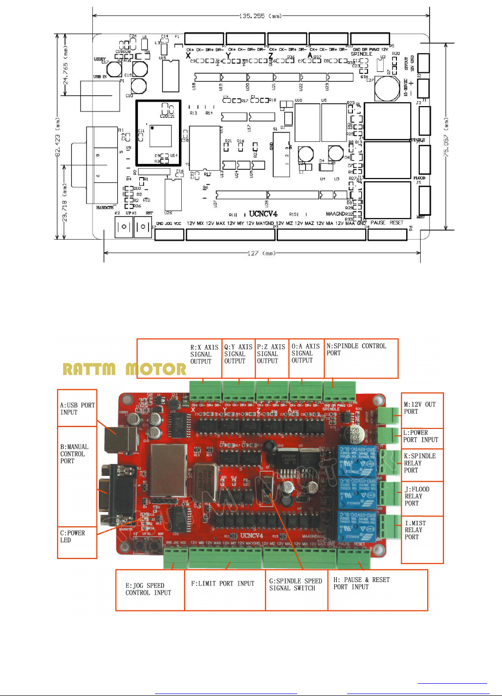
Figure 1-1. Product outline dimension drawing
As Figure 1-1shown, outline dimension is 135.3*82.5mm, product positioning hole installment dimension is
127*75mm
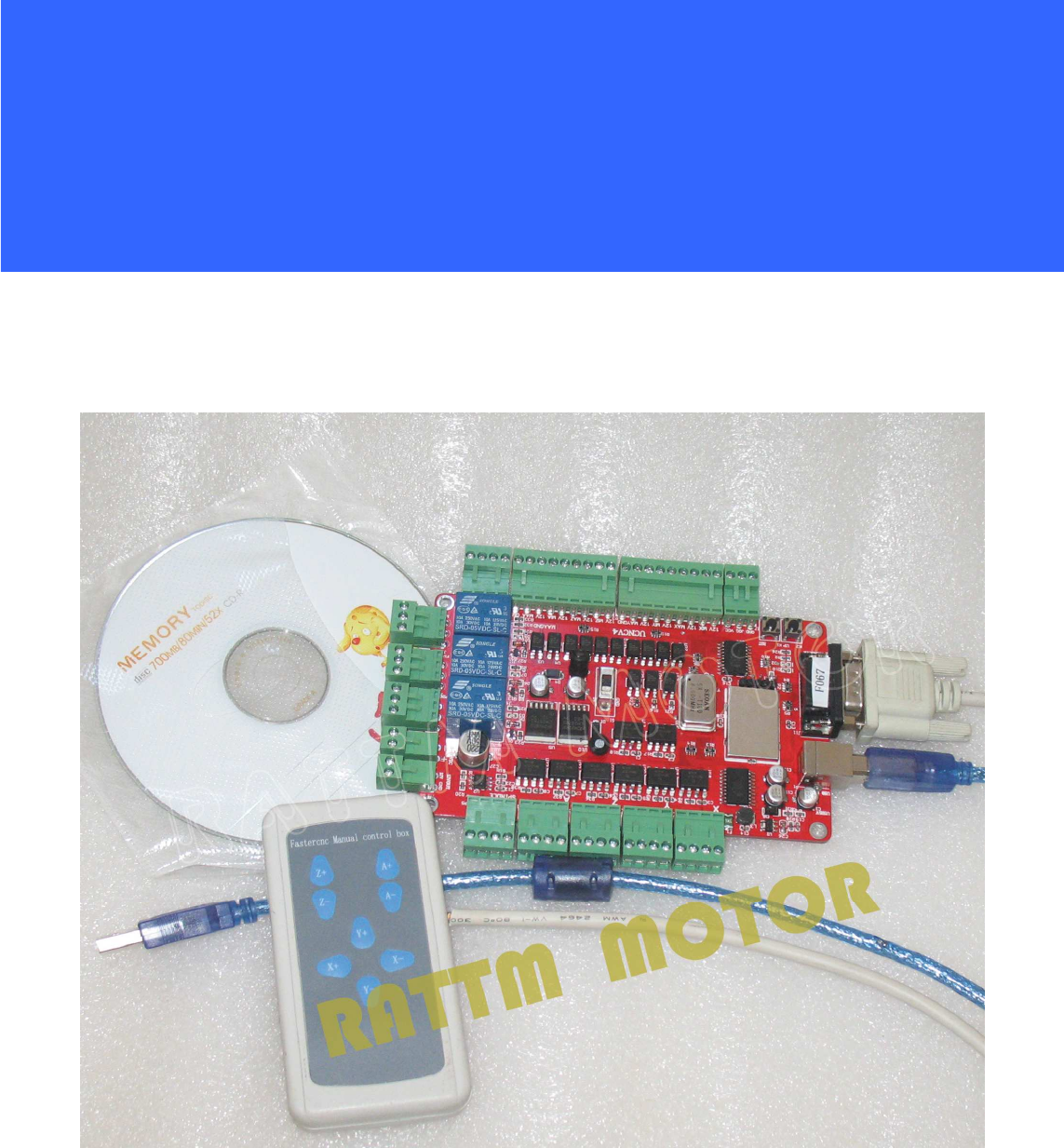
Figure1-2. the overall appearance picture
Changzhou RATTM Motor Co.,Ltd
Changzhou RATTM Motor Co.,Ltd Email:sale1@rattmmotor.com Email:sale2@rattmmotor.com MSN:ali900111342
Skype:tonyswj119; rattm.motor http://www.aliexpress.com/store/704350 http:// http://www.aliexpress.com/store/907217
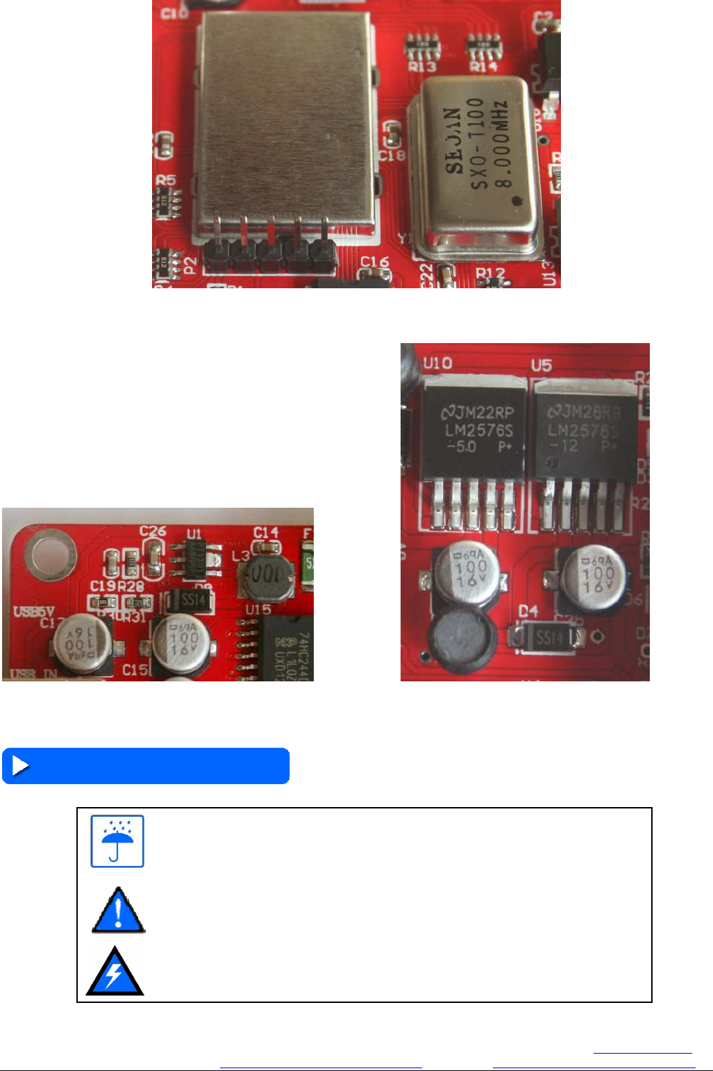
Figure 1-3. features 1 main control chip
Figure 1-4. features 2 stable power supply system Figure 1-5. features 3 double regulated power supply
1.4 Note and Warning
No rain,the board is high performance precision equipment,rain can cause short circuit
Cautions warn, please strictly in accordance with the documentation for installation
Risk High-pressure, the board away from high voltage
Changzhou RATTM Motor Co.,Ltd
Changzhou RATTM Motor Co.,Ltd Email:sale1@rattmmotor.com Email:sale2@rattmmotor.com MSN:ali900111342
Skype:tonyswj119; rattm.motor http://www.aliexpress.com/store/704350 http:// http://www.aliexpress.com/store/907217
2. Detailed functional introduction
2.1 electrical parameters
A. Card input voltage: 15~36V;
B. Limit port working voltage: 12V;
C. Stepper motor control signal output voltage: 5V;
D. External power supply voltage: 12V;
Note: marked 15~36VDC is input interface, marked 12V is
output interface, can not wiring wrong.
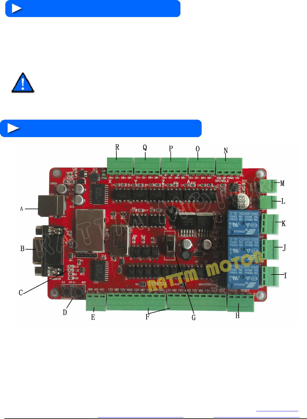
2. 2 Function and definition of each module
Figure2-1 features 3 double regulated power supply
A) USB interface, connect to the computer USB port through this interface,you can use the software usbcnc to
control this board, this USB interface is the square B interface,please use USB2.0 connection cable which with shielding
and magnetic and not to exceed 2 meters in length.
B) Hand control box interface, external hand control box can use this interface to access the system, the interface is
standard DB9 form, its definition as shown in the following table.
Changzhou RATTM Motor Co.,Ltd
Changzhou RATTM Motor Co.,Ltd Email:sale1@rattmmotor.com Email:sale2@rattmmotor.com MSN:ali900111342
Skype:tonyswj119; rattm.motor http://www.aliexpress.com/store/704350 http:// http://www.aliexpress.com/store/907217
Table 4-1 Hand control interface definition
Interface serial number
1 2 3 4 5
Interface definition Common port
A axis corotation
Z axis down
Y axis forward
X axis left move
Interface serial number
6 7 8 9
Interface definition A axis corotation
Z axis up Y axis back X axis right move
C) Power indicator, as shown in figure the above D10 indicator is the front-end USB power indicator, this light lit
up after USB port connection with computer , D2 in below is the back -end power indicator light, this light also will lit
up when board card work power access with it.
D) Board card firmware upgrade button UP and reset button RST, firmware has been updated, so upgrade button
dont need to use, reset button be used when need to restart due to the board fault.
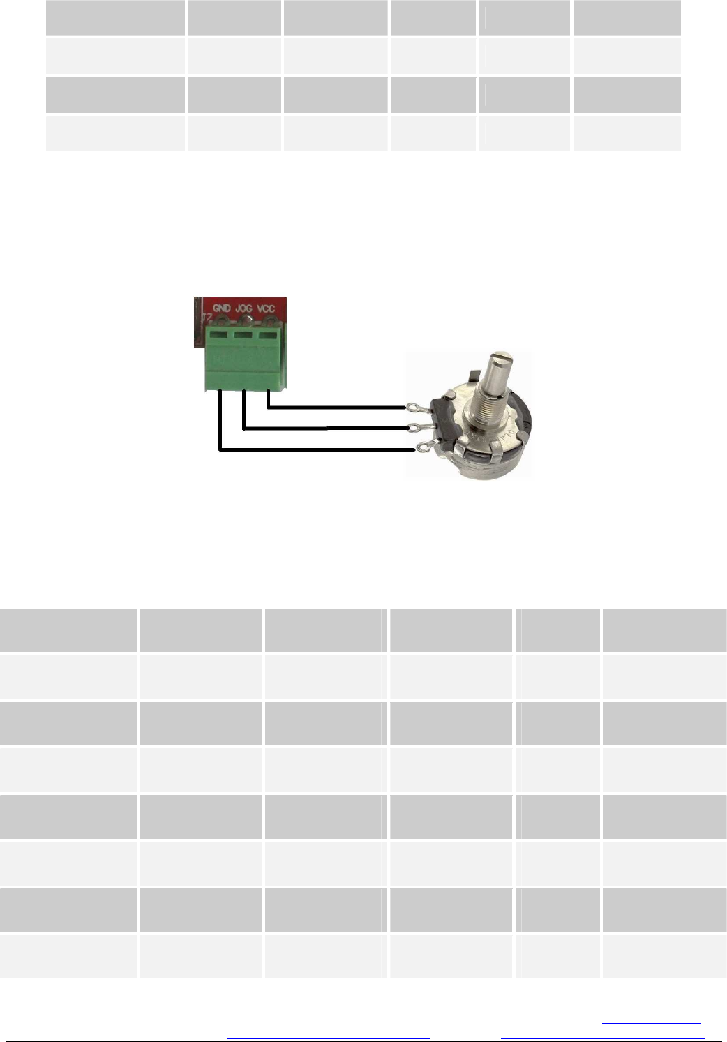
E) Manual speed control interface,wiring connection mode as shown in the following figure .
Figure 2-2 Manual speed control interface connection mode
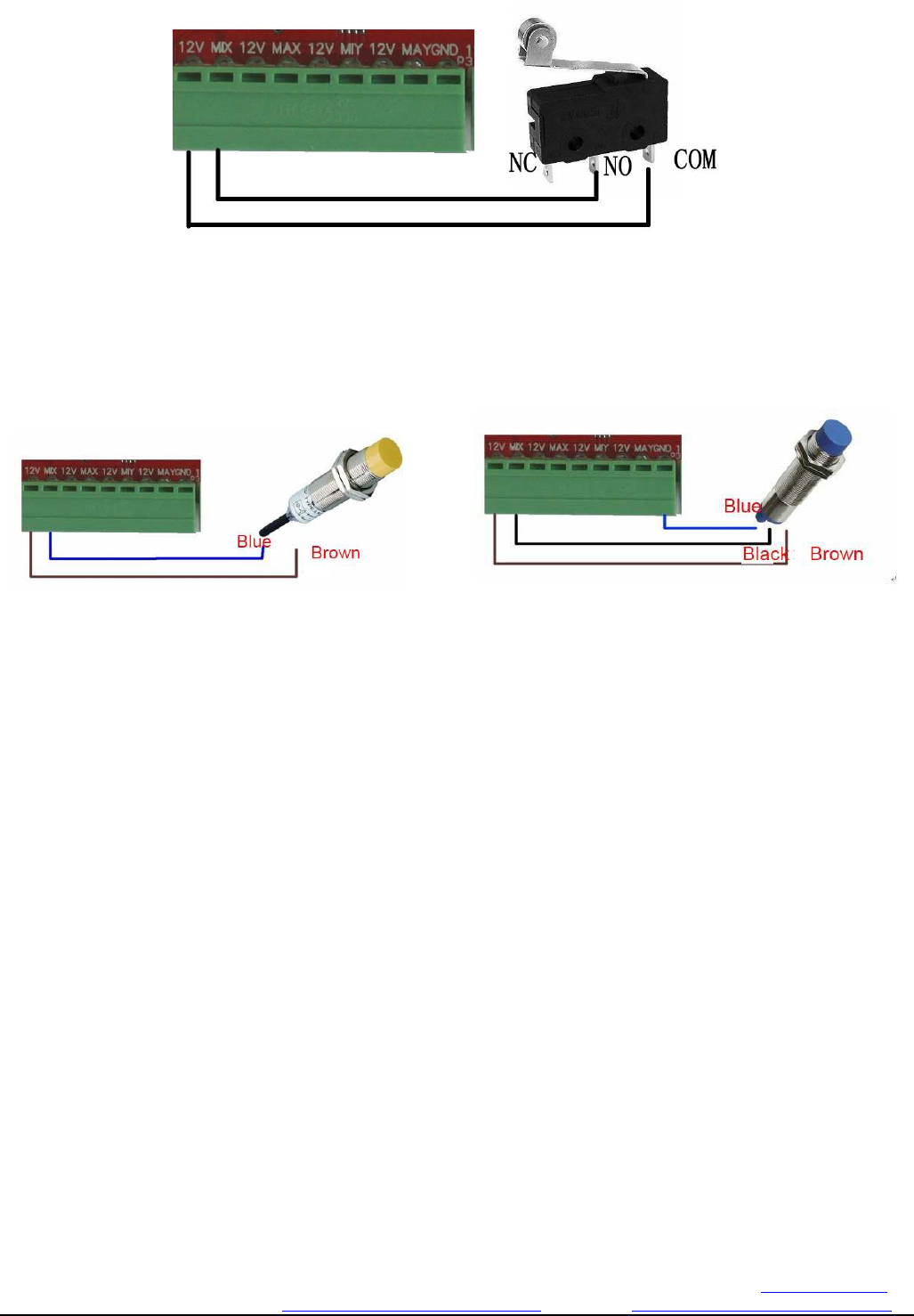
F) Limit input interface. Limit interface definitions are listed in the following table
Table 4-2 Limit interface definition
Interface serial number
12V MIX 12V MAX 12V
Interface definition Switch common port
X lower limit Switch common port
X upper limit
Switch common port
Interface serial number
MIY 12V MAY GND
Interface definition Y lower limit Switch common port
Y upper limit GND
Interface serial number
12V MIZ 12V MAZ 12V
Interface definition Switch common port
Z lower limit Switch common port
Z upper limit
Switch common port
Interface serial number
MIA 12V MAA GND
Interface definition A lower limit Switch common port
A upper limit GND
Changzhou RATTM Motor Co.,Ltd
Changzhou RATTM Motor Co.,Ltd Email:sale1@rattmmotor.com Email:sale2@rattmmotor.com MSN:ali900111342
Skype:tonyswj119; rattm.motor http://www.aliexpress.com/store/704350 http:// http://www.aliexpress.com/store/907217
Limit switch connection as shown in figure 1-8~ figure 1-10
Figure 2-3. Common microswitch connection method
Figure 2-4. 2 wire inductive proximity switch connection Figure 2-5. 3 wire inductive proximity switch connection
G) Spindle control selector switch, as shown in Figure 1-6, the switch shift up to the S1 position for the spindle
speed control ; switching switch position On below for output control MIST relay .
H) External pause and reset interface; the 2 feet marked PAUSE connect suspend switch, 2 feet marked RESET
connection reset switch.
I) Software MIST control relay output, software settings output marked 3, defined from top to bottom, 3 feet is NC,
NO, COM.
J) Software FLOOD control relay output ,output marked 2 in the software settings , defined from top to bottom, 3
feet is NC, NO, COM.
K) Software SPINDLE control relay output , output marked 1 in the software settings , defined from top to
bottom, 3 feet is NC, NO, COM.
L) Board working power input, levels above negative below as the board signed, please pay attention to input
DC 15~36V, overvoltage or reverse connection will damage the board.
M) 12V output interface. as the board marked, GND is -, 12V is +.
N) Spindle control output interface: definitions turn for GND DIR PWM2 12V, respectively is ground,direction
signal output, spindle 0~10V speed control signal output, 12V output.
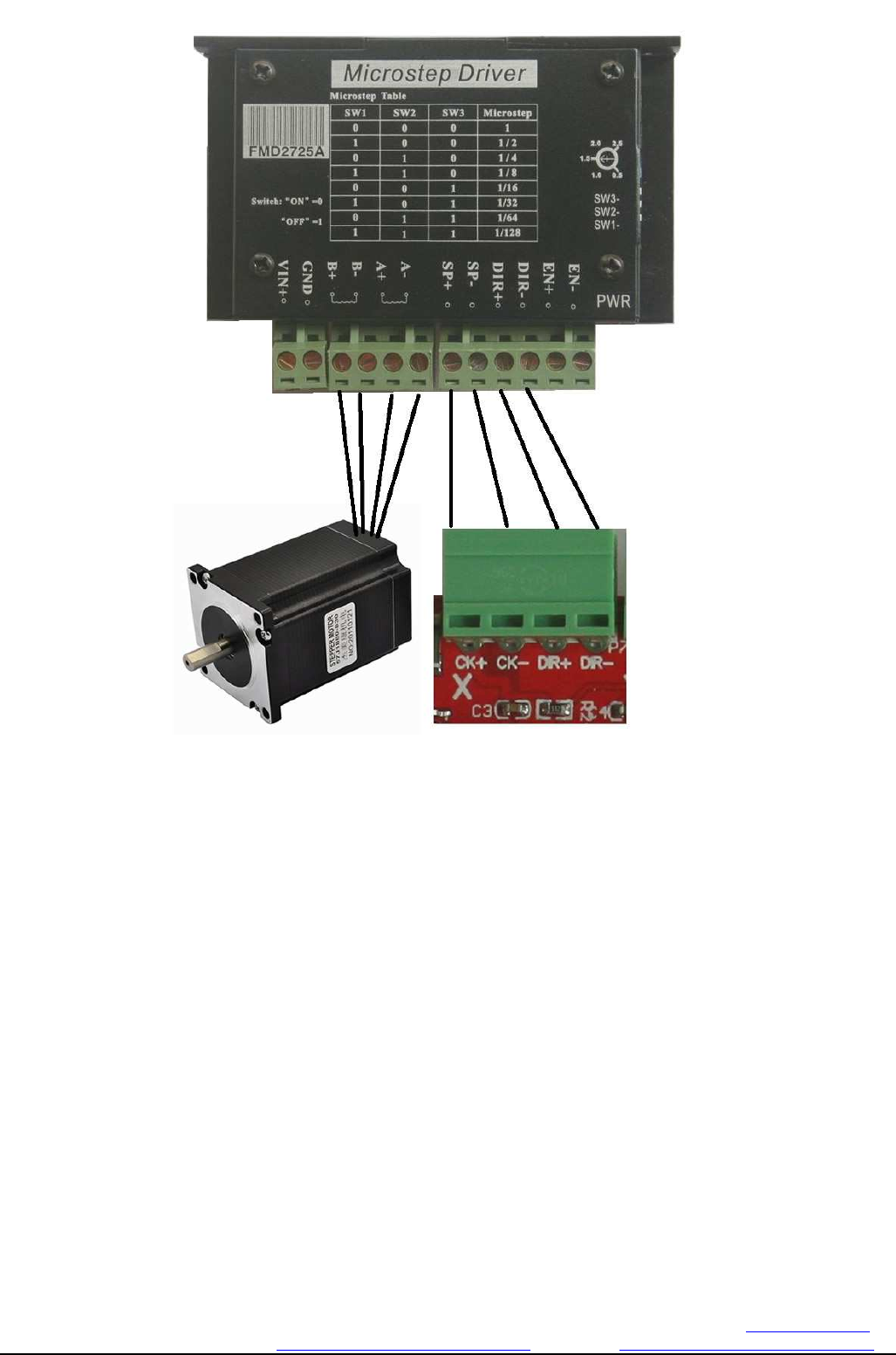
O) A axis stepper motor control signal output, the definition is:CK+\CK-\DIR+\DIR-,respectively is impulsion
positive, impulsion negative, direction positive, direction negative, the board using common anode connection method,
so CK+ and DIR+ linked together to contact to the 5V on the board, this board does not support the common cathode
connection method, the specific wiring methods refer to figure 1-11. This board does not contain the enable control, now
most of driver in the market should not connect with the EN signal and directly work regularly by default .
Changzhou RATTM Motor Co.,Ltd
Changzhou RATTM Motor Co.,Ltd Email:sale1@rattmmotor.com Email:sale2@rattmmotor.com MSN:ali900111342
Skype:tonyswj119; rattm.motor http://www.aliexpress.com/store/704350 http:// http://www.aliexpress.com/store/907217
Figure2-6 connection methods with stepper motor drives
P) Z axis stepper motor control signal output, the definition is CK+\CK-\DIR+\DIR-, respectively for pulse positive,
pulse negative, direction positive , direction negative, the board using anode common connection method, so CK+ and
DIR+ linked together connect to the 5V on the board,this board does not support the common cathode connection
method.
Q) Y axis stepper motor control signal output, the definition is CK+\CK-\DIR+\DIR-,respectively for pulse positive,
pulse negative, direction positive , direction negative, the board using anode common connection method, so CK+ and
DIR+ linked together connect to the 5V on the board,this board does not support the common cathode connection
method.
R)X axis stepper motor control signal output, the definition is CK+\CK-\DIR+\DIR-,respectively for pulse positive,
pulse negative, direction positive , direction negative, the board using anode common connection method, so CK+ and
DIR+ linked together connect to the 5V on the board,this board does not support the common cathode connection
method.
Changzhou RATTM MOTOR Co.,Ltd
Changzhou RATTM Motor Co.,Ltd Email:sale1@rattmmotor.com Email:sale2@rattmmotor.com MSN:ali900111342
Skype:tonyswj119; rattm.motor http://www.aliexpress.com/store/704350 http:// http://www.aliexpress.com/store/907217
3.Software installation
3.1 DirectX Install
In real that install this softare is a little complex,because it developed by vc.net,and it need directx and .net
framework software package support,also be strict required for these 2 type software package version,so it is better use
our software to install which is in our CD,if meet the software package conflict or cant run the software after install
it,pls use a new system PC to install this software,pls remember this!
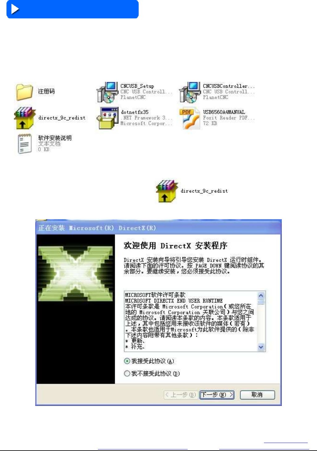
Our CD contain USBCNC software,driver,directx and net framework,user manual,software install guide and
register code.each controller match independent register code,so when you get pls safe keeping it.
Figure 3-1.
Above is CD detail
First install and run the directx_9c_redist
。
This software install is simple
Figure 3-2. DIRECTX 1 installation process
Changzhou RATTM MOTOR Co.,Ltd
Changzhou RATTM Motor Co.,Ltd Email:sale1@rattmmotor.com Email:sale2@rattmmotor.com MSN:ali900111342
Skype:tonyswj119; rattm.motor http://www.aliexpress.com/store/704350 http:// http://www.aliexpress.com/store/907217
Click accept and next step,
Figure 3-3. DIRECTX 1 installation process
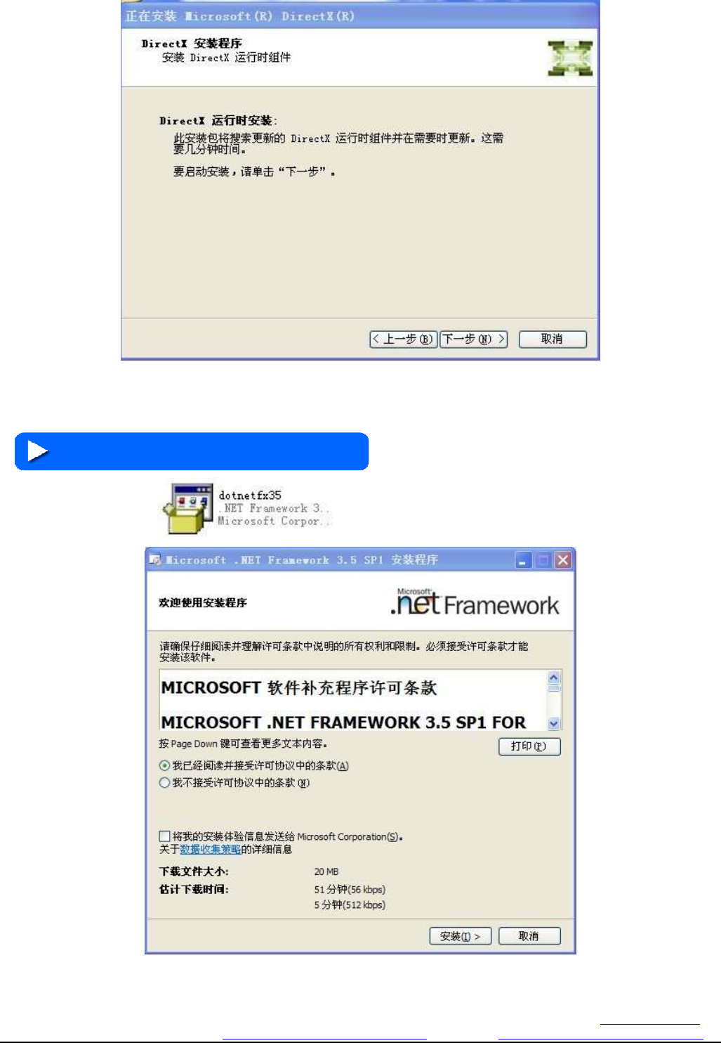
Continue to next step
3.2 NETFRAME3.5 installation
2: Run dotnetfx35 install net framework3.5sp1.
Figure 3-4. NETFRAME3.5 1 installation
Changzhou RATTM MOTOR Co.,Ltd
Changzhou RATTM Motor Co.,Ltd Email:sale1@rattmmotor.com Email:sale2@rattmmotor.com MSN:ali900111342
Skype:tonyswj119; rattm.motor http://www.aliexpress.com/store/704350 http:// http://www.aliexpress.com/store/907217
Select the accept then click install
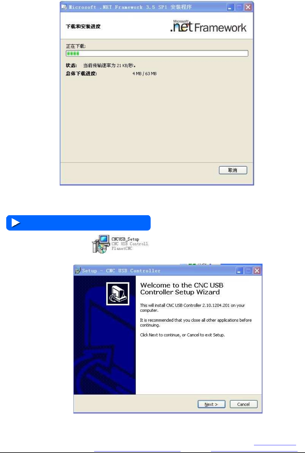
Figure 3-5. NETFRAME3.5 2 installation
Continue to click ok
3.3 Install USBCNC
3: Run CNCUSB_Setup install the main program
Figure 3-6. USBCNC installation step 1
Changzhou RATTM MOTOR Co.,Ltd
Changzhou RATTM Motor Co.,Ltd Email:sale1@rattmmotor.com Email:sale2@rattmmotor.com MSN:ali900111342
Skype:tonyswj119; rattm.motor http://www.aliexpress.com/store/704350 http:// http://www.aliexpress.com/store/907217
Clicknext
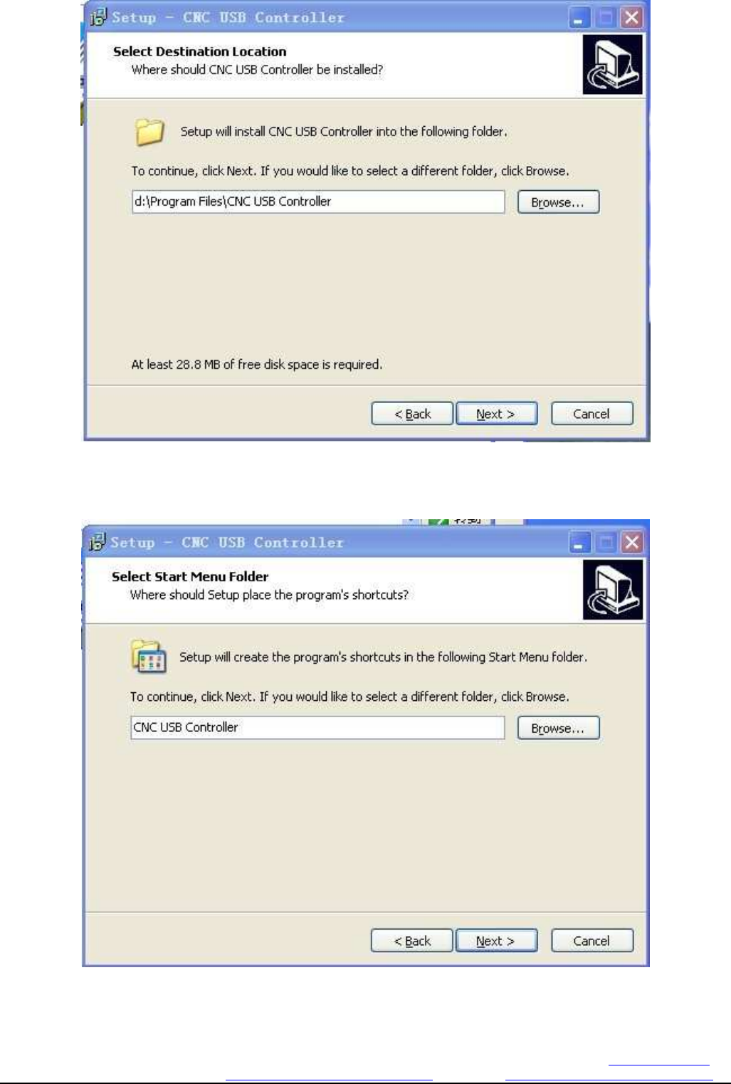
Figure 3-7. USBCNC installation step 2
Slect suitable install path,then next
Figure 3-8. USBCNC installation step 3
Changzhou RATTM MOTOR Co.,Ltd
Changzhou RATTM Motor Co.,Ltd Email:sale1@rattmmotor.com Email:sale2@rattmmotor.com MSN:ali900111342
Skype:tonyswj119; rattm.motor http://www.aliexpress.com/store/704350 http:// http://www.aliexpress.com/store/907217
next
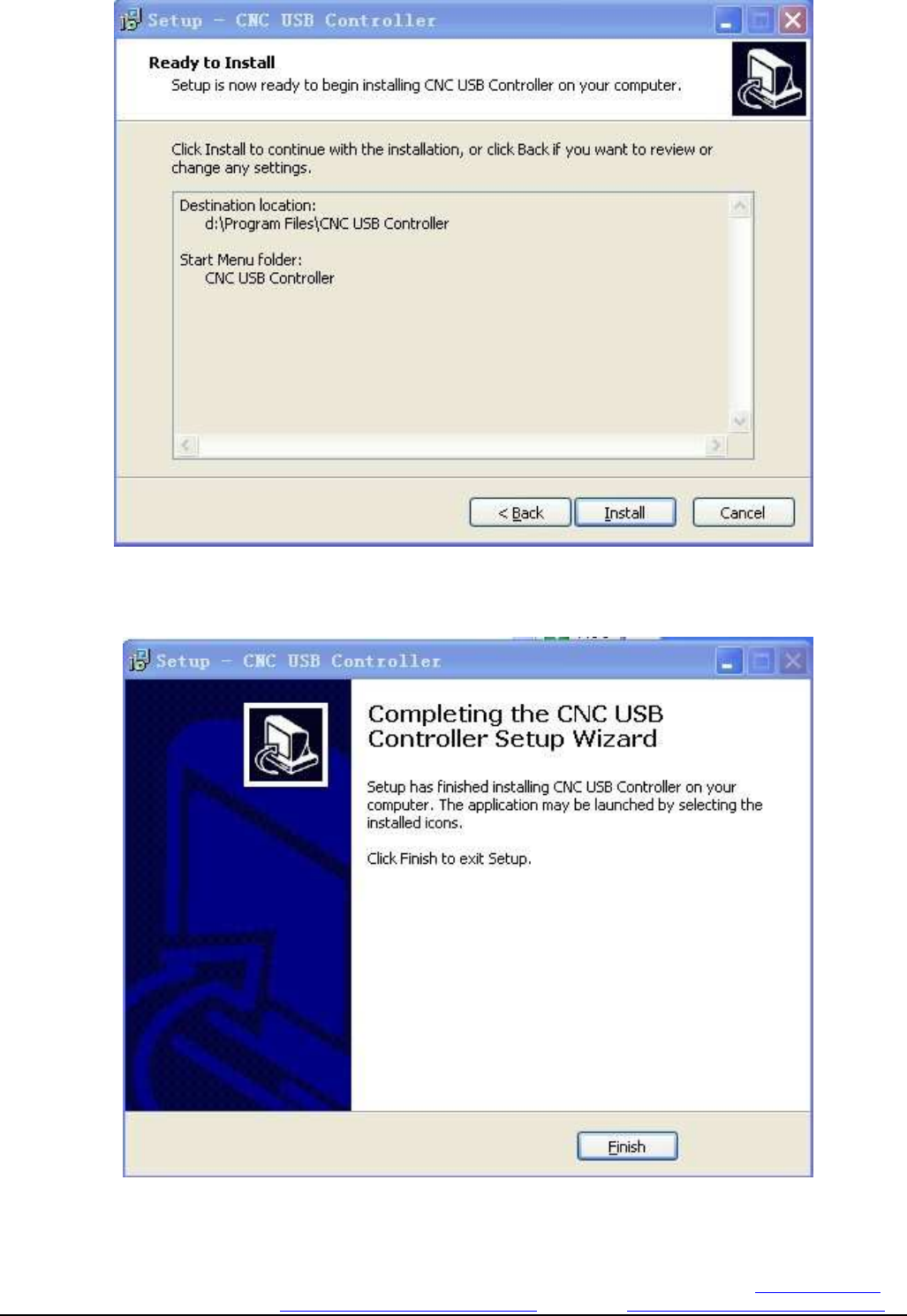
Figure 3-9. USBCNC installation step 4
Click INSTALL to begin
Figure 3-10. USBCNC installation step 5
The installation is complete
Changzhou RATTM MOTOR Co.,Ltd
Changzhou RATTM Motor Co.,Ltd Email:sale1@rattmmotor.com Email:sale2@rattmmotor.com MSN:ali900111342
Skype:tonyswj119; rattm.motor http://www.aliexpress.com/store/704350 http:// http://www.aliexpress.com/store/907217
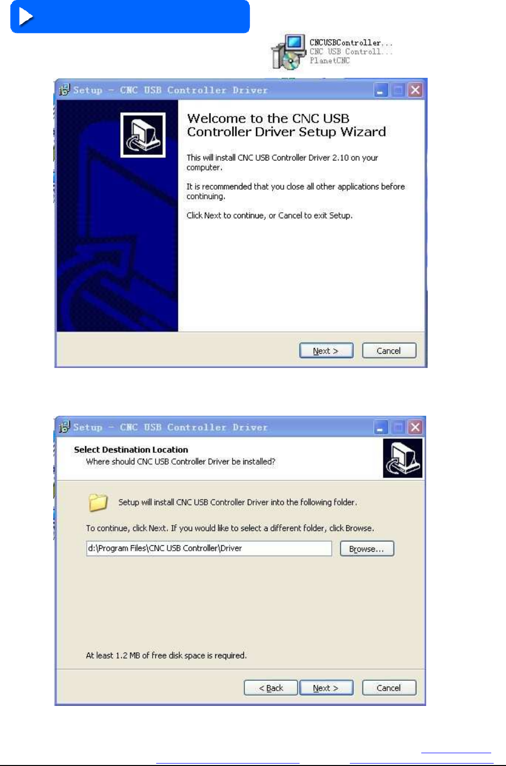
3.4 Install the USB driver
4: Intsall USB driver CNCUSBControllerDriver
Figure 3-11. the USB driver installation step 1
next
Figure 3-12. the USB driver installation step 2
Changzhou RATTM MOTOR Co.,Ltd
Changzhou RATTM Motor Co.,Ltd Email:sale1@rattmmotor.com Email:sale2@rattmmotor.com MSN:ali900111342
Skype:tonyswj119; rattm.motor http://www.aliexpress.com/store/704350 http:// http://www.aliexpress.com/store/907217
Select path,pls keep the same path with main program
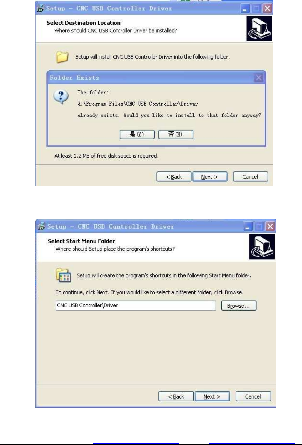
Figure 3-13. the USB driver installation step 3
Here I change to D disk,so see above and click Yes
Figure 3-14. the USB driver installation step 1
Changzhou RATTM MOTOR Co.,Ltd
Changzhou RATTM Motor Co.,Ltd Email:sale1@rattmmotor.com Email:sale2@rattmmotor.com MSN:ali900111342
Skype:tonyswj119; rattm.motor http://www.aliexpress.com/store/704350 http:// http://www.aliexpress.com/store/907217
next
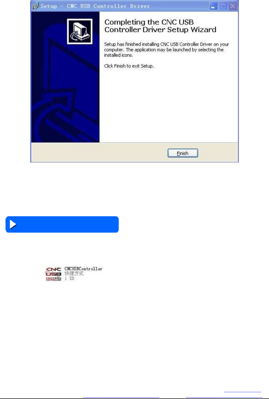
Figure 3-15. the USB driver installation step 1
Click finish
Now the software install work is finished
3.5 Software register
The register is important and if un-successful register,the software wont work,so pls be careful to follow our
guide.
1: After install the usbcnc,to find the usbcnc software,so I setup a shortcut for this software on table,double
click usbcnc enter it
Changzhou RATTM MOTOR Co.,Ltd
Changzhou RATTM Motor Co.,Ltd Email:sale1@rattmmotor.com Email:sale2@rattmmotor.com MSN:ali900111342
Skype:tonyswj119; rattm.motor http://www.aliexpress.com/store/704350 http:// http://www.aliexpress.com/store/907217
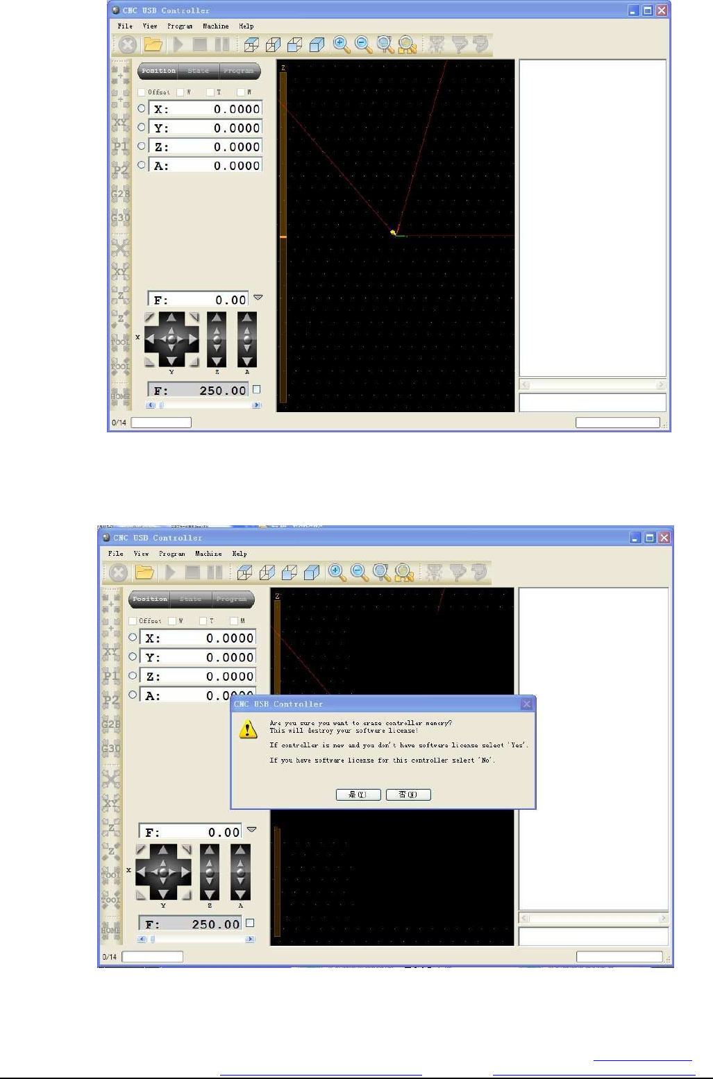
Figure 3-16. the main interface of software
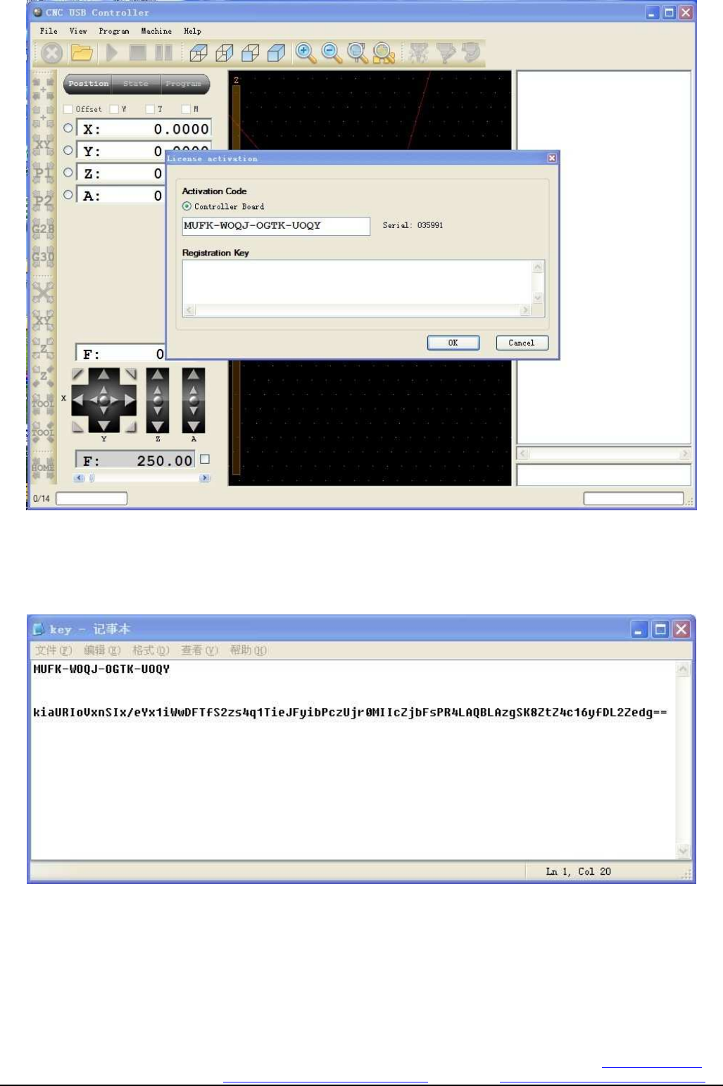
2: Connect USBCNC controller to the PC by usb cable(pls use back usb port 2.0 type),then will
display below
Figure 3-17. the interface by YES
ClickYes,then display below
Changzhou RATTM MOTOR Co.,Ltd
Changzhou RATTM Motor Co.,Ltd Email:sale1@rattmmotor.com Email:sale2@rattmmotor.com MSN:ali900111342
Skype:tonyswj119; rattm.motor http://www.aliexpress.com/store/704350 http:// http://www.aliexpress.com/store/907217
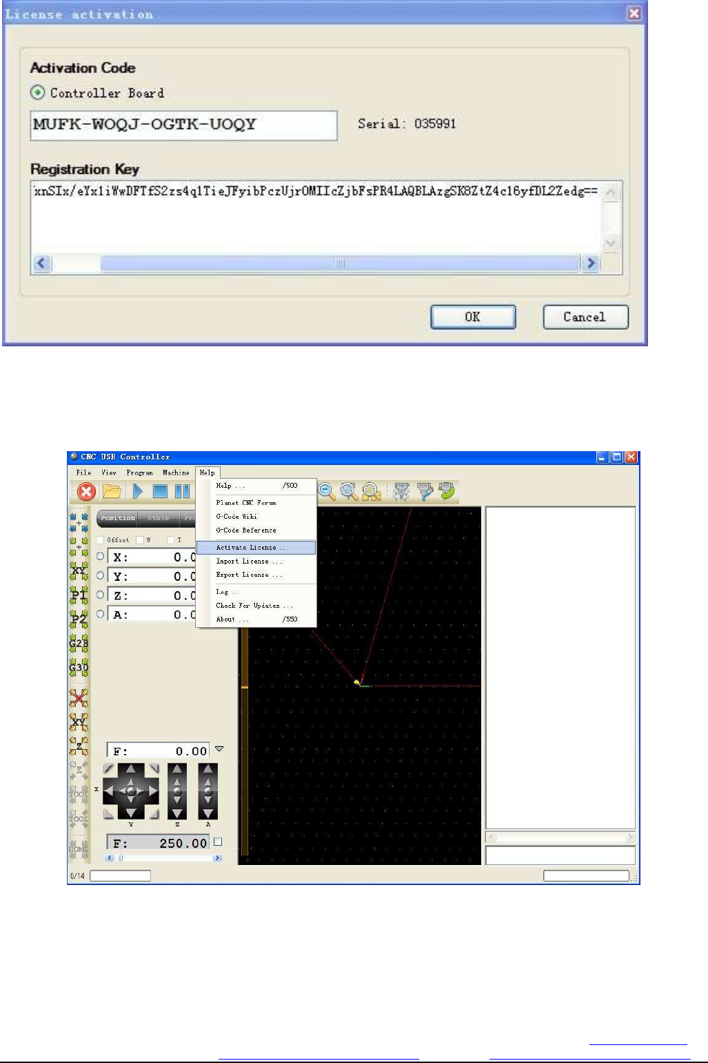
Figure 3-18. software registration interface
Here pls copy the register code(in the CD) to the registration key
Figure 3-19. the disc inside the key file
The Key file of CD see above,the first row character string pls check whether is same as in software,and the second
row is key,pls copy this key to registration key
Changzhou RATTM MOTOR Co.,Ltd
Changzhou RATTM Motor Co.,Ltd Email:sale1@rattmmotor.com Email:sale2@rattmmotor.com MSN:ali900111342
Skype:tonyswj119; rattm.motor http://www.aliexpress.com/store/704350 http:// http://www.aliexpress.com/store/907217
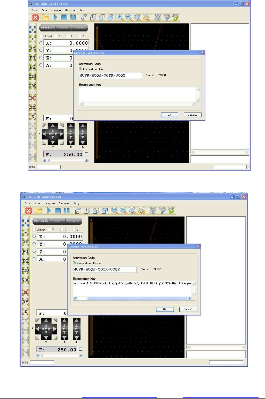
Figure 3-20. registration code copy to key bar
Click OK to confirm. Do not think that is over, there is a section, please read
The following figure 3-21. click the HELP menu in the activate license menu.
Click theactivate license submenu in the Help menu
Changzhou RATTM MOTOR Co.,Ltd
Changzhou RATTM Motor Co.,Ltd Email:sale1@rattmmotor.com Email:sale2@rattmmotor.com MSN:ali900111342
Skype:tonyswj119; rattm.motor http://www.aliexpress.com/store/704350 http:// http://www.aliexpress.com/store/907217
Will display the register code dialog box again,then copy the second row content of key file to this dialog box
ClickOK,so all register job is finished to start work
Changzhou RATTM MOTOR Co.,Ltd
Changzhou RATTM Motor Co.,Ltd Email:sale1@rattmmotor.com Email:sale2@rattmmotor.com MSN:ali900111342
Skype:tonyswj119; rattm.motor http://www.aliexpress.com/store/704350 http:// http://www.aliexpress.com/store/907217
4. Software used
4.1 Common settings
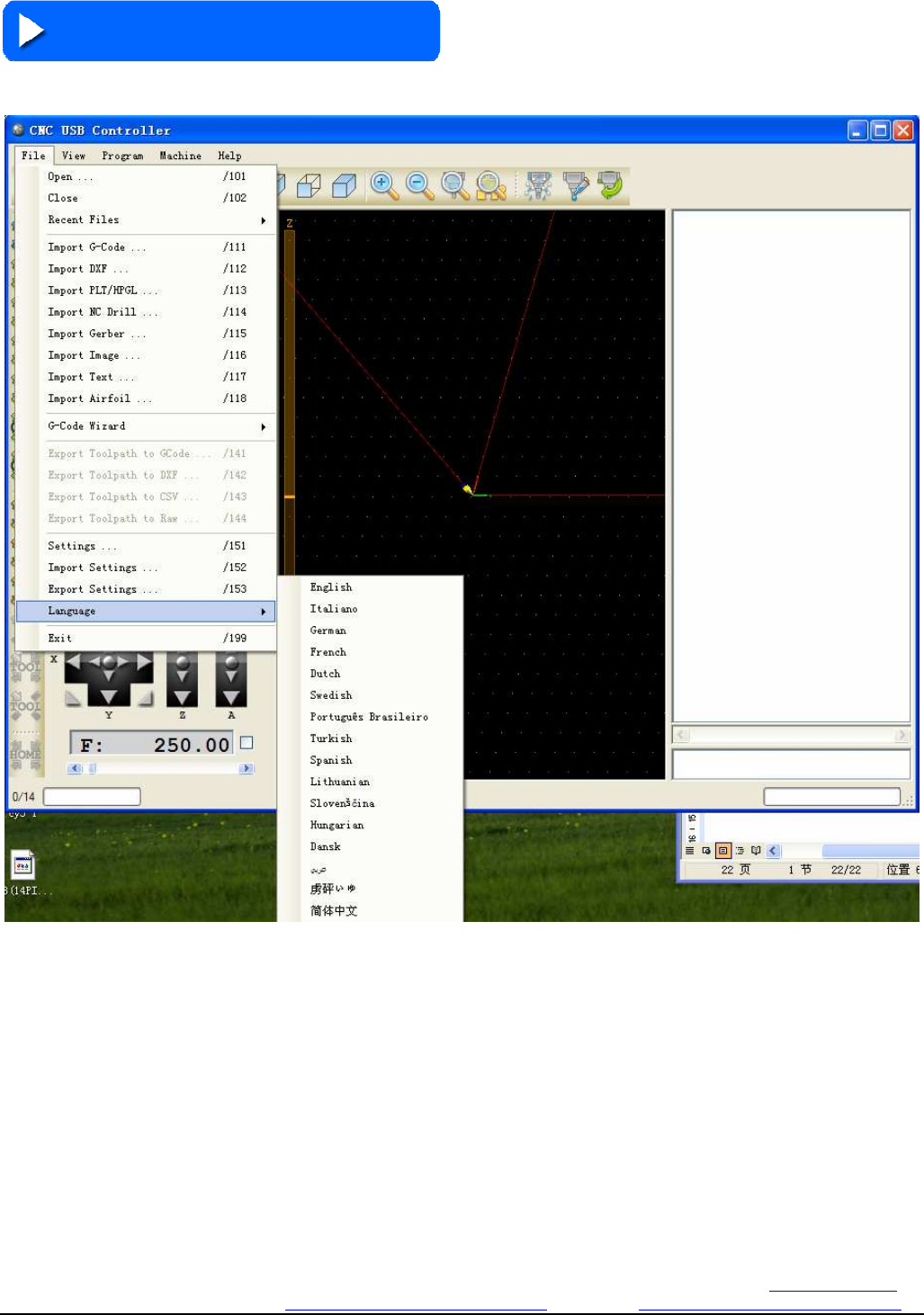
Software language setting
Click File Menus submenu Language,then chose your language
Changzhou RATTM MOTOR Co.,Ltd
Changzhou RATTM Motor Co.,Ltd Email:sale1@rattmmotor.com Email:sale2@rattmmotor.com MSN:ali900111342
Skype:tonyswj119; rattm.motor http://www.aliexpress.com/store/704350 http:// http://www.aliexpress.com/store/907217
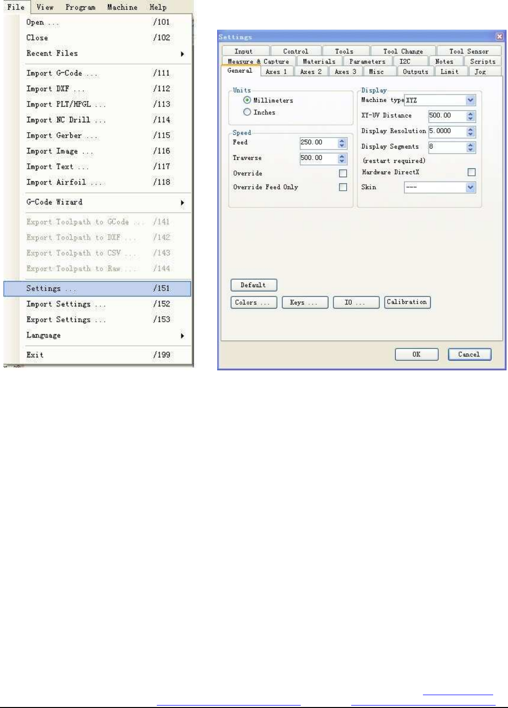
Software setting
Click submenu Settings of File,then can configuration the software
Figure 4-2. software integrated set entrance Figure 4-3. software interface
Enter the follow
As above display have 20 subpage,and we will description some usual setting as below
1. General:This is the most usual setting
l Units have metric and inch to chose
l Speed have feed(working speed) and traverse(un-load speed),and the below select override
and override feed only indicate the speed and the working speed is valid
l Display is display setting,the machine type have XYZ(normal cnc router) model,hot
wire(foam cutting machine)model,rotary(A axis)model and rotary ABC (ABC rotary)
model to chose
l XY-UV is distance setting,and then resolution setting and segment display setting
l Hardware DirectX to chose the whether you need use DX,if you need the flash effect will be
more better,Skin is the skin choice,these 2 choice need re-start the PC can be valid
l Default button is enable all setting to be the original,be careful for this select
l Colors is the forms color
l Keys is the shortcut key setting
Changzhou RATTM MOTOR Co.,Ltd
Changzhou RATTM Motor Co.,Ltd Email:sale1@rattmmotor.com Email:sale2@rattmmotor.com MSN:ali900111342
Skype:tonyswj119; rattm.motor http://www.aliexpress.com/store/704350 http:// http://www.aliexpress.com/store/907217
l IO is the state observation
l Cabibration is all axis calibration
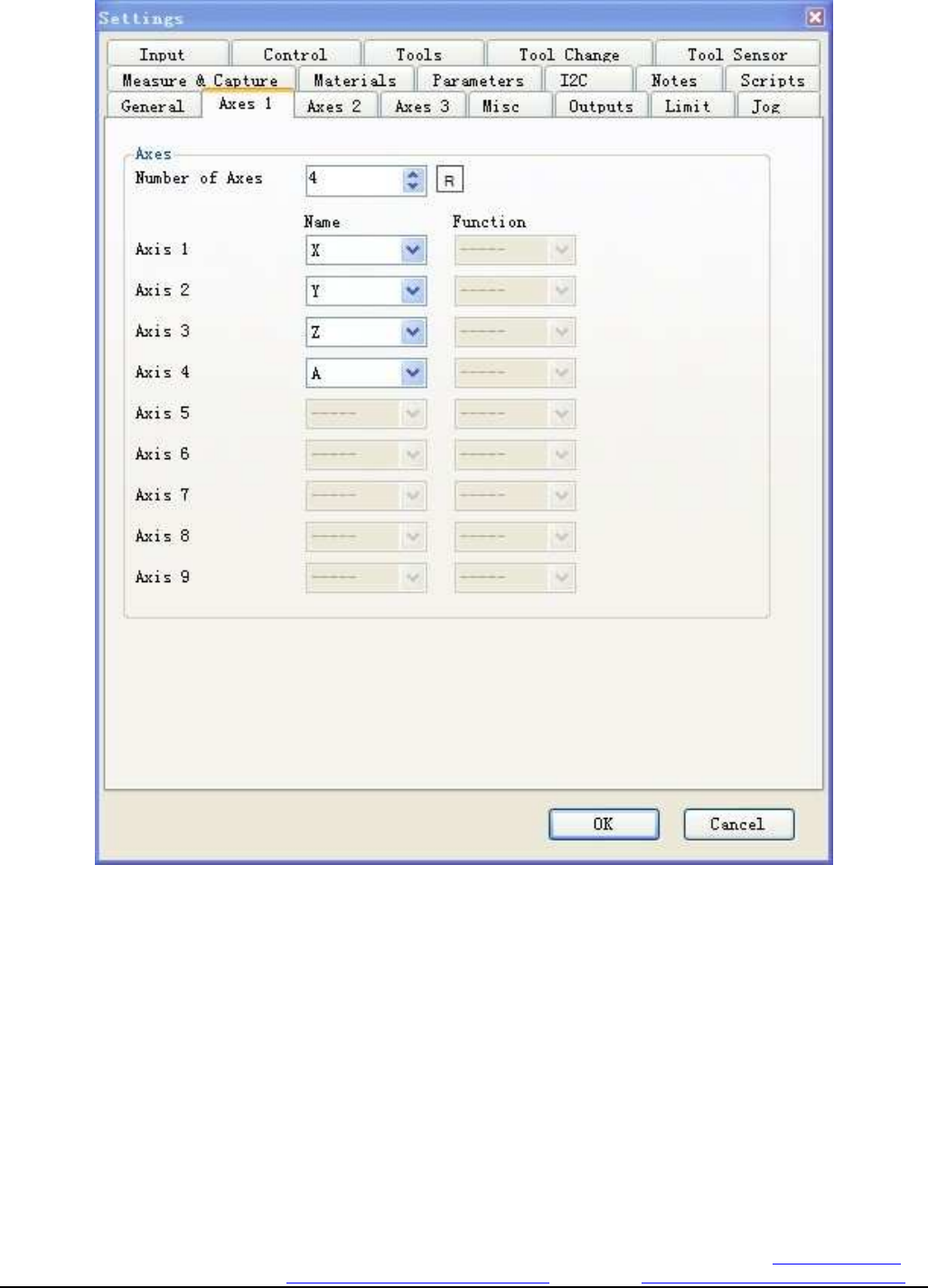
2. AXES1 is the axis number and name setting
Figure 4-4.. AXES1 is the number of the shaft and shaft name selection
Figure number of axes is the number of selected axis, behind the R button for each axis automatic
distribution definition name. The following items are manually assigned each axis definition name.
Changzhou RATTM MOTOR Co.,Ltd
Changzhou RATTM Motor Co.,Ltd Email:sale1@rattmmotor.com Email:sale2@rattmmotor.com MSN:ali900111342
Skype:tonyswj119; rattm.motor http://www.aliexpress.com/store/704350 http:// http://www.aliexpress.com/store/907217
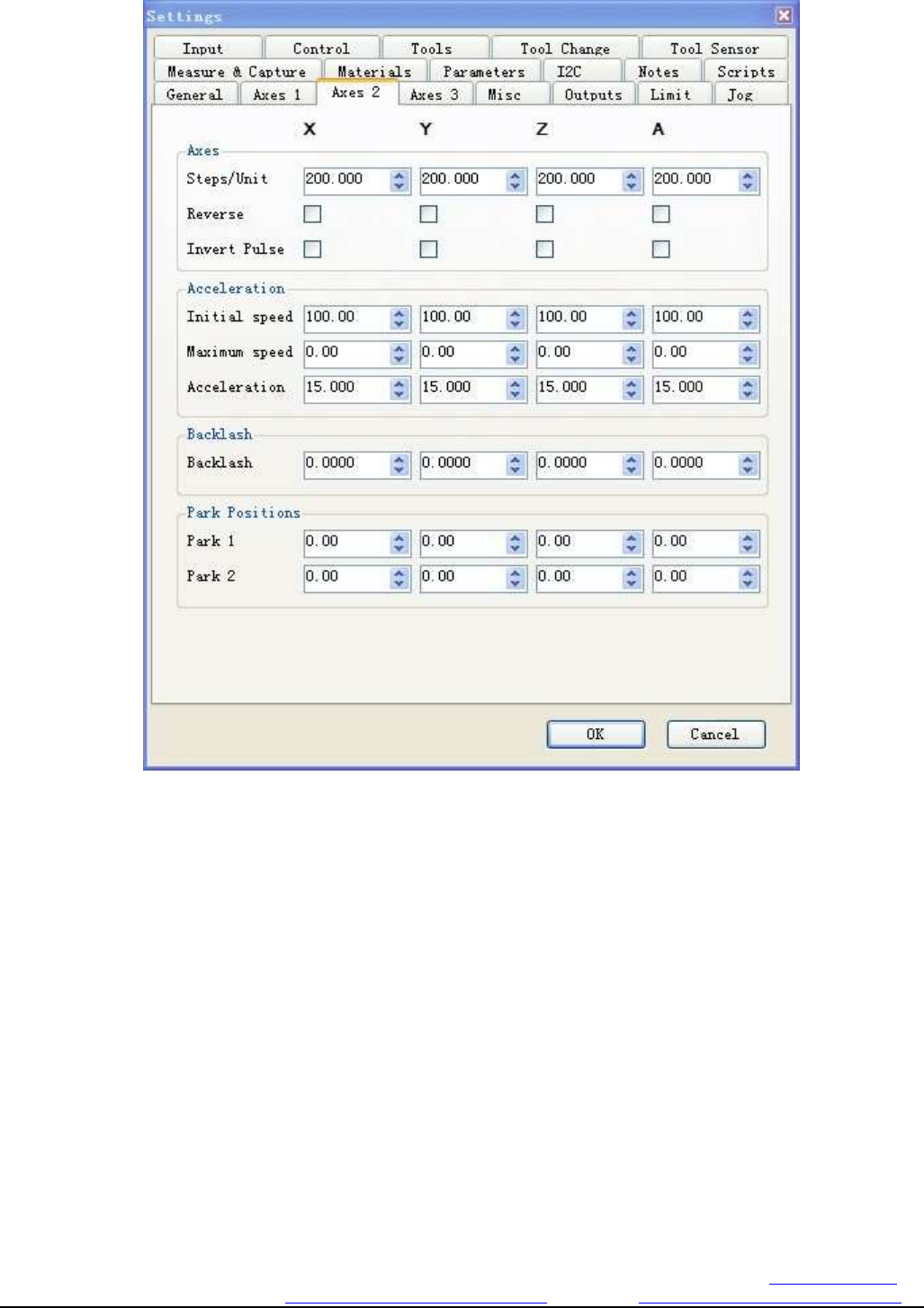
3.AXES2 is the step, speed,acceleration speed,and backlash etc setting
Figure 4-5. axis pulse equivalent, velocity, acceleration, back to poor settings
l Step/unit is step per setting,means when move 1mm need the pulse number,the reserse is the
direction choice,when you find the movement is oppositely,you can chose this,invert pluse is pluse
direction choice.
l initial speed is the start speed,Maximum speed is the max speed,if 0 means the max speed is
according to the system max speed
l Backlash setting need according to the real mechanical structure
l Park positions is cutter tools position choice,if need automatic tool changing need chose this
Changzhou RATTM MOTOR Co.,Ltd
Changzhou RATTM Motor Co.,Ltd Email:sale1@rattmmotor.com Email:sale2@rattmmotor.com MSN:ali900111342
Skype:tonyswj119; rattm.motor http://www.aliexpress.com/store/704350 http:// http://www.aliexpress.com/store/907217
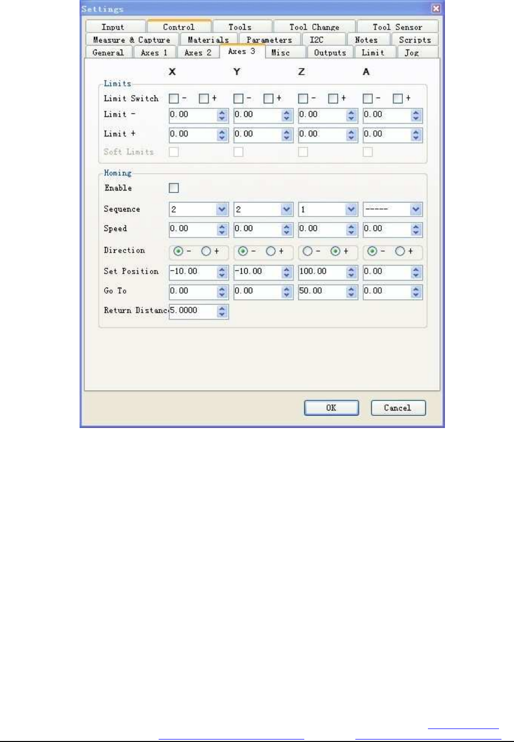
4.AXES3 is for software limit and Go to zero setting
Figure 4-6. software limit and back to the origin set
l - and + of limit switch is soft limit setting,and Limit and Limit+ is upper limit and lower
limit setting
l enable it is valid,Sequence is the sequence of all axis go to zero,speed is the speed
setting,direction is go to zero direction setting,set position is setting the current position,Go to
is setting the position want to move,and Return distance is setting for back distance
Changzhou RATTM MOTOR Co.,Ltd
Changzhou RATTM Motor Co.,Ltd Email:sale1@rattmmotor.com Email:sale2@rattmmotor.com MSN:ali900111342
Skype:tonyswj119; rattm.motor http://www.aliexpress.com/store/704350 http:// http://www.aliexpress.com/store/907217
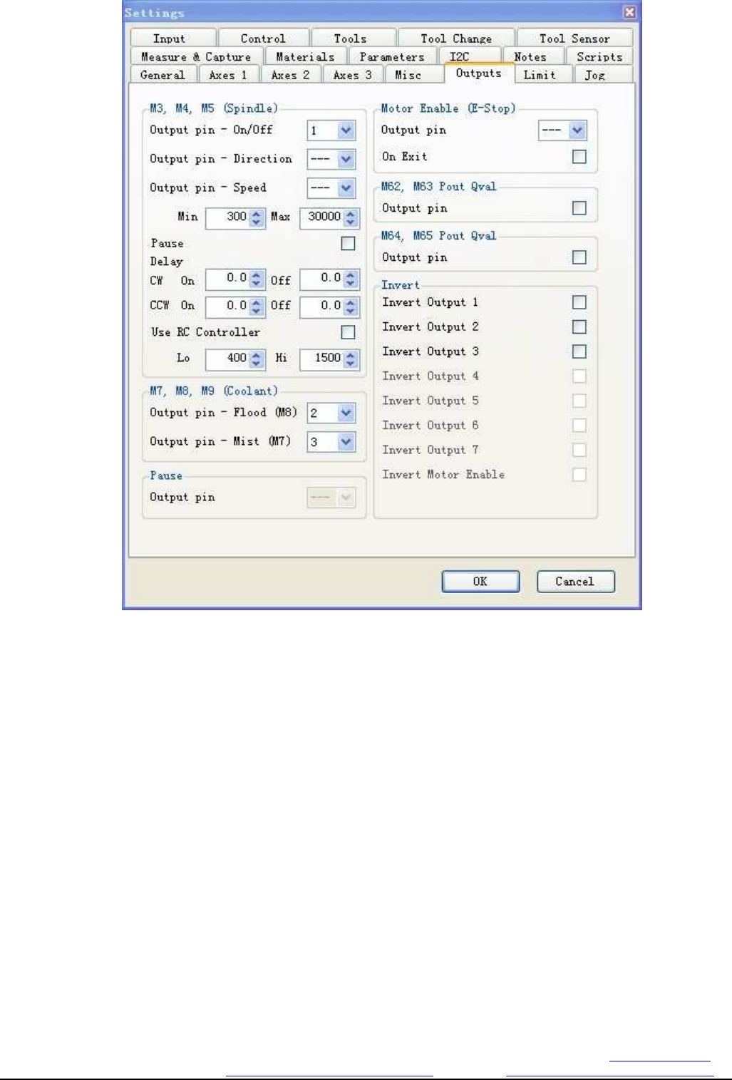
5.OUTPUT is for 3pcs relay ouput setting
Figure 4-7. 3 relay outputs and the main control output settings
This board have 3 way relay output,and it could be setting in this column
l M3,M4,M5 is spindle on/off,direction and speed,here can setting min and max value for the pluse to
control the spindle speed
Delay can setting the delay time for the CW and CCW rotary,if the spindle inertia is big,it is should
be setting delay
User rc controller to chose whether use RC controller
l M7M8M9 is for water cooling or mist cooling,the flood default is relay2,and the mist defult is
relay3
l Invert is for relay ouput convert
Changzhou RATTM MOTOR Co.,Ltd
Changzhou RATTM Motor Co.,Ltd Email:sale1@rattmmotor.com Email:sale2@rattmmotor.com MSN:ali900111342
Skype:tonyswj119; rattm.motor http://www.aliexpress.com/store/704350 http:// http://www.aliexpress.com/store/907217
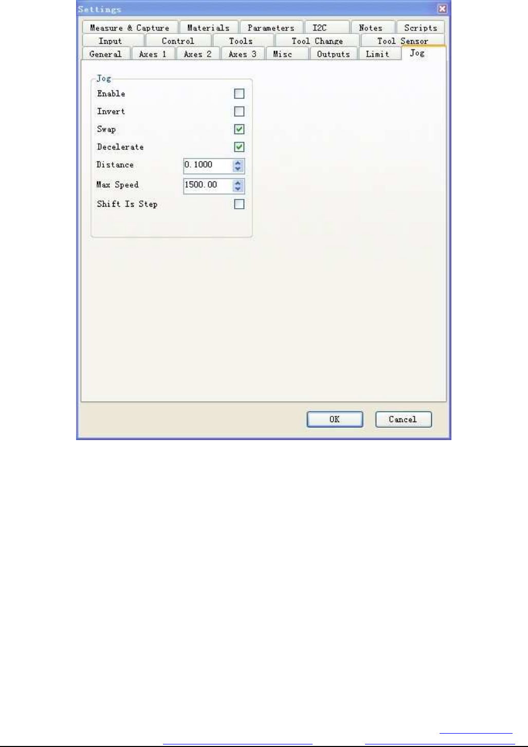
6. Jog Manual Input
Figure 4-8. Jog manual input settings
Enable is for chose connect external manual control,our cnc board have this function,so pls chose it
Invert is electrical level convert,this product no need chose
Swap default chose
decelerateis whether need reduce the speed before stop,need chose it
distance is step distance,it is according to your required
max speed is the speed setting。
Shift is step is single step speed setting
The usual setting is all description,and then can control the cnc machine now
Changzhou RATTM MOTOR Co.,Ltd
Changzhou RATTM Motor Co.,Ltd Email:sale1@rattmmotor.com Email:sale2@rattmmotor.com MSN:ali900111342
Skype:tonyswj119; rattm.motor http://www.aliexpress.com/store/704350 http:// http://www.aliexpress.com/store/907217
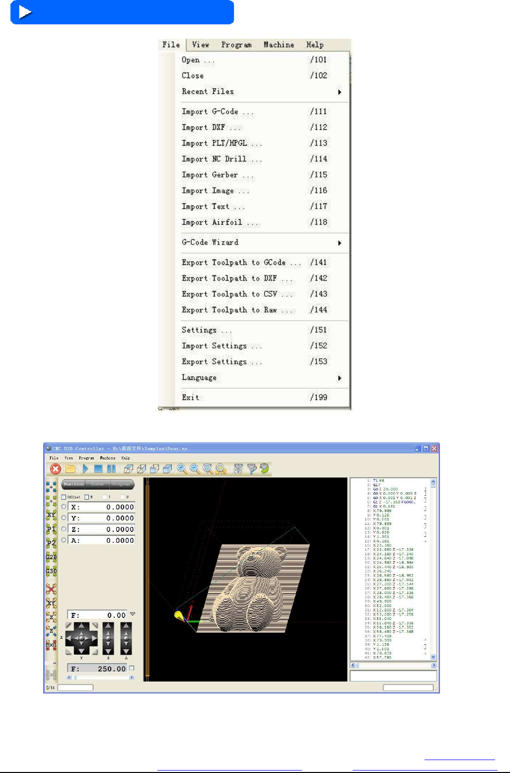
4.2 Software Usage
Clickfilemenu,can open the file directly or input the G-code WDXF etc file,here we open a little bear diagram
Changzhou RATTM MOTOR Co.,Ltd
Changzhou RATTM Motor Co.,Ltd Email:sale1@rattmmotor.com Email:sale2@rattmmotor.com MSN:ali900111342
Skype:tonyswj119; rattm.motor http://www.aliexpress.com/store/704350 http:// http://www.aliexpress.com/store/907217
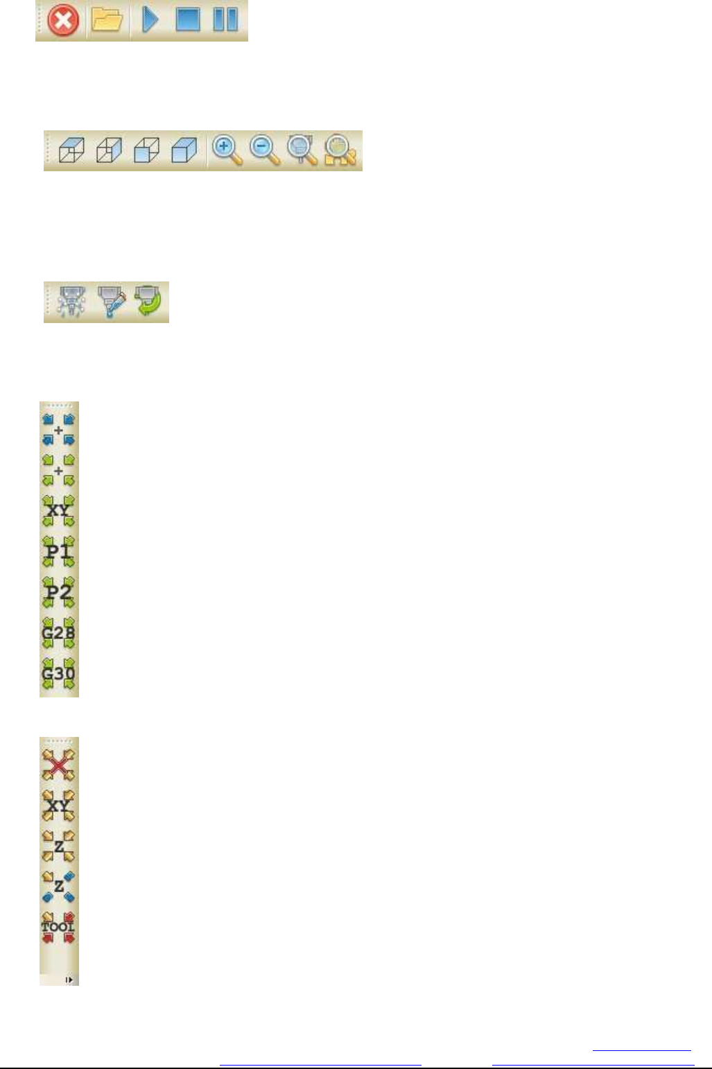
1、
This button is Reset,open,run,stop,suspend
2、
This button is top view,side view,front view, space diagram,amplification, minification,scale tool,
panoramagram
3、
This button is mist cooling,water cooling,spindle on/off
4、This button is control each axis speed move to the position,from top to bottom is clear zero,go to
zero,go to XY0,go to park1,go to park2,go to G28 and go to G30
5、This button is setting for offset,from top to bottom is clear zero,current position
setting XY axis offset,current position setting Z axis offset,Z offset height value and cutter
tool offset value
Changzhou RATTM MOTOR Co.,Ltd
Changzhou RATTM Motor Co.,Ltd Email:sale1@rattmmotor.com Email:sale2@rattmmotor.com MSN:ali900111342
Skype:tonyswj119; rattm.motor http://www.aliexpress.com/store/704350 http:// http://www.aliexpress.com/store/907217
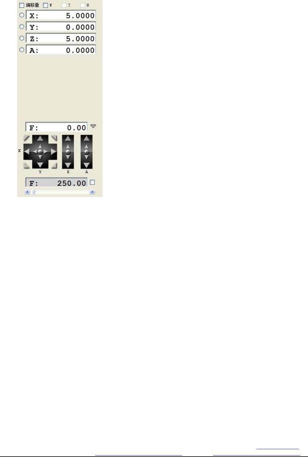
6、This button is 4 axis coordinate display.
Now you can input G-code,and setting the software,then run the machine.
