Manual For The 63890 8 Channel Surveillance DVR With 4 HD Cameras And Mobile Monitoring Capabilities
User Manual: Manual for the 63890 8 Channel Surveillance DVR with 4 HD Cameras and Mobile Monitoring Capabilities 8 Channel Surveillance DVR with 4 HD Cameras and Mobile Monitoring Capabilities
Open the PDF directly: View PDF ![]() .
.
Page Count: 40
Visit our website at: http://www.harborfreight.com
Email our technical support at: productsupport@harborfreight.com
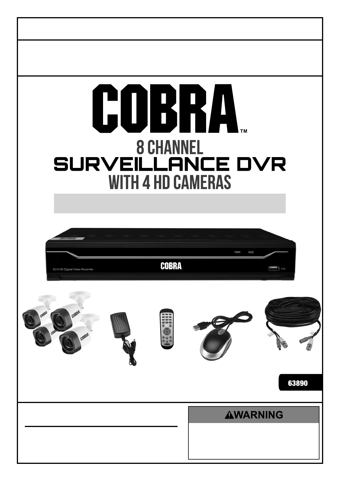
With Mobile Monitoring Capabilities
Owner’s Manual & Safety Instructions
Save This Manual Keep this manual for the safety warnings and precautions, assembly,
operating, inspection, maintenance and cleaning procedures. Write the product’s serial number in the
back of the manual near the assembly diagram (or month and year of purchase if product has no number).
Keep this manual and the receipt in a safe and dry place for future reference. 17g
When unpacking, make sure that the product is intact
and undamaged. If any parts are missing or broken,
please call 1-888-866-5797 as soon as possible.
Copyright© 2017 by Harbor Freight Tools®. All rights reserved.
No portion of this manual or any artwork contained herein may be reproduced in
any shape or form without the express written consent of Harbor Freight Tools.
Diagrams within this manual may not be drawn proportionally. Due to continuing
improvements, actual product may differ slightly from the product described herein.
Tools required for assembly an d se rv ic e may n ot b e in cl uded.
Read this material before using this product.
Failure to do so can result in serious injury.
SAVE THIS MANUAL.
Page 2 For technical questions, please call 1-888-866-5797. Item 63890
IMPORTANT SAFETY INFORMATION
Read all safety warnings and instructions.
Failure to follow the warnings and instructions may result in electric shock, fire and/or serious injury.
Save all warnings and instructions for future reference.
Installation Precautions
1. Check federal, state and local surveillance laws
before installing video
and/or audio surveillance equipment.
2. Install only according to these instructions.
Improper installation can create hazards.
3. Do not overreach when installing this product.
Keep proper footing and balance at all times.
This enables better control in unexpected situations.
4. Wear ANSI-approved safety goggles
during installation.
5. Keep installation area clean and well lit.
6. Keep children and bystanders out of
the area during installation.
7. Do not install when tired or when under the
influence of alcohol, drugs or medication.
Use Precautions
1. This product is not a toy. Do not allow
children to play with or near this item.
2. Use as intended only.
3. Do not modify.
4. Maintain product labels and nameplates.
These carry important safety information.
If unreadable or missing, contact
Harbor Freight Tools for a replacement.
TABLE OF CONTENTS
IMPORTANT SAFETY INFORMATION .........................2
Installation Precautions ...............................................2
Use Precautions ..........................................................2
Service ........................................................................3
Camera Safety Warnings ............................................3
DVR Safety Warnings .................................................3
Grounding .....................................................................4
Extension Cords ..........................................................4
Symbology ..................................................................4
Specifications ...............................................................5
Components and Controls ..........................................6
Setup ..............................................................................8
Operation ......................................................................9
Startup Wizard ............................................................9
Live Screen .................................................................11
Network Settings .........................................................17
Alarm Settings .............................................................20
Record Search & Backup ............................................22
Device .........................................................................27
System ........................................................................29
Advanced ....................................................................32
Shutdown ....................................................................33
Remote Access ...........................................................34
Web Client Manager ....................................................35
Remote Access from Mobile Devices ..........................37
Troubleshooting ...........................................................39
Maintenance and Servicing .........................................40
Limited 90 Day Warranty ..............................................42
Page 3For technical questions, please call 1-888-866-5797.Item 63890
Service
Have your DVR equipment serviced by a qualified repair person using only identical replacement parts.
This will ensure that the safety of the equipment is maintained.
Camera Safety Warnings
1. To prevent electric shock, do not attempt
to disassemble Camera. There are
no serviceable parts inside.
2. Do not expose the Power Adapter to rain
or wet conditions. Water entering the Power
Adapter will increase the risk of electric shock.
3. Do not abuse the Power Adapter cord. Never
use the cord for unplugging the plug from the
outlet. Keep cord away from heat, oil, sharp
edges or moving parts. Damaged or entangled
cords increase the risk of electric shock.
4. Handle Camera with care. Camera could be
damaged by improper handling or storage.
DVR Safety Warnings
1. Maintain adequate airflow around DVR.
2. Use supplied Power Adapter only.
3. To prevent electric shock, do not
attempt to disassemble DVR. There
are no serviceable parts inside.
4. Do not expose the Power Adapter or DVR
console to rain or wet conditions. Water
entering the Power Adapter or DVR console
will increase the risk of electric shock.
5. Do not abuse the Power Adapter cord. Never
use the cord for unplugging the plug from the
outlet. Keep cord away from heat, oil, sharp
edges or moving parts. Damaged or entangled
cords increase the risk of electric shock.
6. Maintain labels and nameplates on the unit.
These carry important safety information.
If unreadable or missing, contact
Harbor Freight Tools for a replacement.
7. The warnings, precautions, and instructions
discussed in this instruction manual cannot
cover all possible conditions and situations
that may occur. It must be understood by the
operator that common sense and caution are
factors which cannot be built into this product,
but must be supplied by the operator.
SAVE THESE INSTRUCTIONS.
Page 4 For technical questions, please call 1-888-866-5797. Item 63890
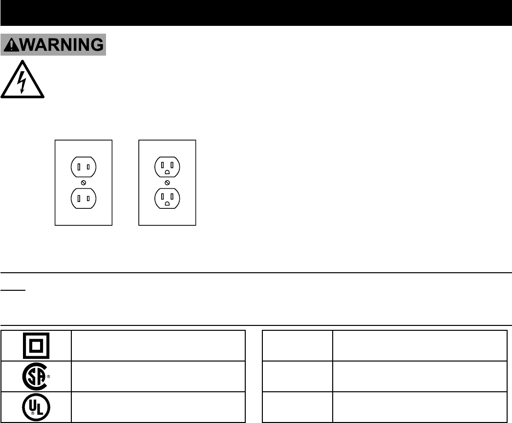
Grounding
TO PREVENT ELECTRIC SHOCK AND DEATH FROM
INCORRECT GROUNDING WIRE CONNECTION:
Check with a qualified electrician if you are in doubt as to whether the outlet is properly grounded.
Do not modify the power cord plug provided with the tool. Never remove the grounding prong from the
plug. Do not use the tool if the power cord or plug is damaged. If damaged, have it repaired by a service
facility before use. If the plug will not fit the outlet, have a proper outlet installed by a qualified electrician.
Figure A: Outlets for 2-Prong Plug
1. The included Power Adapters do
not require grounding.
2. The Power Adapters may be used in
either of the 120 volt outlets shown in the
preceding illustration. (See Figure A.)
Extension Cords
Note: Do not use an extension cord with the Power Adapters.
Symbology
Double Insulated
Canadian Standards Association
Underwriters Laboratories, Inc.
VVolts
~Alternating Current
AAmperes

Page 5For technical questions, please call 1-888-866-5797.Item 63890
Specifications
DVR
Hard Drive 1TB
Video Standard NTSC
Video Codec H.264
Operating System Linux
Video I/O Input: 8 BNC
Output: 1 HDMI / 1 VGA
Audio Codec G.711
Audio I/O Input: 4 RCA
Output: 1 RCA
Recording Resolution 2048 x 1536 (3MP)
1920 x 1080 (1080P)
1280 x 720 (720P)
960 x 480 (960H)
Recording Mode Normal / Motion / Alarm
Motion Detection Selectable Area and Sensitivity Detection
PTZ Interface RS485
Network Interface RJ-45
USB Interface USB 2.0
DVR Input Rating 12V DC / 2A
Power Adapter
Rating
12V DC / 2A
Camera
Lens Type Fixed 3.6mm
Horizontal Resolution 1080P
Effective Pixels 1920H x 1080V
Night Vision Type Infrared LEDs with Low Light Sensor
Image Type Daylight: Color
Infrared: Black & White
Infrared Distance 100 ft. (Under ideal conditions. Objects may be partially or
completely obscured depending on camera position.)
Ingress Protection
Rating
IP 66 - Protected from low-pressure water jets
Video Connector BNC
Camera Input Rating 12V DC / 300 mA
Power Adapter Rating 12V DC / 2A - To power included 4 cameras.
Cable Length 60 ft.
Operating
Temperature
14°-122° F
Page 6 For technical questions, please call 1-888-866-5797. Item 63890
Components and Controls
Read the ENTIRE IMPORTANT SAFETY INFORMATION section at the beginning of this
manual including all text under subheadings therein before set up or use of this product.
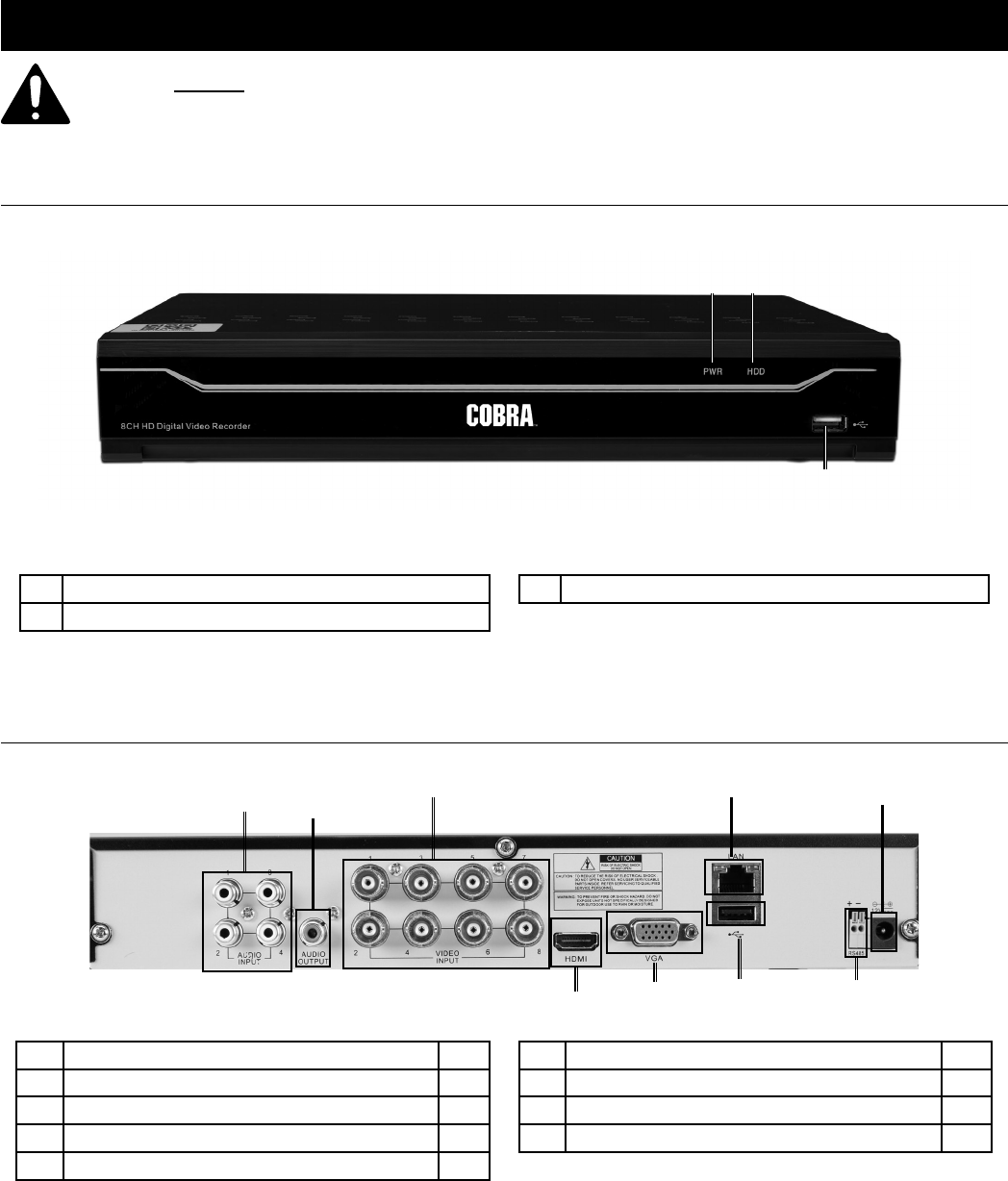
DVR Front Panel
1 2
3
1 Green Power Indicator - glows when power is on
2 Red Hard Drive Light - flashes when recording
3 USB Port
Figure B
DVR Back Panel
1
23
45
7869
1 BNC Video Input 8
2 RCA Audio Input 4
3 RCA Audio Output 1
4 RJ45 LAN Ethernet Port 1
5 12VDC Power Input 1
6 USB 2.0 Port 1
7 HDMI Video Output 1
8 VGA Video Output 1
9 RS485 PTZ Connector 1
Figure C
Page 7For technical questions, please call 1-888-866-5797.Item 63890
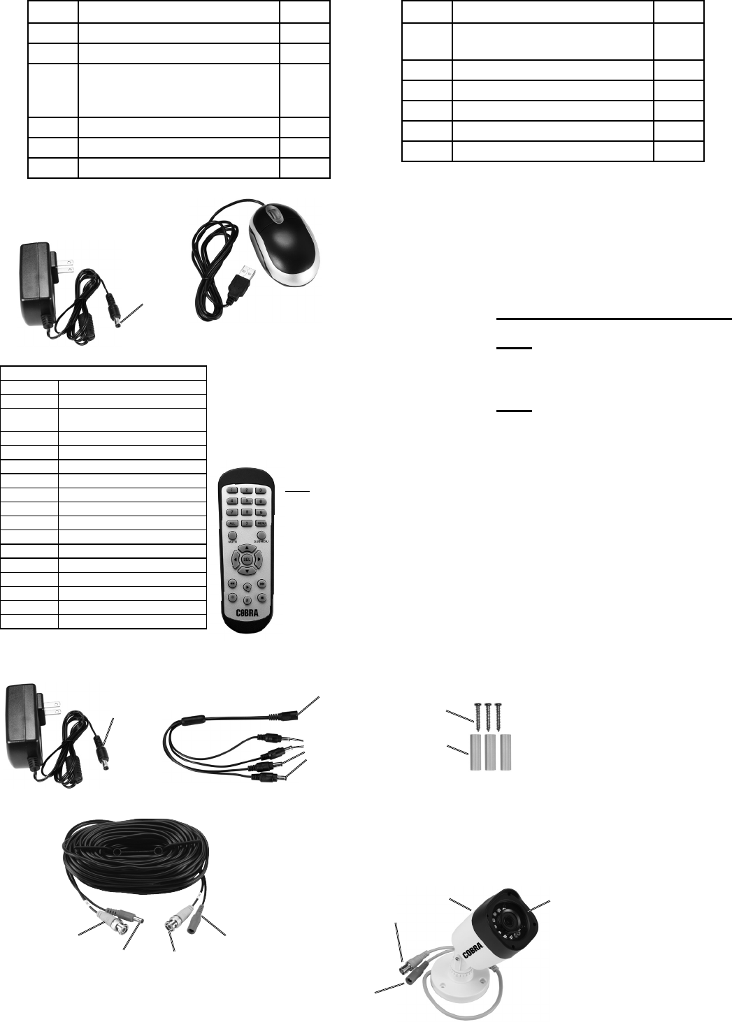
Part Description Qty
1 8-channel H.264 DVR 1
2 Hard Drive (pre-installed) 1
3 3.6mm wide-angle indoor/
outdoor color camera with
infrared night vision
4
4 60 ft. camera cable 4
5 1-to-4 way splitter power cable 1
6 12V/2A power adapter for DVR 1
Part Description Qty
7 12V/2A power adapter
for 4pc camera
1
8 Mouse w/ USB cable 1
9 Remote Control 1
10 AAA battery 2
11 Mounting Screw 12
12 Mounting Anchor 12
12VDC/2A Power Adapter
Power
(to DVR)
Use the Mouse to
navigate the DVR
Mouse
Note: 2 AAA
batteries included
Remote
Remote Control Functions
1 - 8 Select Channel
0Lock and Unlock Controls
ALL Toggle between single, 4
and 8 Screen Displays
MENU Open Menu
MUTE Mute
SUBMENU Open Pop-Up Menu
▲Menu Up
▼Menu Down
◄Menu Left
►Menu Right
SEL Confirm Selected Operation
◄◄ Rewind
►Play / Search Records
►► Fast Forward
●Record
ll Pause
■Stop
Video
(from Camera)
Video
(to DVR)
Power
(to Camera)
Power
(from Splitter)
Cable - 60 ft.
Screws
Anchors
Mounting Hardware
12VDC/1A Power Adapter
Power
(to Splitter)
Power Splitter Power
(from Adapter)
Power
(to Cables)
Record Serial Number Here:
Note: If product has no serial
number, record month and
year of purchase instead.
Note: Some parts are listed and
shown for illustration purposes
only, and are not available
individually as replacement parts.
Power
(from Cable)
Video
(to Cable)
Camera
Hood Lens
Page 8 For technical questions, please call 1-888-866-5797. Item 63890
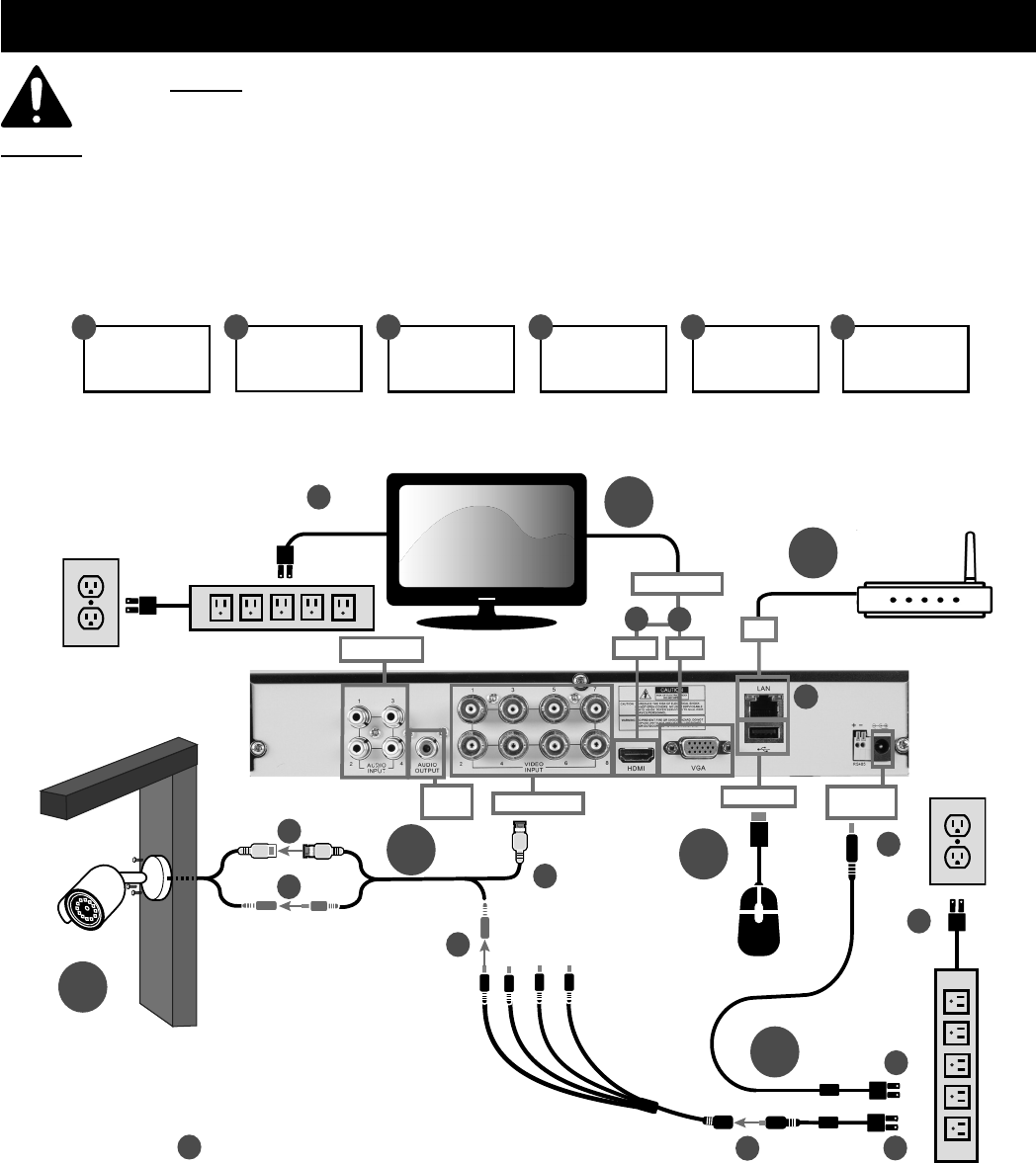
Setup
Read the ENTIRE IMPORTANT SAFETY INFORMATION section at the beginning of this document
including all text under subheadings therein before set up or use of this product.
NOTICE: CHECK FEDERAL, STATE AND LOCAL SURVEILLANCE LAWS BEFORE
INSTALLING VIDEO AND/OR AUDIO SURVEILLANCE EQUIPMENT.
To change settings or set up other functions, see the Owner’s Manual & Safety Instructions
Note: Date and Time are set automatically only when system is connected to the Internet. Otherwise, Date and
Time Format can be set manually during the Startup Wizard process.
B2
D2
D3
D4
B5
D5
D1
Video Input
A
C
USB Port
Power
Input
Video Output
D
Note:
Surge Protector
sold separately
Use Mouse to
navigate the DVR
VGAHDMI
Note: Computer Monitor
or TV and Surge Protector
sold separately
B1
B4
B
E
Connect and test all
equipment and camera
locations BEFORE
mounting cameras
Mount Under
Eave
Protect connections from
moisture with electrical tape
Push together and twist yellow
connectors clockwise to secure
Connect
more
Cameras
F
Audio Input
B3
Audio
Output
Refer to Monitor or TV's owner's
manual to set the Input Source
If adding extra cameras,
use Item 63891.
A
Connect
Monitor
B
Connect
Cameras
C
Connect
Mouse
D
Connect
Power
E
Mount
Cameras
F
Connect
Remotely
Internet connectivity
required for remote viewing
F1
LAN
A1 A2
This DVR system can be remotely
monitored by a smartphone via
the RXCamView app, available
through Google Play and Apple’s
App Store.
F2
Note: Router sold
separately
Page 9For technical questions, please call 1-888-866-5797.Item 63890
Operation
Startup Wizard
Note: After DVR startup is completed, the Startup
Wizard will be displayed. Wizard setting menu
includes: Homepage, HDD Management, Network
Configuration, Email Configuration, Record
Schedule, and General System Configuration.
Note: You can click Cancel to skip Startup Wizard.
Check the box labeled Don’t show this window next
time if you don’t want to display Startup Wizard.
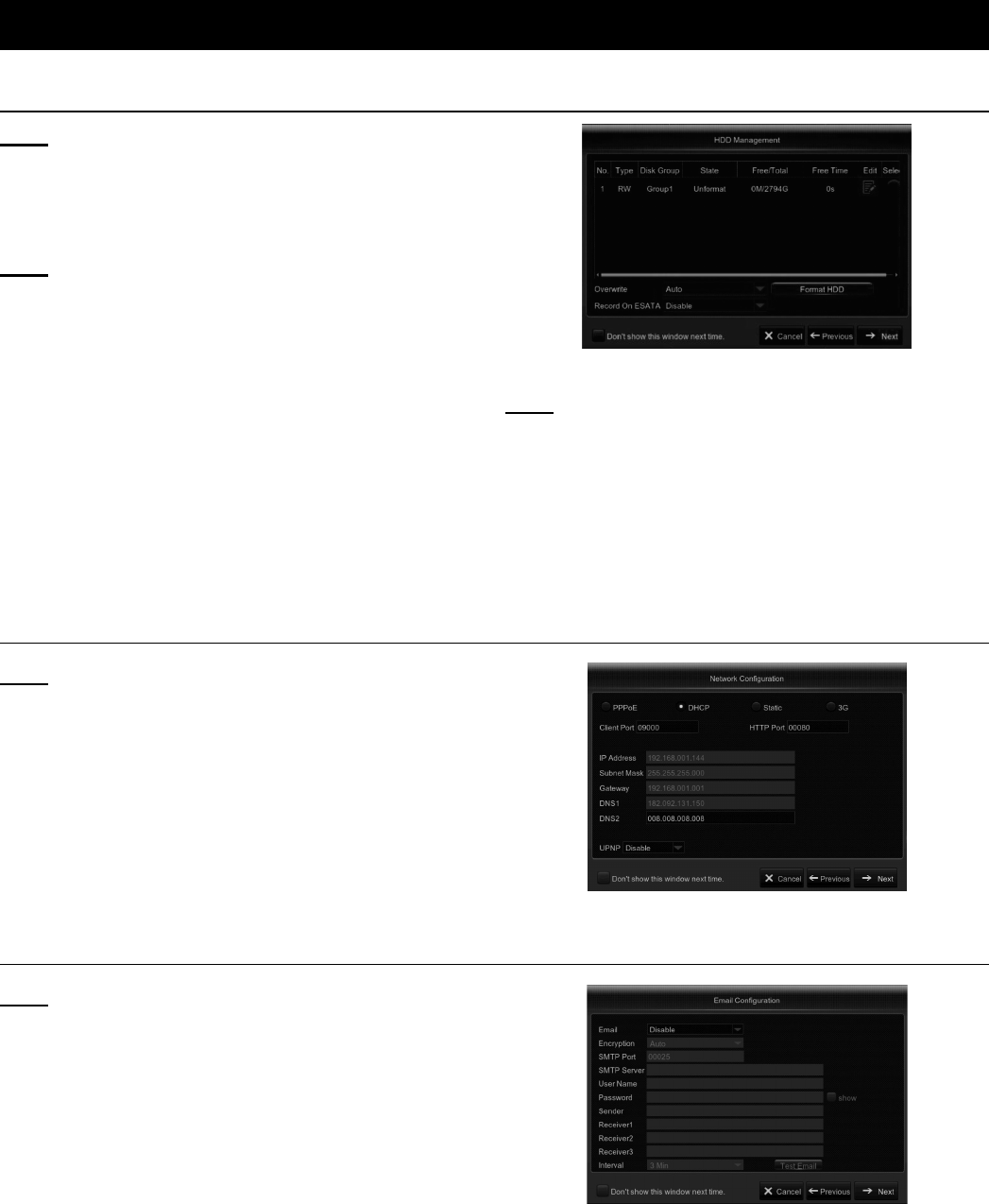
1. If the HDD is installed in the DVR for the first
time, it will be need to be formatted. Select
the HDD which you want to format, and
then click Format HDD. See Figure D
Figure D
Note: Use Overwrite option to overwrite the old
recordings on the HDD when HDD is full. For
example, if you choose the option 7 days then
only the last 7 days’ recordings are kept on the
HDD. To prevent overwriting any old recordings,
select Disable. If you have disabled this function,
please check HDD status regularly,
to make sure it is not full.
Network Configuration
Note: This menu allows you to configure network
parameters, such as PPPoE, DHCP, Static, and 3G.
The most common types are DHCP or Static. Most
likely your network type is DHCP, unless the network
is manually addressed (usually called Static).
1. If you need an authentication username
and password to the internet, then choose
PPPoE. If you want to use a mobile network
connection, then choose 3G. See Figure E.
Figure E
Email Configuration
Note: This menu allows you to configure email settings.
Go through these settings if you want to receive sytem
notifications via email when a motion is detected, HDD
becomes full, HDD is in error state, or Video Loss occurs.
Full account information for the account the emails will be
sent FROM will need to be entered, as well as the email
addresses where the emails will be sent to. See Figure F.
Figure F
Page 10 For technical questions, please call 1-888-866-5797. Item 63890
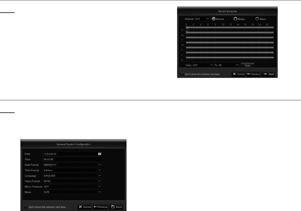
Record Schedule
Note: This menu allows you to specify when the
DVR records video and define the recording mode
for each channel. The recording schedule allows for
Normal (continuous) recording, Motion recording, and
Alarm recording. To set the recording mode, click
first on the mode button (Normal, Motion, or Alarm),
then drag the cursor to mark the slots. See Figure G.
Figure G
General System Configuration
Note: This menu allows you to configure
the general parameters of the system such
as Date, Time, Date Format, Time Format,
Language, Menu Timeouts, and Mode.
Figure H
Page 11For technical questions, please call 1-888-866-5797.Item 63890
R
M
M
I
H
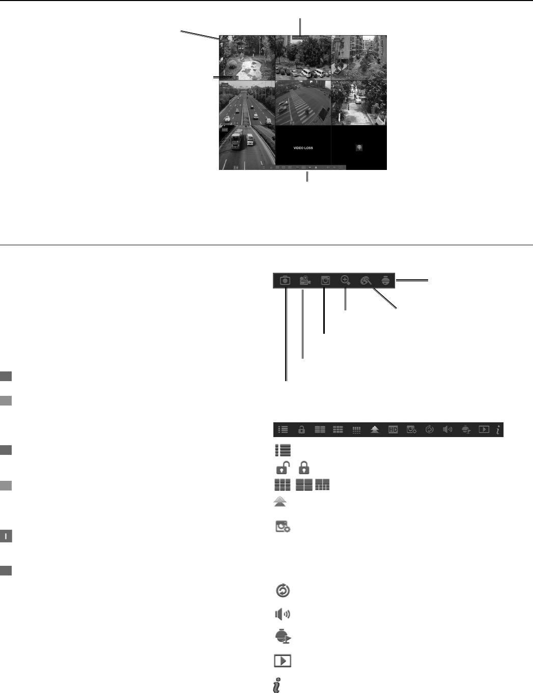
Live Screen
System Date and Time
Pop-up
Menu Bar
Camera Title
Status Icons
Figure I
Camera Icons
System Date & Time
Displays current system date & time
Camera Title
A-: Indicates that the camera
connected is an AHD camera
T-: Indicates that the camera connected is a TVI camera
C-: Indicates that the camera connected is a CVI camera
Status Icons
= DVR is currently recording.
(Green) = DVR is detecting motion
from the camera but not
recording.
(Red) = Camera has detected
motion and triggers recording.
(Green) = Indicates that the external
sensor device is triggered but not
recording.
(Red) = Indicates that the external sensor
device is triggered for recording.
= Indicates that the DVR cannot detect
an HDD or the HDD is not formatted.
VIDEO LOSS: Connection to the camera has been lost.
No Camera: Camera has not been
connected to the DVR.
No HDD: HDD is not installed.
Camera Quick Toolbar
PTZ control panel
Zoom In Channel color settings
Playback the recent 5 minutes recording
Record the channel manually
Manually capture an image
Pop-up Menu Bar
Click to open the Main Menu.
Click to lock/unlock the screen operation.
Click to switch to different camera views.
Click to view more layout options.
Click to switch between real time, balanced,
or smooth view. These modes influence
the displayed video quality by bit rate and
frame rate but not the recording quality.
Click to start viewing channels in a sequence.
Click to adjust volume.
Click this to start/stop cruise for a PTZ camera.
Click to playback videos.
Click to view system information.
Page 12 For technical questions, please call 1-888-866-5797. Item 63890
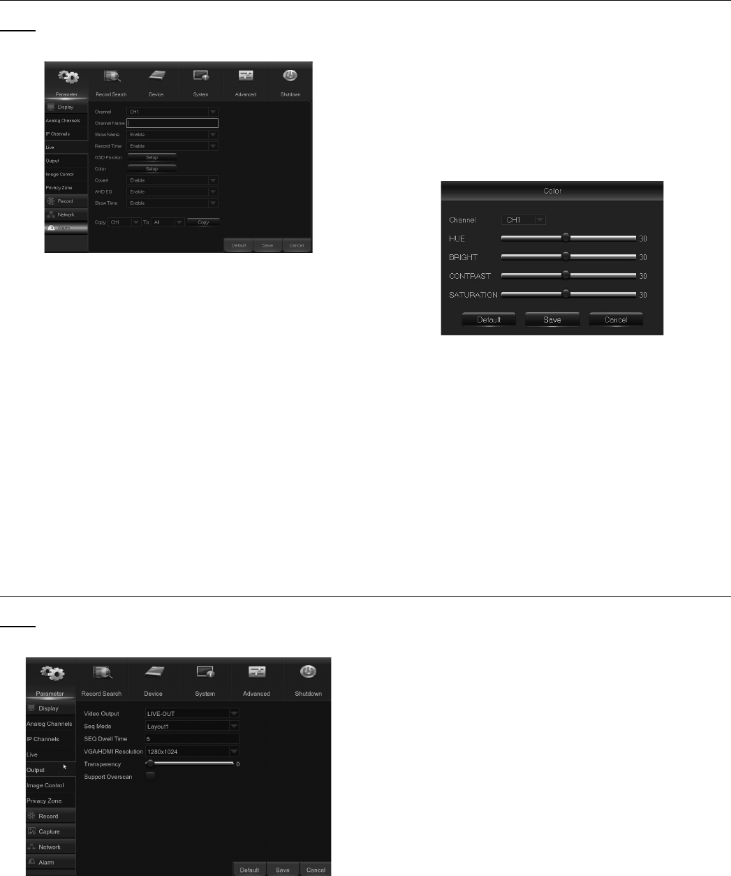
Live
Note: This menu allows you to
configure channel parameters.
Figure J
Channel: Select the channel you want to modify.
Channel Name: Enter the name of the channel.
Show Name: Enable to display the
channel name on the live screen.
Record Time: Disable if you do not want to
see the recording time on the channel.
OSD Position: Click Setup to determine where
you want the channel name and current date to
be displayed when you are viewing the channel.
Drag the channel name box and the date/time box
to the desired location on the channel view.
Covert: Enable if you want to hide this channel
from appearing on the Live Viewing screen.
Disabling or enabling this option does not
affect video recording on the HDD.
AHD EQ: Enable or disable AHD EQ
(Enhanced Quality) function. Configure this
parameter if you are an advanced user.
Show Time: Disable if you do not want the
current time to appear on the channel.
1. Click Setup in the Color row from Figure J
to configure video color settings. You
will see the screen shown below.
Figure K
HUE: Changes the color mix of the image.
BRIGHT: Defines how bright the
image appears on the display.
CONTRAST: Increases the difference between the
darkest black and the whitest white in the image. Modify
the contrast if the sections of the image look “greyed out”.
SATURATION: Alters how much color is displayed
in the image. The higher the saturation, the brighter
and vivid colors will appear to be. Setting this
parameter too high can degrade the image quality.
Output
Note: This menu allows you to configure
video output parameters.
Figure L
Video Output: This is the monitor that
you use for live view display.
Sequence Mode: Choose your favorite
layout from the drop-down menu for viewing
channels in a sequence on live view.
SEQ Dwell Time: Set how long you want the live
view from a channel to be displayed in a sequence.
VGA/HDMI Resolution: Select the highest resolution
your monitor/TV supports. The higher the resolution,
the more details you will see on your images. The
DVR will restart after you change the resolution.
Transparency: Decide how transparent you want
the menus to be. Choose partially transparent
(see-through) if you need to keep an eye on
happenings while adjusting settings.
Support Overscan: Check to adjust the position
of the video image on the live viewing screen.
Page 13For technical questions, please call 1-888-866-5797.Item 63890
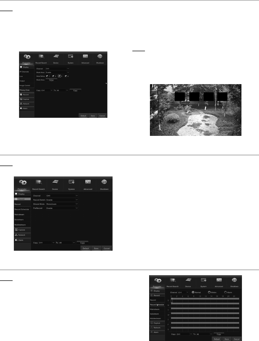
Private Zone
Note: This menu allows you to create Privacy
Zone(s) if you want to partially cover up part of the
image. You can create up to four privacy zones in
any size and location on the channel view. These
zone(s) appear as “red box rectangle areas.” Just
click inside the default red-lined rectangle and drag
it where you want to create a privacy zone.
Figure M
1. Select the Channel where you want to set privacy
zone(s), then set Mask Area to Enable. Decide
how many privacy areas you want to set and
check the area(s) in Area Setup, and click Setup
to open the channel in full screen mode and
start marking the privacy zones See Figure Q.
Note: Depending on the number of areas you have
chosen in Area Setup, you will see areas covered with
black rectangles on the channel view. See Figure N.
2. When you have finished marking the areas,
right-click to return to the Main Menu.
Figure N
Record
Note: This menu allows you to configure
the channel recording parameters.
Figure O
Channel: Select the channel to set
its recording parameters.
Record Switch: Enable in order to allow
the video to be recorded to the HDD.
Stream Mode: Choose the recording resolution. The
available options are Mainstream and Substream.
PreRecord: If this option is enabled, the DVR starts
recording a few seconds before an event occurs. Use
this option if your primary recording type is motion-based.
Record Schedule
Note: This menu allows you to specify when the DVR
records video and defines the recording mode for
each channel. The recording schedule alternates
between Normal (continuous) recording, Motion
recording, and Alarm recording. To set the recording
mode, click first on the mode button (Normal, Motion,
or Alarm), then drag the cursor to mark the slots. The
recording schedule is valid only for one channel. If
you want to use the same recording schedule for
other channels, use the Copy To function.
Figure P
Channel: Select the channel to set
its recording parameters.
Page 14 For technical questions, please call 1-888-866-5797. Item 63890
Normal: When the time slot is marked
Green, this indicates the channel performs
normal recording for that time slot.
Motion: When the time slot is marked Yellow,
this indicates the channel records only when
a motion is detected during that time slot.
NOTE: To use the motion detection, you must enable
and configure the motion settings for the channel
in the Alarm menu. When the time slot is marked
Red, this indicates the channel records only when
the sensor is triggered during that time slot.
No Record: A time slot marked Black means that
there is no recording scheduled for the time slot.
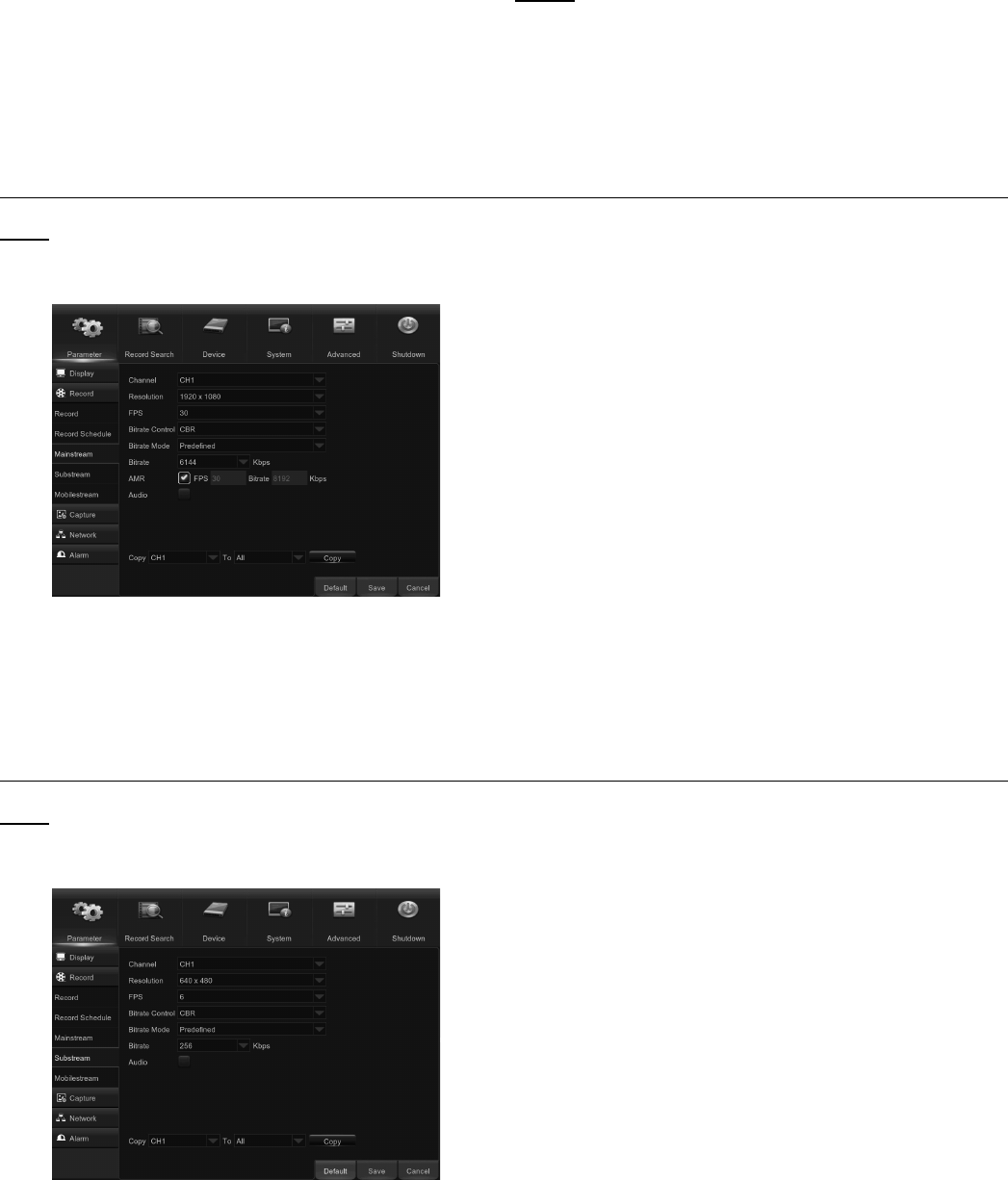
Mainstream
Note: This menu allows you to configure the recorded
video parameters. All modifications you apply to these
settings will affect the recorded video saved into the HDD.
Figure Q
Channel: Select the channel to configure
recording-related information.
Resolution: This parameter defines how
large the recorded image will be.
FPS: This parameter defines the number of
frames per second that the DVR will record.
Bitrate Control: Select the bitrate level based
on the complexity of the scene. For a simple
scene such as a gray wall, use constant bitrate
(CBR). For a more complex scene such as a
busy street, use variable bitrate (VBR).
Bitrate Mode: If you want to set the bitrate by
yourself, then choose User-defined. If you want to
select the predefined bitrate, choose Predefined.
Bitrate: This parameter corresponds to the
speed of data transfer that the DVR will use
to record video. Recordings that are encoded
at higher bitrates will be of better quality.
Audio: Select this option if you want to record audio
along with video and have a microphone connected to
the DVR, or are using a camera with audio capability.
Substream
Note: This menu allows you to configure the settings
of a particular channel if the channel is being viewed
via remote access, for example Web Client.
Figure R
Channel: Choose the channel where
the settings are applied.
Resolution: Set the resolution.
FPS: This parameter defines the number of
frames per second at the remote session.
Bitrate Control: Select the bitrate level based
on the complexity of the scene. For a simple
scene such as a gray wall, use constant bitrate
(CBR). For a more complex scene such as a
busy street, use variable bitrate (VBR).
Bitrate Mode: If you want to set the bitrate by
yourself, then choose User-defined. If you
want to select the predefined bitrate, choose Predefined.
Bitrate: Enter manually or choose
from the drop-down menu.
Audio: Check this box if you want to hear the live
sound at the remote session. Make sure the
camera with audio capability is properly
connected to the selected channel.
Page 15For technical questions, please call 1-888-866-5797.Item 63890
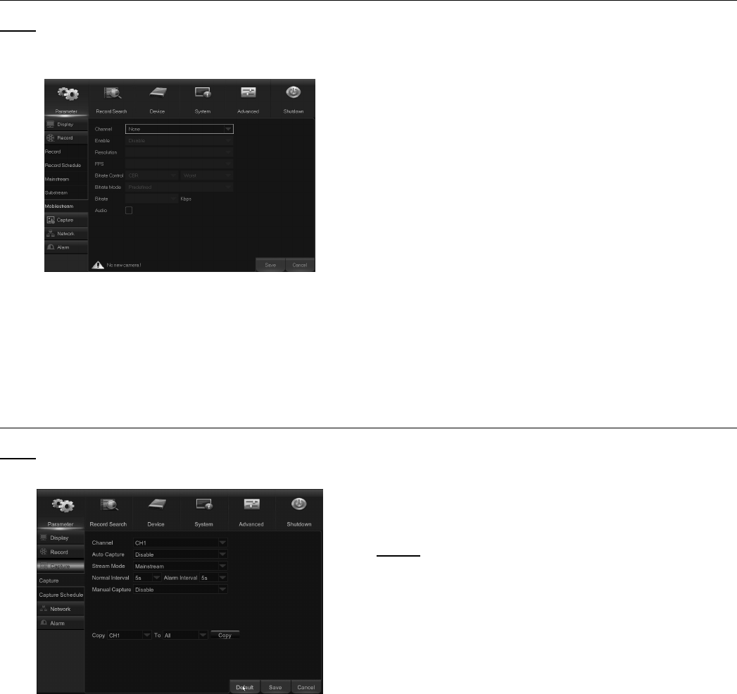
Mobile Stream
Note: This menu allows you to configure the
settings of a particular channel if the channel
is being viewed via a mobile device.
Figure S
Channel: Choose the channel where
the settings are applied.
Enable: Enable to allow to use mobile
streaming on this channel.
Resolution: Set the resolution.
FPS: This parameter defines the number of
frames per second at the mobile session.
Bitrate Control: Select the bitrate level
based on the complexity of the scene. Refer
to previous two sections for criteria.
Bitrate Mode: If you want to set the bitrate by
yourself, then choose User-defined. If you
want to select the predefined bitrate, choose Predefined.
Bitrate: Enter manually or choose
from the drop-down menu.
Audio: Check box if you want to hear the live
sound at the mobile session. Make sure the
camera with audio capability is properly
connected to the selected channel.
Capture
Note: This menu allows you to configure
the snapshot capturing parameters.
Figure T
Channel: Select the channel to set
its capture parameters.
Auto Capture: Enable or disable automatic
capturing on the channel. When enabled, you
can select the snapshot capturing interval.
Stream Mode: Select the image resolution.
NOTE: When the Auto Capture is enabled, you
can select the image capturing interval.
Normal Interval: Snapshots are captured
based on normal interval.
Alarm Interval: Snapshots are captured based on
alarm interval only when a motion is detected
or sensor is triggered.
Manual Capture: Enable or disable
manual capturing on the channel.
Page 16 For technical questions, please call 1-888-866-5797. Item 63890
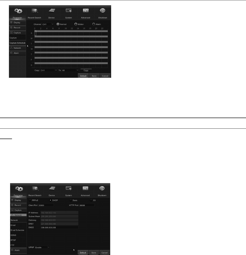
Capture Schedule
Figure U
Channel: Select the channel to set its
snapshot capturing schedule.
Normal: When the time slot is marked Green, this
indicates the channel is capturing snapshots
based on the Normal Interval.
Motion: When the time slot is marked Yellow, this
indicates the channel is capturing snapshots
based on Alarm Interval only when a motion is detected.
Alarm: When the time slot is marked Red, this
indicates the channel is capturing snapshots
based on Alarm Interval only when a sensor is triggered.
No Capturing: A time slot marked Black means
that there is no snapshot capturing scheduled for
the time slot.
Network Settings
Network
Note: This menu allows you to configure network
parameters, such as PPPoE, DHCP, Static, and 3G.
The most common types are DHCP or Static. Most
likely your network type is DHCP, unless the network
is manually addressed (usually called Static). If you
need an authentication username and password
to the Internet, then choose PPPoE. If you want to
use mobile network connection, then choose 3G.
Figure V
Network Type: Select the network type
you are using, from the following:
PPPoE: This is an advanced protocol that allows
the DVR to connect to the network more directly
via DSL modem.
DHCP: This is the network type when a device
on your network (usually a router) assigns
automatically all the network parameters for your DVR.
Static: Requires all the network
parameters to be filled in manually.
3G: Prior to using the mobile network, you
need to connect a 3G dongle to the DVR.
HTTP Port: This port will be used to log in remotely
to the DVR (via Web Client). If the default port 80 is
already taken by other applications, please change it.
Client Port: This is the port that the DVR will use
to send information through. If the default port
9000 is already taken by other
applications, please change it.
IP Address: The IP address identifies the DVR
in the network. It consists of four groups of
numbers between 0 to 255, separated by periods.
For example, “192.168.001.100”. You need to
enter the IP address manually only if
your network type is Static.
Subnet Mask: Subnet Mask is a network parameter
which defines a range of IP addresses that
can be used in a network. If IP address is like a
street where you live then Subnet Mask is like a
neighborhood. The subnet address also consists
of four groups of numbers, separated by
periods. For example, “255.255.000.000”. As with
IP address, you need to enter the Subnet Mask
manually only if your network type is Static.
Gateway: This address allows the DVR to access
the Internet. The format of the Gateway
address is the same as the IP Address. For example,
“192.168.001.001”. As with IP address, you
need to enter the gateway address manually
only if your network type is Static.
DNS1/DNS2: DNS1 is the primary DNS server
and DNS2 is a backup DNS server. Normally it
should be sufficient to enter the DNS1 server address.
Page 17For technical questions, please call 1-888-866-5797.Item 63890
UPNP: If you want to log in remotely to the DVR
using Web Client, you need to complete the port
forwarding. Enable this option if your router
supports the UPnP. You need to enable UPnP
on both the DVR and router. In this case, you do not
need to manually configure port forwarding on your
router. If your router does not support UPnP, make
sure the port forwarding is completed manually.
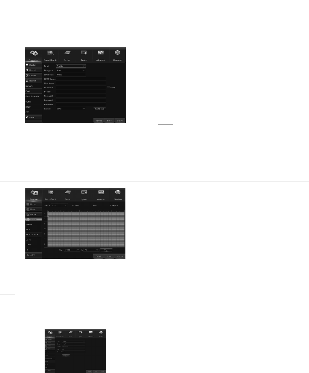
Email
Note: This menu allows you to configure email
settings. Please complete these settings if you
want to receive the system notifications on your
email when a motion is detected, HDD becomes
full, HDD is in error state, or Video Loss occurs.
Figure W
Email: Enable this feature.
Encryption: Enable if your email server requires the
SSL or TLS verification. If you are not sure, set to Auto.
SMTP Port: Enter the SMTP port of your email server.
SMTP Server: Enter the SMTP
server address of your email.
User Name: Enter your email address.
Password: Enter the password of your email.
Receiver 1-3: Enter the email address where you
want to receive the event notifications from the
DVR.
Interval: Configure the length of the time interval
between the notification emails from the DVR.
Note: To make sure all settings are correct, click Test
Email. The system sends an automated email
message to the receiver inboxes. If you received the
test email, it means the configuration parameters are
correct.
Email Schedule
Figure X
The color codes on email schedule
have the following meanings:
Green: Slot for Motion.
Yellow: Slot for I/O Alarm.
Red: Slot for Exception (HDD full,
HDD error, or Video Loss).
DDNS
Note: This menu allows you to configure DDNS
settings. The DDNS provides a static address
to simplify remote connection to your DVR. To
use the DDNS, you first need to open an account
on the DDNS service provider’s web page.
Figure Y
DDNS: Enable the DDNS service.
Server: Select the preferred DDNS server:
DDNS_3322, DYNDNS, NO_IP, CHANGEIP, or
DNSEXIT.
Domain: Enter the domain name you created on
the DDNS service provider’s web page. This will
be the address you type in the URL box when you
want to connect remotely to the DVR via PC.
For example: dvr.no-ip.org.
User/Password: Enter the user name and password
you obtained when creating an account on
the DDNS service provider’s web page.
After all parameters are entered, click Test
DDNS to test the DDNS settings.
Page 18 For technical questions, please call 1-888-866-5797. Item 63890
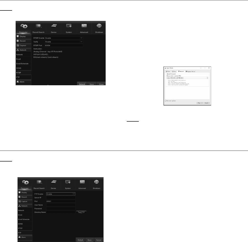
RTSP
Note: The DVR can be remotely viewed
via RTSP protocol. See Figure Z.
Figure Z
RTSP Enable: Enable/Disable
Verify: Enable/Disable
RTSP Port: Default is 554. If default port 554 is
already taken by other applications, please
change it.
Analog Channel: rtsp://IP:Port/chA/B
A: 01(ch1), 02(ch2)….16(ch16)
B: 0(main stream), 1(sub stream)
For example, the DVR IP address is 192.168.1.120,
and you want to view CH1 with mainstream,
then the RTSP address will be:
rtsp://192.168.1.120:554/ch1/0. See Figure BAA.
Figure AA
Note: RTSP user name and password is same with
DVR user name, password and permissions. Follow
the instruction to input IP and port to preview video.
FTP
Note: This menu allows you to enable FTP
function to view and load captured snapshots
from DVR to your storage device over FTP.
Figure AB
FTP Enable: Enable the feature in DVR.
Server IP: Enter your FTP server IP
address or domain name.
Port: Enter the FTP port for file exchanges.
Name/ Password: Enter your FTP
server user name and password.
Directory Name: Enter the default directory
name for the FTP file exchanges.
Test FTP: Click to test the FTP settings.
Page 19For technical questions, please call 1-888-866-5797.Item 63890
Alarm Settings
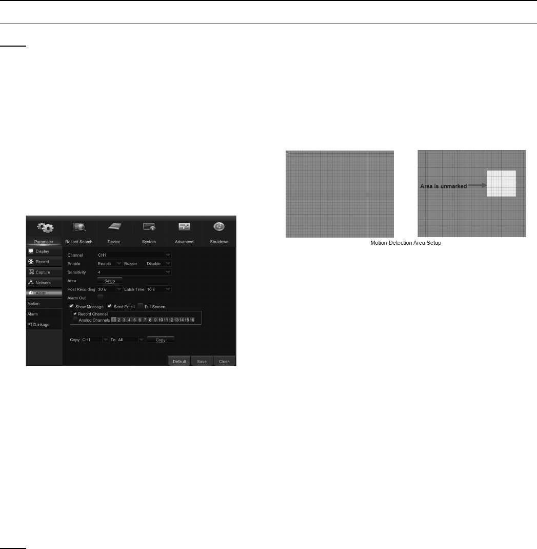
Motion
Note: This menu allows you to configure motion
parameters. A sufficient amount of difference
between frame activity is interpreted as motion.
When the motion is detected, the system can
be set to automatically initiate recording. In this
menu you can select the channels where you want
the motion detection recording to take place.
If you set the motion detection at a high sensitivity
level (“8″ is the most sensitive), then the frequency
of false alarm events increases. If the sensitivity
level is too low (“1″ is the least sensitive), you might
increase the risk that a significant motion event
will not trigger the motion detection to record.
Figure AC
Channel: Select the channel you want
to set the motion detection.
Enable: Enable or disable the function.
Buzzer: The DVR can use its internal buzzer to
emit an alarm tone. You can set the buzzer
duration in seconds when the motion is detected.
Sensitivity: Set the sensitivity level.
Area: To setup motion area, click Setup.
Note: By default, the whole screen is marked
for motion detection (red blocks).
To disable the motion detection on an area:
1. Click the grid cursor and then drag the
mouse to highlight the scope to unmark
the area (transparent block).
2. After setting is completed, right click the
mouse button to return and click Save
to make the area setup effective.
Post Recording: You can set how long after an
event occurs that the DVR will continue to
record. The default recording length is 30
seconds but it can be set higher, up to 5
minutes.
Alarm Out: Optional function. If your DVR
connects to an external alarm device, you can
set it to emit an alarm tone.
Latch Time: To configure the external
alarm time when motion is detected.
Show Message: Check the box to display “M”
icon on the screen when motion is detected.
Send Email: Receive an auto-email
when the motion is detected.
Full Screen: When this function is enabled and a
motion is detected in a channel, you will see that
channel in full screen.
Analog Channels: Here you can select which
channels you want to include to the
motion detection. If the motion is detected, the
recording will start immediately on those channels.
Page 20 For technical questions, please call 1-888-866-5797. Item 63890
Alarm
Note: This is an optional function. If the DVR
you purchased doesn’t connect to external
sensor I/O alarm devices, you will not find
this section in your DVR OSD menu.
Figure AD
Alarm In: User may set four groups of alarm inputs.
Alarm Type: There are 3 types for your choice:
Normally-Open, Normally-Close, and OFF.
Choos one to match your sensor type, or Choose
OFF to close the sensor trigger function.
Latch Time:Set how long the buzzer will sound when
an external sensor is triggered: 10s, 20s, 40s, or 60s.
Buzzer: The DVR can use its internal buzzer to
emit an alarm tone. You can set the buzzer
duration in seconds when a sensor is triggered.
Post Recording: Set how long alarm record
will last when alarm ends: 30s, 1minute,
2minutes, or 5minutes.
Alarm out: Enable external alarm device to emit
an alarm tone when a sensor is triggered.
Show Message: Display the alarm messages
on the screen when sensor is triggered.
Send Email: Set to send email to specified
email when sensor is triggered.
Full Screen: When sensor is triggered, the
corresponding channel will be switched to the full
screen mode.
Analog Channels: Select which channels
you want to record when sensor is
triggered.
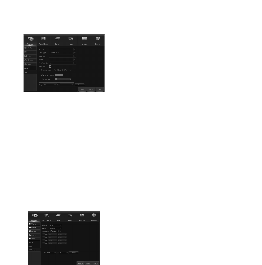
PTZ Linkage
Note: After connecting the PTZ cameras, you can
set the linkage between PTZ cameras and Motion
Alarm and/or external I/O sensor alarm. This function
lets you turn your PTZ camera’s focus to the preset
point when a motion or I/O alarm happens.
Figure AE
Channel: Select the channel to set.
Switch: Enable or disable the PTZ linkage function.
Alarm Type: Choose what kind of alarm
will trigger the PTZ linkage function.
PTZ: Associates the PTZ camera with preset
points. View preset point at 5.8.3.1 PTZ control.
Page 21For technical questions, please call 1-888-866-5797.Item 63890
Record Search & Backup
General
Figure AF
1. Select the channel & the recording type
(All / Normal / Alarm (including preset
point & IO) / Motion / IO / Manual).
2. Determine the recording date.
3. Click Search.
4. Select the recording from the table.
NOTE: Dates marked with orange
triangles have video recordings.
5. Select the channels you want to playback.
6. Modify the start time and end time if
necessary and then click Play.
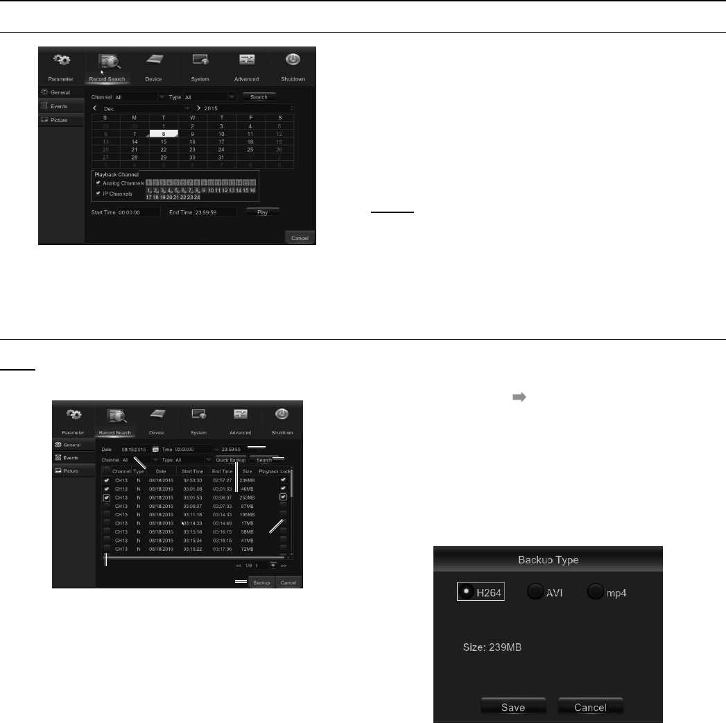
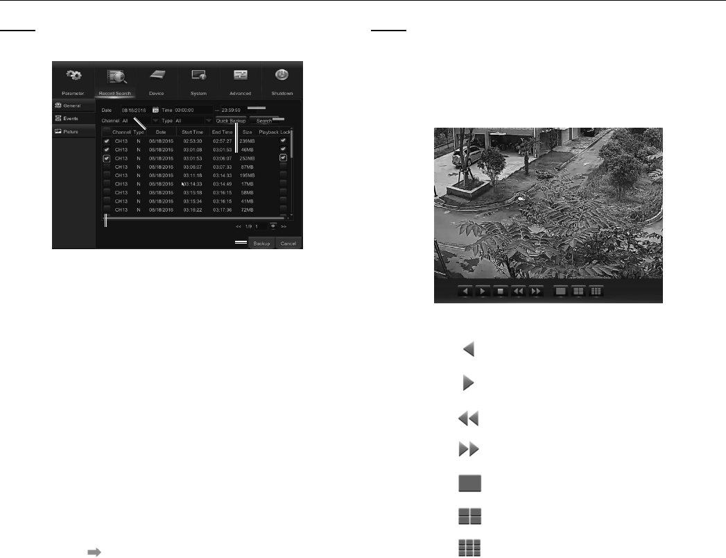
Events
Note: This section is used to check the
recording file lists and make backup.
2
3
4
1
56
7
8
Figure AG
1. Select the recording Date & Time.
2. Select the Channel and Type (All / Normal /
Alarm [including Motion & IO] / Motion / IO).
3. Click Search.
4. If you want to make backup for all recording
files you had searched, click Quick Backup.
5. If you want to make backup for individual files,
select the recording list(s) from the table.
6. If you want to move to a different page,
click << or >>. Or input an individual page
number, then click to jump to the page.
7. After selecting the files, insert the USB drive with
enough free space and click Backup to start the
backup. DO NOT REMOVE THE USB DRIVE
WHILE THE BACKUP IS IN PROGRESS. There
are 3 types of file formats for your backup files:
original H.264, AVI and MP4. The total size of the
backup files will be displayed. See Figure AH.
Figure AH
8. If you want to Lock the recoding files, tick
the checkbox after the files. The locked
files will be protected and unable to be
overwritten by the HDD Overwrite function.
Page 22 For technical questions, please call 1-888-866-5797. Item 63890
Picture
Note: This section is used to view the
captured pictures and make backup.
2
3
4
1
56
7
Figure AI
1. Select the recording Date & Time.
2. Select the Channel and Type (All / Normal / Alarm
[including Motion & IO] / Motion / IO /Manual).
3. Click Search.
4. If you want to make backup for all captured
images you had searched, click Quick Backup.
5. If you want to make backup for individual
files, select the picture lists from the table.
6. If you want to move to a different page,
click << or >> to move to previous or next
page. Or input an indiviual page number,
then click to jump to the page.
7. After selecting all files, click Backup to
start the backup. REMEMBER TO FIRST
INSERT USB DRIVE AND DO NOT REMOVE
IT UNTIL BACKUP IS FINISHED.
Note: Due to the system limitation, a max of 500
captured pictures will be searched & shown. If
you want to view a captured picture, please double
click a picture from the list and the system view
will turn to picture play mode. See Figure AJ.
Right click your mouse to exit the play mode.
Figure AJ
Backward Play, click
twice to pause
Forward Play, click
twice to pause
Move to previous page
Move to next page
Single picture display
Quad pictures display
Nine pictures display
Page 23For technical questions, please call 1-888-866-5797.Item 63890
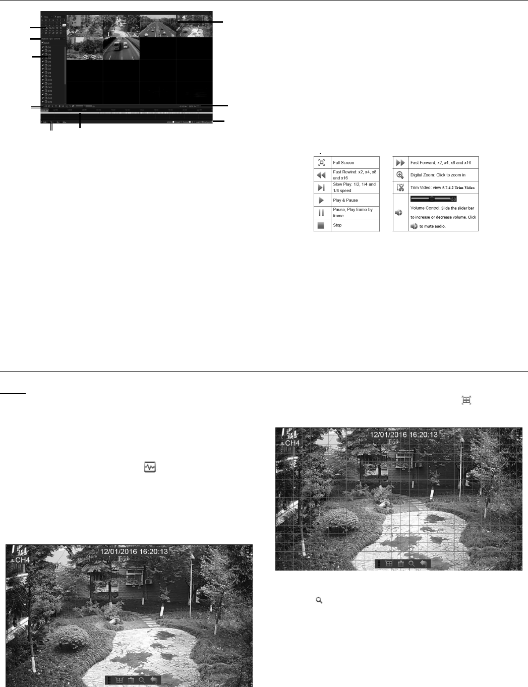
Playback Video Recordings
1
2
3
9
4
5
6
7
8
Figure AK
1. Recording Calendar: Dates marked with
orange triangles have recordings.
2. Playback Type: Select the playback type among
General, Events, Picture & Sub-periods
3. Channels: Check the channels to playback.
4. Time Bar: The color indicates
the video recording type:
- Motion recording (Yellow)
- Smart recording (Dark Green)
- Normal recording (Green)
- I/O sensor recording (Blue)
- Alarm recording (Red)
5. Time Frame: Select Playback timeline.
6. Smart Search: Please see more in the
following Smart Search section.
7. Recording Type Indicator: Motion,
Smart, Normal, IO & Alarm.
8. Recording Playback Screen: Video
recordings from selected channels.
9. Playback Control Bar:
Smart Search
Note: Use this function to find motion within
a specific area of the recording. Only one
channel can be searched at a time. (It supports
to search a single channel every time.)
1. Select a channel to playback in full screen.
2. Click the smart search icon and the system
will enlarge the channel into full screen and
display the Smart Search Quick Toolbar. See
Figure AL. You can move the toolbar by
dragging the vertical bar icon on the left.
Figure AL
3. Use the cursor to mark the area on the channel
where you want to find motion or click
to search motion all over the screen.
Figure AM
4. Click to start search.
5. As a result of Smart Search, you will see the
motion-based recording(s) on the channel
Time Bar marked with Dark Green lines.
Page 24 For technical questions, please call 1-888-866-5797. Item 63890
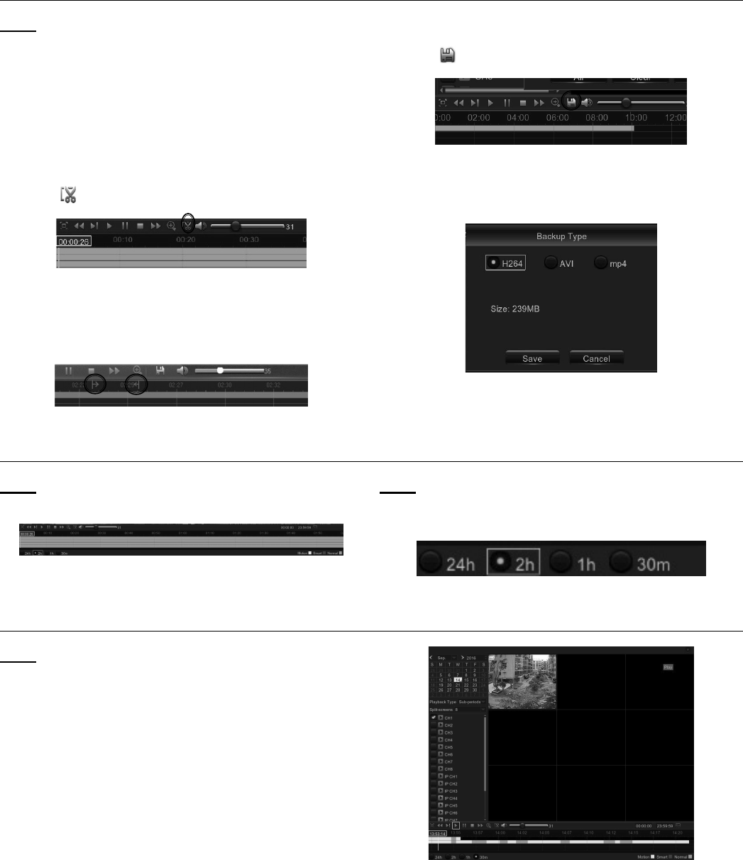
Trim Video
Note: Use this function if you need to backup
a particular section of the video recording.
1. Connect a USB flash drive to the DVR.
2. Double-click on the channel (to display in full screen
during video playback) that you wish to backup.
3. Click on the Time Bar to mark the beginning
of the video footage you wish to backup.
4. Click to start selecting the footage See Figure AN.
Figure AN
5. Click on the Time Bar to mark the end of the video
footage you wish to backup. The marked up area is
now displayed within the red arrows. See Figure AO.
Figure AO
6. Click to save the footage.
Figure AP
7. A video type selection message appears, as
below. Select the file format and click Save.
Figure AQ
Time Frame
Note: During video playback, the time bar is
displayed in 24 Hours (00:00~24:00) by default.
Figure AR
Note: You can shorten the time bar to be displayed
in 2 Hours, 1 Hour or 30 Minutes in order to
make an accurate position to the time bar.
Figure AS
Sub-periods Playback
Note: This function will allow you to divide a
recording video into average separate segments
and play together in the same screen.
1. In the video playback interface, choose Sub-
periods from Playback Type section.
2. Select a channel that you want to play.
3. Choose the Split Screens. If you have a 4
Channel DVR, the max number of split screens
will be 4. For an 8 channel DVR, 8 screens.
For a 16 channel DVR, 16 screens.
For example, if the video you want to play is 60
minutes in length, and the split screen is 4, the
video will be divided in to 4 segments, and each
segment will be 15 minutes in length. All 4 segments
will be played in the same screen. See Figure AT.
Figure AT
Page 25For technical questions, please call 1-888-866-5797.Item 63890
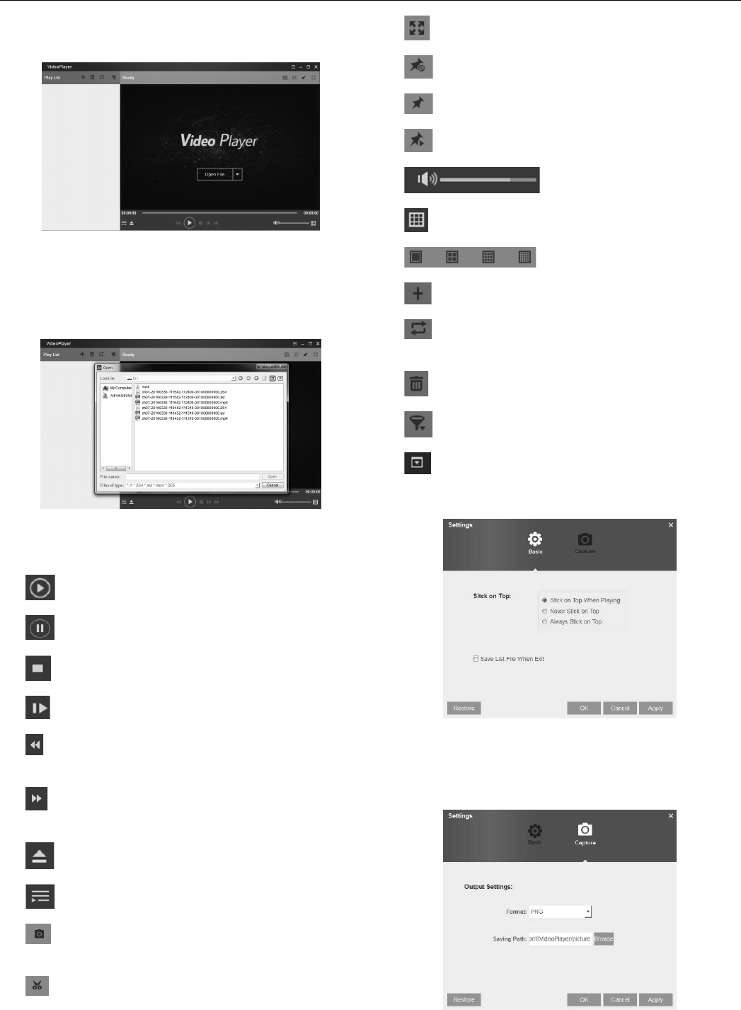
Play Backup Files
1. Install the Video Player software in the CD drive
of a Windows 7 computer and run program.
Figure AU
2. Copy the backup files to your computer.
3. Click + or “Open File” button to add files. (RF, AVI,
Mp4, 264 & 265 files are supported.) See Figure AV.
Figure AV
Function Descriptions:
4. Play: Play file
5. Pause: Pause
6. Stop: Stop playback
7. Frame Forward: Step forward by frame
8. Slow forward: Play at 8x, 4x, 2x,
1x, 1/2, 1/4, 1/8, and 1/16 speed
9. Fast forward: Play at 16x, 8x, 4x,
2x, 1x, 1/2x, 1/4x, 1/8x speed
10. Open file/Open Directory
11. Expand/pack up the list
12. Screenshot: Save path: C:\Users\
Administrator\VideoPlayer\picture
13. Cut: Save path: C:\Users\
Administrator\VideoPlayer\video
14. Full screen display
15. Never on top
16. Always on top
17. On top during playing
18. Adjust volume
19. Window Division
20. 1/4/9/16 channels optional.
21. Add folder or file
22. Playback mode, Single, Order,
Repeat one, Repeat ALL are optional
23. Delete all files in the list
24. Search File
25. Language/Settings
Basic Settings: Set on-Top mode
Figure AW
Capture Settings: Set path to save images
Figure AX
Page 26 For technical questions, please call 1-888-866-5797. Item 63890
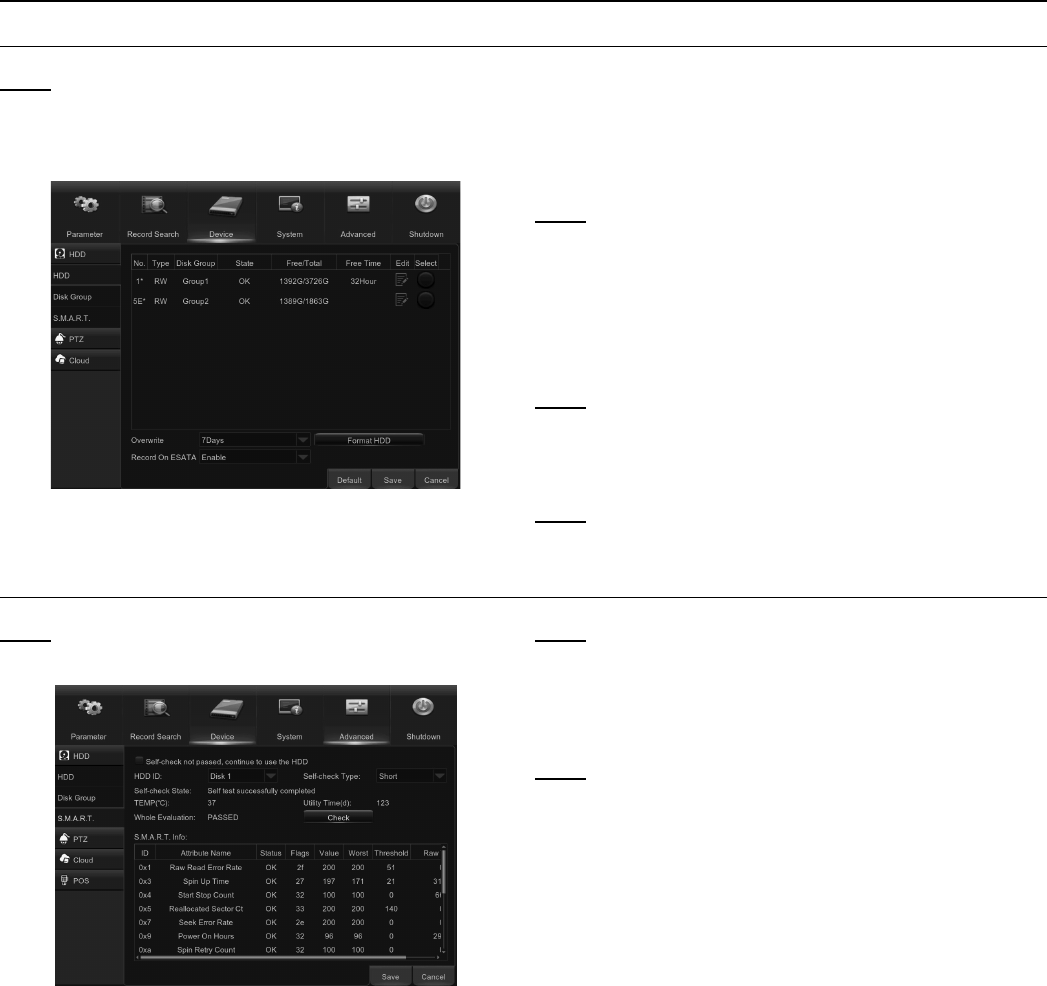
Device
HDD
Note: This menu allows you to check & configure
the internal HDD that the DVR uses for saving
recordings. You need to format the HDD both
at the first startup, and if it is ever replaced.
Figure AY
1. To format HDD: Select the HDD you want to format
and then click Format HDD. See Figure AY.
2. To start formatting, enter your user name and
password and then click OK to confirm.
Note: Overwrite: Use this option to overwrite the old
recordings on the HDD when HDD is full. For example, if
you choose 7 days then only the last 7 days’ recordings
are kept on the HDD. To prevent overwriting any old
recordings, select Disable. If you have disabled this
function, please check the HDD status regularly, to make
sure it is not full. Recording will be stopped if HDD is full.
Note: Record on eSATA: This menu is only
displayed when your DVR has an eSATA port on
the rear panel. It will record the video to an external
eSATA HDD to enhance your HDD capacity.
Note: If the eSATA recording function is enabled,
eSATA backup function will be disabled.
S.M.A.R.T.
Note: This function will help to check the HDD health.
Please note that your DVR may not have this function.
Figure AZ
Note: If you want to continue using the HDD even after
S.M.A.R.T finds an exception, check the box marked
Self-check not passed, continue to use the HDD.
Select HDD ID, then Self-check Type, then Check to
start the test. Self-check State will display the result.
Note: If an HDD S.M.A.R.T error is found, the HDD can
still be used, but at the risk of losing video recording.
Replacing with a new HDD is recommended.
Page 27For technical questions, please call 1-888-866-5797.Item 63890
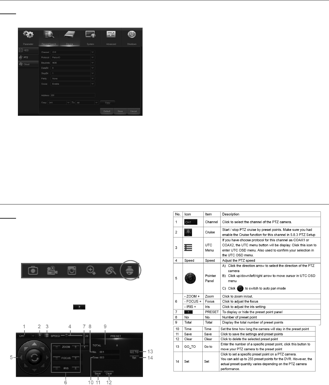
PTZ Setup & Control
Note: This menu allows you to configure the PTZ
(Pan-Tilt-Zoom) settings for the dome camera.
Figure BA
1. Channel: Choose a channel with a
dome camera connected.
2. Protocol: Choose the communication protocol
between the PTZ-capable camera and DVR. If
your camera has UTC (Up the Coax) function, you
can choose COAX1 or 2 to display your camera
OSD menu or control the UTC PTZ function.
3. Baudrate: The speed of the information sent
from the DVR to the PTZ-capable camera.
Make sure it matches the compatibility
level of your PTZ-capable camera.
4. DataBit / StopBit: The information between
the DVR and PTZ-capable camera is sent in
individual packages. The DataBit indicates the
number of bits sent, while the EndBit indicates
the end of the package and the beginning of
the next (information) package. The available
parameters for DataBit are: 8, 7, 6, 5. The
available parameters for the StopBit are 1 or 2.
5. Parity: For error check. See the documentation of
your PTZ-capable camera, to configure this setting.
6. Cruise: Enable to allow to use the Cruise
mode. In order to use the Cruise mode,
set a number of preset points.
7. Address: Set the command address of the PTZ
system. Please note that each PTZ-capable camera
needs a unique address to function properly.
PTZ Control
Note: After finishing PTZ setup, you can use the
PTZ function to control your PTZ camera.
1. Click any channel on the Live Viewing screen
to open Camera Quick Toolbar, and click
the PTZ control icon. See Figure BB.
Figure BB
2. The PTZ control panel will be displayed.
See Figure BC. Click to activate
PRESET points setup page.
Figure BC
Page 28 For technical questions, please call 1-888-866-5797. Item 63890
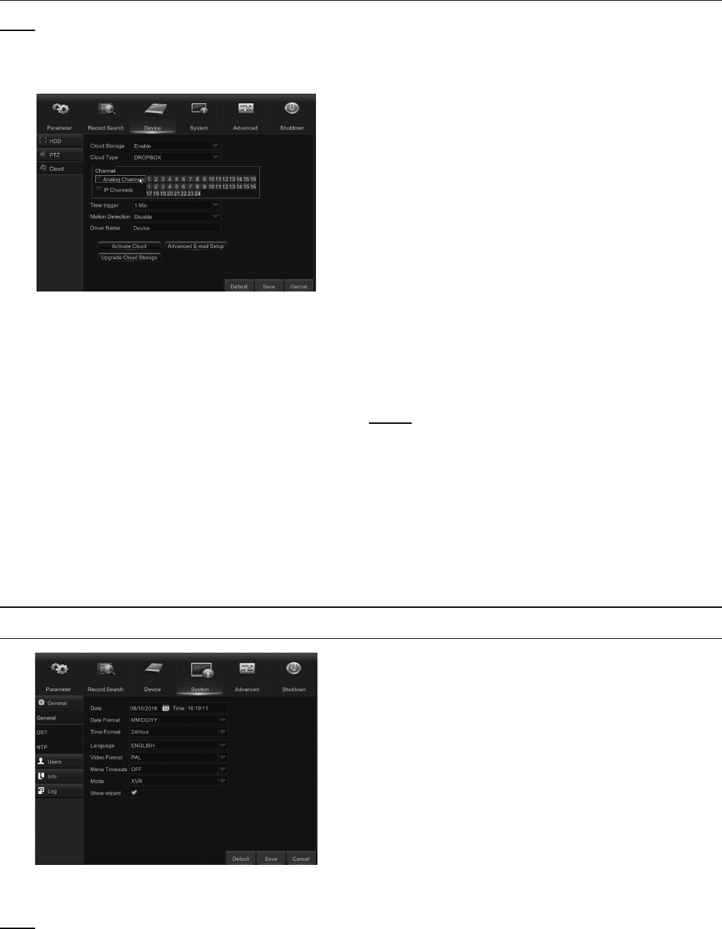
Cloud Storage
Note: This menu allows you to see what is
happening on your camera at any given time.
Uploading the snapshots can be based on a
time interval or when motion is detected.
Figure BD
Cloud Storage: Enable to allow cloud settings.
Cloud Type: Only Dropbox cloud
storage is supported currently.
Channel: Select the channels where you want
to upload the snapshots to Dropbox.
Time trigger: Set the image uploading interval. Set
OFF if you want to use motion baseduploading.
Motion Detection: Enable if you want to upload
snapshots to Dropbox when the camera detects a motion.
Drive Name: Enter the cloud storage name for your DVR.
Activate Cloud: Click to activate the cloud
function. An activation email will be sent
to the Receiver email account.
Advanced E-mail Setup: Click to
configure your email settings.
Upgrade Cloud Storage: Click to upgrade
the current cloud storage service.
To start uploading snapshots:
1. Enable Cloud Storage and configure
Cloud settings for channel(s).
2. Configure advanced e-mail settings
in Advanced E-mail Setup.
3. Click Activate Cloud and wait for
the verification email.
4. Click Activate Cloud in Dropbox
link on verification email.
NOTE: Make sure to check your email and follow the link
to complete cloud storage activationwithin 3 minutes.
5. Enter your Dropbox account credentials.
Setup of the Cloud service is now complete. If you
encountered any problems while activating the
Cloud service, please repeat steps from 3 to 5.
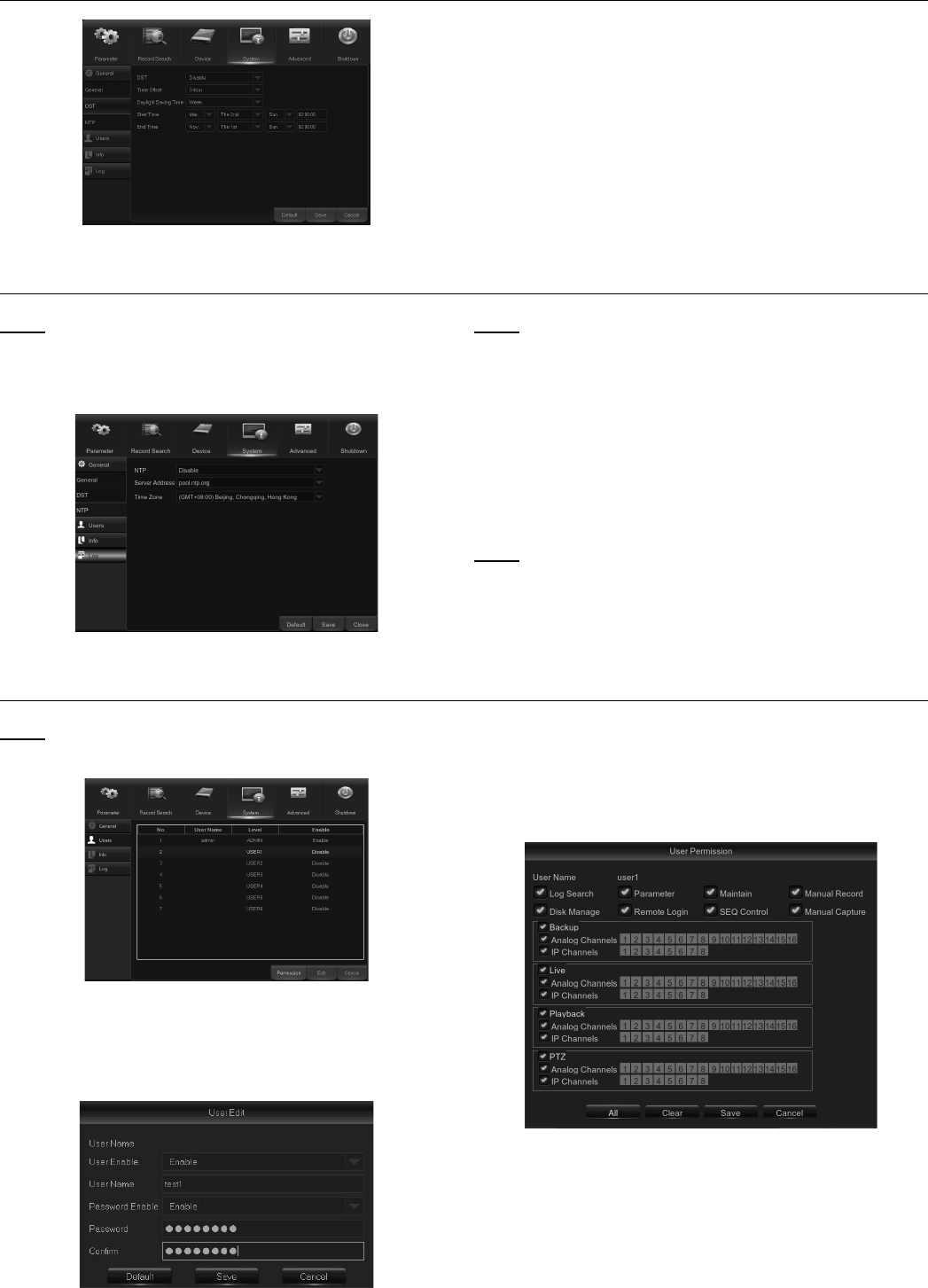
System
General
Figure BE
Date/Time: Enter the date and time manually.
Note: For date/time automation over
the Internet, enable NTP.
Date Format: Set the date format here.
Time Format: Set the time format here.
Language: Choose the OSD language.
Video Format: Choose video format between
NTSC and PAL. If picture is flickering or has
only black screen, format may be incorrect.
Menu Timeouts: Set the time that the DVR will
exit the menus when they are not in use.
Mode: DVR. This mode will
focus on basic analog cameras.
Show Wizard: Check if you want the Startup Wizard
to reappear each time you start up the DVR.
Page 29For technical questions, please call 1-888-866-5797.Item 63890
DST
Figure BF
DST: Enable if Daylight Saving Time
(DST) is observed in your region.
Time Offset: Select the amount of time to offset for DST.
Daylight Saving Time: Choose to set the
daylight saving time in weeks or in days.
Start Time/End Time: Set the start time
and end time for daylight saving.
NTP
Note: NTP stands for Network Time Protocol.
This feature allows you to synchronize the date
and time automatically over the Internet. DVR
needs to be connected to the internet.
Figure BG
Note: Enable if you want the DVR to update
the date and time automatically.
Server Address: Select the NTP
(Network Time Protocol) server.
Time Zone: Select the Time Zone in your location.
Update Time: Click here to update the
system date and time immediately.
Note: When NTP function is enabled, system will
update the system time at 00:07:50 every day,
or every time when the system is started up.
Users
Note: This menu allows you to configure
the user login information.
Figure BH
1. To enable/disable the user account, modify the
user name and password, click on the user account
you wish to edit, then click Edit. See Figure BI.
Figure BI
2. To modify user access permissions, click on
the user account you wish to modify, then click
Permission. The user in Admin level has all
permissions to the system. After modifying the
permissions, click Save to save the modifications.
Figure BJ
Page 30 For technical questions, please call 1-888-866-5797. Item 63890
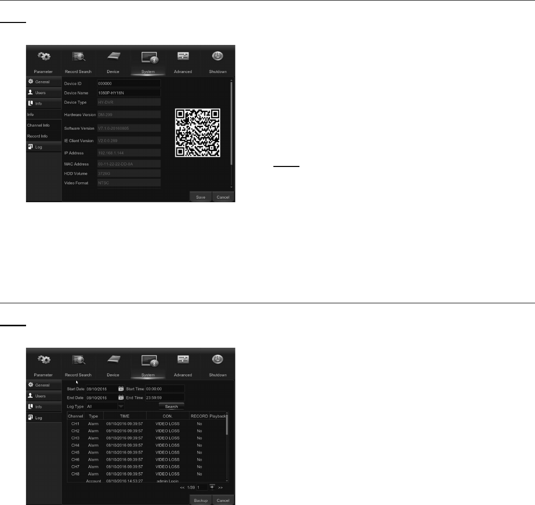
Info
Note: This menu allows you to view the summary of
the system, channel information & record information.
Figure BK
Device Name: Enter the desired name for your
DVR. The name can include both letters and
numbers.
Device ID: Enter the desired ID for your DVR. The
device ID is used to identify the DVR, and can
only be composed of numbers, and cannot be the
same with other IDs when multiple DVRs are
connected in the same network.
MAC Address: Display the MAC address of the
DVR. When multiple DVRs are connected to the
same network, each DVR must have a unique MAC
address to ensure that the DVR can connect
to the network.
Note: If your DVR supports P2P function, you will find
a QR code in the info page. You can scan this QR
code using the mobile app to remotely access DVR.
Channel Info: View the information
summary on the channels.
Record Info: View the recording information
summary by channel, record state, stream type,
FPS, bitrate, and resolution.
Log
Note: This menu allows you to view a
list of events of system operation.
Figure BL
1. To search for a log, enter the start time/end time
in the respective fields and click Search.
2. To display log details, double-click on the item.
3. To backup a log entry, connect an external USB disk
to the DVR, click on the log event and click Backup.
4. Log Type: Select the log type.
5. Start Time/End Time: Specify the start and end
date/time of the logs you want to review and/or
save on an external USB storage device. Click
Search. The logs will be listed on the table.
Page 31For technical questions, please call 1-888-866-5797.Item 63890
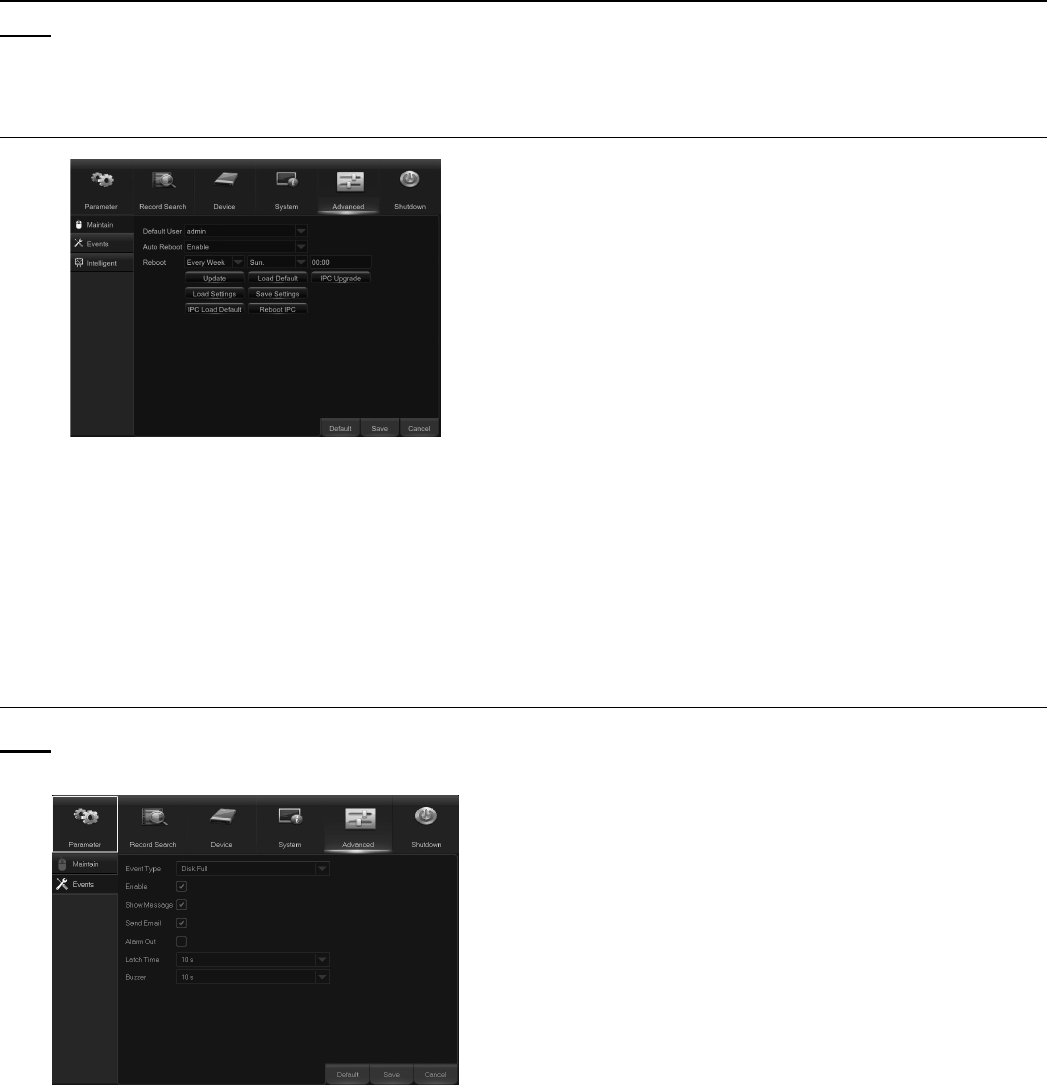
Advanced
Note: This menu allows you to configure
automatic system maintenance, load factory
defaults, update the firmware settings, etc.
Maintain
Figure BM
Default User: If you want to login to the DVR
automatically for live view after each startup, then
only an administrator user account
can be set for auto login.
Auto Reboot: Set Enable to reboot
the DVR based on a schedule.
Reboot: Set the rebooting schedule
based on day, week, or month.
Update: Click to load the update file and then
upgrade the firmware. DO NOT power off
the DVR or remove the USB during the upgrading.
Load Settings: Select this option to import the
setting that you have saved earlier, using the
Save Settings function.
Load Default: Use this feature to restore the
factory default settings of the DVR. It is
recommended to load defaults for all
options, after upgrading the firmware.
Save Settings: Select this option to save the DVR
current settings, such as the video recording
settings, network configurations, etc. to the USB device.
Events
Note: This menu allows you to set the type of events
that you want the DVR to notify you about.
Figure BN
Event Type: Select the event type. Options are:
Disk Full: When HDD is full.
Disk Error: If HDD is not detected properly.
Video Loss: If camera is not detected properly.
Enable: Check the box to enable
the monitoring of the event.
Show Message: Check the box to display a
message on the screen when Disk Full, Disk
Error, or Video Loss event happens.
Send Email: Let the DVR to send you an
auto-email when an event occurs.
Alarm Out: Click to enable the external alarm
device to sound. This is an optional function.
Latch Time: Determine how long the external sensor
alarm device to sound (10s, 20s, 40s, 60s).
Buzzer: Set the buzzer duration when the event occurs
(Off/10s/20s/40s/60s). To disable buzzer, select OFF.
Page 32 For technical questions, please call 1-888-866-5797. Item 63890
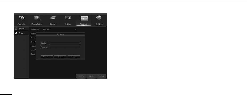
Shutdown
1. Manually turn off or reboot the DVR. See Figure BO.
Figure BO
Note: You will need to input your user name
and password to complete the operation.
Page 33For technical questions, please call 1-888-866-5797.Item 63890
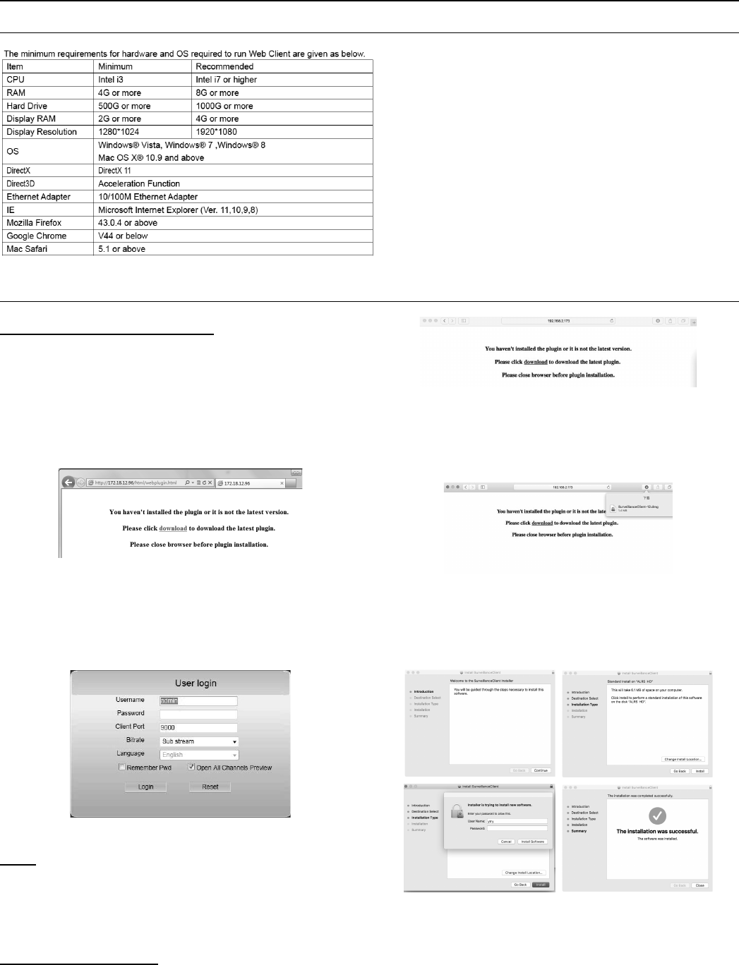
Remote Access
System Environment Requirements
Web Plugin Download and Installation
For IE/Chrome/Firefox users:
1. Launch Explorer on your PC and enter the DVR static
IP address or DDNS domain name (Host Name) you
have set on the DVR in the URL box. The first time
you run the web client, the system will install the
web client plugin. Click download to download the
plugin and install to your computer. See Figure BP.
Figure BP
2. After installing the plug-in, close & relaunch
your browser and repeat step 1 to open the
login page. Input your user name and password
to login to the web client. See Figure BQ.
Figure BQ
Note: If you use Google Chrome, please use Version
V41 or below. If you use V42 to V44, you need
to enable NPAPI plugins. Please enter chrome://
flags/#enable-npapi on URL bar to find and enable
NPAPI. The system does not support V45 or above.
For Mac/Safari users:
1. Launch Safari on your Mac and enter the DVR static
IP address or DDNS domain name (Host Name)
that you have set on the DVR in the URL box.
Figure BR
2. Download the plug-in “SurveillanceClient.
dmg,” locate the downloaded file and
double click it. See Figure BS.
Figure BS
3. Click on Continue then Install. Enter user name
and password for Mac computer, click on Install
Software, then Close to finish installation.
Figure BT
4. Close Safari and repeat Step 1 to
open the Web Client login page.
Page 34 For technical questions, please call 1-888-866-5797. Item 63890
Web Client Manager
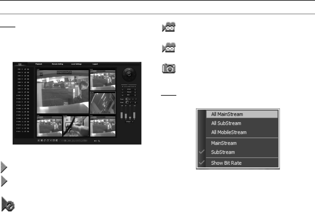
Live Interface
Note: This is the first screen that opens after
you have logged in to the Web Client. Here you
can open or close live preview, record video to a
local computer manually, take snapshots of the
screens, PTZ control, color adjustment, etc.
Figure BU
Preview is closed. Click to open live preview.
Preview is opened, click to close live preview.
Unable to open live view, because
camera is not connected to this channel.
Click to record the channel to computer
The channel is being recorded to computer
Click to take a snapshot of the channel
Note: Right-click on a channel picture to
select the picture quality. See Figure BV.
Figure BV
Page 35For technical questions, please call 1-888-866-5797.Item 63890
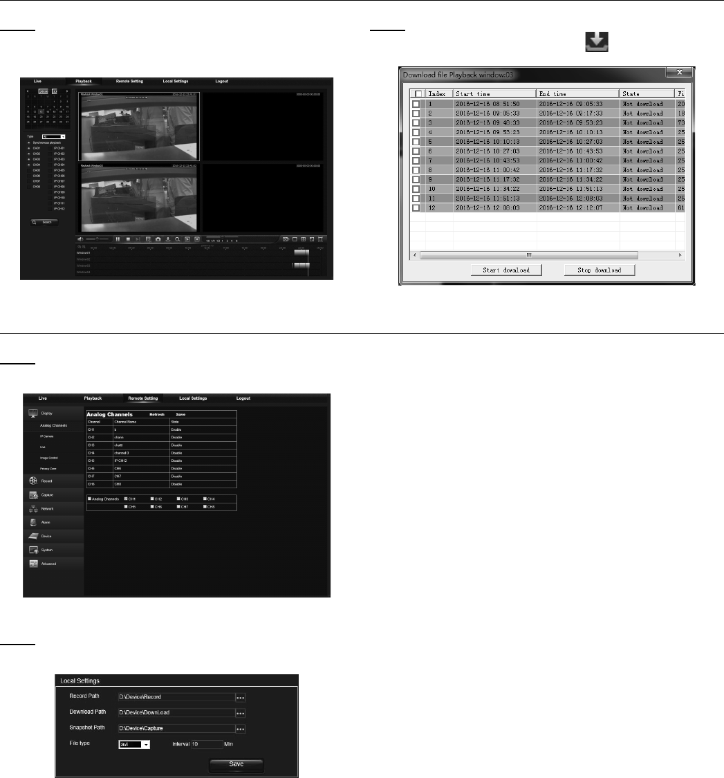
Playback
Note: You can search & play recorded files
stored on the HDD inside the DVR, and save
the result to the local directory on your PC.
Figure BW
Note: Download video clips from the DVR to
your local computer by clicking the icon.
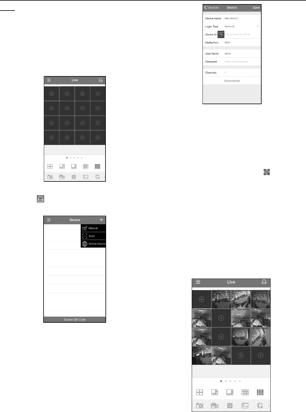
Remote Setting
Note: This mode will allow you to remotely
configure the settings of the DVR.
Figure BX
Note: At the Local Settings screen, find
specific setting modes. See Figure BY.
Figure BY
Record Path: Set the path to save manual
recordings on your PC’s local drive.
Download Path: Set the path on your PC’s local
drive where you want to download recordings
from the DVR.
Snapshot Path: Set the path to save manual
snapshots on your PC’s local drive.
Save: Click Save to save the modifications.
File Type: Choose your preferred file
type for manual recordings.
Interval: Determine the maximum
length of manual recordings.
Page 36 For technical questions, please call 1-888-866-5797. Item 63890
Remote Access from Mobile Devices
Note: This DVR allows for remote access via mobile
devices based on Android & iOS operating systems.
1. Use the QR codes included on the top of the DVR
to download the RXCamView app from Google
Play Store (for android devices) or App Store (for
iOS devices). Once downloaded, install the app.
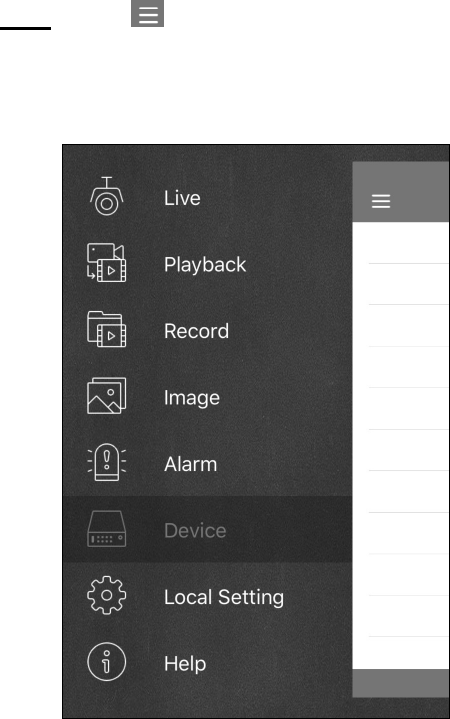
2. Open the app. It will display the live
view screen, as in Figure BZ.
Figure BZ
3. Press the icon to open device list page,
then press + to add device. See Figure CA.
Figure CA
4. Press “Manual” and input the DVR
information. See Figure CB.
Figure CB
Device Name: Input the name you want to display.
Login Type: Device ID and IP/DOMAIN
-Device ID: For P2P connection.
-IP/DOMAIN: IP address or Domain name of the DVR.
Device ID/IP Address: Input the P2P ID or IP
address/Domain name. You can use the icon
to scan the P2P QR code and add a device.
Media Port: Input the media port in DVR network setting.
User Name / Password: Input the user
name & password of the DVR.
Channels: System will display the number of
channels of the DVR after connected.
5. After all settings have been completed,
press Save. The app will then show the
Live View display. See Figure CC.
Figure CC
Page 37For technical questions, please call 1-888-866-5797.Item 63890
Note: Use the icon to open the Menu list
where you can check & configure the live view,
playback, local recorded videos, captured
pictures, push alarm notifications, Device
manager, Local Setting & Help documents.
Figure CD

Page 38 For technical questions, please call 1-888-866-5797. Item 63890
Troubleshooting
Problem Likely Solutions
The system does not detect the HDD. Check that the power supply, data cord, and power
cables are properly connected. Double-check that
the HDD is properly supported by system.
User forgot their password. Consult with Cobra technical personnel. Try to make
password easy to remember and relatively safe.
Abnormal or nonexisent video signal after
connecting DVR and camera together.
Check network cable at DVR side to see if cable
is firmly connected and in good condition, or to
check if NTSC or PAL is selected consistently.
Prevent DVR from being affected by heat. Place DVR in a place with good air circulation
and away from heat sources to ensure
stability and health of the item.
Remote Control won’t work. Make sure to aim remote control at IR receiver on
front panel during use. Also, check condition of
batteries and see if remote itself is not broken.
User wants to take HDD from their
PC and install it in DVR.
All HDDs supported by the system will work. However,
once DVR runs, data on your HDD will be lost.
User wants to playback while recording. This is ok. The system supports this function.
User wants to clear some records from the DVR’s HDD. Due to file security, user may not clear parts of records.
To remove all records, user must format HDD.
Cannot log in DVR client. Check to see if network settings are correct
and RJ-45 port is functional. Make sure
account and password are correctly input.
Cannot find any records during playback. Check to see that data line for HDD is ok and system
time is properly adjusted. Try a few times and restart.
DVR cannot control PTZ. Check for the following errors: PTZ in the front side is
malfunctioned. Setting, connection, and installation of
PTZ are incorrect. PTZ setting is incorrect. Protocol or
address of PTZ decoder does not match that of DVR.
Dynamic detection will not work. Check that the motion detection time and regional settings
are correct, and that sensitivity is not set too low.
Alarm will not work. Check that alarm setting, alarm connection,
and input signals are correct.
Buzzer goes off persistently. Check alarm setting to determine if motion
detection is enabled, object motion is detected all
the time, and I/O alarm is set as Always Off.
User cannot stop recording by pressing “Stop” or
clicking “Stop Recording” in the context menu.
Change recording setting to No Record. To
stop Startup recording, change record mode to
scheduled recording or manual recording. Set
channel as Off status in Record setting.

Page 39For technical questions, please call 1-888-866-5797.Item 63890
Maintenance and Servicing
1. To shut down DVR, first shut down the system and
then turn off the power. Do not turn off the power
directly or HDD data will be lost or damaged.
2. Please keep DVR away from heat sources or places.
3. Clean the internal dust regularly. Make sure DVR is
well ventilated so as to ensure good heat dissipation.
4. Please do not hot plug audio and video cables,
or cables connected to ports like RS-232 or RS-
485. Otherwise the ports will be damaged.
5. Please check the HDD cable and data
cable regularly to see if they are aging.
6. Please prevent the audio and video signals of
the DVR from being interfered with by other
electronic devices, and prevent the HDD from
being damaged by static electricity and induced
voltage. If the network cable is frequently
disconnected and reconnected, it is suggested
that the connecting line be replaced regularly,
or the input signal may be unstable.
FCC STATEMENT
Note: This equipment has been tested and found to comply with the limits for a Class
A digital device, pursuant to part 15 of the FCC Rules. These limits are designed to
provide reasonable protection against harmful interference when the equipment is
operated in a commercial environment. This equipment generates, uses and can
radiate radio frequency energy and, if not installed and used in accordance with the
instruction manual, may cause harmful interference to radio communications. Operation
of this equipment in a residential area is likely to cause harmful interference in which
case the user will be required to correct the intereference at his own expense.

Limited 90 Day Warranty
Harbor Freight Tools Co. makes every effort to
assure that its products meet high quality and
durability standards, and warrants to the original
purchaser that this product is free from defects
in materials and workmanship for the period
of 90 days from the date of purchase. This
warranty does not apply to damage due directly
or indirectly, to misuse, abuse, negligence or
accidents, repairs or alterations outside our
facilities, criminal activity, improper installation,
normal wear and tear, or to lack of maintenance.
We shall in no event be liable for death,
injuries to persons or property, or for incidental,
contingent, special or consequential damages
arising from the use of our product. Some
states do not allow the exclusion or limitation
of incidental or consequential damages, so the
above limitation of exclusion may not apply to
you. THIS WARRANTY IS EXPRESSLY IN LIEU
OF ALL OTHER WARRANTIES, EXPRESS
OR IMPLIED, INCLUDING THE WARRANTIES
OF MERCHANTABILITY AND FITNESS.
To take advantage of this warranty, the product
or part must be returned to us with transportation
charges prepaid. Proof of purchase date and an
explanation of the complaint must accompany the
merchandise. If our inspection verifies the defect,
we will either repair or replace the product at our
election or we may elect to refund the purchase
price if we cannot readily and quickly provide
you with a replacement. We will return repaired
products at our expense, but if we determine
there is no defect, or that the defect resulted from
causes not within the scope of our warranty, then
you must bear the cost of returning the product.
This warranty gives you specific legal
rights and you may also have other
rights which vary from state to state.
3491 Mission Oaks Blvd. • PO Box 6009 • Camarillo, CA 93011 • 1-888-866-5797
