MOTOTRBO™ SL4000 & SL4010 User Guide 68012004076 A BSM EMEA
User Manual: 68012004076-A BSM EMEA
Open the PDF directly: View PDF ![]() .
.
Page Count: 79
- English
- Foreword
- SL4000 Series Portable Radio
- Document History
- Table of Contents
- Foreword i
- Commercial Warranty xiii
- Battery and Charger Warranty xvi
- Chapter 1 Introduction 1-1
- Chapter 2 Test Equipment and Service Aids 2-1
- Chapter 3 Transceiver Performance Testing 3-1
- Chapter 4 Radio Programming and Tuning 4-1
- Chapter 5 Disassembly/Reassembly Procedures 5-1
- Chapter 6 Basic Troubleshooting 6-1
- Appendix A EMEA Regional Warranty, Service and Technical Support A-1
- Glossary Glossary-1
- List of Figures
- List of Tables
- Related Publications
- Commercial Warranty
- Battery and Charger Warranty
- Chapter 1 Introduction
- Chapter 2 Test Equipment and Service Aids
- Chapter 3 Transceiver Performance Testing
- 3.1 General
- 3.2 Setup
- 3.3 Test Mode
- 3.3.1 Radio Test Mode
- 3.3.2 RF Test Mode
- 3.3.3 Display Test Mode
- 3.3.4 Photosensor Test Mode
- 3.3.5 Accelerometer Test Mode
- 3.3.6 Vibrator Test Mode
- 3.3.7 LED Test Mode
- 3.3.8 Backlight Test Mode
- 3.3.9 Speaker Tone Test Mode
- 3.3.10 Earpiece Tone Test Mode
- 3.3.11 Audio Loopback Earpiece Test
- 3.3.12 Battery Check Test Mode
- 3.3.13 Button/Knob/PTT Test Mode
- Chapter 4 Radio Programming and Tuning
- Chapter 5 Disassembly/Reassembly Procedures
- 5.1 Introduction
- 5.2 Preventive Maintenance
- 5.3 Safe Handling of CMOS and LDMOS Devices
- 5.4 Repair Procedures and Techniques – General
- 5.5 Disassembling and Reassembling the Radio – General
- 5.6 Radio Disassembly – Detailed
- 5.7 Radio Reassembly – Detailed
- 5.8 Radio Exploded Mechanical Views and Parts Lists
- 5.9 Torque Chart
- Chapter 6 Basic Troubleshooting
- Appendix A EMEA Regional Warranty, Service and Technical Support
- Glossary
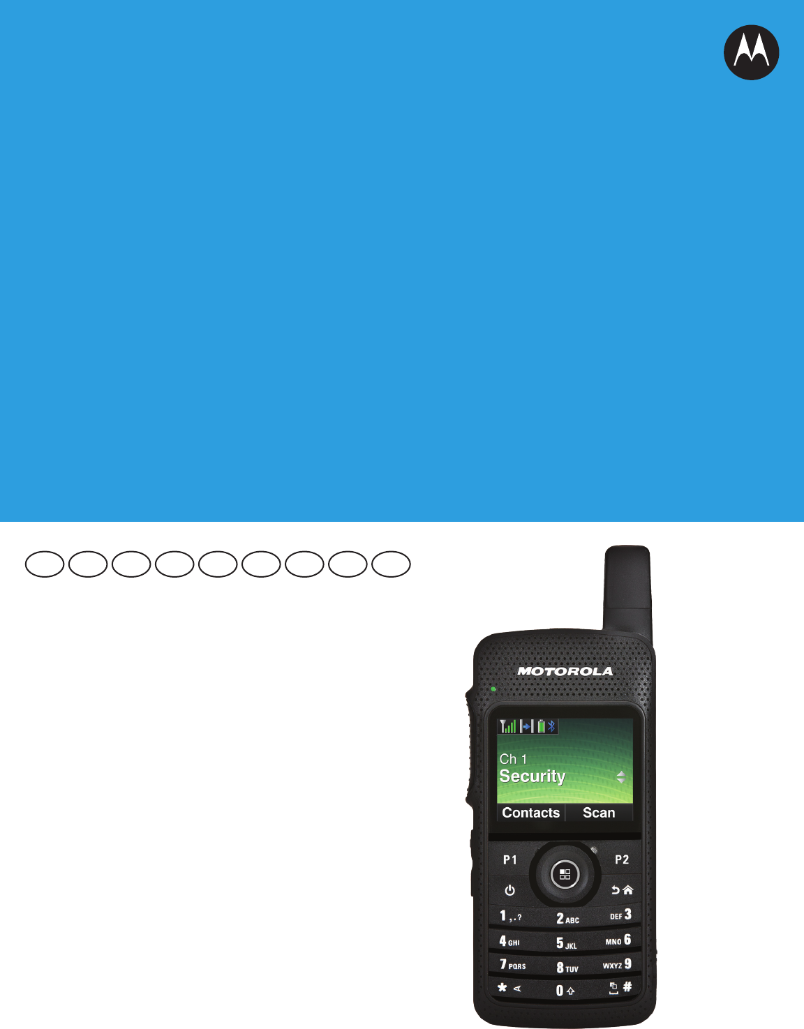
PROFESSIONAL DIGITAL TWO-WAY RADIO
MOTOTRBO™
SL SERIES
SL4000 & SL4010 PORTABLES
BASIC SERVICE MANUAL
EN FR IT ESDE PL RU ARTU

i
Foreword
This manual covers all models of the SL4000 series Portable Radios, unless otherwise specified. It includes all the
information necessary to maintain peak product performance and maximum working time, using levels 1 and 2
maintenance procedures. This level of service goes down to the board replacement level and is typical of some local
service centers, self-maintained customers, and distributors.
Product Safety and RF Exposure Compliance
ATTENTION!
This radio is restricted to occupational use only to satisfy FCC/ICNIRP energy exposure requirements.
Before using this product, read the RF energy awareness information and operating instructions in
the Product Safety and RF Exposure booklet enclosed with your radio (Motorola Publication part
number 6864117B25) to ensure compliance with RF energy exposure limits.
For a list of Motorola-approved antennas, batteries, and other accessories, visit the following web
site: http://www.motorolasolutions.com/slseries
Computer Software Copyrights
The Motorola products described in this manual may include copyrighted Motorola computer programs stored in
semiconductor memories or other media. Laws in the United States and other countries preserve for Motorola certain
exclusive rights for copyrighted computer programs, including, but not limited to, the exclusive right to copy or reproduce
in any form the copyrighted computer program. Accordingly, any copyrighted Motorola computer programs contained in
the Motorola products described in this manual may not be copied, reproduced, modified, reverse-engineered, or
distributed in any manner without the express written permission of Motorola. Furthermore, the purchase of Motorola
products shall not be deemed to grant either directly or by implication, estoppel, or otherwise, any license under the
copyrights, patents or patent applications of Motorola, except for the normal non-exclusive license to use that arises by
operation of law in the sale of a product.
Document Copyrights
No duplication or distribution of this document or any portion thereof shall take place without the express written
permission of Motorola. No part of this manual may be reproduced, distributed, or transmitted in any form or by any
means, electronic or mechanical, for any purpose without the express written permission of Motorola.
Disclaimer
The information in this document is carefully examined, and is believed to be entirely reliable. However, no responsibility is
assumed for inaccuracies. Furthermore, Motorola reserves the right to make changes to any products herein to improve
readability, function, or design. Motorola does not assume any liability arising out of the applications or use of any product
or circuit described herein; nor does it cover any license under its patent rights nor the rights of others.
Trademarks
MOTOROLA, MOTO, MOTOROLA SOLUTIONS and the Stylized M logo are trademarks or registered trademarks of
Motorola Trademark Holdings, LLC and are used under license. All other trademarks are the property of their respective
owners.
© 2012 Motorola Solutions, Inc.
All rights reserved.
Before using this product, read the operating instructions
for safe usage contained in the Product Safety and RF
Exposure booklet enclosed with your radio.
!
C a u t i o n

ii
Notes

iii
Document History
The following major changes have been implemented in this manual since the previous edition:
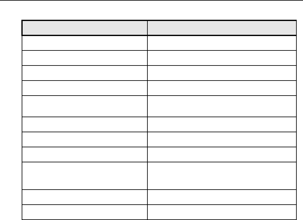
Edition Description Date
68012004076-A Initial Release Jan 2012

iv
Notes

Table of Contents v
Table of Contents
Foreword..........................................................................................................i
Product Safety and RF Exposure Compliance.............................................................................................i
Computer Software Copyrights ....................................................................................................................i
Document Copyrights...................................................................................................................................i
Disclaimer.....................................................................................................................................................i
Trademarks ..................................................................................................................................................i
Document History ........................................................................................ iii
Commercial Warranty .................................................................................xiii
Limited Warranty ...................................................................................................................................... xiii
MOTOROLA COMMUNICATION PRODUCTS............................................................................ xiii
I. What This Warranty Covers And For How Long ................................................................... xiii
II. General Provisions ............................................................................................................... xiii
III. State Law Rights ................................................................................................................xiv
IV. How To Get Warranty Service ............................................................................................ xiv
V. What This Warranty Does Not Cover................................................................................... xiv
VI. Patent And Software Provisions ......................................................................................... xiv
VII. Governing Law....................................................................................................................xv
Battery and Charger Warranty ...................................................................xvi
Workmanship Warranty ............................................................................................................................ xvi
Capacity Warranty.................................................................................................................................... xvi
Chapter 1 Introduction ......................................................................... 1-1
1.1 Notations Used in This Manual.................................................................................................... 1-1
1.2 Radio Description ........................................................................................................................ 1-1
1.2.1 Radio Overview ............................................................................................................... 1-2
1.3 Portable Radio Model Numbering Scheme ................................................................................. 1-3
1.4 Model Charts ............................................................................................................................... 1-4
1.4.1 UHF 2W GOB Enabled (403 – 470 MHz) Model Chart ................................................... 1-4
1.4.2 UHF 2W Non-GOB Enabled (403 – 470 MHz) Model Chart ........................................... 1-4
1.5 Specifications............................................................................................................................... 1-5
Chapter 2 Test Equipment and Service Aids ..................................... 2-1
2.1 Recommended Test Equipment .................................................................................................. 2-1
2.2 Service Aids................................................................................................................................. 2-2

vi Table of Contents
Chapter 3 Transceiver Performance Testing ..................................... 3-1
3.1 General ........................................................................................................................................ 3-1
3.2 Setup............................................................................................................................................ 3-1
3.3 Test Mode .................................................................................................................................... 3-4
3.3.1 Radio Test Mode .............................................................................................................3-4
3.3.2 RF Test Mode.................................................................................................................. 3-4
3.3.3 Display Test Mode........................................................................................................... 3-6
3.3.4 Photosensor Test Mode...................................................................................................3-7
3.3.5 Accelerometer Test Mode................................................................................................3-7
3.3.6 Vibrator Test Mode .......................................................................................................... 3-7
3.3.7 LED Test Mode................................................................................................................3-7
3.3.8 Backlight Test Mode ........................................................................................................3-7
3.3.9 Speaker Tone Test Mode ................................................................................................ 3-8
3.3.10 Earpiece Tone Test Mode ............................................................................................... 3-8
3.3.11 Audio Loopback Earpiece Test........................................................................................ 3-8
3.3.12 Battery Check Test Mode ................................................................................................ 3-8
3.3.13 Button/Knob/PTT Test Mode ........................................................................................... 3-8
Chapter 4 Radio Programming and Tuning ....................................... 4-1
4.1 Introduction .................................................................................................................................. 4-1
4.2 Customer Programming Software Setup ..................................................................................... 4-1
4.3 AirTracer Application Tool............................................................................................................ 4-2
4.4 Radio Tuning Setup .....................................................................................................................4-2
Chapter 5 Disassembly/Reassembly Procedures ............................. 5-1
5.1 Introduction .................................................................................................................................. 5-1
5.2 Preventive Maintenance .............................................................................................................. 5-1
5.2.1 Inspection ........................................................................................................................ 5-1
5.2.2 Cleaning Procedures ....................................................................................................... 5-1
5.3 Safe Handling of CMOS and LDMOS Devices ............................................................................ 5-2
5.4 Repair Procedures and Techniques – General............................................................................ 5-4
5.5 Disassembling and Reassembling the Radio – General.............................................................. 5-5
5.6 Radio Disassembly – Detailed .....................................................................................................5-6
5.6.1 External Antenna Disassembly........................................................................................ 5-6
5.6.2 Back housing Disassembly..............................................................................................5-8
5.6.3 Internal Antenna Disassembly.......................................................................................5-10
5.6.4 PCB Disassembly .......................................................................................................... 5-11
5.6.5 Audio Jack Disassembly................................................................................................ 5-12
5.6.6 LCD Display Disassembly ............................................................................................. 5-13
5.7 Radio Reassembly – Detailed....................................................................................................5-15
5.7.1 LCD Display Reassembly.............................................................................................. 5-15
5.7.2 Audio Jack Reassembly ................................................................................................ 5-17
5.7.3 PCB Reassembly........................................................................................................... 5-18
5.7.4 Internal Antenna Reassembly........................................................................................ 5-19
5.7.5 Back Housing Reassembly............................................................................................ 5-20
5.8 Radio Exploded Mechanical Views and Parts Lists ...................................................................5-24
5.8.1 Non-GOB Model Exploded View and Parts List ............................................................ 5-24
5.8.2 Exploded View and Parts List........................................................................................ 5-26
5.9 Torque Chart.............................................................................................................................. 5-28

Table of Contents vii
Chapter 6 Basic Troubleshooting ....................................................... 6-1
6.1 Introduction .................................................................................................................................. 6-1
6.2 Power-Up Error Codes ................................................................................................................ 6-1
6.3 Operational Error Codes.............................................................................................................. 6-2
Appendix A EMEA Regional Warranty, Service and
Technical Support...............................................................A-1
A.1 Warranty and Service Support.....................................................................................................A-1
A.1.1 Warranty Period and Return Instructions ........................................................................A-1
A.1.2 After Warranty Period ......................................................................................................A-1
A.2 European Radio Support Centre (ERSC) ....................................................................................A-2
A.3 Piece Parts ..................................................................................................................................A-2
A.4 Technical Support........................................................................................................................A-3
A.5 Further Assistance From Motorola ..............................................................................................A-3
Glossary......................................................................................... Glossary-1

viii List of Figures
List of Figures
Figure 1-1. Display Model....................................................................................................................... 1-2
Figure 1-2. Portable Radio Model Numbering Scheme.......................................................................... 1-3
Figure 3-1. DMR Radio Transmitter and Receiver Testing Setup........................................................... 3-2
Figure 3-2. Name plate label ..................................................................................................................3-2
Figure 3-3. RF plug................................................................................................................................. 3-3
Figure 3-4. Connect RF Antenna adaptor to radio RF input/output port................................................. 3-3
Figure 3-5. Battery Check Test Mode Display ........................................................................................3-8
Figure 4-1. CPS Programming Setup..................................................................................................... 4-1
Figure 4-2. Radio Transmitter and Receiver Tuning Setup .................................................................... 4-2
Figure 5-1. Antenna plug and escutcheon cover removal ...................................................................... 5-6
Figure 5-2. Antenna screw removal........................................................................................................ 5-7
Figure 5-3. Antenna removal .................................................................................................................. 5-7
Figure 5-4. Unlatching battery door ........................................................................................................ 5-8
Figure 5-5. Battery door removal............................................................................................................ 5-8
Figure 5-6. Battery removal .................................................................................................................... 5-9
Figure 5-7. Self tapping screws and machining screws removal............................................................ 5-9
Figure 5-8. Back housing removal........................................................................................................5-10
Figure 5-9. Internal antenna removal ................................................................................................... 5-10
Figure 5-10. Board flex and coax cable connector disassembly ............................................................ 5-11
Figure 5-11. Interface board removal ..................................................................................................... 5-11
Figure 5-12. Audio jack flex and keypad flex disassembly ..................................................................... 5-12
Figure 5-13. Audio jack flex removal ......................................................................................................5-12
Figure 5-14. LCD display disassembly ...................................................................................................5-13
Figure 5-15. Lifting of PCB board ........................................................................................................... 5-13
Figure 5-16. PCB board removal............................................................................................................ 5-14
Figure 5-17. Display retainer lock removal .............................................................................................5-14
Figure 5-18. LCD display removal .......................................................................................................... 5-15
Figure 5-19. LCD display reassembly ....................................................................................................5-15
Figure 5-20. Display retainer lock reassembly........................................................................................ 5-16
Figure 5-21. Flex connector tab reassembly ..........................................................................................5-16
Figure 5-22. PCB board reassembly ...................................................................................................... 5-17
Figure 5-23. Audio jack connector reassembly ......................................................................................5-17
Figure 5-24. Audio jack flex connector and keypad connector reassembly............................................ 5-18
Figure 5-25. Interface board reassembly................................................................................................ 5-18
Figure 5-26. Board flex reassembly........................................................................................................ 5-19
Figure 5-27. Internal antenna reassembly..............................................................................................5-19
Figure 5-28. Back housing reassembly ..................................................................................................5-20
Figure 5-29. Self tapping screws and machining screws reassembly .................................................... 5-20
Figure 5-30. Battery reassembly ............................................................................................................ 5-21
Figure 5-31. Battery door reassembly ....................................................................................................5-21
Figure 5-32. Latching battery door .........................................................................................................5-22
Figure 5-33. Antenna reassembly .......................................................................................................... 5-22
Figure 5-34. Antenna screw reassembly ................................................................................................ 5-23
Figure 5-35. Antenna plug and screw plug reassembly ......................................................................... 5-23
Figure 5-36. SL4000 Non-GOB Model Exploded View........................................................................... 5-24
Figure 5-37. SL4010 GOB Model Exploded View .................................................................................. 5-26

List of Tables ix
List of Tables
Table 1-1. Radio Frequency Ranges and Power Levels....................................................................... 1-1
Table 2-1. Recommended Test Equipment........................................................................................... 2-1
Table 2-2. Service Aids ......................................................................................................................... 2-2
Table 3-1. Front Panel Access Test Mode Displays.............................................................................. 3-4
Table 3-2. Test Frequencies.................................................................................................................. 3-5
Table 3-3. Transmitter Performance Checks ........................................................................................3-5
Table 3-4. Receiver Performance Checks ............................................................................................ 3-6
Table 4-1. Software Installation Kits Radio Tuning Setup ..................................................................... 4-1
Table 5-1. Lead Free Solder Wire Part Number List............................................................................. 5-4
Table 5-2. Lead Free Solder Paste Part Number List ........................................................................... 5-4
Table 5-3. Non-GOB Model Exploded View........................................................................................ 5-25
Table 5-4. GOB Model Exploded View Parts List................................................................................ 5-27
Table 5-5. Torque Specifications for Screws ....................................................................................... 5-28
Table 6-1. Operational Error Codes ...................................................................................................... 6-2

x
Notes

Related Publications xi
Related Publications
Product Safety and RF Exposure ................................................................................................ 6864117B25
SL Series SL4000 & SL4010 Portables User Guide.................................................................. 68012004075
MOTOTRBO SL Series SL4000 & SL4010 Portables Quick Reference Guide......................... 68012004073
MOTOTRBO SL Series Accessory Leaflet ................................................................................ 68012004074

xii Related Publications
Notes
Commercial Warranty xiii
Commercial Warranty
Limited Warranty
MOTOROLA COMMUNICATION PRODUCTS
I. What This Warranty Covers And For How Long
MOTOROLA SOLUTIONS INC. (“MOTOROLA”) warrants the MOTOROLA manufactured
Communication Products listed below (“Product”) against defects in material and workmanship
under normal use and service for a period of time from the date of purchase as scheduled below:
Motorola, at its option, will at no charge either repair the Product (with new or reconditioned parts),
replace it (with a new or reconditioned Product), or refund the purchase price of the Product during
the warranty period provided it is returned in accordance with the terms of this warranty. Replaced
parts or boards are warranted for the balance of the original applicable warranty period. All replaced
parts of Product shall become the property of MOTOROLA.
This express limited warranty is extended by MOTOROLA to the original end user purchaser only
and is not assignable or transferable to any other party. This is the complete warranty for the Product
manufactured by MOTOROLA. MOTOROLA assumes no obligations or liability for additions or
modifications to this warranty unless made in writing and signed by an officer of MOTOROLA.
Unless made in a separate agreement between MOTOROLA and the original end user purchaser,
MOTOROLA does not warrant the installation, maintenance or service of the Product.
MOTOROLA cannot be responsible in any way for any ancillary equipment not furnished by
MOTOROLA which is attached to or used in connection with the Product, or for operation of the
Product with any ancillary equipment, and all such equipment is expressly excluded from this
warranty. Because each system which may use the Product is unique, MOTOROLA disclaims
liability for range, coverage, or operation of the system as a whole under this warranty.
II. General Provisions
This warranty sets forth the full extent of MOTOROLA'S responsibilities regarding the Product.
Repair, replacement or refund of the purchase price, at MOTOROLA's option, is the exclusive
remedy. THIS WARRANTY IS GIVEN IN LIEU OF ALL OTHER EXPRESS WARRANTIES. IMPLIED
WARRANTIES, INCLUDING WITHOUT LIMITATION, IMPLIED WARRANTIES OF
MERCHANTABILITY AND FITNESS FOR A PARTICULAR PURPOSE, ARE LIMITED TO THE
DURATION OF THIS LIMITED WARRANTY. IN NO EVENT SHALL MOTOROLA BE LIABLE FOR
DAMAGES IN EXCESS OF THE PURCHASE PRICE OF THE PRODUCT, FOR ANY LOSS OF
USE, LOSS OF TIME, INCONVENIENCE, COMMERCIAL LOSS, LOST PROFITS OR SAVINGS
OR OTHER INCIDENTAL, SPECIAL OR CONSEQUENTIAL DAMAGES ARISING OUT OF THE
USE OR INABILITY TO USE SUCH PRODUCT, TO THE FULL EXTENT SUCH MAY BE
DISCLAIMED BY LAW.
Digital Portable Radios Two (2) Years
Product Accessories (Excluding Batteries and Chargers) One (1) Year

xiv Commercial Warranty
III. State Law Rights
SOME STATES DO NOT ALLOW THE EXCLUSION OR LIMITATION OF INCIDENTAL OR
CONSEQUENTIAL DAMAGES OR LIMITATION ON HOW LONG AN IMPLIED WARRANTY
LASTS, SO THE ABOVE LIMITATION OR EXCLUSIONS MAY NOT APPLY.
This warranty gives specific legal rights, and there may be other rights which may vary from state to
state.
IV. How To Get Warranty Service
You must provide proof of purchase (bearing the date of purchase and Product item serial number)
in order to receive warranty service and, also, deliver or send the Product item, transportation and
insurance prepaid, to an authorized warranty service location. Warranty service will be provided by
Motorola through one of its authorized warranty service locations. If you first contact the company
which sold you the Product, it can facilitate your obtaining warranty service. You can also
V. What This Warranty Does Not Cover
A. Defects or damage resulting from use of the Product in other than its normal and customary
manner.
B. Defects or damage from misuse, accident, water, or neglect.
C. Defects or damage from improper testing, operation, maintenance, installation, alteration,
modification, or adjustment.
D. Breakage or damage to antennas unless caused directly by defects in material workmanship.
E. A Product subjected to unauthorized Product modifications, disassemblies or repairs
(including, without limitation, the addition to the Product of non-Motorola supplied equipment)
which adversely affect performance of the Product or interfere with Motorola's normal
warranty inspection and testing of the Product to verify any warranty claim.
F. Product which has had the serial number removed or made illegible.
G. Rechargeable batteries if:
- any of the seals on the battery enclosure of cells are broken or show evidence of tamper-
ing.
- the damage or defect is caused by charging or using the battery in equipment or service
other than the Product for which it is specified.
H. Freight costs to the repair depot.
I. A Product which, due to illegal or unauthorized alteration of the software/firmware in the
Product, does not function in accordance with MOTOROLA’s published specifications or the
FCC type acceptance labeling in effect for the Product at the time the Product was initially
distributed from MOTOROLA.
J. Scratches or other cosmetic damage to Product surfaces that does not affect the operation of
the Product.
K. Normal and customary wear and tear.
VI. Patent And Software Provisions
MOTOROLA will defend, at its own expense, any suit brought against the end user purchaser to the
extent that it is based on a claim that the Product or parts infringe a United States patent, and
MOTOROLA will pay those costs and damages finally awarded against the end user purchaser in
any such suit which are attributable to any such claim, but such defense and payments are
conditioned on the following:

Commercial Warranty xv
A. that MOTOROLA will be notified promptly in writing by such purchaser of any notice of such
claim;
B. that MOTOROLA will have sole control of the defense of such suit and all negotiations for its
settlement or compromise; and
C. should the Product or parts become, or in MOTOROLA's opinion be likely to become, the
subject of a claim of infringement of a United States patent, that such purchaser will permit
MOTOROLA, at its option and expense, either to procure for such purchaser the right to
continue using the Product or parts or to replace or modify the same so that it becomes
noninfringing or to grant such purchaser a credit for the Product or parts as depreciated and
accept its return. The depreciation will be an equal amount per year over the lifetime of the
Product or parts as established by MOTOROLA.
MOTOROLA will have no liability with respect to any claim of patent infringement which is based
upon the combination of the Product or parts furnished hereunder with software, apparatus or
devices not furnished by MOTOROLA, nor will MOTOROLA have any liability for the use of ancillary
equipment or software not furnished by MOTOROLA which is attached to or used in connection with
the Product. The foregoing states the entire liability of MOTOROLA with respect to infringement of
patents by the Product or any parts thereof.
Laws in the United States and other countries preserve for MOTOROLA certain exclusive rights for
copyrighted MOTOROLA software such as the exclusive rights to reproduce in copies and distribute
copies of such Motorola software. MOTOROLA software may be used in only the Product in which
the software was originally embodied and such software in such Product may not be replaced,
copied, distributed, modified in any way, or used to produce any derivative thereof. No other use
including, without limitation, alteration, modification, reproduction, distribution, or reverse
engineering of such MOTOROLA software or exercise of rights in such MOTOROLA software is
permitted. No license is granted by implication, estoppel or otherwise under MOTOROLA patent
rights or copyrights.
VII. Governing Law
This Warranty is governed by the laws of the State of Illinois, USA.
xvi Battery and Charger Warranty
Battery and Charger Warranty
Workmanship Warranty
The workmanship warranty guarantees against defects in workmanship under normal use and
service.
Capacity Warranty
The capacity warranty guarantees 80% of the rated capacity for the warranty duration.
Lithium-Ion (Li-Ion) Batteries (BT70 and BT90) One (1) Year
Chargers Two (2) Years
Lithium-Ion (Li-lon) Batteries (BT70 and BT90) 12 Months
Introduction: Notations Used in This Manual 1-1
Chapter 1 Introduction
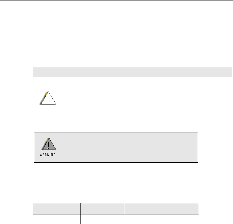
1.1 Notations Used in This Manual
Throughout the text in this publication, you will notice the use of note and caution notations. These
notations are used to emphasize that safety hazards exist, and due care must be taken and
observed.
1.2 Radio Description
The SL4000 series portable radios are available in the following frequency ranges and power levels.
These digital radios are among the most sophisticated two-way radios available. They have a robust
design for radio users who need high performance, quality, and reliability in their daily
communications. This architecture provides the capability of supporting a multitude of legacy and
advanced features resulting in a more cost-effective two-way radio communications solution.
NOTE An operational procedure, practice, or condition that is essential to emphasize.
CAUTION indicates a potentially hazardous situation which, if
not avoided, might result in equipment damage.
WARNING indicates a potentially hazardous situation
which, if not avoided, could result in death or injury.
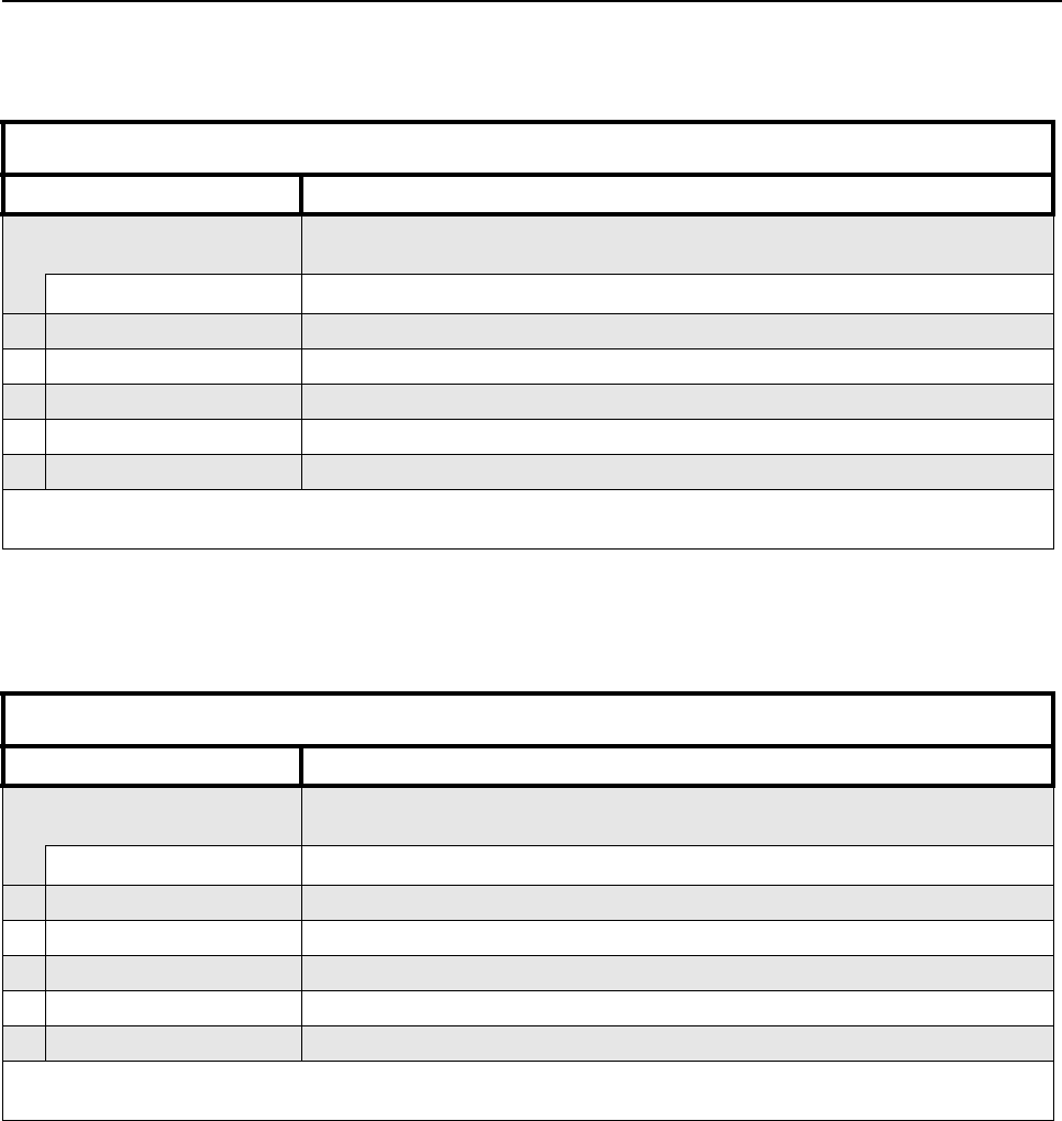
Table 1-1. Radio Frequency Ranges and Power Levels
Frequency Band Bandwidth Power Level
UHF 403 – 470 MHz 2 Watts
!
C a u t i o n
1-2 Introduction: Radio Description
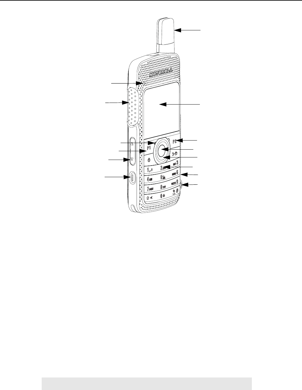
1.2.1 Radio Overview
Figure 1-1. Display Model
• LED INDICATORS – Red, green and orange light-emitting diodes indicate operating status.
• LCD (Liquid Crystal Display) – 320x240 Liquid Crystal Display provides visual information
about many radio features.
• NAVIGATION KEYS and MENU/OK– To provide menu navigation and to select the interface.
• VOLUME BUTTON - To adjust speaker volume.
• KEYPAD – Twelve keys that allow the user to input characters for various text based
operations.
• FRONT and SIDE PROGRAMMABLE BUTTONS – These three buttons are field
programmable using the CPS.
• PUSH-TO-TALK (PTT) BUTTON– Press to execute voice operations (e.g. Group call and
Private Call).
• ANTENNA – Provides the needed RF radiation when transmitting or receiving.
• MICROPHONE – Allows voice to be sent when PTT or voice operations are activated.
• AUDIO JACK – Interface point for audio accessories to be used with the radio.
• MICRO USB PORT – Programs the radio through the computer and charges the radio through
a wall charger.
NOTE Charging the radio through the computer is not supported.
LED Indicators
PTT Button
Microphone
Navigation Keys
Emergency/
Programmable button
Antenna
LCD
Programmable Button
Programmable Button
Keypad
Micro USB Port
Audio Jack
Volume Button
Menu/OK Button

Introduction: Portable Radio Model Numbering Scheme 1-3
• EMERGENCY/ PROGRAMMABLE BUTTON – Turns on and off the programmable Emergency
Operations.
• SPEAKER – Outputs all tones and audio generated by the radio (e.g. features such as keypad
tones and voice audio).
1.3 Portable Radio Model Numbering Scheme
Figure 1-2. Portable Radio Model Numbering Scheme
Model No.Example : AZ H 8 1 Q C N 9 M A 2 A N
Position : 1 2 3 4 5 6 7 8 9 10 11 12
Unique Variation
N: Standard Package
Version Letter
Feature Level
2: Non-FM
Primary System Type
A: Conventional
Primary Operation
M: Standard w/BT
N: GOB w/BT
Channel Spacing
9: Variable/Programmable
Power Level
C: 2W
81: SL Series
Band
Q: 403 – 470MHz
Physical Packages
N: Color Display FKP
H: Portable
AZ: APAC
LA: Latin America
AA: North America
MD: EMEA
1-4 Introduction: Model Charts
1.4 Model Charts
1.4.1 UHF 2W GOB Enabled (403 – 470 MHz) Model Chart
1.4.2 UHF 2W Non-GOB Enabled (403 – 470 MHz) Model Chart
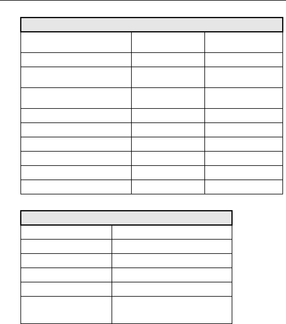
UHF 403 – 470 MHz 2W, GOB Enabled
Model Description
MDH81QCN9NA2AN 403–470 MHz, 2W, MOTOTRBO SL4010 Full Keypad Alphanumberic
Display Portable, GOB Enabled
Item Description
XPMUE3877_ MOTOTRBO™ Display Portable (GOB Enabled)
X PMAE4078_ Antenna Kit – Band 1 (403 – 425 MHz)
XPMAE4076_ Antenna Kit – Band 2 (420 – 445 MHz)
X PMAE4077_ Antenna Kit – Band 3 (438 – 470 MHz)
X68012004073 Portable Quick Reference Guide and Safety Booklet
X = Item Included
_ = The latest version kit. When ordering a kit, refer to your specific kit for the suffix number.
UHF 403 – 470 MHz 2W, Non-GOB Enabled
Model Description
MDH81QCN9MA2AN 403–470 MHz, 2W, MOTOTRBO SL4000 Full Keypad Alphanumberic
Display Portable, Non-GOB Enabled
Item Description
XPMUE3876_ MOTOTRBO Display Portable (Non-GOB Enabled)
X PMAE4078_ Antenna Kit – Band 1 (403 – 425 MHz)
XPMAE4076_ Antenna Kit – Band 2 (420 – 445 MHz)
X PMAE4077_ Antenna Kit – Band 3 (438 – 470 MHz)
X68012004073 Portable Quick Reference Guide and Safety booklet
X = Item Included
_ = The latest version kit. When ordering a kit, refer to your specific kit for the suffix number.
Introduction: Specifications 1-5
1.5 Specifications
General SL4000
Channel Capacity 1000
Frequency UHF: 403 – 470 MHz
Dimensions (HxWxT)
with BT70 battery
with BT90 battery 121 x 55 x 17.4 mm
121 x 55 x 19.8 mm
Weight
with BT70 battery
with BT90 battery 153g
165g
Power Supply 3.7 V nominal
FCC Description ABZ99FT4090
IC Description 109AB-99FT4090
Average battery life at 5/5/90 duty cycle with battery saver enabled
BT70 1370 mAh battery 8.5 hrs
BT90 1800 mAh battery 11.5 hrs
1-6 Introduction: Specifications
Receiver SL4000
Frequencies 403 – 470 MHz
Channel Spacing 12.5 kHz
Frequency Stability (-30°C to +60°C) +/-1.5 ppm
Digital Sensitivity 5% BER: 0.3µV
Intermodulation (ETSI-EN300 113-1) 65 dB
Adjacent Channel Selectivity
(ETSI-EN300 113-1) 60 dB @ 12.5 kHz
Spurious Rejection (ETSI-EN300 113-1) 70 dB
Rated Audio 500 mW
Audio Distortion @ Rated Audio 3% (typical)
Digital Hum and Noise -40 dB @ 12.5 kHz
Conducted Spurious Emission
(ETSI-EN300 113-1) -57 dBm
Introduction: Specifications 1-7
Transmitter SL4000
Frequencies 403 – 470 MHz
Frequency Stability (-30°C to +60°C) +/-1.5 ppm
Power Output 2 W
Digital Hum and Noise -40 dB @ 12.5 kHz
Conducted / Radiated Emission -36 dBm < 1 GHz
-30 dBm > 1 GHz
Digital Adjacent Channel Power 60 dB @ 12.5 kHz
Audio Response +1, -3 dBm
Audio Distortion 3%
4FSK Digital Modulation 12.5 kHz Data: 7K60F1D & 7K60FXD
12.5 kHz Voice: 7K60F1E & 7K60FXE
Combination of 12.5 kHz Data & Voice: 7K60F1W
Digital Vocoder Type AMBE+2
Digital Protocol ETSI TS 102 361 -1,-2,-3

1-8 Introduction: Specifications
UHF1 Self-Quieter Frequencies
403.200 MHz ± 15 kHz
404.000 MHz ± 10 kHz
408.000 MHz ± 10 kHz
412.000 MHz ± 5 kHz
420.000 MHz ± 15 kHz
422.400 MHz ± 15 kHz
428.000 MHz ± 5 kHz
432.000 MHz ± 20 kHz
432.100 MHz ± 10 kHz
432.165 MHz ± 10 kHz
432.450 MHz ± 5kHz
436.000 MHz ± 5 kHz
440.000 MHz ± 5 kHz
441.600 MHz ± 15 kHz
443.895 MHz ± 5 kHz
444.000 MHz ± 20 kHz
444.100 MHz ± 10 kHz
451.200 MHz ± 15 kHz
452.000 MHz ± 10 kHz
456.000 MHz ± 20 kHz
460.000 MHz ± 5 kHz
460.800 MHz ± 15 kHz
468.000 MHz ± 20 kHz
468.100 MHz ± 10 kHz
Introduction: Specifications 1-9
Military Standards
Applicable MIL–STD MIL 810F Methods/
Procedures MIL 810G Methods/
Procedures
Low Pressure 500.4/ Procedure II 500.5/ Procedure II
High Temperature 501.4/ Procedure I/Hot,
Procedure II/Hot 501.5/ Procedure I/ A1,
Procedure II/A1
Low Temperature 502.4/ Procedure I/ C1,
Procedure II/ C1
502.5/ Procedure I/ C1,
Procedure II/ C1
Temperature Shock 503.4/ Procedure I 503.5/ Procedure I/C
Solar Radiation 505.4/ Procedure I 505.5/ Procedure I/ A1
Rain 506.4/ Procedure I 506.5/ Procedure I
Dust 510.4/ Procedure I 510.5/ Procedure I
Vibration 514.5/ Procedure I/24 514.6/ Procedure I/24
Shock 516.5/ Procedure IV 516.6/ Procedure IV, VI
Environmental Specifications
Operating Temperature -10 °C to +60 °C
Storage Temperature -30 °C to +70 °C
ESD IEC 61000-4-2
Water & Dust Intrusion IP54
Humidity 8 hour soak @ +50 °C and 95% RH
Salt Fog 8 hours exposure to 5% saline solution
Sodium Chloride (NaCI) at 35 °C, 16 hours
standing period

1-10 Introduction: Specifications
Notes

Chapter 2 Test Equipment and Service Aids
2.1 Recommended Test Equipment
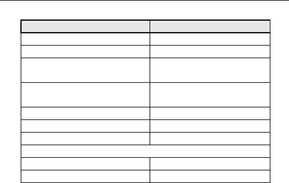
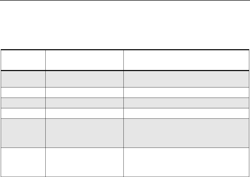
The list of equipment contained in Table 2-1 includes most of the standard test equipment required
for servicing Motorola portable radios.
Table 2-1. Recommended Test Equipment
Equipment Characteristics Example Application
Service
Monitor
Can be used as a
substitute for items
marked with an asterisk
(*)
Aeroflex Digital Radio Test Set
Model 3920 with DMR option
Frequency/deviation meter and
signal generator for wide-range
troubleshooting and alignment
Digital RMS
Multimeter *
100 µV to 300 V
5 Hz to 1 MHz
10 Mega Ohm Impedance
Fluke 179 or equivalent
(www.fluke.com)
AC/DC voltage and
current measurements. Audio
voltage measurements
RF Signal
Generator *
100 MHz to 1 GHz
-130 dBm to +10 dBm
FM Modulation 0 kHz to
10 kHz
Audio Frequency 100 Hz
to 10 kHz
Agilent 443X
R&S Signal Generator
Receiver measurements
Oscilloscope * 2 Channel
50 MHz Bandwidth
5 mV/div to 20 V/div
Leader LS8050
(www.leaderusa.com),
Tektronix TDS1001b
(www.tektronix.com),
or equivalent
Waveform measurements
Power Meter
and Sensor *
5% Accuracy
100 MHz to 500 MHz
50 Watts
Bird 43 Thruline Watt Meter
(www.bird-electronic.com) or
equivalent
Transmitter power output
measurements
RF Millivolt
Meter
100 mV to 3 V RF
10 kHz to 1 GHz
Boonton 92EA
(www.boonton.com) or equivalent
RF level measurements
Power Supply 0 V to 32 V
0 A to 20 A
B&K Precision 1790
(www.bkprecision.com)
or equivalent
Voltage supply
2-2 Test Equipment and Service Aids: Service Aids
2.2 Service Aids
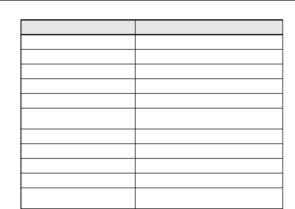
Table 2-2 lists the service aids recommended for working on the radio. While all of these items are
available from Motorola, most are standard workshop equipment items, and any equivalent item
capable of the same performance may be substituted for the item listed.
Table 2-2. Service Aids
Motorola Part
No. Description Application
25-124330-01R Portable Programming Cable Cable connects the radio to a USB port for radio
programming and data applications.
28012039001 RF Antenna Adaptor Adapts radio’s antenna port to test equipment.
07012042001 RF Antenna Adaptor Holder Holds the RF antenna adaptor.
PMNN4429_ Battery Eliminator Connects to radio via battery eliminator cable.
GMVN5141_ MOTOTRBO CPS, Tuner, and
AirTracer Applications CD
CPS allows Dealers/Distributors to program radio
parameters. Tuner allows to tune and test
MOTOTRBO subscriber, repeater and base station
products in the available systems.
GMVN5520_ MOTOTRBO RDAC CD RDAC allows system technicians to remotely moni-
tor the status of the radio and gather real-time radio
hardware failure reports via alarm messages
reported by the radio.
Chapter 3 Transceiver Performance Testing
3.1 General
These radios meet published specifications through their manufacturing process by utilizing high
accuracy laboratory-quality test equipment. The recommended field service equipment approaches
the accuracy of the manufacturing equipment with few exceptions. This accuracy must be
maintained in compliance with the manufacturer’s recommended calibration schedule.
3.2 Setup
Supply voltage is provided using a 3.7 VDC power supply. The equipment required for alignment
procedures is connected as shown in the Radio Tuning Equipment Setup Diagram, Figure 4-2.
The tables in this chapter contain the following related technical data:
Do NOT use any form of connector, e.g. wires, crocodile
clips, and probes, to supply voltage to the radio, other
than the Motorola approved battery eliminator.
Table Number Title
Table 3-1 Front Panel Access Test Mode Displays
Table 3-2 Test Frequencies
Table 3-3 Transmitter Performance Checks
Table 3-4 Receiver Performance Checks
3-2 Transceiver Performance Testing: Setup
Setup:
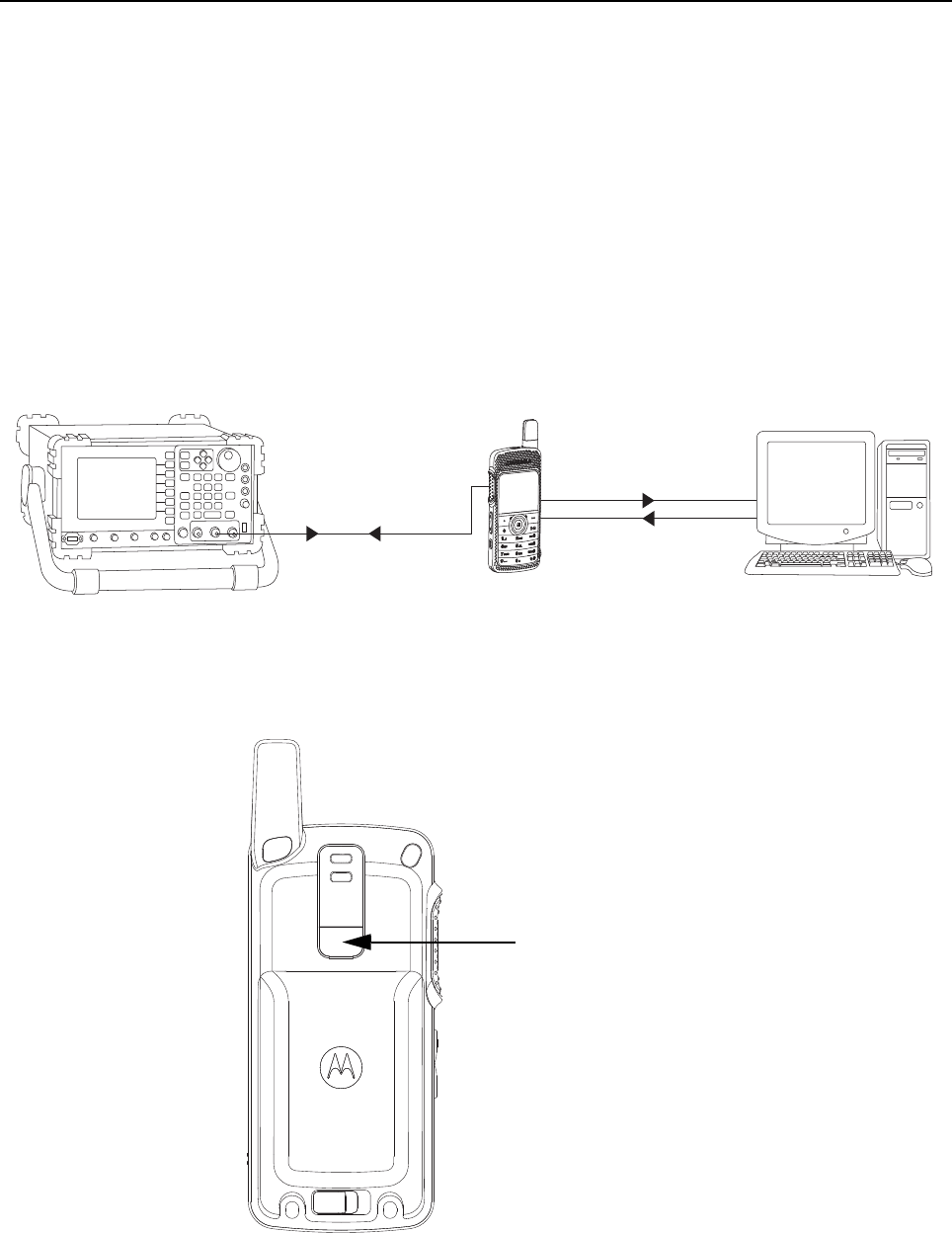
Set up the DMR Transmitter and Receiver Test as per Figure 3-1.
a. Connect the Programming cable to the radio and to the computer.
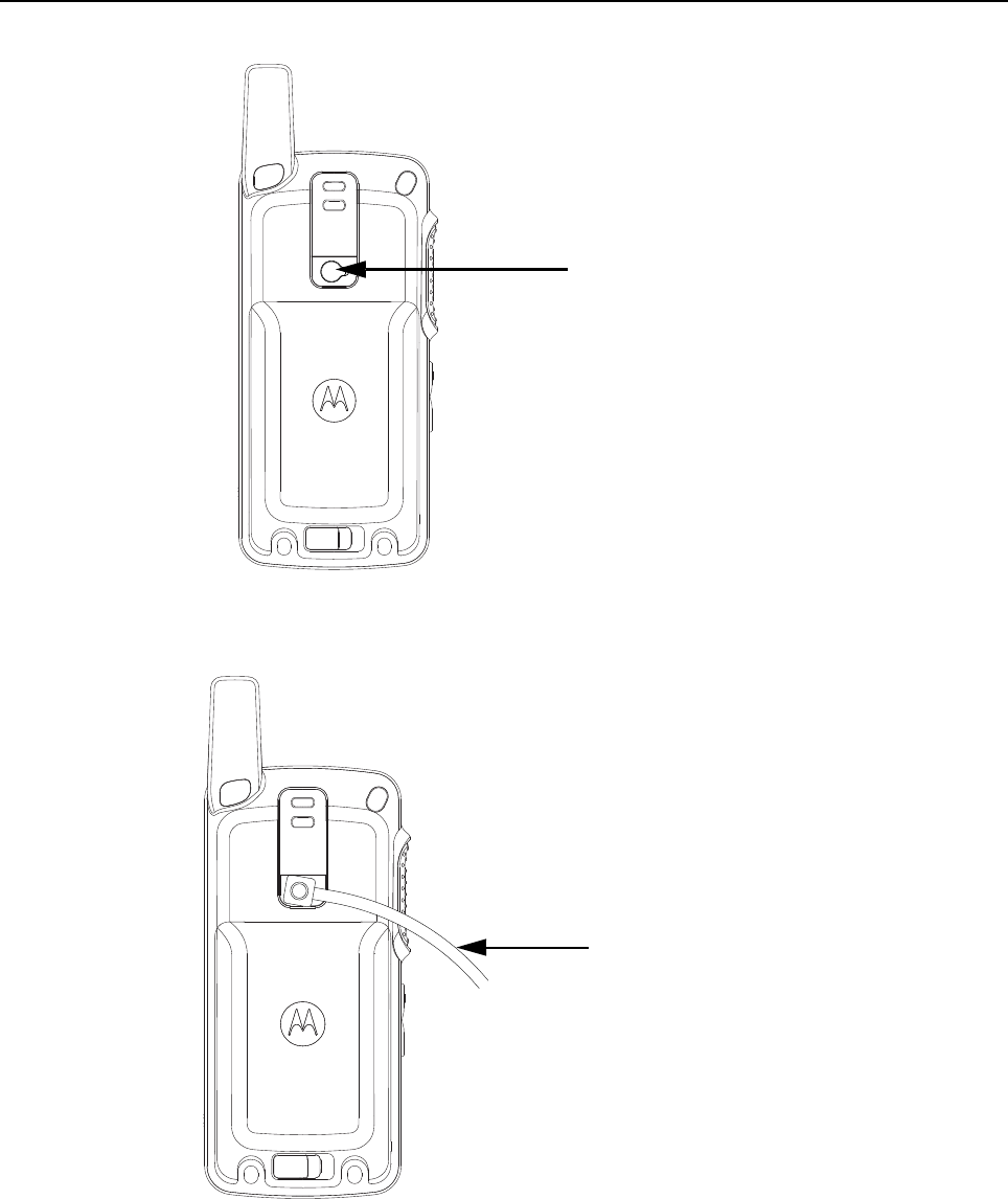
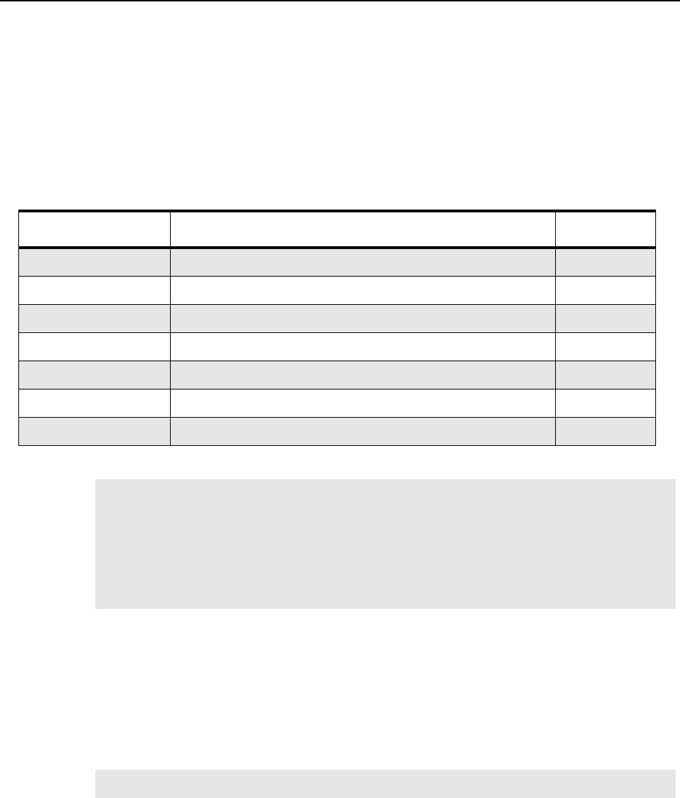
b. Remove the radio’s name plate label and the RF Plug (blue) as shown in Figure 3-2. and
Figure 3-3.
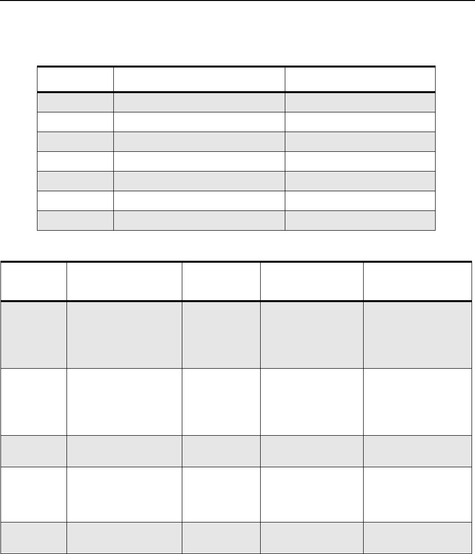
c. Connect the RF antenna adaptor to the 50 Ohm RF Input/Output port of the radio as
shown in Figure 3-4.
d. Connect the other end of the RF antenna adaptor to the T/R port of the Radio Test Set
3920 using the RF cable shown in Figure 3-1.
Figure 3-1. DMR Radio Transmitter and Receiver Testing Setup
Figure 3-2. Name plate label
T/R Port 28012039001
Ant. Input / Output
Programming Cable
Modulated RF Test
Signal / Tx
modulated RF Signal
25-124330-01R
Name plate label
Transceiver Performance Testing Setup 3-3
Figure 3-3. RF plug
Figure 3-4. Connect RF Antenna adaptor to radio RF input/output port
RF plug
RF antenna
adaptor
(28012039001)
3-4 Transceiver Performance Testing: Test Mode
3.3 Test Mode
3.3.1 Radio Test Mode
1. Turn the radio on.
2. Within 10 seconds after Self Test is complete, press the P2 button five times in succession.
3. The radio beeps and shows a series of display that gives information regarding various
version numbers and subscriber specific information.
The displays are described in Table 3-1.
3.3.2 RF Test Mode
When the radio is operating in its normal environment, the radio's micro controller controls the RF
channel selection, transmitter key-up, and receiver muting, according to the customer codeplug
configuration. However, when the unit is on the bench for testing, alignment, or repair, it must be
removed from its normal environment via a special routine, called TEST MODE.
In RF Test Mode, the display upon the first line is “RF Test”. The display upon the second line is the
test environment, the channel number and channel spacing. The default test environment is DIG.
Table 3-1. Front Panel Access Test Mode Displays
Name of Display Description Appears
Service Mode The literal string indicates the radio has entered test mode. Always
Host Version The version of host firmware. Always
DSP Version The version of DSP firmware. Always
Model Number The radio’s model number as programmed in the codeplug. Always
MSN The radio’s serial number as programmed in the codeplug. Always
FLASHCODE The FLASH codes as programmed in the codeplug. Always
RF Band The radio’s band. Always
NOTE The radio stops at each display for 2 seconds before moving to the next information display.
If the information cannot fit into 1 line, the radio display scrolls automatically character by
character after 1 second to view the whole information. If the Left Navigation Key () is
pressed before the last information display, the radio will suspend the information display
until the user presses the Right Navigation Key () to resume the information display. The
radio beeps when each button is pressed. After the last display, RF Test Mode will be dis-
played.
NOTE DIG is digital mode.
Transceiver Performance Testing Test Mode 3-5
1. Press of channel selector button will cycle through the test channel 1->2->3->4->5->6->7->1
as described in Table 3-2. The radio beeps in each position. Frequency units in the table
below is in MHz.
Table 3-3. Transmitter Performance Checks
Table 3-2. Test Frequencies
Frequency UHF RX UHF TX
F1 403.075 403.075
F2 414.075 414.075
F3 425.075 425.075
F4 436.075 436.075
F5 447.075 447.075
F6 458.075 458.075
F7 469.075 469.075
Test
Name IFR Setting Radio Test Set Comments
RF Power DMR mode. Slot 1
Power and Slot 2
Power
TEST MODE,
Digital mode,
transmit with-
out modulation
Key up radio without
modulation using
Tuner
TTR Enable is
needed and IFR to be
set to trigger mode
with signal level
~1.5V
FSK Error DMR mode. FSK error TEST MODE,
Digital mode,
transmit with
0153 test
pattern
Key up radio with
0513 test pattern
modulation using
Tuner
Not Exceed 5%
Magnitude
Error
DMR mode. Magnitude
error
As above As above, Not Exceed 1%.
Symbol
Deviation
DMR mode. Symbol
deviation
As above As above Symbol Deviation
should be within
648Hz +/-10% and
1944Hz +/-10%
Transmitter
BER
DMR mode As above As above Transmitter BER
should be 0%

3-6 Transceiver Performance Testing: Test Mode
3.3.3 Display Test Mode
1. Press and hold the P1 button in RF Test Mode. The radio beeps once and momentarily
displays “Display Test Mode.”
2. Upon entering the Display Test Mode, the radio displays a white background with “Display
Test Mode” in black font.
3. Upon any button/key press, the radio displays black active background with “Display Test
Mode” in white font.
4. Upon any button/key press, the radio shows solid red color display.
5. Upon any button/key press following the above display, the radio shows green color display.
6. Upon any button/key press following the above display, the radio shows blue color display.
7. Upon any button/key press following the above display, the radio shows a big 46% grey “+”
on black background.
8. Upon any button/key press following the above display, the radio shows a big 46% grey 90
degrees rotated “H” on black background.
9. Upon any button/key press following the above display, the radio shows a big 46% grey “H”
on black background.
10. Upon any button/key press following the above display, the radio displays a black horizontal
line in between two white horizontal lines.
11. Upon any button/key press following the above display, the radio displays a red horizontal line
in between two white horizontal lines (increasing one colored horizontal line above and one
below the center row). Once the horizontal lines cover up the screen, the radio shows red
color display.
12. When the screen is filled up with horizontal lines, any button/key press clears the screen and
displays red and white vertical lines at column 0,3,6,9,12,15,18,21,24,27,30. Any button/ key
press fills the screen with vertical lines of the next color, (1 line to the right of any existing line)
until the display is filled up with black display.
13. Once the radio shows solid black color display, the next button/key press clears the screen
and displays the first 10 available icons on the screen. Successive button/key press displays
the remaining 4 icons.
Table 3-4. Receiver Performance Checks
Test
Name IFR Setting Radio Test Set Comments
Receiver
BER
IFR DMR mode. Signal
generator with 0.153 test
pattern
Test Mode,
Digital mode,
receive 0.153
test pattern
Read BER using
Tuner. Adjust RF
level to get 5% BER
RF level to be
<0.35uV for 5% BER
NOTE Each key press will change the screen color from, red->green->blue->black->red.
NOTE Each key press will change the screen color from red->green->blue->black->red->black.

Transceiver Performance Testing Test Mode 3-7
3.3.4 Photosensor Test Mode
1. Press and hold the P1 button after Display Test Mode. The radio beeps once and displays
“Photosensor Test Mode”.
2. Upon any button/ key press, the radio displays “Step 1”, then “Place Radio in Light”, followed
by “Press OK”.
3. Upon the Menu/OK Button press, the radio takes few seconds to read the photosensor and
to compare it with the predefined value, the result of this test is shown at the end of
photosensor mode. The radio displays “Step 2”, then “Cover Photosensor”, followed by
“Press OK”.
4. By pressing the Menu/OK Button the second time, the radio takes a few seconds to read the
photosensor and compare it with the predefined value, the result will then be shown on
screen. The four possible results are:- Photosensor Test Step 1 Failed, Photosensor Test
Step 2 Failed, Photosensor Test Both Steps Failed, or Photosensor Test Passed.
3.3.5 Accelerometer Test Mode
1. Press and hold the P1 button after Photosensor Mode. The radio beeps once and displays
“Accelerometer Test Mode”.
2. Upon any button/ key press, the radio reads the x, y, z position and compare it with the
predefined values (x, y, z) and displays the result on the screen. A pass result will only occur
when the radio is placed in a horizontal position. The possible results are: Accelerometer Test
Failed, Accelerometer Test Passed.
3.3.6 Vibrator Test Mode
Press and hold the P1 button after the Accelerometer Mode. The radio beeps once and vibrates
twice, first a short vibration and second a longer vibration, and displays “Vibrator Test Mode”.
3.3.7 LED Test Mode
1. Press and hold the P1 button after Vibrator Test Mode. The radio beeps once and displays
“LED Test Mode”.
2. Upon any button/key press, the radio’s red LED lights up and displays “Red LED On”.
3. Upon any button/key press following the above display, the red LED turns off. The green LED
will then light up and displays “Green LED On”.
4. Upon any button/key press following the above display, the green LED turns off. Both the
LEDs will then light up and displays “Both LEDs On”.
3.3.8 Backlight Test Mode
1. Press and hold the P1 button after LED Test Mode. The radio beeps once and displays
“Backlight Test Mode”.
2. The radio turns on both LCD and keypad backlight at the same time.
NOTE Select “Press OK” by pressing the center button of the navigation keys.
NOTE As there is only one LED on the radio, the LED color is in orange when both the LED lights
up.

3-8 Transceiver Performance Testing: Test Mode
3.3.9 Speaker Tone Test Mode
1. Press and hold the P1 button after Backlight Test Mode. The radio beeps once and displays
“Speaker Tone Test Mode”.
2. The radio generates a 1 kHz tone with the internal speaker.
3.3.10 Earpiece Tone Test Mode
1. Press and hold the P1 button after Speaker Tone Test Mode. The radio beeps once and
displays “Earpiece Tone Test Mode”.
2. The radio generates a 1 kHz tone with the earpiece.
3.3.11 Audio Loopback Earpiece Test
1. Press and hold the P1 button after Earpiece Tone Test Mode. The radio beeps once and
displays “Audio Loopback Earpiece Test Mode”.
2. The radio shall route any audio on the external mic to the earpiece.
3.3.12 Battery Check Test Mode
1. Press and hold the P1 button after Audio Loopback Earpiece Test Mode. The radio beeps
once and momentarily displays “Battery Check Test Mode”.
2. The radio will display the following:
Figure 3-5. Battery Check Test Mode Display
3.3.13 Button/Knob/PTT Test Mode
1. Press and hold the P1 button after Battery Check Test Mode. The radio beeps once and
displays “Button Test”(line 1) and displays “160/1”.
2. Press the Volume Up Button; “80/1” appears and radio beeps; release, “80/0” appears and
radio beeps.
3. Press the Volume Down Button; “81/1” appears and radio beeps; release, “80/1” appears
and radio beeps.
4. Press the PTT Button; “1/1” appears and radio beeps; release, “1/0” appears and radio
beeps.
5. Press the Emergency/ Programmable Button; “148/1” appears and radio beeps; release,
“148/0” appears and radio beeps.
6. Keypad Checks:
-Press 0, “48/1” appears and radio beeps; release, “48/0” appears and radio beeps.
-Press 1, “49/1” appears and radio beeps; release, “49/0” appears and radio beeps.
-Press 2, “50/1” appears and radio beeps; release, “50/0” appears and radio beeps.
-Press 3, “51/1” appears and radio beeps; release, “51/0” appears and radio beeps.
-Press 4, “52/1” appears and radio beeps; release, “52/0” appears and radio beeps.
-Press 5, “53/1” appears and radio beeps; release, “53/0” appears and radio beeps.
Rem. Capacity 91%

Transceiver Performance Testing Test Mode 3-9
- Press 6, “54/1” appears and radio beeps; release, “54/0” appears and radio beeps.
- Press 7, “55/1” appears and radio beeps; release, “55/0” appears and radio beeps.
- Press 8, “56/1” appears and radio beeps; release, “56/0” appears and radio beeps.
- Press 9, “57/1” appears and radio beeps; release, “57/0” appears and radio beeps.
- Press *, “58/1” appears and radio beeps; release, “58/0” appears and radio beeps.
- Press #, “59/1” appears and radio beeps; release, “59/0” appears and radio beeps.
- Press P1, “160/1” appears and radio beeps; release, “160/0” appears and radio beeps.
- Press P2, “161/1” appears and radio beeps; release, “161/0” appears and radio beeps.
-Press Menu/OK, “85/1” appears and radio beeps; release, “85/0” appears and radio beeps.
- Press Back/Home, “129/1” appears and radio beeps; release, “129/0” appears and radio
beeps.
- Press , “128/1” appears and radio beeps; release, “128/0” appears and radio beeps.
- Press , “130/1” appears and radio beeps; release, “130/0” appears and radio beeps.
- Press ▲, “135/1” appears and radio beeps; release, “135/0” appears and radio beeps.
- Press ▼, “136/1” appears and radio beeps; release, “136/0” appears and radio beeps.
7. After the test mode is completed, turn the radio off.
8. Turn the radio on.

3-10 Transceiver Performance Testing: Test Mode
Notes
Chapter 4 Radio Programming and Tuning
4.1 Introduction
This chapter provides an overview of the MOTOTRBO Customer Programming Software (CPS), as
well as the Tuner and AirTracer applications, which are all designed for use in Windows XP/Vista/
Windows 7 environment. These programs are available in one kit as listed in Table . An Installation
Guide is also included with the kit.
Table 4-1. Software Installation Kits Radio Tuning Setup
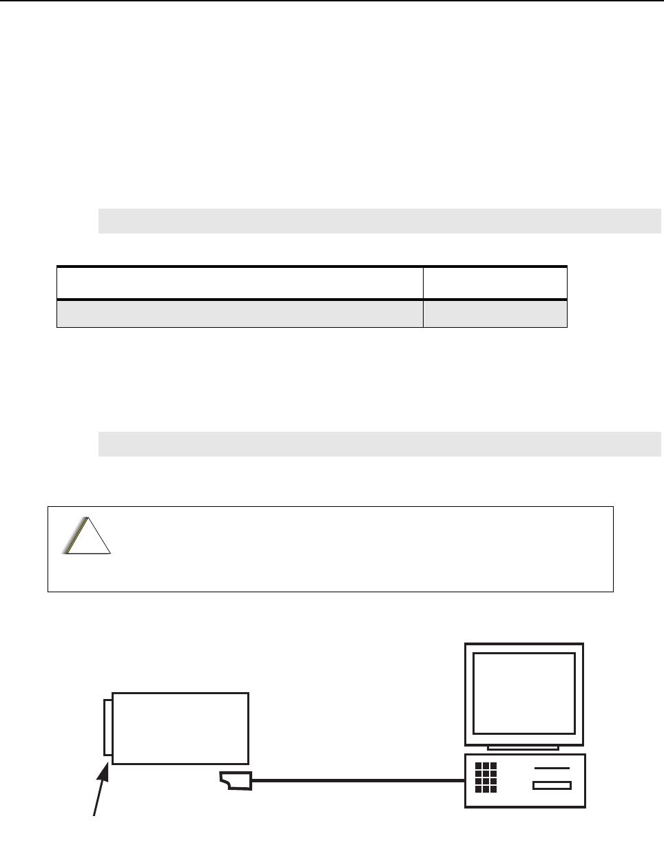
4.2 Customer Programming Software Setup
The CPS programming setup, shown in Figure 4-1 is used to program the radio.
Figure 4-1. CPS Programming Setup
NOTE Refer to the appropriate program on-line help files for the programming procedures.
Description Kit Number
MOTOTRBO CPS, Tuner and AirTracer Applications CD GMVN5141_
NOTE Refer to the appropriate program on-line help files for the programming procedures.
Computer USB ports can be sensitive to Electrostatic Discharge. Do not touch
exposed contacts on cable when connected to a computer.
!
C a u t i o n
Radio
Battery
Portable Programming Cable
25-124330-01R
4-2 Radio Programming and Tuning: AirTracer Application Tool
4.3 AirTracer Application Tool
The MOTOTRBO AirTracer application tool has the ability to capture over-the-air digital radio traffic
and save the captured data into a file. The AirTracer application tool can also retrieve and save
internal error logs from MOTOTRBO radios. The saved files can be analyzed by trained Motorola
personnel to suggest improvements in system configurations or to help isolate problems.
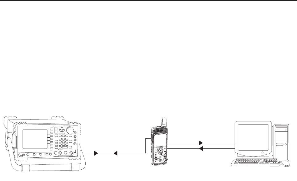
4.4 Radio Tuning Setup
A personal computer (PC), Windows XP/Vista/Win7 and a tuner program are required to tune the
radio. To perform the tuning procedures, the radio must be connected to the PC and test equipment
setup as shown in Figure 4-2.
Figure 4-2. Radio Transmitter and Receiver Tuning Setup
T/R Port 28012039001
Ant. Input / Output
Programming Cable
Modulated RF Test
Signal / Tx
modulated RF Signal
25-124330-01R
Chapter 5 Disassembly/Reassembly Procedures
5.1 Introduction
This chapter provides details about the following:
• Preventive maintenance (inspection and cleaning).
• Safe handling of CMOS and LDMOS devices.
• Repair procedures and techniques.
• Disassembly and reassembly of the radio.
5.2 Preventive Maintenance
Periodic visual inspection and cleaning is recommended.
5.2.1 Inspection
Check that the external surfaces of the radio are clean, and that all external controls and switches
are functional. It is not recommended to inspect the interior electronic circuitry.
5.2.2 Cleaning Procedures
The following procedures describe the recommended cleaning agents and the methods to be used
when cleaning the external and internal surfaces of the radio. External surfaces include the front
housing, housing assembly and battery case. These surfaces should be cleaned whenever a
periodic visual inspection reveals the presence of smudges, grease, and/or grime.
The only recommended agent for cleaning the external radio surfaces is a 0.5% solution of a mild
dishwashing detergent in water. The only factory recommended liquid for cleaning the printed circuit
boards and their components is isopropyl alcohol (100% by volume).
Only Motorola Service Centers or Authorized Motorola Service Dealers can
perform this function.
NOTE Internal surfaces should be cleaned only when the radio is disassembled for service or
repair.
Use all chemicals as prescribed by the manufacturer. Be sure to follow all
safety precautions as defined on the label or material safety data sheet.
The effects of certain chemicals and their vapors can have harmful results on
certain plastics. Avoid using aerosol sprays, tuner cleaners and other
chemicals.
!
C a u t i o n
!
C a u t i o n

5-2 Disassembly/Reassembly Procedures: Safe Handling of CMOS and LDMOS Devices
Cleaning External Plastic Surfaces
Apply the 0.5% detergent-water solution sparingly with a stiff, non-metallic, short-bristled brush to
work all loose dirt away from the radio. Use a soft, absorbent, lintless cloth or tissue to remove the
solution and dry the radio. Make sure that no water remains entrapped near the connectors, cracks,
or crevices.
Cleaning Internal Circuit Boards and Components
Isopropyl alcohol (100%) may be applied with a stiff, non-metallic, short-bristled brush to dislodge
embedded or caked materials located in hard-to-reach areas. The brush stroke should direct the
dislodged material out and away from the inside of the radio. Make sure that controls or tunable
components are not soaked with alcohol. Do not use high-pressure air to hasten the drying process
since this could cause the liquid to collect in unwanted places. After completing of the cleaning
process, use a soft, absorbent, lintless cloth to dry the area. Do not brush or apply any isopropyl
alcohol to the frame, front housing or back housing.
5.3 Safe Handling of CMOS and LDMOS Devices
Complementary metal-oxide semiconductor (CMOS) and Laterally Diffused Metal Oxide
Semiconductor (LDMOS) devices are used in this family of radios, and are susceptible to damage by
electrostatic or high voltage charges. Damage can be latent, resulting in failures occurring weeks or
months later. Therefore, special precautions must be taken to prevent device damage during
disassembly, troubleshooting, and repair.
Handling precautions are mandatory for CMOS/LDMOS circuits and are especially important in low
humidity conditions. DO NOT attempt to disassemble the radio without first referring to the CMOS
CAUTION paragraph in the Disassembly and Reassembly section of the manual.
NOTE Always use a fresh supply of alcohol and a clean container to prevent contamination by
dissolved material (from previous usage).

Disassembly/Reassembly Procedures: Safe Handling of CMOS and LDMOS Devices 5-3
DO NOT attempt to disassemble the radio without first referring to the following CAUTION
statement.
This radio contains static-sensitive devices. Do not open the radio unless you are
properly grounded. Take the following precautions when working on this unit:
• Store and transport all CMOS/LDMOS devices in conductive mate-
rial so that all exposed leads are shorted together. Do not insert
CMOS/LDMOS devices into conventional plastic “snow” trays used
for storage and transportation of other semiconductor devices.
• Ground the working surface of the service bench to protect the
CMOS/LDMOS device. We recommend using the Motorola Static
Protection Assembly (part number 0180386A82), which includes a
wrist strap, two ground cords, a table mat, and a floor mat.
• Wear a conductive wrist strap in series with a 100k resistor to
ground. (Replacement wrist straps that connect to the bench top
covering are Motorola part number 4280385A59).
• Do not wear nylon clothing while handling CMOS/LDMOS devices.
• Do not insert or remove CMOS/LDMOS devices with power applied.
Check all power supplies used for testing CMOS/LDMOS devices to
be certain that there are no voltage transients present.
• When straightening CMOS/LDMOS pins, provide ground straps for
the apparatus used.
• When soldering, use a grounded soldering iron.
• If at all possible, handle CMOS/LDMOS devices by the package and
not by the leads. Prior to touching the unit, touch an electrical
ground to remove any static charge that you may have accumu-
lated. The package and substrate may be electrically common. If so,
the reaction of a discharge to the case would cause the same dam-
age as touching the leads.
!
C a u t i o n
5-4 Disassembly/Reassembly Procedures: Repair Procedures and Techniques – General
5.4 Repair Procedures and Techniques – General
Any rework or repair on Environmentally Preferred Products must be done using the appropriate
lead-free solder wire and lead-free solder paste as stated in the following table:
Parts Replacement and Substitution
When damaged parts are replaced, identical parts should be used. If the identical replacement part
is not locally available, check the parts list for the proper Motorola part number and order the part
Rigid Circuit Boards
This family of radios uses bonded, multi-layer, printed circuit boards. Since the inner layers are not
accessible, some special considerations are required when soldering and unsoldering components.
The printed-through holes may interconnect multiple layers of the printed circuit. Therefore, exercise
care to avoid pulling the plated circuit out of the hole.
When soldering near a connector:
• Avoid accidentally getting solder in the connector.
• Be careful not to form solder bridges between the connector pins.
• Examine your work closely for shorts due to solder bridges.
For soldering components with Hot-Air or infra red solder systems, please check your user guide of
the solder system to get information on solder temperature and time for the different housings of the
integrated circuits and other components
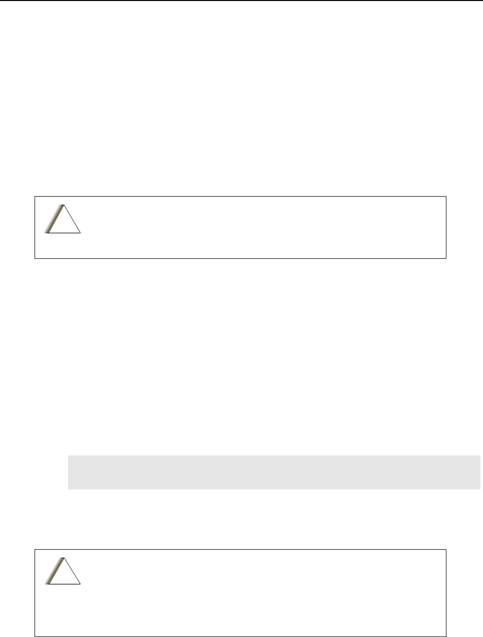
NOTE Environmentally Preferred Products (EPP) (refer to the marking on the printed circuit
boards — examples shown below) were developed and assembled using
environmentally preferred components and solder assembly techniques to comply with
the European Union’s Restriction of Hazardous Substances (ROHS) Directive 2002/
95/EC and Waste Electrical and Electronic Equipment (WEEE) Directive 2002/96/
EC. To maintain product compliance and reliability, use only the Motorola specified parts
in this manual.
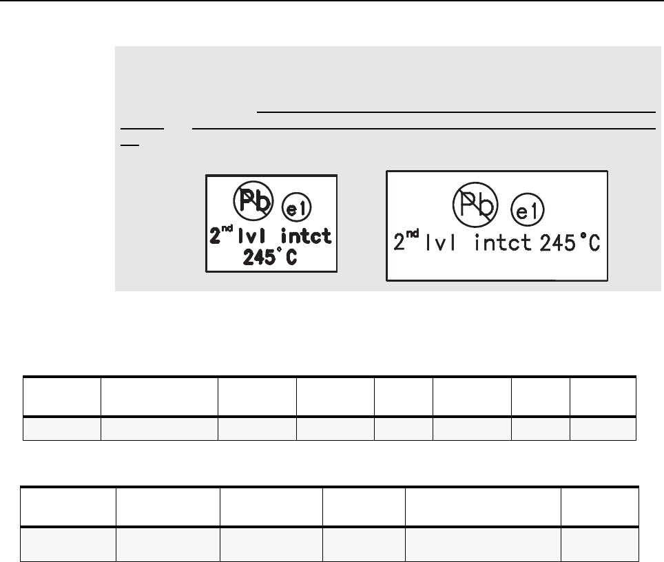
Table 5-1. Lead Free Solder Wire Part Number List
Motorola
Part Number Alloy Flux Type Flux Content
by Weight
Melting
Point
Supplier Part
number Diameter Weight
1088929Y01 95.5Sn/3.8Ag/0.7Cu RMA Version 2.7-3.2% 217C 52171 0.015” 1lb spool
Table 5-2. Lead Free Solder Paste Part Number List
Motorola Part
Number
Manufacturer Part
Number Viscosity Type Composition & Percent Metal Liquid
Temperature
1085674C03 NC-SMQ230 900-1000KCPs
Brookfield (5rpm)
Type 3
(-325/+500)
(95.5%Sn-3.8%Ag-0.7%Cu)
89.3%
217°C
Disassembly/Reassembly Procedures: Disassembling and Reassembling the Radio – General 5-5
5.5 Disassembling and Reassembling the Radio – General
When disassembling and reassembling the radio, it is important to pay particular attention to the
snaps and tabs, and how parts align with each other.
The following tools are required for disassembling and reassembling the radio:
• 6IPTorx PlusTM
• 4IPTorx Plus
• Torque wrench
• Tweezers
If a unit requires further testing or service than is customarily performed at the basic level, please
send the radio to a Motorola Service Center listed in Appendix A.
To assure the safety and regulatory compliance of the SL4000, the radio must be
repaired only at Motorola service facilities. Please call Motorola at 8004224210
for the address and contact information of your nearest service center.
!
C a u t i o n
5-6 Disassembly/Reassembly Procedures: Radio Disassembly – Detailed
5.6 Radio Disassembly – Detailed
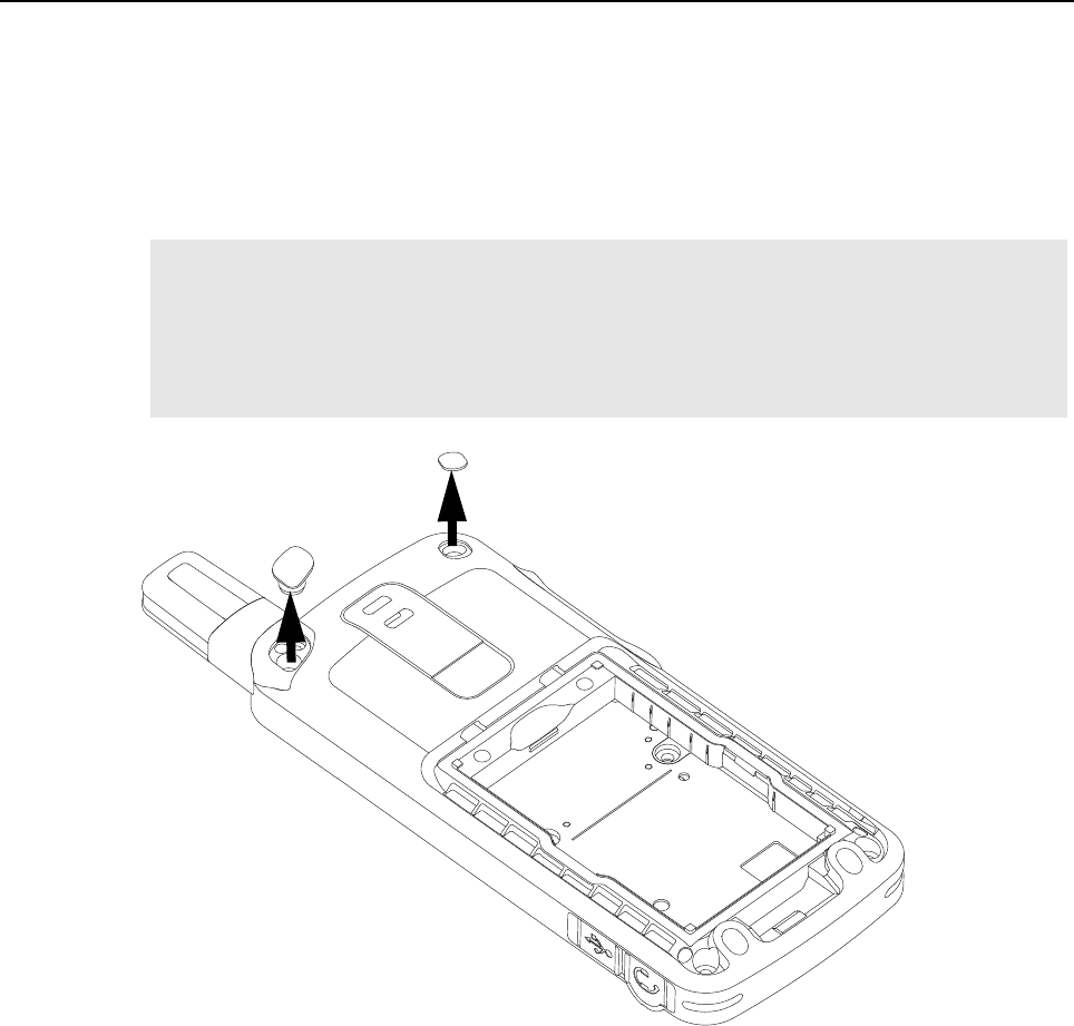
5.6.1 External Antenna Disassembly
1. Turn off the radio.
2. Remove the antenna plug and the escutcheon cover from the back housing as shown
in Figure 5-1.
Figure 5-1. Antenna plug and escutcheon cover removal
NOTE a. Remove the antenna plug with fingers.
b. Remove the escutcheon cover with tweezers. Dispose the escutcheon cover once it has
been removed.
c. Use a cotton bud and IPA (Isopropyl alcohol) to remove the glue residue on the back
cover.
Escutcheon Cover
Antenna plug
Disassembly/Reassembly Procedures: Radio Disassembly – Detailed 5-7
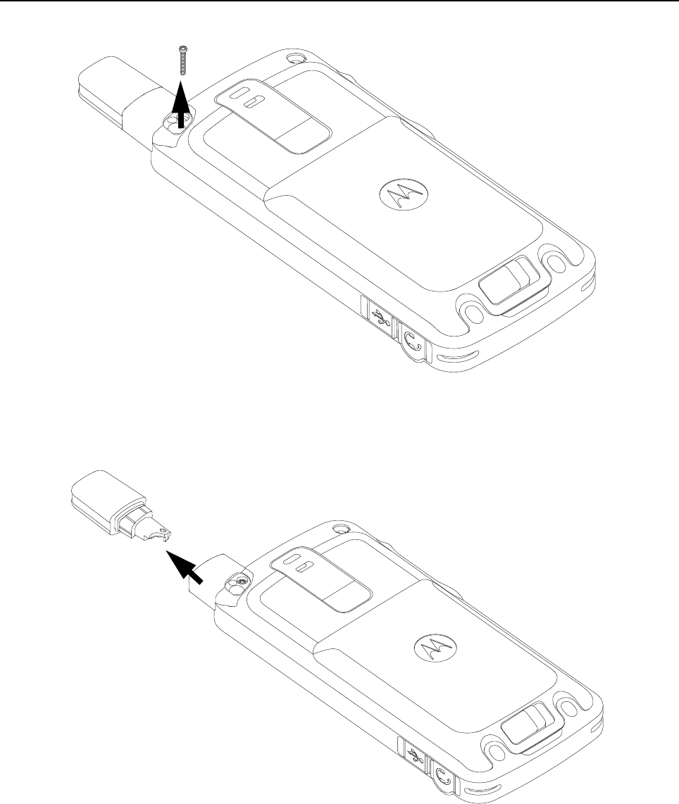
3. Remove the antenna screw with the 4IP Torx Plus screwdriver as shown in Figure 5-2.
Figure 5-2. Antenna screw removal
4. Remove the antenna from the radio by pulling it upwards as shown in Figure 5-3.
Figure 5-3. Antenna removal
Antenna
Screw
Antenna
5-8 Disassembly/Reassembly Procedures: Radio Disassembly – Detailed
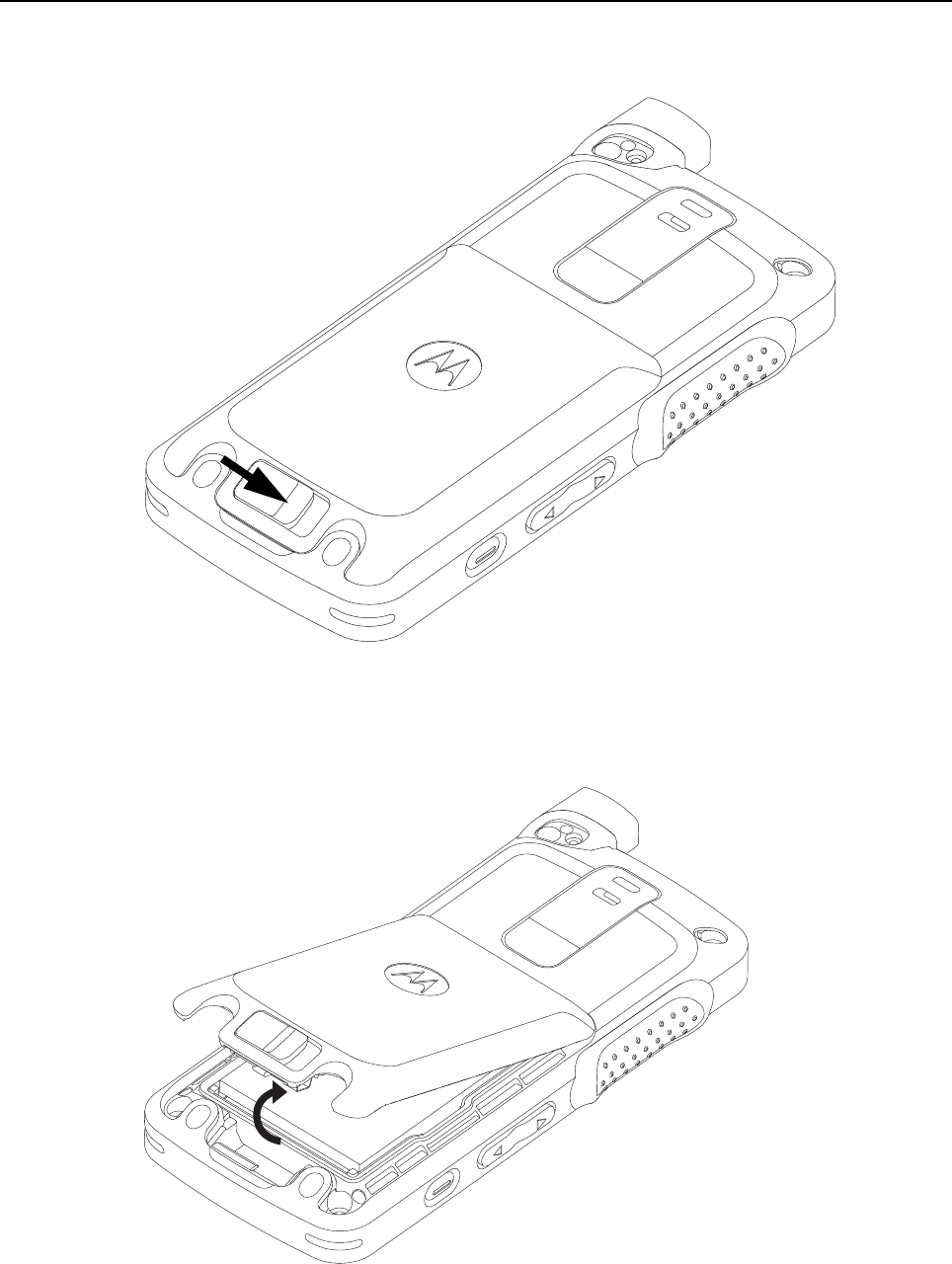
5.6.2 Back housing Disassembly
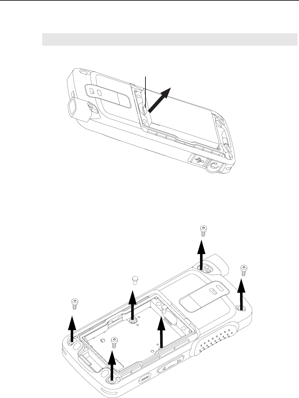
1. Remove the battery door from the back housing by unlocking the latch as shown in Figure 5-4.
Figure 5-4. Unlatching battery door
2. Remove the battery door by lifting it upwards as shown in Figure 5-5.
Figure 5-5. Battery door removal
Disassembly/Reassembly Procedures: Radio Disassembly – Detailed 5-9
3. After removing the battery door, remove battery from battery compartment as shown
in Figure 5-6. To remove battery, grasp the battery groove at the top of the battery and lift up the
battery.
Figure 5-6. Battery removal
4. Remove the self tapping screws from four corners of the back housing marked (a, b, c, d) by
using the 6IP Torx Plus as shown in Figure 5-7.
5. Remove the two machine screws in the battery compartment marked (e and f) by using the 6IP
Torx Plus as shown in Figure 5-7.
Figure 5-7. Self tapping screws and machining screws removal
NOTE The battery cannot be removed bottom first.
Battery groove
c
f
d
e
a
b
5-10 Disassembly/Reassembly Procedures: Radio Disassembly – Detailed
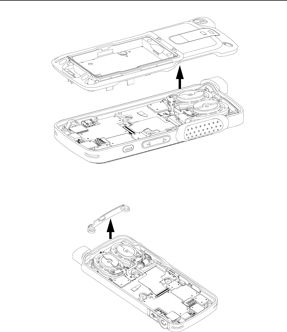
6. Lift back housing from the front housing as shown in Figure 5-8.
Figure 5-8. Back housing removal
5.6.3 Internal Antenna Disassembly
1. Remove the internal antenna upwards by using tweezers as shown in Figure 5-9.
Figure 5-9. Internal antenna removal
Back housing
Front housing
Internal antenna
Disassembly/Reassembly Procedures: Radio Disassembly – Detailed 5-11
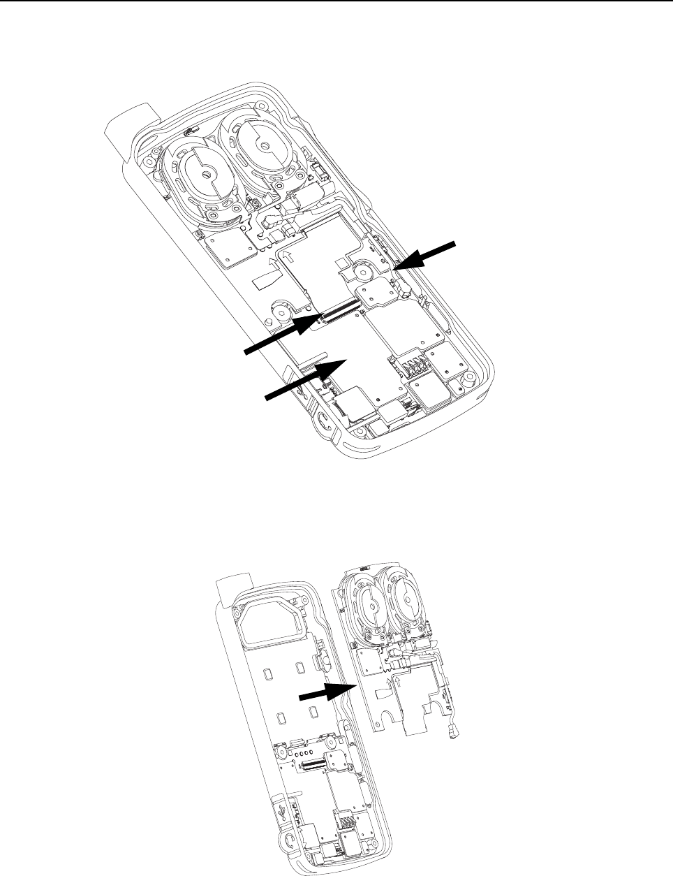
5.6.4 PCB Disassembly
1. Unplug the board flex cable and coax cable connector from the main board. To remove the board
to board flex, unlatch the flex connector tab as shown in Figure 5-10.
Figure 5-10. Board flex and coax cable connector disassembly
2. Remove the interface board from the front housing by sliding it out from the PCB retainer catch as
shown in Figure 5-11.
Figure 5-11. Interface board removal
Coax
cable connector
Flex
connector tab
Board Flex

5-12 Disassembly/Reassembly Procedures: Radio Disassembly – Detailed
5.6.5 Audio Jack Disassembly
1. Unplug the keypad flex connector from the main board.
2. Unplug the audio jack flex connector from the main board.
3. Remove the audio seal as shown in Figure 5-12.
Figure 5-12. Audio jack flex and keypad flex disassembly
4. Lift and pull out the audio jack from its recess as shown in Figure 5-13.
Figure 5-13. Audio jack flex removal
Keypad flex
Audio Jack
flex
Audio
Jack flex
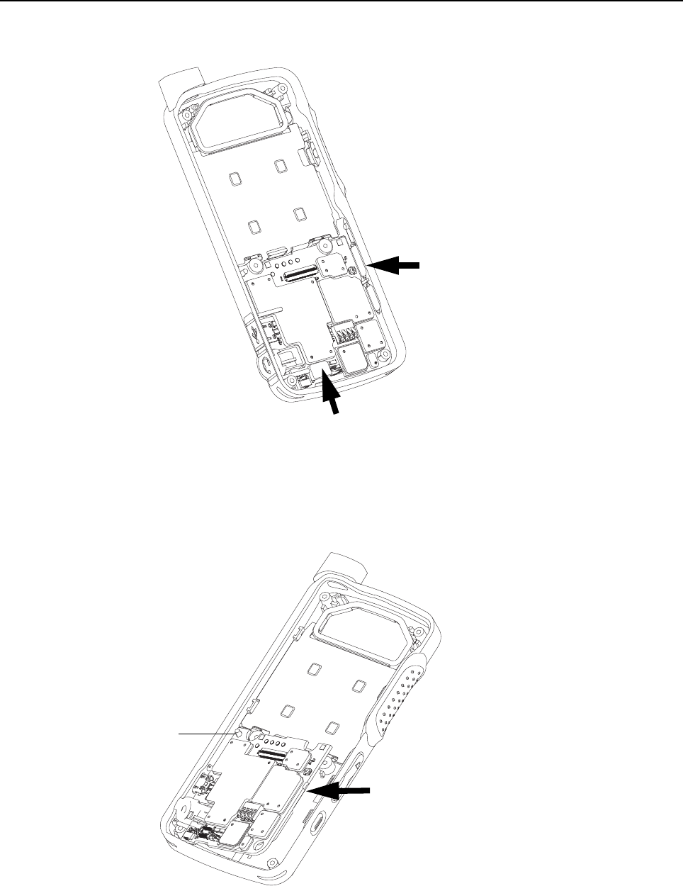
Disassembly/Reassembly Procedures: Radio Disassembly – Detailed 5-13
5.6.6 LCD Display Disassembly
1. Lift the PCB slightly from the right corner using tweezers as shown in Figure 5-14.
Figure 5-14. LCD display disassembly
2. Remove the main PCB from the front housing by turning it slightly counter-clockwise to release
the PCB retainer catch.
3. Lift the PCB upwards and away from the PCB guide pin as shown in Figure 5-15.
Figure 5-15. Lifting of PCB board
Insert tweezers
Keypad connector
PCB guide pin
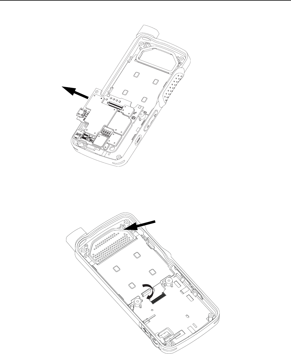
5-14 Disassembly/Reassembly Procedures: Radio Disassembly – Detailed
4. Remove the main PCB from the front housing by unlatching its flex connector tab as shown in
Figure 5-16.
Figure 5-16. PCB board removal
5. Remove the speaker seal.
6. Unlatch the display retainer lock as shown in Figure 5-17.
Figure 5-17. Display retainer lock removal
Speaker seal
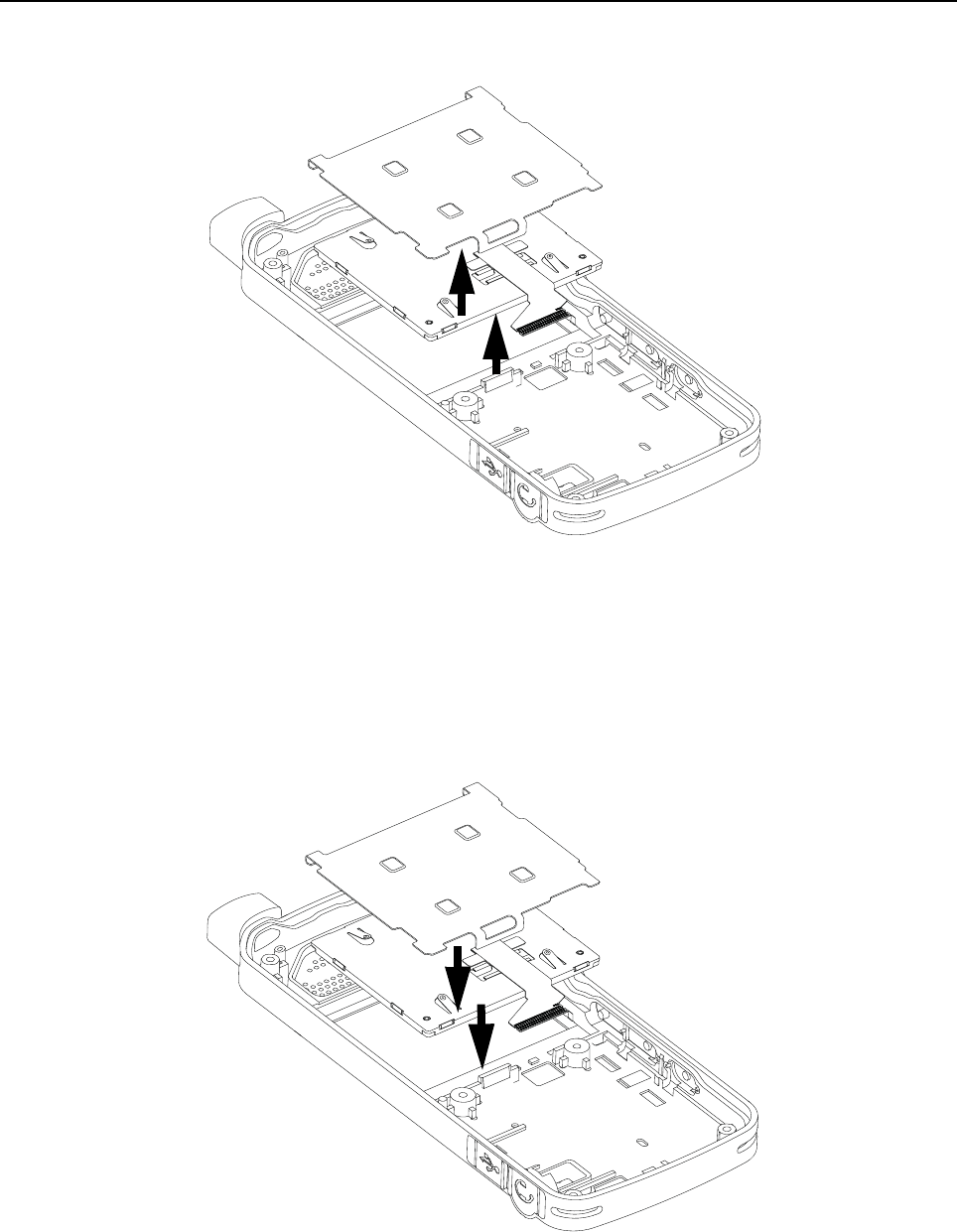
Disassembly/Reassembly Procedures: Radio Reassembly – Detailed 5-15
7. Remove the display retainer by sliding it upwards to clear the PCB retainer catch.
8. Remove the LCD display as shown in Figure 5-18.
Figure 5-18. LCD display removal
5.7 Radio Reassembly – Detailed
5.7.1 LCD Display Reassembly
1. Insert the LCD display.
2. Insert the display retainer slightly higher than the display module and slide it to fit below the PCB
retainer catch as shown in Figure 5-19.
Figure 5-19. LCD display reassembly
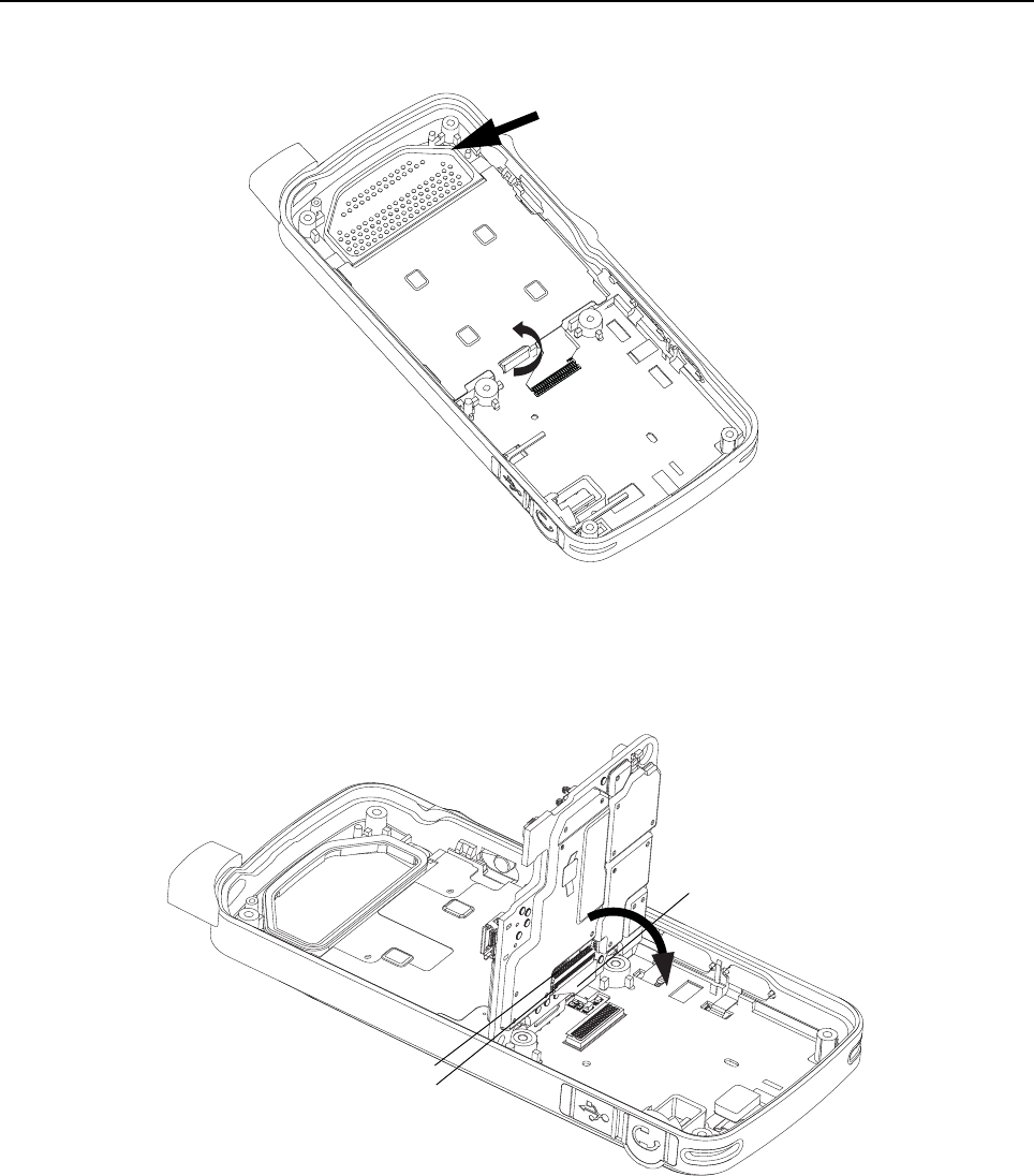
5-16 Disassembly/Reassembly Procedures: Radio Reassembly – Detailed
3. Press down on the display retainer lock to secure the display retainer.
4. Insert the speaker seal as shown in Figure 5-20.
Figure 5-20. Display retainer lock reassembly
5. Attach the main PCB flex to the main PCB and secure it in place by latching the flex connector tab
as shown in Figure 5-21.
Figure 5-21. Flex connector tab reassembly
Speaker seal
Flex connector
Flex
Latch
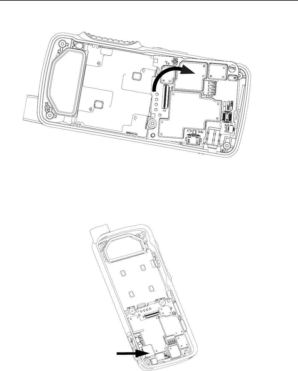
Disassembly/Reassembly Procedures: Radio Reassembly – Detailed 5-17
6. Place the main PCB onto the PCB guide pin and pivot the PCB into the front housing by turning it
clockwise slightly so that it slots under the PCB retainer catch as shown in Figure 5-22.
Figure 5-22. PCB board reassembly
5.7.2 Audio Jack Reassembly
1. Place the audio jack into its recess on the front housing as shown in Figure 5-23.
Figure 5-23. Audio jack connector reassembly
Audio jack
flex
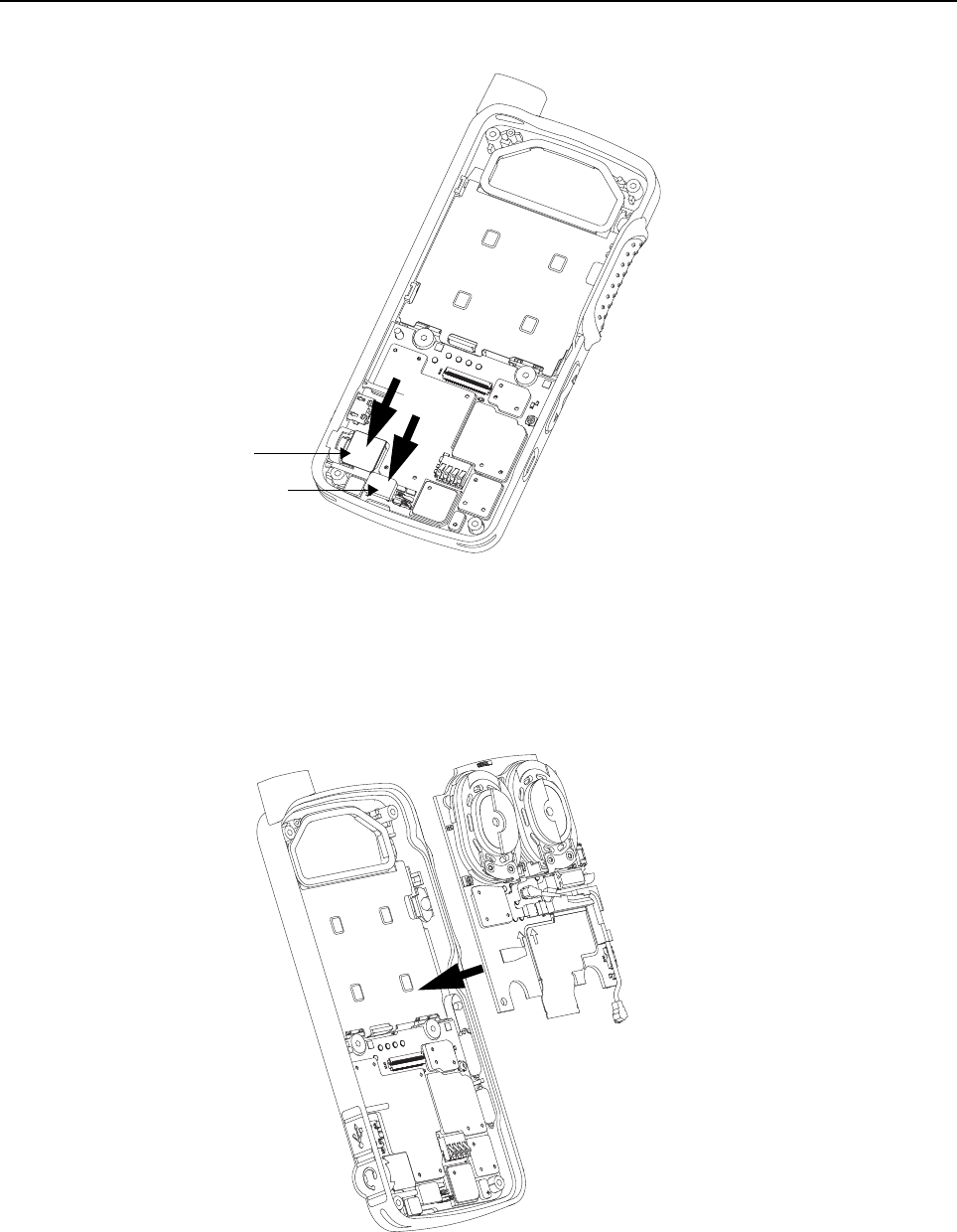
5-18 Disassembly/Reassembly Procedures: Radio Reassembly – Detailed
2. Attach the audio jack flex connector and keypad flex connector to the main board as shown in
Figure 5-24.
Figure 5-24. Audio jack flex connector and keypad connector reassembly
5.7.3 PCB Reassembly
1. Insert the interface board into the front housing by sliding it under the PCB retainer catch as
shown in Figure 5-25
Figure 5-25. Interface board reassembly
Audio jack flex
Keypad connector
Front
Housing
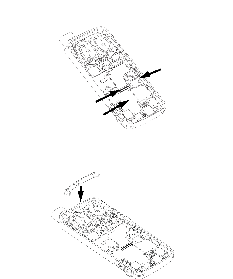
Disassembly/Reassembly Procedures: Radio Reassembly – Detailed 5-19
2. Attach the board flex cable to the main board connector and secure it by latching the flex
connector tab.
3. Plug in the coax cable connector to the main board as shown in Figure 5-26.
Figure 5-26. Board flex reassembly
5.7.4 Internal Antenna Reassembly
1. Insert the internal antenna by using tweezers as shown in Figure 5-27.
Figure 5-27. Internal antenna reassembly
Flex connector
tab
Coax cable connector
Board flex
Internal antenna
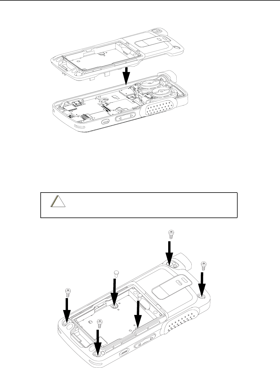
5-20 Disassembly/Reassembly Procedures: Radio Reassembly – Detailed
5.7.5 Back Housing Reassembly
1. Place the back housing onto the front housing as shown in Figure 5-28.
Figure 5-28. Back housing reassembly
2. Using a torque wrench, screw in the self tapping screws at all four corners from back housing
marked (a, b, c, d) by using the 6IP Torx Plus as shown in Figure 5-29.
3. Using a torque wrench, screw in the two machine screws in the battery compartment of the back
housing marked (e and f) by using the 6IP Torx Plus as shown in Figure 5-29.
Figure 5-29. Self tapping screws and machining screws reassembly
Do not over torque these screws. Please refer to the torque
chart on Table 5-5.
Front housing
Back housing
!
C a u t i o n
c
d
e
f
a
b
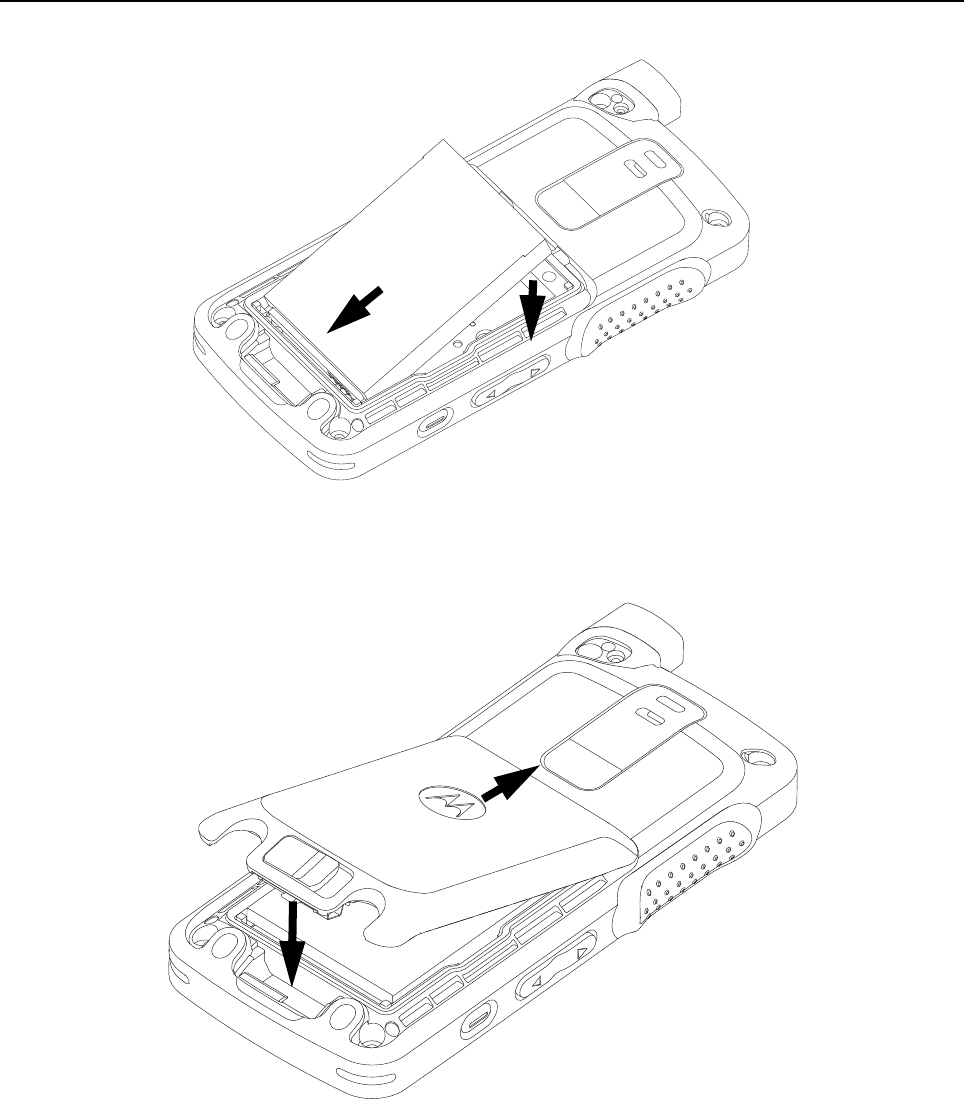

5-22 Disassembly/Reassembly Procedures: Radio Reassembly – Detailed
6. Fasten the battery door latch as shown in Figure 5-32.
Figure 5-32. Latching battery door
7. Attach the antenna to the radio as shown in Figure 5-33.
Figure 5-33. Antenna reassembly
8. Using a torque wrench, screw in the antenna screw with the 4IP Torx Plus screwdriver as shown
in Figure 5-34.
NOTE a. The antenna must be fully inserted before screwing in the antenna screw.
b. Ensure that there is no gap between the antenna and the housing.
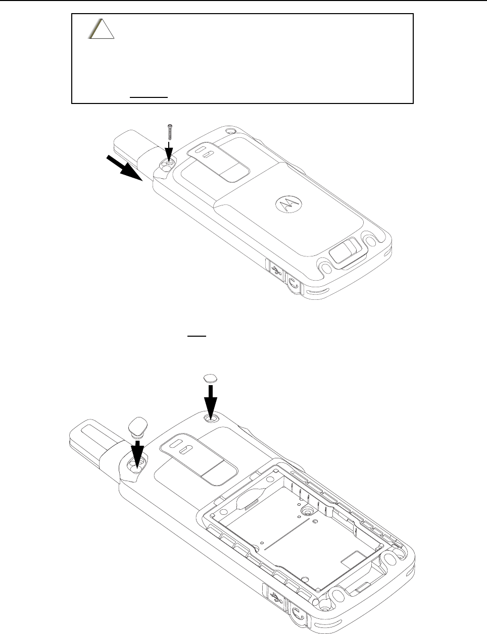
Disassembly/Reassembly Procedures: Radio Reassembly – Detailed 5-23
Figure 5-34. Antenna screw reassembly
9. Insert the antenna plug and a new escutcheon cover to the back housing as shown in
Figure 5-35.
10.Turn the radio on.
Figure 5-35. Antenna plug and screw plug reassembly
Tighten the antenna screw with tightening torque as below
→0.8lbf. in. or
→0.9 N-m or
→0.92 kgf-cm
DO NOT over tighten the antenna screw.
!
C a u t i o n
screw
Antenna
Escutcheon Cover
Antenna Plug
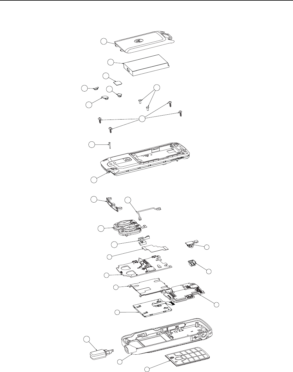
5-24 Disassembly/Reassembly Procedures: Radio Exploded Mechanical Views and Parts Lists
5.8 Radio Exploded Mechanical Views and Parts Lists
5.8.1 Non-GOB Model Exploded View and Parts List
Figure 5-36. SL4000 Non-GOB Model Exploded View
1
23
4
5
6
7
910
11
12
13 14 17
15
16
19 20
21 22 23
18
24
8
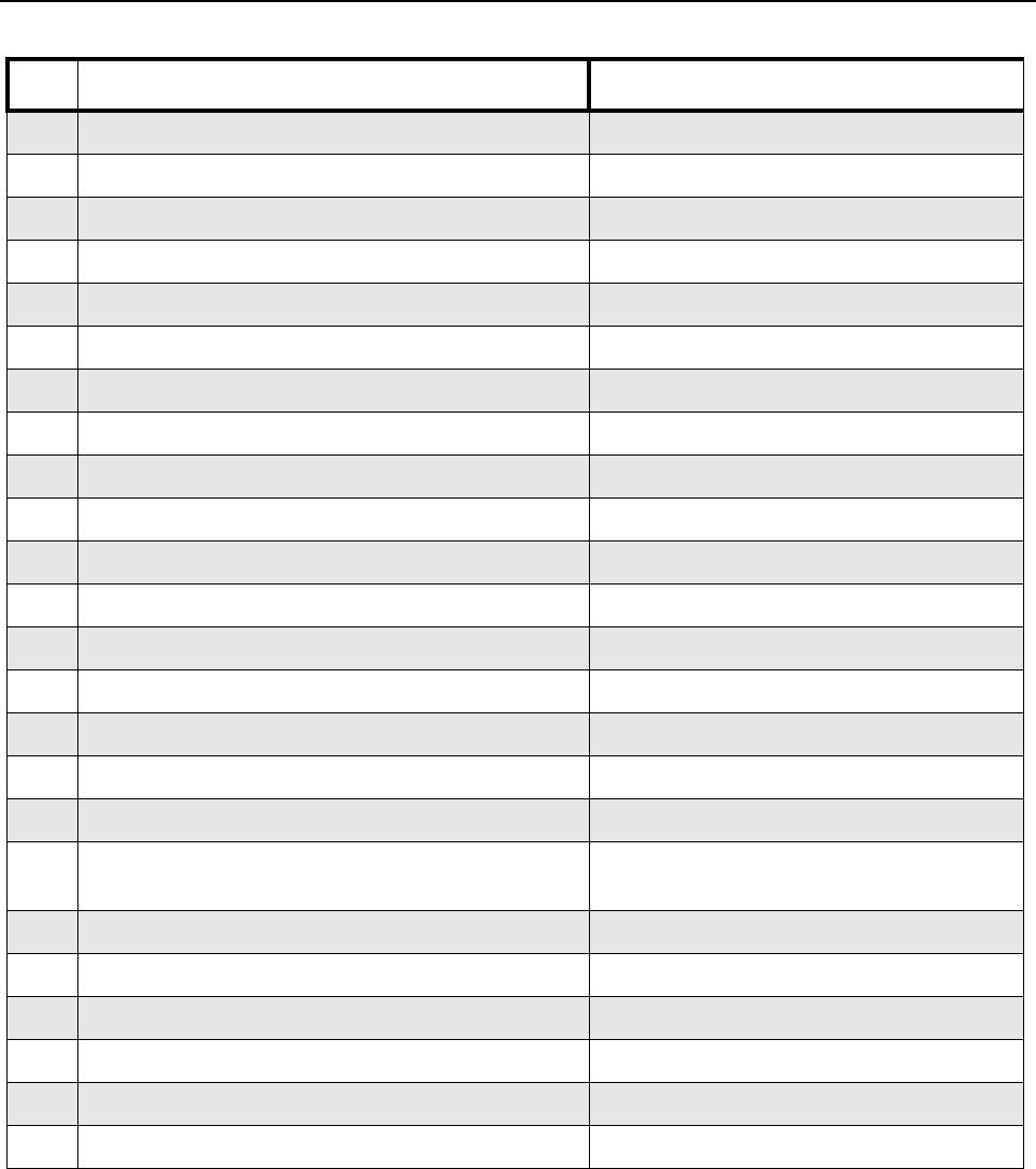
Disassembly/Reassembly Procedures: Radio Exploded Mechanical Views and Parts Lists 5-25
Table 5-3. Non-GOB Model Exploded View
Item Description Part Number
1Keypad Flex Assembly 0104043J44
2 Front Housing Assembly PMLN5969_
3LCD Module 72013002001
4 Main Board PMLE4825_
5Display Bracket Assembly 0104044J48
6 Interface Board PMLN5971_
7Audio jack Flex Assembly 0104043J45
8 Audio jack Boot 32012157001
9Board to Board Flex 84012346001
10 Coax Cable Holder 07012034001
11 Speaker Module 0104042J77
12 Coax Cable Connector 42012051001
13 Internal Antenna 85012037001
14 Back housing Assembly PMLN5968_
15 Top and Bottom Screws 03012043001
16 Middle Screws 0386104Z06
17 Antenna Screw 03012044001
18 Stubby Antenna Please refer to Section 1.4 "Model Charts"
for antenna options.
19 Antenna Plug 38012025001
20 Escutcheon Cover 33012045001
21 RF Plug 28012032001
22 Product Label Escutcheon 33012043001
23 Battery Standard (BT70) PMNN4425_
24 Battery Door Standard PMLN6000_
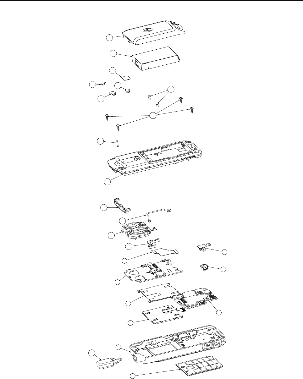
5-26 Disassembly/Reassembly Procedures: Radio Exploded Mechanical Views and Parts Lists
5.8.2 Exploded View and Parts List
Figure 5-37. SL4010 GOB Model Exploded View
1
2
18
35
6
910
11
12
13 14
17 19
20
21
22 23 24
16
15
87
4

Disassembly/Reassembly Procedures: Radio Exploded Mechanical Views and Parts Lists 5-27
Table 5-4. GOB Model Exploded View Parts List
Item Description Part Number
1Keypad Flex Assembly 0104043J44
2 Front Housing Assembly PMLN5969_
3LCD Module 72013002001
4 Main Board PMLE4812_
5Display Bracket Assembly 0104044J48
6 Interface Board PMLN5971_
7Audio Jack Flex Assembly 0104043J45
8 Audio Jack Boot 32012157001
9Board to Board Flex 84012346001
10 Coax Cable Holder 07012034001
11 Speaker Module 0104042J77
12 Coax Cable Connector 42012051001
13 Internal Antenna 85012037001
14 Back housing Assembly PMLN5968_
15 Top and Bottom Screws 03012043001
16 Middle Screws 0386104Z06
17 Antenna Screw 03012044001
18 Stubby Antenna Please refer to Section 1.4 "Model Charts"
for antenna options
19 Antenna Plug 38012025001
20 Escutcheon Cover 33012045001
21 RF Plug 28012032001
22 Product Label Escutcheon 33012043001
23 Battery HI-CAP (BT90) HKNN4013_
24 Battery Door HI-CAP PMLN6001_
5-28 Disassembly/Reassembly Procedures: Torque Chart
5.9 Torque Chart
Table 5-5 lists the various screws by part number and description, followed by the torque values in
different units of measure. Torque all screws to the recommended value when assembling the radio.
Table 5-5. Torque Specifications for Screws
A proper torque screwdriver must be used during installation to
ensure that these torque values are not exceeded.
Part Number Description Qty Driver/
Socket
Torque
N-m lbs-in kgf-cm
03012044001 Screw Antenna 1 4IP Torx
Plus
0.09 0.80 0.92
0386104Z06 Screw Torx Plus 6IP Machine 2 6IP Torx
Plus
0.20 1.80 2.07
03012043001 Screw Torx T-6, M2 self-tapping 4 6IP Torx
Plus
0.20 1.80 2.07
!
C a u t i o n

Chapter 6 Basic Troubleshooting
6.1 Introduction
This chapter contains error codes and board replacement procedures. If the board does not pass all
the performance checks in Chapter 3 or exhibits an error code listed below, then the circuit board
should be replaced. If repair requires knowledge of details of component level troubleshooting,
please send radio to a Motorola Service Center listed in Appendix A.
6.2 Power-Up Error Codes
Upon powering up, the radio performs certain tests to determine if its basic electronics and software
are in working order. Any error detected has an associated error code that is presented on the radio
display. These error codes are intended to be used by a service technician when the radio
generates the Self Test Fail Tone. If these tests are successfully completed, the radio will generate
the Self Test Tone .
There are two classes of detectable errors, fatal and non-fatal. If it is considered as a fatal error, then
the normal radio operation will be inhibited. Fatal errors include hardware errors detected by the
microprocessor and certain memory errors. These memory errors include incorrect ROM checksum,
incorrect RAM checksum, and incorrect checksums of codeplug (Persistent Storage) blocks that
contain operating parameters. If the codeplug block operating parameters are corrupted, operation
of the unit on the proper frequency, system, and group are in question. Attempts to use this
information could provide the user with a false sense of security that others are receiving his
messages. Corrupted codeplug blocks of call IDs, or their associated aliases are considered non-
fatal errors. While the user may be inconvenienced, normal communication is still possible.
NOTE To access the various connector pins, use the housing eliminator/test fixture along with the
diagrams found in this section of the manual. (See the section, "Service Aids" on page 2-2,
for the appropriate Motorola service aids and tools parts numbers.)

6-2 Basic Troubleshooting: Operational Error Codes
6.3 Operational Error Codes
During radio operation, the radio performs dynamic tests to determine if the radio is working properly.
Problems detected during these tests are presented as error codes on the radio’s display. The
presence of an error code should prompt a user that a problem exists and that a Motorola Authorized
MOTOTRBO dealer should be contacted. Use Table to aid in understanding any particular
operational error codes.
Table 6-1. Operational Error Codes
Error Code Description Error Type Corrective Action
FAIL 001 Synthesizer Out-of-Lock. Non-Fatal 1. Reprogram the codeplug.
2. Refer to Detailed Service Manual.
(68012005024)
FAIL 002 Personality checksum or
system block error.
Non-Fatal Reprogram the codeplug.

Appendix A EMEA Regional Warranty, Service and
Technical Support
A.1 Warranty and Service Support
Motorola offers long term support for its products. This support includes full exchange and/or repair
of the product during the warranty period, and service/ repair or spare parts support out of warranty.
Any "return for exchange" or "return for repair" by an authorized Motorola Dealer must be
accompanied by a Warranty Claim Form. Warranty Claim Forms are obtained by contacting an
Authorized Motorola Dealer.
A.1.1 Warranty Period and Return Instructions
The terms and conditions of warranty are defined fully in the Motorola Dealer or Distributor or
Reseller contract. These conditions may change from time to time and the following notes are for
guidance purposes only.
In instances where the product is covered under a "return for replacement" or "return for repair"
warranty, a check of the product should be performed prior to shipping the unit back to Motorola.
This is to ensure that the product has been correctly programmed or has not been subjected to
damage outside the terms of the warranty.
Prior to shipping any radio back to the appropriate Motorola warranty depot, please contact
Customer Resources (Please see page A-3). All returns must be accompanied by a Warranty Claim
Form, available from your Customer Services representative. Products should be shipped back in
the original packaging, or correctly packaged to ensure no damage occurs in transit.
A.1.2 After Warranty Period
After the Warranty period, Motorola continues to support its products in two ways.
1. Motorola's Managed Technical Services (MTS) offers a repair service to both end users and
dealers at competitive prices.
2. MTS supplies individual parts and modules that can be purchased by dealers who are
technically capable of performing fault analysis and repair.

A-2 EMEA Regional Warranty, Service and Technical Support:: European Radio Support Centre (ERSC)
A.2 European Radio Support Centre (ERSC)
The ERSC Customer Information Desk is available through the following service numbers:
Austria: 08 00 29 75 41 Italy: 80 08 77 387
Belgium: 08 00 72 471 Luxemburg: 08 00 23 27
Denmark: 80 88 58 80 Netherlands: 08 00 22 45 13
Finland: 08 00 11 49 910 Norway: 80 01 11 15
France: 08 00 90 30 90 Portugal: 08 00 84 95 70
Germany: 08 00 18 75 240 Spain: 90 09 84 902
Greece: 00 80 04 91 29 020 Sweden: 02 07 94 307
UK: 08 00 96 90 95 Switzerland: 08 00 55 30 82
Ireland: 18 00 55 50 21 Iceland: 80 08 147
Or dial the European Repair and Service Centre:
Telephone: +49 30 6686 1555
Fax ERSC: +49 30 6686 1579
Email ERSC: ERSC@motorolasolutions.com
Please use these numbers for repair enquiries only.
A.3 Piece Parts
Some replacement parts, spare parts, and/or product information can be ordered directly. While
parts may be assigned with a Motorola part number, this does not guarantee that they are available
from Motorola Radio Products and Solutions Organization (RPSO). Some parts may have become
obsolete and no longer available in the market due to cancellations by the supplier. If no Motorola
part number is assigned, the part is normally not available from Motorola, or is not a user-
serviceable part. Part numbers appended with an asterisk are serviceable by Motorola Depot only.
Orders for replacement parts, kits and assemblies should be placed directly on Motorola's local
distribution/dealer organization or via Motorola Online at: http://www.motorola.com/emeaonline
* The Radio Products and Solutions Organization (RPSO) was formerly known as the Radio
Products Services Division (RPSD) and/or the Accessories and Aftermarket Division (AAD).

EMEA Regional Warranty, Service and Technical Support:: Technical Support A-3
A.4 Technical Support
Motorola Product Services is available to assist the dealers/distributors in resolving any malfunctions
which may be encountered.
A.5 Further Assistance From Motorola
You can also contact the Customer Help Desk through the following web address.
http://www.motorolasolutions.com/governmentandenterprise
Russia and Armenia – Andrey Nagornykh
Telephone: +7 495 787 8910
Fax: +7 495 785 0185
Email: mwcb47@motorolasolutions.com
Central and East Europe – Siggy Punzenberger
Telephone: +49 (0) 6128 70 2342
Fax: +49 (0) 6128 95 1096
Email: TFG003@motorolasolutions.com
Middle East and Africa – Wayne Holmes
Telephone: +49 (0) 6126 957 6237
Fax: +49 (0) 6126 957 6826
Email: wayne.holmes@motorolasolutions.com
Germany – Customer Connect Team
Telephone: +49 (0) 30 6686 1539
Fax: +49 (0) 30 6686 1916
Email: ESSC@motorolasolutions.com
France – Armand Roy
Telephone: +33 1 6935 7868
Fax: +33 1 6935 7808
Email: armand.roy@motorolasolutions.com
Italy – Ugo Gentile
Telephone: +39 02 5220 7825
Fax: +39 02 5220 7810
Email: Ugo.Gentile@motorolasolutions.com
France – Laurent Irrmann
Telephone: +33 1 6935 7866
Fax: +33 1 6935 7808
Email: laurent.irrmann@motorolasolutions.com

A-4 EMEA Regional Warranty, Service and Technical Support:: Further Assistance From Motorola
Notes

Glossary Glossary
This glossary contains an alphabetical listing of terms and their definitions that are applicable to
portable and mobile subscriber radio products. All terms do not necessarily apply to all radios, and
some terms are merely generic in nature.
Term Definition
Band Frequencies allowed for a specific purpose.
CPS Customer Programming Software: Software with a graphical user
interface containing the feature set of a radio.
Default A pre-defined set of parameters.
Digital Refers to data that is stored or transmitted as a sequence of discrete
symbols from a finite set; most commonly this means binary data
represented using electronic or electromagnetic signals.
FCC Federal Communications Commission.
Frequency Number of times a complete electromagnetic-wave cycle occurs in a
fixed unit of time (usually one second).
kHz kilohertz: One thousand cycles per second. Used especially as a radio-
frequency unit.
LCD Liquid-Crystal Display: An LCD uses two sheets of polarizing material
with a liquid-crystal solution between them. An electric current passed
through the liquid causes the crystals to align so that light cannot pass
through them.
LED Light Emitting Diode: An electronic device that lights up when electricity
is passed through it.
MHz Megahertz: One million cycles per second. Used especially as a radio-
frequency unit.
PC Board Printed Circuit Board. Also referred to as a PCB.
Programming Cable A cable that allows the CPS to communicate directly with the radio
using USB.
Receiver Electronic device that amplifies RF signals. A receiver separates the
audio signal from the RF carrier, amplifies it, and converts it back to the
original sound waves.
RF Radio Frequency: The portion of the electromagnetic spectrum between
audio sound and infrared light (approximately 10 kHz to 10 GHz).
RX Receive.
Signal An electrically transmitted electromagnetic wave.

Glossary-2
Spectrum Frequency range within which radiation has specific characteristics.
Squelch Muting of audio circuits when received signal levels fall below a pre-
determined value. With carrier squelch, all channel activity that exceeds
the radio’s preset squelch level can be heard.
Transceiver Transmitter-receiver. A device that both transmits and receives digital
signals. Also abbreviated as XCVR.
Transmitter Electronic equipment that generates and amplifies an RF carrier signal,
modulates the signal, and then radiates it into space.
TX Transmit.
UHF Ultra-High Frequency.
USB Universal Serial Bus: An external bus standard that supports data
transfer rates of 12 Mbps.
Term Definition

68012004076-A
*68012004076*
MOTOROLA, MOTO, MOTOROLA SOLUTIONS and
the Stylized M logo are trademarks or registered trademarks
of Motorola Trademark Holdings, LLC and are used under license.
All other trademarks are the property of their respective owners.
© 2012 Motorola Solutions, Inc. All rights reserved.
January 2012.
www.motorolasolutions.com/slseries
