805_107_CSV414_BA_EN_30_05_2014 805107_20140530_CSV414_BA_EN 805107 20140530 CSV414 BA EN
User Manual: 805107_20140530_CSV414_BA_EN
Open the PDF directly: View PDF ![]() .
.
Page Count: 14
Date: 30.05.2014
ESchaudt GmbH, Elektrotechnik und Apparatebau, Planckstraße 8, 88677 Markdorf, Germany, Tel. +49 7544 9577-0, Fax +49 7544 9577-29, www.schaudt--gmbh.de
905.107 BA / EN
Instruction Manual
Caravan Charging System CSV 414
Table of contents
1 Introduction 2............................................
2 Safety information 2......................................
2.1 Meaning of safety symbols 2...............................
2.2 General safety information 2...............................
3 Operation 3..............................................
3.1 Starting up caravan charging system 3......................
3.2 Switching on and off 4.....................................
3.3 Changing the battery 4....................................
4 Application and function 5.................................
4.1 Battery functions 6........................................
4.2 Additional functions 7.....................................
5 Layout 8................................................
5.1 Operating faults 9........................................
5.2 Switching off the system 10.................................
5.3 Closing down the system 10................................
6 Maintenance 10...........................................
Appendix 11..............................................
Operating manual for caravan charging system CSV 414
2Date: 30.05.2014 905.107 BA / EN
1 Introduction
This instruction manual contains important information for the safe operation of equipment
supplied by Schaudt. Make sure you read and follow the safety instructions provided.
The instruction manual should always be kept in the vehicle. All safety information must be
passed on to other users.
2 Safety information
2.1 Meaning of the safety symbols
DANGER !
Failure to comply with this sign may result in danger to life or physical condition.
WARNING!
Failure to comply with this sign may result in injury.
CAUTION!
Failure to comply with the sign may result in damage to equipment or other connected loads.
This symbol references recommendations or special features.
2.2 General safety instructions
The design of the device is state-of-the-art and complies with approved safety regulations.
Failure to observe the safety instructions may nonetheless lead to injury or damage to the
device.
Only use the device when it is in perfect technical condition.
Any faults affecting the safety of persons or the proper functioning of the device must be re-
paired immediately by specialists.
DANGER !
230V units carrying mains voltage.
Risk of fatal injury due to electric shock or fire:
FThe motorhome or caravan’s electrical system must comply with DIN, VDE and ISO
regulations.
FNever try to modify the electrical system.
FDo not try to modify the device.
FOnly qualified electricians are permitted to make the electrical connections in accor-
dance with the installation instructions supplied by Schaudt.
FConnection work may only be carried out after the power has been disconnected.
FNever try to start the device using a defective mains cable or a faulty connection.
FNever undertake maintenance on the device when it is live.
DANGER !
Incorrect installation
Electric shock or damage to connected devices:
FInstall as shown in installation instructions.
FThe mains connection line may only be replaced by an authorised customer service
department or by those qualified.
Operating manual for caravan charging system CSV 414
3
Date: 30.05.2014
905.107 BA / EN
WARNING!
Hot components
Burns:
FBlown fuses may only be changed after the power to the system has been disconnec-
ted
FBlown fuses may only be replaced once the cause of the fault is known and has been
rectified
FNever bypass or repair fuses
FThe back of the device can get hot during operation. Do not touch them.
FOnly use original fuses rated as specified on the device
FNever store heat sensitive objects close to the device (e.g. temperature sensitive clo-
thes if the device has been installed in a wardrobe)
3 Operation
This device is not intended to be used by persons (including children) with limited physical,
sensory or mental aptitude or lack of experience and/or knowledge unless they are supervi-
sed by a person responsible for their safety or have received instruction from this person as
to how the device is used.
Children must be supervised to ensure they do not play with the device.
This device is intended for installation into a vehicle.
The caravan charging system is operated solely from the control and switch panel connec-
ted.
The CSV 414 caravan charging system does not require daily operation.
Initial setting is only needed after the type of battery (lead-acid or lead-gel) has been chan-
ged or during commissioning or when upgrading with accessories (see Section 3.3 and
CSV 414 installation instructions).
3.1 Starting up the caravan charging system
CAUTION!
An incorrect setting on the caravan charging system will result in damage to the battery con-
nected. Ensure therefore that prior to start-up the battery selector switch (Fig. 3, Pos. 10) is
in the correct position for the battery installed.
CAUTION!
The caravan charging system, 12V consumers and connected devices can be damaged if
the thresholds for the 230V supply are exceeded. So therefore:
FDo not connect a generator until it is running smoothly.
FIt is essential that the generator conforms to the specifications of the mains supply.
FDo not connect the caravan charging system to the onboard mains voltage on car fer-
ries (non-problematic mains voltage cannot always be guaranteed on car ferries).
The use of an upstream overvoltage protection device is recommended.
Battery
Generator
operation and
passenger
vehicle ferries
Operating manual for caravan charging system CSV 414
4Date: 30.05.2014 905.107 BA / EN
CAUTION!
When connecting a solar regulator, note that the buffer function of the battery is an absolute
requirement, i.e. the battery must be connected before a solar regulator is connected.
CAUTION!
Switch off the ignition when the towing vehicle is parked (when the caravan is connected to
the towing vehicle). Otherwise the starter battery of the towing vehicle will discharge.
3.2 Switching on and off
Control and switch panels of type LT ... are supplied with a separate operating manual (kept
with the vehicle). Please refer to this manual for instructions on operation.
Activating the 12V main switch (12V ON) on the operating panel connected enables/disables
the following electrical circuits:
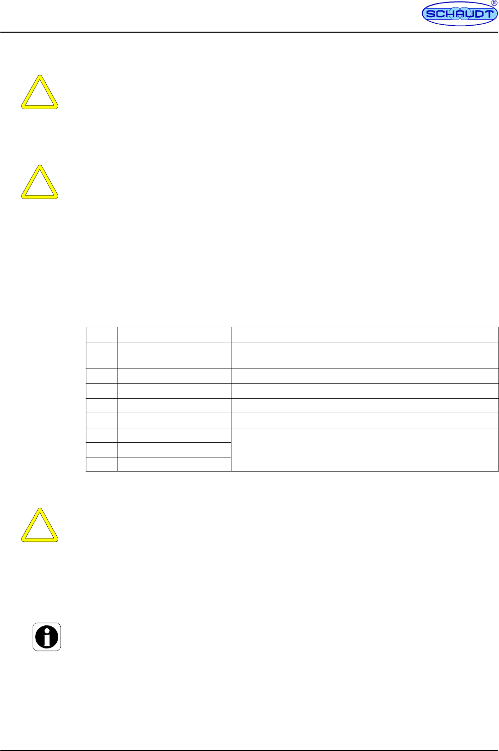
Pos. Circuit Fuse with
1 Pump/WC 7.5 A, connected via switch input Signal
Tap
2WC/Pump 7A with Polyswitch (self-healing fuse)
3Circuit 1 15 A
4Circuit 2 15 A
5Circuit 3 15 A
6Awning light
7TV 10 A
8Spare
3.3 Changing the battery
CAUTION!
The use of incorrect battery types or incorrectly designed batteries can damage the battery
itself or devices connected to the caravan charging system. So therefore:
FBatteries may only be changed by qualified personnel.
FFollow the battery manufacturer’s instructions.
FThe caravan charging system is to be used solely for connecting the 12 V power sup-
ply to 6-cell lead-gel or lead-acid batteries. Never use non-approved battery types
such as NiMH batteries.
Normally only batteries of the same type and capacity should be used, i.e. the same as
those installed by the manufacturer.
It is possible to swap lead-acid batteries with lead-gel batteries.
Changing from lead gel batteries to lead acid batteries is not possible without overhead.
Contact the vehicle manufacturer for more information.
Operation with
solar regulator
Operation on
towing
vehicle
Operating manual for caravan charging system CSV 414
5
Date: 30.05.2014
905.107 BA / EN
Proceed as follows for a battery change:
Disconnect the battery from the caravan charging system by switching the main 12 V
switch off.
Disconnect the caravan charging system from the 230 V supply.
Unhitch the caravan from the towing vehicle.
Replace the battery.
After changing the battery, recheck which type of battery has been inserted.
DANGER !
Incorrectly setting the battery selector switch poses a risk of explosion (by the formation of
detonating gas). Move the battery selector switch to the correct position.
Move the battery selector switch (Fig. 3, Pos. 10) to the correct position using a thin ob-
ject (e.g. a ballpoint pen):
FLead gel battery: Set the battery selector switch to ”Lead-gel”.
FLead-acid battery: Set the battery selector switch to ”Lead-acid”.
Start up the system as described in Section 3.1.
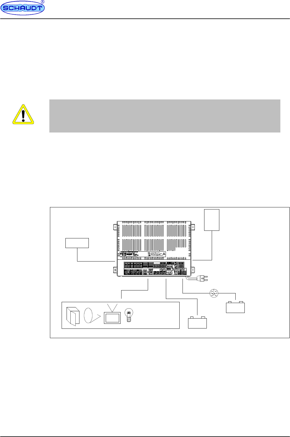
4 Application and function
CSV 414
+--
+--
Caravan charging system
230V AC
12V consumers Caravan battery
Starter battery
Lighting
Pump
Heater
etc.
LR ...
Solar regulator
(accessory)
Towing vehicle
Control and
Control panel
LT ...
Fig. 1 On-board power supply system
The CSV 414 caravan charging system is the central power supply unit for all 12 V consu-
mers connected to the caravan’s electrical system. It is usually located in a cupboard or sto-
rage area and is accessible from the front in order to change fuses.
The caravan charging system has been designed solely for connecting to a 12 V onboard
supply.
Connected units can be supplied from the caravan battery or the towing vehicle’s battery if a
mains supply is not available.
Because the device provides a hum-free, stabilised output voltage, sensitive consumers
such as transistor lights and radios can be connected and powered.
Changing
the battery
Starting up

Operating manual for caravan charging system CSV 414
6Date: 30.05.2014 905.107 BA / EN
The CSV 414 caravan charging system consists of:
Fa charge module for charging all batteries connected
Fa main switch relay to switch certain consumers on and off
Fthe complete 12V distribution system
Ffuses for the 12V circuits
Fa battery booster
A control panel (such as a LT 4XX) is connected for operation.
Connections provided for:
FOperator and control panel
FSolar charge regulator (optional)
Flat vehicle fuses protect the various circuits.
FExcess temperature
FOverload
FShort circuit
230V AC 10%, 47 -- 63 Hz sinusoidal, protection class I
12V outputs may only be loaded up to a maximum of 90% of the rated current of the asso-
ciated fuse (see block diagram or nameplate).
All consumers together may not exceed the following load:
FMains operation: 28 A
FOperation with towing vehicle, ignition ON: 8 A
4.1 Battery functions
6-cell lead acid or lead gel batteries, 80 Ah and above
Charging the caravan battery whilst driving; increasing the supply voltage coming from the
towing vehicle via the battery booster
Maximum charging current 8 A
Caravan battery
Characteristic charging curve IUoU
End of charge voltage 14.3V
Charging current 28 A
Voltage for float charge 13.8V with automatic switch function
The main 12V switch on the operator and control panel connected isolates certain 12V con-
sumers from the caravan battery (see also Page 4).
This prevents the caravan battery from being slowly discharged by standby currents.
The batteries can continue to be charged by the caravan charging system, the towing vehi-
cle or the solar charge regulator (if available), even when the main battery switch is OFF.
Modules
Actuation
Protective
circuits
Mains
Current
Batteries
Battery
charging
when vehicle
is moving
Battery
charging
with
mains
connector
12V main
switch
Operating manual for caravan charging system CSV 414
7
Date: 30.05.2014
905.107 BA / EN
1
2
3
4
5
6
789
10
11
1213
9
10
11
13
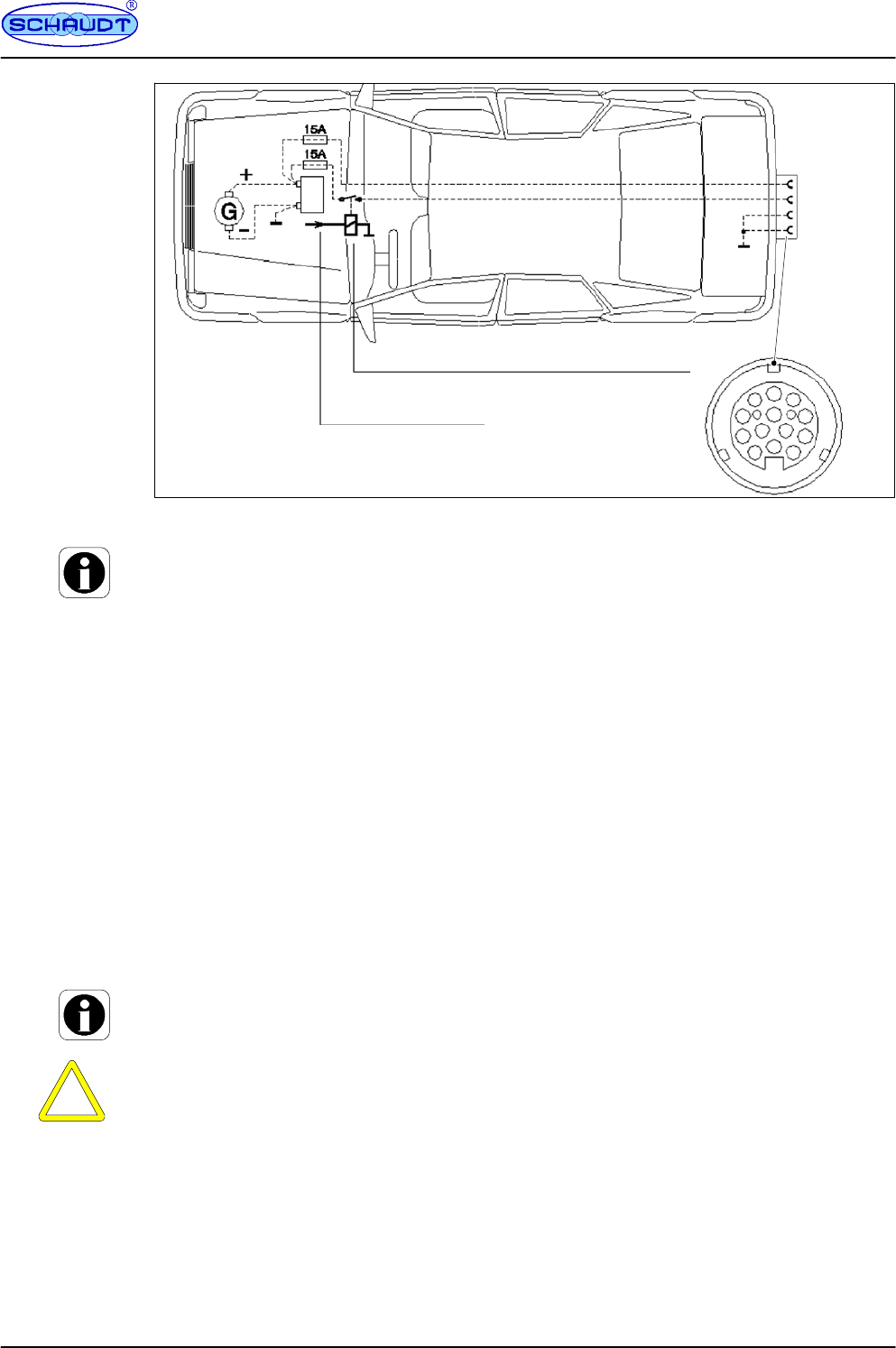
Relay circuit ”+12V for ignition ON” (connector
no. 10)
from terminal 15
Voltage when ignition ON
Fig. 2 Connector for towing vehicle power socket
For the ”Automatic shutoff” and ”Towing vehicle battery standby current” functions to be gua-
ranteed in line with the following specifications, both the 13-pin connector of the caravan,
and the socket of the towing vehicle must be assigned as per EN 1648-1 (see Fig. 2).
Consumers are switched off (with the exception of these with a continual supply, see Page
4) when the caravan is hitched to the towing vehicle and the ignition is switched on (power
on terminal 10 of trailer hitch TH). Consumers can be switched on again at any time (the
automatic disconnector does not prevent this).
No standby current when the towing vehicle ignition is OFF, plus power consumption of con-
trol electronics of refrigerator (see documentation from refrigerator manufacturer and other
consumers with a continual supply, see Page 4); measurement taken when all consumers
in the caravan are switched off.
4.2 Additional functions
This output supplies the control electronics of a fridge:
FFrom the caravan battery
FFrom the towing vehicle’s battery when the ignition is switched on
FFrom the mains supply when it is connected up
The refrigerator only operates on 12 V when the caravan is hitched to the towing vehicle and
the ignition is switched on.
CAUTION!
The caravan / towing vehicle battery is damaged beyond repair by a total discharge. So the-
refore:
FAvoid continuous 12V operation.
The refrigerator only operates on 12V when the caravan is hitched to the towing vehi-
cle and its ignition is ON.
The water pump is connected directly to the CSV 414 (output Pump/WC). The supply vol-
tage to the pump is enabled from the Pump switch on the operator and control panel. The
pump is switched on when a control voltage of 12V is applied to input ”Water Tap Signal” (via
a switch in the water tap). The other output (WC/Pump) is provided parallel.
Autom.
switch-off
Towing
vehicle-
battery
standby
current
Refrigerator
controller
Water pump
Operating manual for caravan charging system CSV 414
8Date: 30.05.2014 905.107 BA / EN
Maximum permitted charge current 14 A, protected with 15 A
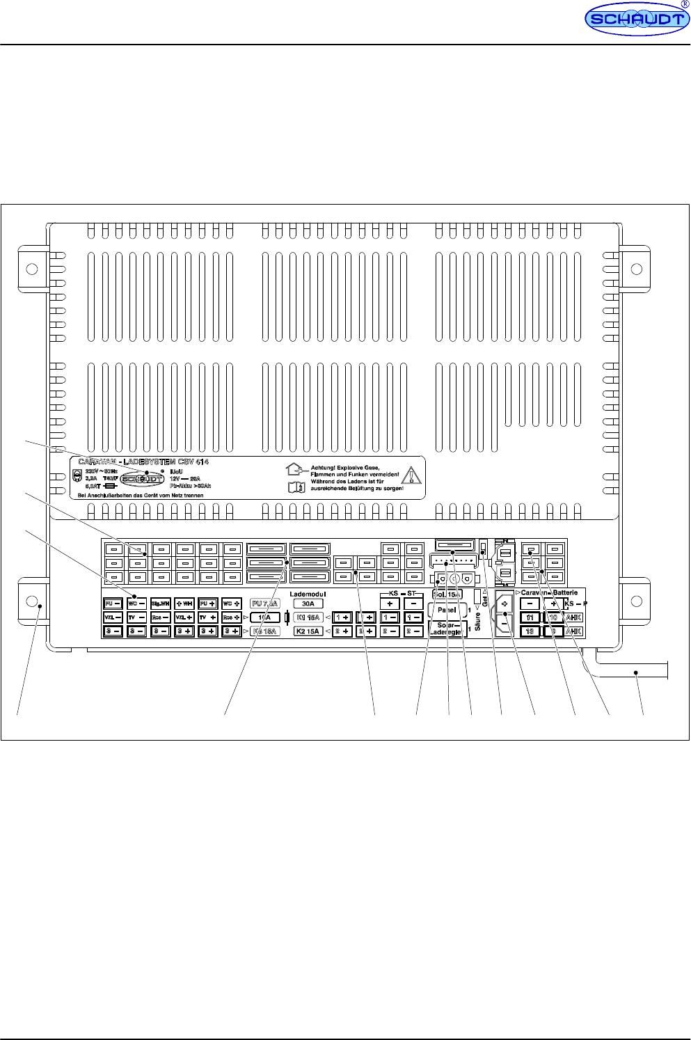
5 Layout
1
2
3
4 5 6 7 8 9 10 11 12 13 14
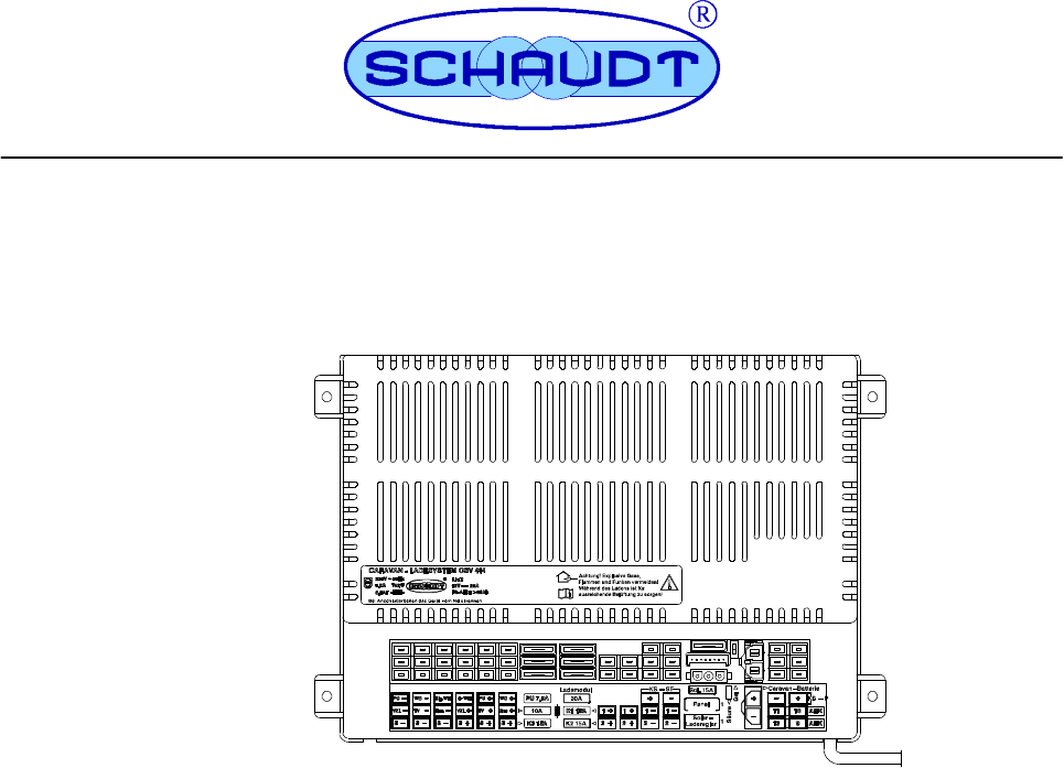
Fig. 3 Front view of CSV 414 caravan charging system
1
2
3
4
5
6
7
Adhesive label for details
Connectors for consumers/pump/water taps
Adhesive label for functions
Housing
Flat vehicle fuses
Connectors for circuits 1 and 2 / fridge controller
Connector for solar charge regulator LR ...
8
9
10
11
12
13
14
Operator and control panel
Flat vehicle fuse LR ...
Selector switch for lead-gel/lead-acid battery
Connector for caravan battery
Connector for refrigerator supply
Trailer coupling connector plug
Mains cable
Battery
charging
with
solar
charging
regulator
Operating manual for caravan charging system CSV 414
9
Date: 30.05.2014
905.107 BA / EN
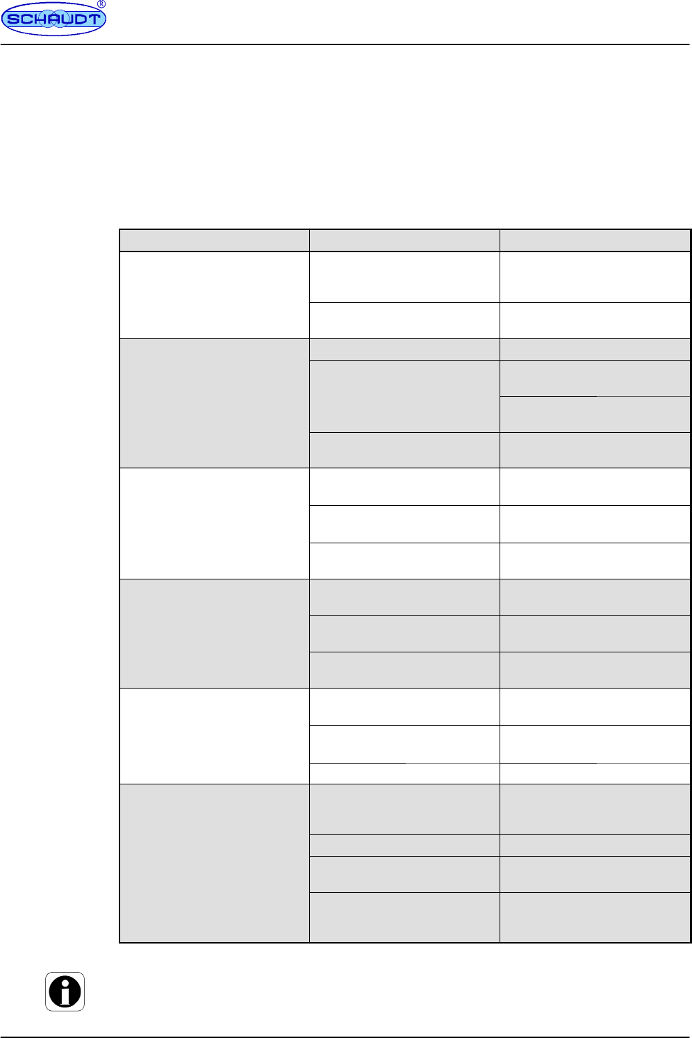
5.1 Faults
A fault in the power supply system is usually caused by a blown fuse.
Please contact our customer service team if you cannot rectify the fault using the following
table.
If this is not possible, e.g. if you are abroad, you can have the caravan charging system re-
paired at a specialist workshop. In this case, you must ensure that the warranty is not invali-
dated by incorrect repairs being carried out. Schaudt GmbH will not accept any liability for
damage resulting from such repairs.
Fault Possible cause Remedy
Caravan batter
y
is not char
g
ed No mains volta
g
eSwitch on the automatic circuit
C
a
r
a
v
a
n
b
a
t
t
e
r
y
i
s
n
o
t
c
h
a
r
g
e
d
during 230 V operation
N
o
m
a
i
n
s
v
o
l
t
a
g
e
S
w
i
t
c
h
o
n
t
h
e
a
u
t
o
m
a
t
i
c
c
i
r
c
u
i
t
breaker in the vehicle; check the
g
p
;
mains voltage
Defective caravan charging sy-
stem
Contact customer service
Caravan battery is not charged
h
i
l
d
i
i
Defective alternator Have the alternator checked
y
g
whilst driving No voltage applied to ”Ignition
ON” input or permanent plus
Have the fuse and cabling chek-
ked
p
p
p
Check the towing vehicle plug
connection
Defective caravan charging sy-
stem
Contact customer service
Solar charger is not working Solar charge regulator not plug- Plug in solar charge regulator
S
o
l
a
r
c
h
a
r
g
e
r
i
s
n
o
t
w
o
r
k
i
n
g
(mains supply off)
S
o
l
a
r
c
h
a
r
g
e
r
e
g
u
l
a
t
o
r
n
o
t
p
l
u
g
ged in
P
l
u
g
i
n
s
o
l
a
r
c
h
a
r
g
e
r
e
g
u
l
a
t
o
r
Defective fuse or cabling Have the fuse and cabling chek-
D
e
f
e
c
t
i
v
e
f
u
s
e
o
r
c
a
b
l
i
n
g
H
a
v
e
t
h
e
f
u
s
e
a
n
d
c
a
b
l
i
n
g
c
h
e
k
ked
Solar charge regulator defective Have solar charge regulator
checked
1
2
V
s
u
p
p
l
y
d
o
e
s
n
o
t
w
o
r
k
i
n
t
h
e
1
2
V
m
a
i
n
s
w
i
t
c
h
i
s
s
w
i
t
c
h
e
d
o
f
f
1
2
V
m
a
i
n
s
w
i
t
c
h
m
u
s
t
b
e
s
w
i
t
-
1
2
V
supp
l
y
d
oes no
t
wor
k
i
n
t
h
e
l
e
i
s
u
r
e
a
r
e
a
1
2
V
ma
i
nsw
i
t
c
h
i
ssw
i
t
c
h
e
d
o
f
f
1
2
V
ma
i
nsw
i
t
c
h
mus
t
b
esw
i
t
-
c
h
e
d
o
n
leisure area ched on
Defective fuse or cabling Have the fuse and cabling chek-
D
e
f
e
c
t
i
v
e
f
u
s
e
o
r
c
a
b
l
i
n
g
H
a
v
e
t
h
e
f
u
s
e
a
n
d
c
a
b
l
i
n
g
c
h
e
k
ked
Defective caravan charging sy-
stem
Contact customer service
Caravan charging system can- Defective caravan charging sy- Contact customer service
C
a
r
a
v
a
n
c
h
a
r
g
i
n
g
s
y
s
t
e
m
c
a
n
not be switched on from the
t
l
l
D
e
f
e
c
t
i
v
e
c
a
r
a
v
a
n
c
h
a
r
g
i
n
g
s
y
stem
C
o
n
t
a
c
t
c
u
s
t
o
m
e
r
s
e
r
v
i
c
e
control panel. No supply voltage Check the battery or mains con-
N
o
s
u
p
p
l
y
v
o
l
t
a
g
e
C
h
e
c
k
t
h
e
b
a
t
t
e
r
y
o
r
m
a
i
n
s
c
o
n
nection
Rocker switch is defective Contact customer service
Pump does not switch on when
a water tap is opened.
Pump supply not switched on
from control panel
Switch on pump supply (see
operating instructions for rele-
vant control panel)
Fuse blown Replace the fuse
Water tap switch or cabling for
water tap defective
Contact customer service
Pump supply not switched on
from control panel
Switch on pump supply (see
operating instructions for rele-
vant control panel)
The charging current is reduced automatically if the device becomes too hot due to exces-
sive ambient temperature or lack of ventilation. Always prevent the device from overheating
nevertheless.
Flat vehicle
fuses

Operating manual for caravan charging system CSV 414
10 Date: 30.05.2014 905.107 BA / EN
5.2 Shutting down the system
Switch off the main 12V switch on the control panel connected.
5.3 Closing down the system
CAUTION!
Total discharge causes damage to the caravan battery. So therefore:
FFully charge the caravan battery before and after closing down the system. Connect a
vehicle with an 80 Ah battery and a vehicle with a 160 Ah battery to the mains for at
least 24 and 36 hours respectively.
CAUTION!
Connected consumers can be damaged on exceeding the input voltages permitted. So the-
refore:
FDo not operate any connected Schaudt LR ... solar charge regulator without battery.
FWhen the battery is replaced or removed, unplug the ”Caravan battery” connector on
the CSV 414 beforehand (or unplug the ”+ Solar cell” connector on the solar charge
regulator).
Fully charge the caravan battery before closing down the system.
The caravan battery is then protected against total discharge. This only applies if the battery
is intact. Follow the battery manufacturer’s instructions.
Fully charge the caravan battery before closing down the system.
Unplug the ”Solar charge regulator” connector on the CSV 414 (or unplug the ”+ Solar
cell” connector on the solar charge regulator).
Unplug the ”Caravan battery” connector on the CSV 414 (or remove the clamps from the
battery terminals).
6Maintenance
The CSV 414 caravan charging system requires no maintenance.
Clean the caravan charging system using a soft, slightly damp cloth and mild detergent. Ne-
ver use spirit, thinners or similar substances. Do not allow fluid to ingress the caravan char-
ging system.
No part of this manual may be reproduced, translated or copied without express written per-
mission.
No part of this manual may be reproduced, translated or copied without express written per-
mission.
Closing
down the
system for
up to
6 months
Closing
down the
system for
more than
6 months
E

Operating manual for caravan charging system CSV 414
11
Date: 30.05.2014
905.107 BA / EN
Appendix
A EC Declaration of Conformity
Schaudt GmbH hereby confirms that the design of the CSV 414 caravan charging system
complies with the following relevant regulations:
The original EC declaration of conformity is available for reference at any time.
Schaudt GmbH, Elektrotechnik & Apparatebau
Planckstraße 8
88677 Markdorf
Germany
B Special fittings/accessories
Schaudt solar charger LR ... model for solar modules with a total current of 14A, including
0.5 m connection cable and connector plug
C Customer service
Schaudt GmbH, Elektrotechnik & Apparatebau
Planckstraße 8
D-88677 Markdorf
Phone: +49 7544 9577-16 Email: kundendienst@schaudt-gmbh.de
Web: www.schaudt-gmbh.de
Returning a faulty device:
Always use well-padded packaging.
Complete and enclose the fault report, see Appendix D.
Send it to the addressee (free delivery).
Manufacturer
Solar-
charge
regulator
Customer
service
address
Send in
device
Operating manual for caravan charging system CSV 414
12 Date: 30.05.2014 905.107 BA / EN
D Fault report
In the event of damage, please fill in the fault report and send it with the faulty device to the
manufacturer.
Device type: _______________________
Item no.: _______________________
Vehicle: Manufacturer: _______________________
Model: _______________________
Own installation? Yes -No -
Upgrade? Yes -No -
Upstream overvoltage protection? Yes -No -
Following fault has occurred (please tick):
-Electrical consumers do not work -- which?
(please specify below)
-Switching on and off not possible
-Persistent fault
-Intermittent fault/loose contact
Other comments:
Operating manual for caravan charging system CSV 414
13
Date: 30.05.2014
905.107 BA / EN
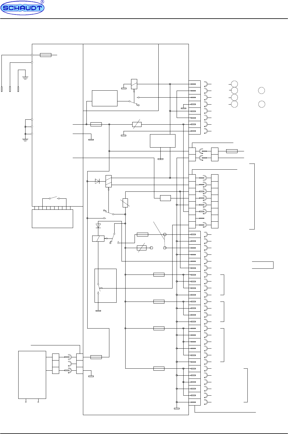
E Block diagram/wiring diagram
* TH-Assignment of the towing vehicle /
caravan connector in accordance with EN
1648-1. Connectors AHK 9 and AHK 10
(TH9 and TH10) must be fused external
within the vehicle (max. 15A).
--
+Pump/WC
230V~50Hz
TV
+
--
--
+Awning light
+
--
--
+
--
+
+
--
--
+
--
+
+
--
Switch Mode
S-CSV 409
--
+
CSV 414
14.3V/28A
A12
A11
A3
A1
A2
Plug connector LF--PA 401
6.3 x 0.8 (32 way)
L = 1.2m
3G1.5
+
-- 12V
1
2
3
4
5
66
5
4
3
2
112V OFF
12V ON
12V indicator
Mains indicator
MSFQ/0 8F pin strip
Circuit 5
Circuit 3
Circuit 2
Circuit 1
Lead--acid
Lead--gel/
Changeover switch
+Ua booster
14.25V
Caravan battery
+
2
1
3
2
1
3
Negative
+
3F MNL socket
Solar module
charge
Solar
LR ...
Booster
Molex Minifit SR--2F
11
--
22
max. 40A
WC/Pump
--
+Spare
Auto.
switch--off
10A
15A
15A
15A
15A
5A Polyswitch
30A
Pump
nc
7
88
7
Switching
stage
To the panel
7A Polyswitch --
+
7.5A
2.5A
Poly
switch
Jumper
Water Tap Signal
+ Water Tap
+
-- Fridge cartridge
-- T H
+ TH TH +12V perm. plus *
9
13 Negative to
9
11
10
-- T H
+TH
Fridge controller
+
--
Negative to
TH +12V connected *
10
PCB KPL CSV 414
A
B
C
regulator

Operating manual for caravan charging system CSV 414
14 Date: 30.05.2014 905.107 BA / EN
(blank page)
