Miniature Helical PCB Antenna For 868 MHz Or 915/920 Antena Guide
868_Antena_PCb_Guide
User Manual:
Open the PDF directly: View PDF ![]() .
.
Page Count: 25
Design Note
DN038
SWRA416 Page 1 of 24
Miniature Helical PCB Antenna for 868 MHz or 915/920 MHz
By Richard Wallace
Keywords
Miniature Helical PCB Antenna
Optimized for compact designs
868 or 915/920 MHz ISM Bands
CC11xx
CC12xx
1 Introduction
This document describes a compact PCB
helical antenna that has been specifically
designed for 868 MHz or 915/920 MHz
ISM bands.
The PCB helical antenna requires two
matching components for matching to a
50-ohm load.
When a large PCB area (38 mm x 24 mm)
is available for the antenna then the
recommended antenna is DN024 [1] since
the impedance is closer to 50 ohm without
any external matching components (868
MHz: 30+j11; VSWR 1.8) and the
bandwidth is around 90 MHz.
The miniature PCB helical antenna is more
compact (19 mm x 11 mm) with
approximately quarter of the size of the
DN024 [1] but requires matching
components since the impedance is far
from 50 ohms (868 MHz: 10-j88; VSWR
22).
When the miniature helical antenna is
matched then the bandwidth is around 40
MHz and has similar efficiency as DN024
[1] antenna when measured on the
TRXEB platform.
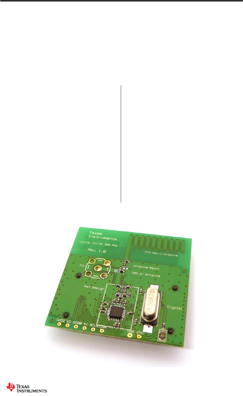
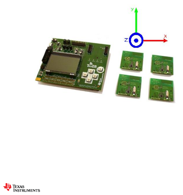
All measurement results presented in this
document are based on measurements
performed on the CC110L EM Rev 1.0
Reference Design [3], shown in Figure 1.
Figure 1. CC110L EM 868 / 915 MHz

Design Note
DN038
SWRA416 Page 2 of 24
Table of Contents
KEYWORDS .............................................................................................................................. 1
1 INTRODUCTION ............................................................................................................. 1
2 ABBREVIATIONS ........................................................................................................... 2
3 ANTENNA DESIGN ........................................................................................................ 3
3.1 PHYSICAL DIMENSIONS .............................................................................................. 3
3.2 ANTENNA MATCH NETWORK ...................................................................................... 4
3.3 ANTENNA BANDWIDTH MEASUREMENT........................................................................ 7
3.4 ANTENNA OTA MEASUREMENT .................................................................................. 7
3.4.1 868 MHz OTA Measurement Summary ............................................................................ 7
4 CONCLUSION ................................................................................................................ 9
5 REFERENCES .............................................................................................................. 10
6 GENERAL INFORMATION ........................................................................................... 10
6.1 DOCUMENT HISTORY ............................................................................................... 10
7 APPENDICES ............................................................................................................... 11
7.1 CTIA OTA REPORT – 868 MHZ (ANTENNA MATCHED AT 868 MHZ) ........................... 11
7.1.1 OTA Evaluation Results .................................................................................................. 11
7.1.2 RP_868.000_tot .............................................................................................................. 12
7.1.3 RP_868.000_hor ............................................................................................................. 13
7.1.4 RP_868.000_ver ............................................................................................................. 14
7.1.5 Theta = 0, Phi = 0 .......................................................................................................... 15
7.1.6 Theta = 180, Phi = 0 ...................................................................................................... 15
7.1.7 Theta = 90, Phi = 0 ........................................................................................................ 16
7.1.8 Theta = 90, Phi = 180 .................................................................................................... 16
7.1.9 Theta = 90, Phi = 270 .................................................................................................... 17
7.1.10 Theta = 90, Phi = 90 ...................................................................................................... 17
7.2 CTIA OTA REPORT – 915 MHZ (ANTENNA MATCHED AT 868 MHZ) ........................... 18
7.2.1 OTA Evaluation Results: ................................................................................................ 18
7.2.2 RP_915.000_tot .............................................................................................................. 19
7.2.3 RP_915.000_hor ............................................................................................................. 20
7.2.4 RP_915.000_ver ............................................................................................................. 21
7.2.5 Theta = 0, Phi = 0 .......................................................................................................... 22
7.2.6 Theta = 180, Phi = 0 ...................................................................................................... 22
7.2.7 Theta = 90, Phi = 0 ........................................................................................................ 23
7.2.8 Theta = 90, Phi = 180 .................................................................................................... 23
7.2.9 Theta = 90, Phi = 270 .................................................................................................... 24
7.2.10 Theta = 90, Phi = 90 ...................................................................................................... 24
2 Abbreviations
ANT Antenna
CTIA Cellular Telephone Industry Association
DC Direct Current
EM Evaluation Module
ETSI European Telecommunications Standards Institute
FCC Federal Communications Commission
FR4 Material type used for producing PCB
ISM Industrial, Scientific, Medical
NM Not Mounted
OTA Over The Air
PCB Printed Circuit Board
SRD Short Range Devices
TRP Total Radiated Power
TRXEB Evaluation Board
Design Note
DN038
SWRA416 Page 3 of 24
3 Antenna Design
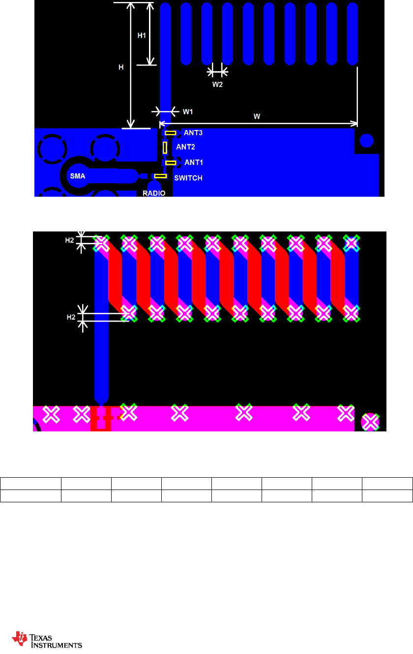
3.1 Physical Dimensions
Figure 2. Top Layer Layout
Figure 3. Zoom of Top and Bottom Layer Layout with Via Markings
Dimension
H
H1
H2
W
W1
W2
Via dia
12 mm
6 mm
0.5 mm
19 mm
1 mm
1 mm
0.38 mm
Table 1. Antenna Dimensions
Top layer is shown in blue and the bottom layer is shown in red for Figure 2 and Figure 3. The
“X” markers indicate via positions which route between the top and bottom layers.
PCB board thickness for the CC110L EM 868 / 915 MHz reference design [3] is 0.8 mm.
Another PCB thickness can be used but then the antenna match must be re-calculated.
Design Note
DN038
SWRA416 Page 4 of 24
Dimensions for the antenna can be found in Table 1 and the gerbers for the antenna design
are also available for 868/915 MHz [3]
3.2 Antenna Match Network
There are several ways to tune an antenna to achieve better performance. For resonant
antennas the main factor is the length. Ideally the frequency which gives least reflection
should be in the middle of the frequency band of interest. Thus if the resonance frequency is
too low, the antenna should be made shorter. If the resonance frequency is too high, the
antenna length should be increased.
Even if the antenna resonates at the correct frequency it might not be well matched to the
correct impedance. Size of ground plane, distance from antenna to ground plane, dimensions
of antenna elements, feed point and plastic casing are factors that can affect the impedance.
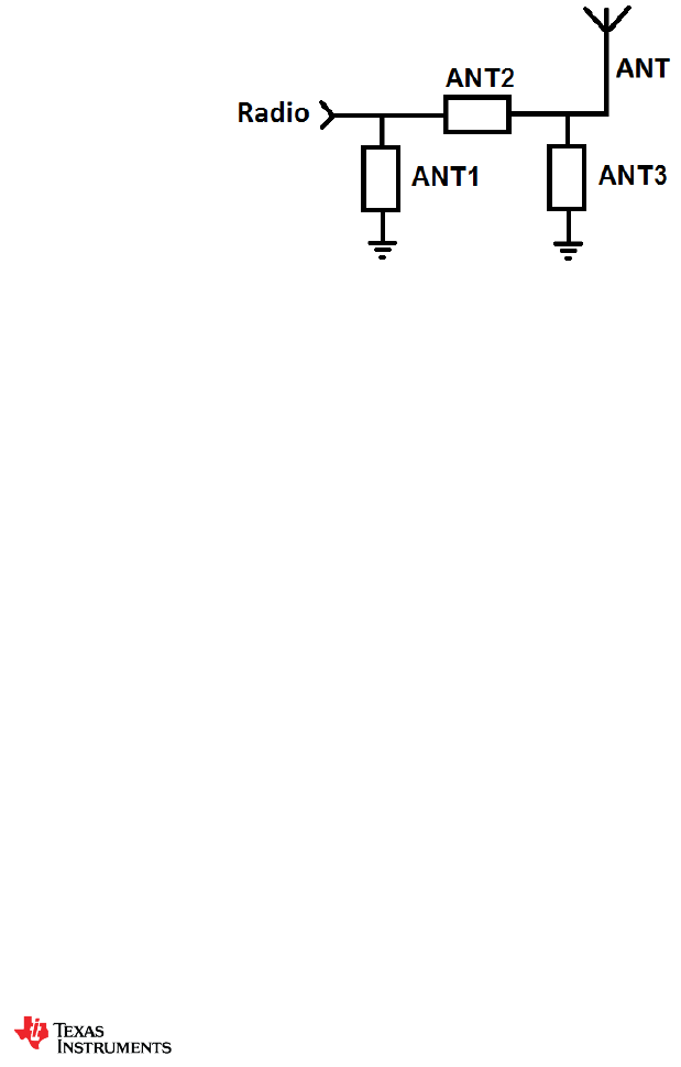
Since the impedance will change depending on several parameters; with a pi-network as
illustrated in Figure 4, the antenna match can always be restored to a 50 ohm match. Only two
of the components (ANT2 + (ANT1 or ANT3) ) are required to match the impedance to 50
ohm depending on the start impedance. For the PCB helical antenna at 868 / 915 MHz, only
ANT2 and ANT3 are required.
Figure 4. Antenna Match Network
Design Note
DN038
SWRA416 Page 5 of 24
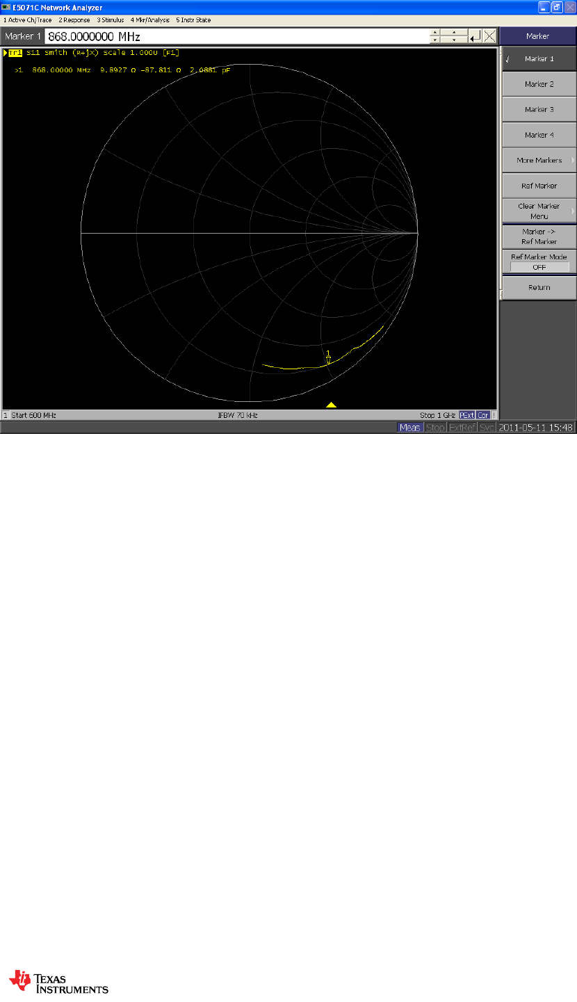
Figure 5. Start Impedance with 0-ohm (ANT2) Resistor in Antenna Match
The impedance of the PCB helical antenna is far from 50 ohm without the antenna matching
network so the matching network acts as a load and matching network for the antenna. The
impedance of the antenna can be seen in Figure 5 when ANT2 is set to 0 ohm.
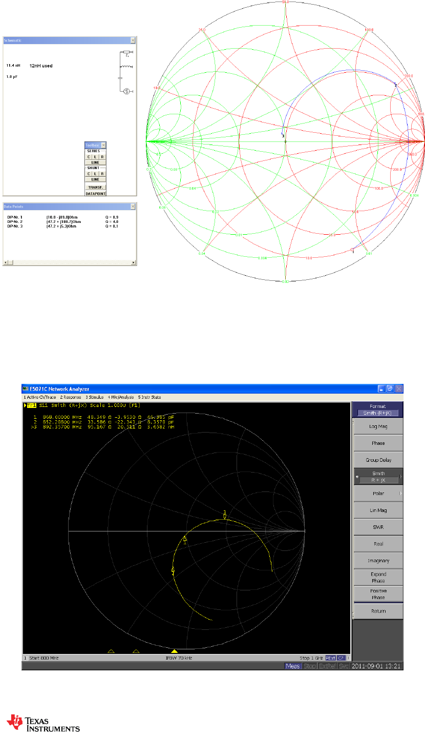
Figure 6 shows the theoretical load and match to at 868 MHz. The Smith diagram shows a
shunt component of 11.4 nH (ANT3) and a series capacitor of 1.0 pF (ANT2). ANT1
component is not required and can be left open. 11.4 nH value does not exist so a 12 nH is
used instead.
Design Note
DN038
SWRA416 Page 6 of 24
Figure 6. Theoretical Antenna Match
Assembling ANT2 (1.0 pF) and ANT3 (12 nH) based on the theoretical calculated match, then
the impedance can be re-measured and a good match is measured and can be seen in Figure
7.
Figure 7. With Antenna Match Components - ANT2: 1.0 pF and ANT3: 12 nH
Design Note
DN038
SWRA416 Page 7 of 24
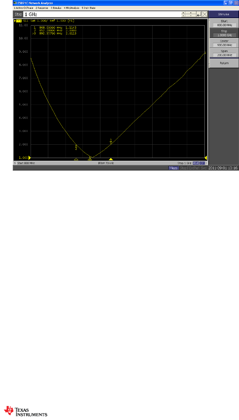
3.3 Antenna Bandwidth Measurement
Figure 8. Bandwidth Measurement at VSWR 2
As can be seen from Figure 8, the bandwidth is 40 MHz with a VSWR 2 and 68 MHz with a
VSWR 3.
3.4 Antenna OTA Measurement
The conducted output power from the radio is 0 dBm and the results shown in section 3.4.1
show the performance of the antenna of the CC110L EM 868 / 915 MHz on the TRXEB
platform.
3.4.1 868 MHz OTA Measurement Summary
Total Radiated Power
-1.83 dBm
Peak EIRP
2.33 dBm
Directivity
4.16 dBi
Efficiency
-1.83 dB
Efficiency
65.55 %
Gain
2.33 dBi
NHPRP 45°
-4.06 dBm
NHPRP 45° / TRP
-2.23 dB
NHPRP 45° / TRP
59.86 %
NHPRP 30°
-5.89 dBm
NHPRP 30° / TRP
-4.05 dB
NHPRP 30° / TRP
39.32 %
NHPRP 22.5°
-7.26 dBm
NHPRP 22.5° / TRP
-5.42 dB
NHPRP 22.5° / TRP
28.69 %
UHRP
-4.91 dBm
UHRP / TRP
-3.07 dB
UHRP / TRP
49.28 %
Design Note
DN038
SWRA416 Page 8 of 24
LHRP
-4.78 dBm
LHRP / TRP
-2.95 dB
LHRP / TRP
50.72 %
Front/Back Ratio
2.52
PhiBW
332.2 deg
PhiBW Up
238.7 deg
PhiBW Down
93.4 deg
ThetaBW
82.9 deg
ThetaBW Up
46.3 deg
ThetaBW Down
36.6 deg
Boresight Phi
90 deg
Boresight Theta
15 deg
Maximum Power
2.33 dBm
Minimum Power
-12.00 dBm
Average Power
-0.91 dBm
Max/Min Ratio
14.33 dB
Max/Avg Ratio
3.24 dB
Min/Avg Ratio
-11.10 dB
Best Single Value
1.11 dBm
Best Position
Phi = 45 deg; Theta = 165 deg; Pol = Ver
For the full CTIA report including 3D radiated plots at 868 MHz please refer to section 7.1.
The antenna was also measured at 915 MHz to show the performance degradation whilst
keeping the same matching network at 868 MHz; this is shown in section 7.2. For optimum
performance at 915 MHz, the antenna needs to be re-matched at this frequency.
For the Over-The-Air (OTA) Measurements performed in the chamber, please refer to Figure
9 for coordinate correlation to the CTIA reports.
Figure 9. Coordinates Correlation to CTIA OTA Reports

Design Note
DN038
SWRA416 Page 9 of 24
4 Conclusion
When a large PCB area (38 mm x 24 mm) is available for the antenna then the recommended
antenna is DN024 [1] since the impedance is closer to 50 ohm without any external matching
components (868 MHz: 30+j11; VSWR 1.8) and the bandwidth is around 90 MHz.
When there is a need for a more compact antenna then the miniature PCB helical antenna is
ideal (19 mm x 11 mm) with approximately quarter of the DN024 antenna size [1] but requires
matching components since the impedance is far from 50 ohms (868 MHz: 10-j88; VSWR
22). It is important to match this antenna since the match network is also used for loading the
antenna to 868 MHz or 915 / 920 MHz.
When the miniature helical antenna is matched then the bandwidth is around 40 MHz and has
similar efficiency as DN024 [1] antenna when measured on the TRXEB platform.
A single match network can be used for 868 MHz and 915 / 920 MHz but due to the reduce
bandwidth compared to DN024 antenna [1] then there will be some degradation in
performance. For the antenna matching network components it is recommended to use tight
tolerance components.
Optimal antenna match for the CC110L EM 868 / 915 MHz reference design [3] is a series 1.0
pF capacitor (ANT2) and a shunt inductor of 12 nH (ANT3) for 868 MHz operation.
The PCB board thickness for the CC110L EM 868 / 915 MHz reference design [3] is 0.8 mm.
The same match has been tested at 1.24 mm thick PCB and the performance was still good
but generally if the PCB thickness is changed then the antenna match should be re-calculated.

Design Note
DN038
SWRA416 Page 10 of 24
5 References
[1] DN024 Monopole PCB Antenna (DN024)
[2] DN035 Antenna Quick Selection Guide (DN035)
[3] CC11xL EM 868/915 MHz Ref Design (swrr082)
[4] AN058 Antenna Measurement with Network Analyzer (AN058)
6 General Information
6.1 Document History
Revision
Date
Description/Changes
SWRA416
2012.11.27
Initial release.

Design Note
DN038
SWRA416 Page 11 of 24
7 Appendices
7.1 CTIA OTA Report – 868 MHz (Antenna matched at 868 MHz)
7.1.1 OTA Evaluation Results
Total Radiated Power
-1.83 dBm
Peak EIRP
2.33 dBm
Directivity
4.16 dBi
Efficiency
-1.83 dB
Efficiency
65.55 %
Gain
2.33 dBi
NHPRP 45°
-4.06 dBm
NHPRP 45° / TRP
-2.23 dB
NHPRP 45° / TRP
59.86 %
NHPRP 30°
-5.89 dBm
NHPRP 30° / TRP
-4.05 dB
NHPRP 30° / TRP
39.32 %
NHPRP 22.5°
-7.26 dBm
NHPRP 22.5° / TRP
-5.42 dB
NHPRP 22.5° / TRP
28.69 %
UHRP
-4.91 dBm
UHRP / TRP
-3.07 dB
UHRP / TRP
49.28 %
LHRP
-4.78 dBm
LHRP / TRP
-2.95 dB
LHRP / TRP
50.72 %
Front/Back Ratio
2.52
PhiBW
332.2 deg
PhiBW Up
238.7 deg
PhiBW Down
93.4 deg
ThetaBW
82.9 deg
ThetaBW Up
46.3 deg
ThetaBW Down
36.6 deg
Boresight Phi
90 deg
Boresight Theta
15 deg
Maximum Power
2.33 dBm
Minimum Power
-12.00 dBm
Average Power
-0.91 dBm
Max/Min Ratio
14.33 dB
Max/Avg Ratio
3.24 dB
Min/Avg Ratio
-11.10 dB
Best Single Value
1.11 dBm
Best Position
Phi = 45 deg; Theta = 165 deg; Pol = Ver

Design Note
DN038
SWRA416 Page 12 of 24
7.1.2 RP_868.000_tot
Azimuth
(deg)
Elevation
0 deg
(dB)
Elevation
15 deg
(dB)
Elevation
30 deg
(dB)
Elevation
45 deg
(dB)
Elevation
60 deg
(dB)
Elevation
75 deg
(dB)
Elevation
90 deg
(dB)
Elevation
105 deg
(dB)
0.00
0.02
-0.55
-1.69
-3.23
-2.91
-2.06
-1.31
-0.58
15.00
-0.04
-0.48
-0.80
-2.29
-1.12
-0.76
-0.52
-1.20
30.00
0.08
0.04
0.05
-0.56
0.06
0.48
-1.00
-1.71
45.00
0.46
0.80
0.81
0.59
0.92
0.74
-1.25
-1.39
60.00
0.63
1.34
1.42
1.60
1.02
0.60
-2.04
-1.20
75.00
1.19
1.85
1.99
1.78
0.57
-0.25
-2.81
-1.24
90.00
1.12
2.33
2.00
1.95
-0.58
-1.64
-4.64
-2.42
105.00
1.37
2.21
1.97
1.65
-1.54
-3.80
-7.33
-4.84
120.00
1.47
1.92
1.68
0.57
-2.67
-6.03
-11.79
-6.83
135.00
1.20
1.25
1.22
-0.69
-3.29
-6.70
-12.00
-7.10
150.00
1.04
0.65
0.65
-1.58
-3.26
-5.29
-7.51
-5.75
165.00
1.04
0.25
0.64
-2.14
-3.25
-3.79
-4.77
-3.39
180.00
0.96
0.14
0.33
-2.17
-2.97
-2.32
-2.90
-1.64
195.00
0.80
0.15
0.24
-2.14
-2.70
-1.86
-2.48
-0.39
210.00
0.91
0.58
-0.06
-2.21
-3.18
-1.65
-2.80
-0.09
225.00
0.71
0.70
-0.32
-2.75
-3.63
-2.49
-4.01
-0.41
240.00
0.88
0.77
-0.90
-3.48
-4.99
-3.50
-5.53
-1.75
255.00
0.85
0.76
-1.59
-4.90
-6.85
-5.37
-7.83
-3.27
270.00
0.98
0.64
-2.34
-6.81
-7.89
-7.40
-9.26
-5.09
285.00
0.94
0.29
-3.49
-8.36
-7.48
-8.68
-11.38
-7.19
300.00
0.86
0.09
-3.82
-8.52
-6.04
-8.61
-9.86
-6.42
315.00
0.85
-0.23
-3.65
-7.17
-5.33
-7.12
-8.26
-4.34
330.00
0.45
-0.71
-3.37
-5.39
-4.28
-7.11
-5.75
-2.38
345.00
0.33
-1.06
-2.72
-4.77
-3.70
-5.69
-3.32
-1.22
360.00
-0.35
-0.55
-2.02
-3.50
-3.23
-2.91
-1.78
-0.68
Azimuth
(deg)
Elevation
120 deg
(dB)
Elevation
135 deg
(dB)
Elevation
150 deg
(dB)
Elevation
165 deg
(dB)
Elevation
180 deg
(dB)
0.00
-0.76
-2.14
0.37
1.33
0.87
15.00
-1.03
-1.52
1.09
1.31
0.85
30.00
-0.65
-0.91
1.35
1.53
0.76
45.00
0.19
-0.33
1.21
1.31
0.45
60.00
0.15
0.13
0.65
0.89
0.17
75.00
-0.60
-0.27
-0.24
0.79
-0.10
90.00
-1.84
-0.98
-1.34
0.26
-0.26
105.00
-3.63
-1.76
-2.10
0.20
-0.06
120.00
-4.61
-2.51
-2.33
-0.20
0.09
135.00
-3.93
-2.41
-1.83
-0.29
0.70
150.00
-2.76
-2.06
-0.94
-0.06
1.32
165.00
-1.84
-1.90
-0.46
0.21
1.81
180.00
-1.28
-1.51
-0.15
0.31
1.98
195.00
-0.87
-1.60
-0.32
0.54
1.65
210.00
-0.70
-1.57
-0.80
0.21
1.33
225.00
-1.46
-1.79
-1.02
0.08
0.61
240.00
-2.37
-1.91
-0.86
-0.10
-0.01
255.00
-3.54
-1.96
-1.24
-0.10
-0.56
270.00
-4.36
-2.45
-1.54
-0.19
-0.61
285.00
-4.49
-2.45
-1.31
-0.31
-0.74
300.00
-3.36
-2.34
-1.29
-0.15
-0.50
315.00
-1.91
-2.28
-0.73
-0.03
-0.03
330.00
-0.78
-2.28
-0.43
0.37
0.43
345.00
-0.13
-2.07
0.01
0.66
0.69
360.00
-0.81
-2.13
0.39
1.19
0.52

Design Note
DN038
SWRA416 Page 13 of 24
7.1.3 RP_868.000_hor
Azimuth
(deg)
Elevation
0 deg
(dB)
Elevation
15 deg
(dB)
Elevation
30 deg
(dB)
Elevation
45 deg
(dB)
Elevation
60 deg
(dB)
Elevation
75 deg
(dB)
Elevation
90 deg
(dB)
Elevation
105 deg
(dB)
0.0
-4.16
-5.12
-6.99
-9.59
-12.40
-18.01
-10.47
-6.31
15.0
-6.76
-7.78
-8.26
-11.23
-15.26
-12.98
-9.90
-8.02
30.0
-10.53
-9.87
-9.14
-13.25
-16.86
-10.46
-11.90
-10.38
45.0
-9.41
-7.61
-9.08
-11.76
-11.68
-9.79
-14.69
-11.82
60.0
-6.02
-5.10
-6.47
-7.35
-9.39
-9.50
-18.97
-11.68
75.0
-3.19
-2.47
-3.22
-4.56
-7.23
-10.27
-19.30
-11.80
90.0
-1.25
-0.48
-1.14
-2.24
-6.06
-10.02
-16.55
-11.80
105.0
0.14
0.57
0.09
-1.25
-4.56
-9.49
-14.42
-10.88
120.0
0.94
1.07
0.66
-1.17
-4.13
-8.71
-15.05
-10.39
135.0
0.90
0.81
0.68
-1.62
-4.06
-8.04
-17.48
-10.19
150.0
0.47
0.01
-0.31
-2.79
-4.71
-8.16
-19.20
-11.48
165.0
-0.60
-1.40
-1.56
-4.71
-6.59
-8.59
-16.45
-14.01
180.0
-2.38
-4.03
-3.98
-7.25
-9.81
-10.30
-14.79
-19.31
195.0
-5.40
-8.08
-7.44
-11.65
-14.07
-11.99
-15.21
-16.76
210.0
-8.54
-13.22
-11.98
-17.44
-18.71
-14.46
-15.42
-14.48
225.0
-10.51
-10.14
-15.98
-21.30
-17.17
-17.02
-17.49
-12.57
240.0
-7.07
-6.29
-11.62
-14.77
-14.74
-20.18
-22.70
-12.50
255.0
-3.64
-3.82
-8.03
-13.01
-13.77
-22.70
-21.66
-10.78
270.0
-1.81
-2.37
-5.92
-12.33
-12.56
-22.70
-18.08
-9.96
285.0
-0.68
-1.63
-5.86
-11.25
-12.19
-22.70
-17.50
-9.78
300.0
-0.07
-1.38
-5.66
-11.20
-11.60
-21.61
-17.27
-8.39
315.0
0.20
-1.52
-5.28
-10.46
-11.06
-18.27
-18.37
-6.73
330.0
-0.69
-2.21
-5.85
-9.82
-9.10
-16.50
-16.84
-5.62
345.0
-1.68
-3.39
-6.33
-9.63
-9.44
-22.62
-13.44
-5.71
360.0
-3.92
-4.37
-6.90
-9.18
-11.27
-22.70
-10.75
-6.34
Azimuth
(deg)
Elevation
120 deg
(dB)
Elevation
135 deg
(dB)
Elevation
150 deg
(dB)
Elevation
165 deg
(dB)
Elevation
180 deg
(dB)
0.0
-5.95
-5.72
-2.33
-2.15
-3.58
15.0
-7.74
-6.58
-3.13
-4.16
-6.26
30.0
-10.02
-8.42
-4.56
-7.56
-9.99
45.0
-12.26
-9.58
-7.20
-12.25
-16.62
60.0
-14.37
-9.62
-9.34
-11.88
-10.12
75.0
-13.44
-8.08
-9.03
-6.38
-5.53
90.0
-10.31
-5.75
-6.02
-3.44
-2.83
105.0
-7.97
-3.99
-3.94
-1.46
-0.98
120.0
-6.03
-3.09
-2.63
-0.64
-0.05
135.0
-4.71
-2.49
-2.09
-0.34
0.57
150.0
-4.53
-2.69
-2.01
-0.66
0.58
165.0
-5.42
-3.82
-2.99
-1.59
0.11
180.0
-7.81
-5.62
-4.68
-3.52
-1.09
195.0
-12.81
-9.68
-7.88
-6.24
-3.56
210.0
-22.70
-19.50
-13.80
-12.67
-7.29
225.0
-13.82
-15.45
-18.70
-17.43
-17.19
240.0
-10.53
-9.04
-9.58
-9.64
-13.11
255.0
-7.85
-5.76
-5.83
-5.25
-6.89
270.0
-6.50
-4.35
-3.44
-2.53
-3.42
285.0
-5.38
-3.44
-2.22
-1.26
-1.56
300.0
-4.58
-3.04
-1.52
-0.40
-0.61
315.0
-3.94
-3.32
-0.94
-0.13
-0.27
330.0
-3.52
-3.77
-0.98
-0.19
-0.57
345.0
-3.98
-4.29
-1.31
-0.86
-1.50
360.0
-5.47
-5.69
-1.82
-1.64
-3.33

Design Note
DN038
SWRA416 Page 14 of 24
7.1.4 RP_868.000_ver
Azimuth
(deg)
Elevation
0 deg
(dB)
Elevation
15 deg
(dB)
Elevation
30 deg
(dB)
Elevation
45 deg
(dB)
Elevation
60 deg
(dB)
Elevation
75 deg
(dB)
Elevation
90 deg
(dB)
Elevation
105 deg
(dB)
0.0
-2.07
-2.41
-3.21
-4.37
-3.42
-2.18
-1.87
-1.93
15.0
-1.08
-1.37
-1.66
-2.88
-1.29
-1.03
-1.05
-2.21
30.0
-0.31
-0.42
-0.50
-0.80
-0.03
0.11
-1.36
-2.35
45.0
-0.01
0.13
0.34
0.33
0.67
0.33
-1.45
-1.81
60.0
-0.43
0.23
0.65
1.01
0.60
0.15
-2.13
-1.60
75.0
-0.79
-0.15
0.43
0.64
-0.22
-0.70
-2.91
-1.64
90.0
-2.65
-0.89
-0.88
-0.14
-2.03
-2.32
-4.93
-2.95
105.0
-4.69
-2.82
-2.57
-1.48
-4.53
-5.17
-8.28
-6.08
120.0
-7.89
-5.58
-5.11
-4.24
-8.11
-9.39
-14.56
-9.35
135.0
-10.56
-8.91
-8.10
-7.86
-11.18
-12.47
-13.45
-10.04
150.0
-8.05
-7.96
-6.38
-7.71
-8.71
-8.45
-7.81
-7.10
165.0
-3.97
-4.75
-3.38
-5.63
-5.94
-5.54
-5.08
-3.79
180.0
-1.75
-1.96
-1.68
-3.79
-3.98
-3.07
-3.20
-1.72
195.0
-0.40
-0.56
-0.57
-2.65
-3.02
-2.30
-2.72
-0.49
210.0
0.39
0.40
-0.34
-2.34
-3.31
-1.89
-3.05
-0.25
225.0
0.37
0.33
-0.44
-2.81
-3.82
-2.65
-4.21
-0.68
240.0
0.13
-0.18
-1.28
-3.81
-5.47
-3.59
-5.62
-2.13
255.0
-1.05
-1.10
-2.71
-5.63
-7.83
-5.45
-8.01
-4.12
270.0
-2.25
-2.38
-4.84
-8.24
-9.71
-7.53
-9.87
-6.81
285.0
-4.12
-4.18
-7.26
-11.49
-9.27
-8.86
-12.59
-10.67
300.0
-6.30
-5.33
-8.44
-11.90
-7.46
-8.84
-10.73
-10.81
315.0
-7.73
-6.12
-8.69
-9.93
-6.68
-7.46
-8.70
-8.08
330.0
-5.93
-6.05
-6.98
-7.33
-6.02
-7.64
-6.10
-5.17
345.0
-3.99
-4.87
-5.20
-6.49
-5.05
-5.78
-3.77
-3.13
360.0
-2.86
-2.89
-3.72
-4.86
-3.97
-2.96
-2.36
-2.05
Azimuth
(deg)
Elevation
120 deg
(dB)
Elevation
135 deg
(dB)
Elevation
150 deg
(dB)
Elevation
165 deg
(dB)
Elevation
180 deg
(dB)
0.0
-2.33
-4.65
-2.98
-1.26
-1.05
15.0
-2.08
-3.14
-0.98
-0.14
-0.09
30.0
-1.18
-1.76
0.07
0.96
0.38
45.0
-0.07
-0.88
0.53
1.11
0.36
60.0
0.00
-0.35
0.19
0.65
-0.26
75.0
-0.83
-1.06
-0.86
-0.13
-1.56
90.0
-2.50
-2.75
-3.15
-2.16
-3.75
105.0
-5.62
-5.74
-6.70
-4.78
-7.27
120.0
-10.17
-11.57
-14.09
-10.39
-14.67
135.0
-11.78
-19.62
-14.19
-19.71
-14.33
150.0
-7.52
-10.79
-7.55
-8.95
-6.75
165.0
-4.34
-6.37
-3.99
-4.48
-3.10
180.0
-2.37
-3.64
-2.04
-2.01
-0.97
195.0
-1.16
-2.34
-1.16
-0.48
0.09
210.0
-0.73
-1.64
-1.03
-0.02
0.69
225.0
-1.72
-1.98
-1.10
0.00
0.54
240.0
-3.09
-2.85
-1.48
-0.61
-0.23
255.0
-5.54
-4.30
-3.10
-1.68
-1.72
270.0
-8.48
-6.97
-6.05
-3.99
-3.83
285.0
-11.83
-9.34
-8.55
-7.35
-8.40
300.0
-9.47
-10.64
-14.24
-12.74
-16.57
315.0
-6.20
-9.01
-14.06
-16.80
-12.83
330.0
-4.08
-7.65
-9.69
-8.78
-6.44
345.0
-2.44
-6.05
-5.79
-4.63
-3.33
360.0
-2.63
-4.65
-3.61
-2.01
-1.79
Design Note
DN038
SWRA416 Page 15 of 24
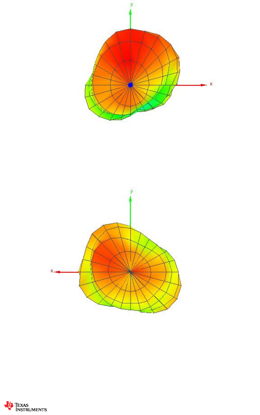
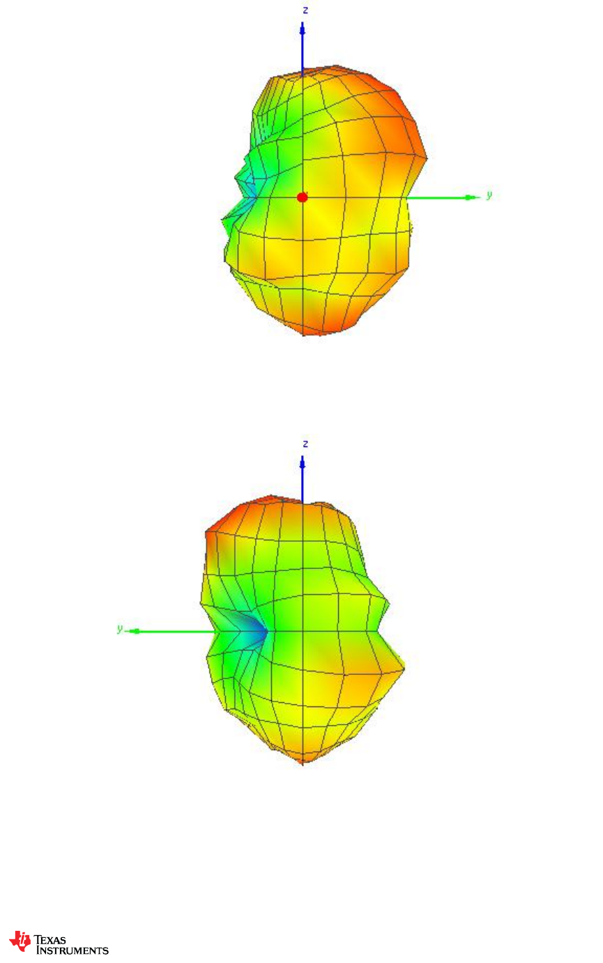
7.1.5 Theta = 0, Phi = 0
7.1.6 Theta = 180, Phi = 0
Design Note
DN038
SWRA416 Page 16 of 24
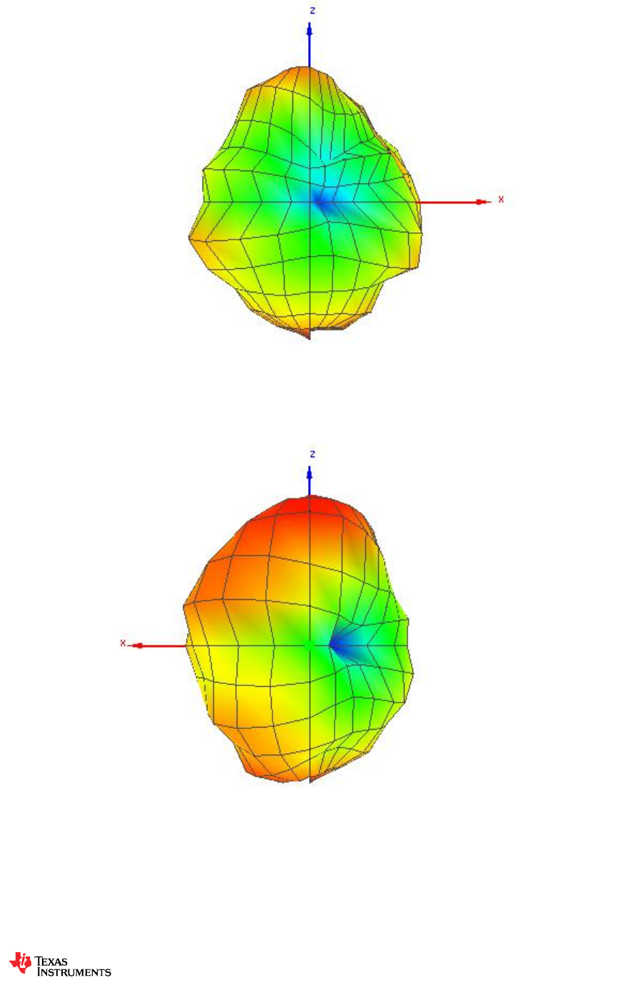
7.1.7 Theta = 90, Phi = 0
7.1.8 Theta = 90, Phi = 180
Design Note
DN038
SWRA416 Page 17 of 24
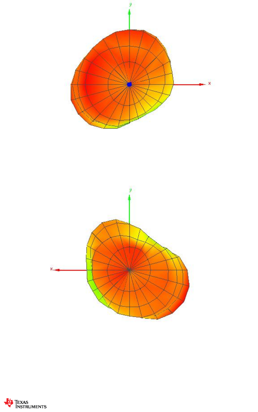
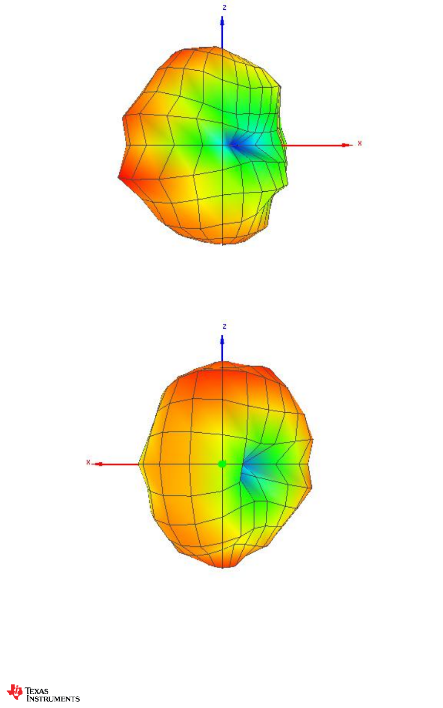
7.1.9 Theta = 90, Phi = 270
7.1.10 Theta = 90, Phi = 90

Design Note
DN038
SWRA416 Page 18 of 24
7.2 CTIA OTA Report – 915 MHz (Antenna matched at 868 MHz)
7.2.1 OTA Evaluation Results:
Total Radiated Power
-3.35 dBm
Peak EIRP
0.01 dBm
Directivity
3.37 dBi
Efficiency
-3.35 dB
Efficiency
46.20 %
Gain
0.01 dBi
NHPRP 45°
-5.54 dBm
NHPRP 45° / TRP
-2.19 dB
NHPRP 45° / TRP
60.42 %
NHPRP 30°
-7.39 dBm
NHPRP 30° / TRP
-4.04 dB
NHPRP 30° / TRP
39.49 %
NHPRP 22.5°
-8.72 dBm
NHPRP 22.5° / TRP
-5.37 dB
NHPRP 22.5° / TRP
29.05 %
UHRP
-6.28 dBm
UHRP / TRP
-2.92 dB
UHRP / TRP
51.01 %
LHRP
-6.45 dBm
LHRP / TRP
-3.10 dB
LHRP / TRP
48.99 %
Front/Back Ratio
4.40
PhiBW
85.3 deg
PhiBW Up
40.5 deg
PhiBW Down
44.8 deg
ThetaBW
272.4 deg
ThetaBW Up
118.8 deg
ThetaBW Down
153.5 deg
Boresight Phi
210 deg
Boresight Theta
105 deg
Maximum Power
0.01 dBm
Minimum Power
-15.33 dBm
Average Power
-2.61 dBm
Max/Min Ratio
15.34 dB
Max/Avg Ratio
2.62 dB
Min/Avg Ratio
-12.72 dB
Best Single Value
-0.16 dBm
Best Position
Phi = 210 deg; Theta = 105 deg; Pol = Ver

Design Note
DN038
SWRA416 Page 19 of 24
7.2.2 RP_915.000_tot
Azimuth
(deg)
Elevation
0 deg
(dB)
Elevation
15 deg
(dB)
Elevation
30 deg
(dB)
Elevation
45 deg
(dB)
Elevation
60 deg
(dB)
Elevation
75 deg
(dB)
Elevation
90 deg
(dB)
Elevation
105 deg
(dB)
0.00
-1.09
-2.11
-2.67
-3.21
-6.21
-7.46
-7.02
-6.05
15.00
-1.29
-2.11
-2.21
-3.23
-5.40
-5.93
-5.16
-5.56
30.00
-1.24
-1.80
-1.61
-2.63
-4.14
-4.38
-3.52
-4.43
45.00
-1.31
-1.26
-1.82
-1.96
-2.98
-3.29
-2.76
-3.39
60.00
-1.51
-1.20
-1.54
-1.21
-2.09
-2.39
-2.36
-2.48
75.00
-1.54
-1.00
-1.76
-0.66
-1.73
-2.82
-2.75
-2.86
90.00
-1.87
-0.83
-1.77
-0.65
-2.03
-3.90
-4.55
-4.72
105.00
-2.24
-0.90
-1.61
-0.77
-3.02
-5.23
-7.19
-8.17
120.00
-2.37
-1.11
-1.05
-1.20
-3.40
-6.89
-12.40
-13.73
135.00
-2.45
-1.41
-0.56
-1.38
-3.29
-6.70
-13.49
-10.32
150.00
-2.33
-1.40
-0.26
-1.33
-2.57
-4.63
-8.31
-5.78
165.00
-2.26
-1.45
-0.19
-1.42
-1.81
-2.49
-4.92
-3.01
180.00
-2.32
-1.49
-0.07
-1.35
-1.47
-1.17
-2.67
-1.34
195.00
-2.03
-1.42
-0.32
-1.41
-1.75
-0.68
-1.96
-0.23
210.00
-2.26
-1.42
-0.66
-1.46
-2.13
-1.04
-2.35
0.01
225.00
-2.05
-1.12
-0.87
-1.87
-2.80
-1.70
-3.32
-0.52
240.00
-1.78
-1.42
-1.48
-2.69
-4.50
-3.24
-5.18
-1.64
255.00
-1.57
-1.43
-2.17
-3.49
-6.35
-4.76
-7.75
-3.56
270.00
-1.39
-1.80
-2.71
-4.99
-8.18
-6.66
-11.21
-5.51
285.00
-1.20
-2.25
-3.41
-5.66
-8.97
-8.81
-14.00
-7.68
300.00
-1.31
-2.55
-3.62
-6.05
-8.69
-10.09
-15.33
-8.97
315.00
-1.24
-2.58
-3.72
-5.53
-8.54
-10.57
-14.59
-8.42
330.00
-1.15
-2.71
-3.40
-4.94
-7.90
-10.23
-11.90
-7.50
345.00
-1.10
-2.81
-3.10
-3.94
-7.34
-9.36
-9.25
-6.90
360.00
-1.38
-2.29
-2.77
-3.35
-6.74
-8.00
-7.42
-6.26
Azimuth
(deg)
Elevation
120 deg
(dB)
Elevation
135 deg
(dB)
Elevation
150 deg
(dB)
Elevation
165 deg
(dB)
Elevation
180 deg
(dB)
0.00
-5.15
-5.17
-2.23
-1.10
-0.45
15.00
-4.56
-4.45
-1.75
-1.39
-0.59
30.00
-3.45
-3.11
-1.54
-1.38
-0.69
45.00
-2.44
-2.29
-1.76
-1.13
-0.99
60.00
-2.04
-1.92
-2.02
-0.96
-1.10
75.00
-2.64
-2.14
-2.55
-0.81
-0.81
90.00
-4.14
-2.87
-3.26
-0.70
-1.11
105.00
-6.22
-3.71
-3.98
-0.75
-0.80
120.00
-7.19
-4.78
-3.75
-0.77
-0.72
135.00
-6.89
-4.75
-3.15
-1.25
-0.56
150.00
-4.91
-3.95
-2.43
-1.63
-0.45
165.00
-3.36
-3.28
-1.93
-1.67
-0.69
180.00
-2.42
-2.48
-1.59
-1.61
-0.88
195.00
-1.81
-1.96
-1.28
-1.73
-1.25
210.00
-1.81
-1.70
-1.38
-1.55
-1.69
225.00
-2.13
-1.54
-1.56
-1.31
-1.87
240.00
-2.58
-1.75
-1.79
-1.48
-2.12
255.00
-3.76
-2.01
-1.93
-1.42
-1.93
270.00
-4.80
-2.81
-2.21
-1.57
-2.17
285.00
-5.12
-3.09
-2.20
-1.42
-1.65
300.00
-5.04
-3.96
-2.32
-1.31
-1.05
315.00
-4.92
-5.05
-2.38
-1.27
-0.53
330.00
-5.22
-5.78
-2.28
-1.05
-0.20
345.00
-4.90
-5.78
-2.04
-1.25
-0.09
360.00
-5.13
-5.74
-2.02
-1.06
-0.52

Design Note
DN038
SWRA416 Page 20 of 24
7.2.3 RP_915.000_hor
Azimuth
(deg)
Elevation
0 deg
(dB)
Elevation
15 deg
(dB)
Elevation
30 deg
(dB)
Elevation
45 deg
(dB)
Elevation
60 deg
(dB)
Elevation
75 deg
(dB)
Elevation
90 deg
(dB)
Elevation
105 deg
(dB)
0.0
-5.94
-7.73
-8.14
-7.43
-11.86
-17.06
-13.93
-12.37
15.0
-8.64
-9.66
-9.28
-9.11
-13.79
-17.09
-13.79
-13.93
30.0
-11.34
-11.09
-11.32
-10.70
-16.72
-17.39
-13.19
-16.91
45.0
-11.19
-11.23
-13.18
-10.66
-14.84
-15.17
-13.74
-16.93
60.0
-8.60
-8.44
-10.43
-8.20
-11.28
-12.36
-14.86
-15.84
75.0
-6.50
-5.78
-7.36
-5.27
-8.07
-12.08
-15.99
-14.05
90.0
-4.42
-3.56
-4.41
-3.41
-5.76
-10.82
-17.80
-13.93
105.0
-3.65
-2.28
-2.67
-2.26
-5.02
-9.19
-16.46
-14.61
120.0
-3.18
-1.78
-1.58
-1.94
-4.05
-7.93
-16.27
-14.53
135.0
-3.10
-1.95
-1.46
-2.14
-3.88
-7.37
-15.70
-14.36
150.0
-3.61
-2.64
-2.15
-3.11
-4.43
-7.74
-15.07
-14.98
165.0
-4.67
-4.38
-3.69
-5.38
-5.90
-8.34
-14.86
-17.32
180.0
-6.61
-6.61
-6.08
-8.28
-8.49
-9.48
-13.82
-24.22
195.0
-9.20
-10.13
-8.91
-11.62
-11.75
-11.60
-14.53
-18.21
210.0
-12.09
-12.92
-11.64
-11.30
-14.18
-14.35
-14.23
-14.21
225.0
-10.64
-10.41
-10.31
-10.59
-14.40
-15.25
-16.41
-12.86
240.0
-7.46
-7.71
-8.14
-9.35
-14.35
-18.25
-17.74
-11.80
255.0
-5.09
-5.60
-6.74
-8.56
-14.72
-20.89
-22.62
-11.90
270.0
-3.52
-4.57
-5.73
-8.61
-14.80
-21.74
-24.22
-11.33
285.0
-2.42
-4.04
-5.57
-8.01
-14.86
-20.89
-23.74
-11.91
300.0
-2.25
-3.96
-5.62
-8.46
-14.28
-22.09
-21.88
-11.37
315.0
-2.33
-4.21
-6.13
-8.28
-13.69
-21.93
-21.81
-10.50
330.0
-2.91
-5.02
-6.69
-8.06
-12.50
-21.43
-17.15
-10.06
345.0
-4.08
-6.32
-7.02
-7.48
-11.70
-17.58
-14.45
-10.65
360.0
-5.87
-7.16
-7.91
-6.99
-11.67
-17.16
-13.44
-11.62
Azimuth
(deg)
Elevation
120 deg
(dB)
Elevation
135 deg
(dB)
Elevation
150 deg
(dB)
Elevation
165 deg
(dB)
Elevation
180 deg
(dB)
0.0
-10.25
-10.26
-5.37
-5.43
-5.89
15.0
-12.10
-10.81
-6.04
-8.45
-8.80
30.0
-13.54
-10.83
-8.16
-12.64
-13.95
45.0
-15.14
-11.47
-11.00
-12.96
-12.58
60.0
-15.91
-11.56
-12.65
-8.18
-7.78
75.0
-16.34
-9.84
-10.26
-5.17
-4.36
90.0
-13.65
-7.55
-6.87
-2.91
-2.71
105.0
-10.47
-5.91
-5.28
-1.75
-1.43
120.0
-8.50
-5.14
-3.91
-1.03
-0.85
135.0
-8.49
-5.00
-3.73
-1.42
-0.76
150.0
-8.58
-5.64
-4.63
-2.56
-1.34
165.0
-9.88
-7.56
-6.12
-4.13
-2.50
180.0
-12.47
-10.42
-9.03
-6.54
-4.49
195.0
-18.10
-15.90
-13.95
-10.81
-7.72
210.0
-16.44
-18.39
-15.79
-12.95
-12.09
225.0
-10.94
-11.95
-10.92
-9.39
-13.28
240.0
-8.60
-7.67
-7.32
-6.68
-8.84
255.0
-7.11
-5.73
-4.94
-4.25
-5.23
270.0
-6.38
-4.95
-3.43
-2.85
-3.51
285.0
-5.92
-4.27
-2.61
-1.78
-1.97
300.0
-5.75
-4.75
-2.50
-1.40
-1.17
315.0
-6.00
-6.03
-2.78
-1.58
-1.06
330.0
-6.98
-7.32
-3.13
-2.10
-1.52
345.0
-7.68
-8.73
-3.81
-3.30
-2.78
360.0
-9.74
-10.81
-4.79
-4.58
-4.95

Design Note
DN038
SWRA416 Page 21 of 24
7.2.4 RP_915.000_ver
Azimuth
(deg)
Elevation
0 deg
(dB)
Elevation
15 deg
(dB)
Elevation
30 deg
(dB)
Elevation
45 deg
(dB)
Elevation
60 deg
(dB)
Elevation
75 deg
(dB)
Elevation
90 deg
(dB)
Elevation
105 deg
(dB)
0.0
-2.81
-3.50
-4.12
-5.27
-7.59
-7.96
-8.01
-7.20
15.0
-2.17
-2.96
-3.16
-4.53
-6.08
-6.28
-5.80
-6.24
30.0
-1.68
-2.34
-2.10
-3.37
-4.39
-4.61
-4.01
-4.68
45.0
-1.78
-1.72
-2.15
-2.59
-3.27
-3.58
-3.12
-3.58
60.0
-2.45
-2.11
-2.14
-2.17
-2.64
-2.85
-2.62
-2.69
75.0
-3.21
-2.76
-3.16
-2.50
-2.87
-3.37
-2.96
-3.21
90.0
-5.40
-4.13
-5.19
-3.92
-4.42
-4.89
-4.76
-5.28
105.0
-7.81
-6.56
-8.26
-6.14
-7.36
-7.46
-7.74
-9.29
120.0
-10.07
-9.59
-10.38
-9.27
-11.95
-13.64
-14.70
-21.45
135.0
-11.00
-10.72
-7.86
-9.28
-12.26
-15.16
-17.48
-12.49
150.0
-8.28
-7.43
-4.78
-6.06
-7.16
-7.54
-9.33
-6.34
165.0
-5.98
-4.56
-2.76
-3.65
-3.95
-3.80
-5.38
-3.17
180.0
-4.35
-3.09
-1.33
-2.33
-2.43
-1.86
-3.01
-1.36
195.0
-2.95
-2.05
-0.97
-1.84
-2.21
-1.05
-2.20
-0.30
210.0
-2.73
-1.74
-1.02
-1.93
-2.41
-1.24
-2.64
-0.16
225.0
-2.70
-1.67
-1.40
-2.50
-3.11
-1.89
-3.54
-0.79
240.0
-3.15
-2.58
-2.53
-3.74
-4.98
-3.38
-5.43
-2.08
255.0
-4.12
-3.54
-4.04
-5.11
-7.03
-4.86
-7.90
-4.25
270.0
-5.49
-5.07
-5.72
-7.46
-9.25
-6.79
-11.43
-6.83
285.0
-7.31
-6.97
-7.49
-9.45
-10.26
-9.08
-14.49
-9.75
300.0
-8.43
-8.13
-7.93
-9.77
-10.09
-10.37
-16.41
-12.69
315.0
-7.78
-7.63
-7.43
-8.81
-10.12
-10.90
-15.50
-12.62
330.0
-5.94
-6.55
-6.16
-7.85
-9.75
-10.57
-13.44
-11.03
345.0
-4.13
-5.38
-5.36
-6.47
-9.32
-10.06
-10.81
-9.28
360.0
-3.28
-4.00
-4.35
-5.81
-8.43
-8.56
-8.67
-7.76
Azimuth
(deg)
Elevation
120 deg
(dB)
Elevation
135 deg
(dB)
Elevation
150 deg
(dB)
Elevation
165 deg
(dB)
Elevation
180 deg
(dB)
0.0
-6.75
-6.77
-5.12
-3.09
-1.91
15.0
-5.40
-5.59
-3.77
-2.34
-1.30
30.0
-3.90
-3.92
-2.60
-1.72
-0.90
45.0
-2.68
-2.85
-2.31
-1.42
-1.30
60.0
-2.22
-2.42
-2.41
-1.88
-2.15
75.0
-2.83
-2.94
-3.36
-2.79
-3.34
90.0
-4.65
-4.68
-5.75
-4.68
-6.21
105.0
-8.26
-7.73
-9.83
-7.61
-9.45
120.0
-13.01
-15.76
-18.06
-12.98
-16.31
135.0
-11.99
-17.34
-12.18
-15.57
-13.97
150.0
-7.34
-8.86
-6.43
-8.79
-7.76
165.0
-4.46
-5.32
-4.01
-5.31
-5.37
180.0
-2.87
-3.24
-2.45
-3.29
-3.36
195.0
-1.91
-2.14
-1.52
-2.30
-2.36
210.0
-1.97
-1.79
-1.55
-1.88
-2.11
225.0
-2.75
-1.95
-2.10
-2.05
-2.20
240.0
-3.83
-3.04
-3.21
-3.05
-3.16
255.0
-6.45
-4.41
-4.95
-4.62
-4.66
270.0
-9.94
-6.92
-8.35
-7.51
-7.93
285.0
-12.83
-9.34
-12.66
-12.43
-13.22
300.0
-13.25
-11.78
-16.18
-18.26
-16.54
315.0
-11.50
-12.01
-12.94
-12.92
-9.96
330.0
-9.98
-11.03
-9.77
-7.72
-6.00
345.0
-8.15
-8.85
-6.79
-5.49
-3.44
360.0
-6.98
-7.36
-5.28
-3.62
-2.46
Design Note
DN038
SWRA416 Page 22 of 24
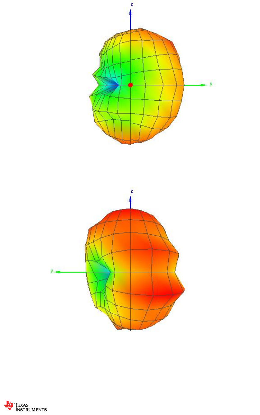
7.2.5 Theta = 0, Phi = 0
7.2.6 Theta = 180, Phi = 0
Design Note
DN038
SWRA416 Page 23 of 24
7.2.7 Theta = 90, Phi = 0
7.2.8 Theta = 90, Phi = 180
Design Note
DN038
SWRA416 Page 24 of 24
7.2.9 Theta = 90, Phi = 270
7.2.10 Theta = 90, Phi = 90

IMPORTANT NOTICE
Texas Instruments Incorporated and its subsidiaries (TI) reserve the right to make corrections, enhancements, improvements and other
changes to its semiconductor products and services per JESD46, latest issue, and to discontinue any product or service per JESD48, latest
issue. Buyers should obtain the latest relevant information before placing orders and should verify that such information is current and
complete. All semiconductor products (also referred to herein as “components”) are sold subject to TI’s terms and conditions of sale
supplied at the time of order acknowledgment.
TI warrants performance of its components to the specifications applicable at the time of sale, in accordance with the warranty in TI’s terms
and conditions of sale of semiconductor products. Testing and other quality control techniques are used to the extent TI deems necessary
to support this warranty. Except where mandated by applicable law, testing of all parameters of each component is not necessarily
performed.
TI assumes no liability for applications assistance or the design of Buyers’ products. Buyers are responsible for their products and
applications using TI components. To minimize the risks associated with Buyers’ products and applications, Buyers should provide
adequate design and operating safeguards.
TI does not warrant or represent that any license, either express or implied, is granted under any patent right, copyright, mask work right, or
other intellectual property right relating to any combination, machine, or process in which TI components or services are used. Information
published by TI regarding third-party products or services does not constitute a license to use such products or services or a warranty or
endorsement thereof. Use of such information may require a license from a third party under the patents or other intellectual property of the
third party, or a license from TI under the patents or other intellectual property of TI.
Reproduction of significant portions of TI information in TI data books or data sheets is permissible only if reproduction is without alteration
and is accompanied by all associated warranties, conditions, limitations, and notices. TI is not responsible or liable for such altered
documentation. Information of third parties may be subject to additional restrictions.
Resale of TI components or services with statements different from or beyond the parameters stated by TI for that component or service
voids all express and any implied warranties for the associated TI component or service and is an unfair and deceptive business practice.
TI is not responsible or liable for any such statements.
Buyer acknowledges and agrees that it is solely responsible for compliance with all legal, regulatory and safety-related requirements
concerning its products, and any use of TI components in its applications, notwithstanding any applications-related information or support
that may be provided by TI. Buyer represents and agrees that it has all the necessary expertise to create and implement safeguards which
anticipate dangerous consequences of failures, monitor failures and their consequences, lessen the likelihood of failures that might cause
harm and take appropriate remedial actions. Buyer will fully indemnify TI and its representatives against any damages arising out of the use
of any TI components in safety-critical applications.
In some cases, TI components may be promoted specifically to facilitate safety-related applications. With such components, TI’s goal is to
help enable customers to design and create their own end-product solutions that meet applicable functional safety standards and
requirements. Nonetheless, such components are subject to these terms.
No TI components are authorized for use in FDA Class III (or similar life-critical medical equipment) unless authorized officers of the parties
have executed a special agreement specifically governing such use.
Only those TI components which TI has specifically designated as military grade or “enhanced plastic” are designed and intended for use in
military/aerospace applications or environments. Buyer acknowledges and agrees that any military or aerospace use of TI components
which have not been so designated is solely at the Buyer's risk, and that Buyer is solely responsible for compliance with all legal and
regulatory requirements in connection with such use.
TI has specifically designated certain components as meeting ISO/TS16949 requirements, mainly for automotive use. In any case of use of
non-designated products, TI will not be responsible for any failure to meet ISO/TS16949.
Products Applications
Audio www.ti.com/audio Automotive and Transportation www.ti.com/automotive
Amplifiers amplifier.ti.com Communications and Telecom www.ti.com/communications
Data Converters dataconverter.ti.com Computers and Peripherals www.ti.com/computers
DLP® Products www.dlp.com Consumer Electronics www.ti.com/consumer-apps
DSP dsp.ti.com Energy and Lighting www.ti.com/energy
Clocks and Timers www.ti.com/clocks Industrial www.ti.com/industrial
Interface interface.ti.com Medical www.ti.com/medical
Logic logic.ti.com Security www.ti.com/security
Power Mgmt power.ti.com Space, Avionics and Defense www.ti.com/space-avionics-defense
Microcontrollers microcontroller.ti.com Video and Imaging www.ti.com/video
RFID www.ti-rfid.com
OMAP Applications Processors www.ti.com/omap TI E2E Community e2e.ti.com
Wireless Connectivity www.ti.com/wirelessconnectivity
Mailing Address: Texas Instruments, Post Office Box 655303, Dallas, Texas 75265
Copyright © 2012, Texas Instruments Incorporated
