8SMC5 USB Enxisupport Ximc User Manual Eng
User Manual:
Open the PDF directly: View PDF ![]() .
.
Page Count: 345 [warning: Documents this large are best viewed by clicking the View PDF Link!]
- 8SMC5-USB User Manual
- 1. About
- 1.1. General information
- 1.2. Benefits
- 1.3. Table of specifications
- 1.4. Specifications
- 2. Safety instructions
- 3. Overview and getting started
- 3.1. One axis configuration
- 3.2. Example of a motor connection
- 3.3. Manual profile setting
- 3.4. Calculation of the nominal current
- 3.5. Possible problems and solutions
- 4. Technical specification 8SMC5
- 4.1. Appearance and connectors
- 4.1.1. Controller board 8SMC5
- Backplane connector
- 4.1.2. One axis system
- 4.1.3. Two axes system
- 4.2. Kinematics and rotation modes
- 4.2.1. Predefined speed rotation mode
- 4.2.2. Rotation for predefined point
- 4.2.3. Predefined displacement mode
- 4.2.4. Acceleration mode
- 4.2.5. Backlash compensation
- 4.2.6. Rotation reversal
- 4.2.7. Recommendations for accurate rotation
- 4.2.8. PID-algorithm for DC engine control
- 4.2.9. Stop motion modes
- 4.2.10. PID-algorithm for BLDC engine control
- 4.3. Main features
- 4.3.1. Supported motor types
- 4.3.2. Motor limiters
- 4.3.3. Limit switches
- 4.3.4. Automatic Home position calibration
- 4.3.5. Operation with encoders
- 4.3.6. Revolution sensor
- 4.3.7. Steps loss detection
- 4.3.8. Power control
- 4.3.9. Critical parameters
- 4.3.10. Saving the parameters in the controller flash memory
- 4.3.11. User defined position units
- 4.4. Safe operation
- 4.5. Additional features
- 4.5.1. Operating modes indication
- 4.5.2. Operations with magnetic brake
- 4.5.3. Joystick control
- 4.5.4. Left-Right buttons control
- 4.5.5. TTL synchronization
- 4.5.6. Multiaxis system design
- 4.5.7. General purpose digital input-output
- 4.5.8. General purpose analog input
- 4.5.9. External driver control interface
- 4.5.10. Serial port
- 4.5.11. Saving the position in controller's FRAM memory
- 4.5.12. The Standa stages detection
- 4.6. Secondary features
- 4.6.1. Zero position adjustment
- 4.6.2. User-defined position adjustment
- 4.6.3. Controller status
- 4.6.4. USB connection autorecovery
- 5. XILab application User's guide
- 5.1. About XILab
- 5.2. Main windows of the XILab application
- 5.2.1. XILab Start window
- 5.2.2. XILab Main window in single-axis control mode
- 5.2.3. XILab Main window in multi-axis control mode
- 5.2.4. Application settings
- 5.2.5. Charts
- 5.2.6. Scripts
- 5.2.7. XILab log
- 5.3. Controller Settings
- 5.3.1. Settings of kinematics (stepper motor)
- 5.3.2. Motion range and limit switches
- 5.3.3. Critical board ratings
- 5.3.4. Power consumption settings
- 5.3.5. Home position settings
- 5.3.6. Synchronization settings
- 5.3.7. Brake settings
- 5.3.8. Position control
- 5.3.9. Settings of external control devices
- 5.3.10. UART Settings
- 5.3.11. General purpose input-output settings
- 5.3.12. Motor type settings
- 5.3.13. Settings of kinematics (DC motor)
- 5.3.14. Settings of PID control loops
- 5.3.15. About controller
- 5.3.16. Settings of kinematics (BLDC motor)
- 5.4. XILab application settings
- 5.4.1. XILab general settings
- 5.4.2. General motor settings
- 5.4.3. Attenuator settings
- 5.4.4. Cyclical motion settings
- 5.4.5. Log settings
- 5.4.6. Charts general settings
- 5.4.7. Charts customization
- 5.4.8. User units settings
- 5.4.9. About the application
- 5.5. Positioner specifications
- 5.5.1. Positioner name
- 5.5.2. Positioner general characteristics
- 5.5.3. Motor characteristics
- 5.5.4. Encoder specifications
- 5.5.5. Hall sensor characteristics
- 5.5.6. Reducing gear specifications
- 5.5.7. Accessories specifications
- 5.6. Correct shutdown
- 5.7. Working over network
- 5.8. XILab installation
- 5.8.1. Installation on Windows
- 5.8.1.1. Installation on Windows XP
- 5.8.1.2. Installation on Windows 7
- 5.8.1.3. Installation on Windows 8
- 5.8.2. Installation on Linux
- 5.8.3. Installation on MacOS
- 6. Programming
- 6.1. Programming guide
- 6.1.1. Working with controller in Labview
- 6.1.2. Working with controller in Matlab
- 6.2. Communication protocol specification (v17.5)
- Protocol description
- Command execution
- Controller-side error processing
- Library-side error processing
- Controller settings setup
- Command SFBS
- Command GFBS
- Command SHOM
- Command GHOM
- Command SMOV
- Command GMOV
- Command SENG
- Command GENG
- Command SENT
- Command GENT
- Command SPWR
- Command GPWR
- Command SSEC
- Command GSEC
- Command SEDS
- Command GEDS
- Command SPID
- Command GPID
- Command SSNI
- Command GSNI
- Command SSNO
- Command GSNO
- Command SEIO
- Command GEIO
- Command SBRK
- Command GBRK
- Command SCTL
- Command GCTL
- Command SJOY
- Command GJOY
- Command SCTP
- Command GCTP
- Command SURT
- Command GURT
- Command SCAL
- Command GCAL
- Command SNMF
- Command GNMF
- Command SNVM
- Command GNVM
- Group of commands movement control
- Group of commands set the current position
- Group of commands to save and load settings
- Group of commands get the status of the controller
- Group of commands to work with the controller firmware
- Service commands
- Group of commands to work with EEPROM
- Bootloader commands
- Controller error response types
- 6.3. 8SMC1-USBhF software compatibility
- 6.4. Libximc library timeouts
- 6.5. XILab scripts
- 7. Files
- 7.1. Configuration files
- Translation Stages
- 8MT160 - Motorized Delay Line
- 8MT295 - Long-Travel Motorized Linear Stages
- 8MT195 - Long-Travel Motorized Linear Stages
- 8MT167 - Motorized Translation Stage
- 8MT173 - Motorized Translation Stages
- 8MT173DC - Motorized Translation Stages
- 8MT50 - Motorized Translation Stages
- 8MT30 - Narrow Motorized Translation Stages
- 8MT175 - Motorized Translation Stages
- 8MT177 - Motorized Translation Stage
- 8MT184 - Motorized Translation Stage
- 8MT193 - Motorized Translation Stage
- 8MT200 - Motorized Translation Stages
- 8MTF - Motorized XY Scanning Stage
- 8MTF2 - Motorized Fiber Coupling Stage
- 8MTFV - Motorized Translation Stage
- 8MT60 - Motorized Translation Stage
- Rotation Stages
- 8MR151 - Motorized Rotation Stages
- 8MR170 - Motorized Rotation Stages
- 8MR174 - Motorized Rotation Stage
- 8MR190 - Motorized Rotation Stage
- 8MR191 - Motorized Rotation Stage
- 8MRB - Large Motorized Rotation Stage
- 8MRU - Universal Motorized Rotation Stages
- 8MPR16-1 - Motorized Polarizer Rotator
- 8MRH240 - Large High Capacity Rotary Stage
- Vertical Translation Stages
- 8MVT100 - Vertical Translation Stage
- 8MVT120 - Vertical Translation Stage
- 8MVT188 - Vertical Translation Stage
- 8MVT40 - Vertical Translation Stage
- 8MVT70 - Vertical Translation Stage
- Screws and Actuators
- 8MS00 - Motorized Screws
- 8CMA06 - Motorized Actuator
- 8CMA20 - Compact Motorized Actuator
- 8CMA28 - Motorized Linear Actuator
- 8CMA16DC - Motorized Linear Actuator
- Motorized Goniometers
- 8MG00 - Motorized Goniometers
- 8MG99 - Motorized Goniometer
- Mirror Mounts
- 8MTOM2 - Motorized Two Axis Translation Optical Mount
- 8MUP21 - Motorized Optical Mount
- 8MBM24 - Motorized Mirror Mounts
- 8MMA60 - Motorized Mirror Mounts
- 8MBM57 - Large Aperture Motorized Mirror Mount
- 8MKVDOM - Motorized Vertical drive optical mount
- Motorized Attenuators
- 10MCWA168 - Motorised Closed Variable Wheel Attenuator
- 10MWA168 - Motorized Variable Wheel Attenuator
- Motorized Iris Diaphragms
- 8MID98 - Motorized Iris Diaphragm
- 7.2. Software
- Full XIMC software package for Windows, last updated: 02.03.2018
- XILab, 1.14.8, last updated 15.02.2018
- Development kit, 2.9.12, last updated 15.02.2018
- Controller firmware
- Configuration files
- LabView examples
- Drivers
- Software for 8SMC1-USBhF controllers with 8SMC4-USB support
- Firmware for USB-Ethernet adapter, 1.1.0, last updated 11.07.2016
- REVEALER, 0.1.0, last updated 16.04.2017
- All XILab versions
- XILab changelog
- All libximc, MicroSMC and XIMC_Labview versions
- Libximc changelog
- XIMC_Labview changelog
- Microsmc changelog
- All firmware versions
- Firmware changelog
- Compatibility table
- All firmware versions for USB-Ethernet adapter
- Firmware changelog
- All REVEALER versions for USB-Ethernet adapter
- REVEALER changelog
- 8. Related products
- 8.1. Control via Ethernet
- 8.1.1. Ethernet adapter Overview
- 8.1.2. Administration

Download user manual in pdf
For quick simple questions you can contact us via Telegram.
The official technical support channel @SMC5TechSupport ( https://t.me/SMC5TechSupport).
Available online Mon-Fri 8:00-16:00 UTC.
8SMC5-USB User Manual
1. About
1. General information
2. Benefits
3. Table of specifications
4. Specifications
2. Safety instructions
3. Overview and getting started
1. One axis configuration
2. Example of a motor connection
3. Manual profile setting
4. Calculation of the nominal current
5. Possible problems and solutions
4. Technical specification
1. Appearance and connectors
1. Controller board
2. One axis system
3. Two axis system
2. Kinematics and rotation modes
1. Predefined speed rotation mode
2. Rotation for predefined point
3. Predefined displacement mode
4. Acceleration mode
5. Backlash compensation
6. Rotation reversal
7. Recommendations for accurate rotation
8. PID-algorithm for DC engine control
9. Stop motion modes
10. PID-algorithm for BLDC engine control
3. Main features
1. Supported motor types
2. Motor limiters
3. Limit switches
4. Automatic Home position calibration
5. Operation with encoders
6. Revolution sensor
7. Steps loss detection
8. Power control
9. Critical parameters
10. Saving the parameters in the controller flash memory
11. User defined position units
4. Safe operation
5. Additional features
1. Operating modes indication
2. Operations with magnetic brake
3. Joystick control
4. Left-Right buttons control
5. TTL synchronization
6. Design of multi-axis system
7. General purpose digital input-output
8. General purpose analog input
9. External driver control interface
10. Serial port
11. Saving the position in controller's FRAM memory
12. The Standa stages detection
6. Secondary features
1. Zero position adjustment
2. User-defined position adjustment
3. Controller status
4. USB connection autorecovery
5. XILab application User's guide
1. About XILab
2. Main windows of the XILab application
1. XILab Start window
2. XILab Main window in single-axis control mode
3. XILab Main window in multi-axis control mode
4. Application Settings
5. Charts
6. Scripts
Page 1 / 345
Page 1 / 345

7. XiLab Log
3. Controller Settings
1. Settings of kinematics (Stepper motor)
2. Motion range and limit switches
3. Critical board ratings
4. Power consumption settings
5. Home position settings
6. Synchronization settings
7. Brake settings
8. Position control
9. Settings of external control devices
10. UART settings
11. General purpose input-output settings
12. Motor type settings
13. Settings of kinematics (DC motor)
14. Settings of PID control loops
15. About controller
16. Settings of kinematics (BLDC motor)
4. XILab application settings
1. XILab general settings
2. General motor settings
3. Attenuator settings
4. Cyclical motion settings
5. Log settings
6. Charts general settings
7. Charts customization
8. User units settings
9. About the application
5. Positioner specifications
1. Positioner name
2. Positioner general characteristics
3. Motor characteristics
4. Encoder specifications
5. Hall sensor characteristics
6. Reducing gear specifications
7. Accessories specifications
6. Correct shutdown
7. Working over network
8. XILab installation
1. Installation on Windows
1. Installation on Windows XP
2. Installation on Windows 7
3. Installation on Windows 8
2. Installation on Linux
3. Installation on MacOS
6. Programming
1. Programming guide
1. Working with controller in Labview
2. Working with controller in Matlab
2. Communication protocol specification
3. 8SMC1-USBhF software compatibility
4. Libximc library timeouts
5. XILab scripts
7. Files
1. Configuration files
1. Translation Stages
1. 8MT160 - Motorized Delay Line
2. 8MT295 - Long-Travel Motorized Linear Stages
3. 8MT195 - Long-Travel Motorized Linear Stages
4. 8MT167 - Motorized Translation Stage
5. 8MT173 - Motorized Translation Stages
6. 8MT173DC - Motorized Translation Stages
7. 8MT50 - Motorized Translation Stages
8. 8MT30 - Narrow Motorized Translation Stages
9. 8MT175 - Motorized Translation Stages
10. 8MT177 - Motorized Translation Stage
11. 8MT184 - Motorized Translation Stage
12. 8MT193 - Motorized Translation Stage
13. 8MT200 - Motorized Translation Stages
14. 8MTF - Motorized XY Scanning Stage
15. 8MTF2 - Motorized Fiber Coupling Stage
16. 8MTFV - Motorized Translation Stage
17. 8MT60 - Motorized Translation Stage
2. Rotation Stages
1. 8MR151 - Motorized Rotation Stages
2. 8MR170 - Motorized Rotation Stages
Page 2 / 345
Page 2 / 345

3. 8MR174 - Motorized Rotation Stage
4. 8MR190 - Motorized Rotation Stage
5. 8MR191 - Motorized Rotation Stage
6. 8MRB250 - Large Motorized Rotation Stage
7. 8MRU - Universal Motorized Rotation Stages
8. 8MPR16-1 - Motorized Polarizer Rotator
9. 8MRH240 - Large High Capacity Rotary Stage
3. Vertical Translation Stages
1. 8MVT100 - Vertical Translation Stage
2. 8MVT120 - Vertical Translation Stage
3. 8MVT188 - Vertical Translation Stage
4. 8MVT40 - Vertical Translation Stage
5. 8MVT70 - Vertical Translation Stage
4. Screws and actuators
1. 8MS00 - Motorized Screws
2. 8CMA06 - Motorized Actuator
3. 8CMA20 - Compact Motorized Actuator
4. 8CMA28 - Motorized Linear Actuator
5. 8CMA16DC - Motorized Linear Actuator
5. Motorized Goniometers
1. 8MG00 - Motorized Goniometers
2. 8MG99 - Motorized Goniometer
6. Mirror Mounts
1. 8MTOM2 - Motorized Two Axis Translation Optical Mount
2. 8MUP21 - Motorized Optical Mount
3. 8MBM24 - Motorized Mirror Mounts
4. 8MMA60 - Motorized Mirror Mounts
5. 8MBM57 - Large Aperture Motorized Mirror Mount
6. 8MKVDOM - Motorized Vertical drive optical mount
7. Motorized Attenuators
1. 10MCWA168 - Motorised Closed Variable Wheel Attenuator
2. 10MWA168 - Motorized Variable Wheel Attenuator
8. Motorized Iris Diaphragms
1. 8MID98 - Motorized Iris Diaphragm
2. Software
8. Related products
1. Ethernet adapter
1. Overview
2. Administration
Page 3 / 345
Page 3 / 345

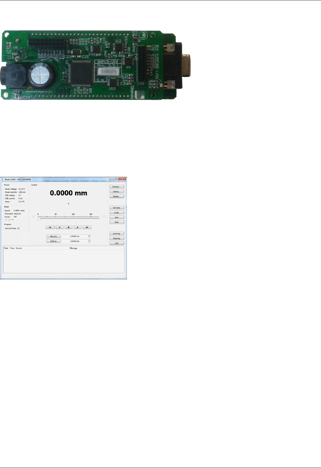
1.1. General information
Controller board.
We offer an inexpensive and ultra-compact servo-drive with USB interface for stepper motors with external power supply.
Forget about cumbersome and expensive servo-drives! All you need is a stepper motor, a controller, a USB cable and any stabilized
external power supply. That is all! Forget about active coolers as well. Controller's board is about the same size as a notepad or a
cellphone, therefore, you may just put it down on the worktable without any assembly procedures. The controller works with any type
of compact stepper motors with the rated winding current of up to 3A. Controller works with stepper motors with no feedback as well
as with ones equipped with encoders in feedback loop, including linear encoders on the stages. The motor connector on the controller
board is the same as one used by Standa company and it fits to all the Standa stages. USB connector provides easy communication
and work with computer. Several controllers can be connected to one computer either via USB ports or through a special backplane
supplied with multiaxis systems. The controller is fully compatible with the majority of operating systems, e.g., Windows, Mac OS X,
Linux, etc.
XILab main window.
All the necessary software including all configuration files are supplied with the controller. It allows you to start working with it the
controller right out of the box, according to "plug-and-play" principle. We continuously develop additional configuration files for newly
supported motors. Therefore, all you need is to download the file for your stage from Configuration files chapter, open it with XILab
software and hit Apply. Your controller is now fully configured! Just issue movement commands and controller will do whatever you
want.
Page 5 / 345
Page 5 / 345

1.2. Benefits
Main benefits
Compact and powerful! The controller's dimensions are 47x25x125 mm including all connectors. The device is adapted to all
stepper motors with rated winding current of up to 3A.
Compatible with 8SMC1-USBh After updating the MicroSMC driver, all the software for 8SMC1-USBh will be working with
8SMC5-USB.
Compatible with all the Standa stages! Have you got a Standa stage? Just plug and play, we have already done the rest for
you!
It does remember all! Do not worry about saving the current position on the computer: the controller does it itself using its
own nonvolatile memory that works even after a sudden power cut.
It works with peripherals! It supports a quadrature encoder, magnetic brake, a joystick, limit switches, a zero position sensor
– all included, just plug and work!
Built-in zero calibration! Using the limit switches, the revolution sensor, the external signal or their combination, the zero
calibration is performed by a single command!
It works with all computers! All the supplied software is compatible with Windows 8, Windows 7, Windows Vista, Windows XP
SP3, Linux, Mac OS X , including 64-bit versions.
All benefits
Really powerful! It is adapted to all the stepper motors with rated winding current of up to 3A.
Compatible with 8SMC1-USBh After updating the MicroSMC driver, all the software for 8SMC1-USBh will be working with
8SMC5-USB.
Compatible with all the Standa stages! Have you got a Standa stage? Just plug and play, we have already done the rest for
you!
It knows its own set! A built-in feature for downloading the configuration file right from the stage memory is available! The
stage's support of such memory is required.
Choose your interface! Both USB and serial port are built-in and ready to use.
Really fast! Up to 35,000 steps per second for any microstep mode!
Precise! The microstep modes from full step to 1/256 of the step on all the speeds.
It does remember all! Do not worry about saving the current position on the computer: the controller does it itself using its
own nonvolatile memory that works even after a sudden power cut.
It works with peripherals! It supports a quadrature encoder, magnetic brake, a joystick, limit switches, a zero position sensor
– all included, just plug and work! Additional stabilized output for peripherals (5V, 100mA) is available.
Built-in zero calibration! Using the limit switches, the revolution sensor, the external signal or their combination, the zero
calibration is performed by a single command!
Stand-alone! Would you like to work in the stand-alone mode? Just go ahead! An external joystick, a keypad or their
combination is supported.
Energy conserving! Programmable current reduction in the motor windings in the hold mode with 1% accuracy.
Silent! Smooth movement at lower speeds and no extra noise at higher speeds.
Protected! An ESD protection on all pins of external connectors and additional short circuit protection for the motor windings.
Attentive! It controls the temperature of the processor and the power driver as well as both currents and voltages for the power
supply and USB.
Modern! The firmware in the nonvolatile memory of the controller can be updated via USB interface.
Controlling and controllable! The built-in synch input and output allow to start the rotation to desired position by the
incoming external signal and/or to transmit the outgoing signal after the desired position is reached. The analog common input
and the digital common input/output are built in as well.
Comprehensible! The status LED displays the power supply and the controller's state. For convenience of use both signals
doubled at the external LEDs as well as the state of the limit switches.
Multiaxis machine! The multiaxis systems are designed by using standard USB hubs, either external or mounted at a special
backplane. There may be up to 32 axis in the system.
It works with all computers! All the supplied software is compatible with Windows 8, Windows 7, Windows Vista, Windows XP
SP3, Linux, Mac OS X , including 64-bit versions.
Examples for all programming languages! Controllers are supplied with cross-platform library and examples which allow
rapid development using C++, C#, .NET, Delphi, Visual Basic, gcc, Xcode, Matlab, Java and LabVIEW.
Full-featured interface! The XILab user interface is supplied with the controller. It allows to easily control all the functions and
features of the device without any programming.
Unique scripting language! A scripting language is integrated into XILab software. It allows easy setting the sequence of
actions, including cycles and branches, without compilation or learning any programming language.
New! Stepper motor close-loop control algorithm are ready! Motion is smoother and faster than ever with innovation
encoder based close-loop on all 8SMC5-USB motor controllers. It combines advantages of BLDC motor control with cheapness of
conventional stepper motors. No hidden catch, no stall or hitch, just free move!
Page 6 / 345
Page 6 / 345

1.3. Table of specifications
Power supply external 12V - 48V DC
Current
consumption up to 5A (depending on the voltage) from external power supply
Current in the
motor winding up to 3A
Protection types current overload protection, voltage overload protection, short circuit protection, motor hotplug/unplug protection
Motion modes move left/right, move to point, shift on delta, continuous speed, acceleration and deceleration ramps, backlash
compensation mode, automatic home position calibration mode
Step modes full-step, 1/2, 1/4, 1/8, 1/16, 1/32, 1/64, 1/128, 1/256
Rotation speed up to 35 000 full steps per second
Speed profile trapezoidal
Position counter 40 bit
Feedback Single-ended and differential quadrature encoder (optional)
Limit switches 2
Feedback
bandwidth 200 kHz for single-ended and 5MHz for differential encoder
Note: The controller's working voltage range is 12V to 48V DC. The voltage limits are 12V and 50V DC. If the voltage
exceeds 50V, the controller is guaranteed to fail. If the voltage falls below 12V, the controller turns off.
Page 7 / 345
Page 7 / 345

1.4. Specifications
Motor requirements
Motor type: bipolar stepper motor, DC motor.
Rated winding current: minimum 100mA.
Rated winding voltage: minimum 2V DC.
Electric specifications of the controller
Power supply modes: external.
Current in each motor winding: up to 3A.
Maximum encoder pulse frequency: 200 kHz for single-ended and 5MHz for differential encoder.
Stabilized 5V DC output (the power supply for encoder and other peripherals): 100mA maximum output current, 5% or better
output voltage stability.
ESD-protection on all pins of the output connectors (e.g., D-Sub 15 pin, mini-USB or power jack).
Winding-to-ground short circuit protection.
Winding-to-winding short circuit protection.
Motor hot-swapping protection.
Wrong power polarity protection (no more than 1s).
Voltage overload protection (no more than 1s).
USB-supplied current limitation.
External power supply current limitation.
Motor rotation speed limitation.
Programmable full winding current with 10mA precision.
Programmable winding current decrease with 1% precision for the hold mode.
Rotation control features
Microstep modes: full-step, 1/2, 1/4, 1/8, 1/16, 1/32, 1/64, 1/128, 1/256.
Noiseless at low speeds.
Minimum speed is 1/256 of the full step per second.
Maximum speed is up to 35 000 full steps per second for all microstep modes.
Minimum shift is 1/256 of the step.
Maximum shift is 2,147,483,647 full steps for all microstep modes.
Smooth start/stop mode.
40-bit position counter (32 bits for full step and 8 bits for microstep).
Motion modes: left/right move, move to point, shift on delta, continuous speed, acceleration and deceleration ramps, backlash
compensation mode, automatic home position calibration mode.
Additional firmware features
Automatic HOME calibration at firmware level.
The nonvolatile memory used for saving/downloading the controller settings.
Software update via USB interface.
Automatic position saving according to step counter and encoder with power-off protection.
Additional features available via motor connector
Processing the signals from one or two limit switches; software configurable.
The Standa stages recognition and automatic downloading of the configuration file right from the stage if the last one supports
this feature.
The "step loss" detection and position recovery using either a revolution sensor or a quadrature encoder (if the stage supports
this feature).
The position detection using a quadrature encoder. The x4 mode.
The stepper motor control using master quadrature encoder mode, providing the maximum speed without any step loss. Starting
with firmware 4.1.
Additional features available via backplane connector
USB connector on backplane that duplicates USB input on controller board.
A serial RS-232 port. TX and RX lines are available. Specifications: 9600 - 921600 baud speed, TTL 3.3V. The Ethernet,
Bluetooth, WiFi, ZigBee and other configurations based on the serial port are available by request.
Synchronization input: once the pulse is received via this pin, the controller starts rotating the motor to predetermined position
or by predetermined shift value. The triggering mode, the polarity and duration of the pulse are adjustable by user.
Specifications: TTL 3.3V.
Synchronization output: emit pulse to this pin if rotation is started or finished, or predetermined user-defined shift value is
reached. The triggering mode, the polarity and duration of the pulse are adjustable by user. Specifications: TTL 3.3V.
Left or right buttons. Once the button is pressed, the rotation in corresponding direction starts and the speed increases gradually
according to acceleration and other settings. Specifications: TTL 3.3V.
Joystick pin allowing operation with various joysticks with the voltage range no more than 0–3V.
Magnetic brake control pin providing control to magnetic brake mounted on the motor shaft. Specifications: TTL 3.3V, 5mA.
Common analog input pin allowing operation with signals within 0–3V range. Reading frequency is 1kHz. The configuration is
programmable.
Common digital input/output pin. 1kHz update frequency, software configurable. Specifications: TTL 3.3V, 5mA.
Page 8 / 345
Page 8 / 345

Limit switches indication pins designed for LED direct connection. Specifications: TTL 3.3V, 2mA.
Digital "Power" and "Status" pins duplicate the status LED and designed for direct connection of LEDs. Specifications: TTL 3.3V,
2mA.
External driver control interface allowing to control any type of external driver using three signals: enable, direction, clock.
Multiaxis systems development. The multiaxis systems are created from standard USB hubs, either external or mounted at a
special backplane. On the PC a multiaxis system is represented as a set of virtual serial ports, according to the number of
connected axes.
Programming the controller
All the software supplied with controller is compatible with Windows 8, Windows 7, Windows Vista, Windows XP SP3, Linux, Mac
OS X, including 64-bit versions.
Controllers are supplied with cross-platform library and examples which allow rapid development using C++, C#, .NET, Delphi,
Visual Basic, gcc, Xcode, Matlab, Java and LabVIEW.
The XILab user interface is supplied with the controller. It allows to easily control all the functions and features of the device
without any programming.
A scripting language, an EcmaScript language dialect, is integrated into XILab software. It allows easy setting the sequence of
actions, including cycles and branches, without compilation or learning any programming language.
Page 9 / 345
Page 9 / 345

2. Safety instructions
Power supply and grounding requirements. Connection to controller
General requirements for a controller board, systems in box ( single and double axes) are listed below.
IMPORTANT. Either the power supply unit should be plugged to grounded 220V AC socket (a three-wire connection
scheme). Make sure that the minus electrode of your power supply unit is grounded. If the power supply unit with
minus electrode disconnected from the grounding circuit is used, ground the controller board via special grounding
terminal (look at the picture below). Non-compliance with these rules may lead to the decrease in controller stability
and noise resistance.
Top view of the controller board. A grounding terminal marked with the red square
Typical connection diagram for a controller (board, systems in box):
Controller
8SMC5-USB
PC Power
supply
Motor
USB 220 V
Controller grounded via minus electrode of power cable connection diagram
Controller
8SMC5-USB
PC Power
supply
Motor
USB 220 V
Controller connection diagram with grounding via special terminal
Page 10 / 345
Page 10 / 345

Warning. Power supply unit should be able to supply sufficient current to rotate the motor. As an absolute minimum
it should be able to supply where is the minimum working current of
power supply unit, is the operating current in the winding, is power supply unit stabilized voltage, and
is rated operating voltage of the motor. It is recommended to use a power supply unit with operating current
equal to . The voltage should be greater than . The higher the voltage, the
faster rotation speed could be reached.
One can use power consumption of power supply unit to calculate minimum requirements instead. An absolute
minimum of power is . For example, for motor with
operating winding current of 1A and operating voltage of 5V (with 5W rated power consumption), the operating
voltage of power supply unit may be chosen at 20V with the output power of at least 10W (the maximum operating
current of power supply unit is at least 0.5A).
Controller board
IMPORTANT. It is strictly forbidden to touch the controller board without any antistatic equipment. We recommend
you to use antistatic wrist strap.
IMPORTANT. It is strictly forbidden to connect positive wire of power supply to the controller board when
ground wire is not connected. It is strictly forbidden to connect or disconnect power cable when the
power supply is on, the controller is connected to the PC and the power supply and the PC are grounded.
This may damage the PC! This is a common requirement for any electronic device with separate power source,
which is connected to the PC via USB.
Warning. Before connecting the controller board to the motor or to the PC via USB interface, it is recommended to
connect controller to power supply with proper grounding or to use separate grounding for controller with the specially
marked ground terminal (look above).
One and two axes system in box
IMPORTANT. You should not exceed maximum allowed voltage of 48V. If voltage goes over allowed value at
more than 2 volts, it can immediately and irreversibly damage the controller.
Page 11 / 345
Page 11 / 345

3. Overview and getting started
This guide describes the operation of controller for multi-axis and one-axis systems, basic parameters configuration and getting started
with XILab software for Windows 7.
One axis configuration - a brief description of the beginning of work with the controller + 8SMC5-USB for one axis +. It is also
considered quick XiLab setup and lists all necessary equipment.
Example of a motor connection - connection of stepper motor Nanotec ST5918L3008-B with encoder CUI INC AMT112S-V to
8SMC5-USB controller. It is described how to make your own cable, guided by the specification on the engine and explanation of
the specification is given.
Manual profile setting - setting of working profile for XiLab. Overview of the main features.
Calculation of the nominal current - setting of amplitude of nominal current for stepper motors.
Possible problems and solutions - description and solution of the most common problems when working with 8SMC5-USB
controller.
Page 12 / 345
Page 12 / 345

3.1. One axis configuration
Introduction
System requirements
Software installation and startup procedures
Getting started with XILab software
Functional test
Control from user applications
3.1. One axis configuration
Controller board.
Introduction
This manual describes the controller installation procedures and getting started with XILab software for Windows 7. The detailed
controller specifications are described in Specifications chapter. For developing your own applications, please read the Programming
guide 8SMC5 chapter and download the programming software package from the software chapter.
System requirements
Note. There are only brief requirements in this chapter. For detailed information please read the Specifications
chapter.
For successful installation you will need:
PC with USB port
A standard PC with USB port.
Make sure that your PC has all of the current Windows updates installed. It will help you to maintain software compatibility. If
necessary, please download the latest updates from www.microsoft.com/updates.
Software
All necessary software to work with the controller can be downloaded from software page.
USB A - mini-B cable
USB-A to mini-USB-B cable.
For detailed information about the USB cable please read the data connector chapter.
8SMC5-USB controller
Page 13 / 345
Page 13 / 345
The motor controller board.
The controller appearance may differ from the one shown on the above figure depending on its configuration and version. For
detailed information about versions please read the Appearance and connectors 8SMC5 chapter.
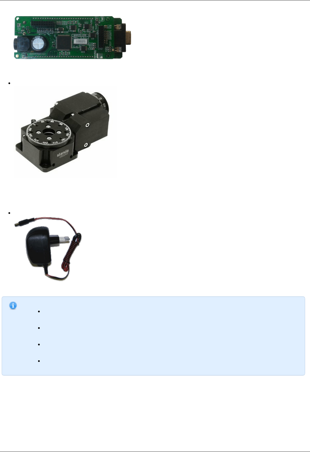
Positioner or motor
The stepper motor-based positioner.
The stepper motor-based positioner used in the operations is shown at the figure. The detailed motor requirements are described
in Specifications chapter. If you use your own cables for connecting the positioner to the controller, please refer to positioner
connection scheme and the controller's output connector scheme . For positioners with limited movement range, two limit
switches must be used: SW1 and SW2. These pins are used to determine the movement limits.
Power supply
Stabilized power supply unit.
Notes.
Please use the 12–36V DC stabilized power supply. Too high voltage may damage the controller. For more
information please read the Safety instructions 8SMC5 chapter. The power supply unit must provide the current
enough for sustainable rotation of the motor.
Please pay attention on the manual supplied with your controller. The more strict power voltage limitation is
possible depending on the controller model. Please check the connection of external power supply unit to the
controller carefully.
If controller is supplied inside the metal case, the case must be grounded. If controller is supplied without any
body, the grounding circuit of power supply unit is used. For more information please read the Safety
instructions 8SMC5 chapter.
If the board is operated without the casing, make sure it lays on the insulating surface and there are no
extraneous particles on the board or around it.
Software installation and startup procedures
Make sure that all controllers are disconnected from your PC.
The software installation manual is here. The installer file name is "xilab-<version_name>.exe". It automatically detects whether it is
running on 32-bit or 64-bit version of Windows and installs the appropriate version of XiLab. Launch the installation program, the
installation window will appear. (The software versions may slightly differ from each other).
Page 14 / 345
Page 14 / 345
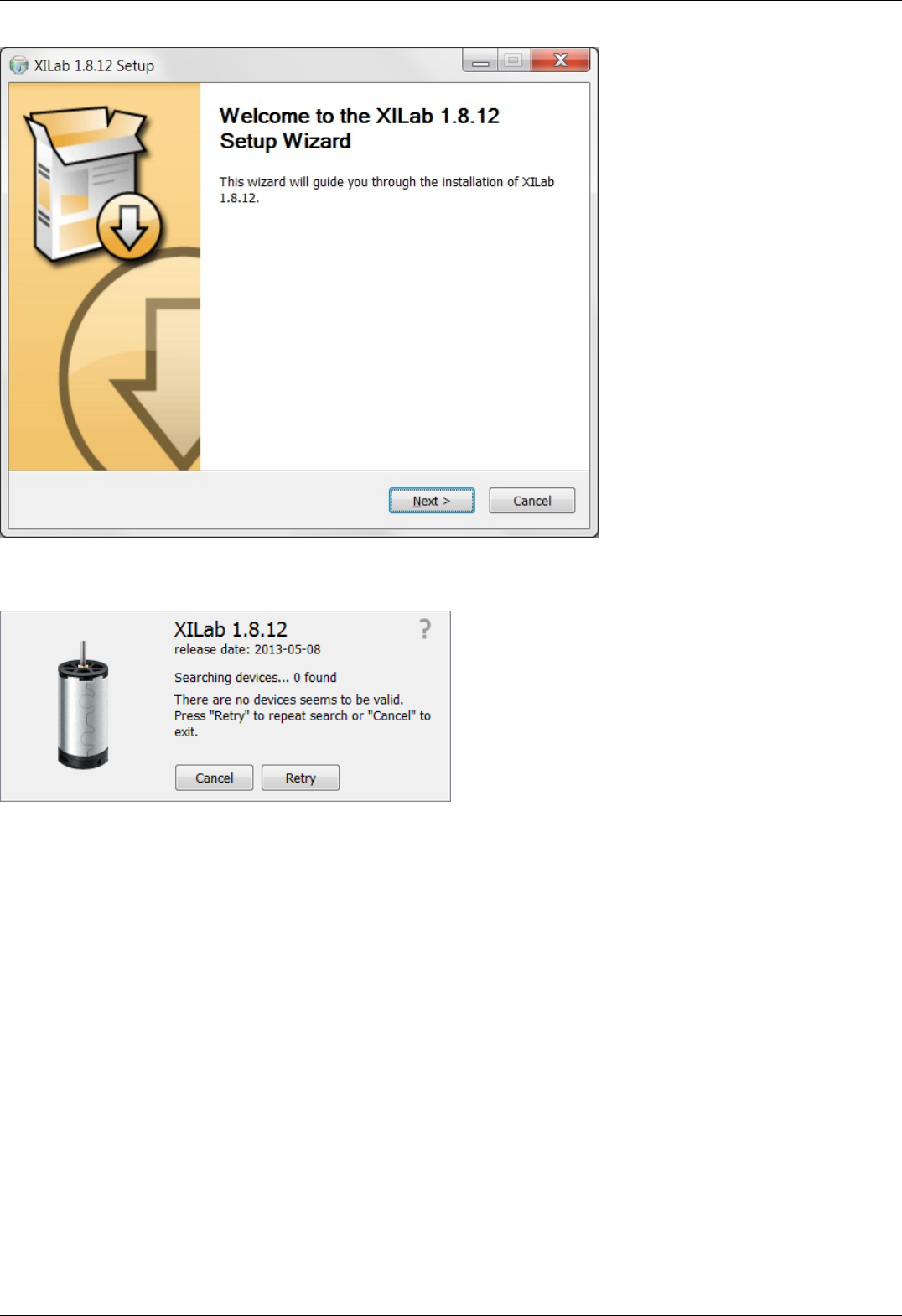
XILab main installation window.
Press “Next>” button and follow the instructions on screen. All the necessary software including all drivers, packages and programs will
be installed automatically. After installation is finished, the XiLab software starts by default and the following window will open:
XILab "No devices found" dialogue window.
Don't press any buttons.
Connect the positioner to the controller. Connect the stabilized power supply unit to the controller. Ground the controller or power
supply unit. Connect the controller to your PC using the USB-A to mini-USB-B cable.
The LED indicator at the controller board will start flashing. The New Hardware Wizard starts working after the first connection of the
controller to PC. Please wait until Windows detects a new device and installs all necessary drivers for it.
If the automatic driver installation has failed, please select ”No, not this time” in the window being opened and press “Next>” button.
Select “Install from a list or specific location (Advanced)” in the next window and press “Next>” again. Browse the software disk
supplied with controller and find the *.inf file there or in the XiLab-install-path\driver\ folder and wait until installation is completed.
Go back to XILab "No devices found" dialog window and press "Retry" button.
If this window was closed, please go to “Start” menu, select Programs->XILab Х.Х.Х->XILab and launch it. The dialog window will
open again.
Getting started with XILab software
XILab is a user-friendly graphic interface designed for control, diagnostics and adjustment of motors. It can also be used for easy
installation and save/restore of parameters for any type of motors. This chapter describes the startup procedures with XILab software.
For complete information please refer to XILab application User's guide chapter.
Page 15 / 345
Page 15 / 345
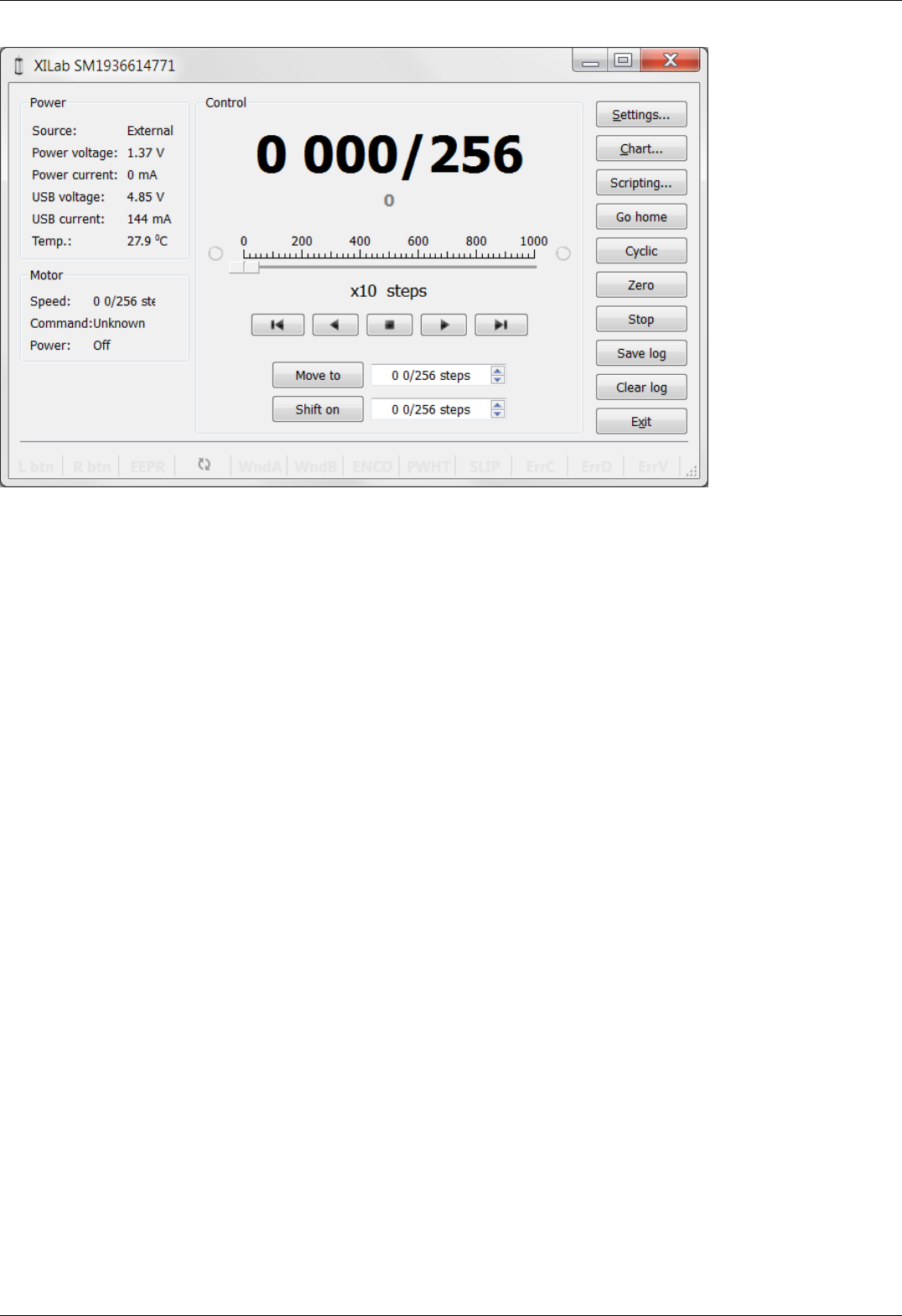
XILab main window.
Open “Settings...”, then press “Restore from file...” and select the configuration file for your positioner from the opened C:\Program
Files\XILab\profiles\ folder. The values applicable for your positioner will automatically fill all the fields of “Settings...” menu. If the
necessary file isn't found, please refer to the Configuration files chapter. If there is still no solution, please leave your request at our
customer service website.
Page 16 / 345
Page 16 / 345
XILab, the Settings menu window.
Warning. For the controller to work with stepper motors it is required to properly set up:
working current,
displacement limits and limit switches ,
critical parameters,
limiters,
power supply mode.
If you decide to configure your controller by yourself, please check these parameters carefully!
Congratulations, your controller is ready for operation!
Functional test
Check if the controller is configured properly by pressing left or right button in the central row of XILab main window control buttons.
The positioner has to start moving. Use the central "soft stop" button to stop the rotation. Please pay attention to the power supply
parameters of the controller in the Power section. The power voltage, working current and temperature of the controller can be set
there.
If Xilab main window is shaded red when the movement was supposed to start, that means that protection was activated and controller
entered the Alarm state. This may be caused by incorrect settings, wrong connection of the positioner or controller malfunction. For
detailed information please read the Critical parameters chapter.
Page 17 / 345
Page 17 / 345

Control from user applications
Xilab software is a convenient way to control stages connected to 8SMC5-USB controller. However, if you need to control the 8SMC5-
USB from your own application, you may do so by using libximc library. Programming guide 8SMC5 has several examples in C, C#,
Delphi, Java, VB.net, Matlab, LabView programming languages. If all you need is to automate a small number of control steps, then
instead of a standalone program you may find it easier to use Xilab scripting language.
Page 18 / 345
Page 18 / 345
3.2. Example of a motor connection
General case
Positioner standard connection diagrams
Example
Preparation
Connecting the motor and encoder to the
controller
3.2. Example of a motor connection
General case
To connect a motor to the controller please refer to positioner connector, and
use the scheme of positioner connection:
Positioner standard connection diagrams
General diagram of positioner and encoder connection using Dsub connector.
Note. If A and B encoder channels work in open drain mode, some extra pull-up of encoder outputs to 5V power
voltage using the resistors may be required at high rotation speeds in order to provide the maximum signal
transmission speed (see Operation with encoders ).
Note. Only firmwares 4.1.0 and older support BLDC.
Example
Consider the connection of the two-phase stepper motor Nanotec ST5918L3008-B with encoder CUI INC AMT112S-V to controller
8SMC5-USB.
Preparation
To get started, we need:
Motor;
Encoder;
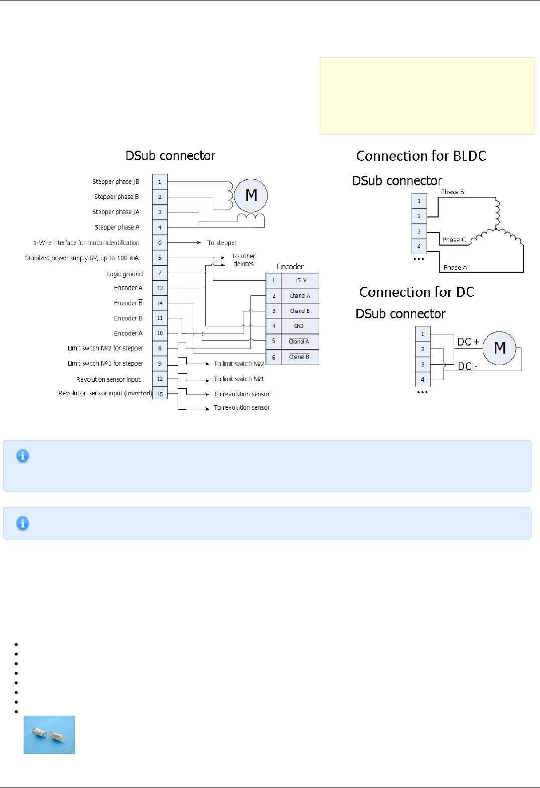
Pinout of D-SUB connector for 8SMC5-USB;
Motor datasheet ;
Encoder datasheet ;
Soldering equipment: soldering-iron, wires, flux, solder, nippers, heat shrink tubes of different sizes;
Screws M2.5x6 for fixing the encoder;
D-SUB cover + connector (male) and wires for cable manufacturing;
Page 19 / 345
Page 19 / 345
Connecting the motor and encoder to the controller
Before you begin, assemble the encoder in accordance with the appropriate instructions.
The motor without encoder. Note 2 holes M2.5 to which is usually attached an encoder
Motor with attached encoder
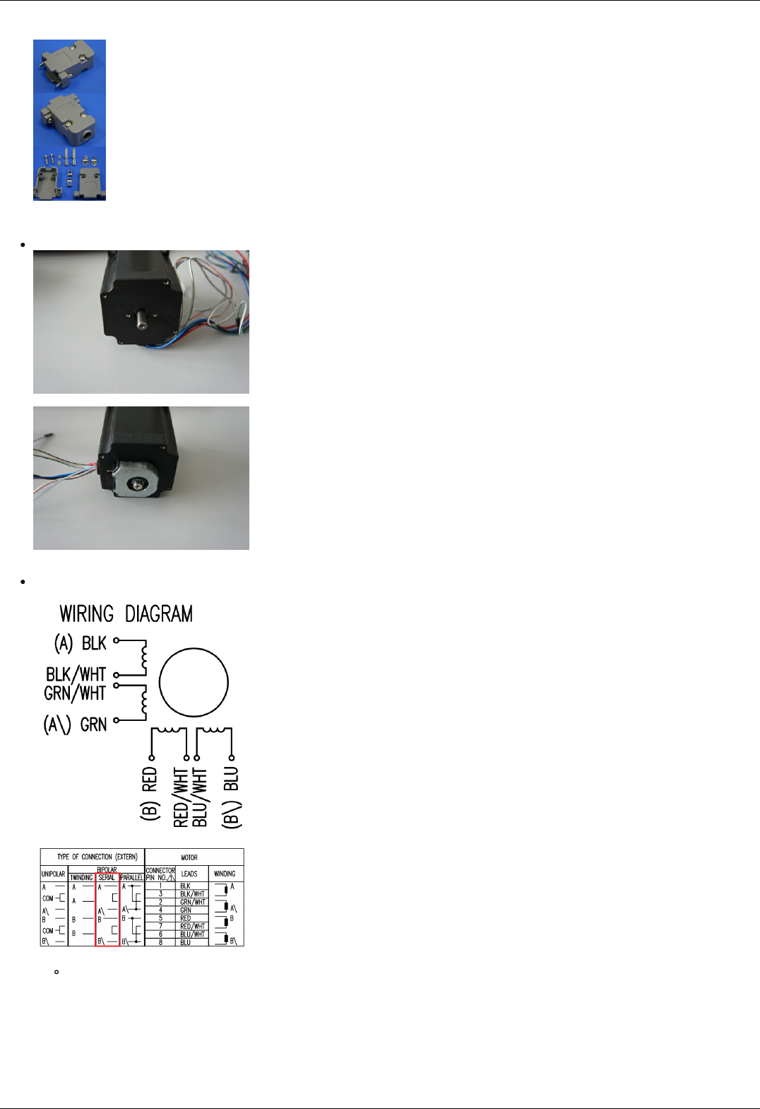
Let us look in the specification of the engine and find the wiring diagram (for Nanotec ST5918L3008-B it is at the bottom right in
the specification):
Motor contacts
Connection type
There exist serial and parallel winding connection and each type allows to obtain various characteristics for the motor. We
will connect the windings in series (red frame on the picture). To do this, wires having two colors BLK/WHT and GRN/WHT,
as well as RED/WHT and BLU/WHT must be connected to each other in pairs. Next, you need to put in accordance A, not A,
B, not B pins of controller to contacts of motor windings ST5918L3008-B: black, green, red, blue. One winding is a
connection of A and not A or B and not B. After the connection between a two-color wire, you will get that one winding of
the motor is black - green connection, other is red - blue. Therefore, matching contacts will be the follows: black - A, green
- not A, red - B, blue - not B. It can be seen in the picture above Connection type.
Page 20 / 345
Page 20 / 345
To connect encoder, open its datasheet and find 5 contacts on encoder connector: A+ (channel A), B+ (channel B, shifted
relative to A by 90 degrees), Z+ (rev counter), 5V, GND. They should be taken from the encoder as 5 separate wires and
put together with the wires from the motor as they then go to a connector. CUI INC AMT112S-V encoder has 18 pin input,
therefore it is needed to make a cable with the same connector on the end to output necessary signals:
Encoder contacts A+, B+, Z+, 5V and GND corresponds to 10, 11, 12, 5, 7 pins of D-SUB male connector respectively.
For convenience, use the next tables (the number in parentheses indicates pin on the corresponding connector):
Encoder pin D-SUB pin
A+ (10) Encoder A(10)
B+ (8) Encoder B(11)
Z+ (12) Revolution sensor input (12)
5V (6) Output 5V, 100 mA (5)
GND (4) Logical ground (7)
Motor pin D-SUB pin
A (BLK) phase А (4)
not A (GRN) phase not А (3)
B (RED) phase B (2)
not B (BLU) phase not B (1)
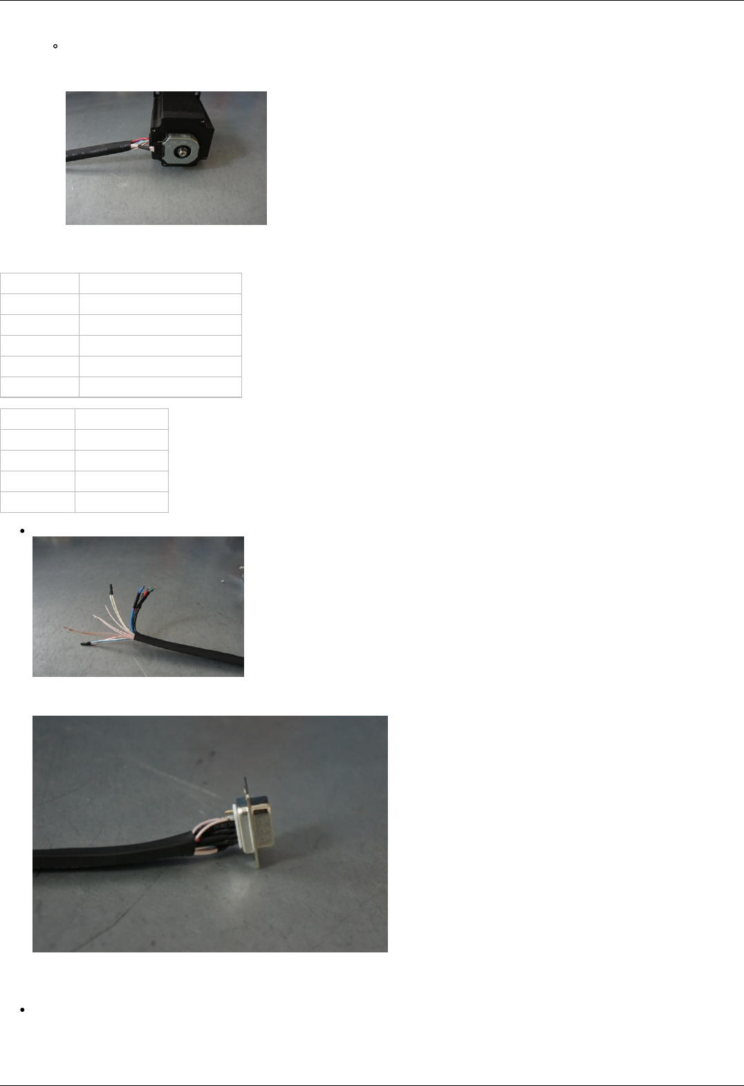
Solder the above contacts to D-SUB male connector:
The wires from the motor and encoder in a heat shrink tube. Note the presence of small heat-shrinkable tubes for wires going to
the motor windings (BLK, GRN, RED and BLU), as well as two-colored wires joined together (BLK/WHT and GRN/WHT, RED/WHT
and BLU/WHT). The thin wires are an encoder contacts (5 pcs).
Ready cable from the motor with the D-SUB connector on its end
Recommendation: use heat shrink tubes of a small diameter (2-3 mm) while soldering contacts to D-SUB connector, and large
diameter to skip through them all the wires coming from the motor and encoder. Put them before soldering.
Put D-SUB connector into the cover.
Page 21 / 345
Page 21 / 345

3.3. Manual profile setting
Introduction
Getting started
Nominal current setting
Basic parameters setting
Hardware limit switches setting. Homing.
Encoder parameters setting
Setting the kinematic characteristics of the
controller
Working with user units
3.3. Manual profile setting
Introduction
All necessary parameters are set after motor connection (see Example of a
motor connection where the Nanotec ST5918L3008-B motor connection is
described). There we will consider the setting of the profile for Nanotec
ST5918L3008-B stepper motor.
Getting started
Install and run XiLab (see One axis configuration).
Load the profile with default settings. To do this, open + Settings ->
Restore from file ... + and select xilabdefault.cfg file from XiLab folder.
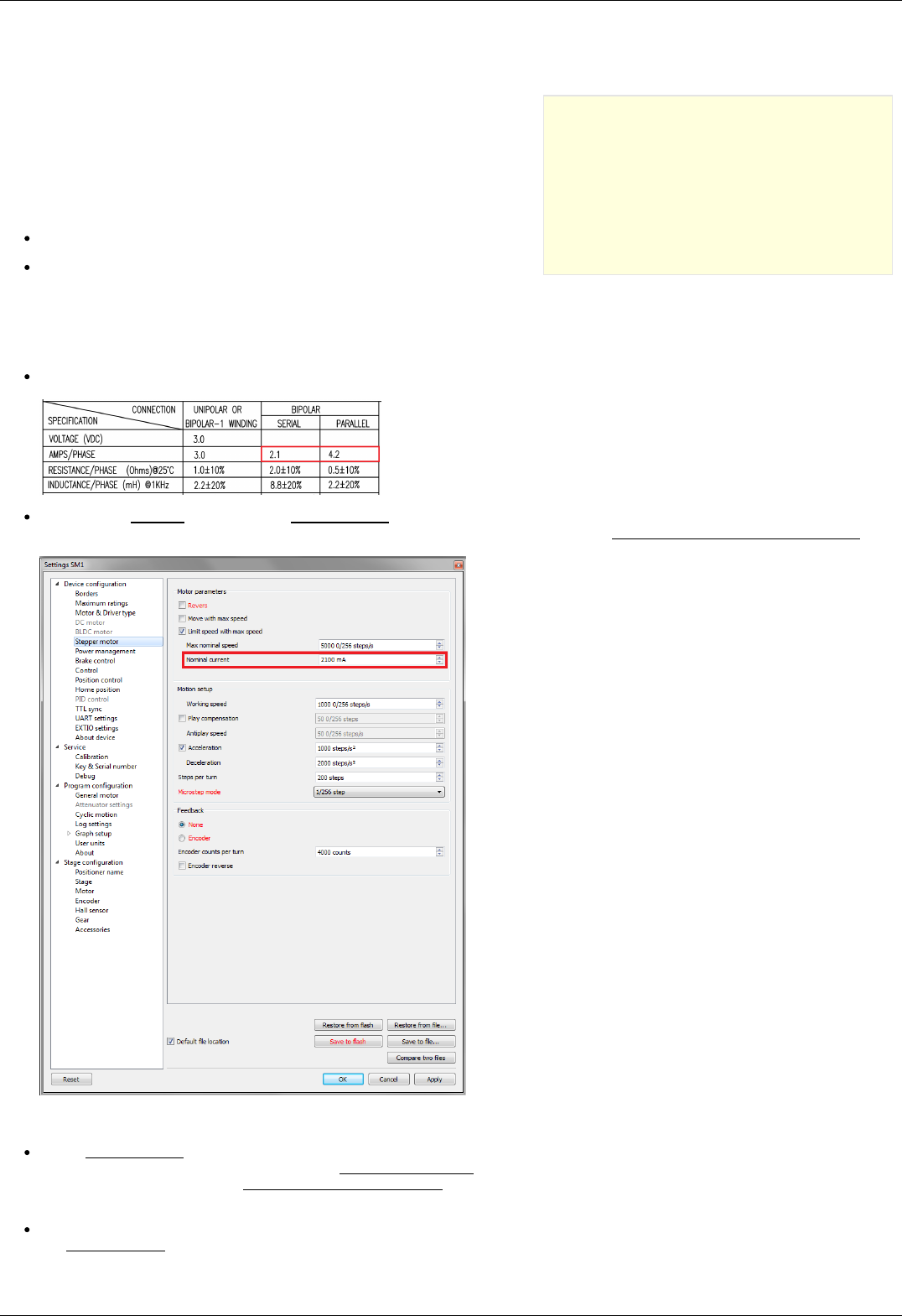
Nominal current setting
Initially, it is needed to set a correct current in motor windings:
From the specification find the phase current 2.1 A - this is the maximum current for the motor in case of serial winding
connection:
Being in the Settings window, open Stepper motor tab. There are such parameters as rotational speed, acceleration, driving
mode, etc. (seeSettings of kinematics (stepper motor) for additional information). In Motor parameters-> Nominal current field
you should specify the value of the phase current not exceeding 2.1 A:
Basic parameters setting
In the Working speed field we will specify a rotation speed. The recommended speed is not more than 1000 s/sec at the first
start. In the same window you should type Max Nominal Speed (5000 s/sec is reasonable value for majority of motors and
motorized stages) and mark Limit speed with max speed. This setting is necessary to limit the motor speed since some
mechanical systems can be designed for low speed, and fast rotation can lead to severe wear of motor/stage mechanics.
In the motor specification we find the number of steps per rotation. For our motor this value is equal to 200 steps. Specify it in
the Steps per turn field. Usually, the value of one pitch in degrees is listed in motor description, on the basis of which you can
Page 23 / 345
Page 23 / 345
calculate the number of steps per revolution, knowing that one revolution consists of 360 degrees.
Make sure that movement to the right from the main window of XiLab corresponds to the movement to the right of the stage. If
not, then check the box Reverse field Stepper motor -> Motor parameters .
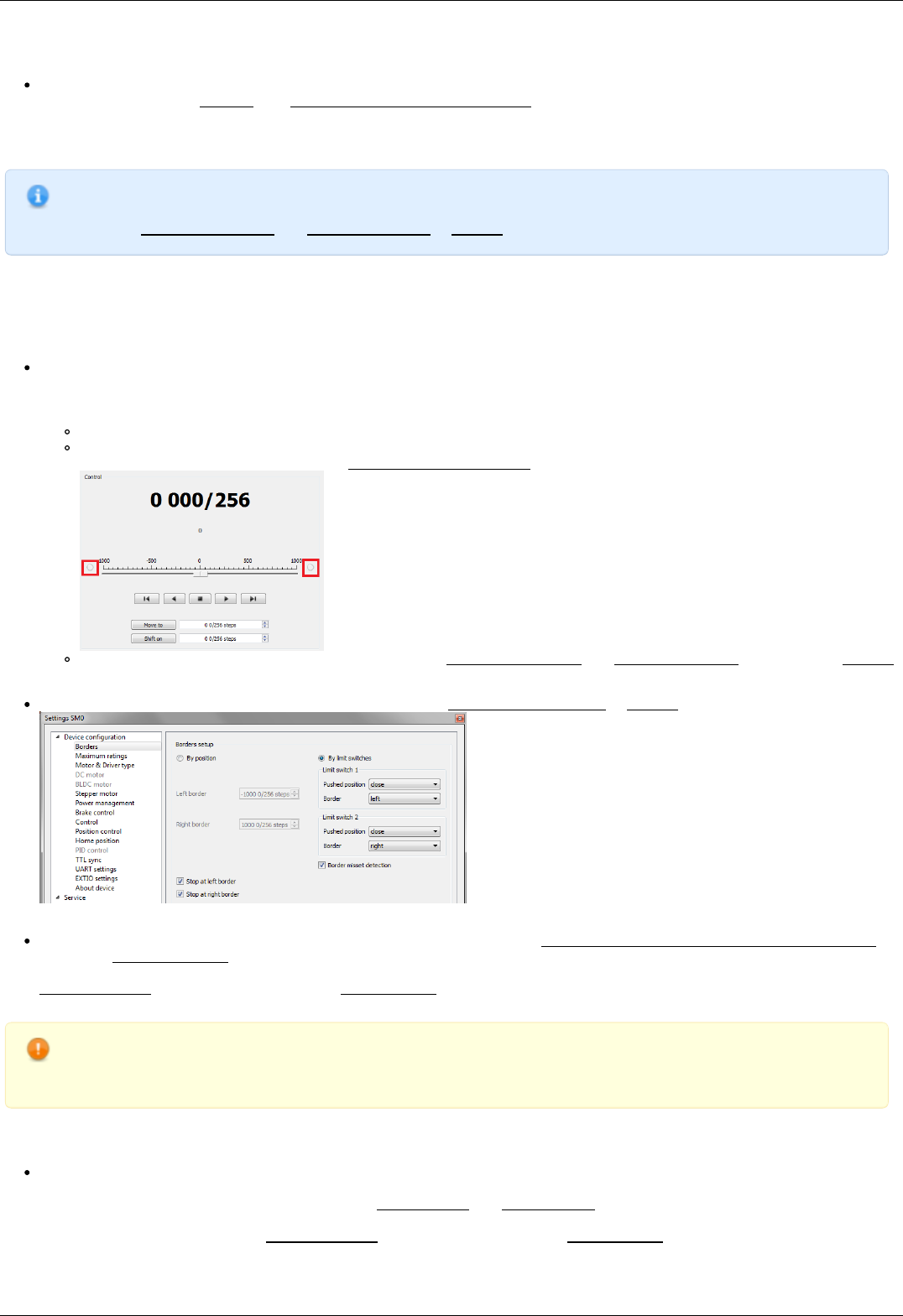
Hardware limit switches setting. Homing.
Note. This section describes the using of motorized stages with hardware limit switches. If your system is not
provided with hardware limit switches, it is recommended to disable stop by limit switches in settings. To do this,
unmark Stop at right border and Stop at left border in Borders tab.
There are positioners with limited (translators) and an unlimited range of motion (rotators). The limitation of movement range can be
done by position or with limit switches using. When you work with translators if its limit switches are configured incorrectly there exists
a risk to break down mechanics, since moving part can try to go out of motion range. Rotators do not have such problem. Moreover, it
should be kept in mind that rotator may have only one limit switch.
To work with limit switches you must specify which one will be left and right. Sometimes it is unknown in advance and we only
know that both switches are connected and fire if the corresponding limit of the motion range is reached. The stage jam is
possible if the limit switches are configured improperly. Therefore, the controller supports just a simple detection of incorrectly
configured limit switches, shutting down the movement on both of them. Please make sure that:
The stage is far from limit switches;
Switches polarity is configured correctly (limit switches indicators are off in the main window of XiLab). In the case of
incorrect settings, change their polarity (Borders -> Pushed position), indicators should go out.
Shutdown mode is activated on both of limit switches ( Stop at right border and Stop at left border are marked in Borders
tab).
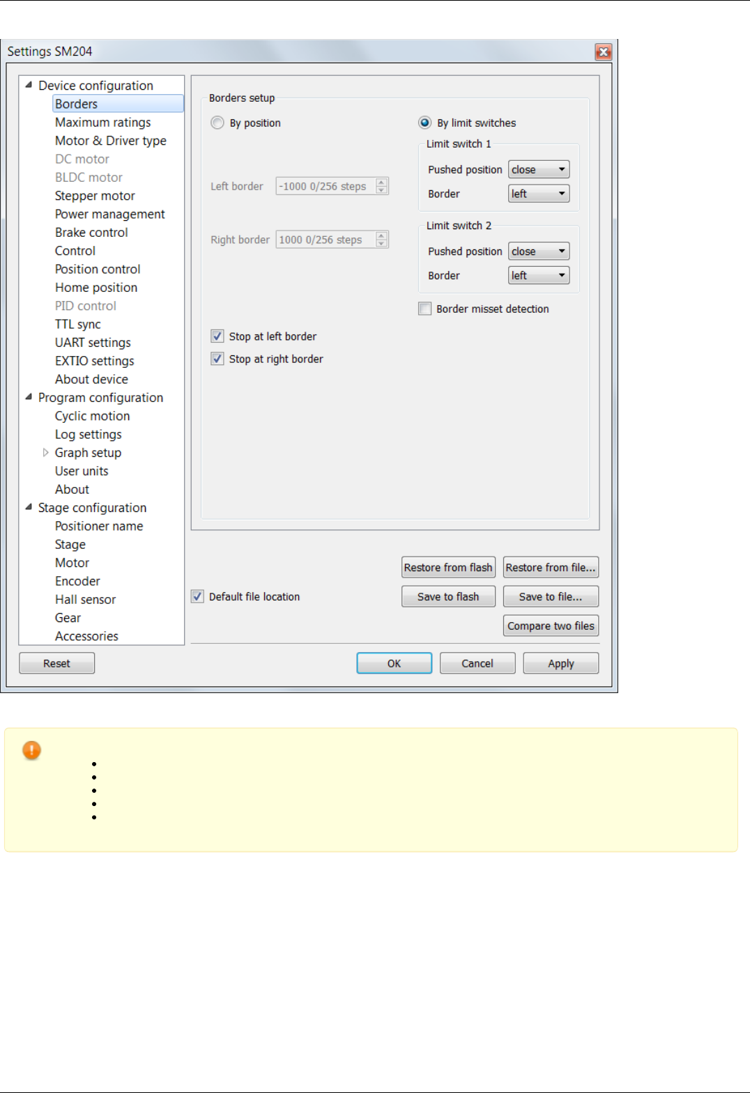
Mark the flag detecting improper connection of limit switches Border misset detection in Borders tab.
Tab with limit switches settings
Controller can switch to Alarm state after false limit switch response, if Enter Alarm state when edge misset is detected is
enabled in Maximum ratings tab. It is recommended to enable it. Start the movement in any direction from the main window of
XiLab up to Alarm state or stopping by the limit switch. When an Alarm occurs you need to reverse limit switches by changing
Borders->Border with reversed values in the Stepper motor tab.
Warning. The protection against mistaken limit switches connection doesn't guarantee the complete solution of the
problem, it only makes the initial configuration procedure easier. Don't start the movement with mixed up limit
switches if any of them is active, even if the protection is on.
There are still two ways to determine which of the limit switch is right and which is the left:
You need to know how each of the limit switches is connected to the positioner. When loading a profile with the default settings,
switch connected to pin 9 of the D-SUB connector is considered as left, while switch connected to pin 8 - as right. Their location
relative to the positioner is configured in the fields Limit switch 1 and Limit switch 2 (see screenshot above). Start the system at
the low speed (<100 ш/с) when it is far away from limit switches. If the direction of movement to the switch in a real setting
differs from the expected, change Borders->Border values with reversed in the Stepper motor tab.
Page 24 / 345
Page 24 / 345
If it is possible to get limit switches activate them and note the correspondence between indicators in XiLab and each particular
switch. Then start the system at the low speed (<100 ш/с) when it is far away from limit switches and make sure that the
system moves to the right switch. Compare this to what you see in the main window of XiLab. If the direction of movement to
the switch in a real setting and in the main window differs, change Borders->Border values with reversed in the Stepper motor
tab.
For detailed information refer to motion range and limit switches.
Controller has a useful function called automatic Home position calibration to set the initial position of the motorized stage.
We will consider the most simple configurations with a single phase only. Start from the setting of the 1st phase speed which is
approximately 5-10 times lower than Working speed. It is necessary for higher precision of automatic calibration procedure. In the filed
Stop after specify the limit switch to make the stage reached one of the limit switches during the calibration (direction is selected in the
1st move direction). In the field Standoff specify number in steps, for which stage must be driven away from the limit switch. Click Ok
or Apply.
Note. Standoff value is signed. Positive direction is right. That is, if the auto-calibration procedure is set up on the
right limit switch, then in order to move stage away to the left you should type negative value in Standoff field.
Start the automatic calibration by clicking Go home in the main window of XiLab. The result of it is a movement of the positioner
to the specified limit switch with a relatively low speed and the shift away from him to the value specified in the field Standoff.
After completion of the calibration process, press Zero in XiLab to set the origin of coordinate system for your stage.
Repeat the calibration process again. The stage must return to the zero position. Please pay attention that there can be slight
deviations from zero connected with calibration procedure error.
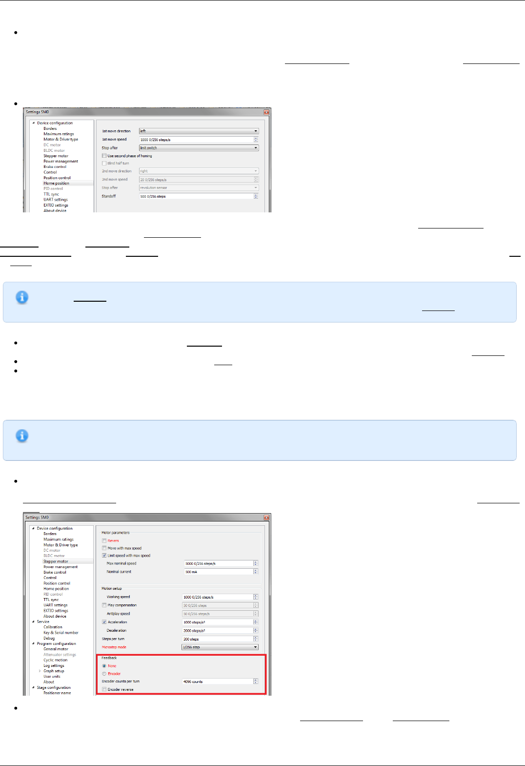
Encoder parameters setting
Note. This section describes the using of motor with encoder. If you motor without an encoder, the parameters
described below can be left unchanged.
Any encoder has Pulse Per Turn - PPT parameter (sometimes it is called PPR - Pulse Per Rotation). For correct operation of
the encoder with controller you should enter the number of encoder counts per revolution, which is equal to 4xPPT in the
Encoder counts per turn field in XiLab. For example, if your encoder has 1024 pulses per turn, specify 4096 in the Counts per
turn:
Start the motor rotation from the main window of XiLab. If everything is configured correctly, the green indicator ENCD will light
in the bottom of window. If ENCD has yellow color, you should mark Encoder reverse in the Stepper motor tab. Red color of
EDCN points to the problem with encoder position recalculation..
Page 25 / 345
Page 25 / 345
It is possible to activate the position control by encoder. To do this, in the tab Position control mark Position control and specify
allowable error in terms of encoder counts in the Threshold field. Then, when a mismatch between position and encoder counts
occurs, indicator SLIP will light in the bottom of XiLab main window. Beyond this, if Alarm on errors is marked, the controller will
go to Alarm state. Correct errors allows you to start closed loop control, when the difference between real position and encoder
position is compensated.
Setting the kinematic characteristics of the controller
In the Stepper motor tab you may specify a necessary acceleration ( Acceleration) and deceleration ( Deceleration) for your
stepper motor. The process of optimal values selection is the next:
Starting from default values make small shifts (start and fast stop) with gradual Acceleration increase until the movement
become unstable and disrupted sometimes. Take acceleration equal to about half of this value.
The deceleration can be configured about 1.5 - 2 times higher than acceleration.
If in your mechanical system moving to the desired position on the left and on the right is not the same, and there is play, it is
possible to eliminate this ambiguity. To do this mark Play compensation in Stepper motor and type number greater than play
value. The sign of this setting determines the direction of moving to the position. Positive sign means move from the left while
negative - from the right. In Antiplay speed field set the speed of compensation movement. This value should be low ( 50 s/sec
is enough) in order to avoid "drifting" during play compensation.
After the basic configuration of the positioner/motor, you can increase working speed. It can be done experimentally like the
process of acceleration setting, i.e. you should take its value about 2 times lower than value at which there is unstable
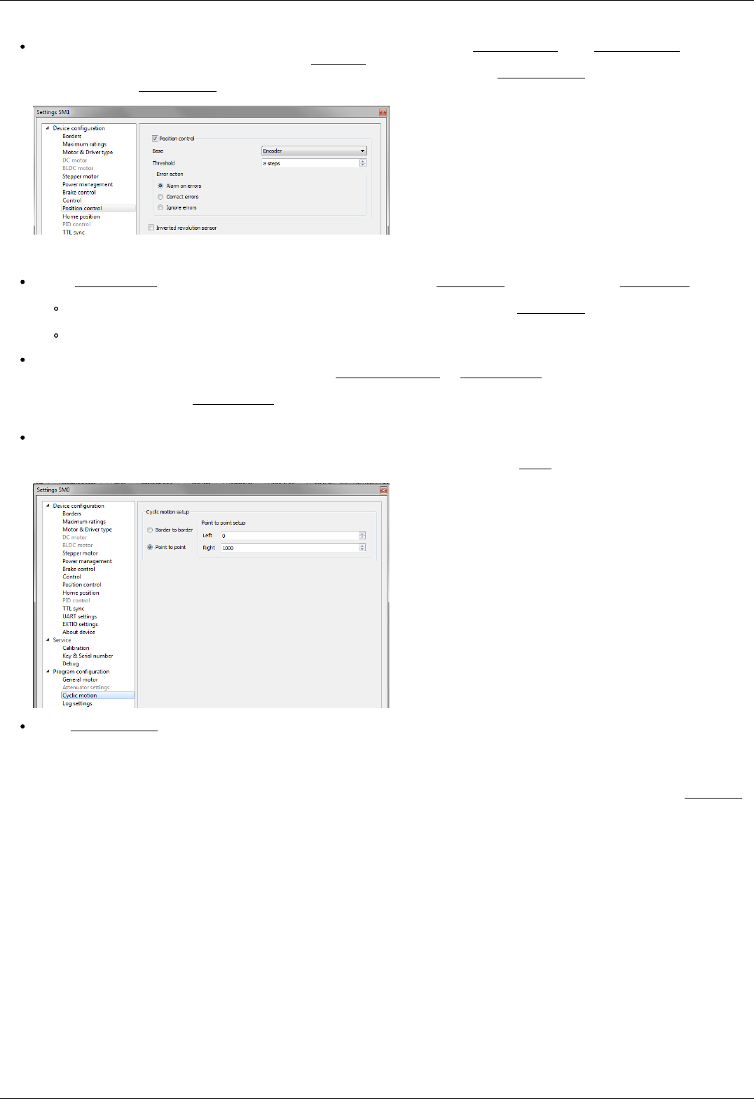
movement. To test the stability of the rotation it is recommended to use the function Cyclic in XiLab main window. Make sure
that you set it previously.
In the Microstep mode field we recommend to enter the value 1/256.
Working with user units
Often it is uncomfortable to work with the steps and microsteps and more convenient units are preferable. For this reason, the
controller can recalculate the coordinates in the usual units, for example in millimeters or degrees. It can be done in the tab User units,
where you should specify the size of the step and the corresponding measurement unit. For more information, refer to relevant
documentation paragraph.
Configuration of the operating profile complete.
Page 26 / 345
Page 26 / 345
3.4. Calculation of the nominal current
In order to stepper engine gave maximum torque, but it does not overheat, it is important to specify such technical characteristic as
the rated current.
The greater a current in the motor winding, the greater the torque at the axis. It is important to remember that with an increase a
current flowing through the winding, thermal power released by the motor increases. So the engine could operate for a long time
allocated to thermal power (Joule heating) must be less power dissipation. Power dissipation can be calculated on the basis of
documentation on the engine.
Calculation based on the parameters of unipolar full step mode
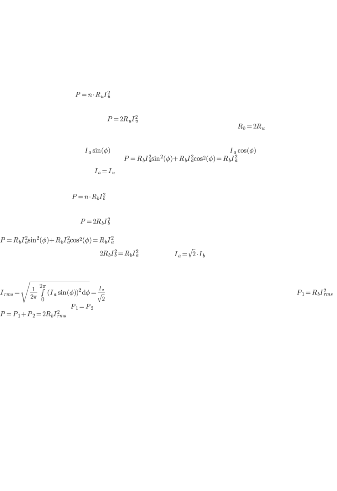
Power dissipation is equal to , where Ru - the resistance of the winding in unipolar mode, Iu - current through the
winding in unipolar mode, n - the number of simultaneous windings.
Consider, for example, ST2818M1006. The table in the documentation shows that in full step mode simultaneously running two
phase (n = 2) in the unipolar mode, i.e. . The motor controllers support only bipolar control mode. To switch from a
unipolar to a bipolar mode, connect each phase windings in series, the resistance will increase, , where Rb - the resistance
of the series-connected windings in the bipolar control mode.
The motor controllers control algorithm is capable of operating in a microstepping mode and maintains the current so that the first
winding current varies in function , in the other winding current varies in function , where Ia - current amplitude.
Thermal power released two windings at any time
It follows from the foregoing that the
Calculation based on the parameters of bipolar full step mode
Power dissipation is equal to , where Rb - the resistance of the winding in bipolar mode, Iu - current through the winding
in bipolar mode, n - the number of simultaneous windings.
Consider, for example, ST2018S0604. The table in the documentation shows that in full step mode simultaneously running two phase
(n = 2) in the bipolar mode, i.e.
Thermal power dissipated in the motor windings that managed by motor controller, still is
We obtain the equation equating power . We find that
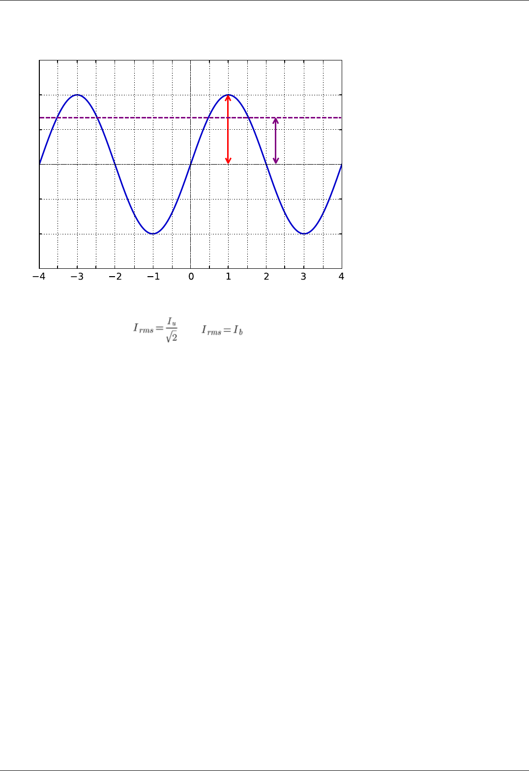
The relationship with an rms current
Alternating current in each motor winding can be characterized by its rms value in the period
. Thermal power of one winding is associated with an rms current through it .
Both windings are identical . The total thermal power of the engine that is run by control by motor controller controller
Page 27 / 345
Page 27 / 345
Steps
Current
IaIrms
It follows from the foregoing that , also
Setting the nominal current
Motor controller are capable of taking the nominal current value as a current amplitude or as rms. The choice of which way to interpret
the input value of the nominal current is determined by the absence or presence corresponding flag ENGINE_CURRENT_AS_RMS in the
EngineFlags engine_settings structure. When setting the nominal current in XILab should properly specify how the current is
interpreted. Motor controllers in this case will provide the maximum torque without overheating the engine.
For all Standa motorized positioners prepared configuration files that contain the specified nominal current as rms. The corresponding
flag is set. Thus the engines operate at optimum settings.
Page 28 / 345
Page 28 / 345
3.5. Possible problems and solutions
Controller is not found in XiLab
Unable to rotate the motor by the controller
Controller has Alarm state
Motor vibrates without rotation
Mechanical jamming.
When using the libximc library and Linux with kernel version less than 3.16, there are possible hanging of the operating
system
3.5. Possible problems and solutions
Here is a list
of common
problems
and possible
solutions
that we
offer to our
users. Your
case may be
the same
mentioned
below, then you will quickly find a solution, otherwise, send your questions with a detailed description of the problem to tech support:
Ask a question
Send an e-mail: 8smc4@standa.lt
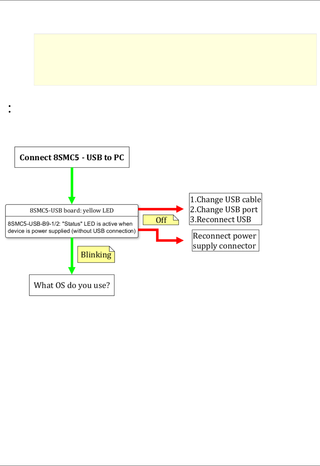
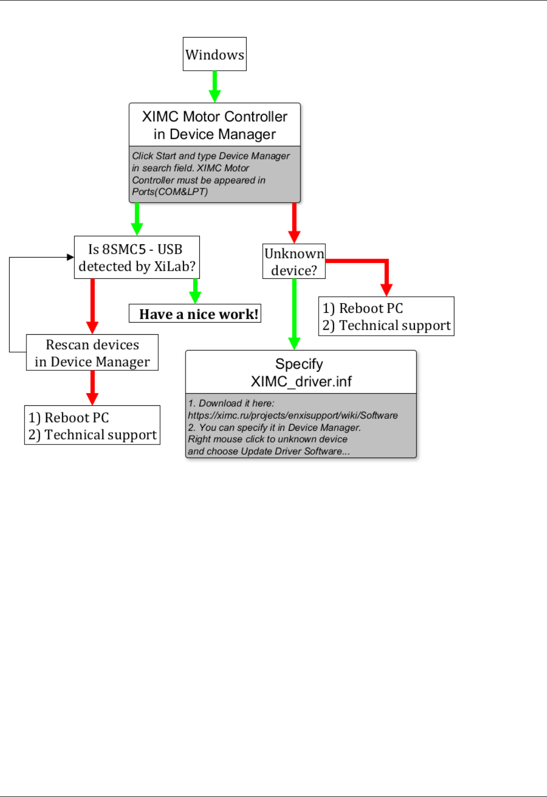
Controller is not found in XiLab
Solution:
Comment to the diagram:
8SMC5-USB-B9-1 - one axis system
8SMC5-USB-B9-2 - two axes system
The following decision maps show the actions for different operating systems.
Windows:
Page 29 / 345
Page 29 / 345
Linux:
Page 30 / 345
Page 30 / 345

Comment to "Can't open device" problem solution:
When working with USB-... converter in Linux it appears as /dev/ttyUSB device. XiLab shows it in a list, but when you try to open it,
an error "can't open device" occurs due to the lack of permissions to the device.
To solve this problem, create a file: /etc/udev/rules.d/31-ximc.rules and add the next line into it:
SUBSYSTEM=="usb", ATTR{idVendor}=="067b", MODE="0666"
idVendor identifier can be found by executing lsusb command.
Mac OS:
Page 31 / 345
Page 31 / 345
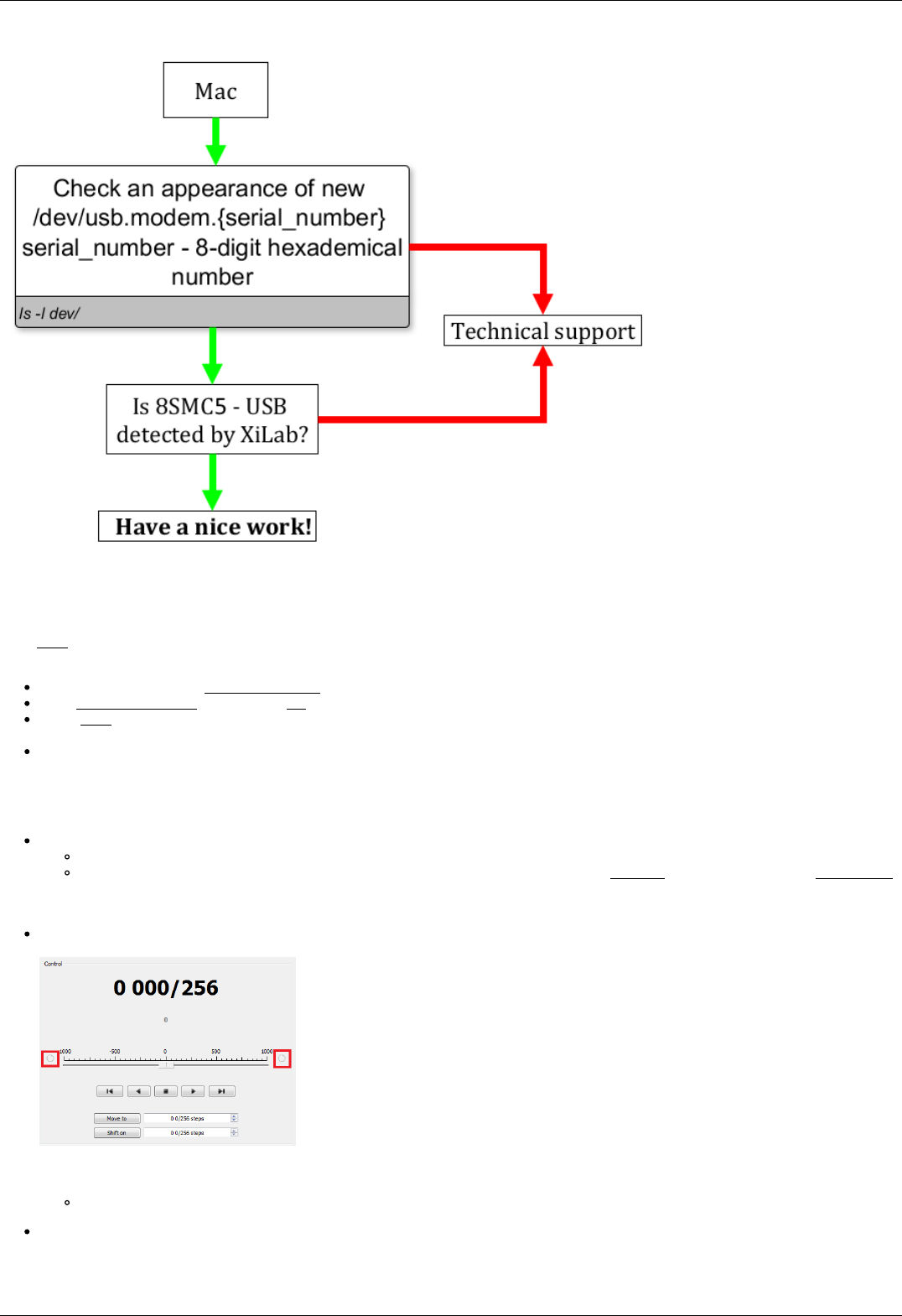
Unable to rotate the motor by the controller
Controller has Alarm state
Click Stop in the main window of XiLab. Controller must return to its normal state. If this approach was not helpful and Alarm state
emerged again, do the following:
Being in XiLab go to the Maximum ratings tab.
Mark Sticky Alarm flags option. Click Ок.
Press Stop in the main window of XiLab, it will temporary return controller to its normal state. Repeat the sequence of actions
leading to Alarm state.
Make the screenshot of XiLab main window and send it to the technical support with detailed description of your problem.
Motor vibrates without rotation
This problem has several reasons:
Installed incorrect profile for your motor/stage.
Search for a better match for the title of profile used by your motorized stage in XiLab folder or refer to enxisupport.
It is recommended to save your current configuration to file. To do this, in the Settings window of XiLab click Save to file
(see XiLab settings), choose path where you want to save the settings. Then send this file in technical support with
detailed description of the problem.
Incorrect configuration of limit switches, as result the stage rests the limit switch. This can usually be seen by the indicator
lights in XiLab.
The main reason for the incorrect setting of limit switches is incorrect configuration file for your positioner (see previous item).
Information about manual setting is located in manual profile setting. When such problem is emerged it is recommended to
contact the technical support for further assistance.
It is also one of the consequences of problems with limit switches can be mechanical jamming (see the next item).
Broken winding of the motor, problems with bad contact in connector etc. It is possible to diagnose this kind of problems
independently. For this purpose, we recommend to get XiLab graphs of voltage and current during the operation of motor. The
Page 32 / 345
Page 32 / 345
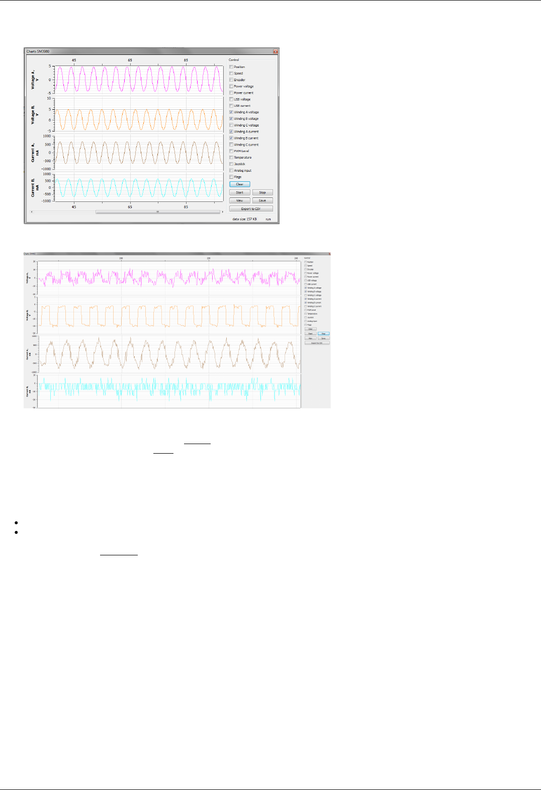
proper motor current in the winding varies according to a sine or cosine. In the broken motor much stronger differences of the
current from harmonic form can be noticed.
Working case
In the charts below you can see the problems. For example, winding B is open circuit. Probably it is broken. Also, voltage and
current forms are distorted.
There are problems with motor
To diagnose the problem set very low speed ( 1 s/sec is optimal) and send movement command. Then turn on graphs of current and
voltage for windings A and B in XiLab (button Charts, then mark correspond fields). Wait for a while until the graphs are built. Then it
is recommended to send them (Click Save in the same window with graphs) in technical support with a detailed description of the
problem. Sometimes, when winding is broken, it is impossible to use XiLab due to permanent loss of device. In this case also contact
technical support with description of the problem.
Mechanical jamming.
There are two ways to deal with jamming:
Turn the motorized stage by hands if it is possible.
Increase the winding current 2-3 times for a short time (about 5-10 seconds) and send movement command to the stage in the
right direction at the low speed (about 50-100 s/sec will be enough). A few seconds after rotation, press stop button (small
black square) until power off status appears in the main window of XiLab in order to prevent motor overheating. After this do
not forget to return the settings back!
When using the libximc library and Linux with kernel version less than 3.16, there are possible hanging of the
operating system
Comment: above-mentioned problem stems from the error in serial port driver cdc-acm. It is observed with frequent sequential
opening and closing of some devices. Operation system hanging was shown on Debian 7 (3.2 kernel version) and worked correctly on
Debian 8 (3.16 kernel version).
For additional information about problem please refer to the next link
Solution: update your current version of Linux.
Page 33 / 345
Page 33 / 345

4. Technical specification 8SMC5
1. Appearance and connectors
1. Controller board
2. One axis system
3. Two axes system
2. Kinematics and rotation modes
1. Predefined speed rotation mode
2. Rotation for predefined point
3. Predefined displacement mode
4. Acceleration mode
5. Backlash compensation
6. Rotation reversal
7. Recommendations for accurate rotation
8. PID-algorithm for DC engine control
9. Stop motion modes
10. PID-algorithm for BLDC engine control
3. Main features
1. Supported motor types
2. Motor limiters
3. Limit switches
4. Automatic Home position calibration
5. Operation with encoders
6. Revolution sensor
7. Steps loss detection
8. Power control
9. Critical parameters
10. Saving the parameters in the controller flash memory
11. User defined position units 8SMC5
4. Safe operation
5. Additional features
1. Operating modes indication
2. Operations with magnetic brake
3. Joystick control
4. Left-Right buttons control
5. TTL synchronization
6. Design of multi-axis system
7. General purpose digital input-output
8. General purpose analog input
9. External driver control interface
10. Serial port
11. Saving the position in controller's FRAM memory
12. The Standa stages detection
6. Secondary features
1. Zero position adjustment
2. User-defined position adjustment
3. Controller status
4. USB connection autorecovery
7. Software compatibility
1. MicroManager
Page 34 / 345
Page 34 / 345

4.1.1. Controller board 8SMC5
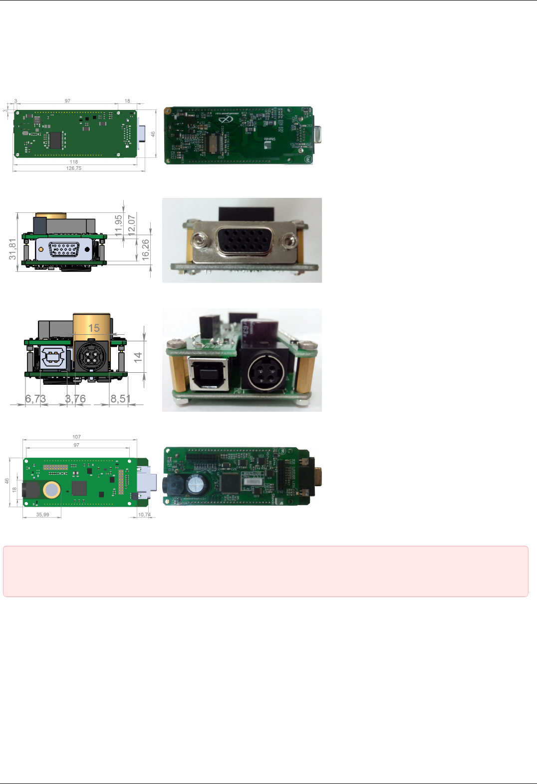
Dimensions and arrangement
Structurally the controlled is designed as two boards, 46x126,75mm each, rigidly connected to each other. A logic controller and
control systems are mounted at the bottom board, a power part is at the top board. A radiator at the power part is available.
Top view on the controller. The view from power part and radiator side.
Front view on the controller. The view from stage cable side.
Rear view on the controller. The view from DIN and USB-b connectors side.
Bottom view on the controller. The view from backplane connectors side.
IMPORTANT. If you are mounting the radiator to the power part by yourself, please make sure that there is no
contact between heat-conducting surfaces and conductive elements of the unit. Such contact may damage the power
circuit! This warning is applicable only to controllers supplied without body.
Connectors
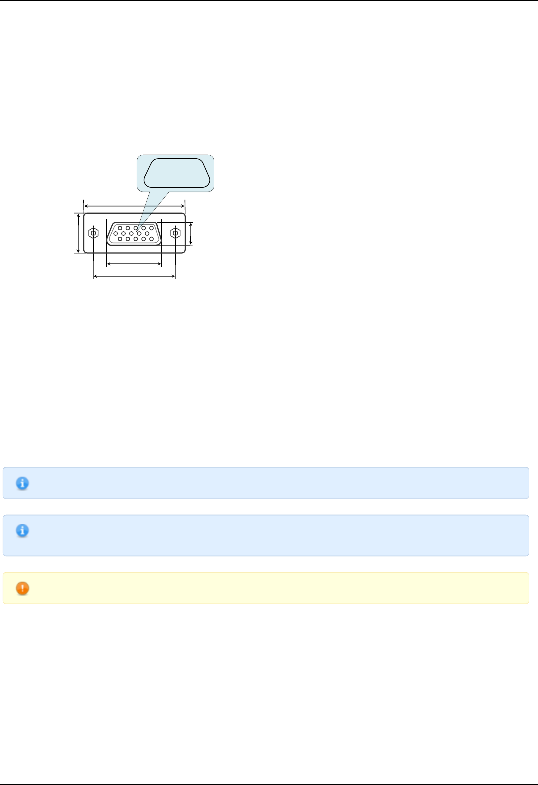
Positioner connector
A female DSub 15-pin connector for positioner is mounted on the controller board.
Page 36 / 345
Page 36 / 345
16,3
25
30,8
12,6
8
1 2 3 4 5
6 7 8 9 10
11 12 13 14 15
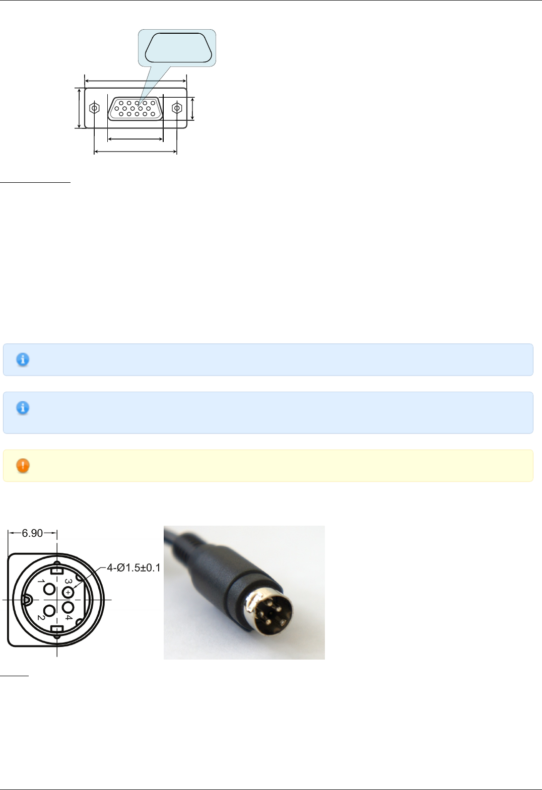
Dimensions and numbers of the pins in DSub connector (front view).
Pins functionality:
1 - Not phase B of SM or - DC of the motor
2 - Phase B of SM or + DC of the motor or phase B on BLDC motor
3 - Not phase A of SM or - DC of the motor or phase C on BLDC motor
4 - Phase A of SM or + DC of the motor or phase A on BLDC motor
5 - 500mA - for 8SMC5, stabilized output for encoder power supply
6 - One-wire interface for positioner identification (for Standa hardware only)
7 - Logic ground for limit switches, encoder, etc.
8 - 2nd limit switch
9 - 1st limit switch
10 - Encoder channel A
11 - Encoder channel B
12 - Revolution sensor input
13 - Inverted Encoder channel A
14 - Inverted Encoder channel B
15 - Inverted revolution sensor input
Note. Only firmwares 4.1.0 and older support BLDC
Note. Outputs 1 & 3 and 2 & 4 must be connected together for proper DC motor function if the nominal current of the
motor is higher than 3A.
Warning. Plugging in/out the motor to the controller is not recommended while motor windings are under voltage.
Power supply connector. 1 and 2 axes system
One- and two-axis controller models in metal cases use Kycon 4-pin DC power connector (part number KPPX-4P, anacapa.kycon.com).
Pinout:
1 - Power, "-".
2 - Power, "+". 12-48V.
3 - Power, "-".
4 - Power, "+". 12-48V.
Page 37 / 345
Page 37 / 345
IMPORTANT. Never supply the power to the controller and do not plug it to power connector if you are not confident
that your power supply parameters conform to the requirements. Never attempt to plug the power supply to the
controller if you are not sure power supply unit and controller connectors are compatible! The acceptable connection
parameters are described in Safety instructions.
IMPORTANT. Hot-swapping or unreliable connection of the power supply connector MF-4MRA may damage the PC
and/or the controller. For more details please refer to Safety instructions.
Data connector. 1 and 2 axes system
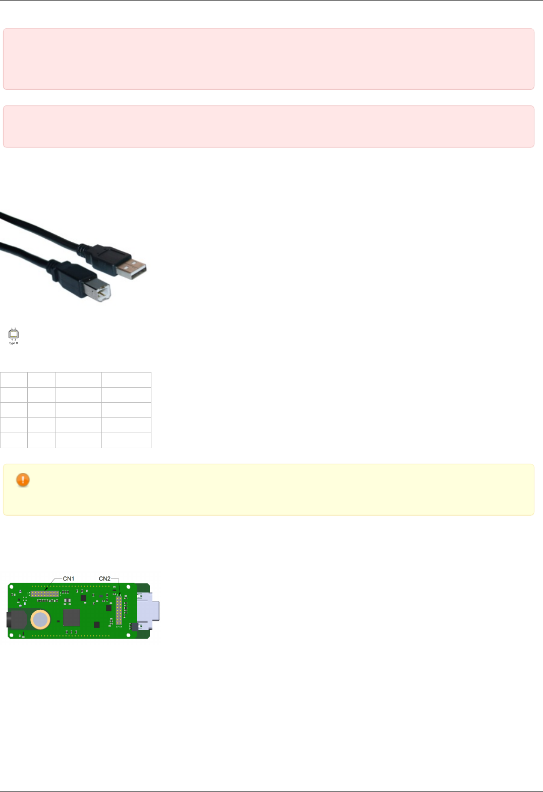
Controllers in metal case connect via USB type-B connector.
USB-A - USB-B cable.
USB type B connector.
Output pin table
Pin # Name Wire color Description
1 VCC Red +5 VDC
2 D- White Data -
3 D+ Green Data +
4 GND Black Ground
Warning. Use verified USB cables only! Damaged or low-quality USB cable may cause improper controller operation,
including motor rotation errors and errors of device recognition by PC operating system. Short cables with thick wires
and screening are ideal for sustainable connection.)
Backplane connector
A female 20-pin double-row connector (PBD-20R) with 2.54mm pitch is mounted on the controller board for backplane connection.
Dimensions and output pins numbers in BPC (BackPlane Connector), connector-side view.
Page 38 / 345
Page 38 / 345

Pin function of CN1:
1 - Power GND 12-48В.
2 - Joy, an analog 0-3 V input used for external joystick connection.
3 - Power GND 12-48В.
4 - Pot, an analog 0-3 V input used for general purpose.
5 - Power GND 12-48В.
6 - A common input/output (or an Enable signal if an external driver is used), 3.3V logic.
7 - Power +12...+48В.
8 - U_LED, A LED Status output displaying controller's operating mode.
9 - Power +12...+48В.
10 - L_LIM, A LED output for left limit switch.
11 - Power+12...+48В.
12 - R_LIM, A LED output for right limit switch.
13 - USB_SEL, selecting USB device in Multi-axis system.
14 - A common input/output EXTGPIO1, 3.3V logic.
15 - USB_D0_N, negative out of USB Slave.
16 - H_USB_D0_N, negative out of USB Master.
17 - USB_D0_P, positive out of USB Slave.
18 - H_USB_D0_P, positive out of USB Master.
Pin function of CN2:
1 - Reserved.
2 - RX, serial port, 3.3V logic.
3 - Reserved.
4 - TX, serial port, 3.3V logic.
5 - Reserved.
6 - A Direction signal for external driver control, 3.3V logic.
7 - Reserved.
8 - A Clock signal for external driver control, 3.3V logic.
9 - Reserved.
10 - Synchronization output, 3.3V logic.
11 - Reserved.
12 - Synchronization input, 3.3V logic.
13 - An output for magnetic brake control, 3.3V logic.
14 - Not used.
15 - BUT_R, an external "Right" button.
16 - 5V output.
17 - BUT_L, an external "Left" button.
18 - Digital GND for 3.3V and 5V.
Note. No additional connection or pull-up to ground/power supply is required for idle pins. Just don't use them.
IMPORTANT. A maximum designed operating voltage for Joy and Pot analog inputs is UP TO 3V. Never supply these
inputs with higher voltage, including 3.3V value, otherwise the proper operation of all the analog channels of the
controller may get disrupted and the controller itself or the motor may get damaged.
IMPORTANT. The outputs available at the internal connector are not protected. Mounting of any additional buffers or
filtering chains is a total responsibility of user or developer who designs a backplane intended to use these lines.
IMPORTANT. While the controller is unpowered, no voltage over 0.3V relative to the DGND pin is allowed on the
internal connector. Provision of any additional protection preventing those accidents (if possible) is a total
responsibility of user or developer who designs a backplane intended to use these lines.
Page 39 / 345
Page 39 / 345
4.1.2. One axis system
Single-axis controller model is a controller board in a metal case. Case dimensions are 62 x 44 x 124 mm.
Front panel of the controller contains power supply connector, USB-B data connector, status LED, power LED, left and right limit switch
LEDs, left and right movement buttons.
Rear panel contains positioner connector.
Connectors
Positioner connector
A female DSub 15-pin connector for positioner is mounted on the controller board.
16,3
25
30,8
12,6
8
1 2 3 4 5
6 7 8 9 10
11 12 13 14 15
Dimensions and numbers of the pins in DSub connector (front view).
Pins functionality:
1 - Not phase B of SM or - DC of the motor
2 - Phase B of SM or + DC of the motor or phase B on BLDC motor
3 - Not phase A of SM or - DC of the motor or phase C on BLDC motor
4 - Phase A of SM or + DC of the motor or phase A on BLDC motor
5 - 500mA - for 8SMC5, stabilized output for encoder power supply
6 - One-wire interface for positioner identification (for Standa hardware only)
7 - Logic ground for limit switches, encoder, etc.
8 - 2nd limit switch
9 - 1st limit switch
10 - Encoder channel A
11 - Encoder channel B
12 - Revolution sensor input
13 - Inverted Encoder channel A
14 - Inverted Encoder channel B
15 - Inverted revolution sensor input
Note. Only firmwares 4.1.0 and older support BLDC
Note. Outputs 1 & 3 and 2 & 4 must be connected together for proper DC motor function if the nominal current of the
motor is higher than 3A.
Warning. Plugging in/out the motor to the controller is not recommended while motor windings are under voltage.
Power supply connector. 1 and 2 axes system
Page 40 / 345
Page 40 / 345
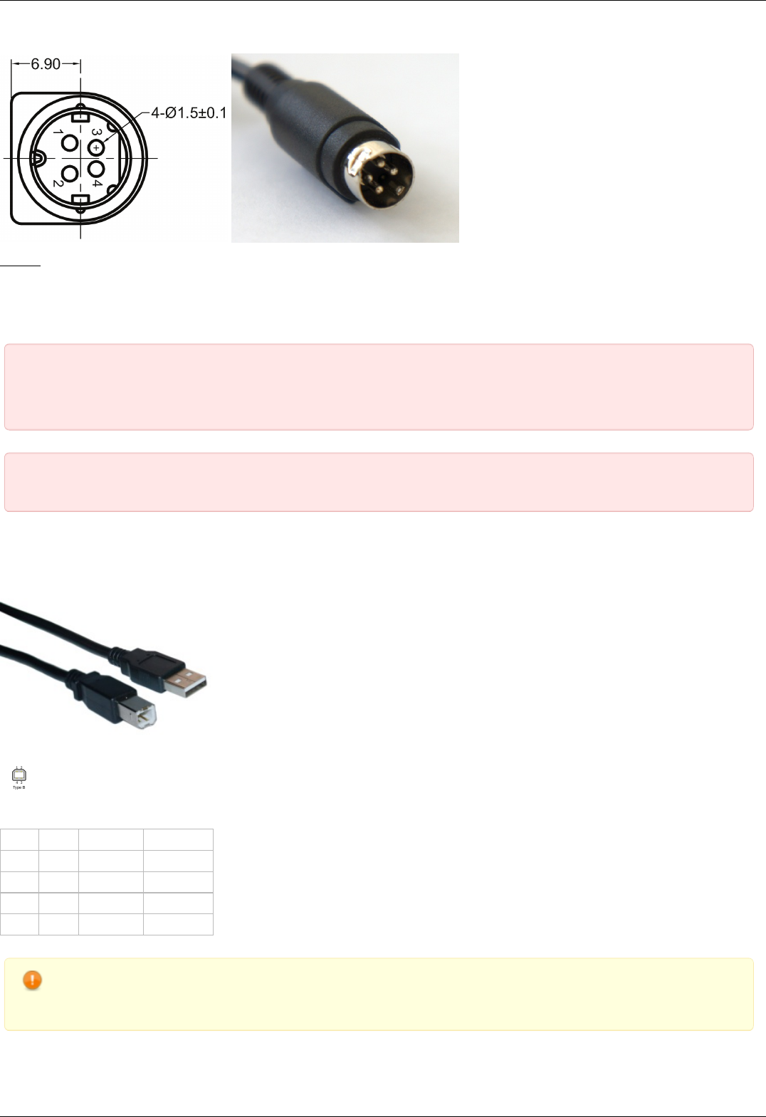
One- and two-axis controller models in metal cases use Kycon 4-pin DC power connector (part number KPPX-4P, anacapa.kycon.com).
Pinout:
1 - Power, "-".
2 - Power, "+". 12-48V.
3 - Power, "-".
4 - Power, "+". 12-48V.
IMPORTANT. Never supply the power to the controller and do not plug it to power connector if you are not confident
that your power supply parameters conform to the requirements. Never attempt to plug the power supply to the
controller if you are not sure power supply unit and controller connectors are compatible! The acceptable connection
parameters are described in Safety instructions.
IMPORTANT. Hot-swapping or unreliable connection of the power supply connector MF-4MRA may damage the PC
and/or the controller. For more details please refer to Safety instructions.
Data connector. 1 and 2 axes system
Controllers in metal case connect via USB type-B connector.
USB-A - USB-B cable.
USB type B connector.
Output pin table
Pin # Name Wire color Description
1 VCC Red +5 VDC
2 D- White Data -
3 D+ Green Data +
4 GND Black Ground
Warning. Use verified USB cables only! Damaged or low-quality USB cable may cause improper controller operation,
including motor rotation errors and errors of device recognition by PC operating system. Short cables with thick wires
and screening are ideal for sustainable connection.)
Supplementary one-axis system connector
Page 41 / 345
Page 41 / 345

One-axis controller model contains a HDB-26 female DSub connector.
Pinout of the supplementary HDB-26 connector, front view.
Pinout:
1 - NC, not used.
2 - NC, not used.
3 - NC, not used.
4 - GND, ground.
5 - NC, not used.
6 - Synchronization input.
7 - Synchronization output.
8 - RX_1, serial port input.
9 - NC, not used.
10 - NC, not used.
11 - NC, not used
12 - NC, not used.
13 - DIR_1, Direction signal for the external driver.
14 - GND, ground.
15 - +5V.
16 - BRAKE_1, brake control output.
17 - CLK_1, Clock signal for the external driver.
18 - TX_1, serial port output.
19 - NC, not used
20 - NC, not used
21 - NC, not used.
22 - GND, ground.
23 - PBRK_1, Magnetic brake output.
24 - +5V.
25 - IO_1, input-output pin.
26 - POT_1, analog input.
Page 42 / 345
Page 42 / 345
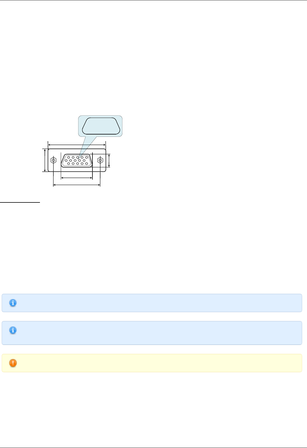
4.1.3. Two axes system
Enclosure view
Two-axis controller model consists of two controller boards in a metal case. Case dimensions are 122 x 45 x 106 mm.
Front panel contains power supply connector, USB-B data connector, supplementary two-axis system connector , USB cascade
connector, and power LED. The cascade USB-A output connector is used to connect several two-axis cases in line terminated with
either one-axis or two-axis case. This way a required number of axes can be connected to the computer with a single USB cable. The
front panel also contains status LED, left and right limit switch LED, left and right movement buttons for each of the two controller
boards of the two-axis system.
Rear panel contains positioner connector for each of the two controller boards, a joystick connector.
Connectors
Positioner connector
A female DSub 15-pin connector for positioner is mounted on the controller board.
16,3
25
30,8
12,6
8
1 2 3 4 5
6 7 8 9 10
11 12 13 14 15
Dimensions and numbers of the pins in DSub connector (front view).
Pins functionality:
1 - Not phase B of SM or - DC of the motor
2 - Phase B of SM or + DC of the motor or phase B on BLDC motor
3 - Not phase A of SM or - DC of the motor or phase C on BLDC motor
4 - Phase A of SM or + DC of the motor or phase A on BLDC motor
5 - 500mA - for 8SMC5, stabilized output for encoder power supply
6 - One-wire interface for positioner identification (for Standa hardware only)
7 - Logic ground for limit switches, encoder, etc.
8 - 2nd limit switch
9 - 1st limit switch
10 - Encoder channel A
11 - Encoder channel B
12 - Revolution sensor input
13 - Inverted Encoder channel A
14 - Inverted Encoder channel B
15 - Inverted revolution sensor input
Note. Only firmwares 4.1.0 and older support BLDC
Note. Outputs 1 & 3 and 2 & 4 must be connected together for proper DC motor function if the nominal current of the
motor is higher than 3A.
Warning. Plugging in/out the motor to the controller is not recommended while motor windings are under voltage.
Power supply connector. 1 and 2 axes system
Page 43 / 345
Page 43 / 345

One- and two-axis controller models in metal cases use Kycon 4-pin DC power connector (part number KPPX-4P, anacapa.kycon.com).
Pinout:
1 - Power, "-".
2 - Power, "+". 12-48V.
3 - Power, "-".
4 - Power, "+". 12-48V.
IMPORTANT. Never supply the power to the controller and do not plug it to power connector if you are not confident
that your power supply parameters conform to the requirements. Never attempt to plug the power supply to the
controller if you are not sure power supply unit and controller connectors are compatible! The acceptable connection
parameters are described in Safety instructions.
IMPORTANT. Hot-swapping or unreliable connection of the power supply connector MF-4MRA may damage the PC
and/or the controller. For more details please refer to Safety instructions.
Data connector. 1 and 2 axes system
Controllers in metal case connect via USB type-B connector.
USB-A - USB-B cable.
USB type B connector.
Output pin table
Pin # Name Wire color Description
1 VCC Red +5 VDC
2 D- White Data -
3 D+ Green Data +
4 GND Black Ground
Warning. Use verified USB cables only! Damaged or low-quality USB cable may cause improper controller operation,
including motor rotation errors and errors of device recognition by PC operating system. Short cables with thick wires
and screening are ideal for sustainable connection.)
Joystick connector
Page 44 / 345
Page 44 / 345
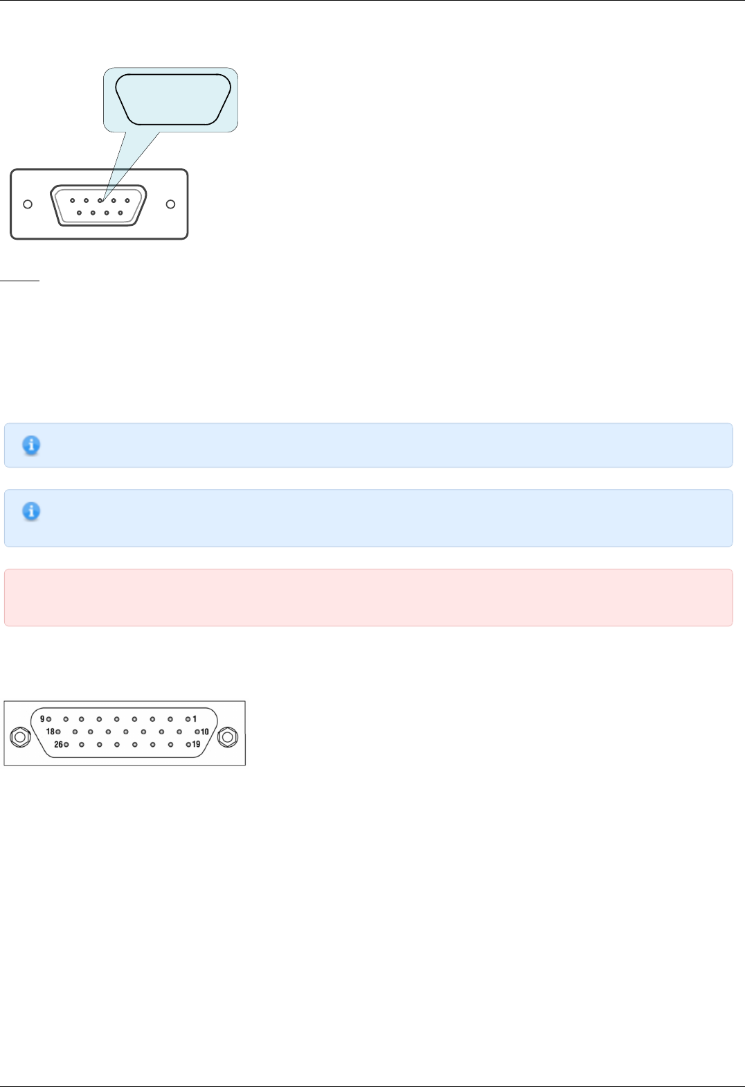
A single-axis or two-axis controller model may contain a 9pin DSub male joystick connector.
6 7 8 9
1 2 3 4 5
Pinout of the joystick connector, front view.
Pinout:
1 - BUT_R_1, right button input, axis 1.
2 - Joy_2, analog 0-3V joystick input, axis 2.
3 - GND, common ground.
4 - BUT_R_2, right button input, axis 2.
5 - GND, common ground.
6 - Joy_1, analog 0-3V joystick input, axis 1.
7 - 3.3V output.
8 - BUT_L_1, left button input, axis 1.
9 - BUT_L_2, left button input, axis 2.
Note. If the connector belongs to a single-axis model, then pins 2, 4, 9 are not used.
Note. Unused pins of the internal connector do not require any additional connection or pullup/pulldown. Simply do
not use them.
IMPORTANT. Analog Joy, Pot inputs are designed to work with LESS THAN 3V voltage. Do not apply higher voltages,
including 3.3V, to these inputs, as it can break all analog controller inputs and lead to the controller or motor failure.
Supplementary two-axis system connector
Two-axis controller model contains a HDB-26 female DSub connector.
Pinout of the supplementary HDB-26 connector, front view.
Page 45 / 345
Page 45 / 345

Pinout:
1 - RX_2, serial port input, axis 2.
2 - Synchronization input, axis 2.
3 - TX_2, serial port output, axis 2.
4 - GND, ground.
5 - Synchronization output, axis 2.
6 - Synchronization input, axis 1.
7 - Synchronization output, axis 1.
8 - RX_1, serial port input, axis 1.
9 - NC, not used.
10 - CLK_1, Clock signal for the external driver, axis 2.
11 - POT_2, analog input, axis 2
12 - IO_2, input-output pin, axis 2.
13 - DIR_1, Direction signal for the external driver, axis 1.
14 - GND, ground.
15 - +5V.
16 - BRAKE_1, brake control output, axis 1.
17 - CLK_1, Clock signal for the external driver, axis 1.
18 - TX_1, serial port output, axis 1.
19 - DIR_2, Direction signal for the external driver, axis .
20 - BRAKE_2, brake control output, axis 2
21 - PBRK_2, Magnetic brake output, axis 2.
22 - GND, ground.
23 - PBRK_1, Magnetic brake output, axis 1.
24 - +5V.
25 - IO_1, input-output pin, axis 1.
26 - POT_1, analog input, axis 1.
Page 46 / 345
Page 46 / 345

4.2. Kinematics and rotation modes
1. Predefined speed rotation mode
2. Rotation for predefined point
3. Predefined displacement mode
4. Acceleration mode
5. Backlash compensation
6. Rotation reversal
7. Recommendations for accurate rotation
8. PID-algorithm for DC engine control
9. Stop motion modes
10. PID-algorithm for BLDC engine control
Page 47 / 345
Page 47 / 345

4.2.1. Predefined speed rotation mode
Predefined speed rotation mode is the main operating mode of the controller for all the motor types. It allows to maintain the
predefined rotation speed at a distance from the destination point and is usually used simultaneously with Rotation for predefined point
or Predefined displacement modes. This mode may also get called by left and right motion commands.
Motor steps or encoder counts (if the encoder is available) per time unit are used as speed measurement units. Encoders work with all
the types of motors. For DC motors the fixed speed is maintained even with the variable external load.
Turning on the Acceleration mode temporarily deactivates the predefined speed rotation mode.
After the controller receives the command to start the motion, it rotates the motor with user-defined speed. The speed adjustment
is available at the appropriate section of the "Settings..." menu of XILab software or using the set_move_settings() function (refer to
Programming guide section). For stepper motors the speed value may be defined in full steps and microsteps per second, for DC
motors the speed is defined in revolutions per minute (RPM).
The speed for special motion modes, e.g., for backlash compensation or automatic zero position calibration, is different from the
general rotation speed and is set separately.
The controller allows limitation of the maximum speed if appropriate parameter is defined by user. In that case any rotation that would
have happened with the speed over the maximum is performed with the maximum speed. A separate adjustment is available,
providing use of the maximum speed for all the ordinary motion modes, except for special ones, e.g., backlash compensation or
automatic zero position calibration . The maximum speed adjustment as well as the adjustment for modes using this speed are
available in the appropriate section of the "Settings..." menu of XILab software .
The actual speed is displayed in XILab main window, in the Speed field, or on main operating parameters charts.
Note. If the stability of the speed maintenance seems to be insufficient while the encoder is used, please refer to
recommendations for accurate rotation .
Note. Maximum allowed speed is 100000 steps/s or 100000 rpm depending on engine type.
Page 48 / 345
Page 48 / 345

4.2.2. Rotation for predefined point
The rotation to predefined point mode is the main operating mode for all the types of motors and is usually used simultaneously with
predefined speed rotation mode. It provides moving the stage to the defined position with absolute value for destination point
coordinates which is different from predefined displacement mode. An additional reciprocal motion close to predefined point may be
performed at Backlash compensation mode.
While using the encoder, few barely noticeable "vibrations" are possible before the motor stops in predefined point.
After the starting command is received by the controller, it either switches on the acceleration mode (if the appropriate option is on) or
immediately starts rotating the shaft of the motor with user-defined speed. After the predefined point is reached, the rotation stops;
deceleration may be activated if the appropriate option is on. The destination point is set in XILab main window. The destination
point may be defined either in full steps and microsteps for stepper motors or in encoder counts for all types of motors.
The actual position is displayed in XILab main window, in the Control section, or on main operating parameters charts.
Note. If the positioning accuracy seems to be insufficient while the encoder is used, please refer to
recommendations for accurate rotation .
Page 49 / 345
Page 49 / 345

4.2.3. Predefined displacement mode
The predefined displacement mode provides displacement of the stage for predefined value relative to zero position (if this is a first
command since the controller started) or relative to position reached by the motor after the previous commands are completed, i.e.,
the destination point coordinate is a relative value. This mode is useful when the absolute position is unknown or doesn't matter.
The predefined displacement mode is exactly analogous to rotation for predefined point mode. The differences concern the destination
position computing rules only. While there is no motion actually, calling the predefined displacement command rotates the motor
relatively to current position. If this command is sent during the rotation to the position (MOVE, MOVR, SSTP, STOP, LOFT), then the
displacement interval adds to destination position and the controller re-adjusts for the new destination point while the motor is
rotating. If this command comes during the rotation for certain direction, then the displacement value adds to previous destination
position and the motion automatically re-adjusts for the new position.
IMPORTANT. The displacement is always performed relative to position reached by stage while performing one of the
previous command, MOVE, MOVR, SSTP, STOP, LOFT, or while performing the displacement after the previous
incoming synchronization pulse has been received, despite whether the motion has been completed or interrupted.
Note. The predefined displacement mode is activated either by corresponding command or by incoming
synchronization pulse. For more information please refer to TTL synchronization chapter.
Page 50 / 345
Page 50 / 345

4.2.4. Acceleration mode
The acceleration function is active by default. The acceleration is used for smooth start or finish of the rotation without shocks that
are inevitable when the predefined speed is reached instantly. Moreover, inertia of rotor and the other components of stage usually
doesn't allow instant gathering of high speed which results in the loss of steps as well as failure in rotation during the operation without
feedback. While operating the motor with feedback via encoder, the speed will increase as quickly as motor limiters allow. High
acceleration makes the rotation unstable as well as it makes more noise and vibration. That's why the acceleration mode is
recommended. The acceleration function provides reaching of both maximum speed and sustainable motion even for motors with
intermediate torque value.
The acceleration/deceleration mode works in the following way: during the speeding-up, while the required speed value is higher than
the actual one, a gradual acceleration is performed at the Acceleration value which is measured in steps per squared second. After the
required speed is reached, the controller switches to predefined speed rotation mode. Approaching the destination position, the
controller begins to decrease the speed as the speeding-down would equal to Deceleration value and the motor would stop exactly at
the destination point. Thus, this mode provides a trapezoidal speed profile. If the displacement distance is small, then the acceleration
may change directly to deceleration; this will result to triangular speed profile. Turning the acceleration mode on and off, as well as
setting of acceleration and deceleration value, is possible using XiLab software (see the Settings of kinematics (Stepper motor) section)
or by set_move_settings() command described in Programming guide.
The Acceleration value is adjusted independently from the Deceleration value – and there is a reason for it. Usually, due to friction
effect resisting acceleration but contributing to deceleration, the maximum acceleration value is less than deceleration one. Therefore,
for the fastest response of the stage either preset profiles should be used, or the acceleration/deceleration values should be established
experimentally, according to what your stage may provide. For stepper motors working without feedback these are the values that do
not lead to the steps loss. For motors with feedback the trapezoidal speed profile should be controlled using XiLab charts. The
acceleration/deceleration values should be taken 1.5–2 times less than those resulting in speed profile distortion or step loss.
Note. Turning the acceleration/deceleration mode off is sometimes useful for multiaxis systems control where, during
the motion along multi-dimensional paths, a continuous speed projection on each of the axes is required.
Note. The acceleration value is not displayed in XILab main window.
Note. Acceleration/deceleration values should be set as to allow the motor to reach target speed or decelerate from
top speed to zero in less than 5 minutes. If the acceleration/deceleration on kinematic settings page is set outside of
this range, then the controller will return an "incorrect value" error and accelerarion/deceleration will be changed in
controller to applicable value.
Page 51 / 345
Page 51 / 345
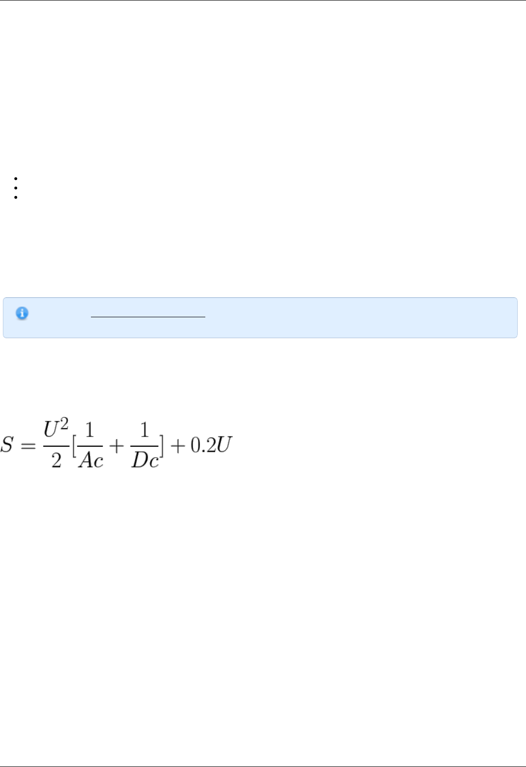
4.2.5. Backlash compensation
Backlash occurs in any mechanical device, e.g., in reduction gear or in worm-gear. Backlash results in differences in physical stage
position when approaching the same point from different directions, whereas the motor shaft is exactly in the required position.
Backlash compensation mode is used in order to eliminate such ambiquity. Its activation allows user to determine the direction from
where the stage would approach the destination point. Further on, the stage will approach the stop point from the defined direction
only, eliminating the mechanical backlash. If the natural approaching direction doesn't match the selected one, then the controller
drives the motor for some user-defined distance beyond the destination point and after that turns the motor around and completes the
approach from the required direction.
While a loaded mechanical system is moving, its dynamic characteristics in the backlash zone do differ from the regular motion mode.
Therefore, the rotation in the backlash zone should be performed with user-defined speed.
The following parameters of backlash-compensating system are available for adjustment by user:
Backlash compensation on/off flag.
Rotation speed while performing the compensating motion.
Backlash compensation distance. The plus or minus sign for that parameter is used to determine the approach direction. The
plus means the approach from the left side whereas the minus means the approach from the right side.
The controller indicates if the backlash compensation is active using MOVE_STATE_ANTIPLAY flag in the state structure which is also
displayed in XILab main window.
A forced backlash compensation by using the LOFT command may be performed if there is no confidence that the actual position is
backlash-free. While carrying out this command, a displacement for backlash compensation distance is performed with subsequent
return. Calling this command while driving will lead to a smooth stop of the engine. This command makes sense only when the
backlash system is active.
Note. The backlash compensation mode presumes no axis position correction, providing the user with just the choice
of the direction from where the stage should approach the destination point, sticking to this selected direction.
The backlash compensation adjustment using XILab software is described in Settings of kinematics (Stepper motor) section. Switching
on and backlash compensation parameters detection commands are described in Programming guide.
The minimum backlash is reached if the approach to the setpoint is performed with the same movement parameters, so the optimal
values of the backlash parameters are: the play speed must be equal to the nominal speed, the backlash compensation distance must
be such that the device could reach the nominal speed.
Backlash compensation distance can be calculated from formula:
S - backlash compensation, Ac, Dc - acceleration and deceleration, U - nominal speed, 0.2 - even motion time.
Page 52 / 345
Page 52 / 345

4.2.6. Rotation reversal
It is a common agreement that the coordinate increase corresponds to movement to the right, whereas its decrease corresponds to
movement to the left. The rotation is to be reversed either if this rule is not satisfied due to physical stage location, or if the stage is
supplied with an anchor which is pointed so that it doesn't match coordinate increase.
The rotation reversal may be switched on in the Motor parameters block of XiLab menu. Switching this feature on will change the
current coordinate sign; thus, "left" and "right" terms will get interchanged. For example, the first movement during the Home position
calibration will perform physically to the opposite direction, the Left and Right commands in XILab main window will interchange, etc.
Warning. Reverse is a setting that affects the whole controller operation if changed. The previously used XiLab scripts
or your own controlling programs will work differently.
Particularly, the limit switches are adjusted independently from the reverse. Thus, after switching this mode on or off,
one must re-adjust them.
Page 53 / 345
Page 53 / 345

4.2.7. Recommendations for accurate rotation
The controller can automatically adjust itself for the required mode, in order to maintain either the speed or the coordinate. However,
both the speed and the adjustment property depend on the controller settings. The stepper motor working in steps and microsteps
positioning mode can instantly reach the required operating conditions. If the stepper motor is physically unable to provide the
required speed or acceleration, the rotation will most likely stop completely. The movement will not fail if a feedback sensor such as
quadrature encoder is used as a reference; however, the controller probably won't be able to maintain the required rotation
parameters.
The additional position sensor (encoder) is required for DC motors. The indirect connection of controlling scheme affection with DC
motor stage displacement results to slowing down of reaching the required coordinate or speed. The following recommendations will
help you to accelerate this process and to make it more stable:
The profile corresponding to the stage being used is normally uploaded to controller and is used by it. Please upload the profile
from the Configuration files chapter if you aren't confident that it is proper;
The motor doesn't enter the limitation mode for one of the operating parameters (refer to Motor limiters and Power control
chapters). Such limitations are displayed by the horizontal bar above the Current indicator in either Power, Voltage or Speed
blocks in the Motor section of XILab Main window in single-axis control mode . For more information please refer to Motor limiters
and Power control chapters.
There are no mechanical impediments for rotation, the axis and stage are not jammed;
The output power of power supply unit being used is sufficient (see the Safety instructions).
Page 54 / 345
Page 54 / 345
4.2.8. PID-algorithm for DC engine control
Algorithm description
DC engine is controlled by the PID regulator, with the coordinate as the controlled parameter. The controlled coordinate changes
according to motion settings and incoming commands to provide motion capability. We will call controller coordinate the running
position. DC engine winding PWM signal fill factor is the control signal of the regulator.
The control action is calculated according to the following formula:
, where:
- is the control action
- is difference between the running coordinate and the current motor coordinate
- are proportional, integral and differential coefficients of the regulator. Regulator coefficients are set on PID settings
page of the XILab program or programmatically by calling set_pid_settings() function of the libximc library (see Programming guide).
The resulting value is normalized according to the following formula to make PID regulator action independent of motor type, feedback
sensor and working voltage:
, where:
- is the PWM fill factor
- is the nominal (maximum) motor voltage, (see Motor limiters).
- is the current supply voltage
- is the feedback encoder resolution in counts per revolution
This approach allows to change motor type, feedback sensor and voltage supply unit without reconfiguring PID regulator.
Warning. Do not forget to change PID regulator coefficents accoring to abovementioned formula if you are going to
change maximum motor voltage.
Particular properties of the algorithm
PID regulator coefficients
User set values are normalized to keep optimal PID regulator coefficients in [0..65535] range.
Let's consider the effects different components have for better understanding.
We will assume the supply voltage is constant and equal to the motor nominal voltage . With this assumption PWM fill
factor will be equal to 1 in the following cases:
1. - if target position is ahead of real position by 256 motor shaft revolutions
2. - if integral in the formula above is equal to 52.5 revolutions second
3. - if real motor speed is higher than the required speed by 96000 rpm.
Reaching target position
Target position is considered to be reached when motor shaft reaches the target position. Some oscillations around target position are
possible. Motor will need some time to stop and return to correct position if smooth deceleration is not used and an immediate stop
command is received or an emergency stop by limit switch has happened.
Warning. Long time oscillations around the target position while the motion is considered finished are possible if the
PID regulator is set up incorrectly.
PID regulator tuning recommendations
There are three quality criterions used when tuning PID regulator:
Speed maintenance accuracy, defined as a mean deviation of current speed from desired speed. Speed maintenance is
considered to work optimally if the speed takes no more than three distinct values when moving. It is impossible to achieve
greater accuracy because speed values are quantized.
Position reach quality, defined by the following criterions:
Page 55 / 345
Page 55 / 345
Time until final stop in target position (lower is better).
No slip on approach to the target position.
No oscillations around target position before stopping.
No spontaneous shifts from the target position after stopping.
Low noise when moving. Noise level is increased when only one of the PID coefficients is increased.
One can choose individual criterion priority depending on the task at hand when tuning PID regulator.
1. It is recommended to disable all DC motor limits including smooth acceleration/deceleration when you start tuning PID regulator.
2. It is recommended to tune PID regulator to maintain constant speed first.
3. It is recommended to start tuning PID regulator with integral and differential coefficients set to zero.
4. Set proportional coefficient
5. Set required movement speed and start the movement far away from the limit switches.
6. Gradually increase and observe current speed graph. Find optimal which makes the controller maintain current speed
the best and makes time to reach target speed less dependent on . One should be aware of possible noise level increase.
7. It is recommended to tune next. Integral PID regulator coefficient has more influence on position reaching behavior.
8. Set integral coefficient and start movement to position. It is convenient to use "shift on offset" command for this.
9. It is advisable to use sufficiently long shifts so that motor reaches at least 20% of required speed.
10. Increase of makes the controller stop at the target position faster.
11. Achieve faster reaching of the target position by gradually increasing . One should stop increasing this coefficient when either
quality of position reaching degrades substantially or noise levels increase. Slip at the target position will remain regardless.
12. Adjust up or down to decrease oscillations at the target position.
13. After one adjusts one should check the speed maintenance quality and noise levels. If these parameters are unsatisfactory
then one should adjust coefficients towards their previous values.
14. After setting and you can set up .
15. It is recommended to start tuning in speed maintenance mode and then check other quality parameters.
16. One should increase until speed oscillations around target speed stop decreasing.
17. In case of target position slip one should increase . However, further increases of this coefficent will lead to oscillations
around target position. One should keep a balance between oscillations and target position reaching speed.
Turn on smooth acceleration/deceleration if you plan on using this mode. This can lead to the slip at the target position. To compensate
one should increase .
After these steps the initial setup of PID algorithm is complete. The obtained coefficients are in most cases suitable for motor
operation. To further optimize these coefficients one can vary them while continuously monitoring quality according to the relevance of
chosen quality criterions to the particular task.
Note. It is not recommended to adjust more than one coefficient at a time while tuning the PID regulator.
IMPORTANT. It is extremely not recommended to start with large values of PID regulator coefficients or to rapidly
adjust them. This can lead to self-excitation of speed oscillations and motor failure.
Page 56 / 345
Page 56 / 345

4.2.9. Stop motion modes
There are two stop motion modes in the controller:
emergency stop;
stop with deceleration.
Emergency stop
Emergency stop is initiated by the command STOP. The controller tries to instantly stop the rotation of the motor shaft. This can lead
to missed steps in a stepper motor, if no feedback is used. Abrupt cessation of movement can adversely affect the equipment, for
example, may shift samples on the microscope stage or require additional adjustment of the optical line after a sudden stop.
Warning. When the controller is configured to trigger a stop on the left/right limit switch, it always occurs
immediately when the stage reaches the limit switch. This should be avoided.
Stop with deceleration
Stop with deceleration is initiated by the command SSTP. A smooth stop occurs with deceleration Deceleration, if it is not disabled in
the acceleration mode settings.
Warning. If the acceleration mode is disabled, then there is no difference between the emergency stop and the stop
with deceleration. An SSTP command will then result in an immediate stop.
Page 57 / 345
Page 57 / 345
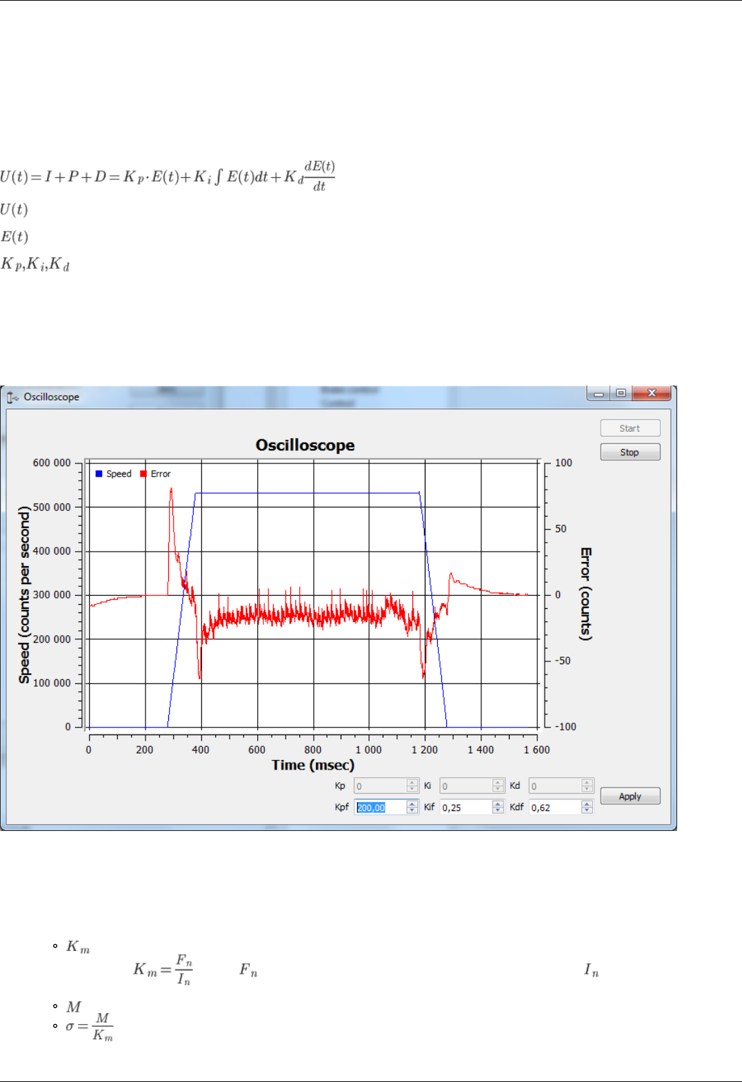
4.2.10. PID-algorithm for BLDC engine control
Algorithm description
BLDC engine is controlled by the PID regulator, with the coordinate as the controlled parameter. The controlled coordinate changes
according to motion settings and incoming commands to provide motion capability. We will call controller coordinate the running
position. Output current is the control signal of the regulator.
The control action is calculated according to the following formula:
, where:
- is the control action
- is difference between the running coordinate and the current motor coordinate
- are proportional, integral and differential coefficients of the regulator. Regulator coefficients are set on PID settings
page of the XiLab program or programmatically by calling set_pid_settings() function of the libximc library (see Programming guide).
The effects different PID components (Kp, Ki, Kd) have are same for BLDC and DC motors. See PID-algorithm for DC engine control
PID regulator manual tuning
We provide a special XiLab extension for the manual adjustment of the PID regulator coefficients. The time dependence of the speed of
the BLDC engine and the speed retention error is shown in a special window, see the screenshot below.
The PID regulator tuning window
The stable position retention is necessary for the correct engine operation.
Steps to adjust the coefficients:
1. First, you need to evaluate the PID coefficients. Given the structure of the managed system, they can be calculated from
simplified formulas. For this, the parameters from the documentation for the appropriate motor and positioner are used.
- electromechanical motor coefficient [H / A] (the torque generated by the current strength is 1 A). Can be calculated
as the ratio , where is the nominal (maximum) force generated by the motor, is the rated (maximum)
current strength.
- weight of load (kg).
.
Page 58 / 345
Page 58 / 345

, , .
2. Set the coefficients calculated by formulas, click Apply. Click the Zero button on the main XiLab window. Set 0 to the Move to
field, send the command. The engine should stop. Try to move the position manually, make sure that the response is correct -
the engine tries to return to zero position (the encoder reverse is set correctly).
3. Set a small speed in the motion settings, click Apply. Start moving in the main window. The differential coefficient (Kdf) should
be increased if there are vibrations and disruptions.
4. If the vibrations have audio frequencies (the positioner emits a loud sound when driving), it may be necessary to reduce the Kd
coefficient or all the coefficients proportionally
5. The integral coefficient (Kif) is responsible for getting into the target position, it is convenient to use the command Shift on for
testing.
6. To fine-tune the coefficients use the Oscilloscope window where the speed retention error is displayed for used motion
parameters.
Note. Only special XiLab version support oscilloscope window. Contact us to get it.
7. After the coefficients are adjusted, they need to be proportionally increased/decreased, this corresponds to an increase/decrease
in mass, response to the impact becomes more/less powerful, sudden stops will not lead to disruption of movement.
Page 59 / 345
Page 59 / 345

4.3. Main features
1. Supported motor types
2. Motor limiters
3. Limit switches
4. Automatic Home position calibration
5. Operation with encoders
6. Revolution sensor
7. Steps loss detection
8. Power control
9. Critical parameters
10. Saving the parameters in the controller flash memory
11. User defined position units 8SMC5
Page 60 / 345
Page 60 / 345

4.3.1. Supported motor types
Currently the controller supports stepper and DC motor types. The parameters of supported motors are described in Specifications
chapter.
Stepper motors
Rated current is the main parameter of the stepper motor. The rated current is adjustable at the Settings of kinematics (Stepper
motor) section.
IMPORTANT. The motor will gradually overheat and get physically damaged if rated current is exceeded. Make sure
that the rated current value is set according to the used stage. All the settings are proper in default stage profiles.
Step division mode is another important parameter. The following step division options are available to user:
1 (full) step
1/2 of the step
1/4 of the step
1/8 of the step
1/16 of the step
1/32 of the step
1/64 of the step
1/128 of the step
1/256 of the step
The microstep mode is set either on Settings of kinematics (Stepper motor) page or by motor adjustment commands. See the
Communication protocol specification and the description of the related functions in the Programming guide chapter.
Note. The controller always uses the internal step division value equal to 1/256. If the user selects a coarser step
division, the software will display only the multiple of the coarser step division positions and both adjustment and
transmission are possible only in that coarser step division mode. This is done for compatibility with both obsolete and
actual software operating with small multiples of the step division values. On the other hand, operations with the
largest step division value provides the most smooth and silent rotation at the smaller speed values.
The number of steps per revolution is the another direct parameter of the stepper motor. This setting does not affect the rotation but is
used in slipping control block or with motors with the encoder feedback.
Note. The controller supports stepper motors with feedback sensor - encoder. The encoder can be used as the main
position sensor (more info) and as the slippage, backlash or steps loss detector ( more info). Using the encoder
facilitates a stable passage of the resonant speeds without movement disruption.
DC motors
Unlike stepper motors, controlling DC motors requires feedback. Currently only encoder is supported as a feedback sensor.
Main DC motor parameters are maximum current and voltage, which can be set on Settings of kinematics (DC motor). Main encoder
parameter is counts per revolution.
IMPORTANT. The motor will gradually overheat and get physically damaged if rated current is exceeded. Make sure
that the rated current value is set according to the used stage. All the settings are proper in default stage profiles.
IMPORTANT. Setting wrong value of encoder counts per revolution will lead to the controller being unable to
maintain speed correctly. In some cases it may lead to stage or reducing gear failure.
DC engine is controlled by the PID regulator. Please carefully read PID-algorithm for DC engine control before you start working with it.
Page 61 / 345
Page 61 / 345
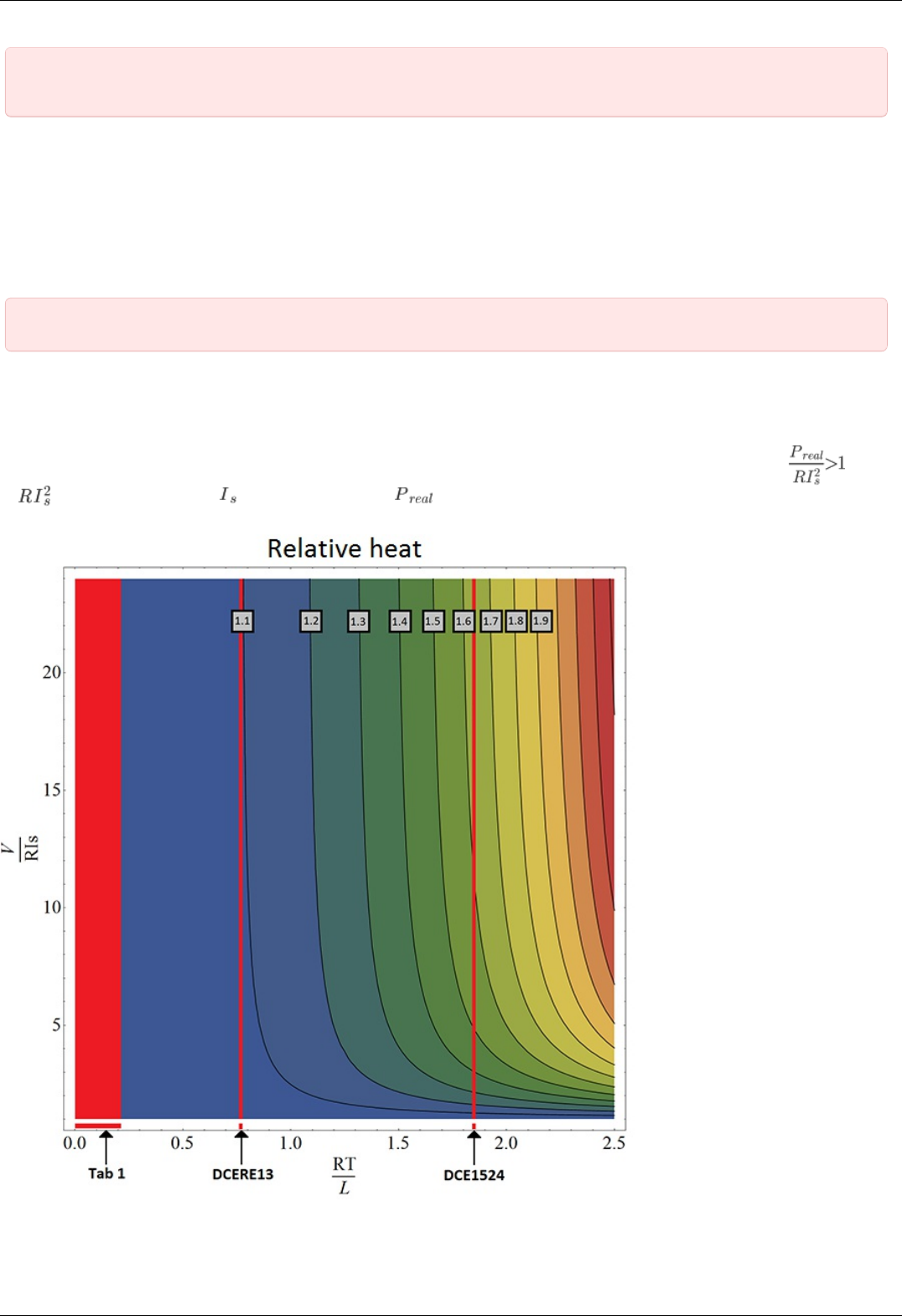
IMPORTANT. Wrong PID regulator settings might lead to stage failure. All supplied profiles are preset with correct
PID settings. It is not recommended to alter these settings unless absolutely necessary.
BLDC motors
Firmwares 4.1.x and older support BLDC motors controlling. Like DC motors, controlling BLDC motors reqiures feedback.
Main BLDC motor parameters are maximum current and number of poles, which can be set on Settings of kinematics (BLDC motor).
Main encoder parameter is counts per revolution.
Like DC, BLDC engine is controlled by the PID regulator. Please carefully read PID-algorithm for BLDC engine control before you start
working with it.
IMPORTANT. Like DC motors, wrong PID regulator settings, current and encoder settings might lead to stage failure
Engine selection criteria
Pulse-width modulation (PWM) is a widely used way to control winding's current in different motor types. It leads to current oscillations
at PWM switching frequency (so-called "current ripple"). Current ripple's amplitude depends on motor characteristics like its winding
inductance and resistance. Motor can heat up more than it is expected with nominal current due to current ripple, i.e. . There
i s - power dissipated by (stabilization current), - real power, dissipated in motor. For overheating estimation we
recommend to use this graph:
Tab 1
Page 62 / 345
Page 62 / 345
Motor RT/L
20 0.19576
28 0.07253
28s 0.07168
4118L1804R 0.02715
4118S1404R 0.02844
4247 0.0273
D42.3 0.0223
5618 0.0146
5618R 0.0146
5918 0.0116
5918B 0.012
VSS42 0.029
VSS43 0.0256
ZSS 0.04248
DCERE25 0.2106
The motor's overheat is determined by this sequence:
calculation. There is - resistance and inductance of motor winding (refer to the motor documentation). - PWM period
time. It's value should be 51.2 us for stepper motors and 25.6 us for DC motors.
calculation. This parameter shows power voltage excess under nominal voltage. There is - power voltage, - winding
resistance, - stabilization current.
Overheat definition. After first two steps point can be plotted at the graph. Now we should define the region, which corresponds
to overheat degree. For example, the region between 1.1 and 1.2 corresponds overheat value between and
There is DCE1524 overheat calculation example:
= 25.6 us = 5.1 Ohm = 70 uH
= 1.86
Now we can draw vertical line corresponds this value (look at graph) and find out overheat with different power voltages. Let's assume
= 500 mA. Nominal voltage in this case is = 2.55 V. If power voltage exceeds nominal more than 5 times but less than 10
times DCE1524's overheat will be between 1.5 and 1.6. Motor overheats about 1.65 times with 30 V of power voltage.
All the major engines and their parameters have been marked in Tab. 1.
Page 63 / 345
Page 63 / 345

4.3.2. Motor limiters
Motor winding current and voltage limiters and motor shaft revolution speed limiters are provided to ensure safe operation. These
limiters, if activated, will lead to gradual power and rotation speed decrease until the parameters being limited are within acceptable
range. Motor limiters work with voltage and current values directly on motor windings, unlike critical parameters, which work with
current and voltage at the controller input. Another distinctive feature of limiters is that they do not stop the motor and let the
controller enter Alarm state; they merely limit voltage, current and motor revolution speed.
For DC motors:
Max voltage is the nominal motor voltage. It defines maximum motor winding woltage. It is usually used to limit voltage growth
when the motor or stage is jammed. Should only be used if maximum motor winding current is unknown. This parameter is used
in PID regulator.
Max current defines maximum engine winding current. It is usually used to limit current growth when the stage is jammed. One
should set this limit based on maximum current which can be sustained by the motor without damage (primarily by heating).
Max RPM is the maximum motor shaft revolution speed. Is usually used to limit revolution speed when working with reducing
gears and other devices which have strict maximum speed limits.
Note. One should be aware of the distinction between maximum motor current and nominal current. In general they
may be different because of motor cooling features and operating conditions. Also, one should not mix up maximum
current and starting current with stationary motor shaft.
IMPORTANT. Changing maximum motor voltage might disrupt PID regulator. For more information see PID-
algorithm for DC engine control.
IMPORTANT. Maximum motor voltage may exceed nominal voltage, usually by 10-15%. If you are using a motor
with low load and you need high motor speed, then you can increase maximum motor voltage.
Current limiter operation.
It is important to note that maximum current limiter does not react immediately when working with DC motors. When a higher than
maximum current is detected in the motor winding, voltage supplied to the motor is gradually decreased until winding current is less
than Max current. In the worst case of a rapid jam during high-speed movement motor voltage may decrease for at most 370ms. If the
current limit is chosen right, motor should not overheat during this time.
Note. If the Max current value is set too low, it is possible that DC motor will not be able to move under high load or
high friction.
For stepper motors:
Max(nominal) Speed is a maximum motor shaft rotation speed in steps per second. Current stepper motor speed is defined by
Speed parameter (see Predefined speed rotation mode).
Nominal current defines maximum motor winding current. This value cannot be exceeded due to characteristic stepper motor
control.
In the XILab software limiter settings are described in sections Settings of kinematics (DC motor) and Settings of kinematics (Stepper
motor).
Page 64 / 345
Page 64 / 345
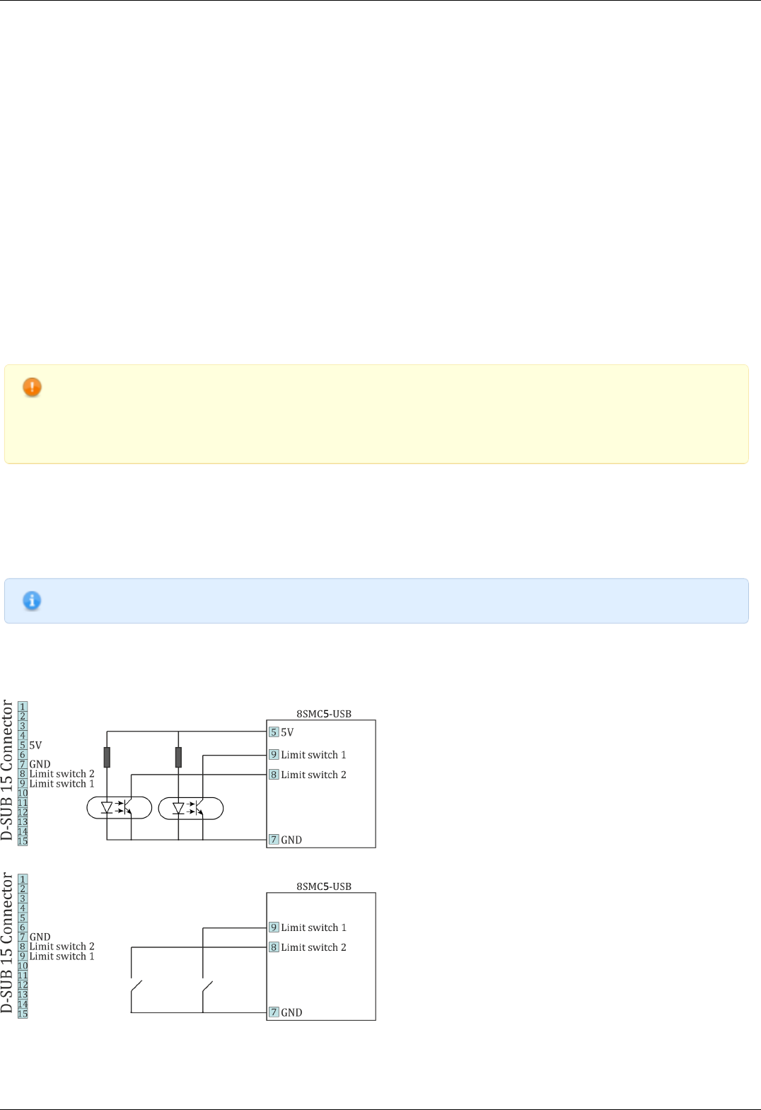
4.3.3. Limit switches
Limit switches designation
Limit switches are designed in order either to prevent the stage movement out of permissible physical movement range or to limit its
movement range according to user-defined requirements. Incorrect setting of the limit switches may result to stage jam if the
controller goes beyond the permissible range.
General settings
If the limit switch is active, a corresponding flag is placed in the state structure and the appropriate icon (left or right) is displayed in
XILab Main window. The controller can either stop any movement in the direction of any active limit switch (left or right) or stop the
movement to the single limit witch (left or right) or not to limit the movement. Limit switches settings are performed in XILab software
(see the Motion range and limit switches section).
Programmable motion range limitation
If there are no hardware limit switches for the motion range but the stage requires such limitation, the programmable limiters can be
used. For doing that, the limiters should be switched to limitation mode according to position reading (see the Motion range and limit
switches section). The left and right margin fields are used (the right margin value should be higher than the left one). In this mode,
the left limit switch is active if the actual position is less than the left margin value and the right one is active if the actual position is
greater than the right margin value. The operation time is about one millisecond.
Warning. The programmable motion range limitation is reliable only if there is no direct setting of the new position
by ZERO or SPOS commands, or if there is no steps loss or encoder malfunction if it is used for positioning, or if there
is no frequent power-cut during the rotation. If any of these problems appears, the programmable range should be re-
adjusted. The appropriate reference sensor allows the automatic re-adjustment using the automatic Home position
calibration feature.
Hardware limit switches
The controller may operate with limit switches based either on dry contacts, or on optocouplers, or on reed switches, or on any other
sensor types generating a 5V TTL-standard "logic one" electric signal in one state and a "logic zero" in the other. Each limit witch may
be configured independently. There is also possible to change the position of limit switches or their polarity in software.
Note. Limit switches are also useful for automatic Zero position calibration .
Limit switches connecting instructions
Limit switches should be connected to D-SUB connector pins as it is shown at the diagrams:
The "optocoupler" limit switches connection diagram.
The "dry contact" limit switches connection diagram.
Limit switches location on translators
Page 65 / 345
Page 65 / 345

The settings of which limit is left or right is required by the controller. Sometimes it is unknown a priori, just it is clear that both limit
switches are connected and fire if the corresponding limit of the motion range is reached. The stage jam is possible if the limit switches
are configured improperly. Therefore, the controller supports just a simple detection of incorrectly configured limit switches, shutting
down the movement on both of them. Please make sure that their polarity is configured correctly and the shutdown mode is activated
on both of limit switches. The flag of improper limit switch connection detection should be turned on in corresponding XiLab software
menu. Start the movement to any direction until the limit switch shuts the movement down. If there was right-side movement but the
left limit switch became active, or viсe versa, the limit switches should be interchanged (see the Motion range and limit switches
chapter). If the improper actuation of the limit switch is detected and if the corresponding feature is set in the Critical parameters
menu, the controller can turn the Alarm mode on.
Warning. The protection against mistaken limit switches connection doesn't guarantee the complete solution of the
problem, it only makes the initial configuration procedure easier. Particularly, don't start the movement if any of the
limit switches is active, even if the protection is on.
Page 66 / 345
Page 66 / 345

4.3.4. Automatic Home position calibration
This feature is used for detection and placing the movement to the starting position. This option of the controller is designed for simple
search of "Home", or "Zero" position by user himself, with no need of any programming skills. The Home position is set relative to one
or two external sensors and/or to an external signal.
Automatic Home position calibration feature is configured by user in Device configuration->Home position folder of XILab software (see
the Home position settings chapter) and is activated by the button in XiLab main window.
After this feature is activated, the controller rotates the motor to the defined direction with normal speed to quickly locate the stop
position. After finding the boundary position controller assigns motor back half a turn and begins rotate the motor to the defined
direction, but with another calibration speed. The calibration speed is usually set lower than the normal rotation speed in order to
improve the calibration accuracy. There are three ways to determine the completion of the motion, according to user-defined
preferences:
rotation until the limit switch is reached, the actual configuration of limit switches is used (e.g., polarity, location). For more
details please refer to Motion range and limit switches chapter.
rotation until a signal from the synchronization input is received, the actual configuration of synchronization input is
used. For more details please refer to Synchronization settings chapter. If the synchronization input is switched off by program,
the signal from it will never be processed.
rotation until a signal from the revolution sensor is received, the actual configuration of revolution sensor is used. For
more details please refer to Position control chapter.
Successful completion of home position calibration results in assertion of the STATE_IS_HOMED flag in the controller state structure . If
after this position somehow got lost (stop on limit switch, emergency stop while moving, steps loss detection, turns the Alarm mode),
the corresponding flag is dropped and it is necessary to re-calibrate the home position.
Note. If command emergency stop or command power shutdown are executed while the engine is stopped then it
isn't necessary to re-calibrate the home position and the STATE_IS_HOMED flag is not dropped.
Note. If the completion of the motion should happen at the limit switch, the calibration program is not crashed.
Fine calibration
After the first displacement the controller position is defined. However, some additional rotation may probably get turned on before the
movement to Home position is performed. It provides fine Home position calibration that may reach 1/256 of the step for stages with
stepper motors or 1 encoder count for stages with DC motors. If the corresponding flag is switched on, the controller rotates the motor
to user-defined direction with defined rotation speed until a signal either from the synchronization input or from the revolution sensor
is received or until the limit switch is reached, according to user-defined preferences. Using the signal from the sensor on the shaft
from motor to reducer and performing the motion with the small speed does make sense. It provides the maximum accuracy. Since
first and second movement signals might happen simultaneously a flag is provided, which will start tracking second motion end signal
only after motor shaft half-turn. This allows avoiding the signals of the completion of the first and second motions to be in ambiguous
sequence. As a result of optional second motion, the calibrating position becomes more accurate.
Note. If the second phase of the motion is used, the first motion usually can be performed at the high speed since it
provides just a coarse calibration and the accuracy is not required there. The accuracy will not improve if the second
limit switch is used for the second phase of the motion since its physical characteristics are the same as for the first
limit switch.
Finally the controller moves the motor to the defined direction with the defined speed at the defined Standoff distance. This is what
required to reach the Home position.
Note. The position reached as a result of calibration will slightly depend on the speed of the last motion until the
selected sensor responsed. Therefore, don't change the speed parameters for further successful reaching the same
position.
The automatic Home position calibration features are described in the Programming guide chapter.
The parameters configuration commands are described in the Communication protocol specification chapter
The position calibration command is described in the Communication protocol specification chapter.
A set_zero script is supplied with XiLab software pack, providing the automatic Home position configuration. This script changes the
Standoff setting in Home position folder, making the actual position as the Home one.
Page 67 / 345
Page 67 / 345

How to use the script:
place the movement to the desired position
launch the script and wait until it's finished.
As a result, the movement will be in the same position and all the following calls of homing function will move it there. Make sure to
save the settings to controller's nonvolatile memory.
Page 68 / 345
Page 68 / 345
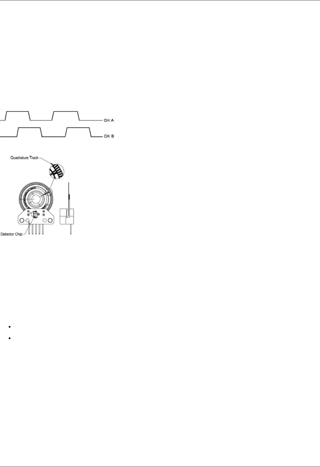
4.3.5. Operation with encoders
Application of encoders
Encoders are designed for creation of accurate and fast feedback according to the coordinate for all the electric motor types.The
feedback is performed by the motor shaft position, by stage's linear position, by the motorized table rotation angle or by any other
parameter related to the shaft position and measured by using the two-channel quadrature encoder complying the requirements
described in Specifications SMC5 chapter for the appropriate controller type. Controller 8SMC5 supports differential encoders and
simple (single-ended) encoders.
What is quadrature encoder?
Encoder is a mechanical motion sensor. The quadrature encoder is designed for direct detection of the shaft position. The sensor
transmits the relative shaft position by using two electric signals at СН А and СН В channels shifted relative to each other at 1/4 of
period.
The signals at СН А and СН В outputs of quadrature encoder.
An optical quadrature encoder mechanics.
An optical quadrature encoder mechanics is shown at the figure above. There are two optocouplers used. The operational principle of
an optocoupler is as following: a LED and a detector are arranged opposite to each other from different sides of a disc. The optocoupler
opens when disc's "window" coincides with the detector (the outgoing signal is logic zero). The outgoing signal is logic one if the
detector is closed by opaque part of the disc.
Number of steps per revolution (CPR) is the main parameter of the quadrature encoder. The standard resolution values for encoder are
from 24 to 1024 CPR. Each period of signal alteration is interpreted by 1, 2 or 4 codes which is corresponding to X1, X2 and X4
operating modes. This controller uses the most accurate X4 mode. The maximum frequency of each encoder's signal depends on the
applied encoder itself, since for 200 kHz in X4 mode the controller can read up to 800,000 encoder counts per second.
Controller's features
There are two operating modes with encoder available for the controller:
the encoder is used as the main position sensor (this is the main operating mode for DC motors and the optional one for stepper
motors).
slippage, backlash or steps loss detection (the recommended mode for joint operations with stepper motors, in case the encoder
is not used as a primary position sensor, see more).
Driving encoder mode
This is the mode when all parameters of the engine including position and velocity are measured directly by the encoder and are
denominated basing on counts of encoder. The position is displayed directly in the encoder counts, the speed is denominated in RPM
(revolutions per minute). The speed is calculated by the controller basing on the speed alteration data as well as on the number of
encoder pulses per one complete revolution of the motor shaft that are displayed in feedback configuration block at the Settings of
kinematics (Stepper motor), (DC motor) folder. Note that in the case of DC motor the speed maintaining mode, the mode of
movement to the predefined point as well as all their derivations use PID control algorithms and the appropriate settings are required.
The driving encoder mode optimizes stepper motor control, this leads to noise reducing and facilitates a stable passage of the resonant
speeds with no risk of steps loss when the coordinate flounders and the recurrent calibration is required.
New! New motor control algorithm is included in the latest firmware. The algorithm add encoder close-loop feedback suppressing
motor oscillations and acoustic noises. It makes almost all motors several times faster without any step loss. It all comes with a free
update of firmware and software. The new algorithm is available with firmware 4.0.7+ which can we downloaded from our Software
page or updated through XiLab. Use XiLab 1.13.13+ and set Feedback to Encoder on the Device configuration -> Stepper motor page.
Note, that position is in encoder counts now.
Page 69 / 345
Page 69 / 345
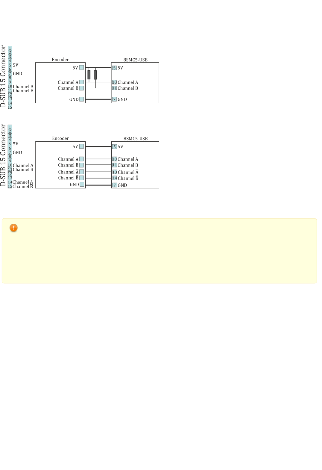
Encoder connection
The encoder is connected to the controller via D-SUB 15 pin connector, which is in all systems ( controller board, one-axis and two-axis
in box
The diagram of single-ended encoder connection using D-SUB 15 pin connector.
The diagram of differential encoder connection using D-SUB 15 pin connector.
See also the Example of a motor connection chapter.
Warning. Encoder inputs of the controller internally pulled up to logic one by using the 5.1kΩ resistors. Frequently
encoder outputs are of "open collector" type equipped with internal pull-up resistor. During the data transmission they
provide good characteristics while passing from higher logic level to lower. However, the pass from logic 0 to logic 1 is
more graduate. It passes through the RC circuit formed by pull-up resistor and cable capacitance. This is the most
important thing if the cable is long. If the internal pull-up is not sufficient, the pull-up resistor with r=1.5kΩ may be
added for every +5V to each output in order to improve the transmission speed parameters; before doing that please
check if the open collector of the encoder can transmit 5mA current. The resistors insertion diagram is shown above.
The maximum operating speed for quadrature encoder may be increased by adding a push-pull driver with the
outgoing current over 10mA to its output, providing quick 0 - 1 and 1 - 0 transmission edges.
Page 70 / 345
Page 70 / 345
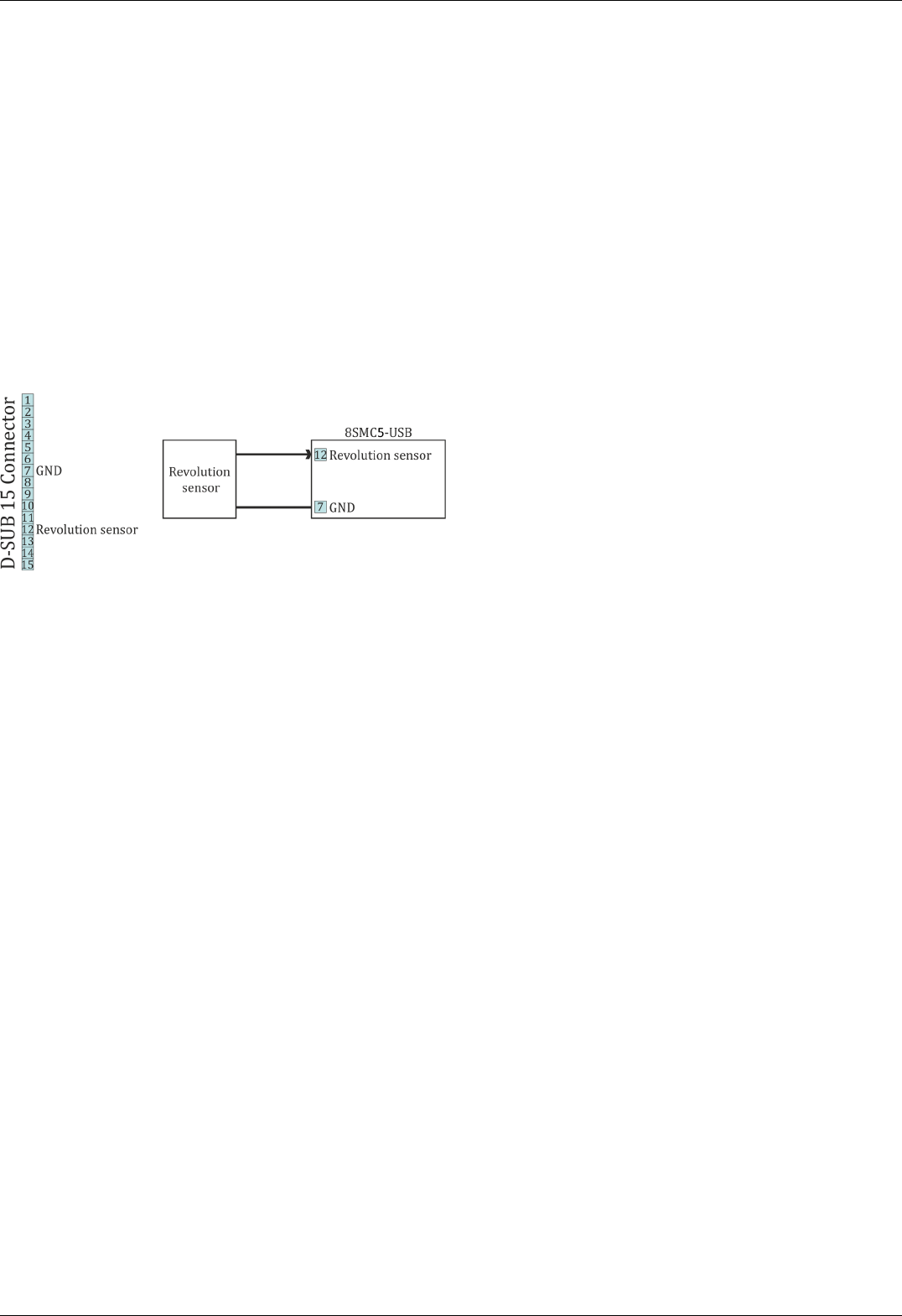
4.3.6. Revolution sensor
Revolution sensor is designed for stepper motor shutdown (failure) detection and for better accuracy of Home position calibration
procedure (see Automatic Home position calibration).
The controller may receive the actual position data from the external revolution sensor mounted on the stepper motor shaft. The
sensor transmits its signals to the controller once or many times per one revolution of the motor.
Usually the revolution sensor is a small disc with precise graduation scale mounted on the motor shaft. A light source (LED) and a
sensor of the optocoupler are placed at the opposite sides of the disc. The sensor is open if there is no interrupter between the LED
and the sensor (the logic zero is transmitted to optocoupler's output), whereas the logic one is transmitted if the light source is closed
by the interrupter.
By default, the lower logic level is interpreted by the controller as the active mode of the revolution sensor. The controller's input is
pulled to logic one level, thus, the disconnected revolution sensor means its inactive mode. The controller's input can be inverted if
necessary, in that case the logic one level will mean the active mode.
Connection diagram
The revolution sensor should be connected to the controller via 15pin D-SUB connector, which is in all systems ( controller board, one-
axis and two-axis in box).
Scheme of revolution sensor connection to the 8SMC5-USB based system
Page 71 / 345
Page 71 / 345

4.3.7. Steps loss detection
This mode is generally used while operating the stepper motor at full speed or limit loads when the shaft jam resulting to the steps loss
is possible. In this case an additional position sensor (revolution sensor) or encoder allows tracking this moment, informing the user
about it. This feature should be applied with stepper motors only and it allows detection of the steps loss. Steps and microsteps are
the measurement units for all coordinates and shaft positions.
When the encoder is used, the controller stores both number of steps and number of encoder's counts per revolution (see the Settings
of kinematics folder of XiLab program). When the feature is activated, the controller saves the current position in steps of the motor
and the current position according to the encoder data. Then, during the motion, the position data according to the encoder converts
to steps and if the difference exceeds the predefined value then the slippage is indicated and the Alarm mode turns on (if the related
option is active). For more information regarding use of encoder as the steps loss detector please refer to Operation with encoders
chapter.
If the revolution sensor is used, the position is controlled according to it. The controller stores the current position in steps according to
active and inactive edges at the sensor's input. Then, at every revolution (number of steps per one full revolution is set by Steps per
turn parameter, see the Settings of kinematics (Stepper motor) chapter) the controller checks if the shaft has been displaced and how
many steps for. If the mismatch exceeds the predefined Threshold value (which is defined in position control settings, see the Position
control chapter), the slippage is indicated by the state structure flag. If the appropriate flag is set and if the error is detected, the
controller turns the Alarm mode on and the motor shuts down, otherwise the motion is continued. If the slippage indication flag is
active, the controller turns the Alarm mode on when the appropriate parameter in the settings is active.
Also you can enable the position correction option in the position control settings. If this option is enabled and the steps loss is
detected the controller stops the movement, adjust the step position on the basis of the encoder data and try to start the movement
again. The flag of the control position error The position control error flag is set when the desynchronization of the steps and the
encoder position is detected and it will be unset automatically when the position becomes corrected. If the controller is not able to
eliminate the desynchronization the controller is set the position control error flag and goes to the Alarm mode. If the steps loss
happens during the movement the movement command status will not be changed while the position is correcting. If the steps loss
happens during holding a position the move to position command will be executed for return the motor axis to the holding position.
Note. For using the position correction function you should have the encoder with the resolution at least two counts
per the motor step.
Note. For correct operation of the position correction option you should let the controller to hold the position during 1
second for calibration before moving. It necessary to repeat the calibration after the transition to the Alarm mode or
after changing the settings.
Note. If the automatically position correction is used it is not recommend to set the Threshold value above than 3
steps because in this case not any slippage will be corrected.
Note. The soft stop and the hard stop commands could be ignored by the controller if it was sent during position
correction process. In this case you can send the soft stop command twice for power off the motor windings.
Note. If you use the software limit switches it is not recommend to use the automatic position correction because the
limit switches positions will be changed during position correction process.
Note. A hard STOP launches the the re-calibration process of the revolution sensor position, and the calibration starts
after the revolution sensor activates during the motion controlled by the motor. It means that the slippage won't be
detected if the shaft has been rotated manually right after the hard stop since the calibration hasn't been performed
yet.
Note. If the motor revolution sensor is bouncing (mechanically), the misoperations of the revolution sensor are
possible at the very low speeds.
Page 72 / 345
Page 72 / 345

Note. The position control of the revolution sensor can't detect the shaft rotation at the zero speed, i.e., if the motor
is shut down and the shaft is rotated manually, it won't be detected.
Page 73 / 345
Page 73 / 345

4.3.8. Power control
Current consumption reduction
Controller has an option to set current when idle to reduce power consumption. This mode is active by default. It is widely used to
lower stepper motor heating in hold mode while keeping position maintenance accuracy. Hold current is set as a percentage of nominal
winding current. A time delay after which current will be reduced is also defined. Current reduction mode can be disabled. To set
current reduction see set_power_settings function in Programming guide or XILab Power consumption settings page. Nominal engine
current is set by set_engine_settings function (see Programming guide) or on Settings of kinematics (Stepper motor) page in XILab.
A reasonable hold current level is 40-70%. This will lower power consumption 2-4 times, while keeping holding force sufficient. A
reasonable time to reduce power lies in 50-500 ms range. This is a sufficent time for mechanical oscillations, which might knock the
system out of the hold position, to subside.
The motor power shutdown
There is also a power shutdown mode to reduce power consumption of a stepper motor. It is mostly used to stop wasting power on
position hold, when no movements are performed for a long time. This mode is on by default, but can be disabled by the user. Time
from motor stop to power off is set in seconds. A reasonable time is 3600 seconds (one hour). To set power off options see
set_power_settings function in Programming guide or XILab Power consumption settings settings page.
Time delay calculation specifics
All timeouts work in the follwing way: on each transition to stop state time is saved with millisecond accuracy. After certain set time is
elapsed depending on PowerOff/CurrentReduce enabled state a motor will reduce winding current or turn its power off. All settings can
be changed online. For example, if you increase PowerOff timeout value after the poweroff has already happened then windings will get
powered on and a PowerOff function will activate after the new delay. Timeout countdowns cancel after each movement start.
Jerk free function
Sometimes smooth motor winding current changes are required to reduce vibrations of a mechanical system. That's why a Jerk free
option is provided, which allows one to set current ramp-up time from zero to nominal value with millisecond precision. When this
option is turned on all changes to stabilization current or winding powerdown will happen with smooth current increase or decrease. For
example, if jerk free time is set to 100ms and the controller needs to reduce current to 50% it will be reduced over the time of 50ms
(because 100ms are required to reduce current from full to zero). To setup Jerk free see set_power_settings function in Programming
guide or XILab Settings of kinematics (Stepper motor) page.
Smooth current change function activates on any change in the amplitude of the winding current, for example on nominal hold current
change. In this case current change speed is calculated based both on older and newer hold currents, whichever is higher. If controller
needs to turn off the motor windings then current is gradually ramped down, then power output circuits are disconnected. If controller
needs to power up the windings, then they are powered with zero current which increases up to nominal current.
There are exceptions to the rule, when the current is immediately reduced to zero even if Jerk free option is active. These are the
critical errors/Alarm state (see Critical parameters) and controller reset events on firmware update. These events are rare and should
not happen during normal stage operation.
A reasonable Jerk free time is 50-200ms, which merely leads to low-energy mechanical oscillations on 3-10 Hz frequencies which are
significantly lower than noise from other common sources. Higher Jerk free times will lead to constant delays when current is switched
on or off.
Page 74 / 345
Page 74 / 345

4.3.9. Critical parameters
Minimum and maximum values of currents, voltages and temperatures are used for safe controller operation. Any value out of
acceptable range leads to the motion stop, windings power-down and Alarm state for the controller. Exiting the Alarm state is possble
only after the critical parameter returns to normal and the STOP command is sent to the controller. Critical settings are used for all
motor types.
The following parameters are available:
Low voltage off defines the minimum voltage value of the controller power supply (measured in tens of mVs). The Low voltage
protection flag is used to turn this option on, otherwise the minimum unpowering threshold doesn't work. The 6000mV to
8000mV range is sensible for operating power range of 12V to 48V. This type of protection helps to determine the power-cut
moment due to activation of any sort of power supply unit protection. This may occur if the operating power consumption of the
stabilized power supply unit is exceeded.
Max current (power) defines the maximum current of the controller power supply (measured in mAs). The sensible value is twice
the maximum operating consumed current registered during the tests. Use the XiLab charts for registration of the consumed
current.
Max voltage (power) defines the maximum voltage value of the controller power supply (measured in tens of mVs). The sensible
value is 20% higher than power supply unit voltage.
Temperature defines the maximum temperature of the microprocessor (measured in tenths of degrees Celsius). The
microprocessor can operate at the working temperature of up to 75ºC and doesn't overheat by itself. Rise of its temperature
indirectly indicates the overheating of the power part of the board. The overheating threshold range from 40ºC to 75ºC is
sensible.
Flags:
ALARM_ON_DRIVER_OVERHEATING means entering the Alarm mode if the driver's critical temperature (over 125ºC) is
exceeded. The power driver indicates if its temperature is approaching the critical value. If the driver is still working then the
further heating will automatically shut it down. It is recommended to set this flag and not to rely on automatic forced shutdown.
H_BRIDGE_ALERT means turning the Alarm mode on if any fault of the power driver due to board overheating or damage is
detected. This flag should be set on.
ALARM_ON_BORDERS_SWAP_MISSET means turning the Alarm mode on if the triggering of the wrong limit switch, not
corresponding to direction, is detected (see the Limit switches chapter). This flag is intended for clear indication of the response
of the limit switch swap detection subsystem. The flag is recommended to be set on.
ALARM_FLAGS_STICKING flag activates the sticking of the error indicators in the status structure of the controller, otherwise
indicators are active only during the accident that caused the error. If there was a short-time error and its cause was
independently removed, then sometimes the reason of Alarm remains uncertain. In that case the sticking is useful and the
accident cause can get diagnosed in XiLab main window.
USB_BREAK_RECONNECT - This flag configures the operation of an USB break reconnect block. When set, this unit starts to
operate and monitor the loss of communication over the USB bus (for example, in case of a static discharge).
Configuration of parameters is described in Critical board ratings menu of XiLab software. The maximum available value configuration
commands are described in Programming guide.
Page 75 / 345
Page 75 / 345

4.3.10. Saving the parameters in the controller flash memory
The controller provides an option to save all its parameters into the non-volatile memory. The configuration is restored when the
controller is powered on, after that the controller itself is instantly ready for operation. The stage requires no new adjustment every
time the power is on. The controller stores its user-defined name which is useful for its further identification.
The non-volatile memory stores all the actual operating parameters of the controller related to Device configuration section of XiLab
settings menu. Either Save to flash button of XiLab program or command_save_settings function are used for it (see the
Programming guide chapter).
All the configuration parameters can get restored to controller's RAM from the non-volatile memory, not only when the power is turned
on but also by clicking the Restore from flash button of XiLab program which provides the access to the data saved in the flash
memory. Internally it uses command_read_settings function (see the Programming guide chapter). The restored settings become
active instantly and all the modules of the controller get re-initialized.
Page 76 / 345
Page 76 / 345

4.3.11. User defined position units
Controller position is set and read in stepper motor steps or encoder counts, if encoder is available and enabled. Is it convenient to set
position in mm (in case of translation stages), in degrees (in case of rotator stages) or in any other natural units. Controller software
can translate coordinates to user-defined units: user can set a ratio, where a certain amount of controller steps is equal to the certain
amount of user-defined units. This enables one to issue movement commands and read controller position in these user units. It
applies both to XiLab interface and to usage in custom programs or scripts. Speed and acceleration are also set in units derived from
user-defined ones (for example mm/s). Zero position adjustment can be done the same way in user-defined units as in encoder counts
or step motor steps.
You can enable user-defined units in XiLab on page User units settings. You can define the name of the natural units in XiLab.
Libximc library functions operating in user defined units have a _calb suffix. They take calibration structure calibration_t as an
additional input. For more information see Programming guide.
Page 77 / 345
Page 77 / 345
4.4. Safe operation
Several controller settings are directly connected with safe operation. If these settings are set wrong it may lead to controller or stage
damage. Positioning element can be damaged by exceeded power, rotation speed, or by moving outside the allowed movement range.
Usually it is enough to load a preset profile for your stage for safe operation, where all necessary settings are already made.
Movement range bounds and limit switches
Linear stages have limited movement range, unlike circular rotators. Moving outside of the allowed physical movement range is the
main reason for stage jamming and damage. To prevent such kinds of breakages the movement range of stages is limited according to
user requirements. For this reason Limit switches are used, but in some cases when, for example, when stage is not equipped with
limit switches or has only one limit switch, movement range can be defined in software (see Limit switches). Frequently limit switches
are reversed. In this case use the mechanism of reversed limit switches detection which is described in Limit switches section because
otherwise the first motion to the border will lead to stage jamming. Motion range and limit switches is described in corresponding
section. Settings commands are described in Programming guide.
Movement range limiters
Nominal winding current is the main safety setting in stepper motors. This is the main parameter which defines power delivered to the
motor. The nominal current should not exceed maximum allowable current for given motor. For more detailed information see Motor
limiters. For DC engines nominal current is a limiting parameter and should be set according to the maximum permissible current
through DC engine. If maximum current is not known, then maximal voltage delivered to the engine may be limited. This also will
prevent engine overheat although voltage limiting is a more coarse mode than current limiting. For more detailed information see
chapter Motor limiters.
Exceeding the speed limit might damage the stage or lead to faster wearout. It is necessary to set speed limit flag and to set correct
maximum speed for the given stage. For more detailed information see chapter Motor limiters.
Critical Parameters
Controller tracks voltages and currents which appear in its circuits and can react on their suspicious values. This reaction blocks the
engine and prevents any further movement until the source of the problem is eliminated. Due to this it is possible to track winding-
winding or winding-ground shortcuts which may happen because of stage cable damage or damage of the stage itself. This reaction
also has informational character because it allows to track incorrect values of source voltage or oncoming overheating. That’s why you
should read Critical Parameters chapter and set necessary protection. In case of dangerous situation controller will enter Alarm state
and the main window of Xilab program will be colored in red. If this happens, track and eliminate the source of danger before you turn
off the Alarm. If you are using your own application for engine control you should pay close attention to Alarm status flag (see
Controller status).
Operation with Encoder
If during encoder connection sensor channels are swapped, then during engine motion encoder will show direction in reverse. During
operation with DC engine this situation will appear if engine control channels (DC+ и DC-) are mixed up. To fix these errors just set
Encoder Reverse flag in Feedback section on Settings of kinematics (stepper motor) page for stepper motors and on Settings of
kinematics (DC motor) page for DC motors.
It is also possible that there is no contact with one of encoder channels. In this case during motor motion values of sensor will be
oscillating in [-1..1] range around the starting position.
During DC engine operation both of these errors will lead to malfunction in control algorithm, which is described in PID-algorithm for
DC engine control. If you have connected new DC engine for the first time it is strongly recommended to check encoder connection
before starting the operation. To do this you should set corresponding regulation factor values and try to
make motion to the right or to the left at a low speed. After the motion please check if encoder values are changing in correspondence
with chosen directions. Set Encoder Reverse flag if it is needed.
Page 78 / 345
Page 78 / 345

4.5. Additional features
1. Operating modes indication
2. Operations with magnetic brake
3. Joystick control
4. Left-Right buttons control
5. TTL synchronization
6. Design of multi-axis system
7. General purpose digital input-output
8. General purpose analog input
9. External driver control interface
10. Serial port
11. Saving the position in controller's FRAM memory
12. The Standa stages detection
Page 79 / 345
Page 79 / 345
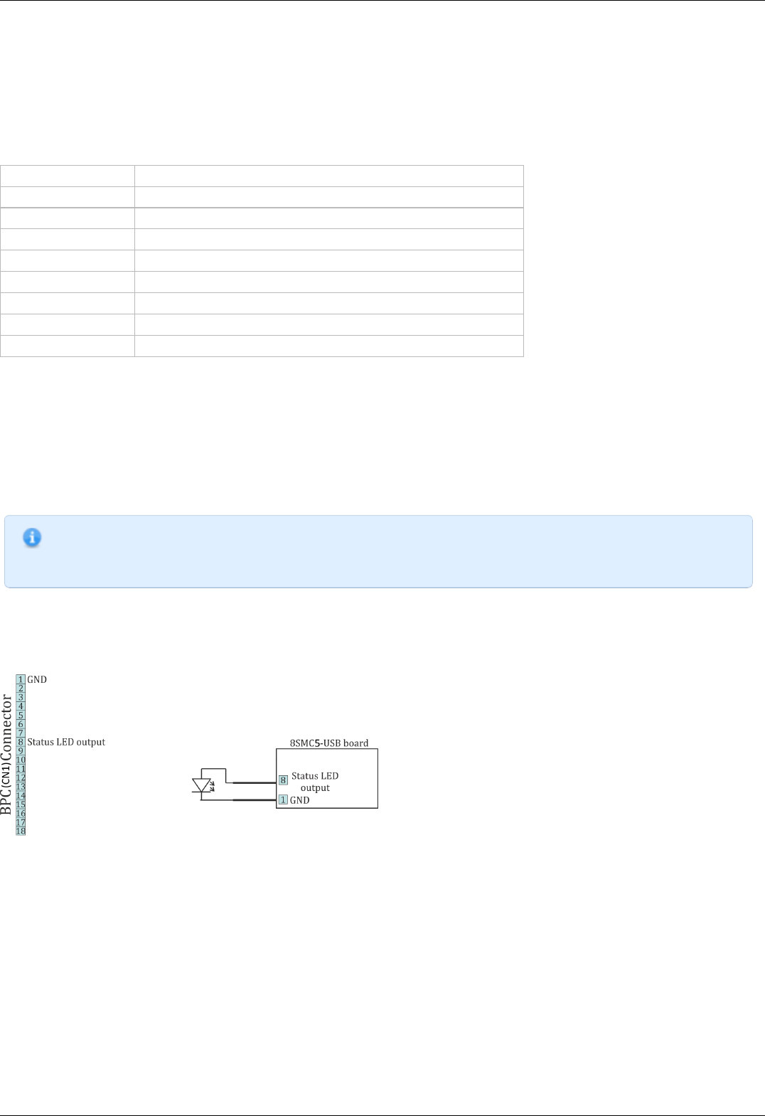
4.5.1. Operating modes indication
Controller status
Mode indication is provided in controller. For this purpose one dual-color LED is located on the board.
Green Power indicator shows presence of 3.3 V power supply of controller.
Red Status indicator represents controller operating mode.
Simultaneous glowing of both lights looks like yellow glow.
Flicker frequency Hz Description
Lights don’t glow the device is shut down, there is no power supply
LED is green the device is broken or the microprogram is not loaded
LED is yellow the device is in Alarm
0,25 the device is operating but there is no connection with USB from PC
1 the device is operating, the movement is stopped
4 the device is operating, with movement
8 the device is in re-flashing mode
10 the device is in USB bus reconnecting mode
Power/Status indicator operation modes
Indication of limit switches
Multifunctional 20 pin BPC connector is provided with limit switches activity indication. High logic level appears on the corresponding
output in the moment of limit switch activity. Active state is determined from limits switches settings (see Motion range and limit
switches)
Connection diagram
Note. In case of additional LEDs they should be designed for 4 mA operational current. There is no need in additional
current limiting resistors. Operational current for typical LEDs is about 2 mA. It is not recommended to use blue and
violet LEDs because of their high cut off voltage and as a consequence low brightness.
Controller board
Indicators Power and Status are duplicated by outputs on the multi functional 20 pin BPC connector with the next scheme of LEDs
connection:
Connection of Power и Status indicators to the controller board
Limit switches are located on the same connector. The connection diagram is shown below. To indicate the limit switches it is
convenient to use the LEDs designed for the necessary current.
Page 80 / 345
Page 80 / 345
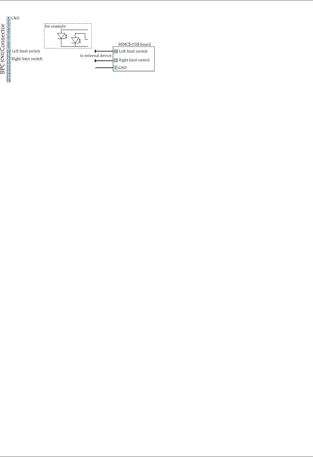
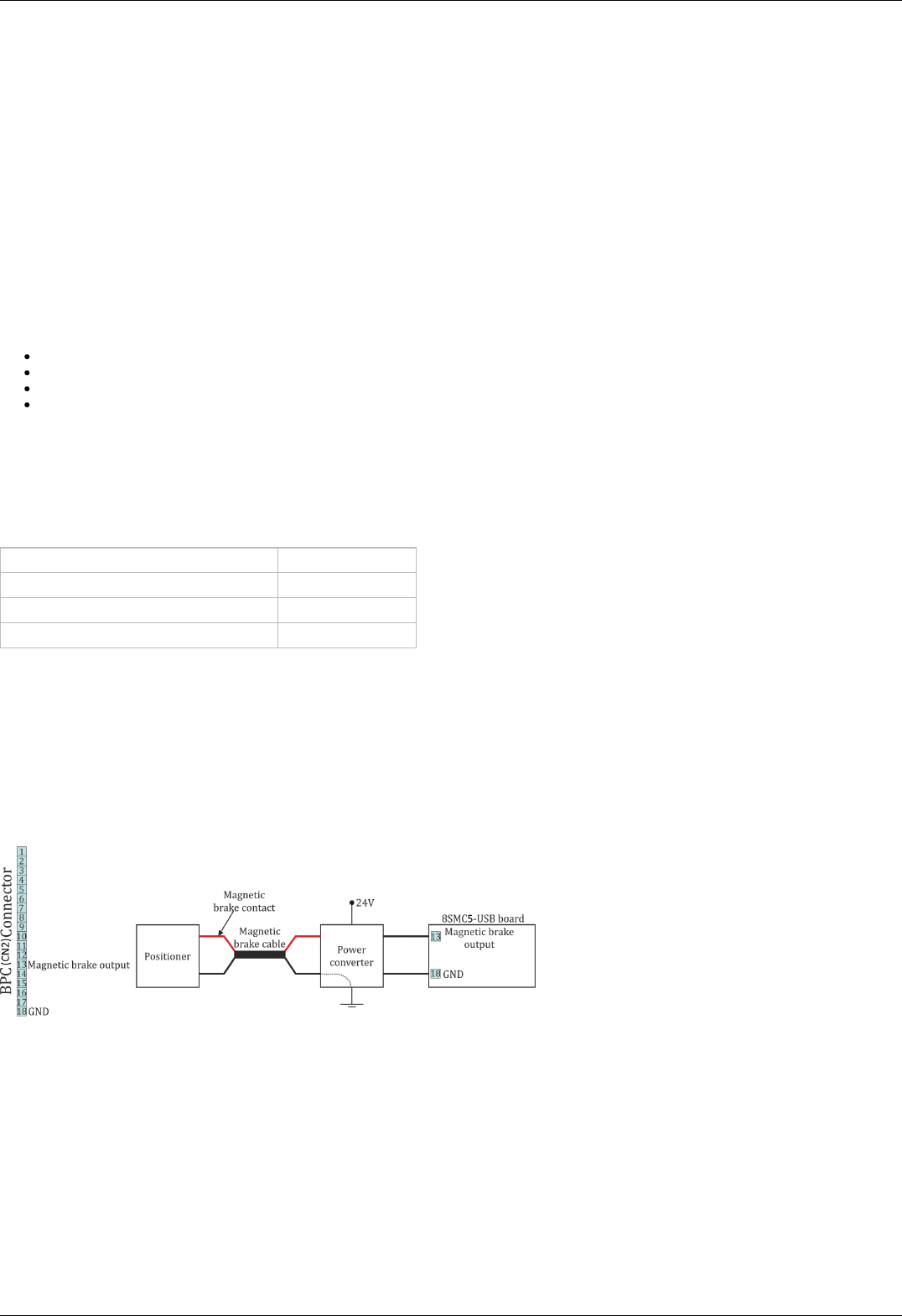
4.5.2. Operations with magnetic brake
There is an output pin on BPC connector for magnetic brake control, which is installed on the stepper motor shaft. Magnetic brake is
used hold motor position in unpowered state.
Description of operation
Magnetic brake consists of a magnet and a spring, which performs stops the motor shaft. In case there is no voltage applied to the
magnet the spring clamps the shaft in place which allows to keep motor position. When voltage is applied the spring releases the
shaft.
Controller operating sequence during stage shutdown.
Engine shutdown (the time of shutdown is recorded in controller) -> magnet power supply cut off, shaft fixation -> board power supply
cut off
During power-on the sequence is reversed.
Since any movement has inertia, the following parameters are set to control magnetic brake and the position fixation process:
Time between motor power-on and brake deactivation (ms)
Time between brake deactivation and readiness for movement (ms)
Time between engine stop and brake activation (ms)
Time between brake activation and power-off (ms)
If magnetic brake function is turned off then controller will constantly transmit brake release signal. This allows to move engine
equipped with magnetic brake without rotor fixation during pauses. If winding poweroff function is turned off then controller will only
pause between brake switching and movement start/stop.
All magnetic brake settings can be changed online and brake will be switched to the mode which would be active in case if the setting
would have a new value. For example a large increase of brake activation delay when the brake is already active will lead to brake
deactivation and countdown to the new delay value. It is also possible to turn on or off magnetic brake itself or winding power function.
Type TTL
Active condition ( brake is released) 0.3 V
Passive condition (brake is not powered) 0 V
Operational current no more than 4 mA
Output electric parameters
Magnetic brake setting in XIlab program is described in Brake settings section.
Connection diagram
For operation with the magnetic brake a special board controlled by digital signal is used. One-axis and two-axis systems, which
equipped with this board and able to work properly with magnetic brake are available separately (look below).
Controller board
A contact for the magnetic brake control is located on the BPC connector.
Connection of magnetic brake to the controller board
Power converter is a converter from digital signals to power. If magnetic brake output is high, the magnetic brake of stage has 24V on
its power input. If it is low, the magnetic brake has 0V on its power input. In the most common case a scheme with transistor and
diode is used. For more detailed information please contact us: 8SMC4@standa.lt.
One-axis and two-axis systems
In order to use magnetic brake check if your controller system is equipped with a special converter board. Models which meets this
demands can be identified by letters BR in its title, for example 8SMC5-USB-B8-1BR
Contact pin responsible for magnetic brake control in boxed versions of controller is located on the HDM26 26 pin connector. A
connection diagram is shown below. Two-axis systems are supplied with only one axis which compatible with magnetic brake.
Page 82 / 345
Page 82 / 345
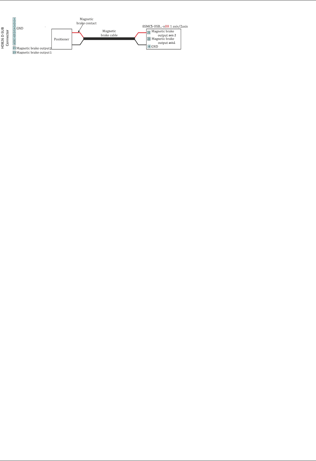
Connection of magnetic brake to one-axis or two-axis systems
Page 83 / 345
Page 83 / 345

4.5.3. Joystick control
General information
Controller accepts an input from an analog joystick with voltage in 0-3 V range. Voltage in the equilibrium (central) position and
voltage in minimum and maximum position can be set to any value from the working range, if the following condition holds: minimum
position < central position < maximum position. Controller uses digital representation of joystick input values: 0 V corresponds to a
value of 0 and 3 V corresponds to a value of 10000.
To stop movement in the central position a DeadZone option is available, which is counted from the central position and measured in
percent. Any joystick position inside deadzone leads to the stopping of the movement by the controller. A larger than deadzone
deviation of the stick starts controller movement with the speed which is calculated from the deviation. One can reverse the joystick
with a reverse flag which can be useful to keep "right joystick offset means movement to the right" correspondence for any physical
orientation of the joystick and the stage.
Movement speed has an exponential dependence on joystick deviation from the center. This enables one to reach high precision
through small joystick shifts and high speed through large ones. Nonlinearity parameter can be varied. If the nonlinearity parameter is
zero, then the motor speed will linearly depend on joystick position.
The following graph shows dependence of movement speed on joystick position for the following settings:
Central deviation 4500
Minimum deviation 500
Maximum deviation 9500
Dead zone 10%
Maximum movement speed 100
An example of motion speed dependence on joystick deviation.
Sometimes exponential joystick response which combines high accuracy and high speed is not enough. That's why controller supports
maximum speed table. User can switch between these speeds using "right"/"left" buttons. In case of right key press maximum speed is
changed from Max speed[i] to Max speed[i+1]. In case of left key press maximum speed is changed from Max speed[i+1] to Max
speed[i]. Controller starts with i=0. There are 10 values in the speed array. If both integer and fractional parts of Max speed[x] are
equal to zero then it isn't possible to switch to this speed from Max speed[x-1]. This is made so that a user can limit speed array size.
An attempt to get out of array bounds will also lead to nothing.
Controller has contact debouncing on control buttons. For keypress to register button press should last longer than 3 ms.
If joystick sits within dead zone for more than 5 seconds it will be logically considered to be out of deadzone only when it has been
physically out of deadzone for more than 100 ms. This allows user to release joystick and to be confident that even occasional noise on
joystick output won't lead to unnecessary motor motion. While joystick is within Dead zone the controller can receive any commands
from computer including motion commands, home position calibration commands, etc. If during command execution joystick is brought
o f Dead zone the motion command is canceled and motor is switched to joystick control. This allows the user to turn on joystick
control mode and use it only when necessary.
Everything that is related to movement under the control of controller commands is also applicable to joystick movement. This includes
acceleration, maximum speed limit, windings poweroff delay, magnetic brake, backlash compensation, etc. For example, if you
suddenly release joystick handle and let it return into the deadzone, then, if corresponding modes are on, controller will gradually slow
the motor, make a backlash compensation motion, stop the motor, fix the motor shaft with the magnetic brake, smoothly reduce
current and switch off windings power.
"Left"\"right" button connection is described in Left-right buttons control.
MaxSpeed[i] and DeadZone parameter change is described in Settings of external control devices.
Connection diagram
IMPORTANT. Analog inputs for joystick connection are designed for a range of 0-3V. Be careful and do not exceed
voltage for joystick contacts.
Controller board
A contact for joystick control is located on the BPC connector.
Page 84 / 345
Page 84 / 345
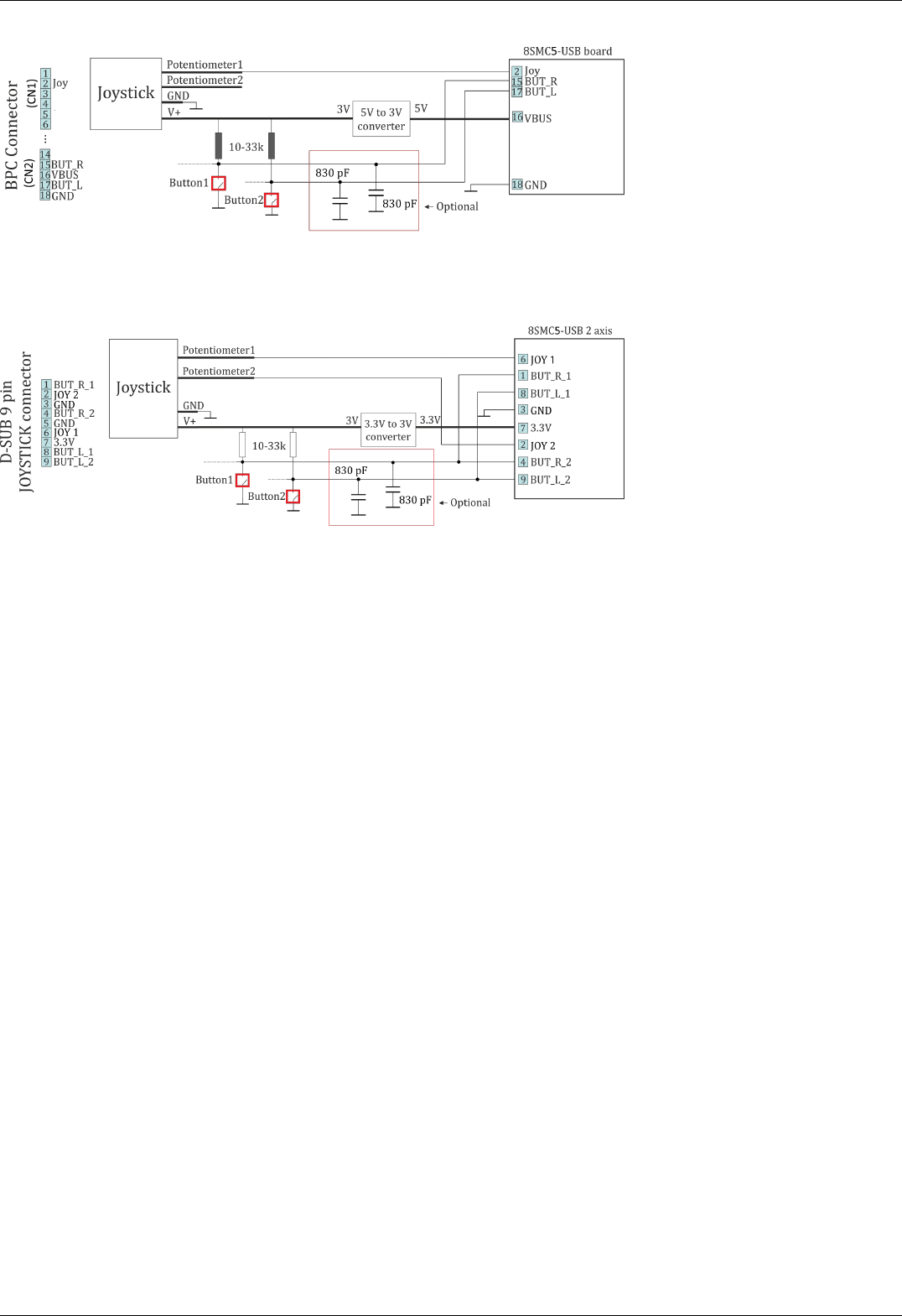
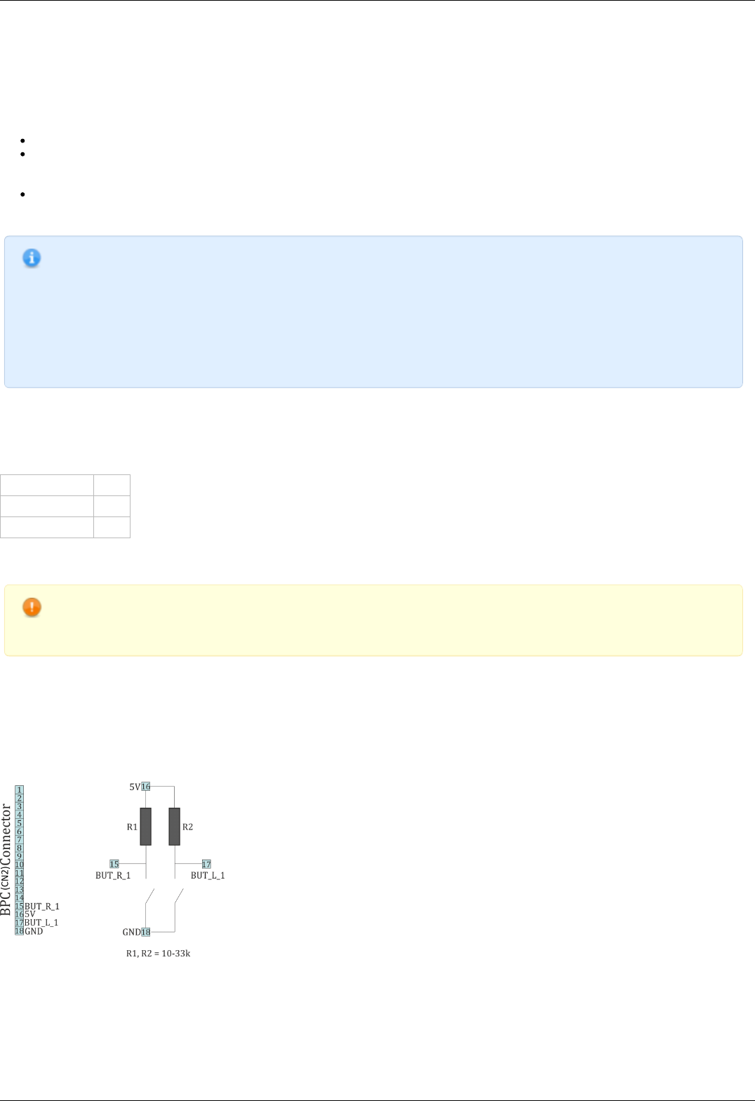
4.5.4. Left-Right buttons control
For each system it is possible to control the movement of a motor with the buttons. Active button state is programmable and can be
logical zero or one. Controller supports a 10-item speed array MaxSpeed[0-9], which is used both for joystick and button control.
The buttons control settings are red/written by commands SCTL/GCTL ( set_control_settings/get_control_settings).
If a left or right button is clicked then motor does a shift on an offset, specified by DeltaPosition and uDeltaPosition.
If a left or right button is pressed and held for longer than MaxClickTime, then motor starts moving with MaxSpeed[0] and
counting down to Timeout[0]. After Timeout[i] microseconds have elapsed speed is changed from MaxSpeed[i] to MaxSpeed[i+1]
for any i between 0 and 9 (inclusive).
If press the two buttons, the controller performs a stop with deceleration . Holding both buttons for 3 seconds starts the
automatic calibration of the "home" position.
Note: You can fill only the upper part of the 10-item speed array if you don't need all of them. Controller changes its
speed to the next one only if the target speed is not zero and the timeout is not zero. For example, if MaxSpeed [0]
and MaxSpeed[1] are nonzero and MaxSpeed[2] is zero (both step and microstep part), then the controller will start
moving with MaxSpeed[0], then change its speed to MaxSpeed[1] after Timeout[0] and will keep moving with
MaxSpeed[1] until the button is released. You can also set Timeout[1] to zero and leave MaxSpeed[2] set to any
value to achieve the same result.
Controller obeys its movement settings (with the exception of target speed). For example, when changing its speed
from MaxSpeed[i] to MaxSpeed[i+i] controller will either accelerate with set acceleration value or change its speed
instantly if acceleration is disabled.
The default state is set according to the voltage levels of the buttons table 4.5.4.1. The state of each button can be software inverted.
When active, the button is considered to be down. It does not matter how the condition is active (after changing the invert states, or
when changing the voltage level at the physical impact of a button). The controller uses button contact debouncing. The button is
considered pressed if active state lasts for longer than 3 ms.
Type TTL
Logic zero level 0 V
Logic one level 3.3 V
Table 4.5.4.1 - Output parameters
WARNING. When you turn on or reboot the controller at the input voltage level of the button is present, which is
considered to be active, the controller will accept it as a button is pressed, and begin to obey the rules described
above.
Connection diagram
Controller board
"Right" and "Left" control buttons can be connected to the controller board via BPC connector for a motor motion control. There are no
integrated pull-down resistors for setting of input potential by default, that’s why it is necessary to use (pull up) and (pull down)
resistors scheme.
Scheme of buttons connection to the BPC connector
One-axis and two-axis systems
For controllers in case user buttons already placed on the front panel. However it is possible to connect custom buttons to the
corresponding contacts that located on the D-SUB 9 pin connector and available only in two-axis system. Connection diagram is shown
below.
Page 86 / 345
Page 86 / 345

Scheme of buttons connection to the HDB-26 connector
Page 87 / 345
Page 87 / 345
4.5.5. TTL synchronization
Principle of operation
TTL-synchronization is used to synchronize controller motion with external devices and/or events. For example, the controller can
output synchronization pulse each time it moves a certain distance. Vice versa, controller can shift a certain distance on incoming
synchronization pulse, for example from an experimental setup which is ready to move to the next measurement position.
To use mechanical contacts as an input synchronization signal a contact debouncing is provided. One can set minimum input pulse
length which is recognized as a valid synchronization signal. An active state is a logical one (see table 4.5.5.1), and a raising edge is
considered to be the start of a signal. However, if for some reason this is undesirable, both options may be inverted independently.
Type TTL
Logic zero level 0 V
Logic one level 3.3 V
Table 4.5.5.1 - Input parameters
Pulse time Pulse time
Inversion of input and output syncronization pulse illustrated
Note. If simultaneous start of several controllers in a multiaxis system is desirable, minimum input pulse length should
be the same for all controllers. Contact debouncing should not be used in systems with no mechanical contacts and
short noise pulses in synchronization input channel. One should use an RC-circuit which would filter these noise
pulses instead.
Synchronization in important in multiaxis systems because it allows one to start movement on several axes simultaneously. To do this
all axes are prepared to start the movement, all slave axes are set to start moving on input synchronization pulse, one master axis is
set to output a synchronization pulse on the start of the movement. Master axis output is connected to slave axes' input. In this setup
any movement of the master axis leads to immediate response of all connected axes.
Note. One should set minimum input sync pulse length to 0 if this kind of connection is used. This disables contact
debouncing, but since there are no mechanical contacts it is not needed. If minimum input sync pulse length is not
zero then to avoid desynchronization of master and slave axes one should set input sync pulse length the same for all
controllers, connect syncout to both master and slave inputs and issue start command by activating input manually.
Synchronization input and output are independent from each other and other means of motion control. Control through XiLab
application or any other user application, joystick control and left-right buttons control are independent of input/output synchronization
state. Last command always takes priority. For example, a movement command sent from XiLab will cancel current movement which
happened because of input sync pulse, but will not affect output sync state. Next input sync pulse will cancel current movement
initiated by user program and will replace it with movement command according to sync in settings.
Page 88 / 345
Page 88 / 345
Note. Sync in settings may be saved in controller flash (non-volatile) memory. In this case everything related to
synchronization may also be said about autonomous controller operation. For example, you may set up shift on offset
on syncin pulse with syncout pulse on movement stop and connect the controller to a standalone measurement
device, which starts measurements on its own input sync pulse and outputs a sync pulse on measurement end. Then
you can run such a system without a PC, because after the first sync pulse all measurements and movements will
happen automatically.
Connection
The controller is supplied with two TTL-sync channels on the BPC connector.
Sync in
Syncronization input has a setting, which defines minimum syncin pulse length which may be registered. This length is measured in
microseconds. Use this setting to decrease controller sensitivity to noise. Synchronization input may be turned on or off. If it is on, then
a sync in pulse will lead to a situation as if Predefined displacement mode command has taken place, which takes its Position and
Speed from syncin settings. If syncin settings are changed during the time the movement takes place it will not change current
movement parameters. Movement parameters will change on the next front on syncronization input. This designed deliberately to
allow one to set up next shift parameters in multiaxis systems during movement.
WARNING. When you turn on or reboot the controller at the input voltage level of the synchronize input is present,
which is considered to be active, the controller interprets it as if Predefined displacement mode command has taken
place.
Note. Position and Speed are two separate variables which also may be saved in non-volatilve controller memory.
They are used only with synchronization input.
Note. Syncin movement obeys acceleration, max speed settings and all other settings which are related to motion.
Their incorrect setting may disrupt coordinated movement in multiaxis system.
Pulse time
Clutter time Motion starts
Motion stops
Moving time
Movement starts becase input pulse is longer than debounce time
Page 89 / 345
Page 89 / 345
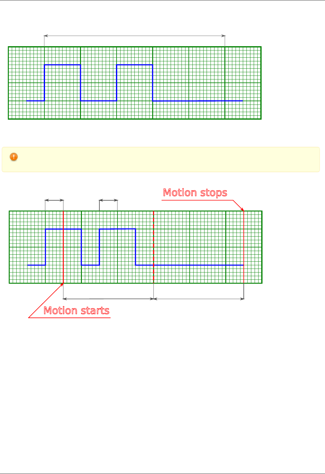
Clutter time
Movement does not start because input pulses are shorter than debounce time
Warning. If a second syncin pulse is received while controller is still moving then the end position will be offset by
two times the shift distance from the start, if a third pulse is received, then by three times, etc.
Clutter time Clutter time
Moving time Moving time
Motion starts
Motion stops
One-time movement with double shift length because second syncin pulse came in before the end of the movement
Page 90 / 345
Page 90 / 345
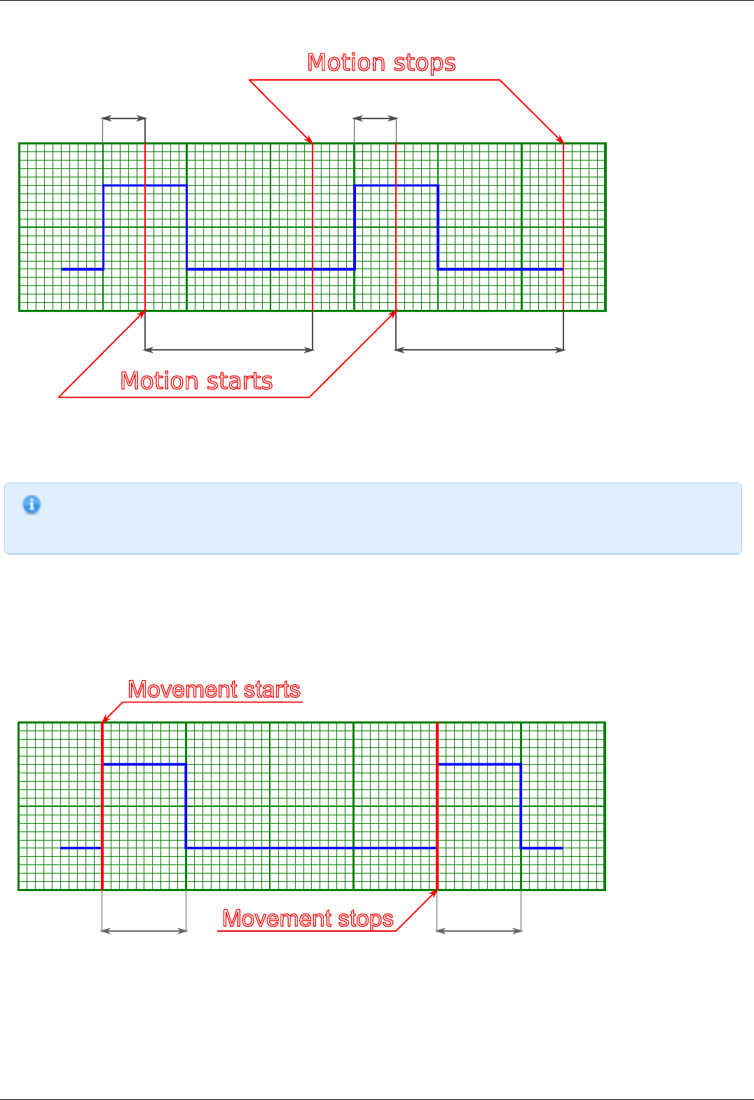
Clutter time Clutter time
Moving time Moving time
Motion starts
Motion stops
Two separate shifts with two start and two stop phases
Default setting is active state is one, movement on raising edge. Synchronization input may be inverted to the active state is zero,
movement on trailing edge.
Note. Inverted synchronization input setting will lead to the change in the definition of active/inactive state which may
be seen, for example, in controller status. However, programmatical inversion of the syncin state by itself will not lead
to the start of the movement, even if the transition happened into the active state.
Sync out
Output synchronization is used to control external devices tied to controller movement events. Sync out pulse can be emitted on start
and/or stop of the movement, and/or on each shift on the preset distance. ImpulseTime setting defines the length of sync pulse, either
in microseconds or in distance units. Synchronization output can be switched into general purpose digital output mode. In this mode it
is possible to set zero/one output logic level programmatically.
Movement starts
Movement stops
Pulse time Pulse time
Sync out pulses generated on start and stop of the movement (fixed length pulse)
Page 91 / 345
Page 91 / 345

Note. If syncout pulse length is measured in distance units and, for example, is equal to 10 stepper motor steps and
"syncout pulse on stop" mode is active, then the active state on synchronization output will be set on the movement
end, but will be cleared only when the motor will move 10 more steps during the next movement.
Movement starts
Movement stops
Pulse time Pulse time
Syncout pulses generated on start and stop of the movement (pulse is measured in distance units)
Note. If you wish to reconfigure synchronization output and are not sure which state is it in, change its state to
general purpose output and set the desired logic level.
Motion starts
Motion stops
Sync out pulses on movement with acceleration and "generate on shift" mode (pulse length measured in distance units)
Sync out pulses on movement with acceleration and "generate on shift" mode (pulse length measured in microseconds)
Note. Periodic syncout pulse generation imitates revolution sensor with reducing gear. Coordinates which trigger
syncout pulse generation are counted from zero position and not from the position the controller is in at the start of
the movement. For example, if synchronization output is set up to generate pulses every 1000 steps then pulses will
be generated in positions 0, 1000, 2000, 3000, etc. Pulse generation works when moving in both directions. Pulse is
generated when the quotient of current coordinate and pulse generation period changes. That is, pulse is generated
when position 1000 is reached when moving in the direction of increasing position and it is generated when position
1000 is left when moving in the direction of decreasing position. Also, syncout pulse is always generated when
position 0 is reached from any direction (including the case when position is reset by the ZERO button).
Page 92 / 345
Page 92 / 345
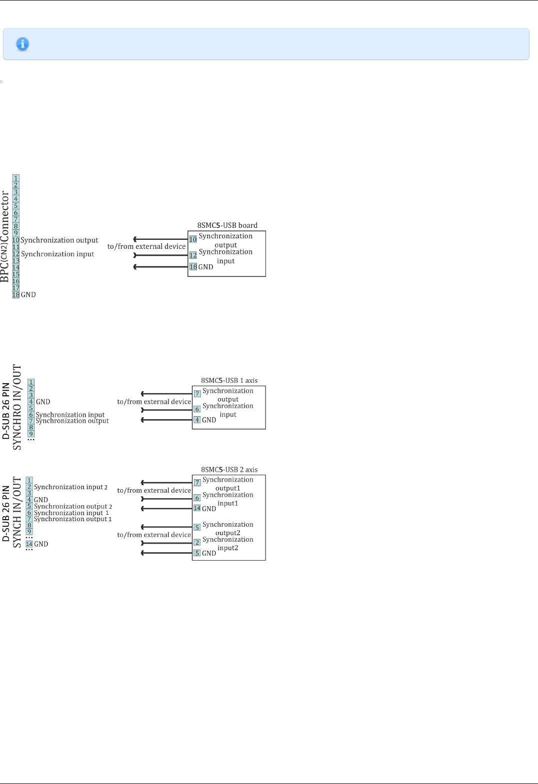
Note. Whenever syncout pulses overlap they are merged into one pulse.
_Syncout pulse merge illustrated, pulse generation on start, stop and shift on offset (pulse length measured in microseconds)
Synchronization settings setup in XiLab is described in Synchronization settings section.
Connection diagram
Controller board
Controller board contains two TTL-channels of synchronization on the BPC connector.
Scheme of connection to the synchronization channels for the controller board
One-axis and two-axis systems
Synchronization signals on the one-axis and two-axis systems are located on the HDB-26 connector.
Scheme of connection to the synchronization channels for the one-axis system
Scheme of connection to the synchronization channels for the two-axis system
Page 93 / 345
Page 93 / 345
4.5.6. Multiaxis system design
Controller axes in multiaxis systems are identified by the controller serial number. Each controller has its own unique serial number,
which may be seen in XiLab software on About controller page. One can read controller serial number using get_serial_number function
(see Programming guide).
Multiaxis systems based on this controller are assembled using an active backplane based on a USB-hub or an external USB-hub.
For proper multiaxis system functioning one should first connect all controllers to the power and USB connectors (place controllers on
the backplane).
Then, in any order, do all of the following:
Connect power to the backplane
Connect external devices
Connect master controller to the USB
Note. Additional 5 V power supply requirements: output current no less than 250 mA per axis, 400 mA per axis for full
functionality.
Multiaxis connection diagram implies connecting power supply to pins 1 and 2 of the BPC connector and connecting data lines D-/D+
from the USB hub to pins 15 and 17 of the BPC connector.
Power is connected next:
1
2
Controller
№
1
PSC
PS-
PS+
3
PS-
4
PS+
1
2
Power
Supply
24
V-36V
PS-
PS+
1
2
Controller
№
2
PSC
PS-
PS+
3
PS-
4
PS+
1
2
Controller
№
N
PSC
PS-
PS+
3
PS-
4
PS+
.
.
.
.
.
Controller connection diagram in multiaxis configuration
PSC - Power Supply Connector, used to connect power supply to the controller
BPC - Back Panel Connector, used to connect accessories to the controller
Page 94 / 345
Page 94 / 345
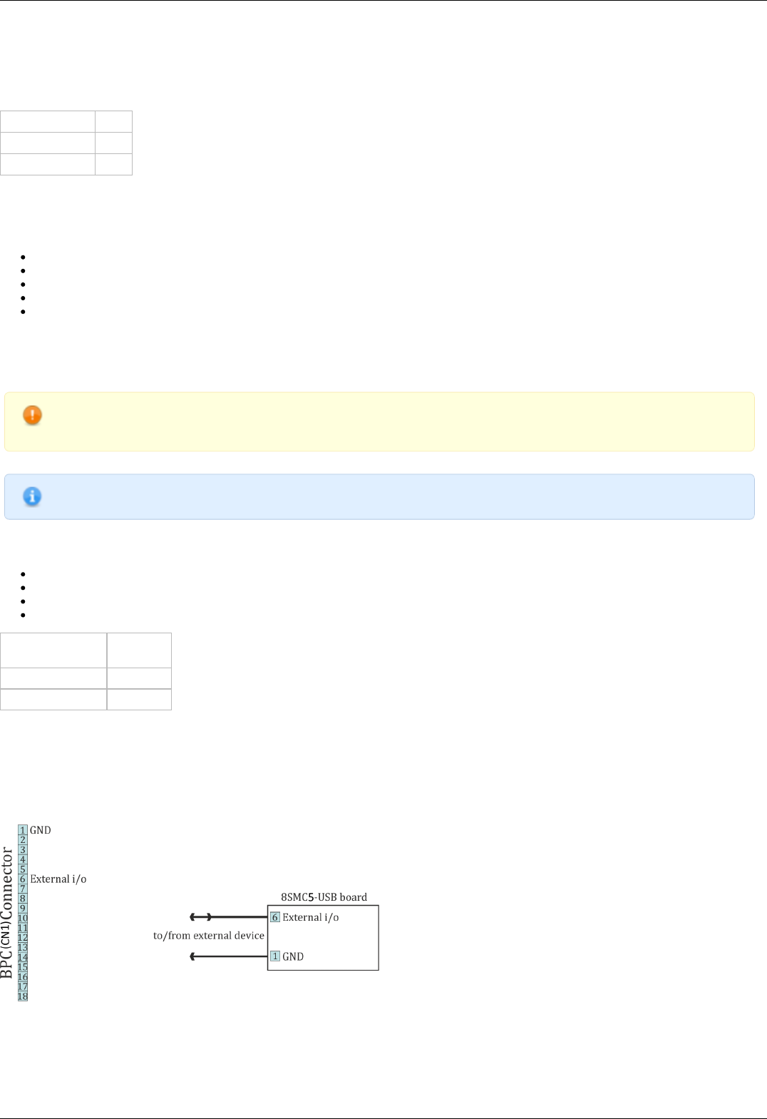
4.5.7. General purpose digital input-output
Output is located on BPC connector. It allows user to configure it as input or output. Logical level one is considered to be active.
However it can be inverted so that logical level zero is considered active.
Type TTL
Logic zero level 0 V
Logic one level 3.3 V
Table 4.5.4.1 - Input parameters
In input mode you can get information about logical level on input (see Controller status), or initiate the following actions during
transfer to active state (or during transfer to non-active state if the input is inverted):
Perform STOP command (quick stop).
Perform PWOF command (windings power supply switch off).
Perform MOVR command (shift to the given distance with last used settings).
Perform HOME command (automatic position calibration).
Enter Alarm state (turn off H-bridges and wait reinitialization).
It does not matter how the state of the input becomes active (after changing the invert states, or when changing the voltage level).
The controller uses a software debounce the input. Initiating the action takes place only when the active state of the input buttons
lasted for more than 3 ms.
WARNING. When you turn on or reboot the controller at the input voltage level of the input is present, which is
considered to be active, the controller interprets it as a signal to trigger any of the actions.
Note. Digital input has weak pull down to the ground.
In output mode it is possible to set active or inactive logic level on the following events:
EXTIO_SETUP_MODE_OUT_MOVING – Active state during motor movement.
EXTIO_SETUP_MODE_OUT_ALARM – Active state when controller is in Alarm state.
EXTIO_SETUP_MODE_OUT_MOTOR_ON – Active state while power is supplied to the motor windings.
EXTIO_SETUP_MODE_OUT_MOTOR_FOUND – Active state while motor is connected.
Logic type TTL 3.3
V
Update frequency 1 kHz
Nominal current 5 mA
Table 4.5.7.2 - Output technical characteristic
Connection diagram
Controller board
Digital output is located on the BPC connector
Scheme of connection to digital input/output for the controller board
One-axis and two-axis systems
Page 95 / 345
Page 95 / 345
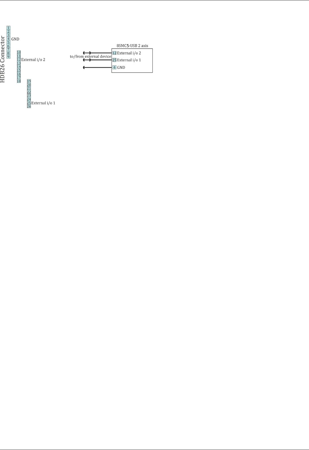
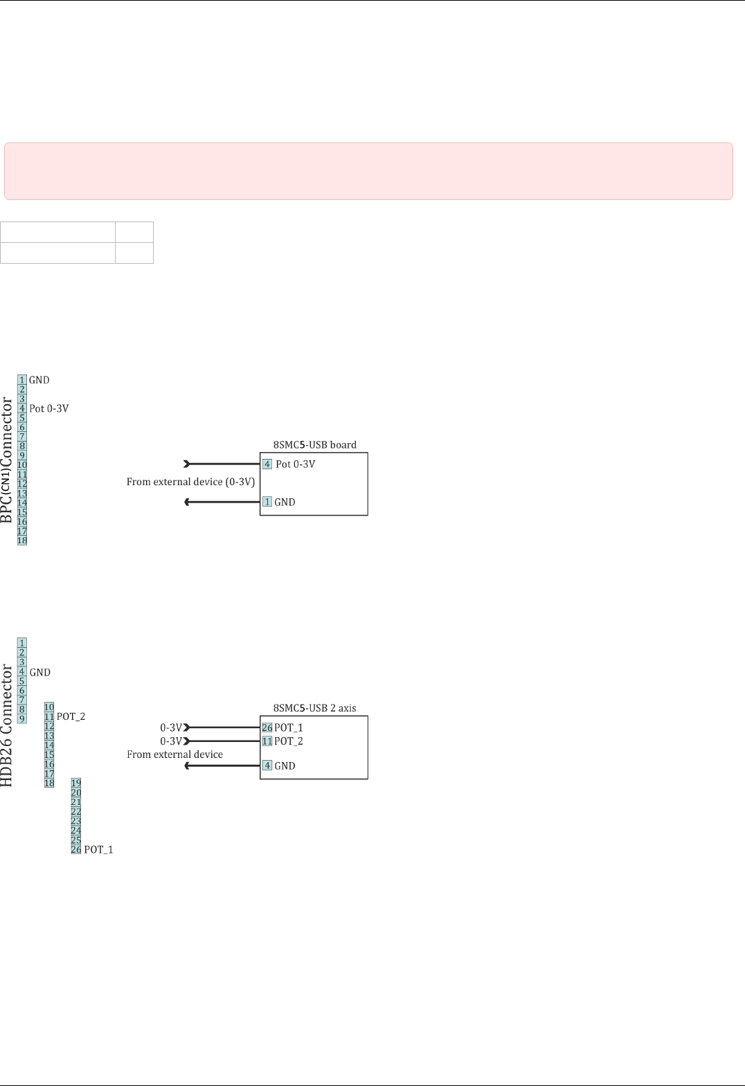
4.5.8. General purpose analog input
Analog input may be used for other purpose. For example, it can be used to measure any external signal. Value at the analog input
may be read by the GETC command and is visible in the XiLab charts.
This controller represents analog input values as a number in 0..10000 range. Analog input pin is located on BPC connector.
IMPORTANT. Analog input voltage should not go outside of 0-3 V range. If this voltage is exceeded errors in analog
input and other controller subsystems are possible! This may also damage the controller or connected motor.
Signal voltage 0-3 V
Scanning frequency 1 kHz
Table. Input parameters.
Connection diagram
Controller board
For the controller board analog input contact is located on the BPC connector.
Scheme of connection to analog input for the controller board
One-axis and two-axis systems
Only two-axis system has general purpose analog input on supplementary HDB-26 connector.
Scheme of connection to analog input for the two-axis system
Page 97 / 345
Page 97 / 345
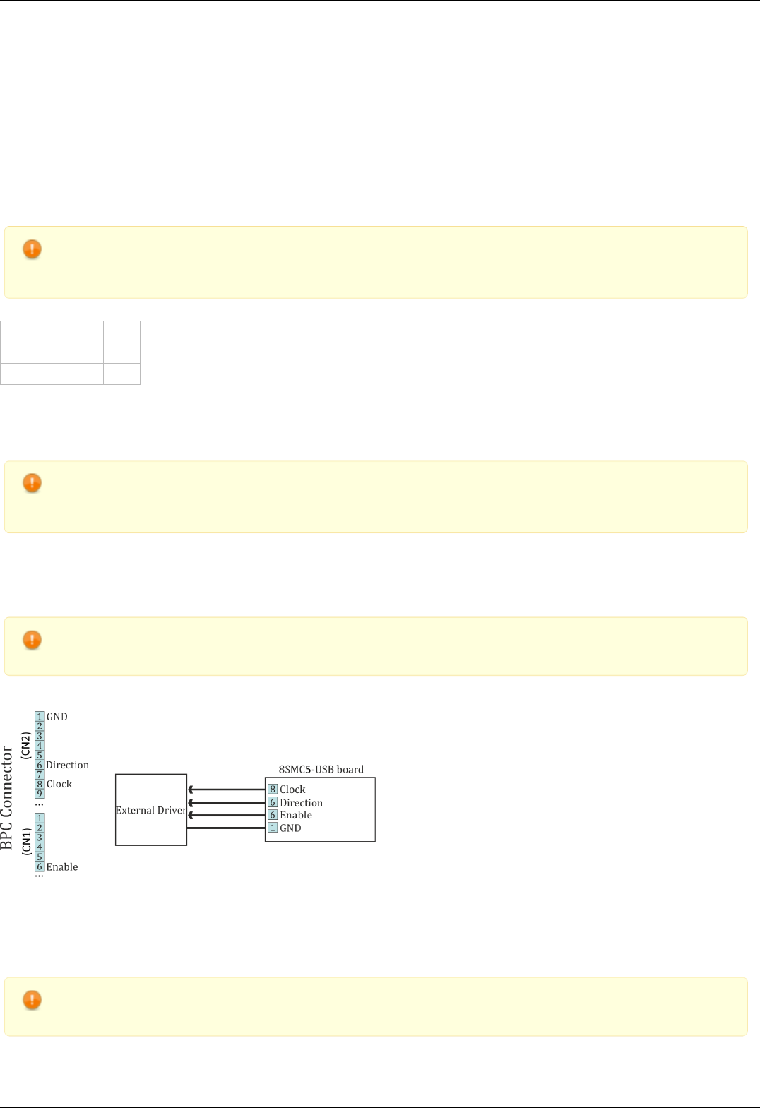
4.5.9. External driver control interface
Interface allows to control any external driver with a help of 3 standard signals: enable, direction, clock. This mode is convenient when
controller power capability is not enough but it is desirable to use its capabilities such as limit switches, revolution sensor, position
control, scripting language, multiaxis systems, joystick/button control, magnetic brake, etc. For example, for creation of multiaxis
system with one powerful lifting axis which is controlled by external controller and two less powerful horizontal axes, you can use XiLab
with 3-axis interface and its scripts and also synchronize the motion of all three axes. I.e. external driver replaces only power part of
the controller.
Clock signal defines the quantity of signals in the given Direction (logical one to the right, logical zero to the left). Displacement is a
minimum step in the current settings of step division. For step division 1/32 there will be 32 impulses per one step. Don’t forget to set
external driver in such a way that it would use the same step division.
WARNING. Clock signal frequency in the given controller is limited by 78 kHz. That's why to reach necessary speed
one might need to reduce step division. Foe example, if rotation speed of 4000 steps per seconds is needed it is
necessary to use 1/8 step division or less.
Type TTL
Logical zero level 0 V
Logical one level 3.3 V
Output parameters of external driver control
Connection diagram
WARNING. Outputs for external driver control are not sufficiently protected and can be damaged in case of incorrect
usage. Proper connection and necessary electric protections are a responsibility of an engineer who designs drivers'
connection system.
Controller board
For external driver connection three outputs in BPC connector are used.
WARNING. Pin 13 is the general purpose input/output (see General purpose digital input-output 8SMC5 ), but it loses
its functionality when external driver control is enabled.
Scheme of connection to the external driver for the controller board
One-axis and two-axis systems
Only two-axis system has the external driver interface. It outputs on the HDB-26 connector.
WARNING. Pins 12 and 25 are general purpose inputs/outputs (see General purpose digital input-output 8SMC5 ),
but they loses functionality when external driver control is enabled.
Page 98 / 345
Page 98 / 345

Page 99 / 345
Page 99 / 345
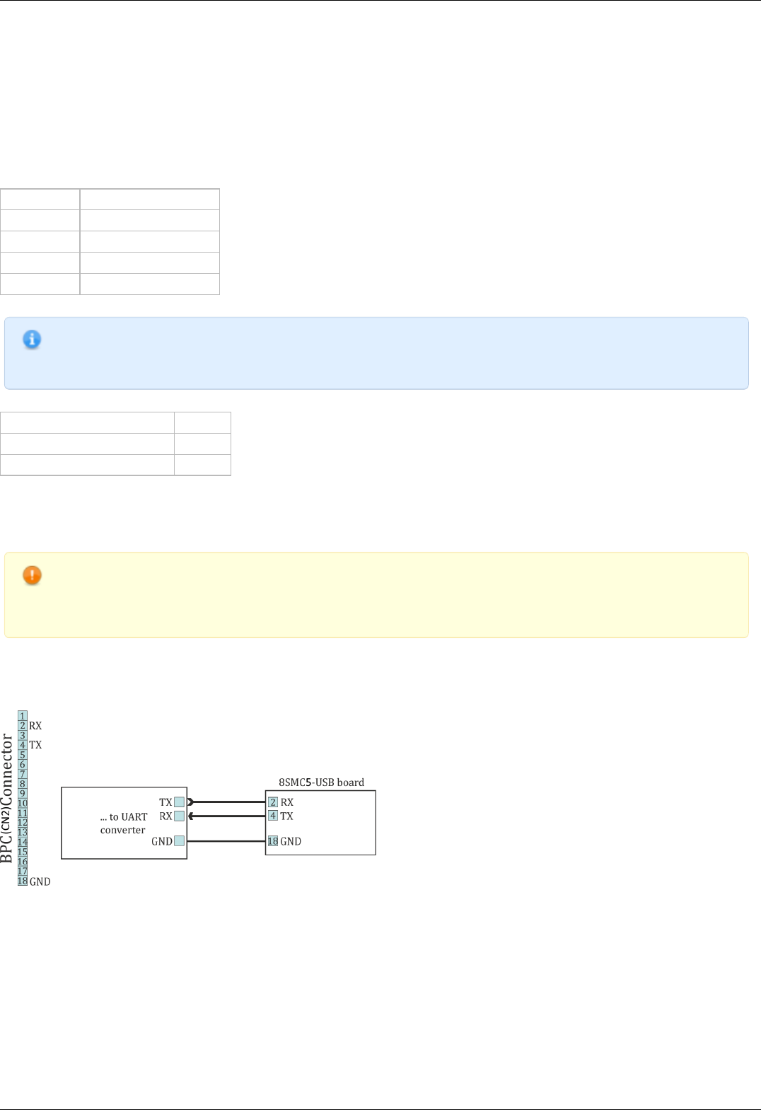
4.5.10. Serial port
Controller allows control through UART serial port with TTL 3.3 V logic. UART outputs are located on BPC connector. Because of
widespread availability of UART and adapters to USB, Bluetooth, Ethernet and other standard interfaces there is an option for wireless
control (Bluetooth) or control over the internet (Ethernet). UART data protocol is the same as USB data protocol. I.e. it is enough to
enable nonstandard serial port polling in XiLab or in libximc and the device will be found if response delay doesn't exceed two seconds.
It is also possible to control controller with the help of other independently programmed micro-controller, however in this case it will be
required to support controller communication protocol.
UART supports the following settings.
Transfer rate 9600-921600 bit/sec
Data bits 8
Parity enabled or disabled
Parity type even, odd, space, mark
Stop bits 1 or 2
Note. To connect to the controller via UART one should first connect to it via USB and set required speed, parity and
stop bits and then save settings to non-volatile memory. Standard settings are listed in Communication protocol
specification, use them if you cannot connect.
Logic type TTL 3.3V
Maximum data transfer speed 921 kbit
Nominal output current 5 mA
Output and input parameters
Connection diagram
WARNING. High data transfer speeds through long cables in case of electromagnetic interference are impossible. If
transfer errors do occur, use RC filtering circuits and reduce transfer speeds so that characteristic time of an RC-
circuit is at least 4 times less than time needed to transfer a single bit. RC-circuit characteristic time is chosen based
on the circumstances.
Controller board
For the controller board UART outputs are located on the BPC connector.
Recommended scheme of connection to serial port pins for the controller board
One-axis and two-axis systems
Two-axis and one-axis system has UART outputs. Corresponding contacts for each axis output on the HDB-26 connector .
Page 100 / 345
Page 100 / 345
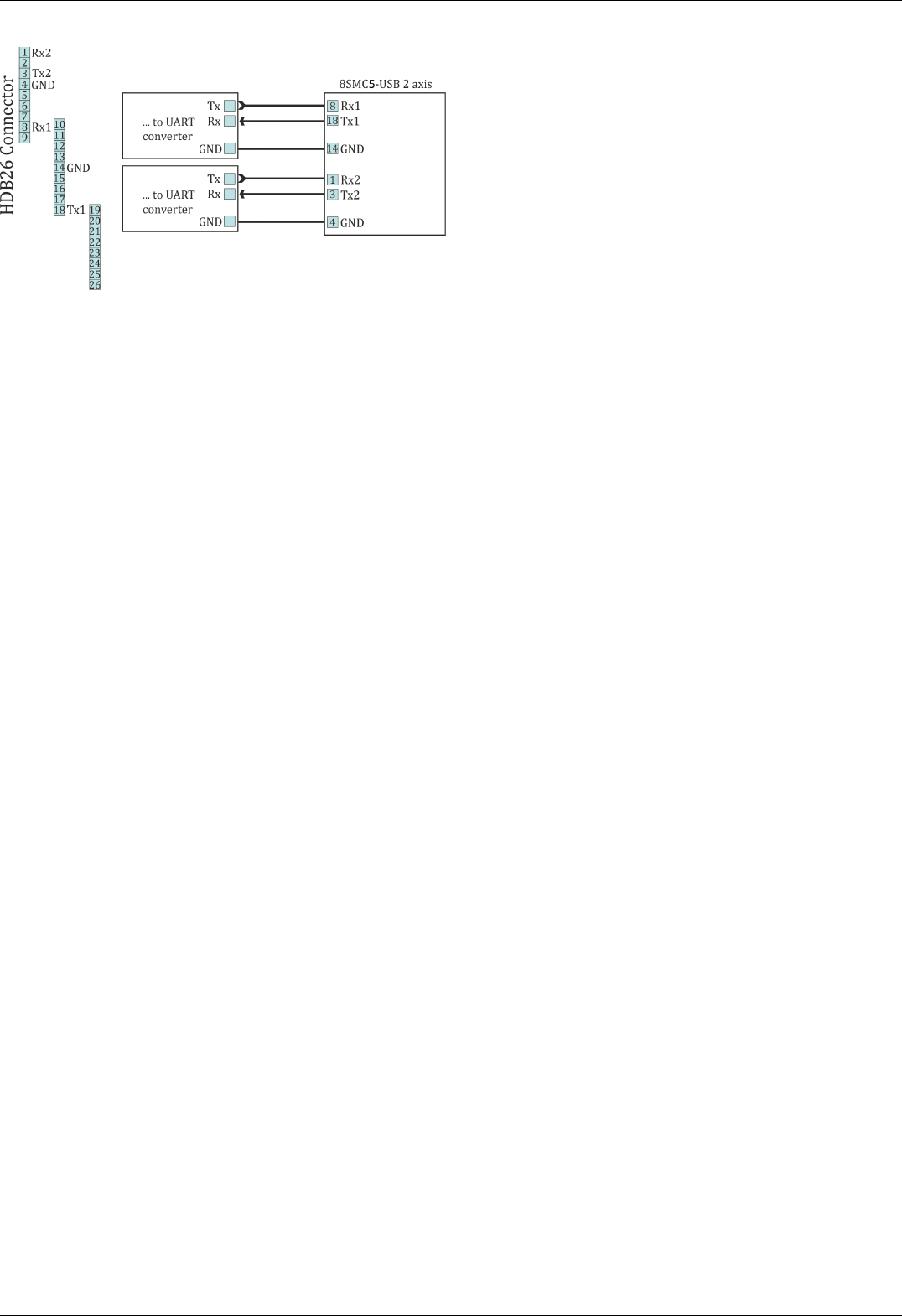
Recommended scheme of connection to serial port pins for two-axis system
Page 101 / 345
Page 101 / 345

4.5.11. Saving the position in controller's FRAM memory
Controller has a function which automatically remembers its last position. This allows one to power-off the controller after it has
stopped. On the next power-on the controller will appear in the same motor position, logical position and encoder value. This will work
if during the time controller was off the motor shaft was not rotated by external means.
Note. For this function to work one should wait at least 0.5 seconds after the stop before cutting the power. Position is
saved even if the controller was powered off during movement, however in this case its saved position will not be
exact and a new calibration will be needed.
Page 102 / 345
Page 102 / 345
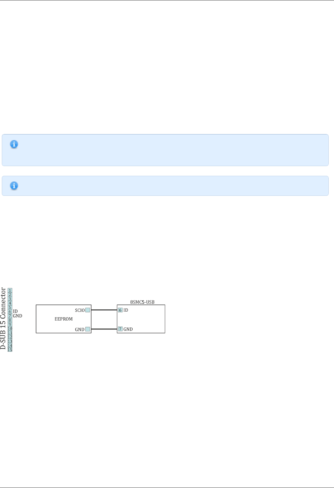
4.5.12. The Standa stages detection
Newest Standa positioners (please check with the manufacturer for the list of exact models) have an option to store settings and
informational parameters in the internal positioner memory. This chip is flashed with correct settings, which allows one to skip optimal
positioner configuration and to start working with the positioner right out of the box. This memory chip also holds user-defined
positioner name (see XiLab tab Positioner name).
When this kind of positioner is connected to the controller (for more information about electrical connection please see example of
motor connection and positioner connector) informational parameters are automatically loaded into the controller memory, see
Positioner specifications. If the EEPROM_PRECEDENCE flag was set, which indicates precedence of settings read from external memory
over the settings saved in the controller flash memory (see About controller), then all controller settings except UART settings and
controller name are also read and applied.
If the EEPROM_PRECEDENCE flag is set then you don't need to check and/or set positioner settings (for example limit switches
orientation and position, nominal current, encoder and magnetic brake parameters, etc). All of this will be done automatically when a
positioner with internal memory chip is connected. However, if this flag is set then settings from positioner memory will be loaded
every time a positioner with memory chip is connected and every time the controller is powered on. That is why if you need to change
some settings you need to clear this flag, change required settings and save them to controller flash memory.
Note. There is a simple rule for this flag preferred state: This flag should be true on early stages of work to embrace
the simplicity of automatic settings. Later, as soon as the will be need for fine tuning the settings, this flag should be
set to false, not forgetting to save this to FRAM.
Note. If a positioner with internal memory is disconnected from the controller no settings are changed.
For developers
Positioner data is stored in DS28EC20 chip connected by 1-wire interface.
Controller periodically sends reset signal to the EEPROM chip during positioner detection. If a response is received, then controller
reads data from the positioner into RAM, applies settings and sets STATE_EEPROM_CONNECTED bit in status structure. In XiLab this is
shown by EEPR indicator in the main window. The EEPROM is then regularly polled. In case connection with EEPROM is lost (no
response to the reset signal) EEPR XiLab indicator is cleared.
Connection diagram
Outputs for connection to the memory chip are located on the D-SUP 15 pin connector for all systems ( controller board, one-axis and
two-axis in box.
Connection diagram for external memory test
Page 103 / 345
Page 103 / 345


4.6.1. Zero position adjustment
Controller supports setting of zero position. This function should be used for anchor marked stages, so that anchor position matches
logical zero. Also, this function is convenient to use in case there is a single chosen physical position.
To set zero position a special command is used. This will zero step/microstep position and encoder count values. Setting of zero
position happens simultaneously for all position counters and will not lead to their desynchronization. Current movement command is
not affected. If controller was moving to some physical position when logical position was reset to zero by this command then the
movement will still end in that physical position. For example, if the controller moved towards logical position 1000 and set zero
position command was sent when it was passing 200, then logical position counter will be decremented by 200 and movement will end
in logical position 800.
Note. Setting of zero position when using shift on offset (see Predefined displacement mode) will not change target
physical position. Next shift will happen towards the same physical position which would have happened without zero
position command.
Page 105 / 345
Page 105 / 345

4.6.2. User-defined position adjustment
A SPOS command can be used if it is necessary to set position and/or encoder value to some user-defined position instead of zero.
New step/microstep position and encoder count values are passed as parameters to this command. If only one of these counters is
needed one should use ignore flags to filter required fields.
This command is different from set zero command in that it doesn't set target position used by MOVE and MOVR commands to zero.
During movement and stopping its behavior is the same. If you issue SPOS command during movement the controller will end in the
same physical position it would move to if this command was not sent.
Page 106 / 345
Page 106 / 345

4.6.3. Controller status
Controller tracks its own status and can transfer it in the status structure of the GETS command. Controller status contains information
about performed movement, its result, state of power supply, state of encoder, state of motor windings, digital input-output states,
numeric information about position and powering voltage and currents and also error flags.
Movement status
MoveSts contains:
Movement flag which is set when controller changes motor position.
"Target speed reached" flag which is set if current speed is equal to the speed controller should be moving with.
Backlash compensation flag, which is set during backlash compensation in the final stage of the movement (see Backlash
compensation).
MvCmdSts contains information about the command being executed. All motor movements are initiated by movement commands to
the MOVE target position, MOVR shift relative to the last target position, RIGT movement to the right, LEFT movement to the left,
smooth stop SSTP or fast stop STOP, HOME home position calibration and LOFT forced backlash compensation. Control by buttons,
joystick, sync in pulses, etc. is also performed by these commands. For example, joystick calls right and left movement commands
during deflection or smooth stop command in central position (see Joystick control). Current movement command or last command
and command status (running/completed) are located in MvCmdSts variable. If the command is completed then another bit shows its
result (successful or not). Unsuccessfully completed command means controller could not reach desired position or backlash
compensation could not be performed. The reason for this can be a sudden stop due to limit switches or Alarm state. Initial state of
this field contains unknown command and successful completion status.
Motor power supply status
PWRSts contains information about supply voltage. Windings' status can be:
Disabled (in this case no voltage is applied).
Powered by reduced current relative to nominal current (for example if winding current reduction option is used).
Powered by nominal current.
Powered by an voltage insufficient to reach nominal current in the windings.
Last status frequently appears with high rotation speeds, because for higher step switching speed one needs higher voltage to ensure
current rise in motor winding inductance. Insufficient voltage does not mean the motor won't move, it will merely emit excess noise
and its torque will drop (see Power control).
Encoder status
EncSts contains information about connected encoder if feedback is disabled (for example for stepper motors). Encoder state can be
one of the following:
Not connected
Unknown state, when there is not enough data to define encoder state.
Connected and working.
Connected and reversed, in this case it is necessary to enable reverse in encoder settings.
Connected and defective.
The last state is realized when switch signals come to encoder inputs but they don't correspond to the motor rotor movement. State
change happens after sufficient statistical data is collected. That's why detection doesn't happen immediately. It is also impossible to
define encoder status without movement (see Operation with encoders).
Motor windings status
WindSts contains information about windings state. State of each of the two windings is shown separately. They can be:
Disconnected from controller
Connected
Short-circuited
In an unknown state.
A state with very small resistance and inductance is considered to be a short-circuit. A state with very high load resistance is
considered to be disconnected.
Position status.
All data about stage position and speed is reflected in status structure. Fields of primary position (CurPosition, uStep), secondary
position (EncPosition), speeds (CurSpeed, uCurSpeed) are used for this. Primary position is counted in steps and microsteps of stepper
motor if control without feedback is used. In case of leading encoder mode
encoder counts are stored in CurPosition and uStep contains 0. Secondary position contains encoder coordinate if no feedback is used
for stepper motor, contains steps if a stepper motor with encoder feedback is used and contains 0 if DC motor is used. Speed is always
displayed for the primary position and is measured in the same units as the current set speed.
Controller power supply status and temperature.
Status structure reflects:
Power current (in mA)
Page 107 / 345
Page 107 / 345

Power voltage (in tens of mV)
USB current (in mA)
USB voltage (in tens of mV)
Microprocessor temperature (tenths of degrees Celsius)
Status flags
There are several types of flags: control command error flags, critical parameter flags, general error flags and state flags. Many flags
do not remove themselves and should be reset by the STOP command.
Protocol command errors:
errc – Unknown protocol command. This error should not appear if the used software corresponds to the used controller protocol
version. Flag can’t be removed by itself.
errd – Data integrity command check code is incorrect. This error appears in case of data transfer failure. The flag can’t be
removed by itself.
errv – One or more values sent in the command could not be applied. It appears when command was received and successfully
recognized but transferred data were incorrect or out of range. This error can also mean that necessary operation is impossible
because of hardware failure. For example, this error appears if you set microstep mode which is not in supported list or if you set
zero steps per motor revolution. The flag can’t be removed by itself.
Critical parameter exceeded errors:
Flag which means that controller is in Alarm state.
Flag which means that power driver gives overheat signal. The flag is removed by itself depending on critical parameters settings
Flag which means that microprocessor temperature is out of acceptable range. The flag is removed by itself depending on critical
parameters settings
Flag which means that power supply exceeded acceptable value. The flag is removed by itself depending on critical parameters
settings
Flag which means that power supply voltage is lower than acceptable value. The flag is removed by itself depending on critical
parameters settings
Flag which means that current drawn from the power unit exceeded acceptable value. The flag is removed by itself depending on
critical parameters settings
Flag which means that USB voltage exceeded acceptable value. The flag is removed by itlsef depending on critical parameters
settings
Flag which means that USB voltage is under acceptable value. The flag is removed by itself depending on critical parameters
settings
Flag which means that current drawn from the USB exceeded acceptable value. The flag is removed by itself depending on
critical parameters settings
Flag which means that limit switches are mixed up. The flag can’t be removed by itself.
General error flag:
Flag which means that position control system detected steps counter and position sensor desynchronization. The flag can’t be
removed by itself (except the case of using position correction ).
State flags:
Presence of connected stage equipped by EEPROM memory.
Presence of external power supply. Otherwise power supply is internal. Is always set.
Digital signals status.
Controller reflects input and output digital signal status as active state flags or as current logical level. Active state corresponds to one
or to zero depending on specific block settings, for example on inverting settings. Flags can be:
Right limit switch state (one if limit switch is active)
Left limit switch state (one if limit switch is active)
Right button state (one if button is pressed)
Left button state (one if button is pressed)
1 if EXTIO pin operates as output. Otherwise - as input.
EXTIO pin state (1 if state is active on input or on output)
Hall A sensor state (1 if logical one is on input)
Hall B sensor state (1 if logical one is on input)
Hall C sensor state (1 if logical one is on input)
Magnetic brake state (1 if power supply is applied to brake)
Complete revolution sensor state (1 if sensor is active)
Input synchronization pin state (1 if synchronization pin is in active state).
Output synchronization pin state (1 if synchronization pin is in active state).
Input encoder A channel state (1 if logical one is on input)
Input encoder B channel state (1 if logical one is on input)
Page 108 / 345
Page 108 / 345

4.6.4. USB connection autorecovery
This unit is designed to reboot the USB in the event of loss of communication (for example, this may occur in the event of electrostatic
discharge or when the USB is disconnected without powering down the controller). The on/off state of this unit is determined by the
USB_BREAK_RECONNECT flag (see Critical parameters). If the unit is turned on, it monitors the connection loss on the USB. In the
case of communication loss on the USB after 500 ms the firmware reconnects the device and then checks the state of the USB bus. If
for a certain time there is no recovery of connection (i.e. data communication), then this unti reconnects the USB again. Thus, in case
USB connection is not restored, the controller will continuously reconnect to the USB bus until connection is restored or until the time
between reconnection attempts exceeds 1 minute. So, in the case the USB is disconnected without powering down the controller (for
example, in the case of motor control with buttons or joystick) controller will remain in USB reconnection mode for about 5 minutes.
Note. USB reconnection mode does not affect other controller functions (for example movement or winding current
maintenance) in any way.
To avoid simultaneous reconnect to the USB bus from both the controller and the computer side, the time between the reconnections
changes exponentially (see Table 1).
Restart number timeout, ms
0 (after communication is lost) 500
1 483
2 622
3 802
4 1034
5 1333
6 1718
The status of the unit can be determined by LED flashing frequency. In the case controller is in reconnection mode the LED will flash
with a frequency of 10 Hz (see Operating_modes_indication).
Warning. Because of the structure of the program unit, as well as USB bus specification, unit doesn`t guarantee
100% recovery of the communication with the computer after a static discharge.
Xilab software also tries to reconnect to the controller when it is running. On connection loss, which is defined as "result_nodevice"
libximc library call error, Xilab waits for 1000 milliseconds, then attempts to reopen device port. On Windows operating systems Xilab
uses WINAPI functions to check if corresponding COM-port device is present. If it is, then after two unsuccessful attempts to reopen it
calls libximc ximc_fix_usbser_sys function, which resets the usbser.sys driver to fix the driver error. On Linux or MacOS Xilab simply
tries to reopen the device every 1000 ms. After the device is opened Xilab sends several commands to read serial number, firmware
version and controller settings which are needed to set up user interface.
Libximc library considers device lost (return error code result_nodevice) on critical errors from system calls ReadFile/WriteFile
(Windows OS) or read/write (Linux/Mac OS).
Page 109 / 345
Page 109 / 345

5. XILab application User's guide
1. About XILab
2. Main windows of the XILab application
1. XILab Start window
2. XILab Main window in single-axis control mode
3. XILab Main window in multi-axis control mode
4. Application Settings
5. Charts
6. Scripts
7. XiLab Log
3. Controller Settings
1. Settings of kinematics (Stepper motor)
2. Motion range and limit switches
3. Critical board ratings
4. Power consumption settings
5. Home position settings
6. Synchronization settings
7. Brake settings
8. Position control
9. Settings of external control devices
10. UART settings
11. General purpose input-output settings
12. Motor type settings
13. Settings of kinematics (DC motor)
14. Settings of PID control loops
15. About controller
16. Settings of kinematics (BLDC motor)
4. XILab application settings
1. XILab general settings
2. General motor settings
3. Attenuator settings
4. Cyclical motion settings
5. Log settings
6. Charts general settings
7. Charts customization
8. User units settings
9. About the application
5. Positioner specifications
1. Positioner name
2. Positioner general characteristics
3. Motor characteristics
4. Encoder specifications
5. Hall sensor characteristics
6. Reducing gear specifications
7. Accessories specifications
6. Correct shutdown
7. Working over network
8. XILab installation
1. Installation on Windows
1. Installation on Windows XP
2. Installation on Windows 7
3. Installation on Windows 8
2. Installation on Linux
3. Installation on MacOS
Page 110 / 345
Page 110 / 345

5.1. About XILab
XILab features a user-friendly graphical interface, which is designed for stages control, diagnostic and fine tuning of the motors driven
by the controllers. XILab allows quick adjustment of connected stage by loading of previously prepared configuration files. The control
process can be automated with script language that can be used either directly or to speed up the process of customized control
program development. XiLab supports multiaxial mode and multidimensional control scripts. It is possible to output the data about
controller and motor status in form of charts and save them to a file, or export tabular data for external processing. The software is
compatible with Windows XP SP3, Windows Vista, Windows 7, MacOS X and Linux operating systems. Depending on the OS of your
computer, appearance of some windows may vary.
Here you can find the Quick Installation Guide for the application. This chapter provides a detailed manual for the XILab software.
Page 111 / 345
Page 111 / 345

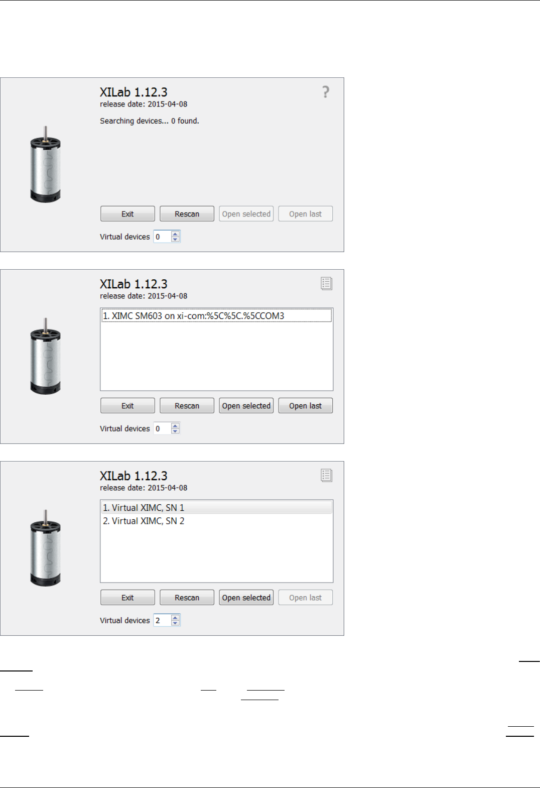
5.2.1. XILab Start window
When started, XILab opens a controllers detection window. By means of libximc library, XILab queries controllers connected to the
system and displays a list of found and successfully identified controllers.
XILab Start Window, 0 controllers found
XILab Start Window, 1 controller found
XILab Start Window, 2 controllers found
The list of found controllers is displayed on the start screen. Here you can select one or more controllers and open them using the Open
selected button. If one controller is chosen, then XILab Main window in single-axis control mode will be opened, if more than one
controller is chosen the XILab Main window in multi-axis control mode window will be opened. You could repeat the search by clicking
the Rescan button or exit the program by clicking Exit. If the Open last button is active it means that all the controllers that had been
opened in the previous run of XILab were found. Clicking the Open last button will then open the last saved configuration.
XILab can work with virtual XIMC controllers, which support the request-response protocol of a real controller. Virtual controllers may
be useful for testing and getting used to the XILab interface, if no real hardware controllers are connected to the system. The Virtual
devices field contains the number of virtual controllers which will appear in the list of available controllers after you press the Rescan
button or restart the XILab.
Page 113 / 345
Page 113 / 345

Note: Since the libximc library opens XIMC devices in the exclusive access mode, when you start subsequent copies of
XILab application, only free controllers will be found and available for selection.
Page 114 / 345
Page 114 / 345
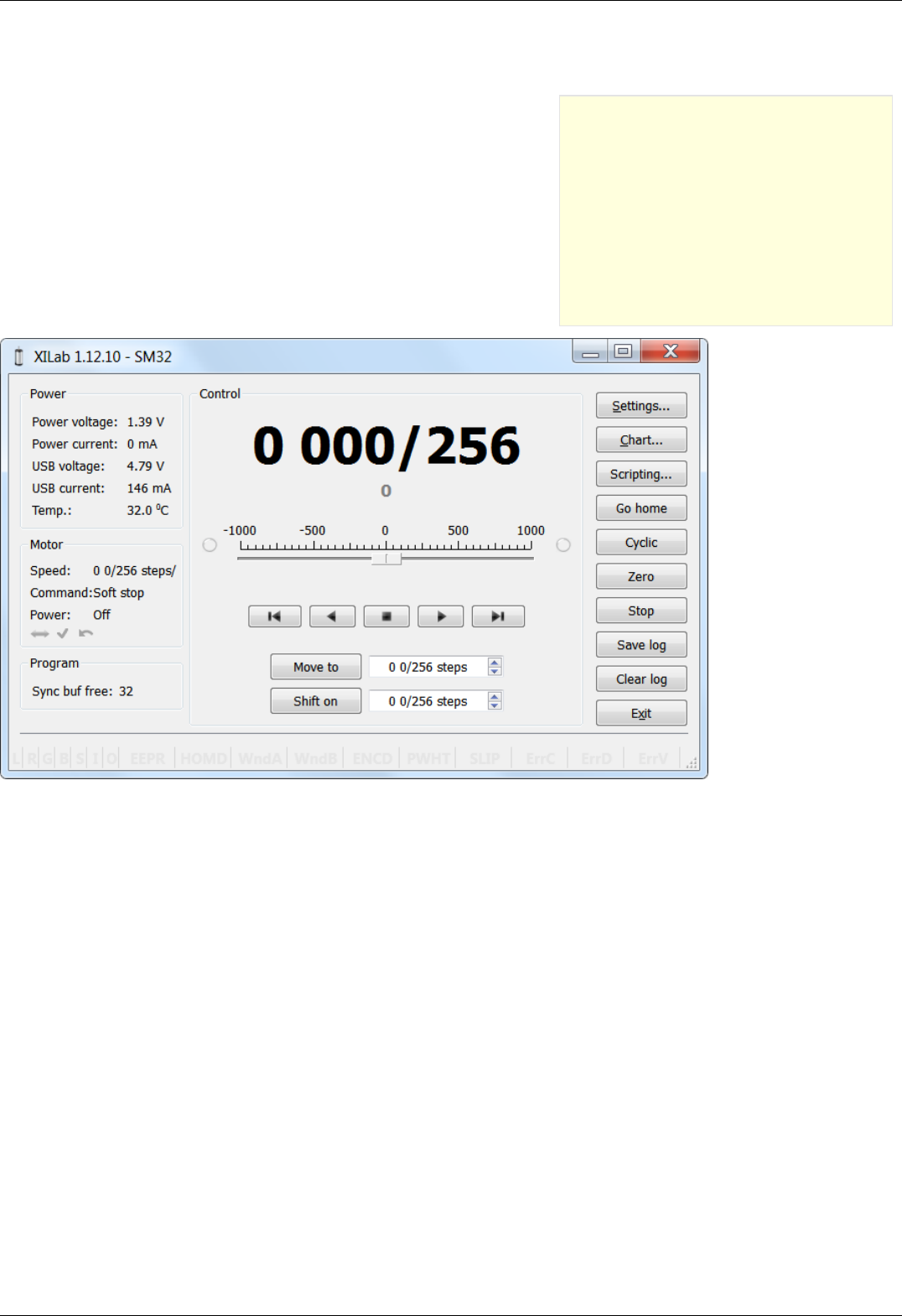
5.2.2. XILab Main window in single-axis control
mode
Motion Control Unit
Movement without specifying the final position
Movement to the target point
Target position for motion commands
Attenuator Control Unit
Controller and motor status
Controller Power Supply
Motor status
Program status
Group of application control buttons
Status bar
5.2.2. XILab Main window in single-axis control mode
XILab Main Window in General Motor mode
Page 115 / 345
Page 115 / 345
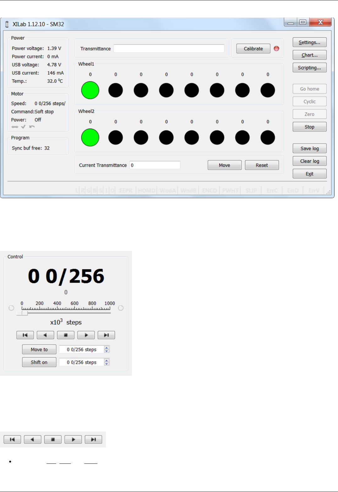
XILab Main Window in Attenuator mode
In the left part of the window in Power and Motor groups of parameters status of the controller and the motor is available. In the
central part of the window there is the Control group, containing the elements of motor motion control. On the right there is a group
of buttons to control the application as a whole. At the bottom there is a log, which is hidden as the window is resized to its minimum
size and a status bar. Below we consider these groups in more detail.
Motion Control Unit
Control Unit
In the central part of the block there is an indicator of the current position. Below it, in case the encoder is enabled, is located an
encoder position indicator. In the closed loop mode (see Operation with encoders section) the main and the secondary indicators swap
their places.
Below is the Control unit, containing the elements of motor motion control. Let us examine them in greater detail:
Movement without specifying the final position
Movement control buttons
The buttons Left, Stop and Right trigger movement to the left without specifying the final position, stop with deceleration any
previously started movement, and start the movement to the right without specifying the final position, respectively.
Page 116 / 345
Page 116 / 345
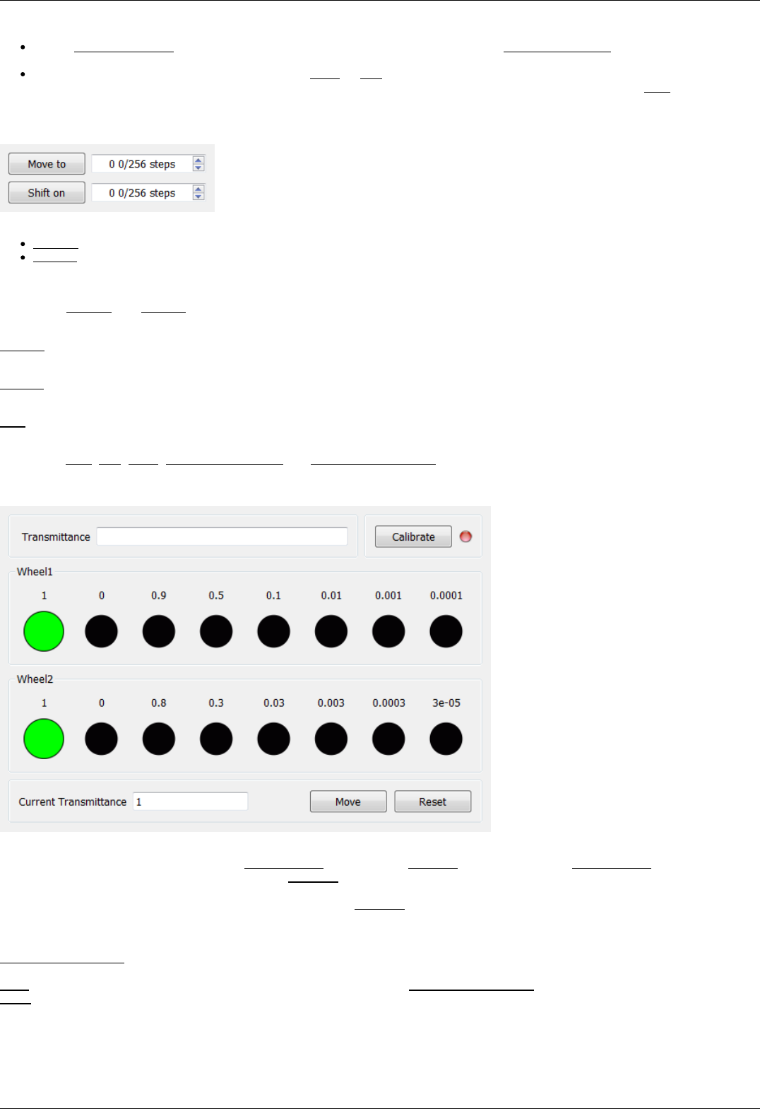
Button Left to the border will make the motor rotate to the left border of the slider. Right to the border, respectively, will do it to
the right edge of the slider.
When you press and hold the keyboard buttons Right or Left and the slider block has input focus, the movement starts in the
direction of increasing or decreasing coordinate. When you release the button the movement stop as if the Stop button on the
main window have been pressed.
Movement to the target point
Movement control to the given point
Move to button starts the process of moving to the given position.
Shift on button starts the process of shift to a given distance from the target position.
Target position for motion commands
Commands Move to and Shift on use the target position to calculate the movement. The target position is changed by the following
commands:
Move to <value>
Target position = <value>
Shift on <offset>
Target position = target position + <offset>
Zero (provided there is no movement at the moment of sending the command)
Target position = 0
Commands Stop, Left, Right, Left up to the border and Right up to the border do not alter the target position.
Attenuator Control Unit
Attenuator Control Unit
At the top of the attenuator control block a Transmittance window and a Calibrate button are located. Transmittance window contains a
control to select desired transmittance coefficient. Calibrate button does manual calibration, or location of the initial position, of the
attenuator - first it initiates one revolution of attenuator with current controller settings to determine relative position of attenuator
wheels and then does Automatic Home position calibration . Calibrate button is optional - if the attenuator did not perform the
calibration or it was reset, for example by pressing Cancel during movement, calibration will be performed before the next movement
automatically.
Attenuator has one or two wheels, each wheel contains 8 optical filters. Below these filters are visualized as bars with circles. Below a
Current Transmittance window is located. This window contains trasmittance coefficient which is the closest to desired one that can be
achieved with the current filters.
Move button performs movement toward the filters corresponding to the Current Transmittance, that is, the highlighted ones.
Reset button deactivates all filters.
Controller and motor status
Page 117 / 345
Page 117 / 345
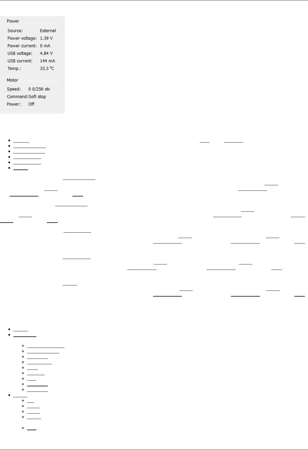
Controller Power Supply
Power group of parameters contains the following indicators:
Source - source of power supply for controller. The controller may be powered by USB or by External power source.
Power voltage - voltage supplied to the power module.
Power current - current consumption of the power module.
USB voltage - voltage on USB connector.
USB current - current consumed by the controller via USB
Temp. - Temperature of the controller processor.
If the color of the indicator Power voltage changes to blue or red, it shows that voltage power supply exceeds the allowed value range
over the acceptable value, which is defined in the Critical board ratings. In this case, the controller switches to Alarm state. It is
possible to quit the Alarm state after terminating of the events that caused Alarm, provided that the flag Sticky Alarm is not set. If the
flag Sticky Alarm is on, use the Stop button to quit the Alarm state.
If color of the indicator Power current turns red, it shows that the current consumed by the controller from the power supply is over
the acceptable value, which is defined in the Critical board ratings. In this case, the controller switches to Alarm state. It is possible to
quit the Alarm state after terminating of the events that caused Alarm, provided that the flag Sticky Alarm is not set. If the flag Sticky
Alarm is on, use the Stop button to quit the Alarm state.
If the color of the indicator USB voltage turns blue or red, it shows that the USB voltage goes out of the allowed value range towards
lower and higher voltage respectively. In this case, the controller switches to Alarm state. It is possible to quit the Alarm state after
terminating of the events that caused Alarm, provided that the flag Sticky Alarm is not set. If the flag Sticky Alarm is on, use the Stop
button to quit the Alarm state.
If the color of the indicator USB current turns red, it shows that the USB current supply exceeds the acceptable value, which is defined
in the Critical board ratings. In this case, the controller switches to Alarm state. It is possible to quit the Alarm state after terminating
of the events that caused Alarm, provided that the flag Sticky Alarm is not set. If the flag Sticky Alarm is on, use the Stop button to
quit the Alarm state.
If the color of the indicator Temp. turns red, it shows that the temperature of the controller board exceeds the acceptable value, which
is defined in the Critical board ratings. In this case, the controller switches to Alarm state. It is possible to quit the Alarm state after
terminating of the events that caused Alarm, provided that the flag Sticky Alarm is not set. If the flag Sticky Alarm is on, use the Stop
button to quit the Alarm state.
Motor status
Motor group of parameters contains the following indicators:
Speed - rotation speed of the motor.
Command - the last performing (bold font) or executed (plain font) controller command. Controller command appears in black if
the flag of the motion error MVCMD_ERROR is not set, in red otherwise. Can be one of the following options:
Move to position - move to the set position
Shift on offset - offset for a predetermined distance
Move left - move left
Move right - move right
Stop - stop
Homing - find the home position
Loft - backlash compensation
Soft stop - smooth stop
Unknown - unknown command (it may appear immediately after the controller starts)
Power - state of stepper motor power supply. Can be one of the following options:
Off - motor winding is disconnected and not controlled by the driver,
Short - winding is short-circuited through the driver,
Norm - winding is powered with nominal current,
Reduc - winding is deliberately powered with reduced current relatively to operational one to reduce the power
consumption,
Max - winding is powered with maximum available current, which a scheme with a given voltage supply can output.
Page 118 / 345
Page 118 / 345

Program status
Program group of parameters contains the following indicators:
Sync buf free - free slots in the syncin command buffer (see description of ASIA command).
Group of application control buttons
Settings... button opens controller settings, see Application Settings.
Chart... button opens a window with charts, see Charts.
Scripting... button opens scripting window, see Scripts.
Go home button searches for the home position, see Home position settings.
Cyclic button turns on the cyclic motion, see Cyclical motion settings.
Zero button resets the current position of the motor and the encoder value.
Stop button sends the command of emergency stop, resets the Alarm state, clears the command buffer for synchronous motion
and stops a script if it is running.
Save log button saves the contents of the log to a file in CSV format (opens a file selection dialog window).
Clear log button clears the contents of the log.
Exit button performs safe shutdown, see Correct shutdown.
Status bar
Status bar contains current controller status indicators. From left to right these are 7 flags,
L - Left button state.
R - Right button state.
G - State of external GPIO pin.
B - State of brake pin.
S - State or revolution sensor pin.
I - State of sync in pin.
O - State of sync out pin.
and separate indicators
EEPR - EEPROM is connected.
HOMD - Controller is in "homed" state (calibration performed).
WndA - Winding A state.
WndB - Winding B state.
ENCD - Encoder state (none/active/inverted/failed).
PWHT - Power driver overheat.
SLIP - Motor slip detected.
ErrC - Command error encountered.
ErrD - Data integrity error encountered.
ErrV - Value error encountered.
Page 119 / 345
Page 119 / 345
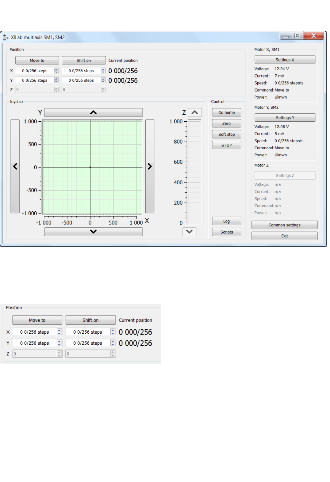
5.2.3. XILab Main window in multi-axis control mode
XILab Main window
In the top left part of the screen in the Position parameter group there are indicators of the current position. In the bottom left part of
the window there is the Joystick and Control blocks, which are a graphical control element for several axes and a button block
respectively. In the top right part, in the Motor blocks data on the current status of controllers and connected motors is located. In the
bottom right part of the window there is a group of buttons for application control as a whole. Let us consider these groups in more
detail.
Motion control block
Motion control block
In the Current position column indicators of the current position in steps or calibrated units (see below) for the axes X, Y and Z (from
left to right) are located. The Move to button performs movement to the coordinate given by the controls of its column, and the Shift
on button performs shift on relative offset for a predefined distance. If one of the controllers is temporarily absent or disabled, the
corresponding line becomes grayed out.
Virtual joystick block
Page 120 / 345
Page 120 / 345
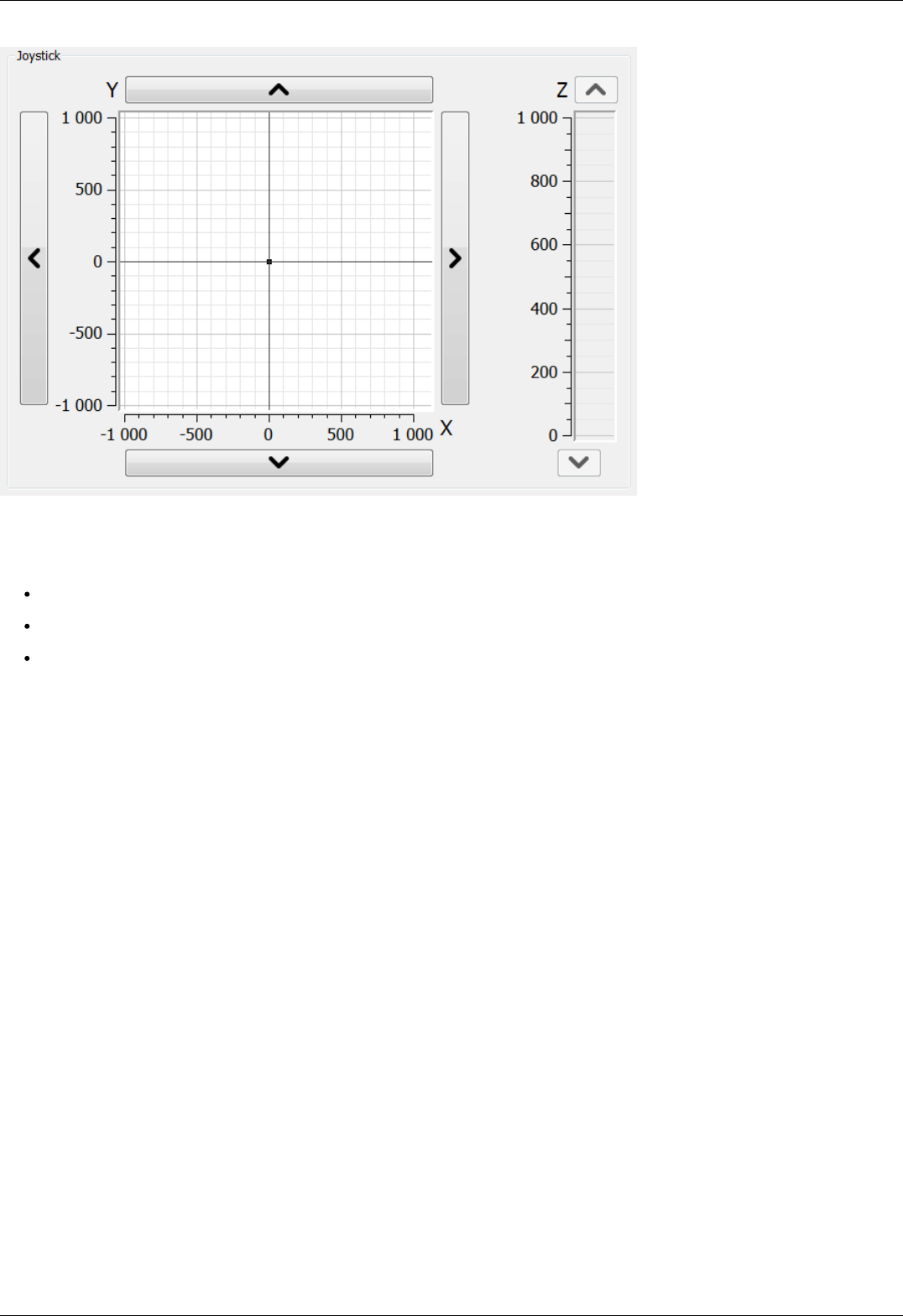
Virtual joystick block
In this block, the current coordinate of the controllers is visualized as a dot with two lines on the plane for X-Y axes and the line for the
Z axis.
There are several possible ways to control movement of the controllers:
When you click anywhere on the X-Y plane or in the Z column, the corresponding controller or controllers start to move to the
selected coordinate in accordance to its own movement settings.
When you press and hold the screen buttons with up, down, left and right arrows, the corresponding axis starts to move in that
direction. The movement stops with deceleration when you release the button (soft stop command is sent).
When you press and hold the keyboard buttons Right, Left, Up, Down, PageUp or PageDown when the joystick block has input
focus, the axis X, Y or Z, respectively, starts to move in the direction of increasing or decreasing coordinate. The movement
stops with deceleration when you release the button (soft stop command is sent). On receiving input focus the widget
background color changes from white to light-green.
The scales of the axes are set in "Slider settings" on Program configuration page in Settings window separately for each controller. If
user units are being used, then the corresponding axis scale is measured in these units. If the position read from any controller is out
of its axis range, then the corresponding indicator will not appear on the screen.
Control block
Page 121 / 345
Page 121 / 345

Control block
The Go home button searches for the home position independently for each of the controllers; see Home position settings.
The Zero button resets the current position of the motor and value of the encoder for each controller.
The Soft stop button executes a soft stop for each of the controllers.
The STOP button sends an emergency stop command to each controller, resets their Alarm statuses, clears their command buffers for
synchronous motion and stops a script if one is running.
The Log button opens a window with log information. Here you can find diagnostic information (errors, warnings, informational
messages) from XiLab, libximc and script sources.
The Scripts button opens a scripting window, see Scripts.
Block of status indicators for controllers and motors
Page 122 / 345
Page 122 / 345
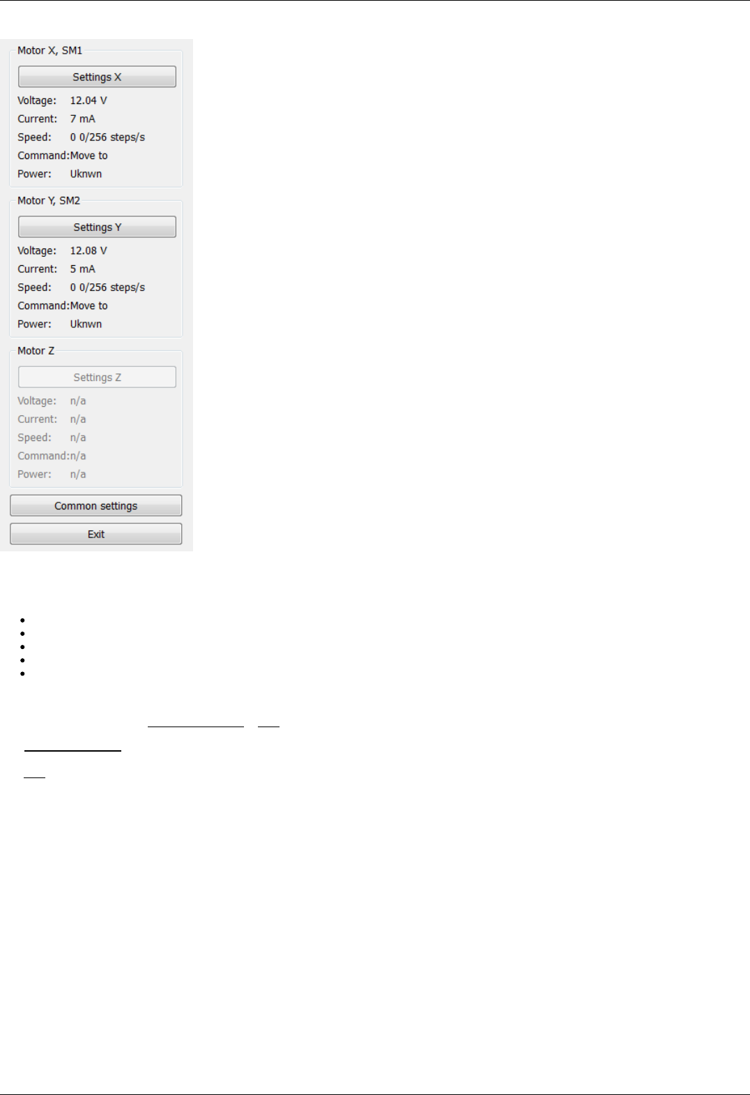
Block of status indicators for controllers and motors
Here are the three blocks of indicators of controllers and motors for axes X, Y and Z. In the title of the block the serial number of
corresponding controller is displayed. Each block contains the following indicators:
Voltage - the voltage at the power section of the motor.
Current - current power consumption of the motor.
Speed - current speed of the motor.
Command - the last command of the controller that was executed, or is being executed.
Power - the state of the motor power supply.
The buttons Settings X, Y, Z open the configurations of a controller, which corresponds to this axis, see Application Settings.
Below the indicator blocks Common settings и Exit buttons are located.
The Common settings button opens a dialog window with general settings. Here you can choose which controller serial numbers are
considered "X", "Y" and "Z" axes, also this window contains logging settings.
The Exit button performs proper shutdown, see Correct shutdown.
Page 123 / 345
Page 123 / 345
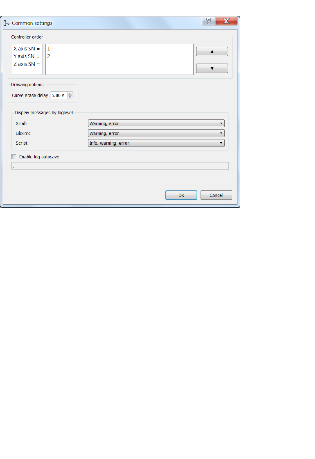
Common settings dialog window
Common settings window contains axis order settings, curve drawing options and logging settings.
You can reorder axes by choosing the axis serial, then pressing "up" or "down" buttons on the right.
First axis in the list, that is, an axis with serial number listed to the right of "X axis SN = " label will be referred to as "X axis", the
second one as "Y axis", the third one, if it is available, as "Z axis".
If you enter a greater than zero value of N seconds in the "curve erase delay" control in the "Drawing options", then last N seconds of X
and Y axis controller motion will be displayed as a trajectory in 2D-space overlaid on the virtual joystick window.
Common logging settings are completely identical to single-axis version logging settings .
Here you can configure logging detail ("None" for no logging, "Error" to only log errors, "Error, Warning" to log errors and warnings,
"Error, Warning, Info" to log errors, warnings and informational messages) for each source: XiLab itself, libximc library and Scripts
module.
If the autosave option is enabled the log is saved to the file, which is flushed every 5 seconds. It has a name of type
"xilab_log_YYYY.MM.DD.csv", where YYYY, MM and DD are current year, month and day respectively. The log is saved in CSV format.
Page 124 / 345
Page 124 / 345
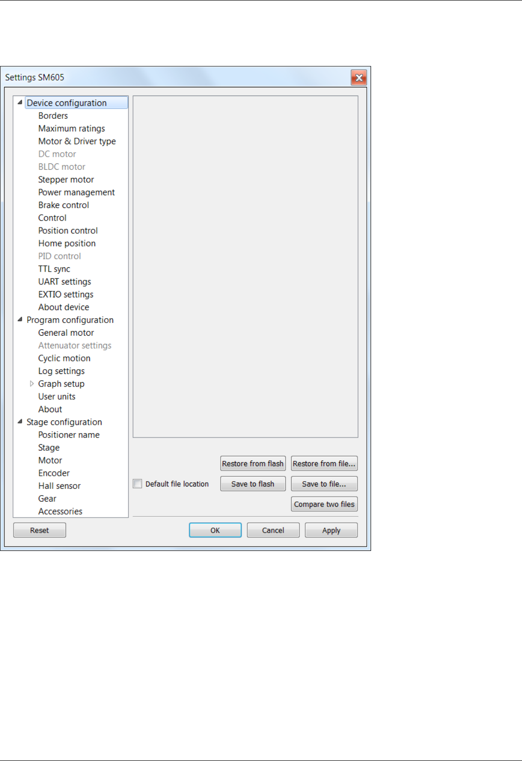
5.2.4. Application settings
Settings button from the main window opens the Settings window.
XILab Settings Main Window
Application settings are presented as a hierarchical tree and are divided into three groups: controller settings - "Device configuration",
XILab application settings - "Program configuration", characteristics of a stage - "Stage confuguration".
The first group Device configuration contains the parameters that can be stored directly in the device (in the flash memory or in the
RAM of controller).
The second group Program configuration contains the XILab application settings, which are not written into the controller, and are
used to control the XILab itself.
The third group Stage confuguration contains information about the parameters of the stage and is read from its ROM chip.
Description of Restore from flash and Save to flash buttons is located in the Saving the parameters in the controller flash memory .
All application settings from the first two groups can be saved to an external file when you click Save to file.
When you click the Restore from file button you can pick a file with application settings to be loaded into Settings window.
When you click the Compare two files button, a dialog window with file selection is opened. If you select two files all their settings
are compared and a list of differences is displayed. Missing keys in one of the files are marked in the table as "<NO KEY>".
Page 125 / 345
Page 125 / 345

The OK Button closes the Settings window and saves all changes to the settings to the controller. The Cancel button closes the
window without saving. The Apply button saves the settings without closing the window.
The Reset button resets all setting changes that were made since the Apply button was pressed, or after opening the Settings, if the
Apply button was not pressed.
Note. Only Device configuration settings can be saved into the flash memory of the controller.
Page 126 / 345
Page 126 / 345

5.2.5. Charts
Values displayed on the
charts
Button functions
5.2.5. Charts
Button Chart of the main window opens a window for working with charts.
XILab Charts window
In the left part of the window there are Charts of variables, in the right side of the window there is the Control block, which contains
the charts control elements. Above the Control block there are flags which enable different charts, below the Control block there is a
group of buttons to control the stored charts data.
Values displayed on the charts
Position is the primary field in which the current position is stored, no matter how feedback is arranged. In the case of a DC-
motor this field has the current position according to the encoder, in the case of a SM (stepping motor) this field contains the
current position in steps;
Speed is the current speed;
Encoder is the position according to the secondary position sensor;
Power voltage is voltage of the power section;
Power current is current consumption of the power section;
USB voltage is voltage on the USB;
USB current is current consumption by USB;
Winding A current - in the case of stepper motor, the current in winding A; in the case of a brushless motor, the current in the
first winding and in the case of DC motor, the current in its only winding;
Winding B current - in the case of stepper motor, the current in the winding B; in the case of brushless motor, the current in the
second winding, unused in the case of DC motor;
Winding C current - in the case of a brushless motor, the current in the third winding, unused in the case of DC or stepper
motor;
Winding A voltage - in the case of stepper motor, the voltage on winding A; in the case of a brushless motor, the voltage on the
first winding and in the case of DC motor, the voltage on its the only winding;
Winding B voltage - in the case of stepper motor, the voltage on the winding B; in the case of brushless motor, the voltage on
the second winding, unused in the case of DC motor;
Winding C voltage - in the case of a brushless motor, the voltage on the third winding, unused in the case of DC or stepper
Page 127 / 345
Page 127 / 345

motor;
PWM level the PWM duty factor (only for DC motors);
Temperature is temperature of controller processor;
Joystick is value of input signal from the joystick;
Analog input is value of analog input;
Flags shows the state of the controller flags.
Button functions
Clear - clears the stored data and the Charts window;
Start - starts recording the data and displaying charts. If the option "Break data update when motor stopped" in Program
configuration -> Graph setup -> Common is turned on, no data recording and charts auto-scrolling will occur when the
motor is stopped;
Stop - stops data reading;
Save - stores chart data to a file;
Load - loads chart data from a previously saved file;
Export to CSV - exports chart data to CSV file
Page 128 / 345
Page 128 / 345
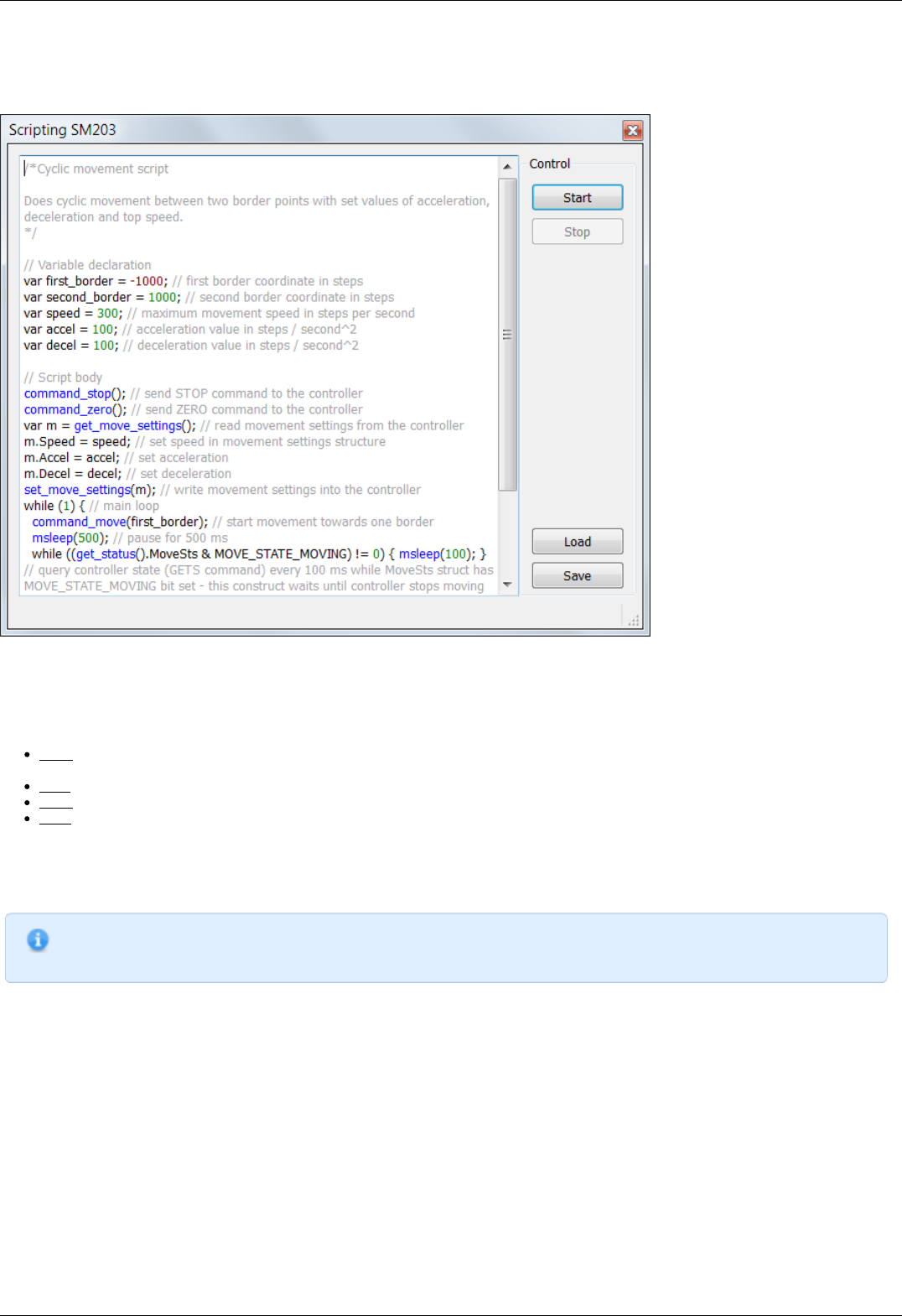
5.2.6. Scripts
The "Scripts" button on the main window opens a window for working with scripts.
XILab scripting window
On the left side of the window a text edit field is located, on the right side of the window a Control block is located, which contains
control buttons.
Button functions
Start - launches the script. The button is inactive if the script is already running. Right after the button is pressed and before the
script is interpreted the body of the script is autosaved to a temporary file (see below).
Stop - stops the script. Inactive if the script is not running.
Save - opens a file save dialog, prompting the user pick a file to save current script text to. Inactive if the script is running.
Load - opens a file load dialog, prompting the user to pick a file to load into the script window. Inactive if the script is running.
Warning! If you load a file all unsaved changes will be lost.
XILab loads last saved script text into the Scripting window on startup. Autosave runs on every script start and on XILab exit. Autosave
file is named "scratch.txt" and is located in user settings directory.
Note.
"Stop" button in XILab main window also stops script execution, acting as an emergency stop button.
Scripting language description is located in the Programming section of the manual.
Page 129 / 345
Page 129 / 345
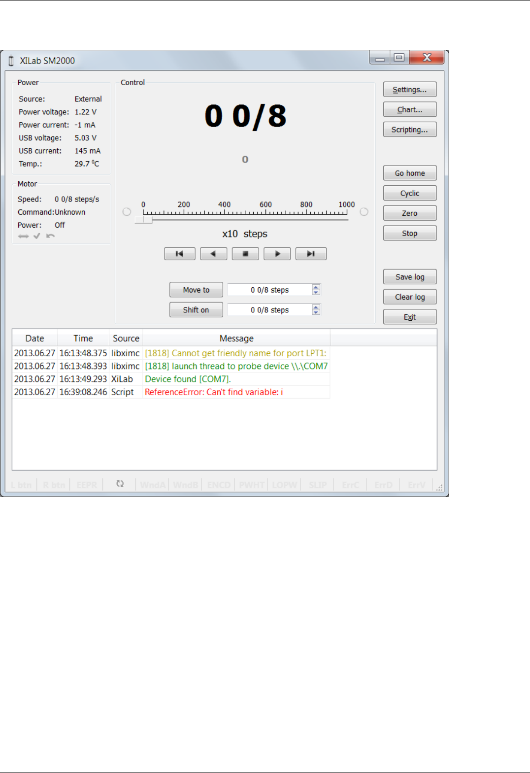
5.2.7. XILab log
XILab log window
XILab log at the bottom part of the main window shows libximc library messages. It also shows messages from XILab application and
Scripts interpreter.
Log has 4 columns: date and time of record, the source and the message text.
Messages have a logging level indicating message importance: error, warning and informational message. Error messages are red,
warnings are yellow and informational messages are green.
You can set a filter on displayed messages on the Log settings page in the Settings window.
Page 130 / 345
Page 130 / 345

5.3. Controller Settings
1. Settings of kinematics (Stepper motor)
2. Motion range and limit switches
3. Critical board ratings
4. Power consumption settings
5. Home position settings
6. Synchronization settings
7. Brake settings
8. Position control
9. Settings of external control devices
10. UART settings
11. General purpose input-output settings
12. Motor type settings
13. Settings of kinematics (DC motor)
14. Settings of PID control loops
15. About controller
16. Settings of kinematics (BLDC motor)
Page 131 / 345
Page 131 / 345
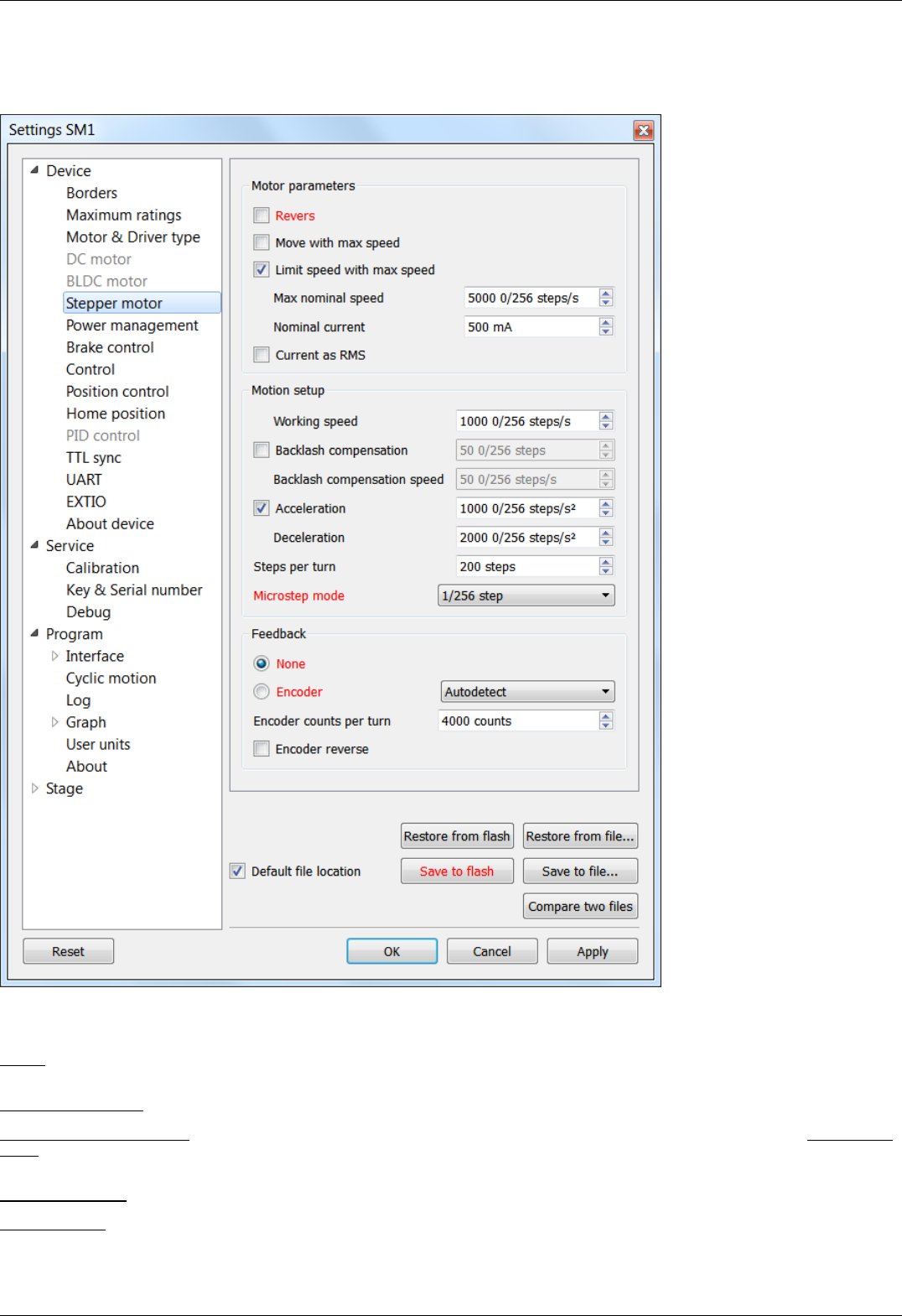
5.3.1. Settings of kinematics (stepper motor)
In the Application Settings Device configuration -> Stepper motor
Settings of stepper motor kinematics window
Motor parameters - directly related to the electric motor settings
Revers - checking this flag associate the motor rotation direction with the position counting direction. Change the flag if positive motor
rotation decreases the value on the position counter. This flag effect is similar to the motor winding reverse polarity.
Move with max speed - if this flag is checked motor ignores the preset speed and rotates at the maximum speed limit.
Limit speed with max speed - if this flag is checked the controller limits maximum speed to the value specified in the Max nominal
speed field. For example, if the speed exceeds the rated value, controller will reduce output action, until the speed come back to the
normal range. However, the controller remains operational and will continue the current task.
Max nominal speed - motor rated speed.
Nominal current - motor rated current. The controller will limit the current with this value.
Page 132 / 345
Page 132 / 345

Current as RMS - if this flag is checked engine current value is interpreted as root mean square current value. If the flag is unset, then
engine current value is interpreted as maximum amplitude value.
Motion setup - movement kinematics settings
Working speed - movement speed.
Backlash compensation - backlash compensation. Since the stage mechanics are not ideal there is a difference between approaching a
given point from the right and from the left. When the backlash compensation mode is on the stage always approaches the point from
one side. The preset value determines the number of steps which the stage takes to pass a given point in order to come back to it
from the same side. If the specified number is above zero the stage always approaches the point from the right. If it is below zero the
stage always approaches the point from the left.
Backlash compensation speed - speed of backlash compensation. When the backlash compensation mode Backlash compensation is on
the stage approaches the point from the right or from the left with a preset speed determined in the number of steps per second.
Acceleration - enables the motion in acceleration mode, the numerical value of the field is the acceleration of movement.
Deceleration - movement deceleration.
Steps per turn - determines the number of steps for one complete motor revolution. The parameter is set by user.
Microstep mode - step division mode. 9 modes are available: from a whole step to the 1/256 of a step. Description of modes is in the
Supported motor types.
Feedback settings
An encoder can be used as feedback sensor for stepper motors. The following encoder types are available: Single-ended, Differential or
Autodetect.
Encoder counts per turn - this parameter defines the number of encoder pulses per one full motor axis revolution.
Encoder reverse - interpret encoder signal as if it were reversed.
Page 133 / 345
Page 133 / 345
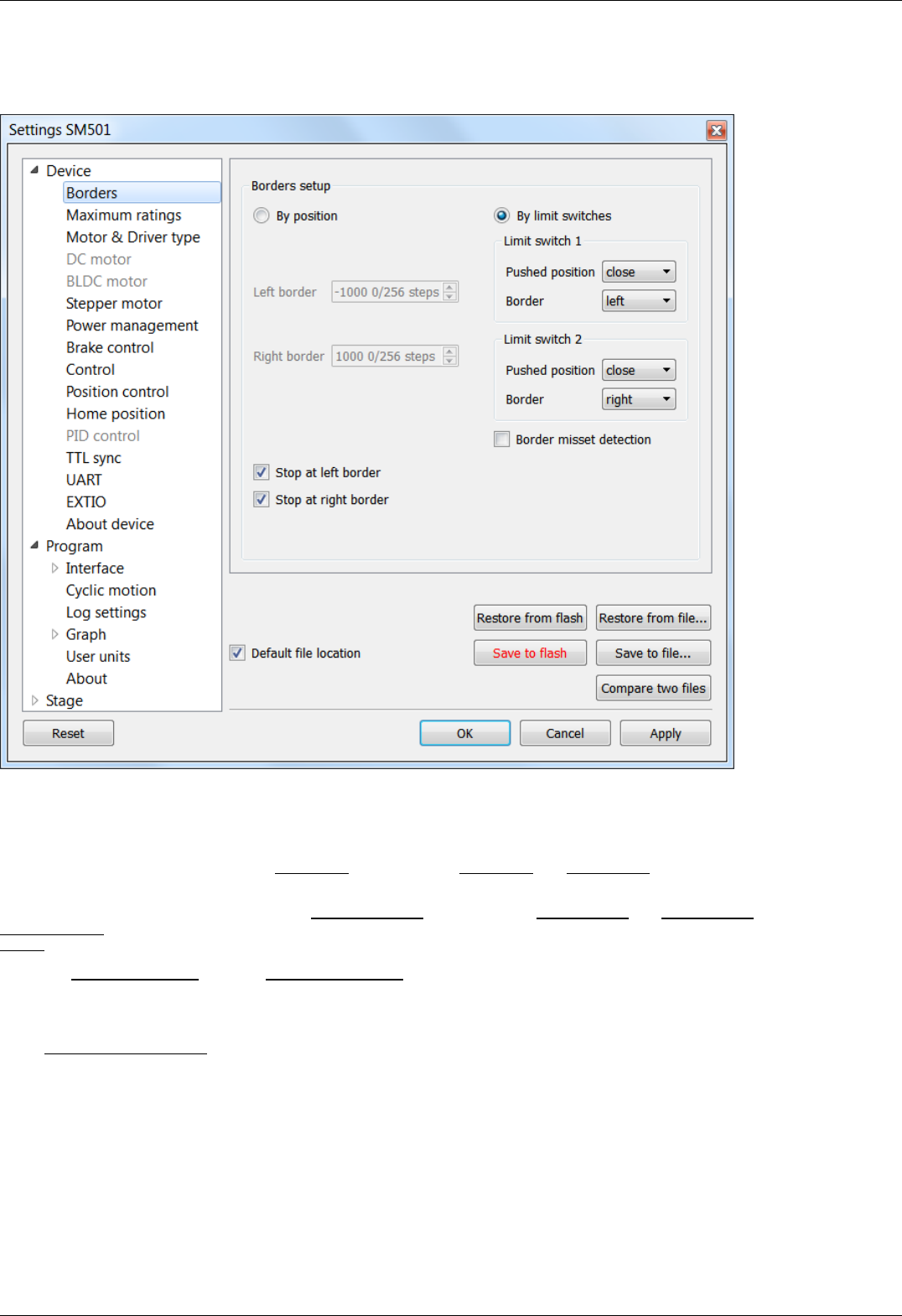
5.3.2. Motion range and limit switches
In the Application Settings Device configuration -> Borders
Motion range and limit switches settings window
Borders setup parameter group contains borders and limit switches parameters. These parameters are used to keep the stage in the
permissible physical movement limits or motion range limit in accordance with the user requirements. Borders can be set either by
position (internal controller step counter) or by limit switches located in the stage terminal points.
To set the borders by position select the By position and specify the Left border and Right border values, which correspond to the left
and right edge respectively.
To set the borders by the limit switches select By limit switches and set up both Limit switch 1 and Limit switch 2.
Pushed position - sets the limit switch condition when it is reached: open or closed.
Border - sets the limit switch position: on the left or on the right of the stage working range.
Check the Stop at left border and / or Stop at right border for a forced stop of motor when the border is reached. In this case the
controller will ignore any commands of movement towards the limit switch if the corresponding limit switch has already been reached.
When the border position is reached the corresponding indicator flashes in the main application window.
If the Border misset detection flag is checked, the engine stops upon reaching of each border. This setting is required to prevent
engine damage if limit switches appear to be potentially incorrectly configured. Read more about controller operation in this mode in
the limit switches location on positioners .
Page 134 / 345
Page 134 / 345
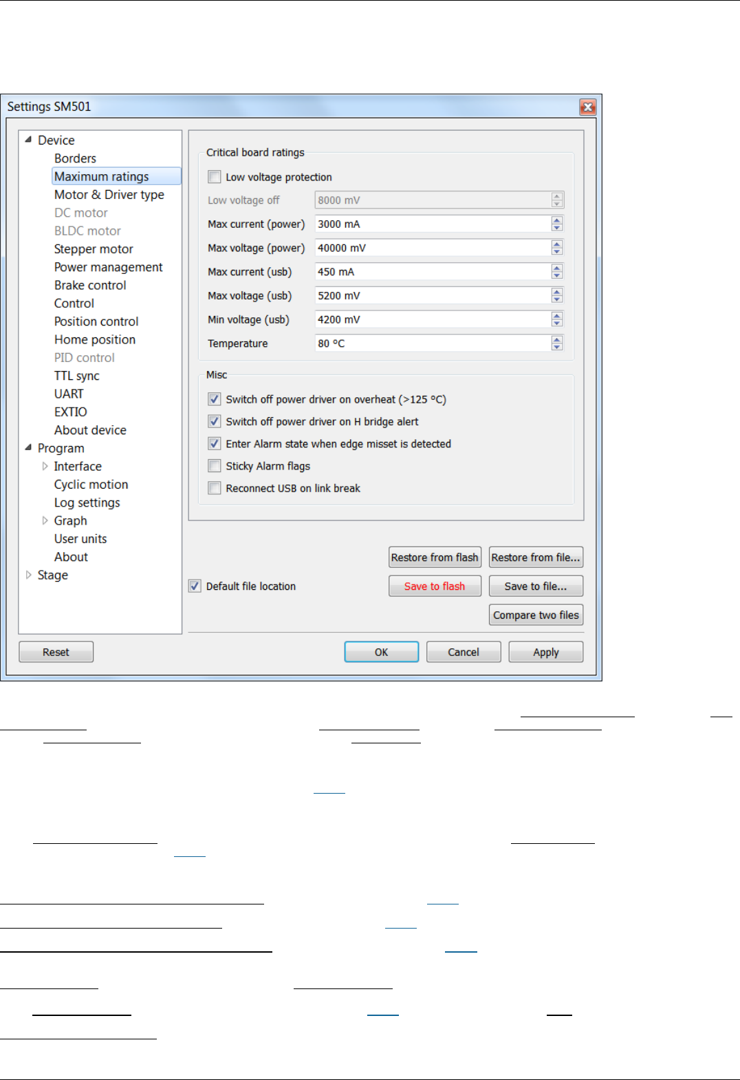
5.3.3. Critical board ratings
In the Application Settings Device configuration -> Maximum ratings
Controller critical parameters settings window
Critical board ratings - This group is responsible for the maximum values of input current Max current (power) and voltage Max
voltage (power) on the controller, the maximum current Max current (usb) and voltage Max voltage ( usb) for USB, the minimum
voltage Min voltage (usb) for USB, and the board temperature Temperature (if the temperature is measured on the given controller
version).
If the controller current consumption value, power supply voltage or the temperature goes out of the allowed range defined here then
the controller turns off all power outputs and switches to Alarm state. At the same time the Alarm state information will appear in the
main window (window background will change to red) and the out of range parameter value will be displayed in blue or red (below or
above the limit respectively).
If the Low voltage protection flag is checked the low voltage supply protection is active. Then Low voltage off and below values of input
voltage turns the controller into Alarm state.
The group Misc includes all other critical parameters settings.
Switch off power driver on overheat (> 125 ° C) - this parameter enables the Alarm state in case of power driver overheat.
Switch off power driver on H bridge alert - this parameter enables the Alarm state in case of the power driver malfunction signal.
Enter Alarm state when edge misset is detected - this parameter enables the Alarm state in case of incorrect boundary detection
(activation of right limit switch upon moving to the left, or vice versa).
Sticky Alarm flags - locking of Alarm condition. If the Sticky Alarm flags check-box is unchecked the controller removes the Alarm flag
as soon as it its cause is removed (e.g. in case of over-current the windings are disconnected, which results in the decreased current).
If the Sticky Alarm flags is enabled, the Alarm mode cause and the Alarm mode are canceled by the Stop command only.
Reconnect USB on link break - if this option is enabled, then the controller will reset USB link if the connection breaks.
Page 135 / 345
Page 135 / 345
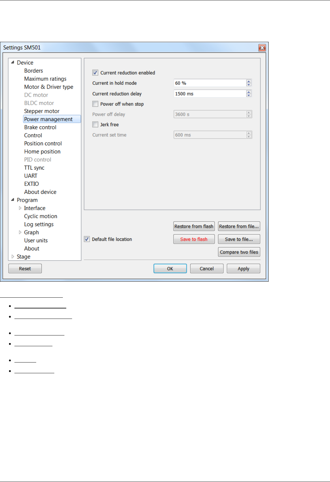
5.3.4. Power consumption settings
In the Application Settings Device configuration -> Power Management
Power consumption settings window
Current reduction enabled - activates the reduced energy consumption mode.
Current in hold mode - it determines the current in the hold mode in % of the nominal value. Value range: 0 .. 100%.
Current reduction delay - parameter determines the delay between switching to the STOP mode and power reduction activation.
It is measured in milliseconds. Value range: 0 .. 65535 ms.
Power off when stop - it activates the function that deenergized the motor windings after switching to the STOP state.
Power off delay - parameter determines the delay in seconds between switching to the STOP mode and motor power-off. Value
range: 0 .. 65535.
Jerk free - activates the current smoothing function to eliminate the motor vibration.
Current set time - parameter determines the time for jerk free current setting in milliseconds. Value range: 0 .. 65535 ms.
Detailed description of these parameters see in the Power control section.
Page 136 / 345
Page 136 / 345
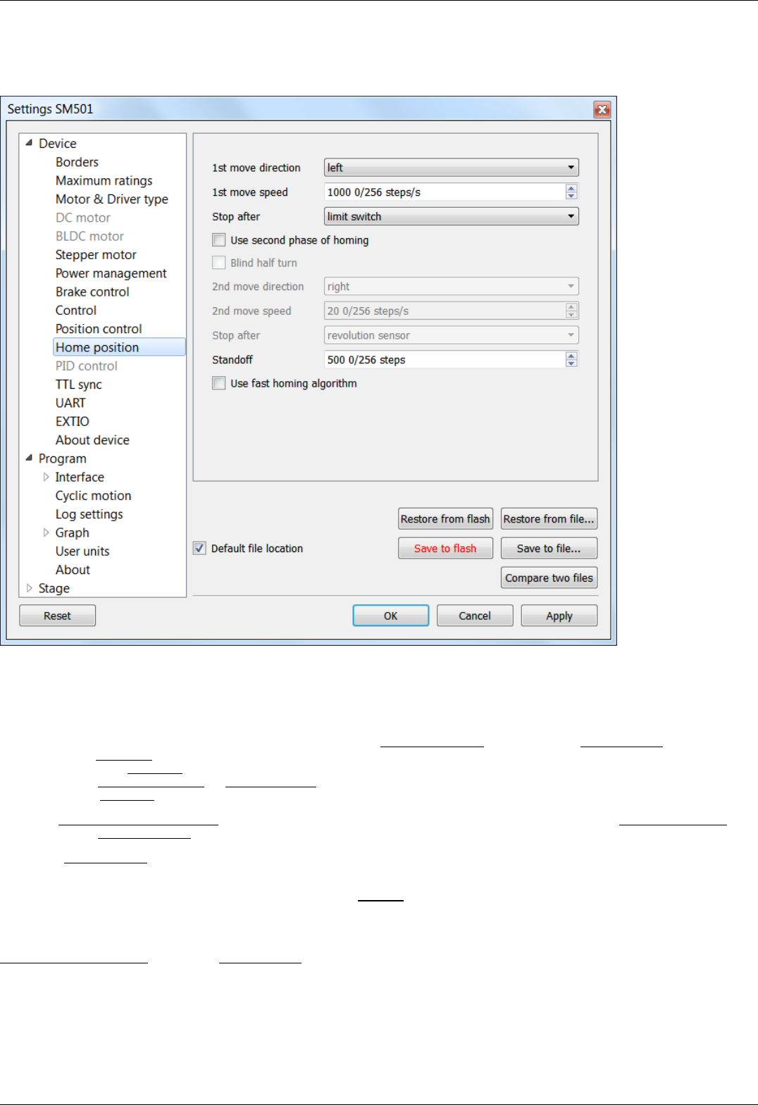
5.3.5. Home position settings
In the Application Settings Device configuration -> Home position
Home position settings window
Tab Home position sets the home position calibration parameters. Calibration comes to automatic accurate detection of the limit
switch, the revolution sensor signal or moment of getting the external signal, which determines the zero position, and grading from it
by a specified offset. It is helpful when the current location of the stage is unknown but we know the base point position relative to
limit switch or some other signal, which is called home position.
Homing comes to the motor movement towards the predetermined 1st move direction (left or right) at Working speed until the signal
from the source stop after don't happen. Then the motor movement towards the opposite direction with the same speed until the
signal from the source stop after in the active state and continue half turn in the same direction. Then begins the precise movement in
a given direction 1st move direction at 1st move speed. The speed is usually set low enough to keep the next signal. Motor stops,
depending on the stop after value, upon getting a sync input signal, signal from RPM sensor or reaching of the limit switch.
If the flag Use second phase of homing is checked the homing algorithm rotates the motor in a predetermined 2nd move direction (left
or right) with the 2nd move speed.
If the flag Blind half turn is checked the motor ignores the end of the second phase signal during half a turn. It helps to set an
unambiguous detection order for the sensors that have the first and the second movement phases signals close each other.
The third phase of homing is the absolute offset to the distance standoff.
The resulting point is called a home position. It is important that its location on the stage does not depend on the calibration starting
point.
Use fast homing algorithm option uses Working speed (see Settings of kinematics (stepper motor) page) for the first phase of homing
to speed up the process.
Configuration commands are described in the Communication protocol specification section.
Page 137 / 345
Page 137 / 345
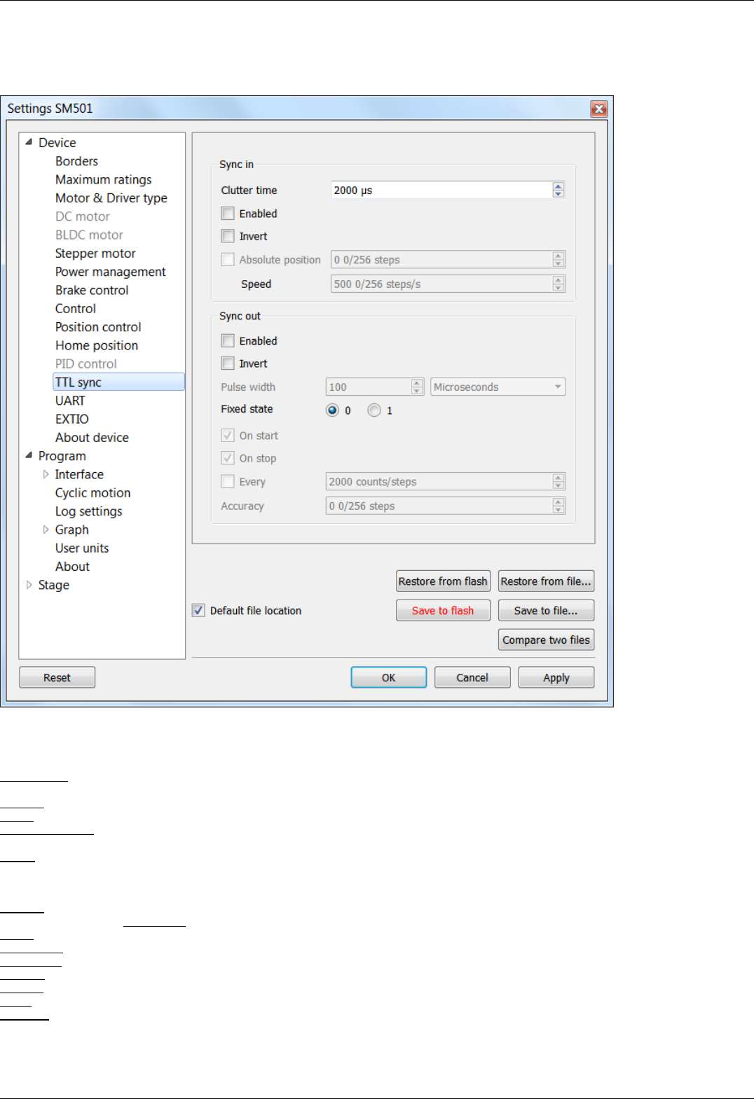
5.3.6. Synchronization settings
In the Application Settings Device configuration -> TTL sync
Synchronization settings window
Synchronization is described in details in TTL synchronization section.
Sync in
Clutter time - setting minimum synchronization pulse duration (in microseconds). Defines the minimum duration, which can be
detected (anti-chatter).
Enabled - check this box for the sync in mode enable.
Invert - checked flag shows that the operation is triggered by the falling sync pulse edge.
Absolute position - if the flag is checked, upon sync pulse the stage moves into the absolute position specified in the field Step/Micro
step. If the flag is unchecked, the shift is relative to the defined destination position.
Speed - the speed to use when moving.
Sync out
The Synchronization Output can be used as a "General purpose Output signal".
Enabled - if the flag is checked, the sync output functions according to the next settings. If the flag is unchecked, the output value is
fixed and equal to the Fixed state.
Invert - if the flag is checked the zero logic level is set to active.
Pulse width - specifies the duration of the output signal in milliseconds or steps/encoder pulses.
Fixed state - sets the logic level of output to 0 or 1, respectively.
On start - synchronizing pulse is generated at the beginning of movement.
On stop - synchronizing pulse is generated at the end of movement.
Every - synchronizing pulse is generated every n encoder pulses.
Accuracy - distance to the target position. As soon as the distance to target on approach is less than or equal to this distance a
synchronizing pulse will be generated if "on stop" option is used.
Page 138 / 345
Page 138 / 345
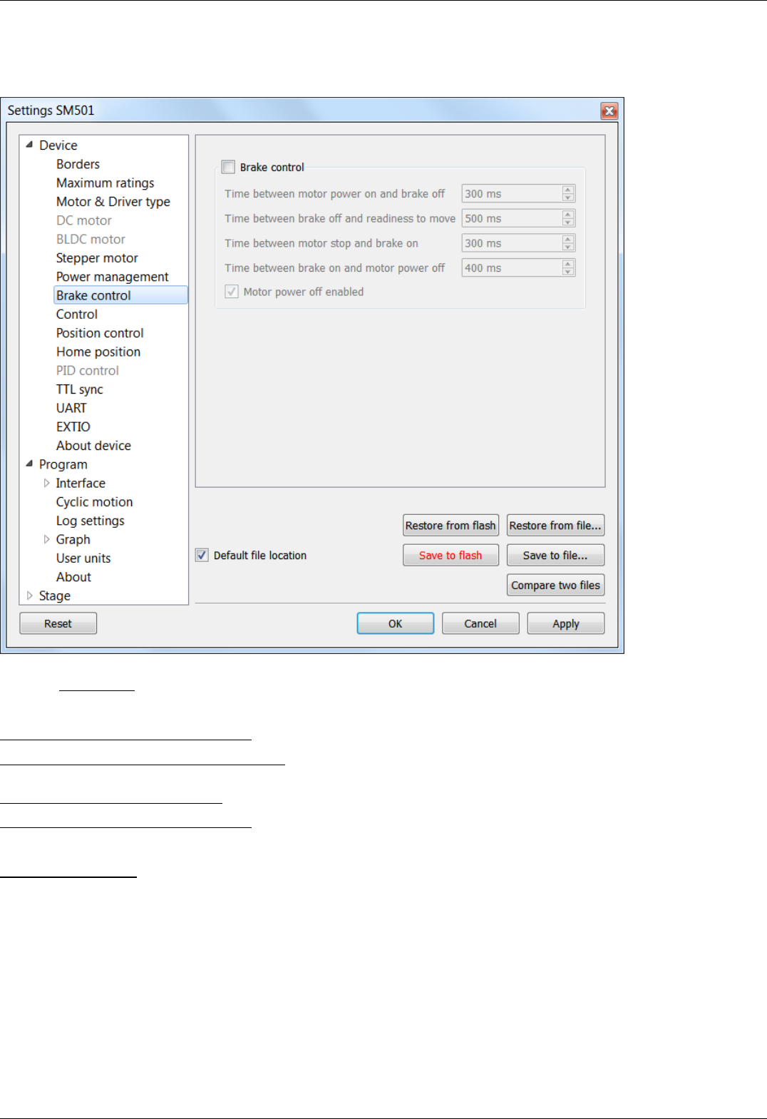
5.3.7. Brake settings
In the Application Settings Device configuration -> Brake control
Magnetic brake settings window
Check the Brake control flag to enable magnetic brake.
Parameters:
Time between motor power on and brake off - time between switching the motor on and switching off the brake (ms).
Time between brake off and readiness to move - time between switching off the brake and motion readiness (ms). All motion
commands will be executed only after this time.
Time between motor stop and brake on - time between stopping the motor and turning on the brake(ms).
Time between brake on and motor power off - time between turning on the brake and motor power-off (ms).
Value range is from 0 to 65535 ms.
Motor power off enabled flag means that when magnetic brake is powered off, the brake turns off motor power supply.
Configuration commands are described in Communication protocol specification.
Page 139 / 345
Page 139 / 345
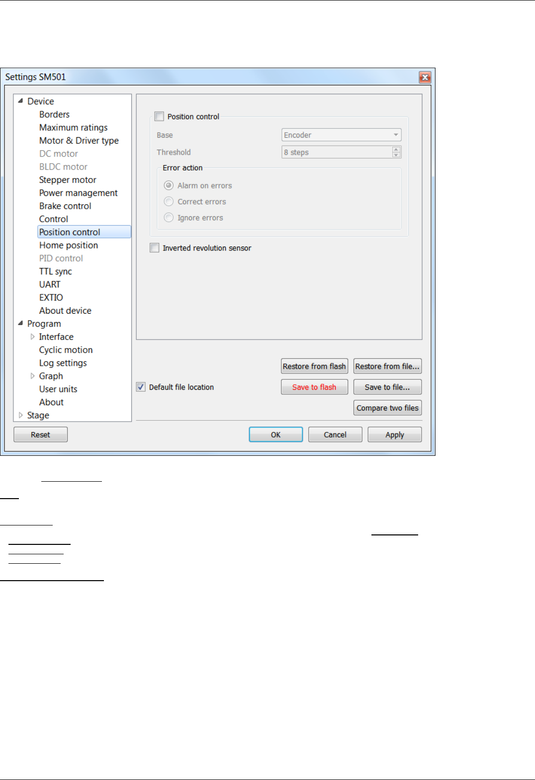
5.3.8. Position control
In the Application Settings Device configuration -> Position control
Window of Position control
Check the Position control checkbox to activate the position control.
Base - selection of the position control device. You can select an encoder (see Operation with encoders) or revolution sensor in the
drop-down list.
Minimal error - determines the number of missed steps (0 .. 255), which is considered to be an error. If the amount of missed steps
exceeds the specified number of steps the SLIP error flag is set. Further actions depend on the Error action setting:
If Alarm on errors is active then the controller will enter Alarm state.
If Correct errors is active then the controller will try to correct slip error (see Steps loss detection).
If Ignore errors is active then the controller will do nothing.
Inverted revolution sensor - if the flag is checked the revolution sensor is triggered by the level 1. Unchecked flag means usual logic is
valid - 0 is the trigger/activation/active state.
Configuration commands are described in the Communication protocol specification.
Page 140 / 345
Page 140 / 345
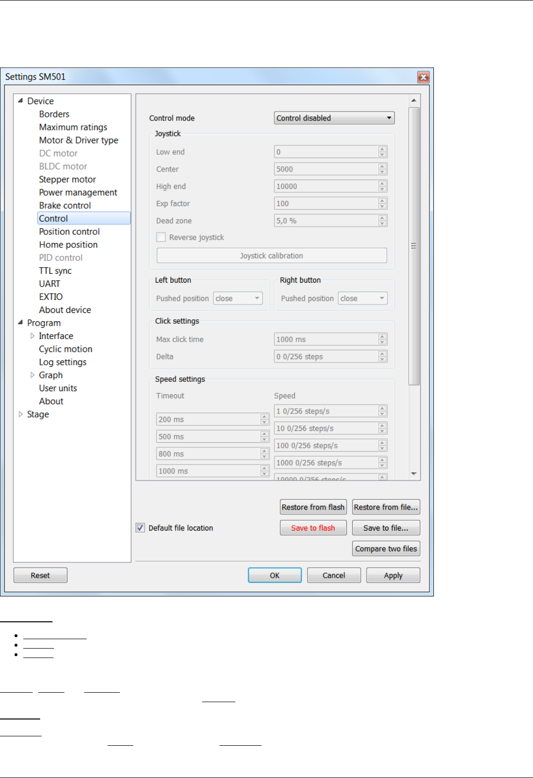
5.3.9. Settings of external control devices
In the Application Settings Device configuration -> Control
Settings of external control devices window
Control mode - range of external motor control devices.
Control disabled - external devices are not used
Joystick - joystick is used
Buttons - buttons are used
Joystick block contains joystick settings.
Low end, Center and High end determine the lower border, the middle and the upper border of joystick range respectively. Hence the
joystick ADC normalized value equal to or less than Low end corresponds to the maximum joystick deflection towards lower values.
Exp factor - exponential nonlinearity parameter. See Joystick control.
Dead zone - dead zone of joystick deviation from the center position. Minimum step of variation: 0.1%, the maximum value is 25.5%.
The joystick deviation from Center position by less than Dead zone value corresponds to zero speed.
Page 141 / 345
Page 141 / 345

Reverse joystick - Reverse the joystick effects. Joystick deviation to large values results in negative speed and vice versa.
Button Joystick calibration opens calibration dialog box.
Dialog box of Joystick Calibration
Calibration is automatic border and the dead zone detection. Below is the process description:
Move the joystick to extremes to determine the borders. The range of all measured values is represented in a green line.
Release the joystick and press the Start to initiate detection of the dead zone. Within 5 seconds imitate accidental influences on the
joystick, which should not be recognized as deviation from the joystick zero position. The dead zone range is represented in red.
Pressing the Apply button will send the computed values into the Settings window. Pressing OK button will send the values and close
the calibration dialog box.
Left button and Right button blocks contain button settings.
Pushed Position - determines the state (pressed or released button) which is considered the motion signal by the controller.
Open - released button is considered to be a motion command.
Close - depressed button is considered to be a motion command.
Click settings block lets one to set up button "click" behaviour. A rapid press of a button is interpreted as a "click".
Max click time - Maximum click time. Until this amount of time is elapsed controller will not start moving with first speed (see below).
Delta - Relative position offset. Controller will do a shift on offset with each click.
Speed settings block contains timeout and speed settings.
Timeout [i] - the time after which the speed switches from Speed[i] to Speed[i+1]. If any of the Timeout[i] is equal to zero, no
switching to the next speeds will occur.
Speed[i] - speed of the motor after time equal to Timeout[i-1]. If any of the speeds is equal to zero, no switching to this and
subsequent speeds will occur.
Configuration commands are described in Communication protocol specification.
Page 142 / 345
Page 142 / 345
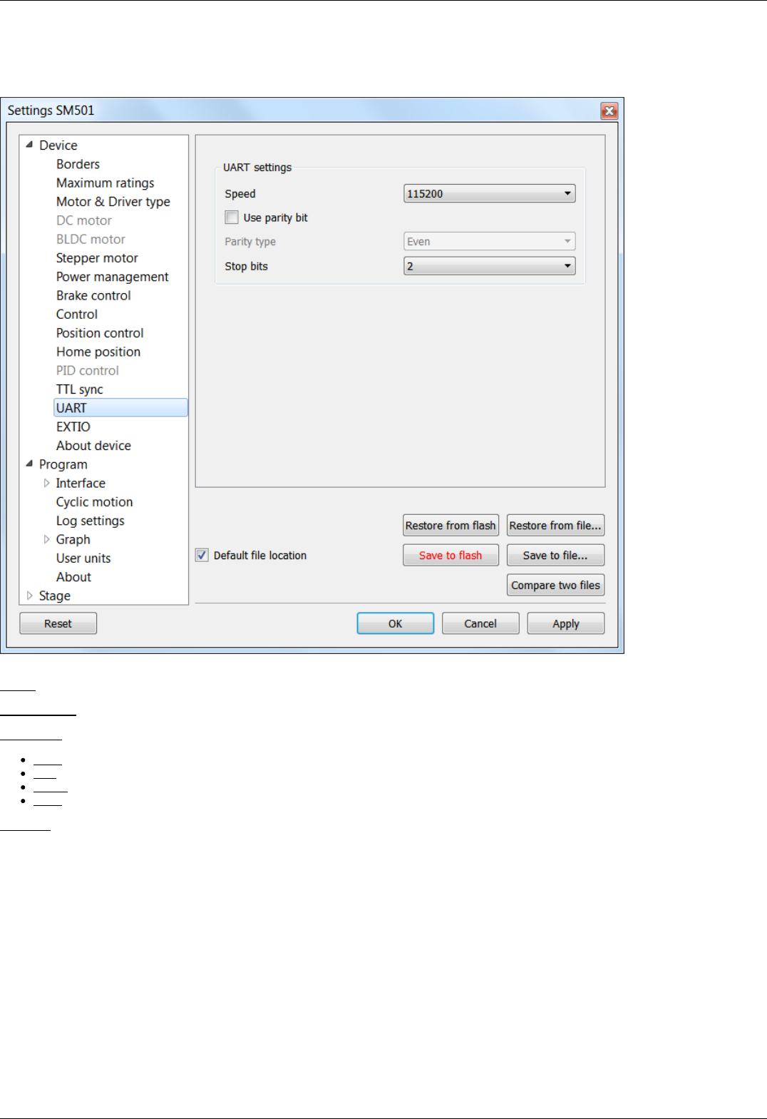
5.3.10. UART Settings
In the Application Settings Device configuration -> UART
UART settings tab
Speed - Select the UART speed from the preset values in the range from 9600 bit/s to 921600 bit/s.
Use parity bit - use of parity bit.
Parity type - Types of parity:
Even - this bit type is set when total number of bits is odd
Odd - this bit type is set when total number of bits is even
Space - parity bit is always 0
Mark - parity bit is always 1
Stop bits - number of stop bits (1 or 2).
Page 143 / 345
Page 143 / 345
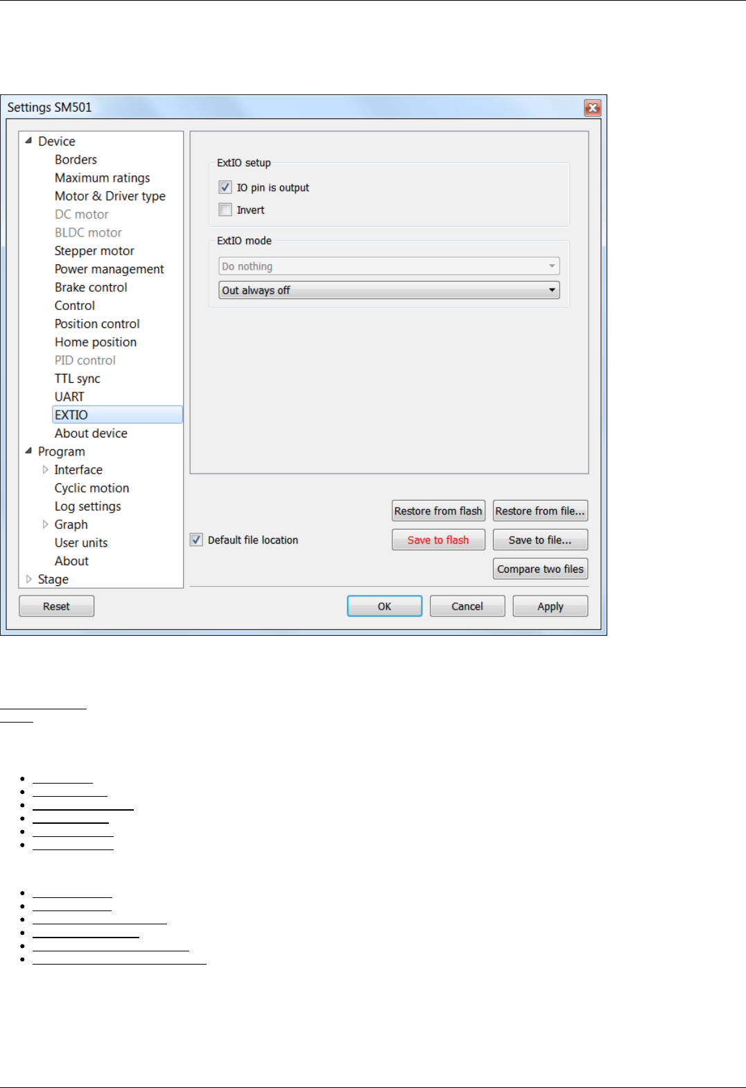
5.3.11. General purpose input-output settings
In the Application Settings Device configuration -> EXTIO settings
General purpose input-output settings tab
For detailed information, please see General purpose digital input-output .
ExtIO setup
IO pin is output - if the flag is checked the needle of ExtIO works in output mode, otherwise - in the input mode.
Invert - if the flag is checked the rising edge is ignored and the falling edge is active.
ExtIO mode - mode selection
If ExtIO configured for input mode the choice of controller action settings by the input pulse is active:
Do nothing - do nothing.
Stop on input - run STOP command.
Power off on input - run PWOF.
Movr on input - run MOVR.
Home on input - run HOME.
Alarm on input - enter ALARM state.
If ExtIO configured for output mode the choice of the output state depending on the controller status is active:
Out always off - always in inactive state.
Out always on - always in active state.
Out active when moving - in active state during motion.
Out active in Alarm - in active state if the controller is in the Alarm state.
Out active when motor is on - in active state if the motor windings are powered.
Out active when motor is found - in active state if the motor is connected.
Page 144 / 345
Page 144 / 345
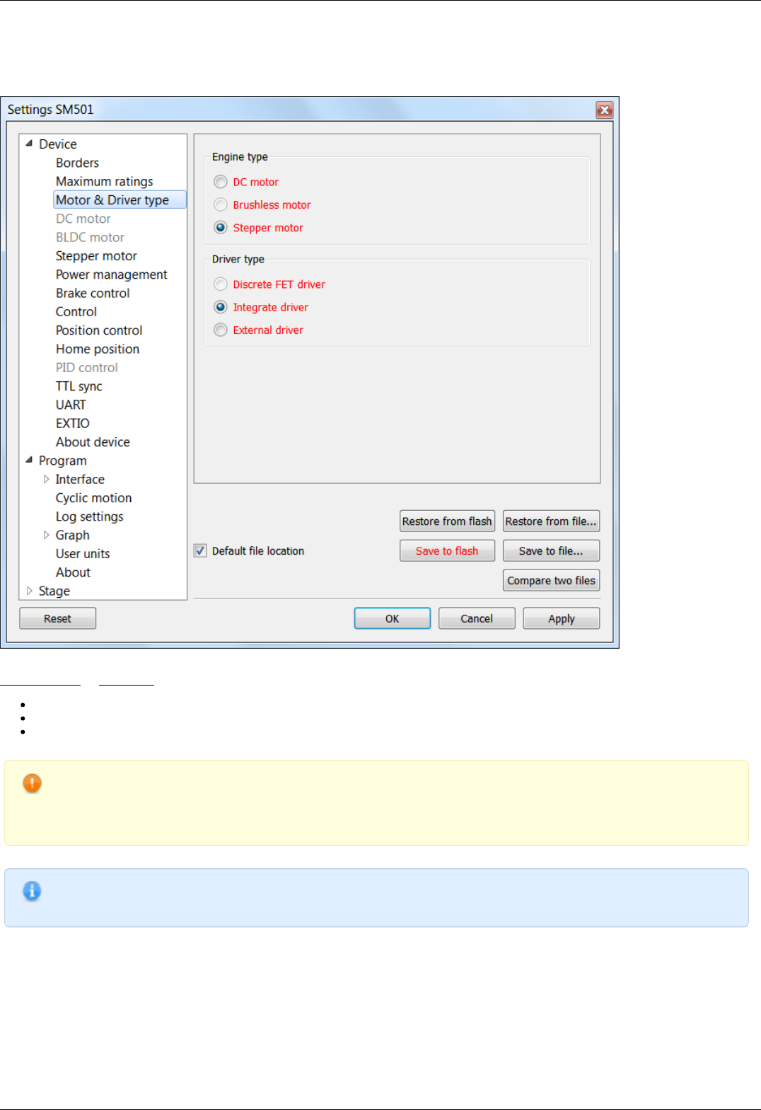
5.3.12. Motor type settings
In the Application Settings Device configuration -> Motor type
Motor type settings window
Stepper motor or DC-motor - motor type indication. Control power driver should be selected as well:
Integrated. This type is used for this controller modification.
On discrete keys. Will be used in future versions.
External driver. Designed to control stepper motors using three standard signals (see External driver control interface)
Warning. Driver type or motor type change is a critical operation that should not be performed while motor rotates.
To implement the change correctly the motor winding should be de-energized and turned off, after that motor type
can be changed and motor of another type can be connected. The same applies to changing of integrated driver to
external one and vice versa.
Note. Available motor types are determined by your firmware upgrade. Available control drivers depend on the
controller board type, except for the external driver.
Page 145 / 345
Page 145 / 345
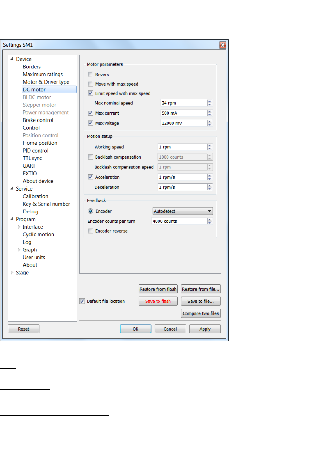
5.3.13. Settings of kinematics (DC motor)
In the Application Settings Device configuration -> DC Motor
Settings of kinematics (DC motor) window
Motor parameters - electric motor settings
Revers - checking this flag associate the motor rotation direction with the current position counting direction. Change the status of the
flag if positive motor rotation decreases the value on the position counter register. This flag effect is similar to connecting the motor
winding to reverse polarity.
Move with max speed - if this flag is checked motor ignores the preset speed and rotates at the maximum speed limit.
Limit speed with max speed - if this flag is checked the controller limits the maximum speed to the number of steps per second,
specified in the Max nominal speed field.
Max nominal speed, Max voltage, Max current - are motor nominal parameters. If they are active and applicable for given type of
motor, the controller limits these parameters within the specified values. For example, if the motor speed and voltage exceeds the
nominal values, the controller will reduce output action until both values are within the normal range. However, the controller remains
in operational condition, and will execute the current task.
Page 146 / 345
Page 146 / 345

Motion setup - settings related to the movement kinematics
Working speed - movement speed.
Backlash compensation - backlash compensation. Since the stage mechanics are not ideal there is a difference between approaching a
given point from the right and from the left. When the backlash compensation mode is on the stage always approaches the point from
one side. The preset value determines the number of steps which the stage takes to pass a given point in order to come back to it
from the same side. If the specified number is above zero the stage always approaches the point from the right. If it is below zero the
stage always approaches the point from the left.
Backlash compensation speed - speed of backlash compensation. When the backlash compensation mode Backlash compensation is on
the stage approaches the point from the right or from the left with a preset speed determined in the number of steps per second.
Acceleration - enables the motion in acceleration mode, the numerical value of the field is the acceleration of movement.
Deceleration - movement deceleration.
Feedback settings
Encoder - use of encoder as a feedback sensor. The following encoder types are available: Single-ended, Differential or Autodetect.
Encoder counts per turn - this parameter defines the number of encoder pulses per one motor axis full rotation.
Page 147 / 345
Page 147 / 345
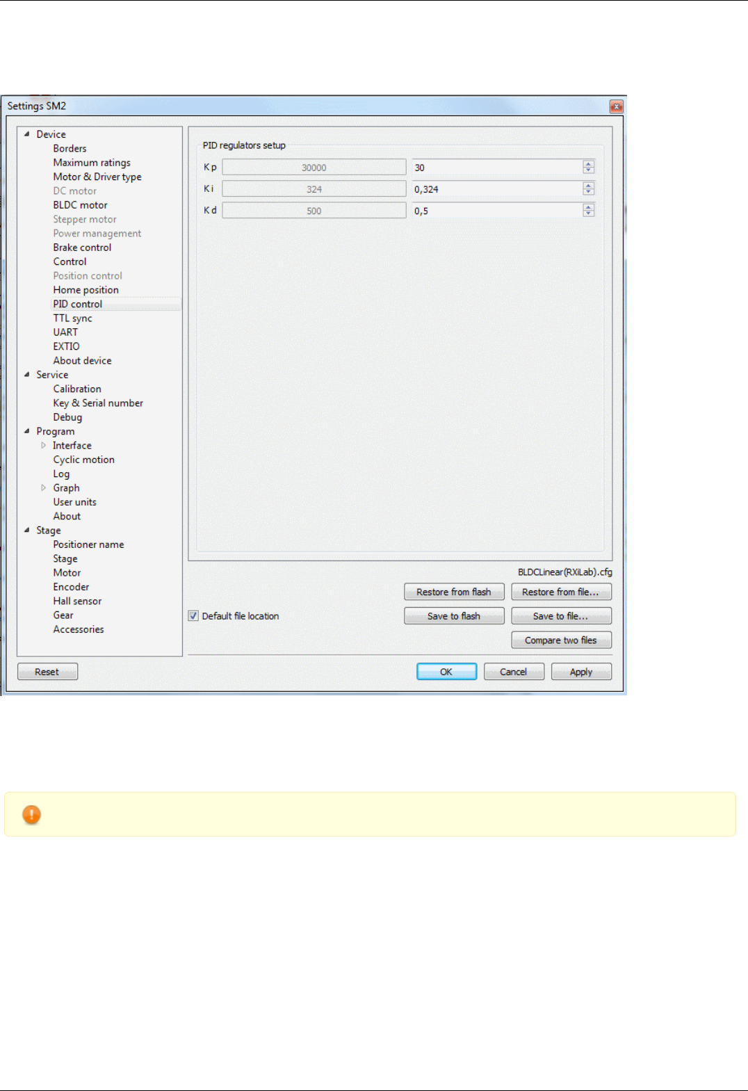
5.3.14. Settings of PID control loops
In the Application settings Device configuration -> PID control
Settings of PID control loops window
In this section, you can change the PID coefficients.
A voltage PID is used, K_p, K_i and K_d coefficients can vary in 0..65535 range for DC motors.
Fractional PID coefficients (on right) are only for BLDC motor (supported in firmware 4.1.x and older).
Warning. Do not change the settings of PID controllers, if you are not sure you know what you are doing!
Configuration commands are described in the Communication protocol specification. PID tuning is described in detail in the PID-
algorithm for DC engine control section.
Page 148 / 345
Page 148 / 345
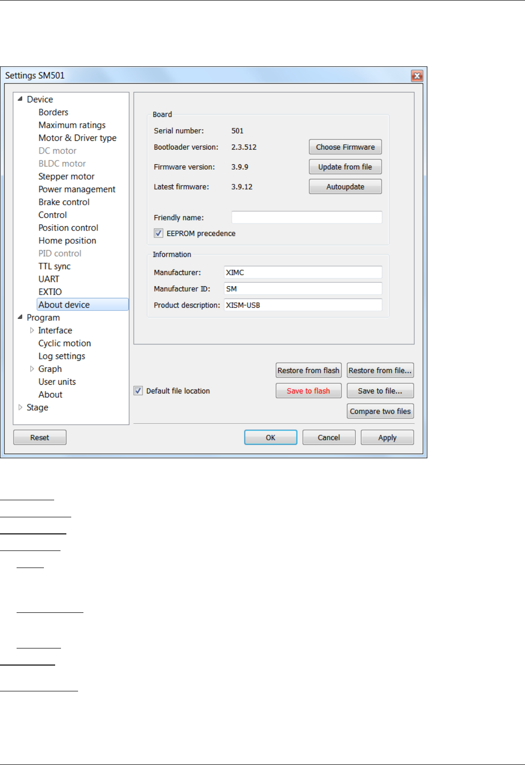
5.3.15. About controller
In the Application Settings Device configuration -> About device
About device tab
The Board section displays information about the controller:
Serial number - device serial number.
Bootloader version - bootloader version.
Firmware version - firmware version.
Latest firmware - latest available firmware version for this device (downloaded from the internet if internet connection is available).
The Update button opens firmware update dialog box.
Select the firmware file with the .cod extension and click Open. XILab will start the firmware update and will display "Please wait while
firmware is updating". Do not power off the controller during the upgrade. Upon completion of the update the "Firmware updated
successfully" dialog will be displayed.
The Choose Firmware button opens a dialog with firmware version numbers. Pick a number and press "Update firmware" to update to
selected version. An appropriate firmware file will be downloaded from the internet and loaded into the controller. This feature requires
an active internet connection.
The Autoupdate button automatically updates firmware from the internet to the latest available version.
Friendly name - an arbitrary user-defined name for the controller. If this string is not empty, then it will replace device id and serial
number in window titles. This is a convenience feature for situations with multiple controllers connected to the same PC.
EEPROM precedence - this flag works only for stages with autodetection feature. If this flag is set, then settings from external EEPROM
memory take precedence and are applied every controller start up or positioner connection. Otherwise settings from FRAM are used. If
this option is turned on then "Save to flash" button is displayed in red. This serves as a warning to the user that settings in flash
memory will be overwritten when a device with external memory is plugged into the controller.
Page 149 / 345
Page 149 / 345

Information block contains information about the device: the manufacturer, device ID, device type. The data are read from the
internal memory of the controller.
All of this data is reported to the XILab application when the device is connected.
Page 150 / 345
Page 150 / 345
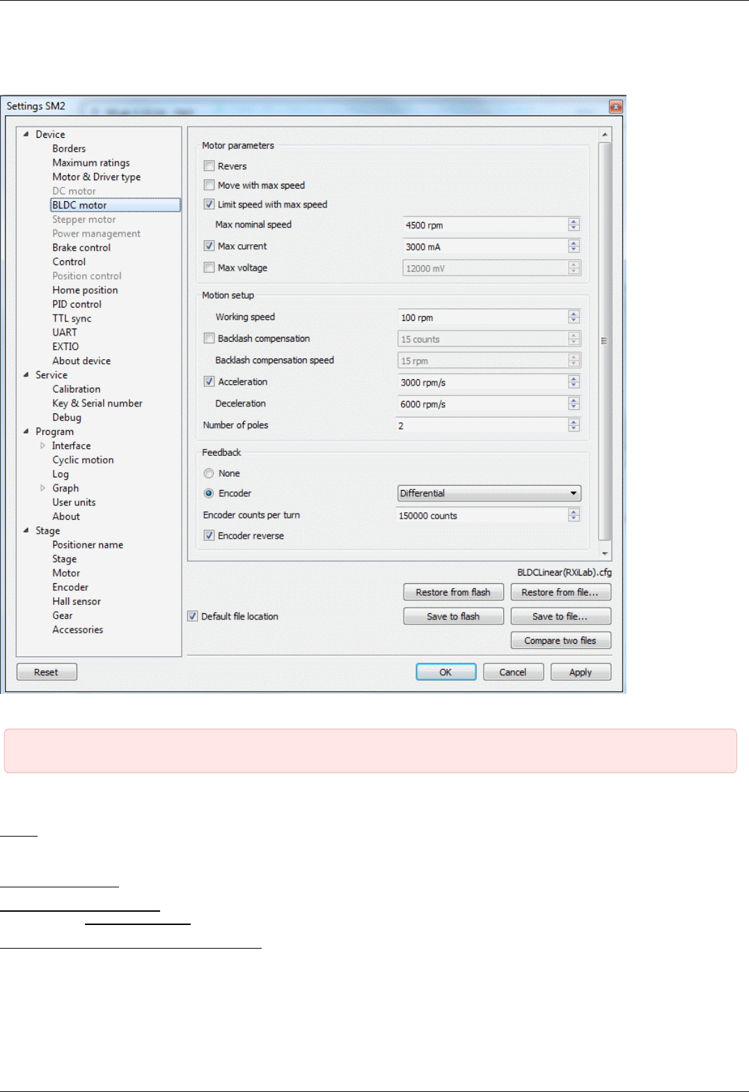
5.3.16. Settings of kinematics (BLDC motor)
In the Application Settings Device configuration -> DC Motor
Settings of kinematics (DC motor) window
IMPORTANT. Only firmwares 4.1.x (and older) support BLDC control
Motor parameters - electric motor settings
Revers - checking this flag associate the motor rotation direction with the current position counting direction. Change the status of the
flag if positive motor rotation decreases the value on the position counter register. This flag effect is similar to connecting the motor
winding to reverse polarity.
Move with max speed - if this flag is checked motor ignores the preset speed and rotates at the maximum speed limit.
Limit speed with max speed - if this flag is checked the controller limits the maximum speed to the number of steps per second,
specified in the Max nominal speed field.
Max nominal speed, Max voltage, Max current - are motor nominal parameters. If they are active and applicable for given type of
motor, the controller limits these parameters within the specified values. For example, if the motor speed and current exceeds the
nominal values, the controller will reduce output action until both values are within the normal range. However, the controller remains
in operational condition, and will execute the current task.
Page 151 / 345
Page 151 / 345

IMPORTANT. BLDC controller always use max current and don't use max voltage because main characteristic for
BLDC is max current, max voltage usually more than 8SMC5 supply voltage.
Motion setup - settings related to the movement kinematics
Working speed - movement speed.
Backlash compensation - backlash compensation. Since the stage mechanics are not ideal there is a difference between approaching a
given point from the right and from the left. When the backlash compensation mode is on the stage always approaches the point from
one side. The preset value determines the number of steps which the stage takes to pass a given point in order to come back to it
from the same side. If the specified number is above zero the stage always approaches the point from the right. If it is below zero the
stage always approaches the point from the left.
Backlash compensation speed - speed of backlash compensation. When the backlash compensation mode Backlash compensation is on
the stage approaches the point from the right or from the left with a preset speed determined in the number of steps per second.
Acceleration - enables the motion in acceleration mode, the numerical value of the field is the acceleration of movement.
Deceleration - movement deceleration.
Number of poles - number of poles per revolution
Feedback settings
Encoder - use of encoder as a feedback sensor. The following encoder types are available: Single-ended, Differential or Autodetect.
Encoder counts per turn - this parameter defines the number of encoder pulses per one motor axis full rotation.
Page 152 / 345
Page 152 / 345


5.4.1. XILab general settings
Program configuration in the Application Settings
XILab general settings tab
This tab configures the Xilab interface type and XIMC devices detection options.
Skin Type group includes Xilab interface type settings. There are two interface types available: "General Motor" and "Attenuator".
General Motor option enables general motor interface. In this mode current motor position is displayed in main window numerically and
graphically as a slider. Controls to move the motor to specified coordinate (in steps) and to shift on specified offset (in steps) are also
available. General motor interface settings are located on the General motor settings page.
Attenuator option enables Attenuator interface. In this mode current motor position is displayed in main window graphically as a series
of circles representing attenuator filters. Controls to find the combination of filters which is the best approximation to the specified
transparency are also available. Attenuator interface settings are located on the Attenuator settings page.
Device detection settings group includes XIMC device detection settings.
If Probe devices option is checked, at the start application tries to identify controllers by sending them commands GETI and GSER.
I f Enumerate non-XIMC devices option is checked the application queries all COM-port type devices in the system. If the option is
disabled, only devices with names matching the XIMC mask ("XIMC Motor Controller" in Windows; /dev/ximc/* and /dev/ttyACM* in
Linux/Mac) are queried.
If Enumerate network devices option is checked the application queries network-attached devices. A list of domain names and/or IP
addesses with XIMC server software is located below. One can add entries to the list manually or use automatic detection by pressing
Scan for local XIMC servers . Please note that in case of more than one local server automatic scan will pick a random one and it will
require several attempts to find them all.
Page 154 / 345
Page 154 / 345

Warning. If both Probe devices and Enumerate non-XIMC devices options are enabled, on startup XILab will send
data to all COM-ports.
If the PC has multiple Bluetooth COM-ports, due to the nature of Bluetooth operation, the queries will be conducted
sequentially, and connection attempts may take from a few to tens of seconds each.
Page 155 / 345
Page 155 / 345
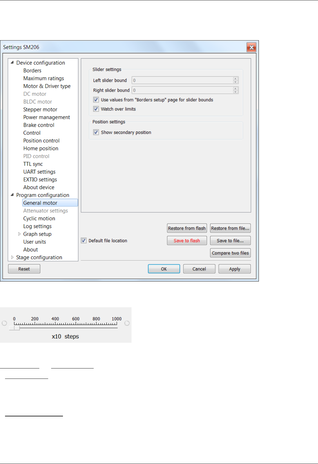
5.4.2. General motor settings
General motor in the Application Settings
General motor settings tab
This tab configures the slider display settings and secondary position display settings for a general motor device. The position slider is
located in the main window and visually represents the stage current position relative to the borders.
Fragment of Main application window containing slider
Slider settings group contains the following slider settings:
Left slider bound and Right slider bound contain the coordinates of the left and right bounds of the slider respectively.
If Watch over ltimits is checked then upon moving out of the slider range, the scale shifts to display the current position. However, he
total distance displayed on the slider remains unchanged. This option is not used by default. It is useful when you know the stage
motion range, but do not know the relation of that position to the values displayed in XILab, e.g. for the calibration purposes. The
option is often used together with the settings of the tab Home position settings.
Position settings group contains the position display settings.
If Show secondary position is checked then a secondary position is shown in the main application window.
Page 156 / 345
Page 156 / 345
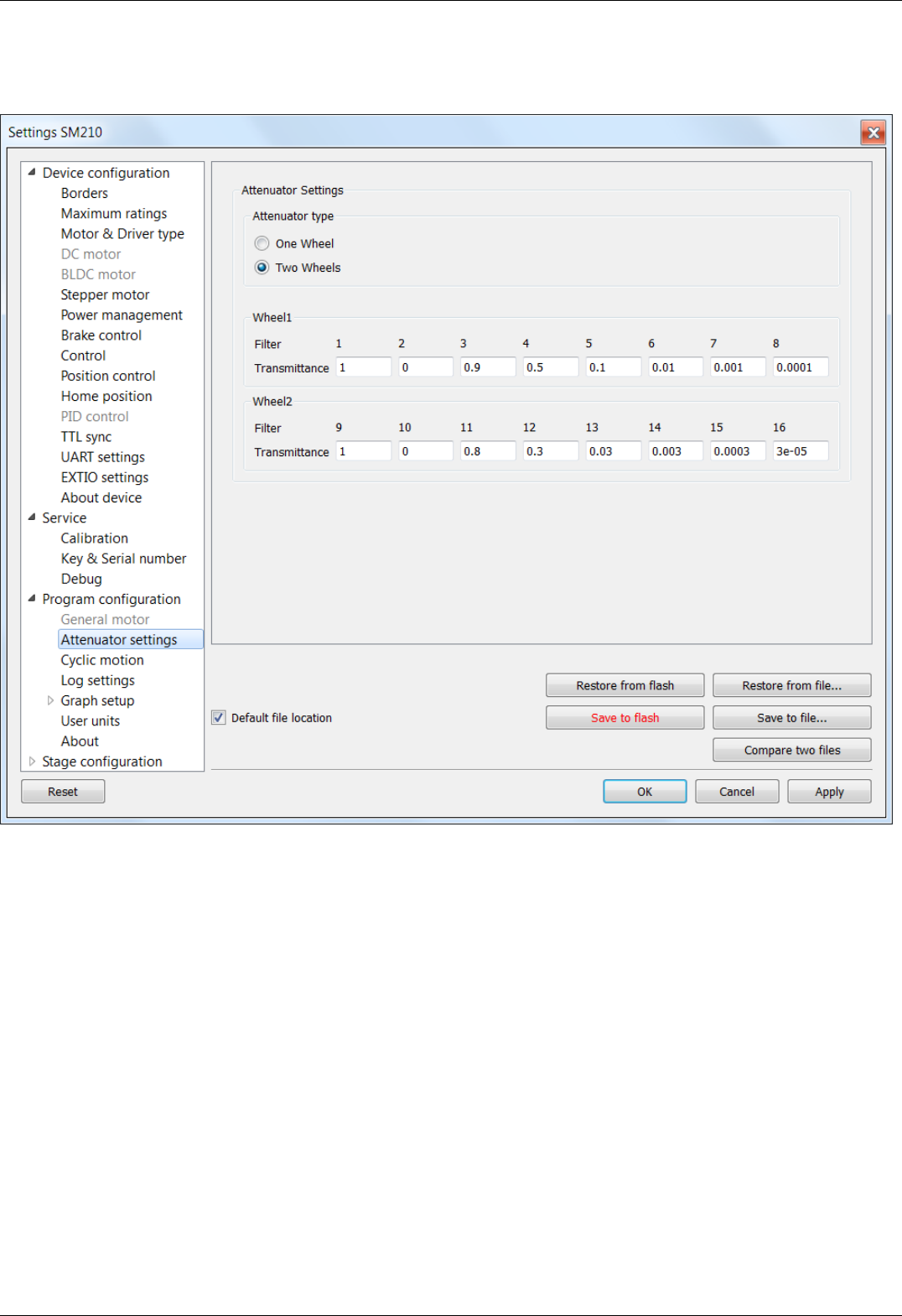
5.4.3. Attenuator settings
In the Application Settings Program configuration -> Attenuator settings
Attenuator settings tab
This tab is used to configure attenuator interface. An attenuator is a device used to reduce the power level of an optical signal by
passing light through one or several optical filters. This tab becomes active when an "Attenuator" skin type is selected in "Program
configuration" tab.
Attenuator type group contains radio buttons which allow one to choose one- or two-wheel configuration of the attenuator.
Depending on the choice here one or two Wheel groups become available. They should be filled with attenuator filters' transparency
values on the corresponding wheel, in order.
Page 157 / 345
Page 157 / 345
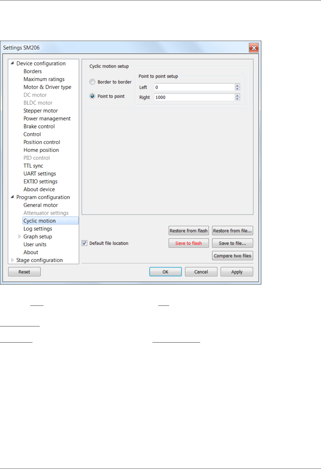
5.4.4. Cyclical motion settings
In the Application Settings Program configuration -> Cyclic motion
Cyclic motion tab
Use this tab to configure the cyclic motion between two preset positions. It is used mainly for demonstration purposes. This mode is
activated by Cyclic button in the main window, and deactivated by Stop button in the main window.
Cyclic motion mode settings:
Border to border - cyclical motion between the borders configured in the Motion range and limit switches . The motion begins towards
the left edge.
Point to point - cyclical motion between points specified in the Point to point setup group. The stage moves to the left point, stops,
then moves to the right point, stops, and then the cycle repeats.
Page 158 / 345
Page 158 / 345
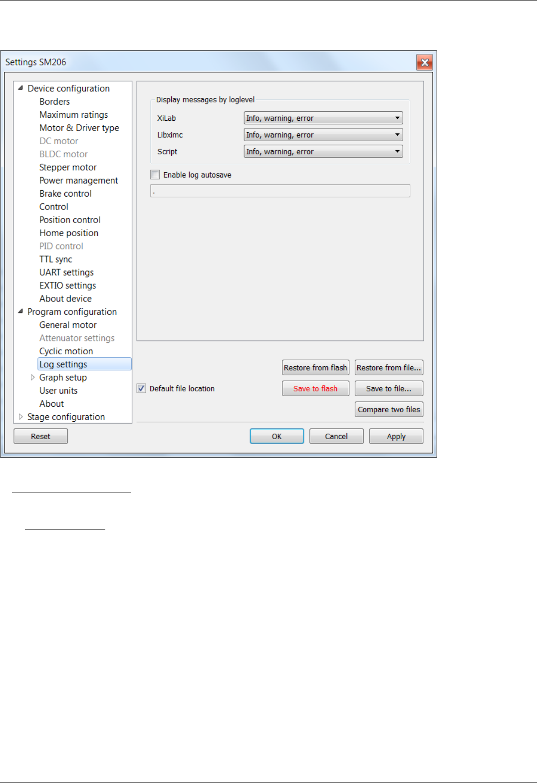
5.4.5. Log settings
XILab log settings window
On this page (Program configuration -> Log settings) you can configure the logging detail level.
I n Display messages by loglevel box you can choose an option to log nothing (None), log only errors (Error), errors and warning
messages (Error, Warning), errors, warnings and information messages (Error, Warning, Info) for each source: XILab application,
libximc library and Scripts module.
If the Enable log autosave checkbox is checked then the log is saved into file. Directory where the log file will be saved is set below.
Log file is flushed to the disk every 5 seconds.
File has a name of type "xilab_log_YYYY.MM.DD.csv", where YYYY, MM and DD are current year, month and day, respectively. Data is
stored in CSV format. Messages that are saved into the log file are not filtered by logging options.
Page 159 / 345
Page 159 / 345
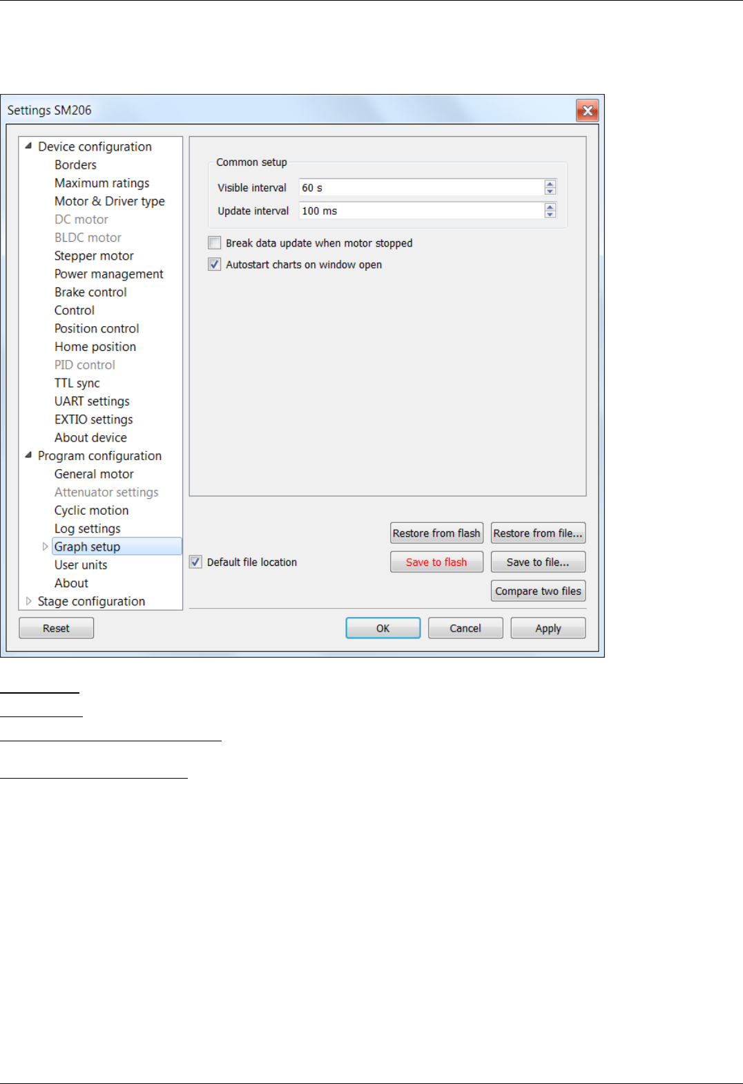
5.4.6. Charts general settings
Program configuration -> Graph setup in the Application Settings
Charts general settings tab
Visible interval - the time interval displayed in charts on the horizontal axis.
Update interval - chart data update interval.
Break data update when motor stopped - stops drawing charts when the motor stops. This option provides the possibility to use the
chart space more rationally, removing the areas when there is no motor motion.
Autostart charts on window open - starts displaying chart data automatically on window open. If you wish to start charts update
manually, then uncheck this option.
Page 160 / 345
Page 160 / 345
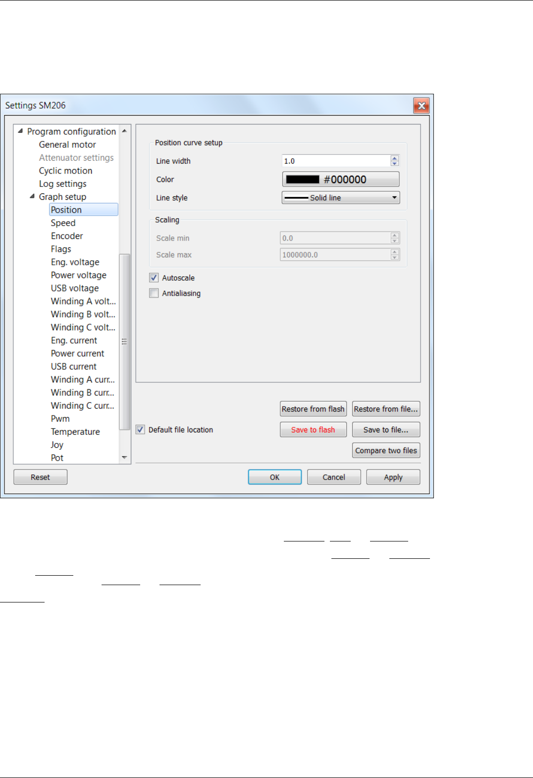
5.4.7. Charts customization
In the Application Settings Program configuration -> Graph setup -> ...
This section equally applies to the individual appearance settings of speed, voltage, current, PWM duty factor, temperature, and other
parameter charts, which can be displayed in the XILab application.
Charts customization on the example of the position chart tab
Charts display settings include line style and chart vertical axis scale adjustment.
Position curve setup group changes curve parameters. It includes the Line width, Color and Line style.
Scaling group changes curve display range on the vertical axis by setting values in Scale min and Scale max.
Checked Autoscale flag results in auto-scaling of the scale limits in accordance with the change limits of the variable on the axis Y. In
this case, the parameters Scale min and Scale max are ignored.
Antialiasing flag enables chart lines smoothing, which provides the possibility to achieve a higher-quality display, but it slows a little the
chart drawing process.
Page 161 / 345
Page 161 / 345

5.4.8. User units settings
In the Application Settings Program configuration -> User units
User units tab
Use this tab to configure user units display. Used to replace internal controller coordinates with units familiar to the user.
User units settings:
Enable user units - enables user unit display instead of steps (in case of stepper motor) or encoder counts (in case of DC motor). User
units replace steps(counts) only in the main XILab window and do not affect any of the Settings pages.
Ratio - conversion of controller steps to position units, set as a ratio of two integer values "x steps = y user units". Values "x", "y" and
unit name string are set by user.
Precision - displayed precision.
Get from EEPROM button reads user unit settings from connected EEPROM.
Page 162 / 345
Page 162 / 345
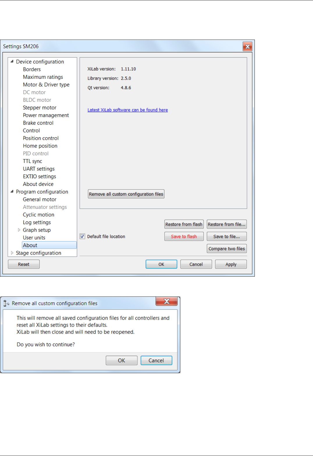
5.4.9. About the application
Program configuration -> About in the Application Settings
About tab
This section displays the XILab application version. It also contains a link to the page with the latest Software version.
User configuration file cleanup dialog
"Remove all custom configuration files" button displays a dialog prompt to delete all custom configuration files created by XiLab. Files
to be deleted are located in XiLab configuration directory. These files are "settings.ini", which stores common program settings,
"SNnnn.cfg", which store per-controller settings, "V_nnn", which store virtual controller internal states, "scratch.txt", which stores last
run script. Here "nnn" means any number. Pressing OK in this dialog will delete all these files and close XiLab, pressing Cancel will
abort deletion and close this dialog.
Page 163 / 345
Page 163 / 345


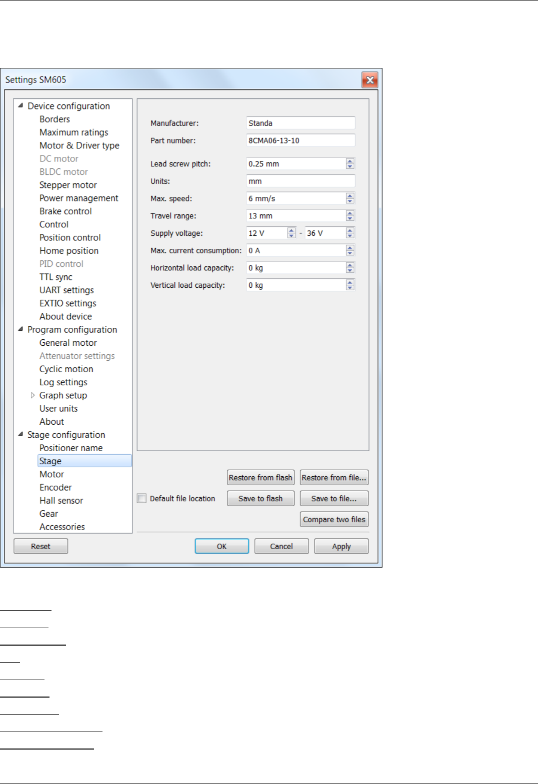
5.5.2. Positioner general characteristics
Stage configuration -> Stage in the Application Settings
Positioner general characteristics window
Stage parameter prouop contains information about the stage.
Manufacturer - the manufacturer name.
Part number - the catalog number.
Lead screw pitch - lead screw pitch.
Units - stage movement measurement units (mm, degrees, steps).
Max. speed - the maximum speed.
Travel range - range of motion.
Supply voltage - acceptable supply voltage range.
Max. current consumption - the maximum current consumption.
Horizontal load capacity - the maximum horizontal load on the stage.
Page 166 / 345
Page 166 / 345

Vertical load capacity - the maximum vertical load on the stage.
Page 167 / 345
Page 167 / 345
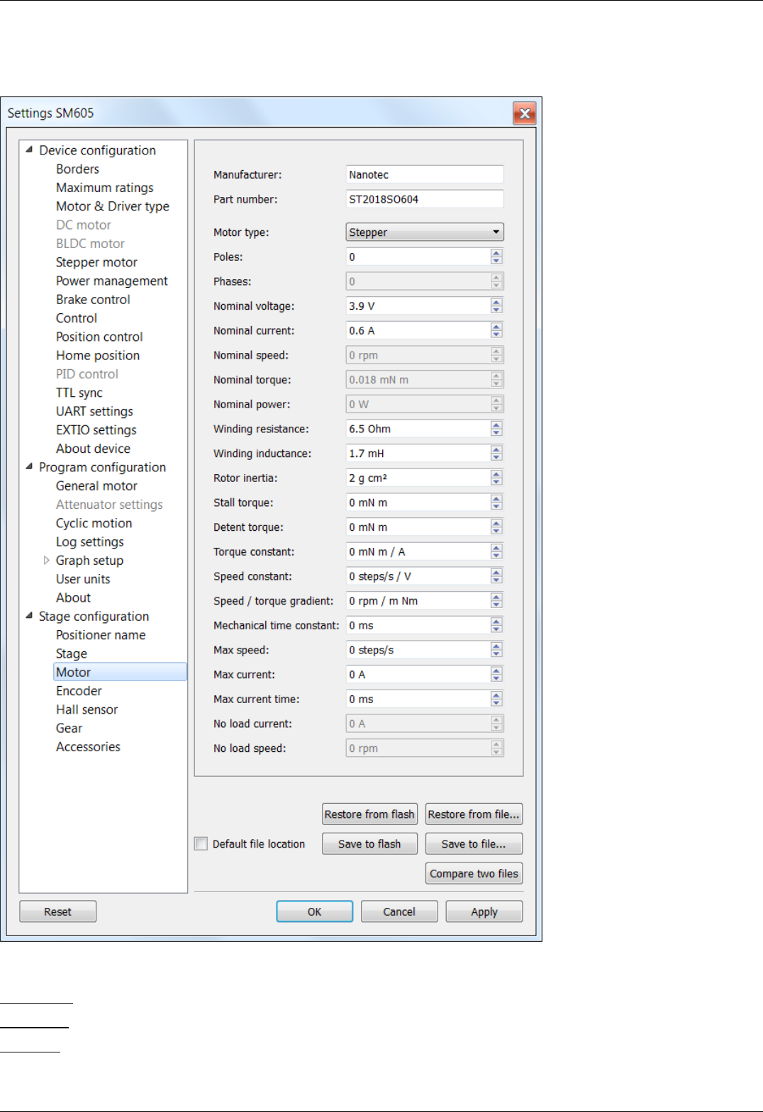

Poles - number of pole pairs for DС or BLDC motors, steps per revolution for stepper motors.
Phases - BLDC motor phases.
Nominal voltage - nominal winding voltage.
Nominal current - maximum continuous winding current for DC or BLDC motors, nominal current for stepper motors.
Nominal speed - nominal speed.
Nominal torque - nominal torque.
Nominal power - nominal power consumption.
Winding resistance - active resistance of the winding.
Winding inductance - inductance of the winding.
Rotor inertia - rotor inertia.
Stall torque - zero speed torque.
Detent torque - hold torque with unpowered windings.
Torque constant - torque constant.
Speed constant - speed constant.
Speed/torque gradient - speed/torque constant.
Mechanical time constant - motor time constant.
Max speed - maximum allowed speed.
Max current - maximum allowed winding current.
Max current time - maximum safe time of max current in the winding.
No load current - no-load current consumption.
No load speed - no-load motor speed.
Page 169 / 345
Page 169 / 345
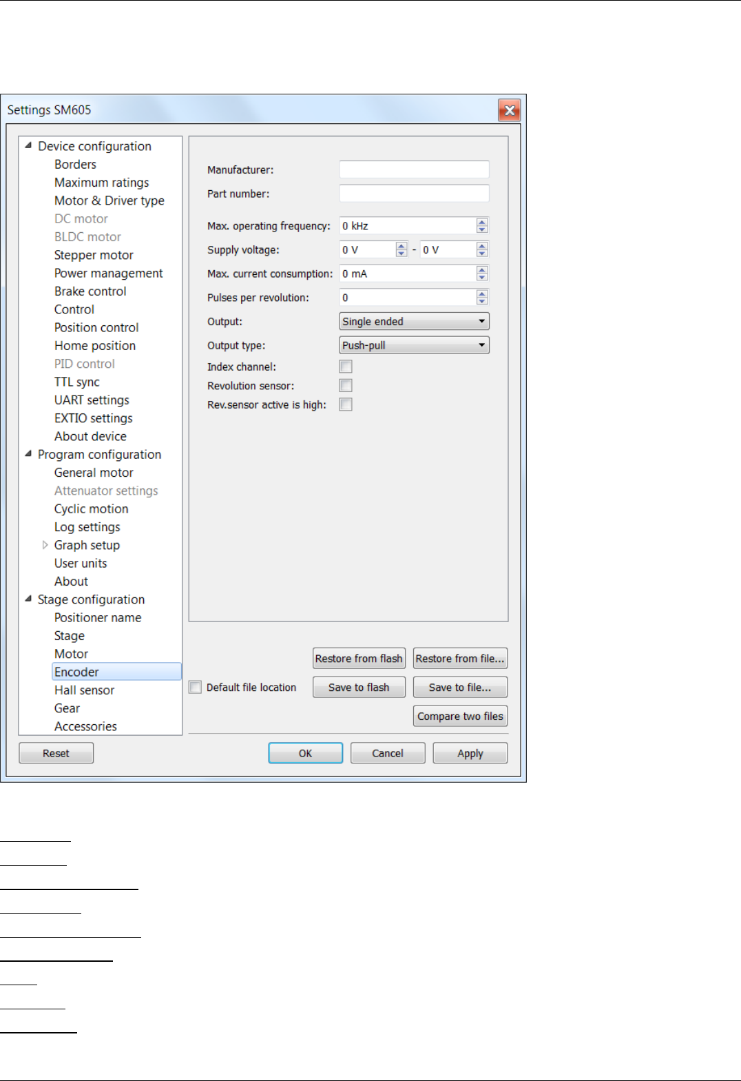
5.5.4. Encoder specifications
Stage configuration -> Encoder in the Application Settings
Window Encoder specifications
This section contains information about encoder
Manufacturer - encoder manufacturer name.
Part number - the catalog number.
Max. operating frequency - the maximum operating frequency.
Supply voltage - acceptable supply voltage range.
Max. current consumption - the maximum current consumption.
Pulses per revolution - pulses per single motor shaft revolution.
Output - differential or single-ended output.
Output type - electric output type (push-pull or open drain).
Index channel - indicates if additional index channel is present.
Page 170 / 345
Page 170 / 345

Revolution sensor - indicates if revolution sensor is present.
Rev.sensor active is high - if enabled then active revolution sensor state is logical 1, else it is logical 0.
Page 171 / 345
Page 171 / 345
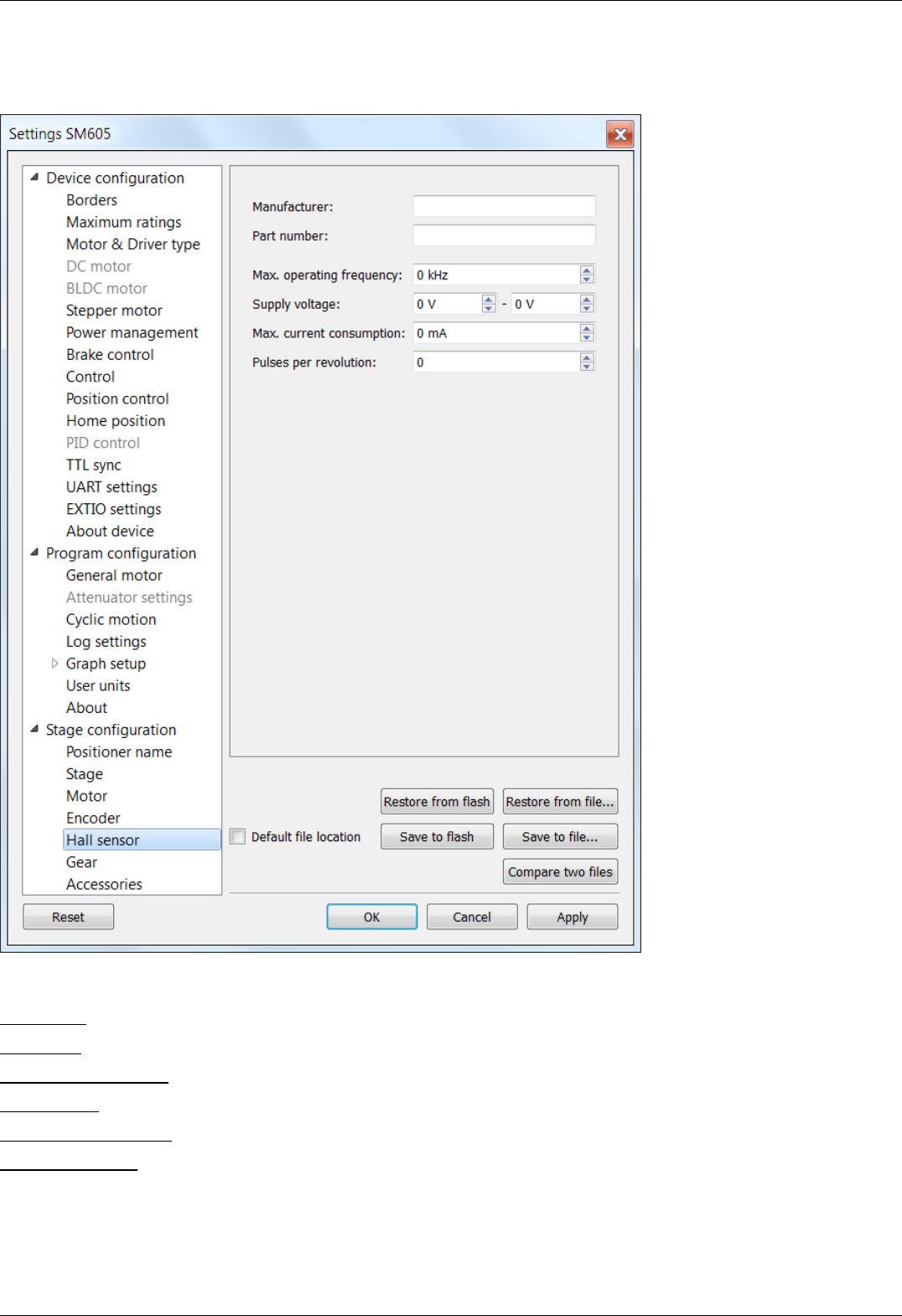
5.5.5. Hall sensor characteristics
Stage configuration -> Hall sensor in the Application Settings
Hall sensor properties window
This section contains information about hall sensor:
Manufacturer - sensor manufacturer name.
Part number - the catalog number.
Max. operating frequency - the maximum operating frequency.
Supply voltage - acceptable supply voltage range.
Max. current consumption - the maximum current consumption.
Pulses per revolution - pulses per single motor shaft revolution.
Page 172 / 345
Page 172 / 345

5.5.6. Reducing gear specifications
Stage configuration -> Gear in the Application Settings
Reducing gear specifications window
This section contains information about the reducing gear.
Manufacturer - the manufacturer name.
Part number - the catalog number.
Reduction - gear transmission ratio.
Max. continious torgue - maximum torque at the gear input.
Max. input speed - the maximum speed at the gear input.
Output backlash - gear output backlash.
Equivalent input inertia - equivalent input inertia of the gear.
Efficiency - Gear efficiency.
Page 173 / 345
Page 173 / 345
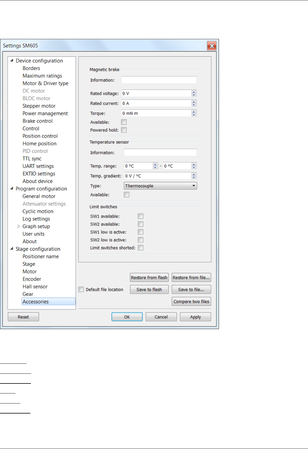
5.5.7. Accessories specifications
Stage configuration -> Accessories in the Application Settings
Accessories specifications window
This panel contains information about various accessories.
Magnetic brake - magnetic brake section.
Information - magnetic brake manufacturer and part number.
Rated voltage - nominal magnetic brake voltage.
Rated current - nominal magnetic brake current.
Torque - hold torque.
Available - indicates if magnetic brake is available.
Powered hold - magnetic brake is in hold mode on power on if this option is enabled.
Temperature sensor - temperature sensor section.
Page 174 / 345
Page 174 / 345

Information - temperature sensor manufacturer and part number.
Temp. range - measuered temperature range.
Temp. gradient - temperature gradient.
Type - sensor type (thermocouple or semiconductor).
Available - indicates if temperature sensor is available.
Limit switches - limit switches section.
SW1 available - indicates if SW1 limit switch is available.
SW2 available - indicates if SW2 limit switch is available.
SW1 low is active - indicates if SW1 limit switch active state is low.
SW2 low is active - indicates if SW2 limit switch active state is low.
Limit switches shorted - if enabled, then limit switches are shorted.
Page 175 / 345
Page 175 / 345

5.6. Correct shutdown
Correct shutdown assumes shutdown of the motor and saving the current position by the controller. The current position is
automatically saved, see Saving the position in controller's FRAM memory .
Exit button performs correct shutdown and exit. When you click it the application sends a soft stop command to the controller, and
after the stop is complete, the application sends command of power-off. If execution of the soft stop command was interrupted by an
event like a motion command from the joystick or signal of TTL synchronization, or if while sending of soft stop command or command
of power off to the controller, the library returned an error, the exit will be canceled. In this case you need to check joystick settings
and settings of "right" and "left" buttons and Synchronization settings.
Page 176 / 345
Page 176 / 345
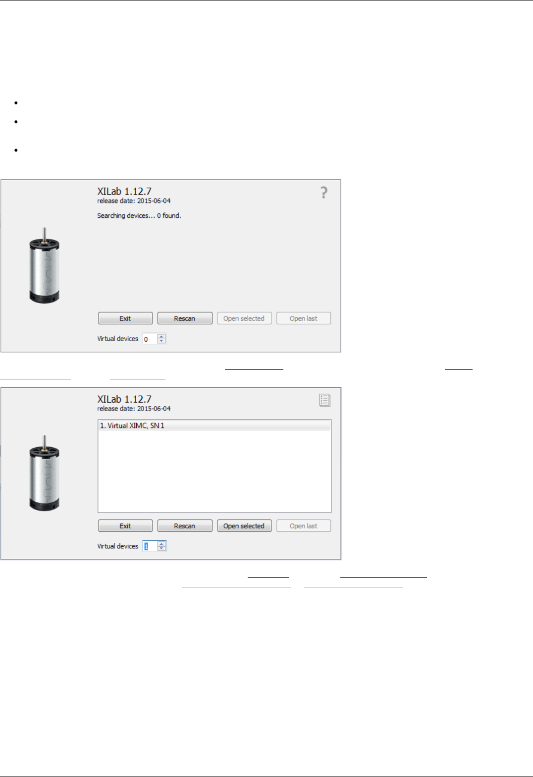
5.7. Working over network
XiLab is capable of interacting with remote controllers via Ethernet. However you need a special XIMC server, which can be either
obtained as a standalone program and installed on any appropriate device, or as one of the services of 8SMC4-USB-Eth1 adapter.
Getting started
Before launching, connect controllers to the device with XIMC server installed using USB cable. At the same time, it is assumed
that controllers can be connected to the motor and energized from power supply (see one axis configuration for more details).
Connect the device with XIMC server to the same subnet that contains the control computer, DHCP server. In case of 8SMC4-
USB-Eth1 adapter supply it with power adapter (via 5V - 2A connector) and wait for a minute to finish Linux boot on the
onboard computer.
Launch XiLab and make the following.
At first start, XiLab opens controller detection window with no devices found.
Add virtual XIMC controller by increasing the number of Virtual Devices in the bottom part of window and click Rescan. Then choose
Virtual XIMC, SN1 and click Open selected.
XiLab main window with single axis mode will appear. Go to Settings... and choose Program configuration (for detailed information
please refer to XiLab general settings). Check Enumerate network devices in Device detection settings and press "Scan for local XIMC
servers" button. XiLab will use broadcast request to find available XIMC servers in your LAN and for each detected instance an entry in
the "IP/hosts" list will be created. You can also edit address list manually if desired.
Click OK and close XiLab.
Page 177 / 345
Page 177 / 345
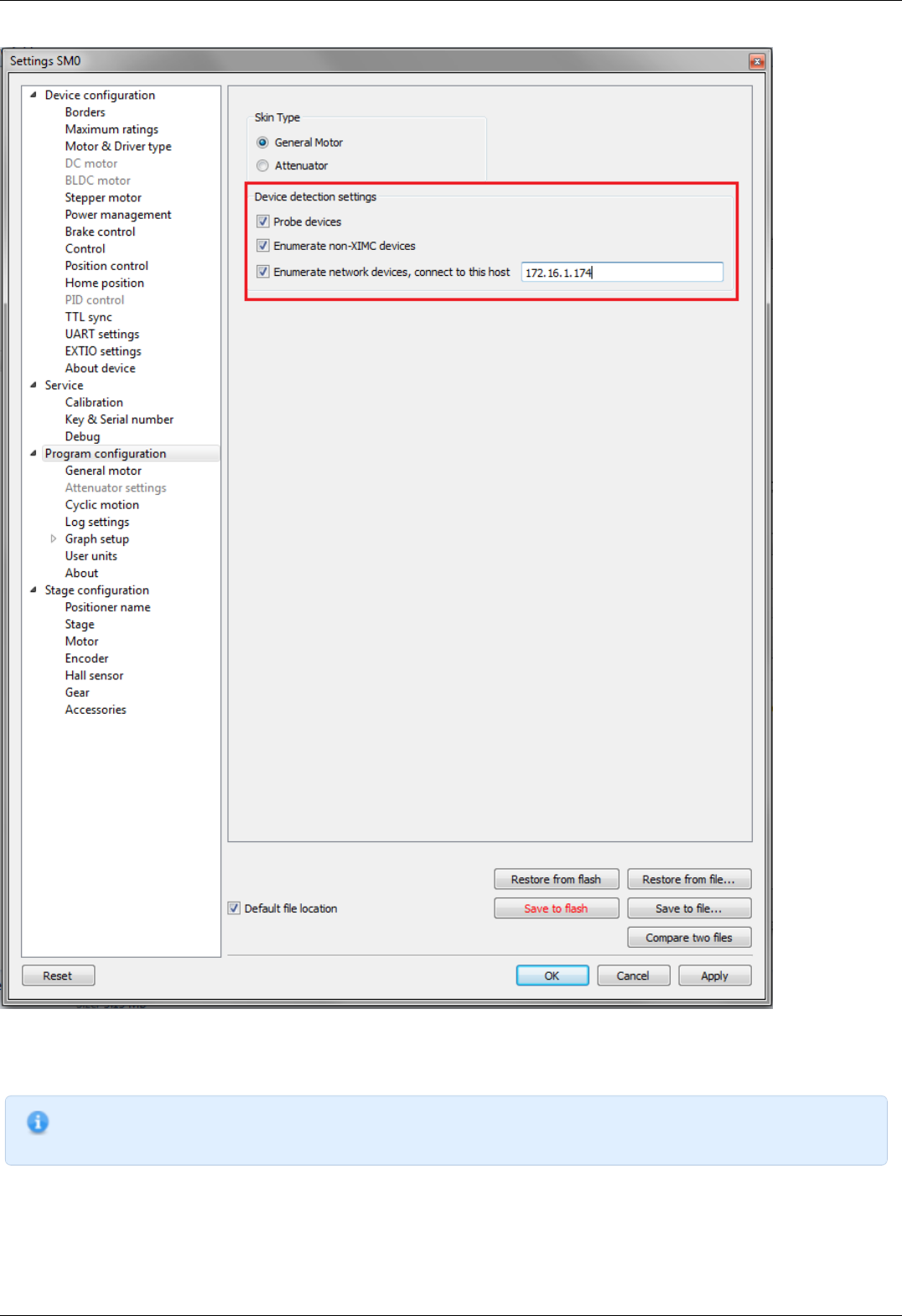
When you restart XiLab it will find all axis connected to the system. In controller detection window choose an axis you need. You can
control it in single-axis mode or in multi-axis mode if more than one axis was chosen. For additional information please refer to Getting
started with XiLab software and XILab application User's guide
Note. Once the device IP address has been found, it should be understood that moving the device to another location
may lead to a change in its IP.
Page 178 / 345
Page 178 / 345

Note. Working with multiple adapters may cause a problem when the same board responds in a broadcast requests.
You can find a new device by two different ways :
Disconnect other axes, find the device on the network, connect all again.
Press Scan for local XIMC servers button until you find sought-for device.
Page 179 / 345
Page 179 / 345


5.8.1.1. Installation on Windows XP
Copy the installer program file to your computer. The installer file name is "xilab-<version_name>.exe". It automatically detects
whether it is running on 32-bit or 64-bit version of Windows and installs the appropriate version of XiLab.
Note: Only Windows XP SP3 is supported. Please update your Windows XP to the latest service pack.
Run the installer and follow the on-screen instructions.
Page 182 / 345
Page 182 / 345
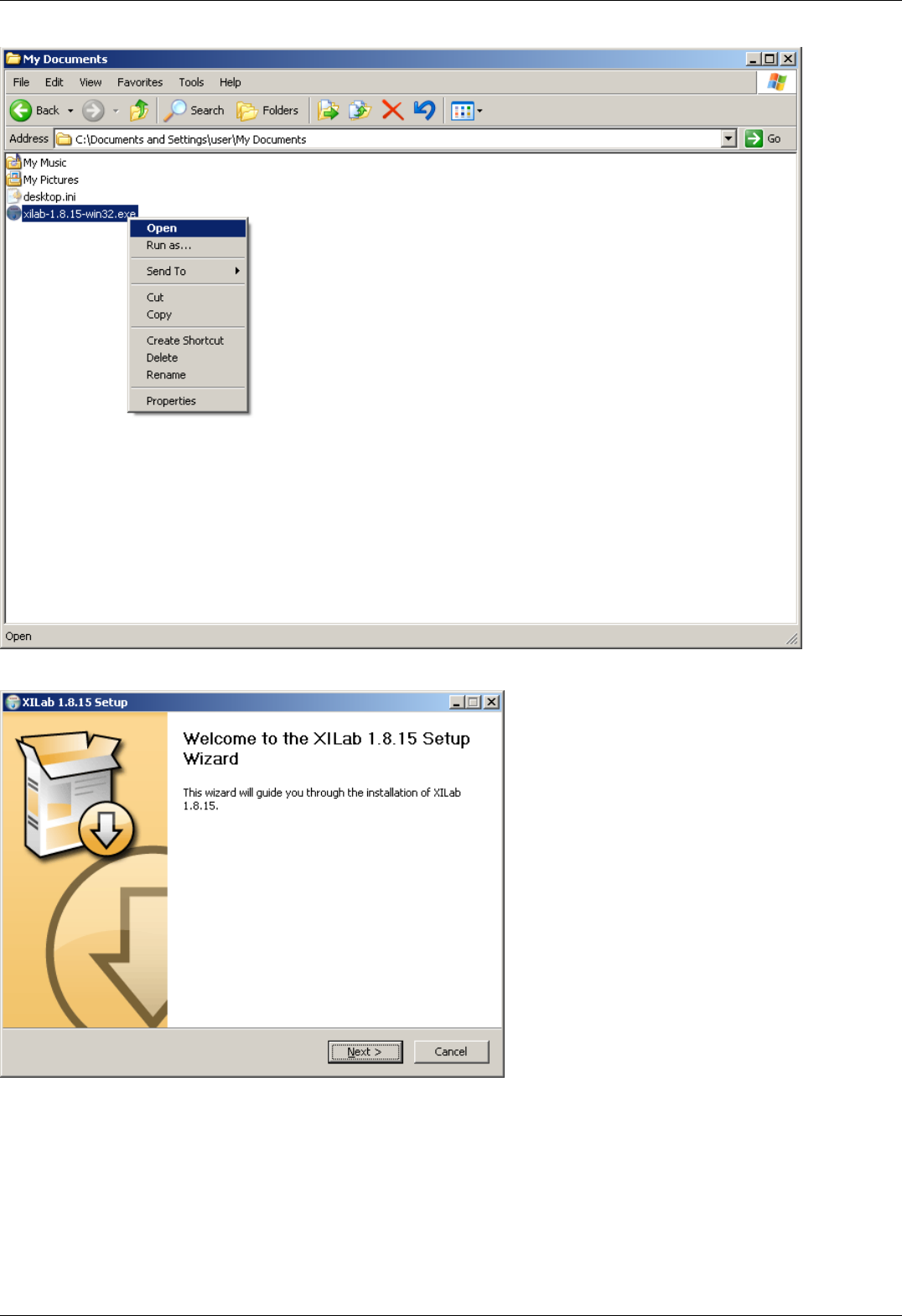
All the necessary software including drivers, packages and programs will be installed automatically.
After the installation is complete the XiLab application will be started by default.
Page 183 / 345
Page 183 / 345
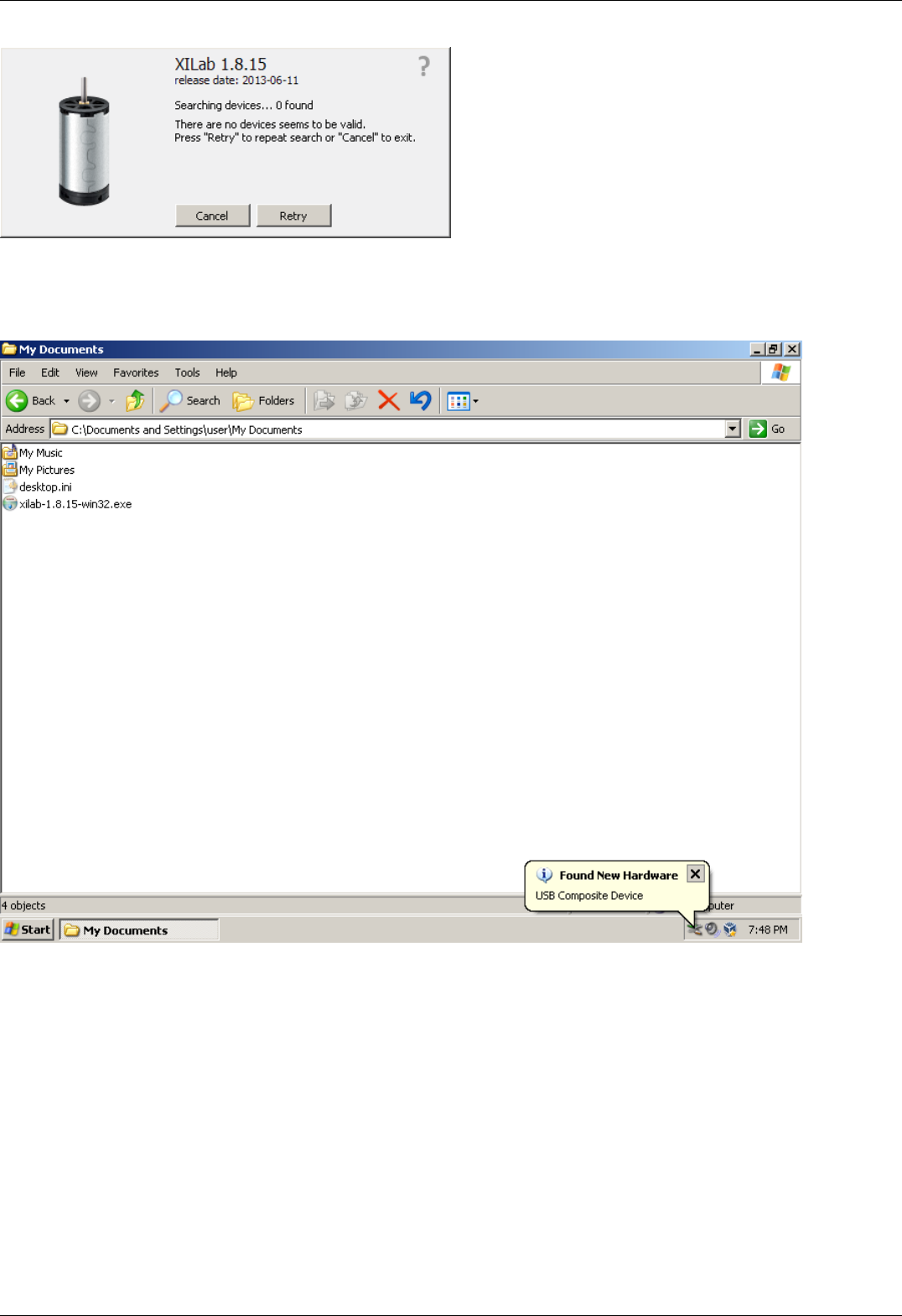
Connect the stage to the controller. Connect regulated power supply to the controller. Ground the controller or the power supply unit.
Connect the controller to the computer using a USB-A - mini-USB-B cable.
LED indicator on the controller board will start to flash. New Hardware Wizard will start after the first controller is connected to the
computer. Wait until Windows detects the new device and installs the drivers for it.
If the driver was not automatically installed select "No, not this time" and click "Next>" in the pop-up window.
Page 184 / 345
Page 184 / 345
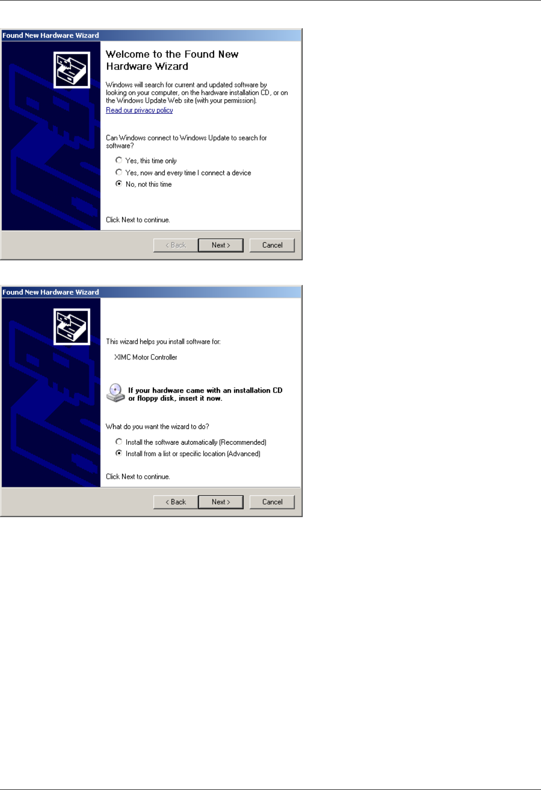
In the next window select "Install from a list or specific location (Advanced)" and click "Next>".
Select the *.inf file on the disk with the software supplied with the controller or in the program directory (by default the path is
C:\Program Files\XiLab\driver\) and click "Next".
Page 185 / 345
Page 185 / 345
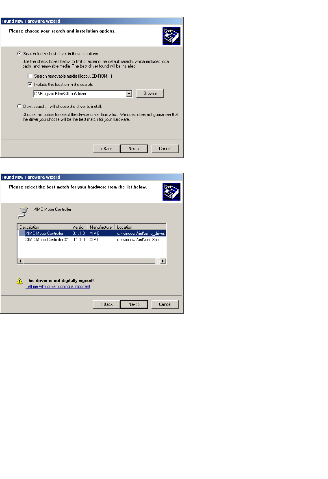
Click "Next".
Click "Continue anyway".
Page 186 / 345
Page 186 / 345
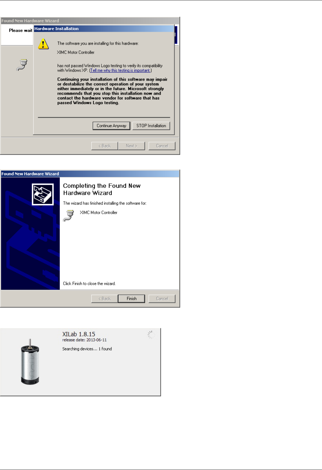
Click "Finish". Driver installation is complete.
Click Retry or run the Xilab application again if it was closed. The system will detect the connected controller and open the main Xilab
window.
Page 187 / 345
Page 187 / 345
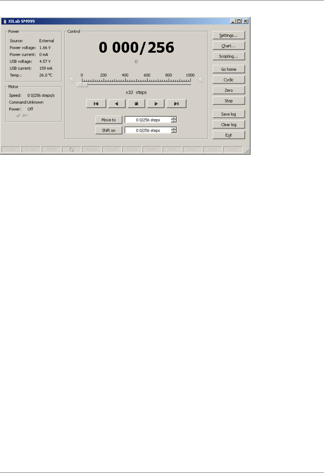
Page 188 / 345
Page 188 / 345
5.8.1.2. Installation on Windows 7
Copy the installer program file to your computer. The installer file name is "xilab-<version_name>.exe". It automatically detects
whether it is running on 32-bit or 64-bit version of Windows and installs the appropriate version of XiLab.
Run the installer and follow the on-screen instructions.
Page 189 / 345
Page 189 / 345
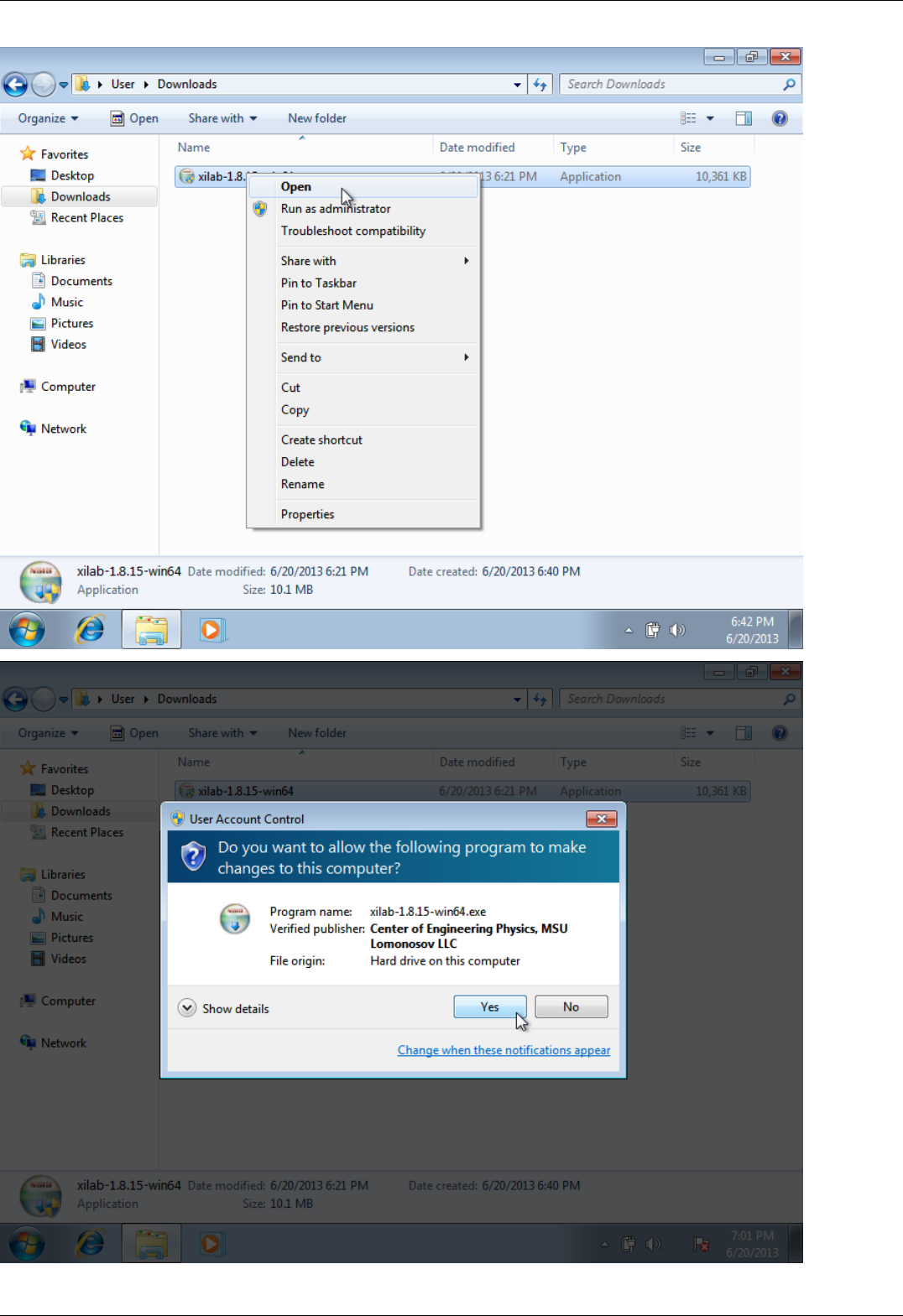
Page 190 / 345
Page 190 / 345

All the necessary software including drivers, packages and programs will be installed automatically.
After the installation is complete the XiLab application will be started by default.
Connect the stage to the controller. Connect regulated power supply to the controller. Ground the controller or the power supply unit.
Connect the controller to the computer using a USB-A - mini-USB-B cable.
LED indicator on the controller board will start to flash. New Hardware Wizard will start after the first controller is connected to the
computer.
Page 191 / 345
Page 191 / 345
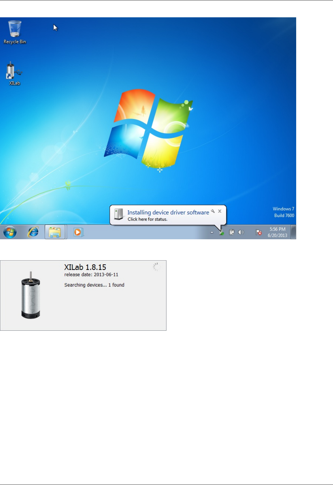
Wait until Windows detects the new device and installs the drivers for it. After the driver is successfully installed click Retry or run the
Xilab application again if it was closed. The system will detect the connected controller and open the main Xilab window.
Page 192 / 345
Page 192 / 345

Page 193 / 345
Page 193 / 345
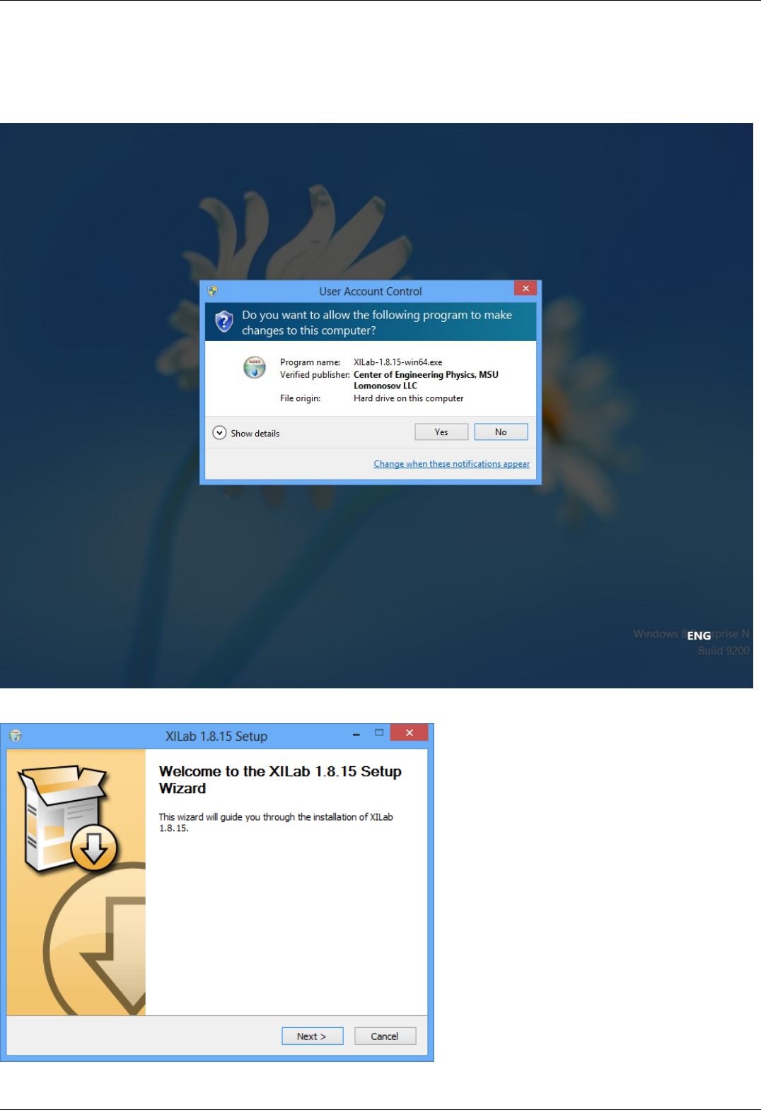
5.8.1.3. Installation on Windows 8
Copy the installer program file to your computer. The installer file name is "xilab-<version_name>.exe". It automatically detects
whether it is running on 32-bit or 64-bit version of Windows and installs the appropriate version of XiLab. Run the installer and follow
the on-screen instructions.
All the necessary software including drivers, packages and programs will be installed automatically.
Page 194 / 345
Page 194 / 345
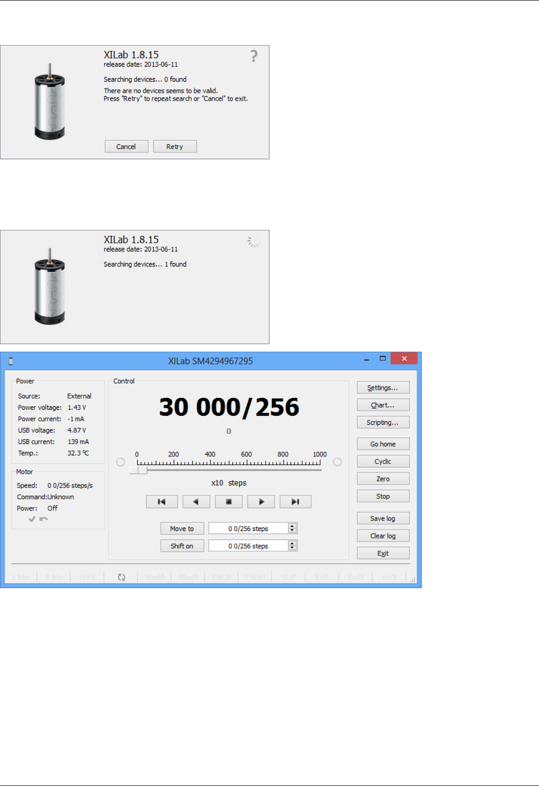
After the installation is complete the XiLab application will be started by default.
Connect the stage to the controller. Connect regulated power supply to the controller. Ground the controller or the power supply unit.
Connect the controller to the computer using a USB-A - mini-USB-B cable.
LED indicator on the controller board will start to flash. New Hardware Wizard will start after the first controller is connected to the
computer. Wait until Windows detects the new device and installs the drivers for it. After the driver is successfully installed, click Retry,
or run the Xilab application again, if it was closed. The system will detect the connected controller and open the main Xilab window.
Page 195 / 345
Page 195 / 345
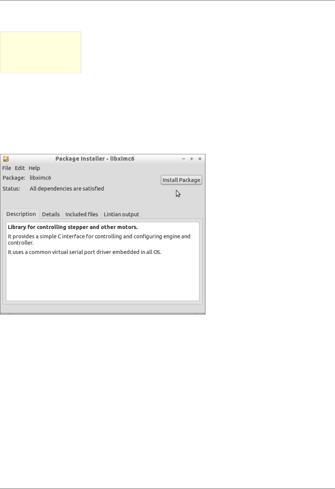
5.8.2. Installation on Linux
5.8.2. Installation on Linux
Debian / Ubuntu
Installing in graphical mode
The text installer
RedHat / OpenSUSE
The text installer
XILab package installs its files in the following directories:
/usr/bin/xilab - executable file
/usr/share/icons/xilab.png - Icon
/usr/share/xilab/scripts/ - directory scripts
/usr/share/xilab/profiles/ - directory with profiles
/usr/share/xilab/xilabdefault.cfg - file with the default settings
Debian / Ubuntu
Installing in graphical mode
Click on the file libximc6_x.y.z-1_i386.deb (for 32-bit versions of Linux) or libximc6_x.y.z-1_amd64.deb (for 64-bit versions of Linux).
Installation window will appear. Click the Install package. This will install the libximc library.
Page 196 / 345
Page 196 / 345
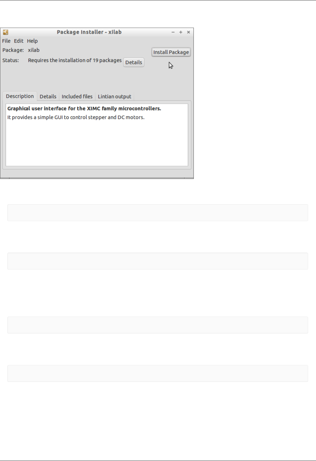
Click on the file xilab_x.y.z-1_i386.deb (for 32-bit versions of Linux) or xilab_x.y.z-1_amd64.deb (for 64-bit versions of Linux).
Installation window will appear. Click the Install package. Dependencies and Xilab application will be installed.
The text installer
Execute the following commands as super-user (root):
gdebi "<FILEPATH>/libximc6_<LIBVERSION>-1_<ARCH>.deb"
gdebi "<FILEPATH>/xilab-<VERSION>-1_<ARCH>.deb"
where <FILEPATH> is the path to package files (eg "/home/user/Downloads/"), <LIBVERSION> and <VERSION> are the version
numbers of libximc library and xilab application respectively (for example, "2.0.2" and "1.8.12") and <ARCH> is the identifier of
architecture ("i386" for 32-bit systems and "amd64" for 64-bit systems).
Example:
gdebi "/home/user/Downloads/libximc6-2.0.2-1_amd64.deb"
gdebi "/home/user/Downloads/xilab-1.8.12-1_amd64.deb"
Xilab application requires X-server (graphic mode) for operation.
RedHat / OpenSUSE
The text installer
Execute the following commands as super-user (root):
zypper install "<FILEPATH>/libximc6-<LIBVERSION>-1.<ARCH>.rpm"
zypper install "<FILEPATH>/xilab-<VERSION>-1.<ARCH>.rpm"
where <FILEPATH> is the path to package files (eg "/home/user/Downloads/"), <LIBVERSION> and <VERSION> are the version
numbers of libximc library and Xilab application respectively (for example, "2.0.2" and "1.8.12") and <ARCH> is the identifier of
architecture ("i386" for 32-bit systems and "amd64" for 64-bit systems).
Example:
zypper install "/home/user/Downloads/libximc6-2.0.2-1.x86_64.rpm"
zypper install "/home/user/Downloads/xilab-1.8.12-1.x86_64.rpm"
Xilab application requires X-server (graphic mode) for operation.
Page 197 / 345
Page 197 / 345
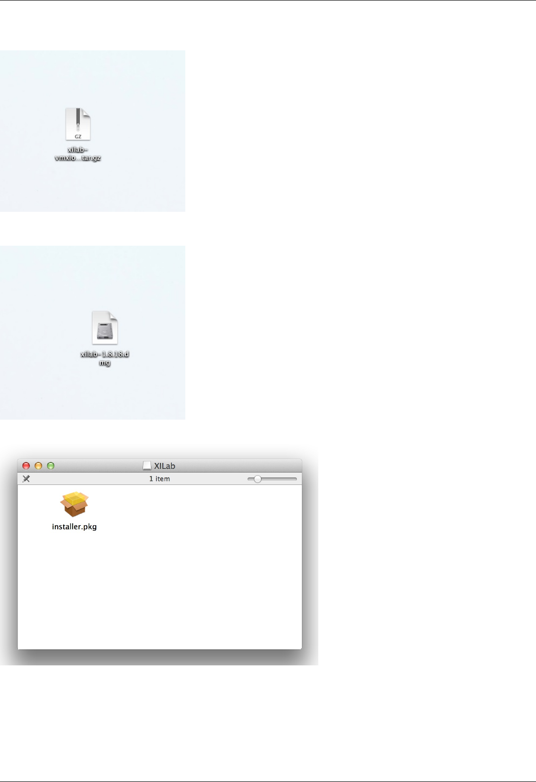
5.8.3. Installation on MacOS
Copy the file with the installer archive to your computer. The archive with the installation program is named "xilab-<version_number>-
osx64.tar.gz".
Unpack the archive by a mouse click.
Make right button click on installer.pkg.
Page 198 / 345
Page 198 / 345
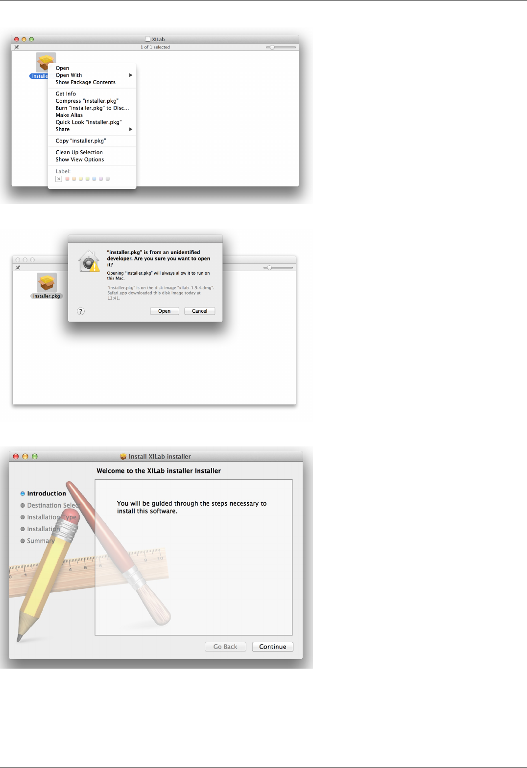
Choose "Open".
Choose "Open".
Select "Continue" in the main window of the installer.
Page 199 / 345
Page 199 / 345
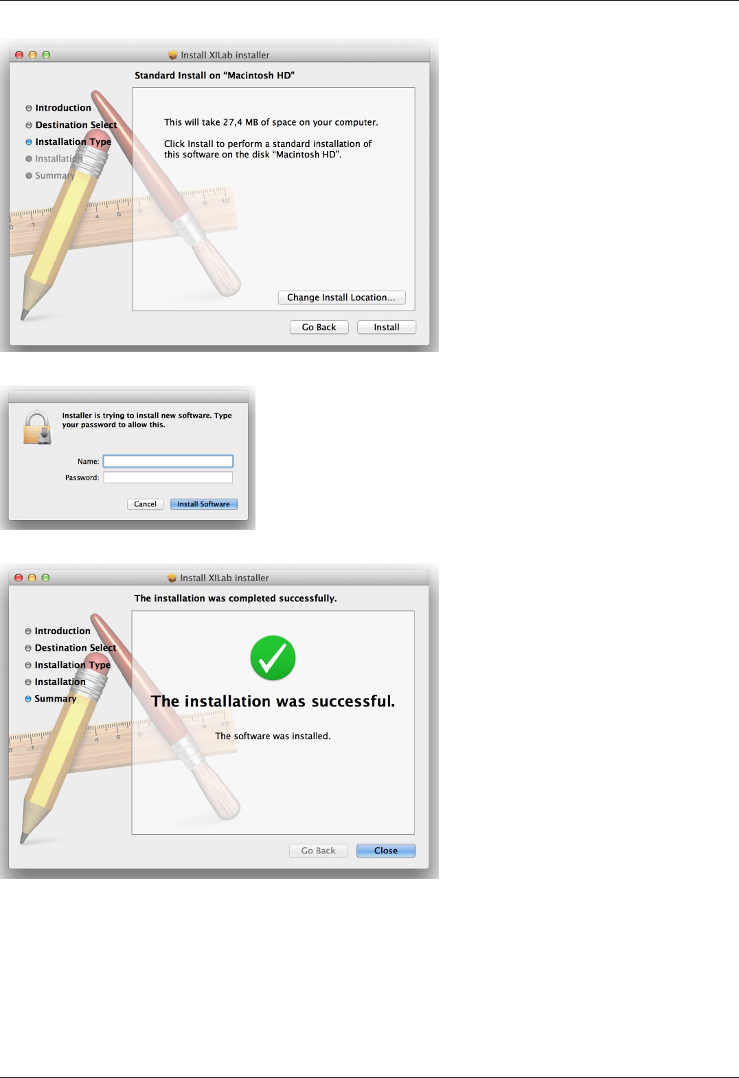
Now select "Install."
Enter the password.
Wait until the installation is complete.
Page 200 / 345
Page 200 / 345

Select the XILab application in the Programs block
Start it.
Page 201 / 345
Page 201 / 345


6.1. Programming guide
Programming guide is included in development kit libximc 2.X.X, where 2.X.X is the version number. It is located in /ximc-
2.X.X/ximc/doc-en/libximc7-en.pdf. Also the programming guide can be downloaded from this link. Development kit can be
downloaded on Software page. Programming guide is Doxygen-based.
Working with controller in Labview
Working with controller in Matlab
Page 203 / 345
Page 203 / 345

6.1.1. Working with controller in Labview
Download Labview example from the Software page.
Extract the archive and run "XImc Example One axis" file using Labview.
LabView environment will start. You will see graphical user interface of the front panel of the example, which looks like a simplified
XILab interface.
In the left part of the window you can find a "Find controllers" button to rescan available controllers, a field to pick the controller by its
serial port name and an information block which displays current open controller state (power and usb voltage and current,
temperature and movement speed).
In the central part of the window you will find indication and control block. This block contains a numeric field with current position,
left, right and soft stop buttons, controls to move to specified coordinate and shift on specified offset.
To the right of this block you can find "HOME", "ZERO", "STOP" and "Exit" buttons, which perform homing, zero current controller
position, perform fast stop and exit the example, respectively.
The rightmost block is a "Move settings" dialog, which demonstrates how you can load and save settings to the controller. When you
press its "GET" button current movement settings are loaded into the fields below this button and the "SET" button sends values from
its edit fields to the controller.
Example source can be viewed by entering edit mode. The example queries the controller status in an infinite loop and outputs the
results. If you press any button on the front panel the corresponding functional block of the example is run.
Page 204 / 345
Page 204 / 345
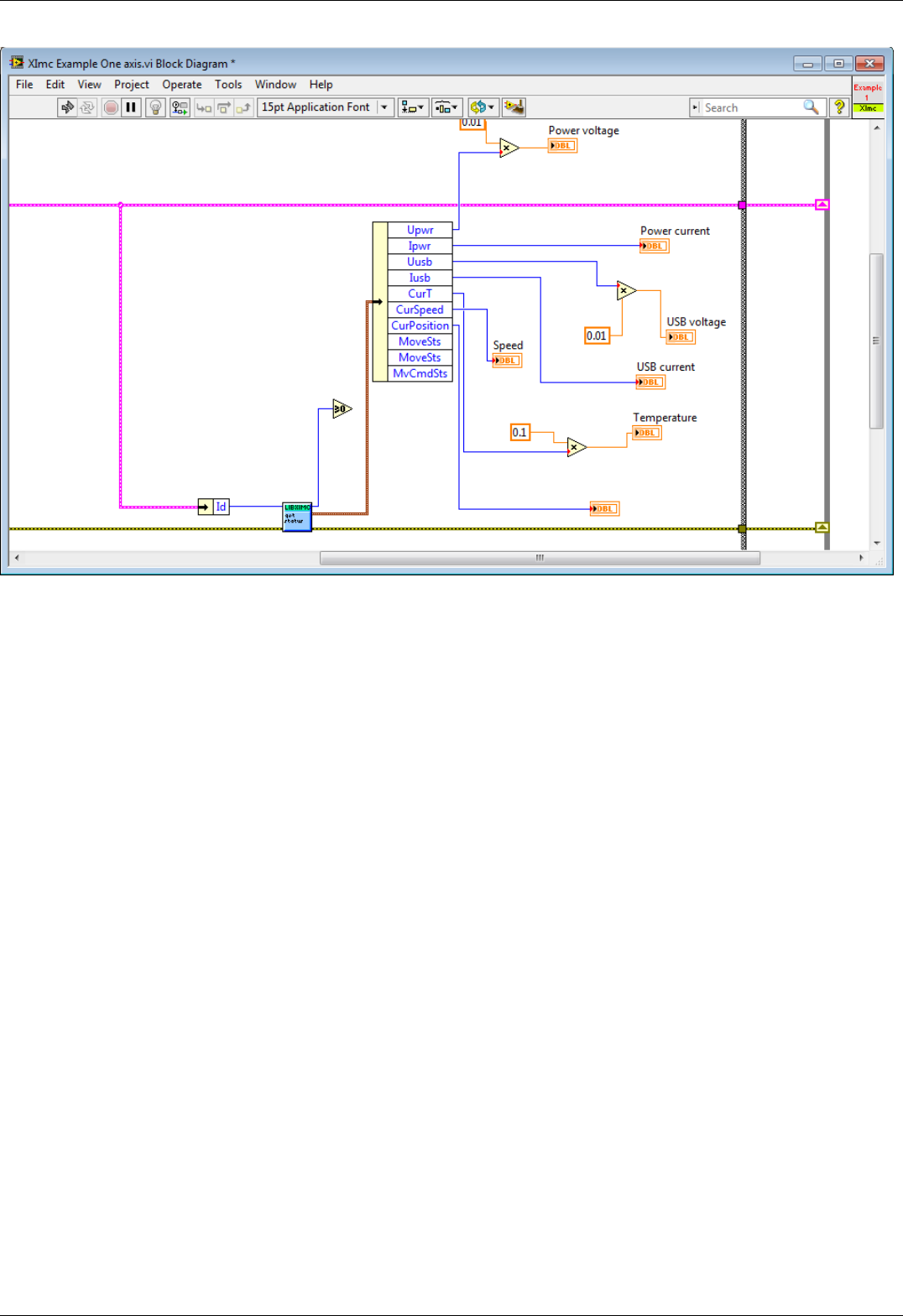
The example uses libximc library functions. Each function has a corresponding subVI module, which has inputs and outputs
corresponding to input and output parameters of this function. To call any libximc function one should first enumerate devices by using
"device_enumerate", then pick any device from the list and open it using "open_device" function, then pass resulting handle to desired
libximc function. After you're finished using the device it should be closed with "close_device" function.
Page 205 / 345
Page 205 / 345
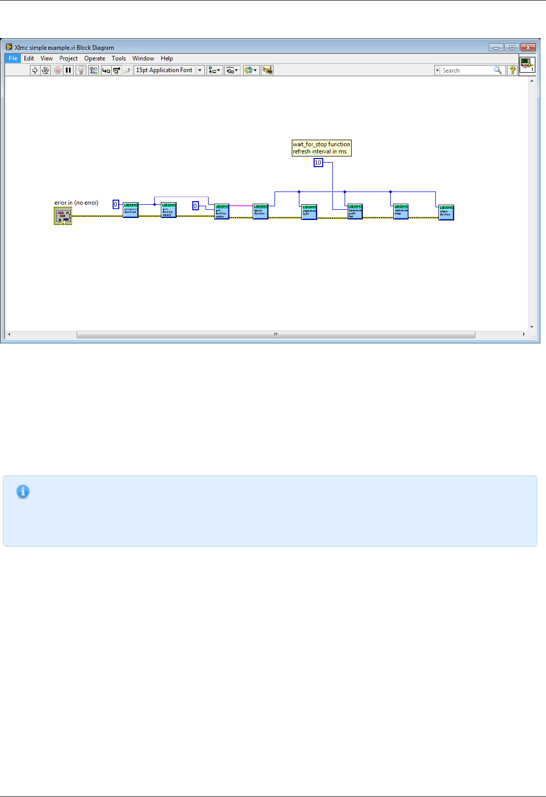
Let's review how to create a simple Labview program with libximc library using "Ximc simple example.vi".
The program starts by calling enumerate_devices function and passing it the enumerate flags parameter (for details see Programming
guide). Result of the enumerate_devices function call is an opaque pointer and is passed to the get_device_name function together
with device number, whose name we want to find out (one can get total number of found devices by passing the same opaque pointer
to the get_device_count function). Result of the get_device_name function call is a string, which is passed to the open_device function.
This function call sequence is not mandatory (though recommended) - one can manually form device name string and pass it to the
open_device function directly.
Result of the open_device function call is a device handle, or a ximc.h header constant device_undefined, which is returned if libximc
could not open specified device. Device handle is passed to all functions which read data from the controller, write data to the
controller or send commands to the controller, together with appropriate parameters if necessary by function prototype. "Ximc simple
example.vi" calls command_left, command_wait_for_stop and command_stop as an example. After you stop using the controller you
need to close its handle by passing it to the close_device function. After you stop using enumerate_devices result you need to free
allocated memory pointed to by this opaque pointer by passing it to the free_enumerate_devices function (not shown in this example).
Note. Libximc library opens controllers in exclusive access mode. Any controller opened by libximc needs to be closed
before it may be used by another process. Do not stop this Labview example or any other Labview program which
uses libximc with the "Abort execution" button - this doesn't give the running program a chance to call the
close_device() function, thus all open controllers will become locked and inaccessible until you close Labview
environment entirely.
Page 206 / 345
Page 206 / 345

6.1.2. Working with controller in Matlab
Libximc library can be used to work with controller in Matlab.
Note: SDK requires Microsoft Visual C++ Redistributable Package 9.0.307291 (provided with SDK - vcredist_x86 or
vcredist_x64).
Extract files from libximc development kit. Copy ximc.h, win64\libximc.dll, win64\bindy.dll, win64\xiwrapper.dll,
win64\wrappers\matlab\libximc_thunk_pcwin64.dll and win64\wrappers\matlab\ximc.m to examples\testmatlab if you are
using 64-bit Matlab environment or copy ximc.h, win32\libximc.dll, win32\bindy.dll, win32\xiwrapper.dll and
win32\wrappers\matlab\ximcm.h if you are using 32-bit one. Connect the controller to the PC and run the file testximc.m.
Page 207 / 345
Page 207 / 345
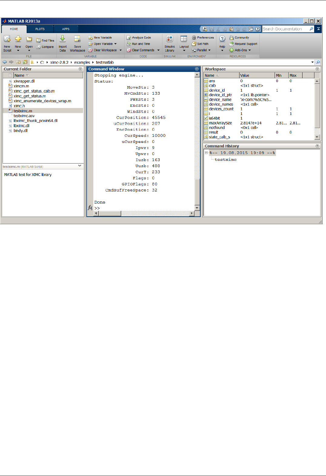
In the command window you will see the output of the example which reports controller status.
You can call libximc functions from Matlab program this way: define the path to the libximc.dll, bindy.dll and xiwrapper.dll
dynamic link libraries and its header ximc.h and additional to libximc_thunk_pcwin64.dll and ximc.m files if you are using 64-bin
environment. Use loadlibrary Matlab function once to load libximc library, then use calllib Matlab function to call desired libximc
function. You will find a list of libximc functions and their input and output parameters in the Programming guide.
Page 208 / 345
Page 208 / 345

6.2. Communication protocol specification (v17.5)
6.2. Communication protocol specification (v17.5)
Protocol description
Command execution
Controller-side error processing
Wrong command or data
CRC calculation
Transmission errors
Timeout resynchronization
Zero byte resynchronization
Library-side error processing
Library return codes
Zero byte synchronization procedure
Controller settings setup
Command SFBS
Command GFBS
Command SHOM
Command GHOM
Command SMOV
Command GMOV
Command SENG
Command GENG
Command SENT
Command GENT
Command SPWR
Command GPWR
Command SSEC
Command GSEC
Command SEDS
Command GEDS
Command SPID
Command GPID
Command SSNI
Command GSNI
Command SSNO
Command GSNO
Command SEIO
Command GEIO
Command SBRK
Command GBRK
Command SCTL
Command GCTL
Command SJOY
Command GJOY
Command SCTP
Command GCTP
Command SURT
Command GURT
Command SCAL
Command GCAL
Command SNMF
Command GNMF
Command SNVM
Command GNVM
Group of commands movement control
Command STOP
Command ASIA
Command PWOF
Command MOVE
Command MOVR
Command HOME
Command LEFT
Command RIGT
Command LOFT
Command SSTP
Group of commands set the current position
Command GPOS
Command SPOS
Command ZERO
Group of commands to save and load settings
Page 209 / 345
Page 209 / 345

Group of commands to save and load settings
Command SAVE
Command READ
Command SARS
Command RERS
Command EESV
Command EERD
Group of commands get the status of the controller
Command GETS
Command STMS
Command GETM
Command GETC
Command GETI
Command GSER
Group of commands to work with the controller
firmware
Command GFWV
Command UPDF
Service commands
Command SSER
Command RDAN
Command DBGR
Command DBGW
Group of commands to work with EEPROM
Command SNME
Command GNME
Command SSTI
Command GSTI
Command SSTS
Command GSTS
Command SMTI
Command GMTI
Command SMTS
Command GMTS
Command SENI
Command GENI
Command SENS
Command GENS
Command SHSI
Command GHSI
Command SHSS
Command GHSS
Command SGRI
Command GGRI
Command SGRS
Command GGRS
Command SACC
Command GACC
Bootloader commands
Command GBLV
Command IRND
Command GUID
Command CHMT
Controller error response types
ERRC
ERRD
ERRV
Protocol description
Controller can be controlled from the PC using serial connection (COM-port). COM-port parameters are fixed controller-side:
Speed: 115200 baud;
Frame size: 8 bits;
Stop-bits: 2 bits;
Parity: none;
Flow control: none;
Byte receive timeout: 400 ms;
Bit order: little endian;
Byte order: little endian.
Command execution
Page 210 / 345
Page 210 / 345

All data transfers are initiated by the PC, meaning that the controller waits for incoming commands and replies accordingly. Each
command is followed by the controller response, with rare exceptions of some service commands. One should not send another
command without waiting for the previous command answer.
Commands are split into service, general control and general information types.
Commands are executed immediately. Parameters which are set by Sxxx commands are applied no later than 1ms after
acknowledgement.
Command processing does not affect real-time engine control (PWM, encoder readout, etc).
Both controller and PC have an IO buffer. Received commands and command data are processed once and then removed from buffer.
Each command consists of 4-byte identifier and optionally a data section followed by its 2-byte CRC. Data can be transmitted in both
directions, from PC to the controller and vice versa. Command is scheduled for execution if it is a legitimate command and (in case of
data) if its CRC matches. After processing a correct command controller replies with 4 bytes - the name of processed command,
followed by data and its 2-byte CRC, if the command is supposed to return data.
Controller-side error processing
Wrong command or data
If the controller receives a command that cannot be interpreted as a legitimate command, then controller ignores this command,
replies with an "errc" string and sets "command error" flag in the current status data structure. If the unreconized command contained
additional data, then it can be interpreted as new command(s). In this case resynchronization is required.
If the controller receives a valid command with data and its CRC doesn't match the CRC computed by the controller, then controller
ignores this command, replies with an "errd" string and sets "data error" flag in the current status data structure. In this case
synchronization is not needed.
CRC calculation
CRC is calculated for data only, 4-byte command identifier is not included. CRC algorithm in C is as follows:
unsigned short CRC16(INT8U *pbuf, unsigned short n)
{
unsigned short crc, i, j, carry_flag, a;
crc = 0xffff;
for(i = 0; i < n; i++)
{
crc = crc ^ pbuf[i];
for(j = 0; j < 8; j++)
{
a = crc;
carry_flag = a & 0x0001;
crc = crc >> 1;
if ( carry_flag == 1 ) crc = crc ^ 0xa001;
}
}
return crc;
}
This function receives a pointer to the data array, pbuf, and data length in bytes, n. It returns a two byte CRC code.
Transmission errors
Most probable transmission errors are missing, extra or altered byte. In usual settings transmission errors happen rarely, if at all.
Frequent errors are possible when using low-quality or broken USB-cable or board interconnection cable. Protocol is not designed for
use in noisy environments and in rare cases an error may match a valid command code and get executed.
Missing byte, controller side
A missing byte on the controller side leads to a timeout on the PC side. Command is considered to be sent unsuccessfully by the PC.
Synchronization is momentarily disrupted and restored after a timeout.
Missing byte, PC side
A missing byte on the PC side leads to a timeout on PC side. Synchronization is maintained.
Extra byte, controller side
An extra byte received by the controller leads to one or several "errc" or "errd" responses. Command is considered to be sent
unsuccessfully by the PC. Receive buffer may also contain one or several "errc" or "errd" responses. Synchronization is disrupted.
Extra byte, PC side
An extra byte received by the PC leads to an incorrectly interpreted command or CRC and an extra byte in the receive buffer.
Synchronization is disrupted.
Altered byte, controller side
An altered byte received by the controller leads to one or several "errc" or "errd" responses. Command is considered to be sent
unsuccessfully by the PC. Receive buffer may also contain one or several "errc" or "errd" responses. Synchronization can rarely be
disrupted, but is generally maintained.
Altered byte, PC side
An altered byte received by the PC leads to an incorrectly interpreted command or CRC. Synchronization is maintained.
Page 211 / 345
Page 211 / 345
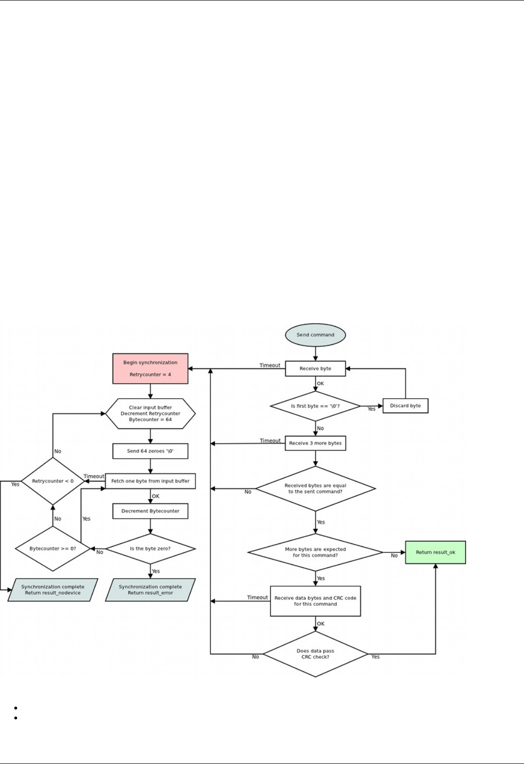
Timeout resynchronization
If during packet reception next byte wait time exceeds timeout value, then partially received command is ignored and receive buffer is
cleared. Controller timeout should be less than PC timeout, taking into account time it takes to transmit the data.
Zero byte resynchronization
There are no command codes that start with a zero byte ('\0'). This allows for a following synchronization procedure: controller always
answers with a zero byte if the first command byte is zero, PC ignores first response byte if it is a zero byte. Then, if synchronization is
disrupted on either side the following algorithm is used:
In case PC receives "errc", "errd" or a wrong command answer code, then PC sends 4 to 250 zeroes to the controller (250 byte limit is
caused by input buffer length and usage of I2C protocol, less than 4 zeroes do not guarantee successful resynchronization). During this
time PC continuously reads incoming bytes from the controller until the first zero is received and stops sending and receiving right after
that.
Received zero byte is likely not a part of a response to a previous command because on error PC receives "errc"/"errd" response. It is
possible in rare cases, then synchronization procedure will start again. Therefore first zero byte received by the PC means that
controller input buffer is already empty and will remain so until any command is sent. Right after receiving first zero byte from the
controller PC is ready to transmit next command code. The rest of zero bytes in transit will be ignored because they will be received
before controller response.
This completes the zero byte synchronization procedure.
Library-side error processing
Nearly every library function has a return status of type result_t.
After sending command to the controller library reads incoming bytes until a non-zero byte is received. All zero bytes are ignored.
Library reads first 4 bytes and compares them to the command code. It then waits for data section and CRC, if needed. If first 4
received bytes do not match the sent command identifier, then zero byte synchronization procedure is launched, command is
considered to be sent unsuccessfully. If first 4 received bytes match the sent command identifier and command has data section, but
the received CRC doesn't match CRC calculated from the received data, then zero byte synchronization procedure is launched,
command is considered to be sent unsuccessfully. If a timeout is reached while the library is waiting for the controller response, then
zero byte synchronization procedure is launched, command is considered to be sent unsuccessfully.
If no errors were detected, then command is considered to be successfully completed and result_ok is returned.
Library return codes
result_ok. No errors detected.
result_error. Generic error. Can happen because of hardware problems, empty port buffer, timeout or successfull
synchronization after an error. Another common reason for this error is protocol version mismatch between controller firmware
Page 212 / 345
Page 212 / 345

and PC library.
result_nodevice. Error opening device, lost connection or failed synchronization. Device reopen and/or user action is required.
If a function returns an error values of all parameters it writes to are undefined. Error code may be accompanied by detailed error
description output to system log (Unix-like OS) or standard error (Windows-like OS).
Zero byte synchronization procedure
Synchronization is performed by means of sending zero ('\0') bytes and reading bytes until a zero byte is received. Optionally one may
clear port buffer at the end of synchronization procedure. Initially 64 zero bytes are sent. If there were no zero bytes received during
the timeout, then a string of 64 bytes is sent 3 more times. After 4 unsuccessful attempts and no zero bytes received device is
considered lost. In this case library should return result_nodevice error code. In case of successful syncronization library returns
result_error.
Controller settings setup
Functions for adjusting engine read/write almost all controller settings.
Command SFBS
result_t set_feedback_settings (device_t id, const feedback_settings_t* feedback_settings)
Command code (CMD): "sfbs" or 0x73626673.
Request: (18 bytes)
INT32U CMD Command
INT16U IPS
The number of encoder counts per shaft revolution. Range: 1..655535. The field is obsolete, it is
recommended to write 0 to IPS and use the extended CountsPerTurn field. You may need to update the
controller firmware to the latest version.
INT8U FeedbackType Type of feedback
0x01 - FEEDBACK_ENCODER (Feedback by encoder.)
0x03 - FEEDBACK_ENCODERHALL (Feedback by Hall detector.)
0x04 - FEEDBACK_EMF (Feedback by EMF.)
0x05 - FEEDBACK_NONE (Feedback is absent.)
INT8U FeedbackFlags Flags
0x01 - FEEDBACK_ENC_REVERSE (Reverse count of encoder.)
0x02 - FEEDBACK_HALL_REVERSE (Reverce count position on the Hall sensor.)
0xC0 - FEEDBACK_ENC_TYPE_BITS (Bits of the encoder type.)
0x00 - FEEDBACK_ENC_TYPE_AUTO (Auto detect encoder type.)
0x40 - FEEDBACK_ENC_TYPE_SINGLE_ENDED (Single ended encoder.)
0x80 - FEEDBACK_ENC_TYPE_DIFFERENTIAL (Differential encoder.)
INT16U HallSPR The number of hall steps per revolution.
INT8S HallShift Phase shift between output signal on BLDC engine and hall sensor input(0 - when only active the Hall sensor,
the output state is a positive voltage on the winding A and a negative voltage on the winding B).
INT8U Reserved [5] Reserved (5 bytes)
INT16U CRC Checksum
Answer: (4 bytes)
INT32U CMD Command (answer)
Description:
Feedback settings.
Command GFBS
result_t get_feedback_settings (device_t id, feedback_settings_t* feedback_settings)
Command code (CMD): "gfbs" or 0x73626667.
Request: (4 bytes)
INT32U CMD Command
Page 213 / 345
Page 213 / 345

Answer: (18 bytes)
INT32U CMD Command (answer)
INT16U IPS
The number of encoder counts per shaft revolution. Range: 1..655535. The field is obsolete, it is
recommended to write 0 to IPS and use the extended CountsPerTurn field. You may need to update the
controller firmware to the latest version.
INT8U FeedbackType Type of feedback
0x01 - FEEDBACK_ENCODER (Feedback by encoder.)
0x03 - FEEDBACK_ENCODERHALL (Feedback by Hall detector.)
0x04 - FEEDBACK_EMF (Feedback by EMF.)
0x05 - FEEDBACK_NONE (Feedback is absent.)
INT8U FeedbackFlags Flags
0x01 - FEEDBACK_ENC_REVERSE (Reverse count of encoder.)
0x02 - FEEDBACK_HALL_REVERSE (Reverce count position on the Hall sensor.)
0xC0 - FEEDBACK_ENC_TYPE_BITS (Bits of the encoder type.)
0x00 - FEEDBACK_ENC_TYPE_AUTO (Auto detect encoder type.)
0x40 - FEEDBACK_ENC_TYPE_SINGLE_ENDED (Single ended encoder.)
0x80 - FEEDBACK_ENC_TYPE_DIFFERENTIAL (Differential encoder.)
INT16U HallSPR The number of hall steps per revolution.
INT8S HallShift Phase shift between output signal on BLDC engine and hall sensor input(0 - when only active the Hall sensor,
the output state is a positive voltage on the winding A and a negative voltage on the winding B).
INT8U Reserved [5] Reserved (5 bytes)
INT16U CRC Checksum
Description:
Feedback settings.
Command SHOM
result_t set_home_settings (device_t id, const home_settings_t* home_settings)
Command code (CMD): "shom" or 0x6D6F6873.
Request: (33 bytes)
Page 214 / 345
Page 214 / 345

INT32U CMD Command
INT32U FastHome Speed used for first motion. Range: 0..100000.
INT8U uFastHome Part of the speed for first motion, microsteps.
INT32U SlowHome Speed used for second motion. Range: 0..100000.
INT8U uSlowHome Part of the speed for second motion, microsteps.
INT32S HomeDelta Distance from break point.
INT16S uHomeDelta Part of the delta distance, microsteps. Range: -255..255.
INT16U HomeFlags Set of flags specify direction and stopping conditions.
0x001 - HOME_DIR_FIRST (Flag defines direction of 1st motion after execution of home command. Direction is
right, if set; otherwise left.)
0x002 - HOME_DIR_SECOND (Flag defines direction of 2nd motion. Direction is right, if set; otherwise left.)
0x004 - HOME_MV_SEC_EN (Use the second phase of calibration to the home position, if set; otherwise the
second phase is skipped.)
0x008 - HOME_HALF_MV (If the flag is set, the stop signals are ignored in start of second movement the first
half-turn.)
0x030 - HOME_STOP_FIRST_BITS (Bits of the first stop selector.)
0x010 - HOME_STOP_FIRST_REV (First motion stops by revolution sensor.)
0x020 - HOME_STOP_FIRST_SYN (First motion stops by synchronization input.)
0x030 - HOME_STOP_FIRST_LIM (First motion stops by limit switch.)
0x0C0 - HOME_STOP_SECOND_BITS (Bits of the second stop selector.)
0x040 - HOME_STOP_SECOND_REV (Second motion stops by revolution sensor.)
0x080 - HOME_STOP_SECOND_SYN (Second motion stops by synchronization input.)
0x0C0 - HOME_STOP_SECOND_LIM (Second motion stops by limit switch.)
0x100 - HOME_USE_FAST (Use the fast algorithm of calibration to the home position, if set; otherwise the
traditional algorithm.)
INT8U Reserved
[9] Reserved (9 bytes)
INT16U CRC Checksum
Answer: (4 bytes)
INT32U CMD Command (answer)
Description:
Set home settings. This function send structure with calibrating position settings to controller's memory.
Command GHOM
result_t get_home_settings (device_t id, home_settings_t* home_settings)
Command code (CMD): "ghom" or 0x6D6F6867.
Request: (4 bytes)
INT32U CMD Command
Answer: (33 bytes)
Page 215 / 345
Page 215 / 345

INT32U CMD Command (answer)
INT32U FastHome Speed used for first motion. Range: 0..100000.
INT8U uFastHome Part of the speed for first motion, microsteps.
INT32U SlowHome Speed used for second motion. Range: 0..100000.
INT8U uSlowHome Part of the speed for second motion, microsteps.
INT32S HomeDelta Distance from break point.
INT16S uHomeDelta Part of the delta distance, microsteps. Range: -255..255.
INT16U HomeFlags Set of flags specify direction and stopping conditions.
0x001 - HOME_DIR_FIRST (Flag defines direction of 1st motion after execution of home command. Direction is
right, if set; otherwise left.)
0x002 - HOME_DIR_SECOND (Flag defines direction of 2nd motion. Direction is right, if set; otherwise left.)
0x004 - HOME_MV_SEC_EN (Use the second phase of calibration to the home position, if set; otherwise the
second phase is skipped.)
0x008 - HOME_HALF_MV (If the flag is set, the stop signals are ignored in start of second movement the first
half-turn.)
0x030 - HOME_STOP_FIRST_BITS (Bits of the first stop selector.)
0x010 - HOME_STOP_FIRST_REV (First motion stops by revolution sensor.)
0x020 - HOME_STOP_FIRST_SYN (First motion stops by synchronization input.)
0x030 - HOME_STOP_FIRST_LIM (First motion stops by limit switch.)
0x0C0 - HOME_STOP_SECOND_BITS (Bits of the second stop selector.)
0x040 - HOME_STOP_SECOND_REV (Second motion stops by revolution sensor.)
0x080 - HOME_STOP_SECOND_SYN (Second motion stops by synchronization input.)
0x0C0 - HOME_STOP_SECOND_LIM (Second motion stops by limit switch.)
0x100 - HOME_USE_FAST (Use the fast algorithm of calibration to the home position, if set; otherwise the
traditional algorithm.)
INT8U Reserved
[9] Reserved (9 bytes)
INT16U CRC Checksum
Description:
Read home settings. This function fill structure with settings of calibrating position.
Command SMOV
result_t set_move_settings (device_t id, const move_settings_t* move_settings)
Command code (CMD): "smov" or 0x766F6D73.
Request: (30 bytes)
INT32U CMD Command
INT32U Speed Target speed (for stepper motor: steps/s, for DC: rpm). Range: 0..100000.
INT8U uSpeed Target speed in microstep fractions/s. Using with stepper motor only.
INT16U Accel Motor shaft acceleration, steps/s^2(stepper motor) or RPM/s(DC). Range: 1..65535.
INT16U Decel Motor shaft deceleration, steps/s^2(stepper motor) or RPM/s(DC). Range: 1..65535.
INT32U AntiplaySpeed Speed in antiplay mode, full steps/s(stepper motor) or RPM. Range: 0..100000.
INT8U uAntiplaySpeed Speed in antiplay mode, 1/256 microsteps/s. Used with stepper motor only.
INT8U Reserved [10] Reserved (10 bytes)
INT16U CRC Checksum
Answer: (4 bytes)
INT32U CMD Command (answer)
Description:
Set command setup movement (speed, acceleration, threshold and etc).
Page 216 / 345
Page 216 / 345

Command GMOV
result_t get_move_settings (device_t id, move_settings_t* move_settings)
Command code (CMD): "gmov" or 0x766F6D67.
Request: (4 bytes)
INT32U CMD Command
Answer: (30 bytes)
INT32U CMD Command (answer)
INT32U Speed Target speed (for stepper motor: steps/s, for DC: rpm). Range: 0..100000.
INT8U uSpeed Target speed in microstep fractions/s. Using with stepper motor only.
INT16U Accel Motor shaft acceleration, steps/s^2(stepper motor) or RPM/s(DC). Range: 1..65535.
INT16U Decel Motor shaft deceleration, steps/s^2(stepper motor) or RPM/s(DC). Range: 1..65535.
INT32U AntiplaySpeed Speed in antiplay mode, full steps/s(stepper motor) or RPM. Range: 0..100000.
INT8U uAntiplaySpeed Speed in antiplay mode, 1/256 microsteps/s. Used with stepper motor only.
INT8U Reserved [10] Reserved (10 bytes)
INT16U CRC Checksum
Description:
Read command setup movement (speed, acceleration, threshold and etc).
Command SENG
result_t set_engine_settings (device_t id, const engine_settings_t* engine_settings)
Command code (CMD): "seng" or 0x676E6573.
Request: (34 bytes)
Page 217 / 345
Page 217 / 345

INT32U CMD Command
INT16U NomVoltage Rated voltage in tens of mV. Controller will keep the voltage drop on motor below this value if
ENGINE_LIMIT_VOLT flag is set (used with DC only).
INT16U NomCurrent Rated current. Controller will keep current consumed by motor below this value if ENGINE_LIMIT_CURR flag
is set. Range: 15..8000
INT32U NomSpeed Nominal speed (in whole steps/s or rpm for DC and stepper motor as a master encoder). Controller will keep
motor shaft RPM below this value if ENGINE_LIMIT_RPM flag is set. Range: 1..100000.
INT8U uNomSpeed The fractional part of a nominal speed in microsteps (is only used with stepper motor).
INT16U EngineFlags Set of flags specify motor shaft movement algorithm and list of limitations
0x01 - ENGINE_REVERSE (Reverse flag. It determines motor shaft rotation direction that corresponds to
feedback counts increasing. If not set (default), motor shaft rotation direction under positive voltage
corresponds to feedback counts increasing and vice versa. Change it if you see that positive directions on
motor and feedback are opposite.)
0x02 - ENGINE_CURRENT_AS_RMS (Engine current meaning flag. If the flag is set, then engine current
value is interpreted as root mean square current value. If the flag is unset, then engine current value is
interpreted as maximum amplitude value.)
0x04 - ENGINE_MAX_SPEED (Max speed flag. If it is set, engine uses maximum speed achievable with the
present engine settings as nominal speed.)
0x08 - ENGINE_ANTIPLAY (Play compensation flag. If it set, engine makes backlash (play) compensation
procedure and reach the predetermined position accurately on low speed.)
0x10 - ENGINE_ACCEL_ON (Acceleration enable flag. If it set, motion begins with acceleration and ends with
deceleration.)
0x20 - ENGINE_LIMIT_VOLT (Maximum motor voltage limit enable flag(is only used with DC motor).)
0x40 - ENGINE_LIMIT_CURR (Maximum motor current limit enable flag(is only used with DC motor).)
0x80 - ENGINE_LIMIT_RPM (Maximum motor speed limit enable flag.)
INT16S Antiplay Number of pulses or steps for backlash (play) compensation procedure. Used if ENGINE_ANTIPLAY flag is
set.
INT8U MicrostepMode Settings of microstep mode(Used with stepper motor only).
0x01 - MICROSTEP_MODE_FULL (Full step mode.)
0x02 - MICROSTEP_MODE_FRAC_2 (1/2 step mode.)
0x03 - MICROSTEP_MODE_FRAC_4 (1/4 step mode.)
0x04 - MICROSTEP_MODE_FRAC_8 (1/8 step mode.)
0x05 - MICROSTEP_MODE_FRAC_16 (1/16 step mode.)
0x06 - MICROSTEP_MODE_FRAC_32 (1/32 step mode.)
0x07 - MICROSTEP_MODE_FRAC_64 (1/64 step mode.)
0x08 - MICROSTEP_MODE_FRAC_128 (1/128 step mode.)
0x09 - MICROSTEP_MODE_FRAC_256 (1/256 step mode.)
INT16U StepsPerRev Number of full steps per revolution(Used with stepper motor only). Range: 1..65535.
INT8U Reserved [12] Reserved (12 bytes)
INT16U CRC Checksum
Answer: (4 bytes)
INT32U CMD Command (answer)
Description:
Set engine settings. This function send structure with set of engine settings to controller's memory. These settings specify motor shaft
movement algorithm, list of limitations and rated characteristics. Use it when you change motor, encoder, positioner etc. Please note
that wrong engine settings lead to device malfunction, can lead to irreversible damage of board.
Command GENG
result_t get_engine_settings (device_t id, engine_settings_t* engine_settings)
Command code (CMD): "geng" or 0x676E6567.
Request: (4 bytes)
INT32U CMD Command
Page 218 / 345
Page 218 / 345

Answer: (34 bytes)
INT32U CMD Command (answer)
INT16U NomVoltage Rated voltage in tens of mV. Controller will keep the voltage drop on motor below this value if
ENGINE_LIMIT_VOLT flag is set (used with DC only).
INT16U NomCurrent Rated current. Controller will keep current consumed by motor below this value if ENGINE_LIMIT_CURR flag
is set. Range: 15..8000
INT32U NomSpeed Nominal speed (in whole steps/s or rpm for DC and stepper motor as a master encoder). Controller will keep
motor shaft RPM below this value if ENGINE_LIMIT_RPM flag is set. Range: 1..100000.
INT8U uNomSpeed The fractional part of a nominal speed in microsteps (is only used with stepper motor).
INT16U EngineFlags Set of flags specify motor shaft movement algorithm and list of limitations
0x01 - ENGINE_REVERSE (Reverse flag. It determines motor shaft rotation direction that corresponds to
feedback counts increasing. If not set (default), motor shaft rotation direction under positive voltage
corresponds to feedback counts increasing and vice versa. Change it if you see that positive directions on
motor and feedback are opposite.)
0x02 - ENGINE_CURRENT_AS_RMS (Engine current meaning flag. If the flag is set, then engine current
value is interpreted as root mean square current value. If the flag is unset, then engine current value is
interpreted as maximum amplitude value.)
0x04 - ENGINE_MAX_SPEED (Max speed flag. If it is set, engine uses maximum speed achievable with the
present engine settings as nominal speed.)
0x08 - ENGINE_ANTIPLAY (Play compensation flag. If it set, engine makes backlash (play) compensation
procedure and reach the predetermined position accurately on low speed.)
0x10 - ENGINE_ACCEL_ON (Acceleration enable flag. If it set, motion begins with acceleration and ends with
deceleration.)
0x20 - ENGINE_LIMIT_VOLT (Maximum motor voltage limit enable flag(is only used with DC motor).)
0x40 - ENGINE_LIMIT_CURR (Maximum motor current limit enable flag(is only used with DC motor).)
0x80 - ENGINE_LIMIT_RPM (Maximum motor speed limit enable flag.)
INT16S Antiplay Number of pulses or steps for backlash (play) compensation procedure. Used if ENGINE_ANTIPLAY flag is
set.
INT8U MicrostepMode Settings of microstep mode(Used with stepper motor only).
0x01 - MICROSTEP_MODE_FULL (Full step mode.)
0x02 - MICROSTEP_MODE_FRAC_2 (1/2 step mode.)
0x03 - MICROSTEP_MODE_FRAC_4 (1/4 step mode.)
0x04 - MICROSTEP_MODE_FRAC_8 (1/8 step mode.)
0x05 - MICROSTEP_MODE_FRAC_16 (1/16 step mode.)
0x06 - MICROSTEP_MODE_FRAC_32 (1/32 step mode.)
0x07 - MICROSTEP_MODE_FRAC_64 (1/64 step mode.)
0x08 - MICROSTEP_MODE_FRAC_128 (1/128 step mode.)
0x09 - MICROSTEP_MODE_FRAC_256 (1/256 step mode.)
INT16U StepsPerRev Number of full steps per revolution(Used with stepper motor only). Range: 1..65535.
INT8U Reserved [12] Reserved (12 bytes)
INT16U CRC Checksum
Description:
Read engine settings. This function fill structure with set of useful motor settings stored in controller's memory. These settings specify
motor shaft movement algorithm, list of limitations and rated characteristics.
Command SENT
result_t set_entype_settings (device_t id, const entype_settings_t* entype_settings)
Command code (CMD): "sent" or 0x746E6573.
Request: (14 bytes)
Page 219 / 345
Page 219 / 345

INT32U CMD Command
INT8U EngineType Engine type
0x00 - ENGINE_TYPE_NONE (A value that shouldn't be used.)
0x01 - ENGINE_TYPE_DC (DC motor.)
0x02 - ENGINE_TYPE_2DC (2 DC motors.)
0x03 - ENGINE_TYPE_STEP (Step motor.)
0x04 - ENGINE_TYPE_TEST (Duty cycle are fixed. Used only manufacturer.)
0x05 - ENGINE_TYPE_BRUSHLESS (Brushless motor.)
INT8U DriverType Driver type
0x01 - DRIVER_TYPE_DISCRETE_FET (Driver with discrete FET keys. Default option.)
0x02 - DRIVER_TYPE_INTEGRATE (Driver with integrated IC.)
0x03 - DRIVER_TYPE_EXTERNAL (External driver.)
INT8U Reserved [6] Reserved (6 bytes)
INT16U CRC Checksum
Answer: (4 bytes)
INT32U CMD Command (answer)
Description:
Set engine type and driver type.
Command GENT
result_t get_entype_settings (device_t id, entype_settings_t* entype_settings)
Command code (CMD): "gent" or 0x746E6567.
Request: (4 bytes)
INT32U CMD Command
Answer: (14 bytes)
INT32U CMD Command (answer)
INT8U EngineType Engine type
0x00 - ENGINE_TYPE_NONE (A value that shouldn't be used.)
0x01 - ENGINE_TYPE_DC (DC motor.)
0x02 - ENGINE_TYPE_2DC (2 DC motors.)
0x03 - ENGINE_TYPE_STEP (Step motor.)
0x04 - ENGINE_TYPE_TEST (Duty cycle are fixed. Used only manufacturer.)
0x05 - ENGINE_TYPE_BRUSHLESS (Brushless motor.)
INT8U DriverType Driver type
0x01 - DRIVER_TYPE_DISCRETE_FET (Driver with discrete FET keys. Default option.)
0x02 - DRIVER_TYPE_INTEGRATE (Driver with integrated IC.)
0x03 - DRIVER_TYPE_EXTERNAL (External driver.)
INT8U Reserved [6] Reserved (6 bytes)
INT16U CRC Checksum
Description:
Return engine type and driver type.
Command SPWR
result_t set_power_settings (device_t id, const power_settings_t* power_settings)
Command code (CMD): "spwr" or 0x72777073.
Request: (20 bytes)
Page 220 / 345
Page 220 / 345

INT32U CMD Command
INT8U HoldCurrent Current in holding regime, percent of nominal. Range: 0..100.
INT16U CurrReductDelay Time in ms from going to STOP state to reducting current.
INT16U PowerOffDelay Time in s from going to STOP state to turning power off.
INT16U CurrentSetTime Time in ms to reach nominal current.
INT8U PowerFlags Flags with parameters of power control.
0x01 - POWER_REDUCT_ENABLED (Current reduction enabled after CurrReductDelay, if this flag is set.)
0x02 - POWER_OFF_ENABLED (Power off enabled after PowerOffDelay, if this flag is set.)
0x04 - POWER_SMOOTH_CURRENT (Current ramp-up/down is performed smoothly during
current_set_time, if this flag is set.)
INT8U Reserved [6] Reserved (6 bytes)
INT16U CRC Checksum
Answer: (4 bytes)
INT32U CMD Command (answer)
Description:
Set settings of step motor power control. Used with stepper motor only.
Command GPWR
result_t get_power_settings (device_t id, power_settings_t* power_settings)
Command code (CMD): "gpwr" or 0x72777067.
Request: (4 bytes)
INT32U CMD Command
Answer: (20 bytes)
INT32U CMD Command (answer)
INT8U HoldCurrent Current in holding regime, percent of nominal. Range: 0..100.
INT16U CurrReductDelay Time in ms from going to STOP state to reducting current.
INT16U PowerOffDelay Time in s from going to STOP state to turning power off.
INT16U CurrentSetTime Time in ms to reach nominal current.
INT8U PowerFlags Flags with parameters of power control.
0x01 - POWER_REDUCT_ENABLED (Current reduction enabled after CurrReductDelay, if this flag is set.)
0x02 - POWER_OFF_ENABLED (Power off enabled after PowerOffDelay, if this flag is set.)
0x04 - POWER_SMOOTH_CURRENT (Current ramp-up/down is performed smoothly during
current_set_time, if this flag is set.)
INT8U Reserved [6] Reserved (6 bytes)
INT16U CRC Checksum
Description:
Read settings of step motor power control. Used with stepper motor only.
Command SSEC
result_t set_secure_settings (device_t id, const secure_settings_t* secure_settings)
Command code (CMD): "ssec" or 0x63657373.
Request: (28 bytes)
Page 221 / 345
Page 221 / 345

INT32U CMD Command
INT16U LowUpwrOff Lower voltage limit to turn off the motor, tens of mV.
INT16U CriticalIpwr Maximum motor current which triggers ALARM state, in mA.
INT16U CriticalUpwr Maximum motor voltage which triggers ALARM state, tens of mV.
INT16U CriticalT Maximum temperature, which triggers ALARM state, in tenths of degrees Celcius.
INT16U CriticalIusb Maximum USB current which triggers ALARM state, in mA.
INT16U CriticalUusb Maximum USB voltage which triggers ALARM state, tens of mV.
INT16U MinimumUusb Minimum USB voltage which triggers ALARM state, tens of mV.
INT8U Flags Critical parameter flags.
0x01 - ALARM_ON_DRIVER_OVERHEATING (If this flag is set enter Alarm state on driver overheat signal.)
0x02 - LOW_UPWR_PROTECTION (If this flag is set turn off motor when voltage is lower than LowUpwrOff.)
0x04 - H_BRIDGE_ALERT (If this flag is set then turn off the power unit with a signal problem in one of the
transistor bridge.)
0x08 - ALARM_ON_BORDERS_SWAP_MISSET (If this flag is set enter Alarm state on borders swap misset)
0x10 - ALARM_FLAGS_STICKING (If this flag is set only a STOP command can turn all alarms to 0)
0x20 - USB_BREAK_RECONNECT (If this flag is set USB brake reconnect module will be enable)
INT8U Reserved [7] Reserved (7 bytes)
INT16U CRC Checksum
Answer: (4 bytes)
INT32U CMD Command (answer)
Description:
Set protection settings.
Command GSEC
result_t get_secure_settings (device_t id, secure_settings_t* secure_settings)
Command code (CMD): "gsec" or 0x63657367.
Request: (4 bytes)
INT32U CMD Command
Answer: (28 bytes)
INT32U CMD Command (answer)
INT16U LowUpwrOff Lower voltage limit to turn off the motor, tens of mV.
INT16U CriticalIpwr Maximum motor current which triggers ALARM state, in mA.
INT16U CriticalUpwr Maximum motor voltage which triggers ALARM state, tens of mV.
INT16U CriticalT Maximum temperature, which triggers ALARM state, in tenths of degrees Celcius.
INT16U CriticalIusb Maximum USB current which triggers ALARM state, in mA.
INT16U CriticalUusb Maximum USB voltage which triggers ALARM state, tens of mV.
INT16U MinimumUusb Minimum USB voltage which triggers ALARM state, tens of mV.
INT8U Flags Critical parameter flags.
0x01 - ALARM_ON_DRIVER_OVERHEATING (If this flag is set enter Alarm state on driver overheat signal.)
0x02 - LOW_UPWR_PROTECTION (If this flag is set turn off motor when voltage is lower than LowUpwrOff.)
0x04 - H_BRIDGE_ALERT (If this flag is set then turn off the power unit with a signal problem in one of the
transistor bridge.)
0x08 - ALARM_ON_BORDERS_SWAP_MISSET (If this flag is set enter Alarm state on borders swap misset)
0x10 - ALARM_FLAGS_STICKING (If this flag is set only a STOP command can turn all alarms to 0)
0x20 - USB_BREAK_RECONNECT (If this flag is set USB brake reconnect module will be enable)
INT8U Reserved [7] Reserved (7 bytes)
INT16U CRC Checksum
Page 222 / 345
Page 222 / 345

Description:
Read protection settings.
Command SEDS
result_t set_edges_settings (device_t id, const edges_settings_t* edges_settings)
Command code (CMD): "seds" or 0x73646573.
Request: (26 bytes)
INT32U CMD Command
INT8U BorderFlags Border flags, specify types of borders and motor behaviour on borders.
0x01 - BORDER_IS_ENCODER (Borders are fixed by predetermined encoder values, if set; borders position on
limit switches, if not set.)
0x02 - BORDER_STOP_LEFT (Motor should stop on left border.)
0x04 - BORDER_STOP_RIGHT (Motor should stop on right border.)
0x08 - BORDERS_SWAP_MISSET_DETECTION (Motor should stop on both borders. Need to save motor then
wrong border settings is se)
INT8U EnderFlags Ender flags, specify electrical behaviour of limit switches like order and pulled positions.
0x01 - ENDER_SWAP (First limit switch on the right side, if set; otherwise on the left side.)
0x02 - ENDER_SW1_ACTIVE_LOW (1 - Limit switch connnected to pin SW1 is triggered by a low level on pin.)
0x04 - ENDER_SW2_ACTIVE_LOW (1 - Limit switch connnected to pin SW2 is triggered by a low level on pin.)
INT32S LeftBorder Left border position, used if BORDER_IS_ENCODER flag is set.
INT16S uLeftBorder Left border position in 1/256 microsteps(used with stepper motor only). Range: -255..255.
INT32S RightBorder Right border position, used if BORDER_IS_ENCODER flag is set.
INT16S uRightBorder Right border position in 1/256 microsteps. Used with stepper motor only. Range: -255..255.
INT8U Reserved [6] Reserved (6 bytes)
INT16U CRC Checksum
Answer: (4 bytes)
INT32U CMD Command (answer)
Description:
Set border and limit switches settings.
Command GEDS
result_t get_edges_settings (device_t id, edges_settings_t* edges_settings)
Command code (CMD): "geds" or 0x73646567.
Request: (4 bytes)
INT32U CMD Command
Answer: (26 bytes)
Page 223 / 345
Page 223 / 345

INT32U CMD Command (answer)
INT8U BorderFlags Border flags, specify types of borders and motor behaviour on borders.
0x01 - BORDER_IS_ENCODER (Borders are fixed by predetermined encoder values, if set; borders position on
limit switches, if not set.)
0x02 - BORDER_STOP_LEFT (Motor should stop on left border.)
0x04 - BORDER_STOP_RIGHT (Motor should stop on right border.)
0x08 - BORDERS_SWAP_MISSET_DETECTION (Motor should stop on both borders. Need to save motor then
wrong border settings is se)
INT8U EnderFlags Ender flags, specify electrical behaviour of limit switches like order and pulled positions.
0x01 - ENDER_SWAP (First limit switch on the right side, if set; otherwise on the left side.)
0x02 - ENDER_SW1_ACTIVE_LOW (1 - Limit switch connnected to pin SW1 is triggered by a low level on pin.)
0x04 - ENDER_SW2_ACTIVE_LOW (1 - Limit switch connnected to pin SW2 is triggered by a low level on pin.)
INT32S LeftBorder Left border position, used if BORDER_IS_ENCODER flag is set.
INT16S uLeftBorder Left border position in 1/256 microsteps(used with stepper motor only). Range: -255..255.
INT32S RightBorder Right border position, used if BORDER_IS_ENCODER flag is set.
INT16S uRightBorder Right border position in 1/256 microsteps. Used with stepper motor only. Range: -255..255.
INT8U Reserved [6] Reserved (6 bytes)
INT16U CRC Checksum
Description:
Read border and limit switches settings.
Command SPID
result_t set_pid_settings (device_t id, const pid_settings_t* pid_settings)
Command code (CMD): "spid" or 0x64697073.
Request: (48 bytes)
INT32U CMD Command
INT16U KpU Proportional gain for voltage PID routine
INT16U KiU Integral gain for voltage PID routine
INT16U KdU Differential gain for voltage PID routine
FLT32 Kpf Proportional gain for BLDC position PID routine
FLT32 Kif Integral gain for BLDC position PID routine
FLT32 Kdf Differential gain for BLDC position PID routine
INT8U Reserved [24] Reserved (24 bytes)
INT16U CRC Checksum
Answer: (4 bytes)
INT32U CMD Command (answer)
Description:
Set PID settings. This function send structure with set of PID factors to controller's memory. These settings specify behaviour of PID
routine for positioner. These factors are slightly different for different positioners. All boards are supplied with standard set of PID
setting on controller's flash memory. Please use it for loading new PID settings when you change positioner. Please note that wrong
PID settings lead to device malfunction.
Command GPID
result_t get_pid_settings (device_t id, pid_settings_t* pid_settings)
Command code (CMD): "gpid" or 0x64697067.
Request: (4 bytes)
INT32U CMD Command
Answer: (48 bytes)
Page 224 / 345
Page 224 / 345

INT32U CMD Command (answer)
INT16U KpU Proportional gain for voltage PID routine
INT16U KiU Integral gain for voltage PID routine
INT16U KdU Differential gain for voltage PID routine
FLT32 Kpf Proportional gain for BLDC position PID routine
FLT32 Kif Integral gain for BLDC position PID routine
FLT32 Kdf Differential gain for BLDC position PID routine
INT8U Reserved [24] Reserved (24 bytes)
INT16U CRC Checksum
Description:
Read PID settings. This function fill structure with set of motor PID settings stored in controller's memory. These settings specify
behaviour of PID routine for positioner. These factors are slightly different for different positioners. All boards are supplied with
standard set of PID setting on controller's flash memory.
Command SSNI
result_t set_sync_in_settings (device_t id, const sync_in_settings_t* sync_in_settings)
Command code (CMD): "ssni" or 0x696E7373.
Request: (28 bytes)
INT32U CMD Command
INT8U SyncInFlags Input synchronization flags
0x01 - SYNCIN_ENABLED (Synchronization in mode is enabled, if this flag is set.)
0x02 - SYNCIN_INVERT (Trigger on falling edge if flag is set, on rising edge otherwise.)
0x04 - SYNCIN_GOTOPOSITION (The engine is go to position specified in Position and uPosition, if this flag is
set. And it is shift on the Position and uPosition, if this flag is unset)
INT16U ClutterTime Input synchronization pulse dead time (mks).
INT32S Position Desired position or shift (whole steps)
INT16S uPosition The fractional part of a position or shift in microsteps. Is used with stepper motor. Range: -255..255.
INT32U Speed Target speed (for stepper motor: steps/s, for DC: rpm). Range: 0..100000.
INT8U uSpeed Target speed in microsteps/s. Using with stepper motor only.
INT8U Reserved
[8] Reserved (8 bytes)
INT16U CRC Checksum
Answer: (4 bytes)
INT32U CMD Command (answer)
Description:
Set input synchronization settings. This function send structure with set of input synchronization settings, that specify behaviour of
input synchronization, to controller's memory. All boards are supplied with standard set of these settings.
Command GSNI
result_t get_sync_in_settings (device_t id, sync_in_settings_t* sync_in_settings)
Command code (CMD): "gsni" or 0x696E7367.
Request: (4 bytes)
INT32U CMD Command
Answer: (28 bytes)
Page 225 / 345
Page 225 / 345

INT32U CMD Command (answer)
INT8U SyncInFlags Input synchronization flags
0x01 - SYNCIN_ENABLED (Synchronization in mode is enabled, if this flag is set.)
0x02 - SYNCIN_INVERT (Trigger on falling edge if flag is set, on rising edge otherwise.)
0x04 - SYNCIN_GOTOPOSITION (The engine is go to position specified in Position and uPosition, if this flag is
set. And it is shift on the Position and uPosition, if this flag is unset)
INT16U ClutterTime Input synchronization pulse dead time (mks).
INT32S Position Desired position or shift (whole steps)
INT16S uPosition The fractional part of a position or shift in microsteps. Is used with stepper motor. Range: -255..255.
INT32U Speed Target speed (for stepper motor: steps/s, for DC: rpm). Range: 0..100000.
INT8U uSpeed Target speed in microsteps/s. Using with stepper motor only.
INT8U Reserved
[8] Reserved (8 bytes)
INT16U CRC Checksum
Description:
Read input synchronization settings. This function fill structure with set of input synchronization settings, modes, periods and flags,
that specify behaviour of input synchronization. All boards are supplied with standard set of these settings.
Command SSNO
result_t set_sync_out_settings (device_t id, const sync_out_settings_t* sync_out_settings)
Command code (CMD): "ssno" or 0x6F6E7373.
Request: (16 bytes)
INT32U CMD Command
INT8U SyncOutFlags Output synchronization flags
0x01 - SYNCOUT_ENABLED (Synchronization out pin follows the synchronization logic, if set. It governed
by SYNCOUT_STATE flag otherwise.)
0x02 - SYNCOUT_STATE (When output state is fixed by negative SYNCOUT_ENABLED flag, the pin state
is in accordance with this flag state.)
0x04 - SYNCOUT_INVERT (Low level is active, if set, and high level is active otherwise.)
0x08 - SYNCOUT_IN_STEPS (Use motor steps/encoder pulses instead of milliseconds for output pulse
generation if the flag is set.)
0x10 - SYNCOUT_ONSTART (Generate synchronization pulse when movement starts.)
0x20 - SYNCOUT_ONSTOP (Generate synchronization pulse when movement stops.)
0x40 - SYNCOUT_ONPERIOD (Generate synchronization pulse every SyncOutPeriod encoder pulses.)
INT16U SyncOutPulseSteps This value specifies duration of output pulse. It is measured microseconds when SYNCOUT_IN_STEPS
flag is cleared or in encoder pulses or motor steps when SYNCOUT_IN_STEPS is set.
INT16U SyncOutPeriod This value specifies number of encoder pulses or steps between two output synchronization pulses when
SYNCOUT_ONPERIOD is set.
INT32U Accuracy This is the neighborhood around the target coordinates, which is getting hit in the target position and
the momentum generated by the stop.
INT8U uAccuracy This is the neighborhood around the target coordinates in micro steps (only used with stepper motor).
INT16U CRC Checksum
Answer: (4 bytes)
INT32U CMD Command (answer)
Description:
Set output synchronization settings. This function send structure with set of output synchronization settings, that specify behaviour of
output synchronization, to controller's memory. All boards are supplied with standard set of these settings.
Command GSNO
result_t get_sync_out_settings (device_t id, sync_out_settings_t* sync_out_settings)
Page 226 / 345
Page 226 / 345

Command code (CMD): "gsno" or 0x6F6E7367.
Request: (4 bytes)
INT32U CMD Command
Answer: (16 bytes)
INT32U CMD Command (answer)
INT8U SyncOutFlags Output synchronization flags
0x01 - SYNCOUT_ENABLED (Synchronization out pin follows the synchronization logic, if set. It governed
by SYNCOUT_STATE flag otherwise.)
0x02 - SYNCOUT_STATE (When output state is fixed by negative SYNCOUT_ENABLED flag, the pin state
is in accordance with this flag state.)
0x04 - SYNCOUT_INVERT (Low level is active, if set, and high level is active otherwise.)
0x08 - SYNCOUT_IN_STEPS (Use motor steps/encoder pulses instead of milliseconds for output pulse
generation if the flag is set.)
0x10 - SYNCOUT_ONSTART (Generate synchronization pulse when movement starts.)
0x20 - SYNCOUT_ONSTOP (Generate synchronization pulse when movement stops.)
0x40 - SYNCOUT_ONPERIOD (Generate synchronization pulse every SyncOutPeriod encoder pulses.)
INT16U SyncOutPulseSteps This value specifies duration of output pulse. It is measured microseconds when SYNCOUT_IN_STEPS
flag is cleared or in encoder pulses or motor steps when SYNCOUT_IN_STEPS is set.
INT16U SyncOutPeriod This value specifies number of encoder pulses or steps between two output synchronization pulses when
SYNCOUT_ONPERIOD is set.
INT32U Accuracy This is the neighborhood around the target coordinates, which is getting hit in the target position and
the momentum generated by the stop.
INT8U uAccuracy This is the neighborhood around the target coordinates in micro steps (only used with stepper motor).
INT16U CRC Checksum
Description:
Read output synchronization settings. This function fill structure with set of output synchronization settings, modes, periods and flags,
that specify behaviour of output synchronization. All boards are supplied with standard set of these settings.
Command SEIO
result_t set_extio_settings (device_t id, const extio_settings_t* extio_settings)
Command code (CMD): "seio" or 0x6F696573.
Request: (18 bytes)
Page 227 / 345
Page 227 / 345

INT32U CMD Command
INT8U EXTIOSetupFlags Configuration flags of the external I-O
0x01 - EXTIO_SETUP_OUTPUT (EXTIO works as output if flag is set, works as input otherwise.)
0x02 - EXTIO_SETUP_INVERT (Interpret EXTIO states and fronts inverted if flag is set. Falling front as
input event and low logic level as active state.)
INT8U EXTIOModeFlags Flags mode settings external I-O
0x0F - EXTIO_SETUP_MODE_IN_BITS (Bits of the behaviour selector when the signal on input goes to the
active state.)
0x00 - EXTIO_SETUP_MODE_IN_NOP (Do nothing.)
0x01 - EXTIO_SETUP_MODE_IN_STOP (Issue STOP command, ceasing the engine movement.)
0x02 - EXTIO_SETUP_MODE_IN_PWOF (Issue PWOF command, powering off all engine windings.)
0x03 - EXTIO_SETUP_MODE_IN_MOVR (Issue MOVR command with last used settings.)
0x04 - EXTIO_SETUP_MODE_IN_HOME (Issue HOME command.)
0x05 - EXTIO_SETUP_MODE_IN_ALARM (Set Alarm when the signal goes to the active state.)
0xF0 - EXTIO_SETUP_MODE_OUT_BITS (Bits of the output behaviour selection.)
0x00 - EXTIO_SETUP_MODE_OUT_OFF (EXTIO pin always set in inactive state.)
0x10 - EXTIO_SETUP_MODE_OUT_ON (EXTIO pin always set in active state.)
0x20 - EXTIO_SETUP_MODE_OUT_MOVING (EXTIO pin stays active during moving state.)
0x30 - EXTIO_SETUP_MODE_OUT_ALARM (EXTIO pin stays active during Alarm state.)
0x40 - EXTIO_SETUP_MODE_OUT_MOTOR_ON (EXTIO pin stays active when windings are powered.)
0x50 - EXTIO_SETUP_MODE_OUT_MOTOR_FOUND (EXTIO pin stays active when motor is connected (first
winding).)
INT8U Reserved [10] Reserved (10 bytes)
INT16U CRC Checksum
Answer: (4 bytes)
INT32U CMD Command (answer)
Description:
Set EXTIO settings. This function writes a structure with a set of EXTIO settings to controller's memory. By default input event are
signalled through rising front and output states are signalled by high logic state.
Command GEIO
result_t get_extio_settings (device_t id, extio_settings_t* extio_settings)
Command code (CMD): "geio" or 0x6F696567.
Request: (4 bytes)
INT32U CMD Command
Answer: (18 bytes)
Page 228 / 345
Page 228 / 345

INT32U CMD Command (answer)
INT8U EXTIOSetupFlags Configuration flags of the external I-O
0x01 - EXTIO_SETUP_OUTPUT (EXTIO works as output if flag is set, works as input otherwise.)
0x02 - EXTIO_SETUP_INVERT (Interpret EXTIO states and fronts inverted if flag is set. Falling front as
input event and low logic level as active state.)
INT8U EXTIOModeFlags Flags mode settings external I-O
0x0F - EXTIO_SETUP_MODE_IN_BITS (Bits of the behaviour selector when the signal on input goes to the
active state.)
0x00 - EXTIO_SETUP_MODE_IN_NOP (Do nothing.)
0x01 - EXTIO_SETUP_MODE_IN_STOP (Issue STOP command, ceasing the engine movement.)
0x02 - EXTIO_SETUP_MODE_IN_PWOF (Issue PWOF command, powering off all engine windings.)
0x03 - EXTIO_SETUP_MODE_IN_MOVR (Issue MOVR command with last used settings.)
0x04 - EXTIO_SETUP_MODE_IN_HOME (Issue HOME command.)
0x05 - EXTIO_SETUP_MODE_IN_ALARM (Set Alarm when the signal goes to the active state.)
0xF0 - EXTIO_SETUP_MODE_OUT_BITS (Bits of the output behaviour selection.)
0x00 - EXTIO_SETUP_MODE_OUT_OFF (EXTIO pin always set in inactive state.)
0x10 - EXTIO_SETUP_MODE_OUT_ON (EXTIO pin always set in active state.)
0x20 - EXTIO_SETUP_MODE_OUT_MOVING (EXTIO pin stays active during moving state.)
0x30 - EXTIO_SETUP_MODE_OUT_ALARM (EXTIO pin stays active during Alarm state.)
0x40 - EXTIO_SETUP_MODE_OUT_MOTOR_ON (EXTIO pin stays active when windings are powered.)
0x50 - EXTIO_SETUP_MODE_OUT_MOTOR_FOUND (EXTIO pin stays active when motor is connected (first
winding).)
INT8U Reserved [10] Reserved (10 bytes)
INT16U CRC Checksum
Description:
Read EXTIO settings. This function reads a structure with a set of EXTIO settings from controller's memory.
Command SBRK
result_t set_brake_settings (device_t id, const brake_settings_t* brake_settings)
Command code (CMD): "sbrk" or 0x6B726273.
Request: (25 bytes)
INT32U CMD Command
INT16U t1 Time in ms between turn on motor power and turn off brake.
INT16U t2 Time in ms between turn off brake and moving readiness. All moving commands will execute after this
interval.
INT16U t3 Time in ms between motor stop and turn on brake.
INT16U t4 Time in ms between turn on brake and turn off motor power.
INT8U BrakeFlags Flags.
0x01 - BRAKE_ENABLED (Brake control is enabled, if this flag is set.)
0x02 - BRAKE_ENG_PWROFF (Brake turns off power of step motor, if this flag is set.)
INT8U Reserved
[10] Reserved (10 bytes)
INT16U CRC Checksum
Answer: (4 bytes)
INT32U CMD Command (answer)
Description:
Set settings of brake control.
Command GBRK
Page 229 / 345
Page 229 / 345

result_t get_brake_settings (device_t id, brake_settings_t* brake_settings)
Command code (CMD): "gbrk" or 0x6B726267.
Request: (4 bytes)
INT32U CMD Command
Answer: (25 bytes)
INT32U CMD Command (answer)
INT16U t1 Time in ms between turn on motor power and turn off brake.
INT16U t2 Time in ms between turn off brake and moving readiness. All moving commands will execute after this
interval.
INT16U t3 Time in ms between motor stop and turn on brake.
INT16U t4 Time in ms between turn on brake and turn off motor power.
INT8U BrakeFlags Flags.
0x01 - BRAKE_ENABLED (Brake control is enabled, if this flag is set.)
0x02 - BRAKE_ENG_PWROFF (Brake turns off power of step motor, if this flag is set.)
INT8U Reserved
[10] Reserved (10 bytes)
INT16U CRC Checksum
Description:
Read settings of brake control.
Command SCTL
result_t set_control_settings (device_t id, const control_settings_t* control_settings)
Command code (CMD): "sctl" or 0x6C746373.
Request: (93 bytes)
INT32U CMD Command
INT32U MaxSpeed [10] Array of speeds (full step) using with joystick and button control. Range: 0..100000.
INT8U uMaxSpeed
[10] Array of speeds (1/256 microstep) using with joystick and button control.
INT16U Timeout [9] timeout[i] is time in ms, after that max_speed[i+1] is applying. It is using with buttons control only.
INT16U MaxClickTime Maximum click time. Prior to the expiration of this time the first speed isn't enabled.
INT16U Flags Flags.
0x03 - CONTROL_MODE_BITS (Bits to control engine by joystick or buttons.)
0x00 - CONTROL_MODE_OFF (Control is disabled.)
0x01 - CONTROL_MODE_JOY (Control by joystick.)
0x02 - CONTROL_MODE_LR (Control by left/right buttons.)
0x04 - CONTROL_BTN_LEFT_PUSHED_OPEN (Pushed left button corresponds to open contact, if this flag is
set.)
0x08 - CONTROL_BTN_RIGHT_PUSHED_OPEN (Pushed right button corresponds to open contact, if this flag
is set.)
INT32S DeltaPosition Shift (delta) of position
INT16S uDeltaPosition Fractional part of the shift in micro steps. Is only used with stepper motor. Range: -255..255.
INT8U Reserved [9] Reserved (9 bytes)
INT16U CRC Checksum
Answer: (4 bytes)
INT32U CMD Command (answer)
Page 230 / 345
Page 230 / 345

Description:
Set settings of motor control. When choosing CTL_MODE = 1 switches motor control with the joystick. In this mode, the joystick to the
maximum engine tends Move at MaxSpeed [i], where i = 0 if the previous use This mode is not selected another i. Buttons switch the
room rate i. When CTL_MODE = 2 is switched on motor control using the Left / right. When you click on the button motor starts to
move in the appropriate direction at a speed MaxSpeed [0], at the end of time Timeout [i] motor move at a speed MaxSpeed [i+1]. at
Transition from MaxSpeed [i] on MaxSpeed [i +1] to acceleration, as usual.
Command GCTL
result_t get_control_settings (device_t id, control_settings_t* control_settings)
Command code (CMD): "gctl" or 0x6C746367.
Request: (4 bytes)
INT32U CMD Command
Answer: (93 bytes)
INT32U CMD Command (answer)
INT32U MaxSpeed [10] Array of speeds (full step) using with joystick and button control. Range: 0..100000.
INT8U uMaxSpeed
[10] Array of speeds (1/256 microstep) using with joystick and button control.
INT16U Timeout [9] timeout[i] is time in ms, after that max_speed[i+1] is applying. It is using with buttons control only.
INT16U MaxClickTime Maximum click time. Prior to the expiration of this time the first speed isn't enabled.
INT16U Flags Flags.
0x03 - CONTROL_MODE_BITS (Bits to control engine by joystick or buttons.)
0x00 - CONTROL_MODE_OFF (Control is disabled.)
0x01 - CONTROL_MODE_JOY (Control by joystick.)
0x02 - CONTROL_MODE_LR (Control by left/right buttons.)
0x04 - CONTROL_BTN_LEFT_PUSHED_OPEN (Pushed left button corresponds to open contact, if this flag is
set.)
0x08 - CONTROL_BTN_RIGHT_PUSHED_OPEN (Pushed right button corresponds to open contact, if this flag
is set.)
INT32S DeltaPosition Shift (delta) of position
INT16S uDeltaPosition Fractional part of the shift in micro steps. Is only used with stepper motor. Range: -255..255.
INT8U Reserved [9] Reserved (9 bytes)
INT16U CRC Checksum
Description:
Read settings of motor control. When choosing CTL_MODE = 1 switches motor control with the joystick. In this mode, the joystick to
the maximum engine tends Move at MaxSpeed [i], where i = 0 if the previous use This mode is not selected another i. Buttons switch
the room rate i. When CTL_MODE = 2 is switched on motor control using the Left / right. When you click on the button motor starts to
move in the appropriate direction at a speed MaxSpeed [0], at the end of time Timeout [i] motor move at a speed MaxSpeed [i+1]. at
Transition from MaxSpeed [i] on MaxSpeed [i +1] to acceleration, as usual.
Command SJOY
result_t set_joystick_settings (device_t id, const joystick_settings_t* joystick_settings)
Command code (CMD): "sjoy" or 0x796F6A73.
Request: (22 bytes)
Page 231 / 345
Page 231 / 345

INT32U CMD Command
INT16U JoyLowEnd Joystick lower end position. Range: 0..10000.
INT16U JoyCenter Joystick center position. Range: 0..10000.
INT16U JoyHighEnd Joystick higher end position. Range: 0..10000.
INT8U ExpFactor Exponential nonlinearity factor.
INT8U DeadZone Joystick dead zone.
INT8U JoyFlags Joystick control flags.
0x01 - JOY_REVERSE (Joystick action is reversed. Joystick deviation to the upper values correspond to negative
speeds and vice versa.)
INT8U Reserved
[7] Reserved (7 bytes)
INT16U CRC Checksum
Answer: (4 bytes)
INT32U CMD Command (answer)
Description:
Set settings of joystick. If joystick position is outside DeadZone limits from the central position a movement with speed, defined by the
joystick DeadZone edge to 100% deviation, begins. Joystick positions inside DeadZone limits correspond to zero speed (soft stop of
motion) and positions beyond Low and High limits correspond MaxSpeed [i] or -MaxSpeed [i] (see command SCTL), where i = 0 by
default and can be changed with left/right buttons (see command SCTL). If next speed in list is zero (both integer and microstep
parts), the button press is ignored. First speed in list shouldn't be zero. The DeadZone ranges are illustrated on the following picture.
The relationship between the deviation and the rate is exponential, allowing no switching speed combine high mobility and accuracy.
The following picture illustrates this:
The nonlinearity parameter is adjustable. Setting it to zero makes deviation/speed relation linear.
Command GJOY
result_t get_joystick_settings (device_t id, joystick_settings_t* joystick_settings)
Command code (CMD): "gjoy" or 0x796F6A67.
Request: (4 bytes)
INT32U CMD Command
Answer: (22 bytes)
INT32U CMD Command (answer)
INT16U JoyLowEnd Joystick lower end position. Range: 0..10000.
INT16U JoyCenter Joystick center position. Range: 0..10000.
INT16U JoyHighEnd Joystick higher end position. Range: 0..10000.
INT8U ExpFactor Exponential nonlinearity factor.
INT8U DeadZone Joystick dead zone.
INT8U JoyFlags Joystick control flags.
0x01 - JOY_REVERSE (Joystick action is reversed. Joystick deviation to the upper values correspond to negative
speeds and vice versa.)
INT8U Reserved
[7] Reserved (7 bytes)
INT16U CRC Checksum
Page 232 / 345
Page 232 / 345

Description:
Read settings of joystick. If joystick position is outside DeadZone limits from the central position a movement with speed, defined by
the joystick DeadZone edge to 100% deviation, begins. Joystick positions inside DeadZone limits correspond to zero speed (soft stop of
motion) and positions beyond Low and High limits correspond MaxSpeed [i] or -MaxSpeed [i] (see command SCTL), where i = 0 by
default and can be changed with left/right buttons (see command SCTL). If next speed in list is zero (both integer and microstep
parts), the button press is ignored. First speed in list shouldn't be zero. The DeadZone ranges are illustrated on the following picture.
The relationship between the deviation and the rate is exponential, allowing no switching speed combine high mobility and accuracy.
The following picture illustrates this:
The nonlinearity parameter is adjustable. Setting it to zero makes deviation/speed relation linear.
Command SCTP
result_t set_ctp_settings (device_t id, const ctp_settings_t* ctp_settings)
Command code (CMD): "sctp" or 0x70746373.
Request: (18 bytes)
INT32U CMD Command
INT8U CTPMinError Minimum contrast steps from step motor encoder position, wich set STATE_CTP_ERROR flag. Measured in steps
step motor.
INT8U CTPFlags Flags.
0x01 - CTP_ENABLED (Position control is enabled, if flag set.)
0x02 - CTP_BASE (Position control is based on revolution sensor, if this flag is set; otherwise it is based on
encoder.)
0x04 - CTP_ALARM_ON_ERROR (Set ALARM on mismatch, if flag set.)
0x08 - REV_SENS_INV (Sensor is active when it 0 and invert makes active level 1. That is, if you do not invert,
it is normal logic - 0 is the activation.)
0x10 - CTP_ERROR_CORRECTION (Correct errors which appear when slippage if the flag is set. It works only
with the encoder. Incompatible with flag CTP_ALARM_ON_ERROR.)
INT8U Reserved
[10] Reserved (10 bytes)
INT16U CRC Checksum
Answer: (4 bytes)
INT32U CMD Command (answer)
Description:
Set settings of control position(is only used with stepper motor). When controlling the step motor with encoder (CTP_BASE 0) it is
possible to detect the loss of steps. The controller knows the number of steps per revolution (GENG :: StepsPerRev) and the encoder
resolution (GFBS :: IPT). When the control (flag CTP_ENABLED), the controller stores the current position in the footsteps of SM and
the current position of the encoder. Further, at each step of the position encoder is converted into steps and if the difference is greater
CTPMinError, a flag STATE_CTP_ERROR. When controlling the step motor with speed sensor (CTP_BASE 1), the position is controlled by
him. The active edge of input clock controller stores the current value of steps. Further, at each turn checks how many steps shifted.
When a mismatch CTPMinError a flag STATE_CTP_ERROR.
Command GCTP
result_t get_ctp_settings (device_t id, ctp_settings_t* ctp_settings)
Command code (CMD): "gctp" or 0x70746367.
Request: (4 bytes)
INT32U CMD Command
Answer: (18 bytes)
Page 233 / 345
Page 233 / 345

INT32U CMD Command (answer)
INT8U CTPMinError Minimum contrast steps from step motor encoder position, wich set STATE_CTP_ERROR flag. Measured in steps
step motor.
INT8U CTPFlags Flags.
0x01 - CTP_ENABLED (Position control is enabled, if flag set.)
0x02 - CTP_BASE (Position control is based on revolution sensor, if this flag is set; otherwise it is based on
encoder.)
0x04 - CTP_ALARM_ON_ERROR (Set ALARM on mismatch, if flag set.)
0x08 - REV_SENS_INV (Sensor is active when it 0 and invert makes active level 1. That is, if you do not invert,
it is normal logic - 0 is the activation.)
0x10 - CTP_ERROR_CORRECTION (Correct errors which appear when slippage if the flag is set. It works only
with the encoder. Incompatible with flag CTP_ALARM_ON_ERROR.)
INT8U Reserved
[10] Reserved (10 bytes)
INT16U CRC Checksum
Description:
Read settings of control position(is only used with stepper motor). When controlling the step motor with encoder (CTP_BASE 0) it is
possible to detect the loss of steps. The controller knows the number of steps per revolution (GENG :: StepsPerRev) and the encoder
resolution (GFBS :: IPT). When the control (flag CTP_ENABLED), the controller stores the current position in the footsteps of SM and
the current position of the encoder. Further, at each step of the position encoder is converted into steps and if the difference is greater
CTPMinError, a flag STATE_CTP_ERROR. When controlling the step motor with speed sensor (CTP_BASE 1), the position is controlled by
him. The active edge of input clock controller stores the current value of steps. Further, at each turn checks how many steps shifted.
When a mismatch CTPMinError a flag STATE_CTP_ERROR.
Command SURT
result_t set_uart_settings (device_t id, const uart_settings_t* uart_settings)
Command code (CMD): "surt" or 0x74727573.
Request: (16 bytes)
INT32U CMD Command
INT32U Speed UART speed
INT16U UARTSetupFlags UART setup flags
0x03 - UART_PARITY_BITS (Bits of the parity.)
0x00 - UART_PARITY_BIT_EVEN (Parity bit 1, if even)
0x01 - UART_PARITY_BIT_ODD (Parity bit 1, if odd)
0x02 - UART_PARITY_BIT_SPACE (Parity bit always 0)
0x03 - UART_PARITY_BIT_MARK (Parity bit always 1)
0x04 - UART_PARITY_BIT_USE (None parity)
0x08 - UART_STOP_BIT (If set - one stop bit, else two stop bit)
INT8U Reserved [4] Reserved (4 bytes)
INT16U CRC Checksum
Answer: (4 bytes)
INT32U CMD Command (answer)
Description:
Set UART settings. This function send structure with UART settings to controller's memory.
Command GURT
result_t get_uart_settings (device_t id, uart_settings_t* uart_settings)
Command code (CMD): "gurt" or 0x74727567.
Request: (4 bytes)
INT32U CMD Command
Page 234 / 345
Page 234 / 345

Answer: (16 bytes)
INT32U CMD Command (answer)
INT32U Speed UART speed
INT16U UARTSetupFlags UART setup flags
0x03 - UART_PARITY_BITS (Bits of the parity.)
0x00 - UART_PARITY_BIT_EVEN (Parity bit 1, if even)
0x01 - UART_PARITY_BIT_ODD (Parity bit 1, if odd)
0x02 - UART_PARITY_BIT_SPACE (Parity bit always 0)
0x03 - UART_PARITY_BIT_MARK (Parity bit always 1)
0x04 - UART_PARITY_BIT_USE (None parity)
0x08 - UART_STOP_BIT (If set - one stop bit, else two stop bit)
INT8U Reserved [4] Reserved (4 bytes)
INT16U CRC Checksum
Description:
Read UART settings. This function fill structure with UART settings.
Command SCAL
result_t set_calibration_settings (device_t id, const calibration_settings_t* calibration_settings)
Command code (CMD): "scal" or 0x6C616373.
Request: (118 bytes)
INT32U CMD Command
FLT32 CSS1_A Scaling factor for the analogue measurements of the winding A current.
FLT32 CSS1_B Shift factor for the analogue measurements of the winding A current.
FLT32 CSS2_A Scaling factor for the analogue measurements of the winding B current.
FLT32 CSS2_B Shift factor for the analogue measurements of the winding B current.
FLT32 FullCurrent_A Scaling factor for the analogue measurements of the full current.
FLT32 FullCurrent_B Shift factor for the analogue measurements of the full current.
INT8U Reserved [88] Reserved (88 bytes)
INT16U CRC Checksum
Answer: (4 bytes)
INT32U CMD Command (answer)
Description:
Set calibration settings. This function send structure with calibration settings to controller's memory.
Command GCAL
result_t get_calibration_settings (device_t id, calibration_settings_t* calibration_settings)
Command code (CMD): "gcal" or 0x6C616367.
Request: (4 bytes)
INT32U CMD Command
Answer: (118 bytes)
Page 235 / 345
Page 235 / 345

INT32U CMD Command (answer)
FLT32 CSS1_A Scaling factor for the analogue measurements of the winding A current.
FLT32 CSS1_B Shift factor for the analogue measurements of the winding A current.
FLT32 CSS2_A Scaling factor for the analogue measurements of the winding B current.
FLT32 CSS2_B Shift factor for the analogue measurements of the winding B current.
FLT32 FullCurrent_A Scaling factor for the analogue measurements of the full current.
FLT32 FullCurrent_B Shift factor for the analogue measurements of the full current.
INT8U Reserved [88] Reserved (88 bytes)
INT16U CRC Checksum
Description:
Read calibration settings. This function fill structure with calibration settings.
Command SNMF
result_t set_controller_name (device_t id, const controller_name_t* controller_name)
Command code (CMD): "snmf" or 0x666D6E73.
Request: (30 bytes)
INT32U CMD Command
CHAR ControllerName
[16] User conroller name. Can be set by user for his/her convinience. Max string length: 16 chars.
INT8U CtrlFlags Internal controller settings.
0x01 - EEPROM_PRECEDENCE (If the flag is set settings from external EEPROM override controller
settings.)
INT8U Reserved [7] Reserved (7 bytes)
INT16U CRC Checksum
Answer: (4 bytes)
INT32U CMD Command (answer)
Description:
Write user controller name and flags of setting from FRAM.
Command GNMF
result_t get_controller_name (device_t id, controller_name_t* controller_name)
Command code (CMD): "gnmf" or 0x666D6E67.
Request: (4 bytes)
INT32U CMD Command
Answer: (30 bytes)
INT32U CMD Command (answer)
CHAR ControllerName
[16] User conroller name. Can be set by user for his/her convinience. Max string length: 16 chars.
INT8U CtrlFlags Internal controller settings.
0x01 - EEPROM_PRECEDENCE (If the flag is set settings from external EEPROM override controller
settings.)
INT8U Reserved [7] Reserved (7 bytes)
INT16U CRC Checksum
Description:
Read user controller name and flags of setting from FRAM.
Command SNVM
Page 236 / 345
Page 236 / 345

result_t set_nonvolatile_memory (device_t id, const nonvolatile_memory_t* nonvolatile_memory)
Command code (CMD): "snvm" or 0x6D766E73.
Request: (36 bytes)
INT32U CMD Command
INT32U UserData
[7]
User data. Can be set by user for his/her convinience. Each element of the array stores only 32 bits of user data.
This is important on systems where an int type contains more than 4 bytes. For example that all amd64 systems.
INT8U Reserved
[2] Reserved (2 bytes)
INT16U CRC Checksum
Answer: (4 bytes)
INT32U CMD Command (answer)
Description:
Write userdata into FRAM.
Command GNVM
result_t get_nonvolatile_memory (device_t id, nonvolatile_memory_t* nonvolatile_memory)
Command code (CMD): "gnvm" or 0x6D766E67.
Request: (4 bytes)
INT32U CMD Command
Answer: (36 bytes)
INT32U CMD Command (answer)
INT32U UserData
[7]
User data. Can be set by user for his/her convinience. Each element of the array stores only 32 bits of user data.
This is important on systems where an int type contains more than 4 bytes. For example that all amd64 systems.
INT8U Reserved
[2] Reserved (2 bytes)
INT16U CRC Checksum
Description:
Read userdata from FRAM.
Group of commands movement control
Command STOP
result_t command_stop (device_t id)
Command code (CMD): "stop" or 0x706F7473.
Request: (4 bytes)
INT32U CMD Command
Answer: (4 bytes)
INT32U CMD Command (answer)
Description:
Immediately stop the engine, the transition to the STOP, mode key BREAK (winding short-circuited), the regime "retention" is
deactivated for DC motors, keeping current in the windings for stepper motors (with Power management settings).
Command ASIA
result_t command_add_sync_in_action (device_t id, const command_add_sync_in_action_t* the_command_add_sync_
in_action)
Command code (CMD): "asia" or 0x61697361.
Page 237 / 345
Page 237 / 345

Request: (22 bytes)
INT32U CMD Command
INT32S Position Desired position or shift (whole steps)
INT16S uPosition The fractional part of a position or shift in microsteps. Is only used with stepper motor. Range: -255..255.
INT32U Time Time for which you want to achieve the desired position in microseconds.
INT8U Reserved [6] Reserved (6 bytes)
INT16U CRC Checksum
Answer: (4 bytes)
INT32U CMD Command (answer)
Description:
This command adds one element of the FIFO commands that are executed when input clock pulse. Each pulse synchronization or
perform that action, which is described in SSNI, if the buffer is empty, or the oldest loaded into the buffer action to temporarily replace
the speed and coordinate in SSNI. In the latter case this action is erased from the buffer. The number of remaining empty buffer
elements can be found in the structure of GETS.
Command PWOF
result_t command_power_off (device_t id)
Command code (CMD): "pwof" or 0x666F7770.
Request: (4 bytes)
INT32U CMD Command
Answer: (4 bytes)
INT32U CMD Command (answer)
Description:
Immediately power off motor regardless its state. Shouldn't be used during motion as the motor could be power on again automatically
to continue movement. The command is designed for manual motor power off. When automatic power off after stop is required, use
power management system.
Command MOVE
result_t command_move (device_t id, int Position, int uPosition)
Command code (CMD): "move" or 0x65766F6D.
Request: (18 bytes)
INT32U CMD Command
INT32S Position Desired position (whole steps).
INT16S uPosition The fractional part of a position in microsteps. Is only used with stepper motor. Range: -255..255.
INT8U Reserved [6] Reserved (6 bytes)
INT16U CRC Checksum
Answer: (4 bytes)
INT32U CMD Command (answer)
Description:
Upon receiving the command "move" the engine starts to move with pre-set parameters (speed, acceleration, retention), to the point
specified to the Position, uPosition. For stepper motor uPosition sets the microstep, for DC motor this field is not used.
Command MOVR
result_t command_movr (device_t id, int DeltaPosition, int uDeltaPosition)
Command code (CMD): "movr" or 0x72766F6D.
Request: (18 bytes)
Page 238 / 345
Page 238 / 345

INT32U CMD Command
INT32S DeltaPosition Shift (delta) of position
INT16S uDeltaPosition Fractional part of the shift in micro steps is only used with stepper motor. Range: -255..255.
INT8U Reserved [6] Reserved (6 bytes)
INT16U CRC Checksum
Answer: (4 bytes)
INT32U CMD Command (answer)
Description:
Upon receiving the command "movr" engine starts to move with pre-set parameters (speed, acceleration, hold), left or right
(depending on the sign of DeltaPosition) by the number of pulses specified in the fields DeltaPosition, uDeltaPosition. For stepper motor
uDeltaPosition sets the microstep, for DC motor this field is not used.
Command HOME
result_t command_home (device_t id)
Command code (CMD): "home" or 0x656D6F68.
Request: (4 bytes)
INT32U CMD Command
Answer: (4 bytes)
INT32U CMD Command (answer)
Description:
The positive direction is to the right. A value of zero reverses the direction of the direction of the flag, the set speed. Restriction
imposed by the trailer, act the same, except that the limit switch contact does not stop. Limit the maximum speed, acceleration and
deceleration function. 1) moves the motor according to the speed FastHome, uFastHome and flag HOME_DIR_FAST until limit switch, if
the flag is set HOME_STOP_ENDS, until the signal from the input synchronization if the flag HOME_STOP_SYNC (as accurately as
possible is important to catch the moment of operation limit switch) or until the signal is received from the speed sensor, if the flag
HOME_STOP_REV_SN 2) then moves according to the speed SlowHome, uSlowHome and flag HOME_DIR_SLOW until signal from the
clock input, if the flag HOME_MV_SEC. If the flag HOME_MV_SEC reset skip this paragraph. 3) then move the motor according to the
speed FastHome, uFastHome and flag HOME_DIR_SLOW a distance HomeDelta, uHomeDelta. description of flags and variable see in
description for commands GHOM/SHOM
Command LEFT
result_t command_left (device_t id)
Command code (CMD): "left" or 0x7466656C.
Request: (4 bytes)
INT32U CMD Command
Answer: (4 bytes)
INT32U CMD Command (answer)
Description:
Start continous moving to the left.
Command RIGT
result_t command_right (device_t id)
Command code (CMD): "rigt" or 0x74676972.
Request: (4 bytes)
INT32U CMD Command
Answer: (4 bytes)
INT32U CMD Command (answer)
Page 239 / 345
Page 239 / 345

Description:
Start continous moving to the right.
Command LOFT
result_t command_loft (device_t id)
Command code (CMD): "loft" or 0x74666F6C.
Request: (4 bytes)
INT32U CMD Command
Answer: (4 bytes)
INT32U CMD Command (answer)
Description:
Upon receiving the command "loft" the engine is shifted from the current point to a distance GENG :: Antiplay, then move to the same
point.
Command SSTP
result_t command_sstp (device_t id)
Command code (CMD): "sstp" or 0x70747373.
Request: (4 bytes)
INT32U CMD Command
Answer: (4 bytes)
INT32U CMD Command (answer)
Description:
Soft stop engine. The motor stops with deceleration speed.
Group of commands set the current position
Command GPOS
result_t get_position (device_t id, get_position_t* the_get_position)
Command code (CMD): "gpos" or 0x736F7067.
Request: (4 bytes)
INT32U CMD Command
Answer: (26 bytes)
INT32U CMD Command (answer)
INT32S Position The position of the whole steps in the engine
INT16S uPosition Microstep position is only used with stepper motors
INT64S EncPosition Encoder position.
INT8U Reserved [6] Reserved (6 bytes)
INT16U CRC Checksum
Description:
Reads the value position in steps and micro for stepper motor and encoder steps all engines.
Command SPOS
result_t set_position (device_t id, const set_position_t* the_set_position)
Command code (CMD): "spos" or 0x736F7073.
Request: (26 bytes)
Page 240 / 345
Page 240 / 345

INT32U CMD Command
INT32S Position The position of the whole steps in the engine
INT16S uPosition Microstep position is only used with stepper motors
INT64S EncPosition Encoder position.
INT8U PosFlags Flags
0x01 - SETPOS_IGNORE_POSITION (Will not reload position in steps/microsteps if this flag is set.)
0x02 - SETPOS_IGNORE_ENCODER (Will not reload encoder state if this flag is set.)
INT8U Reserved [5] Reserved (5 bytes)
INT16U CRC Checksum
Answer: (4 bytes)
INT32U CMD Command (answer)
Description:
Sets any position value in steps and micro for stepper motor and encoder steps of all engines. It means, that changing main indicator
of position.
Command ZERO
result_t command_zero (device_t id)
Command code (CMD): "zero" or 0x6F72657A.
Request: (4 bytes)
INT32U CMD Command
Answer: (4 bytes)
INT32U CMD Command (answer)
Description:
Sets the current position and the position in which the traffic moves by the move command and movr zero for all cases, except for
movement to the target position. In the latter case, set the zero current position and the target position counted so that the absolute
position of the destination is the same. That is, if we were at 400 and moved to 500, then the command Zero makes the current
position of 0, and the position of the destination - 100. Does not change the mode of movement that is if the motion is carried, it
continues, and if the engine is in the "hold", the type of retention remains.
Group of commands to save and load settings
Command SAVE
result_t command_save_settings (device_t id)
Command code (CMD): "save" or 0x65766173.
Request: (4 bytes)
INT32U CMD Command
Answer: (4 bytes)
INT32U CMD Command (answer)
Description:
Save all settings from controller's RAM to controller's flash memory, replacing previous data in controller's flash memory.
Command READ
result_t command_read_settings (device_t id)
Command code (CMD): "read" or 0x64616572.
Request: (4 bytes)
INT32U CMD Command
Page 241 / 345
Page 241 / 345

Answer: (4 bytes)
INT32U CMD Command (answer)
Description:
Read all settings from controller's flash memory to controller's RAM, replacing previous data in controller's RAM.
Command SARS
result_t command_save_robust_settings (device_t id)
Command code (CMD): "sars" or 0x73726173.
Request: (4 bytes)
INT32U CMD Command
Answer: (4 bytes)
INT32U CMD Command (answer)
Description:
Save important settings (calibration coefficients and etc.) from controller's RAM to controller's flash memory, replacing previous data in
controller's flash memory.
Command RERS
result_t command_read_robust_settings (device_t id)
Command code (CMD): "rers" or 0x73726572.
Request: (4 bytes)
INT32U CMD Command
Answer: (4 bytes)
INT32U CMD Command (answer)
Description:
Read important settings (calibration coefficients and etc.) from controller's flash memory to controller's RAM, replacing previous data in
controller's RAM.
Command EESV
result_t command_eesave_settings (device_t id)
Command code (CMD): "eesv" or 0x76736565.
Request: (4 bytes)
INT32U CMD Command
Answer: (4 bytes)
INT32U CMD Command (answer)
Description:
Save settings from controller's RAM to stage's EEPROM memory, which spontaneity connected to stage and it isn`t change without it
mechanical reconstruction. Can be used by manufacturer only.
Command EERD
result_t command_eeread_settings (device_t id)
Command code (CMD): "eerd" or 0x64726565.
Request: (4 bytes)
INT32U CMD Command
Answer: (4 bytes)
Page 242 / 345
Page 242 / 345

INT32U CMD Command (answer)
Description:
Read settings from controller's RAM to stage's EEPROM memory, which spontaneity connected to stage and it isn`t change without it
mechanical reconstruction.
Group of commands get the status of the controller
Command GETS
result_t get_status (device_t id, status_t* status)
Command code (CMD): "gets" or 0x73746567.
Request: (4 bytes)
INT32U CMD Command
Answer: (54 bytes)
INT32U CMD Command (answer)
INT8U MoveSts Move state.
0x01 - MOVE_STATE_MOVING (This flag indicates that controller is trying to move the motor. Don't use
this flag for waiting of completion of the movement command. Use MVCMD_RUNNING flag from the
MvCmdSts field instead.)
0x02 - MOVE_STATE_TARGET_SPEED (Target speed is reached, if flag set.)
0x04 - MOVE_STATE_ANTIPLAY (Motor is playing compensation, if flag set.)
INT8U MvCmdSts Move command state.
0x3F - MVCMD_NAME_BITS (Move command bit mask.)
0x00 - MVCMD_UKNWN (Unknown command.)
0x01 - MVCMD_MOVE (Command move.)
0x02 - MVCMD_MOVR (Command movr.)
0x03 - MVCMD_LEFT (Command left.)
0x04 - MVCMD_RIGHT (Command rigt.)
0x05 - MVCMD_STOP (Command stop.)
0x06 - MVCMD_HOME (Command home.)
0x07 - MVCMD_LOFT (Command loft.)
0x08 - MVCMD_SSTP (Command soft stop.)
0x40 - MVCMD_ERROR (Finish state (1 - move command have finished with an error, 0 - move command
have finished correctly). This flags is actual when MVCMD_RUNNING signals movement finish.)
0x80 - MVCMD_RUNNING (Move command state (0 - move command have finished, 1 - move command
is being executed).)
INT8U PWRSts Power state of the stepper motor (used only with stepper motor).
0x00 - PWR_STATE_UNKNOWN (Unknown state, should never happen.)
0x01 - PWR_STATE_OFF (Motor windings are disconnected from the driver.)
0x03 - PWR_STATE_NORM (Motor windings are powered by nominal current.)
0x04 - PWR_STATE_REDUCT (Motor windings are powered by reduced current to lower power
consumption.)
0x05 - PWR_STATE_MAX (Motor windings are powered by maximum current driver can provide at this
voltage.)
INT8U EncSts Encoder state.
0x00 - ENC_STATE_ABSENT (Encoder is absent.)
0x01 - ENC_STATE_UNKNOWN (Encoder state is unknown.)
0x02 - ENC_STATE_MALFUNC (Encoder is connected and malfunctioning.)
0x03 - ENC_STATE_REVERS (Encoder is connected and operational but counts in other direction.)
0x04 - ENC_STATE_OK (Encoder is connected and working properly.)
INT8U WindSts Windings state.
Page 243 / 345
Page 243 / 345

0x00 - WIND_A_STATE_ABSENT (Winding A is disconnected.)
0x01 - WIND_A_STATE_UNKNOWN (Winding A state is unknown.)
0x02 - WIND_A_STATE_MALFUNC (Winding A is short-circuited.)
0x03 - WIND_A_STATE_OK (Winding A is connected and working properly.)
0x00 - WIND_B_STATE_ABSENT (Winding B is disconnected.)
0x10 - WIND_B_STATE_UNKNOWN (Winding B state is unknown.)
0x20 - WIND_B_STATE_MALFUNC (Winding B is short-circuited.)
0x30 - WIND_B_STATE_OK (Winding B is connected and working properly.)
INT32S CurPosition Current position.
INT16S uCurPosition Step motor shaft position in 1/256 microsteps. Used only with stepper motor.
INT64S EncPosition Current encoder position.
INT32S CurSpeed Motor shaft speed.
INT16S uCurSpeed Part of motor shaft speed in 1/256 microsteps. Used only with stepper motor.
INT16S Ipwr Engine current.
INT16S Upwr Power supply voltage, tens of mV.
INT16S Iusb USB current consumption.
INT16S Uusb USB voltage, tens of mV.
INT16S CurT Temperature in tenths of degrees C.
INT32U Flags Set of flags specify motor shaft movement algorithm and list of limitations.
0x00003F - STATE_CONTR (Flags of controller states.)
0x000001 - STATE_ERRC (Command error encountered.)
0x000002 - STATE_ERRD (Data integrity error encountered.)
0x000004 - STATE_ERRV (Value error encountered.)
0x000010 - STATE_EEPROM_CONNECTED (EEPROM with settings is connected.)
0x000020 - STATE_IS_HOMED (Calibration performed)
0x73FFC0 - STATE_SECUR (Flags of security.)
0x000040 - STATE_ALARM (Controller is in alarm state indicating that something dangerous had
happened. Most commands are ignored in this state. To reset the flag a STOP command must be issued.)
0x000080 - STATE_CTP_ERROR (Control position error(is only used with stepper motor).)
0x000100 - STATE_POWER_OVERHEAT (Power driver overheat.)
0x000200 - STATE_CONTROLLER_OVERHEAT (Controller overheat.)
0x000400 - STATE_OVERLOAD_POWER_VOLTAGE (Power voltage exceeds safe limit.)
0x000800 - STATE_OVERLOAD_POWER_CURRENT (Power current exceeds safe limit.)
0x001000 - STATE_OVERLOAD_USB_VOLTAGE (USB voltage exceeds safe limit.)
0x002000 - STATE_LOW_USB_VOLTAGE (USB voltage is insufficient for normal operation.)
0x004000 - STATE_OVERLOAD_USB_CURRENT (USB current exceeds safe limit.)
0x008000 - STATE_BORDERS_SWAP_MISSET (Engine stuck at the wrong edge.)
0x010000 - STATE_LOW_POWER_VOLTAGE (Power voltage is lower than Low Voltage Protection limit)
0x020000 - STATE_H_BRIDGE_FAULT (Signal from the driver that fault happened)
0x0C0000 - STATE_CURRENT_MOTOR_BITS (Bits indicating the current operating motor on boards with
multiple outputs for engine mounting.)
0x000000 - STATE_CURRENT_MOTOR0 (Motor 0.)
0x040000 - STATE_CURRENT_MOTOR1 (Motor 1.)
0x080000 - STATE_CURRENT_MOTOR2 (Motor 2.)
0x0C0000 - STATE_CURRENT_MOTOR3 (Motor 3.)
0x100000 - STATE_WINDING_RES_MISMATCH (The difference between winding resistances is too large)
0x200000 - STATE_ENCODER_FAULT (Signal from the encoder that fault happened)
0x400000 - STATE_MOTOR_CURRENT_LIMIT (Current limit exceeded)
INT32U GPIOFlags Set of flags of gpio states
Page 244 / 345
Page 244 / 345

0xFFFF - STATE_DIG_SIGNAL (Flags of digital signals.)
0x0001 - STATE_RIGHT_EDGE (Engine stuck at the right edge.)
0x0002 - STATE_LEFT_EDGE (Engine stuck at the left edge.)
0x0004 - STATE_BUTTON_RIGHT (Button "right" state (1 if pressed).)
0x0008 - STATE_BUTTON_LEFT (Button "left" state (1 if pressed).)
0x0010 - STATE_GPIO_PINOUT (External GPIO works as Out, if flag set; otherwise works as In.)
0x0020 - STATE_GPIO_LEVEL (State of external GPIO pin.)
0x0040 - STATE_HALL_A (State of Hall_a pin.)
0x0080 - STATE_HALL_B (State of Hall_b pin.)
0x0100 - STATE_HALL_C (State of Hall_c pin.)
0x0200 - STATE_BRAKE (State of Brake pin.)
0x0400 - STATE_REV_SENSOR (State of Revolution sensor pin.)
0x0800 - STATE_SYNC_INPUT (State of Sync input pin.)
0x1000 - STATE_SYNC_OUTPUT (State of Sync output pin.)
0x2000 - STATE_ENC_A (State of encoder A pin.)
0x4000 - STATE_ENC_B (State of encoder B pin.)
INT8U CmdBufFreeSpace This field shows the amount of free cells buffer synchronization chain.
INT8U Reserved [4] Reserved (4 bytes)
INT16U CRC Checksum
Description:
Return device state. Useful function that fills structure with snapshot of controller state, including speed, position and boolean flags.
Command STMS
result_t command_start_measurements (device_t id)
Command code (CMD): "stms" or 0x736D7473.
Request: (4 bytes)
INT32U CMD Command
Answer: (4 bytes)
INT32U CMD Command (answer)
Description:
Start measurements and buffering of speed, following error.
Command GETM
result_t get_measurements (device_t id, measurements_t* measurements)
Command code (CMD): "getm" or 0x6D746567.
Request: (4 bytes)
INT32U CMD Command
Answer: (216 bytes)
INT32U CMD Command (answer)
INT32S Speed [25] Current speed.
INT32S Error [25] Current error.
INT32U Length Length of actual data in buffer.
INT8U Reserved [6] Reserved (6 bytes)
INT16U CRC Checksum
Page 245 / 345
Page 245 / 345

Description:
A command to read the data buffer to build a speed graph and a sequence error. Filling the buffer starts with the command
"start_measurements". The buffer holds 25 points, the points are taken with a period of 1 ms. To create a robust system, read data
every 20 ms, if the buffer is completely full, then it is recommended to repeat the readings every 5 ms until the buffer again becomes
filled with 20 points.
Command GETC
result_t get_chart_data (device_t id, chart_data_t* chart_data)
Command code (CMD): "getc" or 0x63746567.
Request: (4 bytes)
INT32U CMD Command
Answer: (38 bytes)
INT32U CMD Command (answer)
INT16S WindingVoltageA In the case step motor, the voltage across the winding A; in the case of a brushless, the voltage on the
first coil, in the case of the only DC.
INT16S WindingVoltageB In the case step motor, the voltage across the winding B; in case of a brushless, the voltage on the second
winding, and in the case of DC is not used.
INT16S WindingVoltageC In the case of a brushless, the voltage on the third winding, in the case step motor and DC is not used.
INT16S WindingCurrentA In the case step motor, the current in the coil A; brushless if the current in the first coil, and in the case of
a single DC.
INT16S WindingCurrentB In the case step motor, the current in the coil B; brushless if the current in the second coil, and in the
case of DC is not used.
INT16S WindingCurrentC In the case of a brushless, the current in the third winding, in the case step motor and DC is not used.
INT16U Pot Analog input value in ten-thousandths. Range: 0..10000
INT16U Joy The joystick position in the ten-thousandths. Range: 0..10000
INT16S DutyCycle Duty cycle of PWM.
INT8U Reserved [14] Reserved (14 bytes)
INT16U CRC Checksum
Description:
Return device electrical parameters, useful for charts. Useful function that fill structure with snapshot of controller voltages and
currents.
Command GETI
result_t get_device_information (device_t id, device_information_t* device_information)
Command code (CMD): "geti" or 0x69746567.
Request: (4 bytes)
INT32U CMD Command
Answer: (36 bytes)
INT32U CMD Command (answer)
CHAR Manufacturer [4] Manufacturer
CHAR ManufacturerId [2] Manufacturer id
CHAR ProductDescription [8] Product description
INT8U Major The major number of the hardware version.
INT8U Minor Minor number of the hardware version.
INT16U Release Number of edits this release of hardware.
INT8U Reserved [12] Reserved (12 bytes)
INT16U CRC Checksum
Description:
Return device information. It's available from the firmware and bootloader.
Page 246 / 345
Page 246 / 345

Command GSER
result_t get_serial_number (device_t id, unsigned int* SerialNumber)
Command code (CMD): "gser" or 0x72657367.
Request: (4 bytes)
INT32U CMD Command
Answer: (10 bytes)
INT32U CMD Command (answer)
INT32U SerialNumber Board serial number.
INT16U CRC Checksum
Description:
Read device serial number.
Group of commands to work with the controller firmware
Command GFWV
result_t get_firmware_version (device_t id, unsigned int* Major, unsigned int* Minor, unsigned int* Release
)
Command code (CMD): "gfwv" or 0x76776667.
Request: (4 bytes)
INT32U CMD Command
Answer: (10 bytes)
INT32U CMD Command (answer)
INT8U Major Firmware major version number
INT8U Minor Firmware minor version number
INT16U Release Firmware release version number
INT16U CRC Checksum
Description:
Read controller's firmware version.
Command UPDF
result_t service_command_updf (device_t id)
Command code (CMD): "updf" or 0x66647075.
Request: (4 bytes)
INT32U CMD Command
Answer: (4 bytes)
INT32U CMD Command (answer)
Description:
Command puts the controller to update the firmware. After receiving this command, the firmware board sets a flag (for loader), sends
echo reply and restarts the controller.
Service commands
Command SSER
result_t set_serial_number (device_t id, const serial_number_t* serial_number)
Command code (CMD): "sser" or 0x72657373.
Page 247 / 345
Page 247 / 345

Request: (50 bytes)
INT32U CMD Command
INT32U SN New board serial number.
INT8U Key [32] Protection key (256 bit).
INT8U Major The major number of the hardware version.
INT8U Minor Minor number of the hardware version.
INT16U Release Number of edits this release of hardware.
INT8U Reserved [4] Reserved (4 bytes)
INT16U CRC Checksum
Answer: (4 bytes)
INT32U CMD Command (answer)
Description:
Write device serial number and hardware version to controller's flash memory. Along with the new serial number and hardware version
a "Key" is transmitted. The SN and hardware version are changed and saved when keys match. Can be used by manufacturer only.
Command RDAN
result_t get_analog_data (device_t id, analog_data_t* analog_data)
Command code (CMD): "rdan" or 0x6E616472.
Request: (4 bytes)
INT32U CMD Command
Answer: (76 bytes)
Page 248 / 345
Page 248 / 345

INT32U CMD Command (answer)
INT16U A1Voltage_ADC "Voltage on pin 1 winding A" raw data from ADC.
INT16U A2Voltage_ADC "Voltage on pin 2 winding A" raw data from ADC.
INT16U B1Voltage_ADC "Voltage on pin 1 winding B" raw data from ADC.
INT16U B2Voltage_ADC "Voltage on pin 2 winding B" raw data from ADC.
INT16U SupVoltage_ADC "Voltage on the top of MOSFET full bridge" raw data from ADC.
INT16U ACurrent_ADC "Winding A current" raw data from ADC.
INT16U BCurrent_ADC "Winding B current" raw data from ADC.
INT16U FullCurrent_ADC "Full current" raw data from ADC.
INT16U Temp_ADC Voltage from temperature sensor, raw data from ADC.
INT16U Joy_ADC Joystick raw data from ADC.
INT16U Pot_ADC Voltage on analog input, raw data from ADC
INT16U L5_ADC USB supply voltage after the current sense resistor, from ADC.
INT16U H5_ADC Power supply USB from ADC
INT16S A1Voltage "Voltage on pin 1 winding A" calibrated data.
INT16S A2Voltage "Voltage on pin 2 winding A" calibrated data.
INT16S B1Voltage "Voltage on pin 1 winding B" calibrated data.
INT16S B2Voltage "Voltage on pin 2 winding B" calibrated data.
INT16S SupVoltage "Voltage on the top of MOSFET full bridge" calibrated data.
INT16S ACurrent "Winding A current" calibrated data.
INT16S BCurrent "Winding B current" calibrated data.
INT16S FullCurrent "Full current" calibrated data.
INT16S Temp Temperature, calibrated data.
INT16S Joy Joystick, calibrated data. Range: 0..10000
INT16S Pot Analog input, calibrated data. Range: 0..10000
INT16S L5 USB supply voltage after the current sense resistor.
INT16S H5 Power supply USB
INT16U deprecated
INT32S R Motor winding resistance in mOhms(is only used with stepper motor).
INT32S L Motor winding pseudo inductance in uHn(is only used with stepper motor).
INT8U Reserved [8] Reserved (8 bytes)
INT16U CRC Checksum
Description:
Read analog data structure that contains raw analog data from ADC embedded on board. This function used for device testing and
deep recalibraton by manufacturer only.
Command DBGR
result_t get_debug_read (device_t id, debug_read_t* debug_read)
Command code (CMD): "dbgr" or 0x72676264.
Request: (4 bytes)
INT32U CMD Command
Answer: (142 bytes)
INT32U CMD Command (answer)
INT8U DebugData [128] Arbitrary debug data.
INT8U Reserved [8] Reserved (8 bytes)
INT16U CRC Checksum
Page 249 / 345
Page 249 / 345

Description:
Read data from firmware for debug purpose. Its use depends on context, firmware version and previous history.
Command DBGW
result_t set_debug_write (device_t id, const debug_write_t* debug_write)
Command code (CMD): "dbgw" or 0x77676264.
Request: (142 bytes)
INT32U CMD Command
INT8U DebugData [128] Arbitrary debug data.
INT8U Reserved [8] Reserved (8 bytes)
INT16U CRC Checksum
Answer: (4 bytes)
INT32U CMD Command (answer)
Description:
Write data to firmware for debug purpose.
Group of commands to work with EEPROM
Command SNME
result_t set_stage_name (device_t id, const stage_name_t* stage_name)
Command code (CMD): "snme" or 0x656D6E73.
Request: (30 bytes)
INT32U CMD Command
CHAR PositionerName [16] User positioner name. Can be set by user for his/her convinience. Max string length: 16 chars.
INT8U Reserved [8] Reserved (8 bytes)
INT16U CRC Checksum
Answer: (4 bytes)
INT32U CMD Command (answer)
Description:
Write user stage name from EEPROM.
Command GNME
result_t get_stage_name (device_t id, stage_name_t* stage_name)
Command code (CMD): "gnme" or 0x656D6E67.
Request: (4 bytes)
INT32U CMD Command
Answer: (30 bytes)
INT32U CMD Command (answer)
CHAR PositionerName [16] User positioner name. Can be set by user for his/her convinience. Max string length: 16 chars.
INT8U Reserved [8] Reserved (8 bytes)
INT16U CRC Checksum
Description:
Read user stage name from EEPROM.
Command SSTI
Page 250 / 345
Page 250 / 345

result_t set_stage_information (device_t id, const stage_information_t* stage_information)
Command code (CMD): "ssti" or 0x69747373.
Request: (70 bytes)
INT32U CMD Command
CHAR Manufacturer [16] Manufacturer. Max string length: 16 chars.
CHAR PartNumber [24] Series and PartNumber. Max string length: 24 chars.
INT8U Reserved [24] Reserved (24 bytes)
INT16U CRC Checksum
Answer: (4 bytes)
INT32U CMD Command (answer)
Description:
Set stage information to EEPROM. Can be used by manufacturer only.
Command GSTI
result_t get_stage_information (device_t id, stage_information_t* stage_information)
Command code (CMD): "gsti" or 0x69747367.
Request: (4 bytes)
INT32U CMD Command
Answer: (70 bytes)
INT32U CMD Command (answer)
CHAR Manufacturer [16] Manufacturer. Max string length: 16 chars.
CHAR PartNumber [24] Series and PartNumber. Max string length: 24 chars.
INT8U Reserved [24] Reserved (24 bytes)
INT16U CRC Checksum
Description:
Read stage information from EEPROM.
Command SSTS
result_t set_stage_settings (device_t id, const stage_settings_t* stage_settings)
Command code (CMD): "ssts" or 0x73747373.
Request: (70 bytes)
INT32U CMD Command
FLT32 LeadScrewPitch Lead screw pitch (mm). Data type: float.
CHAR Units [8] Units for MaxSpeed and TravelRange fields of the structure (steps, degrees, mm, ...). Max string
length: 8 chars.
FLT32 MaxSpeed Max speed (Units/c). Data type: float.
FLT32 TravelRange Travel range (Units). Data type: float.
FLT32 SupplyVoltageMin Supply voltage minimum (V). Data type: float.
FLT32 SupplyVoltageMax Supply voltage maximum (V). Data type: float.
FLT32 MaxCurrentConsumption Max current consumption (A). Data type: float.
FLT32 HorizontalLoadCapacity Horizontal load capacity (kg). Data type: float.
FLT32 VerticalLoadCapacity Vertical load capacity (kg). Data type: float.
INT8U Reserved [24] Reserved (24 bytes)
INT16U CRC Checksum
Page 251 / 345
Page 251 / 345

Answer: (4 bytes)
INT32U CMD Command (answer)
Description:
Set stage settings to EEPROM. Can be used by manufacturer only
Command GSTS
result_t get_stage_settings (device_t id, stage_settings_t* stage_settings)
Command code (CMD): "gsts" or 0x73747367.
Request: (4 bytes)
INT32U CMD Command
Answer: (70 bytes)
INT32U CMD Command (answer)
FLT32 LeadScrewPitch Lead screw pitch (mm). Data type: float.
CHAR Units [8] Units for MaxSpeed and TravelRange fields of the structure (steps, degrees, mm, ...). Max string
length: 8 chars.
FLT32 MaxSpeed Max speed (Units/c). Data type: float.
FLT32 TravelRange Travel range (Units). Data type: float.
FLT32 SupplyVoltageMin Supply voltage minimum (V). Data type: float.
FLT32 SupplyVoltageMax Supply voltage maximum (V). Data type: float.
FLT32 MaxCurrentConsumption Max current consumption (A). Data type: float.
FLT32 HorizontalLoadCapacity Horizontal load capacity (kg). Data type: float.
FLT32 VerticalLoadCapacity Vertical load capacity (kg). Data type: float.
INT8U Reserved [24] Reserved (24 bytes)
INT16U CRC Checksum
Description:
Read stage settings from EEPROM.
Command SMTI
result_t set_motor_information (device_t id, const motor_information_t* motor_information)
Command code (CMD): "smti" or 0x69746D73.
Request: (70 bytes)
INT32U CMD Command
CHAR Manufacturer [16] Manufacturer. Max string length: 16 chars.
CHAR PartNumber [24] Series and PartNumber. Max string length: 24 chars.
INT8U Reserved [24] Reserved (24 bytes)
INT16U CRC Checksum
Answer: (4 bytes)
INT32U CMD Command (answer)
Description:
Set motor information to EEPROM. Can be used by manufacturer only.
Command GMTI
result_t get_motor_information (device_t id, motor_information_t* motor_information)
Command code (CMD): "gmti" or 0x69746D67.
Request: (4 bytes)
Page 252 / 345
Page 252 / 345

INT32U CMD Command
Answer: (70 bytes)
INT32U CMD Command (answer)
CHAR Manufacturer [16] Manufacturer. Max string length: 16 chars.
CHAR PartNumber [24] Series and PartNumber. Max string length: 24 chars.
INT8U Reserved [24] Reserved (24 bytes)
INT16U CRC Checksum
Description:
Read motor information from EEPROM.
Command SMTS
result_t set_motor_settings (device_t id, const motor_settings_t* motor_settings)
Command code (CMD): "smts" or 0x73746D73.
Request: (112 bytes)
Page 253 / 345
Page 253 / 345

INT32U CMD Command
INT8U MotorType Motor type
0x00 - MOTOR_TYPE_UNKNOWN (Unknown type of engine)
0x01 - MOTOR_TYPE_STEP (Step engine)
0x02 - MOTOR_TYPE_DC (DC engine)
0x03 - MOTOR_TYPE_BLDC (BLDC engine)
INT8U ReservedField Reserved
INT16U Poles Number of pole pairs for DC or BLDC motors or number of steps per rotation for stepper motor.
INT16U Phases Number of phases for BLDC motors.
FLT32 NominalVoltage Nominal voltage on winding (B). Data type: float
FLT32 NominalCurrent Maximum direct current in winding for DC and BLDC engines, nominal current in windings for
stepper motor (A). Data type: float.
FLT32 NominalSpeed Nominal speed(rpm). Used for DC and BLDC engine. Data type: float.
FLT32 NominalTorque Nominal torque(mN m). Used for DC and BLDC engine. Data type: float.
FLT32 NominalPower Nominal power(W). Used for DC and BLDC engine. Data type: float.
FLT32 WindingResistance Resistance of windings for DC engine, each of two windings for stepper motor or each of there
windings for BLDC engine(Ohm). Data type: float
FLT32 WindingInductance Inductance of windings for DC engine, each of two windings for stepper motor or each of there
windings for BLDC engine(mH). Data type: float
FLT32 RotorInertia Rotor inertia(g cm2). Data type: float
FLT32 StallTorque Torque hold position for a stepper motor or torque at a motionless rotor for other types of engines
(mN m). Data type: float.
FLT32 DetentTorque Holding torque position with un-powered coils (mN m). Data type: float.
FLT32 TorqueConstant Torque constant, which determines the aspect ratio of maximum moment of force from the rotor
current flowing in the coil (mN m / A). Used mainly for DC motors. Data type: float.
FLT32 SpeedConstant Velocity constant, which determines the value or amplitude of the induced voltage on the motion of
DC or BLDC motor (rpm / V) or stepper motor (steps/s / V). Data type: float.
FLT32 SpeedTorqueGradient Speed torque gradient (rpm / mN m). Data type: float.
FLT32 MechanicalTimeConstant Mechanical time constant (ms). Data type: float.
FLT32 MaxSpeed The maximum speed for stepper motors (steps/s) or DC and BLDC motors (rmp). Data type: float.
FLT32 MaxCurrent The maximum current in the winding (A). Data type: float.
FLT32 MaxCurrentTime Safe duration of overcurrent in the winding (ms). Data type: float.
FLT32 NoLoadCurrent The current consumption in idle mode (A). Used for DC and BLDC motors. Data type: float.
FLT32 NoLoadSpeed Idle speed (rpm). Used for DC and BLDC motors. Data type: float.
INT8U Reserved [24] Reserved (24 bytes)
INT16U CRC Checksum
Answer: (4 bytes)
INT32U CMD Command (answer)
Description:
Set motor settings to EEPROM. Can be used by manufacturer only.
Command GMTS
result_t get_motor_settings (device_t id, motor_settings_t* motor_settings)
Command code (CMD): "gmts" or 0x73746D67.
Request: (4 bytes)
INT32U CMD Command
Answer: (112 bytes)
Page 254 / 345
Page 254 / 345

INT32U CMD Command (answer)
INT8U MotorType Motor type
0x00 - MOTOR_TYPE_UNKNOWN (Unknown type of engine)
0x01 - MOTOR_TYPE_STEP (Step engine)
0x02 - MOTOR_TYPE_DC (DC engine)
0x03 - MOTOR_TYPE_BLDC (BLDC engine)
INT8U ReservedField Reserved
INT16U Poles Number of pole pairs for DC or BLDC motors or number of steps per rotation for stepper motor.
INT16U Phases Number of phases for BLDC motors.
FLT32 NominalVoltage Nominal voltage on winding (B). Data type: float
FLT32 NominalCurrent Maximum direct current in winding for DC and BLDC engines, nominal current in windings for
stepper motor (A). Data type: float.
FLT32 NominalSpeed Nominal speed(rpm). Used for DC and BLDC engine. Data type: float.
FLT32 NominalTorque Nominal torque(mN m). Used for DC and BLDC engine. Data type: float.
FLT32 NominalPower Nominal power(W). Used for DC and BLDC engine. Data type: float.
FLT32 WindingResistance Resistance of windings for DC engine, each of two windings for stepper motor or each of there
windings for BLDC engine(Ohm). Data type: float
FLT32 WindingInductance Inductance of windings for DC engine, each of two windings for stepper motor or each of there
windings for BLDC engine(mH). Data type: float
FLT32 RotorInertia Rotor inertia(g cm2). Data type: float
FLT32 StallTorque Torque hold position for a stepper motor or torque at a motionless rotor for other types of engines
(mN m). Data type: float.
FLT32 DetentTorque Holding torque position with un-powered coils (mN m). Data type: float.
FLT32 TorqueConstant Torque constant, which determines the aspect ratio of maximum moment of force from the rotor
current flowing in the coil (mN m / A). Used mainly for DC motors. Data type: float.
FLT32 SpeedConstant Velocity constant, which determines the value or amplitude of the induced voltage on the motion of
DC or BLDC motor (rpm / V) or stepper motor (steps/s / V). Data type: float.
FLT32 SpeedTorqueGradient Speed torque gradient (rpm / mN m). Data type: float.
FLT32 MechanicalTimeConstant Mechanical time constant (ms). Data type: float.
FLT32 MaxSpeed The maximum speed for stepper motors (steps/s) or DC and BLDC motors (rmp). Data type: float.
FLT32 MaxCurrent The maximum current in the winding (A). Data type: float.
FLT32 MaxCurrentTime Safe duration of overcurrent in the winding (ms). Data type: float.
FLT32 NoLoadCurrent The current consumption in idle mode (A). Used for DC and BLDC motors. Data type: float.
FLT32 NoLoadSpeed Idle speed (rpm). Used for DC and BLDC motors. Data type: float.
INT8U Reserved [24] Reserved (24 bytes)
INT16U CRC Checksum
Description:
Read motor settings from EEPROM.
Command SENI
result_t set_encoder_information (device_t id, const encoder_information_t* encoder_information)
Command code (CMD): "seni" or 0x696E6573.
Request: (70 bytes)
INT32U CMD Command
CHAR Manufacturer [16] Manufacturer. Max string length: 16 chars.
CHAR PartNumber [24] Series and PartNumber. Max string length: 24 chars.
INT8U Reserved [24] Reserved (24 bytes)
INT16U CRC Checksum
Answer: (4 bytes)
Page 255 / 345
Page 255 / 345

INT32U CMD Command (answer)
Description:
Set encoder information to EEPROM. Can be used by manufacturer only.
Command GENI
result_t get_encoder_information (device_t id, encoder_information_t* encoder_information)
Command code (CMD): "geni" or 0x696E6567.
Request: (4 bytes)
INT32U CMD Command
Answer: (70 bytes)
INT32U CMD Command (answer)
CHAR Manufacturer [16] Manufacturer. Max string length: 16 chars.
CHAR PartNumber [24] Series and PartNumber. Max string length: 24 chars.
INT8U Reserved [24] Reserved (24 bytes)
INT16U CRC Checksum
Description:
Read encoder information from EEPROM.
Command SENS
result_t set_encoder_settings (device_t id, const encoder_settings_t* encoder_settings)
Command code (CMD): "sens" or 0x736E6573.
Request: (54 bytes)
INT32U CMD Command
FLT32 MaxOperatingFrequency Max operation frequency (kHz). Data type: float.
FLT32 SupplyVoltageMin Minimum supply voltage (V). Data type: float.
FLT32 SupplyVoltageMax Maximum supply voltage (V). Data type: float.
FLT32 MaxCurrentConsumption Max current consumption (mA). Data type: float.
INT32U PPR The number of counts per revolution
INT32U EncoderSettings Encoder settings flags
0x001 - ENCSET_DIFFERENTIAL_OUTPUT (If flag is set the encoder has differential output, else
single ended output)
0x004 - ENCSET_PUSHPULL_OUTPUT (If flag is set the encoder has push-pull output, else open
drain output)
0x010 - ENCSET_INDEXCHANNEL_PRESENT (If flag is set the encoder has index channel, else
encoder hasn`t it)
0x040 - ENCSET_REVOLUTIONSENSOR_PRESENT (If flag is set the encoder has revolution sensor,
else encoder hasn`t it)
0x100 - ENCSET_REVOLUTIONSENSOR_ACTIVE_HIGH (If flag is set the revolution sensor active
state is high logic state, else active state is low logic state)
INT8U Reserved [24] Reserved (24 bytes)
INT16U CRC Checksum
Answer: (4 bytes)
INT32U CMD Command (answer)
Description:
Set encoder settings to EEPROM. Can be used by manufacturer only.
Command GENS
Page 256 / 345
Page 256 / 345

result_t get_encoder_settings (device_t id, encoder_settings_t* encoder_settings)
Command code (CMD): "gens" or 0x736E6567.
Request: (4 bytes)
INT32U CMD Command
Answer: (54 bytes)
INT32U CMD Command (answer)
FLT32 MaxOperatingFrequency Max operation frequency (kHz). Data type: float.
FLT32 SupplyVoltageMin Minimum supply voltage (V). Data type: float.
FLT32 SupplyVoltageMax Maximum supply voltage (V). Data type: float.
FLT32 MaxCurrentConsumption Max current consumption (mA). Data type: float.
INT32U PPR The number of counts per revolution
INT32U EncoderSettings Encoder settings flags
0x001 - ENCSET_DIFFERENTIAL_OUTPUT (If flag is set the encoder has differential output, else
single ended output)
0x004 - ENCSET_PUSHPULL_OUTPUT (If flag is set the encoder has push-pull output, else open
drain output)
0x010 - ENCSET_INDEXCHANNEL_PRESENT (If flag is set the encoder has index channel, else
encoder hasn`t it)
0x040 - ENCSET_REVOLUTIONSENSOR_PRESENT (If flag is set the encoder has revolution sensor,
else encoder hasn`t it)
0x100 - ENCSET_REVOLUTIONSENSOR_ACTIVE_HIGH (If flag is set the revolution sensor active
state is high logic state, else active state is low logic state)
INT8U Reserved [24] Reserved (24 bytes)
INT16U CRC Checksum
Description:
Read encoder settings from EEPROM.
Command SHSI
result_t set_hallsensor_information (device_t id, const hallsensor_information_t* hallsensor_information)
Command code (CMD): "shsi" or 0x69736873.
Request: (70 bytes)
INT32U CMD Command
CHAR Manufacturer [16] Manufacturer. Max string length: 16 chars.
CHAR PartNumber [24] Series and PartNumber. Max string length: 24 chars.
INT8U Reserved [24] Reserved (24 bytes)
INT16U CRC Checksum
Answer: (4 bytes)
INT32U CMD Command (answer)
Description:
Set hall sensor information to EEPROM. Can be used by manufacturer only.
Command GHSI
result_t get_hallsensor_information (device_t id, hallsensor_information_t* hallsensor_information)
Command code (CMD): "ghsi" or 0x69736867.
Request: (4 bytes)
INT32U CMD Command
Page 257 / 345
Page 257 / 345

Answer: (70 bytes)
INT32U CMD Command (answer)
CHAR Manufacturer [16] Manufacturer. Max string length: 16 chars.
CHAR PartNumber [24] Series and PartNumber. Max string length: 24 chars.
INT8U Reserved [24] Reserved (24 bytes)
INT16U CRC Checksum
Description:
Read hall sensor information from EEPROM.
Command SHSS
result_t set_hallsensor_settings (device_t id, const hallsensor_settings_t* hallsensor_settings)
Command code (CMD): "shss" or 0x73736873.
Request: (50 bytes)
INT32U CMD Command
FLT32 MaxOperatingFrequency Max operation frequency (kHz). Data type: float.
FLT32 SupplyVoltageMin Minimum supply voltage (V). Data type: float.
FLT32 SupplyVoltageMax Maximum supply voltage (V). Data type: float.
FLT32 MaxCurrentConsumption Max current consumption (mA). Data type: float.
INT32U PPR The number of counts per revolution
INT8U Reserved [24] Reserved (24 bytes)
INT16U CRC Checksum
Answer: (4 bytes)
INT32U CMD Command (answer)
Description:
Set hall sensor settings to EEPROM. Can be used by manufacturer only.
Command GHSS
result_t get_hallsensor_settings (device_t id, hallsensor_settings_t* hallsensor_settings)
Command code (CMD): "ghss" or 0x73736867.
Request: (4 bytes)
INT32U CMD Command
Answer: (50 bytes)
INT32U CMD Command (answer)
FLT32 MaxOperatingFrequency Max operation frequency (kHz). Data type: float.
FLT32 SupplyVoltageMin Minimum supply voltage (V). Data type: float.
FLT32 SupplyVoltageMax Maximum supply voltage (V). Data type: float.
FLT32 MaxCurrentConsumption Max current consumption (mA). Data type: float.
INT32U PPR The number of counts per revolution
INT8U Reserved [24] Reserved (24 bytes)
INT16U CRC Checksum
Description:
Read hall sensor settings from EEPROM.
Command SGRI
result_t set_gear_information (device_t id, const gear_information_t* gear_information)
Page 258 / 345
Page 258 / 345

Command code (CMD): "sgri" or 0x69726773.
Request: (70 bytes)
INT32U CMD Command
CHAR Manufacturer [16] Manufacturer. Max string length: 16 chars.
CHAR PartNumber [24] Series and PartNumber. Max string length: 24 chars.
INT8U Reserved [24] Reserved (24 bytes)
INT16U CRC Checksum
Answer: (4 bytes)
INT32U CMD Command (answer)
Description:
Set gear information to EEPROM. Can be used by manufacturer only.
Command GGRI
result_t get_gear_information (device_t id, gear_information_t* gear_information)
Command code (CMD): "ggri" or 0x69726767.
Request: (4 bytes)
INT32U CMD Command
Answer: (70 bytes)
INT32U CMD Command (answer)
CHAR Manufacturer [16] Manufacturer. Max string length: 16 chars.
CHAR PartNumber [24] Series and PartNumber. Max string length: 24 chars.
INT8U Reserved [24] Reserved (24 bytes)
INT16U CRC Checksum
Description:
Read gear information from EEPROM.
Command SGRS
result_t set_gear_settings (device_t id, const gear_settings_t* gear_settings)
Command code (CMD): "sgrs" or 0x73726773.
Request: (58 bytes)
INT32U CMD Command
FLT32 ReductionIn Input reduction coefficient. (Output = (ReductionOut / ReductionIn) * Input) Data type: float.
FLT32 ReductionOut Output reduction coefficient. (Output = (ReductionOut / ReductionIn) * Input) Data type: float.
FLT32 RatedInputTorque Max continuous torque (N m). Data type: float.
FLT32 RatedInputSpeed Max speed on the input shaft (rpm). Data type: float.
FLT32 MaxOutputBacklash Output backlash of the reduction gear(degree). Data type: float.
FLT32 InputInertia Equivalent input gear inertia (g cm2). Data type: float.
FLT32 Efficiency Reduction gear efficiency (%). Data type: float.
INT8U Reserved [24] Reserved (24 bytes)
INT16U CRC Checksum
Answer: (4 bytes)
INT32U CMD Command (answer)
Description:
Set gear settings to EEPROM. Can be used by manufacturer only.
Page 259 / 345
Page 259 / 345

Command GGRS
result_t get_gear_settings (device_t id, gear_settings_t* gear_settings)
Command code (CMD): "ggrs" or 0x73726767.
Request: (4 bytes)
INT32U CMD Command
Answer: (58 bytes)
INT32U CMD Command (answer)
FLT32 ReductionIn Input reduction coefficient. (Output = (ReductionOut / ReductionIn) * Input) Data type: float.
FLT32 ReductionOut Output reduction coefficient. (Output = (ReductionOut / ReductionIn) * Input) Data type: float.
FLT32 RatedInputTorque Max continuous torque (N m). Data type: float.
FLT32 RatedInputSpeed Max speed on the input shaft (rpm). Data type: float.
FLT32 MaxOutputBacklash Output backlash of the reduction gear(degree). Data type: float.
FLT32 InputInertia Equivalent input gear inertia (g cm2). Data type: float.
FLT32 Efficiency Reduction gear efficiency (%). Data type: float.
INT8U Reserved [24] Reserved (24 bytes)
INT16U CRC Checksum
Description:
Read gear settings from EEPROM.
Command SACC
result_t set_accessories_settings (device_t id, const accessories_settings_t* accessories_settings)
Command code (CMD): "sacc" or 0x63636173.
Request: (114 bytes)
Page 260 / 345
Page 260 / 345

INT32U CMD Command
CHAR MagneticBrakeInfo [24] The manufacturer and the part number of magnetic brake, the maximum string length is 24
characters.
FLT32 MBRatedVoltage Rated voltage for controlling the magnetic brake (B). Data type: float.
FLT32 MBRatedCurrent Rated current for controlling the magnetic brake (A). Data type: float.
FLT32 MBTorque Retention moment (mN m). Data type: float.
INT32U MBSettings Flags of magnetic brake settings
0x01 - MB_AVAILABLE (If flag is set the magnetic brake is available)
0x02 - MB_POWERED_HOLD (If this flag is set the magnetic brake is on when powered)
CHAR TemperatureSensorInfo
[24]
The manufacturer and the part number of the temperature sensor, the maximum string length: 24
characters.
FLT32 TSMin The minimum measured temperature (degrees Celsius) Data type: float.
FLT32 TSMax The maximum measured temperature (degrees Celsius) Data type: float.
FLT32 TSGrad The temperature gradient (V/degrees Celsius). Data type: float.
INT32U TSSettings Flags of temperature sensor settings.
0x07 - TS_TYPE_BITS (Bits of the temperature sensor type)
0x00 - TS_TYPE_UNKNOWN (Unknow type of sensor)
0x01 - TS_TYPE_THERMOCOUPLE (Thermocouple)
0x02 - TS_TYPE_SEMICONDUCTOR (The semiconductor temperature sensor)
0x08 - TS_AVAILABLE (If flag is set the temperature sensor is available)
INT32U LimitSwitchesSettings Flags of limit switches settings.
0x01 - LS_ON_SW1_AVAILABLE (If flag is set the limit switch connnected to pin SW1 is available)
0x02 - LS_ON_SW2_AVAILABLE (If flag is set the limit switch connnected to pin SW2 is available)
0x04 - LS_SW1_ACTIVE_LOW (If flag is set the limit switch connnected to pin SW1 is triggered by a
low level on pin)
0x08 - LS_SW2_ACTIVE_LOW (If flag is set the limit switch connnected to pin SW2 is triggered by a
low level on pin)
0x10 - LS_SHORTED (If flag is set the Limit switches is shorted)
INT8U Reserved [24] Reserved (24 bytes)
INT16U CRC Checksum
Answer: (4 bytes)
INT32U CMD Command (answer)
Description:
Set additional accessories information to EEPROM. Can be used by manufacturer only.
Command GACC
result_t get_accessories_settings (device_t id, accessories_settings_t* accessories_settings)
Command code (CMD): "gacc" or 0x63636167.
Request: (4 bytes)
INT32U CMD Command
Answer: (114 bytes)
Page 261 / 345
Page 261 / 345

INT32U CMD Command (answer)
CHAR MagneticBrakeInfo [24] The manufacturer and the part number of magnetic brake, the maximum string length is 24
characters.
FLT32 MBRatedVoltage Rated voltage for controlling the magnetic brake (B). Data type: float.
FLT32 MBRatedCurrent Rated current for controlling the magnetic brake (A). Data type: float.
FLT32 MBTorque Retention moment (mN m). Data type: float.
INT32U MBSettings Flags of magnetic brake settings
0x01 - MB_AVAILABLE (If flag is set the magnetic brake is available)
0x02 - MB_POWERED_HOLD (If this flag is set the magnetic brake is on when powered)
CHAR TemperatureSensorInfo
[24]
The manufacturer and the part number of the temperature sensor, the maximum string length: 24
characters.
FLT32 TSMin The minimum measured temperature (degrees Celsius) Data type: float.
FLT32 TSMax The maximum measured temperature (degrees Celsius) Data type: float.
FLT32 TSGrad The temperature gradient (V/degrees Celsius). Data type: float.
INT32U TSSettings Flags of temperature sensor settings.
0x07 - TS_TYPE_BITS (Bits of the temperature sensor type)
0x00 - TS_TYPE_UNKNOWN (Unknow type of sensor)
0x01 - TS_TYPE_THERMOCOUPLE (Thermocouple)
0x02 - TS_TYPE_SEMICONDUCTOR (The semiconductor temperature sensor)
0x08 - TS_AVAILABLE (If flag is set the temperature sensor is available)
INT32U LimitSwitchesSettings Flags of limit switches settings.
0x01 - LS_ON_SW1_AVAILABLE (If flag is set the limit switch connnected to pin SW1 is available)
0x02 - LS_ON_SW2_AVAILABLE (If flag is set the limit switch connnected to pin SW2 is available)
0x04 - LS_SW1_ACTIVE_LOW (If flag is set the limit switch connnected to pin SW1 is triggered by a
low level on pin)
0x08 - LS_SW2_ACTIVE_LOW (If flag is set the limit switch connnected to pin SW2 is triggered by a
low level on pin)
0x10 - LS_SHORTED (If flag is set the Limit switches is shorted)
INT8U Reserved [24] Reserved (24 bytes)
INT16U CRC Checksum
Description:
Read additional accessories information from EEPROM.
Bootloader commands
Command GBLV
result_t get_bootloader_version (device_t id, unsigned int* Major, unsigned int* Minor, unsigned int* Relea
se)
Command code (CMD): "gblv" or 0x766C6267.
Request: (4 bytes)
INT32U CMD Command
Answer: (10 bytes)
INT32U CMD Command (answer)
INT8U Major Bootloader major version number
INT8U Minor Bootloader minor version number
INT16U Release Bootloader release version number
INT16U CRC Checksum
Description:
Read controller's firmware version.
Page 262 / 345
Page 262 / 345

Command IRND
result_t get_init_random (device_t id, init_random_t* init_random)
Command code (CMD): "irnd" or 0x646E7269.
Request: (4 bytes)
INT32U CMD Command
Answer: (24 bytes)
INT32U CMD Command (answer)
INT8U key [16] Random key.
INT8U Reserved [2] Reserved (2 bytes)
INT16U CRC Checksum
Description:
Read random number from controller.
Command GUID
result_t get_globally_unique_identifier (device_t id, globally_unique_identifier_t* globally_unique_identif
ier)
Command code (CMD): "guid" or 0x64697567.
Request: (4 bytes)
INT32U CMD Command
Answer: (40 bytes)
INT32U CMD Command (answer)
INT32U UniqueID0 Unique ID 0.
INT32U UniqueID1 Unique ID 1.
INT32U UniqueID2 Unique ID 2.
INT32U UniqueID3 Unique ID 3.
INT8U Reserved [18] Reserved (18 bytes)
INT16U CRC Checksum
Description:
This value is unique to each individual die but is not a random value. This unique device identifier can be used to initiate secure boot
processes or as a serial number for USB or other end applications.
Command CHMT
result_t command_change_motor (device_t id, const command_change_motor_t* the_command_change_motor)
Command code (CMD): "chmt" or 0x746D6863.
Request: (22 bytes)
INT32U CMD Command
INT8U Motor Motor number which it should be switch relay on [0..1]
INT8U Reserved [15] Reserved (15 bytes)
INT16U CRC Checksum
Answer: (4 bytes)
INT32U CMD Command (answer)
Description:
Change motor - command for switching output relay.
Controller error response types
Page 263 / 345
Page 263 / 345

ERRC
Answer: (4 bytes)
Code: "errc" or 0x63727265
INT32U "errc" Command error
Description:
Controller answers with "errc" if the command is either not recognized or cannot be processed and sets the correspoding bit in status
data structure.
ERRD
Answer: (4 bytes)
Code: "errd" or 0x64727265
INT32U "errd" Data error
Description:
Controller answers with "errd" if the CRC of the data section computed by the controller doesn't match the received CRC field and sets
the correspoding bit in status data structure.
ERRV
Answer: (4 bytes)
Code: "errv" or 0x76727265
INT32U "errv" Value error
Description:
Controller answers with "errv" if any of the values in the command are out of acceptable range and can not be applied. Inacceptable
value is replaced by a rounded, truncated or default value. Controller also sets the correspoding bit in status data structure.
Page 264 / 345
Page 264 / 345

6.3. 8SMC1-USBhF software compatibility
New motor controllers can be used with the software written for the 8SMC1-USBhF series. There are two options available to control
new motor controllers using 8SMC1-USBhF-compatible software:
1. Recommended. Use MicroSMC software with support for both 8SMC1-USBhF and new motor controllers. In this case MicroSMC
process will open all found motor controllers in exclusive mode to arbitrate access and it will be possible to control them through
USMCDLL, which uses MicroSMC.
Download MicroSMC with support for new motor controllers on the Software page.
2. Use USMCDLL/libximc compatibility library to control motor controllers without MicroSMC software. Use this option if you need to
simultaneously run MicroSMC and work with some motor controllers using libximc library.
Download USMCDLL/libximc compatibility library here.
The table below shows the mapping from 8SMC1-USBhF to new motor controller functions: first column lists USMCDLL library
functions, second column lists corresponding paragraph in 8SMC1-USBhF controller user's manual, third column contains this function
features in the migration library.
Function call 8SMC1-
USBhF New motor controller
USMC_Init 7.5.3
Uses libximc enumerate_devices, get_enumerate_device_information,
get_enumerate_device_serial, get_device_count, get_device_name, open_device functions.
Queries all COM-ports present in the system.
USMC_GetState 7.5.4 Uses libximc get_status and get_engine_settings functions. AReset, EMReset, RotTrErr flags
in USMC_State structure are always set to false.
USMC_SaveParametersToFlash 7.5.5 Uses libximc command_save_settings function.
USMC_GetMode 7.5.6
Uses libximc get_edges_settings, get_power_settings, get_control_settings,
get_ctp_settings, get_sync_out_settings functions. EMReset, ResetRT, SyncOUTR,
EncoderEn, EncoderInv, ResBEnc, ResEnc flags in USMC_Mode are always set to false,
SyncINOp flag is always set to true.
USMC_SetMode 7.5.7 Uses all functions used by USMC_GetMode and their "set_" equivalents. Ignores RotTeEn,
RotTrOp, ResetRT, SyncOUTR, SyncINOp, EncoderEn flags.
USMC_GetParameters 7.5.8
Uses libximc get_secure_settings, get_engine_settings, get_move_settings,
get_feedback_settings, get_power_settings, get_control_settings, get_ctp_settings,
get_home_settings, get_sync_out_settings functions. Returns zeroes in BTimeoutR,
BTimeoutD, MinP, MaxLoft, StartPos fields.
USMC_SetParameters 7.5.9 Uses all functions used by USMC_GetParameters and their "set_" equivalents. Ignores
BTimeoutR, BTimeoutD, MinP, MaxLoft, StartPos parameters.
USMC_GetStartParameters 7.5.10 Uses libximc get_move_settings, get_engine_settings functions. WSyncIN, SyncOUTR,
ForceLoft flags in USMC_StartParameters structure are always set to false.
USMC_Start 7.5.11 Uses libximc get_move_settings, get_engine_settings, set_move_settings,
set_engine_settings, command_move functions.
USMC_Stop 7.5.12 Uses libximc command_stop function.
USMC_SetCurrentPosition 7.5.13 Uses libximc set_position function.
USMC_GetEncoderState 7.5.14 Uses libximc get_status function.
USMC_GetLastErr 7.5.15 Does not modify its arguments. Error status is indicated by the nonzero return code of the
corresponding USMC_ function.
USMC_Close 7.5.16 Uses libximc close_device function.
Migration library does not require and does not interact with background MicroSMC.exe process. It uses libximc.dll library to interface
with new motor controllers.
All composite USMC_ functions containing several libximc function calls terminate if any of the underlying libximc functions returns an
error. In this case controller may be left with partially saved settings. Nonzero return code of USMC_ functions is equal to the return
code of the libximc function which returned an error.
Application example: usmcdll_libximc_test.zip
Page 265 / 345
Page 265 / 345

6.4. Libximc library timeouts
A number of timeouts and wait times are used when working with XiLab program or your own application using libximc library to detect
errors and support robust controller operation. A list of times is provided below, together with reasons. Times are optimized for the
USB connection on a modern PC. It is important to take delays into account when designing your own signal transmission lines to avoid
erroneous timeouts.
Condition Name Time in
milliseconds
Enumeration timeout. Happens if device type cannot be determined. ENUMERATE_TIMEOUT_TIME 100
Port open timeout. Happens if library cannot open port. DEFAULT_TIMEOUT_TIME 5000
Wait time when no data is received from device. DEFAULT_TIMEOUT_TIME 5000
Wait time on device open. RESET_TIME/2 50
Wait time from controller reset to device reappearance on firmware
reflash.
RESET_TIME*1.2 +
DEFAULT_TIMEOUT_TIME 5120
Wait time on flash sector write. FLASH_SECTIONWRITE_TIME 100
Reconnect timeout on flash update . XISM_PORT_DETECT_TIME 60000
Page 266 / 345
Page 266 / 345

6.5. XILab scripts
Brief description of the language
Data Types
Statements
Variable statements
Reserved words
Functions
Syntax highlighting
Additional XILab functions
XILab log
Script execution delay
New axis object creation
New file object creation
Creation of calibration structure
Get next serial
Wait for stop
libximc library functions
Examples
Cyclic movement script
A script which scans and writes data to the file
A script which moves the controller through the list of positions with
pauses
A script which enumerates all available axes and gets their coordinates
Bitmask example script
6.5. XILab scripts
XILab scripting language is implemented using QtScript,
which in turn is based on ECMAScript.
ECMAScript is the scripting language standardized by
Ecma International in the ECMA-262 specification and
ISO/IEC 16262.
QtScript (and, by extension, XILab) uses third edition
of the ECMAScript standard.
Brief description of the language
Data Types
ECMAScript supports nine primitive data types. Values of
type Reference, List, and Completion are used only as
intermediate results of expression evaluation and cannot
be stored as properties of objects. The rest of the types
are:
Undefined,
Null,
Boolean,
String,
Number,
Object.
Statements
Most common ECMAScript language statements are
summarized below:
Name Usage Description
Block {[<statement list>]} Several statements may be grouped into a
block using braces.
Variable
declaration var <varialble declaration list> Variables are declared using "var"
keyword.
Empty
statement ;
Semicolon denotes an empty instruction. It
is not required to end a line with a
semicolon.
Conditional
execution
if (<condition>) <instruction>
[ else <instruction> ]
Conditional execution is done using "if ...
else" keywords. If a condition is true, then
"if"-block instruction is executed, else an
"else"-block instruction is executed.
Loop
do <loop body> while (<condition>)
while (<condition>) <loop body>
for ([<initialization>]; [<condition>]; [<iterative statement>]) <loop body>
Loops have several forms. A "do ... while
..." loop executes loop body and then
checks if condition is true or false to see
whether it should stop or continue running.
A "while ... do ..." loop repeatedly checks
the condition and executes loop body if it
is true. A "for ..." loop executes an
initialization statement once, then
executes an iterative statement and loop
body while the condition is true.
Return return [<expression>] Stops function execution and returns
expression as a result.
Exception throw <expression>
Generates or "throws" an exception, which
may be processed by the "try" statement
(see below).
Try-catch
block
try <block> catch (<identifier>) <block>
try <block> finally <block>
try <block> catch (<identifier>) <block> finally <block>
Used together with exceptions. This
statement tries to execute its "try"-block.
If an exception is thrown in it, then a
"catch"-block is executed. Finally a
"finally"-block is executed unconditionally.
Either a "catch" or a "finally" block may be
omitted.
Variable statements
Page 267 / 345
Page 267 / 345
Variables are declared using var keyword. A declared variable is placed within visibility scope that corresponds to the function in which
it is declared. If the variable is declared outside of functions, it is placed in the global visibility scope. Variable is created when the
function within which it was declared, or, if the variable is global, at the start of the application. When a variable is created it is
initialized with Undefined value. If a variable is created with initialization, the initialization does not occur in the moment of variable
creation, it happens when the string with the var statement executes.
Reserved words
The following words are the reserved keywords in the language and may not be used as identifiers:
break else new var
case finally return void
catch for switch while
continue function this with
default if throw
delete in try
do instanceof typeof
The following words are used as keywords in proposed extensions and are therefore reserved to allow
for the possibility of future adoption of those extensions:
abstract enum int short
boolean export interface static
byte extends long super
char final native synchronized
class float package throws
const goto private transient
debugger implements protected volatile
double import public
Functions
Functions are objects in ECMAScript. Functions like any other objects can be stored in variables, objects and arrays, can be passed as
arguments to other functions and can be returned by functions. Functions, like any other objects may have properties. Essential specific
feature of functions is that they can be invoked.
In the application text, the most common way to define a function is:
function sum(arg1, arg2) { // a function which takes two parameters
return arg1 + arg2; // and returns their sum
}
Syntax highlighting
Script window text has syntax highlighting. Its colors are:
Statement type color text example
Arbitrary functions purple
XILab functions blue
Positive numbers green
Negative numbers red
Comments grey
The rest of the text black
During the script execution the background of line with the last executed command is changed to dark gray with update rate of once in
every 20 ms.
Additional XILab functions
This image shows XILab functions which are available from scripts, aside from standard built-in language functions.
Page 268 / 345
Page 268 / 345
new_axis generic functions
log
msleep
wait_for_stop
get_next_serial
libximc functions
get_feedback_settings
get_home_settings
get_move_settings
get_engine_settings
get_entype_settings
...
<120+ functions total>
XiLab functions
Green colored blocks denote functions which create objects,
yellow-colored blocks correspond to libximc functions,
the rest of the functions are colored blue.
new_filenew_calibration
file functions
open
close
size
seek
resize
remove
read
write
axis functions
wait_for_stop
libximc functions
get_feedback_settings
get_home_settings
get_move_settings
get_engine_settings
get_entype_settings
...
<120+ functions total>
log(string text [, int loglevel]) – save text to the XILab log
msleep(int ms) - delay script execution
new_axis(int serial_number) - create new axis object
new_file(string filename) - create new file object
new_calibration(int A, int Microstep) - create calibration structure to pass to calibrated functions
get_next_serial(int serial) - get next serial out of an ordered list of opened controller serials
command_wait_for_stop(int refresh_period) - wait until controller stops moving
and all libximc library functions (see Programming guide)
Also, all constant values from the communication protocol are defined and can be used in scripts. Usage example.
XILab log
Logging is done by calling log(string text [, int loglevel] ) function.
This function adds the text line to the XILab log. If the second loglevel parameter is passed the message receives the appropriate
logging level and is displayed in corresponding color.
Loglevel Type
1 Error
2 Warning
3 Info
Example:
var x = 5;
log("x = " + x);
Function usage example
Note: It is not recommended to invoke functions that interact with XILab user interface (i.e. logging function) with a frequency of more
than once in 20 ms.
Script execution delay
Script is paused by calling the msleep(int ms) function, which suspends script execution for ms milliseconds.
Example:
msleep(200);
Function usage example.
New axis object creation
XILab multi-axis interface provides the ability to manage controllers via scripts. The difference from the single-axis case is that you
should specify the controller which receives the command. An "axis" object is introduced to abstract this concept. It has methods which
match the libximc library function names. Controllers are identified by their serial numbers.
Example:
var x = new_axis(123);
x.command_move(50);
Page 269 / 345
Page 269 / 345

In this example first line of the script creates an axis-type object with the variable name "x", which tries to use controller with the
serial number "123". If this controller is not connected, then the script will return an error and terminate. The second line of the script
sends a "move to position 50" command to this controller.
Function usage example.
New file object creation
XILab scripts can read from and write to files. To do this you need to create a "file" object, passing desired filename in its constructor.
File object has the following functions:
return_type
Function_name Description
bool open() Opens the file. File is opened in read-write mode if possible, in read-only mode otherwise.
void close() Closes the file.
Number size() Returns file size in bytes.
bool seek(Number
pos) Sets current position in file to pos bytes1.
bool resize(Number
size)
Resizes the file to size bytes. If size is less than current file size, then the file is truncated, if it is greater than
current file size, then the file is padded with zero bytes.
bool remove() Removes the file.
String read(Number
maxsize) Reads up to maxsize bytes from the file and returns result as a string. Data is read in utf-8 Unicode encoding.
Number write(String
s, Number maxsize)
Writes up to maxsize btyes to the file from the string. Data is written in utf-8 unicode encoding, end-of-line
character should be set by user. Returns amount of written bytes or -1 if an error occurred.
All file functions which return bool type, return "true" on success and "false" on failure.
Use "/" symbol as path separator, this works on all systems (Windows/Linux/Mac).
1 Seeking beyond the end of a file: If the position is beyond the end of a file, then seek() shall not immediately extend the file. If a
write is performed at this position, then the file shall be extended. The content of the file between the previous end of file and the
newly written data is UNDEFINED and varies between platforms and file systems.
Example:
var winf = new_file("C:/file.txt"); // An example of file name and path on Windows
var linf = new_file("/home/user/Desktop/file.txt"); // An example of file name and path on Linux
var macf = new_file("/Users/macuser/file.txt"); // An example of file name and path on Mac
var f = winf; // Pick a file name
if (f.open()) { // Try to open the file
f.write( "some text" ); // If successful, then write desired data to the file
f.close(); // Close the file
} else { // If file open failed for some reason
log( "Failed opening file" ); // Log an error
}
Function usage example.
Creation of calibration structure
new_calibration(double A, int Microstep) function takes as a parameter a floating point number A, which sets the ratio of user units to
motor steps, and microstep division mode, which was either read earlier from MicrostepMode field of get_engine_settings() return
type, or set by a MICROSTEP_MODE_ constant. This function returns calibration_t structure, which should be passed to calibrated
get_/set_ functions to get or set values in user units. The following two forms are functionally equivalent:
// create calibration: type 1
var calb = new_calibration(c1, c2);
// create calibration: type 2
var calb = new Object();
calb.A = c1;
calb.MicrostepMode = c2;
Function usage example.
Get next serial
Page 270 / 345
Page 270 / 345

get_next_serial(int serial) function takes as a parameter an integer number and returns the smallest serial from a sorted list of opened
controller serials which is strictly greater than the parameter. If there are no such serials a zero is returned.
This function is a convenient shortcut for automatic creation of "axis" type objects without hardcoded serial numbers.
Example:
var first_serial = get_next_serial(0);
var x = new_axis(first_serial);
var y = new_axis(get_next_serial(first_serial));
In this example in the first line we obtain a serial, in the second line an axis-type object is created, in the third line we get the next
serial and create an axis for it.
Function usage example.
Wait for stop
The command_wait_for_stop(int refresh period) script function waits until the controller stops movement, that is, until the
MVCMD_RUNNING bit in the MvCmdSts member of the structure returned by the get_status() function becomes unset.
command_wait_for_stop script function uses command_wait_for_stop libximc function and takes as a paramater an integer denoting
time delay in milliseconds between successive queries of controller state.
This function is also present as a method of an "axis"-type object.
Function usage example.
libximc library functions
Libximc library functions with "get_" prefix read settings from the controller and return the corresponding settings structure. Libximc
library functions with "set_" prefix take as a parameter a settings data structure and write these settings to the controller. There are
two ways to set data structure contents:
1. call the corresponding get-function and modify required fields
// set settings: type 1
var m = get_move_settings();
m.Speed = 100;
set_move_settings(m);
2. create an Object and set all of its properties that are present as members of the data structure (case-sensitive).
// set settings: type 2
var m = new Object;
m.Speed = 100;
m.uSpeed = 0;
m.Accel = 300;
m.Decel = 500;
m.AntiplaySpeed = 10;
m.uAntiplaySpeed = 0;
set_move_settings(m);
Please note, that in the first case controller receives an additional command (sent by the get-function before the set-). In the second
case one should initialize all object properties corresponding to structure members. Any missing property will be initialized with zero.
Any property that does not match a structure member name will be ignored. Any property with non-matching type will be typecast
according to EcmaScript rules. All data structures are described in Communication protocol specification chapter of the manual.
Function usage example.
Examples
This section contains examples of typical tasks which can be easily automated by XILab scripts.
Cyclic movement script
var first_border = -10; // first border coordinate in mm
var second_border = 10; // second border coordinate in mm
var mm_per_step = 0.005; // steps to distance translation coefficient
var delay = 100; // delay in milliseconds
var calb = new_calibration(mm_per_step, get_engine_settings().MicrostepMode); // create calibration structu
re
command_stop(); // send STOP command (does immediate stop)
command_zero(); // send ZERO command (sets current position and encoder value to zero)
while (1) { // infinite loop
command_move_calb(first_border, calb); // move towards one border
command_wait_for_stop(delay); // wait until controller stops moving
command_move_calb(second_border, calb); // move towards another border
command_wait_for_stop(delay); // wait until controller stops moving
}
Page 271 / 345
Page 271 / 345

A script which scans and writes data to the file
var start = 0; // Starting coordinate in steps
var step = 10; // Shift amount in steps
var end = 100; // Ending coordinate in steps
var speed = 300; // maximum movement speed in steps / second
var accel = 100; // acceleration value in steps / second^2
var decel = 100; // deceleration value in steps / second^2
var delay = 100;
var m = get_move_settings(); // read movement settings from the controller
m.Speed = speed; // set movement speed
m.Accel = accel; // set acceleration
m.Decel = decel; // set deceleration
set_move_settings(m); // write movement settings into the controller
var f = new_file("C:/a.csv"); // Choose a file name and path
f.open(); // Open a file
f.seek( 0 ); // Seek to the beginning of the file
command_move(start); // Move to the starting position
command_wait_for_stop(delay); // Wait until controller stops moving
while (get_status().CurPosition < end) {
f.write( get_status().CurPosition + "," + get_chart_data().Pot + "," + Date.now() + "\n" ); // Get curren
t position, potentiometer value and date and write them to file
command_movr(step); // Move to the next position
command_wait_for_stop(delay); // Wait until controller stops moving
}
f.close(); // Close the file
A script which moves the controller through the list of positions with pauses
var axis = new_axis(get_next_serial(0)); // Use first available controller
var x; // A helper variable, represents coordinate
var ms; // A helper variable, represents wait time in milliseconds
var f = new_file("./move_and_sleep.csv"); // Choose a file name and path; this script uses a file from exam
ples in the installation directory
f.open(); // Open a file
while ( str = f.read(4096) ) { // Read file contents string by string, assuming each string is less than 4
KiB long
var ar = str.split(","); // Split the string into substrings with comma as a separator; the result is an
array of strings
x = ar[0]; // Variable assignment
ms = ar[1]; // Variable assignment
log( "Moving to coordinate " + x ); // Log the event
axis.command_move(x); // Move to the position
axis.command_wait_for_stop(100); // Wait until the movement is complete
log( "Waiting for " + ms + " ms" ); // Log the event
msleep(ms); // Wait for the specified amount of time
}
log ( "The end." );
f.close(); // Close the file
move_and_sleep.csv - a sample file for use with the above example
A script which enumerates all available axes and gets their coordinates
var i = 0; // Declare loop iteration variable
var serial = 0; // Declare serial number variable
var axes = Array(); // Declare axes array
while (true) { // The loop
serial = get_next_serial(serial); // Get next serial
if (serial == 0) // If there are no more controllers then...
break; // ...break out of the loop
var a = new Object(); // Create an object
a.serial = serial; // Assign serial number to its "serial" property
a.handle = new_axis(serial); // Assign new axis object to its "handle" property
axes[i] = a; // Add it to the array
i++; // Increment counter
}
for (var k=0; k < axes.length; k++) { // Iterate through array elements
log ( "Axis with S/N " + axes[k].serial + " is in position " + axes[k].handle.get_status().CurPosition );
// For each element print saved axis serial and call a get_status() function
}
Page 272 / 345
Page 272 / 345

Bitmask example script
/*
Bitmask example script
*/
var a = new_axis(get_next_serial(0)); // take first found axis
var gets = a.get_status(); // read status once and reuse it
var gpio = gets.GPIOFlags;
var left = STATE_LEFT_EDGE;
var right = STATE_RIGHT_EDGE;
var mask = left | right;
var result = gpio & mask;
log( to_binary(left) + " = left limit switch flag" );
log( to_binary(right) + " = right limit switch flag" );
log( to_binary(mask) + " = OR operation on flags gives the mask" );
log( to_binary(gpio) + " = gpio state" );
log( to_binary(result) + " = AND operation on state and mask gives result" );
if ( result ) {
log("At least one limit switch is on");
} else {
log("Both limit switches are off");
}
// Binary representation function
function to_binary(i)
{
bits = 32;
x = i >>> 0; // coerce to unsigned in case we need to print negative ints
str = x.toString(2); // the binary representation string
return (repeat("0", bits) + str).slice (-bits); // pad with zeroes and return
}
// String repeat function
function repeat(str, times)
{
var result="";
var pattern=str;
while (times > 0) {
if (times&1) {
result+=pattern;
}
times>>=1;
pattern+=pattern;
}
return result;
}
Page 273 / 345
Page 273 / 345


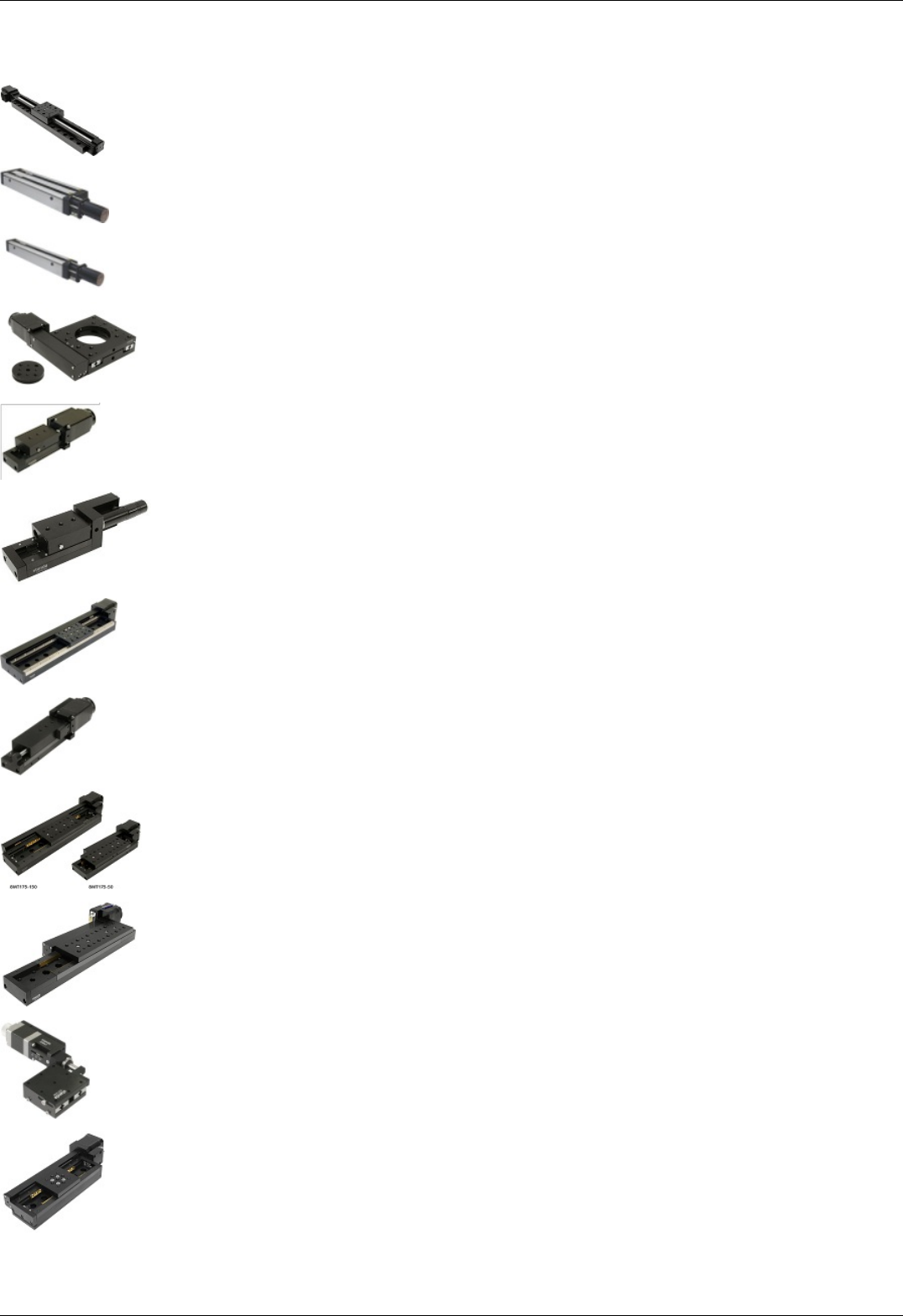
Translation Stages
8MT160 - Motorized Delay Line
8MT295 - Long-Travel Motorized Linear Stages
8MT195 - Long-Travel Motorized Linear Stages
8MT167 - Motorized Translation Stage
8MT173 - Motorized Translation Stages
8MT173DC - Motorized Translation Stages
8MT50 - Motorized Translation Stages
8MT30 - Narrow Motorized Translation Stages
8MT175 - Motorized Translation Stages
8MT177 - Motorized Translation Stage
8MT184 - Motorized Translation Stage
8MT193 - Motorized Translation Stage
Page 276 / 345
Page 276 / 345

8MT160 - Motorized Delay Line
Update: 15 March 2018
Part
number
Travel
range Units Profile Positioner Motor Encoder Brake Accessories Peripherals Attenuator Controller XILab
8MT160-
300 300 mm 8MT160-
300.cfg 8MT160 4247R NoEnc NoBrake NoAcc Buttons NoAtten XismusbDef XIDef
8MT160-
300-
MEn1
300 mm
8MT160-
300-
MEn1.cfg
8MT160 4247R HEDM5500R NoBrake NoAcc Buttons NoAtten XismusbDef XIDef
Page 278 / 345
Page 278 / 345

8MT295 - Long-Travel Motorized Linear Stages
Update: 15 March 2018
Part
number
Travel
range Units Profile Positioner Motor Encoder Brake Accessories Peripherals Attenuator Controller XILab
8MT295X-
240-2.5-
DC
240 mm
8MT295X-
240-2.5-
DC.cfg
8MT295-
2.5
Maxon-
370355 HEDL5540 NoBrake NoAcc Buttons NoAtten XismusbDef XIDef
8MT295X-
340-2.5 340 mm
8MT295X-
340-
2.5.cfg
8MT295-
2.5 5918-R NoEnc NoBrake NoAcc Buttons NoAtten XismusbDef XIDef
8MT295X-
540-4 540 mm 8MT295X-
540-4.cfg 8MT295-4 5918-R NoEnc NoBrake NoAcc Buttons NoAtten XismusbDef XIDef
8MT295X-
740-5 740 mm 8MT295X-
740-5.cfg
8MT295-5-
740 5918-R NoEnc NoBrake NoAcc Buttons NoAtten XismusbDef XIDef
8MT295X-
840-10 840 mm
8MT295X-
840-
10.cfg
8MT295-
10 5918-R NoEnc NoBrake NoAcc Buttons NoAtten XismusbDef XIDef
8MT295X-
1040-5 1040 mm
8MT295X-
1040-
5.cfg
8MT295-5-
1040 5918-R NoEnc NoBrake NoAcc Buttons NoAtten XismusbDef XIDef
8MT295Z-
340-2.5 340 mm
8MT295Z-
340-
2.5.cfg
8MT295-
2.5 5918-R NoEnc BRAKE-
AB41 NoAcc Buttons NoAtten XismusbDef XIDef
8MT295Z-
540-4 540 mm 8MT295Z-
540-4.cfg 8MT295-4 5918-R NoEnc BRAKE-
AB41 NoAcc Buttons NoAtten XismusbDef XIDef
8MT295Z-
740-5 740 mm 8MT295Z-
740-5.cfg
8MT295-5-
740 5918-R NoEnc BRAKE-
AB41 NoAcc Buttons NoAtten XismusbDef XIDef
8MT295Z-
840-10 840 mm
8MT295Z-
840-
10.cfg
8MT295-
10 5918-R NoEnc BRAKE-
AB41 NoAcc Buttons NoAtten XismusbDef XIDef
Page 279 / 345
Page 279 / 345

8MT195 - Long-Travel Motorized Linear Stages
Update: 15 March 2018
Part
number
Travel
range Units Profile Positioner Motor Encoder Brake Accessories Peripherals Attenuator Controller XILab
8MT195X-
340-2.5 340 mm
8MT195X-
340-
2.5.cfg
8MT195-
2.5 5918-R NoEnc NoBrake NoAcc Buttons NoAtten XismusbDef XIDef
8MT195X-
540-4 540 mm 8MT195X-
540-4.cfg 8MT195-4 5918-R NoEnc NoBrake NoAcc Buttons NoAtten XismusbDef XIDef
8MT195X-
540-10 540 mm
8MT195X-
540-
10.cfg
8MT195-
10 5918-R NoEnc NoBrake NoAcc Buttons NoAtten XismusbDef XIDef
8MT195X-
740-5 740 mm 8MT195X-
740-5.cfg
8MT195-5-
740 5918-R NoEnc NoBrake NoAcc Buttons NoAtten XismusbDef XIDef
8MT195X-
840-10 840 mm
8MT195X-
840-
10.cfg
8MT195-
10 5918-R NoEnc NoBrake NoAcc Buttons NoAtten XismusbDef XIDef
8MT195X-
1040-10 1040 mm
8MT195X-
1040-
10.cfg
8MT195-
10 5918-R NoEnc NoBrake NoAcc Buttons NoAtten XismusbDef XIDef
8MT195Z-
240-2.5-
DC
240 mm
8MT195Z-
240-2.5-
DC.cfg
8MT195-
2.5
Maxon-
370355 HEDL9140 BRAKE-
AB41 NoAcc Buttons NoAtten XismusbDef XIDef
8MT195Z-
240-2.5 240 mm
8MT195Z-
240-
2.5.cfg
8MT195-
2.5 5918-R NoEnc BRAKE-
AB41 NoAcc Buttons NoAtten XismusbDef XIDef
8MT195Z-
340-2.5 340 mm
8MT195Z-
340-
2.5.cfg
8MT195-
2.5 5918-R NoEnc BRAKE-
AB41 NoAcc Buttons NoAtten XismusbDef XIDef
8MT195Z-
540-4 540 mm 8MT195Z-
540-4.cfg 8MT195-4 5918-R NoEnc BRAKE-
AB41 NoAcc Buttons NoAtten XismusbDef XIDef
8MT195Z-
740-5 740 mm 8MT195Z-
740-5.cfg
8MT195-5-
740 5918-R NoEnc BRAKE-
AB41 NoAcc Buttons NoAtten XismusbDef XIDef
8MT195Z-
840-10 840 mm
8MT195Z-
840-
10.cfg
8MT195-
10 5918-R NoEnc BRAKE-
AB41 NoAcc Buttons NoAtten XismusbDef XIDef
Page 280 / 345
Page 280 / 345

8MT167 - Motorized Translation Stage
Update: 15 March 2018
Part
number
Travel
range Units Profile Positioner Motor Encoder Brake Accessories Peripherals Attenuator Controller XILab
8MT167-
100 100 mm 8MT167-
100.cfg 8MT167 4247R NoEnc NoBrake NoAcc Buttons NoAtten XismusbDef XIDef
8MT167-
100-28 100 mm 8MT167-
100-28.cfg 8MT167 28R NoEnc NoBrake NoAcc Buttons NoAtten XismusbDef XIDef
8MT167-
100C28 100 mm 8MT167-
100C28.cfg 8MT167 28R NoEnc NoBrake NoAcc Buttons NoAtten XismusbDef XIDef
8MT167S-
100 100 mm 8MT167S-
100.cfg 8MT167 4247R NoEnc NoBrake NoAcc Buttons NoAtten XismusbDef XIDef
8MT167S-
100-28 100 mm 8MT167S-
100-28.cfg 8MT167 28R NoEnc NoBrake NoAcc Buttons NoAtten XismusbDef XIDef
8MT167S-
100C28 100 mm 8MT167S-
100C28.cfg 8MT167 28R NoEnc NoBrake NoAcc Buttons NoAtten XismusbDef XIDef
8MT167-
25BS1 25 mm 8MT167-
25BS1.cfg 8MT167BS 28R NoEnc NoBrake NoAcc Buttons NoAtten XismusbDef XIDef
8MT167-
25BS1-
MEn1
25 mm
8MT167-
25BS1-
MEn1.cfg
8MT167BS 28R HEDM5500R NoBrake NoAcc Buttons NoAtten XismusbDef XIDef
8MT167-
25LS 25 mm 8MT167-
25LS.cfg 8MT167LS 28R NoEnc NoBrake NoAcc Buttons NoAtten XismusbDef XIDef
8MT167-
25LS-MEn1 25 mm
8MT167-
25LS-
MEn1.cfg
8MT167LS 28R HEDM5500R NoBrake NoAcc Buttons NoAtten XismusbDef XIDef
8MT167M-
25BS1 25 mm 8MT167M-
25BS1.cfg 8MT167BS 28R NoEnc NoBrake NoAcc Buttons NoAtten XismusbDef XIDef
8MT167M-
25LS 25 mm 8MT167M-
25LS.cfg 8MT167LS 28R NoEnc NoBrake NoAcc Buttons NoAtten XismusbDef XIDef
8MT167S-
25BS1 25 mm 8MT167S-
25BS1.cfg 8MT167BS 28R NoEnc NoBrake NoAcc Buttons NoAtten XismusbDef XIDef
8MT167S-
25LS 25 mm 8MT167S-
25LS.cfg 8MT167LS 28R NoEnc NoBrake NoAcc Buttons NoAtten XismusbDef XIDef
8MT167S-
25LS-MEn1 25 mm
8MT167S-
25LS-
MEn1.cfg
8MT167LS 28R HEDM5500R NoBrake NoAcc Buttons NoAtten XismusbDef XIDef
8MT167SV-
100-VSS42 100 mm
8MT167SV-
100-
VSS42.cfg
8MT167 VSS42-
RNoEnc NoBrake NoAcc Buttons NoAtten XismusbDef XIDef
8MT167V-
100-VSS42 100 mm
8MT167V-
100-
VSS42.cfg
8MT167 VSS42-
RNoEnc NoBrake NoAcc Buttons NoAtten XismusbDef XIDef
8MT167MV-
25LS-
VSS42
25 mm
8MT167MV-
25LS-
VSS42.cfg
8MT167 VSS42-
RNoEnc NoBrake NoAcc Buttons NoAtten XismusbDef XIDef
8MT167SV-
25LS-
VSS42
25 mm
8MT167SV-
25LS-
VSS42.cfg
8MT167 VSS42-
RNoEnc NoBrake NoAcc Buttons NoAtten XismusbDef XIDef
8MT167V-
25LS-
VSS42
25 mm
8MT167V-
25LS-
VSS42.cfg
8MT167 VSS42-
RNoEnc NoBrake NoAcc Buttons NoAtten XismusbDef XIDef
Page 281 / 345
Page 281 / 345

8MT173 - Motorized Translation Stages
Update: 15 March 2018
Part
number
Travel
range Units Profile Positioner Motor Encoder Brake Accessories Peripherals Attenuator Controller XILab
8MT173-10 10 mm 8MT173-
10.cfg 8MT173 28R NoEnc NoBrake NoAcc Buttons NoAtten XismusbDef XIDef
8MT173-
10-MEn1 10 mm
8MT173-
10-
MEn1.cfg
8MT173 28R HEDM5500R NoBrake NoAcc Buttons NoAtten XismusbDef XIDef
8MT173-20 20 mm 8MT173-
20.cfg 8MT173 28R NoEnc NoBrake NoAcc Buttons NoAtten XismusbDef XIDef
8MT173-
20-E3 20 mm 8MT173-
20-E3.cfg 8MT173 28R RevS NoBrake NoAcc Buttons NoAtten XismusbDef XIDef
8MT173D-
20-E3 20 mm 8MT173D-
20-E3.cfg 8MT173 28R RevS NoBrake NoAcc Buttons NoAtten XismusbDef XIDef
8MT173D2-
20-E3 20 mm 8MT173D2-
20-E3.cfg 8MT173 28R RevS NoBrake NoAcc Buttons NoAtten XismusbDef XIDef
8MT173-
20-50-E3 20 mm
8MT173-
20-50-
E3.cfg
8MT173 28R RevS NoBrake NoAcc Buttons NoAtten XismusbDef XIDef
8MT173-
20-1-28S-
E3
20 mm
8MT173-
20-1-28S-
E3.cfg
8MT173 28S RevS NoBrake NoAcc Buttons NoAtten XismusbDef XIDef
8MT173-
20-E4 20 mm 8MT173-
20-E4.cfg 8MT173 28R RevS NoBrake NoAcc Buttons NoAtten XismusbDef XIDef
8MT173-
20-MEn1 20 mm
8MT173-
20-
MEn1.cfg
8MT173 28R HEDM5500R NoBrake NoAcc Buttons NoAtten XismusbDef XIDef
8MT173-25 25 mm 8MT173-
25.cfg 8MT173 28R NoEnc NoBrake NoAcc Buttons NoAtten XismusbDef XIDef
8MT173-
25-MEn1 25 mm
8MT173-
25-
MEn1.cfg
8MT173 28R HEDM5500R NoBrake NoAcc Buttons NoAtten XismusbDef XIDef
8MT173-30 30 mm 8MT173-
30.cfg 8MT173 28R NoEnc NoBrake NoAcc Buttons NoAtten XismusbDef XIDef
8MT173-
30-MEn1 30 mm
8MT173-
30-
MEn1.cfg
8MT173 28R HEDM5500R NoBrake NoAcc Buttons NoAtten XismusbDef XIDef
8MT173V-
10-VSS42 10 mm
8MT173V-
10-
VSS42.cfg
8MT173V VSS42-
RNoEnc NoBrake NoAcc Buttons NoAtten XismusbDef XIDef
8MT173V-
20-VSS42 20 mm
8MT173V-
20-
VSS42.cfg
8MT173V VSS42-
RNoEnc NoBrake NoAcc Buttons NoAtten XismusbDef XIDef
8MT173V-
25-VSS42 25 mm
8MT173V-
25-
VSS42.cfg
8MT173V VSS42-
RNoEnc NoBrake NoAcc Buttons NoAtten XismusbDef XIDef
8MT173V-
30-VSS42 30 mm
8MT173V-
30-
VSS42.cfg
8MT173V VSS42-
RNoEnc NoBrake NoAcc Buttons NoAtten XismusbDef XIDef
Page 282 / 345
Page 282 / 345

8MT173DC - Motorized Translation Stages
Update: 15 March 2018
Part
number
Travel
range Units Profile Positioner Motor Encoder Brake Accessories Peripherals Attenuator Controller XILab
8MT173-
10DCE2 10 mm 8MT173-
10DCE2.cfg
8MT173-
DCE2
Maxon-
118512-
R
EncMRtypeS-
RNoBrake NoAcc Buttons NoAtten XismusbDef XIDefDC
8MT173-
20DCE2 20 mm 8MT173-
20DCE2.cfg
8MT173-
DCE2
Maxon-
118512-
R
EncMRtypeS-
RNoBrake NoAcc Buttons NoAtten XismusbDef XIDefDC
8MT173-
25DCE2 25 mm 8MT173-
25DCE2.cfg
8MT173-
DCE2
Maxon-
118512-
R
EncMRtypeS-
RNoBrake NoAcc Buttons NoAtten XismusbDef XIDefDC
8MT173-
30DCE2 30 mm 8MT173-
30DCE2.cfg
8MT173-
DCE2
Maxon-
118512-
R
EncMRtypeS-
RNoBrake NoAcc Buttons NoAtten XismusbDef XIDefDC
Page 283 / 345
Page 283 / 345

8MT50 - Motorized Translation Stages
Update: 15 March 2018
Part
number
Travel
range Units Profile Positioner Motor Encoder Brake Accessories Peripherals Attenuator Controller XILab
8MT50-
100BS1 100 mm 8MT50-
100BS1.cfg 8MT50 4247R NoEnc NoBrake NoAcc Buttons NoAtten XismusbDef XIDef
8MT50-
100BS1-
MEn1
100 mm
8MT50-
100BS1-
MEn1.cfg
8MT50 4247R HEDM5500R NoBrake NoAcc Buttons NoAtten XismusbDef XIDef
8MT50-
100XY 100 mm 8MT50-
100XY.cfg 8MT50 4247R NoEnc NoBrake NoAcc Buttons NoAtten XismusbDef XIDef
8MT50-
100XYZ 100 mm 8MT50-
100XYZ.cfg 8MT50 4247R NoEnc NoBrake NoAcc Buttons NoAtten XismusbDef XIDef
8MT50-
150BS1 150 mm 8MT50-
150BS1.cfg 8MT50 4247R NoEnc NoBrake NoAcc Buttons NoAtten XismusbDef XIDef
8MT50-
150BS1-
MEn1
150 mm
8MT50-
150BS1-
MEn1.cfg
8MT50 4247R HEDM5500R NoBrake NoAcc Buttons NoAtten XismusbDef XIDef
8MT50-
150XY 150 mm 8MT50-
150XY.cfg 8MT50 4247R NoEnc NoBrake NoAcc Buttons NoAtten XismusbDef XIDef
8MT50-
150XYZ 150 mm 8MT50-
150XYZ.cfg 8MT50 4247R NoEnc NoBrake NoAcc Buttons NoAtten XismusbDef XIDef
8MT50-
200BS1 200 mm 8MT50-
200BS1.cfg 8MT50 4247R NoEnc NoBrake NoAcc Buttons NoAtten XismusbDef XIDef
8MT50-
200BS1-
MEn1
200 mm
8MT50-
200BS1-
MEn1.cfg
8MT50 4247R HEDM5500R NoBrake NoAcc Buttons NoAtten XismusbDef XIDef
8MT50-
200XY 200 mm 8MT50-
200XY.cfg 8MT50 4247R NoEnc NoBrake NoAcc Buttons NoAtten XismusbDef XIDef
8MT50-
200XYZ 200 mm 8MT50-
200XYZ.cfg 8MT50 4247R NoEnc NoBrake NoAcc Buttons NoAtten XismusbDef XIDef
8MT50Z-
100BS1 100 mm 8MT50Z-
100BS1.cfg 8MT50 ST4118-
K2V17690 NoEnc
BRAKE-
BKE-04-
05
NoAcc Buttons NoAtten XismusbDef XIDef
8MT50Z-
150BS1 150 mm 8MT50Z-
150BS1.cfg 8MT50 ST4118-
K2V17690 NoEnc
BRAKE-
BKE-04-
05
NoAcc Buttons NoAtten XismusbDef XIDef
8MT50Z-
200BS1 200 mm 8MT50Z-
200BS1.cfg 8MT50 ST4118-
K2V17690 NoEnc
BRAKE-
BKE-04-
05
NoAcc Buttons NoAtten XismusbDef XIDef
Page 284 / 345
Page 284 / 345

8MT30 - Narrow Motorized Translation Stages
Update: 15 March 2018
Part
number
Travel
range Units Profile Positioner Motor Encoder Brake Accessories Peripherals Attenuator Controller XILab
8MT30-
50 50 mm 8MT30-
50.cfg 8MT30 28R NoEnc NoBrake NoAcc Buttons NoAtten XismusbDef XIDef
8MT30-
50-MEn1 50 mm
8MT30-
50-
MEn1.cfg
8MT30 28R HEDM5500R NoBrake NoAcc Buttons NoAtten XismusbDef XIDef
8MT30-
50DCE 50 mm 8MT30-
50DCE.cfg 8MT30DC Maxon-
339152-R
EncMRtypeML-
RNoBrake NoAcc Buttons NoAtten XismusbDef XIDefDC
8MT30V-
50-
VSS42
50 mm
8MT30V-
50-
VSS42.cfg
8MT30V VSS42-R NoEnc NoBrake NoAcc Buttons NoAtten XismusbDef XIDef
8MT30V-
50DCE 50 mm 8MT30V-
50DCE.cfg 8MT30VDC FAULHABER-
1524T006SR IE2-16 NoBrake NoAcc Buttons NoAtten XismusbDef XIDefDC
Page 285 / 345
Page 285 / 345

8MT175 - Motorized Translation Stages
Update: 15 March 2018
Part
number
Travel
range Units Profile Positioner Motor Encoder Brake Accessories Peripherals Attenuator Controller XILab
8MT175-
100 100 mm 8MT175-
100.cfg 8MT175 4247R NoEnc NoBrake NoAcc Buttons NoAtten XismusbDef XIDef
8MT175-
100-E3 100 mm
8MT175-
100-
E3.cfg
8MT175 4247R RevS NoBrake NoAcc Buttons NoAtten XismusbDef XIDef
8MT175-
100-MEn1 100 mm
8MT175-
100-
MEn1.cfg
8MT175 4247R HEDM5500R NoBrake NoAcc Buttons NoAtten XismusbDef XIDef
8MT175-
150 150 mm 8MT175-
150.cfg 8MT175 4247R NoEnc NoBrake NoAcc Buttons NoAtten XismusbDef XIDef
8MT175-
150-MEn1 150 mm
8MT175-
150-
MEn1.cfg
8MT175 4247R HEDM5500R NoBrake NoAcc Buttons NoAtten XismusbDef XIDef
8MT175-
200 200 mm 8MT175-
200.cfg 8MT175 4247R NoEnc NoBrake NoAcc Buttons NoAtten XismusbDef XIDef
8MT175-
200-MEn1 200 mm
8MT175-
200-
MEn1.cfg
8MT175 4247R HEDM5500R NoBrake NoAcc Buttons NoAtten XismusbDef XIDef
8MT175-
50 50 mm 8MT175-
50.cfg 8MT175 4247R NoEnc NoBrake NoAcc Buttons NoAtten XismusbDef XIDef
8MT175-
50-MEn1 50 mm
8MT175-
50-
MEn1.cfg
8MT175 4247R HEDM5500R NoBrake NoAcc Buttons NoAtten XismusbDef XIDef
8MT175V-
100-
VSS42
100 mm
8MT175V-
100-
VSS42.cfg
8MT175V VSS42-
RNoEnc NoBrake NoAcc Buttons NoAtten XismusbDef XIDef
8MT175V-
150-
VSS42
150 mm
8MT175V-
150-
VSS42.cfg
8MT175V VSS42-
RNoEnc NoBrake NoAcc Buttons NoAtten XismusbDef XIDef
8MT175V-
200-
VSS42
200 mm
8MT175V-
200-
VSS42.cfg
8MT175V VSS42-
RNoEnc NoBrake NoAcc Buttons NoAtten XismusbDef XIDef
8MT175V-
50-VSS42 50 mm
8MT175V-
50-
VSS42.cfg
8MT175V VSS42-
RNoEnc NoBrake NoAcc Buttons NoAtten XismusbDef XIDef
Page 286 / 345
Page 286 / 345

8MT177 - Motorized Translation Stage
Update: 15 March 2018
Part
number
Travel
range Units Profile Positioner Motor Encoder Brake Accessories Peripherals Attenuator Controller XILab
8MT177-
100 100 mm 8MT177-
100.cfg 8MT177 4247R NoEnc NoBrake NoAcc Buttons NoAtten XismusbDef XIDef
8MT177-
100-E4 100 mm 8MT177-
100-E4.cfg 8MT177 4247R RevS NoBrake NoAcc Buttons NoAtten XismusbDef XIDef
8MT177-
100XY 100 mm 8MT177-
100XY.cfg 8MT177 4247R NoEnc NoBrake NoAcc Buttons NoAtten XismusbDef XIDef
8MT177-
100XYZ 100 mm 8MT177-
100XYZ.cfg 8MT177 4247R NoEnc NoBrake NoAcc Buttons NoAtten XismusbDef XIDef
8MT177-
100-28 100 mm 8MT177-
100-28.cfg 8MT177 28R NoEnc NoBrake NoAcc Buttons NoAtten XismusbDef XIDef
8MT177-
100-
28XY
100 mm
8MT177-
100-
28XY.cfg
8MT177 28R NoEnc NoBrake NoAcc Buttons NoAtten XismusbDef XIDef
8MT177-
100-
28XYZ
100 mm
8MT177-
100-
28XYZ.cfg
8MT177 28R NoEnc NoBrake NoAcc Buttons NoAtten XismusbDef XIDef
Page 287 / 345
Page 287 / 345

8MT184 - Motorized Translation Stage
Update: 15 March 2018
Part
number
Travel
range Units Profile Positioner Motor Encoder Brake Accessories Peripherals Attenuator Controller XILab
8MT184-
13 13 mm 8MT184-
13.cfg 8MT184 20-Rev NoEnc NoBrake NoAcc Buttons NoAtten XismusbDef XIDef
8MT184-
13DC 13 mm 8MT184-
13DC.cfg 8MT184DC FAULHABER-
1524T006SR IE2-256 NoBrake NoAcc Buttons NoAtten XismusbDef XIDefDC
8MT184-
13XY 13 mm 8MT184-
13XY.cfg 8MT184 20-Rev NoEnc NoBrake NoAcc Buttons NoAtten XismusbDef XIDef
8MT184-
13XYZ 13 mm 8MT184-
13XYZ.cfg 8MT184 20-Rev NoEnc NoBrake NoAcc Buttons NoAtten XismusbDef XIDef
8MT184V-
13DC 13 mm 8MT184V-
13DC.cfg 8MT184DCV FAULHABER-
1524T006SR IE2-16 NoBrake NoAcc Buttons NoAtten XismusbDef XIDefDC
Page 288 / 345
Page 288 / 345

8MT193 - Motorized Translation Stage
Update: 15 March 2018
Part
number
Travel
range Units Profile Positioner Motor Encoder Brake Accessories Peripherals Attenuator Controller XILab
8MT193-
100 100 mm 8MT193-
100.cfg 8MT193 4247R NoEnc NoBrake NoAcc Buttons NoAtten XismusbDef XIDef
8MT193-
100-E4-
DS
100 mm
8MT193-
100-E4-
DS.cfg
8MT193 4247R RevS NoBrake NoAcc Buttons NoAtten XismusbDef XIDef
Page 289 / 345
Page 289 / 345

8MT200 - Motorized Translation Stages
Update: 15 March 2018
Part
number
Travel
range Units Profile Positioner Motor Encoder Brake Accessories Peripherals Attenuator Controller XILab
8MT200-
100 100 mm 8MT200-
100.cfg 8MT200 4247R NoEnc NoBrake NoAcc Buttons NoAtten XismusbDef XIDef
Page 290 / 345
Page 290 / 345

8MTF - Motorized XY Scanning Stage
Update: 15 March 2018
Part
number
Travel
range Units Profile Positioner Motor Encoder Brake Accessories Peripherals Attenuator Controller XILab
8MTF-
102LS05 102 mm 8MTF-
102LS05.cfg 8MTF-102 28R NoEnc NoBrake NoAcc Buttons NoAtten XismusbDef XIDef
8MTF-
75LS05 75 mm 8MTF-
75LS05.cfg 8MTF-75 28R NoEnc NoBrake NoAcc Buttons NoAtten XismusbDef XIDef
8MTF-
75LS1 75 mm 8MTF-
75LS1.cfg 8MTF-75-2 28R NoEnc NoBrake NoAcc Buttons NoAtten XismusbDef XIDef
Page 291 / 345
Page 291 / 345


8MTFV - Motorized Translation Stage
Update: 15 March 2018
Part
number
Travel
range Units Profile Positioner Motor Encoder Brake Accessories Peripherals Attenuator Controller XILab
8MTFV-
75_40LS05-
42.3
40 mm
8MTFV-
75_40LS05-
42.3.cfg
8MTFV D423 NoEnc NoBrake NoAcc Buttons NoAtten XismusbDef XIDef
Page 293 / 345
Page 293 / 345

8MT60 - Motorized Translation Stage
Update: 15 March 2018
Part
number
Travel
range Units Profile Positioner Motor Encoder Brake Accessories Peripherals Attenuator Controller XILab
8MT60-
200 200 mm 8MT60-
200.cfg 8MT60 4247R NoEnc NoBrake NoAcc Buttons NoAtten XismusbDef XIDef
8MT60V-
200 200 mm 8MT60V-
200.cfg 8MT60V VSS42-
RNoEnc NoBrake NoAcc Buttons NoAtten XismusbDef XIDef
Page 294 / 345
Page 294 / 345
Rotation Stages
8MR151 - Motorized Rotation Stages
8MR170 - Motorized Rotation Stages
8MR174 - Motorized Rotation Stage
8MR190 - Motorized Rotation Stage
8MR191 - Motorized Rotation Stage
8MRB250 - Large Motorized Rotation Stage
8MRU - Universal Motorized Rotation Stages
8MPR16-1 - Motorized Polarizer Rotator
8MRH240 - Large High Capacity Rotary Stage
Page 295 / 345
Page 295 / 345

8MR151 - Motorized Rotation Stages
Update: 15 March 2018
Part
number
Travel
range Units Profile Positioner Motor Encoder Brake Accessories Peripherals Attenuator Controller XILab
8MR151-1 360 deg 8MR151-
1.cfg 8MR151 28 NoEnc NoBrake NoAcc Buttons NoAtten XismusbDef XIDefRot
8MR151-
1-MEn1 360 deg
8MR151-
1-
MEn1.cfg
8MR151 28 HEDM5500 NoBrake NoAcc Buttons NoAtten XismusbDef XIDefRot
8MR151-
30 360 deg 8MR151-
30.cfg 8MR151 28 NoEnc NoBrake NoAcc Buttons NoAtten XismusbDef XIDefRot
8MR151-
30-E4 360 deg 8MR151-
30-E4.cfg 8MR151 28 RevS NoBrake NoAcc Buttons NoAtten XismusbDef XIDefRot
8MR151-
30-MEn1 360 deg
8MR151-
30-
MEn1.cfg
8MR151 28 HEDM5500 NoBrake NoAcc Buttons NoAtten XismusbDef XIDefRot
8MR151E-
1360 deg 8MR151E-
1.cfg 8MR151 28 NoEnc NoBrake NoAcc Buttons NoAtten XismusbDef XIDefRot
8MR151E-
30 360 deg 8MR151E-
30.cfg 8MR151 28 NoEnc NoBrake NoAcc Buttons NoAtten XismusbDef XIDefRot
8MR151-
30-E3 360 deg 8MR151-
30-E3.cfg 8MR151 28 RevS NoBrake NoAcc Buttons NoAtten XismusbDef XIDefRot
Page 296 / 345
Page 296 / 345


8MR174 - Motorized Rotation Stage
Update: 15 March 2018
Part
number
Travel
range Units Profile Positioner Motor Encoder Brake Accessories Peripherals Attenuator Controller XILab
8MR174-
11-20 360 deg 8MR174-
11-20.cfg 8MR174 20 NoEnc NoBrake NoAcc Buttons NoAtten XismusbDef XIDefRot
8MR174-
11-28 360 deg 8MR174-
11-28.cfg 8MR174 28 NoEnc NoBrake NoAcc Buttons NoAtten XismusbDef XIDefRot
8MR174-
11-28-E4 360 deg
8MR174-
11-28-
E4.cfg
8MR174 28 RevS NoBrake NoAcc Buttons NoAtten XismusbDef XIDefRot
8MR174-
11-28S 360 deg 8MR174-
11-28S.cfg 8MR174 28S NoEnc NoBrake NoAcc Buttons NoAtten XismusbDef XIDefRot
8MR174-
11-28-E3 360 deg
8MR174-
11-28-
E3.cfg
8MR174 28 RevS NoBrake NoAcc Buttons NoAtten XismusbDef XIDefRot
8MR174-
11-28S-E3 360 deg
8MR174-
11-28S-
E3.cfg
8MR174 28S RevS NoBrake NoAcc Buttons NoAtten XismusbDef XIDefRot
8MR174-
11-28-
MEn1
360 deg
8MR174-
11-28-
MEn1.cfg
8MR174 28 HEDM5500R NoBrake NoAcc Buttons NoAtten XismusbDef XIDefRot
8MR174E-
11-20 360 deg 8MR174E-
11-20.cfg 8MR174 20 NoEnc NoBrake NoAcc Buttons NoAtten XismusbDef XIDefRot
8MR174E-
11-28 360 deg 8MR174E-
11-28.cfg 8MR174 28 NoEnc NoBrake NoAcc Buttons NoAtten XismusbDef XIDefRot
8MR174E-
11-28S 360 deg 8MR174E-
11-28S.cfg 8MR174 28S NoEnc NoBrake NoAcc Buttons NoAtten XismusbDef XIDefRot
8MR174E-
11-28-
MEn1
360 deg
8MR174E-
11-28-
MEn1.cfg
8MR174 28 HEDM5500R NoBrake NoAcc Buttons NoAtten XismusbDef XIDefRot
8MR174EV-
11-VSS42 360 deg
8MR174EV-
11-
VSS42.cfg
8MR174V VSS42 NoEnc NoBrake NoAcc Buttons NoAtten XismusbDef XIDefRot
8MR174V-
11-VSS42 360 deg
8MR174V-
11-
VSS42.cfg
8MR174V VSS42 NoEnc NoBrake NoAcc Buttons NoAtten XismusbDef XIDefRot
Page 298 / 345
Page 298 / 345

8MR190 - Motorized Rotation Stage
Update: 15 March 2018
Part
number
Travel
range Units Profile Positioner Motor Encoder Brake Accessories Peripherals Attenuator Controller XILab
8MR190-2-
28 360 deg 8MR190-2-
28.cfg 8MR190 28 NoEnc NoBrake NoAcc Buttons NoAtten XismusbDef XIDefRot
8MR190-2-
28-E4 360 deg 8MR190-2-
28-E4.cfg 8MR190 28 RevS NoBrake NoAcc Buttons NoAtten XismusbDef XIDefRot
8MR190-2-
WH-28-E3 360 deg
8MR190-2-
WH-28-
E3.cfg
8MR190 28 RevS NoBrake NoAcc Buttons NoAtten XismusbDef XIDefRot
8MR190-2-
28-MEn1 360 deg
8MR190-2-
28-
MEn1.cfg
8MR190 28 HEDM5500 NoBrake NoAcc Buttons NoAtten XismusbDef XIDefRot
8MR190-2-
4233 360 deg 8MR190-2-
4233.cfg 8MR190 4233 NoEnc NoBrake NoAcc Buttons NoAtten XismusbDef XIDefRot
8MR190-2-
4247 360 deg 8MR190-2-
4247.cfg 8MR190 4247R NoEnc NoBrake NoAcc Buttons NoAtten XismusbDef XIDefRot
8MR190-2-
ZSS43 360 deg 8MR190-2-
ZSS43.cfg 8MR190 ZSS43 NoEnc NoBrake NoAcc Buttons NoAtten XismusbDef XIDefRot
8MR190V-
2-VSS42 360 deg
8MR190V-
2-
VSS42.cfg
8MR190V VSS42-
RNoEnc NoBrake NoAcc Buttons NoAtten XismusbDef XIDefRot
8MR190E-
2-28 360 deg 8MR190E-
2-28.cfg 8MR190 28 NoEnc NoBrake NoAcc Buttons NoAtten XismusbDef XIDefRot
8MR190E-
2-28-E3 360 deg
8MR190E-
2-28-
E3.cfg
8MR190 28 RevS NoBrake NoAcc Buttons NoAtten XismusbDef XIDefRot
8MR190-2-
28-E3 360 deg 8MR190-2-
28-E3.cfg 8MR190 28 RevS NoBrake NoAcc Buttons NoAtten XismusbDef XIDefRot
8MR190E-
2-4233 360 deg 8MR190E-
2-4233.cfg 8MR190 4233 NoEnc NoBrake NoAcc Buttons NoAtten XismusbDef XIDefRot
8MR190E-
2-4247 360 deg 8MR190E-
2-4247.cfg 8MR190 4247R NoEnc NoBrake NoAcc Buttons NoAtten XismusbDef XIDefRot
8MR190E-
2-ZSS43 360 deg
8MR190E-
2-
ZSS43.cfg
8MR190 ZSS43 NoEnc NoBrake NoAcc Buttons NoAtten XismusbDef XIDefRot
8MR190EV-
2-VSS42 360 deg
8MR190EV-
2-
VSS42.cfg
8MR190V VSS42 NoEnc NoBrake NoAcc Buttons NoAtten XismusbDef XIDefRot
8MR190-
90-59 360 deg 8MR190-
90-59.cfg
8MR190-
90-59 5918-R NoEnc NoBrake NoAcc Buttons NoAtten XismusbDef XIDefRot
8MR190-
90-59-
MEn1
360 deg
8MR190-
90-59-
MEn1.cfg
8MR190-
90-59 5918-R HEDM5500R NoBrake NoAcc Buttons NoAtten XismusbDef XIDefRot
8MR190-
90-4247 360 deg
8MR190-
90-
4247.cfg
8MR190-
90-4247 4247R NoEnc NoBrake NoAcc Buttons NoAtten XismusbDef XIDefRot
8MR190-
90-4247-
MEn1
360 deg
8MR190-
90-4247-
MEn1.cfg
8MR190-
90-4247 4247R HEDM5500R NoBrake NoAcc Buttons NoAtten XismusbDef XIDefRot
8MR190V-
90-VSS43 360 deg
8MR190V-
90-
VSS43.cfg
8MR190-
90-VSS43 VSS43 NoEnc NoBrake NoAcc Buttons NoAtten XismusbDef XIDefRot
8MR190-2-
DCE 360 deg 8MR190-2-
DCE.cfg
8MR190-2-
DCE
Maxon-
339152 EncMRtypeML NoBrake NoAcc Buttons NoAtten XismusbDef XIDefRot
Page 299 / 345
Page 299 / 345

8MR191 - Motorized Rotation Stage
Update: 15 March 2018
Part
number
Travel
range Units Profile Positioner Motor Encoder Brake Accessories Peripherals Attenuator Controller XILab
8MR191-1-
28 360 deg 8MR191-1-
28.cfg 8MR191 28 NoEnc NoBrake NoAcc Buttons NoAtten XismusbDef XIDefRot
8MR191-1-
4233 360 deg 8MR191-1-
4233.cfg 8MR191 4233 NoEnc NoBrake NoAcc Buttons NoAtten XismusbDef XIDefRot
8MR191-1-
4247 360 deg 8MR191-1-
4247.cfg 8MR191 4247 NoEnc NoBrake NoAcc Buttons NoAtten XismusbDef XIDefRot
8MR191-1-
ZSS43 360 deg 8MR191-1-
ZSS43.cfg 8MR191 ZSS43 NoEnc NoBrake NoAcc Buttons NoAtten XismusbDef XIDefRot
8MR191-1-
4209-E4 360 deg
8MR191-1-
4209-
E4.cfg
8MR191 4209 RevS NoBrake NoAcc Buttons NoAtten XismusbDef XIDefRot
8MR191-
30-28 360 deg 8MR191-
30-28.cfg 8MR191 28 NoEnc NoBrake NoAcc Buttons NoAtten XismusbDef XIDefRot
8MR191-
30-4233 360 deg
8MR191-
30-
4233.cfg
8MR191 4233 NoEnc NoBrake NoAcc Buttons NoAtten XismusbDef XIDefRot
8MR191-
30-4247 360 deg
8MR191-
30-
4247.cfg
8MR191 4247 NoEnc NoBrake NoAcc Buttons NoAtten XismusbDef XIDefRot
8MR191-
30-4209-
E4
360 deg
8MR191-
30-4209-
E4.cfg
8MR191 4209 RevS NoBrake NoAcc Buttons NoAtten XismusbDef XIDefRot
8MR191-
30-ZSS43 360 deg
8MR191-
30-
ZSS43.cfg
8MR191 ZSS43 NoEnc NoBrake NoAcc Buttons NoAtten XismusbDef XIDefRot
8MR191-28 360 deg 8MR191-
28.cfg 8MR191 28 NoEnc NoBrake NoAcc Buttons NoAtten XismusbDef XIDefRot
8MR191-
4233 360 deg 8MR191-
4233.cfg 8MR191 4233 NoEnc NoBrake NoAcc Buttons NoAtten XismusbDef XIDefRot
8MR191-
4247 360 deg 8MR191-
4247.cfg 8MR191 4247 NoEnc NoBrake NoAcc Buttons NoAtten XismusbDef XIDefRot
8MR191-
ZSS43 360 deg 8MR191-
ZSS43.cfg 8MR191 ZSS43 NoEnc NoBrake NoAcc Buttons NoAtten XismusbDef XIDefRot
8MR191E-
1-28 360 deg 8MR191E-
1-28.cfg 8MR191 28 NoEnc NoBrake NoAcc Buttons NoAtten XismusbDef XIDefRot
8MR191E-
1-4233 360 deg 8MR191E-
1-4233.cfg 8MR191 4233 NoEnc NoBrake NoAcc Buttons NoAtten XismusbDef XIDefRot
8MR191E-
1-4247 360 deg 8MR191E-
1-4247.cfg 8MR191 4247 NoEnc NoBrake NoAcc Buttons NoAtten XismusbDef XIDefRot
8MR191E-
1-ZSS43 360 deg
8MR191E-
1-
ZSS43.cfg
8MR191 ZSS43 NoEnc NoBrake NoAcc Buttons NoAtten XismusbDef XIDefRot
8MR191E-
30-28 360 deg 8MR191E-
30-28.cfg 8MR191 28 NoEnc NoBrake NoAcc Buttons NoAtten XismusbDef XIDefRot
8MR191E-
30-4233 360 deg
8MR191E-
30-
4233.cfg
8MR191 4233 NoEnc NoBrake NoAcc Buttons NoAtten XismusbDef XIDefRot
8MR191E-
30-4247 360 deg
8MR191E-
30-
4247.cfg
8MR191 4247 NoEnc NoBrake NoAcc Buttons NoAtten XismusbDef XIDefRot
8MR191E-
30-ZSS43 360 deg
8MR191E-
30-
ZSS43.cfg
8MR191 ZSS43 NoEnc NoBrake NoAcc Buttons NoAtten XismusbDef XIDefRot
8MR191E-
28 360 deg 8MR191E-
28.cfg 8MR191 28 NoEnc NoBrake NoAcc Buttons NoAtten XismusbDef XIDefRot
8MR191E-
4233 360 deg 8MR191E-
4233.cfg 8MR191 4233 NoEnc NoBrake NoAcc Buttons NoAtten XismusbDef XIDefRot
8MR191E-
4247 360 deg 8MR191E-
4247.cfg 8MR191 4247 NoEnc NoBrake NoAcc Buttons NoAtten XismusbDef XIDefRot
Page 300 / 345
Page 300 / 345

8MR191E-
ZSS43 360 deg 8MR191E-
ZSS43.cfg 8MR191 ZSS43 NoEnc NoBrake NoAcc Buttons NoAtten XismusbDef XIDefRot
8MR191V-
1-VSS42 360 deg
8MR191V-
1-
VSS42.cfg
8MR191V VSS42 NoEnc NoBrake NoAcc Buttons NoAtten XismusbDef XIDefRot
8MR191V-
30-VSS42 360 deg
8MR191V-
30-
VSS42.cfg
8MR191V VSS42 NoEnc NoBrake NoAcc Buttons NoAtten XismusbDef XIDefRot
8MR191V-
VSS42 360 deg 8MR191V-
VSS42.cfg 8MR191V VSS42 NoEnc NoBrake NoAcc Buttons NoAtten XismusbDef XIDefRot
8MR191EV-
1-VSS42 360 deg
8MR191EV-
1-
VSS42.cfg
8MR191V VSS42 NoEnc NoBrake NoAcc Buttons NoAtten XismusbDef XIDefRot
8MR191EV-
30-VSS42 360 deg
8MR191EV-
30-
VSS42.cfg
8MR191V VSS42 NoEnc NoBrake NoAcc Buttons NoAtten XismusbDef XIDefRot
8MR191EV-
VSS42 360 deg 8MR191EV-
VSS42.cfg 8MR191V VSS42 NoEnc NoBrake NoAcc Buttons NoAtten XismusbDef XIDefRot
Page 301 / 345
Page 301 / 345

8MRB - Large Motorized Rotation Stage
Update: 15 March 2018
Part
number
Travel
range Units Profile Positioner Motor Encoder Brake Accessories Peripherals Attenuator Controller XILab
8MRB240-
152-59 360 deg
8MRB240-
152-
59.cfg
8MRB240 5918 NoEnc NoBrake NoAcc Buttons NoAtten XismusbDef XIDefRot
8MRB240-
152-59D 360 deg
8MRB240-
152-
59D.cfg
8MRB240 5918 NoEnc NoBrake NoAcc Buttons NoAtten XismusbDef XIDefRot
8MRB450-
350-60-
MEn2
360 deg
8MRB450-
350-60-
MEn2.cfg
8MRB450 6018 WEDL5541-
BNoBrake NoAcc Buttons NoAtten XismusbDef XIDefRot
Page 302 / 345
Page 302 / 345

8MRU - Universal Motorized Rotation Stages
Update: 15 March 2018
Part
number
Travel
range Units Profile Positioner Motor Encoder Brake Accessories Peripherals Attenuator Controller XILab
8MRU-1 360 deg 8MRU-
1.cfg 8MRU 28S NoEnc NoBrake NoAcc Buttons NoAtten XismusbDef XIDefRot
8MRU-
1TP 360 deg 8MRU-
1TP.cfg 8MRU 28S NoEnc NoBrake NoAcc Buttons NoAtten XismusbDef XIDefRot
8MRU-
1WA 360 deg 8MRU-
1WA.cfg 8MRU 28S NoEnc NoBrake NoAcc Buttons WA XismusbDef XIDefRot
Page 303 / 345
Page 303 / 345

8MPR16-1 - Motorized Polarizer Rotator
Update: 15 March 2018
Part
number
Travel
range Units Profile Positioner Motor Encoder Brake Accessories Peripherals Attenuator Controller XILab
8MPR16-
1-F 360 deg 8MPR16-
1-F.cfg 8MPR16
FAULHABER-
AM1020-V-
3-16
NoEnc NoBrake NoAcc Buttons NoAtten XismusbDef XIDefRot
Page 304 / 345
Page 304 / 345

8MRH240 - Large High Capacity Rotary Stage
Update: 15 March 2018
Part
number
Travel
range Units Profile Positioner Motor Encoder Brake Accessories Peripherals Attenuator Controller XILab
8MRH240-
60 360 deg 8MRH240-
60.cfg 8MRH240 5918 NoEnc NoBrake NoAcc Buttons NoAtten XismusbDef XIDefRot
Page 305 / 345
Page 305 / 345


8MVT100 - Vertical Translation Stage
Update: 15 March 2018
Part
number
Travel
range Units Profile Positioner Motor Encoder Brake Accessories Peripherals Attenuator Controller XILab
8MVT100-
25-1 26 mm 8MVT100-
25-1.cfg 8MVT100 4118L1804R NoEnc NoBrake NoAcc Buttons NoAtten XismusbDef XIDef
Page 307 / 345
Page 307 / 345

8MVT120 - Vertical Translation Stage
Update: 15 March 2018
Part
number
Travel
range Units Profile Positioner Motor Encoder Brake Accessories Peripherals Attenuator Controller XILab
8MVT120-
5-4247 5 mm
8MVT120-
5-
4247.cfg
8MVT120-
54247R NoEnc NoBrake NoAcc Buttons NoAtten XismusbDef XIDef
8MVT120-
12-4247 12.7 mm
8MVT120-
12-
4247.cfg
8MVT120-
12 4247R NoEnc NoBrake NoAcc Buttons NoAtten XismusbDef XIDef
8MVT120-
25-4247 25.4 mm
8MVT120-
25-
4247.cfg
8MVT120-
25 4247R NoEnc NoBrake NoAcc Buttons NoAtten XismusbDef XIDef
Page 308 / 345
Page 308 / 345

8MVT188 - Vertical Translation Stage
Update: 15 March 2018
Part
number
Travel
range Units Profile Positioner Motor Encoder Brake Accessories Peripherals Attenuator Controller XILab
8MVT188-
20 8744052 steps 8MVT188-
20.cfg 8MVT188 5918 NoEnc NoBrake NoAcc Buttons NoAtten XismusbDef XIDef
Page 309 / 345
Page 309 / 345

8MVT40 - Vertical Translation Stage
Update: 15 March 2018
Part
number
Travel
range Units Profile Positioner Motor Encoder Brake Accessories Peripherals Attenuator Controller XILab
8MVT40-
13-1 13 mm 8MVT40-
13-1.cfg 8MVT40 28SR NoEnc NoBrake NoAcc Buttons NoAtten XismusbDef XIDef
Page 310 / 345
Page 310 / 345

8MVT70 - Vertical Translation Stage
Update: 15 March 2018
Part
number
Travel
range Units Profile Positioner Motor Encoder Brake Accessories Peripherals Attenuator Controller XILab
8MVT70-
13-1 13 mm 8MVT70-
13-1.cfg 8MVT70 4118S1404R NoEnc NoBrake NoAcc Buttons NoAtten XismusbDef XIDef
Page 311 / 345
Page 311 / 345


8MS00 - Motorized Screws
Update: 15 March 2018
Part
number
Travel
range Units Profile Positioner Motor Encoder Brake Accessories Peripherals Attenuator Controller XILab
8MS00-
10 10 mm 8MS00-
10.cfg 8MS00-10 4233-R NoEnc NoBrake NoAcc Buttons NoAtten XismusbDef XIDef
8MS00-
10-28 10 mm 8MS00-
10-28.cfg 8MS00-10 28R NoEnc NoBrake NoAcc Buttons NoAtten XismusbDef XIDef
8MS00-
25 25 mm 8MS00-
25.cfg 8MS00-25 4233-R NoEnc NoBrake NoAcc Buttons NoAtten XismusbDef XIDef
8MS00-
25-28 25 mm 8MS00-
25-28.cfg 8MS00-25 28R NoEnc NoBrake NoAcc Buttons NoAtten XismusbDef XIDef
8MS00V-
10-
VSS43
10 mm
8MS00V-
10-
VSS43.cfg
8MS00V-
10
VSS43-
RNoEnc NoBrake NoAcc Buttons NoAtten XismusbDef XIDef
8MS00V-
25-
VSS43
25 mm
8MS00V-
25-
VSS43.cfg
8MS00V-
25
VSS43-
RNoEnc NoBrake NoAcc Buttons NoAtten XismusbDef XIDef
Page 313 / 345
Page 313 / 345

8CMA06 - Motorized Actuator
Update: 15 March 2018
Part
number
Travel
range Units Profile Positioner Motor Encoder Brake Accessories Peripherals Attenuator Controller XILab
8CMA06-
13_10 13 mm 8CMA06-
13_10.cfg
8CMA06-
13
20-
Rev NoEnc NoBrake NoAcc Buttons NoAtten XismusbDef XIDef
8CMA06-
13_15 13 mm 8CMA06-
13_15.cfg
8CMA06-
13
20-
Rev NoEnc NoBrake NoAcc Buttons NoAtten XismusbDef XIDef
8CMA06-
25_15 25 mm 8CMA06-
25_15.cfg
8CMA06-
25
20-
Rev NoEnc NoBrake NoAcc Buttons NoAtten XismusbDef XIDef
Page 314 / 345
Page 314 / 345

8CMA20 - Compact Motorized Actuator
Update: 15 March 2018
Part
number
Travel
range Units Profile Positioner Motor Encoder Brake Accessories Peripherals Attenuator Controller XILab
8CMA20-
8_15 8 mm 8CMA20-
8_15.cfg 8CMA20 20-
Rev NoEnc NoBrake NoAcc Buttons NoAtten XismusbDef XIDef
Page 315 / 345
Page 315 / 345


8CMA16DC - Motorized Linear Actuator
Update: 15 March 2018
Part
number
Travel
range Units Profile Positioner Motor Encoder Brake Accessories Peripherals Attenuator Controller XILab
8CMA16DC-
13_15 13 mm 8CMA16DC-
13_15.cfg 8CMA16DC FAULHABER-
1524T006SR IE2-256 NoBrake NoAcc Buttons NoAtten XismusbDef XIDefDC
8CMA16DC-
25_15 25 mm 8CMA16DC-
25_15.cfg 8CMA16DC FAULHABER-
1524T006SR IE2-256 NoBrake NoAcc Buttons NoAtten XismusbDef XIDefDC
8CMA16DCV-
13_15 13 mm 8CMA16DCV-
13_15.cfg 8CMA16DCV FAULHABER-
1524T006SR IE2-16 NoBrake NoAcc Buttons NoAtten XismusbDef XIDefDC
8CMA16DCV-
25_15 25 mm 8CMA16DCV-
25_15.cfg 8CMA16DCV FAULHABER-
1524T006SR IE2-16 NoBrake NoAcc Buttons NoAtten XismusbDef XIDefDC
Page 317 / 345
Page 317 / 345


8MG00 - Motorized Goniometers
Update: 15 March 2018
Part
number
Travel
range Units Profile Positioner Motor Encoder Brake Accessories Peripherals Attenuator Controller XILab
8MG00-
50 0.5 deg 8MG00-
50.cfg 8MG00-50 4233-R NoEnc NoBrake NoAcc Buttons NoAtten XismusbDef XIDef
8MG00-
80 0.5 deg 8MG00-
80.cfg 8MG00-80 4233-R NoEnc NoBrake NoAcc Buttons NoAtten XismusbDef XIDef
8MG00V-
50 0.5 deg 8MG00V-
50.cfg 8MG00-50 VSS42-
RNoEnc NoBrake NoAcc Buttons NoAtten XismusbDef XIDef
8MG00V-
80 0.5 deg 8MG00V-
80.cfg 8MG00-80 VSS42-
RNoEnc NoBrake NoAcc Buttons NoAtten XismusbDef XIDef
Page 319 / 345
Page 319 / 345

8MG99 - Motorized Goniometer
Update: 15 March 2018
Part
number
Travel
range Units Profile Positioner Motor Encoder Brake Accessories Peripherals Attenuator Controller XILab
8MG99-
50 0.5 deg 8MG99-
50.cfg 8MG99-50 4233-R NoEnc NoBrake NoAcc Buttons NoAtten XismusbDef XIDef
8MG99-
80 0.5 deg 8MG99-
80.cfg 8MG99-80 4233-R NoEnc NoBrake NoAcc Buttons NoAtten XismusbDef XIDef
8MG99V-
50 0.5 deg 8MG99V-
50.cfg 8MG99-50 VSS42-
RNoEnc NoBrake NoAcc Buttons NoAtten XismusbDef XIDef
8MG99V-
80 0.5 deg 8MG99V-
80.cfg 8MG99-80 VSS42-
RNoEnc NoBrake NoAcc Buttons NoAtten XismusbDef XIDef
Page 320 / 345
Page 320 / 345


8MTOM2 - Motorized Two Axis Translation Optical Mount
Update: 15 March 2018
Part
number
Travel
range Units Profile Positioner Motor Encoder Brake Accessories Peripherals Attenuator Controller XILab
8MTOM2-
14 mm 8MTOM2-
1.cfg 8MTOM2 20 NoEnc NoBrake NoAcc Buttons NoAtten XismusbDef XIDef
Page 322 / 345
Page 322 / 345


8MBM24 - Motorized Mirror Mounts
Update: 15 March 2018
Part
number
Travel
range Units Profile Positioner Motor Encoder Brake Accessories Peripherals Attenuator Controller XILab
8MBM24-
1-2 4 mm 8MBM24-
1-2.cfg 8MBM24 20-
Rev NoEnc NoBrake NoAcc Buttons NoAtten XismusbDef XIDef
8MBM24-
2-2 4 mm 8MBM24-
2-2.cfg 8MBM24 20-
Rev NoEnc NoBrake NoAcc Buttons NoAtten XismusbDef XIDef
8MBM24-
3-2 4 mm 8MBM24-
3-2.cfg 8MBM24 20-
Rev NoEnc NoBrake NoAcc Buttons NoAtten XismusbDef XIDef
Page 324 / 345
Page 324 / 345

8MMA60 - Motorized Mirror Mounts
Update: 15 March 2018
Part
number
Travel
range Units Profile Positioner Motor Encoder Brake Accessories Peripherals Attenuator Controller XILab
8MMA60-
15 deg 8MMA60-
1.cfg 8MMA60 4233 NoEnc NoBrake NoAcc Buttons NoAtten XismusbDef XIDef
8MMA60-
25 deg 8MMA60-
2.cfg 8MMA60 4233 NoEnc NoBrake NoAcc Buttons NoAtten XismusbDef XIDef
8MMA60-
40 5 deg 8MMA60-
40.cfg 8MMA60 4233 NoEnc NoBrake NoAcc Buttons NoAtten XismusbDef XIDef
Page 325 / 345
Page 325 / 345

8MBM57 - Large Aperture Motorized Mirror Mount
Update: 15 March 2018
Part
number
Travel
range Units Profile Positioner Motor Encoder Brake Accessories Peripherals Attenuator Controller XILab
8MBM57-
25 deg 8MBM57-
2.cfg 8MBM57 28 NoEnc NoBrake NoAcc Buttons NoAtten XismusbDef XIDef
8MBM57-
35 deg 8MBM57-
3.cfg 8MBM57 28 NoEnc NoBrake NoAcc Buttons NoAtten XismusbDef XIDef
8MBM57-
45 deg 8MBM57-
4.cfg 8MBM57 28 NoEnc NoBrake NoAcc Buttons NoAtten XismusbDef XIDef
8MBM57-
65 deg 8MBM57-
6.cfg 8MBM57 28 NoEnc NoBrake NoAcc Buttons NoAtten XismusbDef XIDef
Page 326 / 345
Page 326 / 345

8MKVDOM - Motorized Vertical drive optical mount
Update: 15 March 2018
Part
number
Travel
range Units Profile Positioner Motor Encoder Brake Accessories Peripherals Attenuator Controller XILab
8MKVDOM-
16 mm 8MKVDOM-
1.cfg 8MKVDOM 20 NoEnc NoBrake NoAcc Buttons NoAtten XismusbDef XIDef
8MKVDOM-
26 mm 8MKVDOM-
2.cfg 8MKVDOM 28 NoEnc NoBrake NoAcc Buttons NoAtten XismusbDef XIDef
Page 327 / 345
Page 327 / 345


10MCWA168 - Motorised Closed Variable Wheel Attenuator
Update: 15 March 2018
Part
number
Travel
range Units Profile Positioner Motor Encoder Brake Accessories Peripherals Attenuator Controller XILab
10MCWA168-
1360 deg 10MCWA168-
1.cfg 10MCWA168 4247 RevS NoBrake NoAcc Buttons WA168 XismusbDef XIDef
10MCWA168-
20 360 deg 10MCWA168-
20.cfg 10MCWA168 4247 RevS NoBrake NoAcc Buttons WA168 XismusbDef XIDef
Page 329 / 345
Page 329 / 345

10MWA168 - Motorized Variable Wheel Attenuator
Update: 15 March 2018
Part
number
Travel
range Units Profile Positioner Motor Encoder Brake Accessories Peripherals Attenuator Controller XILab
10MWA168-
1360 deg 10MWA168-
1.cfg 10MWA168 4247ROT NoEnc NoBrake NoAcc Buttons WA168 XismusbDef XIDef
10MWA168-
20 360 deg 10MWA168-
20.cfg 10MWA168 4247ROT NoEnc NoBrake NoAcc Buttons WA168 XismusbDef XIDef
Page 330 / 345
Page 330 / 345


8MID98 - Motorized Iris Diaphragm
Update: 15 March 2018
Part
number
Travel
range Units Profile Positioner Motor Encoder Brake Accessories Peripherals Attenuator Controller XILab
8MID98-
4-90 93 mm 8MID98-
4-90.cfg
8MID98-4-
90 28 NoEnc NoBrake NoAcc Buttons NoAtten XismusbDef XIDef
8MID98-
4-H 94 mm 8MID98-
4-H.cfg 8MID98 28 NoEnc NoBrake NoAcc Buttons NoAtten XismusbDef XIDef
8MID98-
4-N 94 mm 8MID98-
4-N.cfg 8MID98 28 NoEnc NoBrake NoAcc Buttons NoAtten XismusbDef XIDef
Page 332 / 345
Page 332 / 345

7.2. Software
Full XIMC software package for Windows, last updated: 02.03.2018
Includes latest versions of XILab user interface application for Windows only, libximc library development kit, firmware binary and user
manual.
Download full software package. Disconnect all controllers from the PC. Launch XILab installer. Full installation manual can be found here.
XILab, 1.14.8, last updated 15.02.2018
XILab can be downloaded here:
Windows XP, Vista, 7, 8, 10 xilab-1.14.8-win32_win64.exe
Generic Linux 32 bit xilab-1.14.8-ia32.AppImage
Generic Linux 64 bit xilab-1.14.8-x86_64.AppImage
MacOS X xilab-1.14.8-osx64.tar.gz
All XILab versions
Compatibility table
XILab changelog
Development kit, 2.9.12, last updated 15.02.2018
Download and extract: libximc-2.9.12-all.tar.gz
Development kit manual may be found here and in the /docs-en/index.html development kit file. Library is located in /ximc-2.9.12 and
examples are in /examples.
PDF-version of the development kit manual can be downloaded here
All libximc versions
Compatibility table
Libximc changelog
Controller firmware
Download for 8SMC5: ximc-4.1.8-hw2.3.x.cod, last updated 12.01.2018
Download for 8SMC4: ximc-3.9.18-hw2.2.x.cod, last updated 06.06.2017
Firmware update instructions:
1. Download firmware file.
2. Start XILab
3. It is recommended to make a backup of your XILab configuration file before firmware update.
4. Open "Settings... -> Device configuration -> About device", press "Update" button, select new firmware file, press "Open".
5. XILab might stop responding for a while. Please wait while firmware is being uploaded, it should take about 10-15 seconds.
6. If settings have changed then load your configuration file and save it to the controller flash memory by pressing "Save to flash" button.
All firmware versions
Compatibility table
Firmware changelog
Configuration files
Configuration files may be found here.
LabView examples
Labview examples can be downloaded here: labview-2.9.12-Labview_12.0.7z
Drivers
On Windows controller doesnt need additional drivers, however you need an inf-file for the controller to be recognized by the operating
system. It will be automatically installed with XILab. It can be found in "C:\Program Files\XILab\Driver" after installation. Also you may
download it here: XIMC_driver.inf
Linux and MacOS do not require driver files.
Software for 8SMC1-USBhF controllers with 8SMC4-USB support
Software may be downloaded here: microsmc-2.3.0-win32_win64.zip
Detailed information is available here.
Firmware for USB-Ethernet adapter, 1.1.0, last updated 11.07.2016
The software can be downloaded here: cubian-1.1.0-armhf.7z
Detailed information is available here.
Page 333 / 345
Page 333 / 345

All Firmware USB-Ethernet adapter versions
Firmware changelog
REVEALER, 0.1.0, last updated 16.04.2017
The software can be downloaded here:
Windows XP, Vista, 7, 8, 10 revealer-0.1.0-win32.zip
Linux 32-bit revealer-0.1.0-lin32.tar.gz
Linux 64-bit revealer-0.1.0-lin64.tar.gz
MacOS revealer-0.1.0-osx64.zip
Java revealer-0.1.0-j.jar
Detailed information is available here.
All REVEALER versions
REVEALER changelog
All XILab versions
Version
Windows
XP, Vista,
7, 8, 10
MacOS X
Generic
Linux
32-bit
Generic
Linux
64-bit
Debian/Ubuntu
32-bit
Debian/Ubuntu
64-bit
RedHat/OpenSUSE
64-bit
RedHat/OpenSUSE
32-bit
1.14.8 Download Download Download Download - - - -
1.14.7 Download Download Download Download - - - -
1.14.5 Download Download Download Download - - - -
1.13.14 Download Download - - Download Download Download Download
1.13.13 Download Download - - Download Download Download Download
1.12.18 Download Download - - Download Download Download Download
1.12.15 Download Download - - Download Download Download Download
1.12.14 Download Download - - Download Download Download Download
1.12.13 Download Download - - Download Download Download Download
1.12.10 Download Download - - Download Download Download Download
1.12.8 Download Download - - Download Download Download Download
1.11.12 Download Download - - Download Download Download Download
1.11.10 Download Download - - Download Download Download -
1.10.14 Download Download - - Download Download Download -
1.10.11 Download Download - - Download Download Download -
1.10.10 Download Download - - Download Download Download -
1.10.6 Download Download - - Download Download Download -
1.9.18 Download Download - - Download Download Download -
1.9.17 Download Download - - Download Download Download -
1.9.16 Download Download - - Download Download Download -
1.9.15 Download Download - - Download Download Download -
1.9.14 Download Download - - Download Download Download -
1.9.13 Download Download - - Download Download Download -
1.9.12 Download Download - - Download Download Download -
1.9.11 Download Download - - Download Download Download -
1.8.30 Download Download - - Download Download Download -
1.8.29 Download Download - - Download Download Download -
1.8.28 Download Download - - Download Download Download -
XILab changelog
View...
All libximc, MicroSMC and XIMC_Labview versions
Page 334 / 345
Page 334 / 345

Версия Libximc Libximc
sources XIMC_Labview MicroSMC
2.9.12 Download Download Download for Labview 12.0 -
2.9.11 Download -Download for Labview 12.0 -
2.9.8 Download - - -
2.8.10 Download - - -
2.8.9 Download - - -
2.8.8 Download - - -
2.8.7 Download - - -
2.8.5 Download -Download for Labview 11.0 Download for Labview 12.0 Download for Labview
8.2 -
2.8.4 Download -Download for Labview 12.0 -
2.8.0 Download -Download for Labview 12.0 Download for Labview 8.0 -
2.3.2 Download - - -
2.3.1 Download - - -
2.3.0 Download -Download for Labview 12.0 Download for Labview 8.6 Download
2.2.2 Download -Download for Labview 12.0 Download
2.2.1 Download -Download for Labview 12.0 Download
2.2.0 Download - - -
2.0.5 Download - - -
Officially supported Labview 12.0, other versions are re-saving with compatibility for earlier versions (not tested)
The build instruction for libximc-src is in the libximc archive in the ximc\doc-en folder
Libximc changelog
View...
XIMC_Labview changelog
View...
Microsmc changelog
View...
All firmware versions
Page 335 / 345
Page 335 / 345

Version (for
8SMC4) File Version (for
8SMC5) File
3.9.18 Download 4.1.8 Download
3.9.16 Download 4.1.6 Download
3.9.14 Download 4.1.5 Download
3.9.12 Download 4.1.4 Download
3.9.11 Download 4.0.9 Download
3.9.10 Download 4.0.7 Download
3.9.9 Download 4.0.4 Download
3.9.8 Download
3.9.7 Download
3.9.5 Download
3.8.19 Download
3.8.17 Download
3.8.16 Download
3.8.14 Download
3.8.11 Download
3.8.10 Download
3.8.9 Download
3.8.8 Download
3.8.7 Download
3.8.4 Download
3.8.3 Download
Firmware changelog
View...
Compatibility table
Protocol version XILab libximc firmware
16.3 1.8.28-1.8.30 2.0.5 3.8.3-3.8.4
16.6 1.9.11-1.9.18 2.2.1-2.2.2 3.8.7-3.8.11
16.6 1.10.6-1.10.14 2.3.0-2.3.2 3.8.7-3.8.11
16.8 1.11.10-1.11.12 2.5.0 3.9.5-3.9.8
16.8 1.12.7-1.12.8 2.8.0 3.9.5-3.9.8
16.10 1.12.10 2.8.4-2.8.5 3.9.9
16.10 1.12.13 2.8.7 3.9.10-3.9.11
16.11 1.12.14 2.8.8-2.8.9 3.9.12
16.12 1.12.15 2.8.10 3.9.14
16.12 1.12.18 2.8.10-2.8.12 3.9.14-3.9.16
17.2 1.13.13-1.13.14 2.9.8-2.9.12 3.9.16-3.9.18, 4.0.4-4.0.9
18.1 1.14.5-1.14.8 2.10.3 4.1.4-4.1.8
All firmware versions for USB-Ethernet adapter
Version File
1.1.0 Download
1.0.0 Download
Detailed information is available here.
Firmware changelog
View...
All REVEALER versions for USB-Ethernet adapter
Page 336 / 345
Page 336 / 345


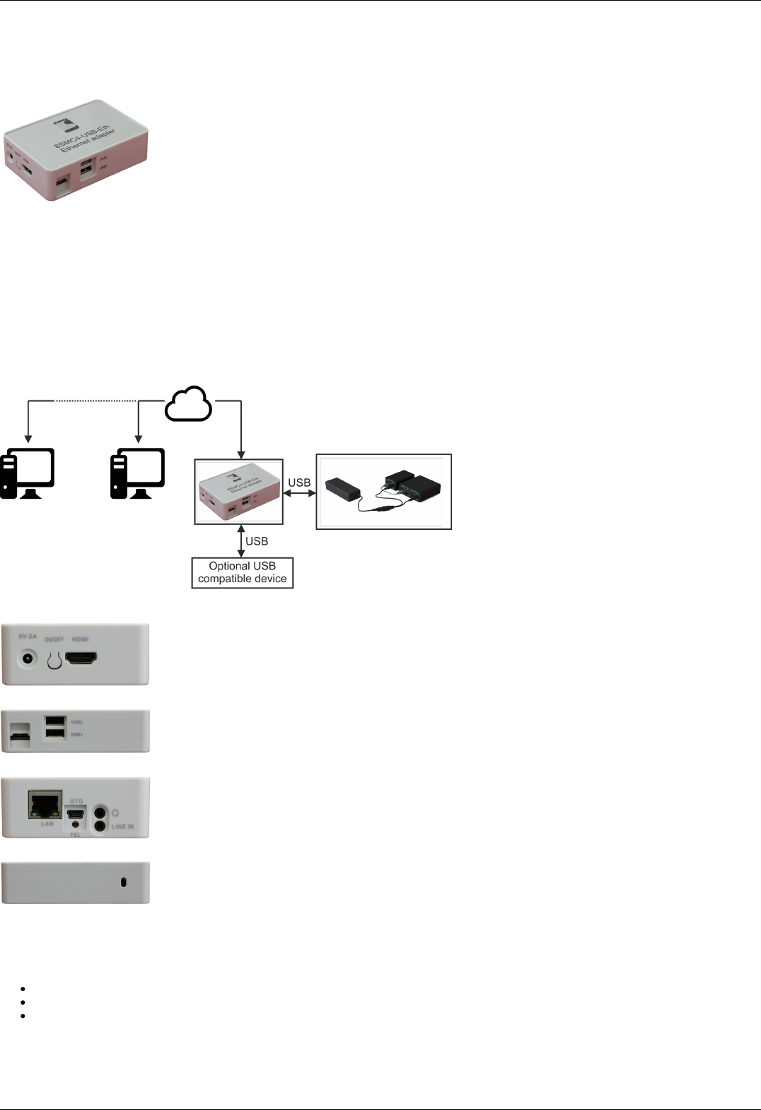
8.1.1. Ethernet adapter Overview
General information
Outward appearance of 8SMC4-USB-Eth1 adapter
8SMC4-USB-Eth11 is a universal device based on Cubieboard2 single-board computer with OS Linux inside, which enables the end
user to interact with motor controllers remotely via various Ethernet-oriented interfaces. This device is also intended to be a universal
provider for different services related to controllers' popular usage scenarios (e.g. motion control). It means that if there is a
standalone program which could be effectively used in conjunction with our controllers, chances are high that this adapter already has
it preconfigured and all you need is to plug some controllers and connect Ethernet cable to it. Out-of-the-box 8SMC4-USB-Eth1
supports online web-camera streaming, LAN auto-discovery system and two interfaces to configure and control motor controllers:
1. TANGO control system interface.
2. XiLab- and libximc-oriented XIMC interface.
Moreover 8SMC4-USB-Eth1 is equipped with embedded web-based administration interface, which enables the end user to
conveniently control the device and monitor its state.
The appearance of the system from different perspectives (all necessary connectors in current version are marked with bold):
Front view. Left to right: power connector, on/off switch, HDMI connector.
View from the right. Left to right: micro-SD card connector, two USB type A female connectors.
Back view. Left to right: Ethernet connector, mini-USB type B, switch to transfer into FEL mode, earphone and line in connectors.
View from the left. IR receiver.
Main requirements
Network configuration
You must have a DHCP server that supports an automatic distribution of ip addresses.
Server and your computer must support IPv4 protocol.
Port 49150 should not be blocked. The cause of blocking can often be the presence of antivirus software, or program which
monitors and filters network traffic (firewalls).
Other
Page 340 / 345
Page 340 / 345

220V socket should be available.
Ethernet cable, USB cable.
1 The vendor code was changed in 2017, earlier this product had the vendor code 8SMC4-USB-Eth.
Page 341 / 345
Page 341 / 345
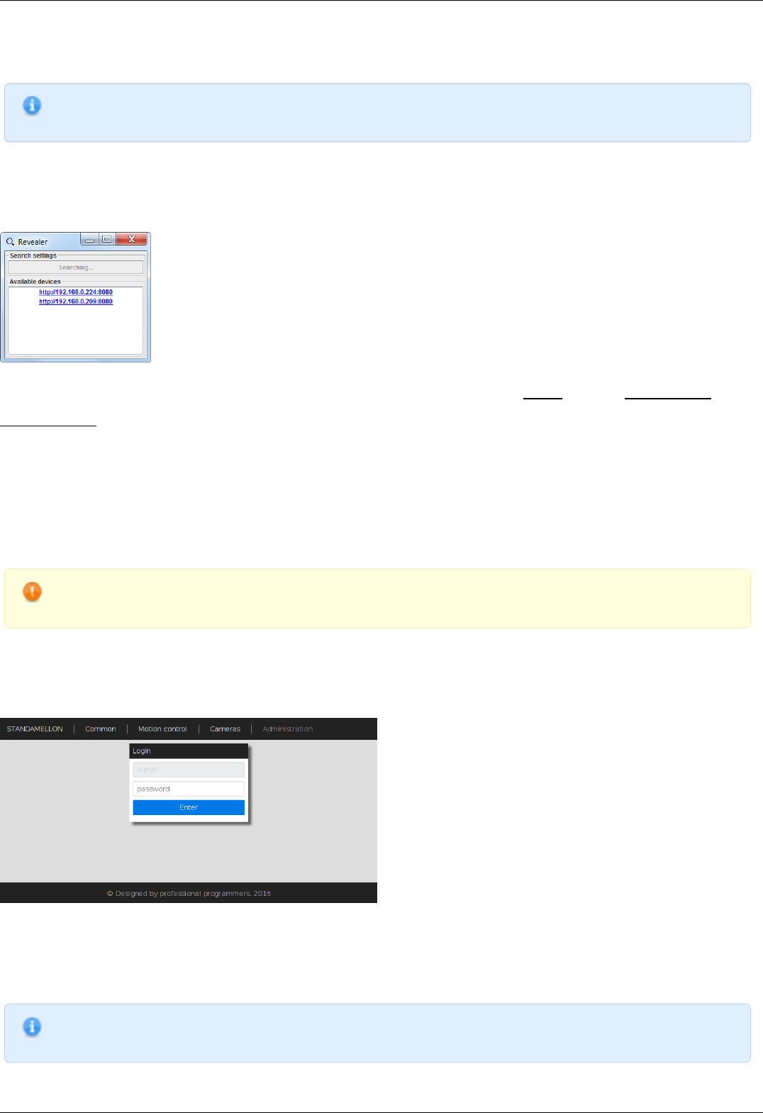
8.1.2. Administration
Note. Administration interface and TANGO support might not be present in your version of the device. You can update
the device firmware using our instruction.
Automatic device detection
As a convenience we provide a small dedicated utility called "Revealer" in order to help you instantly identify all the Standa 8SMC4-
USB-Eth1 adapters connected to your local network. You can download it from our software page.
"Revealer" utility interface
The Graphical User Interface of the "Revealer" is a simple one. In order to start search click Search button on Search settings panel -
the scan takes approximately 3 seconds. After that all Standa 8SMC4-USB-Eth1 devices found in your local network will be listed on
Available devices panel as clickable links. When clicked, the link opens your defaul system browser and redirects it to Administartion
interface web page.
The utility requires Java Runtime Environment (or simply JRE) version 6 or greater to work. There are high chances that you already
have it installed on your PC as it's the requirement for a great number of popular software packages and so you just need to double-
click the "revealer-j_0.1.0.jar" file to launch the utility.
Otherwise it means that you don't have JRE installed and have two options:
1. Download our ready-made packages for your operating system containing the "Revealer" utility and all the stuff necessary to
make it work. In this case you just need to launch "Revealer" executable.
2. Install JRE. A good candidate is Oracle JRE which you can install following the official instructions.
Warning. "Revealer" uses UDP broadcasts to reach all Standa 8SMC4-USB-Eth1 in your LAN so it might be
unusable in the environments where UDP broadcasts are forbidden or unwanted.
Overview
Standa 8SMC4-USB-Eth1 device is equipped with web-based Administration interface which enables the end user to control device
services and monitor system state.
Administration interface login page
In order to get access to the Administration panel, navigate your browser to http://[address] URL (where [address] should be
replaced with IP address of the device in your local network and can be obtained with the help of "Revealer" utility). If you are doing
this for the first time (or you've disabled cookies/password storage in your browser) you'll need to authenticate yourself using "admin"
as login and password.
Note. It's highly recommended to enable javascript in your browser while using Administration interface to get the
best user experience.
Page 342 / 345
Page 342 / 345
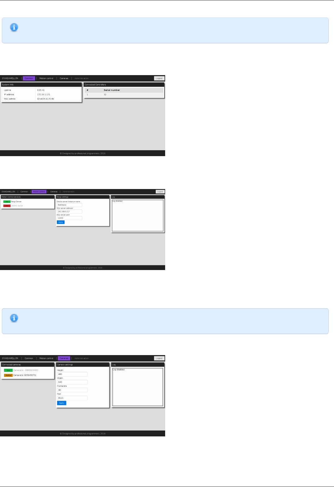
Note. Web-interface is compatable with MS IE 9, MS IE 10, MS IE 11, MS Spartan, Firefox, Chrome browsers and
might not work as expected in others.
Administration interface is split into three functional sections.
"Common" section
Common section page
This section contains generic system information and decimal serial numbers of all controllers connected to the device.
"Motion control" section
Motion control section page
This section is dedicated to motion control services supported by the device. "Motion Control services" panel contains a list of all
currently available motion control services. Clicking on services' title opens an appropriate settings panel (or none if service has no
alterable settings). Clicking "Apply" button in settings panel will persist settings in database and restart corresponding service.
Note. Motion control services are mutually exclusive - only one can be active at any given moment. Starting one of the
services will automatically stop previous active if any.
"Cameras" section
Cameras section page
In this section there is a list of all connected cameras. Each camera is associated with streaming server instance, which exposes
settings, status indicators and controls.
Page 343 / 345
Page 343 / 345

Service control
The Administration panel enables you to control all available device services. There is a common management metaphor for all services
independent of its' actual functionality and aim. Each service has an associated Indicator button on the left of its title which shows
current services's status and enables changing it:
Red color with "Stopped" label indicates that service is completely stopped; pressing the button will run service startup.
Orange color with "Starting" label indicates that service is in interruptible start sequence; pressing the button will revert service
to stopped state.
Green color with "Stop" label shows that the service is up and running; pressing the button will trigger service stop sequence.
Orange color with "Stopping" label indicates uninterruptible stop sequence.
Note. Many services have settings which can be altered. After changing any of such settings the corresponding
process will be automatically restarted shortly - the Indicator button will show it dynamically.
Firmware upgrade
Warning. During the update MicroSD content and 8SMC4-USB-Eth1 device flash memory will be wiped out. Make
sure that you've made necessary backups.
1. Download an appropriate firmware version from software page.
2. Get a 4GB (or larger) MicroSD card.
3. Download and upack an autoinstaller image archive. On Windows family operating system you might have no apropriate archiver
— in this case you may use 7-Zip ( official site).
4. Put the image onto the MicroSD card:
Unix family OS:
1. You can do it via dd utility (e.g.
dd if=autoinstall_image_2015-12-17.bin of=/dev/sdX bs=4M; sync
but remember to substitute the device names with yours).
Windows family OS:
1. Download Win32 Disk Imager ( official site) and start it.
2. Specify autoinstaller image path in "Image File" field.
3. Select your MicroSD drive in "Device" list.
4. Press "Write" button and wait till progressbar completes.
5. Insert the microSD card with the image into your 8SMC4-USB-Eth1 and turn it on (or reboot).
6. Wait approximately 10 minutes to let the firmware be installed. You may check the progress of installation by looking at LED
indicator inside the case of the device through USB plugs:
1. LED is stable green or emits periodic single green pulses - autoinstaller is initializing.
2. LED periodically emits green double pulses - installation is in progress.
3. LED is stable green - installation is complete.
7. Power off the device (just plug the power cable off) and extract MicroSD card.
8. Power on the device and wait another 2-7 minutes to let the device initialize itself.
Warning. On some rare occasions the device might not be visible through the revealer(and have its services and
administration interface unavailable either) even well after estimated initialization period. In this case try to reboot
the device. If it doesn't help try to redo steps from 5 to 8.
Now you should have your 8SMC4-USB-Eth1 device updated and fully operational.
Troubleshooting
Warning. If your device won't work properly, leds don't blink as described above during flashing and your device
manufactured after 2017 October, please, contact support.
Uninitialized Cubieboard2 bootloader
In some rare cases the steps described in Firmware upgrade instruction might not succeed. One of the possible reasons is that due to
some technical failure the Cubieboard2 singleboard computer bootloader (on which 8SMC4-USB-Eth1 is based on) was not properly
Page 344 / 345
Page 344 / 345

initialized. However bootloader initialization isn't very complicated:
1. Download PhoenixSuit ( official site) and unpack it;
2. Download Lubuntu server image with bootloader supporting SoC A20 rev.B for PhoenixSuit ( official site, "Firmwares" ->
"Cubieboard2" -> "Lubuntu Server") and unpack it.
3. Start PhoenixSuit. In case of update request, confirm it and wait till it's done.
4. Switch to "Firmware" tab and specify unpacked Lubuntu server image path.
5. Power off the device. Press and hold FEL button (it's near LAN and USB-OTG connectors). While still holding the button, connect
USB-OTG to your PC and then release the button.
6. You might need to explicitly install driver for the device on Windows family OS.
1. Navigate to the Device Manager.
2. Locate "Unknown Device" and right click on it.
3. In the context menu press "Update driver software...".
7. Specify "PhoenixSuit1.0.7\PhoenixSuit\Drivers\AW_Driver" as driver search directory.
8. After that a popup in PhoenixSuite will appear. Press "YES (Full install)" and wait for the completion.
9. Continue to autoinstall instruction.
Page 345 / 345
Page 345 / 345
