91pdp00_e 91PDP_E 91PDP E
User Manual: 91PDP_E
Open the PDF directly: View PDF ![]() .
.
Page Count: 48
- Notes for the user
- Table of contents
- Quality and support
- Safety regulations
- Norms
- About what does this manual report?
- Which parts do I need?
- A General remarks
- A.1 Basic data interchange
- A.1.1 Settings of the Multibox slave
- A.1.2 Parameterizing of the PCS
- A.1.3 Transfer of the record into the PCS
- A.1.4 Set-up and first powering-up
- A.1.5 PCS 807 Specifications
- B Siemens PLC
- B.1 Determining the configuration
- B.1.1 Configuration of the master board (S5)
- B.1.2 Configuration of the L2-DP network (S7)
- B.1.3 Defining a master system
- B.1.4 Programming of the programmable controller
- B.1.5 Settings of the slave Multibox
- B.1.6 S5 demo project
- B.1.7 Trouble-shooting
- B.1.8 Term of the communication
- B.1.9 Optimal configuration
- C Bosch PLC
- C.1 Determining the configuration
- C.1.1 Configuration of the master board (DESI-DP)
- C.1.2 Trouble-shooting
- C.2 Print out handling software
Reg 5075/0597ss
CiS-Nr.: 360.110.0390
Version 2/02.03
© Systeme Lauer GmbH & Co KG
PCS 91.PDP
english
One does not refer in the manual explicitly to the devices of the PCS plus/win series, the
description applies to all devices. With differentiations between the equipment series the
following allocations apply:
PCS topline = micro/mini: PCS 009, PCS 090, PCS 095, PCS 095.1, PCS 095.2
midi: PCS 900, PCS 950, PCS 950c, PCS 950q, PCS 950qc,
maxi: PCS 9000/9100
PCS plus = micro/mini: PCS 009 plus, PCS 090 plus, PCS 095 plus
midi: PCS 950 plus, PCS 950c plus, PCS 950q plus,
PCS 950qc plus
PCS win = micro/mini: PCS 009 win, PCS 090 win, PCS 095 win
midi: PCS 950 win, PCS 950c win, PCS 950q win,
PCS 950qc win

© Systeme Lauer GmbH & Co KG • Kelterstr.59 • 72669 Unterensingen • Tel. (07022) 96 60-0 • Fax (07022) 96 60-103
0-2
Systeme Lauer GmbH & CoKG
Postfach 1465
D-72604 Nürtingen
Operator reference manual: PCS 91.PDP
Version: 31. Januar 2003
Person responsible: Zoch
Operating manuals, reference manuals, and software are protected by
copyright. All rights remain reserved. The copying, duplication,
translation, conversion in the whole or into parts are not permitted. An
exception applies to making a copy of the own use.
• We reserve the right make changes to the reference manual without
prior notice.
• We can not guarantee the accuracy of the programs and data stored
on the diskette and the fault-free state of this information.
• Since diskette represent manipulatable data media, we can only
guarantee the physical completeness. The responsibility is limited to
a replacement.
• At any time, we welcome suggestions for improvements and remarks
on errors.
• The agreement also applies to the special appendices to this reference
manual.
Microsoft, MS, MS DOS, Windows, Windows 95, Windows NT and the
Windows logo are either registered trademark or trademarks of the Micro-
soft Corporation in the USA and/or other countries.
SIMATIC and STEP are registered trademarks of the Siemens AG.
The remaining designations in this document can be brand names who`s
use by parties for their purposes can violate the rights of the owners.
© Systeme Lauer GmbH & Co KG • Kelterstr.59 • 72669 Unterensingen • Tel. (07022) 96 60-0 • Fax (07022) 96 60-103 0-3
Notes for the user
Please read the manual before beginning and keep the manual for later
use.
Target group The manual has been conceived and written for users who are experienced
in the use of PCs and automation technology.
Typographical conventions [KEY] Keys that are to be pressed by the user are given
in square brackets,e.g [CTRL] or [DEL]
Courier On-screen messages are given in the Courier font,
e.g. C:\>
Courier bold Keyboard input to be made by the user are given
in Courier bold, e.g. C:\>DIR
Italics
Names of buttons to be pressed, menus or other
on-screen elements and product names are given
in italics.
Pictograms The manual uses the following pictograms to highlight certain text
passages:
Danger!
Possibly dangerous situation. Injury to persons can be the result.
Attention!
Possibly dangerous situation. Property damages can be the result.
Tips and supplementary notes

© Systeme Lauer GmbH & Co KG • Kelterstr.59 • 72669 Unterensingen • Tel. (07022) 96 60-0 • Fax (07022) 96 60-103
0-4
Table of contents
Notes for the user 0-3
Table of contents 0-4
Quality and support 0-5
Safety regulations 0-6
Norms 0-7
About what does this manual report? 0-8
Which parts do I need? .......................................................... 0-8
A General remarks A-1
A.1 Basic data interchange.................................................... A-1
A.1.1 Settings of the Multibox slave ......................................... A-3
A.1.2 Parameterizing of the PCS .............................................. A-4
A.1.3 Transfer of the record into the PCS ................................. A-5
A.1.4 Set-up and first powering-up ............................................ A-5
A.1.5 PCS 807 Specifications .................................................. A-6
B Siemens PLC B-1
B.1 Determining the configuration .......................................... B-3
B.1.1 Configuration of the master board (S5) ............................ B-4
B.1.2 Configuration of the L2-DP network (S7).......................... B-7
B.1.3 Defining a master system ............................................... B-8
B.1.4 Programming of the programmable controller ................ B-11
B.1.5 Settings of the slave Multibox ....................................... B-12
B.1.6 S5 demo project ............................................................ B-13
B.1.7 Trouble-shooting ............................................................ B-14
B.1.8 Term of the communication ........................................... B-15
B.1.9 Optimal configuration .................................................... B-17
C Bosch PLC C-1
C.1 Determining the configuration .......................................... C-3
C.1.1 Configuration of the master board (DESI-DP) .................. C-3
C.1.2 Trouble-shooting .............................................................. C-6
C.2 Print out handling software .............................................. C-9
© Systeme Lauer GmbH & Co KG • Kelterstr.59 • 72669 Unterensingen • Tel. (07022) 96 60-0 • Fax (07022) 96 60-103 0-5
Quality and support
In our company, quality comes first. From the electronics component up
to the finished device, the quality assurance test competently and
comprehensively.
National an internation test standards (ISO, TÜV, Germanischer Lloyd)
are the basis.
Within 48 hours, every device passes a 100% check and continuous test
under worst case conditions at changing temperatures (0...50°C) and
test voltages.
A guarantee for maximum quality.
Our products not only feature a maximum economic efficiency and
reliability but also a comprehensive complete service.
You not only receive demo devices but we rather make specialists available
who support you in person with your first application.
Qualified user consultation by competent sales engineers is obvious for
us.
Our support is for you for the side with advice and deed every day.
We set up training programs and technical training for you in our mo-
dern training center or alternatively also in your house.
Request the curent training catalog.
From the consultation up to the user support, from the hotline up to the
service, from the reference manual up to the training an all covering
and individual service for the entire product line is waiting for you.
Whenever you need us, we are there for you:
dynamically, creatively and enormously efficiently. With the entire
experience of a world-wide successful enterprise.
Telephone 07022/9660-132, -231, -230
eMail support@systeme-lauer .de
Web site www.lauer-systeme.net
Systeme Lauer Active Area
(Download of Software, driver, manuals, Forum...)

© Systeme Lauer GmbH & Co KG • Kelterstr.59 • 72669 Unterensingen • Tel. (07022) 96 60-0 • Fax (07022) 96 60-103
0-6
Safety regulations
This reference manual contains the most important remarks in order to
safely operate the device.
• This operator‚s guide, particulary the safety remarks are to be noted
byall persons working with the device.
• Furtherrmore, the rules and regulations for the accident prevention
applying to the application location are to be observed.
• Use as directed. The device is deigned for the application in the
industrial area.
• The device is manufactured to the state of the art and the official
safeguarding regulations. Nevertheless, due to the application, dangers
or impairments can result to the machine or to material assets.
• The device meets the requirement of the EMC guidelines and
harmonized European standards. Any hardware-related modification
of the system can influence the EMC behavior.
• The device may not be used without special protective measures in
the hazardous area and in plants requiring a special monitoring.
• Do not heat up the buffer batteries. Danger of explosion. Serious
burning can be the result.
• The installation and operation may only be performed by trained
personnel.
• The operating voltage of the device may only be in the specified
ranges.
• You find information on this on the type plate and in the specifications
of this reference manual.

© Systeme Lauer GmbH & Co KG • Kelterstr.59 • 72669 Unterensingen • Tel. (07022) 96 60-0 • Fax (07022) 96 60-103 0-7
Norms
The device is constructed using up-to-date technologies and fulfils the
requirements of the following guidelines and norms:
• Compliant with the EMC Directive 89/336/EEC and the German law
on electro-magnetic compatibility
• Interference compliant with the generic requirements norm EN 50081-
2 and product norm EN 55022:
• Measurement of the conducted interference voltage as per EN 55022
• Measurement of the radiated radio interference field power as per
EN 55022 class A
• Interference immunity in compliance with generic requirements norm
EN 50082-2 and product norm EN 61000-6-2:
- Electro-static discharge (ESD) as per with EN 61000-4-2
- High-frequency electromagnetic fields as per EN 61000-4-3
and ENV 50204
- Fast transient interference (burst) as per EN 61000-4-4
- Surge voltages as per EN 61000-4-5
- High-frequency conducted fields as per EN 61000-4-6
- Voltage dips and short-term interruptions as per EN 61000-4-11
The assembly and connection instructions contained in this documen-
tation must be followed.
Conformity of this equipment is confirmed by the CE logo.
The EC declaration of conformity can be requested from:
Systeme Lauer GmbH & Co KG
P-O-Box 1465
D-72604 Nürtingen

© Systeme Lauer GmbH & Co KG • Kelterstr.59 • 72669 Unterensingen • Tel. (07022) 96 60-0 • Fax (07022) 96 60-103
0-8
About what does this manual report?
This manual informs you exclusively about the application of the PCS
807 Profibus DP Multibox together with the PCS micro, mini/VPC 090
Multi Interface, the SIEL2DME.DRV midi and maxi driver and the
programmable controller handling software PROFIBUS.S5D or
PCSS7L2.AWL (S7). The PCS 590/595p operating consoles do not require
the PCS 807 Multibox since this is integrated into the PCS 590p/595p.
The settings of the master board and the use of the handling software is
absolutely identical. Therefore, this principle is used for the here described
procedure.
The network structure set-up was tested with a S5-115U (CPU 942, 943,
944, 945), an S5-135U (CPU 928) in connection with an IM308B (version
6) S5 DP master board, an IM308C (version 2), and a CP5431 (version 3).
The setup was also tested with an S7 fitted with a CPU 315-2 DP. The
following describes the startup of this set-up.
The PCS 807 firmware is based on the Siemens SPC-3 chip set with
Siemens object code. Systeme Lauer can take over no responsibility for
errors and limitations due to the Siemens software.
Programming of the Siemens programmable controllers, of the Profibus
master board, and the basic Profibus DP functions are assumed as known.
Which parts do I need?
The following products are required from Systeme Lauer for a Profibus
DP network set-up:
• PCS807 Profibus DP Multibox, version PX807 0001 (SPC2), or PX807
1000 (SPC3), or higher.
• A PCS micro, mini, midi, or maxi operating console or the VPC 090
Multi Interface.
• The PCSPRO, PCSPROWIN/PCSPROPLUS or PCS 9092 configuration
software and a PCS 733 programming cable for the PCS operating
console.
• This manual including the PCS91.PDP floppy disk.
....as well as power supplies for all components.
© Systeme Lauer GmbH & Co KG • Kelterstr.59 • 72669 Unterensingen • Tel. (07022) 96 60-0 • Fax (07022) 96 60-103 A-1
A General remarksA General remarks
A.1 Basic data interchange
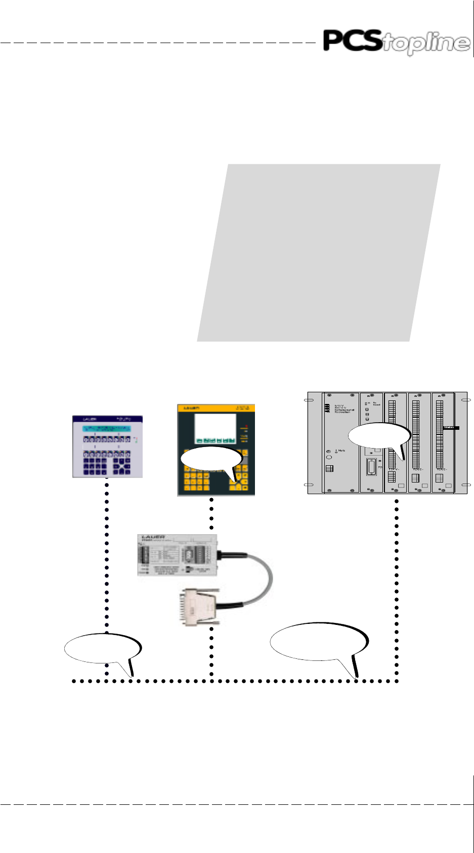
The communication connection between the PCS and the programmable
controller data area is made via the following communication devices:
PCS operating console
À
(PCS807 Multibox) Profibus DP
À
Profibus master
À
Programmable controller
À
Profibus master
À
(PCS807 Multibox) Profibus DP
À
PCS operating console
SPS
Profibus-
Master
COM-
Interface
Operating console
PCS
Operating console
PCS busline
Profibus-
DP
network
cable
to further
participants

© Systeme Lauer GmbH & Co KG • Kelterstr.59 • 72669 Unterensingen • Tel. (07022) 96 60-0 • Fax (07022) 96 60-103
A-2
A General remarks
PCS operating console
The PCS operating console determines the tasks to be executed
(according to the network configuration, the enables, the display content,
and the keys) and sends these in one package to the PCS 807 Multibox
Profibus DP slave.
The PCS 807 Multibox Profibus DP slave passes the package on to the
Profibus master.
À
The master stores the package in the I-area of the programmable
controller.
À
Programmable controller
The communication data block is located in the programmable controller
and occupies 256 words (e.g. DB50).
The tasks input buffer is located in an I-area of the programmable
controller.
The tasks response buffer is located in an O-area of the programmable
controller.
A cyclically selected handling block (FB203) executes the tasks present
in the I-buffer on the data block and stores the result in the O-buffer.
À
The master picks up the response package from the O-area of the
programmable controller and submits it to the slave.
À
The PCS 807 Multibox Profibus DP slave submits the response to the
PCS.
À
PCS operating console
The PCS operating console evaluates the response and shows the data
on the display.
The inquiry/response package is supplied with a task number so that the
response always matches the inquiry.
With the PCS 590p/595p and the PCS plus/win, the intermediate steps
referring to the PCS 807 Multibox are skipped. The master com-
municates directly with the PCS.
© Systeme Lauer GmbH & Co KG • Kelterstr.59 • 72669 Unterensingen • Tel. (07022) 96 60-0 • Fax (07022) 96 60-103 A-3
A General remarks
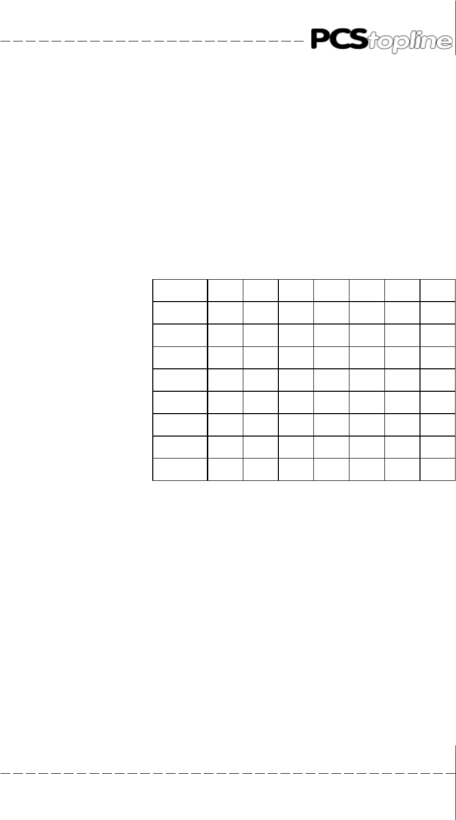
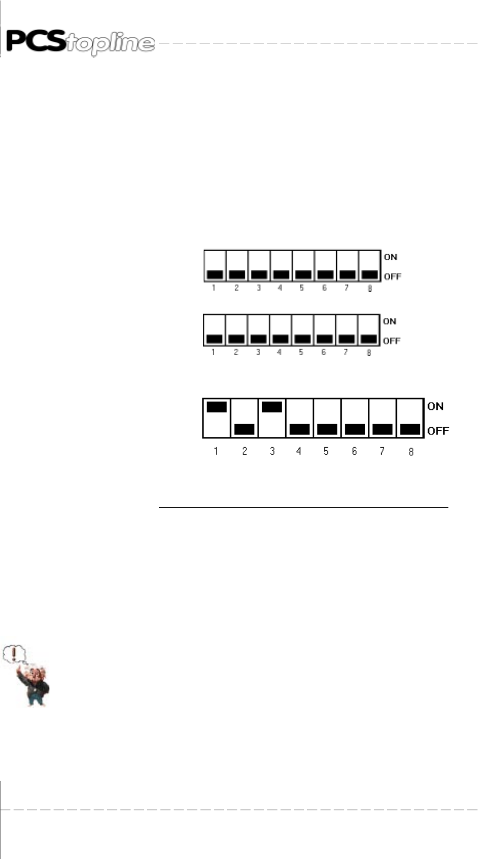
A.1.1 Settings of the Multibox slave
The PCS 807 Multibox Profibus DP slave automatically adapts to the
given configuration. For this, only the slave number of the PCS 807 Multi-
box Profibus DP needs to be set. Using the DIL-switches 1 to 7, you can
set the slave number of the PCS 807 Multibox Profibus DP between 3
and 127. The settings must be performed either with the power being
removed or in the reset state (the settings are taken over at the start).
The slave address is calculated as follows (OFF = 0 and ON = 1):
DIL1 x 64 + DIL2 x 32 + DIL3 x 16 + DIL4 x 8 + DIL5 x 4 + DIL6 x 2 + DIL7 x 1
The slave number of the PCS 590p/595p and PCS plus/win is set in the
driver using the PCSPRO configuration software. Select the
Project
menu
item and then
Driver parameters.
Slave-Nr DIL 1 DIL 2 DIL 3 DIL 4 DIL 5 DIL 6 DIL 7
3 OFF OFF OFF OFF OFF ON ON
4 OFF OFF OFF OFF ON OFF OFF
5 OFF OFF OFF OFF ON OFF ON
6 OFF OFF OFF OFF ON ON OFF
7 OFF OFF OFF OFF ON ON ON
...
125 ON ON ON ON ON OFF ON
126 ON ON ON ON ON ON OFF

© Systeme Lauer GmbH & Co KG • Kelterstr.59 • 72669 Unterensingen • Tel. (07022) 96 60-0 • Fax (07022) 96 60-103
A-4
A General remarks
A.1.2 Parameterizing of the PCS
Both, the application program with data and a selected driver is transferred
when configuring the PCS. The presettings of the variable can be changed
for optimizing the driver.
Variable AJ - number of tasks per package
Using this variable, the number of tasks per task package can be
influenced. Thus, this variable is influenced by the size of the I/O buffer.
Furthermore, the refresh of the variable and the refresh of the keys/LEDs
is offset by this value. The relation is explained best using an example:
AJ = 1 -->
Keys and LEDs will be quickly transferred, variables are refreshed
slowly - suited for jog operation. The I/O buffer can be small.
AJ = 10 -->
Default values. Represent a balance between the key and the varia-
ble refresh.
AJ = 20 -->
Keys and LEDs will be transferred simultaneously with variables -
suited for the display of many variables. The I/O buffer should be as
large as possible.
AA variable - Time-out time The time-out time to be set is related to the maximum time that is required
by the programmable controller for the cyclical call of the communication
program plus the communication time. The time is adjustable in the range
of 2 and 9.9 seconds - default is 4 second. Time monitoring is activated
only if the task read by the PCS is not yet the current one.
In addition, the PCS 590p/595p and PCS plus/win features the following
variables:
AH variable - PCS station number Here, the slave station number of the Profibus DP slave is set. The value
range is 3 (default value) to 127.
BC variable - Direct key values You can reserve 0 2 words of the programmable controller I/O area for
the direct transfer of keys. These keywords are then constantly assigned
to the key bits and are directly to be evaluated. The key transfer time is
significantly faster compared to the PCS transfer since no interpretation
of the data is required. You can use these key words for jog operations.
Assumed, you have reserved 16 bytes from I20 to I35 for slave 3 that is
a PCS 590p/595p.The key words are assigned to I20 to I23 if you have
set 2 key words. These words are now lost for the PCS Expander
communication: set the start of the Expander (e. g. RXFA) to 24 and the
length (e. g. RXLE) to 12. Please note that you can only reserve one
word for direct keys of an input area having a size of eight bytes.
BD BG variables - Contents of the key bytes
Using five instances, you can assign the key words of each byte a certain
information (key bits).
Please refer to the PCS 591/PCS 096 manual for further information on
key bytes.

© Systeme Lauer GmbH & Co KG • Kelterstr.59 • 72669 Unterensingen • Tel. (07022) 96 60-0 • Fax (07022) 96 60-103 A-5
A General remarks
A.1.3 Transfer of the record into the PCS
1. Set DIL-switch 8 on the rearside of the PCS to „OFF“ and DIL-
switches 9 to „ON“. (Not with the PCSmaxi)
2. Apply operating voltage (19 ... 33V) to the PCS. The ERR-LED is
now ON.
3. Connect the programming interface of the PC with the PCS operating
console using the PCS 733 programming cable.
4. Run the PCSPRO/PCSPROWIN/PCSPROPLUS configuration software.
5. Select the Profibus DP driver for your PCS.
6. Create or load your data file.
7. Set the driver parameters using the menu items „Options“ and
„Drivers“. You can take over the default settings in the normal case.
8. Transfer the compiled record into the PCS.
A.1.4 Set-up and first powering-up
Disconnect the supply voltage to the set-up when you have configured
all parts. Thereby, the following points are to be considered:
Profibus DP network
• Use only suited cable for the wiring.
• The last participant in the Profibus DP network must have a
terminator. Use the Siemens SINEC L bus connector for this. Special
bus connectors are required for baud rates between 3 and 12 MHz
(Siemens part number: 6ES7 972-0BA10-0XA0).
Instead of the Siemens connectors you can also use the supplied
Lauer terminals between PCS 807 Multibox Profibus DP slaves (only
recommended up to 500Kbaud).
When using the Lauer terminals, the red wire is connected to „A“
and the green wire to „B“. The cable screening is connected to the
cable clip (not with the PCS 590p/595p and PCS plus/win).
Proceed as follows for powering-up:
• Supply power to the programmable controller and to the PCS 807
Multibox Profibus DP.
• The „SEND“ LED of the master board is activated after a maximum
time of 5 seconds. Then, the green „COM“ LED of the PCS 807
Multibox or of the PCS 590p/595p lights statically.
• Now, connect the PCS (COM interface) to the PCS 807 Multibox
Profibus DP (not the PCS 590p/595p).
• Set the restart input of the programmable controller to „ON“ or switch
the programmable controller from STOP to RUN.
• The „COM“ LED of the PCS is deactivated after a maximum time of
2 seconds.
© Systeme Lauer GmbH & Co KG • Kelterstr.59 • 72669 Unterensingen • Tel. (07022) 96 60-0 • Fax (07022) 96 60-103
A-6
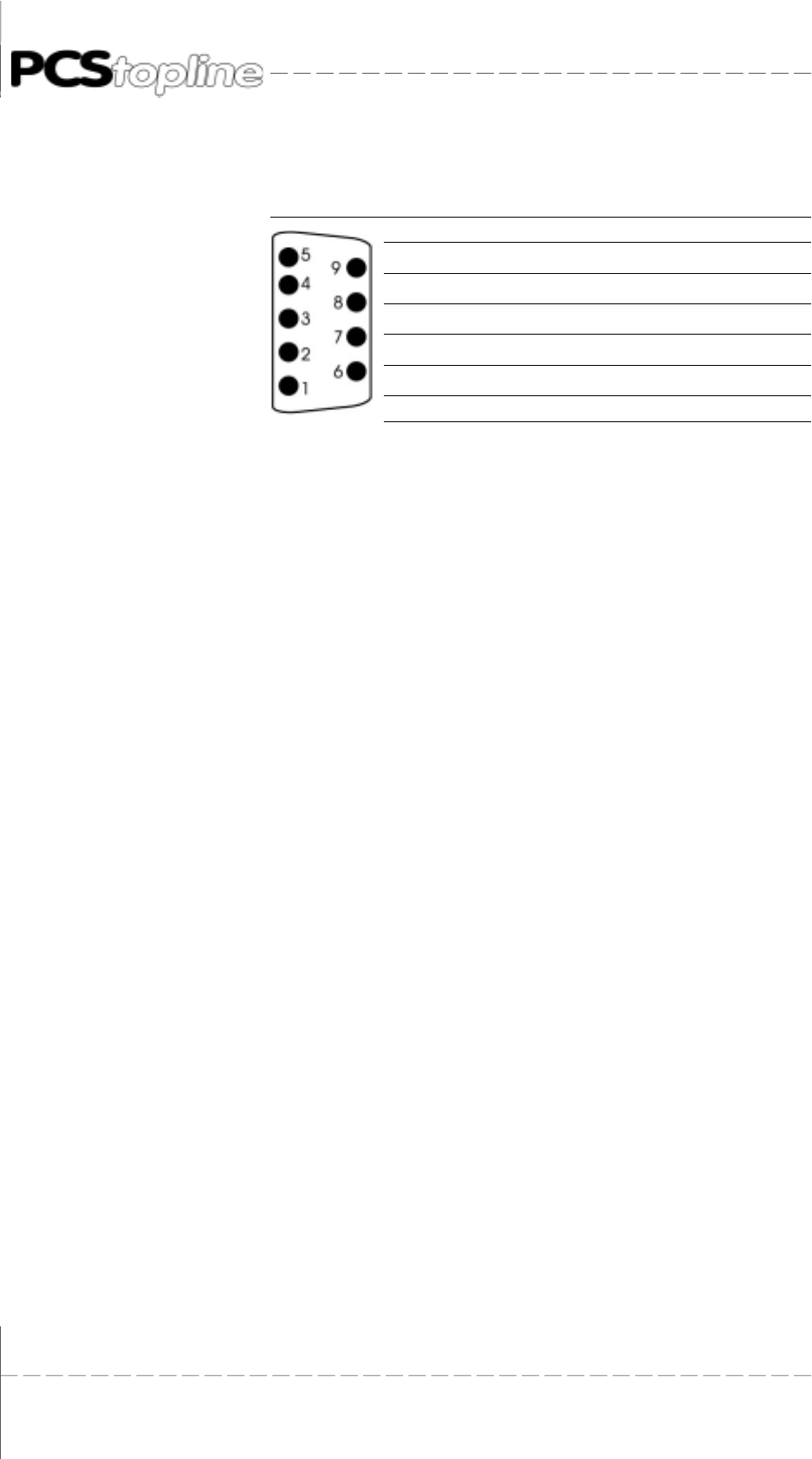
A General remarks
View Pin Signal name Designation
1- -
2- -
3 RxD/TxD-P data line - B
4 RTS request to send
5 M5V2 data reference potential (from the station)
6 P5V2 power supply plus (from the station)
8 RxD/TxD-N data line - A
Mechanical mounting of the PCS 807 Multibox Profibus DP
The PCS 807 Multibox Profibus DP can be mounted on a top hat rail
(DIN rail). The PCS operating console and the PCS 807 Multibox Profi-
bus DP must be earthed!
A.1.5 PCS 807 Specifications
Description PCS 807 Multibox Profibus DP slave
System requirements Standard Profibus DP network according to DIN 19245
System assignments • min. 8 bytes in the input area of the program-mable controller
min. 8 bytes in the output area of the program-mable controller
• max. 32 bytes in the input area of the programmable controller
max. 32 bytes in the output area of the program-mable controller
Mounting dimensions height: 50 mm
width: 80 mm
length: 120 mm (without cable)
Supply voltage 24 volts ± 10 %
Current consumption 200 mA max.
Power consumption 5 VA max.
Operating temp. range 0 ... +50° C
Storage temp. range - 20 ... +80° C
Interfaces RS-232 interface with 25-pin sub D female connector to the PCS operating
console
RS-485 interface with 9-pin sub D male connector
RS-485 interface with 8-pin terminal strip and 24 volts supply voltage
Indicators • 1 yellow LED for supply voltage
• 1 yellow LED for LOAD/RUN state
• 1 green LED for communication state
DIL-switches • DIL 1 .. 7 for setting the slave address
• DIL 10 as reset switch
• DIL 11 for switching from LOAD to RUN

© Systeme Lauer GmbH & Co KG • Kelterstr.59 • 72669 Unterensingen • Tel. (07022) 96 60-0 • Fax (07022) 96 60-103 B-1
B Siemens PLCB Siemens PLC
PCS 807 Profibus-DP Multibox
or PCS 590p/595p connected
to Siemens PLC with
I/O communication

© Systeme Lauer GmbH & Co KG • Kelterstr.59 • 72669 Unterensingen • Tel. (07022) 96 60-0 • Fax (07022) 96 60-103
B-2
B Siemens PLC
© Systeme Lauer GmbH & Co KG • Kelterstr.59 • 72669 Unterensingen • Tel. (07022) 96 60-0 • Fax (07022) 96 60-103 B-3
B Siemens PLC
B.1 Determining the configuration
For a Profibus-DP network setup are required by Siemens following
products:
• a S5-SPS or S7-300 (400) with Profibus-DP master
• a Profibus-DP master plug-in module (only for S5), version IM308b
(version 6), IM308c (version 2) or CP5431
• Programming software for the programmable controller and the
master board
• Profibus-DP network cable and bus connector
... as well as the power supply for all components.
The settings of the components must match to enable all parts to correctly
work together!
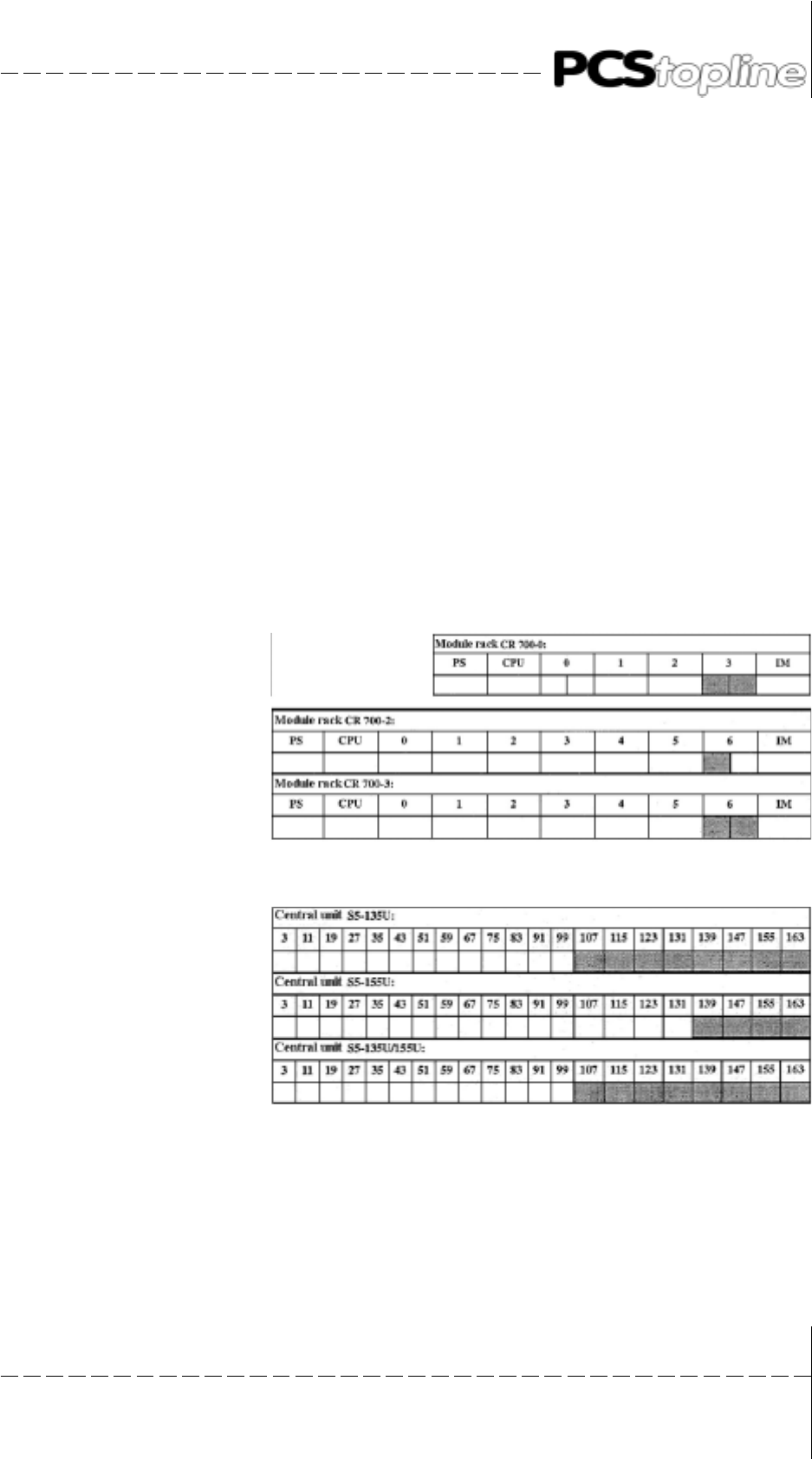
IM308 master board
Search for the right slot for your board. Otherwise, it may be damaged.
The possible outlets are hatched gray.
Slots in the S5-115U system
Slots in the S5-135U and S5-155U system

© Systeme Lauer GmbH & Co KG • Kelterstr.59 • 72669 Unterensingen • Tel. (07022) 96 60-0 • Fax (07022) 96 60-103
B-4
B Siemens PLC
Master board (S7 Profibus master)
You determine the Profibus-DP network by configuring the master board
(S7 Profibus master).
The following limits are valid for a slave:
• maximum number of bytes = 32 for I/O buffer
• minimal number of bytes = 8 for I/O buffer
• optimal number of bytes = buffer size of 12 inputs and 24
outputs for PCS micro/mini
= buffer size of 24 inputs and 32
outputs for PCS midi and maxi
B.1.1 Configuration of the master board (S5)
You define the settings of the Profibus-DP network in the COM ET200
software. Also, each slave must be defined with its data length.
IM308b (version 6)
To be able to define the PCS 807 Multibox Profibus DP slave, you have to
copy the „PCS002TD.200“ file from the PCS91.PDP diskette (please note
the README.TXT file) into the COM ET200 directory.
Pay attention, that under DOS the last drive statement is set to
„LASTDRIVE=Z“ before executing the software.
IM308c (version 2 or higher)
Copy the „LAUERDPX.200“ type data into the „‘Typdat5x“ sub-directory.
CP5431
In the DP editor, set the slave interval time manually.
Call up now the COM ET200 software for an IM308b (version 6)...
ET200 parameters
• the baud rate should be between 187.5 and 1500 Kbaud.
• the bus profile must be selected as „Standard Profibus-DP“.
• the CPU type must be correctly selected.
• a diagnosis is not required.
Config parameters
• here, you determine the slave parameters.
• select the parameter file: „LauerDP slave 50“ for IM308b,
• set the consistency to „0“.
• define 8 ... 32 input bytes and 8 ... 32 output bytes per slave.
Call up the COMWIN10 software for an IM308c...
Bus parameters
Select Profibus-DP
© Systeme Lauer GmbH & Co KG • Kelterstr.59 • 72669 Unterensingen • Tel. (07022) 96 60-0 • Fax (07022) 96 60-103 B-5
B Siemens PLC
Host parameters
Select the used CPU
Master parameters
• station type: IM308c
• addressing type: select the linear range for the P or Q page frame. P
or Q tiles are possible in the page frame. Then, select the number of
the IM308c (0/16/32/48). Each IM308c manages up to 16 tiles.
• error message mode: Can be set to QVZ (acknowledgment delay
on error).
• set the response monitoring to: ON
Slave parameters:
• select the „LAUER_PCS_LCA“ type file.
• you can SELECT P000-P255 and Q000-Q255 in the linear range.
• OP192-15P255 is possible in the P page frame.
• 0Q0-15Q254 is possible in the Q page frame.
• specify the input bytes between 8 and 32and the output bytes
between 8 and 32.
• sync or Freeze are not necessary.
• activate Module Consistency.
Transfer
Now, program the EPROM cassette or the Flash module and plug this
into your IM308 board.
Note the slave settings for the programmable controller programming.

© Systeme Lauer GmbH & Co KG • Kelterstr.59 • 72669 Unterensingen • Tel. (07022) 96 60-0 • Fax (07022) 96 60-103
B-6
B Siemens PLC
Call SINEC.NCM for a CP5431 (version 4.6).
In contrast to the IM308 board, the CP5431 sends no configuration
telegram. Thus, the setting on the boards and in the PCS 807 must agree.
I/O byte 8/8 16/16 24/24 32/32
DIL 5 OFF ON OFF ON
DIL 6 OFF OFF ON ON
The settings of DIL-switches 8 and 9 are taken over after a power up or
reset.
For a PCS 590p/595p, DIL-switches 5 and 6 are used for the configuration
selection:
I/O byte 8/8 16/16 24/24 32/32
DIL 5 OFF ON OFF ON
DIL 6 OFF OFF ON ON
The CP5431 works only together with the SPC3 chip. Therefore use the
PX807 1000.
The Profibus-DP function may only be combined with asynchronous FMS
services! Use only the I/O area of bytes 0...127 in the 115U CPU 941-
943 programmable controllers. Otherwise, inconsistencies can appear.
Please note, that not all RAM modules are permissible for the CP5431
board!
Please note following settings:
CP INIT:
Network file: NETZ2NCM.NET
Network parameters:
Default SAP: 61
Peripheral/ I/Oarea:
DP Update: Cycle synchronous
Input and output areas: enter ZI/DP start (even) and ZI/DP end (odd).
Peripheral/ DP slave parameterizing:
Maker ident: 0008
Sync mode: OFF
Freeze mode: OFF

© Systeme Lauer GmbH & Co KG • Kelterstr.59 • 72669 Unterensingen • Tel. (07022) 96 60-0 • Fax (07022) 96 60-103 B-7
B Siemens PLC
Peripheral / DP editor:
Global data:
Largest min. slave interval: 2 x 1ms
Min. poll cycle time: 1 x 10ms
response monitoring time: 20 x 10ms
Discontinue the user interface accordingly. Perform a network balance
using the „NETZ2NCM.NET“ file and transfer database file into the
CP5431.
B.1.2 Configuration of the L2-DP network (S7)
Sinec L2-DP network
A Sinec L2-DP network is composed of a DP master and DP slave which
are connected by a bus cable. They communicate with each other using
the DP (decentralized peripheral) protocol.
DP master
As DP master you can use:
• a CPU with firmly integrated or pluggable DP master interface (firmly
integrated into e.g. CPU 315-2 DP)
• a interface module that is assign to a CPU/FM (e. g. IF 964-DP in
CPU 488-4)
• a CP together with a CPU (e. g. CP 342-5: this is parameterized
using a special software in called up STEP 7).
DP slaves
As DP slaves you can use:
• modules with integrated digital/analog I/O channels (compact DP
slaves, e. g. ET 200B, PCSS 807 or LCA 3xx.3)
• interface modules with associated S5 or S7 modules (modular DP
slaves, e. g. ET 200M).
© Systeme Lauer GmbH & Co KG • Kelterstr.59 • 72669 Unterensingen • Tel. (07022) 96 60-0 • Fax (07022) 96 60-103
B-8
B Siemens PLC
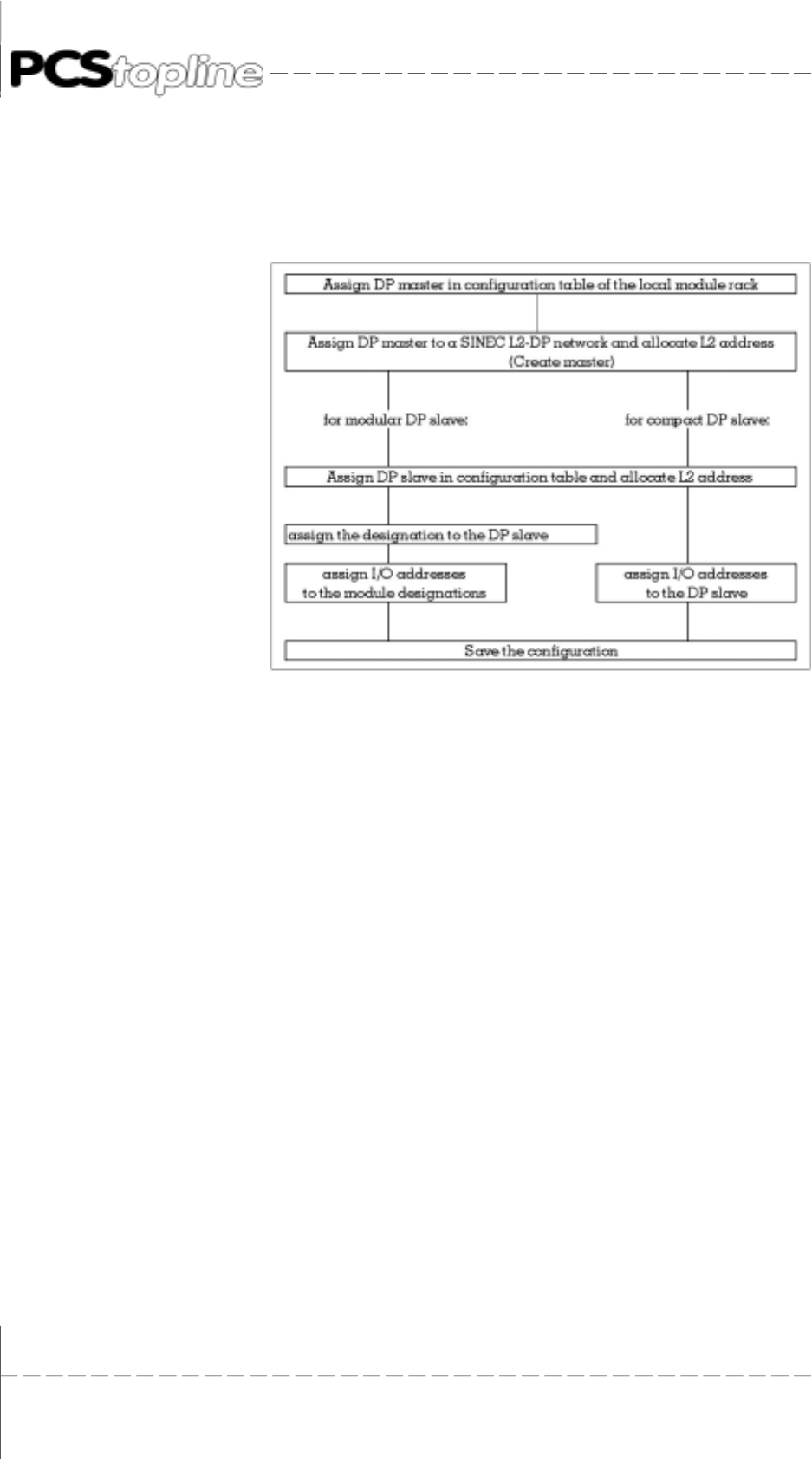
Procedure
Basically, you configure a SINEC L2-DP network using the Step7 software
(hardware configuration) just with a local setup. Go ahead as follows:
Conversion into a configuration table
Allocate the DP master locally to a module rack. Allocate the DP slaves
to an own configuration table. The change to this configuration table is
only made after you have configured the DP master.
B.1.3 Defining a master system
• Requirement
You have called up the configuration table.
• Master system
All DP slaves associated to a DP master and the DP master form a
master system. A master system is part of a SINEC L2-DP network.
• Master system definition
After you have allocated the DP master in the configuration table,
you define the pertinent master system.
A master system means that you associate the DP master a SINEC
L2-DP network and assign an L2 address to the DP master.
• Select and allocate a DP master
You select a DP master from the module catalogue and position it in
the configuration table.
Result: if the DP master is an integrated interface of a CPU then a
„+“ is indicated to the left of the CPU. A second line appears with the
DP master if you click onto the + sign.

© Systeme Lauer GmbH & Co KG • Kelterstr.59 • 72669 Unterensingen • Tel. (07022) 96 60-0 • Fax (07022) 96 60-103 B-9
B Siemens PLC
Further procedure:
If you have allocated the DP master in the configuration table then you
can either:
• continue to allocate the „local“ modules in the configuration table
or
• configure the SINEC L2-DP network further by associating the DP
master a SINEC L2-DP network and assign it an L2 address.
• L2 address
For the unambiguous identification, you must assign an L2 address
to each DP master and DP slave of a master system in the SINEC
L2-DP network.
• Network and L2 address assignment
Go ahead as follows to assign the network and L2 address:
1 mark the line in which the DP master is found.
select the Edit -> Master system -> Open menu command. The
dialog field for the network and L2 address assignment is displayed.
2 assign the DP master a SINEC L2-DP network (a default network is
offered).
3 assign an L2 address to the DP master (the lowest free L2 address
is offered as default value).
Result: the „Master system configuration table“ is displayed after the
assignment of the SINEC L2-DP network and L2 address.
Master system configuration table
In the master system configuration table, you allocate and parameterize
all DP slaves of a master system.
© Systeme Lauer GmbH & Co KG • Kelterstr.59 • 72669 Unterensingen • Tel. (07022) 96 60-0 • Fax (07022) 96 60-103
B-10
B Siemens PLC
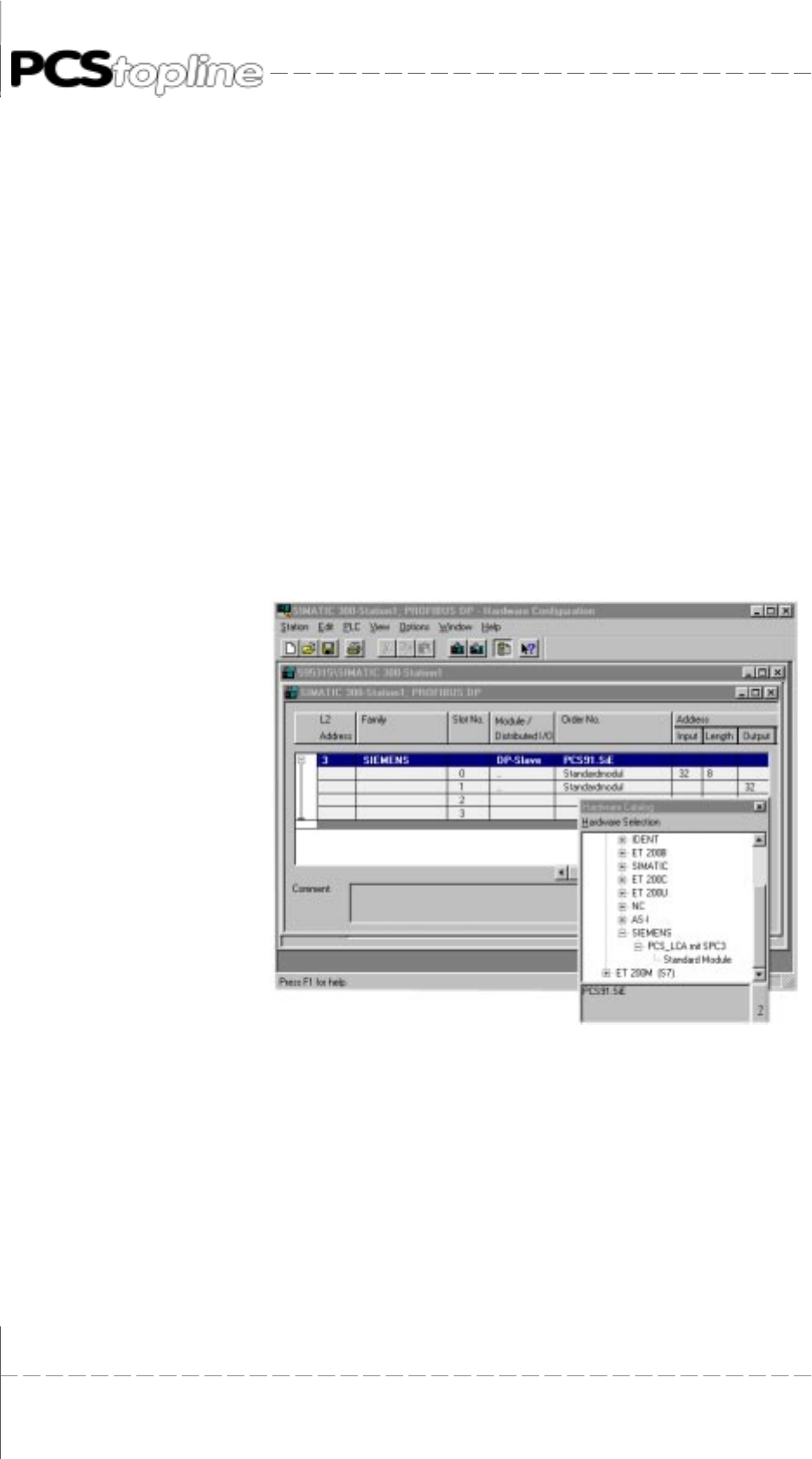
Select and allocate a DP slave
Go ahead as follows to allocate a DP slave in the configuration table:
1 You must create the type file:
From the PCSS 91.PDP diskette copy the LAUSPC3X.200 file into
your STEP7\S7DATA\TYPE FILE directory. Open your configuration
table. Select the Extras Update type files menu command on.
Now, close your application and restart the STEP 7 software. The
type file has now been entered in your hardware catalog.
2 Select the PCS_LCA with SPC3 DP slave from the hardware catalog
(to be found under ProfibusDP\Normslave\Siemens).
3 Allocate the DP slave in the configuration table. STEP 7 offers you
automatically the free L2 addresses in a list box. The next free L2
address is offered as default value.
4 Assign the L2 address.
Allocate modular DP slave modules
Go ahead just as if you allocate modules in a local setup to allocate
modules to a modular DP slave. Please note that the DP slave must be
opened before you can associate modules (click onto „+“).
Now, insert 2 standard modules.
Assign a designation to a modular DP slave
Designations are assigned to modular DP slaves. the characteristics of
the modules, e. g. addressing range and consistency of the data are
encoded in the DP designation.
The DP designation is automatically displayed if you insert the module in
the configuration table. You can edit the DP designation by double-clicking
onto the line of the DP designation.

© Systeme Lauer GmbH & Co KG • Kelterstr.59 • 72669 Unterensingen • Tel. (07022) 96 60-0 • Fax (07022) 96 60-103 B-11
B Siemens PLC
Assigning of I/O addresses
Each input/output of a DP slave is assigned to exactly one address that
is used for addressing. Therefore, you must assigned a starting address
to each module/DP designation of a DP slave.
STEP 7 automatically presents default addresses when you insert the
module/the DP slave in the configuration table. The default addresses
and their lengths are entered in „I addr.“ and „O addr.“ and „length columns.
Enter the number of the input and output bytes for each slave. You can
select between 8 and 32 bytes.
Note the I/O address for the programmable controller programming!
B.1.4 Programming of the programmable controller
In the following, „FC“ is valid instead of „FB“ for an S7 application.
You find the „README.TXT“ in the root directory of the PCS91.PDP floppy
disk. The relevant handling block for each project is described in this file.
Load the handling block for the Profibus-DP project into the programmable
controller for a first test of the connection. With a Siemens S7, load the
‘’PCSS7L2.AWL“ file as S0 object (source) and compile it. (In case you
are using a S7 300 then OB 101 should be deleted after compilation
since it can only be used with the S7 400). Edit FB 201 and FB 202 (S7:
FC 101 and FC 102). Adjust the assignment to the one of the PCS.
Remove the stop commands! The PCS data block must be present in the
start OB.
Please note that the MB 236 ... 255 are used as temporary flags.
For each PCS 807 Multibox Profibus DP slave, include a call of the
handling block FB 203 („PROFIB-PS5D“ for the P page frame, „PROFIB-
Q.S5D“ for the Q page frame or PCSS7l2.AWL for the I/O area of an S7)
in your programmable controller program. In case you are using the P-
page frame or the Q-page frame, you must set these before calling the
FB 203. In the calling parameters, you define:
UBDB the name of the data block, e.g. DB50
RXFA the location of the I-buffer (same as master board), e.g. KF
+40
(S7: input location)
RXLE the length of the I-buffer (same as master board), e.g. KF + 16
TXFA the location of the O-buffer (same as master board), e.g. KF +50
(S7: output location)
TXFE the length of the O-buffer (same as master board), e.g. KF + 16
RSET the restart input, e.g. E0.0
TIMES the designation of the time-out timer, e.g. T5

© Systeme Lauer GmbH & Co KG • Kelterstr.59 • 72669 Unterensingen • Tel. (07022) 96 60-0 • Fax (07022) 96 60-103
B-12
B Siemens PLC
TIMZ the time-out time, e.g. KT 20.1 = 2 seconds
RFLM the first start flag, e.g. M10.0
EROR the error flag, e.g. A0.0
COFF the error block, e.g. FB 202
(S7: FC 102)
INIT the first initializing block, e.g. FB 201
(S7: FC 101)
Thus, the example is set to the following values:
• The I-buffer is located from PW40 to PW54 and/or QW40 to QW54.
• The O-buffer is located from PW50 to PW64 and/or QW50 to QW64.
• Timer is the time-out timer T5 with a value of 2 seconds.
• E0.0 is the restart input
• A0.0 is the error output
• FB 201 is selected in the first cycle.
• FB 202 is called only once at a communication loss.
B.1.5 Settings of the slave Multibox
The PCS 807 Multibox Profibus DP slave automatically adapts to the
alleged configuration. Only the slave number of the PCS 807 Multibox
Profibus DP must be set. You set the slave number of the PCS 807 Multi-
box Profibus DP using the DIL-switches 1 to 7 to a number between 3
and 126. The setting must be made with the power being removed or in a
reset condition (the setting is taken over at the start).
The slave address is calculated as follows (OFF=0 and ON= 1):
DIL1 x 64 + DIL2 x 32 + DIL3 x 16 + DIL4 x 8 + DIL5 x 4 + DIL6 x 2 + DIL7 x 1
Slave-Nr DIL 1 DIL 2 DIL 3 DIL 4 DIL 5 DIL 6 DIL 7
3 OFF OFF OFF OFF OFF ON ON
4 OFF OFF OFF OFF ON OFF OFF
5 OFF OFF OFF OFF ON OFF ON
6 OFF OFF OFF OFF ON ON OFF
7 OFF OFF OFF OFF ON ON ON
...
125 ON ON ON ON ON OFF ON
126 ON ON ON ON ON ON OFF

© Systeme Lauer GmbH & Co KG • Kelterstr.59 • 72669 Unterensingen • Tel. (07022) 96 60-0 • Fax (07022) 96 60-103 B-13
B Siemens PLC
For the PCS 590p/595p operating console, the slave number is set in the
driver using the PCSPRO configuration software.
Start-up the components in two steps
Step 1: Network
• Set up the Profibus-DP network.
• Supply power to the programmable controller and to the PCS 807
Multibox Profibus DP.
• The IM 308 „RN“ LED is activated and the „BF“ LED of the flashes.
• After about 5 seconds, the „BF“ LED of the master board is
deactivated and the green „COM“ LED of the PCS 807 Multibox
Profibus DP or the PCS 590p/595p is statically ON.
• With the S7, the „SF-DP“ and the „BUSF“ LEDs are deactivated.
Step 2: Logical communication
• Now, you can connect the PCS (COM interface) to the PCS 807
Multibox Profibus DP (not the PCS 590p/595p).
• Set the restart input of the programmable controller to „ON“ or switch
the programmable controller from STOP to RUN.
• The „COM“ LED of the PCS is deactivated after a maximum time of
2 seconds.
B.1.6 S5 demo project
A demo project for an IM308c is included on the Siemens floppy disk to
enable a simple introduction into the Profibus-DP configuration. There, a
Profibus-DP network with a PCS operating console in the linear P page
frame area occupying bytes 0...15 is available. The procedure for
commissioning is documented in detail in the enclosed README.DOC

© Systeme Lauer GmbH & Co KG • Kelterstr.59 • 72669 Unterensingen • Tel. (07022) 96 60-0 • Fax (07022) 96 60-103
B-14
B Siemens PLC
file.
B.1.7 Trouble-shooting
Programmable controller enters STOP mode
• The Stop commands in the handling software were not yet eliminated.
Please eliminate these.
• Programmable controller STOP on Profibus-DP error set in master
configuration. Get network up and running.
• Configuration of the master board is not compatible to the
programmable controller. Please correct.
IM308 does not enter the RUN mode or flashes (S7: master)
• Wrong slot for IM308. Please correct.
• Configuration data are wrong, not programmed or EPROM or Flash
module is missing. Examine your data and the cassette.
Programmable controller in RUN mode, IM308 „BF“ LED (S7: „BUSF“
LED) flashes longer than 10 seconds
• error in the network configuration. Please eliminate.
• PCS 807 Multibox Profibus DP not ready, because:
• incorrectly connected. Please correct.
• in the Load condition (DIL-switch 11 = OFF).
first DIL 10 = ON,
next DIL1 1 = ON,
then DIL10 = OFF.
• in reset condition (DIL-switch 10 = ON). Set DIL10 to OFF.
• not powered up. Supply PCS 807 Multibox Profibus DP with 24V +
10% voltage.
• wrong slave number. Set slave number correctly and trigger reset
via DIL 10 (initiate reset with DIL 10 = ON, then DIL 10 = OFF)
Programmable controller in RUN mode, IM308 „BF“ LED (S7: „BUSF“
LED) OFF, PCS „COM“ LED ON
• PROFlBUS block is not called in the programmable controller. Please
link. FB203 configuration does not match the master board.
Time-out timer expired, set restart input to 0. (UEROR: =RSET)
• PCS 807 Multibox Profibus DP DIL-switch 10 set to ON. Set PCS
807 Multibox Profibus DP DIL-switch to OFF.
• A wrong driver was loaded into the PCS operating console. Load the
right driver together with the data record once more into the PCS
operating console.
• IM308B start problems: the IM308B does not consider the slave

© Systeme Lauer GmbH & Co KG • Kelterstr.59 • 72669 Unterensingen • Tel. (07022) 96 60-0 • Fax (07022) 96 60-103 B-15
B Siemens PLC
interval time during the start process. Thus, it can cause problems
with the PX807 001. Switch master board from STOP to RUN.
Programmable controller in RUN mode, IM308 „BF“ LED (S7: „BUSF“
LED) OFF, PCS „COM“ LED OFF, later ON again
At first, communication is active (PCS „COM“ LED is deactivated) but
after a certain time, the „COM“ LED starts to flash. This signals that the
communication is basically functioning but a monitoring condition such
as the time-out time was not observed. Possibly, the restart input is not
set or the handling block is called irregularly.
PCS 807 Multibox Profibus DP power LED (yellow) does not light
• Power supply voltage 24 V + 10% must be observed.
• Supply voltage reversed applied. Please correct.
• Fuse in the unit is burned out. Send the unit in for repair.
B.1.8 Term of the communication
PCS 807 Multibox Profibus DP
The PCS 807 Multibox Profibus DP software is based on the object codes
of the Siemens company. In addition, serial communication and logical
evaluation was added. Furthermore, the firmware is completely loadable.
Loading state
The PCS 807 Multibox Profibus DP is in the loading state if DIL 11 = OFF
(yellow Run LED OFF), i. e. the EPROM is active and the EEPROM is
externally addressable. Using a PC loader program, firmware can be
now loaded into the unit using the serial interface. This is not necessary
in the normal case since the unit is supplied with the firmware being
loaded.
Run state
The PCS 807 Multibox Profibus DP is in the Run state if DIL 11 = OFF
(yellow Run LED OFF) and the EEPROM program is active (the EPROM
is switched off). To guarantee a defined initial start of the software, a
reset must be triggered before the switching over DIL 10 to ON. This
reset is then removed by switching DIL 10 to OFF again.
During the start, the firmware reads the DIP switches 1-7 and takes over
these values as slave address. The firmware now can be run as indepen-
dent slave on the Profibus-DP network.
The logical communication between PCS 807 Multibox Profibus DP and
the programmable controller is started after plugging the serial interface
into PCS 807 Multibox Profibus DP.
Structure of the logical communication
The Profibus-DP communication uses in Siemens the I/O area. Depending
on the programmable controller, its size is between 128 bytes and several
kilobytes (paging). A Profibus-DP master must be available in the
programmable controller for communication. For this, Siemens supplies
the IM308 board. The largest I/O unit that can be transferred is 32 bytes
in size (thus, the largest configuration size of the PCS 807 Multibox Profi-
bus DP is 32 bytes).
The configuration of the PCS 807 Multibox Profibus DP slave is determined

© Systeme Lauer GmbH & Co KG • Kelterstr.59 • 72669 Unterensingen • Tel. (07022) 96 60-0 • Fax (07022) 96 60-103
B-16
B Siemens PLC
with the IM308 master board (S7: Profibus master). The slave with the
correct slave address automatically conforms to the configuration. This
configuration will be submitted to the PCS operating consoles driver to
setup the correct job/response packages.
According to the configuration, the driver in the PCS operating console
splits the occurring jobs into part jobs. One-by-one, every part job is
submitted to the PCS 807 Multibox Profibus DP for the transfer. A job
number is attached to each transmission. The job is stored in the input
area of the programmable controller. A programmable controller expander
program reads the job and executes it on a DB. The result is stored in the
output area with the job number being inverted. From there, it is submitted
to the PCS 807 Multibox Profibus DP. Then, it is serially transferred to the
driver.
The currently realized transfer times of PCS 807 Multibox Profibus DP to
the programmable controller and vice versa are essentially limited by
the SPC3 chip and the Siemens software to 50 msec min. Thus, a transfer
„PCS 807 Multibox Profibus DP – programmable controller processing
– PCS 807 Multibox Profibus DP“ lasts approx. 150ms. Including the serial
transfer, the processing of a part job thus lasts approx. 180 msec. At an
average of 6 jobs for a PCS 090, a communication cycle lasts approx.
500msec. Thus, the key LED time is 2 x communication cycle = 1 se-
cond.
Visual monitoring
yellow „Power On“ LED. It represents the functioning of the switching
power supply.
yellow „RUN“ LED. This LED is OFF in the loading state. It is ON in the
Run state.
green „Communication“ LED. This LED is OFF with communications being
inactive. The LED flashes if a baud rate is recognized. The LED lights if a
data exchange occurs.

© Systeme Lauer GmbH & Co KG • Kelterstr.59 • 72669 Unterensingen • Tel. (07022) 96 60-0 • Fax (07022) 96 60-103 B-17
B Siemens PLC
With a PCS 590p/595p, a green „Communication“ LED is available on
the rearside of the unit. A data exchange occurs if it is activated. In addition,
the „COM“ LED on the PCS 590p/595p frontpanel is only deactivated if
the handling software is correctly executed in the programmable controller.
B.1.9 Optimal configuration
The communication speed depends essentially on the following elements:
Occurring tasks in the PCS
The display content and the enabled transfers in the command words
determine the tasks of the PCS operating console.
Slave configuration
An increased I/O buffer size in the programmable controller will also
increase the processing speed of the jobs in the PCS. The output buffer
should have twice the size of the input buffer.
AJ driver variable
This variable changes the refresh behavior of the variables and the keys.
AJ = 1 -->
Keys and LEDs will be quickly transferred, variables are refreshed
slowly - suited for jog operation. The I/O buffer can be small.
AJ = 10 -->
Default values. Represent a balance between the key and the varia-
ble refresh.
AJ = 20 -->
Keys and LEDs will be transferred simultaneously with variables.
This setting is suited for the display of many variables. The I/O buffer
should be as large as possible.
PCS 807 module version:
In the PX807 0001 version, a SPC2 chip is integrated that requires a min.
slave interval time of 50 msec.
In the PX807 1000 version, a SPC3 chip is integrated that requires a min.
slave interval time of 3 msec.
The version with the SPC3 chip is effectively approx. 3 times faster than
the SPC2 version.
Configuration examples:
²PCS 900
• Slave configuration: 16 bytes I-buffer and 32 bytes O-buffer
• AJ = 10
• The command words in the programmable controller are used as
follows:
W36 = KH0F60
W37 = KH0001
The transfer of the time and the date is disabled and a message

© Systeme Lauer GmbH & Co KG • Kelterstr.59 • 72669 Unterensingen • Tel. (07022) 96 60-0 • Fax (07022) 96 60-103
B-18
B Siemens PLC
block is enabled for the transfer. Now, you will have an optimal
communication for the key LED area of less than one second if you
take provisions to display only a few variables.
²PCS 095
• Slave configuration: 12 bytes I-buffer and 24 bytes O-buffer
• AJ = 10
• The command word in the programmable controller is used as follows:
W13 = KH0FC 1
Thus, the messages M0 ... 15 are enabled for the transfer. Now, you
will have an optimal communication for the key LED area of less
than 0.8 seconds if you take provisions to display only a few varia-
bles.
²PCS 095
• Slave configuration: 8 bytes I-buffer and 16 bytes O-buffer
• AJ = 1
• The command word in the programmable controller is used as follows:
W13 = KH0FC 1
Thus, the messages M0 ... 15 are enabled for the transfer. Keys will
be transferred quickly but the refreshing of the variable takes a longer
time. The key LED time totals approx. 0.5 seconds. However, if you
press a key only for a short time then the LEDs are read only when
the key is released again. Thus, the LED will not light.
²PCS 9000
• Slave configuration: 24 input bytes and 32 output bytes
• AJ = 10
• The command word in the programmable controller is used as follows:
W13 = KH 000C (CLK_D bit on pos. 2) (CLK_C bit on pos. 3)
W16 = KH 0
W17 = KH FF00
The transfer of the time and the date is disabled. Display no external
variables in the status window as far as possible.
²PCSS 590p/595p
• Slave configuration: 16 bytes I-buffer and 32 bytes O-buffer
• AJ = 7
• The command word in the programmable controller is used as follows:
W13=KH 0FC4
W27 = 0
Thus the messages M0 ... M63 are enabled for the transfer. Now,
you will have a communication time of less approx. 0.8 seconds for
the key LED area if you take provisions to display only a few varia-
bles.

© Systeme Lauer GmbH & Co KG • Kelterstr.59 • 72669 Unterensingen • Tel. (07022) 96 60-0 • Fax (07022) 96 60-103 C-1
C Bosch PLCC Bosch PLC
PCS 807 Profibus-DP Multibox
or the PCS 590p/595p
for Bosch PLC with
I/O-communication

© Systeme Lauer GmbH & Co KG • Kelterstr.59 • 72669 Unterensingen • Tel. (07022) 96 60-0 • Fax (07022) 96 60-103
C-2
C Bosch PLC

© Systeme Lauer GmbH & Co KG • Kelterstr.59 • 72669 Unterensingen • Tel. (07022) 96 60-0 • Fax (07022) 96 60-103 C-3
C Bosch PLC
C.1 Determining the configuration
The following Bosch products are required for a Profibus-DP network
setup:
1 Cl400 programmable controller
2 DESI-DP or DESI-DP12 Profibus master board
3 programming software for the programmable controller and the
master board
4 Profibus-DP network cable and bus connector
... as well as power supplies for all components
C.1.1 Configuration of the master board (DESI-DP)
The corresponding settings must match to secure a correct interaction of
all parts!
Type file
Copy the „LAUERDP.GSD“ file into your BOSCH.BIB directory.
This file is required for the master file to be created and contains all
configuration possibilities of the PCS 807 slaves.
Call up now the Profi software of the master board. Select the DP software
using F3. Create a new project or use the included PCS DP project.
Use F2 to enter the editor. Select the PCS 807 in the BTN overview.
Under the Modules group select the configuration fitting your application
best (size of the transfer buffer in bytes). Specify the slave address for
the PCS 807 module or the PCS 590p/595p.
Now, switch to the BTN detail window using F5. Enter here the input and
output bytes desired for the communication. You can use also the
expanded inputs and outputs. Make sure that you specify an asending
order since otherwise the handling block interprets the communication
commands wrong.
The Desi-DP master board requires coupling field with a size of 6 byte for
the data exchange. Set the starting address of the coupling field in the
„Bus master settings“ menu.
Load the master file into the master board. Consider the set baud rate of
the software and the set baud rate of the master board.
Remark!
Note the set sizes for inputs and outputs, their start addresses and all
other settings. They are required for the handling block or for the DIL-
switch settings of the master board.
© Systeme Lauer GmbH & Co KG • Kelterstr.59 • 72669 Unterensingen • Tel. (07022) 96 60-0 • Fax (07022) 96 60-103
C-4
C Bosch PLC
Hardware settings using the DESI-DP board as an example
(refer also to the Bosch DESI-DP Bus Master manual)
Set the coupling address using DIL-switch S4: switch 1 of S4 is used to
select the addressing range.
- ON I/O field
- OFF EZ/AZ field
The other switches of S4 are used for the start address settings (refer to
the following figure).
Valence: I/O 21222324252627
Example:Coupling address: EZ/AZ·
Used: 0.0 - 5.7
Example: Coupling address: I/O 4
Used: 4.0 - 9.7
Baud rate switches
[Kbaud] 1 2 3 4
9.6 OFF OFF OFF OF F
19.2 ON OFF OFF OFF
93.75 OFF ON OFF OFF
187.5 ON ON OFF OFF
500 OF F OFF ON OFF
1500 OFF ON ON OFF
Set the desired transfer rate using DIL-switch S5. Thereby, the PCS 807
slave module is adjusted automatically.
All DIL-switches of S3 were set to OFF in the test setup.
Remark!
With other boards used, possibly other settings are required for the master
station address (refer to DESI-DP12 ). Please inform yourself using the
corresponding manuals of the master board.

© Systeme Lauer GmbH & Co KG • Kelterstr.59 • 72669 Unterensingen • Tel. (07022) 96 60-0 • Fax (07022) 96 60-103 C-5
C Bosch PLC
For the evaluation of the received data, the „PCS_KOMM“ block is required
that takes over the data traffic with the PCS DBs. Furthermore, an
initialization (INIT)and an error block (COFF)is made available. You can
use these blocks to define data word pre-assignments or emergency
assignments. In addition, an example OB 1 is provided in which the
block call is implemented. You find the files on the PCS 91.PDP floppy
disk in the Profibus directory.
Remark!
In OB1, the first input word of the master coupling field must be copied to
the first output word of the coupling field. This is required for the
synchronization of CPU-DP master.
Parameters of the PCS_KOMM block:
The block requires 14 parameters. This makes it possible to freely select
the addresses.
An example is provided in OB 1 (refer to the printout of the handling
block).
The meaning of the parameters is as follows:
P0: PCS user DB. (PCS data 256 words )
P1: Start address of your selected Profibus input bytes
P2: Length of the selected Profibus input field minus 1 byte
P3: Start address of your selected Profibus output bytes
P4: Length of the selected Profibus output field minus 1 byte
P5: Restart input or flag. This is required to restart the communication
after a communications fault. (Set the input to permanently high for
an automatic reset)
P6: Timer for time-out monitoring
P7: timer time as constant
P8: Communication error output (the output is set to high level after a
communications fault)
P9: PB of the „INIT“ block
P10: PB of the „COFF“ block
P11: Required flag (freely selectable, may not be used by other program
parts)
P12: Required flag (freely selectable, may not be used by other program
parts)
P13: Required flag (freely selectable, may not be used by other program
parts)

© Systeme Lauer GmbH & Co KG • Kelterstr.59 • 72669 Unterensingen • Tel. (07022) 96 60-0 • Fax (07022) 96 60-103
C-6
C Bosch PLC
C.1.2 Trouble-shooting
Programmable controller enters STOP mode
• The Stop commands in the handling software were not yet
eliminated. Please eliminate these.
• Configuration of the master board is not compatible to the
programmable controller. Please correct.
Programmable controller in RUN mode, „Send“ LED“ is OFF
• Errors in the network configuration
• Multibox not ready due to:
Wrong slave address. Check whether the master file matches the
address.
In reset condition (DIL-switch 10 is set to ON). Set DIL 10 to OFF.
No supply voltage. Apply voltage to the Multibox.
Programmable controller in RUN mode, „Send“ LED is ON, status
message 01
• Programmable controller in Stop mode. Switch the programmable
controller to RUN
• Network fault. Check whether all participants are configured correctly.
Check the cabling.
• Coupling fault (CPU is not synchronized with master board ). Check
whether the start input word of the selected coupling field is cyclically
copied to the start output word.
Programmable controller in RUN mode, „Send“ LED is ON, no status
message, PCS „Com“ LED is ON
• Lauer handling block is not called in the programmable controller
program. Please link in with correct parameters.
• A wrong driver was loaded into the PCS. Transfer the data record
together with the correct driver again into the PCS operating console.
Programmable controller in RUN mode, „Send“ LED is ON, no status
message, PCS „Com“ LED is OFF but later ON again
• The network configuration was not synchronized with all participants.
Power down all involved units. Restart all units.
• The network setup is located in noisy environment. Provide for
corresponding interference suppression.

© Systeme Lauer GmbH & Co KG • Kelterstr.59 • 72669 Unterensingen • Tel. (07022) 96 60-0 • Fax (07022) 96 60-103 C-7
C Bosch PLC
Configuration examples:
²PCS 900
• Slave configuration: 16 bytes I-buffer and 32 bytes O-buffer
• AJ = 10
• The command words in the programmable controller are used as
follows:
W36 = KH0F60
W37 = KH0001
The transfer of the time and the date is disabled and a message
block is enabled for the transfer. Now, you will have an optimal
communication for the key LED area of less than one second if you
take provisions to display only a few variables.
²PCS 095
• Slave configuration: 12 bytes I-buffer and 24 bytes O-buffer
• AJ = 10
• The command word in the programmable controller is used as
follows:
W13 = KH0FC 1
Thus, the messages M0 ... 31 are enabled for the transfer. Now, you
will have an optimal communication for the key LED area of less
than 0.8 seconds if you take provisions to display only a few varia-
bles.
²PCS 095
• Slave configuration: 8 bytes I-buffer and 16 bytes O-buffer
• AJ = 1
• The command word in the programmable controller is used as
follows: W13 = KH0FC 1
Thus, the messages M0 ... 31 are enabled for the transfer. Keys will be
transferred quickly but the refreshing of the variable takes a longer time.
The key LED time totals approx. 0.5 seconds. However, if you press a
key only for a short time then the LEDs are read only when the key is
released again. Thus, the LED will not light.
²PCS 9000
• Slave configuration: 24 input bytes and 32 output bytes
• AJ = 10
• The command word in the programmable controller is used as
follows:
W13 = KH 000C (CLK_D bit on pos. 2) (CLK_C bit on pos. 3)
W16 = KH 0
W17 = KH FF00
The transfer of the time and the date is disabled. Display no external
variables in the status window as far as possible.

© Systeme Lauer GmbH & Co KG • Kelterstr.59 • 72669 Unterensingen • Tel. (07022) 96 60-0 • Fax (07022) 96 60-103
C-8
C Bosch PLC
²PCSS 590p/595p
• Slave configuration: 16 bytes I-buffer and 32 bytes O-buffer
• AJ = 7
• The command word in the programmable controller is used as
follows:
W13=KH 0FC4
W27 = 0
Thus the messages M0 ... M63 are enabled for the transfer. Now,
you will have a communication time of less approx. 0.8 seconds for
the key LED area if you take provisions to display only a few varia-
bles.

© Systeme Lauer GmbH & Co KG • Kelterstr.59 • 72669 Unterensingen • Tel. (07022) 96 60-0 • Fax (07022) 96 60-103 C-9
C Bosch PLC
C.2 Print out handling software
OB1 OB1 Master Baustein
PB0 PCS_KOMM Expanderprogramm für PCS
PB2 INIT Initialisierungsbaustein
PB3 COFF Fehlerbaustein
; OB1
; Filename: OB1
; function: Organisationsbaustein
; p r o g r a m
;***********************************************************************
1 L W EZ64,A ; copy the first word of your I/O-Area of the
2 T W A,AZ64 ; CPU - DESI-DP communication from input to
; output
; call the Lauer communication subroutine PB (PCS_KOMM)
3 BA -PCS_KOMM,14 ; call expander program
P0 W -DB1 ; DB PCS-datafield of 256 words
P1 W &EZ10 ; W startaddress of the Profibus-Input
P2 W K31D ; K lenght of input-bytes - 1
P3 W &AZ10 ; W startaddress of the Profibus-Output
P4 W K31D ; K lenght of output-bytes - 1
P5 B -RESTART ; B restart input
P6 W -TIMER ; T watch dog PCS-communication
P7 W K4.2 ; K timevalue for watch dog
P8 B M100.0 ; B output-bit communication error
P9 W -INIT ; PB INIT (communication init PCS)
P10 W -COFF ; PB COFF (communication error PCS)
P11 B M100.2 ; B for internal use
P12 B M100.3 ; B for internal use
P13 B M100.4 ; B for internal use
;U B M100.0 ; communication error to output
;= B A3.7
4 PE
;program end
; PCSKOMM
; expander-program for communication via Profibus with PCS-Topline ; Filename:
PCS_KOMM
; function: expander for the CL400
; D e c l a r a t i o n
; subroutine parameter:
;~~~~~~~~~~~~~~~~~~~~~~~~~~
;BA -PCS_KOMM,14 ; call expander program
;P0 W -DB1 ; DB PCS-datafield of 256 words
;P1 W &EZ10 ; W startaddress of the Profibus-Input
;P2 W K31D ; K lenght of input-bytes - 1
;P3 W &AZ10 ; W startaddress of the Profibus-Output
;P4 W K31D ; K lenght of output-bytes - 1
;P5 B -RESTART ; B restart input
;P6 W -TIMER ; T watch dog PCS-communication
;P7 W K4.2 ; K timevalue for watch dog
;P8 B M100.0 ; B output-bit communication error
;P9 W -INIT ; PB INIT (communication init PCS)
;P10 W -COFF ; PB COFF (communication error PCS)
;P11 B M100.2 ; B for internal use
;P12 B M100.3 ; B for internal use
;P13 B M100.4 ; B for internal use
; p r o g r a m
;**************************************************************************
;

© Systeme Lauer GmbH & Co KG • Kelterstr.59 • 72669 Unterensingen • Tel. (07022) 96 60-0 • Fax (07022) 96 60-103
C-10
C Bosch PLC
; processor reset ⇒ reset BT9_KOM
;~~~~~~~~~~~~~~~~~~~~~~~~~~~~~~~~~~~
PZ: 1
1 U B -P_RI
2 O B -NEU_RI
3 SPB -START_KO ; →
4 BX -P0
PZ: 2
5 U B -P12 ;second cycle to catch whole data (inputs)
6 SPB -WAITDAT1
PZ: 3
7 U B -P13
8 SPB -WAITDAT2 ;second cycle to catch whole data (outputs)
; no process if timeout and restart input = 0
;~~~~~~~~~~~~~~~~~~~~~~~~~~~~~~~~~~~~~~~~~~~~~~~~~~~~~~~~~~~~~
PZ: 4
9 UN B -P5 ; timeout ?
10 U B -P8 ; restart ?
11 BEB
; instruction-number = 0 => wait for instruction-number = 0 ;
; if instruction-number = n => process received data
;~~~~~~~~~~~~~~~~~~~~~~~~~~~~~~~~~~~~~~~~~~~~~~~~~~~~~~~~~~~~~
12 XO W B,B ; A Register = 0
13 L W -P1,A ; instruction-number = 0 ? Input
14 L BY [A],A
15 VGL BY A,B
16 SPZ -NO_AUFTR ; →
17 BX -P0 ; open PCS-DB
; instructions-number > 0 ⇒ process the instructions
;
; Have the whole instruction received ?
18 L BY DX3,B ; old instruction-number in byte 3
19 L W -P1,A ; load instruction-number (input)
20 L BY [A],A
21 VGL BY A,B ; compare old with new
22 SPZ -NO_AUFTR ; if even → no new instructions
23 L W -P1,A ; load address of receive inputs
24 L BY [A],B ; load instruction-number 1. byte
25 ADD W -P2,A ;
26 L BY [A],A ; load instruction-number last byte
27 VGL BY A,B ; compare first with last
28 SPN -NO_AUFTR ; if not even → instructions are not
; complete
PZ: 5
29 UN B -P11 ;set wait-flag and wait one cycle
30 = B -P12
31 BE
-WAITDAT1
PZ: 6
32 U B -P11 ;reset the wait-flag
33 = B -P12
34 L W -P1,A ; indir.address of datainputs
35 ADD W K1H,A ; at byte 2 load first instruction
36 L W -P3,B ; indir.address of dataoutputs
37 ADD W K1H,B
38 L W K2H,D ; reset receive counter
39 T BY D,DX2 ; DX2 = receive-counter
; analyse of the instructions
-read_new ; ←
40 L BY [A],C ; read actual instruction
41 L W A,A
;SP -AUFT_END
42 PUSH W C

© Systeme Lauer GmbH & Co KG • Kelterstr.59 • 72669 Unterensingen • Tel. (07022) 96 60-0 • Fax (07022) 96 60-103 C-11
C Bosch PLC
43 ADD W K1,A
44 L BY [A],C
45 T BY C,D
46 U BY KF0H,C
47 VGL BY K10H,C ; read instruction
48 SPZ -READ ; →
49 VGL BY K20H,C ; write instruction
50 SPZ -WRITE ; →
51 VGL BY K40H,C ; write and „AND“ instruction
52 SPZ -WRITE_U ; →
53 VGL BY K80H,C ; write and „OR“ instruction
54 SPZ -WRITE_O ; →
55 POP W C
56 SP -AUFT_END
;==========================================================================
; read instruction: copy data from PCS-datafield to send outputs
;=========================================================================
-READ ; ←
57 POP W C
58 PUSH W A ; pointer receive inputs to stack
59 L BY C,A ; load dataword address
60 U W K00FFH,A
61 SLL W A,1 ; * 2
62 O W K1800H,A ; at to indirect address PCS-Datafield
63 L BY D,C ; load instruction
64 U BY K0FH,C ; mask count of datawords
-return_r ; ← copy until count of datawords = 0
65 VGL BY K0H,C
66 SPZ -r_end ; read instruction end
67 INC W A,1
68 L BY [A],D ; load high byte from PCS-datafield
69 T BY D,[B] ; write to send outputs
70 DEC W A,1
71 INC W B,1 ; increment send pointer
72 L BY [A],D ; load low byte from PCS-datafield
73 T BY D,[B] ; write to send-outputs
74 INC W B,1 ; increment send pointer
75 INC W A,2 ; increment datafield-address
76 DEC BY C,1 ; decrement dataword counter
77 SP -return_r ; →
; is there another instruction ?
;~~~~~~~~~~~~~~~~~~~~~~~~~~~~~~~~~~~~~
-r_end
78 POP W A ; load from stack receive pointer
79 L BY DX2,D ;
80 U W K00FFH,D
81 ADD W K2H,D ; increment receive pointer
82 VGL W -P2,D ; check if receive end
83 SPP -AUFT_END
84 T BY D,DX2
85 INC W A,1 ; next instruction address
86 L BY [A],D ;
87 VGL BY K0H,D ; check if instruction = 0
88 SPZ -AUFT_END
89 SP -read_new ; → ; there is another instruction
; → process the next instruction
; end read instruction
;==========================================================================
; write instruction: copy datawords from receive inputs to PCS-datafield
;==========================================================================
-WRITE ; ←

© Systeme Lauer GmbH & Co KG • Kelterstr.59 • 72669 Unterensingen • Tel. (07022) 96 60-0 • Fax (07022) 96 60-103
C-12
C Bosch PLC
90 POP W C
91 PUSH W B ; send pointer to the stack
92 L W C,B ; load PCS-dataword-address
93 U W K00FFH,B
94 SLL W B,1 ; * 2
95 O W K1800H,B ; add to indirect address PCS-datafield
96 L BY D,C ; load instruction
97 U BY K0FH,C ; mask count of datawords
98 PUSH W C ; dataword counter to the stack
99 INC W A,1 ; increment receive pointer
-return_w ; ← ; copy until dataword counter = 0
100 VGL BY K0H,C
101 SPZ -w_end ; write instruction end
102 INC W B,1 ; receive address of high byte
103 L BY [A],D ; load byte from receive inputs
104 T BY D,[B] ; and store it as high byte
105 DEC W B,1 ; receive address of low byte
106 INC W A,1 ; increment datafield address
107 L BY [A],D ; load byte from receive inputs
108 T BY D,[B] ; and store it as low byte
109 INC W A,1 ; increment datafield address
110 INC W B,2 ; increment receive pointer
111 DEC BY C,1 ; decrement dataword counter
112 SP -return_w ; ←
; is there another instruction ?
;~~~~~~~~~~~~~~~~~~~~~~~~~~~~~~~~~~~~
-w_end
113 POP W C ; load from stack dataword counter
114 POP W B ; load from stack send pointer
115 INC W C,1 ; count +1 instruction word
116 SLL W C,1 ; count of byte
117 L BY DX2,D
118 U W K00FFH,D
119 INC W D,[C] ; increment receive pointer
120 VGL W -P2,D ; check if receive end
121 SPP -AUFT_END
122 T BY D,DX2
123 L BY [A],D ; load next instruction
124 VGL BY K0H,D ; check if instruction = 0
125 SPZ -AUFT_END ; →
126 SP -read_new ; → ; there is another instruction
; → process the next instruction
; end write instruction
; write and „AND“ instruction: that is an „AND“ function between received
; data and the data in the datafield, stored
; later in the datafield
;==========================================================================
-WRITE_U
127 POP W C
128 PUSH W B ; send pointer to the stack
129 L W C,B ; load PCS-dataword-address
130 U W K00FFH,B
131 SLL W B,1 ; * 2
132 O W K1800H,B ; add to indirect address PCS-datafield
133 L BY D,C ; load instruction
134 U BY K0FH,C ; mask count of datawords
135 PUSH W C ; dataword counter to the stack
136 INC W A,1 ; increment receive pointer
-return_u ; ← ; copy until dataword = 0

© Systeme Lauer GmbH & Co KG • Kelterstr.59 • 72669 Unterensingen • Tel. (07022) 96 60-0 • Fax (07022) 96 60-103 C-13
C Bosch PLC
137 VGL BY K0H,C
138 SPZ -u_end ; write „AND“ instruction end
139 INC W B,1 ; receive address of high byte
140 L BY [A],D ; load high byte from receive inputs
141 U BY [B],D ; „AND“ byte from PCS-datafield
142 T BY D,[B] ; store it as high byte
143 DEC W B,1 ; receive address of low byte
144 INC W A,1 ; increment datafield address
145 L BY [A],D ; load low byte from receive inputs
146 U BY [B],D ; „AND“ byte from PCS-datafield
147 T BY D,[B] ; store it as low byte
148 INC W A,1 ; increment datafield address
149 INC W B,2 ; increment receive pointer
150 DEC BY C,1 ; decrement dataword counter
151 SP -return_u ; →
; is there another instruction ?
;~~~~~~~~~~~~~~~~~~~~~~~~~~~~~~~~~~~~~
-u_end
152 POP W C ; load from stack dataword counter
153 POP W B ; load from stack send pointer
154 INC W C,1 ; count +1 instruction word
155 SLL W C,1 ; count of byte
156 L BY DX2,D
157 U W K00FFH,D
158 INC W D,[C] ; increment receive pointer
159 VGL W -P2,D ; check if receive end
160 SPP -AUFT_END
161 T BY D,DX2
162 L BY [A],D ; load next instruction
163 VGL BY K0H,D ; check if instruction = 0
164 SPZ -AUFT_END ; →
165 SP -read_new ; → ; there is another instruction
; → process the next instruction
; end write „AND“ instruction
; write and „OR“ instruction: that is an „OR“ function between received
; data and the data in the datafield, stored
; later in the datafield
-WRITE_O ; ←
166 POP W C
167 PUSH W B ; send pointer to the stack
168 L W C,B ; load PCS-dataword-address
169 U W K00FFH,B
170 SLL W B,1 ; * 2
171 O W K1800H,B ; add to indirect address PCS-datafield
172 L BY D,C ; load instruction
173 U BY K0FH,C ; mask count of datawords
174 PUSH W C ; dataword counter to the stack
175 INC W A,1 ; increment receive pointer
-return_o ; ← ; copy until dataword counter = 0
176 VGL BY K0H,C
177 SPZ -o_end ; write „OR“ instruction end
178 INC W B,1 ; receive address of high byte
179 L BY [A],D ; load byte from receive inputs
180 O BY [B],D ; „OR“ byte from PCS-datafield
181 T BY D,[B] ; and store it as high byte
182 DEC W B,1 ; receive address of low byte
183 INC W A,1 ; increment datafield-address
184 L BY [A],D ; load byte from receive inputs
185 O BY [B],D ; „OR“ byte from PCS-datafield
186 T BY D,[B] ; and store it as low byte

© Systeme Lauer GmbH & Co KG • Kelterstr.59 • 72669 Unterensingen • Tel. (07022) 96 60-0 • Fax (07022) 96 60-103
C-14
C Bosch PLC
187 INC W A,1 ; increment datafield-address
188 INC W B,2 ; increment receive pointer
189 DEC BY C,1 ; decrement dataword counter
190 SP -return_o ; →
; is there another instruction ?
;~~~~~~~~~~~~~~~~~~~~~~~~~~~~~~~~~~~~~
-o_end
191 POP W C ; load from stack dataword counter
192 POP W B ; load from stack send pointer
193 INC W C,1 ; count +1 instruction word
194 SLL W C,1 ; count of byte
195 L BY DX2,D
196 U W K00FFH,D
197 INC W D,[C] ; increment receive pointer
198 VGL W -P2,D ; check if receive end
199 SPP -AUFT_END
200 T BY D,DX2
201 L BY [A],D ; load next instruction
202 VGL BY K0H,D ; check if instruction = 0
203 SPZ -AUFT_END ; → ;
204 SP -read_new ; → ; there is another instruction
; process the next instruction
; end write „OR“ instruction
; AUFT_END: all instructions are done
-AUFT_END ; ←
PZ: 7
205 UN B -P11 ; wait one cycle to be sure that
206 = B -P13 ; all outputs are refreshed
207 BE
; Invert instruction-number and write it to the first and last byte
; of the communication outputs
;~~~~~~~~~~~~~~~~~~~~~~~~~~~~~~~~~~~~~~~~~~~~~~~~~~~~~~~~~~~~~~~~~~
-WAITDAT2
PZ: 8
208 U B -P11 ; reset wait-flag
209 = B -P13
210 L W -P1,A
211 L BY [A],D ; load instruction-number
212 T BY D,DX3 ; store it in byte 3
213 XO BY KFFH,D ; invert the instruction-number
214 L W -P3,A
215 T BY D,[A] ; store it in the first and last
216 ADD W -P4,A ; output bytes
217 T BY D,[A]
; watch dog
;~~~~~~~~~~~
; trigger time
;————————————————————
218 U W -P7,D ; timevalue
PZ: 9
219 U B -LOG0
220 SE D,-P6 ;
PZ: 10
221 U B -LOG1 ; Watchdogmerker reset
222 R B -P8
223 BE ; →

© Systeme Lauer GmbH & Co KG • Kelterstr.59 • 72669 Unterensingen • Tel. (07022) 96 60-0 • Fax (07022) 96 60-103 C-15
C Bosch PLC
; end instructions
; no new instructions
-NO_AUFTR ; ←
224 L W -P7,D ; timevalue
PZ: 11
225 U B -LOG1
226 SE D,-P6
PZ: 12
227 U B -P6 ; timeout ?
228 BEI
; set fault watch dog has responsed
;~~~~~~~~~~~~~~~~~~~~~~~~~~~~~~~~~~~~~~~~~~
-KOMM_FEL
229 S B -P8 ; watch dog
230 XO W D,D
; init after communication error
;~~~~~~~~~~~~~~~~~~~~~~~~~~~~~~~~
231 BA -P0 ; open PCS-DB
232 BA -P10 ; COFF
233 BE ; →
; end watch dog
; start of communication
-START_KO
; start timer
;~~~~~~~~~~~~~~~~~~~~
234 L W -P7,D ; timervalue
PZ: 13
235 U B -LOG0
236 SE D,-P6
; reset fault
;~~~~~~~~~~~~~~~
PZ: 14
237 U B -LOG1
238 R B -P8 ; watch dog
239 XO W D,D
; init output at the first cycle
;~~~~~~~~~~~~~~~~~~~~~~~~~~~~~~~~~
240 L W -P3,A
241 T W D,[A]
; init PCS-DB at first cycle
;~~~~~~~~~~~~~~~~~~~~~~~~~~~~
;BA P0 ; open PCS-DB
;BA P9 ; INIT
242 BE ; →
; end start communication
;program end
;** INIT: Subroutine INIT inits the PCS-datafield at the first cycle
;** The user can program his own specifications
;HLT ;!!!!! Here you have to specify your init values
;********************************** !!! at least set your

© Systeme Lauer GmbH & Co KG • Kelterstr.59 • 72669 Unterensingen • Tel. (07022) 96 60-0 • Fax (07022) 96 60-103
C-16
C Bosch PLC
;********************************** key-bytes to zero !!!!!
;***** Example PCS 009/090/095*****
;L W K0D,A
;T W A,D8
;T W A,D10
;T W A,D46
;L W K0FC8H,A
;T W A,D26 ;CONTROLWORD A
;L W K0080H,A
;T W A,D28 ;CONTROLWORD B
;***** EXAMPLE PCS 900/920/950 *****
;L W K0D,A
;T W A,D8
;T W A,D10
;T W A,D12
;T W A,D18
;T W A,D78 ;CONTROLWORD D
;L W K0080H,A
;T W A,D76 ;CONTROLWORD C
;L W K00FFH,A
;T W A,D74 ;CONTROLWORD B
;L W K1F00H,A
;T W A,D72 ;CONTROLWORD A
1 BE
;** COFF: subroutine COFF inits the PCS-datafield after communication error
;** ( emergancy case ) The user can program his own specifications
;HLT ;!!!!! Here you have to specify your emergancy values
;**********************************
;**********************************
;********************************** !!!!! CAUTION !!!!!
;********************************** at least set the Key-bytes to zero
;**********************************
;***** Example PCS 009/090/095 *****
;L W K0D,A
;T W A,D8 ; keys
;T W A,D10 ; keys
;T W A,D46 ; keys
;***** Example PCS 900/920/950 *****
;L W K0D,A
;T W A,D8 ;keys
;T W A,D10 ;
;T W A,D12
1 BE
