Vdv9324.tmp 927 0221 Onan MCCK Marine Genset Parts Manual (05 1978)
User Manual: 927-0221 Onan MCCK Marine Genset Parts manual (05-1978)
Open the PDF directly: View PDF ![]() .
.
Page Count: 45
The following catalog
has gaps in its page
numbers, or doesn’t
have any numbers.
We have chosen to
leave the page
numbering in the
order that Acrobat
assigns it.
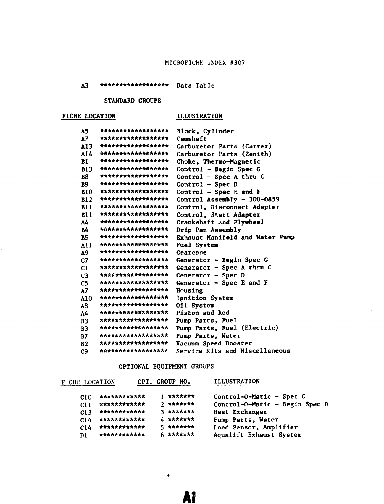
MICROFICHE INDEX #307
A3 ***************s%**
STANDARD GROUPS
FICHE LOCATION
AS
A.?
A13
Al4
BI
B13
ml
B9
BICI
Bi~
Bll
B11
A4
B4
B5
~~ 1
A9
C7
c1
a
C5
A7
A1O
A8
A4
B3
B3
B7
B2
C9
******************
******************
******************
******************
******************
******************
******************
******************
******************
******************
******************
******************
******&***********
*&****************
**&*#f*Mklk*********
******************
******************
**********k*******
******************
*kk3&wt*******it***
******************
******************
******************
******************
******************
******************
******************
******************
******************
******************
Data Table
Block, Cylinder
Casmha ft
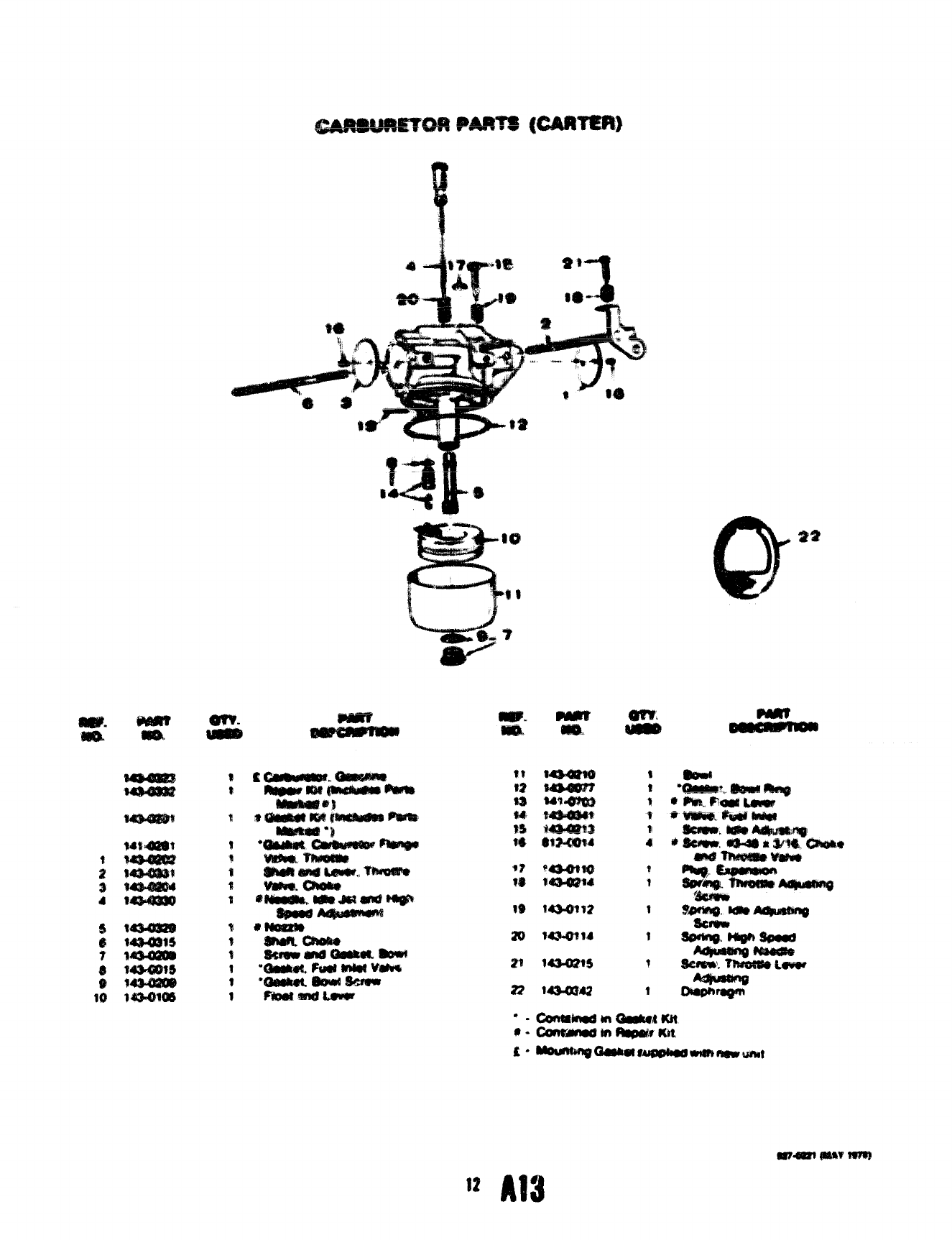
Carburetor Parts (Carter)
Carburetor Parts (Zentth)
Choke, Thmw+agnetic
Pfimtro~
---- - Begin Spec C
Control - Spec A Cbru C
Control --Spec D
Control - Spec E and F
Control Assembly - 300-0859
Control, Disconnect Adapter
Control, Start Adapter
Crankshaft And Flywheel
Drip Pan Assembly
Exhaust Manifold and Water Pwq
Fuel System
Gearcase
Generator - Begin Spec G
Generator - Spec A thru C
Generator - Spec D
Generator - Spec E and F
Hrusing
Ignition System
Oil System
Piston and Rod
Pump Parts, Fuel
Pump Parts, Fuel (ElecErk)
Pump Parts, Water
Vacuum Speed Booster
Service Kits and Miscellaneous
OPTIONAL EQUIPME3JT GROUPS
FICHE LOCATION OPT. GROUP NO. ILLUSTRATION
Clo ************ ~ *******
Cll ************
Control-O-Matic - Spec C
2 ******* Control-O-Matic - Begin Spec D
C13 ************ 3 ******* Heat Exchanger
C14 ************ 4 ******* Pump Parts, Water
C14 ************ 5 ******* Load Sensor, Amplifier
D1 ************ 6 ******* Aqualift Exhaust System
4
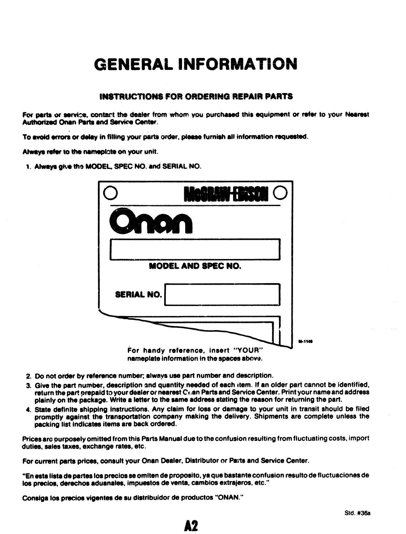
GENERAL INFORMATION
FM parts or aemhs. cam@st tka 44aatar*. whom vou purchased this equipment or refer to your Nesresl
Mtfw@ad onan Parts and SafvWBoentW.
To awid emaraordl$ay Wfftmg yourparts wear, @ease furnish Minformation ruquestadm
1.
2.
3.
c)
MODEL AM) SPEC NO.
SERIAL NO. II
#or handy reference, insert “YOUR”
nameplate ~nforrnationin the apaceaatmwk
N-114$
Do not order by reference numbec always use part number and description.
Give the part number, description and quantity needed of each item. If an older part cannot be identified,
return t?wpart prepaid to your dealer or nearest C~~anPartsand Senha Oenter. Print your name and address
plainly on the package. Write aletter to the same address stating the reason for returning the part.
State definite shimina instructions. Any claim for iOSSor damage to your unit in transit should *filed
promptty againsi the %anspot’tation company making the deliv6ry. Shipments are complete unless the
packing list indicates items are back ordered.
Pricesarc purposely omitted from this Parts Manual due to the confusion resuhing from fluctuating costs, import
duties, sales taxes, exchange rates, etc.
For current parts prices, consult your Onan Dealer, Distributor or parts and Service Center.
●’Eneats Iista de ptwlesIospreciosseomi$ende proposito, ya que bastanteconfusion resulto de fluctuaciones de
IOSpaba, darechos aduanales, impuestos de -m. -mbi* -tra~ermt etc.”
(’2ms@aMI precios tigentes de $Udistribuidor de productos “ONAN.”
Std. #36B
9274221
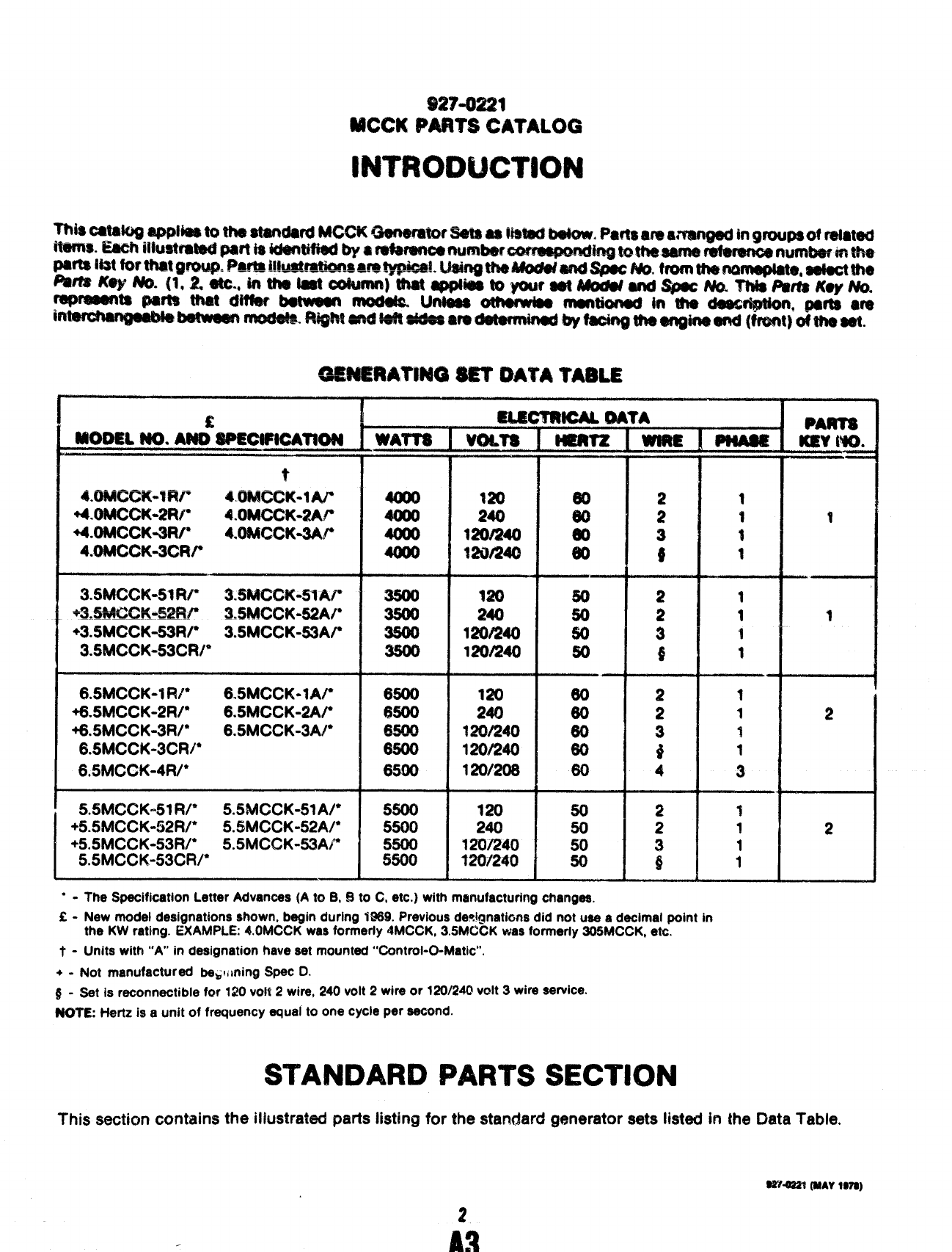
IWCCK PART’SCATALOG
INTRODUCTION
MOOSL NO. ANCii#JMWWATaON
t
----- —.-—— ——
4.UMGCK-lFW 40MCCK-fU
+4.OMCCiIW?R~ 4.OMCCK-2N’
+4.OMCCK-3R~ 4.OMCCK-3W
4.OMCCK-3CR~
3.5MCCK-51 RI” 3.5McCS&’51w
.n EUfinu Emm89
Vhamgu.n.”garf %!.SMCCK-52AP
+3.$M~@(-53f4/” 3.5MccK-53Ar
3.5MccK”53cR/*
6.5MCCK-IRI” 6.5MCCK-lA~
+6.5MCCK-2R/* 6.5MCCK-2A~
+6.5MccK-3R/* 6.5MCCK-3A/”
6.5MCCK-3CR/*
6,5MCCK-4R/*
5.5MccK”51R/* 5.5MCCK-51AP
+5.5MCCK-~2R/* 5.5MCCK-52A/*
+5.5MccK.53Rr 5.5MCCK-53AP
5.5MccK-53cRfl
WAY73
.—
6500
&500
mum
—..
6500
120
240
120/240
1201X0
:=
420/240
12W240
120/206
120
240
120/240
?2W240
m
50
50
60
—.
60
60
60
60
eo
50
50
50
w
1
1
1
1
1
1
Y
1
—.
1
1
1
1
3
“-The Specification Letter Advances (A to B, Elto Getc.) with manufacturing changes.
Q-New model designations shown, begin during 1SS9. Previous designations did not use adecimal pdnt in
the KW rating. EXAMPLE 4.OMCCK was formerly 4MCCK, 3.5MCCK was formerly 305MCCK, etc.
t - Units with “A” in designation have set mounted “Control-O-Matic”.
+-Not manufactured beg!, ming $@ac D.
#-Set is reconnectable for 120 volt 2wire, 240 volt 2wire or 120/240 volt 3wire service.
NOYE: Hertz is aunit of frequency equal to one cycle per second.
STANDARD PARTS SECTION
-4
1
1I
i
2
2
This section contains the illustrated parts listing for the standard generator sets listed in the Data Table.
w?~? (WAY1S9S)
REF. PART
NO. NO.
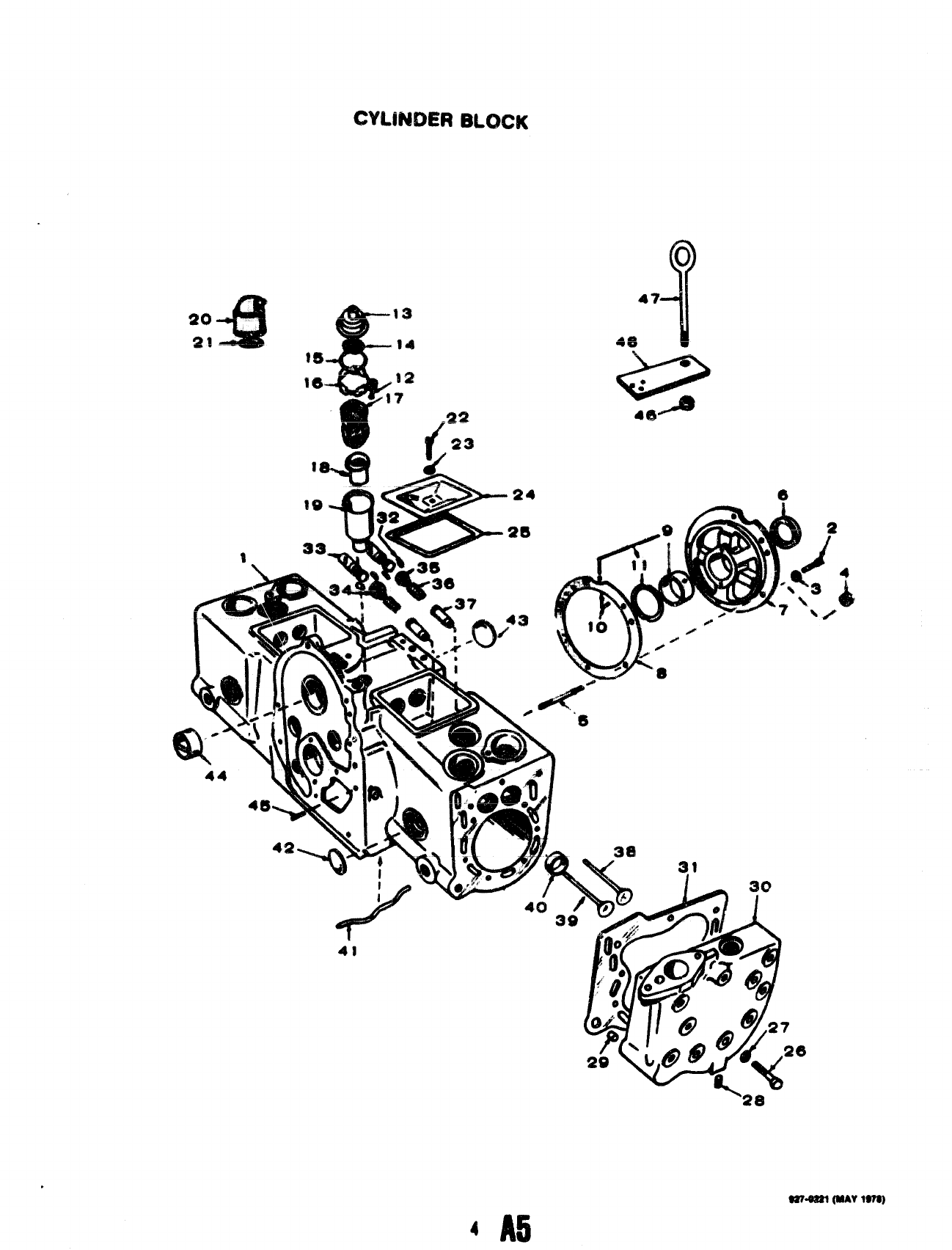
1104-0170
2850-0055
3&?S-0017
4104-05S9
t! 515-0227
6!518-0014
7104AX143
8104-0032
9515-0001
i%%)
1
1
1
1
‘1
1
1
REF.
No.
1
2
3
4
5
6
7
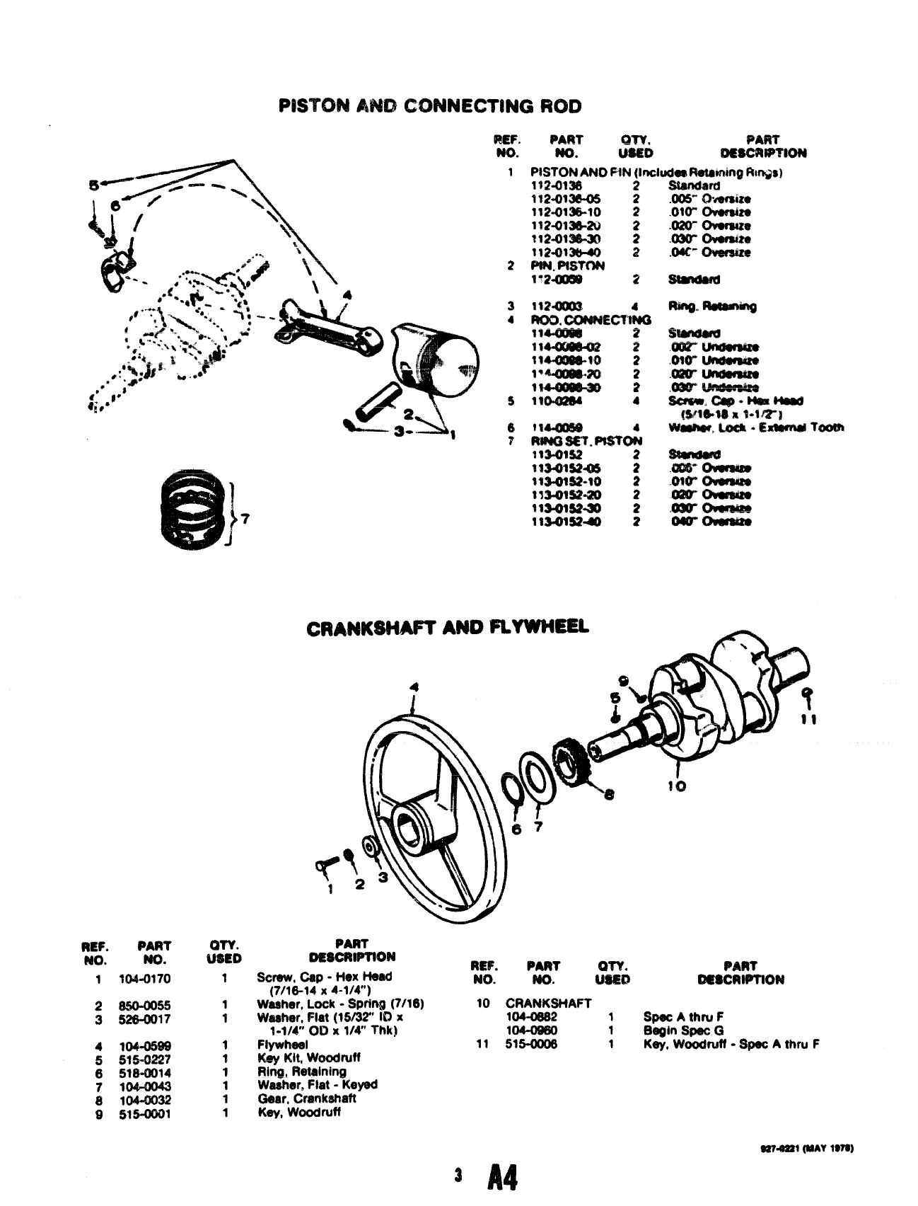
PAFW @AfH
No. S&i Omcm?TloN
PISTON A14r)RN {Includl.etining IWr#sl
1?2-0138 2
l12413&’05 2.00$” Owwsize
112-Ol~lo 2.010- Ov’8mize
112-o13&2Q .020- 0v9mue
112.4)1X :.030- 0ver9&e
$12413&40 2.044” Owsmws
PtN. PtsTON
1“2.0060 2Stmdard
fling. lRuemk?Q
.13m”Owmse
..wrOvuwa
.$%=
04Gf Ow84&
PAnT
DEsciitimoN
Screw, Cap -Hex He@ REF. PART PART
NO. NO.
(7/16-14 x4-1/4) t%% osscRwrloN
Weeher, Lock -Sprtnff (7/16) 10 CRANKSHAFT
Weeher, Flat (15/32” ID x104-08s2 1@ec Athn.i F
1-1/4” 0t3 X1/4” Thk] W-09@ 1Begin Spec G
Ftywheel 11 515-0008 1Key, Woodrdl -Spot Athru F
Key Kit, Wmdruff
Rin@ Retalningj
Wesher, Flat -I@fed
ywar,wc~~y?t
@sT.assl(MM 1s?s)
3A4
CYLiMDER BLOCK
UT4Ul fMAV10YC)
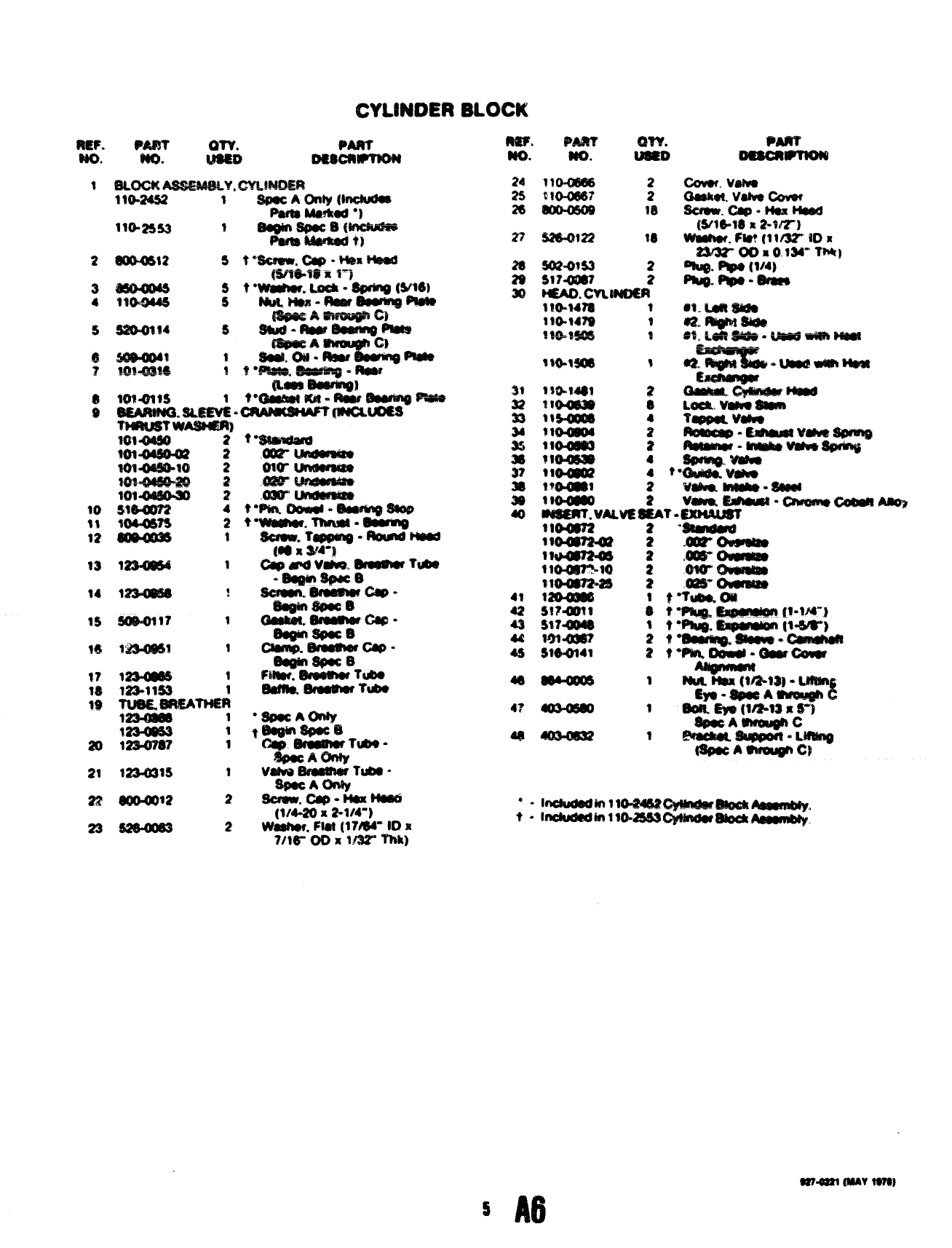
CYLINDER BLOCK
2
3
4
5
20
21
22
23
46
@?.a?alWV tnt9
5A6
L-
a
9
4
/p’
?6
taw. P’m’
No. .
J?
/9
t2 lS@1520
am”
Mm
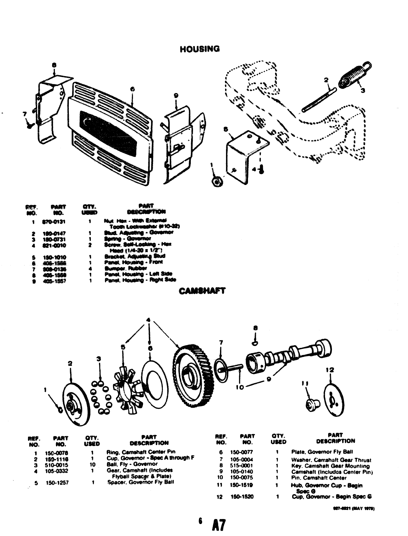
PART
OmewPTIwa
1wale, Govwnor Fly E@lt
1Washer. Cawwtwtt Gear Thrust
1Key. CamshaIt! Gear Mounhrtg
1Camat@ (Includes Center Pmj
1Pin. (%rrwhaft Center
1M@5, G8vurwcuo-wdtl
Sawaal @tAvm)
6
A7
r“- Yi
I/43 17-
!3.
r
14
$$ $w’ma Lmma mmlwR1l-”—
r
4
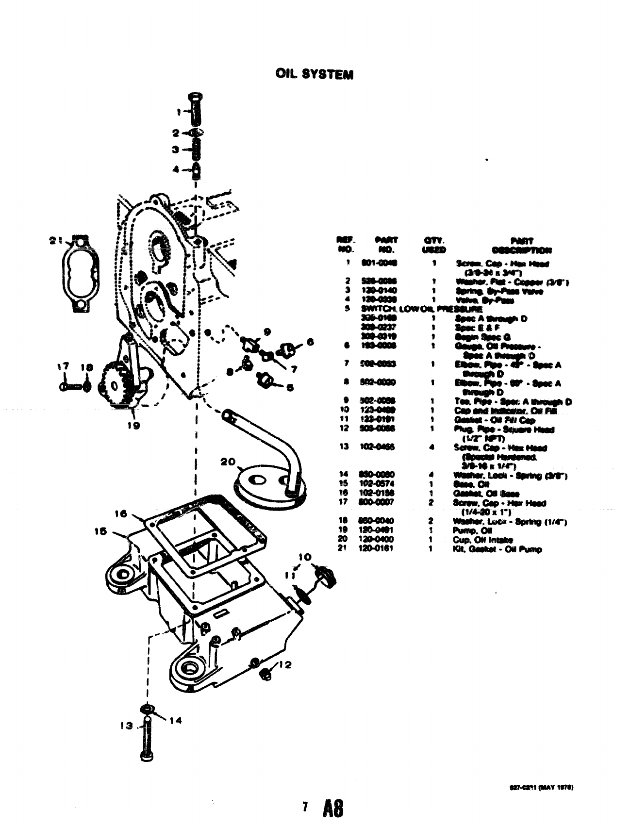
7A8
Wwml (MN 1970
—,. -
a
.‘a
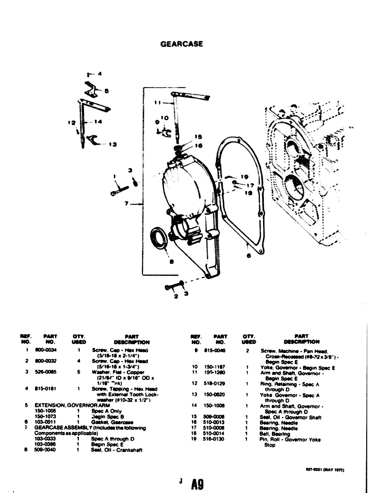
MF. PARv WV.
m. tm. U@@mJ M9J%%mJ
t~ 3swan.caQ*Nexm
(S?16-NI x2-W”)
z~ 4scmW. w* NiW!m
(Weld xI-W”)
3~ 5washer, FM -Co(%xM
mm” 00x Wle” mx
1/16- %k)
4815+181 1Sumu. Tq@rW-hkmad
with Exl@md Tooth Lock-
Wa8huf (WP32 xm“)
$EXI’ENSK)N, C30VEfW0R ARM
ls@lm5 1$p8c AC)nIy
IW=WT3 1i!aginsfwco
6103.5011
3Q&AflCA+$EAW=3-+ti%~_
=1 *nA&~ o
f
8= 1$aalr CM -Crankah8?l
mg. M&T
.940.
98154MI
10 lSO.?lIB?
1$ WO-WIO
12 5W-0129
13 t5ek@21J
14 lSO.l(M
15 SOMwa
16 51&Oo13
97 SIo-om
18 s10af4
19 SW-mm
I
,
-.
Y‘-%i
2
3
4
$
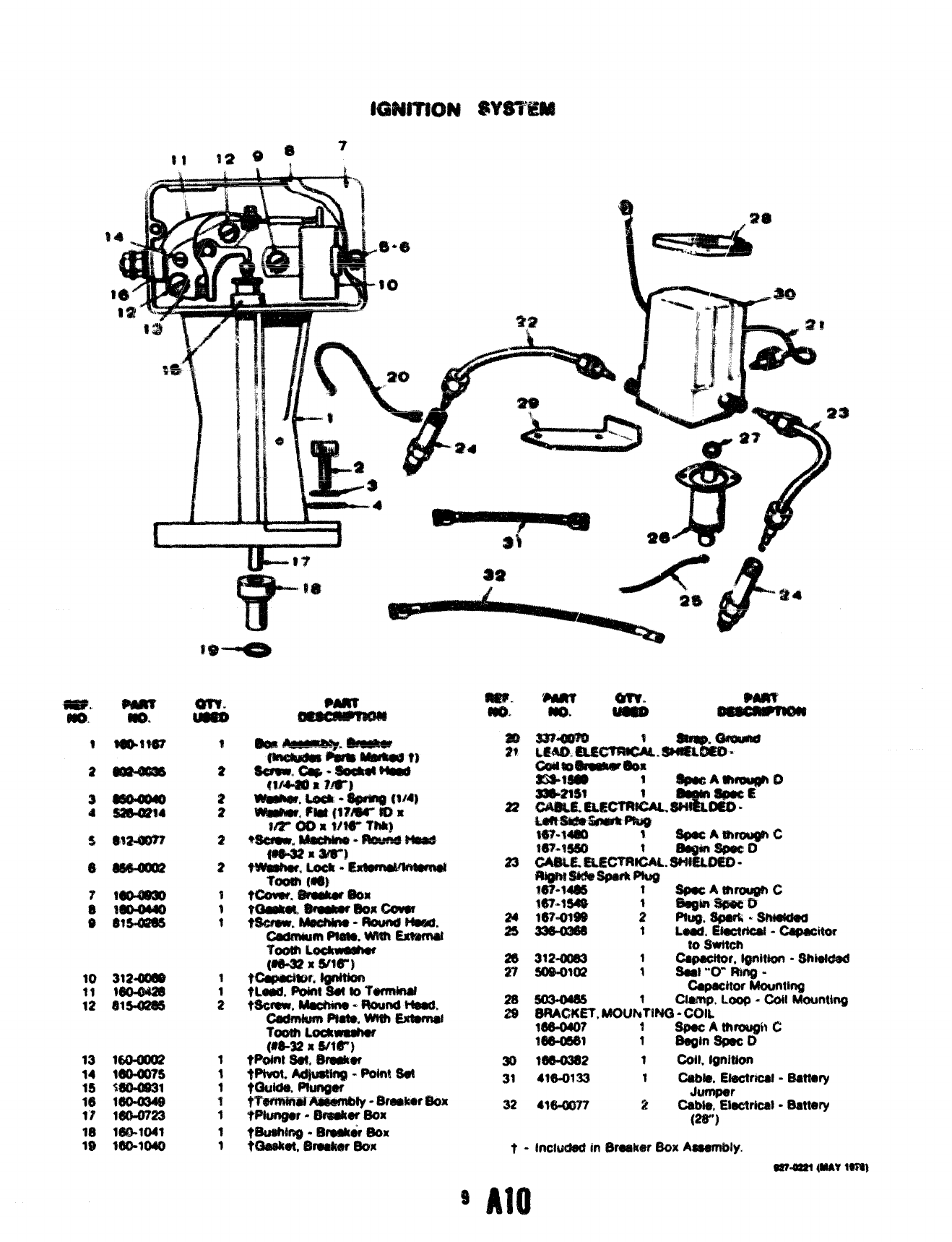
16uaJo2
W)ulrs
Wo41$31
160-U34$
160-0723
lW-l(M1
WO-1OW
(28-)
t - Inchwfed in Breaker Box Assembly.
m-oal (MAYtern)
9No
*L%?
II A12
1
wwm$ ?
22 14$.UM2
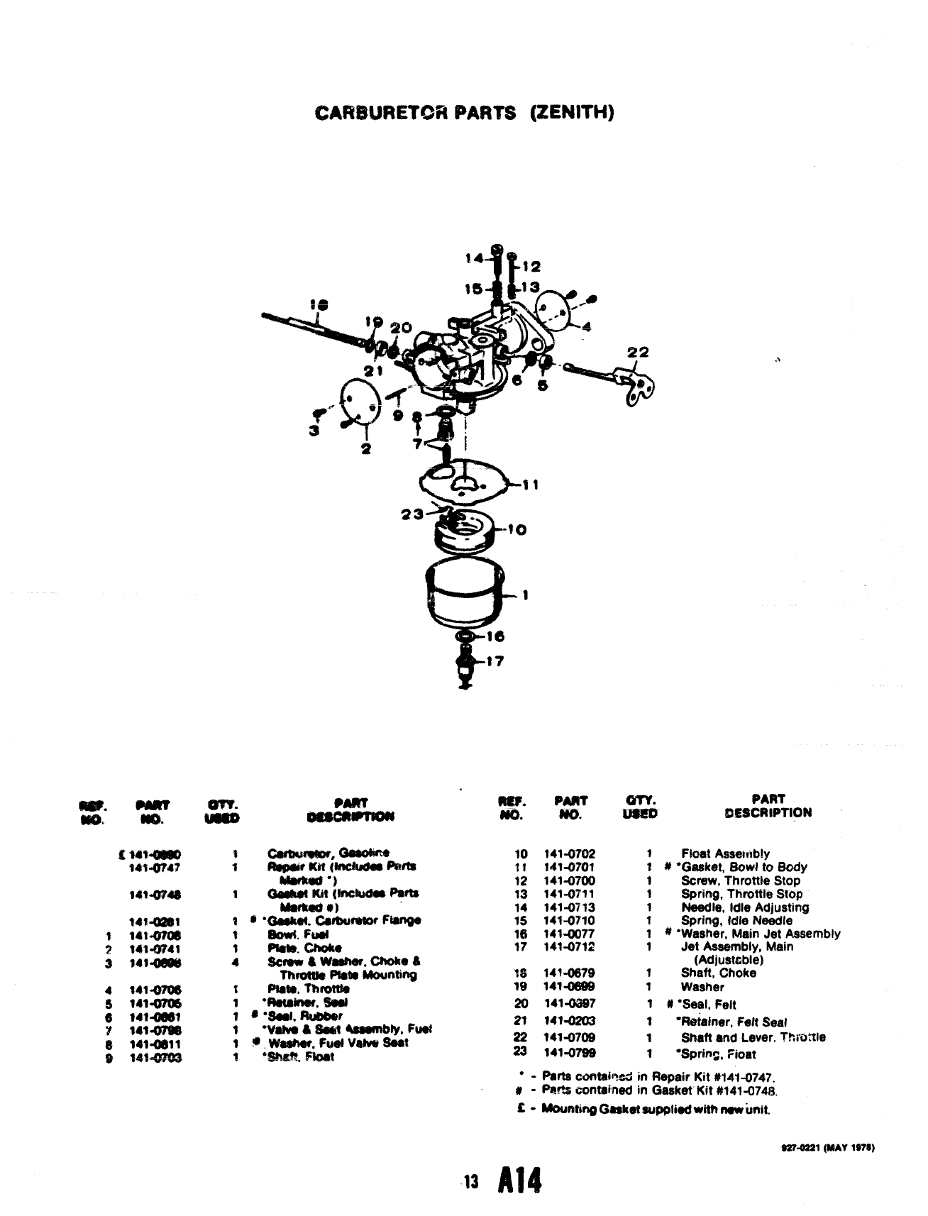
CARWRETGR PARTS [ZENITH)
.-.
MO.
10
11
12
13
14
15
16
17
PAm
m.
141-0702
141-0701
141-0700
141-(W11
141-0713
141-0710
141-0077
141-0712
147-0679
141-0ss9
1414397
$Float Asset~!b!y
1 # “Gasket, Sowl to Body
1screw, Throttle Stop
1Spring, Throttle Stop
1Needle, Idle Adjusting
1Spring, tdle Needle
1 # “Washer, Main Jet Assembly
1Jet Assembly, Main
(Adjustable}
1Shaft, Choke
1Washer
1 # ●Seal, Felt
1●Retainer, Felt Seat
1Shaft and Lever. ?!mttle
1“Spring, ?ioat
“-parts contsiI?sd in Repair Kit #14t-0747.
#- Par% ~ontained in t3asket Kit #141 -074f3,
C-MountingG8sket suppliedwittt ruwunit.
Ia Al~
S27.0S21(MAY1S78)
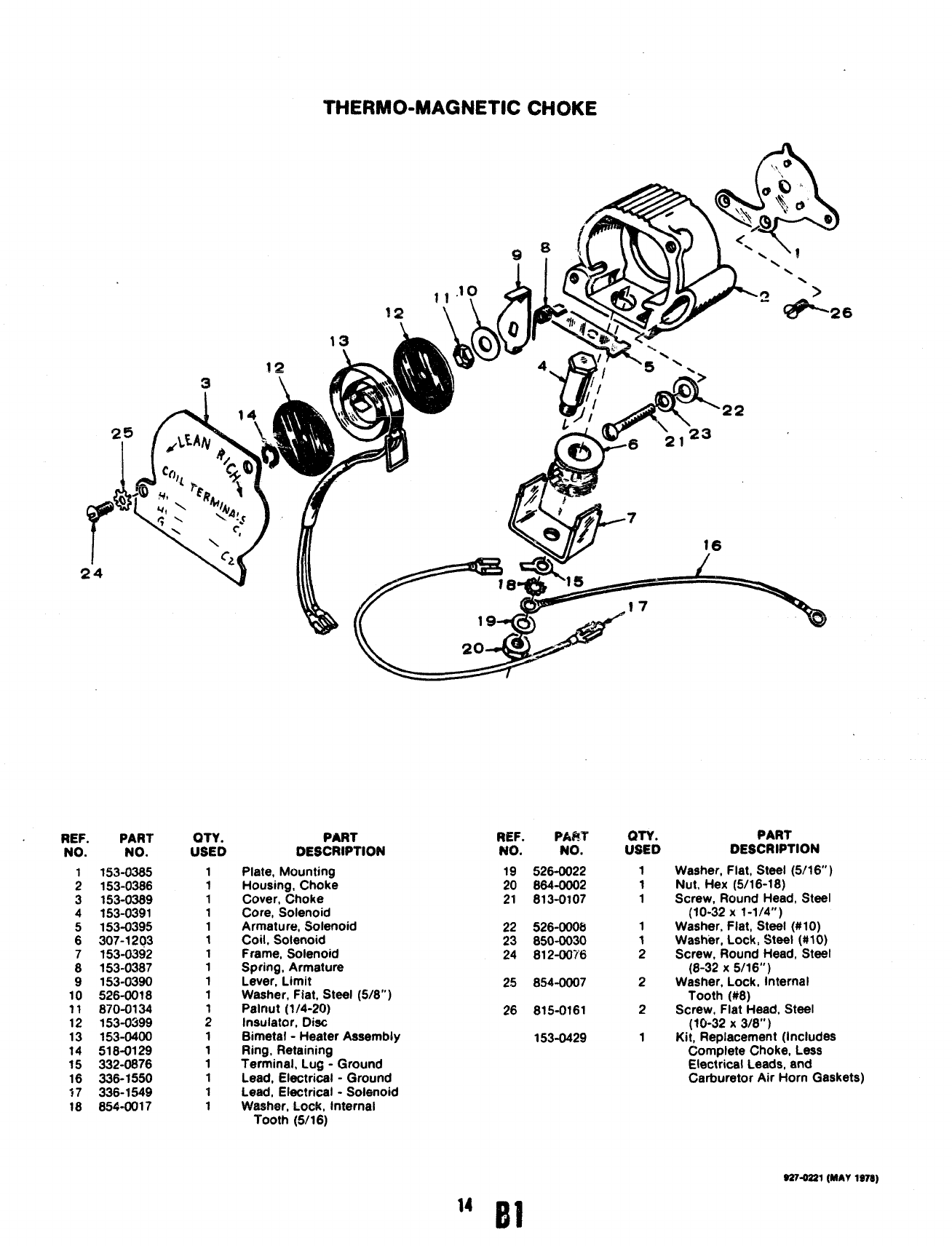
T’HEFIMO-MAGNETIC CHOKE
/+ %,
o
REF. PART
NO. NO.
1153-0385
2153-0386
3153-0389
4153-0391
5153-0395
6307-1203
7153-0392
8153-0387
9153-0390
10 526-0018
11 870-0134
12 153-0399
13 153-0400
14 518-0129
15 332-0876
16 336-1550
17 336-7549
18 854-0017
OTY.
USED
1
1
1
1
1
1
1
1
1
1
;
1
1
1
1
1
1
,l.l$) AI.Qz?
19-
PART
DESCRIPTION
Plate, Mounting
Housing, Choke
Cover, Choke
Core, Solenoid
Armature, Solenoid
Coil, Solenoid
Frame, Solenoid
Spring, Armature
Lever, Limit
Washer, Fiat, Steel (5/8’”)
Palnut (1/4-20)
Insulator, Diet
Bimetal -Heater Assembly
Ring, Retaining
Terminal, Lug -Ground
Lead, Electrical -Ground
Lead, Electrical -Solenoid
Washer, Lock, Internal
Tooth (5/16)
REF. PART
NO. NO.
19 526-0022
20 864-0002
21 813-0107
22 526-0006
23 850-0030
24 812-00?’6
25 854-0007
26 815-0161
153-0429
:SYD
1
1
1
2
2
1
PART
DESCRIPTION
Washer, Flat, Steel (5/16” )
Nut, Hex (5/16-18)
Screw, Round Head, Steel
(10-32 X1-1/4”)
Washer, Flat, Steel (#tO)
Washer, Lock, Steel (#IO)
Screw, Round Head, Steel
(8-32 X5/16”)
Washer, Lock, Internal
Tooth (#8)
Screw, Flat Head, Steel
(10-32 X3/8”)
Kit, Replacement (Includes
Complete Choke, Less
Electrical Leads, and
Carburetor Air Horn Gaskets)
927-0221(MAY1978)
14 Fll
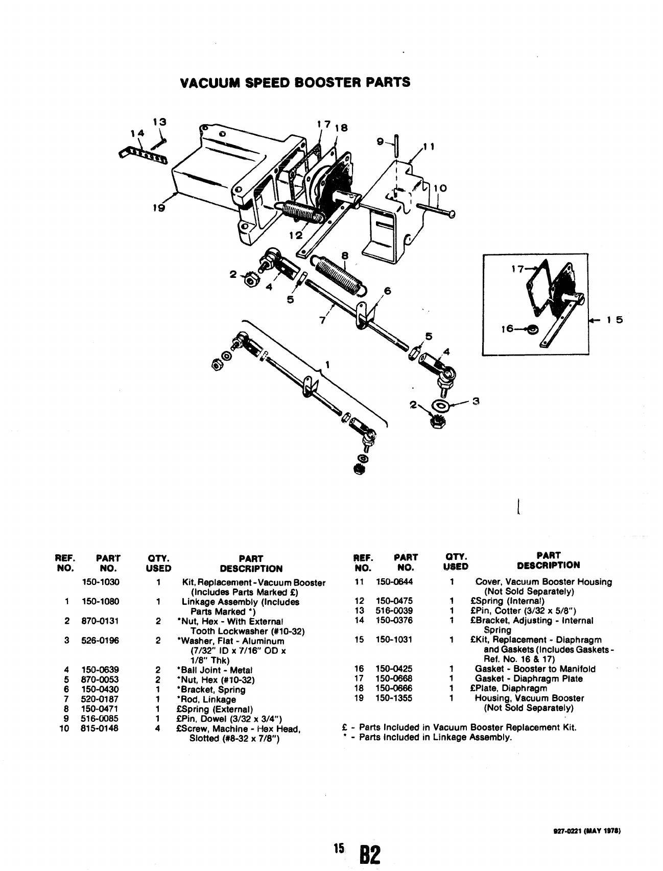
VACUUM SPEED BOOSTER PARTS
REF. PART
NO. NO.
150-1030
1150-1080
2870-0131
3526-0196
4150-0639
5$70-0053
6150-0430
7520-0187
8150-0471
9516-0085
10 815-0148
PART
:s?6 DESCRIPTION
1
1
2
2
2
2
1
1
1
1
4
Kit, Replacement -Vacuum Booster
(Includes Parts Marked f)
Linkage Assembly (Includes
Parts Marked “)
●Nut, Hex -With External
Tooth Lockwasher (#10-32)
●Washer, Flat -Aluminum
(7/32” ID X‘//16 OCI X
1/8” Thk)
“Bail Joint -Metal
●Nut, Hex (#fO-32)
●Bracket, Spring
‘Rod, Linkage
CSpring (External)
CPin, Dowel (3/32x 3/4”)
!2Screw, Machine -Hex Head,
Slotted (#8-32 X7/8”)
I17
%1
a
I●
●
$’
.-
_l
!a!EF. PART (WY. PART
NO. NO. USED DESCRIPTION
11 W&0844 1Cover, Vacuum Booster Housing
(Not Sold Separately)
12 150-0475 1fSpring (Internal)
13 !516-0039 1CPin, Cotter (3/32x 5/8”)
14 150-0376 1E13racket, Adjusting -Internal
Spring
15 150-1031 1ltKit, Replacement -Diaphragm
and Gaskets (Includes Gaskets -
Ref. No. 16& 17)
16 150-0425 1Gasket -Booster to Manifold
17 150-0868 1Gasket -Diaphragm Plate
18 150-0666 1EPlate, Diaphragm
19 150-1355 1Housing, Vacuum Booster
(Not Sold Separately)
L-Parts Included in Vacuum Booster Replacement Kit.
‘-Parts Included in Linkage Assembly.
S27-0221(MAY1978)
15
B2
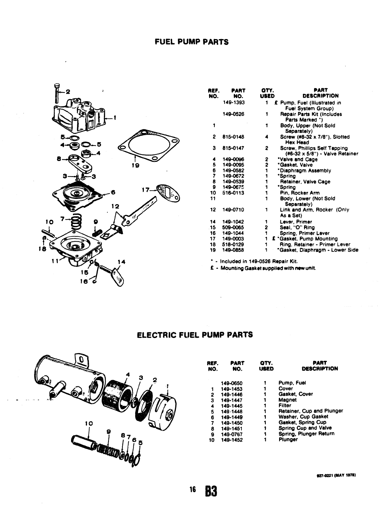
FLJELPUMP PARTS
REF. PART
NO. NO.
149-1393
?49-0526
1
2815-0148
3815-0147
4149-0096
514$-0095
6149-0582
7149-0672
8 14$0539
914$+0675
10 516-0113
11
12 149-0710
14 149-1042
15 509-0065
18 149-1044
17 149-0003
18 518-0129
19 149-0858
QTY. PART
USED DESCRIPT#ON
1.- -..
1
‘t
4
2
2
2
1
1
1
1
1
1
1
fPump, Fuel (Illustrated m
Fuel System Group)
Repair Parts Kit (Includes
Parts Marked *)
80dy, UPPW [Not Sold
Separately)
Screw (#8-32 x7/8”), Slotted
Hex Head
Straw, Phillips Self Tapping
(#6-32 x6/8”) -Valve Retainer
●Valve and Cage
*Gasket, Valve
“Diaphragm Assembly
‘Spring
Retainer, Valve Cage
“Spring
Pin, Rocker Arm
Body, Lower (Not Sold
Separately)
Link and Arm, Rocker (Only
As aS@t)
Lever, Primer
Seal, *’U Ring
SDrinm Primer Lever
:
1
1f‘G”ask6t, Pump Mounting
1Ring, Retainer -Primer Lever
1‘Gasket, Diaphragm -Lower Side
‘-Included in 149-0526 Repair Kit.
E-Moun8ing Gasket supplied with new unit.
ELECTRIC FUEL P(JWW#WRWii
REF. PART
W. NO.
1494)650
1149-1453
2149-1446
3149-1447
4149-1445
5149-1448
6149-1449
7149-1450
8149-1451
9949-0767
10 149-1452
OTY. PART
USED BEf$CRmohl
Pump, Fuel
Cover
C&eaket,Cover
Magnet
Filter
Retainer, Cup and Plunger
Washer, Cup Gasket
Ga6ket, Spring Cup
Spring Cup and Valve
Spring, Plunger Return
Plunger
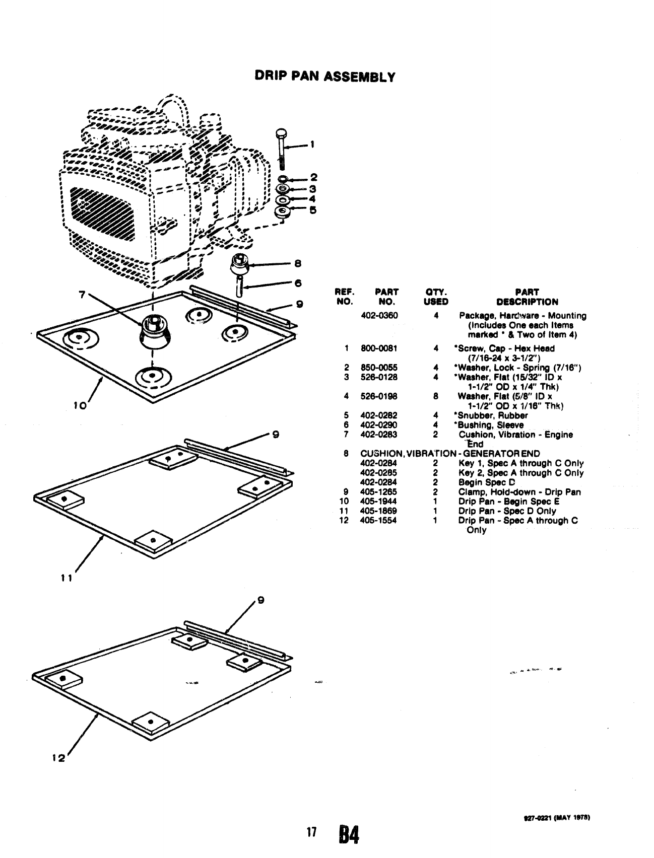
DRIP PAN ASSEMBLY
/..
REF. PART PART
NO. NO. $s:6 OE$CRtPTlON
40%03S0 4Package, Hardware -Mounting
(Includes Cme each Items
marked ●&Two of Item 4)
1SOO@Sl 4“Screw, Cap -Hex Head
(7/16-24 X3-W?)
2s504m5 4“Washer, Lock -Spring (7/16)
3526-0120 4“Waaher, Flat (1W32 ID x
1-1/2” 00X 1/4 Thk)
452S-019S 8Waeher, Fiat (W” ID x
1-1/2 00 x 1/16” Thk)
5402-02132 4‘Snubber, Rubber
6402-0290 4“Bushing, Sleeve
7402-0283 2Cus}~n, Vibration -Engine
8GUW+K31U,VIBRAtlON -GENERATOR END
402-0284 2Key 1, Spec Athrough COnly
402-0285 Key 2, Speo Athrough COnly
402-02S4 :Begin Spec C
9405-12$5 2Clamp, Hoid-down -Drip Pan
10 405-1$44 1Drip Pan -Begin Spec E
11 405-1669 1Drip Pan -$pec DOnly
12 405-1554 1Drip Pan -Spec Athrough C
Only
11
/
Q
@moa21 [MAY1978)
17 64
44
>2 --37
9274221 (MAY Wtl)
18
B5
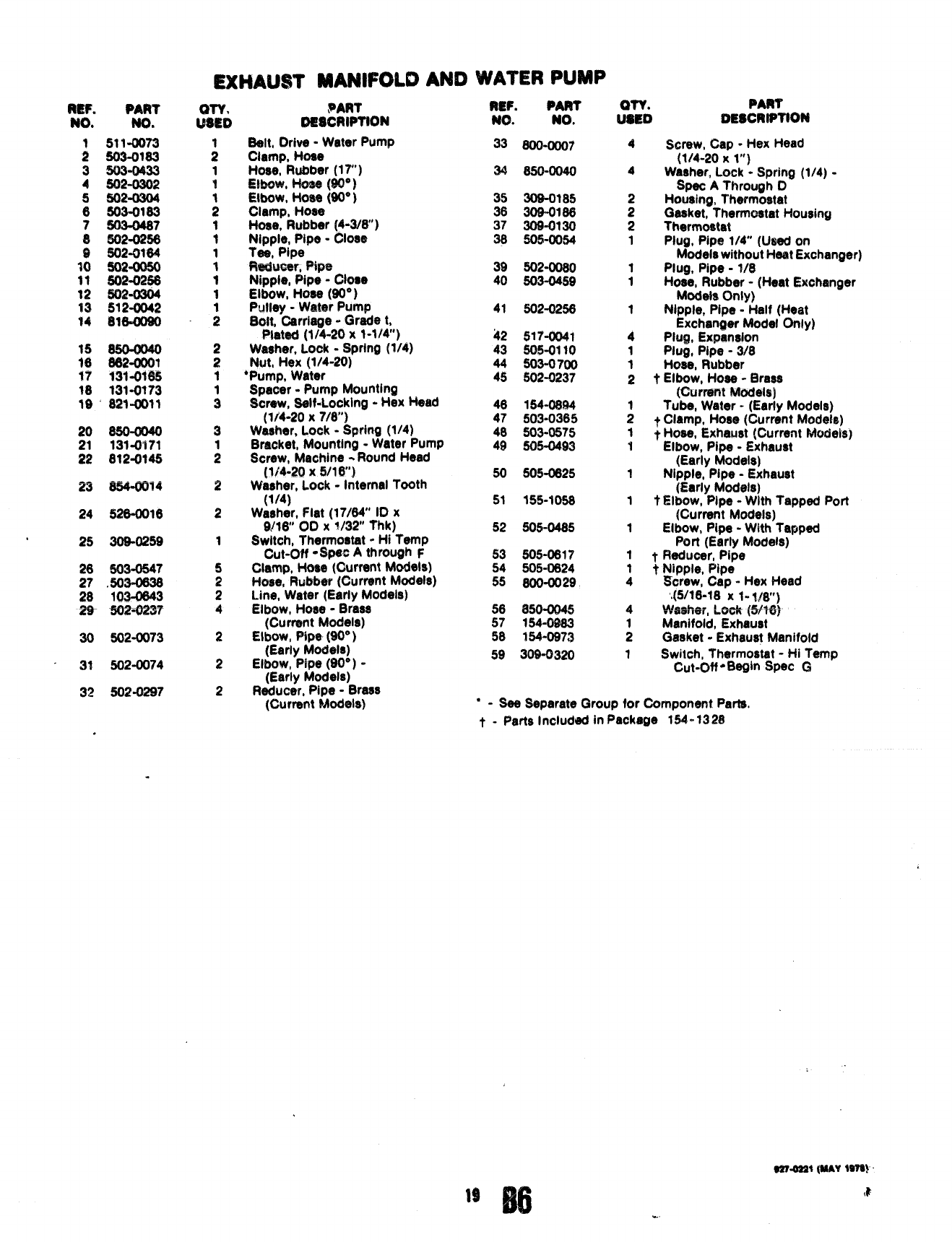
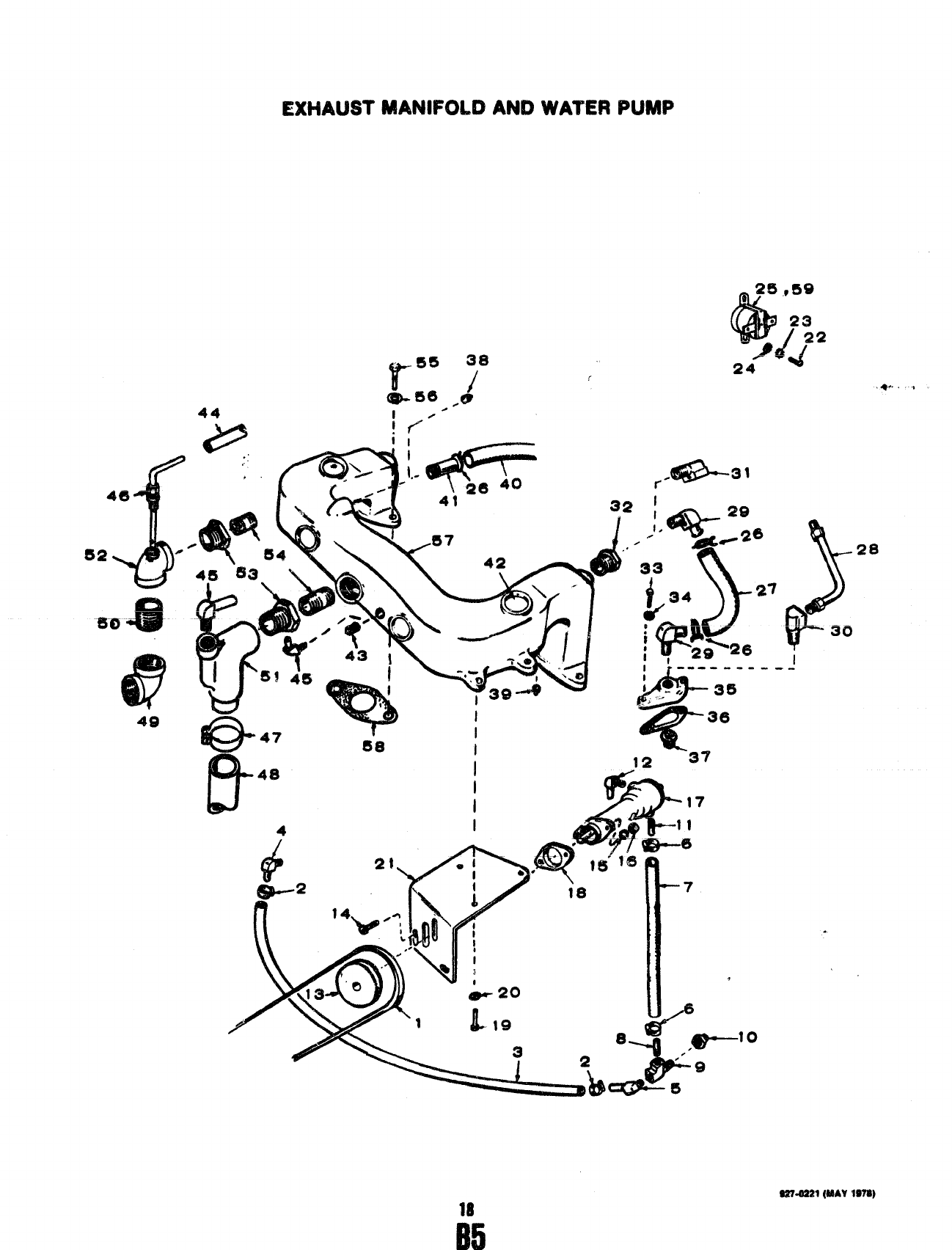
EXHAUST MANIFOLD AND WA’f’EB PUMP
24
25
30
32
.
Pm?
No.
511-0073
503-01s3
503-0433
5Q2-0302
602-0304
503-0163
603-0487
602-0256
502-0764
502-0Q50
502-025s
!502-0304
512-0042
B16-Q09Q
682-QQO1
131-0165
131-0773
821011
66Q-0040
131-0171
8?2-0145
8f54ar14
526-0016
309”0259
503-0647
.5Q3-0638
103-0843
502=0237
602-fJ073
502-0074
802-0297
PART
D2i8CRlPTtON
Belt, Drive -Water Pump
Clamp, Hose
Hose, Rubber (17(’)
E!bo%%~W*)
.-- ,.
WOW, Hose (W” )
Clamp, Hose
Hose, Rubber (4-3/S”)
Nipple, Pipe -Close
Tee, Pipe
Reducer, Pipe
Nipple, Pipe -C{ose
Elbow, Hose (90° )
Pulley -Water pump
Bolt, Carriage -Grade t,
P@tad (1/4-20x 1-1/4)
Washer, Lock -Spring (1/4)
Nut, Hex (1/4-20]
●Pump, Water
Spacer -Pump Mounting
Screw, Self-Locking -flex Head
(1/4-20 X7/8”)
WaaFrer, Lock -Spring (1/4)
Bracket, Mounting -Water Pump
Screw, Machine -Round Head
{1/’4-2Q X5/16”)
Washer, Lock -Internal Tooth
(1/4)
Waaher, Flat (17/64” 10 x
9[18” 00 X?/32 Thk)
Switch, Thermostat -Hi Temp
Cut-off ‘$P6c Athrough F
clamp, Hose (CWrrent Models)
Hose, Rubber (Current Models)
Line, Water (Eariy Models)
Elbow, Hose -Brass
(Current Models)
Elbow, Pipe {90’ )
(Early Models)
Elbow, Pipe (SO”) -
(Early Models)
Reducer, Pipe -Brass
(Current Models)
WF. PART
?40. NO.
33 6QQ-QQQ7
34 850-0Q40
35 309-0185
36 309-018$
37 309-0130
38 505-0054
30 502-0080
40 503-0459
41 502-0256
42 517-0041
43 50s”0110
44 503-0700
45 602-0237
46 154-0s94
47 5Q3-03$5
48 503-0575
49 505-0493
50 5Q5-0625
51 155-1098
52 30$0485
53 505-0617
54 505-0824
55 SOO-0029
56 850-0045
57 154-0983
38 154-0973
59 30!3-0320
PART
!%;0 OESCRfPTfON
4Screw, Cap -Hex Head
(1/4-2Q Xl“)
4Washer, Lock -Spring (1/4) -
Spat AThrough D
Housing, Thermostat
:Gasket, Thermostat Housing
2Thermostat
1Plug, Pipe 1!4” (Ueed on
Models without Heat Exchanger)
1Plug, Pipe -?/8
1Hose, Rubber -(Haat Exchan$er
Models tllnly)
1Nipple, Pipe -Half (Heat
Exchanger Model Only)
4Plug, Expansion
1Plug, Pipe -3/8
1Hose, Rubber
2TElbow, Hose -L3rass
(f%rrent Models)
Tube, Water -(Early Models)
; t C!amp, Hose (Current Models)
1yHose, Exhaust (Current btocieis)
iElbow, Pipe -Exhaust
(Early Models)
tNipple, Pipe -Exhaust
(Early Models)
1tElbow, Pipe -With Tapped Port
(Current Models)
1Elbow, Pipe -With Tapped
Port (Early Models)
1tReducer, Pipe
~*Nipple, Pipe
Screw, Cap -Hex Head
.(5/16-18 x1- IIW)
4Waai7e:, LAWC(%16)
Manifold, Exhaust
:(3aeket -Exhaust Manifold
1Switch, Thermostat -Hi Temp
Cut-off -Begin Spec G
●-Sea Separate Qroup for Component Parts,
t - Parts Included in Package 154-1328
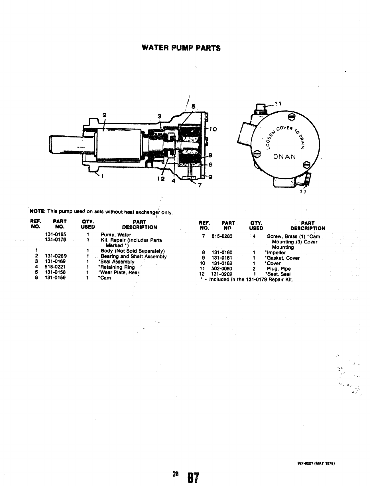
WATER PUMP PARTS
1’
‘
NOTE: This pUmP
REF. PART
NO, NO.
131-0165
MY1-al?!3
;131-0269
3131-01$9
4 5184221
5131-0158
6131-0159
used on eats without heat exchanqf only.
PART
f%k Of!$CRIPTl@N
1
f
1
1
1
1
Pump, VW&l?
Kit, Repair (Includes Parts
Marked ●)
Body (Not Sold Separately)
Bearing and Shaft Assembly
‘Seal A#sembly , .
“Retaining Ring ‘
“Wear Plate, Req
●cam
REF. PART QTY. PART
NO. NO USED DESCRIPTION
7815-0283 4Screw, Brass (1) ●Cam
Mouhtirm c31Cover
-.—,
Mounting
8131-0160 ‘impeller
9131-0161 i“Gasket, Cover
10 131-0162 *Cover
11 f302-oo60 $Plug, Pipe
12 131-0202 1“Seat, Seal
*-Included in the 131-0179 Repair Kit.
“,.
1, ,“,
. .,
.4”.
9S7.0SS1 (WAY 197S)
20
B7
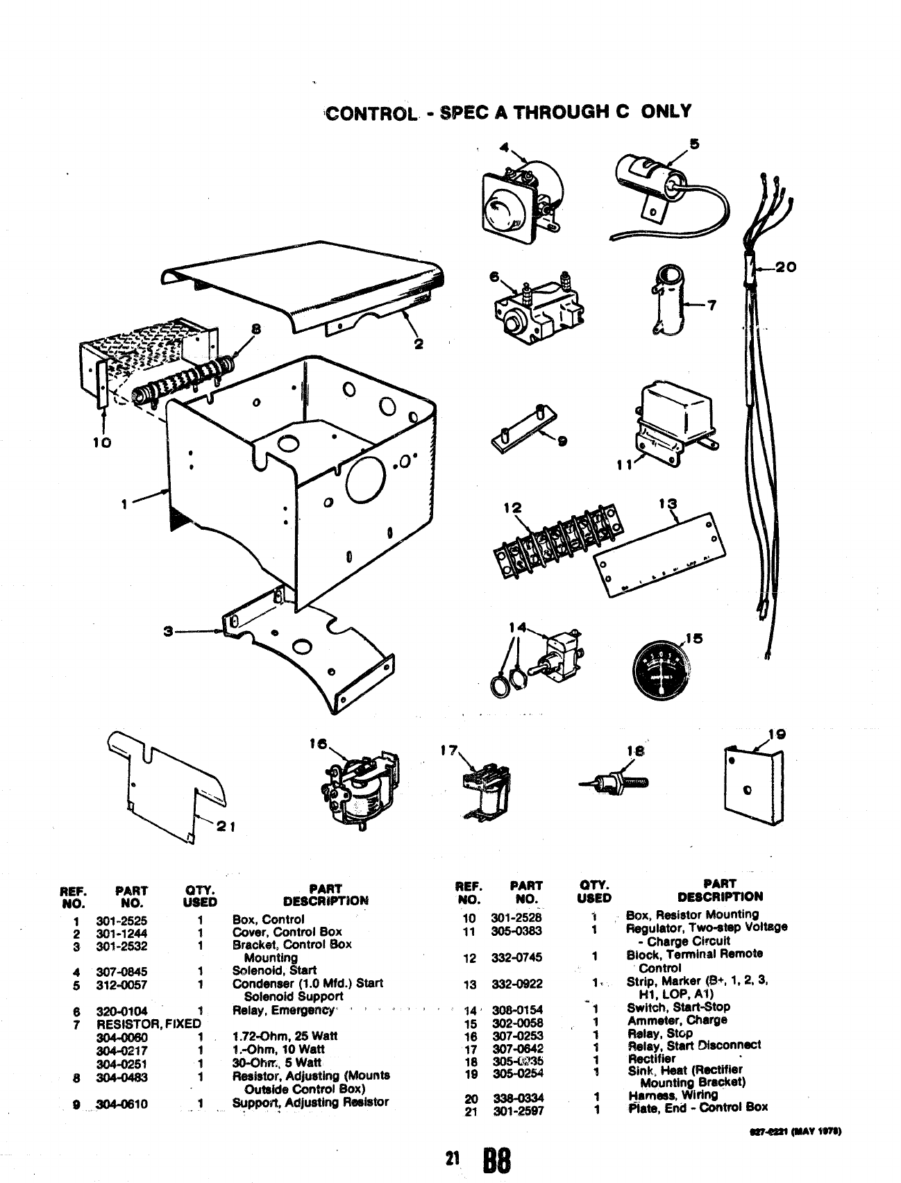
ICXINT’FNX -SPEC ATHROUGH CONLY
y’g. P&t
..$!i!Sib
1301-2525 1
2301-1244 1
3301-2532 1
4307-0645 1
5312-0057 1
6WO-0%04
7RESl$TOR, FIXE~ 1
304-0217 t
304-0259 1
$304-04s3 1
Box, Control
Cover, Control Box
Eiraek@, Control Box
Mounting
Solenoid, start
Condenaar (1.0 Mfd.) Start
Solenoid Support
Relay, Emeqenq: ‘ I ‘ ‘
1.72-Ohm, 26 Watt
!.-Ohm, 10 Watt
30-Oilrr., 5watt
Resistor, Adjusting (Mounts
Outside Controi Box)
Suppo?t, Adjusting Fteai’ator
.
s
—
%
o
14
($j&B
5
,. .
17 f&
4
~EFo PART
No. No.
10 301-252i
11 305-0363
12 332-0745
13 332-0922
14’ 308-0154
15 302-0056
16 307-0253
17 S07-0642
16 305%?35
19 305-0254
20336-03M
21 301-2597
:SYD
1
1
1
1.
19
0“
e
o
PART
DESCRIPTION
BOx, Resistor Mounting
Regulator, Two-at@ Voltage
-Charge Circuit
Biock, Terminai Remote
Control
St;? ~~me~:~t 1.2,31
Switih, S&rt-6top
Ammeter, Cherge
Relay, stop
~t~i~tart Dieconnact
Sink, Heat (Hactifier
Mounting Brecket)
Hvl’laes, wi~w
Plate, End -Controi *X
w-em (NAYW7a)
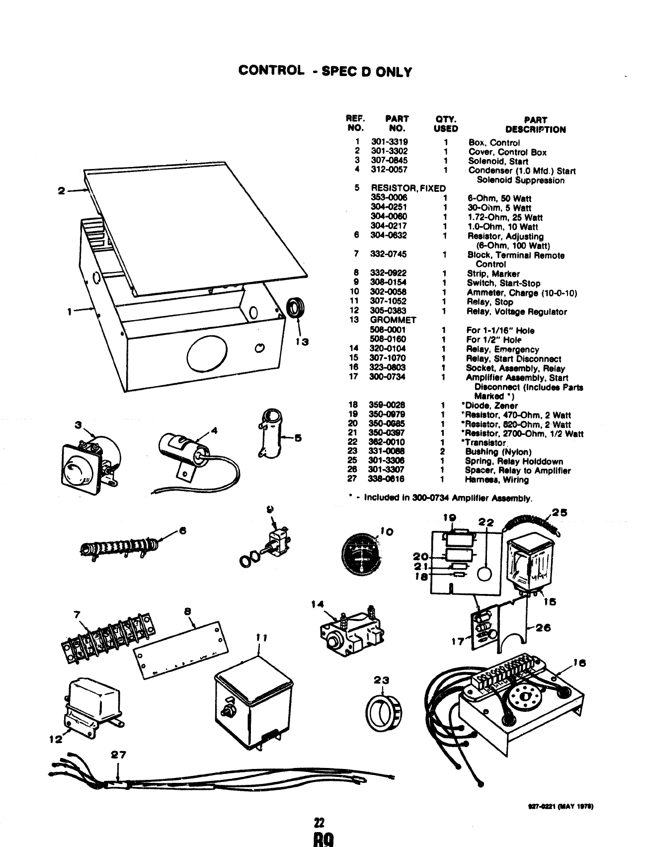
CONTROL IDSPEC DONLY
REF. PART
NO. No. ?SYD
1301-3319 1
2301-3302 1
3307-0645 i
4312-0057 1
\
.
$2--A \5RESISTOR, FIXED
\383-0006
304-0251
\
\
304-0060
304-0217
6304-0632
7332-0745
e
:
10
11
12
13
14
15
16
17
332-0822
306-0154
302-0058
307-1052
GROMMET
508-txxtl
506”0160
320-0104
307-1070
300-0734
18 359-0028
19 360-0879
%=
22 362-UNO
23 331=U188
25 301-3306
26 301-3307
27 336-0618
1
1
1
1
1
1
1
1
1
1
1
1
1
1
1
1
1
1
1
1
1
i
1
1
1
PART
DESCnlPTION
BOX, Control
f,%ver, Oontrol Box
Solenoid, Start
Condenser (1.0 Mfd.) Start
SOIenoid $uppres$ion
f3-Ohm, 50 Watt
3t?-Ohm, 5Watt
1.72-Ohm, 25 Watt
1.O-Ohm, 10 Watt
Reeistor, Adjusting
(6-Ohm, 100 Watt)
Block, Terminal Remote
Control
Strip, Marker
Switch, Start-Stop
Ammeter, Charge (10-0-10)
Relay, stop
Relay, Voltage Regulator
For 1-1/16” Hole
For 1/2” Hole
Relay, Emergency
Relay, Start Disconnect
Socket, Aaaembly, Relay
Amplifier Aaaembly, Start
Dieoonneot (Includes Pmta
Marked ‘)
“Diode, Zener
“Reelstor, 470-Ohm, 2Watt
●m-k4.. n—- nw..
-Dulwr ,wv-sJrWrl, cWUII
“Resistor, 2700-Ohm, 1/2 Watt
“Trenaistor.
Suahing (Nylon)
Spring, Relay Holddown
Spacer, Relay to Amplifier
Hememk Wiring
●-included in 300-0734 Amplifier AaaerrWy.
o
25
23
(@!)
em-em @a&vwa)
22
M
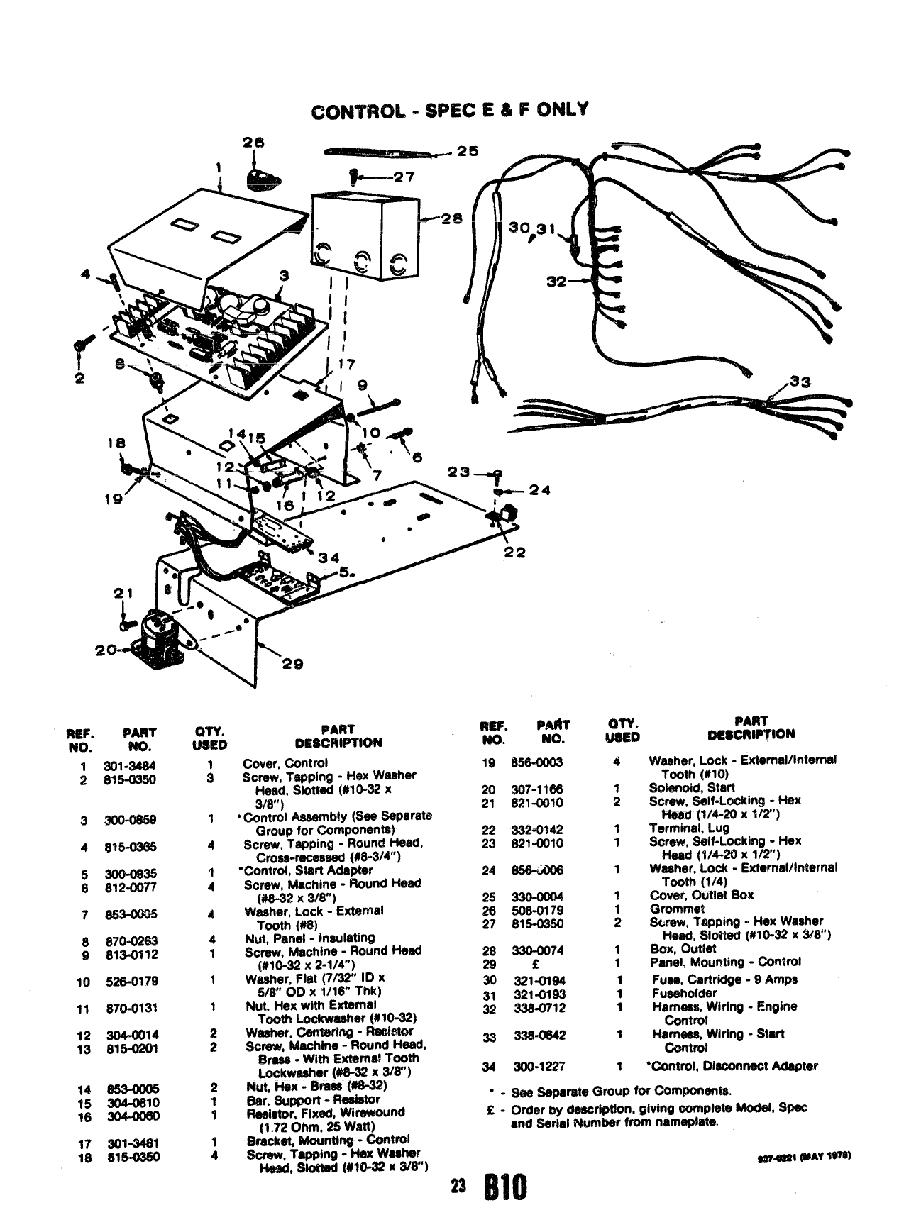
CONTROL-SPEC E&F0NL%
--
1
/
&a
S3- ●.“ ‘%
e
:$?6
4
;
1
1
1
$
;
1
1
1
1
1
1
1
REF. PMIT
NO. NO.
19 858-0003
20 307-1188
21 821-0010
22 3324?42
23 821-0010
24 ~
25 33GOO04
28 $08-0179
27 815-0350
28 330=0074
29E
30 321-0194
31 321-0193
32 338-0712
33 338*2
34 300.1227
PART
ff’$lk DESCYWTION
REF. PAFIT
NO. NO.
1301-3484
2815-0350
. ... .
m!s6Rl~10N
Washer, Lock -Externsd/internal
Tooth (#10)
SOianoki, Start
Scxew, Self-Locking -Hex
Head [1/4-20 x?/2)
Terminal, Lug
Screw, Self-Locking -Hex
Head (1/4-20 X112”)
Washer, Lock -External/Internal
Tooth (1/4)
Oover, Outlet Box
Grommet
Screw, Tapping -Hex Washer
Head, SIottad (#10-32X WW)
Box, Outlet
Panel, Mounting -Control
Fuss, Cartridge -9 Amps
Fuaehoider
Harness, Wiring -Engine
Control
Harness, Wiring -Start
Control
Wontrol, Diaoorrnect Adapter
Cover, Control
Screw, Tapping -Hex Wttaher
Head, Slotted (#l 0-32 x
3/8”)
●Control Assembly (See Separate
Group for Components)
Screw, Tspping -Round Head,
(hOSS-rOCOS@Sd(#8-3/4”)
“Control, Start Adapter
Screw, Machine -Round Head
(#8-32 x3/8”)
Washer, Lock -External
Tooth (#8)
Nut, Panel -Insulating
Screw, Machine -Round Head
(#10-32 X2-1/4”)
Washer, Flat (7/32” ID x
5/8” OD X1/18” Thk]
Nut, Hex with External
Tooth Lockwaahtw (#10-32)
Washer, Centering -Redstor
Screw, Machine -Round Head,
Bmas -With Extem@ Tooth
Lockwasher (#8-32x 3/8”)
Nut, Hax -Brace (#8-32)
Bar, Support -Reeistor
Resistor, Fixed, Wirawound
(1.72 Ohm, 25 Watt)
@%Wke4 Mounting-Centroi
Screw,
Tapping -Hex Weeher
Hesd, slotted (#10-32x 3/8”)
3300-0859
815-0365
4
300-0935
812-0077
853-0005
7
870-0283
813-0112
8
9
10 528-0179
11 870-0131
304-0014
815-0201
12
13
14 853-UI05
15 304-0810
16 3040080
●-aSeparate Group for Oomponanta.
C-Order by dmscriptiorh giving comptete Model, SW
arid Serial Number from namep!ate.
~~ (WAY$W$l
17 301-34s1
18 815+380
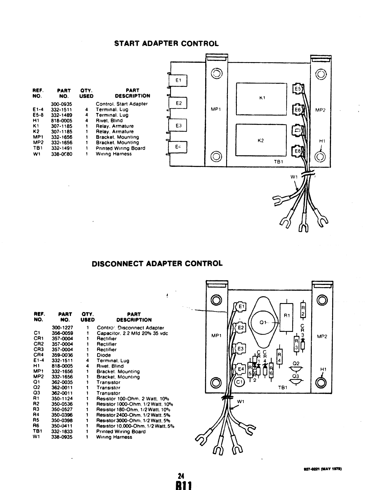
S?’AFITAOAPTER CONTROL
REF.
No.
El-4
E5-8
HI
K1
K2
MP1
MFW
TB?
WI
al
CR2
CR3
CR4
EI-4
HI
MP1
MP2
Q?
02
03
R?
W?
Ft3
FM
R5
R6
Tf31
w!
PART
NO.
300-0935
332-1511
332-1489
818-0005
307-1185
30?”1185
332-1656
332-1656
332-749%
338-0C80
PART
NO.
300-1227
356-0059
357-0004
357-0004
357-0004
359-0036
332-1511
818-0Q05
332-1656
332-1656
362-0035
362-0011
3624011
350-1124
350-0536
350-0527
350-0396
350-03$6
350-04$1
332-1833
338-0935
OTY. PART
USED DESCRIPTION
4
4
4
1
1
1
1
?
1
Control. Start Adapter
“f’ermmal. LuQ
Termmal. Lug
Rwet. E31mcf
Relay. Armaiure
Relay. Armature
Bracket, fdountmg
f3rack@, Mounting
f%ntedWlrmg Board
Wlrmg Harness
El J
E2
E3 I
Ed I
DISCONNECT ADAPTER
c)
L
MPI
o
CONTROL
o--
OTY! PART
IJSEO DE$CRPVWN
-1 Contrcr: !3mconnect Adaptcrr
1Capacitor. 2,2 fvtfd20’7035 vdc
1Rectifier
1F%clifier
1Rectifier
1Diode
4Termmal. Lug
4Rivet, Blind
1Bracket. Mounting
1Bracket. Mounimg
1Transmtor
1Tranwstor
1Trmwwstor
1Resistor 100-Ohm. 2W$tt, 10%
1Resmtor 1000-Ohm. 1/2 Watt. 10%
1Resmtor 180-Ohm, 1}2 Watt. lo%
1Resistor 2400-Ohm, 1/2 Watt. 5%
1Resmtor3000-Ofwn, 1/2 Watt, 5%
1Res!stor 10,000-Ohm. 1/2 Watt. 5°1$
?Pririted Wtring Board
1Wmq Harness
KI
f- TBI ‘
m’W1
—
—
,
#
I
o
MP2
HI
(5
o
24
El 1
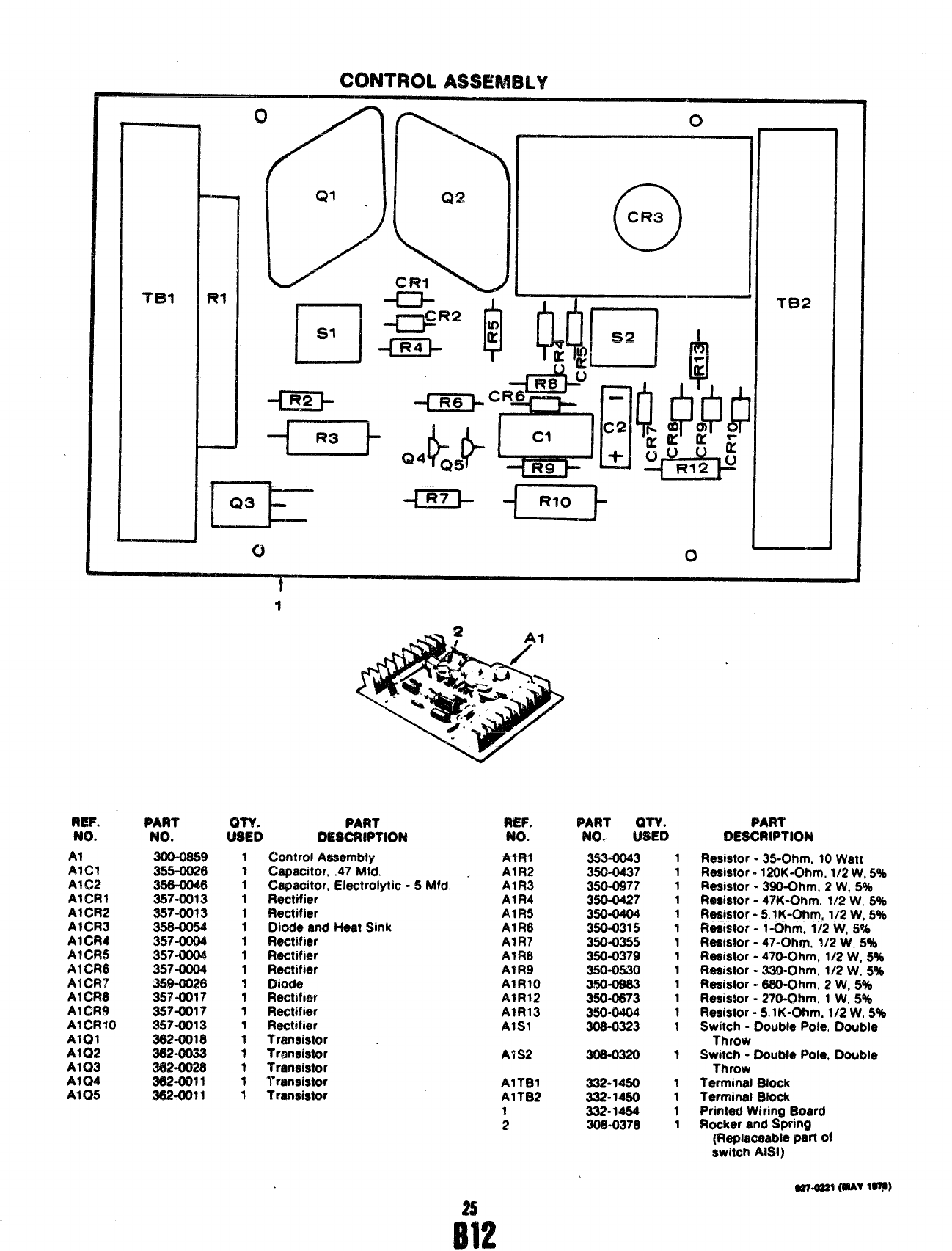
CONTROL ASSEMBLY
Tel
3
-“IQ5! --m
REF.
NO.
Al
AICI
AIG2
AICR1
AICR2
A+CR3
AICR4
AICR5
A1CR6
AICR7
A1CR8
A1CR9
A1CR40
AIQ1
A1Q2
A1Q3
A1Q4
AIQ5
PART
NO.
3004)859
355-0026
358-0046
357-0013
357-0013
358-0054
357-0004
357-0004
357-0004
35$-0028
357”0017
357-0017
357-0013
382+018
382-0033
3$%%0028
3s2-0011
362-(M11
1’
PART
$;9 DESCRIPTION
1Control Assembly
1Capacitor, .47 Mfd.
1Capacitor, Electrolytic -5 Mfct. “
1Rectifier
1Rectifier
1Diode and Heat Sink
1Rectifier
1Rectifier
1Rectifier
1Diode
1Rectifier
1Rectifier
1Rectifier
1Transistor
1Transistor
tTransistor
1I“rtwwistor
1Transistor
REF.
A?R1
A1R2
A1R3
A1R4
AIR5
A1R8
A1R7
A1R8
AIR9
AIRIO
A1R12
AIR13
AISI
Al S2
AITB1
A1TB2
1
2
PART OTY. PART
NO-USED DESCRIPTION
353-0043
350-0437
350-0977
350-0427
350-0404
350”0315
350-0355
350-0379
350-0530
3S0-0983
350-0873
350-0404
308-0323
308-0320
332-1450
332-1450
332-1454
308-0378
1
1
1
1
1
1
1
1
1
1
1
1
1
1
1
1
1
1
Resistor -35-Clhm, 10 Watt
Resistor -120K-Ohm, 1/2 W, 5%
Resistor -390-Ohm, 2W, 5%
Resistor -47K-Ohm, 1/2 W, 5%
Resistor -5. lK-Ohm, 1/2 W, 5%
Resistor -1 -Qhrn, 1/2 W, !3%
Resistor -47-Ohm, 1/2 W. 5%
Resistor -470-Ohm, 1/2 W, 5%
Resistor -330-Ohm, 1/2 W, 5%
Resistor -880-Ohm, 2W, 5%
Resistor -27t)-Ohm, 1W, 5%
Resistor -5. lK-Ohm, 1/2 W, 5%
Switch -Double Pole, Double
Throw
Switch -Double Pole, Double
Throw
Terminal Block
Terminal Block
Printed Wiring Board
Rocker and Spring
(Replaceable part of
switch AISI)
$9?.6?21 fwv lam
25
B12
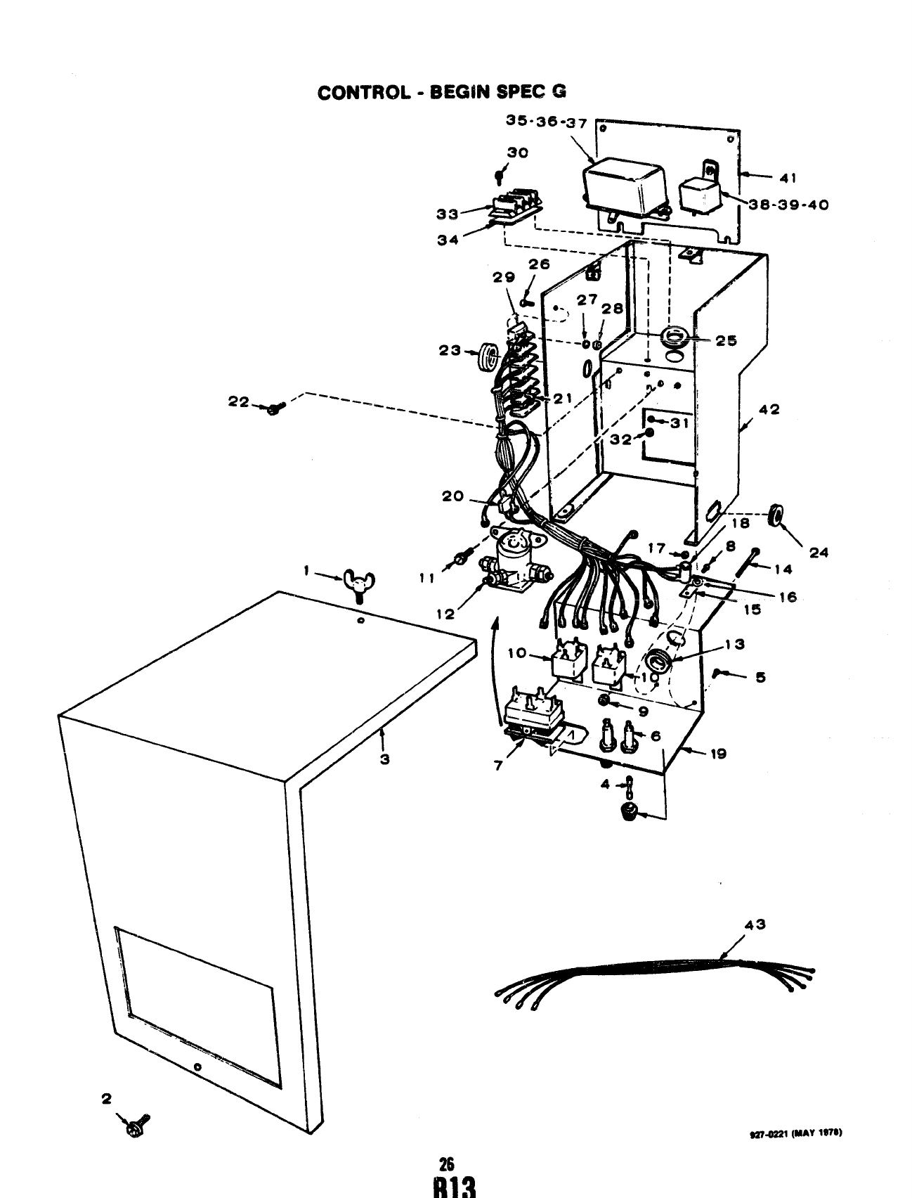
ICONTROL -BEGiN $PEC G
/
//
,///
--’-7//
\3
2
w
“11~1
4+ 1
&.1
40
24
26
m
CONTROL
REF. PART
..-
mu. No.
1518-0056
2821-0004
3301-4694
4&9~.~~ 74
5821-0004
6321-0175
7308-0383
8821-0004
9870-0131
10 307-1575
11 821-0008
12 307-1617
13 331-0088
14 812-0087
15 304-0580
16 508-0015
17 870-0221
18 352-0161
19 301-4442
20 357-0030
21 332-1043
22 821-0008
23 508-0195
24 508-0021
25 331-0102
26 812-0081
27 854-0007
28 860-0008
29 332-0899
30 812-0082
31 853-0005
32 860-0008
33 332-0236
34 332-2117
35 821-0004
36 870-0131
37 305-0383
38 821-0004
39 870-0131
40 307-1632
41 301-4441
42 301-4634
43 338-1099
-13ECWUt3PEC G
ifsli!)
1
1
1
2
4
2
:
2
2
2
1
1
1
1
1
1
1
1
1
2
2
1
1
;
2
2
;
2
2
1
;
2
1
1
1
1
1
1
1
27
PART ‘
DESCRIPTION
Screw, Wing (#10-32 x1/2)
Screw, Self-locking -Hex
Washer Head (#10-32 x5/16”)
Cover, Control Box
Fuse, Cartridge -5 Ampere
Screw, Self-locking -Hex
Washer Head (#10-32 x5/16)
Fuseholder
Switch, Toggle -Start/Stop
Screw, Self-locking -Hex
Washer Head (#10-32 x5/!6”)
Nut, Hex -With External
Tooth Lockwasher (#10-32)
Relay
Screw, Self-locking -Hex
Washer Head (1/4-20 x5/16)
Solenoid
Insulator, Bushing
Screw, Machine -Round Head
(#8-32 X1-1/2)
Insulator, Mounting
Insulator, Washer
Nut, Hex -With External
Tooth Lockwasher (#8-32)
Resistor, Fixed, Wirewound
(100-Ohm, 5Watt)
Panel, Control
Diode, Rectifier
Jumper, Terminal
Screw, Self-locking -Hex
Washer Head (1/4-20 x5/16)
Insulator, Bushing
Grommet, Rubber
Insulator, Bushing
Screw, Machine -Round Head
(#8-32 X5/8)
Washer, Lock -httemal
Tooth (#8)
Nut, Hex (#8-32)
Terminal Block
Screw, Machine -Round Head
(#8-32 X3/4)
Washer, Lock -External
Tooth Lockwasher (#8)
Nut, Hex (#8-32)
Terminzit mock
Marker Strip
Screw, Self-locking -Hex
Washer Head (#10-32 x5/16)
Nut, Hex -With External
Tooth Lockwasher (#10-32)
Regulator, Voltage
Screw, Self-locking -Hex
Washer Head (#10-32 x5/16”)
Nut, Hex -With External
Tooth Lockwasher (#10-32)
Relay
Plate, Mounting -Relay
and Regulator
Box, Control
Harness, Wiring -Remote
Control
WGOZ!l(MAY1970
fllA
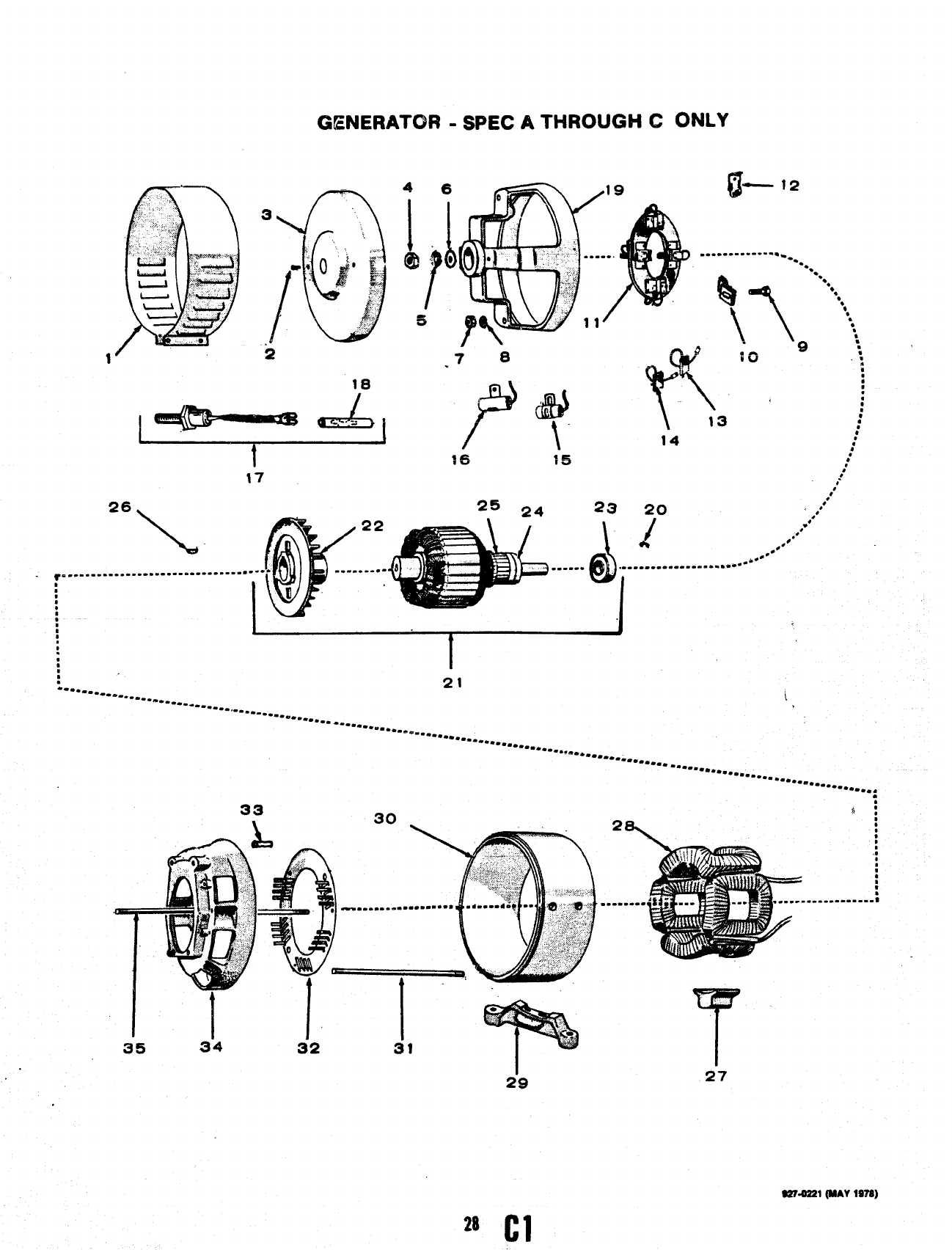
GENERATOR -SPEC ATHROUGH CONLY
2
18
.-
26 ,.-
\
20 ‘.“
/
,,
.*
*,4,“’
~=.......- .....-.. -.-.” -.- .....-.
●**
-a+.
●
.................*-
,
,
*
*
:
a
[
1
,
,
.
*
a
●
:21
---. --.--e -.--- .*-- i
‘--------- ,
‘-- *------ “-=--...*. “.--- .--.-==.*.....-.*....-.-.--....-..*.*
-*---- --.0. -.. -. ‘-”** ..........●
-.*-- .==.. *----- .
.
2“9
i
$:
2,
*
*
*
1
,:
*
:
*
m
v
s
s
..-. . . . . . . . . . ..-
T
27
S274221
(MAV 1978)
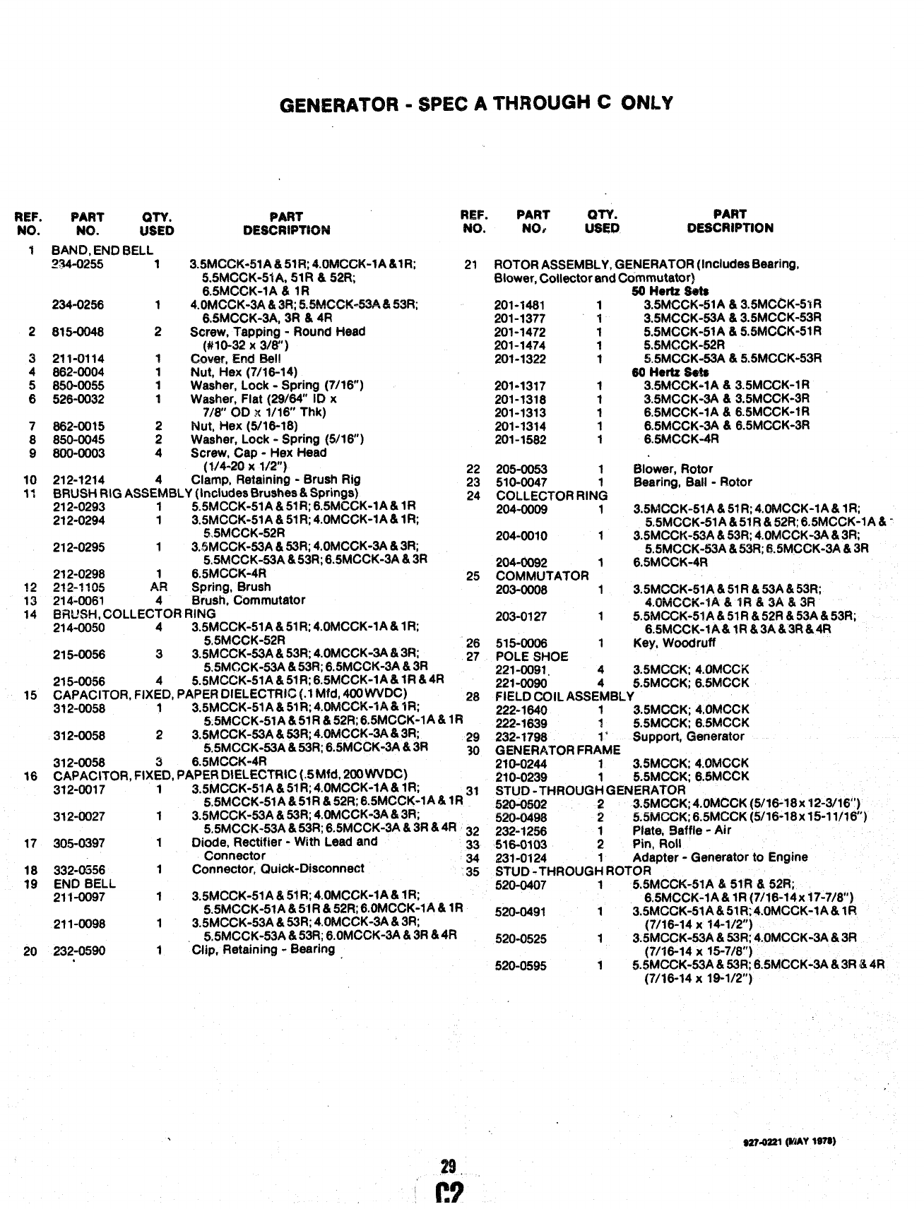
GENERATOR -SPEC ATHROUGH C0NL%
REF.
NO.
1
2
3
4
5
6
7
8
9
10
11
15
16
PART QTY. PAR?
Ma. mm DESCRW7K3N
BAND, END BELL
~~.Q235 13.5MCCK-51A &51Ft; 4.0h#03K-lA &lR;
5.5MCCK-51A, 51R &52R;
6,5MCCK-lA &IR
234-0256 14.OMCCK-3A &3Ra~~~~~U=*A &53R;
,“.”.., -”.. —
6.5MCCK-3A, 3R &4R
815-0048 2Screw, Tapping -Round Head
(#10-32 X3/8”)
211-0114 ~C~~er, Snd ~l!
862-0004 1Nut, Hex (7/16-14)
850-0055 1Washer, Lock -Spring (7/16”)
526-0032 1Washer, Flat (29/64” ID x
7/8” OD x1/16” Thk)
862-0015 Nut, Hex (5/16-18)
850-0045 :Washer, Lock -Spring (5/16”)
800-0003 4Screw, Cap -Hex Head
(W4-20 x1~2”}
212-1214 4Clamp, Retaining -Brush Rig
BRUSH RIG ASSEMBLY (Includes Brushes &Springs)
212-0293 15.5MCCK-51 A & 51R;6.5MCCK-lA &1R
212-0294 13.5MCCK-51A &51R; 4.OMCCK-lA &IR;
%5MCCK-52R
212-0295 13.6MCCK-53A &53R; 4.OMCCK-3A &3R;
5.5MCCK-53A &53R; 6.5MCCK-3A &3R
212-0298 16.5MCCK-4R
9*9.1 *IIK ~~
-,.. ,,”” Spring, t3rush
214-0061 4Brush, Commutator
BRUSH, COLLECTOR RING
214-0050 43.5MCCK-51A &51R;4.OMCCK-lA &1R;
5.5MCCK-52R
REF. PART QTY. PART
215-0056 33.5MCCK-53A& 53R; 4.OMCCK-3A &3R;
5.5MGCK-53A &53R: 6.5MCCK-3A lk3R
215-0056 45.5MCCK-51A &51 R;6.5MCCK-lA& lR &4R
CAPACITOR, FIXED, PAPER DIELECTRIC (.1 Mfd, 400 WVDC)
312-0058 13.5MCCK-51A& 5ti?; 4.OMCCK-IA &tR;
5.5MCCK-51A &51R &52R; 6.!5MCCK-lA &lR
312-0058 23.5MCCK-53A &53R; 4.OMCCK-3A81 3R;
5.5MCCK-53A &53R; 6.5MCCK-3A &3R 29
30
NO. NO. USEW DESCRIPTION
21
22
23
24
25
26
27
28
312-0058 6.5MCCK-4R .-
CAPACITOR, FIX;D, PAPER DIELECTRIC (.5Mfd, 200 WW3C)
3.5MCCK-51A &51R;4.OMCCK-lA &lR; 31
5.5MCCK-51A &51R &52R: 6.5MCCK-lA &lR
312-0017
312-0027
17 305-0397
18 332-0556
19 ENCI BELL
211-0097
211-0098
20 232-0590
1
1
1
1
1
1
1
.
___
3.5MCCK-53A &53R; 4.OMCCK-3A &3R;
5.5MCCK-53A &53R; 6.5MCCK-3A &3R &4R 32
Diode, Reetifier -WNh Lead and 33
Connector
Connector, Quick-Disconnect 34
35
3.5MCCK-51A &51R; 4.OMCCK-lA &lR;
5.5MCCK-51A &5’1R & 52R; 6.OMCCK-lA &lR
3.5MCCK-53A &53R; 4.OMCCK-3A &3R;
5.5MCCK-53A &53R; 6.OMCCK-3A &3R &4R
‘Clip, Retaining -Bearing
29.
ROTOR ASSEMBLY, GENERATOR (Includes Bearing,
Blower, Collector and Commutator)
201-1481 1
201-1377 1
201-1472 1
201-1474 1
201-1322 1
201-1317 1
201-1318 1
201-1313 1
201-1314 1
201-1582 1
205-0053 1
510-0047
COLLECTOR RIN&
204-0008 1
204-0010 1
204-0092 1
COMMUTATOR
203-0008 1
203-0127 1
515-0008 1
POLE SHOE
221-0091. 4
50 Hetlz Sets
3.5MCCK-51A &3.5MCCK-51R
3.5MCCK-53A &3.5MCCK-53R
5.5MCCK-51A &5.5MCCK-51R
!L5MGCK-52R
5.5MCCK-53A &5.5MCCK-53R
68 Heriz Se@
3.5MCGK-lA &3.5MCCK-1 R
3.5MCCK-3A &3.5MCCK-3R
6.5MCCK-lA &6.5MCCK-lR
6.5MCCK-3A &6.5MCCK-3R
6.5MCCK-4R
Blower, Rotor
Bearing, Ball -Rotor
3.5MCCK-51A &51R; 4.OMCCK-IA &lR;
5.5MCCK-51A &SIR &52R; 6.5MCCK-lA &-
3.5MCCK-53A &53R; 4.OMCCK-3A &3R;
5.5MCCK-53A &53R; tl.5MCCK-3A &3R
6.5MCCK-4R
3.5MCCK-51A &51R &53A &531?;
4.OffCCK-fA aiR &3A &W?
5.5MCCK-51A &51R &52R &53A &53R;
6.5MCCK-lA& lR &3A&3R&4R
Key, Woodruff
3.5MCCK; 4.OMCCK
221-0090 5.5MCCK; 6.5MCCK
FIELD COIL ASSEfiBLY
222-1640 13.5MCCK; 4,0MCCK
222-1639 ?5.5MCCK; 6.5MCCK
232-1798 ‘Support, Generator
GENERATOR FRA’ME
210-0244 3.5MCCK; 4.OMCCK
210-0239 :5.5MCCK; 6.5MCCK
STUD -THROUGH GENERATOR
S20-0502 23.5MCCK;4.OMCCK (5/16-18x 12-3/16”)
520-0498 25.5MCCK;6.5MCCK (5/16-18x 15-1 1/16”)
232-1256 Plate, 9affle -Air
516-0103 ;Pin, Roll
231-0124 Adapter -Generator to Engine
STUD -THROUG~ ROTOR
620-0407 15.5PItCCK-51A &51R &52R;
6.5MCCK-lA &lR (7/16-14x 17-7/8”)
520-0491 13.5MCCK-51A&51f% 4.OMCCK-lA& lR
(7/16-14 X?4-1/2”)
520-0525 13.5MCCK-53A &53R; 4.OMCCK-3A &3R
(7/16-14 X15-7/8”)
520-0595 15.5MCCK-53A& 53R; 6.5MCCK-3A &3R &4R
(7/16-14 x19-1/2)
WMS21 (h’JAY1S7S)
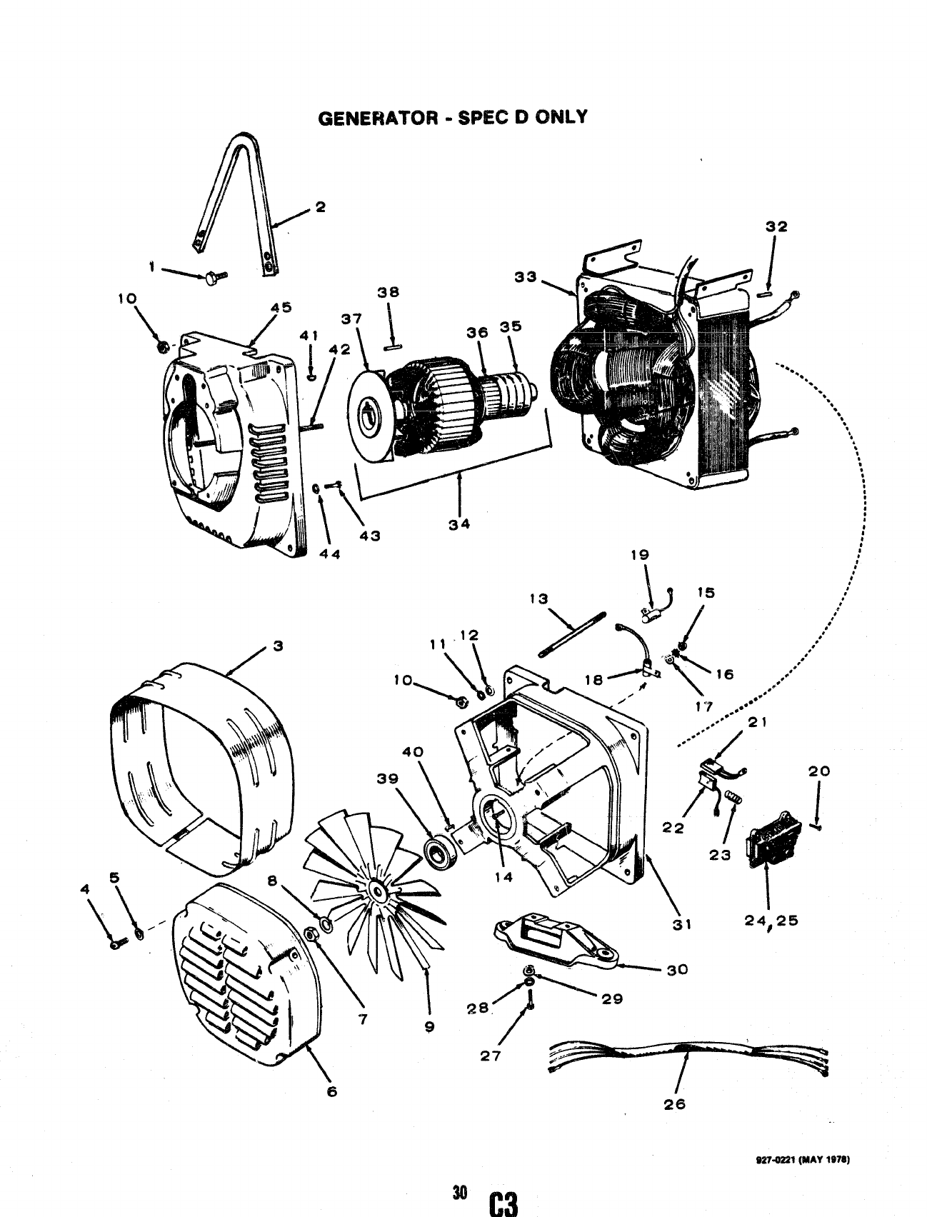
GENERATOR -SPEC DONLY
3
32
‘. ‘. ‘. ‘. 88
‘,‘,+
%
*
,,8
8
8
e
@
:
#
;
:
.
44 19 i
.#
27
,.
;’
,’
.
9274221(MAY 1$78)
30
C3
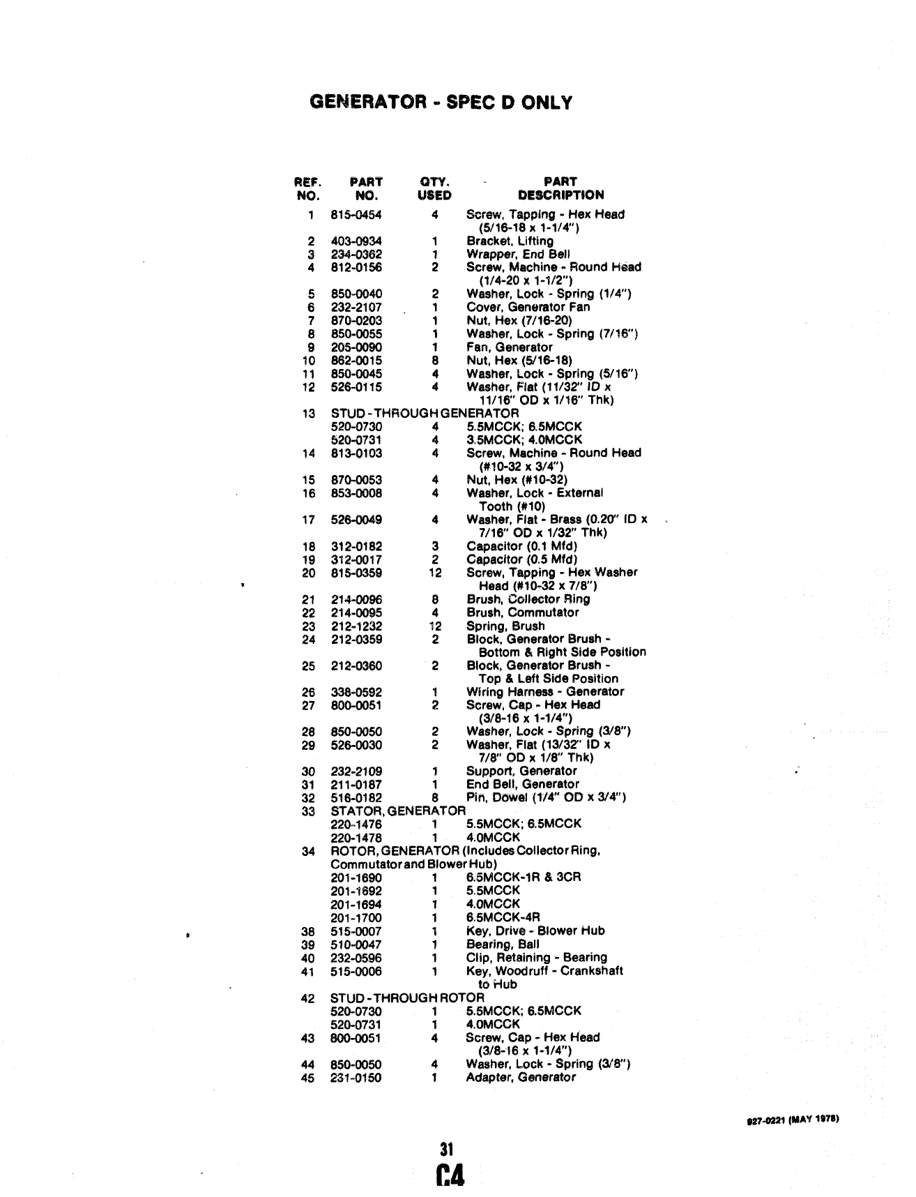
GENERATOR =SPEC 63ONLY
Fw.
No,
1
PART
No.
815-0454
PART
12ESCRlPTtON
Shrew, Tapping -Hex Head
(W16-T8 x1-1/4)
Bracket, Lifting
Wrapper, End Bell
Screw, Machine -Round H&ad
(1/4-20 x1-1/2”)
Waeher, Lock -Spring (1!4’)
Cover, Generator f-an
Nut, Hex (7116-20)
Washer, Lock -Spring (7/?6”)
Fan, Generator
Nut, t’feX (5/16-18)
Washer, Lock -Spring (5/16)
Washer, Flat (11/32’ ID x
2
3
4
403-0934
23442362
812-0156
8moo40
232-2107 ,
870-0203
850-0055
205-0090
662-0015
850-0045
526-01$5
2
1
1
1
:
4
411/16 OD X1/16” Thk)
13 STUD -THRC9LfGti C3ENEFtAT0R
14
52C=0730
520-0731
613-0103
4
4
4
5.5MCGK; 6.5MCCK
345MCCK; 4.OMCCK
Screw, Machine -Round Head
(#~().32 )( 3/&)
Nut, Hex (#10-32)
Waaher, Lock -External
Tooth (#10)
Washer, Flat -Brass (0.20” ID x
7/16 OD X1/32 Thk)
Capacitor (0.1 Mfd)
Capacitor (0.$ Mfd)
Screw, Tapping -Hex Washer
Head (#10-32 x7/6”)
Brush, Chllactor Ring
Brush, Commutator
Spring, Brush
Block, Generator Brush -
Bottom &Right Side Poeition
Block, Generator Brush -
Top &Left Side Position
Wiring Harness -Generator
Screw, C*P -Hex Head
(3/8-16 X1-1/4)
Waeher, Lock -Spring (3/8”)
Washer, Flat (13/32” ID x
7/6” QD X1/8” Thk)
Support, Generator
15
16 870-0053
853-0008 4
4
526-0049 4
312-0182
3?2-0017
815-0359 :
12
21W096
214-0095
212-1232
212-0359
212-0360
336-0592
600-0051
25 2
26
27
28
29 850-0050
526-0030
30
31
232-2109
211-0187 1
1
,“
End”Bell, Generator
32 516-0182 Pin, Dowel (W” OD x314”)
33 STATOR, GENER~TOR
220-1476 15.5MCCK; 6.5MCCK
220-1478 14.OMCCK
ROTOF?,GENERATOR (Includes Collector Ring,
Commutator and Blower Hub)
201-1690 16.5MCCK-fR &3CR
201-1$92 15.5MCCK
201-1694 14.OMCCK
201-1700 16.5MCCK-4R
51$-000? 1Key, Drive -Blower Hub
510-0047 ?Bearing, Ball
232-0596 1Clip, Retaining -Bearing
515-0006 1Key, Woodruff -Crankshaft
to Hub
STUD -THROUGH ROTOR
520-0730 15.5MCCK; 6.5MCCK
520-0731 14.oMCCK
800-0051 4Screw, Cap -Hex t-lead
(3/8-16 X1-1/4”)
6504050 4Washer’, Lock -Spring (3/$”)
23 f-0150 ?Adapter, Generator
34
36
39
40
41
b
42
43
44
45
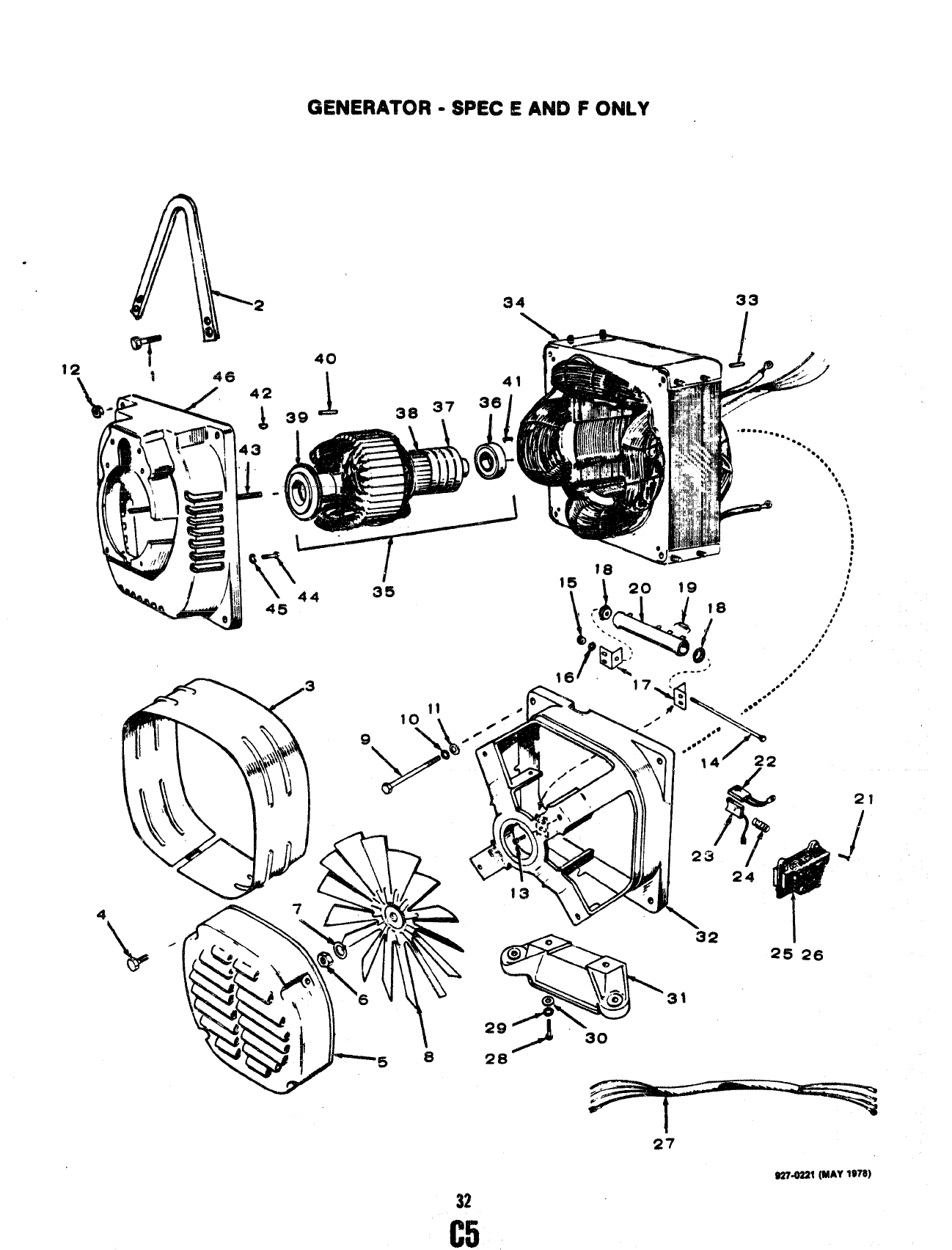
GENERATOR -SPEC EAND FONLY
2?
J
-30
27
WMZl (MAY 1978)
32
C5
GENERATOR -WE(2 EAND FONLY
REF. PART PART
NO. K). tk%ii MfWtlPTiON
1 815-0454 4Screw, Tapping -Hex Head
(tYlf3-lfl x1-1/4”)
2403-0934 1Bracket, Lifting
3234-0362 Wrapper, End Bell
4815-0441 ;Screw, T’qoping -Hex Waeher
Head (1/4-20 xl-in”)
.—..
5232-2107 1Cover, @neratcw Fan
6870-0203 1Nut, Hex -Hardened (7/18-20)
7W3-0055 1Waaher, Lock -Spring (7/16”)
8205-00S0 f%ri, i%arwmltor
9SCREW, CAP- HE~ HEAD
800-0043 4
ii6i)644
10 WW045
11 526-0115
12 8$2-0015
la @$K-n!!’k%
..-—
14 812-01?8
15 880-0011
16 850-0030
17 304-0708
18 304-0015
19 357.0020
n353-0047
21 815-0359
22 214-0096
23 214-0095
24 212-1232
25 212-0359
26 212-0360
27 338-0642
3.5MCCK,4@MCCK( 8/18-18x5”)
5.5MCCK, 6.5MGCK (5/1$-1 8x 7-1/2”)
Washer, Lock -Sprina (5/18”)
Washer, Flat (1l/9T ID x
11118” C3QX1/$8” Thk)
Nut, H*X (W16-18)
_, Tap@ng -“Round Head
(#10-32 X1/2”)
Screw, Machine -Round Head
(#10-32 X6“)
Nut, Hex (#10-24)
Washer, Lock -Spring (#IO)
t3rack@, Mounting, Resistor
Washer, Centering, Reeititor
Diode, Rectifier
Ftaaistor, Tapped, Wirewound
Straw, Tapping -Hex !?lasher
Head (#10-32 x7/8”)
Brush, Collector Ring
Brush, Commutator
Spring, Brush
Shk. ervw%torBrush -
P
Bo om ~.,hig~t side Position
fNock, Genbrator brdah -
Top &Left Side Position ‘.
Wking Harness -Generator
r
f
Lt! ”., ‘- .,,... .
PART WV. PART PART
..-
N~. No. USED QESCR?PTION
28 800-0051 2screw, Cap -Hex Weed
(3/8-16 X1-1/4”)
29 8W3-0050 2Waaher, Lock -Spring (3/8”)
30 528-0030 2Waaher, Fiat (1W32° iD x
?/&’ 00x 11% Thk)
31 232-2321 1Support, Generator
32 211-0187 1End Ripfl,~~n~rator
33 518-0!82
‘in, _M@ {llA Qo ~ ~&)
34
STATOR, GENERiTOR
220-1816 1505MCCK-SPec E:6.5MCCK-Spec E
220-1818 13.5MCCK-Spec F;4,0MCCK-Spec E&F
220-1321 16.5fdCCK-Spec F
220-1822 15.5MCCK-Spec F
35 ROTOR, GENERATOR (Inciudea Bearing, Commutator,
CoiiectorRing and Drive Hub)
201-? 903 16.5MCCK-3CR
201-1905 15.5MCCK-Spec E
201-1907 14.OMCCK
201-1912 15.i5MCCK-Spec F
201-1813 r3.5MccK-4R
201-2323 43.5MCCK-Spat F
38 510-0047 1Bearing, Bali
37 204-0110 1Ring, Coiiector
38 COMMUTATOR
203-0~52 15.5MCCK; 6.5MCCK
203-0153 13.5MCCK; 4.OMCCK
39 232-2316 1Hub, Drive
40 232-0596 1Ciip, Retaining -Bearing
41 515-0007 1Key -i3riv,e Hub
42 515-0006 Kay, Woodruff -Crankshaft/Hub
43 STUD -THROUG~ ROTOR
520-0752 13.5MCCK; 4.OMCCK
520-0233 5A5MCCK; 6.6MCCK
44 800-0051 :Screw, Cap -Hex Head
(3/8-1$ X1-1/4”)
45 850-0050 4Washer, Lock -Spring [3/8”)
46 231-0164 1Acfapter -Generator to Engine
33
C6
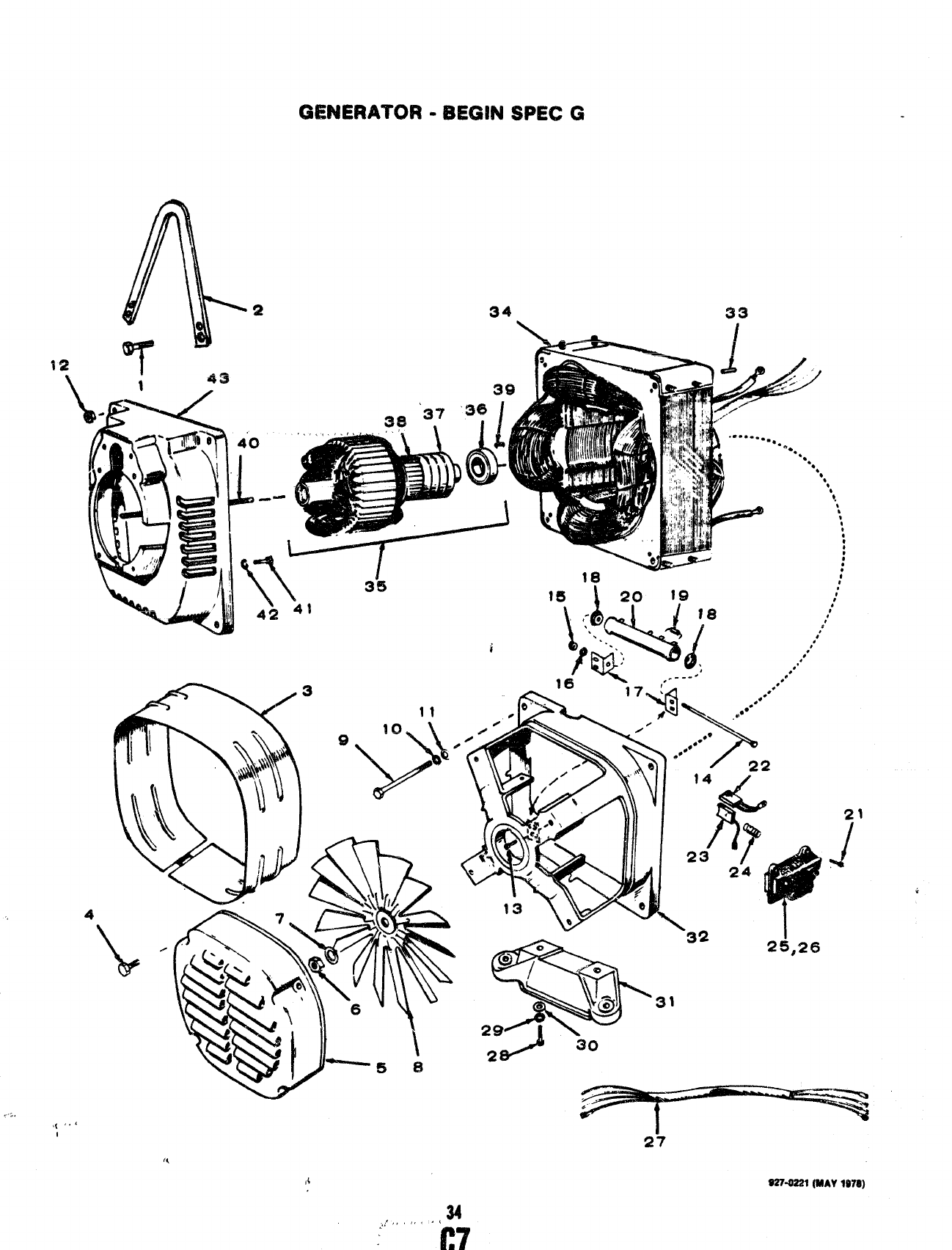
CMNERATOR -BEGIN SPEC G
4
,..,
,( ‘.’
I
,{
34
21
?/
~-8221 (MAV1$78)
....’,,,,,, ,’
C7
GENERATOR -BE(3N4 SPEC G
REF. PART
un
s.”, No.
1815-04S4
2403-0934
3234-0362
461!5-0441
52~2-2107
6870-0203
‘7 iit50-w5a
-----
8205-0090
!%&
4
1
1
1
1
9SCFUEW,CAP-HEXHEAD
800-0043 4
800-0044 4
10 850-0045 4
II 526-0115 4
12 862-0015 4
13 815-0333 2
14 812-0118 1
15 860-0011 1
16 850-0030
17 304-’0706 ;
18 304-0015 2
19 3574020 1
20 353-0047 1
21 815-0359 15
22 214-0096 8
23 214-0095 4
24 212-1232 12
25 212-0359 2
26 212-0360 2
27 338-1099
28 800-0051 :
29 850-0050 2
30 526-0030 2
PART
DESCRIPT’K)N
Screw, Tapping -Hex Head
(5/16-18 X1-1/4’)
Bracket, Lifting
Wrapper, End Bell
Screw, Tapping -Hex W@her
Head (1/4-20 x1-1/2)
Cover, Generator Fan
Nut, Hex -Hardened (7/16-20)
Washer, Lock -Spring (7/16)
Fan, Generator
31
32
33
34
35
36
37
38
39
40
42
43
3.5MCCK; 4.OMCCK (5/16-l$x 5“)
5,5MCCK; 6.5MCCK (5/16-18 x7-1/2”)
Washer, Lock -Spring (5/16”)
Washer, Flat (1?/S2” ID x
11/16 OD X1/16” Thk)
Nut, Hex (5/16-18)
Screw, Tapping -Round Head
(#10-32 X1/2”)
Screw, Machine -Round Head
(#if)-24 X5“)
Nut, Hex (#10-24)
Washer, Lock -Spring (#IO)
Bracket, Mounting, Resistor
Washer, Centering, Resistor
Diode, Rectifier
Resistor, Tapped, Wlrewound
Screw, Tapping -Hex Washer
Head (#10-32 x7/8”)
Brush, Collector Ring
Brush, Commutator
Spring, Brush
Block, Generator Brush -
Bottom &Right Side Position
Block, Generator Brush -
Top &Left Sid, Position
Wiring Harness -Generator
Screw, Cap -Hex Head
(3/8-16 x1-1/4”)
Washer, Lock -Spring (3/8)
Washer, Flat (13/32” ID x
7/8” OD X1/8 Thk)
Support, Generator232-2321 1
211-0187 1End Bell, Generator
516-0182 Pin, Dowel (1/4” OD x3/4”)
STATOR, GENER:TOR
220-1818 13.5MCCK; 4.OMCCK
220-1821 16.5MCCK
220-1822 15.5MCCK
ROTOR, GENERATOR (Includes Bearing, Commutator
and Collector Rings)
201-2503 16.5MCCK-3CR
201-2504 14.OMCCK
201-2505 13.5MCCK
201-2506 15.5MCCK
201-2512 16.5MCCK-4R
510-0047 ;Bearing, Bail
204-0110 Ring, Collector
COMMUTATOR
203-0152 15.5MCCK; 6.5MCCK
203-0153 13.5MCCK; 4.OMCCK
232-0596 Clip, Retaining -Bearing
STUD -THROUG~ ROTOR
520-0732 13.5MCCK; 4,0MCCK
520-0233 5.5MCCK; 6.5MCCK
600-0051 ;Screw, Cap -Hex Head
(3/8-16 x1-?/4)
W)-0050 4Washer, Lock -Spring (3/8)
231-0164 1Adapter, Generator to Engine
S27-0221(MAV1078)
35,
C8
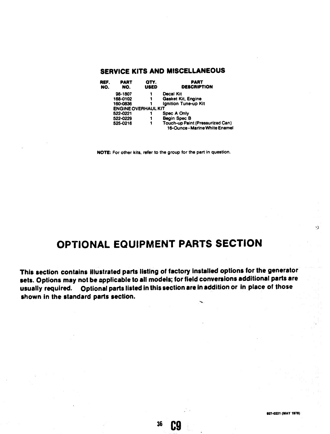
SERVICE KITS AND MISCELLANEOUS
SEF. D-? PART
NO. NO. t??xi DESCRIPTION
9s-1s07 1Decal Kit
1s8-0102 1Gasket Kit, Engine
1s0-0s26 Ignition Tune-up Kit
EN(3fNE OVEtWtA~L KIT
522-0221 1Speo AOnly
522-0229 1Segin Spec e
525-0216 1Touch-up Paint (Pressurized Cm)
lS-Ounce -Marine White Enarnei
NOT12 For other kits, refer to the group for the part in question.
OPTIONAL EQUIPMENT PARTS SECTION
?~is section contains illustrated parts listing of factory installed options for the generator
sets. Options may not be applicabk to al! modek; for field conversions additional parts are
usually required. Optional parts listed inthis section are In addition or in place of those
shown in the standard parts section. %.
92Y4Z21 (MAY 197@)
36 C9
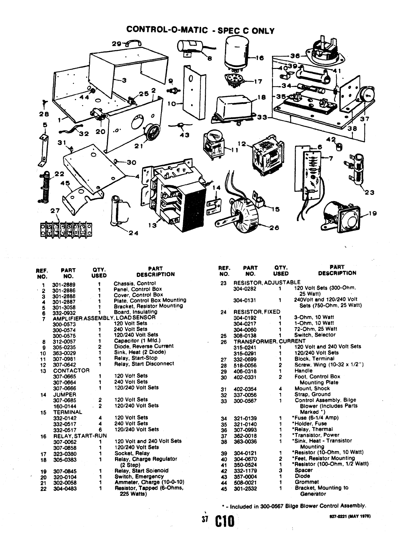
CONTROLO0411ATIC -SPEC CONLY’ .
REF. PART QTY.
NO. NO. USED PART
DEsCRIPTION
‘;
3
4
5
6
7
8
9
10
11
12
13
14
15
16
17
18
301-2889 1Chassis, Control
301-2886 1Panel, Control BOX
301-2888 1Cover, Control BOX
301-2867 1Plate, Control Box Mounting
301-3058 1Bracket, Resistor Mounting
332-0932 Board, Insulating
AMPLtFIER ASSE~BLY, LOAD SENSOR
300-0573 1120 Volt Sets
300-0574 1240 Volt Sets
300-0575 1120/240 Volt Sets
312-0057 Capacitor (1 Mfd.)
305-0235 ;Diode, Reverse Current
363-0029 1Sink, Heat (2 Diode)
307-0981 1Relay, Start-Stop
307-0642 1Relay, Start Disconnect
CONTACTOR
307-0865 1120 volt sets
307-0664 1240 Volt Sets
30~0666 1120/240 Volt Sets
JUMPER
307-0685 2120 Volt Sets
lqO-o144 2120/240 Volt Sets
TERMINAL
332-0142 4120 volt Bets
332-0517 4240 volt sets
332-0517 6120/240 Volt Sets
RELAY, START-RUN
307-0062 1120 Volt and 240 Volt Sets
307-0658 1120/240 Volt Sets
323-0380 1Socket, Relay
305-0383 1Relay, CharSe Regulator
(2 Step)
307-0645 1May, Start S@enoid
320-0104 1Switch, Emergency
302-0058 1Ammeter, Charge (10-O-1O)
304-0483 1Besistor, Tapped (6-Ohms,
225 Watts)
\—
REF. PART QTY.
NO. NO. USED
3
19
,,
PAW
DESCRIPTION
23 RE;~l.:R, ADJUSTABLE
.1120 Volt Sets (300-Ohm,
25 Watt)
304-0131 1240VOlt and 120/240 Vott
24 RESISTOR, FIXED Sets (750-Ohm, 25 Watt)
304-0192 13-Ohm, 10 Watt
304-0217 1l-Ohm, 10 Watt
304-0060 172:Ohm, 25 Watt
25 308-0138 1Switch, Selector
_—-
~6 TRAi’JSFORf4ER, CURRENT
315-0241 1
W3-02W 1
27 332-0899
28 518-0056 ;
29 406-0318
30 402-0331 ;
31 402-0354 4
32 337-0056 1
33 300-0587 1
34 321-0139
35 321-0140
36 307-0993
37 362-0018
38 363-0036
39 304-0121
40 304=0670
41 350-0524
42 332-1179
43 357-0004
44 508-0021
45 301-2532
1
1
1
1
1
120 Volt and 240 Volt Sets
120/240 Volt Sets
Block, Terminal
Screw, Wing (10-32 x1/2”)
Handle
Foot, Control BOX
Mounting Plate
Mount, Shock
Strap, Ground
Control Assembly, Bilge
Blower (Includes Parts
Marked ●)
●Fuse (6-1/4 Amp)
‘Holder, Fuse
●Relay, Thermal
●Transistor, Power
“Sink, Heat -Transistor
Mounting
“Resistor (lO-Ohm, 10 Watt)
●Feet, Resistor Mounting
*Resistor (100-Ohm, 1/2 Watt)
Spacer
Diode
Grommet
Bracket, Mounting to
Generator
●-Included in 3G0-0567 Biige Blower Control Assembly.
s2?4221 (MAY 1978)
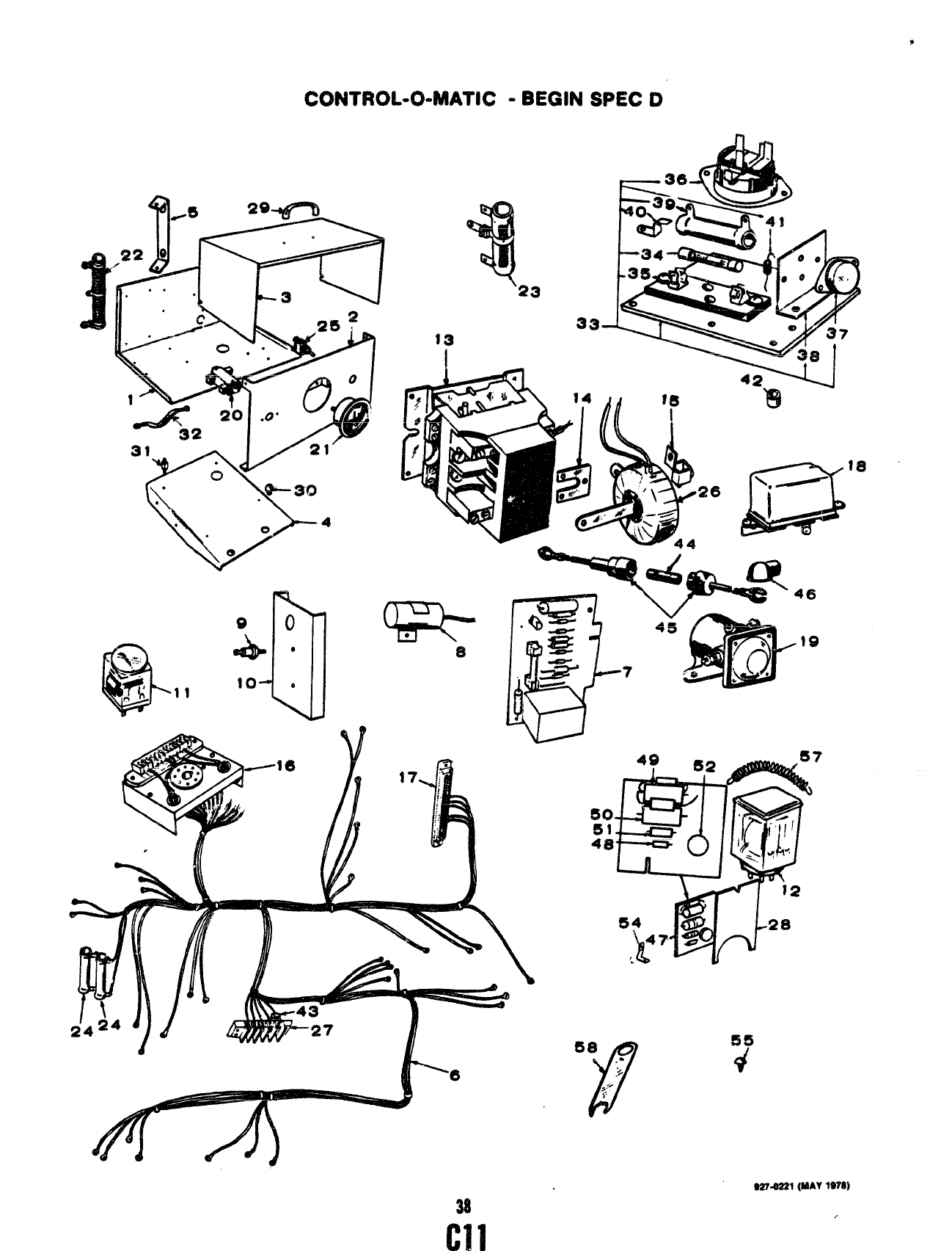
CONT$MM--OOMATK -BEGIN $PEC 0
“
‘4~20 “o”
32
31
‘IL--J’
38
s274221 (MAY 1978]
.,
c11
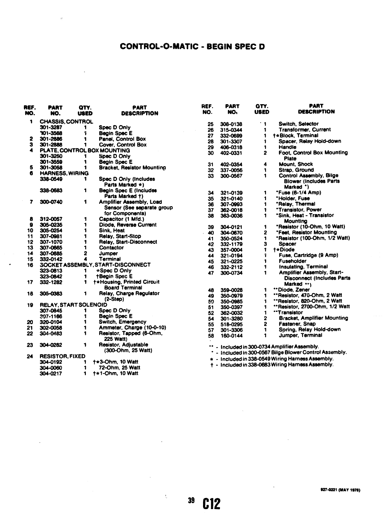
CON’TROL-04ATN2 -BEGIN SPEC D
REF.
No.
1
2
3
4
8
1!!
11
12
ii
15
16
17
18
19
20
21
22
23
24
PART PAt?l
rim. &w& emewPTm N
Cbwsis, CONTROL.
901-3287 1Spat DOnly
301-35S8 iEteginSpec E
3014?6S6 1Pariet, Cm7trol Sox
201-2668 Cover, Control Sox
PLATE, CONTRO~ BOX MOUNTING
90W260 1Spat DOnly
301”9659 1Bagin SW E
301-9053 !3rackat, Resistor Mounting
HARNESS, WWtlN~
338-0549 1Spat Donly (Includes
Parts Marked *)
1Segin Spsc E(Includes
Parts Marked t)
--..
~rw ;Amplifier Assembly, Load
$enacw (Sac separate group
for Components)
at2-oo57 1Capacitor (1 Mfd.)
ao5-0235 1DkMe, Reverse Current
305-0254 Sink, Heat
307-0s81 ;Relay, Start-Stop
307-1070 1!?a!ay, St8n=Mconnect
307-0665 Contactor
:dumper
932-0142
SOCKET ASSEM;LY, S~~~T~#l’SCONNECT
923-0813 1*SpeC f) Only
1tSagin _E
332-1282 1f+l+o@ng, Print@dCircuit
Scmrd Terminel
1Relay, Charge Regulator
(2-step)
RELAY, STAHT SOLENOID
307-0845 1Spec DOnly
.307-1166 tB~ir! Spec E
320-0104 1Switch, Emergency
9024X158 1Ammeter, Chm’ge (10-0-10)
1Raaistor, Tapped (6-Ohm,
225 Watt)
3Q4-41282 1Resistor, Adjustable
(300-Ohm, 25 Watt)
RESISTOR, FIXED
304-0192 1tfr3-Ohm, 10 Watt
172-Ohm, 25 Watt
904-0217 1t*l~m, 10 Watt
REF.
No.
25
28
27
28
29
30
31
32
33
z
41
42
43
44
45
48
47
48
49
50
51
52
54
55
57
58
PART
NOa
3064138
315-0944
332-0698
301-3307
406-0318
402-0331
4024354
997-(W6
3o0-0567
321-0139
3214)140
307-0893
382-0018
383-0038
304-0121
304-0670
350-0524
332-1179
357-0004
921-0194
321-0225
332”2112
300-0734
359-0028
350-0979
350-0965
350-0387
362-0032
301-3280
518-0295
301-3308
180-0144
CWY. PART
tmm oEscrtwnoN
“1
1
1
-i
;
4
1
1
1
1
1
1
1
;
i!
1
1
1
1
1
1
1
1
1
:
2
1
1
Switch, Setector
Transfcmner, Current
txBlo& Terminal
Spacer, f%e#ayHoid+town
Hmldie
Foot, Controt Sox Mounting
Piaie
Meum, shock
Strap, Ground
Control Assembly, Silge
Blower (Includas Parts
Marked “)
●FUSO(6-1/4 Amp)
●Hold@r, Fuse
“Reiey, Thermal
“Transistor, Power
●Sink, Ha@ -Transistor
Mounting
“Resistor (lO-Ohm, 10 Watt)
“Fact, Rsaistor Mounting
●Resistor (loO-Ohm, 1/2 Watt)
Spacer
t* Dkxte
Fuse: Cartrktne 19 Amp)
Fuaeholder ‘-- --
Insulating, Terminal
Amplifier Assembly, Start-
Disconnaot (Includes Parta
Marked **)
●*Diode, Zener
““Resistor, 470-Ohm, 2Watt
*“Resistor, 820-Ohm, 2Watt
●*Ftesistor, 2700-Ohm, 1/2 Watt
“*Transistor
Bracket, Amplifier Mounting
Fastener, Snap
S@ng, Relay Hold+ own
Jumper, Terminal
●✎✍Included in 300-0734 AmdifierAeeembly.
“-iriciuded in 300-0567 Bilge Blower Conttil Assembly.
A-Included in 338-0549 Wiring Harness Assembly.
t - Included in 338-0883 Wiring Harness Assembly.
(H2
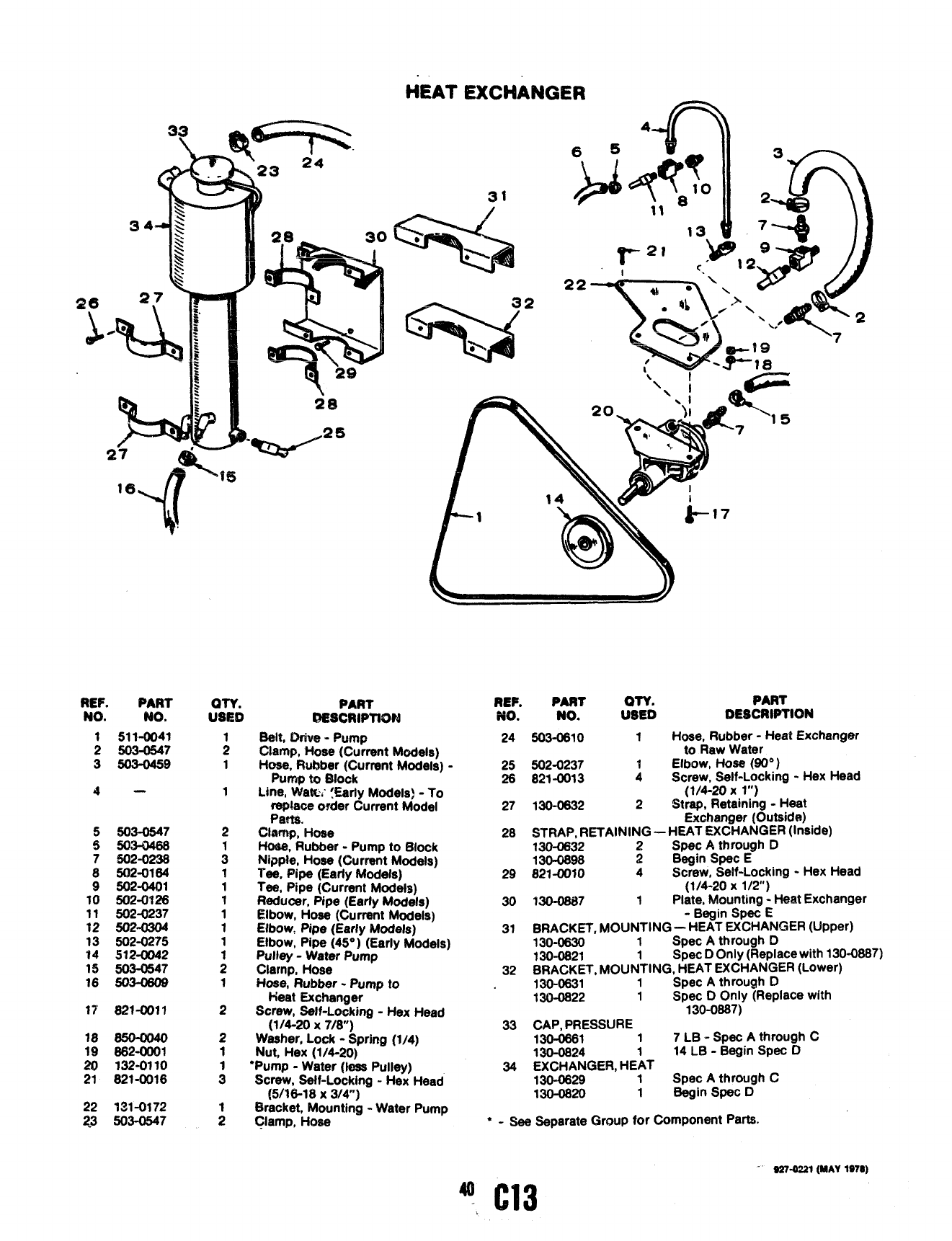
EXCHANGER ==s
4
65 id
\‘.. 224
30
lf3=_
REF. iPART
NO. NO.
1511-0041
2503-0547
3503-0459
4-
5503-0547
5503-0466
7602-0236
8502-0164
9502-0401
10 502-0126
11 502-0237
12 502-0304
13 502-0275
14 512-0042
15 503-0547
16 503-0609
17 821-0011
18 6w—0040
19 662-0001
20 1324N1O
21 821-0016
22 731-0172
23 503-0547
“,.’ ‘. #
<
“>2
‘di+ 7
aw. PART
Ustm esscwwm
Belt, Drive -Pump
GIamp, Hose (Current Models)
Hose, Rubber (Current Models) -
pumP to Etlock
L)ne, Wat&~ !Earfy Models) -To
replace order Current Model
Pam.
Clamp, Hose
Ho@e,Rubber -Pump to Block
Nippie, Hose (Current Models)
Tee, Pipe (Early Models)
Tee, Pipe (Current Models)
Reducer, Pipe (Earfy Models)
Elbow, Hose (Current Modeis)
Elbow, Pipe (Early Modeis)
Elbow, Pipe (45° )(Early Modeis)
Pulley -Water Pump
Clamp, Hose
Hose, Rubber -Pump to
Heat Exchanger
Screw, Self-Locking -Hex Head
(1/4-20 x7/8)
Washer, Lock -Spring (1/4)
Nut, Hex (1/4-20)
●Pump -Water (less Puiley)
Screw, Self-Locking -Hex Head
(5/16-18 x3/4”)
Bracket, Mounting -Water Pump
Ciamp, Hose
\\
REF. PART QTY. PART
NO. NO. USED DESCRWTION
24 5OM1O 1Hose, Rubber -Heat Exchanger
to Raw Water
25 502-0237 Elbow, Hose (~”)
26 821-0013 :Screw, Self-Locking -Hex Head
(1/4-20 xl“)
27 130-0832 2Str~, Retaining -Heat
Exchanger (Outside)
28 STRAP, RETAiNING -HEAT EXCHANGER (Inside)
130-0632 2Spec Athrough D
130-0698 2Begin Spec E
29 821-0010 4Screw, Self-locking -Hex Head
11/4-20 x1/2)
30
31
32
m-0687
BRACKET,
130-0630
130-0621
BRACKET
130-0631
130-0622
1Pl;;e, !Jlowrting: Heat Exchanger
-Begin Spec E
,MouNTiNG —HEAT EXCHANGER (UPper)
1Spec Athrough D
1Spec DOniy (Replace with 130-0687)
,MOUNTING, HEAT EXCHANGER (Lower)
1Spec Athrough D
1Spec DOniy (Repiace with
130-0667)
33 CAP, PRESSURE
130-0661 1 7 LB -Spec Athrough C
130-0624 14 LB -Begin Spec D
34 EXCHANGER, HE~T
130-0629 1Spec Athrough C
130-0620 1Begin Spec D
‘-See Separate Group for Component Parts.
40
-C13 9S7-0221 (MAY 197S)
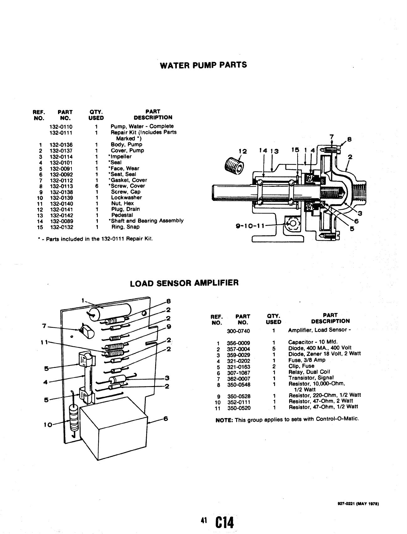
WATER PUMP PARTS
REF. PART
NO. NO.
132-0110
132-0111
1132-0136
2132-0137
3i32-0114
4132-0101
5132-00$1
6132-0092
7132-0112
8132-0113
9132-0136
10 132-0139
11 132-0140
12 332-0147
13 132-0142
14 132-0089
15 132-0132
PART
DEsct?wrlmd
Pump, Water -Complete
Repair Kit (Includes Parts
Marked ●)
Body, Pump
Cover, Pump
“Impeller
‘Seal
‘Face, Wear
*Seat, Seal
●Gasket, Cover
●Screw, Cover
Screw, Cap
Lockwasher
Nut, Hex
Ptiui, main
Pedestal
‘Shaft and Bearing Assembly
Ring, Snap
●-Parts included in the 132-0111 Repair Kit.
L-
LOAD SENSOR AMPLIFIER
%iiiT
WW--2
3
bf2
Ii-u! \A.6
‘“m’r r
REF. PART
NO. NO.
300-0740
1356-0009
2357-0004
3359-0029
4321-0202
5 3214163
6307-1087
7362-0007
8350-0546
9350-0526
10 352-0111
11 350-0520
QTY.
USED
1
1
5
1
;
1
1
1
1
1
1
PART
DESCRIPTION
Amplifier, Load Sensor -
Capacitor -10 Mfd.
Diode, 400 MA., 400 Volt
Diode, Zener 18 Volt, 2Watt
Fuse, 3/8 Amp
Clip, Fuse
Relay, Dual coil
Transistor, Signal
Resistor, 10,000-Ohm,
1/2 Watt
Resistor, 220-Ohm, 1/2 Watt
Resistor, 47-Ohm, 2Watt
Resistor, 47-Ohm, 1/2 Watt
NOTE This group applies to sets with Control-O-Matic.
S274221 (MAY 1978)
41C14
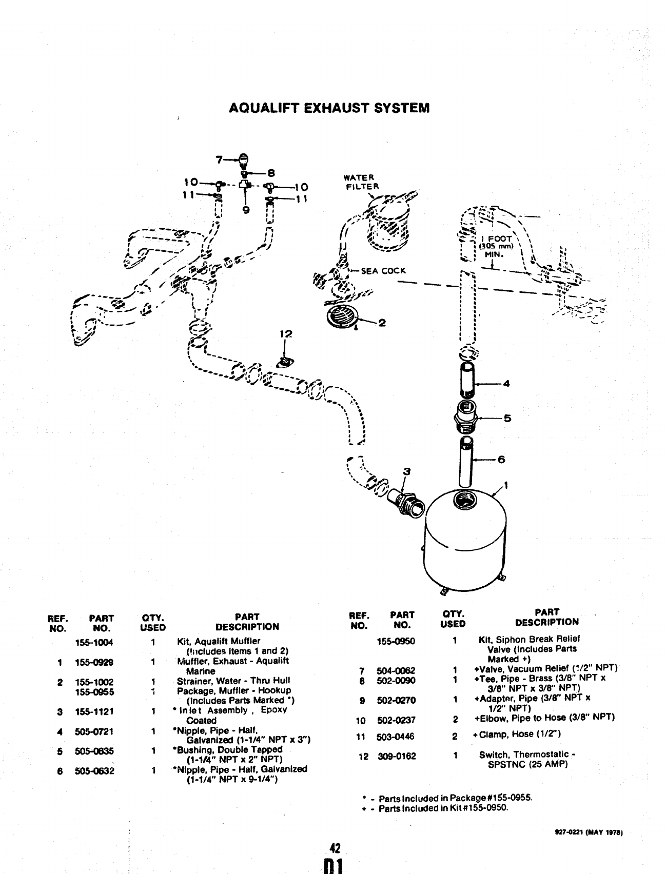
AQtJALIFT EXHAUST SYSTEM
WATER
,;#_ ;OCK
Qq$; /; —
“&
.
42
u--
4
iii-
4!95
IQ
REF.
No. PART REF. PART on.
No. No. USED
PART
DESCRIPTION ‘
QTY. PART
L!SEO DESCRIPTION
No.
155-1004 155-0950 1Kit, Siphon Break Relief
Valve (Includes Parts
7504- 1+Vayv~!Vyc~~m Relief (:/2 NPT)
0502-0090 1+Tee, Pipe .Brass (3/8” NPT x
3/8’ NPT X3/8 NPT)
9502-0270 1+Adapter, Pipe (3/8 NPT x
1/2 NPT)
10 502-0237 2+Elbow, Pipe to Hose (3/6” NPT)
Kit, Aqualift Muffler
(t~icludes items 1and 2)
Muffler, Exhaust -Aqualift
Marine
Strainer, Water -Thru Hull
Package, Muffler -Hookup
(Includes Parta Marked ●)
●In Ie tAssembly ,EPOXY
Coated
“Nipple, Pipe -Half,
Galvanized (1-1/4” NPT x3)
‘Bushing, Double Tapped
(1-1/4” NPT X2NPT)
“Wipple, Pipe -Half, Galvanized
(1-1/4” NPT X9-1/4)
1
1
1
i
1
t
1
9
1
2
155-0929
155-1002
155-0s55
3
4
6
6
155-1121
505-0721 11 503-0448 2+Clamp, Hose (1/2’)
505-cm5 12 309-0162 1Switch, Thermostatic -
SPSTNC (25 AMP)
505-0S32
“-Parts Included in Package #l$5-095S.
+-parts Included in Kit #155-0950.
S27-0221 (MAY 1978)
42
nl

AQUALIFT EXHAUST SYSTEM
-* >
S*
1$
I*
I*
I
‘. k’
REF. PART
No. No.
155-1(N)4
1155-092s
2155-1002
155-0955
3155-1121
4505-0721
5505-0635
6505-0S32
QTY.
l,4sEo
1
1
1
i
1
1
1
1
PART
DESCRIPTION
Kit, Aauafift Muffler
(!~lcludes items 1and 2)
Muffler, Exhaust -Aquaiift
Marine
Strainer, Water -Thtu Hull
Package, Muffier -Hookup
(inciudes Parta Marked ●)
●in ie tAssembly ,EPOXY
Coated
“Nipple, Pipe -Haif,
Galvanized (1-1/4” NPT x3)
“Bushing, Doubie Tapped
(1-1/4” NPT X2NPT)
“Nipple, Pipe -Haif. Galvanized
(%1/4” fUPT x9-1/4)
,..
Id
Q
4!9
I&
P
1
*%
‘.
REF. PART
NO. NO. :Sl?o
PART
DESCRIPTION
155-0950 1W, Siphon Break Reiief
Valve (inciudes Parts
7504-0062 1+Vayv~~Vyc~~m Reiief (t/2 NPT)
8502-00S0 1+Tee, Pipe -Brass (3/6” NPT x
3/8 NPT X3/8 NPT)
9502-0270 1+Adapter, Pipe (3/8” NPT x
1/2 NPT)
10 502-0237 2+Efbow, pipe to Hose (3/8” NPT)
11 503-044s 2+Ciamp, Hose (1/2”)
12 30s-0162 1Switch, Thermostatic -
SPSTNC (25 AMP)
“-Parts inciuded in Package UI$5-095!5.
+.parts Inciuded in Kit #155-0950.
S27-0221 (MAY 1978}
42
nl
