Rwwa024 927 0223 Onan 10KW CCK CCKB (spec A E) Genset Parts Manual (05 1989)
User Manual: 927-0223 Onan 10KW CCK CCKB (spec A-E) Genset Parts Manual (05-1989)
Open the PDF directly: View PDF ![]() .
.
Page Count: 41
The following catalog
has gaps in its page
numbers, or doesn’t
have any numbers.
We have chosen to
leave the page
numbering in the
order that Acrobat
assigns it.
—.—. Carom ‘“
Parts
Manual
10 CXK
Ccsm
GenSet
L
927-0223
5-89 (SPEC A-E)
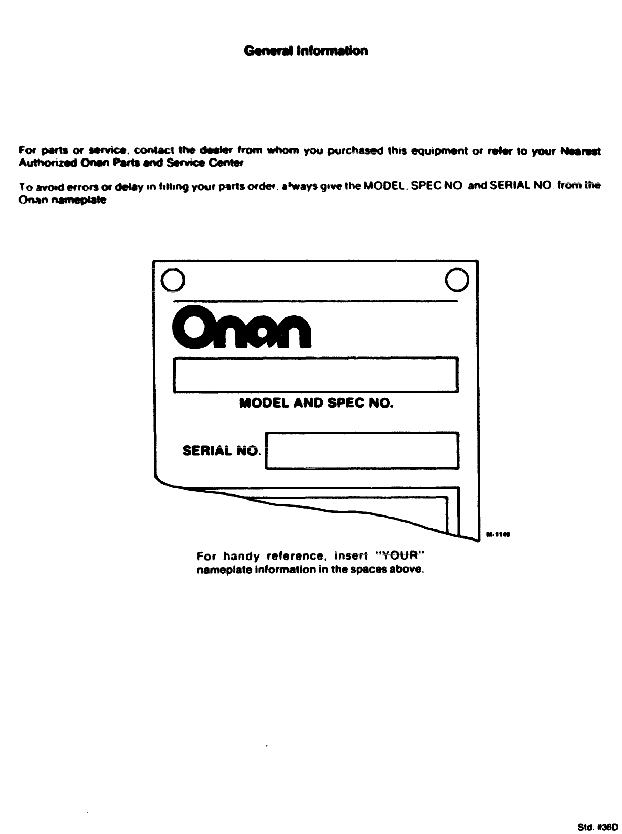
Fo@piaftaors#wiee,ctwtwt the 8e@rM from wbm you @Md%aaed thm equ$pment or de? to your Naar@st
A#Jthmzd man Par?aads!e?wce Gamw
To awodemwsa? ds$ay mfdtmg your parts omkY. sways gwe me MODEL. SPEC NO and SEWAL NO from ttw
-~ ~~
c1
4
MODEL AND SPEC NO.
For handy reference, immt ‘WH.H’
nameptate information in the spacm above.
M-1149
Std. KMO
Cable Cbattery OIO.C1O
Cable. Spsrk plug 8$
Ce-shaf? A8
cm=fmrezer (68s Onlyl C3
Cavburetar. G@so?in@ Al?
Carburetor. Components (Ga9-Gasoline) A14.BI
C*rbur9tor. Components (G*aoline) A14.01
Choice. Thermo-Ma~netic 06
Clampe Wuffl*r C$
Ci*mer. Air C4
clip,, @**ring stop 88
Coil. Field 00.C1l
coil” Ignition @@
Commutator. &ru*h See**
Candenser ea.elo.cll
Control. Generator Blo
Control. Romoto C1O
Cover .Air Clomor A12.C9
Cover .Breaker Box 0$
cover .Control 81O.C1O
Cov*r .End Sell 00
Cov@r. Valve A6
Crankshaft AIO
n: -—L———— *—--L-- n--
-~~ ●~w- Uu
Flywheel AIO,CO
Feame. Carrying CS
F~ame. Generator B8.C1l
Gaaket .8reaker Box 86
Gasket .Carburetor Mounting A12
Gasket. Exhaust Manifold A12
Gasket .Fuel pump A13,S2
Ga*k*t ,Gearcase AI1.C13
Gasket. Intake Manifold A12
Gearcage A1l.C13
Generator 00
Guard, Scroll C7
Guide, Valve A6
ltarne*9, Wiring (Control To
Engine) Uio.cio
Head, Cylinder A6
iteatmr. Oil 8ase C6
Nose, Oreather A12
Housing. Olower CT
Joint, Ball 03
Kit, Carburo;;; Repair A14.01
Kit. Oecal
M.- .——.
ml;. W9SW-I W2
Kit,, Tune-up 07
Lina, Fuel -Flexible C3.C6.C9
Ltne. fuel+Gaaol ine A:2’C2
Link. Throttle S3
Magneto ds
Manifold. E%hauat CS
Manifoid. Intake A12
Muffler A12.C9
Paint. Green 812
Pan. Air Cleaner A12
Piston A8
Plug. Spark 06
Points. t~nit ion 86
Pump. Fuel -Electric C*
Pump. Fuel -Mechanical A12
Pump, Oil AS
Regulator, Garretson C3
Reuiator. Fixed Olo,clo
!?ig. Sruah 8!l,Cll
Ring. Collector -Generator 68,C11
Ring. Piston A@
Rod. Connecting AS
Scroll. Air C7
Seal . Qil-Crankshaft A6
Seat ,Valve A6
Shield. Heat -Air Cleaner A%2
Shoe. Pole 80.C1l
Solenoid. Start B1O
Spring= Governor 03
Starter Readi-Puil 04
Starter Goqmnencs B4
Strap, Ground @10
Switch. ttatco Clo
Switch. Pressure -Oil AS,C1O,C12
Switch. Sturt-stop B3,B1O
Switch. Vacuum Regulator C3
Tank, Day C3
Tank, Fuel C2,C6
Tappet, Valve A6
Tube, Sreather A6
Tube, Exhaust A12
Valve, Exhaust A6
Valve. Intake A6
Valve, Solenoid (Gaseous Fuel) C3
Wheel ,Blower C8
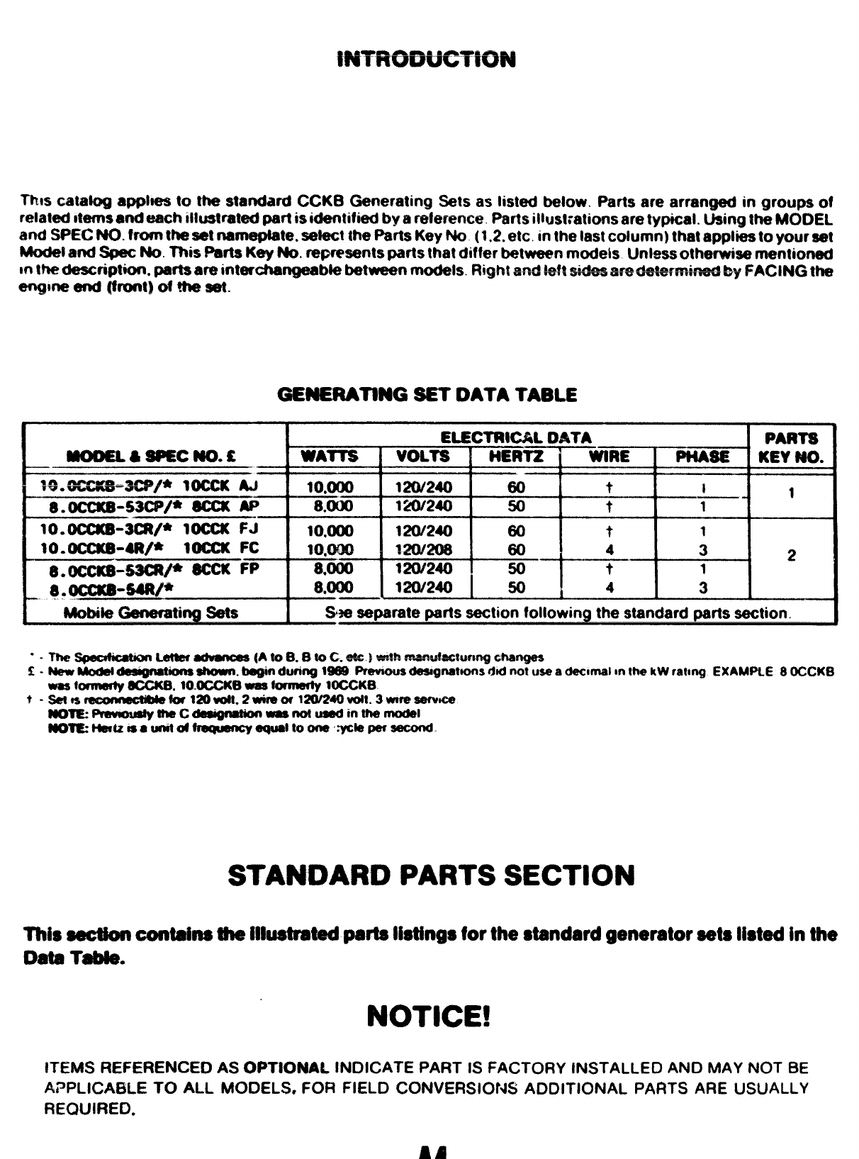
Thts catatog applses to the standard CCK8 Generating Sets as listed below. Parts are arrart~ in groups of
related stems end each ~l!tmtrated part is identified by areference Parts illustrations are typical. Using the MO13EL
and SPEC NO. from the sat nameplate. sefect the Parts Key No (1,2, etc. in the last column) that applies to your set
Modei and Spat No. This Parts Key No. ~sents parts that differ between modeis Unless otherwise mentioned
mthe description. parts are interchangeable between models. Flight and !ef? —~~ k~AC~~ ~
S@3su.w-w.ri.r.- WY
eqne end (front) of the sat.
Generating SETDATA TABLE
mooEL&sPEc No. c
W.~=3C9#* YOCCK AJ—
8. OCCK@-53CP/* == w—
lQ. OCCKB-3Ut/* 10CCK FJ—
10.0ux8-4R/* IOCCK FC
a. 0CCKS+3CIV*-Fp
MotmaGaneratil Sets
ELECTRICAL DATA PARTS
WATTS IVOLTS HERTZ
~&tRE PHASE KEY NO.
lo,mo 120/240 80 ti1
8.000 120/240 so t1
10.OW 120/240 80 t1
IO*OQO 12W208 80 432
8,000 12W240 50 t1
8XXK) 120/240 50 43
.—
%e separate parts section followin~ the standard parts section
“-Th@s@dMawn Letter advanms (A to 8. Bto C. sts )tit mwwiecwm$ ehangas
K-New kAodat daaigrmtions shown. begin dwing 1909 PravIwa daaqnatfons dti not we adecmal mthe kW rating EXAMPLE 8OCCKB
W8Sbmwty SCCK6. 10.MXKO waa formerty 10CCKB
t-%6~til~e,2 timml_#til.3wm-a
-=~-c~~-~int~~l
aom Hmtzisaunitd fmqumcy equ@toom’”*la peraacond
STANDARD PARTS SECTION
Thissectioncontainsthei!btrated partslistingsforthestandardgeneratorsetslistedinthe
OataT-.
NOTICE!
ITEMS HEFEf3ENCE0 As OpTlONAL INDICATE PART IS FACTORY INSTALLED AND MAY NOT BE
ApPLlCAt3LE TO ALL MOOELS, FOR FIELD CONVERs10t4s ADDITIC)NAL PARTS ARE USJALLY
RECXJIREO.
Lfa
?3 -“-
u_,,
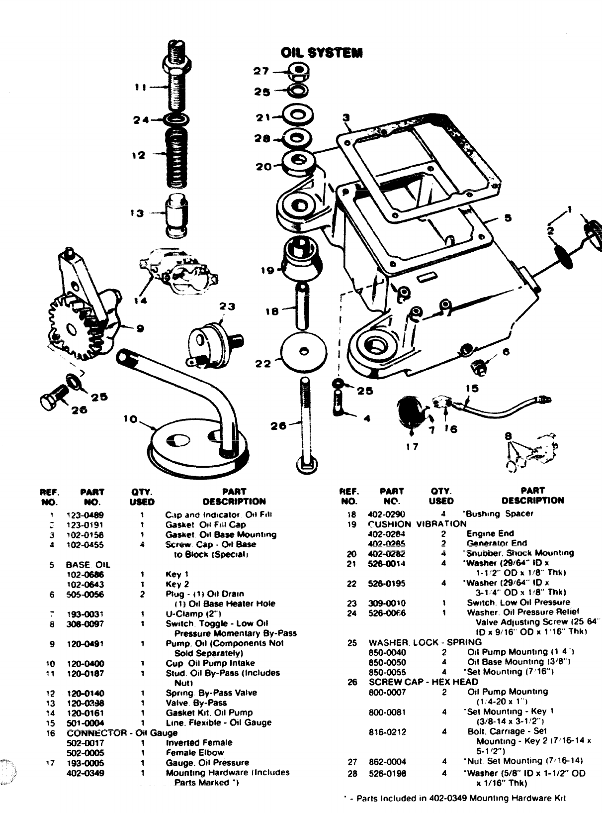
OR $V$YMM
17
PART
DESCRIPTION
CAPand Inmcator CM FIII
Gasket (3@FM cap
Gaakt?t CM Baas+MoUnlmg
*-” cap -oit Base
to Stock (Sf.wc:al;
Key t
Key 2
Prug .11 10d Dram
[1}Od Base Heater Hole
u-c-tamp {2’” 1
Swnch. Toggle -Low 011
Pressure Momentary By-Pass
Pump. 011 (Components NoI
sold Seperatelyl
CUP 011 Pump Intake
Stud. 011 By-pass (Includes
Nutl
SfMmg By-Pass Valve
Valve. By-Pass
Gasket Kit. 011 Pump
Line. Ftex$ble -Oil Gauge
36 CXR4NECTOR -Oil Gauge
502-OR1? 1hrertad Female
502-W05 1Female Eibow
,r.pL 17 193-0005 1Gauge. Oil Pressure
402-0349 1Mounting Hardware !Includes
~,,,.,.,J_Rfnla .Marked .)
ftEF. PART OTY. PART
NO. NO. USED D~SCRWllON
19 402-02W 4.Wmhmg S~cer
19 CUSHION VIBRATION
4&&@t34 2t%gme End
4Q2.@& ~Gen@f@tQfEnd
~~~- 4‘~W?Ber. Shock Mouritmg
21 526-0014 4‘V&#wr (29:64” 10x
1-1:2’ 0(3 x1~8’ Thk)
~z ~Qgw 4‘Washer (2W84’” ID x
3-1:4’”00 x118”Tt?k~
23 309-oo~o 1Swtfch Low CM pressure
24 %?6-0066 1Washer. 011 Pressure Rehef
Valve Adtustmg Screw 12584”’
lD x9/16’ OOX l’l(YThk)
25 WASHER. LOCK -SPRING
850-0040 2 011 Pump Mounting (1 4‘)
850-0050 4011 Base Mourmng [3)8”)
850-0055 4“Set Mourmng (7’16}
26 SCREW CAP -HEX HEAD
800-0007 2 011 Pump Mourmng
(1:4-20X 1“’)
800-0081 4.Set Mounting -Key 1
(3/8-14 X3-1 :2’”)
8?6-0212 4Bolt. Carnage -Set
Mounttng -Key 2[7~16-14 x
5-1 ‘2”)
27 862-0004 4“Nut MMounting [7’16-14)
28 526-0198 4“Waaher (5/8” ID x1-1/2 00
X1/16 Thk)
“ - Parts Included in 402-0349 Mounting Hardware KIt
!!!!
“’-37
40
39 a
e
v
30”
)- S1
f&fJ “& q
36
22
45 4
mtmi3tm SKMx
REf
Nol 9E6GR%W Q& $mcWnra
4
!10-23s6
2:
3
!4
4
a
A
.
2
1$ 101 “W36?
S09-0041 1
21
21 516-00?2
110-044s
23
24
123-0315
S26-0063
2
4
26
27
20
29
120-0366
110”1037
1io+880
110-0872
110-0672-02
110-0872-05
110-0672-10
110-0872-25
11O-1OOO
I1O-1OOO-O2
11O-1 OOO-O5
1IO-N)OO-1O
110-1000-25
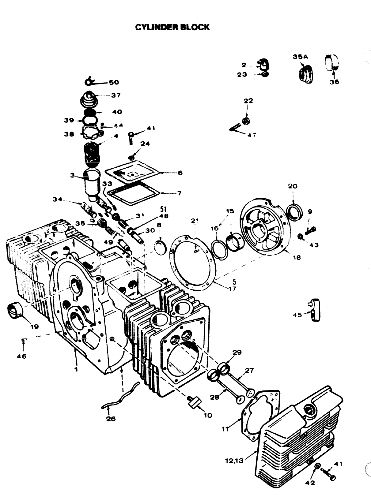
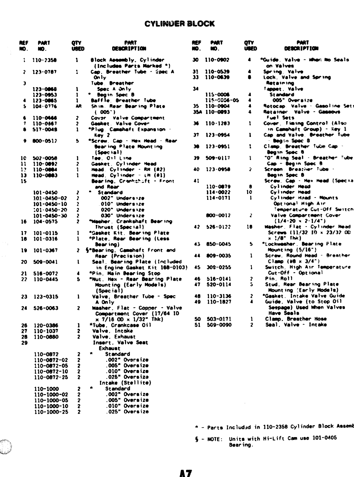
*. Parts lnclud.ad in 110-2358 Cylinder Block
As@emb
$- MOTE: LJnita with Hi-Lift C- use 101-CMQ5
Bear ing.
A7
., -,, ,., ..,”. .,’:.,,:
,.’. ,. !,’: 7
,,, ,,:
..”
,,.’
,-
;.,;, , ,.”,
,. ,”. ,“, ,,, .,~,.~,,
,,
.- ,:,
:“ ‘,, .,-. ,,
.’, ”,!,’ ,. .”,
,,.
.. ::’, ,)’ T‘,, ,,
., ‘. ’,,
-,’.
., ,’, ,,
7,.
,,.
,,:
,“
&
,.
?
1
/f’ i!)
.,
----2
7
11 ‘o 0 10
b~
12
f
~. “Q
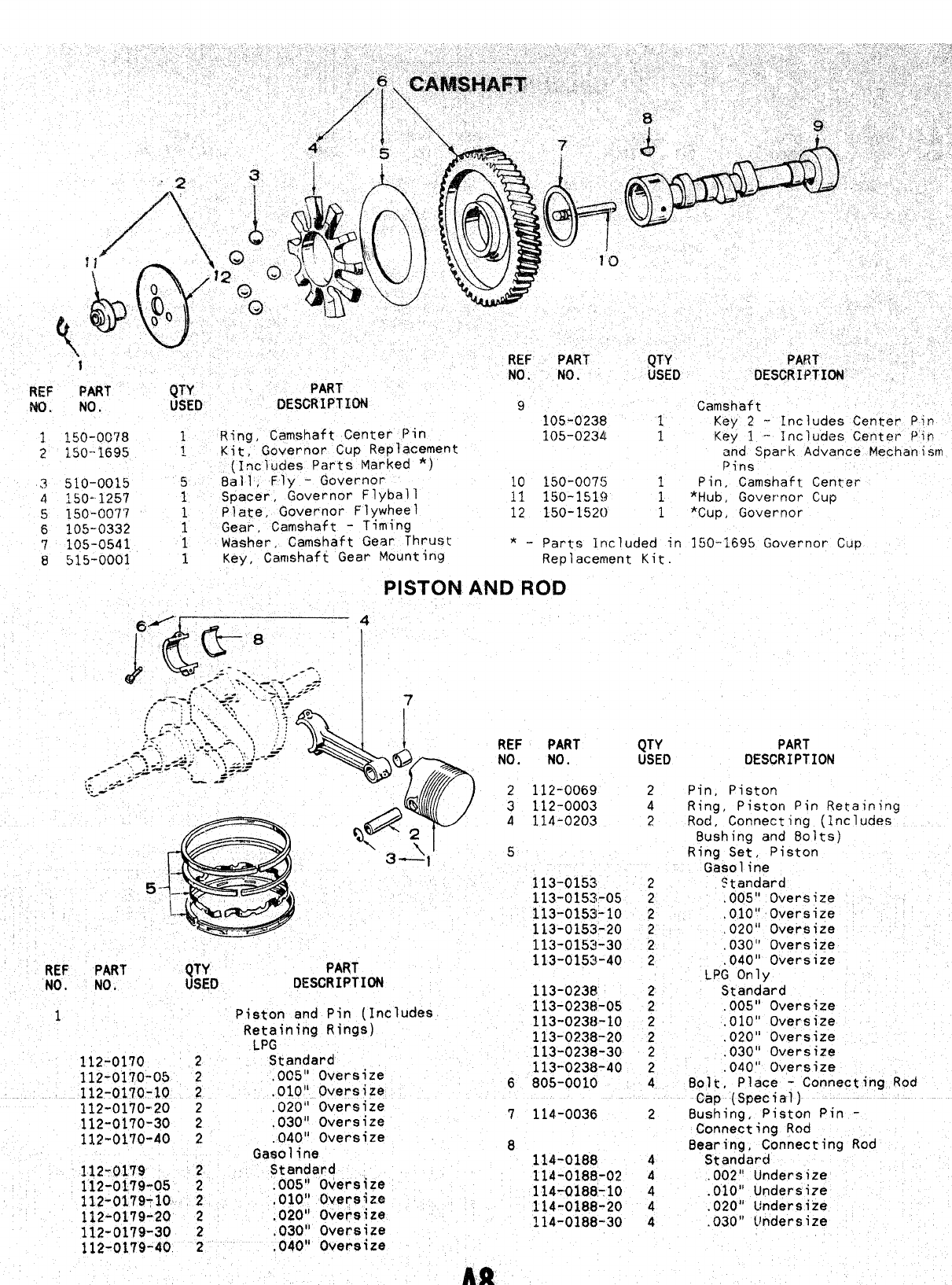
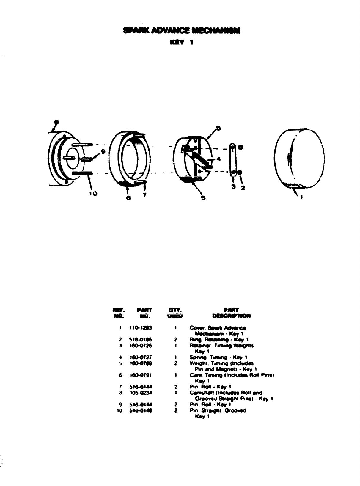
1REF PART’ QTY PART ,’
No. No. USED DESCRIPTION
REF PART (JTY PART
NO. No. USEI) DESCRIPTION 9Camshaft
105-0238 1Key 2-Includes Center Pin
1150-0078 1Ring, Camshaft Center pin 105-0234 1Key 1-Includes Center Pin
2150-1695 ~Kit, Governor Cup Replacement
(Includes Parts Marked *)
and Spark Advance Mechanism
Pins
3510”0015 5Ball, Fly -Governor 10 150-0075 1
Spacer, Governor Flyball Pin, Camshaft Center
4150--1257 111 150-151!1 1*Hub, Governor Cup
5150-0077 1Plate, Governor Flywheel 12 150-1520 1*cup ,
6105-0332 1Gear, Camshaft -Timing Governor
7105-0541 1Washer, Camshaft Gear Thrust *-Parts Included in 150-1695 Governor Cup
8515-0001 1Key, Camshaft Gear Mounting Replacement Kit.
PISTC)NANDROD
REF PART QTY PART
NO. NO. USEl) DESCRIPTION
~---
~: ,
.&-’ 2112-0069 2Pin, Piston
3112-0003 4Ring, Piston Pin Retaining
4114-0203 2Rod, Connecting (Includes
Bushing and Bolts)
5Ring Set, Piston
Gasoline
113-0153 2$tandard
113-0153-05 2,005” Oversize
113-0153-10 2,010” Oversize
113-0153-20 2.020” Oversize
113-0153-30 2.030” Oversize
REF PART QTY PART 113-0153-40 2.040” Oversize
‘W. NO. USED DESCRIPTION LPG Only
113-0238 2Standard
1Pieton and Pin (Includes 113-0238-05 2.005” Oversize
R:J:ining Rings) 113-0230-10 2,010” Overeize
113-0238-20 2.020” Oversize
112-0170 2Standard 113-0238-30 2.030” Oversize
112-01’70-05 2,005” Oversize 113-0238-40 2.040” Oversize
112-0170-10 2.010” Oversize 6805-0010 4Bolt, Place -Connecting Rod
112-0170-20 2,020” Oversize Cap (Special)
112-0170-30 2,030” Oversize 7114-0036 2Bushing, Piston Pin -
112-0170-40 2.040” Oversize Connecting Rod
Gasoline 8Bearing, Connecting Rod
112-0179 2Standard 114-0188 4Standard
112-0179-05 2.005” Oversize 114-0188-02 4.002” Undersize
112-0179-10 2,010” Oversize 114-Q188-1O 4.010” Undersize
112-0179-20 2.020” Oversize 114-0188-20 4.020” Undersize
114-0188-30 4
112-0179-30 2,030” 0ver6ize .030” l~ndersize
112-0179-40 2,040” Oversize
-.
no.
2
.$
4
%
6
9
liJ
Nli).
WM?w
MAPu7aB
M47’sl
S16-0M4
5!6.0846
.
am.
.—
9
2
1
cttaNKwkw’TAm mlwt’f@@tn
s
67
4
art’.
M9yl
—1?
MP. Mm? am.
—-%
830-10?3
m.uwl 9
tmus44
!31&o120
Mo.oeZa
15O-1OW
510@t3
Sm-mcm
351O-OOI4
5M-OWO
m
a
30 ,-
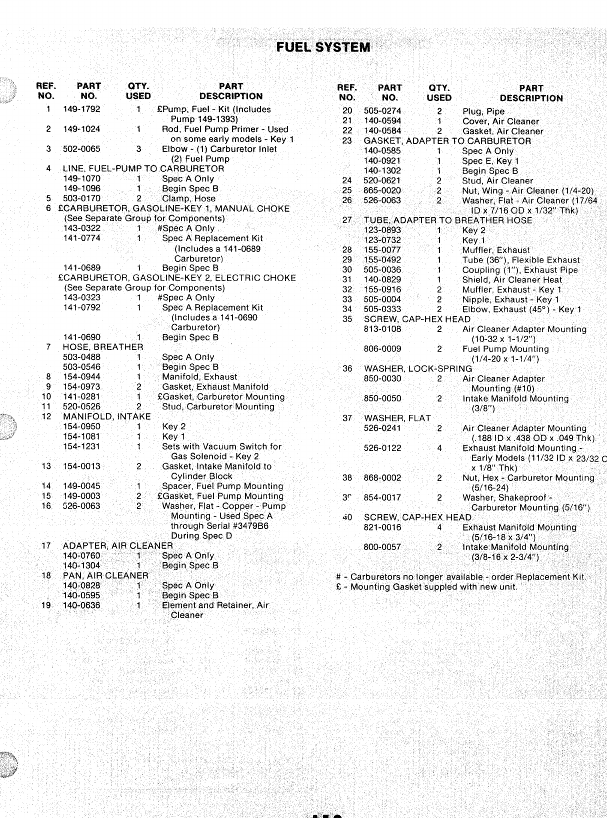
Separate Group for Components) 27 TLJBE. ADAPTER TO BRI
141-0774 1Spec AReplacement Kit ----
123-0732
(Includes a141-0689 28 155-0077
IURETOR, GASOLINE-KEY 2, ELECTRIC CHOKE ,-
31 140-0829 1
(See Separate Group for Components) Shield, ~r’ Ci’~aner H
32 155-0916 2
143-0323 M[~ffler Fxha[lst -Ke
1#Spec AOnly 33 505-0004
141-0792 1Spec AReplacement Kit 34 505-0333
(Includes a141-0690 35 SCREW, CAP-H
Carburetor)
141-0690 813-0108
1Begin Spec B
7HOSE, BREATHER
503-0488 806-0009
1Spec AOnly ‘(;”/4--?0 ;1-1 /L1’~\”o
503-0546 1Begin Spec-B
8154-0944 36 WASHER, LOCK-SPRING’ “‘- “’ “‘
1Manifold, Exhaust 850-0030 2
9154-0973 2Gasket, Exhaust Manifold Air Cleaner Adapter
10 141-0281 1Mounting (#IO)
EGasket, Carburetor Mounting 850-0050 2Intake Manifold Mour
154-1231 1Se~s with Vacuum Switch for ,, .--, -, .,.----,
526-0122 4Eyhai,ct Mnnifnld Mm
Gas Solenoid -Key 2
13 154-0013 2Gasket, Intake Manifold to —-,--
--
X1/8” Thk) ‘
15 149-0003 2Ebask@t, Fuel Pump Mountin~ 3
16 526-0063 2Washer. Flat -Comer -Pum~
Cylinder Block 38 868-0002 2
14 149-0045 1S~acer, Fuel Pum~ Mountincj Nut, Hex -Carburetor Mounting
(5/16-24)
r854-0017 2Washer, Shakeproof -
Mounting -Used’ Spec A‘Carburetor Mounting (5/16”)
40 SCREW. CAP-HEX HEAD
through Serial #3479B6 821-0016 4Exhaust M:
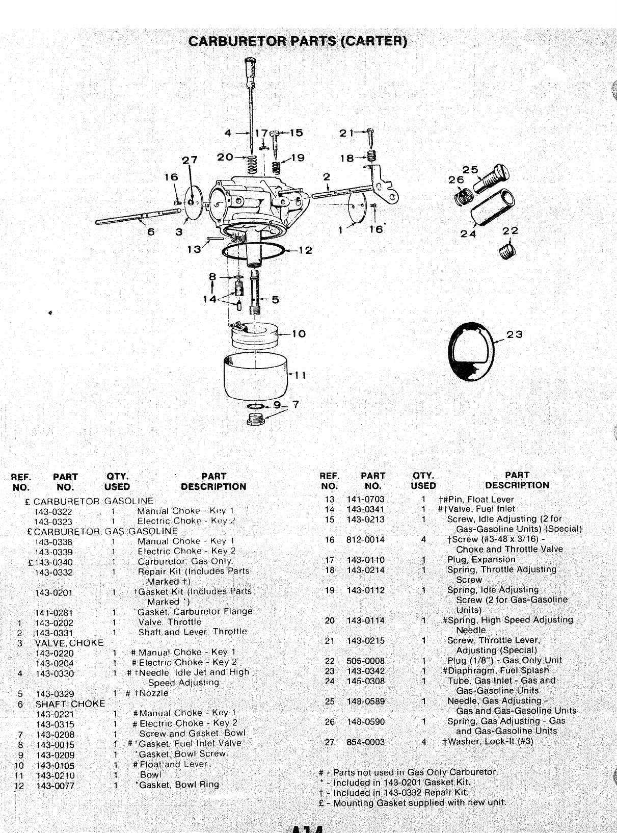
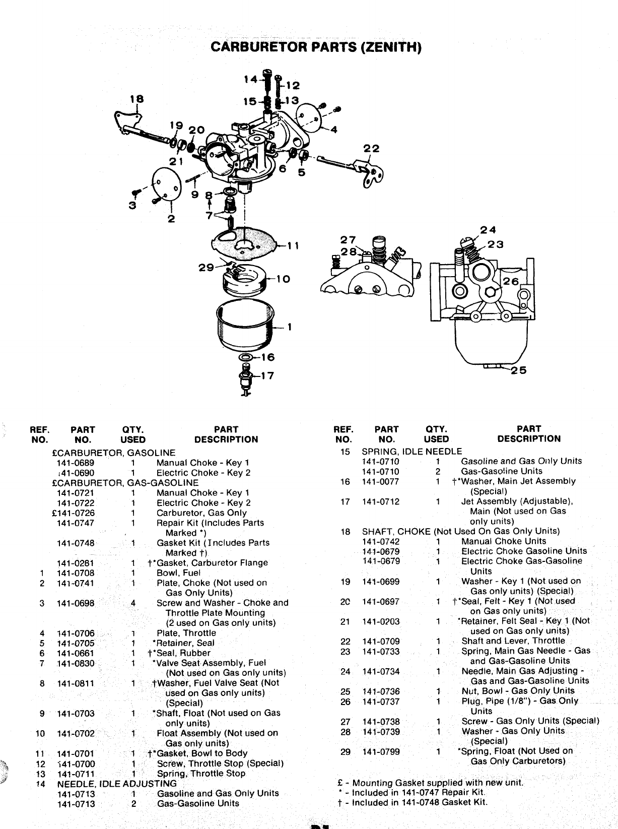
cWOmkTofi PARTS (ZENITH)
m-
14M ,2
2
REF. PART QTY. PART
NO. NO. USEI) DESCRIPTION
~CARBURETOR, GASOLINE
141-0689 1Manual Choke -Key 1
,41-0690 1Electric Choke -Key 2
SCARBURETOR, GAS-GASOLINE
141-0721 1Manual Choke- Keyl
141-0722 1Electric Choke- Key2
2141-0726 1Carburetor, Gas Only
141-0747 1Repair Kit (Includes Parts
Marked*)
141-0748 1Gasket Kit(lrw!udes Parts
.Markedt)
141-0281 1t*Gasket, Carburetor Flange
1141-0708 1BowI, Fuel
2141-0741 1Plate, Choke (Not usedon
Gas Only Units)
3141-0698 4Screw and Washer -Choke and
Throttle Plate Mounting
(2 used on Gas only units)
4141-0706 1Plate, Throttle
5141-0705 1*Retainer, Seal
6141-0661 1l_*Seal, Rubber
7141-0830 1‘Valve Seat Assembly, Fuel
(Not used on Gas only units)
8141-0811 1tWasher, Fuel Valve Seat (Not
used on Gas only units)
(Special)
9141-0703 1●Shaft, Float (Not used on Gas
24
REF. PART (2TY. PART
NO. NO. USED DESCRIPTION
15 SPRING, IDLE NEEDLE
141-0710 1Gasoline and Gas Only Units
141-0710 2Gas-Gaso!ine Units
16 141-0077 1t* Washer, Main Jet Assembly
(Special)
17 141-0712 1Jet Assembly (Adjustable),
Main (Not used on Gas
only units)
18 SHAFT, CHOKE (Not Used On Gas Only Units)
141-0742 1Manual Choke Units
lz$l.1)679 1Electric Choke Gasoline Units
141-6679 1Electric Choke Gas-Gasoline
Units
19 141-0699 1Washer -Key 1(Not used on
Gas only units) (Special)
2C 141-0697 1t* Seal, Felt -Key 1(Not used
on Gas only units)
21 141-0?03 1‘Retainer, Felt Seal -Key 1(Not
used on Gas only units)
22 141-0709 1Shaft and Lever, Throttle
23 141-0733 1Spring, Main Gas Needle -Gas
and Gas-Gasoline Units
24 141-0734 1Needle, Main Gas Adjusting -
Gas and Gas-Gasoline Units
25 141-0736 1Nut, Bowl -Gas Only Units
26 141-0737 1Plug, Pipe (1/8’) -Gas Only
Units
27 141-0738 1Screw -Gas Only Units (Special)
28 141-0739 1Washer -Gas Only Units
(Special)
29 141-0799 1*Spring, Float (Not Used on
Gas Only Carburetors)
only units)
10 141-07’02 1Float Assembly (Not used on
Gas only units)
11 141-0701 1t* Gasket, Bowl to Body
12 -i41-0700 1Screw, Throttle Stop (Special)
13 141-0711 1Spring, Throttle Stop
f4 NEEDLE, IDLE ADJUSTING E-Mounting Gasket supplied with new writ.
141-0713 1Gasoline and Gas Only Units ●-Included in 141-0747 Repair Kit.
141-0713 2Gas-Gasoline Units t-Included in 141-0748 Gasket Kit.
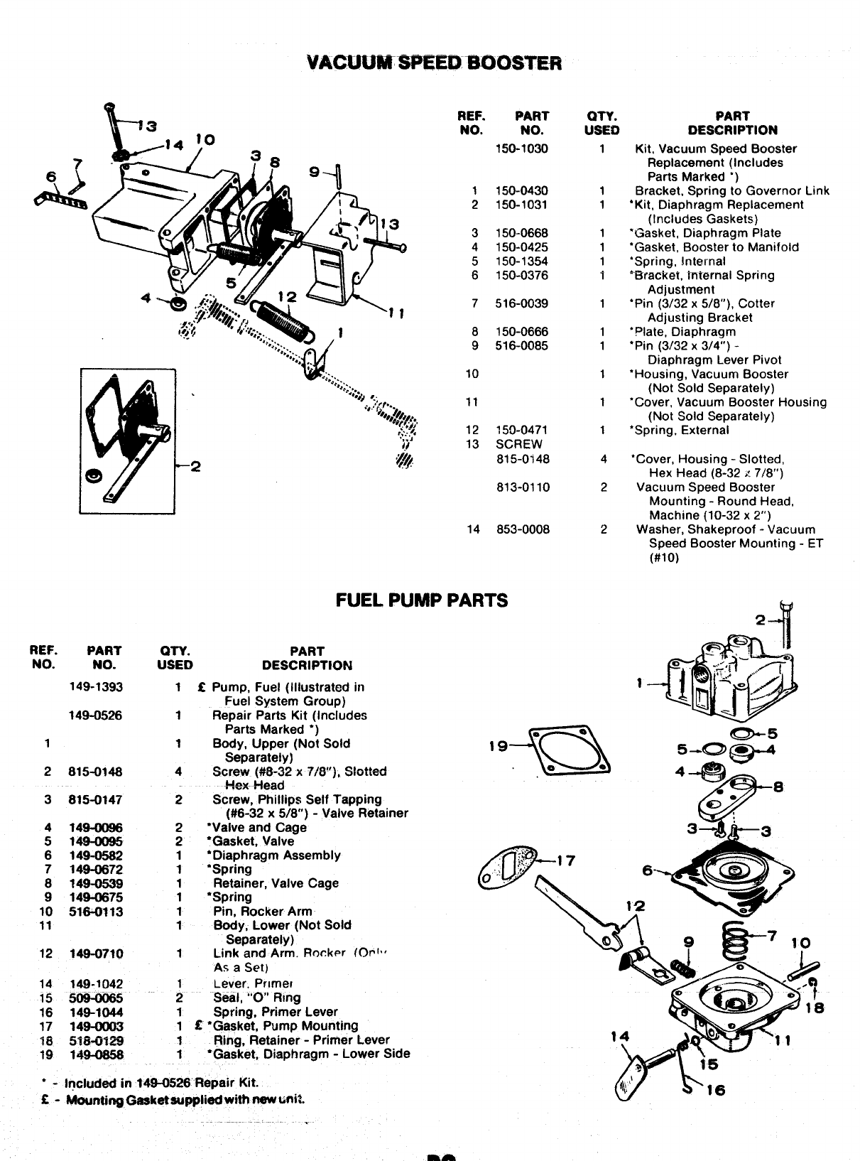
VACUUMSPEE33IKX)STER
%-l
x. .3 REF.
NO. PART
NO.
150-1030
QTY. PART
USED DESCRIPTION
1
1
1
1
1
1
1
1
1
1
1
1
1
4
Kit, Vacuum Speed Booster
Replacement (Includes
Parts Marked *)
Bracket, Spring to Governor Link
●Kit, Diaphragm Replacement
(Includes Gaskets)
“Gasket, Diaphragm Plate
●Gasket, Booster to Manifold
●Spring, !nternal
-–——.—. . . .
r5racKe1, Imernai Spring
Adjustment
‘Pin (3/32 x5/8”), Cotter
Adjusting Bracket
‘plate, Diaphragm
●Pin (3/32 x3/4”) -
Diaphragm Lever Pivot
‘Housing, Vacuum Booster
(Not Sold Separately)
‘Cover, Vacuum Booster Housing
(Not Sold Separately)
‘Spring, External
1
2
150-0430
150-1031
3
4
5
6
150-0668
150-0425
150-1354
150-0376
7516-0039
8
9
150-0666
516-0085
‘J.:,:.. w
%,..
“
%.. ...
.+ ...
%,,;.. 10
.
“2
11
12
13 150-0471
SCREW
815-0i48 ●Cover, Housina -Slotted,
Hex Head (8:32 x7/8”)
Vacuum Speed Booster
Mounting -Round Head,
Machine (10-32 x2“)
Washer, Shakeproof -Vacuum
Speed Booster Mounting -ET
(#lo)
813-0110
14 853-0008
2
2
II
FUEL PUMP PARTS
2-+
REF.
NO. PART
NO. on.
USED
If
1
1
4
2
2
2
1
1
1
1
1
1
1
;
1
Iil
1
1
PART
DESCRIPTION
Pump, Fuel (Illustrated in
Fuel System Group)
Repair Parts Kit flncludes
149-1393
149-0526
Parts Marked ●j
+ff\
*e
Body, Upper (Not Sold 19
Separately)
Screw (M-32 x7/6”;, SM+d e0
Hex- Head
Screw, Phillips Self Tapping
(#6-32 x5/8”) -Valve Retainer
‘Valve and Cage
‘Gasket, Valve
‘Diaphragm Assembly
@
.~..:..
..
‘Spring ....
Retainer, Valve Cage
~.;,,, $’ ‘7
‘Spring \
Q5
5.aJg@&4
4+9
e
8
a“
3--
+
3
6- _@””
4
12
.e
1
2
3
815-0~48
815-0147
4
5
6
;
9
10
11
149
149
149
149
149
149
516
*
*
*
*
.
-0582
-0672
-0539
-0675
-0113 Pin, Rocker Arm
Body, Lower (Not Sold
Separately)
Link and Arm. Rocker (Orl”
As aSet)
l-ever, Primer
Se&l, “O” Rmg
Spring, Primer Lever
‘Gasket, Pump Mounting
Ring, Retainer -Primer Lever
‘Gasket, Diaphragm -Lower Side
12 149-0719
14 149-1042
15 5m-oo65
16 149-1(M4
17 14g-ofXJ3
18 5WOIZ%
19 149-0s56
,
,
●-Included in W$0526 Ftepair Kit.
C-Mounting Gasket eupplied with new Wit.
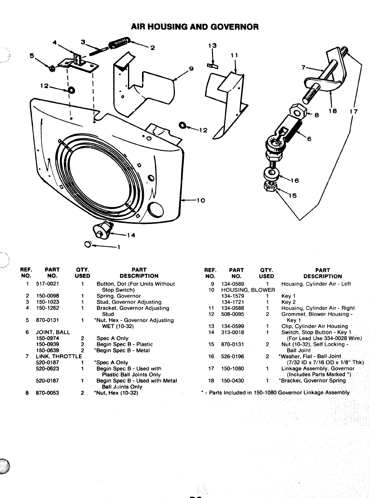
AIR HViwmm mm GOVERNOR
’24 Il-v \
4,, ,
.’..,’ ‘REF. PART
NO. NO.
1517-0021
2150-0098
3150-1023
4150-1262
5870-0131
6JOINT, BALL
.- --- .
13U-WG
150-0939
150-0639
w
0
QTY. PART REF. PART QTY.
USED DESCRIPTION NO. NO. USED
1
1
1
1
1
2
2
2
7LINK, THROTTLE
520-0187 1
520-0623 1
520-0187 1
8870-0053 2
Button, Dot (For Units Without
Stop Switch)
Spring, Governor
Stud, Governor Adjusting
Bracket, Governor Adjusting
Stud
“Nut, Hex -Governor Adjusting
WET (10-32)
Spec AOnly
Begin Spec B-Plastic
‘Begin Spec B-Metal
●Spec AOnly
Begin Spec B-Used with
Plastic Ball Joints Only
Begin Spec B-Used with Metal
Ball Jaints Onlv
9
10
11
12
13
14
15
16
17
18
134-0589 1
HOUSING, BLOWER
134-1579 1
134-1721 1
134-0588 1
508-0095 2
134-0599 1
313-0018 1
870-0131 2
526-0196 2
150-1080 1
150-0430 1’
*
PART
DESCRIPTION
Housing, Cylinder Air -Left
Key 1
Key 2
Housing, Cylinder Air -Right
Grommet, Blower Housing -
Kev 1
Clip, ”Cylinder Air Housing
Switch, Stop Button -Key 1
(For Lead Use 334-0028 Wire)
Nut (10-32), Self Locking -
Bail Joint
‘Washer, Flat -Ball Joint
(7/32 ID X7/16 OD X1/8” Thk)
Linkage Assembly, Governor
(Includes Parts Marked *)
‘Bracket., Governor Spring
●Nut, Hex (10-32)’ *-Parts Included in 150-1080 Governor Linkage Assembly.
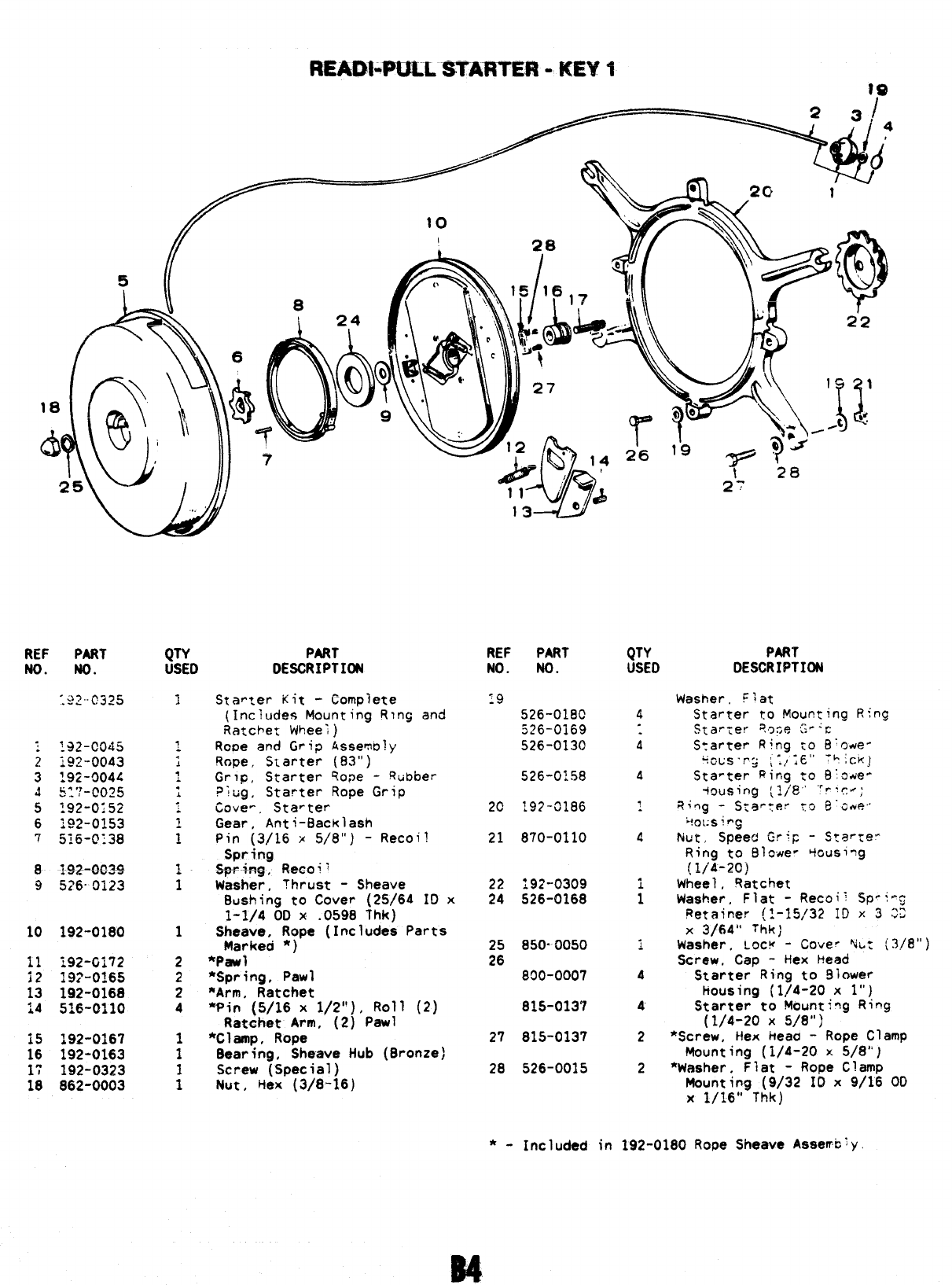
READ1+ULLSTARTER-KEYtfe
REF PART
No. No.
-;>7..~.3~5
---
QTY PART
USED DESCRIPTION
REF PART
NO. NO.
19
526-018C
526-0169
526-0130
526-0:58
20 192-C1186
21 870-0110
192-0309
:: 526-0168
25 850.0050
26 890-0007
815-0137
27 815-0137
28 526-0015
QTY PART
USEO DESCRIPTION
Ring
1Starter Kit -Complete
(Includes Mounting Rlncj and
Ratchet WheeI)
Rooe and Grip Assemoly
Rope, Starter (93”)
Grlo, Starter ~o~e -Rtibber
?ltig, Starter Rope Grip
Cave-, Starter
Gear, Anti-Backlash
Pin (3/16 x5/8”) -Recoil
Spfirig
*.+8~, ~~~o~i
Washer, Thrust -Sheave
Bushing to Cover (25/64 ID x
1-1/4 OD x.0598 Thk)
Sheave, Rope (Includes Parts
Marked *)
*Pawl
*Spring, Pawl
*Arm, Ratchet
‘Pin (5/16 x1/2”), Roll (2)
Ratchet Arm, (2) Pawl
*Clamp, Rope
8aaring, Sheave Hub (8ronze)
Screw (Special)
Nut, Hex (3/8-16)
Washer. C~at
Starter to Mounting
StarTer ?oce Gp:c
4
i
4
4
i
1
A
4
~
2
2
S~arter Ring to B’owe-
+~us.,-.j ;:,;~” ‘h;c~j
Sta~ter Ring :0 B~a4e-
+~using (~/8° “’r~c~;
~i~g -S:ar:er ~~ g’~~5,
k!~:;sin(j
Nut, Speed Gr+p -Starte-
Ring to Blower +cusing
(IJ’A-20)
Wheel, Ratchet
Washer, Flat -Re~cji; Sp-i-cj
petainer (1-l!j,/32 ID x3 02
X3/64” Thkj
Washer, Lock -COve” Nb: (?/8”)
Screw. Cap -Hex Head
Starter Ring to 910wer
housing (1/4-20 xl“)
Starter to Mount+ag Ring
(1/4-20 X5/8”]
*Screw, Hex heaa -Rope Clamp
Mounting (1/4-20 x5/8”)
*Washer. Flat -Rope Clamp
8
9i$?2-OC-3+
!526- 0123
1
i
10 192-0180 1
11 :92-G172
12 19?-0165
13 192-0168
14 516-0110
2
2
2
4
15 192-0167
16 192-0163
17 192-0323
18 862-0003 Mounting (9/32 IO x9/16 OD
X1/16” Thk)
*- Included in 192-0180 Rope Sheave Assemc~y
~
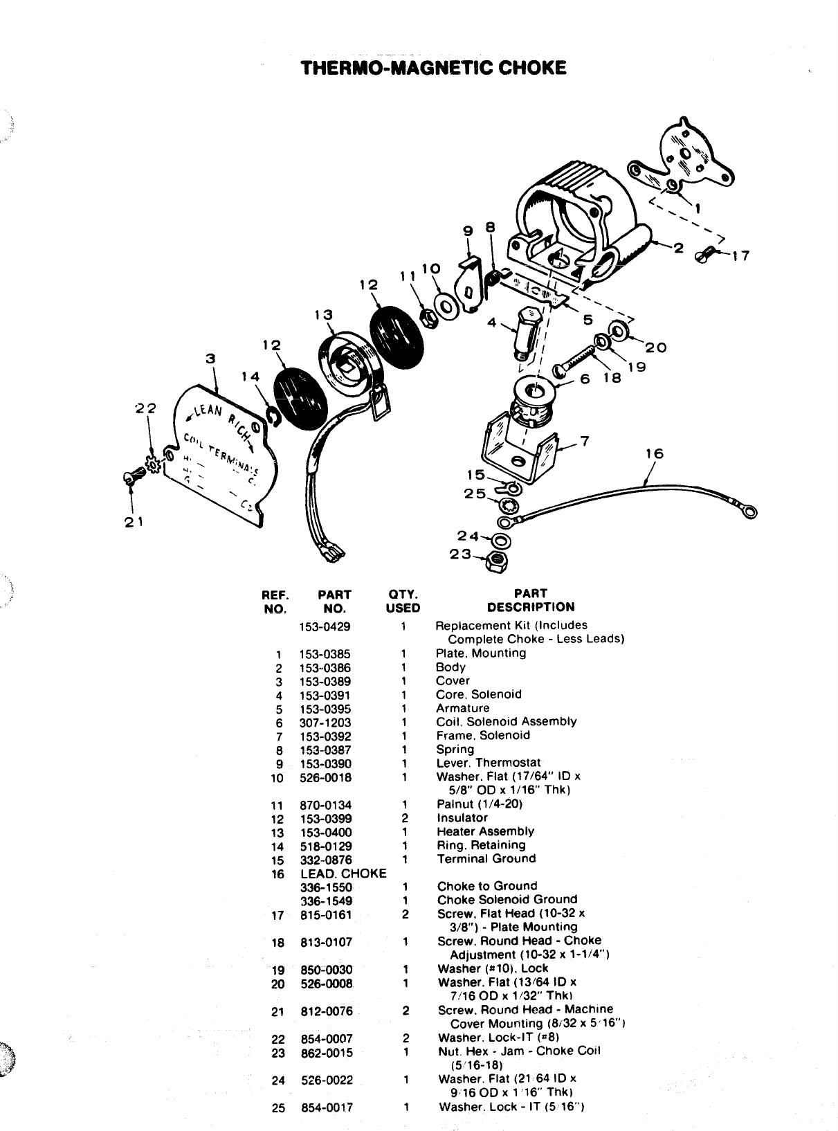
THERMO-MAC3NET!C CHOKE
,,
24 ~-
Q
23 ~
-Q
1’ REF.
No. PART
NO.
153-0429
QTY.
USED
1
1
1
1
1
1
1
1
~
1
1
;
1
1
1
PART
DESCRIPTION
Replacement Kit (Includes
Complete Choke -Less Leads)
Plate, Mounting
Body
Cover
Core. Solenoid
Armature
Coil, Solenoid Assembly
Frame, Solenoid
Spring
Lever. Thermostat
Washer. Flat (17/64” ID x
5/8” OD X1/16” Thk)
Palnut (1/4-20)
Insulator
Heater Assembly
Ring. Retaining
Terminal Ground
1
2
3
4
5
6
7
~
9
10
153-0385
153-0386
153-0389
153-0391
153-0395
307-1203
153-0392
I~~=~~~?
153-0390
526-0018
11
12
13
14
15
16
870-0134
153-0399
153-0400
518-0129
332-0876
LEAD. CHOKE
336-1550
336-1549
815-0161
Choketo Ground
Choke Solenoid Ground
Screw, Flat Head (10-32x
3/8”) -Plate Mounting
Screw. Round Head -Choke
Adjustment (10-32 x1-1/4”)
Washer ($$10), Lock
Washer. Flat (13164 ID x
7/16 OD X1/32” Thk)
Screw. Round Head -Machine
Cover Mounting (8/32 x5’16” I
Washer. Lock-lT (=8)
Nut. Hex -Jam -Choke Coil
(5’16-18)
Washer. Flat (21 64 ID x
9160D X1’16” Thk)
Washer. Lock -IT (5 16”)
17
813-010718 1
19
20
850-0030
526-0008
1
1
21
22
23
812-0076
854-0007
862-0015
2
2
1
24
25
526-0022 1
854-0017 1
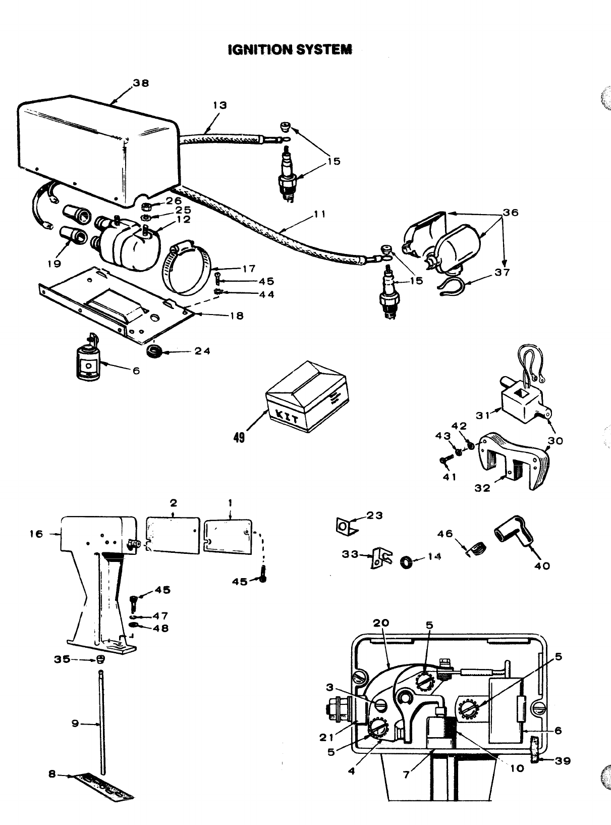
IGNITWM SYSTEM
16
EA7--24
K23
0
33* 46\~ *
&J- (w” ‘- 40
29 5
“
-
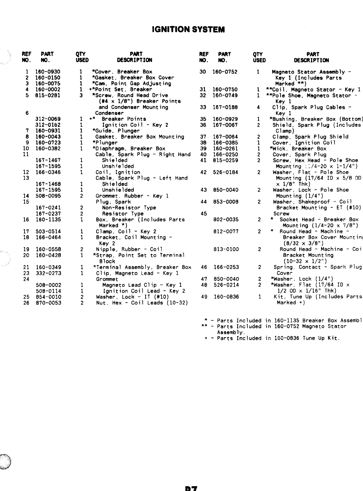
iGNITIONSYSTEM
1160-0930
2160-0150
3160-0075
4160-0002
5815-0281
6
12
13
14
15
16
17
18
19
20
312-0069
312-0162
160-0931
160-0043
160-0723
160-0382
●e” ,..s”
LUI-L4VI
167-1595
166-0346
167-1468
167-1595
508-0095
167-0241
167-0237
160-1135
503-0514
166-0464
160-0558
160-0428
21 160-0349
23 332-0273
24
508-0002
508-0114
25 854-0010
26 870-0053
QTY PART
U6ED DESCRIPTIffl
1
:
1
3
1
i
1
1
1
1
1
1
1
1
1
2
2
2
1
1
1
2
1
1
1
1
1
2
2
*Cover, Breaker 80X
*Gasket, 8reaker Box Cover
*Cam, Point Gap Adjusting
+*point Set, Breaker
*Screw, Round Head Drive
(#4 x1/8”) Breaker Points
and Condenser Mounting
Condenser
+* Breaker Points
ignition Coil -Key 2
*6uide, Plunger
Gasket, Breaker Box Mounting
*Plunger
*Diaphragm, Breaker Box
Cable, Spark Plug -Right Hand
Shielded
Unshielded
Coil, Ignition
Cable, Spark Plug -Left Hand
Shielded
Unshielded
Grommet, Rubber -Key 1
Plug, Spark
Non-Resistor Type
Resistor Type
Box, Breaker (Includes Parts
Marked *)
Clamp, Coil -Key 2
Bracket, Coil Mounting -
Key 2
Nipple, Rubber -Coil
*Strap, Point Set to Terminal
Block
*Terminal Assembly, Breaker Box
Clip, Magneto Lead -Key 1
Grommet
Magneto Lead Clip -Key 1
Ignition Coil Lead -Key 2
Washer, Lock -IT (#10)
Nut, Hex -Coil Leads (10-32)
REF PART
m. m.
30 160-0752
31 160-0750
32 160-0749
33 167-0188
35 160-0929
36 167-0067
37 167-0064
38 166-03B5
39 160-0261
40 166-0250
41 815-0259
42 526-0184
43 850-0040
44 853-0008
45
802-0035
812-0077
813-0100
46 166-0253
47 850-0040
48 526-0214
49 160-0836
QTY PART
USED DESCRIPTI~
1
1
1
4
1
2
2
1
1
2
2
2
2
2
2
2
2
2
2
2
1
-Parts Included
*1 -parts Included
Assembly.
+- Parts Included
Magneto Stator Assembly -
Key 1(Includes Parts
Marked **)
**Coi~, Magneto Statcw -Key 1
**Pole Shoe, Magneto Stator -
Key 1
Clip, Spark Plug Cables -
Key 1
*Bushing, Breaker Box (Bottom)
Shield, Spark Plug (Includes
Clamp)
Clamp, Spark Plug Shield
Cover, Ignition Coil
*Wick, Breaker Box
Cover, Spark Plug
Screw, Hex Head -Pole Shoe
Mounting ::/4-20 X1-1/4”)
Washer, Flat -Pole Shoe
Mounting (17/64 ID x5/8 OD
X1/8” Thk)
Washer, Lock -Pole Shoe
Mounting (1/4”)
Washer, Shakeproof -Coil
Bracket Mounting -ET (#10)
Screw
*Socket Head -Breaker Box
Mounting (1/4-20 x7/8”)
*Round Head -Machine -
Breaker Box Cover Mounting
(8/32 X3/8”)
Round Head -Machine -Coil
Bracket Mounting
(10-32 X1/2”)
Spring, Contact -Spark Plug
Cover
*Washer, Lock (1/4”)
*Washer, Flat (17/64 ID x
1/2 OD X1/16” Thk)
Kit, Tune Up (Includes Parts
Marked +) ‘
in 160-1135 Breaker
in 160-0752 Magneto
in 150-0836 Tune Up
80X
Assembly.
Stator
Kit.
B7
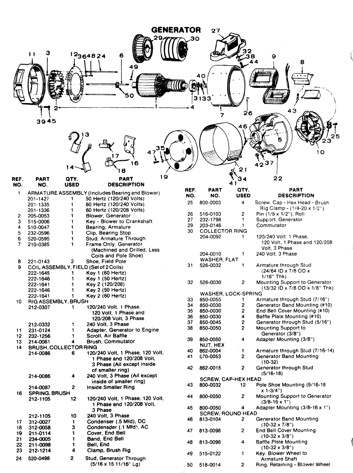
GENERATOR 27
NO.
1
2
3
4
5
6
7
8
9
10
11
12
13
14
NO. USED DESCRIPTION
ARMATURE ASSEMBLY (Includes Bearing and Blower)
201-1427 150 Hertz (120/240 Volts)
201-1335 160 Hertz (120/240 Volts)
201-1336 180 Hertz (120/208 Volts)
2?05-0053 1Blower, Generator
515-0006 1Key -Blower to Crankshaft
510-0047 1Bearing, Armature
232-0596 1Clip, Bearing Stop
520-0595 1Stud, Armature Through
210-0385 1Frame Only, Generator
(Machined and Drilled, Less
Coils and Pole Shoe)
221-0143 2Shoe, Field Pole
COIL ASSEMBLY, FIELD (Set of 2Coils)
222-1645 1Key 1(60 Hertz)
222-1646 1Key 1(50 Hertz)
222-1641 1Key 2(120/208)
222-1646 1Key 2(50 Hertz)
222-1641 Key 2(60 Hertz)
RIG ASSEMBLY, dRUSH
212-0307 1120/240 Volt, 1Phase,
120 Volt, 1Phase and
120/208 Volt, 3Phase
212-0332 1240 Volt, 3Phase
231-0124 1Adapter, Generator to Engine
232-1256 1Scroll, Air Baffle
214-0061 4Brush, Commutator
BRUSH, COLLECTOR RING
214-0086 6
214-0086 4
214-0087 2
16 SPRING, BRUSH
212-1105 12
212-1105
17 312-0027
18 312-0058
19 211-0114
21 234-0005
22 211-0098
23 212-1214
24 520-0498
10
:
1
1
1
4
2
1201240 Volt, 1Phase, 120 Volt,
1Phase and 1201208 Volt,
3Phase (All except inside
of smaller ring)
240 Volt, 3Phase (Ail except
inside of smaller ring)
Inside Smaller Ring
120/240 Volt, 1Phase, 120 Volt,
1Phase and 1201208 Voit,
3Phase
24Il Volt, 3Phase
Condenser (.5 Mfd), DC
Condenser (.1 Mfd), AC
Cover, End Bell
Band, End Bell
Bell, End
C!a.mp, Brush Rig
Stud, Generator Through
(5/16x 15 11/16’ Lg)
.-
4“1--
REF. PART QTY. PART
NO. NO. USED DESCRIPTION
25 800-0003 4Screw, Cap -Hex Head -Brush
Rig Clamp -(1/4-20 x1/2”)
26 516-0103 2Pin (1/8 x1/2”), Roll
27 232-1798 1Support, Generator
29 203-0146 1Commutator
30 COLLECTOR RING
204-0092 1120/240 Volt, 1Phase,
120 Volt, 1Phase and 120/208
Volt, 3Phase
204-0010 1240 Volt, 3Phase
WASHER, FLAT
31 526-0032 1Armature through Stud
(24/64 ID X7/8 OD X
1/16” Thk)
32 526-0030 2Mounting Support to Generator
(13/32 ID X7/8 OD X1/8” Thk)
WASHER, LOCK-SPRING
33
34
35
36
37
38
39
40
41
42
850-0055
850-0030
850-0030
850-0030
850-0045
850-0050
850-0050
NUT, HEX
862-0004
&70-oo53
862-0015
1
2
2
4
2
2
4
1
2
2
Armature through Stud (7/16”)
Generator Band Mounting (#10)
End Bell Cover Mounting (#10)
Baffle Plate Mounting (#10)
Generator through Stud (5/16”)
Mounting Support to
Generator (3/8”)
Adapter Mounting (3/8”)
Armature through Stud (7/16-14)
Generator Band Mounting
(10-32)
Generator throuah Stud
(5/16-18) -
SCREW, CAP-HEX HEAD
43 800-0032 12 Pole Shoe Mounting (5/16-18
x1-3/4”)
44 800-0050 2Mounting Support to Generator
(3/8-16 Xl“)
45 800-0050 4Adapter Mounting (3/8-16 x1”)
SCREW, ROUND HEAD
46 813-0104 2Generator Band Mounting
(10-32 X7/8”)
47 813-0098 2End Bell Cover Mountirm
(10-32 X3/8”) -
48 813-0098 4Baffle Plate Mounting
(10-32 X3/8”)
49 515-0122 1Key, Blower Wheel to
Armature Shaft
50 518-0014 2
Ring,
Retaining -Blawer Wheel

.
.
——-.
@j”’ liib (qip
\’
5
17, 16, A1
B
o
“)-
7
,’
,_&-
0
+
0
37
.;
w
/!
~
fp/
:
,)-Q
:,
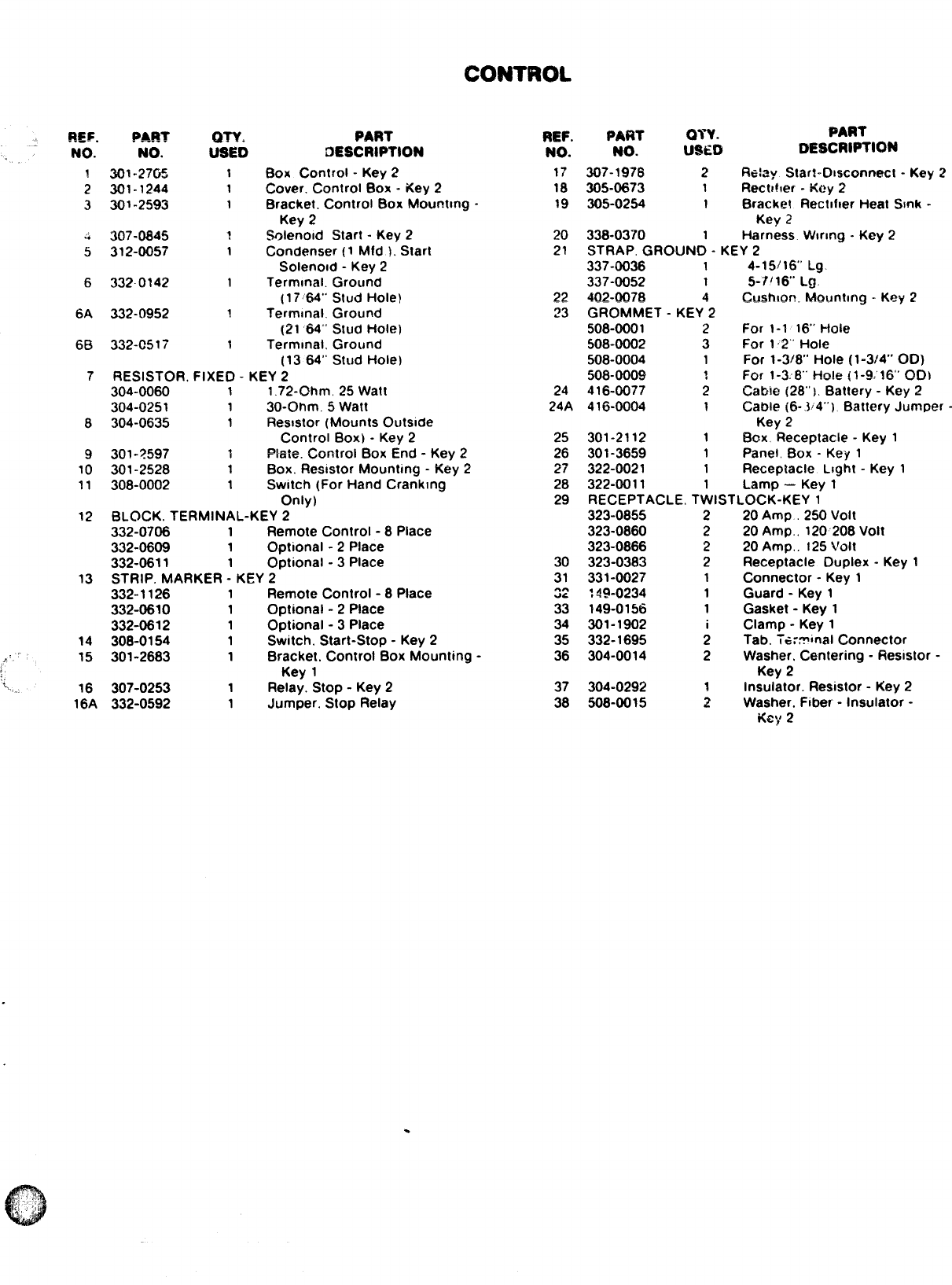
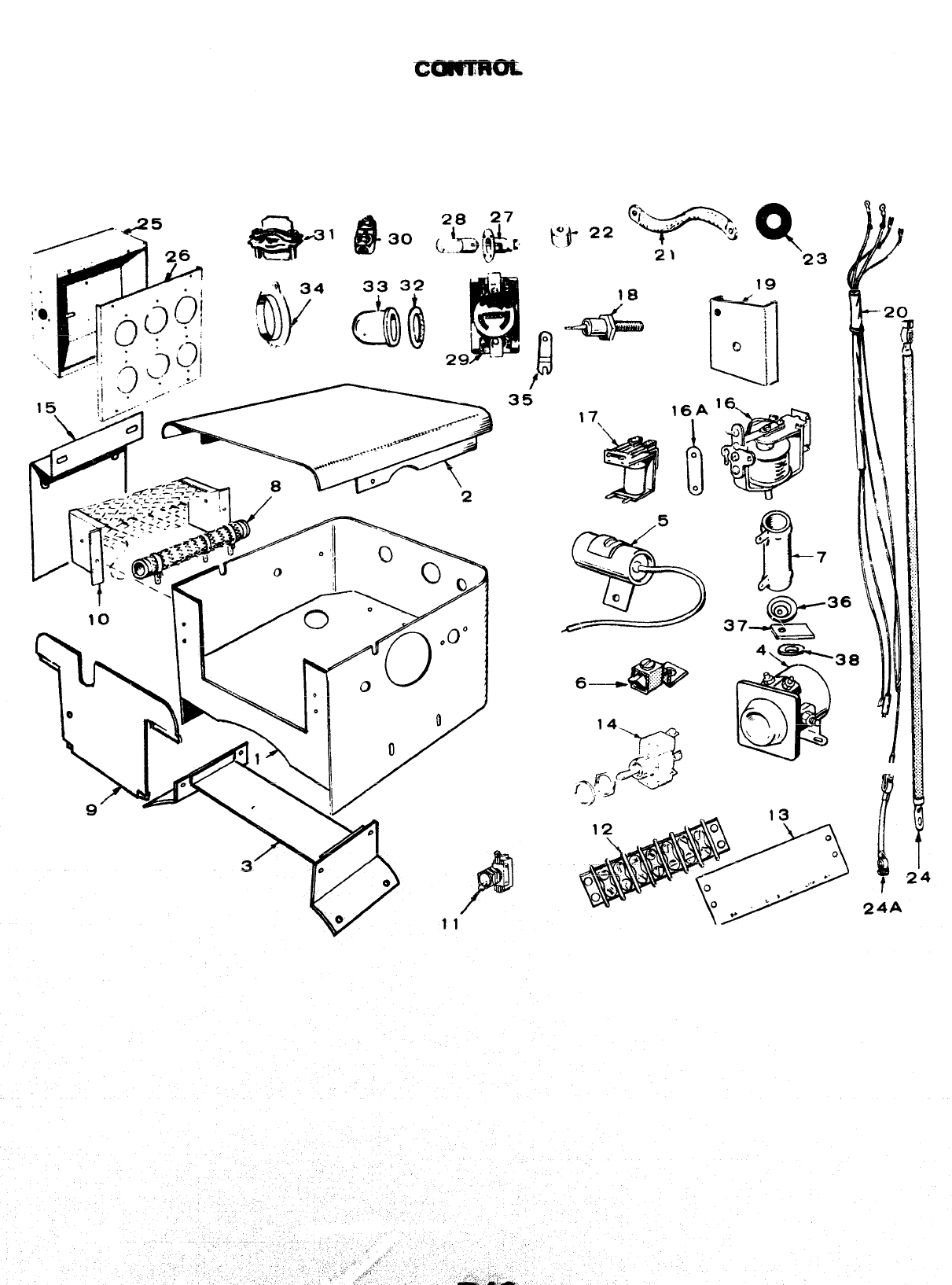
CONTROL
REF.
“’ NO.
~
2
3
6
6A
6B
7
8
9
10
11
12
13
14
J’ 15
1., 16
16A
pART
NO.
3i)l -2705
301-1244
301-2593
307-0645
312-0057
332-0142
332-0952
332-0517
QTY.
USEI)
1
1
1
?
1
1
1
1
PART
DESCRIPTION
Box Control -Key 2
Cover. Control Etox -Key 2
Bracket. Control Box Mourmng -
Key 2
%lenold Start -Key 2
Condenser (1 Mfd ). Start
Solenoid -Key 2
Terminal. Ground
[17%4” Stud Hole)
Terminal. Ground
(21 64”: Stud i-tOh?}
Terminal, Ground
(13 64” Stud Hole)
RESISTOR, FIXED -KEY 2
304-0060 11.72-Ohm, 25 Watt
304-0251 130-Ohm. 5Watt
304-0635 1Resstor (Mounts Outside
Control Box) -Key 2
301-? 597 1Wa:e. Control Box End -Key 2
301-2528 1Box. Reststor Mounting -Key 2
308-0002 1Switch (For Hand Cranking
Only)
BLOCK. TERMINAL-KEY 2
332-0706 1Remote Control -8 Place
332-0609 1Optional -2 Place
332-0611 1Optional -3 Place
STRIP. MARKER -KEY 2
332-1126 1Remote Control -8 Place
332-0610 1Optional -2 Place
332-0612 1Optional -3 Place
308-0154 1Switch. Start-Stop -Key 2
301-2683 1Bracket. Control Box Mounting -
Key 1
307-0253 1Relay. Stop -Key 2
332-0592 1Jumper. Stop Relay
REF. PART WY. PART
NO. NO. USED DESCRIPTION
17 307-1978 2f%:~y Starl-Dwconnac: -Key 2
18 305-0673 1Recther -Key 2
19 305-0254 1Bracket Rectlfler Heat Smk -
Key 2
20 338-0370 1Harness. Wlnng -Key 2
21 STRAP, GROUND -KEY 2
337-0036 14-15116” Lg.
337-0052 15-7116’ Lg.
22 402-0076 Cushion- Mounttng -Key 2
23 GROMMET -KEY42
508-0001 2For 1-1 16” Hole
508-0002 3For 12“ Hole
508-0004 1For 1-3/8” Hole (1-3/4” 00)
508-0009 ?For 1-3:8’ Ho!e {1-9.16” 00}
24 416-0077 2Cabie (28”). Battery -Key 2
24A 416-0004 1Cable (6-3:4”), Battery Jumper
-
Key 2
25 301-2112 1Box, Receptacle -Key 1
26 301-3659 1Panel, Box -Key 1
27 322-0021 1Receptacle Light -Key 1
28 322-0011 1Lamp –Key 1
29 RECEPTACLE. TWISTLOCK-KEY 1
323-0855 2 20 Amp .250 Volt
323-0860 2 20 Amp., 120208 Volt
323-0866 2 20 Amp,. 125 Volt
30 323-0383 2Receptacle Duplex -Key 1
31 331-0027 1Connector -Key 1
22 ;39.0234 1Guard -Key 1
33 149-0156 1Gasket -Key 1
34 301-1902 iClamp -Key 1
35 332-1695 2Tab. TG:Vinal Connector
36 304-0014 2Washer, Centering -Ftesmtor -
Key 2
37 304-0292 Insulator. Resistor -Key 2
38 508-0015 4Washer. Fiber -Insulator -
Kc;# 2
.
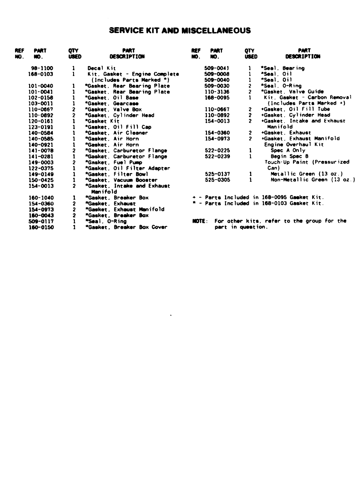
$13WCE KITAND M8SCELLAMWX$$
MF Wtl
w, m.
9s-1100
166-0103
101-0040
101-0041
102-OIW
103-0011
1SO-0667
110-0692
120-016!
------ .
In-mm
140”0564
140-0565
140-0921
141-0078
~:~+g~~
149-0003
122-03’?5
149-0149
150-0425
154-0013
160-1040
.- —----
154-tJ3w
154-0973
160-0043
S09-0117
160-0150
Qw MM
OEsukwma
1
1Oecal Kit
Kit, (iaaket -Engine Complete
(includes Parts Marked *)
%aaket, Rear 6aaring Plate
*Gasket, Rtmr Gearing Plate
%esket, Oil Base
*Gasket. Gaarcasa
*Gasket. Valve 60X
●Gaaket, Cylinder Head
*CA-* ~~g
—.
*Gasket,
*Genket.
*Gaaket,
*Gaaket.
*Gasket.
*P—L.*
—.. .
*Gasket.
*Gasket.
%aeke:,
*Gaaket.
*Gasket,
Oil Fill Cap
Air Cleaner
Air Horn
Air Horn
Carburetor Flange
Carburetor Flange
Fuel Ptmp
Oil Filter Adapter
Filter Ltowl
Vacuum Oooster
Intake and Exhaust
Manifold
*Gasket, Breaker
%aeket. Exhaust
●Gaaket, Exhauat
*Gasket, Breaker
%eal. O-Ring
*Gasket, Breaker
Box
Uanifold
60X
Oox Gover
wPART wPmT
NG. MO. RE9cRIPTIm
SO$-0041
506-00G6
509-0040
S09-0030
110-3136
168-0095
110-0667
110-0892
1!54-0013
154-0360
154-0973
522-0225
S22-0239
I
1
2
2
1
2
2
2
2
2
1
1
1
1
“Seal. Bearing
*seal. oil
“Ss81. Oil
*Seal. O-Ring
*Gasket. Valve Guide
Kit, Gasket -Carbon Removal
(Includes Parts Marked +)
+Gasket. Oil Fill ~uba
+Gasket. cyiinder Head
+Gasket. Intake and Exhaust
Manifold
+Gasket. Exhaust
+Gasket, Exhsust Manifold
Engine Overhaul Kit
Spec AOn~y
6agin Spat B
Touch-Up Paint (Pressurized
Can )
Metallic Green (13 oz.)
Non-Metallic Green (13 oz.)
+- Perts Included in 168-0095 Gasket Kit.
●-Parts Included in 168-0103 Gasket Kit.
NOTE: For other kits, refer to the group for the
part in question.
,,.*.
#w
,..
OPTIONAL !ECiUIPhllEi$lk‘PARTS SECTION
‘+
This section contains illustrated parts listing of factory installed options for the generator
sets. Options may not be applicable to all models; for field conversions additional parts are
usually required. Some parts listed in the standard parts section beginning Spec f3 are’’also
applicable as optionalparts for Spec A. Optional parts listed in this section are in addition or
.,, in place of those shown “in the standard parts section.
,,,
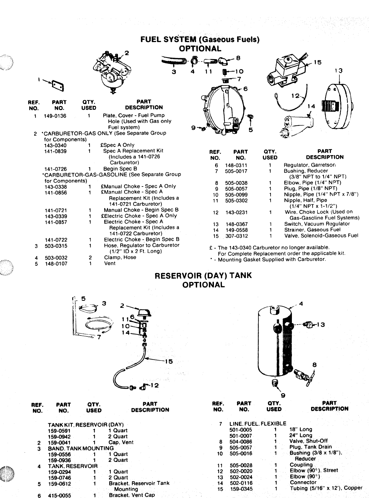
FUEL SYSTEM (Gaseous Fuels)
1
3
PART
411 ylo
-7
9
REF. PART QTY.
NO. NO. USED DESCRIPTION
1149-0136 1Plate, Cover -Fuel Pump
Hole (Used with Gas only
Fuel system)
2‘CARBURETOR-GAS ONLY (See Separate Group
for Components)
143-0340 1C3pec AOnly
141-0839 1Spec AReplacement Kit
(Includes a141-0726
Carburetor)
141-0726 1Begin Spec B
“CARBURETOR-GAS-GASOLINE (See Separate Group
REF. PART
NO. NO.
6148-0311
7505-0017
8505-0038
9505-0057
10 505-0099
11 505-0302
12 143-0231
13 148-0367
14 149-0558
15 307-0312
QTY.
USED
1
1
PART
DESCRIPTION
Regulator, Garretsorl
Bushing, Reducer
(3/8” NPT to 1/4” NPT)
Elbow, Pipe (1/4” NPT)
Plug, Pipe (1/8” NPT)
Nipple, Pipe (1/4” IvPT x718”)
Nipple, Half, Pipe
(1/4” NPT X1-1/2!”)
Wire, Choke Lock (Used on
Gas-Gasoline Fuel Systems)
for Components) fManual Choke -Spec AOnly
!ZManual Choke -Spec A
Replacement Kit (Includes a
141-0721 Carburetor)
Manual Choke -Begin Spec B
QElectric Choke -Spec AOnly
Electric Choke -Spec A
Replacement Kit (Includes a
141-0722 Carburetor)
Electric Choke -,Begin Spec B
Hose, Regulator to Carburetor
(1/2” ID x2Ft. Long)
Clamp, Hose
Vent
1
1
1
1
143-0338
141-0856
1
1
141-0721
143-0339
141-0857
1
1
1
1
1Switch, Vacuum Regulator
1Strainer, Gaseous Fuel
1Valve, Solenoid-Gaseous Fuel
141-0722
3503-0315
1
1E-The 143-0340 Carburetor no longer available.
For Complete Replacement order the applicable kit
‘-Mounting Gasket Supplied with Carburetor.
4503-0032
5148-0107
2
1
RESERVOIR (DAY)
OPTIONAL
TANK
!’,. 5
3
e
)----15
c@#-12
9
PART QTY. PART
NO. USED DESCRIPTION
PART REF.
DESCRIPTION NO.
7
REF. PART QTY.
NO. NO. USED
TANK KIT. RESERVOIR (DAY)
159-0591 11Quart
159-0942 1 2 Quart
LINE. FUEL. FLEXIBLE
501-0005 118“ Long
501-0007 1 24 Long
504-0086 1Valve, Shut-Off
505-0057 1Plug. Tank Drain
505-0016 1Bushing (3/8 x1/8”),
Reducer
2159-0041 Cap, Vent 8
38AND. TANK MO~NTING 9
159-0556 11Quart 10
159-0936 12Quart
$;% 4TANK. RESERVOiR 11 505-0028 1Coupling
159-0294 11Quart 12 502-0020 1Elbow (90’ ), Street
$J :.,j$f 159-0746 12Quart 13 502-0024 1Elbow (90’ )
5159_”12 1Bracket, Reservoir Tank 14 502-0116 1
Mounting
Connector
15 159-0345 1
6415-0055
Tubing (5/16 x12’), Copper
1Bracket, Vent Cap
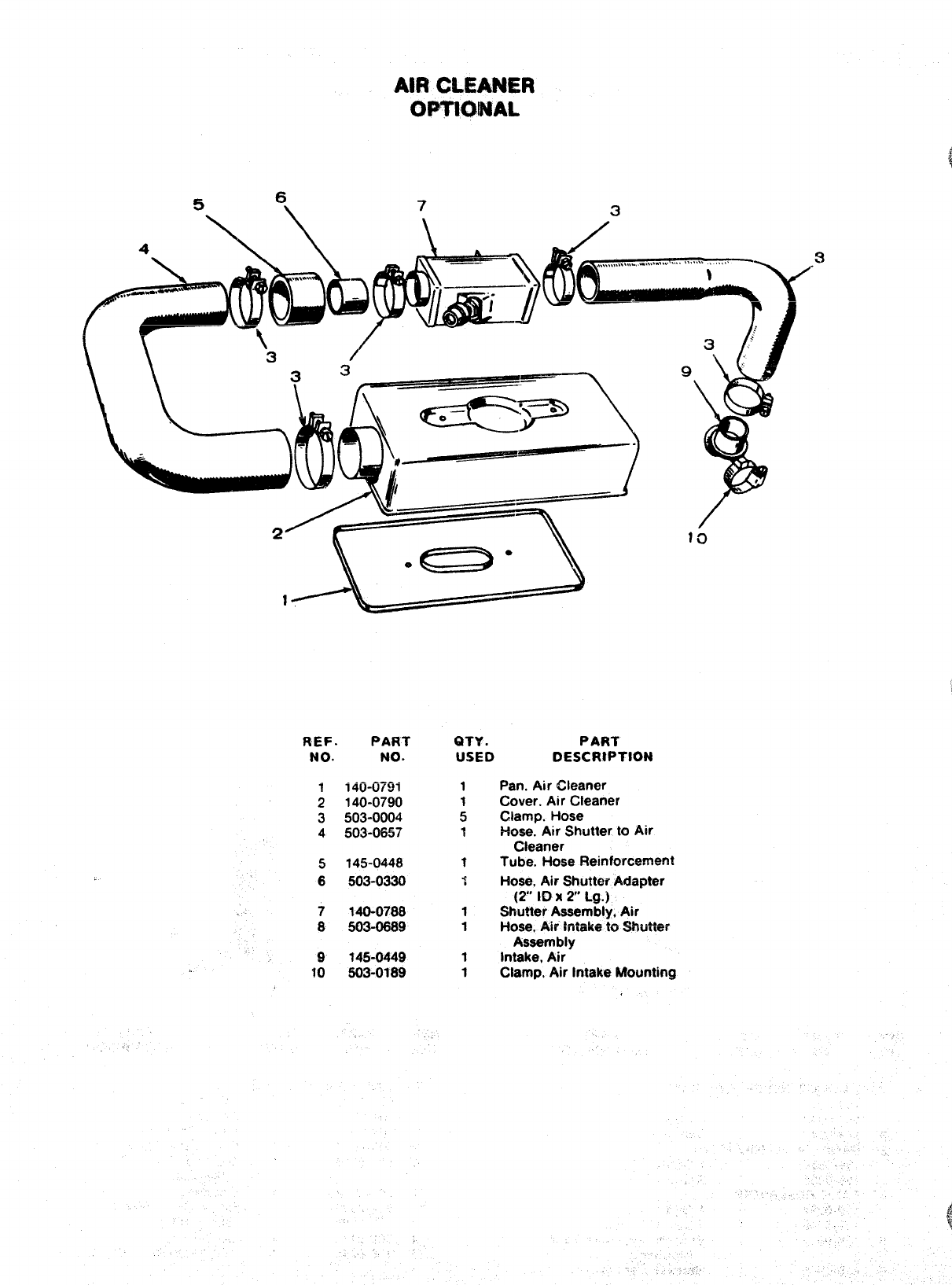
AIRCLEANER
OPTl@PJAL
REF. PART
NO. NO.
1
2
3
4
5
6
14cr-(ml
140-0790
503-0004
503-0657
145-0448
503-0330
140-0788
503-0609
145-0449
S03-0189
QTY .PART
USED DESCRIPTION
1Pan. Air Cleaner
Cover. Air Cleaner
;Clamp. Hose
1Hose. Air Shutter to Air
Cleaner
?Tube. Hose Reinforcement
1Hose, Ah Shutter Adapter
(2” ID x2“ Lg.)
1Shutter Assembly, Ak
1Hose, Air Iniiike i~ %uii~?
Assembly
tIntake, Air
1Clamp, Ak Intake Mounting
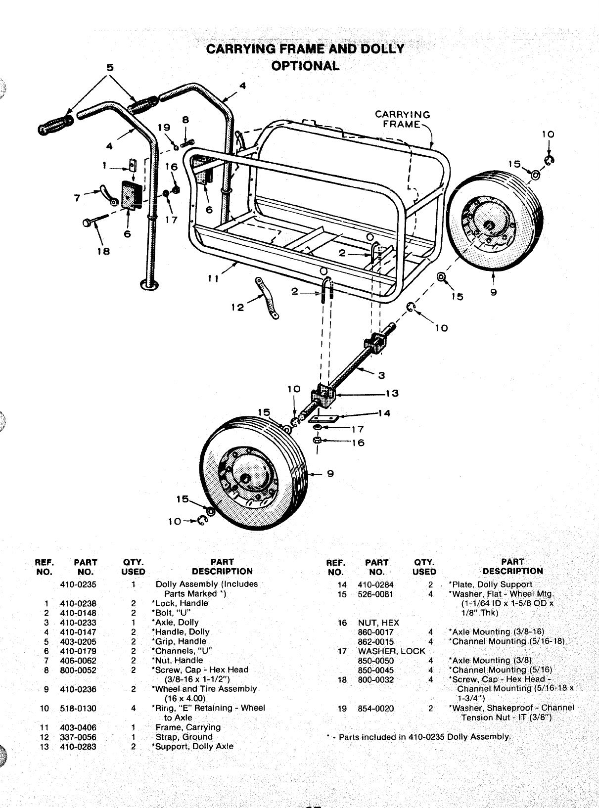
CARRYINGFfimkAiibDOLLY ‘
5OPTIONAL
CARRYING
—. .-) 10
.
1
“lo
REF. PART QTY.
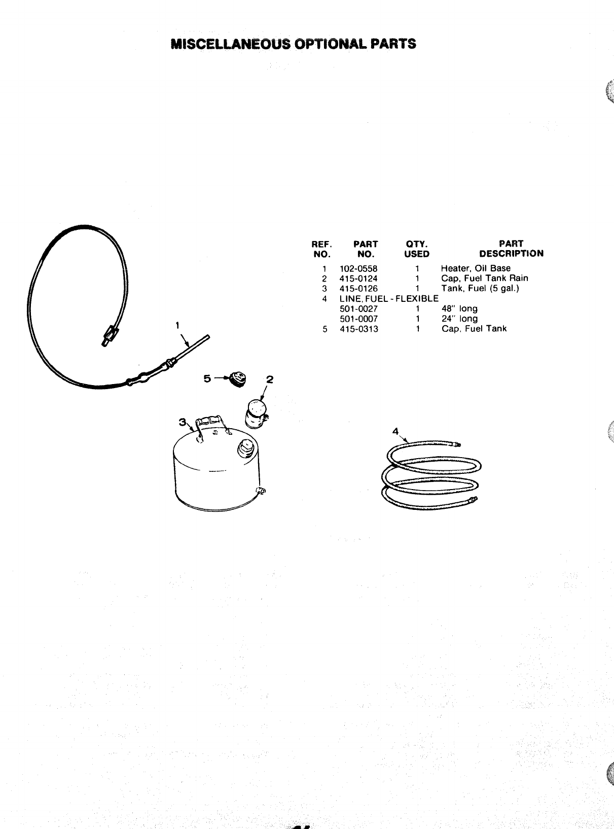
MISCELLANEOUSOPTIONAL PARTS
REF. PART OTY. PART
NO. No. Usim DESCRIPTION
1102-0558 1Heater, Oil Base
2415-0124 1Cap, Fuel Tank Rain
3415-0126 1Tank, Fuel (5 gal. )
4LINE, FUEL- FLEXIBLE
501-0027 148’ long
501-0007 124” long
5415-0313 1Cap, Fuel Tank
5Q 2
/
A
,..
4
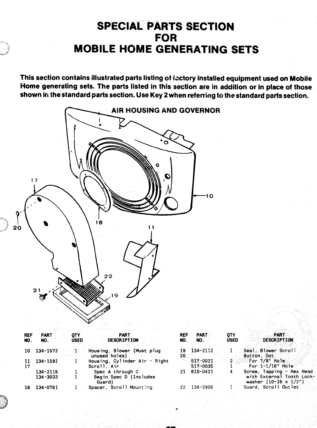
SPECIAL PARTS SECTION
F(JR
,’-”,,,,
~;i
TMOBILE HOME GENERATING SETS
*.,,..$f’
This section contains illustrated parts listing of factory installed equipment used on Mobile
Home generating sets. The parts listed in this section are in addition or in place of those
shown in the standard parts section. Use Key 2when referring to the standard parts section.
REF PART .QTY
ND. w. USED
10 134-1572 1
11 134-1591 1
17 134-2115 1
134-3033 1
18 134-0761 1
PART REF PART CJTY P*T
DESCRIf?TION NO. NO. USED RESCRIPTION
,, .“
,..
Housing, Blower (Must plug 19 i34-2112 1Seal, Blower Scrol 1
unused holes) 20 ‘, flutton, Oot
Housing, Cylinder Air -Right 517-0021
Scroll, Air
~.“ For 7/81’ Hole. ,.’
517-0035 For 1-1/16” Hole
Spec Athrough C21 815-0421 4Screw, Tapping -Hex Head
Begin Spec O(Includes with External Tooth Lock-
Guard) washer (10-16 x1/2”)
Spacer, Scroll Mounti~g 22 134-2956 1Guard, Scroll Outlet
-%..”/-
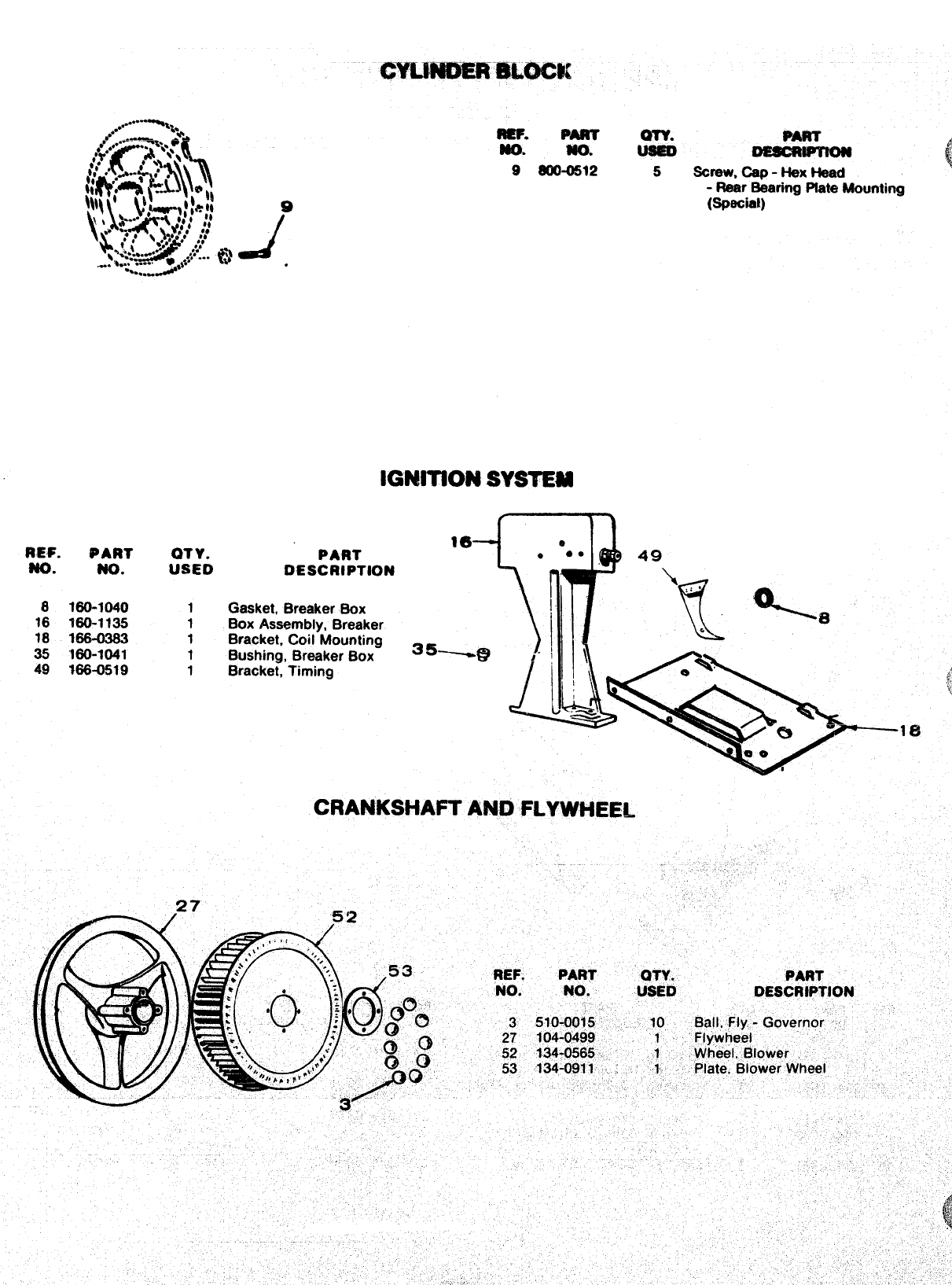
REF. PART
w. No.
8160-1040
16 ?60-1135
18 166-0383
35 “160-1041
49 166-0519
QTY.
USED
1
1
1
1
1
.
-. Pm
m. MO.
9SOO-0512
m.
@
DEssm&o?4
(
~
,
5*reW, -p -kkX Head
-Rear Bearing Plate Mounting
(Special)
IGNITION SYSTEM
fl-l
16
~dw
e
PART e●*49
DESCRIPTION ‘h ,
Gasket, Breaker Box 1’
t
\
Box Assembly, Breaker e
Bracket, Coil Mounting ~ ~ s
Bushing, Breaker Box ~@ \
“\
Bracket, Timing ~%
;’
k
:,
‘
&
eIe
00 8
CRANKSHAFT AND FLYWHEEL
%
35
.
,
...
OES&IPTICN zl~
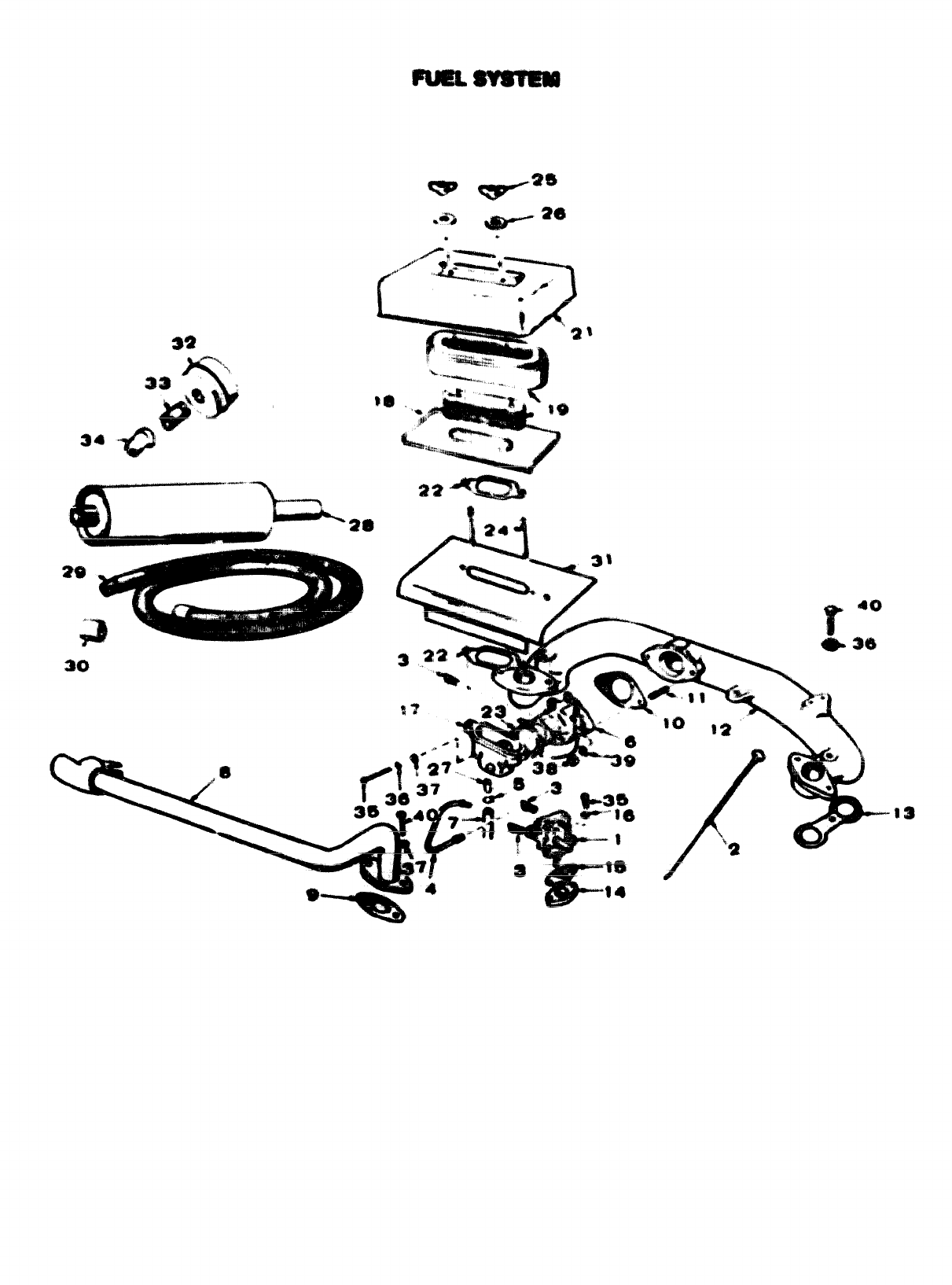
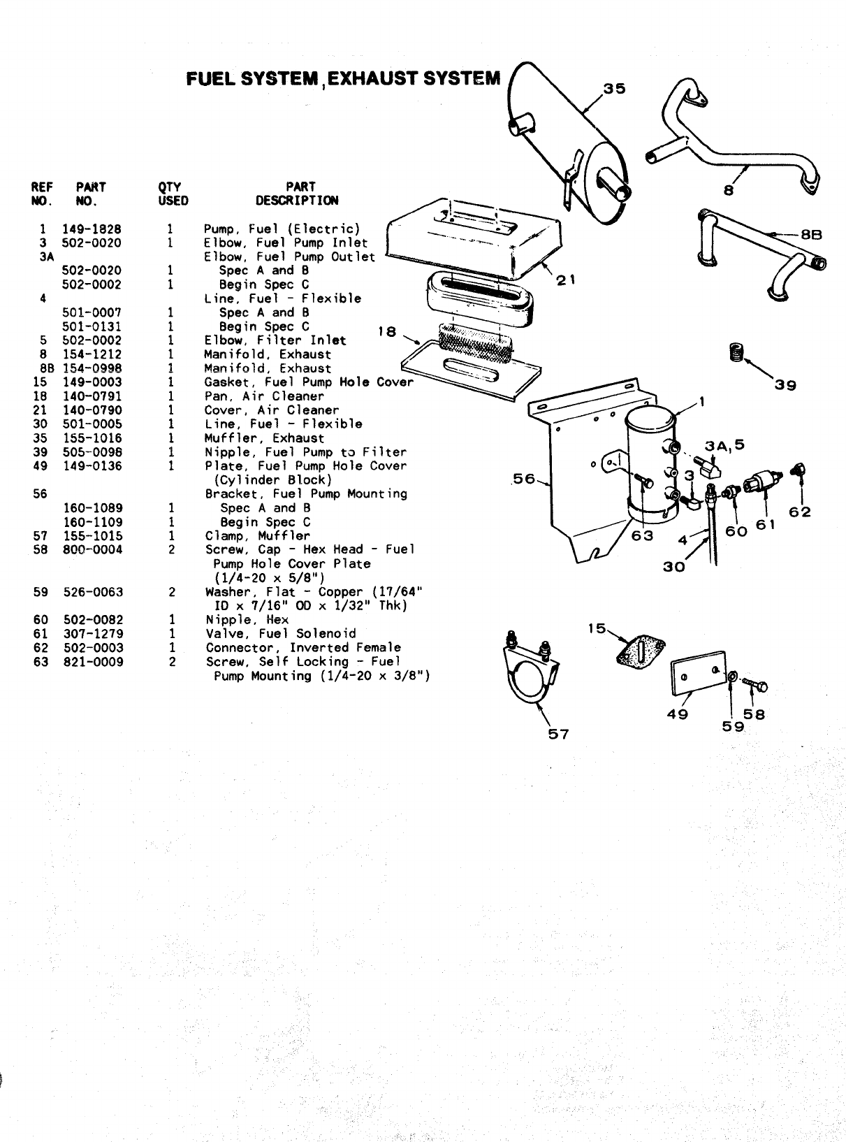
FUEL SYSTEM ,EXHAUST SYSTEM
PART
REF PART
No. No.
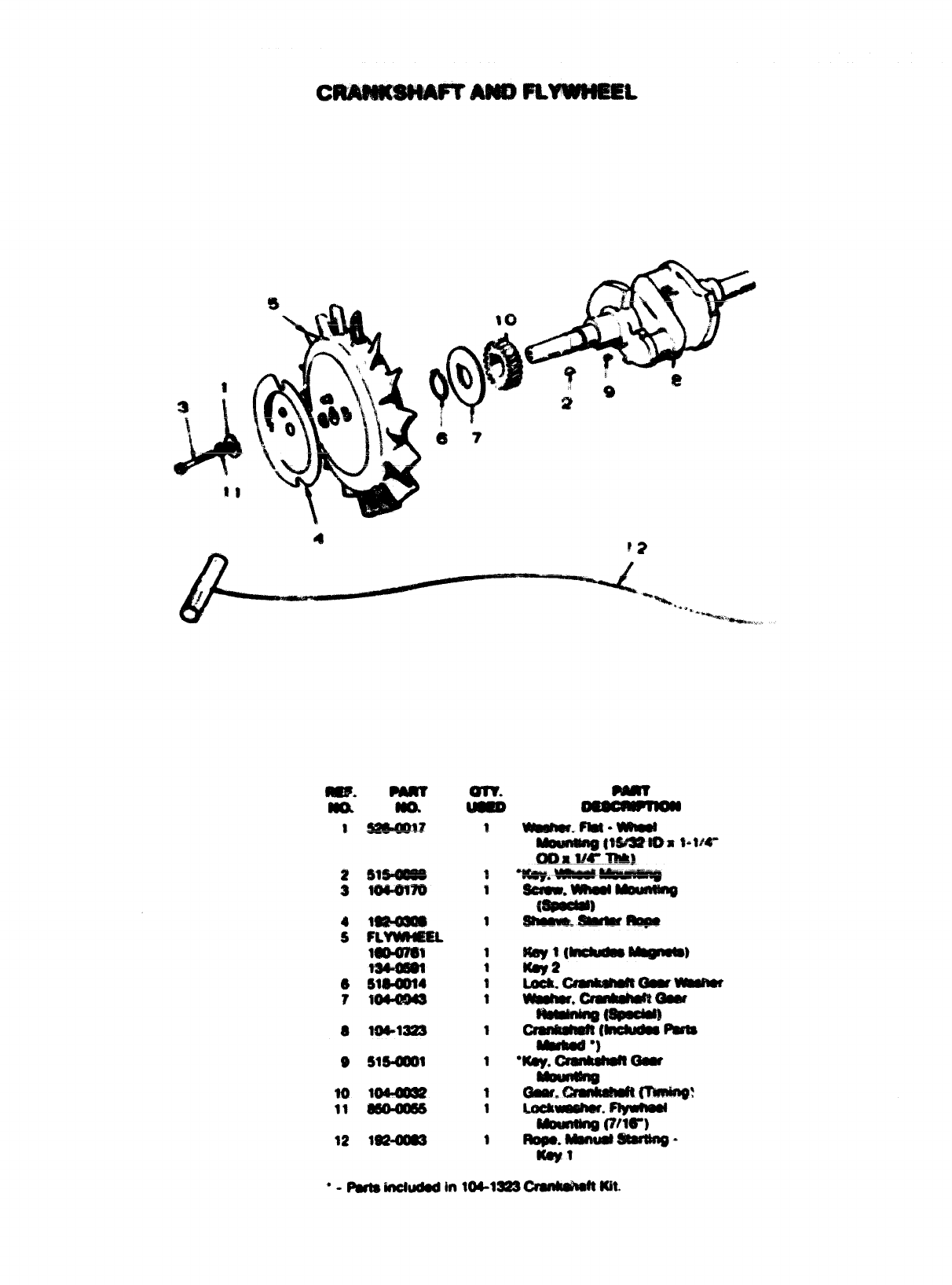
1149-1828
3502-0020
3A
502-0020
502-0002
4
501-0007
501-0131
5502-0002
8154-1212
8e 154-0998
15 149-0003
18 140-0791
21 140-0790
30 501-0005
35 155-1016
39 505-0098
49 149-0136
56
160-1089
160-1109
57 155-1015
58 800-0004
QTY
USED
1
1
1
1
1
1
1
1
I
1
1
1
1
;
1
1
:
2
2
1
1
1
2
Pump, Fuel (Electric)
Elbow, Fuel Pump Inlet <.~>” u
Elbow, Fuel Pump Outlet
Spec Aand B
BeSin Spec C
Line. Fuel -Flexible
Spec Aand Bw’”
Begin Spec C
Elbow, Filter Inlet 18
Manifold, Exhaust
Manifald, Exhaust
Gasket, Fuel Pump Hole COV
Pan, Air Cleaner
Cover, Air Cleaner
Line, Fuel -Flexible
Muffler, Exhaust
Nipple, Fuel Pump ta Filte
Plate, Fuel Pump Hole Cove
(Cylinder Block)
Bracket, Fuel Pump Mountin
Spec Aand B
Begin Spec C
Clamp, Muffler
Screw, Cap -Hex Head -Fuel
Pump Hole Cover Plate
4
I
62
(1/4-20 X5/8’1)
Washer, Flat -Copper (17/64”
ID X7/16” 00 X1/32” Thk)
Nipple, Hex
59 526-0063
60 502-0082
61 307-1279
62 502-0003
63 821-0009
15
m
.....!.
,..,
...... .’:,..,.
.:; .,
...,,...
P~T
a
0
49 58
5’9
Vaitie, Fuel Solenoid
Connector, Inverted Female
Screw, Self Locking -Fuel
@
*
Pump Mounting (1/4-20 x3/8”)
i57
.—t
4
---- .
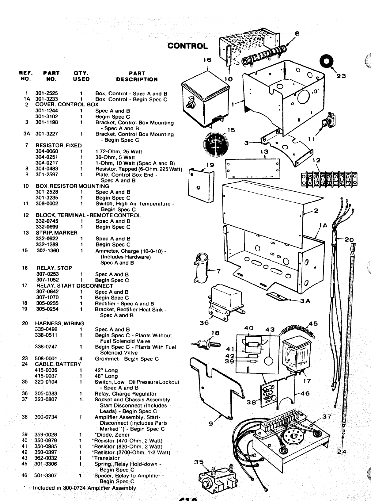
REF. PAW OTY.
NO. NO. USED DESCRIPTION
1301-2525 1Box. Control -Spec Aand B
1A 301-3233 Box. Control -Begin Spec C
2COVER. CONTR~L BOX
301-1244 1Spec Aand B
301-3102 1Be~in SDec C
3
3A
7
8
9
10
11
12
13
15
16
17
301-1198 1Br;cket; Control Box Mounting
-Spec Aand B
301-3227 1Bracket, Control Box Mountinq
-Begin Spec C
RESISTOR. FIXED
304-0060 11.72-Ohm, 25 Watt
304-0251 130-Ohm, 5Watt
304-02 ?7 1l-CNwn, 10 Watt (Spec Aand B)
304-0483 1Resistor, Tapped (6-Ohm, 225 Watt )
301-2597 1Plate, Control Box End -
Spec Aand B
BOX, RESISTOR MOUNTING
301-2528 1Spec Aand B
301-3235 1Begin Spec C
308-0002 1Switch, High Air Temperature -
Begin Spec C
BLOCK, TERMINAL -REMOTE CONTROL
332-0745 1Spec Aand B
332-0699 1Begin Spec C
STRIP, MARKER
332-0922 1Spec Aand B
332-1289 1Begin Spec C
302-3360 1Ammeter, Charge (10-0-1 O) -
(Includes Hardware)
Spec Aand B
RELAY, STOP
307-0253 1Spec Aand B
307-1052 Begin Spec C
RELAY, START DISCONNECT
307-0642 1
307-1070 1
18 305-0235 1
19 305-0254 1
20 HARNESS, WIRING
S3$0492 1
338-0511 1
338-0747 1
23 508-0001
24 CABLE, BATTERY”
416-0036 1
416-0037 1
35 320-0104 1
36 305-0383 1
37 323-0807 1
38 300-0734 1
39 359-0028 1
40 350-0979 1
41 350-0985 1
42 350-0397 1
43 362-0032 1
45 301-3306 1
46 301-3307 1
Spec Aand B
Begin Spec C
Rectifier -Spec Aand B
Bracket, Rectifier Heat Sink -
Spec Aand B
Spec Aand B
Begin Spec C-Plants Without
Fuel Solenoid Valve
Begin Spec C-Plants With Fuel
Solenoid Valve
Grommet -Begin Spec C
42” Long
48” Long
Switch, Low Oil Pressure Lockout
-Spec Aand B
Relay, Charge Regulator
Socket and Chassis Assembly,
Start Disconnect (Includes
Leads) -Begin Spec C
Amplifier Assembly, Start-
Disconnect (Includes Parts
Marked *) -Begin Spec C
“Diode, Zener
“Resistor (470-Ohm, 2Watt)
“Resistor (820-Ohm, 2Watt) !
●Resistor (2700-Ohm, 1/2 Watt)
‘Transistor
Spring, .Relay Hold-down -3q
Begin Spec C
Spacer, Relay to Amplifier -
Begin Spec C
I
9t-’
2
e
F’s
Included in 300-0734 Amplifier Assembly. 4
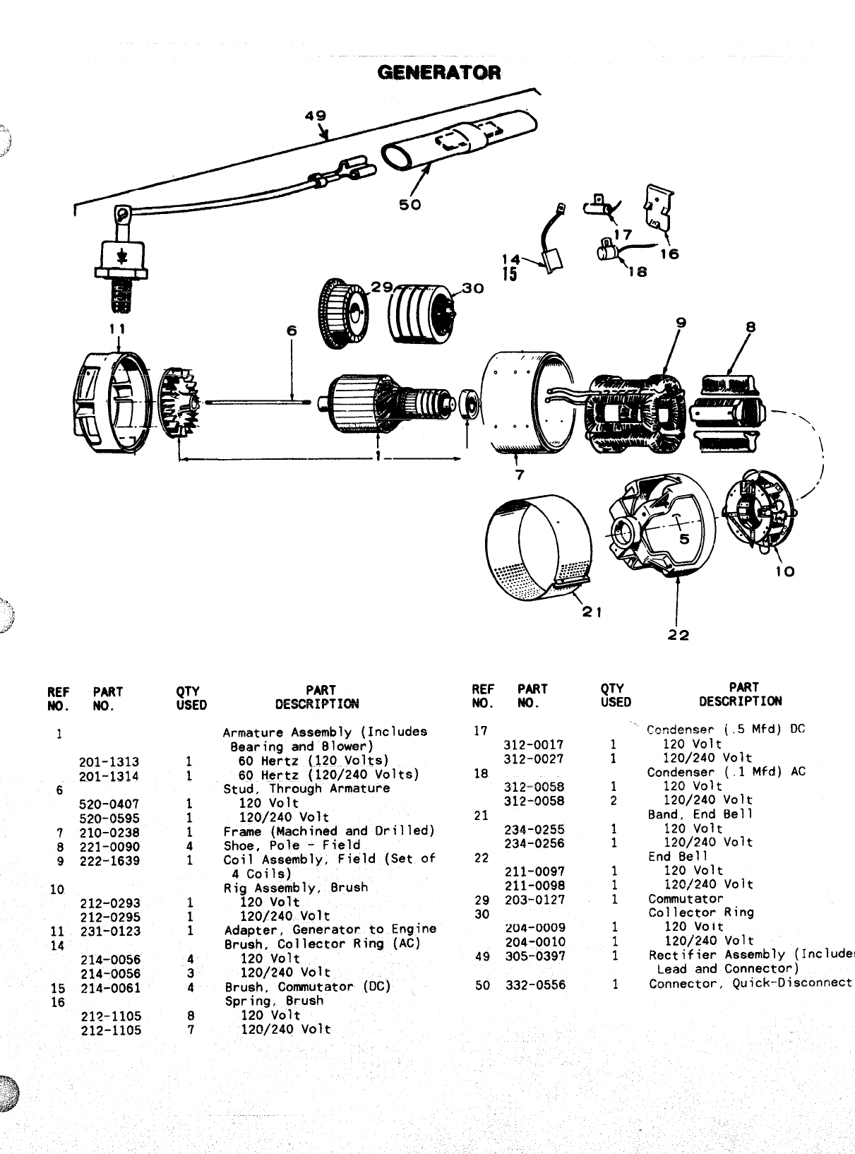
GENERATOR
REF PART
NO. No.
1
201-1313
201-1314
6520-0407
520-0595
7210-0238
8221-0090
9222-1639
10 212-0293
212-0295
11 231-0123
14 214-0056
214-0056
:; 214-0061
21’2-1105
212-1105
QTY
USED
1
1
1
1
1
4
1
1
1
1
4
3
4
8
7
Armature Assembly (Includes
Bearing and Blower)
60 Hertz (120 Volts)
60 Hertz (120/240 Volts)
Stud, Through Armature
120 volt
120/240 Volt
Frame (Machined and Drilled)
Shoe, Pole -Field
Coil Assembly, Field (Set of
4Coils)
Rig Assembly, Brush
120 volt
120/240 Volt
Adapter, Generator to Engine
Br;;~,v:Jlector Ring (AC)
120/240 Volt
Brush, Commutator (DC)
Sp;;:gvo133ush
120/240 Volt
7
Q
“....::.--
......}>.%... ~-.:..:.-.
~::::..
...............
..,:...-:....:.
..::.:.., . .
-::..............
......
REF PART
NO. No.
17
312-0017
312-0027
18 ~~~=~~~g
312-0058
21 234-0255
234-0256
22
211-0097
211-0098
29 203-0127
30
ZU4-0009
204-0010
49 305-0397
50 332-0556
21
QTY
USED
1
1
1
2
1
1
1
1
1
1
1
1
1
1
/’
10
22
PART
DESCRIPTION
~cndenser (.5 Mfd) DC
120 volt
120/240 Volt
Condenser (.1 Mfd) AC
120 volt
120/240 Volt
Band, End Bell
120 volt
120/240 Volt
End Bell
120 volt
i20,/240 Volt
Commutator
Collector Ring
120 volt
120/240 Volt
Rectifier Assembly (Includes
Lead and Connector)
Connector, Quick-Disconnect
19
26
i
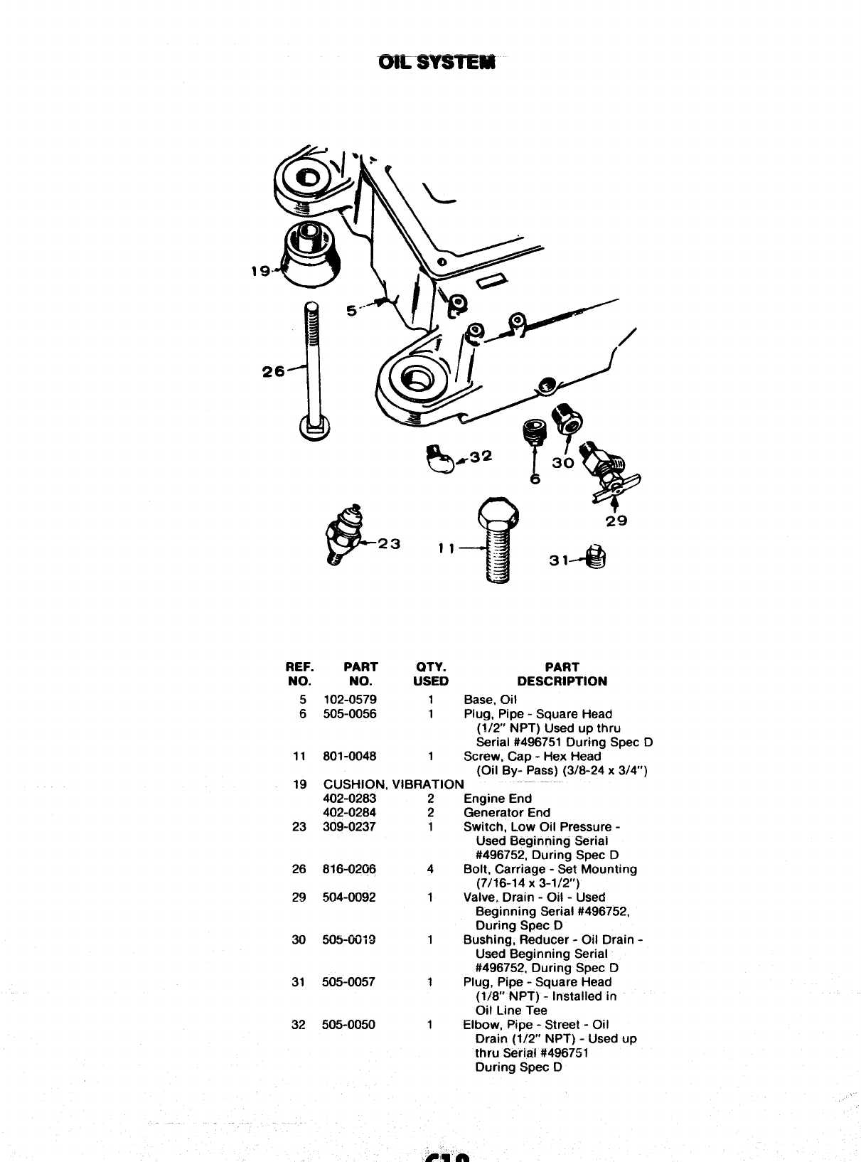
REF. PART OTY. PART
NO. NO. USED DESCRIPTION
5102-0579 1Base, Oil
6505-0056 1Plug, Pipe -Square Head
(1/2” NPT) Used up thru
Serial #496751 During Spec D
11 801-0048 1Screw, Cap -Hex Head
(Oil By- Pass) (3/8-24 x3/4”)
19 CUSHION, VIBRATION
23
26
29
30
31
32
402-0283
402-0284
309-0237
816-0208
504-0092
505-001 a
505-0057
505-0050
2
2
1
4
1
1
1
1
Engine End
Generator End
Switch, Low C)il Pressure -
Used Beginning Serial
#496752, During Spec D
Bolt, Carriage -Set Mounting
(7/16-14 X3-1/2”)
Valve, Drain -Oil -Used
Beginning Serial #496752,
During Spec D
Bushing, Reducer -Oil Drain -
Used Beginning Serial
#496752, During Spec D
Plug, Pipe -Square Head
(1/8 NPT) -Installed in
Oil Line Tee
Elbow, Pipe -Street -Oil
Drain (1/2” NPT) -Used up
thru Serial #496751
During Spec D
GEAMmSE
.. U—3
L.,
I4
10 \:—
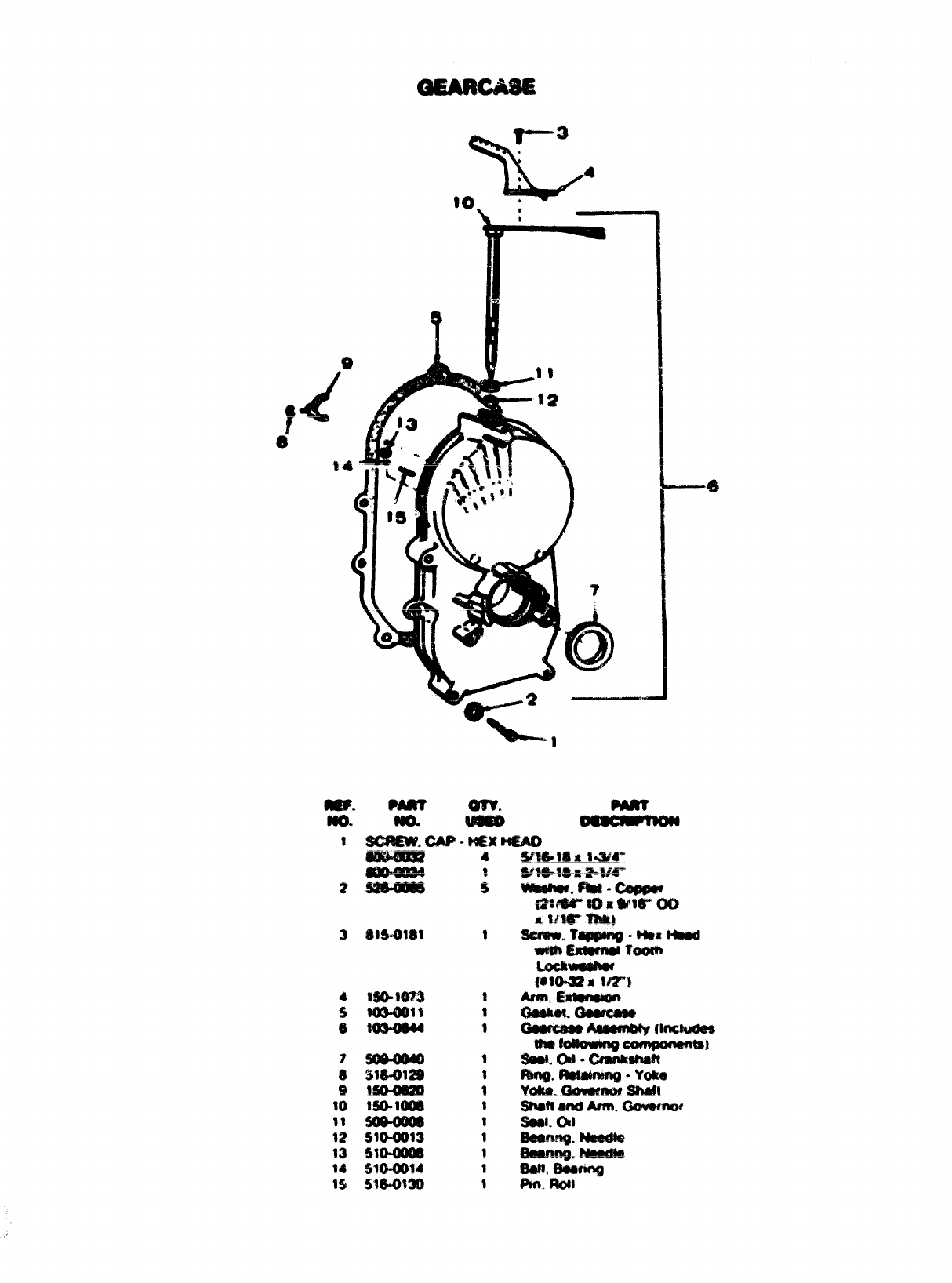
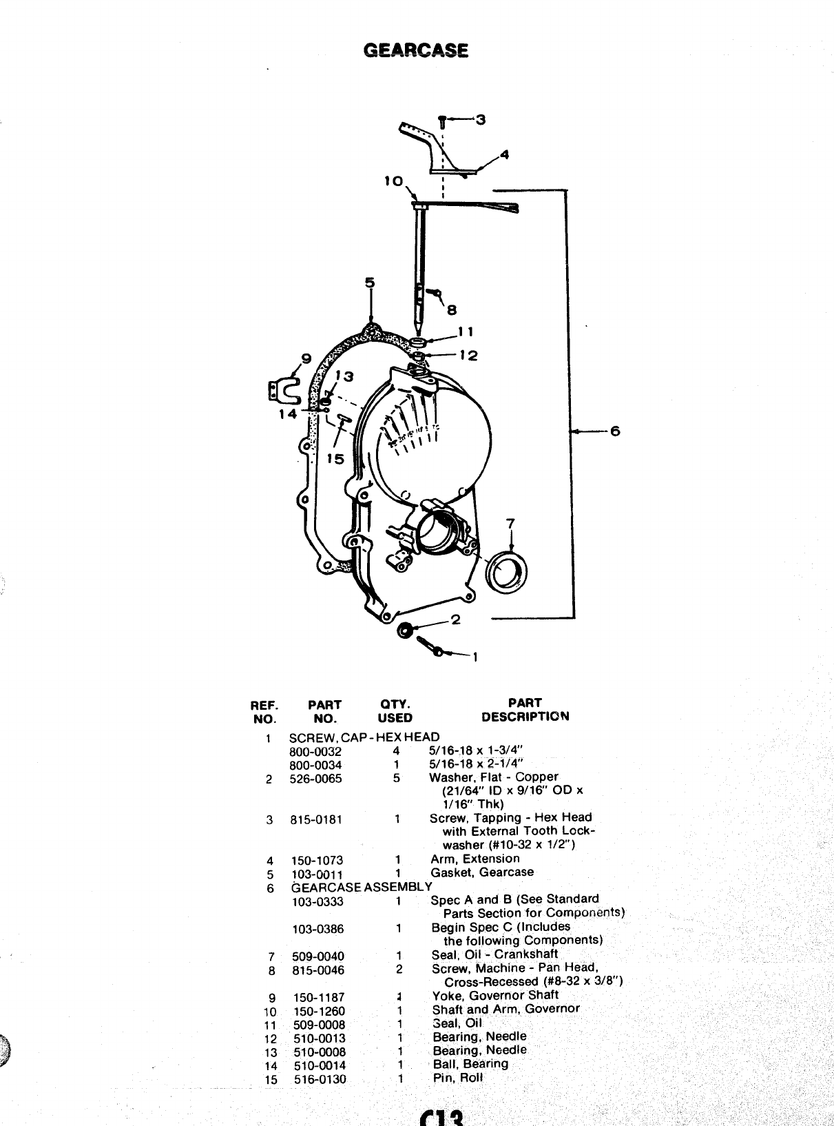
REF. PART QTY. PART
NO. NO. USED DESCRIPTION
1SCREW, CAP- HEX HEAD
800-0032 45/16-18 X1-314”
800-0034 15116-18 X2-1/4”
2526-0065 5Washer, Flat -Copper
(21/64 ID X9/16’ OD X
1/16 Thk)
3815-0181 1Screw, Tapping -Hex Head
with External Tooth Lock-
—6
washer (#10-32x 1/2’)
4150-1073 1Arm, Extension
5103-0011 1Gasket, Gearcase
6GEARCASEASSEM6LY
103-0333 1Spec Aand B(See Standard
Parts Section for Components)
103-0386 1Begin Spec C(Includes
the following Compone
7509-0040 1Seal, Oil -Crankshaft
8815-0046 2Screw, Machine -Pan He
Cross-Recessed (#6-32 x3/8’)
9150-1187 aYoke, Governor Shaft
10 150-1260 1Shaft and Arm, Governor
11 509-0008 1Seal, Oil
12 510-0013 1Bearing, Needle
13 510-0008 1Bearing, Needle
14 !510-0014 1Ball, Bearing
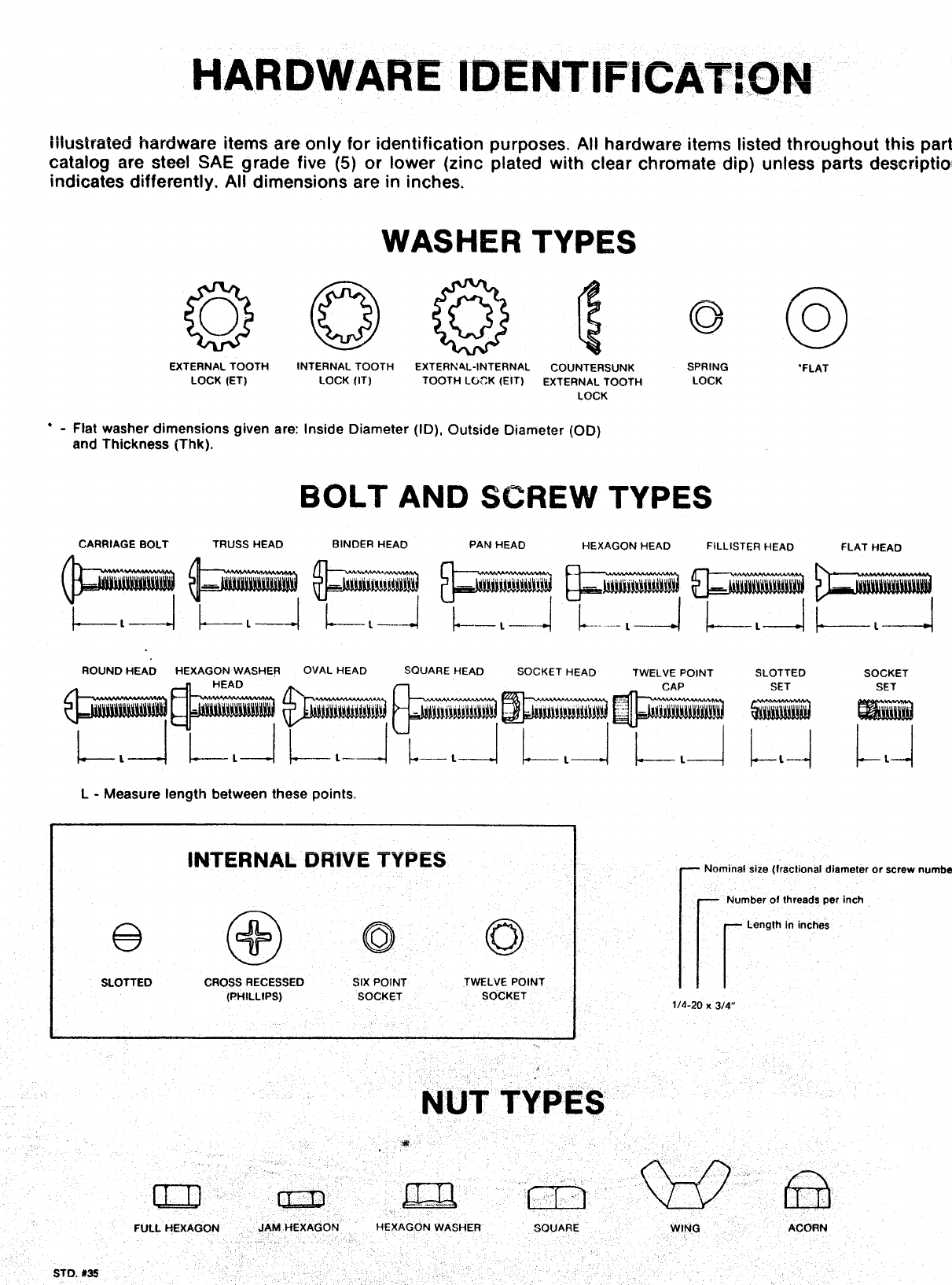
HARDWARE l“DENTIFICAT!OhI
illustrated hardware items are only for identification purposes, All hardware items listed throughout this
parts
catalog are steel SAE grade five (5) or lower (zinc plated with clear chromate dip) unless parts description
indicates differently. All dimensions are in inches.
WASHER TYPES
EXTERNALTOOTH
LOCK(ET)
●-Flat washer dimensions given
and Thickness (Thk).
INTERNAL TOOTH
LOCK (IT)
are: Inside Diameter
EXTERNAL-INTERNAL COUNTERSUNK SPRING ‘FLAT
TOOTH LOCK (EIT) EXTERNAL TOOTH LOCK
LOCK
(ID), Outside Diameter (OD)
BOLT AND SCREW TYPES
CARRIAGE BOLT TRUSS HEAD BINDER HEAD PAN HEAD HEXAGON HEAD FILLISTER HEAD FLAT HEAD
1----
L4
SOCKET
SET
ROUND HEAD HEXAGON WASHER OVAL HEAD SQUARE HEAD SOCKET HEAD TWELVE POINT SLOTTED
L-Measure length between these points.
●
INTERNAL DRIVE TYPES INominal size (fractional diameter or screw
[k
Number of threads per inch
@@oo
Length In inches
SLOTTED CROSS RECESSED SIX POINT TWELVE POINT
[PHILLIPS) SOCKET SOCKET
number
