927 0224 Onan MCCK (spec H J) Marine Genset Parts Manual (05 1988)small
User Manual: 927-0224 Onan MCCK (spec H-J) Marine Genset Parts manual (05-1988)small
Open the PDF directly: View PDF ![]() .
.
Page Count: 42
The following catalog
has gaps in its page
numbers, or doesn’t
have any numbers.
We have chosen to
leave the page
numbering in the
order that Acrobat
assigns it.
*
*....
●
\
;a
Parts
Manual
MCUK
Marine GenSet
Replaces
8-81 (Spec H)
Printed in U.S.A.
Genera[ Information
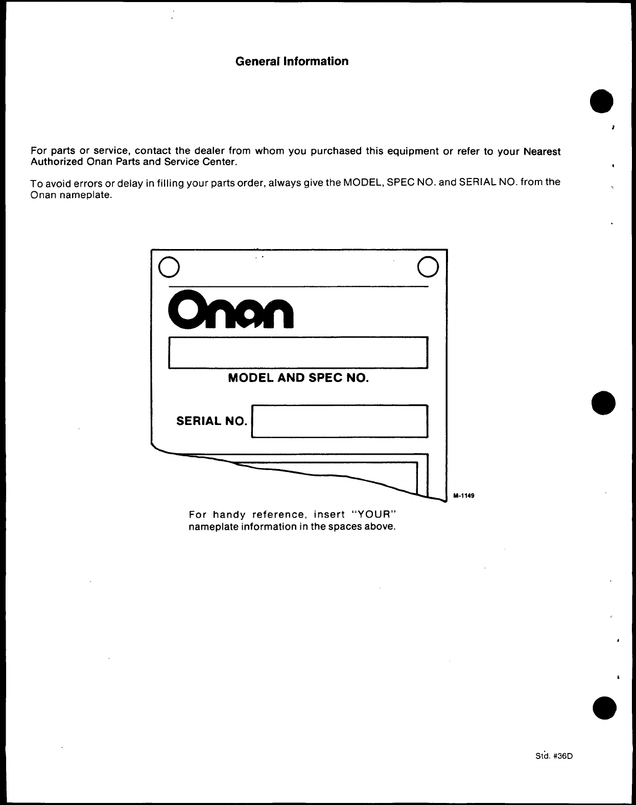
For parts or service, contact the dealer from whom you purchased this equipment or refer to your Nearest
Authorized Onan Parts and Service Center. u
To avoid errors or delay in filling your parts order, always give the MODEL, SPEC NO. and SERIAL NO. from the
Onan nameplate.
10 ,. 0
I
Iomn
II I
MODEL AND SPEC NO.
●
SERIAL NO.
M-1149
For handy reference, insert “YOUR”
nameplate information in the spaces above.
Std. #36D
4
c
Important Safety Precautions
●Read and observe these safety precautions when using
or working on electric generators, engines and related
●equipment. AiSO read and follow the literature provided
with the equipment.
Proper operation and maintenance are critical to perfor-
,mance and safety. Electricity, fuel, exhaust, moving parts
and batteries present hazards that can cause severe
personal injury or death.
FUEL, ENGINE OIL, AND FUMES ARE
FLAMMABLE AND TOXIC
Fire, explosion, and personal injury can result from im-
proper practices.
●
●
●●
●
●
●
●
●
Used engine oil, and benzene and lead, found in
some gasoline, have been identified by government
agencies as causing cancer or reproductive toxicity.
When checking, draining or adding fuel or oil, do not
ingest, breathe the fumes, or contact gasoline or
used oil.
Do not fill tanks with engine running. Do not smoke
around the area. Wipe up oil or fuel spills. Do not
leave rags in engine compartment or on equipment.
Keep this and surrounding area clean.
Inspect fuel system before each operation and peri-
odically while running.
Equip fuel supply with apositive fuel shutoff. “
Do not store ortranspoti equipment with fuel intank.
Keep an ABC-rated fire extinguisher available near
equipment and adjacent areas for use on all types of
fires except alcohol.
Unless provided with equipment or noted otherwise
in installation manual, fuel.lines must be copper or
steel, secured, free of leaks and separated or
shielded from electrical wiring.
Use approved, non-conductive flexible fuel hose for
fuel connections. Do not use coppertubing as aflex-
ible connection. It will work-harden and break.
EXHAUST GAS IS DEADLY
●
✎
●
✎
●●
Engine exhaust contains carbon monoxide (CO),
an odoriess, invisible, poisonous gas. Learn the
symptoms of CO poisoning.
Never sleep in avessel, vehicle, or room with agen-
set or engine running unless the area is equipped
with an operating CO detector with an audible
alarm.
Each time the engine or genset is started, or at least
every day, thoroughly inspect the exhaust system.
Shut down the unit and repair leaks immediately.
.
.Warning: Engine exhaust is known to the State of
California to cause cancer, birth defects and other
reproductive harm.
Make sure exhaust is properiy ventilated.
●
●
●
●
●
●
Vessel bilge must have an operating power
exhaust.
Vehicle exhaust system must extend beyond ve-
hicle perimeter and not near windows, doors or
vents.
Do not use engine or genset cooling air to heat an
area.
Do not operate engine/genset in enclosed area
without ample fresh air ventilation.
Expel exhaust away “from enclosed, sheltered, or
occupied areas.
Make sure exhaust system components are se-
curely fastened and not warped.
MOVING PARTS CAN CAUSE SEVERE
PERSONAL INJURY OR DEATH
Do not remove any guards or covers with the equip-
ment running.
Keep hands, clothing, hair, and jewelry away from
moving parts.
Before performing any maintenance, disconnect
battery (negative [-] cable first) to prevent acciden-
tal starting.
Make sure fasteners and joints are secure. Tighten
supports and clamps, keep guards in position over
fans, drive belts, etc.
[f adjustments must be made while equipment is
running, use extreme caution around hot manifolds
and moving parts, etc. Wear safety glasses and pro-
tective clothing.
BA17ERY GAS IS EXPLOSIVE
●
●
●
Wear safety glasses and do not smoke while setvic-
ing batteries.
Always disconnect battery negative (–) lead first
and reconnect it last. Make sure you connect battery
correctly. Adirect short across batte~ terminals can
cause an explosion. Do not smoke while servicing
batteries. Hydrogen gas given off during charging is
explosive.
Do not disconnector connect battery cables if fuel
vapors are present. Ventilate the area thoroughly.
GSP-1
lof2
DO NOT OPERATE IN FLAMMABLE AND
EXPLOSIVE ENVIRONMENTS
Flammable vapor can be ignited by equipment operation
or cause adiesel engine to overspeed and become diffi-
cult to stop, resulting in possible fire, explosion, severe
personai injury and death. DOnot operate diesel equip-
ment where aflammable vapor environment can be
created by fuel spill, leak, etc., unless equipped with
an automatic safety device to block the air intake and
stop the engine.
HOT COOLANT CAN CAUSE SEVERE
PERSONAL INJURY
.Hot coolant is under pressure. Do not loosen the
coolant pressure cap while the engine is hot. Let the
engine cool before opening the pressure cap.
ELECTRICAL SHOCK CAN CAUSE SEVERE
PERSONAL INJURY OR DEATH
●
●
●
●
●
●
Donot service control panel or engine with unit run-
ning. High voltages are present. Work that must be
done while unit is running should be done only by
qualified service personnel.
Do not connect the generator set to the public utility
or to any other electrical power system. Electrocu-
tion can occur at aremote site where line or equip-
ment repairs are being made. An approved transfer
switch must be used if more than one power source
is connected.
Disconnect starting battery (negative [-] cable first)
before removing protective shields ortouching elec-
trical equipment. Use insulative mats placed on dry
wood platforms. Donot wear jewelry, damp cfothing
or allow skin surface to be damp when handling
electrical equipment.
Use insulated tools. DO not tamper with interlocks.
Follow all SPpbble state and local electrical
codes. Have all electrical installations performed by
aqualified licensed electrician. Tag open switches
to avoid accidental closure.
With transfer switches, keeg cabinet closed and
locked. Only authorized personnel should have
cabinet or operational keys. Due to serious shock
hazard from high voltages ~ln cabinet, all service
and adjustments must be performed by an electri-
cian or authorized service representative.
If the cabinet must be opened for any reason:
1.
2.
3.
Move genset operation switch or Stop/Auto/
Handcrank switch (whichever applies) to Stop.
Disconnect genset batteries (negative [-] lead
first). ●
Remove AC power to automatic transfer
switch. If instructions require othenvise, use ,
extreme caution due to shock hazard.
MEDIUM VOLTAGE GENERATOR SETS
(601~ TO 15kV) .
Medium voltage acts dtierentiy than low voltage.
Special equipment and training are required to work
on or around medium voltage equipment. Operation
and maintenance must be done only by persons
trained and qualified to work on such devices. im-
proper use or procedures WN result in severe per-
sonal injury or death.
Do not work on energized equipment. Unauthorized
personnel must no{ be pefiitted near energized
equipment. Induced voltage remains even after
equipment is disconnected from the power source.
Plan maintenance with authorized personnel so
equipment can be de-energized and safely
grounded.
GENERAL SAFETY PRECAUTIONS
●
●
●
●
●
Do not wok on equipment when mentally or physi-
cally fatigued or after consuming afcohol or drugs.
Carefully follow all applicable Iocaf, state and feder- ●
al codes.
Never step on equipment (as when entering or leav-
ing the engine comp~ent). It can stress and
break unit components, possibly resulting in dan-
gerous operating condtions from leaking fuel, leak-
ing exhaust fumes, etc.
Keep equipment and area clean. Oil, grease, dirt, or
stowed gear can cause fire or damage equipment
by restricting airflow.
Equipment owners and operators are solely re-
sponsible for operating equipment safely. Contact
your authorized Onan/Cummins dealer or distribu-
tor for more information.
KEEP THIS DOCUMENT
EASY REFERENCE. NEAR EQUIPMENT FOR
GSP-1
2of2
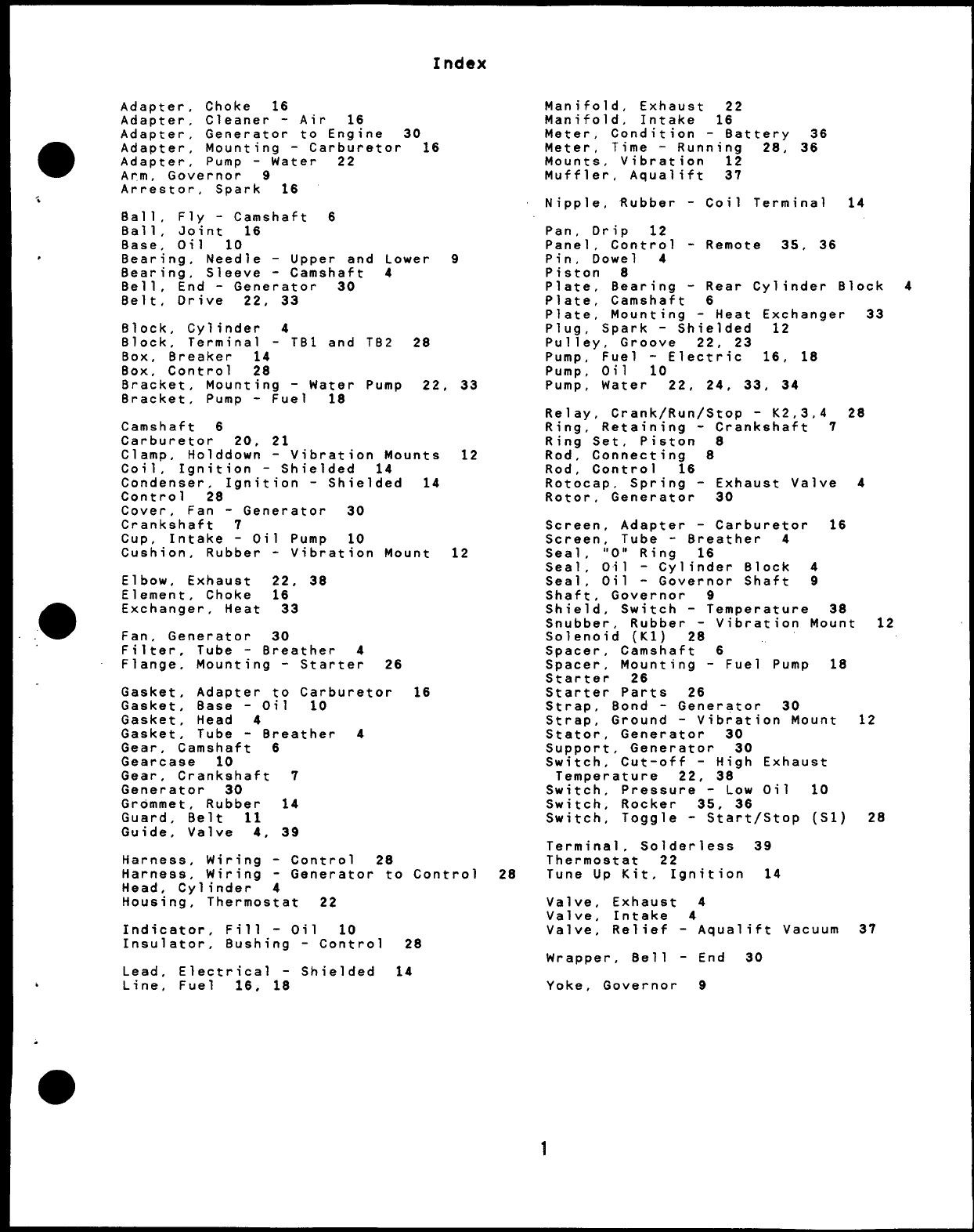
Index
Adapter, Choke 16
Adapter, Cleaner -Air 16
Adapter, Generator to Engine 30
Adapter, Mounting -Carburetor 16
Adapter, Pump -Water 22
Arm, Governor 9
Arrestor, Spark 16
Ball, Fly -Camshaft 6
Ball, Joint 16
Base, Oil 10
Bearing, Needle -Upper and Lower
f33::ing, Sleeve -Camshaft 4
,End -Generator 30
Belt, Drive 22, 33
Block, Cylinder 4
Block, Terminal -TB1 and TB2 28
Box, Breaker 14
Box, Control 28
9
Bracket, Mounting -Water Pump 22, 33
Bracket, Pump -Fuel 18
Camshaft 6
Carburetor 20, 21
Clamp, Holddown -Vibration Mounts
Coil, Ignition -Shielded 14
Condenser, Ignition -Shielded 14
Control 28
Cover, Fan -Generator 30
Crankshaft 7
cup, Intake -Oil Pump 10
Cushion, Rubber -Vibration Mount
Elbow, Exhaust 22, 38
Element, Choke 16
Exchanger, Heat 33
Fan, Generator 30
12
12
Filter, Tube -Breather 4
Flange, Mounting -Starter 26
Gasket ,Adapter to Carburetor 16
Gasket, Base -Oil 10
Gasket, Head 4
Gasket, Tube -Breather 4
Gear, Camshaft 6
Gearcase 10
Gear ,Crankshaft 7
Generator 30
Grommet, Rubber 14
Guard, Belt 11
Guide, Valve 4, 39
Harness, Wiring -Control 28
Harness, Wiring -Generator to Control
Head, Cylinder 4
Housing, Thermostat 22
Indicator, Fill -Oil 10
Insulator, Bushing -Control 28
Lead, Electrical -Shielded 14
.Line, Fuel 16, 18
Manifold, Exhaust 22
Manifold, Intake 16
Meter, Condition -Battery 36
Meter, Time -Running 28, 36
Mounts, Vibration 12
Muffler, Aqualift 37
Nipple, Rubber -Coil Terminal 14
Pan, Drip 12
Panel ,Control -Remote 35, 36
Pin, Dowel 4
Piston 8
Plate, Bearing -Rear Cylinder Block
Plate, Camshaft 6
Plate, Mounting -Heat Exchanger 33
Plug, Spark -Shielded 12
Pulley, Groove 22, 23
Pump, Fuel -Electric 16, 18
Pum~, Oil 10
Pump, Water 22, 24. 33, 34
Relay, Crank/Run/Stop -K2,3,4 28
Ring, Retaining -Crankshaft 7
Ring Set, Piston 8
Rod, Connecting 8
Rod, Control 16
Rotocap, Spring -Exhaust Valve 4
Rotor, Generator 30
Screen, Adapter -Carburetor 16
Screen, Tube -Breather 4
Seal ,“O” Ring 16
Seal, Oil -Cylinder Block 4
Seal, Oil -Governor Shaft 9
Shaft, Governor 9
Shield, Switch -Temperature 38
4
Snubber, Rubber -Vibration Mount 12
Solenoid (Kl) 28
Spacer, Camshaft 6
Spacer, Mounting -Fuel Pump 18
Starter 26
Starter Parts 26
Strap, Bond -Generator 30
Strap, Ground -Vibration Mount
Stator, Generator 30
Support, Generator 30
Switch, Cut-off -High Exhaust
Temperature 22, 38
Switch, Pressure -Low Oil 10
Switch, Rocker 35, 36
Switch, Toggle -Start/Stop (S1)
Terminal, Solderless 39
Thermostat 22
28 Tune Up Kit, Ignition 14
Valve, Exhaust 4
Valve, Intake 4
Valve, Relief -Aqualift Vacuum
Wrapper, 8ell -End 30
Yoke, Governor 9
12
28
37
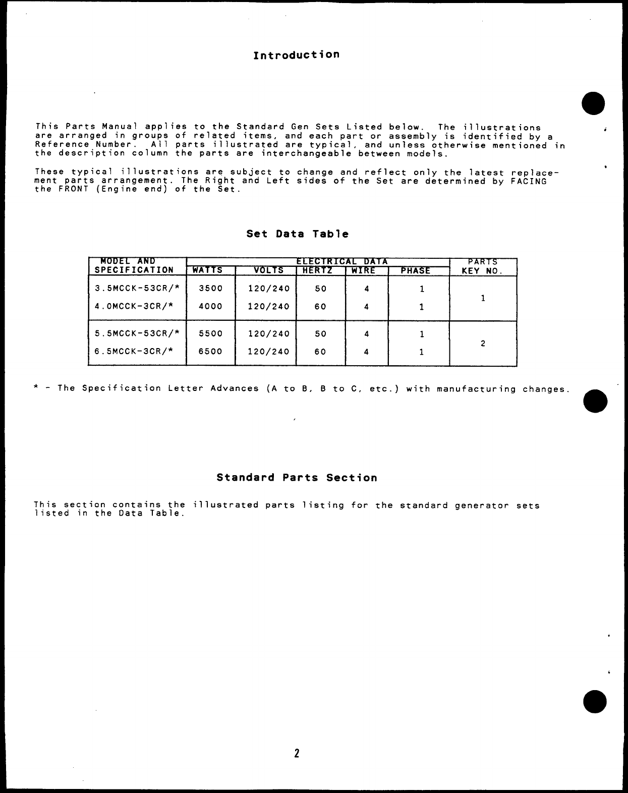
Introduction
This Parts Manual app ies to the Standard Gen Sets Listed below. The illustrations
,. . . ,.
are arrangea In groups ot related Items, and each part or assembly is identified by a
Reference Number. All parts illustrated are typical, and unless otherwise mentioned in
the description column the parts are interchangeable between models.
These typical illustrations are subject to change and reflect only the latest replace-
ment parts arrangement. The Right and Left sides of the Set are determined by FACING
the FRONT (Engine end) of the Set.
Set Data Table
MODEL AN lJ~Cl%17XT~ APARTS
SPECIFICATION WATTS OLTS HERTZ WIRE PHASE KEY NO.
3.5MccK-53cR/* 3500 120/240 50 41
1
4.oMccK-3cR/* 4000 120/240 60 4 1
5.5MccK-53cR/* 5500 120/240 50 4 1
2
6.5MCCK-3CR/* 6500 120/240 60 4 1
*-The Specification Letter Advances (A to B, Bto C, etc.) with manufacturing changes
Standard Parts Section
This section contains the illustrated parts listing for the standard generator sets
listed in the Data Table.
●
●
✌
●
✎
✎
●
2
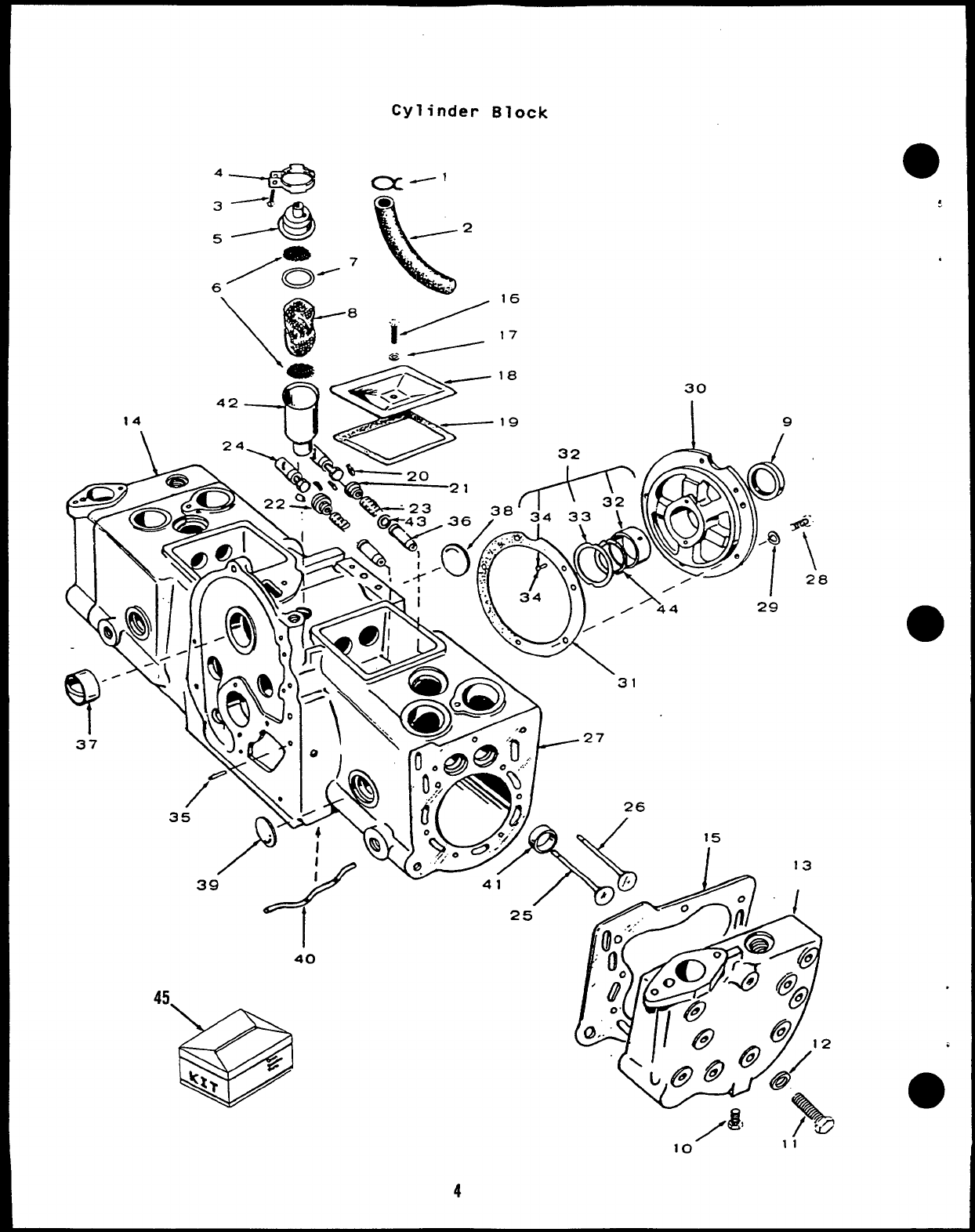
Cylinder Block
16
7
830
32 A9
. /
\~widu---27
35 p>iw’j.$)j<& ;
39 #
A -- on:
‘140 1~
,/,.
,$ ‘%a/
.OOO“f% @0
‘i’o
/4!6 #
0. \@ @ ‘/’2
L@@ @
/8 \
/@
10” 11
4
,
.
;
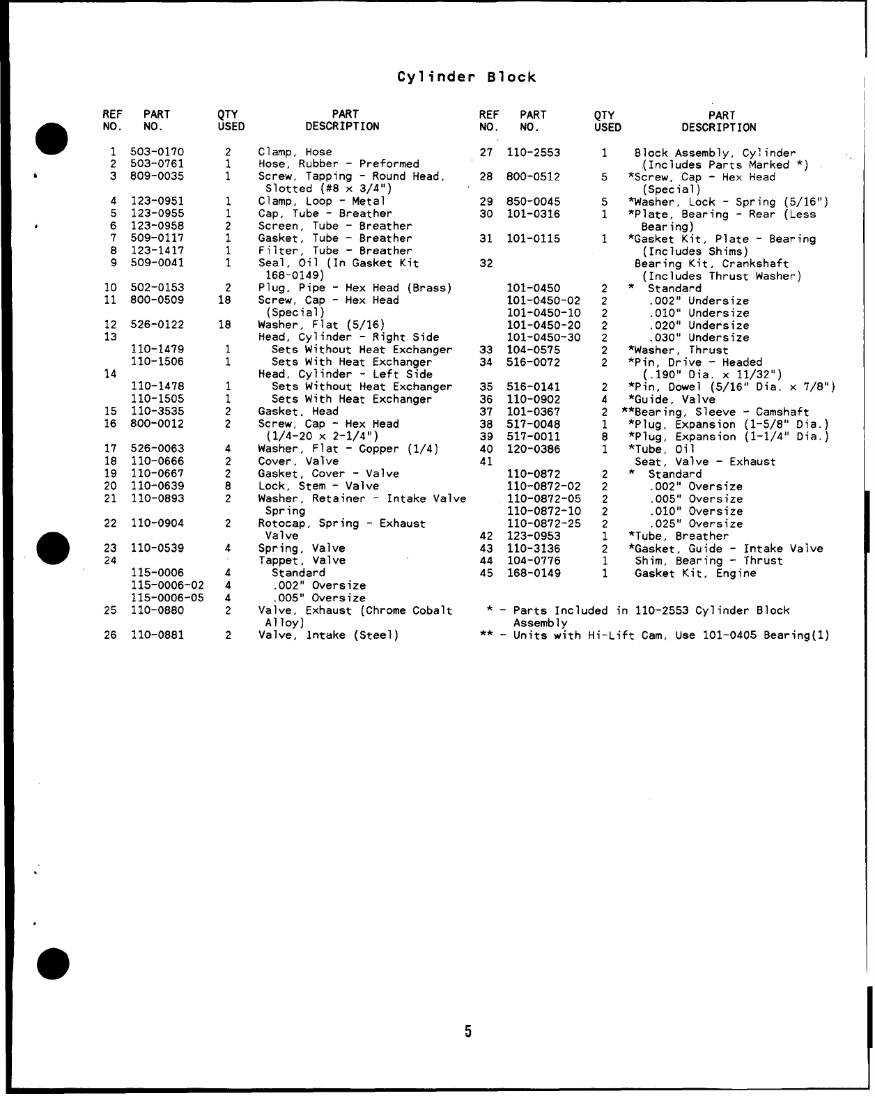
Cylinder Block
REF PART
●NO. NO.
1503-0170
2503-0761
*3
4
5
,6
7
8
9
10
11
12
13
14
15
16
17
::
20
21
22
809-0035
123-0951
123-0955
123-0958
509-0117
123-1417
509-0041
502-0153
800-0509
526-0122
110-1479
110-1506
110-1478
110-1505
110-3535
800-0012
526-0063
110-0666
110-0667
110-0639
110-0893
110-0904
●23 110-0539
24
115-0006
115-0006-02
115-0006-05
25 110-0880
26 110-0881
$TYD
2
1
1
;
2
1
;
1:
18
1
1
1
1
2
2
4
2
2
8
2
2
4
4
4
4
2
2
PART
DESCRIPTION
Clamp, Hose
Hose, Rubber -Preformed
Screw, Tapping -Round Head,
Slotted (#8 x3/4”)
Clamp, Loop -Metal
Cap, Tube -8reather
Screen, Tube -8reather
Gasket, Tube -8reather
Filter, Tube -8reather
Seal, Oil (In Gasket Kit
168-0149)
Plug, Pipe -Hex Head (Brass)
Screw, Cap -Hex Head
(Special)
Washer, Flat (5/16)
Head, Cylinder -Right Side
Sets Without Heat Exchanger
Sets With Heat Exchanger
Head, Cylinder -Left Side
Sets Without Heat Exchanger
Sets With Heat Exchanger
Gasket, Head
Screw, Cap -Hex Head
(1/4-20 X2-1/4”)
Washer, Flat -Copper (1/4)
Cover, Valve
Gasket, Cover -Valve
Lock, Stem -Valve
Washer, Retainer -Intake Valve
Spring
Rotocap, Spring -Exhaust
Valve
Spring, Valve
Tappet, Valve
Standard
.002” Oversize
.005” Oversize
Valve, Exhaust (Chrome Cobalt
Alloy)
Valve, intake (Steel)
REF PART
NO. NO.
27 110-2553
28 800-0512
29 850-0045
30 101-0316
31 101-0115
32
101-0450
101-0450-02
101-0450-10
101-0450-20
101-0450-30
33 104-0575
34 516-0072
35 516-0141
36 110-0902
37 101-0367
38 517-0048
39 517-0011
40 120-0386
41
110-0872
110-0872-02
110-0872-05
110-0872-10
110-0872-25
42 123-0953
43 110-3136
44 104-0776
45 168-0149
QTY PART
USED DESCRIPTION
1Block Assembly, Cylinder
,(Includes Parts Marked *)
5*Screw, Cap -Hex Head
(Special)
5*Washer, Lock -Spring (5/16”)
1*Plate, Bearing -Rear (Less
8earing)
1*Gasket Kit, Plate -Bearing
(Includes Shims)
Bearing Kit, Crankshaft
(Includes Thrust Washer)
2*Standard
2.002” Undersize
2.010” Undersize
2.020” Undersize
2.030” Undersize
2*Washer, Thrust
2*Pin, Drive -Headed
(.190” Dia. x11/32”)
2*Pin, Dowel (5/16” Dia. x7/8”)
4*Guide, Valve
2**Bearing, Sleeve -Camshaft
1*Plug, Expansion (1-5/8” Dia.)
8*Plug, Expansion (1-1/4” Dia.)
1*Tube, Oil
Seat, Valve -Exhaust
2*Standard
2.002” Oversize
2.005” Oversize
2.010” Oversize
2.025” Oversize
1*Tube, Breather
2*Gasket, Guide -Intake Valve
1Shim, Bearing -Thrust
1Gasket Kit, Engine
*-parts Included in 110-2553 Cylinder Block
Assembly
** -Units with Hi-Lift Cam, Use 101-0405 Bearing(1)
5
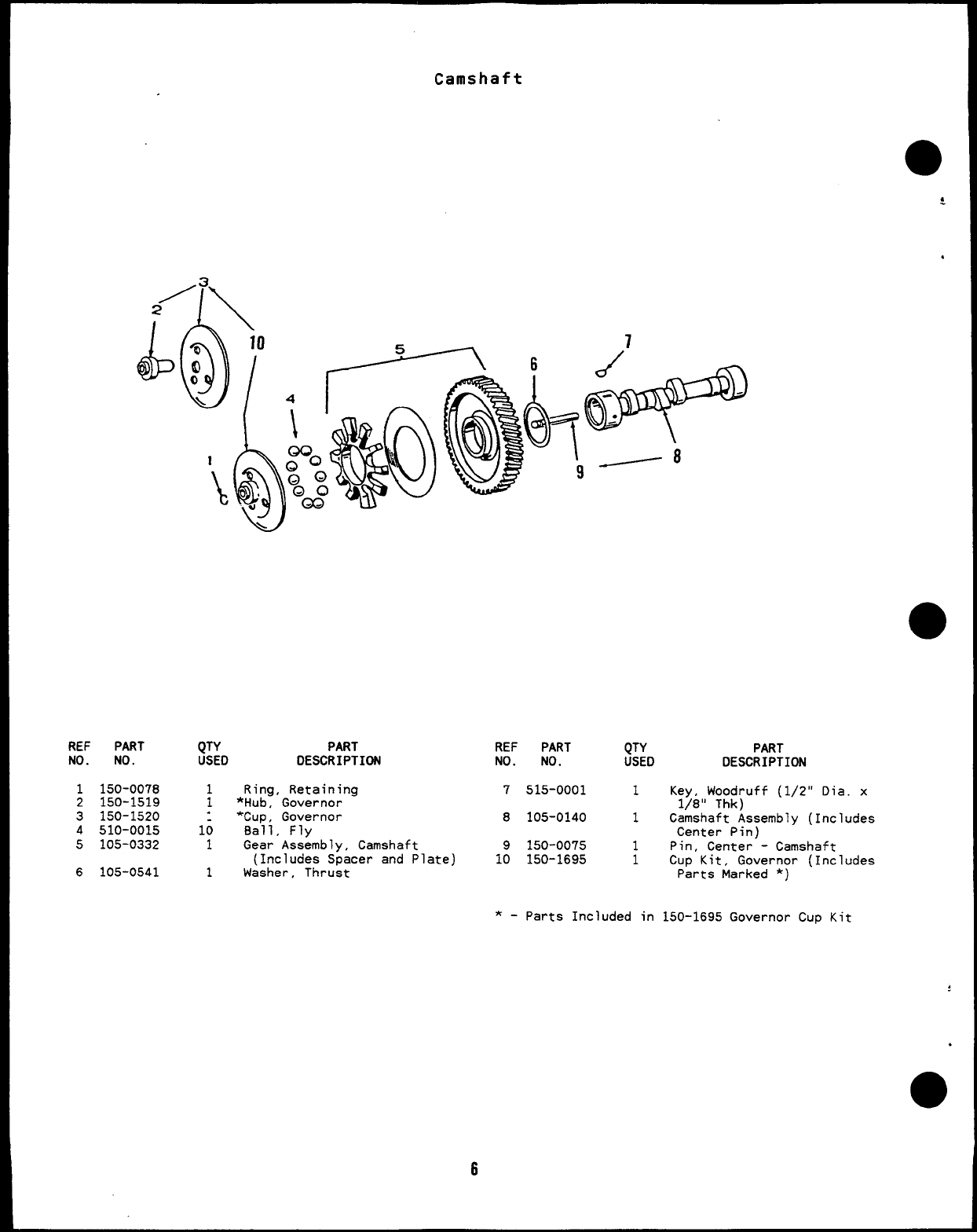
Camshaft
●
$
.
REF PART
NO. NO.
1150-0078
2150-1519
3150-1520
4510-0015
5105-0332
6105-0541
QTY PART
USED DESCRIPTION
1Ring, Retaining
1*Hub, Governor
.*Cup, Governor
16 Ball, Fly
1Gear Assembly, Camshaft
(Includes Spacer and Plate)
1Washer, Thrust
6
REF PART QTY PART
NO. NO. USED DESCRIPTION
7515-0001 1Key, Woodruff (1/2” Dia. x
1/8” Thk)
8105-0140 1Camshaft Assembly (Includes
Center Pin)
9150-0075 1Pin, Center -Camshaft
10 150-1695 1Cup Kit, Governor (Includes
Parts Marked *)
*-parts Included in 150-1695 Governor CUP Kit
:
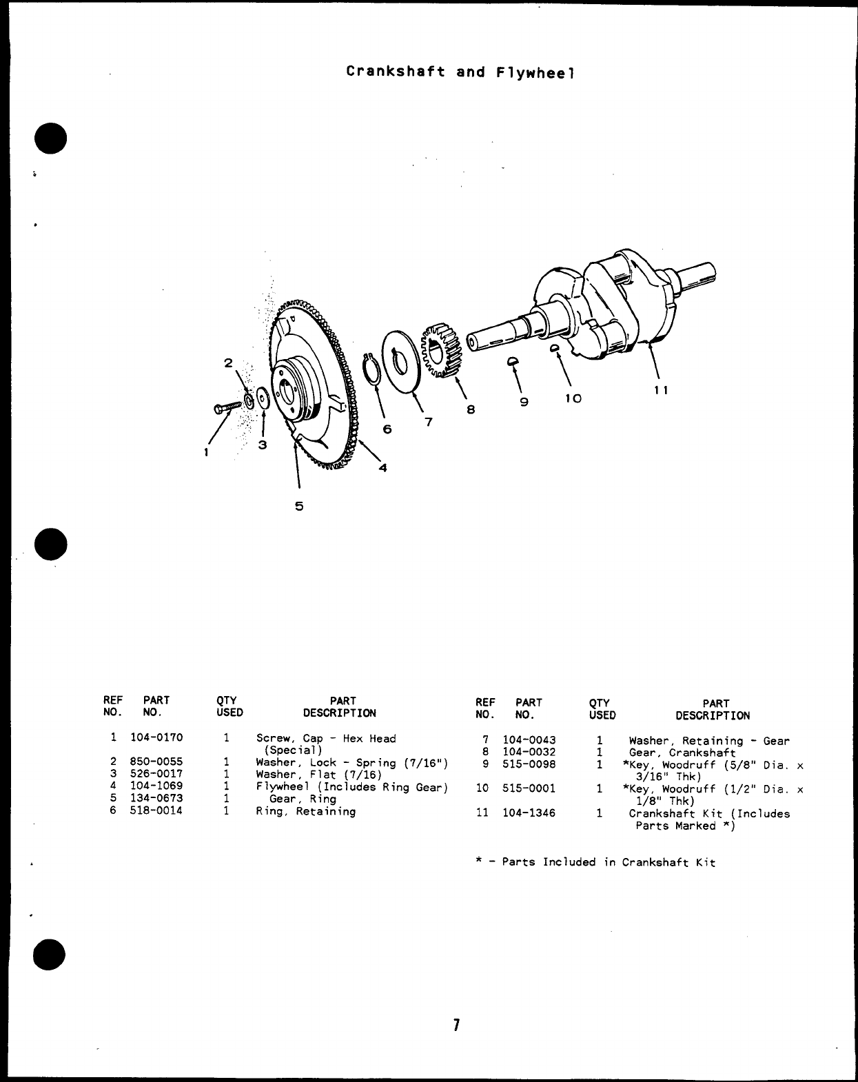
Crankshaft and Flywheel
,
5
REF PART QTY PART REF PART QTY PART
NO. NO. USED DESCRIPTION NO. NO. USED DESCRIPTION
1104-0170 1Screw, Cap -Hex Head 7104-0043 Washer, Retaining -Gear
(Special) 8104-0032 :Gear, Crankshaft
2850-0055 1Washer, Lock -Spring (7/16”) 9515-0098 1*Key, Woodruff (5/8” Dia. x
3526-0017 1Washer, Flat (7/16)
4104-1069 13/16” Thk)
Flywheel (Includes Ring Gear) 10 515-0001 1*Key, Woodruff (1/2” Dia. x
5134-0673 1Gear, Ring
6518-0014 11/8” Thk)
Ring, Retaining 11 104-1346 1Crankshaft Kit (Includes
Parts Marked ‘)
7
*-Parts Included in Crankshaft Kit
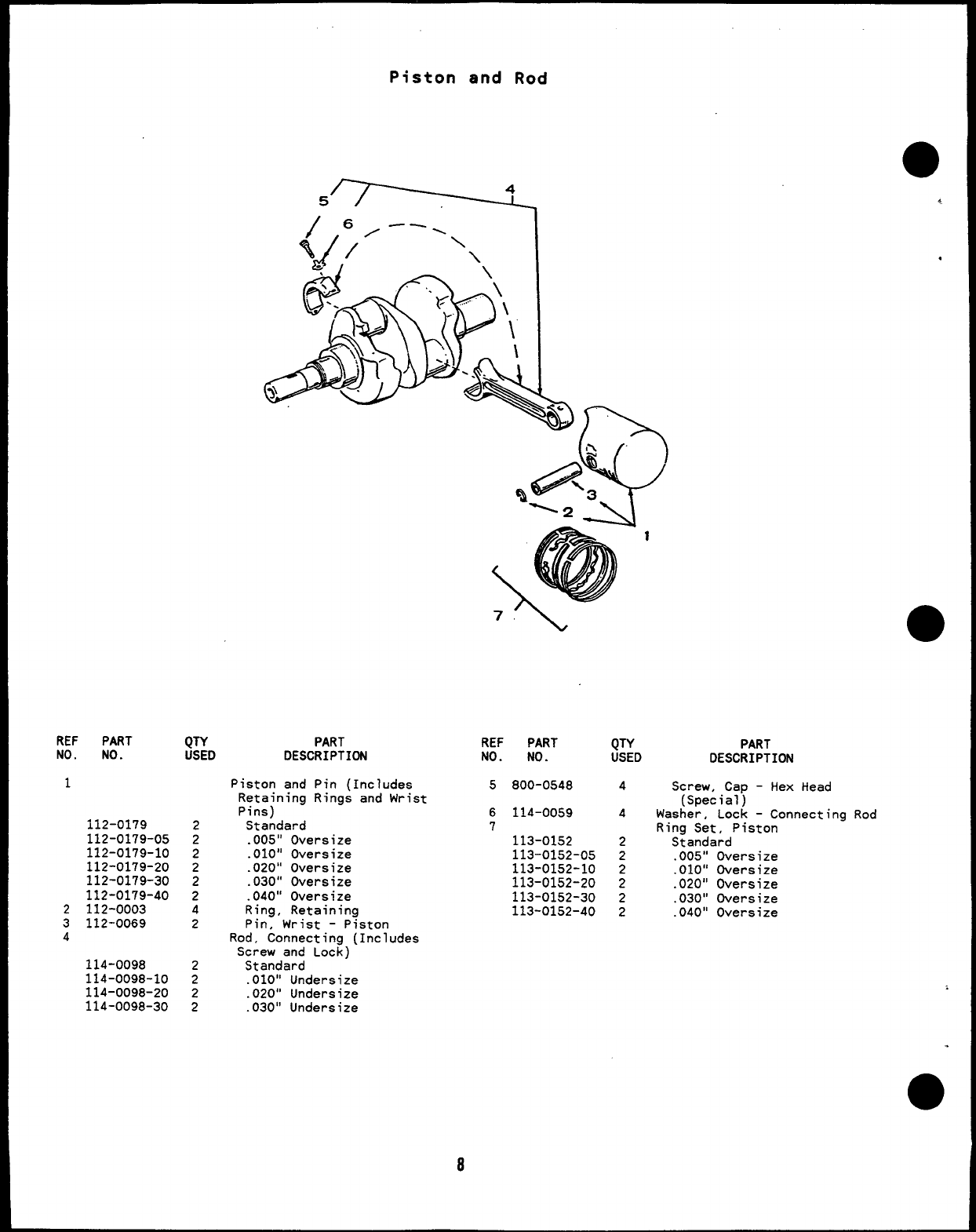
REF PART
NO. NO.
1
112-0179
112-0179-05
112-0179-10
112-0179-20
112-0179-30
112-0179-40
2112-0003
3112-0069
4
114-0098
114-0098-10
114-0098-20
114-0098-30
QTY
USED
2
2
2
2
2
2
4
2
2
2
2
2
Piston and Rod
.
PART
DESCRIPTION REF PART
NO. NO.
5800-0548
6114-0059
7
113-0152
113-0152-05
113-0152-10
113-0152-20
113-0152-30
113-0152-40
QTY
USED PART
DESCRIPTION
8
4
Piston and Pin (Includes
Retaining Rings and Wrist
Pins)
Standard
.005” Oversize
.010” Oversize
.020” Oversize
.030” Oversize
.040” Oversize
Ring, Retaining
Pin, Wrist -Piston
Rod, Connecting (Includes
Screw and Lock)
Standard
.010” Undersize
.020” Undersize
.030” Undersize
4
2
2
2
2
2
2
Screw, Cap -Hex Head
(Special)
Washer, Lock -Connecting Rod
Ring Set, Piston
Standard
.005” Oversize
.010” Oversize
.020” Oversize
.030” Oversize
.040” Oversize
.
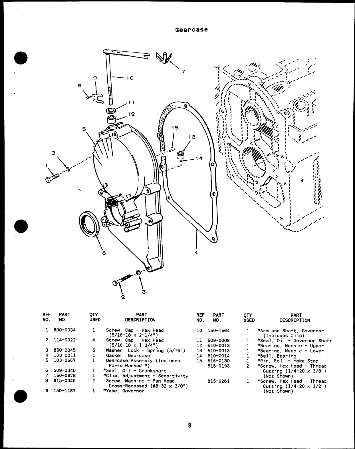
Gearcase
REF PART
NO. NO.
9
!
—lo
8
I
\.. .
E
.
d
11
-’2
1800-0034
2114-0022
3850-0045
4103-0011
5103-0667
6509-0040
7150-0678
.8815-0046
●9150-1187
6
\
.
iji!)i
--
@--B\
\3
2
QTY PART
USED DESCRIPTION
. .
.,-. -0
‘m
1?:
.
15
1~
13 \
;~1~
4
1Screw, Cap -Hex Head
(5/16-18 X2-1/4”)
4Screw, Cap -Hex Head
(5/16-18 X1-3/4”)
5Washer, Lock -Spring (5/16”)
1Gasket, Gearcase
1Gearcase Assembly (Includes
Parts Marked *)
REF PART
NO. NO.
10 150-1564
11 509-0008
12 510-0013
13 510-0013
14 510-0014
15 516-0130
815-0193
1*Seal, Oil -Crankshaft
1*Clip, Adjustment -Sensitivity
2Screw, Machine -Pan Head, 815-0261
Cross-Recessed (#8-32 x3/8”)
1*Yoke, Governor
9
“.. i
‘. I
‘.. ,4 ,
‘. -;0 /“”;’
“. ‘* /
.--. ,/’
-..
QTY PART
USED DESCRIPTION
1
1
1
1
1
1
2
1
*Arm and Shaft, Governc
(Includes Clip)
*Seal, Oil -Governor :
*8earing, Needle -Uppc
*Bearing, Needle -Lowe
*Ball, 8earing
*Pin, Roll -Yoke Stop
*Screw, Hex Head -Thrc
Cutting (1/4-20 x3/E
(Not Shown)
*Screw, Hex Head -Thr~
Cutting (1/4-20 x1/2
(Not Shown)
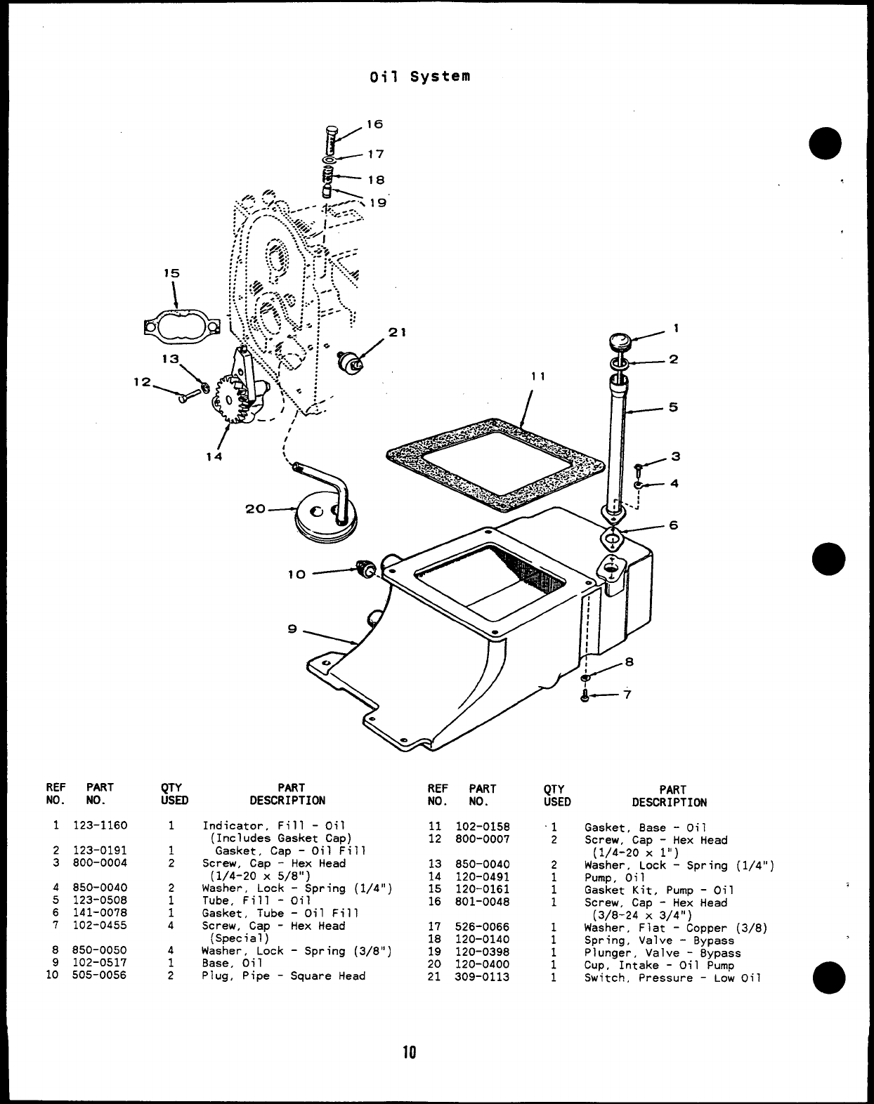
oil System
K
16
.~17
&----l*
.
REF PART
NO. NO.
1123-1160
2123-0191
3800-0004
4850-0040
5123-0508
6141-0078
7102-0455
8850-0050
9102-0517
10 505-0056
QTY
USEO
1
1
2
4
1
PART
DESCRIPTION
Indicator, Fill -Oil
(Includes Gasket Cap,
Gasket, Cap -Oil F
Screw, Cap -Hex Head
(1/4-20 X5/8”)
Washer, Lock -Spring
Tube, Fill -Oil
Gasket, Tube -Oil Fi”
Screw, Cap -Hex Head
(Special)
Washer, Lock -Spring
Base, Oil
REF PART
NO. NO.
11 102-0158
12 800-0007
11
13 850-0040
14 120-0491
(1/4 “ ) 15 120-0161
16 801-0048
1
17 526-0066
18 120-0140
(3/8 “ ) 19 120-0398
20 120-0400
2Plug, Pipe -Square Head 21 309-0113
10
QTY PART
USED DESCRIPTION
‘1 Gasket, Base -Oil
2Screw, Cap -Hex Head
(1/4-20 xl“)
2wa:~eroi~ock -Spring (1/4”)
1
1Gasket Kit, Pump -Oil
1Screw, Cap -Hex Head
(3/8-24 X3/4”)
1Washer, Flat -Copper (3/8
1Spring, Valve -Bypass
Plunger, Valve -Bypass
:Cup, Intake -Oil Pump
1Switch, Pressure -Low Oil
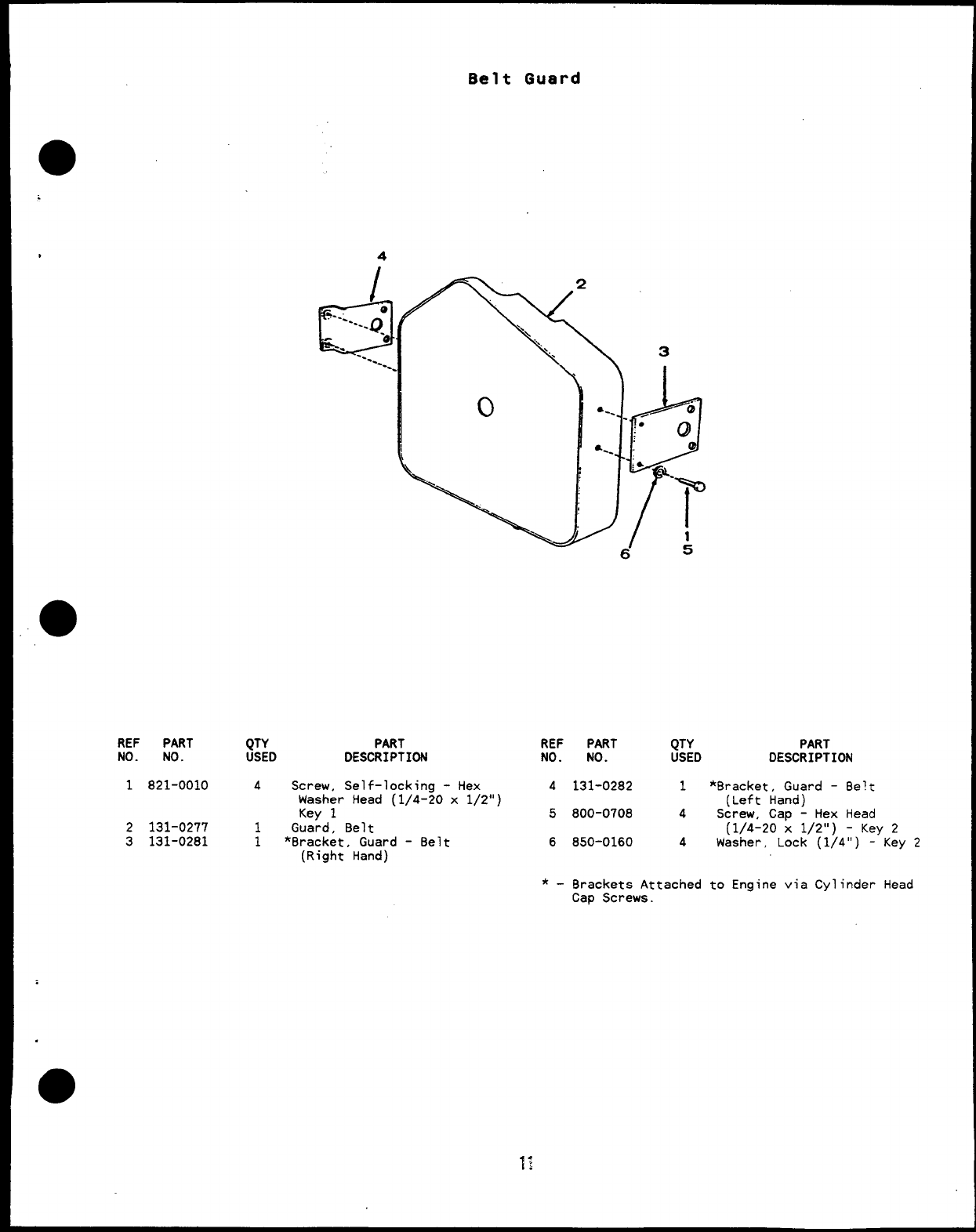
Belt Guard
4
REF PART
NO. NO.
1821-0010
2131-0277
3131-0281
QTY PART REF PART QTY PART
USED DESCRIPTION NO. NO. USED DESCRIPTION
4Screw, Self-locking -Hex 4131-0282 1*Bracket, Guard –Belt
Washer Head (1/4-20 x1/2”) (Left Hand)
Key 15800-0708 4Screw, Cap -Hex Head
1Guard, Belt (1/4-20 x1/2”) -Key 2
1*Bracket, Guard -8elt 6850-0160 4
(Right Hand)
Washer, Lock (1/4”) -Key 2
*-Bra~ket~ Attached to Engine via Cylinder Head
Cap Screws.
.
●
✎✎
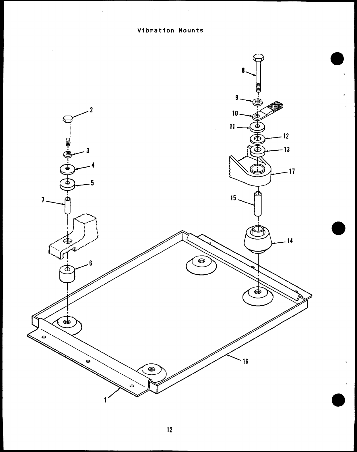
Vibration Mounts
17
.
14
fzk--6 // / \\ \\
Y// AR
t
*
e
1’ -
12
Vibration Mounts
REF PART
aNO. NO.
1405-1265
2800-0055
3850-0050
4526-0124
5402-0131
,6402-0036
7402-0176
8800-0081
9
850-0055
856-0012
QTY PART
USED DESCRIPTION
2Clamp, Holddown
2Screw, Cap -Hex Head
(3/8-16 X2-1/4”)
2Washer, Lock -Spring (3/8”)
4Washer, Flat (3/8”)
2Snubber, Rubber
2Cushion, Rubber
28ushing, Sleeve
2Screw, Cap -Hex Head
(7/16-14 X3-1/2”)
Washer, Lock
1Spring (7/16”)
1External/Internal Tooth
(7/161’)
REF PART
NO. NO.
10 337-0091
11 526-0128
12 526-0198
13 402-0282
14 402-0284
15 402-0290
16 403-1505
17 232-2321
QTY
USED
1
2
4
2
2
2
:
PART
DESCRIPTION
Strap, Ground
Washer, Flat (15/32”)
Washer, Flat (5/8”)
Snubber, Rubber
Cushion, Rubber
Bushing, Sleeve
Pan, Drip
Support, Generator
,
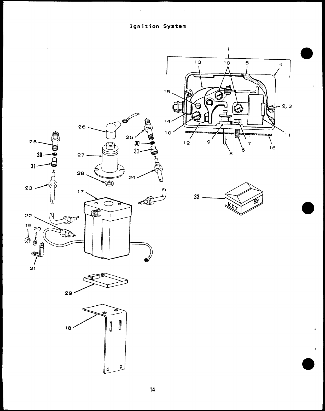
Ignition System
4(\
25
1
I
I13 10 5 A
I
15
,3
10 11
12 9y\ 7
6
8
Ill
,9-
\
16
14
I
REF PART
●NO. NO.
1160-1277
2812-0077
3856-0002
4160-0930
5160-0440
6802-0034
7850-0040
8160-0265
9160-0264
10 518-0049
11 312-0069
12 160-0002
13 160-0428
14 160-0349
15 160-0075
16 160-0043
17 166-0382
18 166-0704
19 870-0053
20 854-0010
21 337-0419
Ignition System
QTY PART REF PART
USED DESCRIPTION NO. NO.
1
2
2
1
1
2
2
1
1
3
1
1
1
1
1
1
1
1
2
1
1
Box Assembly, Breaker
(Includes Parts Marked *)
*Screw, Machine -Round Head
Slotted (#8-32 x3/8”)
Washer, Lock -External
Internal Tooth (#8)
*Cover, 80X -Breaker
*Gasket, Box -8reaker
*Screw, Cap -Socket Head
(1/4-20 X3/4”)
*Washer, Lock -Spring (1/4”)
*Plunger
*Guide, Plunger
*Screw, Machine -Round Head
with External Tooth
Lockwasher (#8-32 x1/4”)
“*Condenser, Ignition
“*Point Set, Breaker
*Lead, Flat -Point Set to
Terminal
*Terminal Assembly, Box -
Breaker
*Pivot, Adjusting -Point Set
*Gasket, Mounting -Breaker Box
Coil, Ignition -Shielded
Bracket. Mountina -Coil
22
23
24
25
26
27
28
29
30
31
32
336-4674
167-1631
167-1632
167-0199
167-0300
QTY PART
USED DESCRIPTION
.
312-0083
509-0102
503-1142
167-0077
167-0302
167-0301
526-0320
167-0208
160-0836
1
1
1
2
1
1
1
1
2
2
2
2
2
1
Lead, Electrical -Shielded
(Box to Coil)
Lead, Electrical -Shielded,
Spark Plug (25”)
(Includes Parts Marked t)
Lead, Electrical -Shielded,
Spark Plug (10”)
(Includes Parts Marked t)
Plug, Spark -Shielded
Nipple, Rubber -Coil
Terminal
Condenser, Ignition -
Shielded
Seal ,1101,Ring
Clamp, Loop -Coil Mounting
tSpring and Washer Assembly
(Includes Parts Marked H)
ttSpring, Steel Wire
ttEyelet, Spring
ttWasher, Flat (.133 I.D. x
.281 O.D. X.025” Thk)
tGrommet, Rubber
Tune Up Kit, Ignition
(Includes Parts Marked ●)
Nut, Hex (#10:32j *-Parts Included in 160-1277 Breaker Box Assembly
Washer, Lock -Internal t-Parts Included in 167-1631, 167-1632 Shielded -
Tooth (#10) Spark Plug Lead
Strap, Ground “ - Parts Included in 160-0836 Ianition Tune UD Kit
t+ -Parts Included in 167-0077 Siring and Washer
Assembly
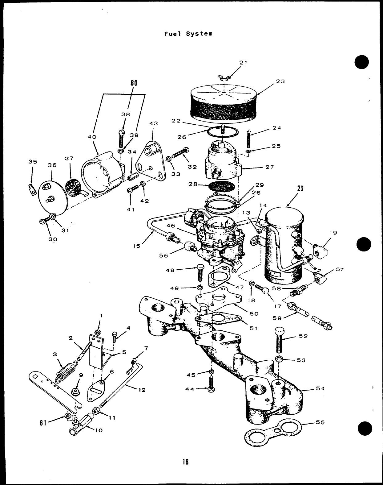
Fuel System
21
60
a7
//
I
3a
b
43
40 39 I
\D
34 3--.,
.=; ,
Yb“-’ “4(42 --
\‘31
30
f’
24
.25
--t!%
44 .
16
20
14
W
e.:f$---r’
.
..’* . .
z,J. . ... . -.,.
y.. .
*
55
I
Fuel System
REF PART
m
NO. NO.
1150-0621
2150-0096
;3150-1612
4800-0004
5
.6
7
9
10
11
12
13
14
15
17
18
19
20
150-1577
149-0003
518-0004
870-0131
150-0639
870-0053
150-1732
862-0015
518-0350
149-1624
149-2154
800-0544
850-0160
502-0002
NFS
149-2159
21 865-0020
●22 520-0093
23 145-0516
24 813-0106
25 850-0030
26 509-0145
27 140-1473
28 120-0848
29 140-1684
30 815-0285
31 526-0062
QTY
USEO
1
1
1
2
;
1
1
1
2
1
:
;
2
2
1
1
1
1
1
3
3
2
1
2
1
2
2
PART
DESCRIPTION
Nut, Acorn
Stud, Adjusting -Governor
Spring, Governor
Screw, Cap -Hex Head
(1/4-20 X5/8”)
Bracket, Governor
Gasket
Clip, Rod -End
‘Nut, Self-locking Hex
(#10-32)
*Ball, Joint
*Nut, Hex (#10-32)
*Rod, Control
Nut, Hex (5/16-18)
Clamp, Loop -Insulated
Line, Fuel
Spec A-H
Spec J
Screw, Cap -Hex Head
(Special)
Washer, Lock -Spring (1/4”)
Elbow, Inverted Male -Brass
(1/4 Pipe, 1/8 NPT)
Pump, Fuel
Spec A-H (Must convert to
Spec J. Use Kit 149-2186)
(See Next Page for
Breakdown)
Spec J
Nut, Wing -Self-locking
(1/4-20)
Stud (1/4-20 X7/8”)
Arrester, Spark
Screw, Machine -Round Head
(#10-32 X1-1/8”)
Washer, Lock -Spring (#10)
Sea 1, !!0)1 Ring
Adapter, Cleaner -Air
Screen, Adapter -Carburetor
Gasket, Adapter to Carburetor
Screw, Machine -Round Head
with External Tooth
Lockwasher (#8-32 x5/16”)
Waaher, Flat (#8)
REF
NO.
32
33
34
35
36
37
38
39
40
41
42
43
44
45
46
47
48
49
50
51
52
53
54
55
56
57
58
59
60
61
PART
NO.
812-0084
850-0025
153-0516
332-0527
153-0116
153-0017
815-0110
850-0030
153-0058
813-0098
850-0030
153-0481
800-0028
850-0045
146-0439
141-0858
800-0007
850-0040
154-2077
141-0859
800-0059
850-0050
154-2078
154-0013
502-0003
502-0020
502-0577
501-0242
153-0440
526-0196
QTY PART
USED DESCRIPTION
1
1
1
1
1
;
1
1
2
2
1
2
2
1
1
2
2
1
1
2
2
1
2
;
1
1
1
1
Screw, Machine -Round Head
(#8-32 X1“ )
Washer, Lock -Spring (#E)
Spacer, Sleeve
Terminal, Tab
Cover, Choke
Element, Choke
tScrew. Machine -Fillister
Head (#10-32 x7/8”)
tWasher, Lock -Sorina f#lO)
tHousing, Choke ‘- -
Screw, Machine -Round
(#10-32 X3/8”)
Washer, Lock -Spring
Adapter, Choke
Screw, Cap -Hex Head
(5/16-18 X1“)
Washer, Lock -Spring
Carburetor, Gasoline (:
Separate Illustration
Parts)
Head
#lo)
5/16” )
ee
for
Gasket’, Mounting -Carburetor
Screw, Cap -Hex Head
(1/4-20 X1“ )
Washer, Lock -Spring (1/4”)
Adapter, Mounting -Carburetor
Gasket, Mounting -Carburetor
Screw, Cap -Hex Head
(3/8-16 X3-1/4”)
Washer, Lock -Spring (3/8”)
Manifold, Intake
Gasket, Manifold -Intake
Adapter, Pipe to Tube
Elbow, Inverted Male
Connector, Male
Line, Fuel (3/8”ID x24”)
Housing, Choke (Includes
Parts Marked t)
*Washer, Flat (#10)
*-parts Included in 150-1718 Linkage Assembly
t-Parts Included in 153-0440 Choke Housing
17
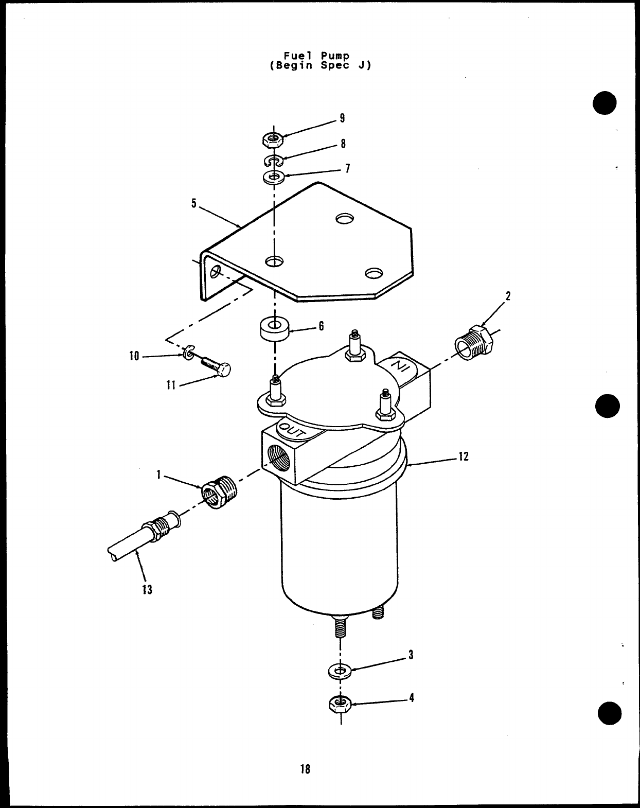
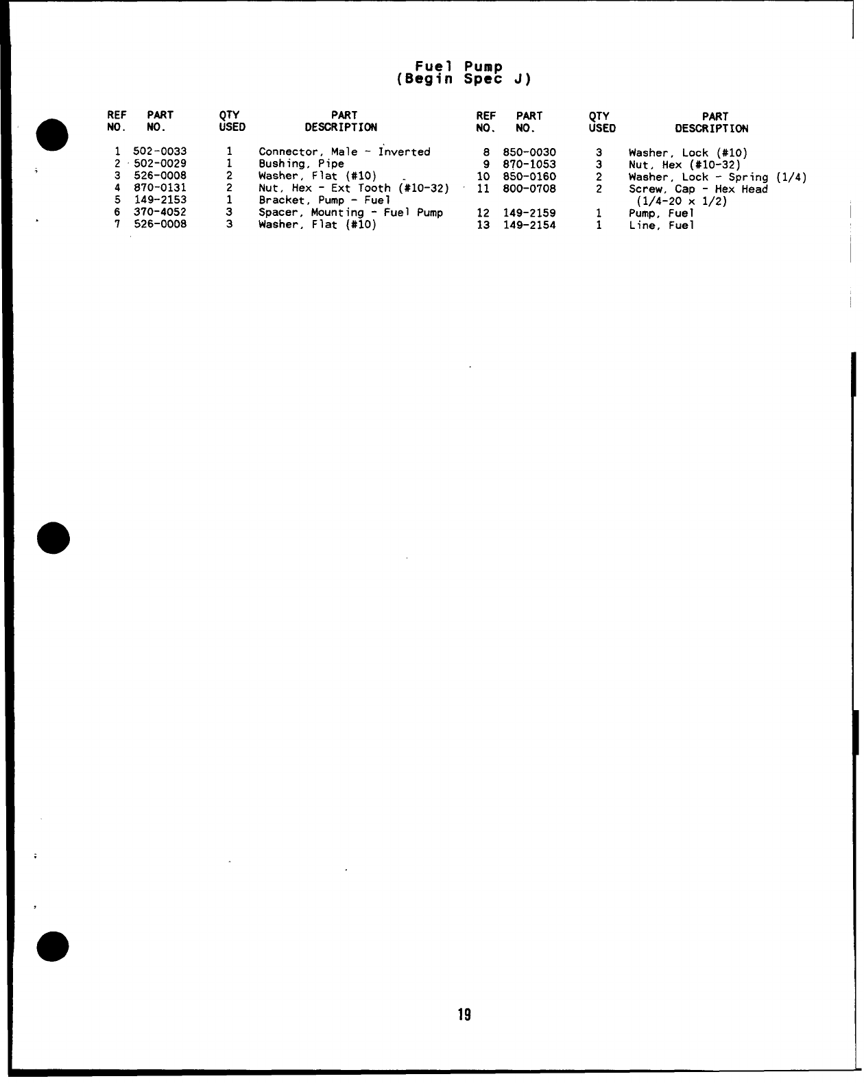
Fuel Pump
(Begin Spec J)
2
Y
18
I
@-’
+--4
●REF PART QTY
NO. NO. USED
1502-0033 1
2502-0029 1
;3526-0008 2
4870-0131 2
5149-2153 1
6370-4052 3
7526-0008 3
Fuel Pump
(Begin Spec J)
PART REF PART
DESCRIPTION NO. NO.
Connector, Male -Inverted 8850-0030
8ushing, Pipe 9870-1053
Washer, Flat (#IO) 10 850-0160
Nut, Hex -Ext Tooth (_#10-32) 11 800-0708
8racket, Pump -Fuel
Spacer, Mounting -Fuel Pump 12 149-2159
Washer, Flat (#IO) 13 149-2154
19
QTY
USEO
3
3
2
2
1
1
PART
DESCRIPTION
Washer, Lock (#10)
Nut, Hex (#10-32)
Washer, Lock -Spring (1/4)
Screw, Cap -Hex Head
(1/4-20 X1/2)
Pump, Fuel
Line, Fuel
.
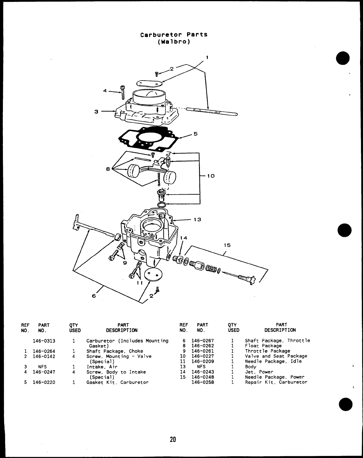
Carburetor Parts
(Walbro)
REF PART
NO. NO.
146-0313
1146-0264
2146-0142
3NFS
4146-0247
5146-0220
65 C&A
●
15
‘w”
QTY PART
USED DESCRIPTION
1Carburetor (Includes
Gasket )
1Shaft Package, Choke
Mounting
4Screw, Moun~ing -Valve
(Special)
1Intake, Air
4Screw, Body to Intake
(Special)
1Gasket Kit, Carburetor
REF PART
NO. NO.
6146-0267
8146-0262
9146-0261
10 146-0227
11 146-0209
13 NFS
14 146-0243
15 146-0248
146-0258
QTY
USED
1
1
1
1
1
1
1
1
1
DESCRIPTION
Shaft Package, Throttle
Float Package
Throttle Package
Valve and Seat Package
Needle Package, Idle
Body .
Jet, Power
Needle Package, Power
Repair Kit, Carburetor
●
20
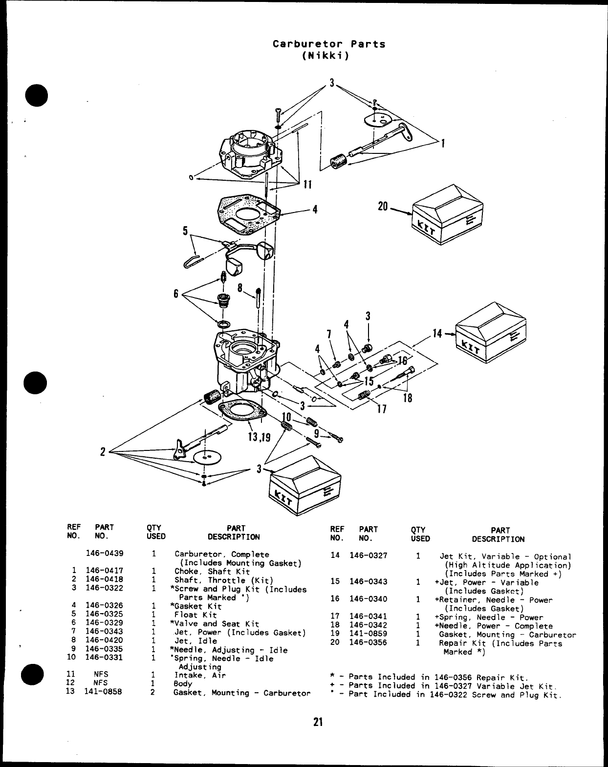
Carburetor Parts
(Nikki)
.
REF PART
NO. NO.
146-0439
1146-0417
2146-0418
3146-0322
4
5
6
7
8
1:
13
146-0326
146-0325
146-0329
146-0343
146-0420
146-0335
146-0331
NFS
NFS
141-0858
QTY PART
USED DESCRIPTION
1Carburetor, Complete
(Includes Mounting Gasket)
1Choke, Shaft Kit
1Shaft, Throttle (Kit)
1*Screw and Plug Kit (Includes
Parts Marked “)
1*Gasket Kit
1Float Kit
*Valve and Seat Kit
:Jet, Power (Includes Gasket)
1Jet, Idle
1*Needle, Adjusting -Idle
1“Spring, Needle -Idle
Adjusting
Intake, Air
;Body
2Gasket, Mounting -Carburetor
18
REF PART
NO. NO.
14 146-0327
15 146-0343
16 146-0340
17 146-0341
18 146-0342
19 141-0859
20 146-0356
QTY PART
USED DESCRIPTION
1Jet Kit, Variable -Optional
(High Altitude Application)
(Includes Parts Marked +)
1+Jet, Power -Variable
(Includes Gaskc:)
1+Retainer, Needle -Power
(Includes Gasket)
+Spring, Needle -Power
;+Needle, Power -Complete
1Gasket, Mounting -Carburetor
1Repair Kit (Includes Parts
Marked *)
*-Parts Included in 146-0356 Repair Kit.
+-Parts Included in 146-0327 Variable Jet Kit.
“ - Part Included in 146-0322 Screw and Plug Kit
21
Cool ing -Exhaust System
37
716lfj 35 41
1td38
k1
10 5
9-*2L._.
AP 1
I
45’ I
43
1/
7
22

I
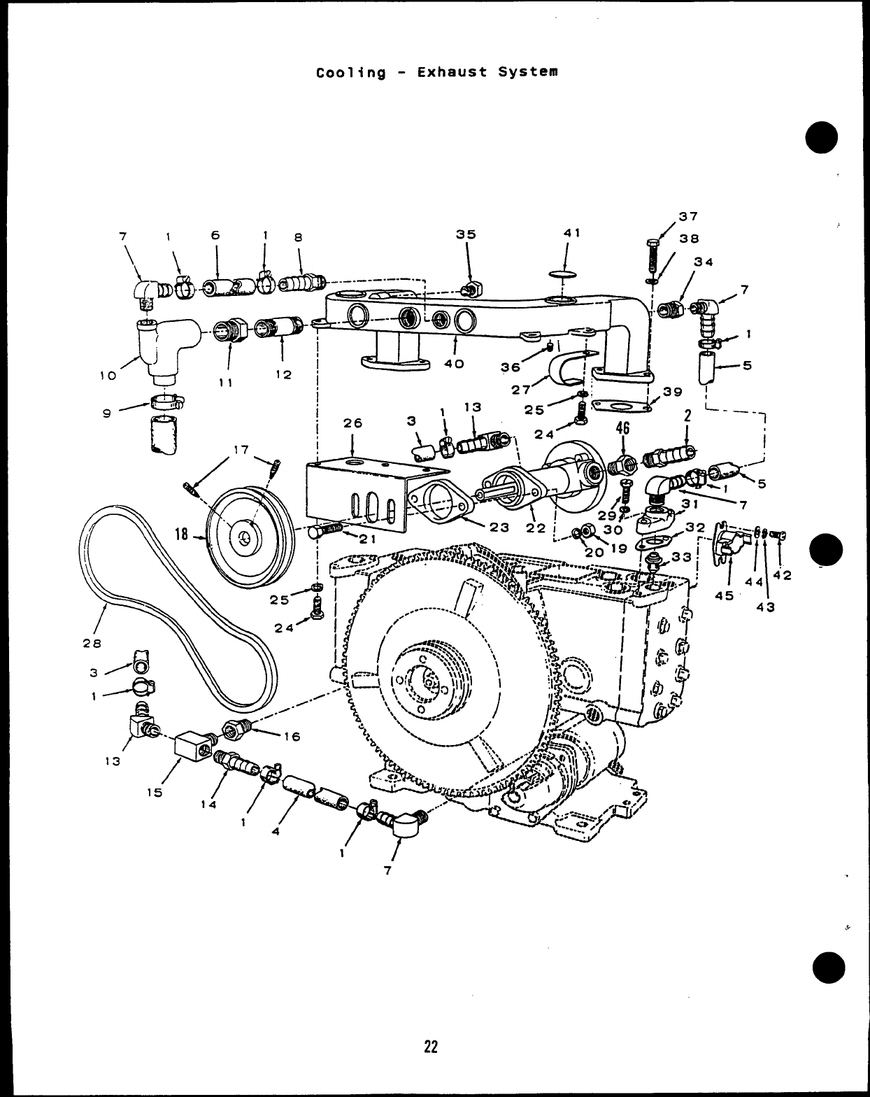
Cooling -Exhaust System
aREF PART
NO. NO.
1503-0976
2503-0827
3503-0696
4503-0468
5
6
‘1
8
1:
11
12
13
14
15
16
17
18
19
20
21
22
503-0975
503-0434
502-0237
502-0238
503-1141
155-1058
505-0023
505-1344
502-0575
502-0238
502-0446
502-0426
803-0062
512-0166
870-0154
850-0160
816-0090
131-0257
23 131-0173
●24 800-0005
QTY
USED
12
i
1
2
1
6
1
2
1
1
1
2
1
1
1
2
1
2
2
2
1
1
4
PART
DESCRIPTION
Clamp, Hose
Connector, Hose
Hose, Rubber (1/2”ID
Hose, Rubber (1/2”ID
13-1/2”)
Hose, Rubber (1/2”ID
Hose, Rubber (1/2”ID
Elbow, Hose -90-
Connector, Hose
Clamp, Hose
x7“)
x
X6“)
X8“)
Elbow, Exhaust with Injector
Port
8ushing, Reducer
Nipple, Pipe (Special)
Elbow, Hose -45”
Connector, Hose
Tee. Pipe
Bushing
Screw, Set -Socket
(5/16-18 x5/16”)
Pulley, Groove (Includes Set
Screw)
Nut, Hex (1/4-20)
Washer, Lock -Spring (1/4”)
8olt, Carriage -Zinc Plate,
Grade 5(1/4-20 x1-1/4”)
Pump, Water -Complete (See
Separate Illustration for
Component Parts)
Adapter, Pump
Screw, Cap -Hex Head
(1/4-20 X3/4”)
REF PART QTY
NO. ND. USEO
25 850-0040 4
26 131-0270 1
27 148-0274 1
28 511-0073 1
29 800-0007 4
30 850-0040 4
31 309-0185 2
32 309-0186 2
33 309-0130 2
34 502-0029-05 2
35 502-0153
36 502-0080 :
37 800-0029 4
38 850-0045 4
39 154-0973 2
40 154-2092 1
41 517-0041 4
42 812-0145 2
43 854-0014 2
44 526-0016 2
45 309-0257 1
46 502-0976 1
PART
DESCRIPTION
Washer, Lock -Spring (1/4”)
8racket, Mounting -Water
Pump
Bracket, Support -Hose
Belt, Drive
Screw, Cap -Hex Head
(1/4-20x l“)
Washer, Lock -Spring (1/4”)
Housing, Thermostat
Gasket
Thermostat
Reducer, Bushing
Plug, Pipe -Hex Head, Brass
Plug, Pipe -Square Head,
8rass
Screw, Cap -Hex Head
(5/16-18 X1-1/8”)
Washer, Lock -Spring (5/16”)
Gasket, Manifold -Exhaust
Manifold, Exhaust (Includes
Expansion Plugs)
Plug, Expansion -Brass
(1-1/4” Dia.)
Screw, Machine -Round Head
(1/4-20 X5/16”)
Washer, Lock -Internal Tooth
(1/4)
Washer, Flat (1/4)
Switch, High Temperature
Adapter
23
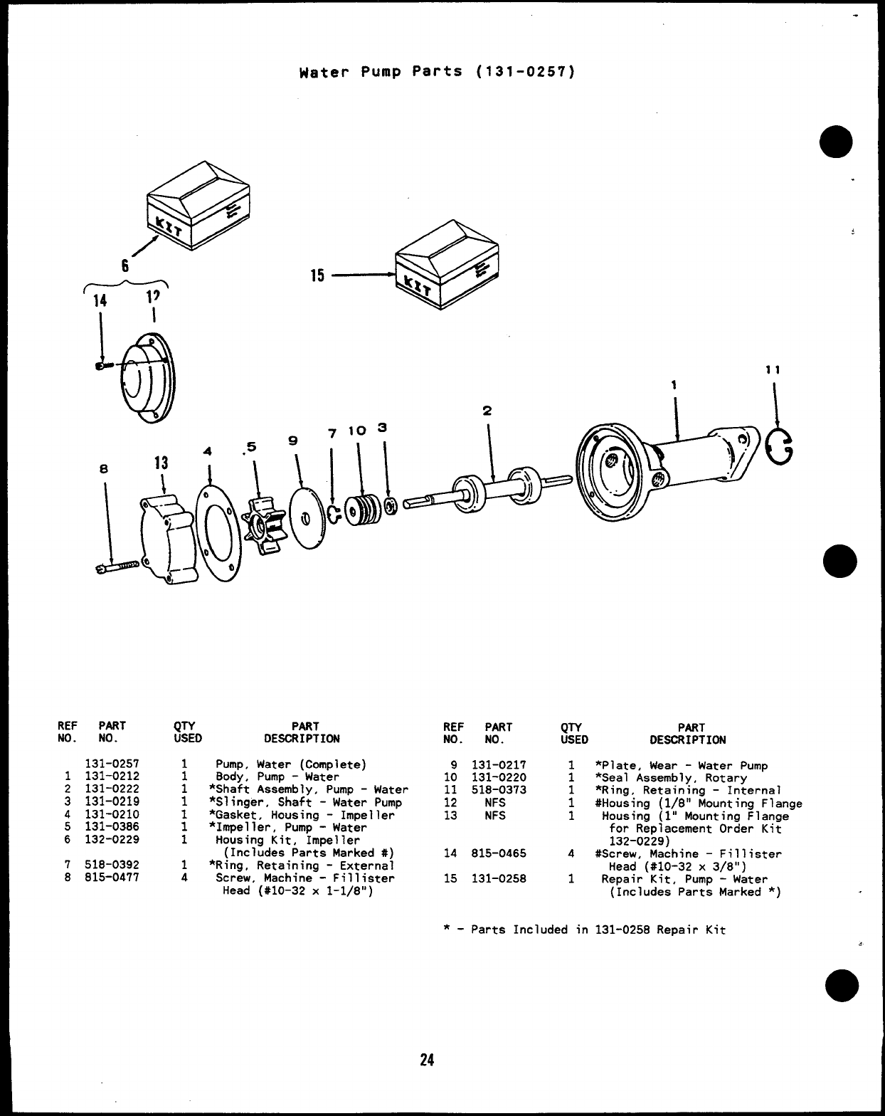
Water PuIup Parts (131-0257)
w
J
7103
REF PART
NO. NO.
131-0257
1131-0212
2131-0222
3131-0219
4131-0210
5131-0386
6132-0229
7518-0392
8815-0477
QTY
USED PART
DESCRIPTION
1Pump, Water (Complete)
8ody, Pump -Water
:*Shaft Assembly, Pump -Water
1*Slinger, Shaft -Water Pump
1*Gasket, Housing -Impeller
1*Impeller, Pump -Water
1Housing Kit, Impeller
(Includes Parts Marked #)
1*Ring, Retaining -External
4Screw, Machine -Fillister
Head (#10-32 x1-1/8”)
REF PART QIY PART
NO. NO. USED DESCRIPTION
9131-0217 1*Plate, Wear -Water Pump
10 131-0220 1*Seal Assembly, Rotary
11 518-0373 1*Ring, Retaining -Internal
12 NFS 1#Housing (1/8” Mounting Flange
13 NFS 1Housing (l” Mounting Flange
for Replacement Order Kit
132-0229)
14 815-0465 4#Screw, Machine –Fillister
Head (#10-32 x3/8”)
15 131-0258 1Repair Kit, Pump -Water
(Includes Parts Marked *)
*-Parts Included in 131-0258 Repair Kit

I
,)
p
9
6
%
o.
‘1
,
,e;
,6’ )
e’
Starter
r’ -5
---- I
t
I
I
I
I
I
\/“ _____ -——-
—————--—— ——-—— . .
M\/T------------
10 12 14 I
i
1
I
J!
L---- ,
,, I
18 19- 21
26
I
Starter
REF PART
No. No.
1800-0051
2850-0050
3800-0049
4800-0050
5850-0050
6191-0508
7191-1246
8191-1267
9813-0110
10 191-1018
QTY PART
USED DESCRIPTION
3Screw, Cap -Hex Head
(3/8-16 X1-1/4’1)
3Washer, Lock -Spring (3/8”)
1Screw, Cap -Hex Head
(3/8-16 X7/8”)
1Screw, Cap -Hex Head
(3/8-16 X1“)
2Washer, Lock -Spring (3/8”)
1Flange, Mounting -Starter
1Starter, Sealed (Includes
Parts Marked *)
1t*Band, Cover (Includes
Gasket and Hardware)
1tScraw, Round Head -Machine
(#10-32 X2“)
1*Head Assembly, Commutator
REF PART
NO. NO.
11 191-1020
12 191-0513
13 191-1022
14 191-1017
15 515-0094
16 191-0517
17 191-1021
18 191-1019
19 191-0271
20 191-0735
21 NFS
22 NFS
23 191-1524
QTY PART
USED DESCRIPTION
1*Spring Set, Brush
*8rush Set
:*Terminal Package
1*Coil Assembly, Field
1Key, Woodruff (#6)
1*Armature
1Washer Package, Thrust
1*Bearing Assembly, Intermediate
1*Drive Assembly, Plated
1*Bearing, Sleeve -Bronze
1*Pinion, Housing -(With Drain
Hole)
*Frame, Starter -Sealed Type
:Band Kit -Starter (Includes
Parts Marked t)
*-parts Included in 191-1246 Starter Assembly
t-Parts Included in 191-1524 Starter 8and Kit
27

Control
24
27 \
35
:..:!&[.”
40 L-- 37
---- --------
45 39
‘-------- ------- !!
--------- —-. A.
---
/
/
\& 25
,?---- -- ,●--
7
.I--A’ ‘--””> :
=@
7
1
4,5
.
,
Control
●REF PART
NO. NO.
1518-0056
.2301-9199
98-3733
3821-0004
.
4321-0174
5321-0153
6321-0175
7308-0383
8821-0004
9870-0131
10 307-1575
11 812-0087
12 304-0580
13 508-0015
14 870-0221
15 352-0161
16 331-0088
17 301-4879
18 800-0708
a.19 850-0160
20 307-1617
21 508-0021
22 508-0208
23 332-1043
24 812-0065
25 854-0006
26 860-0005
27 332-0699
QTY
USEO
2
1
1
2
2
1
3
1
2
2
3
1
;
1
1
2
1
2
2
1
1
1
2
2
2
2
1
PART
DESCRIPTION
Screw, Wing (#~0-32 x1/2”)
Cover, 80X -Control
(Includes Decal)
Decal, Diagram -Wiring
Screw, Self-locking -Hex
Washer Head (#10-32 x5/16”)
Fuss, Cartridge -5Ampere
(Fl, F2)
Fuse, Cartridge -5Ampere
(F3)
Holder, Fuse
Switch, Toggle -Start/Stop
(s1)
Screw, Self-locking -Hex
Washer Head (#10-32 x5/16”)
Nut, Hex -With External
Tooth Lockwasher (#10-32)
Relay, Crank/Run/Stop -
C2.3,4
Screw, Machine -Round Head
(#8-32 X1-1/2”)
Insulator, Mounting -Resistor
Insulator, Washer
Nut, Hex -With External
Tooth Lockwasher (#8-32)
Resistor, Fixed -100-Ohm,
5Watt (RI)
Insulator, 8ushing
Panel, Control
Screw, Cap -Hex Head
(Special)
Washer, Lock -Spring (1/4)
Solenoid (Kl)
Grommet, Rubber
Insulator, 8ushing
Jumper, Terminal
Screw, Machine -Round Head
(#6-32 X5/8”)
Washer, Lock -Internal Tooth
(#6)
Nut, Hex (#6-32)
810ck, Terminal -T81
REF PART
NO. NO.
28 332-2103
29 800-0708
30 850-0160
31 821-0004
32 813-0112
33 870-0131
34 304-0014
35 304-0292
36 304-0060
37 815-0350
38 336-4678
39 301-4887
40 338-1099
41 812-0066
42 860-0005
43 853-0003
44 332-0236
45 332-2117
46 508-0191
47 301-4634
48 98-5966
49 338-1264
50 302-0885
51 815-0385
52 870-1183
53 525-0216
QTY
USED
1
2
2
2
1
1
1
1
1
1
1
1
1
2
2
2
1
1
2
2
1
Strip,
Screw,
PART
DESCRIPTION
Marker
Cap -Hex Head
(special)
Washer, Lock -Spring (1/4”)
Screw, Self-locking -Hex
Washer Head (#10-32 x5/16”)
Screw, Machine -Round Head
(#10-32 X2-1/2”)
Nut, Hex -With External
Tooth Lockwasher (#10-32)
Washer, Shoulder -Resistor
Centering
Insulator, Mounting -Resistor
Resistor, Fixed -1.72-Ohm,
25 Watt (R3)
Screw, Tapping -Hex Washer
Head (#10 x3/8”)
Lead, Electrical (Solenoid
to Starter)
Plate, Mounting -Relay
Harness, Wiring -Generator
to Control
Screw, Machine -Round Head
(#6-32 X3/4”)
Nut, Hex (#6-32)
Washer, Lock -Extern~l
Tooth (#6)
810ck -Terminal -TB2
Strip, Marker
Insulator, Bushing
Box, Control
Decal, Panel -Control
Harness, Wiring -Control
(Includes Relays, Resistor
and Terminal Block)
Meter, Time -Running
Screw, Machine -Round Head
(#6-32 X1/2”)
Nut, Hex -W/ET (#6-32)
Paint, Touch-Up -White
Enamel (16 oz. Spray Can)
●
Generator
t7=&=i48
47
/
5“4 55 49
12
15
4
., --I
I
22
i
/-’
0
\29
27
●
I
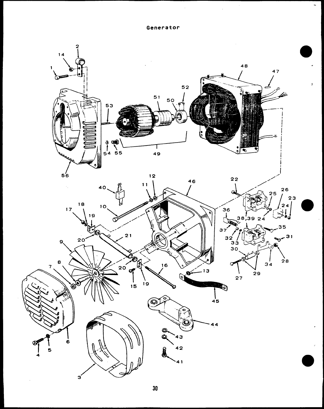
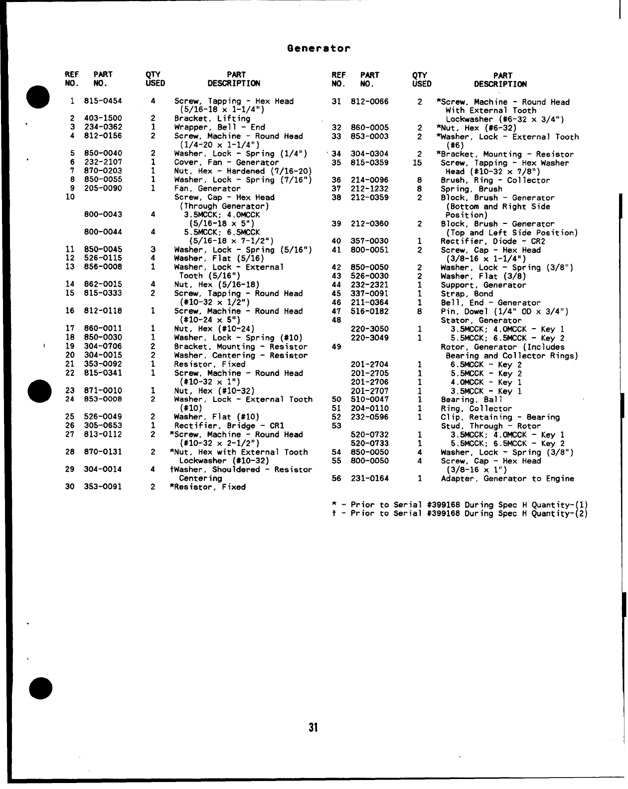
Generator
REF
●NO.
1
2
.3
4
5
6
7
8
1:
11
12
13
14
15
16
17
18
I19
:!
22
●23
24
25
26
27
28
29
30
PART
No.
815-0454
403-1500
234-0362
812-0156
850-0040
232-2107
870-0203
850-0055
205-0090
800-0043
800-0044
850-0045
526-0115
856-0008
862-0015
815-0333
812-0118
860-0011
850-0030
304-0706
304-0015
353-0092
815-0341
871-0010
853-0008
526-0049
305-0653
813-0112
870-0131
304-0014
353-0091
QTY
USED
4
2
1
2
2
1
1
1
1
4
4
3
4
1
4
2
1
1
1
2
2
1
1
1
2
2
1
2
2
4
2
PART
DESCRIPTION
Screw, Tapping -Hex Head
(5/16-18 X1-1/4”)
Bracket, Lifting “
Wrapper, Bell -End
Screw, Machine -Round Head
(1/4-20 X1-1/4”)
Washer, Lock -Spring (1/4”)
Cover, Fan -Generator
Nut, Hex -Hardened (7/16-20)
Washer, Lock -Spring
Fan, Generator
Screw, Cap -Hex Head
(Through Generator)
3.5MCCK; 4.OMCCK
(5/16-18 X5“)
5.5MCCK; 6.5MCCK
(5/16-18x 7-1/2”)
Washer, Lock -Spring
Washer, Flat (5/16)
“(7/16”j
(5/16”)
Washer, Lock -External
Tooth (5/16”)
Nut, Hex (5/16-18)
Screw, Tapping -Round Head
(#10-32 X1/2”)
Screw, Machine -Round Head
(#10-24 X5“ )
Nut, Hex (#10-24)
Washer, Lock -Spring (#10)
Bracket, Mounting -Resistor
Washer, Centering -Resistor
Resistor, Fixed
Screw, Machine -Round Head
(#10-32 X1“)
Nut, Hex (#10-32)
Washer, Lock -External Tooth
(#lo)
Washer, Flat (#10)
Rectifier, Bridge -CR1
*Screw, Machine -Round Head
(#10-32 X2-1/2”)
*Nut, Hex with External Tooth
LockWasher (#10-32)
tWasher, Shouldered -Resistor
Centering
*Resistor, Fixed
REF PART
NO. NO.
31 812-0066
32 860-0005
33 853-0003
34 304-0304
35 815-0359
36 214-0096
37 212-1232
38 212-0359
39 212-0360
40 357-0030
41 800-0051
42 850-0050
43 526-0030
44 232-2321
45 337-0091
46 211-0364
47 516-0182
48
220-3050
220-3049
49
201-2704
201-2705
201-2706
201-2707
50 510-0047
51 204-0110
52 232-0596
53
520-0732
520-0733
54 850-0050
55 800-0050
56 231-0164
QTY PART
USED DESCRIPTION
2
2
2
1:
:
2
2
1
2
2
2
1
1
1
8
i
1
1
;
1
1
1
;
4
4
1
*-prior to Serial
t- Prior to Serial
*Screw, Machine -Round Head
With External Tooth
LockWasher (#6-32 x3/4”)
*Nut, Hex (#6-32)
Washer, Lock -External Tooth
(#6)
*Bracket, Mounting -Resistor
Screw, Tapping -Hex Washer
Head (#10-32 x7/8”)
Brush, Ring -Collector
Spring, Brush
Block, 8rush -Generator
(Bottom and Right Side
Position)
Block, Brush -Generator
(TOD and Left Side Position)
Rect;fier, Diode -CR2 “
Screw, Cap -Hex Head
(3/8-16 X1-1/4”)
Washer, Lock -Spring
Washer, Flat (3/8)
Support, Generator
Strap, Bond
Bell, End -Generator
Pin, Dowel (1/4” 00 x
Stator, Generator
(3/8”
3/4 “ )
3.5MCCK; 4.DMCCK -Key 1
5.5MCCK; 6.5MCCK -Key 2
Rotor, Generator (Includes
Bearing and Collector Rings)
6.5MCCK -Key 2
5.5MCCK -Key 2
4.OMCCK -Key 1
3.5MCCK -Key 1
Bearing, Ball
Ring, Collector
Clip, Retaining -Bearing
Stud, Through -Rotor
3.5MCCK; 4.DMCCK -Key 1
5.5MCCK; 6.5MCCK -Key 2
Washer, Lock -Spring (3/8”)
Screw, Cap -Hex Head
(3/8-16 Xl“)
Adapter, Generator to Engine
#399168 During Spec HQuantity-(1)
#399168 During Spec HQuantity-(2)
.
31

This section coni
generator sets.
additional parts
addition or in p’
OPTIONAL PARTS SECTION
ains illustrated parts listing of factor installed opt’
Options may not be applicable to all models; for field
ons for the
conversions
are usually required”.’ “Optional parts listed in this section are in
ace of those shown in the standard parts section.
32
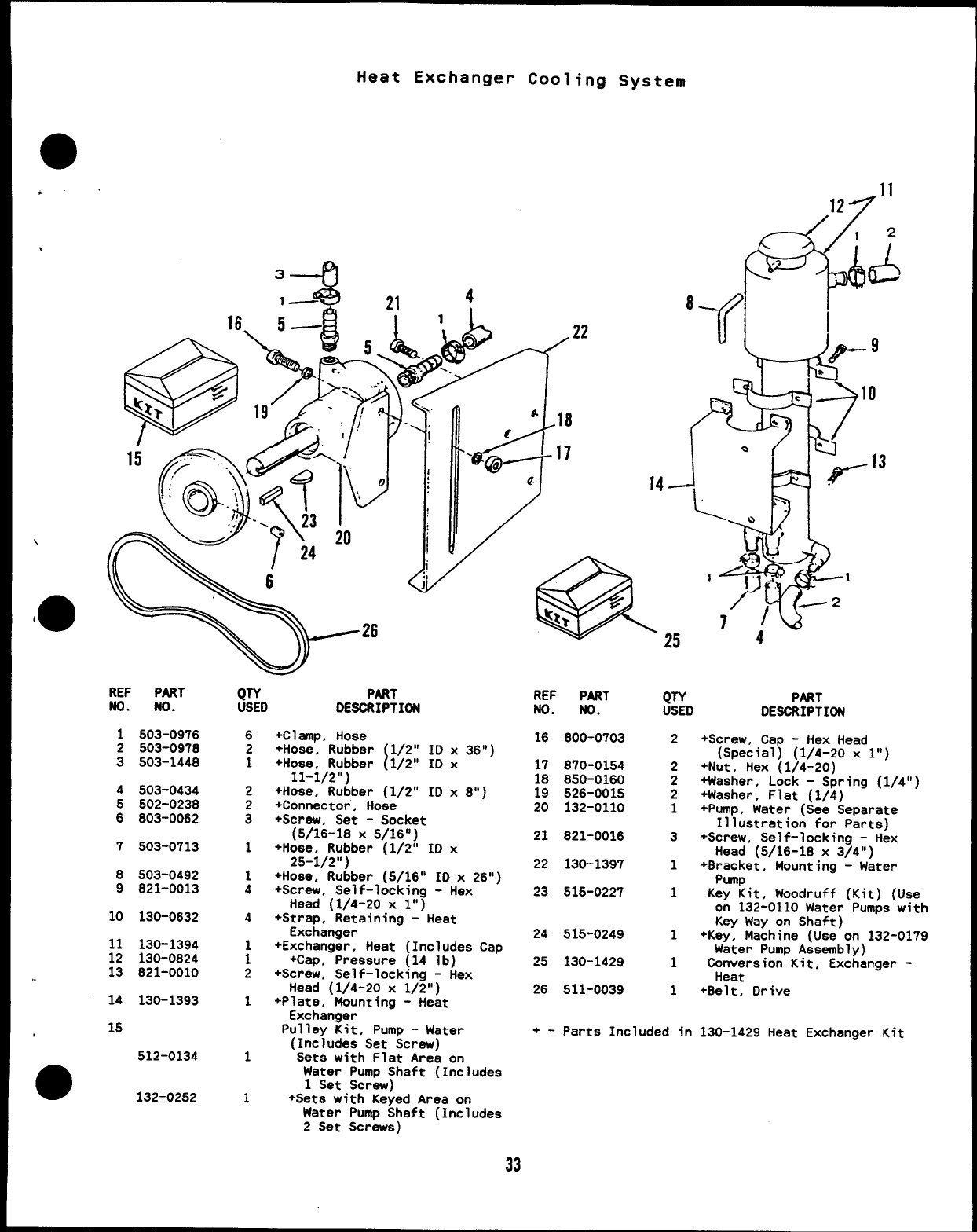
Heat Exchanger Cooling System
3
41—--: 4
21 .&11
12
12
/
(A
REF PART
No. No.
1503-0976
2503-0978
3503-1448
4503-0434
5502-0238
6803-0062
7503-0713
8503-0492
9821-0013
10 130-0632
11 130-1394
12 130-0824
13 821-0010
14 130-1393
15
512-0134
132-0252
QTY PART
USED DESCRIPTION
6
2
1
1
4
1
1
1
+Clasp, Hose
+Hose, Rubber (1/2” ID x36”)
+Hose, Rubber (1/2” ID x
11-1/2”)
+Hose, Rubber (1/2” ID x8“)
+Connector, Hose
+Screw, Set -Socket
(5/16-18 x5/16”)
+Hose, Rubber (1/2” ID x
25-1/2”)
+Hose, Rubber (5/16” ID x26”)
+Screw, Self-locking -Hex
Head (1/4-20 xl“)
+Strap, Retaining -Heat
Exchanger
+Exchanger, Heat (Includes Cap
+Cap, Pressure (14 lb)
+Screw, Self-locking -Hex
Head (1/4-20 x1/2”)
+Plate, Mounting -Heat
Exchanger
Pulley Kit, Pump -Water
(Includes Set Screw)
Sets with Flat Area on
Water Pump Shaft (Includes
1Set Screw)
+Sets with Keyed Area on
Water Pump Shaft (Includes
2Set Screws)
REF PART
No. No.
16 800-0703
17 870-0154
18 850-0160
19 526-0015
20 132-0110
21 821-0016
22 130-1397
23 515-0227
24 515-0249
25 130-1429
26 511-0039
QTY PART
USED DESCRIPTION
2
2
2
2
1
3
1
1
1
1
1
+Screw, Cap -Hex Head
(Special) (1/4-20 x1“)
+Nut, Hex (1/4-20)
+Washer, Lock -Spring (1/4”)
+Washer, Flat (1/4)
+Pump, Water (See Separate
Illustration for Parts)
+Screw, Self-locking -Hex
Head (5/16-18 x3/4”)
+Bracket, Mounting -Water
Pump
Key Kit, Woodruff (Kit) (Use
on 132-0110 Water Pumps with
Key Way on Shaft)
+Key, Machine (Use on 132-0179
Water Pump Assembly)
Conversion Kit, Exchanger -
Heat
+Belt, Drive
+- Parts Included in 130-1429 Heat Exchanger Kit
33
REF PnRT
NO. NO.
132-0110
1132-0113
2132-0137
3132-0112
4132-0114
5132-0092
6132-0091
7132-0101
8132-0141
9132-0138
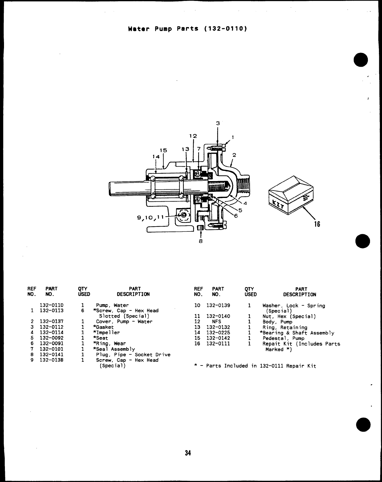
Water PuaIp Parts (132-0110)
3
“12I1
Ihrl!!A”
8
QTY PART REF PART
USED QTY
DESCRIPTION NO. NO. USED
1Pump, Water 10 132-0139 1
6*Screw, Cap -Hex Head
Slotted (Special) 11 132-0140
1Cover, Pump -Water 12 NFS ;
1*Gaaket 13 132-0132 1
PART
DESCRIPTION
Washer, Lock -Spring
(Special)
Nut, Hex (Special)
Body, pumP
Rina, Retainina
1*impeller 14 132-0225 1*Bea~ing &Shaf~ Assembly
1*Seat 15 132-0142 Pedestal, Pump
1*Ring, Wear 16 132-0111 ;Repait Kit (Includes Parts
1*Seal Assembly Marked *)
1Plug, Pipe -Socket Drive
1Screw, Cap -Hex Head
(Special) *-parts Included in 132-0111 Repair Kit
.
34
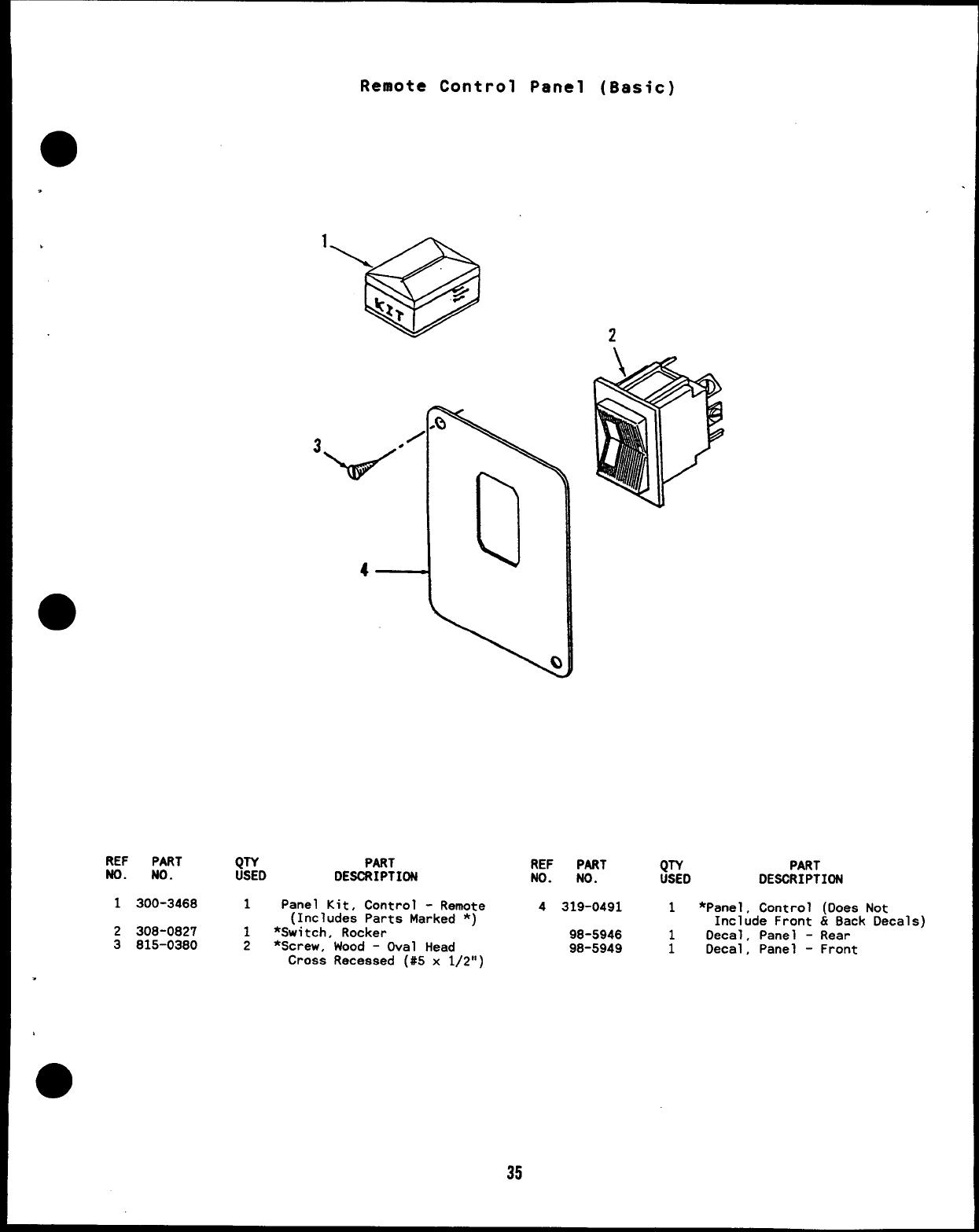
Remote Control Panel (Basic)
REF PART (JTYD PART REF
NO. NO. PART QTY PART
DESCRIPTION NO. NO. USED DESCRIPTION
1300-3468 1Panel Kit, Control -Remote 4319-0491 1*Panel, Control (Does Not
(Includes Parts Marked *)
2308-0827 1*Switch, Rocker Include Front &Back Decals)
98-5946
3815-0380 2*Screw, Wood -Oval Head Decal, Panel -Rear
98-5949 :Decal, Panel -Front
Cross Recessed (#5 x1/2”)
35
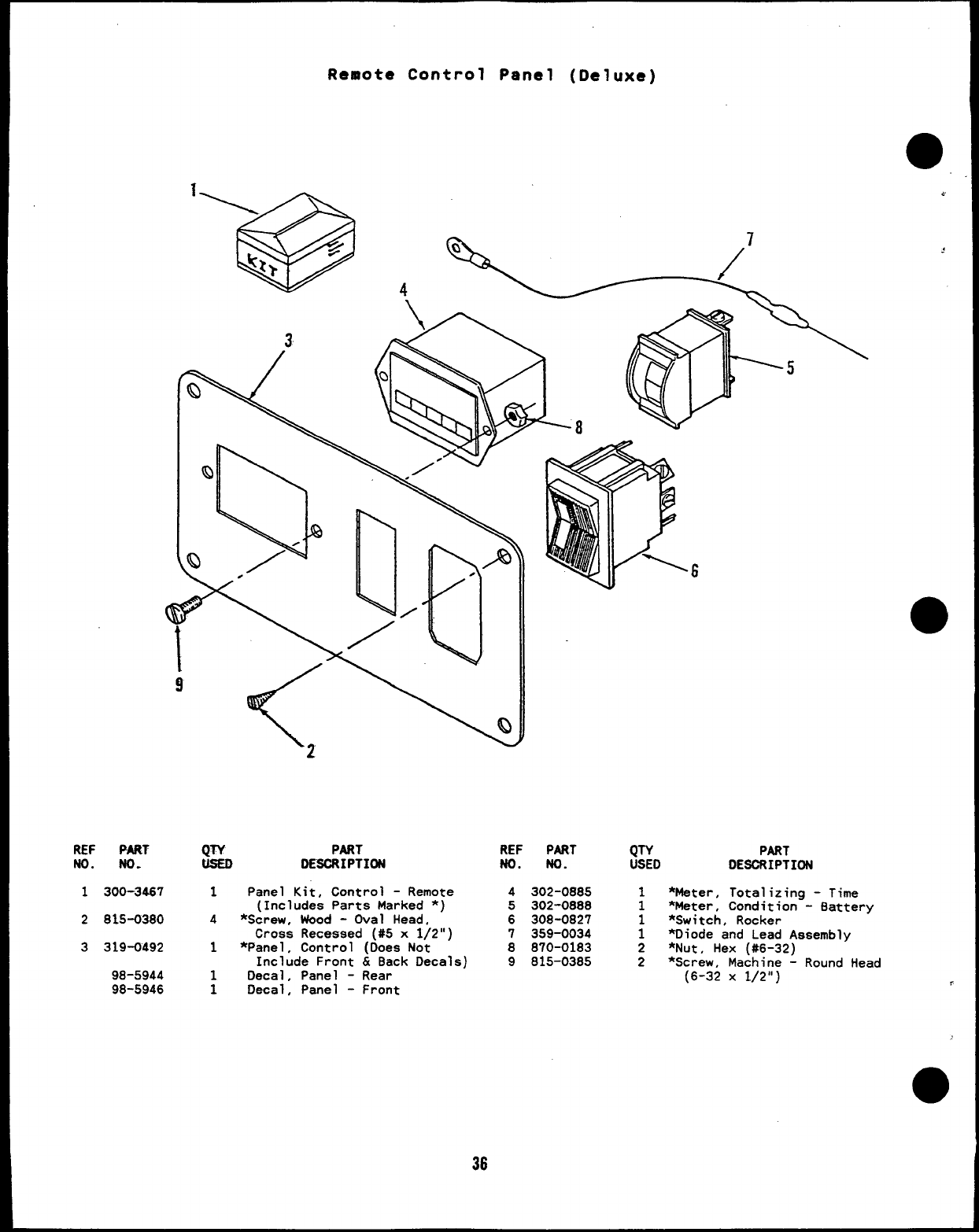
Remote Control Panel (Deluxe)
3
REF PART QTY PART
No. No. DESCRIPTION
1300-34S7 1Panel Kit, Control -Remote
(Includes Parts Marked *)
2815-0380 4*Screw, Wood -Oval Head,
Cross Recessed (#5 x1/2”)
3319-0492 1*Panel, Control (Does Not
Include Front &Back Decals)
98-5944 1Decal, Panel -Rear
98-5946 1Decal, Panel -Front
36
6
REF PART
No. No.
4302-0885
5302-0888
6308-0827
7359-0034
8870-0183
9815-0385
QTY PART
USED DESCRIPTION
1*Mater, Total izing -Time
1*Meter, Condition -Battery
*Switch, Rocker
;*Diode and Lead Assembly
2*Nut, Hex (#6-32)
2*Screw, Machine -Round Head
(6-32 X1/2”)
o
.
1
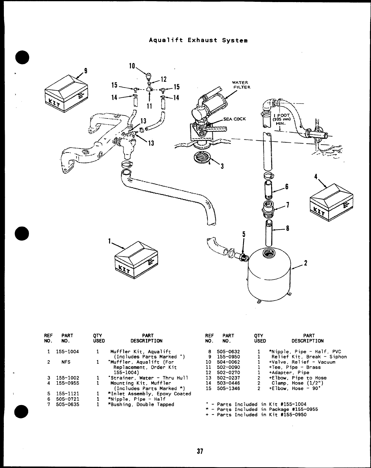
REF PART
NO. NO.
1155-1004
2NFS
.
3155-1002
4155-0955
15155-1121
6505-0721
●7505-0635
Aqualift Exhaust System
10,
QTY PART
USED DESCRIPTION
1Muffler Kit, Aqualift
(Includes Parta Marked ●,
1“Muffler, Aqualift (For
Replacement, Order Kit
155-1004)
1“Strainer, Water -Thru Hull
1Mounting Kit, Muffler
(Includes Parts Marked *)
1*Inlet Assembly, Epoxy Coated
1*Nipple, Pipe -Half
1*Bushing, Double Tapped
...-
REF PART QTY PART
NO. NO. USED DESCRIPTION
8505-0632
9155-0950
10 504-0062
11 502-0090
12 502-0270
13 502-0237
14 503-0446
15 505-1346
1*Nipple, Pipe -Half, PVC
1Relief Kit, Break -Siphon
1+Valve, Relief -Vacuum
1+Tee, Pipe -Brass
1+Adapter, Pipe
2+Elbow, Pipe to Hose
2Clamp, Hose (1/2”)
2+Elbow, Hose -90”
“ - Parts Included in Kit #155-1004
*-Parts Included in Package #155-0955
+- Parts Included in Kit U155-0950
37
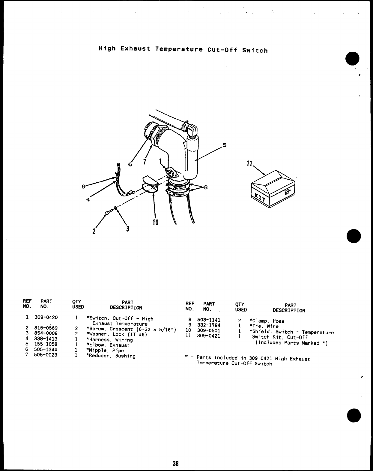
REF PART
NO. NO.
1309-0420
2815-0569
3854-0008
4338-1413
5155-1058
6505-1344
7505-0023
High Exhaust Temperature Cut-Off Switch
QTY PART
USED DESCRIPTION
1
2
2
;
1
1
*Switch, Cut-Off -High
Exhaust Temperature
*Screw, Crescent (6-32 x5/16”)
*Washer, Lock (IT #6)
*Harness, Wiring
*Elbow, Exhaust
*Nipple, Pipe
*Reducer, Bushing
REF PART
NO. NO. QTY PART
USED DESCRIPTION
8503-1141 2*Clamp, Hose
9332-1794 1*Tie, Wire
10 309-0501 *Shield, Switch -Temperature
11 309-0421 ;Switch Kit, Cut-Off
(Includes Parts Marked *)
*-parts Included in 309-0421 High Exhaust
Temperature Cut-Off Switch
38
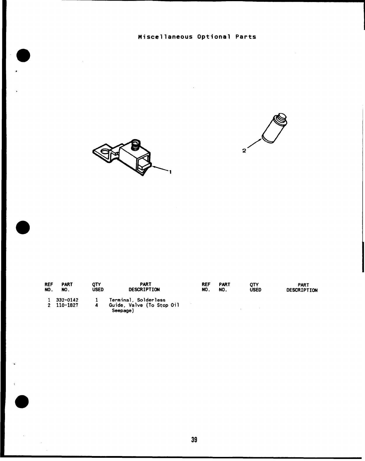
Miscellaneous Optional Parts
*
.
REF PART QTY PART
NO. NO. USED DESCRIPTION
1332-0142 Terminal, Solderless
2110-1827 :Guide, Valve (To Stop Oil
Seepage)
67
/
2
REF PART QTY
NO. NO. USED PART
DESCRIPTION
.
39
