Gnq85 927 0360 Onan CCK (spec R V) Home Standby Genset Parts Catalog (10 1979)
User Manual: 927-0360 Onan CCK (spec R-V) Home Standby Genset Parts catalog (10-1979)
Open the PDF directly: View PDF ![]() .
.
Page Count: 66

The following catalog
has gaps in its page
numbers, or doesn’t
have any numbers.
We have chosen to
leave the page
numbering in the
order that Acrobat
assigns it.
Redistribution or publication of this document
by any means, is strictly prohibited.
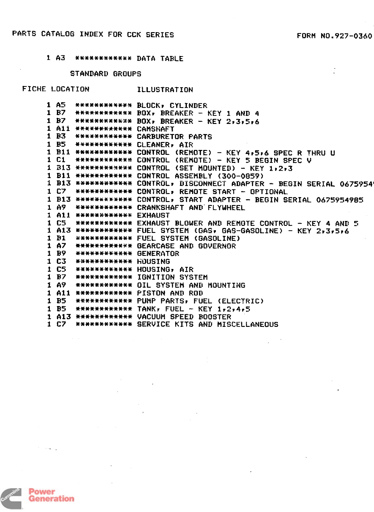
PARTS CGTALOG INDEX FOR CCN SERIES FtNw’1 NO.%22”0360
STANIMVHI GROUPS
W***********
************
**********-E*
************
************
************
************
************
************
****%*******
************
************
*-E**********
***W’********
************
************
************
************
*********M+*
************
*********E**
*9E******3HE**
************
************
************
WE**********
************
************
************
ILLUSTRATION
ICKF CYLINDER
(9 EmEt#tux!- KEY 1 AND 4
K* BREAKER -KEY 2P3v5r6
‘KM%FT
W.WKTOR PARTS
:ANER* AIR
I!TR(3L (REMOTE) -KEY 4P5~& SPEC RTl+Rt,l U
~TROL (REMOTE) -tiEY 5BEGIN SPEC V
QT!M)L (SET MNJNTED) -KEY ls2r3
~TRi3L ASSEMBLY (300-0S59)
$mWN,_r DIENNNNEH MMPTER -BE$31N SERIAL 067!5954
LJTROLr REMOTE START -OPTIONAL
NTRDLs START ADAPTER -BEGIN SERIAL 067595498!5
$NKSHf4FT AND’ FLYWH!EEL
-IAUST
WJST BLOWER AND REMOTE CONTRUL -KEY 4ANI! 5
SL SYSTEM (GASS GAS-GASOLINE) -KEY 293s5?6
ZL SYSTEM (GASOLINE)
W’?(,2WEAND GUVHW3R
QER4iTCM?
JSIN$3
.!!ilNGr AIR
$!.ITIUN SYSTEH
SY?3TEti ANU ?KNJNTING
iiTON AND ROB
%P PARTSS FUEL (ELECTRIC)
WF FUEL - KEY 192y4P!5
H,.N.M SPEEll BOOSTER
V$.ICE KITS ANII HISCELLANECIUS
. .
Redistribution or publication of this document
by any means, is strictly prohibited.
927-M60 (10-7$)
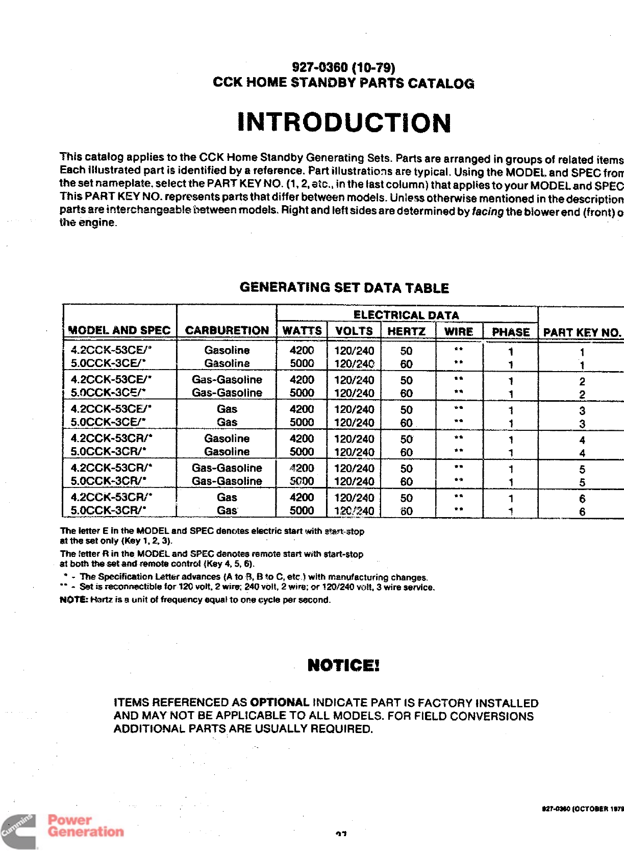
CCK HOME STANDBY PARTS CATALOG
INTRODLJCTION
This catalog applies to the CCK Home Standby Generating Sets. Parts are arranged in groups of related
items,
Each illustrated part is identified by areference. Part illustrations are typical. Using the MODEL and SPEG from
the set nameplate, select the PART KEY t40. (1,2, et% in the last column) that applies to your MODEL and
$3%X2
This PART KEY NO. represents parts that differ between models: Unless otherwise mentioned in the description,
parts are interehangsab!e between models. Right and left sides are determined by facing the biowerend (front)
cd
the engine.
GENERATING SET OATA TABLE
tELECTIMCAL DATA
%lODEL AND SPEC CARBURETK3N WATTS IVOLTS HERTZ WIRE
-r----- PHASE PART KEY NO..
t4.2cxx-53cE/” Gasoline 420Q 120/240 !50 ** 11
5.OCCK-3CE/* Gasoline 5000 120/24(3 60 ●*11
4.2CCK-53CE/* Gas-Gasoline 4200 120/240 50 “* 12
5.OCCK-3CE/* Gas-Gasoline 500Q 120/240 60 ** 12
4.2CCK-53CV Gas 4200 120/240 50 ** 1 3
5.OCCK-3CE/” Gas WOO 120/240 60 ‘“ 13
4.2CCK-53CR/” Gasoline 4200 120/240 50 ** 1 4
5.OCCK-3CFU* Gasoline 120/240 60 ** 14
4.2CCK-53CIV Gas-Gasoline 4.200 120/240 50 ●*15
5.OCCK-3CFV* Gas-Gasoline !54?00 120/240 60 ●*15
4-2CCK-y3GH/* Gas 4200 120/240 50 ●*16
5.OCCK-3CFW f Gas 5000 1,20.?240 60 “* 36
-----
The tetter Ein ttw MODEL and SPEC denotes etectric start wi$h s%$’wtap
atthesetonly (Key 1. Z3).
The kmer Rin the MODEL arid SPEC ~eiietes remte sWt wt:h start-stop
et both the set and remote control {Key 4,5, 6).
*-me Specification Letter advances (A to B, Bto C, etc.) with manufacturing changes.
** -Set is remnnectible for 120 volt, 2win% 240 volt. 2W% crr ?20/240 volt, 3wire service.
IUDTE Hertz is aunit of frequency equal to or!e cycle per eecond.
CWTKX!H
ITEMS REFERENCED AS OPTIONAL INDICATE PART IS FAC7K)RY INSTALLED
AND MAY NOT BE APPLICABLE TO ALL MODELS. FOR FIELD CONVERSIONS
ADDITlONAL PARTSARE USUALLY REQUIRED.
e27.mM
(Ocmalm
1979
27
Redistribution or publication of this document
by any means, is strictly prohibited.
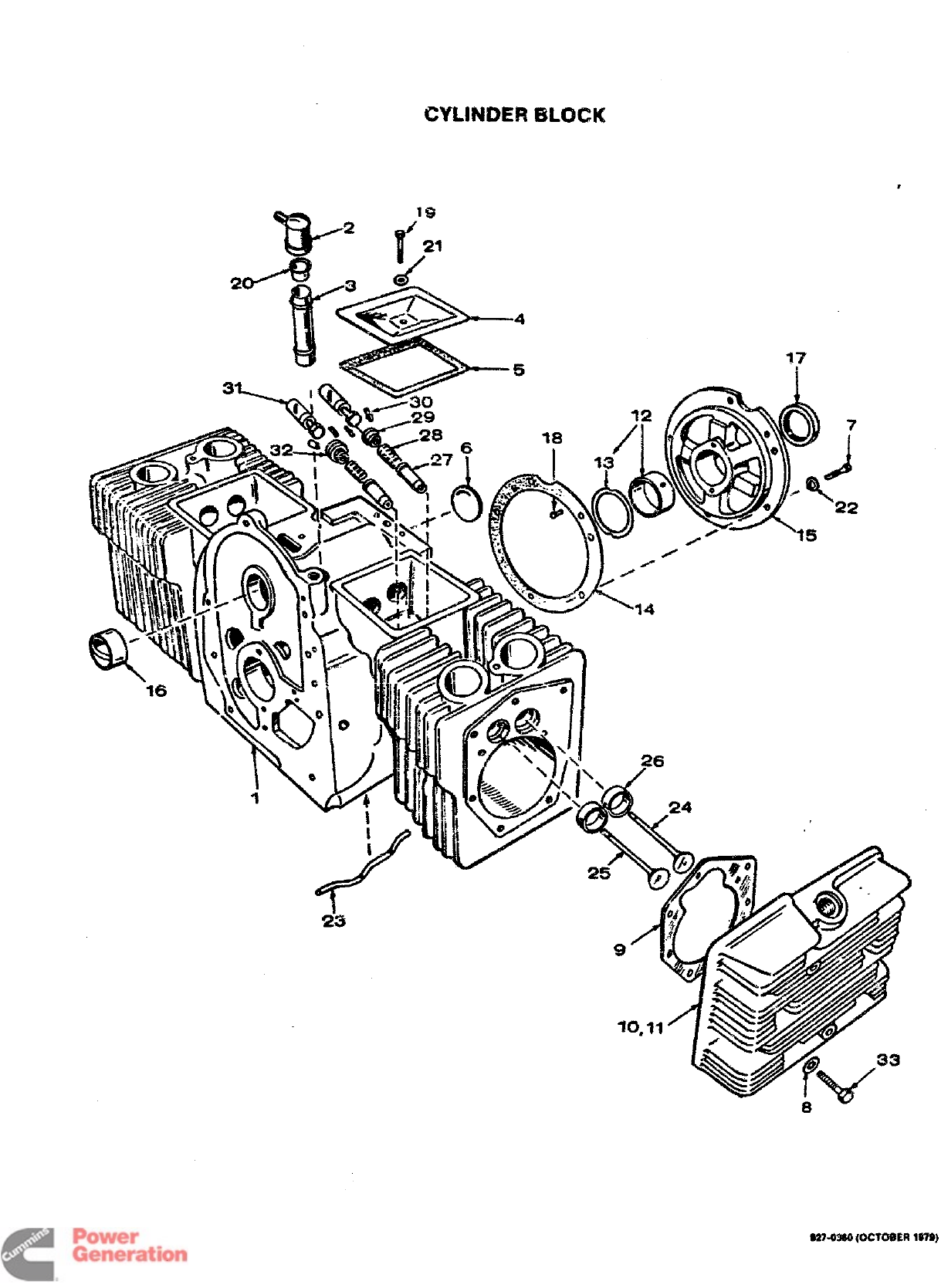
UL:N9EF4 BLOCK
,
—5 y
S274%0 {OCTOBER
1979
Redistribution or publication of this document
by any means, is strictly prohibited.
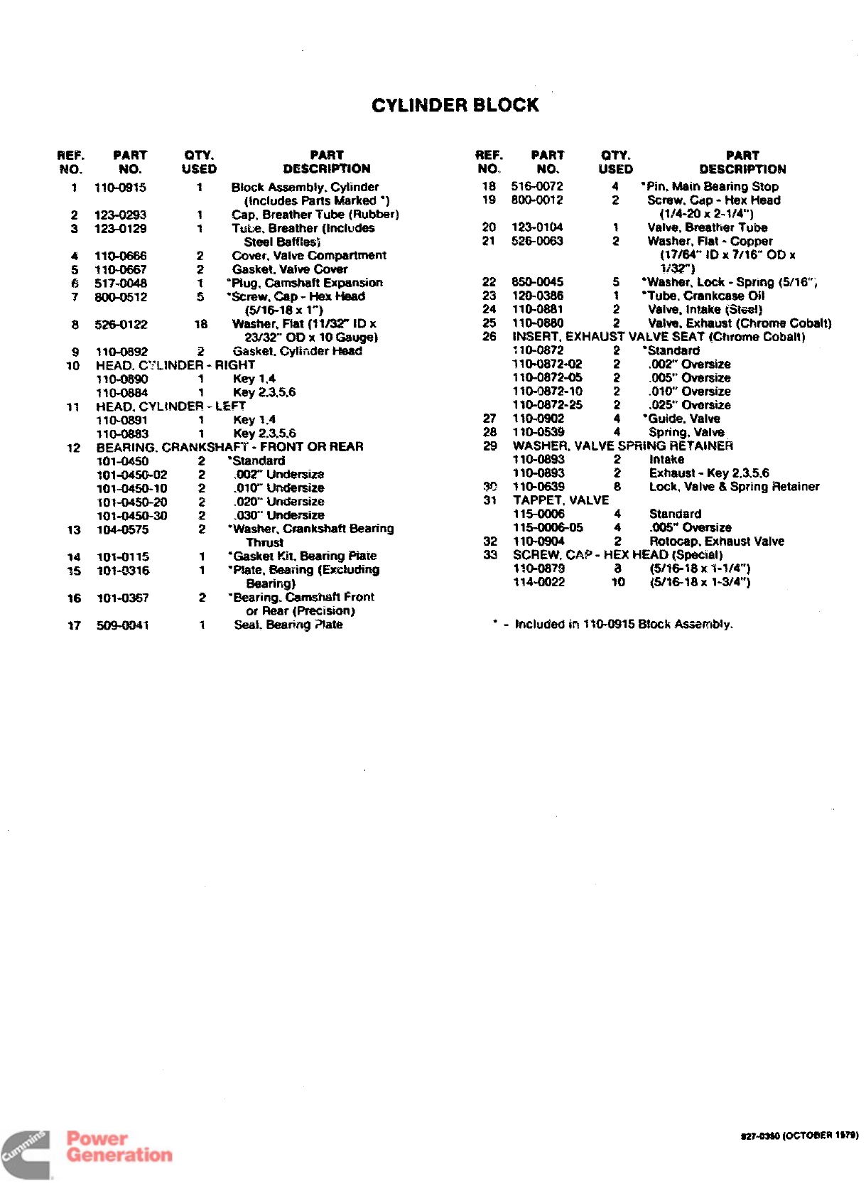
REF. PART
NO. NO.
1110-0915
2123-0293
3123-0129
4lm-0666
5110-0667
6517-0046
78oo-05i2
1
1
2
2
1
5
PART
DESCtWTtON
Block Assembly, Cylinder
(Includes Parts Marked “)
rap, Breather Tube (Rubber)
Tub. Breather (includes
steal Baffles)
Cover, Valva Compartment
Gasket. Valve Cover
“Ptug, Camshaft Expansion
“SUSW, -P -Hex Head
KI/*&la x1“}
REF. PART
NO, NO.
18 516-0072
19 800-0012
20 123-0104
21 526-0063
22 850-0045
23 120-0386
24 110-0661
PART
:S:D DESCRtPTION
4“Pin, Main Bearing Stop
2Screw, Cap -Hex Head
(1!4-20 x2-1/4)
Valve, Breather Tube
:Washer, Flat -Copper
(17/84” ID X7/16 00X
3;32”]
5“Washer, Lock -Spring (5/16;
*●Tube. Crankcase Oil
--- -- ---- .2V~lve”. Intake-@-act}
8!K26-0122 18 Washer, Ftat {%1/32” ID X25 110-0880 2Valve, Exhaust (Chrome Cobalt)
23132” OD X10 Gau@ 26 INSERT, EXHAUST VALVE SEAT’ (Chrome Cobalt]
12
13
14
35
16
17
110-0892 2Gasket. Cytirier Head”
HEAD. C: LINDER -RIGHT
. . . .—
1lu-waw ;Keyi,4
110-0864 1Key 2.3,5.6
HEAD, CYLINDER -L&T
ll&0691 1Key 1.4
110-0863 1Key 2,3.5.6
WEARING. CRANKSHAH -FRONT OR REAR
101-0450 2“Standard
I014M50-02 2.00~ Undersiza
7fw045&lo 2.OIW Undersize
llw0450-20 2.02W Undersize
101-0450-30 2.03W Undersize
104-0575 2“Washer. Crankshaft Bearing
mm
101-0115 1‘Gasket Kit. Bearing Ptwe
101-0316 1“Ptate, Bearing (Excluding
Baaring]
101-0367 2“Searing. Camshaft Front
or Rear (Precision)
509+041 1Saai: Bearing ~ate
110-0872 2“Standard
110-0872-02 2.002 Oversize
110-0872-05 2.00tY Oversize
1NM3872-10 2.OIQ Oversize
110-0672-25 2.025 Oversize
27 1IQ-Q9Q2 4*Guide, Valve
28 110-0539 Spring, Valve
29 WASHER, VALVE4SPRiNG RETAINER
110-0693 2intake
1m-0893 2Exhaust -Key 2,3S,6
w110-0639 8Lock, Vaiva &Spring Retainer
31 TAPPET, VALVE
115-0006 4Standard
115008-05 4.005” Ovarsize
32 110-0904 2Rotocap. Exhaust Valve
33 SCREW. CAP- HEX HEAD (Special)
1?0-0879 a(5/16-18 X1-1/4”]
114-0Q22 10 {5/16-18 X1-3/4”)
●-inctuded in 1W-0915 Block Aasernbly.
m-awl (oCTO@ER lWS)
Redistribution or publication of this document
by any means, is strictly prohibited.
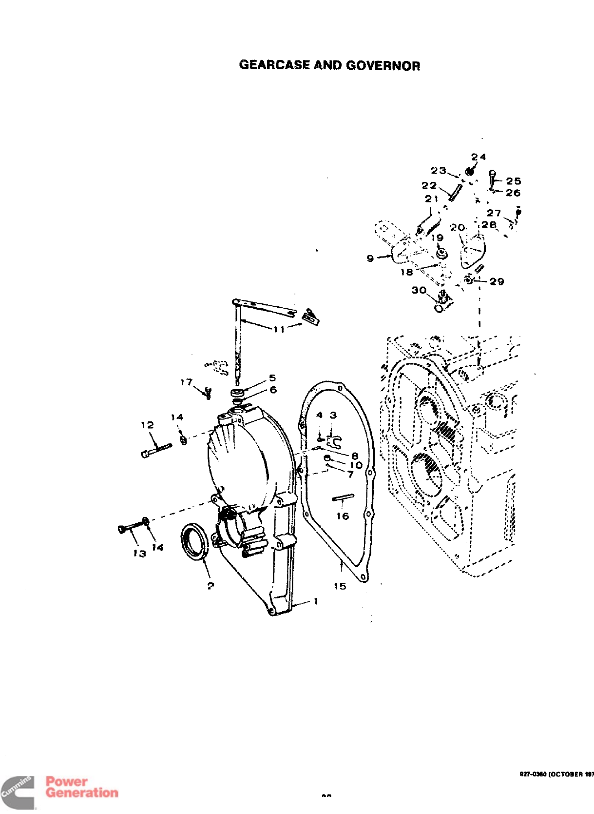
GEARCASE ANO GOVERNOR
24
1
12
23\ d!?-
22 ““ 25
v
21 “* ;“-26
i
1
W%03W (OCTOBER
197
Redistribution or publication of this document
by any means, is strictly prohibited.
REF.
No.
1
2
3
4
5
6
7
a
9
10
12
13
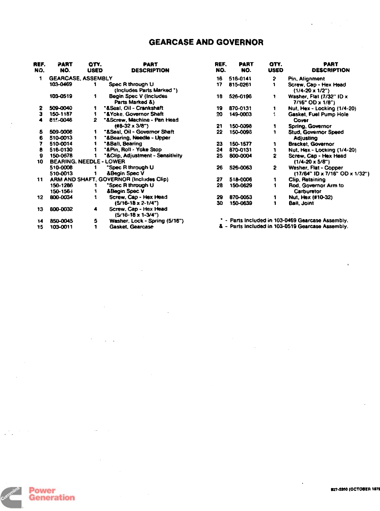
GEAFICASE AND GOVERNOR
*ART on. PART
N-o. USED oEscRIPTtON
WAFV2ASE. ASSEMBLY
103-0469 1Spec Rthrough U
{Includes Parts Merked “)
303-0519 1Begin Spec V(Includes
Pam Merked &}
1‘&SaR1. ~il -Crankshaft
150-1187 ‘&Yoke. Governor shaft
~?~~ :“&Screw, Machine -Fan Head
(!!&& ~m“]
1-&S@al. oil -Govarrror Stwft
5304013 1“&Beering, Ne43dte-Upper
51W14 1“8MI, Bearing
51G0130 1‘Win. Ro!l -Yoke Stop
150-0678 1‘&Clip. Adjustment -S$w@ivity
BEARiNG, NEEDLE -LOWER
MO-0006 1*Spec Rthrou@ U
5WL0013 1&segin Spsc v
ARM AND SHAFT, GOVERNOR (includes Clip)
150-1266 1‘Spec Rthrough U
150-1564 ?&Be@n Spec V
1Screw. Cap -Hex Head
[5/16-18 X2-1/4”]
4screw. cap -Hex He@
{W16-18 x1-3$4”}
REF. PART
No. No.
16 516-0141
17 835-0261
18 526-0196
19 870-0131
20 349-00(33
21 150-0096
22 150-0Q96
23 1=15?7
24 870-0131
25 800004
26 $W6-m63
27 518-@006
28 M&0629
29 870-0053
30 MO-0639
Qw.
USED
2
1
1
1
~
1
1
1
;
2
1
3
1
1
PART
txscwm’!m
f%, Alignment
Screw, Cap -Hex Head
(iM-20 x1/2”)
Washer, Flat (7/32” Wx
7/16” OD X1/8)
Nut, Hex -Locking (1/4-20)
Gasket, Fuel Pump Hoie
Cover
Spring, Governor
Stud, Governor Speed
Adjusting
~m~ket, @mrefnor
Nut, Nex -Locking (1/4-20)
Screw. Cap -Hex Head
(1/4-20 xwan)
Washer. Ftat -Copper
(17f64° ID X?/l& 00 X1/32”)
Clip. Retaining
Rod, ~Gkwemor Arm to
Csrtnmtor
Nut, Hex (#MM2)
Sail. Joint
14 850—00= 5W~r, Lock -Spring (!5/16”) ●-Parts included in 103-0469 Geafcase Assembly.
15 1034M1 1Gasket. Geercase &-Parts included in W1342519Gearcase Assembly.
31
Redistribution or publication of this document
by any means, is strictly prohibited.
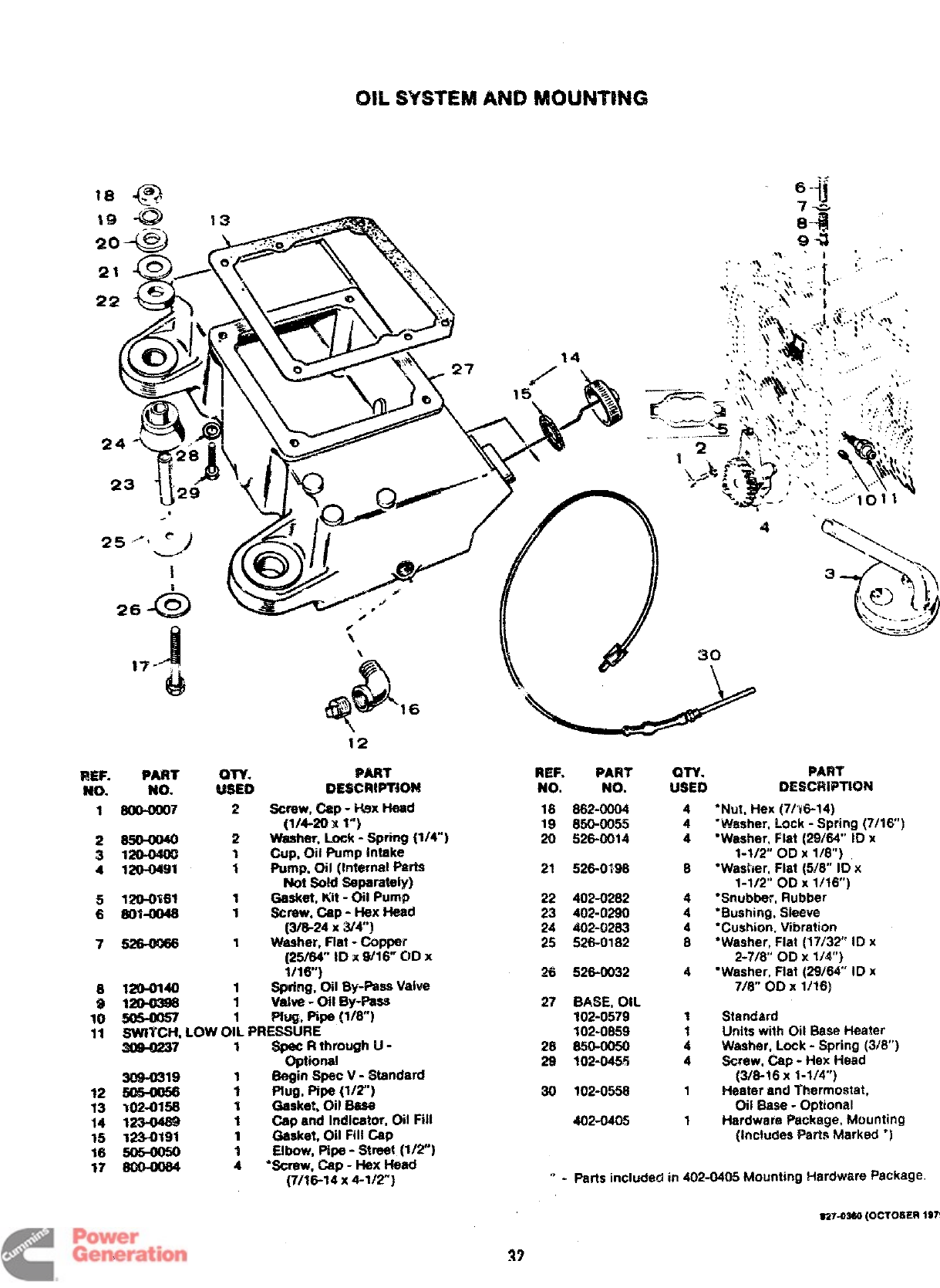
Ok S’WSTEM AND RAOLINTH’4C3
18 m
~+
-—
-ii
&’-’’”h ,,: \ ?’
..
,‘4
.... ..
‘.’..,.\..
,::,, <..’ ..
,-.
s
-. .. ..—
4?> ,.
12
mI#T
DESCRWT30M
Screw, Csp -*X Head
(1/4-20 x1“’)
*ALA-- , --,. =-.:-- 4* IA”%
~FiE?l, ~- -~Wf~ ~?t- J
bp, Oii Pumpintake
Pump.011(Internal Perta
Not SOM Sepereteiy)
Geaket, Kit -Oil Pump
6CmW, @-Hex Head
(3/6-24 xW4”]
Washer, Flat -COpPer
(25/64” ID xW16° OD X
%/16-)
Spring, Oil By-Pass Valve
Vtdve -oil E?y-Paas
Pfutz, Pipe gli8”j
REF. PART QTY.
NO. NO. USED
PART
DESCRWTION
18 662-0004
19 650-0065
20 526-0014
21 526-0296
4
4
4
*Nut, Hex (7/16-14)
“Washer, !mk -Spring (7/16”)
“Washer, Flat (29/64”’ ID x
%$/2” OD X?/8)
“Washer, Flat (5[8 ID x
1-1/2” 00X 1/16”)
“Snubber, Rubber
“Bwmirig, Sieeve
“Cushicm, Vlbratim
●Washer, Flat (17/32 10x
2-7/6” OD X1/4”)
“Washer, Hat (2!316V ID x
716” 00X 1/16)
Standard
Units with Oil Base Heater
Washer. Lock -Spring !3/6”)
Screw, Cap -Hex Head
(3/6-16 X%1/4”)
Heater and Thermostat,
Oit Base -Opticmal
Hardware Package, Mounting
(lnclu@s Parts Marked “)
2650-m40
3W@OMW
41204MW 8
22 402-0262
23 402-a290
24 402-Q263
25 526-0182
4
4
4
8
752&om6
26 526-0032
1204M40
&!&?%
SWITCH, LOW OiL PRESSURE
1Sg#ectg~ough LJ-
309-0319 1Be@ Sptw V-Standard
7Ptug, Pipe (1/2”)
102-0156 1Geeket, ON Base
123-04S9 1Cap and Indicator, Oil Fiil
W3-tNW 1G@@, oil Fill cap
3am, Pipe-Street {1/7)
4●6C~W, ~-Hex Head
(7/16-14 x4-VY)
27 BASE, OIL
102-0579
102-0659
28 S50-0050
29 102-045?3
1
1
4
4
12 30 102-0558 1
402-0405 1
“ - Parts included in 402-0405 Mm,mting Hardware Package
SZ743W {OCl~E~
197S
32
Redistribution or publication of this document
by any means, is strictly prohibited.
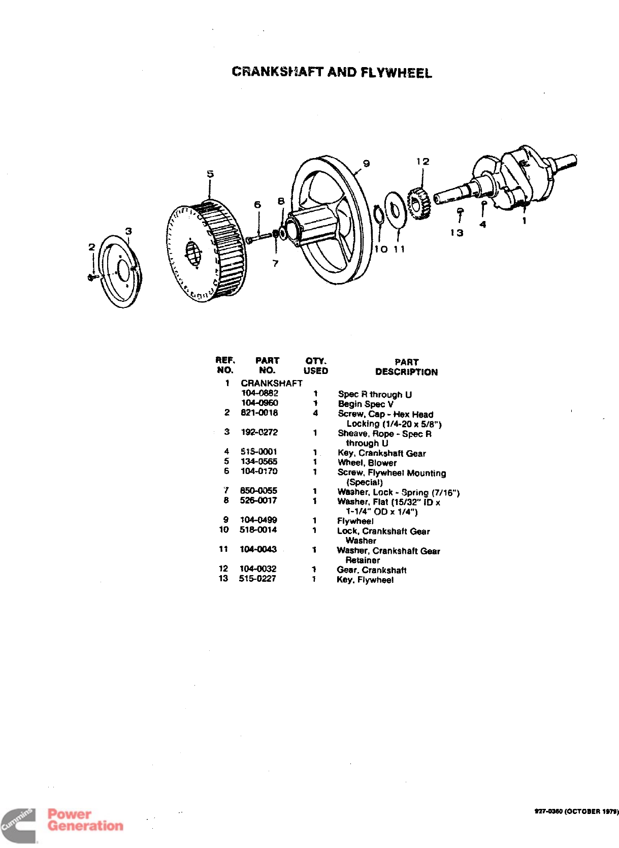
CRANKSbfA~ A?40 FLYWHEEL
REF. PART QTY.
No. NO. USED
1CRANKSHAI=T
MM-Q662
lc#-09m
2821-0018
3192-0272
r8!50U055
8526-0017
9104-0499
ltl 518-0014
$1 m4-m43
12 104-0032
13 515-0227
.
13
PART
DESC3?WT80#4
Spec Rthrqm~h U
Begin Spec V
Screw, Csp -Hex Head
Locking (1/4-20 x516”]
Sheave, Rope -Spec R
through U
Key, Crankshaft Gaar
Wheel, Blower
Screw, Flywhael Mounting
(Special)
Washer, Lock -.!lprin~ (7/16”)
Washer, Fiat (15/32 ID x
1-1/4” tJD X1/4”)
Flywheel
Lock, Crankshaft Gear
Washer
Washer, Crankshaft Gear
Retainer
Gear, Crankshaft
Key. Flywheel
S27-WSO (OCTOBER 1S7S
Redistribution or publication of this document
by any means, is strictly prohibited.
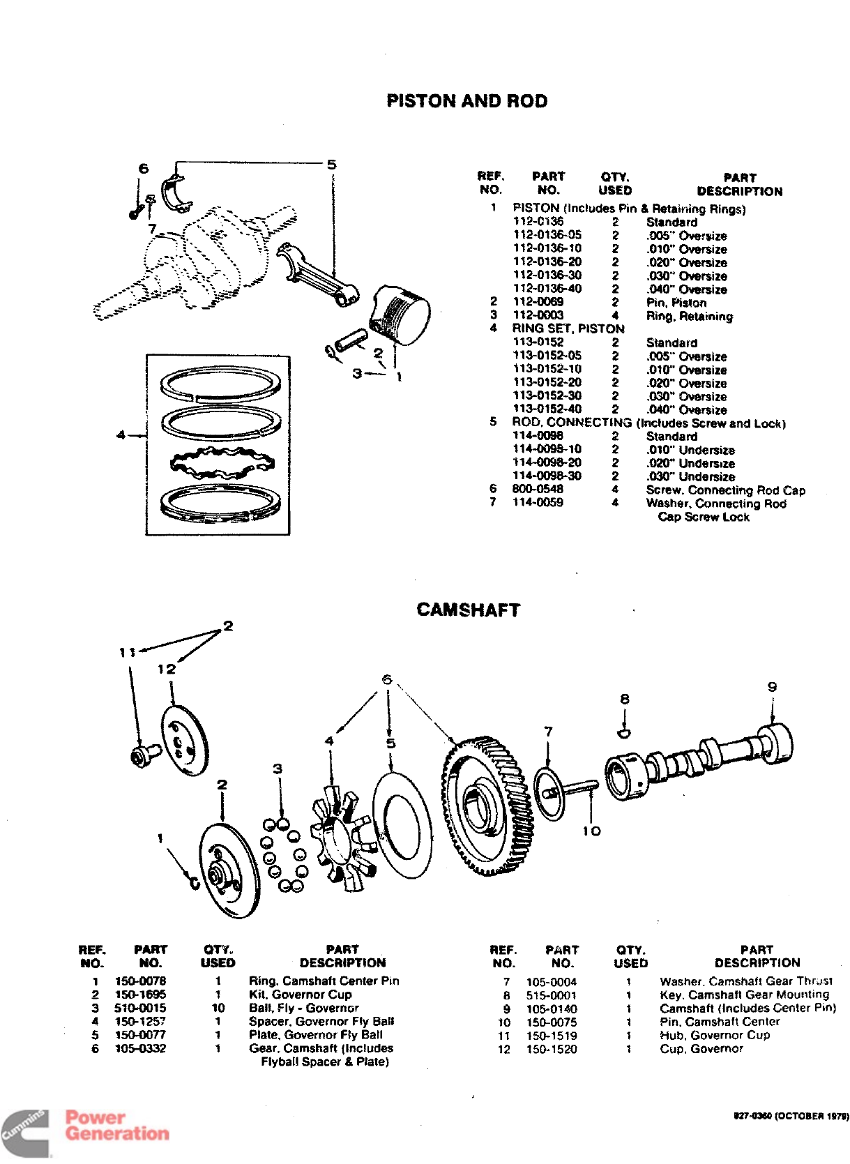
REF. PART QTY. FART
NO. NO. USED LYESCRWTION
1PISTON (includes pin &Retairiing Rings)
112-0135 2Standard
112-0138-05 .00S Qvewize
112-0136-10 :.010” Oversize
112-013S-20 2.020- Ovarsize
112-0135-30 2.03W Oversize
112-013S-40 2.040” O+mrrsize
2112-0089 Pin, Piston
3112-0003 :Ring, Retaining
4RING SET, PISTON
113-0152 2Standard
113-0152-05 2.00S’ Oversize
113-0152-$0 2.OW Oversize
113-0152-20 2.020” oversize
313-0152-30 2.030” Oversize
113-01!52-40 2.04W Oversize
5ROD. CONNECTING (Includes Screw and Lock)
114-0088 Standard
114-0088-10 :.010” Undersize
1W-OOQS-20 2.020” Underwze
114-008S-30 2.030” Undersize
6800-0548 4Screw. Connecting Rod Cap
7114-0059 4Washer, Connecting Rod
Cap Screw Lock
CAMSHAFT
2
REF.
No.
1
~
3
4
5
6
PART GrY.
NO. USED
W504078 1
150-W595 7
51O-OO15 10
1*3257 1
15@0077 1
105-0332 T
Ring. Camshaft Center Pin
Kit, Governor Cup
Ball, Fly -Governor
Spacer, Governor Fly Ba:l
Plate, Governor Fly Ball
Gear. Camshaft (Includes
F!ybal! Spacer &P4ate)
REF. PART
NO. NC).
7105-OOO4
8515-0001
9105-0140
10 150-0075
11 150-1519
12 150-1520
9
81
J)
9TY.
LfsED
1
1
1
1
1
1
PART
DESCRIPTION
Washer. Camshaft Gear Thrust
Key, Camshaft Gear Mounting
Camshaft (Includes Center Pin)
Pin, Camshaft Center
Hub, Governor CUP
Cup, Governor
S27=OMrl (OCTOBER
197S)
Redistribution or publication of this document
by any means, is strictly prohibited.
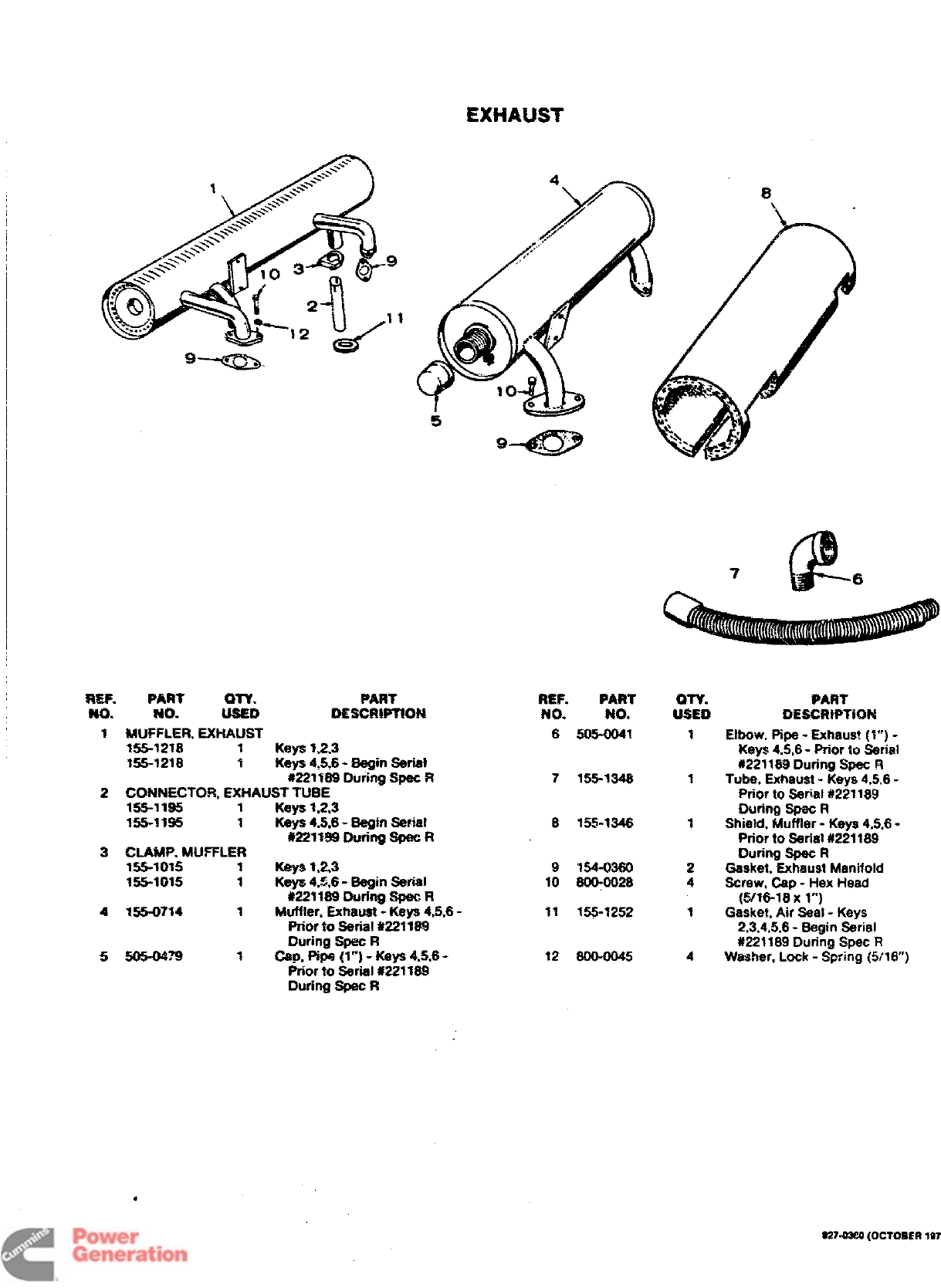
EXHAUST
REF. PART WY. PART
5m. No. BESCRMWQM
1MUFFLER, EXHAUST
155-? 216 1 Keya 1.2,3
%55-1218 1Kqfa 4,$.6- ~in $kial
#221169 During 6pac R
2CONNECTOR, EWWJST TUBE
155-11$5 1Keys 1,2.3
155-1395 1Keye 4.5,6- Begin Serial
-**W -.4— e— m
mu ?Sw uur?r~ ~n
3CLAk4P. MUFFLER
156-1015 1Keya 1.23
155-10%5 1Keys 4,%6 -Be@ Serial
t?221169 During Spec R
4W5S-0714 1Muffter. Exttauat -Keys 4,5,6-
Prior to serial *221 lM
During Spec R
5505-04?9 fCap, Pipe (1’”) -Keya 4.5,6-
Prior to serial #221169
During Spec R
0‘\
9-+l%fJ9
7
●
REF. PART
No.
6
7
8
9
10
12
NO.
505-0041
155-1348
155-1346
154-0360
800-0028
.-- .-—-
155-TZ5Z
800-0045
am.
USED
1
1
1
2
4
i
4
PART
0ESCRWTR3N
Elbow, Pipe -Exhaus? (%””)-
Keys 4,5,6- Prior to Serial
#221 169 During Spec R
Tube, Exhaust -Keys 4.5,6-
Prior to serial #221189
During Spec R
Shield. Muffler -Keye 4,5,6-
Prior to Serittl #221189
During Spec R
Gasket, Exhaust Manifold
Screw, Cap -Hex Head
(5/16-18 Xl“)
Gasket, Air Seal -Keys
2,3,4,5,6- Begin Serial
#221 169 During SpW R
Washer, Lock -Spring (5/16”)
$274m (Oclom?m
Wg)
Redistribution or publication of this document
by any means, is strictly prohibited.
1
2
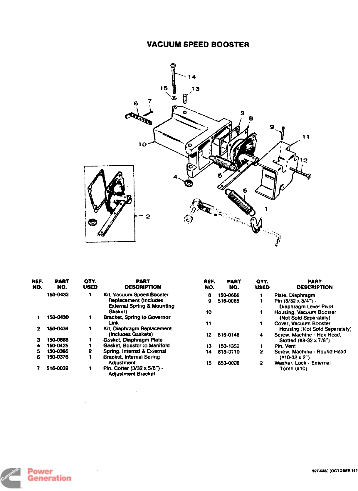
REF. PART
w. ?$0. $zk oEsHKmd
150-0433 1Km W3’txJunrspeed Soostw
R@acement (Includes
REF. PART
?40. Rio.
a15(HM66
9516-0085
External $3@ng &Mounting
G@@ 10
1%504430 -1 BracksL Spring to Governor
Link 11
2WO-U434 1Kit, Dit@tragm Replacement
(Irmkmea Gaakefs} 12 815-0148
31504t666 TGsaket, Diaphragm i%fe
4WMJ425 Gasket, Bcmeter to Manifoid j~ ~~~~~
51504M66 ;6pring. internai &Externai 14 813-0110
e95Q4KW6 1Bracket, it’tterna! Spring
Adjtmtment 15 853-0668
7516-Q(U9 1i%. Cotter (3/32 xW&’) -
Adjustment Bracket
PART
$L!D DESCRWTK)N
1Piate. Diaphragm
1Pin (3/32 x3/4) -
t3iapbragrn Lever Pivot
1Housing. Vacuum Eacster
(Not 3oid $3eParateiy]
*Cover. Vacuum Booster
i-iou_sir?Q{Mot 3oid Separately)
4Screw, Machine -Hex Head,
Siotted (#8-32x 7/8”)
%i%, Vent
2Screw, Machine -Round Head
{#10-32 X2)
2~~~hqrr Loc~ .Ej@rn~[
Tdoth. [#IC)
929-4RS0 (OCTOBER
197s
Redistribution or publication of this document
by any means, is strictly prohibited.
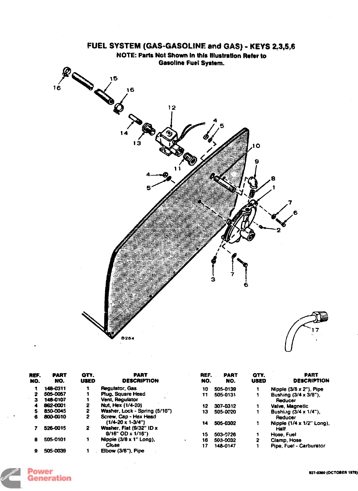
FUEL sifsmivi ((3AS4MSOM+4E and wks) -!m?s $43,s,6
MOTEParisN@ShOwi’ththis iiiustt’atiwqRdw’to
GasG4iRei%d sy8tum.
a
F
?6
.
REF.
km.
:
“3 4
5
,6
PART
m.
%46-03%1
.S15-ms?
M8-O1O7
tttwoool
&m@lo
7526-0015
Pm
mEscRtmo?4
Regulator.GSS
Ptug,SqUereHe@
Veng Regukstor
Nut, Hex (1/4-20)
Washer, Lock -Spring (5/16”)
Screw, Cap -Hex He@
(1/&20 x1-3/4”)
washer, Flat (W32 ID K
9/16” OD x1/?6”)
Ni~laJ/6 x1“ Long],
Elbow (3/6’”]. Pipe
HEF. PART
No. No.
?0 50!%0139
13 !505-0131
$2 30?-0372
13 505-0020
*4 505-0302
15 50M726
16 503-0032
17 $46-Old?
,6
PART
0E!3CWPTiW
Nipple (W8x2“]. Fipe
Bushing (3/4 x3/6”),
Reducer
Valve, Magnetic
fhmhi.lg (3/4x 1/4”),
Reducer
Ni~: (1/4x 112 Long),
Hose, Fuel
Clamp, Hose
Pipe, Fue! -Carburetor
a2743M {O(XOSER ten)
Redistribution or publication of this document
by any means, is strictly prohibited.
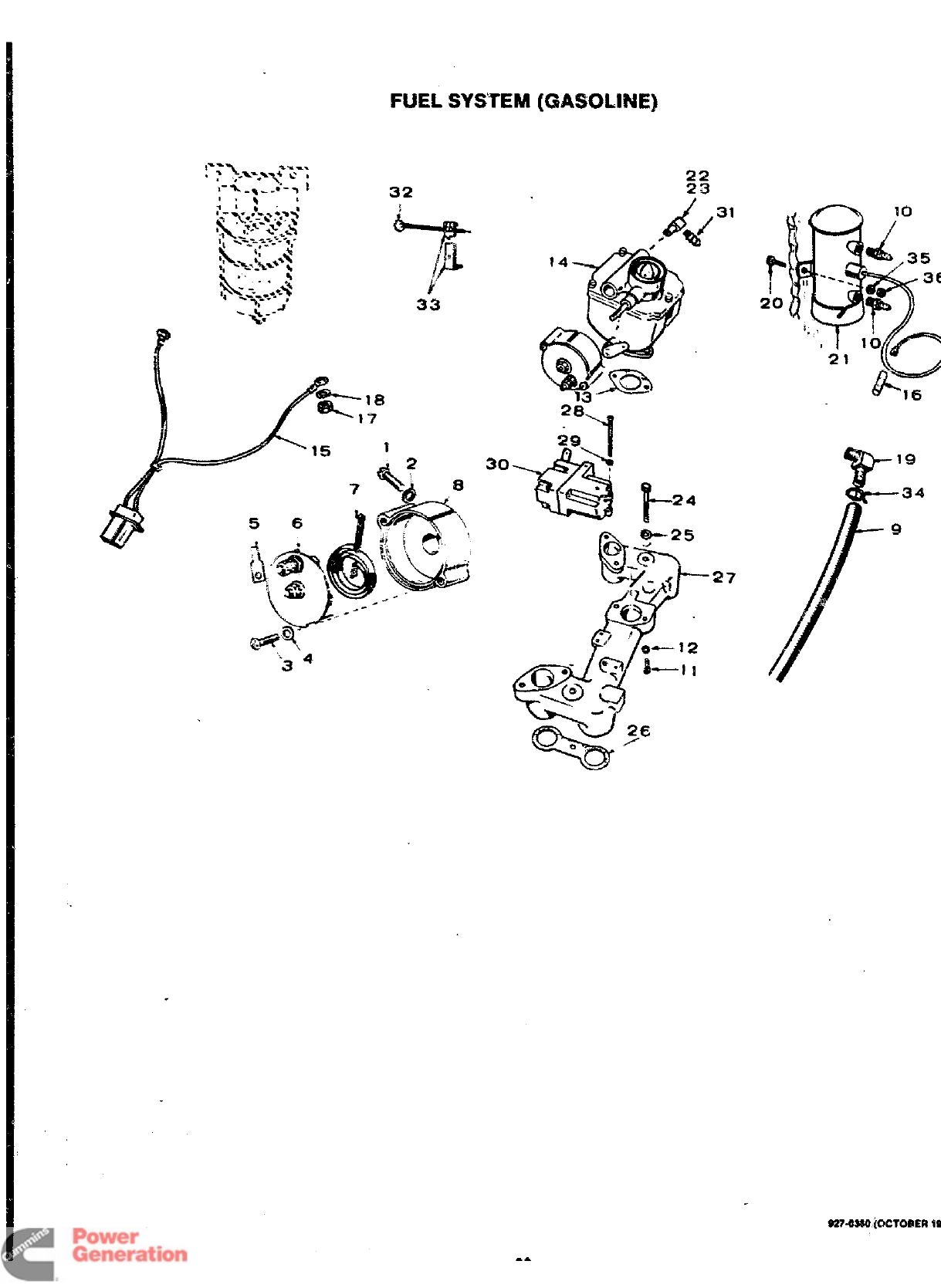
FUEL SYSTEM (GASOLINE)
33
““3 4
--”
30
22
23
31
28
-’I
5’%
**11--
24
t
27
@
10
fi
P+(
,35
--=-
!36
7
20 (,’ -*
i,,,
1;
o
21 \
5-- 16
9274380 (OCTOf4ER !S
Redistribution or publication of this document
by any means, is strictly prohibited.
REF. PART
?40. No.
1815-0190
28504030
3815-0285
4526-0082
5332-0527
6153-0114
7IW17
ml’.
USED
1
1
2
2
1
1
1
1
PART
DESCR!PTIO?4
Screw. Machine -Fillister
Head (#10-32 x7/8”) -
Keys 4,5
Washer, Lock -Spring ($I1O]
Keys 4,5
screw. Machine -Roiind Head
(#l(W2 X5/16”) -Keys 4.5
Washer. Ffat -Brass
(.2 Wx1/2- OD xltlw] -
Keys 4,5
Terminal, Spade -Keys 4.5
Cover, t.%oke -Keys 4.5
Exhaust. Choke -Kevs 4.5
502-0395 2Connector. Keys 1.2
2=-. tip --X Head
(1/4-20 x1-1/2-)
2Washer. Lock -Spring (1/4-)
14%0078 1Gasket. Carburetor
CARSURE7CM? (Includes Mounting Gasket) -See Separate
Group for Components Gasoline
142-0363 1Key 1(Menu%! Chtie]
142-0364 1Key 4(Electric Choke)
Ges-GasoMle
142-0367 1Key 2(Mtwma$ C$mke)
1424366 ~Key 5(Electric Choke}
142-0Y2 1Gas Only -Keys 3.6
1t+srness, Wking -Kay% 4.5
IConnector. Lead -Keys 1,2
~fq~t- *X (#&w)
REF. PART QTY. PART
NO. NO. USED DESCRIP’f”!ON
18 650-0025 Washer, Lock -Spring @f8)
19 502-0313 :Elbow. Fuel Pump -Keys 4,5
20 800-0006 2screw. Cap -Hex Head
(1/4-20 x1-1!4-)
21 PUMP, FUEL (.% Separate Group for Components)
149-0650
14s1553
149-1541
22 502-0313
23 502-0196
24 800-0054
25 6S0-0050
26 154-0013
27 ~54*3
28 813-0130
29 853-0006
w150-0433
31 502-0395
32 153-0351
33 153-0263
34 503-0301
35 853-0013
38 662-OtlOl
1
1
1
1
;
2
2
i!
2
1
-i
1
1
3
2
2
Keys t,2
Keys 45- Kit Fta@eces Original
Equipment (Components of
original pump not add
sapamtely) -Spec R
Kay 5Ba@n Spec V
Elbow, Keys 1.2
Elbow, Keys 4,5
Sorew. Cap -Hex Head
(%’8-16 Xy)
Washer, Lock -Spring (3W)
Gasket. Make Manifola
Manifold, Intake
Screw. Machine -Round Head
(#lo-32 x2-]
Washer, Lock -ET (#lo}
8ooster, Vacuum Speed
(Includes Externsi Spring
and Gesket) (Refer to
separate group for coi.~-
ponents)
Connector. Keys 4,5
Choke, Manual -Keys 1,2
f3racket and Ciip -Choke
Cable -Keys 1,2
Clamp, HOW
Washer, Lock -ET (1/4”)
Nut, f+SX (1/+20]
SS7-0S0 (OCTOBER 1S79)
Redistribution or publication of this document
by any means, is strictly prohibited.
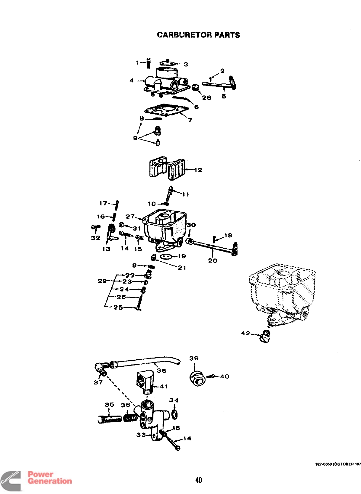
CARBURETOR PARTS
-&!?
42-
39
b
-40
0
ke-
&
?4
40
Redistribution or publication of this document
by any means, is strictly prohibited.
CMW3URETORPARTS
REF.
NO.
2
3
9
10
11
12
13
14
15
17
pg$~? en. PART
NO. l$sm DESCRtPTlON
CAR@WiETOR, GASOL!NE (Includes Mounting Gasket}
1424X363 fKey 1
142-0364 1Key 4
CARBURET(3R, GAS-GASOLINE (includes
Mounting Gasket)
142-0367 1Key 2
142-0366 1Key 5
%lMi372 1Carburetor. Gas -Keys 3,6
SCREW, MACHINE -FILLISTER F!EAD
8?5-0103 110-24 x1/2
815-0109 210-24 X&’fY
815-0091 2“*Screw (4-40 x3/16”]. f220ke
Fly -Key 1.2.4,5
FLY, C3-iOKE
142-0055 1Key 1,2
142-0037 1Key 4.5
142-0205 1Sleeve Assembly. Choke
(coved
SHAFT ASSEMBLY. CHOKE
142-0217
142-0183
142%0038
142-0031
148-0017
142-0049
142-0032
142-0285
142-0361
145-0008
142-0040
142-02S2
142-0035
812-0063
815-0072
%42-0369
1
1
1
1
2
1
1
1
1
1
2
Key 1,2
Kay 4,S
“’Straft. Fioat -Key 1,2.4,5
“Gasket. Body to Bowl
“Gasket -(1) Float Valve Seat
(1) Main Adjusting Needle
Retainer
““Valve &Seat Assembly -
Key 1,2.4,5
‘Gasket, Nozzle
Nozzle Assembly -Key 1,2,4,5
Flat &Lever A~mbly -
Key 1,2.4,5
Lever, Idle Stop
“Wee@% ldie Actj@iw -
2used on Key 2,5
Spring, Idte Needie Adjimt-
ing -2 used on Key 2,5
Spring. Wwottle Stop
Adjusting Screw
Screw, Machine -Ro!md Head
(6-32 XI/Y)
“*Screw, Machine -Oval Head
(4-40 x1/4} -Throttle Fly
Fly. Thrott!e
REF. PART
NO. NO.
20 142-0366
21 142-037Ci
22 142-0046
23 142-Q206
24 14%0045
25 516-0027
26 142-0041
27
28 505-0053
29 142-0042
30 142-0343
31 870-3053
32 813-0103
33 148-0126
34 509-0091
35 148-0131
36 146-0010
37 502-0034
38 149-0030
39 148-0008
40 51s-0075
41 502-0074
42 142-0015
J4j~78
142-0033
142-0371
an. PART
WED 9ESCRIPT30N
1
1
1
1
2
1
1
1
1
1
1
1
1
1
1
1
1
●
“Shaft Assembly, Throttle
Nut &Jet. NOZZkr-
Key ?,2,4,5
Retainer, Mln Adjusting
Packing, Main Adjusting
Naedle
Retainer, Main Arijuatirtg
Needie Packing
Pin, Main Adjusting Needle
●*Needle, Main Adjusting
Body Assembly (Not Sold
Seperate!y)
Plug, Gas Wet
Needle Assembly (includes
Packing, Nut &Retainer]
Bushing, Throttle Shaft
Nut. Throtlie Stop
Screw (IQ-32 x3/4),
Thr@tie Step r2iamp
Adspter, Csrtruretor -
Key 2,3,5.6
Gasket, Adapter Mounting -
Key 2,3,5,6
Screw, Adapter Adjusting -
Key 2,3.5,6
Spring, Adapter Adjusting
Screw -Key 2,3,5,6
Eibow, idie Line to
Adapter -Key 2,3,5,6
Line, idie I%ei -
Key 2,3,5,6
Lock. Choke -Key 5
Screw, Choke Lock -Key 5
Eibow, inverted -Key 2,3,5,6
Piug -Key 3,6
‘Gasket, Carburetor Mounting
●“Gasket Kit, Carburetor
(inc:udes Parts Marked ●)
Repair Kit, Carburetor
(inciudes Parts Marked ●“)
●-Parts inc:dded in Gasket Kit 142-0033.
.* -Parts inciuded in Repair Kit 142-0371.
s27-03sll (ocToaEa
1979)
Redistribution or publication of this document
by any means, is strictly prohibited.
!.2
w
a
#
..
1..
“‘/”
‘“J-=7
I
,-
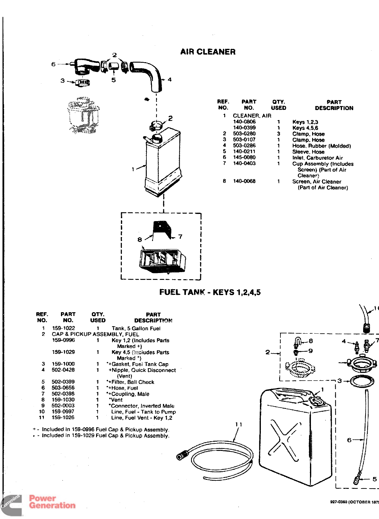
NR CLEANER
REF.
NO.
1
2
3
4
5
6
7
8
PART UTY.
NO. USED
CLEANER, AIR
140-0806 1
140-0399 1
503-0280 3
W.M-0107 1
503-0286 1
140-0211 1
146-0080 1
140-0403 1
140-0068 1
I
1- 1
&.- —- —-— —---- .4
FUEL TANK -KEYS 1,2,4,5
REF. PART my. PART
No. NO. LfSED OESCRIPTKM
1159-1022 1Tank, 5Gallon Fuel
2CAP& PICKUP ASSEMBLY, FUEL
159-0996 1Key 1,2 (lnclw%?s Parts
Msrked +)
159-1029 fKey 4,5 @wiudes F%wts
Marked “)
3159-1000 3*+Gasket, FUG;Tank Cap
4502-0428 1+Nipple, Quick Disconnect
(Vent)
5502-0399 1*+Filter, Ball Check
6503-0656 ~‘H-he, Fuel
7502-0398 1●+Coupling, Male
8159-1030 1‘Vent
9!502-0003 1*Connector, Inverted Male
10 159-0997 1Line, Fuel -Tank to Pump
11 159-1026 1Line, Fuel Vent -Key 1,2
+-Included in 159-0996 Fuel Cap &Pickup Assembly.
.- Inc!tided in 159-1029 Fuel Cap &Pickup Assembly.
11
I
PART
DESCRIPTION
Keys 1.2,3
Keys 4,5.6
Clamp, Hose
Clamp. HOW
Hose. Flubber (Molded)
skew, l-lose
Inlet, Carburetor Air
Cup Assembly (includes
Screen) (Parf of Air
Clearw]
Screen, Atr Cleaner
(Part of Air Cleaner)
r——— -.
1- ..— —.
i
I
-——_ _-
927-0~ (OCIOflER
1S7
Redistribution or publication of this document
by any means, is strictly prohibited.
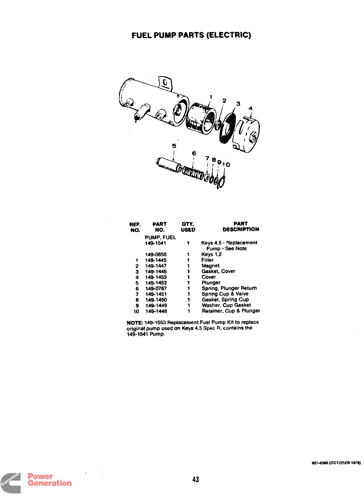
FUEL PUMP PARTS (ELECTRIC)
REF. PART
No. Fm. $?l&#
PUMP, FUEL
149-1541 1
349-0550
7149-1445
2149-1447
3149-1446
4149-1453
5149-1452
6149-0767
7349”3453
8149-1450
~149-1449
10 14%1448
1
1
T
1
1
?
1
1
1
1
1
PART
DESCRIPTION
Keys 4,5- Replacement
Pump -Sea F&Me
Keys 1,2
Filter
Magnet
Gasket. Cover
Cover
Piunger
Spring, Plunger Return
Spring Cup &Valve
Gasket, Spring CUP
Washer, Cup Gasket
Retainer, CUP &Plunger
?W?T& 149-1553 R@acernent %& Pump Kit to rep!ace
original pump used cm Keys 4,5 Spee R, contains the
149-1541 PIJrnp.
$2’7-0360 [OC’R3$WR 1979)
43
Redistribution or publication of this document
by any means, is strictly prohibited.
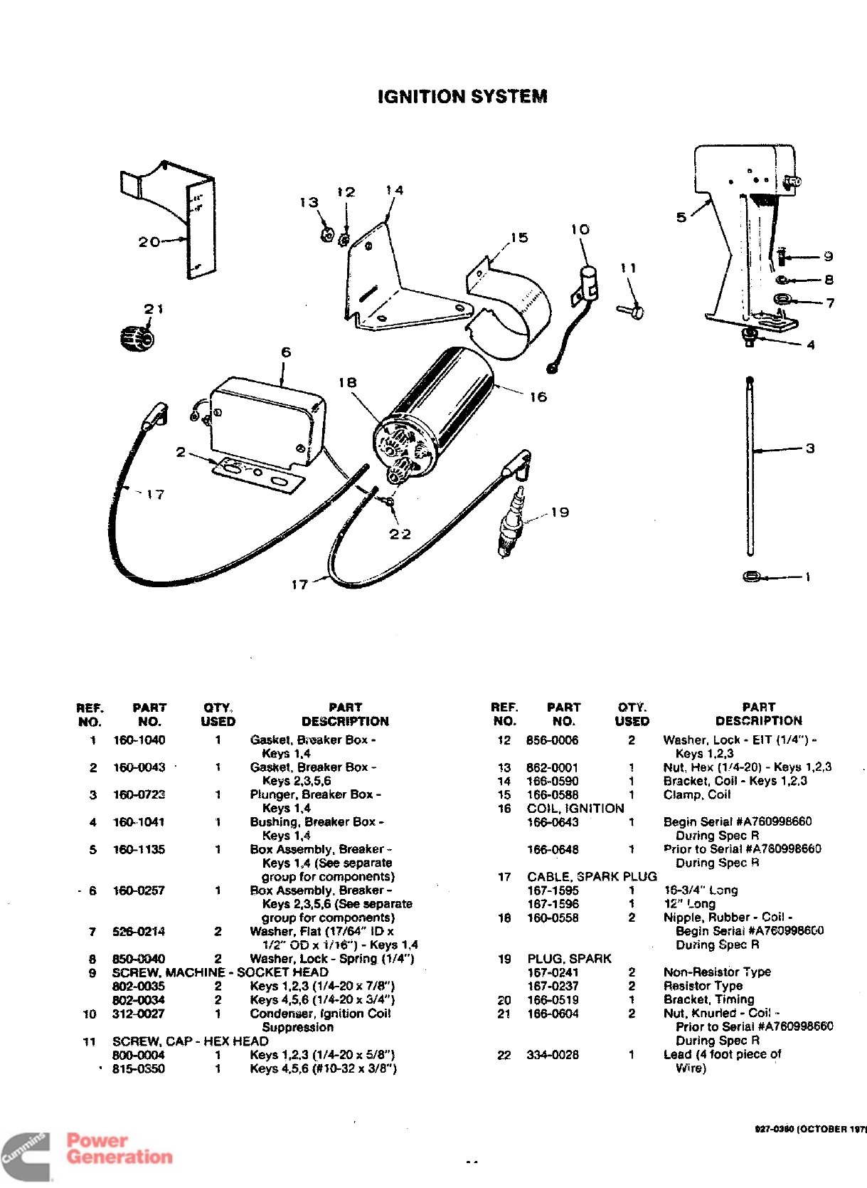
IGNITION SYSTEM
REF.
NO.
1
2
3
4
5
-6
7
8
9
10
ii
.
PART m% PART
NO. USED DESCRWTtON
160-1040 1Gasket, Bn%aker Eiox -
Keys 1,4
160-0043 1Gasket. Breaker Box -
Keys 2,3,5,6
160-0723 1Plunger, Breaker Box -
Key-s 1,4
160-1041 1Bushing, Breaker Box -
Keys 1,4
160-1135 1Box Assembly, Breaker -
Keys 1,4 (See separate
group for components)
160-0257 1Box Assembly, Breaker -
Keys 2,3,5,6 [See separate
group for compcments)
5=74 2Washer, Flat (17164” ID x
%%” CHl xV16) -Keys 1,4
2Washer, Lock -Spring (1/4)
SCREW, MACHIN: -SOCKET HEAD
602-0035 Keys 1,2,3 (1/4-20 x7/8]
802-0034 2Keys 4,5,6 (1/4-20 x3/4)
312-0027 1Condenser, Ignition Coil
Suppression
SCREW. CAP -HEX HEAD
1Keys 1,2,3 (1/4-20 x5/8)
8i5-0350 1Keys 4,5,6 (#10-32 x3/8”)
REF.
NO.
10
11
=&
NO. USED
12 8WOO06 2
13 862-0001 ~
14 166-0590 $
15 .A - ----
~m-uDr28 1
16 COIL, IGNITION
!66-0643 1
166-0646 1
17 CABLE, SPARK PLUG
167-1595 1
167-1596 1
18 160-0558 2
19 PLUG, SPARK
167-0241 2
167-0237 2
20 166-0519
2% 166-0804 ;
22 334-0026 1
5
PART
DESCRIPTION
Washer, Lock -EIT (1/4”) -
Keys 1,2,3
Nut, Hex (1/4-20) -Keys 1,2,3
Bracket, Coil -Keys 1,2,3
Clamp, Coil
Begin serial #A760998660
During Spec R
prior to Serial #A760998660
During Spec R
16-3/4” Lzng
12” f-ong
Nipple, Rubber -Coil -
Begin Seriai #A7609986Wl
During Spec R
Non-Resistor Type
Resistor Type
Bracket, T~ming
Nut, Knurfed -Coi! -
Prior to Seriai #A760996660
During Spec R
Lead (4 foot piece of
Viire)
027-02SQ [OCTOBER
1979
Redistribution or publication of this document
by any means, is strictly prohibited.
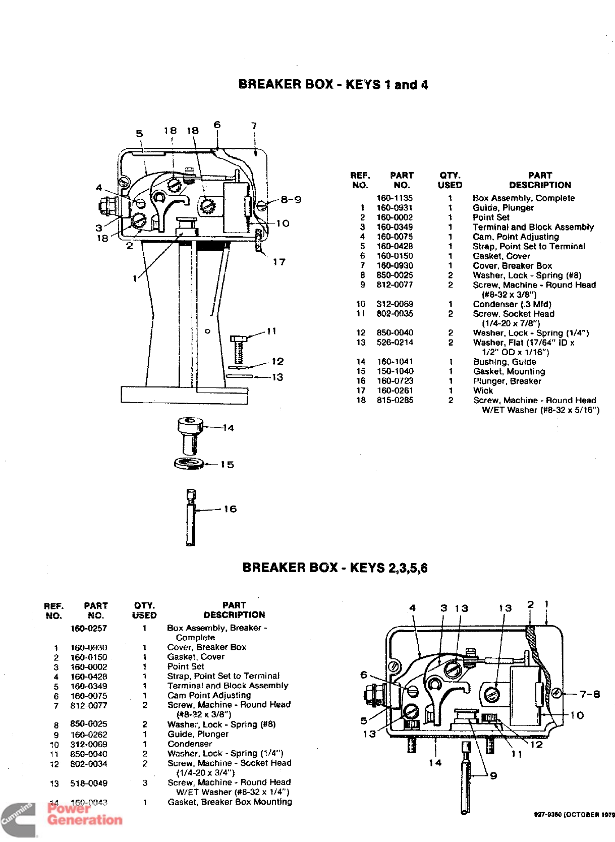
BREAKER BOX -KEYS 1 and 4
REF. PART
Um
,.-. .N~+
160-0257
1160-0930
2160-0150
3160-0002
4160-0428
5160-0349
6160-0075
7812-0077
8850-0025
g160-0262
lIJ 312-0069
11 850-0040
12 802-0034
13 518-0049
14 160-0043
WY.
USED
1
1
1
1
1
1
1
2
2
1
1
2
2
3
1
1
12
-13
REF.
Nil
91
2
3
4
5
6
7
8
9
12
13
14
15
16
17
18
PAW’
NO.
160-1”135
160-0931
160-0002
16(P0349
160-0075
160-0428
160-0150
160-0930
850-0025
812-0077
312-0069
802-0035
850-0040
526-0214
160-1041
150-1040
160-0723
160-0261
815-0285
i-
16
BREAKER BOX -KEYS 2,3,5,6
PART
DESCRWTION 4
\
Box Assembly, Breaker -
Complete
Cover, Breaker Box
Gasket, Cover
Point Set
Strap, Point Set to Terminal
Terminal and Block Assembly
Cam Point Adjusting
Screw, Machine -Round Head
{WI-%? X318”)
Washer, Lock =Spring (#8)
Guide, Plunger
Condenser
Washer, Lock -spring (1/4”)
Screw, Machine -Sucket Head
QTY.
USED
1
1
1
1
1
1
1
1
2
2
1
2
2
2
1
1
1
1
2
PAW
OESC!WPW?N
~mx fiwmbt~, Complete
Guide, Plunger
Point Set
Terminal and Block Assembly
Cam, Point Adjusting
Strap, Point Set to Terminal
Gasket, Cover
Cover, Breaker Box
Washer, Lock -Spring (#8)
Screw, Machine -Round Head
(#8-32 X3/8”)
Condenser (.3 Mfd)
Screw, Socket Head
(1/4-20 X7/8”)
Washer, Lock -Spring (1/4)
Washer, Flat (17/64” ID x
1/2” C)D X1/16)
Bushing, Guide
Gasket, Mounting
Plunger, Breaker
Wick-
Screw, Machine -Round Head
W/ET Washer (#8-32 x5/16”)
(1/4-20 X3/4)
Screw, Machine -Round Head
W/ET Washei (##8-32x 1/4”)
Gasket, Breaker Box Mounting
3 13 13?!
-8
r
9
927-02S0 (OCTOBER
1979
Redistribution or publication of this document
by any means, is strictly prohibited.
GHUERA7’OR
7
,46
S274W80(OCT05ER ism)
46
Redistribution or publication of this document
by any means, is strictly prohibited.
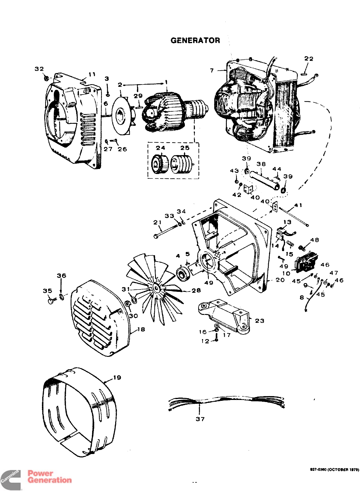
GENERATOR
REF.
NC%.
1
2
3
4
5
6
7
8
9
10
11
12
13
14
15
16
17
18
19
20
PART QTY. PART
NO. Usm DESCRIPTION
R(3T(3R ASSEMBLY. WCWND (Includes Parts
Marked ●)
201-1903 160 t+ertz Sets, Spec R
through U
~3.~~3 160 Hertz Sets, Begin *C V
201-1912 150 Hertz S@s
232-2316 1“Hub. Drive -Spec R
through UOnly
515-0006 1Key, Rotor to Crankshaft -
Spec Rthrough U
510-0047 1Wearing. Rotor (Be!!)
232-0596 1clip. Bearing Stop
520-0733 Stud, Rotor Thro@h
STATOR ASSEM;LY, WOUND
220-1821 160 !iertz
220-1822 150 Hertz
LEAD ASSEMBLY, BRUSH
336-3893 aBtade Type Terminals (9)
336-1890 3Blade Type &Round Type
Terminals (4-)
336-2110 1Blade Type &Round Type
Terminals (6”)
336-0186 2Jumper. Ground (3-lA?j
BLOCK ASSEMBLY. BRUSH {Includes Parts
Marked +)
212-0352 1Bottom
212-0345 1R!ght Side
212-0346 1Top
212-0353 1Left Side
231-0164 1Adapter, Ganerator to
Engine
600-oo51 2Screw, Cep -Hex Head
(3/8-16 xT-1%”)
214-0095 4+Brttsh, OommutaWr
214-0096 8+Brush. Collector Ring
212-1232 12 +Spring. Brush
2Washer, Lock -Sprin9 (3/8”)
526-0030 2Washer. Flat (1W37 ID x
7/8 OD X1/8)
232-2107 1Cover. Fan
234-0362 1Wrapper, End Bell
211-0187 1Bell, End
NE:. PART
NO. NO.
21 Em04044
22 518-0182
23 232-2321
24 203-0152
25 204-0*10
26 600-0050
27 850-0050
28 205-0090
29 515-0007
30 870-0203
31 850-G05S
32 882-0015
33 850-0045
34 .?’?6-0115
35 812-0158
36 850-0040
WV.
USED
4
8
1
1
1
4
4
1
1
1
1
4
4
4
4
4
PAM
DESCRIPTION
Screw, Cap -Hex Head
(5/16-18 X7-112”)
F%, !?011(1/4x 3/4”)
Support. Generator
‘Commutator
“Collector Ring ‘
screw. Cap -Hex Head
(3’S-?6 X1“)
Washer, Lock -Spring (3/8)
Fan, Generator
*Key, Drive Hub
Nut, Hex (7/18-20)
Washer. Lock -Spring (7/16’)
Nut, Hwx (SU&18)
Washer, Lock -Spring (5/15)
Washer, Flat (11/32 ID x
11/16 OD X1/16)
Screw, Machine -Round Head
(1/4-20 x1-1/2)
Washer, Lock -Spring (1/4”)
37 HARNESS ASSEMBLY, WIRING
38
39
40
41
42
43
44
45
46
47
48
49
338-0642
338-0946
353-0047
304-0015
304-0706
8%2-0118
8504)030
860-0011
35?-0020
853-0008
871-0010
528-0049
815-0341
8$5-0359
1
1
1
2
2
1
1
1
1
8
8
4
4
17
Spec Rthrough U
Begin Spec V
Resistor, Tapped
Washer, Centering
Bracket, Resistor Mounting
Screw, Machine -Round Head
(#10-24 X~)
Washer, Lock -Spring (#10)
Nut, Hex (#10-24)
Rectifier, Diode
Washer, Lock -ET (#%0)
Nut, Hex (#10-32)
Washer, Flat (.2W !D x
7/18 00X 1/32)
Screw, Machine -Hex Head
Brass (#10-32 x1”)
Screw, Tapping -HWH
(#10-32 X7/8”)
+- Parts !ncluded in Brush Block Assembly.
“ - Parts Included in Rotor Assembly.
e27.osse (Ocmsm
1$7
47
Redistribution or publication of this document
by any means, is strictly prohibited.
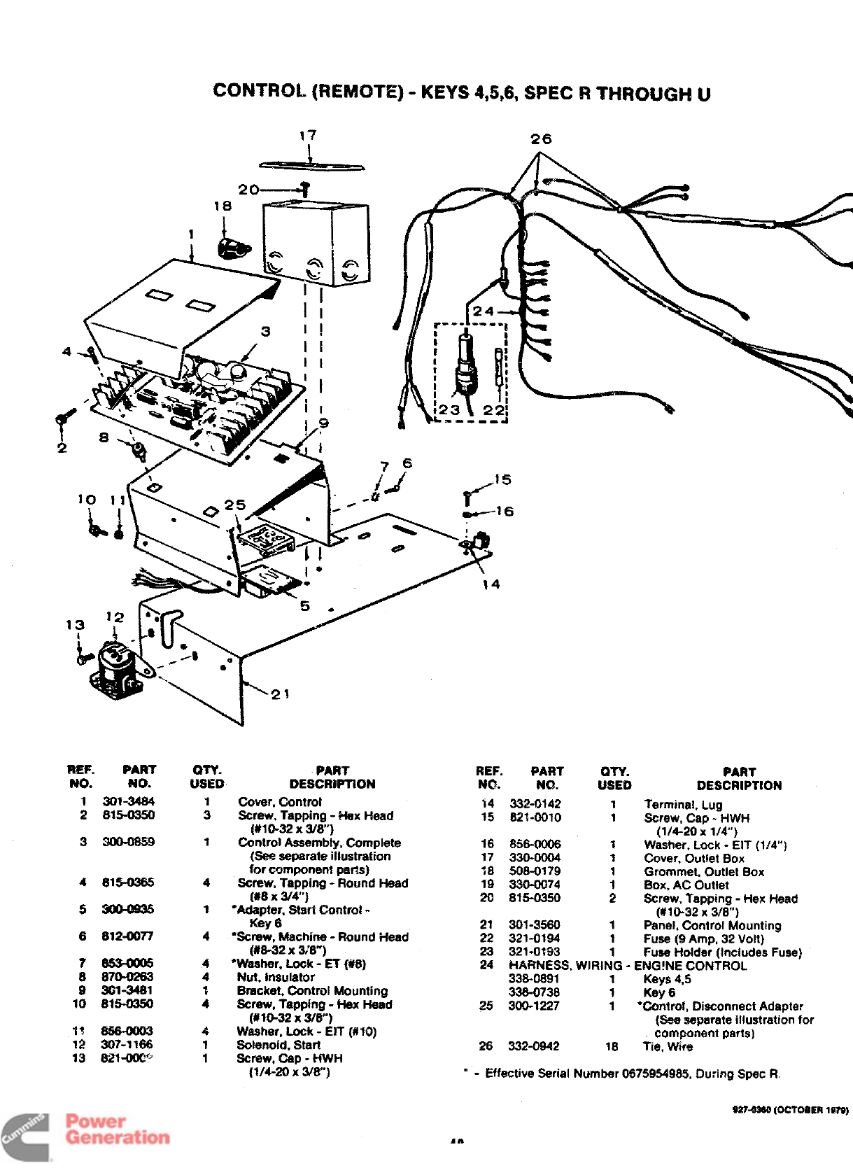
CONTROL (REMOTE) -KEYS 4,5,6, SPEC RTHROUGH U
I
20-4 .
/&p
26
?3EF. PART
NO. NO.
130X3484
2815-0350
3WM859
4815-0365
53m0m5
8812-0077
7S534005
8 8?Lb8283
93G1-3481
10 815-0350
?1 S564003
12 307-1166
13 8i21-OOtY’
QTY.
mm
1
3
1
4
cove?.corwrol
Screw. lapping -Hex Head
(#l@32 x3/8)
~~ntrol Assembly, Complete
(See separate illustration
for component parts)
Screw, Tapping -Round Head
REF. FART
NO. NO.
%4 332-0142
15 82%-0010
16 6S6-0006
17 330-0004
1$ 508-0179
1$ 33Q-0074
1
1
1
i
(#8 X~4”j 20 815-0350 2
1“Adapter, Start C%mtrol -
Key 621 301-3580
41
“Screw, Machine -Round Head 22 321-0194 1
(#6-32 X%’8)
4‘washer, Lock -ET (#8)
4Nut. Insulator
1Bracket, Control Mounting
4Screw, Tapping -Hax Head
(#@-32 x3/8”)
4Waaher, Lock -EIT (#10)
1Solenoid, Start
1screw, cap -HWFi
(1/4-20 xWa)
23 321-0?33 1
PART
DESCRIPTION
Terminal, Lug
Screw, Cap -HWH
(1/4-20 x1/4)
Washer, Lock -EIT (1/4)
Cover, Outlet Box
Grommet, Outlet Box
Box. AC Outlet
Screw. Tatminci -Hex Head
(#16-32 x3/~)
Panel, Control Mounting
Fuse (!3Amp, 32 Vo!t)
Fuse Holder (Includes Fuse)
24 HARNESS, WIRiNQ -ENG!NE CONTROL ‘
336-0891 1Keys 4,5
336-0738 1Key 6
25 300-1227 1●Control, Disconnect Adapter
(See separate illustration for
component parts)
26 332-0942 18 tie, Wire
“ - Effective Serial Number 0675954965, During Spec R.
9274S60 (OCTOBER 1$?9)
48
Redistribution or publication of this document
by any means, is strictly prohibited.
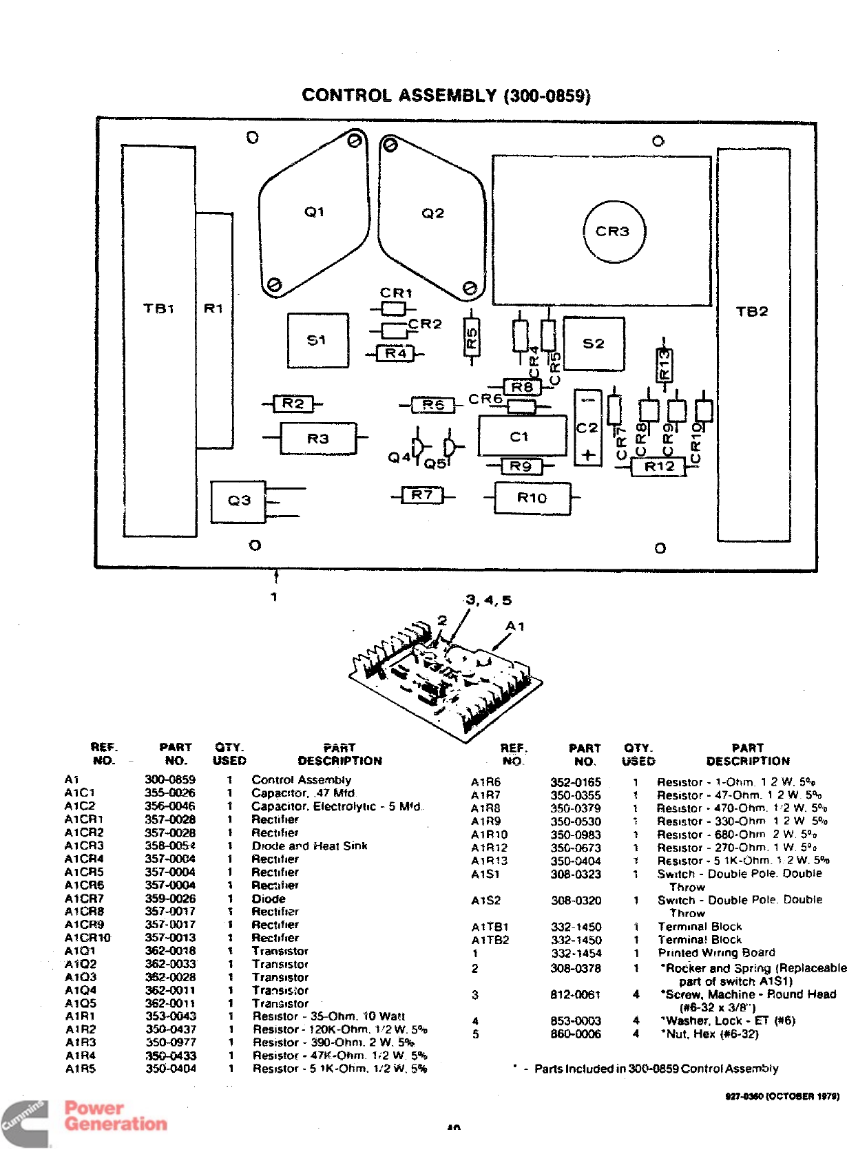
CONTROL ASSEMBLY [300-0859)
Ti32
II ISI I
II -Em-
m=- -L!x!J- L-1
!
00
3,4,5
FART
oEscR$PTmN NQ= PART QTY. PART
NO. Lfff20 OESCRiPTION
REF.
Wt3-
PART
w. mY-
USED
Control Assembly
Capac@cw, .47 Mtd
Capacitor, Electrrslyhc -5 k%d
Flectifler
Rectrnher
Dmde a~d i-feat Sink
F@ctlfler
Recnfter
Re@Efler
Dmcfe
Recflfwr
Rect~fler
Rechfier
Transmtor
Transistor
Transmtor
Transis%x
Trarrwstor
Reswtor -35-Clhm, WWa!t
Res@or -120K-Ohm. 1:2 W. 5%
FteswWr -390-Ohm. 2W. 5%
ResiSFof -47K-ORm. li2 W5%
AIR6
AIR7
A7Rg
AIR9
A1R1O
Alf%12
AIQ13
AISI
Al
Alcl
A1C2
AICR1
A1CR2
AICR3
A1CR4
A1CR5
AICR6
AICR7
43CR$
AlCFt9
AICR1O
Alal
A3U2
AIG3
A1Q4
A~Q~
AIRI
Alf%2
A1R3
AIR4
A1R5
300-0859
355-0Q26
3564X)46
357~8
357-C028
358-0054
357-0004
357-0004
357-0004
359-0026
357-0017
357-0017
357-0013
362-0018
362-0033
36.2-ilJ28
362-0011
362-fNll 1
353-0043
350-0437
350-0977
350-0433
350-0404
352-0165
350-0355
-.*. ti%-lri
.2~~-V~EZ
350-0530
350-0983
35G-0673
350-0404
306-0323
Resistor -1 -Onrn. 1.2W. 5°0
Rewstor -47-Ohm. 12 W. 5%
Reskstcw -470-Ohm. 1‘2 W. 5°-
Resistor -330-Ohrn 1 2 W5°10
Resstor -6130-Ohm 2W. 5°0
Resmtor -270-C?hm 1W5°0
Rmstor -5 lK-Ohm. 1 2 W. 5%
Svwtch -Double Pole. DOuWe
Throw
SwNctI -Double Pole. Double
Throw
Termmal Block
Termina! Block
Printed Wrong Board
“Reeker and Spring (Replaceable
part of switch AIS1 )
“Screw, Machine -Round Head
(#6-32 X3/8”)
“Washer, Lock -ET (#6)
“Nut. H$?x{#6-32)
AIS2 308-0320 1
AlTf31
AITB2
1
2
332-1450
332-1450
332-1454
308-0378
34
4
5853-0003
860-0006
4
4
1Resistor -5 lK-Ohm. 1~2W, S% *-Parts Inclucfad in 300-0859 Control Assembly
S27~ (OC?OeE~1~~)
49
Redistribution or publication of this document
by any means, is strictly prohibited.
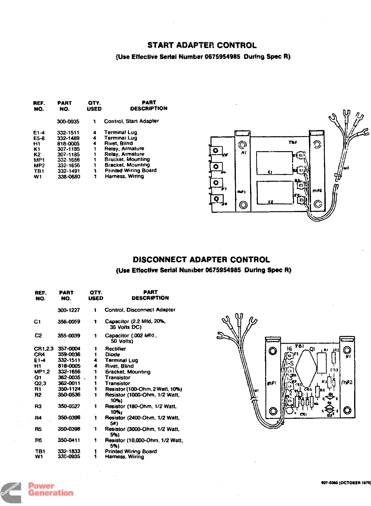
REF.
NO.
El+
&5-8
HI
?(1
K2
~~p?
MP2
TBI
WI
PART
w.
300-0935
332-1511
332-1489
818-0005
307-1185
307-1185
332-$=s
332-16S6
332-1491
338-0680
WY. PART
USED DESCRIPTION
1Control, $MaR Adapter
Termina! Lu~
Termina$ Lug
Rivet Blind
Relay, Armatun2
Retay. Armature
!l$m~ket, Mounting
Bracket. NWuntmg
Printed Wiring Boar@
Harneas. Wiring
i
‘&
\
DISCONNECT ADAPTER CONTROL
(lhe Effective Serial Number 06?5954985 During Spec R]
REF. PART QTY- PART
WI. NO. WNEm DESCR!PTKIN
300-1227 1
C2 35%0039 1
CRI.2.3 357-LKi04 1
CR4 3W—WJ36
El -4 332-1511 :
l-n 818-0005 4
MP1.2 332-1856 1
01 382-003S+ 1
Q2,3 382-0011
R1 350-3124
R2
R3 350-0527
R4
R!i
me
,-v 3s0-0411
TEH 332-1833
WI 33%-0935
CcrntroL Diacormect Adeoter
Capacitor (2.2 Mfd, 20%,
35 Volt= DC j
Capacitor (.002 MM.,
50 volts)
Rectifier
Diode
Terminal Lug
Rivet, Blind
Bracket. Mounting
Transistor
Transistor
Reaistor(100-0hm, 2Watt, 10%]
Resistor (WOO-Ohm, 1/2 Watt,
10%]
fl~gr (180-r3hm, 1/2 Watt.
Reaiator [2400-OtMn. 1/2 Watt,
w)
Rs~or (3000-Ohm. 1/2 Watt,
Resistor (10,000-Ohm, 1/2 Watt,
5%)
Printed Wtring Ward
Harneas, wiring
927-03M (OCYOl!ER
1979)
Redistribution or publication of this document
by any means, is strictly prohibited.
11
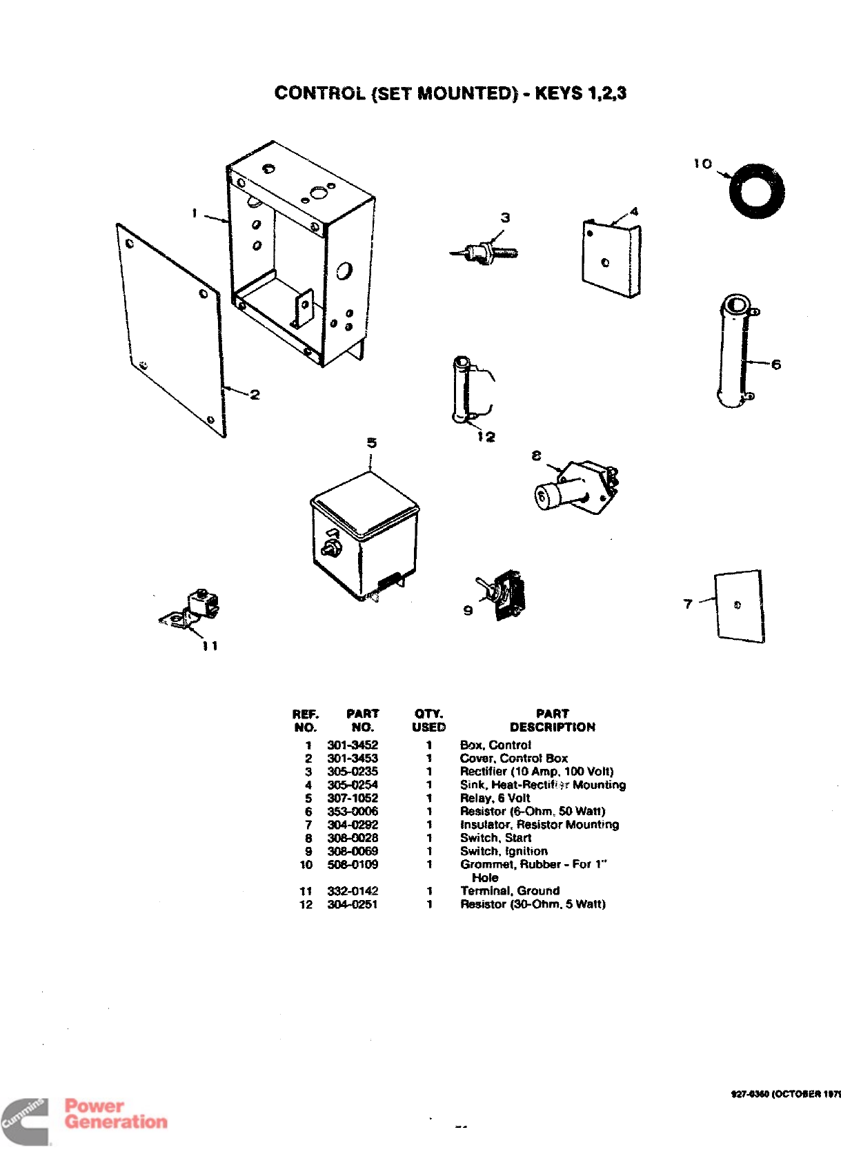
CONTROL
(SET MOUNTED) -KEYS 1,23
Rff. PART
No. rum
:z=
3305-0235
4305’-0254
5307-?052
6353—WM6
7304-0292
8306-0928
9308—W69
10 606-0109
11 332-0142
12 304-9251
34
40
9Q
IT
Q!?
PART
DESGRWltON
Emx. Controi
Cover” Contro# f30x
Rectiiier (70 Amp, IWI VoR]
Sink, Heat-Rectif~w Mounting
Reiay, 6Volt
~q~b. fe-mm cmW.wk
.“. ~-v. -s,, -..-..,
Insulator, Resistor Mounting
Switch, Start
Switch, Ignition
Gr~’ewtt, Rubber -For 1“’
Terminal, Ground
Raeistor (3WOhmi 5Watt)
E’
o
6
7
a
o
e274s60 (Ocmmn
197s)
Redistribution or publication of this document
by any means, is strictly prohibited.
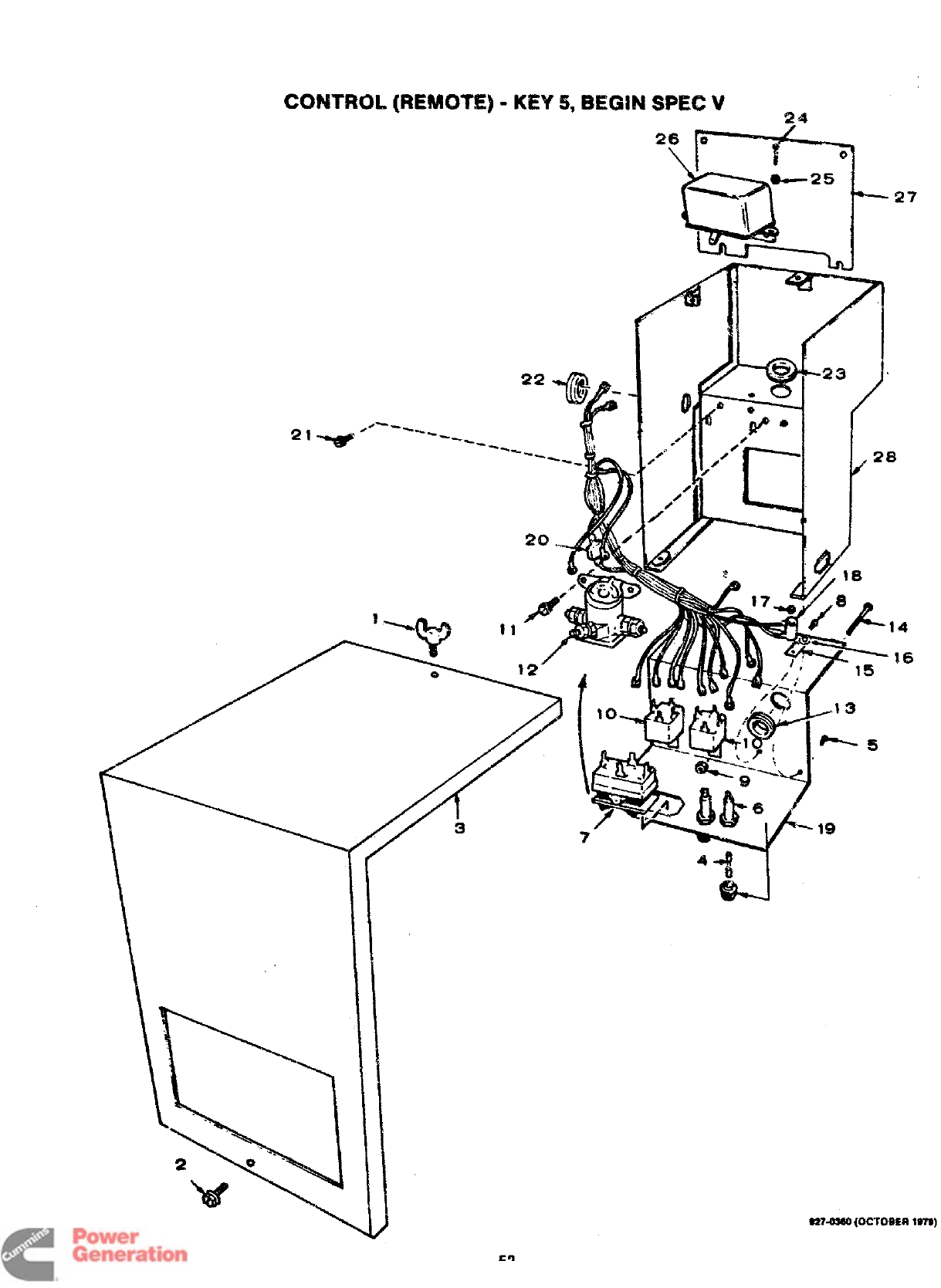
(REMOTE] -KEY !!, BEGiN SPEC V*.
\. -.
~
“\ ~
2e‘-”-
%$
52
4-’4 ‘
id
w-d
$27-o$aO (ocm5ER 1979]
Redistribution or publication of this document
by any means, is strictly prohibited.
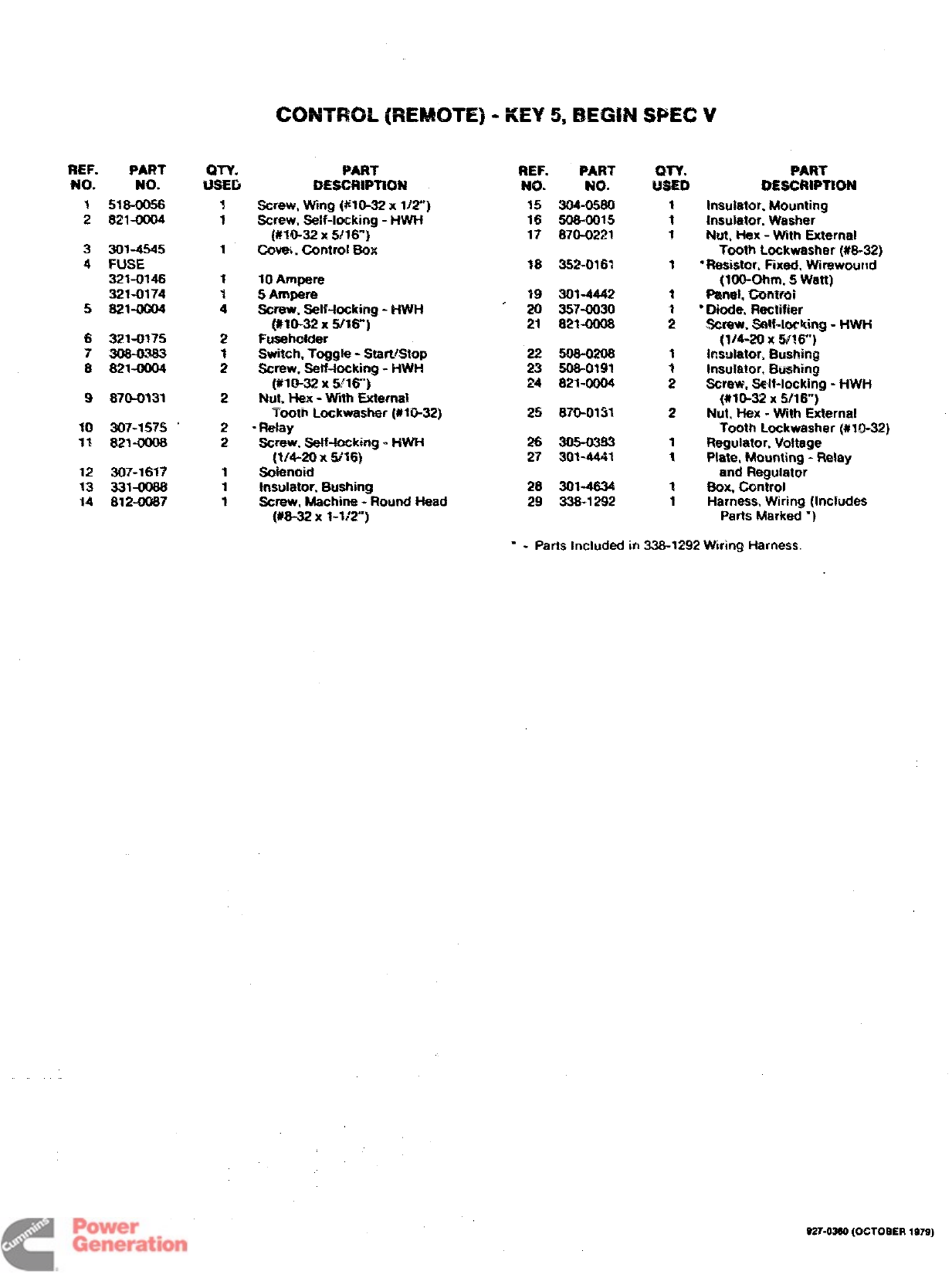
REF. PART
No. NO.
1516-0056
2821-0004
3301-4545
4FUSE
321-0146
321-0174
5821-0004
6
7
&
9
12
13
14
321-0175
821-0004
870-0131
307-1575
821-0008
307-1617
331-0088
S12-0087
i%
1
1
1
1
-1
4
2
1
2
2
2
2
1
1
1
CONTROL (REM4NE) -KEY 5, BEGIN SFEC V
PART
DESCRIPTtOId
screw, Wing ($W-32 xWY’)
Screw, Self-1ocking -HWH
(#lf&32 X5/16”)
Ccrvw, Control Box
10 Ampere
5Ampere
Screw. SeIf-tocking -HWH
(#lo-32 x!M16”)
Fuseholder
Switch. Toggle -StarLfStop
Screw, self-locking -HWH
(WI-32 x51’16]
Nut. Hex -With External
Tooth tackwasher (#10-32]
“Relay
-Screw. Seff-toeking -HWH
(IM-20 x5t16]
Solenoid
Insulator. Bushing
Screw, Machine -Round Head
($!8-32 x1-1!2-)
REF.
N~.
15
16
17
:
21
22
23
24
25
26
27
28
29
PART
NO.
304-0580
608-0015
870-0221
352-0163
301-4442
357-0030
821-0008
506-0208
308-0191
821-0004
870-0131
30%4441
30%4634
338-1292
wY. PAW
Wf!m DESCRIPTION
1Insulator, Mounting
1Insulator, Washer
1Nut, Hex -Wtth External
Tooth tmckwasher (W-32)
3“Resistor. Fixed, VMrewow}d
(loO-Ohm. 5Watt;
1Panel, Controi
●Diode, Rectifier
;Screw. %!f-lorking -tiWti
(1/4-20 x!&W’)
1Irwu!atrx, BusRin~
Insulator, Bushing
;Screw, Self-locking -HWH
(#10-32 X5!16”)
2Nut, Hex -WNh External
Tooth Lockwasher (#10-32)
1Regulator, Voltage
1Plate, Mounting -Relay
and Regulator
1Box, Control
1Harness, Wiring (Includes
Parts Marked “)
“-Parts Included in 338-1292 Wiring Harness.
S27-03S0 (OCTOaER 1979)
53 C2
Redistribution or publication of this document
by any means, is strictly prohibited.
18 17
\
-?
S2%ow0 (OCTOBER
197s
Redistribution or publication of this document
by any means, is strictly prohibited.
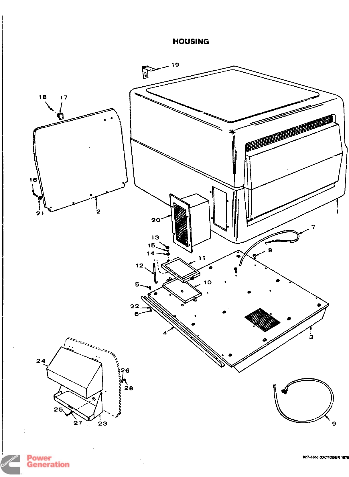
REF. PAR? OTY. PART
?40. NO. USED E$ESCRWWMd
1405-l%M %Housing Assembly, Unit
(includes Parts Marked “)
2PANEL, REAR HOUSING
3
4
5
9
405-? 927 1
405-2170 1
403-1000 1
403-1001 2
813-0105 8
WO-W31 8
403-1002 3
815-0363 !5
CABLE. EMTTERY
4-i6-cJo49 1
4?6-0549 1
4W0538 i
416-!M12
416-0541 :
862-0015 2
Keys 1,2,3,6
Keys 4,5
f3sse, Mounting
Molding, Trim
Screw, ‘Machine -Round Head
(10-32 x1-1/4”:
WM. t+eX (#10-32)
t-bid-down Assembly, Fuel
Tank -Keys 1,2
Straw Eye. Wood -Fue!
Tank Hold-down -Keys 1.2
Negative
Positive
Tray. Brmety
Frame, Battery Hold-down
Stud (5!l&18 X7-1/2”) -
Battery Hold-down
Nut, *X (W16-113)
HCXMNG
REF. PART
NO. NO.
14 526-0054
15 850-0045
16 815.()@3~
17 406-0360
18 815-0382
19 408-0359
20 405-1925
21 !526-0013
22 526-0iM9
23 159-1031
24 405-2175
25 600-0008
26 850-LWO
27 5X-0015
28 862-0001
QTY. PART
USED DESCRIPTION
2
2
5
1
4
1
:
0
1
3
4
4
4
4
Washer, Flat (21/64” ID x
3/4 or) x1/16]
Washer, Lock -Spri?y? (5/16)
~Ok, Lag (3/8X 3“)
Ptate, Hasp
Screw, Wood (#8 x3/4’”)
“Hhge. Hasp
●Duct, Air Housing
Washer. Fiat (25/64” ID x
1“ 00x 1/16’)
Washer. Flat {7/32 ID x
1/2” W)= 1116”)
Bracket, Gas Can -Keys 4,5
Hood, Gas Can -Keys 4,5
Straw. Cap -Hex Head
(1/4-20 x1-1/4)
Washer. Lock -Spring (1/4”)
washer, Flat (9/32’ ID x
9/16” OD x1!16)
Nut, *X (1/4-20]
55
●-Parts Included in 405-1928 Housing assembly.
S27.OWQ Vxwem 1s7s)
Redistribution or publication of this document
by any means, is strictly prohibited.
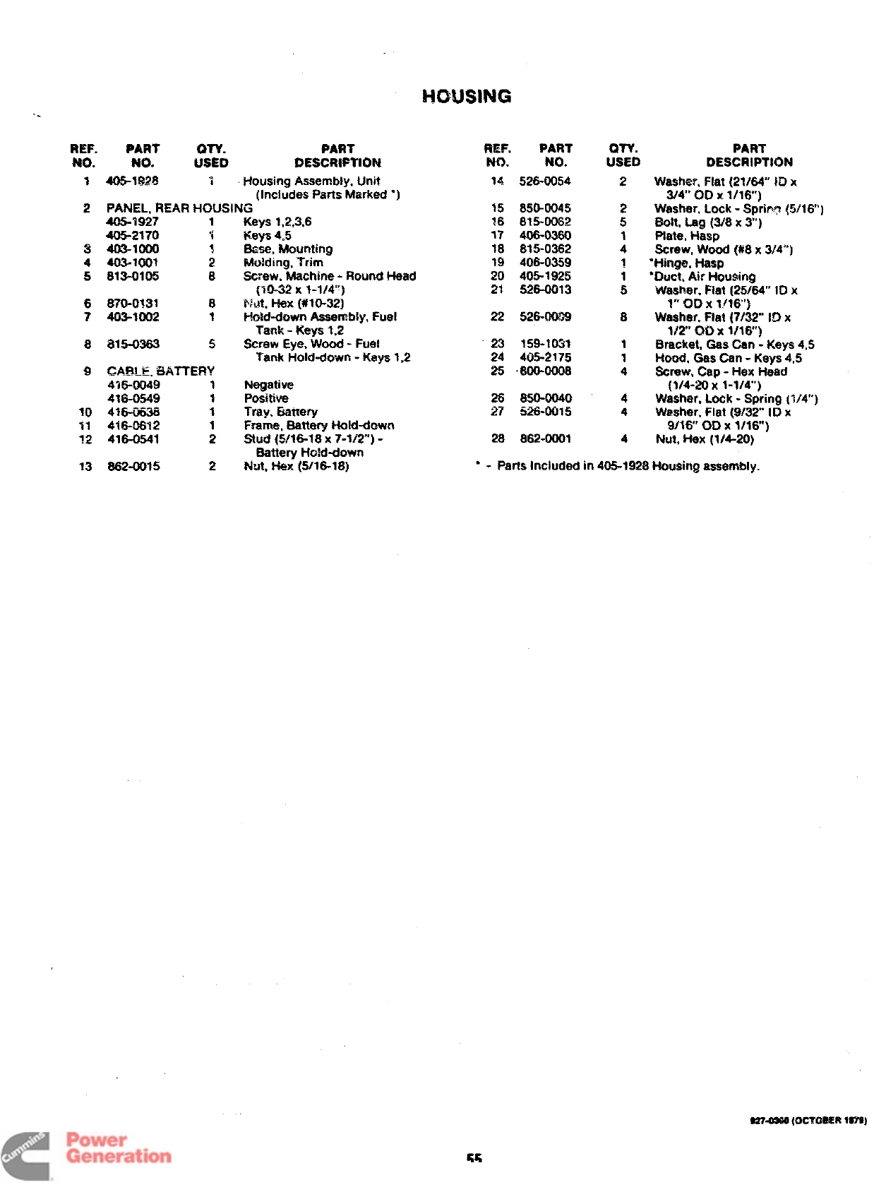
AIR HOUSING
P
12
“- $
11’
‘,*Y”
\
810
REF. PART
NO. NO. :Zb
1734-0589 1
2HCW!31NG, BLOWER
134-2522 1
134-2522 1
134-2102 1
3W4-0588 1
PART
DESCRIPTION
Housing, Cylinder Air -
Left Side
Keys 1.2.3
Keys 4,5,6- Begin Seriaf
#221 189 During Spec R
Keya 4,5,6- Prior to Serial
#221 189 During Spec R
Housing, Cylinder Air -
RiaM Side
4
5
6
7
a
9
10
11
12
SCROLL, BLOWER HOUSltiG
*9A 9-
1*— ?Spec Rthrough U
1*3916 1Begin Spec V
5$7-0035 1Ptug, Dot Button (1-1/16”] 5
608-0166 1Grommet, Rubber -Keys 1,2,3
517-0021 Plug” Dot Button (7/8]
SCFtEW, CAP -l-lgX HEAD
821-0018 4Spec Rthrough U
(1/4-20 X5/8”]
02%0006 4
526-0015 Begin Spec V(1/4-20 x1/2)
4Washer, Flat (9132” !0 x
9{16 OD X1/16”)
653-0013 4Washer, Lock -ET ($/4”)
134-2956 1Guard, scroll Outlet
8?~21 4Screw. Tapping -Hex Head
With ET (#10X 1/2”]
9??-0SS0 @CTOSER W7SY)
Redistribution or publication of this document
by any means, is strictly prohibited.
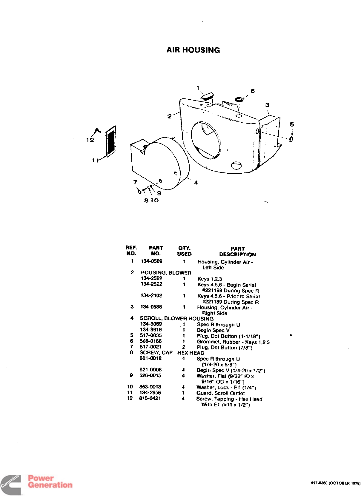
EXHAUST BLOWER AND REMOTE CONTROL -KEYS 4 and 5
REF. PART PART
NO. No. :s:5 DESCRIPTION
REMOTE CONTROL, COMPLETE
300-1140 1Keys 4,5- Spec Rthrough U
(Includes Parts Marked ‘)
300-1819 1Key 5- Begin Spec V
(Includes Parts Marked 8.)
1815-0350 4“&Screw, Tapping -Hex Head
(#W1-32 X3/8)
2301-3911 1“&Cover, Control
3812-0066 4●&Screw, Machine -Round Head
(#6-32 X5/8)
4CIRCUIT BOARD ASSEMBLY
332-1716 1“Keys 4,5- Spec Rthrough U
(Includes Parts Marked t)
332-2264 1&Key 5- Begin Spec V
(Includes Parts Marked ~)
5332-1450 1j$Termiriai f3iock
6307-1165 1*Relay
7307-3347 1?~Relay, Time Delay
82*&Grommet, Rubber
i
14 ?
I
13
REF. PART OTY. PART
NO. No. USED DESCRIPTION
9307-0597 1●&Relay -Start/Stop
10 HARNESS, WiRING
338-0893 1“Keys 4,5- Spec Rthrough tJ
338-1276 1&Key 5- Begin Spec V
11 301-3910 1*&Box, Control
12 313-0016 4●&Spacer
13 399-0092 1Blower, Exhaust
14 405-2172 1Screen, Exhaust Blower
15 812-0156 2Screw, Machine -Round Head
(1/4-20 x1-1/2”)
?6 526-0015 2Washer, Flat (9/32” ID x
9/16’” OD X1/16”)
17 850-0045 2Washer, Lock -Spring (1/4”)
18 862-0001 2Nut, Hex (1/4-20)
“ - Parts Included in 300-1140 Remote Control Assembly.
&-Parts Included in 300-1819 Remote Controi Assembly.
~-Parts Included in 332-1716 Circuit Board Assembly.
~-Parts Included in 332-2264 Circuit Board Assembly.
927-03S0 (OCTOBER 197S)
Redistribution or publication of this document
by any means, is strictly prohibited.
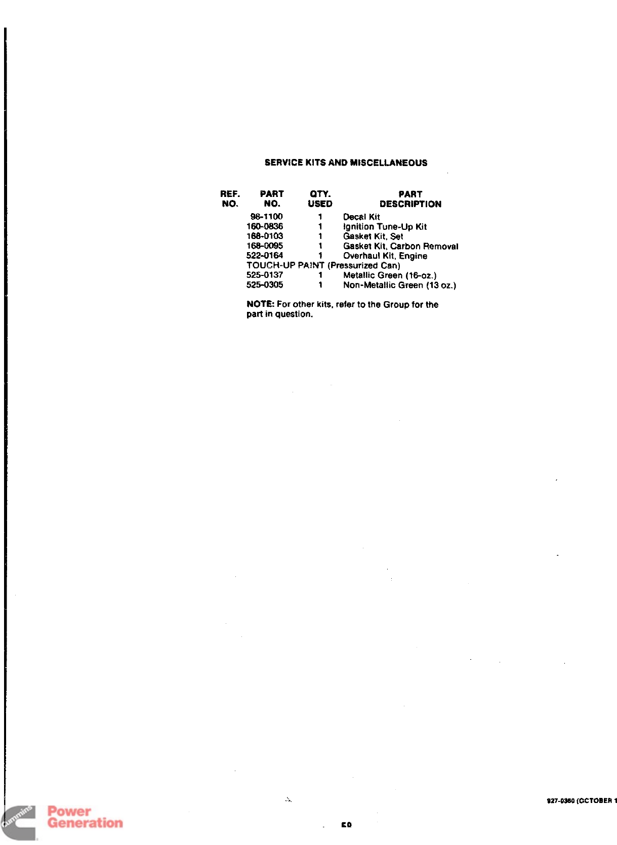
SERViCE KITS AND MISCELLANEOUS
REF. PART WY.
No. No. USED
98-1100 1
160-0836 1
168-0103 1
PART
DESCRIPTION
Oecal Kit
Ignition Tune-Up Kit
Gasket Kit, Set
Gasket Kit, Carbon Removal
Overhaul Kit, Engine
16s-0095 1
52243164 1
TOUGH-UP PPJNT (Pressurized Can) -
525-0137 1Metallic Green (16-oz.)
525-0305 1Non-Metallic Green (13 oz.)
NOTE: For other kits, refer to the Group for the
part in question.
S2742S0 (OCTOBER
1
Redistribution or publication of this document
by any means, is strictly prohibited.
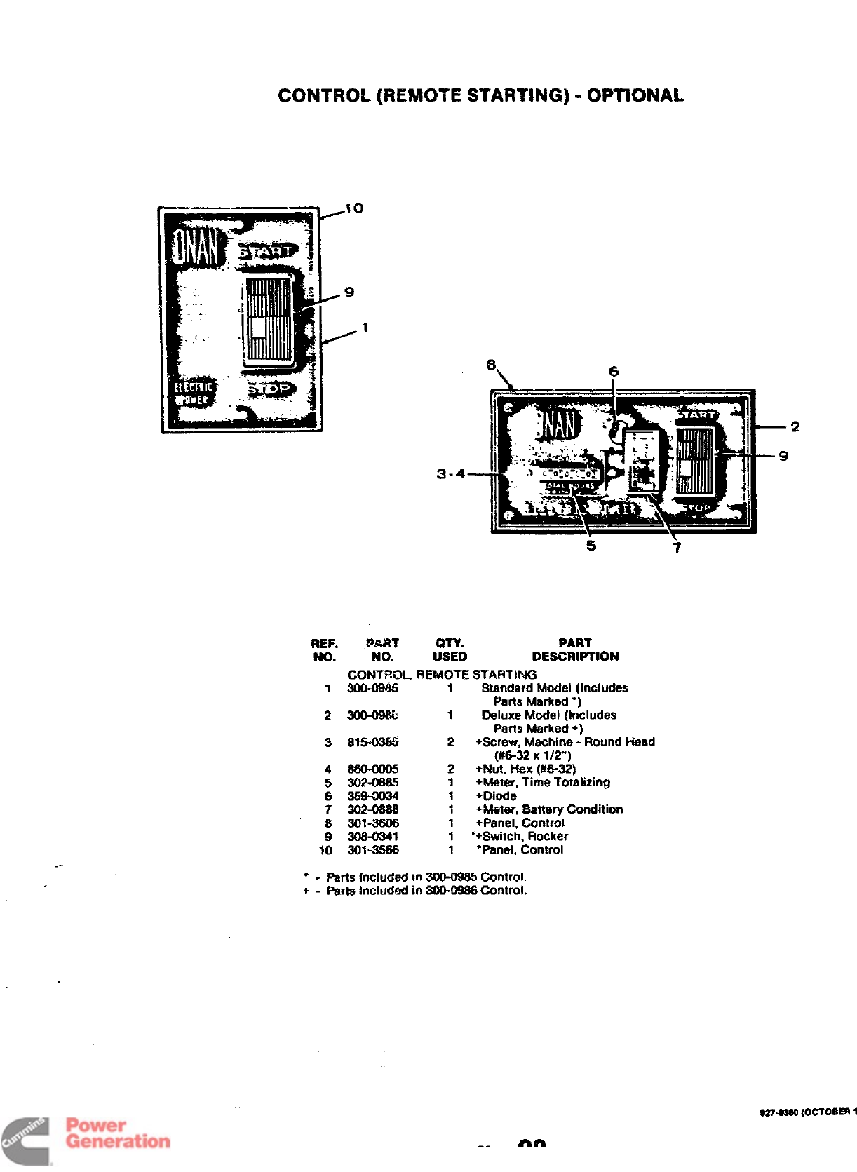
CONTROL {REMOTE STARTING) -OPTIONAL
3-4
e, 6
-2
9
REF.
No.
1
2
3
4
5
6
?
8
9
10
.PART
NO.
CONTROL,
3m-Q98b
815-U365
302-0865
359-9034
302-06SS
301-3606
30$-0341
301-3566
PART
:STD DESCRIPTION
REMOTE STARTING
1Standard Model (Includes
Parts Marked ●)
1Deluxe Model (Includes
Parts Marked +)
2+Screw. Machine -Round Head
(#6-32 Xl/~]
2+N@. kk?X (~~=:
1+Wetw, Time Ta’mlizing
1+Dk3de
1+Meter, Battery Condition
1iPan@ll @n&Q!
.-. .-.,
1“+Switch, Rocker
1“Panel, Control
“-Parts included in3CXM965Control.
+-Partshcludedin3@0966 Control.
,27.osao (OCTOSER
1
Redistribution or publication of this document
by any means, is strictly prohibited.
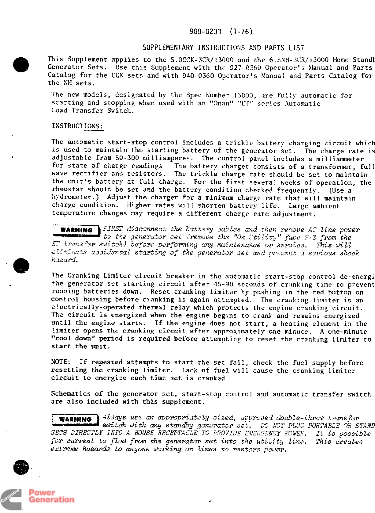
900-0200 (1-76)
.
This Supplement applies to the s.WXX-3X/13(10Q and the 6.S3U+-XR~13000 Hcmw:
Standb
Generator Sets. Use this Supplement with the 927-0360 operator’s Manual and Parts
Catalog for the CCK sets and with 940-0360 Operator’s Manuai and Parts Catalog for
the NH sets,
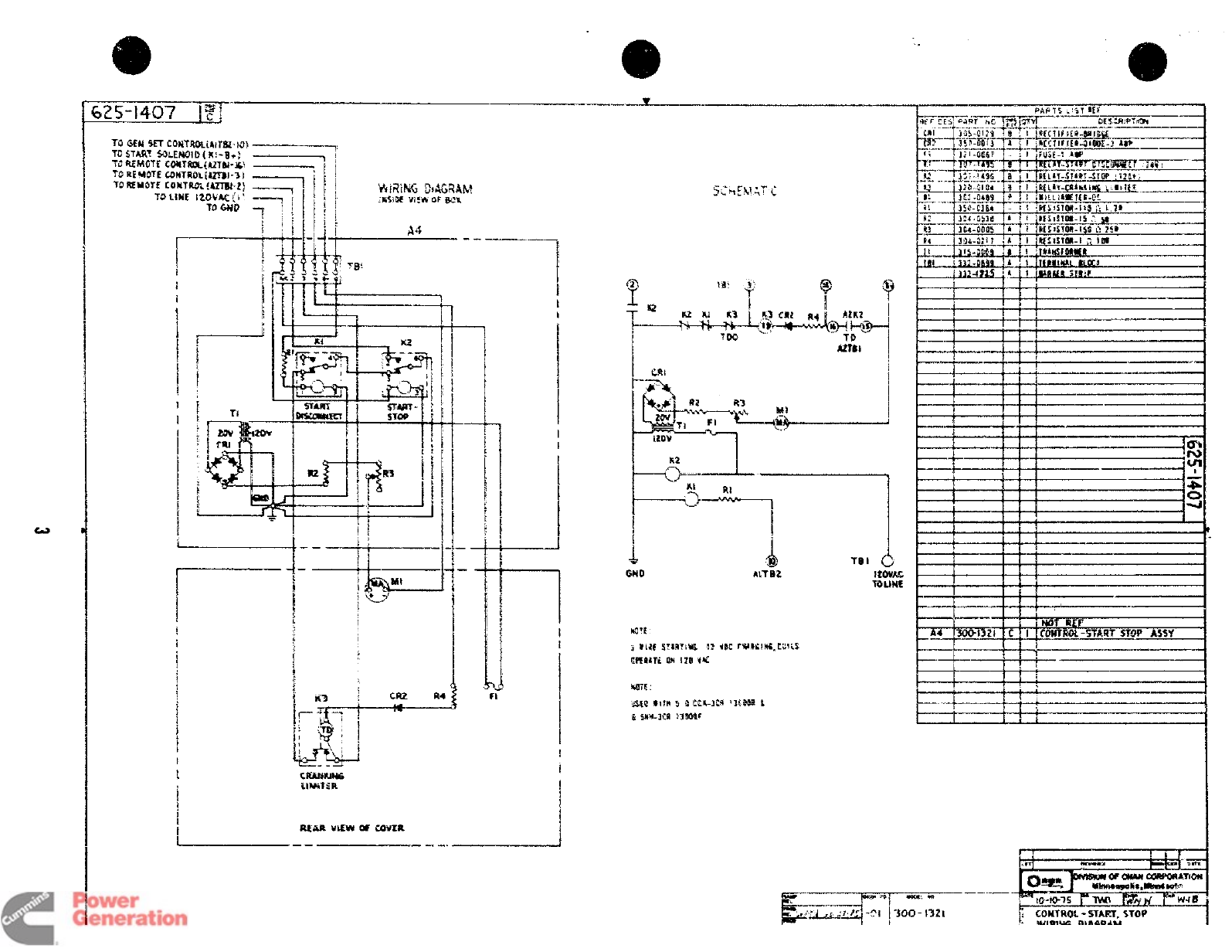
The new models, designated by the Spec Number 13000, :1.refully automatic for
starting and stopping when used with an “C)nan” “ET’ series Automatic
Load Transfer Switch.
The automatic start-stop control includes atrickle battery charging circuit
which
is used to maintain the starting battery of the generator set, The charge rate
is
adjustable from !5Q-300 milliamperes. The control panel includes anilli,mmeter
for state of charge readings. The battery charger consists of atransformer,
full
wave rectifier and resistors. The trickle charge rate should be set to maintain
the tmit?s battery at full ckqe. For the i?i~st several weeks of operation, the
rheostat should be set and the battery condition checked frequently. (Use a
h:;drometer.) Adjust the charger for aminimum charge rate that will maintain
charge condition. Eigher rates will shorten battery life. Large ambient
temperature changes may require adifferent charge rate adjustment.
The Cranking Limiter circuit breaker in the autcmatic start-stop control de-energi
the generator set starting circuit after 4S90 seconds of cranking time to prevent
runaing batteries down. Reset cranking limiter by pushing in the red button on
contYoI housing before clanking is again attempted. The crafiking limiter is an
electrically-operated thermal relay which protects the engine cranking circuit.
The. circuit is energized when the engine begins to crank and remains energized
until the engine starts. If the e~gi~e ~oe~ not start, aheating e~~ment in the
limiter opens the cr~_k&n_g circuit after approximately one mirtute. ~e~~-minute
~*~~~ 4_J~~~:*
period is required before attempting to reset the cranking limiter to
start the unit.
NOTE :If repeated attempts to start the set fail, check the fuel supply before
resetting the cranking limiter. Lack of fuel wiil cause the cranking limiter
circuit to energize each time set is cranked.
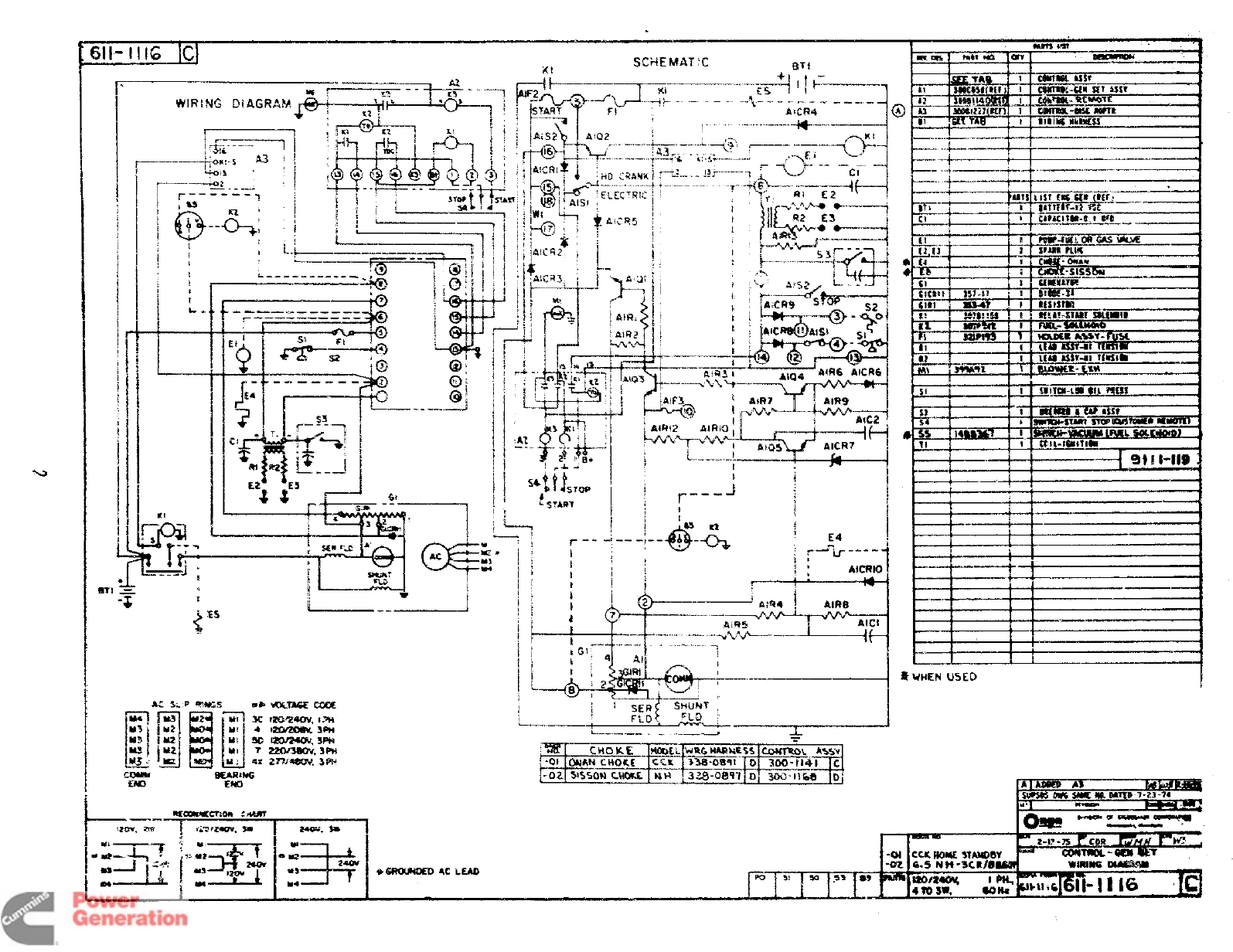
Schematics of the generator set, start-stop coutro] and automatic transfer switch
are also included with this supplement,
-?-he. This C&edes
a
Redistribution or publication of this document
by any means, is strictly prohibited.
ii!
--.—
~jks-*’--=====j
4-----————–-+--+---------
&;; -
~-z —---
IFawn> #______+
,—A. —
[
T.--—. ------
~- ——---——--
.-
●
m:
II,,
ii WHEN U5t~ “1
L..-_.. _,_..- ., _.— &
-WyR&tG
Em
-‘- ====-
-01 ox How 3TW8Y
-m 6.5 Nit ‘3C#@ WIRIM3 IMMmw
m
H
3! w.s3 m120/24m( I*
4wSW* ah
*&mnmoEQ 4C LEAD
Redistribution or publication of this document
by any means, is strictly prohibited.
m
e
TO GEM SET CQNTMLW7W-K3) ------q
TO START SOLENOID (K!- 3.; -1
VREM(!TF COilTW&@ZTS& !Q _?!
TO REW3TE C.0NTROL[4ZTBI-3! —
TO MM5TE COMTK% @ZTM-2) —.—
70 LIME 12 W.K<I; ~
TOGNO -;
I-)5 ts
!-1$$ 1?w
,,.,i- 1
(3-3
1’
..
G4
!AiTBZ 12WA5
YOLINt
i
i
I
I
CAAMLW5
WJ$T:R
Redistribution or publication of this document
by any means, is strictly prohibited.
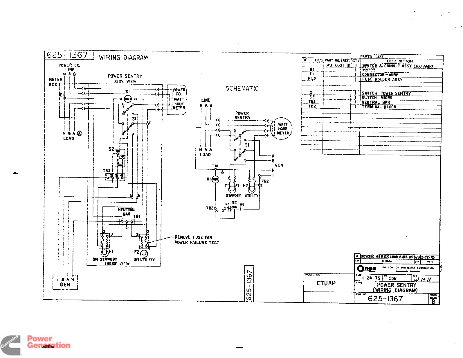
~zs- 1367 iWIRING lXA(XAM “’—~ WRTS -LIST
p>=--oii FfiRT N7@j@ QTY~——–—–—-——”—”———
1-
\.._.
r
DEsCRIPTION
.—. —
.=i___ ~>18 ‘0~9i. lD __! 1.5jilYcH””&-C6i@i~- =~mo AMP) -
,f*(j*@ “——–-–—-
–-.—..J-....--–.-––—.+.=
~- “-El .%
——..l—___.—._—.._
p----- ..i–– . ....__&! CONNECTOR-WIRE
~.. _Fllg _! I FIKi_~ HOLDER ASSY
-.--— —____ _
POWER m.
LINE
SCHEMATIC ?-----””--””----”–-–-—+--”-+------—-–-—— -------
~–sr–”-+’———----‘ ‘———
p-
+–--.. ..+._________ _!... S.W171X-POWERSENyY-——–-—
~—..sz. tSWITCH -kncrto ___
._.. TB~- “~——-”--”’”” “–-It~~UTRAL 5AR
~3~ ]-----------_-_r__mL~ --._. _____
..—_
,, --—-. ——
LINE
MA8
POWER
ill+ SENTRY
=—.—.—4~
!-——--–j———— I1.-— —_—— _-_ ___
b-—–––– !——.—
IJ-
.‘--t------—-——----–
t–—-—--- ----.-–.-- --–- ——.–—
L—---- ...,.-...----___.....
L --------_L–..— ——
ET+l=k;“<
..
LJ
-REMOVE FUSE F(IR
POWER FAILLIRE TEST
Redistribution or publication of this document
by any means, is strictly prohibited.
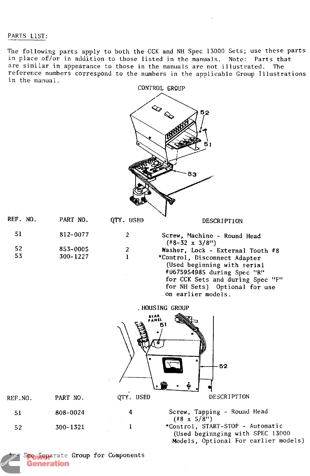
PARTS LIST:
The ibllo-wing pai=ts apply to both the C(X and NH Spec 13000 Sets; tlse these parts
in place of/or in addition to those listed in the manuals. Note: Parts that
are similar in appearance to those in the manuals are not illustrated. The
refererice numbers correspond to the nmbers in the applicable Group Illustrations
in the manual.
CONTROL GROUP
REF. NO. PART NO. QTY. WSED “DESCRIPTIOF$
51 812-0077 2Screw, Machine -Round Head
(#8-32 X3/8”)
52 853-0005 2Washer, Lock -External Tooth #8
53 300-1227 1*Control, Disconnect Adapter
{Used beginning with serial
#0675954985 during Spec “R”
for CCK Sets and during Spec “F”
for NH Sets] Optional for use
.on earlier models.
.HO!JSING GRQI’Jp
REF.NO. PART NO.
52
QTY. USED DESCRIPTION
51 808-0024 4Screw, Tapping -Round Head
(#8 X5/8”)
52 300-1321 1*Control, START-STOP -Automatic
[Used beginning with SPEC 13000
Models, optional For earlier models)
*-See Separate Group for Components
Redistribution or publication of this document
by any means, is strictly prohibited.
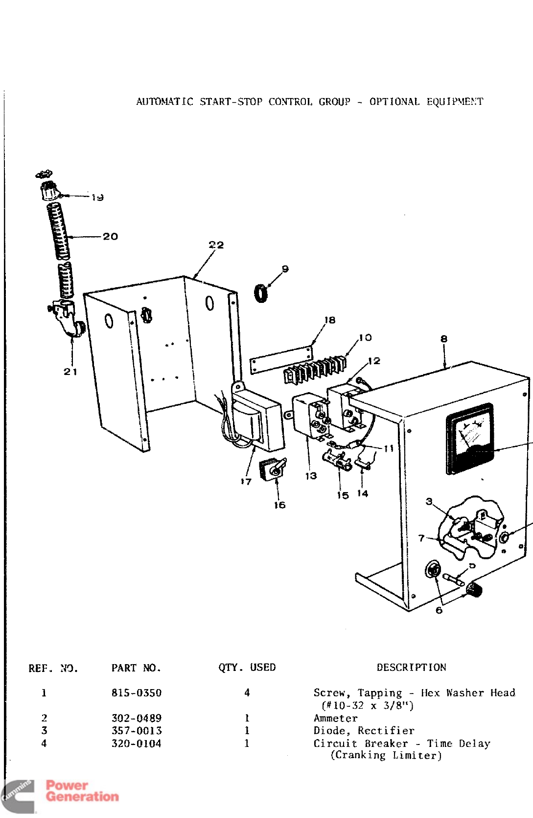
AUTO!4AT1CSTART-STOP CONTROL GROUP .OPTIONAL EQUIPMENT
/
18
/
REF. W. PART NO.
1’
QTY. USED DESCRIPTION
4Screw, Tapping -Hex Washer Head
(#io-32 x3/’8’$)
1Ammeter
1Diode, Rectifier
1Circuit Breaker -‘Time Delay
(Cranking Limiter)
-
Redistribution or publication of this document
by any means, is strictly prohibited.
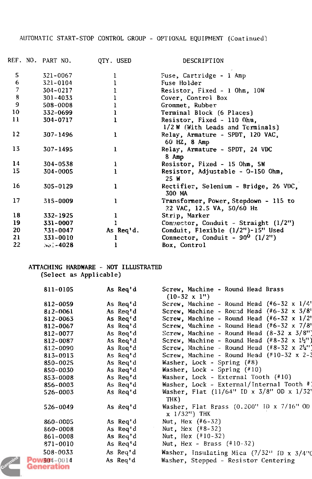
AUTOMATIC START-STOP CONTROL GROUP -OPTIONAL EQUIPMENT (CoI~tinued)
REF. NO. PART NO, QTY. USED
5
6
7
8
9
10
11
12
13
14
15
16
17
18
19
20
21
22
321-0067
321-0104
304-0217
301-4033
508-0008
332-0699
304-0717
307’-1496
307-149s
304-0538
304-000s
305-0129
31s0009
332-1925
331-0007
33~.oo47
331-$30io
5<,1-.4028
1
1
1
1
As’Req:d.
1
1
DESCRIPTION
P
i-USE!,Cartridge - 1 Amp
Fuse Holder
Resistor, Fixed - 1 Ohm, 10W
Cover, Control Box
Grommet, Rubbe~
Terminal Block (6
Resistor, Fixed -
l/2W ~fiithLeads
Relay, Armature -
60 HZ, 8Amp
Relay, Armature -
sm
Resistor, Fixed -
Places)
110 mill,
and Terminals]
SPDT, 120 VAC,
SPDT, 24 VDC
15 Ohm, SW
Resistor, Adjustable -0-1S0 Ohm,
25 w
Rectifier, Selenium -Bridge, 26 ‘[DC,
300 MA
Transformer, Power, Stepdown -11S to
~2 VAC, 12.5 VA, 5(3/40 HZ
!Mr],p, Marker
Cen~~ector, Conduit -Straight (1/2”)
Conduit, Flexible [1/2’’)-15” Used
Connector, Conduit -900 (1/2”)
Box, Control
.AIT’.ACHINGWWARE -NOT ILLUSTRATED
[Select as Applicable]
$11-010s As Req’d Screw, Machine -Round Head Brass
[10-32 x1“]
812-0059 As Req’d screw ,Machine -Round Head (#6-32 x
1/4”
812-Q061 .4.-11...-ta
.- r.=quSere*, Machine -Rousd Head (#6-32 x
3/8”
S12-0063 As Reqfd Screw, Msf-hinQ .
..-W.,A..W Round Head [#6-32 x
1/2”
812-0067 As Req’d Screw, Machine -Round Head (#6-32 x
7/8”
812-007? As Req’d Sc~ew, Machine -Round Head (8-32 x
3/8”)
~~~_~087 k5 ReqPd Screw, Machine -Round Head [#8-32 x
1%”9
812-0099 As Req’d Screw, Machine -Round Head (#8-32 x
2%”)
813-0013 AS Req’d Screw, Machine -Round Head (S10-32 X
2-3
850-002S As Req’d Washer, Lock -Spring [#8)
850-0030 As Req’d Washer, Lock -Spring (#IO)
853-0008 As Req’d Washer, Lock -External Tooth (#10)
856-0003 As Req’d Washer, Lock -External/Internal Tooth
#1
526-0003 As Req’d Washer, Flat (11/64” ID x3/8” Oilx
1/52”
THK)
526-0049 AS Req’d Washer, Flat Brass [0.200” ID x7/16” OD
xl/32~t) THK
860-0005 As Req’d Nut, Hex (#6-32)
6xX&OO08 As Req~d Nut, Hex (#8-32)
861-0008 A.~Reqld Nut,, Hex (#10-32)
871-0010 As Req’d Nut, Hex -Brass {#10-32j
~fl&@zz
v.. AS Reqld Washer, Insulating Mica (’7/32’1ID x
3/4’’
304-0014 As Req’d Washer, Stepped -Resistor Centering
Redistribution or publication of this document
by any means, is strictly prohibited.
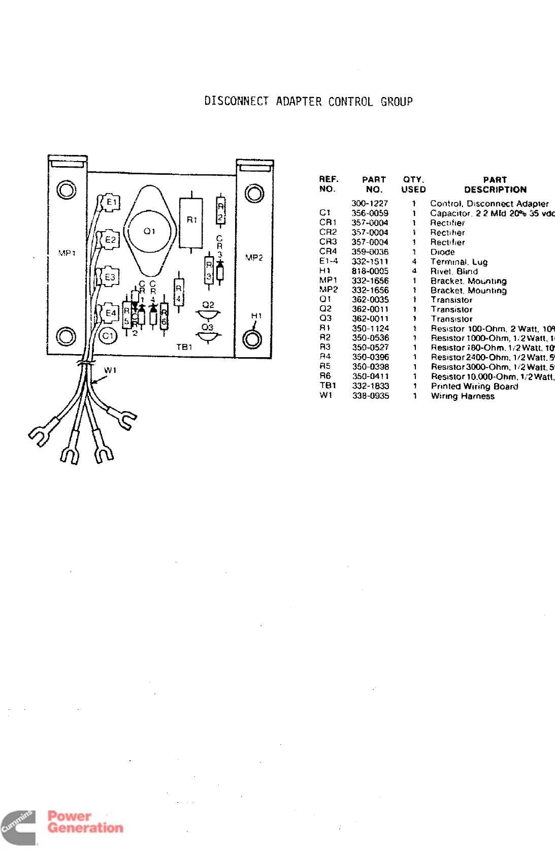
DISCONNECTADAPTER CONTROLHWUP
REF. PART
NO. NO.
300- t227
c1 356-0059
CR? 357-0004
(2?2 3.57-0004
CR3 35?-0004
~~4 ~~g.~~~
El-4 332-1511
HI 818-0005
MPI 332-1656
MP2 332-1656
Q? ?Fi?.m%s
.--- ----
Q2 362-0011
03 362-0011
Rl 350-1124
R2 350-0536
R3 350-0527
i?4 3s0-0396
~fj 350-0398
R6 350-0411
TB1 332-1833
WI 338-0935
QTY. PART
USED DEst2RiPTIol”i
1Control. Ehsconnect Adapter
1Capacttor.22Mfd 20%&5vdc
1F?eclhher
1Rectifier
1Rechher
?Dl@e
4TermmaLl_uQ
4Rwei Bimt
1Bracke!, tvlomtmg
1Bracket,htotmtmg
1Transistor
1Transistor
1Transmtor
tRes@ar100-0hrn,2W att,
10%
1Resistor 1OfX@fim. 1:2 Waft, 1
1Resistor 180-Ohrn. 1/2 Watt.
10%
1Ftesistor2@0-Ofwn. 1!2 Watt.
5%
1Resistor 3000-Ohm. 1~2Watt,
5%
1Resistor 10.000-Ofim, I/2 Watt,
1Printed Wiring Board
1k%rmg Harness
Redistribution or publication of this document
by any means, is strictly prohibited.
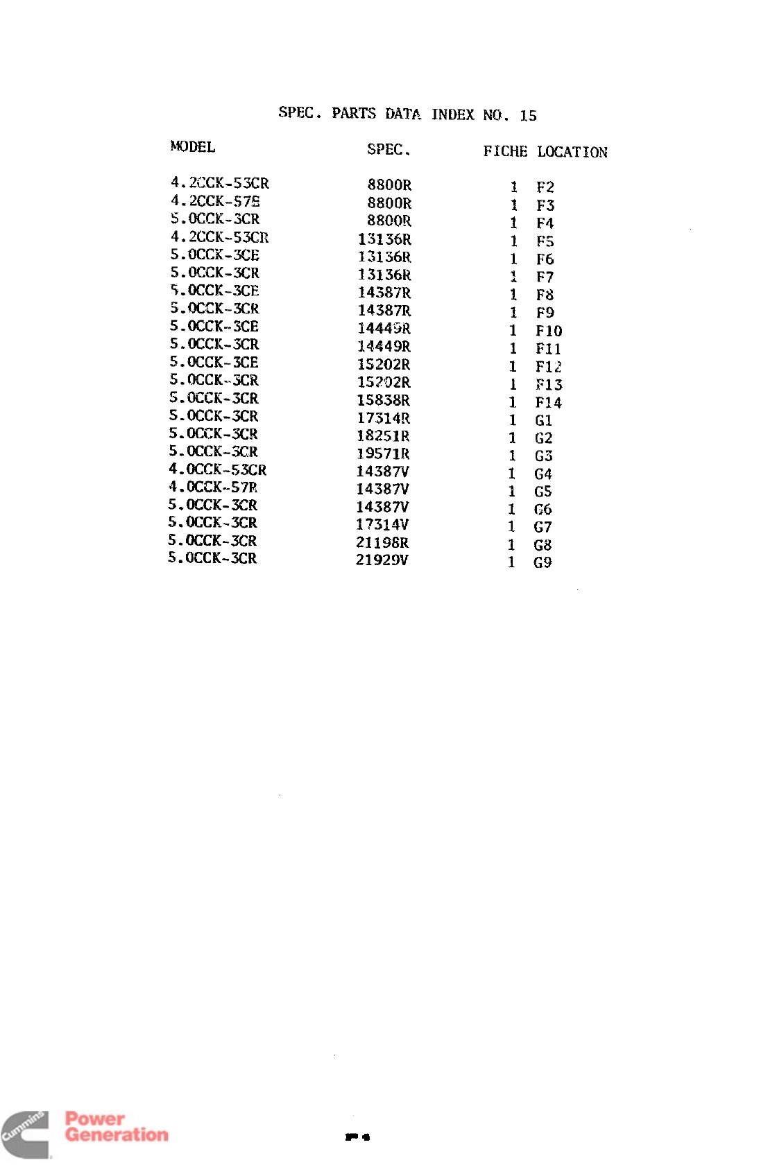
SPEC. PARTS DATA
4.2CCK-53CR
4.2CCK-57E
5.OCM-3CR
4.2(xK-wicR
5.axx-3CE
5.(MK-3CR
$.OUX-3CE
S.OCCK-3CR
5.QCCK-.3CE
s.occK-3cR
~.)g=y a-c
n--L
5. OCCK.3CR
S.OCCK-3CR
5.OCCK-3CR
5.OWK-3CR
5.OKK-3CR
4.OCCK-53CR
4.OCCK-57R
5.OCCK-3CR
5.OCCK-3CR
5. OCCK-3CR
5.OCCK-3CR
88(NIR
88(M)R
88(NR
1313tm
13136R
13136R
14387R
14387R
34445R
34449R
IS2?32R
152i)2R
15838R
17314R
18251R
19571R
1458?V
14387V
14387V
1?31W
21198R
21929V
INDEX Ml. 15
FICHE LOCATION
Fl
Redistribution or publication of this document
by any means, is strictly prohibited.
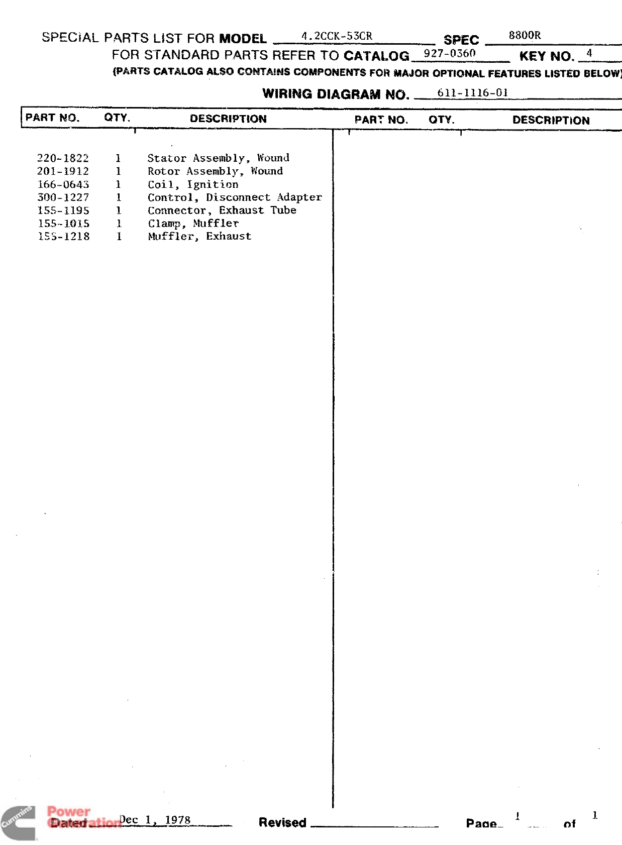
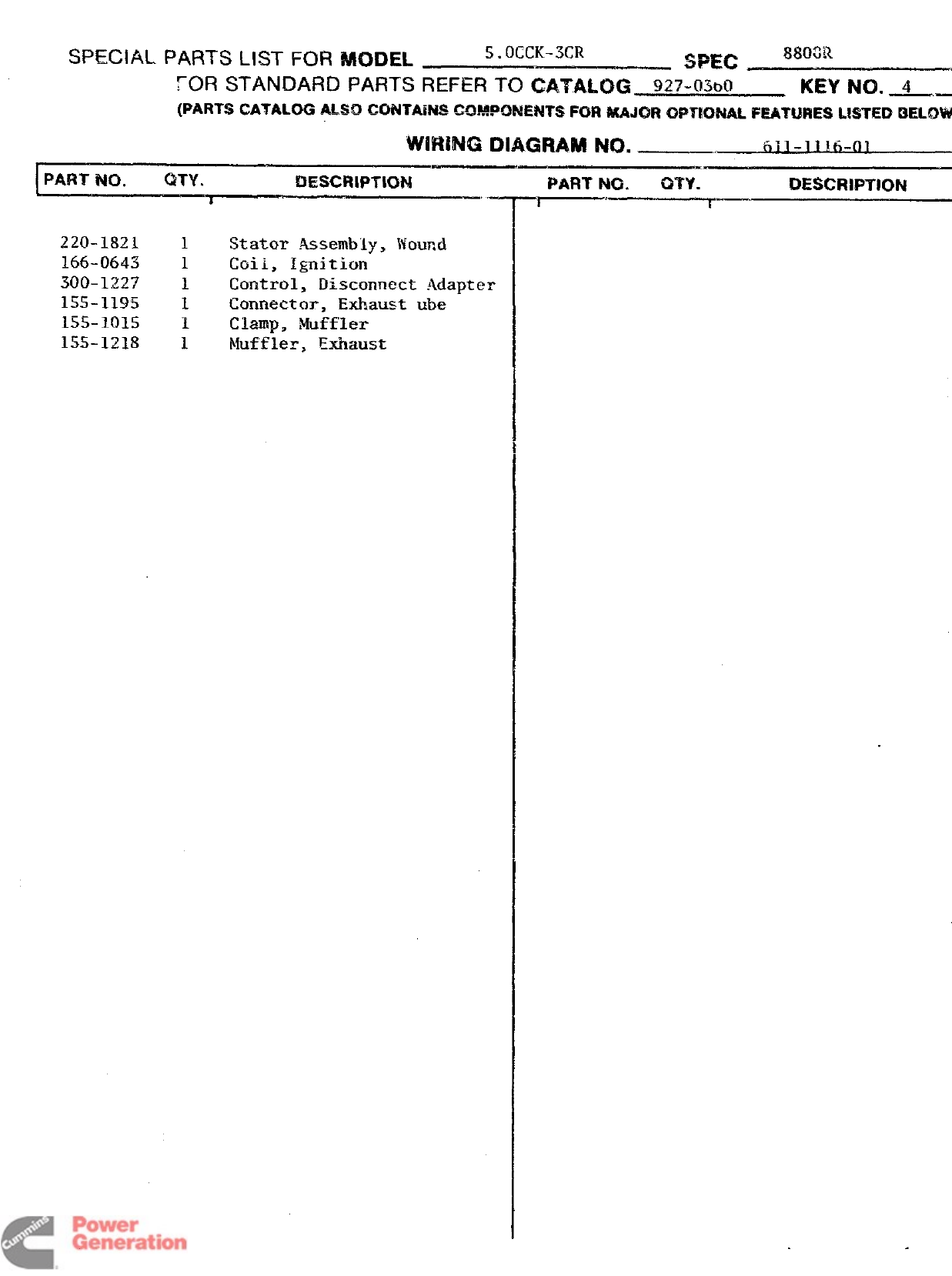
~~~~~~~ p~~~s ~~sT FOR M~~~~ 4. 2CCK-53CR
.—. SPEC 880tIR
FOR STANDARD PARTS REFER To CA~~~~G- 92T-~~~~ KEY No. 4
{PARTS CATALOG ALSO CO!WM4S CQ!!WW4ENTS FQR &lA$QROPTIQ?dAL FEATURES LISTED
BELOW)
WIRING DIAGRAM I’W3. 611-1116-01
PART 040. C3TY. i3ESCRlPTU3N
Dated Dec 1, 1978 Revised
PART NO. QTY. I)ESCRIPTION
#!
Redistribution or publication of this document
by any means, is strictly prohibited.
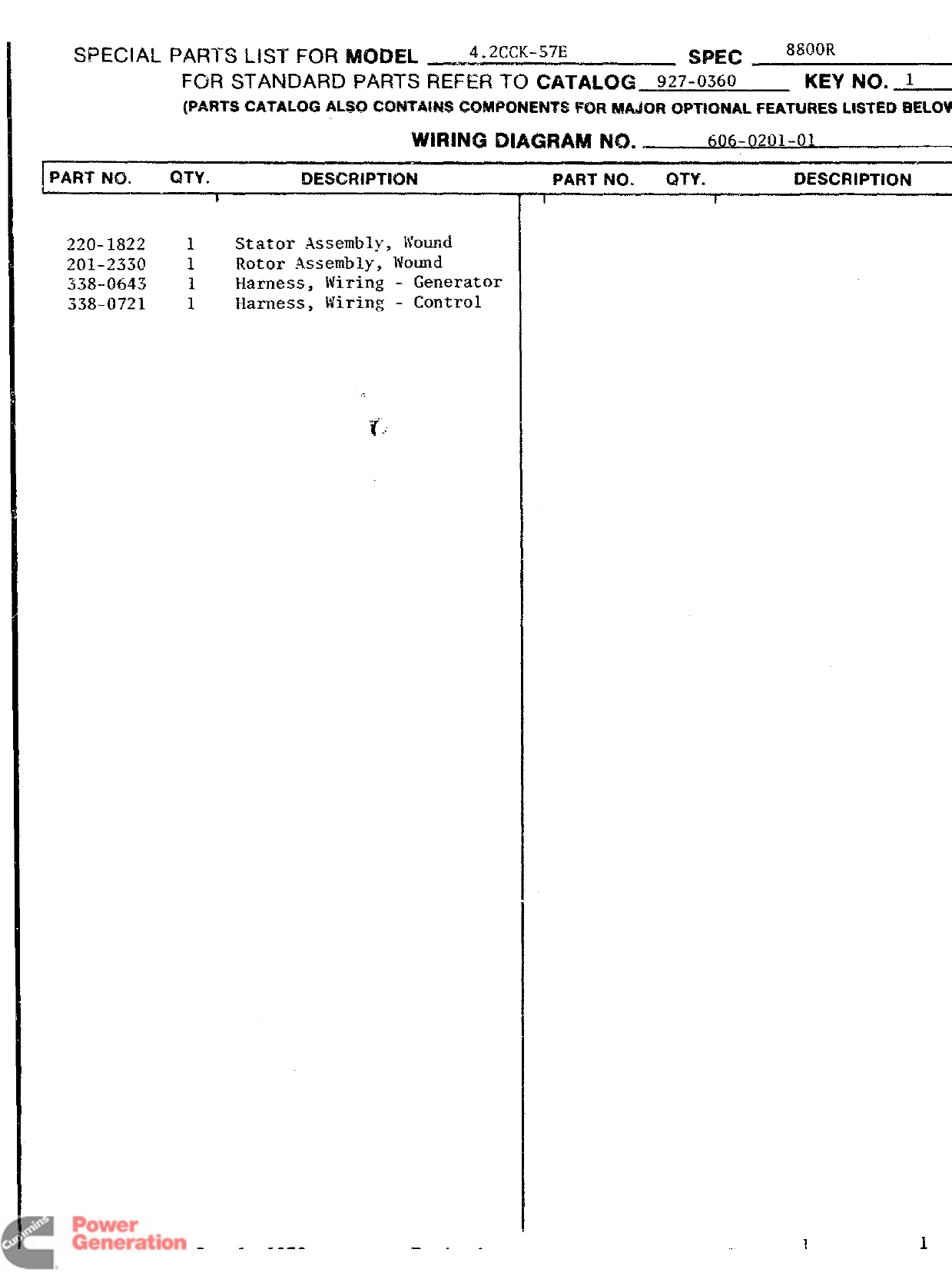
SPECIAL PARTS LIST FOR MODEL _4.2CCK-57E .—. SPEC 8800R
FOR STANDARD PARTS REFER TO CATALOG 9z7-0~6~ KEY NO. 1
{PARTS CATALOG ALSO Ct3hiTA!N$3 @2MPONE?dTS FOR MAJUR OP~!ONAL FEATURES t.lSTEO
BELOW)
WIRING DIAGRAM NO. 606-0201-01
IPART NO. QTY. i) ESCRiPTH3N
z~()-lgzz IStator Assembly, Wound
201-2330 1Rotor Assembly, Wound
338-0643 1Harness, Wiring -Generator
338-0721 1Harness, Wiring’ -Control
PART NO. QTV. DESCRIPTION
I I
Ch3ted Dec 1. 1978 Page 1
1
Revised
Redistribution or publication of this document
by any means, is strictly prohibited.
——
PART N(3. QTY. DESCRIPTION .—
?
220-1821 1Stator Assembly, Wound
166-0643 1Coil, Ignition
300-1227 1Control, Disconnect Adapter
155-1195 1Connector, Exhaust ube
155-1015 1clamp= Muffler
155-1218 1~fiffle~, Exhaust
PAFIT NO. m-f. !3Esciwmm
-’r------~
Dated Dec 1, 1978 Revised PageL
1
of—
Redistribution or publication of this document
by any means, is strictly prohibited.
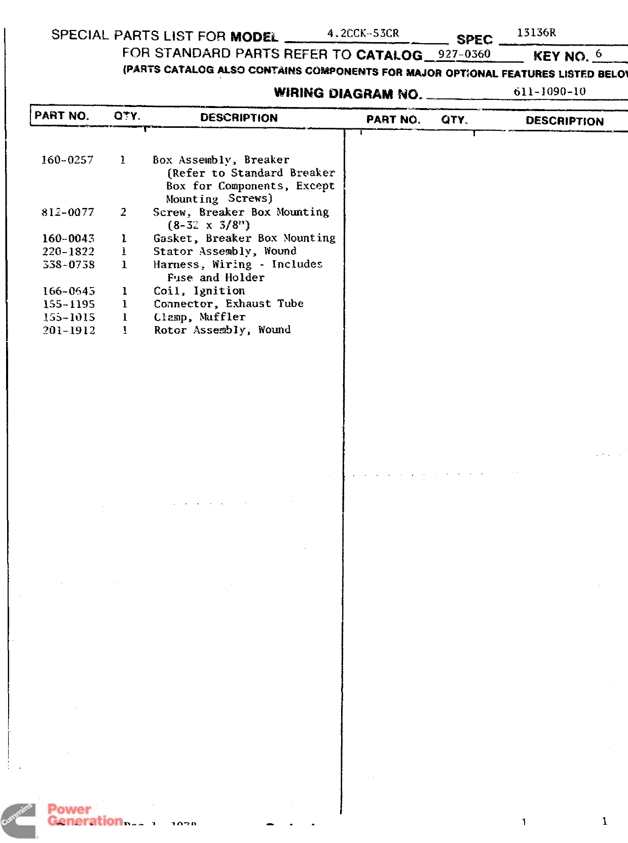
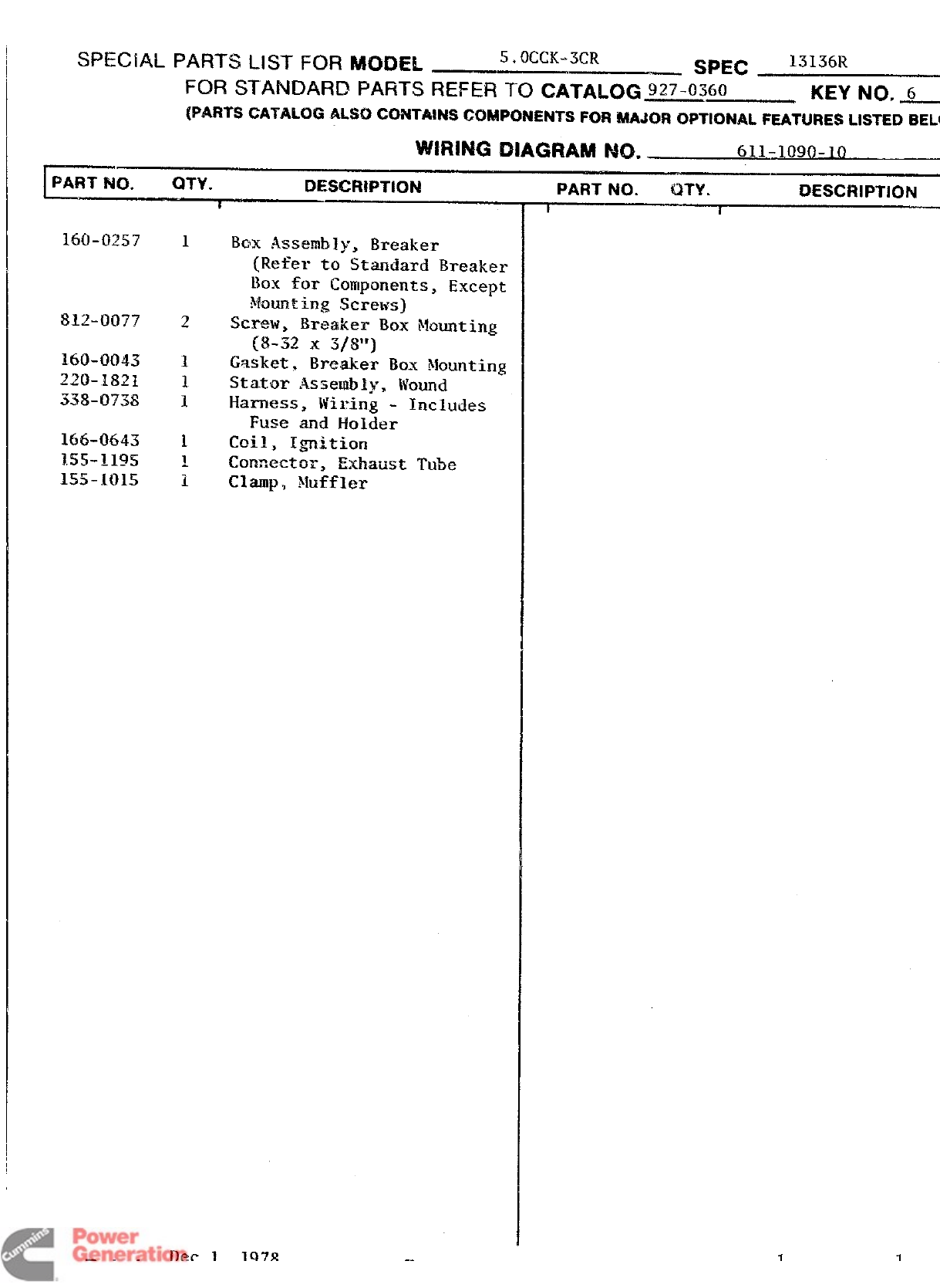
SPECIAL PARTS LIST FOR MODEL ~. ~_-c~..53(-~ -SPEC 13136R
FOR STANDARD PAfWS REFEFI TCI CATAL~~ 927-0360 KEY No. 6
{PARTS CATALOG ALSO CC)NTAIMS CQMM2NENTS FOR i?&AJz~PT;ONAL FEATURES LISTED
BELOW
~i~JNG DIAGRAM NCI. 611-] 090-10
~’., ...-.
DESCRIPTION .—
160-0257 Box Assembly, Breaker
{Refer to Standard Breaker
Box for Components, Except
$Iou?ltingscrews)
Screw, Breaker Box Mounting
{8-X x3/8”)
Gasket, Breaker Box Mounting
Statol- Assembly, ]fOUIld
Harness, Wiring -Includes
FBJse and Holder
coils Ignition
Coanectur, Exhaust Tube
L%mp, Muffler
Rotor Assemb]y, Wound
C)ated Dec 1. 1978
PART N(2. C)n$. DESCRIPTION
—-r-———~”—
Revised ~
.,. .
11
Page of
Redistribution or publication of this document
by any means, is strictly prohibited.
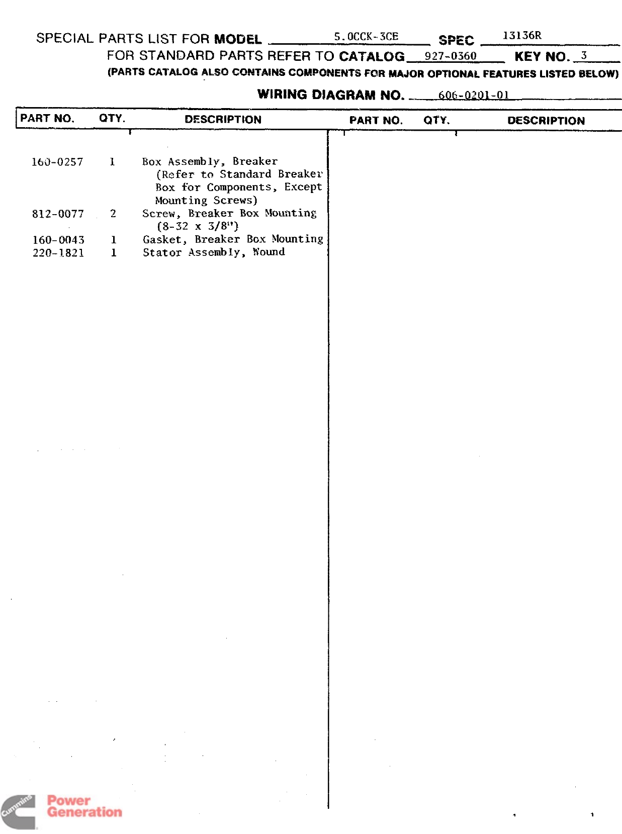
SPECIAL PARTS LIST FOR MODEL 5. OCCK-xx SPEC 1313(X
FOR STANDARD PARTS REFER TO CATALOG 927-0360 Kmhm. 3
(PARTS CATALOG ALSO CQ54TA!!4S CCB!WQNENTS FCMl MAJOR o~llu~~k FEATURES LISTED $ELOW)
WIRING DIAGRAM NO. 60(1-0~~~.(-)1
P
PART NO. f2TY. DESCF?IPT!ON
s
160-0257
812-0077
160-0043
220-1821
1EXIXAssembly, Breaker
(Refer to Standard Breaker
Box for Components, Except
Mounting Screws)
,2 Screw, Breaker Box Mounting
(8-32 X3/8”)
1Gasket, Breaker BGX Mounting
1Stator Assembly, Wound
PART NO. Q’$Y. I)ESCR!PTION
II
Redistribution or publication of this document
by any means, is strictly prohibited.
SPECIAL PARTS LIST FOR MODEL ~.OCCK-3CR SPEC 13136R
FOR STANDARD PARTS REFER 10 CA?ALOG 927-0360
—. KEY NC), 6
(PARTS CATALOG ALSO C094TMW CWWKNWWTS FOR MAJOR QPTIONAL FEATURES LISTED
BELO
WIRING DIAGRAM No. 611-1090-10
PART NO. u-w. DESCRWTNXJ
8
812-0077
160-0043
220-1821
338-0738
1Box Assembly, Breaker
(Refer to Standard Breaker
Box for Components, Except
Mounting Screws)
Screw, Breaker Box Mounting
(8-32 x5/8”)
Gasket, Breaker Box Mounting
Stator Assenbly, Wound
Harness, Wiring -Includes
Fuse and Holder
Coil, Ignition
connector, Exha~st Tube
Clamp, Muffler
PART NO. QTY. DESCRIPTION
1I
lkz 11978 i1
Redistribution or publication of this document
by any means, is strictly prohibited.
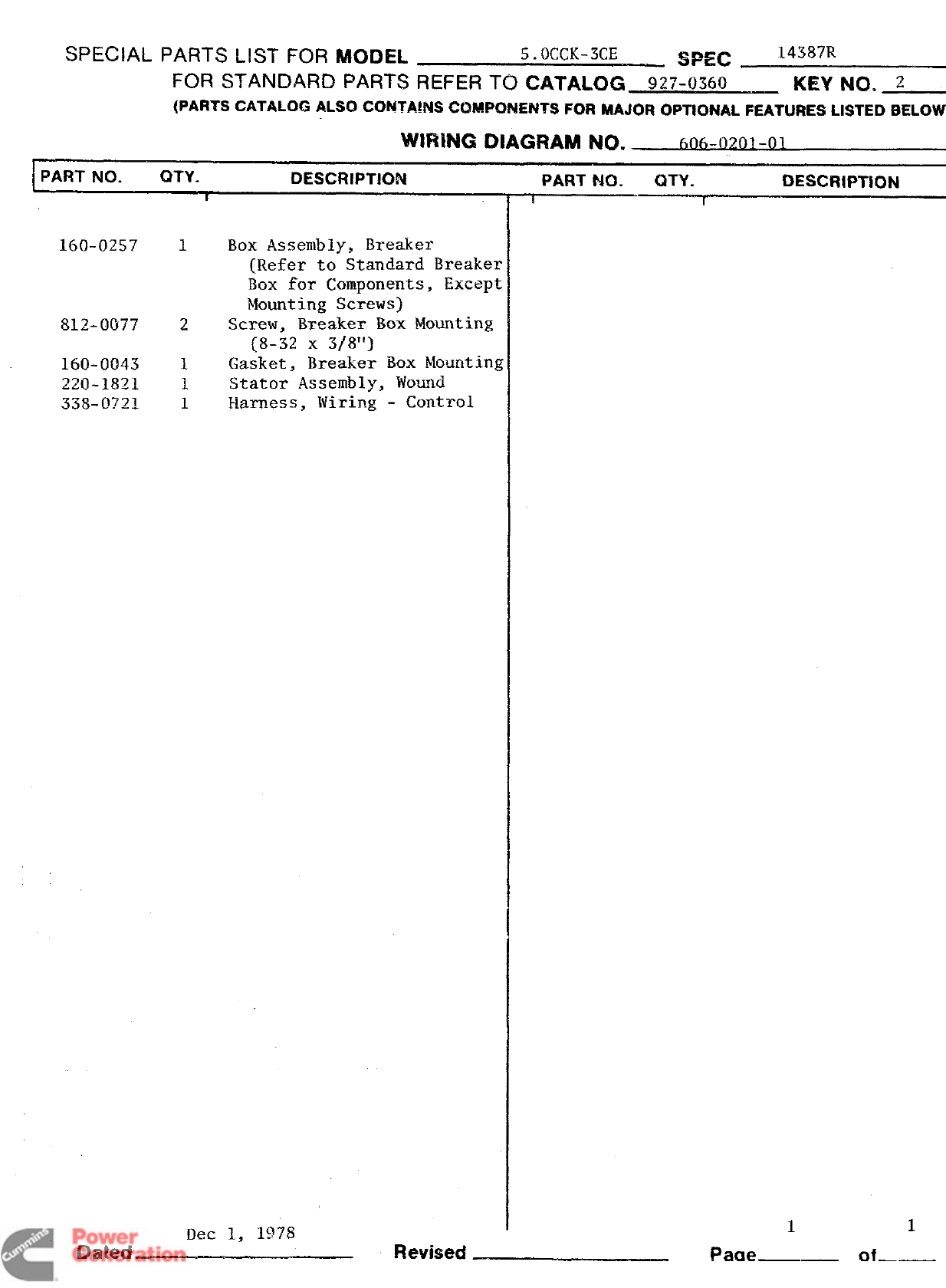
SPEC!AL PARTS LIST FOR MODEL 5. OCfX-3CE SPEC 14387R
FOR STANDARD PARTS REFER TO CXTAUX3 92~-~~6~ KEY NO. 2
(PARTS CATALOG ALSO C(3NTA!NS COMPONENTS FOR MAJO~ OPTIONAL FEATURES LISTED SELOW)
PART NO. QTY. DESCRIPTION
IPART NQ. UTY. DESCRIPTiON
II
160-0257 1Box Assembly, Breaker
(Refer to Standard Breake~
Box for Components, Except
Mounting Screws]
8~~_~~77 2Screw, Breaker Box Mounting
(8-32 X3/8”]
160-0043 1Gasket, Breaker Box Mounting
220-1821 1Stator Assembly, Wound
338-0721 1Harness, Wiring -Control
Ilec 1, 1978
Dated—- Revised Page of
11
Redistribution or publication of this document
by any means, is strictly prohibited.
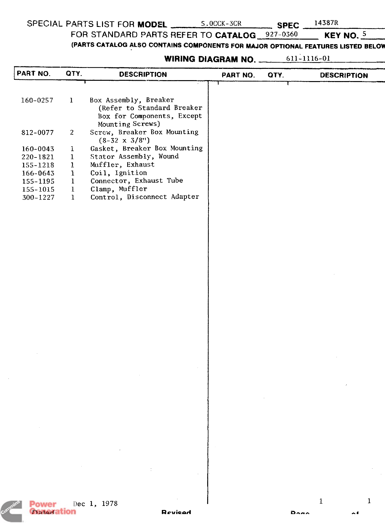
SPECIAL PARTS LIST FOR MODEL 5.KXK-3CR SPEC 1438X?
FOR STANDARD PARTS REFER To C~TAL~G g~T-~360 II(EY NO. 5
(PARTS CATALOG ALSO CO!WA!!W GGMWXWNTS FOR MAJOR OPTIONAL FEATURES LISTED
BELOW
WIRING DIAGRAM NO. 611-1116-01
IPART NO. QTY. 13ESCRIPTIQN
160-0257
812-0077
160-0043
220-1821
155-1218
166-0643
15.5-1195
155-1015
300-1227
1
2
Box Assembly, Breaker
(Refer to Standard Breaker
Box for Components, Except
~~ounting Screws)
Screw, Breaker Box Mounting
[8-32 x3/8”)
Gasket, Breaker Box Mounting
Stator Assembly, Wound
Muffler, Exhaust
Coil, Ignition
Connector, Exhaust Tube
Clamp, Muffler
Control, Disconnect Adapter
Dec 1, 1978
PART NO. QTY. DESCRIPTION
I1
11
Dated Revised of
Redistribution or publication of this document
by any means, is strictly prohibited.
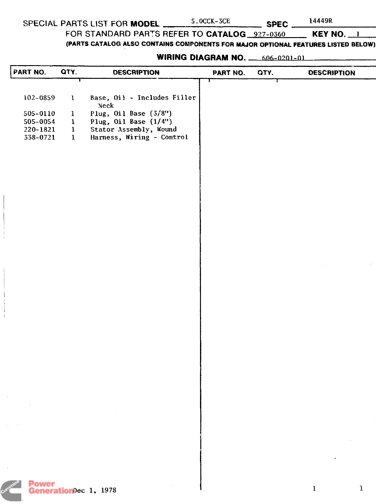
SPECIAL PARTS LIST FOR MODEL !5.OCCK-3CE SPEC 14449R
FOR STANDARD PARTS REFER TO CATALOG 927-0360 KEY NO. 1
(PARTS CATALOG ALSO 4XM4TAR4SCOMPONENTS FQR wJO~ OPTIQNA1. FEATURES L!STED BELOW)
WIRING DIAGRAM NQ. 6ofi-~~rIl -~1
PART NO. QTY. DESCRIPTION
t
102-0859 1Base, Oil -Includes Filler
Neck
50!5-0110 1Plug, Oil Base [3/8”)
50!5-0054 1Plug, Oil Base [1/4”)
220-1821 1Stator Assembly, Wound
338-0721 1Harness, Wiring -Control
Ilec 1, 1978
PART ?40. QTV. DESCRIPTK)N
Ii
.
11
Dated Revised Page —of————
Redistribution or publication of this document
by any means, is strictly prohibited.
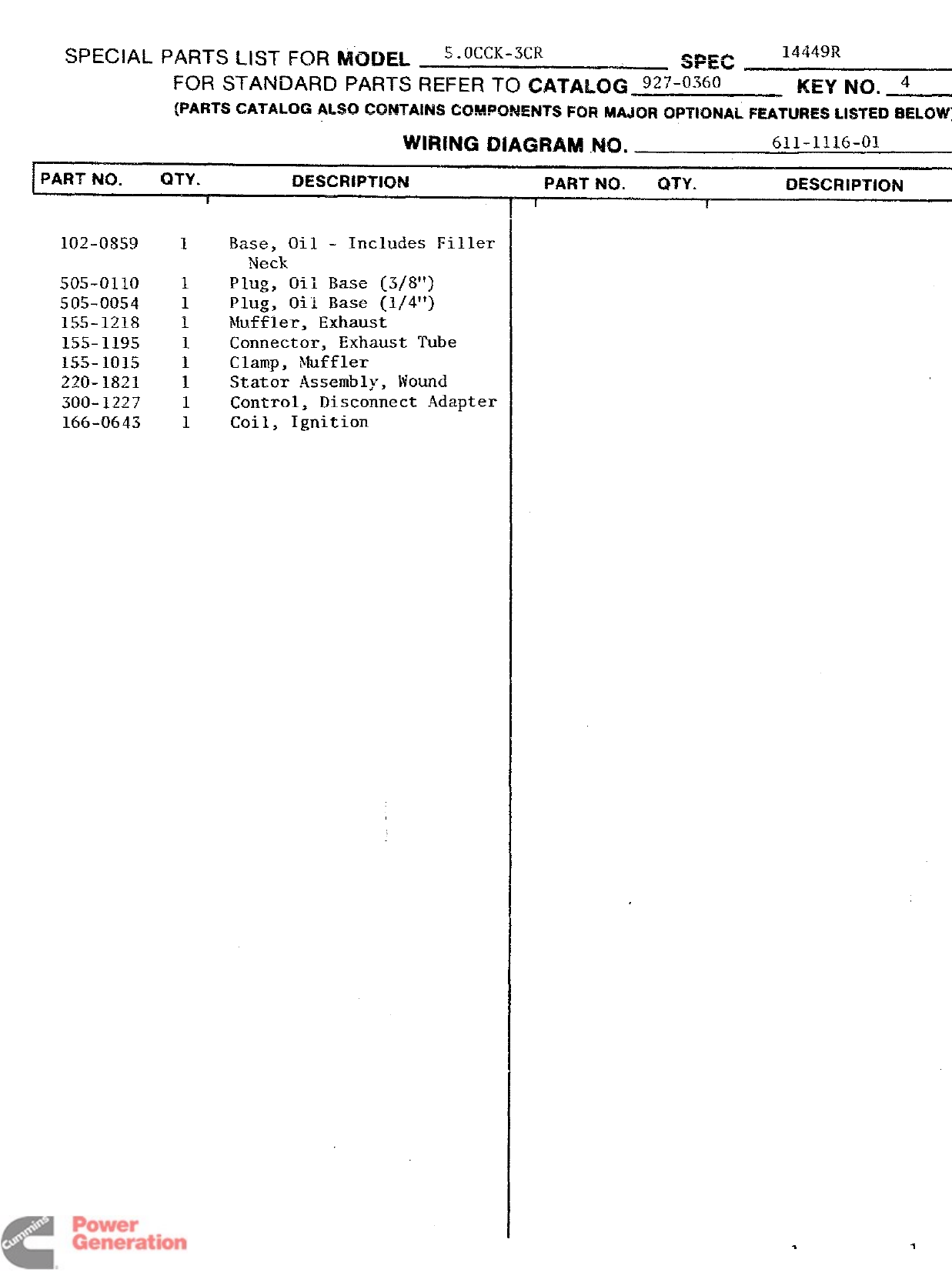
SPEC AL PARTS LIST FOR MODEL 5. OCCK-3CR SPEC 14449R
FOR STANDARD PARTS REFER To ~A~~~~~ 9~7-~3~o KEY No. 4
(PARTS CATALOG ALSO CCM4TA!NS?XMM%2NENTS FOR MAJOR OPTIONAL FEATURES LISTED
BELOW)
WIRING iDiAGRAM .NO. 611-1116-01
~PART N(I. QTY. 13ESCRlPT!0N
505-0110
505-0054
155-1218
155-1195
155-1015
220-1821
300-1227
166-0643
1Base, Oil -Includes Filler
Neck
Plug, Oil Base (3/8”)
Plug, Oil Base (1/4”)
Muffler, Exhaust
Connector, Exhaust Tube
Clamp, Muffler
Stator Assembly, Wound
Control, Disconnect Adapter
Coil, Ignition
PART NO. QTY. DESCRIPTlON
f1
Dated Dec 1, l$j7g Page 1
1
Revised —of—
Redistribution or publication of this document
by any means, is strictly prohibited.
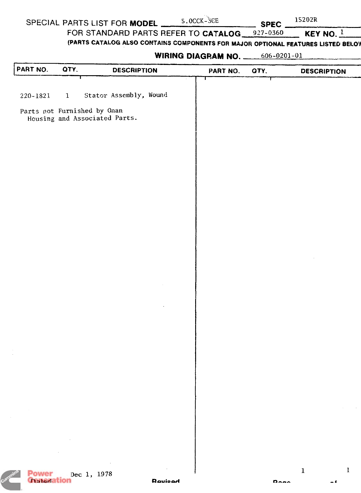
SPECIAL PARTS LIST FOR MODEL S.OCCK-~EE 15202R
SPEC
FOR STANDARD PARTS REFER TO CATALOG 927-0360 KEYNQ. 1
(PARTS CATALOG ~#SO CONTA:N3 COMPONENTS FOR MAJOR OPTiQNAL FEATURES LKiTEi3
BEL~YV
WIFtlNG DIAGRAM IW1. 606-0201-01
~PART NO. CITY. DESCRiPTiOt4
220-1821 1Stator Assembly, Wound
Parts not Furnished by Onan
Housing and Associated Parts.
PART NO. C#TY. &CRIPTION
II
11
Dec
1,
1978
Dated— Revised Of
Redistribution or publication of this document
by any means, is strictly prohibited.
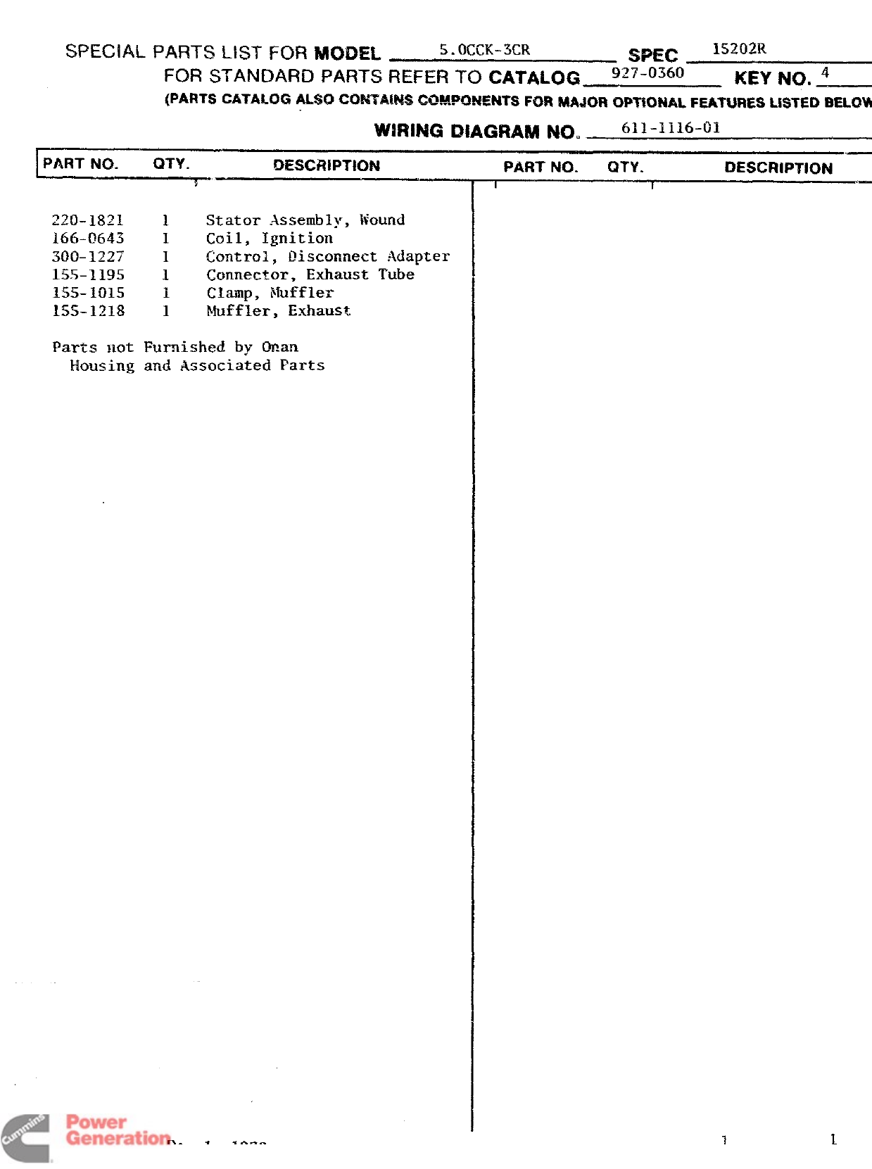
SPECIAL PARTS LIST FOR MODEL !5.(Km-ml SPH2 ~~~ij~~
FOR STANDARD PARTS REFIX TO CATALOG 9~7_Q3fj(J KEY NO. 4
(PARTS CATALOG ALSO CQ54TA!W4CW!4W43?4EFWSFOR MA@il OPWXW. FEAIW4ES USTE13
BELOW
WIRING DIAGRAM NO. t511-1116-Oi
IPART NO. QTY. DESCRIPTION
~z’j.ls~l 1Stator Assembly, liound
166-0643 1Coil, Ignition
300-1227 1Control, I!isconnect .Adapter
155-1195 1Connector, Exhaust Tube
155-1015 1Ciamp, Muffler
155-1218 1Muffler, Exhaust.
Parts Hot Furnished by Onan
Housing and Associated Parts
PART NO. QTY. DZSCRIPTIC)N
I I
“—
l)ated —Dec 1, 1978 Revised
11
Page of—
Redistribution or publication of this document
by any means, is strictly prohibited.
I
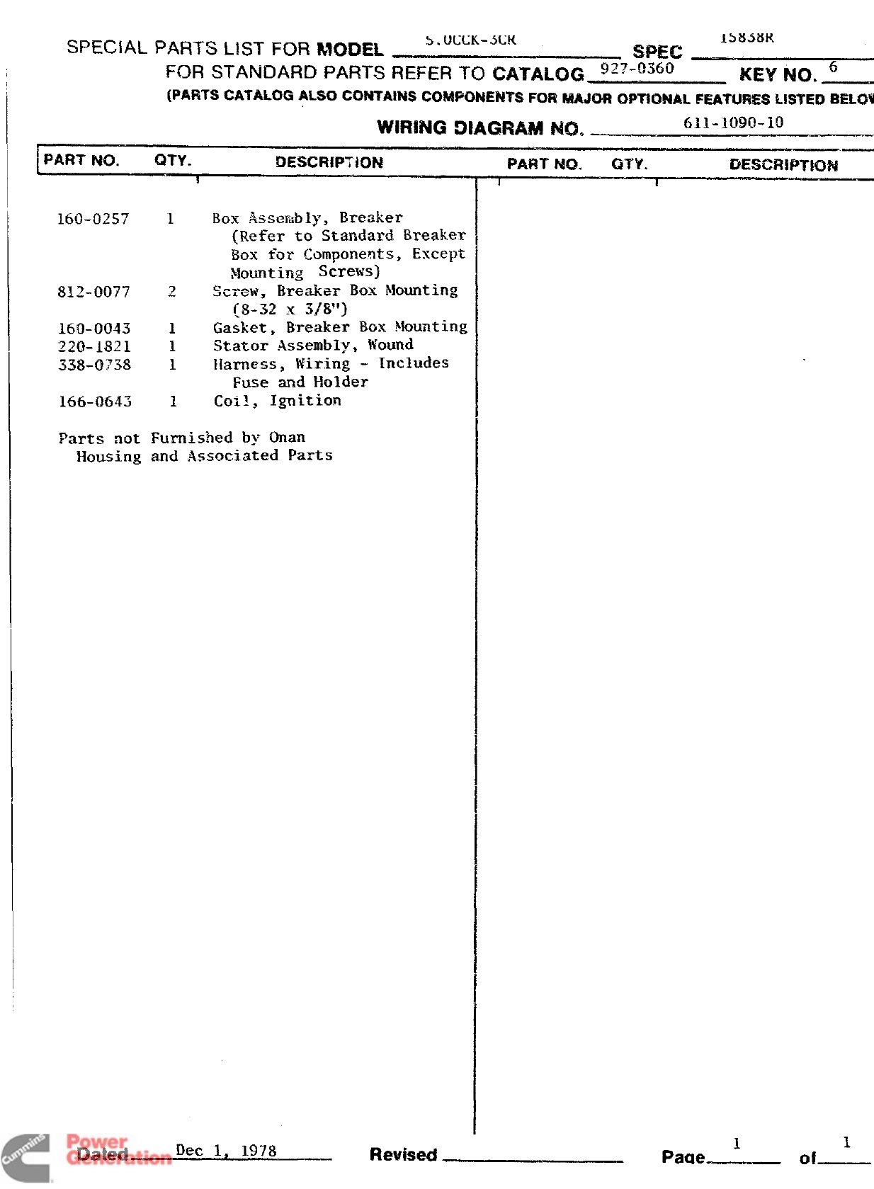
SPECIAL PARTS LIST FOR MODEL b.U(.XK-MX 1353t$K
SPEC _
FOR STANDARD PARTS REFER TO CATALOG ~~=-o~~~ KEY No. 6
(PARTS CATALOG ALSO CO?4TAiiW COMPONENTS FOR m40R OPTlONALFEATW+ESLISTEDWMW)
WIRING DIAGRAM 840. 611-1090-10
__
160-0257 1Box Assembly, Breaker
(Refe~ to Standard Breaker
Box for-Components, Except
~~o~nting SCK?WS)
812-0077 2screw, %=eaker Box Mounting
{8-32 x3j8”]
160-0043 1Gasket, Breaker Box Mounting
220-1821 1.Stator Assembly, wound
338-0’738 1~larness, Wiring -Includes
Fuse and Holder
166-0643 1coil ,Ignition
Parts not Furnished by Onan
Housing and Associated I%n%s
!Da*ed
Df3C
1,
1978
Rewised Page -of
Redistribution or publication of this document
by any means, is strictly prohibited.
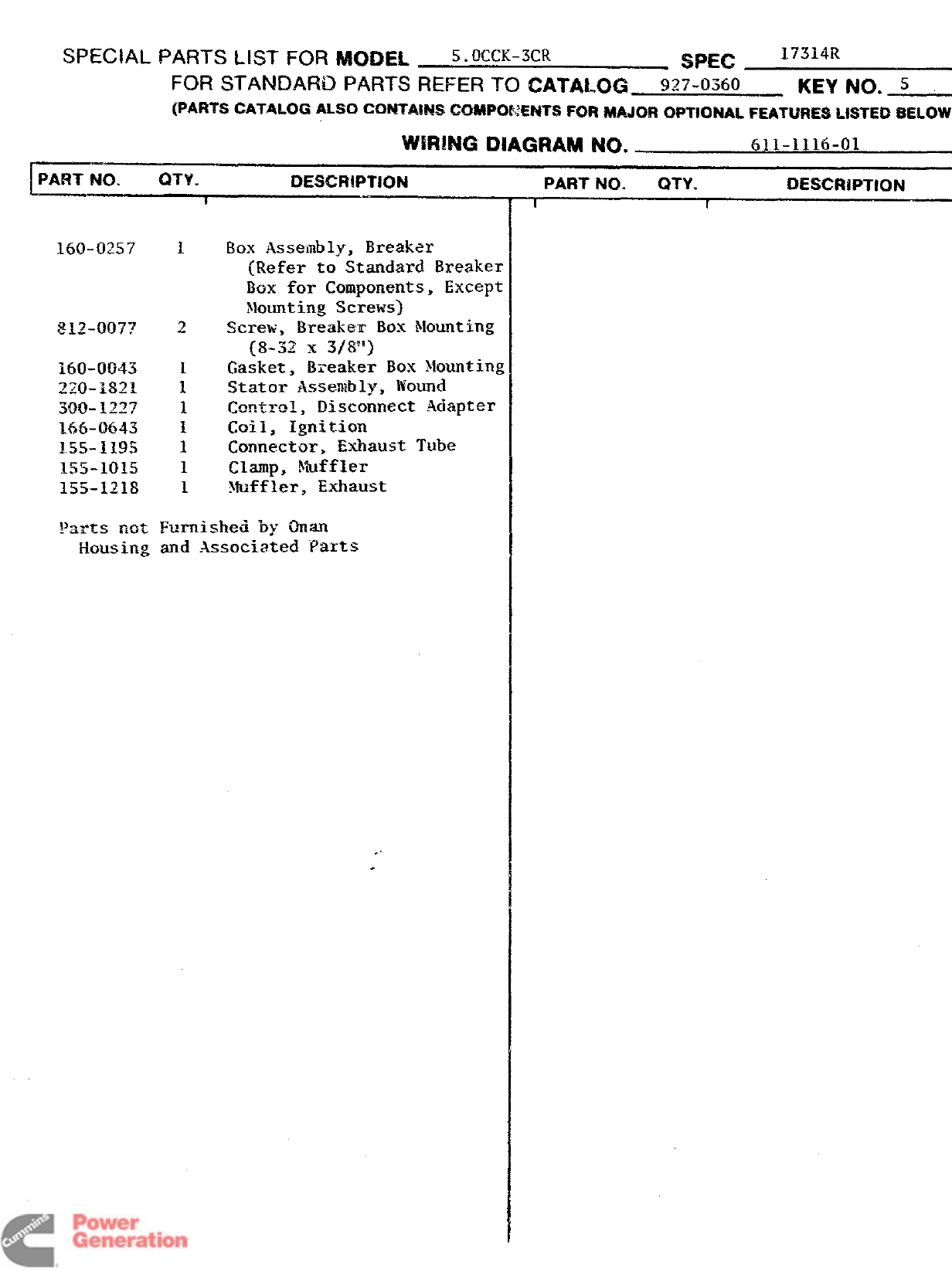
SPECIAL PARTS MST FOR MODEL 5. OUX-3CR Smc 17314R
FOR STANDARD PARTS REFER TO CATALOG 9~7.(J3~o_KEY NO. S
(PARTS CATALOG ALSO GO!WA!NS CO!!M%XENTS F(3R MAJOR OPTIONAL FEATURES LISTED BELOW
WNNNG DIAGRAM NO. 611-1116-01
]PART Nc). LITY. DESCIWPTION
160-0257 1Box Assembly, Breaker
(Refer to Standard Breaker
Box for Components, Except
Mounting Screws)
Screw, Breaka BOX Mounting
(8-52 x3/8”)
Gasket, Breaker Box Mounting
Stator Assenibly, lfound
~~p.$~~~, Disconnect Adapter
Coil} Ignition
Connector, Exhaust Tube
Clamp, Muffler
xmffler, Exhaust
%r%s not I%rnisheii by Onan
Housing and Associated Paxts
PART NC). QTY. DESCRIPTION
!I
Da$ed Dec 1, 1978 Revised —Page
1
CLL
Redistribution or publication of this document
by any means, is strictly prohibited.
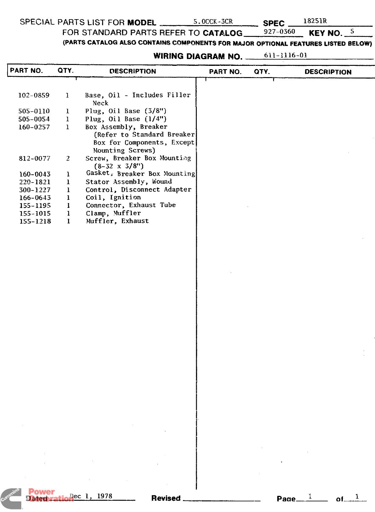
SPECIAL PARTS LIST FOR MODEL .S.OC(X-3CR SPEC l~~S~R
FOR STANDARD PARTS REFER TO CATALOG 927-0360 KEY NO. s
(PARTS CATALOG ALSO CONTA!&lS COMPCMWNTS ~o~ MAJOR opT~QNAL FEATURES LISTED ~~L(#w)
WIRING DIAGRAM NO. 611-1116-01
PART NO. QTY. E3ESC!MPTNIN
I
102-0859
505-0110
505-00!54
160-0257
812-0077
160-0043
~MJ_lj321
300-1227
166-0643
155-1195
155-101.5
15%1218
SMecl —
I
1
1
i
2
1
1
1
1
1
1
1
Base, Oil -Includes Filler
Neck
Plug, Oil Base (5/8”)
Plug, Oil Base [1/4”]
Box Assembly, Breaker
[Refer to Standard Breake~
Box for Components, Excepl
}~o~t,ing s~~e~s)
Screw$ Breaker Box i!ounti,~g
(8-32 x3/8”)
Gasket, Breaker BOX ylountin~
Stator .Assemhly, Wound
Control, Disconnect Adapter
Coil, Ignition
Connector, Exhaust Tube
Clamp, Muffler
Muffler, Exhaust
PART NO. QTV. DESCRIPTION
I[
—Page ~ofA-
Redistribution or publication of this document
by any means, is strictly prohibited.
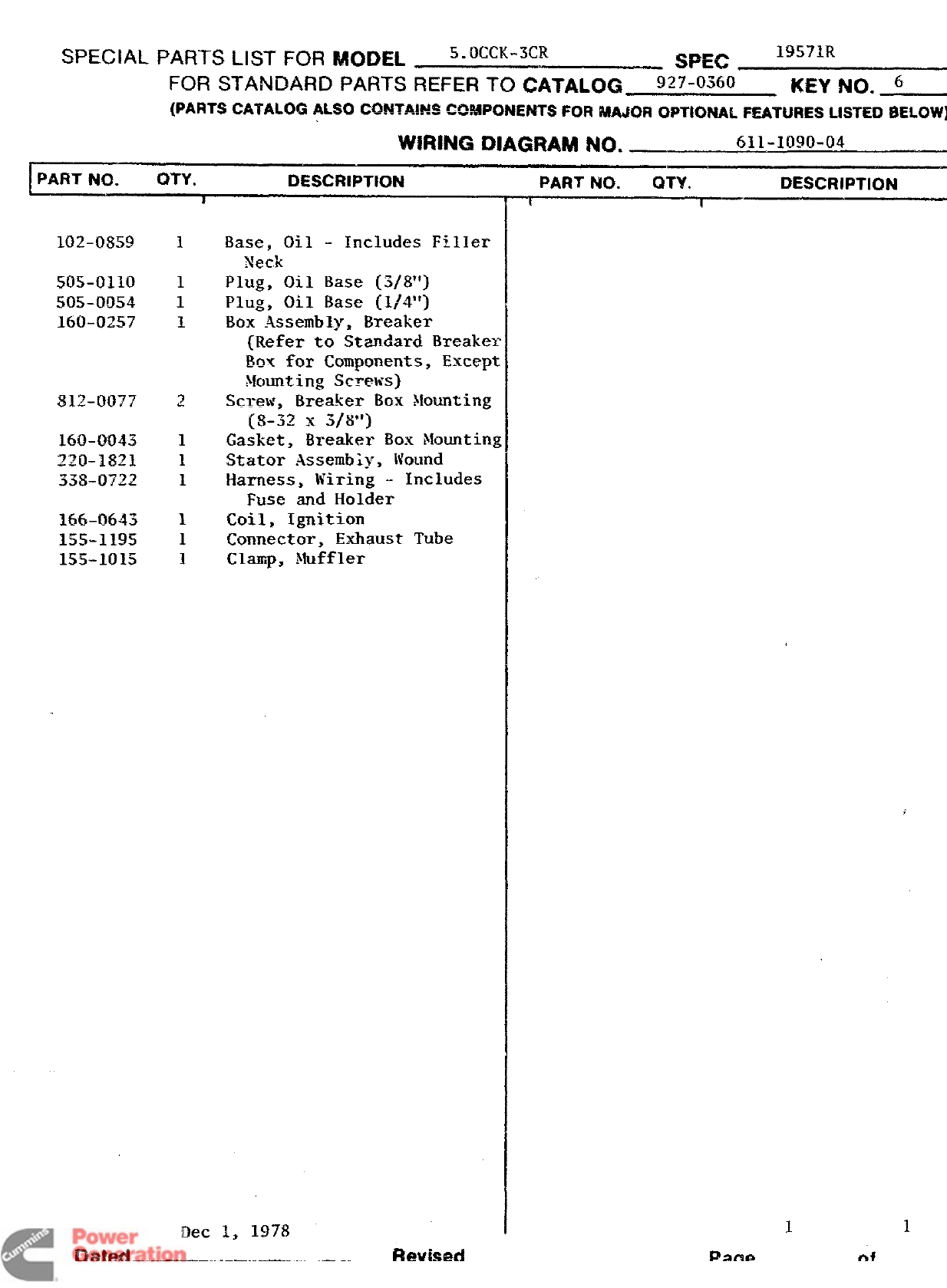
AL PARTS LIST FOR MODEL 5. OCCK-3CR SPEC 19571R
FOR STANDARD PARTS REFER TO CATALOG 927-0360 KEY NO. 6
(PARTS CATALOG ALSO CQNTA!!W 4XW?!%M!ENTS FOR MAJOR OPTIONAL FEATURES LISTED
BELOW)
WIRING DIAGRAM NO. _611-1090-04
QTY. DESCRIPTION
102-0859
505-0110
505-0054
160-!2257
812-0077
160-0043
220-1821
338-0722
166-0643
155-11!35
155-i(l15
Base, Oil -Includes Filler
Neck
Plug, Oil Base (3/8”)
Plug, Oil Base (1/4”)
Box Assembly, Breaker
(Refer to Standard Breaker
L%% for Components, Except
$iounting Screws)
Screw, Brea!!er Box Mounting
(8-32 x3/8”)
Gasket, Breaker Box Nounting
Stator Assembiy, Wound
Harness, Wiring -Includes
Fuse and Holder
Coil, Ignition
Connector, Exhaust Tube
Clamp, Muffler
Dec 1, 1978
Dakd ———
PART NO. QTY. DESCRIPTION
II
Revised
11
Pac& of
Redistribution or publication of this document
by any means, is strictly prohibited.
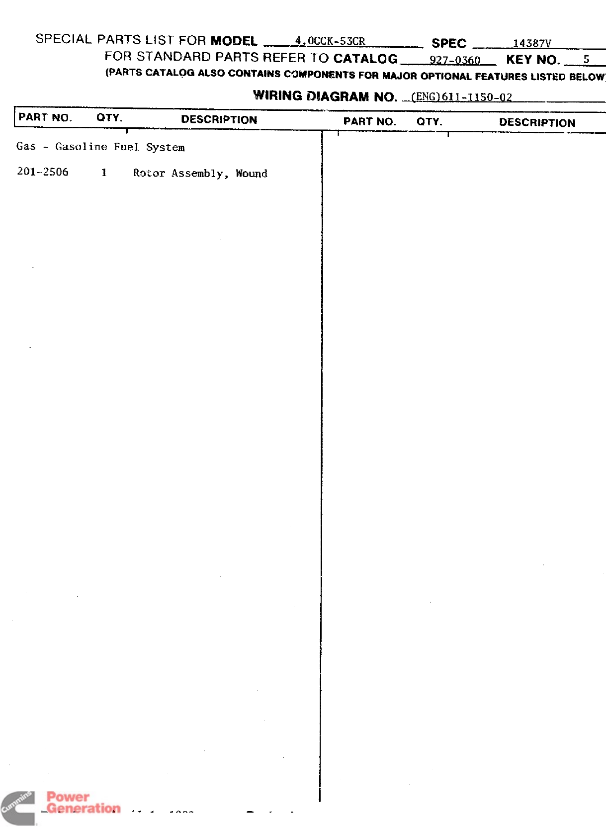
SPECIAL PARTS LIST FOR MODEL 4. OCCK-53CR Sme 14387V
FOR STANDARD PARTS REFER TO CATALOG 927-0360 KEY NO. S
{PAI?TSCATALQG ALSQCONTA!KSCO%PCNRNTS FORMAJOROP~ONAL FEATURES LISTED
BELOW)
WIRING D#AGRAM No. @W)611-1150-02
IPAHT NO. QTY. DESCRIPW.IN
I
Gas -Gasoline Fuel System
201-2506 1Ro%or Assembly, Wound
PART NO. QTY. DESCRIPTION
~~ ——
Redistribution or publication of this document
by any means, is strictly prohibited.
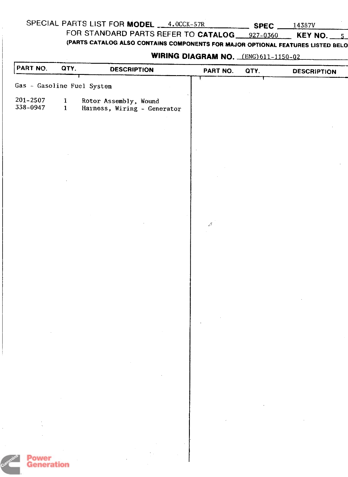
SPECIAL PARTS LIST FOR fljl~DEL ~4.OCCK-57R SPEC 14387V
FOR STANDARD PARTS REFER TO CATALOG 927-0360 KEY NO, 5
{PARTS CATALOG ALSO CXX4TAWS CKMFUNENTS FOR MAJOR OPTIONAL FEATljf3ES L#STEi3
BELOW
Wl~lhJG Ol~@lA~ No. fENG)611-1150-02
r
PART NO. QTY. DESCFIIPTEON
i
Gas - Gasoline Fuel System
201-2507
338-0947 1Rotor Assembly,
1Harness, Wiring
iiiound
-Generator
PART NO. QTY. DESCRIPTION
1I
Redistribution or publication of this document
by any means, is strictly prohibited.
SPECIAL PARTS LIST FOR MODEL 5. OCCK.-3CR III*387V
SFEC ,—
Fol+ STAINDARD PARTS REFER TO CATALOG_ 927-0360 KEY NO. .$
—.—
(PARTS CATALOG ALSO CG?4TA:NS‘am’”
ewmrONENTS FQR MAJOR ~#$T~ONALFEATURE!$ LISTED 13!UDN)
WIRING DtAGRAM NO. li~dMH2_._..
1-
PART NO. QTY. 13ESCR!PTK)N
I
Gas -Gasoline Fuel System
PART NO. QTY. IXSCRIPTI(IN
—Page--L- of~
Redistribution or publication of this document
by any means, is strictly prohibited.
SPECIAL PARTS LIST FOR MODEL ,__,_, 5. OCCK- 3CR WE(2 17314V
FOR STANDARD PAFITS REFER TO CATALOG 927-0360 KEY NO. 5
(PARTS CATALOG ALSO fiAuT....~ --
wwm IMrnm w#4PO?4EPJTSFOI14MAJOR OPTIONAL FEATURES LISTED BELOW)
WIRING DIAGRAM NQ. @{G_611-lU50-02
PART NO. QTY. DESCRIPTION
i
Gas -Gasoline Fuel System
Parts Not Furnished By Onan
Housing And Associated Parts
,
PART NO. QTY. DESCRIPTION
-~
Amil 1. 198(?
Dated Revised —- -F%M&A—
Redistribution or publication of this document
by any means, is strictly prohibited.
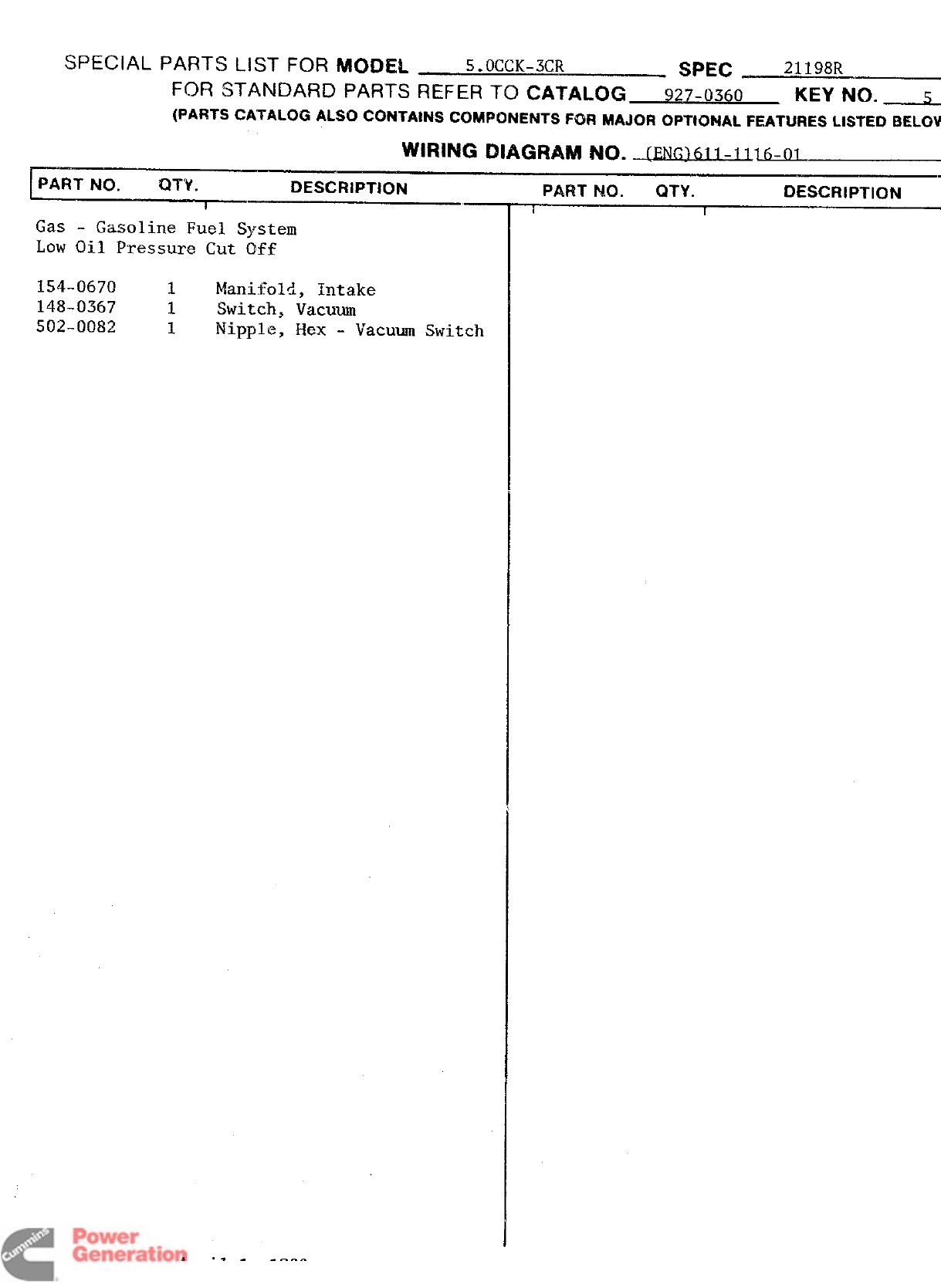
SPECIAL PARTS LIST FOR MODEL 5. OCCK-3CR SPEC 21198R
FOR STANDARD PARTS REFER TO CATALOG 927-0360 KEY NO. s
(PARTS CATALOG ALSO CGN=A --
CAma~~~tW~~hjT~FGR MAJOR OPTIONAL FEAT&jRESLISTED
BELOW
WIRING DIAGRAM NO. -JJN~161~ -1116-~1
PART NO. Q-W. DESCRIPTION
Gas -Gasoline Fuel System
Low Oil Pressure Cut Off
154-0670 1Manifold, Intake
148-0367 1Switch, Vacuum
502-0082 1Nipple, Hex -Vacuum Switch
PART 040. QTY. 13ESCRlpTION
I1
Ail 1 1980
Redistribution or publication of this document
by any means, is strictly prohibited.
[
SPECIAL PARTS LIST FOR MODEL !5.OCCK-5CR SP5C 21929V
FOR STAN13ARD PARTS REFER TO CATALOG 927-0360 KEY I’40. s
(PARTS CATALOG ALSO CONTAINS COMPONENTS FQRMAJOROPT!ONAL FEATURESLISTED
BELOW
/WIRING DIAGRAM NO. (ENG]611-llSO-02
PiR~.NO.>”-~ .
--.—___ Description
*PART NO. QTY. DESCRIPTION
II
r
uas -Gasoline Fuel System
Dated April 1 1980 Revised
Redistribution or publication of this document
by any means, is strictly prohibited.
