Vicb4 927 2501 Onan CCK CCKA Industrial Engine Parts Manual (08 1990)
User Manual: 927-2501 Onan CCK CCKA Industrial Engine Parts manual (08-1990)
Open the PDF directly: View PDF ![]() .
.
Page Count: 23
The following catalog
has gaps in its page
numbers, or doesn’t
have any numbers.
We have chosen to
leave the page
numbering in the
order that Acrobat
assigns it.

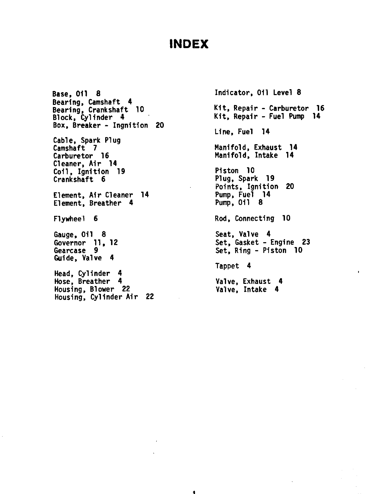
INDEX
Base, Oil 8
Bearing, Camshaft 4
Bearing, Crankshaft 10
Block, Cylinder 4 “
Box$ BFeaker - Ingnition 20
Cable, Spark Plug
Camshaft 7
Carburetor 16
Cleaner, Air 14
Coil, Ignition 19
Crankshaft 6
Element, Air Cleaner 14
Element, Breather 4
Flywheel 6
Gauge, Oil 8
Governor 11, 12
Gearcase 9
Guide, Valve 4
Head, Cylinder 4
Hose, Breather 4
Housing, Blower 22
Housing, Cylinder Air 22
Indicator,Oil Level 8
Kit, Repair - Carburetor 16
Kit, Repair - Fuel Pump 14
Line, Fuel 14
Manifold, Exhaust 14
Manifold, Intake 14
Piston 10
Plug, Spark 19
Points, Ignition 20
Pump, Fuel 14
Pump, Oil 8
Rod, Connecting 10
Seat, Valve 4
Set, Gasket - Engine 23
Set, Ring - Piston 10
Tappet 4
Valve, Exhaust 4
Valve, Intake 4

This catalog applies to the industrial CCK and CCKA Engines listed below and factory installed options. Parts are
arranged in groups of related items. Each illustrated part is identified by areference number corresponding to the
same reference number in the parts list for that group. Parts illustrations are typical. Using the MODEL and SPEC
NO. from the engine nameplate, select the Parts Key No. (1, 2, etc., in the last column) that applies to your Engine
Model and Spec No. This Parts Key No. represents piwts that differ IF--=
=,-=? Imodel% ‘u’#ass otherwise mentioned
in the description, parts are interchangeable between models. Right and left engine sides are determined by lacing
the Mowr end (front) of the engine.
CCK-S/797
CCK-S/797
CCKA-S/l627
CCKA-S/2316
CCKA-S/2583
CCKA-S/2597
CCKA-S/2737
CCKA-S/2744
CCKA-S/2976
CCKA-S/3166
CCKA-S/3522
3
Parts Key Number 1
Parts Key Number 2
Parts Key Number 3
Parts Key Number 4
Parts Key Number 5
Parts Key Number 6
Parts Key Number 7
Parts Key Number 8
Parts Key Number 9
Parts Key Number 10
Parts Key Number 11
SQA Al
2
REF. PART QTY.
woe MO* USED
..—.-.
PART
DESCRIPTION
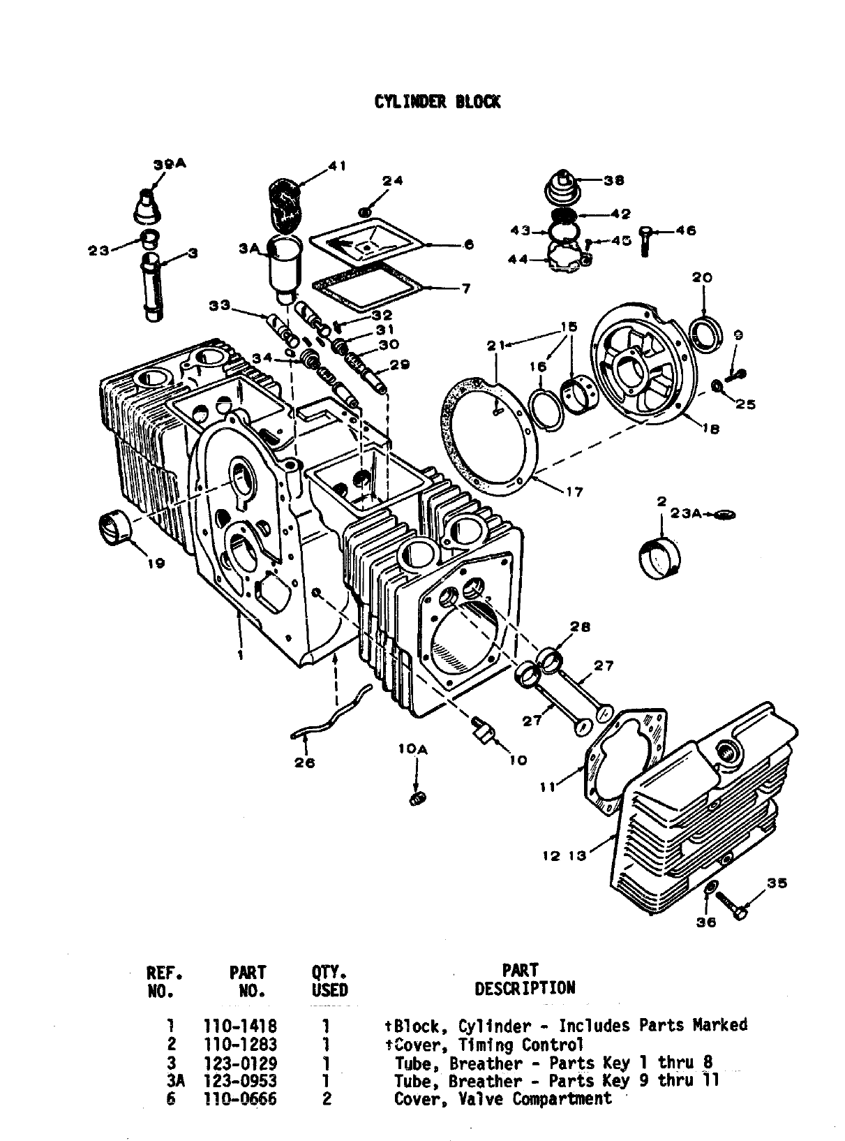
1110-1418 1 tBlock, Cylinder - Includes
2 110-1283 1 $Cover, Timing Control
3 123-0129 1 Tube, Breather - Parts Key
3A 123-0953 1 Tube, Breather - Parts Key
6 110-0666 2 Cover, Valve Compartment
Parts Marked
1 thru~
9thru 11 “-
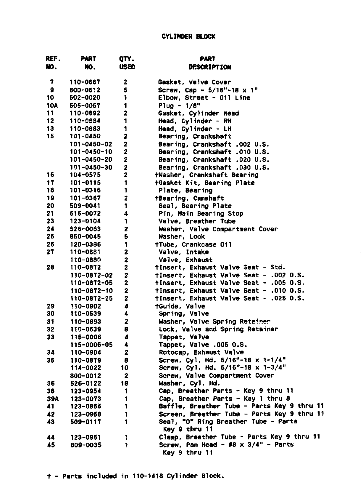
REF.
MO.
7
9
10
10A
11
12
13
15
16
17
Is
19
20
21
23
24
25
26
2?
28
29
30
31
32
33
34
35
36
30
39A
41
42
43
44
45
PART
m.
110-0667
800-0512
502-0020
505”0057
110-0892
~~o-~fJ84
110-0883
101-04s0
101-0450-02
101-0450-10
101-0450-20
101-0450”30
104”0575
101-0115
101-0316
101-0367
509-0041
516-0072
123-0104
526-0063
850-0045
120-0386
110-0881
110-0880
110-0872
110-0872-02
110-0872-05
110-0872-10
110-0872-25
110-0902
110-0539
110-0893
110-0639
115-0006
115-0006-05
110-0904
110-0879
114-0022
800-0012
526-0122
123-0954
123-0073
123-0865
123-0958
509-0117
123-0951
809-0035
QTY.
2
5
1
1
2
1
1
2
2
2
2
2
2
1
1
2
1
4
1
2
5
1
2
2
2
2
2
2
2
4
4
2
8
4
4
2
8
10
2
1$
1
1
1
1
1
1
1
PAR?
DESCRIPTION
Gasket, Valve Cover
Screw, Cap -5/16’’-18 X1“
Elbow, SWvmt -Oil L.fne
Plug -1/8”
Gasket, Cylinder Head
Head, Cylinder -RH
Head, Cylinder -LH
Bearing, Crankshaft
Bearing, Crankshaft .002 U.S.
Bearing, Crankshaft .010 U.S.
Bearing, Crankshaft .020 U.S.
Bearing, Crankshaft .030 U.S.
tWasher, Crankshaft Bearing
tGasket Kit, Bearing Plate
Plate, Bearing
tBearing, Camshaft
Seal, Bearing Plate
Pin, Main Bearing Stop
Valve, Breather Tube
Washer, Valve Compartment Cover
Washer, Lock
tTube, Crankcase Oil
Valve, Intake
Valve, Exhaust
tInsert, Exhaust Valve Seat -Std.
?Insert, Exhaust Valve Seat -.002 0.S.
tInsert, Exhaust Valve Seat -.005 0.S.
tInsert, Exhaust Valve Seat -.010 0.S.
t~nsert, Exhaust Valve Seat -.025 0.S.
tGuide, Valve
Spring, Valve
Washer, Valve Spring l?eta~ner
Lock, Valve and Spring Retainer
Tappet, Valve
Tappet, Valve ,005 0,S.
f?otocap, Exhaust Valve
Screw, Cyl. lid. 5/16’’-18 X1-1/4”
Screw, Cyl. Hd. 5/16’’-18 x1-3/4”
Screw, Valve Compartment Cover
Washer, Cyl. Hd.
Cap, Breather Parts -Key 9thru 11
Cap, Breather Parts -Key 1thru 8
Baffle, Breather Tube -Parts Key 9thru 11
Screen, Breather Tube -Parts Key 9thru 11
Seal, “O” Ring Breather Tube -Parts
Key 9thru 11
Clamp, Breather Tube -Parts Key 9thru 11
Screw, Pan Head -#8 x 3/4” -Parts
Key 9thru 11
?- Parts included in 110--1418 Cylinder Block.
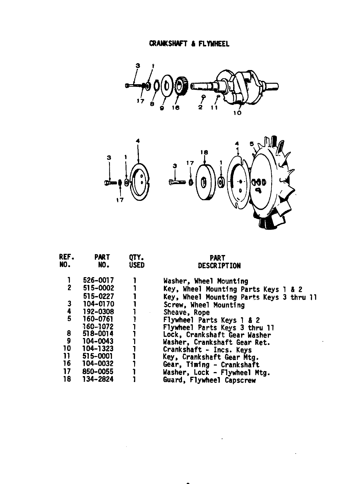
REF.
NO.
1
2
3
4
5
8
9
10
11
16
17
18
4
PART
NO.
526-0017
515-0002
515-0227
104-0170
192-0308
160-0761
q-60+J72
518-0014
104-0043
;;:-;::;
104~0032
850-0055
134-2824
QTY.
USED PART
DESCRIPTION
Washer, Wheel Mounting
Key, Mheel Mounting Parts Keys 1 & 2
Key, Wheel Mounting Parts Keys 3 thru 11
Screw, Wheel Mounting
SF@a~e$Rope
Fl=wheel Parts Keys 1 & 2
Flywheel Parts !(eys3 thru 11
Lock, CrankshaftGear Washer
Washer, CrankshaftGear Ret.
Crankshaft- Incs. Keys
Key, CrankshaftGear Mtg.
fiear,Timing - Crankshaft
Washer, Lock - FlywheelMtg.
Guard, Flywheel Capscrew
REF.
No.
1
2
3
4
5
6
7
;
::
12
13
Jg
15
16
17
18
PART
m.
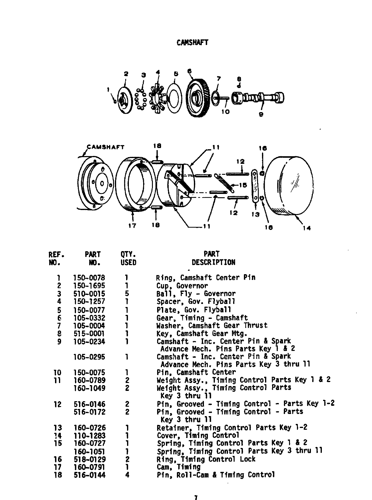
150-0078
150-1695
510-0015
150-1257
150-0077
105-C?332
105-0004
~ ml
?05-0234
105-0295
150-0075
160-0789
160-1049
516-0146
516-0172
160-0726
110-1283
160-0727
160-1051
518-0129
160-0791
516-U 44
17
QTY.
USED
1
1
5
1
1
1
1
1
1
1
1
2
2
2
2
1
1
1
1
2
1
4
PART’
DESCRIPTION
.
Ring, Camshaft Center
Cup, Governor
Ball, Fly - Governor
Spacer, Gov. Flyball
Plate, Gov. Flyball
le “14
PIn
Gear,-Timing--Camshaft
!iasher,CamshaftGear Thrust
Key, Camshaft Gear Mtg.
Camshaft - Inc. Center Pin & Spark
Advance hlech,Pins Parts Key 1 ii2
Camshaft- Inc. Center Pin & Spark
Advance Mech. Pins Parts Key 3 thru 11
Pin, Camshaft Center
Weight Assy., Timing Control Parts Key 1 & 2
Weight Assy., Timing Control Parts
Key 3 thru 11
Pin, Grooved - Timing Control o parts Key 1-2
Pin, Grooved -Timing Control - Parts
Key3 thru 11
Retatner,Timing Control Parts Key 1-2
Cover, Timing Control
Spring, Timing Control Parts Key 1 &2
Spring, Timing Control Parts Key3 thru 11
Ring, Timing Control Lock
Cam, Timing
Ptn, Roll-Cam & Timing Control
7
n
OIL BASE 8 OIL PW
I4* w
17
~~F.
●
1
2
3
4
5
7
8
9
10
11
12
13
14
15
16
17
18
19
25
26
27
28
29
PART
NO.
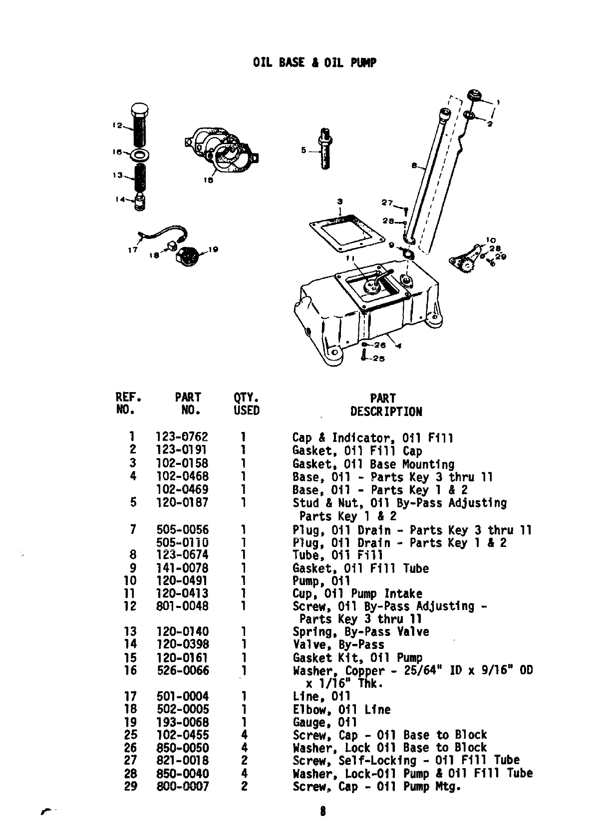
123-0762
123-0191
102-0158
102-0468
102-0469
120-0187
505-0056
505-01iO
i23-0674
;;$;:;;
120~0413
801-0048
120-0140
120-0398
120-0161
526-0066
501-0004
502-0005
;;:-::;:
:3;:;:;:
850=0040
800-0007
QTY.
USED
1
1
:
1
1
1
i
1
1
1
1
1
1
1
1
.1
1
1
1
4
4
2
4
2
5
-t
A27-1
PART
DESCRIPTION
Cap & Indicator,Oil Fill
Gasket, Oil Fill Cap
Gasket, Oil Base Mounting
Base, Gil - Parts Key 3
Base, Oil - Parts Key 1
Stud & Nut, Oil BY+SS
Parts Key 1&2
Plug, Oil Drain - Parts
Plug, Oil Drain - Parts
Tube, Oil Ffll
Gasket, Oil Fill Tube
Pump, oil
~hru 11
82
Adjusting
Key 3thru 11
Key 1&2
Cup;”Oil Pump Intake
Screw, Oil By==PassAdjusting-
Parts Key 3 thru 11
Spring, By-Pass Valve
Valve, By-Pass
Gasket Kit, Oil Pump
Washer, Copper - 25/64” ID X9/16” OD
X1/16” Thk.
Line, Oil
Elbow, Oil Line
Gauge, Oil
Screw, Cap -Oil Base to Block
Washer, Lock Oil Base to Block
Screw, Self-Locking- Oil Fill Tube
Masher, Lock-Oil Pump &Oil Fill Tube
Screw, Cap - Oi1 Pump Mtg.
8
REF. PART
NO* No.
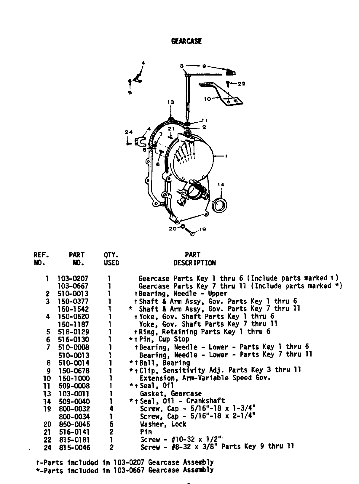
1103-0207
103-0667
2510-0013
3 150-0377
150-1542
4 150=-0620
150-1187
5 518-0129
6 516-0130
7 510-0008
510-0013
8 510-0(914
9 150-0678
10 150-1000
11 509-0008
13 103-0011
14 509-0040
19 800-0032
800-0034
20 850-0045
21 516-0141
22 815-0181
24 815-0046
4
4! 3-—a~
r
b
Tp22
s
13 \10 ;e.
I
24
L
1
1
~
1
7
1
1
1
1
1
1
1
1
1
1
1
1
4
1
5
2
1 Screw - #1O-32 x 1/2””
2Screw - #8-32 x 3/8”
PART
DESCRIPTION
Gearcase Parts Key 1 thru 6 (Includeparts marked ~)
Gear’case
Parts Key 7thru 11 (Include parts marked *)
t~earlngg Needle - Upper
tShaft &Arm Assy, Gov. Parts Key 1thru 6
*Shaft &Arm Assy, Gov. Parts Key 7thru 11
tYoke, Gov. Shaft Parts Key 1thru 6
Yoke, Gov. Shaft Parts Key 7t!m! 11
tRing, Retaining Parts Key 1thru 6
*tPine Cup Stop
tBearing, Needle -Lower -Parts Key 1thru 6
Bearing, Needle - Lower - parts Key 7 thru 11
*tBall, Bearing
*tC~iP, Sensitivity Adj. parts Key 3thru 11
Extension, Arm-variable Speed Gov.
*tSeal~ Oil
Gasket, Gearcase
*tSeal, Oil - Crankshaft
Screw, Cap - 5/16“-18 x 1-3/4”
Screw, Cap - 5/16“-18 x 2-1/4”
Masher, Lock
Pin
t-Parts included in 103-0207 GearCase Assembly
Parts Key 9thru 11
*-Parts inc~uded in 103-0667 GearCase Assembly
Fusmw 4 COWECTING MD
~3
REF.
NO.
1
2
3
5
6
8
:;
P&RT QTY*
m. tfsu’1
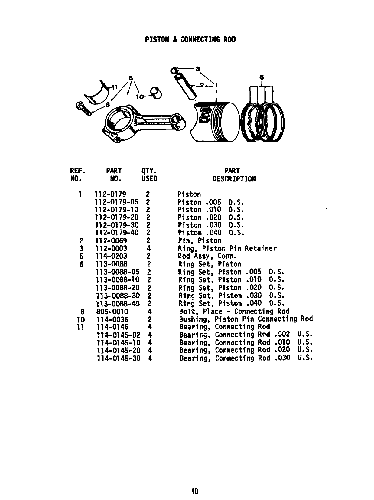
112-0179 2
112=0179-05 2
112-0179-10 2
112-0179-20 2
112-0179-30 2
112-0179-40 2
112-0069 2
112-0003 4
114-0203 2
113-0088 2
113-0088-05 2
113-0088-10 2
113-0088-20 2
113-0088-30 2
;;:-()):-40 2
4
114-0036 ;
114-!2745
114-0145-02 ~
114-0145-10 4
1]4-0145-20 4
114-0145-30 4
PART
IIESCRWTION
Piston
Piston .005 0.S.
Piston .010 0.S.
Piston .020 0.S.
Piston .030 0.S.
Piston .040 0.S.
Pin, Piston
Ring, Piston Pin Retainer
Rod Assy, Corm.
Ring Set, Piston
Ring Set, Piston .005 0.S.
Ring Set, Piston .010 0.S.
Ring Set, Piston .020 0.S.
Ring Set, Piston .030 0.S.
Ring Set, Piston .040 0.S.
Bolt, Place - ConnectingRod
Bushing, Piston Pin ConnectingRod
Bearing, Connecting!?~d
Bearing, Conneetingllod.002 U.S.
Bearing, ConnectingRod .010 U.S.
Bearing, ConnectingRod .020 U.S.
Bearing, ConnectingRod .030 U.S.
10
REF.
No.
1
2
3
4
5
7
0
10
11
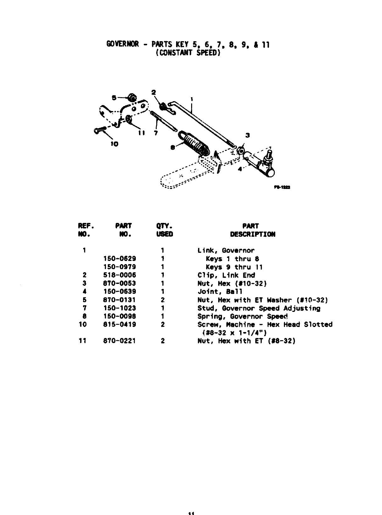
PARTS KEY 5= 6, 7, 8, 9, & 11
Pm
WQ.
1S0-0629
150-0979
518-0006
870-0053
150-0639
870-0131
150-1023
150-0098
815-0419
m=
1
1
1
1
1
1
2
1
1
2
PART
0E8CRIP’IXOW
Link, Governor’
Keys 1thru 8
Keys 9thru 11
Clip, Link End
Nut, tkX (U1O-32]
Joint, Ball
Nut, Hex with ET Washer [#l@32)
Stud, f30vernor Speed Adjusting
Spring, Governor Speed
Screw, Machine -Hex Head Slotted
(#8-32 X1-1/4”)
Nut, Hex with ET (#8-32)
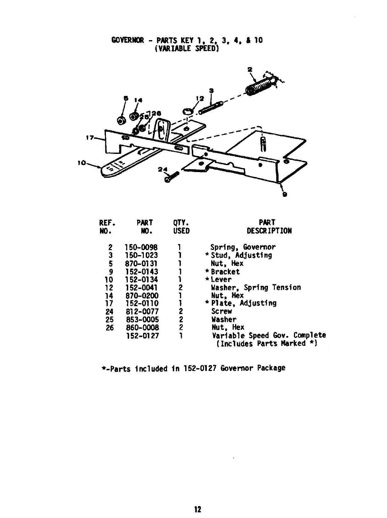
REF.
NO.
2
3
5
9
10
12
14
17
24
25
26
PART
NO*
150-0098
150-1023
870-0131
152-0143
152-0134
152-0041
870-0200
152-0110
812-0077
853-0005
860-0008
152-0127
*-Parts inc1uded
QTY. PART
USED DESCRIPTION
1Sprlng, Governor
1*Stud, Adjusting
1Nut, &X
1*Bracket
1*Lever
2Washer, Spring Tension
1Nut, *X
1*Plate, Adjusting
2Screw
2Masher
2Nut, NeX
1Variable Speed Gov. Complete
[IncTudes Parts ‘Marked *I
in 152-0127 Governor Package
30-
r~
1!
I
I
1
i
L.
40
11
’58
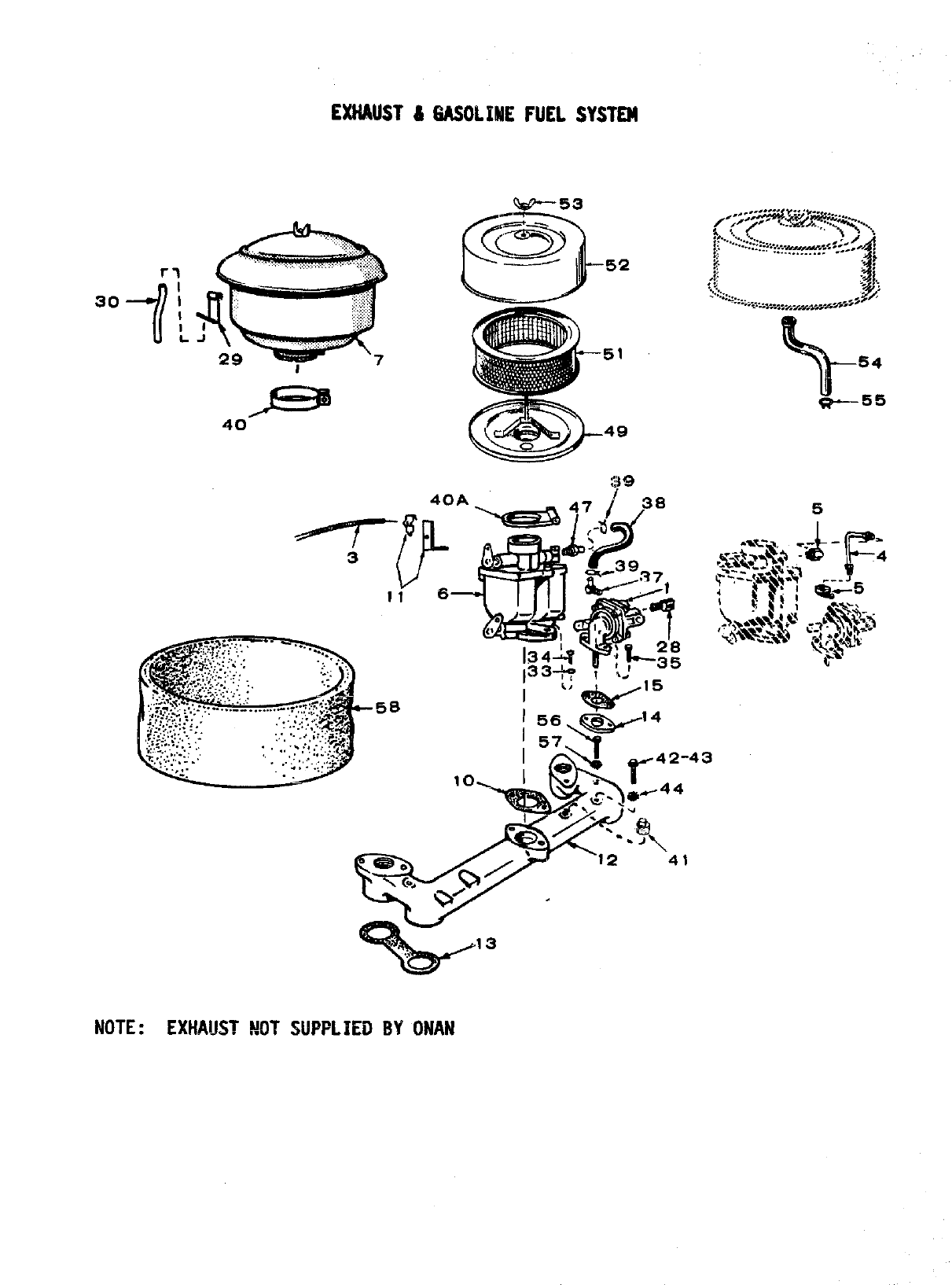
NOTE:EXHAUST NOT SWPLIEO BYONAN
51
49
5
3

REF.
No.
1
2
3
4
5
6
10
1?
12
13
14
15
28
29
30
33
34
35
37
38
39
40
40A
41
42
44
47
49
51
52
53
54
55
56
57
PARI’
No.
149-1784
149-0271
153-0351
149-0611
502-0002
142-0651
..- ----
142-0595
140-1427
141-0078
153-0263
154-0802
154-0013
149-0045
149-0003
502-0020
140-0459
140-0684
850-0040
800-0009
806-0009
502-0313
503-0707
503-0301
503-0398
503-0189
505-0008
--- ----
513-UUY5
853-0008
502-9395
740-1348
140-1216
140-1295
865-0020
123-1284
503-0171
800-0054
850=-0050
EXHAUST&MSOLZNE FUEL $W3TElJl
QTY.
U!3E0
1
1
1
1
1
1
1
1
1
1
1
2
1
2
1
1
1
2
2
2
1
1
2
1
1
~
;
1
1
1
1
1
1
1
1
2
2
PART
DESCRIPTION
Pump, Fuel (See separate group for components)
Rod Assy, Priming
Rod, Choke
Line, Fuel
Elbow, Pipe -90”
Carburetor -Key 1thru 10 (See separate
group for components)
Carburetor -Key 11 (See separate group for
components)
Cleaner, Air (Oil bath to dry conversion kit
uses 140-1216 element)
Gasket, Carburetor Mounting
Bracket &Clamp, Manual Choke Rod
Manifold, Intake
Gasket, Intake Manifold
Spacer, Fuel Pump Mounting
Gasket, Fuel Pump Mounting
Elbow, Pipe
Bracket, Breather Pipe
Tube, Breather
Washer, Lock -1/4”
Screw, Cap -1/4’’-20 X1-1/2”
Screw, Cap -1/4’’-20 x1-1/4”
Elbow, Hose
Hose, Fuel -Parts Key 3thru 11
Clamp, Hose -Parts Key 3thru 11
Clamp, Air Cleaner -Parts Key 3thru 10
Clamp, Air Cleaner -Parts Key 1, 2&11
ml..
rsug, Pipe Cleaner -Parts Key 9thru 11
Screw, Machine -Round Head (#fO-32 x3/8”)
Washer, Lock -ET (#10)
Connector, Hose -Parts Key 3thru 11
Base, Air Cleaner -Parts Key 3thru 11
Element, Air Cleaner -Parts Key 3thru 11
Cover, Air Cleaner -Parts Key 3thru 11
Nut, Wing -Parts Key 3thru 11
Tube, Breather -Parts Key 3thru 11
Clamp, Hose -Parts Key 3thru 1!
Screw, Cap -Hex Head (3/8-16 x2“)
Washer, Lock -Spring (3/8”)

cAREwmR PARTS GROUP
4
12
Lf$=-
11
1
16
‘T
32
1-.
9’
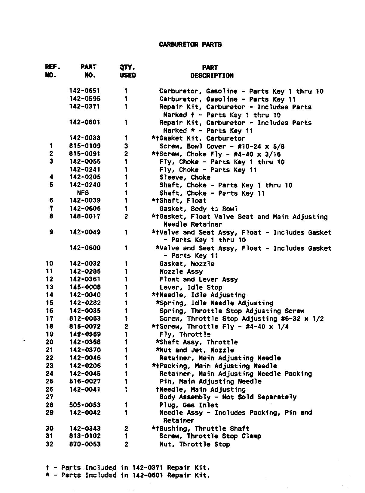
REF. PART
NC).
1
2
3
4
5
6
7
8
9
10
11
12
13
14
15
16
17
18
19
&20
21
22
23
24
25
26
27
28
29
30
33
32
No.
142-0651
142-0595
142-0371
142-0601
142-=0033
81!5-0109
815-0091
..- AA--
14Z-UU39
142-0241
142-0205
142-0240
NFS
142-0039
142-0606
148-0017
14~.oo49
142-(9600
142-0032
142-0285
142-0361
145-0008
142-0040
142-0282
142-0035
812-0063
815-0072
;g~+j~~~
142-0368
142-0370
142-0046
142-0206
142-0045
516-0027
142-0041
505-0053
142-0042
142-0343
813-0102
870-0053
QTYO
USED
1
1
1
1
1
3
2
1
1
1
1
1
1
1
2
1
1
1
1
1
1
1
1
1
1
!)
&
1
1
1
1
1
1
1
1
1
1
2
1
2
PART
0ESCRIP7W)N
Carburetor, Gasoline -Parts Key 1thru 10
Carburetor, Gasoline -Parts Key 11
Repair Kit, Carburetor -Includes Parts
Marked t-Parts Key 1thru %0
Repair Kit, Carburetor -Includes Parts
Marked *-Parts Key 11
*tGasket Kit, Carburetor
Screw, Bowl Cover -#10-24 x5/8
*tScrew, Choke Fly -#4-40 x3/16
Fly, Choke -Parts Key 1thru 10
Fly, Choke -Parts Key !1
Sleeve, Choke
Shaft, Choke -Parts Key 1thru 10
Shaft, Choke -Parts Key 11
*tShaft, Float
Gasket, Body to !30wI
*tGasket, Float Valve Seat and Main Adjusting
Needle Retainer
*tValve and Seat Assy, Float -Includes Gasket
-Parts Key 1thru 10
*Valve and Seat Assy, Float -Includes Gasket
-Parts Key 11
Gasket, Nozzle
Nozzle Assy
Float and Lever Assy
Lever, Idle Stop
*tNeedle, Idle Adjusting
*Spring, Idle Needle Adjusting
Spring, Throttle Stop Adjusting Screw
Screifi, Throttle Stop Adjusting #6-32 x1/2
*?Screw, Throttle Fly -#4-40 x1/4
Fly, Throttle
*Shaft ASSY, Throttle
*Nut and Jet, No~z~~
Retainer, Main Adjusting Needle
*tPack+ng, Main Adjusting Needle
Retainer, Main Adjusting Needle Packing
Pin, Main Adjusting Needle
tNeedle, Main Adjusting
Body Assembly -Not Sold Separately
Plug, Gas Inlet
Needle Assy -Includes Packing, Pin and
Retainer
*tBushing, Throttle Shaft
Screw, Throttle Stop Clamp
Nut, Throttle Stop
t- Parts Included in 142-0371 Repair Kit.
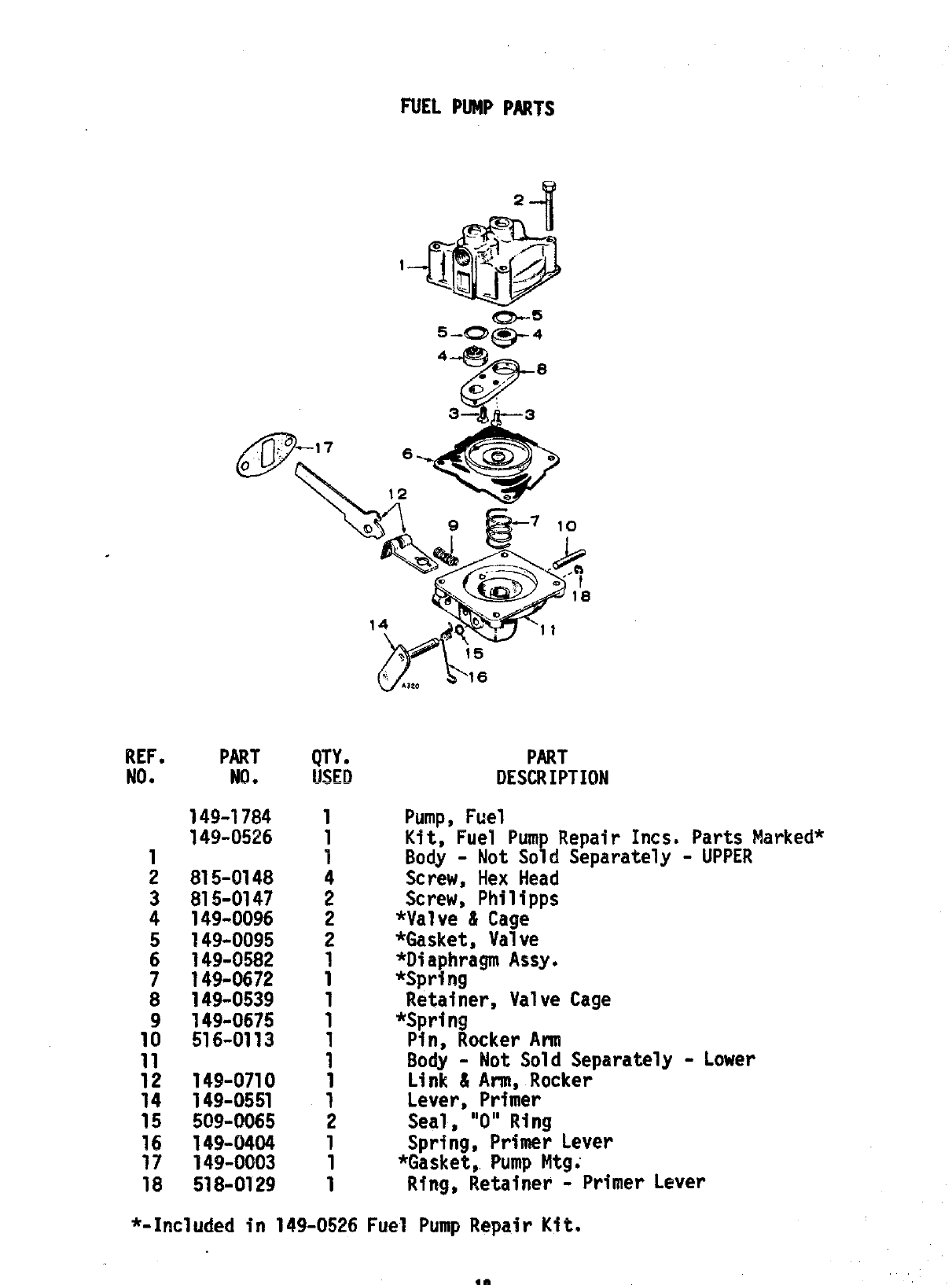
FUEL PUMP PART’S
1
Q.--5
5-0- 4
9-
4-lg!!Ji ~
P
/
0“ “
3— ,&3
REF. PART
NO. NO.
149-1784
149-0526
1
2 815-0148
3 815-0147
4 149-0096
5 149-0095
6 149-0582
7 149-0672
8 149-0539
9 149-0675
10 516-0113
11
12 149-0710
14 149-0551
15 509-0065
16 149-0404
17 149”0003
18 518-0129
(g_——
1
1
1
4
2
2
2
1
1
1
1
1
1
1
1
2
1
1
1
PART
DESCRIPTION
Pump, Fuel
Kit, Fuel Pump Repair Incs. Parts Marked*
Body - Not Sold Separately- UPPER
Screw, Hex Head
Screw, Philipps
*Valve & Cage
*Gasket, Valve
*DiaphragmAssy.
*Sprl.ng
Retainer, Valve Cage
*Spring
Pin, Rocker Ann
Body - Not Sold Separately- Lower
Link 81Arm, Rocker
Lever, Primer
Seal, “O” Ring
Spring, Primer Lever
*Gasket, Pump Mtgi
Ring, Retainer - Primer Lever
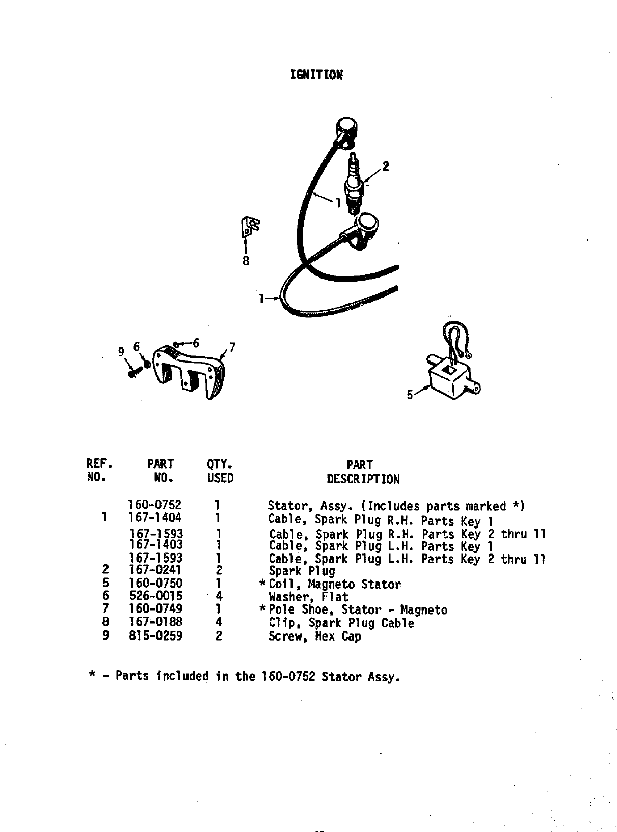
REF.
NO●
1
2
5
6
7
8
9
Umm
PART QTY.
MO. USED
160-0752 1
167-1404 1
167-1593 ~
167-1403
167-1593 1
167-0241 2
160-0750 1
526-0015 4
160-0749 1
167-0188 4
815-0259 2
PART
DESCRIPTION
Stator, Assy. (Includesparts marked*)
Cable, Spark Plug R.H. Parts Key 1
Cable, Spark Plug R.H. Parts Key 2thru 11
Cable, Spark Plug L.H. Parts Key 1
Cable, Spark Plug L.H. Parts Key 2thru 11
Spark Plug
*Cofl, Magneto Stator
Washer, Flat
*Pole Shoe, Stator - Magneto
Clip, Spark Plug Cable
Screw, Hex Cap
*-Parts included in the 160-0752 Statorlksy.
1$
I1
o\w
/22
/23
r14
@!!!B-lo
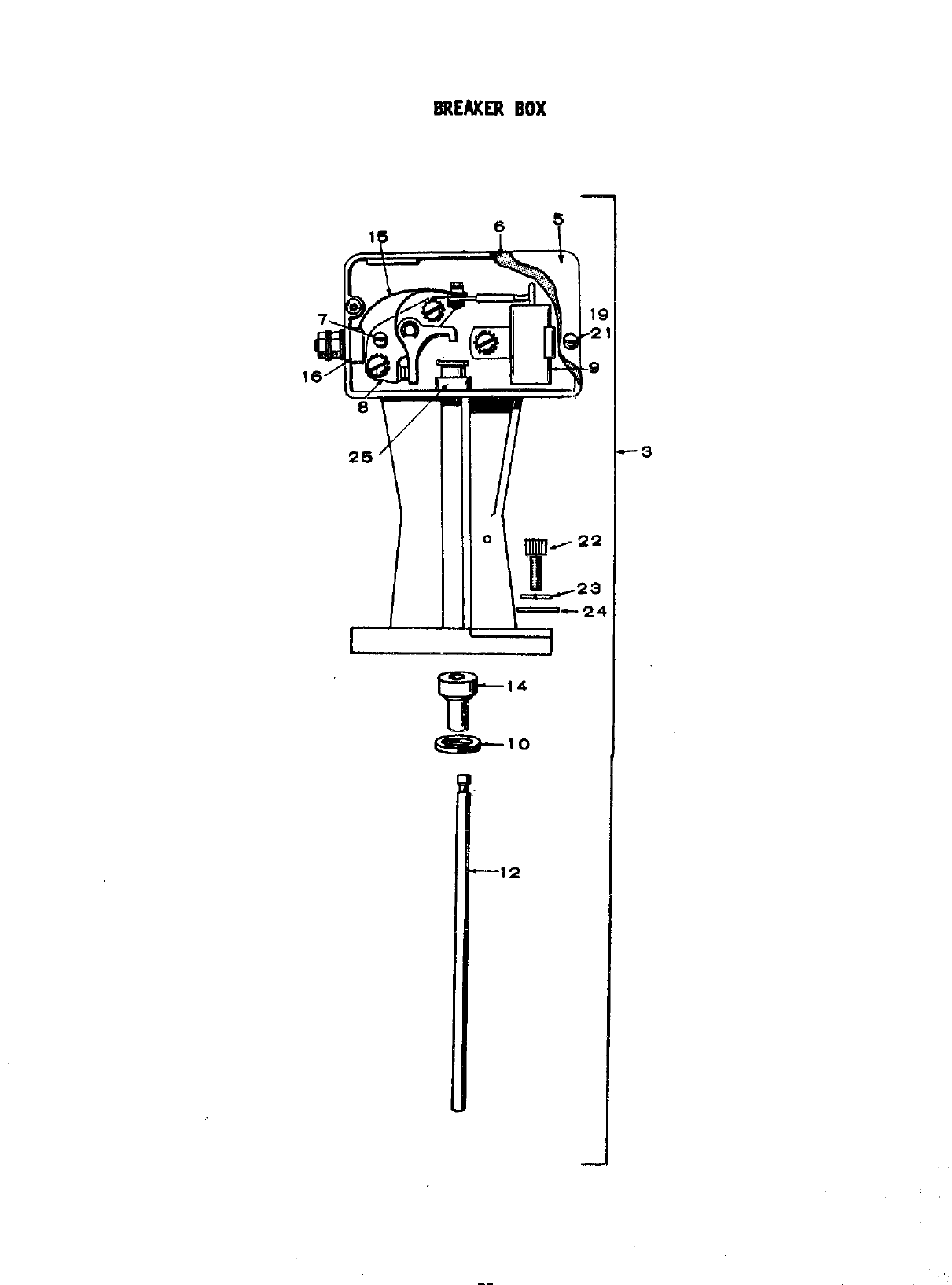
BREAXER BOX
REF.
NO.
3
5
6
7
8
1:
12
14
15
16
19
21
22
23
24
25
PART
NO.
160-1135
160-0930
160-0150
160-0075
160-0002
312-0069
160-1040
160-0723
160-1041
160-0428
332-319
850-0025
812-0077
802-0035
850-0040
526-0214
160-0931
QTY.
USED
1
1
1
1
1
1
1
1
1
1
1
2
2
2
2
2
1
PART
DESCRIPTION
Box Assy., Breaker (Complete)
Cover, Breaker Box
Gasket
Cam, Point Adjusting
Point Set
Condensor
Gasket
Plun er
!
Bush ng
Strap
Block, Terminal
Masher
Screw
Screw
Washer
Washer
Guide, Plunger
C!5
*
,“ p.
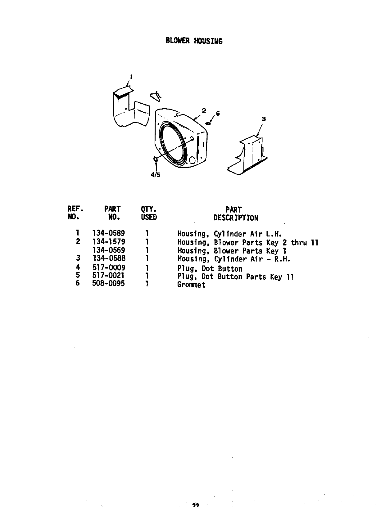
REF.
NO.
1
2
3
4
5
6
PART
NO.
134-0589
134-1579
134-0569
134-0588
517-0009
517-0021
508-0095
4/’5
QTY.
USED
1
1
1
1
1
1
1
PART
DESCRIPTION
Housing, CylinderAirL.H.
Housing, Blower Parts Key 2 thru 11
Housing, Blower Parts Key 1
Housing, CylinderAir- R.H.
Plug, Dot Button
Plug, Dot Button Parts Key 11
Grommet
SERVICEKITS &PAINT
REF. PART QTY. PART
No. N(),USED I)ESCRIPTM)N
98-1100 1 Kit, Decal
160-0836 1 Kit, Ignition tune-up
168-0095 1Gasket Kit, Carlmnl?emoval
168-0103 1Gasket Kit, Engine
